RAJKOT SMART CITY DEVELOPMENT LTD.
449
RAJKOT SMART CITY DEVELOPMENT LTD. e-Tender No.: RSCDL/SMART CITY/18/2020-21. VOLUME-I INVITATION TO BID, INSTRUCTIONS TO BIDDERS, CONDITIONS OF CONTRACT January-2021 :: Milestone dates of e-Tendering :: 1. Downloading of e-Tender documents 16-01-2021 to 11-02-2021up to 17.00 Hrs. 2. a) Pre-bid Queries to be submitted by e-mail only at mail ID [email protected] / [email protected] b) Pre-bid Meeting a) 27-01-2021 up to 11.00 am b) 27-01-2021 at 4-00 pm 3. Online submission of e-Tender 11-02-2021 up to 18.00 Hrs. 4. Physical submission of EMD, Tender fee, Documents required for pre-qualification and other necessary documents. Up to 16-02-2021 18.00 Hrs. 5. Verification of submitted documents (EMD, Tender fee, Documents required for pre- qualification and other Necessary documents.) Up to 19-02-2021 18.00 Hrs. 6. Opening of online Primary Bid (Technical Bid) 17-02-2021 at 10.30 Hrs. onwards 7. Opening of online Commercial Bid (Price Bid) for technically qualified bidders only. 22-02-2021 at 10.30 Hrs. onwards (If possible) 8. Bid Validity 180 Days City Engineer (Drainage Project), Drainage Project , Room No. 3, West Zone Office, Rajkot Municipal Corporation, Shri Harisinhji Gohil Bhawan, 150 Ft. Ring Road, Rajkot-360 005. Gujarat. India. Tender Documents For ENGINEERING, PROCUREMENT, CONSTRUCTION, COMMISSIONING AND 5 YEARS OPERATION & COMPREHENSIVE MAINTENANCE OF 8 MLD CAPACITY TERTIARY TREATMENT PLANT AT RAIYADHAR, RAJKOT UNDER RAJKOT SMART CITY MISSION 1
-
Upload
khangminh22 -
Category
Documents
-
view
0 -
download
0
Transcript of RAJKOT SMART CITY DEVELOPMENT LTD.

RAJKOT SMART CITY DEVELOPMENT LTD.e-Tender No.: RSCDL/SMART CITY/18/2020-21.
VOLUME-IINVITATION TO BID,
INSTRUCTIONS TO BIDDERS,CONDITIONS OF CONTRACT
January-2021
:: Milestone dates of e-Tendering ::1. Downloading of e-Tender documents 16-01-2021 to 11-02-2021up to 17.00 Hrs.
2. a) Pre-bid Queries to be submitted by e-mail only at mail [email protected] / [email protected]) Pre-bid Meeting
a) 27-01-2021 up to 11.00 am
b) 27-01-2021 at 4-00 pm
3. Online submission of e-Tender 11-02-2021 up to 18.00 Hrs.
4. Physical submission of EMD, Tender fee, Documentsrequired for pre-qualification and other necessary documents.
Up to 16-02-2021 18.00 Hrs.
5. Verification of submitted documents (EMD, Tender fee,Documents required for pre- qualification and other Necessarydocuments.)
Up to 19-02-2021 18.00 Hrs.
6. Opening of online Primary Bid (Technical Bid) 17-02-2021 at 10.30 Hrs. onwards
7. Opening of online Commercial Bid (Price Bid) for technicallyqualified bidders only.
22-02-2021 at 10.30 Hrs. onwards(If possible)
8. Bid Validity 180 Days
City Engineer (Drainage Project),Drainage Project , Room No. 3,West Zone Office, Rajkot Municipal Corporation,Shri Harisinhji Gohil Bhawan,150 Ft. Ring Road, Rajkot-360 005.Gujarat. India.
Tender Documents ForENGINEERING, PROCUREMENT, CONSTRUCTION, COMMISSIONING AND
5 YEARS OPERATION & COMPREHENSIVE MAINTENANCE OF 8 MLDCAPACITY TERTIARY TREATMENT PLANT AT RAIYADHAR, RAJKOT
UNDER RAJKOT SMART CITY MISSION
1

CONTENTS OF THE TENDER / BID DOCUMENT
VOLUME DESCRIPTION
VOLUME I INVITATION FOR BIDS, INSTRUCTIONS TO BIDDERSAND CONDITIONS OF CONTRACT
VOLUME II TECHNICAL SPECIFICATIONS ALONG WITH BIDDRAWINGS
VOLUME III DATA SHEETS AND TECHNICAL SCHEDULES
VOLUME IV PRICE BID
2
CONTENTS OF THE VOLUME I
INVITATION FOR BIDS
INSTRUCTIONS TO BIDDERS
AND
CONDITIONS OF CONTRACT
Section Part Description
I 1 Invitation To Bid
2 Instructions to Bidders
II 1 Conditions of Contract
2 Conditions of Particular Application
3 Conditions of Contract for Operation & Maintenance
3

ABBREVIATIONS
Statement showing the details of abbreviations
Full Form Abbreviation
Rajkot Smart City Development Limited RSCDL
Atal Mission of Rejuvenation and Urban Transformation AMRUT
Chief Executive Officer CEO
General Manager GM / G.M.
Additional City Engineer (Drainage) Add.C. E
City Engineer C.E.
Rajkot Municipal Corporation RMC
Dispute Adjudication Board DAB
Operation and Maintenance O&M
Net Present Value NPV
Engineering Procurement and Construction EPC
Paschim Gujarat Vij Company Limited PGVCL
Critical Path Method CPM
Reinforced Cement Concrete RCC
Kilometer KM
Mild Steel MS
Bureau of Indian Standard BIS
Central Public Health & Environmental Engineering Organisation CPHEEO
American Society of Civil Engineers ASCE
American Petroleum Industries API
Million Liter per Day MLD
High Yield Strength Deformed bar HYSD
Corrosion Residence Steel CRS
Ordinary Portland Cement OPC
American Standard for Testing of Material ASTM
Flux Compensated Magnetic Amplifier FCMA
Cost Insurance and fright CIF
Free On Board FOB
Ex – Works EXW
Sewage Treatment Plant STP
Tertiary Treatment Plant TTP
Primary Settling Tank/ Secondary Settling Tank PST/ SST
Aeration Tank AT
Raw Sludge Pump House/ Return Sludge Pump House RPH/ RePH
Sludge Drying Bed SDB
Bio-Chemical Oxygen Demand/ Chemical Oxygen Demand BOD/ COD
Dissolved Oxygen DO
4
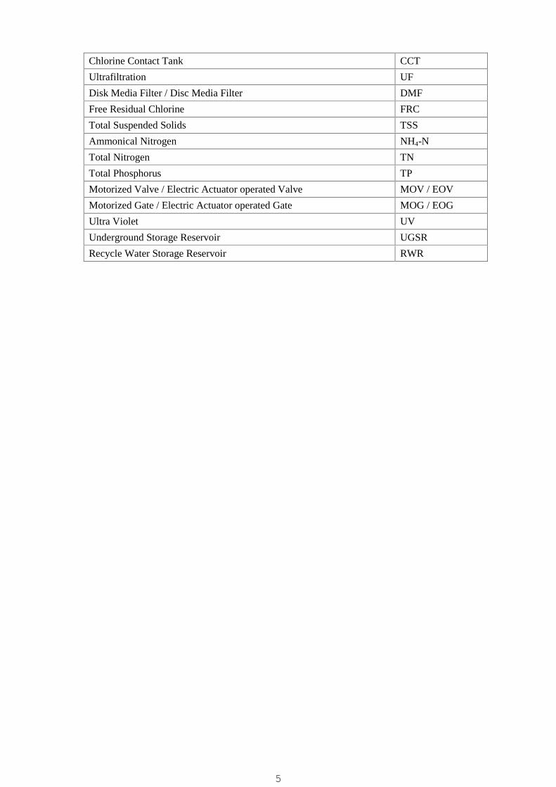
Chlorine Contact Tank CCT
Ultrafiltration UF
Disk Media Filter / Disc Media Filter DMF
Free Residual Chlorine FRC
Total Suspended Solids TSS
Ammonical Nitrogen NH4-N
Total Nitrogen TN
Total Phosphorus TP
Motorized Valve / Electric Actuator operated Valve MOV / EOV
Motorized Gate / Electric Actuator operated Gate MOG / EOG
Ultra Violet UV
Underground Storage Reservoir UGSR
Recycle Water Storage Reservoir RWR
5

SECTION IPART 1. INVITATION TO BID
6

RAJKOT SMART CITY DEVELOPMENT LIMITEDINVITATION FOR BIDS / TENDER
e-Tender Notice
RSCDL, a subsidiary company of Rajkot Municipal Corporation invites Bids from theexperienced contractors registered in appropriate class in Municipal Corporation/GWSSB/StateGovernment/ Central Government for following works under Rajkot Smart City Mission.
Sr.No. Name of Work
a) Estimated Costb) Amount of EMDc) e-Tender feed) Time limit for
completion of work
1 ENGINEERING, PROCUREMENT, CONSTRUCTION,COMMISSIONING AND 5 YEARS OPERATION &MAINTENANCE OF 8 MLD CAPACITY TERTIARYTREATMENT PLANT AT RAIYADHAR, RAJKOTUNDER RAJKOT SMART CITY MISSION
e-Tender No.: RSCDL/SMART CITY/21/1/2020-21
a) Rs. 17,15,00,000/-b) Rs. 17,15,000/-c) Rs.23,500/-d) 15 (Fifteen) Months(including 3 Month TrialRun)
:: Milestone dates of e-Tendering ::
1. Downloading of e-Tender documents16-01-2021 to 11-02-2021up to 17.00Hrs.
2. a) Pre-bid Queries to be submitted by e-mail only atmail ID
[email protected] / [email protected]) Pre-bid Meeting
a) 27-01-2021 up to 11.00 am
b) 27-01-2021 at 4-00 pm
3. Online submission of e-Tender 11-02-2021 up to 18.00 Hrs.
4. Physical submission of EMD, Tender fee,Documents required for pre-qualification and othernecessary documents.
Up to 16-02-2021 18.00 Hrs.
5. Verification of submitted documents (EMD, Tenderfee, Documents required for pre- qualificationand other Necessary documents.)
Up to 19-02-2021 18.00 Hrs.
6. Opening of online Primary Bid (Technical Bid) 17-02-2021 at 10.30 Hrs. onwards7. Opening of online Commercial Bid (Price Bid) for
technically qualified bidders only.22-02-2021 at 10.30 Hrs. onwards(If possible)
8. Bid Validity 180 Days
1. All interested bidders must submit tender fee for an amount of INR 23,500/- (Rupees Twenty
Three Thousand Five Hundred Only) inclusive of all taxes to be deposited directly through
RTGS/NEFT/ Over the Counter in A/c No 70160100018496; Bank: Bank of Baroda, Para
Bazar branch, Rajkot ; IFSC Code: BARB0DBPRAJ (fifth Alphabet is Zero) or submit at
the below mentioned address in the form of Demand draft in favor of “Rajkot Smart City
Development Limited”, Rajkot from any Nationalized Bank or Scheduled Bank (except
Co-Operative Bank) in India.
7
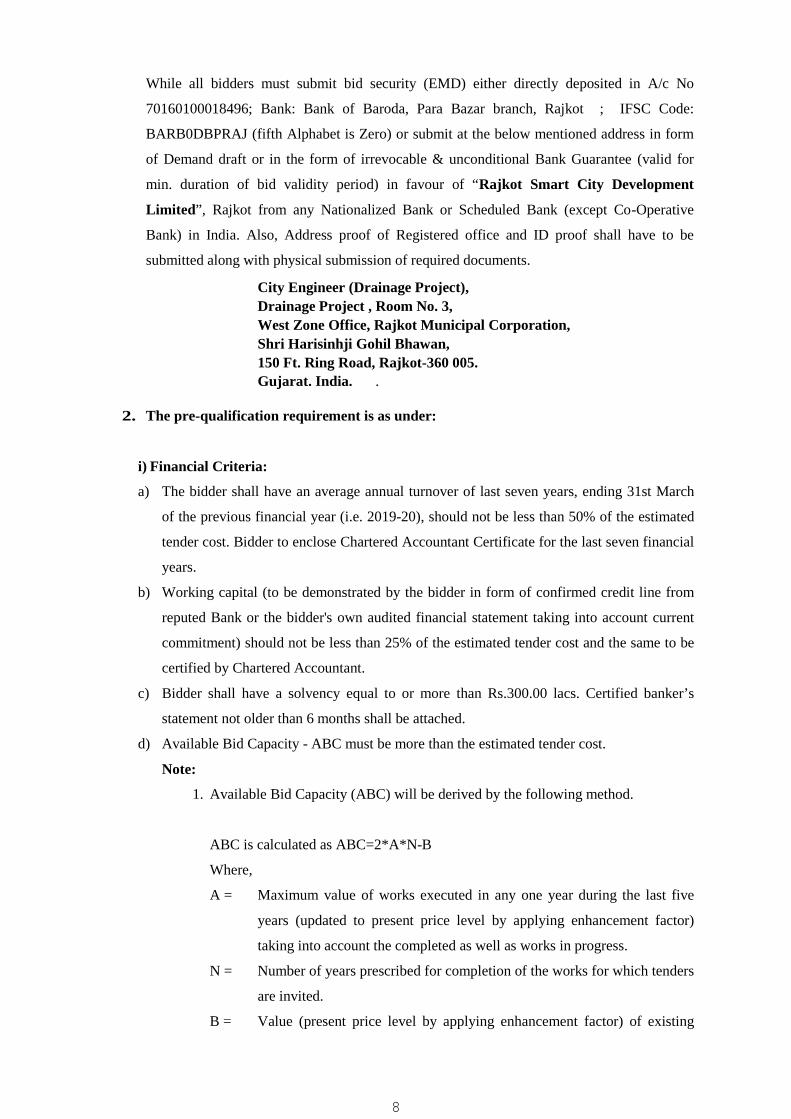
While all bidders must submit bid security (EMD) either directly deposited in A/c No
70160100018496; Bank: Bank of Baroda, Para Bazar branch, Rajkot ; IFSC Code:
BARB0DBPRAJ (fifth Alphabet is Zero) or submit at the below mentioned address in form
of Demand draft or in the form of irrevocable & unconditional Bank Guarantee (valid for
min. duration of bid validity period) in favour of “Rajkot Smart City Development
Limited”, Rajkot from any Nationalized Bank or Scheduled Bank (except Co-Operative
Bank) in India. Also, Address proof of Registered office and ID proof shall have to be
submitted along with physical submission of required documents.
City Engineer (Drainage Project),Drainage Project , Room No. 3,West Zone Office, Rajkot Municipal Corporation,Shri Harisinhji Gohil Bhawan,150 Ft. Ring Road, Rajkot-360 005.Gujarat. India. .
2. The pre-qualification requirement is as under:
i) Financial Criteria:
a) The bidder shall have an average annual turnover of last seven years, ending 31st March
of the previous financial year (i.e. 2019-20), should not be less than 50% of the estimated
tender cost. Bidder to enclose Chartered Accountant Certificate for the last seven financial
years.
b) Working capital (to be demonstrated by the bidder in form of confirmed credit line from
reputed Bank or the bidder's own audited financial statement taking into account current
commitment) should not be less than 25% of the estimated tender cost and the same to be
certified by Chartered Accountant.
c) Bidder shall have a solvency equal to or more than Rs.300.00 lacs. Certified banker’s
statement not older than 6 months shall be attached.
d) Available Bid Capacity - ABC must be more than the estimated tender cost.
Note:
1. Available Bid Capacity (ABC) will be derived by the following method.
ABC is calculated as ABC=2*A*N-B
Where,
A = Maximum value of works executed in any one year during the last five
years (updated to present price level by applying enhancement factor)
taking into account the completed as well as works in progress.
N = Number of years prescribed for completion of the works for which tenders
are invited.
B = Value (present price level by applying enhancement factor) of existing
8
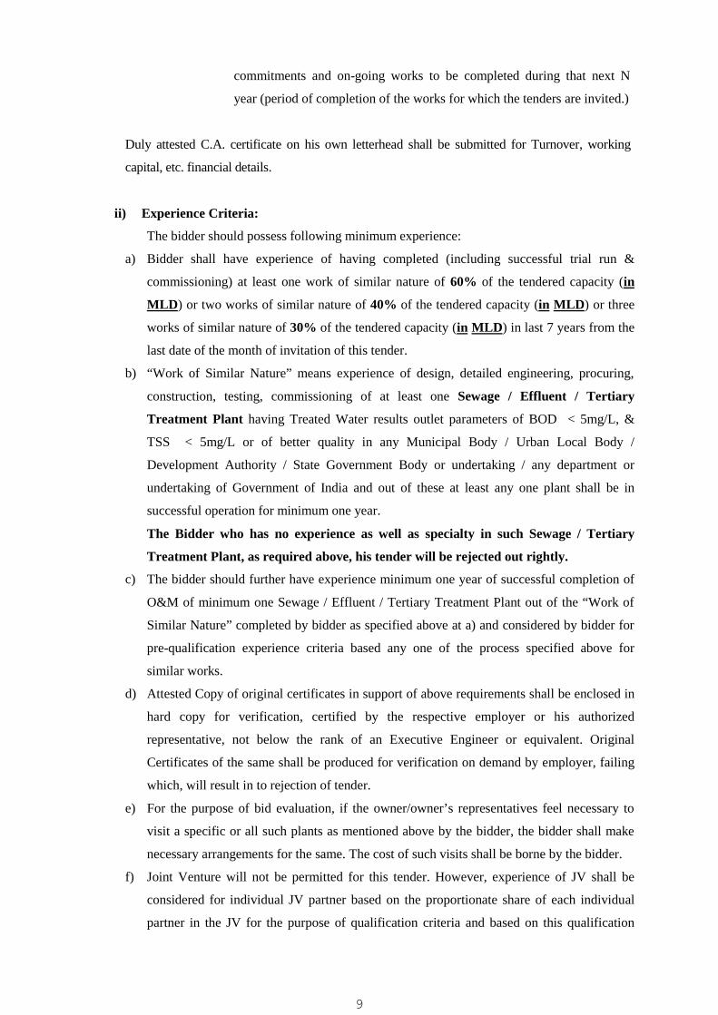
commitments and on-going works to be completed during that next N
year (period of completion of the works for which the tenders are invited.)
Duly attested C.A. certificate on his own letterhead shall be submitted for Turnover, working
capital, etc. financial details.
ii) Experience Criteria:
The bidder should possess following minimum experience:
a) Bidder shall have experience of having completed (including successful trial run &
commissioning) at least one work of similar nature of 60% of the tendered capacity (in
MLD) or two works of similar nature of 40% of the tendered capacity (in MLD) or three
works of similar nature of 30% of the tendered capacity (in MLD) in last 7 years from the
last date of the month of invitation of this tender.
b) “Work of Similar Nature” means experience of design, detailed engineering, procuring,
construction, testing, commissioning of at least one Sewage / Effluent / Tertiary
Treatment Plant having Treated Water results outlet parameters of BOD < 5mg/L, &
TSS < 5mg/L or of better quality in any Municipal Body / Urban Local Body /
Development Authority / State Government Body or undertaking / any department or
undertaking of Government of India and out of these at least any one plant shall be in
successful operation for minimum one year.
The Bidder who has no experience as well as specialty in such Sewage / Tertiary
Treatment Plant, as required above, his tender will be rejected out rightly.
c) The bidder should further have experience minimum one year of successful completion of
O&M of minimum one Sewage / Effluent / Tertiary Treatment Plant out of the “Work of
Similar Nature” completed by bidder as specified above at a) and considered by bidder for
pre-qualification experience criteria based any one of the process specified above for
similar works.
d) Attested Copy of original certificates in support of above requirements shall be enclosed in
hard copy for verification, certified by the respective employer or his authorized
representative, not below the rank of an Executive Engineer or equivalent. Original
Certificates of the same shall be produced for verification on demand by employer, failing
which, will result in to rejection of tender.
e) For the purpose of bid evaluation, if the owner/owner’s representatives feel necessary to
visit a specific or all such plants as mentioned above by the bidder, the bidder shall make
necessary arrangements for the same. The cost of such visits shall be borne by the bidder.
f) Joint Venture will not be permitted for this tender. However, experience of JV shall be
considered for individual JV partner based on the proportionate share of each individual
partner in the JV for the purpose of qualification criteria and based on this qualification
9

individual JV partner can bid in the same name and style of individual company forming
part of JV. For this purpose, the bidder shall enclose the notarized copy of JV agreement
along with physical submission of technical bid.
g) The experience of Sub-Contractor / back to back works shall not be considered.
iii) Personnel Criteria:
Bidder to provide CV's of key personnel proposed to be deployed on the project as below
as a minimum:
Personnel Min. Qualification
Requirement
Min. Experience in Years
Process Engineer:
Environment / Chemical
Engineer
Masters in Environment /
Chemical Engineering
10 Years
Project Engineer B.E. (Civil) 7 Years
Site Engineer - Civil B.E. / Diploma (Civil) BE: 5 Years / Dip: 7 Years
Mechanical Engineer B.E. (Mech) 5 Years
Electrical Engineer B.E. (Elect) 5 Years
Following enhancement factors will be used for the turnover / cost of works completed /
executed in previous years giving weightage of 10% per year to arrive enhanced financial
amount to bring them to 2020-21 price level:
Sr. No. Financial Year Multiplying factor
2020-21 (Base Year) 1.00
1 2019-20 1.10
2 2018-19 1.21
3 2017-18 1.33
4 2016-17 1.46
5 2015-16 1.61
6 2014-15 1.77
7 2013-14 1.95
3. The contractor shall have a registration with State / Central Government or State Water
Supply Boards or in Municipal Corporation in ‘AA’ Class. Supporting documents will be
submitted in hard copy.
4. The bidder should not have been Terminated / Debarred / Black Listed by Government of
India/Government of Gujarat or any State Board/Corporations, since inception of the
firm/Company. A Declaration in this regard on Rs.300/- (or of applicable amount) Stamp
10

Paper duly Notarized, shall have to be submitted as per Annexure-II, along with the tender
documents.
5. The bidder should provide accurate information on any litigation history or arbitration
resulting from contracts completed or under execution by him over the last ten years. This
should also include such cases, which are in process / progress. A consistent history of
awards against the bidder may result in failure of the bid. In case the bidder has not
provided such information and has come to the notice of the authority, the tender will be
rejected at what so ever stage and in such case all the losses that will arise out of this issue
will be recovered from the tenderer / bidder and he will not have any defense for the same.
6. Reserve the right (i) to change, alter or to waive any technical or commercial terms,
condition and qualification (ii) to reject all the bids or any bid in part or full without
assigning any reason whatsoever (iii) for making changes / relaxation in eligibility criteria
at any time in the interest of the public. The bidder shall have no cause of action or claim
against the RSCDL or its Officers / Employee’s successor or assignee for rejection of his
tender/bid.
7. After opening of Technical Bid, the procedure for the pre-qualification shall be adopted
and the Price Bid of only successful qualified bidder shall be opened for the contract. The
decision of Chairman, RSCDL regarding the pre-qualification shall be final and binding to
all the bidders.
8. The Tender of those bidder(s) who fail to submit the required documents physically within
the stipulated date and time will be treated as non-responsive and their Price Bid will not be
opened.
9. Conditional Tenders will be outright rejected.
10. Chairman, Rajkot Smart City Development Limited reserves the right to accept / reject
any or all e-Tender(s) without assigning any reasons is hereby reserved.
Municipal Commissioner & ChairmanRajkot Municipal Corporation
&Rajkot Smart City Development Limited
Pl. Note: The tender can be uploaded and downloaded from www.rmc.nprocure.com only.
11

SECTION – I
PART 2. INSTRUCTIONS TO BIDDERS
12
SECTION-1PART 2. INSTRUCTION TO BIDDERS
TABLE OF CLAUSES
13

A. General
1. Scope of Bid
2. Source of Funds
3. Eligible Bidders
4. Eligible Materials, Equipment and Services
5. Qualification of the Bidder
6. Cost of Bidding
7. Site Visit
B. Bidding Documents
8. Content of Bidding Documents
9. Clarification of Bidding Documents
10 Amendment of Bidding Documents
C. Preparation of Bids
11. Language of Bids
12. Documents Comprising the Bid
13. Bid Form and Price Schedules
14. Bid Prices
15. Currencies of Bid and Payment
16. Bid Validity
17. Bid Security
18. Alternative Proposals by Bidders
19. Pre-Bid Meeting
20. Format and Signing of Bid
D. Submission of Bids
21. Online Primary Bid and Online Price Bid
22. Deadline for Submission of Bids
23. Late Bids of required documents (Physically)
14

E. Opening and Evaluation of Technical Proposals
24. Opening of Primary Bid and Physically submitted documents for Pre-Qualification
25. Process to be Confidential
26. Preliminary Examination of Technical Proposals
27. Evaluation and Comparison of Technical Proposals
28. Clarification of Technical Proposals and Contacting the Employer
29. Opening of Commercial Bid (Price Proposals)
F. Opening of Price Proposals
30. Bid Opening of online Price Proposals
31. Process to be Confidential
32. Clarification of Price Proposals and Contacting the Employer
33. Preliminary Examination of Bids and Determination of Responsiveness
34. Conversion to Single Currency
35. Evaluation and Comparison of Price Proposals
36. Domestic Preference
G. Award of Contract
37. Award
38. Employer's Right to Accept any Bid and to Reject any or all Bids
39. Notification of Award
40. Signing of Contract
41. Performance Security
42. Corrupt or Fraudulent Practices
15
A. General
1. SCOPE OF BID:
The Rajkot Smart City Development Limited (hereinafter referred to as “the Employer” or“the Client”) wishes to receive bids for Engineering, Procurement, Construction,Commissioning and 5 Years Operation & Maintenance of 8 MLD Capacity Tertiary TreatmentPlant at Raiyadhar, Rajkot under Rajkot Smart City Mission design, along with all relatedCivil, Piping, Mechanical, Electrical and Instrumentation equipment and accessories,including miscellaneous works etc. complete at Raiyadhar, Rajkot. Duration of operationand maintenance shall be Five (5) years.
1.1 Project Area and Coverage:
The project aims at tertiary treatment of 8 MLD of treated sewage of secondarytreated sewage from existing 56MLD STP at Raiyadhar, Rajkot with Media Filter +UF Process, and Five years operation and maintenance of the plant.
The project covers related all Civil, Piping, Mechanical, Electrical, Instrumentationworks, three months of trial run and including Operation and Maintenance of theplant for Five Years
1.2 The successful bidder will be expected to complete the works within Twelve (12)months, including Three (3) month successful trial run & monsoon period andacceptance of plant, from the date of issue of Work Order.
1.3 Trial run period shall be three months before the date of issue of completioncertificate during which all expense incurred shall be borne by successful bidder(only secondary treated sewage and power shall be free supply by the Employer).
1.4 On completion of trial run, O & M shall be for 5 (Five) years.
2. SOURCE OF FUNDS:
Rajkot Smart City Development Limited (RSCDL) has sufficient finance for theimplementation of the above work.
3. ELIGIBLE BIDDERS:
3.1 This invitation to the bid is open to all the bidders.
3.2 Bidders shall provide such evidence of their continue eligibility satisfactory to theemployer as the employer shall reasonably request.
3.3 Bidders shall not be under a declaration of ineligibility for corrupt or fraudulentpractices in accordance with sub-clause 42.1 (c).
3.4 A Bidder shall not have a conflict of interest. All bidders found to be in conflict ofinterest shall be disqualified. A Bidder may be considered to have a conflict ofinterest with one or more parties in this bidding process if they;
(a) have controlling shareholders in common; or
(b) receive or have received any direct or indirect subsidy from any of them;or
(c) have the same legal representative for purpose of this Bid; or
16
(d) have a relationship with each other, directly or through common thirdparties, that puts them in a position to have access to information about orinfluence on the Bid of another Bidder, or influence the decisions of theEmployer regarding this bidding process; or
(e) participated as a consultant in the preparation of technical specifications ofthe goods and related services that are the subject of the Bid.
3.5 Government-owned enterprises in the Employer’s country shall be eligible only ifthey can establish that they are legally and financially autonomous and operateunder commercial law, and that they are not a dependant agency of the Employer.
4. ELIGIBLE MATERIALS, EQUIPMENTS & SERVICES:
4.1 The materials, equipment, and services to be supplied under the Contract shallhave their origin in eligible source countries as defined in Sub-Clause 4.3 below andall expenditures made under the Contract will be limited to such materials,equipment, and services. At the Employer's request, bidders may be required toprovide evidence of the origin of materials, equipment, and services.
4.2 For purposes of Sub-Clause 4.1 above, “services" means the works and all project-related services including design services.
4.3 For purposes of Sub-C1ause 4.1 above, “origin" means the place where thematerials and equipment are mined, grown, produced or manufactured, and fromwhich the services are provided. Materials and equipment are produced when,through manufacturing, processing or substantial or major assembling ofcomponents, a commercial recognized product results that is substantially differentin basic characteristics or in purpose or utility from its components.
5. QUALIFICATION OF THE BIDDER:
5.1 To be qualified for the award of the Contract. Bidders shall:
(a) Submit a written power of attorney authorizing the signatory of the bid to committhe bidder; and
(b) Have adequate financial capacity and technical capability to undertake thecontract and assessment of bidder’s proposals regarding work method, schedulingand re-sourcing which shall be provided in sufficient details to confirm the bidder’scapability to complete the works in accordance with the employer’s requirementand the time for completion. The bidder shall have to furnish the details ofqualification criteria given at relevant places of bidding document.
(c) Submit proposals regarding work methods, scheduling and re-sourcing which shallbe provided in sufficient detail to confirm the bidders capability to complete thework in accordance with the Employer’s Requirements and the time for completion.
5.2 Joint Venture (NOT APPLICABLE)
5.3 (a) Qualification:
i) The determination will take into account the bidder's financial, technical andexperience capabilities and past performance; it will be based upon an examinationof documentary evidence of the bidder's qualifications submitted by the bidder,
17
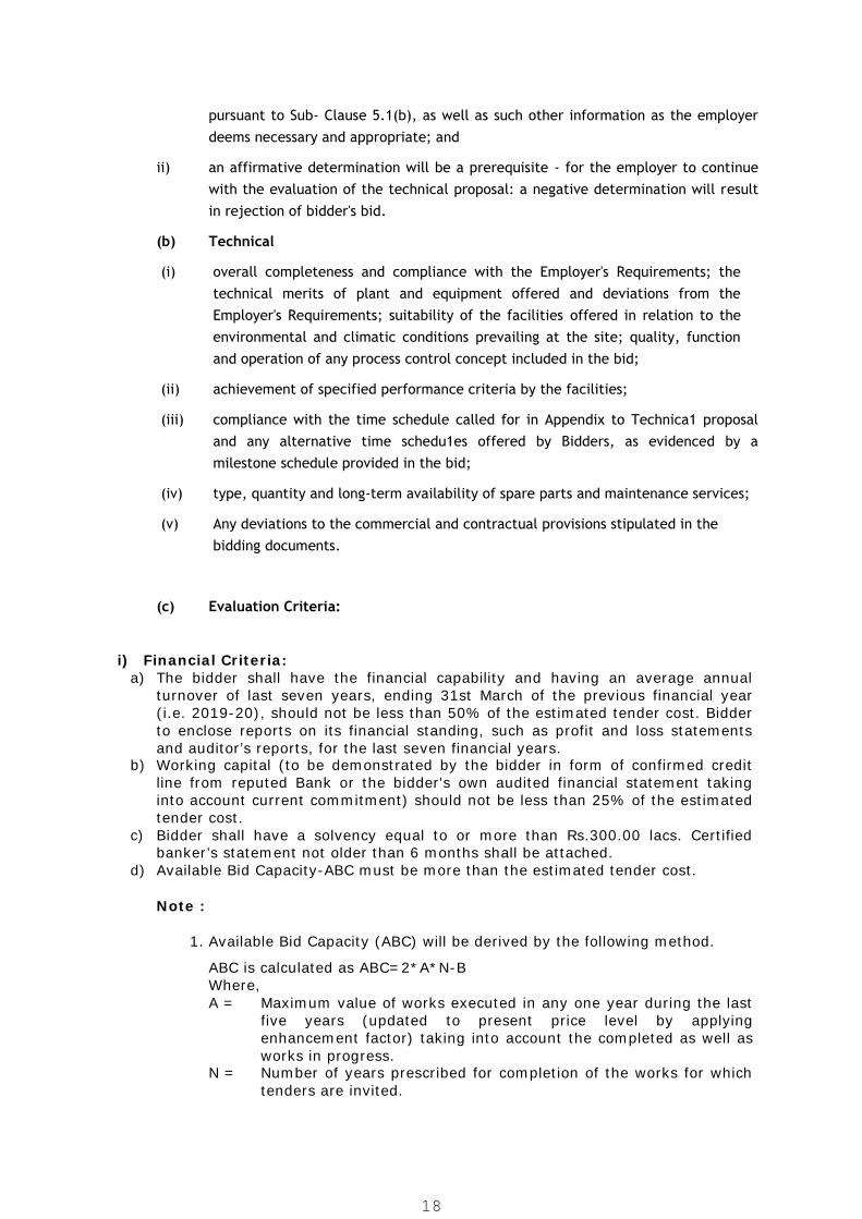
pursuant to Sub- Clause 5.1(b), as well as such other information as the employerdeems necessary and appropriate; and
ii) an affirmative determination will be a prerequisite - for the employer to continuewith the evaluation of the technical proposal: a negative determination will resultin rejection of bidder's bid.
(b) Technical
(i) overall completeness and compliance with the Employer's Requirements; thetechnical merits of plant and equipment offered and deviations from theEmployer's Requirements; suitability of the facilities offered in relation to theenvironmental and climatic conditions prevailing at the site; quality, functionand operation of any process control concept included in the bid;
(ii) achievement of specified performance criteria by the facilities;
(iii) compliance with the time schedule called for in Appendix to Technica1 proposaland any alternative time schedu1es offered by Bidders, as evidenced by amilestone schedule provided in the bid;
(iv) type, quantity and long-term availability of spare parts and maintenance services;
(v) Any deviations to the commercial and contractual provisions stipulated in thebidding documents.
(c) Evaluation Criteria:
i) Financial Criteria:a) The bidder shall have the financial capability and having an average annual
turnover of last seven years, ending 31st March of the previous financial year(i.e. 2019-20), should not be less than 50% of the estimated tender cost. Bidderto enclose reports on its financial standing, such as profit and loss statementsand auditor’s reports, for the last seven financial years.
b) Working capital (to be demonstrated by the bidder in form of confirmed creditline from reputed Bank or the bidder's own audited financial statement takinginto account current commitment) should not be less than 25% of the estimatedtender cost.
c) Bidder shall have a solvency equal to or more than Rs.300.00 lacs. Certifiedbanker’s statement not older than 6 months shall be attached.
d) Available Bid Capacity-ABC must be more than the estimated tender cost.
Note :
1. Available Bid Capacity (ABC) will be derived by the following method.
ABC is calculated as ABC=2*A*N-BWhere,A = Maximum value of works executed in any one year during the last
five years (updated to present price level by applyingenhancement factor) taking into account the completed as well asworks in progress.
N = Number of years prescribed for completion of the works for whichtenders are invited.
18
B = Value (present price level by applying enhancement factor) ofexisting commitments and on-going works to be completed duringthat next N year (period of completion of the works for which thetenders are invited.)
Duly attested C.A. certificate on his own letterhead shall be submitted for Turnover,working capital, etc. financial details
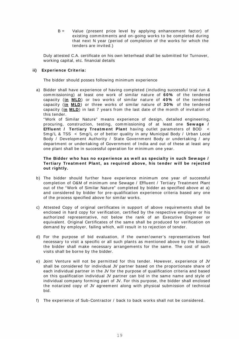
ii) Experience Criteria:
The bidder should posses following minimum experience
a) Bidder shall have experience of having completed (including successful trial run &commissioning) at least one work of similar nature of 60% of the tenderedcapacity (in MLD) or two works of similar nature of 40% of the tenderedcapacity (in MLD) or three works of similar nature of 30% of the tenderedcapacity (in MLD) in last 7 years from the last date of the month of invitation ofthis tender.“Work of Similar Nature” means experience of design, detailed engineering,procuring, construction, testing, commissioning of at least one Sewage /Effluent / Tertiary Treatment Plant having outlet parameters of BOD <5mg/L & TSS < 5mg/L or of better quality in any Municipal Body / Urban LocalBody / Development Authority / State Government Body or undertaking / anydepartment or undertaking of Government of India and out of these at least anyone plant shall be in successful operation for minimum one year.
The Bidder who has no experience as well as specialty in such Sewage /Tertiary Treatment Plant, as required above, his tender will be rejectedout rightly.
b) The bidder should further have experience minimum one year of successfulcompletion of O&M of minimum one Sewage / Effluent / Tertiary Treatment Plantout of the “Work of Similar Nature” completed by bidder as specified above at a)and considered by bidder for pre-qualification experience criteria based any oneof the process specified above for similar works.
c) Attested Copy of original certificates in support of above requirements shall beenclosed in hard copy for verification, certified by the respective employer or hisauthorized representative, not below the rank of an Executive Engineer orequivalent. Original Certificates of the same shall be produced for verification ondemand by employer, failing which, will result in to rejection of tender.
d) For the purpose of bid evaluation, if the owner/owner’s representatives feelnecessary to visit a specific or all such plants as mentioned above by the bidder,the bidder shall make necessary arrangements for the same. The cost of suchvisits shall be borne by the bidder.
e) Joint Venture will not be permitted for this tender. However, experience of JVshall be considered for individual JV partner based on the proportionate share ofeach individual partner in the JV for the purpose of qualification criteria and basedon this qualification individual JV partner can bid in the same name and style ofindividual company forming part of JV. For this purpose, the bidder shall enclosedthe notarized copy of JV agreement along with physical submission of technicalbid.
f) The experience of Sub-Contractor / back to back works shall not be considered.
19

iii) Personnel Criteria:Bidder to provide CV's of key personnel proposed to be deployed on the projectas below as a minimum:
Personnel Min. QualificationRequirement
Min. Experience inYears
Process Engineer:Environment /
Chemical Engineer
Masters in Environment /Chemical Engineering
10 Years
Project Engineer B.E. (Civil) 7 YearsSite Engineer - Civil B.E. / Diploma (Civil) BE: 5 Years / Dip: 7
YearsMechanical Engineer B.E. (Mech) 5 YearsElectrical Engineer B.E. (Elect) 5 Years
Following enhancement factors will be used for the turnover / cost of workscompleted / executed in previous years giving weightage of 10% per year to arriveenhanced financial amount to bring them to 2020-21 price level:
(d) The contractor shall have a registration with State / Central Government or StateWater Supply Boards or in Municipal Corporation in ‘AA’ Class. Supportingdocuments will be submitted in hard copy.
(e) The bidder should not have been Black Listed by Government ofIndia/Government of Gujarat or any State Board/Corporations, since inception ofthe firm/Company. A Declaration in this regard on Rs.300/- (or of applicableamount) Stamp Paper duly Notarized, shall have to be submitted as perAnnexure-II, along with the tender documents.
(f) The bidder should provide accurate information on any litigation history orarbitration resulting from contracts completed or under execution by him over thelast ten years. This should also include such cases, which are in process /progress. A consistent history of awards against the bidder may result in failure ofthe bid. In case the bidder has not provided such information and has come tothe notice of the authority, the tender will be rejected at what so ever stage andin such case all the losses that will arise out of this issue will be recovered fromthe tenderer / bidder and he will not have any defense for the same.
(g) Reserve the right (i) to change, alter or to waive any technical or commercialterms, condition and qualification (ii) to reject all the bids or any bid in part or fullwithout assigning any reason whatsoever (iii) for making changes / relaxation ineligibility criteria at any time in the interest of the public. The bidder shall haveno cause of action or claim against the RSCDL or its Officers / Employee’ssuccessor or assignee for rejection of his tender/bid.
(h) After opening of Technical Bid, the procedure for the pre-qualification shall beadopted and the Price Bid of only successful qualified bidder shall be opened for
Financial Year Multiplying factor2020-21 (Base Year) 1.00
2019-20 1.102018-19 1.212017-18 1.332016-17 1.462015-16 1.612014-15 1.772013-14 1.95
20
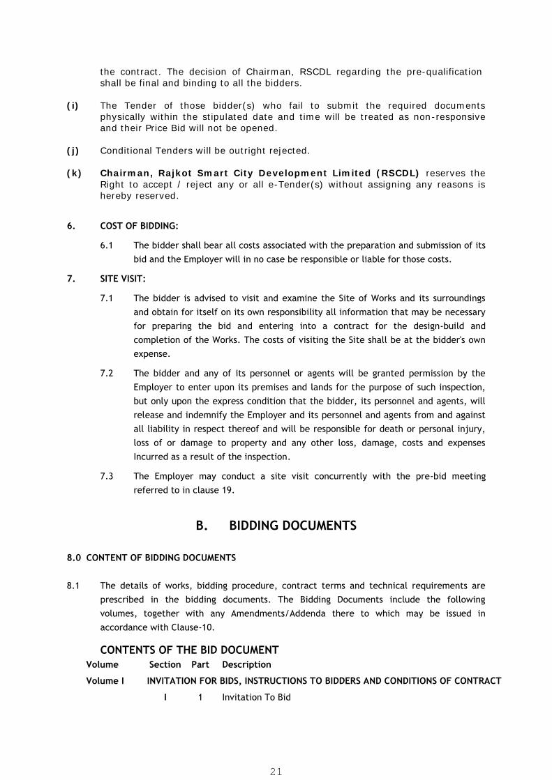
the contract. The decision of Chairman, RSCDL regarding the pre-qualificationshall be final and binding to all the bidders.
(i) The Tender of those bidder(s) who fail to submit the required documentsphysically within the stipulated date and time will be treated as non-responsiveand their Price Bid will not be opened.
(j) Conditional Tenders will be outright rejected.
(k) Chairman, Rajkot Smart City Development Limited (RSCDL) reserves theRight to accept / reject any or all e-Tender(s) without assigning any reasons ishereby reserved.
6. COST OF BIDDING:
6.1 The bidder shall bear all costs associated with the preparation and submission of itsbid and the Employer will in no case be responsible or liable for those costs.
7. SITE VISIT:
7.1 The bidder is advised to visit and examine the Site of Works and its surroundingsand obtain for itself on its own responsibility all information that may be necessaryfor preparing the bid and entering into a contract for the design-build andcompletion of the Works. The costs of visiting the Site shall be at the bidder's ownexpense.
7.2 The bidder and any of its personnel or agents will be granted permission by theEmployer to enter upon its premises and lands for the purpose of such inspection,but only upon the express condition that the bidder, its personnel and agents, willrelease and indemnify the Employer and its personnel and agents from and againstall liability in respect thereof and will be responsible for death or personal injury,loss of or damage to property and any other loss, damage, costs and expensesIncurred as a result of the inspection.
7.3 The Employer may conduct a site visit concurrently with the pre-bid meetingreferred to in clause 19.
B. BIDDING DOCUMENTS
8.0 CONTENT OF BIDDING DOCUMENTS
8.1 The details of works, bidding procedure, contract terms and technical requirements areprescribed in the bidding documents. The Bidding Documents include the followingvolumes, together with any Amendments/Addenda there to which may be issued inaccordance with Clause-10.
CONTENTS OF THE BID DOCUMENTVolume Section Part Description
Volume I INVITATION FOR BIDS, INSTRUCTIONS TO BIDDERS AND CONDITIONS OF CONTRACT
I 1 Invitation To Bid
21

2 Instructions to Bidders
II 1 Conditions of Contract
2 Conditions of Particular Application
3 Conditions of Contract for Operation & Maintenance
Volume II EMPLOYERS’ REQUIREMENTS (TECHNICAL SPECIFICATIONS)
TECHNICAL SPECIFICATIONS ALONG WITH BID DRAWINGS
Volume III DATA SHEETS AND TECHNICAL SCHEDULES
Technical Schedules and Data Sheets
Volume IV PRICE BID
8.2 The bidder is expected to examine carefully the contents of the Bidding documents.Failure to comply with the requirements of bid submission will be at the bidder's ownrisk. Pursuant to Clause-26, bids, which are not substantially responsive to therequirements of the bidding documents, will be rejected.
9. CLARIFICATION OF BIDDING DOCUMENT:
9.1 A prospective bidder requiring any clarification of the bidding documents may notifythe Employer in writing or by fax (hereinafter the term "fax" is deemed to includeelectronic transmission such as facsimile, e-mail, cable and telex) at the Employer’saddress indicated in the Invitation for Bids. The Employer will respond to any requestfor clarification, which it receives earlier than Fifteen days prior to dead line forsubmission of bids or latest on day of pre bid meeting. Copies of the Employer'sresponse, including a description of the inquiry, will be uploaded online. Bidders arerequested to check online on referred website for any amendment / corrigendum /addendum issued from time to time till the time of online bid submission.
10. AMENDMENTS OF BIDDING DOCUMENTS:
10.1 At any time prior to the deadline for submission of bids, the Employer may, for anyreason, whether at its own initiative or in response to a clarification requested by aprospective bidder modify the bidding documents by issuing addenda.
10.2 Any amendment thus issued shall be part of the bidding documents pursuant to Sub-Clause-8.1, and shall be communicated in writing or by fax to all purchasers of thebidding documents. Prospective bidders shall acknowledge receipt of each addendumby fax to the Employer.
10.3 To afford prospective bidders reasonable time in which to take an addendum intoaccount in preparing their bids, the Employer may extend the deadline for submissionof bids, in accordance with Clause-22.
22

C. PREPARATION OF BIDS11. LANGUAGE OF BID:
The bid, and all correspondence and documents, related to the bid, exchanged betweenthe bidder and the Employer shall be written in the English / Gujarati language. Supportingdocuments and printed literature furnished by the bidder may be in another languageprovided they are accompanied by an accurate translation of the relevant passages in theEnglish language, in which case, for purposes of interpretation of the bid the Englishtranslation shall prevail.
12. DOCUMENTS COMPRISING THE BID:
12.1 In Technical Proposal, the required documents submitted physically (hard copy &soft copy) by the bidder for pre-qualification, shall contain following:(i) Bid Form for Technical Proposal and Appendix to Technical Proposal;(ii) Power of Attorney(iii) Information on Qualification(iv) Confirmation of Eligibility(v) Schedule of Major items of equipment(vi) Schedule of Major items of Constructional plant(vii) Schedule of Sub contractors(viii) Schedule of compliance with the bidding documents(ix) Any other material required to be completed and submitted by bidders in
accordance with these instructions to bidders(x) Online Payment (RTGG/NEFT) or DD towards Tender Fee(xi) DD/BG towards Earnest Money Deposit(xii) Unit process design – sizing, layout and Hydraulic Flow Diagram.(xiii) And all other information applicable and asked for in the bid forms and
schedules furnished in the bidding document I, II, III(xiv) A set of Tender documents Volume-I, II, III and Unpriced Volume-IV
including drawings and documents in hard copy and anyaddendum/corrigendum or any clarifications, if any, duly signed andstamped, completed in all respects shall be submitted with Technical Bid.
(xv) Copy of PAN Card(xvi) Copy of IT return filed for last 5 years(xvii) Copy of GST, PF & ESIC registration certificate(xviii) Undertaking as per Annuexure-II and any other as specified in tender
12.2 The online price proposal details to be submitted as per following;
SCHEDULE - A - GRAND SUMMARYSCHEDULE - B - BREAK-UP OF COST FOR CONSTRUCTION PHASE
SCHEDULE B1 (I) - CIVIL WORKSSCHEDULE B1 (II) – INTERCONNECTING PIPING WORKSSCHEDULE B1 (III) - MECHANICAL WORKSSCHEDULE B1 (IV) - ELECTRICAL WORKSSCHEDULE B1 (V) - INSTRUMENTATION WORKS
SCHEDULE - C - BREAKUP OF COST FOR OPERATION AND MAINTENANACE WORKS
SCHEDULE C– BREAKUP OF O&M WORKS FOR 5 YEARSSCHEDULE C1–BREAKUP OF MANPOWER COST FOR 5 YEARS
SCHEDULE – D1/1 PAYMENT BREAKUP FOR CIVIL WORKSSCHEDULE – D1/2,3,4,5 PAYMENT BREAKUP FOR MECHANICAL, PIPING, ELECTRICAL
AND INSTRUMENTATION WORKS
23

13. BID FORM & PRICE SCHEDULES:
13.1 The Bidder shall complete the Bid Forms and schedules furnished in the biddingdocuments in the manner and detail indicated therein, following the requirementsof Clauses 14 and 15.
14. BID PRICES:
14.1 Unless specified otherwise in Employer's Requirements, Bidders shall quote for theentire facilities on a "single responsibility" basis such that the total bid price coversall the Contractor's obligations mentioned in or to be reasonably inferred from thebidding documents in respect of the design, manufacture, including procurementand subcontracting (if any), delivery, construction, installation and completion ofthe facilities. This includes all requirements under the Contractor's responsibilitiesfor testing, pre-commissioning and commissioning of the facilities and, where sorequired by the bidding documents, the acquisition of all permits, approvals andlicenses, etc. operation, maintenance and training services and such other itemsand services as may be specified in the bidding documents, all in accordance withthe requirements of the Conditions of Contract.
14.2 Bidders shall give a breakdown of the prices, in the manner and detail called for inthe schedules of prices.
14.3 In the Schedules, Bidders shall give the required details and a breakdown of theirprices, including all taxes / GST, duties, levies and charges payable in theEmployer's country.
15. BID CURRENCIES:
15.1 Prices shall be quoted in the following currencies:(a) The prices shall be quoted in Indian currency only.
16. BID VALIDITY:
16.1 Bids shall remain valid for a period of 180 days after the date of opening of Priceproposals (Online Price Bid).
16.2 In exceptional circumstances, prior to expiry of the original bid validity period, theEmployer may request that the bidders extend the period of validity for a specifiedadditional period. The request and the responses thereto shall be made in writingor by cable. A bidder may refuse the request without forfeiting its bid security. Abidder agreeing to the request will not be required or permitted to modify its bid,but will be required to extend the validity of its bid security for the period of theextension, and in compliance with Clause 17 in all respects.
24
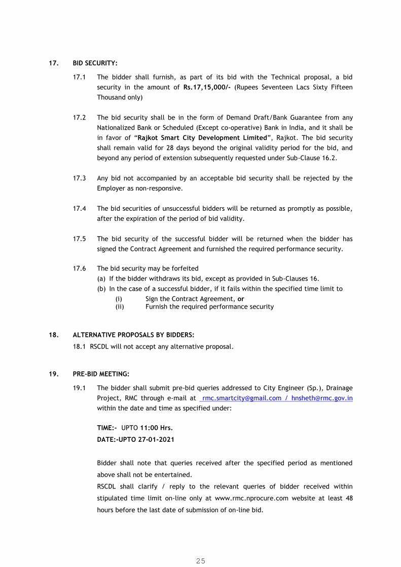
17. BID SECURITY:
17.1 The bidder shall furnish, as part of its bid with the Technical proposal, a bidsecurity in the amount of Rs.17,15,000/- (Rupees Seventeen Lacs Sixty FifteenThousand only)
17.2 The bid security shall be in the form of Demand Draft/Bank Guarantee from anyNationalized Bank or Scheduled (Except co-operative) Bank in India, and it shall bein favor of “Rajkot Smart City Development Limited”, Rajkot. The bid securityshall remain valid for 28 days beyond the original validity period for the bid, andbeyond any period of extension subsequently requested under Sub-Clause 16.2.
17.3 Any bid not accompanied by an acceptable bid security shall be rejected by theEmployer as non-responsive.
17.4 The bid securities of unsuccessful bidders will be returned as promptly as possible,after the expiration of the period of bid validity.
17.5 The bid security of the successful bidder will be returned when the bidder hassigned the Contract Agreement and furnished the required performance security.
17.6 The bid security may be forfeited(a) If the bidder withdraws its bid, except as provided in Sub-Clauses 16.(b) In the case of a successful bidder, if it fails within the specified time limit to
(i) Sign the Contract Agreement, or(ii) Furnish the required performance security
18. ALTERNATIVE PROPOSALS BY BIDDERS:
18.1 RSCDL will not accept any alternative proposal.
19. PRE-BID MEETING:
19.1 The bidder shall submit pre-bid queries addressed to City Engineer (Sp.), DrainageProject, RMC through e-mail at [email protected] / [email protected] the date and time as specified under:
TIME:- UPTO 11:00 Hrs.
DATE:-UPTO 27-01-2021
Bidder shall note that queries received after the specified period as mentioned
above shall not be entertained.
RSCDL shall clarify / reply to the relevant queries of bidder received within
stipulated time limit on-line only at www.rmc.nprocure.com website at least 48
hours before the last date of submission of on-line bid.
25
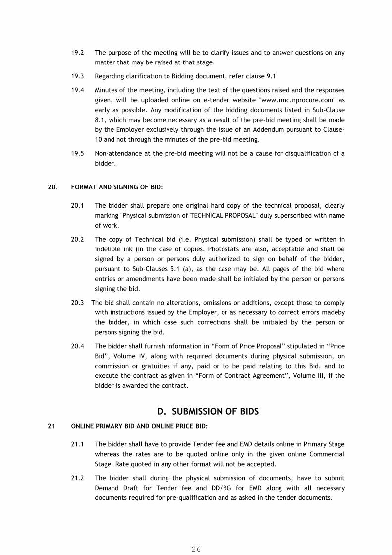
19.2 The purpose of the meeting will be to clarify issues and to answer questions on anymatter that may be raised at that stage.
19.3 Regarding clarification to Bidding document, refer clause 9.1
19.4 Minutes of the meeting, including the text of the questions raised and the responsesgiven, will be uploaded online on e-tender website "www.rmc.nprocure.com" asearly as possible. Any modification of the bidding documents listed in Sub-Clause8.1, which may become necessary as a result of the pre-bid meeting shall be madeby the Employer exclusively through the issue of an Addendum pursuant to Clause-10 and not through the minutes of the pre-bid meeting.
19.5 Non-attendance at the pre-bid meeting will not be a cause for disqualification of abidder.
20. FORMAT AND SIGNING OF BID:
20.1 The bidder shall prepare one original hard copy of the technical proposal, clearlymarking "Physical submission of TECHNICAL PROPOSAL" duly superscribed with nameof work.
20.2 The copy of Technical bid (i.e. Physical submission) shall be typed or written inindelible ink (in the case of copies, Photostats are also, acceptable and shall besigned by a person or persons duly authorized to sign on behalf of the bidder,pursuant to Sub-Clauses 5.1 (a), as the case may be. All pages of the bid whereentries or amendments have been made shall be initialed by the person or personssigning the bid.
20.3 The bid shall contain no alterations, omissions or additions, except those to complywith instructions issued by the Employer, or as necessary to correct errors madebythe bidder, in which case such corrections shall be initialed by the person orpersons signing the bid.
20.4 The bidder shall furnish information in “Form of Price Proposal” stipulated in “PriceBid”, Volume IV, along with required documents during physical submission, oncommission or gratuities if any, paid or to be paid relating to this Bid, and toexecute the contract as given in “Form of Contract Agreement”, Volume III, if thebidder is awarded the contract.
D. SUBMISSION OF BIDS21 ONLINE PRIMARY BID AND ONLINE PRICE BID:
21.1 The bidder shall have to provide Tender fee and EMD details online in Primary Stagewhereas the rates are to be quoted online only in the given online CommercialStage. Rate quoted in any other format will not be accepted.
21.2 The bidder shall during the physical submission of documents, have to submitDemand Draft for Tender fee and DD/BG for EMD along with all necessarydocuments required for pre-qualification and as asked in the tender documents.
26
The physical submission of required documents is to be submitted at the belowgiven address within the stipulated date and time mentioned in Tender Notice. Thesubmission of required documents can be submitted either in person or by SpeedPost.
City Engineer (Drainage Project),Drainage Project , Room No. 3,West Zone Office, Rajkot Municipal Corporation,Shri Harisinhji Gohil Bhawan,150 Ft. Ring Road, Rajkot-360 005.Gujarat. India. .
Bear the following identification:
*Bid for e-Tender No.:- RSCDL RSCDL/SMART CITY/18/2020-21
*Name of work:- Engineering, Procurement, Construction, Commissioning and 5Years Operation & Maintenance of 8 MLD Capacity Tertiary Treatment Plant atRaiyadhar, Rajkot under Rajkot Smart City Mission.
21.3 In addition to the identification required in Sub-Clause 21.2, the envelope shallindicate the name and address of the bidder to enable the physical submissionmade to be returned, unopened incase it is declared "late" pursuant to Clause 23.
21.4 If the envelope is not sealed and marked as above, the Employer will assume noresponsibility for the misplacement ofphysically submitted documents.
22. DEADLINE FOR SUBMISSION OF BIDS:
22.1 The bidder shall have to provide Tender fee and EMD details online in Primary Stagewhereas the rates are to be quoted online only in the given online CommercialStage within the prescribed date and time as mentioned in the Tender Notice.
Physical submission of all required documents must be received by the Employer atthe address specified above not later than the prescribed date and time asmentioned in the Tender Notice. The submission of required documents can besubmitted either in person or by Speed Post.
22.2 The Employer may, at its discretion, extend the deadline for submission of bids byissuing an addendum in accordance with Clause 10, in which case all rights andobligations of the Employer and the bidders previously subject to the originaldeadline will thereafter be subject to the deadline as extended.
23 LATE SUBMISSION OF REQUIRED DOCUMENTS (PHYSICALLY):
23.1 Any physical submission received by the Employer after the deadline for submissionprescribed in Clause 22 will be rejected and returned unopened to the bidder.
27

E. OPENING & EVALUATION OF TECHNICAL PROPOSAL (PHYSICAL SUBMISSION)
24. OPENING OF PRIMARY BID AND PHYSICALLY SUBMITTED DOCUMENTS FOR PRE-
QUALIFICATION:
24.1 The Employer will open the Primary Bid and Physically submitted documents forPre-qualification at the office of the City Engineer (Drainage Project), DrainageProject, Room No. 3, West Zone Office, Rajkot Municipal Corporation, ShriHarisinhji Gohil Bhawan, 150 Ft. Ring Road, Rajkot-360 005. Gujarat. India.
24.2 After opening of Primary Bid and Physically submitted documents for Pre-qualification (i.e. Technical Bid), the procedure for the pre-qualification shall beadopted and then the technical evaluation shall be carried out only of successfullypre-qualified bidders and the Commercial Bid of only successful qualified biddershall be opened for final evaluation of the contract. The decision of The Chairman,RSCDL regarding the pre-qualification shall be final and binding to all the bidders.
25. PROCESS TO BE CONFIDENTIAL:
Information relating to the examination, clarification, evaluation and comparison of bidsand recommendations for the award of a contract shall not be disclosed to bidders or anyother persons not officially concerned with such process. Any effort by a bidder toinfluence the Employer's processing of bids or award decisions may result in the rejection ofthe bidder's bid.
26 PRELIMINARY EXAMINATION OF TECHNICAL PROPOSAL:
The Employer will examine the bids to determine whether they are complete, whether thedocuments have been properly signed, whether-the required security is included, andwhether the bids are generally in order. Any bids found to be non-responsive for any reasonor not meeting the minimum levels of the performance or other criteria specified in thebidding documents will be rejected by the Employer and not included for furtherconsideration.
27. EVALUATION & COMPARISION OF TECHNICAL PROPOSAL
The Employer will carry out a detailed evaluation of the bids in order to determine whetherthe technical aspects are substantially responsive to the requirements set forth in thebidding documents. In order to reach such a determination, the employer will examine theinformation supplied by the bidders and other requirements in the bidding documents,taking into account the factors mentioned in clause 5.3, on a pass or fail basis:
28. CLARIFICATION OF TECHNICAL PROPOSALS AND CONTACTING THE EMPLOYER:
28.1 The Employer may conduct clarification meetings with each or any Bidder to discussany matters, technical or otherwise, 'where the Employer requires amendments orchanges to be made to the Technical Proposal.
28.2 The envelope containing the physical submission of required necessary documentsshall be addressed and bear the name of Contract and Bid Reference Number asspecified in Sub-Clause 21.2.
28
28.3 Any effort by the bidder to influence the employer in the Employer’s evaluation oftechnical proposals, bid comparison or the Employer’s decisions on acceptance orrejection of bids may result in the rejection of the bidder’s bid.
29 OPENING OF ONLINE COMMERCIAL BID (PRICE PROPOSALS):
At the end of the evaluation of the technical proposals and after receiving the approvalfrom competent authority, the Employer will open online Commercial Bid (Price Bid) of pre-qualified bidders only.
In evaluation of technical proposals, the decision of The Chairman, RSCDL shall be final andbinding to all the bidders. RSCDL will not entertain any dispute in this regard.
F. OPENING AND EVALUATION OF PRICE PROPOSALS
30 OPENING OF ONLINE PRICE PROPOSALS (COMMERCIAL BIDS):
The Employer will open the ONLINE price proposals of prequalified bidders who submittedsubstantially responsive technical proposals.
31. PROCESS TO BE CONFIDENTIAL
Information relating to the examination, clarification, evaluation and comparison of bidsand recommendation for the award of a contract shall not be disclosed to bidders or anyother persons not officially concerned with such process until the award to the successfulbidder has been announced. Any effort by a bidder to influence the Employer's, processingof bids or award decisions may result in the rejection of the bidder's bid.
32 CLARIFICATION OF PRICE PROPOSALS AND CONTACTING THE EMPLOYER:
32.1 To assist in the examination, evaluation and comparison of price proposals, theEmployer may, at its discretion, ask any bidder for clarification of its bid. Therequest for clarification and the response shall be in writing or by cable, but nochange in the price or substance of the bid shall be sought, offered or permittedexcept as required to confirm the correction of arithmetic errors discovered by theEmployer in the evaluation of the bids.
32.2 Subject to Sub-clause 32.1, no bidder shall contact the employer on any matterrelating to its bid from the time of opening of price proposals to the time thecontract is awarded. If the bidder wishes to bring additional information to thenotice of the Employer, it should do so in writing.
29

32.3 Any effort by the bidder to influence the Employer in the Employer’s evaluation ofprice proposals, bid comparison or contract award decisions may result in therejection of the bidder’s bid.
33 PRELIMINARY EXAMINATION OF PRICE PROPOSALS AND DETERMINATION OFRESPONSIVENESS:
33.1 The Employer will examine the bids to determine whether they are complete,whether the documents have been properly signed, whether the required security isincluded, whether the bids are substantially responsive to the requirements of thebidding documents; and whether the bids provide any clarification and/orsubstantiation that the Employer may require pursuant to Clause 32.
33.2 A substantially responsive bid is one which conforms to all the terms, conditionsandrequirements of the bidding documents, without material deviation orreservation and includes the amendments and changes, if any, requested by theEmployer during the evaluation of the bidder's technical proposal.
33.3 If a price proposal is not substantially responsive, it will be rejected by theEmployer, and may not subsequently be made responsive by correction orwithdrawal of the nonconforming deviation or reservation.
34 CONVERSION TO SINGLE CURRENCY: NOT APPLICABLE
35 EVALUATION AND COMPARISION OF PRICE PROPOSAL:
35.1 The Employer will evaluate and compare only the bids determined to besubstantially responsive in accordance with Clause 33.
35.2 Evaluation will be done on the total bid price inclusive of all taxes including GST,etc. Taxes and duties.
35.3 The Employer's evaluation of a bid will take into account, in addition to the bidprices indicated in the Schedule of Prices, the following costs and factors that willbe added to each Bidder's bid price in the evaluation using pricing informationavailable to the Employer, in the manner and to the' extent indicated in Sub-Clause35.4 and in the Employer's Requirements.
(a) Compliance with the time schedule called for in the Appendix to Price Proposal andevidenced as needed in a milestone schedule provided in the bid;
(b) The functional guarantees of the facilities offered against the specifiedperformance criteria of the plant and equipment; and
(c) The extra cost of work, services, facilities, etc., required to be provided by theEmployer or third parties.
35.4 Pursuant to Sub-Clause 35.3, the following evaluation methods will befollowed:
30

(a) Time Schedule: The plant and equipment covered by this bidding are required tobe shipped, installed and the facilities completed within the period specified inSub-Clause 1.2 and the Appendix to Technical Proposal. Bidders submitting bidsthat deviate from the time schedule specified will be rejected.
(b) Final Bid Evaluation to decide the lowest bid will be carried out by the employerbased on loading of the 15 years life Cycle Cost of Guaranteed Power declaredby the bidder in the technical bid and duly corrected as part of technicalevaluation. Final bid evaluation methodology with loading of the life cycle costof power is given as below table. Bidder shall not have to fill the data/amountsin technical bid. This table is for the evaluation only to decide the lowest bid.Contract will be awarded to lowest bid evaluated after considering the prices asper A1 + A II as per Price Schedule A of Grand Summary and loading the energycost as per C in below table.
Table for final bid evaluation only:SR.NO. WORK AMOUNT
A Construction PhaseEngineering, Procuring, Constructing, Commissioning (EPC) of(1) Tertiary Treatment Plant of 8 MLD capacity at Raiyadharbased on Media Filter + UF System Process at Raiyadhar,Rajkot along with all related Mechanical, Electrical equipmentand accessories, Instrumentation including miscellaneous worksetc. complete for RSCDL.Total A-I) As Per Price Schedule A of Grand Summary
B Operation & Maintenance PhaseOperation and Maintenance of the entire Tertiary Treatmentfacilities at the site for 5 years after satisfactory commissioningand trial run of entire system (TTP system) including plantacceptance.Total A-II) As Per Price Schedule A of Grand Summary
C Power Cost for 15 Years at 10% Discount Rate Guaranteed Power Consumption (A) = _______________
kW.hr/day. (Taken from The Load List Given in the Bid) Rate of Power to be considered for evaluation = Rs.7.00 per
kW.hr/day Discounting Factor for 15 years at 10% Discount Rate = 7.61 Discounted Power Cost = (A) x 365 x 7.00 x 7.61TOTAL BID VALUE FOR PRICE EVALUATION…..A+B+C
(c) Functional Guarantee of the facilities:
(i) Bidders shall state the functional guarantees (e.g. performance, efficiency, power& chemical consumption) of the proposed facilities in response to the Employer'sRequirements. Plant and equipment offered shall have a minimum (or a maximum,as the case may be) level of functional guarantees specified in the Employer'sRequirements to be considered responsive. Bids offering plant and equipment withfunctional guarantees more than the maximum specified or less than the minimumspecified shall be rejected.These shall also be subject to evaluation and requiredrevisions as part of technical evaluation where felt necessary by client or to meetthe tender conditions and requirements.
(d) Work, services, facilities etc., to be provided by the Employer:
31
Where bids include for the undertaking of work or the provision of services orfacilities by the Employer in excess of the provisions allowed for in the biddingdocuments, the Employer shall assess the costs of such additional work, servicesand/or facilities during the duration of the contract. Such costs shall be addedto the bid price for evaluation; and
35.5 (a) Any adjustments in price that result from the above procedures shall be added, forpurposes of comparative evaluation only, to arrive at an "Evaluated Bid Price." Bidprices quoted by Bidders shall remain unaltered.
(b) The Employer reserves the right to accept or reject any variation or deviation.Variations, deviations, and other factors which are in excess of the requirementsof the bidding documents or otherwise result in the accrual of unsolicitedbenefits to the Employer shall not be taken into account in bid evaluation.
(c) The estimated effect of the price adjustment provisions of the Conditions ofParticular Application, applied over the period of execution of the Contract,shall not be taken into account in bid evaluation.
(d) If the bid of the technically qualified bidder is substantially below theEmployer's estimate for the contract, the Employer may require the bidder toproduce detailed price analyses to demonstrate the internal consistency of thoseprices. After evaluation of the price analysis, the Employer may require that theamount of the performance security set forth in Clause 41 be increased at theexpense of the successful bidder to a level sufficient to protect the Employeragainst financial loss in the event of default of the successful bidder under theContract. However, if employer feels that with substantially lower quotation,the desired quality of work is not possible, than it is at the discretion and rightof employer to reject or to consider such price offer. Under such circumstances,the second lowest bidder shall be called for negotiation.
36 DOMESTIC PREFERENCE: NOT APPLICABLE
32
G. AWARD OF CONTRACT37 AWARD:
Subject to Clause 38, the Employer will award the Contract to the bidder whose bid hasbeen determined to be substantially responsive to the bidding documents and who hasoffered the Lowest Evaluated Bid Price, provided that such bidder has been determined tobe (i) eligible in accordance with the provisions of Clause 3; and (ii) qualified in accordancewith the provisions of Clause 5.
38 EMPLOYER’S RIGHT TO ACCEPT ANY BID OR TO REJECT ANY OR ALL BIDS:
Notwithstanding Clause 40, the Employer reserves the right to accept or reject any bid, andto annul the bidding process and reject all bids, at any time prior to award of Contract,without thereby incurring any liability to the affected bidder or bidders or any obligation toinform the affected bidder or bidders of the grounds for the Employer's action.
39 NOTIFICATION OF AWARD:
39.1 Prior to expiration of the period of bid validity prescribed by the Employer, theEmployer will notify the successful bidder by fax, confirmed by registered letter,that its bid has been accepted. This letter {hereinafter and in the Conditions ofContract called the “Letter of Intent") shall name the sum which the Employer willpay the Contractor in consideration of the execution, completion and maintenanceof the Works by the Contractor as prescribed by the Contract (hereinafter and inthe Conditions of Contract called “the Contract Price”).
39.2The notification of award will constitute the formation of the Contract.
39.3 Upon the furnishing by the successful bidder of a performance security, theEmployer will promptly notify the other bidders that their bids have beenunsuccessful and issue “Notice to proceed to successful bidder.”
40 SIGNING OF CONTRACT AGREEMENT:
40.1 At the same time that he notifies the successful bidder that its bid has beenaccepted, the Employer will send the bidder the letter of acceptanceand inform toenter into Contract Agreement with RSCDL, incorporating all agreements betweenthe parties.The successful bidder shall have to enter into an agreement on a non-judicial stamp paper of Rs.300/- (or required amount) as per the form of theagreement approved by the Corporation. The cost of stamp paper and adhesivestamp shall be borne by the contractor.
40.2 Within 10 (Ten) days of receipt of the letter of acceptance, the successful biddershall sign the Contract Agreement and return it to the Employer.
33

41 PERFORMANCE SECURITY:
41.1 Within 10 (Ten) days of receipt of the notification of award from the Employer, thesuccessful bidder shall furnish to the Employer a performance security in an amountof 10 (TEN) percent of the Contract Price in accordance with the Clause 4.2 ofParticular Conditions of Contract. The form of performance security provided inVolume III of the bidding documents shall be used.
41.2 Failure of the successful bidder to comply with the requirements of Clauses 40 or41.1 shall constitute sufficient grounds for the annulment of the award andforfeiture of the bid security.
42 CORRUPT OR FRAUDULENT PRACTICES:
42.1 The RSCDL requires that bidders/ suppliers/ contractors, observe the higheststandard of ethics during the procurement and execution of such contracts. Inpursuance of this policy:
(a) Defines for the purposes of this provision, the terms set forth below asfollows:
(i) ”corrupt practices” means behavior on the part of officials in thepublic or private sectors by which they improperly and unlawfullyenrich themselves and/or those close to them , or induce others todo so , by misusing the position in which they are placed, and itincludes the offering, giving, receiving, or soliciting of anything ofvalue to influence the action of any such official in theprocurement process or in contract execution; and
(ii) “Fraudulent practice” means a misrepresentation of facts in orderto influence a procurement process or the execution of a contractto the detriment of the Borrower, and includes collusive practiceamong bidders (prior to or after bid submission) designed toestablish bid prices at artificial non-competitive levels and todeprive the borrower of the benefits of free and open competition;
(b) Will reject a proposal for award if it determines that the bidderrecommended for award has engaged in corrupt or fraudulent practices incompeting for the contract in question;
(c) will declare a firm ineligible, either indefinitely or for a stated period oftime, to be awarded
If at any time determines that the firm has engaged in corrupt andfraudulent practices in competing for, or in executing the contract.
42.2 Furthermore, bidders shall be aware of the provision stated Sub-Clause 15.6 of theConditions of Particular Application, Vol. 1 Section II - Part 2.
34

APPENDICES
35

APPENDIX – A
EACH MEMBER OF THE CONSORTIUM SHOULD GIVE ALL THE DETAILS FOR EACH OF THEFOLLOWING APPENDICES.
Sr.No. Name of the ConsortiumMember
Role of the Member Equity Stake in Project.
36

APPENDIX – B
Financial Resources in ongoing projects
Sr.No Description of ongoingprojects
Total cost ofwork/contract(Rs. In Lacs)
Member’scontribution (%)
Funds required to becontributed.
1 2 3 4 5
37

APPENDIX – C
FINANCIAL INFORMATION
1. Annual turnover for last financial seven years
Financial year 2013-14 2014-15 2015-16 2016-17 2017-18 2018-19 2019-20 Averageof last 7
yearsTurnover Rs. InLacs
2. Working Capital
Working CapitalAs on date:- 31/03/2020 Rs.
Note:- The bidder shall have to submit the copies of Audited Report of last seven FinancialYears. The bidder shall also have to submit the Certificate regarding Turnover andWorking Capital from the registered Charted Accountant
38

APPENDIX – D
EXPERIENCE OF EPC / TURNKEY PROJECT EXECUTION OF SEWAGE / EFFLUENT /TERTIARY TREATMENT PLANT OF SIMILAR NATURECOMPLETED AS A MAIN CONTRACTOR DURING LAST 7 (SEVEN) YEARS OF CAPACITY OF 2.4 MLD (i.e.30% of 8 MLD) AND MORE
(Work of Similar Nature” means experience of design, detailed engineering, procuring, construction, testing, commissioning ofat least one Sewage / Effluent / Tertiary Treatment Plant having outlet parameters of BOD < 5mg/L & TSS < 5mg/L orof better quality in any Municipal Body / Urban Local Body / Development Authority / State Government Body or undertaking /any department or undertaking of Government of India and out of these at least any one plant shall be in successful operationfor minimum one year)
Sr.No.
Name of theProject
Capacityin MLD
Name of Clientwith address andcontact number
Cost of theProject(Rs. in lacs)
Brief Details ofProject components
(with type and natureof the process design)
Date ofWorkAwarded
Date ofWorkCompleted
Delay inMonths fromtheScheduleddate ofCompletion
WhetherProjectUnderLitigation(Yes/No) &reasonsthereof
A certificate from client for satisfactory completion of the work and successful performance of the system shall be attached.
Signature of Contractor
39
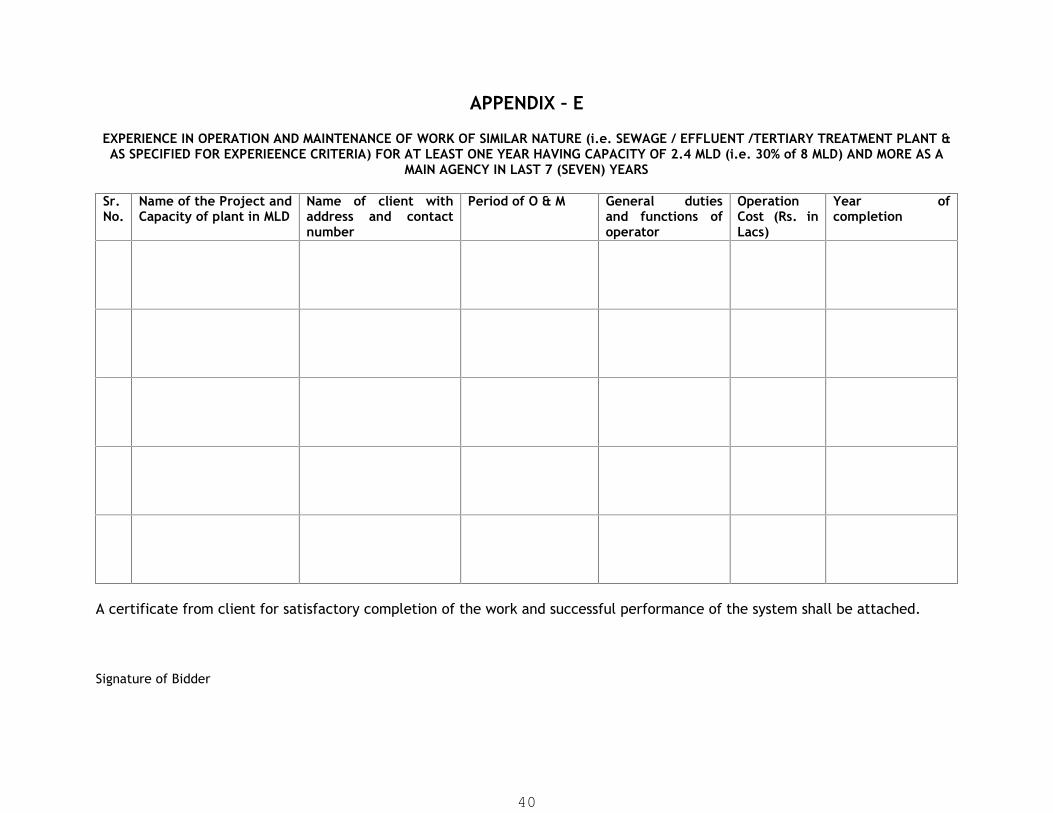
APPENDIX – E
EXPERIENCE IN OPERATION AND MAINTENANCE OF WORK OF SIMILAR NATURE (i.e. SEWAGE / EFFLUENT /TERTIARY TREATMENT PLANT &AS SPECIFIED FOR EXPERIEENCE CRITERIA) FOR AT LEAST ONE YEAR HAVING CAPACITY OF 2.4 MLD (i.e. 30% of 8 MLD) AND MORE AS A
MAIN AGENCY IN LAST 7 (SEVEN) YEARS
Sr.No.
Name of the Project andCapacity of plant in MLD
Name of client withaddress and contactnumber
Period of O & M General dutiesand functions ofoperator
OperationCost (Rs. inLacs)
Year ofcompletion
A certificate from client for satisfactory completion of the work and successful performance of the system shall be attached.
Signature of Bidder
40

APPENDIX – FINFORMATION ON BID CAPACITY
WORK FOR WHICH BIDS HAVE BEEN SUBMITTED AND WORKS WHICH ARE YET TO BE COMPLETED AS ON
THE DATE OF THIS BID (EXISTING COMMITMENTS AND ON-GOING WORKS)
Description ofWork
Place andstate
Contract No.& Date
Name and Address ofthe Employer
Value ofContract Rs. in
Lacs
StipulatedDate of
completion
Value ofwork
remaining tobe
completedRs. in Lacs
Anticipateddate of
completion.
1 2 3 4 5 6 7 8
Note:- Enclose Certificate(s) from Employer or Employer's authorised representative not below the rank of Executive Engineer or equivalentin attested hard copy.
Signature of Bidder
41

APPENDIX – G
Key Technical personnel & Project Manager Competence and qualification(Experience in Year)
Team Name of person QualificationExperience in Years (In
Required status)
Project Manager
Civil Engineer
Mechanical Engineer
Electrical Engineer
Instrumentation Engineer
Procurement Engineer
Environmental Engineer
Laboratory Technician(Micro-biologist)
Note: Please give required details in curriculum vitae (Appendix O1) for each team members
Signature & Stamp of Contractor
42

APPENDIX – G1Key Technical Personnel & Project Manager Competence and qualification
CURRICULUM VITAE
Sr.NoDetails
1. Name
2. Age
3. Qualifications
4. Experience in Project Related field.
5. Other experience
6. Employment Record.
Sr. No. Period
From To
Organization Status
Note:The contractor’s project Team should consist of persons in the following disciplines.
Treatment process;
Other civil engineering works;
Mechanical engineering;
Electrical engineering;
Project management;
Instrumentation Engineer;
Signature & Stamp of Contractor
43

APPENDIX – H
NAME, EXPERIENCE AND DETAILS OF CAPACITY OF SUBCONTRACTOR
Name of Sub-contractor
Details of theworks to be
given if bidderswill be
awarded thework
Experience inYears for the work
to be given
Registrationor Rating if
any
AverageAnnual Turnover of LastThree Years
Note: Please give required details in Information of sub contractor APPENDIX-H1
Signature & Stamp of Contractor
44

APPENDIX – H1
Information of sub-contractors
Sr.No Details
1. Name
2. Registration class if any
4. Experience in Project Related field.
5. Other experience
6. Nos. of Employee in organization:
Sr.No.
Work Carried out by the subcontractor
Value of workRs. In Lacs
Name of client Contact No ofclient
Signature & Stamp of Contractor
45

APPENDIX – I
DETAILS OF PLANT & EQUIPMENT OWNED BY THE CONTRACTOR
Name of Plants /Equipments
Make of Plants/ Equipments
Details of theRTO
registration
Cost of Plants /Equipment
Locationwhere the
Plants /Equipment
located
Signature & Stamp of Contractor
46

APPENDIX – J
Bidder’s Available Credit in Bank
Name of the Bank :
(with address, phone and Fax Nos.)
Sr.No.
(1)
Year
(2)
Working Capital limit (Rs. In Lacs) Interest rate
charged by Bank.
(5)
Sanctioned
(3)
Drawn.
(4)
1 2013-2014
2 2014-2015
3 2015-2016
4 2016-2017
5 2017-2018
6 2018-2019
7 2019-2020
Details of fund base as well as non-fund based credit available with bank should be furnished
Note: The latest credit facilities available from banks with certified copies to be submitted.
Signature & Stamp of Contractor
47

APPENDIX – K
Available Bid Capacity(TO BE SUBMITTED WITH FOLLOWING CALCULATION)
Available Bid Capacity (ABC) will be derived by the following method:
ABC is calculated as ABC=2*A*N-B
Where,A = Maximum value of works executed in any one year during the last
five years (updated to present price level by applyingenhancement factor) taking into account the completed as well asworks in progress.
N = Number of years prescribed for completion of the works for whichtenders are invited.
B = Value (present price level by applying enhancement factor) ofexisting commitments and on-going works to be completed duringthat next N year (period of completion of the works for which thetenders are invited.)
Signature & Stamp of Contractor
48

Application Form(1)General Information
All individual firms and each partner of a consortium applying for qualification are requested tocomplete the information in this form. Nationality information to be provided for all owners orapplicants who are partnerships or individually-owned firms.
Where the Applicant proposes to use named subcontractors for critical components of the works, orfor work contents in excess of 10 percent of the value of the whole works the following informationshould also be supplied for the specialist subcontractor(s).
1. Name of Firm
2. Head office address
3. Telephone Contact
4. Fax Telex
5. Place of incorporation/registration Year of incorporation/ registration
Nationality of owners
Name Nationality
1.
2.
3.
4.
5.
Signature & Stamp of Contractor
49

Name of Bidders officers / Persons to be contacted
Name. Address Phone Nos. Fax.
Signature & Stamp of Contractor
50

Application Form (1A)
Structure and Organization
The applicant isan individuala proprietary firma firm in partnershipa Limited Company or Corporationa group of firms/consortium (if Yes, give completioninformation in respect of each partner)
Attach the Organization Chart showing the structure ofthe organization including the names of the Directorsand position of officers
Number of years of experience :as a Prime Contractor (contractor shouldering
major responsibilityin own countryother countries (specify country)
in a consortiumin own countryother countries (Specify country)
as a sub-contractor (specify main contractor)in own countryother countries (Specify country)
a. Name and address of anyassociates the applicant has inIndia (in case the applicanthappens to be from foreigncountry) who are knowledgeable inthe procedures of customs,immigration, taxes and otherinformation necessary to do thework.
For how many years has your organization been inbusiness of similar work under its present name?What were your fields when your organization wasestablished? Whether any new fields were added inyour organization? And if so, when?
b. Were you ever required to suspendconstruction for a period of morethan six months continuously afteryou started? If so, give the name ofproject and give reasons therefore.
c. Have you ever left the workawarded to you incomplete? If so,
51

give name of project and reasonsfor not completing work.
7. In which fields of civil engineering construction doyou claim specialization and interest?
8. Give details of your experience in mechanizedcement concrete and in modern concretetechnology for manufacture and quality control.
9. Give details of your experience in using heavy earthmoving equipment and quality control incompaction of soils.
10. Details of experience in Design, build, operate andmaintain Works of Similar Nature (Sewage /Effluent / Tertiary Treatment Plant) along-withcapacity, technology used
Signature & Stamp of Contractor
52
SECTION II
PART 1GENERAL CONDITIONS OF CONTRACT
53

SECTION II
PART – 1
General Conditions of Contract
FIDIC Conditions Of Contract For EPC / Turnkey
First Edition 1999
(a) The Conditions of Contract Part I: General Conditions, shall be those forming Partof the “Conditions of Contract for EPC/Turnkey Projects, “ first edition 1999,(ISBN2-88432-021-0) prepared by the Federation International des Ingenieurs -Conseils (FIDIC). These Conditions are subject to the variations and additions setout in Part 2 hereof-entitled “Conditions of Particular Application”.
(b) Copies of the FIDIC Contract can also be obtained from:
FIDIC Secretariat
P.O. Box 86
1000 Lausanne 12
Switzerland
Facsimile: 41 21 653 5432
Telephone: 41 21 653 5003
(c) The General Conditions of Contract are set out Part -II of this document. However, in caseof any ambiguity or dispute in interpreting the conditions set out herein the documentpublished by FIDIC titled as “Conditions of Contract for EPC/Turnkey projects” First Edition1999 as mentioned in (a) above shall be referred to and relied upon.
54

FIDIC CONDITIONS OF THE CONTRACT
For Design-Build & Turn-Key
55
SECTION II
PART 2CONDITIONS OF PARTICULAR
APPLICATION
56

SECTION II
PART – 2
CONDITIONS OF PARTICULAR APPLICATION
The following amendments and additions shall be made to the Part I - General Conditions ofContract for EPC / Turnkey Projects issued by the Federation International des Ingenieurs -Conseils, First edition: 1999.
Clause 1 General Provisions
Insert the following additional definitions:
Sub Clause 1.1.1.6
The word “Tender” is synonymous with “Bid” and their derivatives (bidder / tenderer, bid /tendered, bidding / tendering, etc.) as well as the words “Tender Documents” with “Bid or BiddingDocuments” are synonymous.
Sub Clause 1.1.2 Parties and Persons
Add Sub Clause 1.1.2.11, 1.1.2.12 and 1.1.2.13 as under
Sub Clause 1.1.2.11
“Consultant” means Engineering consultant appointed by the Employer’s representative for thespecific purpose from time to time to aid and assist him.
Sub Clause 1.1.2.12
“Inspection Agency” means a person or a firm appointed by the Employer’s representative for theinspection of the material, equipment and Works to ensure the quality of the Work.
Sub Clause 1.1.2.13
“Employer” means Rajkot Smart City Development Limited referred to as RSCDL (or as Employer /Client / Owner).
Sub Clause 1.4:
Replace the text of sub-clause 1.4 and add the following:-
The law of the Contract is the law of India
Sub Clause 1.5: Priority of Documents
Delete the document listed (a) to (e) and substitute
a) The Contract Agreement;
b) The Letter of Acceptance;
c) The Employer’s Requirements;
d) The Bid;
57
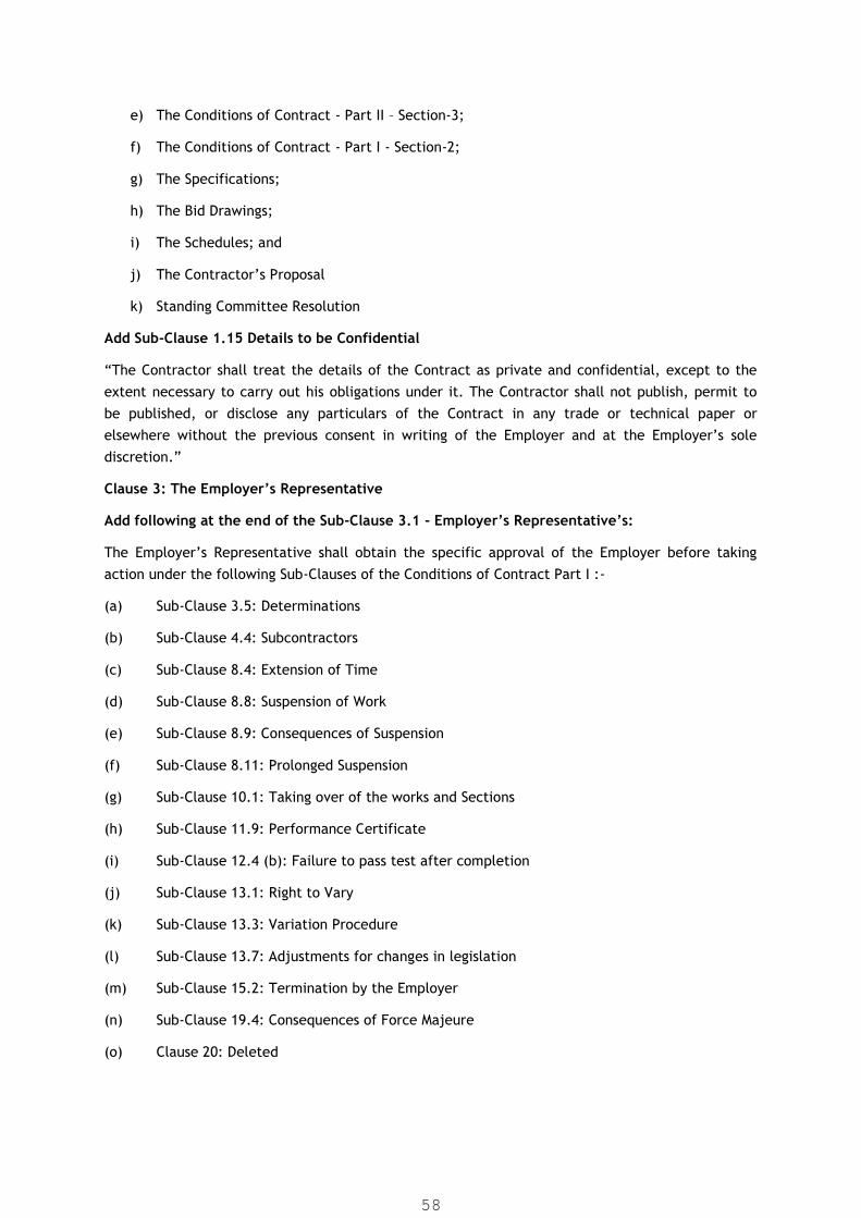
e) The Conditions of Contract - Part II – Section-3;
f) The Conditions of Contract - Part I - Section-2;
g) The Specifications;
h) The Bid Drawings;
i) The Schedules; and
j) The Contractor’s Proposal
k) Standing Committee Resolution
Add Sub-Clause 1.15 Details to be Confidential
“The Contractor shall treat the details of the Contract as private and confidential, except to theextent necessary to carry out his obligations under it. The Contractor shall not publish, permit tobe published, or disclose any particulars of the Contract in any trade or technical paper orelsewhere without the previous consent in writing of the Employer and at the Employer’s solediscretion.”
Clause 3: The Employer’s Representative
Add following at the end of the Sub-Clause 3.1 - Employer’s Representative’s:
The Employer’s Representative shall obtain the specific approval of the Employer before takingaction under the following Sub-Clauses of the Conditions of Contract Part I :-
(a) Sub-Clause 3.5: Determinations
(b) Sub-Clause 4.4: Subcontractors
(c) Sub-Clause 8.4: Extension of Time
(d) Sub-Clause 8.8: Suspension of Work
(e) Sub-Clause 8.9: Consequences of Suspension
(f) Sub-Clause 8.11: Prolonged Suspension
(g) Sub-Clause 10.1: Taking over of the works and Sections
(h) Sub-Clause 11.9: Performance Certificate
(i) Sub-Clause 12.4 (b): Failure to pass test after completion
(j) Sub-Clause 13.1: Right to Vary
(k) Sub-Clause 13.3: Variation Procedure
(l) Sub-Clause 13.7: Adjustments for changes in legislation
(m) Sub-Clause 15.2: Termination by the Employer
(n) Sub-Clause 19.4: Consequences of Force Majeure
(o) Clause 20: Deleted
58

Add Sub-clause 3.6 - Management Meetings“Either the Employer’s Representative or the Contractor’s Representative may require the other toattend a management meeting. The business of each management meeting shall be to review theanticipated arrangement for future work and to resolve any matters raised in accordance with thisSub-Clause. The Employer’s Representative shall record the business of management meetings andprovide copies of this record to those attending the meeting and to the Employer. Theresponsibility of the parties for any actions to be taken shall be included in such record and shall, ifnot agreed in accordance with the Contract, be decided by the Employer’s Representative.
The Contractor’s Representative shall notify the Employer’s Representative at the earliestopportunity of specific likely future events or circumstances, which may adversely affect the work,increase the Contract Price or delay the execution of the Works. The Employer’s Representativemay require the Contractor to submit an estimate of the anticipated effect of the future event orcircumstances, and/or a proposal under Sub-Clause 14.3. The Contractor shall submit such estimateand/or proposal as soon as practicable. The Contractor’s Representative shall co-operate with theEmployer’s Representative in making and considering proposals to mitigate the effect of any suchevent or circumstances, and in carrying out instructions of the Employer’s Representative.
Clause 4 - The Contractor
Sub-clause 4.1: Add the following sentence to proceed the existing textunder Sub clause 4.1:
The Contractor is required to check the design criteria and calculations (if any) included inEmployer’s requirements, to confirm their correctness, in its bid and to assume full responsibilityfor them.
Sub-Clause 4.2 - Performance Security
Replace the text of Sub-Clause 4.2 except last two paras with the following:
The successful bidder shall have to pay performance security deposit, equivalent to 10% of theconstruction contract value, out of which 5% of value of work to be paid at the time of agreementin the form of unequivocal bank guarantee issued by any nationalized bank or scheduled bank(except co-operative bank) in India, and remaining 5% will be deducted from running bill asretention money. However the retention money shall be refunded along-with the final bill whereasthe 5% amount of performance guarantee shall be refunded after completion of defect liabilityperiod of 5 years.
Without limitation to the provisions of the preceding paragraph, whenever the Employer’srepresentative determines an addition to the Contract price as a result of a change in cost and/orlegislation or as a result of variation amounting to more than 25 percent of the portion of theContract Price payable in a specific currency, the Contractor, at the Employer’s representative’swritten request, shall promptly increase the value of the performance security in that currency byan equal percentage.
The performance security for construction shall be valid until 28 days from the date of issue of thetaking-over-certificate. Prior to making any claim under the performance security, the Employer
59

shall, in every case, notify the Contractor stating the nature of the default for which the claim is tobe made.
Sub-Clause 4.4 - Subcontractors
At the end of sub-paragraph 4.4 (a), add:
“However, such consent shall not be required for minor work where the value of the subcontract isless than 0.01% of the Contract price;”
Add Sub-clause (d) as under:
The Contractor shall not be permitted to sub-contract more than 40% of the contracted workawarded to him.
Sub-Clause 4.10 Site Data:
Add the sentence after second para as follows:
The Contractor shall be responsible for interpreting all data including data listed elsewhere in thecontract as open for Inspection at project site as well as Head office.
Sub-Clause 4.12 Unforeseeable Difficulties
Add to the sub clause:
(d) Preliminary Geotechnical Investigation data/survey data generated by the Employer isavailable for the guidance of the bidder. However, the Employer does not take anyresponsibility of its correctness. The bidder shall carry out independent additionalinvestigations and surveys to collect the data required to design and construction ofabove/below ground (sub-soil) structures/facilities as per the Contract conditions. Thebidder shall make provision in his bid for any unforeseen sub-soil condition encountered atthe time of execution of the Works & shall indemnify the Employer for the losses incurredby the Bidder/Contractor on this account.
Sub-Clause 4.17 - Contractor’s Equipment
At the end of Sub-clause 4.17, add the following paragraphs:
“Contractor’s Equipment which are intended for permanent use as a part of works under thecontract and for temporary use during the construction period, initially owned by the Contractor(either directly or indirectly) shall be deemed to be the property of the Employer with effect fromits time of arrival on the site. The vesting of such property in the Employer shall not:
(a) Affect the responsibility or liability of the Employer,
(b) Prejudice the right of the Contractor to the sole use of such Contractor’s Equipment for thepurpose of the Works, or affect the Contractor’s responsibility to operate and maintain thesame under the provisions of the Contract.
The property in each of the equipments of temporary use during construction shall be deemed torevest in the Contractor with effect from the time he is entitled to remove it from the Site, orwhen the Employer’s Representative issues the Taking-Over Certificate for the Works, whicheveroccurs first.
Sub-Clause 4.19 Electricity, Water and Gas
60
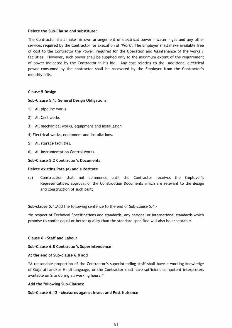
Delete the Sub-Clause and substitute:
The Contractor shall make his own arrangement of electrical power - water - gas and any otherservices required by the Contractor for Execution of "Work". The Employer shall make available freeof cost to the Contractor the Power, required for the Operation and Maintenance of the works /facilities. However, such power shall be supplied only to the maximum extent of the requirementof power indicated by the Contractor in his bid. Any cost relating to the additional electricalpower consumed by the contractor shall be recovered by the Employer from the Contractor’smonthly bills.
Clause 5 Design
Sub-Clause 5.1: General Design Obligations
1) All pipeline works.
2) All Civil works
3) All mechanical works, equipment and installation
4) Electrical works, equipment and installations.
5) All storage facilities.
6) All Instrumentation Control works.
Sub-Clause 5.2 Contractor’s Documents
Delete existing Para (a) and substitute
(a) Construction shall not commence until the Contractor receives the Employer’sRepresentative's approval of the Construction Documents which are relevant to the designand construction of such part;
Sub-clause 5.4:Add the following sentence to the end of Sub-clause 5.4:-
“In respect of Technical Specifications and standards, any national or international standards whichpromise to confer equal or better quality than the standard specified will also be acceptable.
Clause 6 - Staff and Labour
Sub-Clause 6.8 Contractor’s Superintendence
At the end of Sub-clause 6.8 add
“A reasonable proportion of the Contractor’s superintending staff shall have a working knowledgeof Gujarati and/or Hindi language, or the Contractor shall have sufficient competent interpretersavailable on Site during all working hours.”
Add the following Sub-Clauses:
Sub-Clause 6.12 - Measures against Insect and Pest Nuisance
61

“The Contractor shall at all times take the necessary precautions to protect all staff and labouremployed on the Site from insect and pest nuisance, and to reduce the dangers to health and thegeneral nuisance occasioned by the same. The Contractor shall provide his staff and labour withsuitable prophylactics for the prevention of malaria and take steps to prevent the formation ofstagnant pools of water. The Contractor shall comply with all the regulations of the local healthauthorities and shall arrange to spray thoroughly with approved insecticide all buildings erected onthe Site. Such treatment shall be carried out at least once a year or as instructed by suchauthorities”.
Sub-Clause 6.13 - Epidemics
“In the event of any outbreak of illness of an epidemic nature, the Contractor shall comply withand carry out such regulations, orders and requirements as may be required by the Government, orthe local medical or sanitary authorities, for the purpose of dealing with and overcoming thesame.”
Sub-Clause 6.14 -Burial or Cremation of the Dead
“The Contractor shall make all necessary arrangements for the transport, to any place as requiredfor burial / cremation of any of his expatriate employees or members of their families who may diein the Country. The Contractor shall also be responsible, to the extent required by localregulations, for making any arrangements with regard to burial / cremation of any of his localemployees who may die while engaged upon the Works”.
Sub-Clause 6.15 -Alcoholic Liquor or Drugs
“The Contractor shall not, otherwise than in accordance with the statutes, ordinances andgovernment regulations or orders for the time being in force, impart, sell, give, barter or otherwisedispose of any alcoholic liquor or drugs, or permit or suffer any such importation., sale, gift, barteror disposal by his Subcontractors, agents, staff or labour”.
Sub-Clause 6.16 -Arms and Ammunition
“The Contractor shall not have, barter or otherwise dispose of to any person or persons, any armsor ammunition of any kind or permit or suffer the same as aforesaid”.
Sub-Clause 6.17 - Festivals and Religious Customs
“The Contractor shall in all dealings with his staff and labour have due regard to all recognizedfestivals, days of rest and religious or other customs”.
Sub-Clause 6.18 -Foreign Staff and Labour
“The Contractor may import such staff, artisans, and laborers as are required in order to executethe Works. The Contractor must ensure that all such staff and laborers are provided with therequired residence visas and work permits. The Contractor shall be responsible for the return tothe place where they were recruited or to their domicile of all persons whom the Contractorrecruited and employed for the purposes of or in connection with the Contract. The Contractorshall be responsible for such persons as are to be so returned until they shall have left the Site or,in the case of foreign nationals who have been recruited outside the country, shall have left it”.
62

Sub-clause 7.9 regarding Restriction on Eligibility as follows:
(a) Any materials, equipment, services or design services which will be incorporated in orrequired for the contract, as well as the Contractor’s Equipment and other supplies, shallhave their origin in eligible source countries as listed in Section 8.
(b) For the purpose of this clause “services” means the works and all project related servicesincluding design services.
(c) For the purposes of this clause, ”origin” means the place where the materials andequipment were mined, grown, produced, or manufactured, or from which services areprovided.
(d) The Origin of Goods and services is distinct from the Nationality of the Supplier.
Clause 8.2:
The progress of work shall be maintained as under commensurate to the time periods shown below:
Time in months Percentage of work (Physical)4 15%6 50%8 80%12 100% (including 3 months trial run)
Clause 8.7:
Add the following after first paragraph.
In case of the delay attributable to the contractor unless the time of completion has been expresslyextended by the employer, the employer shall derive a power and authority under this clause torecover in terms of money equivalent to 0.1% of the contract value per day of delay, subject to amaximum of 10% of the total value of contract or as decided by the Chairman, RSCDL.
Clause 13.1: Right to Vary
13.1.1 The Engineer-in-Charge will make any variation of the form, quality or quantity of the worksrelating to project that may, in his opinion, be necessary and for that purpose, or if for anyother reason it shall, in his opinion, be appropriate, he shall have the authority to instructthe contractor to do and the contractor shall do any of the following:
a) Increase or decrease the quantity of any work included in the Contract.
b) Omit any such work (but not if the omitted work is to be carried out by theEmployer or by another contractor).
c) Change the character or quality or kind of any such work.
d) Change the levels, lines, position and dimensions of any part of the works,
e) Execute additional work of any kind necessary for the completion of the works, or
63
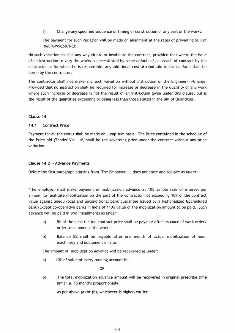
f) Change any specified sequence or timing of construction of any part of the works.
The payment for such variation will be made on alignment at the rates of prevailing SOR ofRMC/GWS&SB/R&B.
No such variation shall in any way vitiate or invalidate the contract, provided that where the issueof an instruction to vary the works is necessitated by some default of or breach of contract by thecontractor or for which he is responsible, any additional cost attributable to such default shall beborne by the contractor.
The contractor shall not make any such variation without instruction of the Engineer-in-Charge.Provided that no instruction shall be required for increase or decrease in the quantity of any workwhere such increase or decrease is not the result of an instruction given under this clause, but isthe result of the quantities exceeding or being less than those stated in the Bill of Quantities.
Clause 14:
14.1 Contract Price
Payment for all the works shall be made on Lump sum basis. The Price contained in the schedule ofthe Price bid (Tender Vol - IV) shall be the governing price under the contract without any pricevariation.
Clause 14.2 - Advance Payments
Delete the first paragraph starting from "The Employer….. does not state and replace as under:
"The employer shall make payment of mobilization advance at 10% simple rate of interest perannum, to facilitate mobilization on the part of the contractor not exceeding 10% of the contractvalue against unequivocal and unconditional bank guarantee issued by a Nationalized &Scheduledbank (Except co-operative bank) in India of 110% value of the mobilization amount to be paid. Suchadvance will be paid in two installments as under;
a) 5% of the construction contract price shall be payable after issuance of work order/order to commence the work.
b) Balance 5% shall be payable after one month of actual mobilization of men,machinery and equipment on site.
The amount of mobilization advance will be recovered as under:
a) 10% of value of every running account bill.
OR
b) The total mobilization advance amount will be recovered in original prescribe timelimit i.e. 15 months proportionally,
As per above (a) or (b), whichever is higher/earlier
64

The bidder shall renew the bank guarantee at least 15 days prior to expiry of submitted ofbank guarantee failing which employer reserves right to encash the bank guarantee withoutany prior intimation to bidder.
Clause 14.2 - Para-2 on Page No.37
Delete paragraph 4 on Page No.37 under Clause 4.2. Following paragraphs shall be deemed to beadded in place of deleted paragraph.
The recovery of advance shall start from the first running bill at the rate of 10% of the bill amount.
Clause 14.4 - Schedule of Payments
14.4.2 Payment for Civil Works
For items of civil works shall be paid based on the % stipulated for respective civil component aslisted in Schedule of Payment of Price Bid, Schedule D (Vol. IV).
However, in no case, the Contractor shall be entitled to recover more than 95% of the total quotedprice prior to Issue of taking over certificate and the balance 5 % of the total quoted price will bepaid aftercompletion of defect liability period.
Clause 14.5: Plant and Materials Intended for the Works.
Add the following clause under the text of the present clause.
The contractor shall submit to the Employer the following documents along with the interim billsfor the payment against delivery of goods.
i) 3 copies of the Contractor’s invoice showing goods description, quantity, unit price, andtotal amount
ii) Manufacturer’s / Contractor’s guarantee certificate
iii) Inspection certificate, issued by the nominated inspection agency and theContractor’s factory inspection report
Clause 14.7 (b): Delete the present clause and substitute as under:
b) The amount which is due in respect of each statement, other than the finalstatement within 30 days after receiving the statement and supporting documents,and
Sub-clause 14.9 :Replace the text of sub clause 14.9 except para three as follows:
The 5% retention money recovered from running account bills under Sub-clause 4.2 will be refundedalong with the final bill.
Sub Clause 14.16:
"Employer, on written request from the contractor, at its own discretion shall make the payment inpart or full as may be expressly requested by the contractor, directly to subcontractors or suppliersnominated by the contractor. Such payments shall be deemed to be the payments made to thecontractor.
65

Add following Sub-Clause 15.6 in clause 15 for Corrupt and Fraudulent practice:-
If in the judgement of the Employer the Contractor has engaged incorrupt or fraudulent practices,in competing for or in executing the Contract, then the Employer may, after having given 14 daysnotice to the Contractor, terminate the Contractor’s employment under the Contract and expel theContractor from the Site, and the provisions of Clause 15 shall apply as if such expulsion had beenmade under Sub-Clause 15.2.
Sub-clause 17.3: Add the following at the end:(g) Loss or damage due to use or occupation by the employer of any section or part of
permanent works except as may be provided for in the contract,
(h) Any operation of force of nature ( in so far as it occurs on the site) which an experiencedcontractor :
(i) Could not have reasonably foreseen, or
(ii) Could reasonably have foreseen, but against which he could not reasonably havetaken appropriate measuresto prevent loss or damage to physical propertyoccurring.
Clause 18 Insurance
Sub Clause 18.1 Add following Para at the end:
The insurance liability under this clause shall cover full reinstatement cost including the costs ofdemolition and professional fees and profit.
Sub Clause 18.2 Add following Para at the end:
Such insurance shall cover the employer and contractor from first working day aftercommencement date until date of issue of taking over certificate of work.
Clause 20 Deleted
66

SECTION II
PART 3CONDITIONS OF CONTRACT
FOR OPERATION AND MAINTENANCE
67
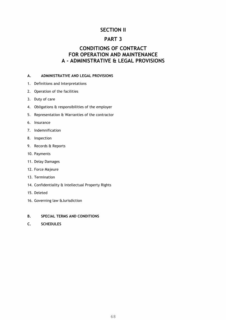
SECTION II
PART 3
CONDITIONS OF CONTRACTFOR OPERATION AND MAINTENANCE
A - ADMINISTRATIVE & LEGAL PROVISIONS
A. ADMINISTRATIVE AND LEGAL PROVISIONS
1. Definitions and Interpretations
2. Operation of the facilities
3. Duty of care
4. Obligations & responsibilities of the employer
5. Representation & Warranties of the contractor
6. Insurance
7. Indemnification
8. Inspection
9. Records & Reports
10. Payments
11. Delay Damages
12. Force Majeure
13. Termination
14. Confidentiality & Intellectual Property Rights
15. Deleted
16. Governing law &Jurisdiction
B. SPECIAL TERMS AND CONDITIONS
C. SCHEDULES
68

CONDITIONS OF CONTRACT
FOR OPERATION AND MAINTENANCE
A - ADMINISTRATIVE& LEGALPROVISIONS
1 DEFINITIONS AND INTERPRETATION
1.1 Definitions
In these Conditions of Contract (“Conditions”) the following words and expressions shall
have the meanings hereby assigned to them, except where the context otherwise requires:
1. “Applicable Law” means all national (or State) legislation, statutes, ordinances and
other Laws and regulations and by lows of any legally constituted public authority.
2. “Contract” means the contract agreement, these conditions, the employer's
requirements, the Tender and the further documents (if any) which are listed in the
contract agreement..
3. “Contractor’s Equipment” shall mean all equipment, instruments, tools, machinery
and other appliances and things of the Contractor at the Site required for the
fulfillment of the obligations of the Contractor under these Conditions.
4. “Contractor’s Personnel” means the contractor's representative and all personal
whom the contractor utilizes on site, who may include the staff, labour, & other
employees of the contractor and of each sub contractor & any other personal
assisting the contractor in the execution of the work.
5. “Dispute” shall have the meaning given to it in Clause 15 of these Conditions.
6. “Defects Liability Period” means the defect liability period of Five (5) years for all
works commencing on and from of taking over during which contractor shall under
take the responsibilities and have the liability for the facility.
7. “Employer’s Risk” shall include the risks mentioned as employers risks in the
General Conditions and shall include any negligence or willful misconduct on the
part of the Employer and also any event of Force Majeure as provided in Clause 12
of these Conditions.
8. “Employer’s Personnel” means the Employer's Representative, the assistants and all
other staff, labour and other employees of the employer and of the Employer's
representative, and any other personnel notified tothe contractor, by the employer
or the employer's representative, as employer's personnel.
9. “Employer’s Requirements” means the document entitled employer's requirements,
as included in the contract, and any additions and modifications to such document
69
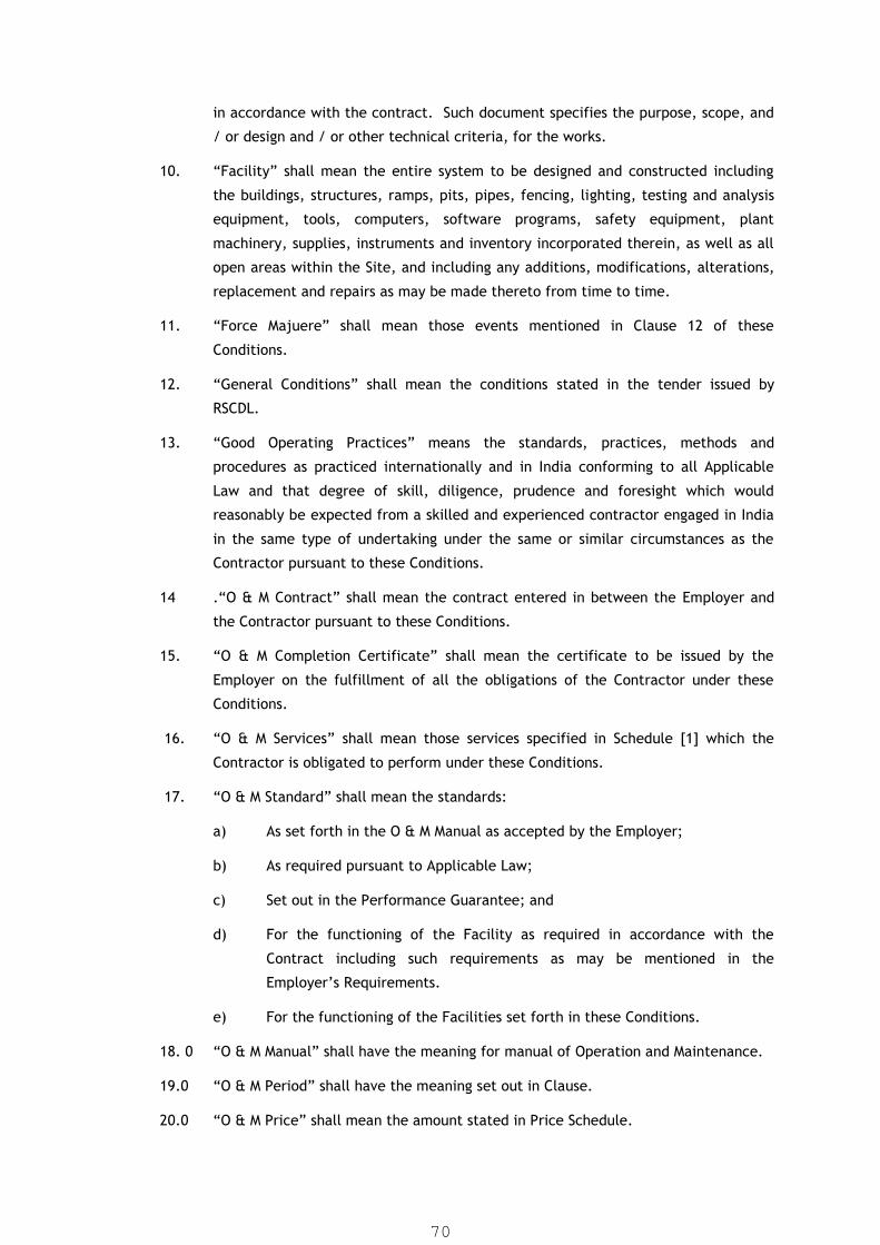
in accordance with the contract. Such document specifies the purpose, scope, and
/ or design and / or other technical criteria, for the works.
10. “Facility” shall mean the entire system to be designed and constructed including
the buildings, structures, ramps, pits, pipes, fencing, lighting, testing and analysis
equipment, tools, computers, software programs, safety equipment, plant
machinery, supplies, instruments and inventory incorporated therein, as well as all
open areas within the Site, and including any additions, modifications, alterations,
replacement and repairs as may be made thereto from time to time.
11. “Force Majuere” shall mean those events mentioned in Clause 12 of these
Conditions.
12. “General Conditions” shall mean the conditions stated in the tender issued by
RSCDL.
13. “Good Operating Practices” means the standards, practices, methods and
procedures as practiced internationally and in India conforming to all Applicable
Law and that degree of skill, diligence, prudence and foresight which would
reasonably be expected from a skilled and experienced contractor engaged in India
in the same type of undertaking under the same or similar circumstances as the
Contractor pursuant to these Conditions.
14 .“O & M Contract” shall mean the contract entered in between the Employer and
the Contractor pursuant to these Conditions.
15. “O & M Completion Certificate” shall mean the certificate to be issued by the
Employer on the fulfillment of all the obligations of the Contractor under these
Conditions.
16. “O & M Services” shall mean those services specified in Schedule [1] which the
Contractor is obligated to perform under these Conditions.
17. “O & M Standard” shall mean the standards:
a) As set forth in the O & M Manual as accepted by the Employer;
b) As required pursuant to Applicable Law;
c) Set out in the Performance Guarantee; and
d) For the functioning of the Facility as required in accordance with the
Contract including such requirements as may be mentioned in the
Employer’s Requirements.
e) For the functioning of the Facilities set forth in these Conditions.
18. 0 “O & M Manual” shall have the meaning for manual of Operation and Maintenance.
19.0 “O & M Period” shall have the meaning set out in Clause.
20.0 “O & M Price” shall mean the amount stated in Price Schedule.
70

21.0 “Party” shall mean each of the Contractor and the Employer and Parties shall mean
both of them together.
22.0 “Performance Guarantees" shall mean the guarantee that the Facility shall be
operated satisfying the minimum performance parameters set out in Schedule.
23.0 “Successor Contractor” shall have the meaning given to it in Clause.
24.0 “Site” shall means that specific area specified in the bid documents & shall include
any other places as may be specifically designed by the employer from the time to
time as forming part of the site.
25.0 “Taking Over Date” shall means the date of issue of the taking over certificate under
the construction phase.
26.0 “Taking Over Certificate” means the certificate to be issued when the whole of the
works or any sections or parts of the permanent works have been substantially
completed & satisfactorily parts of the test on completion in accordance with the
provision of the contract.
27.0 “Termination” shall have the meaning given to it in Clause [13] of these Conditions.
1.2 Interpretation
In these Conditions, except where the context requires otherwise:
(a) words indicating one gender include all genders;
(b) words indicating the singular also include the plural and words indicating
the plural also include the singular;
(c) Provisions including the word "agree", "agreed" or "agreement" require the
agreement to be recorded in writing;
(d) "written" or "in writing" means hand-written, type-written, printed or
electronically made, and resulting in a permanent record;
(e) The marginal words and other headings shall not be taken into
consideration in the interpretation of these Conditions;
(f) The words "include," "includes" and "including" are not limiting;
(g) As used in these Conditions, all defined terms include the plural as well as the
singular;
(h) Any agreement, document or drawing defined or referred to in these
Conditions shall include each amendment, modification and supplement
thereto and waiver thereof as may become effective from time to time,
except where otherwise indicated;
(i) Any reference to any Clause or Sub – Clause shall unless specified otherwise
mean a Clause or Sub- Clause of these Conditions; and
71
(j) Any rights of the Employer to make any inspections or to review any document
shall not create any obligation on the Employer to conduct such inspections or
reviews to detect any errors, inaccuracies, ambiguities or other potential
problems. No inspection or approval by or on behalf of the Employer shall
operate as a waiver of any provision of these Conditions, any obligation of
Contractor under these Conditions, or any of the rights of the Employer
hereunder, except as expressly agreed in writing by the Employer.
1.3 Commencement and Duration of O & M Contract
1.3.1 “The O & M Period” shall commence upon issuing of work order and shall continue
for a period of Five (5) years. The Employer may propose an extension to the O
& M Period by giving 30 days prior notice to the Contractor.
1.3.2 The O & M period may then be extended subject to mutual consent and on
terms and conditions agreed to by both the Parties. However, Employer
reserves right to extend the O&M period for maximum 6 months after the date
of completion of 5 years O&M based on the rate of last year of O&M.
1.4 Applicable Law
1.4.1 The Contractor shall comply with all Applicable Law relevant to the Contractor's
Personnel, including Applicable Law relating to their employment, health, safety,
welfare, immigration and emigration, and shall allow them all their legal rights.
1.4.2 The Contractor shall require his employees to obey all Applicable Laws, including
those concerning safety at work.
1.4.3 In the event Employer becomes liable to any Employers Personnel, any governmental
authority (including but not limited to any fines or penalties levied by or payable to
such authority) or any other third party under the provisions of any Applicable Law
resulting from Contractor's failure to comply with such Applicable Law, Contractor
shall reimburse Employer for all payments required to be made by Employer to such
Employers Personnel, governmental authority or any other third party, plus the actual
expenses that Employer may incur in investigating, settling or defending any litigation
or threatened litigation.
1.5 Assignment
The Contractor shall not be entitled to sub-contract any part of his obligation under
these Conditions to any third party without prior approval of the Employer. Neither
party may assign their rights and obligations under these Conditions without the
consent of the other Party. However the Employer may assign any rights under
these Conditions to any financial institution from whom any financial
assistance/credit facilities have been availed by the Employer.
1.6 Safety
1.6.1 Emergencies
72

In the event of an emergency endangering life or property, the Contractor shall
take such action as may be necessary to prevent, avoid or mitigate injury, damage
or loss and shall, as soon as possible, report any such incidents, including his
response thereto to the Employer.
1.6.2 Contractor Action
The Contractor shall utilize his personnel to take such action as may be necessary in
accordance with Good Operating Practices in the event of an emergency.
Notwithstanding anything to the contrary herein, the Contractor may incur any
expenditure or take any other operating actions as the Contractor deems to be
necessary (in accordance with Good Operating Practices) in the case of
emergencies affecting the Facilities or the operation of the Facilities to counteract
the effects where the Contractor considers immediate action is required to
safeguard lives or property. In case such emergency was caused due to an
Employer’s Risk then the Employer shall reimburse such reasonable expenses that
might have been incurred by the Contractor in relation thereto acting in
accordance with Good Industry Practices.
1.7 Notification
1.7.1 In the event of an emergency the Contractor shall forthwith notify the Employer of
the emergency, the expenditures made and the operating actions taken.
1.7.2 If the Employer considers that an emergency has arisen in relation to the Facilities,
the Employer may give written notice to the Contractor specifying the nature of the
emergency which it has identified and the manner in which it requests such
emergency to be rectified. The Contractor shall rectify such defect with all due
diligence. If such emergency is on account of an Employer’s Risk then the
Contractor shall be reimbursed all costs and expenses reasonably incurred by the
Contractor for any actions taken by it pursuant to such direction or notice. If the
Contractor fails to comply with such direction or notice promptly, the Employer
shall be entitled to procure that it or any third party takes such actions as may be
necessary to remedy such breach by the Contractor. Any costs that may be incurred
by the Employer in this regard shall be reimbursed to him in full by the Contractor
and shall be a debt due to him from the Contractor.
1.8 Inspections
Not withstanding any provisions of these Conditions and without prejudice to any of
the other rights vested by the Contractor under these Conditions, the Employer
shall have the right at all times to inspect the Facilities and the Contractor shall co-
operate in every manner with the representatives of the Employer inspecting the
Facilities and allow them access to every part of the Facilities and produce any
records requested.
73

2 OPERATION OF THE FACILITIES
2.1 Operation of the Facilities
2.1.1 The Employer appoints the Contractor to perform and undertake the O & M Services
and all other obligations set out and in accordance with these Conditions during the
O&M Period. The Contractor accepts the appointment and acknowledges a duty to
perform such obligations.
2.1.2 The Contractor shall be in complete charge of and have custody and control over
and responsibility for the Facilities, and the Contractor shall perform or cause to be
performed on behalf of the Employer all O & M Services for the Facilities and shall
supply or cause to be supplied all materials required therefore in accordance with
the O & M Standard.
2.1.3 The Contractor shall also acknowledge that the Employer and the Employer’s
Personnel and other contractors may be carrying out work at the Facilities and shall
endeavor to fully co-operate and work in a manner so as not to cause any
obstruction or hindrance to them.
2.1.4 The Contractor is an independent Contractor and not an agent, employee and
nothing in these Conditions or the O & M Contract shall be deemed to create a joint
venture between the Employer and the Contractor.
2.2 Responsibility of the Contractor
The Contractor shall be solely and exclusively responsible for:
2.2.1 Necessary procedures for obtaining all necessary permits and consents required by
Applicable Law or any governmental authority for the Contractor to carry out the O
& M Servicesby providing necessary documents /authorization and charges to be
paid by RSCDL. In case of charges paid by O&M Agency, the same shall be
reimbursed by RSCDL.
2.2.2 the procurement of all goods and services necessary to ensure compliance with its
obligations under these Conditions;
2.2.3 making available suitably qualified and trained personnel to perform the O & M
Services;
2.2.4 perform the O & M Services in accordance with the O & M Manuals and maintain the
Facilities in good repair and condition and ensure that the Facilities are well and
suitably maintained at all times in accordance with Good Operating Practices and in
accordance with these Conditions;
2.2.5 procuring and administering all chemicals and other consumables, tools,
equipment, spare parts and other materials (which shall be of good quality and
unused) necessary for the operation and maintenance of the Facilities;
74

2.2.6 maintaining a system of records to identify all inventories related to the Facilities
and preparing and providing to the Employer a complete accounting of such
inventory for every fiscal quarter;
2.2.7 arranging for the testing and recalibration of all scales, meters, gauges and other
measuring devices at the Facilities on an annual basis unless otherwise stated in the
O & M Contract; and
2.2.8 for providing any and all relevant information required by the Employer.
3 DUTY OF CARE BY THE OPERATOR AND PERFORMANCE STANDARDS
3.1 Duty of Care
3.1.1 The Contractor shall manage, operate and maintain the Facilities in accordance
with Good Operating Practices and in accordance with the O & M Standard so that
the Facilities are capable of meeting the outputs and specifications set out in the
Contract.
3.1.2 The Contractor shall take full responsibility for the care of the Facility from the
date of issue of the Taking-Over Certificate, till the end of the O & M Period.
3.1.3 If any loss or damage happens to the Facility, during the O & M Period due to any
breach by the Contractor of any of his obligations under these Conditions including
any willful misconduct, negligence and non conformity with Good Operating
Practices than the Contractor shall, at his own cost, rectify such loss or damage so
that the Facility conforms in every respect with the provisions of these Conditions.
3.1.4 The Employer shall be liable only in case of any damage caused due to any
Employer’s Risk.
4. OBLIGATIONS AND RESPONSIBILITIES OF THE EMPLOYER
The Employer shall employ the Contractor to provide the O & M Services and shall:
4.1 following the issue of work order, hand-over the custody of the Facilities to the
Contractor for its use during the O & M Period; and
4.2 pay the Contractor all sums required to be paid in accordance with the terms of
these Conditions.
Not withstanding anything else herein contained the Employer may set off any sums
owed by the Contractor under the Contract for monies owed to the Contractor by
the Employer under these Conditions or as a debt due from the Contractor.
4.3 No advance payment or Down payment shall be made.
5 REPRESENTATIONS AND WARRANTIES OF THE CONTRACTOR
75

The Contractor hereby represents for the benefit of the Employer as follows:
5.1 Performance of O & M Services
5.1.1 that the Contractor has the required skills and capability to perform, and shall
diligently perform, the O & M Services in a high-quality, timely and professional
manner utilizing sound engineering principles and project management procedures
in accordance with Good Industry Practices;
5.1.2 that the Contractor shall perform its obligations hereunder in accordance with the
requirements of these Conditions and shall meet the Performance Guarantee; and
5.1.3 that it shall not use any spare parts or material that are not new and which shall be
of a quality that is in accordance with Good Industry Practices.
5.2 Knowledge of Adverse Information
5.2.1 As of the Commencement Date, Contractor is not aware of any facts, conditions or
events which would affect the ability of Contractor to provide the O & M Services in
accordance with these Conditions.
5.2.2 Contractor has familiarized itself with the nature and extent of the O & M Services
required to be provided under these Conditions and with all other requirements
under Applicable Law.
5.3 Organization, Standing and Qualification
Contractor is validly existing and in good standing under Applicable Law and has all
necessary power and authority to carry on its business as presently conducted and
to perform its obligations under these Conditions. Contractor is, or shall be prior to
the date on which the O & M Services are to be commenced duly qualified or
licensed to provide these services.
5.4 Due Authorization
5.4.1 Each of the execution, delivery and performance by the Contractor of all contracts
entered into pursuant to these Conditions shall be duly authorized by all necessary
action on the part of Contractor.
5.4.2 Neither the execution and delivery by Contractor of the O&M Contract, nor the
consummation by Contractor of any of the transactions contemplated hereby,
requires the consent or approval of, the giving of notice to, the registration with,
the recording or filing of any document with, or the taking of any other action in
respect of, any governmental authority or agency, except:
(a) Such as have been duly obtained, given, registered, recorded, filed or
taken and are in full force and effect or are not yet required; and
(b) Filings and recordings expressly required pursuant to the O & M Contract.
Contractor holds, or shall obtain, any and all licenses, permits and
approvals on a timely basis. Contractor has no reason to believe that any of
76

those not yet required shall not be readily obtainable or done in the
ordinary course of business upon due application there for.
5.5 Litigation
In the aggregate, there are no pending or, to the knowledge of Contractor,
threatened actions, investigations or proceedings before any court, governmental
authority or arbitrator, which would have material adverse effect on the ability of
Contractor to perform its obligations under these Conditions.
6 INSURANCE
6.1 General Conditions
6.1.1 Without limiting the Contractor's obligations, responsibilities and liabilities under
these Conditions, the Contractor shall be required to provide and maintain in full
force and effect, at his expense the insurance coverage’s specified in Schedule [5]
for the O&M Period. Any deductibles on the insurance shall be to the account of the
Contractor.
6.1.2 Maintenance of insurance shall not relieve the obligation of the Contractor to
remedy or repair any damage to the Facility in case such damage is caused due to
the fraud, negligence, willful misconduct or breach of any obligations of the
Contractor under these Conditions (including failure to perform the O & M Services
in accordance with Good Operating Practices) at the Contractors cost promptly and
regardless of the extent of settlement of claims by the underwriters or the time
taken for settlement of claims. Any amounts not insured or not recovered from the
insurers shall be borne by the Contractor to the extent any such liability or damage
is caused due any breach of any obligations of these Conditions (including failure of
the Contractor to perform the O & M Services in accordance with the Good
Operating Practices) by the Contractor or any willful misconduct, negligence on the
part of the Contractor.
6.1.3 The terms of the Insurance shall be approved by the Employer.
6.1.4 The Contractor within the 14 days from work order shall submit to the Employer
evidence that the insurances required under Schedule [5] of these Conditions has
been obtained as approved by the Employer.
6.1.5 The Contractor shall not make any alteration to the terms of any insurance without
the prior approval of the Employer. If the Contractor fails to effect and keep in
force any of the insurance it is required to effect and maintain under these
Conditions, or fails to provide satisfactory evidence and copies of policies in
accordance with this Sub-Clause, the Employer may (at its option and without
prejudice to any other right or remedy) effect insurance for the relevant coverage
and pay the premiums due and may claim the same from the Contractor.
6.1.6 The insurances shall:
77

(a) shall be in the name of the Employer and the Employer shall be the sole
loss payee,
(b) shall be extended to cover liability for all loss and damage to the
Employer's property arising out of the Contractor's performance of his
obligations or failure to do so under these Conditions and any fraud, gross
negligence or willful misconduct on his part, and
If the Contractor fails to effect and keep in force insurance which is required to be
maintained under these Conditions, and the Employer neither approves the
omission nor effects insurance for the coverage relevant to this default, any
moneys which would have been recoverable pursuant to such insurance shall be
paid by the Contractor.
6.1.7 The insurance shall be limited to electrical, mechanical and automation and pipe
component appurtances only. The insurance for civil work is optional. Since the
responsibility of safety of all work lies with contractor, contractor may prefer to
take the insurance of optional item also if deemed fit.
7 INDEMNIFICATION
7.1 Loss or Damage to Facilities
The Contractor shall at its own expense make good any physical loss or damage to
the Facilities occasioned by it in the course of the performance of its obligations
under these Conditions if and to the extent such loss or damage is caused by the
negligence, wilful default or breach of statutory duty or failure to follow Good
Industry Practices by the Contractor.
7.2 Other Loss or Damage
7.2.1 Except as otherwise stated in this Clause 7.2 or covered by Clause 7.3, the
Contractor shall indemnify, defend and hold harmless the Employer against any and
all liabilities, losses, damages and claims of whatever kind and nature, including all
related costs and expenses incurred in connection therewith, in respect of personal
injury to or death of third parties or any employee of the Employer or the in
respect of loss of or damage to any third party property or property belonging to
employee of the Employer by:
(i) any breach by the Contractor of its obligations hereunder; and
(ii) any negligence, willful default or breach of statutory duty on the part of
Contractor.
7.2.2 Except as otherwise stated in this Clause 7.2 or covered by Clause 7.3, the Employer
shall indemnify, defend and hold harmless the Contractor for all claims and losses of
whatever kind and nature, including all related costs and expenses incurred in
connection therewith, in respect of personal injury to or death of third parties or of
78
any person employed by the Contractor in respect of loss of or damage to any third
party property or property belonging to any person employed by the Contractor to the
extent that the same arises out of any Employer’s Risk.
7.3 Accidents or Injury to Workmen
7.3.1 The Contractor shall indemnify, defend and hold harmless the Employer or any
Employer’s Personnel against any and all claims for loss, damage and expense of
whatever kind and nature (including all related costs and expenses) in respect of
the death of or injury to any person employed by the Contractor in connection with
the performance of the O&M Services and obligations hereunder except to the
extent that such death or injury is caused by an Employer’s Risk.
7.3.2 Neither Party shall be liable to the other Party for loss of use of the Facilities, loss
of profit, loss of any contract or for any indirect or consequential loss or damage
which may be suffered by the other Party in connection with the Contract, other
than under Sub-Clause [13] and this Clause [7].
7.3.3 The total liability of the Contractor to the Employer, under or in connection with
these Conditions other than as provided in Clause 7 & 14 shall not exceed the sum
of the O & M Price and the Delay Damages payable under the these Conditions.
This Sub-Clause shall not limit liability of the Contractor in case of fraud, willful
default, gross negligence and liabilities arising due to breach of Applicable Law and
the liability under any other Clause of these Conditions that might impose a greater
liability on the Contractor.
8 INSPECTION
8.1 General Provisions
8.1.1 The Employer may check the operation of the Facilities or designate an
organization of his choice to carry out inspections regularly. The Employer or the
organization appointed by him shall check that the Contractor is performing the
tasks for which he is responsible with due diligence. The Contractor shall at his
cost provide all the assistance the Employer requires to complete these inspections.
8.1.2 Before any inspection, the Employer shall give prior notice to the Contractor,
indicating the name(s) of the person(s) empowered to carry out such inspection in
the name of the Employer.
8.2 Measurement and Analysis
8.2.1 The Employer has the right to perform any analysis or inspection he deems
necessary. Before any inspection, the Employer shall give a prior written notice to
the Contractor.
79

8.2.2 The water quantity, for any such test, analysis or inspection shall be measured by
flow-meters installed at the Facility, which are acceptable to the Employer.
8.2.3 The flow-meters shall be inspected and certified upon their availability by the
Employer and the Contractor. Thereafter, the said meters shall be tested and their
accuracy verified once in every six (6) months by the Employer and the Contractor.
After each inspection, the flow-meters shall both be sealed in the presence of
representatives of the Employer and the Contractor in a manner that is adequate to
prevent the tampering of said meters by any person.
8.2.4 The Contractor shall be responsible for the security and protection of flow-meters
at the designated point. If there is any malfunctioning of the meters, it should be
replaced at the Contractor’s cost.
8.3 Plant Complex Visits
8.3.1 At the end of each month, or at the initiative of the Employer, a visit shall be
organized so that both Parties can check the condition of the installations at the
Facilities.
8.3.2 A report shall be drawn up to record the opinions of both Parties. The Employer
reserves the right to call in equipment manufacturers or specialized technicians for
these visits.
8.3.3 These visits shall provide an opportunity for examining maintenance programs and
operating procedures and improvements requiring additional investments.
8.3.4 Any test, visit, analysis or inspection and any approval thereof shall not in any way
alter/modify or dilute the responsibility of the Contractor to fulfill his obligations
under these Conditions.
9 RECORDS AND REPORTS
9.1 Operating Records and Data
The Contractor shall:
9.1.1 Prepare and maintain, on a current basis and in accordance with generally
accepted Indian accounting principles, proper, accurate and complete books and
records and accounts of all transactions related to the Facilities including a log
book at the site which shall contain inter alia the following details:
(a) Reading from the different meters, indicators and recorders (including but
not limited to consumption of energy, volume of water conveyed, operating
times of the different items of equipment etc which may be updated on a
daily basis); and
(b) Report of visits by persons other than those of the Employer and the
Contractor to the Facility.
80

9.1.2 Establish and maintain a weekly and monthly reporting system to provide storage
and ready retrieval of operating data relating to the Facilities, including such
information necessary to verify calculations made pursuant to these Conditions or
the O & M Contract and provide the same to the Employer on a monthly basis.
9.1.3 Provide to the Employer or such persons notified by it access to the Facilities and to
data in relation to the Facilities, at all times.
9.1.4 At the Employer’s request, at the end of every month, make a copy of the system
performance data for that month as recorded by the instrument and control system
on floppy diskettes and printed document therefrom and deliver the same to the
Employer with one week.
9.1.5 Provide support to the Employer to meet the data requirements of all competent
authorities and under Applicable Law.
9.2 Reports
9.2.1 The Contractor shall submit the reports mentioned in Schedule [4] at times
indicated in the said Schedule.
9.2.2 The Contractor shall also provide the Employer with such reports as are required by
the Employer and shall comply with all reporting requirements prescribed under
these Conditions and the O & M Contract. In addition the Contractor shall submit
the following information to the Employer:
9.2.3 Upon obtaining knowledge thereof, shall submit prompt written notice of:
(i) any litigation or material claims, disputes or actions, threatened or filed,
concerning the Facilities or the services to be performed hereunder;
(ii) any refusal or threatened refusal to grant, renew or extend or any action
pending or threatened that might affect the granting, renewal or extension
of any clearance, permit or license;
(iii) Notwithstanding the aforementioned materiality, all penalties or notices of
violation issued by any authority under Applicable Law;
9.3 the Contractor shall promptly submit to the Employer any material information
concerning new or significant aspects of the operations of the Facilities, any
material complaint about the Facilities from any person or entity with a bona fide
complaint who complains directly to the Contractor and, upon Employer’s request,
shall promptly submit any other information concerning the Facilities or the
services performed by the Contractor.
9.3.1 The Employer may from time to time specify any changes to be made to any of the
format of any report or plan required hereunder.
9.3.2 If the Contractor is required by any Applicable Law to produce any projection,
report or any other document relating to the provision of the O & M Services of the
81
Facilities or t he Employer requests a report regarding other information relating to
the Facilities, the Contractor shall prepare a draft of such document at the request
of the Employer, as soon as practicable and in any event within any time limit
prescribed by Applicable Law.
9.3.3 If the Contractor is required by any Applicable Law to produce any projection,
report or any other document, it shall prepare such report diligently and submit the
same to the Employer as soon as possible thereafter. Wherever practicable, such
reports shall be submitted to the Employer for review [3] days before the same is
issued. The Contractor shall take into account any comments or revisions proposed
by the Employer thereon.
9.4 Procurement
9.4.1 The Contractor is responsible for the procurement of all goods and services
necessary to ensure compliance with its obligations under these Conditions.
9.4.2 The Contractor shall procure spare parts, materials, supplies and other consumable
items, and maintains an adequate inventory thereof Facilities.
9.4.3 The Contractor shall submit a report for every fiscal quarter to the Employer
reflecting the status of the inventory for spare parts, materials and other
consumable items.
10. PAYMENT
10.1 The Contractors request(s) for payment shall be made to the RSCDL in writing,
accompanies by invoice(s) along with presence sheet of personnel of particular
month duly certified by our Engineer on site, claims etc. as appreciate.
10.2 Payment shall be made by RSCDL as per procedure subsequent to the submission of
such invoice(s)/ claim(s) by the Contractor.
10.3 The RSCDL shall deduct from the amount payable to the Contractor, any amount
paid by RSCDL on behalf of the Contractor e.g. (telephone bills, GEB/PGVCL
penalty for Power factor or any other dues and liquidated damages as per clause
and, as per tender terms and condition. Any telephone bills submitted by telephone
department, the cost of bills shall be borne by Contractor.) RSCDL shall provide
telephone and wireless facilities on site. Batteries of wireless set periodically to be
charged by contractor and wireless set to be kept in running condition by
contractor.
10.4 Contractor shall provide Security Guards services for all assets in plant head works
premises for 24 hours of a day and 365 days of the year for the whole contractor
period.
11 DELAY DAMAGES
Performance Guarantees and Delay Damages
82

The Contractor shall operate and maintain the Facilities in accordance with:
11.1 The O & M Standard; and
11.2 the Good Industry Practices.
In case of the failure of the Contractor to achieve each of the requirements
mentioned in Price Schedule, he shall be liable to pay Liquidity Damages for each
unit of shortfall.
12 FORCE MAJEURE
In this Clause, "Force Majeure" means an event or circumstance, which materially
and adversely affects the ability of the affected Party to perform its obligations:
(a) which is beyond a Party's control,
(b) which such Party could not reasonably have provided against before
entering into the O & M Contract,
(c) which, having arisen, such Party could not reasonably have avoided or
overcome, and
(d) which is not attributable to the other Party.
Force Majeure may include, but is not limited to, exceptional events or
circumstances of the kind listed below, so long as conditions (a) to (d) above are
satisfied:
(i) war, hostilities (whether war be declared or not), invasion, act of foreign
enemies,
(ii) rebellion, terrorism, revolution, insurrection, military or usurped power, or
civil war,
(iii) riot, commotion, disorder, strike or lockout by persons other than the
Contractor's Personnel and other employees of the Contractor,
(iv) amunitions of war, explosive materials, ionising radiation or contamination
by radio-activity, except as may be attributable to the Contractor's use of
such munitions, explosives, radiation or radio-activity, and
(v) Natural catastrophes such as earthquake, hurricane, typhoon or volcanic
activity. heavy rainfall, cyclone, strike and lockout.
(vi) Non-receipt of sewage / influent
12.1 Notice of Force Majeure
12.1.1 If a Party is or shall be prevented from performing any of its obligations under these
Conditions by Force Majeure, then it shall give notice to the other Party of the
event or circumstances constituting Force Majeure and shall specify the obligations,
83

the performance of which is or shall be prevented. The notice shall be given within
7 days after the Party became aware, or should have become aware, of the
relevant event or circumstance constituting Force Majeure.
12.1.2 The Party shall, having given notice, be excused performance of such obligations
for so long as such Force Majeure prevents it from performing them.
Not withstanding any other provision of this Clause, Force Majeure shall not apply
to obligations of either Party to make payments to the other Party under the
Contract.
12.2 Duty to Minimize Delay
12.2.1 Each Party shall at all times use all reasonable endeavors to minimize any delay in
the performance of the Contract as a result of Force Majeure.
12.2.2 A Party shall give notice to the other Party when it ceases to be affected by the
Force Majeure.
12.2.3 Notwithstanding anything else herein contained the Employer may terminate the O
& M Contract if the Force Majeure event continues for more than a period of 90
days.
13 TERMINATION
Termination shall mean the termination of the O&M Contract by the Employer or
the Contractor in accordance with Clause 13.1 or 13.2 respectively.
13.1 Termination by Employer
The Employer may terminate the O & M Contract by notice on:
(a) the dissolution or insolvency of the Contractor, pursuant to an order of a
court or the bankruptcy of the Contractor; or
(b) if 45 days having passed since the Contractor is in material breach of his
obligations under these Conditions, or
(c) if the Contractor ceases to carry on its business; or
(d) abandonment;
(e) the subsisting Force Majeure event as provided in Clause 12.2.3 above.
13.2 Payments upon Termination
13.2.1 Upon termination or as soon as practicable thereafter an account shall be taken of
the net amount owing from the Employer to the Contractor or from the Contractor
to the Employer (as the case may be). The Employer shall forthwith pay to the
Contractor (if the balance is due to the Contractor) all moneys due to the
Contractor. If the account shows a balance due to the Employer from the
Contractor, the Contractor shall forthwith pay any such balance to the Employer;
84

13.2.2 As part of the calculation made pursuant to clause 13.1 of the amounts due to the
Contractor on Termination, the following amount shall be taken into account:
13.2.2.1 The portion of the O & M Price outstanding and payable by the Employer for the
period prior to the Termination;
13.2.2.2 Any Delay Damages or indemnities for which the Contractor would be liable under
these Conditions upto the date of Termination;
13.2.2.3 Any other amounts due to the Employer under these Conditions by the Employer
including return of any amount of the O & M Price paid in advance by the Employer
to the Contractor under Clause [10].
13.3.3 In case of a Termination by the Employer in accordance with Clause 13.1 the
Employer may recover other than the amounts due to him under Clause 13.3.2, any
costs incurred by him in finding any replacement contractor.
13.4 Successor to the Contractor
Upon Termination: -
13.4.1 The Contractor shall use all endeavors to facilitate the appointment and
commencement of duties of any person to be appointed by the Employer to operate
and maintain the facilities (the “Successor Contractor”) so as not to disrupt the
normal Operation & Maintenance of the Facilities and shall provided full access to
the Facilities and to all relevant information, data and records relating thereto by
the Successor Contractor and its representatives and accede to all reasonable
requests made by such persons in connection with preparing for taking over the
Operation & Maintenance of the Facilities,
13.4.2 Promptly after Termination, the Contractor, shall deliver to (and shall, with effect
from Termination, hold on trust for and to the order of) the Employer or (if so
required by the Employer by written notice) to the Successor Contractor all
property in its possession or under its control owned by the Employer or leased or
licensed to the Employer;
13.4.3 The Contractor shall transfer to the Successor Contractor, as from the date of
Termination, its rights as the Contractor under all contracts entered into by it in
the performance of its obligations under these Conditions or relating to the
Operation & Maintenance of its obligations under these Conditions or relating to the
Operation & Maintenance of the Facilities. Pending such transfer, the Contractor
shall hold its rights and interests thereunder for the account and to the order of the
Successor Contractor.
13.4.4 The Employer shall be reimbursed any cost and expenses incurred by the Employer
due to default of the Contractor in discharging its obligations under this Clause
[13].
85
13.4.5 The Contractor shall, upon Termination of the O & M Contract, co-operate with the
Employer and the Successor Contractor and comply with all reasonable requests
thereof, including the execution of documents etc.
13.4.6 Upon Termination of the O & M Contract on expiry of the terms of the O & M
Contract, the Parties agree that:-
13.4.7 The Contractor shall use reasonable efforts to ensure a transition to the next
Contractor that shall avoid operating difficulties for the Facilties.
13.4.8 For a six (6) month period after Termination or six (6) months prior to the
expiration of the O & M Contract, the Contractor shall, at his expense, provide
sufficient assistance to the Employer in the hiring and training of replacement
personnel for those Facilities.
13.5 Notwithstanding anything else herein contained the Employer shall be entitled to
terminate the O & M Contract, at any time at the Employer's convenience, by giving
notice of such termination to the Contractor. The termination shall take effect 28
days after issuance of the notice of termination.
13.5.1 On the expiry of the O & M Contract or Termination of the O & M Contract, all the
installations, works and equipment placed under the Contractor’s responsibility
shall be handed over to the Employer, at no cost, in good working order, except for
normal wear and tear. The Employer may perform any inspections, tests or expert
appraisals he shall consider necessary with a view to checking that the property is
in good working order. The Contractor shall also hand over any unutilized spares,
consumables etc. purchased for the Facilities.
13.5.2 At the end of O & M Period, the Contractor shall be entitled to receive an O & M
Completion Certificate within thirty (30) days.
13.5.3 The delivery of such O & M Completion Certificate shall relieve the Contractor from
his responsibility as regard to the operation & maintenance of the Facilities and
confirm that the Contractor has fulfilled all of his obligations under these
Conditions.
14 CONFIDENTIALITY AND INTELLECTUAL PROPERTY RIGHTS
14.1 Confidential Information
Subject to Clause [14.2], the Contractor shall at all times during the O & M Period
and for a period of two years after that:
14.1.1 use all efforts to keep all information regarding the terms and conditions and any
data or information acquired under or pursuant to these Conditions confidential and
accordingly shall not disclose the same to any other person; and
14.1.2 not use any document or other information (whether technical or commercial)
obtained by them it by virtue of these Conditions or the Contract concerning the
86
Employer’s undertaking for any purpose other than performance of the its
obligations under these Conditions;
Provided that the provisions of this Clause 14.1 shall not apply to information which
at the time of disclosure was in the public domain other than by breach at the
foregoing obligations of confidentiality.
14.2 Disclosure of Confidential Information
The Contractor shall not be entitled to disclose the terms and conditions of
these Conditions and any data or information acquired by it under or pursuant
to these Conditions without the prior written consent of the Employer unless
such disclosure is made in good faith:
14.2.1 to any outside consultants engaged by or on behalf of the Contractor and acting in
that capacity, having made them aware of the requirements of this Clause [14].
14.2.2 to the lenders, any security trustee, any bank or other financial institution and its
advisers from which the Contractor is seeking or obtaining finance, having made
them aware of the requirements of this Clause [14].
14.2.3 to the extent required by Applicable Law;
14.2.4 to any insurer under a policy of insurance; or
14.2.5 to the Contractor’s Personnel having made them aware of the requirements of this
Clause [14];
14.3 Information
The Contractor shall:
14.3.1 make available to the Employer without charge such materials, documents and data
of any nature (except any materials documents and data protected by legal
privilege or which is subject to any duty of confidentiality to any third party)
acquired or brought into existence in any manner whatsoever by it as the Employer
may request for the purposes of exercising its rights or carrying out its duties in
respect of the Facilities or exercising its rights under or performing its obligations
under these Conditions.
14.3.2 make available to the Employer other such materials and documents and data
acquired or brought into existence by third parties as the Employer may request for
the purposes referred to in sub-paragraph (i) above.
14.4 Third Party Intellectual Property
The Contractor shall: -
14.4.1 procure that any intellectual property owned or developed by third parties and
utilized by the Contractor in connection with the performance of its obligations
under these Conditions is licensed to the Contractor for the purposes of the
87

Operation & Maintenance or repair of the Facilities and otherwise for the purposes
of the Facility; and
14.4.2 ensure that the Contractor shall have the right to sub-license that intellectual
property to the Employer and any Successor Contractor for use in connection with
the operation, maintenance and repair of the Facilities. These licenses should
survive termination under these Conditions. The Contractor shall grant all such sub-
licenses. If any fee is payable to the licensor in consideration of any such sub-
license, the Contractor shall pay such amount during the O & M Period and each
such license shall be irrevocable.
14.4.3 Indemnify and hold harmless the Employer against any action, claims, damages,
losses caused to the Employer by the owner of the Intellectual Property due to the
allegedly unauthorized or improper use of this intellectual property by the
Contractor for the fulfillment of his obligations under these Conditions.
14.5 Successor Contractor
If the licenses and sub-licenses of intellectual property granted under this Clause
respectively shall survive termination of the O & M Contract in accordance with the
terms of this Clause, the Employer shall be permitted to grant sub-licenses of
intellectual property licensed to it thereunder to any Successor Contractor of the
Facilities for use only in connection with the operation, maintenance and repair of
the Facilities provided that such Successor Contractor concludes an agreement with
the Contractor or, as the case may be, the licensor of any such intellectual
property on terms which it may reasonably require any payment in connection with
those sub-licenses. Where intellectual property has been sub-licensed to the
Employer under this Clause and such sub-license is not subject to revocation by the
Contractor thereunder, the Contractor shall take such actions as the Employer may
request in connection with the grant of licenses to any Successor Contractor for the
purposes set out above.
15 DELETED
16 GOVERNING LAW AND JURISDICTION
These Conditions and the O & M Contract shall be governed in accordance with
Indian Law.
The Contractor agrees that any legal action or proceedings arising out of these
Conditions may be brought in the courts or tribunals at Rajkot City Only in India
and irrevocably submits themselves to the jurisdiction of such courts or tribunals.
The Employer may, however, in its absolute discretion commence any legal action
or proceedings arising out of these Conditions in any other court, tribunal or other
appropriate forum, and the Contractor hereby consents to such jurisdiction.
88

B.SPECIAL TERMS AND CONDITIONS
1) The operation and maintenance of all the works included in this tender as per details given
should be carried out by contractor at his own cost.
2) All the units of the plant should be kept in fill-up condition as per requirement during the
full day period. (24 Hours)
3) A weekly report for quality and quantity of treated waste water (influent) and tertiary
treated water (effluent) should be submitted to the office of the concern RSCDL Engineer-
in-Charge. A certificate of the concern in-charge Engineer for daily receipt of required qty.
influent at plant & treated effluent at the end of week should be received and submitted
with weekly report.
4) Electric bill for running the plant at head works site shall be paid by RSCDL, bill should be
submitted to office for payment as soon as received by him from GEB/PGVCL. Penalty if
any for delay shall have to be paid by contractor.
5) All the required electrical goods like bulb, tube light, chock, starter, fuse, wire etc.
required for operation and maintenance shall be procured by contractor at his own cost and
lighting arrangement should be kept in good condition.
6) At the time of breakage in pipeline or valves for repairing purpose contractor has to make
arrangement at his risk and cost for labours, fitter, required all materials like rubber
packing, nut bolts, gland, all required parts of valves in Plant & transmission main including
pickup van, Jeep, welding machine, welding rods, Tractor etc. should be provided by
contractor at his own cost. All consumable material should be of standard quality as
approved by Engineer-in-charge of work.
7) All type of pipeline including chambers, open channels, gates should be maintained and
repaired by contractor at his own cost.
8) At the time of repairing or replacement of any type of Pipes and valves required for
repairing or replacement after verification by concerned engineer or his representative,
fitting work of pipe or valves shall be carried out by contractor at his own cost including,
labour, excavation cutting, fitting, welding, testing, refilling etc. complete. Repairing
work shall be started within one hour after breakage or leakage come into notice.
9) Any type of valve or gate or part of the valve or gate not working properly after repairing
and requires replacement, as per opinion ofEngineer-in-Charge or his representative, then
required valve gate shall be supplied to the contractor free of cost from departmental store
if available. Replacement shall be done by the contractor and old valve gate should be
shifted to department store and entered in concerned register including cost of loading,
unloading, carting stacking etc. complete.
89

10) During the period of contract a person other than responsible representative of contractor
or persons employed by him should not enter into the premises of the plant. Every care
should be taken by contractor to prevent such type of unauthorized entry or interruption in
the premises or surrounding the property of RSCDL.
11) Persons required for security of materials in the stores at sub head works sites shall be
deployed by contractor.
12) At any time during the visit of Engineer in charge or his representative if it is observed that
the operation and maintenance is not carried out properly, liable to be terminated.
13) Operation and maintenance of meters installed at plant sites should be carried out by
contractor and entry shall be made in the register at every one hours. If any meter is not
working properly it should be properly repaired by contractor from any technician of such
type of repairing work.
14) After issue of work order contractor or his responsible representative should joint visit the
site of every work accompany with officer concern. A list and position of works and all
valves with dia. and nos. a report shall be prepared and should be jointly signed by
contractor and department. A copy of same report shall be issued to contractor. At the
time of completion of contract period same type of report should be prepared and
possession of all the works and components should be handed over to department. If
repairing & maintenance work is not done properly by contractor, the cost of repairing
work shall be recovered by department from contractor.
15) All the works executed under this project & covers in the scope of this tender shall be
handed over to contractor from the date of work order. Proper operation and maintenance
of the same works/components shall be carried out by contractor and at the time of
completion of contract period or termination of contract, contractor should have to give
possession of all the work and components to the department in good condition. Before
handing over the possession to the department account of contract shall not be finalized
and deposit shall not be refunded to contractor. For all type of legal activities and
expenditure for the same, contractor shall be fully responsible.
16) During the period of contract for any type of dispute, decision of The Chairman, RSCDL
shall be final and binding to both the parties.
17) Prescribed registers as maintained by agency during the period of operation and
maintenance period shall be submitted to the department. All the material received during
repairing and replacement shall be deposited in departmental store at the cost of
contractor. All repairing work should be carried by contractor at his own cost during the
period of contract contractor should be fully responsible for injury to any public person or
men engaged by contractor for work and contractor shall be fully responsible for
compensation for it.
90
18) Proper care is to be taken by contractor housekeeping of every component of the plant.
19) Servicing of all the valves and gates cleaning of all civil works and maintenance shall be
carried out regularly by contractor and entered into the concerned registers.
20) History sheet shall be maintained by contractor for replacement of material in pipeline, or
valves, space parts of Electro -mechanical equipments.
21) Leakage repairing shall be carried out in proper way and technically workmen like manner.
Repairing by rubber tubes or by fixing wooden Peg shall not be allowed. Register of
leakage repairing shall be maintained with reasons properly.
22) All the works included in the scope of work shall be oil / snowcem painted or as
applicable once in the two years contract period at the cost of contractor.
23) All the gardens and plants situated at plant sites shall be supplied water and maintained
properly by contractor. No any extra payment shall be made on account of this work.
24) Telephone/wireless message shall be received and entered in the register and message
should be conveyed to concern party at plant for action. One person shift wise for 24 hours
shall be on duty for this work.
25) All the information regarding labour, staff, vehicles etc. is incorporated in this tender for
preparation of estimate. As per list staff having proper qualification / labour shall be
deployed by contractor for smooth running of plant, failing which, RSCDL shall deploy
required personnel at the risk and cost of contractor and recovery for such expenditure
shall be made from the bill of contractor.
26) The contractor has to make all the arrangements required for the proper operation,
maintenance smooth running of plant and safety of all the works included in this contract
at his own cost during the whole contract period.
27) Separate log book for arrival & releasing of water from Each storage structure shall bemaintained day to day by the contractor and shall be submitted to department at the endof month.
28) List of all the assets, pipeline appurtenances plants & machineries, all types of valves,gates, chambers, pump houses, security cabin, office building and lab, hydraulic civilstructures, spare parts, store , wireless sets, telephone, electric panels etc. shall behanded over to contractor for M&R purpose & same should be returned to RSCDL in workingcondition as soon as the plant is taken over by RSCDL for further M&R period to any otherparty.
29) Any damage / breakage found from mischievous element found in the system, thecontractor should lodge policy case immediately under intimation to concern GeneralManager/CEO, RSCDL & City Engineer (Sp.), Drainage Project, RMC.
30) Material consumption register in prescribed format should be maintained by the contractor.During the visit of Engineer - in - charge if required it should be produced.
91
31) “The Contractor” shall operate the plant and associated services, on a continuous 24 hours
basis to treat the influent received at inlet of plant as specified in tender.
32) “The Contractor” shall operate and utilize all the control and monitoring systems, provided
and if found to be necessary and if approved by the engineer, shall make adjustments
within the operating range of the control system and equipment so that the plant operation
matches the requirement.
33) “RSCDL” shall directly pay all the power bill to GEB/PGVCL but the Contractor shall berequired to furnish Electricity Consumption in the Schedules provided.
a) Telephone bills shall have to be paid by the successful bidder. No reimbursement
shall be made.
b) Electric / Battery operated wireless sets shall be provided by RSCDL. The hand sets
shall be periodically got checked and repaired through other agency but the
operating of wireless sets and it's battery etc shall be in the scope of the
contractor. The wireless sets shall be kept in running condition for round the clock.
c) Electric/Battery operated flow meter or any other instruments &analyzers has tomaintained by successful bidder. In case failure of batteries, same has to bereplaced by successful bidder at his own cost.
34) All miscellaneous items, for example, vehicles, tools, testing equipment, cleaning or green
keeping equipment, security and safety equipment, electrical fixtures, etc shall be
provided by the Contractor at his expense.
35) a) The Contractor shall provide experienced managerial, technical, supervisory,
administrative and non-technical personnel and labour necessary to operate and
maintain the plant in a scientific way.
b) The qualification and capability of the Contractor's personnel shall be appropriate
for the task they are assigned to perform. The staff provided shall be fully trained
in the operation of the Tertiary Treatment Plant before being given responsibility
for operating any part of the plant. If in the opinion of the Engineer, any member
of the Contractors staff is considered to be insufficiently skilled or otherwise
inappropriate for the task he is required to perform, he shall be replaced by the
Contract with a person with the appropriate skills and experience for the task, to
the approval of the Engineer. The Contractor shall be required to submit to the
Employer the Schedule of 'Manpower' and 'Organisation Chart'.
c) The Curriculum Vitae(CV) /Resumes ofthe Contractors personnel shall be submitted
to the Engineer for acceptance at least 7 days before the anticipated
commencement ofthe 0 & M , period. Any change ofpersonnel shall be promptly
informed to the Engineer within a day's time. Normal time duty hours for the
contractors' operation & maintenance personnel may be modified as necessary and
agreed by the Engineer. A rotating shift schedule shall be established by the
Contractor and agreed by the Engineer which shall ensure that an adequate number
92

of the Contractor's staff, fluent in Hindi as well as Gujarati is on duty at Plants 24
hours per day, 7 days per Week, including all holidays.
d) Contractor shall submit one photograph of each personnel, with his resume,
permanent address, etc. and department shall issue identity cards to each
personnel. Any replacement in Employment by Contractor shall have to be reported
in 24 hours to concerned Manager/ CEO, RSCDL & City Engineer (Sp.), Drainage
Project, RMC. Contractor has to put the name person on duty shift wise on display
board. Display board shall be kept in each pumping station.
36) a) The Contractor shall be responsible for safety on Site during the O& M of the Works
by the Contractor.
b) The Contractor's duties with respect to Safety shall include the following:
i) Utilize safety awareness procedures in every element of operation and
maintenance. ii) Give emphasis to site including:
* Safe working and safety procedures as per rules and regulations of Governments
regarding use of protective clothing, gloves, boots and helmet etc.
* Cleanliness of the plants as a whole.
* Awareness of hazardous conditions and accident reporting and necessary compliance.
* Safe practice in Pumping Stations.
37) a)The maintenance service provided by the Contractor for the period specified in the
Contract shall ensure the continuous operation of the Treatment Plant and that the
breakdown or deterioration in performance, under normal operating conditions, of any
items, of Plant and equipment and component-parts thereof is kept to a minimum.
b) The Contractor shall adhere to the manufacturers' recommendations with respect to equipment
maintenance, the type and grades of lubricants to be used, frequency of lubrication,
adjustments to be made regularly and recommended spares to be held in store.
38) The Contractor shall be responsible for:
a) The maintenance of electrical, mechanical, instrumentation, piping, civil work,
plumbing and drainage / plant installations.
b) General Building Maintenance and housekeeping
c) Full maintenance of the site services, cabling and earthing systems, together with
the site road lighting system. Painting of all mechanical structures which are
open to sky once in 2 Years.
d) Site maintenance including the upkeep of landscaped areas.
The building services and housekeeping maintenance shall be undertaken on all building and
services installation.
93
The Contractor shall ensure that all unwanted or redundant items are removed from the
building and sites. Depending on their condition such items shall either be placed into
storage or disposed off site.
39) a) The stores inventory, the issuing and recording of spare parts shall be the responsibility
of the Contractor.
b) The Contractor is also responsible for providing spare parts and material required for the
operation and maintenance during the operation period, including the cost of storing and
safeguarding.
c) The Contractor shall make all necessary arrangements to ensure the continuous supply of
spare parts and material for the works, and the rate of supply of these materials shall be in
such quantities and amounts as would ensure uninterrupted operation.
d) Spare parts shall be supplied by theContractor and the same shall be used during
Operation and Maintenance Contract period.
e) The contractor shall have to procure the required spares from original manufacture or
authorized dealer at his cost.
40) a) The Employer reserves the right to arrange the visits of VIP's dignitaries, public
representatives and other persons of Social or Political repute, any organization as and
when necessary, to the Treatment Plant. The Contractor shall offer full cooperation to the
RSCDL on the occasions of such visits.
b) Inspection register shall have to be maintained, wherein inspection officers shall note
their instructions duly dated signature. Successful bidder has to follow the instructions
strictly.
41) On the date of Contract Completion or if the Contract is terminated, all the installations,
works and equipment placed under the Contractor's responsibility shall be handed over to
the Employer, at no cost, in good working order. The Employer may perform any
inspections, tests or expert appraisals he shall consider necessary with a view to checking
that the property is in good working order and shall certify to that effect to the Contractor
while taking over.
42) No accommodation I guest house/ transportation facility shall be provided by the RSCDL to
Contractor.
43) For smooth & efficient O& M of the plant, and in case of emergency just like fire, fault,
accidents, or other rescues operation, the contractor must keep one vehicle with seating
arrangement at Treatment Plant in working condition for 24 hours of a day & 365 days of
the year for the whole contract period.
44) While handing over the spares to the contractor, Contractor should maintain the record of
spares of inventory of utilize the spares.
45) In the event of any dispute or difference arising, the Jurisdiction of the court shall be
Rajkot (Gujarat) City only.
94

46) It is mandatory for the contractor to operate the pumping machinery not less than limit
efficiency of pump. If deviation is noted in respective energy bill for succeeding month the
difference in amount considering based on KWH shall be invoked through O & M bills of
successful bidders.
47) In case, there is no inflow to the TTP after completion of construction for a period ofone month and/ or more, bidder shall note that only fixed cost shall be paid during theperiod of non-availability of sewage for any reasons at Plant Inlet to be provided by client(RSCDL) &contractor shall not be entitled to claim the variable cost, applicable from thestart date of O&M till a period of 45 days from the date of commencement of O&M.Thereafter(i.e. after 45 days of completion of construction & trails run and acceptance ofplant / start date of commencement of O&M), payment towards security watchmen willonly be made OR for the staff to be deployed& for the fixed cost component for upkeep andpreventive maintenance of equipment (cleaning, lubrication, etc.) as mutually agreedbetween client (RSCDL) & contractor till further notice by client to resume O&M work forwhich client shall provide at least 15 days advance intimation to contractor for resumingO&M work. RSCDL shall intimate contractor by written notice in such event during initialfifteen days of O & M period.
Further bidder to also note that all variable cost quoted by bidder under Schedule C of O&Min price bid shall be payable proportional to the quantity of sewage received/treated in theTreatment Plant during routing O&M period.
Signature of Contractor City Engineer (Sp.)Drainage Project, RMC
95

SCHEDULE 1
Operation and Maintenance Services
The Contractor shall be required to perform the following services under these Conditions:
The Contractor shall be responsible for corrective maintenance of civil, hydraulic, mechanical,piping, electrical, instrumentation and computing equipment as well as miscellaneous equipment.
The Contractor shall be responsible for carrying out regular servicing and lubrication of rotarymachines, complying with maintenance instructions as defined in the Operation and MaintenanceManual, and ensuring that electromechanical equipment and motors operate correctly at all times.
The Contractor shall ensure that measurement systems operate correctly at all times.
The Contractor is responsible for the maintenance of the landscaped areas inside the Employerplant fences.
The Contractor shall be responsible for maintenance of civil structures including intakes, pumphouses, reservoirs, administration buildings, workshops, garages, etc.
The Contractor shall operate and maintain in a state of continuous operational readiness all plantand systems to meet the flow requirements. It shall remain the Contractor’s responsibility toensure that plant systems are at all times able to operate to the maximum capacity of the installedduty plant.
All influent & effluentconveyed by the Contractor shall be metered by the meters installed at theinlet & outlet of Plant and important plant parameters shall be measured as specified in scope ofwork of contract. Contractor shall maintain daily record of influent (treated sewage at outlet ofSTP received at inlet of this proposed tertiary treatment plant) and effluent (tertiary treatedsewage) and any other treatment plant parameters as required to assess the satisfactoryperformance of plant. The meters shall be inspected and certified as to its accuracy jointly by theEmployer and the Contractor.
The Contractor shall be entitled to appoint a representative who shall together with Employer'sRepresentative on the last day of each month or if such day is not a working day on the followingday, jointly carry out a reading of meters and jointly certify the record of such readings.
For the duration of the O & M period, the Contractor shall be responsible for the supply and controlof lubricants, spare parts and consumable materials excluding electrical power, necessary for thecontinuous operation of the works.
The Contractor shall manage the consumables and utilities services to ensure their most economicconsumption and to minimize wastage.
The quantities of all the unutilized spare parts and consumable materials shall be fully handed-overto the Employer at the end of the O&M period.
96

The stores inventory, the issuing and recording of spare parts shall be the responsibility of theContractor.
The Contractor is also responsible for providing spare parts and material required for the operationand maintenance during the operation period, and shall bear the cost for the same, including thecost of storing and safeguarding.
The Contractor shall make all necessary arrangements to ensure the continuous supply of spareparts and material for the works, and the rate of supply of these materials shall be in suchquantities and amounts as would ensure uninterrupted operation.
All the furniture and administrative office/ laboratory equipment etc. required shall be furnishedby the Contractor. Costs of operating administrative office and supplies shall be borne by theContractor.
The Contractor shall take out subscriptions for standard telephone lines. Running cost for thetelephone shall be borne by the Contractor.
Cost of operation and maintenance and housekeeping of housing complexes including domesticwater supply and drainage, roads, gardens, electrical installations, etc. shall be borne by thecontractor.
The Contractor shall provide the personnel stipulated in Volume II & IV for the full term ofoperation, maintenance and training period.
97
SCHEDULE 2
Performance Guarantees
This Schedule may contain certain minimum performance that the Contractor must Guarantee interms of maximum permissible parameters of Tertiarytreated sewage to be re-used / recycled ordischarged into natural water body, quantity of sewage to be treated, quality of the sewage etc. asprescribed in the tender document elsewhere and reviewed by Gujarat Pollution Control Board /End – User (RSCDL or such other to whom RSCDL decided to supply tertiary treated water /sewage).
98

SCHEDULE –3
O & M PRICE
The contractor shall be paid amount towards O&M on monthly basis for Five years of O & M contractas per the break-up specified in price schedule.
Note:
1. O&M cost above shall be inclusive cost of all Chemicals except for Chlorine, and shall be alsoinclusive of cost for supply of manpower, repairs and maintenance of all units includingreplacement of equipment if required (if not working or not repairable or not permittingsatisfactory operation of TTP to achieve desired quantity & quality of permeate at UF Outlet /existing UGSR) , spares, consumables, services of any expert as required, laboratory analysisincluding laboratory ware and chemicals, and any other work required for smooth operation andmaintenance of entire facility. Chlorine shall be free supply by employer at any one locationwith plant premises and any unloading, handling / internal transfer, etc. as well loading ofempty chlorine tonners in vehicle of employer shall be considered by bidder in their scope.
2. Treated Sewage of specified quality & Power shall be supplied by employer. Cost of diesel foroperating DG set during power failure shall be reimbursed at actual by client after necessaryverification by client based operating hours logged in hour meter & actual power generation inpower meter of DG set. Contractor shall submit required supporting documents to client forverifications and to satisfaction of client.
3. Cost of obtaining approval from statutory body for transportation & storage etc. charges forChlorine / Chemical, etc. as applicable is also included in scope of contractor.
99
SCHEDULE 4
REPORTS
MONTHLY REPORT
The monthly report shall include but not be limited to:
Volume of sewage received in the TTP and treated,
Quality of influent, at intermediate stage and effluent (tertiary treated sewage / water) atlocations stipulated elsewhere in the tender
The status and progress of the training programs,
Electricity consumed totally on daily basis and other critical electrical parameters like powerfactor, etc.
Inventory of maintenance and tools/ tackles used, spares utilized, preventive maintenance carriedout during the month
Any other as per the format provided by client
SEMI-ANNUAL REPORTInventory of maintenance and tools/ tackles used, spares utilized during the periodAny other critical parameters or statistics related to plant operation
Any other as per the format provided by client
ANNUAL REPORT
The Contractor shall provide the Employer by March 31 of the current year (n) with an annualreport for the preceding year (n-1). This report shall include:
All technical statistics related to plant operation as supplied by the operation;
A statement of works carried out during the preceding year n-1 in connection with the Contractor’sobligations under these Conditions
Inventory of maintenance and tools/ tackles used, spares utilized during the year
100

SCHEDULE 5
Insurances
Insurance against Injury to Persons and Damage to Property
The Contractor shall insure against each liability for any loss, damage, death or bodily injury, whichmay occur to any physical property or to any person, which may arise out of the Contractor'sperformance of his obligations under these Conditions during the O & M Period.
This insurance shall be with maximum three number of occurrences till the full amount of thetender cost.
Insurance for mechanical, electrical & automation of the package is compulsory whereas that of allTransmission Main / Piping, Storage and other Civil work shall be optional.
Insurance for Contractor's Personnel
The Contractor shall effect and maintain insurance against liability for arising from injury, sickness,disease or death of any person employed by the Contractor or any other of the Contractor'sPersonnel.
The Employer shall also be indemnified under the policy of insurance, except that this insurancemay exclude losses and claims to the extent that they arise from any act or neglect of the Employeror of the Employer's Personnel.
101

Schedule 6 - Liquidated Damages(For non-conformance in meeting the Output Standards for Tertiary Treated Sewage set as per this
tender specifications & Power Factor for electrical installation)
Sr.
No. Event triggering the
recovery of
Liquidated Damages
During the O&M Period
RemarkLiquidated
DamagesFrequency
1 Non-conformance with
respect to any one or
more parameters of
guaranteed quality of
treated effluent after
Tertiary Treatment at TTP
Outlet / existing UGSR
Feed as per quality
specified in Volume II,
Technical Specifications.
(pH, Tu, TSS, BOD/COD,
PO4-P, Fecal Coliform,
FRC)
50% of O&M
payment payable
for each day
(derived based
on monthly O&M
quoted)
For each occurance
in a day
Deduction/Penalty at
actual without Limit
subject to Max. up to
50% of Monthly O&M
Quoted for Given
Month in which penalty
is applicable
2 Non-conformance of
desired power factor of
0.95 (lag) or better as
reflected in electricity bill
of power supply company
or as per power meter at
associated HT/PCC
breaker panel, as
applicable
Rs. 10,000/- per
occurrence as
and when lower
than 0.95PF
reflected in
power supply
company bill
As per billing cycle of
power supply
company
Deduction/Penalty at
actual without Limit
3 Non conformance ofguaranteed power
consumption i.e. actualpower consumption as perelectricity bill of power
supply company exceedingguaranteed power
consumption
Twice thedifference in
amount betweenactual andguaranteed
powerconsumption per
occurrence asreflected inpower supplycompany bill
As per billing cycle of
power supply
company
Deduction/Penalty at
actual without Limit
102

SECTION - III
FORMS
103

FORM ‘ABANK GUARANTEE FOR EARNEST MONEY
In consideration of the Rajkot Smart City Development Ltd., Rajkot of the city of Rajkot(hereinafter to as the RSCDL) having agreed to exempt_______________________________ (hereinafter referred to as “the said Contract”) fromthe demand of security deposit / earnest money in cash for the due fulfillment of the termsand conditions of the agreement made between the RSCDL and the said contractor on_____________ for ______________________________________ (hereinafter referred tous “the said agreement”) on production of Bank Guarantee for Rs. ___________________Rupees _________________________________________________________ only.
We ______________________________________________ Bank (hereinafter referred to as“Bank”) do hereby undertake to pay to the RSCDL as a amount not exceeding Rs.______________________Rupees __________________________________________________ only on the demandfrom RSCDL.
Any such demand on the bank shall be conclusive as regards as amount due and payable bythe bank under this guarantee. However, liability of the bank under this agreement shall berestricted to an amount not exceeding Rs. _______________________Rupees ___________________________________________________only.
We the bank further agree that the guarantee herein contain shall remain in full force andeffect during the period that would be taken for the performance of the said agreement andthat it shall continue to be enforceable till all the dues of the RSCDL under or virtue of thesaid agreement have been paid and its claim satisfied or discharged and till a certificate to theeffect has been received by the bank from the RSCDL. However, unless the demand of claimunder the guarantee is made to the bank in writing on or before the________________________ (specify the date) the bank shall be discharged from allliabilities under this guarantee.
With the bank further with RSCDL shall have fullest liberty, without the concert of the bankwithout effecting in any manner it obligations herein under to vary any of the terms andconditions of the said agreement or extend time for performance by the said contract fromtime to time or to postpone for any time or from time to time any of the powers exercisableby the RSCDL against the said Contractor and to forebear to enforced any of the terms andconditions relating to the said agreement and the bank shall not be relieved from liability byreason of any such variation, or extension granted to the contractor for any forbearance, at allomission on the part of the RSCDL or any indulgence by the RSCDL to the said Contractoror by any such matter or thing whatsoever which under the law relating to sureties would, butthis provision, have the effect of so relieving the Bank.We _____________________________________________ the bank undertake not to revokethe Guarantee during currency except with the previous concert of the RSCDL in writing.
Dated the _____________________ day of __________________ of 20___________
For _______________________________ Bank
104
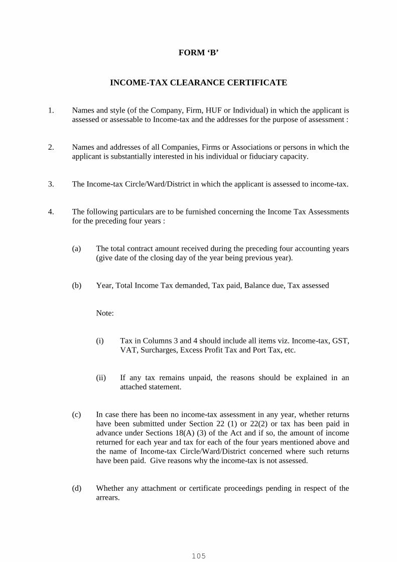
FORM ‘B’
INCOME-TAX CLEARANCE CERTIFICATE
1. Names and style (of the Company, Firm, HUF or Individual) in which the applicant isassessed or assessable to Income-tax and the addresses for the purpose of assessment :
2. Names and addresses of all Companies, Firms or Associations or persons in which theapplicant is substantially interested in his individual or fiduciary capacity.
3. The Income-tax Circle/Ward/District in which the applicant is assessed to income-tax.
4. The following particulars are to be furnished concerning the Income Tax Assessmentsfor the preceding four years :
(a) The total contract amount received during the preceding four accounting years(give date of the closing day of the year being previous year).
(b) Year, Total Income Tax demanded, Tax paid, Balance due, Tax assessed
Note:
(i) Tax in Columns 3 and 4 should include all items viz. Income-tax, GST,VAT, Surcharges, Excess Profit Tax and Port Tax, etc.
(ii) If any tax remains unpaid, the reasons should be explained in anattached statement.
(c) In case there has been no income-tax assessment in any year, whether returnshave been submitted under Section 22 (1) or 22(2) or tax has been paid inadvance under Sections 18(A) (3) of the Act and if so, the amount of incomereturned for each year and tax for each of the four years mentioned above andthe name of Income-tax Circle/Ward/District concerned where such returnshave been paid. Give reasons why the income-tax is not assessed.
(d) Whether any attachment or certificate proceedings pending in respect of thearrears.
105

(e) The name and address of Branch(es), if any.
I declare that the above information is correct and complete to the best of myinformation and belief.
Signature of the Contractor
Registered No. Signature
Address
Date:
In my opinion, the assessee mentioned above has been doing everything possible to pay thetax demanded promptly and regularly and to facilitate the completion of the pendingproceedings.
This will remain valid for one year from the date of issue.
Signature of the Income-tax officer
Circle Ward
NOTE: However, in view of the latest circular of IT Department, contractor can providephoto copy of the PAN card along with acknowledgement copy of last IT return filed bybidder.
106
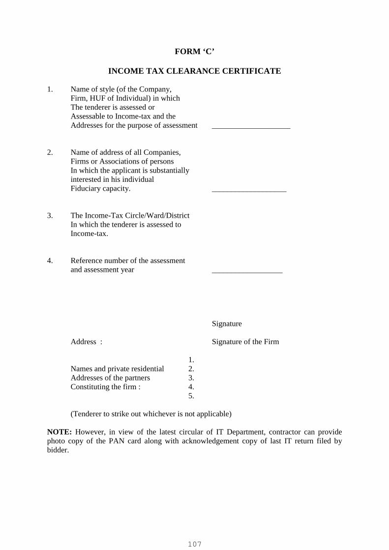
FORM ‘C’
INCOME TAX CLEARANCE CERTIFICATE
1. Name of style (of the Company,Firm, HUF of Individual) in whichThe tenderer is assessed orAssessable to Income-tax and theAddresses for the purpose of assessment ____________________
2. Name of address of all Companies,Firms or Associations of personsIn which the applicant is substantiallyinterested in his individualFiduciary capacity. ___________________
3. The Income-Tax Circle/Ward/DistrictIn which the tenderer is assessed toIncome-tax.
4. Reference number of the assessmentand assessment year __________________
Signature
Address : Signature of the Firm
1.Names and private residential 2.Addresses of the partners 3.Constituting the firm : 4.
5.
(Tenderer to strike out whichever is not applicable)
NOTE: However, in view of the latest circular of IT Department, contractor can providephoto copy of the PAN card along with acknowledgement copy of last IT return filed bybidder.
107
PERFORMANCE BOND
Annexure-I
(See Clause No. 1(b)) (5% of the Tendered cost)
(The date of this bond must not be prior to the date of the instrument in connection withwhich it to given)
Principal (Contractor)
Surety (Bank)
Sum of bond (Express in words and figures)
Contract No. _____________ Date of Contract___________
KNOW ALL MEN BY THESE PRESENTS, THAT WE,THE PRINCIPALS AND SURETY
above mentioned are held and firmly bound unto the Chairman, Rajkot Smart CityDevelopment Limited, Rajkot owner (employer / client) of the work of ENGINEERING,PROCUREMENT, CONSTRUCTION, COMMISSIONING AND 5 YEARS OPERATION& MAINTENANCE OF 8 MLD CAPACITY TERTIARY TREATMENT PLANT ATRAIYADHAR, RAJKOT UNDER RAJKOT SMART CITY MISSION for Rajkot SmartCity Development Ltd. hereinafter called the "employer" in the amount stated forpayment of which sum, well and truly to be made, we bind ourselves, our heirs,executors, administrators and successors jointly and severally, firmly by these presentssubject to the provisions of which the aforesaid contract on demand and withoutdemand on a claim being made by the "employer".
THE CONDITION OF THIS OBLIGATION IS SUCH, that whereas the principals hereinafter called contractor viz. have entered into a contract with the Employer numbered anddates as shown above and hereto attached for the execution of work.
NOW THEREFORE, if the principal shall well and truly perform and fulfill all the undertakings, covenants, terms, conditions and agreements, of said contract during the originalterms of the said contract and any extensions thereof, they may be granted by the employerwith or without notice to the surety and during the lift of any guarantee required under thecontract and shall also well and truly perform, and fulfill all the undertakings, contract, terms,conditions and agreements of any and all duly authorized modifications of said contract thatmay hereafter be made, notice of which modifications to the surety being hereby waived orshall pay over, make good and reimburse to the employer all losses and damages which theemployer may sustain by reason of failure or default on the part of said principal so to do.
108

We _____________________________________________ further agree that guaranteeherein contained shall remain in full force and affect during the period that would be takenfor the validity _______________________ of the said contract and that it shall continue tobe enforceable till all the dues of the employer under or by virtue of the contract have beenfully paid and its claims satisfied of discharged or till the Employer certifies that the termsand conditions of the contract have been fully and properly carried out by the said contractorand accordingly discharges the guarantee. Unless a demand or claim under this guarantee ismade on us in writing on or before the ________________________________________________________________________________________ we shall be discharged from allliability under this guarantee thereafter.
IN WITNESS WHEREOF the above bounded parties have executed this instrument undertheir several on the date indicated above the name and corporate seal of each corporate partybeing hereto affixed and these presents duly signed by its undersigned representative,pursuant to authority of its governing body.
In the presence of witness Individual Principal1. as to (Seal)2. as to (Seal)3. as to (Seal)4. as to (Seal)
Affix
Corporate Seal
Attested By Corporate Surety
Business Address
Affix
Attested By Corporate Seal
Title For and on behalf of the employer
109
Annexure-II
On Rs. 300/- (or of applicable amount) Stamp paper with duly Notarized
Declaration
I______________________________________________________ do hereby declare that
our firm/Company is not blacklisted and no enquires/cases are pending against us by
Govt. of India/Govt. of Gujarat or any State Board/Corporations, since inception of the
firm/Company.
I further undertake that if above declaration is proves to be wrong/ incorrect or
misleading, our Tender/Contract stands to be cancelled or terminate.
Date:Place:
Signature of Authorized person ofthe firm/Company
Note: The above to be submitted along with technical bid.
Notary Seal
110

FORM OF CONTRACT AGREEMENT
AGREEMENT
THIS AGREEMENT made the____________day of_______________20____________ between
________________________________________________________________________
of____________________________________________________________________(hereinafter called “the
Employer”) of the one part and__________________________of __________________
(hereinafter called “the Contractor” of the other part.
WHEREAS the Employer is desirous that certain Works should be executed by the Contractor, viz.,
__________________________________________________________________________________
and has accepted a Bid by the Contractor for the execution and completion of such Works and the remedying of
any defects therein at a cost of Rs.___________________________________________
and _______________________________________.
NOW THIS AGREEMENT WITNESSETH as follows:
In this Agreement, words and expressions shall have the same meanings as are respectively assigned to
them in the Conditions of Contract hereinafter referred to.
The following documents shall be deemed to form and be read and construed as part of this Agreement, viz:
a) The Contract Agreement;
b) The Letter of Acceptance;
c) The Employer’s Requirements;
d) The Bid;
e) The Conditions of Contract
f) The Specifications;
g) The Bid Drawings;
h) The Schedules; and
i) Minutes of the Pre-Bid Meeting
j) Corrigendum & Addenda
k) The Contractor’s Proposal
In consideration of the payments to be made by the Employer to the Contractor as hereinafter mentioned,
the Contractor hereby covenants with the Employer to execute and complete the Works and remedy any
defects therein in conformity in all respects with the provisions of the Contract.
The Employer hereby covenants to pay the Contractor in consideration of the execution and completion of
the Work and the remedying of defects therein the Contract Price or such other sum as may become payable
under the provisions of the Contract at the times and in the manner prescribed by the Contract.
IN WITNESS whereof the parties hereto have caused this Agreement to be executed the day and year first
before written.
111

The Common Seal of_____________________________________________________________________________________________________________was hereunto affixed in thepresence of:___________________________________or_____________________________Signed, sealed, and delivered by the said______________________________in the presence of:_________________________________________________
Binding Signature of Employer______________________________________
Binding Signature of Contractor_____________________________________
112

FORM OF PERFORMANCE SECURITY (BANK GUARANTEE)
To: ___________________________________________(name of Employer)__________________________________________(address of Employer)
WHEREAS_________________________(name and address of Contractor) (hereinafter called “theContractor”) has undertaken, in pursuance of Contract No.________dated______________to execute___________________(name of Contract and brief description of Works) (hereinafter called “theContract”);AND WHEREAS it has been stipulated by you in the said Contract that the Contractor shall furnishyou with a Bank Guarantee by a recognized bank for the sum specified therein as security forcompliance with his obligations in accordance with the Contract;AND WHEREAS we have agreed to give the Contractor such as Bank Guarantee;NOW THEREFORE we hereby affirm that we are the Guarantor and responsible to you as principalobligator, on behalf of the Contractor, un conditionally and irrevocably guarantee the payment of anamount to total of ______________________________(amount of Guarantee) ____________________________________(amount in words), such sumbeing payable in the types and proportions- of currencies in which the Contract Price is payable, andwe undertake to pay you, upon your first written demand and without cavil or argument, any sum orsums within the limits of __________________________(amount of Guarantee) as aforesaid withoutyour needing to prove or to show grounds or reasons for your demand for the sum specified therein.We hereby waive the necessity of your demanding the said debt from the Contractor before presentingus with the demand.We further agree that no change or addition to or other modification of the terms of the Contract or ofthe Works to be performed there under or of any of the Contract documents which may be madebetween you and the Contractor shall in any way release us from any liability under this guarantee, andwe hereby waive notice of any such change, addition or modification.
this guarantee shall be valid until the date of issue of the performance certificate.
SIGNATURE AND SEAL OF THE GUARANTOR
Name of Bank _______________________Address _______________________Date _____________________
113

FORM OF ADVANCE PAYMENT SECURITY ( BANK GUARANTEE )
To:__________________________________________(name of Employer)____________________________________________(address of Employer)____________________________________________________________________________________________________________________________________(name of Contract)Gentlemen:In accordance with the provisions of the Conditions of Contract, (“Advance Payment”) of the above-mentionedContract,_____________________________________________________[name and address of Contractor] (hereinafter called “the Contractor”) shalldeposit with __________________________________(name of the Employer) a bank guarantee to guarantee his proper and faithful performance under the Clause ofthe Contract in an amount of ______________________________(amount of Guarantee)_______________________________________________(amount of words).We, the ____________________(bank or financial institution), as instructed by the Contractor, agreeunconditionally and irrevocably to guarantee as primary obligator and not as Surety merely, the payment to____________________________(name of Employer) on his first demand without whatsoever right ofobjection on our part and without his first claim to the Contractor, in the amount notexceeding__________________________________________(amount of Guarantee)______________________________(amount in words), such amount to be reduced periodically by the amountsrecovered by you from the proceeds of the Contract.We further agree that no change or addition to or other modification of the terms of the Contract or of Works tobe performed there under or of any of the Contract documents which may be made between____________________________________ (name of Employer) and the Contractor, shall in any way releaseus from any liability under this guarantee, and we hereby waive notice of any change, addition, or modification.
This guarantee shall remain valid and in full effect from the date of the advance payment under the Contractuntil ___________________________________(name of Employer) receives full repayment of the sameamount from the Contractor.
Yours truly,SIGNATURE AND SEAL: ________________________Name of Bank or Financial Institution: ________________________Address: ________________________Date: ________________________
114

Bidders’ stamp & initials
RAJKOT SMART CITY DEVELOPMENT LTD.e-Tender No.: RSCDL/SMART CITY/18/2020-21.
VOLUME-II
TECHNICAL SPECIFICATIONS
January-2021
:: Milestone dates of e-Tendering ::1. Downloading of e-Tender documents 16-01-2021 to 11-02-2021up to 17.00 Hrs.
2. a) Pre-bid Queries to be submitted by e-mail only at mail [email protected] / [email protected]) Pre-bid Meeting
a) 27-01-2021 up to 11.00 am
b) 27-01-2021 at 4-00 pm
3. Online submission of e-Tender 11-02-2021 up to 18.00 Hrs.
4. Physical submission of EMD, Tender fee, Documentsrequired for pre-qualification and other necessary documents.
Up to 16-02-2021 18.00 Hrs.
5. Verification of submitted documents (EMD, Tender fee,Documents required for pre- qualification and other Necessarydocuments.)
Up to 19-02-2021 18.00 Hrs.
6. Opening of online Primary Bid (Technical Bid) 17-02-2021 at 10.30 Hrs. onwards
7. Opening of online Commercial Bid (Price Bid) for technicallyqualified bidders only.
22-02-2021 at 10.30 Hrs. onwards(If possible)
8. Bid Validity 180 Days
City Engineer (Drainage Project),Drainage Project , Room No. 3,West Zone Office, Rajkot Municipal Corporation,Shri Harisinhji Gohil Bhawan,150 Ft. Ring Road, Rajkot-360 005.Gujarat. India.
Tender Documents ForENGINEERING, PROCUREMENT, CONSTRUCTION, COMMISSIONING AND
5 YEARS OPERATION & COMPREHENSIVE MAINTENANCE OF 8 MLDCAPACITY TERTIARY TREATMENT PLANT AT RAIYADHAR, RAJKOT
UNDER RAJKOT SMART CITY MISSION
1

INDEX
VOLUME –II
SCOPE OF WORK AND TECHNICAL SPECIFICATIONS
Sr.
No.
Details
1. DESCRIPTION OF PROJECT
2 SCOPE OF WORK
3 PROCESS DESIGN CRITERIA
4 CIVIL AND BUILDING WORKS
5 PIPELINES, PIPEWORK AND FITTING
6 MECHNICAL WORKS
7 ELECRTICAL WORKS
8 INSTRUMENTATION WORKS9 OPERATION AND MAINTENANCE OF SEWAGE
TREATMENT PLANTS10 DRAWINGS
2
01 CHAPTERDESCRIPTION OF PROJECT
1.1 HISTORY OF RAJKOT
Rajkot is the fourth largest city in the state of Gujarat and is 35th-largest urbanagglomeration in India, with a population of about 1.5 million. Rajkot is the centre of theSaurashtra region of Gujarat. Rajkot is also amongst the fastest-growing city in the world. Itis about 245 km from the state capital Gandhinagar, and is located on the bank of the AjiRiver.
Before independence (1947) Rajkot City was divided in to two parts. East of Dhebar roadarea of Rajkot was under rule of Rajkot state shri Lakhajirajsinhji and west part on Dhebarroad (Gondal state Railway line) was known as Sadar under British rule. There were twomunicipalities at that time. After independence in 1949, borough municipality was formedand its administration was formed based on Bombay Municipal Borough Act 1925. In 1951population of Rajkot was 1,32,069 souls. Borough Municipality was converted in to RajkotMunicipality in 1964-65 and Gujarat Municipal Act-1963 was applied. Thereafter In 1973,city council was converted in to Municipal Corporation and administered under BPMC Act-1949 for the area of 69 sq. km.
As needs of basic infrastructure increased, stage wise water supply facilities were increasedas like as Nyari-I reservoir over and above Aji dam, Bhadar WS Scheme, Nyari-II WSScheme, Few temporary schemes under scarcity etc. including Narmada water and atpresent it has reached to 240 MLD capacity.
Similarly, for sewerage system in 1969-70, Rajkot Municipality appointed a consultant“Western Ghia & Company” operated by eminent engineer Mr. Jitendra R. Ghia (B.E. M.S.USA). He was belonging to Rajkot and prepared a good detail engineering report in 1971 ofsewerage system for Rajkot. Periodically, based on this DPR various consultants wereappointed and with joint efforts of Gujarat Water Supply & Sewerage Board this schemewas completed in 1994.
About 40 sq. Km area was covered and commissioned in 1994 to 1997. Thereafter, citylimits were extended to 104.86 Sq.km with town planning schemes and on periodicdemand, sewerage network was extended on west side. In the year 2015 two more villagesKotharia & Vavadi are merged with city limits & present city limits is 129.21 Sq.km.Presently, most of remaining area of east & west part as well as part of residential area ofKotharia & Vavadi is engineered and works are in verge of completion to cover 90%developed area of city limits.
In the year 2020 further five more villages namely Motamava, Munjka, Ghanteshwar andMadhapar & Manharpur are merged with city limits.
The Rajkot city contains the administrative headquarters of the Rajkot District and islocated on the banks of the Aji and Khokadali rivers. The Rajkot district covers an area ofan around 11,203 sq.km. It is one of the largest district in the state of Gujarat.
Rajkot Smart City Development Limited (RSCDL) and Rajkot Municipal Corporation(RMC) have taken initiatives to reduce the fresh water demand by recycle of tertiary treatedsewage.
3
1.2 PHYSICAL CHARACTERISTICS
1.2.1 LOCATION AND TOPOGRAPHY
Rajkot is located at 22.3°N 70.78°E / 22.3; 70.78. It has an average elevation of 134meters. The city is located on the bank of Aji River which remains dry except the monsoonmonths of July to September. The city is spread in the area of 104.86 km². It is about245 km from the state capital Gandhinagar. Rajkot is connected to major Indian cities byAir, Railway and Road.
1.2.2 CLIMATE& GEOGRAPHY
Rajkot area is rocky and deep excavation is difficult because of the massive rock at veryshallow depth. Soak pits for disposal of wastewater are found unsuccessful. The wastewaterfrom households find its way through Nallahs and ultimately pollute the rivers. In thenorthern part, topography is plain with gentle slope towards north and west. The generaltopography of RMC area is highly undulating with level difference from 158 m to 125 mfrom South East to North West.
The state has diverse climatic conditions. Winters are mild and pleasant whereas summersare extremely hot. Minimum temperature ranges from 10 to 12 degrees in winter andmaximum temperature ranges from 46° C to 48 ° C in summer. Rajkot has a semi-aridclimate, with hot, dry summers from mid-March to mid-June and the wet monsoon seasonfrom mid-June to October. The months from November to February are with mildtemperature, the average temperature being around 20°C, with low humidity. The regionexperiences a lot of rainfall and high-speed winds during the time of the year after thenormal monsoon season as well as the months of May and June. However, June experienceslesser amount of rainfall and winds than the post-monsoon time. Thunderstorms are anotherimportant part of the Rajkot weather in the months of June and July. The average annualrainfall of Rajkot city is about 650 mm. The city along with the Rajkot Urban DevelopmentAuthority (RUDA) faced acute water shortage.
Rajkot is situated in the region called Saurashtra in the Gujarat state of India. Thesignificance of Rajkot's location is owing to the fact that it is one of the prime industrialcentres of Gujarat. The district is surrounded by Bhavnagar and Surendranagar in the east,Junagadh and Amreli in the south, Morbi in the north and Jamnagar in the west.
1.2.3 DEMOGRAPHICS
The Population of Rajkot city is 10,03,015 as per the 2001 census. The population hasgrown from 36,151 in 1901 to 1286995 by the year 2011.During independence periodRajkot city experienced highest growth rate 99.04% in between 1941 to 1951 because oflarge immigrants’ refugee from Pakistan. Also in the 1991-2001 decade the city registeredthe growth rate of 79.12%, this is attribute to increasing the Corporation limit by mergingthe three surrounding villages in June-1998 and in decade 2001-2011, city registeredgrowth rate of 28.31%.
1.2.4 WATER SUPPLY &SEWERAGE SYSTEM
Rajkot Municipal Corporation (RMC) &has taken initiatives to keep pace with increasingwater demand and sewage disposal. The present available water supply to the city is 240MLD maintaining 150 lpcd supply per capita and bringing more drinking water for thefuture expansion is made by the corporation. As far as sewerage project of the city is
4
concern, Municipal Corporation has implemented sewerage system under different facessince three decade as under.
For the present city area of 129.21 Sq. Km. various sewerage project phases wereimplemented as under.
Phase-I : 30 sq.km commissioned with 07 PS & 44.5 MLD STP at Madhapar in the year1994.
Phase-II Part-I : 10 sq.km commissioned & upgrade pumping capacity of old 07 PS.
Phase III Part-I : 12.40 sq.km commissioned year 2011 with 03 PS & 51 MLD STP atRaiya.
Phase II Part-II : 29.0 sq.km. area east of Aji river is on verge of completion with 07pumping stations and 70 MLD STP at Gauridad.
Phase-III Part-II : 23.46 sq.km Northen area of Rajkot commissioned with 03 pumpingstations and 56.0 MLD STP at Raiyadhar.
Kothariya & Vavadi Village : 4.50 sq.km. area of residential area is on verge of completionwith 04 pumping stations and 15 MLD STP at Kothariya.
1.3 PROPOSED SEWERAGE SYSTEM
The existing treated sewage quality is not advisable for reuse of sewage into variousapplications. Reusing and recycling alternative water supplies is a key part of reducing thepressure on our water resources and the environment. It is better to reduce water use andavoid generating wastewater in the first place, than to have to identify alternative watersupplies and reuse options.
Under Smart city development, water conservation is recommended to reduce the scarcityof water by way of re-using the treated sewage for Toilet Flushing (with implementation ofDual Plumbing in Smart City and other new developing areas of City), Lanscaping /Gardening, Lake Filling (Non-contact impoundment), Fire Protection, Vehicle ExteriorWashing, Construction Water through Tankers, etc. and thus tertiary treatment is necessary.The use of tertiary treated sewage is also being explored for supply to nearby industrialzones / industries for process, washing and such other non-potable uses as applicable.
RSCDL proposes to provide Tertiary Sewage Treatment Plant (TSTP / TTP) for 8MLDcapacity (inlet flow) in 22 hours operation and with minimum 90% overall recovery atpresent out of 56 MLD capacity treatment plant at Raiyadhar and with provision inspecified civil units to expand to additional 8MLD capacity in future. Bidders to note thatwhere ever “8MLD” or “8MLD capacity” specified hence forth in tender shall beunderstood as 8MLD in 22 hours operation and with minimum 90% overall recovery ofTTP (Disc Filter + UF system losses and any other losses in TTP as per bidder’s design) inorder to produce minimum 7MLD net output at outlet of TTP to feed existing UGSR /Recycled Water Storage Reservoir (being constructed under a separate contract by RajkotSmart City Development Limited - RSCDL).
The design of the Existing 56 MLD STP is based on SBR Technology and generally as perthe design criteria recommended in Manual on Sewerage and Sewage Treatment –November 2013 of CPHEEO, Ministry of Urban Development, Government of India,New Delhi and also on the prevailing standard engineering design practices.
5

This tender document therefore contains proposals to construct a Tertiary SewageTreatment Plant of 8 MLD capacity out of 56 MLD by addition of Fibre Disc Filter andUltra filtration system after biological treatment of existing treatment. The finally treatedsewage from the TSTP shall be reused in Smart City and other new developed areas of Cityand Industries for various applications / uses as specified above.
Adequate land is available to construct the proposed TSTP (Bidder to refer enclosed Plotlayout). The land is in possession of RSCDL.
6

02- CHAPTERSCOPE OF WORK
2.1 EXTENT OF SCOPE OF WORK
The scope of work under this Single Responsibility Contract includes construction of allworks as described in subsequent paragraphs to achieve the objective to treat the sewage asper the stipulated standards to reuse of the treated sewage Toilet Flushing (withimplementation of Dual Plumbing in Smart City and other new developing areas of City),Lanscaping / Gardening, Lake Filling (Non-contact impoundment), Fire Protection, VehicleExterior Washing, Construction Water through Tankers, etc. and acceptable engineeringpractices and workmanship manner.
The scope of work will be in general but not limited to Design & Detailed Engineering,Procurement & Construction of Civil, Mechanical, Electrical, Instrumentation, &Interconnecting Pipe works including erection, testing, trial runs, commissioning,guaranteeing and operation and comprehensive maintenance of 8 MLD capacity TertiaryTreatment Plant (TT) as per detailed technical specifications and data sheet.
2.1.1 The scope also includes:
Geotechnical survey of plot to derive soil bearing capacity, strata classification anddetails of water table etc.
The biologically treated sewage from Chlorine contact tank of existing 56 MLD STPshall be carried up to inlet of TTP by gravity through suitable tapping arrangement.
Providing Tertiary Sewage Treatment Plant (TSTP / TTP) for 8MLD capacity (inletflow) in 22 hours operation and with minimum 90% overall recovery at present andwith provision in specified civil units to expand to additional 8MLD capacity in future totreat secondary treated sewage at outlet of existing 56MLD STP. Bidders to note thatwhere ever 8MLD capacity specified hence forth in tender shall be understood as 8MLDin 22 hours operation and with minimum 90% overall recovery of TTP (Disc Filter + UFsystem losses and any other losses in TTP as per bidder’s design) in order to guaranteeto produce minimum 7MLD net output of tertiary treated water of specified quality atoutlet of TTP / to feed existing UGSR (being constructed under a separate contract byRSCDL).
The scope also includes providing disinfection systems - UV based at TTP outlet as wellas chlorine based at UGSR.
A residual pressure of at least 5m (or higher if required to feed to existing UGSRand as per site / hydraulic requirements) shall be available at outlet of UF systemand the UF Feed pump head shall be designed / selected accordingly.
The treated sewage from the TTP is to be suitable for reuse for various applications asspecified in tender. The TTP shall be constructed within the premises of existing STP of56MLD capacity at Raiyadhar.
The tertiary treated sewage shall be conveyed to partially underground StorageReservoir (UGSR) being provided / constructed under a separate contract by RSCDLwithin this existing 56MLD STP premises as indicated in layout or as directed byengineer-in-charge (storage and onwards pumping & distribution is being executed /
7

shall be executed under a separate contract by RSCDL). However the required feed /connection of feed pipe to supply tertiary treated water to RSCDL UGSR shall beincluded in scope of this work.
The filter back wash / drain water, etc. generated within proposed TTP shall be recycledto inlet of Biological treatment units of 56 MLD STP as specified in the tender. Biddershall consider required piping & isolation valves to recycle the TTP dirty wash / drainwater back to existing STP unit.
Trial Run of Tertiary Sewage Treatment Plant with allied works for a period of three (3)months and then after comprehensive operation and comprehensive maintenance ofTertiary sewage treatment plant (TSTP) for a period of sixty (60) calendar months aftersuccessful completion of trial run, commissioning and acceptance of the plant byemployer. Only Biologically (Secondary) Treated sewage at STP outlet / STP final unit,and Electricity (Grid Power) shall be supplied free by client during trial run and O&Mperiod and rest all expenses including all Manpower; Repairs including Spares orReplacement of part or complete equipment including pumping machinery / blowers /other process or any other equipment or components as required; all Chemicals(including chlorine for final disinfeciton); all consumables including any membranereplacement; etc. to fulfill the O&M requirement and to ensure satisfactory operationand producing guaranteed minimum net output of tertiary treated water of quality asspecified in tender shall be borne by the successful bidder.
The contractor shall undertake the operation and comprehensive maintenance of systemfor 5 (five) years after completion and successful trial run and commissioning &acceptance of TTP works (after Performance Guarantee Run – PGR).
Important Note for O&M Scope: The bidder shall supply 50% of the total designquantity of UF membranes during the last month of completion of 5 years O&M / priorto handing over of plant to Client at the end of O&M tenure as free supply. This freesupply of membranes is in addition to the membrane replacement to be carried out bybidder as required during O&M / up to the end of O&M tenure of 5 years.
Wherever reference is made of the employers design, drawings, or concept, it may beunderstood that these are concepts of the employer and the responsibility for correctness ofdesigns, drawings and safety of equipment/structure shall rest on the contractor. Bidders areadvised to inspect the site for further clarifications and to understand the scope of work. Itis the bidder’s responsibility to carry out all the works required to complete the schemeunder this project whether it has been mentioned or not.
2.2 DESCRIPTION OF PROPOSED TREATMENT
The treatment process of 56 MLD STP does not achieve the quality of water required forintended re-use. It is made possible by advanced Membrane separation processes like microfiltration, ultra filtration, nano-filtration, reverse osmosis and membrane bio-reactors.
Therefore, Out of 56 MLD STP; 8 MLD capacity tertiary treatment facility shall be addedafter chlorination of existing treatment process.
The secondary treated water shall be fed to fiber disc filter for filtration and removal ofsolids before entering to Ultra filtration units for further treatment.
8

Ultra filtration systems are pressure driven processes used for removal of suspended solids /impurities present in wastewater / sewage.
Ultra filtration system shall be provided to obtain high quality water for the re-use oftreated sewage for various applications like Toilet Flushing (with implementation of DualPlumbing in Smart City and other new developing areas of City), Landscaping / Gardening,Lake Filling (Non-contact impoundment), Fire Protection, Vehicle Exterior Washing,Construction Water through Tankers, industrial, etc. applications for re-use as specified.
The tertiary treated sewage after ultra-filtration shall be subjected to disinfection (UV at UF/ TTP Outlet + Chlorine Dosing at UGSR) and then led to existing UGSR / Recycled WaterTank onwards distribution to Smart City (UGSR & onwards work is being executedseparately by RSCDL).
2.3 MAJOR COMPONENT OF WORK
The major treatment units proposed to be provided for Tertiary sewage treatment plant shallcomprise of the following component as a minimum requirement (where specified the civilworks shall be for present as well as future requirements):
Withdrawal arrangement of the sewage / Tapping in CCT of 56 MLD existing STP anddrawing water to inlet / first unit of TTP (suitable for 16MLD @22 hours i.e. 8MLDcapacity each of present & future)
Fiber Disc filter (Civil work for 8MLD channel each of present & future & with 100%bypass arrangement of present & future)
UF feed sump & pumps (civil works for sump shall be for present & with space toprovide additional pumps for future requirement in present sump, present sump shall beplanned to add / expand for equivalent additional sump for future requirement – suitablespace with required provision in structure of existing sump for expansion in future shallbe provided).
UF Building to house UF System, Chlorine dosing system, Office Rooms for Officers &Staff functions, Toilet Block (separate for ladies and gents), etc. complete (Building forpresent 8MLD capacity + space for future 8MLD capacity)
UF System along with Basket Filter, CEB / CIP / Backwash system, etc. complete
UV System
Chlorine Dosing System (to be dosed into existing UGSR directly) with chlorinesolution diffuser mounted at least four locations within the sump (two nos. percompartment) along with required isolation ball valves in SS-316 and required piping inuPVC.
UF Reject Tank & Pump House with Recycling Pumps
UF Backwash Water Tank & Pump House with UF Backwash Pumps
MCC / LT room and Control room (can be provided as part of UF building also)
Drinking / Clear water & service water piping / network in UF building. 5000 Litres tankeach for drinking / clear water and service water shall be provided above UF Building atsuitable elevation with required levels switches / ball float valve, etc. for automaticfilling on level reaching at about middle of tank and stopping when tank is full. Servicewater shall be tapped from UF outlet if adequate residual pressure is available to fillservice water tank or else separate service water pumps shall be provided at existing
9

UGSR / proposed chlorination chamber as per bidder’s design. Drinking water shall bereceived (shall be tapped from existing bore well line / RMC or RSCDL may alsoconsider to supply from city water supply line if feasible) in underground storage watertank in RCC of 5m3 capacity to be constructed near UF Building and provided withclear water service water pumps to feed overhead drinking water tank and shall also beconnected to service water tank as a standby feed option with required isolation valves.
Water Cooler and drinking water dispenser at Office / suitable area in UF Building
DG Set for catering to 100% working load of TSTP/TTP for present design flow
Note:1) All the interconnecting piping for all the TSTP units including reject water / backwash
water piping, UF Permeate header line / UGSR filling pipeline of required length tosupply UF permeate (tertiary treated water) to UGSR in same plot at about 100mdistance or higher as per site condition / bidder’s layout, etc. including fittings andvalves for treatment plant, water supply, & service water lines shall be provided.
2) All necessary electrical (power & control) and instrumentation (signal, communication,control & power) cabling for HT / LT power distribution, instrumentation &PLC/SCADA system for entire Tertiary sewage treatment plant, etc. shall be provided.
Bidders to note that for electrical design purpose HT power to be tapped/taken fromexisting 11KV DP of the Power Company/ client (at existing UGSR Site) and to betransmitted through cables and terminated at proposed 11 KV Outdoor 5 Way RMUSF6 type HT Breaker panel (1 incomer and 4 nos, outgoing) for the proposed TertiaryTreatment Plant (TTP) and to feed to 2 nos. transformers of existing/under executionsmart city project for UGSR adjacent / near to TTP site within the same 56MLD STPsite / plot. The scope shall also include all required liasoning work for obtaining thepower for additional demand of TTP. The location of outdoor type RMU panel shall benear UGSR site or at TTP to be finalized during detailed engineering / during executionand as directed by Client Engineer. HT cable of required size and length from proposedRMU to be connected to existing 2 no, transformers of Smart City project of UGSRshall also be included in scope of bidder including required HT terminations to powerup existing UGSR site transformers (2 Nos., 1W + 1S) is also included in scope ofbidder under present work and as directed by Client Engineers / Engineer-in-Charge(EIC). The distance between proposed works and the transformer of existing UGSRsite shall be considered as about 150m or as per site condition / plant layout.
2.3.1 The other units required are:
a) All Internal Plant Roads including approach, Storm Water Drainage, Plant Pathways,Plinth Protection & Roads. Width of bitumen carpeting shall be 5.00 mtr havingshoulder width of 1.5m on both sides. Necessary approach required as per site conditionsduring construction stage shall be included in scope of bidder. Kerbs shall be providedwith all roads and pathways, typically laid on a concrete bed of at least 100 mmthickness and about 10cm above the edge of road / pavement / pathway.
b) Water for drinking purpose /service water within the plant premises.
Earth filling, levelling and dressing around the treatment unit including cutting of trees,removal of debris, shrubs, etc. within the premises of treatment plant & filling, to bring the
10

site up to formation level, landscape, tree plantation, shall be included in the scope of workof this contract.
2.3.2 The scope of work shall also include:
All interconnecting pipes, channels, valves, fixtures, appurtenances.
Supply, erection, testing, commissioning of various mechanical, piping, electrical &instrumentation equipment required for the smooth working of the Tertiary sewagetreatment plant, including the five years O&M of entire treatment facility.
Any other item not indicated above but necessary, essential or incidental to the completionof the above works and making them operational / All other accessories, whether specifiedor not, but required to complete the project shall form part of contractors scope.
Preparation of plant layout; process design/unit sizing calculations; hydraulic calculationsand flow diagram including pump head calculations; P&I Diagram; civil, mechanical,piping, electrical & instrumentation design, drawings, data sheets, sizing calculations, etc.as applicable including architectural drawings for construction after review and approvaland as built drawings.
Obtaining / Strengthening Power connection for designed power load for running andoperation of proposed tertiary sewage treatment plant (TSTP/TTP) and other units withinthe project campus area from the Existing DP structure of power supply company(PGVCL or as applicable) or of Client (UGSR / STP site) including all required liasoningand documentation. Only the applicable statutory fees shall be borne by the employer.Necessary documents/letters shall be provided by client.
Obtaining statutory approvals for the entire TSTP facility including electrical inspector,chlorine storage & filling, etc. as applicable
Preparation and submitting of operation and maintenance manual for plant and equipmentin six copies.
Operation and maintenance of all components of project for the defined period ofoperation and maintenance after successful trial run for defined period andcommissioning.
Providing training services to RSCDL’s engineers or related departments engineers as perthe direction of engineer-in-charge.
Providing inspection and testing of all equipments(s) and material(s) required forexecution of the work at his own cost.
Bidder shall visit site prior to bidding and obtain all required data own his own includingthe existing STP and ongoing works of UGSR and shall understand and consider allrequired interconnections and coordinating works with both these STP and UGSR workswith respect to this present / proposed work and consider all in the scope of present workas required to complete the work of TTP in all respects.
2.4 COMPLETION PERIOD:
The completion period for construction of entire Tertiary sewage treatment facility as perthe scope of work covered under this tender shall be Twelve (12) months includingmonsoon and 3 months trial run period commencing from the date of issue of Work Order /written order to commence the work i.e. 9 months construction + 3 months trial runincluding monsoon period.
11

2.5 TRIAL RUN PERIOD:
Trial and run period for Tertiary sewage treatment plant shall be three (3) months after thedate of completion of construction of project in all respect. The trial run and acceptance ofthe plant after stipulated guarantee run shall be carried out based on the quantity of sewagemade available by employer at the time of trial run and commissioning includingperformance guarantee run (PGR) of the plant.The PGR can be offered at any time during trial run and on successful PGR the plant can beconsidered for satisfactory commissioning and acceptance by Client and commence O&Mfrom the date of acceptance.
2.6 GENERAL PRINCIPLES
The bidder shall carry out all works wholly in accordance with the terms and conditions ofthe contract to fulfill the requirement of the project. All the material used, and theequipment installed shall be as per the specifications defined in the contract and the workshall be executed with good engineering practices.
Generally, the following activities shall be carried out for each component of this contractbut shall not be limited to.
(i) Submission of all documents required according to the Contract (securitymoney/guarantee, insurance policies, if any etc.)
(ii) Preparatory Work: The Contractor shall use the land earmarked to accommodate forsiting of all the units of the final capacity of proposed works. The Contractor shallconstruct approach roads connecting to all treatment units, and ancillary civil structuresto be constructed within the campus from the main road upto Plant site. The contractorwill have to use the same for transporting the materials to the site. The Contractor shallconstruct a bench mark at a suitable location within the campus to establish a GTSbench mark at a suitable location within the site and transfer level from the existingbench mark, as approved by the Engineer-in-charge. All levels shall be deemed to referto that benchmark. The Contractor may establish other secondary benchmarks on thesite, where required.
(iii) Soil Investigation The Contractor in co-ordination with the Engineer in Charge has todetermine at each location of a building or a water retaining structure the soilcharacteristics (safe bearing capacity, angle of friction, cohesion etc.) in order to designthe dimensions of the foundations. It is also important to assess the potential of changesin water table, erosion and exposure of foundations and the stability of the soil withview to the lateral resistance to be taken into account. The soil conditions have to beanalysed for all important structure of the Tertiary sewage treatment plant. Therequired soil analyses are:
a) Penetration tests Standard penetration test to a depth corresponding to at least 1.5 times the
width of the building/foundation.b) Plate load tests:
To assess soil bearing capacity at the foundation level (Plate test) To take samples for laboratory analyses
12

c) Laboratory analyses for Granulometry Cohesion Angle of friction Proctor density
If the standard penetration tests give a sufficiently clear picture of the soil bearingcapacity the number of test pits can be reduced.
In addition, to the above, the following soil data shall be obtained from the testpits:
Composition and classification of the soil (sand, clay, silt, organic matter etc, soft,medium, hard, decomposed rock, rock etc.) with view to:
Excavation
Need to support walls of trenches
Compacting
Permanent or temporary groundwater (waterlogging)
Hard pans below the sand (depth, thickness, type of layer)
Clay lenses
Soil Resistivity
The results of the survey, the sampling, the laboratory analyses and the calculationsshall be presented in a report in three copies to the Engineer in Charge. The executionof the foundations shall be started only after approval of the Engineer in Charge. Thecontractor however will be responsible for design of the structures based on the resultsof these investigations.
(iv) Along with the excavation for the buildings and underground sump etc., the Contractorshall assess all the necessary parameters such as type of soil, the strata, the level ofgroundwater and other indicators important for structure. He has to establish soilprofiles and submit these to the Engineer in Charge for approval of the following.
(a) Carrying out necessary Topographical Survey for all the units, pipeline etc. roadworks and campus development within the limits of the contract in consultationwith the Engineer in Charge.
(b) Preparation and submission of the layout plans of entire treatment system withancillary structures, cross sections and conceptual drawings etc. of all componentsof the project. The drawings must be on scales as appropriate subject to the priorapproval of the Engineer in Charge.
(c) Additionally he has to assess the type of soil, the strata, the level of ground waterand other indicators if any and establish soil profiles and submit these to theEngineer in Charge.
(d) Submission of the process design, hydraulic calculations for the design of theTertiary sewage treatment plant, inter connecting pipe, channels etc., layout andP&I diagram.
13

(e) The Contractors will have a choice to make use of the data/information/reports etc.placed in this volume but the department does not stand guarantee to the data /information / reports / designs / drawings included in this volume. The Contractorswill be solely responsible for preparing and submitting required drawing aftercarrying out appropriate field surveys, data collection, designs etc. for approval ofEngineer-in-Charge.
(f) Approval of all design and drawings, material to be used, equipment specificationsand the samples, shall be obtained from engineer-in-charge prior to commissioningof work on site. Unless mentioned otherwise, if for any specific provision /references have been made in more than one specifications, the provision which ismore stringent of the lot shall be applicable and shall be binding upon contractor.
(g) Submission of the design, specifications, catalogues and the technical data sheetsof all the equipment, electrical system, design of the electrical components and theswitchyard, shall be made taking into account the interfaces to the other projectcomponents /packages and the second phase of Project.
(h) Preparation and submission of all detailed working drawings on the basis ofconceptual designs and plans approved by the Engineer in Charge.
(i) Providing adequately planned plinth protection works for all structures to beconstructed.
2.7 DESIGN / DRAWING / DOCUMENT SUBMISSION
a) Along with Bid for Evaluation Purpose All drawings/documents/design submitted along with the offer shall be for bid
purpose only. These shall be subject to modification/approval at the time of detailedengineering. Such changes will not have any techno-commercial implications.
The documents as specified elsewhere for submission with bid as shall be submittedin two sets in hard copy as well as in soft copy along with on-line submission
b) Design / Detailed Engineering / Construction Drawings for Review & Approval Contractor shall carry out basic design and detail engineering work for TSTP and
submit various drawings and documents for approval of client / consultant beforethese are released for construction or manufacturing.
On award of the work the contractor shall hold a design conference with client /consultant to discuss and finalise various parameters before the start of actual basicengineering at no extra cost to owner. As this is a lumpsum contract, any changessuggested due to sound engineering practice shall be incorporated at no extra cost tothe client.
Contractor shall initially submit six sets (two set for client, two sets for consultantsand two sets (office & site copy) for contractor) of each of the design, detailedengineering drawings & documents in hard copy for review and approval of client /consultants. In addition contractor shall also submit these drawings & documents intwo sets in soft copy (in PDF format for all and in autocad for all civl & structuredrawings and other relevant drawings / layouts prepared as part of contractor’sengineering) to client / consultants in suitable format for review of client /consultants. Client / consultants shall review and approve or else furnish theircomments / observations, if any. Only the approved drawings can be released for
14

construction / manufacturing, subject to compliance of comments, if any, furnishedwith the drawings or documents approved by client / consultants.
In the event of comments or non-approval of drawings or documents submitted bycontractor, the contractor shall re-submit the concerned drawing or documents within15 days from the date of issue of comments by e-mail or letter, as applicable &whichever is earlier, in number of sets and type as mentioned above for initialsubmission for review and approval of client / consultants. All revision number of thedrawing / documents shall be revised for each re-submission (i.e. initial submissionshall be considered as Revision 0 and subsequent submission shall be treated asRevision 1, 2, 3 and so on till the subject drawing or document is approved forconstruction) and all the revisions shall be marked in the revised drawings.
Contractor shall retain the a set of original as well as a copy of all drawings anddocuments at site duly approved for construction / manufacturing. All constructionand manufacturing shall be as approved drawings only and shall be subject tocompliance of comments.
However reviewing of design / drawings / documents is not obligatory on the part ofclient / consultants and complete correctness / soundness of the design / drawings andtheir execution at site shall be the sole responsibility of the contractor irrespective ofthe fact whether the same has been reviewed / approved by client/consultants or not.Any defect observed during commissioning and / or operating the plant shall berectified by the contractor by carrying out the necessary modification or rectifications,as applicable.
All hard copies shall be submitted to client along with required covering letter bycourier or in person and soft copies may be submitted either in person or by courier(in CD) or by e-mail to client as well as consultants.
c) As-Built Drawings Contractor shall submit five sets (two sets for client, two sets for consultants and one
set for contractor for records) and two sets in soft copy (one set each for client andconsultants) of each of as-built design and detailed engineering drawings &documents in hard copy duly incorporating the changes, if any, during theconstruction phase and duly approved by client with respect to the approved drawingsfor records of client / consultants. The contractor shall get the as-built drawings /documents reviewed and certified by client’s engineer and project managementconsultants or Third Party Inspection Agency (if applicable) representative at siteprior to submitting these documents for records.
Contractor shall submit as-built drawings of all civil works (Civil / Mechanical G.A.Drawings), piping layout and piping drawings/isometrics, electrical SLD, electricaland instrument cable layouts, earthing layout in two sets in auto-cad format (suitablerevision to be conveyed later during detailed engineering) for records and future useof client.
NOTES:1. All civil & structure drawings (each revision) during detailed engineering and in
as-built submission shall be submitted in Autocad as well as PDF format.2. Contractor shall put one laminated copy of approved civil GADs / drawings /
layouts at site office.
15

d) O&M Manual / Commissioning Related DocumentsFollowing Documents shall be submitted as a minimum:
Plant Operating Manual
Equipment Operation & Maintenance Manuals Operation / maintenance manuals supplied by respective vendors for all equipment
/ units in consolidated form (Preferably in volumes covering each treatmentsection).
Recommended spare list for two years smooth, trouble free operation Any other specific requirement.
Initially two sets of each of the above documents in hard copy shall be submitted forreview and approval of client / consultants. Client / consultants shall furnish theircomments / observations, if any.
Contractor shall incorporate the comments / observations furnished by client /consultants and shall submit each of the above documents duly approved byclient/consultants in five sets in hard copy (Three sets for Client, One set for Consultantand One set for Site) and Two sets in soft copy (on two separate CDs, one each for clientand consultant’s records)
2.8 TENDERING INFORMATION
2.8.1 Details of Land:
Adequate land area is available at existing 56MLD STP Site at Raiyadhar of RMC forconstruction of TSTP by RSCDL under this contract. The ground Level is varies from127.5 m to 126.0 m. The average finish ground level (FGL) shall be RL 126.50-126.00Mtr.
2.8.2 Technical notes on 56 MLD STP at Raiyadhar
a) Raw sewage and treated sewage characteristics of existing STP
As a part of the comprehensive drainage system of the city covering sewerage systemand Treatment facility, the 56 MLD Capacity Sewage Treatment Plant at Raiyadharwas commissioned in the year 2017 to cover the treatment facility in 23.46 sq.kmNorthern area of Rajkot. Presently Average flow is considered as 56 MLD with peakfactor of 2.25. The plant was designed to treat the wastewater of followingcharacteristics:
pH : 6.5 – 8.0
Total Suspended Solids : 400 mg/l
Biological Oxygen Demand (BOD5) : 250 mg/l
Chemical Oxygen Demand (COD) : 500 mg/l
Khejndal Nitrogen (TKN) : 40 mg/l
Phosphorus : 6 mg/l
Faecal Coliform : 1 x 10⁶ MPN / 100 ml
16

The treatment plant is designed to treat the sewage to meet the following standards orbetter so as to make it suitable to discharge into irrigation canal / nallah or such suitabledisposal location:
pH : 6.5 – 7.5
Total Suspended Solids : ≤ 10 mg/lBiological Oxygen Demand (BOD5) : ≤ 10 mg/lChemical Oxygen Demand (COD) : ≤ 100 mg/l
Total Nitrogen (TN) : ≤ 10 mg/lTotal Phosphorus (TP) : ≤ 2 mg/lFaecal Coliform : ≤ 100 MPN / 100 ml
Residual Chlorine 0.5-1.0 mg/l
2.8.3 Treatment description for 56 MLD STP:
Raw sewage through pipe lines (rising mains) is received into the Inlet Chamber.Initially the sewage is subjected to pre-treatment which includes the removal offloating material through screen and grit in the Grit Chamber with the help of gritremoval Mechanism. From the Inlet Chamber, the sewage flows to Screen Channels.Each working screen channel comprises of Step (Mat) type mechanical Fine BarScreens and standby channel with manual bar screen for removal of floating materials,etc. After screening, the sewage overflows to grit chambers, each suitable to handle50% of design peak flow for removal and washing of grits from the sewage. Eachmechanical grit chamber has grit removal and grit washing mechanisms and classifiermechanism to collect the grit and transfer the same to the collection or disposal point.After grit removal the sewage passes through Parshall flume for flow measurement.
After de gritting the sewage is fed into the Sequential Batch Reactor (SBR) ProcessBasins for biological treatment to remove BOD, COD, Suspended Solids, BiologicalNitrogen and Phosphorous.
The RCC Division Box receives the screened and de-gritted sewage flow prior tofeeding the same to four numbers of the Sequential Batch Reactor (SBR) Basins. Thebox is designed for peak flow and divides the flow into two equal parts with adjustableoverflow weir plates to take the flow to feed channel, each feed channel feeds rawsewage into two SBR unit. Motorized sluice gates are provided at all inlet points.
Sequential Batch Reactor (SBR) works in Cyclic / Batch mode in single step. Itperforms biological Organic Removal, Nitrification, De-nitrification and BiologicalPhosphorous Removal and is capable of simultaneous sludge stabilization. The oxygenrequired is supplied through fixed type Fine Bubble Diffused Aeration System withauto control of oxygen level in the Basins. The system has an SVI <120 for highersettling rates and is designed in such a way that growth of filamentous bacteria isrestricted. The complete operation including Filling of Sewage, Aeration, SludgeRecirculation, Decanting and Wasting of Excess Sludge is controlled by PLC &SCADA. Treated sewage from Sequential Batch Reactor (SBR) Units is collected inChlorination Tank for its disinfection.
17

The SBR basin has suitable submersible types of pumps which return the activatedsludge back into to the reactor basins and to pump the surplus activated sludge tosludge sump / dewatering units.
The decanted sewage from the SBR basin is taken to chlorine contact tank wheresewage is disposed with chlorine from where it is disposed.
The sludge sump is provided to collect the excess sludge from SBR basins. The sumpis equipped with coarse bubble type air grid with air blowers facilitate the mixing ofcontents of sludge sump.
The sludge from the sludge sump is taken to thickener for concentration of sludge andfurther dewatered with the help of mechanical dewatering (centrifuge) system.Dewatering Polyelectrolyte Dosing System comprising one Solution Preparation andOne Solution Dosing Tank equipped with slow speed Mixers and mechanicallyactuated diaphragm type Metering Pumps is provided to dose DewateringPolyelectrolyte Solution.
2.8.4 Technical / Design Criteria for proposed TSTP :
a) It is proposed to install the tertiary treatment plant of 8 MLD capacity at present out of56 MLD STP at Raiyadhar. An average secondary treated sewage characteristics forTTP design purpose shall be as under:
pH : 6.5 – 7.5
Total Suspended Solids : ≤ 10 mg/lBiological Oxygen Demand (BOD5) : ≤ 10 mg/lChemical Oxygen Demand (COD) : ≤ 100 mg/lTotal Nitrogen (TN) : ≤ 10 mg/lTotal Phosphorus (TP) : ≤ 2 mg/l
Faecal Coli form : ≤ 100 MPN / 100 ml
The above parameters are for guidance only and RSCDL assumes no responsibility forthe correctness of the same and it is the responsibility of bidder to carry out thesampling tests of Secondary treated sewage from 56 MLD STP by themselves toascertain the sewage quality for treatment process at no extra cost. The Employer willnot be responsible for the above and no relaxation will be given to the guaranteeconditions of desired treated effluent quality. For design purposes the lower parametersthan the above mentioned parameter shall not be allowed.
b) Secondary treated sewage from Chlorine contact tank shall be fed to fiber disc filter forremoval of solids before further treatment. The recommended characteristics of treatedsewage from Fiber disc filter shall be:
pH : 6.5 – 7.5
Total Suspended Solids : ≤ 5 mg/l
c) The treated sewage from Fiber disc filter shall be fed to Ultra filtration system. Ultrafiltration is aimed for removal of bacteria and other microorganisms, particulatematerial, colloidal matters, Silica, and natural organic material, which can impart color,
18
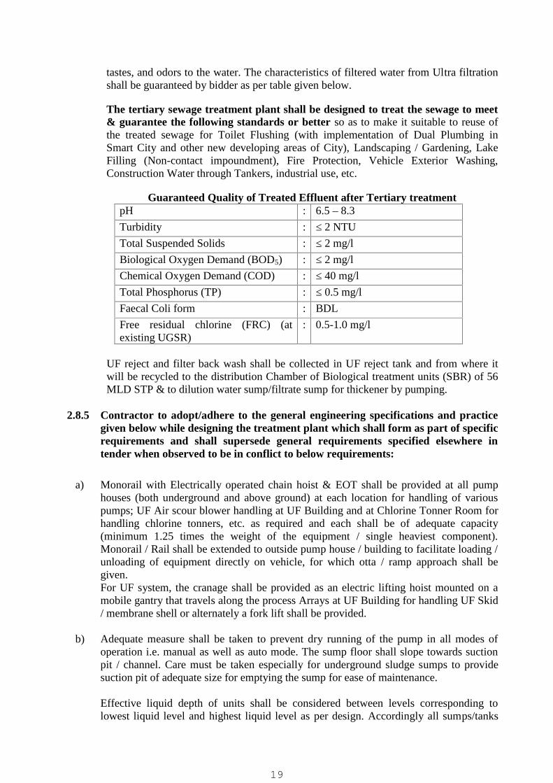
tastes, and odors to the water. The characteristics of filtered water from Ultra filtrationshall be guaranteed by bidder as per table given below.
The tertiary sewage treatment plant shall be designed to treat the sewage to meet& guarantee the following standards or better so as to make it suitable to reuse ofthe treated sewage for Toilet Flushing (with implementation of Dual Plumbing inSmart City and other new developing areas of City), Landscaping / Gardening, LakeFilling (Non-contact impoundment), Fire Protection, Vehicle Exterior Washing,Construction Water through Tankers, industrial use, etc.
Guaranteed Quality of Treated Effluent after Tertiary treatmentpH : 6.5 – 8.3
Turbidity : ≤ 2 NTUTotal Suspended Solids : ≤ 2 mg/lBiological Oxygen Demand (BOD5) : ≤ 2 mg/lChemical Oxygen Demand (COD) : ≤ 40 mg/lTotal Phosphorus (TP) : ≤ 0.5 mg/lFaecal Coli form : BDL
Free residual chlorine (FRC) (atexisting UGSR)
: 0.5-1.0 mg/l
UF reject and filter back wash shall be collected in UF reject tank and from where itwill be recycled to the distribution Chamber of Biological treatment units (SBR) of 56MLD STP & to dilution water sump/filtrate sump for thickener by pumping.
2.8.5 Contractor to adopt/adhere to the general engineering specifications and practicegiven below while designing the treatment plant which shall form as part of specificrequirements and shall supersede general requirements specified elsewhere intender when observed to be in conflict to below requirements:
a) Monorail with Electrically operated chain hoist & EOT shall be provided at all pumphouses (both underground and above ground) at each location for handling of variouspumps; UF Air scour blower handling at UF Building and at Chlorine Tonner Room forhandling chlorine tonners, etc. as required and each shall be of adequate capacity(minimum 1.25 times the weight of the equipment / single heaviest component).Monorail / Rail shall be extended to outside pump house / building to facilitate loading /unloading of equipment directly on vehicle, for which otta / ramp approach shall begiven.For UF system, the cranage shall be provided as an electric lifting hoist mounted on amobile gantry that travels along the process Arrays at UF Building for handling UF Skid/ membrane shell or alternately a fork lift shall be provided.
b) Adequate measure shall be taken to prevent dry running of the pump in all modes ofoperation i.e. manual as well as auto mode. The sump floor shall slope towards suctionpit / channel. Care must be taken especially for underground sludge sumps to providesuction pit of adequate size for emptying the sump for ease of maintenance.
Effective liquid depth of units shall be considered between levels corresponding tolowest liquid level and highest liquid level as per design. Accordingly all sumps/tanks
19
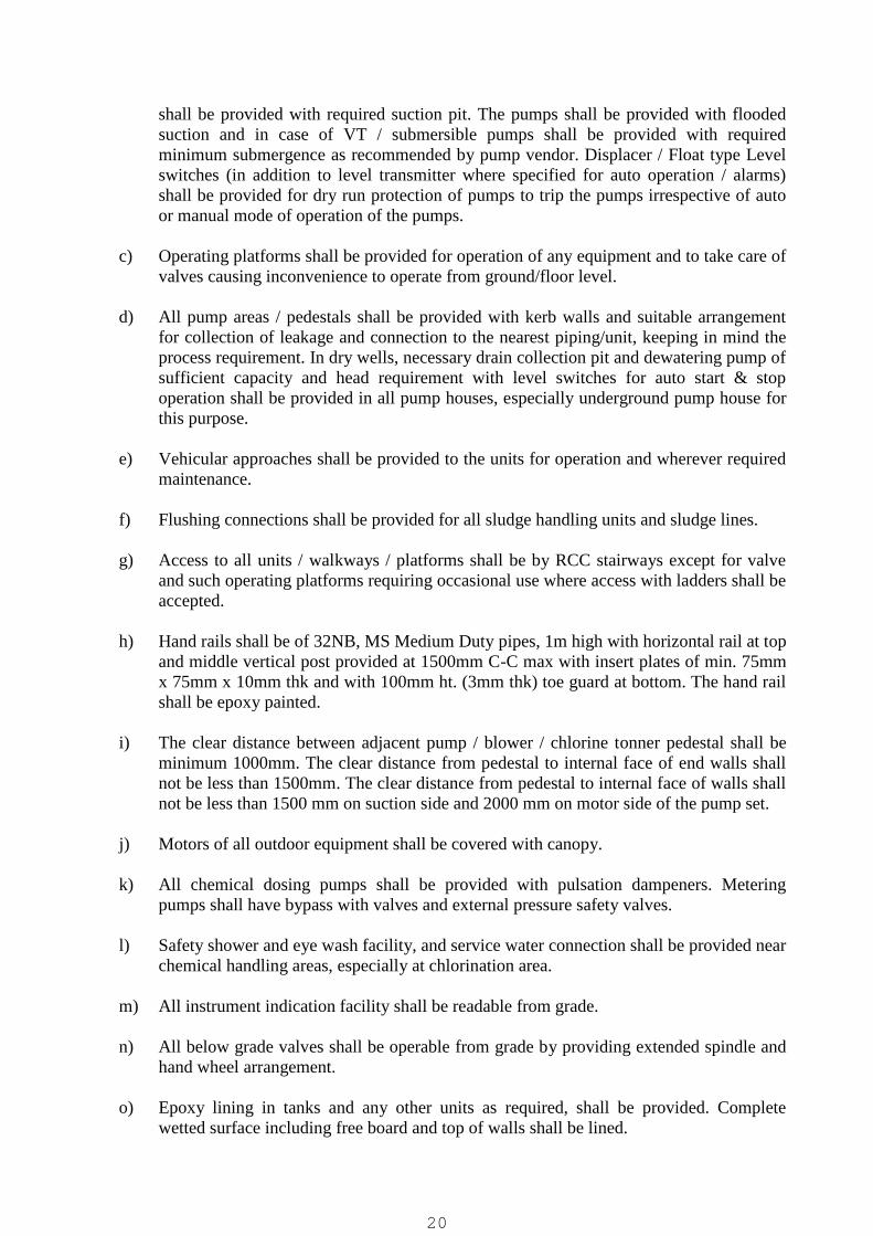
shall be provided with required suction pit. The pumps shall be provided with floodedsuction and in case of VT / submersible pumps shall be provided with requiredminimum submergence as recommended by pump vendor. Displacer / Float type Levelswitches (in addition to level transmitter where specified for auto operation / alarms)shall be provided for dry run protection of pumps to trip the pumps irrespective of autoor manual mode of operation of the pumps.
c) Operating platforms shall be provided for operation of any equipment and to take care ofvalves causing inconvenience to operate from ground/floor level.
d) All pump areas / pedestals shall be provided with kerb walls and suitable arrangementfor collection of leakage and connection to the nearest piping/unit, keeping in mind theprocess requirement. In dry wells, necessary drain collection pit and dewatering pump ofsufficient capacity and head requirement with level switches for auto start & stopoperation shall be provided in all pump houses, especially underground pump house forthis purpose.
e) Vehicular approaches shall be provided to the units for operation and wherever requiredmaintenance.
f) Flushing connections shall be provided for all sludge handling units and sludge lines.
g) Access to all units / walkways / platforms shall be by RCC stairways except for valveand such operating platforms requiring occasional use where access with ladders shall beaccepted.
h) Hand rails shall be of 32NB, MS Medium Duty pipes, 1m high with horizontal rail at topand middle vertical post provided at 1500mm C-C max with insert plates of min. 75mmx 75mm x 10mm thk and with 100mm ht. (3mm thk) toe guard at bottom. The hand railshall be epoxy painted.
i) The clear distance between adjacent pump / blower / chlorine tonner pedestal shall beminimum 1000mm. The clear distance from pedestal to internal face of end walls shallnot be less than 1500mm. The clear distance from pedestal to internal face of walls shallnot be less than 1500 mm on suction side and 2000 mm on motor side of the pump set.
j) Motors of all outdoor equipment shall be covered with canopy.
k) All chemical dosing pumps shall be provided with pulsation dampeners. Meteringpumps shall have bypass with valves and external pressure safety valves.
l) Safety shower and eye wash facility, and service water connection shall be provided nearchemical handling areas, especially at chlorination area.
m) All instrument indication facility shall be readable from grade.
n) All below grade valves shall be operable from grade by providing extended spindle andhand wheel arrangement.
o) Epoxy lining in tanks and any other units as required, shall be provided. Completewetted surface including free board and top of walls shall be lined.
20

p) All overhead units, underground tanks where specified, & other units as required shallbe able to be segregated for manual desludging / draining, whenever required, alongwith drain piping and valve. The purpose is to have possibility to drain all the tanks andother applicable units to make empty for cleaning / maintenance purpose. The drain pipe/ drain valve (sluice valve) shall be of minimum 150mm size.
q) Common suction header of pumps and delivery header of pumps & blowers shall beprovided with a blind flange on one end.
r) Exhaust fans with bird screen / net shall be provided for all LT rooms, chemicalhandling/storage area, laboratory, filter house, etc. Min 2nos. or higher quantity shall beprovided as per requirement.
s) All motors shall have running (on/off), A/M status, & fault indication at MCC as well asat SCADA terminal. All starters shall be provided with auto / manual selector switch(with auto mode selection status input to PLC/SCADA) as well as with Local/Remoteselector switch. The motors shall operate through PLC in auto mode and in manualmode it shall operate through push buttons at LCS when selected in remote mode andfrom push button at MCC when selected for local mode. All stop push buttons shall bemushroom head stay put type with padlocking facility. Proposed Plant shall bedesigned to operate in manual mode as well as in auto mode.
t) PCC/PMCC shall be of single front type only. Similarly the VFD and soft startercubicles shall be in single front execution only.
u) All variable frequency drives and soft starters shall be selected to provide current aftersuitable de-rating for 50°C continuous operating temperature of at least 10% above therated current of driven motor.
v) Clear Distance between two Civil units should generally not be less than 5 m.
w) Sluice Valve / Knife Gate valves shall be provided for sludge application.
x) The reinforcement steel shall be TMT Fe-500 grade. The approved makes shall be Tata,SAIL, Vizag, Electrotherm or other make as approved by engineer-in-charge.
y) All water retaining structures for sewage handling/treatment plant units, buildings andrest water retaining structures shall be constructed in Ordinary Portland Cement (OPC)Grade53 as per IS specification. The approved makes shall be Ambuja, Ultratech,Kamal, Siddhi, Sanghi, Hathi, JK Lakshmi, Binani, Birla, Wonder.
z) Doors, Windows and Ventilators shall be of aluminum glazed type with EZ section.Aluminium Section shall be of Jindal / Hindalco / Gujarat / Maan / National / Royal/Banco as approved by Engineer-in-charge.
aa) Carting of surplus excavated earth shall be within 2 Km radius.
bb) All sludge lines shall be of minimum 100mm dia. Size.
21

cc) All RCC pipes shall be NP3 (or of better class as specified in tender requirement) socketspigot type as per IS with rubber ring.
dd) The plinth level of all the building shall be min. 600 mm above formation level (FGL).The roof of the building (bottom of slab) shall be min. 3.6 m above plinth level or higheras required.
ee) All the building shall be provided with 1000 mm wide plinth protection of 75 mm thickCC 1:2:4 laid over 150 mm consolidated rubble soling.
ff) Plaster, IPS / Bottom Screeding and Paint requirement:
The inside surface of all water retaining structures shall be provided with 20 mm thickwater proof plaster in Cement mortar 1:3. Inside surfaces of rest civil units includingbuildings, pump house, etc. shall be plastered with 12-15 mm thick cement mortar 1:3.
Outside surface of all civil units (water retaining, buildings, pump house, etc.) shall beprovided with 20 mm thick double coat sand face plaster in cement mortar (first coat12mm thk in cement mortar 1:3 and second coat 8mm thk in cement mortar 1:2) uptoFGL and 15 mm thick sand faced plaster in C.M. 1:3 below ground level up to footing.
The bottom of all water retaining structures / units / tanks and channels shall be providedwith 50 mm thick IPS / Screeding
The outside surface of all civil structures including columns, etc. shall be painted with aminimum of two coats of Apex paint (upto 200-300mm below FGL) and all innersurfaces of various pump house and buildings (chemical house, filter house, guard room,HT/PMCC rooms, etc.) shall be painted with a minimum of two coats of Plastic paint asper civil specifications. The paint shall be of Asian / Berger / Shalimar make only. Thecolor shade shall meet approval of client.
gg) Parapet walls of 900mm height shall be provided above administration / UF buildingand 600mm high for rest all buildings and pump houses.
hh) At all joints of Brick work and RCC, chicken mesh jali shall be provided from both thesides
ii) All cables within building shall be laid on cable trays or in cable trenches or both andfor cables on walls / platforms of various buildings or civil units shall be laid on cabletrays and rest all cables to be laid outside the building / outdoors shall be laid buried inground. All cable trays shall be of medium duty GI and cable trenches shall be inconstructed in RCC.
jj) Except for pipes / channels for which minimum sizes are specified in tenderspecifications and in this specific requirement and subject to these sizes being of highersize then pipe sizes calculated as per below given velocity criteria, fluid velocity to beconsidered in the design of balance pipes / channels and all valves / gates shall be sizedas under:
For gravity flow : 1.2 m/sec max.For pump discharge : 2.5 m/sec max
22
For Pump Suction : 1.5 m/sec maxFor Air line : 20 m/sec max
kk) All indoor & outdoor lighting fixtures shall be power saving long life LED typeonly.
ll) Lighting poles shall be GI, Octagonal type only. The street light poles shall have min.7.5m height above FGL, flood light pole shall be min. 9m above FGL, lighting poles ontop of various civil/process unit shall be min. 2.5m height. The street/flood light polesshall be mounted over RCC pedestal / foundation at least 300mm above FGL (floodlights mounted to top of buildings / units with or without suitable height mounting polescan also be accepted for area illumination as per building height). High mast lightingcan also be considered for outdoor lighting.
mm) All rain water down take pipes shall be of min. 100mm dia. uPVC in required numbers.
nn) CI foot rests of size 35 mm x 35 mm, min. weight 4.5 kg/no. staggered 300mm C-C oralternately SS ladders (min. 450-500mm wide and with min. 32mm dia. Side pipes and25mm dia rungs of Sch. 10) shall be provided to access tank / sump.
oo) Freeboard for all water retaining structures shall be min. 500mm or min. 300mm aboveFGL with 1m high surrounding handrail (for underground structures), whichever ishigher.
pp) SS-316 ball valves shall be provided of required sizes for various chemical dosing lines(unless not suitable and requiring alternate MOC), service/ booster water, for pressuregauge isolation (in addition to manifold valves), etc. applications.
qq) For all process equipment (Disc Filter, Membrane, etc.) imported from outside India,contractor shall arrange to inspect by a reputed third party inspection agency (like SGS,Bureau Veritas, TUV, or any such other with client approval) as per approvedinspection plan at manufacturer works at no extra cost. The test / performancecertificates & relevant supporting documents shall be submitted to Client / TPI forreview and approval. The material shall be dispatched only after obtaining dispatchclearance from Client.
rr) UF Skid shall be in SS-304 or better MOC.
23
03- CHAPTERPROCESS DESIGN CRITERIA AND SPECIFICATIONS FOR UNITS
The guide lines for process design criteria for Tertiary Sewage Treatment Plant, unlessotherwise specified shall be as under. The specified sizing and quantities mentioned areminimum and not limited to and contractor shall provide adequately higher sizing /quantities if required and any additional items for satisfactory fulfillment of the specifiedtender conditions and final treated sewage quality.
Note:-Bidder to consider recycle flow ( filtrate, backwash / UF reject flow etc.) wherever“other flows” is specified.
3.1 Tapping for sewage withdrawal from existing CCTNecessary modification shall be carried out in existing CCT by bidder to transfer thesecondary treated sewage for further treatment.
Electric actuator Gate / Valve of required size shall be provided to extract 16 MLD @22hours operation i.e. 730 m3/hr. design sewage flow from CCT with piping / channel ofrequired size up to inlet of Disc Filter. For this purpose a motorized weir gate operatingautomatically in closed loop control to adjust at set water level over weir along withrequired level sensors shall be provided at tapping point / inlet of disc filter for flow control/ controlled drawl of secondary treated sewage to TTP inlet. Alternately bidder can considerproviding electric or suitable actuator operated control valve of suitable type with flowmeter in pipe line ensuring running full of water and with closed loop control at set flowreading. The actuators for this purpose for Gate / Valve shall be modulating type withposition control features.
The hydraulics of TTP shall be so planned to draw complete / required treated sewage fromexisting CCT / STP outlet up to inlet chamber of TTP and only the excess sewageoverflowing / discharging in to existing treated sewage disposal line and to ensure that disc/ cloth media filter submergence does not exceed max. permissible submergence as perfilter vendor.
3.2 Disc Filter (Fiber / Cloth / SS Screen)
The secondary treated sewage enters the disc filter for further treatment before reuse forremoval of suspended solids.
Fibres are piled to enable depth filtration. It is a fully submerged filter with vacuum suctionfor cleaning the filter disc.
Secondary treated Sewage flows by gravity (non-pressure) into the respective disc filter.The RCC structure to accommodate disc filters, shall be as per requirement of the vendordrawing of disc filter. The filter structure shall ensure that Suspended Solids (SS) arefiltered (treated) from outside to inside of the filter panels installed in both sides of the discfilter, and that filtered water is discharged through the centre drum to the treated waterway.During the filtration process, loss of head gradually gets higher as Suspended Solids aretrapped on the fibre media. This raises the level of water in the tank and activates the waterlevel sensor to rotate the disc and drive the suction cleaning pump to clean automatically.Disc filter should be 80 - 100% underwater. Disc filter shall be operated for filtrationwithout stoppage during backwash and suction cleaning. From filter, treated sewage entersthe Treated Sewage / UF Feed sump for further treatment / reuse as applicable.
24

The dirty backwash water / drain shall be led to UF reject water tanks for further recyclingback to existing STP as specified. In case of gravity drain, required drain pit of capacity asrecommended by disc filter vendor with required pipe up to UF reject water tanks shall beprovided.
Filter Bypass arrangement (Overflow weir or motorized gate suitably interlocked withwater level) shall be provided for 100% design flow. This gate shall operate with requiredinterlocking with disc filter water levels to ensure that at no point of time the filter issubmerged beyond permissible level i.e. at high-high level required alarm shall be providedat SCADA and the bypass gate shall open fully / partially as required to prevent the filtersubmergence beyond permissible level.
Disc filter shall comprise high strength and separable discs in each stream, each of whichconsists of filter panels on both sides. Each filter disc shall be subdivided into smallersections to constitute a prefab disc frame (module) so as to ensure easy replacement andmaintenance. In case of replacement of Fiber media, the left and right of the fiber media canbe replaced quickly without disassembling of segments (Disc frames)
Each disc shall be mounted on the center drum by strap band (steel band) for the exactroundness and it shall not be fixed by Stud bolts. When Fiber media is mounted in thesegment (Disc frame), the sealing shall be maintained by one or more fixing device whichhas slope on both sides of segment. Fiber media shall envelop some parts of backside offilter frame and the several springs shall be used to fix the fiber media. The drumshall be round type and shall have enough area in order to discharge the treated waterwithout trouble.
The material of the fiber media shall be polyester; the filter frame that fixes thefiber media, the disc frame and the cover shall be ABS resin.
Total Design Inlet Flow :16 MLD (2 X 8 MLD Cap.) in 22Hours i.e. 730 M3/Hr
No. of Streams - Filter Housing / Tanks :
2 Nos. (1 Nos. each for present & futurerequirement of 8MLD Cap.) i.e. 1 No.stream shall be provided with DiscFilter and for other stream only civilworks shall be carried out withequipment installation in future (Inlet &outlet shall be sealed with brickmasonry wall or such suitablearrangement with gates for this secondstream to be provided in future).
No. of Disc Filter Units :
1 Nos., for present requirement of8MLD Cap. in 22 Hours i.e. 365 m3/hrcap. to be housed in Filter Housing /Tank
Bypass Arrangement :Required, for 100% Total Design InletFlow (i.e. 730 M3/Hr)
Operation Method :Fully Automatic & all Gates / Valvesshall be Electric Actuator Operated orsuch suitable Automatic Operation type
Filtration Rate (m³/m²/h) : < 10
25

Type of Filtration Media : Fibre Disc / Cloth Media / SS Screen
Size of Filtration (micron) : < 20 microns
Backwash Quantity per Day :Shall not exceed 2% of the inletdesign flow (i.e. 8MLD in 22 Hours) tofilter
Filter Membrane Size :10-20 microns max. or smaller as pervendor recommendation
Type of Filtration : Out to In
Operation method :Automatic/Manual operation by thewater level and timer
MOC Main part of Filter
Filter Housing / TankRCC Tank with 2 streams & onebypass channel for 100 % flow
Filter Membrane
Fiber Disc: Polyester with ABS resinor suitable MOCFrame
Cloth Media: Polyamide free fibrefilter cloth (4 to 5 mmThick) with ABS resinor suitable MOCFrame
SS Screen: SS-304Centre drum : STS 304
Drive part of Disc filter
MOC of drive gear motor Drive Motor and Reduction
Gear: Gray Cast Iron (GC 200 )
Chain : Stainless Steel (STS 304)
Sprocket : Stainless Steel (STS 304) or Nylon
Protective cover : Stainless Steel (STS 304)
Suction cleaning pumpNos. of pumps 2 Nos. (1W + 1S) per stream
MOC of suction cleaning pumpCasing : Cast Iron (GC 200 ) or better
Main shaft : SM45C or as per mfr. Std.
Sleeve : Stainless Steel (STS 304) or better
Impeller : Cast Iron (GC 200 ) or better
Co-bed :Rolled steel for general structure steel(SS400) or as per mfr. Stc.
Filter B/W Drain :By Gravity or by Pumping (2 Nos., 1W+ 1S per stream) as per design
Control panel
Type :Double door, closed, self-standingtype
26

MOC of control panel : Stainless Steel (STS 304, 2t)Level Sensor : 1 set / stream
Isolation Gates (Electric ActuatorOperated)
:At inlet & outlet of each streamFor Bypass as applicable
Other valves / gates : 1 Lot / stream as applicable
On-line TSS analyzer : Required for monitoring TSS value atDisk Filter Inlet & trends shall bedisplayed at HMI. Audio-visual alarmfor High TSS Level alarms shall beprovided.
3.3 UF Feed water tank
This tank receives permeate from the disc filter. This tank shall have pumps to feed the UFsystem. The tank shall be having MOC of RCC M30.
The civil works for sump shall be for present & with space to provide additional pumps forfuture requirement (in about same no. and capacity as per present requirement) in presentsump and the present sump shall be planned to add / expand for equivalent additional sumpfor future requirement – suitable space with required provision in structure of existing sumpfor expansion in future shall be provided.
UF feed pumps shall be provided along with all necessary accessories which includes,suction strainer, discharge NRV, suction (as applicable) & discharge isolation valves,piping and instruments.
Dry well with pump house superstructure of adequate size shall be provided for horizontalcentrifugal pumps and including dewatering pit and dewatering pump shall be provided. Incase of submersible pumps a loading/unloading platform of min. 1.5-2m width on one sidewith 1.2m operating platform on rest three sides of pump cut-out shall be provided (cut-outshall be covered with MSEP, min. 5mm thk or FRP, min. 6mm thk. Grating) and 1m highhandrail all around the pump cut-out. Monorail with EOT & Electric Hoist with suitablearrangement for lifting of the pumps shall be provided.
The feed pump drives the feed water into the membrane modules from the bottom / top andis distributed in the shell by the laterals present inside the module.
UF Feed SumpNo. of Units : 1 No.
Design inlet Flow : 8 MLD @22 hours i.e. 365 m3/hr
HRT : 3 hrs.
Min. Capacity : 1095 m3
Size : As per design
Material of Construction : RCC M 30
Min. Free Board : 0.5 m
UF Feed PumpsNo. of Pumps : 3 Nos. (2W + 1S) for present & with
space provision for 3 Nos. (2W + 1S)
27

for future.One to one piping shall be providedbetween one working pump andassociated UF skid and the commonstandby pump shall be provided with 2nos. interconnecting valves on pumpheader to connect to either side ofdelivery line / UF skid. Alternatelybidder can consider to provide flowcontrol valves with electric / pneumaticactuator with closed loop control withinlet / outlet flow meter of each skid.
Capacity of Pumps : 4 MLD @22 hours i.e. 185 m3/hr
Type of Pump : Hori. Centrifugal / Submersible CF
Head : As per design
Motor : As per design
Material of Construction: :
Casing : CI FG 260
Impeller : CF8M
Shaft / Shaft Sleeve : SS 410 / SS 316
VFD : As per Process Requirement
On-line pH analyzer : Required for monitoring pH value atTTP Inlet / UF Feed & trends shall bedisplayed at HMI. Audio-visual alarmfor High & Low pH Level alarms shallbe provided.
On-line TSS analyzer : Required for monitoring TSS value atDisk Filter Outlet / UF Feed Sump &trends shall be displayed at HMI.Audio-visual alarm for High TSSLevel alarms shall be provided.
Level Transmitter : Required, Ultrasonic Non-contact type
Level Switch : Required, for Dry run protection
Recycle Flow Valve : Required, one per UF Skid / stream atpump header to each UF Skid / UFinlet side, auto / electric actuatoroperated with suitable interlocks toopen when UF skid undergoesbackwash and to close when UFbackwash cycle is complete.
3.4 Ultra filtration System
The UF membrane shall be designed and constructed for design flow as mentioned underthe data sheets provided herein. UF stream shall be as per the tender specification and asdesign submitted by the contractor in the data sheet.
28
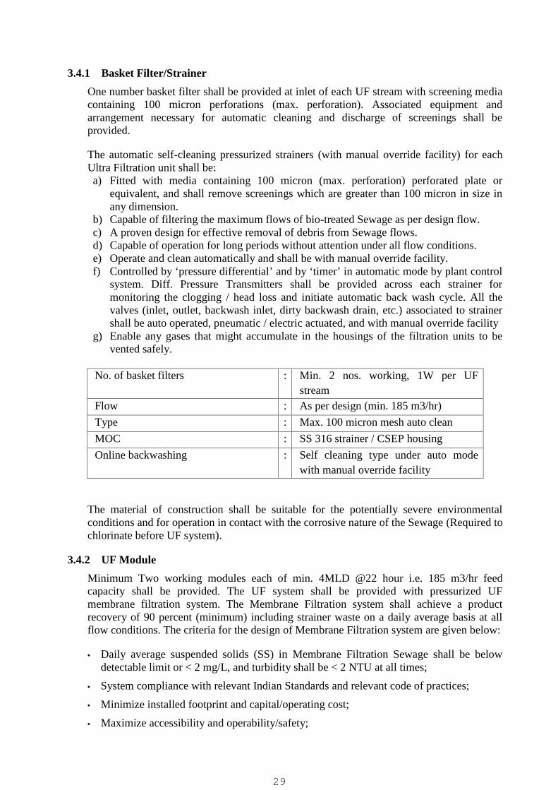
3.4.1 Basket Filter/Strainer
One number basket filter shall be provided at inlet of each UF stream with screening mediacontaining 100 micron perforations (max. perforation). Associated equipment andarrangement necessary for automatic cleaning and discharge of screenings shall beprovided.
The automatic self-cleaning pressurized strainers (with manual override facility) for eachUltra Filtration unit shall be:a) Fitted with media containing 100 micron (max. perforation) perforated plate or
equivalent, and shall remove screenings which are greater than 100 micron in size inany dimension.
b) Capable of filtering the maximum flows of bio-treated Sewage as per design flow.c) A proven design for effective removal of debris from Sewage flows.d) Capable of operation for long periods without attention under all flow conditions.e) Operate and clean automatically and shall be with manual override facility.f) Controlled by ‘pressure differential’ and by ‘timer’ in automatic mode by plant control
system. Diff. Pressure Transmitters shall be provided across each strainer formonitoring the clogging / head loss and initiate automatic back wash cycle. All thevalves (inlet, outlet, backwash inlet, dirty backwash drain, etc.) associated to strainershall be auto operated, pneumatic / electric actuated, and with manual override facility
g) Enable any gases that might accumulate in the housings of the filtration units to bevented safely.
No. of basket filters : Min. 2 nos. working, 1W per UFstream
Flow : As per design (min. 185 m3/hr)
Type : Max. 100 micron mesh auto clean
MOC : SS 316 strainer / CSEP housing
Online backwashing : Self cleaning type under auto modewith manual override facility
The material of construction shall be suitable for the potentially severe environmentalconditions and for operation in contact with the corrosive nature of the Sewage (Required tochlorinate before UF system).
3.4.2 UF Module
Minimum Two working modules each of min. 4MLD @22 hour i.e. 185 m3/hr feedcapacity shall be provided. The UF system shall be provided with pressurized UFmembrane filtration system. The Membrane Filtration system shall achieve a productrecovery of 90 percent (minimum) including strainer waste on a daily average basis at allflow conditions. The criteria for the design of Membrane Filtration system are given below:
Daily average suspended solids (SS) in Membrane Filtration Sewage shall be belowdetectable limit or < 2 mg/L, and turbidity shall be < 2 NTU at all times;
System compliance with relevant Indian Standards and relevant code of practices;
Minimize installed footprint and capital/operating cost;
Maximize accessibility and operability/safety;
29

Following equipment shall be included in the Ultra-Filtration System.
(i) Ultra filtration membrane system will comprise of suitable Ultra Filtration units (allduty), suitable for feed flow of min. 4.0 MLD @ 22 hours per stream i.e. min. 185m3/hr.
(ii) There will be an inlet flow-control valve, Ultra filtration membrane and allinterconnecting fittings and pipes for each unit.
(iii) Complete backwash system including pumps and valves shall be provided suitable toperform automatic backwash to module. The backwash water will be sourced from UFfiltrate tank / UGSR.
(iv) Chemical Enhanced Backwash (CEB) system suitable for cleaning of Ultra Filtrationunits shall be provided in automatic mode. Provision will be given to include chemicaldosing system. All chemical tanks shall be designed to accommodate a particularchemical (say HCl, NaOH, and Hypochlorite etc.) to be used for all different processcleaning mode. All chemical tanks and dosing system will be housed in UF building.
(v) A CIP system shall be provided common to all units and stages which include CIP tanks,pumps, micron filter and all other equipment and auxiliaries to make a complete CIPsystem. Shall operate in automatic mode.
(vi) Instrumentation and Control
o All electrical systems integral to the equipment and necessary for smoothfunctioning of the complete membrane filtration system shall be provided.
o The instrumentation and control systems including SCADA that will automaticallycontrol the operation of the plant with a minimum of operator intervention shall beprovided. Entire filtration process as well as CEB/CIPO system shall operate in fullautomatic mode.
(vii) Ultra filtration system of each unit shall include a continuous indirect integritymonitoring system. The on-line turbidity meter provided separately for each skidshall measure and record permeate turbidity at least once per minute.
Total Design feed flow : Min. 8 MLD in 22 hours
No. of trains or stream : 2 Nos. Working, Min. 4MLD @ 22hours i.e. min. 185 m3/hr
Input flow per train : As per design
No. of modules per train : As per design
Working hours of UF system : 22 hrs / day
MOC of membrane : PVDF / PES
Area per membrane : > 40 m²
UF system recovery : > 90 %
UF system design flux : 40 LHM Gross flux for in to out and60 LHM Gross flux for out to in
Permeate flow/train : As per design
Reject flow/train : As per design
Mode of operation : Dead end filtration
Type of System : Pressure Driven System withmembrane modules mounted on Skid
30

/ Rack, located inside membranebuilding of pre-engineered building.
Membrane Type : Inside-Out / Outside-In, Hollow Fibre
Membrane pore size : 0.08 micron or less
UF Skid MOC SS-304 or better
UF Backwash/CEB PumpsNo. of Pumps : 2 nos. (1W + 1 S)
Capacity of Pumps : As recommend by manufacturer
Type of Pump : Hori. Centrifugal / Submersible CF
Head : As per manufacturer requirement
Material of Construction: :
Casing : CI FG 260
Impeller : CF8M
Shaft / Shaft Sleeve : SS 410 / SS 316
Accessories : SS Guide rail, SS chain, autocoupling, duck foot bend etc.
Chemicals dosing for all cleaningmode (Hypochlorite, Caustic ,Acid) Dosing Tank & Pumps
:
No. of Dosing Tanks : Min. 2 Nos. for each chemical
Capacity of tank : As per design
Solution strength : As required for membrane cleaning
Material of Construction of Tank : HDPE / FRP
No. of Dosing Pump : Min. 2 Nos. (1W + 1S) for eachchemical / application
Capacity of Dosing Pump : As per design
Type of Pump : Diaphragm / Electronic Dosing
Pressure : As required for membrane cleaning
:
UF CIP Tank with mixer :
No. of Tanks : 2 Nos. (1W + 1S) for each chemical
Capacity : As per design
Size of Tank : As per design
Material of Construction of Tank : FRP/MSRL
Accessories : Drain valve, overflow pipe, levelgauge, level transmitter, isolationvalves, puddle pipe
No. of agitator : 1 no / tank
Type of agitator : Turbine type
Mixer speed : < 100 rpm
MOC of mixer : SS 316
31
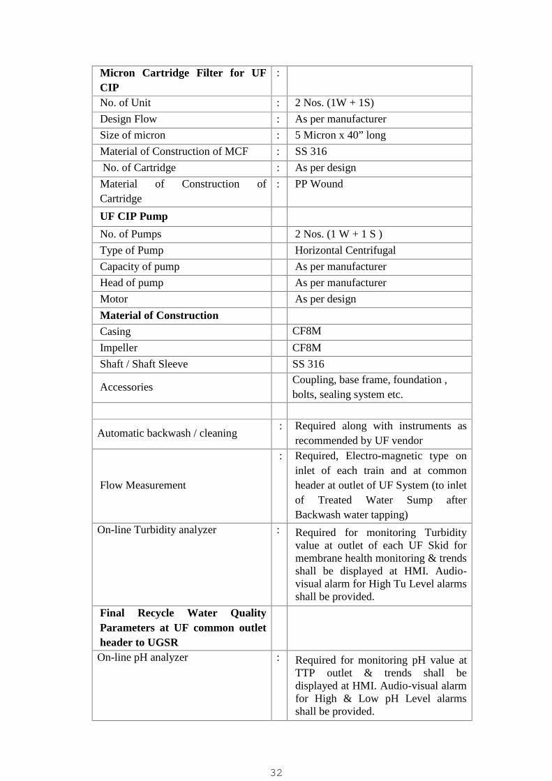
Micron Cartridge Filter for UFCIP
:
No. of Unit : 2 Nos. (1W + 1S)
Design Flow : As per manufacturer
Size of micron : 5 Micron x 40” longMaterial of Construction of MCF : SS 316
No. of Cartridge : As per design
Material of Construction ofCartridge
: PP Wound
UF CIP Pump
No. of Pumps 2 Nos. (1 W + 1 S )
Type of Pump Horizontal Centrifugal
Capacity of pump As per manufacturer
Head of pump As per manufacturer
Motor As per design
Material of ConstructionCasing CF8M
Impeller CF8M
Shaft / Shaft Sleeve SS 316
AccessoriesCoupling, base frame, foundation ,bolts, sealing system etc.
Automatic backwash / cleaning: Required along with instruments as
recommended by UF vendor
Flow Measurement
: Required, Electro-magnetic type oninlet of each train and at commonheader at outlet of UF System (to inletof Treated Water Sump afterBackwash water tapping)
On-line Turbidity analyzer : Required for monitoring Turbidityvalue at outlet of each UF Skid formembrane health monitoring & trendsshall be displayed at HMI. Audio-visual alarm for High Tu Level alarmsshall be provided.
Final Recycle Water QualityParameters at UF common outletheader to UGSROn-line pH analyzer : Required for monitoring pH value at
TTP outlet & trends shall bedisplayed at HMI. Audio-visual alarmfor High & Low pH Level alarmsshall be provided.
32
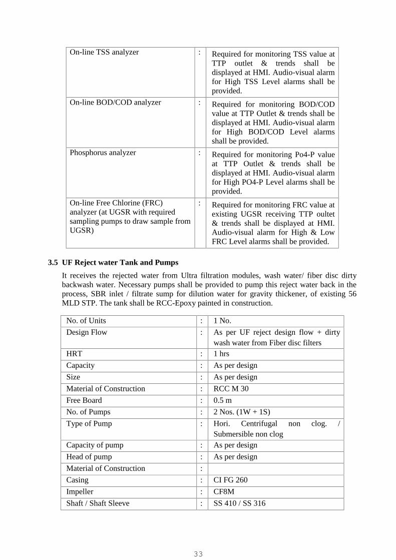
On-line TSS analyzer : Required for monitoring TSS value atTTP outlet & trends shall bedisplayed at HMI. Audio-visual alarmfor High TSS Level alarms shall beprovided.
On-line BOD/COD analyzer : Required for monitoring BOD/CODvalue at TTP Outlet & trends shall bedisplayed at HMI. Audio-visual alarmfor High BOD/COD Level alarmsshall be provided.
Phosphorus analyzer : Required for monitoring Po4-P valueat TTP Outlet & trends shall bedisplayed at HMI. Audio-visual alarmfor High PO4-P Level alarms shall beprovided.
On-line Free Chlorine (FRC)analyzer (at UGSR with requiredsampling pumps to draw sample fromUGSR)
: Required for monitoring FRC value atexisting UGSR receiving TTP oultet& trends shall be displayed at HMI.Audio-visual alarm for High & LowFRC Level alarms shall be provided.
3.5 UF Reject water Tank and Pumps
It receives the rejected water from Ultra filtration modules, wash water/ fiber disc dirtybackwash water. Necessary pumps shall be provided to pump this reject water back in theprocess, SBR inlet / filtrate sump for dilution water for gravity thickener, of existing 56MLD STP. The tank shall be RCC-Epoxy painted in construction.
No. of Units : 1 No.
Design Flow : As per UF reject design flow + dirtywash water from Fiber disc filters
HRT : 1 hrs
Capacity : As per design
Size : As per design
Material of Construction : RCC M 30
Free Board : 0.5 m
No. of Pumps : 2 Nos. (1W + 1S)
Type of Pump : Hori. Centrifugal non clog. /Submersible non clog
Capacity of pump : As per design
Head of pump : As per design
Material of Construction :
Casing : CI FG 260
Impeller : CF8M
Shaft / Shaft Sleeve : SS 410 / SS 316
33

Accessories : SS Guide rail, SS chain, auto coupling,duck foot bend etc.
Level Transmitter : Required, Ultrasonic Non-contact type
Level Switch : Required
Flow Measurement: Required, Electro-magnetic type on UF
reject recycle pump header
3.6 UF Backwash Water Tank and Pumps
It receives UF permeate from Ultra filtration system common outlet. The UF outletcommon header leading to UGSR shall be tapped after UV dosing to draw the UFBackwash and Service Water requirement of TTP with required pipe size (min. 100mm dia.of higher as required) and provided with motorized / electric actuator operated sluice valvefor auto filling of tank (valve shall open when tank level reaches about mid level and closewhen tank level is high / full). The tank shall be RCC-Epoxy painted in construction. Thetanks shall be covered at top and any cut-outs shall also be provided with 5mm thk MSchequered plate covers or such other covers of suitable MOC.
Dry well with pump house superstructure of adequate size shall be provided for horizontalcentrifugal pumps and including dewatering pit and dewatering pump shall be provided. Incase of submersible pumps the pump cut-outs shall be covered with MSEP, min. 5mm thkor FRP, min. 6mm thk. Covers and 1m high handrail shall be provided all around the pumpcut-out.
UF backwash pumps, service water pumps & booster pumps for chlorination system shallbe provided along with all necessary accessories which includes, suction strainer, dischargeNRV, suction (as applicable) & discharge isolation valves, piping and instruments.Monorail with EOT & Electric Hoist with suitable arrangement for lifting of the pumpsshall be provided.
UF Backwash SumpNo. of Units : 1 No.
Design Flow : UF Backwash Water + Service Waterrequirement
HRT : 1 hr.
Capacity : As per design
Size : As per design
Material of Construction : RCC M 30
Free Board : 0.5 m
UF Backwash PumpsNo. of Pumps : UF Backwash Pumps: 2 Nos. (1W +
1S)Type of Pump : Hori. Centrifugal / Submersible CF
Capacity of pump : As per design
Head of pump : As per design
Material of Construction
34

Casing : CI FG 260
Impeller : CF8M
Shaft / Shaft Sleeve : SS 410 / SS 316
Service Water Pumps & ChlorineBooster PumpsNo. of Pumps Service Water Pumps: 2 Nos. (1W +
1S)Booster Water Pumps: 2 Nos. (1W +1S)
Type of Pump : Horizontal Centrifugal / SubmersibleCentrifugal / Submersible Monoblock
Capacity& Head : As per design / mfr. RecommendationMaterial of Construction
Casing : CI FG 260
Impeller : CF8M / Bronze
Shaft / Shaft Sleeve : SS 410
Level Transmitter : Required, Ultrasonic Non-contact type
Level Switch : Required
Flow Measurement: Required, Electro-magnetic type on UF
backwash pump header
3.7 UV system
The UF Permeate shall then be led to UV disinfection system installed on common headerpipe line on common outlet of both UF Skid / stream. The UV disinfected tertiary treatedsewage (Permeate) shall then be led to treated sewage sump / UGSR (existing, beingconstructed by RSCDL under a separate contract) where in additionally the Permeate shallbe further subject to chlorine disinfection within UGSR.
The UV system shall be installed on pipe line. The systems shall be designed for 65% UVTand with minimum Log 3 removal efficiency and min. 40 mJ/Cm2 UV dose and for BOD& TSS each of 5mg/L (average of 30 day grab samples). The system shall be provided withUV intensity monitor and automatic cleaning / wiper system (mechanical or mechanical +chemical type). The UV housing shall be in SS-304 construction. All wetted parts shall bein SS-304 or suitable non-corrosive construction. The control panel shall be in SS-304enclosure housing the ballast and with PLC based control and display of all key operatingparameters and alarms. The UV lamps shall be preferably amalgam type with quartz sleeveand shall be considered for max. 35% efficiency for design purpose. The quartz sleevefouling factor and end of lamp life factor shall be considered as 0.95 max. and 0.89 max.The system shall also have automatic on & off facility based on flow rate sensing to savepower. Dimming facility for UV lamps shall be preferred based on flow rate sensing to savepower for variable flow rates. The UV lamps shall be guaranteed for minimum 12,000operating hours under normal operation conditions. Normal operation conditions include amaximum of four on/off cycles per 24 operating hours. The system shall have drain facility
35
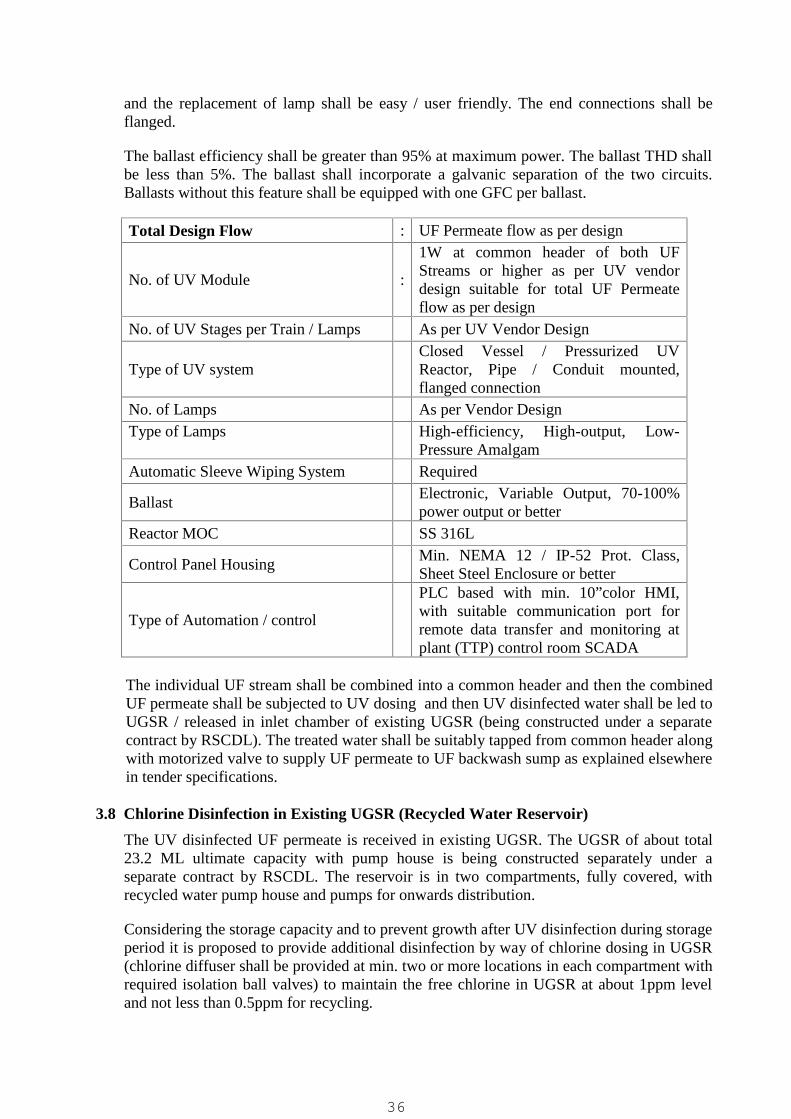
and the replacement of lamp shall be easy / user friendly. The end connections shall beflanged.
The ballast efficiency shall be greater than 95% at maximum power. The ballast THD shallbe less than 5%. The ballast shall incorporate a galvanic separation of the two circuits.Ballasts without this feature shall be equipped with one GFC per ballast.
Total Design Flow : UF Permeate flow as per design
No. of UV Module :
1W at common header of both UFStreams or higher as per UV vendordesign suitable for total UF Permeateflow as per design
No. of UV Stages per Train / Lamps As per UV Vendor Design
Type of UV systemClosed Vessel / Pressurized UVReactor, Pipe / Conduit mounted,flanged connection
No. of Lamps As per Vendor DesignType of Lamps High-efficiency, High-output, Low-
Pressure AmalgamAutomatic Sleeve Wiping System Required
BallastElectronic, Variable Output, 70-100%power output or better
Reactor MOC SS 316L
Control Panel HousingMin. NEMA 12 / IP-52 Prot. Class,Sheet Steel Enclosure or better
Type of Automation / control
PLC based with min. 10”color HMI,with suitable communication port forremote data transfer and monitoring atplant (TTP) control room SCADA
The individual UF stream shall be combined into a common header and then the combinedUF permeate shall be subjected to UV dosing and then UV disinfected water shall be led toUGSR / released in inlet chamber of existing UGSR (being constructed under a separatecontract by RSCDL). The treated water shall be suitably tapped from common header alongwith motorized valve to supply UF permeate to UF backwash sump as explained elsewherein tender specifications.
3.8 Chlorine Disinfection in Existing UGSR (Recycled Water Reservoir)
The UV disinfected UF permeate is received in existing UGSR. The UGSR of about total23.2 ML ultimate capacity with pump house is being constructed separately under aseparate contract by RSCDL. The reservoir is in two compartments, fully covered, withrecycled water pump house and pumps for onwards distribution.
Considering the storage capacity and to prevent growth after UV disinfection during storageperiod it is proposed to provide additional disinfection by way of chlorine dosing in UGSR(chlorine diffuser shall be provided at min. two or more locations in each compartment withrequired isolation ball valves) to maintain the free chlorine in UGSR at about 1ppm leveland not less than 0.5ppm for recycling.
36

Min. Two (02) sets of Chlorinators (1W + 1S) and of adequate capacity to dose min. 2-3ppm chlorine along with Booster Pump Sets (1W + 1S) and required piping & valves shallbe provided. A Chlorination Room / House shall be provided to house all chlorinationequipment including chlorine cylinders/tonners, chlorinators, EOT crane for lifting tonners,and all associated equipment.
Chlorination System
Dose of chlorine :2-3 ppm (min.) or suitable for 1.0 ppmFRC in UGSR of app. 23.5ML capacity
No. of chlorinator : 2 nos. (1W + 1S)
Type of chlorinator : Vacuum type, wall mounted
Capacity of chlorinator :Min. 2.5 Kg/hr capacity or as suitable fordose of chlorine as mentioned above maybe considered.
On-line Residual Chlorine Analyzer : Required.Monitoring, display of FRC Trends &Low & High FRC alarm at HMI /SCADA. With required sampling pumps& piping to draw sample from UGSR forFRC measurement. (This item mentionedunder UF system also)
Chlorine Leak Detection System : Required, min. 3 nos., at chlorine tonnerroom and chlorinator room with alarmand exhaust/ventilation system interlock
A Chlorinator cum Chlorine Tonner Room shall be provided as part of UF Building (or canbe provided as a separate building as per bidder’s design / requirement) to houseChlorination Systems. It shall be RCC Frame cum Brick Masonry Structure with RollingShutter, Windows & Ventilators, EOT Crane of minimum 3 Ton capacity or 1.25 times theweight of the single Unit whichever is more to lift the Chlorine Tonners. Also it shall beprovided with IRONITE IPS Flooring, Internal & External Plaster and Internal & ExternalPainting. Plinth Protection shall be provided along the periphery as per specifications.
Tonners on line, tonners on standby and full and empty tonners shall be stored separately inthe tonner room. Tonner rollers shall be provided for online and standby tonners.
Chlorine TonnersNo. of tonners (Storage for min. 15 daysuse)
3 Nos. (min.) (1 Working + 1Standbyconnected + 1 S/B for Refill)
Capacity of each tonners App. 900 Kg.Note: Contractor shall supply above specified numbers of filled Chlorine Tonners alongwith chlorination system with necessary statutory approvals / permissions (storage, filling,etc. as applicable) on behalf of client at no extra cost.
The container-lifting beam shall be specifically designed for handling chlorine containersand equipped with necessary shackles and hooks. Suitable safety equipment shall beinstalled in the chlorinator room as per mechanical specifications
37
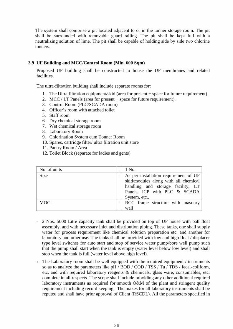
The system shall comprise a pit located adjacent to or in the tonner storage room. The pitshall be surrounded with removable guard railing. The pit shall be kept full with aneutralizing solution of lime. The pit shall be capable of holding side by side two chlorinetonners.
3.9 UF Building and MCC/Control Room (Min. 600 Sqm)
Proposed UF building shall be constructed to house the UF membranes and relatedfacilities.
The ultra-filtration building shall include separate rooms for:
1. The Ultra filtration equipment/skid (area for present + space for future requirement).2. MCC / LT Panels (area for present + space for future requirement).3. Control Room (PLC/SCADA room)4. Officer’s room with attached toilet5. Staff room6. Dry chemical storage room7. Wet chemical storage room8. Laboratory Room9. Chlorination System cum Tonner Room10. Spares, cartridge filter/ ultra filtration unit store11. Pantry Room / Area12. Toilet Block (separate for ladies and gents)
No. of units : 1 No.Size : As per installation requirement of UF
skid/modules along with all chemicalhandling and storage facility, LTPanels, ICP with PLC & SCADASystem, etc..
MOC : RCC frame structure with masonrywall
2 Nos. 5000 Litre capacity tank shall be provided on top of UF house with ball floatassembly, and with necessary inlet and distribution piping. These tanks, one shall supplywater for process requirement like chemical solution preparation etc. and another forlaboratory and other use. The tanks shall be provided with low and high float / displacertype level switches for auto start and stop of service water pump/bore well pump suchthat the pump shall start when the tank is empty (water level below low level) and shallstop when the tank is full (water level above high level).
The Laboratory room shall be well equipped with the required equipment / instrumentsso as to analyze the parameters like pH / BOD / COD / TSS / Tu / TDS / fecal-coliform,etc. and with required laboratory reagents & chemicals, glass ware, consumables, etc.complete in all respects. The scope shall include providing any other additional requiredlaboratory instruments as required for smooth O&M of the plant and stringent qualityrequirement including record keeping. The makes for all laboratory instruments shall bereputed and shall have prior approval of Client (RSCDL). All the parameters specified in
38

the tender for biological outlet and tertiary treated outlet parameters shall be possible tomeasure in-house within the plant laboratory
Lavatory cum Toilet block of required size/area along with sanitary fittings asdecided by the Engineer (separate for men and women in common area) and anattached toilet with office room. Adequate number of toilets and washbasins shall beprovided separately in each block for men and women. Each lavatory/toilet blockshall be provided with following fittings as a minimum:
1. One WC with necessary flushing cistern, GI water tubing, brass bib cocks, toiletpaper holder etc. complete. (Indian WC at for common toilet block for men andwomen, English Style WC for attached toilet with office room for officer staff)
2. A set of 4 urinal basins in men’s toilet, and 1 urinal basins in attached toilet blockwith office room with flushing cistern, GI water tubing, etc.
3. One wash basin with two pillar cocks, looking mirror, shelf, liquid soap container,towel rail and GI water tubing, stop cock and lead connection etc. complete. Ineach toilet block
4. Connection with flushing cisterns of the lavatories shall be made using 15mm GIpipes, medium class / uPVC pipes.
The urinal basins of the lavatory blocks shall be provided with marble partitions. Theglazed tiles shall be provided up to lintel height in the lavatory block. The urinal portionof the floor shall be raised by 150mm from rest of the floor and shall also be providedwith white glazed tiles.
Bidder shall provide following office furniture/facilities as a minimum:
1. Steel Cupboard : 02 Nos. (Godrej Storewel plain or equi.(app. 1.98m H x 1.018m W x 0.535m D)
2. Office Chair : 08 Nos. Chairs with arm rest (revolving, with wheelbase, hydraulic push back)
3. Office Table : 04 Nos. (Godrej, T8 or equi.)4. Computer Table with Revolving Chair5. Two Nos. Filing Cabinet with 4 drawers6. Minimum 2 nos. of 1.5 TR capacity split type inverter duty air conditioners for main
control room shall be provided. Control room shall be provided with false ceilingand room shall be aesthetically appealing. Furniture for PLC/SCADA consoles withat least 02 nos. Executive Tables (Godrej make) and 4 nos. revolving chairs with armrest shall also be provided in control room.
7. 1 no. of 1.5 TR capacity split type inverter duty air conditioners for office room asdirected by EIC.
8. Water Cooler with necessary Water Purifier (Aqua-guard/equi.) shall be provided atsuitable location / in pantry room or as directed by EIC.
9. All air conditioners shall be split type and energy efficient type (5 Star rating andshall be with inverter A.C.).
10. Two sets of latest version of computers with min. 21” or higher LED backlit monitorand one no. A3 size laser printer cum scanner & one no. A4 size color laser printershall be provided at office / laboratory room for daily office work and reportgeneration. These computers will be in addition nay other computers specified aspart of PLC/SCADA system, etc. The computers shall be of Latest Version &Configuration having Intel 9th Generation Core i5 processor or better and with 1TBSATA HDD, 8 GB DDR4 RAM, Keyboard, Mouse, Optical Drive, min. 21" LED
39
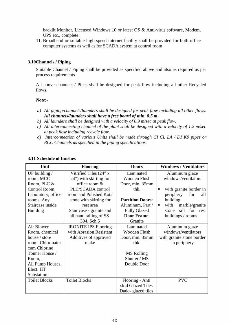
backlit Monitor, Licensed Windows 10 or latest OS & Anti-virus software, Modem,UPS etc., complete.
11. Broadband or suitable high speed internet facility shall be provided for both officecomputer systems as well as for SCADA system at control room
3.10Channels / Piping
Suitable Channel / Piping shall be provided as specified above and also as required as perprocess requirements
All above channels / Pipes shall be designed for peak flow including all other Recycledflows.
Note:-
a) All piping/channels/launders shall be designed for peak flow including all other flows.All channels/launders shall have a free board of min. 0.5 m.
b) All launders shall be designed with a velocity of 0.9 m/sec at peak flow.c) All interconnecting channel of the plant shall be designed with a velocity of 1.2 m/sec
at peak flow including recycle flow.d) Interconnection of various Units shall be made through CI Cl. LA / DI K9 pipes or
RCC Channels as specified in the piping specifications.
3.11 Schedule of finishes
Unit Flooring Doors Windows / Ventilators
UF building /room, MCCRoom, PLC &Control Room,Laboratory, officerooms, AnyStaircase insideBuilding
Vitrified Tiles (24” x24”) with skirting for
office room &PLC/SCADA control
room and Polished Kotastone with skirting for
rest areaStair case - granite andall hand railing of SS-
304, Sch 5
LaminatedWooden Flush
Door, min. 35mmthk.
Partition Doors:Aluminum, Part /
Fully GlazedDoor Frame:
Granite
Aluminum glazewindows/ventilators
with granite border inperiphery for allbuilding
with marble/granitestone sill for restbuildings / rooms
Air BlowerRoom, chemicalhouse / storeroom, Chlorinatorcum ChlorineTonner House /Room,All Pump Houses,Elect. HTSubstation
IRONITE IPS Flooringwith Abrasion ResistantAdditives of approved
make
LaminatedWooden Flush
Door, min. 35mmthk.+
MS RollingShutter / MSDouble Door
Aluminum glazewindows/ventilators
with granite stone borderin periphery
Toilet Blocks Toilet Blocks Flooring - Antiskid Glazed TilesDado- glazed tiles
PVC
40
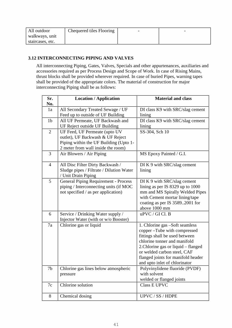
All outdoorwalkways, unitstaircases, etc.
Chequered tiles Flooring - -
3.12 INTERCONNECTING PIPING AND VALVES
All interconnecting Piping, Gates, Valves, Specials and other appurtenances, auxiliaries andaccessories required as per Process Design and Scope of Work. In case of Rising Mains,thrust blocks shall be provided wherever required. In case of buried Pipes, warning tapesshall be provided of the appropriate colors. The material of construction for majorinterconnecting Piping shall be as follows:
Sr.No.
Location / Application Material and class
1a All Secondary Treated Sewage / UFFeed up to outside of UF Building
DI class K9 with SRC/slag cementlining
1b All UF Permeate, UF Backwash andUF Reject outside UF Building
DI class K9 with SRC/slag cementlining
2 UF Feed, UF Permeate (upto UVoutlet), UF Backwash & UF RejectPiping within the UF Building (Upto 1-2 meter from wall inside the room)
SS-304, Sch 10
3 Air Blowers / Air Piping MS Epoxy Painted / G.I.
4 All Disc Filter Dirty Backwash /Sludge pipes / Filtrate / Dilution Water/ Unit Drain Piping
DI K 9 with SRC/slag cementlining
5 General Piping Requirement - Processpiping / Interconnecting units (if MOCnot specified / as per application)
DI K 9 with SRC/slag cementlining as per IS 8329 up to 1000mm and MS Spirally Welded Pipeswith Cement mortar lining/tapecoating as per IS 3589..2001 forabove 1000 mm
6 Service / Drinking Water supply /Injector Water (with or w/o Booster)
uPVC / GI Cl. B
7a Chlorine gas or liquid 1. Chlorine gas –Soft seamlesscopper –Tube with compressedfittings shall be used betweenchlorine tonner and manifold2.Chlorine gas or liquid – flangedor welded carbon steel, CAFflanged joints for manifold headerand upto inlet of chlorinator
7b Chlorine gas lines below atmosphericpressure
Polyvinylidene fluoride (PVDF)with solventwelded or flanged joints
7c Chlorine solution Class E UPVC
8 Chemical dosing UPVC / SS / HDPE
41

9 Rainwater Downtake Piping uPVC – 6 kg/sqcm
3.13 Electrical & Instrumentation Works
ELECTRICAL WORKSIt shall be the Contractor’s responsibility to upgrade / strengthen the existing 11 KVsupply for additional demand of proposed plant. The Employer will pay the chargesfor obtaining the above connection whereas necessary liasoning for the same shall bedone by the Contractor in consultation with Engineer-in-Charge.
The bidder’s Scope of Work shall include the following as a minimum:
Upgrading / Strengthening the existing 11KV supply for the additional demand ofproposed Plant including all required modification / addition in existing 11KVswitchyard & GOD structure and required liaisoning work, documentation etc. withpower supply company for total demand (for proposed TTP & Smart City project underexecution)
11 KV, 350 MVA, 630A Outdoor HT RMU, SF6 Extensible type, Motorized 5 waysmart Ring main unit (1 Isolator +4 VCBs) complete with FRTU & FPI with IPProtection as per detail specification. Scope also includes RCC Foundation (600mmabove FGL / Plinth level), Chain link fencing & gate. Providing Outdoor EmergencyStop / Trip Push Button Station to be installed near transformer to stop/trip HT power toTransformer along with required control wiring. Also a GI/Alu. sheet weather shed shallbe provided for RMU fully covered from top and on sides as required to prevent fromdirect rain.
Outdoor Distribution Transformer (1W + 1S) of required rating with RCC Foundation,Switch-yard, Fencing, gates, etc.
HT Cable with Indoor / Outdoor Termination Kits, as applicable. Scope includes cablefrom RMU panel outgoing feeder to 2 nos. Existing Transformer of Smart City UGSRproject of length approx. 150mtr or higher as per transformer location / site requirement.
LT Panels (PCC / PMCC / MCC as applicable, LDB / PDB). All LDB’s & JunctionBox shall be of IP 67, Polycarbonate enclosure with transparent cover. Gland also shallbe suitable for the same.
Automatic Power Factor Correction Panel. Min. 8 steps, 2 Sets (separate for each bussection with summation CT & including min. 3 nos. Load sensing CTs)
MV / LT Motors Minimum IE3 series as per Tender specification. LT Cabling including Power, Control and Instrumentation Cables; Double Compression
Ni-Plated Brass Cable Glands, Fittings & Accessories, etc. GI Cable Trays & Fittings & Accessories (Hot dip galvanized) Earthing System for Electrical equipment as well as Instruments ( Internal Lighting (LED) in Buildings. External Lighting (LED) including street lighting. Lighting poles shall be GI, octagonal
type only. High mast lighting can also be considered for outdoor lighting. Internal & other Electrification works Local Push Button Stations near respective Drives DG Set for 100% working load of present flow of proposed TTP plant as power backup Safety Accessories as required (Fire extinguishers, sand filled fire bucket with stand,
first aid box, first aid / safety charts & sign boards, battery operated emergency lamp,rubber mats as required, hand gloves as required, etc.)
42

Any other item / accessories required for successful completion of the project.
The Contractor shall design/execute the System as per standard specifications, I.E. Rulesand Regulations, requirements of State Electricity Board and other local Authorities andactual site conditions
Bidders to also note that all electrical works shall be executed by agency having approvedElectrical contract license (i.e. for bidder themselves or electrical contractor).
Bidder shall refer electrical specifications for further requirements / detailed specifications.
INSTRUMENTATION & AUTOMATION WITH PLC/SCADAThe TSTP shall be designed for monitoring and for automatic operation where specified intender through a Programmable Logic Centre (PLC) and Supervisory Control and DataAcquisition (SCADA) with Man-Machine Interface (MMI) as specified in tenderspecifications. The contractor shall provide necessary and adequate automation &instrumentation for the same. Provision shall also be made to operate each Unit of the Plant/ Pumping Station manually, if required by operator.
Salient features of the proposed System shall be as follows: Dynamic display of all Units, Equipment and Drives shall be available on SCADA
Screen. Auto/Manual operation of each Drive shall be made by selecting a Soft Switch on
SCADA Screen. In Auto mode, each Drive shall operate based on pre-set sequence and interlock. In Manual mode, each drive shall be operated in Local/Remote mode by selecting a
selector switch at associated LT Panel. In Local mode, each Drive shall be operatedfrom the Local Push Button Station (LPBS) located nearby and in remote mode shalloperate through START PB at starter of associated LT Panel. In auto mode selectionat starter, operation from LPBS & Starter PB shall be disabled and each drive shallbe operated from PLC as per selection of a L/R Soft Switch on SCADA Screen. InLocal mode, each Drive shall be operated manually by operator through soft PB atSCADA console from PLC. In remote mode at SCADA console, the drive shalloperate as per programmed logic as finalized during detailed engineering. AlsoWorking/Standby selection of Drives shall be done by selecting a Soft Switch onSCADA screen.Similarly it shall be also possible to operate (open & close) motorized valves/ gatesfrom HMI / SCADA as per electric drive operation philosophy.
On, Off, A/M mode & Trip indication of all Drives shall be displayed on SCADAscreen. Drive Ready and other required signals for VFD shall also be displayed onSCADA screen.
Open, Close, L/R mode & Fault indication of all Auto Gates and Auto Valves shallbe displayed on SCADA Screen.
Selector switch status at starter / electric actuator (A/M or L/R as applicable) shall bedisplayed on SCADA screen.
Annunciation & Alarm facility shall be available in PLC/SCADA. In the event of aFault, the symbol representing the Equipment/Drive shall continue flashing onSCADA Screen with Equipment/Drive description appearing at bottom of theSCADA Screen and electric Hooter shall continue blowing until the Fault Alarm is
43

acknowledged. Process control, open or closed loop, for various process parameters, as specified or
required as per process design Data logging of Running Hours of each Drive, Alarm and Historical Trends of
monitored Parameters etc. shall be envisaged in SCADA. Drives shall be possible tooperate on OH (operating hours) basis as well as on level or such process interlockbasis in auto mode.Working pumps shall be turned on & off based on operating hours (pump withlowest OH will start as per starting sequence and during turning off the pump willhighest OH will turn off as per stopping sequence) or will run on a per operatorselected pump at HMI/SCASDA in starting & stopping sequence
Drives shall be possible to operate on OH (operating hours) basis as well as on levelor such process interlock basis in auto mode.
HT & LT incomer breaker status monitoring, breaker status monitoring for VFD andsoft starter breakers. Remote operation of ACBs for LT panels and HT Breakers asapplicable.
Connectivity of all communication ports with PLC/SCADA system of variouselectrical equipment specified in tender specs to be provided with such facility /communication ports e.g. multi-function meters, VFDs, Soft Starters, ACBs, VCBs,Relays, etc. for power parameter and status monitoring, etc. as required.
Report generation software in SCADA instrumentation system to generate reports toinclude following as a minimum: All instrument / analyzer parameter readings (like sump level, flow, pressure,
water quality parameters like pH, TSS, BOD/COD, Tu, FRC, PO4-P, etc. onhourly basis.
All pumps/equipment on-off record with cumulative operation hrs. for each drive All fault alarm report. Power Parameters - for HT/PMCC/PCC incomers for which MFM provided as
per tender (Avg Voltage, Avg Current, Power Consumed (KW), Avg Frequency& Avg Power Factor and also with minimum and maximum values during theday), Power parameters for starters for which MFM if proposed (V, A, KWh),and also the power consumed per M3 of treated water produced shall be includedin report. The required data shall be obtained from RS-485 port of MFMs.
Above all reports should be flexible to obtain in ward, excel and pdf file format.It should be also flexible for graphical representation as and when required.
All above reports should be capable to generate in daily, monthly, half yearly,yearly etc. formats as and when required.
Bidder shall provide following instruments as a minimum in addition to other as specifiedelsewhere in tender specifications (Refer instrumentation chapter for detailedspecifications):
pH analyzer at TSTP Inlet / UF Feed Tank / UF Pump Header and at UF Permeate /treated water outlet header for incoming biologically treated sewage and tertiarytreated (UF permeate) supply water quality.
Phosphorus (PO4-P) analyzer at UF Permeate / treated water outlet header formonitoring dissolved phosphorus levels for tertiary treated (UF permeate) supplywater quality.
TSS analyzer at TSTP Inlet / Disc Filter Inlet, Disc Filter Outlet / UF Feed Tank / UFPump Header and at UF Permeate / treated water outlet for monitoring TSS levels for
44

incoming biologically treated sewage, disc filter outlet and tertiary treated supplywater quality
Turbidity analyzer at outlet of each UF Skid for monitoring Turbidity levels for eachUF system for membrane / skid health monitoring purpose.
BOD/COD analyzer (based on UV absorption/transmittance with necessarycorrelation charts for BOD & COD) at UF Permeate / treated water outlet commonheader for monitoring tertiary treated supply water quality.
FRC analyzer at UGSR with required sampling pumps and piping to monitor FRClevels for monitoring tertiary treated supply water quality.
FRC analyzer for UF inlet with auto chlorine dose control (if SMBS systemapplicable at UF inlet)
Pressure Gauges shall be provided at delivery of each pump, blower, compressor,inketl and outlet of each UF skid, inlet & outlet of each basket strainer, etc. Allpressure gauges shall be glycerine filled type and for chemical / sludge / dirty waterservice shall be diaphragm type.
Diff. Pressure Transmitter shall be provided across each basket strainer and acrosseach UF system (skid) for monitoring clogging and for auto backwash.
Any other instrumentation and automation works as recommended by UF vendor formonitoring and control of UF system including complete automatic operation.
Ultrasonic type level transmitter shall be provided for all tanks / sumps / reservoirs(including Hypochlorite dosing & CIP tanks and all chemical dosing tanks includingUF system chemicals) for monitoring levels and level based auto operation /interlocking of pumps i.e. for UF feed tank, UF reject water tank, UF backwash watertank UF CIP Tank, Treated Water Sump, Sodium Hypo Dosing Tanks, all chemicaltanks, etc.
Ultrasonic type level transmitter shall be provided at inlet chamber / UGSR (existingunit constructed under a separate contract by RSCDL for monitoring UGSR levelsand required interlocking to start and stop the UF system / TTP operation.
Displacer/Float type Low Level Switches shall be provided for all tanks / sumps /reservoirs (including all chemical dosing tanks) for dry run protection of pumps /equipment, as applicable. All dewatering pumps shall be provided with low and highlevel switches for auto operation of dewatering pumps.
Electro-magnetic type flow meter at each UF train inlet, Common outlet of UFsystem after UV dosing & after tapping point for UB backwash water, at UFbackwash pump header, at UF reject recycle water pump header, etc. for monitoringthe flow rate and total flow fed or supplied as applicable and monitor averagerecovery rate of UF system. Flow meter at inlet line of TTP shall be provided ifrequired as per design option selected by bidder to tapping inlet flow as specifiedabove in specifications.
Required instrumentation for Disc Filter as per vendor recommendation for automaticoperation including backwash for disc filters.
Required cables (power, signal, control, communication, etc.), Double compressiontype cable glands of Ni-plated brass & accessories, GI perforated cable trays &accessories, electronic earthing and earth strips / wires, etc. as required to completethe work.
Lightning Protection Units (LPU) as per specifications as a minimum or higher asrequired
Sampling pumps with required piping, etc. shall be provided for instruments whererequired as per application, whether specified or not.
45
Bidder may consider providing multi-channel controllers for various process analyzers toachieve ease of monitoring and optimizing cabling requirement subject to sensor cablelength not exceeding 50m length from the controller. Bidder may also consider providinginstruments with communication port (Ethernet / Modbus / other suitable) with necessaryconverters & communication modules for communication with PLC system providingbenefit of cable optimization and enabling transfer of monitoring as well as diagnostic datato control room aiding for preventive maintenance measures during O&M.
The water quality analyzer sensors (except for PO4-P measurement) shall be digital typeonly.
The process logic shall be submitted by bidder for review and approval during detailedengineering and ensuring the application of above instruments for monitoring and control ofvarious process parameters based on each application and to achieve the process controland desired quality at various stages of treatment.
Bidder shall refer scope of work, Technical notes / process description, process designcriteria and details specifications, instrumentation specifications & other specificationsforming part of this tender for further requirements / detailed specifications.
3.14 OTHER MISCELLENEOUS WORKS: Inauguration and year of construction name plate including lettering with golden color on
granite stone (maximum size 1.5 m x 0.9 m) should be provided and fixed at location asdirected by Engineer-in-charge.
One no. sign board of max. size 2.5m x 1.5m including the details / name of plant, name& logo of client, and other details as desired by RSCDL shall be provided and fixed atTSTP plot at location as directed by Engineer-in-charge.
Providing one no. frost free type refrigerator of min. 300 ltr capacity for plant laboratorywith suitable voltage stabilizer.
The contractor shall be required to give test report and submit the same to ElectricalInspector for complete Electrical installation / works done by the Contractor. Theapproved drawing/test reports shall be handed over to CLIENT.
Indicative drawings including Plant Layout etc. for the proposed TSTP are attached at theend of this technical specifications of Volume–II. These Drawings are indicative and fortendering purpose only and specifying minimum requirements. Bidders need to developtheir own drawings based on his design and site conditions, conforming to thespecifications given in the Tender documents and maintaining the minimum & specificrequirements.
46

04 CHAPTERCIVIL AND BUILDING WORKS
1.1 Design Submissions
1.1.1 Complete detailed design calculations of foundations and superstructure together withgeneral arrangement drawings and explanatory sketches shall be submitted toEMPLOYER. Separate calculations for foundations or superstructures submittedindependent of each other shall be deemed to be incomplete and will not be acceptedby EMPLOYER.
1.1.2 The design considerations described hereunder establish the minimum basicrequirements of plain and reinforced concrete structures, masonry structures andstructural steel works. However, any particular structure shall be designed for thesatisfactory performance of the functions for which the same is being constructed.The Contractor shall also take care to check the stability of partly completedstructures.
1.2 Design Standards
1.2.1 All designs shall be based on the latest Indian Standard (I.S.) Specifications or Codesof Practice. The design standards adopted shall follow the best modern engineeringpractice in the field based on any other international standard or specialist literaturesubject to such standard reference or extract of such literature in the English languagebeing supplied to and approved by EMPLOYER. In case of any variation orcontradiction between the provisions of the I.S. Standards or Codes and thespecifications given along with the submitted tender document, the provision given inthis Specification shall be followed.
1.2.2 All reinforced concrete structural design shall generally conform to the followingpublications of the Indian Standards Institution :
I.S. 456 Code of Practice for plain and reinforced concreteI.S. 875 Code of Practice for design loads for buildings and structures
( Part 1 to 5 )I.S. 3370 Code of Practice for concrete structures for the storage of
liquids (Part I to IV)I.S. 1893 Criteria for earthquake resistant design of structuresI.S. 2974 Code of Practice for design and construction of machine
foundations (Part 1 to 4)
1.2.3 All structural steel design shall generally conform to the following publications of theIndian Standards Institution :I.S. 800: Code of Practice for general construction in steelI.S. 806: Code of Practice for use of steel tubes in general building
construction
47

1.3 Design Life
The design life of all structures and buildings shall be 60 years.
1.4 Design Loading
All buildings and structures shall be designed to resist the worst combination of thefollowing loads / stresses under test and working conditions; these include dead load,live load, wind load, seismic load, stresses due to temperature changes, shrinkage andcreep in materials, dynamic loads, impact load and other specific loads.
1.4.1 Dead Load
This shall comprise all permanent construction including walls, floors, roofs,partitions, stairways, fixed service equipment and other items of machinery.
The following minimum loads shall be considered in design of structures :
(i) Weight of water : 9.81 kN/m3
(ii) Weight of soil (irrespective of strata available atsite and type of soil used for filling etc).However, for checking stability against uplift,actual weight of soil as determined by field testshall be considered.
: 20.00 kN/m3
(iii) Weight of plain concrete : 24.00 kN/m3
(iv) Weight of reinforced concrete : 25.00 kN/m3
(v) Weight of brickwork (exclusive of plaster) : 22.00 N/m2 per mmthickness ofbrickwork
(vi) Weight of plaster to masonry surface : 18.00 N/m2 per mmthickness
(vii) Weight of granolithic terrazzo finish orrendering screed, etc.
: 24.00 N/m2 per mmthickness
1.4.2 Live Load
Live loads shall be in general as per I.S. 875. However, the following minimum loadsshall be considered in the design of structures:(i) Live load on roofs (accessible) : 1.50 kN/m2
(Non-accessible) : 0.75 kN/m2
(ii) Live load on floors supportingequipment such as pumps, blowers,compressors, valves, etc. : 10.00 kN/m2
(iii) Live load on all other floorswalkways, stairways and platforms. : 5.00 kN/m2
In the absence of any suitable provisions for live loads in I.S. Codes or as given abovefor any particular type of floor or structure, assumptions made must receive theapproval of EMPLOYER prior to starting the design work. Apart from the specifiedlive loads or any other load due to material stored, any other equipment load or
48

possible overloading during maintenance or erection / construction shall beconsidered and shall be partial or full whichever causes the most critical condition.
1.4.3 Wind Load
Wind loads shall be as per I.S. 875.
1.4.4 Earthquake Load
This shall be computed as per I.S. 1893. An importance factor appropriate to the typeof structure shall be considered for design of all the structures. Rajkot is falling underseismic zone-3. However, all the structures shall have to be designed with the criteriaof zone-4.
1.4.5 Dynamic Load
Dynamic loads due to working of items such as pumps, blowers, compressors, switchgears, travelling cranes, etc. shall be considered in the design of structures as permanufacturer’s data.
1.5 Joints
1.5.1 Movement joints such as expansion joints, complete contraction joints, partialcontraction joints and sliding joints shall be designed to suit the structure. However,contraction joints shall be provided at specified locations spaced not more than 7.5 min both right angle directions for all walls and rafts.
1.5.2 Expansion joints of suitable gap at suitable intervals not more than 30 m shall beprovided in all walls, floors and roof slabs of water retaining structures.
1.5.3 Construction joints shall be provided at right angles to the general direction of themember. The locations of construction joints shall be decided on convenience ofconstruction. To avoid segregation of concrete in walls, horizontal construction jointsare normally to be provided at every 2-m height. PVC waterstops of 150 mm widthshall be used for walls and 230 mm width for base slabs.
1.5.4 Expansion joints for non liquid retaining structures shall be provided as per IS 3414.
1.6 Design Conditions for ESR, Underground or Partly Underground LiquidRetaining Structures.
1.6.1 All underground or partly underground liquid containing structures shall be designedfor the following conditions :(i) liquid depth to be considered up to full height of wall and no relief due to soil
pressure from other side to be considered.(ii) structure empty condition (i.e., empty of liquid, any material, etc.) : full earth
pressure with saturation and surcharge pressure wherever applicable, to beconsidered.
49

(iii) partition wall between dry sump and wet sump : to be designed for full liquiddepth up to full height of wall.
(iv) partition wall between two compartments : to be designed as one compartmentempty and other full for both the directions.
(v) structures shall be designed for uplift in empty conditions with no live load.Water table is to be considered up to ground level while designing thestructure for uplift. Rock anchors shall not be allowed to resist the upliftpressure.
(vi) walls shall be designed under operating conditions to resist earthquake forcesfrom earth pressure mobilisation and dynamic water loads.
(vii) underground or partially underground structures shall also be checked againststresses developed due to any combination of full and empty compartmentswith appropriate ground/uplift pressures from below to base slab. A minimumfactor of 1.2 shall be ensured against uplift or floatation.
1.6.2 Design Conditions for Elevated Service Reservoir.
(i) The foundation depth shall be minimum 3 mt or up to hard rock stratawhichever is more.
(ii) In case of supporting structure as a shaft, the minimum diameter of the shaftshall be 12 mt. and tolerance limit in the diameter will be ± 0.5%. Thethickness of the shaft shall not be less than 250 mm and grade of concrete forshaft and foundation shall be M-30.
(iii) The minimum thickness of components of container will be as under:a) Bottom dome 200 mmb) Conical dome 600 mmc) Cylindrical wall 250 mmd) Top dome 150 mm
(iv) Depth of water in container maximum 7.6 mt.
1.7 Foundations
(i) The minimum depth of foundations for all structures, equipment, buildingsand frame foundations and load bearing walls shall be as per IS 1904.
(ii) Maximum safe bearing capacity of soil strata shall be taken as indicated ingeotechnical reports.
(iii) Care shall be taken to avoid the foundations of adjacent buildings or structurefoundations, either existing or not within the scope of this Contract. Suitableadjustments in depth, location and sizes may have to be made depending onsite conditions. No extra claims for such adjustments shall be accepted byEMPLOYER.
(iv) Where there is level difference between the natural ground level & thefoundations of structure or floor slabs, this difference shall be filled up in thefollowing ways: In case of non-liquid retaining structures the natural top soil shall be
removed till a firm strata is reached (minimum depth of soil removedshall be 500 mm.) and the level difference shall be made up bycompacted backfill as per specifications. However the thickness ofeach layer shall not exceed 150 mm. The area of backfilling for floorslabs shall be confined to prevent soil from slipping out during
50

compaction. The safe bearing capacity of this well compactedbackfilled soil shall not exceed 100 kN/sq.m.
In case of liquid retaining structures, the natural top soil shall beremoved as described above and the level difference shall be made upwith Plain Cement Concrete (1:5:10)
1.8 Design Requirements
1.8.1 The following are the design requirements for all reinforced or plain concretestructures :
a) All blinding and leveling concrete shall be a minimum 100 mm thick in concretegrade M10 for all structures.
b) All structural reinforced concrete for water retaining structures shall be of a minimumM30 grade with a maximum 20 mm aggregate size for footings and base slabs andwith a maximum 20 mm aggregate size for all other structural members. For nonwater retaining structures the concrete shall be of M25 grade. The structures shallhave to be designed as per IS : 3370 (Part I-IV).
c) The reinforced concrete for water retaining structures shall have a minimum cementcontent of 410 kg/m3 with a maximum 20 mm size aggregate.
d) If limit state design method is adopted, as per IS 3370 – 2009, at serviceability load,maximum stress in reinforcement shall not exceed 0.5 fy (Where fy is characteristicstrength of reinforcement)
e) The minimum reinforcement for water retaining structures in each direction should be0.35% of cross section. The minimum clear cover to all reinforcement includingstirrups and links shall be 50 mm for all water retaining structures.
f) All buildings shall have a minimum 1 metre wide, 100 mm thick plinth protectionpaving in M15 grade concrete or stone slabs/tiles. All plinth protection shall besupported on well compacted strata.
g) Any structure or pipeline crossing below roads shall be designed for Class A of IRCloading.
h) The bridges & bridge supporting structures shall be designed to safely withstand theloading.
i) All pipes & conduits laid below the structural plinth & road works shall be embeddedin reinforced concrete of grade M15 of minimum thickness 150 mm.
j) Approved quality water proofing compound (chloride free) shall be added duringconcreting of all liquid containing structure in the proportions specified bymanufacturer or 2 % by weight of cement whichever is higher.
k) The wall and floor panels shall be poured in sequential order with a minimum timegap of 4 days.
The following minimum thickness shall be used for different reinforced concretemembers, irrespective of design thickness:
(i) Walls for liquid retaining structures : 250 mm(ii) Channel / Launder : 150mm(iii) Roof slabs for liquid retaining structures : 150 mm
(other than flat slabs)(iii) Bottom slabs for liquid retaining structures : 200 mm(iv) Floor slabs including roof slabs, walkways,
canopy slabs : 125 mm
51

(v) Walls of cables / pipe trenches,underground pits etc. : 125 mm
(vi) Column footings : 300 mm(vii) Parapets, chajja : 100 mm(viii) Precast trench cover : 100 mm In Mix design, the water cement ratio should not exceed 0.45. The exposure
condition to be considered as severe.
1.9 Materials in General
1.9.1 The term "materials" shall mean all materials, goods and articles of every kindwhether raw, processed or manufactured and equipment and plant of every kind to besupplied by the Contractor for incorporation in the Works.
1.9.2 Except as may be otherwise specified for particular parts of the works the provision ofclauses in "Materials and Workmanship" shall apply to materials and workmanshipfor any part of the works.
1.9.3 All materials shall be new and of the kinds and qualities described in the Contract andshall be at least equal to approved samples.
1.9.4 As soon as practicable after receiving the order to commence the Works, theContractor shall inform EMPLOYER of the names of the suppliers from whom heproposes to obtain any materials but he shall not place any order without the approvalof EMPLOYER which may be withheld until samples have been submitted andsatisfactorily tested. The Contractor shall thereafter keep EMPLOYER informed oforders for and delivery dates of all materials.
1.9.5 Materials shall be transported, handled and stored in such a manner as to preventdeterioration, damage or contamination failing which such damaged materials will berejected and shall not be used on any part of the Works under this contract.
1.10 Samples and Tests of Materials
1.10.1 The Contractor shall submit samples of such materials as may be required byEMPLOYER and shall carry out the specified tests directed by EMPLOYER at theSite, at the supplier's premises or at a laboratory approved by EMPLOYER.EMPLOYER may appoint separate third party inspection for the material testing toensure the quality of the work. The Contractor shall replace the defective material asan outcome of these tests.
1.10.2 Samples shall be submitted and tests carried out sufficiently early to enable furthersamples to be submitted and tested if required by EMPLOYER.
1.10.3 The Contractor shall give EMPLOYER seven days' notice in writing of the date onwhich any of the materials will be ready for testing or inspection at the supplier'spremises or at a laboratory approved by EMPLOYER. Representative ofEMPLOYER shall attend the test at the appointed place within seven days of the saiddate on which the materials are expected to be ready for testing or inspectionaccording to the Contractor, failing which the test may proceed in his absence unless
52
instructed by EMPLOYER to carry out such a test on a mutually agreed date in hispresence. The Contractor shall in any case submit to EMPLOYER’s Representativewithin seven days of every test such number of certified copies (minimum six) of thetest results as EMPLOYER may require.
1.10.4 Approval by EMPLOYER as to the placing of orders for materials or as to samples ortests shall not prejudice any of EMPLOYER's powers under the Contract.
1.10.5 The provisions of this clause shall also apply fully to materials supplied under anynominated sub-contract.
1.11 Standards
1.11.1 Materials and workmanship shall comply with the relevant Indian Standards (withamendments) current on the date of submission of the tender.
1.11.2 Where the relevant standard provides for the furnishing of a certificate toEMPLOYER, at his request, stating that the materials supplied comply in all respectswith the standard, the Contractor shall obtain the certificate and forward it toEMPLOYER.
1.11.3 The specifications, standards and codes listed below are considered to be part of thisBid specification. All standards, specifications, codes of practices referred to hereinshall be the latest editions including all applicable official amendments and revisions.
1.11.4 In case of discrepancy between the Bid Specification and the Standards referred toherein, the Bid Specification shall govern.
a) Materials
IS : 269 Specification for 33 grade ordinary Portland cementIS : 383 Specification for coarse and fine aggregates from natural sources for
concreteIS : 428 Specification for distemper, oil emulsion, colour as requiredIS : 432 Specification for mild steel and medium tensile steel bars and hard
drawn steel wire for concrete reinforcement (Parts 1 & 2 )IS : 455 Specification for Portland slag cementIS : 458 Specification for precast concrete pipes(with and without
reinforcement)IS : 650 Specification for standard sand for testing of cementIS : 651 Specification for salt glazed stoneware pipes and fittingsIS : 777 Specification for glazed earthenware tilesIS : 808 Specification for dimensions for hot rolled steel beam, column,
channel and angle sectionsIS : 814 Specification for covered electrodes for manual metal arc welding of
Carbon and Carbon Manganese steelIS : 1003 Specification for timber paneled and glazed shutters(Parts 1 & 2)IS : 1038 Specification for steel doors, windows and ventilatorsIS : 1077 Specification for common burnt clay building bricksIS : 1398 Specification for packing paper, water proof, bitumen laminated
53

IS : 1489 Specification for Portland pozzolana cement (Parts 1 & 2)IS : 1566 Specification for hard drawn steel wire fabric for concrete
reinforcementIS :1580 Specification for bituminous compounds for water proofing and
caulking purposesIS : 1786 Specification for high strength deformed steel bars and wires for
concrete reinforcementIS : 1852 Specification for rolling and cutting tolerances for hot rolled steel
productsIS : 1948 Specification for aluminium doors, windows and ventilatorsIS : 1977 Specification for structural steel (ordinary quality)IS : 2062 Specification for steel for general structural purposesIS : 2185 Specification for concrete masonry units (Parts 1 & 2)IS : 2202 Specification for wooden flush door shutters (Parts 1 & 2)IS : 2645 Specification for integral cement water proofing compoundsIS : 2750 Specification for steel scaffoldingsIS : 2835 Specification for flat transparent sheet glassIS : 3384 Specification for bitumen primer for use in waterproofing and damp
roofingIS : 3502 Specification for steel chequerred platesIS : 4021 Specification for timber door, window and ventilator framesIS : 4350 Specification for concrete porous pipes for under drainageIS : 4351 Specification for steel door framesIS : 4990 Specification for plywood for concrete shuttering workIS : 8112 Specification for 43 grade ordinary Portland cementIS : 9862 Ready mixed paint, brushing, bituminous, black, lead free, acid, alkali,
water and chlorine resistingIS : 10262 Recommended guidelines for concrete mix designIS : 12269 Specification for 53 grade ordinary Portland cementIS : 12330 Specification for sulphate resisting Portland cementIS : 12709 Glass fibre reinforced plastics (GRP) pipes, joints and fittings for use
for potable water supplyb) Tests
IS : 516 Method of test for strength of concreteIS : 1182 Recommended practice for radiographic examination of fusion
welded butt joints in steel platesIS : 1199 Methods of sampling and analysis of concreteIS : 2386 Methods of test for aggregates for concrete(Parts 1 to 8)IS : 2720 Methods of test for soils (Parts 1 to 39)IS : 3025 Methods for sampling and test (physical and chemical) for water and
wastewater (Parts 1 to 44)IS : 3495 Method of test for burnt clay building bricks(Parts 1 to 4)IS : 3613 Acceptance tests for wire flux combination for submerged arc weldingIS : 4020 Methods of tests for wooden flush doors Type testsIS : 4031 Methods of physical tests for hydraulic cement (Parts 1 to 15)IS : 5807 Method of test for clear finishes for wooden furniture (Parts 1 to 6)IS : 7318 Approval tests for welders when welding procedure approval is not
required (Parts 1 and 2)
c) Codes of Practice
54

IS :456 Code of practice for plain and reinforced concreteIS : 783 Code of practice for laying of concrete pipesIS : 800 Code of practice for general construction in steelIS : 806 Code of practice for use of steel tubes in general building constructionIS : 816 Code of practice for use of metal arc welding for general construction
in mild steelIS : 817 Code of practice for training and testing of metal arc weldersIS : 875 Code of practice for design loads (other than earthquake) for building
structures(Parts 1 to 5)IS : 1081 Code of practice for fixing and glazing of metal (steel and aluminum)
doors, windows and ventilatorsIS : 1172 Code of practice for basic requirements for water supply, drainage and
sanitationIS : 1477 Code of practice for painting of ferrous metals in buildings (Parts 1&2)IS : 1597 Code of practice for construction of stone masonry (Parts 1 &2)IS : 1742 Code of practice for building drainageIS : 1893 Criteria for earthquake resistant design of structuresIS : 2065 Code of practice for water supply in buildingsIS : 2212 Code of practice for brickworkIS : 2338 Code of practice for finishing of wood and wood based materials (Parts
1 & 2)IS : 2394 Code of practice for application of lime plaster finishIS : 2395 Code of practice for painting, concrete, masonry and plaster surfaces
(Parts1 & 2)IS : 2470 Code of practice for installation of septic tanks (Parts 1 & 2)IS : 2502 Code of practice for bending and fixing of bars for concrete
reinforcementIS : 2571 Code of practice for laying in situ cement concrete flooringIS : 2595 Code of practice for radiographic testingIS : 2751 Recommended practice for welding of mild steel plain and deformed
bars for reinforced constructionIS : 2974 Code of practice for design and construction of machine foundations
(Parts 1 to 4)IS : 3114 Code of practice for laying of Cast Iron pipesIS : 3370 Code of practice for concrete structures for the storage of liquids
(Parts 1 to 4)IS : 3414 Code of practice for design and installation of joints in buildingsIS : 3558 Code of practice for use of immersion vibrators for consolidating
concreteIS : 3658 Code of practice for liquid penetrant flaw detectionIS : 3935 Code of practice for composite constructionIS : 4000 Code of practice for High strength bolts in steel structuresIS : 4014 Code of practice for steel tubular scaffolding (Parts 1 & 2)IS : 4111 Code of practice for ancillary structures in sewerage system (Parts 1-4)IS : 13920 Code of practice for laying of glazed stoneware pipesIS: 4326 Code of practice for Earthquake Resistant Design and Construction of
BuildingsIS : 4353 Recommendations for submerged arc welding of mild steel and low
alloy steels
55
IS : 5329 Code of practice for sanitary pipe work above ground for buildingsIS : 5334 Code of practice for magnetic particle flaw detection of weldsIS : 5822 Code of practice for laying of welded steel pipes for water supplyIS : 7215 Tolerances for fabrication of steel structuresIS : 9595 Recommendations for metal arc welding of carbon and carbon
manganese steelsIS : 10005 SI units and recommendations for the use of their multiples and of
certain other units
d) Construction Safety
IS : 3696 Safety code for scaffolds and ladder (Parts 1 & 2)IS : 3764 Safety code for Excavation workIS : 7205 Safety code for erection of structural steel work
1.12 Orientation
1.12.1 The works shall be laid out within the confines of the Site in order to interface to theexisting infrastructure of roadways and inlet and outlet pipework . Undergroundservices requiring to be relocated in order to accommodate the proposed site layoutshall, with the approval of EMPLOYER, be relocated by the Contractor.
1.13 Buildings and Structures
1.13.1 All the building and structure works shall generally comply with the followingEMPLOYER’s requirements unless otherwise specified elsewhere.
1. All building works shall be of reinforced concrete framework.
2. All external walls shall be in 230 mm thick brick masonry built cement mortarin 1:4. Transoms and mullions of 115 mm x 230 mm size with four numbers 6mm bars and 6 mm links at 150 mm c/c shall be provided to form panels notexceeding 3500 mm x 3500 mm in size.
3. All internal partition walls except for toilets and Residential units shall be in230 mm thick brick masonry built in cement mortar 1:4 with transoms andmullions as in (2) above. Toilet partition walls shall be in 115 mm thick brickmasonry built in cement mortar 1:4 and shall have transoms and mullionsas in (2) above and shall form panels not exceeding 1200 mm x 1200 mm insize.
(a) Finishes to concrete liquid retaining structures (for details, refer clause3.16 of this volume) shall be :F1 - External surfaces, buriedF2 - External surfaces exposed and up to 300 mm below
ground levelF2 - Internal surfaces
(b) Finishes to other concrete structures ( for details, refer clause 3.16 of thisvolume ) shall be :
56

F1 - BuriedF1 - Exposed, where plastering is specifiedF2 - Exposed
4. All internal masonry surfaces finish shall have 15 mm thick plain facedcement plaster in cement mortar (1:4) with neat lime or neeru finish on top.Over this, one coat of primer and two coats of plastic emulsion paint ofapproved quality and shade shall be provided.
5. All external masonry surfaces shall have 20 mm thick sand faced cementplaster in cement mortar (1:3) in two coats. Waterproofing compound ofapproved make and quality shall be added to the cement mortar in proportionsas specified by the manufacturer.
6. All external surfaces above ground level shall have one coat of primer and twocoats of waterproof cement based paint of approved quality and shade. A coatof silicone water repellent paint shall also be applied thereon.
7. Toilet areas, walls and ceilings, shall have one coat of primer and two coats ofplastic emulsion paint.
8. Toilet floor slab shall be filled with brick bat coba (broken bricks in lime) andprovided with waterproofing as per the specifications of an approved specialistwaterproofing company.
9. The finished floor level in toilet areas shall be 25 mm below general finishedfloor level elsewhere in the building.
10. The flooring in all areas except toilets and staircases shall be in 250 mm x 250mm x 20 mm thick white cement based marble mosaic tiles or vitrified tiles ofapproved shade and pattern and placed in cement mortar or lime mortar to giveoverall thickness of 50 mm. Half tile skirting shall also be provided in theseareas.
11. Toilet areas shall have 450 mm x 450 mm x 25 mm thick polished marble Kotastone tiles placed in cement mortar or lime mortar to give an overall thicknessof 50 mm. 2200 mm high ceramic tile ( size 200 mm x 200 mm x 6 mm thick )dado placed in cement mortar shall also be provided in these areas. In W.C.areas, the flooring and 2200 mm high dado shall be provided with 200 mm x200 mm x 6 mm thick coloured ceramic tiles.
12. All staircases shall have 25 mm thick chequered mosaic tiles for treads and 25mm thick plain mosaic tiles of approved shade for risers set in cement mortaror lime mortar to give an overall thickness of 50 mm.
Stairways shall be provided to permit access between different levels withinbuildings. All roof tops and overhead tanks shall be made accessible withladder provision. Vertical ladders fitted with landing point extensions will be
57
permitted where considered appropriate by the EMPLOYER to access areasnot frequently visited.
13 All floor cut-outs and cable ducts, etc. shall be covered with precast concretecovers in outdoor areas and mild steel chequered plates of adequate thicknessin indoor areas. All uncovered openings shall be protected with M.S. handrailing of 32 NB (M).
14. All staircases shall be provided with 32 NB (M) galvanised M.S. pipe handrailing for protection.
15. The reinforced concrete roofs shall be made waterproof by application of anapproved roof polythene / bitumen membrane. The finished roof surface shallhave adequate slope to drain quickly the rain water to R.W downtake inletpoints.
16. For roofing drainage, cast iron/PVC rainwater downtakes with bell mouth andC.I. grating at top shall be provided. For roof areas up to 100 sq.m minimumtwo nos. 100 mm diameter downtake pipes shall be provided. For everyadditional area of 100 sq.m or part thereof, at least one no. 100 mm dia.downtake pipe shall be provided.
17. Top surfaces of chajjas and canopies shall be made waterproof by providing ascreed layer of adequate slope or application of an approved roof membraneand sloped to drain the rain water. Chajjas, canopies and roof projections shallhave drip moulds.
18. Building plinth shall be minimum 600 mm above average finished groundlevel around building.
19. All doors, windows, rolling shutters shall have lintels above. Chajja protectionto lintels on external walls shall be such as to prevent the rain water splashinginto the building.
20. All windows and ventilators shall have 25 mm thick marble stone sills beddedin cement mortar (1:3)
21. All concrete channels and ducts used for conveying liquid shall have insidefinish of type F2. The width of concrete channels shall not be less than 500mm. All open channels shall be provided with handrailings.
22. Kerbs to be provided below the hand railing on the catwalks/pathways shouldbe as per relevant sections of Factory Act.
23. All rooms in the buildings shall be provided with appropriate sign boardsindicating the function of the rooms involved.
24. Wherever equipment and machinery are to be moved for inspection, servicing,replacement etc., suitable movable gantry in the form of EOT / HOT crane
58

shall be provided. Minimum capacity of 2 tonnes or more as required shall beprovided for monorail.
25. The design of buildings shall be suitable for the climatic conditions existing onsite. Buildings shall as far as is possible permit the entry of natural light.
26. Emergency exit doorways with Signboards shall be provided from allbuildings in order to comply with local and international regulations. Stairwaysand paved areas shall be provided at the exit points.
27. The side walls of buildings shall, comprise at least 15% ventilated brickworkor louvers. Ventilated brickwork or louvers shall not be used where the ingressof driven rain could affect equipment or stored materials.
1.14 Roadways, & Pathways
1.14.1 A comprehensive network of roadways shall be provided around the structures to linkin with the existing road network and permit access to the units for necessarymaintenance, delivery of consumables and personnel access. All roads shall be ofasphalt macadam / CC Pavement and minimum 5 metres wide with 1.5 m wide pavedshoulders on both side. Vehicular access shall be provided for all Plant structures andbuildings. All roads shall be provided with drainage and shall be constructed toprevent standing water.
1.15 Site Drainage
The contractor shall provide a site drainage system which shall comprise of the StormWater Drainage and Foul Drainage.
1.15.1 Storm Water Drainage
Storm water drains adjacent to the existing and proposed roads (under this Contract)shall be sized for a rainfall intensity of 80 mm/hr, allowing for 100% runoff. Drainsadjacent to roads shall be in RCC (M25) of appropriate thickness, topped with M25precast concrete covers and plastered internally in cement mortar (1:4), 20 mm thick.
The storm water drainage system shall be designed to cater for the run-off from thestructures, if necessary.
1.15.2 Foul Drainage
The foul drainage system shall accept discharge from toilets, washrooms, offices andshall discharge to separate septic tank and further to a soak pit, both of appropriatevolumes for individual buildings.
1.16 Cable and Pipework Trenches
1.16.1 Cable and pipework trenches shall generally be constructed in reinforced concrete.However, 500 mm x 500 mm size or smaller trenches, not on fill may be constructed
59
in 350 mm thick brick masonry (1:4). The trenches will be plastered internally withcement mortar (1:4) and externally in cement mortar (1:3).
1.16.2 Trenches within the buildings or Plant areas shall be covered with M.S chequeredplates, suitably painted and those outside the buildings shall be covered with M20precast R.C.C covers. The trenches shall be suitably sloped to drain rain water.
1.16.3 Layout of trenches outside the buildings shall allow space for construction of futuretrenches where necessary with due consideration for planning for futuredevelopments. This aspect shall be brought to the notice of EMPLOYER whileplanning the works.
1.17 Pipes and Ducts
1.17.1 R.C.C ducts for drainage shall have minimum 1 metre cover while laid under roads.Access shafts of size not less than 600 mm x 1000 mm shall be provided.
1.17.2 All drains (except storm water drains adjacent to roads) shall be covered and designedstructurally for appropriate loads.
1.18 Valve Chambers
All valve chambers are to be of an adequate size to facilitate maintenance andoperation. The base slab of valve chambers shall slope towards a sump pit from whichwater can be pumped to keep the chamber dry. All valve chambers shall beconstructed in M20 grade reinforced concrete. Chambers shall have removablereinforced concrete covers, as appropriate, approach ladders and valve supports.
1.19 Landscaping
1.19.1 The WTP plot site shall be landscaped once the Works are substantially complete.The landscaping scheme shall be submitted and got approved from EMPLOYER priorto start of actual work.
1.19.2 Landscaping shall include planting of suitable trees and development of grassed areas.Landscaping in general shall meet ecological and environmental conditions of the site.Road widths shall determine the size of the tree height and spread to be selected forplanting. Trees suitable for local conditions shall be selected. Medicinal and fruittrees shall be avoided.
1.19.3 Tree Planting
Pits dug a few days in advance of actual planting shall be allowed to weather and befilled with top soil mixed with manure. Size of the pit shall be as per standardrequirement. Only one tree shall be planted in each pit. A guard made of bamboowith wire mesh shall be provided.
1.20 Security Fencing and Gates
60
1.20.1 Compound wall for the WTP plot shall have to be provided as shown in the tenderdrawing.
1.20.2 Substation shall have internal fencing as per Electricity Board guidelines.
1.20.3 4.5m wide x 2.2m high main steel gates and 1m wide x 2.2 m high steel wicket gatemade out of tubular sections/square bars/flats of welded construction alongwith thelocking arrangement and posts to match with security fencing shall be provided atappropriate places. Gates shall be painted with similar synthetic enamel paint.
1.20.4 Chain link fencing with gates around electrical installations shall be provided as perPower Supply Company’s requirements.
61

2.0 EARTHWORKS
2.1 Applicable Codes
The following Indian Standard Codes, unless otherwise specified herein, shall beapplicable. In all cases, the latest revision of the codes shall be referred to.
a) IS 783 - 1985 - Code of practice for laying of concrete pipes.b) IS 3764 - 1992 - Excavation work - Code of Safety .c) IS 2720 - Methods of test for soils:
(Part-1) - 1983 - Part 1 Preparation of drysoil samples for varioustests.
(Part-2) - 1986 - Part 2 Determination ofWater Content.
(Part-4) - 1985 - Part 4 Grain size analysis.(Part-5) - 1985 - Part 5 Determination of
liquid and plastic limit.(Part-7) - 1980 - Part 7 Determination of
water content - drydensity relation usinglight compaction.
(Part-9) - 1971 - Part 9 Determination ofdry density - moisturecontent by constantweight of soil method.
(Part-14) – 1983 - Part 14 Determination ofdensity index (relativedensity) of cohesionlesssoils.
(Part-22) – 1978 - Part 22 Determination oforganic matter.
(Part-26) – 1987 - Part 26 Determination ofpH Value.
(Part-27) – 1987 - Part 27 Determination oftotal soluble sulphates.
(Part-28) – 1974 - Part 28 Determination ofdry density of soils inplace, by the sandreplacement method.
(Part-33) – 1971 - Part 33 Determination ofthe density in place by thering and waterreplacement method.
(Part-34) – 1972 - Part 34 Determination ofdensity of soil in place byrubber balloon method.
(Part-38) – 1976 - Part 38 Compactioncontrol test (Hilf Method )
62

2.2 General
2.2.1 The Contractor shall furnish all tools, plant, instruments, qualified supervisorypersonnel, labour, materials, any temporary works, consumables, any and everythingnecessary, whether or not such items are specifically stated herein for completion ofthe work in accordance with the Employer’s Requirements.
2.2.2 The Contractor shall survey the site before excavation and set out all lines andestablish levels for various works such as grading, basement, foundations, plinthfilling, roads, drains, cable trenches, pipelines etc. Such survey shall be carried out bytaking accurate cross sections of the area perpendicular to established reference/gridlines at 8m intervals or nearer, if necessary, based on ground profile and thereafterproperly recorded.
2.2.3 The excavation shall be carried out to correct lines and levels. This shall also include,where required, proper shoring to maintain excavations and also the furnishing,erecting and maintaining of substantial barricades around excavated areas andwarning lamps at night.
2.2.4 Excavated material shall be dumped in regular heaps, bunds, riprap with regularslopes within the lead specified and levelling the same so as to provide naturaldrainage. Rock/soil excavated shall be stacked properly as approved by theEmployer’s Representative. As a rule, all softer material shall be laid along the centerof heaps, the harder and more weather resisting materials forming the casing on thesides and the top. Rock shall be stacked separately.
2.2.5 Topsoil shall be stock piled separately for later re-use.
2.3 Clearing the site
2.3.1 The area to be excavated/filled shall be cleared of fences, trees, plants, logs, stumps,bush, vegetation, rubbish, slush, etc. and other objectionable matter. If any roots orstumps of trees are encountered during excavation, they shall also be removed. Thematerial so removed shall be disposed off as approved by the Employer’sRepresentative. Where earthfill is intended, the area shall be stripped of all loose/ softpatches, top soil containing objectionable matter/ materials before fill commences.
2.4 Excavation
2.4.1 All excavation work shall be carried out by mechanical equipment unless, in theopinion of Employer’s Representative, the work involved requires it to be carried outby manual methods.
2.4.2 Excavation for permanent work shall be taken out to such widths, lengths, depths andprofiles as are shown on the drawings provided by the Contractor or such other linesand grades as may be agreed with the Employer’s Representative. Rough excavationshall be carried out to a depth of 150mm above the final level. The balance shall beexcavated with special care. Soft pockets shall be removed below the final level andextra excavation filled up with lean concrete as approved by the Employer’s
63

Representative. The final excavation should be carried out just prior to laying theblinding course.
2.4.3 To facilitate the permanent works the Contractor may excavate, and also backfill later,outside the lines shown on the drawings provided by the Contractor as agreed with theEmployer’s Representative. Should any excavation be taken below the specifiedelevations, the Contractor shall fill it up with concrete of the same class as in thefoundation resting thereon, upto the required elevation at no cost to the Employer.
2.4.4 All excavations shall be to the minimum dimensions required for safety and ease ofworking. Prior approval of the Employer’s Representative shall be obtained by theContractor in each individual case, for the method proposed for the excavation,including dimensions, side slopes, dewatering, disposal, etc. This approval, shall notin any way relieve the Contractor of his responsibility for any consequent loss ordamage. The excavation must be carried out in the most expeditious and efficientmanner. Side slopes shall be as steep as will stand safely for the actual soil conditionsencountered. Every precaution shall be taken to prevent slips. Should slips occur, theslipped material shall be removed and the slope dressed to a modified stable slope.
2.4.5 This work shall consist of removing, as hereinafter set fouth, existingbuildings,roofs,ceiling,flooring and paving, concrete and brick work, partitions, woodwork, steel and iron work, doors and windows, pipes and sewer lines, posts orstruts,fencing wire mesh, glazing, culverts, bridges, pavements, kerbs and otherstructures like guard-raills, utility services, catch basins, inlets,etc., which are in placebut interfere with the new construction or are not suitable to remain in place, and ofsalvaging and disposing of the resulting materials and back filling the resultingtrenches and pits.
2.4.6 Unless otherwise directed on the project specifications, all the following items areincluded in the excavation:
1. Removing all surface obstructions including shrubs,jungle etc.2. Making all necessary excavations true to line and grade,3. Furnishing and installing all shoring and bracing as necessary or as directed4. Pumping and bailing out water to keep trenches free of water during pipe laying
and jointing and thereafter until joints mature,5. Providing for uninterrupted surface water flow during work in progress,6. Providing for disposing off water flows from strom, drains, nallas or other
sources, suitably,7. Protecting all pipes, conduits, culverts, railway tracks, utility poles, wire
fences,buildings, and other public and private property adjacent to or in the lineof work,
8. Removing all shoring and bracing which is not ordered to be left in place or notrequired by the project plans or specifications to remain in place,
9. Hauling away and disposing of excavated materials not necessary or elseunsuitable for back filling purpose. The extra excavated soil will have to beproperly as directed,
10. Backfilling the trenches as directed or as per specifications,11. Restoring all property injured or disturbed by these construction activities to the
condition as near its original condition as possible,
64

12. Restoring the surface and repairing of all roads, streets, alleys,walks, drives,working spaces, and rights of way to a condition as good as prior to excavation.
2.4.7 Slipes and SlidesIf slips,slides,over-breaks or subsidence occur in cutting during the process ofconstrucyion, they shall be removed at the cost of the contractor as ordered by theEngineer.Should slips occur, the slipped material shall be removed and the slopedressed to a modified stable slope.
2.5 Rock
2.5.1 General
‘Rock’ means a natural aggregate of mineral crystals which for its excavation wouldnormally require the use of heavy pneumatic/hydraulic breaker and/or cuttingequipment or explosives. the term shall exclude any material that can be removed byordinary excavating machinery and which in any individual mass has a volume notexceeding 1m3 or 0.25m3 where the net width of excavation is less than 2 m. Ordinaryexcavating machinery means a hydraulic back hoe with rated output of 50 KW or less.
2.5.2 Before classification of material as rock the Contractor shall demonstrate to thesatisfaction of the Employer’s Representative his inability to excavate it withoutresort to heavy percussion tools complete with rock bits, hydraulic wedges or blasting.Excavation by the use of explosive will not normally be permitted except for pipeline.
2.5.3 Material shall not be classified as rock unless the Employer’s Representative hasagreed to such classification on the basis of such a demonstration before itsexcavation. Excavations where rock has been encountered and classified as such shallnot be backfilled before examination of the excavated faces by the Employer’sRepresentative to enable the extent of the rock excavation to be determined.
2.5.4 Excavation by the Use of Explosives
Unless otherwise stated herein, I.S. Specification “ IS:4081: Safety Code for Blastingand related Drilling Operations” shall be followed. As far as possible all blasting shallbe completed prior to commencement of construction. At all stages of excavation,precautions shall be taken to preserve the rock below and beyond the lines specifiedfor the excavation, in the soundest possible condition. The quantity and strength ofexplosives used, shall be such as will neither damage nor crack the rock outside thelimits of excavation. All precautions, as directed by Employer’s Representative, shallbe taken during the blasting operations and care shall be taken that no damage iscaused to adjoining buildings or structures as a result of blasting operations. In case ofdamage to permanent or temporary structures, Contractor shall repair the same to thesatisfaction of Employer’s Representative at his cost. As excavation approaches itsfinal lines and levels, the depth of the charge holes and amount of explosives usedshall be progressively and suitably reduced.
2.5.5 The contractor shall obtain a valid Blasting License from the authorities concerned.No explosive shall be brought near the work in excess of quantity required for aparticular amount of firing to be done; and surplus left after filling the holes shall be
65
removed to the magazine. The magazine shall be built as away as possible from thearea to be blasted. Employer’s Representative’s prior approval shall be taken for thelocation proposed for the magazine.
2.5.6 In no case shall blasting be allowed closer than 30 metres to any structure or tolocations where concrete has just been placed. In the latter case the concrete must beat least 7 days old.
2.5.7 For blasting operations, the following points shall be observed.i) Contractor shall employ a competent and experienced supervisor and licensed
blaster in-charge of each set of operation, who shall be held personallyresponsible to ensure that all safety regulations are carried out.
ii) Before any blasting is carried out, Contractor shall intimate Employer’sRepresentative and obtain his approval in writing for resorting to suchoperations. He shall intimate the hours of firing charges, the nature ofexplosive to be used and the precautions taken for ensuring safety.
iii) Contractor shall ensure that all workmen and the personnel at site are excludedfrom an area within 200 m radius from the firing point, at least 15 minutesbefore firing time by sounding warning whistle. The area shall also be given awarning by sounding a distinguishing whistle.
iv) The blasting of rock near any existing buildings, equipments or any otherproperty shall be done under cover and Contractor has to make all suchnecessary muffling arrangements. Covering may preferably be done by MSplates with adequate dead weight over them. Blasting shall be done with smallcharges only and where directed by Employer’s Representative, a trench shallhave to be cut by chiseling prior to the blasting operation, separating the areaunder blasting from the existing structures.
v) The firing shall be supervised by a Supervisor and not more than 6 (six) holesat a time shall be set off successively. If the blasts do not tally with the numberfired, the misfired holes shall be carefully located after half an hour and whenlocated, shall be exploded by drilling a fresh hole along the misfired hole (butnot nearer than 600 mm from it) and by exploding a new charge.
vi) A wooden tamping rod with a flat end shall be used to push cartridges homeand metal rod or hammer shall not be permitted. The charges shall be placedfirmly into place and not rammed or pounded. After a hole is filled to therequired depth, the balance of the hole shall be filled with stemming whichmay consist of sand or stone dust or similar inert material.
vii) Contractor shall preferably detonate the explosives electrically.viii) The explosives shall be exploded by means of a primer which shall be fired by
detonating a fuse instantaneous detonator (F.I.D) or other approved cables.The detonators with F.I.D. shall be connected by special nippers.
ix) In dry weather and normal dry excavation, ordinary low explosive gunpowdermay be used. In damp rock, high explosive like gelatin with detonator and fusewire may be used. Underwater or for excavation in rock with substantialaccumulated seepage electric detonation shall be used.
x) Holes for charging explosives shall be drilled with pneumatic drills, thedrilling pattern being so planned that rock pieces after blasting will be suitablefor handling without secondary blasting.
xi) When excavation has almost reached the desired level, hand trimming shallhave to be done for dressing the surface to the desired level. Any rock
66

excavation beyond an overbreak limit of 75 mm shall be filled up as instructedby Employer’s Representative, with concrete of strength not less than M10.Stopping in rock excavation shall be done by hand trimming.
xii) Contractor shall be responsible for any accident to workmen, public orEmployer’s property due to blasting operations. Contractor shall also beresponsible for strict observance of rules, laid by Inspector of explosives, orany other Authority duly constituted under the State and / or UnionGovernment as applicable at the place of excavation.
2.6 Stripping Loose Rock
2.6.1 All loose boulders, detached rocks partially and other loose material which mightmove therewith not directly in the excavation but so close to the area to be excavatedas to be liable, in the opinion of Employer’s Representative, to fall or otherwiseendanger the workmen, equipment, or the work shall be stripped off and removedfrom the area of the excavation. The method used shall be such as not to renderunstable or unsafe the portion which was originally sound and safe.
2.6.2 Any material not requiring removal in order to complete the permanent works, butwhich, in the opinion of Employer’s Representative, is likely to become loose orunstable later, shall also be promptly and satisfactorily removed.
2.7 Fill, Backfilling and Site Grading
2.7.1 General
All fill material shall be subject to the Employer’s Representative’s approval. If anymaterial is rejected by Employer’s Representative, the Contractor shall remove thesame forthwith from the site. Surplus fill material shall be deposited/disposed off asdirected by Employer’s Representative after the fill work is completed.
2.7.2 No earthfill shall commence until surface water discharges and streams have beenproperly intercepted or otherwise dealt with to the approval of the Employer’sRepresentative.
2.7.3 MaterialTo the extent available, selected surplus soil from excavations shall be used asbackfill. Backfill material shall be free from lumps, organic or other foreign material.All lumps of earth shall be broken or removed. Where excavated material is mostlyrock, the boulders shall be broken into pieces not larger than 150 mm size, mixed withproperly graded fine material consisting of murum or earth to fill the voids and themixture used for filling.
2.7.4 If fill material is required to be imported, the Contractor shall make arrangements tobring such material from outside borrow pits. The material and source shall be subjectto the prior approval of the Employer’s Representative. The approved borrow pitareas shall be cleared of all bushes, roots of trees, plants, rubbish, etc. Top soilcontaining foreign material shall be removed. The materials so removed shall bedisposed of as directed by Employer’s Representative. The Contractor shall provide
67

the necessary access roads to borrow areas and maintain the same if such roads do notexist.
2.7.5 Filling in pits and trenches around foundations of structures, walls, etc.As soon as the work in foundations has been accepted and measured, the spacesaround the foundations, structures, pits, trenches, etc., shall be cleared of all debris,and filled with earth in layers not exceeding 15 cm, each layer being watered,rammed and properly consolidated, before the succeeding one is laid. Each layer shallbe consolidated to the satisfaction of Employer’s Representative. Earth shall berammed with approved mechanical compaction machines. Usually no manualcompaction shall be allowed unless the Employer’s Representative is satisfied that insome cases manual compaction by tampers cannot be avoided. The final backfillsurface shall be trimmed and leveled to a proper profile to the approval of theEmployer’s Representative.
2.7.6 Plinth FillingPlinth filling shall be carried out with approved material as described hereinbefore inlayers not exceeding 15cm, watered and compacted with mechanical compactionmachines. The Employer’s Representative may, however, permit manual compactionby hand tampers where he is satisfied that mechanical compaction is not possible.When filling reaches the finished level, the surface shall be flooded with water, unlessotherwise directed, for at least 24 hours, allowed to dry and then the surface againcompacted as specified above to avoid settlement at a later stage. The finished level ofthe filling shall be trimmed to the level/slope specified.
2.7.7 Compaction of the plinth fill shall be carried out by means of 12 ton rollers smoothwheeled, sheep-foot or wobbly wheeled rollers. In case of compaction of granularmaterial such as sands and gravel, vibratory rollers shall be used. A smaller weightroller may be used only if permitted by the Employer’s Representative. As rollingproceeds, water sprinkling shall be done to assist consolidation. Water shall not besprinkled in case of sandy fills.
2.7.8 The thickness of each unconsolidated fill layer can in this case be upto a maximum of300mm. The Contractor will determine the thickness of the layers in which fill has tobe consolidated depending on the fill material and equipment used and the approval ofthe Employer’s Representative obtained prior to commencing filling.
2.7.9 Rolling shall commence from the outer edge and progress towards the centre andcontinue until compaction is to the satisfaction of Employer’s Representative, but inno case less than 10 passes of the roller will be accepted for each layer.
2.7.10 The compacted surface shall be properly shaped, trimmed and consolidated to an evenand uniform gradient. All soft spots shall be excavated, then filled and consolidated.
2.7.11 At some locations/areas, it may not be possible to use rollers because of spacerestrictions, etc. The Contractor shall then be permitted to use pneumatic tampers,rammers, etc. and he shall ensure proper compaction.
68

2.7.12 Sand Filling in Plinth and Other Places
Where backfilling is required to be carried out with local sand it shall be clean,medium grained and free from impurities. The filled-in-sand shall be kept floodedwith water for 24 hours to ensure maximum consolidation. The surface of theconsolidated sand shall be dressed to required level or slope. Construction of floors orother structures on sand fill shall not be started until the Employer’s Representativehas inspected and approved the fill.
2.7.13 Filling in TrenchesFilling in trenches for pipes and drains shall be commenced as soon as the joints ofpipe and drains have been tested and passed. The backfilling material shall beproperly consolidated by watering and ramming, taking due care so that no damage iscaused to the pipes.
2.7.14 Where the trenches are excavated in soil, the filling from the bottom of the trench tothe level of the centre line of the pipe shall be done by hand compaction with selectedapproved earth in layers not exceeding 8 cm; backfilling above the level of the centreline of the pipes shall be done with selected earth by hand compaction, or otherapproved means in layers not exceeding 15 cm.
2.7.15 In case of excavation of trenches in rock, the filling upto a level 30 cm above the topof the pipe shall be done with fine materials such as earth, murum, etc. The filling upto the level of the centre line of the pipe shall be done by hand compaction in layersnot exceeding 8 cm whereas the filling above the centre line of the pipe shall be doneby hand compaction or approved means in layers not exceeding 15 cm. The fillingfrom a level 30 cm above the top of the pipe to the top of the trench shall be done byhand or other approved mechanical methods with broken rock filling of size notexceeding 15 cm mixed with fine material as available to fill up the voids.
2.7.16 Filling of the trenches shall be carried out simultaneously on both sides of the pipe toavoid unequal pressure on the pipe.
2.8 General Site Grading
2.8.1 Site grading shall be carried out as indicated in the drawings and as approved by theEmployer’s Representative. Excavation shall be carried out as specified in theEmployer’s Requirements. Filling and compaction shall be carried out as specifiedunder Clause 2.7 and elsewhere unless otherwise indicated below.
2.8.2 If no compaction is called for, the fill may be deposited to the full height in oneoperation and levelled. If the fill has to be compacted, it shall be placed in layers notexceeding 225 mm and levelled uniformly and compacted as indicated in Clause 2.7before the next layer is deposited.
2.8.3 To ensure that the fill has been compacted as specified, field and laboratory tests shallbe carried out by the Contractor.
69

2.8.4 Field compaction tests shall be carried out in each layer of filling until the fill to theentire height has been completed. This shall hold good for embankments as well. Thefill will be considered as incomplete if the desired compaction has not been obtained.
2.8.5 The Contractor shall protect the earth fill from being washed away by rain ordamaged in any other way. Should any slip occur, the Contractor shall remove theaffected material and make good the slip.
2.8.6 If so specified, the rock as obtained from excavation may be used for filling andlevelling to indicated grades without further breaking. In such an event, filling shallbe done in layers not exceeding 50 cms approximately. After rock filling to theapproximate level, indicated above has been carried out, the void in the rocks shall befilled with finer materials such as earth, broken stone, etc. and the area flooded so thatthe finer materials fill up the voids. Care shall be taken to ensure that the finer fillmaterial does not get washed out. Over the layer so filled, a 100 mm thick mixedlayer of broken material and earth shall be laid and consolidation carried out by a 12ton roller. No less than twelve passes of the roller shall be accepted beforesubsequent similar operations are taken up.
2.9 Fill Density
2.9.1 The compaction, under the plant road area and building plinths shall comply withminimum 95% compaction by Standard Proctor at moisture content differing notmore than 4% from the optimum moisture content. The Contractor shall demonstrateadequately by field and laboratory tests that the specified density has been obtained.In other areas the soil should be backfilled and compacted suitably as specified by theEngineer.
2.10 Timber Shoring
2.10.1 Close timbering shall be done by completely covering the sides of the trenches andpits generally with short, upright members called 'polling boards'. These shall be ofminimum 25 cm x 4 cm sections or as approved by the Employer’s Representative.The boards shall generally be placed in position vertically side by side without anygap on each side of the excavation and shall be secured by horizontal walling ofstrong wood at maximum 1.2 metre spacings, strutted with ballies or as approved bythe Employer’s Representative. The length of the ballie struts shall depend on thewidth of the trench or pit. If the soil is very soft and loose, the boards shall be placedhorizontally against each side of the excavation and supported by vertical walling,which in turn shall be suitably strutted. The lowest boards supporting the sides shallbe taken into the ground and no portion of the vertical side of the trench or pit shallremain exposed, so as to render the earth liable to slip out.
2.10.2 Timber shoring shall be 'close' or 'open' type, depending on the nature of soil and thedepth of pit or trench. The type of timbering shall be as approved by the Employer’sRepresentative. It shall be the responsibility of the Contractor to take all necessarysteps to prevent the sides of excavations, trenches, pits, etc. from collapsing.
2.10.3 Timber shoring may also be required to keep the sides of excavations vertical toensure safety of adjoining structures or to limit the slope of excavations, or due to
70
space restrictions or for other reasons. Such shoring shall be carried out, except in anemergency, only under instructions from the Employer’s Representative.
2.10.4 The withdrawal of the timber shall be done carefully to prevent the collapse of the pitor trench. It shall be started at one end and proceeded with, systematically to the otherend. Concrete or masonry shall not be damaged during the removal of the timber.
2.10.5 In the case of open timbering, the entire surface of the side of trench or pit is notrequired to be covered. The vertical boards of minimum 25 cm x 4 cm sections shallbe spaced sufficiently apart to leave unsupported strips of maximum 50 cm averagewidth. The detailed arrangement, sizes of the timber and the spacings shall be subjectto the approval of the Employer’s Representative. In all other respects, theEmployer’s Requirements for close timbering shall apply to open timbering.
2.10.6 In case of large pits and open excavations, where shoring is required for securingsafety of adjoining structures or for any other reasons and where the planking acrosssides of excavations/pits cannot be strutted against, suitable inclined struts supportedon the excavated bed shall be provided. The load from such struts shall be suitablydistributed on the bed to ensure no yielding of the strut.
2.11 Dewatering
2.11.1 The Contractor shall ensure that the excavation and the structures are free from waterduring construction and shall take all necessary precautions and measures to excludeground/rain water so as to enable the works to be carried out in reasonably dryconditions in accordance with the construction programme. Sumps made fordewatering must be kept clear of the excavations/trenches required for further work.The method of pumping shall be approved by Employer’s Representative, but in anycase, the pumping arrangement shall be such that there shall be no movement ofsubsoil or blowing in due to differential head of water during pumping. Pumpingarrangements shall be adequate to ensure no delays in construction. The dewateringshall be continued for at least (7) seven days after the last pour of the concrete. TheContractor shall, however, ensure that no damage to the structure results on stoppingof dewatering.
2.11.2 The Contractor shall study the sub-soil conditions carefully and shall conduct anytests necessary at the site with the approval of the Employer’s Representative to testthe permeability and drainage conditions of the sub-soil for excavation, concretingetc., below ground level.
2.11.3 The scheme for dewatering and disposal of water shall be approved by theEmployer’s Representative. The Contractor shall suitably divert the water obtainedfrom dewatering from such areas of site where a build up of water in the opinion ofthe Employer’s Representative obstructs the progress of the work, leads to insanitaryconditions by stagnation, retards the speed of construction and is detrimental to thesafety of men, materials, structures and equipment.
2.11.4 When there is a continuous inflow of water and the quantum of water to be handled isconsidered in the opinion of Employer’s Representative, to be large, a well pointsystem- single stage or multistage, shall be adopted. The Contractor shall submit to
71
the Employer’s Representative, details of his well point system including the stages,the spacing, number and diameter of well points, headers etc., and the number,capacity and location of pumps for approval.
2.12 Rain Water Drainage
2.12.1 Grading in the vicinity of excavation shall be such as to exclude rain/ surface waterdraining into excavated areas. Excavation shall be kept clean of rain and such water asthe Contractor may be using for his work by suitably pumping out the same. Thescheme for pumping and discharge of such water shall be approved by the Employer’sRepresentative.
72
3.0 CONCRETE WORKS
3.1 Applicable Codes
3.1.1 Materials
1) IS.269 Specification for 33 grade ordinary portland cement.
2) IS.455 Specification for portland slag cement.
3) IS.1489 Specification for portland-pozzolana cement (Part 1&2).
4) IS:8112 Specification for 43 grade ordinary portland cement.
5) IS:12269 Specification for 53 grade ordinary portland cement.
6) IS:12330 Specification for sulphate resisting portland cement.
7) IS:383 Specification for coarse and fine aggregates from natural sources forconcrete.
8) IS:432 Specification for mild steel and medium (tensile steel bars and hard-drawn steel) wires for concrete reinforcement. (Part 1 and 2)
9) IS:1786 Specification for high strength deformed steel bars and wires forconcrete reinforcement.
10) IS:1566 Specification for hard-drawn steel wire fabric for concretereinforcement.
11) IS:9103 Specification for admixtures for concrete.
12) IS:2645 Specification for integral cement water- proofing compounds.
13) IS:4990 Specification for plywood for concrete shuttering work.
3.1.2 Material Testing
1) IS.4031 Methods of physical tests for hydraulic cement (Parts 1 to 15)
2) IS:4032 Method chemical analysis of hydraulic cement.
3) IS:650 Specification for standard sand for testing of cement.
4) IS:2430 Methods for sampling of aggregates for concrete.
5) IS.2386 Methods of test for aggregates for concrete (Parts 1 to 8)
6) IS:3025 Methods of sampling and test (physical and chemical) for waterused in industry.
73
7) IS:6925 Methods of test for determination of water soluble chlorides in
concrete admixtures.
3.1.3 Material Storage
1) IS:4082 Recommendations on stacking and storing of construction materials
at site.
3.1.4 Concrete Mix Design
1) IS:10262 Recommended guidelines for concrete mix design.
2) SP:23 (S&T) Handbook on Concrete Mixes
3.1.5 Concrete Testing
1) IS.1199 Method of sampling and analysis of concrete.
2) IS:516 Method of test for strength of concrete.
3) IS:9013 Method of making, curing and determining compressive strength of
accelerated cured concrete test specimens.
4) IS:8142 Method of test for determining setting time of concrete by
penetration resistance.
5) IS:9284 Method of test for abrasion resistance of concrete.
6) IS:2770 Methods of testing bond in reinforced concrete.
3.1.6 Equipments
1) IS:1791 Specification for batch type concrete mixers.
2) IS:2438 Specification for roller pan mixer.
3) IS:4925 Specification for concrete batching and mixing plant.
4) IS:5892 Specification for concrete transit mixer and agitator.
5) IS:7242 Specification for concrete spreaders.
6) IS:2505 General Requirements for concrete vibrators: Immersion type.
7) IS:2506 General Requirements for screed board concrete vibrators.8) IS:2514 Specification for concrete vibrating tables.
74

9) IS:3366 Specification for pan vibrators.
10) IS:4656 Specification for form vibrators for concrete.
11) IS:11993 Code of practice for use of screed board concrete vibrators.
12) IS:7251 Specification for concrete finishers.
13) IS:2722 Specification for portable swing weigh batchers for concrete (single
and double bucket type).
14) IS:2750 Specification for steel scaffoldings.
3.1.7 Codes Of Practice
1) IS:456 Code of practice for plain and reinforced concrete.
2) IS:457 Code of practice for general construction of plain and reinforced
concrete for dams and other massive structures.
3) IS:3370 Code of practice for concrete structures for storage of liquids
(Parts 1 to 4)
4) IS:3935 Code of practice for composite construction.
5) IS:2204 Code of practice for construction of reinforced concrete shell roof.
6) IS:2210 Criteria for the design of reinforced concrete shell structures and
folded plates.
7) IS:2502 Code of practice for bending and fixing of bars for concrete
reinforcement.
8) IS:5525 Recommendation for detailing of reinforcement in reinforced
concrete works.
9) IS:2751 Code of practice for welding of mild steel plain and deformed barsused for reinforced concrete construction.
10) IS:9417 Specification for welding cold worked bars for reinforced concreteconstruction.
75
11) IS:3558 Code of practice for use of immersion vibrators for consolidatingconcrete.
12) IS:3414 Code of practice for design and installation of joints in buildings.
13) IS:4326 Code of practice for earthquake resistant design and constructionof building.
14) IS:4014 Code of practice for steel tubular scaffolding (Parts 1 & 2)
15) IS:2571 Code of practice for laying insitu cement concrete flooring.
16) IS:7861 Code of practice for extreme weather concreting : Part 1Recommended practice for hot weather concreting.
3.1.8 Construction Safety
1) IS.3696 Safety code for scaffolds and ladders. (Parts 1 & 2)2) IS:7969 Safety code for handling and storage of building materials.3) IS:8989 Safety code for erection of concrete framed structures.
3.2 General
3.2.1 The EMPLOYER shall have the right at all times to inspect all operations includingthe sources of materials, procurement, layout and storage of materials, the concretebatching and mixing equipment and the quality control system. Such an inspectionshall be arranged and the EMPLOYER’s approval obtained, prior to starting ofconcrete work. This shall, however, not relieve the Contractor of any of hisresponsibilities. All materials which do not conform to the Specifications shall berejected.
3.2.2 Materials should be selected so that they can satisfy the design requirements ofstrength, serviceability, safety, durability and finish with due regards to the functionalrequirements and the environmental conditions to which the structure will besubjected. Materials complying with codes/standards shall generally be used. Othermaterials may be used after approval of the EMPLOYER and after establishing theirperformance suitability based on previous data, experience or tests.
3.3 Materials
3.3.1 CementCement shall be ordinary portland cement conforming to IS:269, IS:8112 or IS:12269for all structures.
3.3.2 Where Portland pozzolana or slag cements are used, it shall be ensured thatconsistency of quality is maintained, there will be no adverse interactions between thematerials and the finish specified is not marred.
76

3.3.3 Only one type of cement shall be used in any one mix. The source of supply, type orbrand of cement within the same structure or portion thereof shall not be changedwithout approval from the EMPLOYER.
3.3.4 Cement which is not used within 90 days from its date of manufacture shall be testedat a laboratory approved by the EMPLOYER and until the results of such tests arefound satisfactory, it shall not be used in any work.
3.3.5 Aggregates (General)
Aggregates shall consist of naturally occurring stones (crushed or uncrushed), graveland sand. They shall be chemically inert, strong, hard, clean, durable againstweathering, of limited porosity, free from dust/silt/ organic impurities/deleteriousmaterials and conform to IS:383. Aggregates such as slag, crushed over burnt bricks,bloated clay ash, sintered fly ash and tiles shall not be used.
3.3.6 Aggregates shall be washed and screened before use where necessary or if directed bythe EMPLOYER.
3.3.7 Aggregates containing reactive materials shall be used only after tests conclusivelyprove that there will be no adverse effect on strength, durability and finish, includinglong term effects, on the concrete.
3.3.8 The fineness modulus of sand shall neither be less than 2.2 nor more than 3.2.
3.3.9 The maximum size of coarse aggregate shall be as stated on the drawings but in nocase greater than 1/4 of the minimum thickness of the member.
3.3.10 Plums 160 mm and above of a reasonable size may be used in mass concrete fillwhere directed. Plums shall not constitute more than 20% by volume of the concrete.
3.3.11 WaterWater used for both mixing and curing shall conform to IS:456 inlcuding it’s latestamendments. Potable waters are generally satisfactory. Water containing any excessof acid, alkali, sugar or salt shall not be used.
3.3.12 ReinforcementAll reinforcement steel shall be of TMT Fe-500 grade and welded wire fabric toIS:1566 as shown or specified on the drawing.All reinforcement shall be clean, free from pitting, oil, grease, paint, loose mill scales,rust, dirt, dust, or any other substance that will destroy or reduce bond.
3.3.13 Admixtures
3.3.13.1 Accelerating, retarding, water-reducing and air entraining admixtures shall conformto IS:9103 and integral water proofing admixtures to IS:2645.
3.3.13.2 Admixtures may be used in concrete as per manufacturer's instructions only with theapproval of the EMPLOYER. An admixture's suitability and effectiveness shall beverified by trial mixes with the other materials used in the works. If two or more
77

admixtures are to be used simultaneously in the same concrete mix, their interactionshall be checked and trial mixes done to ensure their compatibility. There should alsobe no increase in risk of corrosion of the reinforcement or other embedments.
3.3.13.3 Calcium chloride shall not be used for accelerating set of the cement for any concretecontaining reinforcement or embedded steel parts. When calcium chloride ispermitted such as in mass concrete works, it shall be dissolved in water and added tothe mixing water by an amount not exceeding 1.5 percent of the weight of the cementin each batch of concrete. The designed concrete mix shall be corrected accordingly.
3.3.14 WastageWastage allowance for cement and steel shall not be considered and no extra paymentshall become payable to the Contractor on any account.
3.4 Samples and Tests
3.4.1 All materials used for the works shall be tested before use.
3.4.2 Manufacturer's test certificate shall be furnished for each batch of cement/steel andwhen directed by the EMPLOYER samples shall also be got tested by the Contractorin a laboratory approved by the EMPLOYER at no extra cost to Employer.EMPLOYER may appoint separate third party inspection for the material testing toensure the quality of the work. The Contractor shall replace the defective material asan outcome of these tests.
3.4.3 Sampling and testing shall be as per IS:2386 under the supervision of theEMPLOYER.
3.4.4 Water to be used shall be tested to comply with requirements of IS:456 inlcuding it’slatest amendments.
3.4.5 The Contractor shall furnish manufacturer's test certificates and technical literature forthe admixture proposed to be used. If directed, the admixture shall be got tested at anapproved laboratory at no extra cost.
3.5 Storing of Materials
3.5.1 All materials shall be stored in a manner so as to prevent its deterioration andcontamination which would preclude its use in the works. Requirements of IS:4082shall be complied with.
3.5.2 The Contractor will have to make his own arrangements for the storage of adequatequantity of cement. If such cement is not stored properly and has deteriorated, thematerial shall be rejected. Cement bags shall be stored in dry weatherproof shed witha raised floor, well away from the outer walls and insulated from the floor to avoidmoisture from ground. Not more than 15 bags shall be stacked in any tier. Storagearrangement shall be approved by the EMPLOYER. Storage under tarpaulins shall notbe permitted. Each consignment of cement shall be stored separately and consumed inits order of receipt.
78

3.5.3 Each size of coarse and fine aggregates shall be stacked separately and shall beprotected from leaves and contamination with foreign material. The stacks shall be onhard, clean, free draining bases, draining away from the concrete mixing area.
3.5.4 The Contractor shall make his own arrangements for storing water at site in tanks toprevent contamination.
3.5.5 The reinforcement shall be stacked on top of timber sleepers to avoid contact withground/water. Each type and size shall be stacked separately.
3.6 Concrete
3.6.1 GeneralConcrete grade shall be as designated on drawings. In concrete grade M15, M20 etc.the number represents the specified characteristic compressive strength of 150 mmcube at 28 days, expressed in N/sq.mm as per IS:456 and it’s latest amendments.Concrete in the works shall be "DESIGN MIX CONCRETE" or "NOMINAL MIXCONCRETE". All concrete works of grade M5, M7.5 and M10 shall be NOMINALMIX CONCRETE whereas all other grades, M15 and above, shall be DESIGN MIXCONCRETE.
Cement Concrete Mix Design shall get approved from Client / Employer. At the timeof casting concrete, Cube sample shall be taken. From cube sample andReinforcement Steel sample at least 10% shall get tested at Govt lab, remaining atNABL approved Lab.
Technical Vigilance department of client / Employer will take Concrete Cube sampleat the time of casting Concrete. Results of the same will affect the payment if notfound as per standard.
3.6.1a Ready mix concrete
Minimum cement consumption shall be as specified in tender document. However,necessary computer print out for consumption of all materials an admixtures ifpermitted shall be made available as and when required in any frequencies as directedby Engineer –in-charge.
Necessary slump requirements at the pouring places shall be made available withready mix concrete.
Concrete mix shall be design for 33% higher strength than the grade of concretespecified. The proportions for ingredients chosen shall be such that concrete hasadequate workability for condition prevailing on the work in question and can beproperly compacted with the means available. Use of cementacious material like Flyash etc. shall not be permissible.
Except where it can be shown to the satisfaction of the Engineer-in-charge that asupply of properly graded aggregate of uniform quality can be maintained till thecompletion of work, grading of aggregate should be strictly controlled. The differentsizes shall be stocked in separate stock piles. Required quality of material shall be
79

stock-piled several hours, preferably a day, before use. Grading of coarse and fineaggregate shall be checked as frequently as possible, frequency for a given job beingdetermined by the Engineer-in-charge to ensure that the suppliers are maintaining theuniform grading as approved for samples use din the design mix.
The quantity of both cement and aggregate shall be determined by weight. Water shalleither be measured by volume in calibrated tanks or weighed. All measuringequipment shall be maintained in a clean and serviceable condition. Their accuracyshall be periodically checked.
It is most important to keep the specified water – cement ratio constants and itscorrect value. To this end, the moisture content in both fine and coarse aggregatesshall be determined by the Engineer-in-charge according to the weather conditions.The amount of mixing water shall then be adjusted to compensate for variations in themoisture content. For the determination of moisture content in the aggregates, IS:2386 (Part-III) shall be referred to. Suitable adjustments shall also be made in theweights of aggregates to allow for the variation in weights of aggregates due tovariation in their moisture content.
The special Conditions / Specification regarding RMC are as follows.
The details like locations, capacity, experience, delivery schedule etc. of the RMCagency shall be submitted by the successfully tenderer for prior approval of theundersigned.
The RMC shall be conforming to IS :4926 with its latest amendments.
All the responsibility of RMC i.e. procurement for all materials, operation of plantand machinery, transit mixers, pumping machineries relevant piping etc. shall be onthe account of the contractor.
The Employer shall not be held responsible for any delay / damage / loss due todeployment of RMC for this project.
The octroi for the RMC shall have to be borne by the contractor as per prevailingrates.
RMC process shall be fully automatic and computerized
When a transit mixer is used for transportation of concrete, no extra water should beadded to the concrete from else where after initial introduction of mixing water fromthe batch, except when on arrival at the site of the work, the slump of the concrete isless than that specified : such additional water to bring the mixer under such pressureand direction of flow that requirements for uniformity are met.
Records and certificates : The contractor shall keep from the manufacture batchrecords of the quantities by mass of all mixing and of the results of all tests. Ifrequired by the Employer, the contractor shall furnish certificates, at agreed intervals,giving this information.
80

The contractor shall supply the following information for guidance of themanufacturer :
The type of cement to be usedDetails Specification of aggregates to be used.Type of admixture to be used. If specified.Min. acceptable strengthSlump of concrete or compaction factorAges at which the test cubes or beams are to be tested and the frequency andnumber of test to be made.Any other requirement.
Tolerance : Unless otherwise agreed to between the Employer and the contractor, theconcrete shall be deemed to comply with the requirements of this, if these results oftestes where applicable lie with in the tolerance specified below.
Consistency of workability : The slump average of two tests shall not differ from thespecified value by + 10 mm for a specified slump of 75 mm. The compacting factoraverage of two test shall be within + 0.03 of the value specified. If any other methodof determining consistency to be used a suitable tolerance shall be agreed to bebetween the purchaser and the manufacture. The tests for consistency or workabilityshall be complete within 15 minutes of the time of receipt of the ready mix concrete atthe site.
Aggregate : When tested in accordance with IS 2386 (Part-I) 1963, the quantity ofaggregate larger than the max size specified by the purchaser shall not exceed 5% ofthe qty. of coarse aggregate and all such pass sieve of next higher size.
3.6.2 Design Mix Concrete
3.6.2.1 Mix Design & Testing
3.6.2.1.1 For Design Mix Concrete, the mix shall be designed according to IS:10262 andSP:23 to provide the grade of concrete having the required workability andcharacteristic strength not less than appropriate values given in latest IS:456inlcuding the latest amendments as applicable. The design mix shall be cohesive anddoes not segregate and should result in a dense and durable concrete and alsocapable of giving the finish as specified. For liquid retaining structures, the mixshall also result in water tight concrete. The Contractor shall exercise great carewhile designing the concrete mix and executing the works to achieve the desiredresult.
3.6.2.1.2 The minimum cement content for Design Mix Concrete shall be as per Appendix-Aof IS:456 or as given below, whichever is higher.
Grade ofConcrete
Minimum Cement Content inKg/Cu.m of Concrete
M15M20M25
290360380
81

M30 410
Important Note: Construction materials and Mix Concrete Design shall got testedand approved at NABL Govt. Approved laboratory. 10% and Minimum 1 sample ofeach test shall be tested at Govt Lab. only. For concrete work IS456 and its latestAmmendments shall be applicable.
3.6.2.1.3 The minimum cement content stipulated above shall be adopted irrespective ofwhether the Contractor achieves the desired strength with less quantity of cement.The CONTRACTOR’s quoted rates for concrete shall provide for the aboveeventuality and nothing extra shall become payable to the CONTRACTOR in thisaccount. Even in the case where the quantity of cement required is higher than thatspecified above to achieve desired strength based on an approved mix design,nothing extra shall become payable to the CONTACTOR.
3.6.2.1.4 It shall be the Contractor's sole responsibility to carry out the mix designs at his owncost. He shall furnish to the EMPLOYER at least 30 days before concretingoperations, a statement of proportions proposed to be used for the various concretemixes and the strength results obtained. The strength requirements of the concretemixes ascertained on 150 mm cubes as per IS:516 shall comply with therequirements of IS:456 inlcuding it’s latest amendments.
Grade of Concrete Minimum CompressiveStrength
N/sq. mm at 7 days
Specified CharacteristicCompressive StrengthN/sq. mm at 28 days
M 15M 20M 25M 30M 35M 40
10.013.517.020.023.527.0
15.020.025.030.035.040.0
3.6.2.1.5 A range of slumps which shall generally be used for various types of constructionunless otherwise instructed by the EMPLOYER is given below :
Structure/Member Slump in millimetersMaximum Minimum
Reinforced foundation walls and footingsPlain footings, caissons and substructure wallsSlabs, Beams and reinforced wallsPump & miscellaneous Equipment FoundationsBuilding columnsPavementsHeavy mass construction
7510075100505050
25252525252525
3.6.2.2 Batching & Mixing of Concrete
3.6.2.2.1 Proportions of aggregates and cement, as decided by the concrete mix design, shallbe by weight. These proportions shall be maintained during subsequent concrete
82

batching by means of weigh batchers capable of controlling the weights within onepercent of the desired value.
3.6.2.2.2 Amount of water added shall be such as to produce dense concrete of requiredconsistency, specified strength and satisfactory workability and shall be so adjustedto account for moisture content in the aggregates. Water- cement ratio specified foruse by the EMPLOYER shall be maintained. Each time the work stops, the mixershall be cleaned out, and while recommencing, the first batch shall have 10%additional cement to allow for sticking in the drum.
3.6.2.2.3 Arrangement should be made by the Contractor to have the cubes tested in anapproved laboratory or in field with prior consent of the EMPLOYER. Samplingand testing of strength and workability of concrete shall be as per IS:1199, IS:516and IS:456, IS 3370.
3.6.3 Nominal Mix Concrete
3.6.3.1 Mix Design & TestingMix design and preliminary tests are not necessary for Nominal Mix Concrete.However works tests shall be carried out as per IS:456 including it’s latestamendments. Proportions for Nominal Mix Concrete and w/c ratio may be adoptedas per Table 3 of IS:456. However it will be the Contractor's sole responsibility toadopt appropriate nominal mix proportions to yield the specified strength.
3.6.3.2 Batching & Mixing of Concrete
Based on the adopted nominal mixes, aggregates shall be measured by volume.However cement shall be by weight only.
3.7 Formwork
3.7.1 Formwork shall be all inclusive and shall consist of but not be limited to shores,bracings, sides of footings, walls, beams and columns, bottom of slabs etc. includingties, anchors, hangers, inserts, falsework, wedges etc.
3.7.2 The design and engineering of the formwork as well as its construction shall be theresponsibility of the Contractor. However, if so desired by the EMPLOYER, thedrawings and calculations for the design of the formwork shall be submitted to theEMPLOYER for approval.
Formwork shall be designed to fulfill the following requirements :
83

(a) Sufficiently rigid and tight to prevent loss of grout or mortar from the concrete atall stages and appropriate to the methods of placing and compacting.
(b) Made of suitable materials.(c) Capable of providing concrete of the correct shape and surface finish within the
specified tolerance limits.(d) Capable of withstanding without deflection the worst combination of selfweight,
reinforcement and concrete weight, all loads and dynamic effects arising fromconstruction and compacting activities, wind and weather forces.
(e) Capable of easy striking out without shock, disturbance or damage to theconcrete.
(f) Soffit forms capable of imparting a camber if required.(g) Soffit forms and supports capable of being left in position if required.(h) Capable of being cleaned and/or coated if necessary immediately prior to casting
the concrete; design temporary openings where necessary for these purposes andto facilitate the preparation of construction joints.
3.7.4 The formwork may be of timber, plywood, steel, plastic or concrete depending uponthe type of finish specified. Sliding forms and slip form may be used with theapproval of the EMPLOYER. Timber for formwork shall be well seasoned, free fromsap, shakes, loose knots, worm holes, warps and other surface defects. Joints betweenformwork and formwork and between formwork and structures shall be sufficientlytight to prevent loss of slurry from concrete, using seals if necessary.
3.7.5 The faces of formwork coming in contact with concrete shall be cleaned and twocoats of approved mould oil applied before fixing reinforcement. All rubbish,particularly chippings, shavings, sawdust, wire pieces dust etc. shall be removed fromthe interior of the forms before the concrete is placed. Where directed, cleaning offorms shall be done by blasting with a jet of compressed air at no extra cost.
3.7.6 Forms intended for reuse shall be treated with care. Forms that have deteriorated shallnot be used. Before reuse, all forms shall be thoroughly scraped, cleaned, nailsremoved, holes suitably plugged, joints repaired and warped lumber replaced to thesatisfaction of the EMPLOYER. The Contractor shall equip himself with enoughshuttering to allow for wastage so as to complete the job in time.
3.7.7 Permanent formwork shall be checked for its durability and compatibility withadjoining concrete before it is used in the structure. It shall be properly anchored tothe concrete.
3.7.8 Wire ties passing through beams, columns and walls shall not be allowed. In theirplace bolts passing through sleeves shall be used. Formwork spacers left insitu shallnot impair the desired appearance or durability of the structure by causing spalling,rust staining or allowing the passage of moisture.
3.7.9 For liquid retaining structures, sleeves shall not be provided for through bolts norshall through bolts be removed if provided. The bolts, in the latter case, shall be cut at25 mm depth from the surface and the hole made good by cement mortar of the sameproportion as the concrete just after striking the formwork.
84

3.7.10 Where specified all corners and angles exposed in the finished structure shall havechamfers or fillets of 20 mm x 20 mm size.
3.7.11 Forms for substructure may be omitted when, in the opinion of the EMPLOYER, theopen excavation is firm enough (in hard non-porous soils) to act as a form. Suchexcavations shall be larger, as approved by the EMPLOYER, than that required as perdrawing to compensate for irregularities in excavation.
3.7.12 The Contractor shall provide adequate props carried down to a firm bearing withoutoverloading any of the structures.
3.7.13 The shuttering for beams and slabs shall be so erected that the side shuttering ofbeams can be removed without disturbing the bottom shuttering. If the shuttering for acolumn is erected for the full height of the column, one side shall be built up insections as placing of concrete proceeds or windows left for placing concrete fromthe side to limit the drop of concrete to 1.0m or as approved by the EMPLOYER. TheContractor shall temporarily and securely fix items to be cast (embedments/ inserts) ina manner that will not hinder the striking of forms or permit loss of grout.
3.7.14 Formwork showing excessive distortion, during any stage of construction, shall berepositioned and strengthened. Placed concrete affected by faulty formwork, shall beentirely removed and formwork corrected prior to placement of new concrete atContractor’s cost.
3.7.15 The striking time for formwork shall be determined based on the followingrequirements:(a) Development of adequate concrete strength;(b) Permissible deflection at time of striking form work;(c) Curing procedure employed - its efficiency and effectiveness;(d) Subsequent surface treatment to be done;(e) Prevention of thermal cracking at re-entrant angles;(f) Ambient temperatures; and(g) Aggressiveness of the environment (unless immediate adequate steps are taken
to prevent damage to the concrete).
3.7.16 Under normal circumstances (generally where temperatures are above 20oC) formsmay be struck after expiry of the time period given in IS:456 unless approvedotherwise by the EMPLOYER. For Portland Pozzolana/slag cement the stripping timeshall be suitably modified as approved by the EMPLOYER. It is the Contractor'sresponsibility to ensure that forms are not struck until the concrete has developedsufficient strength to support itself, does not undergo excessive deformation and resistsurface damage and any stresses arising during the construction period.
3.8 Reinforcement Workmanship
3.8.1 Reinforcing bars supplied bent or in coils shall be straightened cold without damage.No bending shall be done when ambient temperature is below 5oC. Local warmingmay be permitted if steel is kept below 10o C.
85
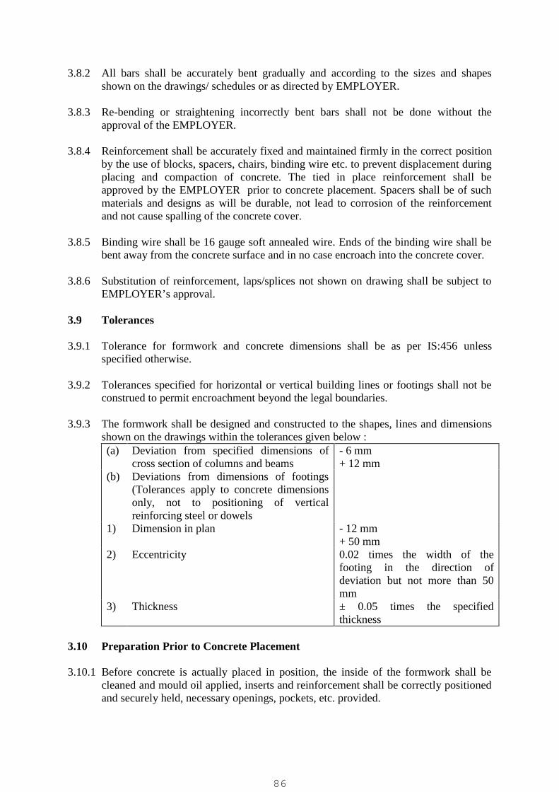
3.8.2 All bars shall be accurately bent gradually and according to the sizes and shapesshown on the drawings/ schedules or as directed by EMPLOYER.
3.8.3 Re-bending or straightening incorrectly bent bars shall not be done without theapproval of the EMPLOYER.
3.8.4 Reinforcement shall be accurately fixed and maintained firmly in the correct positionby the use of blocks, spacers, chairs, binding wire etc. to prevent displacement duringplacing and compaction of concrete. The tied in place reinforcement shall beapproved by the EMPLOYER prior to concrete placement. Spacers shall be of suchmaterials and designs as will be durable, not lead to corrosion of the reinforcementand not cause spalling of the concrete cover.
3.8.5 Binding wire shall be 16 gauge soft annealed wire. Ends of the binding wire shall bebent away from the concrete surface and in no case encroach into the concrete cover.
3.8.6 Substitution of reinforcement, laps/splices not shown on drawing shall be subject toEMPLOYER’s approval.
3.9 Tolerances
3.9.1 Tolerance for formwork and concrete dimensions shall be as per IS:456 unlessspecified otherwise.
3.9.2 Tolerances specified for horizontal or vertical building lines or footings shall not beconstrued to permit encroachment beyond the legal boundaries.
3.9.3 The formwork shall be designed and constructed to the shapes, lines and dimensionsshown on the drawings within the tolerances given below :(a) Deviation from specified dimensions of
cross section of columns and beams- 6 mm+ 12 mm
(b) Deviations from dimensions of footings(Tolerances apply to concrete dimensionsonly, not to positioning of verticalreinforcing steel or dowels
1) Dimension in plan - 12 mm+ 50 mm
2) Eccentricity 0.02 times the width of thefooting in the direction ofdeviation but not more than 50mm
3) Thickness ± 0.05 times the specifiedthickness
3.10 Preparation Prior to Concrete Placement
3.10.1 Before concrete is actually placed in position, the inside of the formwork shall becleaned and mould oil applied, inserts and reinforcement shall be correctly positionedand securely held, necessary openings, pockets, etc. provided.
86

3.10.2 All arrangements-formwork, equipment and proposed procedure, shall be approvedby the EMPLOYER. Contractor shall maintain separate Pour Card for each pour asper the format enclosed.
3.11 Transporting, Placing and Compacting Concrete
3.11.1 Concrete shall be transported from the mixing plant to the formwork with minimumtime lapse by methods that shall maintain the required workability and will preventsegregation, loss of any ingredients or ingress of foreign matter or water.
3.11.2 In all cases concrete shall be deposited as nearly as practicable directly in its finalposition. To avoid segregation, concrete shall not be rehandled or caused to flow. Forlocations where direct placement is not possible and in narrow forms the Contractorshall provide suitable drops and "Elephant Trunks". Concrete shall not be droppedfrom a height of more than 1.0m.
3.11.3 Concrete shall not be placed in flowing water. Under water, concrete shall be placedin position by tremies or by pipeline from the mixer and shall never be allowed to fallfreely through the water.
87

3.11.4 While placing concrete the Contractor shall proceed as specified below and alsoensure the following:
(a) Continuously between construction joints and pre- determined abutments.(b) Without disturbance to forms or reinforcement.(c) Without disturbance to pipes, ducts, fixings and the like to be cast in; ensure that
such items are securely fixed. Ensure that concrete cannot enter open ends ofpipes and conduits etc.
(d) Without dropping in a manner that could cause segregation or shock.(e) In deep pours only when the concrete and formwork designed for this purpose and
by using suitable chutes or pipes.(f) Do not place if the workability is such that full compaction cannot be achieved.(g) Without disturbing the unsupported sides of excavations; prevent contamination
of concrete with earth. Provide sheeting if necessary. In supported excavations,withdraw the linings progressively as concrete is placed.
(h) If placed directly onto hardcore or any other porous material, dampen the surfaceto reduce loss of water from the concrete.
(i) Ensure that there is no damage or displacement to sheet membranes.(j) Record the time and location of placing structural concrete.
3.11.5 Concrete shall normally be compacted in its final position within thirty minutes ofleaving the mixer. Concrete shall be compacted during placing with approvedvibrating equipment without causing segregation until it forms a solid mass free fromvoids thoroughly worked around reinforcement and embedded fixtures and into allcorners of the formwork. Immersion vibrators shall be inserted vertically at points notmore than 450 mm apart and withdrawn slowly till air bubbles cease to come to thesurface, leaving no voids. When placing concrete in layers advancing horizontally,care shall be taken to ensure adequate vibration, blending and melding of the concretebetween successive layers. Vibrators shall not be allowed to come in contact withreinforcement, formwork and finished surfaces after start of initial set. Over-vibrationshall be avoided.
3.11.6 Concrete may be conveyed and placed by mechanically operated equipment aftergetting the complete procedure approved by the EMPLOYER. The slump shall beheld to the minimum necessary for conveying concrete by this method. Whenconcrete is to be pumped, the concrete mix shall be specially designed to suitpumping. Care shall be taken to avoid stoppages in work once pumping has started.
3.11.7 Except when placing with slip forms, each placement of concrete in multiple liftwork, shall be allowed to set for at least 24 hours after the final set of concrete beforethe start of subsequent placement. Placing shall stop when concrete reaches the top ofthe opening in walls or bottom surface of slab, in slab and beam construction, and itshall be resumed before concrete takes initial set but not until it has had time to settleas approved by the EMPLOYER. Concrete shall be protected against damage untilfinal acceptance.
3.12 Mass Concrete Works
88
3.12.1 Sequence of pouring for mass concrete works shall be as approved by theEMPLOYER. The Contractor shall exercise great care to prevent shrinkage cracksand shall monitor the temperature of the placed concrete if directed.
3.13 Curing
3.13.1 Curing and protection shall start immediately after the compaction of theconcrete to protect it from:
(a) Premature drying out, particularly by solar radiation and wind;(b) leaching out by rain and flowing water;(c) rapid cooling during the first few days after placing;(d) high internal thermal gradients;(e) low temperature or frost;(f) vibration and impact which may disrupt the concrete and interfere with its bond
to the reinforcement.
3.13.2 All concrete, unless approved otherwise by the EMPLOYER, shall be cured by use ofcontinuous sprays or ponded water or continuously saturated coverings of sacking,canvas, hessain or other absorbent material for the period of complete hydration witha minimum of 7 days. The quality of curing water shall be the same as that used formixing.
3.13.3 Where a curing membrane is approved to be used by the EMPLOYER, the same shallbe of a non-wax base and shall not impair the concrete finish in any manner. Thecuring compound to be used shall be approved by the EMPLOYER before use andshall be applied with spraying equipment capable of a smooth, even textured coat.
3.13.4 Curing may also be done by covering the surface with an impermeable material suchas polyethylene, which shall be well sealed and fastened.
3.14 Construction Joints and Keys
3.14.1 Construction joints will be as shown on the drawing or as approved by theEMPLOYER. Concrete shall be placed without interruption until completion of workbetween construction joints. If stopping of concreting becomes unavoidableanywhere, a properly formed construction joint shall be made with the approval of theEMPLOYER.
3.14.2 Dowels for concrete work, not likely to be taken up in the near future, shall be coatedwith cement slurry and encased in lean concrete as indicated on the drawings or asapproved by the EMPLOYER.
3.14.3 Before resuming concreting on a surface which has hardened all laitance and loosestone shall be thoroughly removed by wire brushing/hacking and surface washed withhigh pressure water jet and treated with thin layer of cement slurry for vertical jointsand horizontal layers.
3.14.4 When concreting is to be resumed on a surface which has not fully hardened, alllaitance shall be removed by wire brushing, the surface wetted, free water removedand a coat of cement slurry applied. On this, a layer of concrete not exceeding 150
89
mm thickness shall be placed and well rammed against the old work. Thereafter workshall proceed in the normal way.
3.15 Foundation Bedding
3.15.1 All earth surfaces upon which or against which concrete is to be placed, shall be wellcompacted and free from standing water, mud or debris. Soft or spongy areas shall becleaned out and back filled with either soil-cement mixture, lean concrete or cleansand compacted as approved by the EMPLOYER. The surfaces of absorptive soilsshall be moistened.
3.15.2 Concrete shall not be deposited on large sloping rock surfaces. The rock shall be cutto form rough steps or benches by picking, barring or wedging. The rock surface shallbe kept wet for 2 to 4 hours before concreting.
3.16 Finishes
3.16.1 GeneralThe formwork for concrete works shall be such as to give the finish as specified. TheContractor shall make good any unavoidable defects as approved consistent with thetype of concrete and finish specified; defects due to bad workmanship (e.g. damagedor misaligned forms, defective or poorly compacted concrete) will not be accepted.The Contractor shall construct the formwork using the correct materials and to meetthe requirements of the design and to produce finished concrete to requireddimensions, plumbs, planes and finishes. Inside and outside 15 mm thick smoothcement plaster in CM (1:3) with water proofing compound shall be done in all waterretaining structures.
3.16.2 Surface Finish Type F1The main requirement is that of dense, well compacted concrete. No treatment isrequired except repair of defective areas, filling all form tie holes and cleaning up ofloose or adhering debris. For surfaces below grade which will receive waterproofingtreatment the concrete shall be free of surface irregularities which would interferewith proper and effective application of waterproofing material specified for use.
3.16.3 Surface Finish Type F2The appearance shall be that of a smooth dense, well- compacted concrete showingthe slight marks of well fitted shuttering joints. The Contractor shall make good anyblemishes.
3.16.4 Surface Finish Type F3This finish shall give an appearance of smooth, dense, well-compacted concrete withno shutter marks, stain free and with no discolouration, blemishes, arises, airholes etc.Only lined or coated plywood with very tight joints shall be used to achieve thisfinish. The panel size shall be uniform and as large as practicable. Any minorblemishes that might occur shall be made good by the Contractor.
3.16.5 Integral Cement Finish on Concrete FloorIn all cases where integral cement finish on a concrete floor has been specified, thetop layer of concrete shall be screeded off to proper level and tamped with tamper
90
having conical projections so that the aggregate shall be forced below the surface. Thesurface shall be finished with a wooden float and a trowel with pressure. The finishshall be continued till the concrete reaches its initial set. No cement or cement mortarfinish shall be provided on the surface. Where specified, a floor hardener as approvedby the EMPLOYER shall be supplied and used as recommended by the manufacturer.
3.17 Repair and Replacement of Unsatisfactory Concrete work
3.17.1 Immediately after the shuttering is removed, all the defective areas such as honey-combed surfaces, rough patches, holes left by form bolts etc. shall be inspected by theEMPLOYER who may permit patching of the defective areas or reject the concretework.
3.17.2 All through holes for shuttering shall be filled for full depth and neatly plugged flushwith surface.
3.17.3 Rejected concrete shall be removed and replaced by the Contractor at no additionalcost to the Employer.
3.17.4 For patching of defective areas all loose materials shall be removed and the surfaceshall be prepared as approved by the EMPLOYER.
3.17.5 Bonding between hardened and fresh concrete shall be done either by placing cementmortar or by applying epoxy. The decision of the EMPLOYER as to the method ofrepairs to be adopted shall be final and binding on the Contractor. The surface shall besaturated with water for 24 hours before patching is done with 1:5 cement sandmortar. The use of epoxy for bonding fresh concrete shall be carried out as approvedby the EMPLOYER.
3.18 Vacuum Dewatering of Slabs
3.18.1 Where specified floor slabs, either grade or suspended, shall be finished by vacuumdewatering including all operations such as poker vibration, surface vibration, vacuumprocessing, floating and trowelling as per equipment manufacturers recommendation.The equipment to be used shall be subject to the EMPLOYER’s approval.
3.19 Hot Weather Requirements
3.19.1 Concreting during hot weather shall be carried out as per IS:7861 (Part I).
3.19.2 Adequate provisions shall be made to lower concrete temperatures which shall notexceed 40o C at the time of placement of fresh concrete.
3.19.3 Where directed by the EMPLOYER, the Contractor shall spray non-wax based curingcompound on unformed concrete surfaces at no extra costs.
3.20 Cold Weather Requirements
3.20.1 Concreting during cold weather shall be carried out as per Is : 7861 (Part II).
91
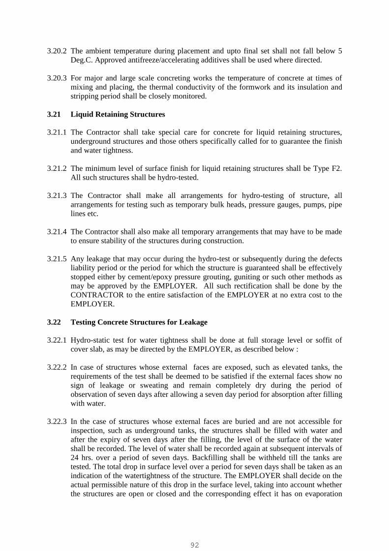
3.20.2 The ambient temperature during placement and upto final set shall not fall below 5Deg.C. Approved antifreeze/accelerating additives shall be used where directed.
3.20.3 For major and large scale concreting works the temperature of concrete at times ofmixing and placing, the thermal conductivity of the formwork and its insulation andstripping period shall be closely monitored.
3.21 Liquid Retaining Structures
3.21.1 The Contractor shall take special care for concrete for liquid retaining structures,underground structures and those others specifically called for to guarantee the finishand water tightness.
3.21.2 The minimum level of surface finish for liquid retaining structures shall be Type F2.All such structures shall be hydro-tested.
3.21.3 The Contractor shall make all arrangements for hydro-testing of structure, allarrangements for testing such as temporary bulk heads, pressure gauges, pumps, pipelines etc.
3.21.4 The Contractor shall also make all temporary arrangements that may have to be madeto ensure stability of the structures during construction.
3.21.5 Any leakage that may occur during the hydro-test or subsequently during the defectsliability period or the period for which the structure is guaranteed shall be effectivelystopped either by cement/epoxy pressure grouting, guniting or such other methods asmay be approved by the EMPLOYER. All such rectification shall be done by theCONTRACTOR to the entire satisfaction of the EMPLOYER at no extra cost to theEMPLOYER.
3.22 Testing Concrete Structures for Leakage
3.22.1 Hydro-static test for water tightness shall be done at full storage level or soffit ofcover slab, as may be directed by the EMPLOYER, as described below :
3.22.2 In case of structures whose external faces are exposed, such as elevated tanks, therequirements of the test shall be deemed to be satisfied if the external faces show nosign of leakage or sweating and remain completely dry during the period ofobservation of seven days after allowing a seven day period for absorption after fillingwith water.
3.22.3 In the case of structures whose external faces are buried and are not accessible forinspection, such as underground tanks, the structures shall be filled with water andafter the expiry of seven days after the filling, the level of the surface of the watershall be recorded. The level of water shall be recorded again at subsequent intervals of24 hrs. over a period of seven days. Backfilling shall be withheld till the tanks aretested. The total drop in surface level over a period for seven days shall be taken as anindication of the watertightness of the structure. The EMPLOYER shall decide on theactual permissible nature of this drop in the surface level, taking into account whetherthe structures are open or closed and the corresponding effect it has on evaporation
92

losses. Unless specified otherwise, a structure whose top is covered shall be deemedto be water tight if the total drop in the surface level over a period of seven days doesnot exceed 40 mm.
3.22.4 Each compartment/segment of the structure shall be tested individually and then alltogether.
3.22.5 For structures such as pipes, tunnels etc. the hydrostatic test shall be carried out byfilling with water, after curing as specified, and subjecting to the specified testpressure for specified period. If during this period the loss of water does not exceedthe equivalent of the specified rate, the structure shall be considered to havesuccessfully passed the test.
3.23 Optional Tests
3.23.1 If the EMPLOYER feels that the materials i.e. cement, sand, coarse aggregates,reinforcement and water are not in accordance with the Specifications or if specifiedconcrete strengths are not obtained, he may order tests to be carried out on thesematerials in laboratory, to be approved by the EMPLOYER, as per relevant IS Codes.Contractor shall have to pay for these tests.
3.23.2 In the event of any work being suspected of faulty material or workmanship requiringits removal or if the works cubes do not give the stipulated strengths, theEMPLOYER reserves the right to order the Contractor to take out cores and conducttests on them or do ultrasonic testing or load testing of structure, etc. TheEMPLOYER also reserves the right to ask the Contractor to dismantle and re-do suchunacceptable work, at no cost to the Employer. Alternately EMPLOYER alsoreserves the right to ask the CONTRACTOR to dismantle and re-do suchunacceptable work at the cost of CONTRACTOR.
3.24 Grouting
3.24.1 Standard Grout
Grout shall be provided as specified on the drawings.The proportion of Standard Grout shall be such as to produce a flowable mixtureconsistent with minimum water content and shrinkage. Surfaces to be grouted shallbe thoroughly roughened and cleaned. All structural steel elements to be grouted,shall be cleaned of oil, grease, dirt etc. The use of hot, strong caustic solution for thispurpose will be permitted. Prior to grouting, the hardened concrete shall be saturatedwith water and just before grouting, water in all pockets shall be removed. Groutingonce started shall be done quickly and continuously. Variation in grout mixes andprocedures shall be permitted if approved by the EMPLOYER. The grout proportionsshall be limited as follows :
Use Grout Thickness Mix Proportions W/C Ratio(max)
a) Fluid mix Under 25mm One part Portland Cementto one part sand
0.44
93
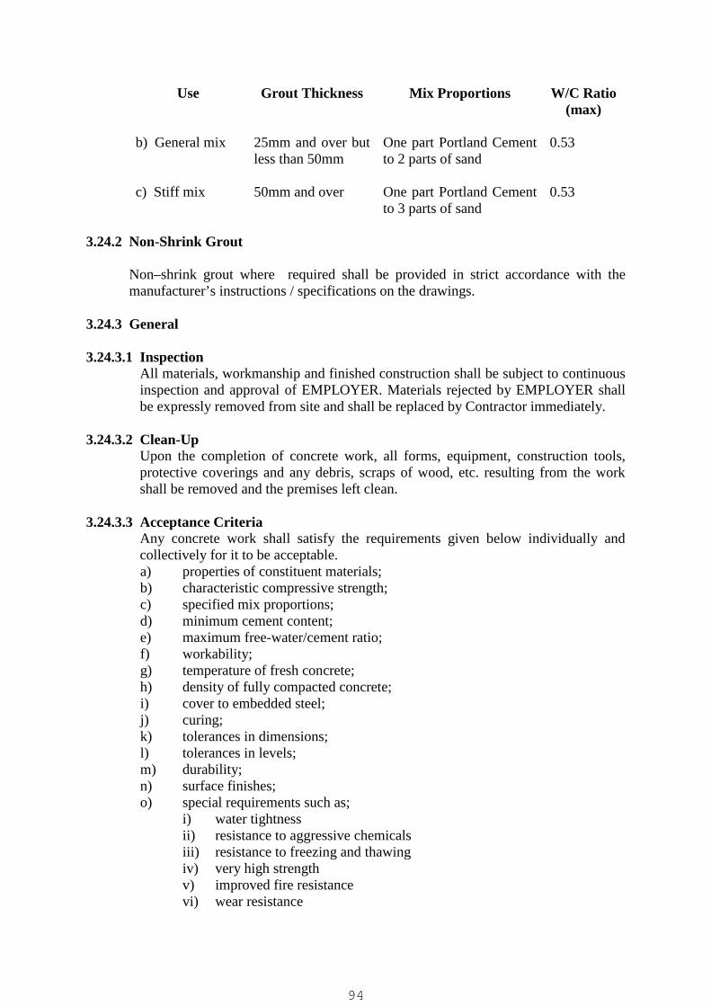
Use Grout Thickness Mix Proportions W/C Ratio(max)
b) General mix 25mm and over butless than 50mm
One part Portland Cementto 2 parts of sand
0.53
c) Stiff mix 50mm and over One part Portland Cementto 3 parts of sand
0.53
3.24.2 Non-Shrink Grout
Non–shrink grout where required shall be provided in strict accordance with themanufacturer’s instructions / specifications on the drawings.
3.24.3 General
3.24.3.1 InspectionAll materials, workmanship and finished construction shall be subject to continuousinspection and approval of EMPLOYER. Materials rejected by EMPLOYER shallbe expressly removed from site and shall be replaced by Contractor immediately.
3.24.3.2 Clean-UpUpon the completion of concrete work, all forms, equipment, construction tools,protective coverings and any debris, scraps of wood, etc. resulting from the workshall be removed and the premises left clean.
3.24.3.3 Acceptance CriteriaAny concrete work shall satisfy the requirements given below individually andcollectively for it to be acceptable.a) properties of constituent materials;b) characteristic compressive strength;c) specified mix proportions;d) minimum cement content;e) maximum free-water/cement ratio;f) workability;g) temperature of fresh concrete;h) density of fully compacted concrete;i) cover to embedded steel;j) curing;k) tolerances in dimensions;l) tolerances in levels;m) durability;n) surface finishes;o) special requirements such as;
i) water tightnessii) resistance to aggressive chemicalsiii) resistance to freezing and thawingiv) very high strengthv) improved fire resistancevi) wear resistance
94
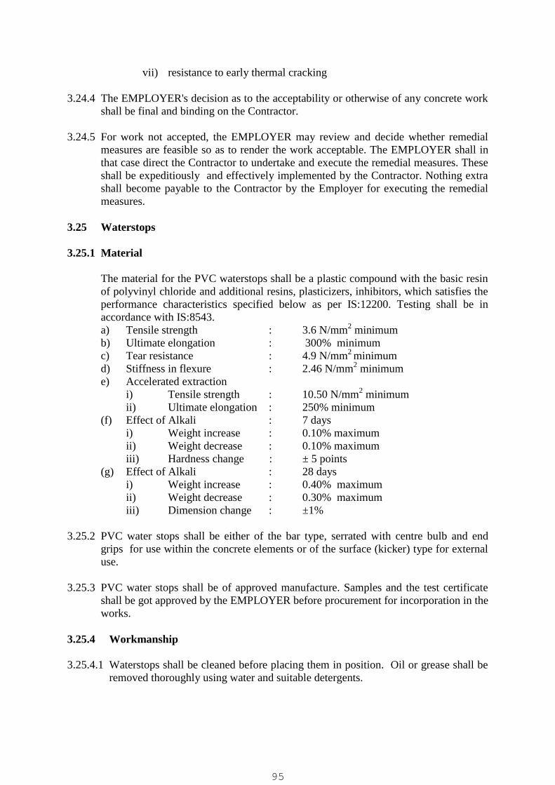
vii) resistance to early thermal cracking
3.24.4 The EMPLOYER's decision as to the acceptability or otherwise of any concrete workshall be final and binding on the Contractor.
3.24.5 For work not accepted, the EMPLOYER may review and decide whether remedialmeasures are feasible so as to render the work acceptable. The EMPLOYER shall inthat case direct the Contractor to undertake and execute the remedial measures. Theseshall be expeditiously and effectively implemented by the Contractor. Nothing extrashall become payable to the Contractor by the Employer for executing the remedialmeasures.
3.25 Waterstops
3.25.1 Material
The material for the PVC waterstops shall be a plastic compound with the basic resinof polyvinyl chloride and additional resins, plasticizers, inhibitors, which satisfies theperformance characteristics specified below as per IS:12200. Testing shall be inaccordance with IS:8543.a) Tensile strength : 3.6 N/mm2 minimumb) Ultimate elongation : 300% minimumc) Tear resistance : 4.9 N/mm2 minimumd) Stiffness in flexure : 2.46 N/mm2 minimume) Accelerated extraction
i) Tensile strength : 10.50 N/mm2 minimumii) Ultimate elongation : 250% minimum
(f) Effect of Alkali : 7 daysi) Weight increase : 0.10% maximumii) Weight decrease : 0.10% maximumiii) Hardness change : ± 5 points
(g) Effect of Alkali : 28 daysi) Weight increase : 0.40% maximumii) Weight decrease : 0.30% maximumiii) Dimension change : ±1%
3.25.2 PVC water stops shall be either of the bar type, serrated with centre bulb and endgrips for use within the concrete elements or of the surface (kicker) type for externaluse.
3.25.3 PVC water stops shall be of approved manufacture. Samples and the test certificateshall be got approved by the EMPLOYER before procurement for incorporation in theworks.
3.25.4 Workmanship
3.25.4.1 Waterstops shall be cleaned before placing them in position. Oil or grease shall beremoved thoroughly using water and suitable detergents.
95

3.25.4.2 Waterstops shall be procured in long lengths as manufactured to avoid joints as faras possible. Standard L or T type of intersection pieces shall be procured for usedepending on their requirement. Any non-standard junctions shall be made bycutting the pieces to profile for jointing. Lapping of waterstops shall not bepermitted. All jointing shall be of fusion welded type as per manufacturer'sinstructions.
3.25.4.3 Waterstops shall be placed at the correct location/level and suitably supported atintervals with the reinforcement to ensure that it does not deviate from its intendedposition during concreting and vibrating. Care shall also be taken to ensure that nohoney-combing occurs because of the serrations/end grips, by placing concrete withsmaller size aggregates in this region. Projecting portions of the waterstopsembedded in concrete shall be thoroughly cleaned of all mortar/ concrete coatingbefore resuming further concreting operations. The projecting waterstop shall alsobe suitably supported at intervals with the reinforcement to maintain its intendedposition during concreting so as to ensure that it does not bend leading to formationof pockets. In addition, smaller size aggregates shall be used for concreting in thisregion also.
3.26 Preformed Fillers and Joint Sealing Compound
3.26.1 Materials
3.26.1.1 Preformed filler for expansion/isolation joints shall be non-extruding and resilienttype of bitumen impregnated fibres conforming to IS:1838 (Part I).
3.26.1.2 Bitumen coat to concrete/masonry surfaces for fixing the preformed bitumen fillerstrip shall conform to IS:702. Bitumen primer shall conform to IS:3384.
3.26.1.3 Sealing compound for filling the joints above the preformed bitumen filler shallconform to Grade 'A' as per IS:1834.
3.26.2 Workmanship
3.26.2.1 The thickness of the preformed bitumen filler shall be 25mm for expansion jointsand 50mm for isolation joints around foundation supporting rotatory equipment's.Contractor shall procure the strips of the desired thickness and width in lengths asmanufactured. Assembly of small pieces/thicknesses of strips to make up thespecified size shall not be permitted.
3.26.2.2 The concrete/masonry surface shall be cleaned free from dust and any looseparticles. When the surface is dry, one coat of industrial blown type bitumen ofgrade 85/25 conforming to IS:702 shall be applied hot by brushing at the rate of1.20 kg/sq.m. When the bitumen is still hot the preformed bitumen filler shall bepressed and held in position till it completely adheres. The surface of the filleragainst which further concreting/masonry work is to be done shall similarly beapplied with one coat of hot bitumen at the rate of 1.20 kg/sq.m.
3.26.2.3 Sealing compound shall be heated to a pouring consistency for enabling it to runmolten in a uniform manner into the joint. Before pouring the sealing compound,
96

the vertical faces of the concrete joint shall be applied hot with a coat of bitumenprimer conforming to IS: 3384 in order to improve the adhesive quality of thesealing compound.
3.26.2.4 Expansion joints between beams/slabs shall be provided with 100mm wide x 4mmthick mild steel plate at the soffit of RCC beams/slabs to support and prevent thepreformed joint filler from dislodging. This plate shall be welded to an edge angleof ISA 50 x 50 x 6mm provided at the bottom corner, adjacent to the expansion jointof one of the beams/slabs, by intermittent fillet welding. Steel surfaces shall beprovided with 2 coats of red oxide zinc chrome primer and 3 coats of syntheticenamel paint finish.
CONCRETE POUR CARDPOUR NO. :DRG. NO. :CONCRETE GRADE/QUANTITY/ :
SLUMP :
DATE :STRUCTURE :MAX. AGGREGATE SIZE /START / COMPLETION TIME :
SL. NO. ITEM Remarks If Any
1. BEFORE CONCRETINGCENTRELINES CHECKED
YES/NO
2. FORMWORK AND STAGINGCHECKED FOR ACCURACY,STRENGTH & FINISH
YES/NO
3. REINFORCEMENT CHECKED YES/NO4. COVER TO REINFORCEMENT
CHECKEDYES/NO
5. VERIFIEDTEST CERTIFICATEFOR CEMENT/STEEL
YES / NO
6. ADEQUACY OF MATERIALS /EQUIPMENT FOR POUR
YES / NO
7. EMBEDDEDPARTS (LOCATION& PLUMB)CHECKED
CIVILYES/NO
MECH. YES/NOELEC. YES/NO
8. SOFFIT(S) & POUR TOP(T)LEVELS CHECKED BEFORE (B)& AFTER (A) FORM REMOVAL(ONLY OF BEAMS OF OVER 10M SPAN & IMPORTANTSTRUCTURE LIKE T.G. ETC.)
S(B)T(B)
S(B)T(B)
9. CONSTRUCTION JOINTSLOCATION & TIME (IF NOT ASPER DRAWING)
10. CEMENT CONSUMPTION INKGS.
97

11. NUMBER OF CUBES ANDIDENTIFICATION MARKS
12. TEST CUBE RESULTS (7 DAYS /28 DAYS)
13. CONCRETE CONDITION ONFORM REMOVAL
V.GOOD/GOOD/FAIR/POOR
Contractor’s Representative EMPLOYER’s Representative
NOTES: 1. EACH POUR TO HAVE SEPARATE CARDS, IN TRIPLICATE ONEEACH FOR CLIENT,CONTRACTOR & SITE OFFICE.
UNDER REMARKS INDICATE DEVIATIONS FROM DWGS. & SPECIFICATIONS,CONGESTION IN REINFORCEMENT IF ANY, UNUSUAL OCCURRENCES SUCH ASFAILURE OF EQUIPMENTS, SINKING OF SUPPORTS / PROPS. HEAVY RAINSAFFECTING CONCRETING, POOR COMPACTION, IMPROPER CURING, OTHERDEFICIENCIES, OBSERVATIONS ETC.
98
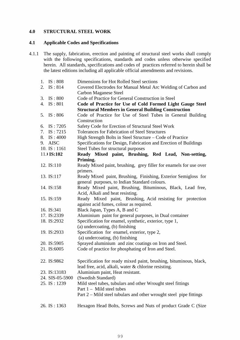
4.0 STRUCTURAL STEEL WORK
4.1 Applicable Codes and Specifications
4.1.1 The supply, fabrication, erection and painting of structural steel works shall complywith the following specifications, standards and codes unless otherwise specifiedherein. All standards, specifications and codes of practices referred to herein shall bethe latest editions including all applicable official amendments and revisions.
1. IS : 808 Dimensions for Hot Rolled Steel sections2. IS : 814 Covered Electrodes for Manual Metal Arc Welding of Carbon and
Carbon Maganese Steel3. IS : 800 Code of Practice for General Construction in Steel4. IS : 801 Code of Practice for Use of Cold Formed Light Gauge Steel
Structural Members in General Building Construction5. IS : 806 Code of Practice for Use of Steel Tubes in General Building
Construction6. IS : 7205 Safety Code for Erection of Structural Steel Work7. IS : 7215 Tolerances for Fabrication of Steel Structures8. IS : 4000 High Strength Bolts in Steel Structure – Code of Practice9. AISC Specifications for Design, Fabrication and Erection of Buildings10. IS : 1161 Steel Tubes for structural purposes11.IS:10 IS:102 Ready Mixed paint, Brushing, Red Lead, Non-setting,
Priming.12. IS:110 Ready Mixed paint, brushing, grey filler for enamels for use over
primers.13. IS:117 Ready Mixed paint, Brushing, Finishing, Exterior Semigloss for
general purposes, to Indian Standard colours.14. IS:158 Ready Mixed paint, Brushing, Bituminous, Black, Lead free,
Acid, Alkali and heat resisting.15. IS:159 Ready Mixed paint, Brushing, Acid resisting for protection
against acid fumes, colour as required.16. IS:341 Black Japan, Types A, B and C17. IS:2339 Aluminium paint for general purposes, in Dual container18. IS:2932 Specification for enamel, synthetic, exterior, type 1,
(a) undercoating, (b) finishing19. IS:2933 Specification for enamel, exterior, type 2,
(a) undercoating, (b) finishing20. IS:5905 Sprayed aluminium and zinc coatings on Iron and Steel.21. IS:6005 Code of practice for phosphating of Iron and Steel.
22. IS:9862 Specification for ready mixed paint, brushing, bituminous, black,lead free, acid, alkali, water & chlorine resisting.
23. IS:13183 Aluminium paint, Heat resistant.24. SIS-05-5900 (Swedish Standard)25. IS : 1239 Mild steel tubes, tubulars and other Wrought steel fittings
Part 1 – Mild steel tubesPart 2 – Mild steel tubulars and other wrought steel pipe fittings
26. IS : 1363 Hexagon Head Bolts, Screws and Nuts of product Grade C (Size
99

(Parts 1 to 3) range M5 to M64)27. IS : 1367
(All parts)Technical Supply Conditions for Threaded Fasteners
28. IS : 1852 Rolling and Cutting Tolerances for Hot Rolled Steel Products29. IS : 1977 Structural Steel (Ordinary Quality)30. IS : 2062 Steel for General Structural Purposes31. IS : 2074 Ready Mixed Paint, Air drying, Red Oxide Zinc Chrome and
Priming32. IS : 3502 Steel Chequered Plate33. IS : 3757 High Strength Structural Bolts34. IS : 5369 General Requirements for Plain Washers and Lock Washers35. IS : 5372 Taper Washers for Channels36. IS : 5374 Taper Washer for 1 Beams37. IS : 6610 Heavy Washers for Steel Structures38. IS : 8500 Structural Steel-microalloyed (medium and high strength
qualities)39. IS : 803 Code of practice for design, fabrication and erection of vertical
mild steel cylindrical welded storage tanks40. IS : 816 Code of Practice for use of Metal Arc Welding for General
construction in Mild Steel
41. IS : 822 Code of Procedure for Inspection of Welds42. IS : 1182 Recommended Practice for Radiographic examination of Fusion
– Welded Butt Joints in Steel Plates43. IS : 1200 Method of Measurement in Building Civil Works44. IS : 1477 Code of Practice for Painting of (Parts 1&2) Ferrous Metals in
Buildings45. IS : 2595 Code of Practice for Radiographic Testing46. IS : 3658 Code of Practice for Liquid Penetrant Flaw Detection47. IS : 5334 Code of Practice for Magnetic Particle Flaw Detection of Welds48. IS : 9595 Recommendations for Metal Arc Welding of Carbon and Carbon
Manganese Steel
4.2 Steel Materials
4.2.1 Steel materials shall comply with the referred to in Sub-Clause 4.1.
4.2.2 All materials used shall be new, unused and free from defects.
4.2.3 Steel conforming to IS:1977 shall be used only for the following :
Fe310-0(St 32-0): For general purposes such as door/window frames,grills, steel gates, handrails, fence posts, tee bars andother non-structural use.
Fe410-0(St 42-0): For structures not subjected to dynamic loading otherthan wind loads such as :Platform roofs, foot overbridges, building, factory sheds etc.
Fe510-0(St 42-0): Grade steel shall not be useda) If welding is to be employed for fabrication
100
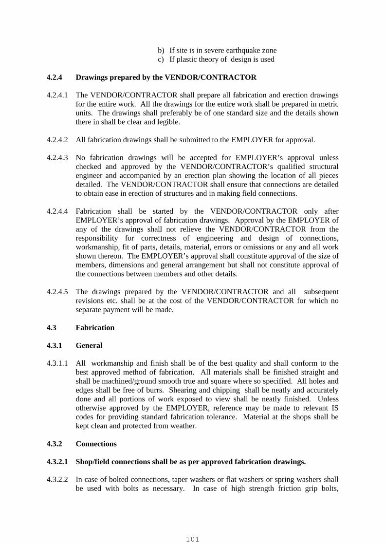
b) If site is in severe earthquake zonec) If plastic theory of design is used
4.2.4 Drawings prepared by the VENDOR/CONTRACTOR
4.2.4.1 The VENDOR/CONTRACTOR shall prepare all fabrication and erection drawingsfor the entire work. All the drawings for the entire work shall be prepared in metricunits. The drawings shall preferably be of one standard size and the details shownthere in shall be clear and legible.
4.2.4.2 All fabrication drawings shall be submitted to the EMPLOYER for approval.
4.2.4.3 No fabrication drawings will be accepted for EMPLOYER’s approval unlesschecked and approved by the VENDOR/CONTRACTOR’s qualified structuralengineer and accompanied by an erection plan showing the location of all piecesdetailed. The VENDOR/CONTRACTOR shall ensure that connections are detailedto obtain ease in erection of structures and in making field connections.
4.2.4.4 Fabrication shall be started by the VENDOR/CONTRACTOR only afterEMPLOYER’s approval of fabrication drawings. Approval by the EMPLOYER ofany of the drawings shall not relieve the VENDOR/CONTRACTOR from theresponsibility for correctness of engineering and design of connections,workmanship, fit of parts, details, material, errors or omissions or any and all workshown thereon. The EMPLOYER’s approval shall constitute approval of the size ofmembers, dimensions and general arrangement but shall not constitute approval ofthe connections between members and other details.
4.2.4.5 The drawings prepared by the VENDOR/CONTRACTOR and all subsequentrevisions etc. shall be at the cost of the VENDOR/CONTRACTOR for which noseparate payment will be made.
4.3 Fabrication
4.3.1 General
4.3.1.1 All workmanship and finish shall be of the best quality and shall conform to thebest approved method of fabrication. All materials shall be finished straight andshall be machined/ground smooth true and square where so specified. All holes andedges shall be free of burrs. Shearing and chipping shall be neatly and accuratelydone and all portions of work exposed to view shall be neatly finished. Unlessotherwise approved by the EMPLOYER, reference may be made to relevant IScodes for providing standard fabrication tolerance. Material at the shops shall bekept clean and protected from weather.
4.3.2 Connections
4.3.2.1 Shop/field connections shall be as per approved fabrication drawings.
4.3.2.2 In case of bolted connections, taper washers or flat washers or spring washers shallbe used with bolts as necessary. In case of high strength friction grip bolts,
101
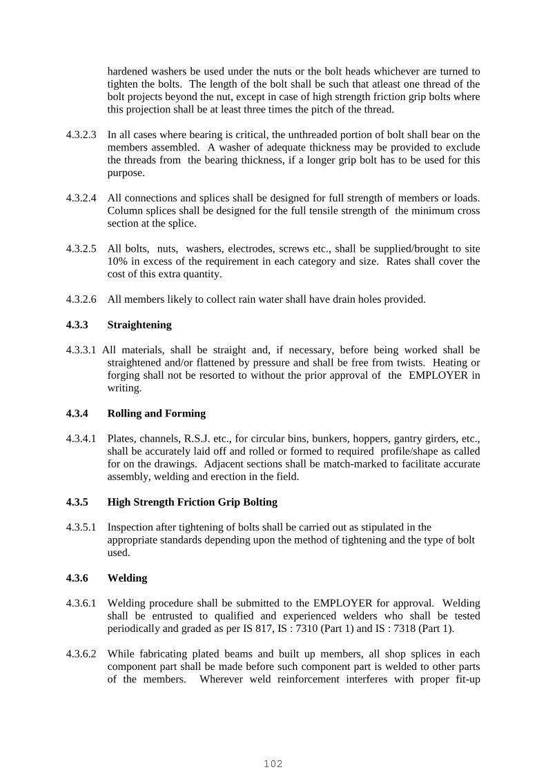
hardened washers be used under the nuts or the bolt heads whichever are turned totighten the bolts. The length of the bolt shall be such that atleast one thread of thebolt projects beyond the nut, except in case of high strength friction grip bolts wherethis projection shall be at least three times the pitch of the thread.
4.3.2.3 In all cases where bearing is critical, the unthreaded portion of bolt shall bear on themembers assembled. A washer of adequate thickness may be provided to excludethe threads from the bearing thickness, if a longer grip bolt has to be used for thispurpose.
4.3.2.4 All connections and splices shall be designed for full strength of members or loads.Column splices shall be designed for the full tensile strength of the minimum crosssection at the splice.
4.3.2.5 All bolts, nuts, washers, electrodes, screws etc., shall be supplied/brought to site10% in excess of the requirement in each category and size. Rates shall cover thecost of this extra quantity.
4.3.2.6 All members likely to collect rain water shall have drain holes provided.
4.3.3 Straightening
4.3.3.1 All materials, shall be straight and, if necessary, before being worked shall bestraightened and/or flattened by pressure and shall be free from twists. Heating orforging shall not be resorted to without the prior approval of the EMPLOYER inwriting.
4.3.4 Rolling and Forming
4.3.4.1 Plates, channels, R.S.J. etc., for circular bins, bunkers, hoppers, gantry girders, etc.,shall be accurately laid off and rolled or formed to required profile/shape as calledfor on the drawings. Adjacent sections shall be match-marked to facilitate accurateassembly, welding and erection in the field.
4.3.5 High Strength Friction Grip Bolting
4.3.5.1 Inspection after tightening of bolts shall be carried out as stipulated in theappropriate standards depending upon the method of tightening and the type of boltused.
4.3.6 Welding
4.3.6.1 Welding procedure shall be submitted to the EMPLOYER for approval. Weldingshall be entrusted to qualified and experienced welders who shall be testedperiodically and graded as per IS 817, IS : 7310 (Part 1) and IS : 7318 (Part 1).
4.3.6.2 While fabricating plated beams and built up members, all shop splices in eachcomponent part shall be made before such component part is welded to other partsof the members. Wherever weld reinforcement interferes with proper fit-up
102

between components to be assembled off welding, these welds shall be ground flushprior to assembly.
4.3.6.3 Approval of the welding procedure by the EMPLOYER shall not relieve theContractor of his responsibility for correct and sound welding without unduedistortion in the finished structure.
4.3.6.4 No welding shall be done when the surface of the members is wet nor duringperiods of high wind.
4.3.6.5 Each layer of a multiple layer weld except root and surfaces runs may bemoderately penned with light blows from a blunt tool. Care shall be exercised toprevent scaling or flaking of weld and base metal from overpeening.
4.3.6.6 No welding shall be done on base metal at a temperature below –5 Deg.C. Basemetal shall be preheated to the temperature as per relevant IS codes.
4.3.6.7 Electrodes other than low-hydrogen electrodes shall not be permitted for thicknessesof 32 mm and above.
4.3.6.8 All welds shall be inspected for flaws by any of the methods described under Sub-clause 4.6.3. The choice of the method adopted shall be agreed with theEMPLOYER.
4.3.6.9 The correction of defective welds shall be carried out in a manner approved by theEMPLOYER without damaging the parent metal. When a crack in the weld isremoved, magnetic particle inspection or any other equally positive means approvedby the EMPLOYER shall be used to ensure that the whole of the crack and materialupto 25 mm beyond each end of the crack has been removed. The cost of all suchtests and operations incidental to correction shall be borne by the Contractor.
4.4 Tolerances
4.4.1 The dimensional and weight tolerances for rolled shapes shall be in accordance withIS : 1852 for indigenous steel and equivalent applicable codes for imported steel.The tolerances for fabrication of structural steel shall be as per IS : 7215.
4.4.2 Cutting, punching, drilling, welding and fabrication tolerances shall be generally asper relevant IS codes.
4.5 End Milling
4.5.1 Where compression joints are specified to be designed for bearing, the bearingsurfaces shall be milled true and square to ensure proper bearing and alignment.
103
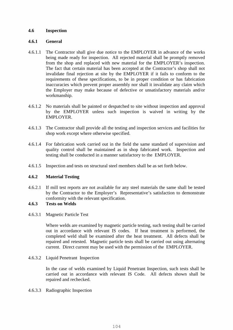
4.6 Inspection
4.6.1 General
4.6.1.1 The Contractor shall give due notice to the EMPLOYER in advance of the worksbeing made ready for inspection. All rejected material shall be promptly removedfrom the shop and replaced with new material for the EMPLOYER’s inspection.The fact that certain material has been accepted at the Contractor’s shop shall notinvalidate final rejection at site by the EMPLOYER if it fails to conform to therequirements of these specifications, to be in proper condition or has fabricationinaccuracies which prevent proper assembly nor shall it invalidate any claim whichthe Employer may make because of defective or unsatisfactory materials and/orworkmanship.
4.6.1.2 No materials shall be painted or despatched to site without inspection and approvalby the EMPLOYER unless such inspection is waived in writing by theEMPLOYER.
4.6.1.3 The Contractor shall provide all the testing and inspection services and facilities forshop work except where otherwise specified.
4.6.1.4 For fabrication work carried out in the field the same standard of supervision andquality control shall be maintained as in shop fabricated work. Inspection andtesting shall be conducted in a manner satisfactory to the EMPLOYER.
4.6.1.5 Inspection and tests on structural steel members shall be as set forth below.
4.6.2 Material Testing
4.6.2.1 If mill test reports are not available for any steel materials the same shall be testedby the Contractor to the Employer’s Representative’s satisfaction to demonstrateconformity with the relevant specification.
4.6.3 Tests on Welds
4.6.3.1 Magnetic Particle Test
Where welds are examined by magnetic particle testing, such testing shall be carriedout in accordance with relevant IS codes. If heat treatment is performed, thecompleted weld shall be examined after the heat treatment. All defects shall berepaired and retested. Magnetic particle tests shall be carried out using alternatingcurrent. Direct current may be used with the permission of the EMPLOYER.
4.6.3.2 Liquid Penetrant Inspection
In the case of welds examined by Liquid Penetrant Inspection, such tests shall becarried out in accordance with relevant IS Code. All defects shown shall berepaired and rechecked.
4.6.3.3 Radiographic Inspection
104
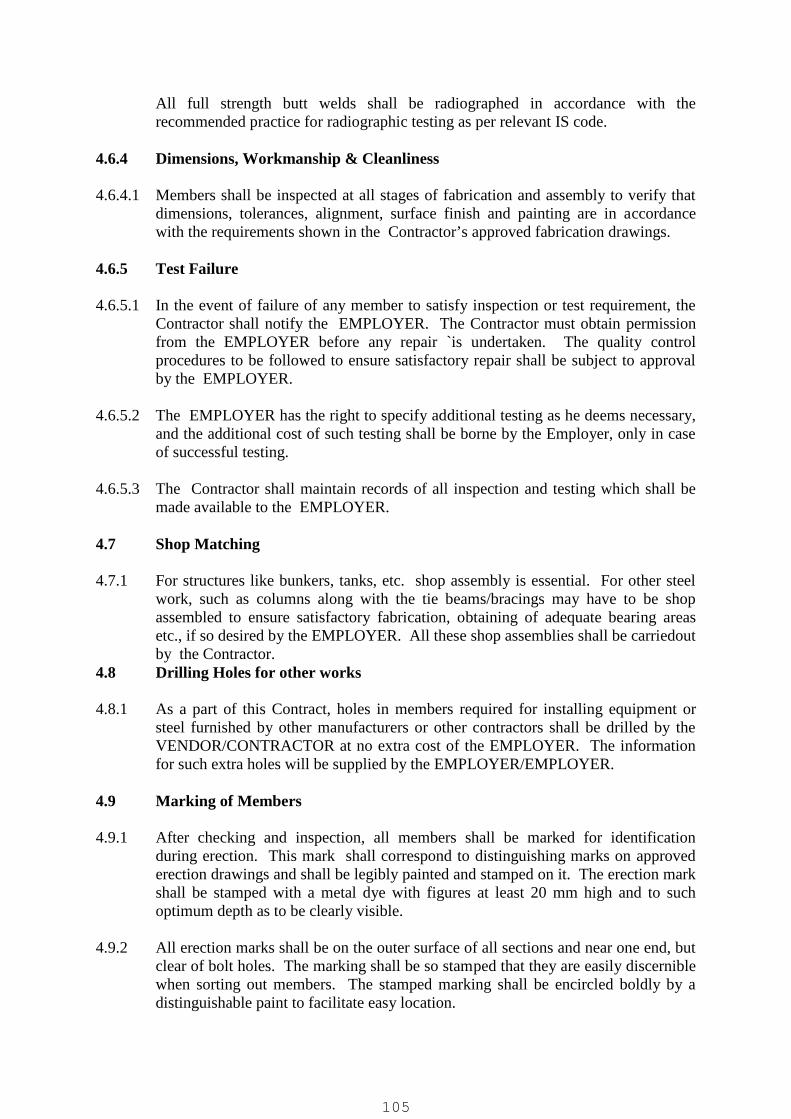
All full strength butt welds shall be radiographed in accordance with therecommended practice for radiographic testing as per relevant IS code.
4.6.4 Dimensions, Workmanship & Cleanliness
4.6.4.1 Members shall be inspected at all stages of fabrication and assembly to verify thatdimensions, tolerances, alignment, surface finish and painting are in accordancewith the requirements shown in the Contractor’s approved fabrication drawings.
4.6.5 Test Failure
4.6.5.1 In the event of failure of any member to satisfy inspection or test requirement, theContractor shall notify the EMPLOYER. The Contractor must obtain permissionfrom the EMPLOYER before any repair `is undertaken. The quality controlprocedures to be followed to ensure satisfactory repair shall be subject to approvalby the EMPLOYER.
4.6.5.2 The EMPLOYER has the right to specify additional testing as he deems necessary,and the additional cost of such testing shall be borne by the Employer, only in caseof successful testing.
4.6.5.3 The Contractor shall maintain records of all inspection and testing which shall bemade available to the EMPLOYER.
4.7 Shop Matching
4.7.1 For structures like bunkers, tanks, etc. shop assembly is essential. For other steelwork, such as columns along with the tie beams/bracings may have to be shopassembled to ensure satisfactory fabrication, obtaining of adequate bearing areasetc., if so desired by the EMPLOYER. All these shop assemblies shall be carriedoutby the Contractor.
4.8 Drilling Holes for other works
4.8.1 As a part of this Contract, holes in members required for installing equipment orsteel furnished by other manufacturers or other contractors shall be drilled by theVENDOR/CONTRACTOR at no extra cost of the EMPLOYER. The informationfor such extra holes will be supplied by the EMPLOYER/EMPLOYER.
4.9 Marking of Members
4.9.1 After checking and inspection, all members shall be marked for identificationduring erection. This mark shall correspond to distinguishing marks on approvederection drawings and shall be legibly painted and stamped on it. The erection markshall be stamped with a metal dye with figures at least 20 mm high and to suchoptimum depth as to be clearly visible.
4.9.2 All erection marks shall be on the outer surface of all sections and near one end, butclear of bolt holes. The marking shall be so stamped that they are easily discerniblewhen sorting out members. The stamped marking shall be encircled boldly by adistinguishable paint to facilitate easy location.
105
4.9.3 Erection marks on like pieces shall be in identical locations. Members havinglengths of 7.0 m or more shall have the erection mark at both ends.
4.10 Errors
4.10.1 Any error in shop fabrication which prevents proper assembling and fitting up ofparts in the field by moderate use of drift pins or moderate amount of reaming willbe classified by the EMPLOYER as defective workmanship. Where theEMPLOYER rejects such material or defective workmanship, the same shall bereplaced by materials and workmanship conforming to the Specifications by theContractor, at no cost to the Employer.
4.11 Painting of Steel Works
All fabricated steel material, except those galvanised shall receive protective paintcoating as specified in specification, which is described below.
4.11.1 Materials
4.11.1.1 Red-oxide – zinc chrome primer shall conform to IS:2074.
4.11.1.2 Synthetic enamel paint shall conform to IS : 2932.
4.11.1.3 Aluminium paint shall conform to IS:2339.
4.11.1.4 All the materials shall be of the best quality from an approved manufacturer.Contractor shall obtain prior approval of the EMPLOYER for the brand ofmanufacture and the colour/shade. All the materials shall be brought to the site insealed containers.
4.11.2 Workmanship
4.11.2.1 Painting work shall be carried out only on thoroughly dry surfaces. Painting shallbe applied either by brushing or by spraying. Contractor shall procure theappropriate quality of paint for this purpose as recommended by the manufacturer.The workmanship shall generally conform to the requirement of IS:1477 (Part 2).
4.11.2.2 The type of paint, number of costs etc. shall be as specified in the respective itemsof work.
4.11.2.3 Primer and finish paint shall be compatible with each other to avoid cracking andwrinkling. Primer and finish paint shall be from the same manufacturer.
4.11.2.4 All the surfaces shall be thoroughly cleaned of oil, grease, dirt, rust and scale. Themethods to be adopted using solvents, wire brushing, power tool cleaning etc., shallbe as per IS:1477 (Part – I) and as indicated in the item of work.
4.11.2.5 It is essential to ensure that immediately after preparation of the surfaces, the firstcoat of red oxide-zinc chrome primer shall be applied by brushing and working itwell to ensure a continuous film without holidays. After the first coat becomes hard
106

dry, a second coat of primer shall be applied by brushing to obtain a film free from‘holidays’.
4.11.2.6 After the second coat of primer is hard dry, the entire surface shall be wet rubbedcutting down to a smooth uniform surface. When the surface becomes dry, theundercoat of synthetic enamel paint of optimum thickness shall be applied bybrushing with minimum of brush marks. The coat shall be allowed to hard-dry.The under coat shall then be wet rubbed cutting down to a smooth finish, takingadequate care to ensure that at no place the undercoat is completely removed. Thesurface shall then be allowed to dry.
4.11.2.7 The first finishing coat of paint shall be applied by brushing and allowed to hard-dry. The gloss from the entire surface shall then be gently removed and the surfacedusted off. The second finishing coat shall then be applied by brushing.
4.11.2.8 Atleast 24 hours shall elapse between the application of successive coats. Each coatshall vary slightly in shade and this shall be got approved by the EMPLOYER.
4.12 Acceptance of Steel, its Handling & Storage
4.12.1 The Contractor shall carefully check the steel to be erected at the time ofacceptance. Any fabrication defects observed should be brought to the notice of theEMPLOYER.
4.12.2 No dragging of steel shall be permitted. All steel shall be stored 300mm aboveground on suitable packing to avoid damage. It shall be stored in the orderrequired for erection, with erection marks visible. All storage areas shall beprepared and maintained by the Contractor. Steel shall not be stored in the vicinityof areas where excavation or grading will be done and, if so stored temporarily, thisshall be removed by the Contractor well before such excavation and/or gradingcommences to a safe distance to avoid burial under debris.
4.12.3 Scratched or abraded steel shall be given a coat of primer in accordance with theSpecifications for protection after unloading and handling prior to erection. Allmilled and machined surfaces shall be properly protected from rust/corrosion by suitable coating and also from damage.
4.13 Anchor Bolts & Foundations
4.13.1 The Contractor shall carefully check the location and layout of anchor boltsembedded in foundations constructed, to ensure that the structures can be properlyerected as shown on the drawings. Any discrepancy in the anchor bolts/foundationshall be reported to the EMPLOYER.
4.13.2 Leveling of column bases to the required elevation may be done either by providingshims or three nuts on the upper threaded portion of the anchor bolt. All shim stockrequired for keeping the specified thickness of grout and in connection with erectionof structures on foundations, crane brackets or at any other locations shall be ofgood M.S. plates and shall be supplied by the Contractor at his cost.
107
4.13.3 A certain amount of cleaning of foundations and preparing the area is considerednormal and shall be carried out by the Contractor at no extra cost.
4.13.4 Where beams bear in pockets or on walls, bearing plates shall be set and levelled aspart of the work. All grouting under column base plates or beam bearing plates willbe carried out by the Contractor.
4.14 Assembly & connections
4.14.1 Field connections may be effected either by riveting, bolting, welding or by use ofhigh strength friction grip bolts as shown on the design and erection drawings.
4.14.2 All field connection work shall be carried as per the drawings. All bolts, nuts,washers, rivets, electrodes required for field connections shall be supplied by theContractor free of cost.
4.14.3 All assembling shall be carried on a level platform.
4.14.4 Drifts shall be used only for drawing the work to proper position and must not beused to such an extent as to damage the holes. Size of drifts larger than the normaldiameter of hole shall not be used. Any damaged holes or burrs must be rectified tothe satisfaction of the EMPLOYER.
4.14.5 Corrections of minor misfits and reasonable amount of reaming and cutting ofexcess stock from rivets shall be considered as a part of erection. Any error in theshop, which prevents proper fit on a moderate amount of reaming and slightchipping or cutting, shall be immediately reported to the EMPLOYER.
4.15 Erection
4.15.1 All structural steel shall be erected as shown on the drawings prepared by theContractor. Proper size steel cable slings, etc., shall be used for hoisting. Guysshall not be anchored to existing structures, foundations, etc., unless so permitted bythe EMPLOYER in writing. Care shall be taken to see that ropes in use are alwaysin good condition.
4.15.2 Steel columns in the basement, if any, are to be lowered and erected carefully withthe help of a crane and/or derrick without damaging the basement walls or floor.
4.15.3 Structural steel frames shall be erected plumb and true. Frames shall be lifted atpoints such that they are not liable to buckle and deform. Trusses shall be liftedonly at node points. In the case of trusses, roof girders, all of the purlins and windbracing shall be placed simultaneously and the columns shall be erected truly plumbon screed bars over the pedestals. All steel columns and beams shall be checked forplumb and level individually before and after connections are made. Temporarybracings shall be introduced wherever necessary to take care of all loads to whichthe structure may be subjected, including erection equipment and the operationthereof. Such bracings shall be left in place as long as may be required for safetyand stability.
108
4.15.4 Chequered plates shall be fixed to supporting members by tack welding or bycountersunk bolts as shown/specified in relevant drawings and/or as approved bythe EMPLOYER. The edges shall be made smooth and no burrs or jagged endsshall be left. While splicing, care should be taken so that there is continuity inpattern between the two portions. Care should also be taken to avoid distortion ofthe plate while welding. The erection of chequered plates shall include :a) Welding of stiffening angles/vertical stiffening ribsb) Cutting to size and making holes to required shape wherever necessary to allow
service piping and/or cables to pass throughc) Splicing as shown in relevant drawingsd) Smoothening of edgese) Fixing of chequered plates by tack welding or by countersunk boltsf) Providing lifting hooks for ease of lifting.
4.15.5 As erection progresses, the work shall be securely bolted to take care of all deadload, wind, seismic and erection stresses.
4.15.6 No riveting or welding or final bolting shall be done until the structure has beenproperly aligned and approved by the EMPLOYER. No cutting, heating orenlarging of the holes shall be carried out without the prior written approval of theEMPLOYER.
4.15.7 Test certificates shall be furnished by the Contractor.
4.16 Inspection
4.16.1 The EMPLOYER shall have free access to all parts of the job during erection andall erection shall be subjected to his approval. In case of faulty erection, alldismantling and re-erection required will be at the Contractor’s cost. No paint shallbe applied to rivet heads or field welds or bolts until these have been approved bythe EMPLOYER.
4.17 Tolerances
4.17.1 General
Tolerances mentioned below shall be achieved after the entire structure or partthereof is in line, level and plumb.
4.17.2 Columns
Deviation of column axes at foundation top level with respect to true axes :(a) In longitudinal direction ±5 mm(b) In lateral direction ±5 mm
Deviation in the level of bearingsurface of columns at foundationtop with respect to true level ±5 mm
109
Out of plumbness (verticality) of column axis from true vertical axis, as measured atcolumn top :(a) For columns upto and including ±1/1000 of column height in mm
15 metres in height or ±15 mm whichever is less(b) For columns exceeding 15 ±1/1000 of column height in mm
metres in height or ±20 mm whichever is lessDeviation in straightness in longitudinal ±1/1000 of column height in mmand transverse planes of column at any or ±10 mm whichever is lesspoint along the heightDifference in erected position of adjacent ±10mmpairs of columns along length or acrosswidth of building prior to connectingtrusses/beams with respect to true distanceDeviation in any bearing or seating level ±5 mmwith respect to true levelDeviation in differences in bearing level ±10 mmof a member on adjacent pair of columnsboth across and along the building
4.17.3 Trusses And BeamsShift at the centre of span of top chord ±1/250 of height of truss in mmmember with respect to the vertical plane or ±15 mm whichever is lesspassing through the centre of bottom chordLateral shift of top chord of truss at the ±1/1500 of span of truss in mmcentre of span from the vertical plane or ±15 mm whichever is lesspassing through the centre of supportsof the truss
Lateral shift in location of truss from its ±10 mmtrue vertical positionLateral shift in location of purlin true ±5 mmposition
Deviation in difference of bearing i) ±20 mm for trusseslevels of trusses or beams from ii) For beams :the true difference Depth < 1800mm : ±6mm
Depth > 1800mm : ±10mm
Deviation in sag in chords and diagonals 1/1500 of length in mm orof truss between node points 10mm whichever is smallerDeviation in sweep of trusses, beams etc. 1/1000 of span in mm subjectin the horizontal plane to a maximum of 10 mm
4.17.4 Crane Girders & Rails
Shift in the centre line of crane rail with ±5 mmrespect to centre line of web of crane girderShift in plan of alignment of crane rail with ±5 mmrespect to true axis of crane rail at any pointDifference in alignment of crane rail in plan ±1 mm
110

measured between any two points 2 metresapart along rail
Deviation in crane track with respect toTime gauge(a) For track gauges upto and
Including 15 metres ±5 mm(b) For track gauges more than ± [5 + 0.25 (S-15)]
15 metres where S in metres is true gauge
Deviation in the crane rail level at any ±1/1200 of the gauge distance orpoint from true level ±10mm whichever is lessDifference in the crane rail actual levels ±2 mmbetween any two points 2 metres apartalong the rail length
Difference in levels between crane track Rails at(a) Supports of crane girders ±15 mm(b) Mid span of crane girders ± 20 mmRelative shift of crane rail surfaces at a 2 mm subject to grinding ofjoint in plane and elevation surfaces for smooth transitionRelative shift in the location of crane 1/1000 of track gauge S instops (end buffers) along the crane tracks mm subject to maximumwith track gauge S in mm of 20 mm
4.17.5 Painting
After steel has been erected, all bare and abraded spots, rivet heads, field welds, boltheads and nuts shall be spot painted with primer. Before paint is applied, thesurface shall be dry and free from dust, dirt, scale and grease. All surfacesinaccessible after erection shall receive two coats of the approved paint beforeerection.
4.18 Clean up of Work site
During erection, the Contractor shall at all times keep the working and storage areasused by him free from accumulation of waste materials or rubbish. Beforecompletion of erection, he shall remove or dispose of in a satisfactory manner alltemporary structures, waste and debris and leave the premises in a conditionsatisfactory to the EMPLOYER.
5.0 PLUMBING WORKS FOR WATER SUPPLY AND SANITARYARRANGEMENTS
5.1 Applicable Codes
5.1.1 The following standards and codes are made a part of this Employer’s Requirement.All standards, codes of practice referred to herein shall be the latest editionsincluding all official amendments and revisions.
111
IS : 210 : Specification for grey iron castingsIS : 269 : Specification for ordinary and low heat portland cementIS : 383 : Specification for coarse and fine aggregates from natural sources for
concreteIS : 432 : Specification for mild steel and medium tensile steel bars and hard
drawn steel wire for concrete reinforcementIS : 456 : Code of Practice for plain and reinforced concreteIS : 458 : Concrete Pipes (with and without reinforcement).IS : 516 : Methods of tests for strength of concreteIS : 554 : Dimensions for pipe threads where pressure tight joints are required
on the threads.IS : 651 : Salt glazed stoneware pipes and fittings.IS : 774 : Flushing Cisterns for water closets and urinals (valveless siphonic
type)IS : 775 : Cast iron brackets and supports for wash basins and sinks.IS : 781 : Sand-cast brass screw-down bib taps and stop taps for water services.IS : 783 : Code of practice for laying of concrete pipes.IS : 1068 : Electroplated coatings of nickel and chromium of iron and steel.IS : 1077 : Specification for common burnt clay building bricksIS : 1786 : Specification for high strength deformed steel bars and wires for
concrete reinforcementIS : 1239 : Mild steel tubes (Part I) and mild steel tubulars and other wrought
steel pipe fittings (Part II)IS : 1536 : Centrifugally cast (spun) iron pressure pipes for water, gas and
sewage.IS : 1626 : Asbestos cement building pipes, gutters and fittings (spigot and
socket types).IS : 1703 : Copper Alloy float valves (horizontal plunger type) for water supply
purposes.IS : 1726 : Cast iron manhole covers and frames.IS : 1729 : Sand cast iron spigot and socket soil, waste and ventilating pipes,
fittings and accessories.IS : 1742 : Code of practice for buildings drainageIS : 2116 : Specification for sand for masonry mortarsIS : 2212 : Code of practice for brickworkIS : 2250 : Code of practice for preparation and use of masonry mortarsIS : 2326 : Automatic flushing cisterns for urinalsIS : 2470 : Code of practice for design and construction of septic tanks (Parts I
& II)IS : 2556 : Vitreous sanitary appliances (Part I to Part XV)IS : 2963 : Specification for copper alloy waste fittings for wash basins and
sinksIS : 3006 : Specification for chemically resistant glazed stoneware pipes and
fittingsIS : 3311 : Waste plug and its accessories for sinks and wash basinsIS : 5455 : Specification for cast iron steps for manholesIS : 4127 : Code of Practice for laying of glazed stoneware pipesIS : 3495 : Methods of tests of burnt clay building bricksIS : 4111 : Code of practice for ancillary structures in sewerage system manholesIS : 5382 : Specification for rubber sealing rings for gas mains, water mains and
112

sewersIS : 5329 : Code of practice for sanitary pipe work above ground for buildingsIS : 5434 : Non-ferrous alloy bottle traps for marine use
5.2 Sanitary Installation
5.2.1 The work shall be carried out complying in all respects with any specificrequirements of the local body in whose jurisdiction the work is situated, and asapproved by the Employer’s Representative.
5.2.2 Any damage caused to the building, or to installations therein, either due tonegligence on the part of the Contractor, or due to actual requirements of the work,shall be made good and the building or the installation shall be restored to itsoriginal condition by the Contractor.
5.2.3 All sanitary and plumbing work shall be carried out by licensed plumbers.
5.2.4 All sanitary appliances including sanitary fittings, fixtures, toilet requisites shall beof size, and design as approved by the Employer’s Representative.
5.2.5 All white glazed porcelain fixtures, such as wash basin, sink drain board, watercloset pan, urinal, `P' trap etc. shall have hard durable white glazed finish. Theyshall be free from cracks and other glazing defects. No chipped porcelain fixturesshall be used.
5.2.6 Joints between iron and earthenware pipes shall be made perfectly air and watertight by caulking with neat cement mortar.
5.3 Indian Type Water Closet
5.3.1 This shall be the long pan pattern with separate footrests made of white glazedearthenware, white glazed vitreous china or of white glazed fire clay. The generalrequirements shall conform to IS:2556 (Parts III and X). Each pan shall have anintegral flushing rim of suitable type. It shall also have an inlet or supply horn forconnecting the flush type. The flushing rim and inlet shall be of the self drainingtype. It shall have a weephole at the flushing inlet to the pan. The flushing inlet shallbe in the front, unless otherwise approved by the Employer’s Representative. Theinside of the bottom of pan shall have sufficient slope from the front towards theoutlet and the surface shall be uniform and smooth enable easy and quick disposalwhile flushing. The exterior surface shall be unglazed and sufficiently rough orgrooved at right angles to the axis of the outlet. Pans shall be provided with a trap`P' or `S' type with a minimum 50 mm water seal and 50 mm dia. vent horn. Panshall be laid at the correct location and level over a bed of lime concrete using brickaggregates (1 part lime mortar to 2 parts brick bats with lime mortar to 2 parts ofsand) or cement-sand admixture as specified in the drawings.
5.4 European Type Water Closet
5.4.1 Water closets shall be either of white glazed earthenware, white grazed vitreouschina or white glazed fire clay as specified and shall be of "Siphonic Wash down
113
type" conforming to IS.2556 (Part VIII). The closets shall be of one piececonstruction with approved plastic/bakelite seat and cover. Each water closet shallhave 4 fixing holes having a minimum diameter of 6.5 mm for fixing to floor andshall have an integral flushing rim of suitable type. It shall also have an inlet ofsupply horn for connecting the flush pipe. The flushing rim and inlet shall be of theself-draining type. The water closet shall have a weephole at the flushing inlet. Eachwater closet shall have an integral trap with either "S" or "P" outlet with at least 50mm water seal. The water closets shall have an antisiphonage 50 mm dia. vent hornon the outlet side of the trap. The inside of water closets and traps shall be uniformand smooth in order to ensure in efficient flush. The serrated part of the outlet shallnot be glazed externally. The water closet when sealed at the bottom of the trap inline with the back plate, shall be capable of holding not less than 10 litres of waterbetween the normal water level and the highest possible water level of the watercloset installed.
5.5 Urinals
5.5.1 Urinals shall be of the bowl pattern, either flat back or angle back type lipped infront. They shall be of white glazed earthenware, white glazed vitreous china orwhite glazed fire clay, and of size as specified conforming to IS.2556 (Part VI). Theurinals shall be of one piece construction. Each urinal shall be provided with notless than two fixings holes of a minimum dia. of 6.5 mm on each side. Each urinalshall have an integral flushing box rim of suitable type and inlet or supply horn forconnecting the flush pipe. The flushing rim and inlet shall be of the self-drainingtype. It shall have a weephole at the flushing inlet of the urinal. At the bottom of theurinal, an outlet horn for connecting to an outlet pipe shall be provided. The exteriorof the outlet horn shall not be glazed and the surface shall be provided with groovesat right angles to the axis of the outlet to facilitate fixing to the uniform and smooththroughout to ensure efficient flushing. The bottom of pan shall have sufficientslope from the front, towards the outlet such that there is efficient draining of theurinal. The waste fittings shall be chromium plated.
5.6 Wash Basins
5.6.1 Wash basins shall be of white glazed earthenware, white glazed vitreous china orwhite glazed fire clay as approved by the Employer’s Representative andconforming to IS.2556
Type SizeFlat Back 630 x 450 mmFlat Back 550 x 400 mm
5.6.2 Wash basins shall be of one piece construction, including a combined overflow. Allinternal angles shall be designed so as to facilitate cleaning. Each shall have a rimsloping inside towards the bowl on all sides except skirting at the back. Basins shallbe provided with single or double tap holes as approved. The tap holes shall besquare. A suitable tap hole button shall be supplied if one tap hole is not required ininstallation. Each basin shall have a circular waste hole to which the interior ofbasin shall drain. The waste hole shall be either rebated or bevelled internally with
114

diameter of 65 mm at top and a depth of 10 mm to suit a waste plug having 64 mmdiameter. Each basin shall be provided with a non-ferrous 32 mm waste fittings.Stud slots to receive the brackets on the under side of the wash basins shall besuitable for a bracket with stud not exceeding 13 mm diameter, 5 mm high and 305mm from the back of basin to the centre of the stud. The stud slots shall be of depthsufficient to take 5 mm stud. Every basin shall have an integral soap holder recessor recesses which shall fully drain into the bowl. The position of the chain stay-holeshall not be lower than the overflow slot. A slot type of overflow having an area ofnot less than 5 sq.cm. shall be provided and shall be so designed as to facilitatecleaning of the overflow. The Employer’s Requirements for waste plug, chain andstay shall be the same as given for sinks.
5.6.3.1 All the waste fittings shall be chromium plated. Bottle trap shall conform toIS. 5434. The chromium plating shall be of service grade No. 2 conforming toIS.1068.
5.7 Sinks
5.7.1 The sinks shall be of white glazed earthenware, white glazed vitreous china or whiteglazed fire clay as approved by the Employer’s Representative conforming toIS.2556 (Part V) and shall be of the following sizes:
450 x 300 x 150 mm600 x 450 x 200 mm
5.7.2 They shall be of one piece construction, including a combined overflow. The floorof the sink shall gently slope towards the outlet. The outlet shall in all cases besuitable for waste fittings having flange of 64 mm diameter and the waste hole shallhave a minimum diameter of 65 mm at the bottom to suit the waste fittings. Thewaste hole shall be either rebated or bevelled having a depth of 10 mm. Each sinkshall be provided with a non-ferrous 40 mm dia. waste fitting. The sink shall haveoverflow of the weir type and the inverts shall be 30 mm below the top edge. Eachsink shall be provided with a waste plug, of suitable dia. chain and stay. The plugshall be of rubber or other equally suitable material and shall be water tight whenfitted. Plug chains shall be of brass wire chromium plated. It shall have an overalllength from the collar to the stay of not less than 300 mm. There shall be atriangular or D shackle at each end, one of which shall be brazed to the plug and theother securely fixed to the stay. The 150 mm long shank of the waste shall bethreaded conforming to the requirements of IS.2556 for sinks only. The wastefittings and plug fittings shall be chromium plated. The chromium plating shall beof service grade No.2 conforming to IS.1068.
5.8 Flushing Cisterns
5.8.1 The flushing cisterns shall be automatic or manually operated, high level or lowlevel, as approved by the Employer’s Representative. For water closets and urinalshigh level cistern is intended to operate with minimum height of 125 cm and a lowlevel cistern a maximum height of 30 cm between the top of the pan and theunderside of the cistern. They shall be of cast iron, glazed earthenware, or pressedsteel complying iron, glazed requirement of IS.774. Automatic flushing cistern forurinals shall conform to IS.2326.
115

5.9 Cast Iron Soil Waste and Vent Pipes and Fittings
5.9.1 All cast iron pipes and fittings shall be of uniform thickness with strong and deepsockets, free from flaws, air holes, cracks, sand holes and other defects and conformto IS.1536 . The diameter approved shall be internal diameter of pipe. The pipes andfittings shall be true to shape, smooth and cylindrical and shall ring clearly whenstruck over with a light hand hammer. All pipes and fittings shall be properlycleaned of all foreign material before being fixed.
5.9.2 All plug bends of drainage pipes shall be provided with inspection and cleaningcaps, covers, which shall be fixed with nuts and screws. Pipes shall be fixed to thewall by W.I. or M.S. holder bat clamps, unless projecting ears with fixing holes areprovided at socket end of pipe. The pipes shall be installed, truly vertical or to thelines and slopes as indicated. The clamps shall be fixed to the walls by embeddingtheir hooks in cement concrete blocks (1:2:4) 10 cm x 10 cm making necessaryholes in the walls at proper places. All holes and breakages shall be made good. Theclamps shall be kept 25 mm clear of the finished face of the walls to facilitatecleaning and painting of pipes.
5.9.3 The annular space between the socket and spigot shall be filled with a gasket ofhemp or spun yarn soaked in neat cement slurry. The joint shall then be filled withstiff cement mortar 1:2 (1 cement : 2 fine sand) well pressed with caulking tool andfinished smooth on top at an angle of 45°. The joint shall be kept wet for not lessthen 7 days by tying a piece of gunny bag kept moist. Joints shall be perfectly airtight as well as water tight.
5.9.4 C.I. pipes and fittings which are exposed shall be first cleaned and then painted witha coat of red leadprimer. Two coats of zinc paint with white base and mixed withpigment of required colour to get the approved shade shall be given over the baseprimer coat.
5.9.5 The thickness of fittings and their socket and spigot dimensions shall conform to thethickness and dimensions approved for the corresponding sizes of straight pipes.
5.9.6 The connection between the main pipe and branch pipes shall be made by usingbranches and bends with access for cleaning. Floor traps shall be provided with 25mm dia. puff pipe where the length of the waste is more than 1800 mm or the floortrap is connected to a waste stack through bends.
5.9.7 All cast iron pipes and fittings including joints shall be tested by a smoke test to thesatisfaction of the Employer’s Representative and left in working condition aftercompletion. The smoke test shall be carried out as stated under :
5.9.8 Smoke shall be pumped into the pipe at the lowest and from a smoke machinewhich consists of a bellow and a burner. The material usually burnt is greasy cottonwaste which gives out a clear pungent smoke which is easily detectable by sight aswell as by smell if there is a leak at any point of the pipeline.
5.9.9 Water test and air test shall be conducted as stipulated in IS.5329.
116

5.10 Galvanised Mild Steel (G.I) Pipes
5.10.1 The pipes shall be galvanised mild steel welded pipes and seamless screwed andsockets tubes conforming to the requirements of IS.1239, for medium grade. Theyshall be of the diameter (nominal bore) approved. The sockets shall be designatedby the respective nominal bores of the pipes for which they are intended. The pipesand sockets shall be finished neatly, well galvanised on both inner and outersurfaces, and shall be free from cracks, surface flaws, laminations and other defects.All screws, threads shall be clean and well cut. The ends shall be cut cleanly andsquare with the axis of the tube.
5.10.2 All screwed tubes and sockets shall have pipe threads conforming to therequirements of IS.554. Screwed tubes shall have taper threads while the socketsshall have parallel threads.
5.10.3 The fittings shall be of malleable cast iron or mild steel tubes complying with all theappropriate requirements as approved for pipes. The fittings shall be designated bythe respective nominal bores of the pipes for which they are intended. The fittingsshall have screw threads at the ends conforming to the requirements of IS.554.Female threads on fittings shall be parallel and male threads (except on runningnipples and collars of unions) shall be tapered.
5.10.4 The pipes and fittings shall be inspected at site before use to ascertain that theyconform to the specification. The defective pipes shall be rejected. Where the pipeshave to be cut or rethreaded, the ends shall be carefully filled out so that noobstruction to bore is offered. The ends of the pipes shall then be threadedconforming to the requirements of IS.554 with pipe dies and taps carefully in such amanner as will not result in slackness of joints when the two pieces are screwedtogether. The taps and dies shall be used only for straightening bent and damagedscrew threads and shall not be used for turning of the threads so as the make themslack, water tight joint. The screw- thread of pipes and fittings shall be protectedfrom damage until they are fitted.
5.10.5 The pipes shall be cleaned and cleared of all foreign matter before being laid. Injointing the pipes, the inside of the socket and the screwed end of the pipes shall beoiled and rubbed over with white lead and a few turns of spun yarn wrapped aroundthe screwed end of the pipe. The end shall then be screwed in the socket, tee, etc.,with the pipe wrench. Care should be taken that all pipes and fittings are properlyjointed so as to make the joints completely water tight and pipes are kept at all timesfree from dust and dirt during fixing. Burrs from the joint shall be removed afterscrewing. After laying, the open ends of the pipes shall be temporarily plugged toprevent access of soil or any other foreign matter.
5.10.6 Any threads exposed after jointing shall be painted or in the case of undergroundpiping thickly coated with approved anticorrosive paint to prevent corrosion.
5.10.7 For internal work the galvanised iron pipes and fittings shall run on the surface ofthe walls or ceiling (not in chase) unless otherwise specified. The fixing shall bedone by means of standard pattern holder bat clamps, keeping the pipes about 1.5
117

cm clear of the wall. Pipes and fittings shall be fixed truly vertical/horizontal. Whenit is found necessary to conceal the pipes, chasing may be adopted or pipes fixed inthe ducts of recesses etc. provided there is sufficient space to work on the pipes withthe usual tools. The pipes shall not ordinarily be buried in walls or solid floors.Where unavoidable, pipes may be buried for short distances provided adequateprotection is given against damage, but the joints in pipes shall not be buried. M.S.pipe sleeve shall be fixed at a place where a pipe is passing through a wall or floorfor reception of the pipe and to allow freedom for expansion/contraction and othermovements/maintenance. In case the pipe is embedded in walls or floors it shouldbe painted with anti-corrosive bitumastic paint of approved quality. The pipe shouldnot come in contract with lime mortar or lime concrete as the pipe is affected bylime. Under the floors the pipes shall be laid in layer of sand filling or as approvedby the Employer’s Representative.
5.10.8 G.I. pipes with socket and spigot ends shall be provided with lead caulked jointswherever specified and the joints shall conform to the requirements of IS.3114.
5.10.9 The work of excavation and backfilling shall be done true to line and gradient inaccordance with general Employer’s Requirements for earthworks in trenches forpipes laid underground.
5.10.10 The pipes shall be laid on a layer of 10.0 cm sand and filled upto 15 cm above thepipes. A sand cushion of 15cm on either side of the pipe shall also be provided. Theremaining portion of the trench shall then be filled with excavated earth. Thesurplus earth shall be got rid of as directed. when excavation is done in rock thebottom shall be cut deep enough to permit the pipes to be laid on a cushion of sand75 mm minimum.
5.10.11 The pipes and fittings after they are laid and jointed shall be subjected to hydrostaticpressure test as approved by the Employer’s Representative and shall satisfactorilypass the test. Pipe line system shall be tested in sections as the work proceeds,keeping the joints exposed for inspection. Pipes shall be slowly and carefullycharged with water allowing all air to escape. All draw off taps shall then be closedand water pressure gradually raised to test pressure. Care shall be taken to ensurethat pressure gauge is accurate and preferably should have been recalibrated beforethe test. Pump used having been stopped, the section of the pipeline shall maintainthe test pressure for at least half an hour. Any joints or pipes found leaking shall beremoved and replaced by the Contractor.
5.10.12 The G.I. pipe line shall be cut to the required length at the position where the meterand stop cock are required to be fixed. The ends of the pipes shall be threaded. Themeter and stop cock shall be fixed in position by means of connecting pipe, G.I.nuts, sockets, etc. The stop cock shall be fixed near the inlet of the water meter. Thepaper disc inserted in the ripples of the meter shall be removed and meter installedexactly horizontally or vertically and with the arrow cast on the body of the meterpointing in the direction of flow. Care shall be taken that the factory seal of themeter is not disturbed. Whenever the meter is to be fixed to a newly fitted pipe line,the pipe line will have to be completely washed before fixing the meter. For thispurpose, a connecting piece of pipe equal to the length of the meter is to be fixed onthe new pipe line. The water shall be allowed to flow completely to wash the pipe
118
line and then the meter installed as described above by replacing the connectingpiece.
5.11 Stoneware Pipes and Fittings
5.11.1 All pipes with spigot and socket ends shall conform to IS.651/3006 and shall be ofgrade `A'. These shall be sound, free from visible defects such as fine cracks or haircracks. The glaze of the pipes shall be free from crazing. The pipes shall give asharp clear note when struck with a light hammer.
5.11.2 The following information shall be clearly marked on each pipe and fitting :(a) Internal diameter;(b) Grade;(c) Date of manufacture;(d) Name of manufacturer or his registered trade-mark or both.All pipes and fittings shall have ISI mark.
5.11.3 Jointing of GSW pipes and fittings shall be done as per the requirements of thefollowing Employer’s Requirements and the relevant IS. After jointing, extraneousmaterial if any, shall be removed from the inside of the pipes and fittings and thenewly made joints shall be thoroughly cured. In case, rubber sealing rings are usedfor jointing, these shall conform to IS : 5382.
5.11.4 Spigot and Socket Joint (Cement Joint)
5.11.4.1 The spigot of each pipe shall be slipped home well into the socket of the pipepreviously laid and adjusted in the correct position. In each joint, spun yarn soakedin neat cement slurry or tarred gasket shall be passed around the joint and inserted init by means of a caulking tool. More skeins of yarn or gasket shall be added ifnecessary and shall be well caulked. Yarn or gasket so rammed shall not occupymore than one- fourth of the depth or socket.
5.11.4.2 Cement mortar (1:1) shall be slightly moistened and carefully inserted by hand intothe remaining space of the joint after caulking of yarn or gasket. The mortar shallthan be caulked into the joint with a caulking tool. More cement mortar shall beadded until the space of joint has been completely filled with tightly caulked mortar.The joint shall then be finished of neatly outside the socket at an angle of 45degrees.
5.11.4.3 The cement mortar joints shall be cured at least for seven days before testing.
5.11.4.4 The approximate quantity of cement required for each joint for certain commonsizes of pipes are give below for guidance :
Nominal diameter of pipe (mm) Cement (kg)150 1.5200 2.0250 2.5300 3.25350 4.5
119

400 5.5450 6.5
5.11.5 Spigot and Socket Joint (Bituminous Joint)
5.11.5.1 The general requirements for this type of joint shall be as specified in 5.12.1 Thematerial for jointing shall consist of composition of asphalt and sand in the ratio of1:7. Asphalt and sand shall be boiled together and filled into the socket in a moltenstate with the aid of special moulds.
5.11.6 Spigot and Socket Joint (Rubber Ring Joint)
5.11.6.1 The pipe with the rubber ring accurately positioned on the spigot shall be pushedwell home into the socket of the previously laid pipe by means of uniformly appliedpressure with the aid of a jack or similar appliance. The rubber rings conforming toIS : 5382 shall be used, and the manufacturer's instructions shall be deemed to forma part of this Employer’s Requirements. The rubber rings shall be lubricated beforemaking the joint and the lubricant shall be soft soap water or an approved lubricantsupplied by the manufacturer.
5.11.7 Cleaning of Pipes
5.11.7.1 As soon as a stretch of GSW pipes has been laid complete from manhole to manholeor for a length as approved by the Employer’s Representative, the Contractor shallrun through the pipes both backward and forward a double disc or solid or closedcylinder 50 mm less in diameter than the internal diameter of pipes. The open end ofan incomplete stretch of pipeline shall be securely closed as approved by theEmployer’s Representative to prevent entry of mud or silt etc.
5.11.7.2 If as a result of the removal of any obstruction the Employer’s Representativeconsiders that damages may have been caused to the pipe lines, he shall be entitledto order the length to be tested immediately. Should such test prove unsatisfactorythe Contractor shall repair the pipeline and carry out such further tests as arerequired by the Employer’s Representative.
5.11.7.3 It shall also be ascertained by the Contractor that each length from manhole tomanhole or the length as approved by the Employer’s Representative is absolutelyclear and without any obstruction by means of visual examination of the interior ofthe pipeline suitably illuminated by projected sunlight or otherwise.
5.11.7.4 After laying and jointing of GSW pipes is completed the pipe line shall be tested asper the following Employer’s Requirements and as approved by the Employer’sRepresentative. All equipment for testing at work site shall be supplied and erectedby the Contractor. Water for testing of pipeline shall be arranged by him. Damageduring testing shall be the Contractor's responsibility and shall be rectified by him tothe full satisfaction of the Employer’s Representative. Water used for test shall beremoved from pipes and not released to the excavated trenches.
5.11.7.5 After the joints have thoroughly set and have been checked by the Employer’sRepresentative and before backfilling the trenches, the entire section of the sewer or
120

storm water drain shall be proved by the Contractor to be water tight. Beforecommencing the hydraulic test, the pipelines shall be filled with water andmaintained full for 24 hours by adding water, if necessary, under a head of 0.6 m ofwater. The test shall be carried out by suitably plugging the low end of the drain andthe ends of connections, if any, and filling the system with water. A knuckle bendshall be temporarily jointed at the top end and a sufficient length of vertical pipejointed to it so as to provide the required test head; or the top end may be pluggedwith a connection to a hose ending in a funnel which could be raised or lowered tillthe required head is obtained and fixed suitably for observation. The pipeline shallbe subjected to a test pressure of at least 2.5 m head of water at the highest point ofthe section under test. The tolerance of two litres per centimeter of diameter perkilometer may be allowed during a period of 10 minutes. Any leakage includingexcessive sweating which causes a drop in the test water level will be visible and thedefective part of the work should be removed and made good.
5.11.7.6 If any damage is caused to the pipeline during the execution of work or whilecleaning/testing the pipeline as specified. The Contractor shall be held responsiblefor the same and shall replace the damaged pipeline and re-test the same to the fullsatisfaction of the Employer’s Representative.
5.11.7.7 Water for testing of pipeline shall be arranged by the Contractor.
5.12 Stop Cock and Bib Cock
5.12.1 A bibcock (bibtap) is a draw off tap with a horizontal inlet and free outlet andstopcock (stop tap) is a valve with a suitable means of connections for insertion in apipe line for controlling or stopping the flow. They shall be of specified size andshall be of the screw down type. The closing device should work by means of a disccarrying a renewable non-metallic washer, which shuts against water pressure on aseating at right angles to the axis of the threaded spindle which operates it. Thehandle shall be either crutch or butterfly type securely fixed to the spindle. Thecocks shall open in anti-clockwise direction. When the bib cocks and stop cocks arerequired to be chromium plated, the chromium plating shall be of service Grade No.2 conforming to IS.1068. in finish and appearance, the plated articles shall be freefrom plating defects such as blisters, pits, roughness and shall not be stained ordiscoloured.
5.12.2 These fittings shall be of brass heavy class, chromium plated (C.P) and of approvedmanufacture and pattern with screwed of flanged ends as specified. The fittingsshall in all respects comply with the requirements of IS.781. The standard size ofbrass fittings shall be designated by the nominal bore of the pipe to which thefittings are attached. A sample of each kind of fitting shall be approved by theEmployer’s Representative and all supplies made according to the approvedsamples.
5.12.3 All cast fittings shall be sound and free from laps, blow holes and fittings, bothinternal and external surfaces shall be clean, smooth and free from sand etc.Burning, plugging stopping or patching of the casting shall not be permitted. Thebodies, bonnets, spindles and other parts shall be truly machined and whenassembled the parts shall be axial, parallel and cylindrical with surfaces smoothly
121

finished. The area of the waterway of the fittings shall not be less than the area ofthe nominal bore.
5.12.4 The fittings shall be fully examined and cleared of all foreign matter before beingfixed. The fittings shall be fitted in the pipe line in a workman like manner. Thejoints between fittings and pipes shall be made leak- proof. The joints and fittingsshall be leak proof when subjected to a pressure test approved by the Employer’sRepresentative and the defective fittings and joints shall be replaced or redone.
5.13 Soak Pit
5.13.1 Soak pit shall be constructed at the location specified by the Employer’sRepresentative. Earthwork excavation shall be carried out to the exact dimensions.Brick masonry lining with open joints shall be constructed in the pit upto 150 mmbelow the outlet pipeline. Brick masonry in cement mortar 1:6 shall be constructedabove this level upto ground. Well burnt brick aggregates of nominal size 40 mm to80 mm and coarse sand shall be filled within the chamber. Construction of pit liningand filling of the brick ballast shall progress simultaneously.
5.14 Manholes
5.14.1 Location
Manholes shall be constructed at places approved by the Employer’sRepresentative.
5.14.2 Excavation
Excavation, shoring, dewatering etc. for the pits of manholes, laying of pipes andfittings/specials shall be done in accordance with Employer’s Requirementsdescribed elsewhere in the document.
5.14.3 Bed Concrete
The bed concrete for manholes shall be done in accordance with Employer’sRequirements described elsewhere in the document.
5.14.4 Bricks
5.14.4.1 Bricks used for construction of manholes shall conform to the relevant IndianStandards. They shall be sound, hard, homogeneous in texture, well burnt in kilnwithout being vitrified, table moulded, deep red, cherry or copper coloured, ofregular shape and size and shall have sharp and square and parallel faces. The bricksshall be free from pores, chips, flaws or humps of any kind. Bricks containingungrounded particles and/or which absorb water more than 1/6th of their weightwhen soaked in water for twenty-four hours shall be rejected. Overburnt orunderburnt bricks shall be liable to rejection. The bricks shall give a clear ringingsound when struck and shall have a minimum crushing strength of 50 kg/sq.cm.unless otherwise noted in drawings. The class and quality requirements of bricksshall be as laid down in IS : 1077.
122
5.14.4.2 The size of the brick shall be 23.0 x 11.5 x 7.5 cm. unless otherwise specified; buttolerance upto 3 mm in each direction shall be permitted. Only full size brick shallbe used for masonry work. Brick bats shall be used only with the permission ofEmployer’s Representative to make up required wall length or for bonding. Samplebricks shall be submitted to the Employer’s Representative for approval and brickssupplied shall conform to approved samples. If required by the Employer’sRepresentative, brick sample shall be tested as per IS : 3495 by Contractor. Bricksrejected by the Employer’s Representative shall be removed from the Site within 24hours.
5.14.5 Cement Mortar
5.14.5.1 Mortar for brick masonry shall be prepared as per IS : 2250. Manholes shall beconstructed in brick masonry with cement mortar (1:2) unless otherwise specified.Gauge boxes for sand shall be of such dimensions that one bag containing 50 kg. ofcement forms one unit. The sand shall be free from clay, shale, loam, alkali andorganic matter and shall be of sound, hard, clean and durable particles. Sand shall beas approved by the Employer’s Representative. If required by the Employer’sRepresentative sand shall be thoroughly washed till it is free of any contamination.
5.14.5.2 For preparing cement mortar, the ingredients shall first be mixed thoroughly in dryconditions. Water shall then be added and mixing continued to give a uniform mixof required consistency. Cement mortar shall be used within 25 minutes of mixing.Mortar left unused in the specified period shall be rejected.
5.14.5.3 The Contractor shall arrange for tests on mortar samples if so required byEmployer’s Representative. Retempering of mortar shall not be permitted.
5.14.6 Brick Masonry
5.14.6.1 All bricks shall be thoroughly soaked in clean water for atleast one hourimmediately before being laid. The cement mortar for brick masonry work ofmanholes shall be in the proportion specified in 5.14.5. Brick work 230 mm thickand over shall be laid in English Bond unless otherwise specified. 115 mm thickbrick work shall be laid with stretchers. For laying bricks, a layer of mortar shall bespread over the full width of suitable length of the lower course. Each brick shall bepressed into the mortar and shoved into final position so as to embed the brick fullyin mortar. Bricks shall be laid with frogs uppermost.
5.14.6.2 All brickwork shall be plumb and square unless otherwise shown on drawing andtrue to dimensions shown. Vertical joints in alternate courses shall come directlyone over the other and be in line. Horizontal courses shall be levelled. The thicknessof brick courses shall be kept uniform. For walls of thickness greater than 230 mmboth faces shall be kept in vertical planes unless otherwise specified. Allinterconnected brickwork shall be carried out at nearly one level (so that there isuniform distribution of pressure on the supporting structure) and no portion of thework shall be left more than one course lower than the adjacent work. Where this isnot possible, the work shall be raked back according to bond (and not saw toothed)at an angle not exceeding 45 degrees. But in no case the level difference betweenadjoining walls shall exceed 1.25 M. Workmanship shall conform to IS : 2212.
123

5.14.6.3 Brick shall be so laid that all joints are well filled with mortar. The thickness ofjoints shall not be less than 6 mm and not more than 10 mm. The face joints shall beraked to a minimum depth of 12 mm by raking tools daily during the progress ofwork when the mortar is still green, so as to provide a proper key for the plasteringto be done. When plastering is not required to be done, the joints shall be uniform inthickness and be struck flush and finished at the time of laying. The face ofbrickwork shall be cleaned daily and all mortar droppings removed. The surface ofeach course shall be thoroughly cleaned of all dirt before another course is laid ontop. If mortar in the lower courses has begun to set, the joints shall be raked out to adepth of 12 mm before another course is laid.
5.14.7 Cement Plaster
5.14.7.1 All joints in masonry shall be raked to a depth of 12 mm with hooked tool made forthe purpose when the mortar is still green and in any case within 48 hours of itslaying. The surface to be rendered shall be washed with fresh clean water free fromall dirt, loose material, grease etc. and thoroughly wetted for 6 hours beforeplastering work is commenced. Concrete surfaces to be rendered will however bekept dry. The wall should not be too wet but only damp at the time of plastering.The damping shall be uniform to get uniform bond between the plaster and the wall.
5.14.7.2 The proportion of the cement mortar shall be as approved on relevant drawings.Cement shall be mixed thoroughly in dry condition and then just enough wateradded to obtain a workable consistency. The quality of water, sand and cement shallbe as per relevant I.S. The mortar thus mixed shall be used immediately and in nocase shall the mortar be allowed to remain for more than 25 minutes after mixingwith water.
5.14.7.3 Curing of plaster shall be started as soon as the applied plaster has hardened enoughso as not to be damaged. Curing shall be done by continuously applying water in afine spray and shall be carried out for at least 7 days.
5.14.7.4 Plastering shall be done on both faces of brick masonry in cement mortar (1:2) and20 mm thick unless otherwise specified.
5.14.7.5 Plastering work shall be carried out in two layers, the first layer being 14 mm thickand the second layer being 6 mm thick. The first layer shall be dashed against theprepared surface with a trowel to obtain an even surface. The second layer shall thenbe applied and finished leaving an even and uniform surface, trowel finished unlessotherwise approved by the Employer’s Representative.
5.14.8 Cement Concrete Channel
5.14.8.1 The channel for the manhole shall be constructed in cement concrete of M15 grade.Both sides of the channel shall be taken up to the level of the crown of the outgoingsewer. They shall be benched up in concrete and rendered in cement mortar (1:1) of20 mm thickness and formed to a slope of 1 in 12 towards the channel.
124
5.14.9 Pipe Entering or Leaving Manhole
5.14.9.1 Whenever a pipe enters or leaves a manhole, bricks on edge must be cut to a properform and laid around the upper end of the pipe so as to form an arch. All around thepipes, there shall be a joint of cement mortar (1:2) 13 mm thick between it and thebricks.
5.14.10 Cast Iron Steps
5.14.10.1 Cast iron steps shall be as per IS : 5455. The steps shall be of grey cast iron ofgrade 15 as per IS : 210. The steps shall be clean, well cast and they shall be freefrom air and sand holes, cold shuts and warpings. The portion of the step whichprojects from the wall of the manhole shall have a raised chequered design toprovide an adequate non-slip grip. C.I. steps shall weigh not less than 4.5 kg eachand shall be of 150 mm x 375 mm overall dimensions. These steps shall be coatedwith a black bituminous composition. The coating shall be smooth and tenacious.It shall not flow when exposed to a temperature of 63 degrees C and shall not bebrittle as to chip of at temperature of 0 degree C.
5.14.10.2 Where the depth of invert of manhole exceeds 800 mm, cast iron steps ofapproved pattern shall be fixed in the brick work at the interval of 300 mmvertically and staggered at 380 mm horizontally centre to centre. In case of pipediameter greater than 600 mm, box type C.I. steps weighing 19 kg each shall beprovided at 300 mm vertically in channel of manhole.
5.14.11 Frame and Covers
5.14.11.1 Frame and covers for manholes shall be of required type and dimensions as perthe relevant drawings prepared by the Contractor. Following information shall beclearly marked on each cover.Year of manufacture,Identification mark of the Employer: EMPLOYERArrow showing direction of flow
5.14.11.2 Cast Iron Frame and Cover
The cast iron frame and cover shall be of grey cast iron as per IS : 1726. Thegeneral requirements for casting and coating of CI frame and cover shall be asspecified for CI steps in Clause 5.15.10. The covers shall have a raised chequereddesign to provide an adequate non-slip grip. The rise of the chequer shall be notless than 4 mm. The locking device for the cover shall be provided as approved bythe Employer’s Representative. The CI covers for the load test shall be selected atone for every lot of fifty or part thereof for each type and size manufactured andas approved by the Employer’s Representative. The frame shall be fixed in cementconcrete of M15 grade all round and finished with neat cement. The manholeframe shall have 560 mm diameter clear opening and shall weigh not less than 208kg. including cover. In case of rectangular CI frame and cover of 900 mm x 600mm clear opening, the total weight shall not be less than 275 kg. In case of scrapermanhole the frame shall have clear opening of 1200 mm x 900 mm and shall
125
weigh not less than 900 kg including cover. The manhole cover and frame shall bepainted with three coats of anti-corrosive paint after fixing in position.
5.14.11.3 Fibre Reinforced Concrete Frame and Cover
Fibre reinforced concrete frame and cover shall be capable of withstanding load of35 tonnes. The frame shall be fixed in cement concrete of M15 grade all aroundand finished with neat cement. The fibre reinforced frame shall have clear openingof 560 mm diameter and weighing 102 kg. The cover shall have a minimumthickness of 100 mm and weighing 78 kg. The fibres shall constitute 1% of theweight of the concrete in the form of 50 mm to 100 mm long high tensile steelwires. For the cover, MS sheet lapping of 18 gauge shall be provided to avoiddamage to the edges. Similarly for frame, MS angle/flat shall be provided alongthe edge. Both MS sheet and angle shall be painted with black bituminous paint.The cover should have suitable lifting arrangement. The fibre reinforced frameand cover shall be manufactured as approved.
5.14.11.4 Reinforced Cement Concrete Frame and Cover
Reinforced cement concrete frame and cover for manholes shall be of requireddimensions and shape as shown on the drawing prepared by the Contractor. Theframe and cover shall be cast in cement concrete of M25 grade. Minimum coverto the reinforcement shall be 40 mm. The edges of frame and covers shall beprovided with mild steel angles to avoid damages to the corners. These anglesshall be painted with black bituminous paint. The covers should have suitablelifting arrangement.
5.14.12 Drop Manhole
5.14.12.1 When a sewer connects a main sewer, and where the difference in level betweenwater line (peak flow levels) of main line and the invert level of branch lines ismore than 600 mm or a drop of more than 600 mm is required to be given in thesame sewer line and it is uneconomical or impractical to arrange the connectionwithin 600 mm, a drop connection shall be provided for which a manhole shall beconstructed as per relevant drawing, incorporating a vertical drop pipe from thehigher sewer to the lower one. This pipe shall be provided outside the shaft andencased in concrete. A continuation of the branch sewer should be built throughthe shaft wall to form a rodding and inspection eye, which should be providedwith a half blank flange. The diameter of the back drop should be at least as largeas that of the incoming pipe. The drop pipe should terminate at its lower end witha plain or duck-foot bend turned so as to discharge its flow at 45 degrees or less tothe direction of the flow in the main sewer. The pipe unless of cast iron should besurrounded with 150 mm thick concrete.
5.14.12.2 In the case of sewers over 450 mm in diameter the drop in level may beaccomplished by one of the following approved methods:
(a) A cascade;(b) A ramp;
126
(c) By drops in previous manholes.
5.14.13 RCC Manhole
5.14.13.1 M25 grade of concrete used for construction of RCC manhole shall haveminimum cement content of 360 kg/cum of concrete. Minimum cover to thereinforcement shall be 50 mm.
5.14.14 Vent Shafts
5.14.14.1 General
Vent shafts shall be erected at such places as approved by the Employer’sRepresentative.
5.14.14.2 Mild Steel Vent Shaft
Mild steel vent shaft shall be of 150 mm diameter and 12.17 m height fromground level with C.I. ornamental cap. This shall be fixed firmly and encased incement concrete of M15 grade as shown on relevant drawing with necessary mildsteel bolts, plates etc. for foundation. The vent shaft shall be painted with onecoat of silver paint over one coat of red lead oxide paint. The vent shaft shall beconnected to manhole by 150 mm diameter glazed stoneware pipe encased byM10 concrete of 150 mm thickness all around as approved by the Employer’sRepresentative.
5.14.14.3 RCC Vent Shaft
Reinforced cement concrete vent shaft shall be of M25 grade concrete, 200 mmdiameter at bottom and tapered to 100 mm diameter at top (both inside clearopenings) and 6 m height from ground level. The vent shaft shall be embedded inconcrete of M10 grade and anchored by 2 nos. of 16 mm diameter and 600 mmlong MS bars. The vent shaft shall be connected to manhole as specified in (b)above through a brick masonry flue chamber.
5.14.15 Miscellaneous
5.14.15.1 If any damage is caused to the other services such as water supply pipeline, sewer,cable, etc. during the construction of manholes and erection of vent shafts, theContractor shall be held responsible for the same and shall replace the damagedservices to the full satisfaction of the Employer’s Representative.
5.14.15.2 The interior of manholes shall be cleared of all debris after construction andbefore testing the same for water tightness by the Contractor.
127
6.0 APPROACH AS WELL AS INTERNAL ROAD WORKS(Part A) Flexible Pavement6.1 Applicable Codes and Client’s Requirements
The following specifications, standards and codes are referred to in this part.IS : 73 : Specification for Paving BitumenIS : 215 : Specification for Road TarIS : 217 : Specification for Cutback BitumenIS : 454 : Specification for Digboi type Cutback BitumenIS : 460 : Specification for Test sieves(Parts 1 to 3)IS : 1077 : Common burnt clay building bricks - SpecificationIS : 1124 : Method of test for determination of water absorption,
apparent specific gravity and porosity of building stonesIS : 1195 : Specification for Bitumen Mastic for FlooringIS : 1196 : Code of Practice for Laying Bitumen Mastic FlooringIS : 1834 : Specification for Hot Applied Sealing Compounds for Joints
in ConcreteIS : 2386 : Methods of test for aggregates for concrete(Parts 1 to 8)IS : 2720 : Method of Test for Soils(Part 5) Determination of Liquid and plastic limitIS : 6241 : Method of test for determination of stripping value of road
aggregates.IRC : 16 : Specification for priming of Base Course with Bituminous
Primers.IRC : 17 : Tentative specification for Single Coat Bituminous Surface
DressingIRC : 19 : Standard specifications and code of practice for water bound
macadamIRC : 27 : Specification for bituminous macadamMoRTH : Specifications for road and bridge works
All earthwork shall be according to Employer’s Requirements specified elsewhere.
6.1.1 Access to Abutting PropetiesFor the duration of the works the contractor shall at all times provide convenientacess to paths, steps, bridge or drives for all entrances to property abutting the siteand maintain them clear, tidy, and free from mud and objectionable matter
6.2 Road Construction
6.2.1 Road shall consist of the following :a) Well compacted sub-grade layer.b) Providing and laying sub-base of 260 mm thick with 40 mm to 90 mm size
aggregates compacted to 200 mm thick in two layers with watering, rolling etc.,as per specification complete.
c) Providing and laying base course of 105 mm size with 40 mm to 60 mm sizeaggregates compacted to 75 mm thickness in one layer with watering, rollingetc., as per specifications.
128

d) Providing and applying Prime Coat with bituminous emulsion (Slow Setting) at7.5 kg/10Sqm
e) Providing and applying Tack Coat with bituminous emulsion (Rapid Setting) at2.5 kg/10Sqm
f) Providing 70 mm compacted thickness of asphalt Macadam as per specificationconsisting of premixed asphaltic carpet and seal coat.
6.3 Materials
6.3.1 General
All materials shall be obtained from local sources and shall be subject toEmployer’s Representative's approval prior to use.
6.3.2 Soling Stone
It shall be clean, sound, dense, hard, tough, durable stone of uniform quality freefrom unsound material, cracks, decay and weathering. Water absorption shall not bemore than 5 percent. The stone shall be in the smallest dimension equal to thicknessof the soling course specified with a tolerance of 25 mm. Soling Stone shall besufficiently flat bedded. The height of the soling stone shall be equal to the specifiedthickness of soling. The length and breadth shall not exceed twice the specifiedthickness.
6.3.3 Stone Aggregate/Metal
Coarse aggregate, stone chippings shall consist of natural or crushed stone, clean,hard, tough, durable and free from excess of flat, elongated, soft and disintegratedparticles, dirt, salt, alkali, vegetable matter, adherent coatings, organic and otherobjectionable matter, and shall conform to the physical requirements given inTables 7.1 or 6.2 hereunder, as applicable. Aggregate for bituminous wearingcourses shall in addition have good hydrophobic properties i.e. capacity of retainingthe film of bituminous material applied to the stone in all weather conditions andespecially in wet conditions. Basalt, dolerite are good in this respect; granite,quartzite are comparatively poor.
Table – 6.1 Physical Requirements of Coarse Aggregate for Water BoundMacadam (Sub Base/ Base Course)
Sl.No.
Test Requirements Test Method
1. Los Angeles Abrasion Value*OrAggregate Impact Value*
50 percent (max.)
40 percent (max.)
IS:2386 (Part – IV)
IS:2386 (Part – IV)OrIS:5640***
2. Flakiness Index ** 15 percent (max.) IS:2386 (Part I)(*) Aggregate may satisfy requirements of either of two tests.(**) Requirements of flakiness index shall be enforced only in case of crushed broken
stone.
129

(***) Aggregates like brick, metal, kankar, laterite etc., which get softened in presence ofwater shall be tested for impact value under wet conditions in accordance withIS:5640.
Table – 6.2 Physical Requirements of Aggregates for Bituminous Wearing Course
Sl.No Test Requirements Test Method1. Los Angeles Abrasion Value*
OrAggregate Impact Value*
40 percent (max.)
30 percent (max.)
IS:2386 (Part – IV)
IS:2386 (Part – IV)
2. Flakiness Index ** 35 percent (max.) IS:2386 (Part I)3. Stripping Value 25 percent (max.) IS:62414. Water Absorption 2 percent (max.) IS:2386 (Part-III)5. Soundness
Loss with Sodium Sulphate – 5 cyclesLoss with Magnesium Sulphate – 5cycles
12 percent (max.)18 percent (max.)
IS:2386 (Part-V)
(*) Aggregate may satisfy requirements of either of two tests(**) Requirement of flakiness index shall be enforced only in case of crushed broken stone
The coarse aggregate for water bound Macadam shall conform to one of the gradings given inTable-6.3 below :
Table – 6.3 Grading Requirements Of Coarse Aggregates For Water Bound MacadamGradingNo.
Size Range Sieve Designation Percent by WeightPassing the Sieve
1. 90mm to 45mm 125 mm90 mm63 mm40 mm22.4 mm
10090-10025-600-150-5
2. 63mm to 45mm 90 mm63 mm64 mm65 mm22.4 mm
10090-10025-750-150-5
3. 53mm to 22.4 mm 63 mm64 mm65 mm22.4 mm11.2 mm
10095-10065-900-100-5
6.3.4 Screenings for Water Bound Macadam
Screenings to fill voids in the coarse aggregate shall consist of the same materials asthe coarse aggregate. However, where permitted, predominantly non-plastic
130
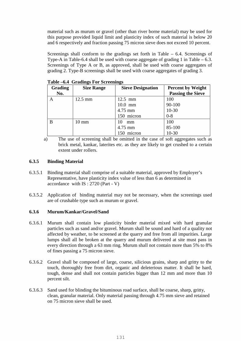
material such as murum or gravel (other than river borne material) may be used forthis purpose provided liquid limit and plasticity index of such material is below 20and 6 respectively and fraction passing 75 micron sieve does not exceed 10 percent.
Screenings shall conform to the gradings set forth in Table – 6.4. Screenings ofType-A in Table-6.4 shall be used with coarse aggregate of grading 1 in Table – 6.3.Screenings of Type A or B, as approved, shall be used with coarse aggregates ofgrading 2. Type-B screenings shall be used with coarse aggregates of grading 3.
Table –6.4 Gradings For ScreeningsGrading
No.Size Range Sieve Designation Percent by Weight
Passing the SieveA 12.5 mm 12.5 mm
10.0 mm4.75 mm150 micron
10090-10010-300-8
B 10 mm 10 mm4.75 mm150 micron
10085-10010-30
a) The use of screening shall be omitted in the case of soft aggregates such asbrick metal, kankar, laterites etc. as they are likely to get crushed to a certainextent under rollers.
6.3.5 Binding Material
6.3.5.1 Binding material shall comprise of a suitable material, approved by Employer’sRepresentative, have plasticity index value of less than 6 as determined inaccordance with IS : 2720 (Part - V)
6.3.5.2 Application of binding material may not be necessary, when the screenings usedare of crushable type such as murum or gravel.
6.3.6 Murum/Kankar/Gravel/Sand
6.3.6.1 Murum shall contain low plasticity binder material mixed with hard granularparticles such as sand and/or gravel. Murum shall be sound and hard of a quality notaffected by weather, to be screened at the quarry and free from all impurities. Largelumps shall all be broken at the quarry and murum delivered at site must pass inevery direction through a 63 mm ring. Murum shall not contain more than 5% to 8%of fines passing a 75 micron sieve.
6.3.6.2 Gravel shall be composed of large, coarse, silicious grains, sharp and gritty to thetouch, thoroughly free from dirt, organic and deleterious matter. It shall be hard,tough, dense and shall not contain particles bigger than 12 mm and more than 10percent silt.
6.3.6.3 Sand used for blinding the bituminous road surface, shall be coarse, sharp, gritty,clean, granular material. Only material passing through 4.75 mm sieve and retainedon 75 micron sieve shall be used.
131

6.3.7 Bituminous Materials
6.3.7.1 Bituminous materials shall conform to IS : 73, IS : 215, IS : 217 or IS : 454 asapplicable and be of the grade specified.
6.4 Earth work
6.4.1 Earthwork in Excavation
6.4.1.1 In general the excavation shall be in accordance to Employer’s Requirementspecified elsewhere.
6.4.1.2 Profiles of road excavation shall be laid at 50 m intervals to conform to the requiredalignment, sections, grades and side slopes and the lines of cuts shall be clearlymarked.
6.4.1.3 Contractor shall on no account excavate beyond the slopes or below the specifiedgrade unless so approved by the Employer’s Representative in writing. If excavationis done below the specified level or outside the section the Contractor shall berequired to fill up with approved materials, in layers of 150 to 200 mm, watered andcompacted as specified for the subgrade.
6.4.1.4 The excavation shall be finished neatly, smoothly and evenly to the correct lines,grades, sections and side slopes as shown in the drawings or approved byEmployer’s Representative.
6.4.2 Earthwork in Embankment
6.4.2.1 The embankment shall be formed of earth obtained from approved source.
6.4.2.2 The ground over which embankment is to be formed shall be cleared of allbrushwood, loose stones, vegetation, bushes, stumps, and all other objectionablematter and materials so removed shall be burnt off or disposed off as approved byEmployer’s Representative.
6.4.2.3 Profiles of embankment shall be set up with stout poles to mark the centre and edgesof the formation with the top levels of formation clearly marked by paint or cut andthe slopes with strings and pegs at every 10 metres on straight portions. Toe linemay be marked with pick marks.
6.4.2.4 Before placing any embankment material the top 150 mm of soil strata receiving itshall be scarified and watered and compacted with one pass of 8-10T roller.
6.4.2.5 Embankment material shall be placed in successive horizontal layers of 200 mmdepth extending to the full width of the embankment including the slopes at thelevel of the particular layer and 300 mm more on both sides to allow compaction ofthe full specified section. Before placing the next layer the surface of the underlayershall be moistured and scarified with pick axes or spades to provide a satisfactorybond with the next layer. The extra loose stuff at the edges shall be trimmed laterafter completion of the bank work leaving the correct section fully compacted.
132
6.4.2.6 When boulders, broken stones and similar hard materials are mixed up with theembankment materials care shall be taken to see that they are distributed uniformlyinto the bank and that no hollows are left near them. No stone or hard material shallproject above the top of any layer. Each layer of embankment shall be watered,leveled, and compacted as specified before the succeeding layer is placed. Thesurface of the embankment shall at all times during construction be maintained atsuch a cross fall as will shed water and prevent ponding.
6.4.2.7 If the bank materials contains less than the optimum moisture, water shall be addedto the loose layers of the embankment to bring the moisture uniformly uptorequirement. If the material contains more than the required moisture it shall beallowed to dry until the moisture is reduced to the required extent.
6.4.2.8 The moistured/dried loose layers shall be compacted with a power roller of 10 to 12tonnes. The roller shall pass at least twice over the same area, once in the forwardmove and the second time in backward move.
6.4.2.9 To allow for subsequent settlement the finished level of the embankment shall bekept higher than the specified level by one centimetre for every metre of the heightof the bank.
6.4.2.10 Embankment shall be finished and dressed smooth and even to conform to thealignment, levels, cross sections, and dimensions shown on drawings with dueallowance for shrinkage. Any damage caused by rain, or due to any other reasonshall be made good in the finishing operation.
6.5 Preparation of Subgrade
6.5.1 In general Earthwork in subgrade shall conform to Employer’s Requirementspecified elsewhere.
6.5.2 Immediately prior to the laying of the soling the subgrade shall be cleaned of allforeign substances, vegetation etc. Any ruts or soft yielding patches that appearshall be corrected and the subgrade dressed off parallel to the finished profile. Thecamber of subgrade shall conform in shape to that of the finished road surface.Camber boards shall be used to get the required section.
6.5.3 The prepared subgrade shall be lightly sprinkled with water, if necessary, and rolledwith power roller of not less than 10 tonnes, till the soil is evenly compacted to 95%of Proctor density with 2% variation in optimum moisture content. Roller shall passminimum 5 runs on the subgrade. Rolling shall commence at the edges and progresstowards the centre longitudinally. Each pass of the roller shall uniformly overlap notless than one third of the track made in the preceding pass. Any undulations in thesurface that develop due to rolling shall be made good with approved earth andsubgrade rerolled.
6.6 Soling
6.6.1 Soling shall not be constructed on a wet subgrade.
133
6.6.2 Unless otherwise specified, the width of the soling shall be 230 mm more on eitherside than that of the waterbound macadam wearing course and the finishedthickness of the soling course shall be 230 mm.
6.6.3 The soling stones shall be laid with the largest face downwards and in contact witheach other. The stones shall break joint as far as possible. The height of the solingstone shall be equal to specified thickness of soling.
6.6.4 As the laying of rubble advances the soling shall be hand packed by wedging andpacking with 80 mm metal in the joints of the soling and driving them by hammersin place so as to fill the voids as completely as possible. This operation of handpacking shall closely follow the rubble laying. The soling shall be laid and handpacket true to grade and section and these shall be often checked by boning rods,template boards and fish line etc. The grades, sections etc. of the soling shallcorrespond to those of the surfacing coming on it. The soling thus laid shall befinished by knocking out projecting stones and filling depressions by chips to comeup to the grade and camber.
6.6.5 The quality of the 80 mm metal shall be same as specified for the soling and thelongest dimension shall not be more than 100 mm and the shortest dimension notless than 50 mm.
6.6.6 The soling after it is properly laid and hand packed including filling of voids with80 mm metal shall be rolled dry with 10 - 12 T power roller to refusal i.e., till thestones in the soling course cease to move under the roller and no more compactioncan be achieved. Rolling shall start at the edges and work towards the centre. Theroller shall run over the same surface of rolling for at least 8 times till the solingcourse is well consolidated. The surface shall be checked by templates and in caseof unevenness high spots shall be knocked out and depressions filled by spalls andrecompacted fully. Bunds shall be laid along the edges and compacted beforestarting rolling on soling to prevent spreading of stones.
6.6.7 Gravel shall be spread in thin layers over the above prepared soling surface, sweptinto the interstices with brooms, watered lightly to assist the filling of voids.Spreading of gravel, sweeping and watering shall continue till the interstices arecompletely filled. At all times only enough water shall be sprinkled to force thegravel into the voids and never so much as to soften the subgrade. The process ofgravel filling shall be accompanied by rolling as for dry rolling of soling with apower roller weighing not less than 10 tonnes starting at edge and working towardsthe centre. The roller shall run over the same surface for at least eight times. Eachpass of the roller shall uniformly overlap not less than one third of the track made inthe preceding pass. The surface shall be checked with templates of approved design(to be provided by Contractor) and high and low spots corrected by removing solingand repacking.
6.7 Water Bound Macadam Course
The surface over which water bound Macadam is to be laid shall be prepared to thespecified grade and camber and made free of dust and other extraneous material.Any ruts or soft yielding places shall be corrected in an approved manner and rolled
134
until firm. To prevent the spreading of the course aggregate during rolling, ifnecessary, two parallel mud walls 200 mm wide and of height equal to uncompactedMacadam course shall be made along the outer edges of the Macadam coursehaving a clear distance between them equal to the width to be metalled.
W.B.M. sub-base course of specified thickness shall be provided. The courseaggregate for this shall conform to requirements of sub-base in Table-1 and itsgrading shall conform to Grading 1 of Table - 6.3 and screening to Type B of Table-6.4.
W.B.M. base course : The coarse aggregate for this shall normally conform torequirements for Base in Table-1 and its grading shall confirm to Grading 3 ofTable – 6.3 and screening to Type-B of Table-6.4.
6.7.1 Spreading Coarse Aggregate
6.7.1.1 The coarse aggregate shall be spread uniformly and evenly upon the preparedsurface in such quantities that the thickness of each compacted layer does notexceed 75 mm or as otherwise specified. In no case, however, shall the thickness ofeach compacted layer exceed 100 mm.
6.7.1.2 The spreading shall be done from stockpiles by raking the stacks with rakes so as toleave behind mud and dust. In no case shall the aggregate be dumped in heapsdirectly on the surface prepared to receive the aggregate nor shall hauling overuncompacted or partially compacted sub-base/base be permitted. The surface of theaggregates spread shall be fully checked with templates and all high or low spotsremedied by removing or adding aggregate as may be required. No segregation oflarge or fine aggregates shall be allowed and the coarse aggregate as spread shall beof uniform gradation with no pockets of fine material. The surface shall be checkedfrequently with a straight edge while spreading and rolling so as to ensure a finishedsurface as per approved plan. The coarse aggregate shall not normally be spread inlengths exceeding 3 days' average work ahead of the rolling and bonding of theproceeding section.
6.7.2 Rolling
6.7.2.1 Following the spreading of the coarse aggregate, rolling shall be started with threewheeled power rollers of not less than 10 tonne capacity or tandem or vibratoryroller of approved type. Rolling shall begin from the edges and gradually progresstowards the centre. First the edges/edge shall be compacted with roller runningforward and backward and then move inwards parallel to the centre line of the road,in successive passes uniformly lapping preceding tracks by at least one half width.Rolling shall be discontinued when the aggregates are partially compacted withsufficient void space in them to permit application of screenings. During rollingslight sprinkling of water may be done, if necessary. Rolling shall not be done whenthe subgrade is soft or yielding or when it causes a wave-like motion in thesubgrade or sub-base. The rolled surface shall be checked transversely andlongitudinally with templates and all undulations shall be corrected by loosening thesurface, adding or removing necessary amounts of aggregate and rerolling until theentire surface conforms to desired camber and grade. In no case shall the use ofscreenings be permitted to make up depressions. Material which crushed
135
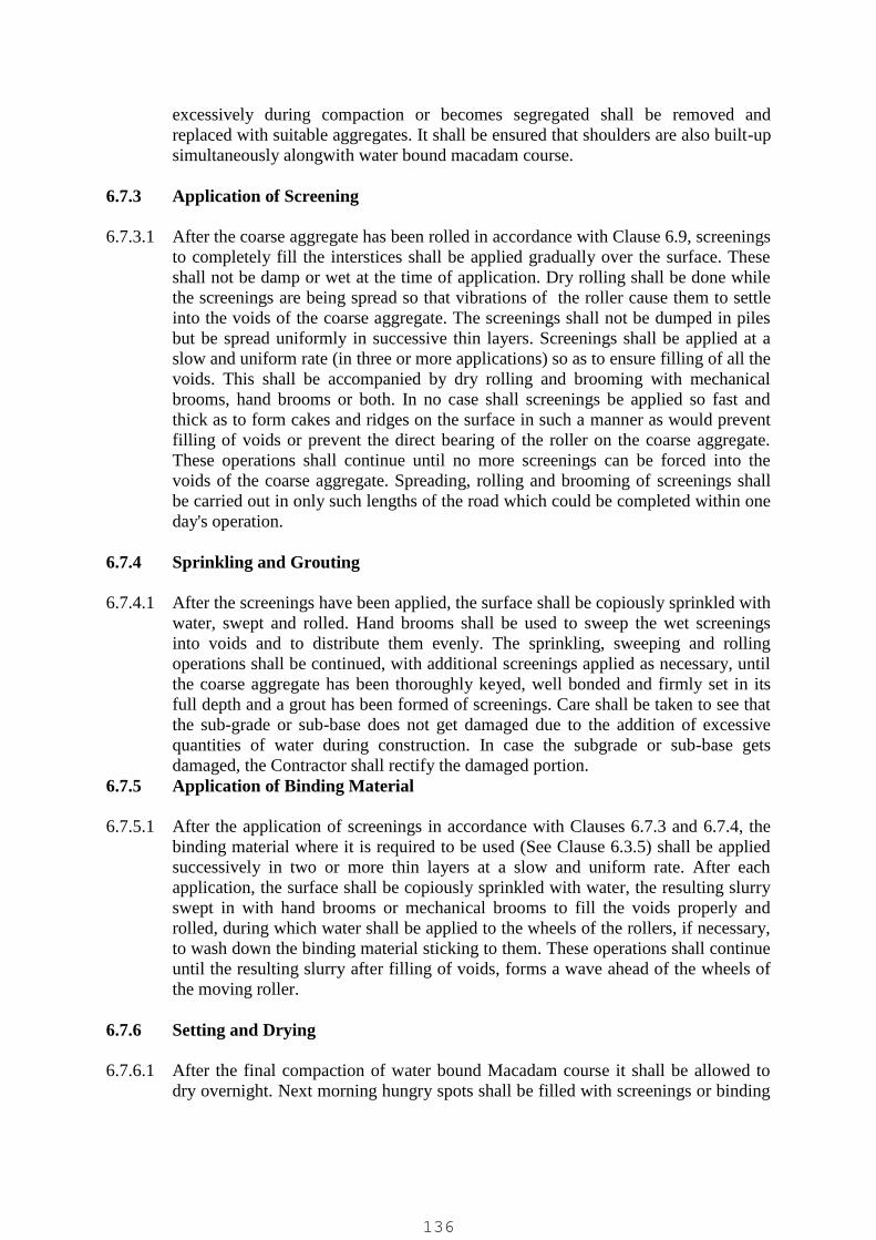
excessively during compaction or becomes segregated shall be removed andreplaced with suitable aggregates. It shall be ensured that shoulders are also built-upsimultaneously alongwith water bound macadam course.
6.7.3 Application of Screening
6.7.3.1 After the coarse aggregate has been rolled in accordance with Clause 6.9, screeningsto completely fill the interstices shall be applied gradually over the surface. Theseshall not be damp or wet at the time of application. Dry rolling shall be done whilethe screenings are being spread so that vibrations of the roller cause them to settleinto the voids of the coarse aggregate. The screenings shall not be dumped in pilesbut be spread uniformly in successive thin layers. Screenings shall be applied at aslow and uniform rate (in three or more applications) so as to ensure filling of all thevoids. This shall be accompanied by dry rolling and brooming with mechanicalbrooms, hand brooms or both. In no case shall screenings be applied so fast andthick as to form cakes and ridges on the surface in such a manner as would preventfilling of voids or prevent the direct bearing of the roller on the coarse aggregate.These operations shall continue until no more screenings can be forced into thevoids of the coarse aggregate. Spreading, rolling and brooming of screenings shallbe carried out in only such lengths of the road which could be completed within oneday's operation.
6.7.4 Sprinkling and Grouting
6.7.4.1 After the screenings have been applied, the surface shall be copiously sprinkled withwater, swept and rolled. Hand brooms shall be used to sweep the wet screeningsinto voids and to distribute them evenly. The sprinkling, sweeping and rollingoperations shall be continued, with additional screenings applied as necessary, untilthe coarse aggregate has been thoroughly keyed, well bonded and firmly set in itsfull depth and a grout has been formed of screenings. Care shall be taken to see thatthe sub-grade or sub-base does not get damaged due to the addition of excessivequantities of water during construction. In case the subgrade or sub-base getsdamaged, the Contractor shall rectify the damaged portion.
6.7.5 Application of Binding Material
6.7.5.1 After the application of screenings in accordance with Clauses 6.7.3 and 6.7.4, thebinding material where it is required to be used (See Clause 6.3.5) shall be appliedsuccessively in two or more thin layers at a slow and uniform rate. After eachapplication, the surface shall be copiously sprinkled with water, the resulting slurryswept in with hand brooms or mechanical brooms to fill the voids properly androlled, during which water shall be applied to the wheels of the rollers, if necessary,to wash down the binding material sticking to them. These operations shall continueuntil the resulting slurry after filling of voids, forms a wave ahead of the wheels ofthe moving roller.
6.7.6 Setting and Drying
6.7.6.1 After the final compaction of water bound Macadam course it shall be allowed todry overnight. Next morning hungry spots shall be filled with screenings or binding
136
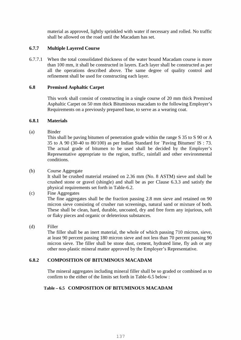
material as approved, lightly sprinkled with water if necessary and rolled. No trafficshall be allowed on the road until the Macadam has set.
6.7.7 Multiple Layered Course
6.7.7.1 When the total consolidated thickness of the water bound Macadam course is morethan 100 mm, it shall be constructed in layers. Each layer shall be constructed as perall the operations described above. The same degree of quality control andrefinement shall be used for constructing each layer.
6.8 Premixed Asphaltic Carpet
This work shall consist of constructing in a single course of 20 mm thick PremixedAsphaltic Carpet on 50 mm thick Bituminous macadam to the following Employer’sRequirements on a previously prepared base, to serve as a wearing coat.
6.8.1 Materials
(a) BinderThis shall be paving bitumen of penetration grade within the range S 35 to S 90 or A35 to A 90 (30-40 to 80/100) as per Indian Standard for `Paving Bitumen' IS : 73.The actual grade of bitumen to be used shall be decided by the Employer’sRepresentative appropriate to the region, traffic, rainfall and other environmentalconditions.
(b) Course AggregateIt shall be crushed material retained on 2.36 mm (No. 8 ASTM) sieve and shall becrushed stone or gravel (shingle) and shall be as per Clause 6.3.3 and satisfy thephysical requirements set forth in Table-6.2.
(c) Fine AggregatesThe fine aggregates shall be the fraction passing 2.8 mm sieve and retained on 90micron sieve consisting of crusher run screenings, natural sand or mixture of both.These shall be clean, hard, durable, uncoated, dry and free form any injurious, softor flaky pieces and organic or deleterious substances.
(d) FillerThe filler shall be an inert material, the whole of which passing 710 micron, sieve,at least 90 percent passing 180 micron sieve and not less than 70 percent passing 90micron sieve. The filler shall be stone dust, cement, hydrated lime, fly ash or anyother non-plastic mineral matter approved by the Employer’s Representative.
6.8.2 COMPOSITION OF BITUMINOUS MACADAM
The mineral aggregates including mineral filler shall be so graded or combined as toconfirm to the either of the limits set forth in Table-6.5 below :
Table – 6.5 COMPOSITION OF BITUMINOUS MACADAM
137

Mix designationNominal aggregatesize Layer thickness
Grading 140mm 8
80-100mm
Grading 219mm
50-75 mmIS Sieve (mm) Cumulative % by weight of total aggregate passing
4537.5
10090-100
26.5 75-100 10019 - 90-10013.2 35-61 56-884.75 13-22 16-362.36 4-19 4-190.3 2-10 2-100.075 0-8 0-8
Bitumen content, %by weight of total
mixture1
3.1-3.4 3.3-3.5
Bitumen grade 35 to 90 35 to 90
6.8.3 Mix Design
Apart from conformity with the grading and quality requirements of individualingredients, the asphaltic concrete mix shall meet the requirements set forth inTable-6.6 hereunder.
6.8.4 Weather and Seasonal Limitations
Asphalt concrete shall not be laid during rainy weather or when the base course isdamp or wet.
Table – 6.6 Requirement of Asphaltic Concrete MixSr.No. Description Requirements1. Number of compaction blows, each end of
Marshalling specimen50
2. Marshall stability (ASTM Designation-D-1559)determined on Marshal specimen
340 Kg. (min.)
3. Marshall flow (mm) 2-44. Percent Voids in mix 3-55. Percent voids in mineral aggregate filled with
bitumen75-85
6. Binder content percent by weight of mix 5-7.5
The contractor shall intimate to the Employer’s Representative in writing, well inadvance of the start of work, the job- mix formula proposed to be used by him forthe work and shall give following details to the Employer’s Representative for hisapproval.
i) Source and location of all materialsii) Proportions of all materials expressed as follows where each is applicable :
138

Binder As percentage by weight of totalmix
Course aggregate As percentage by weight of totalaggregate including mineral filler
Fine aggregateMineral filler
iii) A single definite percentage passing each sieve for the mixed aggregate.iv) The results of the best enumerated in Table-6.6 as obtained by the Contractor.v) Test results of physical characteristics of aggregates to be used.
Should a change in the source of material be proposed, a new job mix formula shallbe established and got approved from the Employer’s Representative before actualusing of the materials.
6.8.5 Preparation of Base
6.8.5.1 The base on which premix carpet is to be laid shall be prepared, shaped andconditioned to the specified lines, grade and cross section by repairing all potholesor patches and ruts. The potholes shall be drained of water and cut to regular shapewith vertical sides. All loose and disintegrated material shall be removed. Thepothole shall then be filled either with (i) Coarse aggregate and screeningsconforming to Clause 3.0 and compacted with heavy hand rammers or approvedmechanical tempers or (ii) premixed chippings binders (bitumen grade 80/100)content of 3 percent by weight of total mix, after painting the sides and bottom ofthe holes with a thin application of bitumen, or a combination of both (i), (ii) asapproved by Employer/Employer’s Representative. The surface shall be thoroughlyswept and scraped clean and free of dust and other foreign matter.
6.8.6 Tack Coat
6.8.6.1 The binder used for tack coat shall be bitumen of suitable penetration grade within80/100 confirming to IS:73. The actual grade of bitumen to be used shall be decidedby the Employer’s Representative, appropriate to the region, traffic, rainfall andother environmental conditions. Binder shall be heated to the temperatureappropriate to its grade and as approved by the Employer’s Representative. Thebinder shall be sprayed on the prepared base at the rate of 1.0 kg/sq.m. The bindershall applied uniformly with the aid of either self propelled or towed bitumenpressure sprayer with self heating arrangement and spraying nozzle arrangementcapable of spraying bitumen at the above specified rate and temperature so as toprovide uniform unbroken spread of bitumen. The tack coat shall be applied justahead of oncoming premixed asphalt carpet.
6.8.7 Preparation of Mix and Laying
6.8.7.1 Hot mix plant of adequate capacity and capable of producing a proper and uniformquality mix shall be used for preparing the mix. The plant may be either a weighbatch type or volumetric proportioning continuous or drum mix type. The stoneaggregate shall be surface dry and contain not more than 2 percent moisture beforeuse. It shall be first screened of dust and measured in boxes, heated to 155 deg.C -
139
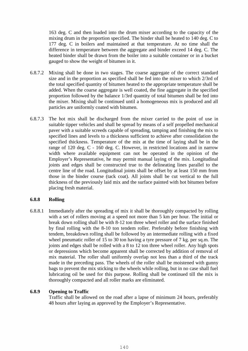
163 deg. C and then loaded into the drum mixer according to the capacity of themixing drum in the proportion specified. The binder shall be heated to 140 deg. C to177 deg. C in boilers and maintained at that temperature. At no time shall thedifference in temperature between the aggregate and binder exceed 14 deg. C. Theheated binder shall be drawn from the boiler into a suitable container or in a bucketgauged to show the weight of bitumen in it.
6.8.7.2 Mixing shall be done in two stages. The coarse aggregate of the correct standardsize and in the proportion as specified shall be fed into the mixer to which 2/3rd ofthe total specified quantity of bitumen heated to the appropriate temperature shall beadded. When the coarse aggregate is well coated, the fine aggregate in the specifiedproportion followed by the balance 1/3rd quantity of total bitumen shall be fed intothe mixer. Mixing shall be continued until a homogeneous mix is produced and allparticles are uniformly coated with bitumen.
6.8.7.3 The hot mix shall be discharged from the mixer carried to the point of use insuitable tipper vehicles and shall be spread by means of a self propelled mechanicalpaver with a suitable screeds capable of spreading, tamping and finishing the mix tospecified lines and levels to a thickness sufficient to achieve after consolidation thespecified thickness. Temperature of the mix at the time of laying shall be in therange of 120 deg. C - 160 deg. C. However, in restricted locations and in narrowwidth where available equipment can not be operated in the opinion of theEmployer’s Representative, he may permit manual laying of the mix. Longitudinaljoints and edges shall be constructed true to the delineating lines parallel to thecentre line of the road. Longitudinal joints shall be offset by at least 150 mm fromthose in the binder course (tack coat). All joints shall be cut vertical to the fullthickness of the previously laid mix and the surface painted with hot bitumen beforeplacing fresh material.
6.8.8 Rolling
6.8.8.1 Immediately after the spreading of mix it shall be thoroughly compacted by rollingwith a set of rollers moving at a speed not more than 5 km per hour. The initial orbreak down rolling shall be with 8-12 ton three wheel roller and the surface finishedby final rolling with the 8-10 ton tendem roller. Preferably before finishing withtendem, breakdown rolling shall be followed by an intermediate rolling with a fixedwheel pneumatic roller of 15 to 30 ton having a tyre pressure of 7 kg. per sq.m. Thejoints and edges shall be rolled with a 8 to 12 ton three wheel roller. Any high spotsor depressions which become apparent shall be corrected by addition of removal ofmix material. The roller shall uniformly overlap not less than a third of the trackmade in the preceding pass. The wheels of the roller shall be moistened with gunnybags to prevent the mix sticking to the wheels while rolling, but in no case shall fuellubricating oil be used for this purpose. Rolling shall be continued till the mix isthoroughly compacted and all roller marks are eliminated.
6.8.9 Opening to TrafficTraffic shall be allowed on the road after a lapse of minimum 24 hours, preferably48 hours after laying as approved by the Employer’s Representative.
140

6.9 Seal CoatThis work shall consist of application of a seal coat sealing the voids in abituminous surface laid to the specified levels, grade and camber. Seal coat shall beeither of the two types below :
Type A : Liquid seal coat comprising of an application of a layer of bituminousbinder followed by a cover of stone chippings.
Type B : Premixed seal coat comprising of a thin application of fine aggregatepremixed with bituminous binder.
6.9.1 Materials
6.9.1.1 BinderThis shall be 30/40, 60/70 or 80/100 grade straight run bitumen conforming toIS:73. The actual grade of bitumen to be used shall be approved by the Employer’sRepresentative, appropriate to the region, traffic, rainfall and other environmentalconditions. The quantity of binder to be utilized, shall be 9.8 kg and 6.8 kg per 10sq.m. of area for Type A and Type B seal coat respectively.
6.9.1.2 Stone Chippings for Type A Seal Coat
These shall consist of angular fragments of clean, hard, tough and durable rock ofuniform quality throughout. They should be free of elongated or flaky pieces, soft ordisintegrated stone, vegetable or other deleterious matter. Stone chippings shall beof 10 mm size defined as 100 percent passing through 12.5 mm sieve and retainedon 2.36 mm sieve. The quantity used for spreading shall be 0.09 cum per 10 sq.m.
6.9.1.3 Fine Aggregate for Type B Seal CoatThe fine aggregate shall be sand or fine grit and shall consist of clean, hard,durable, uncoated dry particles and shall be free from dust, soft or flaky materialorganic matter or other deleterious substances. The aggregate shall pass 1.7 mmsieve and be retained on 180 micron sieve. The quantity used for premixing shall be0.06 cu.m. per 10 square metre area.
6.9.2 Preparation of BaseThe seal coat shall be applied immediately after the laying of bituminous coursewhich is required to be sealed. Before application of seal coat materials the surfaceshall be cleaned free of any dust or other extraneous matter.
6.9.3 Construction of Type A Seal Coat
6.9.3.1 Application of BinderBinder shall be heated in boilers to 163 deg. C to 171 deg. C, maintained at thetemperature and sprayed on the dry surface in a uniform manner with the help ofmechanical sprayers. Excessive deposits of binder caused by stopping or starting ofthe sprayer through leakage or any other reason shall be suitably corrected beforethe stone chippings are spread.
6.9.3.2 Application of Stone ChippingImmediately after the application of the binder, stone chippings in a dry and cleanstate shall be spread uniformly on the complete surface. If necessary the surface
141

shall be broomed to ensure uniform spread of chippings. The surface shall bechecked by means of a camber board laid across the road and a 3 metre straightedge laid parallel to the centre line of the road and undulations if any, shall becorrected by addition or removal of blindage.
6.9.3.3 RollingImmediately after the application of the cover the material, the entire surface shallbe rolled with a 8 to 10 tonne smooth wheeled roller. While rolling is in progressadditional material shall be spread by hand in whatever quantities required to makeup irregularities. Rolling shall continue until all material is firmly bedded in thebinder and presents a uniform closed surface. Generally five to six passes shall bemade for thorough compaction of the surface or as approved by the Employer’sRepresentative. Along kerbs, manholes and at all places not accessible to roller,thorough compaction shall be secured by means of steel rammers or hand rollers.Traffic shall be allowed after 24 hours. After a period of seven days, surplus gritshall be swept and collected and shall be used for binding the spots where bleedingoccurs.
6.9.4 Construction of Type B Seal Coat
6.9.4.1 Preparation of Mix and LayingThe aggregate shall be surface dry and contain not more than 2 percent moisturebefore use, and shall be heated to 155 deg. C - 163 deg. C and then loaded into thedrum mixer according to the capacity of the mixing drum in the proportionspecified. The binder shall be heated to 149 deg. C to 177 deg. C in boilers andmaintained at that temperature. At no time shall the difference in temperaturebetween the aggregate and binder exceed 14 deg. C. The heated binder shall bedrawn from the boiler into a suitable container or in a bucket gauged to show theweight of bitumen in it. The mix shall be immediately transported from the mixingplant to the point of use and spread uniformly on the bituminous surface to besealed.
6.9.4.2 RollingAs soon as sufficient length has been covered with the premixed material, thesurface shall be rolled with 8 to 10 tonne smooth wheeled power rollers. Rollingshall be continued till the premixed material completely seals the voids inbituminous course and a smooth uniform surface is obtained.
6.9.4.3 Opening to trafficTraffic may be allowed soon after final rolling when, the premixed material hascooled down to the surrounding temperature.
6.10 Quality Control
6.10.1 General
6.10.1.1 All materials incorporated and all works performed shall be strictly in conformitywith the Specification requirements. All works shall conform to the lines, grades,cross sections and dimensions shown on the drawings or as approved by theEmployer’s Representative subject to the permitted tolerances described hereinafter.
142

The contractor shall be fully responsible for the quality of the work in the entireconstruction within the Contract. He shall, therefore, have his own independent andadequate set-up for ensuring the same.
6.10.1.2 The Contractor shall carry out quality control tests on the materials and work to thefrequency specified. In the absence of clear indications about method and/orfrequency of tests for any item, the approval of the Employer’s Representative shallbe obtained and he shall provide necessary co-operation and assistance in obtainingthe samples for test and carrying out the field test as required by the Employer’sRepresentative from time to time. This may include provision of Labour,attendance, assistance in packing and dispatching and any other assistanceconsidered necessary in connection with the test.
6.10.1.3 For the work of embankment, subgrade and construction of subsequent layer ofsame or other material over the finished layer shall be done after obtaining approvalfrom the Employer’s Representative. Similar approval from the Employer’sRepresentative shall be obtained in respect of all other items of works prior toproceeding with the next stage of construction.
6.10.1.4 The Contractor shall carry out modification in the procedure of work, if foundnecessary, as approved by the Employer’s Representative during inspection. Worksfalling short of quality shall be rectified by the Contractor as approved by theEmployer’s Representative.
6.10.2 Permitted Tolerances
6.10.2.1 Horizontal AlignmentsHorizontal alignments shall be reckoned with respect to the centre line of thecarriageway as shown on the drawings. The edges of the carriageway as constructedshall be correct within a tolerance of ±25 mm therefrom. The correspondingtolerance for edges of the roadway and lower layers of pavement shall be ±40 mm.
6.10.2.2 Longitudinal ProfileThe levels of the subgrade and different pavement courses as constructed, shall notvary from those calculated with reference to the longitudinal and cross- profile ofthe road shown on the drawings or as approved by the Employer’s Representativebeyond the tolerances mentioned below :
Subgrade ± 15 mmSub-base ± 20 mmBase Course ± 15 mmWearing Course ± 10 mm
Provided, however, that the negative tolerance for wearing course shall not bepermitted in conjunction with the positive tolerance for base course if the thicknessof the former is thereby reduced by more than 6 mm.
6.10.2.3 Surface RegularityThe surface regularity of completed subgrade, sub-bases, base courses and wearingsurfaces in the longitudinal and transverse directions shall be within the tolerancesindicated in Table 6.7.
143
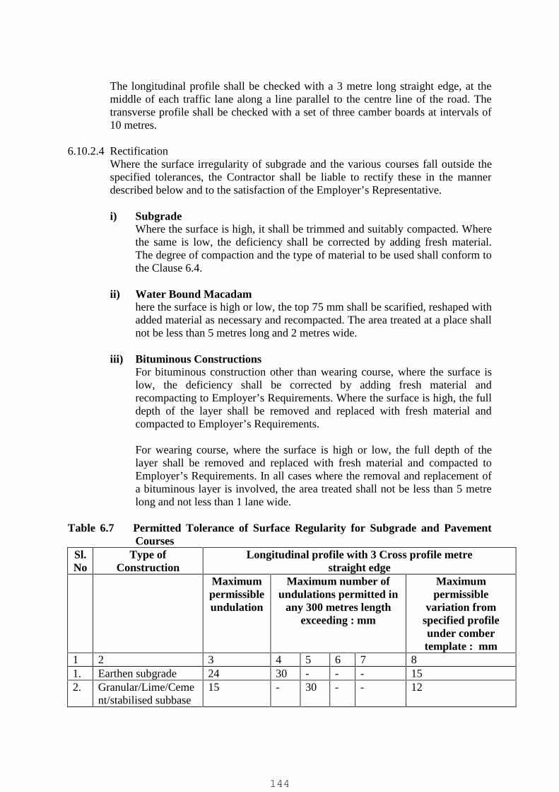
The longitudinal profile shall be checked with a 3 metre long straight edge, at themiddle of each traffic lane along a line parallel to the centre line of the road. Thetransverse profile shall be checked with a set of three camber boards at intervals of10 metres.
6.10.2.4 RectificationWhere the surface irregularity of subgrade and the various courses fall outside thespecified tolerances, the Contractor shall be liable to rectify these in the mannerdescribed below and to the satisfaction of the Employer’s Representative.
i) SubgradeWhere the surface is high, it shall be trimmed and suitably compacted. Wherethe same is low, the deficiency shall be corrected by adding fresh material.The degree of compaction and the type of material to be used shall conform tothe Clause 6.4.
ii) Water Bound Macadamhere the surface is high or low, the top 75 mm shall be scarified, reshaped withadded material as necessary and recompacted. The area treated at a place shallnot be less than 5 metres long and 2 metres wide.
iii) Bituminous ConstructionsFor bituminous construction other than wearing course, where the surface islow, the deficiency shall be corrected by adding fresh material andrecompacting to Employer’s Requirements. Where the surface is high, the fulldepth of the layer shall be removed and replaced with fresh material andcompacted to Employer’s Requirements.
For wearing course, where the surface is high or low, the full depth of thelayer shall be removed and replaced with fresh material and compacted toEmployer’s Requirements. In all cases where the removal and replacement ofa bituminous layer is involved, the area treated shall not be less than 5 metrelong and not less than 1 lane wide.
Table 6.7 Permitted Tolerance of Surface Regularity for Subgrade and PavementCourses
Sl.No
Type ofConstruction
Longitudinal profile with 3 Cross profile metrestraight edge
Maximumpermissibleundulation
Maximum number ofundulations permitted in
any 300 metres lengthexceeding : mm
Maximumpermissible
variation fromspecified profileunder combertemplate : mm
1 2 3 4 5 6 7 81. Earthen subgrade 24 30 - - - 152. Granular/Lime/Ceme
nt/stabilised subbase15 - 30 - - 12
144
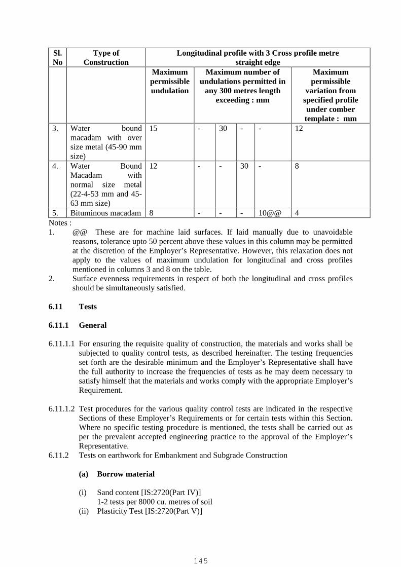
Sl.No
Type ofConstruction
Longitudinal profile with 3 Cross profile metrestraight edge
Maximumpermissibleundulation
Maximum number ofundulations permitted in
any 300 metres lengthexceeding : mm
Maximumpermissible
variation fromspecified profileunder combertemplate : mm
3. Water boundmacadam with oversize metal (45-90 mmsize)
15 - 30 - - 12
4. Water BoundMacadam withnormal size metal(22-4-53 mm and 45-63 mm size)
12 - - 30 - 8
5. Bituminous macadam 8 - - - 10@@ 4Notes :1. @@ These are for machine laid surfaces. If laid manually due to unavoidable
reasons, tolerance upto 50 percent above these values in this column may be permittedat the discretion of the Employer’s Representative. However, this relaxation does notapply to the values of maximum undulation for longitudinal and cross profilesmentioned in columns 3 and 8 on the table.
2. Surface evenness requirements in respect of both the longitudinal and cross profilesshould be simultaneously satisfied.
6.11 Tests
6.11.1 General
6.11.1.1 For ensuring the requisite quality of construction, the materials and works shall besubjected to quality control tests, as described hereinafter. The testing frequenciesset forth are the desirable minimum and the Employer’s Representative shall havethe full authority to increase the frequencies of tests as he may deem necessary tosatisfy himself that the materials and works comply with the appropriate Employer’sRequirement.
6.11.1.2 Test procedures for the various quality control tests are indicated in the respectiveSections of these Employer’s Requirements or for certain tests within this Section.Where no specific testing procedure is mentioned, the tests shall be carried out asper the prevalent accepted engineering practice to the approval of the Employer’sRepresentative.
6.11.2 Tests on earthwork for Embankment and Subgrade Construction
(a) Borrow material
(i) Sand content [IS:2720(Part IV)]1-2 tests per 8000 cu. metres of soil
(ii) Plasticity Test [IS:2720(Part V)]
145

Each type to be tested , 1-2 tests per 8000 cu. metres of soil.(iii) Density Test [[IS:2720(Part VII)].
Each soil type to be tested, 1-2 tests per 8000 cubic metres of soil.(iv) Deleterious Content Test [IS:2720(Part XXVII)]
As and when required by the Employer’s Representative.(v) Moisture Content Test [IS:2720(Part II)]
One test for every 250 cubic metres of soil.(vi) CBR Test on materials to be incorporated in the subgrade on soaked/unsoaked
samples [[IS:2720(part XVI)]One test for every 3000 m3 at least or closer as and when required by theEmployer’s Representative.
(b) Compaction control : Control shall be exercised by taking at least onemeasurement of density for each 1000 square metres of compacted area, orcloser as required to yield the minimum number of test results for evaluation adays work on statistical basis. The determination of density shall be inaccordance with IS:2720 (part XXVIII). Tests locations shall be chosen onlythrough random sampling techniques. Control shall not be based on the resultof any one test but on the mean value of a set of 5-10 density determinations.The number of tests in one tests in one set of measurements shall be 5 as longas it is felt that sufficient control over borrow material and the method ofcompaction is being exercised. If considerable variations are observedbetween individual density results, the minimum number of tests in one set ofmeasurement shall be increased to 10. The acceptance of work shall be subjectto the condition that the mean dry density equals or exceeds the specifieddensity and the standard deviation for any set of results is below 0.08 gm/cc.
However, for earthwork in shoulders (earthen) and in top 500 mm portion of theembankment below the subgrade, at least one density measurement shall be takenfor every 50 square metres of the compacted area provided further `that the numberof tests in each set of measurements shall be at least 10. In other respects, thecontrol shall be similar to that described earlier.
6.11.3 Tests on Sub-bases and Bases(Excluding bitumen bound bases)The tests and their frequencies for the different types of bases and sub-base shall beas given in Table 6.8. The evaluation of density results for compaction control shallbe on lines similar to those set out in clause 6.18.2
Table –6.8 Control Tests and Their Frequencies for Sub-Bases and Bases(Excluding Bitumen Bound Bases)
Sl.No Types ofConstruction
Test Frequency
1. Granular sub-base
i) Gradationii) Atterbergs limitiii) Moisture content prior to
compactioniv) Density of compacted layerv) Deleterious constituents
One test per 200 m3
One test per 200 m3
One test per 250 m2
One test per 500 m2
As requiredAs required
146

Sl.No Types ofConstruction
Test Frequency
vi) C.B.R
2. Lime/CementStabilised
vii) Purity of lime (for lime-soilstabilization
viii) Lime/Cement content
ix) Degree of pulverisation
x) CBR test on a set of 3 specimensxi) Moisture content prior to
compactionxii) Density of compacted layerxiii) Deleterious constituents
One test for eachconsignment subjectto a minimum of onetest per 5 tonnes oflime.Regularly, throughprocedural checks.Periodically asconsidered necessary.As requiredOne test per 250 m3.One test per 500 m2
As required
3 Water BoundMacadam
xiv) Aggregate Impact Value
xv) Grading
xvi) Flakiness Index
xvii) Atterbergs limits of bindingmaterial.
One test per 200m3 ofaggregateOne test per 100 m3 ofaggregateOne test per 200 m3 ofaggregateOne test per 25 m3 ofbinding material
6.11.4 Tests on Bituminous ConstructionsThe tests and their frequencies for the different types of bituminous works shall beas given Table 6.9 hereunder.
Table – 6.9 Control Tests and Their Frequency for Bituminous WorksSl.No.
Types ofConstruction
Test Frequency
1. Prime Coat/TrackCoat
i) Quality of binderii) Binder temperature for a
applicationiii) Rate of spread of binder
As RequiredAs regular close intervals
Two tests per day2. Seal Coat/Surface
Dressingiii) Quality of binderiv) Aggregate Impact Value
v) Flakiness Indexvi) Stripping value of
aggregates
vii) Water absorption ofaggregates
As requiredOne test per 50 m3 ofaggregateOne test per 50 m3 ofaggregateInitially, one set of 8representative specimens foreach source of supply.Subsequently whenwarranted by changes in the
147
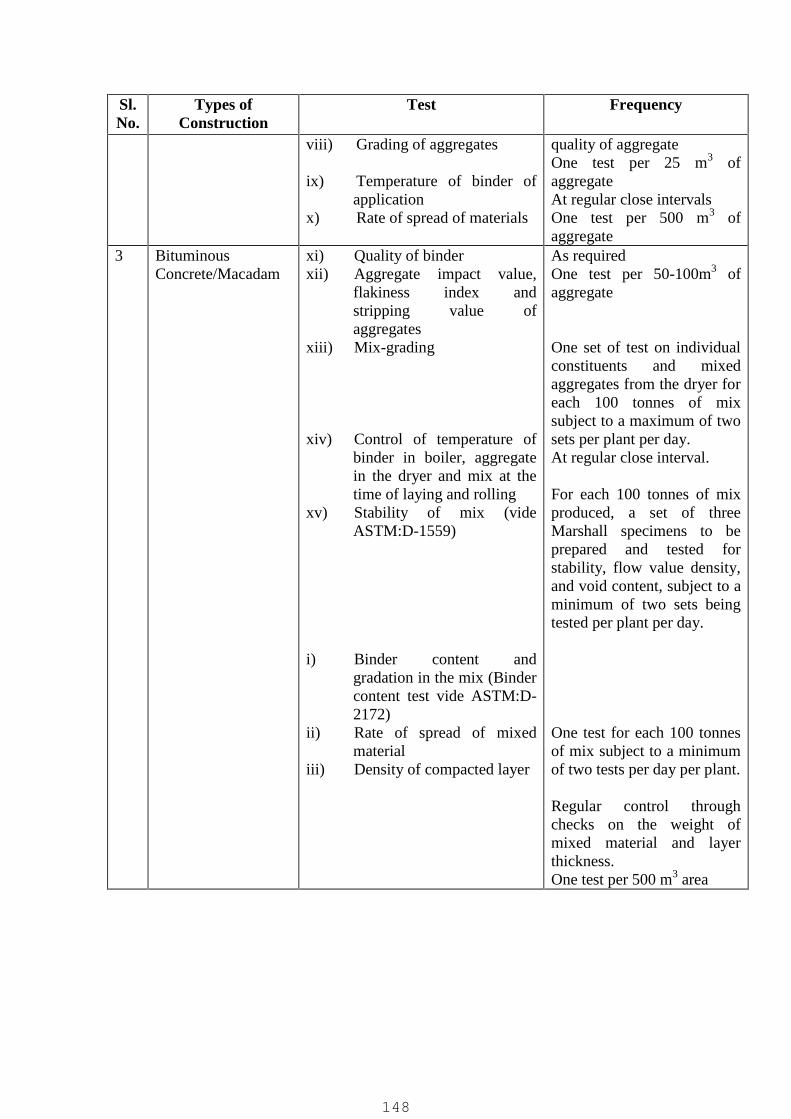
Sl.No.
Types ofConstruction
Test Frequency
viii) Grading of aggregates
ix) Temperature of binder ofapplication
x) Rate of spread of materials
quality of aggregateOne test per 25 m3 ofaggregateAt regular close intervalsOne test per 500 m3 ofaggregate
3 BituminousConcrete/Macadam
xi) Quality of binderxii) Aggregate impact value,
flakiness index andstripping value ofaggregates
xiii) Mix-grading
xiv) Control of temperature ofbinder in boiler, aggregatein the dryer and mix at thetime of laying and rolling
xv) Stability of mix (videASTM:D-1559)
i) Binder content andgradation in the mix (Bindercontent test vide ASTM:D-2172)
ii) Rate of spread of mixedmaterial
iii) Density of compacted layer
As requiredOne test per 50-100m3 ofaggregate
One set of test on individualconstituents and mixedaggregates from the dryer foreach 100 tonnes of mixsubject to a maximum of twosets per plant per day.At regular close interval.
For each 100 tonnes of mixproduced, a set of threeMarshall specimens to beprepared and tested forstability, flow value density,and void content, subject to aminimum of two sets beingtested per plant per day.
One test for each 100 tonnesof mix subject to a minimumof two tests per day per plant.
Regular control throughchecks on the weight ofmixed material and layerthickness.One test per 500 m3 area
148

(Part B) C.C Pavement (Road)
Road shall consist of the following :a) Well compacted sub-grade layer.
b) Providing and laying 100 mm thick PCC in M 10
c) Providing and laying 200 mm thick Concrete in M 20
d) TMT /Mild steel Reinforcement
e) Providing and applying Trimix with dewatering machine and floater machine
f) Groove Cutting & Filling with polysulfide selant
All the material shall confirm to the relevant Specification/ as per MORTh section 1000
Item of PCC ,RCC & TMT/Mild steel shall be executed as per relevant srelevant
specification/MoRTh Specification
P/A Trimix with dewatering machine and floater machine on constructed PavementThe purpose of vacuum processing is the removal of surplus water forms the concrete toprovide quicker setting & earlier maximum strength properties. Vacuum dewatering takesplace immediately after the screeding operation.
Upon the surface of the wet concrete is placed a filler pad consisting of two layers. Thebottom layer is contract with the concrete is the fine nylon cloth to act as filler. The upperlayer consists of a special type of plastic net & acts as a water duct. Finally the top coverconsisting of a light plastic sheet is placed over the filler pad projecting slightly outside on allsides. The border of the top cover rests directly upon the wet concrete to produce an airtightseal.
The suction met is connected with suction houses to a vacuum pump. The normalatmospheric pressure in the pump is reduced by 90% & 90% of the atmospheric pressurecompresses the concrete.
Concrete is submitted to a pressure ofAir pressure .1N / mm2Depression .01N/mm2
= Effective pressure .09 N/ mm2
This pressure of about 9000 kp/m2 compresses the concrete & compacts the aggregates. Atthe same time the excess water which not necessary for the hydration process of the cement isextracted from the concrete & consciously discharged with the air.
Apart from normal compaction through vibration, static compaction takes place duringvacuum dewatering with ensuring reduction w/c ratio. The initial w/c/ ratio is reduced by 10to 20%. This explains the noticeable improvement s of the concrete properties achievedthrough vacuum dewatering.
Vacuuming time is about 1 to 2 min. per cm concrete thickness depending on the particleshape in the mix. M250
One vacuum pump with two suction met can dewater 50 to 60 m2. A 20 cm thick concreteslab takes about 30 min. dewater. Accordingly a normal daily production rate is about 400m2.
149

Making groove in Pavement and filling it with polysulfide selant
General
All joints in surface slabs shall be sealed using polysulfide sealant. Joints shall not be sealedbefore -14 days after construction.Preparation of joint grooves for sealing
Joint grooves usually are not constructed to provide the minimum width specified in thedrawings when saw cut joints are adopted. They shall be widened subsequently by sawingbefore sealing, depth/width gauges shall be used to control the dimension of the groove.
If rough arises develop when grooves are made, they shall be ground to provide a chamferapproximately 5 mm wide. If the groove is at an angle upto 10 degree from the perpendicularto the surface, the overhanging edge of the sealing groove shall be sawn or groundperpendicular. If spalling occurs or the angle of the former is greater than 10 degrees, thejoint sealing groove shall be sawn wider and perpendicular to the surface to encompass thedefects upto a maximum width, including any chamfer, of 35 mm for transverse joints and 20mm for longitudinal joints. If the spalling cannot be so eliminated then the arrises shall berepaired by an approved thin bonded arris repair using cementitious materials.
All grooves shall be cleaned of any dirt or loose material by air blasting with filtered, oil-freecompressed air. If need-arises the Engineer may instruct cleaning by pressurised water jets.Depending upon the requirement of the sealant manufacturer, the sides of the grooves mayhave to be sand blasted to increase the bondage between sealant and concrete.
The groove shall be cleaned and dried at the Lime of priming and sealing.
Before sealing the temporary seal provided for blocking the ingress of dirt, soil etc., shall beremoved. A highly compressible heat resistant paper-backed debonding strip as per drawingshall be inserted in the groove to serve the purpose of breaking the bond betweensealant and the bottom of the groove and to plug the joint groove so that the sealant may notleak through the cracks. The width of debonding strip shall be more than the joint groovewidth so that it is held tightly in the groove. In the case of longitudinal joints, heat resistanttapes may be inserted to block the leakage through bottom of the joint.
Sealing with sealants
When sealants are applied, an appropriate primer shall also be used if recommended by themanufacturer and it shall be applied in accordance with their recommendation. The sealantshall be applied within the minimum and maximum drying times of the primerrecommended by the manufacturer. Priming and sealing with applied sealants shall not becarried out when the naturally occurring temperature in the joint groove to be sealed is below7° C.
If hot applied sealant is used it shall be heated and applied from a thermostaticallycontrolled, indirectly heated preferably with oil jacketed melter and pourer havingrecirculating pump and extruder. For large road projects, sealant shall be applied withextruder having flexible hose and nozzle. The sealant shall not be heated to a temperaturehigher than the safe heating temperature and not for a period longer than the safe heating
150

period, as specified by the manufacturer. The dispenser shall be cleaned out at the end of eachday in accordance with the manufacturer’s recommendations and reheated material shall notbe used.
Cold applied sealants with chemical formulation like polysulphide may be used. Theseshall be mixed and applied within the time limit specified by the manufacturer. Ifprimers are recommended they shall be applied neatly with an appropriate brush. TheMovement Accommodation Factor (MAP) shall be more than 10 per cent.
The sealants applied at contraction phase of the slabs would result in bulging of the sealantover and above the slab. Therefore, the Contractor in consultation with the Engineer, shallestablish the right temperature and time for applying the sealant. Thermometer shall be hungon a pole in the site for facilitating control during the sealing operation.
Sealant shall be applied, slightly to a lower level than the slab with a tolerance of 5 ± 2 mm.
During sealing operation, it shall be seen that no air bubbles are introduced in the sealanteither by vapours or by the scaling process.
Testing of applied sealants: Manufacturer’s certificate shall be produced by the Contractorfor establishing that the sealant is not more than six months old and stating that the sealantcomplies with the relevant standard as in Clause 602.2.8. The samples shall meet therequirement of AASHTO M 282 for hot applied sealant or BS 5212: (Pan-2) for cold appliedsealant.
7.0 BUILDING DETAILS
7.1 Applicable Codes and Specifications
The following codes and standards are included in this section, as part of thesespecifications. However, respective IS codes for the works not mentioned here shallalso be applicable for those particular items of work.
IS:110 - Ready mixed paint, brushing, grey filler, for enamels for use overprimers
IS:269 - Specification for 33 grade ordinary portland cementIS:280 - Specification for mild steel wire for general engineering purposesIS:287 - Recommendations for maximum permissible moisture content of
timber used for different purposesIS:304 - High Tensile Brass Ingots and Castings.IS:337 - Varnish, finishing interiorIS:348 - French polishIS:383 - Specification for coarse and fine aggregates from natural sources
for concreteIS:412 - Expanded metal steel sheets for general purposesIS:419 - Specification for putty for use on window framesIS:428 - Distemper, oil emulsion, colour as requiredIS:459 - Specification for unreinforced corrugated and semi-corrugated
asbestos cement sheetsIS:702 - Specification for industrial bitumen
151

IS:710 - Specification for marine plywoodIS:712 - Specification for building limesIS:730 - Specification for hook bolts for corrugated sheet roofingIS:733 - Wrought aluminium and aluminium alloys, bars, rods and sections
for general engineering purposesIS:777 - Specification for glazed earthenware tilesIS:1003 - Specification for timber panelled and glazed shutters (Parts 1 & 2)IS:1038 - Specification for steel doors, windows and ventilatorsIS:1077 - Specification for common burnt clay building bricksIS:1081 - Code of practice for fixing and glazing of metal (steel &
aluminium) doors, windows and ventilatorsIS:1124 - Method of test for determination of water absorption, apparent
specific gravity and porosity of natural building stonesIS:1237 - Specification for cement concrete flooring tilesIS:1322 - Bitumen felts for water proofing and damp proofingIS:1346 - Code of practice for water proofing of roofs with bitumen feltsIS:1361 - Specification for steel windows for industrial buildingsIS:1397 - Specification for kraft paperIS:1443 - Code of practice for laying and finishing of cement concrete
flooring tilesIS:1477 - Code of practice for painting of ferrous metals in buildings (Parts 1
& 2)IS:1542 - Specification for sand for plasterIS:1580 - Specification for bituminous compounds for water-proofing and
caulking purposesIS:1597 - Code of practice for construction of stone masonry : Part 1 Rubble
stone masonryIS:1659 - Specification for block boardsIS:1661 - Code of practice for application of cement and cement-lime plaster
finishesIS:1834 - Specification for hot applied sealing compound for joint in
concreteIS:1838 - Specification for preformed fillers for expansion joint in concrete
pavements and structures (non extruding and resilient type) : Part 1Bitumen impregnated fibre
IS:1948 - Specification for aluminium doors, windows and ventilatorsIS:1949 - Specification for aluminium windows for industrial buildingsIS:2074 - Ready mixed paint, air drying, red oxide- zinc chrome, primingIS:2098 - Asbestos cement building boardsIS:2114 - Code of practice for laying in-situ terrazzo floor finishIS:2116 - Specification for sand for masonry mortarsIS:2185 - Specification for concrete masonry units (Parts 1,2 & 3)IS:2202 - Specification for wooden flush door shutters (Solid core type) :
Parts 1 & 2IS:2212 - Code of practice for brickworkIS:2250 - Code of practice for preparation and use of masonry mortarsIS:2338 - Code of practice for finishing of wood and wood based materials
(Parts 1 & 2)IS:2339 - Aluminium paint for general purposes, in dual container
152
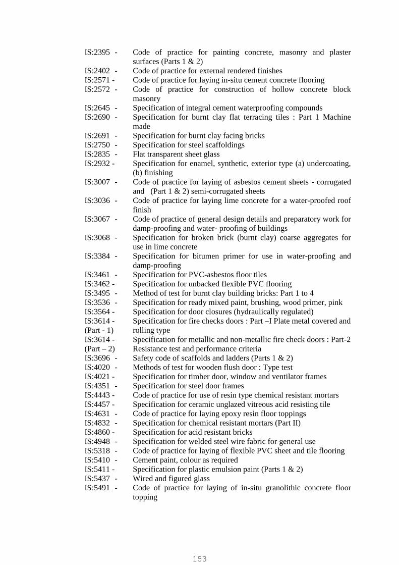
IS:2395 - Code of practice for painting concrete, masonry and plastersurfaces (Parts 1 & 2)
IS:2402 - Code of practice for external rendered finishesIS:2571 - Code of practice for laying in-situ cement concrete flooringIS:2572 - Code of practice for construction of hollow concrete block
masonryIS:2645 - Specification of integral cement waterproofing compoundsIS:2690 - Specification for burnt clay flat terracing tiles : Part 1 Machine
madeIS:2691 - Specification for burnt clay facing bricksIS:2750 - Specification for steel scaffoldingsIS:2835 - Flat transparent sheet glassIS:2932 - Specification for enamel, synthetic, exterior type (a) undercoating,
(b) finishingIS:3007 - Code of practice for laying of asbestos cement sheets - corrugated
and (Part 1 & 2) semi-corrugated sheetsIS:3036 - Code of practice for laying lime concrete for a water-proofed roof
finishIS:3067 - Code of practice of general design details and preparatory work for
damp-proofing and water- proofing of buildingsIS:3068 - Specification for broken brick (burnt clay) coarse aggregates for
use in lime concreteIS:3384 - Specification for bitumen primer for use in water-proofing and
damp-proofingIS:3461 - Specification for PVC-asbestos floor tilesIS:3462 - Specification for unbacked flexible PVC flooringIS:3495 - Method of test for burnt clay building bricks: Part 1 to 4IS:3536 - Specification for ready mixed paint, brushing, wood primer, pinkIS:3564 - Specification for door closures (hydraulically regulated)IS:3614 - Specification for fire checks doors : Part –I Plate metal covered and(Part - 1) rolling typeIS:3614 - Specification for metallic and non-metallic fire check doors : Part-2(Part – 2) Resistance test and performance criteriaIS:3696 - Safety code of scaffolds and ladders (Parts 1 & 2)IS:4020 - Methods of test for wooden flush door : Type testIS:4021 - Specification for timber door, window and ventilator framesIS:4351 - Specification for steel door framesIS:4443 - Code of practice for use of resin type chemical resistant mortarsIS:4457 - Specification for ceramic unglazed vitreous acid resisting tileIS:4631 - Code of practice for laying epoxy resin floor toppingsIS:4832 - Specification for chemical resistant mortars (Part II)IS:4860 - Specification for acid resistant bricksIS:4948 - Specification for welded steel wire fabric for general useIS:5318 - Code of practice for laying of flexible PVC sheet and tile flooringIS:5410 - Cement paint, colour as requiredIS:5411 - Specification for plastic emulsion paint (Parts 1 & 2)IS:5437 - Wired and figured glassIS:5491 - Code of practice for laying of in-situ granolithic concrete floor
topping
153

IS:6041 - Code of practice construction of autoclaved cellular concrete blockmasonry
IS:6042 - Code of practice for construction of light weight concrete blockmasonry
IS:6248 - Specification for metal rolling shutters and rolling grillesIS:7193 - Specification for glass fibre base coal tar pitch and bitumen feltsIS:7452 - Specification for hot rolled steel sections for doors, windows and
ventilatorsIS:8042 - Specification for white portland cementIS:8543 - Methods of testing plasticsIS:8869 - Specification for washers for corrugated sheet roofingIS:9197 - Specification for epoxy resin, hardeners and epoxy resin
composites for floor toppingIS:9862 - Specification for ready mixed paint, brushing, bituminous, black,
lead-free, acid, alkali, water and chlorine resistingIS:12200- Code of practice for provision of waterstops at transverse
contraction joints in masonry and concrete damsBS : 476 - Methods for determination of the fire resistance of elements of(Part – 20) construction (General Principles)BS : 476 - Methods for determination of the fire resistance of load bearing(Part – 21) elements of constructionBS : 476 - Methods for determination of the fire resistance of non-load(Part – 22) bearing elements of constructionPart – IV - National Building code of IndiaFire Protection
7.2 Brickwork
7.2.1 Materials
7.2.1.1 Bricks used in the works shall conform to the requirements laid down in IS: 1077.The class of the bricks shall be as specifically indicated in the respective items ofwork prepared by the Contractor.
7.2.1.2 The nominal size of the modular brick shall be 200mmx100mmx100mm with thepermissible tolerances over the actual size of 190mmx90mmx90mm as per IS:1077. The nominal thickness of one brick and half brick walls using modular bricksshall be considered as 200 mm and 100 mm respectively. In the event of use oftraditional bricks of nominal size 230 mmx115mmx75mm with tolerance upto 3mm in each dimension, one brick and half brick walls shall be considered as 230mm and 115 mm respectively.
7.2.1.3 Bricks shall be sound, hard, homogenous in texture, well burnt in kiln without beingvitrified, hand/machine moulded, deep red, cherry or copper coloured, of regularshape and size & shall have sharp and square edges with smooth rectangular faces.The bricks shall be free from pores, cracks, flaws and nodules of free lime. Handmoulded bricks shall be moulded with a frog and those made by extrusion processmay not be provided with a frog. Bricks shall give a clear ringing sound whenstruck and shall have a minimum crushing strength of 5N/sq.mm unless otherwisespecified in the Items of work prepared by the Contractor.
154

7.2.1.4 The average water absorption shall not be more than 20 percent by weight uptoclass 12.5 and 15 percent by weight for higher classes. Bricks which do not conformto this requirement shall be rejected. Over or under burnt bricks are not acceptablefor use in the works.
7.2.1.5 Sample bricks shall be submitted to the EMPLOYER for approval and brickssupplied shall conform to approved samples. If demanded by EMPLOYER, bricksamples shall be got tested as per IS: 3495 by Contractor. Bricks rejected byEMPLOYER shall be removed from the site of works within 24 hours.
7.2.1.6 Mortar for brick masonry shall consist of cement and sand and shall be prepared asper IS: 2250. Mix shall be in the proportion of 1:5 for brickwork of thickness onebrick or above and 1:4 for brickwork of thickness half brick or below, unlessotherwise specified in the respective items of work prepared by the Contractor. Sandfor masonry mortar shall conform to IS:218. The sand shall be free from clay, shale,loam, alkali and organic matter and shall be of sound, hard, clean and durableparticles. Sand shall be approved by EMPLOYER. If so directed by theEMPLOYER, sand shall be screened and washed till it satisfies the limits ofdeleterious materials.
7.2.1.7 For preparing cement mortar, the ingredients shall first be mixed thoroughly in drycondition. Water shall then be added and mixing continued to give a uniform mixof required consistency. Mixing shall be done thoroughly in a mechanical mixer,unless hand mixing is specifically permitted by the EMPLOYER. The mortar thusmixed shall be used as soon as possible, preferably within 30 minutes from the timewater is added to cement. Incase, the mortar has stiffened due to evaporation ofwater, this may be re-tempered by adding water as required to restore consistency,but this will be permitted only upto 30 minutes from the time of initial mixing ofwater to cement. Any mortar which is partially set shall be rejected and shall beremoved forthwith from the site. Droppings of mortar shall not be re-used under anycircumstances. The Contractor shall arrange for test on mortar samples if so directedby the EMPLOYER.
7.2.2 Workmanship
7.2.2.1 Workmanship of brick work shall conform to IS: 2212. All bricks shall bethoroughly soaked in clean water for at least one hour immediately before beinglaid. The cement mortar for brick masonry work shall be as specified in therespective item of work prepared by the Contractor. Brick work 200mm/230mmthick and over shall be laid in English Bond unless otherwise specified.100mm/115mm thick brickwork shall be laid with stretchers. For laying bricks, alayer of mortar shall be spread over the full width of suitable length of the lowercourse. Each brick shall be slightly pressed into the mortar and shoved into finalposition so as to embed the brick fully in mortar. Only full size bricks shall be usedfor the works and cut bricks utilised only as closers to make up required wall lengthor for bonding. Bricks shall be laid with frogs on top.
7.2.2.2 All brickwork shall be plumb, square and true to dimensions shown. Vertical jointsin alternate courses shall come directly one over the other and be in line. Horizontalcourses shall be levelled. The thickness of brick courses shall be kept uniform. In
155

case of one brick thick or half brick thick wall, at least one face should be keptsmooth and plane, even if the other is slightly rough due to variation in size ofbricks. For walls of thickness greater than one brick both faces shall be kept smoothand plane. All interconnected brickwork shall be carried out at nearly one level sothat there is uniform distribution of pressure on the supporting structure and noportion of the work shall be left more than one course lower than the adjacent work.Where this is not possible, the work shall be raked back according to bond (and notsaw toothed) at an angle not exceeding 45 deg. But in no case the level differencebetween adjoining walls shall exceed one metre. Brick work shall not be raisedmore than one metre per day.
7.2.2.3 Bricks shall be so laid that all joints are well filled with mortar. The thickness ofjoints shall not be less than 6 mm and not more than 10 mm. The face joints shall beraked to a minimum depth of 10mm/15mm by raking tools during the progress ofwork when the mortar is still green, so as to provide a proper key for the plastering/pointing respectively to be done later. When plastering or pointing is not required tobe done, the joints shall be uniform in thickness and be struck flush and finished atthe time of laying. The face of brickwork shall be cleaned daily and all mortardroppings removed. The surface of each course shall be thoroughly cleaned of alldirt before another course is laid on top.
7.2.2.4 During inclement weather conditions, newly built brick masonry works shall beprotected by tarpaulin or other suitable covering to prevent mortar being washedaway by rain.
7.2.2.5 Brickwork shall be kept constantly moist on all the faces for at least seven days after24 hrs of laying. The arrangement for curing shall be got approved from theEMPLOYER.
7.2.2.6 Double scaffolding having two sets of vertical supports shall be provided tofacilitate execution of the masonry works. The scaffolding shall be designedadequately considering all the dead, live and possible impact loads to ensure safetyof the workmen, in accordance with the requirements stipulated in IS:2750 andIS:3696 (Part I). Scaffolding shall be properly maintained during the entire period ofconstruction. Single scaffolding shall not be used on important works and will bepermitted only in certain cases as decided by the EMPLOYER. Where singlescaffolding is adopted, only minimum number of holes, by omitting a header shallbe left in the masonry for supporting horizontal scaffolding poles. All holes in themasonry shall be carefully made good before plastering/pointing.
7.2.2.7 In the event of usage of traditional bricks of size 230 mm x115mm x75mm, thecourses at the top of the plinth and sills as well as at the top of the wall just belowthe roof/floor slabs and at the top of the parapet shall be laid with bricks on edge.
7.2.2.8 All brickwork shall be built tightly against columns, floor slabs or other structuralmembers.
7.2.2.9 To overcome the possibility of development of cracks in the brick masonryfollowing measures shall be adopted.
156

7.2.2.10 For resting RCC slabs, the bearing surface of masonry wall shall be finished on topwith 12 mm thick cement mortar 1:3 and provided with 2 layers of Kraft paperGrade 1 as per IS:1397 or 2 layers of 50 micron thick polyethylene sheets.
7.2.2.11 RCC/ steel beams resting on masonry wall shall be provided with reinforcedconcrete bed blocks of 50 mm thickness, projecting 50mm on either sides of thebeam, duly finished on top with 2 layers of Kraft paper Grade 1 as per IS:1397 or 2layers of 50 micron thick polyethylene sheets.
7.2.2.12 Steel wire fabric shall be provided at the junction of brick masonry and concretebefore taking up plastering work.
7.2.2.13 Bricks for partition walls shall be stacked adjacent to the structural member to pre-deflect the structural member before the wall is taken up for execution. Further, thetop most course of half or full brick walls abutting against either a deshuttered slabor beam shall be built only after any proposed masonry wall above the structuralmember is executed to cater for the deflection of the structural element.
7.2.2.14 Reinforced cement concrete transomes and mullions of dimensions as indicated inthe construction Drawings to be prepared by the Contractor are generally required tobe provided in the half brick partition walls.
7.2.2.15 Where the drawings prepared by the Contractor indicate that structural steel sectionsare to be encased in brickwork, the brickwork masonry shall be built closely againstthe steel section, ensuring a minimum of 20mm thick cement-sand mortar 1:4 overall the steel surfaces. Steel sections partly embedded in brickwork shall be providedwith bituminous protective coating to the surfaces at the point of entry into the brickmasonry.
7.2.2.15 Facing bricks of the type specified conforming to IS:2691 shall be laid in thepositions indicated on the Drawings prepared by the Contractor and all facingbrickwork shall be well bonded to the backing bricks/RCC surfaces. The level ofexecution of the facing brick work shall at any time be lower by at least 600 mmbelow the level of the backing brickwork.
7.2.2.16 Facing bricks shall be laid over 10 mm thick backing of cement mortar. The mortarmix, thickness of joint and the type of pointing to be carried out shall be as specifiedin the item of works prepared by the Contractor. The pattern of laying the bricksshall be as specifically indicated in the Drawings prepared by the Contractor. Forfacing brickwork, double scaffolding shall be used. Faced works shall be kept cleanand free from damage, discoloration etc., at all times.
7.3 Uncoursed Random Rubble Masonry, in Foundation, Plinth andSuperstructure
7.3.1 Materials
7.3.1.1 Stones for the works shall be of the specified variety which are hard, durable, finegrained and uniform in colour (for superstructure work) free from veins, flaws andother defects. Quality and work shall conform to the requirements specified inIS:1597 (Part-I). The percentage of water absorption shall not exceed 5 percent as
157

per test conducted in accordance with IS:1124. The Contractor shall supply samplestones to the EMPLOYER for approval. Stones shall be laid with its grainshorizontal so that the load transmitted is always perpendicular to the natural bed.
7.3.1.2 Cement-sand mortar for stone masonry works shall be in the proportion of 1:6.Materials and preparation of mortar shall be as specified in clause 7.2.1.
7.3.2 Workmanship
7.3.2.1 For All Works below ground level the masonry shall be random rubble uncoursedwith ordinary quarry dressed stones for the hearting and selected quarry dressedstones for the facing.
7.3.2.2 For all works above ground level and in superstructure the masonry shall be randomrubble uncoursed, well bonded, faced with hammer dressed stones with squaredquoins at corners. The bushings on the face shall not be more than 40 mm on anexposed face and on the face to be plastered it shall not project by more than 12 mmnor shall it have depressions more than 10 mm from the average wall surface.
7.3.2.3 Face stones shall extend back sufficiently and bond well with the masonry. Thedepth of stone from the face of the wall inwards shall not be less than the height orbreadth at the face. The length of the stone shall not exceed three times the heightand the breadth on base shall not be greater than three-fourths the thickness of wallnor less than 150 mm. The height of stone may be upto a maximum of 300 mm.Face stones or hearting stones shall not be less than 150 mm in any direction.
7.3.2.4 Chips and spalls shall be used wherever necessary to avoid thick mortar joints andto ensure that no hollow spaces are left in the masonry. The use of chips and spallsin the hearting shall not exceed 20 percent of the quantity of stone masonry. Spallsand chips shall not be used on the face of the wall and below hearting stones tobring them to the level of face stones.
7.3.2.5 The maximum thickness of joints shall not exceed 20 mm. All joints shall becompletely filled with mortar. When plastering or pointing is not required to bedone, the joints shall be struck flush and finished as the work proceeds. Otherwise,the joints shall be raked to a minimum depth of 20 mm by a raking tool during theprogress of the work while the mortar is still green.
7.3.2.6 Through or bond stones shall be provided in walls upto 600 mm thick and in case ofwalls above 600 mm thickness, a set of two or more bond stones overlapping eachother by at least 150 mm shall be provided in a line from face to back. In case ofhighly absorbent types of stones (porous lime stone and sand stone, etc.) the bondstone shall extend about two-thirds into the wall and a set of two or more bondstones overlapping each other by at least 150 mm shall be provided. Each bondstone or a set of bond stones shall be provided for every 0.5 sq.m of wall surface.
7.3.2.7 All stones shall be sufficiently wetted before laying to prevent absorption of waterfrom the mortar. All connected walls in a structure shall be normally raiseduniformly and regularly. However if any part of the masonry is required to be left
158

behind, the wall shall be raked back (and not saw toothed) at an angle not exceeding45deg. Masonry work shall not be raised by more than one metre per day.
7.3.2.8 Green work shall be protected from rain by suitable covering. Masonry work shallbe kept constantly moist on all the faces for a minimum period of seven days forproper curing of the joints.
7.3.2.9 Type of scaffolding to be used shall be as specified in clause 7.2.2.
7.4 Coursed Rubble Masonry (First Sort) for Superstructure
7.4.1 Materials
7.4.1.1 The Material specification for the work shall be as per clause 7.3.1.
7.4.2 Workmanship
7.4.2.1 All Courses shall be laid truly horizontal and shall be of the same height in anycourse. The height of course shall not be less than 150 mm and not more than 300mm. The width of stone shall not be less than its height.
7.4.2.2 Face stones shall tail into the work for not less than their height and atleast 1/3rd thenumber of stones shall tail into the work for a length not less than twice their heightbut not more than three-fourths the thickness of the wall whichever is smaller.These should be laid as headers and stretchers alternately to break joints by atleast75 mm.
7.4.2.3 The face stones shall be squared on all joints and beds; the bed joints being hammeror chisel dressed true and square for at least 80 mm back from the face and the sidejoints for atleast 40 mm. The face of the stone shall be hammer dressed so that thebushing shall not be more than 40 mm on an exposed face and 10 mm on a face tobe plastered. No portion of the dressed surface shall show a depth of gap more than6 mm from a straight edge placed on it. The remaining unexposed portion of thestone shall not project beyond the surface of bed and side joints.
7.4.2.4 No spalls or pinnings shall be allowed on the face. All bed joints shall be horizontaland side joints shall be vertical and no joints shall be more than 10 mm in thickness.When plastering or pointing is not required to be done, the joints shall be struckflush and finished as the work proceeds. Otherwise, the joints shall be raked to aminimum depth of 20 mm by a raking tool, during the progress of the work whilethe mortar is still green.
7.4.2.5 Hearting shall consist of flat bedded stones carefully laid on their proper beds andsolidly bedded in mortar. The use of chips shall be restricted to the filling ofinterstices between the adjacent stones in hearting and these shall not exceed 10percent of the quantity of the stone masonry. Care shall be taken so that no hollowspaces are left anywhere in the masonry.
159

7.4.2.6 The requirement regarding through or bond stones shall be as specified in clause7.3.2 with the further stipulation that these shall be provided at 1.5 m to 1.8m apartclear in every course but staggered at alternate courses.
7.4.2.7 The quoins which shall be of the same height as the course in which they occur,shall not be less than 450 mm in any direction. Quoin stones shall be laid asstretchers and headers alternately. They shall be laid square on their beds, whichshall be rough chisel dressed to a depth of at least 100 mm from the face. Thesestones shall have a minimum uniform chisel drafts of 25mm width at four edges, allthe edges being in the same plane.
7.4.2.8 Type of scaffolding to be used shall be as per Clause 7.2.2. Requirements ofexecution of the work and curing shall be as stipulated in clause 7.3.2 .
7.5 Concrete Block Masonry
7.5.1 Materials
7.5.1.1 Masonry units of hollow and solid concrete blocks shall conform to therequirements of IS : 2185 (Part I).
7.5.1.2 Masonry units of hollow and solid light-weight concrete blocks shall conform to therequirements of IS : 2185 (Part 3).
7.5.1.3 Masonry units of autoclaved cellular concrete blocks shall conform to therequirements of IS:2185 (Part 3).
7.5.1.4 The height of the concrete masonry units shall not exceed either its length or sixtimes its width.
7.5.1.5 The nominal dimensions of concrete block shall be as under.a) Length 400, 500 or 600 mmb) Height 100 or 200 mmc) Width 100 to 300 mm in 50 mm increments
7.5.1.6 Half blocks shall be in lengths of 200, 250 or 300mm to correspond to the fulllength blocks.
7.5.1.7 Actual dimensions shall be 10mm short of the nominal dimensions.
7.5.1.8 The maximum variation in the length of the units shall not be more than ±5 mm andmaximum variation in height or width of the units shall not be more than ± 3mm.
7.5.1.9 Concrete blocks shall be either hollow blocks with open or closed cavities or solidblocks.
7.5.1.10 Concrete blocks shall be sound, free of cracks, chipping or other defects whichimpair the strength or performance of the construction. Surface texture shall asspecified. The faces of the units shall be flat and rectangular, opposite faces shall beparallel and all arises shall be square.
160
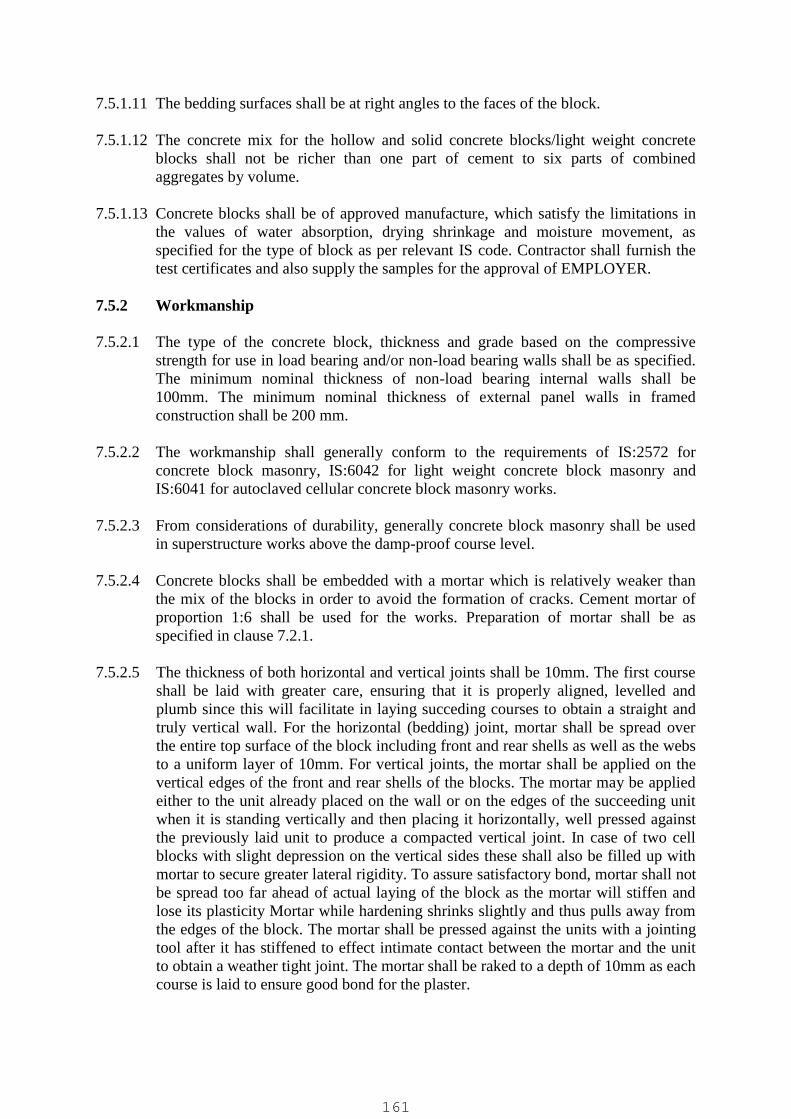
7.5.1.11 The bedding surfaces shall be at right angles to the faces of the block.
7.5.1.12 The concrete mix for the hollow and solid concrete blocks/light weight concreteblocks shall not be richer than one part of cement to six parts of combinedaggregates by volume.
7.5.1.13 Concrete blocks shall be of approved manufacture, which satisfy the limitations inthe values of water absorption, drying shrinkage and moisture movement, asspecified for the type of block as per relevant IS code. Contractor shall furnish thetest certificates and also supply the samples for the approval of EMPLOYER.
7.5.2 Workmanship
7.5.2.1 The type of the concrete block, thickness and grade based on the compressivestrength for use in load bearing and/or non-load bearing walls shall be as specified.The minimum nominal thickness of non-load bearing internal walls shall be100mm. The minimum nominal thickness of external panel walls in framedconstruction shall be 200 mm.
7.5.2.2 The workmanship shall generally conform to the requirements of IS:2572 forconcrete block masonry, IS:6042 for light weight concrete block masonry andIS:6041 for autoclaved cellular concrete block masonry works.
7.5.2.3 From considerations of durability, generally concrete block masonry shall be usedin superstructure works above the damp-proof course level.
7.5.2.4 Concrete blocks shall be embedded with a mortar which is relatively weaker thanthe mix of the blocks in order to avoid the formation of cracks. Cement mortar ofproportion 1:6 shall be used for the works. Preparation of mortar shall be asspecified in clause 7.2.1.
7.5.2.5 The thickness of both horizontal and vertical joints shall be 10mm. The first courseshall be laid with greater care, ensuring that it is properly aligned, levelled andplumb since this will facilitate in laying succeding courses to obtain a straight andtruly vertical wall. For the horizontal (bedding) joint, mortar shall be spread overthe entire top surface of the block including front and rear shells as well as the websto a uniform layer of 10mm. For vertical joints, the mortar shall be applied on thevertical edges of the front and rear shells of the blocks. The mortar may be appliedeither to the unit already placed on the wall or on the edges of the succeeding unitwhen it is standing vertically and then placing it horizontally, well pressed againstthe previously laid unit to produce a compacted vertical joint. In case of two cellblocks with slight depression on the vertical sides these shall also be filled up withmortar to secure greater lateral rigidity. To assure satisfactory bond, mortar shall notbe spread too far ahead of actual laying of the block as the mortar will stiffen andlose its plasticity Mortar while hardening shrinks slightly and thus pulls away fromthe edges of the block. The mortar shall be pressed against the units with a jointingtool after it has stiffened to effect intimate contact between the mortar and the unitto obtain a weather tight joint. The mortar shall be raked to a depth of 10mm as eachcourse is laid to ensure good bond for the plaster.
161
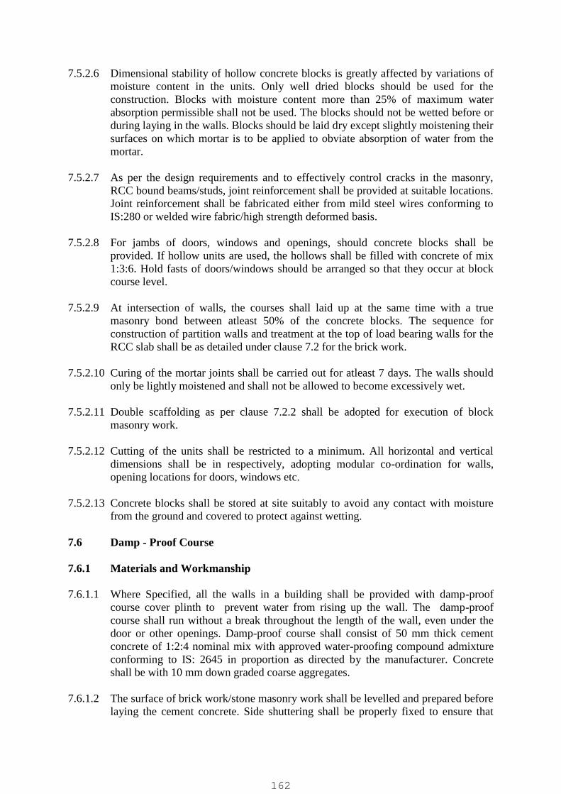
7.5.2.6 Dimensional stability of hollow concrete blocks is greatly affected by variations ofmoisture content in the units. Only well dried blocks should be used for theconstruction. Blocks with moisture content more than 25% of maximum waterabsorption permissible shall not be used. The blocks should not be wetted before orduring laying in the walls. Blocks should be laid dry except slightly moistening theirsurfaces on which mortar is to be applied to obviate absorption of water from themortar.
7.5.2.7 As per the design requirements and to effectively control cracks in the masonry,RCC bound beams/studs, joint reinforcement shall be provided at suitable locations.Joint reinforcement shall be fabricated either from mild steel wires conforming toIS:280 or welded wire fabric/high strength deformed basis.
7.5.2.8 For jambs of doors, windows and openings, should concrete blocks shall beprovided. If hollow units are used, the hollows shall be filled with concrete of mix1:3:6. Hold fasts of doors/windows should be arranged so that they occur at blockcourse level.
7.5.2.9 At intersection of walls, the courses shall laid up at the same time with a truemasonry bond between atleast 50% of the concrete blocks. The sequence forconstruction of partition walls and treatment at the top of load bearing walls for theRCC slab shall be as detailed under clause 7.2 for the brick work.
7.5.2.10 Curing of the mortar joints shall be carried out for atleast 7 days. The walls shouldonly be lightly moistened and shall not be allowed to become excessively wet.
7.5.2.11 Double scaffolding as per clause 7.2.2 shall be adopted for execution of blockmasonry work.
7.5.2.12 Cutting of the units shall be restricted to a minimum. All horizontal and verticaldimensions shall be in respectively, adopting modular co-ordination for walls,opening locations for doors, windows etc.
7.5.2.13 Concrete blocks shall be stored at site suitably to avoid any contact with moisturefrom the ground and covered to protect against wetting.
7.6 Damp - Proof Course
7.6.1 Materials and Workmanship
7.6.1.1 Where Specified, all the walls in a building shall be provided with damp-proofcourse cover plinth to prevent water from rising up the wall. The damp-proofcourse shall run without a break throughout the length of the wall, even under thedoor or other openings. Damp-proof course shall consist of 50 mm thick cementconcrete of 1:2:4 nominal mix with approved water-proofing compound admixtureconforming to IS: 2645 in proportion as directed by the manufacturer. Concreteshall be with 10 mm down graded coarse aggregates.
7.6.1.2 The surface of brick work/stone masonry work shall be levelled and prepared beforelaying the cement concrete. Side shuttering shall be properly fixed to ensure that
162
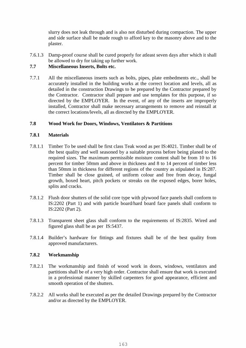
slurry does not leak through and is also not disturbed during compaction. The upperand side surface shall be made rough to afford key to the masonry above and to theplaster.
7.6.1.3 Damp-proof course shall be cured properly for atleast seven days after which it shallbe allowed to dry for taking up further work.
7.7 Miscellaneous Inserts, Bolts etc.
7.7.1 All the miscellaneous inserts such as bolts, pipes, plate embedments etc., shall beaccurately installed in the building works at the correct location and levels, all asdetailed in the construction Drawings to be prepared by the Contractor prepared bythe Contractor. Contractor shall prepare and use templates for this purpose, if sodirected by the EMPLOYER. In the event, of any of the inserts are improperlyinstalled, Contractor shall make necessary arrangements to remove and reinstall atthe correct locations/levels, all as directed by the EMPLOYER.
7.8 Wood Work for Doors, Windows, Ventilators & Partitions
7.8.1 Materials
7.8.1.1 Timber To be used shall be first class Teak wood as per IS:4021. Timber shall be ofthe best quality and well seasoned by a suitable process before being planed to therequired sizes. The maximum permissible moisture content shall be from 10 to 16percent for timber 50mm and above in thickness and 8 to 14 percent of timber lessthan 50mm in thickness for different regions of the country as stipulated in IS:287.Timber shall be close grained, of uniform colour and free from decay, fungalgrowth, boxed heart, pitch pockets or streaks on the exposed edges, borer holes,splits and cracks.
7.8.1.2 Flush door shutters of the solid core type with plywood face panels shall conform toIS:2202 (Part 1) and with particle board/hard board face panels shall conform toIS:2202 (Part 2).
7.8.1.3 Transparent sheet glass shall conform to the requirements of IS:2835. Wired andfigured glass shall be as per IS:5437.
7.8.1.4 Builder’s hardware for fittings and fixtures shall be of the best quality fromapproved manufacturers.
7.8.2 Workmanship
7.8.2.1 The workmanship and finish of wood work in doors, windows, ventilators andpartitions shall be of a very high order. Contractor shall ensure that work is executedin a professional manner by skilled carpenters for good appearance, efficient andsmooth operation of the shutters.
7.8.2.2 All works shall be executed as per the detailed Drawings prepared by the Contractorand/or as directed by the EMPLOYER.
163

7.8.2.3 All members of the door, window, and ventilator shall be straight without any warpor bow and shall have smooth well planed faces. The right angle shall be checkedfrom the inside surfaces of the respective members of the frame. Frames shall havemortice and tenon joints which shall be treated with an approved adhesive andprovided with metal or wood pins. The vertical members of the door frame shallproject 50 mm below the finished floor level. The finished dimension of framesshall be rebated on the solid for keying with the plaster and for receiving theshutters. The depth of rebate for housing the shutter shall be 15 mm. The size of theframes shall be as specified in the respective items of work prepared by theContractor. The workmanship shall generally conform to the requirements specifiedin IS:4021.
7.8.2.4 The face of the frames abutting the masonry or concrete shall be provided with acoat of coal tar.
7.8.2.5 Three hold fasts using 25 mm x 6 mm mild steel flats 225 mm long with split endsshall be fixed on each side of door and window frames, one at the centre and theother two at 300 mm from the top and bottom of the frame. For window andventilator frames less than 1 m in height, two hold fasts on each side shall be fixedat quarter points.
7.8.2.6 Timber panelled shutters for doors, windows and ventilators shall be constructed inthe form of framework of stiles and rails with panel insertion. The panels shall befixed by either providing grooves in the stiles and rails or by beading. Glazing barsshall be as detailed in the Drawings prepared by the Contractor. The stiles and railsshall be joined by mortice and tenon joints at right angles. All members of theshutter shall be straight without any warp or bow and shall have smooth, wellplaned faces at right angles to each other. The right angle for the shutter shall bechecked by measuring the diagonals and the difference shall not be more than 3mm. Timber panels made from more than one piece shall be jointed with acontinuous tongued and grooved joint, glued together and reinforced with metaldowels. The workmanship shall generally conform to the requirements specified inIS:1003 (Parts 1 & 2). The thickness of the shutter, width/thickness of thestiles/rails/panel type shall be as specified. Marine plywood panels conforming toIS:710 shall be used for doors where specified.
7.8.2.7 Details of the wooden flush door shutters, solid core type with specific requirementof the thickness, core, face panels, viewing glazed panel, venetian louvre opening,teak wood lipping etc. shall be as specified. Panels of shutter shall be of marineplywood conforming to IS:710. Flush door shutters shall be from reputedmanufacturers and Contractor shall submit test results as per IS:4020, if so desiredby the EMPLOYER.
7.8.2.8 Glazing of door, window, ventilator and partitions shall be with either flattransparent sheet glass, wired or figured glass. Transparent sheet glass shall be of 'B'quality as per IS:2835.The thickness and type of glazing to be provided shall be asspecified.
164

7.8.2.9 The material of the fittings and fixtures either of chromium plated steel, cast brass,copper oxidised or anodised aluminum shall be as specified. The number, size andtype of the fittings and fixtures shall be as specified.
7.8.2.10 Woodwork shall not be provided with the finishes of painting/varnishing etc. unlessit has been approved by the EMPLOYER. The type of finish and the number ofcoats shall be as stipulated in the respective items of work prepared by theContractor. Preparation of the wood surfaces and application of the finishes shall bein accordance with clause 7.32.
7.8.2.11 Wooden hand railing and architrave's shall be of the size and shape with the fixingarrangement as indicated in the Drawings prepared by the Contractor.
7.8.2.12 The framework of the partitions with mullions and transoms shall be with thesections of dimensions as specified. Panels of double/single glazing/plywood shallbe fixed as per details specified. Partitions shall be fixed rigidly between the floorand structural columns/beams including provision of necessary shims for wedgingetc. Finished work shall be of rigid construction, erected truly plumb to the lines andlevels, at locations as per the construction Drawings prepared by the Contractor.
7.8.2.13 Any carpentry work which show defects due to inadequate seasoning of the timberor bad workmanship shall be removed and replaced by Contractor with work as perSpecifications.
7.9 Steel Doors, Windows and Ventilators
7.9.1 Materials
7.9.1.1 Hot rolled steel sections for the fabrication of steel doors, windows and ventilatorsshall conform to IS: 7452, which are suitable for, single glazing.
7.9.1.2 Pressed steel door frames for steel flush doors shall be out of 1.25mm thick mildsteel sheets of profiles as per IS : 4351.
7.9.1.3 Transparent sheet glass shall conform to the requirements of IS : 2835. Wired andfigured glass shall be as per IS : 5437.
7.9.1.4 Builder’s hardware of fittings and fixtures shall be of the best quality from theapproved manufacturers.
7.9.2 Workmanship
7.9.2.1 All steel doors, windows and ventilators shall be of the type as specified in therespective items of work prepared by the Contractor and of sizes as indicated in theDrawings prepared by the Contractor prepared by the Contractor. Steel doors,windows and ventilators shall conform to the requirements as stipulated in IS :1038. Steel windows shall conform to IS : 1361, if so specified.
7.9.2.2 Doors, windows and ventilators shall be of an approved manufacture. Fabricationof the unit shall be with rolled section, cut to correct lengths and metered. Corners
165

shall be welded to form a solid fused welded joint conforming to the requirementsof IS : 1038. Tolerance in overall dimensions shall be within ±1.5mm. Theframes and shutters shall be free from wrap or buckle and shall be square and trulyplain. All welds shall be dressed flush on exposed and contact surfaces. Punchingof holes, slots and other provisions to install fittings and fixtures later shall be madeat the correct locations as per the requirements. Samples of the units shall be gotapproved by the EMPLOYER before further manufacture/purchase by theContractor.
7.9.2.3 Type and details of shutters, hinges, glazing bar requirement, couplings, lockingarrangement, fittings and fixtures shall be as described in the respective items ofwork and / or as shown in the Drawings prepared by the Contractor for single orcomposite units.
7.9.2.4 For windows with fly proof mesh as per the item of work prepared by theContractor, rotor operator arrangement, for the operation of the glazed shutters fromthe inside shall be provided.
7.9.2.5 Pressed steel door frames shall be provided with fixing lugs at each jamb, hinges,lock-strike plate, mortar guards, angle threshold, shock-absorbers of rubber orsimilar material as per the requirements of IS : 4351. Pressed steel doorframes shallbe fixed as `built-in’ as the masonry work proceeds. After placing it plumb at thespecified location, masonry walls shall be built up solid on either side and eachcourse grouted with mortar to ensure solid contact with the doorframe, withoutleaving any voids. Temporary struts across the width shall be fixed, during erectionto prevent bow/sag of the frame.
7.9.2.6 Door shutters of flush welded construction shall be 45mm thick, fabricated with twoouter skills of 1.25mm thick steel sheets, 1mm thick steel sheet stiffeners and steelchannels on all four edges. Double shutters shall have meeting stile edge beveled orrebated. Provision of glazed viewing panel, louvers shall be made as per the itemsof works and/or Drawings prepared by the Contractor. Shutters shall be suitablyreinforced for lock and other surface hardware and to prevent sagging/twisting.Single sheet steel door shutters shall be fabricated out of 1.25mm thick steel sheets,mild steel angles and stiffeners as per the Drawings prepared by the Contractor.
7.9.2.7 Doors, windows and ventilators shall be fixed into the prepared openings. Theyshall not be ‘built-in’ as the masonry work proceeds, to avoid distortion and damageof the units. The dimensions of the masonry opening shall have 10mm clearancearound the overall dimensions of the frame for this purpose. Any support ofscaffolding members on the frames/glazing bars is prohibited.
7.9.2.8 Glazing of the units shall be either with flat transparent glass or wired / figured glassof the thickness as specified in the items of works prepared by the Contractor. Allglass panels shall have properly squared corner and straight edges. Glazing shall beprovided on the outside of the frames.
7.9.2.9 Fixing of the glazing shall be either with spring glazing clips and putty conformingto IS:419 or with metal beads. Pre-formed PVC or rubber gaskets shall be provided
166

for fixing the beads with the concealed screws. The type of fixing the glazing shallbe as indicated in the items of work and/or in Drawings prepared by the Contractor.
7.9.2.10 Steel doors, windows and ventilators shall be provided with finish of either paintingas specified or shall be hot dip galvanised with thickness of the zinc coating asstipulated all as described in the respective items of works prepared by theContractor.
7.9.2.11 The material of the Builders hardware of fittings and fixtures of chromium platedsteel, cast brass, brass copper oxidised or anodised aluminium shall be as specifiedin the items of works prepared by the Contractor. The number , size and type offittings and fixtures shall be as in the Drawings /items of works prepared by theContractor.
7.9.2.12 Installation of the units with fixing lugs, screws, mastic caulking compound at thespecified locations shall generally conform to the requirements of IS:1081.Necessary holes etc required for fixing shall be made by the Contractor and madegood after installation. Workmanship expected is of a high order for efficient andsmooth operation of the units.
7.10 Aluminum Doors, Windows, Ventilators & Partitions
7.10.1 Materials
7.10.1.1 Aluminum alloy used in the manufacture of extruded sections for the fabrication ofdoors, windows, ventilators shall conform to designation HE9-WP of IS:733.
7.10.1.2 Transparent sheet glass shall conform to the requirements of IS:2835. Wired andfigured glass shall be as per IS:5437.
7.10.1.3 Builder's hardware of fittings & fixtures shall be of the best quality from approvedmanufacturers.
7.10.2 Workmanship
7.10.2.1 All aluminum doors, windows, ventilators and partitions shall be of the type andsize as specified. The doors, windows, ventilators shall conform to the requirementsof IS:1948. Aluminum windows, shall conform to IS:1949, if so specified.
7.10.2.2 All aluminum units shall be supplied with anodized finish. The minimum anodicfilm thickness shall be 0.015 mm.
7.10.2.3 Doors, windows and ventilators shall be of an approved manufacture. Fabrication ofthe units shall be with the extruded sections, cut to correct lengths, mitred andwelded at the corners to a true right angle conforming to the requirements ofIS:1948. Tolerance in overall dimensions shall be within ± 1.5mm. The frames andshutters shall be free from warp or buckle and shall be square and truly plane.Punching of holes, slots and other provisions to install fittings or fixtures later shallbe made at the correct locations, as per the requirements.
167

7.10.2.4 Aluminium swing type doors, aluminum sliding windows, partitions shall be asspecified.
7.10.2.5 IS:1948 and IS:1949 referred to incorporates the sizes, shapes, thicknesses andweight per running metre of extruded sections for the various components of theunits. However, new sizes, shapes, thicknesses with modifications to suit snap-fitglazing clips etc. are being continuously being added by various leadingmanufacturers of extruded sections, which are available in the market. As such, thesections of the various components of the unit proposed by the Contractor, will bereviewed by the EMPLOYER and will be accepted only if they are equal to ormarginally more than that given in the codes/as specified.
7.10.2.6 The framework of the partitions with mullions and transomes shall be with anodisedaluminium box sections. Anodised aluminium box sections shall be in-filled withtimber of class 3 (silver oak or any other equivalent) as per IS:4021. Panels ofdouble/single glazing/plywood shall be fixed as per details indicated in theDrawings to be prepared by the Contractor. Partitions shall be fixed rigidly betweenthe floor and the structural columns/beams including provision of necessary shimsfor wedging etc. Finished work shall be of rigid construction, erected truly plumb tothe lines and levels, at locations as per the construction Drawings to be prepared bythe Contractor.
7.10.2.7 Specific provisions as stipulated for steel doors, windows, ventilators under clause7.9.2 shall also be applicable for this item work. Glazing beads shall be of the snap-fit type suitable for the thickness of glazing proposed as indicated in the items ofworks prepared by the Contractor. A layer of clear transparent lacquer shall beapplied on aluminium sections to protect them from damage during installation.This lacquer coating shall be removed after the installation is completed.
7.11 Steel Rolling Shutters
7.11.1 Materials and Workmanship
7.11.1.1 Rolling shutters shall be of an approved manufacture, conforming to therequirements specified in IS:6248.
7.11.1.2 The type of rolling shutter shall be self coiling type (manual) for clear areas upto 12sq.m, gear operated type (mechanical) for clear areas upto 35 sq.m and electricallyoperated type for areas upto 50 sq.m. Mechanical type of rolling shutters shall besuitable for operation from both inside and outside with the crank handle or chaingear operating mechanism duly considering the size of wall/column. Electrical typeof rolling shutter shall also be provided with a facility for emergency mechanicaloperation.
7.11.1.3 Rolling shutters shall be supplied duly considering the type, specified clearwidth/height of the opening and the location of fixing as indicated in the Drawingsprepared by the Contractor.
7.11.1.4 Shutters shall be built up of interlocking laths 75 mm width between rolling centresformed from cold rolled steel strips. The thickness of the steel strip shall not be lessthan 0.90 mm for shutters upto 3.50 m width and not less than 1.20 mm for shutters
168
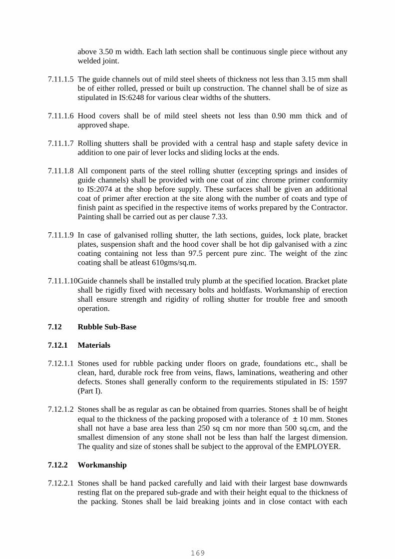
above 3.50 m width. Each lath section shall be continuous single piece without anywelded joint.
7.11.1.5 The guide channels out of mild steel sheets of thickness not less than 3.15 mm shallbe of either rolled, pressed or built up construction. The channel shall be of size asstipulated in IS:6248 for various clear widths of the shutters.
7.11.1.6 Hood covers shall be of mild steel sheets not less than 0.90 mm thick and ofapproved shape.
7.11.1.7 Rolling shutters shall be provided with a central hasp and staple safety device inaddition to one pair of lever locks and sliding locks at the ends.
7.11.1.8 All component parts of the steel rolling shutter (excepting springs and insides ofguide channels) shall be provided with one coat of zinc chrome primer conformityto IS:2074 at the shop before supply. These surfaces shall be given an additionalcoat of primer after erection at the site along with the number of coats and type offinish paint as specified in the respective items of works prepared by the Contractor.Painting shall be carried out as per clause 7.33.
7.11.1.9 In case of galvanised rolling shutter, the lath sections, guides, lock plate, bracketplates, suspension shaft and the hood cover shall be hot dip galvanised with a zinccoating containing not less than 97.5 percent pure zinc. The weight of the zinccoating shall be atleast 610gms/sq.m.
7.11.1.10Guide channels shall be installed truly plumb at the specified location. Bracket plateshall be rigidly fixed with necessary bolts and holdfasts. Workmanship of erectionshall ensure strength and rigidity of rolling shutter for trouble free and smoothoperation.
7.12 Rubble Sub-Base
7.12.1 Materials
7.12.1.1 Stones used for rubble packing under floors on grade, foundations etc., shall beclean, hard, durable rock free from veins, flaws, laminations, weathering and otherdefects. Stones shall generally conform to the requirements stipulated in IS: 1597(Part I).
7.12.1.2 Stones shall be as regular as can be obtained from quarries. Stones shall be of heightequal to the thickness of the packing proposed with a tolerance of 10 mm. Stonesshall not have a base area less than 250 sq cm nor more than 500 sq.cm, and thesmallest dimension of any stone shall not be less than half the largest dimension.The quality and size of stones shall be subject to the approval of the EMPLOYER.
7.12.2 Workmanship
7.12.2.1 Stones shall be hand packed carefully and laid with their largest base downwardsresting flat on the prepared sub-grade and with their height equal to the thickness ofthe packing. Stones shall be laid breaking joints and in close contact with each
169
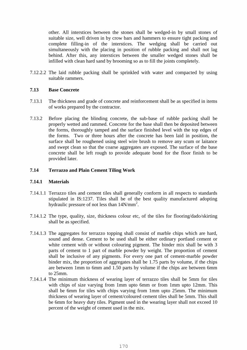
other. All interstices between the stones shall be wedged-in by small stones ofsuitable size, well driven in by crow bars and hammers to ensure tight packing andcomplete filling-in of the interstices. The wedging shall be carried outsimultaneously with the placing in position of rubble packing and shall not lagbehind. After this, any interstices between the smaller wedged stones shall beinfilled with clean hard sand by brooming so as to fill the joints completely.
7.12.2.2 The laid rubble packing shall be sprinkled with water and compacted by usingsuitable rammers.
7.13 Base Concrete
7.13.1 The thickness and grade of concrete and reinforcement shall be as specified in itemsof works prepared by the contractor.
7.13.2 Before placing the blinding concrete, the sub-base of rubble packing shall beproperly wetted and rammed. Concrete for the base shall then be deposited betweenthe forms, thoroughly tamped and the surface finished level with the top edges ofthe forms. Two or three hours after the concrete has been laid in position, thesurface shall be roughened using steel wire brush to remove any scum or laitanceand swept clean so that the coarse aggregates are exposed. The surface of the baseconcrete shall be left rough to provide adequate bond for the floor finish to beprovided later.
7.14 Terrazzo and Plain Cement Tiling Work
7.14.1 Materials
7.14.1.1 Terrazzo tiles and cement tiles shall generally conform in all respects to standardsstipulated in IS:1237. Tiles shall be of the best quality manufactured adoptinghydraulic pressure of not less than 14N/mm2.
7.14.1.2 The type, quality, size, thickness colour etc, of the tiles for flooring/dado/skirtingshall be as specified.
7.14.1.3 The aggregates for terrazzo topping shall consist of marble chips which are hard,sound and dense. Cement to be used shall be either ordinary portland cement orwhite cement with or without colouring pigment. The binder mix shall be with 3parts of cement to 1 part of marble powder by weight. The proportion of cementshall be inclusive of any pigments. For every one part of cement-marble powderbinder mix, the proportion of aggregates shall be 1.75 parts by volume, if the chipsare between 1mm to 6mm and 1.50 parts by volume if the chips are between 6mmto 25mm.
7.14.1.4 The minimum thickness of wearing layer of terrazzo tiles shall be 5mm for tileswith chips of size varying from 1mm upto 6mm or from 1mm upto 12mm. Thisshall be 6mm for tiles with chips varying from 1mm upto 25mm. The minimumthickness of wearing layer of cement/coloured cement tiles shall be 5mm. This shallbe 6mm for heavy duty tiles. Pigment used in the wearing layer shall not exceed 10percent of the weight of cement used in the mix.
170

7.14.2 Workmanship
7.14.2.1 Laying and finishing of tiles shall conform to the requirements of workmanshipstipulated in IS:1443.
7.14.2.2 Tiling work shall be commenced only after the door and window frames are fixedand plastering of the walls/ ceiling is completed. Wall plastering shall not be carriedout upto about 50mm above the level of proposed skirting/dado.
7.14.2.3 The base concrete shall be finished to a reasonably plane surface about 40 to 45mmbelow the level of finished floor. Before the tiling work is taken up, the baseconcrete or structural slab shall be cleaned of all loose materials, mortar droppings,dirt, laitance etc. using steel wire brush and well wetted without allowing any waterpools on the surface.
7.14.2.4 A layer of 25mm average thickness of cement mortar consisting of one part ofcement to 6 parts of sand shall be provided as bedding for the tiles over the baseconcrete. The thickness of bedding mortar shall not be less than 10mm at any place.The quantity of water to be added for the mortar shall be just adequate to obtain theworkability for laying. Sand for the mortar shall conform to IS:2116 and shall haveminimum fineness modulus of 1.5. The surface shall be left rough to provide agood bond for the tiles. The bedding shall be allowed to harden for a day beforelaying of the tiles.
7.14.2.5 Neat cement slurry using 4.4 kg of cement per sq.m of floor area shall be spreadover the hardened mortar bedding over such an area at a time as wouldaccommodate about 20 tiles. Tiles shall be fixed in this slurry one after the other,each tile being gently tapped with a wooden mallet till it is properly bedded and inlevel with the adjoining tiles. The joints shall be in straight lines and shall normallybe 1.5mm wide. On completion of laying of the tiles in a room, all the joints shall becleaned and washed fairly deep with a stiff broom/wire brush to a minimum depthof 5mm. The day after the tiles have been laid, the joints shall be filled with cementgrout of the same shade as the colour of the matrix of the tile. For this purpose whitecement or grey cement with or without pigments shall be used. The flooring shouldbe kept moist and left undisturbed for 7 days for the bedding/joints to set properly.Heavy traffic shall not be allowed on the floor for atleast 14 days after fixing of thetiles.
7.14.2.6 About a week after laying the tiles, each and every tile shall be lightly tapped with asmall wooden mallet to find out if it gives a hollow sound; if it does, such tilesalong with any other cracked or broken tiles shall be removed and replaced withnew tiles to proper line and level. The same procedure shall be followed again aftergrinding the tiles and all damaged tiles replaced, properly jointed and finished tomatch. For the purpose of ensuring that such replaced tiles match with those laidearlier, it is necessary that the Contractor shall procure sufficient quantity of extratiles to meet this contingency.
7.14.2.7 Wherever a full tile cannot be provided, tiles shall be cut to size and fixed. Floortiles adjoining the wall shall go about 10mm under the plaster, skirting or dado.
171
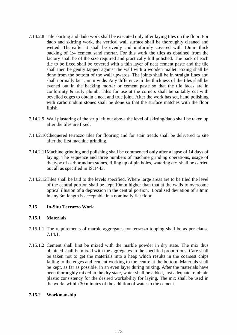
7.14.2.8 Tile skirting and dado work shall be executed only after laying tiles on the floor. Fordado and skirting work, the vertical wall surface shall be thoroughly cleaned andwetted. Thereafter it shall be evenly and uniformly covered with 10mm thickbacking of 1:4 cement sand mortar. For this work the tiles as obtained from thefactory shall be of the size required and practically full polished. The back of eachtile to be fixed shall be covered with a thin layer of neat cement paste and the tileshall then be gently tapped against the wall with a wooden mallet. Fixing shall bedone from the bottom of the wall upwards. The joints shall be in straight lines andshall normally be 1.5mm wide. Any difference in the thickness of the tiles shall beevened out in the backing mortar or cement paste so that the tile faces are inconformity & truly plumb. Tiles for use at the corners shall be suitably cut withbevelled edges to obtain a neat and true joint. After the work has set, hand polishingwith carborundum stones shall be done so that the surface matches with the floorfinish.
7.14.2.9 Wall plastering of the strip left out above the level of skirting/dado shall be taken upafter the tiles are fixed.
7.14.2.10Chequered terrazzo tiles for flooring and for stair treads shall be delivered to siteafter the first machine grinding.
7.14.2.11Machine grinding and polishing shall be commenced only after a lapse of 14 days oflaying. The sequence and three numbers of machine grinding operations, usage ofthe type of carborundum stones, filling up of pin holes, watering etc. shall be carriedout all as specified in IS:1443.
7.14.2.12Tiles shall be laid to the levels specified. Where large areas are to be tiled the levelof the central portion shall be kept 10mm higher than that at the walls to overcomeoptical illusion of a depression in the central portion. Localised deviation of ±3mmin any 3m length is acceptable in a nominally flat floor.
7.15 In-Situ Terrazzo Work
7.15.1 Materials
7.15.1.1 The requirements of marble aggregates for terrazzo topping shall be as per clause7.14.1.
7.15.1.2 Cement shall first be mixed with the marble powder in dry state. The mix thusobtained shall be mixed with the aggregates in the specified proportions. Care shallbe taken not to get the materials into a heap which results in the coarsest chipsfalling to the edges and cement working to the centre at the bottom. Materials shallbe kept, as far as possible, in an even layer during mixing. After the materials havebeen thoroughly mixed in the dry state, water shall be added, just adequate to obtainplastic consistency for the desired workability for laying. The mix shall be used inthe works within 30 minutes of the addition of water to the cement.
7.15.2 Workmanship
172

7.15.2.1 The thickness, type, quality, size and colour of chips etc. for the in-situ terrazzofinish for flooring/dado/ skirting shall be as specified in the respective items ofworks prepared by the Contractor. Laying and finishing of in-situ work shallconform to the requirements of workmanship stipulated in IS: 2114.
7.15.2.2 In-situ terrazzo finish shall be laid over hardened concrete base. The finish layerconsists of an under layer and terrazzo topping. The underlayer shall be of cementconcrete of mix 1:2:4 using 10mm down graded coarse aggregates. The combinedthickness of under layer and topping shall not be less than 30 mm for flooring and20mm for dado/skirting work.
7.15.2.3 The minimum thickness of topping shall be 6mm if chips used are between 1mm to4mm, 9mm if chips are between 4mm to 7mm and 12mm if chips are between 7mmto 10mm. If chips larger than 10mm size are used, the minimum thickness shall beone and one third the maximum size of chips.
7.15.2.4 Both the underlayer and later the topping shall be divided into panels not exceeding2 sq.m for laying so as to reduce the possibility of development of cracks. Thelonger dimension of any panel shall not exceed 2m. Dividing strips shall be used toseparate the panels. When the dividing strips are not provided, the bays shall be laidalternately, allowing an interval of atleast 24 hours between laying adjacent bays.
7.15.2.5 Dividing strips shall be either of aluminium, brass or other material as indicated inthe items of works prepared by the Contractor. Aluminum strips should have aprotective coating of bitumen. The thickness of the strips shall be not less than1.5mm and width not less than 25mm for flooring work.
7.15.2.6 Concrete base shall be finished to a reasonably plane surface to a level below thefinished floor elevation equal to the specified thickness of terrazzo finish. Beforespreading the unde rlayer, the base concrete surface shall be cleaned of all loosematerials, mortar droppings, dirt, laitance etc. and well wetted without allowing anywater pools on the surface. Dividing strips or screed strips, if dividing strips are notprovided shall be fixed on the base and levelled to the correct height to suit thethickness of the finish. Just before spreading the under layer the surface shall besmeared with cement slurry at 2.75 Kg/sq.m. Over this slurry, the under layer shallbe spread and levelled with a screeding board. The top surface shall be left rough toprovide a good bond for the terrazzo topping.
7.15.2.7 Terrazzo topping shall be laid while the under layer is still plastic and normallybetween 18 to 24 hours after the under layer is laid. Cement slurry of the samecolour as the topping shall be brushed on the surface immediately before laying iscommenced. The terrazzo mix shall be laid to a uniform thickness and compactedthoroughly by tamping and with a minimum of troweling. Straight edge and steelfloats shall be used to bring the surface true to the required level in such a mannerthat the maximum amount of marble chips come up and spread uniformly all overthe surface.
7.15.2.8 The surface shall be left dry for air-curing for a period of 12 to 18 hours. Thereafterit shall be cured by allowing water to stand in pools for a period of not less than 4days.
173
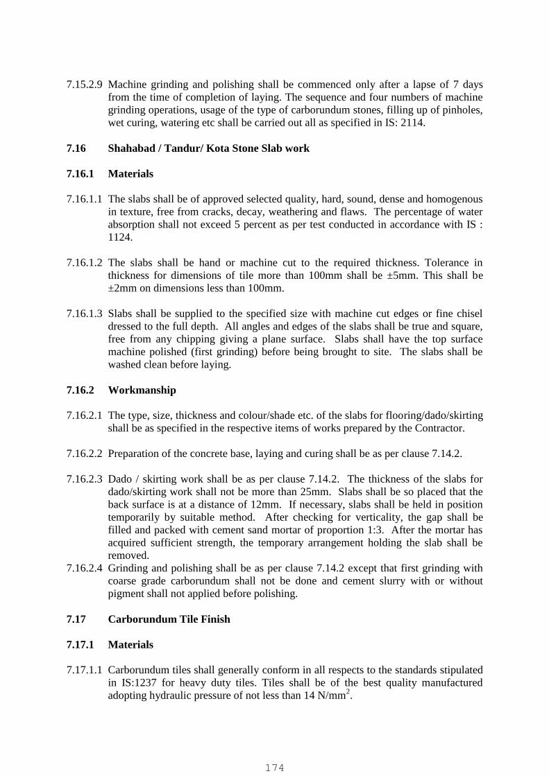
7.15.2.9 Machine grinding and polishing shall be commenced only after a lapse of 7 daysfrom the time of completion of laying. The sequence and four numbers of machinegrinding operations, usage of the type of carborundum stones, filling up of pinholes,wet curing, watering etc shall be carried out all as specified in IS: 2114.
7.16 Shahabad / Tandur/ Kota Stone Slab work
7.16.1 Materials
7.16.1.1 The slabs shall be of approved selected quality, hard, sound, dense and homogenousin texture, free from cracks, decay, weathering and flaws. The percentage of waterabsorption shall not exceed 5 percent as per test conducted in accordance with IS :1124.
7.16.1.2 The slabs shall be hand or machine cut to the required thickness. Tolerance inthickness for dimensions of tile more than 100mm shall be ±5mm. This shall be±2mm on dimensions less than 100mm.
7.16.1.3 Slabs shall be supplied to the specified size with machine cut edges or fine chiseldressed to the full depth. All angles and edges of the slabs shall be true and square,free from any chipping giving a plane surface. Slabs shall have the top surfacemachine polished (first grinding) before being brought to site. The slabs shall bewashed clean before laying.
7.16.2 Workmanship
7.16.2.1 The type, size, thickness and colour/shade etc. of the slabs for flooring/dado/skirtingshall be as specified in the respective items of works prepared by the Contractor.
7.16.2.2 Preparation of the concrete base, laying and curing shall be as per clause 7.14.2.
7.16.2.3 Dado / skirting work shall be as per clause 7.14.2. The thickness of the slabs fordado/skirting work shall not be more than 25mm. Slabs shall be so placed that theback surface is at a distance of 12mm. If necessary, slabs shall be held in positiontemporarily by suitable method. After checking for verticality, the gap shall befilled and packed with cement sand mortar of proportion 1:3. After the mortar hasacquired sufficient strength, the temporary arrangement holding the slab shall beremoved.
7.16.2.4 Grinding and polishing shall be as per clause 7.14.2 except that first grinding withcoarse grade carborundum shall not be done and cement slurry with or withoutpigment shall not applied before polishing.
7.17 Carborundum Tile Finish
7.17.1 Materials
7.17.1.1 Carborundum tiles shall generally conform in all respects to the standards stipulatedin IS:1237 for heavy duty tiles. Tiles shall be of the best quality manufacturedadopting hydraulic pressure of not less than 14 N/mm2.
174
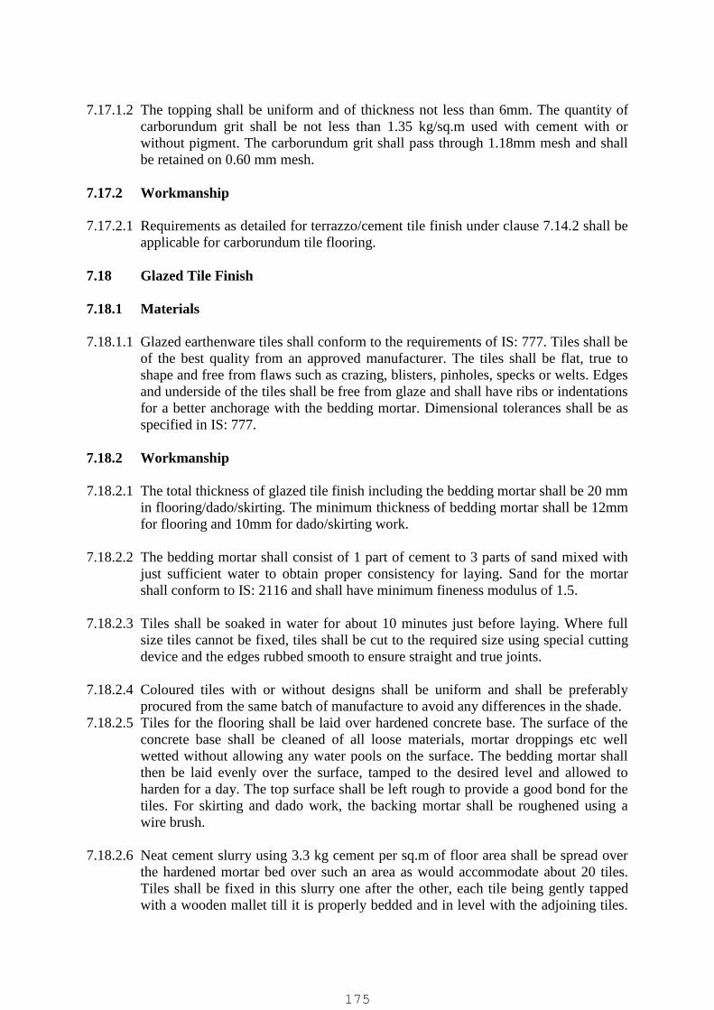
7.17.1.2 The topping shall be uniform and of thickness not less than 6mm. The quantity ofcarborundum grit shall be not less than 1.35 kg/sq.m used with cement with orwithout pigment. The carborundum grit shall pass through 1.18mm mesh and shallbe retained on 0.60 mm mesh.
7.17.2 Workmanship
7.17.2.1 Requirements as detailed for terrazzo/cement tile finish under clause 7.14.2 shall beapplicable for carborundum tile flooring.
7.18 Glazed Tile Finish
7.18.1 Materials
7.18.1.1 Glazed earthenware tiles shall conform to the requirements of IS: 777. Tiles shall beof the best quality from an approved manufacturer. The tiles shall be flat, true toshape and free from flaws such as crazing, blisters, pinholes, specks or welts. Edgesand underside of the tiles shall be free from glaze and shall have ribs or indentationsfor a better anchorage with the bedding mortar. Dimensional tolerances shall be asspecified in IS: 777.
7.18.2 Workmanship
7.18.2.1 The total thickness of glazed tile finish including the bedding mortar shall be 20 mmin flooring/dado/skirting. The minimum thickness of bedding mortar shall be 12mmfor flooring and 10mm for dado/skirting work.
7.18.2.2 The bedding mortar shall consist of 1 part of cement to 3 parts of sand mixed withjust sufficient water to obtain proper consistency for laying. Sand for the mortarshall conform to IS: 2116 and shall have minimum fineness modulus of 1.5.
7.18.2.3 Tiles shall be soaked in water for about 10 minutes just before laying. Where fullsize tiles cannot be fixed, tiles shall be cut to the required size using special cuttingdevice and the edges rubbed smooth to ensure straight and true joints.
7.18.2.4 Coloured tiles with or without designs shall be uniform and shall be preferablyprocured from the same batch of manufacture to avoid any differences in the shade.
7.18.2.5 Tiles for the flooring shall be laid over hardened concrete base. The surface of theconcrete base shall be cleaned of all loose materials, mortar droppings etc wellwetted without allowing any water pools on the surface. The bedding mortar shallthen be laid evenly over the surface, tamped to the desired level and allowed toharden for a day. The top surface shall be left rough to provide a good bond for thetiles. For skirting and dado work, the backing mortar shall be roughened using awire brush.
7.18.2.6 Neat cement slurry using 3.3 kg cement per sq.m of floor area shall be spread overthe hardened mortar bed over such an area as would accommodate about 20 tiles.Tiles shall be fixed in this slurry one after the other, each tile being gently tappedwith a wooden mallet till it is properly bedded and in level with the adjoining tiles.
175

For skirting and dado work, the back of the tiles shall be smeared with cementslurry for setting on the backing mortar. Fixing of tiles shall be done from thebottom of the wall upwards. The joints shall be in perfect straight lines and as thinas possible but shall not be more than 1mm wide. The surface shall be checkedfrequently to ensure correct level/required slope. Floor tiles near the walls shallenter skirting/dado to a minimum depth of 10mm. Tiles shall not sound hollowwhen tapped.
7.18.2.7 All the joints shall be cleaned of grey cement with wire brush to a depth of at least3mm and all dust, loose mortar etc. shall be removed. White cement with or withoutpigment shall then be used for flush pointing the joints. Curing shall then be carriedout for a minimum period of 7 days for the bedding and joints to set properly. Thesurface shall then be cleaned using a suitable detergent, fully washed and wiped dry.
7.18.2.8 Specials consisting of coves, internal and external angles, cornices, beads and theircorner pieces shall be of thickness not less than the tiles with which they are used.
7.19 In-Situ Cement Concrete Floor Topping
7.19.1 Materials
7.19.1.1 The mix proportion for the in-situ concrete floor topping shall be 1:2.5:3.5 (one partcement : two and half parts sand : three and half parts coarse aggregates) by volumeunless otherwise specified.
7.19.1.2 The aggregates shall conform for the requirements of IS:383.
7.19.1.3 Coarse aggregates shall have high hardness surface texture and shall consist ofcrushed rock of granite, basalt, trap or quartzite. The aggregate crushing valve shallnot exceed 30 percent. The grading of the aggregates of size 12.5mm and belowshall be as per IS:2571.
7.19.1.4 Grading of the sand shall be within the limits indicated in IS:2571.
7.19.2 Workmanship
7.19.2.1 The thickness of the floor topping shall be as specified in the items of workprepared by the Contractor. The minimum thickness of the floor topping shall be25mm.
7.19.2.2 Preparation of base concrete/structural slab before laying the topping shall be as perclause 7.13. The surface shall be rough to provide adequate bond for the topping.
7.19.2.3 Mixing of concrete shall be done thoroughly in a mechanical mixer unless handmixing is specifically permitted by the EMPLOYER. The concrete shall be as stiffas possible and the amount of water added shall be the minimum necessary to givejust sufficient plasticity for laying and compacting. The mix shall be used in thework within 30 minutes of the addition of water for its preparation.
176
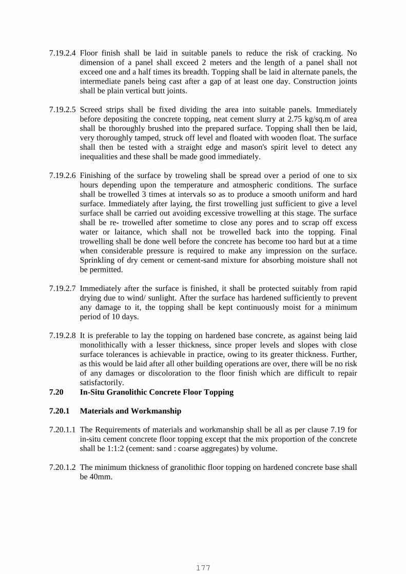
7.19.2.4 Floor finish shall be laid in suitable panels to reduce the risk of cracking. Nodimension of a panel shall exceed 2 meters and the length of a panel shall notexceed one and a half times its breadth. Topping shall be laid in alternate panels, theintermediate panels being cast after a gap of at least one day. Construction jointsshall be plain vertical butt joints.
7.19.2.5 Screed strips shall be fixed dividing the area into suitable panels. Immediatelybefore depositing the concrete topping, neat cement slurry at 2.75 kg/sq.m of areashall be thoroughly brushed into the prepared surface. Topping shall then be laid,very thoroughly tamped, struck off level and floated with wooden float. The surfaceshall then be tested with a straight edge and mason's spirit level to detect anyinequalities and these shall be made good immediately.
7.19.2.6 Finishing of the surface by troweling shall be spread over a period of one to sixhours depending upon the temperature and atmospheric conditions. The surfaceshall be trowelled 3 times at intervals so as to produce a smooth uniform and hardsurface. Immediately after laying, the first trowelling just sufficient to give a levelsurface shall be carried out avoiding excessive trowelling at this stage. The surfaceshall be re- trowelled after sometime to close any pores and to scrap off excesswater or laitance, which shall not be trowelled back into the topping. Finaltrowelling shall be done well before the concrete has become too hard but at a timewhen considerable pressure is required to make any impression on the surface.Sprinkling of dry cement or cement-sand mixture for absorbing moisture shall notbe permitted.
7.19.2.7 Immediately after the surface is finished, it shall be protected suitably from rapiddrying due to wind/ sunlight. After the surface has hardened sufficiently to preventany damage to it, the topping shall be kept continuously moist for a minimumperiod of 10 days.
7.19.2.8 It is preferable to lay the topping on hardened base concrete, as against being laidmonolithically with a lesser thickness, since proper levels and slopes with closesurface tolerances is achievable in practice, owing to its greater thickness. Further,as this would be laid after all other building operations are over, there will be no riskof any damages or discoloration to the floor finish which are difficult to repairsatisfactorily.
7.20 In-Situ Granolithic Concrete Floor Topping
7.20.1 Materials and Workmanship
7.20.1.1 The Requirements of materials and workmanship shall be all as per clause 7.19 forin-situ cement concrete floor topping except that the mix proportion of the concreteshall be 1:1:2 (cement: sand : coarse aggregates) by volume.
7.20.1.2 The minimum thickness of granolithic floor topping on hardened concrete base shallbe 40mm.
177

7.21 Floor Hardener Topping
7.21.1 Materials & Workmanship
7.21.1.1 Floor Hardener topping shall be provided either as integrally finished over thestructural slab/grade slab or laid monolithically with the concrete/granolithic floorfinish on top of hardened concrete base.
7.21.1.2 Floor hardener of the metallic or non-metallic type suitable for the performance ofnormal / medium/ heavy duty function of the floor, the quantum of ingredients andthe thickness of topping shall be as specified in the respective items of workprepared by the Contractor.
7.21.1.3 For monolithic application with the floor finish/slab the thickness of the layer shallbe 15mm. The topping shall be laid within 2 to 3 hours after concrete is laid when itis still plastic but stiffened enough for the workmen to tread over it by placingplanks. The surface of the concrete layer shall be kept rough for providing adequatebond for the topping. Laitance shall be removed before placing the topping. Thetopping shall be screeded and thoroughly compacted to the finished level.Trowelling to a smooth finish shall be carried out as per clause 7.19.2. After thesurface has hardened sufficiently, it shall be kept continuously moist for at least 10days.
7.21.1.4 The procedure for mixing the floor hardener topping shall be as per manufacturer'sinstructions.
7.21.1.5 Surface shall be prevented from any damages due to subsequent building operationsby covering with 75 mm thick layer of sand.
7.22 PVC Sheet/Tile Flooring
7.22.1 Materials
7.22.1.1 PVC floor covering shall be of either unbacked homogeneous flexible type in theform of sheets/tiles conforming to IS:3462 or homogeneous PVC asbestos tilesconforming to IS:3461.
7.22.1.2 The surface of the sheets/tiles shall be free from any physical defects such as pores,blisters, cracks etc. which affects the appearance and serviceability. Tiles/ sheetsshall meet with the tolerance limits in dimensions specified in the IS. Contractorshall submit the test certificates, if so desired by the EMPLOYER.
7.22.1.3 Each tile/sheet shall be legibly and indelibly marked with the name of themanufacturer or his trade mark, IS certificate mark, and batch number.
7.22.1.4 The adhesive to be used for laying the PVC flooring shall be rubber based and ofthe make as recommended and approved by the manufacturer of PVC sheets/tiles.
178

7.22.1.5 The type, size, colour, plain or mottled and the pattern shall be as specified in therespective items of work prepared by the Contractor.
7.22.2 Workmanship
7.22.2.1 PVC Floor covering shall be provided over an under bed of cement concrete floorfinish over the base concrete or structural slab. It is essential that the sub-floor andthe under bed are perfectly dry before laying the PVC flooring. This shall beensured by methods of testing as stipulated in Appendix-A of IS:5318.
7.22.2.2 The surface of the under bed shall have trowelled finish without any irregularities,which creates poor adhesion. Surface shall be free of oil or grease and thoroughlycleaned of all dust, dirt and wiped with a dry cloth.
7.22.2.3 PVC sheets/tiles shall be brought to the temperature of the area in which they are tobe laid by stacking in a suitable manner within or near the laying area for a period ofabout 24 hours. Where air-conditioning is installed, the flooring shall not be laid onthe under bed until the A/C units have been in operation for at least 7 days. Duringthis period, the temperature range shall be between 20deg.C and 30deg.C and thisshall be maintained during the laying operations and also for 48 hours thereafter.
7.22.2.4 Layout of the PVC flooring shall be marked with guidelines on the under bed andPVC tiles/sheets shall be first laid for trial, without using the adhesive, according tothe layout.
7.22.2.5 The adhesive shall be applied by using a notched trowel to the surface of the underbed and to the backside of PVC sheets/tiles. When the adhesive has set sufficientlyfor laying, it will be tacky to the touch, which generally takes about 30 minutes. Thetime period need be carefully monitored since a longer interval will affect theadhesive properties. Adhesive shall be uniformly spread over only as much surfacearea at one time which can be covered with PVC flooring within the stipulated time.
7.22.2.6 PVC sheet shall be carefully taken and placed in position from one end onwardsslowly so that the air will be completely squeezed out between the sheet and thebackground surface and no air pockets are formed. It shall then be pressed with asuitable roller to develop proper contact. The next sheet shall be laid edge to edgewith the sheet already laid, so that there is minimum gap between joints. Thealignment shall be checked after each row of sheet is completed and trimmed ifconsidered necessary.
7.22.2.7 Tiles shall be laid in the same manner as sheets and preferably, commencing fromthe centre of the area. Tiles should be lowered in position and pressed firmly on tothe adhesive with minimum gap between the joints. Tiles shall not be slided on thesurface. Tiles shall be rolled with a light wooden roller of about 5kg to ensure fullcontact with the underlay. Work should be constantly checked to ensure that all fouredges of adjacent tiles meet accurately.
7.22.2.8 Any excess adhesive which may squeeze up between sheets/tiles shall be wiped offimmediately with a wet cloth. Suitable solvents shall be used to remove hardenedadhesive.
179

7.22.2.9 A minimum period of 24 hours shall be given after laying for the development ofproper bond of the adhesive. When the flooring is thus completed, it shall becleaned with a wet cloth soaked in warm soap solution.
7.22.2.10Metallic edge strips shall be used to protect the edges of PVC sheets/tiles which areexposed as in doorways/ stair treads.
7.22.2.11Hot sealing of joints between adjacent PVC sheet flooring to prevent creeping ofwater through the joints shall be carried out, using special equipment as permanufacturer's instructions.
7.23 Acid Resisting Brick/Tiling Work
7.23.1 Materials
7.23.1.1 The ceramic unglazed vitreous acid resisting tiles shall conform to the requirementsof IS:4457. Acid resistant bricks shall conform to the requirements of IS:4860.
7.23.1.2 The finished tile/brick when fractured shall appear fine grained in texture, dense andhomogeneous. Tile/brick shall be sound, true to shape, flat, free from flaws and anymanufacturing defects affecting their utility. Tolerance in dimensions shall bewithin the limits specified in the respective IS.
7.23.1.3 The tiles/bricks shall be bedded and jointed using chemical resistant mortar of theresin type conforming to IS:4832 (Part II). Method of usage shall generally be as perthe requirements of IS:4443.
7.23.2 Workmanship
7.23.2.1 The resin shall have viscosity for readily mixing with the filler by manual methods.The filler shall have graded particles which permit joint thickness of 1.5 mm.
7.23.2.2 The base concrete surface shall be free from dirt and thoroughly dried. The surfaceshall be applied with a coat of bitumen primer conforming to IS:3384. The primedsurface shall then be applied with a uniform coat of bitumen conforming to IS:1580.Tiles or bricks shall be laid directly without the application of bitumen, if epoxy orpolyester resin is used for the mortar.
7.23.2.3 Just adequate quantity of mortar which can be applied within the pot life asspecified by the manufacturer shall be prepared at one time for bedding andjointing. Rigid PVC/Stainless steel/chromium plated tools shall be used for mixingand laying.
7.23.2.4 For laying the floor 6 to 8 mm thick mortar shall be spread on the back of thetile/brick. Two adjacent sides of the tile/brick shall be smeared with 4 to 6 mm thickmortar. Tile/brick shall be pressed into the bed and pushed against the floor andwith the adjacent tile/ brick, until the joint in each case is 2 to 3 mm thick. Excessmortar shall then be trimmed off and allowed to harden fully. Similar procedureshall be adopted for the work on walls by pressing the tile/brick against the prepared
180

wall surfaces and only one course shall be laid at a time until the initial settingperiod.
7.23.2.5 The mortar joints shall be cured for a minimum period of 72 hours with 20 to 25%hydrochloric acid or 30 to 40% sulphuric acid. After acid curing, the joints shall bewashed with water and allowed to thoroughly dry. The joints shall then be filledwith mortar to make them smooth and plane. Acid curing is not required to becarried out if epoxy or polyester resin is used for the mortar.
7.23.2.6 Resin mortars are normally self curing. The area tiled shall not be put to use before48 hours in case epoxy, polyester and furane type of resin is used for the mortar. Ifphenolic or cashewnut shell liquid resin is used for the mortar, the area tiled shallnot be put to use for 7 to 28 days respectively, without heat treatment. This periodshall be 2 to 6 days respectively, if heat treatment is given with infrared lamp.
7.24 Epoxy Lining Work
7.24.1 Materials
7.24.1.1 The epoxy resin and hardener formulation for laying of jointless lining work infloors and walls of concrete tanks/trenches etc shall be as per the requirements ofIS:9197.
7.24.1.2 The epoxy composition shall have the chemical resistance to withstand thefollowing conditions of exposure:a) Hydrochloric acid upto 30% concentrationb) Sodium hydroxide upto 50% concentrationc) Liquid temperature upto 60deg.Cd) Ultraviolet radiatione) Alternate wetting and drying
7.24.1.3 Sand shall conform to grading zone III or IV of IS:383.
7.24.1.4 The hardener shall be of the liquid type such as Aliphatic Amine or anAliphatic/Aromatic Amine Adduct for the epoxy resin. The hardener shall reactwith epoxy resin at normal ambient temperature.
7.24.1.5 Contractor shall furnish test certificates for satisfying the requirements of the epoxyformulation if so directed by the EMPLOYER.
7.24.2 Workmanship
7.24.2.1 The minimum thickness of epoxy lining shall be 4 mm. It is essential that theconcrete elements are adequately designed to ensure that water is excluded topermeate to the surface, over which the epoxy lining is proposed.
7.24.2.2 The epoxy lining shall be of the trowel type to facilitate execution of the requiredthickness for satisfactory performance.
181
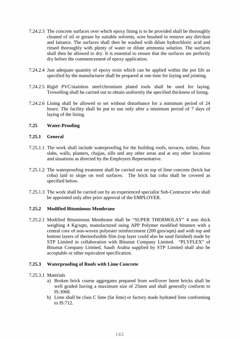
7.24.2.3 The concrete surfaces over which epoxy lining is to be provided shall be thoroughlycleaned of oil or grease by suitable solvents, wire brushed to remove any dirt/dustand laitance. The surfaces shall then be washed with dilute hydrochloric acid andrinsed thoroughly with plenty of water or dilute ammonia solution. The surfacesshall then be allowed to dry. It is essential to ensure that the surfaces are perfectlydry before the commencement of epoxy application.
7.24.2.4 Just adequate quantity of epoxy resin which can be applied within the pot life asspecified by the manufacturer shall be prepared at one time for laying and jointing.
7.24.2.5 Rigid PVC/stainless steel/chromium plated tools shall be used for laying.Trowelling shall be carried out to obtain uniformly the specified thickness of lining.
7.24.2.6 Lining shall be allowed to set without disturbance for a minimum period of 24hours. The facility shall be put to use only after a minimum period of 7 days oflaying of the lining.
7.25 Water-Proofing
7.25.1 General
7.25.1.1 The work shall include waterproofing for the building roofs, terraces, toilets, floorslabs, walls, planters, chajjas, sills and any other areas and at any other locationsand situations as directed by the Employers Representative.
7.25.1.2 The waterproofing treatment shall be carried out on top of lime concrete (brick batcoba) laid to slope on roof surfaces. The brick bat coba shall be covered asspecified below.
7.25.1.3 The work shall be carried out by an experienced specialist Sub-Contractor who shallbe appointed only after prior approval of the EMPLOYER.
7.25.2 Modified Bituminous Membrane
7.25.2.1 Modified Bituminous Membrane shall be “SUPER THERMOLAY” 4 mm thickweighing 4 Kg/sqm, manufactured using APP Polymer modified bitumen with acentral core of non-woven polyester reinforcement (200 gms/sqm) and with top andbottom layers of thermofusible film (top layer could also be sand finished) made bySTP Limited in collaboration with Bitumat Company Limited. “PLYFLEX” ofBitumat Company Limited, Saudi Arabia supplied by STP Limited shall also beacceptable or other equivalent specification.
7.25.3 Waterproofing of Roofs with Lime Concrete
7.25.3.1 Materialsa) Broken brick coarse aggregates prepared from well/over burnt bricks shall be
well graded having a maximum size of 25mm and shall generally conform toIS:3068.
b) Lime shall be class C lime (fat lime) or factory made hydrated lime conformingto IS:712.
182

7.25.3.2 Workmanship
7.25.3.2.1 Lime concrete shall be prepared by thoroughly mixing the brick aggregatesinclusive of brick dust obtained during breaking with the slaked lime in theproportions of 2 1/2 (two and a half) parts of brick aggregates to 1 part of slakedlime by volume. Water shall be added just adequate to obtain the desiredworkability for laying. Washing soap and alum shall be dissolved in the water tobe used. The quantity of these materials required per cum of lime concrete shall be12kg of washing soap and 4kg of alum. Brick aggregates shall be soakedthoroughly in water for a period of not less than six hours before use in theconcrete mix. Lime concrete shall be used in the works within 24 hours aftermixing.
7.25.3.2.2 The roof surface over which the water-proof treatment is to be carried out shall becleaned of all foreign matter by wire brushing, dusting and made thoroughly dry.Preparation of surfaces shall be as stipulated in IS:3067.
7.25.3.2.3 The slope of the finished waterproofing treatment shall be not less than 1 in 60 forefficient drainage. This shall be achieved either wholly in the lime concrete layer.
7.25.3.2.4 The average thickness of lime concrete, slope and the finish on top of machinemade burnt clay flat terracing tiles conforming to IS:2690 (part I) shall be asspecified in the items of work to be prepared by the Contractor. Cement concreteflooring tiles in lieu of clay terracing tiles shall be provided if so specified in theitems of work prepared by the Contractor, duly considering the traffic the terracewill be subjected to.
7.25.3.2.5 The minimum compacted thickness of lime concrete layer shall be 75mm andaverage thickness shall not be less than 100mm. In case, the thickness is morethan 100mm, it shall be laid in layers not exceeding 100mm to 125mm.
7.25.3.2.6 Laying of lime concrete shall be commenced from a corner of the roof andproceeded diagonally towards centre and other sides duly considering the slopesspecified for effectively draining the rain-water towards the downtake points.
7.25.3.2.6 Lime concrete fillet for a minimum height of 150mm shall be provided all alongthe junction of the roof surface with the brick masonry wall/parapet/columnprojections. These shall then be finished on top with provision of clay terracingtiles/cement concrete tiles.
7.25.3.2.7 After the lime concrete is laid it shall be initially rammed with a rammer weighingnot more than 2 Kg and the finish brought to the required evenness and slope.Alternatively, bamboo strips may be used for the initial ramming. Furtherconsolidation shall be done using wooden THAPIES with rounded edges. Thebeating will normally have to be carried on for at least seven days until the THAPImakes no impression on the surface and rebounds readily from it when struck.Special care shall be taken to properly compact the lime concrete at its junctionwith parapet walls or column projections.
183

7.25.3.2.8 During compaction by hand-beating, the surface shall be sprinkled liberally withlime water (1 part of lime putty and 3 to 4 parts of water) and a small proportionof sugar solution for obtaining improved water-proofing quality of the limeconcrete. On completion of beating, the mortar that comes on the top shall besmoothened with a trowel or float, if necessary, with the addition of sugar solutionand lime putty. The sugar solution may be prepared in any one of the followingways as directed by the EMPLOYER.a) By mixing about 3 Kg of Jaggery and 1.5 Kg of BAEL fruit to 100 litres
of water.b) By mixing about 600 gm of KADUKAI (the dry nuts shall be broken to
small pieces and allowed to soak in water), 200 gm of jaggery and 40 litresof water for 10 sq.m of work. This solution shall be brewed for about12 to 24 hours and the resulting liquor decanted and used for the work.
7.25.3.2.9 The lime concrete after compaction shall be cured for a minimum period of sevendays or until it hardens by covering with a thin layer of straw or hessian whichshall be kept wet continuously.
7.25.3.2.10Machine made flat terracing tiles shall be of the size and thickness as specified.Tiles shall be soaked in water for at least one hour before laying. Bedding for thetiles shall be 12mm thick in cement mortar 1:3. Tiles shall be laid, open jointedwith 4 to 6 mm wide joints, flat on the mortar and lightly pressed and set to planesurface true to slope, using a trowel and wooden straight edge. They shall be laidwith their longitudinal lines of joints truly parallel and generally at right angles tothe direction of run-off gradient. Transverse joints in alternate rows shall comedirectly in line with each other. Transverse joints in adjacent courses shall breakjoints by at least 50 mm. The joints shall be completely filled and flush pointedwith cement mortar 1:2 mixed with water proofing compound as permanufacturer's instructions. Curing shall be carried out for a minimum period ofseven days.
7.25.3.2.11Finishing on top with cement concrete tiles or in-situ cement concrete floortopping shall be carried out in similar fashion as described for clay tiles in aboveparagraph. Tiles to be used shall be supplied after the first machine grinding ofthe surface.
7.25.4 Waterproofing of Roofs/Terraces etc.(a) Water proofing of Horizontal Surfaces
7.25.4.1 The waterproofing shall be applied as follows:
7.25.4.2 A coat of Blown Bitumen 85/25 shall be applied at the rate of 1.45 kg/sq.km
7.25.4.3 A roll of Modified Bituminous Membrane shall be unrolled over the primedsurface and completely bonded to the substrate by pressing down evenly for thefull width of the roll using a wooden roller. Torching shall be done, whererecommended by the manufacturer and where directed by the EMPLOYER, as theunrolling progresses.
184

7.25.4.4 The side overlaps shall be minimum 100 mm whereas the end overlaps shall beminimum 150 mm; both shall be bonded and sealed by flame torching.
7.25.4.5 Care shall be taken that the membrane is lapped with the treatment along thevertical surface and roof gutter treatment for at least 500 mm.
7.25.4.6 The membrane shall be properly overlapped/terminated at all openings, rainwaterdown takes etc. to ensure that such junctions do not become sources of leakage.
7.25.4.7 Top of membrane finally shall be painted with antiglouse reflective paint.(b) Waterproofing of Vertical Surfaces at Roof Level and Gutters
7.25.4.8 The Water proofing shall be applied as described in (a) above.
7.25.4.9 Modified Bituminous membrane shall be unrolled and bonded to the substrateafter applying a coat of bitumen and by pressing down evenly for the full width ofthe roll. Light torching shall be done to ensure complete bonding.
7.25.4.10 The membrane shall be overlapped with treatment for the horizontal surface by atleast 500 mm.
7.25.4.11 The membrane shall be taken upto a pre-cut chase anchored and sealed.
7.25.5 Khurras and Rainwater Down Pipes
7.25.5.1 Down pipes shall be isolated from RCC work with 6 mm polyethylene foam fixedwith adhesive (Araldite) and sealed with silicone sealant prior to layingmembrane. A water proofing flashing composed of one layer of Hessian basedself finished felt Type 3 Grade 1 and two layers of aluminium foil of 0.075 mmthickness shall be provided. This flashing shall be carried into the down takepipes for at least 150 mm and sealed with hot bitumen. The Contractor shallclosely coordinate the work with the agency providing and fixing the rainwaterdown take pipes.
7.25.6 Testing
7.25.6.1 The treated area (flat and horizontal only) shall be tested by allowed water tostand on the treated areas to a depth of 150 mm for a minimum period of 72 hours.
7.25.6.2 The treated area (flat and horizontal) shall have continuous slope towards therainwater outlets and no water shall pond any where on the surface.
7.26 Cement Plastering Work
7.26.1 Materials
7.26.1.1 The proportions of the cement mortar for plastering shall be 1:3 (one part ofcement to three parts of sand). Cement and sand shall be mixed thoroughly in drycondition and then just enough water added to obtain a workable consistency. Thequality of water and cement shall be as per relevant IS standards. The quality and
185
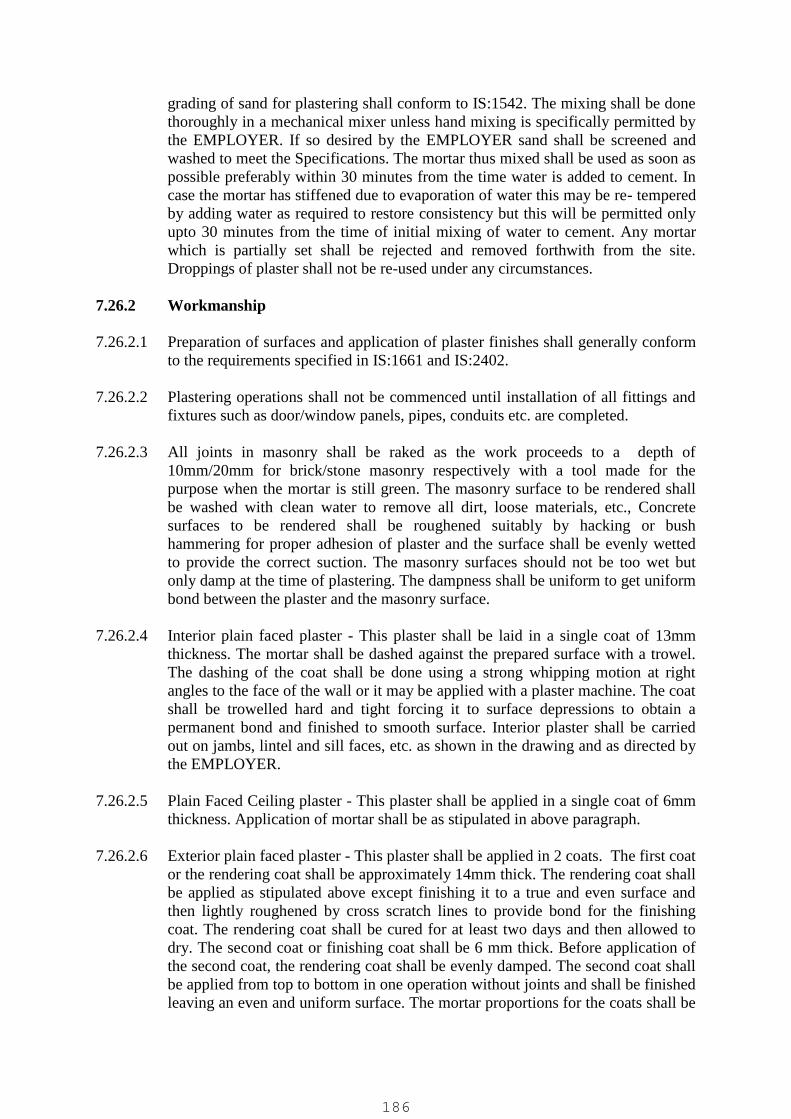
grading of sand for plastering shall conform to IS:1542. The mixing shall be donethoroughly in a mechanical mixer unless hand mixing is specifically permitted bythe EMPLOYER. If so desired by the EMPLOYER sand shall be screened andwashed to meet the Specifications. The mortar thus mixed shall be used as soon aspossible preferably within 30 minutes from the time water is added to cement. Incase the mortar has stiffened due to evaporation of water this may be re- temperedby adding water as required to restore consistency but this will be permitted onlyupto 30 minutes from the time of initial mixing of water to cement. Any mortarwhich is partially set shall be rejected and removed forthwith from the site.Droppings of plaster shall not be re-used under any circumstances.
7.26.2 Workmanship
7.26.2.1 Preparation of surfaces and application of plaster finishes shall generally conformto the requirements specified in IS:1661 and IS:2402.
7.26.2.2 Plastering operations shall not be commenced until installation of all fittings andfixtures such as door/window panels, pipes, conduits etc. are completed.
7.26.2.3 All joints in masonry shall be raked as the work proceeds to a depth of10mm/20mm for brick/stone masonry respectively with a tool made for thepurpose when the mortar is still green. The masonry surface to be rendered shallbe washed with clean water to remove all dirt, loose materials, etc., Concretesurfaces to be rendered shall be roughened suitably by hacking or bushhammering for proper adhesion of plaster and the surface shall be evenly wettedto provide the correct suction. The masonry surfaces should not be too wet butonly damp at the time of plastering. The dampness shall be uniform to get uniformbond between the plaster and the masonry surface.
7.26.2.4 Interior plain faced plaster - This plaster shall be laid in a single coat of 13mmthickness. The mortar shall be dashed against the prepared surface with a trowel.The dashing of the coat shall be done using a strong whipping motion at rightangles to the face of the wall or it may be applied with a plaster machine. The coatshall be trowelled hard and tight forcing it to surface depressions to obtain apermanent bond and finished to smooth surface. Interior plaster shall be carriedout on jambs, lintel and sill faces, etc. as shown in the drawing and as directed bythe EMPLOYER.
7.26.2.5 Plain Faced Ceiling plaster - This plaster shall be applied in a single coat of 6mmthickness. Application of mortar shall be as stipulated in above paragraph.
7.26.2.6 Exterior plain faced plaster - This plaster shall be applied in 2 coats. The first coator the rendering coat shall be approximately 14mm thick. The rendering coat shallbe applied as stipulated above except finishing it to a true and even surface andthen lightly roughened by cross scratch lines to provide bond for the finishingcoat. The rendering coat shall be cured for at least two days and then allowed todry. The second coat or finishing coat shall be 6 mm thick. Before application ofthe second coat, the rendering coat shall be evenly damped. The second coat shallbe applied from top to bottom in one operation without joints and shall be finishedleaving an even and uniform surface. The mortar proportions for the coats shall be
186

as specified in the respective item of work. The finished plastering work shall becured for at least 7 days.
7.26.2.7 Interior plain faced plaster 20mm thick if specified for uneven faces of brick wallsor for random/coursed rubble masonry walls shall be executed in 2 coats similar tothe procedure stipulated in above paragraph.
7.26.2.8 Exterior Sand Faced Plaster- This plaster shall be applied in 2 coats. The first coatshall be approximately 14mm thick and the second coat shall be 6mm thick. Thesecoats shall be applied as stipulated above. However, only approved quality whitesand shall be used for the second coat and for the finishing work. Sand for thefinishing work shall be coarse and of even size and shall be dashed against thesurface and sponged. The mortar proportions for the first and second coats shall beas specified in the respective items of work.
7.26.2.9 Wherever more than 20mm thick plaster has been specified, which is intended forpurposes of providing beading, bands, etc. this work shall be carried out in two orthree coats as directed by the EMPLOYER duly satisfying the requirements ofcuring each coat (rendering/floating) for a minimum period of 2 days and curingthe finished work for at least 7 days.
7.26.2.10 In the case of pebble faced finish plaster, pebbles of approved size and qualityshall be dashed against the final coat while it is still green to obtain as far aspossible a uniform pattern all as directed by the EMPLOYER.
7.26.2.11 Where specified in the Drawings to be prepared by the Contractor prepared by theContractor, rectangular grooves of the dimensions indicated shall be provided inexternal plaster by means of timber battens when the plaster is still in greencondition. Battens shall be carefully removed after the initial set of plaster and thebroken edges and corners made good. All grooves shall be uniform in width anddepth and shall be true to the lines and levels as per the Drawings to be preparedby the Contractor prepared by the Contractor.
7.26.2.12 Curing of plaster shall be started as soon as the applied plaster has hardenedsufficiently so as not to be damaged when watered. Curing shall be done bycontinuously applying water in a fine spray and shall be carried out for at least 7days.
7.26.2.13 For waterproofing plaster, the Contractor shall provide the water-proofingadmixture as specified in manufacturers instruction while preparing the cementmortar.
7.26.2.14 For external plaster, the plastering operations shall be commenced from the topfloor and carried downwards. For internal plaster, the plastering operations for thewalls shall commence at the top and carried downwards. Plastering shall becarried out to the full length of the wall or to natural breaking points likedoors/windows etc. Ceiling plaster shall be completed first before commencingwall plastering.
7.26.2.15 Double scaffolding to be used shall be as specified in clause 7.2.2.
187
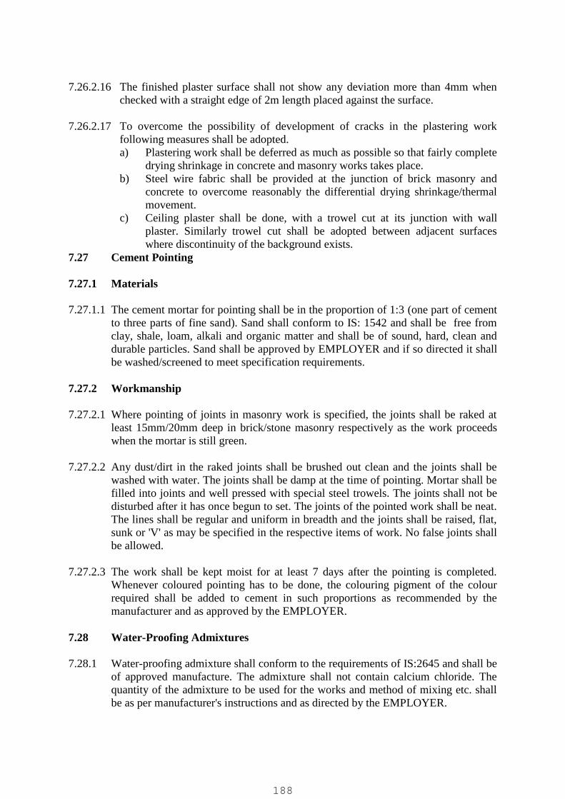
7.26.2.16 The finished plaster surface shall not show any deviation more than 4mm whenchecked with a straight edge of 2m length placed against the surface.
7.26.2.17 To overcome the possibility of development of cracks in the plastering workfollowing measures shall be adopted.a) Plastering work shall be deferred as much as possible so that fairly complete
drying shrinkage in concrete and masonry works takes place.b) Steel wire fabric shall be provided at the junction of brick masonry and
concrete to overcome reasonably the differential drying shrinkage/thermalmovement.
c) Ceiling plaster shall be done, with a trowel cut at its junction with wallplaster. Similarly trowel cut shall be adopted between adjacent surfaceswhere discontinuity of the background exists.
7.27 Cement Pointing
7.27.1 Materials
7.27.1.1 The cement mortar for pointing shall be in the proportion of 1:3 (one part of cementto three parts of fine sand). Sand shall conform to IS: 1542 and shall be free fromclay, shale, loam, alkali and organic matter and shall be of sound, hard, clean anddurable particles. Sand shall be approved by EMPLOYER and if so directed it shallbe washed/screened to meet specification requirements.
7.27.2 Workmanship
7.27.2.1 Where pointing of joints in masonry work is specified, the joints shall be raked atleast 15mm/20mm deep in brick/stone masonry respectively as the work proceedswhen the mortar is still green.
7.27.2.2 Any dust/dirt in the raked joints shall be brushed out clean and the joints shall bewashed with water. The joints shall be damp at the time of pointing. Mortar shall befilled into joints and well pressed with special steel trowels. The joints shall not bedisturbed after it has once begun to set. The joints of the pointed work shall be neat.The lines shall be regular and uniform in breadth and the joints shall be raised, flat,sunk or 'V' as may be specified in the respective items of work. No false joints shallbe allowed.
7.27.2.3 The work shall be kept moist for at least 7 days after the pointing is completed.Whenever coloured pointing has to be done, the colouring pigment of the colourrequired shall be added to cement in such proportions as recommended by themanufacturer and as approved by the EMPLOYER.
7.28 Water-Proofing Admixtures
7.28.1 Water-proofing admixture shall conform to the requirements of IS:2645 and shall beof approved manufacture. The admixture shall not contain calcium chloride. Thequantity of the admixture to be used for the works and method of mixing etc. shallbe as per manufacturer's instructions and as directed by the EMPLOYER.
188

7.29 Painting of Concrete, Masonry & Plastered Surfaces
7.29.1 Materials
7.29.1.1 Oil bound distemper shall conform to IS:428. The primer shall be alkali resistantprimer of the same manufacture as that of the distemper.
7.29.1.2 Cement paint shall conform to IS:5410. The primer shall be a thinned coat ofcement paint.
7.29.1.3 Lead free acid, alkali and chlorine resisting paint shall conform to IS:9862.
7.29.1.4 Colour wash shall be made by addition of a suitable quantity of mineral pigment,not affected by lime, to the prepared white wash to obtain the shade/tint as approvedby the EMPLOYER.
7.29.1.5 All the materials shall be of the best quality from an approved manufacturer.Contractor shall obtain prior approval of the EMPLOYER for the brand ofmanufacture and the colour/shade. All materials shall be brought to the site of worksin sealed containers.
7.29.2 Workmanship
2.29.2.1 Contractor shall obtain the approval of the EMPLOYER regarding the readiness ofthe surfaces to receive the specified finish, before commencing the work onpainting.
2.29.2.2 Painting of new surfaces shall be deferred as much as possible to allow forthorough drying of the sub- strata.
2.29.2.3 The surfaces to be treated shall be prepared by thoroughly brushing them free fromdirt, mortar droppings and any loose foreign materials. Surfaces shall be free fromoil, grease and efflorescence. Efflorescence shall be removed only by dry brushingof the growth. Cracks shall be filled with Gypsum. Workmanship of painting shallgenerally conform to IS:2395.
2.29.2.4 Surfaces of doors, windows etc. shall be protected suitably to prevent paint finishesfrom splashing on them.
7.29.3 White Wash
7.29.3.1 The prepared surfaces shall be wetted and the finish applied by brushing. Theoperation for each coat shall consist of a stroke of the brush first given horizontallyfrom the right and the other from the left and similarly, the subsequent stroke frombottom upwards and the other from top downwards, before the first coat dries. Eachcoat shall be allowed to dry before the next coat is applied. Minimum of 2 coatsshall be applied unless otherwise specified. The dry surface shall present a uniformfinish without any brush marks.
189
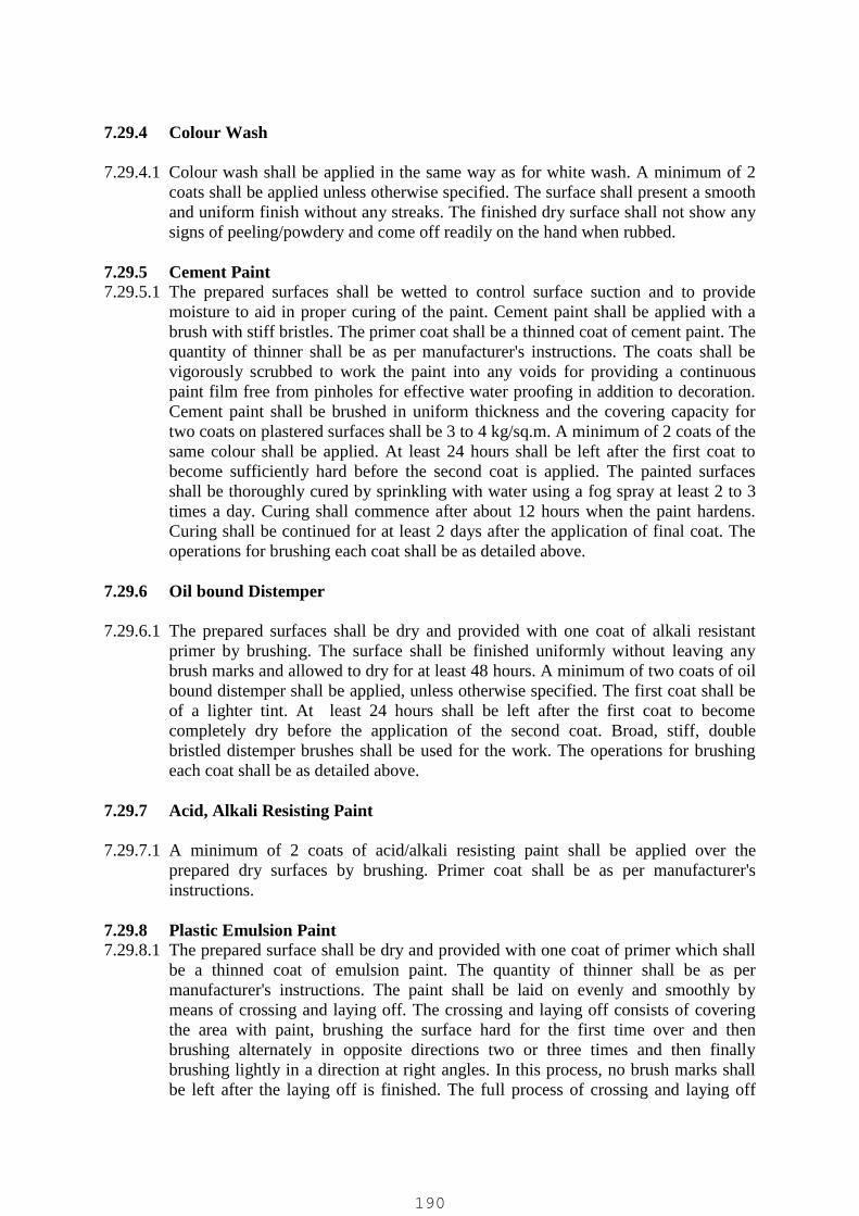
7.29.4 Colour Wash
7.29.4.1 Colour wash shall be applied in the same way as for white wash. A minimum of 2coats shall be applied unless otherwise specified. The surface shall present a smoothand uniform finish without any streaks. The finished dry surface shall not show anysigns of peeling/powdery and come off readily on the hand when rubbed.
7.29.5 Cement Paint7.29.5.1 The prepared surfaces shall be wetted to control surface suction and to provide
moisture to aid in proper curing of the paint. Cement paint shall be applied with abrush with stiff bristles. The primer coat shall be a thinned coat of cement paint. Thequantity of thinner shall be as per manufacturer's instructions. The coats shall bevigorously scrubbed to work the paint into any voids for providing a continuouspaint film free from pinholes for effective water proofing in addition to decoration.Cement paint shall be brushed in uniform thickness and the covering capacity fortwo coats on plastered surfaces shall be 3 to 4 kg/sq.m. A minimum of 2 coats of thesame colour shall be applied. At least 24 hours shall be left after the first coat tobecome sufficiently hard before the second coat is applied. The painted surfacesshall be thoroughly cured by sprinkling with water using a fog spray at least 2 to 3times a day. Curing shall commence after about 12 hours when the paint hardens.Curing shall be continued for at least 2 days after the application of final coat. Theoperations for brushing each coat shall be as detailed above.
7.29.6 Oil bound Distemper
7.29.6.1 The prepared surfaces shall be dry and provided with one coat of alkali resistantprimer by brushing. The surface shall be finished uniformly without leaving anybrush marks and allowed to dry for at least 48 hours. A minimum of two coats of oilbound distemper shall be applied, unless otherwise specified. The first coat shall beof a lighter tint. At least 24 hours shall be left after the first coat to becomecompletely dry before the application of the second coat. Broad, stiff, doublebristled distemper brushes shall be used for the work. The operations for brushingeach coat shall be as detailed above.
7.29.7 Acid, Alkali Resisting Paint
7.29.7.1 A minimum of 2 coats of acid/alkali resisting paint shall be applied over theprepared dry surfaces by brushing. Primer coat shall be as per manufacturer'sinstructions.
7.29.8 Plastic Emulsion Paint7.29.8.1 The prepared surface shall be dry and provided with one coat of primer which shall
be a thinned coat of emulsion paint. The quantity of thinner shall be as permanufacturer's instructions. The paint shall be laid on evenly and smoothly bymeans of crossing and laying off. The crossing and laying off consists of coveringthe area with paint, brushing the surface hard for the first time over and thenbrushing alternately in opposite directions two or three times and then finallybrushing lightly in a direction at right angles. In this process, no brush marks shallbe left after the laying off is finished. The full process of crossing and laying off
190
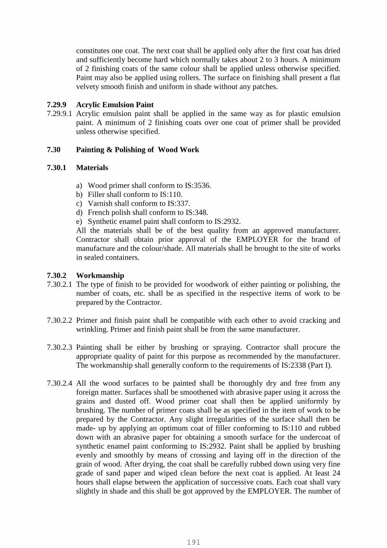
constitutes one coat. The next coat shall be applied only after the first coat has driedand sufficiently become hard which normally takes about 2 to 3 hours. A minimumof 2 finishing coats of the same colour shall be applied unless otherwise specified.Paint may also be applied using rollers. The surface on finishing shall present a flatvelvety smooth finish and uniform in shade without any patches.
7.29.9 Acrylic Emulsion Paint7.29.9.1 Acrylic emulsion paint shall be applied in the same way as for plastic emulsion
paint. A minimum of 2 finishing coats over one coat of primer shall be providedunless otherwise specified.
7.30 Painting & Polishing of Wood Work
7.30.1 Materials
a) Wood primer shall conform to IS:3536.b) Filler shall conform to IS:110.c) Varnish shall conform to IS:337.d) French polish shall conform to IS:348.e) Synthetic enamel paint shall conform to IS:2932.All the materials shall be of the best quality from an approved manufacturer.Contractor shall obtain prior approval of the EMPLOYER for the brand ofmanufacture and the colour/shade. All materials shall be brought to the site of worksin sealed containers.
7.30.2 Workmanship7.30.2.1 The type of finish to be provided for woodwork of either painting or polishing, the
number of coats, etc. shall be as specified in the respective items of work to beprepared by the Contractor.
7.30.2.2 Primer and finish paint shall be compatible with each other to avoid cracking andwrinkling. Primer and finish paint shall be from the same manufacturer.
7.30.2.3 Painting shall be either by brushing or spraying. Contractor shall procure theappropriate quality of paint for this purpose as recommended by the manufacturer.The workmanship shall generally conform to the requirements of IS:2338 (Part I).
7.30.2.4 All the wood surfaces to be painted shall be thoroughly dry and free from anyforeign matter. Surfaces shall be smoothened with abrasive paper using it across thegrains and dusted off. Wood primer coat shall then be applied uniformly bybrushing. The number of primer coats shall be as specified in the item of work to beprepared by the Contractor. Any slight irregularities of the surface shall then bemade- up by applying an optimum coat of filler conforming to IS:110 and rubbeddown with an abrasive paper for obtaining a smooth surface for the undercoat ofsynthetic enamel paint conforming to IS:2932. Paint shall be applied by brushingevenly and smoothly by means of crossing and laying off in the direction of thegrain of wood. After drying, the coat shall be carefully rubbed down using very finegrade of sand paper and wiped clean before the next coat is applied. At least 24hours shall elapse between the application of successive coats. Each coat shall varyslightly in shade and this shall be got approved by the EMPLOYER. The number of
191
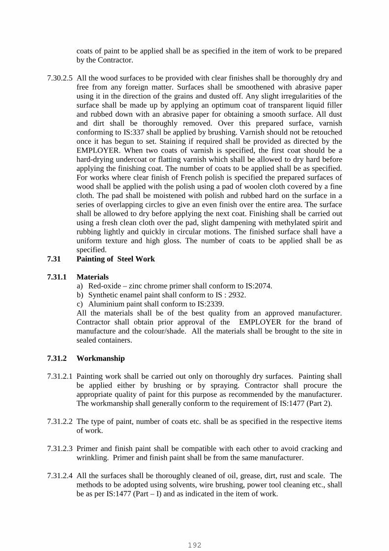
coats of paint to be applied shall be as specified in the item of work to be preparedby the Contractor.
7.30.2.5 All the wood surfaces to be provided with clear finishes shall be thoroughly dry andfree from any foreign matter. Surfaces shall be smoothened with abrasive paperusing it in the direction of the grains and dusted off. Any slight irregularities of thesurface shall be made up by applying an optimum coat of transparent liquid fillerand rubbed down with an abrasive paper for obtaining a smooth surface. All dustand dirt shall be thoroughly removed. Over this prepared surface, varnishconforming to IS:337 shall be applied by brushing. Varnish should not be retouchedonce it has begun to set. Staining if required shall be provided as directed by theEMPLOYER. When two coats of varnish is specified, the first coat should be ahard-drying undercoat or flatting varnish which shall be allowed to dry hard beforeapplying the finishing coat. The number of coats to be applied shall be as specified.For works where clear finish of French polish is specified the prepared surfaces ofwood shall be applied with the polish using a pad of woolen cloth covered by a finecloth. The pad shall be moistened with polish and rubbed hard on the surface in aseries of overlapping circles to give an even finish over the entire area. The surfaceshall be allowed to dry before applying the next coat. Finishing shall be carried outusing a fresh clean cloth over the pad, slight dampening with methylated spirit andrubbing lightly and quickly in circular motions. The finished surface shall have auniform texture and high gloss. The number of coats to be applied shall be asspecified.
7.31 Painting of Steel Work
7.31.1 Materialsa) Red-oxide – zinc chrome primer shall conform to IS:2074.b) Synthetic enamel paint shall conform to IS : 2932.c) Aluminium paint shall conform to IS:2339.All the materials shall be of the best quality from an approved manufacturer.Contractor shall obtain prior approval of the EMPLOYER for the brand ofmanufacture and the colour/shade. All the materials shall be brought to the site insealed containers.
7.31.2 Workmanship
7.31.2.1 Painting work shall be carried out only on thoroughly dry surfaces. Painting shallbe applied either by brushing or by spraying. Contractor shall procure theappropriate quality of paint for this purpose as recommended by the manufacturer.The workmanship shall generally conform to the requirement of IS:1477 (Part 2).
7.31.2.2 The type of paint, number of coats etc. shall be as specified in the respective itemsof work.
7.31.2.3 Primer and finish paint shall be compatible with each other to avoid cracking andwrinkling. Primer and finish paint shall be from the same manufacturer.
7.31.2.4 All the surfaces shall be thoroughly cleaned of oil, grease, dirt, rust and scale. Themethods to be adopted using solvents, wire brushing, power tool cleaning etc., shallbe as per IS:1477 (Part – I) and as indicated in the item of work.
192

7.31.2.5 It is essential to ensure that immediately after preparation of the surfaces, the firstcoat of red oxide-zinc chrome primer shall be applied by brushing and working itwell to ensure a continuous film without holidays. After the first coat becomes harddry, a second coat of primer shall be applied by brushing to obtain a film free from`holidays’.
7.31.2.6 After the second coat of primer is hard dry, the entire surface shall be wet rubbedcutting down to a smooth uniform surface. When the surface becomes dry, theundercoat of synthetic enamel paint of optimum thickness shall be applied bybrushing with minimum of brush marks. The coat shall be allowed to hard-dry.The under coat shall then be wet rubbed cutting down to a smooth finish, takingadequate care to ensure that at no place the undercoat is completely removed. Thesurface shall then be allowed to dry.
7.31.2.7 The first finishing coat of paint shall be applied by brushing and allowed to hard-dry. The gloss from the entire surface shall then be gently removed and the surfacedusted off. The second finishing coat shall then be applied by brushing.
7.31.2.8 At least 24 hours shall elapse between the application of successive coats. Eachcoat shall vary slightly in shade and this shall be got approved by the EMPLOYER.
7.32 Flashing
7.32.1 Materials
7.32.1.1 Anodised Aluminium sheets shall be 1.00mm thick with anodic film thickness of0.025 mm.
7.32.1.2 Galvanised mild steel sheets shall be 1.00mm thick with zinc coating of 800gms/sq.m.
7.32.1.3 Bitumen felt shall be either Hessian base self finished bitumen felt Type-3 Grade Iconforming to IS:1322 or glass fibre base self finished felt Type-2 Grade 1conforming to IS:7193.
7.32.2 Workmanship
7.32.2.1 The type of the flashing and method of fixing shall be as specified.
7.32.2.2 Flashing shall be of the correct shape and size as indicated in the constructionDrawings to be prepared by the Contractor and they shall be properly fixed toensure their effectiveness.
7.32.2.3 Flashing shall be of long lengths so as to provide minimum number of joints. Theminimum overlap at joints shall be 100mm.
7.32.2.4 Fixing of the flashing shall be either by bolting with bitumen washers or by tuckinginto the groove 75 mm wide x 65 mm deep in masonry/concrete along with cementmortar 1:4 filletting as indicated in the Drawings to be prepared by the Contractor.Curing of the mortar shall be carried out for a minimum period of 4 days.
193
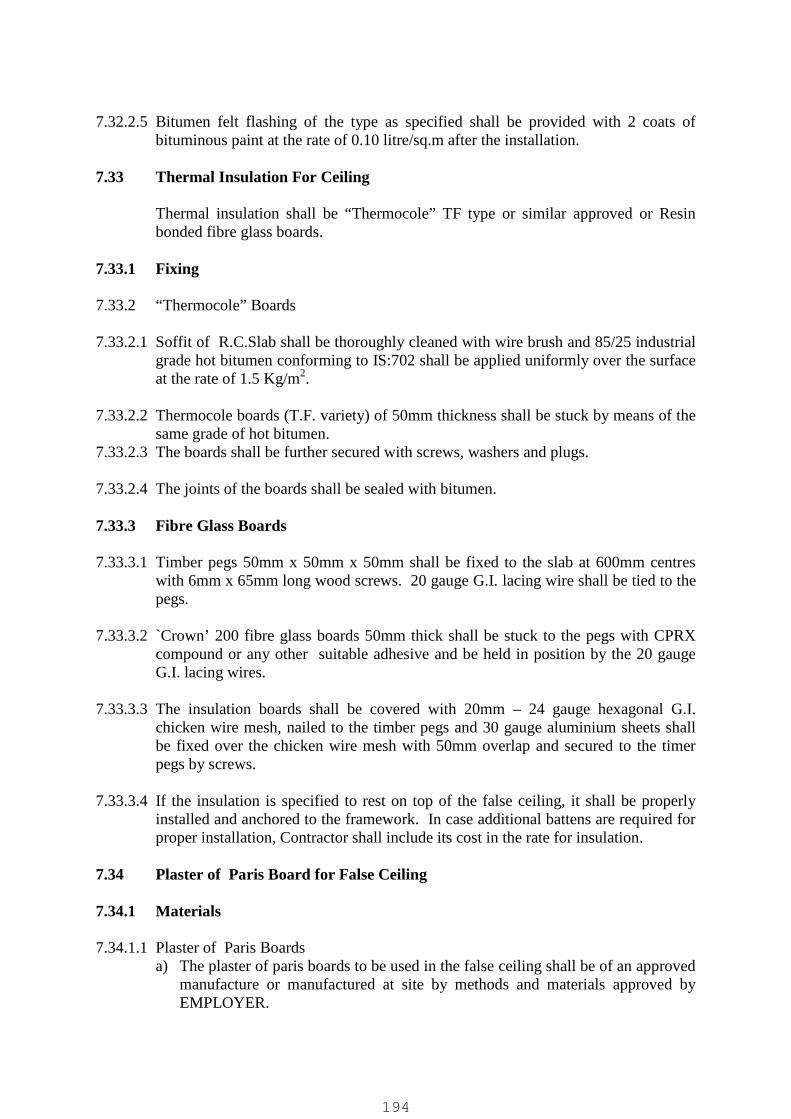
7.32.2.5 Bitumen felt flashing of the type as specified shall be provided with 2 coats ofbituminous paint at the rate of 0.10 litre/sq.m after the installation.
7.33 Thermal Insulation For Ceiling
Thermal insulation shall be “Thermocole” TF type or similar approved or Resinbonded fibre glass boards.
7.33.1 Fixing
7.33.2 “Thermocole” Boards
7.33.2.1 Soffit of R.C.Slab shall be thoroughly cleaned with wire brush and 85/25 industrialgrade hot bitumen conforming to IS:702 shall be applied uniformly over the surfaceat the rate of 1.5 Kg/m2.
7.33.2.2 Thermocole boards (T.F. variety) of 50mm thickness shall be stuck by means of thesame grade of hot bitumen.
7.33.2.3 The boards shall be further secured with screws, washers and plugs.
7.33.2.4 The joints of the boards shall be sealed with bitumen.
7.33.3 Fibre Glass Boards
7.33.3.1 Timber pegs 50mm x 50mm x 50mm shall be fixed to the slab at 600mm centreswith 6mm x 65mm long wood screws. 20 gauge G.I. lacing wire shall be tied to thepegs.
7.33.3.2 `Crown’ 200 fibre glass boards 50mm thick shall be stuck to the pegs with CPRXcompound or any other suitable adhesive and be held in position by the 20 gaugeG.I. lacing wires.
7.33.3.3 The insulation boards shall be covered with 20mm – 24 gauge hexagonal G.I.chicken wire mesh, nailed to the timber pegs and 30 gauge aluminium sheets shallbe fixed over the chicken wire mesh with 50mm overlap and secured to the timerpegs by screws.
7.33.3.4 If the insulation is specified to rest on top of the false ceiling, it shall be properlyinstalled and anchored to the framework. In case additional battens are required forproper installation, Contractor shall include its cost in the rate for insulation.
7.34 Plaster of Paris Board for False Ceiling
7.34.1 Materials
7.34.1.1 Plaster of Paris Boardsa) The plaster of paris boards to be used in the false ceiling shall be of an approved
manufacture or manufactured at site by methods and materials approved byEMPLOYER.
194

b) The plaster of paris shall be of the calcium-sulphate hemi-hydrate variety andshall contain not less than 35 percent sulphur trioxide and other requirements asper IS:2547 (Part I) However, its fineness shall be such that the residue, afterdrying, and sieving on I.S. sieve designation 3.35mm for 5 minutes shall not bemore than 1 percent by weight. Initial setting time shall not be less than 13minutes. The average compressive strength of plaster determined by testing 5cm cubes 24 hours after removal from moulds and drying in an oven at 40 Deg.C till the weight of the cubes is constant, shall not be less than 84 Kg per sq.cm.
c) The plaster of paris boards reinforced with hessian cloth or coir shall beprepared in suitable sizes as shown on the drawings or as directed byEMPLOYER. Wooden forms of height equal to the thickness of boards shall beplaced on truly level and smooth surface such as a glass sheet. The edges of theboards shall be truly square. The glass sheet or surface on which form is keptand the form sides shall be given a thin coat of non-staining oil to facilitate theeasy removal of the board. Plaster of paris shall be evenly spread into the formupto about half the depth and hessian cloth or coir shall be pressed over theplaster of paris layer. The weight of hessian cloth or coir in the board shall be250 gm per sq.m. The ends of the hessian/coir reinforcement shall be turnedover at all edges to form a double layer for a width of 50mm. The hessian clothshall be of an open web texture so as to allow the plaster below and above tointermix with each other and form an integral board. The form shall then befilled with plaster of paris which shall be uniform pressed and then wire cut toan even and smooth surface. The board shall then be allowed to set initially foran hour or so and then removed from the form and allowed to dry and harden forabout a week. The board after drying and hardening shall give a ringing soundwhen struck. The boards shall be true and exact to shape and size and theexposed face shall be truly plane and smooth.
d) The size of boards shall generally be 600mm x 600 mm x 12 mm thick. Boardsshall be kept dry in transit and stored flat in a clean dry place and shall not beexposed to moisture. The boards shall always be carried on edges.
7.34.2 Timber Frame Work
7.34.2.1 Timber for frame work of false ceiling grid and hangers shall be of good qualityand well seasoned. It shall have uniform colour, reasonably straight and closegrains and shall be free from knots, cracks and sapwood. It shall be treated withapproved anti-termite preservative as directed by the EMPLOYER. Extreme careshall be taken so that the preservative treatment does not stain the ceiling boards. Incase metal hangers are used, these shall be M.S. flats or bars, having two coats ofred oxide zinc chromate paint primer, as shown on drawings or as approved byEMPLOYER.
7.34.3 Metal Frame Work
7.34.3.1 The metal frame work may be made of sections of light metal, such as anodisedaluminium, mild steel or as shown on the drawings. The shape of cross-sectionshall be such as to facilitate proper suspension and proper fixing of the ceilingboards covering them and shall be structurally sound and rigid.
195
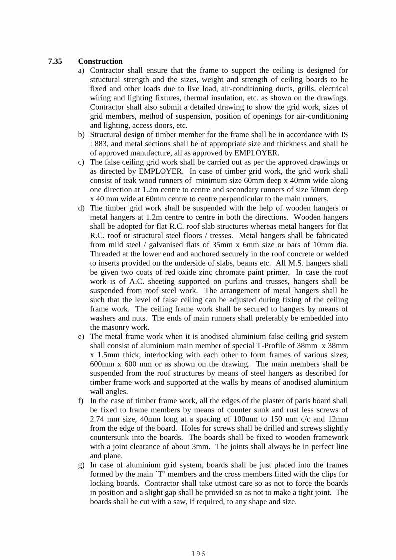
7.35 Constructiona) Contractor shall ensure that the frame to support the ceiling is designed for
structural strength and the sizes, weight and strength of ceiling boards to befixed and other loads due to live load, air-conditioning ducts, grills, electricalwiring and lighting fixtures, thermal insulation, etc. as shown on the drawings.Contractor shall also submit a detailed drawing to show the grid work, sizes ofgrid members, method of suspension, position of openings for air-conditioningand lighting, access doors, etc.
b) Structural design of timber member for the frame shall be in accordance with IS: 883, and metal sections shall be of appropriate size and thickness and shall beof approved manufacture, all as approved by EMPLOYER.
c) The false ceiling grid work shall be carried out as per the approved drawings oras directed by EMPLOYER. In case of timber grid work, the grid work shallconsist of teak wood runners of minimum size 60mm deep x 40mm wide alongone direction at 1.2m centre to centre and secondary runners of size 50mm deepx 40 mm wide at 60mm centre to centre perpendicular to the main runners.
d) The timber grid work shall be suspended with the help of wooden hangers ormetal hangers at 1.2m centre to centre in both the directions. Wooden hangersshall be adopted for flat R.C. roof slab structures whereas metal hangers for flatR.C. roof or structural steel floors / tresses. Metal hangers shall be fabricatedfrom mild steel / galvanised flats of 35mm x 6mm size or bars of 10mm dia.Threaded at the lower end and anchored securely in the roof concrete or weldedto inserts provided on the underside of slabs, beams etc. All M.S. hangers shallbe given two coats of red oxide zinc chromate paint primer. In case the roofwork is of A.C. sheeting supported on purlins and trusses, hangers shall besuspended from roof steel work. The arrangement of metal hangers shall besuch that the level of false ceiling can be adjusted during fixing of the ceilingframe work. The ceiling frame work shall be secured to hangers by means ofwashers and nuts. The ends of main runners shall preferably be embedded intothe masonry work.
e) The metal frame work when it is anodised aluminium false ceiling grid systemshall consist of aluminium main member of special T-Profile of 38mm x 38mmx 1.5mm thick, interlocking with each other to form frames of various sizes,600mm x 600 mm or as shown on the drawing. The main members shall besuspended from the roof structures by means of steel hangers as described fortimber frame work and supported at the walls by means of anodised aluminiumwall angles.
f) In the case of timber frame work, all the edges of the plaster of paris board shallbe fixed to frame members by means of counter sunk and rust less screws of2.74 mm size, 40mm long at a spacing of 100mm to 150 mm c/c and 12mmfrom the edge of the board. Holes for screws shall be drilled and screws slightlycountersunk into the boards. The boards shall be fixed to wooden frameworkwith a joint clearance of about 3mm. The joints shall always be in perfect lineand plane.
g) In case of aluminium grid system, boards shall be just placed into the framesformed by the main `T’ members and the cross members fitted with the clips forlocking boards. Contractor shall take utmost care so as not to force the boardsin position and a slight gap shall be provided so as not to make a tight joint. Theboards shall be cut with a saw, if required, to any shape and size.
196

h) As the work of false ceiling may be inter-connected with the work of air-conditioning ducts and lighting, Contractor shall fully co-operate with the otheragencies entrusted with the above work, who may be working simultaneously .Contractor shall provide necessary openings in the false ceiling work for air-conditioning, lighting and other fixtures. Additional framing, if required, for theabove opening shall also be provided at no extra cost to Employer. Removableor hinged type inspection or access trap doors shall be provided at locationsspecified by EMPLOYER.
7.35.1 Finishing
7.35.1.1 It is essential that false ceiling work should be firm and in perfect line and level andall boards free from distortion, bulge, and other defects. All defective boards andother material shall be removed from site immediately and replaced, and ceilingrestored to original finish to the satisfaction of EMPLOYER.
7.35.1.2 The workmanship shall be of highest order and all joinery work for timber workshall be in the best workmanship manner. The joints for aluminium frame workshall be of inter-locking type so that when the cross member is in place, it cannot belifted out.
7.35.1.3 The countersunk heads of screws and all joints shall be filled with plaster of parisand finished smooth. After filling the joints, a thick skin of the finishing materialshall be spread about 50mm wide on either side of the joint and on to it shall betrowelled dry a reinforcing scrim cloth about 10mm wide. If metal scrim is used, astiffer plaster will be necessary to enable the trowelling of the scrim down to theboard.
7.35.2 Fire Stopping
7.35.2.1 In case of fire protective ceilings, fire resisting barriers at suitable intervals shall beprovided. These shall completely close the gap between the false ceiling and soffitof the structural slab. The material of the barrier shall be as indicated byEMPLOYER (Reference may be made to the British Standards Institutions CP 290:Code of Practice for suspended ceiling and lining of dry construction using metalfixing system, `for guidance).
7.36 False or Cavity Floor
7.36.1 Frame Work
7.36.1.1 The false floor shall consist of a framework of suitable structural member designedto carry the loads specified. This frame work shall be supported on suitablydesigned stools placed at 600mm centre to centre in both directions. The stoolsshall consist of a mild steel base plate with a mild steel stud having adjustable locknut and coupling at the centre and another mild steel plate at top serving as aprophead. The above framework shall be suitably designed to accommodate 35mmthick, 600mm square panels. The base plate shall be fixed to the reinforcedconcrete floor with an approved adhesive compound or with 4 Nos. 6mm dia.
197

anchor fasteners. Bedding of 1:2 or richer cement sand mortar shall be providedlocally under the base plates of stools to provide a level surface.
7.36.1.2 The prophead shall be provided with mild steel lugs welded on top and each placedperpendicular to the other for proper positioning and supporting the main and crossmembers. The stools shall be capable of adjustment to accommodate concrete floorlevel irregularities upto plus or minus 15mm. The framing members shall becompletely removable and shall remain in position without screwing or bolting tothe propheads. All steel framework including steel stools shall be given a coat ofzinc chromate primer and two coats of enamel paint of approved colour and shade.
7.36.2 Floor Panels
7.36.2.1 The floor panels shall be made of 600mm x 600mm x 35 mm thick medium densityunveneered/ non-prelaminated teak wood particle boards having a density of notmore than 800 kg/cu.m bonded with boiling water proof phenol formaldehydesynthetic resin and shall be of fire resistant, termite resistant and moisture proofquality, generally conforming to IS:3087-specification for wood particle boards(Medium Density )for general purposes.
7.36.2.2 The thermal conductivity of the boards shall not exceed 0.12kCal/hr/sq.m/deg./C/m.
7.36.2.3 The panel size given above may be suitably modified near electricalpanel/equipment and also to suit room dimensions with panel size not more than600mm under any circumstances. Exposed 2mm thick vinyl edging shall beprovided on all edges of individual panels. Each panel shall be given a coat orprimer and two coats of approved fire resistant paint from underside.
7.36.2.4 The particle boards shall be faced with 600mm x 600 mm x 2mm thick approvedmake flooring tiles conforming to IS:3462 – “Specification for unbacked flexiblePVC flooring” and of approved colour and shade. The completed panel shall becompletely removable and shall remain in position without screwing or bolting tothe on the inner side with stickers for easy identification and reassembly wheneverrequired.
7.36.2.5 Suitable backing material shall be provided on the underside of the particle board toprevent warping and / or to cater to specified loading.
7.36.2.6 Suitable removable covers shall be provided to serve as outlets for the cables.
7.36.3 Imposed Loading
7.36.3.1 The finished floor shall be capable of supporting a uniformly distributed load of 500to 1000 Kg. per sq.metre of floor area as specified in data sheet. A point load of450 Kg on 600 sq.mm on any part of the panel or a line load of 725 Kg on 100mmstrip across the panel length shall not result in a deflection greater than 2.5mm.
7.36.4 Finish
7.36.4.1 The finished floor shall be true to lines and levels and present a neat flush surface.
198

7.36.5 Vendor Drawing
7.36.5.1 Vendor shall prepare and submit a layout drawing for false floor giving all detailsincluding supporting system for approval. If so called for, vendor shall also submithis calculations for the supporting system with all relevant data assumed, to theEMPLOYER for his approval. Work shall be carried out on approved drawingsonly.
7.37 Fire Proof Doors
7.37.1 Material and Workmanship
7.37.1.1 The design of fire proof doors and the materials to be used in their fabrication haveto be such that they shall be capable of providing the effective barrier to the spreadof fire. The materials, fabrication and erection of fire proof doors shall confirm toIS:3614 (Part – I). The fire proof doors shall be obtained from an approvedmanufacturer. Specific approval for such purchase shall be obtained before hand.Sample approval shall also be obtained from testing authority as per the standard IS: 3614 (Part – 2) for the specified degree of fire rating in hours. All fire proof doorsshall have specified sizes and confirm to the description in the respective items ofwork.
7.37.1.2 Fire proof door shutters shall be of zinc coated weldable steel (confirming toBS:6687) or stainless steel (conforming to IS:304) sheet (18G minimum) fixed in aframe work of rolled channel. The shutter shall consist of an insulating material likemineral wool in required thickness to satisfy the specified fire rating. Normally thethickness of door shutter shall not be less than 35mm for two hour fire rating and 46mm for four hour fire rating.
7.37.1.3 The shutter with the required insulating material shall be mounted on angle ironframe or the special made frame from zinc coated (16G minimum) weldable steelsheet. The shutter shall be fixed to frame by means of suitable hinges and shallhave a three way latching system. All the doors shall be provided with a coat ofprimer and one coat of synthetic enamel paint to attain the specified fire rating. Allother accessories like hinges, door lock, hold fasts, etc. shall be provided asapproved by TAC (Tariff Advisory Committee). All these accessories shall becompatible with the material used for door and shutter.
199

05 CHAPTERSPECIFICATIONS – PIPELINES, PIPEWORK AND FITTINGS
Applicable codes
The following codes and standards unless specified herein shall be referred to.
Materials
IS : 210 Specification for grey iron castingIS : 290 Specification for coal tar black paintIS : 456 Code of practice for plain and reinforced concreteIS : 458 Specification for pre cast concrete pipes (with and without
reinforcement)IS : 516 Method of test for strength of concreteIS : 638 Specification for sheet rubber jointing and rubber insertion jointingIS : 783 Code of practice for laying of concrete pipesIS : 816 Code of practice for use of metal arc welding for general
construction in mild steelIS : 1367 Technical supply conditions for threaded steel fastenersIS : 1387 General requirements for the supply of metallurgical materialsIS : 1500 Method for Brinnell hardness test for metallic materialsIS : 1536 Specification for centrifugally cast (spun) iron pressure pipes for
water, gas and sewageIS : 1537 Specification for vertically cast iron pressure pipes for water,
gas and sewageIS : 1538 Specification for cast iron fittings for pressure pipes for water,
gas and sewageIS : 1916 Specification for steel cylinder pipes with concrete lining
and coatingIS : 2078 Method for tensile testing of grey cast ironIS : 3589 Specification for MS Spirally Welded PipesIS : 3597 Method of tests for concrete pipesIS : 3658 Code of practice for liquid penetrant flow detectionIS : 5382 Specification for rubber sealing rings for gas mains, water mains and
sewersIS : 5504 Specification for spiral welded pipesIS : 6587 Specification for spun hemp yarnIS : 7322 Specification for specials for steel cylinder reinforced concrete pipesIS : 8329 Specification for DI pipesIS : 9523 Specifications for DI fittingsIS : 4984 Specifications for HDPE pipelineIS :14846 Specifications for valves
Code of Practice
IS : 783 Code of practice for laying of concrete pipesIS : 3114 Code of practice for laying of cast iron pipesIS : 3764 Excavation work - Code of SafetyIS : 4127 Code of practice for laying of glazed stoneware pipes
200

IS : 5822 Code of practice for laying of electrically welded steel pipes forwater supply.
IS : 6530 Code of practice for laying of asbestos cement pressure pipes.
Pipe work
The pipe works for the plant involves manufacturing, supplying, laying and jointing ofsuitable size cast iron, ductile iron pipes along with matching special etc as required. Allpiping inside the plant shall be cast iron/ductile iron except for chemical house and chlorinepiping. The specifications for manufacturing, supplying, laying and jointing of pipes shallgenerally conform to the standard specification.
All pipe work and fitting shall be of class rating in excess of the maximum pressure attainedin service including any surge pressure.
The pipe work installation shall be so arranged to offer ease of dismantling and removal ofpumps or other major items of equipments. C.I. dismantling joints which can take radial andaxial misalignment of minimum 1 percent of valve nominal size with tie bolts shall beprovided. All pipe work shall be adequately supported with purpose-made fittings. Whenpassing through walls, pipe work shall incorporate a puddle flange. Flange adapters andunions shall be fitted in pipe work runs, wherever necessary, to permit the simpledisconnection of flanges, valves and equipment.
The Contractor shall be responsible for ensuring that the internal surface of all pipe work isthoroughly clean before and during erection and before commissioning. Cleaning shallinclude removal of all dirt, rust, scale and welding slag due to Site welding. Before dispatchfrom the manufacturer’s work, the ends of the pipe, branch pipe, etc., shall be suitably beremoved until immediately prior to connecting adjacent pipes, valves or pumps. All smallbore pipes shall be blown through with compressed air before connection is made toinstrumental and other equipment. No point of passage of pipes through floors or walls shallbe used as a point of support, except with the approval of the Engineer-in-Charge.
Materials for Pipelines
Each pipeline shall be constructed in a material compatible with the fluid conveyed throughthat pipeline, i.e. the materials used in the pipes which are or can be in contact with theuntreated sewage, suitable additive for mortar protection shall be provided.
Pipework and valve materials for the following duties shall be as follows or equivalent to theapproval of the Employer’s Representative:
CAST IRON PIPING:
Providing and supplying lowering, laying to line, level and slope, centrifugally cast iron(spun) pressure pipes (LA Class Strictly confirming to IS 1536/1989 with latest amendment)and jointing with specials such as Tees, Bends, Reducers including and other safetyprovision, cutting the pipes and making joints and hydraulic testing after laying etc. comp.
The Cast Iron pipes shall be LA Class conforming to IS 1536/1989 with latest amendmentsbearing ISI Mark.
201

The pipes shall be free from the defects resulting from raw materials, loading, handling,carting and unloading. The pipes shall be free from load, bents or bulges greater than 3 mm indepth and extending over a length in any directions greater than twice the thickness of barrel.
Each lot of pipes supplied by the contractor must be accompanied by the test certificates asspecified in IS 1536/1989 with latest amendments. The contractors shall have to makearrangement for inspection/testing of the pipes at manufacturer’s factory at contractor’s ownrisk and cost.
Each pipe shall have cast, stamped or indelibly painted on it the following marks.a) Manufacturer’s name, initials or identification mark.b) The nominal diameter.c) Class reference.d) The last two digits of the year of the manufacture.e) I.S. Certification mark.
The materials shall be carted to the site by the contractor very carefully. The handling, whilecarting the pipes, specials, valves etc. shall be done carefully.
In case of heavy pipes, specials etc. lowering shall be done with the help of the chain pulleyblock.
Caulking:
After a section of convenient length has been leaded, caulking shall be commenced. The leadshall be free from the leading pipe, outside of the socket of the other pipe with flat chisel, andthen caulked round 3 separate times with the proper caulking tools of increasing thicknessand hammer 4 to 5 lbs. in weight in such manner as to make the joints sound and water tight.
Joints under water shall be made with lead wool inserted in strings not less than 6 mm thickand very throughly caulked.
New Flanged Joints:
Flanged joints should be made by painting the facing of the flanges with red lead freesly andbelting up evenly on all sides.
A thin fibre, of lead wool may be very useful in making the joints water tight, where facing ofthe pipes is not true.
Where packing must be used, it should be of rubber insert cloth three ply and of approvedthickness. The packing should be of the full diameter of the flange with proper pipe hole andbolt holes cut and even at both inner and outer edges.
Where the flange is not fully faced, the packing may be of the dimension of the facing striponly. Its proper placing should be tested before another pipe is jointed on.
Testing:
After each section of the pipe line has been completed, it shall be tested for water tightnessbefore being covered in. This can be done by closing each end by means of a reliable guage.When the pipe is laid on any appreciable gradient, the test should be carried out at the lower
202
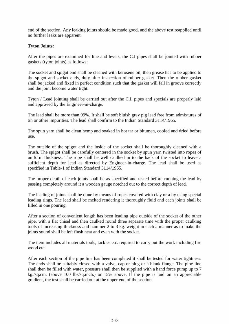
end of the section. Any leaking joints should be made good, and the above test reapplied untilno further leaks are apparent.
Tyton Joints:
After the pipes are examined for line and levels, the C.I pipes shall be jointed with rubbergaskets (tyton joints) as follows:
The socket and spigot end shall be cleaned with kerosene oil, then grease has to be applied tothe spigot and socket ends, duly after inspection of rubber gasket. Then the rubber gasketshall be jacked and fixed in perfect condition such that the gasket will fall in groove correctlyand the joint become water tight.
Tyton / Lead jointing shall be carried out after the C.I. pipes and specials are properly laidand approved by the Engineer-in-charge.
The lead shall be more than 99%. It shall be soft bluish grey pig lead free from admixtures oftin or other impurities. The lead shall confirm to the Indian Standard 3114/1965.
The spun yarn shall be clean hemp and soaked in hot tar or bitumen, cooled and dried beforeuse.
The outside of the spigot and the inside of the socket shall be thoroughly cleaned with abrush. The spigot shall be carefully centered in the socket by spun yarn twisted into ropes ofuniform thickness. The rope shall be well caulked in to the back of the socket to leave asufficient depth for lead as directed by Engineer-in-charge. The lead shall be used asspecified in Table-1 of Indian Standard 3114/1965.
The proper depth of each joints shall be as specified and tested before running the lead bypassing completely around it a wooden gauge notched out to the correct depth of lead.
The leading of joints shall be done by means of ropes covered with clay or a by using specialleading rings. The lead shall be melted rendering it thoroughly fluid and each joints shall befilled in one pouring.
After a section of convenient length has been leading pipe outside of the socket of the otherpipe, with a flat chisel and then caulked round three separate time with the proper caulkingtools of increasing thickness and hammer 2 to 3 kg. weight in such a manner as to make thejoints sound shall be left flush neat and even with the socket.
The item includes all materials tools, tackles etc. required to carry out the work including firewood etc.
After each section of the pipe line has been completed it shall be tested for water tightness.The ends shall be suitably closed with a valve, cap or plug or a blank flange. The pipe lineshall then be filled with water, pressure shall then be supplied with a hand force pump up to 7kg./sq.cm. (above 100 lbs/sq.inch.) or 15% above. If the pipe is laid on an appreciablegradient, the test shall be carried out at the upper end of the section.
203
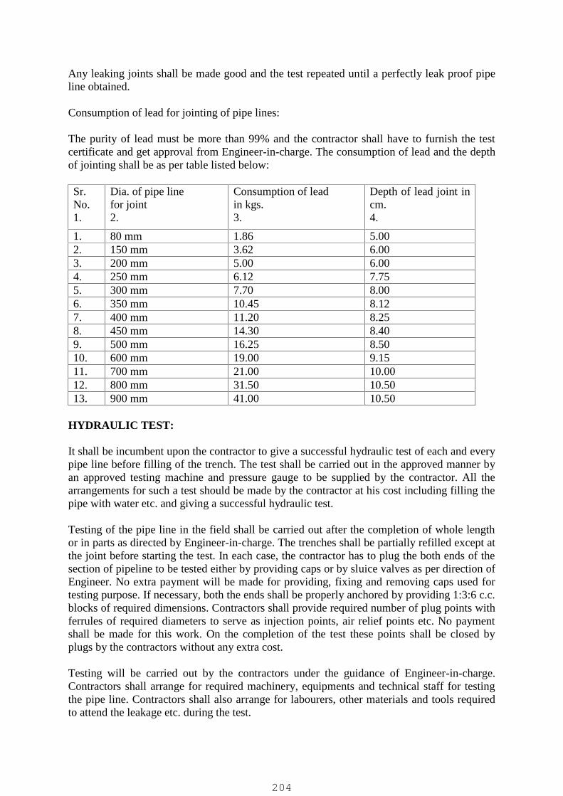
Any leaking joints shall be made good and the test repeated until a perfectly leak proof pipeline obtained.
Consumption of lead for jointing of pipe lines:
The purity of lead must be more than 99% and the contractor shall have to furnish the testcertificate and get approval from Engineer-in-charge. The consumption of lead and the depthof jointing shall be as per table listed below:
Sr.No.1.
Dia. of pipe linefor joint2.
Consumption of leadin kgs.3.
Depth of lead joint incm.4.
1. 80 mm 1.86 5.002. 150 mm 3.62 6.003. 200 mm 5.00 6.004. 250 mm 6.12 7.755. 300 mm 7.70 8.006. 350 mm 10.45 8.127. 400 mm 11.20 8.258. 450 mm 14.30 8.409. 500 mm 16.25 8.5010. 600 mm 19.00 9.1511. 700 mm 21.00 10.0012. 800 mm 31.50 10.5013. 900 mm 41.00 10.50
HYDRAULIC TEST:
It shall be incumbent upon the contractor to give a successful hydraulic test of each and everypipe line before filling of the trench. The test shall be carried out in the approved manner byan approved testing machine and pressure gauge to be supplied by the contractor. All thearrangements for such a test should be made by the contractor at his cost including filling thepipe with water etc. and giving a successful hydraulic test.
Testing of the pipe line in the field shall be carried out after the completion of whole lengthor in parts as directed by Engineer-in-charge. The trenches shall be partially refilled except atthe joint before starting the test. In each case, the contractor has to plug the both ends of thesection of pipeline to be tested either by providing caps or by sluice valves as per direction ofEngineer. No extra payment will be made for providing, fixing and removing caps used fortesting purpose. If necessary, both the ends shall be properly anchored by providing 1:3:6 c.c.blocks of required dimensions. Contractors shall provide required number of plug points withferrules of required diameters to serve as injection points, air relief points etc. No paymentshall be made for this work. On the completion of the test these points shall be closed byplugs by the contractors without any extra cost.
Testing will be carried out by the contractors under the guidance of Engineer-in-charge.Contractors shall arrange for required machinery, equipments and technical staff for testingthe pipe line. Contractors shall also arrange for labourers, other materials and tools requiredto attend the leakage etc. during the test.
204

The pipe line shall be subjected for following test:
Leakage Test:
The test shall be conducted after satisfactory completion of the pressure test.
There shall not be any leakage in the pipe or at the joint. A seepage allowance of a 2.5 litresper kilometer per hour per centimeter diameter of the pipe shall be permissible and thatquantity will not be considered as leakage.
If the retest is delayed for more than 48 hours after any test has proved unsuccessful theEngineer-in-charge, after giving 24 hours notice, shall have every right to get all defectsrectified and carry out other necessary works and take hydraulic test/leakage test to thecontractor. Any damage done to the pipes, materials, the other labour cost, etc. incurred thereunder shall be recoverable from the contractor either from his bill or deposit.
The responsibility of the contractor as specified above in case of unsuccessful hydraulic testshall not cease to exist by his pleading that any materials used by him in the pipe line washaving cracked or was otherwise defective, as if he has a reason to believe so, he must refuseto accept such materials right at the stores.
If the first test is not found satisfactory, repeated tests will be taken and procedure mentionedabove should be followed for testing till a satisfactory test is given. All testing shall be doneat the risk of the contractors and they have to attend be done at the risk of the contractors andthey have to attend all defects including repairing bursts, leaks at joints, sluice valve ends,caps etc. removing and replacing cracked pipes etc. These unserviceable articles shall be theproperty of the contractors and they shall arrange to remove the same from the site as directedby the Engineer.
Any portion of the pipe line that does not stand the specified pressure, shall be rectified bythe contractor. Who should make his own arrangement for the water required for the testing.
When the section of the pipe line is tested successfully the contractor shall remove the blankflanges, pump out water from the pipes and back fill the portion as per directions of theEngineer.
CI Double Flanged Pipes / Piping within pump house shall be tested for 150 % of maximumsystem pressure.
The items include all materials and labour required to carry out the work as detailed above.
205
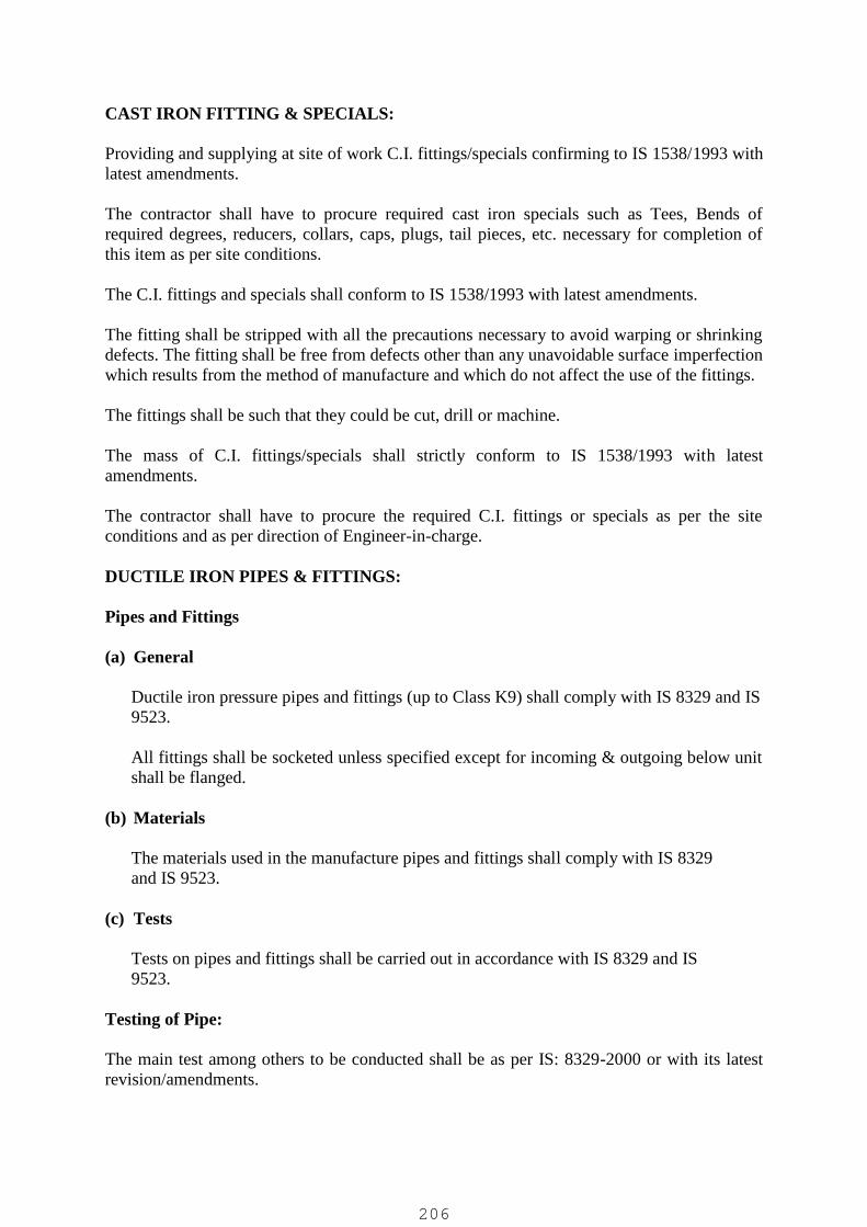
CAST IRON FITTING & SPECIALS:
Providing and supplying at site of work C.I. fittings/specials confirming to IS 1538/1993 withlatest amendments.
The contractor shall have to procure required cast iron specials such as Tees, Bends ofrequired degrees, reducers, collars, caps, plugs, tail pieces, etc. necessary for completion ofthis item as per site conditions.
The C.I. fittings and specials shall conform to IS 1538/1993 with latest amendments.
The fitting shall be stripped with all the precautions necessary to avoid warping or shrinkingdefects. The fitting shall be free from defects other than any unavoidable surface imperfectionwhich results from the method of manufacture and which do not affect the use of the fittings.
The fittings shall be such that they could be cut, drill or machine.
The mass of C.I. fittings/specials shall strictly conform to IS 1538/1993 with latestamendments.
The contractor shall have to procure the required C.I. fittings or specials as per the siteconditions and as per direction of Engineer-in-charge.
DUCTILE IRON PIPES & FITTINGS:
Pipes and Fittings
(a) General
Ductile iron pressure pipes and fittings (up to Class K9) shall comply with IS 8329 and IS9523.
All fittings shall be socketed unless specified except for incoming & outgoing below unitshall be flanged.
(b) Materials
The materials used in the manufacture pipes and fittings shall comply with IS 8329and IS 9523.
(c) Tests
Tests on pipes and fittings shall be carried out in accordance with IS 8329 and IS9523.
Testing of Pipe:
The main test among others to be conducted shall be as per IS: 8329-2000 or with its latestrevision/amendments.
206

[a] Mechanical Tests
Mechanical tests shall be carried out during manufacture of pipes as specified in theStandards. The frequency and sampling of tests for each batch of pipes shall be in accordancewith IS 11606-1986. The test results so obtained for all the pipes and fittings of differentsizes shall be submitted to Engineer. The method for tensile tests and the minimum tensilestrength requirement for pipes and fittings shall be as per IS; 8329/EN 545 for pipes and IS:9523/EN 545 for fittings.
[b] Brinell Hardness Test
For checking the Brinell hardness the test shall be carried out on the test ring or bars cut formthe pipes used for the ring test and tensile test in accordance with IS:1500. The test shallcomply with the requirements specified in IS: 1500/ISO 6506.
[c] Re-tests
If any test piece representing a lot fails in the first instance, two additional tests shall be madeon test pieces selected from two other pipes from the same lot. If both the test results satisfythe specified requirements the lot shall be accepted. Should either of these additional testpieces fail to pass the test, the lot shall be liable for rejection.
For hydrostatic test at works, the pipes and fittings shall be kept under test pressure asspecified in the standard for a period of minimum 15 seconds during which the pipes shall bestruck moderately with a 700 g hammer for conformation of satisfactory sound. They shallwithstand the pressure test without showing any leakage, sweating or other defect of anykind. The hydrostatic test shall be conducted before surface coating and lining.
Quality Assurance
The manufacturer shall have a laid down Quality Assurance Plan for the manufacture of theproducts offered which shall be submitted along with the tenders.
The Employer’s Representative shall be permitted free access to the place of manufacture forthe purpose of examining and witnessing the testing of pipes and fittings.
Joints
(a) Spigot and Socket Joints
These shall have sockets which are integral with the pipe and incorporate an elastomericrubber ring gasket conforming to IS 12820 suitable for carrying raw sewage with highsepticity.
EPDM Rubber Gasket:
Rubber Gasket shall be suitable for Push-on-Joint on lines carrying septic sewage.
The spigot ends shall be suitably chamfered or rounded off to facilitate smooth entry ofpipe in the socket fitted with the rubber gasket. Rubber Gasket shall confirm to IS 5382-
207
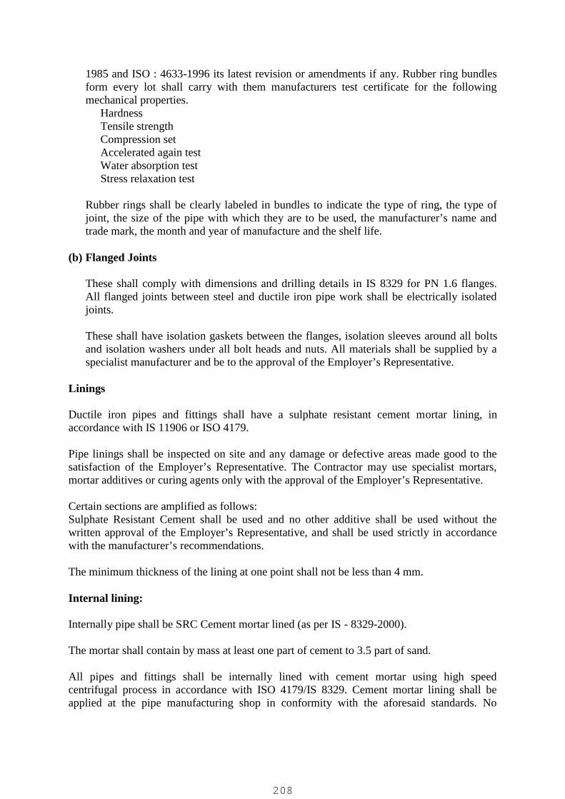
1985 and ISO : 4633-1996 its latest revision or amendments if any. Rubber ring bundlesform every lot shall carry with them manufacturers test certificate for the followingmechanical properties.�Hardness�Tensile strength�Compression set�Accelerated again test�Water absorption test�Stress relaxation test
Rubber rings shall be clearly labeled in bundles to indicate the type of ring, the type ofjoint, the size of the pipe with which they are to be used, the manufacturer’s name andtrade mark, the month and year of manufacture and the shelf life.
(b) Flanged Joints
These shall comply with dimensions and drilling details in IS 8329 for PN 1.6 flanges.All flanged joints between steel and ductile iron pipe work shall be electrically isolatedjoints.
These shall have isolation gaskets between the flanges, isolation sleeves around all boltsand isolation washers under all bolt heads and nuts. All materials shall be supplied by aspecialist manufacturer and be to the approval of the Employer’s Representative.
Linings
Ductile iron pipes and fittings shall have a sulphate resistant cement mortar lining, inaccordance with IS 11906 or ISO 4179.
Pipe linings shall be inspected on site and any damage or defective areas made good to thesatisfaction of the Employer’s Representative. The Contractor may use specialist mortars,mortar additives or curing agents only with the approval of the Employer’s Representative.
Certain sections are amplified as follows:Sulphate Resistant Cement shall be used and no other additive shall be used without thewritten approval of the Employer’s Representative, and shall be used strictly in accordancewith the manufacturer’s recommendations.
The minimum thickness of the lining at one point shall not be less than 4 mm.
Internal lining:
Internally pipe shall be SRC Cement mortar lined (as per IS - 8329-2000).
The mortar shall contain by mass at least one part of cement to 3.5 part of sand.
All pipes and fittings shall be internally lined with cement mortar using high speedcentrifugal process in accordance with ISO 4179/IS 8329. Cement mortar lining shall beapplied at the pipe manufacturing shop in conformity with the aforesaid standards. No
208
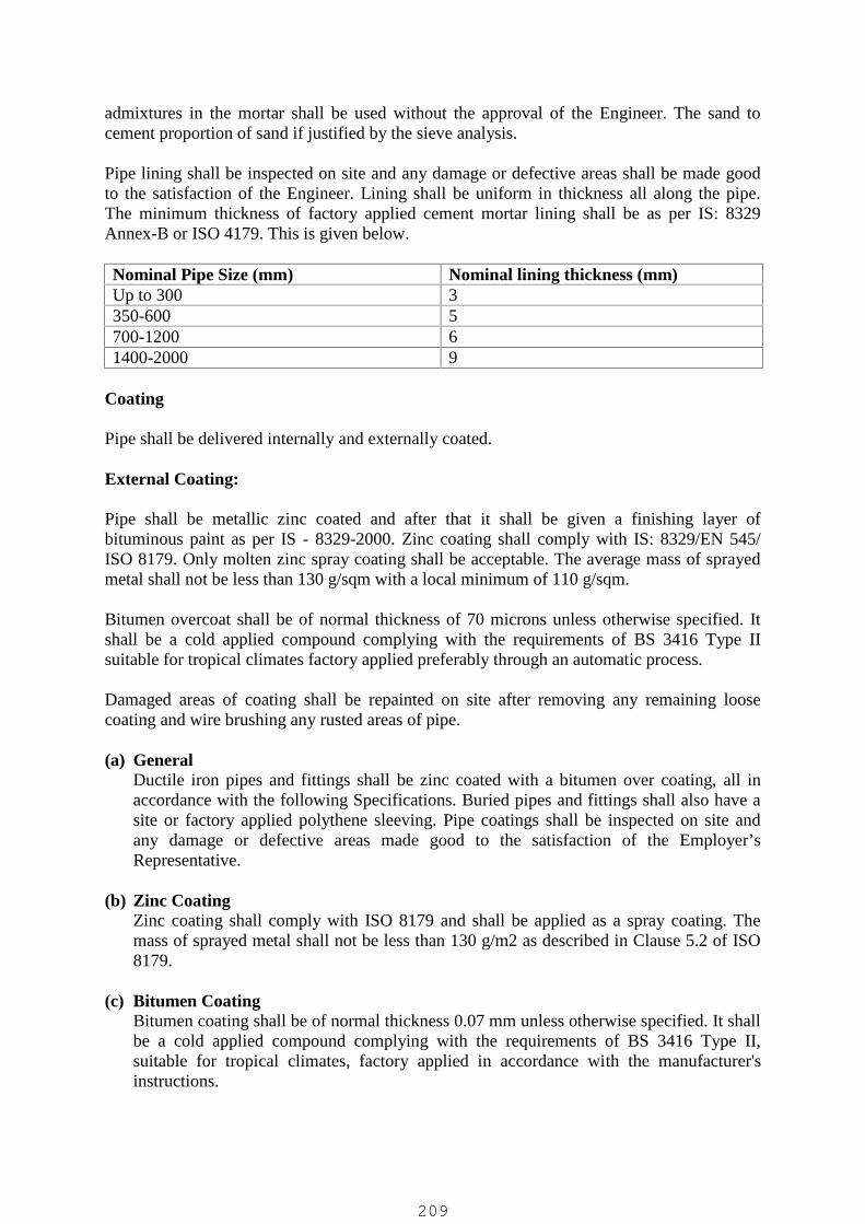
admixtures in the mortar shall be used without the approval of the Engineer. The sand tocement proportion of sand if justified by the sieve analysis.
Pipe lining shall be inspected on site and any damage or defective areas shall be made goodto the satisfaction of the Engineer. Lining shall be uniform in thickness all along the pipe.The minimum thickness of factory applied cement mortar lining shall be as per IS: 8329Annex-B or ISO 4179. This is given below.
Nominal Pipe Size (mm) Nominal lining thickness (mm)Up to 300 3350-600 5700-1200 61400-2000 9
Coating
Pipe shall be delivered internally and externally coated.
External Coating:
Pipe shall be metallic zinc coated and after that it shall be given a finishing layer ofbituminous paint as per IS - 8329-2000. Zinc coating shall comply with IS: 8329/EN 545/ISO 8179. Only molten zinc spray coating shall be acceptable. The average mass of sprayedmetal shall not be less than 130 g/sqm with a local minimum of 110 g/sqm.
Bitumen overcoat shall be of normal thickness of 70 microns unless otherwise specified. Itshall be a cold applied compound complying with the requirements of BS 3416 Type IIsuitable for tropical climates factory applied preferably through an automatic process.
Damaged areas of coating shall be repainted on site after removing any remaining loosecoating and wire brushing any rusted areas of pipe.
(a) GeneralDuctile iron pipes and fittings shall be zinc coated with a bitumen over coating, all inaccordance with the following Specifications. Buried pipes and fittings shall also have asite or factory applied polythene sleeving. Pipe coatings shall be inspected on site andany damage or defective areas made good to the satisfaction of the Employer’sRepresentative.
(b) Zinc CoatingZinc coating shall comply with ISO 8179 and shall be applied as a spray coating. Themass of sprayed metal shall not be less than 130 g/m2 as described in Clause 5.2 of ISO8179.
(c) Bitumen CoatingBitumen coating shall be of normal thickness 0.07 mm unless otherwise specified. It shallbe a cold applied compound complying with the requirements of BS 3416 Type II,suitable for tropical climates, factory applied in accordance with the manufacturer'sinstructions.
209

Damaged areas of coating shall be repainted on site after removing any remaining loosecoating and wire brushing any rusted areas of pipe.
(d) Polythene Sleeving
Where polythene sleeving is specified to be applied in addition to bitumen coating it shallcomply with ISO 8180. Site applied sleeving shall be stored under cover, out of directsunlight, and its exposure to sunlight shall be kept to a minimum. Pipes having a factoryapplied sleeving must be stored in the same conditions.
CEMENT CONCRETE PIPES:
Design
Design of Cement Concrete pipes including reinforcement details and the ends of pipes shallbe in accordance with the relevant clauses of IS: 458:2003
Manufacturing
(a) General
The method of manufacture shall be such that the form and the dimensions of the finishedpipes are accurate within the limits specified in relevant clause of IS: 458.
The surfaces and edges of the pipes shall be well defined and true, and their ends shall besquare with the longitudinal axis. The ends of the pipes shall be further reinforced by an extraring of reinforcement to avoid breakage during transportation.
The RCC pipes and rubber rings shall be systematically checked for any manufacturingdefects by experienced supervisors so as to maintain a high standard of quality.
The Employer’s Representative shall at all reasonable times have free access to the placewhere the pipes and collars/rubber rings are manufactured for the purpose of examining andtesting the pipes and collars/ rubber rings and of witnessing the test and manufacturing.
All tests specified either in this Employer’s Requirements or in the relevant Indian standardsshall be performed by the supplier/contractor at his own cost and in presence of theEmployer’s Representative if desired. For this, sufficient notice before testing of the pipesand fittings shall be given to the Employer’s Representative.
If the test is found unsatisfactory, the Employer’s Representative may reject any or all pipesof that lot. The decision of the Employer’s Representative in this matter shall be final andbinding on Contractor and not subject to any arbitration or appeal.
(b) Materials
(i) CementCement used for the manufacture of RCC pipes and collars shall conform to relevant IScodes. The use of pozzolana as an admixture to Portland cement shall not be permitted.
210
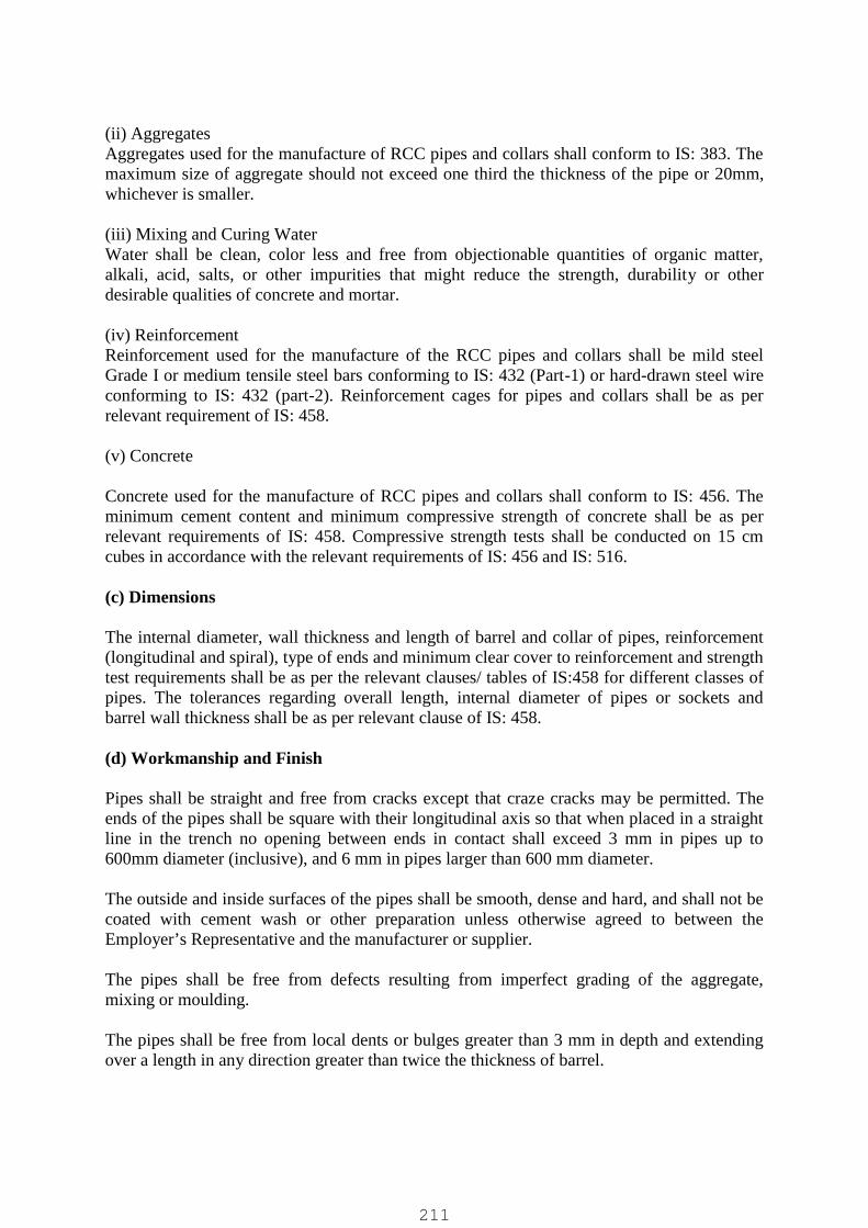
(ii) AggregatesAggregates used for the manufacture of RCC pipes and collars shall conform to IS: 383. Themaximum size of aggregate should not exceed one third the thickness of the pipe or 20mm,whichever is smaller.
(iii) Mixing and Curing WaterWater shall be clean, color less and free from objectionable quantities of organic matter,alkali, acid, salts, or other impurities that might reduce the strength, durability or otherdesirable qualities of concrete and mortar.
(iv) ReinforcementReinforcement used for the manufacture of the RCC pipes and collars shall be mild steelGrade I or medium tensile steel bars conforming to IS: 432 (Part-1) or hard-drawn steel wireconforming to IS: 432 (part-2). Reinforcement cages for pipes and collars shall be as perrelevant requirement of IS: 458.
(v) Concrete
Concrete used for the manufacture of RCC pipes and collars shall conform to IS: 456. Theminimum cement content and minimum compressive strength of concrete shall be as perrelevant requirements of IS: 458. Compressive strength tests shall be conducted on 15 cmcubes in accordance with the relevant requirements of IS: 456 and IS: 516.
(c) Dimensions
The internal diameter, wall thickness and length of barrel and collar of pipes, reinforcement(longitudinal and spiral), type of ends and minimum clear cover to reinforcement and strengthtest requirements shall be as per the relevant clauses/ tables of IS:458 for different classes ofpipes. The tolerances regarding overall length, internal diameter of pipes or sockets andbarrel wall thickness shall be as per relevant clause of IS: 458.
(d) Workmanship and Finish
Pipes shall be straight and free from cracks except that craze cracks may be permitted. Theends of the pipes shall be square with their longitudinal axis so that when placed in a straightline in the trench no opening between ends in contact shall exceed 3 mm in pipes up to600mm diameter (inclusive), and 6 mm in pipes larger than 600 mm diameter.
The outside and inside surfaces of the pipes shall be smooth, dense and hard, and shall not becoated with cement wash or other preparation unless otherwise agreed to between theEmployer’s Representative and the manufacturer or supplier.
The pipes shall be free from defects resulting from imperfect grading of the aggregate,mixing or moulding.
The pipes shall be free from local dents or bulges greater than 3 mm in depth and extendingover a length in any direction greater than twice the thickness of barrel.
211
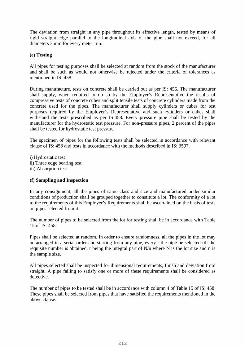
The deviation from straight in any pipe throughout its effective length, tested by means ofrigid straight edge parallel to the longitudinal axis of the pipe shall not exceed, for alldiameters 3 mm for every meter run.
(e) Testing
All pipes for testing purposes shall be selected at random from the stock of the manufacturerand shall be such as would not otherwise be rejected under the criteria of tolerances asmentioned in IS: 458.
During manufacture, tests on concrete shall be carried out as per IS: 456. The manufacturershall supply, when required to do so by the Employer’s Representative the results ofcompressive tests of concrete cubes and split tensile tests of concrete cylinders made from theconcrete used for the pipes. The manufacturer shall supply cylinders or cubes for testpurposes required by the Employer’s Representative and such cylinders or cubes shallwithstand the tests prescribed as per IS:458. Every pressure pipe shall be tested by themanufacturer for the hydrostatic test pressure. For non-pressure pipes, 2 percent of the pipesshall be tested for hydrostatic test pressure.
The specimen of pipes for the following tests shall be selected in accordance with relevantclause of IS: 458 and tests in accordance with the methods described in IS: 3597.
i) Hydrostatic testii) Three edge bearing testiii) Absorption test
(f) Sampling and Inspection
In any consignment, all the pipes of same class and size and manufactured under similarconditions of production shall be grouped together to constitute a lot. The conformity of a lotto the requirements of this Employer’s Requirements shall be ascertained on the basis of testson pipes selected from it.
The number of pipes to be selected from the lot for testing shall be in accordance with Table15 of IS: 458.
Pipes shall be selected at random. In order to ensure randomness, all the pipes in the lot maybe arranged in a serial order and starting from any pipe, every r the pipe be selected till therequisite number is obtained, r being the integral part of N/n where N is the lot size and n isthe sample size.
All pipes selected shall be inspected for dimensional requirements, finish and deviation fromstraight. A pipe failing to satisfy one or more of these requirements shall be considered asdefective.
The number of pipes to be tested shall be in accordance with column 4 of Table 15 of IS: 458.These pipes shall be selected from pipes that have satisfied the requirements mentioned in theabove clause.
212

A lot shall be considered as conforming to the requirements of IS: 458 if the followingconditions are satisfied.
The number of defective pipes shall not be more than the permissible number given incolumn 3 of Table 15 of IS: 458.
All the pipes tested for various tests shall satisfy corresponding requirements of the tests.
In case the number of pipes not satisfying requirements of any one or more tests, one or twofurther samples of same size shall be selected and tested for the test or tests in which thefailure has occurred. All these pipes shall satisfy the corresponding requirements of the test.
(g) Marking
The following information shall be clearly marked on each pipe :
a) Internal diameter of pipeb) Class of pipec) Date of manufacture andd) Name of manufacturer or his registered trade-mark or both.
Jointing
(h) General
Jointing of RCC pipes shall be done as per the following Employer’s Requirements and asper the relevant IS. After jointing, extraneous material, if any, shall be removed from theinside of the pipe and the newly made joints shall be thoroughly cured. In case, rubber sealingrings are used for jointing, these shall conform to IS: 5382.
(i) Spigot and Socket joint (Rigid)
The spigot of each pipe shall be slipped home well into the socket of the pipe previously laidand adjusted in the correct position. The opening of the joint shall be filled with stiff mixtureof cement mortar which shall be rammed with caulking tool. This joint is used for lowpressure pipe line.
(j) Collar Joint (Rigid)
After laying the RCC pipes at proper alignment and gradient their abutting faces shall becoated with hot bitumen in liquid condition by means of a brush. The wedge-shaped groovein the end of the pipe shall then be filled with a tarred gasket in one length for each joint. Thecollar shall then be slipped over the end of the pipe and the next pipe butted well against thetarred gasket by suitable appliances approved by the Employer’s Representative so as tothoroughly compress the tarred gasket into the grooves, care being taken that theconcentricity of the pipes and levels are not disturbed during this operation. The collar shallthen be place symmetrically over the end of the two pipes and the space between the inside ofthe collar and the outside of the pipe filled with a mixture of cement and sand, tempered withjust sufficient water to have a consistency of the semi-dry conditions, well packed andthoroughly rammed with caulking tools. The joints shall be finished off with a fillet sloping at450 to the side of the pipe. The finished joints shall be protected and cured thoroughly as
213

directed by the Employer’s Representative. Any plastic solution or cement mortar that mayhave been squeezed into the inside of the pipe shall be removed so as to leave the inside ofthe pipe perfectly clean.
(k) Flush Joint (Internal)
This joint shall be generally used for culvert pipes of 900 mm diameter and over.The ends of the pipes are specially shaped to form a self centering joint with an internaljointing space 13 mm wide. The finished joint is flush with both inside and outside with thepipe wall. The jointing space is filled with cement mortar mixed sufficiently dry to remain inposition when forced with a trowel or rammer.
(l) Flush Joint (External)
This joint is suitable for pipes which are too small for jointing from inside. This joint iscomposed of specially shaped pipe ends. Each end shall be butted against each other andadjusted in correct position. The jointing space shall then be filled with cement mortarsufficiently dry and finished off flush. Great care shall be taken to ensure that the projectingends are not damaged as no repairs can be readily affected from inside the pipe.
(m) Spigot and Socket (Semi-flexible)
This joint is composed of specially shaped spigot and socket ends on the RCC pipes.A rubber ring shall be lubricated and then placed on the spigot which is forced into the socketof the pipe previously laid. This compresses the rubber ring as it rolls in to the annular spaceformed between the two surfaces of the spigot and socket, stiff mixture of cement and mortarshall then be filled into the remaining annular space with a caulking tool.
(n) Collar Joint (Semi-Flexible)
This joint is made up of a loose collar which covers two specially shaped pipe ends.Each end shall be fitted with a rubber ring which when compressed between the spigot andcollar, seals the joint. Stiff mixture of cement mortar shall then be filled into the remainingannular space and rammed with a caulking tool.
(o) Spigot and Socket Joint (Flexible)
The RCC pipe with the rubber ring accurately positioned on the spigot shall be pushed wellhome into the socket of the previously laid pipe by means of uniformly applied pressure withthe aid of a jack or similar appliance. The RCC pipes shall be of spigot and socket type andrubber rings shall be used, and the manufacturer’s instructions shall be deemed to form a partof these Employer’s Requirements. The rubber rings shall be lubricated before making thejoint and the lubricant shall be soft soap water or an approved lubricant supplied by themanufacturer.
Cleaning of Pipes
As soon as a stretch of RCC pipes has been laid complete from manhole to manhole or for astretch as directed by the Employer’s Representative, Contractor shall run through the pipesboth backwards and forwards a double disc or solid or closed cylinder 75 mm less in diameter
214

than the internal diameter of pipes. The open end of an incomplete stretch of pipe line shallbe securely closed as may be directed by the Employer’s Representative to prevent entry ofmud or silt etc.
If as a result of the removal of any obstructions the Employer’s Representative considers thatdamages may have been caused to the pipe lines, he shall be entitled to order the stretch to betested immediately. Should such test prove unsatisfactory, contractor shall amend the workand carry out such further tests as are required by the Employer’s Representative.
It shall also be ascertained by contractor that each stretch from manhole to manhole or thestretch as directed by Employer’s Representative is absolutely clear and without anyobstruction by means of visual examination of the interior of the pipe line suitablyenlightened by projected sunlight or otherwise.
Testing at work site
After laying and jointing of RCC pipes is completed the pipe line shall be tested at work siteas per the following Employer’s Requirements and as directed by the Employer’sRepresentative. All equipment for testing at work site shall be supplied and erected bycontractor. Water for testing of pipes shall be arranged by him. Damage during testing shallbe contractor's responsibility and shall be rectified by him to full satisfaction of theEmployer’s Representative. Water used for the test shall be removed from pipes and notreleased to the excavated trenches.
After the joints have thoroughly set and have been checked by the Employer’s Representativeand before back filling the trenches, the entire section of the sewer or storm water drain shallbe proved by the contractor to be water tight by filling in pipes with water to the level of1.50m above the top of the highest pipe in the stretch and heading the water up for a period ofone hour. The apparatus used for the purpose of testing shall be approved by the Employer’sRepresentative. Contractor if required by the Employer’s Representative shall dewater theexcavated pit and keep it dry during the period of testing. The loss of water over a period of30 minutes should be measured by adding water from a measuring vessel at regular 10minutes intervals and noting the quantity required to maintain the original water level. For theapproval of this test the average quantity added should not exceed 1 liter/ hour/100 linearmeters/ 10mm of nominal internal diameter. Any leakage including excessive sweating whichcauses a drop in the test water level will be visible and the defective part of the work shouldbe removed and made good.
In case of pressure pipeline, the completed stretch of pipeline shall be tested for site testpressure. The site test pressure should not be less than the maximum operating pressure plusthe calculated surge pressure, but in no case should it exceed the hydrostatic test pressure asspecified in IS: 458.
Support of Pipe work and Accessories
All necessary supports, saddles, slings, fixing bolts and foundation bolts shall be supplied tosupport the pipe work and its associated equipment in an approved manner. Valve, meters,strainers, and other devices mounted in the pipe work shall be supported independently of thepipes to which they connect.
215
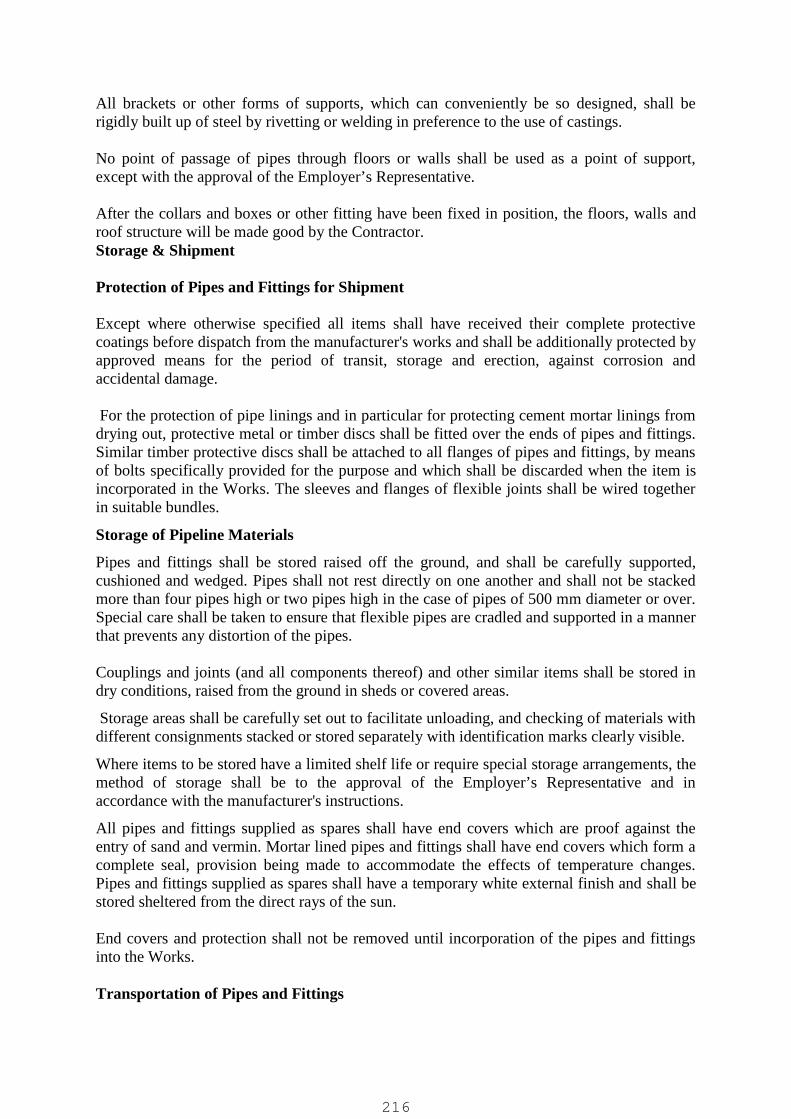
All brackets or other forms of supports, which can conveniently be so designed, shall berigidly built up of steel by rivetting or welding in preference to the use of castings.
No point of passage of pipes through floors or walls shall be used as a point of support,except with the approval of the Employer’s Representative.
After the collars and boxes or other fitting have been fixed in position, the floors, walls androof structure will be made good by the Contractor.Storage & Shipment
Protection of Pipes and Fittings for Shipment
Except where otherwise specified all items shall have received their complete protectivecoatings before dispatch from the manufacturer's works and shall be additionally protected byapproved means for the period of transit, storage and erection, against corrosion andaccidental damage.
For the protection of pipe linings and in particular for protecting cement mortar linings fromdrying out, protective metal or timber discs shall be fitted over the ends of pipes and fittings.Similar timber protective discs shall be attached to all flanges of pipes and fittings, by meansof bolts specifically provided for the purpose and which shall be discarded when the item isincorporated in the Works. The sleeves and flanges of flexible joints shall be wired togetherin suitable bundles.
Storage of Pipeline Materials
Pipes and fittings shall be stored raised off the ground, and shall be carefully supported,cushioned and wedged. Pipes shall not rest directly on one another and shall not be stackedmore than four pipes high or two pipes high in the case of pipes of 500 mm diameter or over.Special care shall be taken to ensure that flexible pipes are cradled and supported in a mannerthat prevents any distortion of the pipes.
Couplings and joints (and all components thereof) and other similar items shall be stored indry conditions, raised from the ground in sheds or covered areas.
Storage areas shall be carefully set out to facilitate unloading, and checking of materials withdifferent consignments stacked or stored separately with identification marks clearly visible.
Where items to be stored have a limited shelf life or require special storage arrangements, themethod of storage shall be to the approval of the Employer’s Representative and inaccordance with the manufacturer's instructions.
All pipes and fittings supplied as spares shall have end covers which are proof against theentry of sand and vermin. Mortar lined pipes and fittings shall have end covers which form acomplete seal, provision being made to accommodate the effects of temperature changes.Pipes and fittings supplied as spares shall have a temporary white external finish and shall bestored sheltered from the direct rays of the sun.
End covers and protection shall not be removed until incorporation of the pipes and fittingsinto the Works.
Transportation of Pipes and Fittings
216

Any vehicle on which pipes are transported shall have a body of such length that the pipes donot overhang. Large pipes shall be placed on cradles and the loads properly secured duringtransit. The pipes shall be handled in accordance with the manufacturer's recommendations.
Approved slings shall be used and all hooks and dogs and other metal devices shall be wellpadded. Hooks engaged on the inner wall surface at pipe ends shall not be used. Steadyingropes shall be employed. The positions of lifting slings shall ensure that stresses and tendencytowards deformation in the pipes are kept at a minimum.
Pipe handling equipment shall be maintained in good repair and any equipment which in theopinion of the Employer’s Representative may cause damage to the pipes shall be discarded.
Under no circumstances shall pipes be dropped, be allowed to strike one other, be rolledfreely or dragged along the ground.
Inspection of Pipes and Fittings
Before incorporating into the Works each pipe shall be brushed out and carefully examinedfor soundless. Damaged pipes which in the opinion of the Employer’s Representative cannotbe satisfactorily repaired, shall be rejected and removed from Site. Damage to pipe coatingsor linings shall be repaired to the satisfaction of the Employer’s representative.
Built-in Pipe work and other Plant
The pipes and other Plant in water retaining structures shall, wherever possible, be built in asthe work on the structure proceeds. The Contractor shall ensure that delivery of the requisitepipe work and other Plant is in accordance with the requirements of the programme.
Where a pipe subject to thrust passes through a concrete structure or where an external seal isrequired, a puddle flange shall be used. The puddle flange dimensions shall be to BS 4504 butshall be undrilled. The exterior of the pipe shall be cement washed symmetrically about thepuddle flange by the manufacturer for a length at least equivalent to the thickness of the wallthrough which it passes.
The Contractor shall be responsible through every stage of the Works for checking thecorrectness of the setting of built-in Plant and shall satisfy himself they are positioned inaccordance with his approved drawings.
Unplasticised PVC Pipes and Fittings
Unplasticised polyvinyl chloride pipes, fittings and specials shall be to BS 3505 for potablewater and BS 4346: Part 1 for fittings. The pipes shall be of the spigot and socket type withapproved gasket type flexible joint. The rubber gaskets shall be to BS 2494, Class C. WherePVC pipes, fittings and specials are to be connected to cast iron, stainless steel or steel pipes,‘Viking Johnson’ type flange adaptors or stepped couplings shall be used.
217

Rubber Hosing
Rubber hosing shall conform to BS 5119, Type 2. It shall be capable of handling a workingpressure of 12 bars.
HDPE pipeline
The item shall be covering manufacturing, supplying, and delivery of HDPE pipes havingpressure rating PN-10 & material grade PE – 80 / PE – 100 bearing IS 4984/1995 and itslatest version or amendments. The HDPE pipes shall be supply in standard length or as perowner's requirements.
Standard:
The HDPE pipes is to be procured, supplied under the scope of this item and which shall bemeet the requirement of pressure rating of PN 6 / PN 10 and material grade PE-80 / PE-100in accordance and confirming to IS:4984/1995 or its latest version or amendments with IScertification mark.
Temperature Variation:
All the pipes to be supplied and delivered shall be subject to weather condition like sun, dust,rain, wind as available in the state of Rajasthan. They shall also be subject to carry andconvey drinking water under available temperature condition ranging from 4 Deg. Centigradeto 40 Deg. Centigrade.
Marking:
The method of marking to all the pipes to be used under the scope of contract shall ensurethat all the information as mentioned in clause 10 of IS: 4984/1995 and/or its latestamendments. The marking will remain legible even after transportation, storage in open spaceetc. In general the legible and indelible marking upon the pipes shall indicate the following:
a) Manufacturer's name or trade mark.b) Grade of material.c) Class of pipes and pressure rating.d) Nominal diameter.e) Lot number / Batch number of manufacturer.f) ISI certification Mark.Any other important matter that the manufacturer of purchaser deems fit to be inscibed.
Push fit joints shall be used for joining of pipes. These fittings shall carry the necessaryinternational approvals for leak proof jointing.
100 % virgin material only shall be used and no rework/recycled material is to be used for theproduction of pipes.
INSPECTION OF JOINTS:
218
The visual inspection of each joint should be done to ensure correct bead formation. Weldjoint should be checked for axial alignment of welded pipes.
SPECIFICATIONS FOR UPVC PIPESuPVC pipes made of unplasticized polyvinyl chloride shall be confirming to IS: 15328 withsocket(s) suitable for elastomeric sealing ring type joints for conveyance of water underpressure. The pipes are intended to be used for buried water mains with ambient atmospherictemperature reaching up to 45 °C and soil surface temperature rising more than 65°C. Thestipulations given in this document for uPVC pipe which are not covered by any othercode/standard, shall be governed by the provisions of IS 4985. The pipes will be suppliedwith plain ends or one end plain with chamfer and other end socket suitable for elastomericsealing ring type joints in accordance with IS: 4985 as per requirement. Each pipe shall besupplied along with one suitable elastomeric sealing ring with 5% extra rings on overallnumber of pipes.
MaterialThe material from which the pipes are made shall consist substantially of unplasticizedpolyvinyl chloride conforming to IS: 10151, to which may be added only those additives thatare absolutely needed to facilitate the manufacture of the polymer, and the production ofsound, durable pipes of good surface, finish, mechanical strength and opacity. The pressurerating of pipes shall be of class-3 and class-4 in accordance with IS: 4985 with a maximumcontinuous working pressure at 27°C of 6 and 10 kg/cm2.
Dimensions of the pipes and the socketsThe dimensions and tolerances of pipes shall comply with IS: 4985. The tolerance on outsidediameter and wall thickness of pipe shall be as per Table given in IS: 4985. The dimensionsof the socket for elastomeric sealing ring type joint shall be in accordance with IS 4985. Thepipe shall be supplied in straight lengths of 6 m with tolerance of + 20 mm and -0 mm. Theeffective length of socket pipe shall be considered as shown in IS: 4985.
Physical & chemical propertiesThe pipe shall confirm to the Clause 10 of IS 4985-2000 for its physical and chemicalproperties except for the density and ash content provisions which shall be as per thestipulations made above. The colour of the pipes shall be dark grey. Influence on waterintended for human consumption shall be governed by IS: 12235. All plastic and non-plasticmaterial for components of the uPVC piping system e. g. Elastomeric sealing ring, lubricants,when in permanent or in temporary contact with water which is intended for humanconsumption, shall not adversely affect the quality of the drinking water.
Mechanical propertiesThe pipes and integral sealing ring will confirm to internal hydrostatic pressure in accordancewith Clause 11.1 and sampling as per annexure D of IS 4985.
Inspection:The pipes shall be offered for factory inspection and performance testing as per relevantstandard if required by Purchaser / client / client’s consultant.
CARBON STEEL PIPING:
219
Providing and laying C.S. pipes confirming to IS: 1239 and IS: 3589 with latest amendmentswith all necessary fittings, specials, tees, bends etc. as required and as per the direction ofEngineer-in-charge.
Material:
Material shall confirm to IS-1239/latest amendments and IS-3589/ latest amendments. Thepipes up to 6" shall confirm to IS-1239 with latest amendments and should be heavy duty.The pipes of 8" and above shall confirm to IS-3589/ latest amendments and designation ofsteel grades applicable shall be Fe410 heavy duty .
Lowering:
The pipes shall be lowered cautiously to prevent distance of the bed and sides of the trench.The heavy pipes shall be lowered by means of proper shear legs, chain pulley or as directedby Engineer-in-charge.
Fabrication:
Layout, cutting and fitting-up:
(i) Templates shall be used in laying out headers, laterals and other irregular detailsto ensure accurate cutting and proper fit-up.
(ii) Machine cut bevels to form the welding groove are preferred, out smooth, clean,slag-free flame cut bevels are acceptable.
(iii) In fitting up details preparatory to final welding, spares shall be used while tackwelding the pipe and connections in position so that a proper gap is made for fullpenetration of welds. The following are the recommended gaps:
For pipe size below 150 mm -1.5 mm weld gap.For pipe size 150 mm (inclusive)-3.0 mm weld and above gap.
(iv) Only small tack welds which penetrate to the bottom of the welding groove shallbe used and shall become a part of the finished weld. Tack welds lackingpenetration are not acceptable and must be chipped out. Each weld shall becleaned of all scale, slag, flux and other foreign matter before additional weldingbeads are applied.
(v) In general, permanently, welded-in rings shall not be used. If back-up rangsshould be necessary or desirable, they may be used only upon specified approvalof Engineer-in-charge.
Bending:
(i) Complete bends shall have smooth surface and shall be free of flat spots andcorrugations.
(ii) Fabricated pipe:Hot bending, shall be done with the pipe filled with temped sand. Following thebending operation, the bend shall be allowed to cool slowly in still air before the
220

sand is removed. The minimum radius shall be six times the nominal pipediameter.
Welding:
(i) Welders and welding procedures shall be qualified in accordance with therequirement of the code and IS: 817-1966. Horizontal and/or vertical weldingqualifications shall be shown on qualification papers.
(ii) All welding shall have full thickness penetration and shall be done by Electric ArcProcess. Gas welding may be used with Engineer’s approval.
(iii) In multiple pass welding the slag shall be cleaned from each layer and any seriousdefects chipped out before the next layer is applied. Peening shall be done ifnecessary to prepare a bead for the next phase.
(iv) The completed weld shall be cleaned out slag and spatter metal on all surfaces,and when possible the inside bead shall be ground smooth.
(v) No undercutting of pipe adjacent to the completed weld will be permitted.(vi) Finished welds shall project not less than 1.5 mm but not more than 3 mm from
the outer surface of the pipe.Laying:
The pipe shall be secured in place with approved back fill material tamped under it expect atthe end. Pipe and fittings which do not allow sufficient and uniform space for joints shall beremoved and replaces with pipe and fittings of proper dimensions to ensure such space.Precautions shall be taken to prevent dirt from entering the joint space.
At times when pipe laying is not in progress, the open ends of pipe shall be closed by awatertight plug or other means approved by the Authority.
Joining:
Flange faces shall be in a plane perpendicular, true and square to the centre line of the pipe towhich they are welded.
Wherever screwed flanges are used the pipe shall extend to within 1.5 mm to 3 mm of theface of the flanges but not beyond.The jointing material used between flanges of pipes shall be compressed fibre board or rubber[See IS: 638-1955] of thickness between 1.5 mm to 3.0 mm.
MS SPIRALLY WELDED PIPES:
Providing, Manufacturing, supplying, lowering and laying in position sleeve / swagedended, outer coated, spirally weld M.S. pipes confirming to I . S. 2062 : 1992 includingall type of necessary , coping, welding, outer coating treatment with corrosion chlorideresistant treatment of “ corrocretive te “ or 4 mm thick pipe coat, inner lining, safeguarding, lightening, barricading, fencing, field welding and hydraulic test as per thedetailed item specification and as per the direction of Engineer – in – charge.
Material:
221

I. Spirally submerged arc Welding Pipes shall be manufactured from steel produced bythe open hearth or electric or one of the basic oxygen process. The designation of steelgrades applicable shall be Fe410 as specified in Table-1 of IS .
II. Steel to be used in Manufacture of spiral welded pipe shall be conforming to IS :2062 : 1992 and to its latest amendments also. Steel should be of Grade – B, designatedas Fe 410 in IS:2062 – 1992.
III. Sampling of pipes shall be as per IS: 4711: 1994.
Manufacture:
The pipes shall be manufactured from steel strips by spirally submerged arc welding.The weld must be automatic and continuous. All the edges of the Plates / strips should beprepared suitable prior to the welding of pipes. Welding joints and its manufacturingprocess shall conform to IS : 3589 :2001.
Length:
The Client intends a speedy as well as easy laying work of the pipes procured throughthis tender. Accordingly, spiral welding pipes of all the sizes shall be supplied insingle random lengths form 5.50 mt. to 6.50 mt. Pipes in such lengths shall be 90% ofthe total quantity. Remaining 10% (Max.) pipes of the ordered quantity may have alength 10% shorter / longer in Rmts. To the length specified above.
Wall Thickness:
Wall thickness shall be as per IS : 3589 : 2001 without negative tolerance.
Finished pipes shall not deviate from straightness by more than 0.1% of the totallength. Straightness shall be checked out by using a taut string or wire from end toend, along the side of the pipe to measure, the greatest deviation.
Hydraulic Pressure Test:
Each and every pipe shall be hydraulically tested at the manufacturer’s work at a testpressure of 1.7 MPa. Testing shall be carried out as specified in IS : 3589 : 2001.
Mechanical Test:
I. Tensile Test:
Tensile test shall be carried out as mentioned in IS : 1894 : 1972 as well as IS : 3589 :2001. The tensile strength & Percentage elongation of the pipes shall strictly conformto the provision of IS : 3589 :2001. The Manufacturer shall submit the required testcertificates at free of cost, both for the pipes as well as steel strips also.
II. Guided Bend Test:
Guided Bend Test shall be carried out as per the provisions of IS : 3589 : 2001 andnecessary test at free if cost.
222

Other Test:Radiographic testing or Ultrasonic testing in factory (15% of welded length of each pipe) asper IS:3589-2001.
Chemical Composition:
As mentioned earlier the steel used for manufacturing shall strictly conform to IS :2062 : 1992 having designation of the grade of pipe steel grade Fe 410. Chemicalcomposition should be conforming to Is :2062 : 1992 and various constituents viz.Carbon, Manganese, sulphur, Phosphorus, Silicon, copper etc. shall be within prescribedpermissible limits. The manufacturer shall submit the required test certificates at freeof cost, both for the pipes as well as steel strips also.
Pipe Ends:
I. All the pipes shall have one end swelled and one end plain suitable for fieldwelding. Both the edges of each pipe must be truly vertical. The swelled end shall beformed, strictly as per the dimensions mentioned in IS: 3589: 2001.
II. The sleeve/swelled end of the pipes shall be formed in such a way that the plainend of the pipe shall be inserted inside freely / easily.
Mass:
The mass of steel shall be 7.85 g/cm3.
Workmanship:
I. All the pipes shall be clearly finished and when visually inspected shall be free fromdefects such as cracks, surface flaws, lamination etc. The ends of the pipes shall becleanly cut as mentioned in 7.0 and truly vertical with the axis of the pipe.
II. The copy of the ISI License for manufacture of pipes for the particular unit fromwhere the pipes will be manufactured shall also be submitted.
III. Owner intends to utilize the pipes with two coats of red Oxide as anti-corrosiveprimer. The pipes shall be supplied Oxide to avoid corrosion during monsoon period,the anti – corrosive primer shall be applied to the inside and other side of the pipes.
Marking:
Each pipe shall be legibly marked at free of cost with the following details.(a) Manufacturer’s name or trade – mark.(b) Outside diameter in mm.(c) Wall thickness in mm.(d) ISI mark.(e) Purchaser’s Name(f) Last two digits of the year of Manufacture.
FIELD WELDING:
223

The welding and joint of the pipes in the field shall comply with I.S.816 – 1965 or itslatest amendments.
The weld shall be run in three runs of welding. The welding and testing of the weld shall alsobe done as per the procedure laid down in I.S.: 823 - 1964 or it’s latest amendments.Experienced welders whose performance shall be tested from time to time, shall only bepermitted to carry out the welding work. No apprentices or helpers shall be allowed to do anywelding work, No apprentices or helpers shall be allowed to do any welding whatsoever. Ifany un authorised person is found to do welding work, he shall be removed from the workand the work carried out by him will have to be redone after gauging out the same. Thefollowing points shall be borne in mind by the contractors.
ELECTRODES:
The contractors shall use standard electrodes its number (i.e. type) depending on thethickness of plate and the type of joint, they shall also use standard current andvoltages required for the machine in use. Electrodes be of ESAB India, ADVANI andD&H only.
Electrodes to be used welding work shall conform to IS : 814 & 815 and welding shallconform to IS : 816 :822 and 823, The Electrodes must be of make “ESAB-INDIA”,“Advani”, “D&H” or “BOBSHELL” only.
TESTING OF WELDED JOINTS:
( i ) GENERAL :
The weld joints shall be tested in accordance with Indian Standard SpecificationI.S.823 – 1964 and I.S.:600 – 1973 or to its latest amendments.
The test pieces shall be taken out from the pipes pointed out by the Engineerwithout any delay. They shall be immediately delivered at the Engineer’s Office forbeing numbered, machined and tested.
The shape of the test pieces removed from the pipes shall be such that It will give aspecimen of the required dimension and at the same time leave a hole in the pipewith round corners. This hole shall be closed up by patch plating from the outside soas to have over lap of 3” on all sides of the opening Great care shall be taken inpreparing required M.S. Plates for this, is included in the item. After the jointing iscompleted, all protruding portions shall be chipped off, and the portion of the pipelinenear the field joint shall be thoroughly scrapped and cleaned to receive the guinite.
( ii ) DETAILS OF TESTS.
The following test shall be made.
TENSILE TEST:
The test specimen taken perpendicularly across the weld shall be shaped in accordancewith the I.S.S. No. 1663 – 1962. The specimen shall be taken from the end of the pipeor at any joint in the pipe as directed by the Engineer and shall be cut with the
224

weld approximately in the middle of the specimen. The tension test specimen shall bemachined. The protruding welding portions from both inside and outside shall beremoved by machining or grinding before the specimen is tested.
At least one field joint out of every 100 shall be subjected to test by taking out aspecimen. If a test specimen shows defective machining or taking out a specimen. If a testspecimen shows defective machining or develops flaws not associated with welding, itmay be discarded and another specimen substituted.
The weld joint shall show a strength not less than the minimum tensile strength specifiedfor the plate.
BEND TEST:
The bend test specimen shall be prepared in the same way as for tensile test andtested in the presence of the Engineer. The specimen shall be taken from the pipeselected for tensile test. The specimen shall stand being bent cold through 180 degreesaround a pin, the diameter of which is equal 4 ½ times the thickness of the platewithout developing cracks. In making the bend test be placed next to the pin.
OUTERCOATING:
Corrosion and chloride resistant treatment shall be carried out as specified below,
I. Prior to application of treatment, the pipe shall be made free from all mill scale, rust,foreign matters or any such materials must be removed from the pipe surface byuse of wire brush followed by sand blasting to “SA 2 ½ standard immediatelyprior to the application of priming coating.
II. In addition, metal surface should be free oil, grease, and other impurities which canimpair the adhesion.
In case of COROCRETIN_TE ( i.e. thixotropic two component resin system with modifiedamine harder) layer, outer coating shall be carried out as below.
Prior to application of treatment, the pipe shall be made free from all mill scale, rust,foreign matters or any such materials must be removed from the pipe surface by use ofwire brush followed by sand blasting to “SA 2 ½ standard immediately prior to theapplication of priming coating.
In addition, metal surface should be free from oil, grease, and other impurities which canimpair the adhesion.
Application:
I. Mix the individual components ( Component A & Component B )separatelyhomogeneity. Mix one part of component A and one part of component B by weightthoroughly, and apply using conventional brush, roller and spray.
II. Immediately after preparing surface by sand blasting apply one coat of CorocretineTE(S). Apply two more coats within the interval of 12 to 48 hours until the surfaceis completely free from pores.
225

Following care should be taken while application of this treatment.
i. Due care should be taken to prevent impurities and dampness on the surface in thetime between the every application of treatment coat.
ii. If longer time is anticipated between topcoat, then the existing coat should beroughened before fresh coating is applied.
iii. After application corocretin TE(S) should be protected from moisture (rain, dew, fog)for a period of 6-8 hours.
Consumption:
For one prior coating and two topcoat each of 80 micron ( total 240 micron) theconsumption of Corocretin TE(S) shall be 750 gm/sm.
a) Painting near expansion joints internally and external paintings of patch plates.
b) For curing, depth of 20 to 30 cm, of water be maintained in the flat portion of thepipeline to maintain adequate humidity in the pipe required for curing.
c) Carrying out performance test for ‘C’ value.Outer coating work, in case of “pypekot” Material shall be carried out as below.
1) All the mill scale, rust, foreign debries or any such material must be removed fromthe pipe surface by use of wire brush / power brush immediately prior to theapplication of primer on the surface of the pipe.
2) One coat of fiber coal tar and solvent based compatible primer of density ).92gm /cumt. and viscosity of 1000 to 2000 CPS at 150 gm /sqmt. shall be applied. The primer shallbe allowed to dry until the surface becomes tacky. The primer shall be applied to dry untilthe surface become tacky. The primer shall be allowed to dry until the surface becomes tacky.The primer shall be applied to dry until the surface becomes tacky. The primer shall beapplied in such a manner that it produces an effective bond between metal andsubsequent coating of the 4 mm thick polymeric tape.
3) Tape may be wound either circumferentially or spirally with using thermo fusionprocess to completely adhere with primer coated surface maintaining minimum 15 mmoverlaps to the two adjacent layers. Cost of overlap is included in the item and noextra payment shall be done for it.
4) Either end of the pipe shall be left uncoated to enable proper installation / laying aswell as field welding work. This area shall be coated in situ after the installation / layingand welding of the pipes in the trench. In case of any damage is occurred to the outercoating of the pipe during handling, laying and installation at any place of the surface,the rectification shall be done by patching up the damaged area by thermo fusion atno extra cost.
5) Holiday test as described in IS : 10221 shall be conducted at the cost of theContractor in the presence of an authorised representative of and if any fault / defect isfound, it shall be rectified at no extra cost.
226

INNER LINING:
This clause covers scope of material and application of cement mortar lining on theinside surface of the pipe line. The application of mortar lining covers lining ofstraight pipe sections, long, short radius bends, vertical shafts and all specials etc. thelining shall be carried out through an access by a machine that progress uniformlythrough an access by a machine that progress uniformly through the pipe and appliesmortar against the pipe surface and Mechanically trowels it to obtain smooth lining ofbends, specials and areas adjacent to valves shall be appropriately dealt with according tothe best practice of the trade for the diameter concerned. The Contractor should specify whatis the best practice and produce acceptable evidence therefore.
All access openings and feed openings or manhole for feeder hoses shall be re-weldedin position after lining them. The line will be restored to the satisfaction of the owner.
The scope further includes mobilization of equipment, making access openingswherever required and curing of the mortar lined pipe including testing. Patching accessholes, etc. as described in following pages.
The main items of work will be generally as follows.
a) Mobilisation of equipment, Plant and machinery.
b) Deciding access openings in the main and providing temporary access up toopenings wherever necessary.
c) Making trenches of suitable depth, width and length for making access openings incase of underground (U.G.) pipe including dewatering and refilling.
d) Breaking gunited/concreted surface ( if any ) of U,G, Pipe and cutting the topportion of pipe ( Under ground as well as above ground ) to provide for accessopening.
e) Provide necessary platform for installation of mixing machinery.
f) Remove and refix appurtenances, provide additional ventilation openings and plugs, ifrequired. Take suitable measures for adequate ventilation in case of U.G. Pipes.
g) Maintaining the pipe temperature between 50 degree F and 90 degree F.
h) Cleaning the pipe surface internally.
i) Mortar lining the internal surface of the pipe lines.
j) Curing the mortar lining.
k) Inspection and testing of mortar lining.
227

l) Hand lining with cement mortar for top and bottom portion of pipe removed foraccess opening. While at enter side it should be coated with 4 mm thick. Thermo fusiblepolymeric corrosion protection tape called “PYPE COAT” conforming to IS: 10221.
General cement mortar lining design
a) COMPOSITION:
Mortar for the lining shall be composed of cement, sand and water that have been wellmixed and are of such consistency as to produce a dense, homogenous lining. Unlessotherwise specified by the Owner, the mortar may also include admixtures.
b) PROPORTIONS:
The approximate proportions of cement and sand in the mortar for the mortar for thelining shall be 1 part of Portland cement to 1 part of sand by volume.
The exact proportions shall be determined by the characteristics of the sand used.Admixtures, if added, shall be used in strict compliance with the Manufacturersrecommendation.
The Contractor should specifically state as to the cement proportion to use havingregard to his experience (to be stated) and the practice or specifications his principlefollow generally and recommend in this particular case.
c) WATER CONTENT:
The water content shall be the minimum quantity that produces a workable mixture,with full allowances made for moisture collecting on the interior of the pipe surfaces.Slump tests should be made periodically on freshly mixed mortar immediately prior tothe mortar lining conveyed to the lining machine. The test results of slump testshould indicate slump of Mortar required consistency or as per directives of theEngineer-in-charge.
d) MIXING:
Mortar shall be mixed long enough by machine to obtain Maximum plasticity. The mortarshall be used before initial set.
e) FIELD TEST:
The Slump test for compressive strength of mortar shall be carried out by theContractor for determining the Quality of mortar.
f) THICKNESS OF LINING:
The lining shall be uniform in thickness within the allowable tolerance, except at jointor deformations in the pipeline, Cement mortar lining thickness shall be 9.5 mm. Thetolerance for lining shall be + 2.5 mm for pipe and + 5.0 mm for specials with nominus tolerance, the mortar lining work shall be by single application.
228

LAYING OF PIPES
Carting & Handling
Pipes and fittings /specials shall be transported from the factory to the work sites at placesalong the alignment of pipeline as directed by the Employer’s Representative. Contractorshall be responsible for the safety of pipes and fittings/specials in transit, loading/unloading.Every care shall be exercised in handling pipes and fittings/specials to avoid damage. Whileunloading, the pipes and fittings/specials shall not be thrown down from the truck on to hardsurfaces. They should be unloaded on timber skids with steadying ropes or by any otherapproved means. Padding shall be provided between coated pipes, fittings/specials and timberskids to avoid damage to the coating. Suitable gaps between pipes should be left at intervalsin order to permit access from one side to other. In case of spigot socket pipes, care should betaken regarding orientation of pipes while unloading. As far as possible pipes shall beunloaded on one side of the trench only. The pipes shall be checked for any visible damage(such as broken edges, cracking or swelling of pipe) while unloading and shall be sorted outfor reclamation. Any pipe which shows sufficient damage to preclude it from being used shallbe discarded. Dragging of pipes and fittings/specials along concrete and similar pavementwith hard surfaces shall be prohibited.
Storage
Each stack of pipes shall contain only pipes of same class and size, with consignment orbatch number marked on it with particulars of suppliers wherever possible. Storage shall bedone on firm level and clean ground and wedges shall be provided at the bottom layer to keepthe stack stable. The stack shall be in pyramid shape or the pipes laid lengthwise andcrosswise in alternate layers. The pyramid stack shall be made for smaller diameter pipes forconserving space in storing them. The height of the stock shall not exceed 1.5 m.
Fittings/Specials shall be stacked under cover and separated from pipes.
Rubber rings shall be stored in a clean, cool store away from windows, boiler, electricalequipment and petrol, oils or other chemicals. Particularly in the field where the rubber ringsare being used it is desirable that they are not left out on the ground in the sun or overnightunder heavy frost or snow conditions.
Laying
f) Laying of Pipes and Fittings/SpecialsAll precautions shall be taken during excavation and laying operations to guard againstpossible damage to any existing structure/pipeline of water, gas, sewage etc. After excavationof trenches, pipes shall not be lowered unless the dimensions of trenches and bedding workfor pipes at the bottom of the trenches are approved and measured by Employer /Employer’sRepresentative. Pipes and fittings/specials shall be carefully lowered in the trenches. Specialarrangements such as cranes, tripods with chain pulley block for lowering the pipes andfittings/specials shall be made by Contractor. In no case pipes and fittings/specials shall bedropped. Slings of canvas or equally non-abrasive material of suitable width or specialattachment to fit the ends of pipes and fittings/specials shall be used to lift and lower thecoated pipes and fittings/specials. The pipes and fittings /specials shall be inspected for
229
defects and be rung with a light hammer preferably while suspended to detect cracks. If doubtpersists, further confirmation shall be done by pouring a little kerosene/dye on the inside ofthe pipe at the suspected spot. No sign of kerosene/dye should appear on the outside surface.Pipes and fittings/specials damaged during lowering or aligning shall be rejected by theEmployer’s Representative.
All the pipes are to be laid perfectly true both in alignment and to gradient specified. In caseof spigot and socket pipe the socket end of the pipe shall face upstream, except when thepipeline runs uphill in which case the socket ends should face the upgrade. The laying ofpipes shall always proceed upgrade of a slope. After placing a pipe in the trench, the spigotend shall be centered in the socket and the pipe forced home and aligned to required gradient.The pipes shall be secured in place with approved backfill material tamped under it except atthe socket. Pipes and fittings/specials which do not allow a sufficient and uniform space forjoints shall be removed and replaced with pipes and fittings/specials of proper dimensions toensure such uniform space. Precautions shall be taken to prevent dirt from entering thejointing space. At times when pipe laying is not in progress, the open ends of pipe shall beclosed by a watertight plug or other means approved by the Employer’s Representative.During the period that the plug is on, the Contractor shall take proper precautions againstfloating of the pipe owing to entry of water into the trench. Wherever it is necessary to deflectpipe from a straight line, either in the vertical or horizontal plane, to avoid obstructions orwhere long radius curves are permitted the deflection allowed at joints shall not exceed 2 ½0.In case of pipes, with joint to be made with loose collars, the collars shall be slipped onbefore the next pipe is laid. The pipes shall be laid such that the marking on pipes appears atthe top of the pipes in case of flexible joints only
The cutting of pipe for inserting valves, fittings, or specials shall be done in a neat andworkman like manner without damage to the pipe so as to leave a smooth end at right anglesto the axis of the pipe. For this purpose, pipe cutting machine shall be used.
230
g) Thrust Blocks
Thrust Blocks shall be provided, to counteract hydraulic thrust, at places wherever directedby the Employer’s Representative especially at horizontal and vertical bend.
h) Jointing
Jointing for pipes and fittings/specials shall be done in accordance with the relevantEmployer’s Requirements depending upon the type of pipes being used.
i) Testing and Commissioning
Testing and commissioning of pipes shall be done in accordance with the relevantEmployer’s Requirements.
Carbon Steel/MS pipe after installation at site with respective joints, piping shall be tested forjoint tightness at 150 % of Maximum working / system pressure it is likely to subject to.
Further the contractor shall offer ultrasonic testing for 15% of welded length of each fieldjoint of pipe at site.
j) BackfillingTrenches shall be backfilled with approved selected excavated material only after thesuccessful testing of the pipeline. The tamping around the pipe shall be done by hand or otherhand-operated mechanical means. The water content of the soil shall be as near the optimummoisture content as possible. Filling of the trench shall be carried out simultaneously on bothsides of the pipe in such a manner that unequal pressure does not occur. Backfilling shall bedone in layers not exceeding 30 cm. Each layer shall be consolidated by watering, ramming,care bring taken to avoid damage to the pipeline. In case of the mild steel pipes/specials, thespiders provided during assembly and welding shall be retained until the trench is refilled andconsolidated. Where timbers are placed under the pipeline to aid alignment, these timbersshall be removed before backfilling.
k) Reinstatement of Road/FootpathReinstatement of road/footpath shall be done as per the requirements of local authorities andthe Employer’s Requirements after completion of work.
l) Clearing of SiteAll surplus materials, and all tools and temporary structures shall be removed from the site asdirected by the Employer’s Representative and the construction site left clean to thesatisfaction of the Employer’s Representative.
231

07 CHAPTERSPECIFICATIONS FOR MECHANICAL WORKS (GENERAL)
Applicability
The following clauses specify general mechanical requirements and standards ofworkmanship for equipment and installation and must be read in conjunction with theparticular requirements for Contract. These general specification clauses shall apply whereappropriate except where redefined in the particular required sections of the specificationwhich shall be applicable.
List of Standards
Title of various standards referred to in the specifications are indicated below. This list doesnot necessarily cover all the standards referred to:
BS 5135 Specification for are welding of carbon manganese steels
BS 5316 Part-2 Specification for acceptance test for centrifugal, mixed flow andaxial pumps – Test for performance and efficiency
BS 6072 Method for magnetic particle flow detectionBS 6405 Specification for non-calibrated short link steel chain (Grade 30)
for general engineering purposes : Class 1 & 2BS 6443 Method for penetrate flow detectionASTM A-36 Specification for Structural SteelASTM A-216 Specification for Steel Castings, Carbon suitable for fusion welding
for high temperature serviceASTM A-276 Specification or stainless steel and heat resisting steel bars and
shapesASTM A-351 Specification for castings, Austenitic – Ferric (Duplex), for
Pressure containing partsASTM A-743 Specification for castings, Iron – Chromium, Iron – Chromium –
Nickel and Nickel Base Corrosion Resistant for general ApplicationASTM A-744 Specification for castings, Iron Chromium – Nickel, Corrosion –
ResistantIEC – 189Part 1 & 2
Low frequency cables and wires with PVC insulation and PVCSheath
AWWA C 501 Cast Iron Sluice GatesIS 5 Colours for ready mixed paints and enamelsIS 210 Grey Iron CastingsIS 318 Leaded Tin Bronze Ingots and CastingsIS 325 Three Phase Induction MotorsIS 807 Code of Practice for Design, manufacture, erection and testing
(Structural Portion) of cranes and hoistsIS 1239 Mild Steel tubes, tubular and other wrought steel fittingsIS 1536 Centrifugally Cast (Spun) iron pressure pipe for water gas and
sewageIS 1537 Vertically cast iron pressure pipes for water, gas and sewageIS 1538 Specification for cast iron fittings for pressure pipes for water, gas
232

and sewageIS 1554 PVC insulated (Heavy duty) electric cablesIS 2062 Steel for general structural purposesIS 2147 Degrees of protection provided by enclosures for low voltage
switch gear and control gearIS 3177 Code of practice of electric overhead traveling cranes and gantry
cranes other than steel work cranesIS 3624 Vacuum and Pressure gaugesIS 3815 Point hooks with shank for general engineering purposesBS 2910 Methods for radiographic examination of fusion welded
circumferential butt joints in steel pipesBS 3017 Specification for mild steel forged ram shorn hooksBS 3100 Specification for steel castings for general engineering purposesBS 3923 Methods for ultrasonic examination of weldsBS 4360 Specification for weldable structural steelsBS 4772 Specification for ductile iron pipes and fittingsBS 4870 Specification for approval testing of welding proceduresBS 4871 Specification for approval the sting of welders working to approved
welding proceduresBS 4942 Short chain link for lifting purposesIS 5120 Technical requirements of roto dynamic special purpose pumpsIS 5600 Horizontal / vertical non clog type centrifugal pump for sludge
handlingIS 7090 Guide lines for rapid mixing devicesIS 7208 Guide lines for flocculator devicesIS 10261 Requirements for clarifier equipment for waste water treatmentIS 8413 Requirements for biological treatment and equipmentPart-II Activated sludge process and its modificationsIS 10037 Requirements for sludge dewatering equipment, sludgePart-I Drying beds, sand, gravel and under drainsIS 6280 Specification for Sewage ScreensIS 3938 Electric Wire rope hoists
Further, following codes and standards unless specified herein shall be referred to for pipelines, pipe work & fittings:
IS: 210 Specification for grey iron castingIS:290 Specification for coal tar black paintIS:456 Code of practice for plain and reinforced concreteIS :458 Specification for pre cast concrete pipes (with and without
reinforcement)IS :516 Method of test for strength of concreteIS :638 Specification for sheet rubber jointing and rubber insertion jointingIS :783 Code of practice for laying of concrete pipesIS :816 Code of practice for use of metal arc welding for general
construction in mild steelIS :1367 Technical supply conditions for threaded steel fastenersIS :1387 General requirements for the supply of metallurgical materialsIS :1500 Method for Brinnell hardness test for metallic materials
233

IS :1536 Specification for centrifugally cast (spun) iron pressure pipes forwater, gas and sewage
IS :1537 Specification for vertically cast iron pressure pipes for water, gasand sewage
IS :1538 Specification for cast iron fittings for pressure pipes for water,gas and sewage
IS :1916 Specification for steel cylinder pipes with concrete liningand coating
IS :2078 Method for tensile testing of grey cast ironIS:3589 Specification for MS Spirally Welded PipesIS :3597 Method of tests for concrete pipesIS :3658 Code of practice for liquid penetrant flow detectionIS :5382 Specification for rubber sealing rings for gas mains, water mains
and sewersIS :5504 Specification for spiral welded pipesIS :6587 Specification for spun hemp yarnIS :7322 Specification for specials for steel cylinder reinforced
concrete pipesIS:8329 Specification for DI pipesIS:9523 Specifications for DI fittingsIS:4984 Specifications for HDPE pipelineIS:14846 Specifications for valvesIS :783 Code of practice for laying of concrete pipesIS :3114 Code of practice for laying of cast iron pipesIS :3764 Excavation work - Code of SafetyIS :4127 Code of practice for laying of glazed stoneware pipesIS :5822 Code of practice for laying of electrically welded steel pipes for
water supply.IS :6530 Code of practice for laying of asbestos cement pressure pipes.
Materials
All materials incorporated in the works shall be the most suitable for the duty concernedand shall be new and of first class commercial quality, free from imperfection andselected for long life and minimum maintenance.
Design and Construction
a.The plant design, workmanship and general finish shall be of sound quality in accordancewith good engineering practice. Design shall be robust and rated for continuous service, atthe specified duties, under the prevailing operational site conditions.
b.The general design of mechanical and electrical plant, particularly that of wearing parts,shall be governed by the need for long periods of service without frequent attention butshall afford ready access for any necessary maintenance.
c.Similarly items of Plant and their component parts shall be completely interchangeable.Spare parts shall be manufactured from the same material specification as the originals.
234

d.No welding, filling or plugging of defective work will be permitted without the writtenpermission of the Engineer. All welding spatter shall be removed.
e.It shall be the responsibility of the contractor to ensure that all the equipment selected isfully compatible, mechanically, electrically and also with respect to instrumentation,control and automation.
f. It shall be the responsibility of the contractor to ensure his equipment interfaces with anyexisting equipment correctly. Any interfaces must not affect the integrity of the equipment,or invalidate any warranties or guarantees.
g.Each component or assembly shall have been proven in service in a similar application andunder conditions no less than those specified therein.
h.The equipment shall be compatible with the civil structure, when installed, with sufficientspace for operator access and maintenance procedures.
i. All materials shall be of the best commercial quality and free from any flaws, defects orimperfections.
j. Materials shall be selected to eradicate or reduce corrosion to a minimum.
Tropicalization:
Equipment is to be designed for tropical climate suitable for Indian conditions and the city /location where it is to be installed and the following shall apply:
i. Tropical grade materials should be used wherever possible. Some relaxation of theseprovisions may be permitted where equipment is hermetically sealed.
ii. Iron and steel and in general to be painted or galvanized as appropriate in accordancewith the specification. Small iron and steel parts (other than stainless steel) of allinstruments and electrical equipment, the cores of electro-magnets and the metal partsof relays and mechanisms are to be treated in an approved manner to prevent rusting.Cores etc. which are built up of lamination or can not for any other reasons be antirust treated, are to have all exposed parts thoroughly cleaned and heavily enameled,lacquered or compounded.
iii. The use of iron and steel is to be avoided in instruments and electrical relayswhenever possible. Steel screws, when used, are to be zinc, cadmium or chromiumplated or, when plating is not possible owing to tolerance limitations, shall becorrosion resisting steel. Instruments screws (except those forming part of a magneticcircuit) are to be of brass or bronze. Springs are to be of brass, bronze or other non-rusting material. Pivots and other parts for which non-ferrous material is unsuitableare to be of an approved stainless steel.
iv. Fabrics, cork, paper and similar materials, which are not subsequently to be treated byimpregnation, are to be adequately treated with an approved fungicide. Sleeving andfabrics treated with linseed oil or linseed oil varnishes are not to be used.
235

Climate
i. All part and materials used shall in all respects be suitable for the climatic conditionsof the city/location where it is to be installed. The following maximum conditionsshall be used for all design.
Maximum Ambient Temperature : 47° CMinimum Ambient Temperature : 5° CYearly Average Ambient Temperature ( Max. / Min. ) : 43° C/15° CMaximum Ambient Temperature for Design Purpose : 50 ° CMaximum Relative humidity : 95 %
In damp situations and wherever exposed to the weather, precaution shall be takenagainst corrosion of metal work, cable armour conduit and the like.
De-rating due to the climatic conditions
i. All electrical equipment including cables shall be de-rated for continuous operation inan ambient temperature of 50 deg C in accordance with the appropriate regulationsunless otherwise specified.
ii. All materials and equipment which are subject to certification by testing authoritiesetc. shall be certified as being tested at 50 deg C ambient unless other highertemperature specified elsewhere for specific equipment/product.
Packing and Delivery
a. All part and equipment as necessary shall be packed in first quality containers orpacking; no second hand timber shall be used. All packing must be suitable forseveral stages of handling via sea or air freight, inland transport and movement onsite.
b. Flanged pipes are to have their open ends protected by adhesive tape or jointing andare then to be covered with a wooden blank flange secured by service bolts.
c. The sleeves and flanges of flexible couplings shall be bundled by wire ties. Casescontaining rubber rings, bolts and other small items shall not normally weigh morethan 500 Kg. gross.
d. Precaution is to be taken to protect shafts and journals where they rest on wooden orother supports likely to contain moisture. At such points wrappings impregnated withanti-rust composition or vapour phase inhibitors are to be used of sufficient strengthto resist changing and indentation due to movement which is likely to occur in transit.The form of the protective wrappings and impregnation are to be suitable for aminimum period of twelve months.
e. Lids and internal cross battens of all packing cases are to be fixed by screws andnot nails.
Hoop metal bindings of cases are to be sealed where ends meet and if not of rust lessmaterial are to be painted. Contents of cases are to be bolted securely or fastened inposition with struts or cross battens and not with wood chocks, unless they arefastened firmly in place. All struts or cross battens are preferably to be supported bycleats fixed to the case above and below to form ledges of which the batten may rest.Cases are to be up-ended after packing to prove that there is no movement of contents.
236

Where parts are required to be bolted to the sides of the case, large washers are to beused to distribute the pressure and the timber is to be strengthened by means of a pad.
Contents of cases are to be bolted securely or fastened in position with struts or crossbattens and not with wood chocks, unless they are fastened firmly in place. All strutor cross battens are preferably to be supported by cleats fixed to the case above andbelow to form ledges on which the batten may rest. Cases are to be up-ended afterpacking to prove that there is no movement of contents.
Where parts are required to be bolted to the sides of the case, large washers are to beused to distribute the pressure and the timber is to be strengthened by means of a pad.
All stencil marks on the outside of the casings are to be either of a water proofmaterial or protected by Shellac or varnish to prevent obliteration in transit.
f. Wood wool is to be avoided as far as possible. Waterproof paper and felt linings areto overlap at seams at least 12 mm and the seams secured together in an approvedmanner, but the enclosure is to be provided with screened openings to obtainventilation.
g. Where applicable, indoor items such as electric motors, winch and control gear,instruments and panels, machines components, etc. are to be ‘cocooned’ or covered inpolythene sheeting, selected at the joints and the enclosures provided internally withan approved desiccators.
h. Bright metal parts are to be covered before shipment with an approved protectivecompound or coating and protected adequately during transport to site. After erectionthese parts are to be cleaned by the Contractor.
i. Each crate or package is to contain a packing list in a waterproof envelope and copiesin duplicate are to be forward to the Engineer; prior to dispatch. All items of materialare to be clearly marked for ready identification against the packing list.
All cases, packages, etc. are to be clearly marked on the outside to indicate the totalweight, to show where the weight is bearing and to indicate the correct positions forslings and are to bear an indelible identification mark relating them to the appropriateshipping documents.
j. Structural steel work, pipes, valves, encased fittings and metal work shall be similarlymarked. In addition, one in every ten repeated articles shall bear the dispatch marks insuitable paint or other approved medium. When in the opinion of the Engineer, thedispatch marks can not be applied satisfactorily to any item, they shall be stamped ona petal label attached to the item they shall be stamped on a metal label attached to theitem or part by means of a piece of wire passing through holes at either end of thelabel and secured so that it lies flat with the item.
k. The Engineer may require inspecting and approving the packing before the items aredispatched but the contractor is to be entirely responsible for ensuring that thepacking is suitable for transit and such inspection will not relieve the Contractorfor any loss or damage due to faulty packing.
237
Finish
Workmanship and general finish shall be of first class commercial quality and in accordancewith best practice. All covers, flanges and joints shall be properly faced, bored, fitted, fixed,hollowed, mounted or chamfered as the case may be, according to the best approved practiceand all working parts of the plant and other apparatus, shall similarly be well and accuratelyfitted, finished, fixed and adjusted.
Wrought Steels
Where not otherwise specified wrought steel shall be selected from the appropriate grade ofIS : 1570 and be free from blemishes, short or hammer marks.
The Contractor shall submit for the approval of the Engineer-in-charge, the grade numberselected for each component.
Castings
All casting shall have an homogenous structure and be free from blow holes, flaws andcracks. Any casting having a thickness in parts in excess of 3 mm to that which it ispurported to be shall be rejected. No repairs or patchwork to castings shall be allowed otherthan that approved by the Engineer-in-charge.
Castings subject to hydraulic pressure shall be tested to 1.5 times the maximum workingpressure. Certified copies of Test Reports shall be forwarded to the Engineer as soon as thetest is completed.
Steel Castings
Where not otherwise specified, steel castings shall be selected from the appropriate grade ofBS. 3100.
Grey Iron Castings
All grey iron castings supplied shall be to the appropriate grade of IS:210. The Contractorshall replace any casting which the Engineer considers is not of first class appearance or isnot in any way the best which can be produced, although such a casting may have passed thenecessary hydraulic or other tests. No plugging, filling, welding or “burning on” will beacceptable.
Spheroidal Graphite Iron Castings
All spheroidal graphite or modular graphite iron shall be to the appropriate grade of BS-2789.
Bronze
Where not otherwise specified, the bronze used shall be made of a strong and durable zincfree mixture to IS : 318.
238
Aluminum and Aluminum Alloys
Bars and extruded sections shall be to designation EN 8 or BS. 1474. Aluminum andaluminum alloys shall not be utilized unless alternative materials are consideredunacceptable. The use of aluminum requires the approval of the Engineer in all cases.
Aluminum and Aluminum alloy Castings
Castings shall be manufactured from LM5 to BS 1490 and subjected to a chill cast to increasetensile strength. Aluminum and aluminum alloys shall not be utilized unless no othermaterials is considered suitable. Immersed structures or structures that are periodicallyimmersed shall not be constructed from aluminum or aluminum alloys.
Painting and Metal Protection
All bright metal parts shall be covered before shipment with an approved protectivecompound and adequately protected during shipment to site. After erection these parts areto be cleaned.
All exposed metal parts of the equipment including piping, structures, etc. whereverapplicable, after installation unless otherwise surface protected shall be first painted with atleast one coat of suitable Zinc rich epoxy primer which matches the shop primer paint used,after thoroughly cleaning all such parts of all dirt, rust, scales, greases, oils and other foreignmaterials by wire brushing, scraping or sand blasting and the same being inspected andapproved by the Engineer for painting. After wards, the above parts shall be finished withtwo coats of epoxy / coal tar epoxy coating / paint. The quality of the finish paint shall be asper the standards of ISI or equivalent and to be of the colour as approved by the Engineer.The paint shall be suitable for use in industrial corrosive works atmosphere.
All bright metal parts shall be covered before shipment and transportation with approvedprotective compound and protected adequately during shipment and transportation to the site.After erection, these parts are to be cleaned.
All pipe services wherever applicable are to be painted in accordance with the Owner’sstandard colour code scheme, by the Contractor.
MS/GI Hand Rails shall be painted with synthetic enamel paint of shade approved byengineer-in charge.
Chromium Plating
All chromium plating shall comply with IS:1986.
Galvanizing
Where steel or wrought iron is to be galvanized, it shall be carried out by the hot-dip processand shall conform in all respects with IS:2629.
239

Attention shall be paid to the details of members in accordance with BS:4479. Adequateprovision for filling, venting and draining shall be made for assemblies fabricated fromhollow section. Vent holes shall be suitably plugged after galvanizing.All surface defects in the steel including cracks, surface lamination, laps and folds shall beremoved in accordance with IS:6159. All drilling, cutting, welding, forming and finalfabrications of unit members and assemblies shall be complete before the structures aregalvanized. The surface of the steel work to be galvanized shall be free from welding slag,paint, oil, grease, and similar contaminants. The articles shall be pickled in dilute sulfuric orhydrochloric acid, followed by rinsing in water and pickling in phosphoric acid. They shallbe thoroughly washed, stoved and dipped in molten zinc and brushed, so that the whole of themetal shall be less than 610 grams per square meter of surface galvanized, except in the caseof tubes to BS : 1387 when it shall be 460 grams per square meter.
On removal from the galvanizing bath the resultant coating shall be continuous, adherent, assmooth and evenly distributed as possible, and free from gross imperfections such as barespots, lumps, blisters and inclusions of flux ash or dross, etc. and free from any defect that isdetrimental to the stated end use of the coated article. Edges shall be clean and surfacesbright.
Bolts nuts and washers shall be hot dip galvanized and subsequently centrifuged inaccordance with IS : 2669. Nuts shall be tapped up to 0.4 mm oversize before galvanizingand the threads oiled to permit the nuts to be finger turned on the bolt for the full depth ofnuts.
During off-loading and erection, the use of nylon slings shall be used. Galvanized workwhich is to be stored in works or on site shall be stacked so as to provide adequate ventilationto all surfaces to avoid wet storage staining.
Small areas of the galvanized coat damaged in any way shall be restored by :-i. Cleaning the area of any weld slag and thoroughly wire brushing to give a clean
surface.ii. The application of two coats of zinc-rich paint (not less than 90% zinc, dry film), or
the application of a low melting point zinc alloy repair rod or power to the damagedarea, which is heated at 300 deg C.
Where surfaces of galvanized steel work are to be in contact with aggressive solutions and/oratmospheres the galvanizing shall receive further protection by painting.
Fasteners
Bolts, nuts and studs and fasteners with nominal diameters up to and including 39 mmrequired to be made in carbon steel shall conform to BS 6104 and threaded in accordancewith IS : 1363 + 1367. Bright steel washers 3.0 mm in thickness shall conform to BS 4320and shall be provided beneath bolt head and nut.
The above items required to be supplied in stainless steel shall conform to IS : 1570. Theseitems together with holding – down bolts and anchor plates required to be supplied in hightensile steel shall conform to BS – 970 Ref. Symbol T.
Drilled anchor fixings fasteners for use on concrete structures shall be of an approved type bythe Engineer’s Representative. The Positions of all drilled anchors shall be approved by the
240

Engineer’s Representative and a Contractor proposing to use such fixings shall be deemed tohave undertaken to supply, mark off, drill and fit. All exposed bolt heads and nuts shall behexagonal and the length of all bolts shall be such, that when fitted and tightened down with anut and washer, the threaded Portion shall fill the nut and not protrude from the face thereofby more than a half diameter of the bolt. Rivets shall conform to BS : 641 and tested inaccordance with BS : 1109.
Forgings
Carbon steel forgings shall be manufactured heat treated forgings and tested in accordancewith BS: 29.
Foundation and Settings of Machinery
The Contractor shall arrange for the provision of all foundation and plinths required for theplant and shall be responsible and setting for ensuring that all foundations and plinths areconstructed and boxed out for Machinery holding down bolts in accordance with theapproved drawings.
The Contractor shall provide all necessary templates for suspension of the holding – downbolts during grouting of same.
The Contractor shall visit the site during the course of construction and check the CivilWorks to ensure that the foundation and / or plinths are at correct required location andheight, for the acceptance of the machinery. When the foundations and /or plinths have beencomplete and are in a satisfactory condition, the machinery shall be installed as directed bythe Engineer’s Representative.
The machinery shall be mounted on flat steel packing of a thickness selected to take upvariations in the level of the correct foundations. The packing shall be bedded by chipping orgrinding of the concrete surface.
Only one packing of selected thickness shall be used at each location, which shall be adjacentto each holding down bolt. The number of shims shall not exceed two at each location andthe thickness of each shim shall not exceed 3 mm.
The machinery shall be alighted, leveled and pulled down by the nuts of the holding downbolts with a spanner of normal length, and no grout shall be applied until the machinery hasbeen run and approved by the Engineer for stability and vibration. The Civil Contractor shallthen carry out the grouting and building in of the machinery. However, the Contractor shalltake responsibility for the satisfactory nature of this work, and shall have a representativepresent.
Built In Items
The Contractor shall include in the relevant Schedule of the Specification, details of all theitems of equipment to be “Built in” by the Civil Contractor, together items with details of theperiod in which these items could be delivered to site.
The Contractor shall provide to the Civil Contractor full details of the box outs and plantfixing and foundation requirements for incorporating in the Civil Work. The Contractor shall
241
liaise closely with the Civil Work and shall obtain from him a program of the Civil works,clearly showing the dates when box-out and plant foundation details will be required. TheContractor will be responsible for co-coordinating and program his work schedule with theCivil Work so as to ensure an optimum arrangement with the minimum of disturbance to theprogress of the Works as a whole. The Contractor shall deliver all items of equipment thatare required to be built in the civil works, as required by the construction program and shallarrange for a representative from the equipment supplier to be in attendance during theprogress of such works. The Civil Contractor shall grout up and make good when instructedby the Engineer’s Representative.
Location and Alignment
Where individual items of equipment and mechanically located and coupled, such asalignment motors, gearboxes and similar items depended upon correct alignment forsatisfactory operation, each shall be mounted on a common bed plate and when alighted shallbe located by means of dowels to ensure that correct re-alignment can be easily achievedwhen re-assembling the items after removal for overhauls.
Coupling
Flexible couplings shall be Couplings rated at not less than the stalling torque load of themotor. Couplings liable to impregnation by oil shall be of the all metal flexible type.
General Service coupling shall be of the flexible multi-pin and resilient bush type, having notless than six bushes and each bush shall have an inner sleeve to allow rotation on the pin(bushes shall not be in direct contact with the pin). All pins shall have shoulders to allowpositive location and securing to the half coupling face.
Flexible couplings shall be supplied in matching balanced sets machined, balanced andmarked before leaving manufacturer’s works. The couplings shall be a tight fit on the shaftsand secured with hand fitted keys and fully checked for alignment shall be a tight fit on theshafts and secured the hand fitted keys and fully checked for alignment. All necessaryequipment for checking alignment shall be supplied by the Contractor.
Where flexible coupling are used, the Contractor shall fully describe the arrangementsproposed for ensuring that the desired freedom of relative movement between the shafts isobtained when transmitting a torques corresponding to the continuous maximum rating of themotor.
Solidly bolted couplings shall be subject to accurate alignment and the Contractor’s proposedalignment procedure shall be subject to the approval of the Engineer. In particular, thealignment procedures which involve rotating one half coupling only will not be accepted.
Overload release couplings shall not rely on shear pins. Release torque shall be adjustableover a wide range and preferably without the need to change components. The coupling shallbe capable of angular alignment of 1 deg. Maximum and 1 mm displacement of shafts.
Hydraulic couplings shall be oil filled with thermal overload protection device. The couplingshall be fully rated to transmit the motor full load power without exceeding normal workingtemperature and due regard shall be taken to ambient temperatures. An enclosure around the
242
coupling shall be provided to prevent oil spray in the event of operation of the thermaloverload device.
Final alignment of all types of coupling shall be checked by the Contractor in the presence ofthe Engineer’s Representative.
Bearings and Lubricators
The size of bearing shall be not less than that calculated for bearings and a minimum L10basic rating life in accordance with BS:5512 Lubricators Part 1., taking into account allconsiderations of reliability materials of manufacture and operating conditions. All bearingsshall be rated and sized to ensure satisfactory running without vibration under all conditionsof operation for a minimum life of 50,000 hours running.
They shall be efficiently lubricated and adequately protected from ingress of moisture, dustand sand and the particular climatic condition prevalent at the site. All bearings shall be toISO standard SI unit dimensions where practicable.
All ball or roller bearings, except those supplied and “sealed for life” shall be arranged forgrease gun lubrication and a suitable high pressure grease gun shall be supplied.Adequate “Stauffer” screw top pressure grease lubricator with ‘tell tale’ stems or ‘Tat” greasenipples shall be provided for all moving parts. The position of all greasing and oiling pointsshall be arranged so as to be readily accessible for routine servicing. Wherever necessary,suitable access platform shall be provided.
The type of lubricant and intervals of lubrication, which shall be kept to a minimum (not lessthan nine days), for each individual item of plant shall be entered on a working schedule,which shall form part of the Operation and Maintenance instructions.
A list of recommended Lubricants and their equivalents Bearings shall be entered in theOperation and Maintenance instructions.
Gearboxes
The Gearboxes shall be totally enclosed dust, water and hose proof. Suitable lifting lugs shallbe provided. They shall be robustly constructed and arduous duty.
The gear case shall be manufactured from grey cast iron to IS: 210 and of a grade to ensurehigh strength and wear resistance. Inspection covers shall be provided together with protectedoil level indication , breather, with oil mist prevented, and drain plugs.
The gearboxes shall be designed for operation at the ambient temperatures specified withoutthe assistance of a cooling fan.
The mechanical service factor shall be not less than 1.5 when applied to the rated motorpower or higher as recommended by equipment manufacturer.
The gears shall be manufactured from steel to BS: 970 of grade selected by the Contractorand entered in the Schedule of Particulars. The teeth shall be profile ground and lapped to ahigh standard of accuracy and finish.
243
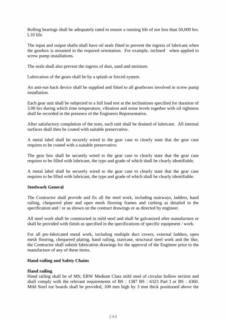
Rolling bearings shall be adequately rated to ensure a running life of not less than 50,000 hrs.L10 life.
The input and output shafts shall have oil seals fitted to prevent the ingress of lubricant whenthe gearbox is mounted in the required orientation. For example, inclined when applied toscrew pump installations.
The seals shall also prevent the ingress of dust, sand and moisture.
Lubrication of the gears shall be by a splash or forced system.
An anti-run back device shall be supplied and fitted to all gearboxes involved in screw pumpinstallation.
Each gear unit shall be subjected to a full load test at the inclinations specified for duration of3.00 hrs during which time temperature, vibration and noise levels together with oil tightnessshall be recorded in the presence of the Engineers Representative.
After satisfactory completion of the tests, each unit shall be drained of lubricant. All internalsurfaces shall then be coated with suitable preservative.
A metal label shall be securely wired to the gear case to clearly state that the gear caserequires to be coated with a suitable preservative.
The gear box shall be securely wired to the gear case to clearly state that the gear caserequires to be filled with lubricant, the type and grade of which shall be clearly identifiable.
A metal label shall be securely wired to the gear case to clearly state that the gear caserequires to be filled with lubricant, the type and grade of which shall be clearly identifiable.
Steelwork General
The Contractor shall provide and fix all the steel work, including stairways, ladders, handrailing, chequered plate and open mesh flooring frames and curbing as detailed in thespecification and / or as shown on the contract drawings or as directed by engineer.
All steel work shall be constructed in mild steel and shall be galvanized after manufacture orshall be provided with finish as specified in the specifications of specific equipment / work.
For all pre-fabricated metal work, including multiple duct covers, external ladders, openmesh flooring, chequered plating, hand railing, staircase, structural steel work and the like,the Contractor shall submit fabrication drawings for the approval of the Engineer prior to themanufacture of any of these items.
Hand railing and Safety Chains
Hand railingHand railing shall be of MS; ERW Medium Class mild steel of circular hollow section andshall comply with the relevant requirements of BS : 1387 BS : 6323 Part I or BS : 4360.Mild Steel toe boards shall be provided, 100 mm high by 3 mm thick positioned above the
244
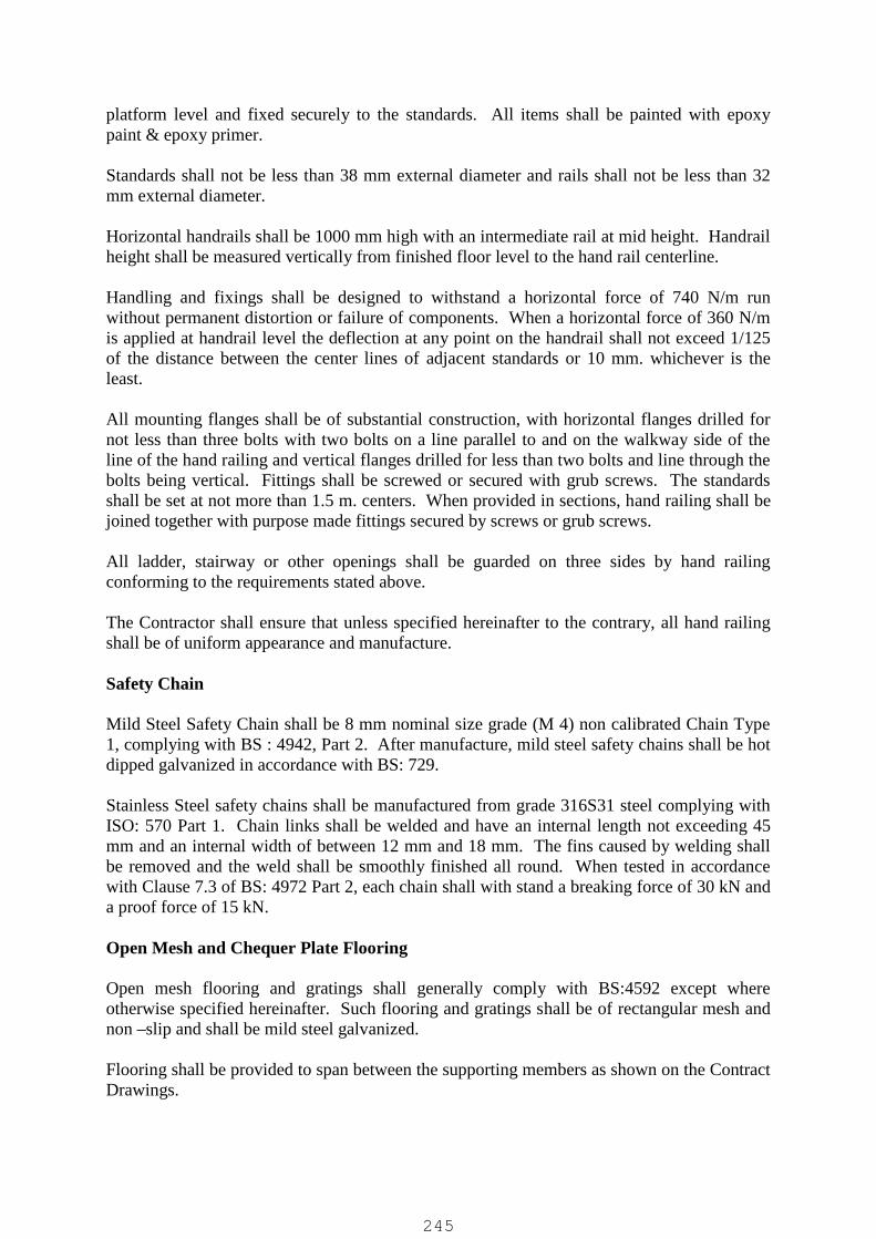
platform level and fixed securely to the standards. All items shall be painted with epoxypaint & epoxy primer.
Standards shall not be less than 38 mm external diameter and rails shall not be less than 32mm external diameter.
Horizontal handrails shall be 1000 mm high with an intermediate rail at mid height. Handrailheight shall be measured vertically from finished floor level to the hand rail centerline.
Handling and fixings shall be designed to withstand a horizontal force of 740 N/m runwithout permanent distortion or failure of components. When a horizontal force of 360 N/mis applied at handrail level the deflection at any point on the handrail shall not exceed 1/125of the distance between the center lines of adjacent standards or 10 mm. whichever is theleast.
All mounting flanges shall be of substantial construction, with horizontal flanges drilled fornot less than three bolts with two bolts on a line parallel to and on the walkway side of theline of the hand railing and vertical flanges drilled for less than two bolts and line through thebolts being vertical. Fittings shall be screwed or secured with grub screws. The standardsshall be set at not more than 1.5 m. centers. When provided in sections, hand railing shall bejoined together with purpose made fittings secured by screws or grub screws.
All ladder, stairway or other openings shall be guarded on three sides by hand railingconforming to the requirements stated above.
The Contractor shall ensure that unless specified hereinafter to the contrary, all hand railingshall be of uniform appearance and manufacture.
Safety Chain
Mild Steel Safety Chain shall be 8 mm nominal size grade (M 4) non calibrated Chain Type1, complying with BS : 4942, Part 2. After manufacture, mild steel safety chains shall be hotdipped galvanized in accordance with BS: 729.
Stainless Steel safety chains shall be manufactured from grade 316S31 steel complying withISO: 570 Part 1. Chain links shall be welded and have an internal length not exceeding 45mm and an internal width of between 12 mm and 18 mm. The fins caused by welding shallbe removed and the weld shall be smoothly finished all round. When tested in accordancewith Clause 7.3 of BS: 4972 Part 2, each chain shall with stand a breaking force of 30 kN anda proof force of 15 kN.
Open Mesh and Chequer Plate Flooring
Open mesh flooring and gratings shall generally comply with BS:4592 except whereotherwise specified hereinafter. Such flooring and gratings shall be of rectangular mesh andnon –slip and shall be mild steel galvanized.
Flooring shall be provided to span between the supporting members as shown on the ContractDrawings.
245

Where necessary intermediate support members shall be provided and fixed.
Galvanized mild steel toe plates 100 mm high and not less than 3 mm thick shall be providedand fixed at all cut-outs except where otherwise shown on the approved drawings.
Both the load bearing and transverse bars in rectangular flooring panels shall be obtainedsystemically around the centre lines of the panels in both directions, so that when the panelsare fixed in extensive areas or in long runs, the bars of all panels are in line.
Chequer plate flooring shall be galvanized and of the non-slip type, not less than 10 mm thickmeasured excluding the raised pattern. The flooring shall be secured to its frame by stainlesssteel countersunk set screws.
All flooring shall be designed to carry a loading of 750 Kg. per Sq. meter and the deflectionshall not exceed 1/200 of the span or 10 mm whichever is the least.
All flooring shall be removable and set flush in mild steel galvanized frames. All framesshall be provided with lugs for building in.
Flooring shall be provided in sizes suitable for lifting and removal by one man and with theappropriate cutouts to permits its removal without disturbing or dismantling spindles,supporting brackets, cables or pipe work. Flooring spanning wide openings shall besupported on removable bearers and fixings to provide the required rigidity and these shall besupplied and fitted by the Contractor. These members shall be removable to afford clearaccess to the openings which includes ducts.
Lifting keys shall be supplied for each location and the type of key shall be such thatinadvertent release is avoided.
Stairways
Stairways shall be detailed, fabricated and erected to the dimensions shown on the drawingsand in accordance with BS : 449 Part 2 to carry a load of 750 Kg. Per sq. meter. Treads shallbe rectangular open mesh fixed to the stringers, not directly to concrete. Sloping hand railingshall be as specified for horizontal hand railing but with the top rail 850 mm vertically abovethe line of pitch and standards vertical and spaced at not more than 1500 mm., measuredparallel to the line of pitch.
Staircases shall be constructed to the size and position shown on the drawings or as instructedby the Engineer. They shall be steel galvanized at works after manufacture and shallcomprise stringers supporting the open mesh stair treads and shall be supplied complete withhandrails and stanchions conforming to the above except the height which shall be 900 mmabove the pitch line.
Ladders
Ladders shall conform to BS: 4211 except where the specified here after. They shall be inmild steel galvanized as specified in. The stringers shall be flat section not less than 65 mm x10 mm spaced 380 mm apart and shall be flanged and drilled for wall fixing at both ends.The stringers shall be radiuses over the top where they shall be not less than 600 mm apart.
246

Ladders over 3.0 m long shall have additional intermediate stays at not more than 2.5 mcenters.
Rungs shall be 20 mm diameter round bar at 250 mm c-c distance shouldered at each end andsecurely riveted into countersunk holes. Rungs shall be not less than 225 mm from the wall.
All ladders shall have safety cages which shall be constructed of three flat vertical stripssupported by flat hoops, with a diameter of 750 mm. The hoops shall be at approximately 70mm centers and the first hoop shall be 2400 mm. above ground or lower platform level.
Where the rise exceeds 6000 mm, an intermediate landing shall be provided.
Multiple Duct Covers and Frames
Multiple Duct Covers and Frames shall be of cast iron, water proof, non-rocking and recessedfor filling with concrete or similar material.
They shall be of the type incorporating integral, removable, intermediate beams to given therequired clear pit opening as shown on the approved drawings.
A heavy grease seal is to be formed between the cover and frame to prevent ingress of grit.
General Requirements for Pipe work
The Contractor shall supply, deliver and erect all pipe work and fittings within the structuresand externally to the limits indicated on the approved drawings and in accordance with eachsection of specification.
Pipe work and fittings shall be suitable for a safe working pressure equivalent to themaximum working pressure of the system. The safe working pressure of the pumping mainsshall be the closed valve head of the pump plus the maximum suction static head. Themaximum surge pressure shall be limited to 125% of the maximum working pressure. Allpipe work and fittings shall be of adequate strength to accommodate the maximum surgepressure of the system.
The minimum pressure rating of pipe work and fittings shall be 10 Bar, the exception beingductile iron pipe work and fitting which shall have a minimum pressure rating of 16 Bar.
There shall be a sufficient number of mechanical joints to enable mechanical plant and valvesto be disconnected from built – in pipe work. Such joints shall be tied and shall not beallowed to sustain the weight of any pipe work.
All pipe work and fittings shall be sized for the required capacity at a velocity limitsdepending on the nature of the fluid or substance to be conveyed.
All pipe work shall be adequately supported by purpose made fixings. Support shall not beprovided by plant or equipment.
The position of any thrust blocks required shall be indicated on the Contractor’s detailsdrawing together with the position of any sleeping required through partition walls inbuildings. Puddle flanges shall be provided for building at locations in which pipes 80mmdiameter and above pass through structural concrete below ground level.
247
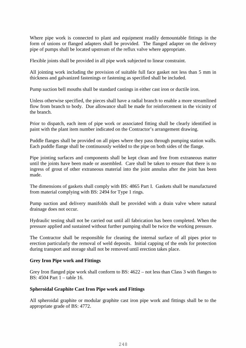
Where pipe work is connected to plant and equipment readily demountable fittings in theform of unions or flanged adapters shall be provided. The flanged adapter on the deliverypipe of pumps shall be located upstream of the reflux valve where appropriate.
Flexible joints shall be provided in all pipe work subjected to linear constraint.
All jointing work including the provision of suitable full face gasket not less than 5 mm inthickness and galvanized fastenings or fastening as specified shall be included.
Pump suction bell mouths shall be standard castings in either cast iron or ductile iron.
Unless otherwise specified, the pieces shall have a radial branch to enable a more streamlinedflow from branch to body. Due allowance shall be made for reinforcement in the vicinity ofthe branch.
Prior to dispatch, each item of pipe work or associated fitting shall be clearly identified inpaint with the plant item number indicated on the Contractor’s arrangement drawing.
Puddle flanges shall be provided on all pipes where they pass through pumping station walls.Each puddle flange shall be continuously welded to the pipe on both sides of the flange.
Pipe jointing surfaces and components shall be kept clean and free from extraneous matteruntil the joints have been made or assembled. Care shall be taken to ensure that there is noingress of grout of other extraneous material into the joint annulus after the joint has beenmade.
The dimensions of gaskets shall comply with BS: 4865 Part I. Gaskets shall be manufacturedfrom material complying with BS: 2494 for Type 1 rings.
Pump suction and delivery manifolds shall be provided with a drain valve where naturaldrainage does not occur.
Hydraulic testing shall not be carried out until all fabrication has been completed. When thepressure applied and sustained without further pumping shall be twice the working pressure.
The Contractor shall be responsible for cleaning the internal surface of all pipes prior toerection particularly the removal of weld deposits. Initial capping of the ends for protectionduring transport and storage shall not be removed until erection takes place.
Grey Iron Pipe work and Fittings
Grey Iron flanged pipe work shall conform to BS: 4622 – not less than Class 3 with flanges toBS: 4504 Part 1 – table 16.
Spheroidal Graphite Cast Iron Pipe work and Fittings
All spheroidal graphite or modular graphite cast iron pipe work and fittings shall be to theappropriate grade of BS: 4772.
248

Carbon Steel Pipe work
Carbon Steel Pipe work for pressure purposes shall be to BS: 3601 and assemblies shall bemanufactured from pipe to this specification. The type of pipe shall be hot finished seamlesssteel. The wall thickness shall be not less than that required in BS: 534 – Table – 1.
ABS Pipe work
ABS Pipe work shall be provided and installed for special purposes where hereinafterspecified. The pipe work shall conform to BS : 5391 and the fittings to BS : 5392.
Fabrication of Carbon Steel pipe work and Fittings
The Contractor shall fabricate the pipeline by butt-welding without utilizing a backing ring inaccordance with BS: 2971 – Class II metal arc welding of carbon steel pipe work. Branchesshall be formed in accordance with BS. 2971 (Class I or Class II, depending on operatingconditions) and shall be welded before so that at any point along the bend, ovality will notreduce the bore by more than 21%. Radii of hot bends for all pipes shall not be less than fivetimes the outside diameter. Gusseted “Cut and Shut” and wrinkle. All pipe flanges shall beof the wrought steel slip on type conforming to BS 4504 PN 16, welded on in accordancewith BS : 2971 (Class I or Class II, depending on operating conditions) No flanged jointsshall be located with in a backfilled trench. Flexible joints shall be bolted gland or victauliccoupling as necessary.
Welder Qualification
Before welding work commences on pipe work, the Contractor shall satisfy the Engineer’sRepresentative that the welders have previously carried out similar welding work withinrecent months. When instructed by the Engineer’s Representative, the Contractor shallarrange for the welder to produce test welds in accordance with the provisions of BS 2971.
Pipe work Installation
All pipe work, pipe fittings, jointing materials etc., shall be of the best quality free fromdefects an obtained from a supplier approved by the Engineer. The installation of the pipework shall be carried out using skilled personnel and pipe work shall be installed according tothe drawing approved by the Engineer. Where valves are incorporated in pipe work , thevalves shall be provided with their own supports, such that no excess loading is exerted onpipe work. All pipe work materials shall have no excess loading is exerted on pipe work. Allpipe work materials shall be off-loaded, stored on site and handled thereafter in such amanner that they are adequately protected for damage or deterioration.
Underground Pipes
Unless otherwise state all underground pipes shall be buried in trenches which have beenexcavated in accordance with the relevant section of the specification.
Examining Pipes
Before being used, each pipe casting or fitting shall be properly examined and should appeardefective in any way, it shall be set apart and not used until it has been examined and passedby the Engineer. All metal pipes which shall be buried in the ground shall, prior to their
249

installation, be slung and sounded in an approved manner. Any pipe found to be faulty bythis method, shall be set aside for examination by the Engineer.
Cutting Pipe work
All pipe work shall be cut with proper pipe cutting tools. The use of hammer and chisel forthis purpose shall not be permitted. Great care shall be exercised when cutting concrete /bitumen lined spun iron and ductile iron pipes, to ensure that there is no damage to the lining.Should any damage to the lining take place which is to an extent which the Engineer deemsto be undesirable, then the pipe shall be rejected. The Contractor shall then prepare anotherpipe for incorporation into the works. All pipes which have been cut shall have the edgesdressed and deburred.
Labels
The Contractor shall arrange for the supply and fitting of engraved identification labels to allvalves and items/equipment of plant. The reference numbers of all valves shall be asindicated on the schematic diagram to be supplied under the Contract.
All warning labels shall comply with BS: 5378 parts 1,2 and 3 and screw fixed rigidconstruction.
Designation labels shall be of 5 mm traffoly with black lettering on white background.Embossed materials and techniques shall not be accepted.
The Contractor shall provide 2 nos. enameled iron plates worked “Men Working of Plant”.The plates shall be 200 mm x 75 mm with red lettering on a white background.
N. B.: All identification and warning labels shall be in (“Hindi Language”) and English.
Guards
Adequate guards shall be supplied and installed throughout the installation to cover drivemechanisms. All rotating and reciprocating parts, drive belts, etc. shall be securely shroudedto the satisfaction of the Engineer to ensure the complete safety for both maintenance andoperating personnel. However, whilst all such guards shall be of adequate and substantialconstruction, they shall also be readily removable for gaining access to the plant, with out theneed for first removing or displacing any major item of plant. The guards shall be of theopen mesh type except where retention of fluid spray is required.
Suppression of Noise
All plant equipments offered shall be quiet in operation. The noise level within the buildingshall not be more than 85 dB (+5 percent on this over the audible frequency spectrummeasured at mid-band), “A” scale when measured along a contour 3 meters from any singleitem of plant during starting, running and stopping. The noise level outside the building shallnot be more than 60 dB (+5 % on this over the audible frequency spectrum measured at mid-band), “A” scales when measured along a contour 3 meters from the external wall. Noise testmeasurement shall be made on completion of the installation of the plant at Site to verify thatit complies with this Clause. Plant which fails to comply with the noise level limits when
250
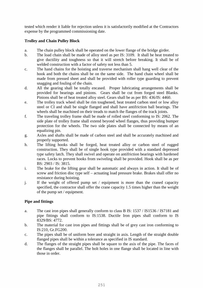
tested which render it liable for rejection unless it is satisfactorily modified at the Contractorsexpense by the programmed commissioning date.
Trolley and Chain Pulley Block
a. The chain pulley block shall be operated on the lower flange of the bridge girder.b. The load chain shall be made of alloy steel as per IS: 3109. It shall be heat treated to
give ductility and toughness so that it will stretch before breaking. It shall be ofwelded construction with a factor of safety not less than 5.
c. The hand chains for the hoisting and traverse mechanism shall hang well clear of thehook and both the chains shall be on the same side. The hand chain wheel shall bemade from pressed sheet and shall be provided with roller type guarding to preventsnagging and fouling of the chain.
d. All the gearing shall be totally encased. Proper lubricating arrangements shall beprovided for bearings and pinions. Gears shall be cut from forged steel Blanks.Pinions shall be of heat treated alloy steel. Gears shall be as per BS: 436/IS: 4460.
e. The trolley track wheel shall be rim toughened, heat treated carbon steel or low alloysteel or CI and shall be single flanged and shall have antifriction ball bearings. Thewheels shall be machined on their treads to match the flanges of the track joints.
f. The traveling trolley frame shall be made of rolled steel conforming to IS: 2062. Theside plate of trolley frame shall extend beyond wheel flanges, thus providing bumperprotection for the wheels. The two side plates shall be connected by means of anequalizing pin.
g. Axles and shafts shall be made of carbon steel and shall be accurately machined andproperly supported.
h. The lifting hooks shall be forged, heat treated alloy or carbon steel of ruggedconstruction. They shall be of single hook type provided with a standard depressedtype safety latch. They shall swivel and operate on antifriction bearings with hardenedraces. Locks to prevent hooks from swiveling shall be provided. Hook shall be as perBS: 2903 / IS: 3815.
i. The brake for the lifting gear shall be automatic and always in action. It shall be ofscrew and friction disc type self – actuating load pressure brake. Brakes shall offer noresistance during hoisting.
j. If the weight of offered pump set / equipment is more than the craned capacityspecified, the contractor shall offer the crane capacity 1.5 times higher than the weightof the pump set / equipment.
Pipe and fittings
a. The cast iron pipes shall generally conform to class B IS: 1537 / IS1536 / IS7181 andpipe fittings shall conform to IS:1538. Ductile Iron pipes shall conform to IS8329/BS: 4772.
b. The material for cast iron pipes and fittings shall be of grey cast iron conforming toIS:210, Gr.FG200.
c. The pipes shall be of uniform bore and straight in axis. Length of the straight doubleflanged pipes shall be within a tolerance as specified in IS standard.
d. The flanges of the straight pipes shall be square to the axis of the pipe. The faces ofthe flanges shall be parallel. The bolt holes in one flange shall be located in line withthose in order.
251

e. The faces of the flanges of the fittings shall be square to the directional axes. Theholes shall be located symmetrically off the centre line. The intersecting axes of thetees shall be perpendicular to each other.
f. The bolt holes on flanged pipes and fittings shall be drilled with the help of drillingjig. The blank flanges are to be machined and drilled.
g. The dismantling joints shall be of cast iron with EPDM seal ring.
Ventilation Systems
These specifications are common to all dry well / wet well effluent, sewage and waterpumping stations. The scope of ventilation system includes
a. Supply Air Fansb. Exhaust Fansc. Associated ducting
Wherever the drawings provided for ventilation system, indicate proposed ventilation fansand the routing of ducting. It is the responsibility of the contractor to study and analyse theadequacy of the system and suggest any improvement at the same time taking intoconsideration all the requirements of the public authorities including safety orders and FireProtection Rules & Regulations and IS Code. The necessary permits shall be obtained by thecontractor and all payments towards license inspections, etc. paid before starting the work.
Supply Air Fans
Air fans shall be of centrifugal type and fan housing shall be hot-rolled steel of thickness3/8”. End flanged shall be fixed to the casing by continuously welding over the entirecircumference. The flanges shall have bolt holes for bolting to inlet bell, companion flangesor ducts as the case may be. Housing shall be continuously welded and shall be expanded bysuitable mechanical means to insure concentricity. Motor support shall not be less than 3/9”thick steel plate. Support ring shall be continuously welded to the support plate.
Fan rotor and blades shall be made from cast aluminum with suitable corrosion resistantcoating. Belt –driven fans shall have multi V belts on pulleys with suitable guards. V beltsshall be 150% of rated HP duty.
The fan rotor shall be whirl-tested to 125% or operating speed and shall be statically anddynamically balanced on fan motor shaper to maximum tolerance in one (1) mil doubleamplitude at design operating speed.
The fans shall have inlet screen at inlet bell cone and carbon steel bolts for existingdischarges cone with flanges on both ends attachment to fan and to discharge ducting.Fan motor supports shall be of adequate strength, constructed from 1/4" carbon steel angles.All the external fasteners shall be stainless steel.
Motors
Motors selected for the fan shall be of adequate rating with a safety factor of 1.5 or greater.If the fans are belt-driven the motor shall be mounted on slide rails for belt tension andadjustment. The complete assembly shall be mounted on Neoprene Vibration Isolators. The
252

motor shall conform to the relevant latest Indian Standards of British Standards. It shall havepermanently lubricated ball bearings. The motor shall be suitable for 415B, 3 Phase, 50 Hzsupply.
The bearing life shall not be less than 20,000 hours at design conditions and motor shall be ofclass ‘F’ insulation to allow for operation up to 95 rise over the ambient temperature of 45 C.External copper grease leads for lubrication of motor bearings shall be provided by themanufacturer.
Fan motor shall be standard totally enclosed fan cooled (TEFC) foot mounted squirrel cageinduction motor with single speed, single winding, continuous duty variable torque’s.
A conduit box shall be mounted on the exterior of fan casing and lead wires from the motorconduit box shall be protected from the air stream by being encased in a tight metal conduitpipe.
The belt drives shall have stainless steel wire cage guards.Supply of air fans in dry well shall have air flow switches and pressure switches fitted in theducting. The selection of these switches is left to the contractor to suit the fan units beingsupplied.
Exhaust Fans
Exhaust fans shall be of direct drive, impeller propeller type, having max. speed of 1450 rpm.
All the exposed parts shall be of aluminum, with transparent anodic, anti-salt spray coating,All external fasteners shall be of stainless steel. Hood shall be hinged for accessibility andservicing. Fans shall be complete with aluminum bird screens, Plastic or light weightaluminum back draft compels and electrical disconnecting means beneath the hood andprotective grid guard below fan motor.
Motors shall be of relevant Indian Standards or British standards and shall have permanentlylubricated ball bearings. The rating shall be adequate with service factor of 1.50 based onrated horsepower. All motor shall be TEFC and be suitable for continuous operation withoutexceeding a temperature rise of 50o C over ambient.
The motor shall be of constant speed and squirrel cage type, operating on 415 V, 3 phase, 50Hz Supply. Roof mounted motors shall have electrical disconnects.
Contractor shall submit all catalogues showing the sizing and rating of fans with the size ofopenings to be provided for approval before proceeding with the work.
Dampers
All dampers shall be of louver type, robust construction, and tightly fitted suitable for thelocation and service required.
Dampers shall have suitable links, levers and quadrants as required for the proper operations,control or setting in any desired position. Dampers and these operating devices shall be made
253
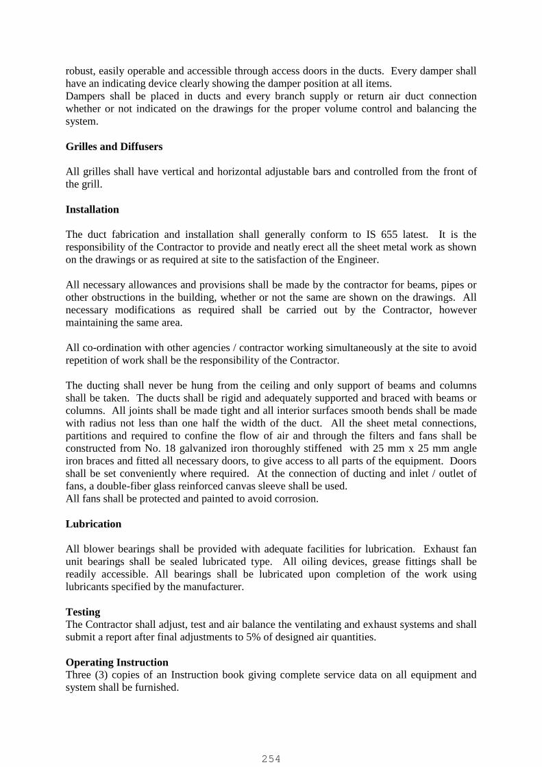
robust, easily operable and accessible through access doors in the ducts. Every damper shallhave an indicating device clearly showing the damper position at all items.Dampers shall be placed in ducts and every branch supply or return air duct connectionwhether or not indicated on the drawings for the proper volume control and balancing thesystem.
Grilles and Diffusers
All grilles shall have vertical and horizontal adjustable bars and controlled from the front ofthe grill.
Installation
The duct fabrication and installation shall generally conform to IS 655 latest. It is theresponsibility of the Contractor to provide and neatly erect all the sheet metal work as shownon the drawings or as required at site to the satisfaction of the Engineer.
All necessary allowances and provisions shall be made by the contractor for beams, pipes orother obstructions in the building, whether or not the same are shown on the drawings. Allnecessary modifications as required shall be carried out by the Contractor, howevermaintaining the same area.
All co-ordination with other agencies / contractor working simultaneously at the site to avoidrepetition of work shall be the responsibility of the Contractor.
The ducting shall never be hung from the ceiling and only support of beams and columnsshall be taken. The ducts shall be rigid and adequately supported and braced with beams orcolumns. All joints shall be made tight and all interior surfaces smooth bends shall be madewith radius not less than one half the width of the duct. All the sheet metal connections,partitions and required to confine the flow of air and through the filters and fans shall beconstructed from No. 18 galvanized iron thoroughly stiffened with 25 mm x 25 mm angleiron braces and fitted all necessary doors, to give access to all parts of the equipment. Doorsshall be set conveniently where required. At the connection of ducting and inlet / outlet offans, a double-fiber glass reinforced canvas sleeve shall be used.All fans shall be protected and painted to avoid corrosion.
Lubrication
All blower bearings shall be provided with adequate facilities for lubrication. Exhaust fanunit bearings shall be sealed lubricated type. All oiling devices, grease fittings shall bereadily accessible. All bearings shall be lubricated upon completion of the work usinglubricants specified by the manufacturer.
TestingThe Contractor shall adjust, test and air balance the ventilating and exhaust systems and shallsubmit a report after final adjustments to 5% of designed air quantities.
Operating InstructionThree (3) copies of an Instruction book giving complete service data on all equipment andsystem shall be furnished.
254

SPECIFICATIONS FOR MECHANICAL ITEMS (SPECIAL)
DETAILED MECHANICAL SPECIFICATIONS
1.0 TWIN LOBE AIR BLOWERS
Air blower shall be designed to perform satisfactorily under specified start up condition, part load /full load operation, max. differential pressure operation and relief valve setting pressure and up to tripspeed. All the compressor casing shall be air cooled type for up to 5500mmWC discharge pressure /water cooled type or with after cooler for more than 5500mm WC discharge pressure unless specifiedotherwise elsewhere in tender.
The design parameters to be considered are as under:Blower Design Parameters:
a Min. / Max. air inletTemperature
5 / 45 Degree C
b Design RH 65%c Altitude As per Site Locationd Capacity (Nm3/hr) – at
DischargeAs per design / process requirement, Nm3/hr(defined @ 0 degree C, 1.013 bar & 0 % Rh)
e Head / Disch. Pr. (Kg/cm2) As per designf Speed of blower 1200 RPM (max.)
Air blower shall consist of the following accessories:
- Twin lobe compressor- TEFC Squirrel cage induction motor as per electrical specifications & of approved make.
Motor for VFD operated blower shall be of VFD duty.- Suction Filter- Suction / discharge silencer- V belt & V belt guard- Motor pulley & compressor pulley- Slide rail- Common base frame- Safety valve- Anti-vibration pads- Pressure gauges – Bourdon type, 150mm dia., SS casing, glycerin filled with manifold valve,
syphon and snubber, etc. & of make as per specification for instrumentation work.- The blower noise level shall be within 85 dB (A) at a distance of 1.86m. If noise level exceeds
without hood then acoustic hood shall be provided to meet this requirement.- Acoustic hood comprising of fabricated 50 mm square welded tube, frame, acoustic insulation
of glass wool of density 30 kg3/m2 and perforated sheet on inside face and MS sheet onoutside face in welded construction – as per requirement to limit noise level within limit asspecified.
- Inter connecting piping comprising of discharge butterfly valve, flap type non-return valve,and metallic expansion bellow. Bidder to refer specification for mechanical work for restspecifications and make of valves and bellows. Additionally the MOC of bellows and valves /internals shall be suitable to withstand the temperature at discharge of blower considering thetemperature rise at delivery of blower over design ambient of 50 degC.
- Any other required accessories and protections for satisfactory running of blowers.
Material of construction of various part of the air blower shall be as under:
Casing CI-FG-260, IS:210
255
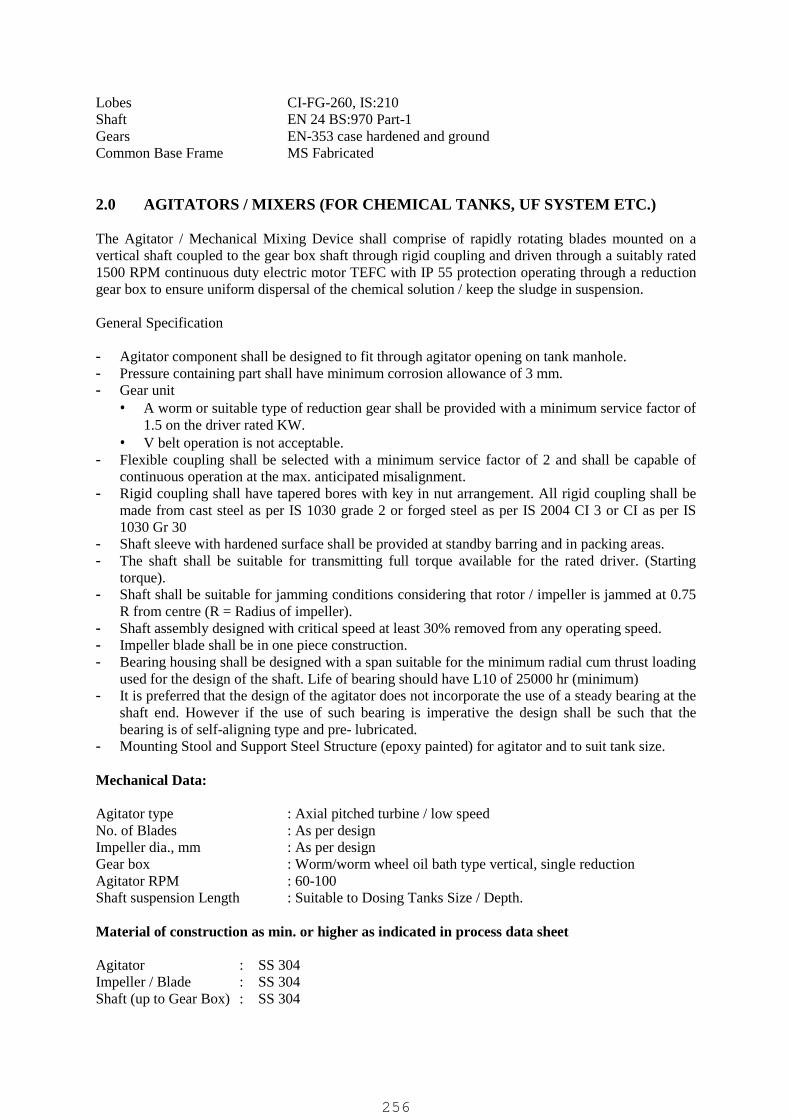
Lobes CI-FG-260, IS:210Shaft EN 24 BS:970 Part-1Gears EN-353 case hardened and groundCommon Base Frame MS Fabricated
2.0 AGITATORS / MIXERS (FOR CHEMICAL TANKS, UF SYSTEM ETC.)
The Agitator / Mechanical Mixing Device shall comprise of rapidly rotating blades mounted on avertical shaft coupled to the gear box shaft through rigid coupling and driven through a suitably rated1500 RPM continuous duty electric motor TEFC with IP 55 protection operating through a reductiongear box to ensure uniform dispersal of the chemical solution / keep the sludge in suspension.
General Specification
- Agitator component shall be designed to fit through agitator opening on tank manhole.- Pressure containing part shall have minimum corrosion allowance of 3 mm.- Gear unit
A worm or suitable type of reduction gear shall be provided with a minimum service factor of1.5 on the driver rated KW.
V belt operation is not acceptable.- Flexible coupling shall be selected with a minimum service factor of 2 and shall be capable of
continuous operation at the max. anticipated misalignment.- Rigid coupling shall have tapered bores with key in nut arrangement. All rigid coupling shall be
made from cast steel as per IS 1030 grade 2 or forged steel as per IS 2004 CI 3 or CI as per IS1030 Gr 30
- Shaft sleeve with hardened surface shall be provided at standby barring and in packing areas.- The shaft shall be suitable for transmitting full torque available for the rated driver. (Starting
torque).- Shaft shall be suitable for jamming conditions considering that rotor / impeller is jammed at 0.75
R from centre (R = Radius of impeller).- Shaft assembly designed with critical speed at least 30% removed from any operating speed.- Impeller blade shall be in one piece construction.- Bearing housing shall be designed with a span suitable for the minimum radial cum thrust loading
used for the design of the shaft. Life of bearing should have L10 of 25000 hr (minimum)- It is preferred that the design of the agitator does not incorporate the use of a steady bearing at the
shaft end. However if the use of such bearing is imperative the design shall be such that thebearing is of self-aligning type and pre- lubricated.
- Mounting Stool and Support Steel Structure (epoxy painted) for agitator and to suit tank size.
Mechanical Data:
Agitator type : Axial pitched turbine / low speedNo. of Blades : As per designImpeller dia., mm : As per designGear box : Worm/worm wheel oil bath type vertical, single reductionAgitator RPM : 60-100Shaft suspension Length : Suitable to Dosing Tanks Size / Depth.
Material of construction as min. or higher as indicated in process data sheet
Agitator : SS 304Impeller / Blade : SS 304Shaft (up to Gear Box) : SS 304
256
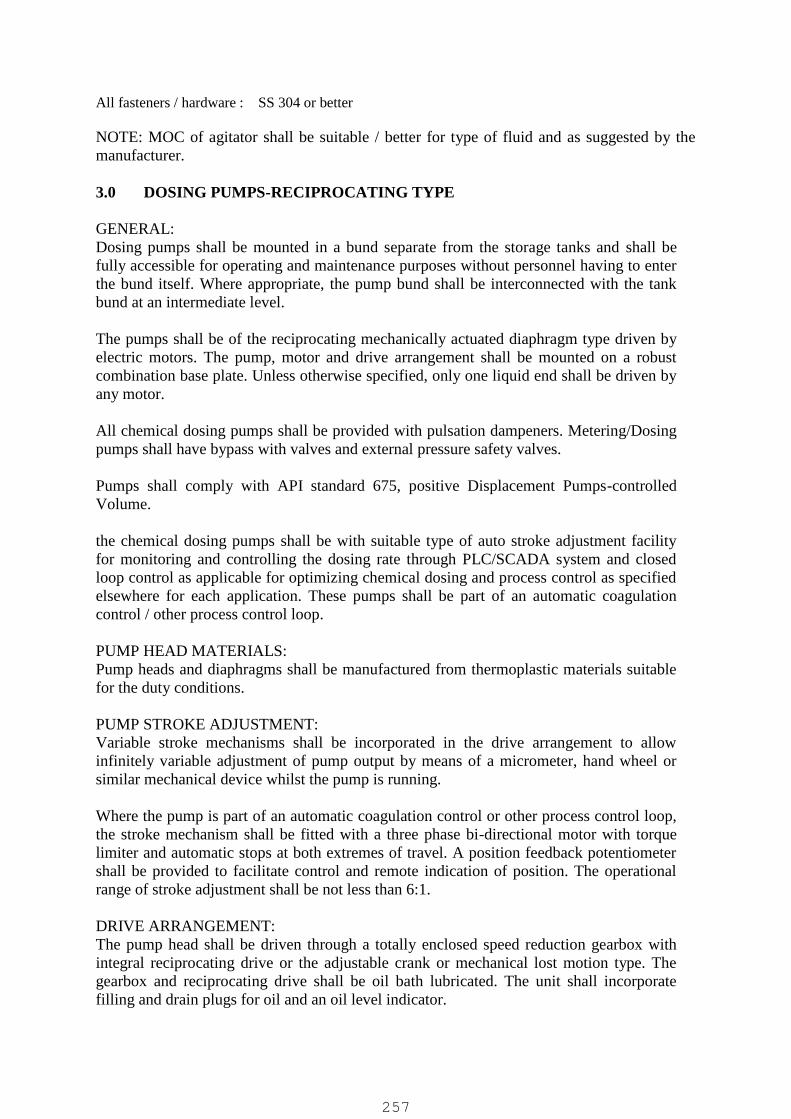
All fasteners / hardware : SS 304 or better
NOTE: MOC of agitator shall be suitable / better for type of fluid and as suggested by themanufacturer.
3.0 DOSING PUMPS-RECIPROCATING TYPE
GENERAL:Dosing pumps shall be mounted in a bund separate from the storage tanks and shall befully accessible for operating and maintenance purposes without personnel having to enterthe bund itself. Where appropriate, the pump bund shall be interconnected with the tankbund at an intermediate level.
The pumps shall be of the reciprocating mechanically actuated diaphragm type driven byelectric motors. The pump, motor and drive arrangement shall be mounted on a robustcombination base plate. Unless otherwise specified, only one liquid end shall be driven byany motor.
All chemical dosing pumps shall be provided with pulsation dampeners. Metering/Dosingpumps shall have bypass with valves and external pressure safety valves.
Pumps shall comply with API standard 675, positive Displacement Pumps-controlledVolume.
the chemical dosing pumps shall be with suitable type of auto stroke adjustment facilityfor monitoring and controlling the dosing rate through PLC/SCADA system and closedloop control as applicable for optimizing chemical dosing and process control as specifiedelsewhere for each application. These pumps shall be part of an automatic coagulationcontrol / other process control loop.
PUMP HEAD MATERIALS:Pump heads and diaphragms shall be manufactured from thermoplastic materials suitablefor the duty conditions.
PUMP STROKE ADJUSTMENT:Variable stroke mechanisms shall be incorporated in the drive arrangement to allowinfinitely variable adjustment of pump output by means of a micrometer, hand wheel orsimilar mechanical device whilst the pump is running.
Where the pump is part of an automatic coagulation control or other process control loop,the stroke mechanism shall be fitted with a three phase bi-directional motor with torquelimiter and automatic stops at both extremes of travel. A position feedback potentiometershall be provided to facilitate control and remote indication of position. The operationalrange of stroke adjustment shall be not less than 6:1.
DRIVE ARRANGEMENT:The pump head shall be driven through a totally enclosed speed reduction gearbox withintegral reciprocating drive or the adjustable crank or mechanical lost motion type. Thegearbox and reciprocating drive shall be oil bath lubricated. The unit shall incorporatefilling and drain plugs for oil and an oil level indicator.
257
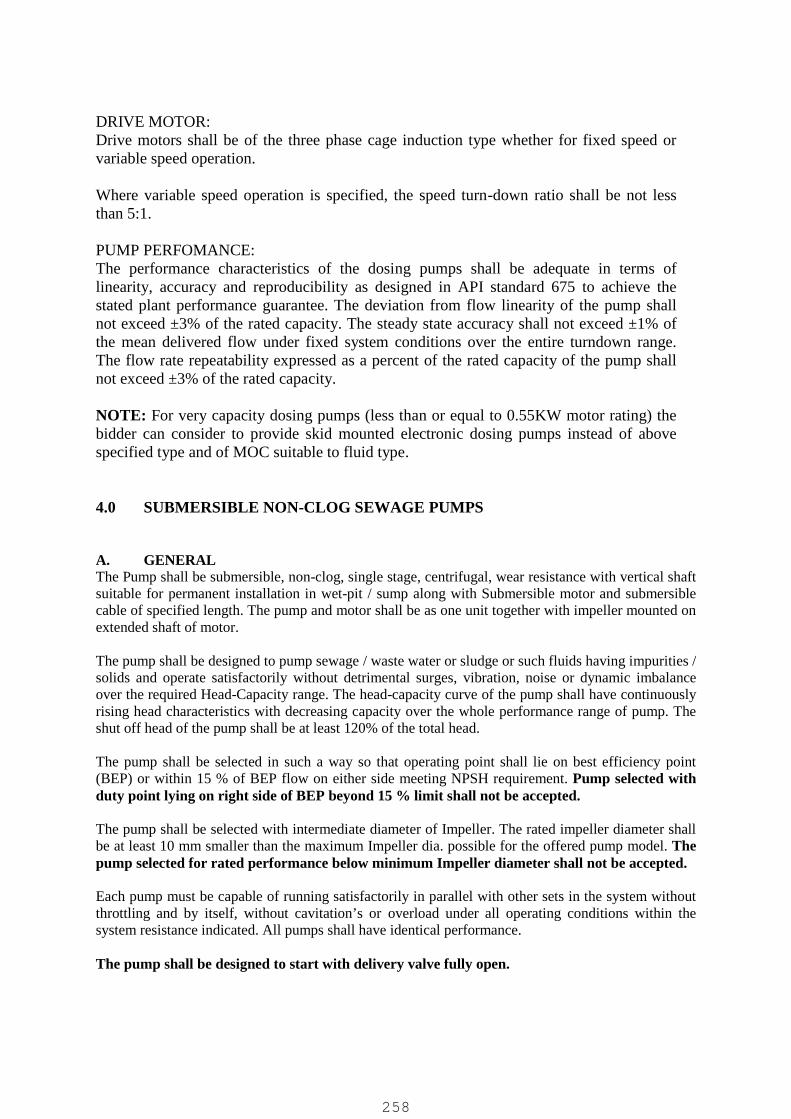
DRIVE MOTOR:Drive motors shall be of the three phase cage induction type whether for fixed speed orvariable speed operation.
Where variable speed operation is specified, the speed turn-down ratio shall be not lessthan 5:1.
PUMP PERFOMANCE:The performance characteristics of the dosing pumps shall be adequate in terms oflinearity, accuracy and reproducibility as designed in API standard 675 to achieve thestated plant performance guarantee. The deviation from flow linearity of the pump shallnot exceed ±3% of the rated capacity. The steady state accuracy shall not exceed ±1% ofthe mean delivered flow under fixed system conditions over the entire turndown range.The flow rate repeatability expressed as a percent of the rated capacity of the pump shallnot exceed ±3% of the rated capacity.
NOTE: For very capacity dosing pumps (less than or equal to 0.55KW motor rating) thebidder can consider to provide skid mounted electronic dosing pumps instead of abovespecified type and of MOC suitable to fluid type.
4.0 SUBMERSIBLE NON-CLOG SEWAGE PUMPS
A. GENERALThe Pump shall be submersible, non-clog, single stage, centrifugal, wear resistance with vertical shaftsuitable for permanent installation in wet-pit / sump along with Submersible motor and submersiblecable of specified length. The pump and motor shall be as one unit together with impeller mounted onextended shaft of motor.
The pump shall be designed to pump sewage / waste water or sludge or such fluids having impurities /solids and operate satisfactorily without detrimental surges, vibration, noise or dynamic imbalanceover the required Head-Capacity range. The head-capacity curve of the pump shall have continuouslyrising head characteristics with decreasing capacity over the whole performance range of pump. Theshut off head of the pump shall be at least 120% of the total head.
The pump shall be selected in such a way so that operating point shall lie on best efficiency point(BEP) or within 15 % of BEP flow on either side meeting NPSH requirement. Pump selected withduty point lying on right side of BEP beyond 15 % limit shall not be accepted.
The pump shall be selected with intermediate diameter of Impeller. The rated impeller diameter shallbe at least 10 mm smaller than the maximum Impeller dia. possible for the offered pump model. Thepump selected for rated performance below minimum Impeller diameter shall not be accepted.
Each pump must be capable of running satisfactorily in parallel with other sets in the system withoutthrottling and by itself, without cavitation’s or overload under all operating conditions within thesystem resistance indicated. All pumps shall have identical performance.
The pump shall be designed to start with delivery valve fully open.
258

The pump shall be designed to operate safely at the maximum speed attainable in the reverse directionof rotation due to liquid returning through the pump at times when the power supply to the motor isinterrupted and the discharge valve fails to close.
Pumps’ rotating parts & assembly shall be statically and dynamically balanced as per ISO standardsand shall run smooth without undue noise and vibration. The velocity of vibration shall be within the6.3 mm/sec. Noise level shall be limited to 85 dBA at a distance of 1.0 m.
The Sole plates / auto coupling unit with foundation plate shall be grouted with the RCC foundationwith the help of “J” type foundation bolts of manufacturer’s recommended / approved size.
The power rating of motor to drive pump shall be suitable to meet max. requirement of power for therated impeller throughout its’ performance range and specific gravity of the liquid.
B. FEATURES OF CONSTRUCTION
PUMPPump shall be Vertical Submersible centrifugal, single stage, Non Clog suitable for permanentinstallation in wet-pit / sump. The pump shall have bottom suction and side discharge nozzle. Thepump and motor shall be as one unit together with impeller mounted on extended shaft of motor.
The pump having delivery size upto 100 mm shall be designed to handle solids of min. 35-40 mm (for50mm delivery size) to 80 mm size (for 100mm delivery size) such that the solid handling is one pipesize lower than offered pump delivery size. For pumps having delivery size above 100 mm. shall becapable of handling solids of minimum 100 mm size.
CASINGPump casing shall be volute type of robust construction and designed for high efficiency. Liquidpassages shall be designed to allow free passage and finished smooth. The tongue shall be straightacross and filed to a smooth rounded edge. Casing can be provided with wearing rings / wear plates.
Casing shall have facility for removal of clogged material from impeller vanes without dismantlingthe whole pump.
IMPELLERImpeller shall be semi-open or suitable as per manufacturer’s design, single suction with smooth andlarge ways so as to allow free passage to the fluid being pumped. Impeller shall have two / three vanesmax. and be capable to handle solids of specified size. It shall be free from sharp corners andprojections likely to catch and hold rags and stringy materials. Typical sewage has high content ofsand, silt & ash. Hence the pump design shall be of wear resistant type.
Impeller shall be statically and dynamically balanced at rated speed as per applicable standard so as toavoid vibration. The Impeller shall have back vanes or suitable features to balance axial thrust.
Pump having semi open impeller shall be provided with suitable wear plate fixed in casing withadjusting bolts & nuts.
Suitable mechanisms should be provided to avoid accumulation of grit / silt for enhanced life ofmechanical seal.
IMPELLER NUTImpeller shall be fixed on rotating shaft with the help of SS 316 impeller screw or cap top typeimpeller nut with helicoil insert and washer in such a way that impeller doesn’t get loose duringrotation of pump in either direction.
259

SHAFT SEAL / MECHANICAL SEALSDouble mechanical seals shall be provided to protect the motor from ingress of water along the shaft.The preliminary and secondary seals shall be oil-lubricated. The seal faces of the preliminary sealshall be of either tungsten carbide or silicon-carbide faces while the secondary seal can be of carbonversus chrome steel or tungsten carbide. Pumps shall be equipped with an electrical monitoringsystem for seal failure detection. Use of Lip seals or back to back seals is not allowed. Themechanical seals shall be bi-directional.
BEARINGSPump set shall have double anti friction grease lubricated bearings. The bearings life shall beminimum 40,000 hrs of operation. Bearings shall be greased for life –i.e. shall not require any re-greasing. Bearings shall be of SKF / FAG / NBC make only.
AUTO COUPLING / GUIDE PIPE / LIFTING CHAINEach pump shall be supplied with pump connector unit in order to connect connector unit to pumpsupport bracket with rubber diaphragm to make leak proof joint and fixing it to the concrete floor ofthe suction well. The design of the automatic coupling system shall be such that the joint between thepump discharge flange and the delivery piping shall be made by merely lowering the pump into guiderails / wire rope from access level. The pedestal of the automatic coupling system shall be integrallycast with the delivery bend thereby obviating the need of separately bolted CI Duck Foot Bend. Itshall be provided with all necessary fixtures like guide wire / guide pipe for guiding the pumps duringlifting/lowering.
Each pump shall be provided with a stainless steel lifting chain in conforming to relevant standards.The lifting chain shall be provided with dual ‘O’ Rings / shackles in SS-304 at every about 1.5m C-Cfor intermediate level support of pump and changeover of hoist hook during lowering and lifting
Each pump shall be provided with a stainless steel guide pipe / wire rope of required length.
LIFTING HOOKTo “fish out” a vertical submerged pump set from the wet well (even if a chain has not been attachedto the lifting hook prior to the pump set being lowered) the pump shall have a self centering liftinghook. Its design shall be such that the lifting chain’s hook can be engaged to the pump’s lifting hookwithout the need for man to enter the wet well.
INDUCTION MOTOR (Submersible)The submersible motor shall be Induction, Squirrel Cage, and Dry type, designed for continuousoperation (S1 duty) capable of working satisfactorily in water immersion. Motor shall be capable ofgiving rated output without reduction in the expected life span when operated continuously under thefollowing electric supply conditions:
Supply voltage : 415 Volts, 3 Phase, 50 Hz AC supplyVoltage variation : + 10%Frequency variation : + 5%Combined variation ofVoltage & Frequency : + 10%
The Motor shall be generally designed to have performance characteristics like Nominal efficiency,Locked rotor current, etc. in line with IS: 12615:2018. (Efficiency minimum IE2 of IS: 12615)
Degree of protection of motor shall be IP 68. The power rating of the motor shall be min. 110% ofpower required by the rated impeller on its entire performance range. Further, the minimum powerratings for motors to drive pump / sub. pump / driven equipment should be selected as per table ofsafety factor provided for Squirrel cage induction motors under electrical specifications and higher ofthe two ratings shall be provided.
260
Motor shall be suitable for full voltage & star-delta starting. Motor shall be capable of starting andaccelerate the load with the applicable method of starting, without exceeding acceptable windingtemperature, when the supply voltage is in the range 85% of the rated motor voltage to maximumpermissible voltage. Motors shall be designed to withstand 120% of rated speed for two minuteswithout any mechanical damage, in either direction of rotation. The motor vibration shall be withinthe limit specified in applicable standard unless otherwise specified for the driven equipment. Exceptas mentioned herein, the guaranteed performances of the motor shall be met with tolerances specifiedin applicable standards.
Any joints in the motor insulation such as at coil connection or between slot and end winding section,shall have strength equivalent to that of the slot section of the coil. The insulation shall be giventropical and fungicidal treatment for successful operation of the motor in hot, humid and tropicalclimate. The tropical treatment shall be as per the applicable standard.
The stator winding shall be made from high conductivity annealed copper conductor, super enameledinsulated winding wires conforming to IS 8783-1978 for dry type motors. The stator winding shall beof high conductivity annealed copper enameled insulated wires conforming to IS 4800 (part-VII):1970 for dry type motors. The corresponding Class of insulation shall be Class F with temperature riselimited to Class B. However, however for motors to be operated on VFD’s , only Class “H” insulationwith temperature rise limited to Class F is allowed and motor shall be inverter duty type and to suit forspeed variation from 50% to 100% or higher..
As the cable resistance method, due care is taken to account for the correct hot and cold resistance ofwindings.
If these pump’s motors are to be used with Variable Speed Frequency drives ( VFD’s ) than :
The motor insulation shall be Vacuum Varnish Impregnated instead of Dip Varnishing orTrickle Varnishing with double insulation coating.
The motor insulation is to be of Class “H” only Current insulated bearing/s (preferably NDE) required for motor ratings above 200kW.
Terminal chamber shall be of IP 68 type construction to eliminate entry of storm water and dust. TheTerminal chamber should be isolated from the motor chamber to prevent entry of liquid / moisture inthe motor chamber through the terminal chamber. The terminal shall be the stud type with necessaryplain washer, spring washers and check nuts. They shall be substantially designed for the currentcarrying capacity and shall ensure ample phase to phase to ground clearance.
PROTECTIONProtection against increase in stator winding temperature (15 Deg. C) shall be provided. Minimumthree number thermostats / bimetallic switches in series shall be provided to sense the stator windingtemperature.
Sensors are to be provided to detect if leakage of water into the oil housing is above 30%concentration. Bimetallic thermal switch to trip the motor against increase in temperature shall beprovided.
The required control unit to process these safety signals & with potential free contact o/p for alarm /trip shall be provided by pump vendor for suitable interlocking in starter circuit and /or PLC.
Manufacturer shall provide Pump Monitoring Unit (PMU) with each pump set.
SUBMERSIBLE CABLEA watertight Cable Junction Box sealed from the motor shall be provided for the motor power and
261

signaling cables. The cable shall be of sufficient length and shall be brought out of the submergedmotor without joint to terminate in junction box / control panel, located in LT panel room /outside thewet well.
Power as well as Control Cables shall be of Dual Sheathed EPRS / PVC Armored type with requiredno. of Copper Core, round type and of required size as per design requirement.
The power cable shall be PVC insulated and PVC sheathed, flexible, 3.5/4.0 core round type. The sizeof the conductor shall be adequate for continuous use under water and air. Cable half/full core as perdesign to be used for earthing. The size of the conductor and length of cable shall be suitably selectedso that the voltage drop at motor terminals does not exceed 3 percent of the rated voltage.
The control cable shall be PVC insulated PVC sheathed, flexible, round type and shall be adequate forcontinuous use under water and air. The control cable for stator winding temperature sensor, Bearingtemperature sensor, level sensor (Thermostats/ bimetallic switches/RTD ) of 1.5/2.5 sq.mm, multistrand copper conductor of required number shall be provided or as required as per design. Controlcable shall be with minimum 1 no. spare core.
The cable connection to the motor entry should be such that cable fitment should be possible at thesite.
Earthing of the motors shall be done in accordance with the relevant provisions of IS:3043-1966 forthe purpose of earthing these motors, earthing connection may be made to discharge pipe.
MOTOR COOLINGThe motor cooling shall be normally by surrounding water. However jacket cooling with in-builtoverflow or such suitable design of other method of jacket cooling shall be provide as specified inprocess data sheet / scope of work or if specified in BOQ.
C. MATERIAL OF CONSTRUCTION
The specific requirement shall be considered as under:
Pump Casing CI IS210 Gr FG 260Casing wear ring/wear plate CI IS210 Gr FG 260Suc. cover/Oil chamber/ Mot. casing CI IS210 Gr FG 260Shaft AISI 410Shaft sleeve AISI 316 (if applicable)Impeller / Impeller Nut CF8MAuto Coupling Unit CI / WCBHardware (Nuts, Bolts, Fasteners, etc.) SS-304Motor Jacket (if applicable) SS 304Guide rail pipe Heavy duty min. 50 mm dia. of SS 304 of suitable
lengthLifting Chain SS-304, Min. equivalent to sump depth + 3 m with dual
‘O’ Rings/ shackles at every about 1.5m C-C.Bolts, Nuts, Fasteners, etc. SS 304 (All, Wetted & Non-wetted)Cable length (each run) As per BOQ or Min. equivalent to sump depth + 10 m,
whichever is higherMax. Permissible solid Size As specified above in pump specifications
The above MOC is min. requirement and if process requirement is higher as indicated inprocess data sheet the stringent MOC to be provided.
262

5.0 SUBMERSIBLE CENTRIFUGAL PUMP
A. GENERALPump shall be Submersible, Vertical shaft, centrifugal, single stage suitable for permanent installationin wet-pit / sump /jack-well constructed on the river / dam etc. along with Submersible motor andsubmersible cable of specified length. The pump and motor shall be as one unit together with impellermounted on extended shaft of motor.
The pump-motor set shall be designed to pump raw / clear water and operate satisfactorily withoutdetrimental surges, vibration, noise or dynamic imbalance over the required Head-Capacity range.The head-capacity curve of the pump shall have continuously rising head characteristics withdecreasing capacity over the whole performance range of pump. The shut off head of the pump shallbe at least 120% of the total head.
The pump shall be selected in such a way so that operating point shall lie on best efficiency point(BEP) or within 15 % of BEP flow on either side meeting NPSH requirement. Pump selected withduty point lying on right side of BEP beyond 15 % limit shall not be accepted.
The pump shall be selected with intermediate diameter of Impeller. The rated impeller diameter shallbe at least 10 mm smaller than the maximum Impeller dia. possible for the offered pump model. Thepump selected for rated performance below minimum Impeller diameter shall not be accepted.
Each pump must be capable of running satisfactorily in parallel with other sets in the system withoutthrottling and by itself, without cavitation’s or overload under all operating conditions within thesystem resistance indicated. All pumps shall have identical performance.
The pump shall be designed to start with delivery valve fully open.
The pump shall be designed to operate safely at the maximum speed attainable in the reverse directionof rotation due to liquid returning through the pump at times when the power supply to the motor isinterrupted and the discharge valve fails to close.
Pumps’ rotating parts & assembly shall be statically and dynamically balanced as per ISO standardsand shall run smooth without undue noise and vibration. The velocity of vibration shall be within the6.3 mm/sec. Noise level shall be limited to 85 dBA at a distance of 1.0 m
The Sole plates / auto coupling unit with foundation plate shall be grouted with the RCC foundationwith the help of “J” type foundation bolts of manufacturer’s recommended / approved size.
The power rating of motor to drive pump shall be suitable to meet max. requirement of power for therated impeller throughout its’ performance range and specific gravity of the liquid.
B. FEATURES OF CONSTRUCTION
PUMPPump shall be Submersible centrifugal, Vertical shaft, single stage suitable for permanent installationin clear water reservoir / sump or in wet-pit / sump / jack-well constructed in the river /sump/ dam etc.The pump shall have bottom suction and side discharge nozzle. The pump shall be designed to handlesilt, clay, pebbles & vegetation those are normally associated with river / surface water.
The SS heavy duty strainer shall be provided at pump suction so as to restrict the entry of oversizesolids / floating material in order to run pump set without clogging and interruption. The strainer shallhave sufficient suction area and openings throughout its surface to let water in easily. The size of the
263
holes on strainer shall not be more than max. permissible solid handling size/capacity of pump orlower as per the permissible solid handling capacity of pump and as recommended by pump vendor.The strainer shall be supplied by pump vendor only as per the area of opening and openingrequirement to suit the offered pump design.
CASINGPump casing shall be volute type, of robust construction and designed for high efficiency. Liquidpassages shall be designed to allow free passage and finished smooth. The tongue shall be straightacross and filed to a smooth rounded edge. Casing can be provided with wearing rings / wear plates.
IMPELLERImpeller shall be enclosed or suitable as per manufacturer’s design, single suction type with smoothand large ways so as to allow free passage to the fluid being pumped. Impeller shall be designed tohandle silt, clay, pebbles & vegetation those are trapped with raw water of river. It shall be free fromsharp corners and projections likely to catch and hold rags and stringy materials.
Impeller shall be statically and dynamically balanced at rated speed as per applicable standard so as toavoid vibration. The Impeller shall have back vanes or suitable design features to balance axial thrust.
IMPELLER NUTImpeller shall be fixed on rotating shaft with the help of SS 316 impeller screw or cap top typeimpeller nut with helicoil insert and washer in such a way that impeller doesn’t get loose duringrotation of pump in either direction.
SHAFT SEAL / MECHANICAL SEALSDouble mechanical seals shall be provided to protect the motor from ingress of water along the shaft.The preliminary and secondary seals shall be oil-lubricated. The seal faces of the preliminary sealshall be of either tungsten carbide or silicon-carbide faces while the secondary seal can be of carbonversus chrome steel or tungsten carbide. Pumps shall be equipped with an electrical monitoringsystem for seal failure detection. Use of Lip seals or back to back seals is not allowed. Themechanical seals shall be bi-directional.
BEARINGSPump set shall have double anti friction grease lubricated bearings. The bearings life shall beminimum 40,000 hrs of operation. Bearings shall be greased for life –i.e. shall not require any re-greasing . Bearings shall be of SKF / FAG make only.
AUTO COUPLING / GUIDE PIPE / LIFTING CHAINEach pump shall be supplied with pump connector unit in order to connect connector unit to pumpsupport bracket with rubber diaphragm to make leak proof joint and fixing it to the concrete floor ofthe suction well. The design of the automatic coupling system shall be such that the joint between thepump discharge flange and the delivery piping shall be made by merely lowering the pump into guiderails / wire rope from access level. The pedestal of the automatic coupling system shall be integrallycast with the delivery bend thereby obviating the need of separately bolted CI Duck Foot Bend. Itshall be provided with all necessary fixtures like guide wire / guide pipe for guiding the pumps duringlifting/lowering.
Each pump shall be provided with a stainless steel lifting chain in conforming to relevant standards.The lifting chain shall be provided with dual ‘O’ Rings / shackles in SS-304 at every about 1.5m C-Cfor intermediate level support of pump and changeover of hoist hook during lowering and lifting
Each pump shall be provided with a stainless steel guide pipe / wire rope of required length.
LIFTING HOOK
264

To “fish out” a vertical submerged pump set from the wet well (even if a chain has not been attachedto the lifting hook prior to the pump set being lowered) the pump shall have a self centering liftinghook. Its design shall be such that the lifting chain’s hook can be engaged to the pump’s lifting hookwithout the need for man to enter the wet well.
INDUCTION MOTOR (Submersible)The submersible motor shall be Induction, Squirrel Cage, and Dry type, designed for continuousoperation (S1 duty) capable of working satisfactorily in water immersion. Motor shall be capable ofgiving rated output without reduction in the expected life span when operated continuously under thefollowing electric supply conditions:
Supply voltage : 415 Volts, 3 Phase, 50 Hz AC supplyVoltage variation : + 10%Frequency variation : + 5%Combined variation ofVoltage & Frequency : + 10%
The Motor shall be generally designed to have performance characteristics like Nominal efficiency,Locked rotor current, etc. in line with IS: 12615:2018. (Efficiency minimum IE2 of IS: 12615)
Degree of protection of motor shall be IP 68. The power rating of the motor shall be min. 110% ofpower required by the rated impeller on its entire performance range. Further, the minimum powerratings for motors to drive pump / sub. pump / driven equipment should be selected as per table ofsafety factor provided for Squirrel cage induction motors under electrical specifications and higher ofthe two ratings shall be provided.
Motor shall be suitable for full voltage & star-delta starting. Motor shall be capable of starting andaccelerate the load with the applicable method of starting, without exceeding acceptable windingtemperature, when the supply voltage is in the range 85% of the rated motor voltage to maximumpermissible voltage. Motors shall be designed to withstand 120% of rated speed for two minuteswithout any mechanical damage, in either direction of rotation. The motor vibration shall be withinthe limit specified in applicable standard unless otherwise specified for the driven equipment. Exceptas mentioned herein, the guaranteed performances of the motor shall be met with tolerances specifiedin applicable standards.
Any joints in the motor insulation such as at coil connection or between slot and end winding section,shall have strength equivalent to that of the slot section of the coil. The insulation shall be giventropical and fungicidal treatment for successful operation of the motor in hot, humid and tropicalclimate. The tropical treatment shall be as per the applicable standard.
The stator winding shall be made from high conductivity annealed copper conductor, super enameledinsulated winding wires conforming to IS 8783-1978 for dry type motors. The stator winding shall beof high conductivity annealed copper enameled insulated wires conforming to IS 4800 (part-VII):1970 for dry type motors. The corresponding Class of insulation shall be Class F with temperature riselimited to Class B. However, however for motors to be operated on VFD’s , only Class “H” insulationwith temperature rise limited to Class F is allowed and motor shall be inverter duty type and to suit forspeed variation from 50% to 100% or higher..
As the cable resistance method, due care is taken to account for the correct hot and cold resistance ofwindings.
If these pump’s motors are to be used with Variable Speed Frequency drives ( VFD’s ) than :
The motor insulation shall be Vacuum Varnish Impregnated instead of Dip Varnishing orTrickle Varnishing with double insulation coating.
265
The motor insulation is to be of Class “H” only Current insulated bearing/s (preferably NDE) required for motor ratings above 200kW.
Terminal chamber shall be of IP 68 type construction to eliminate entry of storm water and dust. TheTerminal chamber should be isolated from the motor chamber to prevent entry of liquid / moisture inthe motor chamber through the terminal chamber. The terminal shall be the stud type with necessaryplain washer, spring washers and check nuts. They shall be substantially designed for the currentcarrying capacity and shall ensure ample phase to phase to ground clearance.
PROTECTIONProtection against increase in stator winding temperature (15 Deg. C) shall be provided. Minimumthree number thermostats / bimetallic switches in series shall be provided to sense the stator windingtemperature.
Sensors are to be provided to detect if leakage of water into the oil housing is above 30%concentration. Bimetallic thermal switch to trip the motor against increase in temperature shall beprovided.
The required control unit to process these safety signals & with potential free contact o/p for alarm /trip shall be provided by pump vendor for suitable interlocking in starter circuit and /or PLC.
Manufacturer shall provide Pump Monitoring Unit (PMU) with each pump set.
SUBMERSIBLE CABLEA watertight Cable Junction Box sealed from the motor shall be provided for the motor power andsignaling cables. The cable shall be of sufficient length and shall be brought out of the submergedmotor without joint to terminate in junction box / control panel, located in LT panel room /outside thewet well.
Power as well as Control Cables shall be of Dual Sheathed EPRS / PVC Armored type with requiredno. of Copper Core, round type and of required size as per design requirement.
The power cable shall be PVC insulated and PVC sheathed, flexible, 3.5/4.0 core round type. The sizeof the conductor shall be adequate for continuous use under water and air. Cable half/full core as perdesign to be used for earthing. The size of the conductor and length of cable shall be suitably selectedso that the voltage drop at motor terminals does not exceed 3 percent of the rated voltage.
The control cable shall be PVC insulated PVC sheathed, flexible, round type and shall be adequate forcontinuous use under water and air. The control cable for stator winding temperature sensor, Bearingtemperature sensor, level sensor (Thermostats/ bimetallic switches/RTD ) of 1.5/2.5 sq.mm, multistrand copper conductor of required number shall be provided or as required as per design. Controlcable shall be with minimum 1 no. spare core.
The cable connection to the motor entry should be such that cable fitment should be possible at thesite.
Earthing of the motors shall be done in accordance with the relevant provisions of IS:3043-1966 forthe purpose of earthing these motors, earthing connection may be made to discharge pipe.
MOTOR COOLINGThe motor cooling shall be normally by surrounding water. However jacket cooling with in-builtoverflow or such suitable design of other method of jacket cooling shall be provide as specified inprocess data sheet / scope of work or if specified in BOQ.
C. MATERIAL OF CONSTRUCTION
266

The specific requirement shall be considered as under:
Pump Casing CI IS210 Gr FG 260Casing wear ring CF8M / Bronze, IS 318 Gr. LTB 2Suc. cover/Oil chamber/ Mot. casing CI IS210 Gr FG 260Shaft AISI 410Shaft sleeve AISI 316 (if applicable)Impeller / Impeller Nut CF8M / Bronze, IS 318 Gr. LTB 2Auto Coupling Unit CI / WCBMotor Jacket (if applicable) SS 304Guide rail pipe Heavy duty min. 50 mm dia. of SS 304 of suitable
lengthLifting Chain SS-304, Min. equivalent to sump depth + 3 m with dual
‘O’ Rings/ shackles at every about 1.5m C-C.Suction Strainer SS 304Bolts, Nuts, Fasteners, etc. SS 304 (All, Wetted & Non-wetted)Cable length (each run) Min. equivalent to sump depth + 10 m
The above MOC is min. requirement and if process requirement is higher as indicated inprocess data sheet the stringent MOC to be provided.
6.0 SUBMERSIBLE DRAIN / DEWATERING PUMPS
6.0A SUBMERSIBLE CENTRIFUGAL MONOBLOCK PUMP (Service / BoosterWater application)
GeneralThe pump shall be horizontally / Vertically-mounted, single stage submersible centrifugalmono block pump set with enclosed / semi open type impeller and close coupled to its fullysubmersible electric motor designed for performance range of the impeller with requirereserve power margin.
The total head capacity characteristic of mono block pump shall be continuously risingtowards the shut off with the highest at shut off. It shall be suitable for handling clear /chlorinated water.
The pump shall run smooth without undue noise and vibration.
Features of Construction
The pump casing shall be volute type and Impeller shall be as described above, cast in onepiece. Pump with Semi open impeller shall be with wear plate of matching profile. Thesuction nozzle shall preferably be provided with strainer.
The pump and motor shall be as one unit together with impeller mounted on extended shaft ofmotor and fixed with the help of SS impeller screw or cap top type impeller nut with helicoilinsert and washer in such a way that impeller doesn’t get loose during rotation of pump ineither direction.
267

Pump shaft /stuffing box of pump with dry type motor shall be sealed with mechanical seal-one between Motor & Oil Chamber and second between Oil Chamber & pump unit, suitablefor liquid to be pumped and shall have minimum 40000 hrs life.
Pump with wet type motor shall be duly filled with cooling media and plugged properly.Pump shall be designed for intermittent & frequent operations.
Each pump shall be provided with delivery reflux and isolating valves, required power cables(& control cable if applicable) and suitable lifting gear for lowering and lifting the pumpfrom the sump in case of fix installation. Power / Control Cables shall be of Dual SheathedEPRS / PVC type with required no. of Copper Core, round type and of required size as perdesign requirement.
INDUCTION MOTOR (Submersible)The submersible motor shall be Induction, Squirrel Cage, and Dry type, designed forcontinuous operation (S1 duty) capable of working satisfactorily in water immersion. Motorshall be capable of giving rated output without reduction in the expected life span whenoperated continuously under the following electric supply conditions:
Supply voltage : 415 Volts, 3 Phase, 50 Hz AC supplyVoltage variation : + 10%Frequency variation : + 5%Combined variation ofVoltage & Frequency : + 10%
The Motor shall be generally designed to have performance characteristics like Nominalefficiency, Locked rotor current, etc. in line with IS: 12615:2018. (Efficiency minimum IE2of IS: 12615)
Degree of protection of motor shall be IP 68. The power rating of the motor shall be min.110% of power required by the rated impeller on its entire performance range. Further, theminimum power ratings for motors to drive pump / sub. pump / driven equipment should beselected as per table of safety factor provided for Squirrel cage induction motors underelectrical specifications and higher of the two ratings shall be provided.
Motor shall be suitable for full voltage & star-delta starting. Motor shall be capable ofstarting and accelerate the load with the applicable method of starting, without exceedingacceptable winding temperature, when the supply voltage is in the range 85% of the ratedmotor voltage to maximum permissible voltage. Motors shall be designed to withstand 120%of rated speed for two minutes without any mechanical damage, in either direction ofrotation. The motor vibration shall be within the limit specified in applicable standard unlessotherwise specified for the driven equipment. Except as mentioned herein, the guaranteedperformances of the motor shall be met with tolerances specified in applicable standards.
Any joints in the motor insulation such as at coil connection or between slot and end windingsection, shall have strength equivalent to that of the slot section of the coil. The insulationshall be given tropical and fungicidal treatment for successful operation of the motor in hot,humid and tropical climate. The tropical treatment shall be as per the applicable standard.
268

The stator winding shall be made from high conductivity annealed copper conductor, superenameled insulated winding wires conforming to IS 8783-1978 for dry type motors. Thestator winding shall be of high conductivity annealed copper enameled insulated wiresconforming to IS 4800 (part-VII): 1970 for dry type motors. The corresponding Class ofinsulation shall be Class F with temperature rise limited to Class B.
As the cable resistance method, due care is taken to account for the correct hot and coldresistance of windings.
Terminal box shall be of IP 68 type construction to eliminate entry of water and dust. Theterminal shall be the stud type with necessary plain washer, spring washers and check nuts.They shall be substantially designed for the current carrying capacity and shall ensure amplephase to phase to ground clearance.
Material of Construction:
Casing/Casing Cover/Wear plates/OilChamber/Motor Housing
CI, IS 210 GR FG 260
Impeller CI, IS 210 GR FG 260
Shaft/ Shaft Sleeve AISI 410
Shaft Sealing Double Mechanical seal (as applicable)
Lifting ArrangementSS-304 chain or wire rope with hook/sand having min. length equivalent tosump depth + 3 m.
Cable length (each run) Min. equivalent to sump depth + 10 m
The above MOC is min. requirement and if process requirement is higher as indicatedin process data sheet the stringent MOC to be provided.
6.0B SUBMERSIBLE NON-CLOG DE-SILTING / DEWATERING PUMP(PORTABLE)
GeneralThe pump shall be non-clog, vertically-mounted, single stage with semi open / open-impellertype and close coupled to its fully submersible electric motors designed for dewatering.
The total head capacity characteristic of pump shall be continuously rising towards theshutoff with the highest at shut off. It shall be suitable for handling turbid water containingstringy materials. The pump shall be designed to handle solids up to 25 mm dia. size.
The pump shall run smooth without undue noise and vibration.
The power rating of the pump motor shall be min.150% more than the power required fromzero discharge to zero head.
Features of ConstructionThe pump casing shall be volute type and Impeller shall be non-clog type, cast in one piece.Pump with Semi open impeller shall be with wear plate of matching profile. Pump impellers
269
shall be designed to pass solids and shall be capable of pumping solids of up to 25 mmdiameter.
The pump and motor shall be as one unit together with impeller mounted on extended shaft ofmotor and fixed with the help of SS 316 impeller screw or cap top type impeller nut withhelicoil insert and washer in such a way that impeller doesn’t get loose during rotation ofpump in either direction.
Pump shaft /stuffing box shall be sealed with double mechanical seal- one between Motor &Oil Chamber and second between Oil Chamber & pump unit, suitable for sewage/dirty waterand shall have minimum 20000 hrs life. Pump shall be designed for intermittent & frequentoperations.
Pumps shall be supplied with all necessary pipe work to discharge to surface drainage. Pumpsin general shall be without guide pipe, and duck foot bend but with required CI/GI stool /support arrangement to place the pump in location in bottom of sump.
Portable De-silting Pump shall be supplied along with starter comprising of MCCB asisolator and required Thermal Over Load Relay, contactor etc. (Vendor can also consider toprovide MPCB) as per Type 2 co-ordination. Starter panel shall be installed near the pump.Starter panel shall be suitable for manual operation through panel mounted on/off pushbuttons and provided with on, off & trip indications and with local panel mounted digital typeammeter & voltmeter. Vendor to refer specification for LT panel for other generalrequirement for panel and for make of switch gear as specified under electrical specification /tender specifications. The pump shall be provided with built-in low level switch to trip thepump in case of inadequate water level and the same shall be interlocked with starter panelsupplied with pump.
INDUCTION MOTOR (Submersible)The submersible motor shall be Induction, Squirrel Cage, and Dry type, designed forcontinuous operation (S1 duty) capable of working satisfactorily in water immersion. Motorshall be capable of giving rated output without reduction in the expected life span whenoperated continuously under the following electric supply conditions:
Supply voltage : 415 Volts, 3 Phase, 50 Hz AC supplyVoltage variation : + 10%Frequency variation : + 5%Combined variation ofVoltage & Frequency : + 10%
The Motor shall be generally designed to have performance characteristics like nominalefficiency, Locked rotor current, etc. in line with IS: 12615:2018. (Efficiency minimum IE2of IS: 12615)
Degree of protection of motor shall be IP 68. The power rating of the motor shall be min.110% of power required by the rated impeller on its entire performance range. Further, theminimum power ratings for motors to drive pump / sub. pump / driven equipment should beselected as per table of safety factor provided for Squirrel cage induction motors underelectrical specifications and higher of the two ratings shall be provided.
270

Motor shall be suitable for full voltage & star-delta starting. Motor shall be capable ofstarting and accelerate the load with the applicable method of starting, without exceedingacceptable winding temperature, when the supply voltage is in the range 85% of the ratedmotor voltage to maximum permissible voltage. Motors shall be designed to withstand 120%of rated speed for two minutes without any mechanical damage, in either direction ofrotation. The motor vibration shall be within the limit specified in applicable standard unlessotherwise specified for the driven equipment. Except as mentioned herein, the guaranteedperformances of the motor shall be met with tolerances specified in applicable standards.
Any joints in the motor insulation such as at coil connection or between slot and end windingsection, shall have strength equivalent to that of the slot section of the coil. The insulationshall be given tropical and fungicidal treatment for successful operation of the motor in hot,humid and tropical climate. The tropical treatment shall be as per the applicable standard.
The stator winding shall be made from high conductivity annealed copper conductor, superenameled insulated winding wires conforming to IS 8783-1978 for dry type motors. Thestator winding shall be of high conductivity annealed copper enameled insulated wiresconforming to IS 4800 (part-VII): 1970 for dry type motors. The corresponding Class ofinsulation shall be Class F with temperature rise limited to Class B.
As the cable resistance method, due care is taken to account for the correct hot and coldresistance of windings.
Terminal box shall be of IP 68 type construction to eliminate entry of water and dust. Theterminal shall be the stud type with necessary plain washer, spring washers and check nuts.They shall be substantially designed for the current carrying capacity and shall ensure amplephase to phase to ground clearance.
Material of Construction
Casing/Casing Cover/Wear plates/OilChamber/Motor Housing
CI, IS 210 GR FG 260
Impeller CI, IS 210 GR FG 260
Shaft/ Shaft Sleeve AISI 410
Shaft Sealing Double Mechanical seal
Lifting ArrangementSS-304 chain or wire rope with hook/s andhaving min. length equivalent to sump depth+ 3 m.
Cable length (each run) Min. equivalent to sump depth + 10 m
Hose pipePVC or suitable with required clamps in SS,Min. equivalent to sump depth + 25 m length
6.0C SUBMERSIBLE DRAIN / DEWATERING PUMPS (for dry well installation andsuch application)
GeneralThe pump shall be non clog, vertically-mounted, single stage with semi open / open-impeller type andclose coupled to its fully submersible electric motors designed for dewatering.
271

The total head capacity characteristic of pump shall be continuously rising towards the shutoff withthe highest at shut off. It shall be suitable for handling turbid water containing stringy materials. Thepump shall be designed to handle solids up to 25 mm dia size.
The pump shall run smooth without undue noise and vibration.
The power rating of the pump motor shall be min.150% more than the power required from zerodischarge to zero head.
Features of ConstructionThe pump casing shall be volute type and Impeller shall be non clog type, cast in one piece. Pumpwith Semi open impeller shall be with wear plate of matching profile. Pump impellers shall bedesigned to pass solids and shall be capable of pumping solids of up to 25 mm diameter.
The pump and motor shall be as one unit together with impeller mounted on extended shaft of motorand fixed with the help of SS 316 impeller screw or cap top type impeller nut with helicoil insert andwasher in such a way that impeller doesn’t get loose during rotation of pump in either direction.
Pump shaft /stuffing box shall be sealed with double mechanical seal- one between Motor & OilChamber and second between Oil Chamber & pump unit, suitable for sewage and shall haveminimum 20000 hrs life. Pump shall be designed for intermittent & frequent operations.
Pumps shall be supplied with all necessary pipe work to discharge to nearby surface drainage / sumpas required. Each pump shall be provided with delivery reflux and isolating valves, and suitable liftinggear for lowering and lifting the pump from the sump in case of fix installation / when installed in drywell .
Pumps in general shall be without guide pipe, and duck foot bend but with required CI/GIstool / support arrangement to place the pump in location in dewatering pit of dry well or inbottom of sump as required.
Pump if required to be supplied with starter panel, the starter panel shall be comprising of MCCB asisolator and required Thermal Over Load Relay, contactor etc. (Vendor can also consider to provideMPCB) as per Type 2 co-ordination. Starter panel shall be installed near the pump. Starter panel shallbe provided with A/M and L/R selector switches as required such that when L/R selector switchplaced in local mode it shall be possible for manual operation through panel mounted on/off pushbuttons when A/M selector switch placed in manual as well as in auto mode through in-built levelswitches or other applicable method when A/M selector switch placed in AUTO mode and shall bepossible to operate from remote location through PLC/SCADA when L/R selector switch placed inRemote Mode.. Pot. Control circuit shall be suitable for on/off operation from remote and shall alsoprovide potential free contacts for remote monitoring of pump status viz. on/off status, A/M & L/Rselector switch status, Trip status, etc. feedback signals to PLC and on/off command. Panel shall beprovided with required on, off & trip indications and local panel mounted digital type ammeter &voltmeter. Vendor to refer specification for LT panel for other general requirement for paneland for make of switch gear as specified under electrical specification / tender specifications
The dewatering pump shall operate in auto mode through in-built Low & High level float switch to besupplied with pump and suitably interlocked with control circuit for turning ON the pump at highlevel and turning OFF the pump at low level. High- High level float switch shall also be providedalong with pump for necessary alarm at control panel. Necessary junction box and cables in requiredlength from level switch up to junction box and from junction box to starter panel & control panel, asapplicable, shall be included in the scope of supply of this item.
INDUCTION MOTOR (Submersible)
272
The submersible motor shall be Induction, Squirrel Cage, and Dry type, designed forcontinuous operation (S1 duty) capable of working satisfactorily in water immersion. Motorshall be capable of giving rated output without reduction in the expected life span whenoperated continuously under the following electric supply conditions:
Supply voltage : 415 Volts, 3 Phase, 50 Hz AC supplyVoltage variation : + 10%Frequency variation : + 5%Combined variation ofVoltage & Frequency : + 10%
The Motor shall be generally designed to have performance characteristics like nominalefficiency, Locked rotor current, etc. in line with IS: 12615:2018. (Efficiency minimum IE2of IS: 12615)
Degree of protection of motor shall be IP 68. The power rating of the motor shall be min.110% of power required by the rated impeller on its entire performance range. Further, theminimum power ratings for motors to drive pump / sub. pump / driven equipment should beselected as per table of safety factor provided for Squirrel cage induction motors underelectrical specifications and higher of the two ratings shall be provided.
Motor shall be suitable for full voltage & star-delta starting. Motor shall be capable ofstarting and accelerate the load with the applicable method of starting, without exceedingacceptable winding temperature, when the supply voltage is in the range 85% of the ratedmotor voltage to maximum permissible voltage. Motors shall be designed to withstand 120%of rated speed for two minutes without any mechanical damage, in either direction ofrotation. The motor vibration shall be within the limit specified in applicable standard unlessotherwise specified for the driven equipment. Except as mentioned herein, the guaranteedperformances of the motor shall be met with tolerances specified in applicable standards.
Any joints in the motor insulation such as at coil connection or between slot and end windingsection, shall have strength equivalent to that of the slot section of the coil. The insulationshall be given tropical and fungicidal treatment for successful operation of the motor in hot,humid and tropical climate. The tropical treatment shall be as per the applicable standard.
The stator winding shall be made from high conductivity annealed copper conductor, superenameled insulated winding wires conforming to IS 8783-1978 for dry type motors. Thestator winding shall be of high conductivity annealed copper enameled insulated wiresconforming to IS 4800 (part-VII): 1970 for dry type motors. The corresponding Class ofinsulation shall be Class F with temperature rise limited to Class B.
As the cable resistance method, due care is taken to account for the correct hot and coldresistance of windings.
Terminal box shall be of IP 68 type construction to eliminate entry of water and dust. Theterminal shall be the stud type with necessary plain washer, spring washers and check nuts.They shall be substantially designed for the current carrying capacity and shall ensure amplephase to phase to ground clearance.
Material of Construction
273
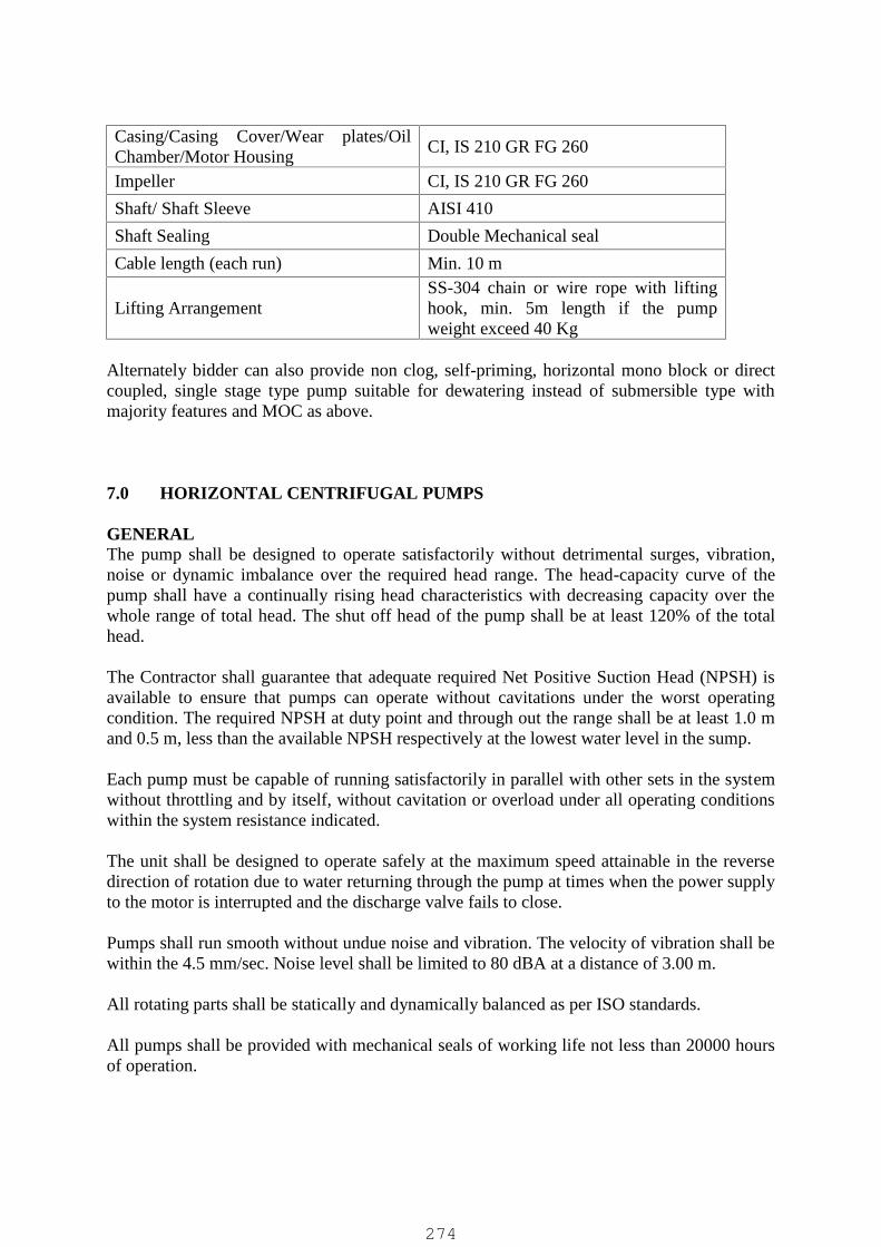
Casing/Casing Cover/Wear plates/OilChamber/Motor Housing
CI, IS 210 GR FG 260
Impeller CI, IS 210 GR FG 260
Shaft/ Shaft Sleeve AISI 410
Shaft Sealing Double Mechanical seal
Cable length (each run) Min. 10 m
Lifting ArrangementSS-304 chain or wire rope with liftinghook, min. 5m length if the pumpweight exceed 40 Kg
Alternately bidder can also provide non clog, self-priming, horizontal mono block or directcoupled, single stage type pump suitable for dewatering instead of submersible type withmajority features and MOC as above.
7.0 HORIZONTAL CENTRIFUGAL PUMPS
GENERALThe pump shall be designed to operate satisfactorily without detrimental surges, vibration,noise or dynamic imbalance over the required head range. The head-capacity curve of thepump shall have a continually rising head characteristics with decreasing capacity over thewhole range of total head. The shut off head of the pump shall be at least 120% of the totalhead.
The Contractor shall guarantee that adequate required Net Positive Suction Head (NPSH) isavailable to ensure that pumps can operate without cavitations under the worst operatingcondition. The required NPSH at duty point and through out the range shall be at least 1.0 mand 0.5 m, less than the available NPSH respectively at the lowest water level in the sump.
Each pump must be capable of running satisfactorily in parallel with other sets in the systemwithout throttling and by itself, without cavitation or overload under all operating conditionswithin the system resistance indicated.
The unit shall be designed to operate safely at the maximum speed attainable in the reversedirection of rotation due to water returning through the pump at times when the power supplyto the motor is interrupted and the discharge valve fails to close.
Pumps shall run smooth without undue noise and vibration. The velocity of vibration shall bewithin the 4.5 mm/sec. Noise level shall be limited to 80 dBA at a distance of 3.00 m.
All rotating parts shall be statically and dynamically balanced as per ISO standards.
All pumps shall be provided with mechanical seals of working life not less than 20000 hoursof operation.
274
A stationary coupling guard shall be provided for the coupling conforming to all relevantsafety codes and regulations. Guard shall be designed for easy installation and removal,complete with necessary support, accessories and fasteners.
The pumping unit shall be provided with a common base plate. The base plate shall be ofsufficient size and rigidity to maintain the pump and motor in proper alignment and position.
The power rating for motors to drive pumps should be selected with safety factor as per thetable furnished in electrical specifications.
Features of ConstructionPump shall be horizontal centrifugal, non-clog, end-suction, dry-pit installation type, wearresisting, single stage type/ type as applicable. The pump shall have end suction and topdischarge nozzle shall be oriented in horizontal direction. It shall be self venting type.
Pump casing shall be of robust construction. Liquid passages shall be designed to allow freepassage of solids and finished smooth. The tongue shall be straight across and filed to asmooth rounded edge. Casing shall be provided with wearing ring.
Hand hole shall be provided in the casing to allow easy access to the impeller as well as tothe casing throat. Casing drain connection with collard plug shall be provided.
Impeller shall be non-clog, enclosed type with smooth blunt edges and large water ways so asto allow free passage of stringy materials and large size solids. It shall be free from sharpcorners and projections likely to catch and hold rags and stringy materials.
Replaceable shaft sleeves shall be provided and shall be securely locked or keyed to the shaftto prevent loosening. The surface hardness of the shaft sleeve shall be minimum 300 BHN.
Bearings shall be easily accessible for inspection and maintenance.
Stuffing box shall be of such design that they can be repacked without removal of any partother than gland and lantern ring. Stuffing box drain with pipe connection shall be providedat the lowest point so that no leakage accumulates in it.
Lantern ring shall be sandwiched between packing and shall be easily removable.
Lantern ring shall be of axially split type. Grease shall be used for stuffing box sealing.
Water will not be available for this purpose. Gland shall be of split type.
Pump and motor coupled through flexible coupling shall be mounted on a common baseplate. Coupling guard bolted to the base plate shall be provided.
Tapping shall be provided at suction and discharge nozzles for pressure gauge connection.
These tapping shall be plugged by collard plugs.
Materials of Construction:Casing CI IS210 Gr FG 260
275

Impeller SS ASTM A743 Gr CF8MShaft ASTM A276 SS 431Shaft sleeve ASTM A276 SS 431Casing ring SS AISI 410Shaft Seal Gland PackedBase Plate CI/ Epoxy Coated MS
8.0A HORIZONTAL CENTRIFUGAL PUMPS (HSCF)(CLEAR / TREATED WATER PUMPS, ETC.)
A. GENERALThe Pump shall be Centrifugal, Horizontal shaft, Horizontal split case type designed andmanufactured for pumping liquid like raw / potable water. Pump shall be directly coupled to motorthrough coupling, mounted on common base plate with foundation bolts and all other requiredaccessories.
The pump shall be designed to operate satisfactorily without detrimental surges, vibration, noise ordynamic imbalance over the required Head-Capacity range. The head-capacity curve of the pumpshall have continuously rising head characteristics with decreasing capacity over the wholeperformance range of pump. The shut off head of the pump shall be at least 120% of the total head.
The pump shall be selected in such a way so that operating point shall lie on best efficiency point(BEP) or within 15 % of BEP flow on either side meeting NPSH requirement. Pump selected withduty point lying on right side of BEP beyond 15 % limit shall not be accepted.
The pump shall be selected with intermediate diameter of Impeller. The rated impeller diameter shallbe at least 10 mm smaller than the maximum Impeller dia. possible for the offered pump model. Thepump selected for rated performance below minimum Impeller diameter shall not be accepted.
The manufacturer shall ensure while selecting pump that required Net Positive Suction Head(NPSHR) is less than available NPSH (NPSHA) to ensure pump’s operation without cavitations underthe worst operating condition. The required NPSH at duty point and throughout the range shall be atleast 1.0 m and 0.5 m, less than the available NPSH respectively at the lowest water level in the sump.However, the NHPSR of the offered pump shall not be more than 7.5m (meeting flooded suctionconditions) or lower as per the design requirement / as per the conditions indicated in tender drawings.
Each pump must be capable of running satisfactorily in parallel with other sets in the system withoutthrottling and by itself, without cavitations or overload under all operating conditions within thesystem resistance indicated. All pump shall have identical performance.
The pump shall be designed to start with delivery valve fully open.
The unit shall be designed to operate safely at the maximum speed attainable in the reverse directionof rotation due to water returning through the pump at times when the power supply to the motor isinterrupted and the discharge valve fails to close.
Pump’s rotating assembly shall be statically and dynamically balanced as per ISO standards and shallrun smooth without undue noise and vibration. The velocity of vibration shall be within the 4.5mm/sec. Noise level shall be limited to 85 dB A at a distance of 1.0 m
The power rating of motors to drive pumps shall be suitable to meet maximum requirement of powerfor the rated impeller throughout its’ performance range.
276

B. FEATURES OF CONSTRUCTION
PUMP:Pump shall be horizontal centrifugal, single / double stage; Horizontal split case Type suitable for dry-pit installation with wearing rings. The pump shall have side suction and side discharge nozzle locatedin lower part of delivery casing.
The SS heavy duty strainer shall be provided at pump suction so as to restrict the entry of oversizesolids / floating material in order to run pump set without clogging and interruption. The strainer shallhave sufficient suction area and openings throughout its surface to let water in easily. The size of theholes on strainer shall not be more than max. permissible solid handling size/capacity of pump orlower as per the permissible solid handling capacity of pump and as recommended by pump vendor.The strainer shall be supplied by pump vendor only as per the area of opening and openingrequirement to suit the offered pump design.
CASING:Pump casing shall be of robust construction. Liquid passages shall be designed to allow free passageand finished smooth. The tongue shall be straight across and filed to a smooth rounded edge. Casingshall be provided with wearing rings. Casing drain connection with collard plug shall be provided atlowest part of casing. Tapping shall be provided at side center of suction and discharge nozzles forpressure gauge connection. These tapping shall be plugged by collard plugs.
IMPELLER:Impeller shall be enclosed, single or double suction type or as per manufacturer design with smoothand large ways so as to allow free passage to the fluid being pumped. It shall be free from sharpcorners and projections likely to catch and hold rags and stringy materials. Impeller shall be staticallyand dynamically balanced at rated speed as per applicable standard so as to avoid vibration.
SHAFT SLEEVE:Replaceable shaft sleeves shall be provided and shall be securely locked or keyed to the shaft toprevent loosening. Necessary rubber ‘O’ ring or CAF / Teflon gaskets shall be provided betweenimpeller and shaft sleeve to prevent liquid passage between shaft and sleeve. In no case shaft shall bein contact with liquid. The surface hardness of the shaft sleeve shall be minimum 250 BHN.
STUFFING BOX:Pump shall be provided with stuffing box arrangement as mentioned in specific requirement forshaft sealing.
Pump when required with gland packed Stuffing box; same shall be of such design that they can berepacked without removal of any part other than gland and lantern ring. Stuffing box drain with pipeconnection shall be provided at the lowest point so that no leakage accumulates in it. Lantern ringshall be sandwiched between packing and shall be easily removable. Lantern ring shall be of axiallysplit type and shall be sealed with self liquid being pumped or as recommended by the pumpmanufacturer. Necessary pipe connections and piping for this shall be provided by pumpmanufacturer. Gland shall be of split type. Gland bolts and nuts shall be of SS.
Pumps required with Mechanical Seals shall be provided with necessary piping for cooling, flushingand lubrication of seal faces as recommended by seal manufacturer. Seal shall be designed andselected for the specified application in order to perform the equipment trouble free and working lifenot less than 40,000 hours of operation. Seals shall be covered with SS 304 mechanical seal cover andshall be tightened with SS fasteners as per the specifications.
Pumps shall be supplied with Rubber liquid deflector to prevent liquid entry to bearings, in case offailure of mechanical seal / leakage through stuffing box.
277

BEARINGS:Pump shall be provided with anti friction grease lubricated bearings. The whole rotating assembly ofpump shall rest between minimum two bearings for smooth operation. Bearings shall be easilyaccessible for inspection and maintenance. Bearings shall be of SKF / FAG make only.
COUPLING:The pump shall be coupled with electric motor mounted on a common base plate using pin bush typeof KTR / Rathi / Fenner make only. Coupling shall be statically and dynamically balanced at ratedspeed.
COUPLING GUARD:A stationary coupling guard shall be provided for the coupling conforming to all relevant safety codesand regulations. Coupling guard design shall be such that coupling is covered from both the sides aswell apart from top cover. Guard shall be designed for easy installation and removal, complete withnecessary support, accessories and SS fasteners.
BASE PLATE:The pumping unit shall be provided with a common drain rim type base plate with 25mm dia. drainpipe , terminated to nearest drain pit/trench. The base plate shall be of sufficient size and rigidsufficient to maintain the pump and motor in proper alignment and position. Base plate shall besupplied by pump manufacturer only. The base plate shall be grouted on the RCC foundation with thehelp of “J” type foundation bolts of manufacturer’s recommended / approved size.
C. MATERIAL OF CONSTRUCTION:The specific requirement shall be considered as under:
Pump Casing CI IS210 Gr. FG 260Casing / Impeller wear ring CF8M / Bronze, IS 318, Gr. LTBShaft AISI 410Shaft sleeve AISI 410Impeller CF8M / Bronze, IS 318, Gr. LTBShaft Seal Gland Packed. / Mechanical SealLantern Ring Bronze, IS 318, Gr LTBLiquid Deflector Natural RubberGland CI IS210 Gr. FG 260Base Plate (Drain Rim type) CI / MS - Epoxy CoatedSuction Strainer SS 304Bolts, Nuts, Fasteners, etc. Wetted - SS 304, Non-Wetted - GI
The above MOC is min. requirement and if process requirement is higher as indicated inprocess data sheet the stringent MOC to be provided.
8.0B VERTICAL TURBINE (V.T.) CENTRIFUGAL PUMPS(CLEAR / TREATED WATER PUMPS, ETC.)
A. GENERAL
The Pump shall be single or multi stage, wet pit, Centrifugal, Vertical shaft, Vertical Turbinetype designed and manufactured to operate without affected by large water level fluctuationsand pumping raw / potable water with suction strainer, bell mouth, column assembly,discharge elbow, motor stool, thrust bearing, non reversing device, etc . Pump shall be
278
directly coupled to motor through coupling, mounted on motor stool, sole plates withfoundation bolts and all other required accessories.
The vertical turbine pump shall comply to all currently applicable statutes, regulations andsafety codes and performance shall conform to IS 1710 or its latest edition.
The pump shall be designed to operate satisfactorily without detrimental surges, vibration,noise or dynamic imbalance over the required Head-Capacity range. The head-capacity curveof the pump shall have continuously rising head characteristics with decreasing capacity overthe whole performance range of pump. The shut off head of the pump shall be at least 120%of the total head.
The pump shall be selected in such a way so that operating point shall lie on best efficiencypoint (BEP) or within 20 % of BEP flow on either side meeting minimum submergencerequirement.
The pump shall be selected with intermediate diameter of Impeller. The rated impellerdiameter shall be at least 10 mm smaller than the maximum Impeller dia. possible for theoffered pump model. The pump selected for rated performance below minimum Impellerdiameter shall not be accepted.
The manufacturer shall ensure while selecting pump that required Net Positive Suction Head(NPSH) is less than available NPSH to ensure pump’s operation without cavitation’s underthe worst operating condition. The required NPSH at duty point and through out the rangeshall be at least 1.0 m and 0.5 m, less than the available NPSH respectively at the lowestwater level in the sump.
Each pump must be capable of running satisfactorily in parallel with other sets in the systemwithout throttling and by itself, without cavitation or overload under all operating conditionswithin the system resistance indicated. All pumps shall have identical performance.
The pump shall be designed to start with delivery valve fully open.
The unit shall be designed to operate safely at the maximum speed attainable in the reversedirection of rotation due to water returning through the pump at times when the power supplyto the motor is interrupted and the discharge valve fails to close.
Pump’s rotating assembly shall be statically and dynamically balanced as per ISO standardsand shall run smooth without undue noise and vibration. The velocity of vibration shall bewithin the 4.5 mm/sec. Noise level shall be limited to 85 dB A at a distance of 1.5 m
The power rating of motors to drive pumps shall be suitable to meet maximum requirementof power for the rated impeller through out its’ performance range.
B. FEATURES OF CONSTRUCTION
PUMP
Pump shall be vertical turbine comprising of complete pump unit assembly, column assemblyand discharge head assembly. , Sole plates, motor stool, Thrust bearing housing, etc.
279

The Pump unit assembly shall be consisting of suction strainer, bell mouth, impellers,Impeller/pump shaft, Shaft sleeves, bowl assembly comprising of suction covers, bowl / s,pump shaft bearings, wear rings, etc. The bowl shall have integral housing to provide supportfor pump shaft bearings.
The column assembly shall consist of the column pipes, bearing spiders to hold Linebearings, line bearings, Line shafts, couplings, shaft sleeves, shaft enclosing tubes, etc. toconvey the liquid handled from bowl assembly to shaft assemblies and discharge elbow.
The discharge head assembly shall consist of discharge head with side discharge flange,stuffing box assembly, motor/drive shaft, thrust bearing assembly with bearing coolingsystem, etc.
BOWL
The Pump bowl shall be of robust construction and free from blow holes and otherdetrimental defects. Liquid passages shall be designed to allow free passage and finishedsmooth. Bowl shall be provided with replaceable wearing rings / suction covers and shallcontain bushes to serve as bearings for the impeller shaft.
IMPELLER:
Impeller shall be enclosed / semi open type, single suction type with smooth and large waysso as to allow free passage to the fluid being pumped. It shall be free from sharp corners andprojections likely to catch and hold rags and stringy materials. Impeller shall be statically anddynamically balanced at rated speed as per applicable standard so as to avoid vibration.Impellers shall be adjustable vertically by means of an adjusting nut in the head assembly.
Impeller shall be securely fastened to the impeller shaft with keys, taper bushings or lock-nuts.
The impeller adjustment shall be such that the impeller runs free in any installed conditiondespite extension of line shaft (caused by hydraulic down thrust), the weight of shafting andweight of impellers.
The bowl & impeller shall be designed not to generate internal resonance.
IMPELLER SHAFT:
The impeller/pump shaft shall be made of high tensile alloy steel having min. 230 BHNhardness. It shall be guided by shaft bearings above and below each impeller. The buttingfaces of the shaft shall be machined square to the axis and the shaft ends shall be chamferedat the edges.
LINE SHAFT
The line shaft shall be designed so as to transfer required power and rotate the completerotating assembly from stand still to rated speed without generating any vibration, noise orshear of shaft.
280

The critical speed of the shaft shall be at least 30 % lower or above the operating speed.
The shaft shall be furnished with interchangeable sections having a nominal length of 1.25 or2.5 m or unless specified in specific requirement. The maximum permissible error in the axialalignment of the thread axis with the axis of the shaft shall be 0.05 mm in 150 mm.
Line shafts shall be connected through threaded couplings designed with a safety factor of150 % of shaft factor and shall have positive locking/tightening during pump operation.
LINE SHAFT BEARINGS:
Line shaft bearings shall be of Thordon type, in general, with outer shell of brass or asspecified in specific requirement. Anti-friction bearing shall be of standard type and shall beselected to give 20000 hours continuous operation at rated conditions.
The Line shaft bearings shall be housed in bearing spider (in case of self lubricated pumps)and sandwiched between flanges of two consecutive column pipes. Bearing spiders shall bedesigned to support & locate the line shaft in the center.
COLUMN PIPE:
The standard lengths of column pipe shall be same as of line shaft nominal length, i.e. 1.25 m/ 2.5 m maximum/as specified in specific requirement. No part in the column pipe such as theflange outside dia. shall exceed the bowl outside dia. The column pipe shall be welded MildSteel pipe or shall be manufactured from tubes confirming to IS 1978 or grade A of IS 2062with internally & externally epoxy coated. The column pipe shall be double flanged ended.
The column pipe size shall be sized generally for velocity range of 2 to 3 m/sec and withmax. permissible velocity of 3.15 m/sec velocity. Further the column losses shall not exceed0.5m per 10m column length and the rest pump losses (entry, discharge bend, etc.) shall notexceed 0.5m.
SHAFT SLEEVE:
Replaceable shaft sleeves shall be provided for each line/transmission shaft bearing and shallbe securely locked or keyed to the shaft to prevent loosening.
STUFFING BOX:
Pump shall be provided with stuffing box arrangement as mentioned in specificrequirement for shaft sealing.
Pump when required with gland packed Stuffing box; same shall be of such design that theycan be repacked without removal of any part other than gland and lantern ring. Stuffing boxdrain with pipe connection shall be provided at the lowest point so that no leakageaccumulates in it. Lantern ring shall be sandwiched between packing and shall be easilyremovable. Lantern ring shall be of axially split type and shall be sealed with self liquid beingpumped or as recommended by the pump manufacturer. Necessary pipe connections and
281

piping for this shall be provided by pump manufacturer. Gland shall be of split type. Glandbolts and nuts shall be of SS.
THRUST BEARINGS:
Pump shall be provided with anti-friction Thrust bearings. The whole rotating assembly ofpump shall rest on minimum one bearing for smooth operation. Bearings shall be easilyaccessible for inspection and maintenance. Bearings shall be of SKF / FAG make only.
COUPLING:
The pump shall be coupled with electric motor mounted on a MS /CI motor stool using pinbush type coupling of KTR / Rathi / Fenner make only. Coupling shall be statically anddynamically balanced at rated speed.
DRIVER:
Driver shall be coupled through flexible coupling to the head shaft.
D. MATERIAL OF CONSTRUCTION:
The specific requirement shall be considered as under:
Bowl/Suction Bell & cover : CI IS210 Gr. FG 260 with 1.5% to 2% NiPump Shaft : AISI 316Line Shaft : AISI 410Head Shaft : AISI 410Shaft sleeve : AISI 410-HShaft Coupling : SS 410Impeller : CF8MImpeller wear ring : CF8MCasing wear ring : CF8MShaft Seal : Gland PackedGland Packing : Graphited CottonGland : CI IS 210 Gr FG 260Lantern Ring : Bronze, IS 318, Gr LTBLength of each Line Shaft : 1.25 / 2.5 m& Column PipeColumn Pipe : MS ERWMotor Stool : MS - Epoxy CoatedStrainer : SS 304 of 5 mm Ø round bar of 50 mm x 50mm. opening.Sole plates : MS - Epoxy CoatedHardware (Nuts, Bolts, Fasteners, etc.) : SS-304
9.0 ULTRAFILTRATION SYSTEM
282

The primary purpose of the UF system is to remove sub-micron particles including bacteria,large colloids and other suspended solids from the Fiber disc filter permeate.
Scope of SupplyThe scope of supply for the UF system shall consist of, but not limited, to the following:
A complete, approved micro porous membrane system, based on ultrafiltration (UF)membranes and associated pumps and process equipment as necessary to meet theperformance requirements All equipment associated with the backwash system including,pumps, chemical addition systems, air blowers, air compressors, dryers and receivers asnecessary to sustain the short term permeability of micro porous membranes. This alsoincludes the pre chemical dosing before UF along with in line static mixer provision as perprocess requirement.
Chemical storage, handling, injection and mixing systems, pumps tanks, heaters andinstrumentation associated with the micro porous membrane clean-in-place system;
All interconnecting pipe work, fittings, and valves;
All interconnecting wiring (power and control);
All required process control and monitoring instrumentation; and
All on-line analyzers for performance monitoring and verification.
Performance Requirements
The Contractor shall supply a UF system that fully complies with the following performancerequirements:
a) Filtrate water qualityThe product water from the UF process (or filtrate) shall meet the following water qualityrequirements:
(1) The filtrate turbidity for any 24-hour period shall not exceed 1 NTU 95 percent of thetime and shall never exceed 2.0 NTU.
(2) The Silt Density Index (SDI) of the filtrate shall not exceed 3.0
b) The UF system shall be provided by the bidder as per his design considering minimumdesign requirements specified in the tender.
c) Process RecoveryThe UF system shall achieve a product recovery of greater than 90 percent on a dailyaverage basis. Product recovery is defined as net filtrate produced over a 22 hour perioddivided by the effluent fed to the process over the same time 22 hour period. TheContractor shall provide calculations that show an individual UF train, be it a skidmounted unit , can achieve a recovery of 90% based on the duty membrane loading rate,the minimum expected backwash interval and the maximum volume of water dischargedduring the backwash cycle.
283

d) Membrane integrity testThe UF system will incorporate a Membrane Integrity Test system. The membraneintegrity test system will be based on some variation of the bubble point pressure conceptfor a cylindrical pore.
e) Membrane Design FluxThe Contractor shall supply a UF System that has been designed with a Gross maximummembrane flux of 40 LMH for IN TO OUT membrane and 60 LMH for OUT TO INmembrane.
f) Redundant CapacityThe Contractor shall supply and install additional membrane area so that the loading onthe membrane area shall not exceed the design flux with 10% of the membrane area forcleaning or maintenance.
Features of the Ultra filtration SystemThe Contractor shall provide a complete UF system, which includes, as a minimum, thefollowing components:
(i) Micro porous membraneThe UF system shall use a pressurised micro porous, hollow fiber membrane spun froman organic polymer (PES or PVDF) as ultrafiltration membrane. Micro porousmembranes prepared from inorganic materials or micro porous membranes cast in flatsheet or tubular configurations shall not be accepted.
The hollow fiber membrane may be operated cross flow mode. For UF systems with thecross flow mode the Contractor shall be responsible for supplying all pipe work, valvesand fittings required to return excess feed to the suction side of either the feed pump orthe dedicated feed recirculation pump as required.
The Contractor shall ensure that adequate chlorine is present in the feed to the hollowfibre membrane at all times during operation to control fouling. The hollow fibermembrane shall be chemically resistant to continuous exposure to feed water containing5.0 mg/L of chloramine.
(ii) Membrane elementsMultiple hollow fiber membranes shall be packaged as elements. The nomenclatureadopted by the UF manufacturer for the elements may include sub-modules, modules.The Contractor shall supply hollow fiber elements that are specifically designed formunicipal wastewater applications.
The ultra filtration membrane shall have a nominal pore size smaller that 0.08 micron atminimum 98% pore distribution. At the ultra filtration membrane barrier, the contractorshall guarantee a removal efficiency of 6- log for all Bacteria, protozoa and Helminthmicroorganism species and that of 4- log for all other remaining virus species. Themembranes and associated equipment shall be suitable for the operation with watertemperature anticipated at any such sewage treatment facility in general.
(iii) System Configurations
284

The UF System shall consist of multiple process units. Each process unit shall containmultiple hollow fibre elements. The process units shall be configured as an array ofpressure vessels housing the membrane elements. For the UF system, the Contractorshall be fully responsible for the detailed design and layout, and provide all associatedequipment, tanks and controls to provide a fully functional, operating system whichmeets the specified performance requirements.
Each array system shall be capable of operation independent from the other arrays. Theseindependent operations shall include filtering, backwashing and membrane chemicalcleaning. Each array shall have a local control interface with control from the controlpanel or from fully integrated local PLC’s, inlet and outlet connections, stop valves,control valves, actuators, instrumentation, membrane integrity checking systems, processand filtrate quality monitoring systems, to provide an independent operating unit whichis fully functional. Each array shall have its own membrane integrity monitoring system,for example, an off-line pressure test system.
Exposure to higher concentration levels of membrane wash chemical and cleaning agentsmay have potential to damage or degrade the structure integrity of UF membranes. Inorder to avert such risk, the contractor shall design, supply and install online monitoringand detection system as recommended by the UF membrane manufacturer. Alarmsshould be provided to notify the integral part of the ultrafiltration plant and be allowedfor in the PLC logic and controlled and monitored from the local and central SCADA.
(iv) Access to ModulesThe Contractor shall provide clear space around the arrays that allows for unobstructedaccess to the membrane elements as required for installation inspection, integrityprofiling, in-situ maintenance and removal of the elements.
The Contractor shall supply all tools and devices required to safely and efficientlyremove the membrane elements. The Contractor shall submit all catalogues andoperation and maintenance details associated with the tools and devices for review andapproval to the CLIENT prior to installation of the membrane elements.
The Contractor is responsible for the design, certification, supply and installation of thecranage required to remove membrane from a array. The cranage shall be provided as anelectric lifting hoist mounted on a mobile gantry that travels along the process Arrays.Alternatively, the cranage shall be provided as an electric lifting hoist attached to a selfsupported overhead monorail. The Contractor shall submit all calculations, detaileddrawings, certifications which indicate that the cranage is structurally sound and safe tooperate for review and approval to the CLIENT prior to installation. Each array, shallhave its own on-board process performance monitoring instrumentation, including, as aminimum, the following:
a) Inlet (Feed): pressure, flow, turbidity (one common for entire system),temperature;
b) Recirculation Loop (where utilised): pressure, flow, turbidity (one common forentire system);
c) Outlet (Filtrate): pressure, flow, membrane flux rate (calculated), turbidity;
285

d) Transmembrane pressure (TMP);
e) Backwash Water Inlet: pressure;
f) Backwash Water Outlet: pressure, flow
g) Total unit run (elapsed) time;
h) Elapsed Time: since last backwash;
i) Filtered Water Volume: since last backwash;
j) Elapsed Time: since last membrane chemical cleaning; and
k) Filtered Water Volume: since last membrane chemical cleaning.
The Operator shall be able to adjust process set points from the control system operationalstations in the Control Room.
Adjustable set points shall be provided for each of the membrane filtration systems and shallinclude, but not be limited to, the following:
i. Number of process units on-line and off-line;ii. UF Feed Tank operating water level range;
iii. Filtrate tank water level settings;iv. UF feed pumps start and stop based on flow UF feed tank levels, slow start and
slow stop operation, adjustable pump/motor speed based on UF array flow.v. Control set points for the dosing of sodium hypochlorite to the feed water and
residual chlorine levelvi. Filtrate water quality limits, such as turbidity, particle counts, to initiate backwash
or alarm on poor water qualityvii. All set points relating to UF backwash initiation, duration, and frequency
viii. Backwash water flow rates, including slow start and slow stop modes.ix. Feed water inlet flow rate through each train or flow streamx. Alarm settings
Tools and Devices
The Contractor shall provide handheld/portable instruments for the monitoring of membranemodule integrity, and the checking of individual membrane elements for integrity such as‘sonic sensing’ equipment. The Contractor shall supply any special tools required forremoving membrane elements.
Membrane Element Life
The Contractor shall define the guaranteed membrane element life in the pro-rated membranewarranty.The Contractor is advised that the following criteria shall be used for the purposes of definingmembrane module life:a) Failure to meet the specified filtrate quality criteria;
286
b) Failure to meet specified integrity test requirements; and,
c) Failure to restore the permeability of the membrane to allow the system to achieve thespecified MC and RC CIP frequency requirements at the design flow using only the dutymembranes.
The Contractor shall provide all details of membrane life and pro-rata warranty life asrequired in the Technical Particulars required for Process Equipment and the TechnicalParticulars required for Equipment Performance Guarantees. The membrane manufactured inchina is not acceptable.
10.0 MICRON CARTRIDGE FILTER (FOR CIP & SUCH OTHERAPPLICATIONS)
For the feed water, each of the micron cartridge filter vessel shall have a capacitysufficient to hold the required number and size of the cartridge elements to filter.
Micron cartridge filter elements shall be made of synthetic non degradable material suchas polypropylene. The filter shall be provided with a differential pressure transmitter andthereby indicating the extent of its fouling. Micron cartridge vessel shall be provided withpressure relief valve, drain valve and vent valve.
The filter elements shall be cylindrical cartridges constructed from continually woundpoly propylene fibers which have a 5 micron nominal 90% efficient rating. The filterelements used in the membrane cleaning system.
The filter vessel shall be designed in accordance with relevant Indian Standard code. Thedesign pressure of MCF shall be equal to the shut off pressure of the cartridge filter feedpumps + 5% Margin + available maximum Static Head at pump suction or 6 kg/ sqcm (g)whichever is higher.
The MCF shall be hydro tested to a pressure of 1.5 times of design pressure for 30minutes duration.
The design temperature of MCF shall be 45 Deg C The minimum thickness of the vessel shall not be less than 6 mm The material of construction shall be SS 316 strainer / CSEP housing. The cartridge filter element shall be proven polypro propylene spiral wound type material
provided for the required no of cartridge. Necessary top connectors shall be providing for holding the cartridge. MCF top cover shall be dished end of ellipsoidal or torispherical form single piece made
by pressing/ forging MCF bottom plate can be dished end / un stayed flat plate or stayed flat plate with stiffer
11.0 CAST IRON OPEN CHANNEL GATES
GENERAL:The construction of cast iron open channel gate shall be strictly in accordance with the specificationsmentioned hereunder. The open channel gate shall be capable of performing the isolation duties inwater / waste water treatment plant for those applications where the height of water is at least 300 mmless than the height of opening / shutter. They shall be so constructed that there is no undue wear ordeterioration during its operative life and so designed that the maintenance is kept to a minimum.
287

DESIGN:The open channel gate shall comprise of frame suitable for mounting in the parallel side walls of thechannel. The frame shall be self-contained type with a yoke on top for mounting of the operatingarrangement. The shutter shall move within the frame guides and shall be provided with suitableconnecting arrangement to enable connect it to the spindle.
Water sealing on sides and bottom shall be affected by means of non-corroding seating faces securedin groves of frames and remaining in forced contact with corresponding sealing arrangement mountedon shutter. Bottom sealing arrangement shall be flush bottom type to ensure that invert level ofchannel on either side of gate remains flush with the invert of the gate.
The spindle shall be rising type and provided with stop nut to avoid over closing of gate. The risingspindle shall be provided with transparent scratch proof and UV resistant polycarbonate cover tube toprotect the threaded portion from the effect of dust, dirt and rain. The operating arrangement shall bemanual or electric as specified elsewhere in the tender specifications. In case of manual operationoperating mechanism should be such that the effort required to open / close the gate does not exceed18 kgs with diameter of hand wheel / crank restricted to max. 750 mm. However for all gates of sizeabove 1000 mm x 1000 mm or above 1 m2 shutter area shall be gear operated type only.
MATERIAL OF CONSTRUCTION:The material of construction for various components shall be as under:
Gate frame, shutter/Door Cast iron IS 210 FG 200Side Guides Cast iron IS 210 FG 200Seating faces Stainless Steel ASTM A 240 type 304Rubber Seals EPDM Rubber to ASTM D 2000Rubber seal retainer bar Stainless Steel ASTM A 240 type 304Assembly bolts, nuts and fasteners Stainless Steel ASTM A 276 type 304Stem & connecting pin Stainless Steel ASTM A 276 type 304Yoke Mild Steel to IS : 2062 grade A, epoxy paintedHeadstock Cast iron IS 210 FG 200Spindle cover tube / pipe hood Polycarbonate
12.0 CAST IRON SLUICE GATES
GENERAL:The construction of cast iron sluice gates shall be strictly in accordance with the specificationsmentioned hereunder. The Sluice gates shall be capable of performing the isolation duties in water /waste water treatment plant & pumping stations for isolation of flow in & out of a closed conduit aswell as in those applications where water head is more than the height of shutter / opening. They shallbe so constructed that there is no undue wear or deterioration during its operative life and so designedthat the maintenance is kept to a minimum.
The Sluice gates shall be Wall thimble mounted only except for shallow channels. For shallowchannels of up to 3.5 meter depth with water head not exceeding 2.0 meter and Gate/ Shutter area notexceeding 1.5 m2 wall mounted gates can be accepted instead of wall thimble.
The gate shall be designed for seating and unseating head of minimum 5m liquid depth or as perdesign requirement (except for shallow channels / units <5m total height for which it shall be subjectto top of channel / unit and accordingly head shall be as per actual full height).
DESIGN & CONRUCTIONAL DETAILS:
288
The sluice gates shall be manufactured generally as per IS-13349-1992. The constructional featuresand details of components of the required gates are to be as under:
GATE FRAME:a) The gate frame will be made from cast iron and shall be sufficiently rigid to withstand the
designated water head. The gate frame shall either be flat back type or flange back type to suit thedesigned head and site condition.
b) Back flange of the gate aperture frame to be precisely machined flat and drilled to engage with theCast iron wall thimble mounted on the wall. A rubber gasket will be provided between the wallthimble and the gate for ease in future dismounting of the gate for repairs / replacement and sealany leakage between the flange of frame and wall thimble.
c) The gate frame of these sluice gates shall either be self contained type or non self contained typedepending upon site requirement. In case of non self contained gates the frames shall have shortlength extension guides and shall be without yoke at their top. The length of extension guides insuch cases shall be sufficient to engage atleast half the overall vertical height of door when thegate is full open and shall be in accordance with the relevant provisions of IS-13349. In case ofself contained gates the frames shall have full length extension guides and shall be provided witha yoke at their top. The length of extension guides in such cases shall be sufficient to engage theoverall vertical height of door when the gate is full open position.
WALL THIMBLE:a) The Wall thimble will be made from cast iron for placement in the concrete wall. Its front flange
will be machined, drilled and tapped to match with the frame flange.
b) The cross section of the thimble shall be F shaped and the depth of thimble shall be minimum 300mm long. Gates subjected to high unseating heads shall have thimble cross section shaped E.
c) To permit entrapped air to escape as the thimble is being encased in concrete, cast holes of 40mmdiameter shall be provided at the bottom of wall thimble in each entrapment zone.
GATE SLIDE / SHUTTER / DOOR:a) The gate slide / shutter / door will be made from cast iron and shall be sufficiently ribbed to
withstand the designated water head.
b) The gate slide / shutter will be provided with integral pocket to house the thrust nut used toconnect the stem with the slide.
SEATING/SEALING FACES:a) Materials: These should be of Stainless steel or Bronze or as specified.
b) Fitment: The facings shall be attached to flat / rectangular / dovetailed machined faces of gateframe and door, depending upon the applicable water head, and be secured in place using taperscrews. The taper screws adopted for facings shall be of same material as that of the seat facings.
c) The front faces of integral extension guides which can come in contact with the sealing faces ofdoor while opening, shall also be fitted with sealing faces of the same material as that of thesealing faces on door. This is required to offer non corroding smooth sliding surfaces to thesealing faces of door/shutter during its vertical travel for opening and enhance the effective life ofgate.
d) Finish: The mating seating/sealing faces on the gate frame and door shall be precisely finishedfor proper contact. They should be so finished that the clearance or gap, if any, between themating sealing faces, in gate closed position, does not exceed 0.1mm.
289
WEDGING DEVICES:a) The sluice gates shall be provided with individually adjustable wedging devices to ensure forced
contact between frame and shutter seat facings, when the gate is in closed position.
b) The gates meant for seating head shall be provided only with side wedging devices. Gatesmeant for unseating head of sizes larger than 600 mm, shall be provided with side, top andbottom wedging devices or with side and top wedging devices and flush bottom closingarrangement as required.
c) The wedging devices comprise of wedge brackets fitted on gate aperture frame and door. Thewedge bracket on frame shall remain in fixed position and those on door shall be adjustable orvice versa. A sort of slot and tennon arrangement shall be provided on base of wedge bracketsto prevent any tendency to shift. Provision shall be made to clamp the adjustable bracketsfirmly in adjusted position.
d) The wedging devices shall be made of cast iron. If the wedges/wedge blocks of wedging devicesare of Cast Iron, then these are to be lined with contacting faces of the same material as that ofsealing faces attached to the gate frame and door.
CONVENTIONAL OR FLUSH BOTTOM CLOSING:The sluice gates shall be provided with conventional or flush bottom closure arrangement as required.
Generally as a standard the gates shall be provided with flush bottom closing only especially forgates mounted on bottom of channel, etc. Only the gates mounted above the floor level and havingrequired clearance below for applications like inlet pipe isolation at elevated level, etc. shall be withconventional bottom closing.
The sluice gates provided with conventional bottom closing arrangement involve corrosion resistantmetallic contacting sealing faces at the bottom sill of gate. In such cases, the invert of the gate isrequired to be kept above the floor of the channel / chamber by at least 150mm to 250mmdepending upon the size and type of gate. The contractor should verify whether this clearance isavailable at the site of installation for fitting a conventional bottom closure gate.
In case of conventional closing gate, if the invert of the gate is kept at the same level as that of thechannel/chamber floor, then there remains a slot or a groove at the invert of the gate. Debris, dirtetc. which may settle in this slot and may not allow the gate to close properly and this may give riseto heavy leakages while in operation. With a view to avoid this, in situations where the invert of thegate is to remain at the same level as that of the channel/floor, a Flush Bottom closing gate insteadof Conventional Bottom Closing gate should be provided.
Flush Bottom Closing shall involve a flexible rubber seal at the bottom of the gate, mounted either onthe shutter or on the frame, ensuring that the sealing face remains flush with the floor. The cast ironbar fitted at the bottom of the frame is required to be embedded in the channel / chamber floor and forthis a cut out / recess of ample dimensions is required to be provided beneath the waterway openingalong the gate invert, while constructing the floor. The dimensions of this cut out shall be provideddepending upon the feasibility to do so as per actual site conditions.
This cut out/recess is to be later on filled up with removable asphalt or loose concrete mixed withsand dust or vermiculate after putting the gate in position so that it is possible to break open thissecond stage grout for removal of the gate in future.
The rubber seal employed shall be made of EPDM or Neoprene rubber and the rubber seal retainer baras well as the fasteners for fitting the rubber seal and the retainer bar are of stainless steel.
290

GATE OPERATING HEADSTOCK/LIFT MECHANISM :a) The operating headstocks shall be designed in such a manner as to permit the gate operation by
a single person under the specified maximum operating head with an effort of less than 18kgs onthe crank or hand wheel with a radius not exceeding 375mm. Vendor shall provide torquecalculations in support of same.
b) The headstock may be ungeared or geared type and the geared headstock may be either of singlespeed or of double speed, as might be necessary to make it convenient for one person to open orclose the gate as fast as practicable. Two speed headstocks shall be supplied with gates requiringhigher hoisting capacities. In this type of headstock the low speed is meant for crack opening thegate when the effort required to open the gate is maximum and the high speed is meant for furtherfaster opening after the gate is crack opened.
c) Geared headstock shall be supplied with easily removable crank handle or handwheel with aradius not exceeding 375mm.
d) All the gears of geared headstock shall be kept completely encased in cast iron housing to protectthem from damage, dirt, dust, water etc. and other atmospheric effects and thus ensure theirsmooth operation. Grease nipples shall be provided at proper places for lubricating with grease.
e) Headstock meant for mounting on operating platform shall be supplied with a pedestal/floor standto provide a convenient operating height of approximately 900 mm. The pedestal of the headstockshall be provided with a covered window opening to enable cleaning and greasing of stemthreads.
LIFTING SPINDLE/STEM :The sluice gates shall be supplied with Rising type lifting spindles/stems. The stem shall be providedwith acme / square threading, length of threaded portion being about 400mm more than the height ofwaterway opening. This much extra length is required to allow for a minor variation of approximately100mm on either side of the specified height of operating platform.
The design of stem will be done as per the provision in IS-13349.
STEM BLOCK / CONNECTING BLOCK / THRUST NUT:The rising type stem shall be connected to the door through a stem block/thrust nut housed in a ribbedpocket cast integral with the door. The bottom end of stem shall thread into the stem block and islocked in place by a set screw to prevent the stem from unscrewing. The Stem block shall be castBronze or Gunmetal.
SAFETY STOP NUT:The stem shall be provided with a safety stop nut to prevent the chances of over closing of gate whichmay otherwise damage either the stem or the lifting platform. The stop nut shall be furnished with aset screw for setting it in a fixed position after the gate is installed. Upon installation the safety stopnut should be set in such a way that its bottom remains about 1 to 2 mm away from the top ofheadstock, in gate closed position.
In case of stainless steel stem, the stop nut shall also be of stainless steel material of the same grade.
STEM/SPINDLE COUPLINGS:For ease in transportation and handling, maximum length of one piece stem shall be restricted within5 meter length. Where the stem are required to be furnished in more than one piece, threaded stemcouplings shall be furnished to interconnect different sections of the stem. The couplings shall haveprovision for pinning after inserting in the threaded end of the stem.
In case of stainless steel stem, the couplings shall also be of stainless steel material of the same grade.
291
STEM GUIDE BRACKETS :Longer stems shall be provided with sufficient number of stem guides to prevent buckling of stem.The stem guide bracket to be provided shall be Adjustable Centre Type - wherein a separate stemguide is bolted on to the wall bracket. The stem guide shall be adjustable in the slots on wall bracketin a direction perpendicular to the face of wall. Wall bracket should also offer minor adjustment in thedirection parallel to the wall.
The stem guides shall have machine bored split journals to facilitate erection. The journal shall belined with brass/gunmetal bush.
PIPE HOOD FOR STEM :A Pipe hood shall be provided on the top of headstock in case of rising spindle/stem gates to cover thespindle threads for protection against damage, dirt, dust, water etc. It shall be made of transparentfracture resistant polycarbonate material. The pipe hood shall have vent holes to preventcondensation.
GATE OPENING INDICATING ARRANGEMENT :Gate opening indicating arrangement shall be provided to indicate the position of the shutter. Thisshall comprise of scale mounted on the pipehood and an indicator nut mounted on the rising spindle toshow the extent of the opening and closing. The minimum scale graduation shall be 25 mm.
MATERIAL OF CONSTRUCTION:The material of construction for various components shall be as under:
Gate Frame, Shutter , Thimble, Plain Cast iron IS 210 FG 200Headstock, Wedges, Stem Guides Plain Cast iron IS 210 FG 200
Stem Guide shall be with LTB-2 LiningSeating / Sealing Faces & Wedge Lining Stainless Steel ASTM A 240 type 304Rubber Seals (If Applicable) EPDM Rubber to ASTM D 2000Rubber Seal Retainer Bar (If Applicable) Plain Cast iron IS 210 FG 200 / Stainless Steel
ASTM A 240 type 304Stem, Stem Guide Brackets, Coupling & StopNut
Stainless Steel ASTM A 276 type 304
Assembly Bolts, Nuts and Fasteners Stainless Steel ASTM A 276 type 304Yoke (If Applicable) Mild Steel to IS : 2062 grade A, Epoxy PaintedStem block Leaded tin bronze to IS 318 type LTB2Lift nut for manual ungeared Leaded tin bronze to IS 318 type LTB2Pipe Hood for Stem Transparent fracture resistant polycarbonate
materialOperationLift nut for manual geared / actuatorOperation
As per gear box / actuator manufacturer Std.
13.0 CRANE / HOIST / CHAIN PULLEY BLOCKS
GENERAL
Suitable handling arrangements shall be provided for all equipment’s included inContractor’s scope to transfer the equipment to maintenance area within the building and / or
292

to transfer the equipment outside the building up to ground level for further transportation bythe Employer. For this purpose Contactor shall provide monorails and hoist blocks with crosstravel facility or cranes with 3D movement where specified.
CODES AND STANDARDS
The design, manufacture, inspection and testing of Monorails and Hoists shall comply withall the currently applicable statutes, regulations and safety codes in the locality where theequipment is to be installed. The Monorails & Hoists shall conform to the latest edition of thefollowing standards & codes. Other internationally acceptable standards/codes, which ensureequal or higher performance than those specified, shall also be accepted. Nothing in thisspecification shall be construed to relieve the contractor of the required statutoryresponsibility. In case of any conflict in the standard and this specification, the decision of theEmployer shall be final and binding.
IS:3938 : Specification for Electric Wire Rope Hoist
IS:3832 : Chain pulley blocks
IS:2429 : Round steel short link Hand chain
IS:6216 : Short link Load chain grade 80 Alloy Steel
IS:15560 : Points hooks with shank and safety latch
IS: 210 : Cast Iron castings
DESIGN REQUIREMENTS
If not specified elsewhere in specific requirement of tender specifications / BOQ, thengenerally for the Hoists with more than 2.0 tonne lifting capacity or more than 10.0 M lift,motor operated hoist blocks for both long travel and lift shall be provided where rest otherhoist blocks shall be of hand operated type for both travel and lift. Min. 1.5-3 meter length ofCantilever from edge of building/cladding, shall be provided in monorails coming out of thebuilding to lower the equipment to ground level clearing the building sidewalls / cladding andany other facilities beneath the floor up to ground level.
The exact lift/travel and capacity of the hoisting mechanisms and the mode of liftingequipment’s shall be as per approved G.A. Drawings of Building / Civil Unit.
Clear height shall be maintained when handling one equipment over other, in such casedismantling of any equipment shall not be permitted. The center line of monorail shall notdeviate by more than 500 mm from the center of gravity of any equipment that is to be lifted.Monorails shall be extended outside the building to handle the equipment to ground level. Formonorail/hoist routed inside the buildings, suitable machinery well and removable handrailand grating shall be provided on various floors of buildings, as necessary, to handle theequipment.
13A ELECRIC OVERHEAD TRAVELLING (EOT) CRANES
293
The crane shall be electrically operated, box / standard ‘ I ‘ beam type single / double girder ,complete with all accessories including down shop conductor, crane rails and fixtures, starterpanel, cable up to starter and shall conform to IS:3177, IS:807, IS:3938 and other relevantapproved standards. Crane having 20T or higher capacity shall be double girder typeonly and shall be provided as per the relevant IS and other applicable standards.
The crane bridge shall consist of Single bridge girders on which a wheeled trolley is to run.The bridge trucks and trolley frames shall be fabricated from structural steel. Accesswalkway with safe hand railing as required along the full span length of the bridge girdershall be provided for double girder crane and for single girder crane a centre platform andtwo platforms at drive end shall be provided for ease of maintenance / access to crane drive.Steel shall be tested for quality conforming to IS : 2062, plates more than 20 mm thick shallconform to IS:2062, BS:4360 or relevant internationally approved standards.
The bridge shall be designed to carry safely the loads specified in IS:807, BS:2573 orrelevant internationally approved standards. All anti-friction bearings for bridge and trolleytrack wheels, gear boxes and bottom sheaves on hook shall be lubricated manually by handoperated grease pump through respective grease nipples.
Wheel base and structural frame of the wheel mounting of the end carriages shall be designedso as to ensure that the crane remains square and prevent skew ness. Bridge and trolley trackwheels shall be of forged steel and shall be double flanged type. The wheel diameter and railsizes shall be suitable for the wheel loads confirming to relevant standards.
The crane rails / square bars shall be of MS Polish as per IS:2062 or better grade of material.Mountings of the wheels shall be designed to facilitate easy removal for maintenance.
Walkways shall be of at least 500 mm clear inside width with a 6 mm thick non-skid steelplate surface. Steel rail stops to prevent rails from creeping and trolley from running off thebridge shall be abutted against ends of rails and welded to the girders. Bridge and trolleystops to match the wheel radius shall be provided before the buffer stops.
All exposed couplings, shafts, gear, wheels, pinions and chain drives etc. shall be safelyencased and guarded completely to prevent any hazard to persons working around. Allbearings and gears shall have a design life of 10,000 hours. Electro-magnetic or hydraulicthruster brake shall be provided for the main hoist. One electro-magnetic brake shall beprovided for each of the cross travel and long travel motions.
Hook shall be solid forged, heat treated alloy or carbon steel suitable for the duty service.They shall have swivels and operate on ball thrust bearings with hardened races. The liftinghooks shall comply with the requirements of IS 15560 or relevant internationally approvedstandards and shall have a safety latch to prevent rope coming off the hook.
Hoist rope shall be extra flexible, improved plough galvanised / FMC Plug steel rope withwell lubricated hemp core and having six strands of 36 wires per stand with minimumultimate tensile strength of 1.6 X 10⁶ kN/m2 of Right Hand Ordinary (RHO) layconstruction. The ropes shall have a 6:1 safety factor on the specified safe working load, andshall conform to IS:2266.
294
Rope drums shall be grooved and shall be made of seamless pipe as per ASTM 106 Gr. A orB, Cast iron of minimum Grade 25 or cast steel, rolled steel of welded construction and incase of welded drum this should be stress relieved and conforming to IS:3177, BS:466 orrelevant internationally approved standards.
Gears shall be cut from solid cast or forged steel blanks or shall be stress relieved weldedsteel construction. Pinions shall be of forged carbon or heat treated alloy steel. Strength,quality of steel, heat treatment, face, pitch of teeth and design shall conform to BS:436,IS:4460 or BS:721 or relevant internationally approved standards.
A SWL plate not less than 150 mm in height showing year of manufacture and rated capacityof hoist in figures shall be placed on each side of the crane girder.
The maximum deflection under full load shall not exceed 1/900 of the span.
All accessory and auxiliary electrical equipment including drive motors, electrically operatedbrakes, controllers, braking resistors, conductors, insulators, current collectors, pendant pushbutton station, protective devices, operating devices, cables, conduits, etc. necessary for thesafe and satisfactory operation of the crane shall be provided.
Power to the crane shall be provided by down shop conductors manufactured from highconductivity hard drawn copper, GI Shrouded Type. Conductors shall be completelyshrouded such that they have no exposed current carrying surfaces. Pendant type push buttonstation shall be sheet steel enclosed and shall comprise the following push buttons andindicating lamps:
`Start’ and `Stop’.Long travel - `Right’ and `Left’.Cross travel - `To’ and `Fro’.Hook - `Hoist’ and `Lower’ and micro hoist and lowerRed indicating lamp for supply `ON’ indication.
Pendant type push button shall be supported independently of the electrical cable and shall beearthed separately, independent of the suspension. Automatic reset type of limit switchesshall be provided to prevent over travel for each of the following:
For `UP’ and `Down’ motions of the hook.Long travel motionCross travel motion
Crane structures, motor frames and metal cases of all electrical equipment including metalconduit and cable guards shall be earthed. All motors, brakes, limit switches, panels, drumcontrollers, resistor unit sets shall be provided with two studs for earthing.
Drive motors shall be suitable for crane duty (S4) application and generally conforming tolatest IS:12615 / IEC:600342-1 standards as applicable. Motor shall be designed for frequentreversal, braking, inching and acceleration. Pullout torque shall be 2.15 times the ratedtorque. Pendant control switch, controllers and resistors, controls, electrical protectivedevices, cables and conductors, earthing guards, etc. shall be as per IS : 3938/ IS : 3177.Limit switches shall be provided for over hoisting and over-lowering and of two extremeends of trolley travel i.e. crosses as well as long travel.
295
Drive for hoist drive (up & down motion) shall be provided with VFD. VFD shall be constanttorque suitable for crane/hoist and the de-rated current of VFD when de-rated at 50degC shallbe at least 10% above the rated current of motor. The VFD shall be with 3C2 conformalcoating for sewage application (pumping station / treatment plant) and with 3C3 conformalcoating for industrial waste water / effluent application.
TESTS AND TEST CERTIFICATES:Overload tests at 125% of the rated load shall be carried out and test certificates shall befurnished for hook, wire rope, brake and complete crane.
FOLLOWING ACCESSORIES SHALL BE PROVIDED WITH E.O.T. CRANE:
a) Mechanical stoppers for long travel & cross travel shall be provided.b) Pendant push button station shall be located at maximum 1.0 Mt. from operating floor
elevation.c) Earthing terminals shall be provided.d) Limit switches for over hoist, over lower, over cross travel & over long travel shall be
provided.e) Flexible trailing cable system shall be provided with sufficient number of loops for
specified cross travel.f) The control panel shall be provided. Panel shall be with isolation breaker / switch to
receive the power from Electrical Panel.g) M.S. ladder shall be provided by the contractor for maintenance.
Painting:The final coat shall be golden yellow colour with black zebra marking wherever applicable.All machined parts shall be coated with grease, varnish or other approved protective coatsbefore dispatching from the supplier’s works. Interiors of the gear casings shall be paintedwith one coat of oil resisting paint.
13B HAND OPERATED OVERHEAD CRANES
Cranes shall be designed and manufactured in accordance with BS 2573 / IS : 3177 / IS :3832 and shall comply with the requirements of BS 466 / IS : 3177 / IS : 3832 class-2medium duty.
The crane details and ancillary equipment provided shall conform with applicable parts ofthe general requirements specified above for electrically operated over-head cranes, exceptthat the crane shall be manually operated in all motions by conveniently mounted endlesschains, arranged for operation by one man.
13C ELECTRIC CHAIN HOIST AND EOT WITH MONORAILThe design, manufacture, inspection and testing of Monorail, Electric chain Hoist andelectrically operated traveling trolley shall comply with all the currently applicable statutes,regulations and safety codes in the locality where the equipment is to be installed.Electrically operated chain hoist shall confirm to IS 6547-1972 and shall be designed for
296

duty service Class –II. Other internationally acceptable standards/codes, which ensure equalor higher performance than those specified, shall also be accepted.
IS:6547-1972 : Electric Chain HoistIS:2429 : Round steel short Hand link chainIS:6216 : Short link Load chain grade 80, Alloy SteelIS:15560 : Points hooks with shank and safety LatchIS: 808 : Indian Standard Medium Weight BeamIS: 210 : Cast Iron castings
Electrically operated chain pulley hoist shall consist of following major components.
(a) Electrically operated Chain Hoist, motor with motor cable, hoisting block andhooks complete.
(b) Limit switch to prevent over hoisting and over lowering.(c) Erection hardware.(d) Pendent control station suspended from hoist.(e) Control panel mounted on wall or crane/ hoist as applicable.
Load chain shall be Grade 80 alloy steel chain as per IS -6216-1982. Chain wheel shall bemade from malleable / SG Iron Cast confirming to IS 1865, accurately shaped pocketsensuring smooth operation of load chain.
Chain hoist shall be suitable to Fix with supporting/monorail Girder at fix location at thetop/bottom flange of beam (for Fixed installation) and bottom hook shall be so designed thatit shall be free to swivel in the loaded conditions without twisting the load chain. Hook shallbe Forged as per IS 15560 or its latest amendment.
All running shafts and wheels running on fixed axles / pins shall be fitted with antifrictionbearings. Necessary provision shall be made for lubrication of all moving parts and bearings.All exposed bearings shall be suitably sealed or shielded.
Electric Chain hoist shall be with limit switch, pendant push button control switch and overload relay.
Drive motors shall be suitable for crane duty (S4) application and generally conforming tolatest IS:12615 / IEC:60034-1 standards as applicable.
Hoist shall be designed into two separate independent units, i.e. motor and hoist for easymaintenance.
The load hook shall be swiveling type forged circular shank section and shall be as perIS:15560 with antifriction / thrust bearing.
Further, suitable local brake shall be provided as per IS to arrest and sustain loads in allworking positions.
The velocity rates, effort on chain required to raise the safe working load and travel andspeed shall be within the limit as per IS. Proof load test shall be carried out as per IS:6547.
297
Cast iron parts, wherever used, shall be of minimum grade 30, IS:210.
Trolley for manual/electric cross travel shall be designed to accommodate a wide range of I-beams and shall be capable of traveling on straight as well as curved monorails with thedesign being such to maintain uniform distribution of pressure on the flanges.
All gears and pinions shall be of hardened and tempered steel with machine cut teeth inmetric modules and shall confirm to relevant Indian standard. Surface hardening of steel isnot acceptable.
All running shafts and wheels shall be lifted with ball / roller bearings with a rated life notless than 20 years based on equivalent running time as per IS:3938.
Monorail ‘I’ beam shall be Indian Standard Medium weight Beams (ISMB) as per IS: 808-1989 (Reaffirmed 1999) for steel beam in case of providing the same.
Clear height of the monorail shall be maintained to handle one equipment over other.
Monorails shall be extended outside the building to handle the equipment to ground level.For monorail/hoist routed inside the buildings, suitable machinery well and removablehandrail and grating shall be provided on various floors of buildings, as necessary, tohandle the equipment
13D CHAIN PULLEY BLOCKS & TROLLEY:
All chain pulley blocks shall be designed to IS:3832, the operating hand chain shall conformto IS:2429 grade 30 pitched and polished and the load chain to IS:6216 grade 80. The chainpulley block shall be suitable for duty class 2. Hooks shall be as per IS:15560 & withantifriction bearing.
All hoists/chain pulley blocks shall be selected to have minimum headroom and shall beselected to lift heaviest piece of equipment. Further, it shall be possible to handle anyequipment without disturbing other equipment.
The hand chain wheels shall be of cast steel / cast iron / sheet metal, the wheels shall be withflanges and designed to ensure effective operation of hand chain. Further, suitable local brakeshall be provided as per IS:3832 to arrest and sustain loads in all working positions.
The velocity rates, effort on chain required to raise the safe working load and travel andspeed shall be within the limit specified in IS:3832. Proof load test shall be carried out as perIS:3832. Balance requirements shall be as discussed in earlier clauses pertaining to electrichoists.
CONSTRUCTION REQUIREMENT
The hoist mechanism shall consist of a grooved rope drum driven by electric motor throughgears. Each end of the rope shall be anchored to the drum in such a way as the anchorage isreadily available for maintenance. Each rope shall have two (2) full turns of the drum whenthe hook is at its lowest position and one (1) spare groove when the hook is at its highest
298
position. The leading rope taken by the drum should not slope sideways when slack and itshould not caught between the gear wheel.
Rope drum, gear box, block etc. should be fabricated out of weldable quality steel and as perIS : 3177 / IS : 4460 / IS : 3938.
Trolley wheels shall be of single flange type in the taper / straight treads. The wheels shall bemounted on antifriction bearings and shall be easily removable for repair/replacement.
The load hook shall be swiveling type forged circular shank section and shall confirm toIS:15560.
All gears and bearings shall be lubricated by grease. All lubricating points shall be groupedtogether in easily accessible position.
The bottom block shall be of enclosed type and shall have guard against rope jamming innormal use. It shall have standard forged swivel shank hook fitted on antifriction thrustbearing. Lock to prevent hook from rotation and locking arrangement to prevent accidentalunlocking shall be provided. Pulley of the bottom block shall be provided with antifrictionbearings.
All parts requiring replacement/inspection/lubrication shall be accessible without need fordismantling of other parts/structures.
All components of hoist of identical capacity and duty shall be interchangeable.
Hoist shall have permanent inscription in English on each side readily recognizable fromfloor level stating safe working load.
14.0 VALVESGeneral
General
Valves shall be as per Internationally recognized standards. Flanges shall be machined onfaces and edges to ISO 7005, IS 6392 or BS 4504. Flange drilling should confirm to IS 1538
Valves shall be double flanged type (unless the end connection is permitted otherwise asspecified in specifications for each valve below / in process data sheet) and the face shall beparallel to each other and flange face should be at right angles to the valve centerline. Backside of valve flanges shall be machined or spot faced for proper seating of the head and nut.
Valve buried or installed in underground chamber, where access to a hand wheel would beimpractical, shall be operated by means of extension spindle and/or keys.
Valve shall be suitable for frequent operation as well as operation after long periods ofidleness in either open or closed position.
299

The valve stem, thrust washers, screws, nuts and all other components exposed to the sewageshall be of a corrosion resistant grade of stainless steel.
Valves shall be free from sharp projections.
A SLUICE / GATE VALVES
Design Requirements and construction FeaturesValve shall be non rising spindle type sluice valve confirming to IS 14846 having PN 1.0 /PN 1.6 rating free from sharp projections which are likely to catch and hold stringy materials.
For Valve size 50mm and above end connection shall be flanged and for sizes below 50mmshall be flanged / threaded type.
Body of the valve shall be designed for 1.5 times the rating of the valve.
Valve flange face shall be parallel to each other and flange face should beat right angle to thevalve centerline.
Back side of valve flange shall be machined or spot faced for proper seating of bolt head andnut.
Wherever extension spindle is provided, the valve shall also be provided with suitableheadstock.
Valve shall close with clockwise rotation of the hand wheel. The direction of closing shall bemarked on the hand wheel.
Valve shall be non rising spindle type and rated for nominal pressure of PN 1.0 / PN 1.6.
Accessories shall be provided as under:1. Valves above 300 mm size shall be provided with Repacking arrangement as per IS
14846.2. The Valves 600 mm & above size shall have channel and shoe arrangement as per IS
14846.3. The Valves 450 mm size & above shall have spur / bevel gear arrangement as per IS
14846.4. All Valves shall have valve’s OPEN / CLOSE indicator arrangement as per IS 14846.
Materials of Constructiona) Body, Bonnet and Wedge : DI to IS 1865 Gr. 500/7b) Spindle Nut : Bronze to IS 318 Gr LTB2c) Spindle : SS to BS 970 Gr 304 S16d) Seat rings : SS to BS 970 Gr 304 S16e) Back seat bush : Bronze to IS 318 Gr LTB2f) Shoe & channel linings : SS to BS 970 Gr 304 S16
Note: Material test certificates shall be furnished for all the above parts.
300
For Valve size 50mm and above end connection shall be flanged and for sizes below 50mm shall beflanged / threaded type.
However, Valves 15 mm to 40 mm size shall be generally as per API 6D/API 602 and havingCarbon Steel Body (Body: forged carbon steel A105 / cast carbon steel Gr WCB, Trim: 13%Cr) in Class 150 or higher rating and shall be screwed / flanged ended.
B1 NON RETURN VALVES
Design Requirements and Construction FeaturesValve shall be free from sharp projections which are likely to get clogged with stringymaterials.
For Valve size 50mm and above end connection shall be flanged and for sizes below 50mmshall be flanged / threaded type The valve shall be suitable for mounting on horizontal pipeline.
The internal parts shall be easily accessible for inspection through inspection hole.
Hydraulic passages and doors shall be designed to avoid cavitations.
Valve body shall be designed for 1.5 times the rated pressure.
Valve shall be of swing type or ball type. Ball type valve must house a freely moving ball insuch a way that return flow is effectively prevented.
Valve shall be quick closing type with non-slam characteristics in case of swing type. Thenon-slam characteristics shall be achieved by providing suitable combination of door andhydraulic passages without any external lever/dampening arrangement.
Flow direction shall be clearly embossed on the valve body.
Valve flange face shall be parallel to each other and shall be at right angles to valvecenterline. Flange back shall be machined or spot faced for proper seating of bolt head andnut.
Valve shall be rated to PN 1.0 / PN 1.6 bars
Accessories shall be provided as under:1. Valves above 300 mm size shall be provided with by-pass arrangement as per process
requirement as per IS 53122. Valves above 300 mm size shall be provided with drain plugs as per IS 5312.3. Valves above 450 mm size shall have support foot as per IS 5312.
Materials of Construction
a) Body, Cover, Doors & Hinge : DI to IS 1865 Gr. 500/7b) Body Ring : SS to BS 970 Gr 304 S16c) Door Ring : SS to BS 970 Gr 304 S16
301

d) Bearing bushes : bronze to IS 318 Gr LTB2e) Ball (if applicable) : to be with EPDM Rubber
However, Valves 15 mm to 40 mm size shall generally as per API 6D/API 602 and havingCarbon Steel Body (Body: forged carbon steel A105 / cast carbon steel Gr WCB, Trim: 13%Cr) in Class 150 or higher rating and shall be screwed / flanged ended
B1 DUAL PLATE CHECK VALVES
GeneralAll double flanged dual plate check valves shall conform to API 594-1997 and API 598 or itslatest amendment for pressure rating PN 1.6 / Class 300. All the parts of the valve shall bedesigned so as to withstand the test pressure as specified in the standard. Valve shall be freefrom sharp projections which are likely to get clogged with stringy materials.
The internal dimensions and shape of the body, plates, etc. shall ensure that the area for flowpassage at any cross section in the valve is not less than the area of the nominal bore of thevalve as per manufacturing standard.
The designs of the plates, hinge pin, stop pins, etc shall ensure free swinging of the plates.The spring action shall optimize the equal closing rates of each plate. The dual plates faceshall have close face contact with the body seat ring in close position. Valves shall bedesigned for horizontal and vertical mounting position. The plates shall not vibrate under fullor partial flow condition.
Valve shall be quick closing type with non-slam characteristics. The non-slam characteristicsshall be achieved by providing suitable combination of plates, springs and hydraulicpassages.
B. FEATURES OF CONSTRUCTION
BODY:Valve body shall be double flanged. The minimum thickness of metal for body shall be asper directives given in the API 594 and shall be maintained throughout any section uniform.The Flange to flange dimensions shall be in accordance with manufacturing standard (tables2A & 2B).
Body of the valve shall be fitted with removable seat ring securely fixed in machined recessesby proper engineering practice. Rear side of valve flanges shall be machined or spot faced forproper seating of bolt head, washer and nut.
Each check valve shall carry an embossed ARROW to indicate the direction of flow.
FLANGES:Valve flange faces shall be parallel to each other and shall be at right angle to the valvecenterline. The finish on facing shall comply with MSS SP-6 / ASME B 16.5. The flangesand their dimensions of drilling shall be in accordance with the requirements of IS 1538,Table IV & VI.
302

PLATES & HINGES:Plates and hinges shall be designed so as to withstand satisfactorily the repeated impactslikely to occur during service. Plates shall be securely positioned on body seat face with theassistance of required nos. of spring or other devices. Plate seating face shall be renewable oruniformly deposited weld metal machined and lapped using good manufacturing process soas to provide leak less seating on body face ring.
The spring action shall optimize the equal closing rates of each plate. The plates shall betotally vibration free under full or partial flow condition.
INTERNAL WETTED PARTS:Internal wetted parts shall be suitable for the specified service conditions. The term shallinclude but not be limited to hinges, pins, bolts, bearings and any other part in contact withthe fluid medium other than the body, plates, trim, springs and pipe plugs.
OPTIONAL ITEMS:1. Valves above 300 mm size shall have lifting eyebolts.2. Valves above 600 mm size shall have support foot.3. Valves above 600 mm size shall have Bypass arrangement as per process
requirement.
C KNIFE GATE VALVES
GeneralKnife gate valves shall be suitable for use in waste water and sewage water containing solidsand fibrous wastes etc. These shall be suitable for use at suction and delivery side of pumpsas well as in branch lines in a sludge handling application of treatment plant or a pumpingstation.
The valve should be provided with gate made of stainless steel and the gate should havebeveled knife edge at the bottom to cut through and easily enter in the solids settled in thebottom and ensure positive shut-off / closure in sewage environment.
DesignThe valve should preferably be bonneted up to 300 mm size and bonnet-less for highersizes. Valves shall be of wafer lug type construction up to 450 mm size and full flangedconstruction for higher sizes. The valve shall be provided with flange drilling to suit ANSI16.5B 150# with raised face or DIN PN10 or IS 1538 -1993 flange connections in betweenpipelines.
The valves shall be designed to withstand minimum 10 bar pressure. It should be suitable foruni-directional application and should be able to withstand small bi-directional pressure.
The valve body should be cast and provided with replaceable type flexible sealing seals tooffer drop tight shut off. The seals should be made of EPDM rubber and should be held inplace by an easily removable type seal retainer ring.
The valve housing should have integral as cast tapered lugs provided for pushing the gatetowards the flexible rubber seal only at the verge of closure with a view to avoid seal wear
303
and achieve drop tight shut off. The surface of the gate coming in contact with the seal shouldbe polished & buffed.
Bonneted type valves shall be provided with O-rings based arrangement to seal the rearopening and reduce the operating torque. Bonnet-less valves shall be provided with sufficientply of stuffing seals in the in built stuffing box to seal the rear opening. The seals should beof non-asbestos PTFE to reduce the friction and offer higher life. Provision shall be made toenable tighten the stuffing seals. Replacement of stuffing seals should be possible to becarried out in installed condition of the valve but without there being line pressure.
The spindle should be double start threaded and non-rising type for compact & safeoperation. Gate opening indicating arrangement should be provided to find out the extent ofgate opening /closing.
MATERIALS:
The following material of construction shall be offered for the knife gate valves.
Body : Bonnet less - Cast Iron FG 260 as per IS 210 / Ductile IronKnife gate : AISI:304 Gr. ASTM A240Retainer ring : Ductile Iron / Steel hard chromed / Stainless steel Gr. CF:8Inlet Seal : EPDMSpindle : Stainless steel Gr. ASTM A276 Type 410 / 303Spindle Nut : Bronze to IS 318 GR LT B2Stuffing plate : Cast Steel ASTM A216 Gr. WCBStuffing seal : Synthetic yarn with PTFESupport channel : Steel , epoxy painted
PAINTING:All valves shall be provided with following painting specification:
Surface preparation : Blast clean to near white metal finish.Priming : 2 coats of Epoxy primer.Finish painting : 2 coat of epoxy paint. Minimum DFT inclusive of priming 200
microns.
D BUTTERFLY VALVE
Resilient seated butterfly valve short body shall be as per IS 13095/ BS 5155. Valve shall besuitable for mounting in any position.
For Valve size 150mm and above end connection shall be flanged and for sizes up to andincluding 125mm shall be flanged / full lug wafer type
The valve seat shall be of integrally cast or replaceable design. When the valve is fullyclosed, the seal shall seat firmly so as to prevent leakage. The seat surfaces shall bemachined smooth to provide a long life for the seal.
304
All fasteners shall be set flush so as to offer the least resistance possible to the flow throughthe valve.
Valve shall be suitable for throttling purpose.
All valve, spindles and hand wheels shall be positioned to give good access for operationalpersonnel.
Valve of diameter 400 mm and above shall be provided with enclosed gear arrangement forease of operation. The operation gear shall be such that they can be opened and closed byone man against an unbalanced head 15% in excess of the maximum specified rating. Valveand any gearing shall be such as to permit manual operation in a reasonable time and notexceed a required rim pull of 400 N.
All hand wheels shall be arranged to turn in a clockwise direction to close the valve, thedirection of rotation for opening and closing being indicated on the hand wheels.
Butterfly valve where specified shall be electrically operated.
MATERIALS OF CONSTRUCTION:
SR.NO. COMPONENT MATERIAL
(a) Body Ductile Iron : IS 1865 Gr 500/7
(b) Body ring Stainless Steel; BS 970 Gr. 431 S29
(c) Disc Ductile Iron : IS 1865 Gr 500/7
(d) Shaft Stainless Steel; BS 970 Gr. 431 S29
(e) Disc ring EPDM Rubber
(f) Bearing Teflon
E BALL VALVES
GENERAL :Ball valve shall be supplied with a lever / wrench unless it is gear operated / ele. motoroperated. .
Soft-seated ball shall be with antistatic devices.
Soft-sealed BW / SW end ball valves shall have a 100 mm long seamless pipe nipple weldedto each end of the valve. Nipples are to be welded prior to assembling Teflon seats / seats.
The face-to-face dimensions of all ball valves shall be same as those of gate valves of thecorresponding ANSI class up to 200 mm NB size. Valves 200 mm NB onwards shall be inclass 150 where the face-to-face dimensions shall be as per API 6D long pattern..
305

The ball of ball valve shall not protrude outside the end flanges of valve and shall provide100 % through passage to the flow of liquid.
Ball valve shall be of floating ball / trunnion mounted type as per following:
Class 150 200mm & below Floating ballClass 150 250 mm & above Trunnion Mounted
Unless otherwise specified, bore of all reduced bore ball valve shall be limited to one sizelower than the nominal bore.
Valve Design : 2 Piece or 3 Piece Ball ValveType of Bore : Full Bore
MATERIAL OF CONSTRUCTION:
Body & End caps : ASTMA-351 GR. CF8MBall / Stem : AISI-304/316Seat : PTFEEnd Connection : Less than 50mm - SW / Threaded
50mm and above - Flanged end, 150#Operation of Valve : By lever
F AIR VALVE WITH ISOLATION SLUICE VALVE
DI Temper proof Flanged Air Valve with Isolation Sluice Valve as per IS 14845 PN-1.6 &IS-14846 PN-1.6 respectively with SS304 float, gun metal nozzle, complete hardware's, bolts,nuts & washers, gaskets etc. Sluice Valve shall meet the requirements as specified in sluicevalve specifications here in.
KINETIC AIR VALVE
GENERAL:The double acting Kinetic Air Valve shall be manufactured as per IS 14845-2000 or its latestamendment suitable for the specified pressure rating. All the parts of the valve shall bedesigned so as to withstand the test pressure as specified in the standard. Valve shall be freefrom blow hole, flaw burr or other defects and sharp projections which are likely to getclogged with stringy materials.
The valve shall be capable of releasing air from pipe automatically when the pipe is beingfilled by liquid without generating high air pressure in pipe and shall remain close once thepipe is filled to prevent spillage and loss of liquid and maintain rising main’s pressure.Similarly, the valve shall be capable to admit air automatically to prevent development ofvacuum while the pipe is being emptied.
FEATURES OF CONSTRUCTION:
BODYBody of the Air valve shall be flanged type and shall have high pressure and low pressurechambers to accommodate high pressure and low pressure float respectively. The chambers
306

shall be designed and have proper guide for small orifice float and guide ribs with minimumclearance to large orifice float so as to allow wobble free upward & downward movement offloats in the chamber when require for releasing or admitting air without any obstruction.
Body shall be designed to avoid prematurely closing of the valve by the air whilst beingdischarged.
The cone angle of the low pressure chamber shall be such that even at critical velocity of airescaping at 344 m/sec the total impact force on the float is less than the suction force on theannular area between the float and cone. Cone angle and the min. body thickness shall be asper pacified in IS 14845-2000. The low pressure cover shall be designed to withstand fulloperating thrust in working Conditions.
The seat ring shall be held securely in place under the low pressure cover by a joint supportring to prevent it from sagging when the ball is not sealing the orifice.
HIGH PRESSURE ORIFICEThe high pressure orifice shall be so designed that the orifice is effectively sealed in workingcondition. The orifice shall be of size not less than 2.5 mm and tapering to 10 mm suitable torelease accumulated air within the pipe. The edge of orifice shall be carefully profiled toavoid damage to the float surface. The orifice shall be protected by a Suitable plug ofstainless steel.
FLANGESAll valve flanges shall be designed to withstand the stresses to which they would be subjectedunder hydraulic tests. Flanges shall be machined flat and drilled in accordance with IS:1538 ,table 4 & 6. Flange bolt shall be drilled off centre.
FLOATSThe float size shall be as per individual design subject to min. as specified in IS 14845-2000.The buoyancy of the floats shall ensure effective sealing of large orifice even at low pressure.The float shall be made of seasoned wood or any other material having bearing strength andequivalent specific gravity. The floats shall be externally coated with vulcanite or rubberhaving required shore hardness as per IS. The floats shall be non clogging and self sealingtype for trouble free operation.
LOW PRESSURE SEAT RINGLow pressure seat ring shall be of natural or synthetic rubber having required shore hardness.The central orifice shall be profiled for maximum discharge in any given condition ofpressure differential between the chamber and atmosphere. The float shall make contact withinner profile of the seat ring and seat ring shall withstand the bearing load under workingcondition without any deterioration in the quality.
JOINT SUPPORTING RINGLow Pressure seat ring shall be held securely in place under low pressure cover by a jointsupport ring to prevent it from sagging when the float is not sealing the orifice.
COWLA cowl shall be temper proof and designed to provide protection to low pressure , largeorifice chamber, seat ring and float. It shall be designed to prevent direct ingress of foreign
307
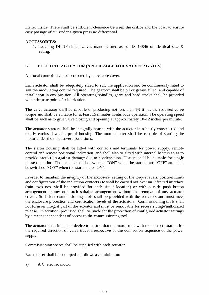
matter inside. There shall be sufficient clearance between the orifice and the cowl to ensureeasy passage of air under a given pressure differential.
ACCESSORIES:1. Isolating DI DF sluice valves manufactured as per IS 14846 of identical size &
rating.
G ELECTRIC ACTUATOR (APPLICABLE FOR VALVES / GATES)
All local controls shall be protected by a lockable cover.
Each actuator shall be adequately sized to suit the application and be continuously rated tosuit the modulating control required. The gearbox shall be oil or grease filled, and capable ofinstallation in any position. All operating spindles, gears and head stocks shall be providedwith adequate points for lubrication.
The valve actuator shall be capable of producing not less than 1½ times the required valvetorque and shall be suitable for at least 15 minutes continuous operation. The operating speedshall be such as to give valve closing and opening at approximately 10-12 inches per minute.
The actuator starters shall be integrally housed with the actuator in robustly constructed andtotally enclosed weatherproof housing. The motor starter shall be capable of starting themotor under the most severe conditions.
The starter housing shall be fitted with contacts and terminals for power supply, remotecontrol and remote positional indication, and shall also be fitted with internal heaters so as toprovide protection against damage due to condensation. Heaters shall be suitable for singlephase operation. The heaters shall be switched “ON” when the starters are “OFF” and shallbe switched “OFF” when the starters are “ON”.
In order to maintain the integrity of the enclosure, setting of the torque levels, position limitsand configuration of the indication contacts etc shall be carried out over an Infra red interface(min. two nos. shall be provided for each site / location) or with outside push buttonarrangement or any one such suitable arrangement without the removal of any actuatorcovers. Sufficient commissioning tools shall be provided with the actuators and must meetthe enclosure protection and certification levels of the actuators. Commissioning tools shallnot form an integral part of the actuator and must be removable for secure storage/authorizedrelease. In addition, provision shall be made for the protection of configured actuator settingsby a means independent of access to the commissioning tool.
The actuator shall include a device to ensure that the motor runs with the correct rotation forthe required direction of valve travel irrespective of the connection sequence of the powersupply.
Commissioning spares shall be supplied with each actuator.
Each starter shall be equipped as follows as a minimum:
a) A.C. electric motor.
308
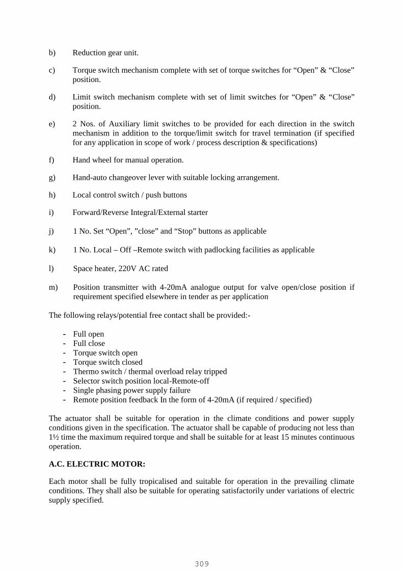
b) Reduction gear unit.
c) Torque switch mechanism complete with set of torque switches for “Open” & “Close”position.
d) Limit switch mechanism complete with set of limit switches for “Open” & “Close”position.
e) 2 Nos. of Auxiliary limit switches to be provided for each direction in the switchmechanism in addition to the torque/limit switch for travel termination (if specifiedfor any application in scope of work / process description & specifications)
f) Hand wheel for manual operation.
g) Hand-auto changeover lever with suitable locking arrangement.
h) Local control switch / push buttons
i) Forward/Reverse Integral/External starter
j) 1 No. Set “Open”, ”close” and “Stop” buttons as applicable
k) 1 No. Local – Off –Remote switch with padlocking facilities as applicable
l) Space heater, 220V AC rated
m) Position transmitter with 4-20mA analogue output for valve open/close position ifrequirement specified elsewhere in tender as per application
The following relays/potential free contact shall be provided:-
- Full open- Full close- Torque switch open- Torque switch closed- Thermo switch / thermal overload relay tripped- Selector switch position local-Remote-off- Single phasing power supply failure- Remote position feedback In the form of 4-20mA (if required / specified)
The actuator shall be suitable for operation in the climate conditions and power supplyconditions given in the specification. The actuator shall be capable of producing not less than1½ time the maximum required torque and shall be suitable for at least 15 minutes continuousoperation.
A.C. ELECTRIC MOTOR:
Each motor shall be fully tropicalised and suitable for operation in the prevailing climateconditions. They shall also be suitable for operating satisfactorily under variations of electricsupply specified.
309

MOTORS:
The electric motors shall be of 3 phase, minimum Class ‘F’ insulated with temperaturelimited to Class B, high torque low inertia motors of 15 minutes rating, squirrel cage typewith ‘O’ ring seal to provide complete environmental protection during long period ofinactivity. The winding shall be impregnated to render them non-hydroscopic and oilresistant. All internal metal parts shall be painted. Motor shall be capable of atleast 60 startsper hour.
MOTOR PROTECTION:
Following motor protection shall be provided:
a) The motor shall be de-energized in the event of a stall when attempting to unseat ajammed valve.
b) Motor temperature shall be sensed by a thermostat to protect against overheating
c) Single phasing protection
MOTOR CONTROLS:
The reversing contactor starter and local controls shall be integral or external for actuator.The starters shall comprise mechanically and electrically interlocked reversing contactor ofappropriate rating fed from a 220 V control transformer (120V AC for energization ofcontactors and 24V DC rectifier supply for local control for integral starter is alsoacceptable). The common connection of the contactor coils at the transformer shall begrounded. HRC type primary and secondary fuses shall be provided.
Local control shall comprise push buttons for open close and stop operations, and a local /remote selector switch lockable in the three positions as below :
Local control only,Remote control plus local stop only,Stop locked off - No electrical operation
Vendor should also make a provision for transmitting the mode selected to control panel andcontrol panel will have corresponding indication lamps.
INTEGRAL STARTER WITH MICROPROCESSOR BASED PROGRAMMABLECONTROLS:
The starter unit shall be with micro controller based control logic. Entire unit along with basicactuator should confirm to IP 68 standard of enclosure.
The actuator shall be field configurable having inbuilt pushbutton and LCD display toconfigure the features like inching or non-inching (hold on) mode etc. Also LCD display ofactuator shall be able to show the operational status and fault information in text format. LCDDisplay shall have min. 32 characters
Isolated 24V DC output shall be available for customer’s use and for internal use of actuator.
310

TORQUE AND TURNS LIMITATION:
Torque and turns limitation to be adjustable as follows: Position setting range – multi-turn: 2.5 to 100,000 turns, with resolution to 15 deg. of
actuator output. Position setting range – direct drive part turn actuators: 90 +/-10, with resolution to 0.1
deg. of actuator output. Torque setting: 40% to 100% rated torque..Measurement of torque shall be from direct measurement of force at the output of theactuator. Methods of determining torque-using data derived from the motor such as motorspeed, current, flux etc. are not acceptable
A means for automatic “torque switch bypass” to inhibit torque off during valve unseatingand “latching” to prevent torque switch hammer under maintained or repeated control signalsshall be provided.
The electrical circuit diagram of the actuator should not vary with valve type remainingidentical regardless of whether the valve is to open or close on torque or position limit.
LOCAL POSITION INDICATION
The actuator display shall include a dedicated numeric/symbol digital position indicatordisplaying valve position from fully open to fully closed in 1% increments. Valve closed andopen positions shall be indicated by symbols showing valve position in relation to the pipework to ensure that valve status is clearly interpreted. With main power on the display shallbe backlit to enhance contrast at low light levels and shall be legible from a distance of atleast 6 feet (2m).
Red, green, and yellow lights corresponding to open, closed, and intermediate valve positionsshall be included on the actuator display when power is switched on. The digital display shallbe maintained and updated during hand wheel operation when all power to the actuator isisolated.In addition, the actuator display shall include a separate text display element with a minimumof 32 characters to display operational, alarm and configuration status. The text display shallbe selectable in English. Provision shall be made to upload a different language withoutremoval of any covers or using specialized tools not provided as standard with the actuator.
MONITORING FACILITIES:
Facilities shall be provided for monitoring actuator operation and availability as follows:Monitor (availability) relay, having one change-over contact, the relay being energized fromthe control transformer will de-energise under any one or more the following conditions: Loss of main or customer 24V DC power supply Actuator control selected to local or stop Motor thermostat tripped Actuator internal fault
Where specified, provision shall be made for contacts to provide discreet indication of one ormore of the following:
311

Remote selected Thermostat trip Actuator fault
Actuator text display indication of the following status/alarms: Closed Limit, open limit, moving open, moving closed, stopped Torque trip closing, torque trip opening, stalled ESD active, interlock active Thermostat trip, phase lost, 24V supply lost, Local control failure Configuration error, Position sensor failure, Torque sensor failure Battery low, power loss inhibit
Integral data logger to record and store the following operational data: Opening last /average torque against position Closing last /average torque against position Opening motor starts against position Closing motor starts against position Total open/closed operations Maximum recorded opening and closing torque values Event recorder logging operational conditions (valve, control and actuator)
The data logger shall record relevant time and date information for stored data.
Data logger data is to be accessed via non-intrusive IrDA communication. Sufficientstandard intrinsically safe tools shall be provided for downloading data logger and actuatorconfiguration files from the actuators and subsequent uploading to a PC. The actuatormanufacturer shall supply PC software to enable data logger files to be viewed and analyzed.
WIRING AND TERMINALS:
Internal wiring shall be of grade PVC insulated stranded cable of 650 V and of minimum 1.5mm² copper for control circuits and of minimum 4 mm² for the power circuit. Each wire shallbe number identified at each end. The terminals shall be of stud type and they shall also beidentified by numbers. Cable entries shall be suitable for suitably sized PVC cables.
ENCLOSURE:
Actuators shall be O-ring sealed IP68. The motor and all other internal electrical elements ofthe actuator shall be protected from ingress of moisture and dust when the terminal cover isremoved for site for cabling, the terminal compartment having the same ingress protectionrating as the actuator with the terminal cover removed.
Enclosure must allow for temporary site storage without the need for electrical supplyconnection.
START-UP KIT:Each actuator shall be supplied with a start-up kit comprising installation instruction manual,electrical wiring diagram and cover seals to make good any site losses during thecommissioning period. In addition, sufficient actuator commissioning tools shall be supplied
312

to enable actuator set up and adjustment during valve/actuator testing and site installationcommissioning.
COMMUNICATION CAPABILITY (OPTIONAL FOR FUTURE USE / UPGRADE):
The actuator shall be suitable for future upgradation for atleast any one of the followingcontrol facilities. Modbus Profibus Foundation Fieldbus DeviceNet Pakscan
POSITION TRANSMITTER:Position transmitter shall be provided if required to be provided as per process requirement.
NOTE: The actuator shall be modulating type with positioner, etc. for flow controlapplication as specified in tender specifications / scope.
15.0 METALLIC EXPANSION BELLOWS
Expansion bellow shall be shall be in accordance with the EJMA/ ASME standard.
The bellows shall be metallic corrugated design of MOC as specified and shall have double flangewith liner / internal sleeve. The Fatigue life expectancy considered for the Expansion Bellows shall bemin. 3000 cycles. The drilling standard of expansion joint flange shall be matched on piping side toensure proper alignment and bellows is not subjected to torsional forces due to misalignment. Theexpansion joint shall be single bellow design and shall be generally suitable for axial movement of upto total 30mm (20mm axial compression & 10mm axial extension). Further it shall be suitableaccommodate angular misalignment of piping for up to min. 5mm / 3 degrees for installation.
To achieve maximum flexibility coupled with required resistance to pressure, bellows shall be formedwith single or multiple walls using a number of concentric cylinders (multi-ply construction) ofspecified MOC, each longitudinally welded. However for the blower application the bellows shall beof multi-ply construction only.
The expansion joint overall length for up to 250mm size shall be 250mm and for rest above 250mmshall be 300mm.
Generally the expansion joint is provided of single bellow design as a dismantling / disassembly jointin piping near valve or pump or flow meter or such device or equipment for ease of removal andjointing. Tie Rods / Threaded draw bars attached to expansion joint assembly shall be provided forthis application.
In case of bellows used for air piping application / in air blower discharge piping or such applicationwitnessing vibration and temperature variations the expansion joint shall be single bellow with orwithout limit rods as recommended by manufacturer suitable to absorb axial movement and to suitthis requirement.
In case of bellows used for diaphragm type dosing pump or such pulsating service the expansion jointshall be single bellow with or without limit rods as recommended by manufacturer suitable to absorbaxial movement and to suit this requirement.
313
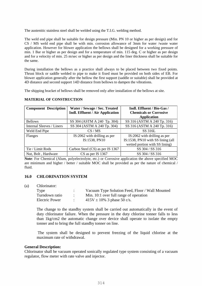
The austenitic stainless steel shall be welded using the T.I.G. welding method.
The weld end pipe shall be suitable for design pressure (Min. PN 10 or higher as per design) and forCS / MS weld end pipe shall be with min. corrosion allowance of 3mm for water /waste waterapplication. However for blower application the bellows shall be designed for a working pressure ofmin. 1 Bar or higher as per design and for a temperature of min. 115 deg. C or higher as per designand for a velocity of min. 25 m/sec or higher as per design and the liner thickness shall be suitable forthe same.
During installation the bellows as a practice shall always to be placed between two fixed points.Thrust block or saddle welded to pipe to make it fixed must be provided on both sides of EB. Forblower application generally after the bellow the first support (saddle or suitable) shall be provided at4D distance and second support 14D distance from bellows to dampen the vibrations.
The shipping bracket of bellows shall be removed only after installation of the bellows at site.
MATERIAL OF CONSTRUCTION
Component Description Water / Sewage / Sec. TreatedIndl. Effluent / Air Application
Indl. Effluent / Bio-Gas /Chemicals or Corrosive
ApplicationBellows SS 304 (ASTM A 240 Tp. 304) SS 316 (ASTM A 240 Tp. 316)Internal Sleeves / Liners SS 304 (ASTM A 240 Tp. 304) SS 316 (ASTM A 240 Tp. 316)Weld End Pipe CS / MS SS 316LFlanges IS:2062 with drilling as per
IS:1538, PN10IS:2062 with drilling as per
IS:1538, PN10 with SS lining (allwetted portion with SS lining)
Tie / Limit Rods Carbon Steel (CS) as per IS 1367 SS 304 / SS 316Nut, Bolt , Hardware CS as per IS 1367 SS 304 / SS 316
Note: For Chemical (Alum, polyelectrolyte, etc.) or Corrosive application the above specified MOCare minimum and higher / better / suitable MOC shall be provided as per the nature of chemical /fluid.
16.0 CHLORINATION SYSTEM
(a) Chlorinator:Type : Vacuum Type Solution Feed, Floor / Wall MountedTurndown ratio : Min. 10:1 over full range of operationElectric Power : 415V ± 10% 3 phase 50 c/s.
The change to the standby system shall be carried out automatically in the event ofduty chlorinator failure. When the pressure in the duty chlorine tonner falls to lessthan 1kg/cm2 the automatic change over device shall operate to isolate the emptytonner and to bring the full standby tonner on line.
The system shall be designed to prevent freezing of the liquid chlorine at themaximum rate of withdrawal.
General Description:Chlorinator shall be vacuum operated sonically regulated type system consisting of a vacuumregulator, flow meter with rate valve and injector.
314

Each Chlorinator should consist of:
- Remote Vacuum regulator- Injector Assembly- Differential pressure regulator- Chlorine Pressure Gauge- Vacuum Gauge- Water Pressure Gauge- Chlorine flow-meter (Rota meter)- Chlorine rate control valve- Inter connecting withdrawable type pipes of PVC with sealing rubber “O” rings.- High pressure solution discharge rigid PVC/HDPE pipes with fitting and protecting
enclosures as per requirement.- Vacuum and vent tubing as per requirement.- Cylinder connecting valve with clamp to connect copper coil and tonner.- Line stop valve.- 18 mm schedule 80 Carbon steel pipe with fitting for Chlorine gas line including
Chlorine pressure regulating valve.- Required no. of isolating valve at tonner and near chlorinator on common header.- Manual covering erection and maintenance instruction, spare parts list.- Required length of ‘C’ class GI piping fitting, valves etc. for necessary
interconnection within Chlorination room.- Necessary automatic safety devices like gas-off-etc. in case of emergency like failure
of power, water supply, should be incorporated. Further safety devices for back waterentry in chlorinator due to failure of NRV should also be incorporated.
- Each set shall also comprise of all std. accessories, sub assembly that is required forsmooth operation of chlorinator.
Further following shall also be considered in scope of supply:- Safety devices as under shall be supplied as a minimum: Two sets of approved Breathing apparatus/gas mask with rechargeable respirators
(self-contained breathing apparatus, each comprising an air set, carrying harness,face mask and valves and ancillary equipment. Each set shall be provided withthree 1200 liter capacity, 140mm diameter, air tonners)
Ammonia torch for leak detection Two ‘instant action’ resuscitators Four sets of safety clothing in various sizes, each comprising PVC overalls,
Wellington boots with steel toe caps, goggles, gloves and safety helmets Each set of safety equipment shall be mounted in a glass-fronted, non-locking
PVC coated steel cabinet in approved locations on the outside of the building. Vendor to furnish the list of additional safety accessories required as a minimum
as per statutory requirement and shall supply the same.- Emergency safety shower and eye wash fountain- Ton container repair kit- Minimum 3 nos. chlorine leak detectors shall be provided in the chlorination
equipment room for high and high-high level alarms and suitable safety interlocks.Detector shall be provided, one each at chlorine tonner storage area and at chlorinatorarea. Chlorine gas leak detectors shall be provided each, with a single detector cell. Atleast two sensors shall be located in the chlorine tonner storage room and at least one
315

sensor in the chlorination room. The chlorine leak detectors in the tonner room shallbe mounted at each end of the tonner room. The chlorine leak detectors shall initiate alocal audible and visual alarm.
- Statutory warning notices relating to the storage and handling of chlorine shall beprovided. The signs shall be pictorial and provided in Hindi and English.
- Residual Chlorine test kit of range 0.2 PPM to 5.0 PPM to color glass comparatortype.
- Set of erection and maintenance tools including special tools and tackles.- Complete lot of piping in required quantity and MOC with required interconnection.- Set of diffuser for chlorination.- 900 kg capacity tonner confirming to BS-1500 part-1 1958 for liquid chlorine
sufficient for 15 days requirement or in minimum quantity as specified in ProcessDesign Criteria / elsewhere in this tender, whichever is higher.The same shall be approved from explosive Dept. of central Govt., permission to fillthe tonner with liquid chlorine should be furnished. The container should be completewith first filling of liquid chlorine.
- Roller support for chlorine tonner connected with each of working and standbychlorination system.
- The chlorinator should be complete with suitable end suction back pull out typebooster pump sets, directly coupled by spacer type flexible coupling to a motor ofsuitable HP and mounted on a common base plate. The pump should have bronzeimpellers and stainless steel shaft with double ball bearing. Alternately bidder mayoffer in-line type pumps or submersible centrifugal pumps for booster pumpapplication.
- Neutralization pit suitable for two tonners in addition to the chlorine scrubbing systemas stand by.
17.0 WEIGHING SCALESTwo (02) nos. platform type digital weighing scales of reputed make, one each of 500 kgcapacity and 2.0 Tonnes capacity shall be provided as part of the scope of this work.
18.0 SAFETY EQUIPMENT / TOOLS: 1 LOT
Following Necessary tools / tackles as a min. shall be provided as a minimum as a part ofscope of this work:
(a) 1 Set : Digital Auto MultimeterDigital Clip of meter ( 0- 600 volts, 0-1000 Amp)Manually operated Megger (1000 volt) or as directed by Engineer incharge.
Make :- Meco / AE / Philips / Yokogawa.
(b) 1 Set Tools & Tackles
1. Box spanner set. Size 6 to 34 mm : 1 set2. Ring spanner set : size 6 to 32 mm : 1 set3. Fix spanner : size 6 to 32 mm : 1 set4. Adjustable screw spanner set : (A) size of 9”: 1 No. (B) Size 12”:1 No.
316

5. Chiesel(A) No. 105 N : 2 No
6. Screw Driver with insulated sleeve(A) No. 936 : 1 No.(B) No. 937 : 1 No.(C) No. 938 : 1 No.(D) No. 832 : 1 No.
7. Steel Scale(A) 6” : 1 No(B) 24” : 1 No
8. Centre punchSize / Product No. 1985 : 1 No.
9. Hexo Frame(A) 12” : 1 No.
10. Hex wrench set (Elen key)Size : standard : 1 No
11. Tool boxSize : standard : 1 No
12. File with handle(A) Round Smooth 12” : 1 No.(B) Half Round Smooth 12” : 1 No.(C) Halt Round Rough 12” : 1 No.(D) Flat Smooth 12” : 1 No.(E) Flat Rough 12” : 1 No.(F) Triangle Smooth 8” : 1 No.(G) Triangle Rough 8” : 1 No.
13. Bench vice(a) 6” (No.5) : 1 No.
14. Insulated Plier(A) size : 8” 2 Nos.
15. Mechanical Screw Jack with Tomy(A) 3 Ton : 1 set.
16. Drill Machine wolf make ( 3 ph)6 mm to 20 mm drilling capacity : 2No. Portable and Fix type
17. Bench Grinder - 1 No.18. Bearing Puller – 3 Jaw – 12” – 1 No.19. Cealing rope with hook at both end of minimum 4 mt. length of 3 Tonne
capacity – 6 Nos20. Hot and cold air blower – 1 No.21. Aluminum sprit level – 12 Inch - 1 No.22. Monkey Wrench
a. 12” – 1 No.b. 18” – 1 No.c. 24” – 1 No.
23. Pipe (Chain) wrencha. Pipe Size – 4”
24. Tap Set – 1 Set25. Hammer – 3 Nos.
317

318

18.0 GENERAL REQUIREMENT FOR ALL ABOVE ITEMS:
GENERAL REQUIREMENT FOR MECHANICAL ITEMS / EQUIPMENT:
PAINTING
MS / CI / DI BODY OR PARTS OR STRUCTURE (GENERAL FOR PIPING AND PUMP /BLOWER / EQUIPMENT IF NOT PROVIDED AS SPECIFIC)Shall be provided with one coat of red oxide / epoxy primer followed by two coat of epoxy paint afterproper surface preparation as recommended by paint manufacturer / shot blasting prior to dispatch, toa total DFT of minimum 150 microns inclusive of priming.
Zinc rich epoxy primer and epoxy paint of approved quality shall be used for external andinternal painting as applicable. The max of zinc rich epoxy primer shall be prepared at worksite not earlier then 15 minutes before applying the same on pipes and special surfaces. Onecoat of zinc rich epoxy primer of DFT 75 micron shall be applied along with two coats ofepoxy paint DFT 40-45 micron and DFT 30-35 micron respectively. No thinner shall beadded to ready mix paint without previous approval of the Employers’ representative and thefinishing coats on top of the primer coat shall only be applied after allowing the film to curefor at-least 48hrs.
After application of zinc rich epoxy primer the surface should be cleaned by duster andinspected. If during inspection any portion is found rusting the same shall be removed byemery paper and coated with zinc rich epoxy primer.
Mixed paint should be used within 3 to 4 hrs. of mixing or as recommended by manufacturerand fresh mixing shall be done for every new application. Every successive coat of paint shallbe applied only after 48 hrs. of previous coat. Before applying the next coat the surfaceshould be properly cleaned by duster
OPEN CHANNEL GATES / SLUICE GATES (THIMBLE MOUNTED GATES)Following painting procedure shall be adopted for the gates :
Surface Preparation: Blast clean to near white metal finish using shot blasting.Priming: 1 coat of red oxide primer.Finish Painting: Black bituminous paint for gate assembly. Minimum DFT 200 microns
inclusive of priming. Yoke & Headstock to be provided with red oxideprimer and epoxy Grey paint having minimum DFT 150 microns inclusive ofpriming.
DOCUMENT SUBMISISON
In general, the minimum document submission for various items shall be as described belowto be submitted by vendor for review and approval during detailed engineering / execution &prior to manufacturing and manufacturing shall be carried out as per approved documentsonly and after complying comments as applicable:
PUMP SET (CENTRIFUGAL / POSITIVE DISPLACEMENT / PROGRESSIVECAVITY (SCREW) / RECIPROCATING (DOSING), ETC.):
319

The following drawings shall be submitted by the Bidder for review and approval prior tomanufacturing:
1. Product Technical data sheet.2. Preliminary outline dimensional drawing (GA Drawing) showing the details of pump
and motor, Suction, discharge connections and foundation details.3. Performance curves showing capacity v/s total head, efficiency, NPSH-Required and
KW requirements ranging from run out to pump shut off for min., max. and ratedimpeller dia of offered pump.
4. Typical cross sectional drawing showing internal features of pump, parts and theirmaterial.
5. Torque – Speed curve of the pump.6. Catalogues showing type of construction.7. Quality Assurance Plan.
VALVES (SV / NRV / SPCV / BFV / KGV/ BALL VALVE / AIR VALVE)
The following drawings shall be submitted by the Bidder for review and approval prior tomanufacturing:
1. Product Technical data sheet.2. General outline dimensional drawings.3. Cross sectional drawing showing constructional details with part list with their qty
& MOC confirming relevant standards.4. QAP of the product.5. Catalogues showing type of construction.
In addition to above following documents shall be furnished for review and approval whenvalves are required with Electric Actuator for Operation.
1. Actuator Data sheet.2. G.A. & wiring Drawing of Electric actuator.3. Valve Torque Calculations.4. Product catalogue.
SLUICE / OPEN CHANNEL GATE
The manufacturer shall submit following drawings. Product Technical data sheet. General outline dimensional drawings along with part list with their qty & MOC
confirming relevant standards. QAP of the product.
In addition to above following documents shall be furnished for review and approval whenvalves are required with Electric Actuator for Operation.
1. Actuator Data sheet.2. G.A. & wiring Drawing of Electric actuator.3. Valve Torque Calculations.4. Product catalogue.
EXPANSION BELLOWS
320
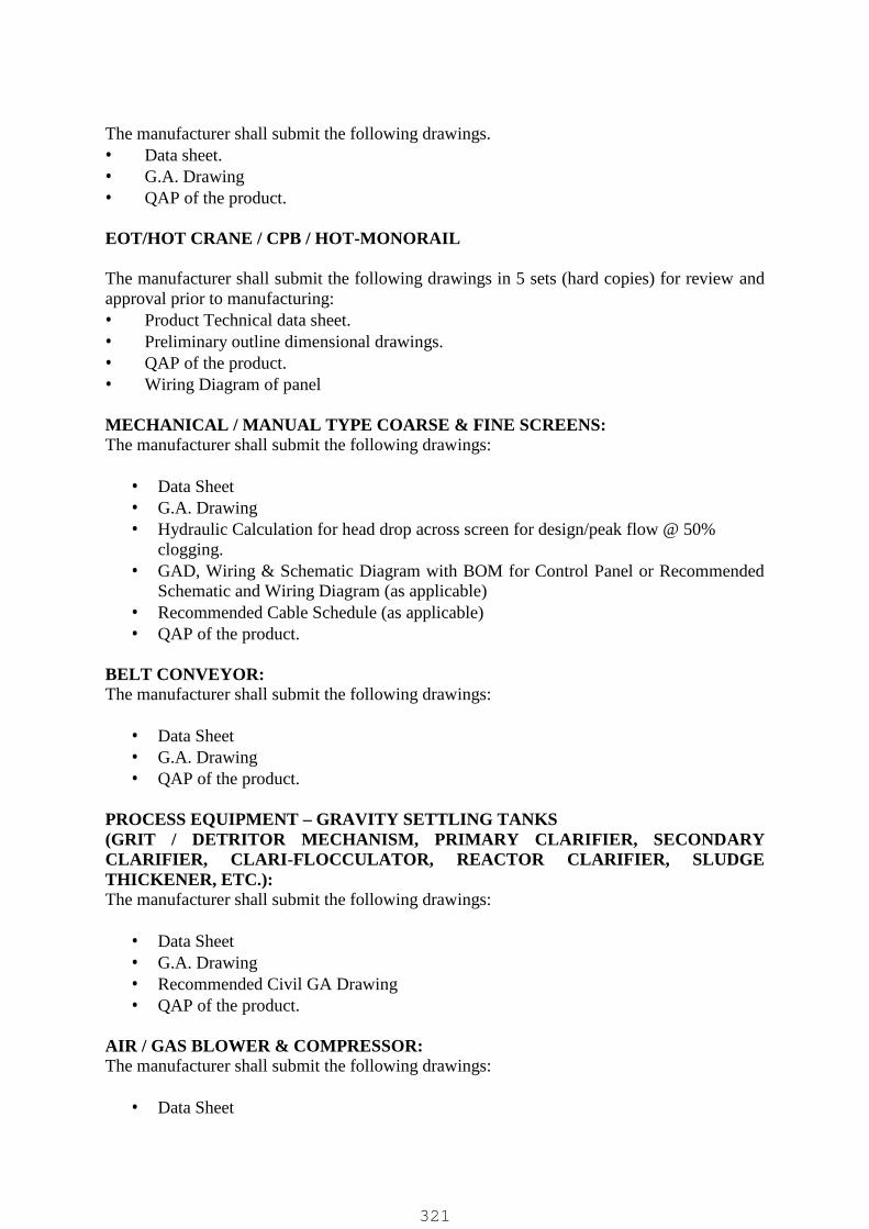
The manufacturer shall submit the following drawings. Data sheet. G.A. Drawing QAP of the product.
EOT/HOT CRANE / CPB / HOT-MONORAIL
The manufacturer shall submit the following drawings in 5 sets (hard copies) for review andapproval prior to manufacturing: Product Technical data sheet. Preliminary outline dimensional drawings. QAP of the product. Wiring Diagram of panel
MECHANICAL / MANUAL TYPE COARSE & FINE SCREENS:The manufacturer shall submit the following drawings:
Data Sheet G.A. Drawing Hydraulic Calculation for head drop across screen for design/peak flow @ 50%
clogging. GAD, Wiring & Schematic Diagram with BOM for Control Panel or Recommended
Schematic and Wiring Diagram (as applicable) Recommended Cable Schedule (as applicable) QAP of the product.
BELT CONVEYOR:The manufacturer shall submit the following drawings:
Data Sheet G.A. Drawing QAP of the product.
PROCESS EQUIPMENT – GRAVITY SETTLING TANKS(GRIT / DETRITOR MECHANISM, PRIMARY CLARIFIER, SECONDARYCLARIFIER, CLARI-FLOCCULATOR, REACTOR CLARIFIER, SLUDGETHICKENER, ETC.):The manufacturer shall submit the following drawings:
Data Sheet G.A. Drawing Recommended Civil GA Drawing QAP of the product.
AIR / GAS BLOWER & COMPRESSOR:The manufacturer shall submit the following drawings:
Data Sheet
321

G.A. & Cross Section Drawing Performance Curve Acoustic Hood Details (if applicable) Actual Flow Calculation at design ambient, relative humidity and site altitude GAD, Wiring & Schematic Diagram with BOM for Control Panel (if forming part of
blower supply / part of blower skid) Soft Starter / VFD Sizing & Selection after de-rating and (if forming part of blower
supply / part of blower skid) QAP of the product.
DIFFUSER – FINE / COARSE BUBBLE:The vendor shall submit the following drawings:
Data Sheet G.A. Drawing / Diffuser Layout in Aeration Basin with BOM of installation hardware SOTE Curve Diffuser Design Throughput / Flux Rate & Header / Lateral pipe sizing QAP of the product.
DECANTER – MOVING WEIR / FLOATING FOR SBR:The vendor shall submit the following drawings:
Data Sheet G.A. Drawing Weir loading rate Design Travel Rate GAD, Wiring & Schematic Diagram with BOM for Control Panel or Recommended
Schematic and Wiring Diagram (as applicable) Recommended Cable Schedule QAP of the product.
AGITATOR / MIXER / AERATOR (INCLUDING FLAOTING MIXER/AERATOR):The manufacturer shall submit the following drawings.
Data Sheet G.A. Drawing Installation / Layout Drawing (as applicable) QAP of the product.
CHLORINATION SYSTEMThe manufacturer shall submit the following drawings.
P & ID of chlorination system. Bill of Material Data sheet and dimensional drawing of various components of system Lay out drawing of installation.
322

GAD / Recommended Installation Drg of Chlorination System GAD of chlorine tonner GAD / Recommended Installation Drg of Chlorine Scrubber (as applicable) GAD, Wiring & Schematic Diagram with BOM for Control Panel or Recommended
Schematic and Wiring Diagram (as applicable) QAP of the product.
UV DISINFECTION SYSTEMThe manufacturer shall submit the following drawings.
Data Sheet G.A. Drawing Recommended Civil GA Drawing Recommended P & ID GAD, Wiring & Schematic Diagram with BOM for Control Panel or Recommended
Schematic and Wiring Diagram QAP of the product.
SLUDGE DEWATERING DEVICE / EQUIPMENT (CENTRIFGUE / BELT FILTERPRESS, ETC.)The manufacturer shall submit the following drawings:
Data Sheet G.A. Drawing Recommended Civil GA Drawing Recommended P & ID of dewatering system GAD, Wiring & Schematic Diagram with BOM for Control Panel or Recommended
Schematic and Wiring Diagram (as applicable) QAP of the product.
DISC FILTERThe manufacturer shall submit the following drawings.
Data Sheet G.A. Drawing Recommended Civil GA Drawing Recommended P & ID GAD, Wiring & Schematic Diagram with BOM for Control Panel or Recommended
Schematic and Wiring Diagram QAP of the product.
ODOR CONTROL SYSTEMThe manufacturer shall submit the following drawings.
Data Sheet G.A. Drawing including foundation drawing Recommended P & ID
323

GAD, Wiring & Schematic Diagram with BOM for Control Panel or RecommendedSchematic and Wiring Diagram
QAP of the product.
PIPES (CI / DI / MS, HDPE, PVC, ETC. MOC)The manufacturer shall submit the following drawings / documents:
Bill of Material QAP of the product.
Note: The data sheet and GAD as specified for equipment shall also be considered to include coupleditems like electrical drives / motor including it’s performance curves, electric actuators including it’swiring diagram, pneumatic actuators, etc. as applicable.
324

INSPECTION AND TESTING REQUIREMENTS:
The material shall be cleared for dispatch based review of documents / test certificates or bycarrying out inspection and testing at manufacturer’s works as per requirement specified intender for various equipment and as per approved Quality Assurance Plan. Client reserves theright to waive inspection at manufacturer’s works or ask for inspection at manufacturer’sworks even though not specified in tender but in client’s opinion is required and contractorshall hold no objection to the same.
Inspection & testing of mechanical equipment at manufacture works shall be conducted forequipment / components in presence of engineer-in-charge / client’s representative OR thirdparty inspection agency appointed by client.
All the charges for third party inspection shall be included under the scope of contractor.Inspection and testing at manufacturers’ works’ shall be carried out as specified below / asper applicable IS.
All instrument and equipment required for such tests shall be provided by the Contractor /Vendor. The instruments shall be calibrated and certified by an approved independent testingauthority with valid calibration certificates as on date of inspection.
All the tests shall be carried out as per the relevant standard & codes.
The inspection category and brief description of tests to be carried out for various equipmentis as follows:
CENTRIFUGAL PUMP:
HYDROSTATIC TEST: A standard hydrostatic test shall be conducted on the pump casing with water at 1½
times the maximum discharge pressure on the head characteristic curve or 2 times therated pressure whichever is higher.
Unless otherwise stated in Data Sheet, the hydrostatic test on casing shall beconducted for minimum duration of 30 minutes.
MECHANICAL BALANCING: Major rotating components of the pumps like impellers, shaft, shaft sleeve etc., shall
be individually statically as well as dynamically balanced at rated speed. Necessary test certificates shall be furnished by vendor for purchaser’s approval.
PERFORMANCE TESTING:Pump shall be tested for its full operating range in accordance with the applicable standardand approved data sheet.
Test shall be carried out with minimum NPSH as available at site for rated discharge andmaximum discharge. Each pump shall be tested at its rated speed with shop motor for itsentire working range.
325

At least one pump shall be dismantled for internal material and undue rubbing marksverification at the time of inspection in the presence of client’s representative.
During pump testing, readings to the extent possible shall be taken to correspond to the neteffective lift specified in the Data Sheet, and cover its full working range from its closedvalve condition to run out condition i.e. when delivery valve is fully opened. Head-flow,Power-flow and efficiency-flow curves shall be drawn based on test readings. The curvesproduced shall be used to determine the capacity of pump sets to meet guaranteedperformance at site at rated speed.
MATERIAL TEST CERTIFICATEMaterial test certificates for the various pumps components shall be furnished for purchaser’sreview & approval as stated in the Data Sheet.
WITNESSING OF PERFORMANCE TESTING OF PUMP
Pump RatingPump performance Testing to be witnessed for each duty and
type (Also see Note below)
upto 15 kW motorsVisual / Performance witnessing Not Required.Vendor to submit test certi. For review/approval and dispatchclearance as per Note Given Below prior to dispatch.
> 15 kW upto 75 kWmotors
25 % Qty. or min. 1 No whichever is higher per duty / type .
> 75 kW upto 160 kWmotors
50 % Qty. or min. 1 No whichever is higher per duty / type .
>160 kW 100 % Qty. to be WitnessedNote: (1) Manufacturer shall test all the pumps internally and shall provide their Internal testrecords along with Dynamic balancing, material test certificates for all major parts as perTender, Hydrostatic test certificate, Dimensional check certificates, etc as per approved QAP& DS of each pump for review, record and dispatch clearance prior to dispatch of material.(2) Vendor shall Parallel operation curve for pumps where more than two pumps areincorporated in BOQ along with individual pumps performance testing witnessing.
VALVES (SV / NRV / BFV / DPCV/ KGV/ AIR VALVE)
Valves shall be tested at manufacturer works for visual inspection, hydro test, operational testand dimensional check as per relevant standard.
Manufacturer shall offer valves for testing & inspection as per approved QAP and shallfurnish all relevant certificates including material test cert. for review and approval.
SLUICE VALVEClosed End Test of All C.I. sluice valves shall be carried out in presence of Engineer incharge / client’s representative at manufacturer works & testing certificates shall be furnishedalong with each lot of supply.
Valve shall be subjected to hydrostatic tests as described in appendix B of IS: 14846 for 2minutes duration minimum.
326
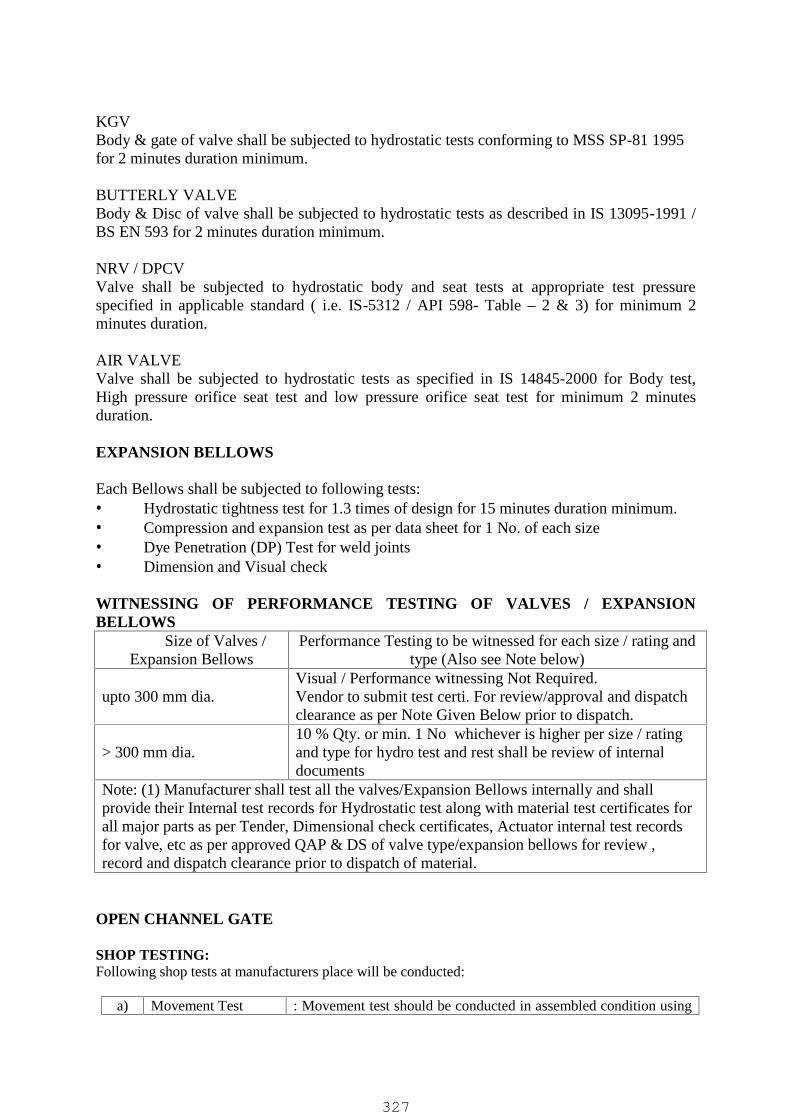
KGVBody & gate of valve shall be subjected to hydrostatic tests conforming to MSS SP-81 1995for 2 minutes duration minimum.
BUTTERLY VALVEBody & Disc of valve shall be subjected to hydrostatic tests as described in IS 13095-1991 /BS EN 593 for 2 minutes duration minimum.
NRV / DPCVValve shall be subjected to hydrostatic body and seat tests at appropriate test pressurespecified in applicable standard ( i.e. IS-5312 / API 598- Table – 2 & 3) for minimum 2minutes duration.
AIR VALVEValve shall be subjected to hydrostatic tests as specified in IS 14845-2000 for Body test,High pressure orifice seat test and low pressure orifice seat test for minimum 2 minutesduration.
EXPANSION BELLOWS
Each Bellows shall be subjected to following tests: Hydrostatic tightness test for 1.3 times of design for 15 minutes duration minimum. Compression and expansion test as per data sheet for 1 No. of each size Dye Penetration (DP) Test for weld joints Dimension and Visual check
WITNESSING OF PERFORMANCE TESTING OF VALVES / EXPANSIONBELLOWS
Size of Valves /Expansion Bellows
Performance Testing to be witnessed for each size / rating andtype (Also see Note below)
upto 300 mm dia.Visual / Performance witnessing Not Required.Vendor to submit test certi. For review/approval and dispatchclearance as per Note Given Below prior to dispatch.
> 300 mm dia.10 % Qty. or min. 1 No whichever is higher per size / ratingand type for hydro test and rest shall be review of internaldocuments
Note: (1) Manufacturer shall test all the valves/Expansion Bellows internally and shallprovide their Internal test records for Hydrostatic test along with material test certificates forall major parts as per Tender, Dimensional check certificates, Actuator internal test recordsfor valve, etc as per approved QAP & DS of valve type/expansion bellows for review ,record and dispatch clearance prior to dispatch of material.
OPEN CHANNEL GATE
SHOP TESTING:Following shop tests at manufacturers place will be conducted:
a) Movement Test : Movement test should be conducted in assembled condition using
327

b)
c)
d)
e)
f)
Dimensional Check
Seat clearance check
Material Testing
PMI test
DFT measurement
stems & headstock. The gate should be operated once from fullclose to full open and back to full close condition with a max.force of 135 Newton-meter on the crank or hand wheel.
: Important Dimensions shall be checked with reference toapproved GA drawing.
: With the gate in closed condition 0.1 mm thick feeler gaugeshould not pass through the sealing faces.
: Material test certificates for important components such as Frame,Side guides, Shutter, Rubber seals & Spindle to be furnished forreview at the time of inspection.
: Positive Material Identification (PMI) test to be conducted forSeating / Sealing faces, Rubber Seal Retainer Bar & Stem /Spindle during inspection.
: DFT of Paint with reference to approved G.A. drawing to bemeasured with paint thickness measurement gauge during theinspection.
WITNESSING OF PERFORMANCE TESTING OF OPEN CHANNEL GATE:Size / Area of Open
Channel Gate (Shutter)Witnessing for each size, type & class of Sluice Gate
(Also see Note below)
Up to 1m2 areaVisual / Performance witnessing Not Required.Vendor to submit test certi. For review/approval and dispatchclearance as per Note Given Below prior to dispatch.
> 1m2 area10% Qty. or min. 1 No. whichever is higher per size of gate /shutter
Note: (1) Manufacturer shall test all the gates internally and shall provide their Internal testrecords as specified above along with material test certificates for all major parts as perTender, clearance check test, leakage test, movement test, Dimensional check certificates,Actuator internal test records for gates, etc. as per approved QAP & DS of Open ChannelGate for review , record and dispatch clearance prior to dispatch of material.
SLUICE GATE
Following shop tests at manufacturers place will be conducted:a)
b)
Movement Test
Shop leakage test
Movement test should be conducted in horizontal/verticalassembled condition using stems & headstock. The gateshould be operated once from full close to full open and backto full close condition with a max. force of 135 Newton-meter on the crank or hand wheel.
Shop leakage test by applying unseating hydraulic pressurewill be conducted at manufacturer’s shop with gate mountedvertically on a test bench. A hydrostatic pressure equal tomaximum seating/unseating head shall be applied to gate atcenter line of gate opening from the back, i.e. Unseating face
328

c)
d)
e)
f)
g)
h)
Hydrostatic Body test
Torque test at operatingHead
Dimensional Check
Seat clearance check
Material Test Certificates
PMI Test
of the gate in closed position, through pump. A suitablescaled calibrated pressure gauge put on the unseating face ofthe gate shall indicate reading equal to unseating pressurehead. Water leakage through the gate under above conditionshall be collected in a collection pan and measured. Theleakage so measured should not exceed the limit of 2.5, 3.5and 4.5 lpm per meter sealing perimeter for class-1, class IIand class III sluice gates as stated in the IS:13349-1992.
No alternate testing arrangement will be permitted in place ofabove method. Gates can be applied with a coat of primer toprevent rusting due to water exposure during testing.
After the leakage test Hydrostatic body test will beconducted at manufacturer’s shop. A hydrostatic pressureequal to 1.5 times the maximum operating head should beapplied on the gate for 5 minutes continuously. Nopermanent deformation in casting should be observed.
Torque test at operating head would be conducted atapplicable head at manufacturer’s shop for gates up to2000x2000mm size
Important Dimensions shall be checked with reference toapproved GA drawing.
With the gate in closed condition 0.1 mm thick feeler gaugeshould not pass through between seat facings.
Material tests certificates for all important components ofgates such as Thimble, Frame, Shutter, Seat facings, Spindle,& Rubber seals etc. to be furnished at the time of inspection.
Positive Material Identification (PMI) test to be conductedfor Sealing / Seating Faces, Rubber Seal Retainer Bar (Ifapplicable) & Stem / Spindle during the inspection.
WITNESSING OF PERFORMANCE TESTING OF SLUICE GATE:Size, Class & Type of
Sluice GateWitnessing for each size, type & class of Sluice Gate
(Also see Note below)
Up to 800 mm dia. /SquareVisual / Performance witnessing Not Required.Vendor to submit test certi. For review/approval and dispatchclearance as per Note Given Below prior to dispatch.
> 800 mm dia./ square10% Qty. or min. 1 No. whichever is higher per size / classand type.
329
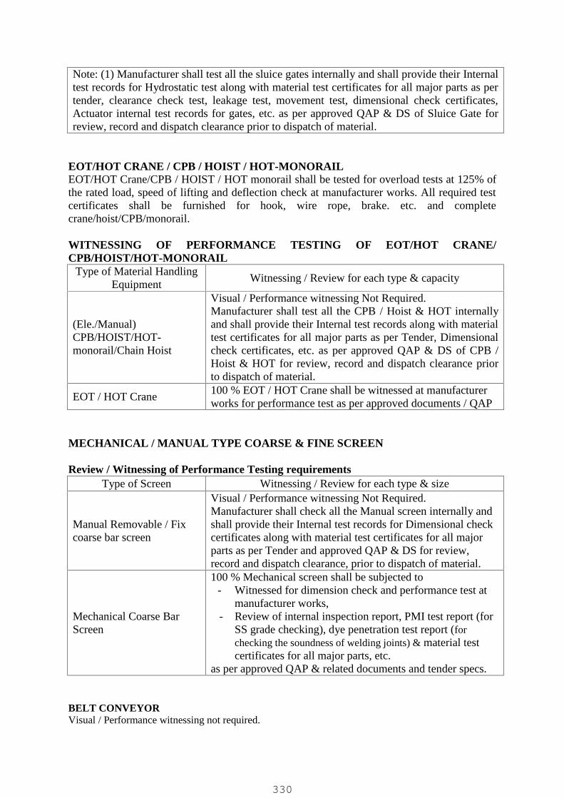
Note: (1) Manufacturer shall test all the sluice gates internally and shall provide their Internaltest records for Hydrostatic test along with material test certificates for all major parts as pertender, clearance check test, leakage test, movement test, dimensional check certificates,Actuator internal test records for gates, etc. as per approved QAP & DS of Sluice Gate forreview, record and dispatch clearance prior to dispatch of material.
EOT/HOT CRANE / CPB / HOIST / HOT-MONORAILEOT/HOT Crane/CPB / HOIST / HOT monorail shall be tested for overload tests at 125% ofthe rated load, speed of lifting and deflection check at manufacturer works. All required testcertificates shall be furnished for hook, wire rope, brake. etc. and completecrane/hoist/CPB/monorail.
WITNESSING OF PERFORMANCE TESTING OF EOT/HOT CRANE/CPB/HOIST/HOT-MONORAIL
Type of Material HandlingEquipment
Witnessing / Review for each type & capacity
(Ele./Manual)CPB/HOIST/HOT-monorail/Chain Hoist
Visual / Performance witnessing Not Required.Manufacturer shall test all the CPB / Hoist & HOT internallyand shall provide their Internal test records along with materialtest certificates for all major parts as per Tender, Dimensionalcheck certificates, etc. as per approved QAP & DS of CPB /Hoist & HOT for review, record and dispatch clearance priorto dispatch of material.
EOT / HOT Crane100 % EOT / HOT Crane shall be witnessed at manufacturerworks for performance test as per approved documents / QAP
MECHANICAL / MANUAL TYPE COARSE & FINE SCREEN
Review / Witnessing of Performance Testing requirementsType of Screen Witnessing / Review for each type & size
Manual Removable / Fixcoarse bar screen
Visual / Performance witnessing Not Required.Manufacturer shall check all the Manual screen internally andshall provide their Internal test records for Dimensional checkcertificates along with material test certificates for all majorparts as per Tender and approved QAP & DS for review,record and dispatch clearance, prior to dispatch of material.
Mechanical Coarse BarScreen
100 % Mechanical screen shall be subjected to- Witnessed for dimension check and performance test at
manufacturer works,- Review of internal inspection report, PMI test report (for
SS grade checking), dye penetration test report (forchecking the soundness of welding joints) & material testcertificates for all major parts, etc.
as per approved QAP & related documents and tender specs.
BELT CONVEYORVisual / Performance witnessing not required.
330

Manufacturer shall carry out internal inspection for the offered equipment and shall provide theirInternal test records for Dimensional check certificates along with material test certificates for allmajor parts as per Tender and approved QAP & DS for review, record and dispatch clearance prior todispatch of material.
PROCESS EQUIPMENT – GRAVITY SETTLING TANKS(GRIT / DETRITOR MECHANISM, PRIMARY CLARIFIER, SECONDARYCLARIFIER, CLARI-FLOCCULATOR, REACTOR CLARIFIER, SLUDGETHICKENER, ETC.):Visual / Performance witnessing not required.
Manufacturer shall carry out internal inspection for the offered equipment and shall provide theirInternal test records for Dimensional check certificates along with material test certificates for allmajor parts as per Tender and approved QAP & DS for review, record and dispatch clearance prior todispatch of material.
AIR / GAS BLOWERS
Test by ManufacturerSr.No.
Tests Specs
1 Hydrostatic tests Twice the maximum working pressure (To be provided forClient Review)
2 Performance test As per BS : 15713 Strip test Clearances with tolerance limit (To be provided for Client
Review of at least 1 No.)4 Mechanical
balancingISO 1940 Gr. 6.3 or better (To be provided for Client Review)
5 Visual Inspection Before painting
Review / Witnessing of Performance Testing requirements
Blower RatingReview / Blower performance Testing to be witnessed for each
duty and type (Also see Note below)
upto 15 kW motorsVisual / Performance witnessing Not Required.Vendor to submit test certi. For review/approval and dispatchclearance as per Note Given Below prior to dispatch.
> 15 kW upto 75 kWmotors
25 % Qty. or min. 1 No whichever is higher per duty / type .
> 75 kW upto 160 kWmotors
50 % Qty. or min. 1 No whichever is higher per duty / type .
>160 kW 100 % Qty. to be WitnessedNote: (1) Manufacturer shall test all the blowers internally and shall provide their Internaltest records along with material test certificates for all major parts as per Tender, Hydrostatictest certificate, Dimensional check certificates, Dynamic Balancing, etc. as per approvedQAP & DS of each blower for review, record and dispatch clearance prior to dispatch ofmaterial.
331
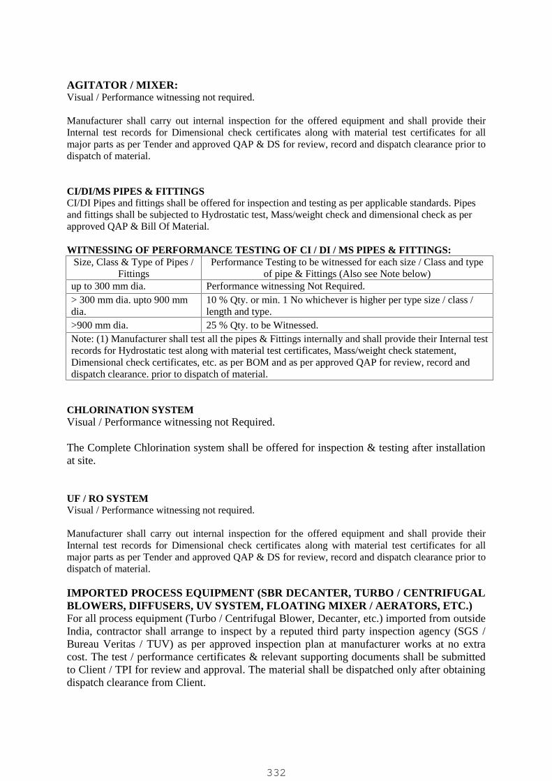
AGITATOR / MIXER:Visual / Performance witnessing not required.
Manufacturer shall carry out internal inspection for the offered equipment and shall provide theirInternal test records for Dimensional check certificates along with material test certificates for allmajor parts as per Tender and approved QAP & DS for review, record and dispatch clearance prior todispatch of material.
CI/DI/MS PIPES & FITTINGSCI/DI Pipes and fittings shall be offered for inspection and testing as per applicable standards. Pipesand fittings shall be subjected to Hydrostatic test, Mass/weight check and dimensional check as perapproved QAP & Bill Of Material.
WITNESSING OF PERFORMANCE TESTING OF CI / DI / MS PIPES & FITTINGS:Size, Class & Type of Pipes /
FittingsPerformance Testing to be witnessed for each size / Class and type
of pipe & Fittings (Also see Note below)up to 300 mm dia. Performance witnessing Not Required.> 300 mm dia. upto 900 mmdia.
10 % Qty. or min. 1 No whichever is higher per type size / class /length and type.
>900 mm dia. 25 % Qty. to be Witnessed.Note: (1) Manufacturer shall test all the pipes & Fittings internally and shall provide their Internal testrecords for Hydrostatic test along with material test certificates, Mass/weight check statement,Dimensional check certificates, etc. as per BOM and as per approved QAP for review, record anddispatch clearance. prior to dispatch of material.
CHLORINATION SYSTEMVisual / Performance witnessing not Required.
The Complete Chlorination system shall be offered for inspection & testing after installationat site.
UF / RO SYSTEMVisual / Performance witnessing not required.
Manufacturer shall carry out internal inspection for the offered equipment and shall provide theirInternal test records for Dimensional check certificates along with material test certificates for allmajor parts as per Tender and approved QAP & DS for review, record and dispatch clearance prior todispatch of material.
IMPORTED PROCESS EQUIPMENT (SBR DECANTER, TURBO / CENTRIFUGALBLOWERS, DIFFUSERS, UV SYSTEM, FLOATING MIXER / AERATORS, ETC.)For all process equipment (Turbo / Centrifugal Blower, Decanter, etc.) imported from outsideIndia, contractor shall arrange to inspect by a reputed third party inspection agency (SGS /Bureau Veritas / TUV) as per approved inspection plan at manufacturer works at no extracost. The test / performance certificates & relevant supporting documents shall be submittedto Client / TPI for review and approval. The material shall be dispatched only after obtainingdispatch clearance from Client.
332
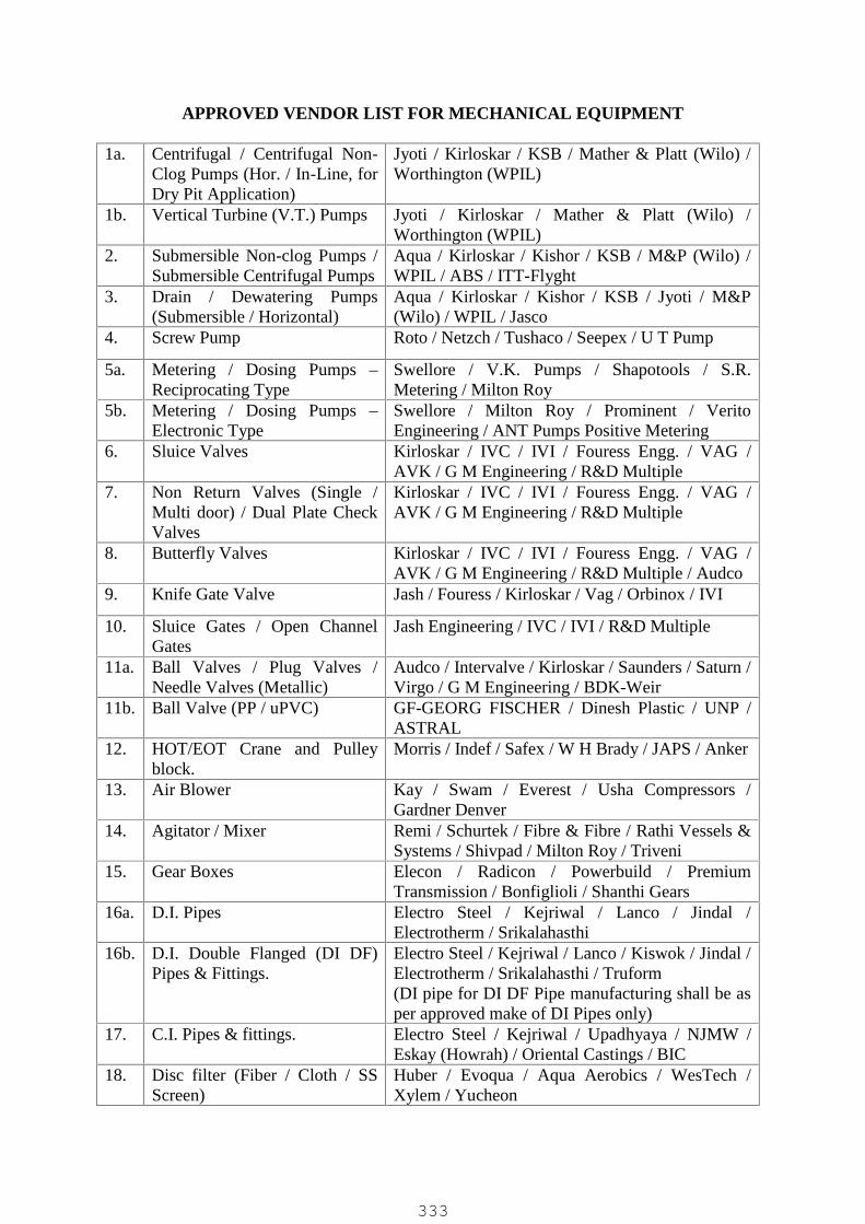
APPROVED VENDOR LIST FOR MECHANICAL EQUIPMENT
1a. Centrifugal / Centrifugal Non-Clog Pumps (Hor. / In-Line, forDry Pit Application)
Jyoti / Kirloskar / KSB / Mather & Platt (Wilo) /Worthington (WPIL)
1b. Vertical Turbine (V.T.) Pumps Jyoti / Kirloskar / Mather & Platt (Wilo) /Worthington (WPIL)
2. Submersible Non-clog Pumps /Submersible Centrifugal Pumps
Aqua / Kirloskar / Kishor / KSB / M&P (Wilo) /WPIL / ABS / ITT-Flyght
3. Drain / Dewatering Pumps(Submersible / Horizontal)
Aqua / Kirloskar / Kishor / KSB / Jyoti / M&P(Wilo) / WPIL / Jasco
4. Screw Pump Roto / Netzch / Tushaco / Seepex / U T Pump
5a. Metering / Dosing Pumps –Reciprocating Type
Swellore / V.K. Pumps / Shapotools / S.R.Metering / Milton Roy
5b. Metering / Dosing Pumps –Electronic Type
Swellore / Milton Roy / Prominent / VeritoEngineering / ANT Pumps Positive Metering
6. Sluice Valves Kirloskar / IVC / IVI / Fouress Engg. / VAG /AVK / G M Engineering / R&D Multiple
7. Non Return Valves (Single /Multi door) / Dual Plate CheckValves
Kirloskar / IVC / IVI / Fouress Engg. / VAG /AVK / G M Engineering / R&D Multiple
8. Butterfly Valves Kirloskar / IVC / IVI / Fouress Engg. / VAG /AVK / G M Engineering / R&D Multiple / Audco
9. Knife Gate Valve Jash / Fouress / Kirloskar / Vag / Orbinox / IVI
10. Sluice Gates / Open ChannelGates
Jash Engineering / IVC / IVI / R&D Multiple
11a. Ball Valves / Plug Valves /Needle Valves (Metallic)
Audco / Intervalve / Kirloskar / Saunders / Saturn /Virgo / G M Engineering / BDK-Weir
11b. Ball Valve (PP / uPVC) GF-GEORG FISCHER / Dinesh Plastic / UNP /ASTRAL
12. HOT/EOT Crane and Pulleyblock.
Morris / Indef / Safex / W H Brady / JAPS / Anker
13. Air Blower Kay / Swam / Everest / Usha Compressors /Gardner Denver
14. Agitator / Mixer Remi / Schurtek / Fibre & Fibre / Rathi Vessels &Systems / Shivpad / Milton Roy / Triveni
15. Gear Boxes Elecon / Radicon / Powerbuild / PremiumTransmission / Bonfiglioli / Shanthi Gears
16a. D.I. Pipes Electro Steel / Kejriwal / Lanco / Jindal /Electrotherm / Srikalahasthi
16b. D.I. Double Flanged (DI DF)Pipes & Fittings.
Electro Steel / Kejriwal / Lanco / Kiswok / Jindal /Electrotherm / Srikalahasthi / Truform(DI pipe for DI DF Pipe manufacturing shall be asper approved make of DI Pipes only)
17. C.I. Pipes & fittings. Electro Steel / Kejriwal / Upadhyaya / NJMW /Eskay (Howrah) / Oriental Castings / BIC
18. Disc filter (Fiber / Cloth / SSScreen)
Huber / Evoqua / Aqua Aerobics / WesTech /Xylem / Yucheon
333

19. UF Membrane Dow / Toray / Ovivo / Norit / Hydranautics / Koch/ Hyflux / Inge (BASF) /Asahi
20. UV system Alfa UV / Calgon / Trojan / UltraAqua A/S /Xylem
21. HDPE Pipes Astral / Dutron / Duraline / Narmada / RIL (PIL) /Penwalt / Anjney / Jain Irrigation / Sangir
22. PVC / uPVC / CPVC Pipes Astral / Supreme / Prince / Dutron
23. M.S. / C.S. / G.I. Pipes Jindal / Tata / Welspun / Asian / SAIL / Anyreputed Mfr.
24. Air Compressor Ingersoll-Rand / Khosla / Kirloskar / CPE
25. Bearing for all equipments SKF / FAG / NBC
26. Mechanical Seals Eagle Seals (Sealol) / Durametallic / Burgman
27. Electric Actuator Auma / Rotork / Emerson
28. Metallic Expansion Bellows Precise Engineers / Dhruv / Beloflex (B.D.Engineers) / Technoflex / Flexican Bellows &Hoses / Flexpert Bellows / Sur Industries (Surflex)/ Athulya Bellows / Stanfab Engineering
29. Chlorinator Metito, USA / Pennwalt (Wallace & Tiernan) /Chlorotech / Banaco / Supreme (Evoqua)
30. Chlorine Container ISGEC / Anup
31. Air Conditioner Blue Star / Carrier / Daikin / Hitachi / LG / O-General / Samsung / Voltas
32. Office Furniture Godrej / Blind Men’s Association
33. Paint Asian Paints / Shalimar / Berger / Dulux
34. PP Pump Leak proof / Propeller / BEW-Bhagwati / ALFAPumps / Engineer Combine / ANTICO
35. Globe Valve Kirloskar / IVC / IVI / Audco / R&D Multiple/Advance / Fouress / Kejriwal / GM Engg.
36. Foot Valve Kirloskar / IVC / IVI / Audco / R&D Multiple/Advance / Fouress / Kejriwal / GM Engg.
37. PP Foot Valve/Strainer Gokul Poly Valves / GF-GEORG FISCHER /Dinesh Plastic / UNP / ASTRAL
38. Diaphragm Valve Audco / Intervalve / Kirloskar / Saunders / GMEngg. / L&T
39. MS Steel Plate / Sheet Essar / Tata / Jindal / SAIL / Zenith / Asian
40. Pneumatic Actuator OperatedValves for UF system (Control& On/Off Type) withPneumatic Accessories
40a Control Valves / On-Off Valves– Pneum. Actuator Operated
ABB / Samson Control / Fisher Xomox (Sanmar) /Arca (Forbes Marshall) / MIL Control / TycoValves / SPX Valves
40b Air Filter Regulators ABB / Divya Control / Janatics / Shavo Norgren /V. Automat / Veljan Hydrair
334
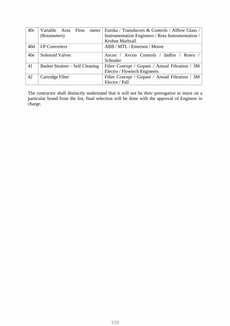
40c Variable Area Flow meter(Rotameters)
Eureka / Transducers & Controls / Alflow Glass /Instrumentation Engineers / Rota Instrumentation /Krohne Marhsall
40d I/P Converters ABB / MTL / Emerson / Moore
40e Solenoid Valves Ascon / Avcon Controls / Indfos / Rotex /Schrader
41 Basket Strainer – Self Cleaning Filter Concept / Gopani / Amiad Filtration / 3MElectro / Flowtech Engineers
42 Cartridge Filter Filter Concept / Gopani / Amiad Filtration / 3MElectro / Pall
The contractor shall distinctly understand that it will not be their prerogative to insist on aparticular brand from the list, final selection will be done with the approval of Engineer incharge.
335