Radio Network Chapter 4
66
Radio Network Chapter 4 This chapter is designed to provide the student with knowledge of cell configuration. OBJECTIVES: Upon completion of this chapter the student will be able to: • Understand how to define, configure and activate a cell • Understand the purpose of cell parameters • Understand how the locating algorithm works
Transcript of Radio Network Chapter 4

Radio Network
Chapter 4
This chapter is designed to provide the student with knowledgeof cell configuration.
OBJECTIVES:Upon completion of this chapter the student will be able to:
• Understand how to define, configure and activate a cell
• Understand the purpose of cell parameters
• Understand how the locating algorithm works

GSM BSC Operation
EN/LZT 123 3801 R2A
ll aa nn kkBB
iioonnaall llyy
ttnneettnnII
4 Radio Network
EN/LZT 123 3801 R2A – i –
4 Radio Network
Table of Contents
Topic Page
INTRODUCTION................................................................................105
LOCATING.........................................................................................106
LOCATING PROCESS .............................................................................................. 106
ORGANIZING THE CANDIDATE LIST...................................................................... 108
CALL PROCESS........................................................................................................ 109
THE CELL.................................................................................................................. 109
THE CLUSTER .......................................................................................................... 111
CELL DATA .......................................................................................113
CELL DEFINITION..................................................................................................... 113
DESCRIPTION DATA................................................................................................ 113
DEFINITION OF SUBCELLS..................................................................................... 118
CHANGE OF TRAINING SEQUENCE CODE........................................................... 120
CHANNEL GROUPS ................................................................................................. 121
DISCONTINUOUS TRANSMISSION DOWNLINK .................................................... 121
CONFIGURATION POWER DATA FOR CELL OR SUBCELL ................................. 121
FREQUENCY HOPPING DATA ................................................................................ 122
CONFIGURATION FREQUENCY DATA................................................................... 122
CONFIGURATION CONTROL CHANNEL DATA ..................................................... 123
BSC LOCATING DATA.............................................................................................. 125
CELL LOCATING DATA ............................................................................................ 131
LOCATING DISCONNECT DATA ............................................................................. 134
LOCATING URGENCY DATA ................................................................................... 134
LOCATING PENALTY DATA..................................................................................... 135
LOCATING FILTER DATA......................................................................................... 138
LOCATING HIERARCHICAL DATA .......................................................................... 139
INTRA-CELL HANDOVER LOCATING DATA........................................................... 144
LOCATING OVERLAID SUBCELL DATA.................................................................. 146

GSM BSC Operation
– ii – EN/LZT 123 3801 R2A
MEASUREMENT FREQUENCIES ............................................................................ 148
NEIGHBOR RELATIONS........................................................................................... 149
CHANGE OF NEIGHBOR RELATIONS .................................................................... 149
SYSTEM INFORMATION SACCH AND BCCH DATA.............................................. 152
SYSTEM INFORMATION BCCH DATA .................................................................... 155
SYSTEM INFORMATION BCCH MESSAGE DISTRIBUTION.................................. 158
CHANNEL ALLOCATION PROFILE.......................................................................... 159
DYNAMIC MS POWER CONTROL CELL DATA ...................................................... 159
DYNAMIC BTS POWER CONTROL CELL DATA..................................................... 160
CELL LOAD SHARING.............................................................................................. 161
CELL LOAD SHARING DATA ................................................................................... 161
IDLE CHANNEL MEASUREMENT............................................................................ 164
IDLE CHANNEL MEASUREMENT DATA ................................................................. 164
CONNECTION OF CELL TO TRANSCEIVER GROUP............................................ 165
CELL STATE.............................................................................................................. 165

4 Radio Network
EN/LZT 123 3801 R2A – 105 –
INTRODUCTION
This chapter provides an introduction to:
• Basic radio networks terminology.
• Commands and parameters used to define a cell.
• A description of the parameters used in the definition of acell.
It does not provide a description of all commands andparameters that can be used in cell definition and configuration.

GSM BSC Operation
– 106 – EN/LZT 123 3801 R2A
LOCATING
LOCATING PROCESS
In the locating process, the BSC selects the cell which providesthe best connection between an MS and a BTS. If the BSCdetects that, for example, a neighboring cell provides a radioconnection with better signal strength, the BSC will initiate achange from the current (serving) cell to this neighboring cell,this process is called handover. The decision on a handover isbased on two 0HDVXUHPHQW�5HSRUWV��05V�:
1. The MR which the MS sends to the BSC via the SACCH;these values are measured by the MS and describe thedownlink connection. This MR contains the signal strengthand quality of the serving cell and the signal strength of thesix strongest neighboring cells.
2. The MR which is provided by the BTS; it contains thevalues of signal strength and quality of the uplinkconnection.
Basically, there are two reasons for a handover:
• A neighboring cell provides a better connection.
• The quality of the existing connection is that bad or thetiming advance is too high that an urgency handover isrequired.
This paragraph gives an introduction to the basic locating data,i.e. the data which is essential to control the handover from onecell to another. A detailed description of the algorithm andoptional data for network tuning can be found in Appendix A.
Since the quality of a radio connection changes in time, the radioconnection must be verified from time to time. Therefore, thelocating procedure must be executed cyclically.

4 Radio Network
EN/LZT 123 3801 R2A – 107 –
step 1: Measurement Handling
step 2: Filtering
step 3: Basic Ranking
step 4: Penalty Handling
step 6: Urgency Conditions
step 7: Evaluation of network-features
step 8: Organizing the Candidate List
step 9: Sending the list to Call Process
step 10: Evaluation of allocation result
Call Process
step 5: Handling fast moving mobiles
Figure 4-1
In steps 1 through 7, the BSC only tries to determine the besthandover candidate; the handover itself (in terms of signalingand allocation of a new dedicated channel) is performed duringthe Call Process. The locating procedure evaluates themeasurements of both the uplink and downlink connections. Onthe downlink connection, the procedure evaluates themeasurements delivered by the MS in the MR. These values are:
• The signal strength level RXLEV_DL the MS receives fromthe serving cell
• The quality RXQUAL_DL (or Bit Error Rate %(5respectively) of the serving cell.
• The RXLEV_DL_N the MS measures on the BCCH-carrierof the six strongest neighboring cells.
On the uplink connection, the BTS measures the followingvalues on the existing radio connection and forwards the resultto the BSC:
• The signal strength (uplink) RXLEV_UL
• The quality (uplink) RXQUAL_UL
• The timing advance TA

GSM BSC Operation
– 108 – EN/LZT 123 3801 R2A
The procedure is started whenever the BSC receives a completeMR from the MS, i.e. every 480 ms. The following paragraphgives a brief description of all steps. It only includes parameterswhich are essential to adjusting the locating algorithm. A moredetailed description of additional features for the fine tuning of aradio network can be found in Appendix A.
ORGANIZING THE CANDIDATE LIST
The final ranking of candidate cells does not only depend on thebasic ranking list, but on other criteria as well. Variousconditions determine the selection of target cells. Theseconditions can change the order of candidate cells:
1. AW-state (assignment to worse cell required)
2. TA exceeded (urgency condition)
3. Poor quality urgency handover required
4. Overlaid / underlaid subcell change required
5. Intra-cell handover required
Some of the handover conditions are detected early on in thelocating algorithm, e.g. urgency handover due to exceeded TA.The conditions for handover described above are all on the samelevel, but may change the order of candidates in the list. Thecandidate list is structured to include several categories of cells.The category in which a candidate cell is found depends on theconditions named above. The categories have the followingpriority:
1. Normal handover from K to L cell
2. Timing advance urgency
3. Change in cell hierarchy from higher to lower level
4. Change of subcell
5. Intra-cell handover
6. Bad quality urgency
7. Change in cell hierarchy from lower to higher level
4 Radio Network
EN/LZT 123 3801 R2A – 109 –
CALL PROCESS
The Call Process is the stage which performs the handover interms of signaling. That is, it reserves a new dedicated channelin the target cell, carries out signaling to the MS, controls thehandover result and, in case of successful handover, clears theold channel. In addition it handles all communication with theMSC.
Once the candidate list is finalized, the Call Process takes overthe list from the Locating Process and attempts to perform ahandover. Call Process takes the cell in first position of thecandidate list. Whatever the result of handover will be(successful or failed handover), the Call Process returns theallocation result to the Locating Process which in turn carriesout penalties according to the allocation result.
THE CELL
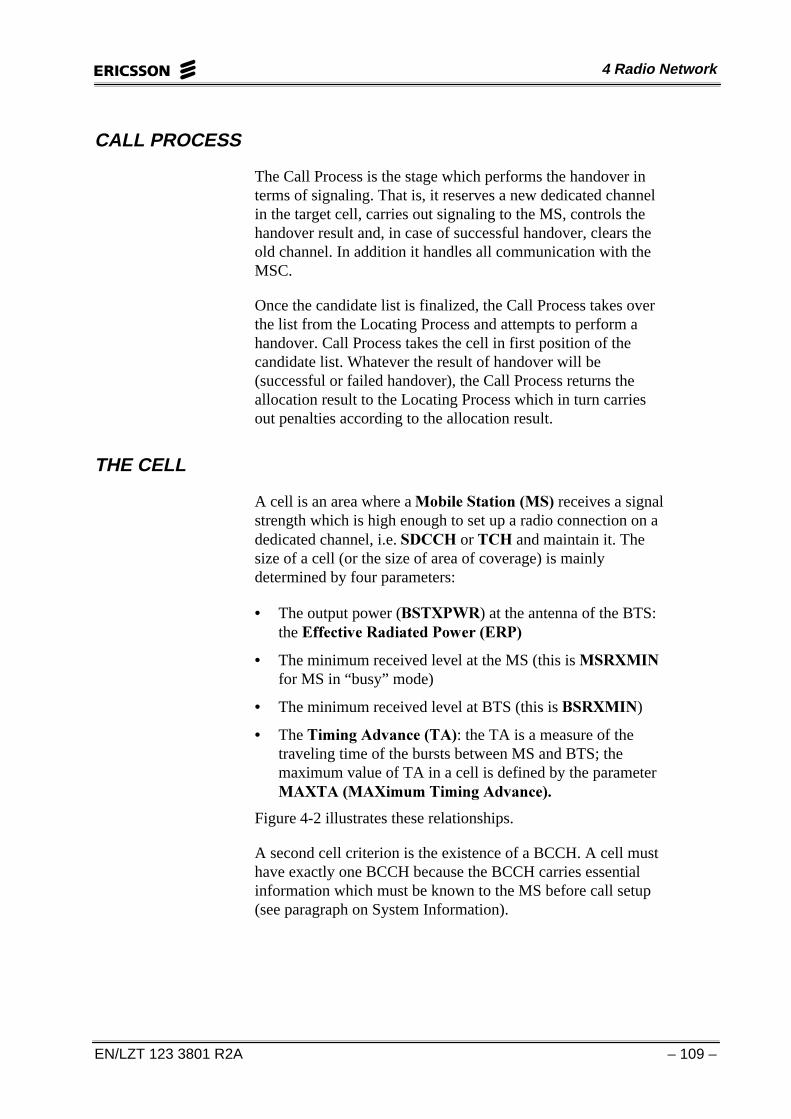
A cell is an area where a 0RELOH�6WDWLRQ��06� receives a signalstrength which is high enough to set up a radio connection on adedicated channel, i.e. 6'&&+ or 7&+ and maintain it. Thesize of a cell (or the size of area of coverage) is mainlydetermined by four parameters:
• The output power (%67;3:5) at the antenna of the BTS:the (IIHFWLYH�5DGLDWHG�3RZHU��(53�
• The minimum received level at the MS (this is 065;0,1for MS in “busy” mode)
• The minimum received level at BTS (this is %65;0,1)
• The 7LPLQJ�$GYDQFH��7$�: the TA is a measure of thetraveling time of the bursts between MS and BTS; themaximum value of TA in a cell is defined by the parameter0$;7$ �0$;LPXP�7LPLQJ�$GYDQFH��
Figure 4-2 illustrates these relationships.
A second cell criterion is the existence of a BCCH. A cell musthave exactly one BCCH because the BCCH carries essentialinformation which must be known to the MS before call setup(see paragraph on System Information).
GSM BSC Operation
– 110 – EN/LZT 123 3801 R2A
BTS
BSTXPWR
MSRXMIN
no coverageno call possible
calls possible
RXLEV
distance to BTS
Figure 4-2
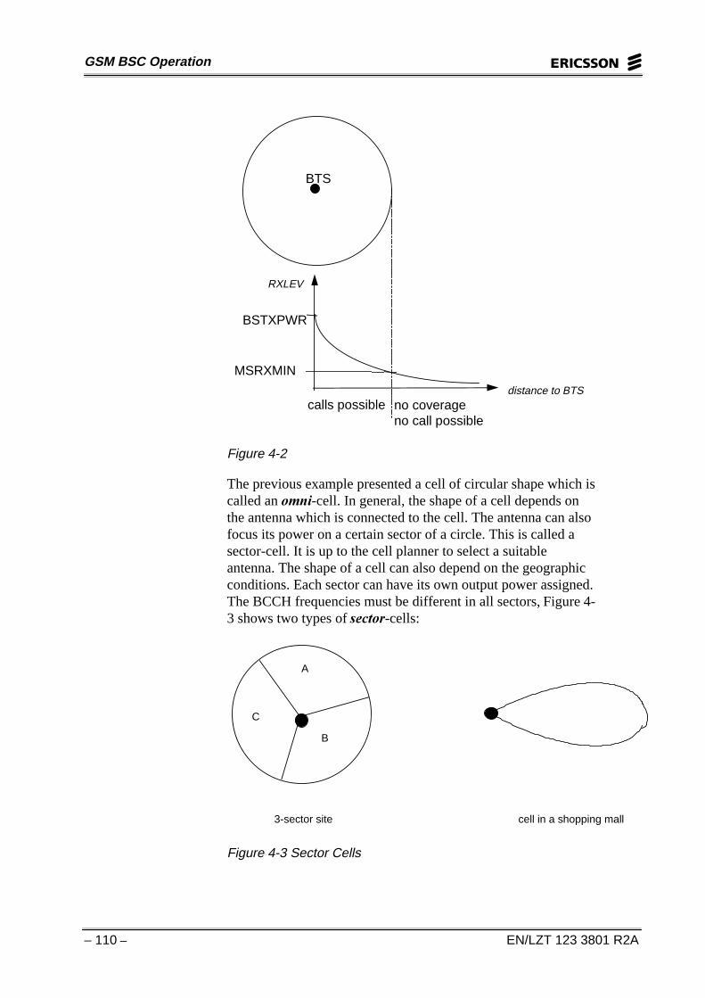
The previous example presented a cell of circular shape which iscalled an RPQL-cell. In general, the shape of a cell depends onthe antenna which is connected to the cell. The antenna can alsofocus its power on a certain sector of a circle. This is called asector-cell. It is up to the cell planner to select a suitableantenna. The shape of a cell can also depend on the geographicconditions. Each sector can have its own output power assigned.The BCCH frequencies must be different in all sectors, Figure 4-3 shows two types of VHFWRU-cells:
A
B
C
3-sector site cell in a shopping mall
Figure 4-3 Sector Cells

4 Radio Network
EN/LZT 123 3801 R2A – 111 –
THE CLUSTER
The aim of the cell planning process is to provide maximumcapacity with least interference. The cell pattern and frequencyplan should be designed not only for the initial network, but alsofor gradual growth phases. An initial network must be plannedto adapt successive demands on traffic growth.
To prevent interference between cells, a cell pattern called acluster is designed. In this cluster, a frequency will be used onlyonce. The aim of a cluster is to have a large frequency reusedistance. Ericsson uses three types of clusters:
• 7/21 (21 frequency groups in 7 sites)
• 4/12 (12 frequency groups in 4 sites)
• 3/9 (9 frequency groups in 3 sites)
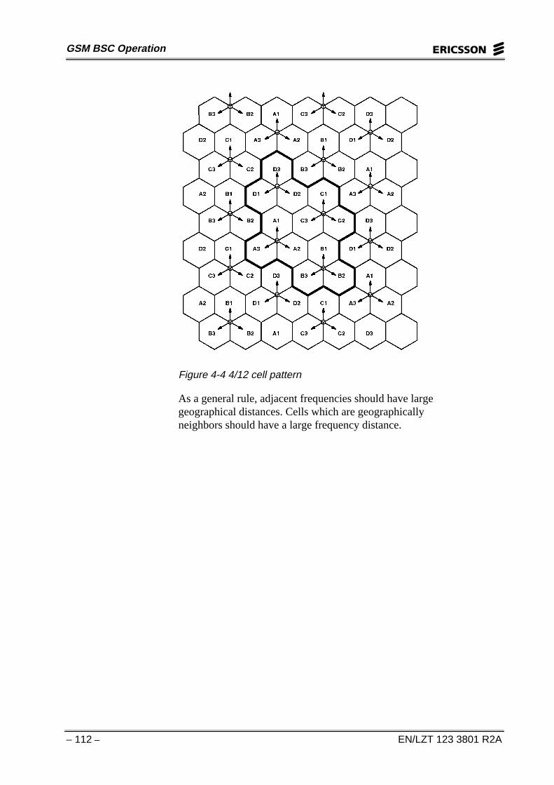
If a 4/12 cluster is used for cell planning, the number of cellsconsisting of different channel numbers in the network will be12. To enable allocation of channels to cells without co–channelinterference, a reuse pattern is utilized. The assignment is shownin Table 4-1.
Freq. group A1 B1 C1 D1 A2 B2 C2 D2 A3 B3 C3 D3Ch. 1 2 3 4 5 6 7 8 9 10 11 12
13 14 15 16 17 18 19 20 21 22 23 2425 26 27 28 29 30 31 32 33 34 35 36. . . . . . . . . . . .121 122 123 124
Table 4-1 Frequency groups in a 4/12 - cluster
These frequency groups are then placed in the cluster as shownin the next figure. Groups containing adjacent frequencies, e.g.D1 and A2 or D3 and A1 should not be placed as neighboringcells.
GSM BSC Operation
– 112 – EN/LZT 123 3801 R2A
Figure 4-4 4/12 cell pattern
As a general rule, adjacent frequencies should have largegeographical distances. Cells which are geographicallyneighbors should have a large frequency distance.

4 Radio Network
EN/LZT 123 3801 R2A – 113 –
CELL DATA
The following sections on cell data and locating describeessential cell parameters. When defining a cell, the followingOPIs must be observed:
%6&��,QWHUQDO�&HOOV��'HILQH%6&��,QWHUQDO�&HOO�'DWD��&KDQJH
CELL DEFINITION
RLDEI: CELL=cell, CSYSTYPE=csystype, EXT;
A cell can be defined in the BSC as internal or external. Internalcells are fully controlled by their own BSC while external cellsare not controlled by their own BSC. However, certain data mustbe known in order to carry out a handover from a cell in its ownBSC to a cell controlled by another BSC.
&(//��Cell designation or cell name can be a maximum ofseven characters. Using the name of the site plus one morecharacter to identify the cell within the site; 1, 2, 3 or A, B, C isrecommended, alternatively, identifying the aerial direction ofthe cell in a sector-site.
&6<67<3(� If the BSC global system type is mixed thenCSYSTYPE must be used to define to which system the cellbelongs, GSM900 and GSM1800, or GSM1900.
(;7� External cell, the cell belongs to another BSC.
Note: The global system type for the BSC is defined withcommand RLTYI. This command must be given before the firstcell is defined.
DESCRIPTION DATA
RLDEC: CELL=cell, CGI=cgi, BSIC=bsic, BCCHNO=bcchno,NEWNAME=newname, AGBLK=agblk, MFRMS=mfrms,BCCHTYPE=bcchtype, FNOFFSET=fnoffset,XRANGE=xrange;
&*,� Cell global identity. Expressed as MCC-MNC-LAC-CI.
&HOO�,GHQWLW\��&,�: every cell is assigned a CI. This number isunique per /RFDWLRQ�$UHD��/$� and is part of the &HOO�*OREDO,GHQWLW\��&*,�� The CGI uniquely identifies a cell within GSM.

GSM BSC Operation
– 114 – EN/LZT 123 3801 R2A
The CGI is sent to the idle MSs in system information messages.The combination MCC-MNC-LAC is also known as the/RFDWLRQ�$UHD�,GHQWLW\��/$,�. It is important to the cellularnetwork to know the location of a mobile since paging signalsare distributed in one LA only. A record in the MSC/VLRadministrates a mobile location by means of the LAI. When theMS moves from one LA to another, it sends a location updatingrequest to the MSC/VLR.
LAI 1
LAI 2
LAI 3CI=0001
CI=0001CI=0001
LAI 1
LAI 2
LAI 3
Figure 4-5 Location areas are divided into cells with their ownidentity
%6,&: Base Station Identity Code. It is transmitted on the SCHand is expressed as:
NCC = National Color Code of PLMN. Numeric 0 - 7.
BCC = Base Station Color code. Numeric 0 - 7.
Each operator in a country is assigned one NCC value Q toensure that the same NCC is not used in adjacent PLMNs. Thepurpose of the BSIC is to distinguish between cells with thesame carrier frequency but from different clusters. It can also beused to distinguish between cells from different operators at theborder between two countries. It is essential for the locatingalgorithm that the correct neighboring cells are evaluated.
As seen in Figure 4-6, cells which are close to country bordersare given different NCC values. The MS is in active mode, usinga TCH on f15. The MS measures the neighboring frequenciesbroadcast as system information. In this example they are f1, f26,f29 and f33. In country C, f1 is reused too close to one of ourneighbors with the same frequency. Thus, neighbor f1 is subject

4 Radio Network
EN/LZT 123 3801 R2A – 115 –
to severe radio shadowing towards the MS. When the MS triesto measure f1, it picks up the wrong signal. However, it detectsthat the NCC is incorrect and the measurement is discarded.
Country ANCC =1
Country BNCC =2
Country CNCC =3
f15
f29
f33
f26
f6 f1
f1
Figure 4-6 PLMN color code
In this case, the MS will not perform a call setup in anothercountry or a different PLMN which means that the operator hassaved signaling and the subscriber has saved money. Thismethod can also be used inside a country in order to preventsignaling and handovers between different MSCs. If a call setupin another country or a different PLMN is permitted, theparameter 1&&3(50 supersedes NCC.
BCC is used as a protection against co-channel interference. Forthis purpose, BCC must be allocated as wisely as possible. It isrecommended that all cells in a given cluster use the same BCC.In doing so the distance of a certain BCC is maximized.Suppose a MS is actively measuring neighboring cells (seeFigure 4-7). Unfortunately f15x is too close to neighbor f15y. Insome MRs the MS includes measurements from f15x instead off15y. The only difference between the two is that one has BCC =2 and the other has BCC = 3. The best result is sent to the BSC,even if the BCC is wrong. The locating algorithm in the BSCincludes a filtering function which removes cells with anincorrect BCC. In this example, f15x with BCC = 3 will nolonger be evaluated.

GSM BSC Operation
– 116 – EN/LZT 123 3801 R2A
f6
f28
f2
f10
f25
f15y
f36 f15xBCC =2
BCC =2
BCC =2
BCC =3Country B
Figure 4-7 Base Station Color Code
%&&+12� Absolute RF channel number for BCCH. Numeral 1- 124 in GSM900, 512 - 885 in GSM1800, 512-810 inGSM1900.
1(:1$0(��New cell designation. Symbolic name, maximum7 characters.
At relocation of cells between BSCs, data must be redefined forthe target cell in the target BSC and removed from the originalcell in the original BSC. The cell can not have the same name inboth BSCs, especially when relocating a border cell that isdefined in both BSCs,
This parameter provides means to temporarily define cells andcell data in the target BSC. When the cell has been reallocated tothe target BSC, it is then possible to change the name back tothe original cell name used in the original BSC, in order tomaintain consistency of the cell.
$*%/.� Number of reserved access grant blocks. Numeric 0 -7. Numeric 0 - 2 for SDCCH/4.
Number of CCCH blocks reserved for the AGCH. Theremaining CCCH blocks are used as PCHs. The parameter isvalid only for internal cells, that is, cells belonging to the currentBSC.
Within Ericsson´s GSM system, access grant messages havepriority over paging messages, but if Cell Broadcast or SystemInformation type 7&8 are to be broadcast then AGBLK must beequal to 1. During this reserved CCCH block the MS is told tolisten to the cell broadcast or it will receive System Informationtype 7&8.

4 Radio Network
EN/LZT 123 3801 R2A – 117 –
1RWH���(ULFVVRQ�5%6�����DQG�5%6������FDQ�RQO\�VXSSRUW$*%/. ��RU���
FCCH
SCH
BCCH CCCHB0
FCCH
SCH
CCCHB2
FCCH
SCH
CCCHB4
FCCH
SCH
CCCHB6
FCCH
SCH
CCCHB8
CCCHB1
CCCHB3
CCCHB5
CCCHB7
0 5 10 15 20 25 30 35 40 45 50
DOWNLINK BCH51 - frame (235.4ms)
Figure 4-8 CCCH location in a multiframe
0)506��Multiframes period. Numeric 2 - 9. Defines theperiod of transmission for PAGING REQUEST messages to thesame paging group. The parameter is expressed as the number ofCCCH multiframes. The parameter is valid only for internalcells.
Each MS, according to its IMSI number, belongs to a specificpaging group. Dependent on the IMSI-number, a MS is allocatedone of the CCCH-blocks in a set of multiframe. Paging signalsto this MS are then exclusively sent in this CCCH-block. The setof multiframes is determined by 0)506. Since MFRMS canbe set between 2 and 9, and the number of CCCH blocks withina multiframe is 9, it is possible to have 18 to 81 paging groups.
In idle mode, a MS listens to its paging group to detect a pagingsignal. In the gap between a certain paging group, the MS staysin a sleeping mode to minimize power consumption. If MFRMSis set to 2, the mobile listens to every 18 CCCH block whichcorresponds to 470.8ms (2 x 235.4ms).
35 40 45 50 0 5 10 15 20 25 30 35 4 0 45 50 0 5 10 15 20 25 30 35 40 45 50 0 5 10 15
D O W N LIN K D O W N LIN K D O W N LIN K
BC H 51 - fram e (235 .4m s) B C H 51 - fram e (235.4m s)
M ultifram e M ultifram e
Period 470 .8 m s (2 x 235 .4m s)
Figure 4-9 MS listening for paging request

GSM BSC Operation
– 118 – EN/LZT 123 3801 R2A
%&&+7<3(� Identifies the type of BCCH to be used, this isonly applicable for internal cells:
COMB � Indicates the cell has a combined BCCH andSDCCH/4.
COMBC � Combined with the CBCH. Indicates the cell hasa combined BCCH and SDCCH/4 with a CBCHsubchannel.
NCOMB Indicates the cell does not have a combinedBCCH and SDCCH/4.
)12))6(7� Frame number offset. Numeral 0-1325. Indicatesthe time difference from the )UDPH�1XPEHU��)1� generator inthe BTS expressed as a number of TDMA frames. This preventsall cells on a site sending BCCH channels at the same time. Byusing FNOFFSET on a two or three sector site the time fordecoding BSIC can be reduced. This parameter is valid only forinternal cells.
;5$1*(��Extended range cell. It can support traffic at adistance of greater than 35 km between the MS and BTS. Thisparameter is valid only for internal cells.
See Appendix A for details.
DEFINITION OF SUBCELLS
RLDSI: CELL=cell;
This command creates a subcell structure for one or severalcells. The cell must be internal, and can be in the state ACTIVEor HALTED.
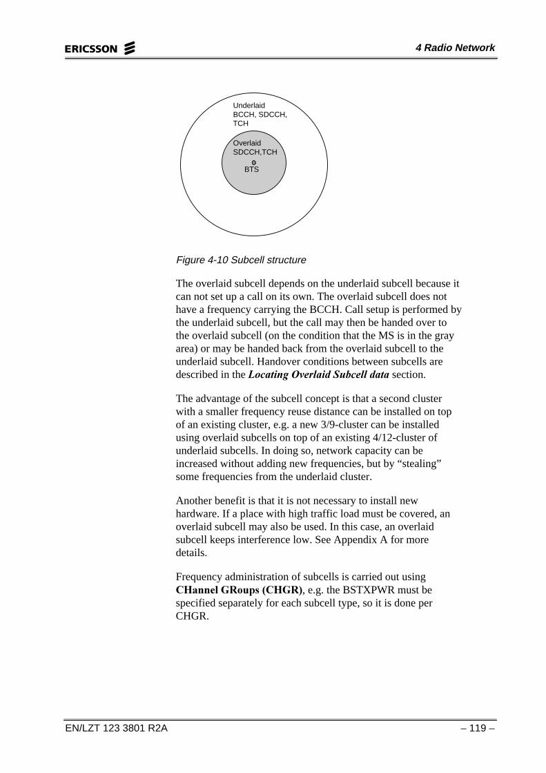
If a cell is configured with at least two frequencies, it can besplit into two subcells - an overlaid subcell and an underlaidsubcell. More than one frequency can be assigned to a subcell.In the BSC, subcells are denoted by the parameter 6&7<3(.SCTYPE can be 8/ for underlaid or 2/ for overlaid subcell.
The area from the center (BTS) to the outer border is covered bythe underlaid subcell. In addition, the gray area is the coverage-area of overlaid subcell.
4 Radio Network
EN/LZT 123 3801 R2A – 119 –
UnderlaidBCCH, SDCCH,TCH
OverlaidSDCCH,TCH
BTS
Figure 4-10 Subcell structure
The overlaid subcell depends on the underlaid subcell because itcan not set up a call on its own. The overlaid subcell does nothave a frequency carrying the BCCH. Call setup is performed bythe underlaid subcell, but the call may then be handed over tothe overlaid subcell (on the condition that the MS is in the grayarea) or may be handed back from the overlaid subcell to theunderlaid subcell. Handover conditions between subcells aredescribed in the /RFDWLQJ�2YHUODLG�6XEFHOO�GDWD section.
The advantage of the subcell concept is that a second clusterwith a smaller frequency reuse distance can be installed on topof an existing cluster, e.g. a new 3/9-cluster can be installedusing overlaid subcells on top of an existing 4/12-cluster ofunderlaid subcells. In doing so, network capacity can beincreased without adding new frequencies, but by “stealing”some frequencies from the underlaid cluster.
Another benefit is that it is not necessary to install newhardware. If a place with high traffic load must be covered, anoverlaid subcell may also be used. In this case, an overlaidsubcell keeps interference low. See Appendix A for moredetails.
Frequency administration of subcells is carried out using&+DQQHO�*5RXSV��&+*5�, e.g. the BSTXPWR must bespecified separately for each subcell type, so it is done perCHGR.
GSM BSC Operation
– 120 – EN/LZT 123 3801 R2A
CHANGE OF TRAINING SEQUENCE CODE
RLDTC: CELL=cell, SCTYPE=sctype, TSC=tsc;
6&7<3(� subcell type
UL= underlaid
OL= overlaid
76&� training sequence code. Numeral 0-7.
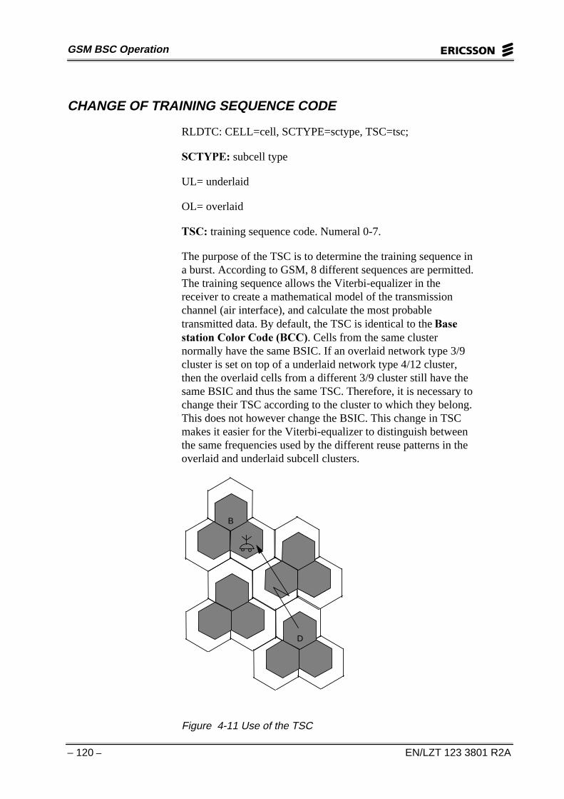
The purpose of the TSC is to determine the training sequence ina burst. According to GSM, 8 different sequences are permitted.The training sequence allows the Viterbi-equalizer in thereceiver to create a mathematical model of the transmissionchannel (air interface), and calculate the most probabletransmitted data. By default, the TSC is identical to the %DVHVWDWLRQ�&RORU�&RGH��%&&�. Cells from the same clusternormally have the same BSIC. If an overlaid network type 3/9cluster is set on top of a underlaid network type 4/12 cluster,then the overlaid cells from a different 3/9 cluster still have thesame BSIC and thus the same TSC. Therefore, it is necessary tochange their TSC according to the cluster to which they belong.This does not however change the BSIC. This change in TSCmakes it easier for the Viterbi-equalizer to distinguish betweenthe same frequencies used by the different reuse patterns in theoverlaid and underlaid subcell clusters.
B
D
Interference
Figure 4-11 Use of the TSC

4 Radio Network
EN/LZT 123 3801 R2A – 121 –
In a case where the MS receives a stronger signal from Dbecause of shadowing in B, the MS makes up a model for thedownlink channel from B. The MS knows its own TSC overlaidcell B. Thus it can ignore the even stronger signal from overlaidcell D. Different training sequences allow for a bettertransmission in case of interference. In addition, the MS candifferentiate between cells from the overlaid and the underlaidnetwork.
CHANNEL GROUPS
RLDGI: CELL=cell, CHGR=chgr, SCTYPE=sctype;
This command is used to specify channel groups for a cell orsubcell. If a subcell structure is specified with the commandRLDSI, the parameter SCTYPE must be included in thiscommand.
&+*5� Channel group. Numeral 0-15. Maximum 16 channelgroups can be specified per cell.
6&7<3(� subcell type
UL= underlaid
OL= overlaid
DISCONTINUOUS TRANSMISSION DOWNLINK
RLCXC: CELL=cell, DTXD=dtxd;
This command enables or disables the status of discontinuoustransmission downlink for a cell. Valid for internal cells only.
'7;'� Discontinuous transmission downlink. On or off.
CONFIGURATION POWER DATA FOR CELL OR SUBCELL
RLCPC: CELL=cell, SCTYPE=sctype, MSTXPWR=mstxpwr,BSPWRB=bspwrb, BSPWRT=bspwrt;
067;3:5��Maximum transmit power in dBm for an MS on aconnection.
%63:5%��Base Station nominal output power in dBm, for theRF channel number ZKLFK�KDV the BCCH.

GSM BSC Operation
– 122 – EN/LZT 123 3801 R2A
%63:57��Base Station nominal output power in dBm, for theRF channels ZKLFK�GR�QRW�KDYH the BCCH.
This step is used to define or change configuration power data ina cell or a subcell. The indicated power is the nominal power ofthe transmitter in the BTS, not the ERP. If a subcell structureexists, the parameters MSTXPWR and BSPWRT must bespecified for each subcell. If the cell is external, only parameterMSTXPWR is valid with CELL.
FREQUENCY HOPPING DATA
RLCHC: CELL=cell, CHGR=chgr, HOP=hop, HSN=hsn;
This command is used to change the frequency hopping statusand hopping sequence number for a channel group. The CHGRparameter is mandatory if channel groups other than 0 exist. Thecommand is only valid for internal cells.
&+*5� Channel group. Numeral 0-15.
+23� Frequency hopping status. On or off.
+61� Hopping sequence number. Numeral 0-63.
HSN= 0 is cyclic hopping
HSN= 1-63 identifies a pseudo-random sequence
See Appendix A for details.
CONFIGURATION FREQUENCY DATA
RLCFI: CELL=cell, CHGR=chgr, DCHNO=dchno;
If more frequencies than the BCCHNO must be added to thecell, these frequencies are defined separately. The cell inquestion can be ACTIVE or HALTED. If subcells exist, newfrequencies are added to the channel group (CHGR).
&+*5� Channel group. Numeral 0-15.
'&+12��ARFCN (Absolute RF channel number). Numeric 1 -124 in GSM900, 512 - 810 in GSM1800, 512 - 885 inGSM1900. A maximum of 16 DCHNO per channel group isallowed except for channel group 0 which allows only 15.Overall: 31 DCHNO per cell.

4 Radio Network
EN/LZT 123 3801 R2A – 123 –
CONFIGURATION CONTROL CHANNEL DATA
RLCCC: CELL=cell, TN=tn, CHGR=chgr, SDCCH=sdcch,CBCH=cbch, CCHPOS=cchpos;
71��Time slot Number. Numeral 0-3 for normal cell. Numeral 0or 2 for extended range cell. System default value= 2.
&+*5� Channel group. Numeral 0-15.
6'&&+��Required number of SDCCH/8. Numeral 0-16.Numeral 0-7 when parameter CCHPOS is set to BCCH.Numeral 0-3 when parameter CCHPOS is set to BCCH and thecell is an extended range cell.
&%&+��Cell Broadcast Channel.
CBCH = YES shall be included in one of SDCCH/8 for the cellor channel group.
CBCH = NO indicates that no SDCCH/8 for the cell or channelgroup shall include CBCH.
Only one CBCH is allowed per cell. In case of the channelcombination with CBCH (BCCHTYPE=COMBC), the CBCH isalready integrated to TS0. Therefore, in control channel data, theCBCH must be set to NO (CBCH = NO).
SMS CB provides an operator with the capability to distributeshort messages to idle subscribers. Before SMS CB data can bedistributed, the cell must be configured with a CBCH and atleast one reserved $FFHVV�*UDQW�%ORFN��$*%/.�. The SMSCB function distributes messages to idle MSs within a certaincoverage area. Message data is entered as an SMS CB messageby command per cell in the BSC and can contain up to 15 pages.
A CBCH configured for the selected cell is required fordistribution. Distribution is temporarily prevented when theCBCH is blocked. The message can, e.g., contain informationsuch as traffic reports, weather reports and charging information.The source and type of the message is identified by a 2 octetmessage identifier in the SMS CB header.
SMS CB messages are sent as pages of up to 82 octets.Reception of a SMS CB message by an MS is only possible inidle mode. Before entering a new SMS CB message in a cellwhere distribution is already active, the old SMS CB messagemust be deleted and the distribution stopped.

GSM BSC Operation
– 124 – EN/LZT 123 3801 R2A
The 5/0%, command is used to specify message identity,update number, text entry mode, the number of pages in themessage and language. It should be noted that the MS must beset up with the appropriate code in order to be able to receive themessage.
&&+326� Control channel position.
This parameter can only be used for channel group 0. For allother channel groups CCHPOS is always equal to TN andcannot be changed.
CCHPOS= BCCH, all SDCCHs in channel group 0 will beplaced on the Broadcast Control CHannel (BCCH) frequency.
CCHPOS= TN, the SDCCHs in the cell will be placed on thetime slot number entered with parameter TN.
For various reasons it can be necessary to change SDCCH/8configuration in a cell or channel group, e.g. in an area with ahigh rate of call setups, it might be useful to add anothersignaling channel. 6KRUW�0HVVDJH�6HUYLFH���3RLQW�WR�3RLQW�606�33) also uses the SDCCH and can create a high trafficload. In rural areas, a time slot can be gained if the SDCCH ismultiplexed on TS0, sharing the time slot with the BCCH. TS1can then be used as a TCH.
When parameter CCHPOS is set to BCCH, all SDCCH/8 inchannel group zero will be placed on the BCCH frequency. Thefirst SDCCH/8 will be placed on TS0, the next on TS2 and soon. For extended range cells, only even time slot numbers can beused, starting with TS2. When parameter CCHPOS is set toBCCH and if parameter TN is entered, it does not affect theconfiguration in channel group zero. The maximum number ofSDCCH/8s that can be added to channel group zero is seven fornormal cells and three for extended range cells.
By system default one SDCCH/8 without CBCH is provided inthe cell if the BCCH frequency for the cell is defined and thetype of BCCH is non-combined.
It is possible to have up to 16 SDCCH/8s per cell. This numberis reduced by one if an SDCCH/4 is defined for the cell. Thetotal number of SDCCH/8s in the cell must not be greater thanthe number of frequencies in the cell. The number of SDCCH/8sin the channel group must also not be greater than the number offrequencies in the channel group.

4 Radio Network
EN/LZT 123 3801 R2A – 125 –
If parameter CBCH is specified, then one logical SDCCH in oneSDCCH/8 is replaced by a CBCH. CBCH may not be specifiedfor a channel group within the overlaid subcell. It is not possibleto define more than one CBCH per cell including CBCH(specified by the command RLDEC). This command does notremove a CBCH which has been defined for the cell using thecommand RLDEC.
If channel groups have been defined for the cell using thecommand RLDGI, then the CHGR parameter is mandatorywhen giving parameter SDCCH, CBCH or CCHPOS. CHGRcannot be given with TN when SDCCH, CBCH and CCHPOSare omitted, as TN always applies to the whole cell.
The command is valid for internal cells only.
BSC LOCATING DATA
RLLBC:SYSTYPE=systype, TAAVELEN=taavelen,TINIT=tinit,TALLOC=talloc, TURGEN=turgen,EVLATYPE=evaltype, THO=tho, NHO=nho, ASSOC=assoc,IBHOASS=ibhoass, IBHOSICH=ibhosich, IHOSICH=ihosich;
6<67<3(� System type. Identifier GSM900, GSM1800 orGSM1900.
7$$9(/(1� Timing advance average length. Number ofvalues in the moving average of timing advance. Numeral 1-20.
Filtering must be applied to the evaluation of the TA. Thenumber of values in the average is determined by TAAVELEN.
7,1,7� Time after initiation. Minimum time before handover isallowed on an initial call or after handover. Numeral 0-120(SACCH periods).
After a new dedicated channel assignment, the BSC starts thetimer TINIT. The assignment can be any dedicated channel suchas SDCCH or TCH. It does not matter if it is directly after a callsetup or a successful handover. The Call Process performs theassignment and starts the timers. For the time specified byTINIT, the BSC does not allow handover. Once TINIT expires,the BSC allows handovers again. The purpose of TINIT is toprevent the MS from jumping from one cell to another because afrequent change of the radio channel deteriorates the overallquality of the connection and increases the processor load.

GSM BSC Operation
– 126 – EN/LZT 123 3801 R2A
7$//2&� Time before allocation is allowed again. Minimumtime between allocation attempts because of a better cellcondition and the first allocation attempt has failed (failurecould be due to interference or congestion). Numeral 0-120(SACCH periods).
785*(1� Timer of urgency. Minimum time betweenallocation attempts because of an urgency condition and the firstallocation attempt has failed. Numeral 0-120 (SACCH periods).
After a failed channel allocation attempt, the Call Process startsTURGEN. No further handover attempt will be made due toanother urgency condition unless the TURGEN has expired.
(9$/7<3(� Evaluation type. Numeral 1 or 3.
1= Cell ranking according to the Ericsson1 locating algorithm.
3= Cell ranking according to the simplified and optimizedEricsson3 locating algorithm.
Ericsson1
In the Ericsson1 algorithm, the candidate cells pass three stages :the M-criterion, K-criterion, and L-criterion.
Cells rankedaccording to
L-criteriaCells rankedaccording to
K-criteria
Acceptedcells
Unacceptedcells
M-algorithm
Rankedbetter
Rankedworse
K-algorithm L-algorithm
PO-Cell list
Figure 4-12 The M,L, and K criteria
The M-criterion
In the first step, the system checks whether or not a candidatefulfills a minimum requirement or not. Every cell that is apotential candidate must provide a signal strength above acertain threshold on both the downlink and the uplink.

4 Radio Network
EN/LZT 123 3801 R2A – 127 –
For the downlink connection, there is a minimum threshold level065;0,1. This is the threshold of MS_RXLEV (SS the MSmust receive from neighboring cells). For the uplink, the BTSmust receive a signal strength above the threshold %65;0,1(BTS received minimum). The BSC selects the smaller valuefrom MS_RXLEV and BS_RXLEV:
Min(BS_RXLEV, MS_RXLEV)
and compares the result to the corresponding BSRXMIN orMSRXMIN threshold. If one of the two values is below thecorresponding threshold, the candidate will not be accepted forfurther evaluation. The list with the accepted cells is forwardedto the K-criterion stage.
The K-criterion
All candidates in this phase are checked against anotherthreshold, the sufficient signal strength level, that is,065;68)) for the downlink and %65;68)) for uplink.
As with the M-criterion, the values for both the uplink and thedownlink must be above the corresponding MSRXSUFF andBSRXSUFF thresholds, respectively. If both values are abovethe threshold, they are marked as L-cells, those below thethreshold are marked as K-cells.
K-cells are ranked according to signal strength. In the K-list, thecell providing the highest signal strength is ranked first. In theend, the K-list is appended to the L-list. K-cells always have aninferior position to L-cells.
The L-criterion
All cells above the sufficient level (BSRXSUFF, MSRXSUFF)are ranked according to path loss. On the downlink, path loss Lis defined as:
L = BSPWR - MS_RXLEV
where BSPWR applies to the case of the serving cell (seeFigure 4-13). In the case of neighboring cells, BSPWR isreplaced by BSTXPWR.

GSM BSC Operation
– 128 – EN/LZT 123 3801 R2A
pathloss L
distance to BTS
BSTXPWR
MS_RXLEV
MS
Figure 4-13 Pathloss
On the uplink, the path loss L is defined as:
L = MSTXPWR - BS_RXLEV
The cell with the lowest path loss is ranked first. Rankingaccording to path loss shifts the nominal point of handover tothe geographical center between two cells. Thus, interferencecan be reduced.
The following example (Figure 4-14) illustrates this effect. Alarge cell A with high output power (ERP) %63:5 and a smallcell B with small output power (ERP) BSPWR are neighbors.For reason of simplification, it is assumed that RXLEV is aboveMSRXSUFF at all places. Only downlink signal strength isconsidered. The MS moves on the axis between the centers.
Shadowed areas indicate the areas where both cells areconsidered L-cells. In the white area, they are ranked as K-cells.First, the MS belongs to cell A; a handover to cell B isperformed as soon as the MS moves out (on the axis) of theshadowed area of cell A.

4 Radio Network
EN/LZT 123 3801 R2A – 129 –
RXLEV
L
point of HO in K-ranking
point of HO in L-ranking
Cell BCell A
Figure 4-14
Ericsson3
The Ericsson1 algorithm is complex, which means that it isdifficult to optimize. Ericsson2 is a much simpler algorithm butlacks possibilities to optimize. A new locating algorithm,Ericsson3, which is easier to handle (less parameters) and easierto understand than Ericsson1, but still possible to optimize, hasbeen introduced and replaces Ericsson2.
• Only a simplified K-ranking is done. The double rankingcriteria is removed.
• Candidates are ranked in order of absolute signal strength,and not for their relative signal strength level.
• A parameter to class a serving cell as a high signal or a lowsignal cell is introduced. If the serving cell is a high signalcell, a high hysteresis is used and if it is a low signal cell alow hysteresis is used.

GSM BSC Operation
– 130 – EN/LZT 123 3801 R2A
• Both downlink and uplink signal strength is used to selectappropriate hysteresis level.
• Only one offset parameter per cell to cell relation is used.
Basic Ranking
The basic ranking is done by the Locating function.
Absolute signal strength is used when ranking cells. Ranking isnot done in relation to any minimum level or sufficient level. Allcells are ranked in the same list. The parameters MSRXSUFFand BSRXSUFF are not used by Ericsson3.
Cells are not classified as K- or L-cells. Instead the serving cellis classed as a high signal or a low signal cell depending on thelevel HYSTSEP. If the downlink signal strength is belowHYSTSEP, the serving cell is classified as low signal cell.Otherwise it will be classified as high.
If the serving cell is a high signal cell, a high hysteresis,HIHYST, is used and if it is a low signal cell, a low hysteresis,LOHYST, is used. The hysteresis value is subtracted from theranking value for the neighboring cell.
Bad Quality Urgency and Assignment to Worse Cell
At Bad Quality (BQ) urgency and assignment to worse cell (AW= ON at assignment) ranking will stop after the basic ranking,i.e. the +LHUDUFKLFDO�&HOO�6WUXFWXUHV (HCS) logic will beskipped.
Neighbor Cell Filters
Every cell has a filter (a set of filter parameters) used whenfiltering a cell and that cell’s neighbors. No change is done whenfiltering “own” cell, but when filtering a neighboring cell, thatneighboring cell’s filter is used. In this way a specific cell willalways be filtered with the same filter.
Nevertheless, if a Finite Impulse Response (FIR) filter isspecified for a cell, the cell will be filtered differently dependingon whether it acts as a serving cell or a neighboring cell. This isalready done today.
The filter parameters are SSEVALSD, SSEVALSI,SSRAMPSD, SSRAMPSI, SSLENSD and SSLENSI.

4 Radio Network
EN/LZT 123 3801 R2A – 131 –
When filtering values for the “own” cell, the Locating functionwill fetch these parameters from “own” cell data as today. Whenfiltering values for a neighboring cell, the Locating function willfetch these parameters from neighboring cell’s data instead offrom the “own” cell data.
7+2� Time interval for measuring the number of handoversallowed (NHO) before simplified ranking without HCS.Numeral 10-100.
1+2� Number of handovers during THO that are allowedbefore simplified ranking without HCS. Numeral 2-20.
The parameter FASTMSREG in command RLLHC is used toswitch the function ‘Handling of fast moving mobiles’ on andoff.
Note: For THO and NHO, simplified ranking will only beperformed if the feature ‘Handling of fast moving mobiles’ isactivated in the cell.
$662&� Switch which defines if assignment to cells other thanserving cell is allowed (that is, assigning a TCH in another cell).On or off.
,%+2$66� Switch which defines if inter BSC handover duringassignment is allowed. On or off.
,%+26,&+� Switch which defines if inter BSC handover onthe signaling channel is allowed. On or off.
,+26,&+� Switch which defines if intra cell handover on thesignaling channel is allowed. On or off.
CELL LOCATING DATA
RLLOC: CELL=cell, SCTYPE=sctype, BSPWR=bsprw,BSTXPWR=bstxpwr, BSRXMIN=bsrxmin,BSRXSUFF=bsrxsuff, MSRXMIN=msrxmin,MSRXSUFF=msrxsuff, SCHO=scho, MISSNM=missnm,AW=aw, EXTPEN=extpen, HYSTSEP=hystsep;
%63:5� Base Station Effective Radiated Power (ERP) for theabsolute RF channel in the cell defined for BCCH. Numeral 0-80 (dBm).

GSM BSC Operation
– 132 – EN/LZT 123 3801 R2A
%67;3:5� Base Station Effective Radiated Power (ERP) forthe absolute RF channel in the cell not defined for BCCH.Numeral 0-80 (dBm).
%65;0,1� Minimum estimated uplink signal strength levelthreshold. Numeral 0-150 (dBm).
The estimated uplink signal strength of a neighboring cell iscompared to this threshold so as to be considered for handover.The estimation is done by calculating the downlink path loss andsubtracting that from the mobile output power.
065;0,1� Minimum downlink signal strength levelthreshold. Numeral 0-150 (dBm).
The downlink signal strength of a neighboring cell is comparedto this threshold so as to be considered for handover.
%65;68))� Sufficient estimated uplink signal strength levelthreshold. Numeral 0-150 (dBm).
The estimated uplink signal strength of a neighboring cell iscompared to this threshold so as to be considered for furtherranking according to pathloss.
065;68))� Sufficient downlink signal strength levelthreshold. Numeral 0-150 (dBm).
The downlink signal strength of a neighboring cell is comparedto this threshold so as to be considered for further rankingaccording to pathloss.
6&+2� SDCCH handover switch. On or off.
Handover on SDCCH is switched ON or OFF using theparameter SCHO. SCHO applies to cells. It allows handovers onthe signaling channel between cells of the same BSC.
0,6610� Maximum number of consecutive missingmeasurements. Numeral 0-18 (number of SACCH periods, i.e.480ms).
The parameter 0,6610 defines the maximum size of the gapif more values than specified by MISSNM are missing. If thesize of the gap exceeds the MISSNM values; all previousmeasurements are discarded and collection of measurementsstarts again.

4 Radio Network
EN/LZT 123 3801 R2A – 133 –
40 41 30 19 * * 18 25 * 28 30
Missing Reports Signal Strength
19 + 18.66 + 18.33 + 18 => 18.5
27 + 27.5 + 28 => 27.5
Interpolation
Figure 4-15 Interpolation of missing measurements
For the serving cell, the locating process is suspended until asufficient number of measurements from the serving cell isavailable again. No handover is possible during that time. Incase of a required urgency handover, the system refers to the lastavailable measurements from neighboring cells.
$:� Assignment to worse cell switch. On or off.
In case of congestion in the serving cell, a target cell which isworse than the serving cell can be used for assignment where theSDCCH is used. See Appendix A for details.
(;73(1� Switch that defines handover penalty support. On oroff.
Identifies if the target BSC supports penalty handling for theexternal cell that measurements are being made upon. Seesection “Locating Penalty Data”.
+<676(3� Hysteresis separator. Numeral 0-150.
When using the Ericsson3 evaluation algorithm for basicranking, cells are not classified as K- or L-cells. Instead theserving cell is classed as a high signal or a low signal celldepending on the level HYSTSEP. If the signal strength,downlink or uplink, subtracted by HYSTSEP is below zero, theserving cell is classified as low signal cell. Otherwise it will beclassified as high.
See section “BSC Locating Data” for details.

GSM BSC Operation
– 134 – EN/LZT 123 3801 R2A
LOCATING DISCONNECT DATA
RLLDC: CELL=cell, MAXTA=maxta, RLINKUP=rlinkup;
0$;7$� Timing advance limit when an MS is considered lost.Numeral 0 - 63 bit periods (Normal range cell). Numeral 0 - 219bit periods (Extended range cell).
5/,1.83� Radio link timeout. Numeral 0-63 SACCH periods.
The maximum value of the radio link counter. A number ofuplink SACCH messages, within a certain time, cannot bedecoded by the BTS. The BTS will then disconnect the call.This number is specified by 5/,1.83.
LOCATING URGENCY DATA
RLLUC: CELL=cell, SCTYPE=sctype, QLIMUL=qlimul,QLIMDL=qlimdl, TALIM=talim, CELLQ=cellq;
4/,08/� Quality limit uplink for handover. Numeral 0-100.
4/,0'/� Quality limit downlink for handover. Numeral 0-100.
The system constantly measures the transmission quality of boththe uplink and downlink connections. Another term fortransmission quality is BER. A high BER may result from toolow a signal strength or interfering signals. The following tableshows the relationship between BER numeric quality values, asused in the Ericsson system, and GHFL�WUDQVIRUPHG�TXDOLW\XQLWV (GWTX), as specified by GSM:
%(5�EHIRUH�FKDQQHOGHFRGHU
9DOXH GWTX
< 0.2% 0 00.2 - 0.4 % 1 100.4 - 0.8 % 2 200.8 - 1.6 % 3 301.6 - 3.2 % 4 403.2 - 6.4 % 5 50
6.4 - 12.8 % 6 60> 12.8 % 7 70
Table 4-2
This table shows that a good quality (low BER) corresponds to alow dtqu value. Poor quality corresponds to a high dtqu value. If

4 Radio Network
EN/LZT 123 3801 R2A – 135 –
the quality value as calculated in the averaging process exceedseither the 4XDOLW\�/,0LW�'RZQ/LQN (4/,0'/) or the4XDOLW\�/,0LW�8S/LQN (4/,08/), the system indicates anurgency condition. QLIMUL and QLIMDL parametersdetermine thresholds which trigger an urgency handover.
7$/,0� Timing advance limit for handover. Numeral 0-63 bitperiods (normal cell), 0-219 bit periods (extended range cell).
If an MS is close to the cell border defined by the TA, ahandover would also be triggered. The BSC compares thecurrent average value of TA to the defined TALIM. If the TAexceeds TALIM, the BSC tries to hand the MS over to a suitableneighboring cell. If no suitable neighbor is available, nohandover will be executed. Since GSM defines the maximumTA to be 63 bit periods, the TALIM value must be smaller than63 (TALIM < 63, normal cell).
&(//4� Cell quality. High or low.
An incoming MR initiates a new evaluation cycle. Depending onthe RPD processor load in the BSC where the locating functionis performed, it is possible to have the process started everysecond MR. This can be adjusted using the parameter &(//4.Processor load can be controlled in the following way:
• CELLQ=HIGH:�means that a constantly good quality can beexpected within the cell. Every MR is evaluated but thecycles only start at arrival of every second MR. As soon astransmission quality deteriorates, the system automaticallyswitches to calculation of handover criteria at arrival of everyMR.
• CELLQ=LOW:�means that transmission quality changeswithin a broad range. The radio connection requires constantsupervision and quick reactions to poor conditions.Therefore, the cycle is performed every time a MR arrives.
LOCATING PENALTY DATA
RLLPC: CELL=cell, PTIMHF=ptimhf, PTIMBQ=ptimbq,PTIMTA=ptimta, PSSHF=psshf, PSSBQ=pssbq, PSSTA=pssta;
A handover attempt is not always successful. Sometimes asuitable neighbor is found for handover (target cell), but theneighbor has no idle channel available. In such a case, the MSremains in the old cell. One cycle later, the system attempts tohand the MS over to the same congested cell again. When a

GSM BSC Operation
– 136 – EN/LZT 123 3801 R2A
successful handover occurs, the system must avoid handing theMS back to the original cell immediately after the previoushandover. Otherwise, this can lead to constant jumping betweentwo cells (ping-pong effect). Therefore, abandoned cells orcongested cells are penalized.
Imposing a penalty works as follows. From the real (measuredand filtered) signal strength value, a predefined Penalty SignalStrength value is subtracted. This value differs depending on thereason for the handover attempt. The corresponding parametersare called:
366+)� it is applied to a target cell in the case of a failedhandover.
366%4� it is applied to an abandoned cell in the case of badquality handover.
3667$� it is applied to an abandoned cell in the case of the TAbeing exceeded.
The effect of the penalty is that the penalized cell may be shiftedto a lower position in the basic ranking list.
The penalty is valid for a specified length of time depending onthe reason for the handover attempt. The correspondingparameters are:
37,0+)� for a failed handover.
37,0%4� for bad quality.
37,07$� for timing advance exceeded.
The unit for definition is seconds.
Figure 4-16 illustrates how a cell changes its position in theranking list depending on penalty parameters.

4 Radio Network
EN/LZT 123 3801 R2A – 137 –
Cell A (serving cell)
Cell B
Cell C
Cell E
Cell F
Cell C (serving cell)
Cell B
Cell A
Cell E
Cell F
Cell D
Cell C (serving cell)
Cell B
Cell A
Cell E
Cell F
Cell D
before HO attempt after HO failure to Cell B after expiry of PTIMHF
Cell D
A B D
Cell A (serving cell)
Cell B
Cell C
Cell E
Cell F
Cell D
C
after successful handover to Cell C
Figure 4-16 Penalty handling
Situation A:
The system finds out that a handover in Cell A is required due topoor signal quality. Cell B is the best suitable candidate but dueto congestion Cell B is not accessible. Cell C is the nextcandidate.
Situation B:
Due to the failed handover, Cell B is penalized. That is, thevalue PSSHF is subtracted from its real signal strength value.The penalty is valid for a period of time specified by PTIMHF.
Situation C:
A handover to cell C is attempted and succeeds.
Situation D:
Cell C is now the serving cell. After PTIMHF expires, Cell B isback in an upper position on the ranking list.
This type of penalty evaluation only works with cells in one andthe same BSC. In the cases of inter-BSC or inter-MSChandover, another BSC is involved. The target BSC may notmanage penalty handling and therefore can not penalize theabandoned cell with PTIMBQ or PTIMTA. The target BSCmight hand the call back to the abandoned cell immediately. Forthis reason, the current BSC must know if the target BSCsupports penalty handling. This is indicated with the parameter

GSM BSC Operation
– 138 – EN/LZT 123 3801 R2A
(;73(1 (command RLLOC). It is defined for external cells.EXTPEN=ON means that penalty handling is supported in theexternal cell. EXTPEN=OFF means that it is not supported.After penalty evaluation, the locating process enters the stage ofBasic Ranking.
LOCATING FILTER DATA
RLLFC:CELL=cell, SSEVALSD=ssevalsd,QEVALSD=qevalsd, SSEVALSI=ssevalsi, QEVALSI=qevalsi,SSLENSD=sslensd, QLENSD=qlensd, SSLENSI=sslensi,QLENSI=qlensi, SSRAMPSD=ssrampsd,SSRAMPSI=ssrampsi;
66(9$/6'� Signal strength evaluation selection atspeech/data. Numeral 0-9.
66(9$/6,� Signal strength evaluation selection at signalingonly. Numeral 0-9.
66/(16'� Filter length for signal strength, speech/data.Numeral 1-20.
66/(16,� Filter length for signal strength, signaling. Numeral1-20.
665$036'� Ramping length for signal strength, speech data.Numeral 1-20.
665$036,� Ramping length for signal strength, signaling.Numeral 1-20.
4(9$/6'� Quality evaluation selection at speech/data.Numeral 1-9.
4(9$/6,� Quality evaluation selection at signaling only.Numeral 1-9.
4/(16'� Filter length for quality, speech data. Numeral 1-20.
4/(16,� Filter length for quality, signaling. Numeral 1-20.
Filtering can be performed on both signal strength andtransmission quality. Transmission quality corresponds to %LW(UURU�5DWH��%(5�. Furthermore, the process of averaging isseparated in evaluation for signaling (SI) channels, e.g. SDCCH,and evaluation for speech and data channels (SD), e.g. TCH.Therefore, the parameters 4/(16' and 4/(16, determine

4 Radio Network
EN/LZT 123 3801 R2A – 139 –
the filter length for quality evaluation; the parameters66/(16' and 66/(16, determine the filter length for signalstrength evaluation on speech and data channels or signalingchannels respectively. For easy handling of averaging/filtering,the BSC keeps predefined sets of filters. These predefined filterscan be selected using an EVALuation set. As with filter length,they apply to both signal strength and quality, separated byspeech and data channels and signaling channels. Theparameters are 4(9$/6', 4(9$/6,, 66(9$/6' and66(9$/6,.
LOCATING HIERARCHICAL DATA
RLLHC:CELL=cell, LEVEL=level, LEVTHR=levthr,LEVHYST=levhyst, PSSTEMP=psstemp,PTIMTEMP=ptimtemp, FASTMSREG=fastmereg;
/(9(/� Cell level. Numeral 1-3. (1-micro, 2-normal, 3-umbrella).
The relationship between cells is organized in hierarchicallayers. In a network, every cell is assigned a parameter level in a3-layer network. The level of a cell in the hierarchy determinesthe call setup or handover priority. Figure 4-17 shows cells inthe three different layers.
Layer 3("Umbrella").
Layer 2("Normal")
Layer 1("Micro")
Figure 4-17 Cell Hierarchy
The layer (parameter /(9(/) to which a cell belongs isassigned to the cell in the definition. The following examplesillustrate the advantage of hierarchical network structures. In theprocess of optimizing a radio network, two problems can occur:
1. There may be gaps between cells. That is, areas where thereis no coverage.
2. Hot spots may occur. That is, places where there is hightraffic demand.

GSM BSC Operation
– 140 – EN/LZT 123 3801 R2A
Table 4-3
Layer Priority Name3 low umbrella2 medium normal1 high micro
Gaps can be covered by a large cell, that is, a BTS with a highoutput power and high timing advance. A cell covering theseareas is called a layer 3 cell or an umbrella cell. An umbrella cellalso provides coverage in the area of normal cells (See thefollowing figure).
Figure 4-18 Solving the problem of Gaps
The gray area is the area which is not covered by the normalcells but covered exclusively by the layer 3 cell. Calls are nowpossible in the gray area. Since the layer 3 cell also providescoverage in the area of the normal cells (white area), it can alsobe used in the case where a normal cell is congested.
The use of layer 3 cells requires high output power and producesa high level of interference. Thus, it steals capacity from thenetwork. It should only be used as a last resort. A layer 3 cellmust not be confused with a subcell structure. A layer 3 cell canbe operated from a BTS of its own. The term umbrella onlyindicates a low priority in cell selection.
A hot spot is a geographically small area where high capacity isrequired. It can be, e.g. a business center or an exhibition or fair.The best way to cover such an area is to implement a cell with acoverage area that suits the area. All calls in this geographicalarea should be allocated to this layer 1 or micro cell, and not tonormal cells or umbrella cells. In cell selection, micro cells havehighest priority.

4 Radio Network
EN/LZT 123 3801 R2A – 141 –
/(9+<67� Signal strength hysteresis for level changes in dB.Numeral 0-63.
/(97+5� Signal strength threshold for level changes in dBm.Numeral 0-150.
The decision to change level in the cell hierarchy is made afterbasic ranking. The MS can move up in the hierarchy, e.g. theMS can move from layer 1 (micro) to layer 2 (normal) or fromlayer 2 to layer 3 (umbrella) cell. It also can move down inhierarchy from layer 3 to layer 2 or from layer 2 to layer 1. Theranking list is made up so that the lowest layer is alwayspreferred.
Case 1: moving up
If the SS-level in the serving cell (layer 1) drops below athreshold /(97+5, the system also includes cells from higherlayers in the candidate list. In order to avoid “ping-pong” effects,a hysteresis /(9+<67 is subtracted. The criterion for a changein hierarchy level is then:
5;/(9�R����/(97+5���/(9+<67
LEVTHR
LEVTHR - LEVHYST
RXLEV(o)
moving upstay in cell
Figure 4-19 Cell level change, moving up
If there are neighboring cells at the same level, they must fulfillthe criterion:
5;/(9�Q��!�/(97+5���/(9+<67
to be considered a candidate. If so, they have priority over a cellat a higher level. No threshold is defined for cells of layer 3.

GSM BSC Operation
– 142 – EN/LZT 123 3801 R2A
Case 2: moving down
Any layer 1 or layer 2 cell is considered a better candidate if itfulfills the following criterion:
5;/(9�Q��!�/(97+5���/(9+<67
LEVTHR
LEVTHR + LEVHYST
RXLEV(n)
move down stay in cell
Figure 4-20 Cell level change, moving down
In order to implement priority of lower layers to higher layers,the system modifies the basic ranking list. From the basicranking list, the system constructs three different lists:
• A list with layer-1 cells only• A list with layer-2 cells only• A list with layer-3 cells only
Cells are only compared to cells of the same layer, so cells ineach list are ranked separately. Then the three lists are re-assembled with the layer-1 list in first position, layer-2 list insecond and layer-3 list in last position. If neighbors belong todifferent layers, a cell can be considered a better candidate, evenif it is worse according to the basic ranking. This is how thepriority principle is established.
3667(03� Signal strength penalty, temporary offset in dB.Numeral 0-63.
37,07(03� Penalty duration in seconds. Numeral 0-600.
Since lower layer cells have priority over cells from higherlayers, the system always tries to hand a “busy” MS down to alower layer. This can cause a large amount of handovers.
The following figure shows what happens if the MS is movingfast along the black line through an area with two layer-1 cells Band C (white area) and a layer-2 cell A (gray area).

4 Radio Network
EN/LZT 123 3801 R2A – 143 –
Cell A: layer-2
Cell B: layer-1
Cell C: layer-1
HO HOHOHO HOHO
Figure 4-21 Fast moving MS
Four of the handovers shown can be saved. This is accomplishedin the following manner:
The first time the cell reports cell B in the 0HDVXUHPHQW5HSRUW �05�, cell B is “punished” by subtracting a penaltysignal strength 3667(03 from the real value. The penalty isvalid for an interval 37,07(03. The penalty causes theneighbor to be shifted to a lower position in the ranking list. It iseven excluded from evaluation if the signal strength drops below065;0,1. If the MS looses sight of cell B beforePTIMTEMP expires, no handover takes place.
How to Estimate PTIMTEMP
The black line represents a road with a speed limit of 60 km/h.The operator tries to avoid frequent handovers. PTIMTEMP canthen be estimated as follows:
Measurements from test drives show that the distance V betweenthe first report of cell B in MR and the disappearance of cell Bfrom MR is 1 km. The car has a speed of v=60 km/h. The timebetween the two points is thus:
t = s/v = 1/60 h = 1 minute
So PTIMTEMP must be greater than 1 minute. If the MSremains longer in the area of cell B, cell B joins the candidatelist as a non-penalized layer-1 cell.
)$67065(*� Handling of fast moving mobiles switch. On oroff.

GSM BSC Operation
– 144 – EN/LZT 123 3801 R2A
To enhance the use of parameters PSSTEMP and PTIMTEMPspecifically for fast moving mobiles, the parameterFASTMSREG can be used.
A fast moving mobile will be identified by counting the numberof inter cell handovers during a certain time. If the handoverintensity increases above a threshold value, and the function‘handling of fast moving mobiles' is switched on in the new cell,the mobile will not use the HCS structure when ranking cells inlocating. Instead, the ranking is based on best signal strengthuntil the next inter-cell handover has taken place. The handoverintensity algorithm is then nulled and normal ranking with HCSis used again. New deviations from HCS locating may occuronly if the handover intensity increases again during the call.
The rate of handovers for a mobile is monitored, regardless ofwhether the function is switched on or off in a cell, since lateron, a handover to a cell where the function is switched on mightoccur.
The parameter FASTMSREG is used to switch the function onand off. It has the value range ON, OFF with default OFF, andcan be set per cell.
Two new parameters THO, defining the time interval formeasuring the number of handovers, and NHO (see commandRLLBC), defining the number of handovers during THO that areallowed before ranking without HCS ranking are used, and setper BSC.
INTRA-CELL HANDOVER LOCATING DATA
RLIHC: CELL =cell, SCTYPE=sctype, IHO=iho,MAXIHO=maxiho, TMAXIHO=tmaxiho,SSOFFSETULP=ssoffsetulp, SSOFFSETULN=ssoffsetuln,SSOFFSETDLP=ssoffsetdlp, SSOFFSETDLN=ssoffsetdln,QOFFSETULP=qoffsetulp, QOFFSETULN=qoffsetuln,QOFFSETDLP=qoffsetdlp, QOFFSETDLN=qoffsetdln;
An intra-cell handover is a handover from one dedicated channelto another within the same cell. This can include the change toanother carrier. The reason for intra-cell handover can be badtransmission quality due to co-channel interference or Rayleigh-fading.
6&7<3(� subcell type
UL= underlaid

4 Radio Network
EN/LZT 123 3801 R2A – 145 –
OL= overlaid
All= both UL and OL
,+2� Intra-cell handover switch. On or off.
0$;,+2� Maximum number of intra-cell handovers. Numeral0-15.
70$;,+2� Timer for handover counter. Numeral 0-60(seconds).
7,+2� Intra-cell handover inhibition timer.
The intra-cell handover evaluation is only performed when thefollowing conditions are fulfilled:
• IHO = ON
• IHOSICH switches intra-cell handover ON or OFF for thesignaling channel
If the intra-cell handover is switched on, it may be inhibitedaccording to the following conditions:
• A number 0$;,+2 consecutive intra-cell handoversoccurred.
• An intra-cell handover is considered “consecutive”, if thenext one occurred within an interval of 70$;,+2.
TMAXIHO
TMAXIHO
TMAXIHO
TMAXIHO
a) consecutive b) not consecutive
Figure 4-22 Timers for intra-cell handover
The last intra-cell handover in a row of MAXIHO starts aninhibition-timer 7,+2� As long as TIHO has not expired, nofurther intra-cell handover is executed. This prevents the systemfrom jumping from channel to channel. Every intra-cellhandover also starts the timer 7,1,7 (see locating).

GSM BSC Operation
– 146 – EN/LZT 123 3801 R2A
TMAXIHO
TMAXIHO
TMAXIHO
TIHO
Figure 4-23 MAXIHO = 3
662))6(78/3��662))6(78/1��662))6(7'/3�662))6(7'/1��42))6(78/3��42))6(78/1�42))6(7'/3��42))6(7'/1
These parameters are used in a quality vs. signal strengthfunction which, for every signal strength level, gives a minimumaccepted quality level.
LOCATING OVERLAID SUBCELL DATA
RLOLC:CELL=cell, LOL=lol, LOLHYST=lolhyst, TAOL=taol,TAOLHYST=taolhyst;
7$2/� Timing Advance Overlaid, timing advance threshold inbit periods. Numeral 0-61.
7$2/+<67� Hysteresis for timing advance in bit periods.Numeral 0-61.
The parameter TAOL and a corresponding hysteresisTAOLHYST determine the range of the overlaid subcell. In caseof a handover from an overlaid subcell to an underlaid subcell,the handover is performed if the measured TA exceeds the valueTAOL, or, including the hysteresis, if:
TA ≥ TAOL + TAOLHYST
In case of a handover from an underlaid subcell to an overlaidsubcell, the handover can be performed if the measured TA isbelow the value TAOL, or including the hysteresis, if:
TA ≤ TAOL − TAOLHYST
Signal strength criteria must also be fulfilled (LOL, LOLHYST).
/2/� Pathloss threshold in dB. Numeral 0-150.
/2/+<67� Hysteresis for pathloss in dB. Numeral 0-63.

4 Radio Network
EN/LZT 123 3801 R2A – 147 –
In an overlaid subcell, the output power BSTXPWR_OL is used.In an underlaid subcell, the output power used isBSTXPWR_UL. The handover upward from an underlaidsubcell to an overlaid subcell is performed at a threshold definedas:
RXLEV = BSTXPWR_UL − LOL + LOLHYST
For simplification the LOLHYST parameter is omitted inFigure 4-24.
LOL
HO from OL to ULwith hysteresis
BSTXPWR_UL
BSTXPWR_OL
RXLEV
distance from BTS
Figure 4-24 Subcell handover, UL to OL
The handover downward from an overlaid subcell to anunderlaid subcell is performed at a threshold defined as:
RXLEV = BSTXPWR_OL − LOL − LOLHYST
For simplification the LOLHYST parameter is omitted inFigure 4-25.

GSM BSC Operation
– 148 – EN/LZT 123 3801 R2A
point of HO from OL to ULwithout hysteresis
LOL
BSTXPWR_UL
BSTXPWR_OL
RXLEV
distance from BTS
Figure 4-25 Subcell handover, OL to UL
MEASUREMENT FREQUENCIES
RLMFC:CELL=cell, MBCCHNO=mbcchno,LISTTYPE=listtype, MRNIC;
0%&&+12:�Is the $EVROXWH�5)�&KDQQHO�1XPEHU��$5)&1�for measurement on BCCH. Numeric 1 - 124 in GSM 900, 512 -885 in GSM 1800 and 512 - 810 in GSM 1900. It represents theBCCH frequencies to be measured on by MSs in the cell.
In dual mode systems, frequencies from both systems can beused simultaneously.
/,677<3(: Indicates if the list of measurement frequencies isto be used by the MS for measurements in idle mode or formeasurements in active mode.
051,&: Measurement Reports Not Interpreted Correctly. IfMRNIC is used, the change of frequencies is executedimmediately. As a consequence, the MS delivers incorrectmeasurements until it has read the complete list from systeminformation. The BSC takes this into account when evaluatingthe MRs. If MRNIC is skipped, the list is updated when there isa suitable point in time.
In order to measure the signal strength of neighboring cells, theMS must know the frequencies of the neighboring cell’s BCCH-carriers. Up to 32 measurement frequencies can be defined in a

4 Radio Network
EN/LZT 123 3801 R2A – 149 –
cell. The indicated MBCCHNO must correspond to the BCCH-carriers of the cells indicated in the neighbor relationship.
If a new cell is added to the network, the new cell must knowthe number of the own BCCH-carrier (BCCHNO) and theBCCHNO of the neighboring cells. The neighboring cells mustalso know the BCCHNO of the new cell.
The BCCHNOs of these cells are transmitted to the MS viasystem information in the BCCH allocation list (BA-list). Whenthe measurement frequencies are changed, the internallycontrolled parameter BAIND (BCCH allocation sequencenumber indication) toggles (see chapter 2: Channel Concept).Thus, the BSC knows if the MS has used the new or the old listof measurement frequencies. This parameter synchronizes theuse of a new measurement frequencies allocation list in themobile and the BSC.
NEIGHBOR RELATIONS
RLNRI: CELL=cell, CELLR=cellr, SINGLE;
&(//5��Related cell. Max. 7 characters.
6,1*/(� Defines the relationship between the cells.
The parameter SINGLE is only given if the relation is one-wayfrom CELL - CELLR. This means that handover can be madefrom CELL to CELLR. Default is mutual which means thathandovers are allowed in both directions.
It is mandatory to define neighbor relationships. Theserelationships control the handover between cells. The type ofrelationship between the cells can be either mutual or one-way.Handovers in both directions are permitted when therelationship is mutual. Relationship to an external cell must beSINGLE. The handover from an internal to an external cell isinitiated and controlled by its own BSC. The handover back iscontrolled by the other BSC. Up to 64 neighbors can be definedper cell.
Thirty-two mutual neighbors can be defined for a cell.
CHANGE OF NEIGHBOR RELATIONS
RLNRC: CELL=cell, CELLR=cellr, CS=cs, CAND=cand,KHYST=khyst, KOFFSETP/N=koffsetp/n, LHYST=lhyst,

GSM BSC Operation
– 150 – EN/LZT 123 3801 R2A
LOFFSETP/N=loffsetp/n, TRHYST=trhyst,TROFFSETP/N=troffsetp/n, AWOFFSET=awoffset,BQOFFSET=bqoffset;
&6��Indicates if the cell and neighbor cell reside at the same site.If so (CS=YES), a handover between sectored overlaid subcellsis allowed.
YES: CELL and CELLR reside at the same site
NO: CELL and CELLR do not reside at the same site
The default value is NO.
&$1'��The candidate type indicates in which cases the relatedcell is to be treated as a possible handover candidate.
NHN Neighbor at normal handover
AWN Neighbor at assignment to worse cell
BOTH Both of the above
.+<67��SS hysteresis when evaluating K-cells. Numeric 0 - 63(dB).
.2))6(73�1��SS positive/negative offset when evaluating K-cells. Numeric 0 - 63 (dB) for positive. 1 - 63 for negative
/+<67��SS hysteresis when evaluating L-cells. Numeric 0 - 63(dB).
/2))6(73�1��SS positive/negative offset when evaluating L-cells. Numeric 0 - 63 (dB) for positive, 1 - 63 for negative.
75+<67��SS hysteresis when transition between K- and L-cells. Numeric 0 - 63 (dB).
752))6(73�1��SS positive/negative offset when transitionbetween K- and L-cells. Numeric 0 - 63 (dB) for positive, 1 - 63for negative.
$:2))6(7��SS corridor where assignment to worse cell isallowed. Numeric 0 - 63 (dB).
%42))6(7��SS corridor for bad quality urgency handover.Numeric 0 - 63 (dB).
The execution of the %DG�4XDOLW\�+2 (see section on “LocatingUrgency Data”) depends on how close the MS is to the border
4 Radio Network
EN/LZT 123 3801 R2A – 151 –
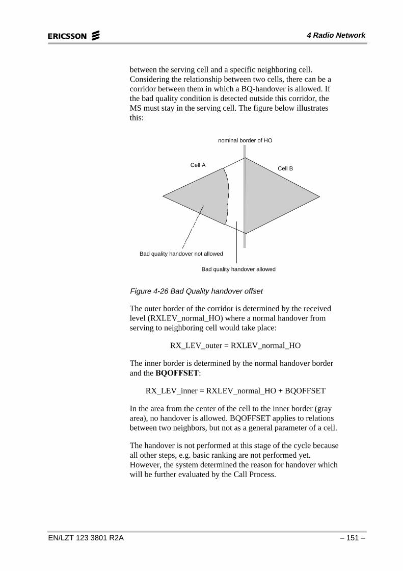
between the serving cell and a specific neighboring cell.Considering the relationship between two cells, there can be acorridor between them in which a BQ-handover is allowed. Ifthe bad quality condition is detected outside this corridor, theMS must stay in the serving cell. The figure below illustratesthis:
Cell ACell B
nominal border of HO
Bad quality handover allowed
Bad quality handover not allowed
Figure 4-26 Bad Quality handover offset
The outer border of the corridor is determined by the receivedlevel (RXLEV_normal_HO) where a normal handover fromserving to neighboring cell would take place:
RX_LEV_outer = RXLEV_normal_HO
The inner border is determined by the normal handover borderand the %42))6(7:
RX_LEV_inner = RXLEV_normal_HO + BQOFFSET
In the area from the center of the cell to the inner border (grayarea), no handover is allowed. BQOFFSET applies to relationsbetween two neighbors, but not as a general parameter of a cell.
The handover is not performed at this stage of the cycle becauseall other steps, e.g. basic ranking are not performed yet.However, the system determined the reason for handover whichwill be further evaluated by the Call Process.

GSM BSC Operation
– 152 – EN/LZT 123 3801 R2A
SYSTEM INFORMATION SACCH AND BCCH DATA
RLSSC: CELL=cell, ACCMIN=accmin, CCHPWR=cchpwr,CRH=crh, DTXU=dtxu, NCCPERM=nccperm, RLINKT=rlinkt,NECI=neci, MBCR=mbcr;
$&&0,1��Minimum received signal level in dBm at the MSfor permission to access the system. Numeric 47 - 110 (dB).
47 = greater than -48dBm48 = - (49 to 48) dBm
• • •
108 = - (109 to 108) dBm109 = - (110 to 109) dBm110 = less than -110 dBm
&&+3:5��Maximum WUDQVFHLYHU�SRZHU�OHYHO��7;3:5� indBm a MS may use when accessing the system on CCCH orSDCCH.
GSM 900 Numeral 13 - 43 (dBm) in steps of 2
GSM 1800: Numeral 4 - 30 (dBm) in steps of 2
The parameters CCHPWR and ACCMIN are used to calculatethe cell access criterion C1 as explained in Chapter 2.
&5+��Cell Reselect Hysteresis. Receiving SS (RXLEV)hysteresis in dB for required cell reselection over LA border.Numeral 0 - 14 (dB) in steps of 2
This parameter prevents unnecessary location updating andjumping between different cells connected to different LAswhen the idle MS is moving along the border between two LAs.In other words, it saves signaling from unnecessary locationupdating procedures.
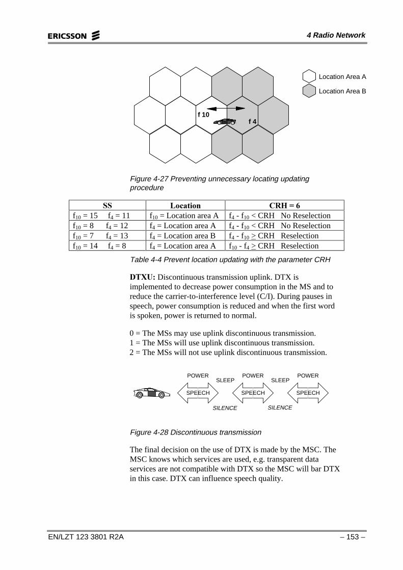
Example: In Cell f10 the value for CRH is equal to six. Themobile station is located in f10, but jumps between f4 and f10.These cells belong to different location areas. Whenever themobile moves from f10 to f4, location updating takes place. Toprevent this jumping, CRH is used. Figure 4-27 illustrates this.
4 Radio Network
EN/LZT 123 3801 R2A – 153 –
f 10f 4
Location Area A
Location Area B
Figure 4-27 Preventing unnecessary locating updatingprocedure
66 /RFDWLRQ &5+� ��f10 = 15 f4 = 11 f10 = Location area A f4 - f10 < CRH No Reselectionf10 = 8 f4 = 12 f4 = Location area A f4 - f10 < CRH No Reselectionf10 = 7 f4 = 13 f4 = Location area B f4 - f10 > CRH Reselectionf10 = 14 f4 = 8 f4 = Location area A f10 - f4 > CRH Reselection
Table 4-4 Prevent location updating with the parameter CRH
'7;8��Discontinuous transmission uplink. DTX isimplemented to decrease power consumption in the MS and toreduce the carrier-to-interference level (C/I). During pauses inspeech, power consumption is reduced and when the first wordis spoken, power is returned to normal.
0 = The MSs may use uplink discontinuous transmission.1 = The MSs will use uplink discontinuous transmission.2 = The MSs will not use uplink discontinuous transmission.
SLEEP SLEEP
SPEECH
POWER
SPEECH
POWER
SPEECH
POWER
SILENCE SILENCE
Figure 4-28 Discontinuous transmission
The final decision on the use of DTX is made by the MSC. TheMSC knows which services are used, e.g. transparent dataservices are not compatible with DTX so the MSC will bar DTXin this case. DTX can influence speech quality.
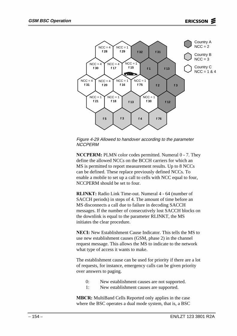
GSM BSC Operation
– 154 – EN/LZT 123 3801 R2A
NCC = 4
NCC = 4
NCC = 4NCC = 4
NCC = 4
NCC = 1
NCC = 1
NCC = 1 NCC = 1
NCC = 1NCC = 1NCC = 1
f 28 f 29
f 30
f 31
f 32
f 2
f 1 f 13f 17 f 15
f 31
f 20 f 16 f 75
f 30f 18f 21 f 13
f 5 f 3 f 4 f 76
f 12
f 3
Country ANCC = 2
Country BNCC = 3
Country CNCC = 1 & 4
Figure 4-29 Allowed to handover according to the parameterNCCPERM
1&&3(50��PLMN color codes permitted. Numeral 0 - 7. Theydefine the allowed NCCs on the BCCH carriers for which anMS is permitted to report measurement results. Up to 8 NCCscan be defined. These replace previously defined NCCs. Toenable a mobile to set up a call to cells with NCC equal to four,NCCPERM should be set to four.
5/,1.7��Radio Link Time-out. Numeral 4 - 64 (number ofSACCH periods) in steps of 4. The amount of time before anMS disconnects a call due to failure in decoding SACCHmessages. If the number of consecutively lost SACCH blocks onthe downlink is equal to the parameter RLINKT, the MSinitiates the clear procedure.
1(&,� New Establishment Cause Indicator. This tells the MS touse new establishment causes (GSM, phase 2) in the channelrequest message. This allows the MS to indicate to the networkwhat type of access it wants to make.
The establishment cause can be used for priority if there are a lotof requests, for instance, emergency calls can be given priorityover answers to paging.
0: New establishment causes are not supported.1: New establishment causes are supported.
0%&5��MultiBand Cells Reported only applies in the casewhere the BSC operates a dual mode system, that is, a BSC

4 Radio Network
EN/LZT 123 3801 R2A – 155 –
which combines GSM 900 and GSM 1800. MBCR indicateshow many neighboring cells from each band are to be reportedto the BSC. The operator has the following choices:
0: The strongest identified neighboring cells should bereported regardless of the frequency band used in the cells.
1: The MS will attempt to report at least the strongestidentified neighboring cell in each frequency band.
2: The MS will attempt to report at least the two strongestand identified neighbor cells in each frequency band.
3: The MS will attempt to report at least the three strongestidentified neighboring cells in each frequency band.
SYSTEM INFORMATION BCCH DATA
RLSBC: CELL=cell, CB=cb, ACC=acc, MAXRET=maxret,TX=tx, ATT=att, T3112=t3212, CBQ=cbq, CRO=cro, TO=to,PT=pt, ECSC=ecsc;
$&&��Access Control Class. This defines which access classesare barred. An access class can be assigned to normalsubscribers (ACC=1..9) or to subscribers with priority such asemergency services or test-equipment. Up to 16 access classescan be defined.
Bit 0 - 9 Access classes that are barred (normal subscribers)10 Emergency call not allowed for MSs belonging to
classes 0 - 911 - 15 Access classes that are barred (special subscribers)CLEAR No access classes are barred
0$;5(7��Maximum retransmissions. Numeric 1, 2, 4 or 7.This defines the maximum number of retransmissions an MS ispermitted when accessing the system. This implies that the sameaccess is sent up to MAXRET times in case of access failure.The time interval between accesses is determined by theparameter TX.
7;��TX-integer. Numeric 3 - 12, 14, 16, 20, 25, 32, 50. Definesthe time interval in number of TDMA frames the mobile mayuse to spread random accesses. The waiting time between twoaccess attempts depends on the time interval defined by TX andthe configuration of CCCH.
If TX is set to 12 and the CCCH configuration is normal, themobile waits 1 second plus a random time between 1-11 TDMAframes (TX-integer minus 1) for the next access.

GSM BSC Operation
– 156 – EN/LZT 123 3801 R2A
RACH
RACH
RACH
RACH
RACH
RACH
RACH
RACH
RACH
RACH
RACH
RACH
RACH
ACCESS 1 ACCESS 2 ACCESS 3 ACCESS 4
Wait Wait Wait
Figure 4-30 Choice of RACH when TX is set to 12
$77��Attach-detach allowed.
If Attach-detach is set to NO: Mobiles in the cell are notallowed to apply IMSI attach/detach.
If Attach-detach is set to YES: Mobiles in the cell shouldapply IMSI attach/detach.
The IMSI attach/detach operation is an action taken by an MS toindicate to the network it has entered an active/inactive state.When an MS is powered off, an IMSI detach message is sent tothe MSC/VLR. When an MS is powered on, an IMSI attachmessage is sent. A flag is set in the VLR which indicates thepresent state of a certain MS. There is no need to page adetached MS.
7������Time-out value. Numeric 0 - 255 (decihours). Definesthe time-out value that controls the periodic registrationprocedure, that is, when notifying the availability of the MS tothe network. If no registration is performed before the time-outand the guard period set in the MSC expire, the MS will beregistered as detached (implicit detached).
0 = Infinite time out1 = 0.1 hours255 = 25.5 hours
&%��Cell Bar Access. If a cell is barred, it will be ignored by anMS in idle mode. However, an active MS can handover to it.This feature can be applied to all types of internal cells.
If CB = NO, the cell is not barredIf CB = YES, the cell is barred

4 Radio Network
EN/LZT 123 3801 R2A – 157 –
The &%4 parameter is designed to distinguish between GSMphase 1 mobiles and GSM phase 2 mobiles. It defines thestrength of parameter &%. GSM defines the following relationbetween &% and &%4:
MS phase 1: MS phase 2: MS phase 2:
CB CBQ Cell selectionpriority
Cell selectionpriority
Cell re-selectionpriority
no high normal normal normalno low normal low priority normalyes low barred low priority normalyes high barred barred barred
Table 4-5
&%4� Cell Bar Qualify. Defines the cell priority as either HIGHor LOW.
&52� Cell Reselect Offset. Defines an offset to encourage ordiscourage MSs to reselect the cell. Numeral 0 - 63.
0 = 0dB; 1 = 2dB; . . . 63 = 126dB
72� Temporary Offset. Defines a negative offset applied toCRO.
Numeric 0 - 7. 0 = 0dB; 1 = 10dB; 6 = 60dB; 7 = infinite
37� Penalty Time. Defines the duration for which the TO isapplied.
Numeric 0 - 31. 0 = 20 s; 1 = 40 s; 30 = 620 s
The value 31 indicates that CRO is negated and TO is ignored.
These parameters, CRO, TO and PT control the selection orreselection of a cell according to GSM Phase 2. Cell selectionmeans that the idle MS searches for the cell that promises toprovide the best connection in the case of call setup. The accesscriterion for cell selection is C1-criterion (path loss-criterion) asexplained in chapter 2. If C1 > 0 the MS camps on that cell. Cellreselection means a change of the cell in idle mode. It can occurin the following cases:
• Downlink signaling failure (BCCH-messages notdecodable).
• Failure of setup on RACH.

GSM BSC Operation
– 158 – EN/LZT 123 3801 R2A
• The current cell became barred in between.
• The access criterion C1 is not fulfilled (C1 < 0).
• Another cell provides a better C2 value for at least 5seconds.
The C2-criterion is a special criterion for cell reselection. Its useand parameters are explained below. For more information, referto GSM 05.08. The basic concept of C2-criterion is:
After reselection, a period of penalty time starts. The penaltytime can be defined with the 3HQDOW\�7LPHU��37�. As long asPT is running (t < PT), a cell can be punished with a7HPSRUDU\�2IIVHW (72). After PT expires (t > PT), TO is nolonger subtracted from the real signal strength. A &HOO�5HVHOHFW2IIVHW (&52) encourages or discourages the reselection of acell. If it is assumed that the C2-criterion is based on the C1-criterion, it is calculated as follows:
For t < PT: C2 = C1 + CRO − TOFor t > PT: C2 = C1 + CRO
Thus CRO encourages cell reselection while TO temporarilydiscourages cell reselection. Cell reselection is generallydiscouraged if PT = 31. In this case, C2 is calculated for alltimes as:
C2 = C1 − CRO
(&6&� Early classmark sending control. Yes or no.
An MS which has multislot capability will implement thecontrolled early classmark sending. Directly after signalingconnection setup, the BSC will receive a CLASSMARKCHANGE message with the new MS classmark information,MS Multislot Class. The CLASSMARK CHANGE message issent provided that the Early Classmark Sending Control (ECSC)bit is set to ‘yes’.
This is used with the function +LJK�6SHHG�&LUFXLW�6ZLWFKHG'DWD��+6&6'���See Appendix A for more on HSCSD.
SYSTEM INFORMATION BCCH MESSAGE DISTRIBUTION
RLSMC:CELL=cell, SIMSG=simsg, MSGDIST=msgdist;
06*',67� System information BCCH message distribution.On or off.

4 Radio Network
EN/LZT 123 3801 R2A – 159 –
6,06*� System information BCCH message. Numeral 1,7 or 8.
This command is used to turn on or off the optional systeminformation messages 1,7 and 8.
CHANNEL ALLOCATION PROFILE
RLHPC: CELL=cell, CHAP=chap;
&+$3� Channel allocation profile. Numeral 0-7.
CHAP is used as a strategy for the allocation of channels in acell. For details see Appendix A.
DYNAMIC MS POWER CONTROL CELL DATA
RLPCC: CELL=cell, SCTYPE=sctype, SSDES=ssdes,SSLEN=sslen, LCOMPUL=lcompul, INIDES=inides,PMARG=pmarg, INILEN=inilen, QDESUL=qdesul,QLEN=qlen, QCOMPUL=qcompul, REGINT=regint,DTXFUL=dtxful;
66'(6� Desired signal strength, stationary, uplink. Numeral 47-110 (dBm).
66/(1� Length of stationary signal strength filter uplink.Numeral 3-15 (SACCH periods).
/&2038/� Pathloss compensator factor uplink. Numeral 0-100 (%).
,1,'(6��Initial desired signal strength uplink. Numeral 47-110(dBm).
30$5*� Power margin at assignment andassignment/handover failure, uplink. Numeral 0-20 (dBm).
,1,/(1� Length of initial signal strength filter, uplink. Numeral0, 2-5 (SACCH periods).
4'(68/� Desired quality uplink. Numeral 0-70 (dtqu).
4/(1� Length of stationary quality filter, uplink. Numeral 1-20(SACCH periods).
4&2038/� Quality deviation compensator factor, uplink.Numeral 0-60 (%).

GSM BSC Operation
– 160 – EN/LZT 123 3801 R2A
5(*,17� Regulation interval, stationary, uplink. Numeral 1-30(SACCH periods).
'7;)8/� Number of measurement periods before FULLmeasurement periods are used, uplink. Numeral 0-40 (SACCHperiods).
For more information on the above parameters see Appendix A.
DYNAMIC BTS POWER CONTROL CELL DATA
RLBCC: CELL=cell, SCTYPE=sctype, SDCCHREG=sdcchreg,SSDESDL=ssdesdl, REGINTDL=regintdl, SSLENDL=sslendl,LCOMPDL=lcompdl, QDESDL=qdesdl, QCOMPDL=qcompdl,QLENDL=qlendl, BSPWRMINP=bspwrminp,BSPWRMUNN=bspwrminn;
6'&&+5(*� SDCCH regulation switch. On or off.
66'(6'/� Desired signal strength downlink. Numeral 47-110(dBm).
5(*,17'/� Regulation interval downlink, stationary.Numeral 1-10 (SACCH periods).
66/(1'/� Length of signal strength filter, downlink. Numeral3-15 (SACCH periods).
/&203'/� Pathloss compensator factor, downlink. Numeral0-100 (%).
4'(6'/� Desired quality downlink. Numeral 0-70 (dtqu).
4&203'/� Quality deviation compensator factor, downlink.Numeral 0-60 (%).
4/(1'/� Length of stationary quality filter, downlink.Numeral 1-20 (SACCH periods).
%63:50,13� Minimum base station Effective RadiatedPower (ERP) positive offset for the absolute RF channel in thecell defined for non BCCH frequencies. Numeral 0-50 (dBm).
%63:50,11� Minimum base station Effective RadiatedPower (ERP) negative offset for the absolute RF channel in thecell defined for non BCCH frequencies. Numeral 1-20 (dBm).
For more information on the above parameters see Appendix A.

4 Radio Network
EN/LZT 123 3801 R2A – 161 –
CELL LOAD SHARING
RLLCI: CELL=cell;
This command activates the cell load sharing function.
CELL LOAD SHARING DATA
RLLCC: CELL=cell, CLSLEVEL=clslevel, CLSACC=clsacc,HOCLSACC=hoclsacc, RHYST=rhyst, CLSRAMP=clsramp;
&/6/(9(/� Percentage of available full rate capable trafficchannels at which or below which cell load sharing evaluationsare initiated. CLSLEVEL must be less then CLSACC. Numeral0-99 (%).
&/6$&&� Percentage of available full rate capable trafficchannels below which no handovers due to cell load sharing willbe accepted. Numeral 0-100 (%).
+2&/6$&&� Handover due to cell load sharing accepted tothis cell. On or off.
5+<67� Hysteresis reduction factor. Numeral 0-100 (%).
&/65$03� Cell load sharing ramping time. Numeral 0-30(seconds).
The purpose of the Cell Load Sharing function is to distributetraffic load to other cells during peaks in traffic. This is done bymoving established connections from cells with high traffic toneighboring cells that have idle resources. As a result, the trafficload is distributed more evenly in the network and thecongestion probability in a cell decreases, that is, the probabilityof a failed channel allocation due to congestion in the cell isreduced.
The level of idle traffic channels where traffic is moved awayfrom a cell is one major criterion. A second criterion is the levelof rejection of traffic, i.e. number of idle TCHs in the target cell.At this level, shifted traffic due to cell load sharing is rejected.
Cell load sharing is not used between BSCs or between cellswith different hierarchical levels. Cell load sharing is applicableto TCH channels only. The evaluation takes place immediatelyafter basic ranking in the locating algorithm. In the case of anurgency handover, it is not applied.

GSM BSC Operation
– 162 – EN/LZT 123 3801 R2A
The function performance is regulated by parameters which arechangeable via operator commands. Load sharing must beactivated for both BSC and the cells.
If a cell is to participate in LS, it can hand a call over to another(worse) cell or it can accept handovers from other cells. Foracceptance of a shifted call, the level of traffic in the target cellmust be below a level of acceptance, &/6$&&. If a percentageof all TCHs in the cell are already busy (that is, the traffic levelis above CLSACC), handovers due to LS are not accepted. Ofall TCHs (100%), more than (CLSACC)% TCHs must remainidle.
100% idle 0% idle
0% idle 100% idle
CLSACC
CLSLEVELCLS-handover accepted
CLS active
CLS-handover accepted
Cell BCell A
CLSACC
CLSLEVEL
CLS active
Figure 4-31 Cell load sharing parameters
If the number of idle TCHs drops below a level defined by&/6/(9(/, the cell in question initiates a CLS-handover to aneighboring cell. Clearly, CLSLEVEL must always be smallerthan CLSACC.
Acceptance of handovers can generally be allowed or prohibitedby a CLS-switch +2&/6$&&. In case of +2&/6$&& 2)),the cell does not accept the handover. If +2&/6$&& 21, itaccepts the handovers.
Only connections that are close to handover are moved. For thisreason, the hysteresis area between cells is used to select theconnections which must be moved. Only cells which are rankedworse than the serving cell are considered target cells.Basically, ranking of cells is redone using the hysteresis used inbasic ranking (KYST, LHYST, TRHYST). However, thesehysteresis-values are now adjusted by a ramping hysteresis(5+<67). RHYST applies to all types of hysteresis.

4 Radio Network
EN/LZT 123 3801 R2A – 163 –
RHYST can be defined as:
• RHYST = 0%, the normal hysteresis (xHYST) is applied.
• RHYST = 50%, no hysteresis at all is applied.
• RHYST = 100%, the negative value of xHYST is applied.
The following figure shows the border of handover whenmoving from cell A to cell B. The indicated values of RHYSTapply to cell A. Offsets are not respected:
Cell A Cell B
nominal border of HO
border for HO from A to Bfor RHYST=0%
border for HO from A to Bfor RHYST=0%
Figure 4-32 Cell load sharing hysteresis
A transition between the lower (0%) and the upper end (100%)is possible. Thus, RHYST defines a corridor of load sharingaround the serving cell. Any MS in this corridor may be subjectto load sharing. Since all types of hysteresis are related to aneighboring cell, the corridor may have a different shapetowards different neighbors of the cell in question.
A problem might be that if the traffic level exceeds CLSLEVEL,all MSs in the corridor become subject to LS at the same time.This creates a sudden increase in processor load. In the worstcase, an uncontrolled shift leads to congestion in a target cellwhich again can lead to dropped calls. Therefore, the MS whichis closest to the neighbor is handed over first, not those furthestaway from the neighbor.
The problem is solved with the principle of time dependentramping. It is controlled by &/65$03. CLSRAMP specifiesan interval in which the value RHYST is ramped up from 0 toits final value. This changes the size of the corridor in time. The

GSM BSC Operation
– 164 – EN/LZT 123 3801 R2A
mobiles which are closest to the handover border are handledfirst.
IDLE CHANNEL MEASUREMENT
RLIMI: CELL=cell, NOALLOC;
12$//2&� Not at allocation. Idle channel measurements arenot to be used at channel allocation (they will be used forstatistical purposes only).
IDLE CHANNEL MEASUREMENT DATA
RLIMC:CELL=cell, INTAVE=intave, LIMIT1=limit1,LIMIT2=limit2, LIMIT3=limit3, LIMIT4=limit4;
,17$9(� Number of measurements that should be used in thecalculation of the interference band for a channel. Numeral 1-31(SACCH multiframes).
/,0,7Q� Four threshold limits which define the fiveinterference bands for the function.
Limits must ascend in value as follows: LIMIT1 < LIMIT2 <LIMIT3 < LIMIT4.
The interference level on idle TCHs and SDCCHs iscontinuously monitored by the BTS. The measurements areaveraged over a time period and then placed into one out of fiveinterference bands, see the figure below.
Band RXLEV dBm
1 0-4 <-106
2 5-8 -106 to -102
3 9-15 -102 to -95
4 16-25 -95 to -85
5 26-63 -85 to >-48
Figure 4-33 Default interference bands.
The time period and limits for the interference bands can bealtered on a per cell basis.
The BTS reports to the BSC which interference band an idlechannel belongs to. At channel allocation, this information can

4 Radio Network
EN/LZT 123 3801 R2A – 165 –
be used to choose the channel with the lowest possibleinterference level.
CONNECTION OF CELL TO TRANSCEIVER GROUP
RXTCI: MO=mo, CELL=cell, CHGR=chgr;
On completion of the OPI: %6&��,QWHUQDO�&HOO��'HILQH� the BSCknows the cell as a set of data. However, the cell does not have aconnection to a BTS. No BTS is configured yet according to theparameters as defined in configuration power data, controlchannel data or frequency data. Therefore, the cell must beconnected to a TG before it is activated. A TG is indicated to thecell as a MO (see chapter 3) and a CHGR. See Figure 4-34:
BSC
Cell Data File
CHGR=0
CHGR=1
MO = TG
TRX 1
TRX 2
Figure 4-34 Connection of channel groups to transceivergroups
The connection is carried out via the CHGR. A normal cell (nosubcell structure) is always connected via CHGR=0. In the caseof subcells, the underlaid subcell is always CHGR=0 whereasthe overlaid subcell is CHGR=1.
CELL STATE
RLSTC: CELL=cell, CHGR=chgr, STATE=state;
&+*5� Channel group. Numeral 0-15
67$7(� The state of the cell. Active or halted.
When defining cell data, the state of a cell is HALTED (off air).After cell data definition, the state of the cell must be changed to

GSM BSC Operation
– 166 – EN/LZT 123 3801 R2A
ACTIVE (on air). Alternatively, an individual CHGR can beactivated. During cell activation, the cell data for description andconfiguration is downloaded to the connected TG. The purposeof the cell state is to control the input of data to the cell in orderto minimize the effect on ongoing traffic. Very important datacan only be changed in the HALTED state, e.g. cell descriptiondata (CGI, BCCHNO, etc.).
Cell state transition from HALTED to ACTIVE
The defined cell configuration data is used for configuration.Logical channels are created and the BCCH for the cell isactivated. System information messages are distributed to theMSs.
From ACTIVE to HALTED
Ongoing calls are disconnected. All logical channels are deletedand the BCCH for the cell is deactivated.
ACTIVE The cell is in operationHALTED BCCH is deactivated and no further connections
are allowed. All active connections are released