Radiation Monitoring in Mixed Environments at CERN: From the IRRAD6 Facility to the LHC Experiments
9
EUROPEAN ORGANIZATION FOR NUCLEAR RESEARCH ORGANISATION EUROPÉENNE POUR LA RECHERCHE NUCLÉAIRE CERN-PH-EP/2006-024 CERN-TS-2006-003 02 August 2006 RADIATION MONITORING IN MIXED ENVIRONMENTS AT CERN: FROM THE IRRAD6 FACILITY TO THE LHC EXPERIMENTS F. Ravotti , M. Glaser , 1 1 A.B. Rosenfeld , M.F.L. Lerch , A.G. Holmes-Siedle and 2 2 3 G. Sarrabayrouse 4 1 Technical Support and Physics Department, CERN, Geneva 23, Switzerland 2 Center for Medical Radiation Physics, University of Wollongong, Wollongong, NSW, 2522, Australia 3 REM Oxford Ltd., Eynsham, Witney, OX29 4PD, U.K. 4 LAAS-CNRS, 7 avenue du colonel Roche, 31077, Toulouse Cedex 04, France Abstract RadFET and p-i-n diode semiconductor dosimeters from different manufacturers will be used for radiation monitoring at the Experiments of the CERN LHC accelerator. In this work these sensors were exposed over three months in the CERN-IRRAD6 facility that provides mixed high-energy particles at low rates. The aim was to validate the operation of such sensors in a radiation field where the conditions are close to the ones expected inside full working LHC particle detectors. The results of this long-term irradiation campaign are presented, discussed and compared with measurements by other dosimetric means as well as Monte Carlo simulations. Finally, the integration of several dosimetric devices in one sensor carrier is also presented. Paper presented at the RADECS 2006 Workshop, 27-29 September, 2006, Athens, Greece
Transcript of Radiation Monitoring in Mixed Environments at CERN: From the IRRAD6 Facility to the LHC Experiments
EUROPEAN ORGANIZATION FOR NUCLEAR RESEARCH
ORGANISATION EUROPÉENNE POUR LA RECHERCHE NUCLÉAIRE
CERN-PH-EP/2006-024 CERN-TS-2006-003
02 August 2006
RADIATION MONITORING IN MIXED ENVIRONMENTS AT CERN: FROM
THE IRRAD6 FACILITY TO THE LHC EXPERIMENTS
F. Ravotti , M. Glaser ,1 1 A.B. Rosenfeld , M.F.L. Lerch , A.G. Holmes-Siedle and 2 2 3 G. Sarrabayrouse4
1Technical Support and Physics Department, CERN, Geneva 23, Switzerland2Center for Medical Radiation Physics, University of Wollongong, Wollongong, NSW, 2522, Australia
3REM Oxford Ltd., Eynsham, Witney, OX29 4PD, U.K. 4LAAS-CNRS, 7 avenue du colonel Roche, 31077, Toulouse Cedex 04, France
Abstract
RadFET and p-i-n diode semiconductor dosimeters from different manufacturers will be used for radiation
monitoring at the Experiments of the CERN LHC accelerator. In this work these sensors were exposed over
three months in the CERN-IRRAD6 facility that provides mixed high-energy particles at low rates. The
aim was to validate the operation of such sensors in a radiation field where the conditions are close to the
ones expected inside full working LHC particle detectors. The results of this long-term irradiation
campaign are presented, discussed and compared with measurements by other dosimetric means as well as
Monte Carlo simulations. Finally, the integration of several dosimetric devices in one sensor carrier is also
presented.
Paper presented at the RADECS 2006 Workshop, 27-29 September, 2006, Athens, Greece

PAPER PH-2 145 RADECS 2006 WORKSHOP, 27-29 SEPTEMBER 2006 - ATHENS, GREECE 1
Radiation Monitoring in Mixed Environments atCERN: from the IRRAD6 Facility to the LHC
ExperimentsF. Ravotti, Student Member, IEEE, M. Glaser, A.B. Rosenfeld, Senior Member, IEEE,
M.L.F. Lerch Member, IEEE, A.G. Holmes-Siedle, Senior Member, IEEE, and G. Sarrabayrouse, Member, IEEE
Abstract— RadFET and p-i-n diode semiconductor dosimetersfrom different manufacturers will be used for radiation monitor-ing at the Experiments of the CERN LHC accelerator. In thiswork these sensors were exposed over three months in the CERN-IRRAD6 facility that provides mixed high-energy particles at lowrates. The aim was to validate the operation of such sensorsin a radiation field where the conditions are close to the onesexpected inside full working LHC particle detectors. The resultsof this long-term irradiation campaign are presented, discussedand compared with measurements by other dosimetric meansas well as Monte Carlo simulations. Finally, the integration ofseveral dosimetric devices in one sensor carrier is also presented.
Index Terms— Accelerators, dosimetry, p-i-n diodes, MOSFET,particle beams, proton, RadFET, radiation damage.
I. INTRODUCTION
THE measurement of the radiation environment generatedby proton-proton collisions at the High Energy Physics
(HEP) Experiments of the CERN Large Hadron Collider(LHC) accelerator [1], has become an important issue overthe last few years.
For the survey of the cumulative radiation damage indetectors and electronic devices [2] at the LHC, the mixedenvironment constituted of electromagnetic and hadronic radi-ation, will be constantly monitored with dosimetry of absorbeddose and fast particle fluence.
It has been already shown that semiconductor sensors canbe successfully employed to characterize mixed radiation fieldsin terms of ionization dose (IEL) measured in SiO2 and non-ionizing energy loss (NIEL) causing atom displacement withinthe silicon lattice. This can best be achieved by combining twotype of devices: RadFET transistors and p-i-n silicon diodesrespectively [3].
The RadFET dosimeter operates by the build-up of ”oxide-trapped charge”, positive charge in the gate silicon oxide layerof the transistor [4]. This charge, responsible for the shift of
Manuscript received September 27, 2006.F. Ravotti and M. Glaser are with Technical Support and Physics De-
partment, CERN, Geneva 23, CH-1211, Switzerland. F. Ravotti is also withCEM2 University Montpellier II, 34095 Montpellier Cedex 5, France (e-mail:[email protected])
A.B. Rosenfeld and M.F.L. Lerch are with the Center for Medical RadiationPhysics, University of Wollongong, Wollongong, NSW, 2522, Australia.
A.G. Holmes-Siedle is with REM Oxford Ltd., Eynsham, Witney, OX294PD, U.K.
G. Sarrabayrouse is with the LAAS-CNRS, 7 avenue du colonel Roche,F-31077 Toulouse Cedex 4, France.
the transistor threshold voltage, is stored internally, allowingthe measurement of the deposited Total Ionizing Dose (TID)over several years. The p-i-n diodes are junction devices witha base of high-resistivity n-type silicon [5]. Hadron irradiationof such diodes produces displacement damage in the siliconbase leading to an increase of the diode’s forward voltagewhich is proportional to particle fluence [6].
In the HEP Experiments of the LHC, the use of thesesemiconductor technologies, as well as their integration ona sensor Printed Circuit Board (PCB), has already beenproposed [7] and is now described. Semiconductor sensorssuitable for the LHC must work over a very long time (10-years) and in challenging conditions including:
• particle runs of variable intensity with monthly shutdownperiods;
• radiation compositions varying with the distance and theangle with respect to the interaction point;
• differing operating temperature in different measurementsites.
It is thus clear that the sensors for the LHC have to coverdifferent sensitivities and a broad dynamic range in terms ofTID and particle fluence as well as to comply with specificstability [8], [9] and response [10] requirements. For all thesereasons, after intensive test campaigns, a series of four devices(two RadFETs and two p-i-n diodes) has been proved to fulfillLHC Experiments needs [11].
In this work the performances of the above four semi-conductor sensors were validated by placing them in a low-rate, mixed-particle accelerator environment that simulated theworking conditions at the LHC.
In the CERN facility IRRAD6 of the PS accelerator thiswas achieved by working off-axis in the 23 GeV proton beam-line directed to the IRRAD1 irradiation area [14]. Placing thesensors at different distances from the beam axis, various ratesof high-energy photons, neutrons and charged particles in theGeV energy range were simultaneously available. Moreover,changes of beam conditions and the alternation of operationand shutdown periods, made this facility an ideal test-benchto validate stability over time.
Finally, this article will also present the integration of theemployed sensors in a general-purpose chip carrier and PCBsuitable for the LHC needs in terms of dimensions and materialbudget.
PAPER PH-2 145 RADECS 2006 WORKSHOP, 27-29 SEPTEMBER 2006 - ATHENS, GREECE 2
TABLE ISEMICONDUCTOR SENSORS CHARACTERISTICS IN THE MEASUREMENT
RANGE OF INTEREST FOR THIS WORK
REM LAAS CMRP BPW34RadFET p-i-n
oxide/base thick. µm 0.25 1.6 1000 250W/L ratio µm 440/10 9500/37 - -Readout i mA 0.16 0.10 1.0 1.0
Readout ∆t s 5.0 1.0 0.7 0.7Initial Vth/F V 2.9 2.6 3.1 0.5
Initial Tc mV/◦C -0.6 -0.05 -0.8 -2.6Max. Dose Gy 530 10 - -Max. Φeq cm−2 - - 2x10¹² 3x10¹³
Max. Vth/F V 12.1 5.5 12.3 5.3post-irrad. Tc mV/◦C -2.3 ∼ -0.05 -15.1 -6.0
Calibration Data
D < 20 Gya V/Gy 0.018 0.515 - -b 0.911 0.481 - -
D > 20 Gya V/Gy 0.029 - - -b 0.708 - - -
c−1 cm−2/mV - - 1.7x10⁸ 9.1x10⁹
Calib. Error ±% 10 10 13 20
II. EXPERIMENTAL DETAILS
A. Irradiation Facility
In the T7 beam-line of the East-Hall Experimental Area ofthe CERN-PS Complex, the primary 23 GeV proton beam ofthe PS accelerator can be directed through the area wherethe irradiation facilities are located. In this area, primary-proton bursts of 2x10¹¹ particles each are delivered towarda marble absorber placed in front of a cast iron beam-dumpas shown in Fig. 1. In that location, the protons produce auniform irradiation spot over a surface of about 2x2 cm2 [14].Typically from 2 to 4 proton bursts per machine cycle of 16.8sare extracted from the PS accelerator and delivered towardT7. This irradiation layout will be referred as ”Primary Beamconditions” in the following.
The above conditions are used to perform irradiation ofsamples moved inside the T7 beam by means of a remotecontrolled shuttle (IRRAD1 facility). However, during theoperation of IRRAD1, the 23 GeV proton interactions producein the surrounding area a radiation field manly composed byneutrons, photons, pions and protons. This setup is known asthe IRRAD6 facility.
Moving downstream along the T7 beam-line, another test-beam facility can run in order to provide the users with a non-separated lower-energy secondary particle beam composed byp+, π± and e± [15]. This secondary beam is produced byinserting a thick target toward the 23 GeV proton beam andmodifying the magnetic field of the BHZ01 element (seeFig. 1). In these conditions, particles from the target with aselected momentum are bent over the T7a beam-pipe locatedin the right-hand side with respect the IRRAD1 position.While the secondary beam is thus delivered to users, the
TABLE IILOCATION OF TESTED DEVICES IN IRRAD6
Label r = 60 r = 90 r = 100 PMI Loc. Mag. QF003
Z (cm) 15 15 15 130 60r (cm) 60 90 100 80 140
IRRAD1 facility, and consequently the IRRAD6 environment,is reached by a degraded primary proton beam. This irradiationset-up will be referred as ”Secondary Beam conditions” in thefollowing.
The instrumentation available in the T7 area consist of aSecondary Emission Chamber (SEC) labeled MSC01 in Fig. 1that provides a measurement of the intensity for the primaryprotons delivered to IRRAD1 [16]. An Ionization Chamber(PMI in Fig. 1) is also installed on the roof of the irradiationarea for measuring the dose-rate due to induced activity duringmaintenance operations.
B. Devices Tested
The RadFET dosimeters used in this work, are those rec-ommended for the LHC Experiments in the Sensor Cataloguedocument [11]. The supplier were the laboratory CNRS-LAAS, France [17] and REM in England [18]. These deviceswere all encapsulated in sealed TO-5 metal packages. TheLAAS devices have been chosen for their sensitivity in themGy dose range, while the REM devices have been selectedbecause of their broad dynamic range. The recorded signalfrom RadFETs is the shift of the transistor threshold voltageVth that is converted to dose D (Gy) following a power-low calibration curve ∆Vth = a ·Db, where a and b areexperimental parameters.
As showed in many works [8], [9] and in references therein,annealing phenomena [2] that affects the RadFETs selectedin [11] are of the order of a few percent over years time-scale. For this reason, the data presented in this work werenot corrected for such a effect.
To measure the 1-MeV neutron equivalent particle fluenceΦeq (cm−2), p-i-n diodes were supplied by CMRP, Aus-tralia [19]. Because of the very high sensitivity, these deviceswork in a limited fluence range up to about 2x1012 cm−2.After that exposure level the signal loses its linearity withΦeq.
To extend the measurement range of Φeq at higher val-ues as required for the LHC, commercial BPW34 diodesfrom OSRAM, Germany [20] were also investigated andadopted as Φeq sensors. Complementary to CMRP devices,the BPW34 show sensitivity to fast particles once Φeq exceeds2x1012 cm−2 [7].
For both p-i-n diodes, the recorded dosimetric parameteris the shift of the forward voltage VF that increasesproportionally with the fluence following the equation:
∆VF = c · k · Φ = c · Φeq (1)
where k is the hardness factor allowing to compare the damage

PAPER PH-2 145 RADECS 2006 WORKSHOP, 27-29 SEPTEMBER 2006 - ATHENS, GREECE 3
Fig. 1. Layout of the IRRAD facilities at the CERN-PS Accelerator.
efficiency in silicon of different radiation sources [21], Φ isthe total particle fluence and c is an experimental parameter.
Both RadFETs and p-i-n diodes were exposed in ”zerobias” mode and the dosimetric parameters (voltages) wereread-out by forcing different pulsed currents through them.The main characteristics of the sensors, together with theirreadout and calibration parameters a, b and c are listed inTable I. The data used as REM and BPW34 calibration curvescome from different irradiation sources [11]. For CMRP andLAAS devices the existing data [11] were complemented withRef. [12] and with recent data sets from the authors measuredat the TRIGA nuclear reactor of the Jozef Stefan Institute inLjubljana, Slovenia [13].
Before converting the voltages to dosimetric quantities,the recorded signals from the sensors were corrected againsttemperature variations using the set of Tc reported in Table I.
C. Irradiation Setup
RadFET and p-i-n diode sensors were placed at five mea-surement points in the IRRAD6 area facing the cast iron beam-dump as indicated in Fig. 1. Table II details the measurementpositions as well as their labeling used in the discussion of theresult. The coordinate Z is the distance from the beam-dumpcalculated along the beam-line, while r is the radial distancefrom the beam-axis.
Three measurement positions were chosen, at different radii,close to the marble absorber (r = 60, r = 90 and r = 100)while the other two were in proximity of the beam-line element
Fig. 2. Intensity of the 23 GeV proton beam delivered to T7
named QF003 (Mag. QF003) and the PMI Ionization Chamber(PMI Loc.) represented as black dot in Fig. 1.
Each sensor was then connected to the readout system via25-m coaxial cable. LAAS RadFETs and both CMRP andBPW34 p-i-n diodes were installed in their array positionsfrom the beginning of the irradiation test. REM RadFETs wereinstead added to the setup during an accelerator shut-downperiod 1000 hours after the beginning of the experiments.
All measurements employed an automated DAQ systemconsisted of an Agilent Switch Matrix that commutes thesensors terminals between exposure and readout mode, and
PAPER PH-2 145 RADECS 2006 WORKSHOP, 27-29 SEPTEMBER 2006 - ATHENS, GREECE 4
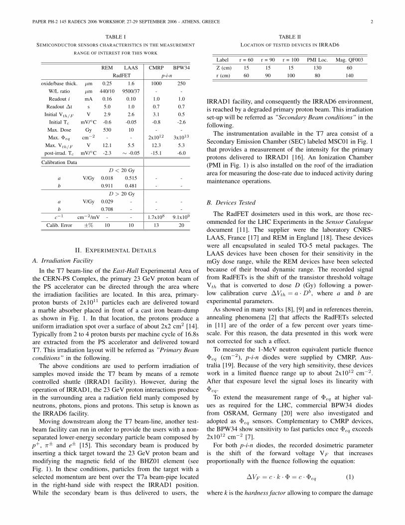
(a) Radiation Dose
(b) Equivalent Fluence
Fig. 3. Radiation measurements during the first irradiation run.
a Keithley Source Meter 2410. The Source Meter was usedas current generator and also to record the sensor voltages.Both units were under PC control by means of a LabVIEWprogram that periodically runs the sensors readout cycle.
III. RESULTS AND DISCUSSION
The irradiation period lasted about three months (1900hours). The intensity of the primary 23 GeV proton beamdelivered to the irradiation area in this period (in term ofcounts from the SEC) is shown in Fig. 2. During the tests, thebeam conditions in the T7 area were switched several timesfrom Primary to Secondary beam and back, according to apre-defined schedule. Therefore, to simplify the discussion ofthe results data have been grouped in two separate runs:• First Irradiation Run from 0 to 1000 hours: After about
50 hours in which the PS beam was normally extractedand directed to the irradiation area (Low Intensity PrimaryBeam), a severe beam-line failure occurred and the T7beam-line was shut down for about 500 hours (BeamOFF). Then, after about 100 hours from the recoveryof the beam (i.e. 600 hours in Fig. 2) the T7 beam-linewas setup for the delivery of the Secondary Beam.
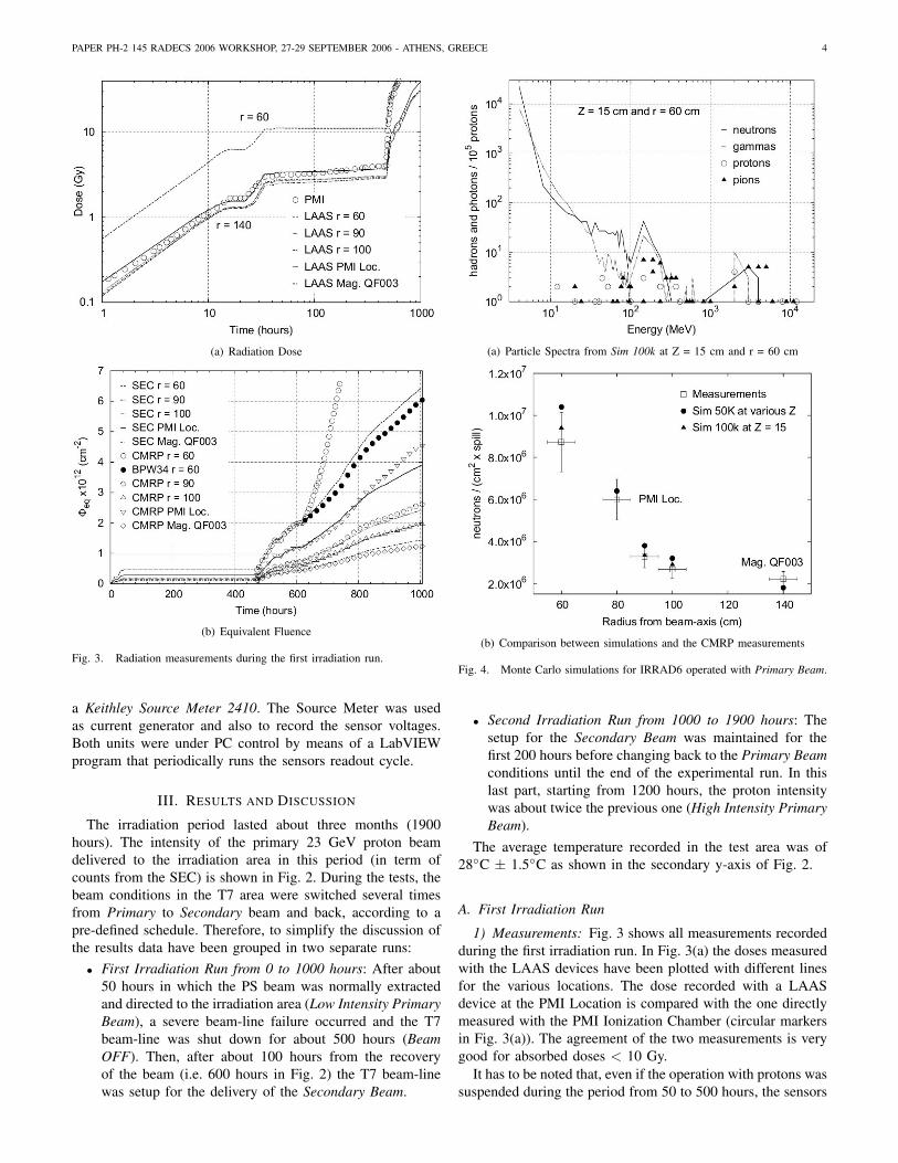
(a) Particle Spectra from Sim 100k at Z = 15 cm and r = 60 cm
(b) Comparison between simulations and the CMRP measurements
Fig. 4. Monte Carlo simulations for IRRAD6 operated with Primary Beam.
• Second Irradiation Run from 1000 to 1900 hours: Thesetup for the Secondary Beam was maintained for thefirst 200 hours before changing back to the Primary Beamconditions until the end of the experimental run. In thislast part, starting from 1200 hours, the proton intensitywas about twice the previous one (High Intensity PrimaryBeam).
The average temperature recorded in the test area was of28◦C ± 1.5◦C as shown in the secondary y-axis of Fig. 2.
A. First Irradiation Run
1) Measurements: Fig. 3 shows all measurements recordedduring the first irradiation run. In Fig. 3(a) the doses measuredwith the LAAS devices have been plotted with different linesfor the various locations. The dose recorded with a LAASdevice at the PMI Location is compared with the one directlymeasured with the PMI Ionization Chamber (circular markersin Fig. 3(a)). The agreement of the two measurements is verygood for absorbed doses < 10 Gy.
It has to be noted that, even if the operation with protons wassuspended during the period from 50 to 500 hours, the sensors
PAPER PH-2 145 RADECS 2006 WORKSHOP, 27-29 SEPTEMBER 2006 - ATHENS, GREECE 5
were exposed at the PMI location to a remanent dose-rate ofabout 2 mGy/h due to scattered particles from the neighboringsecondary beam-lines running in the PS East-Hall. Duringthis period the signal of the LAAS devices continued toincrease even at this very low dose-rate, demonstrating thehigh sensitivity of such devices. Once the operation withprotons restarted, the dose-rate in the area increases to a levelthat saturates the PMI readout electronics (> 400 mGy/h),making a further use of this signal as a reference for thedevices under test impossible [22].
In Fig. 3(b) the Φeq recorded by the CMRP devices havebeen plotted with open markers. To verify the linearity in theresponse of these devices, the experimental data were linearlyfitted by scaling the proton beam intensity of Fig. 2 with aseries of conversion factors mi (SEC counts 7→ Φeq) for anygiven measurement locations. The results of these calculationsare plotted with different lines in Fig. 3(b). For all CMRPdevices, the measurements fit well the data over the entirerun when Φeq is lower than the sensor’s dynamic range (i.e.< 2x1012 cm−2). Even for the location in which the particleflux was the less intense (Mag. QF003 plotted with diamondmarkers) the sensor behaves linearly with the calculation,proving that annealing phenomena that could affect suchdevices are lower than the measurement error.
For the measurement position r = 60 on Fig. 3(b), in whichthe flux of particle was the highest recorded, the signal of theBPW34 diode has been plotted with filled circular markers.This signal has been normalized to the last measurement pointof the CMRP device at Φeq = 2x1012 cm−2. The BPW34signal is in agreement with the calculation (dotted line) withinthe calibration error (20 %) if, already for this relative highparticle intensity, the raw data are corrected against both short-and long-term annealing phenomena. For the present work,the annealing corrections have been based on annealing datarecorded after irradiation [23] and from some independentresults [12]. A more detailed characterization of the annealingof the BPW34 devices in presently under way at CERN.
2) Comparison with Monte Carlo Simulations: To validatethe absolute Φeq presented in Fig. 3(b), the CMRP resultshave been compared with two sets of Monte Carlo simulationsperformed for IRRAD6 [24]. The two simulations, labeledSim 50k and Sim 100k, differ in the number of generatedprimary events (5x10⁴ and 1x10⁵ primary 23 GeV protonsrespectively) and slightly in the layout and materials used tomodel the T7 area. Moreover, while the Sim 50k has been runfor different pairs of coordinates r and Z, the Sim 100k predictsonly the variation of the radiation field along the radius fromthe beam axis at a fixed Z of 15 cm.
To compare particle fluence measurements and simulations,the set of scale parameters mi previously calculated in Sec-tion III-A.1 (1-MeVeq part./(cm2 × counts)) were normal-ized to the intensity of a single primary proton burst (1-MeVeq part./(cm2 × spill)). Knowing the hardness factor forthe IRRAD6 area, it is then possible, via Eq. 1, to express theexperimental data in terms of part./(cm2 × spill) and proceedwith the comparison.
Fig. 4(a) show the particle spectra predicted with theSim 100k for the measurement position r = 60. In this location
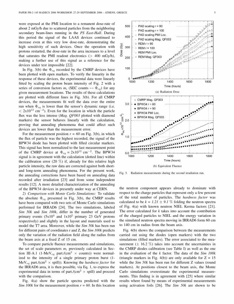
(a) Radiation Dose
(b) Equivalent Fluence
Fig. 5. Radiation measurements during the second irradiation run.
the neutron component appears already to dominate withrespect to the charge particles that represent only a few percentof the total number of particles. The hardness factor wascalculated to be k = 1.21 ± 9.1 % folding the neutron spectraof Fig. 4(a) with known neutron NIEL Kerma factors [21].The error calculated for k takes into account the contributionof the charged particles to NIEL and the energy variation inthe simulated neutron spectra moving in IRRAD6 form 60 cmto 140 cm in radius from the beam axis.
Fig. 4(b) shows the comparison between the measurementscarried out using the diodes (open markers) with the twosimulations (filled markers). The error associated to the mea-surement (± 16.2 %) takes into account the uncertainties inthe CMRP diodes calibration (see Table I) as well as the onein the evaluation of the k factor. The data of the Sim 100k(triangle markers in Fig. 4(b)) are only available for Z = 15while the Sim 50k has been run for different Z values (roundmarkers). At positions closest to the beam axis, the MonteCarlo simulations overestimate the experimental measure-ments. This finding is in agreement with [25] where similarresults where found by means of experimental measurementsusing activation foils [26]. The Sim 50k are shown to be

PAPER PH-2 145 RADECS 2006 WORKSHOP, 27-29 SEPTEMBER 2006 - ATHENS, GREECE 6
overestimates with respect to the experimental measurementup to more than 20 % for the closest position to beam-axiswhere the higher particle gradient may enhance the errorsfor both measurements and simulations. The Sim 100k, showinstead an agreement better than 10 % with the experiments.These two results confirm thus the validity of CMRP diodemeasurements.
B. Second Irradiation Run
Fig. 5 show all measurements recorded during the secondirradiation run. In Fig. 5(a) the results from REM deviceshave been compared with the TID measurements carriedout with Polymer-Alanine dosimeters (PAD) [27]. In thefigure, the PAD measurements are the filled markers at 1900hours, while the lines are the scaling of the dose from PADsusing the proton intensity plotted in Fig. 2. The TID valuesmeasured from RadFETs agree for all positions with PADmeasurements within an experimental error of ± 10 %. Thechoice of PAD dosimeters to validate the measurement fromREM RadFETs become clear if the contribution to the TIDof photons (γ), neutrons (n) and charged hadrons (Ch.H) inthe mixed radiation field are considered separately as shownin Eq. 2 and Eq. 3. In the formulas, Kj
i are the IEL Kermafactors [28]–[30] where i = γ, n or Ch.H and j = P for PADor R for REM devices. Φ are instead the different particlefluences, while the numerical factors take into account therelative sensitivity for neutrons of the two dosimeters withrespect to the gamma rays.
DPAD=KPγ × Φγ+(0.2)×KP
n × Φn+KPCh.H × ΦCh.H (2)
DREM =KRγ × Φγ+(0.6)×KR
n × Φn+KRCh.H × ΦCh.H (3)
From the tabulated Kji factors it is easy to verify that, in
the energy range from 4 MeV to several GeV, even if fromFig. 4(a) it is that ΦCh.H ∼ 0.1 ×Φn ∼ 0.1 ×Φγ , the chargedparticle component delivers to both PAD and REM about thesame TID two order of magnitude higher than the one deposedby neutrons and photons. In such conditions PAD dosimetersare expected to be a good benchmark for the REM dosimeters.
With different filled markers, Fig. 5(b) shows the Φeq
measurements recorded by the BPW34 diodes. The scalingof the primary beam intensity for any measurement location,as calculated in Section III-A.1, has been again plotted withlines for comparison with the experimental data. As previouslypointed out, with the opportune annealing correction, thesignal of such a devices match, in all cases, the predictedΦeq within the uncertainty of about ± 20 % that affects thecalibration data.
C. Discussion of the ratio ”REM response/LAAS response”or ”R/L Ratio”
In the second irradiation run, the responses from the LAASdevices, already exposed to a TID exceeding some tens ofGy during the first run, are of interest. For doses exceeding10 Gy their response curve becomes strongly sub-linear, i.e.begins to saturate. Although the responses of all MOSFETs
Fig. 6. Sensitivity ”R/L ratio” for RadFETs REM and LAAS during thesecond irradiation run. Plot relative to the couple of sensors installed at r =90.
under ”zero bias” are always strongly sub-linear [10], the REMdevices at the same total dose are not saturating in this way.The saturation mechanism is not known but it is clear thatfurther electron escape might be retarded by built-in oxidefields due to oxide-trapped positive charge [31]. At a TID of500 Gy, saturation of LAAS devices is nearly complete. TheREM devices have been instead proven to have smoothly risingradiation response curves over a range of several tens of kGyunder exposure to many different types of radiation [11].
In Fig. 6, we show the ”R/L ratio”, i.e. the sensitivity of theREM devices with respect the LAAS ones during the secondirradiation run. Primary Beam registers a ratio of 3, whilethe Secondary Beam registers a factor of 2. In GeV protonexperiments, it may be of practical benefit to monitor the ”R/Lratio”, as will be explained later.
As with the saturation effects in zero-bias cases, the exactmechanism of the clear-cut change in ”R/L ratio” is not clear.The explanation is likely to arise from the plentiful creationof secondary (scattered) protons and other charged particlesin the second case. This is because the Secondary Beam hasbeen scattered from a thick target placed in the primary beam.
The number of secondaries in the IRRAD6 area is knownto scale with the number of particles directed to the beam-dump, and these are duly counted by the SEC. However,many aspects of beam focusing are altered so that the beam-spot geometry changes. Many new possibilities of generatingneutrons and photons at the measurement locations in IRRAD6are created. In addition, the proton energies have degradedto just the region where previous workers [31], [32] havediscovered severe dependence of the MOSFET response onparticle LET.
Further work is needed to decide whether the ratio changesmore due to average proton LET (we could call this ”soften-ing” of the proton beam) or to the addition of photons andneutrons to the beam, which, given their high LETs [2], wecould describe as ”dilution” of the beam.
This finding suggests, using these RadFETs at the LHC,to monitor the REM/LAAS signal ratio to uncover important
PAPER PH-2 145 RADECS 2006 WORKSHOP, 27-29 SEPTEMBER 2006 - ATHENS, GREECE 7
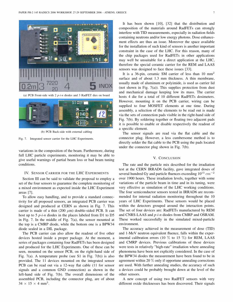
(a) PCB Front-side with 2 p-i-n diodes and 3 RadFET dies on board
(b) PCB Back-side with external cabling
Fig. 7. Integrated sensor carrier for the LHC Experiments.
variations in the composition of the beam. Furthermore, duringfull LHC particle experiments, monitoring it may be able togive useful warnings of partial beam loss or bad beam tuningconditions.
IV. SENSOR CARRIER FOR THE LHC EXPERIMENTS
Section III can be said to validate the proposal to employ aset of the four sensors to guarantee the complete monitoring ofa mixed environment as expected inside the LHC Experimentareas [7].
To allow easy handling, and to provide a standard connec-tivity for all proposed sensors, an integrated PCB carrier wasdesigned and produced at CERN as shown in Fig. 7. Thiscarrier is made of a thin (200 µm) double-sided PCB. It canhost up to 5 p-i-n diodes in the places labeled from D1 to D5in Fig. 7. In the middle of Fig. 7(a), the sensor mounted atthe top is a CMRP diode, while the bottom one is a BPW34diode sealed in a DIL package.
The PCB carrier can also allow the readout of five otherdevices hosted inside a proper package. At the moment, aseries of packages containing four RadFETs has been designedand produced for the LHC Experiments. One of these can beseen, mounted on the sensor PCB, on the right-hand side ofFig. 7(a). A temperature probe (see S1 in Fig. 7(b)) is alsoprovided. The 11 devices mounted on the integrated sensorPCB can be read out via a 12-way flat cable (11 for sensorsignals and a common GND connection) as shown in theleft-hand side of Fig. 7(b). The overall dimensions of theassembled PCB, including the connector plug, are of about34 × 15 × 4 mm3.
It has been shown [10], [32] that the distribution andcomposition of the materials around RadFETs can stronglyinterfere with TID measurements, especially in radiation fieldscontaining neutrons and/or low energy photons. Dose enhance-ment effects are thus an issue. Moreover the space availablefor the installation of such kind of sensors is another importantconstraint in the case of the LHC. For this reason, many ofthe chip packages used for RadFETs in other applicationsmay well be unsuitable for a direct application at the LHC,therefore the special ceramic carrier for the REM and LAASsensors was designed to face these issues [33].
It is a 36-pin, ceramic SM carrier of less than 10 mm2
surface and of about 1.3 mm thickness. A thin membrane,usually made of aluminum or polyimide, is used as carrier lid(not shown in Fig. 7(a)). This supplies protection from dustand mechanical damage keeping low its mass. The carrierhosts 4 die for a total of 10 different RadFETs dosimeters.However, mounting it on the PCB carrier, wiring can besupplied to four MOSFET elements at one time. Duringassembly, a selection of the elements to be read out is madevia the sets of connection pads visible in the right-hand side ofFig. 7(b). By soldering together or floating two adjacent padsit is possible to enable or disable respectively the readout ofa specific element.
The sensor signals are read via the flat cable and theconnector plug. However, a less cumbersome method is todirectly solder the flat cable to the PCB using the pads locatedunder the connector plug shown in Fig. 7(b).
V. CONCLUSION
The rate and the particle mix described for the irradiationtest at the CERN IRRAD6 facility, gave integrated doses ofseveral hundred Gy and particle fluences exceeding 1013 cm−2
over 1900 hours. These irradiation levels, together with somevariations of the particle beam in time and in its tuning, werevery effective as simulation of the LHC working conditions.The four semiconductor sensors tested in IRRAD6 are recom-mended for internal radiation monitoring throughout the 10years of LHC Experiments. These sensors would be placedwithin the detectors grouped around the interaction points.The set of four devices are: RadFETs manufactured by REMand CNRS-LAAS and p-i-n diodes from CMRP and OSRAM.These worked successfully in the simulated mixed-particleenvironment.
The accuracy achieved in the measurement of dose (TID)and 1-MeV neutron equivalent fluence, falls within the exper-imental calibration errors (10 % to 15 %) for REM, LAASand CMRP devices. Previous calibrations of these deviceswere tests in relatively ”high-rate” irradiation where annealingphenomena have been not explicitly considered. In the case ofthe BPW34 diodes the measurement have been found to be inagreement within 20 % only if opportune annealing correctionsare used. With further annealing studies, the accuracy of sucha devices could be probably brought down at the level of theother sensors.
A new concept of using two RadFET sensors with verydifferent oxide thicknesses has been discovered. Their signals
PAPER PH-2 145 RADECS 2006 WORKSHOP, 27-29 SEPTEMBER 2006 - ATHENS, GREECE 8
at TID > 10 Gy can be fruitfully used as complementaryinformation to detect changes in the radiation field composi-tion. This feature is thought to be a valuable indication of (in-tentional or accidental) changes in the LHC beam conditionsinduced by differing or faulty tuning of the primary beams.
The set of the four recommended sensors covers well theneeds of the LHC Experiments in terms of sensitivity (3.5mGy/mV, 1.7x108 cm−2/mV) and dynamic range (> 20 kGy,4x1014 cm−2). The above studies justified the production ofan integrated sensor PCB which is expected to simplify thehandling of the radiation sensor set.
The signals from the integrated carrier can be remotelyreadout up to very long distances using cabled connections.However, as all mounted sensors keep stored the dosimetricinformation over time, the integrated PCB can be also usedin a ”passive” mode by exposing it to radiations with allconnections grounded. For this latter application, the integratedsensor must be removed from the measurement field andplugged on a laboratory test-bench to perform the readoutcycle.
While the present carrier was optimized for the LHC,the above features makes its utilization easily extendible toany application in which monitoring of cumulative dose andparticle fluence is needed.
ACKNOWLEDGMENT
The authors would like to thank M. Moll from CERN forthe review of the manuscript and its valuable contributionto improve it and the colleagues of the Jozef Stefan Insti-tute of Ljubljana, Slovenia for their help in the calibrationcampaigns of the studied dosimeters. The TS-DEM group andthe technicians of the PH-DT2 Bonding Lab at CERN aregratefully acknowledged for their support in the design ofthe integrated sensor carrier and in the assembly of the SMDRadFET packaging respectively.
REFERENCES
[1] The Large Hadron Collider Project Webpage [Online]. Available:http://www.cern.ch/lhc-new-homepage/.
[2] A. G. Holmes-Siedle, L. Adams, Handbook of Radiation Effects (secondedition), Oxford University Press, 2002.
[3] A.B.Rosenfeld, M.I. Reinhard, D. Marinaro, P. Ihnat, G. Taylor, L. Peak,N. Freeman, D. Alexiev, M. Lerch, ”A system for radiation damagemonitoring”, IEEE Trans. Nucl. Sci., vol. 46, pp. 1766-1772, 1999.
[4] A.G. Holmes-Siedle and L. Adams, ”RadFETs: a review of the use ofmetal-oxide-silicon device as integrating dosimeters”, Rad. Phys. andChem., vol. 28 (2), pp. 235-244, 1986.
[5] A.B.Rosenfeld et al., ”PIN diodes with a wide measurement range offast neutron dose”, Rad. Prot. Dos., vol. 33, no. 1-4, pp. 175-178, 1990.
[6] Z. Li, W. Chen and W. Kraner, ”Effects of fast neutron irradiation in theelectrical proprieties of silicon detectors”, Nucl. Inst. Meth., vol. A308,pp. 585-595, 1991.
[7] F. Ravotti, M. Glaser, M. Moll, K. Idri, J-R. Vaille, H. Prevost, andL. Dusseau, ”Conception of an Integrated Sensor for the RadiationMonitoring of the CMS Experiment at the Large Hadron Collider”, IEEETrans. Nucl. Sci., vol. 51 (6), pp. 3642-3648, 2004.
[8] F. Ravotti, M. Glaser, ”A study of the response of solid-state dosimetersto be used for the measurement of the radiation environment of the CMSExperiment at the LHC”, CERN Tech. Note EST-LEA-2003-03, 2003.
[9] F. Ravotti, M. Glaser, F. Saigne, L. Dusseau, G. Sarrabayrouse, ”Predic-tion of the thermal annealing of thick oxide metal-oxide-semiconductordosimeters irradiated in a harsh radiation environment”, Appl. Phys.Lett., submitted for publication, 2006. In preprint collection CERN-PH-EP/2006-021; CERN-TS-2006-002.
[10] F. Ravotti, M. Glaser, M. Moll, Ch. Ilgner, B. Camanzi, A.G. Holmes-Siedle, ”Response of RadFET dosimeters to high fluences of fastneutrons”, IEEE Trans. Nucl. Sci., vol. 52 (4), pp. 959-965, 2005.
[11] F. Ravotti, M. Glaser, M. Moll, ”SENSOR CATALOGUE - DataCompilation of Solid-state Sensors for Radiation Monitoring”, CERNTS-Note-2005-002, 13 May 2005.
[12] G. Kramberger, V. Cindro, I. Mandic, M. Mikuz, M. Zavrtanik,”Development of ATLAS Radiation Monitor” [Online]. Available:http://www.cern.ch/lhc-expt-radmon
[13] M. Ravnik, R. Jeraj, ”Research Reactor Benchmarks”, Nucl. Sci. Eng.,vol. 145, pp. 145-152, 2003.
[14] M. Glaser, F. Ravotti, M. Moll, ”Dosimetry Assessments in the Irradi-ation Facilities at the CERN-PS Accelerator”, IEEE Trans. Nucl. Sci.,vol. 53 (4), in press, 2006.
[15] D.J. Simon, L. Durieu, ”Secondary beams for tests in the PS Eastexperimental area”, CERN PS/PA Note 93-21, 4 August 1993.
[16] K. Bernier, G. de Rijk, G. Ferioli, E. Hatziangeli, A. Marchionni, V.Palladino, G.R. Stevenson, T. Tabarelli and E. Tsesmelis, ”Calibrationof Secondary Emission Monitors of Absolute Proton Beam Intensity inthe CERN SPS North Area”, CERN Yellow Report 97-07, 1997
[17] G. Sarrabayrouse, V. Polischuk, ”MOS ionizing radiation dosimeters:from low to high dose measurements”, Rad. Phys. and Chem., vol. 61,pp. 511-513, 2001.
[18] Radiation Experiments and Monitors (REM) Webpage [Online]. Avail-able: http://www.radfet.com
[19] University of Wollongong, Center for Medical Radiation Physics(CMRP) [Online]. Available: http://www.uow.edu.au/eng/phys/rpg/
[20] BPW34F photodiode datasheet. OSRAM Opto-Semiconductors [On-line]. Available: http://www.osram-os.com
[21] ASTM E722-94, ”Standard practice for characterizing neutron energyfluence spectra in terms of an equivalent monoenergetic neutron flu-ence for radiation hardness testing of electronics”, ASTM Committee,November 1994.
[22] H. Vincke, private communication, CERN SC-RP, Geneva, Switzerland,February 2006.
[23] F. Ravotti, unpublished, CERN TS-LEA, Geneva, Switzerland, 2004.[24] C. Leroy, P. Roy, ”Calculation of particle fluxes in the PS silicon proton
irradiation zone”, UdeM-GPP-EXP-98-03, 1998.[25] I. Bacardit-Corrons, ”Flux measurement of hadrons using activation
methods at CERN AD target area and at T7 irradiation facility”, DiplomaThesis, Universitat Politecnica de Catalunya, Barcelona, Spain, 2000.
[26] S. Charalambus, J. Dutrannois, K. Goebel,”Particle flux measurementwith activation detectors”, CERN DI/HP 90 Health Physics, 14 July1966.
[27] F. Coninckx, H. Schonbacher, M. Tavlet, G. Paic, D. Razem, ”Com-parison of high-dose dosimetry systems for radiation damage studiesin collider detectors and accelerators”, Nucl. Inst. Meth., vol. B83, pp.181-188, 1993.
[28] M.B. Chadwick, H.H, Barschall et al., ”A consistent set of neutronkerma coefficients from thermal to 150 MeV for biologically importantmaterials”, Med. Phys., vol. 26, pp. 974-991, 1999.
[29] J. H. Hubbell, ”Photon mass attenuation and energy absorption coeffi-cients from 1 keV to 20 MeV”, Int. J. Appl. Radiat. Isot., vol. 33, pp.1269-1290, 1982.
[30] Particle Data Group, ”Review of Particle Physics”, Eur. Phys. J. C, vol.15, pp. 1-878, 2000.
[31] R. Pease, M. Simons, P. Marshall, ”Comparison of pMOS total doseresponse for Co-60 gammas and high-energy protons”, IEEE Trans.Nucl. Sci., Vol. 48 (3), pp. 908-912, 2001.
[32] S. Kronenberg, G.J. Brucker, ”The use of hydrogenous material forsensitising pMOS dosimeters to neutrons”, IEEE Trans. Nucl. Sci., Vol.42 (1), pp. 20-26, 1995.
[33] R. Capra, S. Guatelli, M. Moll, M. Glaser, M.G. Pia, F. Ravotti, ”Sim-ulation for LHC Radiation Background: Optimization of monitoringdetectors and experimental validation”, in Proc. Computing in HighEnergy and Nuclear Physics (CHEP 2006), February 13-17, 2006,Mumbai, India.