Radiation Induced Conductivity in Teflon FEP Irradiated With Multienergetic Electron Beam
6
3520 IEEE TRANSACTIONS ON PLASMA SCIENCE, VOL. 41, NO. 12, DECEMBER 2013 Radiation Induced Conductivity in Teflon FEP Irradiated With Multienergetic Electron Beam Rachelle Hanna, Thierry Paulmier, Philippe Molinié, Mohamed Belhaj, Bernard Dirassen, Denis Payan, and Nicolas Balcon Abstract—Teflon Fluorinated Ethylene Propylene (FEP), used as thermal blankets on satellites, has a specific electrical behavior under space ionizing environment. Charging behaviors of this dielectric material, under electron beam irradiation, is of special interest for future spacecraft needs. Hence, ground experimental parameters have been adjusted in order to distinguish between the different physical mechanisms that steers FEP charging potential. The effect of incident electron spectrum, electric field, and dose rate has been investigated through surface potential measurements during and after the irradiation process. The experimental results especially reveal that charging potential evolution as a function of time is not strongly dependent upon the electron spectrum and the electric field but varies noticeably with dose rate. These results have been analyzed in the light of a physi- cal model that takes into account ionization, trapping/detrapping, and recombination mechanisms for negative and positive charges. Index Terms— Charge transfer, conductivity, dielectric materials, radiation effects, space technology. I. I NTRODUCTION I N THE space environment, dielectric materials are irra- diated under geostationary orbit by electrons with high incident flux. This irradiation induces the implantation of a large quantity of charged particles in the material bulk, which may trigger electrostatic discharges or arc discharges on dif- ferent parts of the satellite [1]. These electrostatic phenomena could cause electromagnetic disturbances or serious damages in the materials. It is therefore of high importance to test and qualify space dielectric materials under representative charging conditions and to assess thoroughly their electric properties for realistic numerical predictions of charging levels that may be encountered by the satellite systems and subsystems. Polymers are widely used on spacecraft for thermal, opti- cal, and electrical application. Their charging behavior under multienergetic electron fluxes representative of geostationary conditions is not well understood, especially at microscopic Manuscript received October 30, 2012; revised July 11, 2013; accepted September 21, 2013. Date of publication November 8, 2013; date of current version December 9, 2013. This work was supported by CNES. R. Hanna is with ONERA, The French Aerospace Laboratory, Toulouse F- 31055, France, with the Département Energie/ Supelec, Gif-sur-Yvette Cedex 91192, France, and also with CNES, Toulouse Cedex 9 31401, France (e-mail: [email protected]). T. Paulmier, M. Belhaj, and B. Dirassen are with ONERA, The French Aerospace Laboratory, Toulouse F-31055, France (e-mail: [email protected]; [email protected]; bernard.dirassen@ onera.fr). P. Molinié is with the Département Energie/ Supelec, Gif-sur-Yvette Cedex 91192, France (e-mail: [email protected]). D. Payan and N. Balcon are with CNES, Toulouse Cedex 9 31401, France (e-mail: [email protected]; [email protected]). Digital Object Identifier 10.1109/TPS.2013.2287097 Fig. 1. Evolution of surface charging potential measured on space used poly- mers under GEO-like electron irradiation (Kp > 5)—irradiation conditions: ([20 keV, 250 pA.cm -2 ] + [0–400 keV, 50 pA.cm -2 ]). levels; this hinders good numerical simulation of their charging behavior during the polymer lifetime. Fig. 1 shows surface potential evolution of two polymers under geostationary-like electron irradiation (the experimental method used for surface potential measurement will be discussed later in this paper). Strong differences between the materials are noticeable. For instance, Kapton is highly conductive in this condition and becomes more and more conductive with the increasing radia- tion dose. By contrast, Teflon Fluorinated Ethylene Propylene (FEP) exhibits a nonmonotonous charging behavior with a charging phase followed by a decrease in the absolute surface potential, further followed by an increase of this parameter. Most of the polymers tend to become more conductive with irradiation. The electrical conductivity is enhanced by electron irradiation through ionization processes; this is com- monly referred to as radiation induced conductivity (RIC). The induced conductivity in polymers is well documented both experimentally and theoretically. It has been established that the steady state RIC depends on radiation dose rate and traps distribution within the material [2]. RIC can then be expressed with the following equation: σ ric = k dD dt (1) where dD/dt is the radiation dose rate, and k and are empirical parameters depending on material and its trap energy distribution. This formulation, based on the Rose–Fowler theory, forms the basis of most of the theoretical approaches for the description of RIC in polymers exposed to continuous 0093-3813 © 2013 IEEE
Transcript of Radiation Induced Conductivity in Teflon FEP Irradiated With Multienergetic Electron Beam
3520 IEEE TRANSACTIONS ON PLASMA SCIENCE, VOL. 41, NO. 12, DECEMBER 2013
Radiation Induced Conductivity in Teflon FEPIrradiated With Multienergetic Electron Beam
Rachelle Hanna, Thierry Paulmier, Philippe Molinié, Mohamed Belhaj,Bernard Dirassen, Denis Payan, and Nicolas Balcon
Abstract— Teflon Fluorinated Ethylene Propylene (FEP), usedas thermal blankets on satellites, has a specific electrical behaviorunder space ionizing environment. Charging behaviors of thisdielectric material, under electron beam irradiation, is of specialinterest for future spacecraft needs. Hence, ground experimentalparameters have been adjusted in order to distinguish betweenthe different physical mechanisms that steers FEP chargingpotential. The effect of incident electron spectrum, electric field,and dose rate has been investigated through surface potentialmeasurements during and after the irradiation process. Theexperimental results especially reveal that charging potentialevolution as a function of time is not strongly dependent upon theelectron spectrum and the electric field but varies noticeably withdose rate. These results have been analyzed in the light of a physi-cal model that takes into account ionization, trapping/detrapping,and recombination mechanisms for negative and positive charges.
Index Terms— Charge transfer, conductivity, dielectricmaterials, radiation effects, space technology.
I. INTRODUCTION
IN THE space environment, dielectric materials are irra-diated under geostationary orbit by electrons with high
incident flux. This irradiation induces the implantation of alarge quantity of charged particles in the material bulk, whichmay trigger electrostatic discharges or arc discharges on dif-ferent parts of the satellite [1]. These electrostatic phenomenacould cause electromagnetic disturbances or serious damagesin the materials. It is therefore of high importance to test andqualify space dielectric materials under representative chargingconditions and to assess thoroughly their electric properties forrealistic numerical predictions of charging levels that may beencountered by the satellite systems and subsystems.
Polymers are widely used on spacecraft for thermal, opti-cal, and electrical application. Their charging behavior undermultienergetic electron fluxes representative of geostationaryconditions is not well understood, especially at microscopic
Manuscript received October 30, 2012; revised July 11, 2013; acceptedSeptember 21, 2013. Date of publication November 8, 2013; date of currentversion December 9, 2013. This work was supported by CNES.
R. Hanna is with ONERA, The French Aerospace Laboratory, Toulouse F-31055, France, with the Département Energie/ Supelec, Gif-sur-Yvette Cedex91192, France, and also with CNES, Toulouse Cedex 9 31401, France (e-mail:[email protected]).
T. Paulmier, M. Belhaj, and B. Dirassen are with ONERA, TheFrench Aerospace Laboratory, Toulouse F-31055, France (e-mail:[email protected]; [email protected]; [email protected]).
P. Molinié is with the Département Energie/ Supelec, Gif-sur-Yvette Cedex91192, France (e-mail: [email protected]).
D. Payan and N. Balcon are with CNES, Toulouse Cedex 9 31401, France(e-mail: [email protected]; [email protected]).
Digital Object Identifier 10.1109/TPS.2013.2287097
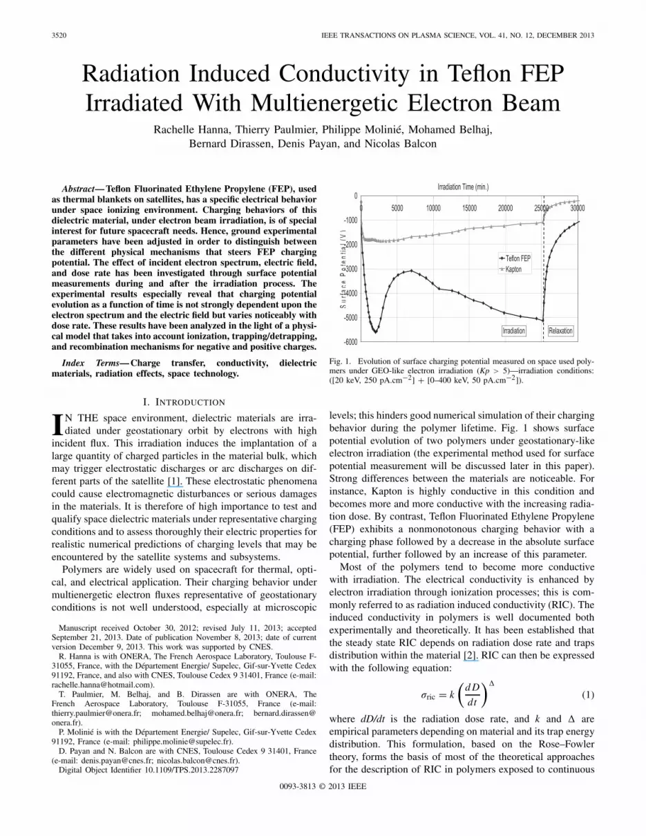
Fig. 1. Evolution of surface charging potential measured on space used poly-mers under GEO-like electron irradiation (Kp > 5)—irradiation conditions:([20 keV, 250 pA.cm−2] + [0–400 keV, 50 pA.cm−2]).
levels; this hinders good numerical simulation of their chargingbehavior during the polymer lifetime. Fig. 1 shows surfacepotential evolution of two polymers under geostationary-likeelectron irradiation (the experimental method used for surfacepotential measurement will be discussed later in this paper).Strong differences between the materials are noticeable. Forinstance, Kapton is highly conductive in this condition andbecomes more and more conductive with the increasing radia-tion dose. By contrast, Teflon Fluorinated Ethylene Propylene(FEP) exhibits a nonmonotonous charging behavior with acharging phase followed by a decrease in the absolute surfacepotential, further followed by an increase of this parameter.
Most of the polymers tend to become more conductivewith irradiation. The electrical conductivity is enhanced byelectron irradiation through ionization processes; this is com-monly referred to as radiation induced conductivity (RIC). Theinduced conductivity in polymers is well documented bothexperimentally and theoretically. It has been established thatthe steady state RIC depends on radiation dose rate and trapsdistribution within the material [2]. RIC can then be expressedwith the following equation:
σric = k
(d D
dt
)�(1)
where dD/dt is the radiation dose rate, and k and � areempirical parameters depending on material and its trap energydistribution. This formulation, based on the Rose–Fowlertheory, forms the basis of most of the theoretical approachesfor the description of RIC in polymers exposed to continuous
0093-3813 © 2013 IEEE

HANNA et al.: RIC IN TEFLON FEP IRRADIATED WITH MULTIENERGETIC ELECTRON BEAM 3521
Fig. 2. SIRENE standard spectrum and reference Kp > 5 spectrum [1].
ionizing radiation. Surprisingly, it has been shown [4] thatTeflon FEP exhibits a rapid increase of its conductivity at theonset of the irradiation followed by a change in its behaviorafter a given time and tends to become more insulating.This special feature has been also detected on other polymers(polystyrene, polyethylene, polyester) irradiated by differentionizing radiations such as X-rays, β and γ particles [3]–[5].According to these studies, conductivity decay has beenascribed to a polarization effect, new traps formation, or totrapping/recombination processes.
To highlight another important point, the aforementionedstudies have been performed with monoenergetic ionizingradiation. However, to the best of our knowledge, compre-hensive analysis of transient RIC in polymers irradiated in amultienergetic mode is still lacking (low and high energeticirradiation). For this purpose, an experimental program hasbeen held at the ONERA/Toulouse Laboratory to improveour knowledge of materials charging behavior under complexfluxes encountered in space environment. Once a better identi-fication of the physical phenomena responsible of conductivityevolution are established, physical models based on micro-scopic mechanisms (such as generation/recombination, ageing,and so on) can be developed. Thus, this paper will be focusedon the discussion of results that reveal the influence of theelectron spectrum, field, and dose rate on RIC evolution. Butfirst, we describe the SIRENE experimental facility, which hasbeen especially designed to test space materials under extremeenvironment conditions.
II. EXPERIMENTAL SETUP
The SIRENE facility built at ONERA Laboratory (Toulouse,France) has been especially designed to simulate geostationaryorbit conditions and to test space materials in these harshenvironments [1]. Fig. 2 shows the electron beam spectralcharacteristics of the SIRENE facility with an energy spectrum(Kp > 5) approaching that of the geostationary chargingenvironment.
SIRENE electron spectrum ([20 keV, 250 pA/cm2] +[0–400 keV, 50 pA/cm2]) simulation is achieved by use oftwo monoenergetic electron beams. In order to get a space-like electron spectrum, the 400 keV electron beam, passing
Fig. 3. Depth-dose rate profile induced by a multienergetic (0–400 keV) anda monoenergetic (400 keV) electron beam on a Teflon sample irradiated withelectron flux equal to 1 nA.cm−2.
through a complex diffusion foil, is dispersed in the energyrange 0–400 keV. The nominal fluxes used for the 20-keVmonoenergetic beam and the distributed 400-keV one are equalto 250 and 50 pA.cm−2, respectively, but can be raised upto 1 nA.cm−2 and 200 pA.cm−2, respectively. A pumpingsystem allows experiments at vacuum of around 10−6 mbar.The temperature of the sample holder can be controlled in therange −150 °C–250 °C allowing reproduction of temperaturevariation of materials on flight. However, this paper wasperformed at room temperature. The evolution of chargingpotential, during and after beam cutoff are monitored using anoncontact electrostatic system (Kelvin probe TREK 3455ETcoupled with an electrostatic voltmeter TREK 341B).
Due to this flexibility and the effective representation ofthe broadband geosynchronous spectrum, the SIRENE facilityallows a more accurate and realistic prediction of charging lev-els at geostationary orbit. The major scientific interest of thisfacility is that it combines low and high energy electrons. Thelow energy will be responsible for material charging and thehigh energy will contribute to discharging the sample throughRIC process. In this paper, 5 × 5 cm2 Teflon FEP sampleswere used. These 127-μm-thick samples were metalized withaluminum on the back face.
III. ANALYSIS METHOD
This section provides a concise description of the analysismethod used to assess the radiation dose received by the Teflonsamples and the equivalent conductivity induced by radiation.Such analysis is required for a better identification of theinvolved mechanisms that determines charging potential.
A. Injected Dose Calculation
The representation of surface potential with radiation doseis of great interest to distinguish between the different mech-anisms involved. In such representation, the injected dosewithin the material was assessed using GEANT 4 software [6].This software is a Monte Carlo toolkit for simulating chargetransport in matter without taking into account the conductioneffect. The depth-dose profile for Teflon sample is shown inFig. 3. According to this result, the received dose is constant

3522 IEEE TRANSACTIONS ON PLASMA SCIENCE, VOL. 41, NO. 12, DECEMBER 2013
within the material for thicknesses <150 μm. For our paper,we took into account an average dose value received from thehigh electron beam and we neglected the dose received fromthe low electron beam. The dose rate injected by low energy(20 keV and 250 pA.cm−2) is 2 Gy.s−1, which is one decadehigher than dose injected by high electron beam (400 keV,50 pA.cm−2), which is equal to 0.2 Gy.s−1. However, the lowenergy electron beam transfers its energy close to the surface:radiation dose injected by the 20-keV electron beam does nottherefore contribute to charge transport in the bulk, contrary to400-keV electron beam that ionizes the overall material bulk.
Knowing the current density of the high electron beam andthe irradiation time, the injected dose rate can be evaluated.
B. Conductivity Evaluation
Characterization of space material electric properties, espe-cially conductivity, is usually performed in our study using thesurface potential decay method. To evaluate volume conduc-tivity of space materials, the traditional method is to modelthe material sample as a parallel combination of a capacitanceand resistance [1]. As we have earlier revealed the presence ofa lateral conductivity [7] on Teflon samples irradiated by lowenergy, which depends upon incident energy W0 and currentdensity J0, we suggest adding another parallel resistance tothe traditional model. According to current conservation law,we can write
JRIC = J0 − JES − Js − dq
dt(2)
where JRIC is the bulk conduction current, J0 is the incidentelectron current, Js is the surface leakage current density,which depends upon incident energy W0 and current densityJ0(JS = β[W0, J0] · J0), dq/dt is the temporal evolutionof space charge displacement (dq/dt = (1/S)(d Q/dt) =(ε/L)(dV /dt)), and JES the leakage current density resultingfrom electronic emission (JES = ψ · J0).
These equations lead to
σric(t) = 1
V
((1 − ψ(t) − β [W0(t), J0])J0 L − ε
dV
dt
)(3)
where V is the surface potential, ψ is the total electronemission yield, β is the leakage surface current coefficient,L is the space charge distance to the ground, and ε is thematerial permittivity.
IV. RESULTS
As we mentioned above, Teflon FEP and some other poly-mer present a special behavior compared with other insulators.An initial rapid rise followed by a pronounced decrease inconductivity with time was frequently observed. It is clear thattwo main mechanisms are thought to be responsible for suchbehavior. The first one (related to an increase of conductivity)is apparently due to the ionization of the material and/or tothe introduction of free radicals into the polymer exposedto the radiation. The second one (related to a decreasing ofconductivity) is more difficult to identify. This second mecha-nism seems to be closely related to the accumulated localizedcharges within the material, which may act as recombination
Fig. 4. Evolution of charging potential with irradiation time for multi andmonoenergetic irradiation configurations.
centers for mobile carriers of opposite sign, thus causingconductivity decrease.
The decreasing conductivity could also be explained as adirect effect of material polarization or attributed to materialdegradation. To determine and discriminate between the dif-ferent mechanisms, a parametrical study was performed. Asa first step, we studied the influence of electron spectrum ontemporal potential profile. The basic objective of this first testwas to determine if the nonmonotonic behavior observed onTeflon FEP is due to charge implantation in the bulk (throughthe wide energy distribution for the incident electrons) or toionization effects induced by the high energy electrons comingthrough the sample. We investigated as well the influence ofthe electric field and the dose rate effects on RIC evolution.
A. Effect of Electron Spectrum
In the context of this paper, three FEP samples have beencharged by a low 20-keV electron beam with 250-pA/cm2 cur-rent density. Simultaneously, two samples have been respec-tively irradiated by a high electron beam in a distributed(0–400 keV) and a 400-keV monoenergetic mode. The currentdensity of the high electron beam was 50 pA/cm2. A compari-son of charging behavior under 400-keV monoenergetic modeand under multienergetic mode (SIRENE spectrum) is shownin Fig. 4.
The evolution of charging potential is similar for both irra-diation modes. A supplementary charging effect may howeverbe noticed with the distributed spectrum. At the onset of theirradiation (phase I), the samples charged negatively due tothe implantation of charge carriers by the 20-keV electronbeam. However, the charging kinetics is lower than the oneobserved on FEP sample irradiated with the monoenergetic20-keV electron beam. The high (multi or monoenergetic)electron beams significantly reduce the charging potentialeffect through enhancement of electric conductivity within thematerial (RIC). After 2000-s irradiation duration (phase II),the absolute charging potential decreases: extraction of RICfrom (2) shows that this potential decrease could be directlylinked to a steep rise of RIC with the increasing total receiveddose, as shown in Fig. 5.

HANNA et al.: RIC IN TEFLON FEP IRRADIATED WITH MULTIENERGETIC ELECTRON BEAM 3523
Fig. 5. Evolution of RIC of Teflon FEP under irradiation with multienergeticelectron spectrum.
Fig. 6. Evolution of charging potential as a function of irradiation time fortwo levels of 20-keV beam intensity.
During a third phase, the absolute charging increases againdue to a decrease in RIC for high dose levels (higher than103 Gy), as shown in Fig. 5. This RIC decrease at higherdose can be explained by the effect of recombination betweentrapped electrons and free holes, as shown in Section V. Atthis dose level, it is supposed that ionization effect overcomesdefects generation (that may act as well on charge transport).
One of the most important features in such results is thatcharge profile does not strongly depend on electric chargerepartition within the material, even if charge implantationinduced by 0–400 keV is effectively higher than for 400 keV.The radiation effect due to the high energy electrons penetrat-ing the sample prevails therefore over charge implantation inthe bulk.
B. Effect of Electric Field
At first sight, we may think that potential profile andamplitude are field dependent. To assess the effect of electricfield on RIC evolution, our approach is to vary the 20-keVcurrent density (low energy part of the spectrum). This allowsus to adjust the applied electric field during the irradia-tion phase, since the low electron beam is responsible for127-μm samples charging. Keeping up the same current den-sity for the 400-keV monoenergetic electron beam, two currentlevels for the 20-keV electron beam, 250 and 125 pA.cm−2,have been applied. The results, shown in Fig. 6, show thatpotential profiles are similar for both 20-keV current levels.
Fig. 7. Evolution of the normalized charging potential after beam cutoff fortwo levels of 20-keV beam intensity.
At the onset of irradiation, doubling 20-keV beam intensityroughly leads to doubling the charging potential. Hence, thefirst phase of the irradiation process is not field dependent.During the second phase (after 6000 s), we can however noticethat the surface potential for the gray curve is not twice theone for the black curve. This unexpected result cannot lead toa specific conclusion since the 20-keV electron can also induceionization of the surface that may enhance surface diffusion ofthe implanted charge or recombination of reattracted secondaryelectrons with positive centers in the surface depletion region,thereby reducing the E-Field to pull electrons deposited deeperin the material toward the surface.
The 20-keV incident electron beam can indeed dissipate theabsorbed energy in series of ionizing and exciting interactions,creating electron–hole pairs within a few micrometers ofdepth within the material surface. Thus, increasing the 20-keVcurrent density induces a rise in the number of ionized particlesas well as charge conduction at the vicinity of the samplesurface. After the injection of a sufficiently high radiationdose (by the 20-keV electron beam), the number of ionizedparticles is sufficient to enhance conductivity (the effect ofsurface RIC appears), and therefore the gap between bothcharging potentials (on the two samples) decreases (sincesurface RIC is higher for the highest 20-keV electron fluxtest). Surface conduction effect is however counterbalance bythe configuration of electric field with the sample, which isdirected to the rear face of the sample and furthers thereforeconduction in the bulk (furthered as well by ionization withthe 400-keV electron beam). At higher dose, surface effectcould however have a noticeable effect.
For such results, an analysis of the voltage decay evolution(Fig. 7) after irradiation shut down is quite useful. We noticethat voltage decay is not strongly affected by the electric fieldeither. One should however emphasize that charge decay ishere due to delayed RIC. During this phase, the sample is nolonger subjected to ionization but the sole effect is that of thelifetime of free charges (electrons and holes) in the conductionand valence bands. During ionization, the electric field may acton the apparent kinetics of electron–hole pair generation, sincethe instantaneous electron–hole pair recombination increaseswith lower electric field. This last effect is however not clearlyobvious from the different experimental tests performed in ourradiation configuration.

3524 IEEE TRANSACTIONS ON PLASMA SCIENCE, VOL. 41, NO. 12, DECEMBER 2013
Fig. 8. Evolution of the normalized charging potential as a function ofradiation dose for various exposure rates.
Fig. 9. Evolution of the calculated conductivity as a function of radiationdose for various exposure rates.
C. Effect of Dose Rate
Four FEP samples have been charged by the 20-keV elec-tron beam with a current density of 250 pA.cm−2. Simulta-neously, they have been irradiated by the 0–400 keV at fourlevels of current density (10, 20, 50, and 100 pA/cm2), toassess the effect of radiation dose rate.
Fig. 8 shows the evolution of the normalized charging poten-tial with radiation dose for various current densities (equivalentto dose rates). With the onset of irradiation, the normalizedpotential increases up to a maximum level and subsequentlydecreases. The dose needed to reach the maximum increasesslightly with current density rise. This feature was earlierobserved in [8] in FEP irradiated by X-rays. It was interpretedusing a 0-D model based on trapping and recombinationof charge carriers. We will describe this 0-D model in thefollowing section. The evolution of the calculated conductivityas a function of dose (Fig. 9) presents the same feature asdescribed above with a shift of maximum conductivity towardhigher radiation dose when radiation dose rate increases. Wecan notice as well that the evolution of the conductivity withdose rate is not linear and seems to follow the Rose–Fowlerformulation (1).
The k and � coefficients can be assessed, respectively, bythe y-intercept and the slope of Log(σ) versus Log(dD/dt)
Fig. 10. Evolution of the calculated conductivity as a function of dose ratein a logarithmic scale.
curve. This linear curve in a logarithmic scale is shown inFig. 10, where a maximum value of conductivity was evaluatedfor each dose rate. We deduced a magnitude value of theexponent� equal to 0.45. This value is comparable with thosediscussed in [9]. According to such a result, the nonlineardecrease of conductivity with dose rate can be interpreted byan increase of the recombination process due to an increaseof the trapped electrons density, as shown in the followingsection.
V. DISCUSSION
The specific behavior observed on Teflon FEP under mono-energetic ionizing radiation has been described, in the litera-ture, by a trapping/recombination model. This model is basedon theoretical foundations of photoconductivity established in[10] and then extended in [2] to the case of RIC in polymersunder steady-state radiation conditions. We also adapted thismodel to the case of FEP irradiated by a multienergeticelectron beam (low and high energetic beam) and to thecase of surface potential measurement. In this model, weassume that charge distribution is constant over time andthe model is therefore simply based on time dependent RIC.This assumption is reinforced by the experimental results thatreveal only a slight influence of the electric field and theelectron spectrum on RIC evolution. Indeed, the generationrate of electrons and holes through the high energy electronirradiation and designated by the factor g is constant anduniform over time. A single level of localized traps equivalentto deep traps is assumed and the shallow traps are consideredto be in thermal equilibrium with the extended states. Weassume also that a free charge recombines with a localizedcharge with opposite sign. Based on the above assumptionsand introducing charge detrapping process in the model, theequations describing the 0-D RIC model are
dn
dt= g − αnpt − n
τn+ nt
τnt(4)
dnt
dt= n
τn− nt
τnt− αpnt (5)
dp
dt= g − αnt p − p
τp+ pt
τpt(6)

HANNA et al.: RIC IN TEFLON FEP IRRADIATED WITH MULTIENERGETIC ELECTRON BEAM 3525
Fig. 11. Evolution of the normalized charging potential as a function ofradiation dose (equivalent to the product of generation rates and irradiationtime) for various generation rates derived from 0-D model.
dpt
dt= p
τp− pt
τpt− αnpt (7)
where n and p are the concentrations of free electrons andholes, nt and pt are the concentrations of trapped electronsand holes in localized states, α the recombination coefficient,and τnt and τpt are the mean electrons and holes lifetimesin transport state. Equations (4) and (5) are, respectively,the evolutions of free and trapped electrons concentrations.Equations (6) and (7) are, respectively, the evolutions of freeand trapped holes concentrations.
The charging potential evolution can then be assessed bymodeling the sample as a combination of a capacitance andtwo resistances in parallel configuration. The first resistanceis equivalent to a bulk resistance of the material, reducedby the RIC effect of the high energetic electron beam. Thisresistance can be evaluated by the evolution of free electronand hole densities from RIC model. The second resistance isused to take into account lateral conductivity of the sample,which has been earlier characterized on FEP [7]. In this model,the charging potential evolution depends on the charging20-keV incident current j , the secondary electron emissionyield ψ, the lateral conductivity coefficient β, and the con-ductivity induced by the high energetic electron beam (RIC)
dV
dt= L j (1 − ψ − β)− e(μnn + μp p)V
ε(8)
where j is the current density of the 20-keV electron beam, eis elementary charge, µn and µp are the mobilities of electronsand holes, and n and p are the free electron and hole densities.
To describe RIC evolution on Teflon FEP, we assumed thatelectrons are deeply trapped (τnt = 10−3 s), whereas positivecharges are assumed to present a longer lifetime in the valenceband (τpt = 5000 s). The holes are deeply trapped as well.In Fig. 11, we present the evolution of charging potentialwith radiation dose at different dose rates based on the0-D RIC model and the above assumptions for FEP. Accordingto this model [11], the conductivity rise (first phase) is due tofree hole densities enhancement. The decrease of conductivity(second phase) is ascribed to the onset of holes trappingas well as an increase in electron–hole recombination dueto the accumulation of localized electrons with irradiationtime. This model reproduces quite well, at a qualitative level,the surface potential profile observed on Teflon FEP under
geostationary conditions, as a function of radiation dose fordifferent radiation dose rates, as seen by comparing Figs. 8and 11. The different evolutions observed as a function of radi-ation dose rate are proved to be due to a competition betweenkinetics of holes generation in the valence band and kineticsof recombination between trapped electrons and free holes.
VI. CONCLUSION
One of the main outcomes of this paper is the nonmonotoniccharging behavior of Teflon FEP under GEO-like electronirradiation, which could be ascribed to the nonmonotoneousevolution of RIC with the received radiation dose and doserate. A simple 0-D model has been proved to agree correctlywith the experimental phenomenology at qualitative level.Indeed, the evolution of RIC on FEP could be attributed tofast electron trapping coupled with a competition betweenhole generation in the extended states and process of holetrapping and recombination with trapped electrons. Predictionof charging and relaxation kinetics in various space condi-tions should therefore be feasible with this 0-D model andmore reasonable with a 1-D model (by adding the effect ofcharge centroid displacement). These models can also takeinto account radiation assisted ageing process (free radicalscreation, chains scission, and cross linking), that could inducenew levels of charge traps in the bulk or at the surfaceof the materials after a radiation dose threshold. Furthermeasurements are required to revise these ageing effects onthe evolution of the induced conductivity.
REFERENCES
[1] T. Paulmier, B. Dirassen, D. Payan, and M. Van Eesbeek, “Mater-ial charging in space environment: Experimental test simulation andinduced conductive mechanisms,” IEEE Trans. Dielectr. Electr. Insul.,vol. 16, no. 3, pp. 682–688, Jun. 2009.
[2] J. F. Fowler, “X-ray induced conductivity in insulating materials,”R. Soc. London, vol. 236, pp. 464–480, Sep. 1956.
[3] F. T. Farmer, “Electrical properties of polystyrene,” Nature, vol. 150,pp. 521–523, Oct. 1942.
[4] B. Gross, V. H. Seggern, and D. A. Berkley, “Long term behaviour ofradiation induced currents in fluorinated ethylene propylene copolymer,”Phys. Stat. Solidi, vol. 79, no. 2, pp. 607–615, 1983.
[5] A. P. Tyutnev, V. S. Saenko, I. A. Smirnov, and E. D. Pozhidaev, “Radi-ation induced conductivity in polymers during long term irradiation,”High Eng. Chem., vol. 40, no. 5, pp. 319–330, 2006.
[6] J. Allison, K. Amako, J. Apostolakis, and H. Araujo, “Geant4 devel-opments and applications,” IEEE Trans. Nucl. Sci., vol. 53, no. 1,pp. 270–278, Feb. 2006.
[7] R. Hanna, T. Paulmier, M. Belhaj, P. Molinié, B. Dirassen, D. Payan,et al., “Characterization of charge carrier lateral conduction in irradiateddielectric,” J. Phys. D, Appl. Phys., vol. 44, no. 44, pp. 445402–445407,2012.
[8] B. Gross, R. M. Faria, and G .F. Ferreira, “Radiation induced conductiv-ity in Teflon irradiated by X rays,” J. Appl. Phys., vol. 52, pp. 571–578,Sep. 1981.
[9] G. M. Sessler, M. T. Figueiredo, and G. F. Ferreira, “Models of chargetransport in electron beam irradiated insulators,” J. Appl. Phys., vol. 11,no. 2, pp. 192–200, 2004.
[10] A. Rose, “Recombination processes in insulators and semiconductors,”Phys. Rev., vol. 97, no. 6, pp. 322–333, 1955.
[11] P. Molinié, P. Dessante, R. Hanna, T. Paulmier, B. Dirassen, M. Belhaj,et al., “Polyimide and FEP charging behavior under multienergeticelectron-beam irradiation,” IEEE Trans. Dielectr. Electr. Insul., vol. 19,no. 4, pp. 1215–1220, Aug. 2012.
Authors’ photographs and biographies not available at the time of publication.