r1rniU Pla 5 - Audio electronics for You and Me
66
r1rniU Pla 5 J e T""'.. lua 2 - lO
-
Upload
khangminh22 -
Category
Documents
-
view
1 -
download
0
Transcript of r1rniU Pla 5 - Audio electronics for You and Me

r1rniU Pla 5Je T""'..
lua 2 - lO

IND TURBINE
_CIP B~ ~K
A
R
THE AXIAL FLUX WINDMILL PLANS
© HUGH PIGGOTT
WITH THANKS TO ALAN BUSH, DAN BARThIANN, LES VINCENT,AND COUNTLESS OTHERS WHO HAVE INSPIRED ME.
\
JANUARY 200 METRIC EDITION

l'nge 2 A WINO TURBINE RECIPE BOOK' THE AXIAL FLUX ALTERNATOR WINDMILL PLANS-
T1I1SIOOK11lis is the January 2009 edition of m}' 'Axial Flux\"indmill plans'. This Recipe Book (first edition in2008, sequel to the 2005 edition 'How to build a Windturbine') is all new. and much better structured thanthe 2005 book, with complete details of how to buildsix different sizes of turbine choosing between four ormOf'e'voltages.
There are several sections of general interest, but mostof the book is very specific to Ule stages ofconstmction, and has dimensions for each size ofturbine tabulated alongside diagrams and text. At theback you willlind a set of basic drawings of the fourmain types of head for the turbines.
It is Quite likely that I will continue to update thisdocument for a while and you can find details ofcorrections and e",'tra material at
Steehvork 10V~loodworkingtOOI5 10
Using the tools 11Cordless drill 11Scre,,,driver bits 1I
f\1easurenlcnls 11
Vernier c..'lllipers 1]
Levels _ J I
Conlpasses 11
f\1ultinleters 12
Soldering technique 12
Crimping connections 12
Electric Arc welding 12
Cutting steel 13
Drilling 13
Tapping a thread '3'""ood sa\"s 14Other wood cutting tools 14
Sandpaper 14
Po\ver tools 14..I http Ilwww.scoralgwind.com/axialplans/ recipe%20updatel
This book is aB metric (dimensions in mm) but I havealso produced a separate 'English' version withdimensions in inches, and using the 2" x J" x 1/2"
magnet blocks that are common in North America.
THIS BOOK 2Choosing what to do 4
Be safe! 4How big? 4D' f 11' dlagram 0 a sma W111 system 4\'\'hat can the wind turbine do? 4
Load controllers 5Choosing battel)' voltage 5
Battel)' types 6Wby some popular ideas are not good ideas 6
Car alternators 6Steel cores in the stator coils 7Multiple rotors and stators 7Vertical axis wind turbioes (VAWfs) 7Multi blade rolors BRooftop mounting BSaving money off the electricity bill 8Mounting a wind turbine on a car to charge thebattel)' 8Usiog a centrifugal c1utcb or brake to limit speed 9Buildiog a duct that forces the air through asmaller diameter rotor at high speed 9
\¥bat goes wrong with homebuilt wind turbines? 9Useful web ~es for more information: 9
Tools 10Safety etc 10All-purpose tools 10For marking and measuring 10Electrical 10Resin preparation 10
Have fun!
CONTENTS
Hugh
Blades 15Parts of lhe blade 15Selecting the wood 15The blank shapes 16The trailing edge line 17
Mark out the shape of the blade at each of sixstations aloog its length 17CaNe away wood above the trailing edge line tocreate a ne\v face 18
Blade thickness IBAirfoil shape 19Hub assembly 20
Cutting the 120 degree angles at the roots 20
The plywood pieces thal sandwich the blades 20Marking out the holes in the plywood 20Assembling the blades 21
Balancing 22B I .. . .a anclng In posItIon 22
Fine balancing 22
Alternative ways to balance the blades 22B I' 'ka anclng on a Spl 'e 23Dynamic balance 23
Painting and finishing 23
Mechanics 24The yaw bearing 24The alternator ··24
Choosing a hub 24Magnet rotor disks 25Alternator frame 26Mounting the alternator to the yaw bearing 2712 volt turbine rectifier boxes 29
The tail 30Th'!'dh'e IOC loe l.nge 30
Tail boom ·31
Tail stops ·32
Electrics 34Energy conversion ······34Choosing wire size and number of turns per coil 34St t" .a or \Vlnng connectIOns ·····35Three-phase stators ·.. ·35Batte!)' charging with DC 36
The coils ·36

\
3600 mm diameterturbine
/i
I...--'
The title page shows the general arrangement of the1800 - 3000 metre diameter turbines.
WIND TURBINE RECIPE BOOK NOVEMBER 2008 METRIC EDIT10N page 3
12-VOIt stators marked •· .. ······· .. ·············· .. ········ 36 MATERIALS REQUIRED FOR BUILDINGMaking the coil "'nder 37 THE WIND TURBINES 63Winding the coils 38 ..Connecting the coils 38 Views of the turbine head 64'2-VOIt stators 39 1200 TURBINE 64Output w,nng 39 ,800 TURllINE 64
The moulds 39 2400 and 3000 turbines 65The stator mould 39 3600 and 4200 turbines 65The 1200 stator mould A1The magnet rotor mould .41The magnet positioningjig 42
Resin casting 43Casting the statoL 43Don't forget the jacking screw boles 45Casting the magnet rotor(s) 45 1200 mm diameter
Alternator assembly and testing 46 turbineRotor mounting options 46Rotor mounting studs 47Assembly .. ·· .. ·.. · ·· .. · ·.. · ·.. · 4712-volt turbine rectifiers 48Testing the alternator 48
Wiring the batteries 49The rectifier and brake 49Meters · · · · ·50Controller 50Inverter 50Commissioning the turbine 50
To\vers 51Wiring the to\ver 51Tower pipe sizes for towers with guys (guyedto\vers} 51Guy ancbors 52Lifting the tower 53Taller to\\'ers 53
_.....cA",djusting the guys 53
Alternator design 54Matcbing the blades 54Tip speed ratio Oambda I) 54
Calculating the blade rotor rpm 54Blade power 54Calculating the output voltage vs. speed 54Wire sizes and power losses 55
Size of ""rire to use 55Coil resistance 56Stator resistance 56Current and power loss 57Rectifier loss 57Efficiency 57Windspeed 57Stator cooling 57
Estimating tbe rpm 57Blade speed at full power 58
Exploring some alternator design factors 58Magnet spacing 58The effects of speed 59The effects of battery voltage on efficiency 59Varying the voltage with the speed 59
_---'H!.!.igh voltage transmission 59
Glossary 60LIST OF USEFUL SUPPLIERS 62

ChDosln whIr hi do
A WIND TURBINE RECIPE BOOK -THE AXIAL FLUX ALTERNATOR WINDMILL PLANS·
little innuence for most of the time, because full ratedpower is only available in stronger winds. The rest ofthe time the power output is limited by the wind andby the size of the rotor.
There is pknty of srope for hurting yoursclf or others"hen building And operating small wind turbines. Youfollow these guidelines nt your own risk! Iam notgoing to fill this manual with nil the snfety notices anddisclnimcrs that make mnny manuals unreadAble. But1will point out the main hRznrdS up fronl.
In mye.xperience, most people hurt their fingers whenhnndling magnets. In some cases I hear that they losetingcrs. Treat the magnets with respect and neverlenve magnet or magnet rotors lying around loo e.
\\'car protective clothing where it helps safety - fol'e.xomple when grinding metal you should always lIseeye protection. All workshop activities have a degreeofdanger if conducted carelessly or with ignorance.Tnkc care to learn how to use your tools.
Batteries are particularly hawrdous items. They candeHvcr a lot of energy in the event of nshort-circuit,causing bums or fires. They contain e:\1>losive gassesthat can spatter acid in your eyes if ignited by a spark.They contain lead that is a persistent toxin and abackbreaking weight to lift.
Erecting towers can be deceptively lri 1..')' and manypeople have dropped \\;nd turbines from a height inthe attempt. Needing a n w set of blades would be asetback, but nothing compared to crushing a child.Keep everyone out of the fall zone, and pa attentionall the time. Do not erect a wind turbine tower in apublic area where people congregate beneaUl it.
Battery-charging wind turbines do not generally createany risk of electric shock, but bear in mind that whenthe are running fast and not connected to a batterythe voltage they produce is much higher than nominalbattery voltage. Dangerous voltages cnn arise inexceptional conditions (especially ,,;th 48-vollsystems), so it is best to keep junction boxes closed.
HowbiglThe amount of energy that you will get from theturbine depends mostly on two things: the diameter ofthe blade rotor, aud the exposure to good winds. Thepower rating of the alternator in watts aClually has vel)'
I have included a very rough estimate of the cost ofmaterials in the table as well. Much will depend onhow yOll buy things, what the shipping cost is, whetheryou can re-use some discarded materials such as steelpipcs or timber. There is a list of useful suppliers atthe back of this book. Also a glossa'1' of terms.
Cost is less significant than the time it takes tocomplete a project like this. You are likely to be at itfor weeks rather than days. I recommend building asmall one first so as to get experience and also so as toget a final result beforeyoll run out of enthusiasm. Itis hard to describe the feeling you will get when itstarts to produce power.
Di.ag,rao1 of a snlull wind sysMllil3-phase AC power from the wind turbine is convertedto DC power by a reclifier. (Only onc DC wire is shownto simplify this diagram but rou need two.) In mostcases the DC is then made into single phase AC power(normal household electricity).
WIND RECfIFIERTURBINE
LOADCONTROLLER
BATIERlBS
DC POWERAND BATrERY
DUMP FUSESLOAD(S)
DUMP INVERTERLOADS
PREVENTEXCESSIvE ACPOWERVOL.TAGE •
·ON-DEMAND- lJl1UWGRlDLOADS
Estimated monthlv en er ' oroduction at different mean winds. eedsnlrbiw:~iam t rmm 1200 1800 2400 3000 3600 4200
Power ratin 200W 350 W 700W 800W 1000W 1000W
Mean 3 m/s 5 kWh 12 kWh 22 kWh 34 kWh 49 kWh 67 kWhMean 4 m/s 14 kWh 30 kWh 54 kWh 85 kWh 122 kWh 166 kWhMean 5 m/s 23 kWh 53 kWh 93 kWh 146 kWh 210 kWh 286 kWhMean 6 m/s 33 kWh 74 kWh 131 kWh 205 kWh 296 kWh 402 kWhMean 7 m/s 41 kWh 92 kWh 164 kWh 256 kWh 369 kWh 502 kWhEsttmate cost
of matenals £200 £300 £500 £600 £900 £1000
What can the ll'iru!~Small wind turbines are agood way to produceelectricity in a windy place.Wind energy is highlydependent on the windspeed, so it is a good idea toerect a tall tower to reachthe best winds. The turbineneeds to be well ~bovesurrounding trees andbuildings - not just at

The energy that is diverted to heat c.1n be used in awater heater and then diverted to lower priority usesonce the wnter is hot. There is potentially no end tothe complexity of the system if you wish to make tilebest use ofyour wind energy.
(fyoll are keen on electronics then you can make yourown load controller. Some of them work by switchingmultiple small loads on nnd off on a slow timescalewhile others work by very rapidly switching a singleload. The amount of energy you dump depends onhow long the load is pulsed on compared to the periodbetween pulses.
\Vhether you want heat or not, you should use somsort of electronic load control that connects healers tothe turbine when the voltage rises above the desiredlevel. Such controllers are easily available for batt rychar'bring systems and are becoming more widelya"nilable for grid connection applic.llion as well. Beaware that load controllers that are designed to workwith b[ltteries cannot usually function \v;thoutbatteries, although in some cases )"ou can usec..1pacitors in place of batteries to slabili e the \'olrnge ifthe operating frequency of the pulses is high enough.
Adedicated solar PV charge controller ,viII not workfor a wind turbine unless it has the option to be used ina load control mode. Most solar electric chargecontrollers regulate charge by disconnecting ti,e solarpanel, and this is not a good idea with a wind turbine.Xantrex C-40 and Morningstor TS4s controllers (seeleft) are both optionally suitable for 'diversion 10<1ds'but the laller has a quicker response to gusts.
....""...::;:..."" -'- .. ;. . ~...- .- .- ......\~, -~~;;,...or"
AN INVERTER IS JUST ABIG BOX OF ELECTRONICS
If you already have utility grid power on site then thereis not so much point in storing energy in batteries. Themost effective use of wind energy is to feed it straightto the grid using a special 'grid connect' inverter. Thisset-up is cheaper than a stand-alone battery system,but the electricity will also be worth less in the endsince you are competing with very cheaply producedgrid power.
It is good to connectsolar photovoltaic (PV)panels that charge thebattery when the windis low, and it's alsoeasy to convert batterypower into AC powerfor conventionalhousehold wiring andappliances. Butthebatteries and olheritems of equipment todo this are not cheap.
The wind turbines inthis book are primarilydesigned for chargingbatteries. They canprovide electricitywhere there is none.
WIND TURBINE RECIPE BOOK NOVEMBER 2008 METRIC EDITION P.:'8e 5
rooftop level. Ifthe IOc"ltion is not windier than turn at ;'Ill, but if the wind is strong then you have toaverage, then small wind is probably a waste of effort give it something to do or iI will overspeed and runbut there is no reason not to do it if you just want to do wild. If the wires are disconnected from the turbineit. There is no reason to drive around town in 1.1 big then the voltage will shoot up until it can damagefour-wheel drive vehicle, but people do that. IfYOll lights ~md electronic equipment.need to build or buy a small wind turbine. then that isfine too (even better!). But you need to understandthat it will not save you any significant money (unlessthe site is really windy). It will be less environmentallydamaging than a fOUf wheel drive, but it will notimmediately 'save the planet'
Some prefer to use the wind for heating only. Thissaves the hassle of dealing with the utility, and avoidsthe issues of energy storage in batteries - it is muchcheaper to store heat - but in the end the value of heatenergy is often much lower than that of electricity.
It is not a great idea tosimply connect a heaterdirectly to the turbinebecause that will prevent itfrom starting up. The heaterhas to be turned on when tilevoltage is high enough. Youneed a 'load controller'thatautomatically turns on theheater(s).
The wind turbine is ratherlike an engine whose throttleyou cannot control. If thereis no wind then it will not
A lOAD CONTROLLER IS ASMAUER BOX OF elECTRONICS
12-vOIt balleries are only suitable for very smallsystems becnuse tile wires you need n very thick,expensive and clumsy. Unless you have a specialreason to need 12 volts. tllen choose 24 volts or betterstill 48 volts. You would bnild a 48-volt battery usingfour 12-volt balleries. 48-volt power can be con, rtedto mains voltage AC power with an inve.rter.
Cheaper inverters are avoilable for 12 or 24-voltballery systems, SO ifyou cannot afford a high grndeinverter then 24 volts may be the best choice,
[fyou are feeding tile mains grid without balleriesthen a good choice of inverter is the 'Windy Boy' 1700wall inverter from SMA. This grid connect inverterworks over a range of voltages from about J-IO to 350volts. There are many other SUcll inverters toc~.
On tile pages about wiuding coils for the turbine I ha'presented. table of different options for differentballel)' voltages and also for the Windy 80 in''erter.

!!£.2. ...!:.A~W1~':!.m~TUR~~B~r~N=Ec.!RE~C~'~PE~BO~O~Kc::.~TH~E:.:AXJ=:::AL:::.:FUJ~::X:..:AL=TE:.=:R::N::A:..:T::O=R'_Wl'_'_N'_O::::....::ILL='_Pl.ANS-=..::..=_
Solutions? You can fit it with permanent magnets.This is vel)' laborious and whal you are left with is slillraUter small and light, so the efficiency is still vcr)'poor unless the machine is very small (50 -100 wattssay).
• Use shorter blades. The tips have less far to go perrevolution, so they can spin at higher rpm. Thissolution can produce power in high winds whenthe speed and power are sufficient to energise thefield coil. But you will find Ihat most of the timethe wind is insufficient and the turbine producesnothing. Small blades cannol catch much energynor run vary fast in low windspeeds.
I. 11 is designed 10 be lightweight and robust and 10withstand running al very high rpm. At low speed(below 1000 rpm) il produces no usable outpullfyoumount wind turbine blades on Ihe shaft then the)' willturn il relatively slowl)'. This speed mismalch can beaddressed in onc of several unsatisfactory ways:
A car altemalorappears attractive forhome-brew powergeneration, because itis made for the job ofcharging batteries andis widely available allow cost. But it is abad choice for a windgenerator. Theefficiency in nonnaJuse is never more thanabout 60%. In practice it usually wasles over half ofthe power that drives it. The bearings are too small toreliably support large blades (over aboul 'SOD mmdiameter). There are three main problems:
• Use gearing to increase the rpm. This involvesextra cost. extra power losses, extra unreliabilityand overall ugly and clumsy engineering. Wastedefforl for a disappoinling output.
• Rewind the coils to work at lower speed. Use moreturns of thinner wire in each coil. This reduces thecut-in rpm but also increases the losses in the coilsthemselves, limiting the power output and furtherreducing Ihe already low efficiency.
2. The allemator Reld coil needs 10 be supplied withpower to excite the magnetic flux. To get output allowspeed, you need the flux 10 be maximised. Thiscurrent in the field coil represents a constant powerloss of 30-40 watts during operation. The lossclobbers the output in low winds. 40 watts continuousnearly adds up 10 one full kWh of energy per day.
~y some WlPular ideas are not good ideas
Car alJema=
Porkliftlruck batleriesor good for very heavy,d :Cl' ey l of chargeond dis h rge bul donol hold th ir chargewell over periods ofwe Iuo. ",ey g 'nerallywork hest wh re a smallbattery ClIpa ity is used( r regular daily chargeand discharg . The oncshown has sixindivlduol .-voll lismaking up ,. volts.
ndhand batteries are 3n attractive way to reduceboth cost and environmental impocl of your renewableenergy syst m. But in many cases a used battery is notwo,1h the ltollble. The beslty]>e is Ihe old 'slandby'botter)' built from single cells in transporenl cases.Some of th e can last for .5 or 30 years.
Seml-l rnclion or 1eisurc'balleri look more likehug (60-kg) carbolleries. Used in boatsC!tc. they oft no come in,.-voll, units. Widclynvoilable, h np andgood 01 holding Iheirchurge, 11,ey are 0
populnr choice.
cnled balleries of Ihe gelnnd AGM l)'pes are used~ r low·mnintenance andremot~ sites or forsituations wbere spillageIs • mojor oncem. Theyore twice the price of'flood 'd' bUllelies ond oreeasily damnged byIncorre<:1 chorgingvoltoges.
1klJ.IJ:aL1JIThere a m ny of batteries, even among thegeneric 1 ad acid' ( mily that is u.se<! for mall ~nd,>"IIem5. r balleri are nolsu,tabldor slonngIgJliRcanl amoun of energy - jusl for delivering a
brief high surge of power to lart an engine. Mosloth r ballery types n be e"Peeled 10 lasl abouI Rve
'" bUlllfe c>rpeetancy depends heavily on how theyare lac<!. They can la,ttwo or len years.
If ,ll pl.u1 th turbine for heating Ihen th.I will dtpend on ",bat sort of heaters and
rnb whatlOf'! of h ting mntroller you wish too . 80 • hi&her. ltag will enablelhe lransmissi.onwi to C<lny Ihe eneTg)' with a smaller current whIchWIlI'1 I power a heat in Ihe wires.

WINO TURBINE RECIPE BOO~ OVEMBER 200B IETRIC EomON
s.ame- enelgy C'Om"prsion rffkit'nn hut lilt' Il\~'t" ,,"ouklbe then be proportionalf>l~ \ t'1"'\ high.
If you put all your m<tgnets and roil.. into OUt"
alternator \\;lh t\,;ce the diameter. you h..mdlt:' ~lw\"'(>n4-8 times as mtll"h power instcmt oi just 2 tim~.
•
Low speed vertical axis windturbines of the 'Savonius' typeare useful for really basic simplerugged machines with lowefficiency, and low rpm. But thesame amount of effort put into ahorizontal axis machine will yieldmuch greater returns, Low speedalternators are very heavy andexpenSive,
\ -ero'cal a,\is u'ind..ru.rbines 0 ~.\ i ''ill'Vertical a..\.;s· turbines hm'e a vertical shaft. that isdrh'en b\' blades that mO"e horizontallv like;l
• •
roundabout. 'Horizontal axis' describes the morecom'entional windmill which has to face itself into the\\;nd and whose blades re\'olvi:' in 3 \'er1ical plane. Thevertical a\.;s \\;nd turbine idea is popular {'ven thoughit is thousands of years old and has long ago beensuperseded technically by the horizontal a.xis bladerotor.
Attractive features of the VA\IT include the ability totake wind from any direction, and the ability to drive agenerator at ground level. But in spite of a hugeamount of research, verticalax;s wind turbines ha\'efailed to become \\~dely successful. They can be hardto start, hard to stop, and they have inherently lowerefficiency than horizontal a.xis turbines. (They convertless of the energy that is in the wind). Putting them onlower towers means that they have also got access toless wind. It is often hard to mount a VAWl' on a taUenough tower where it can get agood wind,
Any rime you adapt the design you \,"ill 11l,{.'{1 10 lakecare that the alternator matches the blades you arcusing. Alternator speed dep~l1ds 011 magnets, roildetails. battt'ry \'olt3ge etc. If the speed i:" loo luw thenthe blades may stall whereas if it is too high then theblades \\ill not be able to run fast enough to drive thealternator, See the section on alternator design at theend of the book.
High speed Darrieus 'egg-beater'or alternatively H-rotor typevertical axis (VA\¥T) windturbines are popular inuniversity engineeringdepartments but have never beensuccessful in the marketplace,except for a few years in the1980s in California. In brief, themain problem with high speedvertical axis wind turbines is the faclthat the bladessuffer from reverse buffeting by the wind every inglerevolution. This causes severe fatigue loading which
If you instead put all the magnets onto rotors of doublediameter, and all the coils into one big stator, theneach coil will also produce h,ice the voltage. So youhave double the coils but each coil can produce hvicethe power with the same losses. The coils can eachactually produce four times as much power with the
3. The internal regulator in the alternator is notsuitable for charging a remote batter,,-. If the battery isnot close by then the \'oltage at the aitemator \\ill bt.higher than battery \-oJtage and so the regulator \\illstart to limit the output before the battel}' is chargingproperly..-\lso the way it reduces output is 10 reducethe magnetic field. This unloads the blades. which ,\illrun faster and cause noise. ,;bration and wear to allcomponents (bearings. blade tips. etcl.
You want low operating speed and high efficiency atminimum cost of magnets and wire, lfyou build analternator with 1'0"0 stators and four sets of magnetsthen you will get twice the power at the same speed.
Steel cores in the stJ!wr cojL~
~Iost cOll\'entionaJalternators havecores made oflaminated steel thatenhance themagnetic circuitthrough the coils ofcopper wire and thusincrease the output \'oltage you can get from a givenamount of magnet material,
Alternators with steel cores are harder to startgenerally and they do e>.:perience quite a noticeablemagnetic drag, which impacts on the efficiency in lowwinds. The axial flu>.: alternators in this book are veryfree turning and much easier to build. The oolydisadvantage is the higher cost of magnets.
You \\;11 ha\'e to remO\'e and bypass the internalregulator.
Multiple rotQrs and staf.Q..aVery many people ask me if}'ou can increase the powerof the a.xial alternator by adding more rotors and morestators. The answer is yes, but it is not the best way touse the materials.
The axial flux alternators described here do not usecores in the coils and so they need much more magnetvolume to achieve the same perfornlance, You couldfit cores into the coils, but it would not be advisable.The magnets would seek to align themseh'es \\;th thecoil cores aDd this would make the alternator very hardto start and very rough in operation. The uoe\'entorque is known as ·cogging'.
While it is cheap and attractive at first look. the caralternator is more trouble than it is \\·orth. It issimpler and better to build a purpose-built alternatorfor a wind turbine.

!,age 8 A WIND TURBINE RECIPE BOOK -THE AXIAL FLUX ALTERNATOR WINDMILL PLANS-
For electricity production you need speed rather thantorque, because the amount of magnets and wire youneed to buy is much less at high rpm. At high speedsyou can catch all the power (not torque but power) thatthere is in the \vind using only two or three blades.Three blades run more smoothly than two, so that isthe number I suggest you use.
Saving WQn.1t Qff.1b. electricity bill,.vhen people contact me with an enthusiastic desire tosave money by using a small wind turbine to cut theirelectricity bills, I always feel uncomfortable. I amenthusiastic about small wind energy but I also have arealistic knowledge of what it can do, having used it forthirty years. As you can see from the table at the startof this section, even a well sited \vind turbine can onlyproduce a few kVlh un.its of electrical energy permonth. Achieving this output ,viII cost a lot of moneyand time compared to the effort required to savemoney by reducing electricity consumption in mostcases. Ifyour electricity bill is high then energyconservation is going to pay quicker dividends than asmall wind turbine.
Wind energy itself is free but converting it to usableelectricity is no free lunch. You will reduce yourelectricity bill by using a smaIJ 'vind turbine, but ifsaving money is your motivation then there arecheaper and easier ways to achieve this end. Investingin home insulation, heating controls, energy savinglights and modern fridges and freezers will be the firstthings to consider. Burn wood to heal your house.S\vitch off your 1V and computer systems when not inuse. You can easily save a lot of money with energyconservation measures and reduce your environmentalfootprint. Once your electricity consumption has beenminimised then you can think about meeting yourneeds with wind and solar power. But you are notlikely to save money in the end when you considerevel)1.hing you have bought and done. The pleasure ofusing small wind energy comes at a price.
exposed sites the building will be seriously impactedand the occupiers will find the noise distracting. In •either case there would be much better results formputting the wind turbine on an indcl>cndenl towerwell above the building and a distance away from it.While I sympathise with urban dwellers \\'ho wish tomake use of wind energy, I have to discourage the ideabecause I know it is not a good onc. Solar waterheating and PV are much better choices for rooftoprenewable energy.
shortens the life expectancy ofblad . This is usually U,emain ren on why lhey f3il tobecomc commercially viable.
0/'
The old water-pumping\vindmills were built \vithmulti-bladed rotors so asto produce high torque inlow winds. They work verywell for this purpose.More blades obviouslypush harder and lift thewater from deep under theground.
BQo.[Wp IDQuntin.gAnother idea that has caughlthepublic imagination lately is 10mount a small wind turbine on theroof of tile house. This has longbeen known to be a bad idea, butpublic interest in urban windenergy has encouraged sales peopleto offer rooftop mounted windturbines nevertheless.
Th re are numerous smallVAWfs appearing in themarketplace U,ese day butnonc of them seem to have any :AIort of track record. In fact nonc of them seem to be
able to offer any real world measured data for energyproduction. Beware of computer-generatedpredictions of outpul!
Windspeed at rooflop level is very poor due to the factthat obstructions such as buildings and trees have adramatic effect on the flow of air, breaking it intodiverse vortices and gusts that contain very littleenergy but do cause wear and tear of the turbine.Access for installation and maintenance is oftendifficult or expensive. In urban areas the turbineshould really be placed at least to metres above therooftop level, which is not very practicable with a roofmounted tower.
Wmd turbines are machines that produce somevibration during operation. In \vindy locations this cancause problems with noise in the buildingl and evendamage to the structure of the building. On most sitesthis will not be a problem because the 'vind will beinsuffieient for the turbine to do mucb, but the wholeexercise is likely to be a waste of effort. On very
Ifyou bave a suitable site for a small hydro turbinethen there is a much better chance of saving moneywith renewable energy that way. A good hydro powersite can be a real money-earner.
Mounting a wi1JCl.1y.rQine on a car to charge t.h.e.lmIurJlObviously a windturbine mounted on avehicle 'viII experiencegood winds and beable to producehealthy output. Butthe drag caused by theturbine will put anextra load OD theeogine of the vehicle.

WIND TURBINE RECIPE BOOK NOVEMBER 200B METRIC EDITION page 9
•
There is no free energy to be had in this way except onrare occasions when )'OU are coasting down a hill.\Vhile driving on the level the engine will have toproduce more power to charge the battery in this waythan it would by charging it via a conventionalalternator with all its shortcomings.
It can be fun and also interesting to mount a windturbine on a vehicle for test purposes. But this is nolan efficient way to produce power. Nor is it aparticularly accurate way to measure the performanceor the turbine. Its main virtue is that you can controlthe windspeed at will.
USil]g a cenn:!fugal..&lJ!tch or I1rake..tl!../im.iupeedThis would just wear itself out in a few days on a windysite. The thing with wind turbines is that they work alot more hours than most of the machines we use. Abrake has to come on completely and stop the turbineor it will wear itself away and become useless.
Building a ductlh.otfol'ces tile ail' through g smallerdiameter rotor at high sp.fid.
It simply isn't worth all the extra material involved inbuilding a duct like that. The wind tends to divertaround it so you don't gain as much as you wouldthink. It is actually more effective to build aconventional blade rotor with larger diameter, than tomake a duct. Some big companies have spent a lot oftheir investors' money finding this out.
What.J:.Qes wrong with homebuill windturbines?Those who have worked with them agree that smallwind turbines are surprisingly troublesome pieces ofequipment, whether bought new or home built.Catching the wiad is fun but can be frustrating becauseof all the little things (and some big ones) that gowrong.
Here are some typical examples of things that mighthappen:
• Poor welding skills and poor blade balancelead to the tail falling off. When the macbineis shakiag, the tail tends to be the worstaffected part.
• Diodes in the rectifier fail due to poorconnections and/or poor cooling. Or due tonearby lightning or similar surges. It pays t.ohave a nice big heatsink. Earthing the towerhelps to prevent lightning-induced surges.
• In some cases the bearings can give trouble.When bearings fail they can allow the rotors torub tbe stator with consequent damage thatreduces the life of these parts.
• In very turbulent and wild conditions thegyroscopic forces on the blades have beenknown to push them back into contact with thetower so that they break. This is a very rarebut persistent problem. In this 2008 book Ihave changed the direetion of furliag of theturbines so that the gyro forces push the bladetips out from the tower as the machine moves
into furl. This is the yaw movement where theblades tend to be racing fastest. Thi. changeshould reduce or even prevent the contact ofblades "vith tower from now on.
• Longer termthe biggest issues tendto be with corrosion ofthe magnet rotorplates, or the magnetsthemselves that canlead to a major failurein under 5 years. Themagnet rotors must bepainted very wen orthe disk/plate could
perhaps be galvanised if the turbine is used in a dampclimate. I am now using an epoxy bitumen paint forthis. In the photo you can see damage to the coating ofthe magnets, caused by metal swarf (sharp strips andfragments of cut steel from drilling and tapping holes)in the air gap. Once the proteclive plating on themagnet is punctured, the magnet corrodes and swellsgradually. This magnet was cut out of the casting andreplaced.
Small ,vind turbines can last twenty years, but repairsare called for now and then. It's hard to say how often,because aB builders are different, as are all sites. Iwould expect a couple of problems in the first year, andmaybe one per year thereafter. Can be just a blowndiode, or can be a new set of blades need to be calVed.It's a good idea to collect a stock of spares for theturbine so as la be able to get it back into action fast inthe event of problems.
Useful web u..a.ges for more infQrmatiooj
www.scoraigwind.co.uklbuildyowww.otherpower.comwww.fieldlines.comwww.windpower.orgwww.windmission.dklworkshop/www.gotwind.orgnndex.hlmwww.windstuffnow.comlmain/www.windchasers.caJwww.buildyourownwindturbine.comwww.ecoinn.co.nzlpageslcomplele_solar.hLmIwww.cal.org.uklwww.navitron.org.uklforurnJwww.homepower.com/www.briel)..com/wind_lurbinelht.p:J1continoo.OOllY'suslainable%2OimgN(ndmlI%2OO7NflOdn'tl.htmwww.lhebackshed.comlWindmiIVdetaull.aspwww.forcefieldmagnels.com/www.royalfabricalion.com/www.reuk.co.uklwww.mdpub.comlWind_Turbinelwww.stanford.edul-jparmerlProject%20WebsltelHome.h~

.\''\& 10 A WIND TURBINE RECIPE BOOK· THE AXIAL FLUX ALTERNATOR WINDMILL PLANS-
1.------Allcast130 amps outpul for3.2-mm rod electrodes.(A Mig welder is also fine.)MilSk,Chipping hammerSa~ I)' glas c ,glol' and car protectors. Plasters for
fingers. Hand cleaner, Paper towels.
Tools1n mo!':t ens there tlfC various options depending onrost and what skills )'ou may have.
can beuseful but not essential
Hand saw, chisels,sharpening stoneDrill bits for wood.
Jigsaw
~~
A bandsawand/or a circular saw can be usefulbut not essential.
Angle grinder -------
Drill bits,hole saws
Jlr.i.IJ..IlJ.=----for accurately drillingholes
Spanners,FilcsTaps for threading holes
....
Cllim saw (or steel -------(and/or bandsaw)speeds things upHack aw,Mctol shears(for cutting lead Oashing),
Compasses protractor ,.. callipcrs
I
Square Bevel
+-
Weighing scales level
Cordless drill with screwdriver bits. screwdrivers,I Hers. vice grips. clamps. vice, files, hammer, centrepunch.
.For markino oncLweasul'iUQ
Tape mea ure, teel rulc, pencil, felt pen, spirit level,s ISSOrs.
spoke shave plane block plane
Catalyst di penser or syringe for measuring small"olumes, Buckets and pots, spoons and sticks formixing resin.
~
"''ire cutters wire slri ';ers7'-.o.k"n"i~=.e__-::-..,--..,.__.,.....,Multimeter soldering iron Crimping tool

WIND TURBINE RECIPE BOOK NOVEMBER 2006 M
I have a big pair of divide...(spikes On both anns) and I fixa pencil la onc ann with aheavy electrical wiringtcrmi nal.
Once you have drawn Q circle,you can use the compasses onthe same setting to make ahexagon, and divide the circleinto six, 60 degree angles. '11istrick can be handy for layingout magnets, coils, statormounts, etc in cases where thenumber is divisible by three.
~
There are 0 number ofcircl 'to draw on pi ofplywood, so a nice big set of compasses will be useful.If you don't have compas s then you can draw aroundthings like bowls and cans, or make )'our OW11
compasses Ollt of a strip of plywood. Just drill a holenear to one end for the pencil, aDd UICn us .. s rcwthrough thc ply near t1lC other end as a pivot. Mov'the position of the screw to adjust Ih radills. fllltlhiskind of thing is clumsy.
I&Uf~
A 'spirit level' is never pen: I. NOle Ihatlhe b"bblwill sit a little to one side of centre. If in doubltry th.level bolh ways around so as to verify lhe bubblc andaverage the answers out for a mor 3 urate r ulL
p~. I I
is a good way to check Ih magnet rotor p....,on ofyou pass itlhrough th' ja king-srtl'W holes,
using the toolsYou may need to hire or borrow SOme tools U,at youhave little or no expcrieoce of using. Take the time towatch others demonstrote the right way to hold themand guide them safely and comfortably. Try them outon some waste material before doing anything critical.
You can often drive screws into wood directly withouta pilot hole, but be aware that il may take a couple ofrevolutions orthe screw before it bites properly into anunderlying piece. So ifyou are screwing one I>iece ofplywood to another (for example) then make a hole inthe first one so as to prevent the screw from jacking itaway from the piece beneath while the tip is gettingstarted into that second piece. Otherwise you wiUcreate a space between the pieces of plywood.
Cordless ,/.rillMost cordless drill batteries have a memory (especiallyNicad ones) and will give best results if you dischargeUlem as completely as possible before re-charging.
Be aware of the differentt)'pes of'cross-headed' screws that areincompatible with each other. Themain ones are the well known 'Philips'!)'pe and the more recently popular'pozidrive' (PZ or prodrive) !)'pe.Pozidrive screws and bits both havenoticeable marks at the 45 degreepositions between the arms of thecross. Ifyou use the wrong type or sizeof bit on a screw then you will damageboth the screw head and the bit, ending up frustrated.
60DEGREES
~
Remember the old saying "measure twice, cut once"and take your time about measurements. Literallymeasure them again and you may be surprised to findOllt the errors you have made. The dimensions i.nthese plans are rarely very critical but it's stillnecessary to take a bit of care. Be especially carefulabout the outer parts of the blades near the tips. Try towork within 1 mm tolerance there.
yerlljcl' cal1i.uers
can be a great way to takeaccurate measurementsprovided you know how touse them. Close the jaws andcheck that the reading iszero. Most peoplemisunderstand the vernierscale and fail to notice thatthe correct hairline to takereadings from is labelled '0'.You can measure overall size with the parts ofthe largejaws that meet each other. Internal sizes (hole boreetc) are measured with the other jaws, and depth canbe measured wilh the rod at the end. TIlis depth gauge
You can walk the compasses or dividers around acircle. marking one arc at 60 degrees, and thenmarking anoU,er are from that point and so forth uotilyou return to the start. It's an interesting test ofaccuracy to sce how close to the starting point you canget after the six steps.

K· TH AXIAL FLU' ALTERNATOR WINDMILL PLANS·
Lml1llU .
If lhe ,,>in'S ore '''Cl' thick nod hard 10 t,,;sl togctherthen It\.Y them side by Jde ins~d. Then wind a \'l'J:Ytint'str'lnd f copper around the two in n spirntla. hil\S Ihem togelher. Fi03l1y tlood lhe whole thins"'th solder.
When the tips of the wireshA' ,been tinned. yuu canfonn Ihejoinl by l\dstingthem together, Agnin placethe Stlld'ring iron sgnioslthe joint and hlNtt it untilIhe solder melts. dd Sl)mesolder if O","'CSSSI:\' nnlil the"'res are nire(y solderedlOh"'ther. Slip someleeving O\~ the joint or
tltllC ilIa prevent oocidelltltlcon'" I ,,>ilh olher "'~rewires.
Crimping (cru hing \\il'<'s io a msllh'be is good "'l\)' IQ coonect \\ires.YOIl rail llse pliers or mole grips ,,>ith •ellre. bill the OOlTl'Ct e.rimping I is~t. S\lCci.1 PIOG iosnlolfd mOIP ..."plllCles areidesl forrormooting the reelifier.Ba", ropper mnlp lugs s'" goodfor tem,in:.tin,g \\ites ontobotteri< aod bolts. SIll 11 ooreroppe.rh,be" n be uS<><! to m..l-ecrim)) ronnections ofh \)~ ',ires..
'Tin' il by louching the sold 'r ,,;re to it. The solder\\'illnlll onto thp iron ifit is hot ~nollgh. Ne.\.1 'tin' the wire,,;th solder. Do Ihis by plnein lhe flat spol .llhe lipof the iron ag.inst the bright copper sun. et' .ndtou hing, the solder wire into Ihe rack between LhemWhen solder melts inlo Ihe crock \,. it a few seconds ,."~li1C tht': wire gelS up to t('mpcratllre nd th n you canprocet.'illo mueh tI,e!'"Older wire din..--ct:ly nNNtNG THEonlo the copper TAIL Of A con"ire, The sttlde.rshould melt di"..",tlyonto the copper. Donot lIempt 10 SPillssolder from the irononto Ihe copper Sthe flu. will be gone,and it ",ill not flow.
This i probabl)' the mostdiffiellll skill ~\,ired. bllt itis ",rl' ""tis(\ing. i\s "ithsold<'ri.\&. the ke)' flK:lOrs areto &d the jolt cleao aod hot.YOIl oeed good rontact fortit<' Nrth c1alllp and a cleaoslUfa<:e m strike an arc.Grind off the ",sI o.od slog.
TO 011.:: ~\lf'(' hCMlAtoroutput us 3n '7 (oltcn1fttil'lgen""OI rn~g If th ,'OlllIge is too high for the r81\llelit n) n ",11 s"" a )'1110011 olllhe left f lhe djsl'll\)'.
Check re lifier diod,~ Ilsing Ihe diode check *fnllti 0 ofth~ m tl.'r """001 showlI on right.Ikfore roOIll'<'liltt; lhe probes ''\Ill \\>ill Si'" Ih~n circuil di. plll,\' oh' on Ihe leO haod side.
D.isromlC<'1 ti,e bott...~, Slid Ihe ahemotor from the,Iiode "on ."hOlM gel 1"'0 diffioreot I'l'SIlIls dell"lldil\~
on whir.h \\ y~roul1d ~ \1, nl\~t the vrooo ,:ross II
dii)dc~One ""i\Y is opt'n ireui!. The other "'1\)' ~ u "il1gt'J number.-round soo! but 1woutd It t \\ 1'1)1 toomneh ~ooullhe~ elmnllbcrso 10l\SM) n d 001 el
Z""II indicates shorted diode. pen cirollil inoolh dirediOlI. is Ihe olher" "the)' roil.
The (hm re.. iston ""\'l'J cso be Ilsed 10 checkcontinuity and resist1\n fth'H\;ndit1p.. I llin 'f'O
is a short cl""'ilood I on lhe leO It nd ide is pen• •cU''C\Ut.
ch k, bMIel)' fore.' olple, choose. '(dil'l'Ct\,"""t ,'lit r3l\gl'. For ~amplo chOO»'C 0 \
t, Is for '2·,'Oh b.,II"I)' • S lillle higher lhno Ih"\ I~ bollc!)' , hllgt'. Check that the o<;gath.. lend
i "o"",,'iltt> M' (rommoo) aod the "-'d ooe m a, "'I that mentioos '\r , Its} amOllg other Ihings.I'ttt Ihe rt'd probe tip inm the posilive lem'inalandthe bl. cl< intt> the n"ll"lh You will gel. mious sign";Ih Ihe ""dioS if) u gel this k to frool. Yoush \lId find Ih.tth- b.'1Iel:\" 111\l,'<' is aooul.l2-5' Its.lfil i belo' 12 Ihen il i in oeed of ch.rging. ConnC<ll
I d to il :\nd measure \ hn.gc agnin so S10 cheekhow" 11 it h Id 'Ill.
11\ n,ultimerer t. 'Our 'c.)"s nd ellr.-)' (or t'lectricalwork. k me., '""em nl b<-tW\'ell two llOints in ;I
il'<'llll b.I' I' iltg Iho li, oflhe proOO fin"ly IIgninslcl o. bo,,' met I. The firsllhil\ll i 10 rhooso am uremc.nt r:,,~.
You ".11 nl>o.'d deril\ll ~roo' luat\)' made f!'OPper) and resin-m"-'d S(llde~"ire. The iOI\lOrtsoljlOints are to make the ,,;re c1esn enough ood htl\"oough.~ the sol<kr ,,;11 nlll 01110 the "ire .nd fillthe j<lillt. I lbe Wtres sre thid-erlh.u I mm '''"' "illfind a lltF solderi'lg iron h"ps. YOII ellO e,~ list' S-..p pi«e ofeopJl"f pip" 00 Iit<' end f" Ix iuch n it.hflal\>d 00 a r. bum....
First olJ the enanle! fronl the ends of the ";resto a~ ofaboul :m 0101, Y ne 0 US<''' hsrp l...ifeor sandl"'P« but be ,~·thorour.lt. Plug in th~
SlOIdedI\& iron th tit hflats 1\1' whUe )1111 re eh:aninsthe ell 1)0 not"', the S<TIlPed laik m ~;dise. Usethettt ""'i~ lhe)' are still brighl.
~~ ure the tQpper tip of the soldering iron is c1""otl \\~ it, and if _ ' file Ifany rorrosiun.
hU~h'scoro.igwind.co.uk

WIND TURBINE RECIPE BOOK NOVEMBER 2008 ME 1RIC EDITION pa~e 13
A sanding disk on Ihe angl. grinder is • good w.y 10 do .nd USt' Ih. full length of the biRd. in a sle2dy rhythm,lhis. It is no hardrr than S3"ing wood. A linlf- oil Clln help..
8.s10-,&
t2
14
Tap Holenn-L.JIIIIlM8M,0~lt2
N14MI6
Taps usuMly come in sets ofthree. but you may only needto use the first one which is themost tal"'J'fd. The hole needsto be slightly smaller than thefinal size (see di..meters onright). Most are common sizesbut the 10."5 can be aehie\.'edby wallowing a 10 mm drill around to re&IIl it out(mak'e it larger).
If the drill makes a squealing noise then slOp. n isblunt. G<'t .nother drill bit or shorpen the old one,andapply nlOre. pressure. Use a lubricanL
Take care when. drill is about to break through theback oftheworkpieee. In tl'Hase of stoe! it is likdytojam and break or spin the work around. Reduce yourpressure as )'OU finish the hole. In the case of wood itmay splinter the bock ofth. piere, so rest on anotllerwaste pie<e and drill on into thot to get 0 clean bole.
Most people prefer to U$ea chop saw or a grinder.\"ith any cuttingmachine there is danger.espt.......-:ially if the stt'elmon.'s, ro clamp it weH.\VroT eye protection anddirect the sparks awayfrom other people .ndfrom sensitive areaswhere they may c.'U1se 3
fire or damage p..'\int.""hen cutting \\ith anangle grinder, use a thin rutting disk. 00 not~ thindisks for grinding pu",osCS-
~It is sUll'risingly difficull to drill a hole in the co""",tpiacc- Th. besl way tQ be a«oul1lt. is to drill throughsomething clse (usually the other part that is to beboIled on). For e-'ample drill through a wheel-hubflange and into the steel magnets rotor (or vice \"ersa) .This will mean drilling al full diameter Strl.ight awa)'.whereas it is eASier to drill using a pilot hole of smallerdiameter. Drilling a ]0 or 12 mm hole directly isslo"", but quit. feasibl. pro,ided the drill is shall' and)'ou apply good pressure. A drill press makes this easybut ifyou cannot get the work under it )'lU can stil~ do.it "ith a hand held drill. taking ..... tu keep the dnll bItperpendicula.r. and resting your weight on it. This ismuch l"asier if the work is at floor lev~J.
"'hen the 8n:' starts up. takt> care not to mO''\.'' too fast.K"~l) tht" rod pretty steady and allow the work to warn]up. Then gradually 0l0\'e Along the work. melting thestoe! underneath .nd building up • be.,d of metal. Al.~..,r of slag fom,s on the top. 1'1)' to p...,,,,,t Ih. slaggenillS unct., th. "".Id. I Ilk. tu s.1 up th.job on ag• .ntlcs slope.•nd work uphill from left to right "iththe rod at an angle so that the slag cannot easily run infn.'\1\t of the- weld pool. When you have completed anUl. and the sins ht'ls cooled you can chip it otT and lay• nolher nm beside and o"eri.ppi,IS the first.
The- ad\ire 1alw8)'S h3\,'(" to gh't" is to mov'(" moreslowly. The pror'C'Ss happens quite slowly and ifyoumove t\."l() fast then you will get an une\"en result"""ause th. ",cld is not hot enough tu penelntr. Ifyoumo,.., too slowly it might melt a hol~ right through thest..1. bUI this is ""'y IInllkely ~-rel)t ot thill~ .ndcorners. Beginners welds.re often scattered blobs onth. surfa"" of the steel. The reason is th.t they oremo"ing too fRst. Creep .Iong the sllrfare as slowly ondsteadily liS ~l.)u ("an.
"'hen we.lding tw'O pieces together. the main point is tokeep good pellct...l;on into both pia.--es. Wea,,, gentlyhetW'eell lhem t-aling the time to ensure. good contactand (k.'I\elration of each in tun\. Olhernise you ro8,)1get to th. end .nd find thot the wcld is all 00 one sideofthe gop. "ith 0 band ofslag olong th~ other sid~.You""" ootllally bridge acro..<s a gap up tu .bout 3 mmif the parts do not fit well. But timing is important oryou "ill make the gap bigger by melting the edges.
As the weld cools it "ill shrink and this causes parts tomm... Tlv tu mok." the first welds in p10ces wbereshrink~cannot ca\l~mo\~ment. Tack the parts inse''<CII <omers so as to Jock them in p1Rtt before doingan~' hea,)' welding.
Take care not to ","eId on galnnised metal or othersteel platings because it is not only diffiOlIt but thefomes ..re highly to).;e. Grind them dean firs\.
Tak~ can." ne,,~r to look directly at the arc or you willdtuna,gl' your eyes and this can be painful later. 'Vamotht~rs too. It C~.\Il be hanJ to see wh~reyou are strikingthe 3rc unless the sun is bright because the glass in the1lt:lsk is so dark. Gently tap or rub the tip of theclC"Ctl'\'ldt.' on the job until the 3re starts up, and lhl~n
pun it b..1ck lip very slightly to pre\'ent it 'fT\........zing· ontothe "'-lrk. 1f it s;til'l-s on then break it off and tl) again.You may net."'<I to take a new rod. 1f it freezes e\"el':Ytil1\l~ tht'n check that you h:\\'t" 3 good earth ronnl"Ctionand tum up the current on the welder.
~A 8'-.0<1 quali~' hacksaw is probahly the eh<Japest andmost efficient _y to rot stoe! RIld pro,idcd you use agood quoli13' blade ..nd use the saw <:<lITCdl)' it is alsoquite fast. Press clown gently on the for"...rd strok~
The 'tap holder' is a cross-bar handle. URit to pr IIIthe tI.p firmly down ioto tlte bole and tum it 90 as toream the boJe and begio the th.-l. U lubrialtioe,hold it straWttand press,~ hard as )_ tum itcIod......se to r:et startOO. One the th.-l ..... bi_ it
hughfscoraiqvind. co. uk

A WINO TURBINE: R BOQI( THE AXIAL FLUX ALTERNATOR WINDMILL PLANS-
depthadjustment
•
The easiest way to find outthe direction of the grain isby trial and error, but onedoes have to be aware of it.The grain is different indifferent places, and canchange suddenly aroundknots.
right way
My favourite wood tool is thedraw-knife, and you canalmost cnrve;) blade usingthat alone. 1'1)/ it one way UI>nnd then the other becausethey etlch work best indifferent situations - natfaces or hollows. Be awarethat it's a long hlade that canall be used by sliding it acrossthe work as you cut. A sawingmotion saves effort and improves control.
With all h::md tools you will have better results workingwith the grain of the wood. The fibl"es in the woodcannot be seen but they emerges from most cut faces at:m angle. If the tool works against the grain then itpicks up these fibres and tears the wood. Work withthe fibres so that they are Oallened, giving a smoothfinish.
The spokeshave is better for really fine cuts, and forsmoothing out hollows. You have to press down hardwith the spokeshave as it tends to judder along andmake i.l mess. Out the best tool fOI" straight faces is theplane. A l3rge one for coarse work and a small 'blockplane' for delicate work. Adjust the deplh of cullo suitconditions as you go.
SandoapecMost people want to use sandpaper a lot whi,le shapingthe blades. Hand sanding is not very productivethough. Sandpaper removes wood extremely slowlyand tends to produce a relatively rough finishcompared to 3. sharp cutting tool. The growth rings inthe tree are composed of hard and soft wood that thesandpaper removes unevenly, leaving the hard ringsproud in a series of ridges. A plane will cut themequally and leave a Oat surface.
+f1at sIde
burr...~.
nolight
reflectoffhere----+
It is n good idea to practice cutting. See how :I('curat lyyou can do it using a dummy tine and then cut as closeas you confid ntlr can to the real line. You can planeoff any surplus wood later to I' nch the line accurately.If you cut the piece ofwood too small then itmay become unusable.
llI!!/:iAll tool work bestwben sharp. Take thetime to get a good edgeon the blades. If )"oucan see light reOectedoff the edge tben it is blunt.
~
Power snws present obvious dangers to the fingers.I1igh velo it)' dust in the eyes is also painful. If using abllndsaw, do not pull the wood toward yOll or the bandmay become. cl Nliled. top the saw if you have lov.;thdr.lw th wood from it.
\\1U ,tt,de itsdfbut Jo clwck thllt it is going in true.f'I'i'("t thl' line if n~e~sftl'y by sidc\Vtl)'s I>rc.ssu re
"hilt.: sC!""r"intt in, "cl out. ncc )'011 hi-wC Il I],Qodth~fid going you eau pro8~ssquite f:lst, but it islll'lpfull(l ba k IT a half turn on r every turn so os tobn'nk lhe hip..
'Vhen turning {I corner, do not apply side pressure tothe saw. Press fon,'nrd but steer the wood or the sawto change direction. For example to steer a jigsaw youmu t swing the back end of the saw around whilekeeping the blade still. Otherwise the blade will denectand the cut fnce will be angled.
Rone the bevelled side with a flat stone or diamondcard 3S desired with oil or water as required. Learn tofind tJ,. best angle by rocking lhe tool until it sits onUle bevel. Rub it bard until a small burr appears onthe nat side. Then rub the Oat side brieOy without anyangle (complelely Oat) to push the burr over. You mal'have to go to and fro betw'een sides a couple moretimes until the burr is gone. If the angle becomes looobtu e then you c:m attack the bevel with a gTindstone.A bollow face makes subsequent sharpening easier.Take care not to o\'erheat the edge wheo grinding asthis spoils the temper of the steel.
~
Power tools can definitelyspeed up the process of calVinglarge blades, but hand tools arequieter and create less dust. Asharp tool can usually keep upwith a belt sander. Withingenuity, all sorts of tools canbe used to carve blades, fromchain saws to CNe routers - itjust depends on how )"ou like to tackle the job.

WIND TURBINE RECIPE BOOK NOVEMBER 2008 METRIC EDITION page 15
BladesThis is a description ofho\\' to calVe wooden blades foryour turbine. Wood is a very suitable material, beinglight, strong and resistant to fatigue. For one-off bladeproduction it ~s h.a~d to beat. On the downside, being anatural matenaltt IS hard to find consistent qualitystocks of wood.
Parts of the hlade
There are 3 blades, rotating clockwise. The outer endis called the tip. The inner part where they join iscalled the root. The blade edge tbat strikes things firstis called the leading edge. The streamlined part thatleaves the air behind is called the traiting edge.
The blade tip isnarrower than theroot. A very narrowblade is all you need tocatch the power of thewind when the blades
TIP are turning fast.
BlADE IMOTION ..
EADl G EDGE
BLACEROOT "{RAJUNG
I ~EI WIND DIREcnON ""
~
L NCloser to the root theblades move moreslowly and so theyshould be wider and
more steeply angled to the wind. But the outer part isthe most important. The root part does not sweepmuch \\~nd compared to the part near the tip.
Metal is not so good for blades because it is very apt tofatigue, especially at the fastenings (around rivet holesetc).
Plastics and metals can also be used to make blades.Glass-fibre reinforced polyester composite (GRP) is acommon choice of plastic composite. But making goodblades with GRP is much harder tllan making woodenones, especially at first. GRP is ideal for larger batchesof blades, which are easy to produce after the mouldshave been created and the structural design has beenworked out. Sheet polypropylene is also Quite a goodchoice of plastic for crude hollow blades. Some peoplelike to cut their blades out of PVC pipes and you willfind a few recipes for this on the web.
MINIMUM SIZES FOR BLADE WOOD (3 PIECES) in mm
1\lrbine diameteJ: 1200 1800 2400 3000 3600 4200
wood width (min.) 95 95 125 145 195 225
thickness Imin.) 35 35 40 45 60 75
lenQth each blade 600 900 1200 1500 1800 2,100
Tbe third example isthe best of the three.This is sometimesknown as 'verticalgrain' or 'quartersawn' wood.
I II (I \\,'\\ ,'-..
The ne>.1. one is better, but itwould be even better if the grainrings ran vertically across the
•piece.
The first example of grain sectionis the least ideal. It will tend towarp.
It is possible to build a blade up out of strips of woodlaminated together with glue. Laminated blades areless prone to weaknesses due to knots ete, but they aremore difficult to carve with hand tools because thegrain orientation is random.The way the piece is cut out of the tree can make adifference although it is not critically important. Hereare some examples of what the end of the piece mightlook like.
Seleeting the wQodLook for pieces of wood without knots, with very smallknots. or with knots that you can work around anddiscard. The name of the tree is not so important, butcedar and larch are good. Pine and spruce are oftenused. Avoid dense timber (bandwood) because it willproduce large gyroscopic forces as it spins.
The windward side ofthe blades is flat, but the back isCUlVed like the top of a wing. The back generates a liftforce, pushing the blades back and slowing the wind.
ROTATION
WINDDIRECTION
---~
/'TIP
ROOT
~

Align the leading edge ofthe template with a clean
edge on the piece of wood.
/
, ?--, '¥'')
, '::1"/
The root of the blade needs tobe cut to a 120 degrees point,so that the 3 blades will fittogether inside the hub, butthere is no rush to do this ifyou wish to leave it until theblades are being assembledtogether.
Drawa line extendingbeyond the tipof the template.
Finally cut around theshape that you havedrawn. and create theblank shape of theblade.
Knots near the tip Of the root orthe blade make it harder to carve
the wood neatly but it does no_t .-:o.-:::;;~!,-'~matter if they weaken the
structure or the blade.
The diagram shows how to lay the template onto apiece of wood and mark the shape of the blade. Lay itthis way up. The wood is normally narrower than thetemplate. Just make the line as long as it can be on theavailable wood.
When laying the template on the wood, tl)' to avoidincluding knots, especially in the lone marked byhatching lines in the sketch below.
~ Try to avoid large knots in the.... u,;: ~...... area marked With hatChing lines
-,.,., b rh" h>....... ecause IS IS were blades.... '
<:::; ..... (.... ; b,/ tend to break.
'q "-
A blade with vel)' small knols is fine. but large knolscan disturb the grain of the wood so much that there isvcry little strcngth left.
Find the clearest face of the wood and choose a cleanstraight edge of that face for the leading edge. Most ofthe finished blade will be close to this face of the blank.
I
W
IR
_J
W2
/L •
A WIND TURBINE RECIPE BOOK ·THE AXIAL FLUX ALTERNATOR WINDMILL PLANS-
IX
2W
/
OETAlL OF ROOT I
Make a plywood template ofthe blank shape of oneblade. Tbe length R will be half of the diameter of lbeturbine. See table below. Lay the template on a longpiece of wood in various positions to determine thebest parts from which to cut out each blade. When youhave chosen the best locations, then you can drawaround the template to mark the shape of the blank.
Mark six stations on the template at equal intetvaJs soyou can mark their locations on the wood. (The 1200diameter blades have fewer stations.)
-w
Try to Cllt the blanksslightly longer at the tipthan the final blade size.Then you can trim thesurplus at the end of theprocess to get a neatertip.
tart by clItting out theblade blank ,th piecesofwood from which t.heblades are carved.Minimum sizes for theblanks are listed above,but larger siz· s arcprcJcrabl . If the wood iswider or thicker than theminimum then you canmakc the blade rootlarger, which is alwaysgood. The ollter part ofthe blades is lInaffected.
Tt is easier to choosegood blade blanks ifyollhave long pieces of woodto work with. Thismakes it easier to avoidknot~.
DIMENSIONS OF THE BLADE BLANK TEMPLATE in mmTur!!ine 1200 IBOO 2400 3000 3600 4200diameter
R 600 900 1200 1500 1800 2100W 38 50 50 63 75 88
W2 150 140 200 250 300 350X 66 87 87 109 130 152
Stations at 200 150 200 250 300 350

WIND TURBINE RECIPE BOOK NOVEMBER 2008 METRIC EDITION page 17•
The tts,iling edge line
jIoTark al/Uhe sltape aftlte...blade at each Q,[six slaIiQ/1£along itIJengI/LAt this stage draw a line around the piece at eachstation using a square. Measure and mark stations at 6equal intervals. No need to be vef)' precise about thestations.
ramp, bordered by two lines. One line starts at theleading edge and the other at the trailing edge and theymeet at a point as shown. The line from the leadingedge should nm at 45 degrees across the piece.
45
~
First check that the wood IS level
Then check the dropat each statIon ---~~>:::::'/
r
LEva.
~~. r---- ~-=
If you suspect that the wood is warped, then use aspirit level to check the drop as shown above.
The drop controls the angle of the blade, which is acritical parameter. Try to be accurate in measuringand marking the trailing edge, especiaJly in the outerpart of the blade. If the face of the wood is warpedthen the drop \"{iIl still not be accurate, even ifmeasured as described above.
Dr~in mm at each station. Station 6 tl.rQ.Q..is d~th of wood.Dtrbine 1200 1800 2400 3000 3600 4200diarus1U
1 2 1 1 1 2TIP2 4 3 4 5 63 5 8 7 9 11 134 14 15 19 22 265 28 28 32 40 48 56
Stations
This is the leading edge of the blade.
The blade willrotate'-/""'- ,><..-"-~ .dockwise
When the work piece is lying on a benchas shown above, the windward 'fTont'face is uppermost. The 'leading edge' isthe top edge of the face furthest away.The 'trailing edge' will be marked as apencil line on the nearer face of the pieceas shown below:
Draw a pencil line n t",-"
around the workpiece 3,,-,,,each station, using asquare
Station 6 does not have aspecific drop or thickness.
This pencil linemarks the trailingedge of the blade.
rhis measurement is called'the drop'
The 1200 mm diameter machine hasfewer stations as shown on the right.The last station, where the ramp starts.is '50 from the root. The others areevenly spaced at 200 and 400 from theroot.
The position of the trailing edge is defined by ameasurement caUed the 'drop' at each station. Thedrop is measured down from the front face of thewood. Mark the drop at each station, and then draw aHne to join the marks. At the last station, near~t tothe root maximise the drop to nearly the full thIcknessof the a~ailablewood. Draw the trailing edge lineright down to the bottom edge.
From there the cross section of the blade tapers rapidlyback to the full size of the blank piece in a triangular
First set the work-piece up such that the root area islevel and then check the drop at each station along thelength. Push the spirit level up with the end of. ruleuntil it sits level when making the measurement.
This check can also be done while the cmving is inprogress. You can correct the drop by shaving morewood off the trailing edge, or even off tbe leading edgeif necessary. But if possible you should try to keep theleading edge straight.

A W1NO TURBINE RECIPE BOO~ ·THE AXIAL FLU ALTERNATOR WINDMILL PLANS-
Lnter you will make the bnck of the blade clIn'ed andstreamlined.
-------.,
Start by drawing g1lidelines along the edges of thework-piece at the correct distance from the leading andtrailing edges at each station. You will not be cuttingthe leading or trailing edges that you were workingwith in the previous stage, You measure the thicknessfrom those edges. draw guidelines. and tllen cut awayall the sU'l'lus wood beyond these lines from the back(do\\l1-wind side). This means remO\;ng most Ortllethickness orthe work-piece at the tip.
Again YOll I11USt me..'lSure and mark the thickness of theblades at eacll station• • •
Thickness in mm :ll e~ch st~tion.
D.u:b..!.nt. 1200 1800 2400 3000 3600 4200~am~ter
5 6 6 7 8 10TIP2 8 9 11 14 163 10 11 14 17 20 244 14 19 23 28 335 17 20 27 34 41 47R2 100 100 125 150 188 225
,•<(
You should be able to laya straight edge betweenthe Ieacing edge and thetrailing edge
('
The face) u are cuning extends ri ht up la the le~ding
• but t ke""", not to cut into thele.,ding edgeIf. Th face is flattish but 1,\; led, as shO\\11 below:
This area is cut away first
When rOll think you have finished, lay a ntler acrossthe blade between the leading and trailing edges. If itcannot touch them both then you have to remo\'c thehump in the middle of the face until it is flat.
A plane is the best tool to use in the outer part of theblade because it gives a smooth, straight finish. (Somepeople like to u e an electric planer for the coarsecutting work.) But planes will not work in the bollowpart near the rool. 1use a draw knife in the hollowpart~ but others prefer to make numerous cuts into itwith a saw. and then break out the wood with a chisel(known as 'kerfing'). Use a spoke-shave to smooth itoff. Some prefer the belt sander. A sha'l' draw knife isQuickest.
The root of the blade will he left untouched. Thecentre of the blade assembly is a distance W from theleading edge at the rool. R2 in the above table is theradius from the centre of a circular Oat area on theback that is never to be cut at all.
The back of the blade
Leading \edge ..
W
/
centre-':~Z-----=:::::::::::~--------
As a general rule lbe outer part of the blade toward thetip is lbe part that oeeds careful attention to detail and),ou should spend time on this part. The inner, widerpart of lbe blade is less important and can be morecoarseJy formed, so you do not have to take so muchcare here. Just ay to keep all the blades looking thesame, but do Dot worry so much about precision.
The area inside this arc is to be kept flatfor the hub of the blade assembly
The guideline that you measure from the leading edgehas to temlinate where it reaches the above Oat zone.The guideline along the trailing edge connects la adiagona.lline across the back and thence la the sameend point. See further e.\"]>lanation as follows.
R~ "ood from this.---.side of the wOf1(..piece
Blade thicknessHaving completed lbe above task creating the\\;nd",ard or 'front' face of the blade, it is time to shavethe 'back' of it down until the blade bas the correctthickness. At this point you are creating a tapered,twisted plank, with no aerodynamic streamlining. ,
The guide!ine at the trsifmg edge runs out at this pofnt ""~:r:::Draw a ~ne across to jointhe end of the other gl.llde line.
P$$~dN/'1 ,¥,j/ / -89jf IRemove the wood marked with hatdllng tines :
'A tapered, twisted ~ank'
hugh@scoraigwind,co,uk

•
•
---
so.'\M•--I I I •
Shave \,,'ood off the unwanted corner on the back,creating more corners, shave them off in turnuntil a smooth curve is created. Take care that thethickest point is not left as a flat spot nor cut to asharp summit. The thickest part should have avery smooth and gentle cut"\'e. Avuid carving offany wood in the 'Oat zone' described by a circle ofradius R2 from the root.
Do not cut the leading or trailing edgesthemselves although you will wnrk right up tothem, from the back side this time. Take care notto make the leading edge a sharp angle like thetrailing edge - it should be a coarse, blunt angle.It can be a little more rounded than shownaccoming to taste. This mal' help to delay stall.
~~"".:.'11 II / I' .
Then cut a ne\\' face that connects this line to thetrailing edge, so U13t the trailing edge ends up sharp asshown. The width of the trailing edge should be underI mm. As you get close to the edge, clamp the bl.desideways in a vice with the edge uppemlOst, so that youcan see the light reOected off it and judge how muchmore you can safely plane off. Use a ver)' small. sharpplane for this job.
When the trailing edge has been cut like this, you canthen move on to curving off the back of the blade,aiming for a shape like that shown above.
-----~----------""""7~ C£SIREOfltW. SHAJ'(, ....~t~.
The first stage before car\'ing it is to draw a centre linealong the back of the blades (shown as 50% line in thediagrams above).
Mak sure that the thickness is roughly constant ocr"".the work-piece so that the back face rou are cutting iparnllelto Ule front face ~l)n ut in the previou age.
irfoil.h
The blades need to have a streamlined airfoil shape tospin fast with the minimum of d.rag. Here i a pictureof a suit:lble shape:
•r,
, -VIEW OF BACK OF BLADE
LEADING EDGE
~llilCKEST PART (3~UNE)
5'" UNE
!:Ir:, t-...
UNTbuCHEOTl-lICKNESS CUT GUIDEUNE
,When carving Ule blade down to the correct thickness.cut away wood beyond the guidelines to create a fueebetween these lines. Start with rough cuts and thenmake it a nice straight face, using a plane wherepossible. As you The leacing~ remllllS tmtouctl~
approach closer ~ - __-.-- _ jto the lines _- -themselves, you ------ ____need to start to ,",---check the actual _-__thickness withcallipers. At thisstage }l)U can _ -::-ignore the " ): ?guidelines and c .... /:;.~.c _--;-''- ThIs is ...".t tt1~lOCUS on •
, newty o.rt f1,oeachieving the ~ took be.correct thicknessat each station asmeasured withcallipers direcUy.
Then cany theline aroundthe corner anddiagonallyacross theback of thework-piece tojoin the end ofU,e I..,dingedge guideline.
WIND TURBINE RECIPE BOOK NOVEMBER 2008 METRIC E0lT10N
When marking the guideline beside the trailing edge,you will find that the line runs off the wood at somestage as it approaches the root where the thickness isgreatest (see below). Draw the line as far as you can,heading toward a point in space where the ne.xlstation's thickness would have been marked.
The lower drnwing with the hatched lines shows theback of the wood where you must remove the surplus.
The blades do not even have tobe the correct thickness all theway across their width. But byto be as accurate as you can inthe area where they will finallybe thickest. Check thethickness at each station at apoint 30% of the way from theleading to the trailing edge asshown right. This is where youshould IIse the callipers.
I' .' .....7.,"
I----- -------~".......-.- \
thickest point
When the blades are completedand you are happy that they are anice shape. then cut off any urpluslength that you mal' ha"e includedbeyond the tip station. Use aWl)'fine saw blade to cut it off, workininward toward the middle of thepiece from both edges. so as not tosplinter tht> wood.

.e.as 20 A WIND TUI~8IN • RECIP, fJ 01< - THE AXIAL FLUX ALTERNATOR WINDMILL PLAN
REAR VIEW
DISK I I FRONT F BLADESL. I
Next draw more circles between the mounting holesond the outside of the disk, so os to layout the screwholes evenly.
On one of these circles, you will take your compassesand walk them around the circle to mark six equallyspaced points, Use three ofthese six points 10 mark outthe three lines where the blode.!llViU meet each other.Avoid getting mounting holes or screws on the joinbellVeen blades. I(there are (our holes then the bestway to loy them out is to start exactly midway betweentwo of the mounting holes.
The plywood disks need to be pre-drilled with patlernsof holes for the mounting studs and the s-mm screwsthot hold the blades together. Drill these holes with adrill-press (pillar drill) if possible so to as keep Ihemperpendiculur to U1C surface. Countersink them also.
Start lVilh the holes for Ihe long mounting studs, whichpass through Ihe blodes ond the magnet rotors in Ihealternator. Draw a circle on the centre orthe disk,usi ng the some diameter as the large hole in themagnet rotor. Now place a magnet rotor on top or thedisk, centring it on the circle you have just drawn.Clamp Ihem together, and drill through the magnetrotor holes so as to creatc an idcntical pattern or holesin the plywood disk. Illaee some wooden woste behindthe disk~!o prevent domage os the drill bursts through.
I)imenslons o~l'ywoO(tl~ieces
l:w:b.IJ.w 1200 1800 2400 3000 3600 4200
~t~e:l!CSS 9 9 12 12 18 18lJlllk
250 300 375 450dlnlOclur 200 200Trinnglc
250 274 357 446 536 625lIltlcSlolnlCJS
75@Itcel 30@ 40@ 50@ 60@ 60@lWrcWJI 2Smm )Omm 30 30 SOmrn SO
I
Th. tool. of the] ,.,.,.blad" flt logetherIlk. thl, (s..n from '-'.Jthe back).
disk on the b.ck (against thealternator)
The blade assembly is held together by two plywoodplates that are screwed onto the front and the back ofIl,e assembly. The front piece is triangular and therear is a disk. ) like to use bireh plywood. Findsomething tough and durable. Make sure it isprotected (rom the local weather conditions so it doesnOl 5u((er in heat, ultraviolet or changing humidity.Metal (JIn also be used.
DETAJl. OF ROOT
trlllngle on the front(Windward) sIde
-7.:...J:; _
AsSembled blad.s
The diagoOlIllabelled "2W" is twice the length of the tip width W.
I... I
I •,w-
rh dimensions Wand Xore given inIl,e toble ofdimensions of theblodc blank templn!eat th' beginning ofthis section (Ilagc16).
N \\' if) It hov ilo notalready don so youmusl ul Ihe lriongle ouloflhe root oflh bladso that there is 0 120degree point on th endof oeh hlode so thotthe)' 011 three ftltogether.
hugh@8coraigwind,co.uk

..:W.:..::.'N;.:D=-·=-rU::.R..:B::.'=-N:.;:C:..:'.:.:<E:.:C:.:'=-P.::E.::B;.:D:.:O:.:K.:..:..:N:.:O::..V:..:E::.·;.:M;.:B:::E:::R.:..::2:::0:::0:::8::..:.:M.:=..T:..:R..:.':::C::..::ED::::..:rr.::'O:::':;:, .e! J( ;1' I
LilY 0 hlade on the plywood in po,ilion, and draw the plywood down, and Ihe nd. orthe pie e "' h Id,hope or its outline. Do this lhree times so you con se' down by lamp. 0 the edges orthe labl .the ilreA where the blades tOll -h the 1>lywood.
You can dismantl ,the assembly for painling ortransport. If you wish to glue illog -ther lhcn you cando so, bul IIle," is nu n 'cd for lhis. 11,e scr'w d·togethcr assembly Is very slrong. In some c1imales,plywood hllS os short lif ,and il may be n '. ry touse metal or plaslic plales inslead. Ilul well painledplywood IlISts well in most plac , ome people Ilk. tofit a nosc~cone or 'spinner', Thi~ anlmprovt lht looof the turbine and prolecl th plywood.
rinally put the disk back onlo the rear of the a.scmblynnd screw it down using nU the screws.
Get 0 couple of friends to check that Yflur drill Isvertical by holding sqnures in front of lI,em as shownin the photo.
Wheo you are happy thatlhe luyoul is. ymm trical nIlthe plywood disk is perfectly cenlred, fix Ih disk downwith a ~'w scrcws (soy 3 pcr blade), bearing in mindthal it will be removed later.
Now turn the assembly ha k over llnd mark thepositions of the mounting holes as follows. Placing thelip of a drill in each hole in th plywood disk, drill ju ta small dimple in the blade roots at each hole position.Remove the disk so lhot you can drill 'clearance' holeentr d on the dimpl's. The clearance holesshould bealleast 25% larger diameler Ihun Ihe mounting slud.,and go righl through the blades and outlhrough thIriaogle. Thc studs will be a light fit in the plywooddisk, but there is no virtue in making them 3 tight fit inthe whole assembly. Drill the clearance holesperpendicular 10 Ihc plywood surface while resting theplywood on some scrap moteriolso thalthe drill doesnot burst out and damllge the surface.
Cenlre the Illywood di,k on the ar you drew to definthe nat ar -a (radiu•• R.2). Moke ,ur thot the blodlips afC cClually spa ed aparl.
Turn lhe assembly over and fillhe plywood Iriangle tothe fronl permanenlly, with all i screws. Support theblade tips so lhat alllhree blades are I vel whil doingthis.
~ 0
00
0
0
LINE ARALLELTO H DGES
00 0
00
00
WALKING THECOMPASSES ALONG
THE LINE
Or you can use a length of wood bridging right acrossthe loble. 11,e centre of lhe piece or wood holds lhe
Do nol drill the larger mounting holes in the trianglenllhis slage, but do consider the circles where theseholes will bc, so as 10 avoid putting Screws there.Agnin avoid milking screw holes too near 10 lit edgesof the blades. Draw some parollelline, and layout anenL pattern or screw holes on the triangle.
rind a table or olh r surface large cnough to lay lheblades out on face down with Iheir 120 degree rootsmeeling althc centre. Clamp the plywood disk lightlyon top. (fthe blades are laid on a pallet or on lhe joinbelwccn two lobles lhcn ou can use G c10m 5......
Drill clearance holes for the screws (holes large enoughllwt the screws puss through without catching thepl)'\\lood) ond countersink them so the screw heads arcnush with the plywood.
Now set the COl11fl:lSSCS to Ihe desired spacing of thesc,'c\,/s (soy 2.5 mm), and wulk around the arcs lh:lt youhave drawn, to mork a pattern of hole positions. Avoidlllilkillg scruw holes vcry near 10 the edges of Lheblnde,.

• nw, ILL
You run l mpl\1'C illdhi ttHtl1 Indes with e{\ch Olh~r t"h"".I< Ihol Ih" n rmb~ i goillf, to be bl,lane""'. \lnl itis not cllough I sinlVI,)' w~igh en,'h blnde. Wh I), uare lookil'll fur iHh· '1l1om~ntor \I·illh.. f "n h bln"~.Thu Si01pt~ 'wHy to l't}mpnrr tha moments. of,,, ·'ip,hl isto S 'lh bludr. \\1 !'o lhnt tht,lr "'''SI on l.\ 1)1\ 'ut thl'll\)ot. Vou 'hen mcn~ure tht "ttQ,hl ofthl' lip or'hnblnde.~ ,uld mvure Iheso lI:adill!Jil. 1),k' C1lN to lok,'
Irthe blnd"s nN' his 10 . ','mhle inside n sh"lkl\.'<IS;1~\l'e 1hen \l n'l\)' ht\\ to t ,11.U1te th~m on thc.ir own.'l1tis ",ill not '\~1'k oat unit s th bh1tk~ fire \ '~
C\refunS eentred \\1' th(' nlternt,tor tx"'Cn\\s on.y ~rror '"the I .iti nit'll of 'h" """....mbl" US n whol~ will t"'funlIII wholr "ffort.
trthere ion. bh'd" where the "eillhl loc· "01 h. ,." IIIbe lilO' ~ Ollt,· •fur bero.." Ihe bind" Sl1lrt todcseI'lId ,....di\,\'. Ihell this h1."lol .liul" too hl'll' \Md s me" 'ishl in the re '. b<:)lill I Ihe b;,,,\~h' onIhe PI ile sid" ortho bhlde s. embld''\llll Ihi. h."" •blad" "ns III ")I"'" ltho pi itio" or Iht' "I'" or&rn\'i~\,. RCI>cM tho ICSI illld 0 \.i"sllhe 'il of Il,e""tl~hl"Ct..-"t)rdingls \1 ntil u h, {\ ..it\lllt'OI\ ,,, hereeach blndc t n be slnrted d ""''' rd by n(lllylolf, th"l'tSl" -:ith' in noout lhe Sl'Imt) 1)()..~iU n.
,\I this ,lO!,'" Ihe bkole. "in ptl:lb3,*' be" '~I en "1;hhllt.m't'd m tlUI Sill Ih\)\ bnt ir the ........rinss re lillIhen Ilm.Q'~ h...d t do. good enot\l\hj, "h r\\ ,. it t s.y t do f\\rtl"'r tes;1 tts folio" "'.
FInd sm U",· htth.1 !In sit n Ihe <'<\is ,ra hl.\I".llt .uoch th·" "~~hl tQ' hook. 'd one hI. d~h ri 1\lI\ nd "",nh" " "il;ht \ n itto. ';rit "in st..rtthclnrbine tllmit\ll. Ir illltils 10 slllrt, III ,." Ih" ""'shlut\\1\fXllO", rd the lip r \1,,, blnde ulllil ~ U hod
,lOSiti\}(\ \\ here iljust hns suOleknt t\)"l\l~ to $.tart up"ll,'lnSI Ihe fri H n. Illk 'n 111"'\1\,1 ""~ r Il,e1X'SiI;un nn t It)l thi. lesIon the uthel' I" . bh,d... IrIh" diS\1In~ al"'\Illh. bh,de is Ihe, '''''' in ~cl\ coS<'the" Il,~ bhldc. nl'e well hulnnct-d.
. un 11
Add, n'" weightabo\ - thl:' l"tnt.ro(OPl>osile to theC"t-nt.;, of &r.\\'l~ .Cl'et'k ror Sll "'''''by looking for nnl'
• •re.nU\1tHI\gte.ndel\~Y f1 r thebl.ld"s m rotnl"sponmnooustv innny dh lionrtlllll O'~\'. ,ptlSll1Un.
Attlldlbal nee
wei hts inthis rt
\1~ the blotl".. ",,*. mId be n'It"" ·l\'\bIt\,u,. t the 'nnd t....biu· will.h k'. ",11 11 off usu. 1\)'lh,' I il L th.. fi"'l
The simplest "1\~' to hulnn the bh,des wcl' is 10 fil Il,..bind • in posil; ''''' the Ilenlolor roto"'. lid III I net'th" entire romtiog assClub\)·. '1,;. h, • S\:,"{'ml
, u : il RI. b: I. u= out '\"I'Cttlllrici~'or the:u.tero t r itself, and it mld.--es no ..,~U1ll\lliQ.ng bemtth" ""nlre or rototi 11 or the blnde "mhll·th loollldbe lse. H " '~r thi \l "only be done 1\ '"rnt~b'ind ['S. bec:tuse the sl4;ht:esl wind will m ,\.~ itinlp<k.'Sihle tt deled nu imbulall 'l.
Id••lI)' there houkl be 110 hc.,ring", 01 oud littl" or 110lll'e<l. ill Ihe hc.'rilIf,S dllMII!)thL ptO<'l.'<IlIre. The fi"'l-tuge is to simplv w8tch how the. blnde sit rtheir o\\'"ucenrd. In mO! l ca CS they \ -n :wins lik~ n pendulumt \\ rdap.rdern."<l ~iti n whcrethct.:entroofgr~i\;t)· is lowes .
''''' ifit h <heM l\etf< 1\)' c.<''''<I. Ih celllre of....". t"" l>t de ~1I,*·"ill be ff'<."",tre be'" ""
d .;. of the " ",1111 t be un; nil. 11 is u IIwd to om' tbe ceuI'N) ""i~'b 'n"oehinll smull, • IS lPi le: d 8. shil\lluS<'\1 fur11. hinl' wel!lhts. (,.. e, 11 nll'-culS n s~,<,I). A!JOOO plol~
ntlll·h "~hlS is bell'......1I th hltld<s UII I behiud Ihep\)'\ trio ogle. But Ihe e.",et iti 1\ depeuds 1\
, 'b~ they ~nNXlt: t. ':uetimt: it i bant to \ idpl3ci1\!l th , in I'loin 'iew Ih" bl.d" sum."".
hu [email protected]_uk

~I\' 1''' 1j)lll,,' Is thtl . Itht bladll. \ "".h ,,111 sll~r m 'l~hl 1\\1 n,,1$11011 Insllol\!\ allh\l\\llh ill "ll,rtnl, M.k tl~ Ih" - lis wcll (lrlmtd, a Id ,rnl"'l) ~, '1<\'h '"do" n nnd W~ n fillnl ('\)<\, SI ss \l\Iln
, -"' IltlllJlc \\8<\ IlnS'l 1 1.",\ nOlhh'l\ '1 III I Ith bladt' nlld hll\ Illld 'hnUhls" I' ,. ,~\.
Thltndll\!\ tdllt-'8oflhe blndes IIl~f .\\~rdnll\\\SllO\ I' tlm tSl~I.Il). Il'\lllll'blll~ I ,I \\ IIII t'lll\ ~'\\ ,,1tl'\)\lt a t(lI11ltetl "to the bnl.i1' 'tu, ",rotlt SIl\'t\l, "OU\"I.II buy. "nl 'I....dlllll <I'llt" fur .,,,. t\ 1rol)llllf'1'S, bIll Ihl doo I1,,,nl\\ ,stkk \''cl\. Or 1'clJ\llId th" \'\Is" wlU\ \'1 'I1d fiU I'I)\)\\ Ii'll' fo.' 11 robl1Slltlllsh,
hlngsules
lfit Is l)()SSihk I 'Sll~ml~\llhi' bl di).~ III Id••shdlel'lld ~\),'ce ~ I1!t hon I1lllRI' Ihtu ~ \l ell" blIl~I1Ctlthe .=mb\)' hy slltill\llt on " l\llik I rill a sm~1Idlml)le hok in a l\iL'N.' \If mt'al 1l11l1e,"nd strow Ih~pl",\I 10 Ihn \){,u\:( Q.f the l)~,,,)()d ,lis\::; TlIQ dimple muslooftllht ""tltentreoflb b1nd~sll Ih '\1 11 \ll:!III Ul1tt.'tI hQ cel1lre Ofthi' clrd<s nfmmUlti!' holes.
111 IhHHlIS m. ,", al ' Iful' lhe rool Ihe bl.de. 1\~> nl'\' 1\\ ph'Ut ttl"-\\,.Ihl"()\\~h Ih" I)~ ''OOd 11. Hne IhM Ill~~ th root endoflhe bl.d '. St·",w Iht M' -~ 10 the UI1 ItrS.dIhe b!,"de, Ihnl Ih.s 1111 'Just tOlll'hl'S Ihl! rool, It" 'Ithe "'cisbl otth" roo, 011 Ih \lO1'" of'hdll'Sll\\O~\\ Wcl.~h Ih Illl IIsilll; '. ~,cll otShnnnrll\'ll\ "Il.\', .11l1)3" '0 L'(l\l'Nllhll "'" I poll',., "h'llh ~ '.l\Ik Ih. "'cish' mtnSlltIlllle\'I. USt'lh SlImll NIII) I'tllch blnde. 1-Ihel'\' Is tIl~'dlm,rel1ttlll1 Ihe '1)l)II.tl1~
o " ishl, Ihe" add ;,'(lll\e "'cishItQ Ih tlllhler on •llm 'Il; Ihe:l hladl'S S n 10 end lip will) tII,••1",~dh\~\
e.'\t".h" ~~h' ,w~s\trem~'" "" th~",~"u~dish'l·'Ih~" I" Ih I ~'Ql' n\llll~ Ih~ III "~n\-la;;ro n ,h~ S< Ill~ I\\d.\. ' .::"t':::;t~ll)l~'~, -.
, N ulIng Ill. hi
~I up a ,pi (a c,('fllrt punc o..h", ftrlt~n\. ~ lu.vice m",'be) .nd cartfully 1'\'51 Ih. dimpl~oulO Ih.llpoflh .plke, Support tht bl.d~. "iIO'~'lu, '1111 bolhdire tiol1~ ""d obstn whitl. dh'etiol1 tb~' till 0'''-1'.11 Id W 'llIhl IQ Ihe Opposll\' .Id and try Ihe le. , lIl!ull1,
Thi is a S\"n.ilh test. but il de\lt'nds trltitllll» on1l",1i!1l; Ih CIl~1 centre iu ,h~ nl'j;ll'l~C\l.

.E/.ir 24 A WINO TURBINE RECIPE BOOK· THE AXIAL FLUX ALTERNATOR WINDMILL PLANS·
Ih~ n)lccnulw:The alternator consists of one or two magnet-rotorsthat turn with the blades, and a stator that is mountedon a stationary frame. The first item to select whenbuilding the mechanical parts of the alternator is abearing hub to support the spinning magnet rotors andblades,
The photo shows a yawbearing pipe with a steelplale on lop, The Csl13ped arc of pipeprovides a support for\\~res tha11)aSS down thehole at the centre of theyaw pipe. The wires willbe secured to thissupport with cable ties that prevent them moving andchafing.
Choosing a hub.A wheel bearing hub from a car or van is a good choicefor a wind turbine alternator. The smaller machinesnormally use a car or trailer hub with four holes (wheelstuds) on a 4 inch or 100 mm circle. The larger threemachines could use bearings from a van with maybefive or size holes in the flange. The bearings arc apotential source of problems, especially on high windsiles, so it pays 10 get 0 good bearing hub,
Some people prefer 10 make sliding contacls (brushes)instead of .Howing the cables 10 Iwisl like this, If theslip·rings and brushes are vcry well made and properlywe:1ther-sealed then this can be a good alternative. Iwould recommend a more precisely fitting bearing insuch cases. But a crude yaw bearing with hangingwires will function vel)' well for years without attentionon a good site where the wind is not too turbulent.Simple solutions are often the best oncs. On turbulentsites this system can still work prO\~ded there is a plugand socket to allow unhV'isting of the cable whennecessary.
Wiring is again VClY simple and crude. Wires from thealternator arc passed through a hole at the centre ofthe yaw bearing cap and allowed to hang the length ofthe tower. It is important to use sturdy but flexiblewires and anchor them securely. Le3VC j] nice loop ofslack at the bottom end. On a good wind power sitethey will twist up only gradu;llly over a period ofyears.
This style of Y:lW be3ring is crude but effective. Thesloppy fit is no problem. More sophisticated bearingstend to fail :md seize up. And the friction damping ofthe crude bearing is beneficial in reducing idle yawingmotion in light winds that can lead la problems withtwisting up the wiring to the ground.
ALTERNATOR
BLADES
TOWER
PARTS OF lliEWIND nJRBINE
For heavy turbines it is a good idea toalso cap the inner pipe with 3 circularsteel washer to provide a largerbeoring surface, Or simply 10 placeone or two washers on top of thistower top stub, The ouler pipe fitsover this tower top stub and rotatesfreely,
The III nor pIpe takes a cntlcal load, especlOlly onturbulent sites where a speeding rotor yaws sharplyond ereates high gyroscopic bending forces, Find pipeswith thick waUs for Ute lower lOp stub,
Here are the recommended sizes ofsteel pipe expressed as 'nominal bore'sizes in inches with the overalldiameter for each nominal size.
The yaw bearing consists of two pieces of sleel pipeone inside lhe other. The smnllcr, inner onc is a shortstub welded to the tower lop. You need to weld a heavypiece of 1>latc ucross the lop of the larger outer pipe.'111C plate bears on the top orthe tower stub andprevents the turbine from slipping down. You willneed to keep this contact surface well greased. to wetplaces it is worth keeping the rain out of the yawbearing.
TIle ynw bcnriDI:
As Lhe wind direction changes. the wind turbine has toswivel or 'yaw' on the tower top to face the wind andcatch its power. The 'yaw bearing' is the interfacebetween the turbine and the tower.
l1,ere are drawings of the heads of 011 the Iypes ofturbine on poges 64 ond 65 allhe back of the book,
Mechlnlcs
YAW BEARING PI PE SIZESDI.<I>lw: 4' 6 - 10' 12 - 1.4'
~'[ l" NOMINAL ..2.5" NOM.1.5 NOM.
TOP STUB 33,4 mm ~8,3mm 73 mm (76)OlTrER l.25" NOM, 2" NO~HNAl. 3" NOMINAl.YAW PIPE 42,3 mm 60,3 mm 88,omm
, , ' , ,
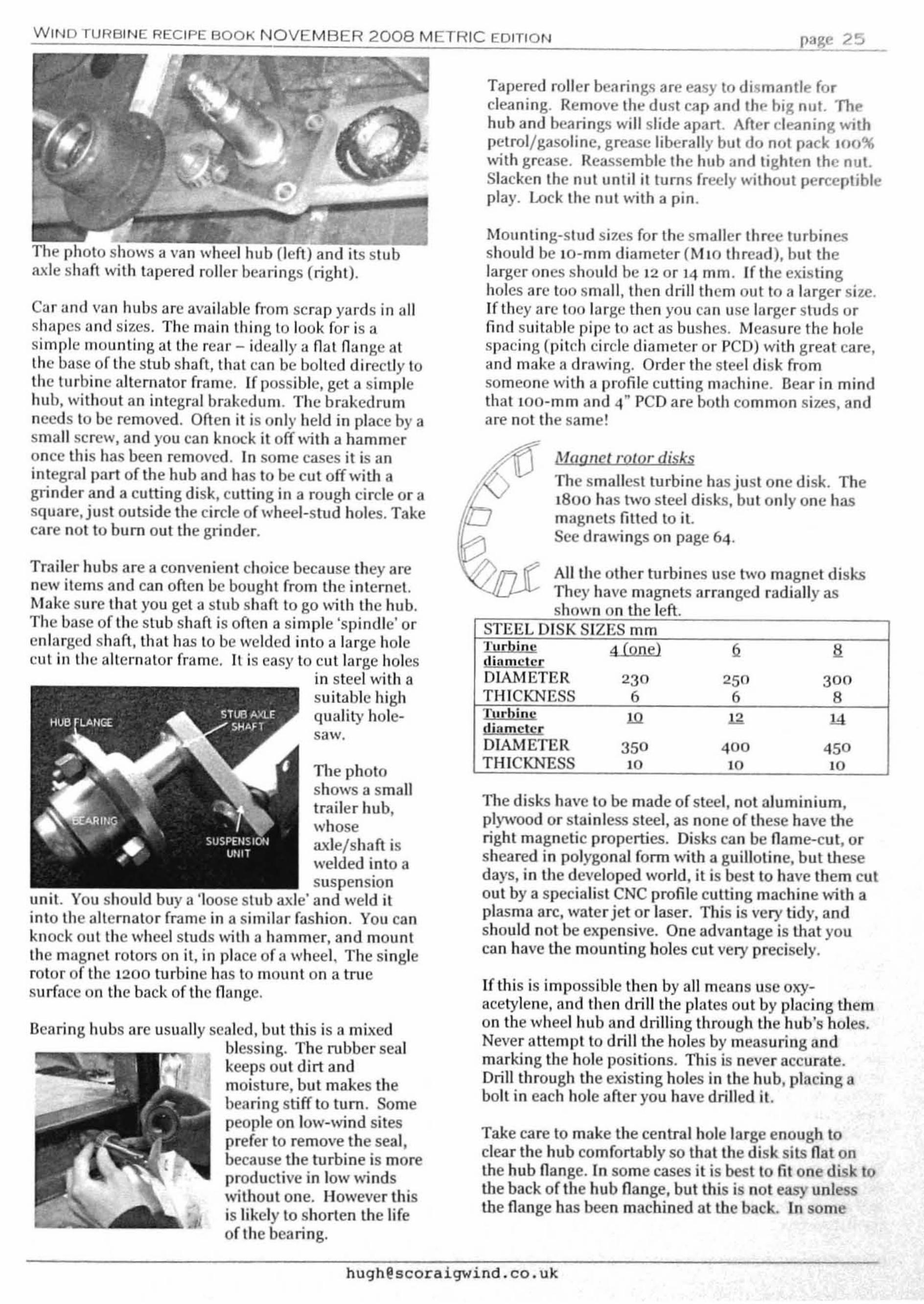
page 25
Mngnctl:J1lor disksThe smallest turbine has just one disk. The1800 has two steel disks. but only one hasmagnets fitted to it.See dra",..ings on page 64.
All the other turbines use two magnet disksThey have magnets arranged radially asshown on the left
Tapered roller bearing.co are easy to dismantle forcleaning. Remove the dust cap and the hig nut. Thehub and bearings will slide apart. Aftereleaning withpetrol/gasoline, grease liberally but do not pack 100%with grease. Reassemble the hub and tighten the nut.Slacken the nut until ittums freely without perceptibleplay. Lock the nut \"'th a pin.
Mounting-stud sizcs for the smaJler three turbinesshould be ID-mm diameter (M 10 thread), but theJargerones should be 12 or 14 mm. If the existingholes arc too small, then drill them out to a larger size.If they arc too large then you can usc larger studs orfind suit~lble pipe to act as bushes. Measure the holespacing (pitch circle diameter or PCD) with great care,and make a drawing. Order the steel disk fromsomeone with a profile cutting machine. Bear in mindthat lOO-mm and 4" PCD are both common Si7.eS, andare not the same!
If this is impossible then by all means use oxyacetylene, and then drill the plates out by placing themon the wheel hub and drilling through the hub's holes.Never attempt to drill the hole by measuring andmarking the hole positions. This is never accurate.Drill through the existing holes in the hub, placing abolt in each hole after you have drilled it.
The disks have to be made of steel, not aJuminium,pl)'\I/Qod or stainless steel, as none of these have Uleright magnetic properties. Disks can be name-cut. orsheared in polygonal form with a guillotine, but thesedays, in the developed world, it is best la have them cutout by a specialist CNC profile cutting machine with aplasma arc. water jet or laser. This is very tidy. andshould not be expensive. One advantage is Ulat youcan have the mounting holes cut very precisely.
Take care to make the central hole large enough toclear the hub comfortably so that the disk sits nat onthe hub nange. In some cases it is best to fit one disk 10ti,e back of the hub nange, bUllhis is not easy uolessthe flange has been machined at the back. In some
•
STEEL DISK SIZES mmTurbine ~ 2 acHarnel£[DIAMETER 230 250 300THICKNESS 6 6 8~ ill ~ 1.<1sliamcl£rDIAMETER 350 400 450THICKNESS 10 10 10
WIND TURBINE RECIPE BOOK NOVEMBER 2008 METRIC EDITION
Trailer hubs are a convenient choice because they arcnew items and can often be bought (Tom the intcrnel.Make sure that you get a stub shaft to go with the hub.The base of the stub shaft is often a simple 'spindle' orenlarged shaft, that has to be welded into a large holecut in the alternator frame. It is easy to cut large holes
in steel with asuitable highquality holesaw,
Bearing hubs are usually scaled, but this is a mixedblessing. The rubber sealkeeps out dirt andmoisture, but makes thebearing stiff to turn. Somepeople on low-wind sitesprefer to remove the seal,because the turbine is moreproductive in low windswithout one. I-Iowever thisis likely to shorten the lifeof the bearing.
Car and Viln hubs are available from scrap yards in allshapes and sizes. The main thing la look for is asimflle mounting allhe re'lf - ideally anal nange aLthe base of the stub shaft, that can be bolted directly tothe turbine alternator frame. Ifpossiblc, get a simplehub, without an integral brakcdum. The brakedrumneeds to be removed. Often it is only held in place by asmall screw, and you can knock it off with a hammeronce this has been removed. In some cases it is anintegral part of the hub and has to be cut off witl' agrinder and a cutting disk, cutting in a rough circle or asquare, just outside the circle of wheel-stud holes. Takecare not to bum out the grinder.
The photo shows a van wheel hub (left) and its stubaxle shaft with tapered roller bearings (right).
TI,e photoshows a smalltrailer hub,,,'hoseaxle/shaft iswelded into a
•suspensionunit. You should buy a 'loose stub axle' and weld itinto the alternator frame in a similar fashion. YOll canknock Ollt the wheel studs \"'th a hammer, and mountthe magnet rotors on it, in place of 3 wheel, The singlerotor of the 1200 turbine has to mount on a truesurface on the back of the flange.

A WINO TURBINE RECIPE BOOK· THE AXIAL FLUX ALTERNATOR WINDMILL PLANS-
as the hub ils If nnbe: rt'\-crscd on its haft,butthi hasirnplict'ltion for sealsand dust covers.
Drill and tap one of thedi ks in three places sothat you can usejacldng screws. Seepages 45 and 48 formore 8 sembly details.
J '\ ~
-
_STATOR
'-._ MAGNETROTOR
You should tl)' 10 keep the magnet rotors close 10 thefr:lme so as to keep the statal" mounts short, and thiscnn :lffcct how far forward you mount the shanSometimes it's belter to pass the shan through the fl~lt
surface, and to bolt the flange on from behind.
If Ihe shaft has a spindle ralher than a flange then ),OU
can make a big hole into the same flat sluface using ahole saw and weld in the spindle. Or ifyou have nosaw, ),ou can grind out two semicircular hollows in thetwo pieces of angle (B and C below) prior to weldingthem together.
A
.,-- B,C---'
WELDING SETUP FOR SHAFT
X is the distance of Ute shaft centre from the uprightpiece.
Cut the 4 pieces A, B, C and D. Weld Band C logetherin a c1lannel. A and D go on Ihe ends. Take care 10make U,e T square and s)'lllmetrical. The slalormounting faces must be in the same plane. Lay theframe face down on Ihe bench while welding
IlIlhe case of the 3000 diameter lurbine the hub mightbe larger, so )'OU ma), have 10 spread Band C apartinstead.
FRAME DIMENSIONS INCHES- 50 X 50 X 6 ANGLE'n Ila 1800 2 00 000
Len thofu ri hlA 319 353 411Channel ieces B,C 187 216 267End bracket D 100 100 100-130Position of shaft X SS 65 82
The ,8003000 turbinesuse a T shapedframe for 3slalor mounts.Their statorshave 9 coils, andhence3mountingpoints.
1\'1ake sure that the stub shaft is central in thealternator frame and mounted exactly square to it. Usespacers to keep the spindle square to the frame whiletack welding. The spacers should be chosen to allowclearance for any magnet rotor and nuts behind thehub fl:mge.
Start with threesmall lacks,bearing in mindthat sleelcontracts as itcools. If it is notlacked onsquare, thengrind off thetacks and tryagain.
...L.jOS1,;AFT
STATOR"'OUNTlNGS
STUOS
HUB
MAGNET_ROTOR.
STATOR
ALTERNATOR FOR SMALLEST TURBINE
Frames for all theother turbines oremade from anglesection steel, in aTorBn Hshape,dependingon thenumber ofslatormountingpoints.
If the shaft has aflange, then you canbolt this flange ontothe flat surface.
The stalormountsare tbeshortstuds withnuts in thedrd\ving. The rolorsand blades willmount on the longerstuds in the hub. Twopieces of sleel anglemake a channelsection with :l flatsurface in themiddle.
The altemator frame supports Ihe slub shaft thatcarries the hub. 11 also supports the stalor. The framein turn is upported by the yaw bearing. The centre ofthe llhe-rnatar needs to be offset sideways from thecentre of the yn\\' bearing (} as to make the turbineyaw away from the wind (under the control of thefurling tail d cribed lalcr).
The fTame of thesmaJlest turbine issimply a smallbackplate, becauseth slator mountsare at the centre.

-,W-,-,'N;.:O,--T_U-,R_B_'_N_E,--R_E_C_'_P;.:E;.:B;.:O,--O=-K-,-,N;.:O=-V,-E=M;.:B=-E=-R-.:...::2:.:0:.:0:.:8::..cM.::ET::..:..R=IC:...::E=.O;.:'T.::'O=.N'-'- e:!.& 27
The largerturbines with l2coils have 4 statormounls and theframe is Hshaped. Thechannel (ormedby tJle two piecesof angle has to bewide enough laencompass thehub, which oftenmeans that a gapappears betweenthe two pieces ofangle as in thedrawing below.
G0 0
,
H
,0 0
•
Hole InstetI
frame forwires
throughv.w
bQnng
'nte alternator frame is either tilted slightly (4 deg...",.)or cantilevered forward (or both) so as to achieveample clearance between the blade tips and Ihe tower.On turbulent sites it is not uncommon for gyroscopicforces to push the blade tips back toward the lowerduring sudden yaw movements.
The alternator frame must be strongly welded to theyaw bearing. The shaft centre must be offset to oneside to suit the furling system.
OFFSET DISTANCE LATERALLY FROMALTERNATOR CENTRE TO YAW CENTRE IN mmD!d.tinc dioOlClC[ 12.0..0. J.8.D..aOFFSET 60 '00. . = 3Wlll ;J.4ll.Q
OFFSET 1 0 200 2 0
1200 machineThe (rame o(thesmallest machineis vcI')' simpl,>, alength of steelangle (50 x 50 x 6mm) thatsu pports thealternatorbackplane at oneend, ~llld the tailhinge 3tthe other.
Overnlllength is206mm. Thealternator end iscut off al approx30 degree angle asshown on Ule nc.;d page (30 mm off S(IUare).
80 0280 ~o:e-------l
oX oX6ANCLE600 200
In the above view the shaft flange is fitted to the backof U,e I1 frame, and the shaft passes through the frame.This is a good way to keep the stator mounting studsshort where the shaft is long. Another trick is tomount Lhe rear magnet rotor on the back orthe hubflange. You can adjust the position ofthe magnetrotors relative to the frame in various other ways. forexample you can use nuts as spacers between theframe and the shaft flange or between Ute hub flangeand the magn t rotor. I like to run the back magnetrotor close to the steel (rame so as to keep the slalor1110unts as short as conveniently possible.
FRAME DIMENSIONS• " . .
CH

1 00 TOP VI W
The top pllllo u( Iho YIIW bOlll'in~, noed. 11 cl'nl,ul hole(0' w!l'lng, The pinto exlend heyond Ihe y"w pipe.Idowllysto c,'cllte 11 MOP 'I' belwoenthe plpo und Iheullo,nlllo, ('UIIIO, IInd (orwln'ds 11 dlslunco 'K', Tholowe' b,"ekol .hown on tho len o( tho skoteh hlls Iho801110 '(' dllllenslon bill 01.0 oxlend. 0 10l'Mel' dl.lunco'J' (O'OlIIlho pipo .0 0.10 kid' tho bollolll o( theolt 1'11010' (rulllO outwo"), Thl. c,elltoslhe 4 dc~,co
ollgl' bolwoolI tho oltornoto' oud th verHcul.
o
Al,TIlRNATOR VitAM!! TO YAW TUDE S ZIlS 111111
=,1800 2400 3000
2~ow lubo 40 3319 24 32
,J 37 45 53K 20 25 30
125
I
i
HUB
f 200
HAF
60TAILHINGE
.' .'1':.,9...·-·~~'I I t I '\. \ I,.. ', .....
~ ..
YAWPIPE
UNDER
RAMANGL
IRON
I
I
I
,K
"
J........."
I
Weld 0 qUGrtl toppial 0010 tho yow IlIbo(with 0 01'01 hole),R IIhl8 losldo Ihe.lccl ollgl , (You willoCl'd 10 I.•ko oil' OJ1YhArp corne' n''Ilt,)
Dolow III two lOll-view, o( lho YlllY·hellliog pipe, 10Il\ItI, CMU'. tI,o ve,t! OI"loco Ao(tloo olt rllolo,'. T·Ihlmo will ",.t naoln'llloo rollllded 01T eOl'OO' lit thelowt'r Ml oflbo drowlng,
....----~
,800 - ,1000 11I1'bllle.'1110.0 nil lollY" 'I'.Ioft\,l!d f'rum ., 'l'helip' Slol Io'M o( tloo T I.roollOl'l1ld to tI,· ynwbourtna oUler lubo UI.Ioown:
•• hU9hlacoraiqwind.co,uk

III'
WIN!) n~"n,,::,,~c 11"1: 130 1< NOV MS R 200 METRIC ,ClllON
:.,MI() 11//(1 (,:lO(J III1'!Ji1/c'.'i
UNC 11 plt·C'l.' of hCIlVy nlll NII'd hili' (100 X I() Illm} lu1;1,\'1)1' Illt'lup oflhc )'UW Iwul'il1H. IIncl CXllllld 1)111 ICI
SlIl'l'Orllhc I1 ('rlllne III I) 4fi dUK"cl' ullglullkc Ilai~:
Us'u secood piueo o(the .IIn1O bll" npl'ight bon'uth Itto stl((en it, Milk suro yon hllve the CO'Teet o((setbelween the ecnlre or th frllme nnd the ecntrQ o( Iheyow pipe, liS shown In this lop vi 'w, The 89mm pipe isunder Ihc n,'st pieco of nlllbllr hlltll. poslllollls shownwllh dllshod linos III this vlow,
I)
,I
Th 'photo shows how uJunetioo box (or wiring eun n,neully inside the angle (ormed by Lh IWO pieces of nalbnr',
Tho overhunging position o( Ihe olternntor (rome hips10 keep Lhe bludes c1eur o( Lhe tower und nlso hipswith (urllng In high winds, For u (urth 'I' (nctor o(su(oty ogulnsl tho bindcs slI'iklng the lower you ouldolso lilt Ihe (rome 4 dogrees o((ve.'tienlns below, Thelop eOnler of Ihe second piece nf bOl' will cover 7 mmmore o( Ihe uliel'l1utorfromc Ihon the bottom to get 4dogl'-'cs.
4degrees
-,
,
owo
•,
L
TOP VIEW OF FRAME
Th ' oxocl loog!'l. o( Lho 89mm yow plpo is oot erltic.!I,bill I rccolomolld nbollt 400-500 mm length, T11is Is ngood timo 10 think obood to the mounlinll uh
... tiner box on the lop of tho yaw beurloll ifyou need10 (for .2 volL bott ry systems), Sec P"llc 48 (or dOlaim.
,hughllcoroigwind,co,uk

page 30•
A WIND TURBINE RECIPE BOOK ·THE AXIAL FLUX ALTERNATOR WINDMILL PLANS-
Tllt" tail is.\ plywood vane bolted la steel flat bArs on asteel pipe. ',Vind pressure on the tail pushes itb~ J...··ward tlnd thcl'Cby makes lhe turbine face the"ind. pivoting on its yaw bearing. However the taildoes much more t.han simply push lhe turbine aroundto (TIce the wind. The tail also allows the turbine to furlOul of stronger winds and protect itself from overload.
TIle alternator frame is mounted onto the yaw bearingoff·cc.nlrc. in order to create a 'yawing moment' thattends 10 swivclthe turbine around sidewAys to thewind. The tail is deliberately angled a Uttle to theoPl)osite side in order to balance this tendency and tokeep the turbine facing squarely into the wind undermost conditions.
TOP VIEW OFWIND TURBINE
THE TAILYEILDS TO
ALLOW THIS3!DE-FURLlNG
TO TAKEPLACE
WIND BLOWSTURBINE AWAYTO THE SIDE(YAWS IT)
AlTERNATORIS OFFSET TOONE SlDE
I--./! TAll 1$ ANGLED
TO THE OTHERSlOE TOBALANCE THAT
When the machine is furling. the blades continue tohim and produce power, but if rated power is exceededthe hlrbine will furl, that is to say it will yaw away fromfacing the wind directly, so as to prevent overload.Ultimately the tail can swing into a position that isclose to paraHel to the blades, aHowing the blades toswing edge-on to the \vind direction and escape fromits violence.
Furling works well to limit the power and speed solong as the turbine is connected, but it will not preventa disconnected turbine from over-speeding.
TI,e inclined hingeThe tail is mounted on a very simple hinge, built fromtwo pipes in much the same way as the yaw bearing.The inner pipe of the tail hinge is attached to the outerpipe of tile yaw bearing at an angle of 20 degrees to thevertical. See pipe sizes in the table on the next page.
THE TAIL INTHE FULLYFURLEDPOSITION ISRAISED
As the wind gets stronger, the thrust force on theblades increases but so does the force on the tail, so thewind turbine keeps facing the wind squarely.
The tail has to have a large enough area to control theblades and overcome their tendency to turn away orthe turbine will never be able to face the wind. This isa separate consideration from the furling design. Forcorrect furling, what matters is the weight of the tailand its length. By making the tail heavier you candelay the furling and drive the turbine harder instronger winds. A turbine with a light tail will furlsooner and have an easier life, but produce less.Neither will make any difference in low windshowever.
The tail is mounted on a hinge that allows it to swingaway from its nOnllal position when the wind exceedsa certain thrust force. At the chosen level of windthrust, the tail can no longer hold the turbine facingsquarely into the wind. It swings sideways and slightlyupward. allowing the turbine to face away from thewind. As the turbine swings to tile side, the windthrust is diminished, and so tile furling motion of thetail stops, and an equilibrium is established that limitsthe thrust force of the wind on the machine.

.:.W.:.::.'N~D~T:::.U-"R:::.B:::'N=E..:.R:::.E:.:C:.:'..:.P:::.E..:.B:.:O::.O=.:..:K..:.N..:.O:::...:.V..:.E:::M=B:.:E:::R..:...:.2:::0::.0=8...:M=ET:..:..:.R:::.,.::C:...E=-D=.:..:In.::O=.:..:N --'e:'ge 3 I
-
PlANE Of AtTERNATORFAAME IS SS CEGRff5FROM nE HORIZQlTAl
I
YAW BEARING IS HORIZONTAl "'-
TAlL HINGE IS .t.8CN£ VAW
-
TAIL HINGE IS20 DEGREESOfl'VERTICAL
,,
,, 'J-=..' ".,:,....~ -.... ~":'....t ij ~ •<f -'j I'~ ",'-.....
''1T,;1 I /W - I
'--..-/ -- ....._.---- -:-",~~
600
20088.
.00_lUfGrH "
- ,
-i
\ \\
HtHG£ OUI£fillfNGlW C \
\
I. !--, t •[
I\lr t::::
."'"Ol,OIETIR !l
Turhine digmelc.r
OI......'ETER r
800M LENGTH A ~~~7--+-~:'--t-~:'--jDiameter BHINGE OlITER CDiameter DHINGE INNER EDiameter F
Turhine diameter 1
BOOM LENGTH A 800
Diameter B ""-_f--",,,,8,,,.'--t-"-:-~--iHlNGE OlITER C tOO
Diameter D -=,--+_6"07.~-t--==''-IHINGE INNER E 200Diameter F ",8.:.1---'_ ='--'
HIHQ: u.!oVtlENGTH
\OIAMETt.R o-t"'\
STEEL PlfE DIMENSIONS FOR TAIL mm
Thil bOQmTAIL 800M DIMENSIONS
Weld the inner pipe of the hinge (E) onto the raw pipesecurely because it has been a common weak point,especially with beginners' welding and when the bladesare out ofbal3J1Ce and the tail starts to bounce about.Start by welding a cross piece of 30-mm flat bar to theinner pipe of the hinge. positioned 85 mm from theend so as to gh'c lhe desired 20 degree tilt.
The hinge is not fixed tothe downwind (back) sideof the raw bearing, butabout mid-way betweenthe back and the side. (55degrees off downwind.)
Then weld this inner pipe to the yaw bearing outerpipe near its bottom, and finally add two cheek pieces.
The axis of onepipe is directlyabove the a.xis ofthe other one.
A good way to set it up forwelding is to prop theframe of the machine upon the bench or the floor at55 degrees to thehorizontal. Then weld thetail hinge pipe onin a vertical planeabove the yawbearing pipe.judging this by eyeifrou like.

A WIND TURBINE RECIPE BOOK ·THE AXIAL FLUX ALTERNATOR WINDMILL PLANS-
11,. onter pipe of the hinge (the moving part Cl needso cap ofsleel plate on top that can rest on the top of thelnner pipe.. and also to keep rain out of the bearing sotll grease does not wash onl. Weld a piece of plate onthere tllking care not to spread slag into the insidewhere it can foul up the smooth motion of the hinge.
~The tail should only move through about 100 degreesof swing. You will need to create stops that li mit therange of movement.
The larger turbines require stops to be welded on tothe hinge outer that prevent the tail swinging toofar down, and a stop between the boom and the yawpipe to prevent it swinging too far up into the blade, Itis easiest to fit and adjust all of these stops byassembling the turbine with the tail at the correct angleas shmvu on the next a e.
,Notch in pipe
to restrictrange of swing
The notch drops over ti,e edge ofthe steel angle that supports thehinge inner pipe.
The Tail for the smallest turbine
The smallest turbine's tail can be dealt with by cuttinga notch in the outer pipe of the tail hinge.
A
f
-
G
I ,_
J ,
Tail vane and brackets
,
You can make the tail vane anyshape you like the look of solong as it is roughly the overallsize specified in the table, If thearea is too sman then the vanewill not be able to hold theblades to face the wind in lowwinds, The weight of the tailcontrols the way the turbinebehaves in stronger winds too,so I suggest that you use thesizes listed below,
Some people like to make Quite complex shapes, butyou must bear in mind that the wind turbine is seen asa whole and the shape must work together with theblades to produce a coherent aesthetic design.
Weld the end of tile boom to the hinge onter at anangle of 0 degrees. A few ex'1:ra gussets wil1 bringpeace of l11ind~ as this is a highly stressed connection,especially for blade diameters above 3 metres. In thecase of the 1800 turbine you can just flatten the end ofthe boom 0 bit and cnt it at a 70 degree angle. but thelarger turbines have long tans that put quite a strain onthe 48 mm pipe, Shape the boom end to fit the hingepipe neatly, and add some triangular bracing pieces toreinforce the join.
I
Turbine diameter 1200 1800 2400 3000 3600 4200
Tail vane area G X H 20x50 cm 400x100cm 50x120 cm 70x130 cm 70x 170cm 90x 200cmthickness of plywood 6mm 6mm 6mm 9mm 6mm 9mmFlat bar section mm B x 30 8 x30 B x 30 B x 30 6x50 6 x 50
Length of each One at Two at Two at Two at Two at Two atftatbar lug 20 cm 30 cm 30cm 40 cm 50 cm 60cm

WIND TURBINE RECIPE BOOK NOVEMBER 2008 METRIC EDITION page 33
The high end stop
Weld a piece of flat steel bar to the side of the boom soas to prevent the tail from swinging too close to theblades.
10 degree angle
The low end stop
This determines where the tail will normally sit.Restrain the tail in a position where it makes an angleof 110 degrees approximately to the back of thealternator frame and tack weld a piece of flat bar ontothe tail hinge outer pipe. The end of this flat bar mustrest against the yaw bearing outer pipe in such a waythat the tail cannot swing further down than this lowend position. Remove the tail and weld the stop onsecurely.HIGH END STOP
WELDED TO TAILCOMES AGAINSTTHEYAWPIPE
\
'\
TAIL FULLY FURLED
-110 degrees
(It's good to weld a little'safet)' catch' to the yaw pipeabove this point of contact soas to prevent that tail fromslipping upward and off itshinge when in this full)'furled position. This isespecially hand)' when youare using the tail to support alarge turbine while fitting theblades before erecting thetower.
The high end stop is a piece of flat steel bar welded tothe side of the tail pipe. Wl,en the tail is fully furled,the bar contacts the yaw pipe, and prevents the tailfrom swinging too close to the blades.
LOW END STOP

A WIND TURBINE RECIPE BOOK· THE AXIAL FLUX ALTERNATOR WINDMILL PLANS-
lleclrlcs
The slator is then mounted between the magnet rotors,so that the magnetic flux from each magnet passesthrough the centre of each coil in turn.
The magnets are first glued to the surface of a steeldisk and then cast in resin and glass fibre as well, so asto protect them from damage and hold them fromfl)'ing off the rotor.
Voltage alone is not the same as power. If there is noexternal circuit connected to the coils, or if the voltageis too low for battery charging, the magnet rotors spinfreely, because no energy is being converted. Underthese conditions the blades can become noisy due torunning faster than they are designed to run.When a circuit is connected then current in the coilscreates magnetic forces that interact with the magnetsto oppose the motion of the blades.
Power is the rate at which energy is produced. Theelectrical output of the turbine will depend mainly onthe strength of the wind and the size of the blades. Theblades produce mechanical energy that is converted toelectricity by the alternator. A powerful alternator willnot help ifthere is not enough mechanical power.
Current manifests itself as torque (resistance toturning). Voltage is proportional to speed. Voltagecombined with current amounts to electrical energybeing produced. Speed combined Vo."ith torque are theingredients of the mechanical power you need to put in(using the blades) so as to get electrical power out. Inboth cases, power is measured in watts, and ifsustained it will deliver energy in Watt-hours orkilowatt-hours.
Ifyou connect the output wires together in a 'shortcircuit' then there Vo."iH be a high current that producesa large torque that slows the blades dramaticall)'.Short circuiting the stator like this can be useful for'braking' the turbine. The very high torque will usuallystall the blades and kill their speed, bringing themdown to a very slow and feeble mode of operation thatis ideal when you are raising and lowering the tower oreven for parking the turbine if the battery is fulI.
Some energy is lost in the conversion process, due tothe electrical resistance of the wires in the coils, andthis lost energy also heats the coils. In low winds thereis very little energy loss in the alternator. In higherwinds the larger currents will ultimately burn the coilsout unless the turbine furls and protects itself. Thestatal' is very exposed to the wind and is cooled by it,enabling it to survive higher power conversion than itcould if it were confined in an enclosure.
'- -
I- -f- ~
~ '-
The stator is the name for theassembly of coils. Here is aphoto of a coil. It is made b)'winding turns of enamelledcopper wire. The coils areconnected together and thenplaced in a mould and cast inpolyester or vinyl ester resin.
Encrgj,l COnltersiQll
TIle alternator is very simple. Themagnets are mounted on steel disks(01agn t rotors) that tum with the bladeson the same hub. In most cases there aretwo magnet rotors. The magnets arearranged facing each other. There is aslTOng magnetic flux in the space beh-....eenthem. The poles of the magnets are theirlargest faces. The steel disks behind themcomplete the magnetic 'circuit' betweenthe back poles of the magnets.
An)' change in the magnetic flux passing through a coilwill induce a voltage in that coil. More rapidmovement, or stronger flux induces a higher voltage ineach turn of each coil. These three factors detenninethe voltage produced b)' the coil as a whole:
• rpm,• flux, and• the Dumber of coil turns.
At low rpm, the coils wiII produce a low voltage. Whenthe turbine reaches a certain 'cut-in' speed, the voltagebecomes high enough to charge a battery. Onl)' whenthe speed is above cut-in can the stator feed currentinto tbe batte,y. Below that speed the blades spinfreely without any restraining torque. The same is trueif the battery becomes disconnected.
Choosing wire size and number Qiturns Q&r coilThe number of turns per coil aDd the wire size havebeen carefully chosen so as to make the coils fit exactlyinto the stator. The number oftums controls thevoltage produced at the desired cut in rpm. A 12-voltalternator needs only about half as many turns percoils as a 24-vo1t one working Vo."ith the same blades (atthe same rotational speed).
If the number of tums is too small for the chosenbattery, then the blades will overspeed while tl)<ing toreach the cut in rpm. If the number of turns is toomany then the alternator Vo."ill start to charge thebattery at a very low speed, and will exert too muchtorque, preventing the blades from reaching their best

The altemators in this bookare all 'three-phase'. Thestators contain three groupsof coils that produce thesame voltage but at differenttimes. 3 phase stators makebetter use of the spacebetween the magnets, andalso deliver a smootheroUlput.
~ iL--------'...-----'-=-----,~
Three-phasesr~
Each coil will produce an 'alternating' (AC) voltage asthe alternating magnet poles pass over it (north, south,north, south, etc). A graph of how this voltage variesover time looks like this (sine wave):
WIND TURBINE RECIPE BOOK NOVEMBER 2008 METRIC EDITION page 35
speed. This can lead to stalling of the blades and hence voltages implies a very small number of turns of veryvery little power. So it is important to have the correct thick wires in each coil that can become clumsy tonumber of turns to suit the chosen blade size and handle. With parallel connection onc can use thinnerbattery voltage. More on page 54· wire. And the problem of parasitic cUlTents can be
dealt with by a special rectifier on board the windturbine (see '12-volt stators' below).
In some cases for 12 volts. the stator's coilswill be connected in parallel rather than inseries so as to reduce the wire size neededin the coils (see '12-volt stators' below).
Very thick wires are clumsy to handle, so beyond acertain point it makes more sense to wind the coilswith several wires 'in hand' instead ofjust one. lfyouare winding with two wires in hand then you will needto have the wire on two reels, and feed ,.-- ~
them both inlo the coil winder at once.Two thinner wires make less of a lump inthe finished stator as they cross over thecoils coming out of the middle.
The wire sizes given here are the thickest wire that youcan easily fit into the coil with the chosen number ofturns. Thicker \vires gets less hot when carryingcurrent, and wastes less power. A 12-voll alternatorwill need to handle twice as much current as a 24-voltone (for the same power) but because the wires in thecoils are shorter and thicker the heating of the coils isjust the same. (The wires from the turbine to thebattery will also need to be much thicker to preventexcessive loss, and here you do need more copper for12 than for 24-vo1t systems because they have to gojust as faL)
SIgtQr wiring connectionsEach coil will produce a voltage. but tl,e voltage of thewhole stator depends on how the coils are connectedtogether. There are various options for connectingthings together
ANlS><ANlS><AI'IISH
I
r;tI[ Ill.'
FINISH FINISH ANISH
(There is another scheme called 'delta' but I prefer toavoid this because again it allO\ys parasitic currentsin the coils.)
In star connection, all three starts are connectedtogether as shown above. The output wires are thethree finishes. In most cases the best connectionscheme is series/star. An example with six coils isshown below:
The besl scheme forconnecting thethree-phase coilstogether is called
'star' (also knownas 'wye')connection.
START ANISH
SERIES CONNECTIONSTART ANISH
PARAllEL CONNECTION
START FINI HIn parallel connection, both ofthe starts are connectedtogether and so are both of thefinishes. The resulting voltageis the same as one coil, but bysharing they can carry twicethe current.
A coil has two ends: the startand the finish. Coils can beconnected together in series orin parallel as shown below. Inseries, the finish of one coilconnects to the start of thenext. The voltages of the coilsadd together to produce adouble voltage between startand finish of the pair.
Jprefer to connect coils in series. There is a problemwith using parallel connections in a hand-madealternator. Inevitably the oUlput voltage from each coilwill be slightly different. These differences lead toparasitic currents benyeen the coils that waste power.But series connections benveen coil for low battery
Coils 1 and 4 are in the same phase. so they are seriesconnected. The other two phase groups are 2&5, 3&6.For larger alternators there may be three or four coilsin each phase, for a total of nine or twelve coils in thestator.

page 36 A WIND TURBINE RECIPE BOOK - THE AXIAL FLUX ALTERNATOR WINDMILL PLANS-
prevents the battery (rom discharginginto the stalor.
·n,. CQils
Use enamelled copper wire to wind thecoils. This is often called 'magnet wire' or'winding wire', Grade 2 (which is goodfor up to 200 degrees C) is ideal, butlower grade is probably adequate. Theclear enamel coating on the wire insulatesit from its neighbours in the coil.
The table below suggests wire sizes and numbers ofturns for a variety of battery voltages and turbine sizes.In some cases J recommend two wires in hand(marked 2@... ) to avoid clumsy wire sizes, but feel freeto use a single wire hvice the weight and likewise feelfree to substitute hvo wires of half the weight for oU,ercases, ifyou wish to. Thick \\1 res make a lump as theycross over the coil and this makes the stator thicker.
The price of copper is rather high at the time ofwriting, but U,e best deals can be got by buying about20 kg in a reel. In Europe the 'vire is specified by itsouter diameter of copper (unlike electrical wiringwhich is listed by cross-sectional area of copper in sqmm). In the USA and some other countries the wire issized by American wire gauge (AWG). Adding 3to anyAWG size reduces the weight of the wire to one half.Multiplying a metric size by 0.71 reduces its weight byhalf. (see tables on page 56)
d1scharglngcharging~
I
• • •!charge
atter) loadIsource
DCPOSITIVE
•DC
NEGATIVE..
To produce a DC output (direct current which does notalternate) for charging a battery you have to connectthe three AC phases to a 'bridge rectifier'.
Batteries are chemicaldevices that store energy.There is a vohage betweenthe terminals but it is prettysteady, not alternating likethe voltage hetween the endsof a coil. To charge a batterywiUl energy yOll have to forcea current of electric charge to pass into the positiveterminal of the battery and out of the negative. As thebattery discharges, this energy is used, forcing currentout of the positive terminal and through any loads thatyou choose to connect across its tenninals. In bothcases these DC currents return to their source becausethere can be no current vvithout a complete circuit. losome cases the wind turbine can feed current directlythrough the loads, and the battery will not even have toparticipate. But usually there will be a mismatchbetween the supply and the demand that isaccommodated by the battery.
A 3-PHASEBRIDGE
RECTIFIER
1I r1
12-uoIW!llors marke<eIn most cases rhave marked the 12 volt stators with anasterisk· denoting that these stators are not seriesconoected like the others.
SPECIAL RECTIFIERFOR 12-VOLT STATORS
..
Turbine diamele!: 1200 1800 2400 3000 3600 4200Weiaht of wire 1.5~ 2.6~ 3~ 5~ 5~ 7~12-V diam(mml 1.4 1.4 1.7 1.8 1.7 1.7Turns Der coil 76 130* 73* 90* 80* 100*24-V diam(mm) 1.06 1.5 [email protected] [email protected] [email protected] [email protected] oer coil 140 110 45 55 37 4548-V diamlmml 0.75 1.06 1.5 1.6 1.8 1.8Turns Der coil 270 220 90 110 75 90
WINDY BOY INVERTERS WINDY BOY 0.85 0.9 .95140 - 350V INPUT (for grid) Turns per coil 400 300 250
The little arrow symbols in the diagram representdiodes - devices that only allow current io thedirection of the arrow. The bridge nehvork of diodesensures that current can only go one way in the DCcircuit. The bridge converts AC into DC and also
For 12 volts series connected the wires become veryclumsy. I therefore propose a parallel connection for
these stators.To avoidparasiticcurrents, Jrecommendthat you usea separatepair ofdiodes foreach coil.This meansplacing therectifier onthe windturbine.

WIND TURBINE RECIPE BOOK NOVEMBER 2008 METRIC EDITION
There are many pros and cons la this arrangement, butoverall it works best for 12 volt systems. 12-voll wiringneeds to be very heavy to reduce the losses of powerinherent in the high currents required. Using two DCwires is more efficient than three AC wires. It is 110thard la cool a rectifier up there in the wind. BUllhcrectifier on the turbine is harder to inspect and repairif necessa.)'. See also page 48 for how 10 mount this.
The short-circuit brake is also morc complex, becauseyou have to disconnect the batte.)· before you connectthe two wires to each other (see clo switch in diagramon page 36).
Mokiua..t1l~coil wine/1lI:
yage 37
because you will useit to drill throughtwo layers ofplywood.
The simplest way tomark U,e holepatlern accurately isto work near thecorner of a sheet of plywood. Use a square riding onthe edges of the plywood to draw pnrallellies. Keepinga distance of about 70 mm from each edge. draw twoparallel lines 40 mm apart in one direction, and thentwo lines 24 mm apart at right llngles to the first two.making an accurate rectangle. Your hole centres for thepins will be at the four corners where the lines meet.
J
1
40
..
....,.
0-
".
I
10•
I
" 0I -
.-0 0L~J
You will also need to make aspacer that keeps the two cheekpieces the correct distance apart.This should be 13 mm thick (9.5mm for the 1200 turbine). Youcan adjust the thickness if thefirst coil altempt does nol fil thestator. It needs to have a 10 mm diameter hole at theexact centre. The shape is not too critical butrectangular 30 x 40 mm with corners cut to At belweenthe pins is ideal.
Make deep V notches as shown. Cut these throughboth disks. They need to bottom out between the Ilinsso that you can reed a tie-wire or a cable tie under U'eturns of the coil.
Cut out the two circles with ajigsaw. Place the markeddisk on top of the other and centre them. Using a drillpress, make the five holes neat and square, Uuoughboth disks. Make sure therc is some waste woodunderneath so that thc drill does not burst out at theback. Mark the disks so that the)· can bc reassembledin the same way in future. This will milke it easier to fitthe I'ins and to ensure that UleY are parallel.
30 ..,
Next draw diagonals to find the centre. Carefullypunch this centre and each of the corners with a centrepunch. Draw the overall circle (radius about 60 mm)on the centre point. Draw another identical circle forthe other disk next to it. Only one disk needs to bemarked with hole positions.
Start each hole by lifting the plywood so as 10 fit the tipof the drill into apunched hole, thenbring the drill down sothe disks lie flat on thelable and drill through.Slart by drillingdiagonally oppositecorners, inserting a pinin each so as to preventthe disks from movingr lative to each otherbefore the next hole isdrilled.
PIPEHANDLE
TEEPIPE
5T'A"ND MADE FROM STEEL ANGLE
r~OTCHES
yCHEEK PIECES
":j.:::: PINS-
COIL WINDER
The coil winder is the same for any of the windturbines.
Feel free to modify the details of the design. If youthink ahead then the same uprighl piece of pipe canalso be used as a stand for assembling the turbine onlater. Make sure the pipe is long enough that theblades do not hit the floor.
You need two 'cheek pieces' to contain the coil. Theyshould be made from 120-mm diameter pieces of 13mm plywood. (These are rough sizes.) Before cuttinganything out, precisely mark out U,e holes for U,e pinsthat the coil is actually wound on. There are four pins.each 6 mm diameter so you need to drill four holesthrough both disks at Ule four corners of the coil. Theopen space in the middle of the coil should be 46 x 30mm, the same as the face of a magnet block. The holesshould therefore be spaced at the corners of a 24 x 40mm rectangle so that the overall size is correct. Thisrectangular pattern only ha to be marked out once
The shaft is made of 10-mm threllded rod, bent into acrank shape, and filted with a handle made of pipe.Use pairs of nuts tightened securely against each otherto position the handle and also to retain the shaft in ahole through a piece of 48-mm pipe in which it rotates.This supporting pipe is usually welded to a piece ofsteel angle that you can screw to the edge of theworkbench.

A WIND TURBINE RECIPE BOOK -THE AXIAL FLUX ALTERNATOR WINDMILL PLANS-
RAg~UY\s--- ISlAND
COIL \SPACE
I like to weigh each coil so as to check that they areconsistent (+/- 596 say). A heavier coil may indicate amistake with counting turns or it may simply be moreloosely wound, but if one coil is radically different fromthe others then J prefer to reject it.
Both tails should come out in the same direction asshown. When the first coil has been wound you shouldcheck its size to make sure that it fits the stator. Forexample if there are 12 coils they must fit within a 30degree segment (9 coils each fit within 40 degrees, 6coils each fit 60 degrees). And the outer edge of thehole must match the outer edge of the magnet disk. Ifit looks fine, then carry on and wind more coils.
Conneclin!l. the coilsIn most cases, the coils in the stator will be connectedseries/star. See ne>.1' page for an example wiringdiagram using 9 coils.
The count of turns does not have to be perfect, but tryto be accurate. When you have reached the correctnumber of turns, do not release the tension in the wire.First tie the coil up tightly with a short length of wirepassed under the coil at the base of the V slot and thentwisted together tightly around it. Cut the windingwire off leaving a 200 mm long tail at the 'finish'.Bend this tail over so it cannot sUp through the tiewire. Remove the four pins and the front cheek so thatthe coil is released from the winder. Handle it withcare to maintain its shape, and tape it together with athin layer of electrical insulation tape on the two longlegs as shown in the photo:
If the coil is well formed but does not fit the stator,then you may have to try again using a thicker spaceror making the central hole smaller, but this is veryunlikely to be necessary if the coils are wound withcare. If the coil is too small, ulen try winding \'vith lesstension or use a thinner spacer so as to get theoptimum overall size.
the rear cheek piece. Then start a second l:lyerworking back toward the front again. Do not allow thewires to zigzag in a random fashion, as this wastesspace. You need to make coils that will fit into Ulestator.
Start winding the handle and keep count of the turns.Make sure that the turns build up in an even layer, onewire snugly next to the other, until you have reached
WINDING ACOIL
Do not manipulate the wire unnecessarily. Ideally itshould be free of kinks and bends. But do make asharp 90 degree bend about 200 mm from the end andfit this into the V notch so that the tail comes outbeside the heads of tile pins. Press the wire against theouter cheek and wrap the tail of wire loosely aroundthe tail of the threaded rod.
From now on you need to keep hold of the wire(s) withone hand and the bandle of the winder with the otherhand. Keep a gentle tension in the wire(s). If yourelease the wire then tlle coil may lose its shape and beimpossible to salvage.
Windi09JIJe CQil~
Place the reel(s) of wire on the floor beneath thewinder. If it is a large (20kg) reel then it is best toplace the side of the reel flat on the floor, so that thewire pulls off the other side. If it is a small reel then itmay be better to slide the reel onto an axle so that thereel unrolls as the wire is used.
Put on U,e front cheek piece and clamp the assemblytogether with a nut and washer. Make sure ule cheeksarc assembled in the original orientation, using yourmarks. Fit the fOUf pins into their holes. Tighten thenut securely so that they cannot spin on the rod.
semble the threaded crank shaft into its supportingstand and lock the nuts to each other so that there is50-60 mm of bare rod projecting. Place a big washer,one check piece and then the spacer onto the shaft.They will stay on during the winding job. You maywish to glue the spacer onto the rear cheek piece.Make sure that it does not bulge outside the spacedcJined by the four pins.

WIND TURBINE RECIPE BOOK NOVEMBER 2008 METRIC EDITION page 39
•~
The 12-volt windings markedwith a * in the table have noseries connections between coils.Instead the starts are allconnected to a ring of'neutral'wire that runs righl around thestalor and connects to nothingelse but the starts. The finishesare each connected to a tail offlexible insulated wire that isbrought out of the stator to arectifier box mounted on the top ofU,e yaw bearing. Ilike to cover these nine wires with a piece of flexibleconduit.
Finally test the continuity of the stator using themultimeter set on Q (Ohms). You should get the samelow reading between any pair of wire tails.
ThemQulds
The stator and the magnet rotors will be cast usingpolyester or vinyl ester resin that encapsulates the coilsand magnets. Start by making moulds to contain thisresin during the casting process.
Q.u.rput wirinnUse tails of flexible insulated wire for the output of anystator. Solder them to the three finishes (or more inthe case of 12-volt stators). They need to be morerobust than the \\findings wires because they will besubject to bending, vibration and abrasion of variouskinds. r like to use equipment 'hook-up' wiresometimes known as "tn-rated' wire.
3-phaseseries/star
stator
5
3
8
9
1
1,2,3 starts are ~~::~~;}~connectedtogether ,,~
Coils 1,4 and 7 make up one phase group. If a northpole is passi ng coil I then another north pole will bepassing coil 4 and another coil 7, so they are allexperiencing the same induced voltage at the sameinstant. These three coils are connected in senes. Thefinish of coil I connects to the stal1 of coil 4. the finishof coil 4 connects to the start of coil 7, and the finish ofcoil 7 is one of the 3 output wires.
Connect the other two phase groups (2, 5 and 8) and(3,6 and 9) in the same way. The starts of coils I, 2
and 3 connect to each other (at the 'neutral') and tonothing else. Coils 8 and 9 provide the other outputwires that are fed via long wires to the rectifier (near tothe battery),
•
,
•
STATOftMOULD
UD
BASE
LOCATIN
The stC!IQr mouldThis consists of a sandwich contained by a base and alid which are both just Oat pieces of plywood.
Make the moulds from plywood, MOF or similar sheetmaterial. Better quality plywood will give a neaterfinish. You \vill coat the moulds with some sort ofpolish or grease (Vaseline petroleum jelly is good)before adding the resin, but leave this until you havedone a 'dry run' to check that the coils or magnets fitcorrectly, together with the glass cloth that is used togive the casting strength.
ISLAND \,.-"+SHOULDTOUCHCOILS
The djagram shows the wiresspread out but in reality theyneed to form a neat bundle thatlies snugly against the outside ofthe coils.
You should lay the coils out .carefully in their correct positions and clamp them 10
place while making these connections. This makes iteasier to position them in the LAYING Ol1TTH~ COIL POsrnONSmould later. Draw around amagnet disk and align theoUler edges ofthe holes in thecoils with this circle. Thisexercise will also help you tofind the ideal size for the islandat the centre of the statormould.
If there are only six coils then the phases are (1&4)(2&5) and (3&6). If there are 12 coils then the phasesare (1,4.7 and 10) etc. Connections between most ofthe coils are very simple: connect the finish to the startof the third coil on (skipping two). Bypass two coilsand connect to the third one. Often a good position forthe actual solder join is between the two coils you arebypassing. See the section on tools for advice aboutsoldering.

1>',&c 40 A WINO TURBINE RECIPE BOOK· THE AXIAL FLUX ALTERNATOR WINDMILL PLANS-
3600 and 4200 stators. As usual the smallest turbinewill be different, with mounting studs set into thecentral part of the stalor. See next page for a diagramof the 1200.
At each mounting point, draw a circle with radius 25mm. Place a ruler so that it just touches both the smallcircle and the big circle, and draw lines (called'tangents') to outline the outer shape of the statorcasting. Do not cut along this line just yet.
The diagram above shows three mounting holes. Theycan be laid out using llle compasses to walk aroundthe larger circle and choosing every second mark. (Seepage 11 for more.) In the case of the larger turbines themounting holes will be where the diagonal lines hit tbecircle. Blit in all cases do check that they are equallyspaced apart.
The sketch shows the coils inposition in the mould, touchingthe island. When louching ittheir centres should be lyingbetween the magnets' centres asthey spin pasL The extra spaceat the perimeter is for wires.When arranging the wires, dokeep them well away from themounting points or they may getcut by a d.rill.
•
•
Cut out the shape of the stator with a jigsaw to formthe surround for the mould. Follow the outline with asingle cut so that the stalor-shaped off-cut is stillusable. You can drill large holes in the off-cut forstarting out with the saw blade. Use a sbarp, finetoothed blade and take care steering around the curvessmoothly. Never apply side-pressure to the blade, butsteer with the back end of tbe tool, swinging itsideways steadily as you press forward so as to directthe saw along the line. If in doubt, take time to practiceyour steering so that you can do a nice looking job ofthe moulds. It makes a difference to tbe appearance.
At this stage you should make a plan for clamping lbemould together when the resin is setting. This can bedone WiU, clamps, but you need to use a lot of them toachieve uniform pressure. I normally use screws orbolts distributed around the edges of the casting andon the island. Yuu might want to drill rigbt throughthe three pieces of ply using a 10 mm drill bit and thenclamp the sandwich with 8 mm bolts. But mypreference is to drill clearance holes just through lbesurround and the lid so that I can clamp the lid downonto the base firmly with plenty of screws biting intothe base. This is a good time to drill these holes beforethe island is cut out and loses its fixed position at thecentre. The holes also allow air to escape as lbepressure comes onto the casting with the first fewscrews going in. Screws and bolts will getcontaminated with resin and are not likely to be reusable but lbe rest of the mould can be used severaltimes over.
At the centre, draw outer andinner circles with radius BandC respectively.
•C is the radius of theisland/hole in lbe middle ofthe stator. Check lbat lbeisland fits lbe coils )'OU havewound as you lay them out foroldering. Coils vary in shape.
For lbe 1800 turbine you could alternatively make tbeisland a he.xagonal shape to fit the six coils. Often withlbe 1200 I make the outer shape of the statorhexagonal.
I like to drill three holes through the stack so that Ican always reassemble the pieces in the same wayusing pins made from nails or boils. This is especiallyuseful when placing thc lid on during the castingprocess.
Now mark the positions of the mounting holes. Theylie on the same circle (radius exacUy B) that marks theoutside of the stator. There will be 3 of these holes onthe turbines 1800-3000 and four holes in the larger
Start by drawing diagonal lines across the corners tofind the centre. With the 16 pole machines you couldalso use these Hoes to mark the fOUf mounting points.
The lid and base need to be strong material with asmooth finish. You could for example use flooringchipboard or some rough board with a smooth, thinmdf board on top. But good 13 mm plywood is alsofine for all three pieces. Screws grip much beller inplywood tban in other boards when clamping the liddown.
Mark out the shape of the stator on lbe centralsurround piece of plywood as follows:
Cut oulthree square pieces of plywood, with sidelength A (nominal sizes - sce table below). The middlepiece can be lbe same U,ickness as a coil. It could bc alittle thinner, but never thicker because you need to beablc to squeeze the stator thickness during the casting.
nu:bine di"met~ 1200 1800 2400A 450 500 600B 152 167 166C 45 66 63
1\lrbine diameter 3000 3600 4200A 600 650 700B 220 240 272C 99 129 147
In ti,e middle thc coils are cast in resin. The edges ofth resin c..'\sting are contained by a third, middle pieceof p1)~,'OOd called the 'surround'. The hole in Lhcmiddlc of thc stator is formed by a piece called the'island'. See slator shapes on pages 64 and 65·

WIND TURBINE RECIPE BOOK NOVEMBER 2008 METRIC EDITION page 41
•
,'. ~~-1- / \ \I. I II ---::,
;_./
\~=--~-
MAGNETS: NTurbinedial1J~
No. of 8magnets on one disk
2412 per disk
3216.,...disk
The magnet rotor is cast in resin for two reasons. Oneis to restrain the magnets from flying off the rotor iDthe event that the turbine overspeeds. To improve thestrength of the resin casting I like to place a layer ofthin fibreglass cloth on top of the magnets. Thecasting also protects Ihe magnets from damage.NdFeB (neo) magnets are very vulnerable todegradation by corrosion, so it is important that thecoating is not damaged. The resin and the fibreglasscloth help to prevent the coating from being scrapedoff.
MAGNET ROTORMOULD
Again the mould is a saodwicb "ith a heavy base, asurround and a lid. I often use thin plywood or MDF
for the lid and then bold il do\Vll firmly using pieces ofsteel 00 top. The magnets pull tbe steel do\Vll '''ryhard. But the lid cao be clamped do\Vll in other wa} .Try to prevent the lid from sliding around once it is on.
The thickness of the surround should ide'lll)' bejustless tban the steel disk plus magnet. This e.nsure; thatthe lid bears down bard 0010 the magnet faces.
You may wish 10 make two of these moulds so as beable to cast the hVQ magnet rotors at once. (Ho'Vlo"'f"Yerthe 1200 aDd 1800 turbines each only have one rotorwith magnets on it. The 1800 also bas a blank steeldisk on the other side of the stalor.)
BASEBOLTS
SURROUND
RESINCASTING
-
STATOR MOULD FOR1200 TURBINE
':IS
•
,
Now reassemble the surround to the lid of the mouldso as to mark the exit point of the wiring ont.o the lid.The exit point should be close to the edge of the castingin a position where the wiring can be easily brought tothe connection box. Keep away from mounting points.Separate the lid from the surround and cut out the exitnotch.
The top of the islandrises to U1C samelevel as the top of thelid so as to form theraised ring that thestuds are embedded into.
The trid..')' part is to support the studs in their correctpositions during the casting. Fix them to theirbackplate. If the shaft has been welded on then youmay have to make a hole in the island and the base topass the shaft through. This can help you to centre theslalor.
The 1200 statQr mQuldThe outer part ofthe 1200 slator is only 10 mm thick.The stator has three mounting studs set into it atradius 55 mm from the centre in a raised portion of thecasting 20 nun thick. A central hole with radius 45allows for the shaft and hub passing through.
Fix the studs la thesteel back-plateduring the castingprocess.
The "iring comes oUI of the hole in the lid alongsidethe studs.

1,a1\< 42 A WIND TURBINE R CIPE BOOK· THE AXIAL FLUX ALTERNATOR WINDMILL PLANS·
EEl. 01 K SlZES mm
Ifthere are 12 magnets then )'ou will need to divide thecircle into sLx parts as follows. Using the same radiusE. but centring on Yand Z, draw arcs on the outercircle marking the 60 degree points. Draw linesthrough tilC centre X al60 degrees.
Start by finding acentre point X that I "" ..-~- -.-..........-is morc than E millaway from the
I~- -E(edgcs of a piece of Dthin plywood. I \\Draw a I line
y \ x / z\
,through X. Draw /two circles centred ........_./
on X with radius Dand radius E.
Tllrl,jnc diameter 1200 1800 2400Smaller radius D 83 93 104
larcer radius E 115 125 150:IJ.cbi!ll:. di;l!I'cltt 3000 3600 4200
Smaller radius D 129 154 194larcer radius E 175 200 225
6 6 8230 250 300
1200 1800 2400
3000 3600 4200DIAMETER 350 400 450
DIAMETER
THICKNESS 10 10 10
THICKNESS
I
Here are the sizes for the moulds. The nominal overallSi7.e or the pieces is A. The rildius of the hole in thesurround that fonns the outside of the rotor is B. Theisland has radius C.
The h01e in the sUlTOlInd is about 5 mm larger radiusthem the magnet rotor, so that the casting covers andprotects the edges of the mugncts. rVloke an island of 9mm pl),,'ood boILed to lhe sleel plate thal prevenlsresin from flooding over the mounting holes at theecnlre of the slccl disk. All the parts are kepi inconcentric position by t""o bolts that penetrate thebase, lhe stccl disk and the island. The nuts go on topof thc island. The lid has larger holes to fit over thcnuts.
Start to divide tile60 degree anglesin half as follows.Choose anarbitrary settingof the compassesto createoverlapping arcscentred on V andWasshown. rDraw Hnesthrough theintersections ofthese latest arcs~lTld the circle'scentre X to cut the
B0
,@ @ V
,A
,t \
\oC -
/I
.l•
L
I
TurtWu:..dilllnclCl: 1200 1800 2400~rox. mould sIde A 350 400 400
Rotor radius B 120 130 155Island radius C 65 66 83
~ 3000 3600 4200600Al'mrox. mould side A 500 500
Rotor radius B 180 205 230Island radius C 99 129 147
The mugneljlQsiUQlliugjig
Before c.'\Sting tile mogllel rotor )'OU should glue themagnets to the steel disk. Use a jig (template) 10 placethe magnets accul"'dtely on lhe disk. Thejig is made oftilln plywood ,,;th Iwo holes that are used to bolt it toti,e steel disk concentrically.
angle in two.
Continue right around the circle carefully marking out12 evenly spaced centres for the 12 magnets.
If you are working with 8 or 16 magnets then you canskip the 60 degree stage of the process, and just usethis angle-halving technique to keep on dividing anglesin two until you have the correct number of divisions.Slart \\;th Y and Z and find 90 degrees then go 10 45(for 8 magnets) .nd further halving lhem .gaio for 16magnets.
Now you should have divided the outer circles neatlyup so as to mark the evenly spaced ccntres for themagnets.

WIND TURBINE RECIPE BOOK NOVEMBER 2008 METRIC EDITION page 43
~You can enst the Sllllor and magnet rotors in ordin<:ll)'polyester resin (:lS used for rnoking fibreglass hoats orfor resin caslings). NPG polyesler resin is slightlybetler because it withstnnds higher lcmpernlures. It isalso possible la use CPO)'Y resin. This is much morcexpensive but better for the magnets because itadheres better :lIld is also waterproof. Corrosion of themagnets is more likely whell the casting is polyester.Epox')' is not so good for the coils because it does notconduct hcat so well. Vinyl Ester resin is vcry POPUIMfor resin casting both coils ilncl magnets because it iseasier to cast and withstnnds higher temperatures thanpolyester. It is also waterproof.
Ester resins contain nil accelerator premixed withthem and yOll add a ctltnlyst to make them set. Thecatalyst (highly toxic peroxide) reacts with the cobaltaccelerator producing heat that sets the resin. WhenyOll make c:lstings yOll need 0 lot less cntolysl them forlaying up libreglass boats. Castings tcnd 10 heat upand set prematurely because the heat is trapped inside.If you use too much catalyst or the room is Wflrm, thisCiln mean that the resin sets before you get the lid onthe mould and squeeze it to the right thickness. If thecasting heals up then it will also gel very stressed flS itcools. and it may warp or crack.
Adding a powder such:ls talcum powder, or illuminatrihydrate (ATH) powder to the resin mix will reducethe tendency of the cnsting to heat up. These powdersconduct heat well, lmd this also helps the stator's coilsto keep cool when working with currents. Fillerpowder is very chenp and pretty essential for makinggood resin ctlstings. Other powders may also besuitable. You can also add I>owders to epoxy to reducecost and improve heat dissipation.
Slart by preparing evel),thing You will need:• A mould \\~lh a lid that clamps down,• An as embly of coils connected together,• 1\vo pieces of fibreglass c101h cui Oullo the shape
of the statal',• Some wax or grense to make sure the mould
doesn't gel sluck 10 lhe resin. (Don't gellhis onanything that you do want resin to stick to),
• Resin and disposable buckets 10 mix it in• Scales to weigh out
the resin.• Catalyst, und a
sylinge or similar tomeasure it out.
• Talcum powder oralulll ini 1I1ll
trihydrale.• SUicone or other
caulk in a tube,• Protective gear such
as di posable glo'<esand safety glosses,
• Newspaper to cover
Whcn you have marked all the points, then draw asmall circle with diameter same lIS a magnet ,,~dth on
I d tll t
Draw many parallellllles that Just touch these Circles35 shown and you have the outlines of the magnet jig.Cut out the shaded portion with u jigsaw to create the..Jig.
eac loomt, an a le ccn rc.Turbine diameter 1200 1800 2400
Circle radius 23 23 15Turhinc dianlclg 3000 3600 4200
Circle radius 15 15 15• •
Measure the sizeof the big hole in amab'llet rotor diskccntre. Draw asimilar circle onthe cenlre of Ihejig. Place amagnet diskexactly on thatcentre. Line lip ati.ast one of lh.mounting holecentres with the magnet centres on a diameter line.Drill 2 or 3 holes through Ihe mounling holes in Ihedisk and Ihe inlo Ihe pl)~voodjig. These will allow you10 position Ihejig upon Ihe disk cenlrally and with alleast one magnel directly in line with onc hole.
hugh@scoraigwind. co . uk

page 44 A WIND TURBINE RECIPE BOOK ·THE AXIAL FLUX ALTERNATOR WINDMIll.. PLANS·
up and set prematurely. But if you are very confidentyou can put it together fast then you can mix the VinylEster resin in one shot. 1always mix polyester inbatches.
The styrene monomer solvent has an unpleasant smelland can cause giddiness and nausea. This job is bestdone in an open area with good ventilation, or evenoutside where possible.
When the mould is full, place the top sheet of glasscloth on top of the coils. Mix a final 200 with 3 cc ofcatalyst without powder to wet it out. Then bring thelid down, carefully aligning the locating pins, andscrew it down hard.
Leave polyester castings overnight to set and cure.Vinyl ester sets in a coupleof hours. When the resinthat has escaped is sethard, remove the lid andinvert the mould,supporting the casting.Knock the edges of themould againsl the tableuntil the casting drops outof the mould. Clean offany ragged edges beforethe resin reaches fullhardness.
Now place the coils in the mould. I like to arrangethem on a piece of plywood above the mould, and thensimply slide the ply out from under them so they dropinto place quietly. You do not want to drag the clothout of place by moving them too much in the mould.Pour any surplus resin over the coils so it soaksbetween the wires.
During this process place a bead of silicone caulkaround the surround, about 30 mm from the edge ofthe casting to limit any overflowing of the resin whenthe lid comes down on it. This helps to preventunsightly voids. Also bang the mould with a hammerto encourage air bubbles to rise out of the casting.
Meanwhile someone can start to mix 400g of resinwith 6 cc of catalyst. ML, the catalyst weLl at first andtheo add powder. Add 200-300g gradually, stirring as)'OU go, but avoid whisking in air. Add as much as youcan so long as the mix will still pour. If the resin isvery runny (casting resin) then you can add as much asequal weights of powder and resin. Pour this mix intothe mould and mix another batch. Keep going untilthe mould starts to get full.
Mix 200 grams of resin with 3 cc of catalyst and stirthoroughly for a minute or two. You do not need to bevery precise about ratios with catalysing resin. Pourthis liquid mL, into the bottom oftbe mould but do notwipe off any polish. Lay down a layer of cloth andsahlrate it with resin. Poke it so as to chase outbubbles of air.
When satisfied, disassemble eve,,>thing and grease themould including the interior, the edges of thesurround, and the faces of the surround and lid. Begenerous, especially on the edges of the plywood and inthe wiring e.xit notch where the surplus resin wiHoverflow out. Also cover any screw heads and boltthreads that could get covered in resin. Avoid greasingthe coils or the glass cloth. Vaseline (petroleum jelly)is a good substance but any grease, \v3X or polishseems to work.
AJlow sufficient time to do the casting job - usuallyabout an hour is plenty. If the room is cold then youmay need to use heat later to warm a polyester castingup and help it set. Leave heating it uotil the lid is on.You can warm it up the next day if necessary, ifyou arenot in a bun)'. Vinylester seems to set atjust about anytemperature.
the table top and to catch any spillage of surplus•
resin.
Lf in doubt, mix theresin in smallbatches to avoidbaving a big pot ofresin mb, standingaround at one time. Large bodies of resin tend to heat
IT the temperature isabove 20 degrees beaware that the resinmay start to curefast, so be sparingwith the catalyst.You may be safercutting the catalystdose in half. A trialrun will give you anidea of the time ittakes to set.
Do not embed any olher conductive substances (apartfrom the coils) in ti,e stator casting or the magnets willinduce ele tric currents in them, wasting power andheating the stator up.
Go through a 'dry run' where you check that it all fitstogether before waxing the mottld. Place a piece ofglass clotb into ti,e bottom, then slide the coils incarefully with the wires at the chosen exit point.Check that the stator mounting holes will be well awayfrom any coils and wiring. Fit a big nail or screw in themould at the exit notch so you can tie the wiressecurely out of the way of the overtlowing resin. Placeanother layer of cloth on top aod put the lid on usingthe three pins to align it with the rest of the mould.Check that you have the means to clamp it downtightly with screws, bolts or whatever. Check thatthere are holes for air to escape and surplus resin tooverflow (usually some of the central clamping-screwholes also serve this purpose).

WIND TURBINE RECIPE BOOK NOVEMBER 200B METRIC EDITION pOlle 45
Thejacking screw holes are in addition to themounting stud holes. You can see both hole patternsclearly on page 48. Tbe disk shown on this page hasno jacking screw holes. Only one disk needs jackingscrews.
This process is similar to the stator casting. But firstyou have to glue the magnets to the steel disks.GenUy grind the black mill-scale off the area of thedisk where the magnels will sit. Do not grind out holesin lhe steel disk itself. Remove any grease from thedisks.
The magnets on the diskmust alternate, northsouth, north. so that theOlD: alternates in thecoils. Each time you fitanother magnet it has tobe the right way up.Hold it in your palm,close your fingerstightly, and try bringingUle back ofyour handdown above the previousmagnet. If it is repelledthen it is the right wayup to place on the diskbeside the other. If it isattracted then turn the
'Vhen it comes to loading the second rotor \\~th
magnets, you must be aware of the index holes. Thefirst magnet, aligned with the index hole on disk onemust attract the first magnet on disk two. This meansUlat the back of the new magnet will be repelled by thefirst magnet of the first disk. Place it onto the seconddisk at the index mark without turning it over. The topfaces of the two first magnets will now attract eachother. Go ahead and place the rest of the magnets,alternating them as before.
When you have a few magnets in place then try thepolarity test on them all. Vour test magnet will beattracted and repelled alternately as you move itaround the circle.
new magnet over first.
It does not matter which way lip the first magnet isplaced onto the first disk. Snap it carefully into itsnotch and push it right home quickly before the gluesets.
NN
Choose one of Ule mountingholes in each disk to be an'index hole'. Align it withthe first magnet centre, sothat these first magnets onthe two rotors face eachother when the alternator isassembled. (They also mustattract each other.) Markthe index holes clearly withacentre punch or a grinderin an area where the resinwill not obscure the marks.
Donlforget thejackjng scrmv holesOne of the rotor disks needs to be drilled and tappedfor jacking screws that \\~II be used to separate therotors during disassembly (and to control theassembly). Drill and tap them before the magnets getinvolved. Drill 3 evenly spaced holes at a suitabledistance from the resin casting and from themounting studs. The holes need to be a little smallerthan UJethreaded size. See page t3 for guidance.Keep the tap perpendicular to Ule plate while youmake the thread.
When you have fitted themagnets, do a dry run in themoulds. Vou need a disk ofglass cloth the same shape asthe area between the islandand the surround.
Fit the magnet jig in place with two or more bolts sothat the index hole lines up exactly with one magnet.There is a danger of Ule jig getting glued to the disk if ittouches it. Place washers between them so as to createa gap.
C)'anoac,)'late ('super') glue is ideal because it sets fast.llike to put it under each magnet, but some like to addit after the magnets have all been placed.
Try placing some magnets without glue at first to gainexperience with handling them. Handle them withgreat care, taking them one at a time. Take e>.:ra carewhen removing from a stack as they tend to OIP backand snap onto another magnet. Hold on with 1:\\10
hands where possible. Put any loose magnets that arenot in use on a steel surface, preferably on the wall, buttry not to scratch the coating. Loose magnets on theworkbench tend fly to off and hit things at great speed.When this happens they often sbatter. Keep anydelicate electronics, credit cards, phones, etc awayfrom magnets, to avoid the strong magnetic field.
These magnet rotors are now hazardous items that canhurt people if they come together with each otherunexpectedly. You can lose a finger. Store themcarefully. Keep them away from work areas with metalswart and dust that would stick to the magnets and behard to remove.
-', ~
, GV.S~OTH ...'Ajl;),
~.~'--\ rsWIO" j
~- .t:.~c :';1 ..~~ z-
" SUAAOUtlO,~ , First place the magnet rotor
, in tbe bottom of the mouldand then bolt the island down onto it Your pieces ofglass cloth should fit on top at this stage. Finally p.laceti,e lid on top and check that the magnets stand a httleproud above the surround. The lid must clear the nutsand washers used to bolt the island down. It has to sitright down onto the island. Check you can sit themould level, in spite of the bolt heads under it.

.I3"_4::.::6~ .:.A::..:W~I~N::::O:..TU~R::B~IN::E:..:.:RE:=:C.:.:'PE.::..:::BOO:::::::::K:,·_T:.:H.:.:E::..::I-.X=IAL=F:..:L:::U:::X=A:::L:.:TE.=:.:R::.N::A:.:T"O:::R.:....:.W~'::N::::D:::M:::'=LL=.:.PlA~~N':S-~_
frame-=--J....iI .,Iff))
hub
TheTe are various options formounting lbe two magnetrotors of larger turbines onthe wheel hub. You canmounl them in front orbehind the wheel nange. Intile top view shown below,the magnet rotors are bothmounted on tile frontofthehub.
1200singlemagnetrotor -{,~
The other turbineshave two rotorsalthough the .800 hasonly got magnets onthe back rotor. See also the drawings on page 64.
~The single rotor for the1200 turbine ismounted on the backof the hub, facing thestator.
If necessary, enlarge the holes in the hub nange byboring them oul, or you can make them smaller byinserting bushes, or even 'helicoils' that create athread. If enlarging the hub holes il helps to place thesteel rotor disk on the hub, and drill through theprecisely cut pattern of holes in the disk. This helps toavoid eccentricity. Do all such drilling jobs beforecasting the magnets onto the disk.
1800blank ( er::: T.... -- isteel r;' ~ ~ '7~ ! I J
"f;;-~~ " Iyaw I~'.'~ '! i /'~ I \ \ /
"'-~~ .- ~ I;s:. /stalDr • :k
Mix a runny resin mixand pour it carefullyinto the gap aroundthe edge of the rotordisk.!Jying to chaseoot any bubbles thatmight spoil theappearance. Pul a lineof silicone around thesurround to catchsurplus resin. Mix athicker mix to fillthe spacesbetweenmagnets.Hammer the
mould to remove bubbles. Finish wilh a runnymix on top of the glass cloth so as to salurate it.Place the lid on top carefully so as not to drag thecloth out of place. Hold it down by placing manysleel objeets evenly on top of the magnet faces.
T it apart and grease everything you do not wish 10luw in stick 10. Grease the mould all aver and bothides of the ~land.",the glass cloth and magnet
ralnr free of Jtrease and greasy fingers. Grease the lid.including the inside edges of the holes in iL Smoothoff the grease inside the mould to get a neat finisharound the edges. Drop the rolnr into place carefullyand boil the island down gently. Ifyou aver-lightenthe nuts you wm warp the ~Iand. Hold the spanner inboth hands or it will damage the magnets. Grease thenu and the boil threads liberally so you can undothem later.
You can set the mould(s) level under a hcatlampfor a while to speed up the polyester setting process. Itis good to get the lids off before thc'Y have fullyhardened though, because there will be some resinover the top of the island that has to be trimmed offneatly. Take grcat care working near the magnets witha knife.
When you have taken the rotor out of the mould, creanaway surplus resin, especially from the areas aroundthe mounting holes. Store the rotor safely oul of theway of fingeJ'll and magnetic debris.
You may wish to paint the magnet rotors with a specialpaint such as a bitumen epoxy coating. Corrosion ofthe steel disk can cause the magnets to come off. If themagnets' coating gets damaged then lhe magnetsthemselves corrode. An impermeable seal over thewbole thing is a good iJlvestment.
The alternator is held together by long sluds made ofthreaded rods ('all-thread'). These are the samethreaded rods that the blade hub is mounted on. I liketo use stainless steel rods. The rods need to fit tbeholes in the hubRecommended sizes fOf stainless steel studs fmmlmachine 1200 1800 2400 3000 3600 4200SWd dla. 10 10 10·12 12 12·14 14
FRAME
STATOR_~rn ..,., la:B,... ~HUBMOUNTS
..;
STATORL U. \,
ROTORSST bs
(In some of these sketches the magnets are visible,whereas in reality they would be embedded in resin.)
In some cases the hub nange is machined nat on thebaek. and so you can mount one disk behind and the
• other in front. Thismakes for a morecompact alternatorwith shorter statormounts.

WIND TURBINE RECIPE BOOK NOVEMBER 2008 METRIC EDmON page 47
Add washers if required to fine-tune the g;tp. W..henmy need to be checked with callipers and sorted forthickness. A total g;tp of 40 mm between steel dis I
a good first assumption.
~Magnet rotor faces may need to be cleaned to removeany magnetic dusl or metal swari. Swift strokesoutward with a d.ry paint brush work well.
to cases where the back of the hub is not nat then itmay be necessary to grind off the corners of the nuts sothat they do not put a bending load on the studs.
SHAFt NUT IS BEVELLEDACROSS HALF OF
In such cases you will need to tighten the stud onto thenut when you fit the fit"51 magnet rotor. The nul itselfcannot be turned and lightened later. But if the backof the hub nange is nat, then you can leave lhetightening of this nut until both rolors are fitted,making it much easier la assemble the aJtemator.
In lhe case of the smallest, 1200 machine, you start bymounting the stator. For the other turbines, start bymounting the first magnet rotorand the hub. If the rotor is to gobehind the hub then you willneed to mount this beforemounting the hub. Otherwisestart by mounting the hub nn itsshaft and bearings.
Build up the stack of nuts in the correct position beforeyou assemble the alternator. Take care 10 lighten thenuts evenly against each other so that each slack is thesame size. It is bard to do this when they are betweenmagnet rotors because the magnets ",;11 grab the tools.
/ ITS FACENUT f-II 11=I I~ ~I
0 IDJ, I
I
SHORTERSTATOR,.:n.....STUDS .-J
'I fT1 c.U.T IT,
..,..,I ,
.Lw W ~
1~
,l,.J,=
It is generally easierto build theallemator if the frontmagnet rotor is onthe front of the hubnange and can bemounted after thehub is on itsbearings, but youcan even put bothdisks on the back.This works OK andcan help to keep thestator mounts veryshort, but thealternator isawkward toassemble.
Shorter slator mounts a.re more robust, but providedthey are securely tightened, a long stator mountingstud abo seems to work. The nuts on the slatormounts must not be over-tightened or tbey win crackthe slator, but they do need to be carefully locked,either witb tbread sealant or by adding extra nutslocked against the first ones very tightly. Do this afterthe assembly is completed and you are happy with theclearances.
The studs that are used for mounting the magnetrotors and the blade assembly must be long enough togo right from the back of the alternator to the front ofthe blades and accommodate nuts between the twomagnet rotors, and at both ends. J like to make them alittle longer still just for luck.
The magnet rotors needto be spaced apart by aprecise distance so thatthey run true with thecorrect gap to fit theslator. Use a stack ofnuts on each stud tobuild a spacer.
Clean and grease the bearings. Use plenty of grease,but do not pack them lotally solid with grease.
Adjust them up tight with the nut so that there is noplay, but do not over-tighten them so they are stiff toturn. Lock with a split pio.
After the first rotor is on, place the stator onto itsmounting studs, but do not attempt to adjust itsposition with the nuts at this stage.
Now mount the second magnet rotor. Check that theindex holes of the two rotors are aligned. Take greatcare ofyour fingers because the two magnet rotors willattract very strongly. The best solution is to use'jacking screws' threaded through lhe second rotor(usually tbe front magnet rotor) and use these screwsto gradually lower the ro10rs together.

png 48 A WIND TURBINE RECIPE BOOK ~ THE AXIAL FLUX ALTERNATOR WINDMILL PLANS-
JACKINGSCREWS
J2-uolt turbine rectifiers
A good way to install therectifier for the l2 voltstators with multiple ACwires is to use a die-castaluminium box mounted onlop of the yaw tube. Any ACwire can connect to any ACterminal on a row of singlephase reclifier blocks. All ofthe DC positives are joined tothe positive cable to theballery, and likewise all ofthe negatives.
DC voltage is approximately 40% higher than this, butthe rectifier takes about 1.4 volts fTOm the total. DCvoltage does not vary in exact proportion to speed.
!fthe voltage IS much higher than the table predIctsthen you should increase the gap between magnetrotors to reduce voltage and prevent the turbine fromstalling.
The cables down the towerneed to be well anchored orthe connections may bedamaged by their weight andtwisting motion.
The box is well cooled by thewind but needs to be wellsealed against moistureentry. Allow the box to ventvia the cable exit into thelower at the bottom.
Testing the alternatQ[At this stage you can test thealternator by checking theoutput voltage at differentspeeds. Use a multimeter set "for 'ACV and place one probe on each of any twowires.. Yo~ will find that the AC voltage between anytwo Wlres IS the same but varies in proportion to speed.An easy speed to measure is 60 rpm, which is one turnper second. Here is a table of predicted AC voltages foreach size turbine and each nominal baltery voltage(DC). Check each pair of wires because a little randomvariation is normal. If a coil is reversed in the statorthen there will be gross differences.
AC voltage at 60 rpmTurbine di!l.meter 1200 1800 2400
12V 1.9 2.3 2.924V 3.4 4.2 5.34BV 6.B B.4 10.6
Turbine..l!i!l.mettl 3000 3600 420012V 3.5 4.2 5.224V 6.5 7.7 9.44BV 12.9 15.6 1B.B
350V 47 63 52• • •
~en the second magnet rotor is sitting down on itspde of nuts then you can judge how well the allernatorfits together. Adjust the stator mounts so that thestator sits in the middle ofthe gap between the tworotors. There should be about 1.5 mm minimumclearance on each side as you spin the rotors around.!fthere is less, then take the second rotor off and add awasher to each stud to increase the spaciog. Tightenthe magnet rotor down onto the stack of nuts (andmaybe washers) with nuts on the outside. Check thegap again while spinning the alternator around. Makesure that the rotors are running true and that they donot come close to thestator at any point. Apiece of 1.5 mm thickboard is ideal forchecking clearance in :the gap as you lock thestator mounts.
Note that the alternator will turn freely so long as nowires are touching but if you touch 2 output wirestogether there is a pulsating resistance to turning therotors. If all 3 wires are touching then there will be astrong, smooth resistance due to the high current intothe short circuit. Shorting them like this can be usedto brake the wind turbine.
You can assemble thealternator in itsnonnal position orlying on its back asshown. Thejackingscrews need to be clearof the other studs andthe resin casting. Youcan make them up bycutting lengths ofthreaded rod andwelding a nut on theend of each. Makethem long enough tostand out beyond the ends of the mounting studs soyou can easily get at these welded nuts. I use a socketspanner in a cordless drill to spin the screws in andout.

--. "
,•
--
,
•
The rectifier consists of diodes butthe)' are often packaged intobridge rectifiers aJread)'. A 3phase bridgerectifier willhave fivetenninals on itand looksomething liketbis:You should fit lugs to the ends ofthe wires with a crimping too) andthen screw them on to therectifier.
rhe J'eeti/ier oJlcLbrake''''here the rectifier is at the battery lhere will be threewires arriving from the turbine. It's a good practice tobring these three wires first to a brake switch that canbe used to park the turbine while you work on the rest
of the wiring. Never disconnectthe wind turbine \vithout firstapplying a short circuit to thewires so as to prevent it fromrunning away. A low-tech way todo this is just to have three wiretails that you connect togetherwhen youwisb to brakethe turbine.Anothersolution is touse a big 2
pole mainswitch from abouseholdfuse panel.
All the circuits from the battery must pass throughfuses that are chosen to carry the maximum current inthe circuit but will blow before the wiring getsoverloaded. It is nonna) to put the fuses in the positivewire. Strictiy speaking there should be a fuse in eachnegative wire too unless the negative is earthed.
Alternatorheater
switch
~Iheater
- heater}-
Rectifier Load+ Digital Inverter
ControlJcrvoltmeter
+ - + -Bat+ Bat-I Bat+ Bat-
Ammett;r
fuse fuse fuse
fuse
/+ 12V battery - + 12V battel)' -
+ J2V battery - + J2V battery -
Here are some minimum recommended wire sizes inIl'~ '1
Wiring the batteries Another solution that is lessGroup your batteries in series strings that add up to cosll)' is to use several 'single-the desired s)'stem voltage. In a 24-vOlt s)'stem for phase' rectifier blocks that lookexample you could use pairs of 12-volt batteries wired like this:
WIND TURBINE RECIPE BOOK NOVEMBER 2008 METRIC EDITION page 49
Installalion in series. Connect the pairs to each other in parallel toThe electrical wiring needs 10 add capacity. The circuit diagram shows a typicalbe thick enough to carry the layout. The positive and negative connections 10 tbecurrent. All connections .-..~ CRIMP inverter, rectifier etc are best connected to differentneed to be nice and tight. If ~ LUG ends of the parallel links so as to even out the wiringyou use terminal blocks, resistance between battery strings.
make sure tbat the screws tIN TERMINALare tightened as hard as you BLOCK Never disconnect the battery and leave the windcan. A better solution in turbine connected la the inverter or charge controllermost cases is to crimp a lug alone, because the voltage ",ill rise sharply and damageonto the end of ti,e wire and to bolt it down. the electronics. The charge controller is unlikely 10 be
able to prevent this voltage rise without the presence ofbatteries.
These SIZes are OK for tower wmog, rectlfier hookupetc. You will need larger wire for the longer wire runsin most cases - see page 51. Use fuses that ",11 blowbefore your chosen wires can overheat. Check theircurrent ratings based on size and insulation type.
square mm a owmR or occasIOna over-currents:D,ameler 1200 1800 2400 3000 3600+
Nominal 200W 350W 700W 800W 1 kWPower
12-V 4mm2 10mm2 25mm2 35mm2 50mm2
24-V 2mm2 3mm2 10mm2 10mm2 16mm2
4SN 2mm2 2mm2 3mm2 4mm2 6mm2
• • • •

page 50 A WIND TURBINE RECIPE BOOK· THE AXIAL FLUX ALTERNATOR WINDMILL PLANS-
TI,e A temlinats are in opposite corners, and theposilive 0 lenninal is at righl angles 10 Ihe olhers.
You C~lO connect ,,~th highquality PIDG crimp'receptacles or solder.
Make good connections or IIlCy will heat up and thediodes will fail. Rcclifiers need 10 be bolted to a heavyoluminium heatsink to keep them cool. Scrapaluminium will do, provided it is clean. Use 'hcatsinkcompound' under the rectifier to improve the contact.
The single-phase bridge package contains four diodesand you can use it for hvo of your AC wires, placing thethird wire on a separate block. But a better solution isto use three of these single-phase units and to combinethe two AC terminals on each unit so as la reduce thecurrenl in each diode and prolong its life:
,--------,Ballerynegative
one ohm heater works well at 14 volts, and a 3 ohmheater is suitable for 28 volt operation. These arelypical ballery charging vollages for 12 and 24 volt(nominal) systems. These healers will dump up lo 14and 9 amps respectively. Add more heaters in paralleluntil you have enough load 10 absorb alllhat the windturbine can produce together with any extra solar PVcharging current that is not already regulated.
You can also build your own charge controller lIsingcircuits available on the web - for example on my ownweb site athlrp:/I www.scoraigwlnd.com/circults/chargecontrol.htm
l.wi.WJ:.J:There are many options for buying an inverter that willgive you AC power from your batteries. Choose yourinverter before deciding what voltage your windlurbine should be. Bear in mind that higher vollagesystems use less copper in the wiring, so try to find a48-volt or 24-volt inverter unless you have a goodreason for wanting a 12-vOlt system.
3 ACinputs
Batterypositive
•, •
•
Cheap inverters can work very well, but the moreexpensive sine-wave models are slightly better if youcan afford to pay the difference. Buy a big enoughinverter to meet your highest demand, bearing in mindthat some items (such as fridges) need a hefty surge ofpower 10 start up even though they do not use muchonce running. Keep the inverter close to the batteryand connect it with heavy wires but do not sit it on topof the ballery in a small comparlment or it willcorrode. Better to separale the ballery from theinverter by a bulkhead or partition wall.
If you are using a 'grid connect' inverter withoutbatteries then take great care that the wind turbinevoltage does not rise too high and destroy the inverter.The inverter will nolload the turbine all the time. Youwill need a controller that brings heaters on in time tostop the voltage going wild.
Connect an ammeter in the line from therectifier to the ballery so that you can see what thewind turbine is putting out. A moving coil meter witha needle on a scale is easiest, because current changesso rapidly over a wide range. For more data you mayalso wish to fit a marc sophisticated metcr such as the'Or WallSon' amp-hour meters that are now availableat low cost.
It is important to have a good ballery voltmeter (withits own small fuse for safety). A clear digital display isreally helpful when reading ballery voltage becausesmall changes are significant.
QznI!:u./1el:You will need a load controller to protect the balleryfrom over-charge. The Morningslar 'Tristar 45 or 60amp controllers can be configured to work as'diversion load' controllers and will dump somecu.rrent into heaters if the wind turbine produces moreUl30 the batteries need. J use 300 watt resistors fromPamell (see suppliers lisl) as dump load heaters. A
Wire up the batteries and controller and mostimportanlly the brake switch before you erect the windturbine for the first time. You would noltest drive acar without brakes. The wind turbine will overspeed ifnot connected to a load. This will not immediatelydamage it but it is a stressful mode ofoperation andcan be alarming to watch. [f you run the wind turbinewilhout batleries connected lhen the high voltage willdestroy any inverter or other electronics that areconnected to it.
Get the electrical system completed, and gel the towererected and adjusted and lowered again. Make surethat all the nuts are locked so that they cannot vibrateloose, and the blades are properly balanced. Insl3l1 it00 the tower and check that it spins freely. Then checkthat the brake switch works by applying it and lI)'ing tospin the rotor. Finally erect the tower with the turbineon it.Take the brake off and enjoy the fruits of your labours.

WIND TURBINE RECIPE BOOK NOVEMBER 200B METRIC EDITION page 51
\
o
w~\IuI\I
WELD Hill \
Pipes often come in 6 or 7 melre lengths. Use at leastone set of guys per length of pipe, but the top guys willtake the real strain. Lower ones can be thinner sincelhey are simply U,.re to keep the pipe straight so it ,viIInot buckle.
The best way to allach the guys isto shackle them on to lugs thatare welded to the tower. Makethe lugs out of nat steel bar 8-10mm thick \I;th holes drilled inthem.
Towerrope sizes (or lowers with guys (gyyecL/owecs)Here are some minimum recommended sizes of waterpipe to use for the various rurbines. Larger pipes wouldhave a larger factor of safety. The assumption herethat you lvill guy the pipes close below the blade tipswith guys that are not too steep - Jrecommend 45degrees or so for the guys. This \....-ill minimise thestresses on the pipe. If the tower is guyed more steeplyand further down then larger pipes may be beller.
Also place such bars at the buttjoins between two pipes. Startby weldiog some orall of the lugs halfway on to one pipe.but projectingbeyond the end.
The volt-drop in lhe lvires pushes the voltage at thealternator up higher. The blades need lo run a litllefaster to produce this voltage. This is not such a badth.ing because the blades often tend to stall in slrongerwmds, due to lhe allemator speed being too low, SO athinner ,,;re can help to keep them out of stall byallowIOg them to run fasler. In fact you can often gainpower on blade efficiency whilsllosing power ontransmission losses.
Then push the otherpipe into positionbehVeen them andweld it to the samelugs. This helps to keep the pipes concentric, and alsoallows you to weld onto the pipe ,,;tbout the danger ofa weld contracting and pulling the join out ofline.Finish by welding the pipes to each olher. The endresult is very strong and you can also attach guys to it.
•
Turbinediameter 1200 1800 2400 3000 3600 4200
~eo.D. 4B 60 60 73 89 101Steel guy~mm 3 4 6 6 8 8
Where the yaw bearing calls for a smaller pipe size 3tthe top you can join them 'vitb stepped pieces of flatbar that weld on in the same way. Or bull weld thepipes to a central, horizontal plale ,vith a big holedrilled in it for the ,vires to pass through, but this isless strong.
--
On turbulent sites, fit a plug and socket to the wires atlhe tower base and unhvistthem periodically. But onmost good sites the t,vists,,;1I build up Quite slowlyand there will be no need to worry for a few years.
Towers
v· .The wiring inside the towerneeds to be tough andnexible 10 withstandmovement orthe turbineon the tower lop. Irecommend using threesingle, 'tri rated', nexibleequipment wires. Asheathed cable (\\;th threecores) would withslandmore abrasion, but is lessable to take hundreds of twists, so overall I preferusing three single conductors. Leave plenty of slackwire. You can slip a large bore piece of plastic pipeover the wires where they emerge at the bottom if itlooks as if tbey will rub on the steel. This also protectsthem against being chewed by livestock. But keep itloose and easy to see the extent of any twisting so thatyou can take action if necessary.
Use 'steel wire armoured'(swa) cable from the towerbase 10 the rectifier at thebattery sbed. The copperconductors inside should beas heavy as possible. Youmay be able to find length ofthis in scrap yards. Connectthick wires together cheaplyand effectively by pushing them inside 30 mm ofcopper pipes (small bores such as 8 or 10 mm pipe)stripped and laid side by side, and crimping themthoroughly. You may lvish to include U"ee branchwires in the junction at the lower base, for shortcircuiting the turbine during tower erection.
Current in the wiring to the rectifier will produce a'volt-drop' in the wires. Here are some wire sizes (insq.mm) that would be suitable for 50 metre runs 'vith
% I f
If lhe dIStance IS longer than 50 metres then the w"eshould be heavier in proportion. You do not want towaste lOO much power heating up the cable, but thenagain copper is expensive, so you ",ill need to losesome power in the wires. Choice of wire size to avoidpower loss is a compromise behveen efficiency andcost. In some cases it will be worth accepting a larger96 of power loss to reach a better wind site or to save onthe cost of heavy ,,;res, especially at lower voltages.
la ass 0 volta eat full I ower current:Turbinediameter 1200 1800 2400 3000 3600 4200
12-V 25 50 95 95 120 120
24-V 6 10 25 25 35 35
48-V 1.5 2.5 6 6 10 10• • •

52 A WlNO TURBINE RECIPE BOOK· THE AXiAL FLUX ALTERNATOR WINDMILL PLANS-
Connecting a pipeto the top of the
tower
same level as the (m'.-ee base hinge. If there is a slope.then the back anchor (see diagram below) should be upthe slope. The side anchors should be on a straight.horizontal line through the hinge so that their tensionremains the same throughout the lifL
If in doubt, place the lower hinge a lillJe abo'·e the lioebelween the anchors and/or a lillJe toward the liftanchor. so that the gu}'S become tight wheo the to"-eris vertical and become slacker when lo\\'ering.
Set out: four guyanchors al9ned ao assany stope, and up and
down It.
_-----'-:.~9~U~.,anchors must bellligned wfth hinge uts
Guys shookt makeapproxtmatJ!lya 4Sdegree ang5e tD the
\-ertX:2t1 tDwe-
The most popular malerial for guys is sleel wire rope.But you can also use high tensile fence wire, chain andother things where appropriate. When I use HT fence\\;re, I alwa)'S fit tl\'o or more strands because it canfatigue une:<pecledly. Otherwise il is very durable andstrong.
Sleel wire rope can be cut "ith a grinder. and madeinlo eyes by il doubling back around a hard e}e or'thimble' and l}ing tn itself with three rope grips.
At the lower base }"OU "ill Deed a hioge. I recommeDde.'<lending the lo"-er be>"ODd the bottom of the pipe soas to allow any twists in the \'\iring to emerge easily. Agood solution is to make a channel out of two pieces ofangle as sho\'\'1l below.
You can make a simplehinge at the bottum ofthe channel sectiODUSiDg a big boltthrough the channelsection. Support thatOD two more largepieces of angle boltedto a rock, sleeper,concrele pad (asabove) or simply ontoa steel frame. Muchdepends on grouDdconditions but theto,""'"fi base needs DO'.ery substantialfoundatioD. The guyanchors are theimportanl thing.
In fact, a simple T-piece (Doe metre of pipe or angle)welded al righl angles to the bottom of the chanDel and.esting on the ground against a boulder can work ,·erywell as both a base and a hinge.
Nole thal in the sketch there is a lug welded 10 thetower for allachment of a pipe thal "ill be al righlangles - the 'gin pole' used for lifting the lower.
Guy anchorsIn order 10 make the tower easy 10 raise and lower. }"OUshould use foor guys. Anchor them at a distance abouIequal 10 the to"-er heighl away from the lower. Tieheavy chain around a cross bar of pipe or sleel angleburied in the ground or set in concrete. In some cases\'Ou can shackle thecIWn to rock boltsinstead Or bolt asteel bracket to therock. and shackle thechain or the gu}'SoDlothaL
b"O of the anchorsshould be on the

A~ring the 9Yl/S
Do not lI). to adjustthe gu)"s until thetower has beenerected for the firsttime. During thefirst erection :\0'00
can tie them onloosely \\ith just onegrip, or use fibreropes to hold theto""'r upright. Takecare that the gu)"S doDot become overtensioned and breakduring the liftingoperation.
page 53
~
If the tower is taIland there are seven!guy I",,,,Is. then youalso need to haye"".era/ gtI)"S fromtower to gin pole..Attach the liftingcable to the top endof the gin pole. Theangle between towe.rand gin pole mustthen be less than 90deyees. so that e'-en,..ften the tower isvertical the hoist stillpulls it against an)",\ind or randomfon:es. Usecomplete~· separategu)"S for anchoringthe tower.
---Do not install the Windturbine while erecting
the tower for thefirst tflle.
12 metre tower
01~ I
Avoid using a vehicle topull up the tower as this israther dangerous. Use aTirfor or similar 'ropehoist' to raise it hy handeasily and slo\\1r.
WINO TURBINE RECIPE BOOK NOVEMBER 2008 METRIC EomON
Fit the saddle of the rope grip to the Dyepart of the rope and the 'If bolt on thedead end. Tbe U bolt teods to cut therope, so it must not be 00 the li,·e part.
r
lJlting the tQtllfr
Use a gin pole fitted to the lug at the tower base forlift:ing and lowering the tower.
If the tower is short,. then you can Lift the tower usingone of the gu)"s passing o'·er a saddle/fork at the top ofthe gin pole. Tbe gin pole ilself needs three gu)"s: oneto the tower and ODe to each side anchor. The gin polelug is a binge, and the guys hold it in place.
l\1len lowering the tower ),ou can attachthe winch, then unwind the tumbucklecompleteI)', thus releasing the gu}"S onthe lift side. When making it fast again remember tolock it so that it cannot unwind inadyertentJr. Allshackles and tumbuckles must be tightly lockedagainst the e!feels ofvibration.
\¥hen the to'.,.-e.r is up~ adjust and tension the guysstarting ,...ith the bottom set, wbile using a level placedagainst the tower. Be aware that before }"OU tighten aguy on one side, the opposite gur may need 10 beslackened firsL Sight carefully along the to"..,r tocheck that it is straight as )"OU .djust the upper le,'els.The tension is not critical but the tower must not sway~nor must the gu)"S be so tight as to sbess the structureunnecessarily.
Use a tumbuckle to tension the guywire(s) easily.
Make provision forattaching the gur to theanchor beforedetaching the hoist. Aloog chain and plentrof shackles are usefulfor this. Take the chainaround the side of thehoist and shackle it tothe lifting guy.
.. USING AQ{AN TOSWASS A RtPE
HOIST NlOAnACH THE QJ'f
l:liRECTt.y TO THENIOtOil
IN Tt&S CASf Tl£ANOiOR: IS Sl.NPLY"" AOCX BOlT MO
BEIlIlOCl<

.p8Re 54 A WIND TURBINE RECIPE BOOK· THE AXIAL FLUX ALTERNATOR WINDMILL PLANS·
CP/lambda c.urva
.... ,....JaJS"Il>
,
I, ,- I
i: --+- -~,... ;-
i IS' r-'·l'''' -- -,.. ....• , • • • 10 U
Up lpeed ratla
The actual power coefficient of the blades depends onthe operating tip speed ratio. Here is a chart showinghow it might vary (theoretically) for a blade rotordesigned for).. = 7.
The alternator must be designed so as to absorb theamount of power that the blades can deliver at anygiven rotational speed over its operating range. Theblade tips will run best at a speed that is a certainmultiple the wind speed. At each windspeed we canpredict both: the blades' best speed of rotation, andalso the power that they should crank out (based onwhat that wind offers for a blade rotor of that size).
IIIImlllr !IHIInI have tried to provide a wide enough range of recipesin this book so that you will not need to desib'" yourown alternator, but you may be interested tounderstand the way I have gone about designing them.
--_ _--J
Cp peaks at the design tip speed ratio but it is stilluseful at lower and higher ratios. from about 5 to 9.
Above tip speed ratio 9 the blades generate a lot ofdrag due to excessive speed and the wind now hils theblades at a too fine angle of attack.
When using an alternator connected simply via arectifier to a battery it is not possible to keep the bladesat the ideal tip speed ratio over the full range ofwindspeeds. The battery will hold the speed relativelycoostant. The best option is to compromise and cut inat a higher rpm than the ideal, so that the tip speedratio becomes optimal in a mid-range windspeed, anddoes not rises high enough in stronger winds when theblades would like to be running quite fast but theallemator speed is holding them back.
•
machine 1200 1800 2400 3000 3600 4200de~ntlr 5 6 7 7 7 7
6.75 8.75 8.76cui in Is, 6.25 7.5 8.75cut lQ..!2.m 300 240 210 167 140 120
Below tip speed ratio 5 the blades literally stall. Thewind strikes the leading edge at a coarse angle and failsto follow the back curve but separates instead andcreates a lot of turbulence and drag.
When designing an alternator to match blades thatprefer to run at tip speed ratio 7. I actually try to setthe alternator speed so that the blades are running attip speed ratio 8.5 or more when they cut in at 3 m/swindspeed. At around this point the wind is juststrong enough to overcome the friction in the bearingsand so forthPower = (deosity ofair)/2 x area X windspeed cubed
Density ofair is 1.2 kg per cubic metre (or close).Ares is diameter squared x 0.785 (0.785 = 11/4)Wiodspeed is in metres per second again.
Rpm = (blade tip speed x 60)/(diameter X 3.14)
Full power 10 m/s winds are over 3 times faster thanthe cut in at 3 m/so The ideal blade rpm for full poweris therefore more than three times faster than the cutin rpm. This is a problem because the typical speedrange of the alternator from cut in to full power is lessthan double.
In a 10 m/s windspeed the turbine should reach closeto full power and the blade tips should ideally run at 70m/so Speeds above 80 m/s tend to erode the bladeleading edges.
~The theoretical power contained in the wind is:
Most of the blades in this book are designed to work ata tip speed ratio 7. This means that the blades tipsshould move at 7 times the windspeed. Windspeedsfor turbines arc usually expressed in metre per second.
(2.2 mph = I m/s )A 3 m/s windspeed is suitable for starting to producepower. In such conditions the blade tips should ideallyrun at 3 x7 = 21 m/s
However it is oat physically possible to catch all of thiswind, and in reality the mechanical power that theblades can produce is a certain percentage of this,known as the coefficient ofperformance or Cp.
The highest possible Cp is 59.3% (known as the Betzlimit). Ifyou try to capture more wind energy thanthis, theo the wind just diverts away and goes aroundthe wind turbine instead. Catching wind energy slowsthe air down and blocks the flow.
The alternator cut in speed (rpm where it starlJ toproduce power) should match the targets above. Theway to find the alternator cut-in speed is to work outthe voltage you will get from the alternator as afunctioo of rpm. The cut in rpm is where DC outputreaches battery voltage.
Voltage induced in a wire depends on the rate ofchange of magnetic flux through the coil. You can

The equation for DC voltage output therefore comesout as follows:
DCV = (A x Bx n x rpm x 2.72/30) - 1.4
WIND TURBINE RECIPE BOOK NOVEMBER 2008 METRIC EDITION page 55
easily calculate the total flux that passes through the The DC output at the rectifier will bejust below Ibi~coils due to the magnets, using their flux density and peak value. It is reduced by the voltage lost in thtotal area. In each revolution this flux will cut the rectifier itself, which is about 1.4 volts. Thi. 10•• is awires twice: once entering a coil and once leaving. much more significant fraction of the total for 12-volt
systems than it is for 24 or 48-volt ones.So the average voltage= 2 Xtolal nux x number of turns x revolutions per second
total flux = area A sq.m x flux density B (Tesla)turns n = turns per coils x coils in seriesrevolutions per second = rpm/60
So average voltage = A x B x n x rpm/30To find Ihe number of coil turns required for a givenrpm one needs to turn this equation around thus:
Area of one magnet is 46 x 30 mm = .00138 sq.m Total series turns n = (DCV + 1.4) x tt/ (A x B x rpm)
machine 1200 1800 2400 3000 3600 4200No. ofma"nels 8 8 12 12 16 16A~m .011 .011 .017 .017 .022 .022
.3 .62 .62 .628 lesla .44 .62
The flux density B depends on the way the magnets areused. If there are magnets on both disks and the airgap is approximately equal to the combined 'length' ofmagnet (20 mm in this case), then B will be about halfofthe'remanent flux Br' of the magnets - in fact 0.62Tesla (or 620 milliTesla). The 1200 has only one disk.The 1800 has two disks but only 8 magnets. ThesesmaJler turbines have lower flux density. Practicalmeasurements bear oul these assumptions.
For example 10 gel a 24-volt DC cui in for the 1200machine then:
DCV = 24A = .OttB =.3rpm = 300
n = (24 + 1.4) x tI/(.OIl x.3 x 300)= 280 turns (total per phase)
There are two coils in series pcr phase, each having 140turns or so per coil.
That sums up my procedure to dccide the number ofturns pcr coil in the alternator.
Choose the largest wire size that fits the available spaceto minimise that the loss of power and heating of thestator.
Availahle space for copper depends on the size andthickness of the stator. Thickness of the coil is a littleless than the stator because of fibreglass cloth on theoutsides. You need to work out the other dimensionsof the coils from the overall diameter of the magnetrotor via a drawing of the stator itself. Three coils forevery four magnets works nicely. but the coil leg widthdepends heavily on the spacing of the magnets.
The coil leg width is limited by the size ofcoils thal fitnext to each other. This will depend on how tightlytbey are wound. and you have to make ao estimate ofthe perceolllge of the space that you can fill withcopper. Space factors between 5596 to 60'Jli seem to betypical although with great care you can do even benft'.
The voltages ofthe three phasescombine toincrease thisaverage by afactor of root(3)or 1.73 at theoutput wires......
....,
l.1J
Furthermore the peak will be higher than the average,by a factor of 1.57 (assuming a sine wave output).
PEA~
(Average voltage is a little lower than lbe RMS valuethat we commonly use to measure AC vollages.)So the output voltage from the thee-phase winding willpeak at 2.72 times higher than the average voltage forone phase. (2.72 = 1.73 x 1.57).
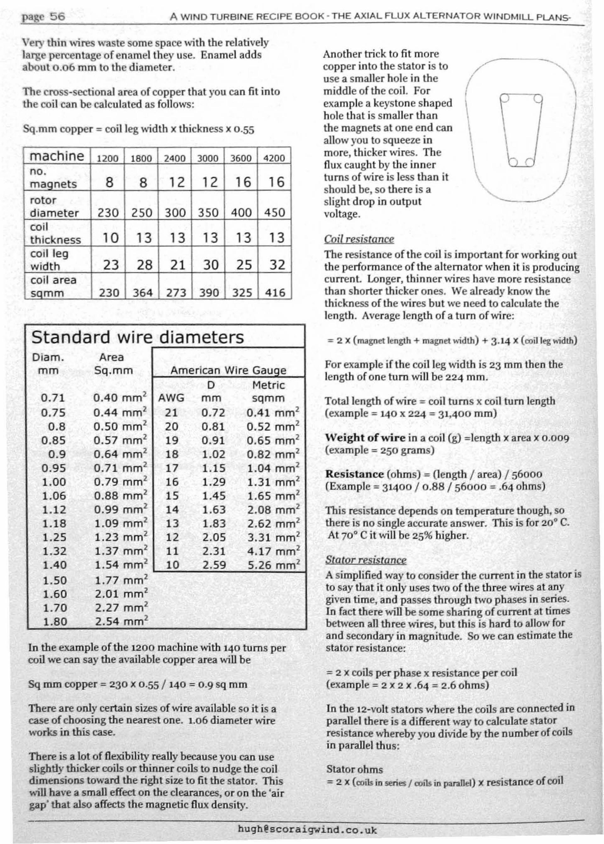
page 56 A WINO TURBINE RECIPE BOOK· THE AXIAL FLUX ALTERNATOR WINDMILL PLANS-
!&i1 resistanceThe resistance of the coil is important for working outthe performance ofthe alternator when it is producingcurrenl Longer. thinner 'vires have more resistancethan shorter thicker ones. We already know thethickness of the wires but we need to calculate thelength. Average length of a turn of wire:
Very thin wires waste some space with the relativelyllU1;e percentage of enamel they use. Enamel addsabout 0.06 mm 10 lhc diameter.
The cross-sectional area of copper that you can fit inlothe coil can be calculated as follows:
Sq.mm copper = coil leg width x thickness x 0.55
machine 1200 1800 2400 3000 3600 4200no.mannets 8 8 12 12 16 16rotordiameter 230 250 300 350 400 450coilthickness 10 13 13 13 13 13coil legwidth 23 28 21 30 25 32coil areasnmm 230 364 273 390 325 416
Another trick to fit morecopper into the stator is touse a smaller hole in themiddle of the coil. Forexample a keystone shapedhole that is smaller thanthe magnets at one end canallow you to squeeze inmore, thicker ,-.rires. TheDux caught by the innerturns of wire is less than itshould be, so there is aslight drop in outputvoltage.
l.
hr
Standard wire diametersDiam. Areamm 5q.mm American Wire Gauoe
D Metric0.71 0.40 mm' AWG mm sqmm0.75 0.44 mm' 21 0.72 0.41 mm'
0.8 0.50 mm' 20 0.81 0.52 mm'0.85 0.57 mm' 19 0.91 0.65 mm'
0.9 0.64 mm' 18 1.02 0.82 mm'0.95 0.71 mm' 17 1.15 1.04 mm'1.00 0.79 mm' 16 1.29 1.31 mm'1.06 0.88 mm' 15 1.45 1.65 mm'1.12 0.99 mm' 14 1.63 2.08 mm'1.18 1.09 mm' 13 1.83 2.62 mm'1.25 1.23 mm' 12 2.05 3.31 mm'1.32 1.37 mm' 11 2.31 4.17 mm'1.40 1.54 mm' 10 2.59 5.26 mm'
1.50 1.77 mm'1.60 2.01 mm'1.70 2.27 mm'1.80 2.54 mm'
In the example of the 1200 machine with 140 turns percoil we can say the available copper area will be
Sq mm copper = 230 x 0·55 / 140 = 0.9 sq mm
There are only certain sizes of wire available so it is acase of choosing the Dearest one. 1.06 diameter wireworks in this case.
There is a lot of Dexibility really because you cao useslightly thicker coils or thinner coils to Dudge the coildimensions toward the right size to fil the stator. This...ill bave a small effect on the clearances, or on the 'airgap' that also affects the magnetic Dux density.
= 2 x (magnet length + magnet w;dth) + 3.14 x (ooil leg w;dth)
For example if the coil leg width is 23 mm lhen thelength of one turn will be 224 mm.
Total length of wire = coil turns x coil turn length(example = 1.40 x 224 = 31,400 mm)
Weight of wire in a coil (g) =Iength x area x 0.009(example = 250 grams)
Resistance (ohms) = (length / area) / 56000(Example = 31400 / 0.88 / 56000 = .64 ohms)
This resistance depends on temperature though, sothere is no single accurate answer. This is for 20° C.At 70' C it will be 25% higher.
Sl!I.lor resisroncgA simplified way to consider the current in the stator isto say that it only uses two of the three wires at anygiven time, and passes through two phases in series.In fact there will be some sharing of current at timesbetween all three wires, but this is hard to allow forand secondary in magnitude. So we can estimate thestator resisbnce:
= 2 x coils per phase x resistance per coil(example = 2 X 2 x .64 = 2.6 ohms)
In the 12-volt stators where the coils are connected inparallel there is a different way to calculate statorresistance whereby you divide by the number of coilsin parallel thus:
Statorohms= 2 x (roils in series I roils in parallel) X resistance of coil

WIND TURBINE RECIPE BOOK NOVEMBER 2008 METRIC EDITION page 57
Power loss = resistance x current squared
For example if the output is 200 watts and the voli;lgeis 24 volts, then current = 8·3 amps.
CurreoLandpoIQer loss ~
Current = power / voltage It is helpful to work out the heal dissipation per squarecentimetre of stator surface so as to avoid burning thestator out. The resin is a poor conductor. Look at theplaces where the coil is near the surface. Exposedsurface of a coil on each side equals coil leg width x coilturn length, so
(example = 2.6 x 8.3 x 8.3 = 180 watts loss)
In other words, at 200 watt output, our IitUe 1200 mmdiameter turbine will be losing 180 watts in its si;ltorwinding. The blades will have to produce at leasl380watts to cover this.
R~tifier lossThere will also be some loss of power in the rectifierdue to lbe voltage dropped across the diodes. Eachdiode will drop about 0.7 volts, so
rectifier loss = 1.4 x Current(example =1.4 x 8.3 =12 watts)
Note that the rectifier loss is worst with lower systemvoltages and higher currents. The stator 105s is thesame regardless of system voltage, because theresistance is much lower in the shorter, thicker wiresof the lower voltage windings.
EfficiencuClearly this example is not very efficient because thealternator needs 392 watts input to give 200 watts out.Efficiency is therefore 200/392 = 51 %, or less whenyou consider other losses.
This is however the worst case. At lower power youwill be able to show that the efficiency is much better.(For example at 48 watts, 2 amps, losses are 13 watts.)
There 'viII also be friction in the bearings and seals toconsider, but there are no core losses (because there isno steel in the stator), so this type of alternator is bestin low winds when you need the efficiency most.
W;IJdSjJeedKnowing the power required to drive the alternator,you can find out the windspeed needed. Assume th.atthe Cp is 35% which means multiplying by 0.35, so
BiJlde Power = 0.35 x (1.2/2) X area x windspeed cubed
Area is diameter squared x 0.785
Windspeed cubed = Blade power / (0.165 x wamele"')
For example = 392 / (0.165 x 1.2') = 1651
Cube root of .651 is 11.8 metres per second windspeed.This is the rated windspeed for the t200 tuTbine.The larger turbines in this book reach rated power at10 or 11 rn/s.
Surface = 2 x coil leg width x coil turn length
(example in cm = 2 x 224 x 2.3 = 103 sq.cm)
Each coil will only be working 2/3 of the timeaccording to our approximate analysis of the current inthe si;ltor.
Loss in each coil = 2/3 x resistance x current squared
(example = 2/3 x .64 x 8.3 x 8.3 = 32 watts)
(Or you could divide the total si;ltor loss by the numberof coils instead. The an5\ver is the same.)
Dissipation in watts/sq.cm = 32/103 = 0.3 W/sq.cm
This much heat will cause a rapid temperature rise in abench test in the workshop, but on the top of a pole ina good wind it is sustainable. Significantly higherdissipation is not advisable.
,m n
You already know the estimated cut in speed, but it'suseful to try to predict the speed at which thealternator will produce a certain power output Thishelps with predicting the blade rotor tip speed ratioand stuff like that.
Open circuit voltage from the wind turbine (withnothing connected) is more or less proportional to therpm. call this 'electro-motive force' or EMF. Actuallylbe DC EMP is not exactly proportional to rpm becausethe rectifier drops the voltage down by about 1.4 volts,but this is a minor adjustment.
If the alternator is connected to a battery, then itsactual DC output voltage is 'clamped' to the batteryvoli;lge. The battery voltage is a lot more stable thanthe allernator EMF. When you connect the battery tothe alternator, the battery wins. The alternator tries topush the voli;lge higher as it speeds up more but it canonly push it up very slightly. What happens is that tbehigher EMF of lbe alternator pushes current into tbebattery, raising the battery voltage slightly (if thebattery is off load at the time and no current is beingused by heaV)'loads).
The significance of the EMF is that it drives the currenlinto the battery. By Ohm's law, the difference betweenEMP and battery voltage, divided by the impedance ofthe circuit, determines the current. Impedance is notexactly the same as resistance but it is similar. You canread about the differences in electricity textbooks.
hugh@scoraigwind.. co.ux

page 58 A WIND TURBINE RECIPE BOOK' THE AXIAL FLUX ALTERNATOR WINDMILL PLANS·
60 r---~:"""'::~---=~-=----=---=-~=----~~=-=-==:;'
so• Open circuit EMF• Battery
- Rectified output •
•
•
4001
u:lQ-~O
••
• This dltr~rence Involtage dnv~ the
current In the statorand transmission wires. ,,
• • • •20
'.
10 ,
300 400
Rotational speed rpm
600
-
500
You can calculate the ,vindspeed required to give fullpower (sce earlicr example 11.8 m/s) and also arotational specd for full power (630 rpm). From theseit is possible la calculate a nolionaltip speed ralio atfull power and to check whether the turbine will stall01' not.
Revs per second = ( 630 / 60 ) = 10.5 per secondCircle tmvelled by lips each rev = 1.2 X 3.14 = 3.77 mTip Speed =10.5 X 3.77 =39.6 m/s
Tip speed mtio is therefore = 39.6 / It.8 = 3.35
Yon can go through the same calculations but startingwith a battery voltage at 28 volts and using a lowercurrent to obtain 200 watts and it will give anotheranswer. The speed will not be much different but Uteefficiency is beller because of the lower currenl.
But bear in mind that this is a very approximateprocess, with several assumptions and simplifications.l1tere are plenty of variables that can innucnce thisoutcome, including temperatures in the coils.
200100o
o
rpm B (DCV + 1.4) X 11/ (A X BX n)z 55.4 X n /(.011 x.3 x 280) = 630 rpm
To find the rpm, you need to estimate the extra voltagerequired to drive the desired current, add this to U,eballery voltage and then finally find the rpm needed toproduce this much EMF.
You want 8.3 amps out of the Iitlle 24 volt turbine usedas an example up to now. Multiply thc resistance by1.3 to estimatc impedance giving 3.3 ohms. Add a bitfor a cable from thc turbinc to the battery, for example50 metres of 6 sqmm cable would havc resistanceabout 0.3 ohms so you Clm say thc total impcdance is3.6 ohm. Required cxtra voltage will thus bc 3.6 x 8.3B 30 volts. Battery voltagc is 24 volts. Total EMF ,viIIbc 54 volts.
The impedancc of lhc stator is not simply itsresistance. There is some self-inductance that causesreactance too and the rectifier makes this vel)' difficultto analysc concisely. Asimple rule of thumb is tomultiply the resistancc by a faclor of 1.3 to correct forthis and get a rough idca of the impedance. Thus onecan get an idca of Ute power/speed cnrve.
I'redlded output
This mtio is low but acceptable, given that Ute designtip speed mtio for lhis little turbine is only 5.
..... ""'"
Ifyou want to get the most power from a magnet rotorof given diameter, place many magnets close together.Ifyou want to get the most power from a given set ofmagnets, use a large rotor and place thcm far apart.Then you have room for more copper in the coils andyou also get less leakage of nux betwccn magnets.
~ .....---
•!--"='--::--~.. .. .. -.1-_--
..

WIND TURBINE RECIPE BOOK NOVEMBER 200B METRIC EDITION page 59
I . S
Ifyou double the speed of the alternator, lhen you can:• Keep the stator the same and the voltage \\~II
double. If the current is the same lhen you gett",rice as much power that way.
I You can also double the current and gel fourlimes :JS much power, with four times as muchloss, so the % efficienc)' is the same. Butcooling m:lY be an issue.
• Halve lhe number of magnets and handle thesame power with the same efficiency.
•
•
The alternator losses depend on the square ofthe current, 0 an increase in voltage andcorresponding reduction in current (for agiven power oulput) cuts the losses in thecoils, saving energy and avoiding overheating.The blades will work best at a constanllipspeed ratio which implies that the rotationalspeed should change in direcl proportion 10windspeed. Working a constanl voltageimplies working at more like a constant speed,whereas using a converter allows you to varylhe a11ernalor speed more widely.
For agiven alternator at a given speed, the outputI'oltoge will depend on the turns per coil, and U,e seriesparallel connections in the coils, as described earlier.Lets keep the connections the same and just vmy thelurns pCI' coil.
You can double the batteIJ' voltage by Ilutting moreLurns of thinner wire into the coils to get the correctcut in speed. You would (roughly) double lhe numberof turns in each coil. If you double the turns in;) coilthcn YOUl11l1s\ use wire with half the cross sectionalarea of copper (sq mm). The effect on the resistance ofthe coil is 10 increase it fourfold (double lenglh of \\,reand half the al'ea).
The current al U,is higher voltage will be halved.Powcr loss in the stfltor depends on the resistrmcetimes the current squnred. Current squared will dropto 114 while resistance increases four times. So thepower loss in the stator coils is exactly the sameregardless of lhe chosen voltage.
Choice of batteIJ' voltage will not make any difference10 U,e efficiency of the stator coils if lhe speed isunchanged. You would gel about the samepClfomlance from a 12-\l01t, a 24-\,01\ or a 48-voltaltemolor with the same cui in speed. (Actually thereclifier losses would make the 12-volt option slightlyless allroeUve,)
~ 1
So far U,e assumption has been that Ihe voltage isclamped by a battel)'. You c..ln also consider changingIl,e operotillg voltage in rcsllonse to changes in speedofa given alternator. This is sometimes called'maximum power poillt tracking' (MPPT). It's quite anexciting avenue of wind turbine devclol>ment.
BATTERYWIND I MPPT (FIXED
TURIlINE CONVERTER VOLTAGE)
III low winds, the alternator can only generaterelatively low voltage, whereas in high winds it has theability to produce much higher voltage, Connecting ildirecUy to the battel)' ha.ndicaps its efficiency by tyingillo the same voltage under all conditions. Using aconvcrter to change the voltagc, aHowing it to rise inhigher winds, has several benefits.
This book does not attempt to offer a design for such aconverter, but thcy have been built for bothcommercial and homebrew turbines. The question youcould ask is whether the extra complexity, cost andvulnerability 10 failures is justified by the extra powerobtained in this way.
The basic direct battel)'-charging design without aconverter has poor efficiency in stronger \\~nds
because of the high resistance in th stator (caused bythe need to cuI in allow rpm) and also the tendency tostall the blades (for the same reason). But il does havethe advantage of simplicity and reliability. Reliabilityis the biggest problem WiUl small \\~nd turbines,outstripping any efficiency problems, The slowlyturning rotor blades of the direct-connected turbineare also very quiet and suffer less wear and tear.
J:li!Jilllol1a!zf1ransmissionIf the best site for the turbine is a long way from thebattel)', and the batteIJ' voltage is necessarily Iow dueto the choice of inverter, then you can wind the statorfor high voltage operation and step this down withthree transformers at U,e balleIJ'·
Make sure that the transformers are not saturated atIow frequency, The frequenc)' equals the number ofpoles on one rotor times rpm/12o. If a transformer isdesigned for 240 volts at 50 Hz for example, and theactual frcquency is only 2S Hz, then the maximumvoltage should be 120 volts.
You may wish to use a relay to disconnect thetransfonners when the wind turbine is turning slowlybecause the current they use in low windspeeds canimpede startup.
In theol)' )'ou can also change U,e t.lpS on thetrnnsfomlcr so as to vary the operating voltage indifferent windspeeds achieving a crude MPPT ell t.But it's not easy to design a circu.it thot can tell when tomake U,e changes.
It goes \vithout saying that bigh voltages ca.n bedangerous. Make sure that all \vires are safelyinsulaled and all connections are safely in grOllOdedboxes. 1like 10 fit an over-voltage trip on such systems10 short out the turbine if it becomes unloaded,

Fudin{) - /In automatic self-prote tiv' opcr"tion thatreduces exposure to violent winds by facing the bladesroway from Ihe wind. In Ihis book thal furling motionis produc d by 0 Int -rnJ offset of Ihe bl"d ' rotor fromthe centf of yaw, -I1,e llIil and Its hinge control ~eynwing motion so thatlllimitB the power produellon,
Fllse - Ad vice for protecting ir uit wir s agalnsloverload. If the current is too high 1I1e fuse melts andbl'e"ks Ihe circuit, CUlling of Ihc current.
Groin - the fibr 's within 0 piece of wood 11101 give itslrength, They em rge from II cut8U1fnce allln "ngie
Grill- Ihe mains eleclricity supply as provided by spower ompany or ulility. using n 'grid tied' inverter,you can feed power bn k inlO the grid supply,nnd youcan carn moncy by doing this,
Inuer/er - Adevice that converts DC battery power to/lC power, similnr 10 grid power, on demllnd,
Jig· A templnle Or devicc used to correctly place themngnets on Ihe rOlor.
Flux - 'I'he 'sh.fl' of magn ,tism, Similllf to 'current' Incleclricity, 11 con be visu"lised os 'Iin ' 'coming oul ofone pole lInd I'elllrning to the other. I~ux d nsily InTesla is the same as Webers of nux per squar' mctre,AW-b I' of nux per second utlingnwir'gen r"tone voll.
p"eqllcncy - '11, number of times thullIn /lC vollage" tuully nllernates in eoeh second, M 'nsur d in ~Iertz
(11.)
Enamel/cd coppe,' wire -wire Ihflt has a clearinsulating coating ou it sO th"t il e"n be wound inlocoils without any electric,,1 contact belwe 'n Ih turnsin th coil.
EMI' - m'clromolive force, /In other nllme for theopen-circuit voltage of ~I supply when no current isdrawn from it.
Dump lood - A hellter that is used to conlrollhevollage by lUking excess cUl'rcnt from thc supply,
Efficiency - In this book the word is uscd to denole Ihepercenlage of power thut is conv 'M d by ndevice. Forexample if nn aHcrnalor nbsol'bs 100 watls ofmechanical power to pl'odu 'e 50 watls of lectrlclllpower thcn il is 50% efficienl. The rest is wasted asheal.
O"O/> - Used here IQ describe a ccrluin measurement ofIhc shap of a windmill blade. The Irailing edge 'drop'is marked al each station so that the blade angle isC01'l'cct ot that stalion.
Diometer - The distance from one side of a circle lOthe other, The width of n disk righl across the middle.
Con/r'ol/er - An eleclronic box thlllswitches surpluspower aUlomatically into hcaters, Usually th 'seoperate at a certain vollngc, The conI roller adjusts the:unount of current diveo'led to hCllt so as to pr vent thevoltage rising nbove 1I set I 'vel. DrawIng current (from11,. battery or alternator) pulls the voltag' down,
Curl'cnl - I'Iow of charge arollnd a clrcuil of copperwire 1I1rough a supply and nload so as to trnnsferenergy.
CuI-ill spced - lI,e rpm allVhich the alternator slartsto produce enough voltage to be usabl .
DC - 'dlrecl current' of positive charge - nOw8 frompositive to negative. Mainly found in bnttery circu.lts.The term DC is also used for voltages Ihal do nolalternate.
Broke switch - Aswitch used to short-circuit the wiresfrom the nllernator so Ihat the turbine stops.
ca/olyst - /I chemical used to make resin set solid,Calalysll'eaclS wilh 'occeleralor' already pres~nt in theresin solution 10 produce heat ond sel th' rCSIll.
cail - MagnelS passing a piece of wire will induce 0volwg' in it bullo getll useful vollog' you need manylums or wire wound into 0 coil. 'me turns 01'0 in 8 lieswith Meh other, and so the volwge builds up.
Airfoil (Aerofoil) - A rOS$·scct!onal shape for thc. 'blnde thal has good lift/drag ral'O so Ihat the blnde canmove fnsl through the air without wasllng power.
Air gnp - A gop in :) mflgnetic circuit where there i,s noiron or steel. 11,e gap can be full of copper 0" plnst,c oranylhing bUI is slill considered to b' air as far as Ihcmago lS ure onccrncd.
Alternator - /I machine for converting m 'chanicnlpower into elcctri I powc~. MO\:ing mag~clS .in~lIccallernaling voltage (EM F) In slat,onary co~ls: l111sv Ilage is proportional 10 speed. If a ~"Clut IS .connectcd 10 these coils then alternallng currenl w,lInow. 'l1,e allernat I' Ihen becomes harder 10 turn andobsorbs I11cchoniclll power. while clcctricnl power isbeingg 'neral d,
Ammeter - Adevice (or measuring the current (limps)pllssing through it.
ATH -lIIuminium trihydrale, used in powdered formas an allernative to talcum powder for Ihickening lI,e
in mix and mod rating its rcnclion heat.
GlossaA . 'Allcrnntingcurrcul' as produccd by Ihealt rnalor. 'A voltage' is alternaliag vollngc.
,c...:~~ ..!.A~W~'~N!!:D~T:!.U~R~B~'N~E:..!:R~E~C:!:'P,::E~B~O:::O::.K::....'.:.T:..:H::::.:A.::X.::'.::A.::L.::F..:L:.;U;..X.;..A.;....:LT.;....:E_R_N_A.;..T..:O;..R.;...::W.::'.::N.::D.:.M.::'.::L.::L.:.P..::LA::::.:N::;5-::..-~o
0""9 - /I force exe~1cd I~y Ihe wind onl.n. objc'Ct. Dragis parall '11u th • wind d" 'cloon al the object. (sec Lift)
huqh@scoraigwind,co.uk

floul' Th' wid Si pari of the blade near to the hub atthe centre of the rotor.
~W~IN~D~T~U~H~B~IN~E~'~H~E~C~II'~E~B~O"-,,O=K~N~O:::;V~E::M~8~E~R~2::'_0~O:::8C!M~E"c.!.r!:R~IC:::...':E:!:D~n!.!I:'O.':!N~ page 6 I
Kllol - a disllll'l.H1IlCC in the grain of the woocJ in a treecaused by lJ brunch. You should try to ovoid iflcludinglarge knots as they weaken the l>lndc.
I eod;/If1 edfle' The edge of a blade thal would slrike;n object pli.ll:cd in ilS path as the I'OIOr spil1~.
UfI- Aforce exerted b~ the ~Yil1ll. on 011 objcc~. Lift isal right angles 10 tile wind dlrecllon at the obJecl. (sccDrag)
toucl- nn c1cclricalluad is just sorn thing Ihlll drawscurrent in iI circuit. A hClller, u lump or any nppliuncc.
MOOllctic: dn;u;1 - The puthway for nux from onc I>oleof amngnello tl\l: OUIl:I', Similur to on electric circuit,inlhat the HIlIOUllt of nux depends on the alllount ofiron (equivalent to cupper) that curries the nux,
MOllld - A 6hnped conlilincr in which resin -'nstlngs lireforrned. The mould e"n be dioellrded nfler lhe enstinghas Bet. or it C111l be UI;C mUIlY times,
MlIltime/r,.·" versatile clcetricllltest inSlrumenl,lIsed 10 measure voltugc, current nnd olherparamclcrs,
Neodymium Ut' IICO - The nicknum given to [J type ofpermuncnt m~lgllcl conluinirlg the elementsnL'Odymiurn. iron and horon (Nd"oB). Very strong,a"d gelting cheaper all L1,e time, 'l1,e strength isIndicated by Ihe ~rade. Grade 40 I. eosl-offeelive atthis lime.
Offset, An ecccnl rie rosillon. off eenlr '.
Open d"cu;1 - A oitll"lion where a supply i. prcsentbUl there is no circuil for current.
I'"rolle/- a eOllnection belween coils or bal.le'·i .... thulshnre8 eurrelll belween them while lhe volluge Is thes.nie for all of them "s for onc aloll •.
Pilase - The timing oflhe cyclieul allomnllon of vohag •i" ucirculI. Differenl phuseB will peuk 01 differenttimes. Agroup of coils with the same Ilming Is knownas'u ph"se·. All of the "U.cmnlors In tbls book hnveIhree phases thnl follow IIch olher In un evensuccession 80 th"t the oulput is 8mooth.
Palyeslel' - A type of r....in used in fibreglnss work.AJsoBuilable for making enstings. S e also vinyl CBI r.
Power -lhe rate of d ·liv ry of energy. Can be electrical(voltnge x Curr 'nt) Or meehallienl (speed x torque).
Ucelifier - A network of semiconductor devices(diodes) Ihal r·direels AC eurrenls to flow onc wnyonly In IJ DC circuli for eh"rging the bullery.
UeS;slance - 'O'e degree orobstruction to tbe pasBngeof electric current in a circuit or a part of onc,mensured in ohms (0). Equal to the voltage across anobject, divided by eurrentthrotlgh it (Obm's Law).
ROlor·/\ rolating part. Mognell'Olors ar~ the sle~1
disks carrying the mogncls past the stolor. Rotorblades arc the 'propeller' driven by Ihe wind "nddriving t1wlllagnct rotors.
UPM - revolutions per minute, The ItlC3$Ur' of howfast something l'l..'Volvcs. this is important for thebeh"viollr ofbolh bllldes "lid ahernalo",.
Serics - 11 COJlllcction of oils or butteries lhot'increases the vnltogc between th, ends of th ~ string,
Shm" circuit - An electr! al circuit conlnins npowersupply Ihal producesn voh"ge. When th slIpply isconn~ctcd 10 a lond then currenl posses oround tll .circuit through Iho land nnd energises il. 'flnst 'ad thecirculi is COml)ieled withoul n load (shorted) then Ih.curr 'nlls only limitod by the resistance of the SIlPllly.'£1'18 current is usually too high, [lnd crentes a hU7.nrdIhal mllsl be gu"rded aglllnst by Including fUBes in thewiring of the Bupply. III the CDse of Ihc wind turbln "Ihe eurrenlls limited by the pow 'r of the blades. Theshort circuil overlonds the bl"d"" nnd slulls them.bringing the wind turbil1c speed down to a crowl.
SolderinlJ' A mel.hod for m"klng eleclrlcultOnne 'tions by hCllting the wires with un 'Iron' nndlben coating 'verylhlng with mollen solder.
Stution - A point on 1110 hlude'. 8pan wher" the .hap"is Inensurcd. Ther· {Ire several stotions ulollg lheblade, The shape follow8 ",rnight Iine8 b 'tw...n th m.
Slotor - An n88embly or coils embedded in a slab ofresin 10 form pa"1 of the ull malor. '111. mugn 'Isinduce Ii voltage in the el,1I8 and we enn IIBe thl voltage10 g nerlite electrical pow"r,
Slyrene mOnOnwr -111e nilllly smelling solvenl' usedfor Ih 'rcshl 80lullon (pol}'CHlcr und vinyl e81 'r resins).
Toi/- Aprojecting van' mounl don n boom at thebuck of the windmill used to ",eer illnto or out of thowind uutomatically.
1'ap- n tool for muking L1Jread In1lld holc8 80 you canSerOW thillgs into th hole.
7711'''51- l'11e force of L1le wind pushing Ihe mnehlnebneKwurdB.
Torque - Turning force. Mechanical puwer conslslB o(boLlI 8peed nnd torque. (power ~ speed xtorqu )
Tower, 'rhe mast supporting the wlodmill,
1'rulling edge - '0,. blade edge forthe.t from theleuding edge. 'rhe IrailJng edge is shaq"t.lt'd, 80 M toreleaso the passing air withoutlurbulenco.
[email protected]~igwind,co,uk

p"!! 62 A WIND TURBINE RECIPE BOOK • THE AXIAL FU.JX ALTERNATOR WINDMlU- PLANs-
Yow bearing - the swivel at the top of the Inwer onwh'ch th . d turbi· ed. Th
Wild - when the wind t:url>ine is running freeI)'without any connecti~nIn anythi~gthen the .-oltagecan be descnbed as wild because .t ,'alios wildly. Wmdturbine frequency also .-aries with speed of rotationand 50 wind turbine oUlput is often descn1>ed as 'wildAC unlike grid power that has constant frequency (say50 Hertz) and near constant.-oltage.
Workpiece - The piece of wood or metaJ being shapedin the worl<shop.
VO/loge - The electrical pressure from an electricalsupply ....hich is usuall)' faidy constant and has anominal .-alue. For example '12 .-olts DC' from ab betw I de d'
Ver!iool axis (VAwn - a type of turbine with no Jawbearing because tbe blades rotate on a vertical shaft.
Vinyl ester - An ester resin that is banler In find andmo", l!XpCIlSive than polJes1er, but bas superiorproperties. It is easier In worl< with, is waterproof,withstmds bigher temperatures, and is a betteradhesi.-e.
altery can vary eeo 11·15 vots pen IOgon I ewlO ne IS mount e ),aw bearingwhether it is discharged or charging up rapidl)'. allows the tu.rbine to face the wind.
lIST IF ISDIlSI.....EIS .,(MOSTLY IN THE UK. 81fTMANYOPERATE WORLDWIDE)Goods s!!.l!2!led Name and web address Phone and street address
Patrik Larsson (Sweden) Phone 0046 (0)411-306 35Magnets~IWww.solber avind.seJ Mobile 01706-30 63 50
Ii~~"""'"~ ~netstnre.comI UKsa nets.com in CHINA iiiiO:/lWww.frene!9Y:corn.aul in Australiah :/1Www.ma~comI in Janan. !!!!I!11Www.m~nes.hulinH~CERMAG (UK) 94 H~ell Rd. Sheffleld. SM 8ASh :/1Www. .co.uk! 0114 244 6136
Winding wire EC WIRE LTD UK 019241266 377EC wire Ireland 14 Ushers Island. Dublin 8 -lel 01 671 8754.rhlfD':lIWww.oe~s.co.ukI I 1015381 523 229
Polyester Resin ele Glasplies Fibreglass Supplies Tel 01704 540626h :/1Www. !as ies.co.uJ<! 2 Crowtand Street, South • PR97RZ
Vmvl Ester Resin h :l1Www~lbre.co.uk! 0121 327 2360Sleel disks E-Teq (ScoUand) Limited. Te101556612128
~:/IWww.e- .co.uk! Dumlries & GallowavEmsea Lld. Tel: +44 (0) 1684 299156h :/1Www.emsea-laser.comI Uril5. Green Lane.Tewl<eslJury. GIDoGL2D 8HO
Trailer hubs Merecfoth & Eyre Limited, Tel 0161368 6414.h JIWww.meredithand~e.co.uk! Ekoadway tnd_ Est•• Hyde. Chest*e. SK1A~
~hoists chain A P Ufti...!!9. Gear Com...l!!'.nv Tel 01384 250552Birch plywood James Latham 0191 4694211
h :/Iwww.lathamlimber.co.uk! Nesl Rd. Fell' lod. Eslale. GatesheadVoltage regulalnrs Sco~Wmd Eleclric email belowl 01854 633 28611 ALSO SELL INVERTERS
SoIarAccess OIf-Grid tel; +31(0)570 51 02 47~IWww.solaraccess.nl P.O.Box 789 ; 7'OllAT DevenIerThe_
Solar Converters Inc. Canada 001 519824 5272< •
nleLne\>Waler healers (any voltage) TP Fay (Kirkby) Lld Tel 0870 3 50 50 58
h :/1Www.lDfav.co.uk!Workshop tools 8.nd supplies Beal (UK) lid Tel; 0113 253 8888DC electric and mechanical httD:i Iwww.beal.or .ukl ....Irion Mills, Church Street. Mort..... LeecIs.15Z7 SlYFixings (stainless threaded Screwlix Lld 0500414141rod &a8Wll atel ~1Www.screwIix.co.uk!Copper cable (steel wire Ball cables 8ranches all over the UK and el5ewherearmoured. tri-raIed. etel h :/1Www.ballco.uk!Panel ammeters h :/1Www.eltime.ro.uk! 01621 859500 Essex UKRectifiers. connectors. wres, Rapid Electronics Ordertine: +44 (0)1206 751166solder, PIOO reoeptacles http://Www.rapidonline.comI PtOG .tiIl .... ' code 33-3730
Cl1N reetiflen code 47-3228Wlrewound resislors. Famell TeI 08701 200 2003OOwa1l1ow voltage heaters httpJluk.farnell.comI ONE.oHM HEATER CODE 111ll81S3
DIGITAL VOLTMETER CODE 1216315
• •

..1lII11lS BE OIBED FOB BlIlDIIIG THE WIIID TURBIIIES$iZ.eS are in mm 1200\ 1800 2400 3000 3600 4200BLADE WOOD (MINIMUM' mm
blade wood width 95 95 125 145 195 225thickness 35 35 40 45 60 75
Totall~th 1,600 2.700 3.600 4,500 5.400 6.300Stainless steel saews 3O@25mm 4O@l30mm 50@l30mm 6O@3Omm 60 @ SOmm 7S @ SOmmIPI.yWQOD - fractions of A very rough guide to the amount of plywood needed in different sizes for each turbine
s'.andard sheet {2.4 x 1.2m\ for all pu s indu<l' the moulds and" s.6mm 1/4 1/2 1/2 1/2 1 1/49mm 1/4 1/4 1/4 1/4 1/4 1
12mm 1/2 1/2 1/2 1/2 1/2 118mm 1/4 1/2 1/2 1/2 1 1
5TEB. DISKS mm 0!'h'.onel (t.., cisl<s) (!wo_s) (twollislls) (!wo <isks) (two<isl<sJ
DIAMETER 230 I 250 300 350 400 450THICKNESS 6 6 8 10 10 10
STEEL LENGTHS IN mm IANGLE 50 x 50 x 6 200 800 900 1 100 1300 1500FlAT BAR 30 x 8 200 700 700 900
50 x 8 700 600 600 1500 1700100 x 8 100 800 900
STEEL PIPE LENGTHS These estimates below do not allow for any tower.I" nom. 33.4 outer 1000
1 1/4" nom. 42.3 outer 2001 1/2" nom. 48.3 outer 1400 1700 2000 1600 1800
2" nom. 60.3 outer 340 430 530
2 1/2" nom. 73.0 or largerthick wall i to fit inside 3- BOO 900
3" nom. B8.9 outer I 600 700
MAGNETS: 4OX30X10mmgrade N40 NdFeB~thel0mm_ 8 B 24 24 32 32
EHAMEUEDCOPPER WIRE. 1.5ko 2.6ko. 3~ . 5'>9. . 5kO. 7koToogh, fleXJble WIre for hooking up the stator and for hangIng down tower - see Installation section for mInimum sizes.~connectors and lu . Connector blocks. Junction boxes.Resin-cored solder wire for stator connections. PVC~ for coi~, and sleev~for connections. Cable ties.Rectifiers. Choose bridge rectifiers rated for at least twice the current and five times the voltage. Connect in parallel ifnecessary to share current. (Current can be found by dividing power by voltage.)Use best quality PIDG crimp connectors and boil to a large aluminium heatsink (can be saap saucepans ete) using'semiconductor mounting paste' between each rectifier and the heatsilk body.Diecast aluminium boxes make ood enclosures and healsinks combined for 12 vall rectifiers mounted on turbines.Flexible conduit and....9.lands can be used to make a nealE,bof~'~ '!!!y.where the stator has 9 wires out.
Resin sugplies: Polyester or Vinylester rest!. Catalyst, Filler: talcum or ATH powder,Fibfeglass cloth loo-3OOgIsqmetres, polish or grease for mould release, Silicone sealant or other caulk. Superglue.The estimates below are verY ~h, and I su estvou~ extra so can e~rimenlwith mixtures.Estimated W$ht resin 700....9. 1.4 ko 1.7~ 2.3 ~ 2.5 ~ 3.2 koEstimated weight of powder 400....2. 7000 800 ~ 1.2 !:!l. 1.2 !:!l. 1.6 koBEARING HUB PCD loomm lOomm lOomm 12..§!!!!!!. l40mm ..&ommWELDING RODS Qua!\\Y.2.5-mm or better 32-mm.JI!'neral pu se wek!i!:!Jl. electrodes for mild sleelANGLE GRINDER DISKS Grind~and sandSdisks.~saw disks and also hacksaw bladesGreasefor~s _ in hub and also~and tail hi~. filler for defects Inca~ and blades. PamL
Sheet lead for bala~wilints for blades. ~saw blades.~r,Assorted bolts and nuts for fixino tailvane. rectifiers, moulds, and cod winder.
STAINLESS STEEL FASTENINGSTHREADED ROD estimated 1'.110 x 1000 1'.110 x 1500 Ml00r 1'.112 x 1500 1'.112 or 1'.114 M14 x 2000
sizes. Also nuts and washers M12x 1500 x 2000
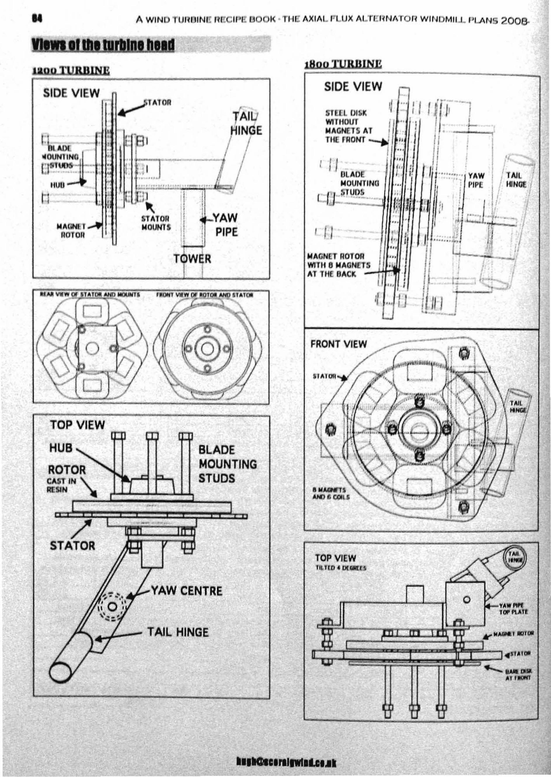
.. A WINO TUI10lN • 11 IPE BOOK' Ti'l A~IAL LU~ ALTEl1NATOrl WINOMIl.l.. PLANS 200&
'. -,
TOP VIEWltl,.l(O 4 ex_o
I /1
FRONT VIEW
SIDE VIEW -mu OI~K 11'" 11 / '/'11 --1WllflOUT I" 'I .)....MAGNElS At • / ' IfilE FRONT --to! '! I i I
I ", I I I
( 11 I';: '/ I I /'( iDlAD ,. . YAW TAIL
MOUlmNG ..../ ""1' PIPE ,/'~NG£I-tl~l' UDS ,i.~ ."" ...-. r ,.: j [I ~d i
.:' ·r J' --'I- ... -.., .
MAGNET IIDTOIlWIn. BMAGNETS ", i J 'JAT filE BACK /1 ,. ·1 t', /.-_,
'" I ~+---'I[ ... IJ
~It'tIN E
YAWPIPE
I,
BLADEMOUNTINGSTUDS
•I
1
-~ ..
............~.", .•~ '"_''r'''
L-YAW CENTRE
. .j1
~STAlOn IMOUN'lS I I
I I
TQW R
• ~tAtOIl
,,
.J-- TAIL HINGE
o
/'STATOR
TOP VIEW
HUB
ROTORCAST IN \.
RUIN r-~.-l~~:;;::!:::i __.,
SIDE VIEW
Itunh

WIND TUllfllN . RE IPE: 200BV R ION pa
'I1H!6C vicws do not show Ih' rCllln on the magnetrotors. SIDE VIEWSIDE VIEW OFWIND TURBINE HEAD r ., '4 STATOR
!\\ \ I '1 4 MAGNET
, ROTORS:rAW
IPII'[ All
TAlL_ TAW \\ I .1- -HINGE PIPE ,
,.; .MOUNTING
t STUDS ~RAFT • IfLAD
II I I.-
• I- •
• ,-:t--I
FRAME/
\l\ I \ "~STATORMOUNTS
,"aNT \/Ifw
FRONT VIEW
0//
!t
)
TAll
\ HINOE
J Sf ATO" HAS IZ COilS"01'0"5 EACIIIIAVE16 MAGN£1S
MOUNTINGSTUOS 'OR
oLAbEs
TOP VIEWliLT EO • 0EGHf[STAll
HINGETAWPII'[
SHAFT
TOP VIEW