
Quantum teleportation between light and matter
23
Page 1 of 23 Quantum teleportation between light and matter Jacob F. Sherson 1,3 , Hanna Krauter 1 , Rasmus K. Olsson 1 , Brian Julsgaard 1 , Klemens Hammerer 2 , Ignacio Cirac 2 & Eugene S. Polzik 1 1 Niels Bohr Institute, Copenhagen University, Blegdamsvej 17, Copenhagen Ø, Denmark. 2 Max Planck Institute for Quantum Optics, Hans-Kopfermann-Str. 1, Garching, D-85748, Germany. 3 Department of Physics and Astronomy, University of Aarhus, Aarhus, 8000, Denmark. Quantum teleportation 1 is an important ingredient in distributed quantum networks 2 , and can also serve as an elementary operation in quantum computers 3 . Teleportation was first demonstrated as a transfer of a quantum state of light onto another light beam 4–6 ; later developments used optical relays 7 and demonstrated entanglement swapping for continuous variables 8 . The teleportation of a quantum state between two single material particles (trapped ions) has now also been achieved 9,10 . Here we demonstrate teleportation between objects of a different nature—light and matter, which respectively represent ‘flying’ and ‘stationary’ media. A quantum state encoded in a light pulse is teleported onto a macroscopic object (an atomic ensemble containing 10 12 caesium atoms). Deterministic teleportation is achieved for sets of coherent states with mean photon number (n) up to a few hundred. The fidelities are 0.58±0.02 for n=20 and 0.60±0.02 for n=5— higher than any classical state transfer can possibly achieve 11 . Besides being of fundamental interest, teleportation using a macroscopic atomic ensemble is relevant for the practical implementation of a quantum repeater 2 . An important factor for the implementation of quantum networks is the teleportation distance between transmitter and receiver; this is 0.5 metres in the present experiment. As our experiment uses propagating light to achieve the entanglement of light and atoms required for teleportation, the present approach should be scalable to longer distances. Quantum teleportation—a disembodied transfer of a quantum state with the help of distributed entanglement—was proposed in a seminal paper 1 . The generic protocol of quantum teleportation begins with the creation of a pair of entangled objects which are shared by two parties, Alice and Bob. This step establishes a quantum link between them. Alice receives an object to be teleported and performs a joint measurement on this
-
Upload
independent -
Category
Documents
-
view
2 -
download
0
Transcript of Quantum teleportation between light and matter
Page 1 of 23
Quantum teleportation between light and matter
Jacob F. Sherson1,3, Hanna Krauter1, Rasmus K. Olsson1, Brian Julsgaard1, Klemens Hammerer2, Ignacio
Cirac2 & Eugene S. Polzik1
1Niels Bohr Institute, Copenhagen University, Blegdamsvej 17, Copenhagen Ø, Denmark. 2Max Planck
Institute for Quantum Optics, Hans-Kopfermann-Str. 1, Garching, D-85748, Germany. 3Department of
Physics and Astronomy, University of Aarhus, Aarhus, 8000, Denmark.
Quantum teleportation1 is an important ingredient in distributed quantum
networks2, and can also serve as an elementary operation in quantum computers3.
Teleportation was first demonstrated as a transfer of a quantum state of light onto
another light beam4–6; later developments used optical relays7 and demonstrated
entanglement swapping for continuous variables8. The teleportation of a quantum
state between two single material particles (trapped ions) has now also been
achieved9,10. Here we demonstrate teleportation between objects of a different
nature—light and matter, which respectively represent ‘flying’ and ‘stationary’
media. A quantum state encoded in a light pulse is teleported onto a macroscopic
object (an atomic ensemble containing 1012 caesium atoms). Deterministic
teleportation is achieved for sets of coherent states with mean photon number (n)
up to a few hundred. The fidelities are 0.58±0.02 for n=20 and 0.60±0.02 for n=5—
higher than any classical state transfer can possibly achieve11. Besides being of
fundamental interest, teleportation using a macroscopic atomic ensemble is
relevant for the practical implementation of a quantum repeater2. An important
factor for the implementation of quantum networks is the teleportation distance
between transmitter and receiver; this is 0.5 metres in the present experiment. As
our experiment uses propagating light to achieve the entanglement of light and
atoms required for teleportation, the present approach should be scalable to longer
distances.
Quantum teleportation—a disembodied transfer of a quantum state with the help
of distributed entanglement—was proposed in a seminal paper1. The generic protocol of
quantum teleportation begins with the creation of a pair of entangled objects which are
shared by two parties, Alice and Bob. This step establishes a quantum link between
them. Alice receives an object to be teleported and performs a joint measurement on this
Page 2 of 23
object and her entangled object (a Bell measurement). The result of this measurement is
communicated via a classical communication channel to Bob, who uses it to perform
local operations on his entangled object, thus completing the process of teleportation.
In our experiment, a pair of entangled objects is created by sending a strong ‘in’
pulse of light (shown on the left in Fig. 1) through an atomic sample at Bob’s location.
As a result of the interaction between the light and the atoms the transmitted ‘out’ light
received by Alice’s and Bob’s atoms become entangled. On Alice’s site the entangled
pulse is mixed with the pulse to be teleported on a 50/50 beamsplitter (BS in Fig. 1). A
Bell measurement in the form of homodyne measurements of the optical fields in the
two output ports of the BS is carried out and the results are transferred to Bob as
classical photocurrents. Bob performs spin rotations on the atoms to complete the
teleportation protocol. Finally, the state of the atoms is analysed to confirm that the
teleportation has been successful.
The experiment follows a recent proposal for light-to-atoms teleportation12 using
multimode entanglement of light with an atomic ensemble placed in a magnetic field.
We describe teleportation in the language of dimensionless canonical variables13; this
provides a common description for light and atoms, and allows for a complete
tomographic characterization of the states.
The atomic object is a spin-polarized gas sample of approximately 1210=atN caesium atoms in a 25 25 25mm× × paraffin-coated glass cell at around room
temperature14–18 placed in a homogeneous magnetic field (B). Atoms are initially
prepared in a coherent spin state by a 4-ms circularly polarized optical pumping pulse
propagating along the direction of the magnetic field, into the sublevel 4,4 == FmF
(Fig. 1) of the ground state with the collective ensemble angular momentum
atomsˆ 4x xJ J N= = , and the transverse projections with minimal quantum uncertainties,
xzy JJJ 2122 == δδ . Changing to the frame rotating at the Larmor frequency Ω and
introducing the canonical variables for the collective transverse atomic spin
components12, we obtain rot rotA A
ˆ ˆ ˆ ˆ/ , /y x z xX J J P J J= = which obey the canonical
Page 3 of 23
commutation relation A Aˆ ˆ,X P i⎡ ⎤ =⎣ ⎦ provided that zyzyx JJJ ,
2, ,δ>> . Here AX
and AP are the recipient operators in the teleportation protocol.
The light to be teleported, and the ‘in’ and ‘out’ modes (Fig. 1), are described by
single mode canonical operators6,12 QY ˆ,ˆ , and in inˆ ˆ,y q and out outˆ ˆ,y q , respectively. These
operators obeying [ ] [ ] iqyQY == ˆ,ˆˆ,ˆ are quantum analogues of the amplitude and phase
of light in classical physics, or, more precisely, of the classical quadrature phase
amplitudes y, q in the decomposition of the electric field of light with the frequency ω
as tqtyE ωω sincos +∝ (see Methods for exact definitions). Two non-commuting
variables in quantum mechanics cannot be measured without distortion. The challenge
of teleportation thus consists of a faithful transfer of these not simultaneously
measurable operators, QY ˆ,ˆ , onto atomic operators AX and AP . The Raman-type
interaction (see Fig. 1 inset) couples the quantum ω Ω+ sideband of the ‘in’ field to the
Zeeman sublevels separated by the frequency 322 kHzΩ = . Therefore we introduce the
cos , sint tΩ Ω components of the light operators c,s c,sˆˆ ,Y Q and c,s c,sˆ ˆ,y q (see Methods).
Canonical operators for the upper sideband mode QY ˆ,ˆ can be expressed12 via
measurable sin( )tΩ and cos( )tΩ components, s s c cˆ ˆˆ ˆ, , ,Y Q Y Q , as
1 1s c c s2 2
ˆ ˆ ˆˆ ˆ ˆ( ), ( )Y Y Q Q Y Q= + = − − .
We first describe generation of entanglement between light and atoms. The ‘in’
strong pulse is y-polarized, hence its x-polarized mode in inˆ ˆ,y q is in a vacuum state. After
interaction with atoms12, the x-polarized ‘out’ mode operators out outˆ ˆ,y q are given by:
2 2out in in in out inc c s s A s,c s,c
2 2out in in ins s c c A
ˆˆ ˆ ˆ ˆ ˆ,4 4 3 2
ˆˆ ˆ ˆ4 4 3 2
y y q v P q q
y y q v X
κ κ κ
κ κ κ
⎧ ⎫= + + + =⎨ ⎬⎩ ⎭⎧ ⎫
= − − −⎨ ⎬⎩ ⎭
(1)
The terms in curly brackets in the equations for y represent vacuum contributions
coming from different orthogonal modes of the ‘in’ pulse where the canonical operators
s,cv represent vacuum temporal higher order canonical modes12. The terms containing
Page 4 of 23
inAP and in
AX describe the imprint of the atomic state on the light via coherent forward
scattering from the atomic ensemble, or, in other words, polarization rotation due to the
Faraday effect14,15. The atomic spin operators are transformed by the interaction with
light as follows12:
ins
inA
outA
inc
inA
outA ˆ
2ˆˆ,ˆ
2ˆˆ qPPqXX κκ
+=+= (2)
The second terms in equation (2) describe the imprint of the light state onto atoms via
the dynamic Stark effect14.
The atoms–light entanglement described by equations (1) and (2) is very close12,
under our experimental conditions, to the Einstein–Podolsky–Rosen entanglement
optimal for quantum teleportation. The light–atoms coupling constant
1 ph at 0/a N N F Aκ σΓ Δ α= ∝ has been discussed in detail previously12,14–18. (Here σ
is the dipole cross-section18, 1a is the vector polarizability18, MHz6.2=Γ is the natural
linewidth (HWHM) of the transition, 13ph 4 10N = × is the number of the y-polarized
photons in the strong pulse, 825MHzΔ = is the blue detuning of light from the atomic
resonance, and 28.4 cmA = is the cross-section of the atomic sample. As in our
previous experiments with the atoms–light quantum interface, strong coupling with the
atomic ensemble is achieved in the region of a high resonant optical depth α0. In the
experiment we choose a nearly optimal value12 of 1≈κ by changing 0 atNα ∝ with the
temperature of the vapour. Note that another condition for strong coherent coupling is a
very high phN in the y-polarized mode.
At Alice’s location (Fig. 1), the ‘out’ pulse is mixed on BS with the object of
teleportation—a few-photon x-polarized coherent pulse with frequency ω Ω+
generated by an electro-optical modulator (EOM). A Bell measurement of canonical
variables6,12,13 is performed by two sets of polarization homodyne detectors in the two
output ports of BS (Fig. 1). Homodyne detection followed by the normalization to the
vacuum (shot) noise of light6 is a standard method for measuring canonical variables of
light. In our experiment, the strong y-polarized pulse, besides driving the entangling
interaction, also plays the role of a local oscillator for the homodyne detection. The
Page 5 of 23
variables in phase with the strong pulse out1c,s c,s c,s2
ˆˆ ˆ( )y y Y= + are measured via a
measurement of the Stokes parameter 2S in one output of BS, whereas the out-of-phase
components out1c,s c,s c,s2
ˆˆ ˆ( )q q Q= − are measured via the Stokes parameter 3S in the other
arm (see Methods). The sin( )tΩ and cos( )tΩ components are measured by processing
photocurrents with lock-in amplifiers. The Bell measurement of operators c,sy and c,sq
yields four results, c,sy and c,sq . Operationally, these values are properly normalized
integrals of corresponding photocurrents over the pulse duration (see Methods). As
shown in Fig. 1, the photocurrents are combined to yield two feedback signals
proportional to s cy q− and c sy q+ which are sent from Alice to Bob. Auxiliary
magnetic field pulses14,17 with frequency Ω and amplitudes proportional to the
feedback signals are applied to the atoms, so that the collective atomic spin variables at
Bob’s site are shifted to become:
tele out out out out1A A s c A s c2
tele out out out out1A A c s A c s2
ˆ ˆ ˆ ˆˆ ˆ( ) ( )
ˆˆ ˆ ˆ ˆ ˆ( ) ( )
X X X
P P P
X X g y q X g y q g Y
P P g y q P g y q g Q
= + − = + − +
= − + = − + + (3)
where PXg , are the feedback gains. This step completes the teleportation protocol, as
the light operators QY ˆ,ˆ are now transferred onto atomic operators tele teleA A
ˆ ˆ,X P , and all
other terms in equation (3) can be made small with a suitable choice of κ and g.
To prove that we have performed the quantum teleportation, we determine the
fidelity of the teleportation. Towards this end, we send a second—verifying—strong
pulse of y-polarized light through the atomic ensemble after the teleportation is
completed. From this measurement we reconstruct the atomic operators teleAX and tele
AP .
The fidelity is the overlap of the input state and the teleported state averaged over the
input state distribution12,14,17. The classical benchmark fidelity which has to be exceeded
in order to claim the success of quantum teleportation is known11 for a gaussian
distribution of coherent states with the width corresponding to the mean photon number
n centred at zero. The experimental fidelity for such distribution can be found as6,18:
)21)1(2)(21)1(2(2
2222PPXX
ngngn
Fσσ ++−++−
=
Page 6 of 23
The gains are defined from the mean values of atomic and light operators: tele teleA A,X PX g Y P g Q= = . 22 , PX σσ are the variances for the final gaussian state of the
atoms.
The mean values for the input light operators are determined from the results of
the Bell measurement: s cy q Y− = and c sy q Q+ = . The mean values and the variances
of the atomic operators are determined from the verifying pulse measurements. Using
equations (1) and (3) and the input–output beamsplitter relations12, we can link the
measurement of the verifying pulse on the 2S detector to the atomic mean values:
ver telec A2 2
Pgy P Qκκ= = , ver tele
s A2 2Xgy X Yκκ
= = . Using these expressions, we can
calibrate PXg , , as shown in Fig. 2a where vercy is plotted as a function of Q , as the
value of 93.0=κ is determined independently from the projection noise measurement
(see Methods). From the linear fit to this distribution we find Pg , which can then be
tuned to a desired value electronically. Results plotted in Fig. 2a along with similar
results for the other operator s ( )y Y present the proof of the successful classical transfer
of the mean values of the quantum mechanical operators QY ˆ,ˆ of light onto atomic
operators.
To verify the success of the quantum teleportation, we have to determine the
variances of the two atomic operators which now contain the teleported input light
operators. Figure 2b shows an example of results ver verc sˆ ˆ,y y for 250 teleportation runs for
a fixed input state. Making use of equation (1) and the beamsplitter relations, we can
directly find the atomic state variances from { }s(c)ˆVar y of such distribution as
{ }4
2( ) s(c)2
4 1ˆVar48 2X P y κσ
κ⎡ ⎤
= − −⎢ ⎥⎣ ⎦
. The final values of 22 , PX σσ for a coherent state with a
varied phase and a given n are found as averages over 10,000 points (that is, 40 runs
like in Fig. 2b). For example, for 5=n we find )12.1(20.12)( =PXσ taken at gains 0.96
and 0.95 respectively. The results of )( ,2
, PXPX gσ for a range of photon numbers
0=n (vacuum), 500,180,45,20,5=n at various gains are summarized in a figure in
Page 7 of 23
the Supplementary Methods. From this we obtain )( ,2
, PXPX gσ , which can be inserted
into the fidelity expression. For a given width of the gaussian distribution of coherent
states we find the values of Xg , Pg , and the corresponding )( ,2
, PXPX gσ which
maximize the fidelity. We obtain the following fidelities for distributions with a
width 200,20,10,5,2=n : 02.064.02 ±=F ; 02.060.05 ±=F ; 02.059.010 ±=F ;
02.058.020 ±=F ; 03.056.0200 ±=F . The expression for the classical benchmark
fidelity11 class 12 1n
nF
n+
=+
gives class2 0.60F = ; class
5 0.545F = ; class10 0.52F = ; class
20 0.51F = ;
class200 0.50F = (see Supplementary Methods for details on the fidelity calculations). The
maximal n for successful teleportation is limited by small fluctuations of the classical
gain, which for large n lead to large uncontrolled displacements of the teleported state
with respect to the input state, and hence to the decrease in the fidelity.
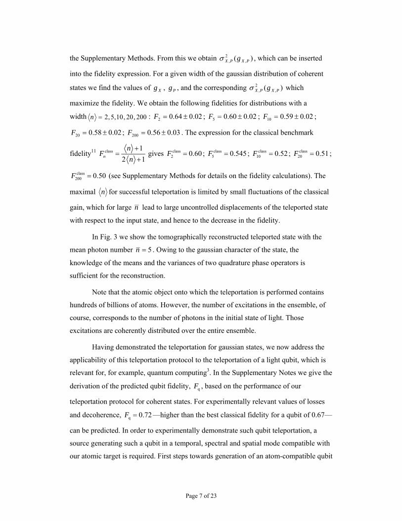
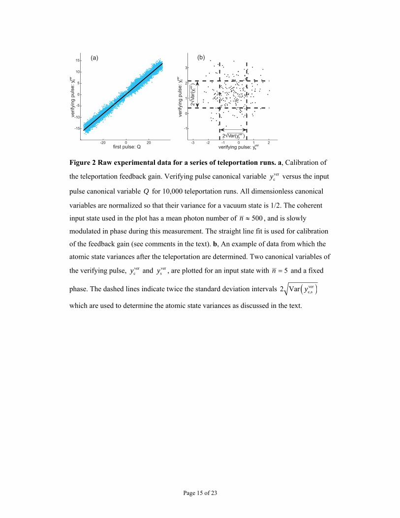
In Fig. 3 we show the tomographically reconstructed teleported state with the
mean photon number 5=n . Owing to the gaussian character of the state, the
knowledge of the means and the variances of two quadrature phase operators is
sufficient for the reconstruction.
Note that the atomic object onto which the teleportation is performed contains
hundreds of billions of atoms. However, the number of excitations in the ensemble, of
course, corresponds to the number of photons in the initial state of light. Those
excitations are coherently distributed over the entire ensemble.
Having demonstrated the teleportation for gaussian states, we now address the
applicability of this teleportation protocol to the teleportation of a light qubit, which is
relevant for, for example, quantum computing3. In the Supplementary Notes we give the
derivation of the predicted qubit fidelity, qF , based on the performance of our
teleportation protocol for coherent states. For experimentally relevant values of losses
and decoherence, q 0.72F = —higher than the best classical fidelity for a qubit of 0.67—
can be predicted. In order to experimentally demonstrate such qubit teleportation, a
source generating such a qubit in a temporal, spectral and spatial mode compatible with
our atomic target is required. First steps towards generation of an atom-compatible qubit
Page 8 of 23
state of light have been recently made using atomic ensembles19–21, single atoms in a
cavity22,23, and a photon subtracted squeezed state24.
In our experiment, the entanglement generation and the Bell measurement
overlap in time because the duration of the strong pulse and the pulse to be teleported is
2 ms, which is much longer than the time it takes light to travel from Alice to Bob. This
situation, also the case in some teleportation experiments6,8, is different, for example,
from the teleportation7,9,10 in which the entanglement generation and the Bell
measurement are separated in time. This feature is not inherent to our teleportation
scheme—indeed, in principle, a shorter strong pulse (of higher power) would generate
the same entanglement on a timescale short compared to the propagation time,
especially if the distance from Alice to Bob is extended to a few kilometres. The
teleportation distance can be increased, and is limited only by propagation losses of
light and the atomic coherence lifetime. The timing of the entanglement generation and
the Bell measurement may be potentially important for future applications.
Further improvement of the present teleportation protocol can be achieved by
performing more complex photocurrent processing with the same homodyne set-up. As
shown in ref. 12 and in the Supplementary Notes, a fidelity of 0.93 can be achieved if
such processing is combined with the use of an experimentally feasible25 6 dB squeezed
strong pulse.
Methods
Calibration and measurement techniques.
Physically, we perform measurements of the Stokes operators of light by two sets of
balanced homodyne detectors (Fig. 1). The measurements on the first pulse represent
the generalized Bell measurement. The same measurements on the second (verifying)
pulse allow us to determine the teleported atomic state by performing quantum state
tomography. The relevant ( )cos tΩ and ( )sin tΩ modulation components of the Stokes
operators are measured by processing the corresponding photocurrents with lock-in
amplifiers. The Stokes operators of interest are 2S (which is the difference between
photon fluxes in the modes polarized at 45± ° to the vertical axis, and 3S (which is the
corresponding quantity for the left- and right-hand circular polarizations).
Page 9 of 23
Calibration of the measurement of canonical variables for light is based on
measurements of the shot (vacuum) noise level. We measure the Stokes parameters for
the x-polarization mode in a vacuum state. The linear dependence of the variance of the
measured photocurrents on the optical power of the strong pulse proves that the
polarization state of light is, in fact, shot (vacuum) noise limited25. All other
measurements of 32ˆ,ˆ SS are then normalized to this shot noise level, yielding the
canonical variables as
2vacuum 02
0
1 d cos( ) ( )2 d cos( ) ( )
T
c Ty t St S
τ Ω ττ Ω τ
= ∫∫
and similarly for c 3( )q S and the ( )sin tΩ components. Since our detectors have nearly
unity (better than 0.97) quantum efficiency, the Stokes operators can be operationally
substituted with measured photocurrents.
Next we need to calibrate the atomic coherent (projection) noise level. Whereas
balanced homodyne detection for light has become an established technique for
determination of the vacuum state6, a comparable technique for atoms is a relatively
recent invention. Here we utilize the same procedure as used in our previous
experiments on the atoms–light quantum interface14,15. We use the fact that the vacuum
(projection) noise level for collective atomic spin states in the presence of a bias
magnetic field can be determined by sending a pulse of light through two identical
atomic ensembles with oppositely oriented macroscopic spin orientation. We therefore
insert a second atomic cell in the beam. As described in detail in ref. 15, the transmitted
light state in this experiment is given by
( )out in inc c atom1 atom2 c total
ˆ ˆ ˆˆ ˆ ˆ2
y y P P y Pκ κ= + + = +
where totalP is the spin canonical variable for the entire 2-cell atomic sample. Intuitively
this equation can be understood by noting that terms proportional to 2κ in equation (1)
cancel out for propagation through two oppositely oriented ensembles. A similar
equation holds for outsy with substitution of totalX for totalP . The results for ( )out
c,sˆVar y as
a function of the number of atoms are shown in the figure in the Supplementary
Page 10 of 23
Methods. The fact that the points lie on a straight line, along with the independent
measurement of the degree of spin polarization above 0.99, proves14,15,18 that we are
indeed measuring the vacuum (projection) noise of the atomic ensemble. 2κ for
different atomic numbers is then calculated from the graph (Supplementary Methods).
Its values are in good agreement with the theoretical calculation18 according to
1 ph at /a N N F Aκ σΓ Δ= . In the experiment, we monitor the number of atoms by
sending a weak off-resonant probe pulse along the direction x and measuring the
Faraday rotation angle proportional to the collective macroscopic spin of the ensemble
atoms4xJ N= . This Faraday angle is monitored throughout the teleportation experiment,
so that the value of 2κ is known at every stage.
Decoherence and losses.
The main sources of imperfections are decoherence of the atomic state and reflection
losses of light. For experimental values of the atomic decoherence and losses, the model
developed in ref. 12 predicts, for example, 66.05 =F , which is still higher than the
observed value owing to imperfections unaccounted for in the model but comparable to
the obtained experimental results. Dissipation also affects the experimental state
reconstruction procedure. The main effect of the light losses 09.0=ε is that it modifies
κ into 1κ ε− . However, this modified κ is, in fact, exactly the parameter measured in
the two-cell calibration experiment described above, so no extra correction is due
because of these losses. There is also a small amount of electronic noise of detectors
which can be treated as an extra vacuum contribution to the input state.
Standard deviation of the teleportation fidelity.
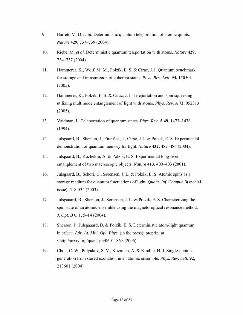
The standard deviation of the fidelity for 20≤n is calculated as follows:
2 2 2 2 2 2 2PN SN el SNR fit
2 2 2 2 2 2 2 2
SD( )
10 1.0 1.65 0.1 0.3 0.2 1.2 0.8 0.02
gF βδ δ δ δ δ δ δ
−
= + + + + + + =
= + + + + + + ≈
where PN 0.01δ = is the contribution to the SD( )F due to the projection noise
fluctuations including an error due to imperfect optical pumping, SN 0.017δ = is the
contribution due to the shot noise level uncertainty, el 0.001δ = is the contribution of the
Page 11 of 23
electronics noise level fluctuations, 003.0=βδ is the uncertainty due to fluctuations in
the atomic decay constant, SNR 0.002δ = is the contribution of the fluctuations in the
ratio of responses of two pairs of detectors, fit 0.012δ = is the deviation due to the
uncertainty of the quadratic fit of the atomic noise as a function of gain, and 008.0=gδ
is the contribution of the gain fluctuations. For 20>n , fit 0.016δ = , giving
SD( ) 0.026 0.03F ≈ ≈ .
Received 6 May; accepted 28 July 2006; doi:10.1038/nature05136.
1. Bennett, C. H. et al. Teleporting an unknown quantum state via dual classical
and Einstein-Podolsky-Rosen channels. Phys. Rev. Lett. 70, 1895–1899 (1993).
2. Briegel, H. J., Dur, W., Cirac, J. I. & Zoller, P. Quantum repeaters: the role of
imperfect local operations in quantum communication. Phys. Rev. Lett. 81,
5932–5935 (1998).
3. Gottesman, D. & Chuang, I. Demonstrating the viability of universal quantum
computation using teleportation and single-qubit operations. Nature 402, 390–
393 (1999).
4. Bouwmeester, D. et al. Experimental quantum teleportation. Nature 390, 575–
579 (1997).
5. Boschi, D., Branca, S., De Martini, F., Hardy, L. & Popescu, S. Experimental
realization of teleporting an unknown pure quantum state via dual classical and
Einstein-Podolsky-Rosen channels. Phys. Rev. Lett. 80, 1121–1125 (1998).
6. Furusawa, A. et al. Unconditional quantum teleportation. Science 282, 706–709
(1998).
7. de Riedmatten, H. et al. Long distance quantum teleportation in a quantum
relay configuration. Phys. Rev. Lett. 92, 047904 (2004).
8. Takei, N., Yonezawa, H., Aoki, T. & Furusawa, A. High-fidelity teleportation
beyond the no-cloning limit and entanglement swapping for continuous
variables. Phys. Rev. Lett. 94, 220502 (2005).
Page 12 of 23
9. Barrett, M. D. et al. Deterministic quantum teleportation of atomic qubits.
Nature 429, 737–739 (2004).
10. Riebe, M. et al. Deterministic quantum teleportation with atoms. Nature 429,
734–737 (2004).
11. Hammerer, K., Wolf, M. M., Polzik, E. S. & Cirac, J. I. Quantum benchmark
for storage and transmission of coherent states. Phys. Rev. Lett. 94, 150503
(2005).
12. Hammerer, K., Polzik, E. S. & Cirac, J. I. Teleportation and spin squeezing
utilizing multimode entanglement of light with atoms. Phys. Rev. A 72, 052313
(2005).
13. Vaidman, L. Teleportation of quantum states. Phys. Rev. A 49, 1473–1476
(1994).
14. Julsgaard, B., Sherson, J., Fiurášek, J., Cirac, J. I. & Polzik, E. S. Experimental
demonstration of quantum memory for light. Nature 432, 482–486 (2004).
15. Julsgaard, B., Kozhekin, A. & Polzik, E. S. Experimental long-lived
entanglement of two macroscopic objects. Nature 413, 400–403 (2001).
16. Julsgaard, B., Schori, C., Sørensen, J. L. & Polzik, E. S. Atomic spins as a
storage medium for quantum fluctuations of light. Quant. Inf. Comput. 3(special
issue), 518-534 (2003).
17. Julsgaaard, B., Sherson, J., Sørensen, J. L. & Polzik, E. S. Characterizing the
spin state of an atomic ensemble using the magneto-optical resonance method.
J. Opt. B 6, 1, 5–14 (2004).
18. Sherson, J., Julsgaaard, B. & Polzik, E. S. Deterministic atom-light quantum
interface. Adv. At. Mol. Opt. Phys. (in the press); preprint at
<http://arxiv.org/quant-ph/0601186> (2006).
19. Chou, C. W., Polyakov, S. V., Kuzmich, A. & Kimble, H. J. Single-photon
generation from stored excitation in an atomic ensemble. Phys. Rev. Lett. 92,
213601 (2004).
Page 13 of 23
20. Chaneliere, T. et al. Storage and retrieval of single photons transmitted between
remote quantum memories. Nature 438, 833–836 (2005).
21. Eisaman, M. D. et al. Electromagnetically induced transparency with tunable
single-photon pulses. Nature 438, 837–841 (2005).
22. Kuhn, A., Hennrich, M. & Rempe, G. Deterministic single-photon source for
distributed quantum networking. Phys. Rev. Lett. 89, 067901 (2002).
23. McKeever, J. et al. Deterministic generation of single photons from one atom
trapped in a cavity. Science 303, 1992–1994 (2004).
24. Neergaard-Nielsen, J. S., Melholt Nielsen, B., Hettich, C., Mølmer, K. &
Polzik, E. S. Generation of a superposition of odd photon number states for
quantum information networks. Phys. Rev. Lett. (in the press); preprint at
<http://arxiv.org/quant-ph/0602198> (2006).
25. Polzik, E. S., Carri, J. & Kimble, H. J. Spectroscopy with squeezed light. Phys.
Rev. Lett. 68, 3020–3023 (1992).
Acknowledgements The experiment was performed at the Niels Bohr Institute, and was funded by the
Danish National Research Foundation through the Center for Quantum Optics (QUANTOP), by EU
grants COVAQIAL and QAP, and by the Carlsberg Foundation. I.C. and E.S.P. acknowledge the
hospitality of the Institut de Ciències Fotòniques (ICFO) in Barcelona where ideas leading to this work
were first discussed. The permanent address of K.H. is the Institut für theoretische Physik, Innsbruck,
Austria.
Author Information Reprints and permissions information is available at www.nature.com/reprints. The
authors declare no competing financial interests. Correspondence and requests for materials should be
addressed to E.S.P. ([email protected]).
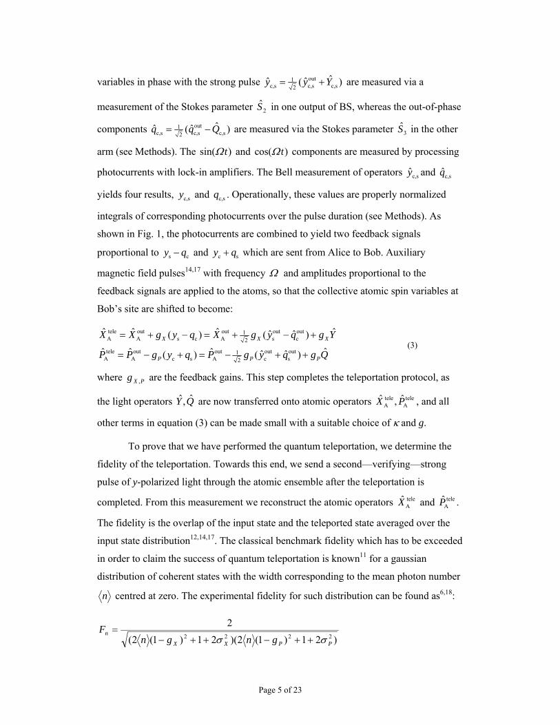
Page 14 of 23
EOM
Rf-coils
opticalpumpingpulse
6P3/2
F=4, 6S1/2m =4Fm =3F
+-
�/2�/2�/4
Alice
ysqc
qs yc
--
Bob
y
x
xout
in
BSPBS
PBS
strong
pulse pulse tobe
teleported
gatoms
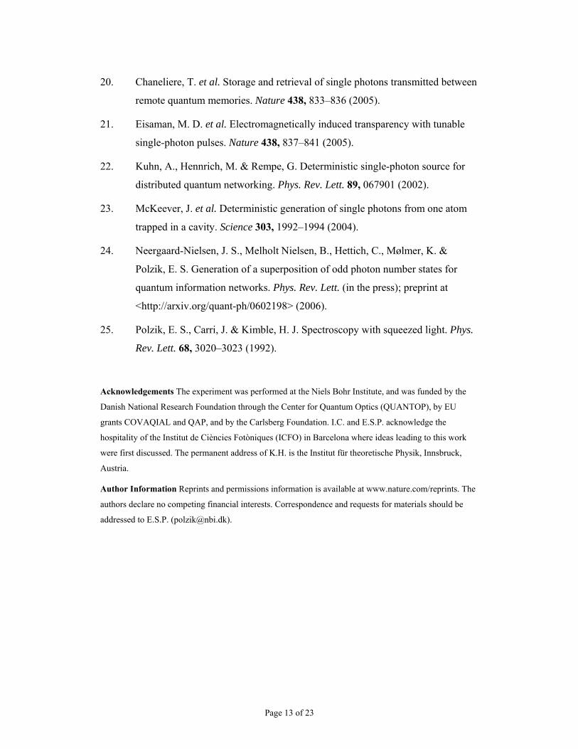
Figure 1 Experimental set-up for teleportation of light onto an atomic ensemble.
Atoms are initially optically pumped into F=4, mF=4 state with a 4-ms pulse. A strong
y-polarized 2-ms ‘in’ pulse of light is then sent through the atomic sample at Bob’s
location and becomes entangled with the atoms (the pulse length is around 600 km and
is not shown to scale in the figure). The pulse travels 0.5 m to Alice’s location, where it
is mixed on a beamsplitter (BS) with the object of teleportation—a few-photon coherent
pulse of light—generated by the electro-optical modulator (EOM) synchronously with
the strong pulse. In the two output ports of the BS, two polarization beamsplitters (PBS)
split light onto two pairs of detectors which perform a polarization homodyne
measurement (a Bell measurement). The results of these measurements are combined,
processed electronically, as described in the text, and sent via a classical communication
channel to Bob. There they are used to complete the teleportation onto atoms by shifting
the atomic collective spin state with a pulse of a radio-frequency (RF) magnetic field of
0.2-ms duration. After a delay of 0.1 ms, a second strong pulse—the verifying pulse—is
sent to read out the atomic state, in order to prove the successful teleportation. Inset,
relevant atomic sublevels and light modes (not to scale). The frequency difference
between a weak quantum field (black arrow) and the strong entangling field (thick red
arrow) is equal to the Zeeman splitting of the ground state sublevels.
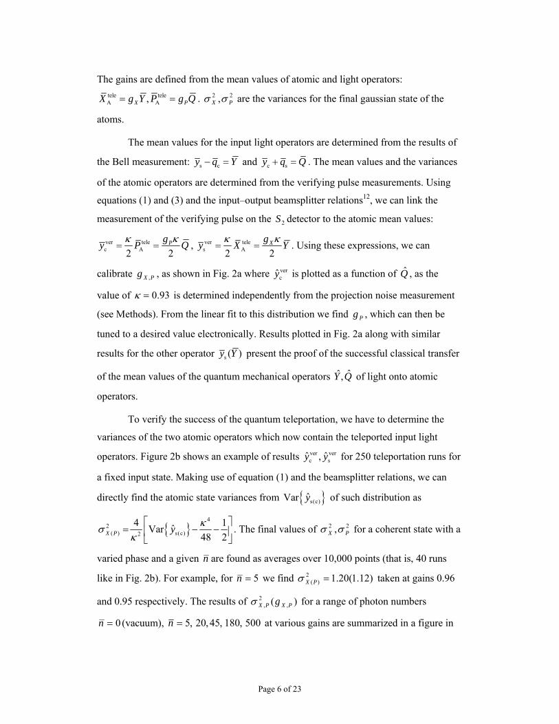
Page 15 of 23
-3 -2 -1 0 1 2
-1
0
1
2
3
verifying pulse: ysver
Var(y )s
ver2
-20 0 20
-15
-10
-5
0
5
10
15
first pulse: Q
(b)(a)
Var(
y)
cver
2
verify
ing
pu
lse
:y cv
er
ve
rify
ing
pu
lse
:y cv
er
Figure 2 Raw experimental data for a series of teleportation runs. a, Calibration of
the teleportation feedback gain. Verifying pulse canonical variable vercy versus the input
pulse canonical variable Q for 10,000 teleportation runs. All dimensionless canonical
variables are normalized so that their variance for a vacuum state is 1/2. The coherent
input state used in the plot has a mean photon number of 500≈n , and is slowly
modulated in phase during this measurement. The straight line fit is used for calibration
of the feedback gain (see comments in the text). b, An example of data from which the
atomic state variances after the teleportation are determined. Two canonical variables of
the verifying pulse, vercy and ver
sy , are plotted for an input state with 5=n and a fixed
phase. The dashed lines indicate twice the standard deviation intervals ( )verc,s2 Var y
which are used to determine the atomic state variances as discussed in the text.
Page 16 of 23
-5
0
5
-5
0
5
0
0.02
0.04
0.06
0.08
0.1
0.12
0.14
XA
telePA
tele
probability density
Figure 3 Tomographic reconstruction of a teleported state with 5=n (coloured
contour) versus the state corresponding to the best classical state transfer.
Canonical variables plotted on horizontal axes are normalized so that their variance for
a vacuum state is 1/2.
Page 17 of 23
Supplementary Methods. Atomic state variances, optimization of classical gains, and the fidelity calculation
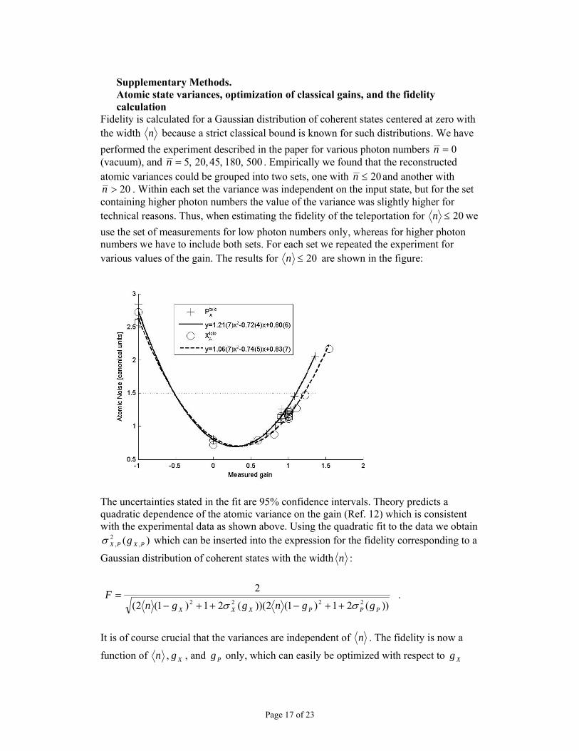
Fidelity is calculated for a Gaussian distribution of coherent states centered at zero with the width n because a strict classical bound is known for such distributions. We have performed the experiment described in the paper for various photon numbers 0=n (vacuum), and 500,180,45,20,5=n . Empirically we found that the reconstructed atomic variances could be grouped into two sets, one with 20≤n and another with
20>n . Within each set the variance was independent on the input state, but for the set containing higher photon numbers the value of the variance was slightly higher for technical reasons. Thus, when estimating the fidelity of the teleportation for 20≤n we use the set of measurements for low photon numbers only, whereas for higher photon numbers we have to include both sets. For each set we repeated the experiment for various values of the gain. The results for 20≤n are shown in the figure:
The uncertainties stated in the fit are 95% confidence intervals. Theory predicts a quadratic dependence of the atomic variance on the gain (Ref. 12) which is consistent with the experimental data as shown above. Using the quadratic fit to the data we obtain
)( ,2
, PXPX gσ which can be inserted into the expression for the fidelity corresponding to a
Gaussian distribution of coherent states with the width n :
))(21)1(2))((21)1(2(
22222
PPPXXX ggnggnF
σσ ++−++−= .
It is of course crucial that the variances are independent of n . The fidelity is now a
function of n , Xg , and Pg only, which can easily be optimized with respect to Xg
Page 18 of 23
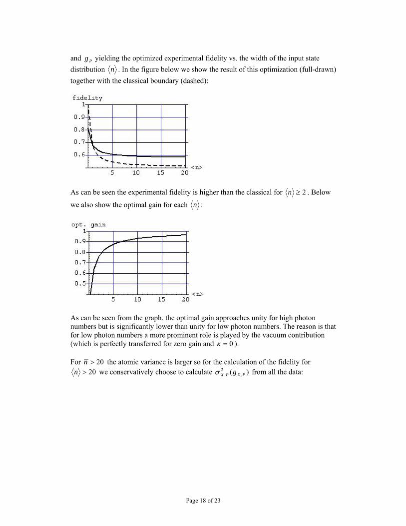
and Pg yielding the optimized experimental fidelity vs. the width of the input state distribution n . In the figure below we show the result of this optimization (full-drawn) together with the classical boundary (dashed):
As can be seen the experimental fidelity is higher than the classical for 2≥n . Below
we also show the optimal gain for each n :
As can be seen from the graph, the optimal gain approaches unity for high photon numbers but is significantly lower than unity for low photon numbers. The reason is that for low photon numbers a more prominent role is played by the vacuum contribution (which is perfectly transferred for zero gain and 0=κ ).
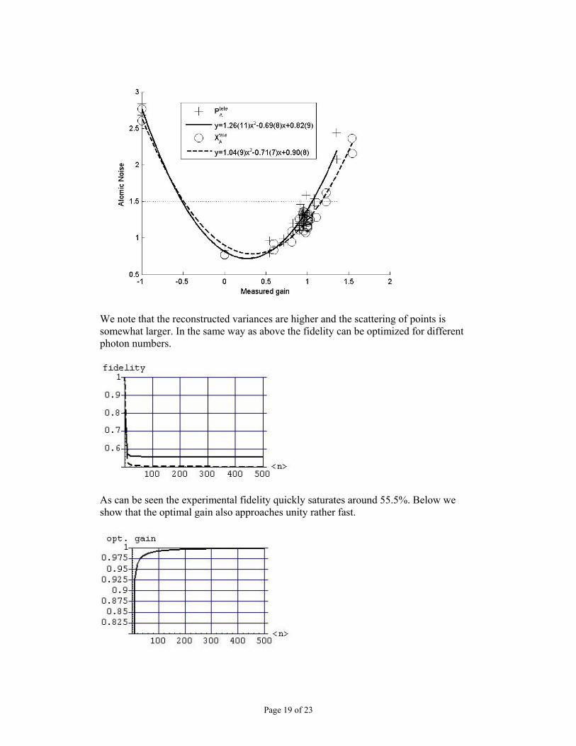
For 20>n the atomic variance is larger so for the calculation of the fidelity for 20>n we conservatively choose to calculate )( ,
2, PXPX gσ from all the data:
Page 19 of 23
We note that the reconstructed variances are higher and the scattering of points is somewhat larger. In the same way as above the fidelity can be optimized for different photon numbers.
As can be seen the experimental fidelity quickly saturates around 55.5%. Below we show that the optimal gain also approaches unity rather fast.
Page 20 of 23
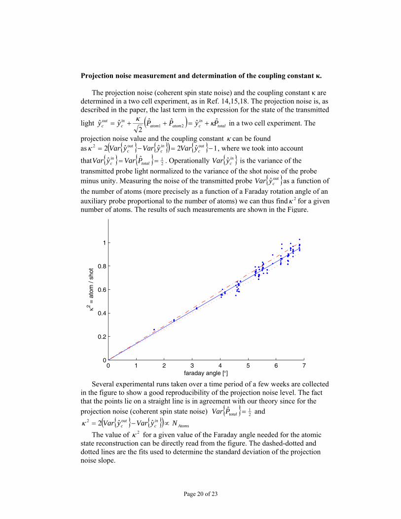
Projection noise measurement and determination of the coupling constant κ.
The projection noise (coherent spin state noise) and the coupling constant κ are determined in a two cell experiment, as in Ref. 14,15,18. The projection noise is, as described in the paper, the last term in the expression for the state of the transmitted
light ( ) totalincatomatom
inc
outc PyPPyy ˆˆˆˆ
2ˆˆ 21 κκ
+=++= in a two cell experiment. The
projection noise value and the coupling constant κ can be found as { } { }( ) { } 1ˆ2ˆˆ22 −=−= out
cinc
outc yVaryVaryVarκ , where we took into account
that { } { } 21ˆˆ == total
inc PVaryVar . Operationally { }in
cyVar ˆ is the variance of the transmitted probe light normalized to the variance of the shot noise of the probe minus unity. Measuring the noise of the transmitted probe { }out
cyVar ˆ as a function of the number of atoms (more precisely as a function of a Faraday rotation angle of an auxiliary probe proportional to the number of atoms) we can thus find 2κ for a given number of atoms. The results of such measurements are shown in the Figure.
0 1 2 3 4 5 6 70
0.2
0.4
0.6
0.8
1
faraday angle [°]
κ2 = a
tom
/ sh
ot
Several experimental runs taken over a time period of a few weeks are collected
in the figure to show a good reproducibility of the projection noise level. The fact that the points lie on a straight line is in agreement with our theory since for the projection noise (coherent spin state noise) { } 2
1ˆ =totalPVar and { } { }( ) Atoms
inc
outc NyVaryVar ∝−= ˆˆ22κ
The value of 2κ for a given value of the Faraday angle needed for the atomic state reconstruction can be directly read from the figure. The dashed-dotted and dotted lines are the fits used to determine the standard deviation of the projection noise slope.
Page 21 of 23
Atomic decoherence
The rate of atomic decoherence in a paraffin coated glass cell in the absence of interaction with light is very low15,17,18 corresponding to the coherence lifetime of
sec40m . However, the verifying pulse causes a much faster decoherence of the atomic state via the process of light-induced collisions14,18. This leads to the reduction in the mean spin values zyJ , according to βτ−e . We must adjust the gain calibration to take this small but still important effect into account. The decay constant 1sec09.0 −= mβ of the mean atomic spin orientation in the presence of the probe light is measured in a separate experimental run. As a result of this decay the verifying pulse measures reduced mean values YegyQegy sc
βτβτ κκ −− == 21
21 , as
compared to the teleported mean values, where sec1m=τ is the time interval from the beginning of the verifying pulse to its center yielding 91.0=−βτe . Thus the unity gain g is determined from the condition that the slope in Fig.2a is
42.091.093.0121
21 =⋅⋅⋅== −βτκeg
Qyc .
Page 22 of 23
Supplementary Notes Calculation of the fidelity for a qubit teleportation and a protocol with improved fidelity In this section we show (i) how one can relate the teleportation fidelity of coherent states to that of qubits and (ii) how a fidelity approaching unity can be achieved in a more sophisticated teleportation protocol. (i) Let us call E the (completely positive) map that transforms the state to be teleported to the teleported one. We assume that we know the action of E on coherent states, i.e.,
(| |)E α α⟩⟨ . The goal is to determine the qubit fidelity, qF , of this map. This is given by
( ) | (| ( ) ( ) |) | ( )qF d E= Ω ⟨Ψ Ω Ψ Ω ⟩⟨Ψ Ω Ψ Ω ⟩∫
where | ( ) cos( / 2) | 0 sin( / 2) |1ie ϕθ θΨ Ω ⟩ = ⟩ + ⟩ and the integration is over the 4π solid angle. This expression can be easily determined in terms of
2| |
0
1| (| |) | | (| |) |! !
n ma E n m b e a E bn m
αα α α
α α∗=
⎡ ⎤⟨ ⟩⟨ ⟩ = ∂ ∂ ⟨ ⟩⟨ ⟩⎣ ⎦
with n,m,a,b=0,1. Note that, in practice, one can also determine these quantities in terms of other measurable quantities. In the present experiment, one can characterize E as
2 22 | | /(2 )2
1(| |) | |2
g sE d es
β αα α β β βπ
− −⟩⟨ = ⟩⟨∫
where 2 24 1s σ= − is related to the atomic variance, 2 ( ) ( )tele teleA AVar X Var Pσ = = and g
is the gain (whose values are restricted given the complete positiveness of E). For this map we obtain
2 4 2 2 2
2 3
6 16 24 4( 1)(1 2 ) ( 1) (1 6 )6(1 2 )q
s s g s g sFs
+ + + − − + − −=
+
This shows that, in principle, one can obtain arbitrarily high fidelities for 1=g and small variances. For a particular teleportation protocol used in this paper, the value of
2σ follows from the expressions for ,tele teleA AX P (see text) and one obtains a theoretical
limit on the fidelity of 0.74 for 1κ = , in the absence of losses and decoherence. Including10% of light losses and atomic decay as in Ref. 12 of the paper, the theoretical prediction is still 0.72 for the same value of κ . (ii) A fidelity approaching unity can be achieved, in principle, by using squeezed light in the entangling pulse and measuring a number of higher order scattering modes in addition to the zero-th order cosine and sine modes. As explained in Ref .12 of the paper, the input-ouput relations describing the state of atoms and light after the interaction can be appended by similar relations for higher order modes , ,,n m nmy q iα β αβδ δ⎡ ⎤ =⎣ ⎦ where , ,c sα β = and , 1, 2,n m = … . Note that for the noise
operators αν in Eq. (1) we have ,1qα αν = . The envelopes of these modes are, apart from the (co)sine factor, given by the nth-order Legendre Polynomials (see Ref. 12 of the paper). Note that they can be measured by simply multiplying the photocurrents recorded in the polarization homodyne measurements of the present setup by suitable slowly varying time envelopes. In the light-atom interaction, these modes are
Page 23 of 23
transformed as out in( ), ( ),c s n c s nq q= and ( )2out in in in
( ), ( ), ( ), 1 1 ( ), 14c s n c s n n s c n n s c ny y c q c qκ− + += ± − where
( ) 1/ 224 1nc n−
= − . Extension of the teleportation protocol which includes these modes amounts to preparing the input state in some appropriate linear combination thereof, that is, in a mode 1
, ,2( )n s n c nn
Y g Y Q= +∑ and 1, ,2
( )n c n s nnQ g Y Q= − −∑ where
2 1nng =∑ . Optimization with respect to the coefficients ng shows that it suffices to
include the first three modes only ( ng = 0 for n>3 ) in order to achieve a final state of atoms after the feedback which is close to tele in1
,2A n s nnX Y g y= + ∑ and
tele in1,2A n c nn
P Q g y= + ∑ . The sums in these expressions amount to half a unit of vacuum noise in each spin component or a teleportation fidelity of 0.80F = . The corresponding optimal coefficients ng determine the envelope of the input modeY ,Q , which is a slowly decaying profile, as shown in Figure 1. The remaining half unit of added noise is due to the vacuum fluctuations of the entangling beam. It is possible to reduce this remaining noise by using squeezed light, such that the fidelity would approach unity, as the variances of in
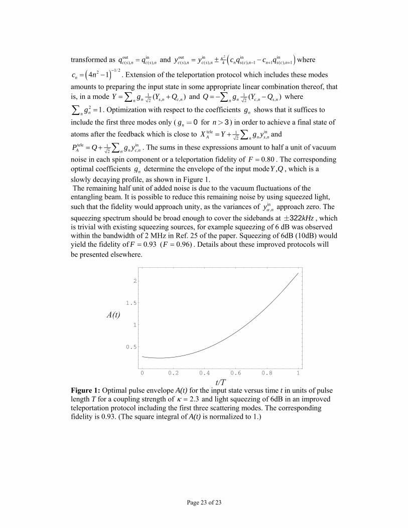
,nyα approach zero. The squeezing spectrum should be broad enough to cover the sidebands at kHz±322 , which is trivial with existing squeezing sources, for example squeezing of 6 dB was observed within the bandwidth of 2 MHz in Ref. 25 of the paper. Squeezing of 6dB (10dB) would yield the fidelity of )96.0(93.0 == FF . Details about these improved protocols will be presented elsewhere.
Figure 1: Optimal pulse envelope A(t) for the input state versus time t in units of pulse length T for a coupling strength of 3.2=κ and light squeezing of 6dB in an improved teleportation protocol including the first three scattering modes. The corresponding fidelity is 0.93. (The square integral of A(t) is normalized to 1.)