QRG_Aruz_2019.pdf - E-Owner-Manual - Perodua
43
QUICK USER GUIDE This Quick User Guide is not designed to provide owners with comprehensive information about the ARUZ. Please refer to the Owner’s Manual that comes with this vehicle for more details. All information in this guide is valid at the time of printing. Perodua reserves the right to make changes at any time without prior notice.
-
Upload
khangminh22 -
Category
Documents
-
view
4 -
download
0
Transcript of QRG_Aruz_2019.pdf - E-Owner-Manual - Perodua

QUICK USER GUIDE This Quick User Guide is not designed to provide owners with comprehensive
information about the ARUZ. Please refer to the Owner’s Manual that comes withthis vehicle for more details. All information in this guide is valid at the time of printing.
Perodua reserves the right to make changes at any time without prior notice.

INDEX
INSTRUMENT PANEL .............................................................. 1INSTRUMENT CLUSTER ........................................................ 2INTERIOR VIEW ....................................................................... 4SMART ENTRY ........................................................................ 5PUSH START/STOP BUTTON .................................................. 7HOOD & FUEL TANK DOOR RELEASE .................................. 9ENGINE COMPARTMENT ........................................................ 10
SAFETY AND EMERGENCY FEATURE ..................................... 38
SETTING UP ‘SMART LINK’ FOR ANDROID ........................... 11ADVANCED SAFETY ASSIST (A.S.A.) 2.0 ............................... 18EMERGENCY STOP SIGNAL (ESS) ........................................ 20‘ECO IDLE’ SYSTEM ................................................................ 21HILL-START ASSIST (HSA) ...................................................... 23VSC & TRC SYSTEMS ............................................................. 24WINDOW JAM PROTECTION ................................................. 26LIGHT, TURN SIGNALS & WIPER ........................................... 27SEATS ...................................................................................... 29AUDIO, CLOCK ....................................................................... 31CHANGING BACKGROUND COLOUR .................................. 32PAIRING A BLUETOOTH DEVICE, STEERINGSWITCH, REVERSE CAMERA ................................................. 33AIR CONTROL SYSTEMS ........................................................ 34REAR COOLER SYSTEM, POWER WINDOW ......................... 35SIDE MIRROR REMOTE CONTROL, POWER SOCKET,USB POWER OUTLET, HDMI POWER OUTLET ...................... 36GLASSES CASE, ROOF RAIL, BUILT-IN TOLL READER, DVR, SEAT POCKET ................................................ 37
FEATURE/OPERATION
SAFETY & EMERGENCY
OVERVIEW

1
OVERVIEW
1 Turn signal control lever 2 Headlight control3 Combination meter panel4 Wiper and washer control lever5 Hazard warning signal switch6 Audio control panel7 SRS air bags for front passenger8 Glove box9 SRS air bags for driver! HDMI power outlet (if equipped)" USB power outlet# Power socket
$ Air conditioner control panel% Front corner sensor switch& Central doors lock switch' Rear passenger seat belt indicator( Front passenger seat belt indicator) Engine start/stop button* Headlight levelling switch+ Eco Idle OFF switch, VSC & TRC OFF switch- Advanced Safety Assist (A.S.A.) OFF switch
SRS AIRBAG
A/C MODE1
MEMORY2
MEMORYFRONT REAR
MAXCOOL MAX
OFF
1
2
PPASSENGER
REAR
O
12
OFF
OFFA
OFF
156 2
9
$
%
378 4
( ,
-
)
*
+
"!
&'
#
INSTRUMENT PANEL

2
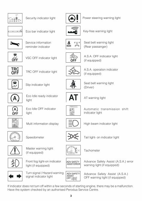
Air bag warning light
For details, refer to “Indicator & Warning Lights” in Section 5 Owner’s Manual.
Parking brake warning light
Brake warning light
Oil pressure warning light
Battery charge warning light Malfunction indicator light (MIL)
ABS (Anti-lock Braking System) warning light
Water temperature warning light
Low fuel level warning light
Door ajar warning light
INDICATOR SYMBOL
0OFF
TRIPAVG
CFCRANGE
ODO
km/L
OFF
ADV SAFETY
A
E
F
x1000r/min km/h
AOFFATRC
OFF
P
OFF AT!
ODO/TRIPDISP
1
23 4
7
8
5
0
20
40
80140
180
200
100 12060
1606 ERRORASSIST
1 Tachometer2 Fuel Gauge3 AT Shift Indicator Light4 Speedometer
5 Odometer Display Reset Button6 Indicator & Warning Light7 Multi-information Display
If indicator & Warning lights do not turn off within a few seconds of starting the engine, there may be a malfunction. Have your car checked at an authorised Perodua Service Centre.
6
4
7 5
1 32
P
!
INSTRUMENT CLUSTER
3
Turn signal / Hazard warning signal indicator light
Speedometer
Multi information display
Eco Idle OFF indicatorlight
Eco Idle ready indicator light
Slip indicator light
TRC OFF indicator light
VSC OFF indicator light
Service informationreminder indicator
Eco bar indicator light
Security indicator light
Tail light- on indicator light
A.S.A. operation indicator (if equipped)
A.S.A. OFF indicator light (if equipped)
Seat belt warning light(Rear passanger)
Seat belt warning light(Driver)
AT warning light
High beam indicator light
Automatic transmission shift indicator light
Key-free warning light
Power steering warning light
Master warning light(if equipped)
Advance Safety Assist (A.S.A.) error warning light (if equipped)
Front fog light-on indicatorlight (if equipped)
Advance Safety Assist (A.S.A.) OFF warning light (if equipped)
Tachometer
If indicator does not turn off within a few seconds of starting engine, there may be a malfunction. Have the system checked by an authorised Perodua Service Centre.
TRCOFF
P
OFF AT!
1
2
7
80
6SecurityIndicatorlight
OFF
TRCOFF
A
OFFA
TRIPAVG
CFCRANGE
ODO
km/L
OFF
ADV SAFETY
A
E
F
ERRORASSIST
0
km/h
AOFFA
20
40
80140
180
200
100 12060
160
REAR
OFF
ATTRIPAVG
CFCRANGE
ODO
km/L
OFF
ADVASSIST
SAFETYERROR
A
E
F
x1000r/min
TRCOFF
P
OFF AT!
1
23 4
7
8
5
0
6
ADV SAFETYERRORASSIST
OFF
ADVASSIST
SAFETY

4
1 Sun Visor2 Door lock / unlock switch3 Power window switch4 Seat belt
5 Third row seat6 Second row seat7 Front seat8 Shift lever
4
1 23
8
5
6
7
INTERIOR VIEW
5
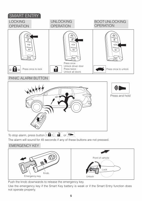
PANIC ALARM BUTTON
Press and hold
EMERGENCY KEY
To stop alarm, press button , or .The alarm will sound for 45 seconds if any of these buttons are not pressed.
Push the knob downwards to release the emergency key.Use the emergency key if the Smart Key battery is weak or if the Smart Entry function does not operate properly.
UNLOCKINGOPERATION
LOCKINGOPERATION
BOOT UNLOCKING OPERATION
: Press once to lock
Press once :Unlock driver doorPress twice :Unlock all doors
Press once to unlock
KnobEmergency key
Front of vehicle
Unlock
Lock
SMART ENTRY

6
LOCK / UNLOCK DOORS
UNLOCK BACK DOOR
Operating range may vary by surrounding conditions.(i) Key-free: Within 3 metres from centre of vehicle.(ii) Request switch: When the smart key is within approximately 80cm from outer door handle.
Smart entrySmart Key
Request switch
Lock
Smart key
Unlock
Grasp
Press button to open boot

7
TO START ENGINE TO STOP ENGINE
PUSH START SYSTEM
TO CHANGE ENGINE IGNITION MODE
Switch indicator
The Push Start/Stop Buttonallows you to start and stop theengine without inserting a keyinto ignition.
P
P
The engine will stop when you :
Shift lever button
Q
Press and hold the Push Start/Stop Button for more than 3 seconds or ;
Q Press the Push Start/Stop Button more than 3 times.
OFF ACC ON
Not in P range
In P range
When brake pedal is not depressed, pressing the Push Start/Stop Button will change the engine mode.
PUSH START/STOP BUTTON

8
SWITCHING ENGINE ON WHEN SMART KEY BATTERY IS WEAK
P
1 Move the gear shift to ‘P’ while depressing the brake pedal.
2 Touch the Push Start/Stop Button with SmartKey until the buzzer sounds and the engine switch indicator turn green.
3 Push the Push Start/Stop Button within 4 seconds after the buzzer sounds and the engine switch indicator turns green.

9
HOOD RELEASE
FUEL TANK DOOR RELEASE AND CAP OPENING
Insert rod holdhood to open
Pull up latch andraise hood
Make sure cap is securely closed (indicatedby a ‘click’ sound) to prevent fuel spillage.
Lever
CloseOpen
Hanger
HOOD & FUEL TANK DOOR RELEASE

10
1 Windshield washer fluid tanks2 Automatic transmission oil level gauge3 Engine oil filter cap4 Spark plug5 Engine oil level gauge
6 Brake fluid reserve tank7 Battery8 Fusible link9 Radiator cap! Engine coolant reserve tank
Regularly scheduled maintenance, including oil changes, will help extend the life of your vehicle and maintain performance. Please refer to the maintenance schedule in section 13 of the Owner’s Manual.
13
9 !
246
7 8
5
ENGINE COMPARTMENT

11
FEATURE/OPERATION
1 Activate Bluetooth on your Android device and pair it with the Multimedia System to enable ‘Smart Link’ Audio*
2 ‘Smart Link’ connection requires you to enable ‘Developer Options’. If your device does not have ‘Developer Options’ enabled, follow the steps below.
a. Go to ‘Settings’b. Go to ‘About Phone’ (or ‘About Device’)c. Tap ‘Build Number’ 7 times to enable ‘Developer Options’.
*Please refer to Bluetooth pairing manual for more details.
TURN ON H/P USB DEBUG
CONNECT TO THE SMART PHONE
SETTING UP ‘SMART LINK’ FOR ANDROID (IF EQUIPPED)
Settings
CONNECTION DEVICE CONTROLS GENERAL
Accessories
Application manager
Default applications
Battery
Power saving mode
Storage
Security
About device
k
k

12
3 A ‘USB Debugging’ screen will appear. Follow the instructions listed on the screen.
a. Go to ‘Developer Options’.b. Enable ‘Developer Options.b. Check or enable ‘USB Debugging’.
4 Allow ‘USB Debugging’ on your Android device when window pops up on smartphone.
Your device may have a dierent way of enabling ‘Developer Options’.Please refer to your device’s user manual for more details.
Allow USB debugging?
USB debugging is intended for development purposes only. It can be used to copy data between your computer and your device, install applica-vtions on your device withoutnoti�cation, and read log data.
CANCEL OK

13
5 Connect USB cable to the USB port. Enter ‘Smart Link’ mode by touching the ‘Smart Link’ button.
6 Touch ‘Detect Phone’ on Audio Navigation. On the Android device, allow for USB Debugging.
CONNECT USB CABLE

14
Open the Drive Mode app to enter the ‘Smart Link’ control menu. ‘Smart Link’ is now ready for use.
• Steps 1 to 7 only need to be done once for each Android device, for first time users only.
• ‘Smart Link’ only works with Android OS 4.0 and above. • 'Smart Link' does not support iOS.• The Drive Mode app installation requires at least 50MB of storage space on your Android
device.• ‘Drive Mode’ App does not contain viruses. You may receive an alert from your device’s antivirus software during its first installation. Select “yes” if confirmation of installation is
required.• Use only original USB cables.• Performance may vary according to device specifications.
7 The Drive Mode app will be automatically downloaded and installed to your Android device. Once download is complete, Smart Link control menu will be shown on audio display.
‘DRIVE MODE’ APP INSTALLATION
Drive ModeExciting and Safe k

15
Touch [Navigation] on the ‘Smart Link’ control menu to access Google Maps or Waze applications.
Touch [Telephone] on the ‘Smart Link’ control menu to make a phone call.
Dial the desired phone number using the keypad, then touch [ ].OR
Touch [Contact] to enter the Phone Book. Touch the desired contact number.
Select the desired map application by tapping on the icon.
‘SMART LINK’ NAVIGATION
‘SMART LINK’ TELEPHONE
k
k
Maps Waze
Choose application
#* 0+
3DEF
1 2ABC
6MNO
4GHI
5JKL
9WXYZ
7PQRS
8TUV
*
KEYPAD CONTACT
John012345678
John012345678
Jaden019123456
Jacob016789123

16
Touch [Music] on the ‘Smart Link’ control menu to play music from your Android device.
Playing music functions:
[ ] Pause
[ ] Play
[ ] Skip forward[ ] Skip backward[ ] Repeat playlist[ ] Repeat current song[ ] Random playTouch [Song] to display song list.Select the desired song.
• Touch [ + ] on the ‘Smart Link’ control menu to add an application from your Android device.
• Select the desired application from the application list.
• The added application icon will overwrite the [ + ].
A total of 15 applications can be added to the ‘Smart Link’ control menu, but only Map, Phone & Music Apps function during driving.
‘SMART LINK’ MUSIC
ADDITIONAL ‘SMART LINK’ APP
k

17
REMOVING ‘SMART LINK’ APP
OTHER CONTROL FUNCTIONS
POTRAIT AND LANSCAPEDISPLAY SELECTION
• Touch and hold the application icon until [ _ ] appears.• Touch the [ _ ] to remove the application.
Touch [ ] to display the ControlFunction bar.
Q
Q
Control Functions :[ ] Close Control Functions bar
[ ] Back to previous screen
[ ] Go to home screen
[ ] Go to main menu
[ ] Control volume
[ ] Quit ‘Smart Link’
• Touch and hold the desired application icon until appears.
• Touch to select portrait or landscape display. dim : Portrait Display light : Landscape Diplay
k
‘Smart Link’ videos play at a frame rate of 15 to 20 FPS.‘Drive Mode’ App does not contain viruses. You may receive an alert from your device’santivirus software during its first installation. Select “yes” if comfirmation of installation is required.

18
STEREO CAMERA
A.S.A. OFF SWITCH
A.S.A. is a system designed to support the driver’s awareness, decision making and vehicle operation contributing to a safe driving experience.
A.S.A. OFF indicator light will illuminate at the meter panel. Every time you start the engine by the engine switch operation, A.S.A. function will return to ready state.
i) A stereo camera mounted in front of the inside rear view mirror which detect vehicle up to about 60m (pedestrian up to 30m) in front.
ii) The stereo camera will not operate properly if the wind shield view in front of the camera is obstructed by something, dirt, foggy, sticker etc.
Push more than 2 secondsto turn OFF A.S.A. function
A.S.A. OFF indicator light ENGINESTARTSTOP
OFF OFF
Vertical viewabout 20 degrees
Horizontal viewabout 40 degrees
Stereo cameradetection range
Stereo cameradetection range
ADVANCED SAFETY ASSIST (A.S.A.) 2.0 (IF EQUIPPED)

19
1 PRE-COLLISION WARNING
2 PRE-COLLISION BRAKING
3 PEDAL MISOPERATION CONTROL
Q Driver should instantly press the brake pedal to continue stop condition because the vehicle will slowly starts moving after about 1.5 seconds.Q Pre-collision braking will be disabled after the secondary brake has been activated 3 times. It will reset when engine restarts.
Alert the driver when it detects a risk of frontal collision.
Apply brakes to avoid the collision or mitigate damage.
Suppresses engine output when the driver accidentally stomps the accelerator pedal.
If the depression of accelerator pedal is strong but quick at under 4 km/h, only warning isoperated.
PiPiPiPiPiPi
Stereo camera
Possibility to crash with front vehicle : high
The system alerts the driver when there is a risk of collision with a front obstacle through recognition from the stereo camera.
This function operates when own vehicle speed and the speed difference between the front obstacles are about 4 ~ 100 km/h (vehicle)or about 4 ~ 50 km/h (pedestrian)
Flashing
PiPiPiPiPi...
Possibility to crash with front vehicle : more high
Stereo camera
Q The system implements emergency braking when it detects an increasing risk of collision with the speed between own vehicle and front obstacles are about 4~80 km/h (vehicle) or about 4~50 km/h (pedestrian).Q Collision can be avoided if the speed between own vehicle and front obstacles are about below 30km/h.Q When the driver step on the brake pedal, this function apply additional braking force in reducing the damage with the speed between own vehicle and front obstacles are about 30~80 km/h (vehicle) or about 30~50 km/h (pedestrian).
Flashing Lighting
PiPiPiPiPi...
Stepping on the wrong pedal STORE
Obstacle
Stereo camera
Suppress of engine output
Flashing Lighting
about 4 meter
When the vehicle detects obstacles (vehicle/wall/building) in front and driver depressaccelerator pedal quickly and strongly, thesudden acceleration is controlled.
* If there is no parking curb, car will stillmove slowly.
20
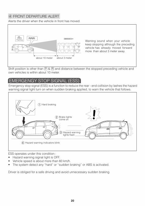
4 FRONT DEPARTURE ALERT
Shift position is other than H & I and distance between the stopped preceding vehicle and own vehicles is within about 10 meter.
ESS operates under this condition : • Hazard warning signal light is OFF.• Vehicle speed is about more than 60 km/h.• The system detect any ‘‘hard’’ or ‘‘sudden braking’’ or ABS is activated.
Driver is obliged for a safe driving and avoid unnecessary sudden braking.
Emergency stop signal (ESS) is a function to reduce the rear - end collision by lashes the hazard warning signal light turn on when sudden braking applied, to warn the vehicle that follows.
Alerts the driver when the vehicle in front has moved.
PiPiPi
about 3 meter
éééé
about 10 meter
Flashing Warning sound when your vehiclekeep stopping although the precedingvehicle has already moved forwardmore than about 3 meter away.
Hard braking
Brake lightscome on
Hazard warninglights flash
Hazard warning indicators blink4
3
2
1
EMERGENGY STOP SIGNAL (ESS)

21
The ‘Eco Idle’ system automatically shuts down the engine when the vehicle is idle and restarts it when the vehicle returns to motion, improving fuel consumption, reducing emissions and minimising idling noise.
1 When conditions for ‘Eco Idle’ mode are fulfilled during driving, the ‘Eco Idle’ ready indicator turns on in green (standby state).
2 While the gear shift is in D, depress the brake pedal and stop your vehicle for ‘Eco Idle’ mode. The indicator will remain on in green during ‘Eco Idle’ mode.
3 The engine restarts when foot is released from the brake pedal. The ‘Eco Idle’ ready indicator will turn off.
4 The ‘Eco Idle’ ready indicator turn on in green again after conditions for ‘Eco Idle’ mode are fulfilled.
0OFF
TRIPAVG
CFCRANGE
ODO
km/L
OFF
ADV SAFETY
A
E
F
x1000r/min km/h
AOFFATRC
OFF
P
OFF AT!
ODO/TRIPDISP
1
23 4
7
8
5
0
20
40
80140
180
200
100 12060
1606 ERRORASSIST
OFFA
AEco Idle ready
Eco Idle OFF
Engine restart
Release the foot from the brake pedal
Eco Idle
‘ECO IDLE’ SYSTEM

22
‘Eco Idle’ may not operate normally under the following conditions. Have the vehicle checked by an authorized Perodua Service Centre.
The interior light turns on when the driver’sdoor is closed and does not turn on whenthe driver’s door is opened.
Door
Door ajar warning light turns on when thedriver’s door is closed and does not turn onwhen the driver’s door is opened.
Seat belt reminder light flashs when driver’sseatbelt is fasterned, and/or does not flashwhen driver’s seat belt is not fasterned.

23
Hill-start Assist (HSA) helps to prevent the vehicle from rolling back when starting up again froma stopped position on an incline.
HILL - START ASSIST (HSA)
1 Release the brake pedal slowly.
2 Vehicle retains brake force for 2 seconds.
3 Accelerate to continue driving.

24
Vehicle Stability Control (VSC)Keeps the vehicle stable during sudden turns or on slippery roads.
Traction Control (TRC)Assists with keeping the stability of the vehicle when accelerating on slippery roads.
• These situations may arise depending on road, tyre and weather conditions.• The vehicle is more secure if it is equipped with ABS (Anti-lock Bracking System) & EBD
(Electronic Brake force Disribution.)
VSC & TRC OPERATION
With VSC - The vehicle isstabilized Without VSC - Skidding occur
Front wheels skid Rear wheels skid Rear wheels skid
VSC & TRC SYSTEMS

25
If there is an error,
illuminates
OFF
Pressing
illuminates
OFF
OFF
OFF
TRCOFF and
Pressing and holding
illuminates
switches VSC off
switches VSC & TRC off
ENGINESTARTSTOP
OFF
IMPORTANT:
Even when VSC & TRC are operation, there arelimits to the systems’ traction and stability control.Dangerous driving may still cause accidents.

26
The Window Jam Protection function is an auto-reverse safety feature. The window will stop rising when closing if the sensor detects an obstruction between the glass and window frame.
Window jam Protection will not a activateif obstruction is too small.
Turn ignition switch ‘‘ON’’.Push and hold the power window switchdown until window has opened completely.Hold the power window switch in the one -touch closing position.Continue holding the switch for a further 2seconds after the window has closedcompletely.
••
•
•
k
k
Obstruction
Glass
Retract
Glass
Rising
WINDOW JAM PROTECTION

27
HIGH BEAM & HEADLIGHT FLASH
FOLLOW ME HOME FUNCTIONTURN SIGNAL CONTROL LEVER
FOG LIGHT SWITCH (IF EQUIPPED)
Headlight will turn “ON” for 30 seconds before it will automatically turn “OFF”.
1 Clearance lights 3 Headlight flasher2 Headlights 4 High beam
1
3
4
2
Front fog light switch
ON
OFF
1
2
3
4
Left turn
Right turn
Lane change
Lane change
1
2
3
4
Headlight OFF PULL
OFF 1
2 3
HEADLIGHT LEVELLING SWITCH
Rotate the dial up & down to changethe direction.
ENGINESTARTSTOP
O
12
LIGHTS, TURN SIGNALS & WIPER

28
AUTO LIGHT OFF FUNCTION
WINSHIELD WIPER AND WASHER LEVER
Door open
TURNOFF
Slow speed
Fast speed
OFF
MIST
INT
Washer
ON
The headlights are automatically turned off if the driver’s door opened after the engine switch is turned to “OFF or “ACC” or after 10 minutes when the engine switch is in “OFF” position and the driver’s door is remain closed.
During intermittent (INT) operation, the interval becomes shorter as the driving speed rises.
AUTO LIGHT FUNCTION (IF EQUIPPED)
QThe headlight turn on when the auto light sensor sense dark condition.
QDo not shield the sensor as the function may not operate properly.
Auto position
ON Sensor

29
SEAT ADJUSTMENT
FOLDING SECOND SEAT
1
1
1
2
2
223
3Front seats Second row seats Third row seats
2
1 Seat position (forward/backward)2 Seat back angle3 Seat hight adjuster (driver’s side only)
1 Stow the seat belt buckles
3 Fold the seatback down 4 Swing the whole seat up and forward
2 Lower the head restraint
Pull
SEATS

30
FOLDING THIRD SEAT
1 Stow the seat belt buckles
3 Fold the seatback down
5 Take out the hook from the strap
4 Swing the whole seat up and forward
6 Hook the holding strap to the head restraint
2 Lower the head restraint
Pull
Pull

31
Volume buttonPower button
(Type A) (Type B)
USB door1
2
3
SD card4
12
3 3
2 1
4
HEAD RESTRAINTS
Lock release button
Up
Down
Lock release buttonLock release button
Adjust InstallRemove
* For details, refer to “Audio System” in section 7 owner’s manual
1 Press [setting] button on main menu screen.
2 Press [time] to display the setting.
3 Adjust date and clock time by scrolling up or down on required column.
AUDIO
CLOCK

32
(Type A) (Type B)
1 Touch [Setting] button on Main Menu Screen to set various setting functions.
2 Background – Select and touch desired colour. The selected background colour will also be applied to the navigation user interface.
CHANGING BACKGROUND COLOUR
k k

33
** Do not attempt bluetooth pairing driving **
1) Press [Bluetooth] button on main menu screen.2) Press [pairing].3) Search new device in bluetooth mode using your phone until you found “PERODUA”.4) Audio System default name is “PERODUA” and passkey is 6-digit similar on both mobile phone and audio system.5) LCD will display “CONNECTED” and “ ”.6) New bluetooth system enters into stanby mode and ready to use.
*A maximum of 8 devices can be paired to the system.
5) LCD will display “CONNECTED” and “ ”.
SRS AIRBAG
^
^
Volume down button
Volume up button
Tune down button
Tune up button
Mode button
1
2
3
4
51
2
3 4
5
3.0m 3.0m
1.2m1.2m
Bumper red line
Red Green
Yellow
D
C
B
A
0.6m
A C
B D
0.6m
PAIRING A BLUETOOTH DEVICE
STEERING SWITCH
REVERSE CAMERA

34
TURN ON THE AIR CONDITIONER
TEMPERATURE CONTROL
A/C MODE1
MEMORY2
MEMORYFRONT REAR
MAXCOOL MAX
OFF
1
2
1 Ignition switch on
2
2
Press
33
Press A/C
1
1Press to increase level
2 Press to decrease level
3
2
MAXCOOL will appear afterpressing to the maximum/end
A/C MODE1
MEMORY2
MEMORYFRONT REAR
MAXCOOL MAX
OFF
1
2
MAXCOOL
3
BLOWER FAN SWITCH
1 Press to increase level
2
1
2Press to decrease level
3 Press until no level display
of LCD to turn off the blower
OFF
A/C MODE1
MEMORY2
MEMORYFRONT REAR
MAXCOOL MAX
OFF
1
2
MAX
OFF
1
2
OFF
AIR CONTROL SYSTEMS

35
Automatic operation Push the switch down or pull it completely up and release to fully open or close . To stop window partially, push the switch lightly in the opposite direction during opening or closing.
Rear passengersides
Driver side
PassengerMaster switch
Frontpassengerside
Up
Down
SET MEMORY
1 Set preferred sett ing ofair conditioner by pressing or button.
2 To replace a memory, holdeither button for 1.5 second.
1MEMORY
2MEMORYA/C MODE
1MEMORY
2MEMORY
FRONT REAR
MAXCOOL MAX
OFF
1
2
A/C MODE1
MEMORY2
MEMORYFRONT REAR
MAXCOOL
OFF
1
2
MAX
REAR COOLER SYSTEM
POWER WINDOW

36
SIDE MIRROR REMOTE CONTROL
1
2
3 PUSH
Ignition switch set to “ACC” or “ON” positionfor use.
HDMI POWER OUTLET(IF EQUIPPED)USB POWER OUTLET
Front Rear
*Ignition switch set to “ACC” or “ON” position for use.1 Set the switch to left or right. 3 Return the switch to neutral (OFF) position.2 Push the switch to adjust the mirror.
TO ADJUST
Front
TO FOLD
RearPOWER SOCKET

37
SEAT POCKETDVR (IF EQUIPPED)
Rear Side
GLASSES CASE ROOF RAIL (IF EQUIPPED)
BUILT-IN TOLL READER
Antenna
* Card not included
LCDCard slotPress button to check theprepaid card balance
Front windscreen1
1
2
3
3 2
Roof rail

38
DOOR LOCK
FRONT CORNER SENSOR SWITCH
DOOR CHILD SAFETY LOCK TILT STEERING
SAFETY & EMERGENCY
Lock button
Front of vehicle Front of vehicle
Inside handle
SRS AIRBAG
UnlockLock
SRS AIRBAGP• This function will assist driver to park
the vehicle during front parking
• Press the switch to activate the system
Lock
Unlock
Moving the lever to “LOCK” will allow the doorto be opened only from the outside.
Lock
Unlock
SAFETY & EMERGENCY FEATURES

39
CHILD RESTRAINT SYSTEM
SEAT BELTS
Baby seats Child seats Junior seats
Right sidebuckle (small)
Left sidebuckle (center)
1
2
Push
Take upslack
Correct
Adjusting Unfasten
Too high
Seperate type
Front
Rear
QThis vehicle is equipped with ISO FIX child restraint system seat.QThe child restraint seat should be properly installed on the rear seat.

40
FRONT SEAT BELT PRETENSIONER
AIR BAGS
SRS Front Air Bags
SRS Curtain Air Bags
Severe impact from front of the vehicle
Severe impact from side & rear of the vehicle
Severe impact from side of the vehicle
SRS Side Air Bags
Q Actuated when subjected to a strong impact from the front.
Q Seat belt will instantly retracts to secure the upper body of occupant.

41
TOOL BOX SPARE TYRE LOCATION
FLOOR MAT INSTALLATION
Jack
Tool bag Spare tyre
Refer to the Owner’s Manual in section 11 for tyre changing and jack positioning procedure.
Floor mat
Fastener
Before driving, ensure that thefloor mat is installed securelyin the correct position.