QoS Policies
66
7950 XRS Quality of Service Guide Page 23 QoS Policies In This Chapter This chapter provides information about Quality of Service (QoS) policy management. Topics in this chapter include: • QoS Overview on page 25 • Service and Network QoS Policies on page 30 → Network QoS Policies on page 31 → Network Queue QoS Policies on page 33 → Service Ingress QoS Policies on page 49 → Service Egress QoS Policies on page 56 → Queue Parameters on page 36 • Named Pool Policies on page 57 • QoS Policies on page 26 • Scheduler Policies on page 68 → Virtual Hierarchical Scheduling on page 70 − Single Tier Scheduling on page 71 − Hierarchical Scheduler Policies on page 73 • Forwarding Classes on page 78 → High-Priority Classes on page 79 → Assured Classes on page 79 → Best-Effort Classes on page 80 → Shared Queues on page 80 • ATM Traffic Descriptor Profiles on page 80
-
Upload
khangminh22 -
Category
Documents
-
view
1 -
download
0
Transcript of QoS Policies
7950 XRS Quality of Service Guide Page 23
QoS Policies
In This Chapter
This chapter provides information about Quality of Service (QoS) policy
management.
Topics in this chapter include:
• QoS Overview on page 25
• Service and Network QoS Policies on page 30
→ Network QoS Policies on page 31
→ Network Queue QoS Policies on page 33
→ Service Ingress QoS Policies on page 49
→ Service Egress QoS Policies on page 56
→ Queue Parameters on page 36
• Named Pool Policies on page 57
• QoS Policies on page 26
• Scheduler Policies on page 68
→ Virtual Hierarchical Scheduling on page 70
− Single Tier Scheduling on page 71
− Hierarchical Scheduler Policies on page 73
• Forwarding Classes on page 78
→ High-Priority Classes on page 79
→ Assured Classes on page 79
→ Best-Effort Classes on page 80
→ Shared Queues on page 80
• ATM Traffic Descriptor Profiles on page 80
In This Chapter
Page 24 7950 XRS Quality of Service Guide
• QoS Policy Entities on page 81
• Configuration Notes on page 87

QoS Policies
7950 XRS Quality of Service Guide Page 25
QoS Overview
Routers are designed with Quality of Service (QoS) mechanisms on both ingress and egress to
support multiple customers and multiple services per physical interface. The router has an
extensive and flexible capabilities to classify, police, shape and mark traffic.
In the Alcatel-Lucent service router’s service model, a service is provisioned on the provider-edge
(PE) equipment. Service data is encapsulated and then sent in a service tunnel to the far-end
Alcatel-Lucent service router where the service data is delivered.
The operational theory of a service tunnel is that the encapsulation of the data between the two
Alcatel Lucent service routers (such as the 7950 XRS, 7750 SR, 7710 SR, 7750 SR MG and 7450
ESS) appear like a Layer 2 path to the service data although it is really traversing an IP or IP/
MPLS core. The tunnel from one edge device to the other edge device is provisioned with an
encapsulation and the services are mapped to the tunnel that most appropriately supports the
service needs.
The router supports eight forwarding classes internally named: Network-Control, High-1,
Expedited, High-2, Low-1, Assured, Low-2 and Best-Effort. The forwarding classes are discussed
in more detail in Forwarding Classes on page 78.
Router use QoS policies to control how QoS is handled at distinct points in the service delivery
model within the device. There are different types of QoS policies that cater to the different QoS
needs at each point in the service delivery model. QoS policies are defined in a global context in
the router and only take effect when the policy is applied to a relevant entity.
QoS policies are uniquely identified with a policy ID number or name. Policy ID 1 or Policy ID
“default” is reserved for the default policy which is used if no policy is explicitly applied.
The QoS policies within the router can be divided into three main types:
• QoS policies are used for classification, defining and queuing attributes and marking.
• Slope policies define default buffer allocations and WRED slope definitions.
• Scheduler policies determine how queues are scheduled.

QoS Policies
Page 26 7950 XRS Quality of Service Guide
QoS Policies
Service ingress, service egress, and network QoS policies are defined with a scope of either
template or exclusive. Template policies can be applied to multiple SAPs or IP interfaces, whereas,
exclusive policies can only be applied to a single entity.
On most systems, the number of configurable SAP ingress and egress QOS policies per system is
larger than the maximum number that can be applied per FP. The tools dump system-resources
output displays the actual number of policies applied on a given FP (noting that the default SAP
ingress policy is always applied once for internal use). The show qos sap-ingress and show qos
sap-egress commands can be used to show the number of polices configured.
One service ingress QoS policy and one service egress QoS policy can be applied to a specific
SAP. One network QoS policy can be applied to a specific IP interface. A network QoS policy
defines both ingress and egress behavior.
Router QoS policies are applied on service ingress, service egress, and network interfaces and
define:
Classification rules for how traffic is mapped to queues
• The number of forwarding class queues
• The queue parameters used for policing, shaping, and buffer allocation
• QoS marking/interpretation
The router supports thousands of queues (exact numbers depend on the hardware being deployed).
There are several types of QoS policies:
• Service ingress
• Service egress
• Network (for ingress and egress)
• Network queue (for ingress and egress)
• ATM traffic descriptor profile
• Scheduler
• Shared queue
• Slope
Service ingress QoS policies are applied to the customer-facing Service Access Points (SAPs) and
map traffic to forwarding class queues on ingress. The mapping of traffic to queues can be based
on combinations of customer QoS marking (IEEE 802.1p bits, DSCP, and TOS precedence), IP
and MAC criteria. The characteristics of the forwarding class queues are defined within the policy
QoS Policies
7950 XRS Quality of Service Guide Page 27
as to the number of forwarding class queues for unicast traffic and the queue characteristics. There
can be up to eight (8) unicast forwarding class queues in the policy; one for each forwarding class.
A service ingress QoS policy also defines up to three (3) queues per forwarding class to be used
for multipoint traffic for multipoint services. In the case of the VPLS, four types of forwarding are
supported (which is not to be confused with forwarding classes); unicast, multicast, broadcast, and
unknown. Multicast, broadcast, and unknown types are flooded to all destinations within the
service while the unicast forwarding type is handled in a point-to-point fashion within the service.
Service egress QoS policies are applied to SAPs and map forwarding classes to service egress
queues for a service. Up to 8 queues per service can be defined for the 8 forwarding classes. A
service egress QoS policy also defines how to remark the forwarding class to IEEE 802.1p bits in
the customer traffic.
Network QoS policies are applied to IP interfaces. On ingress, the policy applied to an IP interface
maps incoming DSCP and EXP values to forwarding class and profile state for the traffic received
from the core network. On egress, the policy maps forwarding class and profile state to DSCP and
EXP values for traffic to be transmitted into the core network.
Network queue policies are applied on egress to network ports and channels and on ingress to
MDAs. The policies define the forwarding class queue characteristics for these entities.
Service ingress, service egress, and network QoS policies are defined with a scope of either
template or exclusive. Template policies can be applied to multiple SAPs or IP interfaces whereas
exclusive policies can only be applied to a single entity.
One service ingress QoS policy and one service egress QoS policy can be applied to a specific
SAP. One network QoS policy can be applied to a specific IP interface. A network QoS policy
defines both ingress and egress behavior.
If no QoS policy is explicitly applied to a SAP or IP interface, a default QoS policy is applied.

QoS Policies
Page 28 7950 XRS Quality of Service Guide
A summary of the major functions performed by the QoS policies is listed in Table 3.
Table 3: QoS Policy Types and Descriptions
Policy Type Applied at… Description Page
Service Ingress SAP ingress • Defines up to 32 forwarding class queues and queue parame-
ters for traffic classification.
• Defines up to 31 multipoint service queues for broadcast,
multicast and destination unknown traffic in multipoint ser-
vices.
• Defines match criteria to map flows to the queues based on
combinations of customer QoS (IEEE 802.1p bits, DSCP,
TOS Precedence), IP criteria or MAC criteria.
49
Service Egress SAP egress • Defines up to 8 forwarding class queues and queue parame-
ters for traffic classification.
• Maps one or more forwarding classes to the queues.
56
Network Router interface Packets are marked using QoS policies on edge devices.
Invoking a QoS policy on a network port allows for the pack-
ets that match the policy criteria to be remarked.
• Used for classification/marking of MPLS packets.
• At ingress, defines MPLS LSP-EXP to FC mapping and 12
meters used by FCs.
• At egress, defines FC to MPLS LSP-EXP marking.
31
Network Ports • Used for classification/marking of IP packets.
• At ingress, defines DSCP or Dot1p to FC mapping and 8
meters.
• At egress, defines FC to DSCP or Dot1p marking or both.
•
Network
Queue
Network ingress • Defines forwarding class mappings to network queues and
queue characteristics for the queues.
33
Slope Ports • Enables or disables the high-slope, low-slope, and non-TCP
parameters within the egress or ingress pool.
66
Scheduler Customer multi-
service site
Service SAP
• Defines the hierarchy and parameters for each scheduler.
• Defined in the context of a tier which is used to place the
scheduler within the hierarchy.
• Three tiers of virtual schedulers are supported.
68
Shared Queue SAP ingress • Shared-queues can be implemented to mitigate the queue
consumption on an MDA.
80

QoS Policies
7950 XRS Quality of Service Guide Page 29
ATM Traffic
Descriptor
Profile
SAP ingress • Defines the expected rates and characteristics of traffic.
Specified traffic parameters are used for policing ATM cells
and for selecting the service category for the per-VC queue.
80
ATM Traffic
Descriptor
Profile
SAP egress • Specified traffic parameters are used for scheduling and
shaping ATM cells and for selecting the service category for
the per-VC queue.
80
Table 3: QoS Policy Types and Descriptions (Continued)
Policy Type Applied at… Description Page
QoS Policies
Page 30 7950 XRS Quality of Service Guide
Service and Network QoS Policies
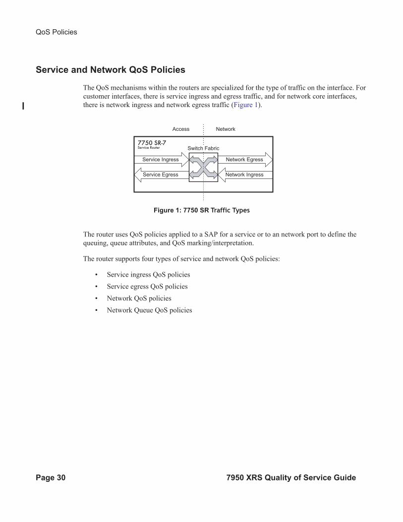
The QoS mechanisms within the routers are specialized for the type of traffic on the interface. For
customer interfaces, there is service ingress and egress traffic, and for network core interfaces,
there is network ingress and network egress traffic (Figure 1).
Figure 1: 7750 SR Traffic Types
The router uses QoS policies applied to a SAP for a service or to an network port to define the
queuing, queue attributes, and QoS marking/interpretation.
The router supports four types of service and network QoS policies:
• Service ingress QoS policies
• Service egress QoS policies
• Network QoS policies
• Network Queue QoS policies
OSSG019
Access Network
Network Egress
Network Ingress
Service Ingress
Service Egress
Switch Fabric
QoS Policies
7950 XRS Quality of Service Guide Page 31
Network QoS Policies
Network QoS policies define egress QoS marking and ingress QoS interpretation for traffic on
core network IP interfaces. The router automatically creates egress queues for each of the
forwarding classes on network IP interfaces.
A network QoS policy defines both the ingress and egress handling of QoS on the IP interface.
The following functions are defined.
• Ingress
→ Defines DSCP name mappings to a forwarding classes.
→ Defines LSP EXP value mappings to forwarding classes.
• Egress
→ Defines the forwarding class to DSCP value markings.
→ Defines forwarding class to LSP EXP value markings.
→ Enables/disables remarking of QoS.
The required elements to be defined in a network QoS policy are:
• A unique network QoS policy ID.
• Egress forwarding class to DSCP value mappings for each forwarding class.
• Egress forwarding class to LSP EXP value mappings for each forwarding class.
• Enabling/disabling of egress QoS remarking.
• A default ingress forwarding class and in-profile/out-of-profile state.
Optional network QoS policy elements include:
• DSCP name to forwarding class and profile state mappings for all DSCP values received.
• LSP EXP value to forwarding class and profile state mappings for all EXP values
received.
Network policy ID 1 is reserved as the default network QoS policy. The default policy cannot be
deleted or changed.
The default network QoS policy is applied to all network interfaces which do not have another
network QoS policy explicitly assigned.
QoS Policies
Page 32 7950 XRS Quality of Service Guide
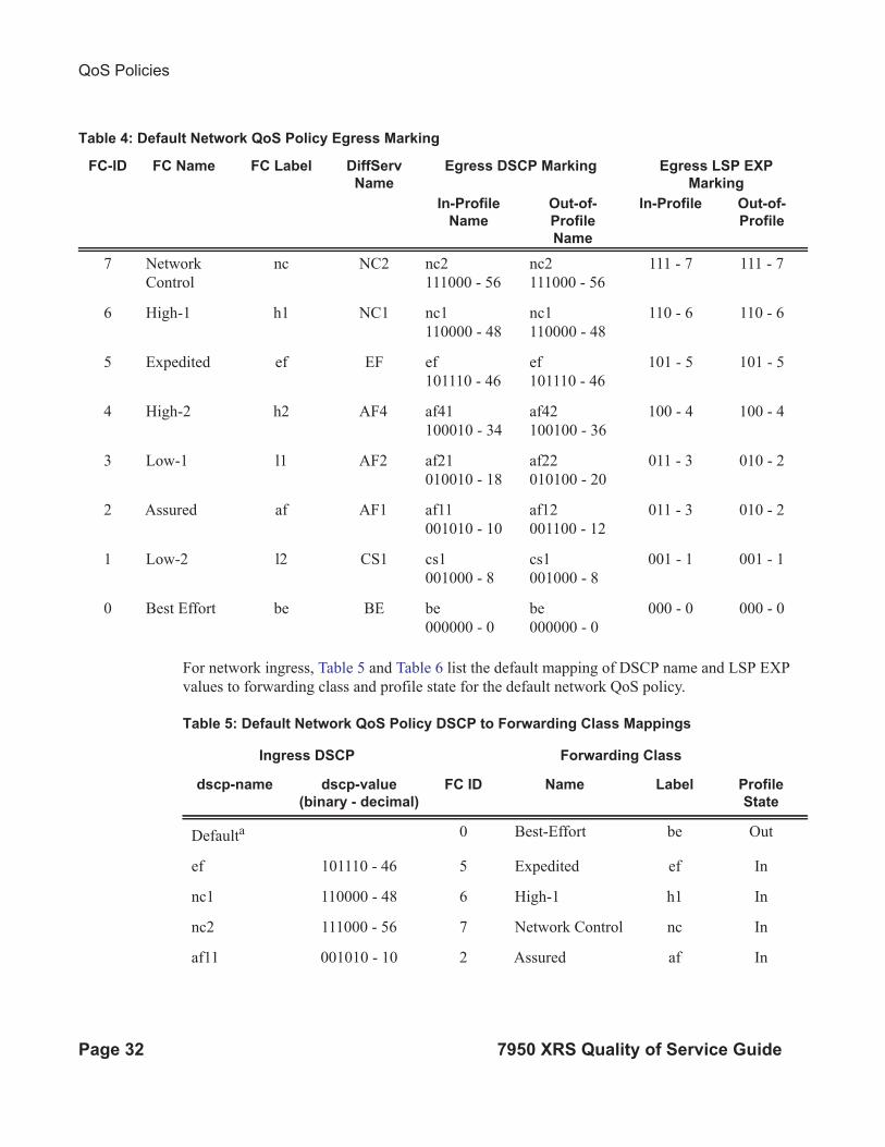
For network ingress, Table 5 and Table 6 list the default mapping of DSCP name and LSP EXP
values to forwarding class and profile state for the default network QoS policy.
Table 4: Default Network QoS Policy Egress Marking
FC-ID FC Name FC Label DiffServ
Name
Egress DSCP Marking Egress LSP EXP
Marking
In-Profile
Name
Out-of-
Profile
Name
In-Profile Out-of-
Profile
7 Network
Control
nc NC2 nc2
111000 - 56
nc2
111000 - 56
111 - 7 111 - 7
6 High-1 h1 NC1 nc1
110000 - 48
nc1
110000 - 48
110 - 6 110 - 6
5 Expedited ef EF ef
101110 - 46
ef
101110 - 46
101 - 5 101 - 5
4 High-2 h2 AF4 af41
100010 - 34
af42
100100 - 36
100 - 4 100 - 4
3 Low-1 l1 AF2 af21
010010 - 18
af22
010100 - 20
011 - 3 010 - 2
2 Assured af AF1 af11
001010 - 10
af12
001100 - 12
011 - 3 010 - 2
1 Low-2 l2 CS1 cs1
001000 - 8
cs1
001000 - 8
001 - 1 001 - 1
0 Best Effort be BE be
000000 - 0
be
000000 - 0
000 - 0 000 - 0
Table 5: Default Network QoS Policy DSCP to Forwarding Class Mappings
Ingress DSCP Forwarding Class
dscp-name dscp-value
(binary - decimal)
FC ID Name Label Profile
State
Defaulta 0 Best-Effort be Out
ef 101110 - 46 5 Expedited ef In
nc1 110000 - 48 6 High-1 h1 In
nc2 111000 - 56 7 Network Control nc In
af11 001010 - 10 2 Assured af In
QoS Policies
7950 XRS Quality of Service Guide Page 33
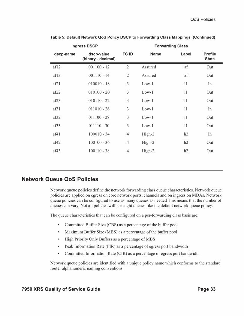
Network Queue QoS Policies
Network queue policies define the network forwarding class queue characteristics. Network queue
policies are applied on egress on core network ports, channels and on ingress on MDAs. Network
queue policies can be configured to use as many queues as needed This means that the number of
queues can vary. Not all policies will use eight queues like the default network queue policy.
The queue characteristics that can be configured on a per-forwarding class basis are:
• Committed Buffer Size (CBS) as a percentage of the buffer pool
• Maximum Buffer Size (MBS) as a percentage of the buffer pool
• High Priority Only Buffers as a percentage of MBS
• Peak Information Rate (PIR) as a percentage of egress port bandwidth
• Committed Information Rate (CIR) as a percentage of egress port bandwidth
Network queue policies are identified with a unique policy name which conforms to the standard
router alphanumeric naming conventions.
af12 001100 - 12 2 Assured af Out
af13 001110 - 14 2 Assured af Out
af21 010010 - 18 3 Low-1 l1 In
af22 010100 - 20 3 Low-1 l1 Out
af23 010110 - 22 3 Low-1 l1 Out
af31 011010 - 26 3 Low-1 l1 In
af32 011100 - 28 3 Low-1 l1 Out
af33 011110 - 30 3 Low-1 l1 Out
af41 100010 - 34 4 High-2 h2 In
af42 100100 - 36 4 High-2 h2 Out
af43 100110 - 38 4 High-2 h2 Out
Table 5: Default Network QoS Policy DSCP to Forwarding Class Mappings (Continued)
Ingress DSCP Forwarding Class
dscp-name dscp-value
(binary - decimal)
FC ID Name Label Profile
State
QoS Policies
Page 34 7950 XRS Quality of Service Guide
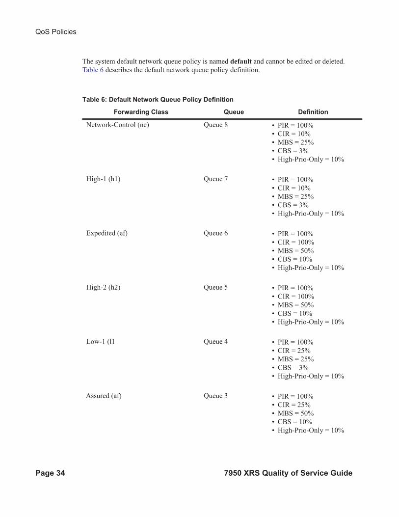
The system default network queue policy is named default and cannot be edited or deleted.
Table 6 describes the default network queue policy definition.
Table 6: Default Network Queue Policy Definition
Forwarding Class Queue Definition
Network-Control (nc) Queue 8 • PIR = 100%
• CIR = 10%
• MBS = 25%
• CBS = 3%
• High-Prio-Only = 10%
High-1 (h1) Queue 7 • PIR = 100%
• CIR = 10%
• MBS = 25%
• CBS = 3%
• High-Prio-Only = 10%
Expedited (ef) Queue 6 • PIR = 100%
• CIR = 100%
• MBS = 50%
• CBS = 10%
• High-Prio-Only = 10%
High-2 (h2) Queue 5 • PIR = 100%
• CIR = 100%
• MBS = 50%
• CBS = 10%
• High-Prio-Only = 10%
Low-1 (l1 Queue 4 • PIR = 100%
• CIR = 25%
• MBS = 25%
• CBS = 3%
• High-Prio-Only = 10%
Assured (af) Queue 3 • PIR = 100%
• CIR = 25%
• MBS = 50%
• CBS = 10%
• High-Prio-Only = 10%
QoS Policies
7950 XRS Quality of Service Guide Page 35
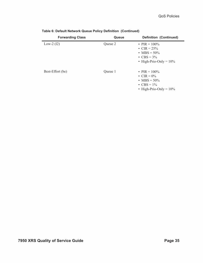
Low-2 (l2) Queue 2 • PIR = 100%
• CIR = 25%
• MBS = 50%
• CBS = 3%
• High-Prio-Only = 10%
Best-Effort (be) Queue 1 • PIR = 100%
• CIR = 0%
• MBS = 50%
• CBS = 1%
• High-Prio-Only = 10%
Table 6: Default Network Queue Policy Definition (Continued)
Forwarding Class Queue Definition (Continued)
QoS Policies
Page 36 7950 XRS Quality of Service Guide
Queue Parameters
This section describes the queue parameters provisioned on access and queues for QoS.
The queue parameters are:
• Queue ID on page 36
• Unicast or Multipoint Queue on page 36
• Queue Hardware Scheduler on page 37
• Committed Information Rate on page 38
• Peak Information Rate on page 39
• Adaptation Rule on page 40
• Committed Burst Size on page 45
• Maximum Burst Size on page 45
• High-Priority Only Buffers on page 45
• Packet Markings on page 46
• Queue-Types on page 47
Queue ID
The queue ID is used to uniquely identify the queue. The queue ID is only unique within the
context of the QoS policy within which the queue is defined.
Unicast or Multipoint Queue
Currently, only VPLS services utilize multipoint ingress queues although IES services use
multipoint ingress queues for multicast traffic alone when PIM is enabled on the service interface.

QoS Policies
7950 XRS Quality of Service Guide Page 37
Queue Hardware Scheduler
The hardware scheduler for a queue dictates how it will be scheduled relative to other queues at
the hardware level. When a queue is defined in a service ingress or service egress QoS policy, it is
possible to explicitly define the hardware scheduler to use for the queue when it is applied to a
SAP.
Being able to define a hardware scheduler is important as a single queue allows support for
multiple forwarding classes. The default behavior is to automatically choose the expedited or non-
expedited nature of the queue based on the forwarding classes mapped to it. As long as all
forwarding classes mapped to the queue are expedited (nc, ef, h1 or h2), the queue will be treated
as an expedited queue by the hardware schedulers. When any non-expedited forwarding classes
are mapped to the queue (be, af, l1 or l2), the queue will be treated as best effort by the hardware
schedulers.
The expedited hardware schedulers are used to enforce expedited access to internal switch fabric
destinations.

QoS Policies
Page 38 7950 XRS Quality of Service Guide
Committed Information Rate
The committed information rate (CIR) for a queue performs two distinct functions:
1. Profile marking service ingress queues — Service ingress queues mark packets in-profile or
out-of-profile based on the queue's CIR. For each packet in a service ingress queue, the CIR
is checked with the current transmission rate of the queue. If the current rate is at or below
the CIR threshold, the transmitted packet is internally marked in-profile. If the current rate is
above the threshold, the transmitted packet is internally marked out-of-profile.
2. Scheduler queue priority metric — The scheduler serving a group of service ingress or egress
queues prioritizes individual queues based on their current CIR and PIR states. Queues oper-
ating below their CIR are always served before those queues operating at or above their CIR.
Queue scheduling is discussed in Virtual Hierarchical Scheduling on page 70.
All router queues support the concept of in-profile and out-of-profile. The network QoS policy
applied at network egress determines how or if the profile state is marked in packets transmitted
into the service core network. If the profile state is marked in the service core packets, out-of-
profile packets are preferentially dropped over in-profile packets at congestion points in the core.
1. When defining the CIR for a queue, the value specified is the administrative CIR for the
queue.The router has a number of native rates in hardware that it uses to determine the oper-
ational CIR for the queue. The user has some control over how the administrative CIR is con-
verted to an operational CIR should the hardware not support the exact CIR and PIR
combination specified. The interpretation of the administrative CIR is discussed below in
Adaptation Rule on page 40
Although the router is flexible in how the CIR can be configured, there are conventional ranges for
the CIR based on the forwarding class of a queue. A service ingress queue associated with the
high-priority class normally has the CIR threshold equal to the PIR rate although the router allows
the CIR to be provisioned to any rate below the PIR should this behavior be required. If the service
egress queue is associated with a best-effort class, the CIR threshold is normally set to zero; again
the setting of this parameter is flexible.
The CIR for a service queue is provisioned on ingress and egress service queues within service
ingress QoS policies and service egress QoS policies, respectively.
The CIR for network queues are defined within network queue policies based on the forwarding
class. The CIR for the queues for the forwarding class are defined as a percentage of the network
interface bandwidth.
QoS Policies
7950 XRS Quality of Service Guide Page 39
Peak Information Rate
The peak information rate (PIR) defines the maximum rate at which packets are allowed to exit the
queue. It does not specify the maximum rate at which packets may enter the queue; this is
governed by the queue's ability to absorb bursts and is defined by its maximum burst size (MBS).
The actual transmission rate of a service queue depends on more than just its PIR. Each queue is
competing for transmission bandwidth with other queues. Each queue's PIR, CIR and the relative
importance of the scheduler serving the queue all combine to affect a queue's ability to transmit
packets as discussed in Single Tier Scheduling on page 71.
The PIR is provisioned on ingress and egress service queues within service ingress QoS policies
and service egress QoS policies, respectively.
The PIR for network queues are defined within network queue policies based on the forwarding
class. The PIR for the queues for the forwarding class are defined as a percentage of the network
interface bandwidth.
When defining the PIR for a queue, the value specified is the administrative PIR for the queue.The
router has a number of native rates in hardware that it uses to determine the operational PIR for the
queue. The user has some control over how the administrative PIR is converted to an operational
PIR should the hardware not support the exact CIR and PIR values specified. The interpretation of
the administrative PIR is discussed below in Adaptation Rule on page 40

QoS Policies
Page 40 7950 XRS Quality of Service Guide
Adaptation Rule
The adaptation rule provides the QoS provisioning system with the ability to adapt specific CIR
and PIR defined administrative rates to the underlying capabilities of the hardware the queue will
be created on to derive the operational rates. The administrative CIR and PIR rates are translated to
actual operational rates enforced by the hardware queue. The rule provides a constraint used when
the exact rate is not available due to hardware implementation trade-offs.
For the CIR and PIR parameters individually, the system will attempt to find the best operational
rate depending on the defined constraint. The supported constraints are:
• Minimum — Find the hardware supported rate that is equal to or higher than the specified
rate.
• Maximum — Find the hardware supported rate that is equal to or lesser than the specified
rate.
• Closest — Find the hardware supported rate that is closest to the specified rate.
Depending on the hardware upon which the queue is provisioned, the actual operational CIR and
PIR settings used by the queue will be dependant on the method the hardware uses to implement
and represent the mechanisms that enforce the CIR and PIR rates.
The adaptation rule always assumes that the PIR (shaping parameter) on the queue is the most
important rate. When multiple available hardware rates exist for a given CIR and PIR rate pair, the
PIR constraint is always evaluated before the CIR.
The router 20 Gbps Input/Output Module (IOM) uses a rate step value to define the granularity for
both the CIR and PIR rates The adaptation rule controls the method the system uses to choose the
rate step based on the administrative rates defined by the rate command. The supported CIR and
PIR values ranges and increments are summarized in Table 7.
The MDA hardware rate-step values are listed in Table 9 for all MDAs (except deep channel
MDAs).
Table 7: Supported Hardware Rates and CIR/PIR Values for Non-Channelized MDAs
Hardware Rate Steps Rate Range (Rate Step x 0 to Rate Step x 127 and max)a
0.5Gb/sec 0 to 64Gb/sec and ∞
100Mb/sec 0 to 12.7Gb/sec and ∞
50Mb/sec 0 to 6.4Gb/sec and ∞
10Mb/sec 0 to 1.3Gb/sec and ∞
5Mb/sec 0 to 635Mb/sec and ∞
5Mb/sec 0 to 640 MB/sec and ∞

QoS Policies
7950 XRS Quality of Service Guide Page 41
The MDA hardware rate-step values are listed below for deep channel MDAs (m1-choc12-sfp,
m4-choc3-sfp, and m4-chds3). The table shows supported hardware rates and CIR/PIR values for
ingress traffic from all MDAs/CMAs and egress traffic for all CMAs and deep channel MDAs.
1Mb/sec 0 to 127Mb/sec and ∞
500Kb/sec 0 to 64Mb/sec and ∞
100Kb/sec 0 to 12.7Mb/sec and ∞
50Kb/sec 0 to 6.4Mb/sec and ∞
10Kb/sec 0 to 1.2Mb/sec and ∞
8Kb/sec 0 to 1Mb/sec and ∞
1Kb/sec 0 to 127Kb/sec and ∞
a. 0 is unavailable for PIR
Table 8: Supported Hardware Rates and CIR/PIR Values for Deep Channel MDAs
Hardware Rate
StepsRate Range (Rate Step x 0 to Rate Step x 127 and max)a
0.5Gb/sec 0 to 64Gb/sec and ∞
100Mb/sec 0 to 12.7Gb/sec and ∞
10Mb/sec 0 to 1.3Gb/sec and ∞ (0 unavailable for PIR)
2Mb/sec 0 to 254Mb/sec and ∞ (0 unavailable for PIR)
1Mb/sec 0 to 127Mb/sec and ∞
512Kb/sec 0 to 65Mb/sec and ∞ (0 unavailable for PIR)
256Kb/sec 0 to 32.5Mb/sec and ∞
128Kb/sec 0 to 16.3Mbit/sec and ∞
64Kb/sec 0 to 8.1Mb/sec and ∞
32Kb/sec 0 to 4.1Mb/sec and ∞
16Kb/sec 0 to 2Mb/sec and ∞
8Kb/sec 0 to 1Mb/sec and ∞
4Kb/sec 0 to 500Kb/sec and ∞
1Kb/sec 0 to 127Kb/sec and ∞
Table 7: Supported Hardware Rates and CIR/PIR Values for Non-Channelized MDAs
Hardware Rate Steps Rate Range (Rate Step x 0 to Rate Step x 127 and max)a
QoS Policies
Page 42 7950 XRS Quality of Service Guide
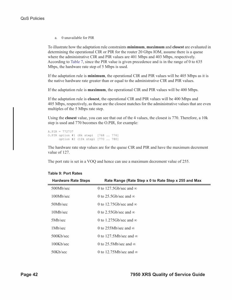
To illustrate how the adaptation rule constraints minimum, maximum and closest are evaluated in
determining the operational CIR or PIR for the router 20 Gbps IOM, assume there is a queue
where the administrative CIR and PIR values are 401 Mbps and 403 Mbps, respectively.
According to Table 7, since the PIR value is given precedence and is in the range of 0 to 635
Mbps, the hardware rate step of 5 Mbps is used.
If the adaptation rule is minimum, the operational CIR and PIR values will be 405 Mbps as it is
the native hardware rate greater than or equal to the administrative CIR and PIR values.
If the adaptation rule is maximum, the operational CIR and PIR values will be 400 Mbps.
If the adaptation rule is closest, the operational CIR and PIR values will be 400 Mbps and
405 Mbps, respectively, as those are the closest matches for the administrative values that are even
multiples of the 5 Mbps rate step.
Using the closest value, you can see that out of the 4 values, the closest is 770. Therefore, a 10k
step is used and 770 becomes the O.PIR, for example:
A.PIR = 772737
O.PIR option #1 (8k step) [768 .. 776]
option #2 (10k step) [770 .. 780]
The hardware rate step values are for the queue CIR and PIR and have the maximum decrement
value of 127.
The port rate is set in a VOQ and hence can use a maximum decrement value of 255.
a. 0 unavailable for PIR
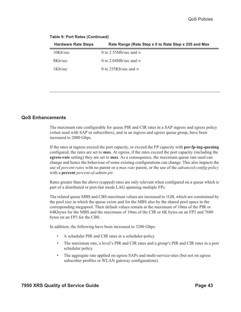
Table 9: Port Rates
Hardware Rate Steps Rate Range (Rate Step x 0 to Rate Step x 255 and Max
500Mb/sec 0 to 127.5Gb/sec and ∞
100Mb/sec 0 to 25.5Gb/sec and ∞
50Mb/sec 0 to 12.75Gb/sec and ∞
10Mb/sec 0 to 2.55Gb/sec and ∞
5Mb/sec 0 to 1.275Gb/sec and ∞
1Mb/sec 0 to 255Mb/sec and ∞
500Kb/sec 0 to 127.5Mb/sec and ∞
100Kb/sec 0 to 25.5Mb/sec and ∞
50Kb/sec 0 to 12.75Mb/sec and ∞
QoS Policies
7950 XRS Quality of Service Guide Page 43
QoS Enhancements
The maximum rate configurable for queue PIR and CIR rates in a SAP ingress and egress policy
(when used with SAP or subscribers), and in an ingress and egress queue group, have been
increased to 2000 Gbps.
If the rates at ingress exceed the port capacity, or exceed the FP capacity with per-fp-ing-queuing
configured, the rates are set to max. At egress, if the rates exceed the port capacity (including the
egress-rate setting) they are set to max. As a consequence, the maximum queue rate used can
change and hence the behaviour of some existing configurations can change. This also impacts the
use of percent-rates with no parent or a max-rate parent, or the use of the advanced-config-policy
with a percent percent-of-admin-pir.
Rates greater than the above (capped) rates are only relevant when configured on a queue which is
part of a distributed or port-fair mode LAG spanning multiple FPs.
The related queue MBS and CBS maximum values are increased to 1GB, which are constrained by
the pool size in which the queue exists and for the MBS also by the shared pool space in the
corresponding megapool. Their default values remain at the maximum of 10ms of the PIR or
64Kbytes for the MBS and the maximum of 10ms of the CIR or 6K bytes on an FP2 and 7680
bytes on an FP3 for the CBS.
In addition, the following have been increased to 3200 Gbps:
• A scheduler PIR and CIR rates in a scheduler-policy
• The maximum rate, a level’s PIR and CIR rates and a group’s PIR and CIR rates in a port
scheduler policy.
• The aggregate rate applied on egress SAPs and multi-service-sites (but not on egress
subscriber profiles or WLAN gateway configurations).
10Kb/sec 0 to 2.55Mb/sec and ∞
8Kb/sec 0 to 2.04Mb/sec and ∞
1Kb/sec 0 to 255Kb/sec and ∞
Table 9: Port Rates (Continued)
Hardware Rate Steps Rate Range (Rate Step x 0 to Rate Step x 255 and Max

QoS Policies
Page 44 7950 XRS Quality of Service Guide
All queue, scheduler and egress scheduler overrides relating to the above rates have also been
increased to the corresponding value.
Note that due to the changes in this implementation, there may be small differences in the resulting
rates, MBS and CBS compared to the previous implementation.
This is supported on FP2- and higher-based hardware but is not applicable to the HS-MDA.
QoS Policies
7950 XRS Quality of Service Guide Page 45
Committed Burst Size
The committed burst size (CBS) parameters specify the amount of buffers that can be drawn from
the reserved buffer portion of the queue’s buffer pool. Once the reserved buffers for a given queue
have been used, the queue contends with other queues for additional buffer resources up to the
maximum burst size.
The CBS is provisioned on ingress and egress service queues within service ingress QoS policies
and service egress QoS policies, respectively. The CBS for a queue is specified in Kbytes.
The CBS for network queues are defined within network queue policies based on the forwarding
class. The CBS for the queues for the forwarding class are defined as a percentage of buffer space
for the pool.
Maximum Burst Size
The maximum burst size (MBS) parameter specifies the maximum queue depth to which a queue
can grow. This parameter ensures that a customer that is massively or continuously over-
subscribing the PIR of a queue will not consume all the available buffer resources. For high-
priority forwarding class service queues, the MBS can be relatively smaller than the other
forwarding class queues because the high-priority service packets are scheduled with priority over
other service forwarding classes.
The MBS is provisioned on ingress and egress service queues within service ingress QoS policies
and service egress QoS policies, respectively. The MBS for a queue is specified in Kbytes.
The MBS for network queues are defined within network queue policies based on the forwarding
class. The MBS for the queues for the forwarding class are defined as a percentage of buffer space
for the pool.
High-Priority Only Buffers
High priority (HP)-only buffers are defined on a queue and allow buffers to be reserved for traffic
classified as high priority. When the queue depth reaches a specified level, only high-priority
traffic can be enqueued. The HP-only reservation for a queue is defined as a percentage of the
MBS value.
On service ingress, the HP-only reservation for a queue is defined in the service ingress QoS
policy. High priority traffic is specified in the match criteria for the policy.
On service egress, the HP-only reservation for a queue is defined in the service egress QoS policy.
Service egress queues are specified by forwarding class. High-priority traffic for a given traffic
QoS Policies
Page 46 7950 XRS Quality of Service Guide
class is traffic that has been marked as in-profile either on ingress classification or based on
interpretation of the QoS markings.
The HP-only for network queues are defined within network queue policies based on the
forwarding class. High-priority traffic for a specific traffic class is marked as in-profile either on
ingress classification or based on interpretation of the QoS markings.
Packet Markings
Typically, customer markings placed on packets are not treated as trusted from an in-profile or out-
of-profile perspective. This allows the use of the ingress buffering to absorb bursts over PIR from
a customer and only perform marking as packets are scheduled out of the queue (as opposed to
using a hard policing function that operates on the received rate from the customer). The resulting
profile (in or out) based on ingress scheduling into the switch fabric is used by network egress for
tunnel marking and egress congestion management.
The high/low priority feature allows a provider to offer a customer the ability to have some
packets treated with a higher priority when buffered to the ingress queue. If the queue is
configured with a hi-prio-only setting (setting the high priority MBS threshold higher than the
queue’s low priority MBS threshold) a portion of the ingress queue’s allowed buffers are reserved
for high priority traffic. An access ingress packet must hit an ingress QoS action in order for the
ingress forwarding plane to treat the packet as high priority (the default is low priority).
If the packet’s ingress queue is above the low priority MBS, the packet will be discarded unless it
has been classified as high priority. The priority of the packet is not retained after the packet is
placed into the ingress queue. Once the packet is scheduled out of the ingress queue, the packet
will be considered in-profile or out-of-profile based on the dynamic rate of the queue relative to
the queue’s CIR parameter.
If an ingress queue is not configured with a hi-prio-only parameter, the low priority and high
priority MBS thresholds will be the same. There will be no difference in high priority and low
priority packet handling. At access ingress, the priority of a packet has no affect on which packets
are scheduled first. Only the first buffering decision is affected. At ingress and egress, the current
dynamic rate of the queue relative to the queue’s CIR does affect the scheduling priority between
queues going to the same destination (either the switch fabric tap or egress port). The strict
operating priority for queues are (from highest to lowest):
• Expedited queues within the CIR (conform)
• Best Effort queues within the CIR (conform)
• Expedited and Best Effort queues above the CIR (exceed)
For access ingress, the CIR controls both dynamic scheduling priority and marking threshold. At
network ingress, the queue’s CIR affects the scheduling priority but does not provide a profile

QoS Policies
7950 XRS Quality of Service Guide Page 47
marking function (as the network ingress policy trusts the received marking of the packet based on
the network QoS policy).
At egress, the profile of a packet is only important for egress queue buffering decisions and egress
marking decisions, not for scheduling priority. The egress queue’s CIR will determine the dynamic
scheduling priority, but will not affect the packet’s ingress determined profile.
Queue Counters
The router maintains counters for queues within the system for granular billing and accounting.
Each queue maintains the following counters:
• Counters for packets and octets accepted into the queue
• Counters for packets and octets rejected at the queue
• Counters for packets and octets transmitted in-profile
• Counters for packets and octets transmitted out-of-profile
Queue-Types
The expedite, best-effort and auto-expedite queue types are mutually exclusive to each other.
Each defines the method that the system uses to service the queue from a hardware perspective.
While parental virtual schedulers can be defined for the queue, they only enforce how the queue
interacts for bandwidth with other queues associated with the same scheduler hierarchy. An
internal mechanism that provides access rules when the queue is vying for bandwidth with queues
in other virtual schedulers is also needed.

QoS Policies
Page 48 7950 XRS Quality of Service Guide
Color Aware Profiling (Policing)
The normal handling of SAP ingress access packets applies an in-profile or out-of-profile state to
each packet relative to the dynamic rate of the queue as the packet is forwarded towards the egress
side of the system. When the queue rate is within or equal to the configured CIR, the packet is
considered in-profile. When the queue rate is above the CIR, the packet is considered out-of-
profile. (This applies when the packet is scheduled out of the queue, not when the packet is
buffered into the queue.) Egress queues use the profile marking of packets to preferentially buffer
in-profile packets during congestion events. Once a packet has been marked in-profile or out-of-
profile by the ingress access SLA enforcement, the packet is tagged with an in-profile or out-of-
profile marking allowing congestion management in subsequent hops towards the packet’s
ultimate destination. Each hop to the destination must have an ingress table that determines the in-
profile or out-of-profile nature of a packet based on its QoS markings.
Color aware profiling adds the ability to selectively treat packets received on a SAP as in-profile
or out-of-profile regardless of the queue forwarding rate. This allows a customer or access device
to color a packet out-of-profile with the intention of preserving in-profile bandwidth for higher
priority packets. The customer or access device may also color the packet in-profile, but this is
rarely done as the original packets are usually already marked with the in-profile marking.
Each ingress access forwarding class may have one or multiple sub-class associations for SAP
ingress classification purposes. Each sub-class retains the chassis wide behavior defined to the
parent class while providing expanded ingress QoS classification actions. Sub-classes are created
to provide a match association that enforces actions different than the parent forwarding class.
These actions include explicit ingress remarking decisions and color aware functions.
All non-profiled and profiled packets are forwarded through the same ingress access queue to
prevent out-of-sequence forwarding. Profiled packets in-profile are counted against the total
packets flowing through the queue that are marked in-profile. This reduces the amount of CIR
available to non-profiled packets causing fewer to be marked in-profile. Profiled packets out-of-
profile are counted against the total packets flowing through the queue that are marked in-profile.
This ensures that the amount of non-profiled packets marked out-of-profile is not affected by the
profiled out-of-profile packet rate.

QoS Policies
7950 XRS Quality of Service Guide Page 49
Service Ingress QoS Policies
Service ingress QoS policies define ingress service forwarding class queues and map flows to
those queues. When a service ingress QoS policy is created by default, it always has two queues
defined that cannot be deleted: one for the default unicast traffic and one for the default multipoint
traffic. These queues exist within the definition of the policy. The queues only get instantiated in
hardware when the policy is applied to a SAP. In the case where the service does not have
multipoint traffic, the multipoint queues will not be instantiated.
In the simplest service ingress QoS policy, all traffic is treated as a single flow and mapped to a
single queue, and all flooded traffic is treated with a single multipoint queue. The required
elements to define a service ingress QoS policy are:
• A unique service ingress QoS policy ID.
• A QoS policy scope of template or exclusive.
• At least one default unicast forwarding class queue. The parameters that can be configured
for a queue are discussed in Queue Parameters on page 36.
• At least one multipoint forwarding class queue.
Optional service ingress QoS policy elements include:
• Additional unicast queues up to a total of 32.
• Additional multipoint queues up to 31.
• QoS policy match criteria to map packets to a forwarding class.
To facilitate more forwarding classes, sub-classes are now supported. Each forwarding class can
have one or multiple sub-class associations for SAP ingress classification purposes. Each sub-class
retains the chassis wide behavior defined to the parent class while providing expanded ingress
QoS classification actions.
There can now be up to 64 classes and subclasses combined in a sap-ingress policy. With the extra
56 values, the size of the forwarding class space is more than sufficient to handle the various
combinations of actions.
Forwarding class expansion is accomplished through the explicit definition of sub-forwarding
classes within the SAP ingress QoS policy. The CLI mechanism that creates forwarding class
associations within the SAP ingress policy is also used to create sub-classes. A portion of the sub-
class definition directly ties the sub-class to a parent, chassis wide forwarding class. The sub-class
QoS Policies
Page 50 7950 XRS Quality of Service Guide
is only used as a SAP ingress QoS classification tool, the sub-class association is lost once ingress
QoS processing is finished.
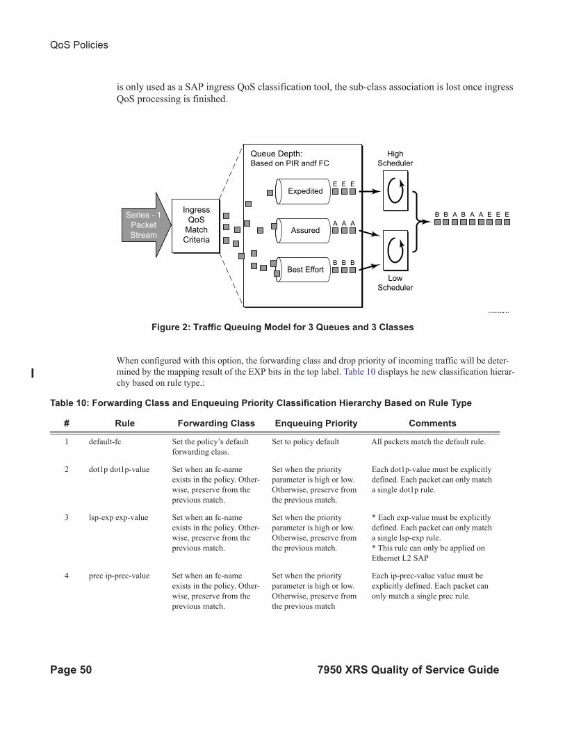
Figure 2: Traffic Queuing Model for 3 Queues and 3 Classes
When configured with this option, the forwarding class and drop priority of incoming traffic will be deter-
mined by the mapping result of the EXP bits in the top label. Table 10 displays he new classification hierar-
chy based on rule type.:
OSSG236
A A A
B B A B A A E E E
B B B
E E E
Ingress
QoS
Match
Criteria
Series - 1
Packet
Stream
Queue Depth:Based on PIR andf FC
Expedited
High
Scheduler
Low
Scheduler
Assured
Best Effort
Table 10: Forwarding Class and Enqueuing Priority Classification Hierarchy Based on Rule Type
# Rule Forwarding Class Enqueuing Priority Comments
1 default-fc Set the policy’s default
forwarding class.
Set to policy default All packets match the default rule.
2 dot1p dot1p-value Set when an fc-name
exists in the policy. Other-
wise, preserve from the
previous match.
Set when the priority
parameter is high or low.
Otherwise, preserve from
the previous match.
Each dot1p-value must be explicitly
defined. Each packet can only match
a single dot1p rule.
3 lsp-exp exp-value Set when an fc-name
exists in the policy. Other-
wise, preserve from the
previous match.
Set when the priority
parameter is high or low.
Otherwise, preserve from
the previous match.
* Each exp-value must be explicitly
defined. Each packet can only match
a single lsp-exp rule.
* This rule can only be applied on
Ethernet L2 SAP
4 prec ip-prec-value Set when an fc-name
exists in the policy. Other-
wise, preserve from the
previous match.
Set when the priority
parameter is high or low.
Otherwise, preserve from
the previous match
Each ip-prec-value value must be
explicitly defined. Each packet can
only match a single prec rule.
QoS Policies
7950 XRS Quality of Service Guide Page 51
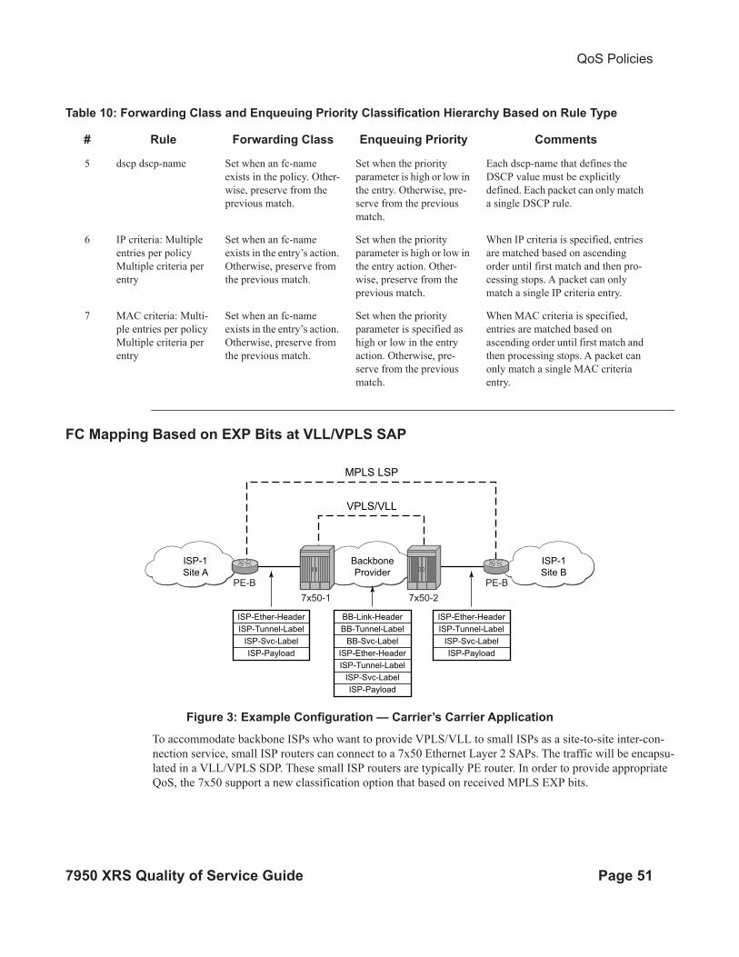
FC Mapping Based on EXP Bits at VLL/VPLS SAP
Figure 3: Example Configuration — Carrier’s Carrier Application
To accommodate backbone ISPs who want to provide VPLS/VLL to small ISPs as a site-to-site inter-con-
nection service, small ISP routers can connect to a 7x50 Ethernet Layer 2 SAPs. The traffic will be encapsu-
lated in a VLL/VPLS SDP. These small ISP routers are typically PE router. In order to provide appropriate
QoS, the 7x50 support a new classification option that based on received MPLS EXP bits.
5 dscp dscp-name Set when an fc-name
exists in the policy. Other-
wise, preserve from the
previous match.
Set when the priority
parameter is high or low in
the entry. Otherwise, pre-
serve from the previous
match.
Each dscp-name that defines the
DSCP value must be explicitly
defined. Each packet can only match
a single DSCP rule.
6 IP criteria: Multiple
entries per policy
Multiple criteria per
entry
Set when an fc-name
exists in the entry’s action.
Otherwise, preserve from
the previous match.
Set when the priority
parameter is high or low in
the entry action. Other-
wise, preserve from the
previous match.
When IP criteria is specified, entries
are matched based on ascending
order until first match and then pro-
cessing stops. A packet can only
match a single IP criteria entry.
7 MAC criteria: Multi-
ple entries per policy
Multiple criteria per
entry
Set when an fc-name
exists in the entry’s action.
Otherwise, preserve from
the previous match.
Set when the priority
parameter is specified as
high or low in the entry
action. Otherwise, pre-
serve from the previous
match.
When MAC criteria is specified,
entries are matched based on
ascending order until first match and
then processing stops. A packet can
only match a single MAC criteria
entry.
Table 10: Forwarding Class and Enqueuing Priority Classification Hierarchy Based on Rule Type
# Rule Forwarding Class Enqueuing Priority Comments
VPLS/VLL
MPLS LSP
7x50-2
PE-BPE-B
Backbone
Provider
BB-Link-Header
BB-Tunnel-Label
BB-Svc-Label
ISP-Ether-Header
ISP-Tunnel-Label
ISP-Svc-Label
ISP-Payload
ISP-1
Site A
ISP-1
Site B
7x50-1
OSSG257
ISP-Ether-Header
ISP-Tunnel-Label
ISP-Svc-Label
ISP-Payload
ISP-Ether-Header
ISP-Tunnel-Label
ISP-Svc-Label
ISP-Payload

QoS Policies
Page 52 7950 XRS Quality of Service Guide
The lsp-exp command is will be supported in sap-ingress qos policy. This option can only be applied on
Ethernet Layer 2 SAPs.
The enqueuing priority is specified as part of the classification rule and is set to “high” or “low”.
The enqueuing priority relates to the forwarding class queue’s High-Priority-Only allocation
where only packets with a high enqueuing priority are accepted into the queue once the queue’s
depth reaches the defined threshold. (See High-Priority Only Buffers on page 45.)
The mapping of IEEE 802.1p bits, IP Precedence and DSCP values to forwarding classes is
optional as is specifying IP and MAC criteria.
The IP and MAC match criteria can be very basic or quite detailed. IP and MAC match criteria are
constructed from policy entries. An entry is identified by a unique, numerical entry ID. A single
entry cannot contain more than one match value for each match criteria. Each match entry has a
queuing action which specifies: the forwarding class of packets that match the entry.
• The forwarding class of packets that match the entry.
• The enqueuing priority (high or low) for matching packets.
The entries are evaluated in numerical order based on the entry ID from the lowest to highest ID
value. The first entry that matches all match criteria has its action performed. Table 12 and
Table 13 list the supported IP and MAC match criteria.
Table 11: Forwarding Class Classification Based on Rule Type
# Rule Forwarding Class Comments
1 default-fc Set the policy’s default forwarding
class.
All packets match the default rule.
2 IP criteria:• Multiple entries per policy
• Multiple criteria per entry
Set when an fc-name exists in the
entry’s action. Otherwise, preserve
from the previous match.
When IP criteria is specified,
entries are matched based on
ascending order until first match
and then processing stops. A
packet can only match a single IP
criteria entry.
3 MAC criteria:• Multiple entries per policy
• Multiple criteria per entry
Set when an fc-name exists in the
entry’s action. Otherwise, preserve
from the previous match.
When MAC criteria is specified,
entries are matched based on
ascending order until first match
and then processing stops. A
packet can only match a single
MAC criteria entry.
QoS Policies
7950 XRS Quality of Service Guide Page 53
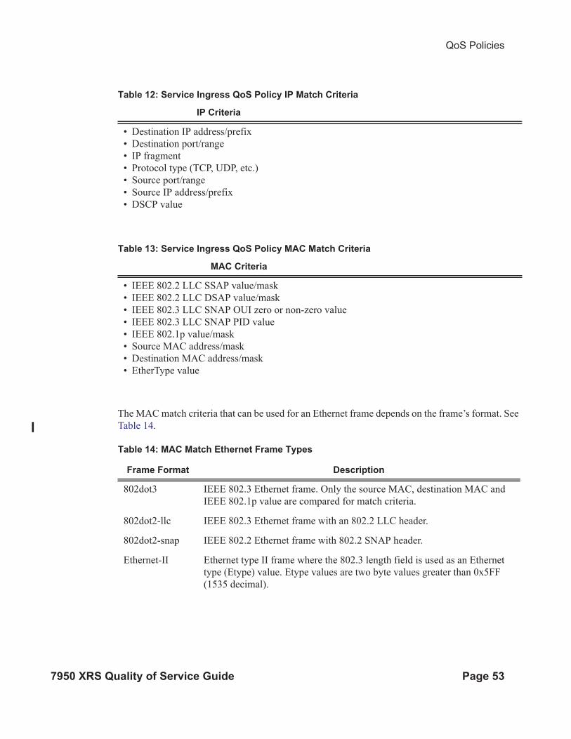
The MAC match criteria that can be used for an Ethernet frame depends on the frame’s format. See
Table 14.
Table 12: Service Ingress QoS Policy IP Match Criteria
IP Criteria
• Destination IP address/prefix
• Destination port/range
• IP fragment
• Protocol type (TCP, UDP, etc.)
• Source port/range
• Source IP address/prefix
• DSCP value
Table 13: Service Ingress QoS Policy MAC Match Criteria
MAC Criteria
• IEEE 802.2 LLC SSAP value/mask
• IEEE 802.2 LLC DSAP value/mask
• IEEE 802.3 LLC SNAP OUI zero or non-zero value
• IEEE 802.3 LLC SNAP PID value
• IEEE 802.1p value/mask
• Source MAC address/mask
• Destination MAC address/mask
• EtherType value
Table 14: MAC Match Ethernet Frame Types
Frame Format Description
802dot3 IEEE 802.3 Ethernet frame. Only the source MAC, destination MAC and
IEEE 802.1p value are compared for match criteria.
802dot2-llc IEEE 802.3 Ethernet frame with an 802.2 LLC header.
802dot2-snap IEEE 802.2 Ethernet frame with 802.2 SNAP header.
Ethernet-II Ethernet type II frame where the 802.3 length field is used as an Ethernet
type (Etype) value. Etype values are two byte values greater than 0x5FF
(1535 decimal).
QoS Policies
Page 54 7950 XRS Quality of Service Guide
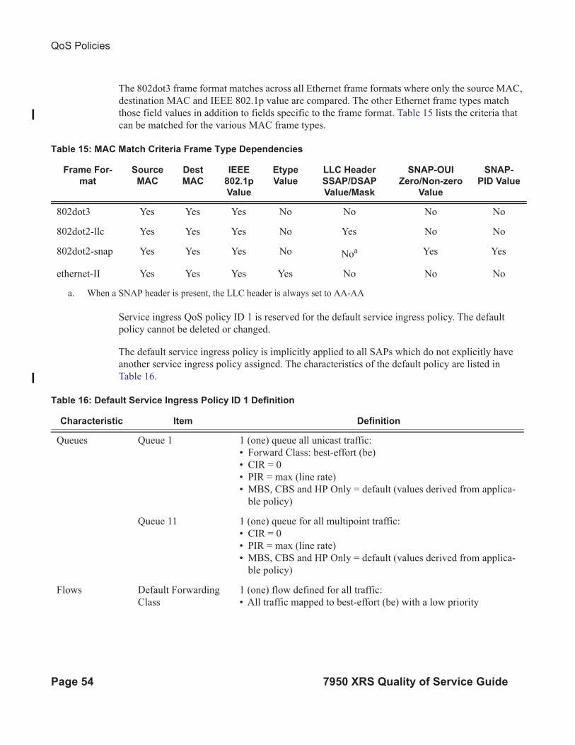
The 802dot3 frame format matches across all Ethernet frame formats where only the source MAC,
destination MAC and IEEE 802.1p value are compared. The other Ethernet frame types match
those field values in addition to fields specific to the frame format. Table 15 lists the criteria that
can be matched for the various MAC frame types.
Service ingress QoS policy ID 1 is reserved for the default service ingress policy. The default
policy cannot be deleted or changed.
The default service ingress policy is implicitly applied to all SAPs which do not explicitly have
another service ingress policy assigned. The characteristics of the default policy are listed in
Table 16.
Table 15: MAC Match Criteria Frame Type Dependencies
Frame For-
mat
Source
MAC
Dest
MAC
IEEE
802.1p
Value
Etype
Value
LLC Header
SSAP/DSAP
Value/Mask
SNAP-OUI
Zero/Non-zero
Value
SNAP-
PID Value
802dot3 Yes Yes Yes No No No No
802dot2-llc Yes Yes Yes No Yes No No
802dot2-snap Yes Yes Yes No Noa
a. When a SNAP header is present, the LLC header is always set to AA-AA
Yes Yes
ethernet-II Yes Yes Yes Yes No No No
Table 16: Default Service Ingress Policy ID 1 Definition
Characteristic Item Definition
Queues Queue 1 1 (one) queue all unicast traffic:
• Forward Class: best-effort (be)
• CIR = 0
• PIR = max (line rate)
• MBS, CBS and HP Only = default (values derived from applica-
ble policy)
Queue 11 1 (one) queue for all multipoint traffic:
• CIR = 0
• PIR = max (line rate)
• MBS, CBS and HP Only = default (values derived from applica-
ble policy)
Flows Default Forwarding
Class
1 (one) flow defined for all traffic:
• All traffic mapped to best-effort (be) with a low priority

QoS Policies
7950 XRS Quality of Service Guide Page 55
Egress Forwarding Class Override
Egress forwarding class override provides additional QoS flexibility by allowing the use of a
different forwarding class at egress than was used at ingress.
The ingress QoS processing classifies traffic into a forwarding class (or sub-class) and by default
the same forwarding class is used for this traffic at the access or network egress. The ingress
forwarding class or sub-class can be overridden so that the traffic uses a different forwarding class
at the egress. This can be configured for the main forwarding classes and for sub-classes, allowing
each to use a different forwarding class at the egress.
The buffering, queuing, policing and remarking operation at the ingress and egress remain
unchanged. Egress reclassification is possible. The profile processing (in/out) is completely
unaffected by overriding the forwarding class.
When used in conjunction with QPPB (QoS Policy Propagation Using BGP), a QPPB assigned
forwarding class takes precedence over both the normal ingress forwarding class classification
rules and any egress forwarding class overrides.
Figure 4: Egress Forwarding CLass Override
Figure 4 shows the ingress service 1 using forwarding classes AF and L1 that are overridden to L1
for the network egress, while it also shows ingress service 2 using forwarding classes L1, AF, and
L2 that are overridden to AF for the network egress.
al_0187
FC EFThese 2 AF classes are
combined and use FC
L1 across the core
These 3 CP classes are
combined and use FC
L1 across the core
FC AF
FC L1
FC BE FC EF
FC L1
FC AF
FC BE
EF
FC EFEF
FC L2
FC AFCP2
FC L1CP1
FC BE
AF21
CP3
Classification
Ingress (Service 2):
Ingress (Service 1):
Egress (Network):AF11
BE
BE

QoS Policies
Page 56 7950 XRS Quality of Service Guide
Service Egress QoS Policies
Service egress queues are implemented at the transition from the service core network to the
service access network. The advantages of per-service queuing before transmission into the access
network are:
• Per-service egress subrate capabilities especially for multipoint services.
• More granular, fairer scheduling per-service into the access network.
• Per-service statistics for forwarded and discarded service packets.
The subrate capabilities and per-service scheduling control are required to make multiple services
per physical port possible. Without egress shaping, it is impossible to support more than one
service per port. There is no way to prevent service traffic from bursting to the available port
bandwidth and starving other services.
For accounting purposes, per-service statistics can be logged. When statistics from service ingress
queues are compared with service egress queues, the ability to conform to per-service QoS
requirements within the service core can be measured. The service core statistics are a major asset
to core provisioning tools.
Service egress QoS policies define egress queues and map forwarding class flows to queues. In the
simplest service egress QoS policy, all forwarding classes are treated like a single flow and
mapped to a single queue. To define a basic egress QoS policy, the following are required:
• A unique service egress QoS policy ID.
• A QoS policy scope of template or exclusive.
• At least one defined default queue.
Optional service egress QoS policy elements include:
• Additional queues up to a total of 8 separate queues (unicast).
• IEEE 802.1p priority value remarking based on forwarding class.
Each queue in a policy is associated with one of the forwarding classes. Each queue can have its
individual queue parameters allowing individual rate shaping of the forwarding class(es) mapped
to the queue.
More complex service queuing models are supported in the router where each forwarding class is
associated with a dedicated queue.
The forwarding class determination per service egress packet is determined at ingress. If the
packet ingressed the service on the same router, the service ingress classification rules determine
the forwarding class of the packet. If the packet is received, the forwarding class is marked in the
tunnel transport encapsulation.

QoS Policies
7950 XRS Quality of Service Guide Page 57
Service egress QoS policy ID 1 is reserved as the default service egress policy. The default policy
cannot be deleted or changed. The default access egress policy is applied to all SAPs service
egress policy explicitly assigned. The characteristics of the default policy are listed in the
following table.
Named Pool Policies
The named buffer pool feature allows for the creation of named buffer pools at the MDA and port
level. Named pools allow for a customized buffer allocation mode for ingress and egress queues
that goes beyond the default pool behavior.
Named pools are defined within a named pool policy. The policy contains a q1-pools context
which is used to define port allocation weights and named pools for buffer pools on Q1 based
IOMs (all IOMs that are currently supported). The policy may be applied at either the port or
MDA level at which time the pools defined within the policy are created on the port or MDA.
When the policy is applied at the MDA level, MDA named pools are created. MDA named pools
will typically be used when either a pool cannot be created per port or when the buffering needs of
queues mapped to the pool are not affected by sharing the pool with queues from other ports.
MDA named pools allow buffers to be efficiently shared between queues on different ports
mapped to the same pool. However, MDA named pools do present the possibility that very active
queues on one port could deplete buffers in the pool offering the possibility that queues on other
ports experiencing buffer starvation. Port named pools are created when the policy is applied at the
port level and allow for a more surgical application of the buffer space allocated for a physical
port. MDA pool names do not need to be unique. If a name overlaps exists, the port pool will be
used. The same pool name may be created on multiple ports on the same MDA.
The named pool policy is applied at the MDA ingress and egress level and at the ingress and
egress port level. Each MDA within the system is associated with a forwarding plane traffic
manager that has support for a maximum of 57 buffer pools. The following circumstances affect
Table 17: Default Service Egress Policy ID 1 Definition
Characteristic Item Definition
Queues Queue 1 1 (one) queue defined for all traffic classes:
• CIR = 0
• PIR = max (line rate)
• MBS, CBS and HP Only = default (values derived from
applicable policy)
Flows Default
Action
1 (one) flow defined for all traffic classes:
• All traffic mapped to queue 1 with no marking of IEEE
802.1p values

QoS Policies
Page 58 7950 XRS Quality of Service Guide
the number of named pools that can be created per MDA (these circumstances may be different
between ingress and egress for the MDA):
• The forwarding plane can be associated with multiple MDAs (each MDA has its own
named pools).
• A single system level pool for system created queues is allocated.
• There must be default pools for queues that are not explicitly mapped or are incorrectly
mapped to a named pool.
• Default pools for most IOM types (separate for ingress and egress).
• Access pool.
• Network pool.
• The number of named per-port pools is dependant on the number of ports the MDA
supports which is variable per MDA type.
• Per-port named pools cannot be used by ingress network queues, but pools defined in a
named pool policy defined on an ingress all network port are still created.
→ Ingress network queues use the default network pool or MDA named pools.
→ Ingress port buffer space allocated to network mode ports is included in the buffers
made available to ingress MDA named pools.
→ Ingress port buffer space on channelized ports associated with network bandwidth is
included in the buffers made available to ingress MDA named pools.
→ Ingress port named pools are only allocated buffers when the port is associated with
some access mode bandwidth.
• Per-port named pools on ports aggregated into a LAG are still created per physical port.
• Default, named MDA and named per-port pools are allocated regardless of queue
provisioning activity associated with the pool.
If the named pool policy is applied to an MDA or port that cannot create every pool defined in the
policy, the policy application attempt will fail. Any pre-existing named pool policy on the MDA or
port will not be affected by the failed named pool policy association attempt.
When buffer pools are being created or deleted, individual queues may need to be moved to or
from the default pools. When a queue is being moved, the traffic destined to the queue is first
moved temporarily to a ‘fail-over’ queue. Then the queue is allowed to drain. Once the queue is
drained, the statistics for the queue are copied. The queue is then returned to the free queue list. A
new queue is then created associated with the appropriate buffer pool, the saved stats are loaded to
the queue and then the traffic is moved from the fail-over queue to the new queue. While the
traffic is being moved between the old queue to the fail-over queue and then to the new queue,
some out of order forwarding may be experienced. Also, any traffic forwarded through the fail-
over queue will not be accounted for in billing or accounting statistics. A similar action is
performed for queues that have the associated pool name added, changed or removed. Please note
this only applies to where fail-over queues are currently supported.
QoS Policies
7950 XRS Quality of Service Guide Page 59
The first step in allowing named pools to be created for an MDA is to enable ‘named-pool-mode’
at the IOM level (config card slot-number named-pool-mode). Named pool mode may be enabled
and disabled at anytime. When MDAs are currently provisioned on the IOM, the IOM is reset to
allow all existing pools to be deleted and the new default, named MDA and named port pools to be
created and sized. If MDAs are not currently provisioned (as when the system is booting up), the
IOM is not reset. When named pool mode is enabled, the system changes the way that default
pools are created. The system no longer creates default pools per port, instead, a set of per
forwarding plane level pools are created that are used by all queues that are not explicitly mapped
to a named pool.
After the IOM has been placed into named pool mode, a named pool policy must be associated
with the ingress and egress contexts of the MDA or individual ports on the MDA for named pools
to be created. There are no named pools that exist by default.
Each time the default pool reserve, aggregate MDA pool limit or individual pool sizes is changed,
buffer pool allocation must be re-evaluated.
Pools may be deleted from the named pool policy at anytime. Queues associated with removed or
non-existent pools are mapped to one of the default pools based on whether the queue is access or
ingress. The queue is flagged as ‘pool-orphaned’ until either the pool comes into existence, or the
pool name association is changed on the pool.
An ingress or egress port managed buffer space is derived from the port’s active bandwidth. Based
on this bandwidth value compared to the other port’s bandwidth value, the available buffer space
is given to each port to manage. It may be desirable to artificially increase or decrease this
bandwidth value to compensate for how many buffers are actually needed on each port. If one port
has very few queues associated with it and another has many queues associated, the commands in
the port’s “modify-buffer-allocation-rate” CLI context may be used to move one port’s bandwidth
up, and another port’s bandwidth down. As provisioning levels change between ports, the rate
modification commands may be used to adapt the buffer allocations per port.
Buffer allocation rate modification is supported for both standard and named pool mode buffer
allocation methods.
The system allocates buffers based on the following criteria:
• “named-pool-mode” setting on the IOM.
• Amount of path bandwidth on channelized ports.
• Existence of queues provisioned on the port or channel.
• Current speed of each port.
• Each ports “ing-percentage-of-rate” and “egr-percentage-of-rate” command setting.
• The port-allocation-weights setting for default, MDA and port.
• The ports division between network and access bandwidth.
• Each individual named pool’s network-allocation-weight and access-allocation-weight.
QoS Policies
Page 60 7950 XRS Quality of Service Guide
Slope Policies
For network ingress, a buffer pool is created for the MDA and is used for all network ingress
queues for ports on the MDA.
Slope policies define the RED slope characteristics as a percentage of pool size for the pool on
which the policy is applied.
Default buffer pools exist (logically) at the port and MDA levels. Each physical port has two pools
objects associated:
• Access ingress pool
• Access egress pool
• Network egress pool
By default, each pool is associated with slope-policy default.
Access, and network pools (in network mode) and access uplink pools (in access uplink mode) are
created at the port level; creation is dependent on the physical port mode (network, access) or the
mode of provisioned channel paths.
Node-level pools are used by ingress network queues and bundle access queues. A single ingress
network pool is created at the node-level for ingress network queues.
An ingress and egress access pool is created at the MDA level for all bundle access queues.
QoS Policies
7950 XRS Quality of Service Guide Page 61
RED Slopes
Operation and Configuration
Each buffer pool supports a high-priority RED slope, a non-TCP RED slope, and a low-priority
RED slope. The high-priority RED slope manages access to the shared portion of the buffer pool
for high-priority or in-profile packets. The low-priority RED slope manages access to the shared
portion of the buffer pool for low-priority or out-of-profile packets.
For access buffer pools, the percentage of the buffers that are to be reserved for CBS buffers is
configured by the user software (cannot be changed by user). This setting indirectly assigns the
amount of shared buffers on the pool. This is an important function that controls the ultimate
average and total shared buffer utilization value calculation used for RED slope operation. The
CBS setting can be used to dynamically maintain the buffer space on which the RED slopes
operate.
For network buffer pools, the CBS setting does not exist; instead, the configured CBS values for
each network forwarding class queue inversely defines the shared buffer size. If the total CBS for
each queue equals or exceeds 100% of the buffer pool size, the shared buffer size is equal to 0
(zero) and a queue cannot exceed its CBS.
When a queue depth exceeds the queue’s CBS, packets received on that queue must contend with
other queues exceeding their CBS for shared buffers. To resolve this contention, the buffer pool
uses two RED slopes to determine buffer availability on a packet by packet basis. A packet that
was either classified as high priority or considered in-profile is handled by the high-priority RED
slope. This slope should be configured with RED parameters that prioritize buffer availability over
packets associated with the low-priority RED slope. Packets that had been classified as low
priority or out-of-profile are handled by this low-priority RED slope.
The following is a simplified overview of how a RED slope determines shared buffer availability
on a packet basis:
1. The RED function keeps track of shared buffer utilization and shared buffer average utiliza-
tion.
2. At initialization, the utilization is 0 (zero) and the average utilization is 0 (zero).
3. When each packet is received, the current average utilization is plotted on the slope to deter-
mine the packet’s discard probability.
4. A random number is generated associated with the packet and is compared to the discard
probability.
5. The lower the discard probability, the lower the chances are that the random number is within
the discard range.

QoS Policies
Page 62 7950 XRS Quality of Service Guide
6. If the random number is within the range, the packet is discarded which results in no change
to the utilization or average utilization of the shared buffers.
7. A packet is discarded if the utilization variable is equal to the shared buffer size or if the uti-
lized CBS (actually in use by queues, not just defined by the CBS) is oversubscribed and has
stolen buffers from the shared size, lowering the effective shared buffer size equal to the
shared buffer utilization size.
8. If the packet is queued, a new shared buffer average utilization is calculated using the time-
average-factor (TAF) for the buffer pool. The TAF describes the weighting between the pre-
vious shared buffer average utilization result and the new shared buffer utilization in deter-
mining the new shared buffer average utilization. (See Tuning the Shared Buffer Utilization
Calculation on page 64.)
9. The new shared buffer average utilization is used as the shared buffer average utilization next
time a packet’s probability is plotted on the RED slope.
10.When a packet is removed from a queue (if the buffers returned to the buffer pool are from
the shared buffers), the shared buffer utilization is reduced by the amount of buffers returned.
If the buffers are from the CBS portion of the queue, the returned buffers do not result in a
change in the shared buffer utilization.
Figure 5: RED Slope Characteristics
A RED slope itself is a graph with an X (horizontal) and Y (vertical) axis. The X-axis plots the
percentage of shared buffer average utilization, going from 0 to 100 percent. The Y-axis plots the
probability of packet discard marked as 0 to 1. The actual slope can be defined as four sections in
(X, Y) points (Figure 5):
1. Section A is (0, 0) to (start-avg, 0). This is the part of the slope that the packet discard value
is always zero, preventing the RED function from discarding packets when the shared buffer
average utilization falls between 0 and start-avg.
2. Section B is (start-avg, 0) to (max-avg, max-prob). This part of the slope describes a linear
slope where packet discard probability increases from zero to max-prob.
OSSG020
D
C
B
A
Average Utilization
Max-Avg
Max-ProbStart-Avg
00% 25% 50% 75% 100%
.25
.50
.75
1
Probability

QoS Policies
7950 XRS Quality of Service Guide Page 63
3. Section C is (max-avg, max-prob) to (max-avg, 1). This part of the slope describes the instan-
taneous increase of packet discard probability from max-prob to one. A packet discard prob-
ability of 1 results in an automatic discard of the packet.
4. Section D is (max-avg, 1) to (100%, 1). On this part of the slope, the shared buffer average
utilization value of max-avg to 100% results in a packet discard probability of 1.
Plotting any value of shared buffer average utilization will result in a value for packet discard
probability from 0 to 1. Changing the values for start-avg, max-avg and max-prob allows the
adaptation of the RED slope to the needs of the access or network queues using the shared portion
of the buffer pool, including disabling the RED slope.
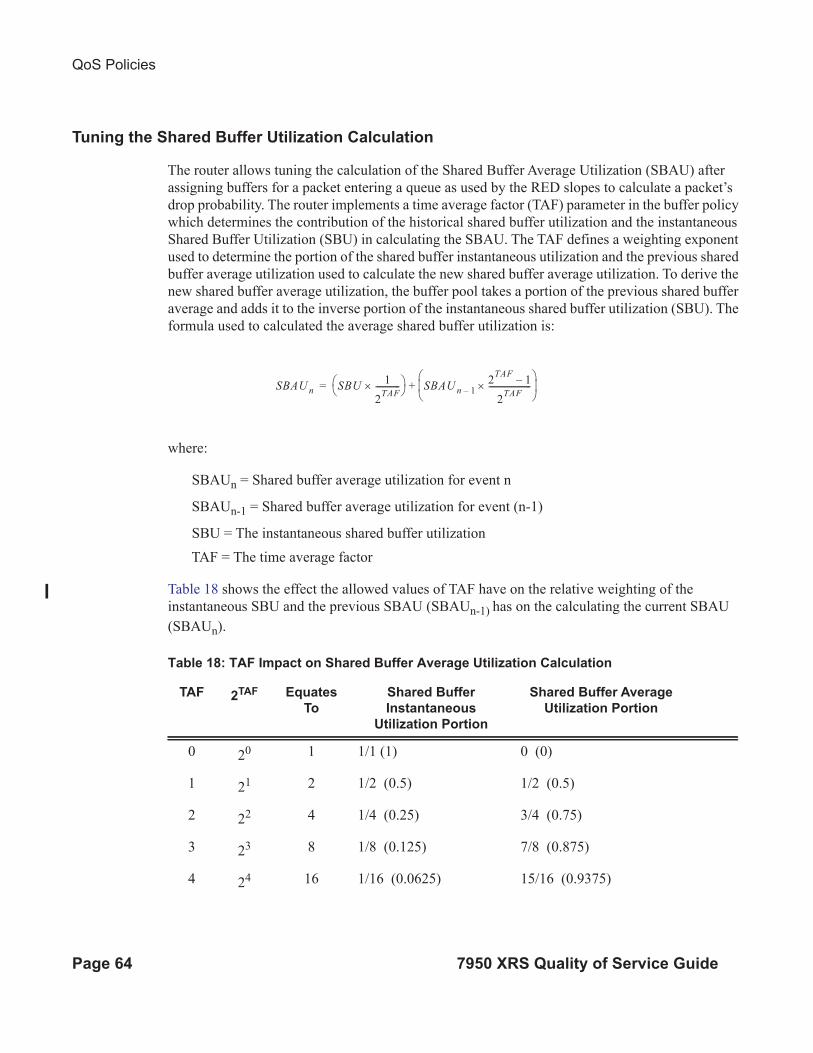
QoS Policies
Page 64 7950 XRS Quality of Service Guide
Tuning the Shared Buffer Utilization Calculation
The router allows tuning the calculation of the Shared Buffer Average Utilization (SBAU) after
assigning buffers for a packet entering a queue as used by the RED slopes to calculate a packet’s
drop probability. The router implements a time average factor (TAF) parameter in the buffer policy
which determines the contribution of the historical shared buffer utilization and the instantaneous
Shared Buffer Utilization (SBU) in calculating the SBAU. The TAF defines a weighting exponent
used to determine the portion of the shared buffer instantaneous utilization and the previous shared
buffer average utilization used to calculate the new shared buffer average utilization. To derive the
new shared buffer average utilization, the buffer pool takes a portion of the previous shared buffer
average and adds it to the inverse portion of the instantaneous shared buffer utilization (SBU). The
formula used to calculated the average shared buffer utilization is:
where:
SBAUn = Shared buffer average utilization for event n
SBAUn-1 = Shared buffer average utilization for event (n-1)
SBU = The instantaneous shared buffer utilization
TAF = The time average factor
Table 18 shows the effect the allowed values of TAF have on the relative weighting of the
instantaneous SBU and the previous SBAU (SBAUn-1) has on the calculating the current SBAU
(SBAUn).
SBAU n SBU1
2TAF------------×
SBAU n 1–2TAF
1–
2TAF
---------------------×
+=
Table 18: TAF Impact on Shared Buffer Average Utilization Calculation
TAF 2TAF Equates
To
Shared Buffer
Instantaneous
Utilization Portion
Shared Buffer Average
Utilization Portion
0 20 1 1/1 (1) 0 (0)
1 21 2 1/2 (0.5) 1/2 (0.5)
2 22 4 1/4 (0.25) 3/4 (0.75)
3 23 8 1/8 (0.125) 7/8 (0.875)
4 24 16 1/16 (0.0625) 15/16 (0.9375)
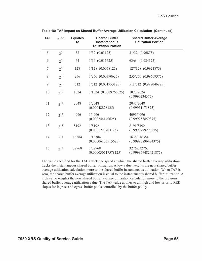
QoS Policies
7950 XRS Quality of Service Guide Page 65
The value specified for the TAF affects the speed at which the shared buffer average utilization
tracks the instantaneous shared buffer utilization. A low value weights the new shared buffer
average utilization calculation more to the shared buffer instantaneous utilization. When TAF is
zero, the shared buffer average utilization is equal to the instantaneous shared buffer utilization. A
high value weights the new shared buffer average utilization calculation more to the previous
shared buffer average utilization value. The TAF value applies to all high and low priority RED
slopes for ingress and egress buffer pools controlled by the buffer policy.
5 25 32 1/32 (0.03125) 31/32 (0.96875)
6 26 64 1/64 (0.015625) 63/64 (0.984375)
7 27 128 1/128 (0.0078125) 127/128 (0.9921875)
8 28 256 1/256 (0.00390625) 255/256 (0.99609375)
9 29 512 1/512 (0.001953125) 511/512 (0.998046875)
10 210 1024 1/1024 (0.0009765625) 1023/2024
(0.9990234375)
11 211 2048 1/2048
(0.00048828125)
2047/2048
(0.99951171875)
12 212 4096 1/4096
(0.000244140625)
4095/4096
(0.999755859375)
13 213 8192 1/8192
(0.0001220703125)
8191/8192
(0.9998779296875)
14 214 16384 1/16384
(0.00006103515625)
16383/16384
(0.99993896484375)
15 215 32768 1/32768
(0.000030517578125)
32767/32768
(0.999969482421875)
Table 18: TAF Impact on Shared Buffer Average Utilization Calculation (Continued)
TAF 2TAF Equates
To
Shared Buffer
Instantaneous
Utilization Portion
Shared Buffer Average
Utilization Portion

QoS Policies
Page 66 7950 XRS Quality of Service Guide
Slope Policy Parameters
The elements required to define a slope policy are:
• A unique policy ID
• The high and low RED slope shapes for the buffer pool: the start-avg, max-avg and max-
prob.
• The TAF weighting factor to use for the SBAU calculation for determining RED slope
drop probability.
Unlike access QoS policies where there are distinct policies for ingress and egress, slope policy is
defined with generic parameters so that it is not inherently an ingress or an egress policy. A slope
policy defines ingress properties when it is associated with an access port buffer pool on ingress
and egress properties when it is associated with an access buffer pool on egress.
Each access port buffer pool can be associated with one slope policy ID on ingress and one slope
policy ID on egress. The slope policy IDs on ingress and egress can be set independently.
Slope policy ID default is reserved for the default slope policy. The default policy cannot be
deleted or changed. The default slope policy is implicitly applied to all access buffer pools which
do not have another slope policy explicitly assigned.
Table 19 lists the default values for the default slope policy.
Table 19: Default Slope Policy Definition
Parameter Description Setting
Policy ID Slope policy ID 1 (Policy ID 1 reserved for default slope
policy)
High (RED) slope Administrative state Shutdown
start-avg 70% utilization
max-avg 90% utilization
max-prob 80% probability
Low (RED) slope Administrative state Shutdown
start-avg 50% utilization
max-avg 75% utilization
max-prob 80% probability
TAF Time average factor 7
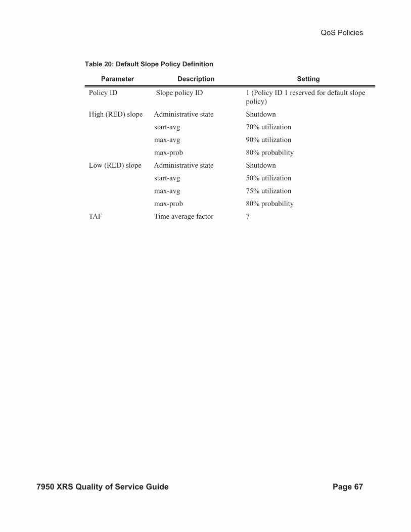
QoS Policies
7950 XRS Quality of Service Guide Page 67
Table 20: Default Slope Policy Definition
Parameter Description Setting
Policy ID Slope policy ID 1 (Policy ID 1 reserved for default slope
policy)
High (RED) slope Administrative state Shutdown
start-avg 70% utilization
max-avg 90% utilization
max-prob 80% probability
Low (RED) slope Administrative state Shutdown
start-avg 50% utilization
max-avg 75% utilization
max-prob 80% probability
TAF Time average factor 7

QoS Policies
Page 68 7950 XRS Quality of Service Guide
Scheduler Policies
A scheduler policy defines the hierarchy and all operating parameters for the member schedulers.
A scheduler policy must be defined in the QoS context before a group of virtual schedulers can be
used. Although configured in a scheduler policy, the individual schedulers are actually created
when the policy is applied to a site, such as a SAP or interface.
Scheduler objects define bandwidth controls that limit each child (other schedulers and queues)
associated with the scheduler. The scheduler object can also define a child association with a
parent scheduler of its own.
A scheduler is used to define a bandwidth aggregation point within the hierarchy of virtual
schedulers. The scheduler’s rate defines the maximum bandwidth that the scheduler can consume.
It is assumed that each scheduler created will have queues or other schedulers defined as child
associations. The scheduler can also be a child (take bandwidth from) a scheduler in a higher tier,
except for schedulers created in Tier 1.
A parent parameter can be defined to specify a scheduler further up in the scheduler policy
hierarchy. Only schedulers in Tiers 2 and 3 can have parental association. Tier 1 schedulers cannot
have a parental association. When multiple schedulers and/or queues share a child status with the
scheduler on the parent, the weight or strict parameters define how this scheduler contends with
the other children for the parent’s bandwidth. The parent scheduler can be removed or changed at
anytime and is immediately reflected on the schedulers actually created by association of this
scheduler policy.
When a parent scheduler is defined without specifying level, weight, or CIR parameters, the
default bandwidth access method is weight with a value of 1.
If any orphaned queues (queues specifying a scheduler name that does not exist) exist on the
ingress SAP and the policy application creates the required scheduler, the status on the queue
becomes non-orphaned at this time.
Figure 6 depicts how child queues and schedulers interact with their parent scheduler to receive
bandwidth. The scheduler distributes bandwidth to the children by first using each child’s CIR
according to the CIR-level parameter (CIR L8 through CIR L1 weighted loops). The weighting at
each CIR-Level loop is defined by the CIR weight parameter for each child. The scheduler then
distributes any remaining bandwidth to the children up to each child’s rate parameter according to
the Level parameter (L8 through L1 weighted loops). The weighting at each level loop is defined
by the weight parameter for each child.

QoS Policies
7950 XRS Quality of Service Guide Page 69
.
Figure 6: Virtual Scheduler Internal Bandwidth Allocation
al_0188
ChildScheduler
Child Offered Within CIR and Above CIR LoadLimited by Child Maximum Rate (PIR)
Child Served Within CIR Loop According toProvisioned CIR-Level
Scheduler CIR Based onProvisioned Value orSum of Child CIR Values
Rate Limiting Strict LoopReceives BandwidthAccording to it’s OfferedLoad Within CIR andOffered Load Above CIR
Rate Limiting Strict LoopDistributes Available Bandwidth to Each ChildAccording to ChildOffered Load Within andOffered Load Above Child CIR
Scheduler Rate (PIR)Based on ProvisionedValue
Child Served By Above CIR Loop According toProvisioned Level
Prioritizing Loop (Weighted or Strict)
Legend
Maximum and CommittedRate Parameters
Bandwidth Dependency Association
Bandwidth Allocation
CIR-Weight Determines Ratio of Bandwidth forChild When Multiple Children Are Mapped toSame Within CIR Loop
Weight Determines Ratio of Bandwidth forChild When Multiple Children Are Mapped toSame Above CIR Loop
RateLimiting
StrictLoop
WithinCIR
StrictLoop
CIRL8
CIRL7
CIRL6
CIRL5
CIRL4
CIRL3
CIRL2
ChildQueue
Child Undefined CIRLevel Forces AllOffered Load ForChild to be Treated asAbove CIR Leveland Weight
Offe
red
Load
With
in C
IR
Offered Load W
ithin CIR
ORCIRL
1
L8
L7
L6
L5
L4
L3
L2
L1
HighPriority
LowPriority
SchedulerLoop Within
Policy
AboveCIR
StrictLoop
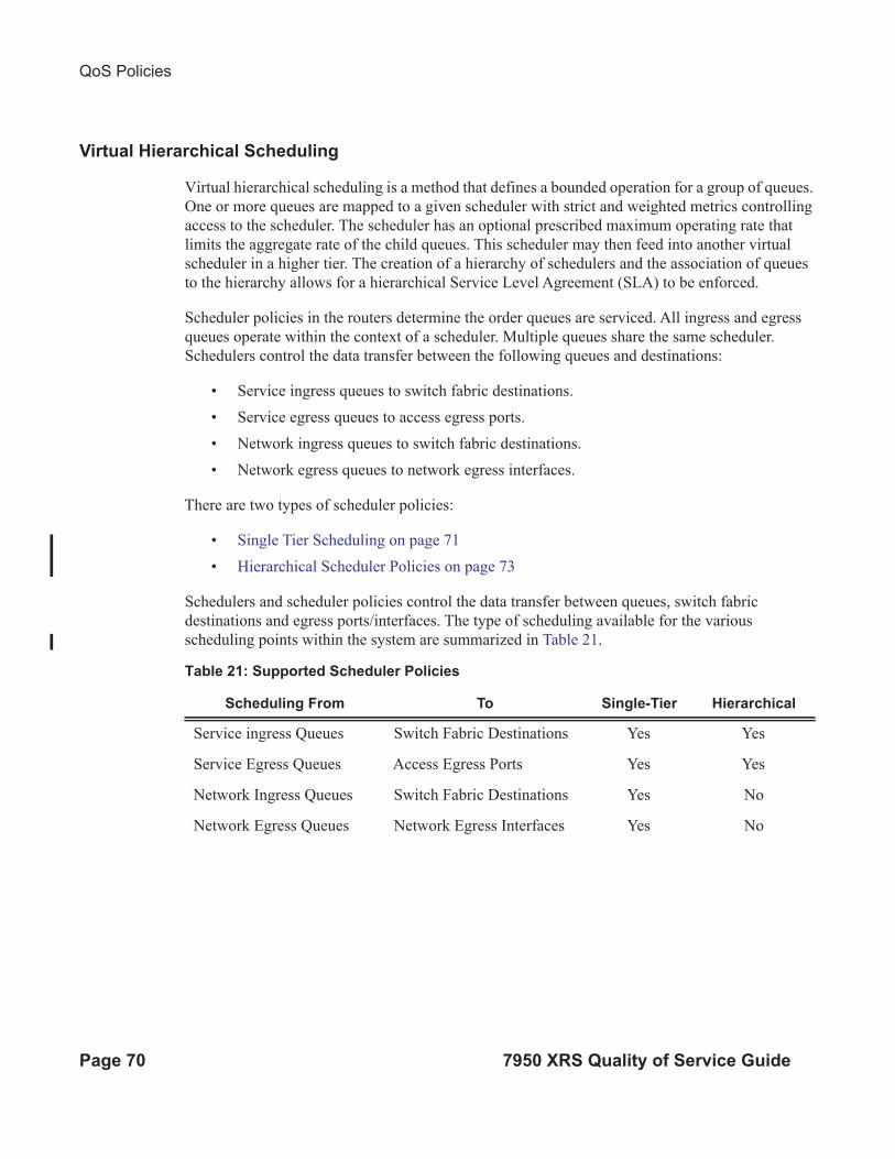
QoS Policies
Page 70 7950 XRS Quality of Service Guide
Virtual Hierarchical Scheduling
Virtual hierarchical scheduling is a method that defines a bounded operation for a group of queues.
One or more queues are mapped to a given scheduler with strict and weighted metrics controlling
access to the scheduler. The scheduler has an optional prescribed maximum operating rate that
limits the aggregate rate of the child queues. This scheduler may then feed into another virtual
scheduler in a higher tier. The creation of a hierarchy of schedulers and the association of queues
to the hierarchy allows for a hierarchical Service Level Agreement (SLA) to be enforced.
Scheduler policies in the routers determine the order queues are serviced. All ingress and egress
queues operate within the context of a scheduler. Multiple queues share the same scheduler.
Schedulers control the data transfer between the following queues and destinations:
• Service ingress queues to switch fabric destinations.
• Service egress queues to access egress ports.
• Network ingress queues to switch fabric destinations.
• Network egress queues to network egress interfaces.
There are two types of scheduler policies:
• Single Tier Scheduling on page 71
• Hierarchical Scheduler Policies on page 73
Schedulers and scheduler policies control the data transfer between queues, switch fabric
destinations and egress ports/interfaces. The type of scheduling available for the various
scheduling points within the system are summarized in Table 21.
Table 21: Supported Scheduler Policies
Scheduling From To Single-Tier Hierarchical
Service ingress Queues Switch Fabric Destinations Yes Yes
Service Egress Queues Access Egress Ports Yes Yes
Network Ingress Queues Switch Fabric Destinations Yes No
Network Egress Queues Network Egress Interfaces Yes No

QoS Policies
7950 XRS Quality of Service Guide Page 71
Tiers
In single tier scheduling, queues are scheduled based on the forwarding class of the queue and the
operational state of the queue relative to the queue’s CIR and PIR. Queues operating within their
CIR values are serviced before queues operating above their CIR values with “high-priority”
forwarding class queues given preference over “low-priority” forwarding class queues. In single
tier scheduling, all queues are treated as if they are at the same “level” and the queue’s parameters
and operational state directly dictate the queue’s scheduling. Single tier scheduling is the system
default scheduling policy for all the queues and destinations listed above and has no configurable
parameters.
Hierarchical scheduler policies are an alternate way to schedule queues that can be used on service
ingress and service egress queues. Hierarchical scheduler policies allow the creation of a hierarchy
of schedulers where queues and/or other schedulers are scheduled by superior schedulers.
To illustrate the difference between single tier scheduling and hierarchical scheduling policies,
consider a simple case where, on service ingress, three queues are created for gold, silver and
bronze service and are configured as follows:
• Gold: CIR = 10 Mbps, PIR = 10 Mbps
• Silver: CIR = 20 Mbps, PIR = 40 Mbps
• Bronze: CIR = 0 Mbps, PIR = 100 Mbps
In the router, the CIR is used for policing of traffic (in-profile or out-of-profile), and the PIR is the
rate at which traffic is shaped out of the queue. In single tier scheduling, each queue can burst up
to its defined PIR, which means up to 150 Mbps (10 Mbps + 40 Mbps + 100 Mbps) can enter the
service.
In a simple example of a hierarchical scheduling policy, a superior (or parent) scheduler can be
created for the gold, silver and bronze queues which limits the overall rate for all queues to 100
Mbps. In this hierarchical scheduling policy, the customer can send in any combination of gold,
silver and bronze traffic conforming to the defined PIR values and not to exceed 100 Mbps.
Single Tier Scheduling
Single-tier scheduling is the default method of scheduling queues in the router. Queues are
scheduled with single-tier scheduling if no explicit hierarchical scheduler policy is defined or
applied. There are no configurable parameters for single-tier scheduling.
In single tier scheduling, queues are scheduled based on the Forwarding Class of the queue and the
operational state of the queue relative to the queue’s Committed Information Rate (CIR) and Peak
Information Rate (PIR). Queue’s operating within their CIR values are serviced before queue’s
operating above their CIR values with “high-priority” forwarding class queues given preference
over “low-priority” forwarding class queues. In Single Tier Scheduling, all queues are treated as if
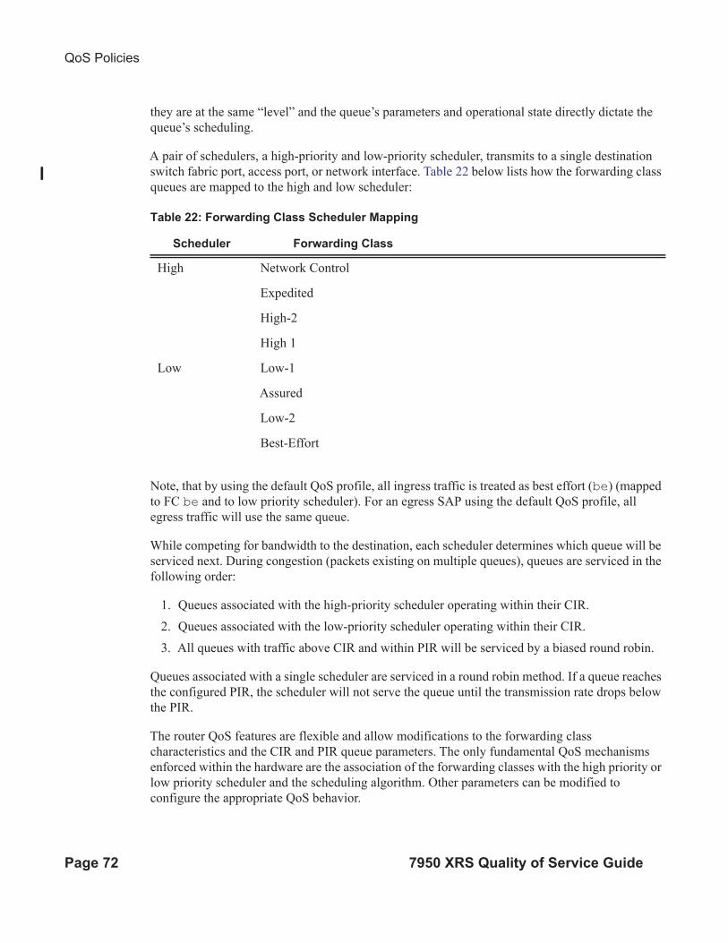
QoS Policies
Page 72 7950 XRS Quality of Service Guide
they are at the same “level” and the queue’s parameters and operational state directly dictate the
queue’s scheduling.
A pair of schedulers, a high-priority and low-priority scheduler, transmits to a single destination
switch fabric port, access port, or network interface. Table 22 below lists how the forwarding class
queues are mapped to the high and low scheduler:
Note, that by using the default QoS profile, all ingress traffic is treated as best effort (be) (mapped
to FC be and to low priority scheduler). For an egress SAP using the default QoS profile, all
egress traffic will use the same queue.
While competing for bandwidth to the destination, each scheduler determines which queue will be
serviced next. During congestion (packets existing on multiple queues), queues are serviced in the
following order:
1. Queues associated with the high-priority scheduler operating within their CIR.
2. Queues associated with the low-priority scheduler operating within their CIR.
3. All queues with traffic above CIR and within PIR will be serviced by a biased round robin.
Queues associated with a single scheduler are serviced in a round robin method. If a queue reaches
the configured PIR, the scheduler will not serve the queue until the transmission rate drops below
the PIR.
The router QoS features are flexible and allow modifications to the forwarding class
characteristics and the CIR and PIR queue parameters. The only fundamental QoS mechanisms
enforced within the hardware are the association of the forwarding classes with the high priority or
low priority scheduler and the scheduling algorithm. Other parameters can be modified to
configure the appropriate QoS behavior.
Table 22: Forwarding Class Scheduler Mapping
Scheduler Forwarding Class
High Network Control
Expedited
High-2
High 1
Low Low-1
Assured
Low-2
Best-Effort

QoS Policies
7950 XRS Quality of Service Guide Page 73
Hierarchical Scheduler Policies
Hierarchical scheduler policies are an alternate way of scheduling queues which can be used on
service ingress and service egress queues. Hierarchical scheduler policies allow the creation of a
hierarchy of schedulers where queues and/or other schedulers are scheduled by superior
schedulers.
The use of the hierarchical scheduler policies is often referred to as hierarchical QoS or H-QoS on
the SR OS.
Hierarchical Virtual Schedulers
Virtual schedulers are created within the context of a hierarchical scheduler policy. A hierarchical
scheduler policy defines the hierarchy and parameters for each scheduler. A scheduler is defined in
the context of a tier (Tier 1, Tier 2, Tier 3). The tier level determines the scheduler’s position
within the hierarchy. Three tiers of virtual schedulers are supported (Figure 7). Tier 1 schedulers
(also called root schedulers) are defined without a parent scheduler. It is not necessary for Tier 1
schedulers to obtain bandwidth from a higher tier scheduler. A scheduler can enforce a maximum
rate of operation for all child queues and associated schedulers.

QoS Policies
Page 74 7950 XRS Quality of Service Guide
Figure 7: Hierarchical Scheduler and Queue Association
Tier 3 Tier 2 Tier 1
Weighted
Rate Limiting
Scheduler
Queue(8)C1
B1
A1
C2
C3
(7)
(6)
(5)
(4)
(3)
Queue
Queue
Queue
Queue
Queue
Weighted
Rate Limiting
Scheduler
Weighted
Rate Limiting
Scheduler
Weighted
Rate Limiting
Scheduler
Weighted
Rate Limiting
Scheduler
OSSG268
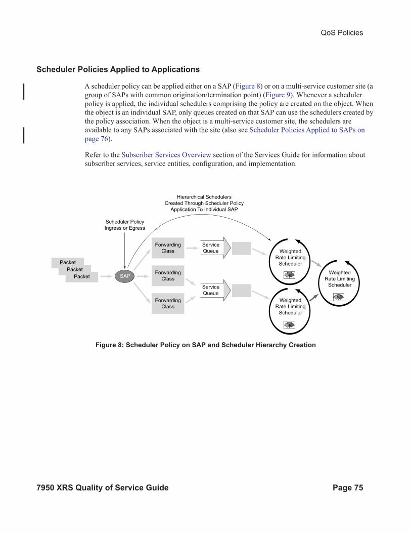
QoS Policies
7950 XRS Quality of Service Guide Page 75
Scheduler Policies Applied to Applications
A scheduler policy can be applied either on a SAP (Figure 8) or on a multi-service customer site (a
group of SAPs with common origination/termination point) (Figure 9). Whenever a scheduler
policy is applied, the individual schedulers comprising the policy are created on the object. When
the object is an individual SAP, only queues created on that SAP can use the schedulers created by
the policy association. When the object is a multi-service customer site, the schedulers are
available to any SAPs associated with the site (also see Scheduler Policies Applied to SAPs on
page 76).
Refer to the Subscriber Services Overview section of the Services Guide for information about
subscriber services, service entities, configuration, and implementation.
Figure 8: Scheduler Policy on SAP and Scheduler Hierarchy Creation
Service
Queue
Service
Queue
Scheduler Policy
Ingress or Egress
Hierarchical Schedulers
Created Through Scheduler Policy
Application To Individual SAP
Forwarding
Class
SAPForwarding
Class
Packet
Packet
Packet
Forwarding
Class
Weighted
Rate Limiting
Scheduler
Weighted
Rate Limiting
Scheduler
Weighted
Rate Limiting
Scheduler
OSSG269

QoS Policies
Page 76 7950 XRS Quality of Service Guide
Figure 9: Scheduler Policy on Customer Site and Scheduler Hierarchy Creation
Queues become associated with schedulers when the parent scheduler name is defined within the
queue definition in the SAP ingress policy. The scheduler is used to provide bandwidth to the
queue relative to the operating constraints imposed by the scheduler hierarchy.
Scheduler Policies Applied to SAPs
A scheduler policy can be applied to create egress schedulers used by SAP queues. The schedulers
comprising the policy are created at the time the scheduler policy is applied to the SAP. If any
orphaned queues exist (queues specifying a scheduler name that does not exist) on the egress SAP
and the policy application creates the required scheduler, the status on the queue will become non-
orphaned.
Queues are associated with the configured schedulers by specifying the parent scheduler defined
within the queue definition from the SAP egress policy. The scheduler is used to provide
bandwidth to the queue relative to the operating constraints imposed by the scheduler hierarchy.
Weighted
Rate Limiting
Scheduler
Service
Queue
Service
Queue
Service
Queue
Service
Queue
Service
Queue
Service
Queue
Weighted
Rate Limiting
Scheduler
Weighted
Rate Limiting
Scheduler
Weighted
Rate Limiting
Scheduler
Forwarding
Class
Forwarding
Class
Forwarding
Class
Forwarding
Class
Forwarding
Class
Forwarding
Class
Scheduler Policy
Ingress or Egress
SAP
SAP
Hierarchical Schedulers
Created Through Scheduler Policy
Application To Individual SAP
Customer
Site
Each SAP Belongs
To The Same
Customer And Is
Associated With
The Same Port
Packet
Packet
Packet
Packet
Packet
Packet
OSSG270

QoS Policies
7950 XRS Quality of Service Guide Page 77
Customer Service Level Agreement (SLA)
The router implementation of hierarchical QoS allows a common set of virtual schedulers to
govern bandwidth over a set of customer services that is considered to be from the same site.
Different service types purchased from a single customer can be aggregately accounted and billed
based on a single Service Level Agreement.
By configuring multi-service sites within a customer context, the customer site can be used as an
anchor point to create an ingress and egress virtual scheduler hierarchy.
Once a site is created, it must be assigned to the chassis slot or a port . This allows the system to
allocate the resources necessary to create the virtual schedulers defined in the ingress and egress
scheduler policies. This also acts as verification that each SAP assigned to the site exists within the
context of the customer ID and that the SAP was created on the correct slot, port, or channel. The
specified slot or port must already be pre-provisioned (configured) on the system.
When scheduler policies are defined for ingress and egress, the scheduler names contained in each
policy are created according to the parameters defined in the policy. Multi-service customer sites
are configured only to create a virtual scheduler hierarchy and make it available to queues on
multiple SAPs.
Scheduler Policies Applied to Multi-Service Sites
Only an existing scheduler policy and scheduler policy names can be applied to create the ingress
or egress schedulers used by SAP queues associated with a customer’s multi-service site. The
schedulers defined in the scheduler policy can only be created after the customer site has been
appropriately assigned to a chassis port, channel, or slot. Once a multi-service customer site is
created, SAPs owned by the customer must be explicitly included in the site. The SAP must be
owned by the customer the site was created within and the site assignment parameter must include
the physical locale of the SAP.

QoS Policies
Page 78 7950 XRS Quality of Service Guide
Forwarding Classes
Routers support multiple forwarding classes and class-based queuing, so the concept of
forwarding classes is common to all of the QoS policies.
Each forwarding class (also called Class of Service (CoS)) is important only in relation to the other
forwarding classes. A forwarding class provides network elements a method to weigh the relative
importance of one packet over another in a different forwarding class.
Queues are created for a specific forwarding class to determine the manner in which the queue
output is scheduled into the switch fabric. The forwarding class of the packet, along with the in-
profile or out-of-profile state, determines how the packet is queued and handled (the per hop
behavior (PHB)) at each hop along its path to a destination egress point. Routers support eight (8)
forwarding classes (Table 23).
Note that Table 23 presents the default definitions for the forwarding classes. The forwarding class
behavior, in terms of ingress marking interpretation and egress marking, can be changed by a
Network QoS Policies on page 31. All forwarding class queues support the concept of in-profile
and out-of-profile.
Table 23: Forwarding Classes
FC-ID FC Name FC
Designa-
tion
DiffServ
Name
Class Type Notes
7 Network
Control
NC NC2 High-Priority Intended for network control traffic.
6 High-1 H1 NC1 Intended for a second network control
class or delay/jitter sensitive traffic.
5 Expedited EF EF Intended for delay/jitter sensitive traffic.
4 High-2 H2 AF4 Intended for delay/jitter sensitive traffic.
3 Low-1 L1 AF2 Assured Intended for assured traffic. Also is the
default priority for network management
traffic.
2 Assured AF AF1 Intended for assured traffic.
1 Low-2 L2 CS1 Best Effort Intended for BE traffic.
0 Best Effort BE BE
QoS Policies
7950 XRS Quality of Service Guide Page 79
The forwarding classes can be classified into three class types:
• High-priority/Premium
• Assured
• Best effort
High-Priority Classes
The high-priority forwarding classes are Network Control (nc), Expedited (ef), High 1 (h1), and
High 2 (h2). High-priority forwarding classes are always serviced at congestion points over other
forwarding classes; this behavior is determined by the router queue scheduling algorithm (Virtual
Hierarchical Scheduling on page 70).
With a strict PHB at each network hop, service latency is mainly affected by the amount of high-
priority traffic at each hop. These classes are intended to be used for network control traffic or for
delay or jitter-sensitive services.
If the service core network is over-subscribed, a mechanism to traffic engineer a path through the
core network and reserve bandwidth must be used to apply strict control over the delay and
bandwidth requirements of high-priority traffic. In the router, RSVP-TE can be used to create a
path defined by an MPLS LSP through the core. Premium services are then mapped to the LSP
with care exercised to not oversubscribe the reserved bandwidth.
If the core network has sufficient bandwidth, it is possible to effectively support the delay and
jitter characteristics of high-priority traffic without utilizing traffic engineered paths, as long as the
core treats high-priority traffic with the proper PHB.
Assured Classes
The assured forwarding classes are Assured (af) and Low 1 (l1). Assured forwarding classes
provide services with a committed rate and a peak rate much like Frame Relay. Packets transmitted
through the queue at or below the committed transmission rate are marked in-profile. If the core
service network has sufficient bandwidth along the path for the assured traffic, all aggregate in-
profile service packets will reach the service destination. Packets transmitted out the service queue
that are above the committed rate will be marked out-of-profile. When an assured out-of-profile
service packet is received at a congestion point in the network, it will be discarded before in-
profile assured service packets.
Multiple assured classes are supported with relative weighting between them. In DiffServ, the code
points for the various Assured classes are AF4, AF3, AF2 and AF1. Typically, AF4 has the highest
weight of the four and AF1 the lowest. The Assured and Low 1 classes are differentiated based on
the default DSCP mappings. Note that all DSCP and EXP mappings can be modified by the user.

QoS Policies
Page 80 7950 XRS Quality of Service Guide
Best-Effort Classes
The best-effort classes are Low 2 (l2) and Best-Effort (be). The best-effort forwarding classes
have no delivery guarantees. All packets within this class are treated, at best, like out-of-profile
assured service packets.
Shared Queues
Shared-queue QoS policies can be implemented to facilitate queue consumption on an MDA. It is
especially useful when VPLS, IES, and VPRN services are scaled on one MDA. Instead of
allocating multiple hardware queues for each unicast queue defined in a SAP ingress QoS policy,
SAPs with the shared-queuing feature enabled only allocate one hardware queue for each SAP
ingress QoS policy unicast queue.
However, as a tradeoff, the total amount of traffic throughput at ingress of the node is reduced
because any ingress packet serviced by a shared-queuing SAP is recirculated for further
processing. When the node is only used for access SAPs, 5 Gbps ingress traffic is the maximum
that can be processed without seeing packet drops at the MDA ingress. The reason for this is that
any ingress packet serviced by a shared-queuing SAP is processed twice in Flexible Fast Path
which greatly reduces bandwidth.
Shared-queuing can add latency. Network planners should consider these restrictions while trying
to scale services on one MDA.
ATM Traffic Descriptor Profiles
Traffic descriptors profiles capture the cell arrival pattern for resource allocation. Source traffic
descriptors for an ATM connection include at least one of the following:
• Sustained Information Rate (SIR)
• Peak Information Rate (PIR)
• Minimum Information Rate (MIR)
• Maximum Burst Size (MBS)
QoS Traffic descriptor profiles are applied on IES, VPRN, VPLS, and VLL SAPs.
QoS Policies
7950 XRS Quality of Service Guide Page 81
QoS Policy Entities
Services are configured with default QoS policies. Additional policies must be explicitly created
and associated. There is one default service ingress QoS policy, one default service egress QoS
policy, and one default network QoS policy. Only one ingress QoS policy and one egress QoS
policy can be applied to a SAP or network port.
When you create a new QoS policy, default values are provided for most parameters with the
exception of the policy ID and queue ID values, descriptions, and the default action queue
assignment. Each policy has a scope, default action, a description, and at least one queue. The
queue is associated with a forwarding class.
QoS policies can be applied to the following service types:
• Epipe — Both ingress and egress policies are supported on an Epipe service access point
(SAP).
• VPLS — Both ingress and egress policies are supported on a VPLS SAP.
• IES — Both ingress and egress policies are supported on an IES SAP.
• VPRN — Both ingress and egress policies are supported on a VPRN SAP.
QoS policies can be applied to the following entities:
• Network ingress interface
• Network egress interface
Default QoS policies maps all traffic with equal priority and allow an equal chance of transmission
(Best Effort (be) forwarding class) and an equal chance of being dropped during periods of
congestion. QoS prioritizes traffic according to the forwarding class and uses congestion
management to control access ingress, access egress, and network traffic with queuing according
to priority

Frequently Used QoS Terms
Page 82 7950 XRS Quality of Service Guide
Frequently Used QoS Terms
The following terms are used in router Hierarchical QoS to describe the operation and
maintenance of a virtual scheduler hierarchy and are presented for reference purposes.
Above CIR Distribution
‘Above CIR’ distribution is the second phase of bandwidth allocation between a parent scheduler
and its child queues and child schedulers. The bandwidth that is available to the parent scheduler
after the ‘within CIR’ distribution is distributed among the child members using each child’s level
(to define strict priority for the above CIR distribution), Weight (the ratio at a given level with
several children) and the child’s rate value. A rate value equal to the child’s CIR value results in a
child not receiving any bandwidth during the ‘above CIR’ distribution phase.
Available Bandwidth
Available bandwidth is the bandwidth usable by a parent scheduler to distribute to its child queues
and schedulers. The available bandwidth is limited by the parent’s schedulers association with its
parent scheduler. If the parent scheduler has a parent of its own and the parent schedulers defined
rate value, then available bandwidth is distributed to the child queues and schedulers using a
‘within CIR’ distribution phase and an ‘above CIR’ distribution phase. Distribution in each phase
is based on a combination of the strict priority of each child and the relative weight of the child at
that priority level. Separate priority and weight controls are supported per child for each phase.
CBS
The Committed Burst Size (CBS) specifies the relative amount of reserved buffers for a specific
ingress network MDA forwarding class queue or egress network port forwarding class queue. The
value is entered as a percentage.
CIR
The Committed Information Rate (CIR) defines the amount of bandwidth committed to the
scheduler or queue.
• For schedulers, the CIR value can be explicitly defined or derived from summing the child
member CIR values.
• On a queue, the CIR value is explicitly defined.
The CIR rate for ingress queues controls the in-profile and out-of-profile policing and
ultimately egress in-profile and out-of-profile marking. Queue CIR rates also define the
hardware fairness threshold at which the queue is no longer prioritized over other queues.
QoS Policies
7950 XRS Quality of Service Guide Page 83
A child’s (queue or scheduler) CIR is used with the CIR level parameter to determine the child’s
committed bandwidth from the parent scheduler. When multiple children are at the same strict CIR
level, the CIR weight further determines the bandwidth distribution at that level.
CIR Level
The CIR level parameter defines the strict level at which bandwidth is allocated to the child queue
or scheduler during the within CIR distribution phase of bandwidth allocation. All committed
bandwidth (determined by the CIR defined for the child) is allocated before any child receives
non-committed bandwidth. Bandwidth is allocated to children at the higher CIR levels before
children at a lower level. A child CIR value of zero or an undefined CIR level results in bandwidth
allocation to the child only after all other children receive their provisioned CIR bandwidth. When
multiple children share a CIR level, the CIR weight parameter further defines bandwidth
allocation according to the child’s weight ratio.
CIR Weight
The CIR weight parameter defines the weight within the CIR level given to a child queue or
scheduler. When multiple children share the same CIR level on a parent scheduler, the ratio of
bandwidth given to an individual child is dependent on the ratio of the weights of the active
children. A child is considered active when a portion of the offered load is within the child’s
defined CIR rate. The ratio is calculated by first adding the CIR weights of all active children and
then dividing each child’s CIR weight by the sum. If a child’s CIR level parameter is not defined,
that child is not included in the within CIR distribution and the CIR weight parameter is ignored.
A CIR weight of zero forces the child to receive bandwidth only after all other children at that
level have received their ‘within CIR’ bandwidth. When several children share a CIR weight of
zero, all are treated equally.
Child
Child is a logical state of a queue or scheduler that has been configured with a valid parent
scheduler association. The child/parent association is used to build the hierarchy among the queues
and schedulers.
Level
The level parameter defines the strict priority level for a child queue or scheduler with regards to
bandwidth allocation during the above CIR distribution phase on the child’s parent scheduler. This
allocation of bandwidth is done after the ‘within CIR’ distribution is finished. All child queues and
schedulers receive the remaining bandwidth according to the strict priority level in which they are
defined with higher levels receiving bandwidth first and lower levels receiving bandwidth if
available.
Frequently Used QoS Terms
Page 84 7950 XRS Quality of Service Guide
MBS
The Maximum Burst Size (MBS) command specifies the relative amount of the buffer pool space
for the maximum buffers for a specific ingress network MDA forwarding class queue or egress
network port forwarding class queue. The value is entered as a percentage.
MCR
The Minimum Cell Rate (MCR).
Offered Load
Offered load is evaluated per child in the scheduler hierarchy. The offered load is the amount of
bandwidth a child queue or scheduler can use to accommodate the data passing through the child.
It is separated into two portions; within CIR and above CIR. Within CIR offered load is the portion
of bandwidth required to meet the child’s CIR value. It can be less than the CIR value but never
greater. If the forwarding requirement for the child is greater than the CIR value, the remaining is
considered to be the above CIR offered load. The sum of the within CIR and above CIR offered
load cannot be greater than the maximum rate defined for the child.
Orphan
When a child queue is configured with a parent scheduler specified but the parent scheduler does
not exist on the object the queue is created on, the state is considered orphaned.
An orphaned state is not the same condition as when a queue is not defined with a parent
association. Orphan states are cleared when the parent scheduler becomes available on the object.
This can occur when a scheduler policy containing the parent scheduler name is applied to the
object that the queue exists on or when the scheduler name is added to the scheduler policy already
applied to the object that the queue exists on.
Parent
A scheduler becomes a parent when a queue or scheduler defines it as its parent. A queue or
scheduler can be a child of only one scheduler. When defining a parent association on a child
scheduler, the parent scheduler must already exist in the same scheduler policy and on a scheduler
tier higher (numerically lower) then the child scheduler. Parent associations for queues are only
checked once, when an instance of the queue is created on a SAP.
Queue
A queue is where packets that will be forwarded are buffered before scheduling. Packets are not
actually forwarded through the schedulers; they are forwarded from the queues directly to ingress
or egress interfaces. The association between the queue and the virtual schedulers is intended to
accomplish bandwidth allocation to the queue. Because the offered load is derived from queue
utilization, bandwidth allocation is dependent on the queue distribution among the scheduler
hierarchy. Queues can be tied to only one scheduler within the hierarchy.

QoS Policies
7950 XRS Quality of Service Guide Page 85
Rate
The rate defines the maximum bandwidth that will be made available to the scheduler or queue.
The rate is defined in kilobits per second (Kbps).
• On a scheduler, the rate setting is used to limit the total bandwidth allocated to the
scheduler’s child members.
• For queues, the rate setting is used to define the Peak Information Rate (PIR) at which the
queue can operate.
Root (Scheduler)
A scheduler that has no parent scheduler association (is not a child of another scheduler) is
considered to be a root scheduler. With no parent scheduler, bandwidth utilized by a root scheduler
is dependent on offered load of child members, the maximum rate defined for the scheduler and
total overall available bandwidth. Any scheduler can be a root scheduler. Since parent associations
are not allowed in Tier 1, all schedulers in Tier 1 are considered be a root scheduler.
Scheduler Policy
A scheduler policy represents a particular grouping of virtual schedulers that are defined in
specific scheduler tiers. The tiers and internal parent associations between the schedulers establish
the hierarchy among the virtual schedulers. A scheduler policy can be applied to either a multi-
service site or to a service Service Access Point (SAP). Once the policy is applied to a site or SAP,
the schedulers in the policy are instantiated on the object and are available for use by child queues
directly or indirectly associated with the object.
Tier
A tier is an organizational configuration used within a scheduler policy to define the place of
schedulers created in the policy. Three tiers are supported; Tier 1, Tier 2, and Tier 3. Schedulers
defined in Tier 2 can have parental associations with schedulers defined in Tier 1. Schedulers
defined in Tier 3 can have parental associations with schedulers defined at Tiers 1 or 2. Queues can
have parental associations with schedulers at any tier level.
Virtual Scheduler
A virtual scheduler, defined by a name (text string), is a logical configuration used as a parent to a
group of child members that are dependent upon a common parent for bandwidth allocation. The
virtual scheduler can also be a child member to another parent virtual scheduler and receive
bandwidth from that parent to distribute to its child members.
Weight
The weight parameter defines the weight within the ‘above CIR’ level given to a child queue or
scheduler. When several children share the same level on a parent scheduler, the ratio of
bandwidth give to an individual child is dependent on the ratio of the weights of the active

Frequently Used QoS Terms
Page 86 7950 XRS Quality of Service Guide
children. A child is considered active when a portion of the offered load is above the CIR value
(also bounded by the child’s maximum bandwidth defined by the child’s rate parameter). The
portion of bandwidth given to each child is based on the child’s weight compared to the sum of the
weights of all active children at that level. A weight of zero forces the child to receive bandwidth
only after all other children at that level have received their ‘above CIR’ bandwidth. When several
children share a weight of zero, all are treated equally.
Within CIR Distribution
Within the CIR distribution process is the initial phase of bandwidth allocation between a parent
scheduler and its child queues and child schedulers. The bandwidth that is available to the parent
scheduler is distributed first among the child members using each child’s CIR level (to define a
strict priority for the CIR distribution), CIR weight (the ratio at a given CIR level with several
children), and the child’s CIR value. A CIR value of zero or an undefined CIR level causes a child
to not receive any bandwidth during the CIR distribution phase. If the parent scheduler has any
bandwidth remaining after the ‘within CIR’ distribution phase, it will be distributed using the
above CIR distribution phase.
QoS Policies
7950 XRS Quality of Service Guide Page 87
Configuration Notes
The following information describes QoS implementation caveats:
• Creating additional QoS policies is optional.
• Default policies are created for service ingress, service egress, network, network-queue,
slope policies. Scheduler policies must be explicitly created and applied to a port.
• Associating a service or access ports with a QoS policy other than the default policy is
optional.
• A network queue, service egress, and service ingress QoS policy must consist of at least
one queue. Queues define the forwarding class, CIR, and PIR associated with the queue.
Configuration Notes
Page 88 7950 XRS Quality of Service Guide