Reinforcement Learning as a Means of Dynamic Aggregate QoS Provisioning
Upload
independentCategory
view
1download
0
Using Active Networks Technology for
Dynamic QoS
T. Tansupasiri a,∗ , K. Kanchanasut a , C. Barakat b ,P. Jacquet c
aAsian Institute of Technology, Computer Science and Information ManagementProgram, P.O. Box 4, Pathumthani, 12120, Thailand
bINRIA, PLANETE research group, 2004, route des Lucioles, 06902 SophiaAntipolis, France
cINRIA, HIPERCOM research group, B.P. 105, Rocquencourt, 78153 Le ChesnayCedex, France
Abstract
We propose a dynamic QoS, or D-QoS, model where QoS settings can be automat-ically reconfigured based upon requests from authorized users. Different levels ofprivilege can be assigned to users enabling higher privileged users to interrupt thenetwork flows belonging to those of lower privileged levels. To request for a specialQoS treatment, a user can issue an active packet to interrupt any active node alongits flow path which is D-QoS enabled. The request for a specific interruption levelis approved by a D-QoS enabled node which allows for multi-level interruptions tobe handled. After an interrupting flow has completed transmitting all its packets,D-QoS enabled node can resume its services for those pending flows which are oflower privilege levels. In this paper, we describe the overall concept of D-QoS anddemonstrate how it can be implemented by a small prototype. Using simulation, weshow that the proposed system can provide assurance for privileged flows with animproved network utilization where bandwidth is shared among the flows accord-ing to the levels of privilege. D-QoS should be deployed on those bottleneck hopswith limited bandwidth on the edge network to ensure the best service is given toprivileged users.
Key words: QoS, Active Network, Bandwidth Management
∗ Corresponding author. Tel./Fax +66-2524-6619Email addresses: [email protected] (T. Tansupasiri), [email protected] (K.
Kanchanasut), [email protected] (C. Barakat),[email protected] (P. Jacquet).
Preprint submitted to Elsevier Science 5 May 2005

1 Introduction
The concept of active networks was introduced in 1994 by Defense AdvancedResearch Projects (DARPA) research community, as a future direction of net-working system [1]. In addition to packet forwarding mechanism in traditionalIP network, active networks allow the network nodes to perform user or ap-plication specific computations on user data passing through them. In activenetworks, normal packets are replaced with active packets containing smallprograms and possibly data. Network nodes are substituted by active nodescapable of performing computations on packets as requested by the applica-tions. Thus, the role of the network is changed from a passive carrier of datainto a general computation engine. New network services can, therefore, befaster innovated and deployed. These network services are, for example, IPmulticast, mobile IP and web caching, as they can be effectively provided inthe network layer.
One of the services that could also be offered based on active network is thequality of services, QoS. As Internet traffic can be generated possibly fromanywhere and at any time, it is desirable that QoS be dynamically adaptableto user requirements thus tailoring to the demand of the Internet users. Activenetwork technology can be used as a useful tool for providing dynamic oron demand QoS where active nodes can adjust their QoS configuration asinstructed by the programs in active packets.
Integrated Service (IntServ) model described in RFC 1633 [2] provides re-source sharing mechanism which could be requested dynamically per-flow. Themodel deploys resource reservation mechanism in which network resources arereserved along each communication path. However, this model suffers from itsscalability problem due to the overhead on maintaining the path state infor-mation at each node or router. Several attempts to provide scalable dynamicQoS have been made as in [3–6]. They combine IntServ with another QoSmodel, Differentiated Service (DiffServ) [7] which is known to be scalable.Rather than providing per flow QoS, DiffServ provides coarse grained QoS fortraffic aggregates or classes and applies different per-hop services to differentclasses. These works share the idea on deploying IntServ at the edge and Diff-Serv at the core networks. They introduce the use of a signaling mechanism inIntServ to communicate the QoS requirements to DiffServ. An additional net-work element called bandwidth broker, is introduced to monitor the resourcesusage within the domain and determines the admission control dynamically.Although this idea allows dynamic admission control, but flows are assignto a static preconfiguration in [3–5]. An extended idea for dynamic resourceallocation is explained in [6]. The bandwidth broker, in this case, is also re-sponsible for monitoring the bandwidth usage of the client and the state ofthe network. As the actual traffic rarely approaches the reserved bandwidth
2

for the peak rate, a portion of the unused bandwidth can be reclaimed to thepool of available bandwidth and reallocated to other flows. However, theseworks require that some elements in DiffServ network are IntServ-aware forsuch interoperation and restrict the resource allocation with DiffServ precon-figuration. Hence, they cannot really provide QoS on demand which could berequested directly by authorized users.
In [8,9], dynamic QoS has been proposed where active network technology isdeployed. A QoS scheme particularly for MPEG video transmission is proposedin [8] with an active buffer management and active packet scheduling mecha-nisms. Packets are classified into queues according to their contents. Packetscontaining self-contained video frames receive better service at network nodeswhile less important packets are preferably dropped. In [9], an integration ofDiffServ, active network and policy based management has been proposed toautomate the configuration at DiffServ nodes. The proposed model, namelyDiffServ Active Control Architecture (DACA), consists of DiffServ active com-ponents that allow flexible control over the classifier, meter, dropper and sched-uler algorithms through policies. It provides a repository of the active codesfor those mechanisms that could be loaded on active nodes on demand and aDynamic Management Information Base (DMIB) where the managed objectsand information can be changed or added dynamically. However, this workfocuses on dynamic QoS within the DiffServ framework only.
In [10], Tansupasiri and Kanchanasut proposed another concept of using ac-tive networks to provide dynamic QoS. The proposed system, namely DynamicQuality of Service (D-QoS), allows the QoS requirements to be reconfigureddynamically on network nodes upon receiving the requests within the activepackets from authorized users. An authorized user can request for an interrup-tion of a privileged flow transmission, in the same manner as the interruptionof a super user process in the operating system where system resources arefirst given to the super user. An example of the privileged flows is the timesensitive flow that requires high precision of data transmission like telesurgeryflow.
Each D-QoS node is triggered and the normal operation mode is automaticallychanged to the interruption mode upon receiving a request from an authorizeduser. In the interruption mode, the privileged flow is then transmitted withthe privilege over other existing flows. Even though QoS can be characterizedby throughput, delay, jitter and/or loss, the model relies on a narrow QoSconcept based on the bandwidth sharing among flows. The system also allowsmulti-level interruptions where privileged flows with different priority levelscan coexist.
Dynamic QoS can be applied regardless of existing network settings providedthat some nodes on the network are D-QoS enabled. The existing network
3

could be a best-effort network without any QoS or it can be a network whichdeploys some other QoS models, such as DiffServ. In this particular study,we have chosen to assume that existing network is employing DiffServ sinceDiffServ is a widely used and accepted QoS model.
In [10], the D-QoS model has been successfully implemented and tested throughthe prototype and experiments, where the model has operated satisfactorilyin both normal operation mode with DiffServ and interruption mode. In thenormal operation mode where DiffServ is the only QoS model, D-QoS followsthe service level agreement (SLA) of DiffServ, but once in the interruptionmode, the SLA no longer applies.
D-QoS nodes are designed such that they could co-exist with other QoS mod-els, thus the scheme could be deployed incrementally. We can start by deploy-ing the scheme in congested routers and then extend it to other routers whereD-QoS nodes may substitute non-active nodes afterwards to ensure the qualityof the privileged flow transmissions. A network administrator may place D-QoS nodes only on bottleneck hops of the edge network with tight bandwidth.The system can be deployed without tunneling effort as needed for the ActiveNetwork Backbone (ABone) [11], a dynamic virtual network or Internet over-lay system, where isolated active nodes are connected through tunnels with IPencapsulation. We mainly consider deploying D-QoS within an edge networkunder same administrator such as within the same autonomous system (AS).Hence, the security issue for user authentication is not as prominent as in alarge scale network and is outside the scope of this paper.
This paper describes how D-QoS system automatically adjusts its QoS set-tings according to user requests. The prototype of the D-QoS model is ex-plained together with the experiments to demonstrate the realization of themodel. An extensive work to that reported in [10], is presented to study thebehavior of the proposed conceptual model through simulation with Internettraffic patterns and provide analytical study of the model. The paper is or-ganized as follows. Details of the D-QoS system is presented in Section 2. Asummary of the prototype implementation and the experiments is providedin Section 3. In Section 4, we present the study of the system performancewhere the simulations with ns-2 [12] are reported in Section 4.1. We providean analytical investigation on delays using delay probability generating func-tion in Section 4.2. The security and scalability characteristics are discussedin Section 4.3. Section 5 investigate other works related to dynamic QoS and,finally, we conclude the paper in Section 6.
4
2 Dynamic Quality of Service (D-QoS) System
Our proposed model allows bandwidth allocation be dynamically adjustedbased on the concept of active network. An authorized user can send an activepacket requesting for a QoS reconfiguration on D-QoS nodes whenever it has aneed for a prioritized flow to get through. D-QoS system allows the authorizedusers to perform interruptions on the nodes such that their privileged flowscan be transmitted through the network with the priority on the expense ofother existing flows. The interruption mechanism of the D-QoS model followsthe concept used in the interruption of a super user process in the operatingsystem, where the resources are first given to the super user process whileother processes are suspended. In D-QoS, a number of interruption levels areprovided allowing a set of privileged flows to be transmitted according to theirlevels of privilege.
The model relies on the concept of active IP network presented in [13,14]where active IP nodes can coexist and interoperate with normal IP nodes.Each active packet, called capsule, carries both the program fragment and dataparts. The program part is stored within packet options that are recognizedonly on those active nodes and triggers the interruption to be performed onthe nodes. Normal IP nodes ignore the program part and treat these capsulesas normal IP packets.
A flow is a sequence of packets and can be uniquely identified by the informa-tion placed in packet headers, which are source and destination IP addresses,source and destination port number and protocol. We refer to flows belongingto those authorized users as privileged flows. A privileged flow transmissioncan be sent as a stream of capsules containing the same program part request-ing for an interruption. These capsules are forwarded according to any routingmechanism in used. When a D-QoS node receives a capsule, an interruption isgenerated for the flow it belongs to. When an alternate path has been chosenby dynamic routing mechanism, the interruption generated on D-QoS nodeson the previous path are removed on timeout where the nodes turn to normalstate. This allows D-QoS to co-operate with any routing mechanisms, bothstatic and dynamic, where the flow is guaranteed to be transmitted with theprivilege over any D-QoS nodes along its flow path.
D-QoS can be applied regardless of existing network settings. The networkcould be a best-effort network without any QoS or it can be a network whichdeploys some other QoS models, such as DiffServ. In our demonstration, weassume that the network is running with DiffServ since it is widely adoptedon IP networks due to its simplicity and scalability. Hence it is expected thatin the practical environment, we would be likely to operate in an environmentwith DiffServ is present.
5
In the normal operation mode in our prototypical implementation of D-QoS,the system offers two main classes in DiffServ, Expedited Forwarding (EF) andAssured Forwarding (AF) classes following the specification in RFC 3246 [15]and RFC 2597 [16] respectively.
The bandwidth sharing between classes is predefined and preconfigured whereEF is designed for traffic with low loss, low delay and low jitter requirements,and AF offers relative bandwidth sharing and drop characteristics among theaggregates. However, the choice of the QoS model for the normal operationmode is not limited to DiffServ, any other models can also be provided, eventhe best effort service.
To transmit a privileged flow, an authorized user can send active packets orcapsules, each of which contains the interruption request in its program partand flow payload in its data part. When a D-QoS node receives any of thesecapsules, it is triggered to change its operation mode into the interruptionmode where its QoS setting is reconfigured according to the request. Thecapsule is then forwarded towards the destination of the flow to generate theinterruption on any D-QoS nodes along the communication path.
In this interruption mode, the D-QoS node no longer supports DiffServ, but al-lows the privileged flow to be transmitted with the highest possible bandwidthat the expense of other lower priority traffic. Whenever the node receives apacket belonging to the privileged flow, the packet is always transmitted be-fore packets of non-privileged flows. However, the suspended flows can also beserviced in the absence of the privileged flow.
The queueing mechanism used within this interruption mode aims to givehigher priority to the privileged flow. Other flows previously classified intoDiffServ’s EF and AF classes are transmitted with the lowest priority. Toprovide different services for time-sensitive (EF) flows and non-time sensitive(AF) flows, the two lowest priority levels are reserved for each one of thesetwo flow types. The time-sensitive flows previously classified into DiffServ’s EFclass are placed in the second lowest priority level, while other flows previouslybelonging to DiffServ’s AF classes are given the lowest priority level. Thus,EF traffic receives lower-loss, lower-delay and lower-jitter comparing to AFtraffic.
D-QoS system provides a fixed range of interruption levels, each of which canbe assigned to a particular privileged flow. These levels determine the prioritiesamong the privileged flows. The queueing structure in the interruption mode isillustrated in Fig. 1, with the two lowest priority queues reserved as mentionedabove. Thus, the first interruption request received would change a D-QoSnode operating in its normal operation mode to the interruption mode withthree output queues of different priorities where the highest priority is for the
6

DiffServ AF Classes
Privileged Flow (level n)
Highest Priority
Lowest Priority
DiffServ EF Class
Privileged Flow (level 3)
Priority Level
n
3
1
2
DiffServ AF Classes
Privileged Flow (level n)
Highest Priority
Lowest Priority
DiffServ EF Class
Privileged Flow (level 3)
Priority Level
n
3
1
2
Fig. 1. Queueing Architecture for Interruption Mode on D-QoS Node
privileged flow.
An authorized user may request for a specific interruption level according tothe flow requirement. The requested level is examined by each D-QoS enablednode for its availability. If the privileged flow is requesting for an interruptionlevel which is occupied by another privileged flow, an interruption with a lowerlevel is generated instead. An interruption request results in an insertion of anew queue with the requested priority level into the output queueing structure.At the end of the privileged flow transmission, the queue is removed from thesystem. Thus, the number of queues shown in Fig. 1 may vary according to thenumber of active privileged flows. Once all the privileged flows have completedtheir transmissions, the system resumes its normal operation on DiffServ.
3 D-QoS Prototype and Experiments
A prototype implementation of D-QoS has been constructed to demonstratethe concept with three D-QoS nodes, as shown in Fig. 2, where each D-QoSnode is a PC router running FreeBSD. Each D-QoS node is implemented asan active node by emulating an active IP node that provides restricted prim-itives related to the interruption handling. The program code transmission isseparated from the data transmission in this particular implementation. Pro-gram code for interruption request or removal is sent to D-QoS nodes throughan opened UDP socket, while flow payload is transmitted as normal IP pack-ets. Prior to the flow transmission, the request is sent to all D-QoS nodes,one by one. A request contains the information used to identify a particularflow and the required interruption level as the parameters for the primitive.A specific flow is identified by the source and destination addresses, sourceand destination port numbers and protocol identification. Upon receiving anactive packet, its program part is examined and the appropriate action is per-formed on the D-QoS node, as instructed by the program. Once the D-QoS
7

A BEthernet 1 0 0 M b p s CEthernet
1 0 M b p s
T r a f f i c D i r e c t i o n
S o u r c e S i n k
A BEthernet 1 0 0 M b p s CEthernet
1 0 M b p s
T r a f f i c D i r e c t i o n
S o u r c e S i n k
Fig. 2. The D-QoS Prototype
node is triggered to reconfigure its settings for the interruption, the flow pay-load can be transmitted. At the end of the transmission, another programpacket is sent to mark the end of the interrupting flow which in effect re-moves the interruption of the flow and reconfigures the queueing structure ona D-QoS node accordingly. Even though the program and data transmission isseparated in our implementation, the mechanism of combining both programand data parts within an active IP packet can be accomplished as presentedin [13,14]. To achieve interoperability between normal and active IP nodes,program part is placed in packet options which is unknown and ignored bynormal IP nodes, while data part is carried within packet payloads.
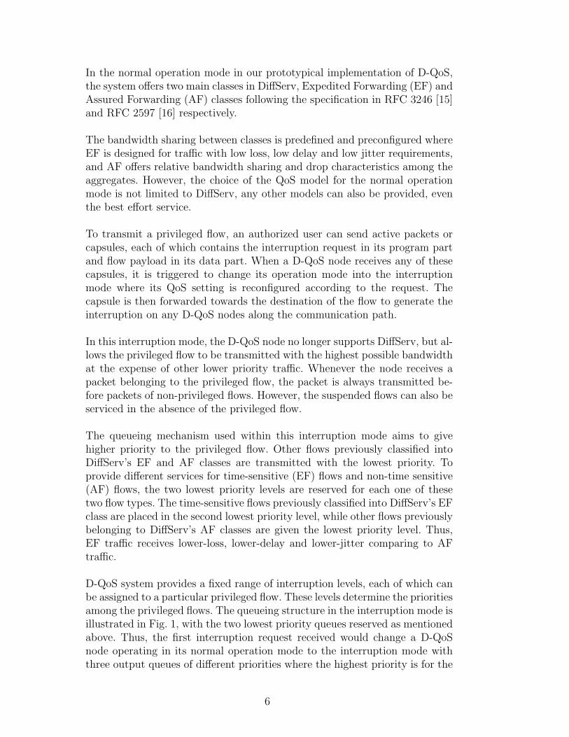
Two queueing mechanisms used in our D-QoS system are Class-Based Queue-ing (CBQ) [17] and Priority Queue(PQ). They are implemented using theAlternate Queueing (ALTQ) package [18]. In our DiffServ implementation,CBQ is used to represent the bandwidth partitioning and sharing among Diff-Serv classes. In this prototype, the system provides one EF class for real-timeflow and four AF classes for background flows where each class has its ownqueue with a predefined portion of bandwidth. The structure of the CBQ usedin the system is shown in Fig. 3. As EF class was designed for traffic that re-quires low loss, low delay and low jitter, it has been configured with higherpriority comparing to AF classes. We give preference to time sensitive trafficwhere a limited 75% of the total bandwidth is given to the EF class whichmeans that even if there is no other traffic, the EF class can only occupy 75%of the total available bandwidth.
Each of the four AF classes applies an extended version of Random EarlyDetection with In and Out (RIO) that provides three drop precedence levels.In contrast to the limitation in the bandwidth consumption of EF class, anAF class may receive excess bandwidth, in the absence of any real-time flowsin EF class, up to 100% of the total link bandwidth. Unknown and best efforttraffic flows are classified into one of the four AF classes, AF class 3 or AF3as shown in Fig. 3.
In the interruption mode, this CBQ structure is automatically substitutedby priority queue (PQ) allowing 16 priority levels maximum. Our prototypeis intended to present a realization of our active node concept rather thanto study the system performance. The PQ used in our prototype puts bothDiffServ EF and AF classes on the same level, priority level 1, hence differsslightly from the queueing structure shown in Fig. 1. Whenever a D-QoS node
8
! "
#
$ $ %
& ' % ' %
Fig. 3. Class-Based Queuing (CBQ) Structure for DiffServ Implementation
t = 40t = 0
Real-Time Flow
Telesurgery Flow
Background Flow
t = 10 t = 30 t = 40t = 0
Real-Time Flow
Telesurgery Flow
Background Flow
t = 10 t = 30
Fig. 4. Traffic Generation Pattern in the Experiments
receives an interruption request, the node reconstructs its queueing structurewhere a new queue with the requested level is inserted to the PQ allowinga number of privileged flows with different priories to coexist. A queue canbe removed once an active packet marking the end of the transmission of aprivileged flow is received. Thus, the number of queues and their prioritiesin this PQ is dynamically adjusted over time according to the active packetsreceived. When there is no more privileged flows in the system, the D-QoS noderesumes its normal operation mode with DiffServ. Note that, each queueingreconstruction results in empty queues where the previous queue content hasbeen flushed.
The two Ethernet links in the prototype have been configured with differentspeeds, 100 Mbps and 10 Mbps, in order to create a bottleneck. The aims ofthe experiments are to demonstrate how interruption can be realized using anetwork with D-QoS nodes. We set up an experiment whereby a telesurgeryflow which needs high precision of data transmission and also has high band-width is authorized to interrupt any existing flows. The interruption requestis assumed to be the one at level 16. Similar to the transmission of other timesensitive flows where the transmission rate is preferred over reliability, the flowis transmitted over UDP rather than TCP. In our experiments, three flows rep-resenting the telesurgery flow, the real-time flow and the background Internetflow are generated by the generator program, Iperf [19], as uni-directionalUDP flows from node A to C. Each of the three flows is a constant rate UDPflow of size 6 Mbps, which consumes 60% of the 10 Mbps link. The flow gener-ation pattern is shown in Fig. 4. The two flows, real-time flow and backgroundInternet flow, are transmitted at the beginning of the experiments and last for40 seconds. After the first 10 seconds, the telesurgery flow is generated andlasts for 20 seconds.
9
0
2
4
6
8
10
0 5 10 15 20 25 30 35 40
time (second)
Ban
dw
idth
(M
bp
s)
Telesurgery Real-Time Background
Fig. 5. Experimental Results in Normal Mode with DiffServ
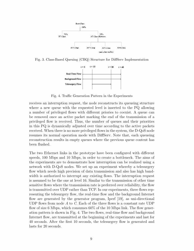
Fig. 5 shows the bandwidth consumed by the three flows in normal operationmode with DiffServ. In this case, both real-time flow and telesurgery flow areclassified into EF class and share the available bandwidth of 7.5 Mbps duringthe middle 20 seconds of the experiment. The rest of the link bandwidth of 2.3Mbps is given to the background Internet flow placed into AF class 3 (AF3).The packet loss percentages for each flow during the middle 20 seconds are 42%for the telesurgery traffic flow, 44% for the real-time traffic flow and 63% forthe background Internet traffic flow. In the last 10 seconds of the experiment,there is a period where the real-time traffic flow obtains about 7.2 Mbps, whichis higher than the generated rate and nearly reaches the maximum bandwidthlimitation for EF class. The reason is because there are some packets left inthe buffer queue during the congestion time and they are forwarded out whenmore bandwidth becomes available.
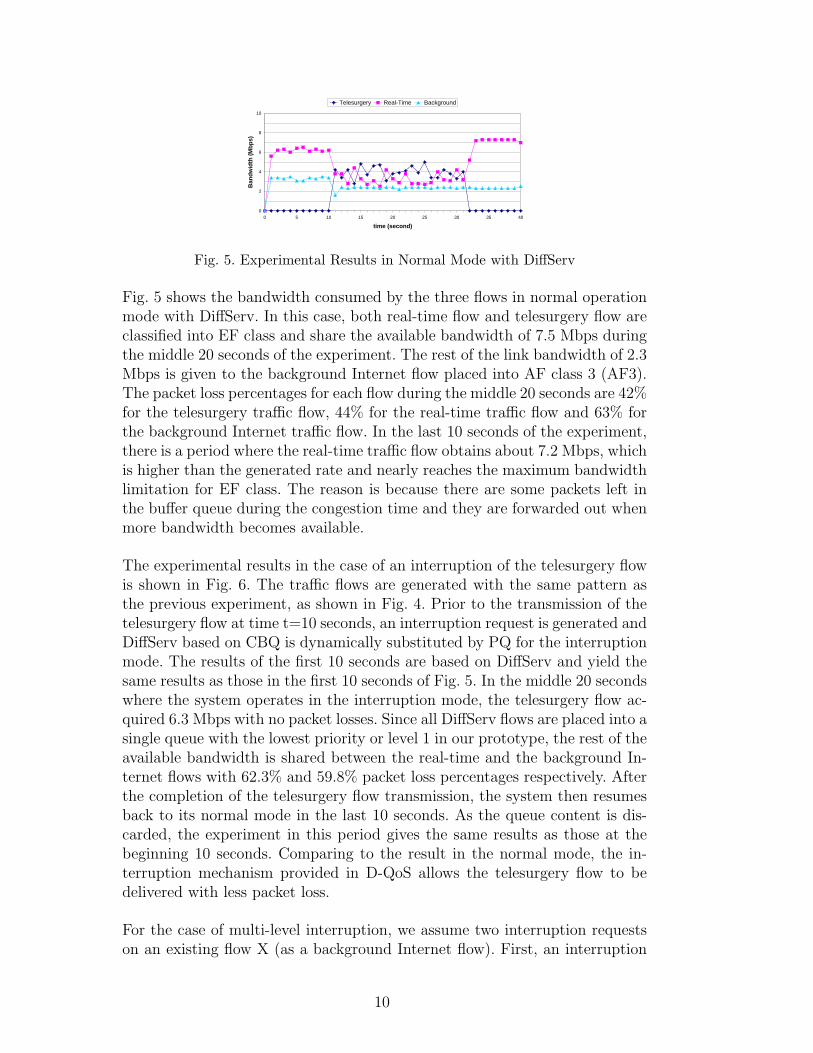
The experimental results in the case of an interruption of the telesurgery flowis shown in Fig. 6. The traffic flows are generated with the same pattern asthe previous experiment, as shown in Fig. 4. Prior to the transmission of thetelesurgery flow at time t=10 seconds, an interruption request is generated andDiffServ based on CBQ is dynamically substituted by PQ for the interruptionmode. The results of the first 10 seconds are based on DiffServ and yield thesame results as those in the first 10 seconds of Fig. 5. In the middle 20 secondswhere the system operates in the interruption mode, the telesurgery flow ac-quired 6.3 Mbps with no packet losses. Since all DiffServ flows are placed into asingle queue with the lowest priority or level 1 in our prototype, the rest of theavailable bandwidth is shared between the real-time and the background In-ternet flows with 62.3% and 59.8% packet loss percentages respectively. Afterthe completion of the telesurgery flow transmission, the system then resumesback to its normal mode in the last 10 seconds. As the queue content is dis-carded, the experiment in this period gives the same results as those at thebeginning 10 seconds. Comparing to the result in the normal mode, the in-terruption mechanism provided in D-QoS allows the telesurgery flow to bedelivered with less packet loss.
For the case of multi-level interruption, we assume two interruption requestson an existing flow X (as a background Internet flow). First, an interruption
10

0
2
4
6
8
10
0 5 10 15 20 25 30 35 40
Time (second)
Ban
dw
idth
(M
bp
s)
Telesurgery Real-Time Background
Fig. 6. Experimental Results in Interruption Mode
t = 60t = 0
Flow X
Flow Z
Flow Y
t = 10 t = 40 t = 50t = 20 t = 60t = 0
Flow X
Flow Z
Flow Y
t = 10 t = 40 t = 50t = 20
Fig. 7. Traffic Generation Pattern in the Experiments for Multi-Level Interruption
0
2
4
6
8
10
0 10 20 30 40 50 60
Time (second)
Ban
dw
idth
(M
bp
s)
Flow Z Flow Y Flow X
Fig. 8. Experimental Results with Multi-level Interruptions
by privileged flow Y at level 10. Then, another interruption by privileged flowZ at level 16. All flows are of 6 Mbps each. The traffic generation pattern isillustrated in Fig. 7 and the experimental results are shown in Fig. 8. CBQused in the first 10 seconds is substituted by a PQ with 2 levels when flow Ybegins its transmission. PQ with 3 levels is used when the request from flowZ is received. After the completion of flow Z, the queue for flow Z is removedand the system is based on PQ with 2 levels, where DiffServ is resumed atthe end. Throughout the experimental period, the results have shown that theflows are transmitted according to their priorities. The highest priority flowgains 6.2 Mbps, while 3.4 Mbps is given to the second priority flow.
11
4 Performance Analysis
4.1 Simulation Results with Internet Traffic
The performance of a network is decided by those links where congestionoccurs, usually called bottleneck links. A necessary condition for our serviceto be effective is to deploy D-QoS at these links. One can ignore what happensin the other non-congested links of the network. Thus, as a first step, we onlyconsider a single bottleneck topology in our simulations, which follows the D-QoS prototype shown in Fig. 2. The congestion is supposed to appear in oneplace of the network which is modelled in the topology by the 10 Mbps link,and the rest of the network is abstracted by the two links before and after thebottleneck. In a second step we consider a simulation topology composed ofmultiple bottleneck links in series.
The simulations are performed on a modified version of ns-2 based on realistictraffic types according to the traffic patterns found in the Internet. For ourprivileged flow, we use a sample telesurgery flow which is a transmission ofa high quality video stream from the patient side to the doctor side. It isrepresented as a unidirectional VBR stream. On the background, the Internettraffic is divided into two main types, time-sensitive and non time-sensitiveapplications. Additional video flows with VBR are simulated as time-sensitivebackground traffic. Non time-sensitive traffic is represented by FTP flows. Theperformance parameters measured in the simulations for the time-sensitiveflows are delay, jitter and packet loss percentage. In case of non time-sensitiveflows, only the transmission time is measured.
All VBR flows are generated from video trace files of movies [20–24]. Eachtrace file records the results obtained from the video encoding algorithm, withITU-T H.26L standard, and comprises the times at which the frames aretransmitted and the frame sizes. These times are then transformed into theinter-frame times, which are equal, of 40 msec (millisecond), since all thestreams are generated with the rate of 25 frame/sec. The frame size varies asa result of the video encoding mechanism. Each frame may be split into severalUDP packets of 1500 bytes each. As burstiness is not likely to happen in thenetwork due to traffic shaping mechanisms, the packets from a single frame arespaced evenly within 40 msec instead of being generated as a bunch at every 40msec. Each VBR flow starts with a random starting point within the trace file.As the random starting point is used, the trace files are modified by excludingthe beginning and/or ending parts to get rid of the extraordinary frames.When the end of the trace file is reached, the trace is wrapped around and thebeginning of the trace is used. To make sure that flows are not synchronized,each flow begins its transmission at a random time within the first 40 msec.
12

t = 0 t= 120 t = 420 t = 540
Video1
Video2
Telesurgery
FTP1*
FTP2*
* FTP completion time is not known in advance
t = 0 t= 120 t = 420 t = 540
Video1
Video2
Telesurgery
FTP1*
FTP2*
* FTP completion time is not known in advance
Fig. 9. Traffic Generation Pattern of 5 Flows
The FTP flows are based on TCP Reno implementation in ns-2.
We present, in this section, four simulation scenarios. The first scenario, inSection 4.1.1, aims to compare the performance in normal operation modewhere the network uses DiffServ without any D-QoS enabled nodes and in theinterruption mode where D-QoS nodes are present. To demonstrate a scenariowhen the bandwidth available is insufficient, an extreme case where the priv-ileged flow requires higher bandwidth than the total link capacity is reportedin Section 4.1.2. The scalability of the system is analyzed in Section 4.1.3 and4.1.4 based on the number of the interruptions at a particular bottleneck link,and the number of interruption links on a flow path, respectively. For eachscenario, a number of simulations are repeated to obtain simulation resultswith 90% confidence level. As we mainly consider the network within an au-tonomous system (AS), each link has been configured with 10 msec delay. Thesizes of the network queues are set with ns-2 default values of 50 packets.
4.1.1 Performance Comparison with DiffServ
We compare the performance of the flow transmissions in two operation modes,in normal operation mode without the interruption and the one supportinginterruption request on D-QoS nodes. The predefined QoS setting follows theCBQ structure previously presented in Fig. 3. The time diagram in Fig. 9shows the traffic generation pattern used in this scenario. The simulations firststart with the transmission of two video flows, video1 and video2, which lastfor 540 seconds. The telesurgery flow starts 120 seconds after the beginning ofthe simulation and completes after its 300 seconds of transmission. These flowsare generated from a trace file [20], of which the average bit rate is 3.5 Mbps,at different starting points randomly chosen in each simulation run. They areclassified into the same class, DiffServ EF class. There are also two FTP flows,each of which is configured for a transfer of 100 MB file. FTP flows start theirtransmissions at the beginning of the simulation and are placed into DiffServAF class 3 or AF3.
An example of the bandwidth sharing among the flows, taken from a particular
13
0
1
2
3
4
5
0 50 100 150 200 250 300 350 400 450 500 550
Time (second)
Ban
dw
idth
(M
bp
s)
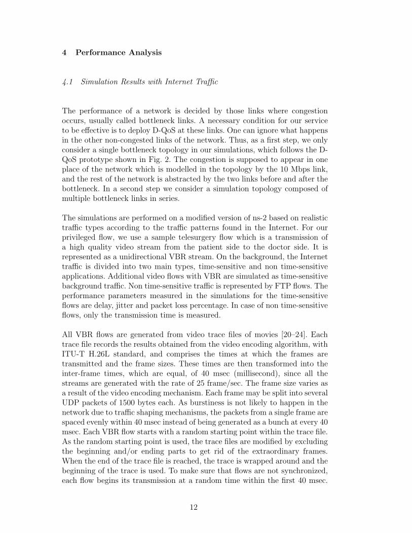
Telesurgery Video1 Video2 FTP1 FTP2
Fig. 10. Bandwidth Sharing of Flows with DiffServ in Normal Mode
Flow Packet Loss Percentage(%) Delay(msec) Jitter(msec)
Telesurgery 27.32±2.35 94.69±0.10 2.11±0.10
Video1 27.16±1.43 94.67±0.10 2.21±0.14
Video2 28.42±1.99 94.70±0.12 2.21±0.14Table 1Statistical Results in the Middle 300 Seconds with DiffServ
run in case of DiffServ, is shown in Fig. 10. The bandwidth assigned to EFclass of 7.5 Mbps is shared among the three VBR flows and the rest of the linkbandwidth is given to the two FTP flows. Table. 1 presents results from 10simulation runs. The performance parameters are calculated within the 300seconds transmission time of the telesurgery flow when all flows are active. Theperformance of the three VBR flows are close to each other as they belong tothe same class and, therefore, they receive the same treatment. The two FTPflows, placed in AF3 class, finish their transmissions at nearly the same time.The transmission time used by the FTP1 is 563.24±3.96 seconds, while FTP2uses 563.26±3.96 seconds.
When D-QoS nodes are present in the network, the telesurgery flow can makean interruption, assumed at level 16, on other existing flows before its trans-mission. It then receives the highest priority during the interruption period of300 seconds. The bandwidth sharing result, taken from a single run, is shownin Fig. 11. The rest of the link bandwidth is first given to the two VBR flowspreviously belonging to EF class, as they have priority level 2. The two FTPflows have priority level 1, the lowest level, and receive nearly no bandwidthduring the interruption. The results during the interruption, calculated from50 runs, are shown in Table. 2. The transmission times for FTP flows are649.27±1.78 and 649.69±1.69 seconds for FTP1 and FTP2 respectively.
Comparing to the results in the normal mode with DiffServ, the telesurgeryflow is transmitted over D-QoS nodes with the best service from the network
14

0
1
2
3
4
5
0 50 100 150 200 250 300 350 400 450 500 550 600 650
Time (second)
Ban
dw
idth
(M
bp
s)
Telesurgery Video1 Video2 FTP1 FTP2
Fig. 11. Bandwidth Sharing of Flows with D-QoS Interruption Mechanism
Flow Packet Loss Percentage(%) Delay(msec) Jitter(msec)
Telesurgery 0.00±0.00 21.86±0.00 0.41±0.00
Video1 6.96±0.66 86.74±3.26 29.82±1.55
Video2 7.24±0.77 86.67±3.27 29.79±1.56Table 2Statistical Results in the Middle 300 Seconds with D-QoS Interruption Mechanism
and receives much lower delay and jitter, with no packet loss at all. Theperformance of the two video flows are also improved with less delay but higherjitter, and less packet loss percentages. D-QoS outperforms DiffServ in thisparticular case. This is because the static configuration of DiffServ is posinglimitation on bandwidth allocation of the EF flows where 7.5 Mbps is given toall the three VBR flows which is insufficient. D-QoS allows dynamic bandwidthallocation where all the three VBR flows share the 10 Mbps link bandwidth,in which the highest priority is given to the telesurgery flow (3.5 Mbps) andthe other two flows each of 3.25 Mbps. Thus, dynamic bandwidth allocationscheme in D-QoS offers better services, in terms of delay and loss, to EF flowswhen the preconfigured bandwidth limitation in DiffServ is insufficient fortheir requirements. The jitter experienced by these two VBR flows are higherdue to the interruption mechanism where the packets are possibly blocked forlonger times. Video1 and Video2 have less packet loss percentages since thereare two flows in the queue instead of three flows. The two FTP flows needlonger transmission times because they are pending during the interruptionperiod. The bandwidth portion of 2.5 Mbps assigned to them in DiffServ is nolonger available for their transmissions, but is reallocated to those VBR flows.Most of FTP data are transmitted after the interruption has completed.
15
0
2
4
6
8
10
0 50 100 150 200 250 300 350 400 450 500 550 600 650
Time (second)
Ban
dw
idth
(M
bp
s)
Telesurgery Video1 Video2 FTP1 FTP2
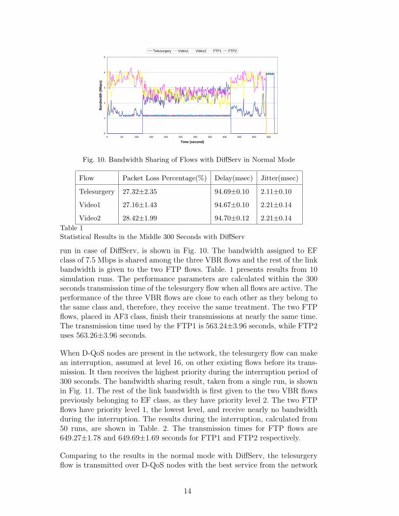
Fig. 12. Bandwidth Sharing in the Extreme Case of the Interruption
Flow Packet Loss Percentage(%) Delay(msec) Jitter(msec)
Telesurgery(14Mbps) 33.38±0.02 79.26±0.01 1.00±0.02
Video1(1Mbps) 99.99±0.00 n/a n/a
Video2(1Mbps) 99.99±0.00 n/a n/aTable 3Statistical Results During the Interruption Period in the Extreme Case
4.1.2 An Extreme Case
It is possible that the bandwidth requirement of the privileged flow is higherthan the link capacity. In this scenario, the telesurgery flow is representedas a 14.3 Mbps VBR flow [21]. Two 3.5 Mbps VBR flows [20] and two FTPof 100 MB files are generated as the background traffic. The simulations fol-low the time diagram used in the previous scenario, as shown in Fig. 9. Thebandwidth sharing result is shown in Fig. 12 and the statistical results duringthe interruption, from 5 runs, are presented in Table. 3. The results demon-strate that the privileged flow is always given the network resources at D-QoSnodes. It can be seen, from the figure, that no other flows is serviced duringthe interruption period. However, even the link is dedicated to the telesurgeryflow, the flow also experiences losses since its bandwidth requirement is higherthan the network capacity. In this scenario, the network queue is always fulland, therefore, this results in higher delay and jitter of the telesurgery flow, incomparison to the former case in Section 4.1.1. With nearly 100% packet lossof the two background VBR flows, their delay and jitter cannot be reported.The transmission time of the two FTP flows are 655.63±2.64 and 655.68±2.63seconds for FTP1 and FTP2 respectively.
16
t = 0 t = 300
Video1
Video2
Telesurgery1
FTP1*
Telesurgery2
Telesurgery10
* FTP completion time is not known in advance
t = 0 t = 300
Video1
Video2
Telesurgery1
FTP1*
Telesurgery2
Telesurgery10
* FTP completion time is not known in advance
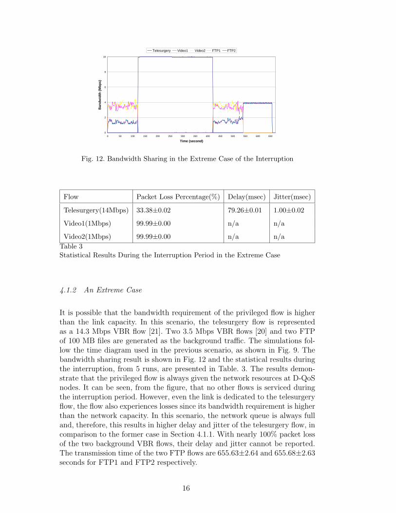
Fig. 13. Traffic Generation with Various Number of Telesurgery Flows
4.1.3 Multiple Number of Interruptions
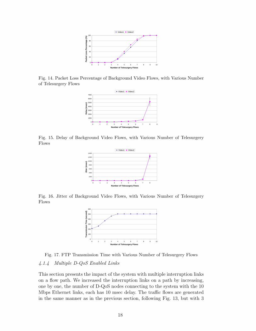
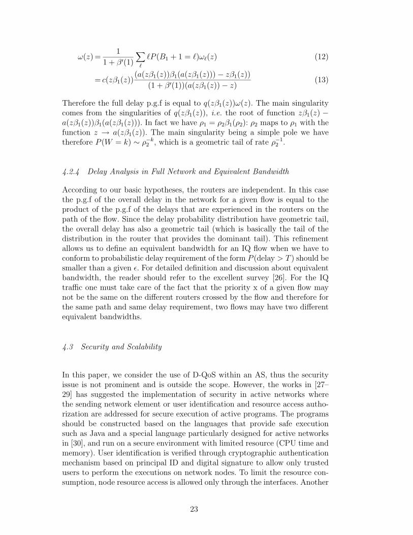
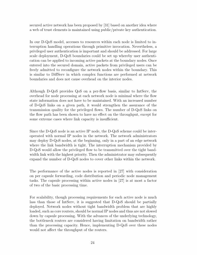
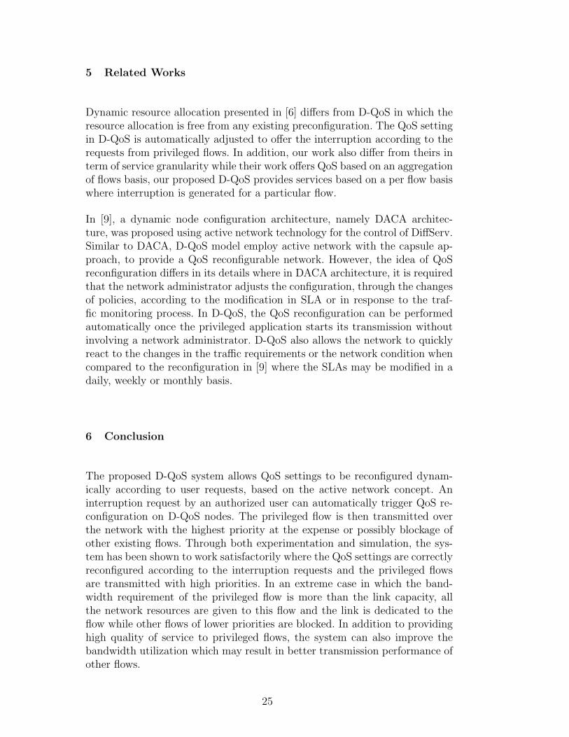
As Internet traffic is dynamic, there can be an arbitrary number of flows ata bottleneck link. In this scenario we aim to find the number of interruptionsof privileged flows at a bottleneck. The background traffic is configured toconsume half of the link bandwidth and consists of two VBR flows and oneFTP flow. Video1 and Video2 have the average bit rates of 3.4 and 1.9 Mbpsrespectively [22,23]. The FTP flow is configured for a transmission of a 100MB file. The telesurgery flow is a VBR flow of size 1.2 Mbps [24]. All flowsstart their transmissions at the same time at the beginning of the simulationand last for 300 seconds, except the FTP flow in which its completion timeis unknown, as illustrated in Fig. 13. We increase the number of telesurgeryflows in the system, with an increment of its interruption level, one by one. Thefirst interruption is at level 3 and the interruption level of the 10th telesurgeryflow is at level 12. The results of the performance degradation of the back-ground traffic are shown in Fig. 14–17. The two background video flows startto have packet loss when there are 3 telesurgery flows in the system. Packet losspercentages increase linearly until they reach 100%. When the loss percent-age reaches 100%, the delay and jitter cannot be reported. The transmissiontime required by the FTP flow increases and becomes stable after there are 4telesurgery flows in the system as FTP flow can use the link only after all thevideo flows have completed.
We can conclude that the maximum number of telesurgery flows at a bot-tleneck link is limited by the total link bandwidth. All telesurgery flows aretransmitted with nearly 0% packet loss and low delay and jitter. However,when the total bandwidth requirement of the privileged flows nearly reachesthe bottleneck link bandwidth, the privileged flow with the lowest prioritystarts to experience performance degradation. In this case, when there are 7telesurgery flows in the system, even the total average rate is 8.4 Mbps, thefirst telesurgery flow with the lowest interruption priority (level 3) starts toexperience 2.9% packet loss due to the nature of VBR traffic.
17
0
20
40
60
80
100
0 1 2 3 4 5 6 7 8 9 10
Number of Telesurgery Flows
Pac
ket
Lo
ss P
erce
nta
ge
(%)
Video1 Video2
Fig. 14. Packet Loss Percentage of Background Video Flows, with Various Numberof Telesurgery Flows
0
1000
2000
3000
4000
5000
6000
7000
0 1 2 3 4 5 6 7 8 9
Number of Telesurgery Flows
Del
ay (
mse
c)
Video1 Video2
Fig. 15. Delay of Background Video Flows, with Various Number of TelesurgeryFlows
0
2000
4000
6000
8000
10000
12000
14000
0 1 2 3 4 5 6 7 8
Number of Telesurgery Flows
Jitt
er (
mse
c)
Video1 Video2
Fig. 16. Jitter of Background Video Flows, with Various Number of TelesurgeryFlows
0
100
200
300
400
500
600
0 1 2 3 4 5 6 7 8 9 10
Number of Telesurgery Flows
Tra
nsm
issi
on
Tim
e (s
eco
nd
)
Fig. 17. FTP Transmission Time with Various Number of Telesurgery Flows
4.1.4 Multiple D-QoS Enabled Links
This section presents the impact of the system with multiple interruption linkson a flow path. We increased the interruption links on a path by increasing,one by one, the number of D-QoS nodes connecting to the system with the 10Mbps Ethernet links, each has 10 msec delay. The traffic flows are generatedin the same manner as in the previous section, following Fig. 13, but with 3
18

0
0.2
0.4
0.6
0.8
1
3 4 5 6 7 8 9 10
Number of Nodes
Pac
ket
Lo
ss P
erce
nta
ge
(%)
Video1 Video2 Telesurgery1 Telesurgery2 Telesurgery3
Fig. 18. Packet Loss Percentage of Video Flows, with Various D-QoS Links
0
20
40
60
80
100
120
3 4 5 6 7 8 9 10
Number of Nodes
Del
ay (
mse
c)Video1 Video2 Telesurgery1 Telesurgery2 Telesurgery3
Fig. 19. Delay of Video Flows, with Various D-QoS Links
0
5
10
15
20
25
30
35
3 4 5 6 7 8 9 10
Number of Nodes
Jitt
er (
mse
c)
Video1 Video2 Telesurgery1 Telesurgery2 Telesurgery3
Fig. 20. Jitter of Video Flows, with Various D-QoS Links
0
200
400
600
800
1000
1200
3 4 5 6 7 8 9 10
Number of Nodes
Tra
nsm
issi
on
Tim
e (s
eco
nd
)
Fig. 21. FTP Transmission Time with Various D-QoS Links
telesurgery flows. The results are shown in Fig. 18–21. From our simulationresults, it is observed that by increasing the number of nodes on the flow pathdoes not affect the performance of the privileged flows. The privileged flowsare given the best service over all the links with D-QoS nodes. Even the flowsexperience higher delays, but they are due to the unavoidable link delays. Asthe link is added linearly with a fixed delay of 10 msec each, the delay of eachflow is also linearly increased. Thus, having more D-QoS nodes on the flowpath would ensure the transmission quality of the privileged flows.
19

4.2 Analytical Analysis of Delays
We model the D-QoS mechanism by focusing on a D-QoS router that operatesin the Internet backbone. We assume that the D-QoS router degree is largeand that each individual flow has a very small throughput compared to therouter capacity. On each router there is a buffer, called NQ, for queuing packetscoming from the interrupted non-privileged flows such as DiffServ EF, and aset of priority buffers, called IQs, for flows that have priority over the non-privileged flows. The NQ and IQ buffers can be seen as a set of priority queuesin parallel ranked in the increasing order of priority. Since the network is large,we assume that there are lot of IQ queues on each D-QoS node and that eachD-QoS node only sends a quantum of its load to each of its neighboring routers.
That way, considering an arbitrary router and referring to the Law of LargeNumbers we can assume that the global traffic load in its IQ queues and in itsNQ queue are Poisson of respective load λI and λN in packets/s. The inputtraffic in each prioritized queue may be periodic with jitter but it does notmatter since we assume there are so many IQ queues that none of them willcontain more than one packet at a time. We further assume that all flows inthe network have the same throughput. This assumption is not critical, it ismade to ease the exposition of the analysis.
4.2.1 Queueing Analysis
If X and Y are two integer random variables, we denote by X ∗ Y therandom variable obtained by summing X identical independent distributed(i.i.d) copies of Y . Or in other words X ∗ Y = Y 1 + · · · + Y X where theY is are i.i.d like Y . Notice that X ∗ Y 6= Y ∗ X. Let f(z) and g(z) be re-spectively the probability generating functions (p.g.f.) of variables X and Y :f(z) =
∑k P (X = k)zk = E(zX) and g(z) =
∑k P (Y = k)zk = E(zY ), then
the p.g.f of X ∗ Y is E(zX∗Y ) = f g(z)
4.2.2 Delay Distribution for Privileged Queues
We consider that the NQ and IQ priorities rank from 0 to 1 with 1 being thelowest priority and 0 the highest priority. Therefore an IQ flow of priority xhas to give priority to a volume of traffic of size λIx. We take a slotted modeland slot duration is the time unit.
First we analyze the length of the busy period Bx of the traffic of priorityless than x, i.e. the waiting time between two consecutive slots accessible fortraffic of priority x. We denote by βx(z) the probability generating function(p.g.f.) of Bx, namely βx =
∑k P (Bk = k)zk. We have the identity between
20

random variables
Bx = Ax ∗ (1 + Ax ∗ (1 + · · ·)) (1)
or, similarly
Bx = Ax ∗ (1 + Bx) (2)
where Ax is the number of packet arrivals of priority less than x during a timeslot. Since the p.g.f of Ax is exp((z − 1)xλI), we have the p.g.f identity.
βx(z) = exp((zβx(z)− 1)xλI) (3)
Using the well known Cayley Tree function T (z) =∑
kkk−1
k!zk which is the
solution of the functional equation T (z) exp(−T (z)) = z [25] we get
βx(z) = T (xλIe−xλIz)
1
xλIz(4)
We have P (Bx = k) = ( (k+1)k
(k+1)!
(xλIe
−xλI
)k. Since the tree function has a
singularity on z = e−1 which is of the square root type, we have P (Bx = k) ∼1
k√
2πk
(xλIe
−xλI+1)k
. Notice that xλIe−xλI+1 < 1 as long as 0 < xλI < 1.
Second, from the busy period expression we derive the p.g.f of the delay dis-tribution Wx of a random packet of the flow of priority x. Taking wx(z) =∑
k P (Wx = k)zk, it comes that Wx is the remaining of a busy period Bx
taken at a random time. In other word:
∑
k
P (Wx = k)zk =
∑k P (Bx = k)(1 + z + · · ·+ zk−1)∑
` P (Bx = `)`(5)
=1− βx(z)
(1− z)β′x(1)(6)
and it has the same singularity as βx(z), indeed one finds P (Wx = k) ∼1√2πk
(xλIe
xλI+1)k
. The delay distribution of packets belonging to IQ flows
has a geometric tail (the factor√
k has negligible variations compared toexponential).
4.2.3 Delay Analysis of the Non-Privileged Queue
The non-privileged queue, NQ, is equivalent to a single server queue withvacation. A vacation corresponds to the busy period of the whole IQ queues,
21

namely B1 plus one slot.
First, let Q be the queue length after the end of a random busy period. Wehave the random variable identity obtained from the evolution over a vacationperiod:
Q = Q− 1|+ + (B1 + 1) ∗ AE (7)
where x|+ = x if x > 0 and zero otherwise, and AE is a per slot packet arrivalin the NQ queue. The p.g.f of A is a(z) = exp((z − 1)λN).
Translating this identity in p.g.f., with q(z) =∑
k P (Q = k)zk it comes:
q(z) =(
1
z(q(z)− q(0)) + q(0)
)a(z)β1(a(z)) (8)
and therefore
q(z) = q(0)a(z)β1(a(z))z − 1
z − a(z)β1(a(z))(9)
and q(0) = 1 − (β′1(1) + 1)λN in order to keep q(1) = 1 (unitarity). It turnsout that P (Q > k) ∼ ρ−k
1 where ρ1 is the first root greater than 1 of z −a(z)β1(a(z)).
Second we look at the delay that a packet experiences when it arrives duringa vacation period of length `. The delay is Q ∗ (B1 + 1) + Ω` where Ω` isthe remaining delay, i.e. the sum of the remaining time before the end of thecurrent vacation period and the additional vacation cycles the packet has towait due to the packets arrivals before its own during that vacation cycle. LetΩj
` be the remaining delay when packet arrives on the jth slot of a vacationperiod of length `. We have Ωj
` = ` − j + (j − 1) ∗ AE ∗ (B1 + 1) + CE ∗(B1 +1), where CE is the number of arrivals on slot j which arrived before the
packet. The p.g.f of CE is c(zβ1(z)) = e(z−1)λN2 . Therefore ωj
`(z) = E(zΩj`) =
c(zβ1(z))z`−j(a(zβ1(z)))j−1. Let ω`(z) =∑
k P (Ω` = k)zk. We have
ω`(z) =1
`
∑
j=1
ωj`(z) (10)
=1
`c(zβ1(z))
a(zβ1(z))` − z`
a(zβ1(z))− z(11)
The p.g.f. of Q ∗ (B1 + 1) is equal to q(zβ1(z)). Let ω(z) be the unconditionalp.g.f of the remaining delay. we have:
22
ω(z) =1
1 + β′(1)
∑
`
`P (B1 + 1 = `)ω`(z) (12)
= c(zβ1(z))(a(zβ1(z))β1(a(zβ1(z)))− zβ1(z))
(1 + β′(1))(a(zβ1(z))− z)(13)
Therefore the full delay p.g.f is equal to q(zβ1(z))ω(z). The main singularitycomes from the singularities of q(zβ1(z)), i.e. the root of function zβ1(z) −a(zβ1(z))β1(a(zβ1(z))). In fact we have ρ1 = ρ2β1(ρ2): ρ2 maps to ρ1 with thefunction z → a(zβ1(z)). The main singularity being a simple pole we havetherefore P (W = k) ∼ ρ−k
2 , which is a geometric tail of rate ρ−12 .
4.2.4 Delay Analysis in Full Network and Equivalent Bandwidth
According to our basic hypotheses, the routers are independent. In this casethe p.g.f of the overall delay in the network for a given flow is equal to theproduct of the p.g.f of the delays that are experienced in the routers on thepath of the flow. Since the delay probability distribution have geometric tail,the overall delay has also a geometric tail (which is basically the tail of thedistribution in the router that provides the dominant tail). This refinementallows us to define an equivalent bandwidth for an IQ flow when we have toconform to probabilistic delay requirement of the form P (delay > T ) should besmaller than a given ε. For detailed definition and discussion about equivalentbandwidth, the reader should refer to the excellent survey [26]. For the IQtraffic one must take care of the fact that the priority x of a given flow maynot be the same on the different routers crossed by the flow and therefore forthe same path and same delay requirement, two flows may have two differentequivalent bandwidths.
4.3 Security and Scalability
In this paper, we consider the use of D-QoS within an AS, thus the securityissue is not prominent and is outside the scope. However, the works in [27–29] has suggested the implementation of security in active networks wherethe sending network element or user identification and resource access autho-rization are addressed for secure execution of active programs. The programsshould be constructed based on the languages that provide safe executionsuch as Java and a special language particularly designed for active networksin [30], and run on a secure environment with limited resource (CPU time andmemory). User identification is verified through cryptographic authenticationmechanism based on principal ID and digital signature to allow only trustedusers to perform the executions on network nodes. To limit the resource con-sumption, node resource access is allowed only through the interfaces. Another
23
secured active network has been proposed by [31] based on another idea wherea web of trust elements is maintained using public/private key authentication.
In our D-QoS model, accesses to resources within each node is limited to in-terruption handling operations through primitive invocation. Nevertheless, aprivileged user authentication is important and should be addressed. For largescale deployment, D-QoS boundaries could be set up whereby user authenti-cation can be applied to incoming active packets at the boundary nodes. Onceentered into the secured domain, active packets from privileged users can befreely admitted to reconfigure the network nodes within the boundary. Thisis similar to DiffServ in which complex functions are performed at networkboundaries and does not cause overhead on the interior nodes.
Although D-QoS provides QoS on a per-flow basis, similar to IntServ, theoverhead for node processing at each network node is minimal where the flowstate information does not have to be maintained. With an increased numberof D-QoS links on a given path, it would strengthen the assurance of thetransmission quality for the privileged flows. The number of D-QoS links onthe flow path has been shown to have no effect on the throughput, except forsome extreme cases where link capacity is insufficient.
Since the D-QoS node is an active IP node, the D-QoS scheme could be inter-operated with normal IP nodes in the network. The network administratorsmay deploy D-QoS nodes, at the beginning, only in a part of an edge networkwhere the link bandwidth is tight. The interruption mechanism provided byD-QoS would allow the privileged flow to be transmitted over the tight band-width link with the highest priority. Then the administrator may subsequentlyexpand the number of D-QoS nodes to cover other links within the network.
The performance of the active nodes is reported in [27] with considerationon per capsule forwarding, code distribution and periodic node managementtasks. The capsule processing within active nodes in [27] is at most a factorof two of the basic processing time.
For scalability, though processing requirements for each active node is muchlass than those of IntServ, it is suggested that D-QoS should be partiallydeployed. Network nodes without tight bandwidth problem that are highlyloaded, such as core routers, should be normal IP nodes and thus are not sloweddown by capsule processing. With the advances of the underlying technology,the bottleneck routers are considered having limitation on bandwidth ratherthan the processing capacity. Hence, implementing D-QoS over these nodeswould not affect the throughput of the routers.
24
5 Related Works
Dynamic resource allocation presented in [6] differs from D-QoS in which theresource allocation is free from any existing preconfiguration. The QoS settingin D-QoS is automatically adjusted to offer the interruption according to therequests from privileged flows. In addition, our work also differ from theirs interm of service granularity while their work offers QoS based on an aggregationof flows basis, our proposed D-QoS provides services based on a per flow basiswhere interruption is generated for a particular flow.
In [9], a dynamic node configuration architecture, namely DACA architec-ture, was proposed using active network technology for the control of DiffServ.Similar to DACA, D-QoS model employ active network with the capsule ap-proach, to provide a QoS reconfigurable network. However, the idea of QoSreconfiguration differs in its details where in DACA architecture, it is requiredthat the network administrator adjusts the configuration, through the changesof policies, according to the modification in SLA or in response to the traf-fic monitoring process. In D-QoS, the QoS reconfiguration can be performedautomatically once the privileged application starts its transmission withoutinvolving a network administrator. D-QoS also allows the network to quicklyreact to the changes in the traffic requirements or the network condition whencompared to the reconfiguration in [9] where the SLAs may be modified in adaily, weekly or monthly basis.
6 Conclusion
The proposed D-QoS system allows QoS settings to be reconfigured dynam-ically according to user requests, based on the active network concept. Aninterruption request by an authorized user can automatically trigger QoS re-configuration on D-QoS nodes. The privileged flow is then transmitted overthe network with the highest priority at the expense or possibly blockage ofother existing flows. Through both experimentation and simulation, the sys-tem has been shown to work satisfactorily where the QoS settings are correctlyreconfigured according to the interruption requests and the privileged flowsare transmitted with high priorities. In an extreme case in which the band-width requirement of the privileged flow is more than the link capacity, allthe network resources are given to this flow and the link is dedicated to theflow while other flows of lower priorities are blocked. In addition to providinghigh quality of service to privileged flows, the system can also improve thebandwidth utilization which may result in better transmission performance ofother flows.
25

With the D-QoS prototype and its performance evaluation, we have shownthat the active networking concept can be used as a tool to achieve dynamicQoS network where network nodes can automatically adjust their settingsaccording to the active packets received. Even the model provides QoS basedon a simple priority queue mechanism, more general and complex QoS modelsmay also be accomplished through the use of active networks in the future.
7 Acknowledgements
The first author wishes to thank the Royal Thai Government for providinga scholarship for her study. This work was partially supported by the Frenchregional cooperation programme and the 2004 Next Generation Internet STIC-ASIE project.
References
[1] D. L. Tennenhouse, J. M. Smith, W. D. Sincoskie, D. J. Wetherall, G. J. Minden,‘A Survey of Active Network Research’, IEEE Communications Magazine, Vol.35, No. 1, January 1997, pp. 80-86
[2] R. Braden, D. Clark, S. Shenker, ‘Integrated Services in the InternetArchitecture: an Overview’, RFC 1633, June 1994.
[3] A. Detti, M. Listanti, S. Salsano, L. Veltri, ‘Supporting RSVP in a DifferentiatedService Domain: an Architectural Framework and a Scalability Analysis’,ICC’99, June 1999.
[4] Y. Bernet, R. Yavatkar, F. Baker, L. Zhang, M. Speer, R. Braden, B. Davie,J. Wroclawski, E. Felstaine, RFC 2998, ‘A Framework for Integrated ServicesOperation over Diffserv Networks’, November 2000.
[5] S. Salsano, E. Sangregorio, M. Listanti, ‘COPS DRA: a protocol fordynamic Diffserv Resource Allocation’, Joint Planet-IP NEBULA workshop,Courmayeur, Italy, January 2002.
[6] A. Ramanathan, M. Parashar, ‘Active Resource Management for TheDifferentiated Services Environment’, in Proc. of the Third AnnualInternational Workshop on Active Middleware Services, IEEE ComputerSociety 2001, 2001, pp. 78-86.
[7] S. Blake, D. Black, M. Carlson, E. Davies, Z. Wang, W. Weiss, ‘An Architecturefor Differentiated Services’, RFC 2475, December 1998.
[8] Y. Bai, M. R. Ito, ‘Active Network-based Mechanisms and Node Architectureto Enhance Quality of Service for Video Transport over IP Networks’, 5thWorkshop on Media and Streaming Processors (MSP5), December 2003.
26
[9] N. Achir, N. Agoulmine, M. Fonseca, Y. Ghamri-Doudane, G. Pujolle,‘ActiveTechnology as an Efficient Approach to Control DiffServ Networks: theDACA Architecture’, IFIP/IEEE International Conference on Management ofMultimedia Networks and Services (MMNS) 2002, October 2002.
[10] T. Tansupasiri, K. Kanchanasut, ‘Dynamic Quality of Service on IP Networks’,in Proc. of ICOIN 2003, LNCS 2662, Springer-Verlag, 2003, pp. 573-582.
[11] ‘ABone Home page’, http://www.isi.edu/abone/.
[12] ‘Network Simulator – ns-2’, http://www.isi.edu/nsnam/ns/.
[13] D. J. Wetherall, D. L. Tennenhouse, ‘The ACTIVE IP Option’, in Proc. of theSeventh ACM SIGOPS European Workshop, September, 1996.
[14] D. M. Murphy, ‘Building an Active Node on the Internet’, Master’s thesis, MIT,1997.
[15] B. Davie, A. Charny, J. C. R. Bennett, K. Benson, J. Y. Le Boudec, W.Courtney, S. Davari, V. Firoiu, D. Stiliadis, ‘An Expedited Forwarding PHB(Per-Hop Behavior)’, RFC 3246, March 2002.
[16] J. Heinanen, F. Baker, W. Weiss, J. Wroclawski, ‘Assured Forwarding PHBGroup’, RFC 2597, June 1999.
[17] S. Floyd, V. Jacobson, ‘Link-Sharing and Resource Management Models forPacket Network’, IEEE/ACM Transactions on Networking, Vol. 3 No. 4, August1995.
[18] K. Cho, ‘A Framework for Alternate Queueing: Towards Traffic Managementby PC-UNIX Based Routers’, Proceedings of USENIX 1998 Annual TechnicalConference, 1998.
[19] A. Tirumala, F. Qin, J. Dugan, J. Ferguson, ‘Iperf’, May 2002,http://dast.nlanr.net/Projects/Iperf/
[20] Acticom Mobile Networks, ‘Starship Troopers: Quantization parameter for allframes: 1’, 2002, http://www.acticom.info/1469.html
[21] Acticom Mobile Networks, ‘Bridge Close (CIF): Quantization parameter for allframes: 1’, 2002, http://www.acticom.info/1631.html
[22] Acticom Mobile Networks, ‘Bridge Close (QCIF): Quantization parameter forall frames: 1’, 2002, http://www.acticom.info/1630.html
[23] Acticom Mobile Networks, ‘High Way (QCIF): Quantization parameter for allframes: 10’, 2002, http://www.acticom.info/1572.html
[24] Acticom Mobile Networks, ‘Starship Troopers: Quantization parameter for allframes: 10’, 2002, http://www.acticom.info/1467.html
[25] J. Fill, P. Flajolet, N. Kapur, ‘Singularity Analysis, Hadamard Products, andTree Recurrences’, Journal of Computational and Applied Mathematics, Vol.174, February 2005, pp. 271-313.
27

[26] L. Georgiadis,P. Georgatsos, K. Floros, S. Sartzetakis, ‘Lexicographicallyoptimal balanced networks’, IEEE/ACM Transactions on Networking, Vol. 10,Issue 6, December 2002, pp. 818-829.
[27] D. Wetherall, ‘Active Network Vision and Reality: Lessons from a Capsule-based System’, 17th ACM Symposium on Operating Systems Principles,December 1999, pp. 64-79.
[28] S. Murphy, E. Lewis, R. Puga, R. Watson, R. Yee, ‘Strong security for activenetworks’, In The Fourth IEEE Conference on Open Architectures and NetworkProgramming, April 2001.
[29] T. Faber, B. Braden, B. Lindell, S. Berson, K. Bhasker, ‘Active NetworkSecutiry for the ABone’, November 2001.
[30] M. Hicks, P. Kakkar, J. T. Moore, C. A. Gunter, S. Nettles, ‘PLAN: A PacketLanguage for Active Networks’, in Proc. of the International Conference onFunctional Programming (ICFP) 1998, 1998.
[31] D. S. Alexander, W. A. Arbaugh, A. D. Keromytis, J. M. Smith, ‘A SecureActive Network Environment Architecture’, IEEE Network Magazine, SpecialIssue on Active and Controllable Networks, 1998.
28
Copyright © 2022 FDOKUMEN