Anatase and rutile surfaces with adsorbates representative of acidic and basic conditions
Nanoscale
PAPER
Publ
ishe
d on
25
Janu
ary
2013
. Dow
nloa
ded
by H
aldo
r T
opso
e A
/S o
n 17
/04/
2015
14:
28:5
6.
View Article OnlineView Journal | View Issue
Center for Materials Crystallography, Depa
University, Langelandsgade 140, DK-8000
au.dk
† Electronic supplementary informa10.1039/c3nr33127j
Cite this: Nanoscale, 2013, 5, 2372
Received 11th October 2012Accepted 22nd January 2013
DOI: 10.1039/c3nr33127j
www.rsc.org/nanoscale
2372 | Nanoscale, 2013, 5, 2372–237
Pulsed supercritical synthesis of anatase TiO2
nanoparticles in a water–isopropanol mixture studiedby in situ powder X-ray diffraction†
Jakob Rostgaard Eltzholtz, Christoffer Tyrsted, Kirsten Marie Ørnsbjerg Jensen,Martin Bremholm, Mogens Christensen, Jacob Becker-Christensenand Bo Brummerstedt Iversen*
A new step in supercritical nanoparticle synthesis, the pulsed supercritical synthesis reactor, is investigated
in situ using synchrotron powder X-ray diffraction (PXRD) to understand the formation of nanoparticles in
real time. This eliminates the common problem of transferring information gained during in situ studies to
subsequent laboratory reactor conditions. As a proof of principle, anatase titania nanoparticles were
synthesized in a 50/50 mixture of water and isopropanol near and above the critical point of water (P ¼250 bar, T ¼ 300, 350, 400, 450, 500 and 550 �C). The evolution of the reaction product was followed
by sequentially recording PXRD patterns with a time resolution of less than two seconds. The crystallite
size of titania is found to depend on both temperature and residence time, and increasing either
parameter leads to larger crystallites. A simple adjustment of either temperature or residence time
provides a direct method for gram scale production of anatase nanoparticles of average crystallite sizes
between 7 and 35 nm, thus giving the option of synthesizing tailor-made nanoparticles. Modeling of
the in situ growth curves using an Avrami growth model gave an activation energy of 66(19) kJ mol�1
for the initial crystallization. The in situ PXRD data also provide direct information about the size
dependent macrostrain in the nanoparticles and with decreasing crystallite size the unit cell contracts,
especially along the c-direction. This agrees well with previous ex situ results obtained for hydrothermal
synthesis of titania nanoparticles.
Introduction
Inorganic nanoparticles form an integral part of diverse humantechnologies ranging from simple pigments in paints to pho-toactive centers in solar cells.1,2 Several synthesis approaches tryto span the gap between the control of laboratory synthesisneeded for well-dened particle characteristics and the scal-ability of industrial production. Few have been as successful ascontinuous ow hydrothermal (supercritical) synthesis origi-nally introduced by Adschiri and co-workers in 1992.3 In thistechnique, an aqueous metal salt stream is mixed with a pre-heated solvent stream for fast initial heating, leading toinstantaneous precipitation of inorganic nanoparticles, fol-lowed by ripening in a heated reactor before nally quenchingthe reaction by rapidly cooling the nanoparticle suspensionstream.3 The supercritical ow synthesis method providessuperior control of nanoparticle characteristics such as size,
rtment of Chemistry and iNANO, Aarhus
Aarhus C, Denmark. E-mail: bo@chem.
tion (ESI) available. See DOI:
8
size distribution, morphology, purity and crystallinity, whilestill allowing high throughput and scalability for possibleindustrial applications.4–6 Many groups have reported contin-uous ow supercritical synthesis of inorganic nanoparticleswith ever increasing complexity, including the recently devisedapproach of supercritical microuidics.7–13 However, due to anunavoidable ow inhomogeneity, a distribution of residencetimes is likely for conventional ow systems. This leads to abroadening of the nanoparticle size distributions. In addition,even an ideal ow reactor has limitations on the residence time,which in practical applications can be neither very short(seconds) nor very long (hours). This brings certain limitationsto the types of reactions and chemistry that may be successfullyaccomplished in a ow reactor. An exemplication of this is thechallenge of producing defect-free LiFePO4 nanoparticles giventhe requirement for prolonged synthesis durations.14 Recently,we reported on the construction of a new type of supercriticalreactor, which we coined “pulsed supercritical synthesis”.15 Thepulsed method makes it possible to rapidly inject a well-denedvolume of a chemical solution into a heated reactor zone inwhich it stays for a predetermined residence time. Hereaer,the product is rapidly ejected from the heated zone into a cooledzone thereby quenching the reaction. Each step of injection is
This journal is ª The Royal Society of Chemistry 2013
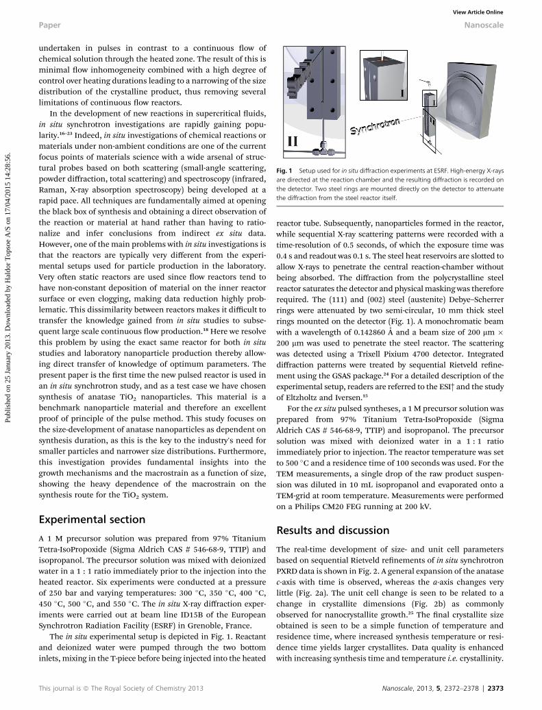
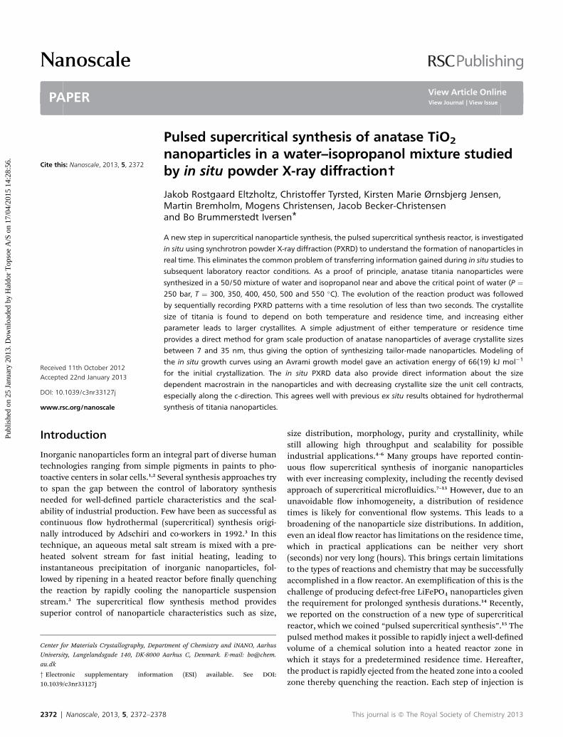
Fig. 1 Setup used for in situ diffraction experiments at ESRF. High-energy X-raysare directed at the reaction chamber and the resulting diffraction is recorded onthe detector. Two steel rings are mounted directly on the detector to attenuatethe diffraction from the steel reactor itself.
Paper Nanoscale
Publ
ishe
d on
25
Janu
ary
2013
. Dow
nloa
ded
by H
aldo
r T
opso
e A
/S o
n 17
/04/
2015
14:
28:5
6.
View Article Online
undertaken in pulses in contrast to a continuous ow ofchemical solution through the heated zone. The result of this isminimal ow inhomogeneity combined with a high degree ofcontrol over heating durations leading to a narrowing of the sizedistribution of the crystalline product, thus removing severallimitations of continuous ow reactors.
In the development of new reactions in supercritical uids,in situ synchrotron investigations are rapidly gaining popu-larity.16–23 Indeed, in situ investigations of chemical reactions ormaterials under non-ambient conditions are one of the currentfocus points of materials science with a wide arsenal of struc-tural probes based on both scattering (small-angle scattering,powder diffraction, total scattering) and spectroscopy (infrared,Raman, X-ray absorption spectroscopy) being developed at arapid pace. All techniques are fundamentally aimed at openingthe black box of synthesis and obtaining a direct observation ofthe reaction or material at hand rather than having to ratio-nalize and infer conclusions from indirect ex situ data.However, one of the main problems with in situ investigations isthat the reactors are typically very different from the experi-mental setups used for particle production in the laboratory.Very oen static reactors are used since ow reactors tend tohave non-constant deposition of material on the inner reactorsurface or even clogging, making data reduction highly prob-lematic. This dissimilarity between reactors makes it difficult totransfer the knowledge gained from in situ studies to subse-quent large scale continuous ow production.18 Here we resolvethis problem by using the exact same reactor for both in situstudies and laboratory nanoparticle production thereby allow-ing direct transfer of knowledge of optimum parameters. Thepresent paper is the rst time the new pulsed reactor is used inan in situ synchrotron study, and as a test case we have chosensynthesis of anatase TiO2 nanoparticles. This material is abenchmark nanoparticle material and therefore an excellentproof of principle of the pulse method. This study focuses onthe size-development of anatase nanoparticles as dependent onsynthesis duration, as this is the key to the industry's need forsmaller particles and narrower size distributions. Furthermore,this investigation provides fundamental insights into thegrowth mechanisms and the macrostrain as a function of size,showing the heavy dependence of the macrostrain on thesynthesis route for the TiO2 system.
Experimental section
A 1 M precursor solution was prepared from 97% TitaniumTetra-IsoPropoxide (Sigma Aldrich CAS # 546-68-9, TTIP) andisopropanol. The precursor solution was mixed with deionizedwater in a 1 : 1 ratio immediately prior to the injection into theheated reactor. Six experiments were conducted at a pressureof 250 bar and varying temperatures: 300 �C, 350 �C, 400 �C,450 �C, 500 �C, and 550 �C. The in situ X-ray diffraction exper-iments were carried out at beam line ID15B of the EuropeanSynchrotron Radiation Facility (ESRF) in Grenoble, France.
The in situ experimental setup is depicted in Fig. 1. Reactantand deionized water were pumped through the two bottominlets, mixing in the T-piece before being injected into the heated
This journal is ª The Royal Society of Chemistry 2013
reactor tube. Subsequently, nanoparticles formed in the reactor,while sequential X-ray scattering patterns were recorded with atime-resolution of 0.5 seconds, of which the exposure time was0.4 s and readout was 0.1 s. The steel heat reservoirs are slotted toallow X-rays to penetrate the central reaction-chamber withoutbeing absorbed. The diffraction from the polycrystalline steelreactor saturates the detector and physicalmasking was thereforerequired. The (111) and (002) steel (austenite) Debye–Scherrerrings were attenuated by two semi-circular, 10 mm thick steelrings mounted on the detector (Fig. 1). A monochromatic beamwith a wavelength of 0.142860 A and a beam size of 200 mm �200 mm was used to penetrate the steel reactor. The scatteringwas detected using a Trixell Pixium 4700 detector. Integrateddiffraction patterns were treated by sequential Rietveld rene-ment using the GSAS package.24 For a detailed description of theexperimental setup, readers are referred to the ESI† and the studyof Eltzholtz and Iversen.15
For the ex situ pulsed syntheses, a 1 M precursor solution wasprepared from 97% Titanium Tetra-IsoPropoxide (SigmaAldrich CAS # 546-68-9, TTIP) and isopropanol. The precursorsolution was mixed with deionized water in a 1 : 1 ratioimmediately prior to injection. The reactor temperature was setto 500 �C and a residence time of 100 seconds was used. For theTEM measurements, a single drop of the raw product suspen-sion was diluted in 10 mL isopropanol and evaporated onto aTEM-grid at room temperature. Measurements were performedon a Philips CM20 FEG running at 200 kV.
Results and discussion
The real-time development of size- and unit cell parametersbased on sequential Rietveld renements of in situ synchrotronPXRD data is shown in Fig. 2. A general expansion of the anatasec-axis with time is observed, whereas the a-axis changes verylittle (Fig. 2a). The unit cell change is seen to be related to achange in crystallite dimensions (Fig. 2b) as commonlyobserved for nanocrystallite growth.25 The nal crystallite sizeobtained is seen to be a simple function of temperature andresidence time, where increased synthesis temperature or resi-dence time yields larger crystallites. Data quality is enhancedwith increasing synthesis time and temperature i.e. crystallinity.
Nanoscale, 2013, 5, 2372–2378 | 2373
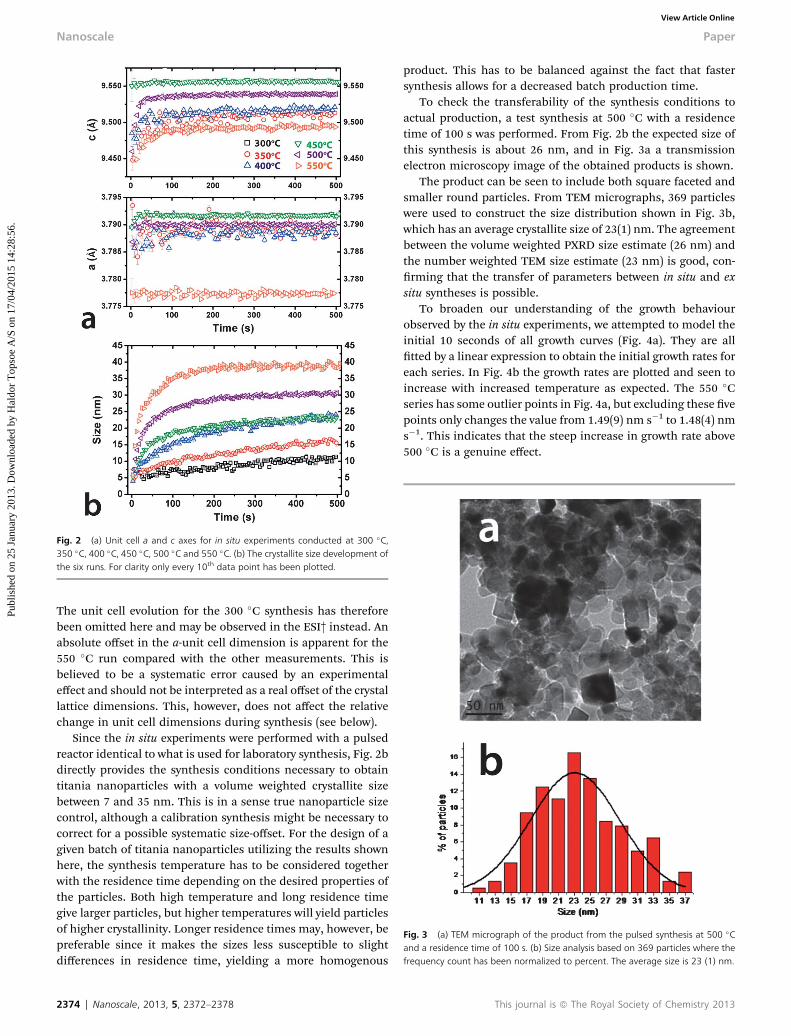
Fig. 2 (a) Unit cell a and c axes for in situ experiments conducted at 300 �C,350 �C, 400 �C, 450 �C, 500 �C and 550 �C. (b) The crystallite size development ofthe six runs. For clarity only every 10th data point has been plotted.
Fig. 3 (a) TEM micrograph of the product from the pulsed synthesis at 500 �Cand a residence time of 100 s. (b) Size analysis based on 369 particles where thefrequency count has been normalized to percent. The average size is 23 (1) nm.
Nanoscale Paper
Publ
ishe
d on
25
Janu
ary
2013
. Dow
nloa
ded
by H
aldo
r T
opso
e A
/S o
n 17
/04/
2015
14:
28:5
6.
View Article Online
The unit cell evolution for the 300 �C synthesis has thereforebeen omitted here and may be observed in the ESI† instead. Anabsolute offset in the a-unit cell dimension is apparent for the550 �C run compared with the other measurements. This isbelieved to be a systematic error caused by an experimentaleffect and should not be interpreted as a real offset of the crystallattice dimensions. This, however, does not affect the relativechange in unit cell dimensions during synthesis (see below).
Since the in situ experiments were performed with a pulsedreactor identical to what is used for laboratory synthesis, Fig. 2bdirectly provides the synthesis conditions necessary to obtaintitania nanoparticles with a volume weighted crystallite sizebetween 7 and 35 nm. This is in a sense true nanoparticle sizecontrol, although a calibration synthesis might be necessary tocorrect for a possible systematic size-offset. For the design of agiven batch of titania nanoparticles utilizing the results shownhere, the synthesis temperature has to be considered togetherwith the residence time depending on the desired properties ofthe particles. Both high temperature and long residence timegive larger particles, but higher temperatures will yield particlesof higher crystallinity. Longer residence times may, however, bepreferable since it makes the sizes less susceptible to slightdifferences in residence time, yielding a more homogenous
2374 | Nanoscale, 2013, 5, 2372–2378
product. This has to be balanced against the fact that fastersynthesis allows for a decreased batch production time.
To check the transferability of the synthesis conditions toactual production, a test synthesis at 500 �C with a residencetime of 100 s was performed. From Fig. 2b the expected size ofthis synthesis is about 26 nm, and in Fig. 3a a transmissionelectron microscopy image of the obtained products is shown.
The product can be seen to include both square faceted andsmaller round particles. From TEM micrographs, 369 particleswere used to construct the size distribution shown in Fig. 3b,which has an average crystallite size of 23(1) nm. The agreementbetween the volume weighted PXRD size estimate (26 nm) andthe number weighted TEM size estimate (23 nm) is good, con-rming that the transfer of parameters between in situ and exsitu syntheses is possible.
To broaden our understanding of the growth behaviourobserved by the in situ experiments, we attempted to model theinitial 10 seconds of all growth curves (Fig. 4a). They are alltted by a linear expression to obtain the initial growth rates foreach series. In Fig. 4b the growth rates are plotted and seen toincrease with increased temperature as expected. The 550 �Cseries has some outlier points in Fig. 4a, but excluding these vepoints only changes the value from 1.49(9) nm s�1 to 1.48(4) nms�1. This indicates that the steep increase in growth rate above500 �C is a genuine effect.
This journal is ª The Royal Society of Chemistry 2013
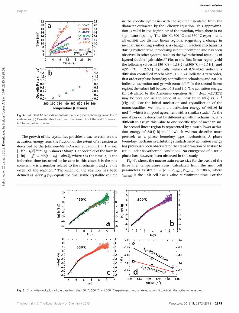
Fig. 4 (a) Initial 10 seconds of anatase particle growth showing linear fits toeach series. (b) Growth rates found from the linear fits of the first 10 seconds(20 frames) of each series.
Paper Nanoscale
Publ
ishe
d on
25
Janu
ary
2013
. Dow
nloa
ded
by H
aldo
r T
opso
e A
/S o
n 17
/04/
2015
14:
28:5
6.
View Article Online
The growth of the crystallites provides a way to estimate theactivation energy from the fraction or the extent of a reaction asdescribed by the Johnson–Mehl–Avrami equation, f ¼ 1 � exp[�k(t� t0)
n].26–28 Fig. 5 shows a Sharp–Hancock plot of the form ln[�ln(1 � f)] ¼ nln(t � t0) + nln(k), where t is the time, t0 is theinduction time (assumed to be zero in this case), k is the rateconstant, n is a number related to the mechanism and f is theextent of the reaction.29 The extent of the reaction has beendened as V(t)/Vinf (Vinf equals the nal stable crystallite volume
Fig. 5 Sharp–Hancock plots of the data from the 450 �C, 500 �C and 550 �C expe
This journal is ª The Royal Society of Chemistry 2013
in the specic synthesis) with the volume calculated from thediameter estimated by the Scherrer equation. This approxima-tion is valid in the beginning of the reaction, when there is nosignicant ripening. The 450 �C, 500 �C and 550 �C experimentsall exhibit two distinct linear regions, suggesting a change inmechanism during synthesis. A change in reaction mechanismsduring hydrothermal processing is not uncommon and has beenobserved in other systems such as the hydrothermal reactions oflayered double hydroxides.30 Fits to the rst linear region yieldthe following values: n(450 �C)¼ 1.18(2), n(500 �C)¼ 1.51(1), andn(550 �C) ¼ 2.5(1). Typically, values of 0.54–0.62 indicate adiffusion controlled mechanism, 1.0–1.24 indicate a zero-order,rst-order or phase boundary controlledmechanism, and 2.0–3.0indicate nucleation and growth control.26,29 In the second linearregion, the values fall between 0.8 and 1.0. The activation energy,Ea, calculated by the Arrhenius equation k(t) ¼ Aexp(�Ea/(RT))may be obtained as the slope of a linear t to ln(k) vs. T�1
(Fig. 5d). For the initial nucleation and crystallisation of thenanocrystallites we obtain an activation energy of 66(19) kJmol�1, which is in good agreement with a similar study.31 As theinitial period is described by different growth mechanisms, it isdifficult to assign this value to one specic type of mechanism.The second linear region is represented by a much lower activa-tion energy of 35(4) kJ mol�1 which we can describe moreprecisely as a phase boundary type mechanism. A phaseboundarymechanism exhibiting similarly sized activation energyhas previously been observed for the transformation of anatase torutile under solvothermal conditions. No emergence of a rutilephase has, however, been observed in this study.
Fig. 6b shows the macrostrain versus size for the c-axis of thethree high-temperature runs, calculated from the unit cellparameters as strainc ¼ (ci � cinnite)/cinnite � 100%, wherecinnite is the unit cell c-axis value at “innite” time. For the
riments and a rate equation fit to obtain the activation energies.
Nanoscale, 2013, 5, 2372–2378 | 2375
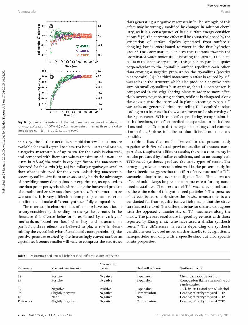
Fig. 6 (a) c-Axis macrostrain of the last three runs calculated as strainc ¼(ci � cinfinite)/cinfinite � 100%. (b) a-Axis macrostrain of the last three runs calcu-lated as straina ¼ (ai � ainfinite)/ainfinite � 100%.
Nanoscale Paper
Publ
ishe
d on
25
Janu
ary
2013
. Dow
nloa
ded
by H
aldo
r T
opso
e A
/S o
n 17
/04/
2015
14:
28:5
6.
View Article Online
550 �C synthesis, the reaction is so rapid that few data points areavailable for small crystallite sizes. For both 450 �C and 500 �C,a negative macrostrain of up to 1% for the c-axis is observed,and compared with literature values (maximum of �0.28% at5 nm in ref. 32) the strain is very signicant. The macrostrainobserved for the a-axis (Fig. 6a) is similarly negative yet smallerthan what is observed for the c-axis. Calculating macrostrainversus crystallite size from an in situ study holds the advantageof providing many data-points per experiment, as opposed toone data-point per synthesis when using the harvested productof a traditional ex situ autoclave synthesis. Furthermore, in exsitu studies it is very difficult to completely control reactionconditions and make different syntheses fully comparable.
The macrostrain characteristics of anatase have been foundto vary considerably depending on the synthesis route. In theliterature this diverse behavior is explained by a variety ofmechanisms based on local chemistry and structure. Inparticular, three effects are believed to play a role in deter-mining the crystal behavior of small oxide nanoparticles: (1) thepositive pressure exerted by the increasingly curved surface ascrystallites become smaller will tend to compress the structure,
Table 1 Macrostrain and unit cell behavior in six different studies of anatase
Reference Macrostrain (a-axis)Macrostrain(c-axis)
38 Positive Negative39 Positive Negative
35 Negative Positive32 Slightly negative Negative40 None NegativeThis work Slightly negative Negative
2376 | Nanoscale, 2013, 5, 2372–2378
thus generating a negative macrostrain.33 The strength of thiseffect may be strongly modied by changes in solution chem-istry, as it is a consequence of basic surface energy consider-ations.34 (2) The curvature effect will be counterbalanced by thegeneration of surface dipoles generated from surface-Tidangling bonds coordinated to water in the rst hydrationshell.35 The coordination displaces the Ti-atoms towards thecoordinated water molecules, distorting the surface Ti–O octa-hedra of the anatase crystallites. This generates parallel dipolesperpendicular to the crystallite surface repelling each other,thus creating a negative pressure on the crystallites (positivemacrostrain). (3) The third macrostrain effect is caused by Ti4+
vacancies in the structure which also produce a negative pres-sure on small crystallites.36 In anatase, the Ti–O octahedron iscompressed in the edge-sharing plane in order to more effec-tively screen neighbouring cations, while it is elongated alongthe c-axis due to the increased in-plane screening. When Ti4+
vacancies are generated, the surrounding Ti–O octahedra relax,leading to an increase in the a,b-parameter and a shortening ofthe c-parameter. With one effect predicting compression inboth directions, one effect predicting expansion in both direc-tions and one effect predicting expansion along c and contrac-tion in the a,b-plane, it is obvious that different outcomes arepossible.
Table 1 lists the trends observed in the present studytogether with ve selected previous studies of anatase nano-particles. Despite the different results, there is a consistency inresults produced by similar conditions, and as an example allTTIP-based syntheses produce the same types of strain. Thestrong negative macrostrain observed in the present study forthe c-direction suggests that the effect of curvature and/or Ti4+-vacancies dominates over the dipole-effect. The curvatureeffect should always be present to some extent for any nano-sized crystallites. The presence of Ti4+ vacancies is indicatedby the white color of the synthesized particles.37 The presenceof defects is reasonable since the in situ measurements areconducted far from equilibrium, which means that the struc-ture has not relaxed. The different behavior of the a-axis agreeswith the opposed characteristic of Ti4+ vacancies along thea-axis. The present results are in good agreement with thosereported by Zhang et al., who have used a similar synthesisroute.32 The differences in strain depending on synthesisconditions can be used as yet another handle to design titaniananoparticles not only with a specic size, but also specicstrain properties.
Unit cell volume Synthesis route
Expansion Chemical vapor depositionExpansion Combustion ame chemical vapor
condensationExpansion TiCl4 in EtOH and benzyl alcoholCompression Heating of prehydrolyzed TTIPN/A Heating of prehydrolyzed TTIPCompression Heating of prehydrolyzed TTIP
This journal is ª The Royal Society of Chemistry 2013
Paper Nanoscale
Publ
ishe
d on
25
Janu
ary
2013
. Dow
nloa
ded
by H
aldo
r T
opso
e A
/S o
n 17
/04/
2015
14:
28:5
6.
View Article Online
Conclusions
The present in situ study reports on nanoparticle formation andgrowth in sub- and supercritical water–isopropanol using apulsed synthesis method. The pulsed synthesis method allowsdirect transfer of synthesis parameters from in situ experimentsto subsequent laboratory scale production, but the robustreactor design also allows data measurement up to ratherextreme conditions (P ¼ 250 bar, T ¼ 550 �C). The synthesisparameters needed to produce a certain average size of anatasenanocrystals can be found from the size versus temperature/time plot providing a strong tool for nanoparticle “design”. Thepresent proof of principle study shows that one can greatlyreduce the time and effort spent on optimizing parameters for aspecic synthesis. The in situ growth curves were tted to anAvrami growth model and, based on Sharp–Hancock plots, anactivation energy of 66(19) kJ mol�1 for the initial crystallizationwas estimated. The in situ experiments also allow study of themacrostrain of titania anatase nanoparticles, where eachsynthesis run provides many data points under highlycontrolled conditions. The present results indicate a largenegative c-axis macrostrain, which is in good agreement withprevious ex situ hydrothermal experiments under similarconditions.
Acknowledgements
We gratefully acknowledge the ESRF for beam time and assis-tance during the experiment from Veijo Honkimaki. This workwas supported by the Danish Strategic Research Council (Centerfor Energy Materials), the Danish National Research Founda-tion (Center for Materials Crystallography), and the DanishResearch Council for Nature and Universe (Danscatt).
Notes and references
1 D. C. Hurum, A. G. Agrios, K. A. Gray, T. Rajh andM. C. Thurnauer, J. Phys. Chem. B, 2003, 107, 4545–4549.
2 B. Oregan and M. Gratzel, Nature, 1991, 353, 737–740.3 T. Adschiri, K. Kanazawa and K. Arai, J. Am. Ceram. Soc.,1992, 75, 1019–1022.
4 Y. Hakuta, H. Hayashi and K. Arai, Curr. Opin. Solid StateMater. Sci., 2003, 7, 341–351.
5 C. Aymonier, A. Loppinet-Serani, H. Reveron, Y. Garrabosand F. Cansell, J. Supercrit. Fluids, 2006, 38, 242–251.
6 E. Lester, P. Blood, J. Denyer, D. Giddings, B. Azzopardi andM. Poliakoff, J. Supercrit. Fluids, 2006, 37, 209–214.
7 Y. Hakuta, K. Seino, H. Ura, T. Adschiri, H. Takizawa andK. Arai, J. Mater. Chem., 1999, 9, 2671–2674.
8 S. Moisan, J. D. Marty, F. Cansell and C. Aymonier, Chem.Commun., 2008, 1428–1430.
9 A. Cabanas and M. Poliakoff, J. Mater. Chem., 2001, 11, 1408–1416.
10 J. Becker, P. Hald, M. Bremholm, J. S. Pedersen,J. Chevallier, S. B. Iversen and B. B. Iversen, ACS Nano,2008, 2, 1058–1068.
This journal is ª The Royal Society of Chemistry 2013
11 P. Hald, J. Becker, M. Bremholm, J. S. Pedersen, J. Chevallier,S. B. Iversen and B. B. Iversen, J. Solid State Chem., 2006, 179,2674–2680.
12 L. Znaidi, R. Seraphimova, J. F. Bocquet, C. Colbeau-Justinand C. Pommier, Mater. Res. Bull., 2001, 36, 811–825.
13 S. Marre, Y. Roig and C. Aymonier, J. Supercrit. Fluids, 2012,66, 251–264.
14 V. G. Courtecuisse, J. F. Bocquet, K. Chhor and C. Pommier,J. Supercrit. Fluids, 1996, 9, 222–226.
15 J. R. Eltzholtz and B. B. Iversen, Rev. Sci. Instrum., 2011, 82,0841021–0841027.
16 K. Jensen, M. Christensen, C. Tyrsted and B. B. Iversen,J. Appl. Crystallogr., 2011, 44, 287–294.
17 C. Tyrsted, B. R. Pauw, K. M. O. Jensen, J. Becker,M. Christensen and B. B. Iversen, Chem.–Eur. J., 2012, 18,5759–5766.
18 M. Bremholm, M. Felicissimo and B. B. Iversen, Angew.Chem., Int. Ed., 2009, 48, 4788–4791.
19 N. Pienack and W. Bensch, Angew. Chem., Int. Ed., 2011, 50,2014–2034.
20 N. Lock, M. Christensen, K. M. Ø. Jensen and B. B. Iversen,Angew. Chem., Int. Ed., 2011, 50, 7045–7047.
21 S. J. Moorhouse, N. Vranjes, A. Jupe, M. Drakopoulos andD. O'Hare, Rev. Sci. Instrum., 2012, 83, 084101.
22 F. Millange, R. El Osta, M. E. Medina and R. I. Walton,CrystEngComm, 2011, 13, 103–108.
23 Y. Zhou, E. Antonova, W. Bensch and G. R. Patzke,Nanoscale, 2010, 2, 2412–2417.
24 A. C. Larson and R. B. Von Dreele, Los Alamos NationalLaboratory Report LAUR, 2004, pp. 86–748.
25 C. Tyrsted, K. M. O. Jensen, E. D. Boejesen, N. Lock,M. Christensen, S. J. L. Billinge and B. B. Iversen, Angew.Chem., Int. Ed., 2012, 51, 9030–9033.
26 G. A. Rossetti, D. J. Watson, R. E. Newnham and J. H. Adair,J. Cryst. Growth, 1992, 116, 251–259.
27 M. J. Avrami, J. Chem. Phys., 1939, 7, 1103–1113.28 W. A. Johnson and R. F. Mehl, Trans. Soc. Pet. Eng., 1939, 135,
416.29 J. D. Hancock and J. H. Sharp, J. Am. Ceram. Soc., 1972, 55,
74–77.30 F. Millange, R. I. Walton and D. O'Hare, J. Mater. Chem.,
2000, 10, 1713–1720.31 A. Laumann, K. M. O. Jensen, C. Tyrsted, M. Bremholm,
K. T. Fehr, M. Holzapfel and B. B. Iversen, Eur. J. Inorg.Chem., 2011, 2221–2226.
32 H. Z. Zhang, B. Chen and J. F. Baneld, Phys. Chem. Chem.Phys., 2009, 11, 2553–2558.
33 D. A. Porter, K. E. Easterling and M. Y. Sherif, PhaseTransformations in Metals and Alloys, CRC Press, BocaRaton, 2004.
34 G. V. Jensen, M. Bremholm, N. Lock, G. R. Deen,T. R. Jensen, B. B. Iversen, M. Niederberger, J. S. Pedersenand H. Birkedal, Chem. Mater., 2010, 22, 6044–6055.
35 G. Li, L. Li, J. Boerio-Goates and B. F. Woodeld, J. Am. Chem.Soc., 2005, 127, 8659–8666.
36 I. E. Grey and N. C. Wilson, J. Solid State Chem., 2007, 180,670–678.
Nanoscale, 2013, 5, 2372–2378 | 2377

Nanoscale Paper
Publ
ishe
d on
25
Janu
ary
2013
. Dow
nloa
ded
by H
aldo
r T
opso
e A
/S o
n 17
/04/
2015
14:
28:5
6.
View Article Online
37 V. Swamy, D. Menzies, B. C. Muddle, A. Kuznetsov,L. S. Dubrovinsky, Q. Dai and V. Dmitriev, Appl. Phys. Lett.,2006, 88, 243103.
38 M. I. Ahmad and S. S. Bhattacharya, Appl. Phys. Lett., 2009,95, 191906.
2378 | Nanoscale, 2013, 5, 2372–2378
39 T. B. Ghosh, S. Dhabal and A. K. Datta, J. Appl. Phys., 2003,94, 4577–4582.
40 A. Bokhimi, A. Morales, O. Novaro, T. Lopez, E. Sanchezand R. Gomez, J. Mater. Res., 1995, 10, 2788–2796.
This journal is ª The Royal Society of Chemistry 2013
Copyright © 2022 FDOKUMEN