Pulse shaping for background free broadband CARS
8
Pulse shaping for background free broadband CARS Young Jong Lee and Marcus T. Cicerone Polymers Division, National Institute of Standards and Technology, 100 Bureau Drive, Gaithersburg, MD, USA 20899-8543 ABSTRACT We demonstrate that pulse shaping of a narrowband pulse can suppress the nonresonant background (NRB) contribution and retrieve resonant Raman signals efficiently in a broadband coherent anti-Stokes Raman scattering (CARS) spectrum. A pulse shaper prepares a probe pulse with two spectral components of differing phase. When the CARS fields generated by these two out-of-phase components are optically mixed, the NRB signal is greatly reduced while a resonant CARS signal survives with minimal attenuation. We discuss three model schemes for the interfering pulse components: (1) two pulses with different bandwidths and the same center frequency (ps-fs scheme); (2) two pulses with the same bandwidth and shifted center frequencies (ps-ps scheme); and (3) a pulse with different phases across the center frequency (fs(+/-) scheme). In all schemes, only the resonant signal from the “3-color” CARS mechanism survives. The resonant signal from “2-color” CARS mechanism vanishes along with the NRB. We discuss optimization conditions for signal intensity and shape of resonant CARS peaks. Keywords: pulse shaping, Raman spectroscopy, CARS, nonresonant background 1. INTRODUCTION Broadband coherent anti-Stokes Raman scattering (CARS) approaches provide a broad Raman spectrum from a single measurement by overlapping a narrowband picosecond pulse and a broadband continuum pulse [1-4]. This multiplex measurement techniques show advantages over single-frequency approaches for quantitative and qualitative Raman spectrum analysis of complex media including biological samples, which generally require spectral data over a wide frequency range from a single measurement. For both single-frequency and broadband CARS approaches, the nonresonant background (NRB) poses a significant interference to the resonant Raman signal and often overwhelms weak resonant signals, leading to significant reduction in imaging contrast and sensitivity. The NRB in a broadband CARS spectrum is particularly difficult to characterize because the CARS spectrum is directly affected by the continuum pulse, whose intensity and phase is often unstable and may contain multiple temporal modes [5]. Several experimental approaches have been established for reducing the NRB contribution, but those approaches either provide significantly reduced signal intensity or are not applicable to the broadband CARS scheme. Interferometric CARS offers the possibility of detecting NRB-free CARS signals with minimal attenuation of resonant signal intensity. Conventional interferometric detection methods combine the signal of a CARS field from the sample of interest and a well-controlled reference field. However, when a reference field is generated in a different medium, it is generally very difficult to account for differential phase shift and differential chirp over a broad frequency range, and to remove phase jitter. Generating signal and reference fields in the same sample obviates these problems. The general approach is to generate interference between signal and reference CARS polarizations induced by two phase-controlled probe pulses. Silberberg et al. [6] have demonstrated and Lim et al. [7] have improved single pulse CARS techniques where NRB is reduced by interfering adjacent narrow spectral components of a single ultrashort laser pulse using a pulse shaper. Cicerone et al. [8] have demonstrated a different approach to scanning interferometric broadband CARS microscopy by mixing signal and reference fields that are generated by a spectrally narrow pulse and a broad pulse for pump/probe light, respectively. However, the single pulse technique has limited control for optimization of the probe pulse because a spatial light modulator controls the whole frequency range of pump, Stokes, and probe, and the scanning interferometric approach requires long acquisition time to extract Fourier amplitudes of the signals generated. In this paper we describe single-shot interferometric approaches to suppress NRB contribution to a broadband CARS spectrum that do not require scanning the relative pulse phase and result in very little attenuation of resonance signal intensity. In these approaches, two probe pulse components are separately controlled by a pulse shaper and the CARS fields they generate are interferometrically mixed. We discuss characteristics of the interference CARS spectra Multiphoton Microscopy in the Biomedical Sciences IX, edited by Ammasi Periasamy, Peter T. C. So, Proc. of SPIE Vol. 7183, 71830Y · © 2009 SPIE · CCC code: 1605-7422/09/$18 · doi: 10.1117/12.809102 Proc. of SPIE Vol. 7183 71830Y-1 Downloaded from SPIE Digital Library on 26 Oct 2009 to 129.6.154.178. Terms of Use: http://spiedl.org/terms
-
Upload
independent -
Category
Documents
-
view
0 -
download
0
Transcript of Pulse shaping for background free broadband CARS
Pulse shaping for background free broadband CARS
Young Jong Lee and Marcus T. Cicerone
Polymers Division, National Institute of Standards and Technology, 100 Bureau Drive, Gaithersburg, MD, USA 20899-8543
ABSTRACT
We demonstrate that pulse shaping of a narrowband pulse can suppress the nonresonant background (NRB) contribution and retrieve resonant Raman signals efficiently in a broadband coherent anti-Stokes Raman scattering (CARS) spectrum. A pulse shaper prepares a probe pulse with two spectral components of differing phase. When the CARS fields generated by these two out-of-phase components are optically mixed, the NRB signal is greatly reduced while a resonant CARS signal survives with minimal attenuation. We discuss three model schemes for the interfering pulse components: (1) two pulses with different bandwidths and the same center frequency (ps-fs scheme); (2) two pulses with the same bandwidth and shifted center frequencies (ps-ps scheme); and (3) a pulse with different phases across the center frequency (fs(+/-) scheme). In all schemes, only the resonant signal from the “3-color” CARS mechanism survives. The resonant signal from “2-color” CARS mechanism vanishes along with the NRB. We discuss optimization conditions for signal intensity and shape of resonant CARS peaks.
Keywords: pulse shaping, Raman spectroscopy, CARS, nonresonant background
1. INTRODUCTION Broadband coherent anti-Stokes Raman scattering (CARS) approaches provide a broad Raman spectrum from a single measurement by overlapping a narrowband picosecond pulse and a broadband continuum pulse [1-4]. This multiplex measurement techniques show advantages over single-frequency approaches for quantitative and qualitative Raman spectrum analysis of complex media including biological samples, which generally require spectral data over a wide frequency range from a single measurement. For both single-frequency and broadband CARS approaches, the nonresonant background (NRB) poses a significant interference to the resonant Raman signal and often overwhelms weak resonant signals, leading to significant reduction in imaging contrast and sensitivity. The NRB in a broadband CARS spectrum is particularly difficult to characterize because the CARS spectrum is directly affected by the continuum pulse, whose intensity and phase is often unstable and may contain multiple temporal modes [5]. Several experimental approaches have been established for reducing the NRB contribution, but those approaches either provide significantly reduced signal intensity or are not applicable to the broadband CARS scheme.
Interferometric CARS offers the possibility of detecting NRB-free CARS signals with minimal attenuation of resonant signal intensity. Conventional interferometric detection methods combine the signal of a CARS field from the sample of interest and a well-controlled reference field. However, when a reference field is generated in a different medium, it is generally very difficult to account for differential phase shift and differential chirp over a broad frequency range, and to remove phase jitter. Generating signal and reference fields in the same sample obviates these problems. The general approach is to generate interference between signal and reference CARS polarizations induced by two phase-controlled probe pulses. Silberberg et al. [6] have demonstrated and Lim et al. [7] have improved single pulse CARS techniques where NRB is reduced by interfering adjacent narrow spectral components of a single ultrashort laser pulse using a pulse shaper. Cicerone et al. [8] have demonstrated a different approach to scanning interferometric broadband CARS microscopy by mixing signal and reference fields that are generated by a spectrally narrow pulse and a broad pulse for pump/probe light, respectively. However, the single pulse technique has limited control for optimization of the probe pulse because a spatial light modulator controls the whole frequency range of pump, Stokes, and probe, and the scanning interferometric approach requires long acquisition time to extract Fourier amplitudes of the signals generated.
In this paper we describe single-shot interferometric approaches to suppress NRB contribution to a broadband CARS spectrum that do not require scanning the relative pulse phase and result in very little attenuation of resonance signal intensity. In these approaches, two probe pulse components are separately controlled by a pulse shaper and the CARS fields they generate are interferometrically mixed. We discuss characteristics of the interference CARS spectra
Multiphoton Microscopy in the Biomedical Sciences IX, edited by Ammasi Periasamy, Peter T. C. So,Proc. of SPIE Vol. 7183, 71830Y · © 2009 SPIE · CCC code: 1605-7422/09/$18 · doi: 10.1117/12.809102
Proc. of SPIE Vol. 7183 71830Y-1
Downloaded from SPIE Digital Library on 26 Oct 2009 to 129.6.154.178. Terms of Use: http://spiedl.org/terms
depending on CARS mechanisms occurring in broadband CARS. We present three model schemes and discuss the optimization conditions for high resonant signal intensity of NRB-free broadband CARS spectra.
2. THEORY The CARS signal is induced by the third-order nonlinear polarization, P(3), which is expressed as
prSpaSprSpprSpaSprSpaS ddd ωωωωωωωδωωωωωωωχω )()()()();,,()( *)3()3( −+−= ∫ ∫ ∫
∞
∞−
∞
∞−
∞
∞−EEEP (1)
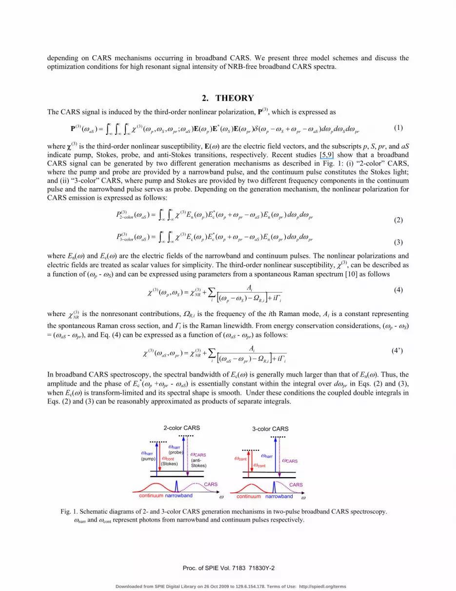
where χ(3) is the third-order nonlinear susceptibility, E(ω) are the electric field vectors, and the subscripts p, S, pr, and aS indicate pump, Stokes, probe, and anti-Stokes transitions, respectively. Recent studies [5,9] show that a broadband CARS signal can be generated by two different generation mechanisms as described in Fig. 1: (i) “2-color” CARS, where the pump and probe are provided by a narrowband pulse, and the continuum pulse constitutes the Stokes light; and (ii) “3-color” CARS, where pump and Stokes are provided by two different frequency components in the continuum pulse and the narrowband pulse serves as probe. Depending on the generation mechanism, the nonlinear polarization for CARS emission is expressed as follows:
∫ ∫∞
∞−
∞
∞−− −+= prppraSprppaS ddEEEP ωωωωωωωχω )()()()( n*cn
)3()3(color2 (2)
∫ ∫∞
∞−
∞
∞−− −+= prppraSprppaS ddEEEP ωωωωωωωχω )()()()( n*cc
)3()3(color3 (3)
where En(ω) and Ec(ω) are the electric fields of the narrowband and continuum pulses. The nonlinear polarizations and electric fields are treated as scalar values for simplicity. The third-order nonlinear susceptibility, χ(3), can be described as a function of (ωp - ωS) and can be expressed using parameters from a spontaneous Raman spectrum [10] as follows
[ ]∑ +−−
+=i iiRSp
iNRSp iΓΩ
A
,
)3()3(
)(),(
ωωχωωχ (4)
where )3(NRχ is the nonresonant contributions, ΩR,i is the frequency of the ith Raman mode, Ai is a constant representing
the spontaneous Raman cross section, and Γi is the Raman linewidth. From energy conservation considerations, (ωp - ωS) = (ωaS - ωpr), and Eq. (4) can be expressed as a function of (ωaS - ωpr) as follows:
[ ]∑ +−−
+=i iiRpraS
iNRpraS iΓΩ
A,
)3()3(
)(),(
ωωχωωχ (4’)
In broadband CARS spectroscopy, the spectral bandwidth of Ec(ω) is generally much larger than that of En(ω). Thus, the amplitude and the phase of Ec
*(ωp +ωpr - ωaS) is essentially constant within the integral over dωpr in Eqs. (2) and (3), when Ec(ω) is transform-limited and its spectral shape is smooth. Under these conditions the coupled double integrals in Eqs. (2) and (3) can be reasonably approximated as products of separate integrals.
Fig. 1. Schematic diagrams of 2- and 3-color CARS generation mechanisms in two-pulse broadband CARS spectroscopy.
ωnarr and ωcont represent photons from narrowband and continuum pulses respectively.
ωnarr ωcont ωCARS
ω narrowbandcontinuum
CARS
ωcont
3-color CARS
ωnarr ωnarr ωCARS
ω narrowbandcontinuum
CARS
ωcont
2-color CARS
(pump) (Stokes)
(probe)
(anti-Stokes)
Proc. of SPIE Vol. 7183 71830Y-2
Downloaded from SPIE Digital Library on 26 Oct 2009 to 129.6.154.178. Terms of Use: http://spiedl.org/terms
∫ ∫∞
∞−
∞
∞−− −+= prprpraSpaSprppaS dEdEEP ωωωωχωωωωωω )(),()()()( n)3(*
cn)3(color2
(5)
∫ ∫∞
∞−
∞
∞−− −+= prprpraSpaSprppaS dEdEEP ωωωωχωωωωωω )(),()()()( n)3(*
cc)3(color3
(6)
The 3-color and 2-color CARS signals differ in several ways; one is that the former always displays amplitude that decreases with increasing Raman shift due to the frequency-domain autocorrelation of the continuum pulse, expressed in the first integral of Eq. (6). Another difference, crucial in the context of this paper, is that the 2-color signal is generated with two photons from the narrowband pulse, whereas 3-color uses only one. As we will see, this difference results in vanishing of all 2-color signal but survival of resonant 3-color signal under the condition required for NRB suppression.
Below we demonstrate three model cases in which we modify a “narrowband” pulse En(ω) into a superposition of two pulse components whose amplitudes and phases are independently controlled. In case (1) “ps-fs”, two narrowband Gaussian pulses have different bandwidths and are located at the same center frequency. In case (2) “ps-ps”, two narrowband Gaussian pulses have the same bandwidths and the center frequencies are separated from each other. In case (3) “fs(+/-)”, a narrowband Gaussian pulse has phase reversal across the center frequency. In all model cases, the resulting CARS spectra show a strong interferometric behavior with the relative phase between the two pulse components. Below we describe the model cases using both analytical expressions and simulations of spectra. In the spectral simulations we use a Raman spectrum with two peaks centered at ΩR,1 = 1000 cm-1 and ΩR,2 = 1200 cm-1 with amplitudes A1 = 1, and A2 = 0.5, and widths Γ1 = 10 cm-1 and Γ2 = 5 cm-1, we also assume )3(
NRχ = 0.2. In all simulations the full width at half maximum (FWHM) of the continuum pulse is set to be 2500 cm-1. Both the narrowband and continuum pulses are assumed to be transform-limited Gaussian functions.
2.1 ps-fs interference scheme
In the ps-fs scheme, En(ω) consists of two Gaussian pulses Eps(ω) and Efs(ω), where the bandwidths are significantly different but center frequencies are the same. The electric fields of the two Gaussian pulses are expressed as
]/)()2ln2(exp[)( 2ps
2c
0psps ωωωω Δ−×−= EE and ]/)()2ln2(exp[)( 2
fs2
c0fsfs ωωωω Δ−×−= EE , where 0
psE and 0fsE are
the peak field amplitudes, ωc is the center frequency, and Δωps and Δωfs are the FWHM of the intensity spectra. The overall electric field of the narrowband pulse can be written as
)(e)()( fsΔ
psn ωωω φ EEE i += (7)
where Δφ is the phase difference between the two pulses. (Note that the fs pulse is considered as a component of the narrowband pulse.) We obtain expressions for 2-color or 3-color CARS emission intensity, 2)3( )()( aSaS PI ωω ∝ , by
combining Eq. (7) with Eqs. (5) or (6), respectively:
[ ] [ ]2
fsi
ps)3(*
fsi
pscolor2fs-ps )()e(),()()()e(),( prprprpraSpaSprpcppaS dEEdEEEI ωωωωωχωωωωωωφω φφ +−++∝Δ Δ∞
∞−
∞
∞−
Δ− ∫∫ (8)
[ ]2
fsi
ps)3(*
cccolor3fs-ps )()e(),()()(),( prprprpraSpaSprppaS dEEdEEI ωωωωωχωωωωωφω φ∫∫
∞
∞−
Δ∞
∞−
− +−+∝Δ (9)
The NRB contribution to the signal is obtained by replacing χ(3) with )3(NRχ (a frequency-independent constant) in Eqs. (8)
and (9). In 2-color and 3-color CARS, interference between the signals generated from Eps(ω) and Efs(ω) results in strong dependence of NRB intensity on both Δφ and 0
ps0fs / EE .
Figure 3(a) shows an example En(ω) composed of Eps(ω) and Efs(ω) with Δωps = 5 cm-1, Δωfs = 50 cm-1 and 0ps
0fs / EE =
0.1. For any given value of 0ps
0fs / EE , the NRB contribution is minimized any time Δφ = π, when the two pulses are out of
phase. It is maximally suppressed only when Δφ = π and ωωωω dEdE ∫∫∞
∞−
∞
∞−= )()( fsps
. Inspection of Eq. (8)
immediately shows that both resonant and nonresonant signals arising from the 2-color mechanism are eliminated under the conditions of NRB suppression since the first integral term in Eq. (8) becomes zero under these conditions independent of the value of χ(3)(ωaS, ωpr). For 3-color CARS signal, described by Eq. (9), the integral involving Eps(ω)
Proc. of SPIE Vol. 7183 71830Y-3
Downloaded from SPIE Digital Library on 26 Oct 2009 to 129.6.154.178. Terms of Use: http://spiedl.org/terms
and Efs(ω) can have a non-zero value under the conditions of NRB suppression due to the presence of the term χ(3)(ωaS, ωpr).
As discussed above, the NRB contributions generated using a pulse pair such as Efs(ω) and Eps(ω) depicted in Fig. 3(a), will be of equal amplitude and will cancel because the two contributions are phase shifted by π with respect to each other. In such a spectrum, the 3-color resonant Raman features generated by Efs(ω) are smeared out, yielding a more-or-less spectrally flat signal, while the resonant Raman features generated by Eps(ω) are sharp and dispersive, characteristic of high-resolution CARS spectra. As with the NRB, the resonant components are π out of phase, but the resonant signal from Efs(ω) only slightly attenuates the resonant signal from Eps(ω) due to the flat line shape of the Efs(ω)-derived signal, and the fact that the latter is spread out over a wider frequency range. Thus, the surviving signal is composed primarily of contributions from the resonant CARS signal due to the ps pulse.
-100 -50 0 50 1000
1 (a)Eps(ω)
Efs(ω)
|E(ω
)|
Frequency (cm-1)900 1000 1100 1200 1300
0.0
0.2
0.4
0.6
(b)
Inte
nsity
(a.u
.)
Raman Shift (cm-1)
900 1000 1100 1200 13000
1 Δω
fs = 500 cm-1
Δωfs = 50 cm-1(c)
Inte
nsity
(a.u
.)
Raman Shift (cm-1)1 10 100
0.0
0.5
1.0 (d) ΩR = 1000 cm-1
Nor
mal
ized
Inte
nsity
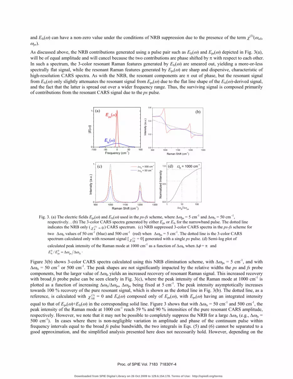
Δωfs/Δωps Fig. 3. (a) The electric fields Eps(ω) and Efs(ω) used in the ps-fs scheme, where Δωps = 5 cm-1 and Δωfs = 50 cm -1,
respectively. . (b) The 3-color CARS spectra generated by either Eps or Efs for the narrowband pulse. The dotted line indicates the NRB only ( 0)3( =Rχ ) CARS spectrum. (c) NRB suppressed 3-color CARS spectra in the ps-fs scheme for two Δωfs values of 50 cm-1 (blue) and 500 cm-1 (red) when Δωps = 5 cm-1. The dotted line is the 3-color CARS spectrum calculated only with resonant signal [ )3(
NRχ = 0] generated with a single ps pulse. (d) Semi-log plot of
calculated peak intensity of the Raman mode at 1000 cm-1 as a function of Δωfs when Δφ = π and
fsps0ps
0fs / ωω ΔΔ=EE .
Figure 3(b) shows 3-color CARS spectra calculated using this NRB elimination scheme, with Δωps = 5 cm-1, and with Δωfs = 50 cm-1 or 500 cm-1. The peak shapes are not significantly impacted by the relative widths the ps and fs probe components, but the larger value of Δωfs yields an increased recovery of resonant Raman signal. This increased recovery with broad fs probe pulse can be seen clearly in Fig. 3(c), where the peak intensity of the Raman mode at 1000 cm-1 is plotted as a function of increasing Δωfs/Δωps, Δωps being fixed at 5 cm-1. The peak intensity asymptotically increases towards 100 % recovery of the pure resonant signal, which is shown as the dotted line in Fig. 3(b). The dotted line, as a reference, is calculated with )3(
NRχ = 0 and En(ω) composed only of Eps(ω), with Eps(ω) having an integrated intensity equal to that of Eps(ω)+Efs(ω) in the corresponding solid line. Figure 3 shows that with Δωfs = 50 cm-1 and 500 cm-1, the peak intensity of the Raman mode at 1000 cm-1 reach 59 % and 90 % intensities of the pure resonant CARS amplitude, respectively. However, we note that it may not be possible to completely suppress the NRB for a large Δωfs (e.g., Δωfs = 500 cm-1). In cases where there is non-negligible variation in amplitude and phase of the continuum pulse within frequency intervals equal to the broad fs pulse bandwidth, the two integrals in Eqs. (5) and (6) cannot be separated to a good approximation, and the simplified analysis presented here does not necessarily hold. However, depending on the
Proc. of SPIE Vol. 7183 71830Y-4
Downloaded from SPIE Digital Library on 26 Oct 2009 to 129.6.154.178. Terms of Use: http://spiedl.org/terms
details of the shape of the continuum pulse, we may still expect a significant decrease in NRB contribution for much of the CARS signal bandwidth by adjusting the relative intensity and phase of the two narrowband pulse components.
2.2 ps-ps interference scheme
In the ps-ps scheme, En(ω) consists of two narrowband Gaussian pulses whose bandwidths are the same but whose center frequencies are shifted, as shown in Fig. 4(a). The electric fields of the ps pulses can be expressed as
]/)2()2ln2(exp[)( 2ps
2cc
0psps1 ωωωωω ΔΔ+−×−= EE and ]/)2()2ln2(exp[)( 2
ps2
cc0psps2 ωωωωω ΔΔ−−×−= EE , where
Δωc is the frequency separation between the two pulses. The overall electric field of the narrowband pulse is thus written as:
)(e)()( ps2Δ
ps1n ωωω φ EEE i += (10)
We obtain expressions for the 2-color or 3-color CARS signal intensity in the ps-ps scheme when we combine Eq. (10) with Eqs. (5) or (6), respectively:
[ ]
[ ]2
ps2i
ps1)3(
*cps2
ips1
color2ps-ps
)()e(),(
)()()e(),(
prprprpraS
paSprpppaS
dEE
dEEEI
ωωωωωχ
ωωωωωωφω
φ
φ
+×
−++∝Δ
Δ∞
∞−
∞
∞−
Δ−
∫
∫ (11)
[ ]2
ps2i
ps1)3(
*cc
color3ps-ps
)()e(),(
)()(),(
prprprpraS
paSprppaS
dEE
dEEI
ωωωωωχ
ωωωωωφω
φ∫
∫∞
∞−
Δ
∞
∞−
−
+×
−+∝Δ (12)
When the NRB suppression condition, [ ] 0)()e( ps2i
ps1 =+∫∞
∞−
Δppp dEE ωωω φ , is satisfied, the entire resonant 2-color
CARS spectrum, as well as NRB contributions from both 2-color and 3-color mechanisms vanish, as with the ps-fs scheme. In the ps-ps scheme, the NRB suppression condition is fulfilled when Δφ = π and |Eps1| = |Eps2| irrespective of the value of Δωc, provided the amplitude of the NRB does not change significantly over the interval Δωc.
-50 0 50
(a)Eps1(ω)Eps1(ω)
|E(ω
)|
Frequency (cm-1)900 1000 1100 1200 1300
0.0
0.2
0.4
0.6 (b)
Inte
nsity
(a.u
.)
Raman Shift (cm-1)900 1000 1100 1200 1300
0.0
0.5
1.0 Δωc(c) 35 cm-1 20 cm-1 10 cm-1 5 cm-1
Γ2 = 5 cm-1
Γ1 = 10 cm-1
Nor
mal
ized
Inte
nsity
Raman Shift (cm-1)
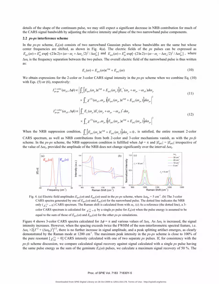
Fig. 4. (a) Electric field amplitudes Eps1(ω) and Eps2(ω) used in the ps-ps scheme, where Δωps = 5 cm-1. (b) The 3-color CARS spectra generated by one of Eps1(ω) and Eps2(ω) for the narrowband pulse. The dotted line indicates the NRB only ( 0)3( =Rχ ) CARS spectrum. The Raman shift is calculated from with ωc. (c) As a reference (the dotted line), a 3-color CARS spectrum is calculated for 0)3( =NRχ by a single ps pulse for En(ω) when the pulse energy is assumed to be
equal to the sum of those of Eps1(ω) and Eps2(ω) for the other ps-ps simulations.
Figure 4 shows 3-color CARS spectra calculated for Δφ = π and various values of Δωc. As Δωc is increased, the signal intensity increases. However, when the spacing exceeds twice the FWHM of the non-interferometric spectral feature, i.e. Δωc >2[Γ 2 + (Δωps)2]1/2, there is no further increase in signal amplitude, and a peak splitting artifact emerges, as clearly demonstrated by the Raman mode at 1200 cm-1. The maximum peak intensity in the ps-ps scheme is close to 100% of the pure resonant [ )3(
NRχ = 0] CARS intensity calculated with one of two separate ps pulses. If, for consistency with the ps-fs scheme discussion, we compare calculated signal recovery against signal calculated with a single ps pulse having the same pulse energy as the sum of the geminate En(ω) pulses, we calculate a maximum signal recovery of 50 %. The
Proc. of SPIE Vol. 7183 71830Y-5
Downloaded from SPIE Digital Library on 26 Oct 2009 to 129.6.154.178. Terms of Use: http://spiedl.org/terms
signal increase and peak splitting with Δωc in the ps-ps 3-color CARS can be understood as a result of two out-of-phase resonant CARS polarization spectra. When Δωc is small and the two equivalent peaks are close, the resonant-only CARS polarizations interfere destructively and the resulting peak becomes weak. When Δωc is larger and the two peaks are sufficiently separated, both peaks appear individually and the peak heights remain unaffected. For a small Δωc, destructive interference in the overlap region of the two pulse spectra can reduce the total (time-averaged) light intensity. However, this destructive interference leads to a signal reduction of only a factor of two between Δωc = 5 cm-1 and 20 cm-1, while the CARS peak height ratio for the peaks resulting from these conditions is 6. This additional increase is a result of a faster-rising electric field in the time domain for Δωc = 20 cm -1, and thus a more efficient sampling of the resonant Raman response at early times, before it decays. This is shown in Fig. 6(e) below.
2.3 fs(+/-) interference scheme
The interferometric approach by the fs(+/-) scheme was first demonstrated by Silberberg et al. [11], who reversed the phase of a Gaussian-like probe pulse by π across the center frequency. They found that the 3-color interferometric CARS spectrum generated by the phase modified femtosecond probe pulse showed narrower bandwidth and stronger signal intensity at resonance frequencies than the CARS spectrum by an equivalent transform-limited probe pulse. The similar approach has been applied to the single pulse CARS spectroscopy to suppress the NRB contribution. However, since a pulse shaper in the single pulse CARS controls the whole frequency range, the limited spectral resolution of the pulse shaper limits further optimization of the probe pulse. Here we present not only NRB suppressed CARS spectra but the effect of the probe pulse shape, in particular the bandwidth, on the CARS signal intensity and the spectral resolving power.
The electric field of the narrowband pulse in the fs(+/-) scheme is expressed as follows:
⎪⎩
⎪⎨⎧
<Δ−×−=>×Δ−×−=
=−
+
c2fs
2c
0fs)fs(
cΔ2
fs2
c0fs)fs(
n for,]/)()2ln2(exp[)(for,e]/)()2ln2(exp[)(
)(ωωωωωωωωωωωω
ωφ
EEEE
Ei
(13)
-100 0 100
(a)Efs(+)(ω)Efs(-)(ω)
|E(ω
)|
Frequency (cm-1)900 1000 1100 1200 1300
Δωfs(b) 60 cm-1 20 cm-1 5 cm-1
Γ2 = 5 cm-1
Γ1 = 10 cm-1
Inte
nsity
(a.u
.)
Raman Shift (cm-1)
0 10 20 30 40 50 60 70 80 90 1000
1
Γ2 = 5 cm-1
Γ1 = 10 cm-1
(c)
Peak
Inte
nsity
Δωfs (cm-1)
0
1 Δωfs
= 10 cm-1
(d)
Inte
nsity
(a.u
.)
20 cm-1
35 cm-1
1100 1150 1200 12500
160 cm-1
1100 1150 1200 1250
80 cm-1
Raman Shift (cm-1)1100 1150 1200 1250 1300
100 cm-1
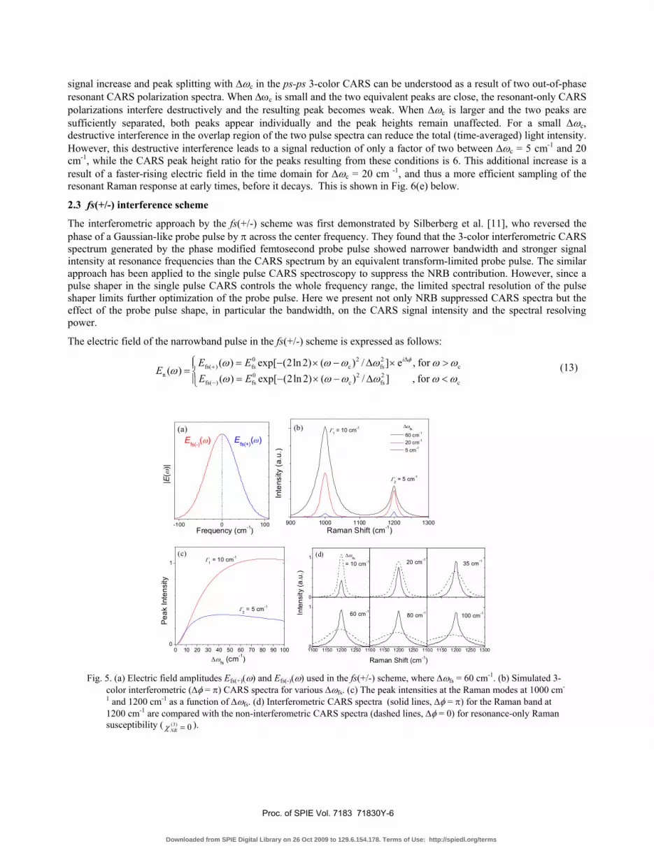
Fig. 5. (a) Electric field amplitudes Efs(+)(ω) and Efs(-)(ω) used in the fs(+/-) scheme, where Δωfs = 60 cm-1. (b) Simulated 3-color interferometric (Δφ = π) CARS spectra for various Δωfs. (c) The peak intensities at the Raman modes at 1000 cm-
1 and 1200 cm-1 as a function of Δωfs. (d) Interferometric CARS spectra (solid lines, Δφ = π) for the Raman band at 1200 cm-1 are compared with the non-interferometric CARS spectra (dashed lines, Δφ = 0) for resonance-only Raman susceptibility ( 0)3( =NRχ ).
Proc. of SPIE Vol. 7183 71830Y-6
Downloaded from SPIE Digital Library on 26 Oct 2009 to 129.6.154.178. Terms of Use: http://spiedl.org/terms
As with the ps-fs and ps-ps schemes, when the NRB suppression condition (Δφ = π) is satisfied, the total 2-color CARS signal and the nonresonant 3-color CARS signal disappear and only a resonant 3-color spectrum remains. Figure 5(b) shows 3-color interferometric CARS spectra calculated with varying Δωfs, while the time averaged intensity of the probe pulse is kept constant for all Δωfs. First, it is noted that the peak intensity of the interferometric (Δφ = π) CARS increases with increasing Δωfs but after the peak height reaches the maximum it decreases very slowly with Δωfs, which is shown in Fig. 5(c). This Δωfs dependence of the interferometric CARS peak intensity is significantly different from that of non-interferometric (Δφ = 0) CARS, which monotonically decrease with increasing Δωfs, an shown in the series of CARS spectra (the dashed curves) in Fig. 5(d). Second, the widths of the interferometric CARS peaks are much narrower than that of the non-interferometric CARS peak, which corresponds to [Γ 2 + (Δωfs)2]1/2. Figure 5(d) shows the clearly different Δωfs dependence of the peak width between the interferometric and non-interferometric CARS. Third, the opposite Δωfs dependence of the peak height between the interferometric and non-interferometric CARS spectra results in a greater signal intensity at the peak of an interferometric CARS spectrum than that of a non-interferometric CARS spectrum generated by a transform-limited probe pulse. This strongly suggests that the optimal bandwidth of the probe pulse (e.g., Δωfs ≈ 80 cm-1 for Γ = 10 cm-1) in the fs(+/-) scheme should be much larger than the typical spontaneous Raman linewidth (≈ 10 cm-1). This optimization condition can be applied not only to broadband CARS but single pulse CARS spectroscopy.
2.4 Time domain considerations
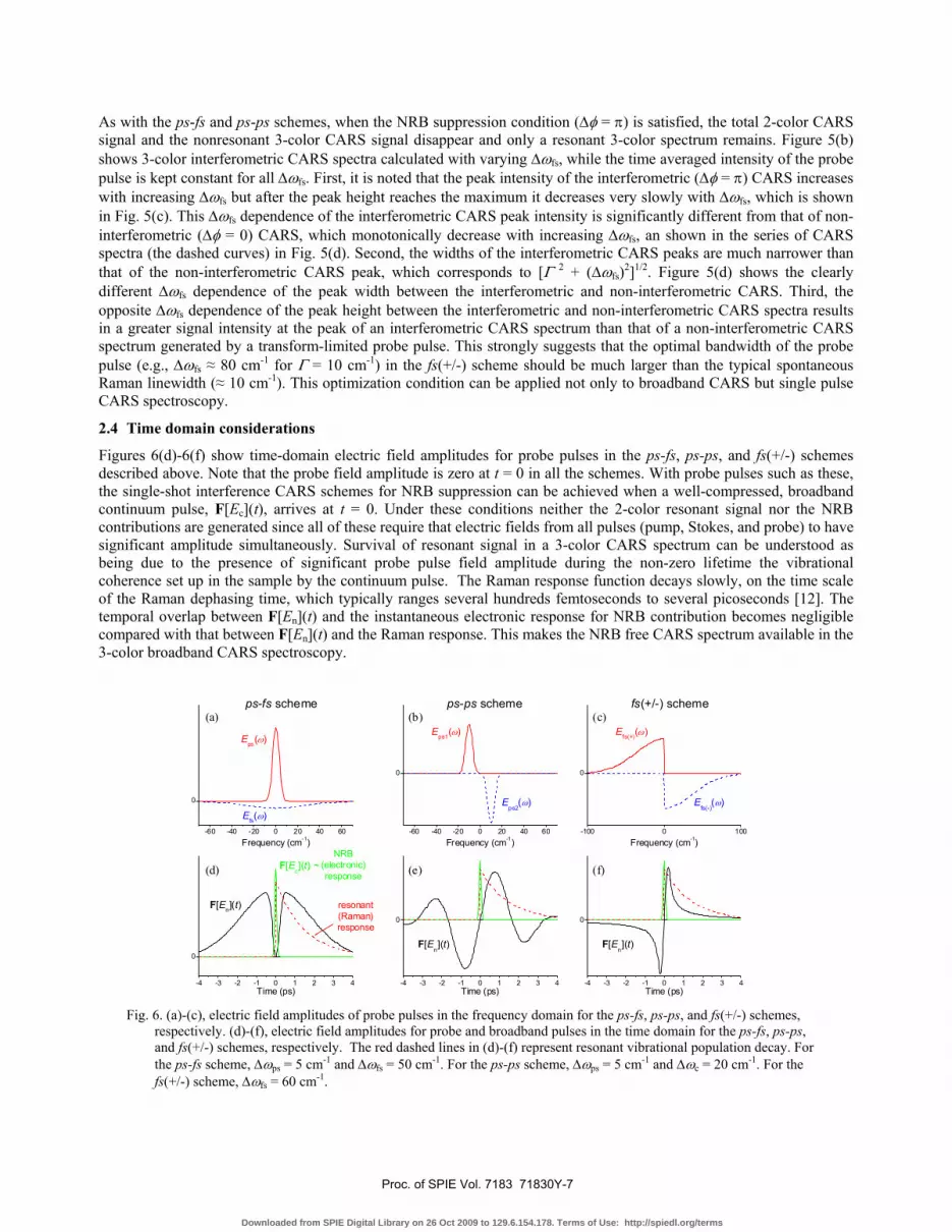
Figures 6(d)-6(f) show time-domain electric field amplitudes for probe pulses in the ps-fs, ps-ps, and fs(+/-) schemes described above. Note that the probe field amplitude is zero at t = 0 in all the schemes. With probe pulses such as these, the single-shot interference CARS schemes for NRB suppression can be achieved when a well-compressed, broadband continuum pulse, F[Ec](t), arrives at t = 0. Under these conditions neither the 2-color resonant signal nor the NRB contributions are generated since all of these require that electric fields from all pulses (pump, Stokes, and probe) to have significant amplitude simultaneously. Survival of resonant signal in a 3-color CARS spectrum can be understood as being due to the presence of significant probe pulse field amplitude during the non-zero lifetime the vibrational coherence set up in the sample by the continuum pulse. The Raman response function decays slowly, on the time scale of the Raman dephasing time, which typically ranges several hundreds femtoseconds to several picoseconds [12]. The temporal overlap between F[En](t) and the instantaneous electronic response for NRB contribution becomes negligible compared with that between F[En](t) and the Raman response. This makes the NRB free CARS spectrum available in the 3-color broadband CARS spectroscopy.
-60 -40 -20 0 20 40 60
0
(a)
Frequency (cm-1)
Eps(ω)
Efs(ω)-60 -40 -20 0 20 40 60
0
(b)ps-ps schemeps-fs scheme
Eps1(ω)
Eps2
(ω)
Frequency (cm-1)
-4 -3 -2 -1 0 1 2 3 4
0
(d)NRB
(electronic)response
F[Ec](t) ~
resonant(Raman)response
F[En](t)
Time (ps)-4 -3 -2 -1 0 1 2 3 4
0
(e)
F[En](t)
Time (ps)
-100 0 100
0
(c)fs(+/-) scheme
Efs(+)(ω)
Efs(-)
(ω)
Frequency (cm-1)
-4 -3 -2 -1 0 1 2 3 4
0
(f)
F[En](t)
Time (ps) Fig. 6. (a)-(c), electric field amplitudes of probe pulses in the frequency domain for the ps-fs, ps-ps, and fs(+/-) schemes,
respectively. (d)-(f), electric field amplitudes for probe and broadband pulses in the time domain for the ps-fs, ps-ps, and fs(+/-) schemes, respectively. The red dashed lines in (d)-(f) represent resonant vibrational population decay. For the ps-fs scheme, Δωps = 5 cm-1 and Δωfs = 50 cm-1. For the ps-ps scheme, Δωps = 5 cm-1 and Δωc = 20 cm-1. For the fs(+/-) scheme, Δωfs = 60 cm-1.
Proc. of SPIE Vol. 7183 71830Y-7
Downloaded from SPIE Digital Library on 26 Oct 2009 to 129.6.154.178. Terms of Use: http://spiedl.org/terms
It is clear from the time-domain description of Fig. 5 that the NRB is completely suppressed only when the continuum pulse is extremely short. A small amount of chirping is expected to increase temporal overlap between the continuum and the pulse-shaped probe pulses, resulting in residual NRB. We note that a transform-limited continuum pulse is desirable not only for removal of the NRB contribution, but significantly increases signal intensity and spectral coverage of the entire 3-color CARS spectrum [5]. However, it is difficult to generate a compressible and spectrally broad (>3000 cm-1) continuum pulse from a nonlinear fiber, and these continua generally contain multiple modes with higher order dispersion [13].
3. CONCLUSION
We have introduced a new interferometric approach to suppress nonresonant background in a 3-color CARS spectrum and have demonstrated it using broadband CARS. The approach uses an amplitude-and-phase optimized pair of probe pulses and yields background-suppressed spectra in each shot without need for phase scanning. We have demonstrated three model schemes; the ps-fs scheme, the ps-ps scheme, and the fs(+/-) scheme. In all schemes, the resonant CARS signal from only the “3-color” CARS mechanism is recovered with minimal attenuation while the resonant signal from “2-color” CARS mechanism becomes negligible when the NRB contribution is suppressed. We have discussed optimization conditions for the signal intensity and shape of resonant peaks.
REFERENCES
[1] J. X. Cheng, A. Volkmer, L. D. Book, and X. S. Xie, "Multiplex coherent anti-stokes Raman scattering microspectroscopy and study of lipid vesicles," J. Phys. Chem. B 106, 8493 (2002).
[2] T. W. Kee and M. T. Cicerone, "Simple approach to one-laser, broadband coherent anti-Stokes Raman scattering microscopy," Opt. Lett. 29, 2701 (2004).
[3] G. I. Petrov and V. V. Yakovlev, "Enhancing red-shifted white-light continuum generation in optical fibers for applications in nonlinear Raman microscopy," Opt. Express 13, 1299 (2005).
[4] H. A. Rinia, M. Bonn, and M. Muller, "Quantitative multiplex CARS spectroscopy in congested spectral regions," J. Phys. Chem. B 110, 4472 (2006).
[5] Y. J. Lee, Y. Liu, and M. T. Cicerone, "Characterization of 3-color CARS in a 2-pulse broadband CARS spectrum," Opt. Lett. 32, 3370 (2007).
[6] D. Oron, N. Dudovich, and Y. Silberberg, "Femtosecond phase-and-polarization control for background-free coherent anti-Stokes Raman spectroscopy," Phys. Rev. Lett. 90, 213902 (2003).
[7] B. C. Chen and S. H. Lim, "Optimal laser pulse shaping for interferometric multiplex coherent anti-stokes Raman scattering microscopy," J. Phys. Chem. B 112, 3653 (2008).
[8] T. W. Kee, H. X. Zhao, and M. T. Cicerone, "One-laser interferometric broadband coherent anti-Stokes Raman scattering," Opt. Express 14, 3631 (2006).
[9] H. Kano and H. Hamaguchi, "Dispersion-compensated supercontinuum generation for ultrabroadband multiplex coherent anti-Stokes Raman scattering spectroscopy," J. Raman Spectrosc. 37, 411 (2006).
[10] G. L. Eesley, Coherent Raman Spectroscopy, (Pergamon Press, Oxford, 1981). [11] D. Oron, N. Dudovich, D. Yelin, and Y. Silberberg, "Narrow-band coherent anti-stokes Raman signals from broad-
band pulses," Phys. Rev. Lett. 88, 273001 (2002). [12] A. Morresi, L. Mariani, M. R. Distefano, and M. G. Giorgini, "Vibrational-Relaxation Processes in Isotropic
Molecular Liquids - A Critical Comparison," J. Raman Spectrosc. 26, 179 (1995). [13] J. M. Dudley, G. Genty, and S. Coen, "Supercontinuum generation in photonic crystal fiber," Rev. Mod. Phys. 78,
1135 (2006). * Official contribution of the National Institute of Standards and Technology; not subject to copyright in the United
States
Proc. of SPIE Vol. 7183 71830Y-8
Downloaded from SPIE Digital Library on 26 Oct 2009 to 129.6.154.178. Terms of Use: http://spiedl.org/terms