
rx8_2018_manual.pdf - XRAY RACING MODEL CARS
52
1
-
Upload
khangminh22 -
Category
Documents
-
view
0 -
download
0
Transcript of rx8_2018_manual.pdf - XRAY RACING MODEL CARS

1

2
BEFORE YOU STARTThe RX8 is a high-competition, high-quality, 1/8-scale on-road nitro car intended for persons aged 16 years and older with previous experience building and operating RC model racing cars. This is not a toy; it is a precision racing model. This model racing car is not intended for use by beginners, inexperienced customers, or by children without direct supervision of a responsible, knowledgeable adult. If you do not fulfill these requirements, please return the kit in unused and unassembled form back to the shop where you have purchased it.
Before building and operating your RX8, YOU MUST read through all of the operating instructions and instruction manual and fully understand them to get the maximum enjoyment and prevent unnecessary damage.
Read carefully and fully understand the instructions before beginning assembly.Make sure you review this entire Instruction Manual and examine all details carefully. If for some reason you decide the RX8 is not what you wanted or expected, do not continue any further. Your hobby dealer cannot accept your RX8 kit for return or exchange after it has been partially or fully assembled.
Contents of the box may differ from pictures. In line with our policy of continuous product development, the exact specifications of the kit may vary without prior notice.
SAFETY PRECAUTIONSWARNING: This product contains a chemical known to the state of California to cause cancer and birth defects or other reproductive harm.CAUTION: CANCER HAZARDWash thoroughly after using. DO NOT use product while eating, drinking or using tobacco products. May cause chronic effects to gastrointestinal tract, CNS, kidneys, and blood. MAY CAUSE BIRTH DEFECTS.
When building, using and/or operating this model always wear protective glasses and gloves.
Take appropriate safety precautions prior to operating this model. You are responsible for this model‘s assembly and safe operation! Please read the instruction manual before building and operating this model and follow all safety precautions. Always keep the instruction manual at hand for quick reference, even after completing the assembly. Use only genuine and original authentic XRAY parts for maximum performance.
Using any third party parts on this model will void guaranty immediately.Improper operation may cause personal and/or property damage. XRAY and its distributors have no control over damage resulting from shipping, improper construction, or improper usage. XRAY assumes and accepts no responsibility for personal and/or property damages resulting from the use of improper building materials, equipment and operations. By purchasing any item produced by XRAY, the buyer expressly warrants that he/she is in compliance with all applicable federal, state and local laws and regulation regarding the purchase, ownership and use of the item. The buyer expressly agrees to indemnify and hold harmless XRAY for all claims resulting directly or indirectly from the purchase, ownership or use of the product. By the act of assembling or operating this product, the user accepts all resulting liability. If the buyer is not prepared to accept this liability, then he/she should return this kit in new, unassembled, and unused condition to the place of purchase.
• Keep the wheels of the model off the ground when checking the operation of the radio equipment.• Disconnect the battery pack before storing your model.• When learning to operate your model, go to an area that has no obstacles that can damage your model
if your model suffers a collision.• Remove any sand, mud, dirt, grass or water before putting your model away.• If the model behaves strangely, immediately stop the model, check and clear the problem.• To prevent any serious personal injury and/or damage to property, be responsible when operating all
remote controlled models.• The model car is not intended for use on public places and roads or areas where its operation can conflict with
or disrupt pedestrian or vehicular traffic.• Because the model car is controlled by radio, it is subject to radio interference from many sources that
are beyond your control. Since radio interference can cause momentary loss of control, always allow a safety margin in all directions around the model in order to prevent collisions.
• Do not use your model: - Near real cars, animals, or people that are unaware that an RC car is being driven. - In places where children and people gather - In residential districts and parks - In limited indoor spaces - In wet conditions - In the street - In areas where loud noises can disturb others, such as hospitals and residential areas. - At night or anytime your line of sight to the model may be obstructed or impaired in any way.
To prevent any serious personal injury and/or damage to property, please be responsible when operating all remote controlled models.
IMPORTANT NOTES – GENERAL• This product is not suitable for children under 16 years of age without the direct supervision of a
responsible and knowledgeable adult.• Carefully read all manufacturers warnings and cautions for any parts used in the construction and use
of your model.• Assemble this kit only in places away from the reach of very small children.• First-time builders and users should seek advice from people who have building experience in order to
assemble the model correctly and to allow the model to reach its performance potential.• Exercise care when using tools and sharp instruments.• Take care when building, as some parts may have sharp edges.• Keep small parts out of reach of small children. Children must not be allowed to put any parts in their
mouth, or pull vinyl bag over their head.• Read and follow instructions supplied with paints and/or cement, if used (not included in kit).• Immediately after using your model, do NOT touch equipment on the model such as the motor and
speed controller, because they generate high temperatures. You may seriously burn yourself seriously touching them.
• Follow the operating instructions for the radio equipment at all times.• Do not put fingers or any objects inside rotating and moving parts, as this may cause damage or
serious injury as your finger, hair, clothes, etc. may get caught.• Be sure that your operating frequency is clear before turning on or running your model, and never
share the same frequency with somebody else at the same time. Ensure that others are aware of the operating frequency you are using and when you are using it.
• Use a transmitter designed for ground use with RC cars. Make sure that no one else is using the same frequency as yours in your operating area. Using the same frequency at the same time, whether it is driving, flying or sailing, can cause loss of control of the RC model, resulting in a serious accident.
• Always turn on your transmitter before you turn on the receiver in the car. Always turn off the receiver before turning your transmitter off.
FAILURE TO FOLLOW THESE INSTRUCTIONS WILL BE CONSIDERED AS ABUSE AND/OR NEGLECT.
CUSTOMER SUPPORT XRAY EuropeK Výstavisku 699291101 TrenčínSlovakia, EUROPEPhone: +421-32-7401100Fax: +421-32-7401109Email: [email protected]
We have made every effort to make these instructions as easy to understand as possible. However, if you have any difficulties, problems, or questions, please do not hesitate to contact the XRAY support team at [email protected]. Also, please visit our Web site at www.teamxray.com to find the latest updates, set-up information, option parts, and many other goodies. We pride ourselves on taking excellent care of our customers.
You can join thousands of XRAY fans and enthusiasts in our online community at: www.teamxray.com
XRAY RC America2030 Century Center Blvd #15, Suite 10975062 IrvingTexas, USAPhone: (214) 744-2400Fax: (214) 744-2401Email: [email protected]
IMPORTANT NOTES – NITRO ENGINES• Always test the brakes and the throttle before starting your engine to avoid losing control of the model.• Make sure the air filter is clean and oiled. • Never run your engine without an air filter. Your engine can be seriously damaged if dirt and debris get
inside the engine.• For proper engine break-in, please refer to the manual that came with the engine.
• Do not run near open flames or smoke while running your model or while handling fuel.• Some parts will be hot after operation. Do not touch the exhaust or the engine until they have cooled.
These parts may reach 275°F during operation!

3
IMPORTANT NOTES – ELECTRICAL• Insulate any exposed electrical wiring (using heat shrink tubing or electrical tape) to prevent dangerous
short circuits. Take maximum care in wiring, connecting and insulating cables. Make sure cables are always connected securely. Check connectors for if they become loose. And if so, reconnect them securely. Never use R/C models with damaged wires. A damaged wire is extremely dangerous, and can cause short-circuits resulting in fire. Please have wires repaired at your local hobby shop.
• Low battery power will result in loss of control. Loss of control can occur due to a weak battery in either the transmitter or the receiver. Weak running battery may also result in an out of control car if your car‘s receiver power is supplied by the running battery. Stop operation immediately if the car starts to slow down.
• When not using RC model, always disconnect and remove battery. • Do not disassemble battery or cut battery cables. If the running battery short-circuits, approximately
300W of electricity can be discharged, leading to fire or burns. Never disassemble battery or cut battery cables.
• Use a recommended charger for the receiver and transmitter batteries and follow the instructions
correctly. Over-charging, incorrect charging, or using inferior chargers can cause the batteries to become dangerously hot. Recharge battery when necessary. Continual recharging may damage battery and, in the worst case, could build up heat leading to fire. If battery becomes extremely hot during recharging, please ask your local hobby shop for check and/or repair and/or replacement.
• Regularly check the charger for potential hazards such as damage to the cable, plug, casing or other defects. Ensure that any damage is rectified before using the charger again. Modifying the charger may cause short-circuit or overcharging leading to a serious accident. Therefore do not modify the charger.
• Always unplug charger when recharging is finished.• Do not recharge battery while battery is still warm. After use, battery retains heat. Wait until it cools
down before charging. • Do not allow any metal part to short circuit the receiver batteries or other electrical/electronic device on
the model.• Immediately stop running if your RC model gets wet as may cause short circuit. • Please dispose of batteries responsibly. Never put batteries into fire.
WARRANTYXRAY guarantees this model kit to be free from defects in both material and workmanship within 30 days of purchase. The total monetary value under warranty will in no case exceed the cost of the original kit purchased. This warranty does not cover any components damaged by use or modification or as a result of wear. Part or parts missing from this kit must be reported within 30 days of purchase. No part or parts will be sent under warranty without proof of purchase. Should you find a defective or missing part, contact the local distributor. Service and customer support will be provided through local hobby store where you have purchased the kit, therefore make sure to purchase any XRAY products at your local hobby store. This model racing car is considered to be a high-performance racing vehicle. As such this vehicle will be used in an extreme range of conditions and situations, all which may cause premature wear or failure of any component. XRAY has no control over usage of vehicles once they leave the dealer, therefore XRAY can only offer warranty against all manufacturer‘s defects in materials, workmanship, and assembly at point of sale and before use. No warranties are expressed or implied that cover damage caused by what is considered normal use, or cover or imply how long any model cars‘ components or electronic components will last before requiring replacement.
Due to the high performance level of this model car you will need to periodically maintain and replace consumable components. Any and all warranty coverage will not cover replacement of any part or component damaged by neglect, abuse, or improper or unreasonable use. This includes but is not limited to damage from crashing, chemical and/or water damage, excessive moisture, improper or no maintenance, or user
modifications which compromise the integrity of components. Warranty will not cover components that are considered consumable on RC vehicles. XRAY does not pay nor refund shipping on any component sent to XRAY or its distributors for warranty. XRAY reserves the right to make the final determination of the warranty status of any component or part.
Limitations of LiabilityXRAY makes no other warranties expressed or implied. XRAY shall not be liable for any loss, injury or damages, whether direct, indirect, special, incidental, or consequential, arising from the use, misuse, or abuse of this product and/or any product or accessory required to operate this product. In no case shall XRAY‘s liability excess the monetary value of this product.
Take adequate safety precautions prior to operating this model. You are responsible for this model’s assembly and safe operation.
Disregard of the any of the above cautions may lead to accidents, personal injury, or property damage. XRAY MODEL RACING CARS assumes no responsibility for any injury, damage, or misuse of this product during assembly or operation, nor any addictions that may arise from the use of this product.All rights reserved.
QUALITY CERTIFICATEXRAY MODEL RACING CARS uses only the highest quality materials, the best compounds for molded parts and the most sophisticated manufacturing processes of TQM (Total Quality Management). We guarantee that all parts of a newly-purchased kit are manufactured with the highest regard to quality. However, due to the many factors inherent in model racecar competition, we cannot guarantee any parts once you start racing the car. Products which have been worn out, abused, neglected or improperly operated will not be covered under warranty. We wish you enjoyment of this high-quality and high-performance RC car and wish you best success on the track!
Please note that raw materials such as aluminum, steel, brass, fibreglass, or carbon fibre may have small scratches on the surface which is a standard characteristic of any raw material. Scratches on the surface of any materials are NOT considered to be material defects.
Products may potentially have small amounts of corrosion on them. This may be caused by variances in weather during different times of the year, humidity in the shop or during shipping, and other contributing factors. Even though we have taken all precautions and protection methods to prevent corrosion, these small amounts of corrosion (if present) are unavoidable and considered to be acceptable.
In line with our policy of continuous product development, the exact specifications of the kit may vary. In the unlikely event of any problems with your new kit, you should contact the model shop where you purchased it, quoting the part number. We do reserve all rights to change any specification without prior notice. All rights reserved.
R/C & BUILDING TIPS• Make sure all fasteners are properly tightened. Check them periodically.• Make sure that chassis screws do not protrude from the chassis.• For the best performance, it is very important that great care is taken to ensure the free movement of all parts.• Clean all ball-bearings so they move very easily and freely.• Tap or pre-thread the plastic parts when threading screws.• Self-tapping screws cut threads into the parts when being tightened. Do not use excessive force when
tightening the self-tapping screws because you may strip out the thread in the plastic. We recommended
you stop tightening a screw when you feel some resistance.• Ask your local hobby shop for any advice.
Please support your local hobby shop. We at XRAY Model Racing Cars support all local hobby dealers. Therefore we ask you, if at all possible, to purchase XRAY products at your hobby dealer and give them your support like we do. If you have difficulty finding XRAY products, please check out www.teamxray.com to get advice, or contact us via email at [email protected], or contact the XRAY distributor in your country.
IMPORTANT NOTES – NITRO FUEL• Handle fuel only outdoors. Never handle nitro fuel indoors, or mix nitro fuel in a place where ventilation
is bad.• Only use nitro fuel for R/C models. Do not use gasoline or kerosene in R/C models as it may cause a fire
or explosion, and ruin your engine.• Nitro fuel is highly inflammable, explosive, and poisonous. Never use fuel indoors or in places with open
fires and sources of heat. • Always keep the fuel container cap tightly shut.• Always read the warning label on the fuel container for safety information. • Nitro-powered model engines emit poisonous vapors and gasses. These vapors irritate eyes and can be highly
dangerous to your health. We recommend wearing rubber or vinyl gloves to avoid direct contact with nitro fuel.• Nitro fuel for RC model cars is made of the combination of the methyl alcohol, castor or synthetic oil,
nitro methane etc. The flammability and volatility of these elements is very high, so be very careful during handling and storage of nitro fuel.
• Keep nitro fuel away from open flame, sources of heat, direct sunlight, high temperatures, or near batteries.
• Store fuel in a cool, dry, dark, well-ventilated place, away from heating devices, open flames, direct sunlight, or batteries. Keep nitro fuel away from children.
• Do not leave the fuel in the carburetor or fuel tank when the model is not in use. There is danger that the fuel may leak out.
• Wipe up any spilled fuel with a cloth• Be aware of spilled or leaking fuel. Fuel leaks can cause fires or explosions.• Do not dispose of fuel or empty fuel containers in a fire. There is danger of explosion.

4
EQUIPMENT REQUIRED
TOOLS REQUIRED
SYMBOLS USED
Transmitter Steering & Throttle ServosReceiver
Battery Charger
Starter Box (HUDY #104400) & Battery Pack
Exhaust Manifold
Engine
Air Filter Air Filter Oil(HUDY #106240)
Model R/C Car Fuel(nitromethane)
ThreadlockCA Glue
Glowplug Igniter
One-Way Lube(HUDY #106231)
Engine After Run Oil(HUDY #106250)
Bearing Oil(HUDY #106230)
Apply cyanoacrylate (CA) glue
Part bags used
Optional parts
Assembly view
Assemble left and right sides the same way
Assemble in the specified orderDetail
Pay attention here
Assemble as many times as specified (here twice)
Apply threadlock Number of teeth
Apply oil (may indicate specific type)
Follow tip here
Cut off remaining material
Ensure smooth non-binding movement
Apply grease
Graphite Grease(HUDY #106210)
Lexan® Paint Bodyshell Receiver Battery Pack
Personal Transponder
DETAIL
Wheels & Tires Tire Truer (HUDY #102003)
Reamer(HUDY #107602)(HUDY #107601)
Wrench Glowplug/Clutchnut(HUDY #107581)
Flywheel Tool(HUDY #182010)
Pliers(HUDY #189020)
Side Cutters(HUDY #189010)
Pocket Hobby Knife(HUDY #188981)
3.0 mm
Turnbuckle ToolsTurnbuckle Tools(HUDY #181091 3.0/4.0mm) (HUDY #181030 - 3.0mm)
Scissors(HUDY #188990)
Professional Multi Tool (HUDY #183011)
Ball Joint Wrench(HUDY #181110)
Alu Pinion Gear Tool(XRAY #349903)
Phillips 3.5mm
Allen Ball 2.5mm
Slotted Screwdriver 4.0mm
Exhaust Spring / Caster Clip RemoverAllen 1.5 / 2.0 / 2.5 / 3.0mm
Arm Reamer 3mm/4mm
5
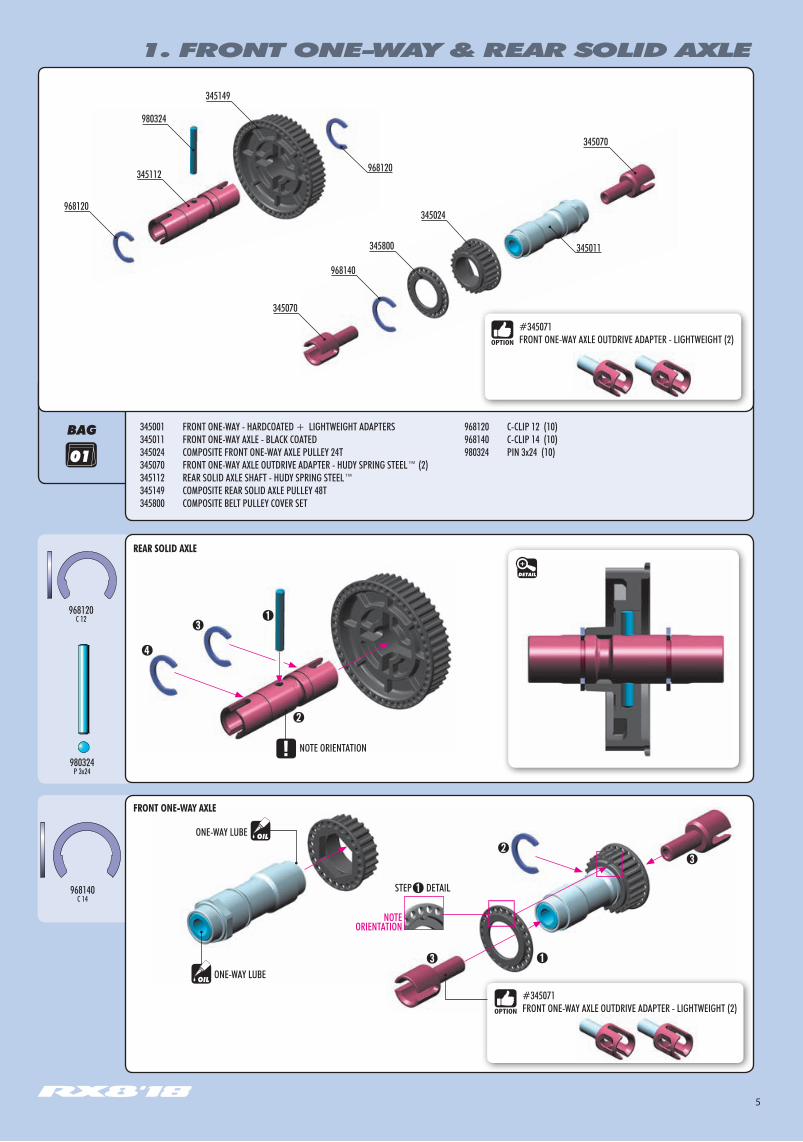
#345071FRONT ONE-WAY AXLE OUTDRIVE ADAPTER - LIGHTWEIGHT (2)
REAR SOLID AXLE
FRONT ONE-WAY AXLE
#345071FRONT ONE-WAY AXLE OUTDRIVE ADAPTER - LIGHTWEIGHT (2)
BAG
ONE-WAY LUBE
ONE-WAY LUBE
STEP DETAIL
NOTEORIENTATION
OIL
OIL
1. FRONT ONE-WAY & REAR SOLID AXLE
345070
345011
345024
968140
345070
968120
345001 FRONT ONE-WAY - HARDCOATED + LIGHTWEIGHT ADAPTERS345011 FRONT ONE-WAY AXLE - BLACK COATED345024 COMPOSITE FRONT ONE-WAY AXLE PULLEY 24T345070 FRONT ONE-WAY AXLE OUTDRIVE ADAPTER - HUDY SPRING STEEL™ (2)345112 REAR SOLID AXLE SHAFT - HUDY SPRING STEEL™345149 COMPOSITE REAR SOLID AXLE PULLEY 48T 345800 COMPOSITE BELT PULLEY COVER SET
968120 C-CLIP 12 (10)968140 C-CLIP 14 (10)980324 PIN 3x24 (10)
980324
345112
345149
968120
345800
01
968120C 12
980324P 3x24
968140C 14
DETAIL
NOTE ORIENTATION

6
#345312ALU REAR CVD DRIVE AXLE SWISS 7075 T6 - HARDCOATED
#345301REAR CVD DRIVE SHAFT SET HUDY SPRING STEEL™
#345290ALU SHIM 12x15x1.0MM (4)
BAG
2. REAR SUSPENSION
2x
345360-O
345310 306219
901316
343311
337250
372651901410
342630
343150
343285
902308
962121
941218
342070
901306
343130
337253345280
901303
902306
902308
343195
306219
343111
306219 COMPOSITE SET OF SERVO SHIMS (4)337250 STEEL PIVOT BALL 8.4 MM (2)337253 COMPOSITE ADJUSTING NUT M10x1 (4)342070 COMPOSITE SET OF BUSHINGS (2)342630 ADJ. TURNBUCKLE L/R 20 MM - HUDY SPRING STEEL™ (2)343111 SUSPENSION ARM FOR EXTENSION - REAR LOWER343130 COMPOSITE SUSPENSION ARM REAR UPPER343150 UPPER BALL JOINT 5.8MM - SHORT & LONG (2+2)343195 STEEL EXTENSION FOR SUSPENSION ARM - REAR LOWER (2)
343285 PIVOT BALL 6.8MM (2)343311 COMPOSITE UPRIGHT REAR FOR AERO DISC345280 WHEEL SPRING (2)345310 REAR WHEEL AXLE - HUDY SPRING STEEL™345360-O ALU REAR WHEEL LOCK - SWISS 7075 T6 - ORANGE (2)345370 GRAPHITE REAR AERODYNAMIC DISC 1.6MM - SET (OPTION) 372651 PIVOT BALL UNIVERSAL 4.9 MM - HUDY SPRING STEEL™ (2)
941218 HIGH-SPEED BALL-BEARING 12x18x4 RUBBER SEALED (2)
980322
962121
962120
941218
342070
901303 HEX SCREW SB M3x3 (10)901306 HEX SCREW SB M3x6 (10)901316 HEX SCREW SB M3x16 (10)901410 HEX SCREW SB M4x10 (10)902306 HEX SCREW SH M3x6 (10)902308 HEX SCREW SH M3x8 (10)962120 WASHER S 12x15x0.5 (10)962121 WASHER S 12x15x1.0 (10)980322 PIN 3x22 (10)
02.1
#345370GRAPHITE REAR AERO DISC 1.6mm - SET
ADJUSTING NUT#337253 COMPOSITE INCLUDED#337252 ALU OPTION
PIVOT BALLS#337250 STEEL INCLUDED#337251 ALU OPTION#337255 TITANIUM OPTION
SUSPENSION UPPER ARMS#343130 MEDIUM INCLUDED#343131 HARD OPTION#343132 GRAPHITE OPTION
SUSPENSION LOWER ARMS#343111 MEDIUM INCLUDED#343112 HARD OPTION#343113 GRAPHITE OPTION

7
COMPOSITE SET OF BUSHINGS
CONCENTRICCONCENTRIC
INITIAL SETTING
INITIAL SETTINGECCENTRIC
2x
2. REAR SUSPENSION
BEARING OIL
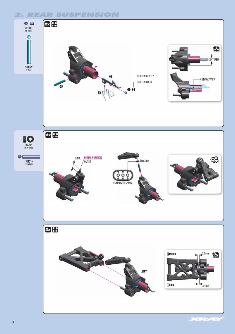
BEARING OILWhen using eccentric bushings, both bushings must be in same position.
NOTE ORIENTATION
962120S 12x15x0.5
962121S 12x15x1.0
941218BB 12x18x4
OIL
OIL
#345312ALU REAR CVD DRIVE AXLE SWISS 7075 T6 - HARDCOATED
#345301REAR CVD DRIVE SHAFT SET HUDY SPRING STEEL™
#345290ALU SHIM 12x15x1.0MM (4)
DETAIL
IN OUT1+1 0.51+0.5 11 1+0.50.5 1+10 1+1+0.5
INITIAL SETTING
SHIM SHIM
Tighten gently
2x
48mm
NOTEORIENTATION
Tighten composite hex nuts usingHUDY tool #107581
When you use INNER position on the upright, use SHORTER ball joint.
(INITIAL SETTING)When you use OUTER position on the upright, use LONGER ball joint.
The length of the ball joint depends on the position used on the upright. See page 8, step 2.
902308SH M3x8
902306SH M3x6
901410SB M4x10
901306SB M3x6
DETAIL
2.5mm2.5mm
During initial assembly, tighten each composite hex nut until the pivot ball starts to bind, then loosen slightly. Verify that the pivot balls move freely.
PIVOT BALLS MUST MOVE FREELY
DETAIL
3x8mm
3x6mm
3x6mm
3x6x1mm
COMPOSITE SHIMS
3x8mm
4x10mm
ADJUSTING NUT#337253 COMPOSITE INCLUDED#337252 ALU OPTION
PIVOT BALLS#337250 STEEL INCLUDED#337251 ALU OPTION#337255 TITANIUM OPTION
2x
Install the pivot balls with Professional Multi Tool (HUDY #183011)
12x15x0.5mm
12x15x1mm
SUSPENSION UPPER ARMS#343130 MEDIUM INCLUDED#343131 HARD OPTION#343132 GRAPHITE OPTION
SUSPENSION LOWER ARMS#343111 MEDIUM INCLUDED#343112 HARD OPTION#343113 GRAPHITE OPTION
NOTE ORIENTATION
Right thread
Left thread
8
901303SB M3x3
INITIAL POSITION3x6x2mm
6mm
COMPOSITE SHIMS
OUTER
3.6mm
3.4mm
2x
2x
2x
TIGHTEN GENTLY
TIGHTEN FULLY
306219SHIM 3x6x2
901316SB M3x16
980322P 3x22
DETAIL
CUTAWAY VIEW
DETAIL
CENTERED
2. REAR SUSPENSION
9
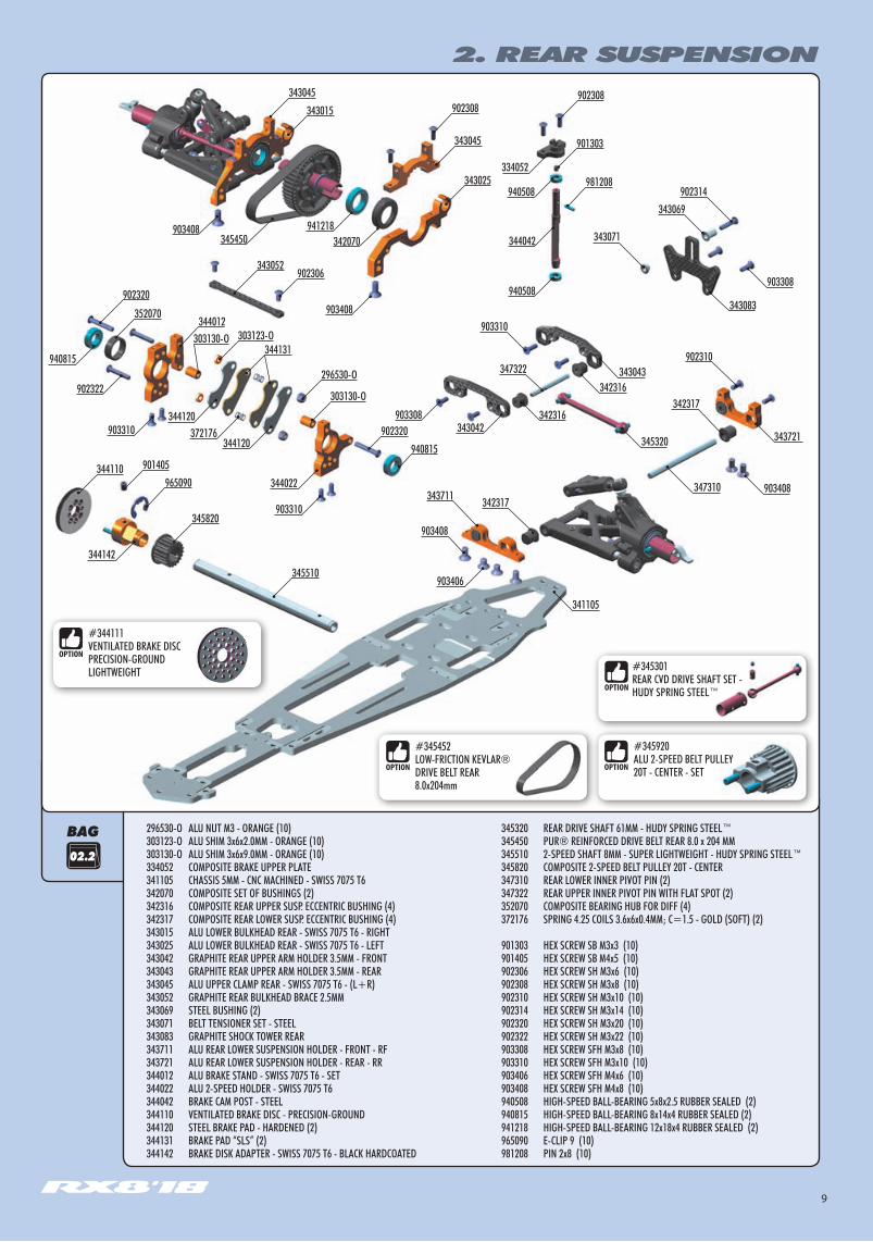
#345920ALU 2-SPEED BELT PULLEY 20T - CENTER - SET
BAG
2. REAR SUSPENSION
296530-O ALU NUT M3 - ORANGE (10)303123-O ALU SHIM 3x6x2.0MM - ORANGE (10)303130-O ALU SHIM 3x6x9.0MM - ORANGE (10)334052 COMPOSITE BRAKE UPPER PLATE 341105 CHASSIS 5MM - CNC MACHINED - SWISS 7075 T6342070 COMPOSITE SET OF BUSHINGS (2)342316 COMPOSITE REAR UPPER SUSP. ECCENTRIC BUSHING (4)342317 COMPOSITE REAR LOWER SUSP. ECCENTRIC BUSHING (4)343015 ALU LOWER BULKHEAD REAR - SWISS 7075 T6 - RIGHT343025 ALU LOWER BULKHEAD REAR - SWISS 7075 T6 - LEFT343042 GRAPHITE REAR UPPER ARM HOLDER 3.5MM - FRONT343043 GRAPHITE REAR UPPER ARM HOLDER 3.5MM - REAR343045 ALU UPPER CLAMP REAR - SWISS 7075 T6 - (L+R)343052 GRAPHITE REAR BULKHEAD BRACE 2.5MM343069 STEEL BUSHING (2)343071 BELT TENSIONER SET - STEEL343083 GRAPHITE SHOCK TOWER REAR343711 ALU REAR LOWER SUSPENSION HOLDER - FRONT - RF343721 ALU REAR LOWER SUSPENSION HOLDER - REAR - RR344012 ALU BRAKE STAND - SWISS 7075 T6 - SET344022 ALU 2-SPEED HOLDER - SWISS 7075 T6344042 BRAKE CAM POST - STEEL344110 VENTILATED BRAKE DISC - PRECISION-GROUND344120 STEEL BRAKE PAD - HARDENED (2)344131 BRAKE PAD “SLS” (2)344142 BRAKE DISK ADAPTER - SWISS 7075 T6 - BLACK HARDCOATED
345320 REAR DRIVE SHAFT 61MM - HUDY SPRING STEEL™345450 PUR® REINFORCED DRIVE BELT REAR 8.0 x 204 MM345510 2-SPEED SHAFT 8MM - SUPER LIGHTWEIGHT - HUDY SPRING STEEL™345820 COMPOSITE 2-SPEED BELT PULLEY 20T - CENTER347310 REAR LOWER INNER PIVOT PIN (2)347322 REAR UPPER INNER PIVOT PIN WITH FLAT SPOT (2)352070 COMPOSITE BEARING HUB FOR DIFF (4)372176 SPRING 4.25 COILS 3.6x6x0.4MM; C=1.5 - GOLD (SOFT) (2)
901303 HEX SCREW SB M3x3 (10)901405 HEX SCREW SB M4x5 (10)902306 HEX SCREW SH M3x6 (10)902308 HEX SCREW SH M3x8 (10)902310 HEX SCREW SH M3x10 (10)902314 HEX SCREW SH M3x14 (10)902320 HEX SCREW SH M3x20 (10)902322 HEX SCREW SH M3x22 (10)903308 HEX SCREW SFH M3x8 (10)903310 HEX SCREW SFH M3x10 (10)903406 HEX SCREW SFH M4x6 (10)903408 HEX SCREW SFH M4x8 (10)940508 HIGH-SPEED BALL-BEARING 5x8x2.5 RUBBER SEALED (2)940815 HIGH-SPEED BALL-BEARING 8x14x4 RUBBER SEALED (2)941218 HIGH-SPEED BALL-BEARING 12x18x4 RUBBER SEALED (2)965090 E-CLIP 9 (10)981208 PIN 2x8 (10)
02.2
902320940815
296530-O
344131303123-O
303130-O
303130-O
902320
902306343052
352070
940508
902308902308
901303
902314
345510
345820
965090901405344110
343043
903308
902310
981208
341105
342316
342316
903310
343069
347322
347310
903310
940815
902322
372176344120
344120
903408
903408
342070941218903408
345450
334052
940508
344042 343071
343042903308
345320
903408
903310
343083344012
343045
343015343045
343025
343721
344022
344142
903406
343711
#345452LOW-FRICTION KEVLAR® DRIVE BELT REAR 8.0x204mm
342317
342317
#344111VENTILATED BRAKE DISC PRECISION-GROUND LIGHTWEIGHT #345301
REAR CVD DRIVE SHAFT SET - HUDY SPRING STEEL™

10
COMPOSITE SET OF BUSHINGS
COMPOSITE BUSHING
NOTEORIENTATION
DETAIL
903408SFH M4x8
BEARING OILBEARING OIL
NOTE ORIENTATION
NOTE ORIENTATION
NOTE ORIENTATIONBoth bushings must be in same position
Both bushings must be in same position
941218BB 12x18x4
TO LOOSEN REAR BELT: Rotate both rear composite hubs in arrow direction A
REAR BELT TENSION ADJUSTMENT
Use white mark on tab for better visibility of composite hub position.
NOTE ORIENTATION L=R
TO TIGHTEN REAR BELT: Rotate both rear composite hubs in arrow direction B
INITIAL POSITION
B A
DETAIL
902308SH M3x8
#345452LOW-FRICTION KEVLAR® DRIVE BELT REAR 8.0 x 204 MM
DETAIL
2. REAR SUSPENSION
11
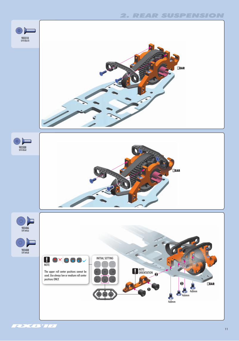
903408SFH M4x8
903406SFH M4x6
INITIAL SETTING
2. REAR SUSPENSION
903308SFH M3x8
NOTEORIENTATION
4x8mm
4x8mm4x6mm
The upper roll center positions cannot be used. Use always low or medium roll center positions ONLY.
NOTE
903310SFH M3x10
12
903408SFH M4x8
INITIAL SETTING
TIGHTEN FULLYset-screw M3x6 onto flatspot
NOTE ORIENTATION
2x
DETAIL
DETAIL
INITIAL SETTING
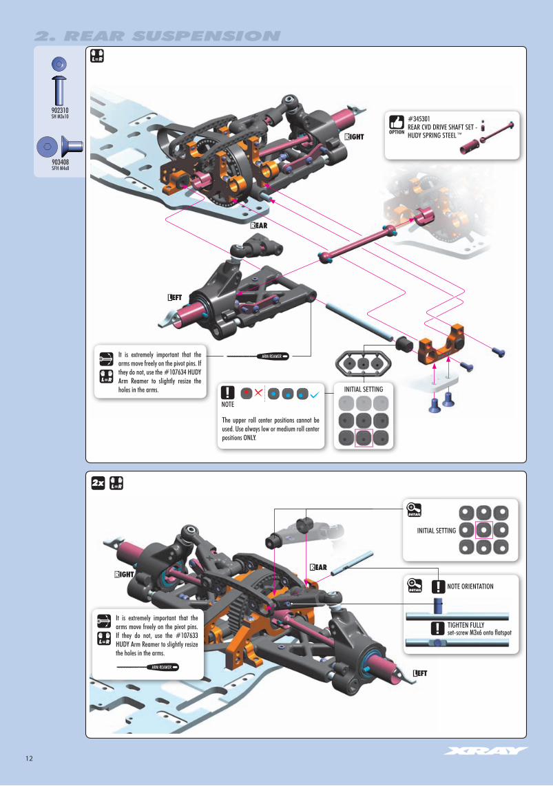
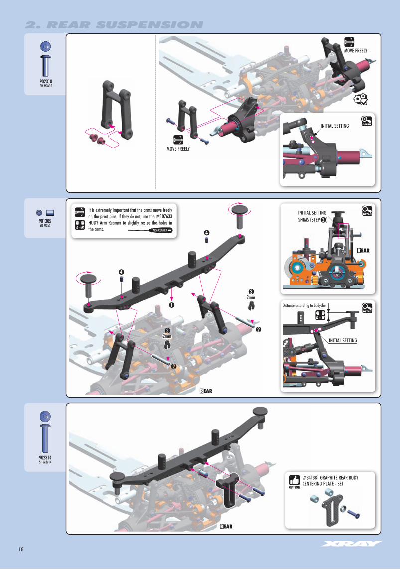
It is extremely important that the arms move freely on the pivot pins. If they do not, use the #107634 HUDY Arm Reamer to slightly resize the holes in the arms.
It is extremely important that the arms move freely on the pivot pins. If they do not, use the #107633 HUDY Arm Reamer to slightly resize the holes in the arms.
#345301REAR CVD DRIVE SHAFT SET - HUDY SPRING STEEL™
The upper roll center positions cannot be used. Use always low or medium roll center positions ONLY.
NOTE
902310SH M3x10
ARM REAMER
ARM REAMER
2. REAR SUSPENSION
13
940508BB 5x8x2.5
940815BB 8x14x4
296530-ON M3
303123-OSHIM 3x6x2
902322SH M3x22
FIBRE PADS FACE TOGETHER
3x6x2mm
3x6x2mm
10mm
DETAIL
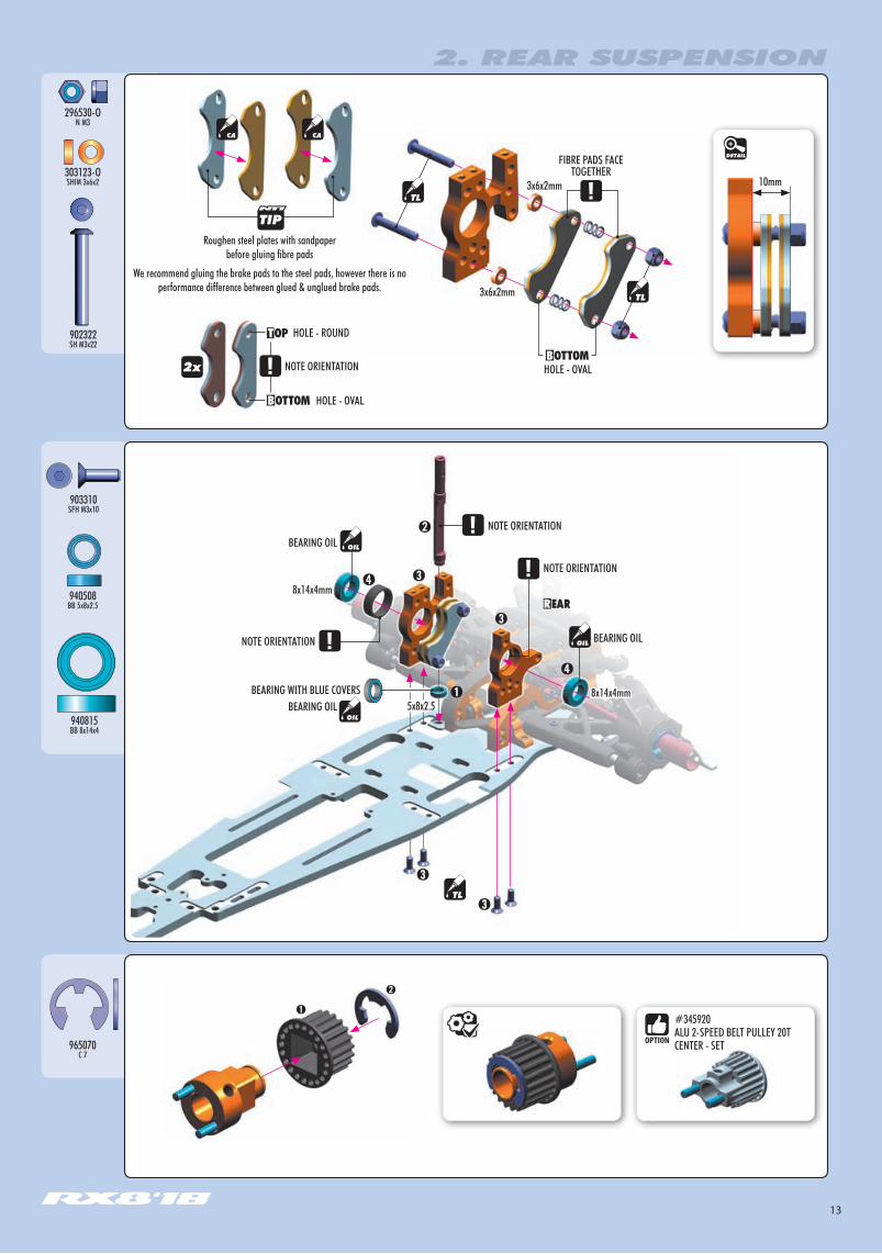
Roughen steel plates with sandpaper before gluing fibre pads
We recommend gluing the brake pads to the steel pads, however there is no performance difference between glued & unglued brake pads.
NOTE ORIENTATION
HOLE - OVAL
HOLE - OVAL
HOLE - ROUND
2. REAR SUSPENSION
965070C 7
➊
➋
#345920ALU 2-SPEED BELT PULLEY 20T CENTER - SET
903310SFH M3x10
NOTE ORIENTATION
NOTE ORIENTATION
NOTE ORIENTATION BEARING OIL
BEARING OIL
8x14x4mm
8x14x4mm
5x8x2.5BEARING WITH BLUE COVERS
BEARING OIL

14
903308SFH M3x8
901405SB M4x5
902314SH M3x14
➊
➍
NOTE ORIENTATION
➌
Tighten set-screw onto flat spot.➍STEP DETAIL
DETAIL
BEARING OIL
Pin must protrude equally on both sides of camshaft
940508BB 5x8x2.5
981208P 2x8
902308SH M3x8
902306SH M3x6
901303SB M3x3
#344111VENTILATED BRAKE DISC - PRECISION - GROUND - LIGHTWEIGHT
2. REAR SUSPENSION
3x8mm 3x8mm3x3mm
3x6mm
3x6mm
These screws are part of theREAR SUSPENSION MULTI-FLEX™ TECHNOLOGY(see page 15)
BEARING WITH BLUE COVERS

15
303130-OSHIM 3x6x9
902320SH M3x20
2. REAR SUSPENSION
Graphite brace and posts are not used. This allows maximum flex of the rear suspension and generates maximum rear traction. Recommended for low-traction tracks.
Graphite brace connected to 2-speed bulkheads without posts. This slightly reduces the flex of the rear suspension and improves out-of-corner steering and rotation of the car, but also slightly decreases rear traction. Recommended for medium-traction tracks.
The all-new rear suspension design features Multi-Flex™ quick adjustment to easily adapt the handling of the car to particular track conditions and tires used. There are 3 different flex characteristics to choose from.
Graphite brace connected to 2-speed bulkheads with posts. This connects the entire rear suspension together, creating a stiff frame which allows the car to rotate more and improves out-of-corner steering. Recommended for high-traction tracks.
(INITIAL SETTING)
ALTERNATIVE 1SOFT
ALTERNATIVE 2MEDIUM
ALTERNATIVE 3STIFF
REAR SUSPENSION MULTI-FLEX™TECHNOLOGY
3x6x9mm
3x6x9mm
16
#341381 GRAPHITE REAR BODY CENTERING PLATE - SET
26mm
DETAIL
DETAIL
2. REAR SUSPENSION
BAG
902314
901303
940508
362650
302080
901305
341370
341360
902310
302291302291
341380
341331
347330
902310
302663
901304
333461
343458
02.3
901305
341360
901303940508
343481-K
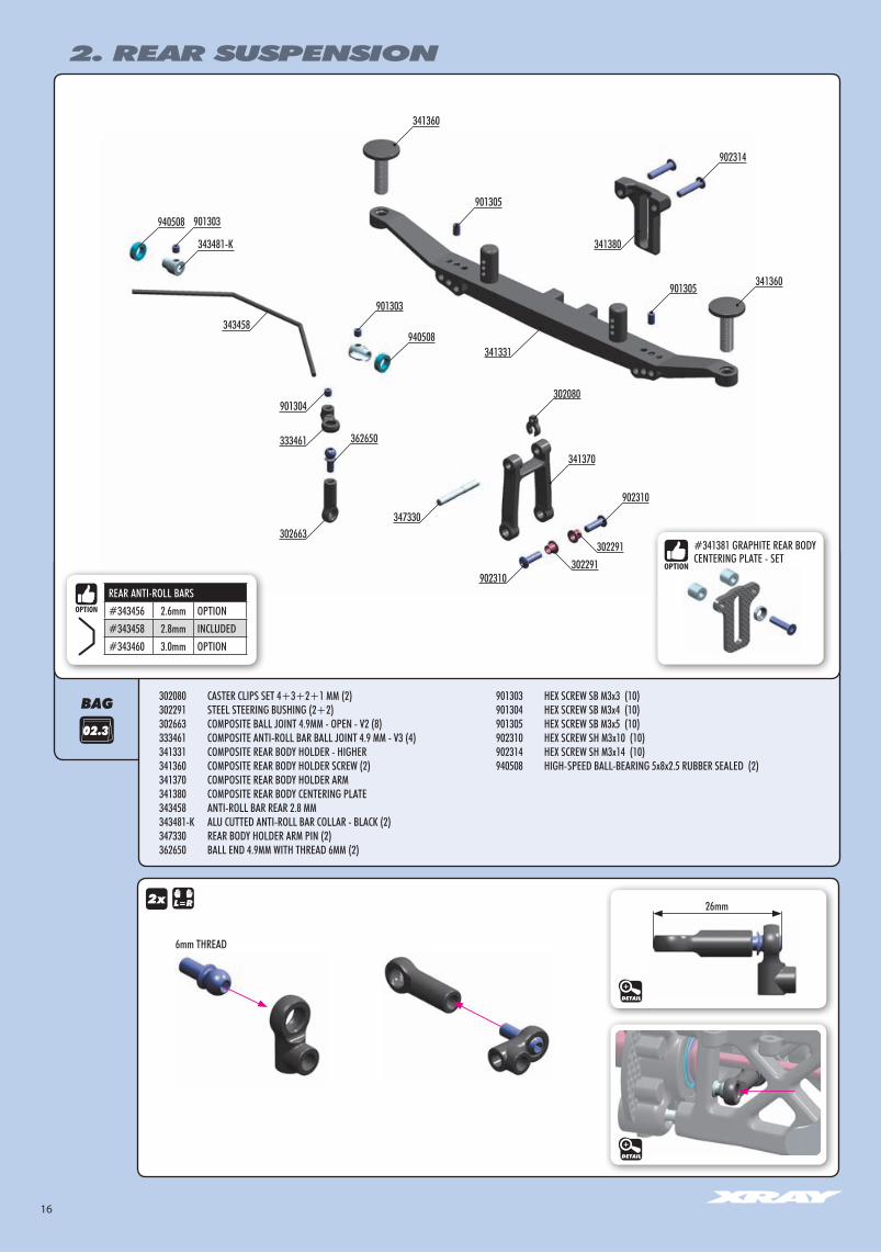
302080 CASTER CLIPS SET 4+3+2+1 MM (2)302291 STEEL STEERING BUSHING (2+2)302663 COMPOSITE BALL JOINT 4.9MM - OPEN - V2 (8)333461 COMPOSITE ANTI-ROLL BAR BALL JOINT 4.9 MM - V3 (4)341331 COMPOSITE REAR BODY HOLDER - HIGHER341360 COMPOSITE REAR BODY HOLDER SCREW (2)341370 COMPOSITE REAR BODY HOLDER ARM341380 COMPOSITE REAR BODY CENTERING PLATE343458 ANTI-ROLL BAR REAR 2.8 MM343481-K ALU CUTTED ANTI-ROLL BAR COLLAR - BLACK (2)347330 REAR BODY HOLDER ARM PIN (2)362650 BALL END 4.9MM WITH THREAD 6MM (2)
901303 HEX SCREW SB M3x3 (10)901304 HEX SCREW SB M3x4 (10)901305 HEX SCREW SB M3x5 (10)902310 HEX SCREW SH M3x10 (10)902314 HEX SCREW SH M3x14 (10)940508 HIGH-SPEED BALL-BEARING 5x8x2.5 RUBBER SEALED (2)
REAR ANTI-ROLL BARS#343456 2.6mm OPTION#343458 2.8mm INCLUDED#343460 3.0mm OPTION
6mm THREAD
17
940508BB 5x8x2.5
BEARING OIL
BEARING OIL
901303SB M3x3
901304SB M3x4
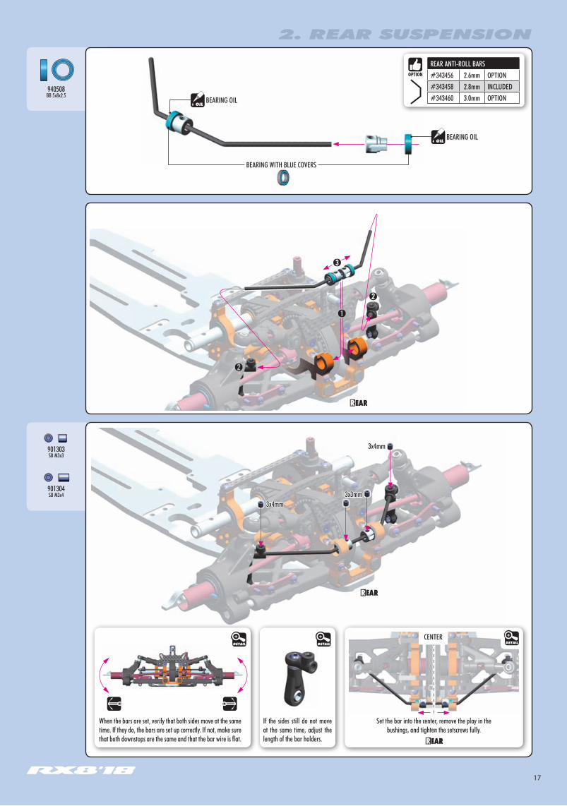
When the bars are set, verify that both sides move at the same time. If they do, the bars are set up correctly. If not, make sure that both downstops are the same and that the bar wire is flat.
If the sides still do not move at the same time, adjust the length of the bar holders.
3x4mm
3x4mm
3x3mm
Set the bar into the center, remove the play in the bushings, and tighten the setscrews fully.
CENTERDETAILDETAILDETAIL
REAR ANTI-ROLL BARS#343456 2.6mm OPTION#343458 2.8mm INCLUDED#343460 3.0mm OPTION
2. REAR SUSPENSION
BEARING WITH BLUE COVERS
18
902310SH M3x10
DETAIL
901305SB M3x5
902314SH M3x14
DETAIL
DETAIL
2. REAR SUSPENSION
INITIAL SETTING
INITIAL SETTING
INITIAL SETTING
2mm
2mm
Distance according to bodyshell
SHIMS (STEP )
#341381 GRAPHITE REAR BODY CENTERING PLATE - SET
It is extremely important that the arms move freely on the pivot pins. If they do not, use the #107633 HUDY Arm Reamer to slightly resize the holes in the arms. ARM REAMER
MOVE FREELY
MOVE FREELY
19
3. REAR TRANSMISSION
BAG
345592-KALU SHIM 8x10x1.5
980314P 3x14
965070C 7
ALU Shims 8x10x1.5mm
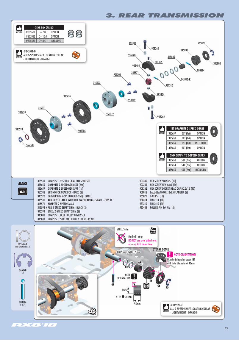
335540 COMPOSITE 2-SPEED GEAR BOX SHOE SET 335655 GRAPHITE 2-SPEED GEAR 55T (2nd)335659 GRAPHITE 2-SPEED GEAR 59T (1st)335582 SPRING FOR GEAR BOX - HARD (2)345522 CARRIER FOR 2-SPEED GEAR (2nd) - SMALL345531 ALU DRIVE FLANGE WITH ONE-WAY BEARING - SMALL - 7075 T6345571 ADAPTER 2-SPEED SMALL345592-K ALU 2-SPEED SHAFT SHIM - BLACK (2)345593 STEEL 2-SPEED SHAFT SHIM (2)345800 COMPOSITE BELT PULLEY COVER SET345838 COMPOSITE SIDE BELT PULLEY 18T ø8 - REAR
901305 HEX SCREW SB M3x5 (10)903306 HEX SCREW SFH M3x6 (10)908262 HEX SCREW SOCKET HEAD CAP M2.5x12 (10)950812 BALL-BEARING 8x12x3.5 FLANGED (2)965070 E-CLIP 7 (10)980314 PIN 3x14 (10)981310 PIN 3x10 (10) 983404 ROLLER PIN 4x4 MM (2)
901305
950812
965070
983404
980314
345592-K
981310
345800
908262
#345591-OALU 2-SPEED SHAFT LOCATING COLLAR - LIGHTWEIGHT - ORANGE
908262
345593
335659345531
903306
335655
950812
345522
903306 345571
983404
335540
345838
965070335582
345800
➊
➋
NOTEORIENTATION
➌ ➍➏
➎
Use the belt pulley cover 18T with hole diameter of 10mm
7.5mm
8mm
➌STEP DETAIL
STEP DETAIL➊
NOTE ORIENTATION
18
#345591-OALU 2-SPEED SHAFT LOCATING COLLAR - LIGHTWEIGHT - ORANGE
GEAR BOX SPRING#335581 C=7.8 OPTION#335582 C=10.4 OPTION#335583 C=8.5 INCLUDED
1ST GRAPHITE 2-SPEED GEARS335657 57T (1st) OPTION335658 58T (1st) OPTION335659 59T (1st) INCLUDED335660 60T (1st) OPTION
2ND GRAPHITE 2-SPEED GEARS335653 53T (2nd) OPTION335654 54T (2nd) OPTION335655 55T (2nd) INCLUDED
STEEL ShimDETAIL
Marked 1 stripDO NOT use steel shim here; use only ALU shims here.
20
3. REAR TRANSMISSION
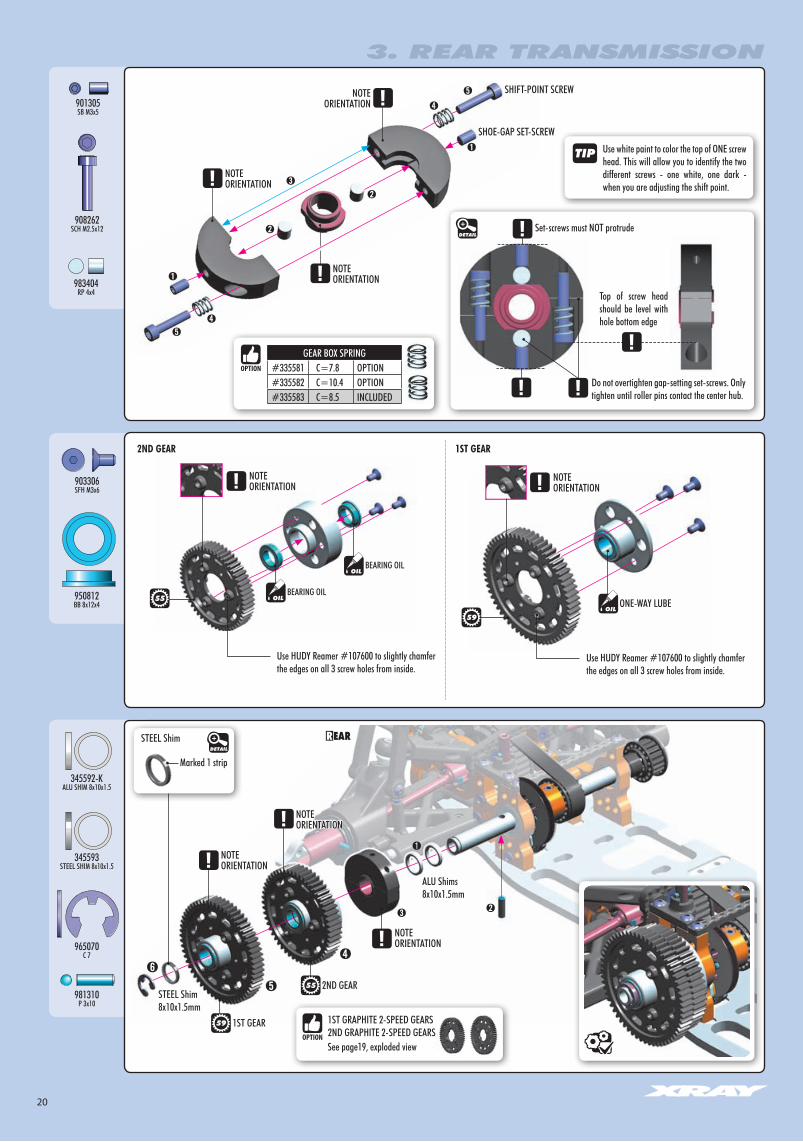
965070C 7
981310P 3x10
345592-KALU SHIM 8x10x1.5
345593STEEL SHIM 8x10x1.5
901305SB M3x5
908262SCH M2.5x12
983404RP 4x4
➊
➊
➋
➋
➌
➍
➍
➎
➎
NOTEORIENTATION
NOTEORIENTATION
NOTEORIENTATION
Use white paint to color the top of ONE screw head. This will allow you to identify the two different screws - one white, one dark - when you are adjusting the shift point.
SHIFT-POINT SCREW
SHOE-GAP SET-SCREW
Set-screws must NOT protrude
Top of screw head should be level with hole bottom edge
Do not overtighten gap-setting set-screws. Only tighten until roller pins contact the center hub.
903306SFH M3x6
950812BB 8x12x4
NOTEORIENTATION
2ND GEAR 1ST GEAR
NOTEORIENTATION
ONE-WAY LUBEBEARING OIL
BEARING OIL
Use HUDY Reamer #107600 to slightly chamfer the edges on all 3 screw holes from inside.
Use HUDY Reamer #107600 to slightly chamfer the edges on all 3 screw holes from inside.
55
59
DETAIL
ALU Shims8x10x1.5mm
STEEL Shim8x10x1.5mm
STEEL ShimDETAIL
2ND GEAR
1ST GEAR
NOTEORIENTATION
NOTEORIENTATION
NOTEORIENTATION
➊
➋➌
55
59 1ST GRAPHITE 2-SPEED GEARS2ND GRAPHITE 2-SPEED GEARSSee page19, exploded view
GEAR BOX SPRING#335581 C=7.8 OPTION#335582 C=10.4 OPTION#335583 C=8.5 INCLUDED
Marked 1 strip
21
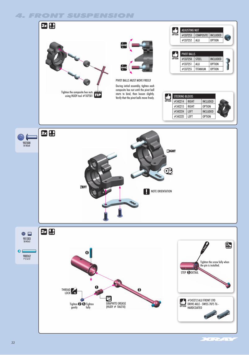
4. FRONT SUSPENSION
BAG
04.1
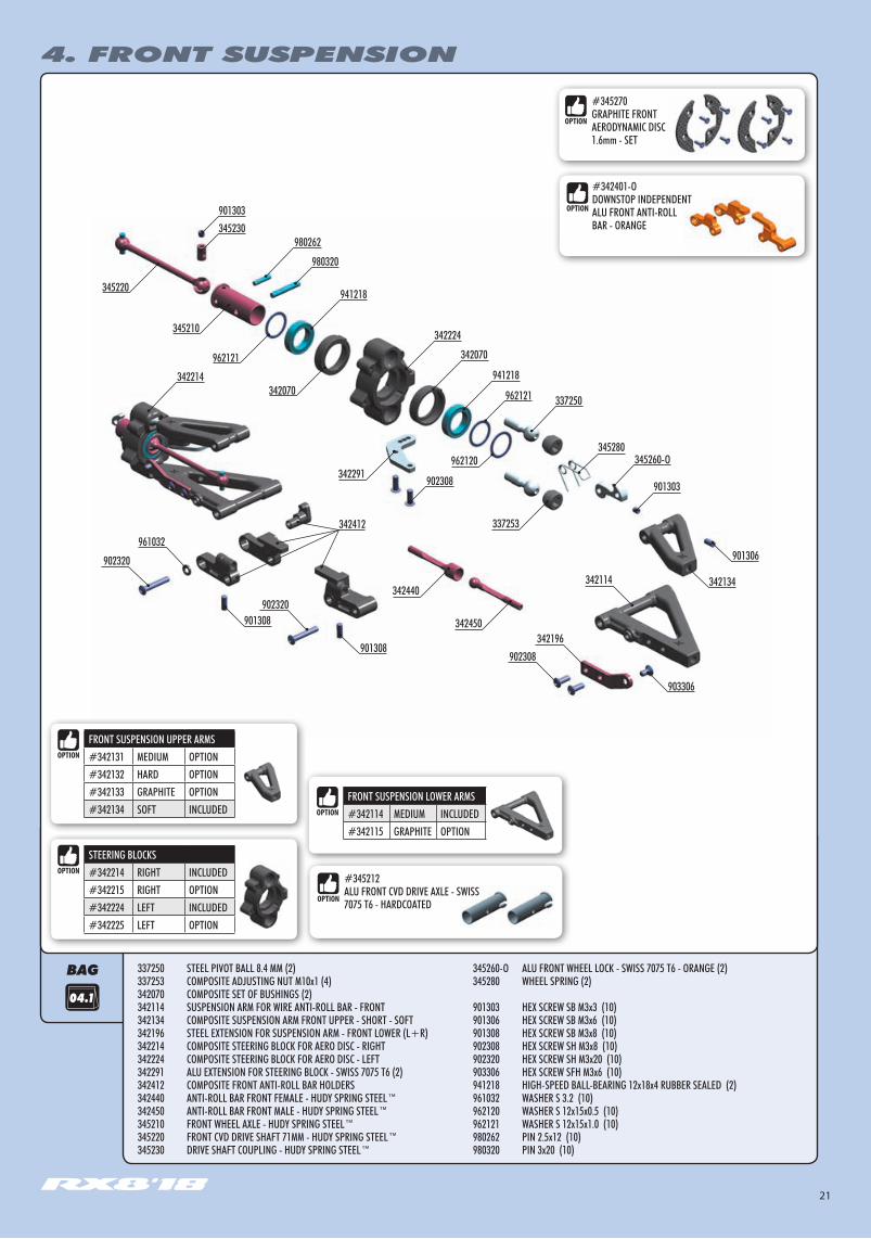
337250 STEEL PIVOT BALL 8.4 MM (2)337253 COMPOSITE ADJUSTING NUT M10x1 (4)342070 COMPOSITE SET OF BUSHINGS (2)342114 SUSPENSION ARM FOR WIRE ANTI-ROLL BAR - FRONT342134 COMPOSITE SUSPENSION ARM FRONT UPPER - SHORT - SOFT342196 STEEL EXTENSION FOR SUSPENSION ARM - FRONT LOWER (L+R)342214 COMPOSITE STEERING BLOCK FOR AERO DISC - RIGHT342224 COMPOSITE STEERING BLOCK FOR AERO DISC - LEFT342291 ALU EXTENSION FOR STEERING BLOCK - SWISS 7075 T6 (2)342412 COMPOSITE FRONT ANTI-ROLL BAR HOLDERS342440 ANTI-ROLL BAR FRONT FEMALE - HUDY SPRING STEEL™342450 ANTI-ROLL BAR FRONT MALE - HUDY SPRING STEEL™345210 FRONT WHEEL AXLE - HUDY SPRING STEEL™345220 FRONT CVD DRIVE SHAFT 71MM - HUDY SPRING STEEL™345230 DRIVE SHAFT COUPLING - HUDY SPRING STEEL™
345260-O ALU FRONT WHEEL LOCK - SWISS 7075 T6 - ORANGE (2)345280 WHEEL SPRING (2)
901303 HEX SCREW SB M3x3 (10)901306 HEX SCREW SB M3x6 (10)901308 HEX SCREW SB M3x8 (10)902308 HEX SCREW SH M3x8 (10)902320 HEX SCREW SH M3x20 (10)903306 HEX SCREW SFH M3x6 (10)941218 HIGH-SPEED BALL-BEARING 12x18x4 RUBBER SEALED (2)961032 WASHER S 3.2 (10)962120 WASHER S 12x15x0.5 (10)962121 WASHER S 12x15x1.0 (10)980262 PIN 2.5x12 (10)980320 PIN 3x20 (10)
901303345230
980262
941218
342412
342224
342214 941218
345260-O
337253
901303902308342291
342196
980320
345280
961032
902320
902320
962121
342070
342070
962121
345210
901308
901308
337250
345220
902308
903306
342134
901306
342114342440
342450
962120
#345270GRAPHITE FRONT AERODYNAMIC DISC 1.6mm - SET
#342401-ODOWNSTOP INDEPENDENT ALU FRONT ANTI-ROLL BAR - ORANGE
#345212ALU FRONT CVD DRIVE AXLE - SWISS 7075 T6 - HARDCOATED
FRONT SUSPENSION LOWER ARMS#342114 MEDIUM INCLUDED#342115 GRAPHITE OPTION
STEERING BLOCKS#342214 RIGHT INCLUDED#342215 RIGHT OPTION#342224 LEFT INCLUDED#342225 LEFT OPTION
FRONT SUSPENSION UPPER ARMS#342131 MEDIUM OPTION#342132 HARD OPTION#342133 GRAPHITE OPTION#342134 SOFT INCLUDED
22
4. FRONT SUSPENSION
902308SH M3x8
Tighten gently
Tighten fully
THREAD LOCK
GRAPHITE GREASE(HUDY # 106210)
2x
2x
901303SB M3x3
980262P 2.5x12
Tighten the screw fully when the pin is installed.
DETAILSTEP
1.5mm DETAIL
#345212 ALU FRONT CVD DRIVE AXLE - SWISS 7075 T6 - HARDCOATED
PIVOT BALLS MUST MOVE FREELY
During initial assembly, tighten each composite hex nut until the pivot ball starts to bind, then loosen slightly. Verify that the pivot balls move freely.
Tighten the composite hex nuts using HUDY tool #107581
2x
PIVOT BALLS#337250 STEEL INCLUDED#337251 ALU OPTION#337255 TITANIUM OPTION
ADJUSTING NUT#337253 COMPOSITE INCLUDED#337252 ALU OPTION
STEERING BLOCKS#342214 RIGHT INCLUDED#342215 RIGHT OPTION#342224 LEFT INCLUDED#342225 LEFT OPTION
NOTE ORIENTATION
23
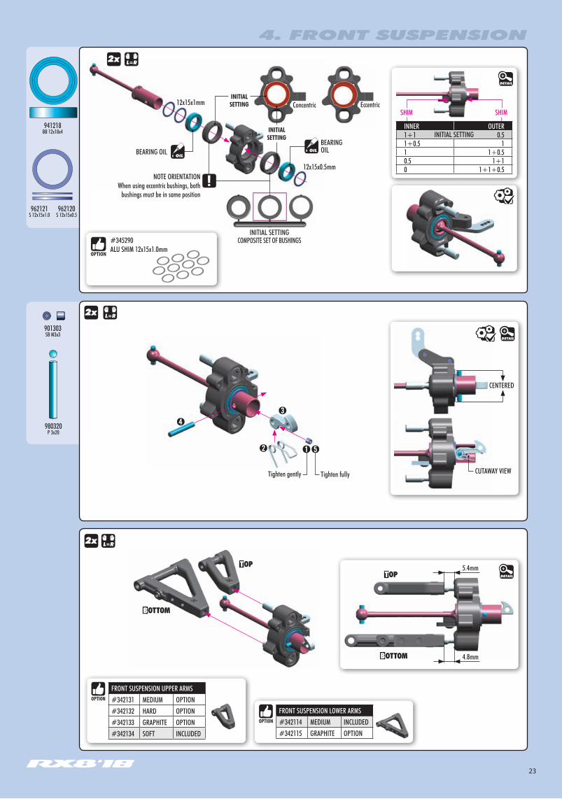
4. FRONT SUSPENSION
COMPOSITE SET OF BUSHINGSINITIAL SETTING
2x
CENTERED
CUTAWAY VIEW
2x
901303SB M3x3
980320P 3x20
Tighten gently Tighten fully
BEARING OILBEARING OIL
12x15x0.5mm
12x15x1mm
NOTE ORIENTATIONWhen using eccentric bushings, both
bushings must be in same position
ConcentricINITIALSETTING
INITIALSETTING
EccentricSHIM SHIM
962120S 12x15x0.5
962121S 12x15x1.0
941218BB 12x18x4
DETAIL
DETAIL
INNER OUTER1+1 0.51+0.5 11 1+0.50.5 1+10 1+1+0.5
INITIAL SETTING
#345290ALU SHIM 12x15x1.0mm
2x
5.4mm
4.8mm
DETAIL
FRONT SUSPENSION LOWER ARMS#342114 MEDIUM INCLUDED#342115 GRAPHITE OPTION
FRONT SUSPENSION UPPER ARMS#342131 MEDIUM OPTION#342132 HARD OPTION#342133 GRAPHITE OPTION#342134 SOFT INCLUDED
24
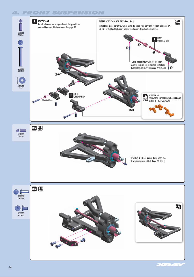
4. FRONT SUSPENSION
902308SH M3x8
903306SFH M3x6
2x
TIGHTEN GENTLY, tighten fully when the drive pins are assembled. (Page 29, step 1)
901308SB M3x8
901306SB M3x6
961032S 3.2
902320SH M3x20
ALTERNATIVE 2: BLADE ANTI-ROLL BAR
2x
1. Pre-thread mount with the set-screw. 2. After anti-roll bar is inserted, install and tighten the set-screw. (see page 27 / step 1)
Install these blade parts ONLY when using the blade-type front anti-roll bar. See page 27.DO NOT install the blade parts when using the wire-type front anti-roll bar.
IMPORTANTInstall all mount parts, regardless of the type of front anti-roll bar used (blade or wire). See page 27.
3.2x6.7x0.5mm
NOTEORIENTATION
NOTEORIENTATION
DETAIL
DETAIL
#342401-ODOWNSTOP INDEPENDENT ALU FRONT ANTI-ROLL BAR - ORANGE
25
BAG
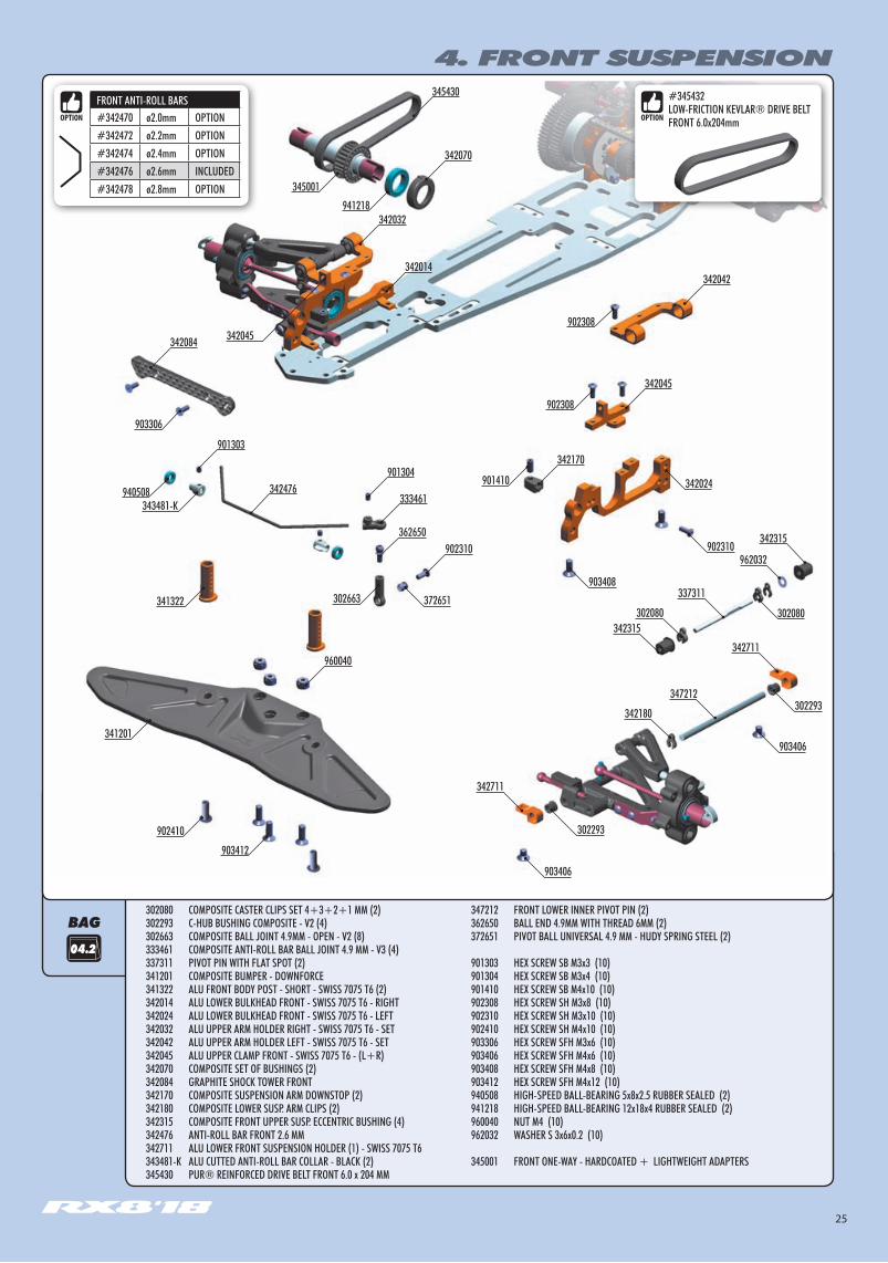
4. FRONT SUSPENSION
04.2
302080 COMPOSITE CASTER CLIPS SET 4+3+2+1 MM (2)302293 C-HUB BUSHING COMPOSITE - V2 (4)302663 COMPOSITE BALL JOINT 4.9MM - OPEN - V2 (8)333461 COMPOSITE ANTI-ROLL BAR BALL JOINT 4.9 MM - V3 (4)337311 PIVOT PIN WITH FLAT SPOT (2)341201 COMPOSITE BUMPER - DOWNFORCE341322 ALU FRONT BODY POST - SHORT - SWISS 7075 T6 (2)342014 ALU LOWER BULKHEAD FRONT - SWISS 7075 T6 - RIGHT342024 ALU LOWER BULKHEAD FRONT - SWISS 7075 T6 - LEFT342032 ALU UPPER ARM HOLDER RIGHT - SWISS 7075 T6 - SET342042 ALU UPPER ARM HOLDER LEFT - SWISS 7075 T6 - SET342045 ALU UPPER CLAMP FRONT - SWISS 7075 T6 - (L+R)342070 COMPOSITE SET OF BUSHINGS (2)342084 GRAPHITE SHOCK TOWER FRONT342170 COMPOSITE SUSPENSION ARM DOWNSTOP (2)342180 COMPOSITE LOWER SUSP. ARM CLIPS (2)342315 COMPOSITE FRONT UPPER SUSP. ECCENTRIC BUSHING (4)342476 ANTI-ROLL BAR FRONT 2.6 MM342711 ALU LOWER FRONT SUSPENSION HOLDER (1) - SWISS 7075 T6 343481-K ALU CUTTED ANTI-ROLL BAR COLLAR - BLACK (2)345430 PUR® REINFORCED DRIVE BELT FRONT 6.0 x 204 MM
347212 FRONT LOWER INNER PIVOT PIN (2)362650 BALL END 4.9MM WITH THREAD 6MM (2)372651 PIVOT BALL UNIVERSAL 4.9 MM - HUDY SPRING STEEL (2)
901303 HEX SCREW SB M3x3 (10)901304 HEX SCREW SB M3x4 (10)901410 HEX SCREW SB M4x10 (10)902308 HEX SCREW SH M3x8 (10)902310 HEX SCREW SH M3x10 (10)902410 HEX SCREW SH M4x10 (10)903306 HEX SCREW SFH M3x6 (10)903406 HEX SCREW SFH M4x6 (10)903408 HEX SCREW SFH M4x8 (10)903412 HEX SCREW SFH M4x12 (10)940508 HIGH-SPEED BALL-BEARING 5x8x2.5 RUBBER SEALED (2)941218 HIGH-SPEED BALL-BEARING 12x18x4 RUBBER SEALED (2)960040 NUT M4 (10)962032 WASHER S 3x6x0.2 (10)
345001 FRONT ONE-WAY - HARDCOATED + LIGHTWEIGHT ADAPTERS
342084
342476901304
902310
960040
901303
333461
362650902310
342170
342070
345430
372651 337311
347212
302080
342180
342315
940508
341201
902410
903412
903406
903406
302293
302293
343481-K
903306
302663
902308
902308
901410
903408
345001
941218
342711
342711
342024
342042
342032
342014
342045
342045
341322302080
342315
FRONT ANTI-ROLL BARS#342470 ø2.0mm OPTION#342472 ø2.2mm OPTION#342474 ø2.4mm OPTION#342476 ø2.6mm INCLUDED#342478 ø2.8mm OPTION
#345432LOW-FRICTION KEVLAR® DRIVE BELT FRONT 6.0x204mm
962032

26
941218BB 12x18x4
902308SH M3x8
DETAIL
DETAIL
DETAIL
2x
2x
4. FRONT SUSPENSION
902310SH M3x10
901410SB M4x10
903408SFH M4x8
903306SFH M3x6
NOTEORIENTATION
NOTEORIENTATION
NOTEORIENTATION
NOTEORIENTATION
NOTEORIENTATION
NOTEORIENTATION
NOTEORIENTATION
NOTEORIENTATION
NOTEORIENTATION
NOTEORIENTATION BEARING OIL
BEARING OIL
Both bushings must be in same position
COMPOSITE SET OF BUSHINGSINITIAL SETTING
3.5mm
#345432LOW FRICTION KEVLAR DRIVE BELT FRONT 6.0x204mm
27
NOTE ORIENTATION
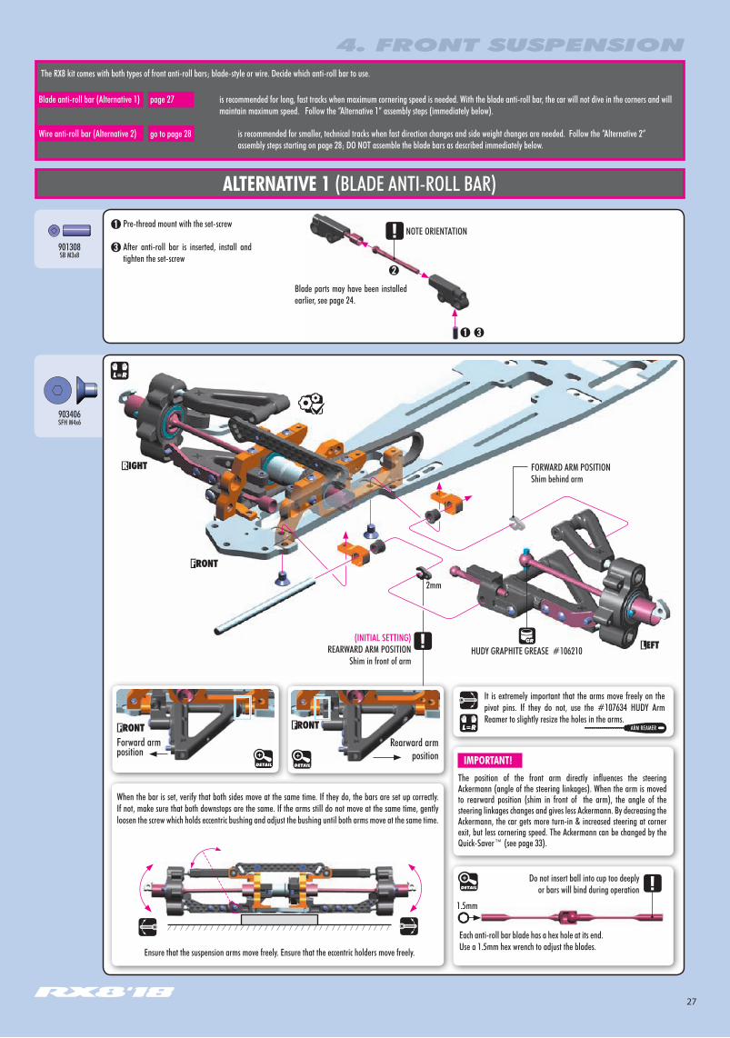
The RX8 kit comes with both types of front anti-roll bars; blade-style or wire. Decide which anti-roll bar to use.
Pre-thread mount with the set-screw
After anti-roll bar is inserted, install and tighten the set-screw
Blade parts may have been installed earlier, see page 24.
ALTERNATIVE 1 (BLADE ANTI-ROLL BAR)
is recommended for long, fast tracks when maximum cornering speed is needed. With the blade anti-roll bar, the car will not dive in the corners and will maintain maximum speed. Follow the “Alternative 1“ assembly steps (immediately below).
is recommended for smaller, technical tracks when fast direction changes and side weight changes are needed. Follow the “Alternative 2“ assembly steps starting on page 28; DO NOT assemble the blade bars as described immediately below.
Blade anti-roll bar (Alternative 1)
Wire anti-roll bar (Alternative 2)
DETAIL
HUDY GRAPHITE GREASE #106210
It is extremely important that the arms move freely on the pivot pins. If they do not, use the #107634 HUDY Arm Reamer to slightly resize the holes in the arms.
ARM REAMER
page 27
go to page 28
4. FRONT SUSPENSION
901308SB M3x8
Do not insert ball into cup too deeply or bars will bind during operation
Each anti-roll bar blade has a hex hole at its end. Use a 1.5mm hex wrench to adjust the blades.
1.5mm
903406SFH M4x6
2mm
Rearward arm position
DETAIL
Forward armposition
DETAIL
(INITIAL SETTING)REARWARD ARM POSITION
Shim in front of arm
FORWARD ARM POSITIONShim behind arm
Ensure that the suspension arms move freely. Ensure that the eccentric holders move freely.
When the bar is set, verify that both sides move at the same time. If they do, the bars are set up correctly. If not, make sure that both downstops are the same. If the arms still do not move at the same time, gently loosen the screw which holds eccentric bushing and adjust the bushing until both arms move at the same time.
The position of the front arm directly influences the steering Ackermann (angle of the steering linkages). When the arm is moved to rearward position (shim in front of the arm), the angle of the steering linkages changes and gives less Ackermann. By decreasing the Ackermann, the car gets more turn-in & increased steering at corner exit, but less cornering speed. The Ackermann can be changed by the Quick-Saver™ (see page 33).
IMPORTANT!

28
28mm
ALTERNATIVE 2 (WIRE ANTI-ROLL BAR)
HUDY GRAPHITE GREASE #106210
INITIAL SETTING
902308SH M3x8
4. FRONT SUSPENSION
2mm
(INITIAL SETTING)REARWARD ARM POSITION
Shim in front of arm
FORWARD ARM POSITIONShim behind arm.
The position of the front arm directly influences the steering Ackermann (angle of the steering linkages). When the arm is moved to rearward position (shim in front of the arm), the angle of the steering linkages changes and gives less Ackermann. By decreasing the Ackermann, the car gets more turn-in & increased steering at corner exit, but less cornering speed. The Ackermann can be changed by the Quick-Saver™ (see page 33).
IMPORTANT!
4mm
2mm3x6x0.2mm
1mm
COMPOSITE SET OF BUSHINGS
(INITIAL SETTING)Use 0mm suspension holders
NOTEORIENTATION
Rearwardarm position
DETAIL
Forward armposition
DETAIL
6mm THREAD
903406SFH M4x6
It is extremely important that the arms move freely on the pivot pins. If they do not, use the #107634 HUDY Arm Reamer to slightly resize the holes in the arms.
ARM REAMER
962032SHIM 3x6x0.2
This shim should be used ONLY with the SOFT arm included in the kit.
When using other optional arms - medium, hard, or graphite - DO NOT use this shim.
FRONT SUSPENSION UPPER ARMSMEDIUM OPTIONHARD OPTIONGRAPHITE OPTIONSOFT INCLUDED
DO NOT use 0.2mm shim
USE this shim
DO NOT use 0.2mm shim
DO NOT use 0.2mm shim

29
940508BB 5x8x2.5
BEARING OILBEARING OIL
902310SH M3x10
FRONT ANTI-ROLL BARS#342470 ø2.0mm OPTION#342472 ø2.2mm OPTION#342474 ø2.4mm OPTION#342476 ø2.6mm INCLUDED#342478 ø2.8mm OPTION
BEARING WITH BLUE COVERS
4. FRONT SUSPENSION
NOTE ORIENTATION
DETAIL
TIGHTEN FULLY

30
901303SB M3x3
901304SB M3x4
902410SH M4x10
903412SFH M4x12
960040N M4
If the sides still do not move at the same time, adjust the length of the bar holders.
DETAIL
4. FRONT SUSPENSION
When the bars are set, verify that both sides move at the same time. If they do, the bars are set up correctly. If not, make sure that both downstops are the same and that the bar wire is flat. If the sides still do not move at the same time, adjust the length of the bar holders.
DETAIL DETAIL
Set the bar into the center, remove the play in the bushings, and tighten the set-screws fully.
3x4mm
3x4mm3x3mm
CENTER
NOTE ORIENTATION
NOTE ORIENTATION
31
STEP DETAIL
STEP DETAIL
NOTEORIENTATION
5. FRONT TRANSMISSION
BAG
BEARING OIL
INITIAL SETTING
BEARING OIL
Use the belt pulley cover 18T with hole diameter of 9mm.
NOTEORIENTATION
940613BB 6x13x5
965050C 5
965050C 5
981262P 2.5x12
981262P 2.5x12
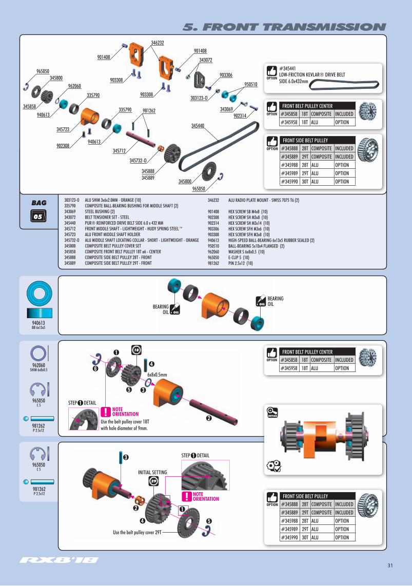
303123-O ALU SHIM 3x6x2.0MM - ORANGE (10)335790 COMPOSITE BALL-BEARING BUSHING FOR MIDDLE SHAFT (2)343069 STEEL BUSHING (2)343072 BELT TENSIONER SET - STEEL345440 PUR® REINFORCED DRIVE BELT SIDE 6.0 x 432 MM345712 FRONT MIDDLE SHAFT - LIGHTWEIGHT - HUDY SPRING STEEL™345723 ALU FRONT MIDDLE SHAFT HOLDER345732-O ALU MIDDLE SHAFT LOCATING COLLAR - SHORT - LIGHTWEIGHT - ORANGE345800 COMPOSITE BELT PULLEY COVER SET345858 COMPOSITE FRONT BELT PULLEY 18T ø6 - CENTER345888 COMPOSITE SIDE BELT PULLEY 28T - FRONT345889 COMPOSITE SIDE BELT PULLEY 29T - FRONT
346232 ALU RADIO PLATE MOUNT - SWISS 7075 T6 (2)
901408 HEX SCREW SB M4x8 (10)902308 HEX SCREW SH M3x8 (10)902314 HEX SCREW SH M3x14 (10)903306 HEX SCREW SFH M3x6 (10)903308 HEX SCREW SFH M3x8 (10)940613 HIGH-SPEED BALL-BEARING 6x13x5 RUBBER SEALED (2)950510 BALL-BEARING 5x10x4 FLANGED (2)962060 WASHER S 6x8x0.5 (10)965050 E-CLIP 5 (10)981262 PIN 2.5x12 (10)
345800
940613
940613
346232901408
303123-O
345800965050
981262
965050
343069902314
903306
950510
901408
903308
903308962060
335790
335790
343072
345712
345732-O
345888345889
902308
345723
345858
18
Use the belt pulley cover 29T
29
345440
962060SHIM 6x8x0.5
DETAIL
FRONT SIDE BELT PULLEY#345888 28T COMPOSITE INCLUDED#345889 29T COMPOSITE INCLUDED#345988 28T ALU OPTION#345989 29T ALU OPTION#345990 30T ALU OPTION
FRONT SIDE BELT PULLEY#345888 28T COMPOSITE INCLUDED#345889 29T COMPOSITE INCLUDED#345988 28T ALU OPTION#345989 29T ALU OPTION#345990 30T ALU OPTION
FRONT BELT PULLEY CENTER#345858 18T COMPOSITE INCLUDED#345958 18T ALU OPTION
FRONT BELT PULLEY CENTER#345858 18T COMPOSITE INCLUDED#345958 18T ALU OPTION
6x8x0.5mm
#345441LOW-FRICTION KEVLAR® DRIVE BELT SIDE 6.0x432mm

32
5. FRONT TRANSMISSION
TIGHTEN GENTLY
TIGHTEN GENTLY
901408SB M4x8
903308SFH M3x8
902308SH M3x8
903306SFH M3x6
303123-OSHIM 3x6x2
902314SH M3x14
950510BB 5x10x4 1. Loosen upper screw
2. Move belt tensioner as needed3. Re-tighten upper screw
TO ADJUST THE BELT TENSIONER:
STEP DETAIL
NOTEORIENTATION
NOTEORIENTATION
BEARING OIL
3x6x2mm
THREADLOCK
DETAIL
Adjust the tension of the front & side belt by moving the front middle shaft holder.
#345441LOW-FRICTION KEVLAR® DRIVE BELT SIDE 6.0x432mm

33
6. STEERING
BAG
➊ DETAILSTEP
3-4mm
3.0mm
INITIAL PRELOAD
INITIAL SETTING
THERE ARE 4 DIFFERENT ACKERMANN SETTINGS POSSIBLE WITH THE QUICK-SAVER™
STEP 1 gives the most Ackermann and makes the car understeer more into & out of corners. It offers good cornering speed and creates very good traction mainly in chicanes, because the car will be more stable.Recommended for tracks with long sweepers where a lot of cornering speed is needed.
USE ONLY ACKERMANN POSITIONS 1 OR 2.DO NOT use Ackerman positions 3 or 4; these can be used ONLY after modifying the ball joint & one-way pulley so that they do not touch.
For initial Ackermann setting, use Step 1 (2nd shortest length).
STEP 4 gives the least Ackermann and creates a lot of steering into & out of corners. However, the car is more difficult to drive in chicanes because there is less traction and stability. Recommended for tracks where a lot of in-corner steering is needed.
1 STEP OUT
4 STEPS OUT
970100O 10x1.5
901310SB M3x10
903312SFH M3x12
301159-O ALU COUNTERSUNK SHIM - ORANGE (4)302663 COMPOSITE BALL JOINT 4.9MM - OPEN - V2 (8) 303123-O ALU SHIM 3x6x2.0MM - ORANGE (10)307455 PIVOT BALL 4.9 MM DOUBLE BEVEL SHOULDERS (10) 332540 ALU SERVO SAVER ADJUSTABLE NUT332561 SERVO SAVER SPRING C=14332660 COMPOSITE STEERING & SERVO BALL JOINT 5.8 MM (4+2)333240 BALL UNIVERSAL 5.8 MM HEX (4) 342501 SERVO SAVER COMPLETE SET
342510 COMPOSITE SERVO SAVER352648 ADJ. TURNBUCKLE M3 L/R 62 MM - HUDY SPRING STEEL (2)
901310 HEX SCREW SB M3x10 (10)902308 HEX SCREW SH M3x8 (10)902310 HEX SCREW SH M3x10 (10)903312 HEX SCREW SFH M3x12 (10)940508 HIGH-SPEED BALL-BEARING 5x8x2.5 RUBBER SEALED (2)970100 O-RING 10 x 1.5 (10)
342501
342510
332561
342501
332540
903312
301159-O
342510
307455
333240
303123-O
902308
940508
901310
970100
940508
302663
352648
352648
902308
902308
333240
303123-O
332660
902310
BEARING OIL
4321
4321
4321
DETAIL
DETAIL
DETAIL
#342511-OAlu Adjustable Servo Saver - Swiss 7075 T6 - Orange
#342511-OAlu Adjustable Servo Saver - Swiss 7075 T6 - Orange

34
Install the pivot balls with Professional Multi Tool (HUDY #183011)
BALL JOINT WRENCH(HUDY #181110)
BEARING WITH BLUE COVERS
3x6x2mmBy adding shims, the car becomes
less responsive, but easier to drive.
➊
6. STEERING
NOTEORIENTATION
NOTEORIENTATION
NOTEORIENTATION
BEARING OIL
BEARING OIL
902308SH M3x8
940508BB 5x8x2.5
902310SH M3x10
902308SH M3x8
INITIAL SETTING
DETAIL
303123-OSHIM 3x6x2
NOTE ORIENTATIONNOTE ORIENTATION
42.5mm42.5mm
BEARING WITH BLUE COVERS
35
BAG
7. FUEL TANK & ELECTRONICS
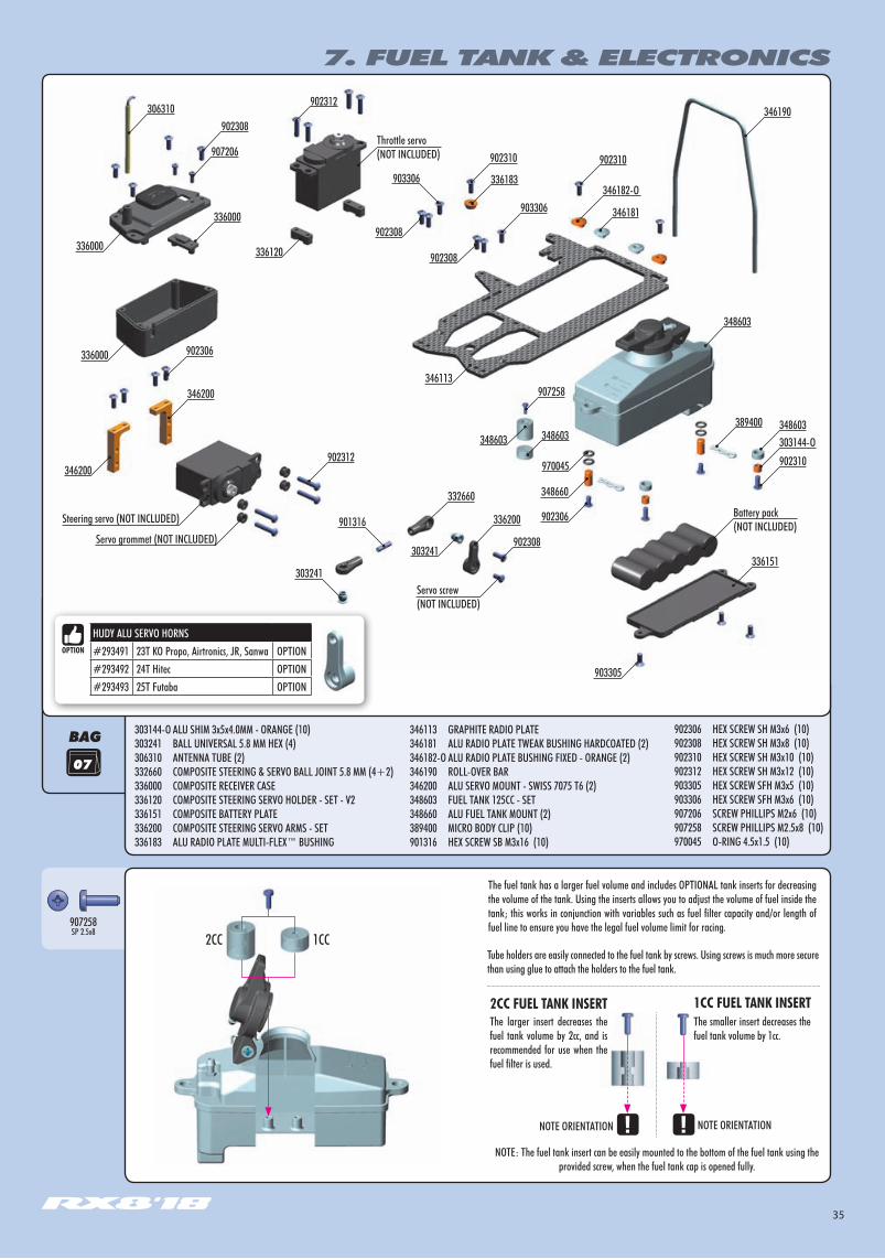
303144-O ALU SHIM 3x5x4.0MM - ORANGE (10)303241 BALL UNIVERSAL 5.8 MM HEX (4)306310 ANTENNA TUBE (2)332660 COMPOSITE STEERING & SERVO BALL JOINT 5.8 MM (4+2)336000 COMPOSITE RECEIVER CASE336120 COMPOSITE STEERING SERVO HOLDER - SET - V2336151 COMPOSITE BATTERY PLATE336200 COMPOSITE STEERING SERVO ARMS - SET336183 ALU RADIO PLATE MULTI-FLEX™ BUSHING
346113 GRAPHITE RADIO PLATE346181 ALU RADIO PLATE TWEAK BUSHING HARDCOATED (2) 346182-O ALU RADIO PLATE BUSHING FIXED - ORANGE (2)346190 ROLL-OVER BAR346200 ALU SERVO MOUNT - SWISS 7075 T6 (2)348603 FUEL TANK 125CC - SET348660 ALU FUEL TANK MOUNT (2)389400 MICRO BODY CLIP (10)901316 HEX SCREW SB M3x16 (10)
346190
902310
902308
903306
902312
332660
389400
907258
348603303144-O
902310
348603
348603
336151
336200
902306
346200
336000
902308
907206
306310902312
902310
901316
903306
346113
902308
902308336120336000
336000
346200
903305
303241
Servo screw (NOT INCLUDED)
303241
902306
970045
348603
346182-O
346181
336183
348660
Battery pack (NOT INCLUDED)
Throttle servo(NOT INCLUDED)
Steering servo (NOT INCLUDED)
Servo grommet (NOT INCLUDED)
902306 HEX SCREW SH M3x6 (10)902308 HEX SCREW SH M3x8 (10)902310 HEX SCREW SH M3x10 (10)902312 HEX SCREW SH M3x12 (10)903305 HEX SCREW SFH M3x5 (10)903306 HEX SCREW SFH M3x6 (10)907206 SCREW PHILLIPS M2x6 (10)907258 SCREW PHILLIPS M2.5x8 (10)970045 O-RING 4.5x1.5 (10)
HUDY ALU SERVO HORNS#293491 23T KO Propo, Airtronics, JR, Sanwa OPTION#293492 24T Hitec OPTION#293493 25T Futaba OPTION
NOTE: The fuel tank insert can be easily mounted to the bottom of the fuel tank using the provided screw, when the fuel tank cap is opened fully.
NOTE ORIENTATIONNOTE ORIENTATION
Tube holders are easily connected to the fuel tank by screws. Using screws is much more secure than using glue to attach the holders to the fuel tank.
The larger insert decreases the fuel tank volume by 2cc, and is recommended for use when the fuel filter is used.
The smaller insert decreases the fuel tank volume by 1cc.
1CC FUEL TANK INSERT2CC FUEL TANK INSERT
The fuel tank has a larger fuel volume and includes OPTIONAL tank inserts for decreasing the volume of the tank. Using the inserts allows you to adjust the volume of fuel inside the tank; this works in conjunction with variables such as fuel filter capacity and/or length of fuel line to ensure you have the legal fuel volume limit for racing.907258
SP 2.5x82CC 1CC

36
Use appropriate servo arm:K - (23T) = KO, JR, AirtronicsH - (24T) = Futaba,F - (25T) = Hitec
HUDY ALU SERVO HORNS#293491 23T KO Propo, Airtronics, JR, Sanwa#293492 24T Hitec#293493 25T Futaba
Use alum servo horns for more in-corner steering and better steering response.
approx. 6.0mm
Note the 90° angle difference between the ball joints
7. FUEL TANK & ELECTRONICS
For low-profile battery pack. For standard size battery pack.
3x6mm
3x6mm
3x10mm
3x5x4mm
5x8x3.5mm
5x8x3.5mm
3x5x4mm
3x10mm
1.5mm
902306SH M3x6
902310SH M3x10
902308SH M3x8
901316SB M3x16
Servo grommet(NOT INCLUDED)
Make sure that servo does not touch the bulkhead.
Servo screw (NOT INCLUDED)
THREAD LOCK
902312SH M3x12
3x12mm
3x8mm
970045O 4.5x1.5
DETAIL
ALTERNATIVE 1 ALTERNATIVE 2
DETAILDETAIL
Standard size battery packLow-profile battery pack
303144-OSHIM 3x5x4
Install the pivot balls with Professional Multi Tool (HUDY #183011)

37
3x8mm
3x8mm3x6mm
3x6mm
THREADLOCK
902306SH M3x6
7. FUEL TANK & ELECTRONICS
Servo grommet (NOT INCLUDED)
NOTEORIENTATION
NOTE
903306SFH M3x6
902310SH M3x10
902312SH M3x12
3x12mm
3x12mm
3x6mm
3x6mm
Attach steering linkage to servo saver
TIGHTEN FULLY
When big servo and/or thick servo grommets are used, the servo can touch the chassis if is mounted from the bottom of the radio plate. In this case, mount servo from the top of the radio plate.
ALTERNATE MOUNTINGon top of radio plate
INITIAL SETTINGMount servo BELOW the radio plate
3x10mm
3x10mm
902308SH M3x8
Servo arm must be perpendicular to linkage when servo is in neutral
90°
DETAIL
DETAIL
FLEX
FIXED(INITIAL SETTING)

38
7. FUEL TANK & ELECTRONICS
BATTERY PLATE#336151 COMPOSITE INCLUDED#336155 GRAPHITE OPTION#346157 BRASS (100g) OPTION
Use an appropriate receiver battery pack
Use tape to mount the receiver battery pack to the lower holder(not included).
3x8mm
3x8mm
3x8mm
3x8mm
Battery (NOT INCLUDED)
If the receiver box has 2 different-size openings for cable entry (narrow and wider), cut away the tab for the appropriate opening to allow the cables to fit properly.
902308SH M3x8
9072062x6
903305SFH M3x5
➊
➋
➌
➌
Antenna Tube
2x6mm
Receiver(NOT INCLUDED)
Route servo and transponder leads into box and seal with silicone sealant.
DETAIL
39
BAG
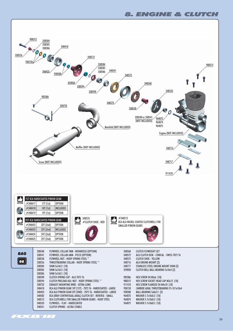
#348513 XCA ALU NICKEL-COATED CLUTCHBELL FOR SMALLER PINION GEARS
08
8. ENGINE & CLUTCH
Screw (NOT INCLUDED)
Muffler (NOT INCLUDED)
Manifold (NOT INCLUDED)
338732
348418
348512
348541348575
348560
348533
338540 or 338541 (NOT INCLUDED)
338584338585338586
338584338585338586
908312
348716
908312
Engine (NOT INCLUDED)
911410
348717
902306
338556
348423
338594
338590
348572
338550
964073964074964075
930508
359050
930150
338540 FLYWHEEL COLLAR 7MM - NOVAROSSI (OPTION)338541 FLYWHEEL COLLAR 6MM - PICCO (OPTION)338550 FLYWHEEL NUT - HUDY SPRING STEEL™338556 THRUSTBEARING COLLAR - HUDY SPRING STEEL™338584 SHIM 5x7x0.2 (10)338585 SHIM 5x7x0.3 (10)338586 SHIM 5x7x0.5 (10)338590 CLUTCH SPRING CUP - ALU 7075 T6338594 CLUTCH PRELOAD ADJ. NUT - HUDY SPRING STEEL™338732 EXHAUST MOUNTING WIRE - EXTRA-LONG348418 XCA ALU PINION GEAR 18T (1ST) - 7075 T6 - HARDCOATED - LARGE348423 XCA ALU PINION GEAR 23T (2ND) - 7075 T6 - HARDCOATED - LARGE 348502 XCA (XRAY CENTRIFUGAL-AXIAL) CLUTCH SET - REVERSE - SMALL348512 XCA CLUTCHBELL FOR SMALLER PINION GEARS - HUDY STEEL348533 FLYWHEEL - FLAT - HARDCOATED348541 CLUTCH SPRING - ULTRA-STABLE
348560 CLUTCH FLYWEIGHT SET348572 ALU CLUTCH DISK - CONICAL - SWISS 7075 T6348575 CLUTCH SHOE - YELLOW348716 ALU ENGINE MOUNT (2)348717 STAINLESS STEEL ENGINE MOUNT SHIM (2)359050 CLUTCH BELL BALL-BEARING 5x10x4 (2)
902306 HEX SCREW SH M3x6 (10)908312 HEX SCREW SOCKET HEAD CAP M3x12 (10)911410 HEX SCREW FLANGED SH M4x10 (10)930150 CARBIDE AXIAL THRUSTBEARING F5-10 5x10x4930508 BALL-BEARING 5x8x2.5 (2)964073 WASHER S 7x10x0.2 (10)964074 WASHER S 7x10x0.3 (10)964075 WASHER S 7x10x0.5 (10)
1ST XCA HARDCOATED PINION GEAR#348417 17T (1st) OPTION#348418 18T (1st) INCLUDED#348419 19T (1st) OPTION
2ST XCA HARDCOATED PINION GEAR#348422 22T (2nd) OPTION#348423 23T (2nd) INCLUDED#348424 24T (2nd) OPTION#348425 25T (2nd) OPTION
348576#CLUTCH SHOE - RED

40
Flywheel
CUTClutch weights are machined as 1 piece, with thin film connecting the pieces together. Cut the connecting film to separate the 3 shoes.
10~11mm
9.2 +0.1mm
Adjust with spring preload collar
Adjust with shims behind flywheel
8. ENGINE & CLUTCH
NOTEORIENTATION
Tighten the clutch nut using HUDY tool #107581
Use the flywheel collar that comes with your engine, or use optional XRAY collars:
#338540 – XRAY flywheel collar for Ø6mm crankshafts#338541 – XRAY flywheel collar for Ø7mm crankshafts
The flywheel collar must stay inside the flywheel.
If the flywheel collar is too long – if it is flush with the flywheel or protrudes slightly – remove a small amount of material from the end, or use an XRAY collar.
Hold the flywheel using HUDY Flywheel Tool #182010
Shim (for adjusting flywheel distance)
964073S 7x10x0.2
964074S 7x10x0.3
964075S 7x10x0.5
CORRECT INCORRECT
INITIAL POSITION FOR FLYWHEEL PINS
TECH TIP FOR EXTRA BOTTOM-END POWER
For extra bottom-end power, thread a M3x4 set-screw (#901304) into each clutch flyweight as shown. The set-screw will add more weight to the end of the flyweight which will cause the flyweight to open harder, giving more bottom-end power. This is recommended for high-traction tracks where bottom-end power is required.
After inserting the set-screw, some excess material may come out of the hole. REMOVE this excess material with a knife.
CUTAWAY VIEW
IMPORTANT!Install set-screw into free (non-pivot) end of flyweight.
M3x4#901304 NOT INCLUDED
3x
➊
➋
➌
➍
➎
➏
TECH TIP FOR RX8 CLUTCH SHOE
To ensure that the RX8 clutch shoe works properly and for a long time, it is very important to run in the clutch shoe.
Please follow these run-in steps to help ensure proper clutch operation:
Install clutch according to manual.
Check that the spring preload is not too much; for run-in process use less preload.
When you start the engine, the clutch should start engage under low RPM.If the clutch engages only under high RPM, stop the engine and loosen the spring preload collar. Repeat until the clutch engages under low RPM.
Run in the clutch shoe on the track, or on the starter box if you have only limited time.(We recommend running it in on the track.)
Run in the clutch shoe for 1 tank of fuel using a soft preload setting, and then after that slightly tighten the spring preload. DO NOT run in the clutch shoe under high RPM.
Continue this process until the clutch shoe is properly run in; this will be indicated by a dark and glossy surface colour on the top of the clutch shoe.
348576#CLUTCH SHOE - REDDETAIL
DETAIL
DETAIL
DETAIL
41
8. ENGINE & CLUTCH
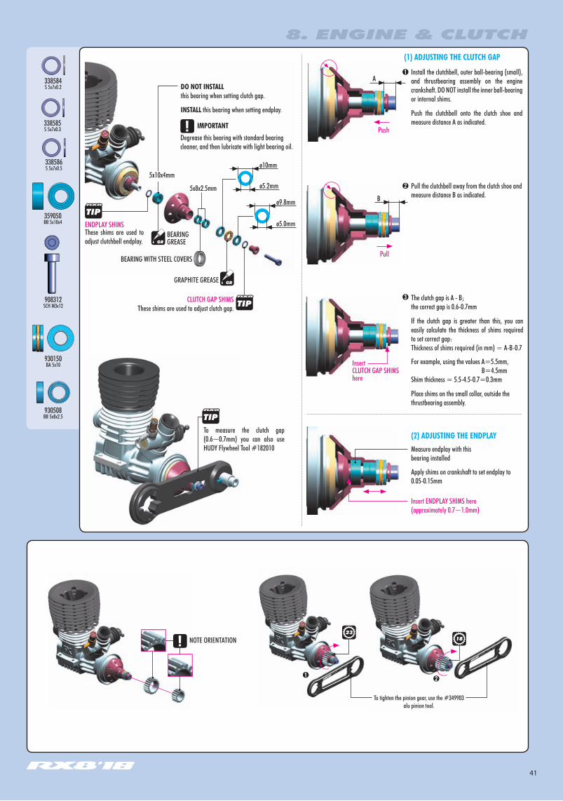
Pull the clutchbell away from the clutch shoe and measure distance B as indicated.
These shims are used to adjust clutchbell endplay.
A
Measure endplay with this bearing installed
Pull
Install the clutchbell, outer ball-bearing (small), and thrustbearing assembly on the engine crankshaft. DO NOT install the inner ball-bearing or internal shims.
Push the clutchbell onto the clutch shoe and measure distance A as indicated.
Push
B
The clutch gap is A - B; the correct gap is 0.6-0.7mm
If the clutch gap is greater than this, you can easily calculate the thickness of shims required to set correct gap:Thickness of shims required (in mm) = A-B-0.7
Apply shims on crankshaft to set endplay to 0.05-0.15mm
(1) ADJUSTING THE CLUTCH GAP
ENDPLAY SHIMS
CLUTCH GAP SHIMSThese shims are used to adjust clutch gap.
To measure the clutch gap (0.6~0.7mm) you can also use HUDY Flywheel Tool #182010
➊
➋
➌
➊➋
DO NOT INSTALL this bearing when setting clutch gap.
INSTALL this bearing when setting endplay.
(2) ADJUSTING THE ENDPLAY
ø10mm
ø5.2mm
ø9.8mm
ø5.0mm
Degrease this bearing with standard bearing cleaner, and then lubricate with light bearing oil.
IMPORTANT
NOTE ORIENTATION
InsertCLUTCH GAP SHIMS here
For example, using the values A=5.5mm, B=4.5mm Shim thickness = 5.5-4.5-0.7=0.3mm
Place shims on the small collar, outside the thrustbearing assembly.
Insert ENDPLAY SHIMS here(approximately 0.7~1.0mm)
BEARING GREASE
GRAPHITE GREASE
338584S 5x7x0.2
338585S 5x7x0.3
338586S 5x7x0.5
930150BA 5x10
930508BB 5x8x2.5
359050BB 5x10x4
908312SCH M3x12
5x10x4mm
1823
5x8x2.5mm
To tighten the pinion gear, use the #349903 alu pinion tool.
BEARING WITH STEEL COVERS
42
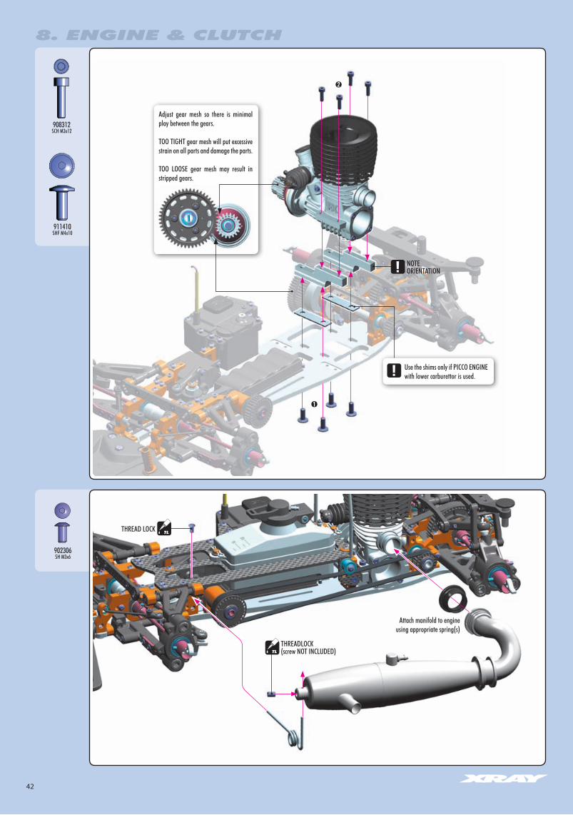
THREADLOCK(screw NOT INCLUDED)
THREAD LOCK
➊
➋
Attach manifold to engine using appropriate spring(s)
911410SHF M4x10
908312SCH M3x12
902306SH M3x6
8. ENGINE & CLUTCH
Adjust gear mesh so there is minimal play between the gears.
TOO TIGHT gear mesh will put excessive strain on all parts and damage the parts.
TOO LOOSE gear mesh may result in stripped gears.
Use the shims only if PICCO ENGINE with lower carburettor is used.
NOTEORIENTATION
43
1.01.11.2
1.01.11.2
1.0
1.1
1.2
1.01.11.2
4x
INITIAL SETTING
INITIAL SETTING2x
2x
SHOCK OIL
4x
972030O 3x2
9. SHOCK ABSORBERS
BAG
308331
308352-O
308091
303241
965023
965023
308036
338061
338021
REAR - LONG
FRONT - SHORT308040-O
DO NOT USE CROSSED-OUT PARTS
970121
348284
348185
972030
308331
308315FRONT - SHORT
333130REAR - LONG
308081
308327-O
308036
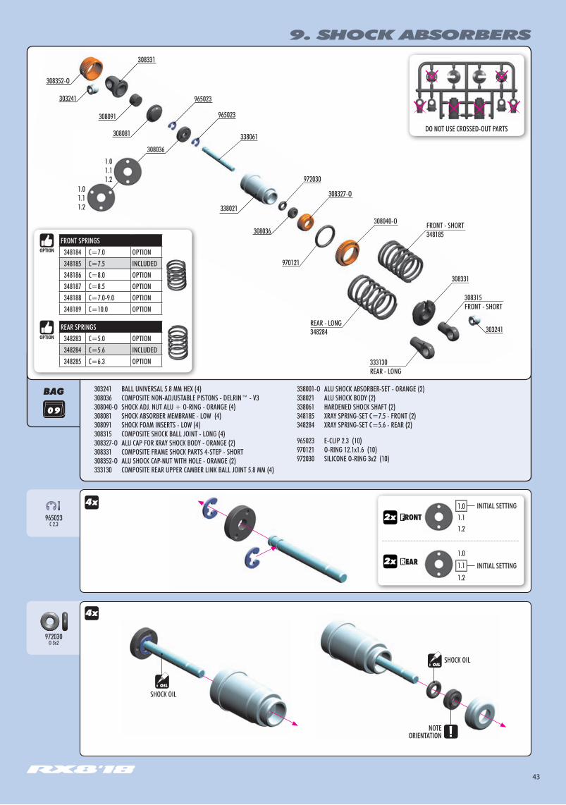
303241 BALL UNIVERSAL 5.8 MM HEX (4)308036 COMPOSITE NON-ADJUSTABLE PISTONS - DELRIN™ - V3308040-O SHOCK ADJ. NUT ALU + O-RING - ORANGE (4)308081 SHOCK ABSORBER MEMBRANE - LOW (4)308091 SHOCK FOAM INSERTS - LOW (4)308315 COMPOSITE SHOCK BALL JOINT - LONG (4)308327-O ALU CAP FOR XRAY SHOCK BODY - ORANGE (2) 308331 COMPOSITE FRAME SHOCK PARTS 4-STEP - SHORT308352-O ALU SHOCK CAP-NUT WITH HOLE - ORANGE (2)333130 COMPOSITE REAR UPPER CAMBER LINK BALL JOINT 5.8 MM (4)
338001-O ALU SHOCK ABSORBER-SET - ORANGE (2)338021 ALU SHOCK BODY (2)338061 HARDENED SHOCK SHAFT (2)348185 XRAY SPRING-SET C=7.5 - FRONT (2)348284 XRAY SPRING-SET C=5.6 - REAR (2)
965023 E-CLIP 2.3 (10) 970121 O-RING 12.1x1.6 (10) 972030 SILICONE O-RING 3x2 (10)
965023C 2.3
SHOCK OIL
NOTEORIENTATION
FRONT SPRINGS348184 C=7.0 OPTION348185 C=7.5 INCLUDED348186 C=8.0 OPTION348187 C=8.5 OPTION348188 C=7.0-9.0 OPTION348189 C=10.0 OPTION
REAR SPRINGS348283 C=5.0 OPTION348284 C=5.6 INCLUDED348285 C=6.3 OPTION
303241

44
DO NOT USE CROSSED-OUT PARTS
Install the ball joint with Professional Multi Tool (HUDY #183011)
CROSSED-OUT
CORRECT
INCORRECT
Fully extend the piston rod so the piston is at the bottom of the shock body.
Hold the shock upright and slightly overfill the shock body with shock oil.
Let the oil settle and allow air bubbles to rise to the top. Slowly move the piston up and down until no more air bubbles appear. Add shock oil as necessary.
Pull the piston rod most of the way out of the shock body. Let the shock rest for 5 minutes to allow the air bubbles to escape.
➊
➋
➌
➍
SHOCK OIL
SHOCK OIL
➊
➋
After you insert the membrane ensure that it sits properly all around the alu cup properly.
CUTAWAY VIEW When installing the shock cap assembly on the shock body, some oil will leak out... this is normal.
Fully tighten the cap and clean off any excess oil.
After the shock is assembled, the shock rod will push itself out of the shock body fairly quickly.
Follow the next procedure to adjust the rebound.
SHOCK FILLING
FRONTSHORT
REARLONG
4x
4x 4x 4x
9. SHOCK ABSORBERS
970121O 12.1x1.6
Be careful not to cross-thread the collar on the shock body.
2x2x
HINT: Pre-thread the ball joint using an M3 screw.
WARNING! Be careful not to pre-thread too far, since the ball joint may split or the plastic threads may strip out1~2mm
DETAIL

45
AFTER THE SHOCK IS ASSEMBLED YOU HAVE TO SET THE SHOCK REBOUND.
➊ Release the shock cap by 2-3 turns.
➋ Push the shock shaft fully up. For the first time the extra oil will release through the hole in the alu cap-nut.
➌ Tighten the shock cup. When tightening the shock cap, extra oil will again release through the hole in the alu cap - nut. When tightening, the shock shaft will push out from the shock body.
RELEASE2-3 turns
TIGHTENFULLY
REBOUND CHECK
It is very important to push the shock shaft into the shock body slowly otherwise air can come into the shock body which would create bubles.
100% rebound - repeat step 2 and 3 two - three times75% rebound - repeat step 2 and 3 until the shock shaft will push out 75% of its length 50% rebound - repeat step 2 and 3 until the shock shaft will push out 50% of its length25% rebound - repeat step 2 and 3 until the shock shaft will push out 25% of its length0% rebound - repeat step 2 and 3 until the shock shaft will push out 0% of its length
If the shock shaft does not rebound enough, you will have to refill the shock with shock oil, and then repeat the bleeding and rebound adjustment procedure.
REBOUND ADJUSTMENT
➊ ➋ ➌4x
4x
CROSSED-OUT
LONGER SPRINGS
SHORTER SPRINGS
9. SHOCK ABSORBERS
0% 50%
75%
100%
25%
SHOCK SPRING RETAINING COLLAR#308031 ALU - SILVER OPTION#308031-O ALU - ORANGE OPTION#308031-K ALU - BLACK OPTION#308331 COMPOSITE INCLUDED
SHOCK LENGTH ADJUSTMENT
It is VERY important that all shocks are equal length.Fully extend the shock absorber and measure the end-to-end length; we recommend using digital calipers to give an accurate measurement. If a shock absorber is shorter or longer than others, adjust the shock length by tightening or loosening the ball joint on the shock rod.
NOTE ORIENTATION(SHINY FINISH SIDE)
NOTE ORIENTATION(SHINY FINISH SIDE)
Install the pivot balls with Professional Multi Tool (HUDY #183011)

46
HUDY ALU SERVO HORNS#293494 23T KO Propo, Airtronics, JR, Sanwa#293495 24T Hitec#293496 25T Futaba
BAG
10. FINAL ASSEMBLY
10
Servo screw (NOT INCLUDED)
902306
349400
336400
336401
902310
901303
336400336400
336400
336401358950
336401
902306
903305
342580
902306
349400
338001-O REAR - LONG
338001-O FRONT - SHORT336400
902310
336400
336401
336400 THROTTLE LINKAGE SET336401 BRAKE LINKAGE SET338001-O ALU SHOCK ABSORBER-SET - ORANGE (2)342580 ALU FRONT CHASSIS BRACE349400 BODY CLIP (10)358950 SILICONE TUBING 1M (2.4 x 5.5MM)
#334061-OALU BRAKE POST ARM - SWISS 7075 T6 - ORANGE
901303 HEX SCREW SB M3x3 (10)902306 HEX SCREW SH M3x6 (10)902310 HEX SCREW SH M3x10 (10)903305 HEX SCREW SFH M3x5 (10)
47
10. FINAL ASSEMBLY
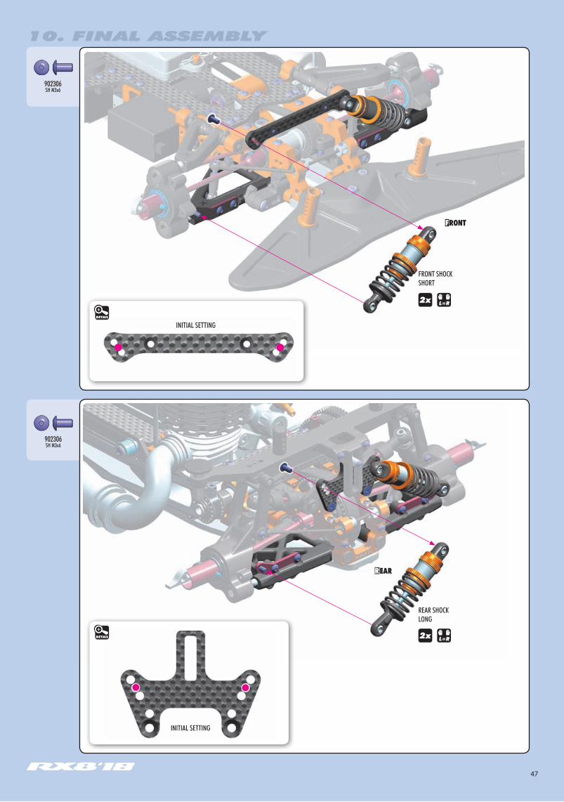
REAR SHOCK LONG
INITIAL SETTING
INITIAL SETTING
FRONT SHOCKSHORT
902306SH M3x6
902306SH M3x6
DETAIL
DETAIL
48
10. FINAL ASSEMBLY
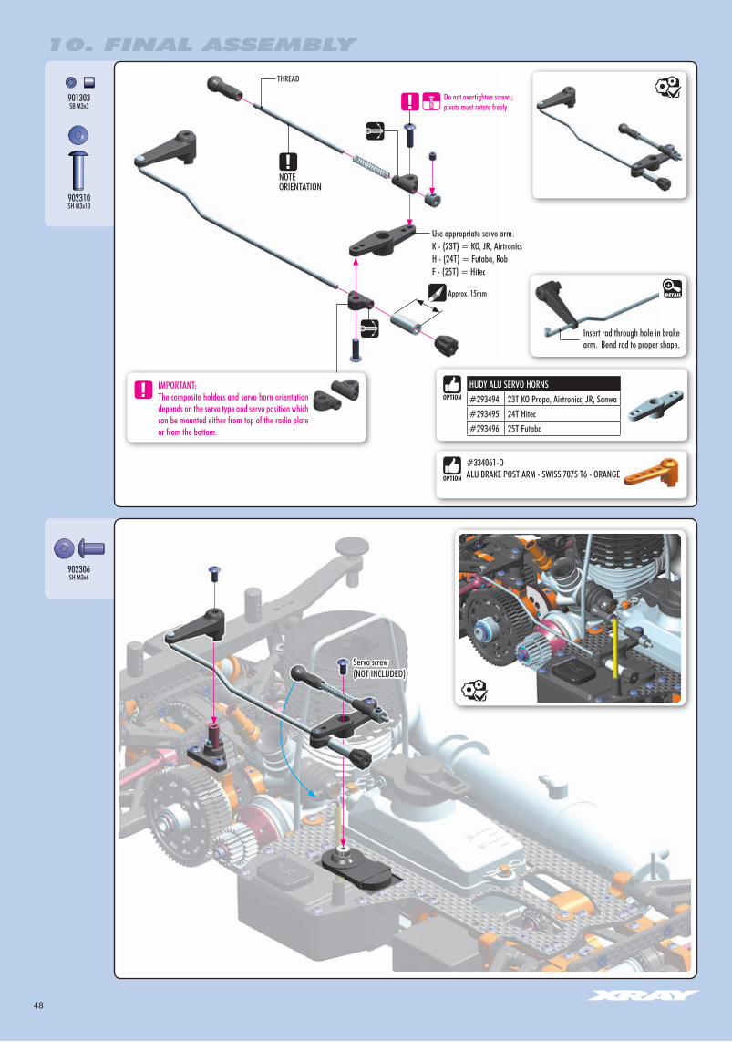
Approx. 15mm
THREAD
Do not overtighten screws; pivots must rotate freely
901303SB M3x3
902310SH M3x10
Servo screw(NOT INCLUDED)
902306SH M3x6
NOTEORIENTATION
Insert rod through hole in brake arm. Bend rod to proper shape.
DETAIL
HUDY ALU SERVO HORNS#293494 23T KO Propo, Airtronics, JR, Sanwa#293495 24T Hitec#293496 25T Futaba
#334061-OALU BRAKE POST ARM - SWISS 7075 T6 - ORANGE
Use appropriate servo arm:K - (23T) = KO, JR, AirtronicsH - (24T) = Futaba, RobF - (25T) = Hitec
IMPORTANT:The composite holders and servo horn orientation depends on the servo type and servo position which can be mounted either from top of the radio plate or from the bottom.

49
10. FINAL ASSEMBLY
Cut 2 pieces of silicone tubing and install as follows: SILICONE TUBE MARKED AS RED = FROM MUFFLER TO FUEL TANK CAP
Aluminum Brace
SILICONE TUBE MARKED ASBLUE = FROM FUEL TANK TO CARBURETOR
3x5mm 3x5mm3x5mm
25g25g
#341187 BRASS CHASSIS WEIGHT FRONT 25g
#341189BRASS CHASSIS WEIGHT REAR 25g
#341188BRASS CHASSIS WEIGHT MIDDLE
903305SFH M3x5
903305SFH M3x5
FRONT CHASSIS FLEX ADJUSTMENTChassis features unique and innovative front flex adjustment using
an insertable aluminum brace.
STIFF SETTINGUSING THE ALUMINUM BRACE: Car has increased steering response and cornering speed.
SOFT SETTINGNO BRACE: The care is easier to drive
and has more forward traction.
BRASS CHASSIS WEIGHTS (OPTIONAL)

50
CARB LINKAGE ADJUSTMENT
Turn on transmitter and receiver and set the throttle servo trim to the neutral position.
Adjust the idle adjustment screw on the carburetor to open approx. 0.5-1mm.
Adjust both collars on the carb and brake linkages accordingly. The carb linkage must have approximately 0.5mm of preload on the spring at neutral.
DO NOT ADJUST while the engine is running.
With the engine NOT RUNNING but the receiver turned ON, apply full throttle at the transmitter.
Adjust the transmitter‘s throttle servo high-end point so that the servo horn fully opens the carburettor when the transmitter‘s throttle control (e.g., throttle trigger) is at 95% of full throttle. The servo should not have excessive strain when at full throttle, or throttle/carb damage will result.
If the transmitter does not have throttle high-end point adjustment, adjust the throttle linkage pivot position on the servo horn until full throttle is obtained.
Adjust the composite collar on the brake linkage so the brakes work smoothly.
If the brakes apply too much or not enough, adjust the collar accordingly. If your transmitter has throttle servo low-end point adjustment (or brake adjustment), use that to set the appropriate amount of throttle servo horn throw.
NEUTRAL (IDLE)
FULL THROTTLE
BRAKE
Approx. 0.5mm
IDLE ADJUSTMENT SCREWDo not allow carburettor to close to less than 0.5mm.
Approx. 0.5-1mm
Engine idling
BRAKE ADJUSTING COLLAR
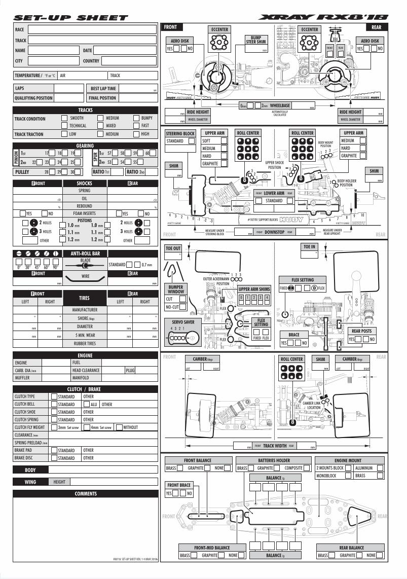
51
1 0 -1 -2 -3234
76548 9 10
FRONT REAR
REARFRONT
REARFRONT
REARFRONT
MEASURE UNDERREAR UPRIGHT
MEASURE UNDERSTEERING BLOCK
AUTOMATICALLYCALCULATED
UPPER SHOCKPOSITION
BODY HOLDER POSITION
CAMBER LINKLOCATION
BODY MOUNTPOSITION
ROLL CENTER
OUTER ACKERMANNPOSITION
STEERING BLOCKSTANDARD
#107701 SUPPORT BLOCKS
BUMPSTEER SHIM
mm
AERO DISK
YES NO
AERO DISK
YES NO
ECCENTER ECCENTER
2mm0mm WHEELBASE mm
DOWNSTOPmm mm
12
3SHIM
mm 1
1
1
2
2
2
3
3
TOE OUT°
TOE IN°
FLEX
FLEX
1 2 3
SERVO SAVER4 3 2 1
BUMPER
CUT
NO-CUT
WINDOW
1 2
CAMBER/degr.
TRACK WIDTH mmmm
LEFT RIGHT
CAMBER/degr.
LEFT RIGHT
#107713 GAUGE#107713 GAUGE
STANDARD
LOWER ARMFRONT REAR
ROLL CENTER ROLL CENTER
SHIM
mm
UPPER ARM
SOFT
MEDIUM
HARD
GRAPHITE
FLEXSETTING
FIXED FLEX
SHIM
mm
FLEX SETTING
FIXED FLEX
#107711 GAUGE#107711 GAUGE
FRONT REAR
FRONT REAR
FRONT REAR
RIDE HEIGHTWHEEL DIAMETER
mm
mm
RIDE HEIGHTWHEEL DIAMETER
mm
mm
UPPER ARM SHIMS
43210
BATTERIES HOLDER
BRASS GRAPHITE COMPOSITE
BALANCE /g
BALANCE /g
FRONT-MID BALANCE
BRASS GRAPHITE NONE
FRONT BALANCE
BRASS GRAPHITE NONE
REAR BALANCE
BRASS GRAPHITE NONE
ENGINE MOUNT2 MOUNTS BLOCK
MONOBLOCK
ALUMINUM
BRASS
UPPER ARM
MEDIUM
HARD
GRAPHITE
FRONT BRACE
YES NO
BRACE
YES NO
REAR POSTS
YES NO
SET-UP SHEET
LAPS BEST LAP TIME
FINAL POSITION
sec
QUALIFYING POSITION
RACE
TRACK
COUNTRYCITY
DATENAME
TEMPERATURE / °F or °C AIR TRACK
TRACK CONDITION
TRACK TRACTION
TECHNICAL MIXED
BUMPYMEDIUMSMOOTH
FAST
LOW MEDIUM HIGH
TRACKS
1ST
2ND
1ST
2NDPINI
ON
SPUR
RATIO RATIO
17 18 57 58 59 60
53 54 5522 23 24
19
25
3028 29
GEARING
PULLEY 2ND1ST
BODY
COMMENTS
WING HEIGHT
CLUTCH TYPE
CLUTCH SHOE
BRAKE PAD
CLUTCH / BRAKESTANDARD
CLUTCH BELL STANDARD
STANDARD
STANDARD
STANDARDBRAKE DISC STANDARD
SPRING
REBOUND
OIL
YES NO YES NOFOAM INSERTS
SHOCKS
PISTONS
cStcSt
% %
2 HOLES
3 HOLES
2 HOLES
3 HOLES1.0 mm
1.1 mm
1.2 mm
1.0 mm
1.1 mm
1.2 mm
WIREmmmm
MANUFACTURER
DIAMETER
5 MIN. WEAR
RUBBER TIRES
TIRESRIGHTLEFT RIGHTLEFT
° °° °
mm
mm
mm
mm
mm
SHORE /degr.
mm
mm
mm
BLADESTANDARD
ANTI-ROLL BAR
mm0.70° 30° 45° 60° 90°
OTHEROTHER
ALU OTHER
OTHER
OTHER
OTHER
OTHER
OTHER
CLUTCH SPRING
CLUTCH FLY WEIGHT
CLEARANCE /mm
SPRING PRELOAD
3mm
/mm
Set screw 4mm WITHOUTSet screw
ENGINE
HEAD CLEARANCEMUFFLER MANIFOLDCARB. DIA
FUELENGINE
/mm PLUG
RX8’18 SET-UP SHEET VER. 1 ©XRAY 2018v

/TeamXray /TeamXray /TeamXray /XrayRacing /+TeamXrayRC /XrayRacing
RC AMERICA, 2030 Century Center Blvd #15, Irving, TX 75062, USAPHONE: 214-744-2400, FAX: 214-744-2401, [email protected]