Pūhoi to Warworth motorway viaducts - attachment 2
40
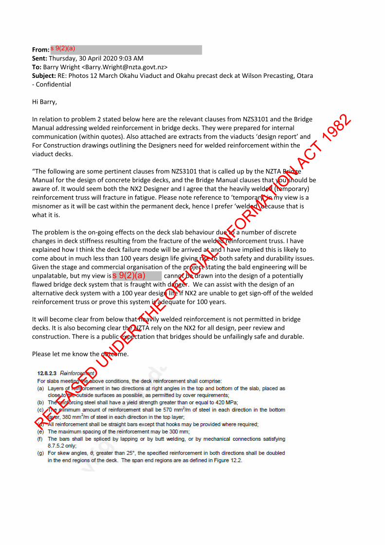
From: Sent: Thursday, 30 April 2020 9:03 AM To: Barry Wright <[email protected]> Subject: RE: Photos 12 March Okahu Viaduct and Okahu precast deck at Wilson Precasting, Otara - Confidential Hi Barry, In relation to problem 2 stated below here are the relevant clauses from NZS3101 and the Bridge Manual addressing welded reinforcement in bridge decks. They were prepared for internal communication (within quotes). Also attached are extracts from the viaducts ‘design report’ and For Construction drawings outlining the Designers need for welded reinforcement within the viaduct decks. “The following are some pertinent clauses from NZS3101 that is called up by the NZTA Bridge Manual for the design of concrete bridge decks, and the Bridge Manual clauses that you should be aware of. It would seem both the NX2 Designer and I agree that the heavily welded (temporary) reinforcement truss will fracture in fatigue. Please note reference to ‘temporary’ in my view is a misnomer as it will be cast within the permanent deck, hence I prefer ‘welded’ because that is what it is. The problem is the on-going effects on the deck slab behaviour due to a number of discrete changes in deck stiffness resulting from the fracture of the welded reinforcement truss. I have explained how I think the deck failure mode will be arrived at and I have implied this is likely to come about in much less than 100 years design life giving rise to both safety and durability issues. Given the stage and commercial organisation of the project stating the bald engineering will be unpalatable, but my view is cannot be drawn into the design of a potentially flawed bridge deck system that is fraught with danger. We can assist with the design of an alternative deck system with a 100 year design life if NX2 are unable to get sign-off of the welded reinforcement truss or prove this system is adequate for 100 years. It will become clear from below that heavily welded reinforcement is not permitted in bridge decks. It is also becoming clear the NZTA rely on the NX2 for all design, peer review and construction. There is a public expectation that bridges should be unfailingly safe and durable. Please let me know the outcome. s 9(2)(a) s 9(2)(a) RELEASED UNDER THE OFFICIAL INFORMATION ACT 1982
-
Upload
khangminh22 -
Category
Documents
-
view
1 -
download
0
Transcript of Pūhoi to Warworth motorway viaducts - attachment 2
From: Sent: Thursday, 30 April 2020 9:03 AM To: Barry Wright <[email protected]> Subject: RE: Photos 12 March Okahu Viaduct and Okahu precast deck at Wilson Precasting, Otara - Confidential Hi Barry, In relation to problem 2 stated below here are the relevant clauses from NZS3101 and the Bridge Manual addressing welded reinforcement in bridge decks. They were prepared for internal communication (within quotes). Also attached are extracts from the viaducts ‘design report’ and For Construction drawings outlining the Designers need for welded reinforcement within the viaduct decks. “The following are some pertinent clauses from NZS3101 that is called up by the NZTA Bridge Manual for the design of concrete bridge decks, and the Bridge Manual clauses that you should be aware of. It would seem both the NX2 Designer and I agree that the heavily welded (temporary) reinforcement truss will fracture in fatigue. Please note reference to ‘temporary’ in my view is a misnomer as it will be cast within the permanent deck, hence I prefer ‘welded’ because that is what it is. The problem is the on-going effects on the deck slab behaviour due to a number of discrete changes in deck stiffness resulting from the fracture of the welded reinforcement truss. I have explained how I think the deck failure mode will be arrived at and I have implied this is likely to come about in much less than 100 years design life giving rise to both safety and durability issues. Given the stage and commercial organisation of the project stating the bald engineering will be unpalatable, but my view is cannot be drawn into the design of a potentially flawed bridge deck system that is fraught with danger. We can assist with the design of an alternative deck system with a 100 year design life if NX2 are unable to get sign-off of the welded reinforcement truss or prove this system is adequate for 100 years. It will become clear from below that heavily welded reinforcement is not permitted in bridge decks. It is also becoming clear the NZTA rely on the NX2 for all design, peer review and construction. There is a public expectation that bridges should be unfailingly safe and durable. Please let me know the outcome.
s 9(2)(a)
s 9(2)(a)
RELEASED U
NDER THE OFFIC
IAL INFORMATIO
N ACT 1982
RELEASED U
NDER THE OFFIC
IAL INFORMATIO
N ACT 1982
RELEASED U
NDER THE OFFIC
IAL INFORMATIO
N ACT 1982
From the NZTA Bridge Manual:
RELEASED U
NDER THE OFFIC
IAL INFORMATIO
N ACT 1982
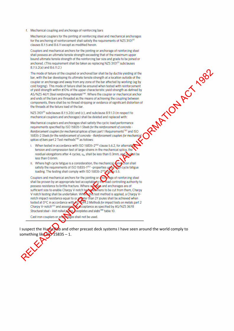
I suspect the HumeSlab and other precast deck systems I have seen around the world comply to something like ISO 15835 – 1.
RELEASED U
NDER THE OFFIC
IAL INFORMATIO
N ACT 1982
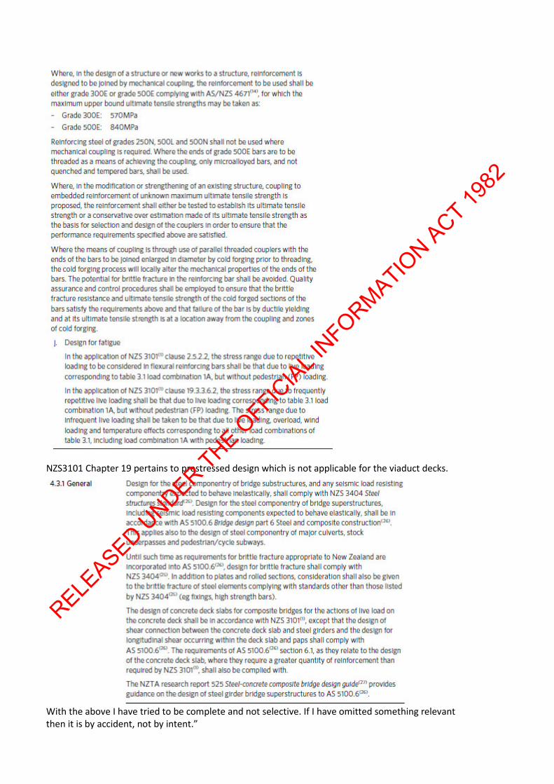
NZS3101 Chapter 19 pertains to prestressed design which is not applicable for the viaduct decks.
With the above I have tried to be complete and not selective. If I have omitted something relevant then it is by accident, not by intent.”
RELEASED U
NDER THE OFFIC
IAL INFORMATIO
N ACT 1982

By my calculations based on an assumed number of 6t axles and AASHTO detail classification E the Temporary Reinforcement Trusses will fail within the first year. Are you able to let me know the timeframe and outcome of the NZTA investigation?
s 9(2)(a)
RELEASED U
NDER THE OFFIC
IAL INFORMATIO
N ACT 1982
RELEASED U
NDER THE OFFIC
IAL INFORMATIO
N ACT 1982
RELEASED U
NDER THE OFFIC
IAL INFORMATIO
N ACT 1982
RELEASED U
NDER THE OFFIC
IAL INFORMATIO
N ACT 1982

From: Sent: Thursday, 9 April 2020 2:33 PM To: Barry Wright <[email protected]> Subject: RE: Photos 12 March Okahu Viaduct and Okahu precast deck at Wilson Precasting, Otara - Confidential Hi Barry The NZTA investigation should discover the following:
Problem Cause 1. Temporary Rebar Truss top
chord buckling during topping pour preparations or during the pour. There is a considerable gap between the top chord axial capacity and the demands placed up them.
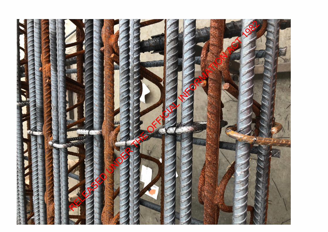
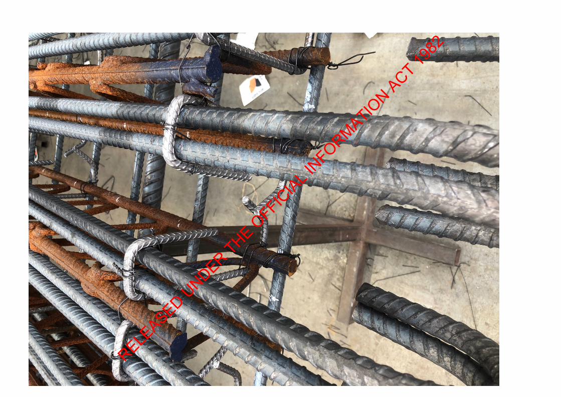
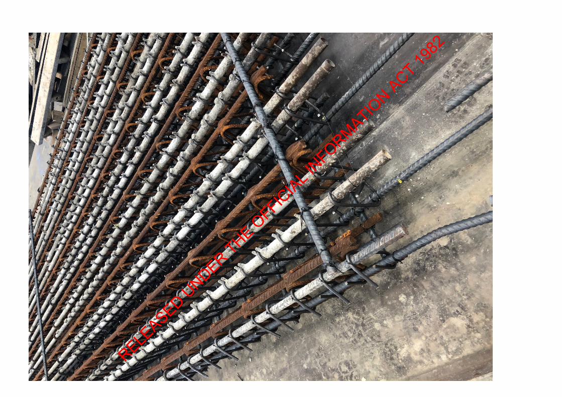
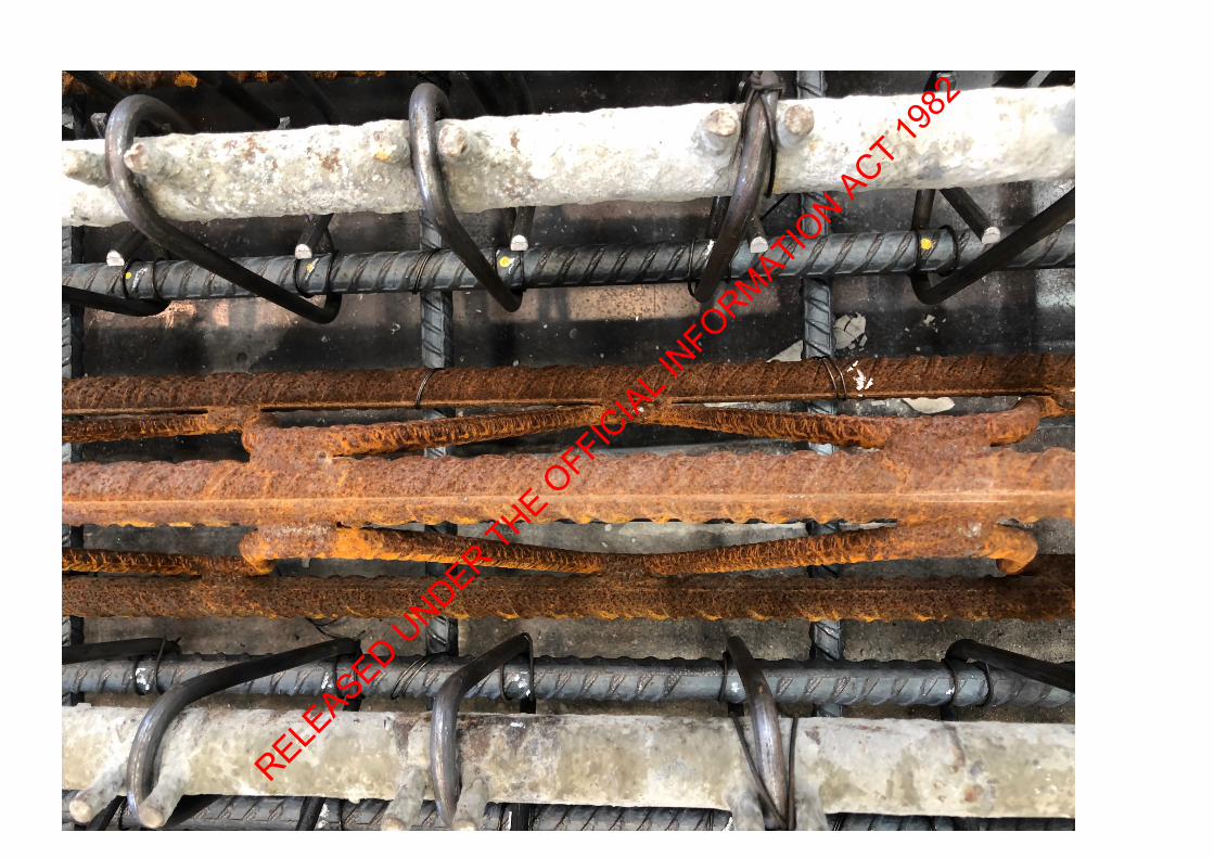
Acciona Ingeneria undertook a SAP 2000 FE analysis and accounted for the rebar truss and the precast concrete as both having linear elastic properties. That is the full 130mm thick precast concrete panel was modelled to carry maximum tension at the panel soffit and compression at the precast top surface. The error being the concrete cannot reliably carry any tension and only about 40mm depth of the concrete precast is immediately above the neutral axis is available to carry some small compression. Given the truss top chord is about 140mm above the neutral axis and at ‘extreme compression fibre’ then the vast majority of the compression loads are carried by the top chord. This prevents the high compressive strains in the concrete precast 100mm below the top chord. That is the concrete compression contributes a negligible of flexural capacity. Acciona results indicate that the precast concrete panel carry about half the required flexural capacity hence the compression demand in the top chord is about half what it should be. Acciona have taken no reasonable account of damaged to the top chord (e.g. say from a bundle of rebar being lowered onto the precast during supply for fixing the permanent deck reinforcement). Damage further reduces the top chord capacity. The erroneous Acciona analysis also indicates the precast panel deflections are much less than by elastic theory. The poorly performed load testing where the kentledge acted as a rudimentary but effective ‘top flange’ meant precast panels didn’t deflect as much as elastic analysis indicates resulting in the precast panels not being cambered and added to the confidence that the precast panel will be suitable and disguised the top chord buckling failure mode.
2. High deck curvatures at locations of fatigue fractured Temporary Rebar Truss. There seems to be a gap between the allowable fatigue stress range and the actual stress range based on reasonable assumptions of detail category and number of load cycles. The longer
The designers clearly understood that the Temporary Rebar Truss would suffer from fatigue effects as it is mentioned in the Construction drawings. It is therefore concluded that the designers assumed that fatigue cracking will occur through the welds only; not the truss chords. (Please note that ‘Temporary’ is regarded as a misnomer because the trusses are permanently and completely embedded within the permanent deck slab.) Assuming a Detail Category E (from AASHTO and AREMA bridge codes) and an estimated 1 million load cycles of 6tonne axles per year it is was calculated the Temporary Reinforcement Truss will fracture
s 9(2)(a)
RELEASED U
NDER THE OFFIC
IAL INFORMATIO
N ACT 1982

term effects on deck stiffness of a heavily reinforced slab have not been fully considered.
within the first year of service. The annual number of load cycles was based on a number of 9 axle A and B trains and 4 axle trucks using two lanes causing maximum cyclic stresses of the deck transverse reinforcement. Research into fatigue design shows the fractures start as micro cracking at locations of steel embrittlement (from welding causing a heat affected zone) and concentration of stresses (stress risers). The invisible micro cracks propagate to form threshold cracks and these can further propagate suddenly to compromise the entire section or top and bottom truss chords in this instance. Supposedly the truss are not contributing to the bending strength of the deck slab, but they do contribute to the deck stiffness. A sudden fracture of the truss chords results in an abrupt change in deck stiffness. Simple elastic beam theory shows the inverse of radius of curvature is proportional to the inverse of beam stiffness. In the viaduct deck slabs this is likely to result in sharper curvatures and high strains in the concrete at points of abrupt change in deck stiffness. This is likely to result in the localised deterioration of cover concrete and so on.
3. Slender girder webs in sagging regions. Various bridge codes allow web depth to thickness ratios of between 133 to 152 to prevent web bend buckling. These ratios are exceeded with ratios of 165 to 167 being provided in the viaducts.
Simply not accounted for by the designer or checked by the reviewer.
Please keep me posted on the investigation. Before the lock down Acciona were reaching the point where the precast deck panels were to be transported to the Okahu viaduct from Wilsons Precast, Heritage Way, Otara, to lift onto the girders. I have developed solutions for these issues should the NZTA investigation concur with our concerns. On a personal note I believe these issues are too big to ‘bury’. The issue becomes at what point do they get validated. Kind regards
s 9(2)(a) RELEASED U
NDER THE OFFIC
IAL INFORMATIO
N ACT 1982
From: Sent: Thursday, 9 April 2020 10:52 AM To: Barry Wright <[email protected]> Subject: RE: Photos 12 March Okahu Viaduct and Okahu precast deck at Wilson Precasting, Otara - Confidential Hi Barry, Is the process outlined below suitable? That is find a way for the NZTA appointed investigator (from routine QA assessments) to approach
in the first instance based on what they discover from Acciona. If it is then he should refer investigator queries to Transport Lead, who will refer them to me if he is allowed to.
s 9(2)(a)
s 9(2)(a)
s 9(2)(a)s 9(2)(a)
s 9(2)(a)
RELEASED U
NDER THE OFFIC
IAL INFORMATIO
N ACT 1982

From: Sent: Tuesday, 7 April 2020 4:00 PM To: Barry Wright <[email protected]> Subject: RE: Photos 12 March Okahu Viaduct and Okahu precast deck at Wilson Precasting, Otara - Confidential Hi Barry, Please see my responses in red below.
. Please do this. I would also suggest any site investigations only carried out at the end of
the lock down when construction begins again but before any precast panels are lifted onto the girders, and; the NZTA should carry out its regulatory obligations in strict accordance with the appropriate QA procedures with this project but in a routine manner (Its $20M+ mistake with almost certain chance of being discovered – preferably before someone is injured or killed).
From
the above Acciona ) will ‘let slip’ that had been involved which can then prompt your investigator to formally approach is our geotechnical engineer helping Acciona on geotech issues) for our assistance. In principle and ethically this should be forthcoming. This temporary rebar truss top chord buckling issue can then lead to the fatigue fracture/abrupt change in stiffness in deck, and the overly slender webs in the sagging regions of the main girders and anything else that may come up in the investigation. Acciona is a platinum global client . Should choose not to participate then please let me know and NZTA and I can take it from there.
s 9(2)(a)
s 9(2)(a)
Out of Scope
Out of Scope
Out of Scope
s 9(2)(a) s 9(2)(a)
s 9(2)(a)
s 9(2)(a)s 9(2)(a)RELEASED U
NDER THE OFFIC
IAL INFORMATIO
N ACT 1982

From: Sent: Tuesday, 7 April 2020 2:41 PM To: Barry Wright <[email protected]> Subject: RE: Photos 12 March Okahu Viaduct and Okahu precast deck at Wilson Precasting, Otara - Confidential Hi Barry, Confidential. Acciona want to ‘bury’ these issues. They have confirmed the temporary rebar truss design with Acciona Ingeneria in Spain and received a letter of peer review from Case International (don’t know them).
have performed a manual analysis (by myself) and had it confirmed by Strand 7 FE analysis independent of me in Auckland. Given the discrepancy in our results we suggested that they raise the issue with the NZTA as Principal and Regulator. They maintain they are not obliged to ‘close out’ this temporary works design or notify the NZTA. Please let me know if you want to assist with any NZTA investigation? Kind regards
s 9(2)(a)
s 9(2)(a)
s 9(2)(a)
s 9(2)(a)
RELEASED U
NDER THE OFFIC
IAL INFORMATIO
N ACT 1982
From: Sent: Monday, 23 March 2020 4:25 PM To: Barry Wright <[email protected]> Subject: RE: Photos 12 March Okahu Viaduct and Okahu precast deck at Wilson Precasting, Otara - Confidential Hi Barry, We have finished the report into the Okahu and Puhoi Viaduct temporary reinforcement trusses. Given various commercial imperatives I am not sure if or how it will be received by NX2. Nevertheless the recommendations in summary are:
1. Act urgently and decisively 2. Revalidate, if able, the intended viaduct system by:-
a. Getting the Spanish temporary works engineering to recalculate the safe capacity of the trusses
b. Conduct further load testing this time to failure and without the kentledge bearing on the top chords
c. Gather evidence of the longer term performance of welded trusses cast within the permanent deck
d. Gather further evidence of the designers philosophy and peer review comments with regard to the temporary reinforcement trusses.
3. In parallel with 2 investigate an alternative deck system and recheck the super and sub structure design, cost and programme implications.
We have not recommended NX2 notify NZTA. We have not offered any assistance with the above. We have stated that we can not peer review the temporary reinforcement trusses as requested. If the NZTA wishes to investigate further then there should be official channels as either the Principal or regulator to do this.
s 9(2)(a)
s 9(2)(a)
RELEASED U
NDER THE OFFIC
IAL INFORMATIO
N ACT 1982

From: Sent: Monday, 23 March 2020 11:59 AM To: Barry Wright <[email protected]> Subject: RE: Photos 12 March Okahu Viaduct and Okahu precast deck at Wilson Precasting, Otara - Confidential Hi Barry, I have finished my report. For various commercial imperatives there is reluctance to advance it. Understandable. However basically my recommendations to NX2 are:
1. Act urgently and decisively. 2. Defend the current design by:- getting the Spanish temporary works engineer to confirm the
temporary reinforcement truss design; conduct further precast panel load testing to failure with the kentledge separated from the top chord; gather evidence of the long term performance of the decks with a welded trusses within them; gather complete evidence of the designers philosophy and peer review comments with respect to the temporary reinforcement trusses etc.
3. In parallel with 2 develop an alternative deck solution and recheck the super and sub structures, construction programme and cost estimate.
We have not suggested to NX2 to notify the NZTA. We have not offered further engineering assistance to the NX2 on this serious matter. The report is ‘matter of fact’ with no opinions. There may be another way the NZTA could raise the temporary reinforcement truss design with NX2 through official channels. Kind regards
I’ll still be working in Wellington this week except this afternoon Thursday which are ‘work from home’ days for if you want to meet me to discuss.
s 9(2)(a)
s 9(2)(a)
s 9(2)(a)
RELEASED U
NDER THE OFFIC
IAL INFORMATIO
N ACT 1982
From: Sent: Tuesday, 17 March 2020 4:31 PM To: Barry Wright <[email protected]> Subject: RE: Photos 12 March Okahu Viaduct and Okahu precast deck at Wilson Precasting, Otara - Confidential Hi Barry, Here is the first draft ES for my report.
s 9(2)(a)
RELEASED U
NDER THE OFFIC
IAL INFORMATIO
N ACT 1982

Executive summary
Upon a request by NX2 (NX2Group – PPP special purpose vehicle to deliver P2Wk project for the NZTA) for to peer review a temporary works component associated with the deck construction for both the Okahu and Puhoi viaducts two significant deck failure modes have been discovered. The temporary works concerned is the ‘lynch-pin’ for both modes of failure.
By calculation and assessment have confirmed these deck failure modes are serious. first notified NX2 of these potentially dangerous failure modes on 6 March 2020 by email. Because of the deck failure modes discovered, are unable to peer review the Temporary Reinforcement Truss (TRT).
This report formerly outlines to NX2, and if necessary, the NZTA, two potential failure modes
associated with the viaduct decks. One failure mode is associated with the sudden failure of the precast deck panels during construction. The other failure mode is associated with a premature decline in deck durability during its service life.
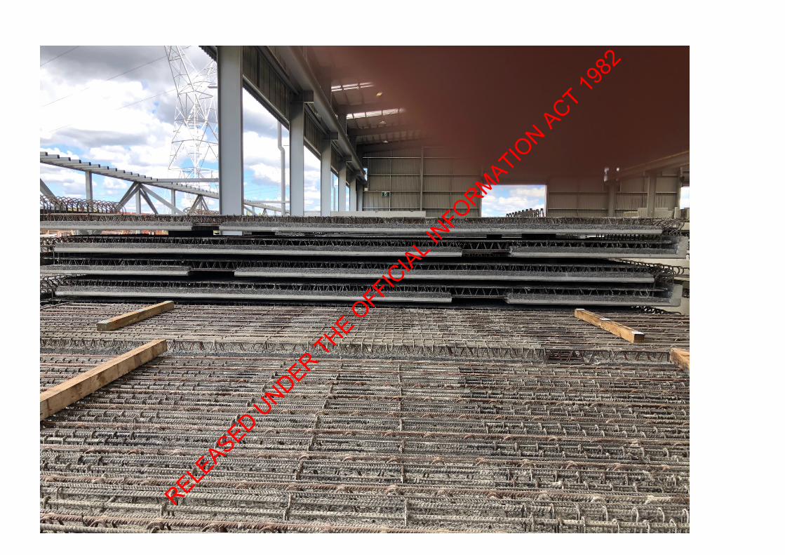
The first and most serious failure mode eventuates from the TRT top chord buckling failure either
in preparation or during the topping pour. Over the two viaducts there are over 17,400m2 of precast deck panels that could collapse suddenly and fall down nearly 20m at the lowest point of ground level. The nature, chance and consequence of failure render the proposed deck system as an unacceptable risk. It is strongly recommended that NX2 prove the resilience and demonstrate sufficient margins of safety of the deck system to the NZTA before proceeding further with the viaduct deck construction.
The second failure mode comes about from the sudden changes in deck stiffness caused by the
design intended and highly likely fatigue fractured TRT’s cast into the permanent deck slabs. This failure mode is subordinated to the first because should the first occur this will prevent the viaduct decks being constructed as currently intended.
It is extremely concerning that such deck failure modes could be overlooked in the viaduct design
process beginning up to three years earlier, progressing through peer review and only ‘picked-up’ when construction of the viaduct decks is imminent.
Seven recommendations have been put forward. There is onus on NX2 to demonstrate to the NZTA
that the two failure modes outlined are either unfounded or can be remedied. It is further suggested that work begin immediately on developing an alternative deck solution and reassessing the existing superstructure and substructure designs.
I also note the heavy lift crane hire sub-contractor had to remove the crane keys from their machines at both viaduct sites at the beginning of last week to ensure outstanding invoices were paid. Worrying signs?
s 9(2)(a)
s 9(2)(a)
s 9(2)(a)
s 9(2)(a)
s 9(2)(a)
RELEASED U
NDER THE OFFIC
IAL INFORMATIO
N ACT 1982
From: Sent: Tuesday, 17 March 2020 11:04 AM To: Barry Wright <[email protected]> Subject: RE: Photos 12 March Okahu Viaduct and Okahu precast deck at Wilson Precasting, Otara - Confidential Morning Barry, If it transpires that NX2 don’t want to engage to review the Temporary Reinforcement Truss system for the viaduct deck system, then at what point, if any, would NZTA step in? The NX2 know from the attached email bad news is on the way.
s 9(2)(a)
s 9(2)(a)
s 9(2)(a)
RELEASED U
NDER THE OFFIC
IAL INFORMATIO
N ACT 1982
From:To:Cc:Subject: P2Wr - Puhoi and Okahu Viaducts - Proposed deck system peer reviewAttachments: image003.png
Dear Thank you for time and explanation yesterday. As promised our anticipated failure mechanism of the proposed viaduct decks during service lifeis outlined below under point 2. But first we would like to explain the anticipated failuremechanism of the proposed viaduct decks during construction under point 1. This is of moreimmediate concern. We encourage the NX2Group to gather any evidence it can to prevent either of these failuremechanisms from occurring and present this evidence to the NZTA as Principal and Regulator. We would like to be furnished with this evidence so that we can work with the NX2Group tosolve these deck safety and durability issues promptly. We are aware of your tight programme, the two thirds of the temporary reinforcement trusseson site and general commitment of NX2 to this proposed deck system. Nevertheless we feelobligated to outline our concerns regarding the proposed viaduct deck system.
1. Anticipated failure mechanism of the proposed viaduct deck system duringconstruction.
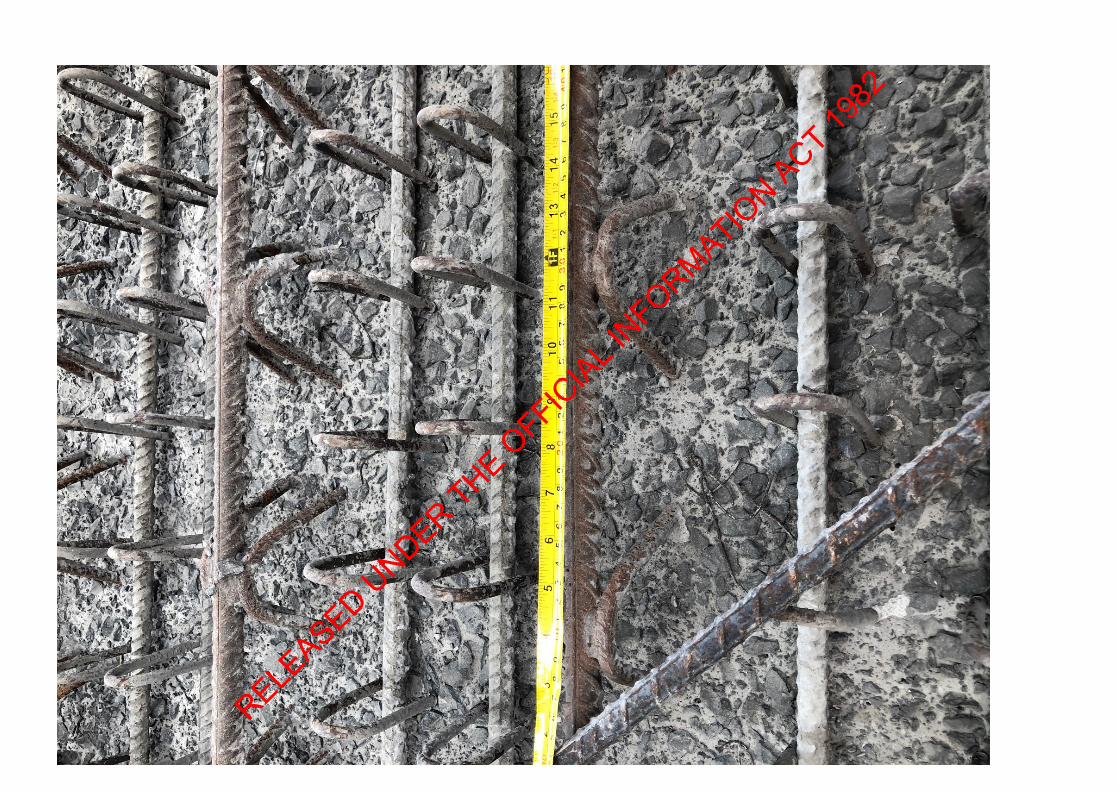
a. Considering the two viaducts we estimate over 38km of top chords are incompression and will have their maximum axial compressive loading when theconcrete topping (205mm thick) is being poured. Any damage resulting in kinks ormisalignment of HD20 top chord will dramatically reduce the buckling capacity (i.e.a sudden failure) due to P-delta effects.
b. We would suggest with the best intentions in the world, it is highly likely someDH20 top chords will be damaged by construction loading preparing for the toppingpour.
c. A failure of one top chord in sudden buckling will shed additional compression loadonto the adjacent top chords.
d. This may lead to a progressive failure of a particular 2.7m wide precast panel.e. This is irrespective of the theoretical buckling capacity of a perfectly straight HD20
top chord (between points of restraint) as Acconia Ingeneria have based theircalculations on. Given the extent of top chords it is impractical to expect pure axialcompression; there will be bending moments and moment magnification leading tosudden buckling failure.
2. Anticipated failure mechanism of the proposed viaduct deck system during service
loading.a. The deck slab spanning transversely across the 4 girders and cantilevering outwards
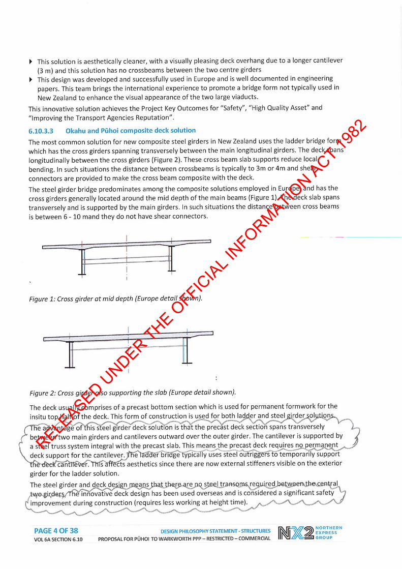
is very stiff with both the required deck reinforcement and the additional stifftemporary reinforcing truss. From the drawings truss chords are at the same depthas the deck slab transverse bars. We assume no reliance has been placed on the
s 9(2)(a)
s 9(2)(a)
RELEASED U
NDER THE OFFIC
IAL INFORMATIO
N ACT 1982

temporary reinforcing truss in the design of the ordinary slab reinforcement. Itmight be that the decks have nearly twice as much transverse reinforcement as afull depth deck slab. That is say half from the truss and half from the ordinaryreinforcement. Hence the deck slab is very stiff.
b. After an unknown period (much less than 100 years) of service loading, particularlyfrom heavy truck axles impacting on every truss, the temporary reinforcing truss isexpected to crack due to fatigue loading at quite low cyclic stresses. This is thedesign intent as per the drawings. The truss is likely to fracture in regions of higheststrain. That is over the girders (hogging moment) and between the girders (saggingmoment) but fatigue crack propagation could be at any weld or stress riser alongthe length of the trusses. The location of fatigue cracking is practicablyunpredictable. Given the extent of welding then the degree of residual stresseswithin the trusses may be significant. That is the bottom chords could be undersignificant tension due both residual stresses and deck construction loading beforevehicle loading places additional demands on these chords.
c. Once the trusses fracture through the rebar chords then the stiffness of the deckslab at that point is much less relative to the remainder of the deck slab.
d. Further traffic loading will concentrate deck rotations at these locations of lowrelative stiffness and higher strain. The deck slab will no longer deflect like it ismonolithic with constant stiffness; but will behave like a series of stiff straightsections connected between with less stiff hinges.
e. At the points of lower stiffness; higher deck rotations; and subject to high cyclicload concentrations there will be considerable ‘working’ of the fractured temporaryreinforcing truss within the deck slab. Concrete cracking and corrosion pockets atthe ends of the fractured bars and within the slab will develop.
f. It is likely there will end up with larger than normal longitudinal cracks above thegirders and along the underside between the girders. As water accumulates withinthe deck slab then corrosion of the shear studs could occur and loss of compositeaction result over a longer period of time; some corrosion pockets are likely to bedirectly over the girders.
We understand from our conversation yesterday that BECA are the Designer and Aecom are thePeer Reviewer. They put forward and approved the proposed deck system. This obligated theTemporary Works Engineer (Acciona Ingeneria) to sign-off the temporary reinforcement truss,which has been done. The Designer now wants a NZ independent peer review of the temporaryreinforcement truss. NX2Group have asked to do this. We have not beenable to analyse the temporary reinforcement truss in pure isolation because it is integral with thetotal viaduct deck system. We are concerned about the above two failure mechanisms occurringand have suggested these are either proven incorrect by supporting evidence, or NX2Groupnotify the NZTA forthwith of these failure mechanisms. We are ready and willing to design an alternative unfailing safe and durable viaduct deck systemfor the P2Wr project and work with all concerned parties to achieve this on a best for projectbasis.Kind regards
s 9(2)(a)
s 9(2)(a)
RELEASED U
NDER THE OFFIC
IAL INFORMATIO
N ACT 1982
The information contained in this e-mail is intended only for the person or entity to which it is addressed and maycontain confidential and/or privileged material. If you are not the intended recipient of this e-mail, the use of thisinformation or any disclosure, copying or distribution is proh bited and may be unlawful. If you received this in error,please contact the sender and delete the material from any computer.
s 9(2)(a)
RELEASED U
NDER THE OFFIC
IAL INFORMATIO
N ACT 1982
From: Sent: Monday, 16 March 2020 9:42 AM To: Barry Wright <[email protected]> Subject: RE: Photos 12 March Okahu Viaduct and Okahu precast deck at Wilson Precasting, Otara - Confidential Morning Barry, Currently I am estimating the number of load cycles to fracture the temporary reinforcement truss and the resulting change in stiffness in the deck and therefore the change in curvature. This may be an academic exercise but will allow me to more clearly think through the situation. Then I will write a report. I have a colleague verifying my buckling calculations by a limit state method. Based on my calculations it is conceivable that NX2 will assume the temporary reinforcement truss top chords act as ideal fully restrained segments and therefore have sufficient capacity to allow the deck pour; and further assume the likelihood of fatigue failure within the 25 year concession period is low enough to proceed with the design as it is. If they do so then it is likely to be contrary to our recommendations which will be based both on probability of failure and consequence of failure. Cheers
s 9(2)(a)
s 9(2)(a)
RELEASED U
NDER THE OFFIC
IAL INFORMATIO
N ACT 1982
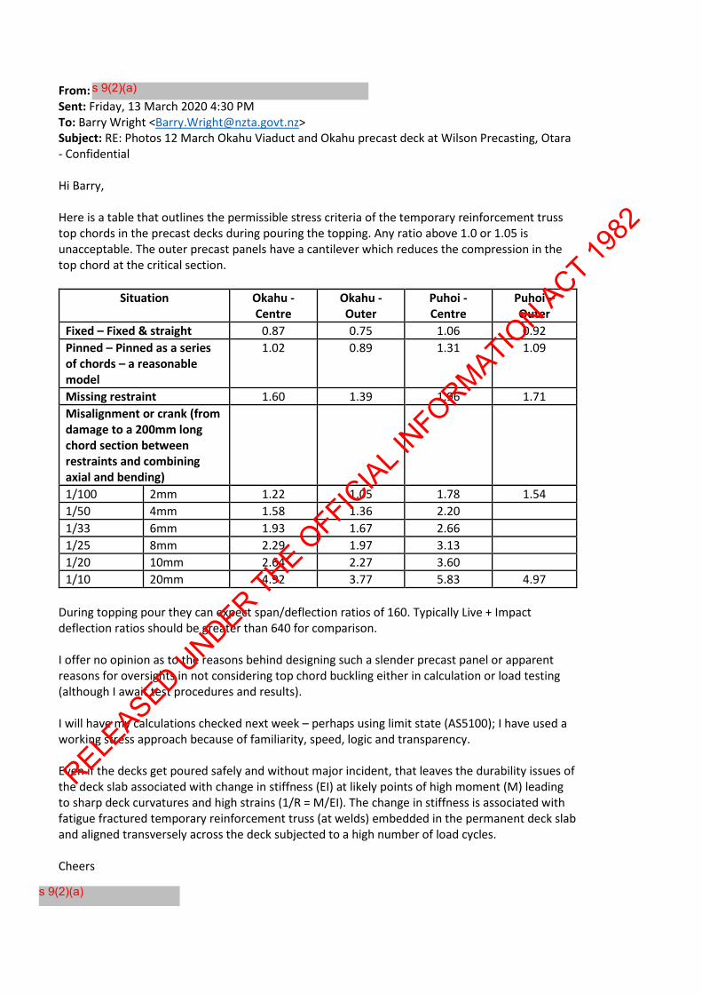
From: Sent: Friday, 13 March 2020 4:30 PM To: Barry Wright <[email protected]> Subject: RE: Photos 12 March Okahu Viaduct and Okahu precast deck at Wilson Precasting, Otara - Confidential Hi Barry, Here is a table that outlines the permissible stress criteria of the temporary reinforcement truss top chords in the precast decks during pouring the topping. Any ratio above 1.0 or 1.05 is unacceptable. The outer precast panels have a cantilever which reduces the compression in the top chord at the critical section.
Situation Okahu - Centre
Okahu - Outer
Puhoi - Centre
Puhoi – Outer
Fixed – Fixed & straight 0.87 0.75 1.06 0.92 Pinned – Pinned as a series of chords – a reasonable model
1.02 0.89 1.31 1.09
Missing restraint 1.60 1.39 1.96 1.71 Misalignment or crank (from damage to a 200mm long chord section between restraints and combining axial and bending)
1/100 2mm 1.22 1.05 1.78 1.54 1/50 4mm 1.58 1.36 2.20 1/33 6mm 1.93 1.67 2.66 1/25 8mm 2.29 1.97 3.13 1/20 10mm 2.64 2.27 3.60 1/10 20mm 4.92 3.77 5.83 4.97
During topping pour they can expect span/deflection ratios of 160. Typically Live + Impact deflection ratios should be greater than 640 for comparison. I offer no opinion as to the reasons behind designing such a slender precast panel or apparent reasons for oversights in not considering top chord buckling either in calculation or load testing (although I await test procedures and results). I will have my calculations checked next week – perhaps using limit state (AS5100); I have used a working stress approach because of familiarity, speed, logic and transparency. Even if the decks get poured safely and without major incident, that leaves the durability issues of the deck slab associated with change in stiffness (EI) at likely points of high moment (M) leading to sharp deck curvatures and high strains (1/R = M/EI). The change in stiffness is associated with fatigue fractured temporary reinforcement truss (at welds) embedded in the permanent deck slab and aligned transversely across the deck subjected to a high number of load cycles. Cheers
s 9(2)(a)
s 9(2)(a)
RELEASED U
NDER THE OFFIC
IAL INFORMATIO
N ACT 1982

s 9(2)(a)
RELEASED U
NDER THE OFFIC
IAL INFORMATIO
N ACT 1982
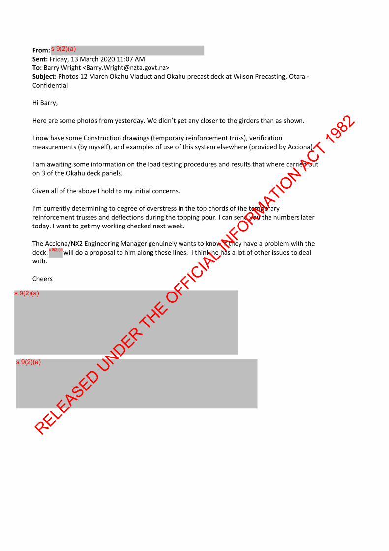
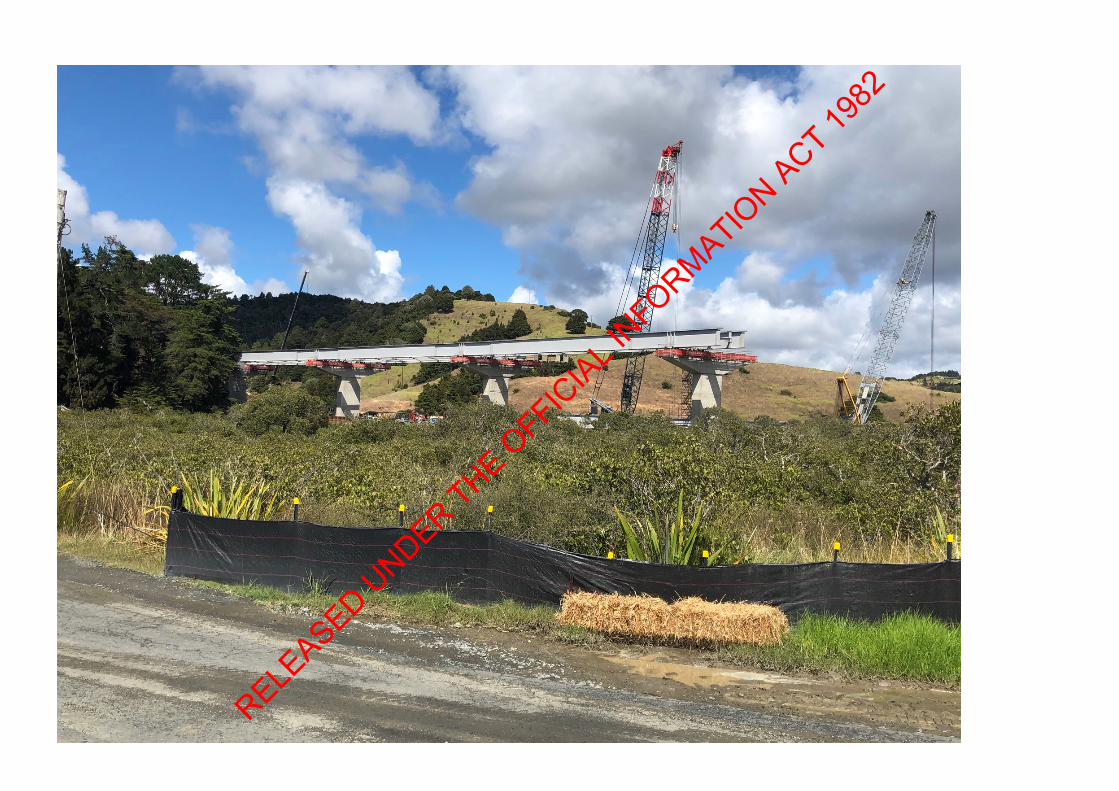
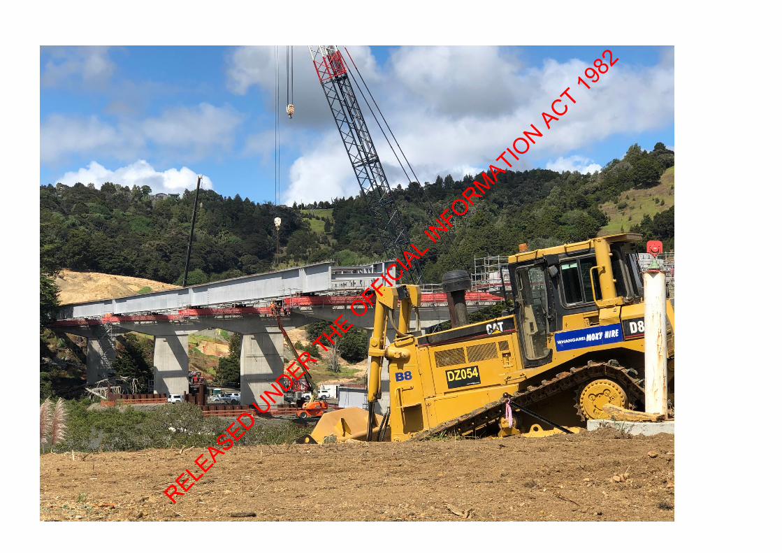
From: Sent: Friday, 13 March 2020 11:07 AM To: Barry Wright <[email protected]> Subject: Photos 12 March Okahu Viaduct and Okahu precast deck at Wilson Precasting, Otara - Confidential Hi Barry, Here are some photos from yesterday. We didn’t get any closer to the girders than as shown. I now have some Construction drawings (temporary reinforcement truss), verification measurements (by myself), and examples of use of this system elsewhere (provided by Acciona). I am awaiting some information on the load testing procedures and results that where carried out on 3 of the Okahu deck panels. Given all of the above I hold to my initial concerns. I’m currently determining to degree of overstress in the top chords of the temporary reinforcement trusses and deflections during the topping pour. I can send you the numbers later today. I want to get my working checked next week. The Acciona/NX2 Engineering Manager genuinely wants to know if they have a problem with the deck. will do a proposal to him along these lines. I think he has a lot of other issues to deal with. Cheers
s 9(2)(a)
s 9(2)(a)
s 9(2)(a)
s 9(2)(a)
RELEASED U
NDER THE OFFIC
IAL INFORMATIO
N ACT 1982
RELE
ASED UNDER THE O
FFICIAL I
NFORMATION ACT 19
82
RELEASED U
NDER THE OFFIC
IAL INFORMATIO
N ACT 1982
RELEASED U
NDER THE OFFIC
IAL INFORMATIO
N ACT 1982

RELEASED U
NDER THE OFFIC
IAL INFORMATIO
N ACT 1982
RELEASED U
NDER THE OFFIC
IAL INFORMATIO
N ACT 1982
RELEASED U
NDER THE OFFIC
IAL INFORMATIO
N ACT 1982
RELEASED U
NDER THE OFFIC
IAL INFORMATIO
N ACT 1982
RELEASED U
NDER THE OFFIC
IAL INFORMATIO
N ACT 1982

RELEASED U
NDER THE OFFIC
IAL INFORMATIO
N ACT 1982
RELEASED U
NDER THE OFFIC
IAL INFORMATIO
N ACT 1982

RELEASED U
NDER THE OFFIC
IAL INFORMATIO
N ACT 1982

RELEASED U
NDER THE OFFIC
IAL INFORMATIO
N ACT 1982
RELEASED U
NDER THE OFFIC
IAL INFORMATIO
N ACT 1982