PTT Operation Manual Sept 2008 Update.qxp - Mountz
39
Corporate Headquarters: 1080 North 11th Street, San Jose, CA 95112 Phone: (408) 292-2214 Fax: (408) 292-2733 www.etorque.com PTT PTT Operating Instructions Version 5.1 September 11, 2008 For Item # 072999 and # 072995
-
Upload
khangminh22 -
Category
Documents
-
view
7 -
download
0
Transcript of PTT Operation Manual Sept 2008 Update.qxp - Mountz

Corporate Headquarters: 1080 North 11th Street, San Jose, CA 95112 Phone: (408) 292-2214 Fax: (408) 292-2733www.etorque.com
P T TP T TOperating Instructions
Version 5.1September 11, 2008
For Item # 072999 and # 072995
F e a t u r e s
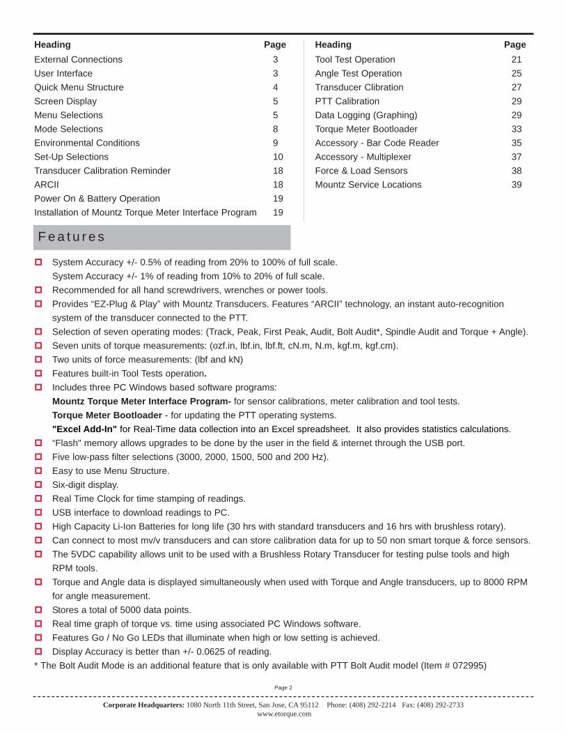
System Accuracy +/- 0.5% of reading from 20% to 100% of full scale.System Accuracy +/- 1% of reading from 10% to 20% of full scale.
Recommended for all hand screwdrivers, wrenches or power tools. Provides “EZ-Plug & Play” with Mountz Transducers. Features “ARCII” technology, an instant auto-recognition
system of the transducer connected to the PTT. Selection of seven operating modes: (Track, Peak, First Peak, Audit, Bolt Audit*, Spindle Audit and Torque + Angle). Seven units of torque measurements: (ozf.in, lbf.in, lbf.ft, cN.m, N.m, kgf.m, kgf.cm). Two units of force measurements: (lbf and kN) Features built-in Tool Tests operation. Includes three PC Windows based software programs:
Mountz Torque Meter Interface Program- for sensor calibrations, meter calibration and tool tests.Torque Meter Bootloader - for updating the PTT operating systems."Excel Add-In" for Real-Time data collection into an Excel spreadsheet. It also provides statistics calculations.
“Flash" memory allows upgrades to be done by the user in the field & internet through the USB port. Five low-pass filter selections (3000, 2000, 1500, 500 and 200 Hz). Easy to use Menu Structure. Six-digit display. Real Time Clock for time stamping of readings. USB interface to download readings to PC. High Capacity Li-Ion Batteries for long life (30 hrs with standard transducers and 16 hrs with brushless rotary). Can connect to most mv/v transducers and can store calibration data for up to 50 non smart torque & force sensors. The 5VDC capability allows unit to be used with a Brushless Rotary Transducer for testing pulse tools and high
RPM tools. Torque and Angle data is displayed simultaneously when used with Torque and Angle transducers, up to 8000 RPM
for angle measurement. Stores a total of 5000 data points. Real time graph of torque vs. time using associated PC Windows software. Features Go / No Go LEDs that illuminate when high or low setting is achieved. Display Accuracy is better than +/- 0.0625 of reading.* The Bolt Audit Mode is an additional feature that is only available with PTT Bolt Audit model (Item # 072995)
Corporate Headquarters: 1080 North 11th Street, San Jose, CA 95112 Phone: (408) 292-2214 Fax: (408) 292-2733www.etorque.com
Page 2
Heading PageExternal Connections 3User Interface 3Quick Menu Structure 4Screen Display 5Menu Selections 5Mode Selections 8Environmental Conditions 9Set-Up Selections 10Transducer Calibration Reminder 18ARCII 18Power On & Battery Operation 19Installation of Mountz Torque Meter Interface Program 19
Heading PageTool Test Operation 21Angle Test Operation 25Transducer Clibration 27PTT Calibration 29Data Logging (Graphing) 29Torque Meter Bootloader 33Accessory - Bar Code Reader 35Accessory - Multiplexer 37Force & Load Sensors 38Mountz Service Locations 39
U s e r I n t e r f a c e
Corporate Headquarters: 1080 North 11th Street, San Jose, CA 95112 Phone: (408) 292-2214 Fax: (408) 292-2733www.etorque.com
Page 3
E x t e r n a l C o n n e c t i o n s
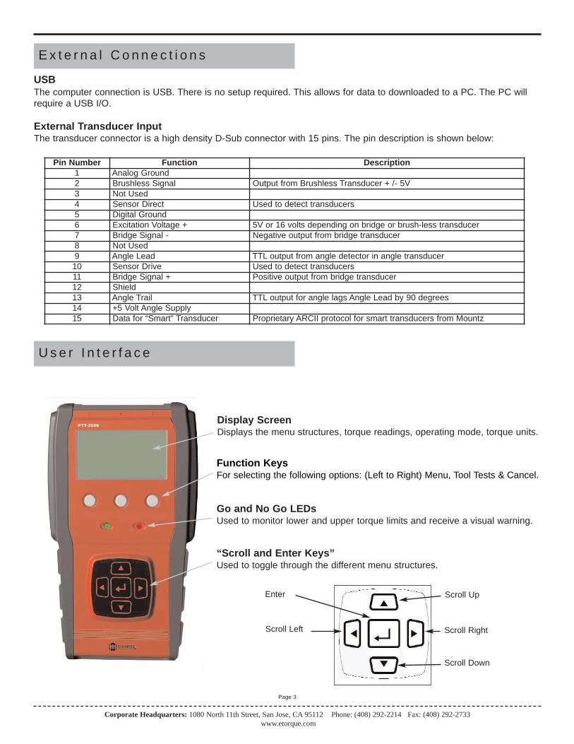
USBThe computer connection is USB. There is no setup required. This allows for data to downloaded to a PC. The PC willrequire a USB I/O.
External Transducer InputThe transducer connector is a high density D-Sub connector with 15 pins. The pin description is shown below:
Pin Number Function Description1 Analog Ground2 Brushless Signal Output from Brushless Transducer + /- 5V3 Not Used4 Sensor Direct Used to detect transducers5 Digital Ground6 Excitation Voltage + 5V or 16 volts depending on bridge or brush-less transducer7 Bridge Signal - Negative output from bridge transducer8 Not Used9 Angle Lead TTL output from angle detector in angle transducer
10 Sensor Drive Used to detect transducers11 Bridge Signal + Positive output from bridge transducer12 Shield13 Angle Trail TTL output for angle lags Angle Lead by 90 degrees14 +5 Volt Angle Supply15 Data for “Smart” Transducer Proprietary ARCII protocol for smart transducers from Mountz
Display ScreenDisplays the menu structures, torque readings, operating mode, torque units.
“Scroll and Enter Keys”Used to toggle through the different menu structures.
Function KeysFor selecting the following options: (Left to Right) Menu, Tool Tests & Cancel.
Go and No Go LEDsUsed to monitor lower and upper torque limits and receive a visual warning.
Scroll Up
Scroll Right
Scroll Down
Scroll Left
Enter
Corporate Headquarters: 1080 North 11th Street, San Jose, CA 95112 Phone: (408) 292-2214 Fax: (408) 292-2733www.etorque.com
Page 4
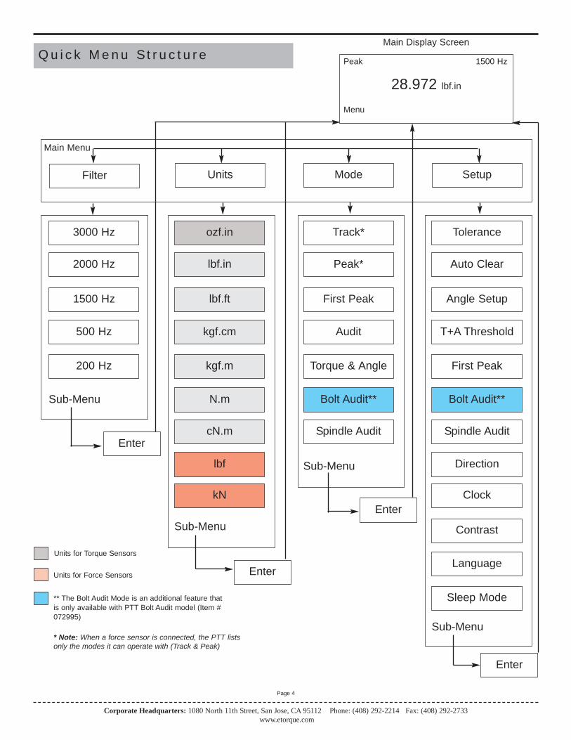
Q u i c k M e n u St r u c t u r eMain Display Screen
Peak 1500 Hz
28.972 lbf.in
Menu
Filter Units Mode Setup
Main Menu
3000 Hz
2000 Hz
1500 Hz
500 Hz
200 Hz
ozf.in
lbf.in
lbf.ft
kgf.cm
kgf.m
N.m
cN.m
Track*
Peak*
First Peak
Audit
Torque & Angle
Tolerance
Auto Clear
Angle Setup
T+A Threshold
First Peak
Bolt Audit**
Spindle Audit
Sub-Menu
Sub-Menu
Sub-Menu
Sub-Menu
Enter
Enter
Enter
Directionlbf
kN
Units for Torque Sensors
Units for Force Sensors
* Note: When a force sensor is connected, the PTT lists only the modes it can operate with (Track & Peak)
Clock
Contrast
Enter
Bolt Audit**
Spindle Audit
** The Bolt Audit Mode is an additional feature thatis only available with PTT Bolt Audit model (Item #072995)
Language
Sleep Mode

Corporate Headquarters: 1080 North 11th Street, San Jose, CA 95112 Phone: (408) 292-2214 Fax: (408) 292-2733www.etorque.com
Page 5
S c r e e n D i s p l a y
When the Torque Analyzer is turned on and it is connected to a Mountz "Smart" Torque Transducer with ARCII technolo-gy it will display a Screen similar to that below for 5 seconds and then go into Reading Mode. This will also happen if a"Smart" transducer is disconnected and another smart transducer is connected. It will automatically detect if the sensor isa torque or force sensor.
Mountz PTT-2000Version 1.06k
Tool ModelBMX250i
Serial Number04-93-071
If an un-calibrated torque transducer or force sensor is connected then the Analyzer will display a screen as below.
Note:The PTT supports Non-Smart torque transducers & force sensors as well as Non-Mountz transducers. Non-smart transducers can be detected and can be calibrated in the "internal" memory. The PTT will offer 2 choices. It offers to calibrate or choose from a list of transducers stored in the internal memory.
Mountz PTT-2000Version 1.06k
Uncalibrated Transducer -Connect to Calibration Software
Note:When disconnecting a smart transducer and connecting another, the operator must unplug the cable from thePTT unit.

Corporate Headquarters: 1080 North 11th Street, San Jose, CA 95112 Phone: (408) 292-2214 Fax: (408) 292-2733www.etorque.com
Page 6
R e a d i n g S c r e e n
Track 3000 Hz
+0.0000 Lbf.in
Menu Tool Tests
M e n u S e l e c t i o n s
Pressing the "Menu" Key will present the following Screen:1. Use the Scroll Up or Down key to toggle through:Filter, Units, Mode and Setup.2. Press Enter key to select a choice.
Filter
Units
Mode
Setup
1. Select Filter by highlighting and pressing Enter.2. Use the Scroll Up or Down key to toggle through the Filter options.3. Press Enter key to select a Filter Setting.
Filter
Units
Mode
Setup
3000 Hz2000 Hz1500 Hz500 Hz200 Hz
Selecting Filters
Main
Main Cancel
Note:Not applicable for Force & LoadSensors.

lbf.inlbf.ftozf.inkgf.cmkgf.mN.m
M e n u S e l e c t i o n s
1. Select Units by highlighting and pressing Enter.2. Use the Scroll Up or Down key to toggle through the Unit options.3. Press Enter key to select a Filter Setting.
Filter
Units
Mode
Setup
Selecting Units
Note:When a torque sensor is connected,the PTT lists only torque units. Also,cN.m is also available but you mustscroll down.
When a force sensor is connected,the PTT lists only force units.
TrackPeakFirst PeakAuditTorque + AngleBolt Audit
1. Select Mode by highlighting and pressing Enter.2. Use the Scroll Up or Down key to toggle through the Mode options.3. Press Enter key to select a Mode Setting.4. The Main (or reading screen) will display the value of the selected Mode.
Filter
Units
Mode
Setup
Selecting Mode Options
ToleranceAuto ClearAngle SetupT+A ThresholdFirst PeakBolt Audit
1. Select Setup by highlighting and pressing Enter.2. Use the Scroll Up or Down key to toggle through the Setup options.3. Press Enter key to select a Setup Setting.
Filter
Units
Mode
Setup
Selecting Setup
Note:Spindle Audit, Direction, Clock,Contrast, Language, & Sleep is alsoavailable but you must scroll down.
The Bolt Audit Mode is an additionalfeature that is only available withPTT Bolt Audit model (Item #072995)
Main Cancel
Main Cancel
Main
Corporate Headquarters: 1080 North 11th Street, San Jose, CA 95112 Phone: (408) 292-2214 Fax: (408) 292-2733www.etorque.com
Page 7
For Torque Sensors
lbfkN
TrackPeak
Note:When a torque sensor is connected,the PTT lists only modes it canoperate with.
When a force sensor is connected,the PTT lists only modes it can operate with.
The Bolt Audit Mode is an additionalfeature that is only available withPTT Bolt Audit model (Item #072995)
For Force Sensors
For Torque Sensors For Force Sensors
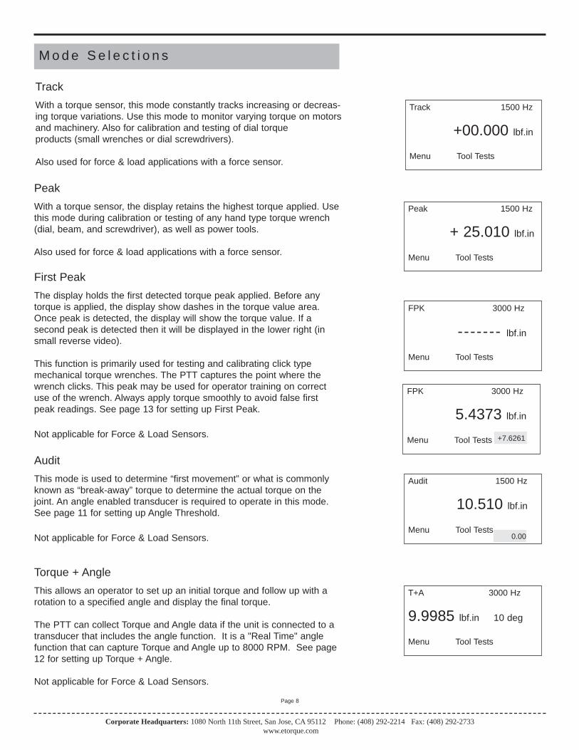
M o d e S e l e c t i o n s
With a torque sensor, this mode constantly tracks increasing or decreas-ing torque variations. Use this mode to monitor varying torque on motorsand machinery. Also for calibration and testing of dial torque products (small wrenches or dial screwdrivers).
Also used for force & load applications with a force sensor.
Track
Track 1500 Hz
+00.000 lbf.in
Menu Tool Tests
With a torque sensor, the display retains the highest torque applied. Usethis mode during calibration or testing of any hand type torque wrench (dial, beam, and screwdriver), as well as power tools.
Also used for force & load applications with a force sensor.
Peak
Peak 1500 Hz
+ 25.010 lbf.in
Menu Tool Tests
The display holds the first detected torque peak applied. Before anytorque is applied, the display show dashes in the torque value area.Once peak is detected, the display will show the torque value. If a second peak is detected then it will be displayed in the lower right (insmall reverse video).
This function is primarily used for testing and calibrating click typemechanical torque wrenches. The PTT captures the point where thewrench clicks. This peak may be used for operator training on correctuse of the wrench. Always apply torque smoothly to avoid false firstpeak readings. See page 13 for setting up First Peak.
Not applicable for Force & Load Sensors.
First Peak
FPK 3000 Hz
------- lbf.in
Menu Tool Tests
FPK 3000 Hz
5.4373 lbf.in
Menu Tool Tests +7.6261
This mode is used to determine “first movement” or what is commonlyknown as “break-away” torque to determine the actual torque on thejoint. An angle enabled transducer is required to operate in this mode.See page 11 for setting up Angle Threshold.
Not applicable for Force & Load Sensors.
Audit
Audit 1500 Hz
10.510 lbf.in
Menu Tool Tests
This allows an operator to set up an initial torque and follow up with arotation to a specified angle and display the final torque.
The PTT can collect Torque and Angle data if the unit is connected to atransducer that includes the angle function. It is a "Real Time" anglefunction that can capture Torque and Angle up to 8000 RPM. See page12 for setting up Torque + Angle.
Not applicable for Force & Load Sensors.
Torque + Angle
T+A 3000 Hz
9.9985 lbf.in 10 deg
Menu Tool Tests
Corporate Headquarters: 1080 North 11th Street, San Jose, CA 95112 Phone: (408) 292-2214 Fax: (408) 292-2733www.etorque.com
Page 8
0.00

M o d e S e l e c t i o n s
This feature is designed for auditing the torque applied to a fastener fora test such as determining relaxation after a fastener has been tight-ened. An angle enabled transducer is required to operate in this Mode.An initial and final torque threshold is entered into the bolt audit modefields and the angle required to move between these 2 thresholds isreported. See page 14 for setting up Bolt Audit
Bolt Audit*
Bolt Audit 1500 Hz
+20.010 lbf.in
Menu Tool Tests
This feature is designed for auditing the operation of a Spindle Tool. Anangle enabled transducer is required to operate in this Mode. The unitchecks the Torque and Angle setting of a Spindle. When the spindlestops, the PTT will display and record the final angle, and final peaktorque. See page 15 for setting up Spindle Audit.
Spindle Audit
+7.6261
Note:* The Bolt Audit Mode is an additional feature that is only availablewith PTT Bolt Audit model (Item # 072995)
Spindle Audit 1500 Hz
+18.969 lbf.in
Menu Tool Tests +2.8723
Corporate Headquarters: 1080 North 11th Street, San Jose, CA 95112 Phone: (408) 292-2214 Fax: (408) 292-2733www.etorque.com
Page 9
E n v i r o n m e n t a l C o n d i t i o n s
Operating Temperature: 0 Degrees Centigrade to 50 Degrees Centigrade
Storage Temperature: -20 Degrees Centigrade to 70 Degrees Centigrade
Humidity: Maximum of 95% Relative Humidity

ToleranceAuto ClearAngle SetupT+A ThresholdFirst PeakSpindle Audit
S e t u p S e l e c t i o n s
The Tolerance parameters control the Go and No-Go signal response (see Go / No Go Signal section). The user setsa lower and upper torque thresholds to get a visual and audible warning signals when these limits are reached orbreached during operation. This function is primarily used for safety and quality control.
Tolerance
Tolerance Setting
Low: _0.000 lbf.inHigh: 84.950 lbf.in
Main
1. Press the "Menu" Button. 2. Use the Scroll Down key and select Setup by highlighting and pressing Enter.3. Use the Scroll Up or Down key to toggle through the Setup options.4. Press Enter key to select a setup setting for Tolerance.
Filter
Units
Mode
Setup
Selecting Tolerance
1. Press the Right or Left key to toggle between High and Low Tolerance..2. Use the Scroll Up or Down key to change the tolerance settings .3. Press Enter key once setting is complete.4. Press Main button to return to main display screen.
This function controls the method of clearing the display of torque readings.
Auto ClearWhen Auto Clear is selected, the torque values, during operation, will automatically be cleared from the display.The user can set the time threshold to control how long the values should be displayed before clearing.
Manual ClearWhen Manual Clear is selected, the torque values during operation will indefinitely be display until the user pressesthe Clear key.
Clear
Corporate Headquarters: 1080 North 11th Street, San Jose, CA 95112 Phone: (408) 292-2214 Fax: (408) 292-2733www.etorque.com
Page 10
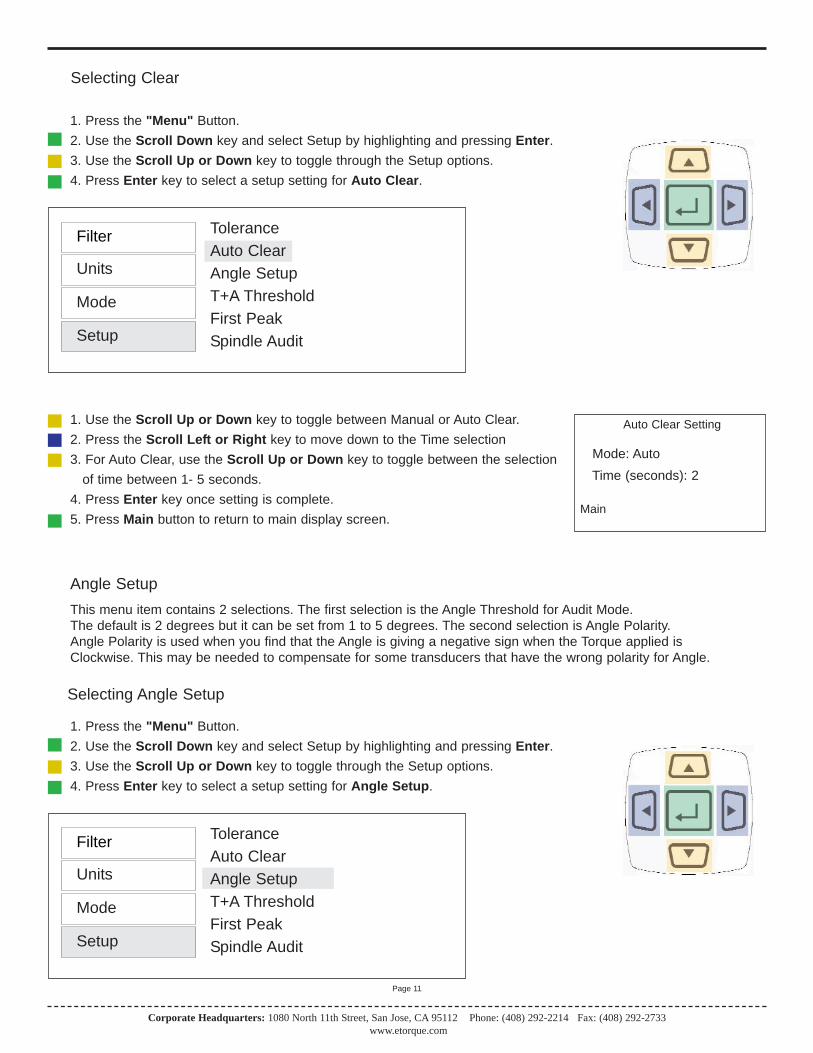
ToleranceAuto ClearAngle SetupT+A ThresholdFirst PeakSpindle Audit
Auto Clear Setting
Mode: AutoTime (seconds): 2
Main
1. Press the "Menu" Button. 2. Use the Scroll Down key and select Setup by highlighting and pressing Enter.3. Use the Scroll Up or Down key to toggle through the Setup options.4. Press Enter key to select a setup setting for Auto Clear.
Filter
Units
Mode
Setup
Selecting Clear
1. Use the Scroll Up or Down key to toggle between Manual or Auto Clear.2. Press the Scroll Left or Right key to move down to the Time selection3. For Auto Clear, use the Scroll Up or Down key to toggle between the selection
of time between 1- 5 seconds.4. Press Enter key once setting is complete.5. Press Main button to return to main display screen.
ToleranceAuto ClearAngle SetupT+A ThresholdFirst PeakSpindle Audit
This menu item contains 2 selections. The first selection is the Angle Threshold for Audit Mode. The default is 2 degrees but it can be set from 1 to 5 degrees. The second selection is Angle Polarity. Angle Polarity is used when you find that the Angle is giving a negative sign when the Torque applied is Clockwise. This may be needed to compensate for some transducers that have the wrong polarity for Angle.
Angle Setup
1. Press the "Menu" Button. 2. Use the Scroll Down key and select Setup by highlighting and pressing Enter.3. Use the Scroll Up or Down key to toggle through the Setup options.4. Press Enter key to select a setup setting for Angle Setup.
Filter
Units
Mode
Setup
Selecting Angle Setup
Corporate Headquarters: 1080 North 11th Street, San Jose, CA 95112 Phone: (408) 292-2214 Fax: (408) 292-2733www.etorque.com
Page 11
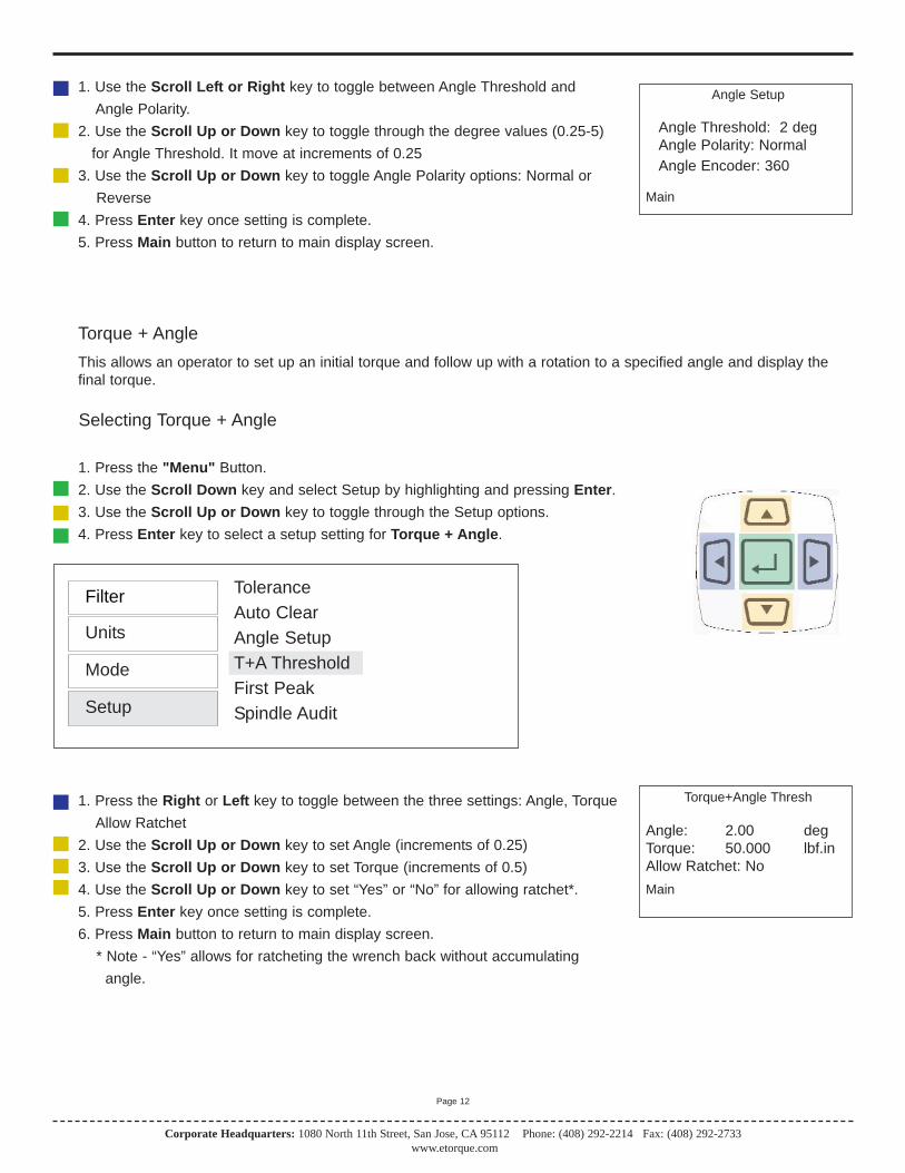
Angle Setup
Angle Threshold: 2 degAngle Polarity: NormalAngle Encoder: 360
Main
1. Use the Scroll Left or Right key to toggle between Angle Threshold and Angle Polarity.
2. Use the Scroll Up or Down key to toggle through the degree values (0.25-5)for Angle Threshold. It move at increments of 0.25
3. Use the Scroll Up or Down key to toggle Angle Polarity options: Normal or Reverse
4. Press Enter key once setting is complete.5. Press Main button to return to main display screen.
Corporate Headquarters: 1080 North 11th Street, San Jose, CA 95112 Phone: (408) 292-2214 Fax: (408) 292-2733www.etorque.com
Page 12
ToleranceAuto ClearAngle SetupT+A ThresholdFirst PeakSpindle Audit
This allows an operator to set up an initial torque and follow up with a rotation to a specified angle and display thefinal torque.
Torque + Angle
Torque+Angle Thresh
Angle: 2.00 degTorque: 50.000 lbf.inAllow Ratchet: NoMain
1. Press the "Menu" Button. 2. Use the Scroll Down key and select Setup by highlighting and pressing Enter.3. Use the Scroll Up or Down key to toggle through the Setup options.4. Press Enter key to select a setup setting for Torque + Angle.
Filter
Units
Mode
Setup
Selecting Torque + Angle
1. Press the Right or Left key to toggle between the three settings: Angle, Torque Allow Ratchet
2. Use the Scroll Up or Down key to set Angle (increments of 0.25)3. Use the Scroll Up or Down key to set Torque (increments of 0.5)4. Use the Scroll Up or Down key to set “Yes” or “No” for allowing ratchet*.5. Press Enter key once setting is complete.6. Press Main button to return to main display screen.
* Note - “Yes” allows for ratcheting the wrench back without accumulating angle.
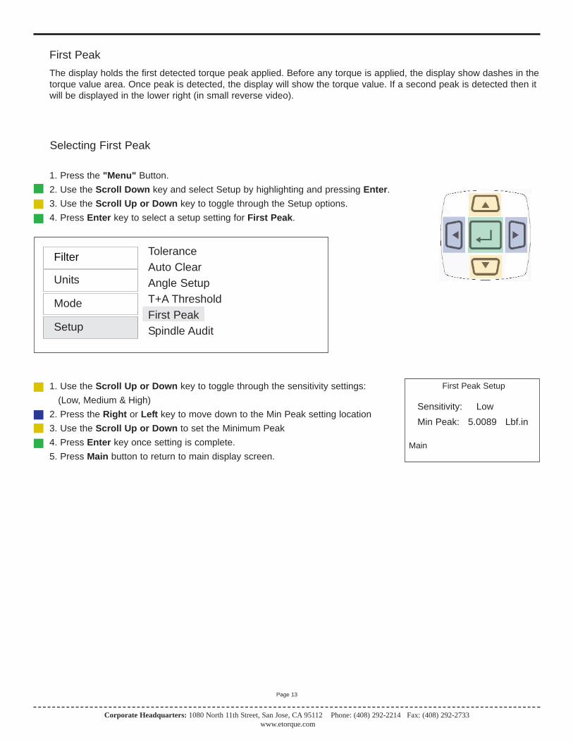
ToleranceAuto ClearAngle SetupT+A ThresholdFirst PeakSpindle Audit
The display holds the first detected torque peak applied. Before any torque is applied, the display show dashes in thetorque value area. Once peak is detected, the display will show the torque value. If a second peak is detected then itwill be displayed in the lower right (in small reverse video).
First Peak
First Peak Setup
Sensitivity: LowMin Peak: 5.0089 Lbf.in
Main
1. Press the "Menu" Button. 2. Use the Scroll Down key and select Setup by highlighting and pressing Enter.3. Use the Scroll Up or Down key to toggle through the Setup options.4. Press Enter key to select a setup setting for First Peak.
Filter
Units
Mode
Setup
Selecting First Peak
1. Use the Scroll Up or Down key to toggle through the sensitivity settings: (Low, Medium & High)
2. Press the Right or Left key to move down to the Min Peak setting location3. Use the Scroll Up or Down to set the Minimum Peak4. Press Enter key once setting is complete.5. Press Main button to return to main display screen.
Corporate Headquarters: 1080 North 11th Street, San Jose, CA 95112 Phone: (408) 292-2214 Fax: (408) 292-2733www.etorque.com
Page 13

Auto ClearAngle SetupT+A ThresholdFirst PeakBolt AuditSpindle Audit
This feature is designed for auditing the torque applied to a fastener for a test such as determining relaxation after afastener has been tightened. An angle enabled transducer is required to operate in this Mode.
Bolt Audit*
Bolt Audit Thresholds
Initial Torque Threshold450 N.m
Final Torque Threshold650 N.m
Main
1. Press the "Menu" Button. 2. Use the Scroll Down key and select Setup by highlighting and pressing Enter.3. Use the Scroll Up or Down key to toggle through the Setup options.4. Press Enter key to select a setup setting for Bolt Audit.
Filter
Units
Mode
Setup
Selecting Bolt Audit
1. Press the Right or Left key to toggle between the threshold settings.2. Use the Scroll Up or Down key to set torque thresholds.4. Press Enter key once setting is complete.5. Press Main button to return to main display screen.
Corporate Headquarters: 1080 North 11th Street, San Jose, CA 95112 Phone: (408) 292-2214 Fax: (408) 292-2733www.etorque.com
Page 14
Note:* The Bolt Audit Mode is an additional feature that is only available with PTT Bolt Audit model (Item # 072995)

ToleranceAuto ClearAngle SetupT+A ThresholdFirst PeakSpindle Audit
This feature is designed for auditing the operation of a Spindle Tool. An angle enabled transducer is required to oper-ate in this Mode. The unit checks the Torque and Angle setting of a Spindle. When the spindle stops, the PTT will dis-play and record the final angle, and final peak torque.
Spindle Audit
Spindle Audit Thresh
Initial Torque: 43 lbf.in
Low Angle: 25 degHigh Angle: 28 deg
Main
1. Press the "Menu" Button. 2. Use the Scroll Down key and select Setup by highlighting and pressing Enter.3. Use the Scroll Up or Down key to toggle through the Setup options.4. Press Enter key to select a setup setting for Spindle Audit.
Filter
Units
Mode
Setup
Selecting Spindle Audit
1. Press the Right or Left key to toggle between the settings.2. Use the Scroll Up or Down key to set torque torque and angle settings.4. Press Enter key once setting is complete.5. Press Main button to return to main display screen.
Corporate Headquarters: 1080 North 11th Street, San Jose, CA 95112 Phone: (408) 292-2214 Fax: (408) 292-2733www.etorque.com
Page 15
Auto ClearAngle SetupT+A ThresholdFirst PeakSpindle AuditDirection
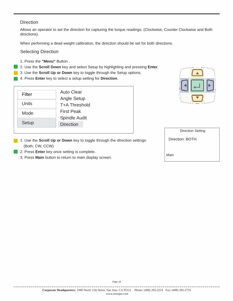
Allows an operator to set the direction for capturing the torque readings: (Clockwise, Counter Clockwise and Bothdirections).
When performing a dead weight calibration, the direction should be set for both directions.
Direction
Direction Setting
Direction: BOTH
Main
1. Press the "Menu" Button . 2. Use the Scroll Down key and select Setup by highlighting and pressing Enter.3. Use the Scroll Up or Down key to toggle through the Setup options.4. Press Enter key to select a setup setting for Direction.
Filter
Units
Mode
Setup
Selecting Direction
1. Use the Scroll Up or Down key to toggle through the dIrection settings: (Both, CW, CCW)
2. Press Enter key once setting is complete.3. Press Main button to return to main display screen.
Corporate Headquarters: 1080 North 11th Street, San Jose, CA 95112 Phone: (408) 292-2214 Fax: (408) 292-2733www.etorque.com
Page 16
Corporate Headquarters: 1080 North 11th Street, San Jose, CA 95112 Phone: (408) 292-2214 Fax: (408) 292-2733www.etorque.com
Page 17
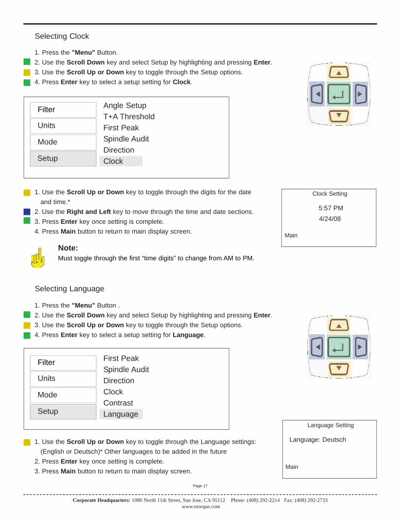
Angle SetupT+A ThresholdFirst PeakSpindle AuditDirectionClock
Clock Setting
5:57 PM4/24/08
Main
1. Press the "Menu" Button. 2. Use the Scroll Down key and select Setup by highlighting and pressing Enter.3. Use the Scroll Up or Down key to toggle through the Setup options.4. Press Enter key to select a setup setting for Clock.
Filter
Units
Mode
Setup
Selecting Clock
1. Use the Scroll Up or Down key to toggle through the digits for the date and time.*
2. Use the Right and Left key to move through the time and date sections.3. Press Enter key once setting is complete.4. Press Main button to return to main display screen.
Note:Must toggle through the first “time digits” to change from AM to PM.
First PeakSpindle AuditDirectionClockContrastLanguage
Language Setting
Language: Deutsch
Main
1. Press the "Menu" Button . 2. Use the Scroll Down key and select Setup by highlighting and pressing Enter.3. Use the Scroll Up or Down key to toggle through the Setup options.4. Press Enter key to select a setup setting for Language.
Filter
Units
Mode
Setup
Selecting Language
1. Use the Scroll Up or Down key to toggle through the Language settings: (English or Deutsch)* Other languages to be added in the future
2. Press Enter key once setting is complete.3. Press Main button to return to main display screen.

Corporate Headquarters: 1080 North 11th Street, San Jose, CA 95112 Phone: (408) 292-2214 Fax: (408) 292-2733www.etorque.com
Page 18
The PTT provides “EZ-Plug & Play” with Mountz Transducers that feature “ARCII” technology, an instant auto-recognition system of the transducer connected to the PTT. When an ARCII Transducer is connected to the PTT itautomatically recognizes the transducer and displays the Model and Serial Number of the connected transducer onthe PTT.
The information stored in the ARCII chips contains:
The Model of Transducer The Serial Number of the Transducer True Calibration Information Date of Calibration
Spindle AuditDirectionClockContrastLanguageSleep
Sleep Mode Setting
Auto Sleep: On
Main
1. Press the "Menu" Button. 2. Use the Scroll Down key and select Setup by highlighting and pressing Enter.3. Use the Scroll Up or Down key to toggle through the Setup options.4. Press Enter key to select a setup setting for Sleep.
Filter
Units
Mode
Setup
Selecting Sleep
1. Use the Scroll Up or Down key to toggle through the Sleep settings: (On or Off)
2. Press Enter key once setting is complete.3. Press Main button to return to main display screen.
Six months from the date of the transducer’s calibration a message will appear on the screen informing the operator thatthe calibration interval has been exceeded. At this point the operator can pull the Transducer out of service or decide tocontinue to use it. After the initial message the user will be reminded each time they connect the transducer.
T r a n s d u c e r C a l i b r a t i o n R e m i n d e r
A R C I I ( A u t o R e c o g n i t i o n C h i p )
Corporate Headquarters: 1080 North 11th Street, San Jose, CA 95112 Phone: (408) 292-2214 Fax: (408) 292-2733www.etorque.com
Page 19
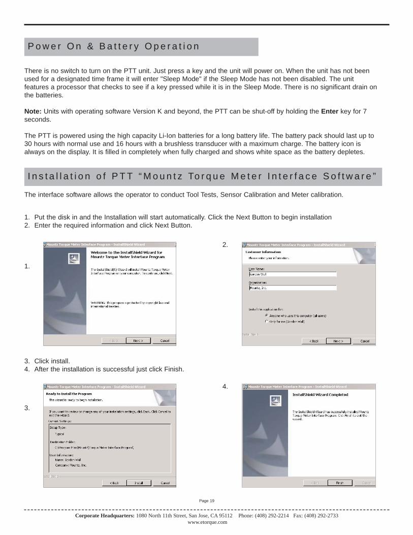
The interface software allows the operator to conduct Tool Tests, Sensor Calibration and Meter calibration.
1. Put the disk in and the Installation will start automatically. Click the Next Button to begin installation2. Enter the required information and click Next Button.
1.
2.
3. Click install.4. After the installation is successful just click Finish.
3.
4.
I n s t a l l a t i o n o f P T T “ M o u n t z To r q u e M e t e r I n t e r f a c e S o f t w a r e ”
There is no switch to turn on the PTT unit. Just press a key and the unit will power on. When the unit has not beenused for a designated time frame it will enter "Sleep Mode" if the Sleep Mode has not been disabled. The unit features a processor that checks to see if a key pressed while it is in the Sleep Mode. There is no significant drain onthe batteries.
Note: Units with operating software Version K and beyond, the PTT can be shut-off by holding the Enter key for 7seconds.
The PTT is powered using the high capacity Li-Ion batteries for a long battery life. The battery pack should last up to30 hours with normal use and 16 hours with a brushless transducer with a maximum charge. The battery icon isalways on the display. It is filled in completely when fully charged and shows white space as the battery depletes.
P o w e r O n & B a t t e r y O p e r a t i o n

Corporate Headquarters: 1080 North 11th Street, San Jose, CA 95112 Phone: (408) 292-2214 Fax: (408) 292-2733www.etorque.com
Page 20
6. Shortly after the PTT is detected the following screen will appear. Do not allow Windows to search for software. Click "No, not this time".
7. The CD should still be inserted from the installation, but if not insert it. Click "Install from a list or specific location" and click Next Button.
6. 7.
8. Check the "Search removable media" box and click Next Button.9. The USB drivers will begin to be installed. If a pop up window appears that the product has not passed the
Windows Logo Testing, just click "Continue Anyway". Mountz has tested the product with both the Home version and Professional version of XP. You will not get this message if you are installing under Windows 2000.
8. 9.
5. After installation of the PTT Interface Program turn on the PTT unit. Connect the USB cable to the PTTand connect the other end to the computer. The computer detects the device in the lower right side of the screen.

Corporate Headquarters: 1080 North 11th Street, San Jose, CA 95112 Phone: (408) 292-2214 Fax: (408) 292-2733www.etorque.com
Page 21
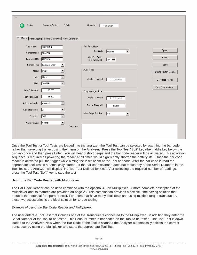
The Tool Test mode contains the followfields.
A. Test NameB. Sensor ModelC. Tool Serial No.D: Sensor TypeE. ModeF. UnitsG. FilterH. Low ToleranceI. High ToleranceJ. Auto-Clear ModeK. Auto-Clear TimeL. DirectionM. CommentsN. OperatorO. First Peak SensitivityP. Minimum First Peak (% of full scale)
To o l Te s t O p e r a t i o n
All tool tests must be entered using the PC Windows based Calibration Program. Once this is done the tests can beaccessed using the "Tool Test" soft key on the PTT.
Entering data for the Tool Test is done using the PC Windows based Calibration Program. See the Screen above.Select the “Tool Tests” tab. Enter the relevant information on this screen such as the Test Name, which is the name bywhich the test will be identified on the PTT. Then enter all required information on the screen because once the tool testis activated on the PTT no changes can be made with the units, tolerances or other information. There is a field for comments to include user specific information. The transducer being used for the Tool Test must be identified. This isdone to prevent a test being run on a transducer with an inappropriate range.
When entering the “Sensor Model” this must match with the sensor identification that was used to identify the transducerwhen it was calibrated. The case of alphanumeric characters will be ignored. If the transducer to be used for the test isconnected you can click on the "Read" button next to the Sensor Model field and the field will be automatically populated. If you are not sure about how the transducer is identified, unplug the transducer from the PTT unit and plug itback in.
Note:*the Sensor Model identification appears on the PTT screen during the initialization.
There are various control buttons to perform operations with this program, these include:
Save - Saves the Tool Test Setups on the PC so it can be used to run further tests in the future.
Open - Opens previously saved Tool Test Setups.
Send - Send a Tool Test to the PTT. It can store up to 5000 results total. Examples of combinations include 100 testswith 50 readings or 50 tests with 100 readings. Note that there is a maximum of 100 tool tests.
Delete Test in Meter - Clicking the “Delete Test in Meter” button brings up a screen that allows you to delete all of theTool Tests stored in the meter or select the Tests you wish to delete. See the example on next page..

Corporate Headquarters: 1080 North 11th Street, San Jose, CA 95112 Phone: (408) 292-2214 Fax: (408) 292-2733www.etorque.com
Page 22
Download Results - Retrieves the results of a tool test after it has been run. It will offer a change to add further notes tothe test at this point. The results will save in the PC in a location of your choice. There will be an "Operator Folder" withthe name of the Operator entered in the upper portion of the Tool Test Screen. The results are stored in a .csv file whichcan be opened in Excel or using a text editor program, such a Notepad. The file name will be the name given to the toolfollowed by the date and the time at which to test was started. If you use this function often you probably will want to cre-ate a shortcut to this folder on your desktop
Clear Data in Meter - Clears the test data for this Tool Test in the PTT meter. Make sure to Download the Results beforeclicking this button. The operator will be asked for confirmation before the action takes place.
Corporate Headquarters: 1080 North 11th Street, San Jose, CA 95112 Phone: (408) 292-2214 Fax: (408) 292-2733www.etorque.com
Page 23
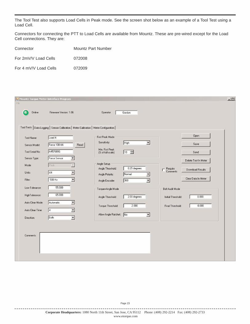
The Tool Test also supports Load Cells in Peak mode. See the screen shot below as an example of a Tool Test using aLoad Cell.
Connectors for connecting the PTT to Load Cells are available from Mountz. These are pre-wired except for the LoadCell connections. They are:
Connector Mountz Part Number
For 2mV/V Load Cells 072008
For 4 mV/V Load Cells 072009

Corporate Headquarters: 1080 North 11th Street, San Jose, CA 95112 Phone: (408) 292-2214 Fax: (408) 292-2733www.etorque.com
Page 24
Once 1 or more tool tests are sent to the PTT meter the operator can press the "Tool Test" soft key on the PTT and following Menu choices will appear:
SelectQuick TestStartStopClear Memory
Choose the function desired, from the menu list, by using the Up /Down keys and use Enter key to finalize the selectionhighlighted in reverse video.
Select is used to select the desired test from a list of tests that have been downloaded. When an operator selects thishe/she will view an introduction for 3 seconds that provide directions, and then this will display:
Choose Tool Test from List of available tests.Use Up /Down keys to toggle between tests.Use Enter to select test.
After the short introduction the operator will see the tool tests displayed and can select the desired test.
Quick Test: By selecting Quick Test the operator can run a quick test using the currently selected parameters of themeter such as Mode, Units, and Tolerance etc. After selecting Quick Test, Press the Enter key. The test starts immediate-ly and the operator can start collecting data. Once the operator collected the number of reading desired then press theTool Test "soft" button that now reads Quick Test. Then the operator can select Stop to end the test.
When the operator connects to the Interface Program and click on Download Results, the Quick Test data is down-loaded. The file name will be Quick Test with associated Date and Time. If the operator performs several different QuickTests he/she will have different Time and/or Date files for each test.
Start begins collecting test data. The tool name will be followed by a colon and then the number of data points collected.
Stop ends the test. This is required as some users may want to collect 10 data or others may want to collect 25 points ormore.
Clear Memory allows the test points to be cleared in the meter itself. Theoperator will be asked for confirmation before the action takes place. This function should only be used if the readings have been downloaded to the PCor test data is invalid for some reason.
Once all desired tests are run the operator can return to the PC to download all Tool Tests stored in the PTT. If they choose to add comments they can do so by checking the"Require Comments" check box. During a particular test download the operator will be given the opportunity to add further notes to the file stored onthe PC.
An example of a Tool Test Result file (image - right)
There is an optional Excel Add-In included on the PTT CD to perform Real-Time data acquisition into an open Excel spreadsheet. It also includesTabs for performing statistical analysis on the data in the spreadsheet. Followthe instructions in the readme file, in this folder, to use this Add-In.
Using the Tool Tests on the PTT
Peak 1500 Hz
33.785 lbf.in
Menu Tool Tests
Corporate Headquarters: 1080 North 11th Street, San Jose, CA 95112 Phone: (408) 292-2214 Fax: (408) 292-2733www.etorque.com
Page 25
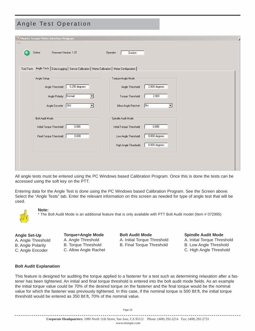
A n g l e Te s t O p e r a t i o n
Angle Set-UpA. Angle ThresholdB. Angle PolarityC. Angle Encoder
All angle tests must be entered using the PC Windows based Calibration Program. Once this is done the tests can beaccessed using the soft key on the PTT.
Entering data for the Angle Test is done using the PC Windows based Calibration Program. See the Screen above.Select the “Angle Tests” tab. Enter the relevant information on this screen as needed for type of angle test that will beused.
Note:* The Bolt Audit Mode is an additional feature that is only available with PTT Bolt Audit model (Item # 072995)
Torque+Angle ModeA. Angle ThresholdB. Torque ThresholdC. Allow Angle Rachet
Bolt Audit ModeA. Initial Torque ThresholdB. Final Torque Threshold
Spindle Audit ModeA. Initial Torque ThresholdB. Low Angle ThresholdC. High Angle Threshold
Bolt Audit Explanation
This feature is designed for auditing the torque applied to a fastener for a test such as determining relaxation after a fas-tener has been tightened. An initial and final torque threshold is entered into the bolt audit mode fields. As an examplethe initial torque value could be 70% of the desired torque on the fastener and the final torque would be the nominalvalue for which the fastener was previously tightened. In this case, if the nominal torque is 500 lbf.ft, the initial torquethreshold would be entered as 350 lbf.ft, 70% of the nominal value.
Corporate Headquarters: 1080 North 11th Street, San Jose, CA 95112 Phone: (408) 292-2214 Fax: (408) 292-2733www.etorque.com
Page 26
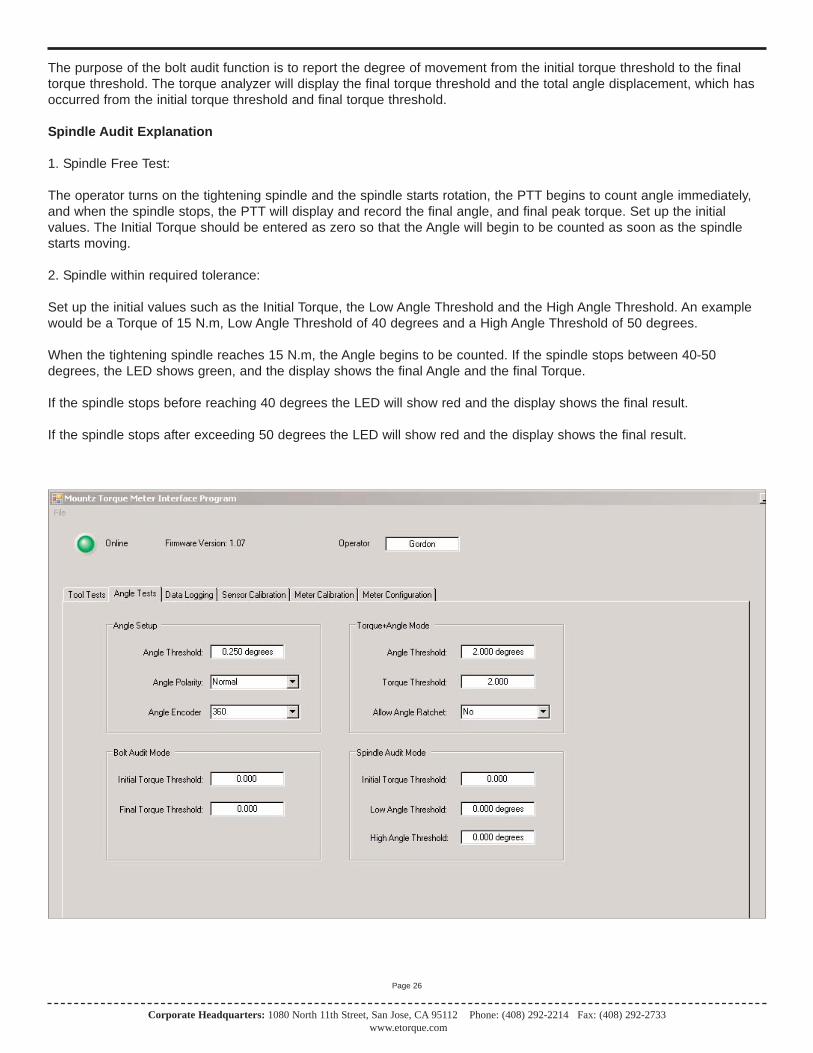
The purpose of the bolt audit function is to report the degree of movement from the initial torque threshold to the finaltorque threshold. The torque analyzer will display the final torque threshold and the total angle displacement, which hasoccurred from the initial torque threshold and final torque threshold.
Spindle Audit Explanation
1. Spindle Free Test:
The operator turns on the tightening spindle and the spindle starts rotation, the PTT begins to count angle immediately,and when the spindle stops, the PTT will display and record the final angle, and final peak torque. Set up the initial values. The Initial Torque should be entered as zero so that the Angle will begin to be counted as soon as the spindlestarts moving.
2. Spindle within required tolerance:
Set up the initial values such as the Initial Torque, the Low Angle Threshold and the High Angle Threshold. An examplewould be a Torque of 15 N.m, Low Angle Threshold of 40 degrees and a High Angle Threshold of 50 degrees.
When the tightening spindle reaches 15 N.m, the Angle begins to be counted. If the spindle stops between 40-50degrees, the LED shows green, and the display shows the final Angle and the final Torque.
If the spindle stops before reaching 40 degrees the LED will show red and the display shows the final result.
If the spindle stops after exceeding 50 degrees the LED will show red and the display shows the final result.

Corporate Headquarters: 1080 North 11th Street, San Jose, CA 95112 Phone: (408) 292-2214 Fax: (408) 292-2733www.etorque.com
Page 27
Transducer Calibration should only be performed by an operator with the necessary calibration wheels or arm and weightsets or by a calibration lab. Mountz offers calibration services to perform this function.
PTT calibrations are done in conjunction with a PC Windows based Calibration Program. The program is easy to useand guides the user through the calibration steps.
Once the program is started and connected to the PTT meter, a button "Start" is provided to start the calibration. All theneeded information must be entered in the appropriate text boxes. This includes information such as the Sensor Model,Serial Number, the Full Scale torque value, the units of calibration and the transducer type (Bridge or Brushless). Thereis also a Scroll box to allow setting of the Calibration Interval. The default is 6 months but that can be changed. Once allrequired information is entered, the Start button is clicked, and its function changes to "Continue" as shown in figurebelow and procedural information will be given in the large text box. A 2-point calibration should work well in all butexceptional circumstances.
Once the calibration is complete the calibration data will be stored in a Mountz "Smart" transducer using the ARCII proto-col. For non-smart transducers calibration data will be stored in the PTT internal memory. A sophisticated error correction algorithm assures that the data written to and retrieved from memory is always correct.
Once the calibration is complete, Torque Values will be displayed in the Torque Window allowing for verification of cali-bration data points.
T r a n s d u c e r C a l i b r a t i o n
Corporate Headquarters: 1080 North 11th Street, San Jose, CA 95112 Phone: (408) 292-2214 Fax: (408) 292-2733www.etorque.com
Page 28
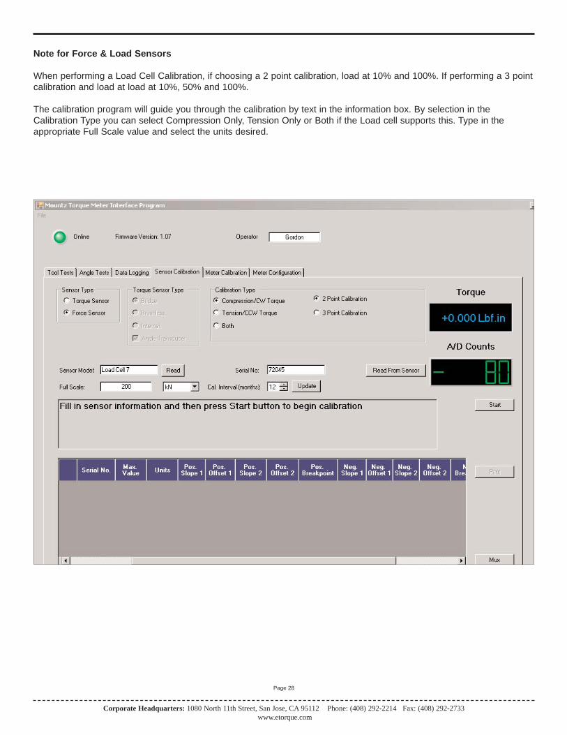
Note for Force & Load Sensors
When performing a Load Cell Calibration, if choosing a 2 point calibration, load at 10% and 100%. If performing a 3 pointcalibration and load at load at 10%, 50% and 100%.
The calibration program will guide you through the calibration by text in the information box. By selection in theCalibration Type you can select Compression Only, Tension Only or Both if the Load cell supports this. Type in the appropriate Full Scale value and select the units desired.
Corporate Headquarters: 1080 North 11th Street, San Jose, CA 95112 Phone: (408) 292-2214 Fax: (408) 292-2733www.etorque.com
Page 29
This procedure is used to calibration the gain of the PTT to a high degree of accuracy. This allows all PTT to exhibit thesame accuracy with a Mountz "Smart" transducer as the meter that was used to perform the calibration.
The PTT Calibration requires special equipment. This equipment is available from Mountz for those that require it as anoptional item.
P T T C a l i b r a t i o n
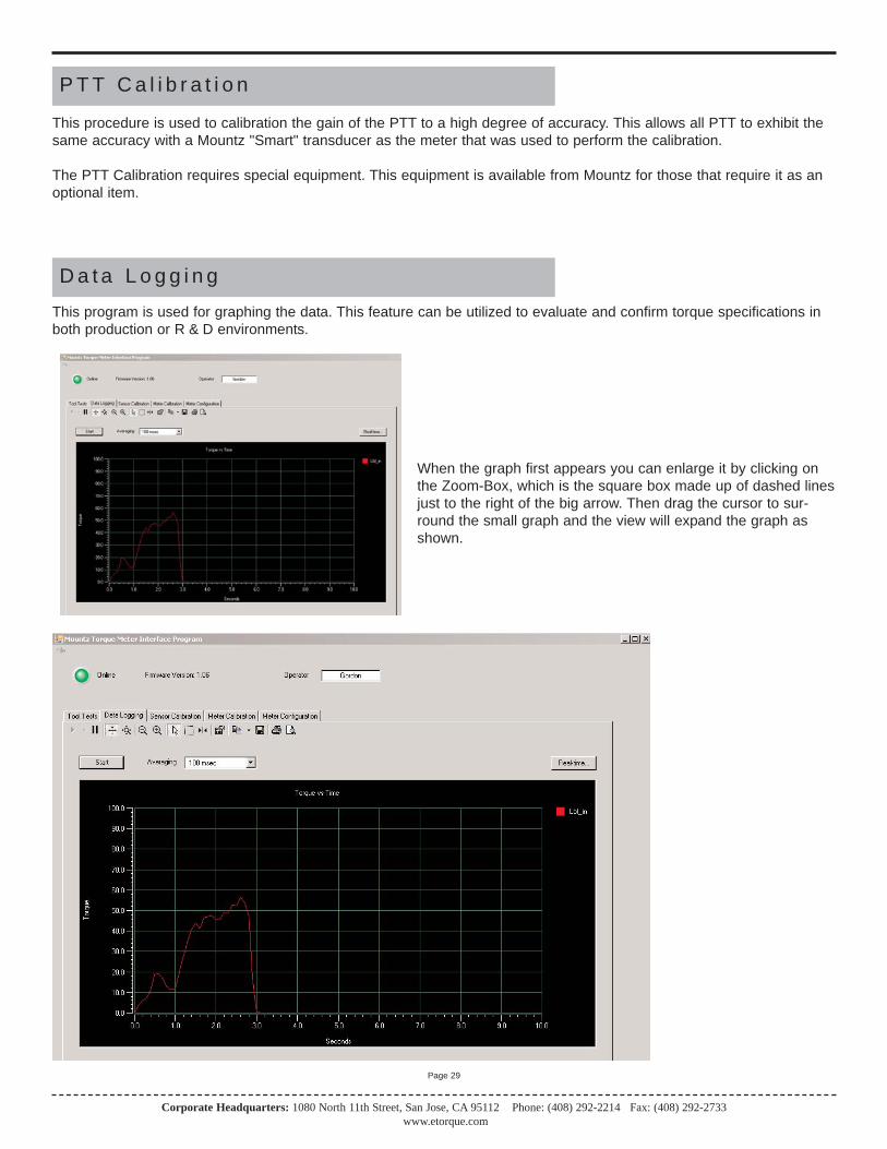
D a t a L o g g i n g
This program is used for graphing the data. This feature can be utilized to evaluate and confirm torque specifications inboth production or R & D environments.
When the graph first appears you can enlarge it by clicking onthe Zoom-Box, which is the square box made up of dashed linesjust to the right of the big arrow. Then drag the cursor to sur-round the small graph and the view will expand the graph asshown.

Corporate Headquarters: 1080 North 11th Street, San Jose, CA 95112 Phone: (408) 292-2214 Fax: (408) 292-2733www.etorque.com
Page 30
The PTT interface program contains a Tab for Data Logging. The actual plot on the Screen is Torque vs. Time. If youhave an Angle enabled transducer the Torque and Angle data will be collected in a .csv file. The data collection beginswhen you click the "Start" button and ends when you click the same button which changes to "Stop" after the data collec-tion begins. The data is collected is available in:The results will be saved in the PC in C:\Program Files\Mountz\ Torque Meter Interface Program \Tool TestResults\Operator Folder where the "Operator Folder" will be the name of the Operator entered in the upper portion of theTool Test Screen. " If you use this function frequently you probably will want to create a shortcut to this folder.
The .csv file can be opened using Excel. You can use Excel to plot this data in a variety of formats or by using otherWindows based tools of your choice. There is also an Excel Spreadsheet with a Macro as an example of Plotting Torqueand Angle. This is available on the PTT CD in the folder Excel Macro for Torque and Angle. Open this Excel file, highlightthe Torque and Angle data, click the Graphing Icon that is on the spreadsheet, the Torque and Angle will be plotted foryou. If you have your own Torque and Angle data you can just replace the example data with your own, highlight it andclick the Graphing Icon to plot it.
Angle Torque6 3.64
21 3.6236 3.63
137 4.34153 3.99167 4.05182 4.23196 4.30211 4.13225 3.74240 3.99254 4.32269 4.52283 4.31298 4.01313 4.18327 4.38342 4.23356 3.95371 3.74385 3.99400 4.13414 4.15429 4.19444 4.13458 3.88473 3.90488 4.09503 4.01517 3.77532 3.79547 4.31561 4.26576 4.22591 4.05605 3.91620 3.86
This Spreadsheet gives an example of Plotting Torque and AngleValues. Simply highlight the cells containing the values of Angle andTorque and click on the Graphing Icon above.
If you have collected Torque and Angle values, using the PTT DataLogging Program, you can use this Template to Plot Torque andAngle. Simply substitute your own values for those on the left.
The data is collected is available in:C:\Program Files\Mountz\PTT Interface Program\Streaming DataFiles\”operator name”Where the “operator name” is the operator entered on the DataLogging Tab. If you use this function often you probably will want tocreate a shortcut to this folder on your desktop.
Corporate Headquarters: 1080 North 11th Street, San Jose, CA 95112 Phone: (408) 292-2214 Fax: (408) 292-2733www.etorque.com
Page 31
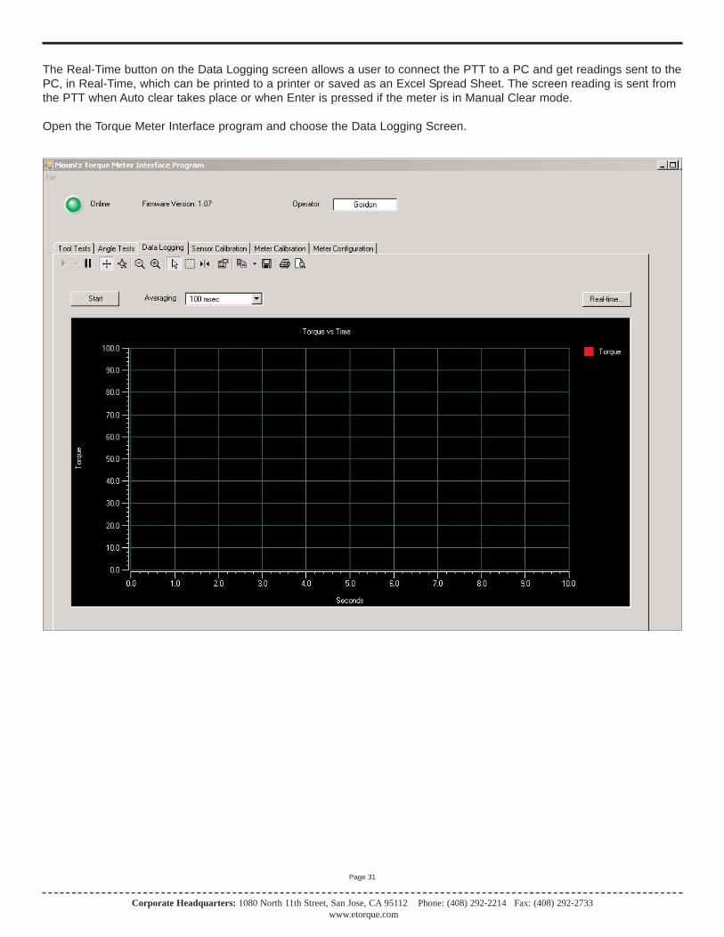
The Real-Time button on the Data Logging screen allows a user to connect the PTT to a PC and get readings sent to thePC, in Real-Time, which can be printed to a printer or saved as an Excel Spread Sheet. The screen reading is sent fromthe PTT when Auto clear takes place or when Enter is pressed if the meter is in Manual Clear mode.
Open the Torque Meter Interface program and choose the Data Logging Screen.
Corporate Headquarters: 1080 North 11th Street, San Jose, CA 95112 Phone: (408) 292-2214 Fax: (408) 292-2733www.etorque.com
Page 32
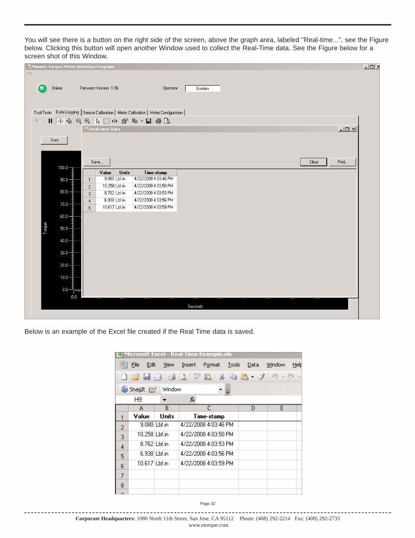
You will see there is a button on the right side of the screen, above the graph area, labeled "Real-time...", see the Figurebelow. Clicking this button will open another Window used to collect the Real-Time data. See the Figure below for ascreen shot of this Window.
Below is an example of the Excel file created if the Real Time data is saved.
Corporate Headquarters: 1080 North 11th Street, San Jose, CA 95112 Phone: (408) 292-2214 Fax: (408) 292-2733www.etorque.com
Page 34
To r q u e M e t e r B o o t l o a d e r
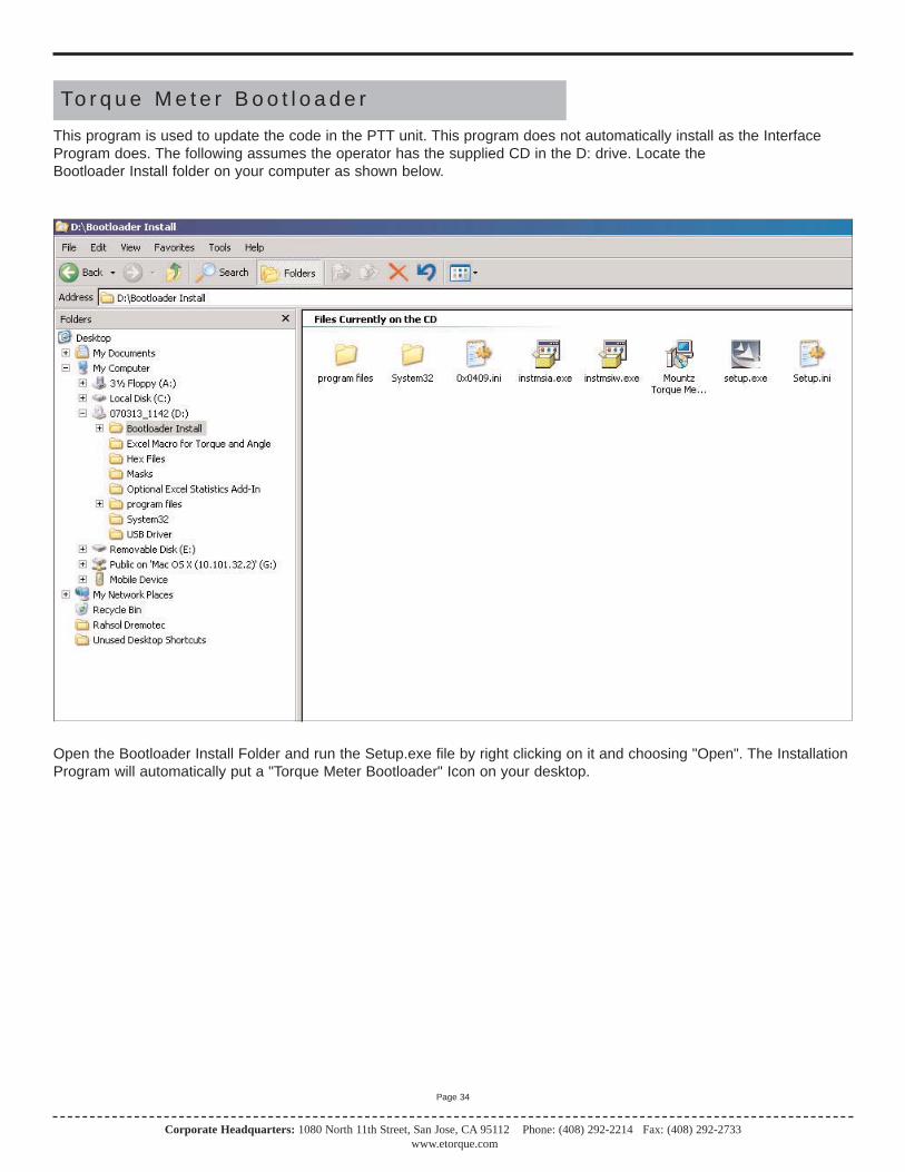
This program is used to update the code in the PTT unit. This program does not automatically install as the InterfaceProgram does. The following assumes the operator has the supplied CD in the D: drive. Locate theBootloader Install folder on your computer as shown below.
Open the Bootloader Install Folder and run the Setup.exe file by right clicking on it and choosing "Open". The InstallationProgram will automatically put a "Torque Meter Bootloader" Icon on your desktop.
Corporate Headquarters: 1080 North 11th Street, San Jose, CA 95112 Phone: (408) 292-2214 Fax: (408) 292-2733www.etorque.com
Page 34
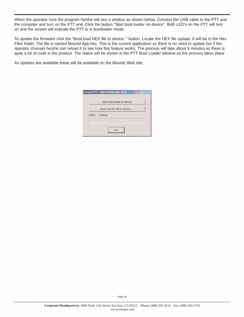
When the operator runs the program he/she will see a window as shown below. Connect the USB cable to the PTT andthe computer and turn on the PTT unit. Click the button "Start boot loader on device". Both LED's on the PTT will turnon and the screen will indicate the PTT is in bootloader mode.
To update the firmware click the "Boot load HEX file to device.." button. Locate the HEX file update. It will be in the HexFiles folder. The file is named Mountz App.hex. This is the current application so there is no need to update but if theoperator chooses he/she can reload it to see how this feature works. The process will take about 6 minutes as there isquite a lot of code in the product. The status will be shown in the PTT Boot Loader window as the process takes place
As updates are available these will be available on the Mountz Web site.
Corporate Headquarters: 1080 North 11th Street, San Jose, CA 95112 Phone: (408) 292-2214 Fax: (408) 292-2733www.etorque.com
Page 35
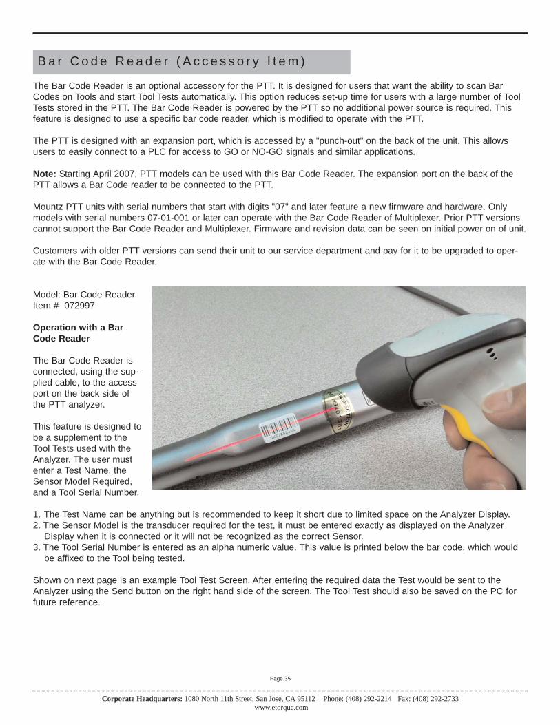
B a r C o d e R e a d e r ( A c c e s s o r y I t e m )
The Bar Code Reader is an optional accessory for the PTT. It is designed for users that want the ability to scan BarCodes on Tools and start Tool Tests automatically. This option reduces set-up time for users with a large number of ToolTests stored in the PTT. The Bar Code Reader is powered by the PTT so no additional power source is required. Thisfeature is designed to use a specific bar code reader, which is modified to operate with the PTT.
The PTT is designed with an expansion port, which is accessed by a "punch-out" on the back of the unit. This allowsusers to easily connect to a PLC for access to GO or NO-GO signals and similar applications.
Note: Starting April 2007, PTT models can be used with this Bar Code Reader. The expansion port on the back of thePTT allows a Bar Code reader to be connected to the PTT.
Mountz PTT units with serial numbers that start with digits "07" and later feature a new firmware and hardware. Onlymodels with serial numbers 07-01-001 or later can operate with the Bar Code Reader of Multiplexer. Prior PTT versionscannot support the Bar Code Reader and Multiplexer. Firmware and revision data can be seen on initial power on of unit.
Customers with older PTT versions can send their unit to our service department and pay for it to be upgraded to oper-ate with the Bar Code Reader.
Model: Bar Code ReaderItem # 072997
Operation with a BarCode Reader
The Bar Code Reader isconnected, using the sup-plied cable, to the accessport on the back side ofthe PTT analyzer.
This feature is designed tobe a supplement to theTool Tests used with theAnalyzer. The user mustenter a Test Name, theSensor Model Required,and a Tool Serial Number.
1. The Test Name can be anything but is recommended to keep it short due to limited space on the Analyzer Display. 2. The Sensor Model is the transducer required for the test, it must be entered exactly as displayed on the Analyzer
Display when it is connected or it will not be recognized as the correct Sensor. 3. The Tool Serial Number is entered as an alpha numeric value. This value is printed below the bar code, which would
be affixed to the Tool being tested.
Shown on next page is an example Tool Test Screen. After entering the required data the Test would be sent to theAnalyzer using the Send button on the right hand side of the screen. The Tool Test should also be saved on the PC forfuture reference.
Corporate Headquarters: 1080 North 11th Street, San Jose, CA 95112 Phone: (408) 292-2214 Fax: (408) 292-2733www.etorque.com
Page 36
Once the Tool Test or Tool Tests are loaded into the analyzer, the Tool Test can be selected by scanning the bar coderather than selecting the test using the menu on the Analyzer. Press the Tool Test "Soft" key (the middle key below thedisplay) once and then press Enter. You will hear 3 short beeps and the bar code reader will be activated. This activationsequence is required as powering the reader at all times would significantly shorten the battery life. Once the bar codereader is activated pull the trigger while aiming the laser beam at the Tool bar code. After the bar code is read the appropriate Tool Test is automatically started. If the bar code scanned does not match any of the Serial Numbers in theTool Tests, the Analyzer will display "No Tool Test Defined for xxx". After collecting the required number of readings,press the Tool Test "Soft" key to stop the test
Using the Bar Code Reader with Multiplexer
The Bar Code Reader can be used combined with the optional 4-Port Multiplexer. A more complete description of theMultiplexer and its features are provided on page 28. This combination provides a flexible, time saving solution thatreduces the potential for operator error. For users that have many Tool Tests and using multiple torque transducers,these two accessories is the ideal solution for torque testing.
Example of using the Bar Code Reader and Multiplexer.
The user enters a Tool Test that includes one of the Transducers connected to the Multiplexer. In addition they enter theSerial Number of the Tool to be tested. This Serial Number is bar coded on the Tool to be tested. This Tool Test is down-loaded to the Analyzer. Now when the Bar Code of the Tool is scanned the Analyzer automatically selects the correcttransducer by using the Multiplexer and starts the appropriate Tool Test.

Corporate Headquarters: 1080 North 11th Street, San Jose, CA 95112 Phone: (408) 292-2214 Fax: (408) 292-2733www.etorque.com
Page 37
The Multiplexer is an optional accessory for the PTT. It allows users to connect 1-4 transducers to the Torque Analyzersimultaneously. The device eliminates the need to plug and unplug transducers. The PTT powers the Multiplexer so noadditional power source is required.
Note: Starting April 2007, PTT models can be used with this Multiplexer.
Mountz PTT units with serial numbers that start with digits "07" and later feature a new firmware and hardware. Onlymodels with serial numbers 07-01-001 or later can operate with the Bar Code Reader of Multiplexer. Prior PTT versionscannot support the Bar Code Reader and Multiplexer. Firmware and revision data can be seen on initial power on of unit.
Customers with older PTT versions, can send their unit to our service department and pay for it to be upgraded to operate with the Multiplexer.
M u l t i p l e x e r ( A c c e s s o r y I t e m )
Model: MultiplexerItem # 072998
Operation with the Multiplexer (Mux)
When the Analyzer is connected to the Multiplexer and powered on it reviews the Multiplexer (Mux) to determine whattransducers are connected and downloads the identity and calibration data for each of the attached transducers.
The "Soft" key on the right hand side will indicate the currently selected Mux port such as Mux 1, Mux 2 etc. In addition,an LED on the right side of the transducer connection to the Mux will light-up indicating which transducer is currentlyselected.
Selecting Transducer Manually1. Press the Mux "Soft" key and it will provide a list of currently connected Transducers. 2. The user can scroll through the list transducers and press Enter to select a model.
Selecting a Transducer AutomaticallyAn automatic transducer selection is available. 1. A Tool Test is entered that includes one of the transducers connected to the Mux and this Tool Test is sent to the
Analyzer. 2. Now when the Tool Test is selected on the PTT, the analyzer automatically connects to the required Transducer using
the Mux. This reduces operator error of accidentally selecting the wrong transducer for a tool test.
The Multiplexer can be used with the optional Bar Code Reader. A more complete description of the Bar Code Reader ison page 36. This combination provides a flexible, time saving solution that reduces the potential for operator error. Forusers that have many Tool Tests and using multiple torque transducers, these two accessories is the ideal solution fortorque testing.
Example of using the Bar Code Reader and Multiplexer.
The user enters a Tool Test that includes one of the Transducers connected to the Mux. In addition they enter the SerialNumber of the Tool to be tested. This Serial Number is bar coded on the Tool to be tested. This Tool Test is downloadedto the Analyzer. Now when the Bar Code of the Tool is scanned the Analyzer automatically selects the correct transducerby using the Mux and starts the appropriate Tool Test.
Note: When calibratingTransducers, perform this opera-tion with the Transducer connect-ed directly to the PTT and not con-nected through the Multiplexer.

Corporate Headquarters: 1080 North 11th Street, San Jose, CA 95112 Phone: (408) 292-2214 Fax: (408) 292-2733www.etorque.com
Page 38
F o r c e & L o a d S e n s o r s
Starting April 2007, PTT models can be used with Force & Load sensors.
Note: Mountz PTT units with serial numbers that start with digits "07" and later feature a new firmware and hardware.Only models with serial numbers 07-01-001 or later can operate with the Force & Load sensors. Prior PTT versions can-not support the Bar Force & Load sensors. Firmware and revision data can be seen on initial power on of unit.
Customers with older PTT versions, can send their unit to our service department and pay for it to be upgraded to operate with load & force sensors.
Using PTT 2000 as a Force Measurement MeterThe PTT recognizes standard or ARCII equipped force sensors (load cells). The active modes of operation for force areTRACK & PEAK. Descriptions of these modes are found in this manual (see page 8).
ARCII equipped sensors incorporate a small chip that allows for automatic sensor recognition (see page 14). This featureidentifies the sensor, all calibration data and a calibration date reminder. This chip can be added to the connection cableto enable the features of the ARCII technology.
The SET UP mode allows users to define how the PTT operates, including setting of the Clock. Three modes that areirrelevant to Force are Angle, T+A Threshold and First Peak (these are Torque Only selections).
The PTT only supports 2 units of measure when connected to a force or lead sensor. Those units are kN or Lbf.
Force sensors can be used in 3 directions. Clockwise (Compression), Counter Clockwise (Tension) or Both can beselected in the Setup mode. (See page 16) for setting direction.
The included software program Mountz Torquemeter Interface Program (MTIP) has functions for Tool Tests, DataLogging, Sensor and Meter Calibration. For calibration of Force sensors, select the sensor type Force.
For Tool Test you can define a type of parameter criteria, including tolerance settings for a specific function. (See page18 for setting up Tool tests). For questions related to Force use, please study the manual or you can call a Mountz representative for assistance.

Mountz, Inc.Corporate Headquarters & Service Center
1080 North 11th StreetSan Jose, CA 95112
Phone: (408) 292-2214Fax: (408) 292-2733
E-mail: [email protected]
Distribution & Service Center19051 Underwood Road
Foley, AL 36535Phone: (251) 943-4125
Fax: (251) 943-4979
US & Canada Sales OfficesAnaheim, Boston, Charlotte, Chicago,
Cleveland, Dallas, El Paso, Los Angeles, Minneapolis, Nashville, Phoenix,
Seattle, San Jose, Toronto
Mountz Mexico SA de CVMain Office & Service Center
Av. Cristobal Colon #15343Col. Paseos de Chihuahua
Chihuahua, Chih. Mexico CP 31125Phone: (614) 481-0023
Fax: (614) 481-0053
Mexico Sales OfficesChihuahua, Guadlajara, Juarez, Mexico City
Monterrey, Reynosa, Saltillo, Tijuana