
Pt incorporated hollow core mesoporous shell carbon nanocomposite catalyst for proton exchange...
10
Pt incorporated hollow core mesoporous shell carbon nanocomposite catalyst for proton exchange membrane fuel cells Berker Fıc ¸ ıcılar a, *, Ays x e Bayrakc ¸eken b , _ Inci Erog ˘lu a a Department of Chemical Engineering, Middle East Technical University, 06531 Ankara, Turkey b Department of Chemical Engineering, Atatu ¨ rk University, 25240 Erzurum, Turkey article info Article history: Received 19 June 2009 Received in revised form 4 October 2009 Accepted 2 November 2009 Available online 20 November 2009 Keywords: PEMFC Hollow core mesoporous shell carbon Carbon black Pt nanoparticles Microwave irradiation Cathode electrode abstract In the present study, various commercial carbon black materials like Vulcan XC72, Black Pearl 2000, and Regal 330 were used as supporting material for polymer electrolyte membrane fuel cell (PEMFC) electrocatalysts. A promising carbon material exhibiting hollow core mesoporous shell (HCMS) structure was synthesized by the template replication of the silica spheres with solid core and mesoporous shell structure. Two carbon supports with similar pore texture were prepared by the injection of two different carbon precursors. 20 wt% Pt/C electrocatalysts were synthesized by microwave irradiation method as the cathode electrode for PEMFC. Ex situ characterization of the electrocatalysts was performed by N 2 adsorption analysis, X-ray diffraction (XRD), X-ray photoelectron spectroscopy (XPS), thermogravimetric analysis (TGA), and transmission electron microscopy (TEM). Electro- chemical characterization of the electrocatalysts was conducted by cyclic voltammetry (CV) analysis. Effect of different carbon supports on the cathode performance was investigated in a single cell H 2 /O 2 PEMFC. Fuel cell performance tests and additional ex situ characteriza- tions showed that HCMS carbons exhibit good support characteristics with improved single cell performance. For the cathode electrode kinetics, promising fuel cell performance results were obtained as compared to the commercial carbon blacks. ª 2009 Professor T. Nejat Veziroglu. Published by Elsevier Ltd. All rights reserved. 1. Introduction Among the several fuel cell types, polymer electrolyte membrane fuel cells (PEMFCs) have attracted much more attention for both portable and stationary applications due to its beneficial characteristics such as high power density at rela- tively lower temperatures, lightweight, and compactness [1]. Development of fuel cell electrocatalyst plays a critical role in the commercialization of the PEMFCs in the aspects of the cost and the performance. Platinum is the most active metal for the anode and the cathode electrochemical reactions of PEMFCs. However, high cost of platinum, lack of availability of platinum, possibility of catalyst poisoning (e.g. CO poisoning), stability and durability issues are some of the critical problems that hinder the electrodics of the polymer electrolyte membrane fuel cells [2]. Platinum should be uniformly distributed over a porous support material to increase the electrochemically active area. Optimization of the catalyst particle diameter is a critical issue since the activity of an electrocatalyst increases as the reaction surface area of the catalytic material increases [3,4]. Besides the active metal, supporting material for the elec- trocatalyst also plays a significant role for the enhancement of the electrochemical reactions at the catalytic regions of the PEMFC. In recent years, various methods have been proposed * Corresponding author. Tel.: þ(90) 312 210 4349; fax: þ(90) 312 210 2600. E-mail address: [email protected] (B. Fıc ¸ ıcılar). Available at www.sciencedirect.com journal homepage: www.elsevier.com/locate/he international journal of hydrogen energy 35 (2010) 9924–9933 0360-3199/$ – see front matter ª 2009 Professor T. Nejat Veziroglu. Published by Elsevier Ltd. All rights reserved. doi:10.1016/j.ijhydene.2009.11.016
Transcript of Pt incorporated hollow core mesoporous shell carbon nanocomposite catalyst for proton exchange...
i n t e r n a t i o n a l j o u r n a l o f h y d r o g e n e n e r g y 3 5 ( 2 0 1 0 ) 9 9 2 4 – 9 9 3 3
Avai lab le at www.sc iencedi rect .com
journa l homepage : www.e lsev ie r . com/ loca te /he
Pt incorporated hollow core mesoporous shell carbonnanocomposite catalyst for proton exchange membranefuel cells
Berker Fıcıcılar a,*, Aysxe Bayrakceken b, _Inci Eroglu a
a Department of Chemical Engineering, Middle East Technical University, 06531 Ankara, Turkeyb Department of Chemical Engineering, Ataturk University, 25240 Erzurum, Turkey
a r t i c l e i n f o
Article history:
Received 19 June 2009
Received in revised form
4 October 2009
Accepted 2 November 2009
Available online 20 November 2009
Keywords:
PEMFC
Hollow core mesoporous shell carbon
Carbon black
Pt nanoparticles
Microwave irradiation
Cathode electrode
* Corresponding author. Tel.: þ(90) 312 210 4E-mail address: [email protected] (B. F
0360-3199/$ – see front matter ª 2009 Profesdoi:10.1016/j.ijhydene.2009.11.016
a b s t r a c t
In the present study, various commercial carbon black materials like Vulcan XC72, Black
Pearl 2000, and Regal 330 were used as supporting material for polymer electrolyte
membrane fuel cell (PEMFC) electrocatalysts. A promising carbon material exhibiting hollow
core mesoporous shell (HCMS) structure was synthesized by the template replication of the
silica spheres with solid core and mesoporous shell structure. Two carbon supports with
similar pore texture were prepared by the injection of two different carbon precursors.
20 wt% Pt/C electrocatalysts were synthesized by microwave irradiation method as the
cathode electrode for PEMFC. Ex situ characterization of the electrocatalysts was performed
by N2 adsorption analysis, X-ray diffraction (XRD), X-ray photoelectron spectroscopy (XPS),
thermogravimetric analysis (TGA), and transmission electron microscopy (TEM). Electro-
chemical characterization of the electrocatalysts was conducted by cyclic voltammetry (CV)
analysis. Effect of different carbon supports on the cathode performance was investigated in
a single cell H2/O2 PEMFC. Fuel cell performance tests and additional ex situ characteriza-
tions showed that HCMS carbons exhibit good support characteristics with improved single
cell performance. For the cathode electrode kinetics, promising fuel cell performance results
were obtained as compared to the commercial carbon blacks.
ª 2009 Professor T. Nejat Veziroglu. Published by Elsevier Ltd. All rights reserved.
1. Introduction possibility of catalyst poisoning (e.g. CO poisoning), stability and
Among the several fuel cell types, polymer electrolyte
membrane fuel cells (PEMFCs) have attracted much more
attention for both portable and stationary applications due to its
beneficial characteristics such as high power density at rela-
tively lower temperatures, lightweight, and compactness [1].
Development of fuel cell electrocatalyst plays a critical role in
the commercialization of the PEMFCs in the aspects of the cost
and the performance. Platinum is the most active metal for the
anode and the cathode electrochemical reactions of PEMFCs.
However, high cost of platinum, lack of availability of platinum,
349; fax: þ(90) 312 210 26ıcıcılar).sor T. Nejat Veziroglu. Pu
durability issues are some of the critical problems that hinder
the electrodics of the polymer electrolyte membrane fuel cells
[2]. Platinum should be uniformly distributed over a porous
support material to increase the electrochemically active area.
Optimization of the catalyst particle diameter is a critical issue
since the activity of an electrocatalyst increases as the reaction
surface area of the catalytic material increases [3,4].
Besides the active metal, supporting material for the elec-
trocatalyst also plays a significant role for the enhancement of
the electrochemical reactions at the catalytic regions of the
PEMFC. In recent years, various methods have been proposed
00.
blished by Elsevier Ltd. All rights reserved.
i n t e r n a t i o n a l j o u r n a l o f h y d r o g e n e n e r g y 3 5 ( 2 0 1 0 ) 9 9 2 4 – 9 9 3 3 9925
for the synthesis of carbon materials as PEMFC electrocatalyst
support [5–9]. A proper catalyst support, usually carbon, must
exhibit good electronic conductivity to create a pathway for
the flow of electrons throughout the solid matrix [10]. Pore
texture of the carbon material should facilitate the passage of
reactants and products from the active catalytic sites to the
bulk of the fluid. This issue becomes especially critical at high
current densities, that is, when the water production rate is
accelerated. Another important feature of the carbon support
is that the support must have high surface area to increase
the reaction rate for both the hydrogen oxidation reaction and
the oxygen reduction reaction (ORR) such that one must avoid
the pore clogging phenomena by polymer solution
(e.g. Nafion� solution) [11].
In carbon supported catalysts, the structure of the support
affects the catalyst properties such as the particle size,
dispersion, metal–support interaction and the accessibility of
the reactants to the active metal [12]. In PEMFCs, the electrolyte
is a solid polymer (e.g. Nafion�). To provide a network between
the catalyst and the membrane, commonly Nafion� solution is
used in the catalyst ink. There is also a need for an ordered
macro/meso bimodal pore structure to provide an efficient
pathway for the flow of protons from the active sites to the
membrane. In case of carbon supports having a high
percentage of micropores, addition of the Nafion� solution can
inhibit the access of the reactants to the metal which will result
in a decrease in the fuel cell performance. However, use of high
surface area carbon supports with increased mesoporosity
provides a high accessibility to the active surface area of the
catalyst.
Among the other catalyst preparation techniques [13,14],
microwave irradiation seems to be a promising method
because of being time and energy efficient. Microwave irra-
diation has a wide variety of applications in chemistry. Many
chemical reactions can be accelerated by the utilization of the
microwave field which depends on the material having high
dielectric constant. In the literature, it is shown that micro-
wave irradiation can be used to prepare the catalysts for
different applications [15–17]. In our previous study, we
revealed that microwave irradiation method can be used to
prepare considerably active electrocatalysts such as Pt, Pt–Ru
or Pt–Pd incorporated over carbon support [18,19].
Electrocatalytic performance of the catalysts can be tested
either with half cell experiments (ex situ analysis with cyclic
voltammetry tests) [20] or in a single cell PEMFC [19]. Performing
half cell experiments with rotating disk electrode (RDE) system
is a convenient and relatively fast method of screening elec-
trocatalysts. The full fuel cell test is the primary technique for
the characterization of the whole fuel cell performance. PEMFC
tests supply the voltage–current density relationship under fuel
cell environment. The performance curve obtained also gives
information about the cell losses under the fuel cell operating
conditions. For a detailed characterization of the fuel cell, the
effects of both system components and operating conditions
have to be analyzed by performance curves. In addition, these
performance curves help to determine which performance loss
dominates and provide the information for a new route to
compensate the inverse effect. There are few publications in
literature, which have compared the relative significance of
these experimental data [21–23].
The purpose of the present research was to explore and
compare the performance of Pt/C electrocatalysts supported
on various carbon supports by testing their ex situ perfor-
mances with cyclic voltammetry (CV) method and in situ
performances in a single cell PEMFC where the catalysts are
being used as cathode electrodes. We compared the relevance
of these data on the electrocatalyst development and
improvement for PEMFCs. In the present work, the carbon
supports which were under investigation are the carbon
blacks (Vulcan XC72, Black Pearl 2000, and Regal 330) and
a synthesized novel ordered mesoporous carbon. A promising
carbon nanomaterial with hollow core mesoporous shell
(HCMS) structure was synthesized as PEMFC catalyst support.
High surface area HCMS carbon with a bimodal macroporous/
mesoporous structure was prepared with the template repli-
cation of solid core mesoporous shell (SCMS) silica. Microwave
synthesis method was used for the incorporation of Pt nano-
particles on carbon supports. The Pt/C electrocatalysts were
characterized by N2 adsorption analysis, X-ray diffraction
(XRD), X-ray photoelectron spectroscopy (XPS), thermogravi-
metric analysis (TGA), and transmission electron microscopy
(TEM). Subsequently, electrochemical activity measurements
(CV tests) were conducted and single cell PEMFC performances
of these electrocatalysts were investigated in the cathode
electrode.
2. Experimental
Spherical carbon particles can be synthesized by template
replication of silica spheres exhibiting solid core and meso-
porous shell structure. Solid core mesoporous shell (SCMS)
silica spheres with adjustable core/shell properties are
prepared by the concurrent sol–gel polymerization of tetrae-
thoxysilane (TEOS) and octadecyltrimethoxysilane (C18TMS).
Removal of the organic group yields the silica spheres. SCMS
silica synthesis procedure is given elsewhere [24,25]. In the
present study, phenol/paraformaldehyde (hereinafter, HCMS1)
and divinylbenzene/azobis-isobutyronitrile (DVB/AIBN) (here-
inafter, HCMS2) were used as carbon precursors for the prep-
aration of HCMS1 and HCMS2 carbon supports respectively.
The details of the synthesis of HCMS carbon were given in our
previous study [19]. Prior to the electrocatalyst preparation, no
oxidative treatment or thermal treatment was applied to the
carbon supports.
Microwave irradiation method was used for the incorpo-
ration of the 20 wt% platinum nanoparticles into the carbon
supports. The detailed synthesis procedure of the 20% Pt/C
electrocatalysts was outlined in the previous study [18]. In the
present work, microwave duration of the Pt/HCMS1 electro-
catalysts was altered in a range of 50–150 s at 800 W. On the
basis of Pt/HCMS1 single cell PEMFC cathode performance
tests, microwave synthesis conditions of Pt/HCMS2 electro-
catalysts were adjusted to 120 s at 800 W. Previously, effect of
microwave duration on Pt/Vulcan XC72 (Pt/VX) electro-
catalysts was investigated [18] and an optimum microwave
duration of 50 s at 800 W was reported for Pt supported Vulcan
XC72. Therefore, in the case of carbon black based electro-
catalysts, microwave duration was adjusted to 50 s at 800 W.
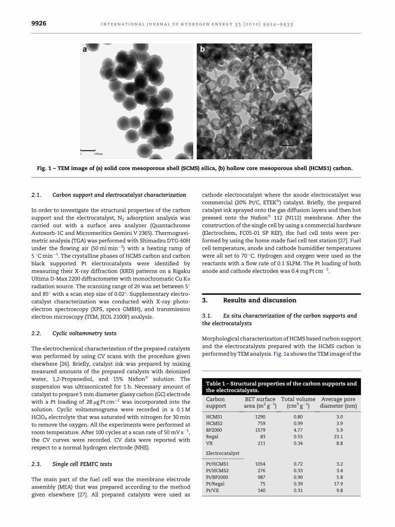
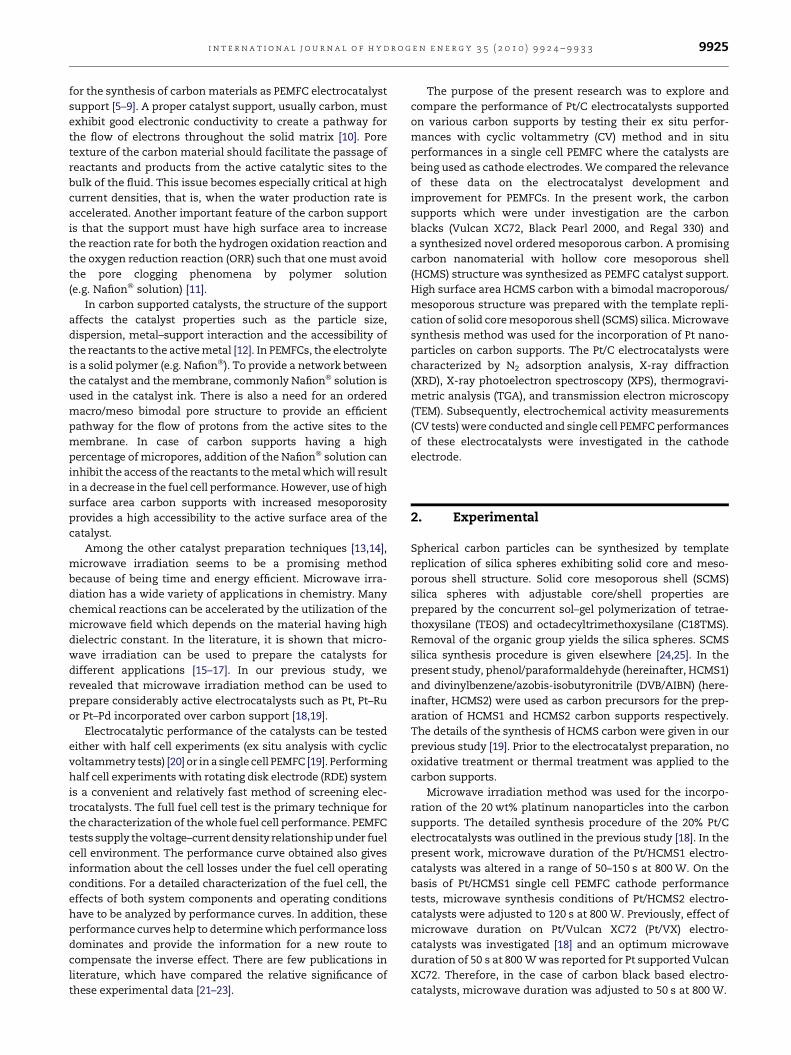
Fig. 1 – TEM image of (a) solid core mesoporous shell (SCMS) silica, (b) hollow core mesoporous shell (HCMS1) carbon.
Table 1 – Structural properties of the carbon supports andthe electrocatalysts.
Carbonsupport
BET surfacearea (m2 g�1)
Total volume(cm3 g�1)
Average porediameter (nm)
HCMS1 1290 0.80 3.0
HCMS2 759 0.99 3.9
BP2000 1579 4.77 5.9
Regal 83 0.55 23.1
VX 211 0.34 8.8
Electrocatalyst
Pt/HCMS1 1054 0.72 3.2
Pt/HCMS2 276 0.33 3.4
Pt/BP2000 987 0.90 5.8
Pt/Regal 75 0.39 17.9
Pt/VX 140 0.31 9.8
i n t e r n a t i o n a l j o u r n a l o f h y d r o g e n e n e r g y 3 5 ( 2 0 1 0 ) 9 9 2 4 – 9 9 3 39926
2.1. Carbon support and electrocatalyst characterization
In order to investigate the structural properties of the carbon
support and the electrocatalyst, N2 adsorption analysis was
carried out with a surface area analyzer (Quantachrome
Autosorb-1C and Micromeritics Gemini V 2365). Thermogravi-
metric analysis (TGA) was performed with Shimadzu DTG-60H
under the flowing air (50 ml min�1) with a heating ramp of
5 �C min�1. The crystalline phases of HCMS carbon and carbon
black supported Pt electrocatalysts were identified by
measuring their X-ray diffraction (XRD) patterns on a Rigaku
Ultima D-Max 2200 diffractometer with monochromatic Cu Ka
radiation source. The scanning range of 2q was set between 5�
and 85� with a scan step size of 0.02�. Supplementary electro-
catalyst characterization was conducted with X-ray photo-
electron spectroscopy (XPS, specs GMBH), and transmission
electron microscopy (TEM, JEOL 2100F) analysis.
2.2. Cyclic voltammetry tests
The electrochemical characterization of the prepared catalysts
was performed by using CV scans with the procedure given
elsewhere [26]. Briefly, catalyst ink was prepared by mixing
measured amounts of the prepared catalysts with deionized
water, 1,2-Propanediol, and 15% Nafion� solution. The
suspension was ultrasonicated for 1 h. Necessary amount of
catalyst to prepare 5 mm diameter glassy carbon (GC) electrode
with a Pt loading of 28 mg Pt cm�2 was incorporated into the
solution. Cyclic voltammograms were recorded in a 0.1 M
HClO4 electrolyte that was saturated with nitrogen for 30 min
to remove the oxygen. All the experiments were performed at
room temperature. After 100 cycles at a scan rate of 50 mV s�1,
the CV curves were recorded. CV data were reported with
respect to a normal hydrogen electrode (NHE).
2.3. Single cell PEMFC tests
The main part of the fuel cell was the membrane electrode
assembly (MEA) that was prepared according to the method
given elsewhere [27]. All prepared catalysts were used as
cathode electrocatalyst where the anode electrocatalyst was
commercial (20% Pt/C, ETEK�) catalyst. Briefly, the prepared
catalyst ink sprayed onto the gas diffusion layers and then hot
pressed onto the Nafion� 112 (N112) membrane. After the
construction of the single cell by using a commercial hardware
(Electrochem, FC05-01 SP REF), the fuel cell tests were per-
formed by using the home made fuel cell test station [27]. Fuel
cell temperature, anode and cathode humidifier temperatures
were all set to 70 �C. Hydrogen and oxygen were used as the
reactants with a flow rate of 0.1 SLPM. The Pt loading of both
anode and cathode electrodes was 0.4 mg Pt cm�2.
3. Results and discussion
3.1. Ex situ characterization of the carbon supports andthe electrocatalysts
Morphological characterization of HCMS based carbon support
and the electrocatalysts prepared with the HCMS carbon is
performed by TEM analysis. Fig. 1a shows the TEM image of the
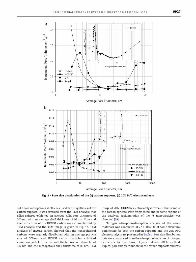
Fig. 2 – Pore size distribution of the (a) carbon supports, (b) 20% Pt/C electrocatalysts.
i n t e r n a t i o n a l j o u r n a l o f h y d r o g e n e n e r g y 3 5 ( 2 0 1 0 ) 9 9 2 4 – 9 9 3 3 9927
solid core mesoporous shell silica used in the synthesis of the
carbon support. It was revealed from the TEM analysis that
silica spheres exhibited an average solid core thickness of
300 nm with an average shell thickness of 95 nm. Core and
shell structures of the HCMS1 carbon were characterized by
TEM analysis and the TEM image is given in Fig. 1b. TEM
analysis of HCMS1 carbon showed that the nanospherical
carbons were regularly distributed with an average particle
size of 500 nm and HCMS1 carbon particles exhibited
a uniform particle structure with the hollow core diameter of
330 nm and the mesoporous shell thickness of 85 nm. TEM
image of 20% Pt/HCMS2 electrocatalyst revealed that some of
the carbon spheres were fragmented and in some regions of
the catalyst, agglomeration of the Pt nanoparticles was
observed [19].
Nitrogen adsorption–desorption analysis of the nano-
materials was conducted at 77 K. Results of some structural
parameters for both the carbon supports and the 20% Pt/C
electrocatalysts are presented in Table 1. Pore size distribution
data were calculated from the adsorption branches of nitrogen
isotherms by the Barrett–Joyner–Halenda (BJH) method.
Typical pore size distribution for the carbon supports and Pt/C

10 20 30 40 50 60 70 80 90
2θ/o
Inte
nsit
y (a
u)
Pt/BP2000
Pt/Regal
Pt/VX
{111}
{200}{220} {311}
Pt/HCMS2
Pt/HCMS1
Fig. 3 – The XRD patterns of 20% Pt/C electrocatalysts.
i n t e r n a t i o n a l j o u r n a l o f h y d r o g e n e n e r g y 3 5 ( 2 0 1 0 ) 9 9 2 4 – 9 9 3 39928
electrocatalysts is shown in Fig. 2. HCMS based carbons
present a different morphology and pore texture both at the
nanoscopic level and at the macroscopic level. As can be seen
from Fig. 2a, pore size distribution of the prepared HCMS
carbon spheres is uniform and the average pore diameter is
centered at around 3.0 nm in the mesoporous region. On the
other hand, Vulcan XC72 and Regal have random pores and
indicate a pore size distribution both in the mesoporous and
macroporous regions (Fig. 2a). Inset curve in Fig. 2a shows the
pore size distribution of Black Pearl 2000 (BP2000) carbon
support. BP2000 exhibited a uniform pore size distribution in
the highly microporous region leading to a higher Brauner-Emett-
Teller (BET) surface area. Conversely, Regal carbon support
showed a pore size distribution mostly in the meso/macro range
with larger pores and smaller BET surface area (Table 1).
Fig. 2b shows the pore size distributions of the Pt/C electro-
catalysts. Inset curve for Pt/HCMS1 electrocatalyst shows
a sharp pore size distribution centered at ca. 3.5 nm, whereas Pt/
HCMS2 electrocatalyst signifies a broadened peak at ca. 3.0 nm
that is mostly spread in the mesoporous region with larger
mesopores. Modification in the pore structure with the use of
different carbon precursor might be responsible for the better
transfer of reactants and products inside the catalyst layer. As
compared to HCMS carbon based electrocatalysts, pore size
distribution curves for Vulcan XC72 carbon based Pt/VX and Pt/C
Table 2 – Electrochemical and total surface area of the prepare
Electrocatalyst Microwave duration (s) Pt contenta (%) d
Pt/HCMS1 120 18.7
Pt/HCMS2 120 18.7
Pt/BP2000 50 17.5
Pt/Regal 50 18.3
Pt/VX 50 17.1
Pt/C (ETEK�) 50 19.6
a From TGA.
b From XRD data.
c Cyclic voltammetry analysis, Pt utilization (%)¼ ESAPt/SAPt� 100.
(ETEK�) catalysts exhibited a lower total pore volume and
micropore fraction. Large portion of the pores of Pt/VX and Pt/C
(ETEK�) electrocatalysts were detected in the mesoporous and
macroporous regions with significantly larger pores compared
to the HCMS carbon based electrocatalysts.
High surface area HCMS1 and HCMS2 nanosized spherical
carbons exhibited meso/macro bimodal pore structure. BET
surface area of the hollow core mesoporous shell carbons was
found in the range of ca. 750–1300 m2 g�1. Moreover, average
pore diameter of the ordered HCMS based carbons was calcu-
lated in the mesoporous range (ca. 3–4 nm). On the other hand,
average pore diameter of the carbon blacks with disordered
structures changed approximately between 6 nm and 23 nm. In
addition, BP2000 exhibited the largest BET surface area with
a highly microporous structure in comparison to the other
carbon blacks. Recent studies [28,29] have revealed that the
meso/macro structures and the porosity of the carbon support
can greatly affect the electrochemical properties of the catalyst
in the fuel cell environment. Therefore, it is critical to obtain
a suitable pore structure for both high metal dispersion and
high gas flow.
As the Pt nanoparticles were incorporated into the carbon
supports, BET surface areas of the electrocatalysts were found
to change between 75 m2 g�1 (Pt/Regal) and 1054 m2 g�1 (Pt/
HCMS1). It has to be remarked that introducing the platinum
nanoparticles into the HCMS2 carbon support structure low-
ered the BET surface area of the electrocatalyst sharply, which
might indicate the uniform dispersion of Pt particles in the
mesopores of the HCMS2 carbon structure. However, due to
the slight decrease in BET surface area of Pt/HCMS1 electro-
catalyst (Table 1), one can conclude that the smaller pore size
of the HCMS1 carbon (w3 nm) hindered the incorporation of
the larger Pt nanoparticles into the HCMS1 carbon structure.
Typical XRD patterns for both HCMS carbon based elec-
trocatalysts and commercial carbon based electrocatalysts are
shown in Fig. 3. It was observed that all the XRD patterns of
the Pt/C electrocatalysts exhibit the main characteristic peaks
of FCC crystalline Pt with the planes of (111), (200), (220) and
(311). The particle sizes of the catalysts were calculated by
using Scherrer equation and given in Table 2. Incorporation of
Pt particles by microwave synthesis resulted in smaller cata-
lyst particles. Particle size diameters were computed in
a range of 3.3–4 nm.
During the catalyst preparation, as the microwave duration
increases the temperature of the solution increases that may
d and commercial electrocatalysts.b (nm) SAPt (m2 g�1) ESAPt (m2 g�1) Pt utilizationc (%)
3.6 78 5 6
4.0 70 14 20
3.7 77 6 8
3.4 82 16 20
3.3 85 20 23
2.7 104 41 39

68 70 72 74 76 78 80Binding energy, eV
Inte
nsity
(a.
u.)
Pt/BP2000
Pt/VX
Pt/Regal
Pt/HCMS2
Pt 4f
Pt/HCMS1
a
0 100 200 300 400 500 600 700
Binding energy, eV
Inte
nsity
(a.
u.)
Pt/BP2000
Pt/VX
Pt/Regal
Pt/HCMS2
f4tP
s1C s1
O
Pt/HCMS1
b
Fig. 4 – (a) Pt 4f XPS spectra for 20% Pt/C electrocatalysts, (b)
XPS survey spectra for 20% Pt/C electrocatalysts.
i n t e r n a t i o n a l j o u r n a l o f h y d r o g e n e n e r g y 3 5 ( 2 0 1 0 ) 9 9 2 4 – 9 9 3 3 9929
cause the growth of the Pt particle size. Effect of microwave
duration on catalyst particle size was previously reported for
Pt/VX electrocatalysts [18]. Optimum microwave duration was
found as 50 s for VX based catalysts. When the microwave
duration was increased up to 120 s, relatively larger catalyst
particles of 5.7 nm were obtained for Pt/VX catalysts. It may be
concluded that both the carbon structure and the microwave
duration affect the catalyst particle size and therefore it is
essential to optimize microwave duration to meet the desired
catalyst particle size. For HCMS carbon based Pt/C
Table 3 – XPS data of Pt/C electrocatalysts.
Electrocatalyst Binding energy (eV)
Pt 4f7/2 Pt 4f5/2 C 1s O 1s
Pt/HCMS1 71.3 74.6 284.4 532.8
Pt/HCMS2 71.3 74.5 284.4 532.4
Pt/BP2000 71.5 74.8 284.8 532.8
Pt/Regal 71.2 74.5 284.4 532.4
Pt/VX 71.2 74.4 284.4 532.4
electrocatalyst synthesis, microwave duration was optimized
and set to 120 s, whereas microwave duration for the carbon
black based Pt/C electrocatalysts was adjusted to 50 s (Table 2).
Oxygen reduction reaction of PEM fuel cells is highly
dependent on the oxidation states of the Pt crystallites on the
surface of the electrocatalyst. In this study, Pt oxidation state
and the interaction between carbon support and platinum
metal were determined by XPS. Fig. 4a shows the Pt 4f core
level spectra of 20% Pt/C electrocatalysts for high and low
energy bands. Table 3 presents the XPS data for the Pt/C
electrocatalysts. Considering all Pt/C electrocatalysts, the
intensive doublet (at ca. 71.3 and 74.5 eV) indicates the
metallic Pt. The observed slight shift of the doublet to the
higher binding energies might be a signal of stronger carbon
support/platinum interaction. Pt 4f7/2 core level spectra shif-
ted from the probable 70.9 eV to 71.3 eV for Pt/HCMS1 and Pt/
HCMS2 electrocatalysts and in the case of carbon black based
electrocatalysts Pt 4f7/2 peak shifted slightly to higher binding
energies for the carbon blacks (Table 3). This small shift of Pt
4f7/2 peak can signify the oxidation of platinum [28,30]. Fig. 4b
shows the XPS survey spectra of HCMS carbon based and
carbon black based electrocatalysts. As can be seen from the
figure, XPS spectra were dominated by Pt and C signals. C 1s
and O 1s peaks were detected at the binding energy ranges of
284.4–284.8 eV and 532.4–532.8 eV respectively (Table 3).
A slight shift of C 1s and O 1s peaks was observed for Pt/BP2000
electrocatalyst, small shift of O 1s peak to higher values might
indicate a higher content of surface oxides on the BP2000
carbon support surface due to electrochemical oxidation [29].
As a result of surface elemental composition analysis by
XPS, some small amounts of chlorine and fluorine anions
were found in the HCMS carbon based catalyst structure. In
addition, some chlorine anion was also measured in carbon
black based electrocatalysts. It is noteworthy that no harmful
effect of anions like Cl� and F� was detected on single cell
polymer electrolyte membrane fuel cell performance.
Thermogravimetric analysis results of 20% Pt/C electro-
catalysts are shown in Fig. 5. TGA experiments were per-
formed under the flowing air to roughly estimate the Pt
content and detect the thermal decomposition of the elec-
trocatalysts [31]. Incorporation of platinum into the carbon
support accelerated the oxidation of carbon supports. Each
electrocatalyst follows a different thermal history, which
might be a consequence of surface functional groups. It was
found that the Pt content of the Pt/C electrocatalysts was close
to the 20 wt% theoretical Pt loading (Table 2). It can be
concluded that the thermal stability of the HCMS2 supported
catalyst was increased considerably with respect to HCMS1
supported catalyst (Fig. 5a). Furthermore, both BP2000 and
Regal started to decompose at around 600 �C (Fig. 5b and c).
However, Pt/BP2000 electrocatalyst exhibits much less
thermal stability compared to the other electrocatalysts for
the reported temperature ranges. On the other hand, VX and
Pt/VX (Fig. 5d) exhibited a higher thermal stability compared
to the other nanomaterials.
3.2. Electrochemical characterization
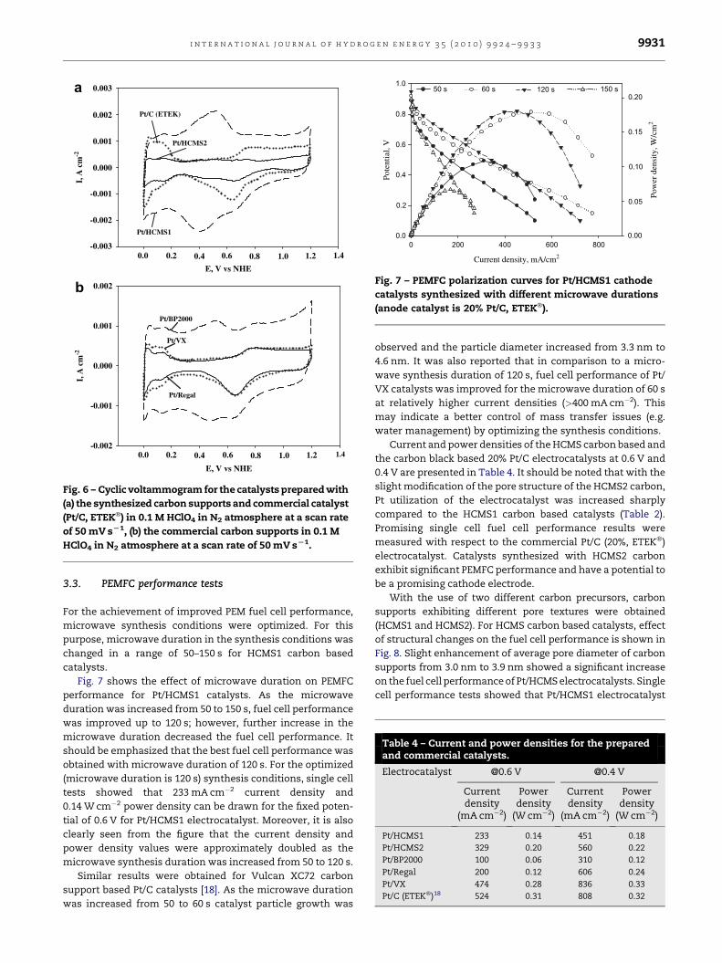
Cyclic voltammograms for the HCMS carbon based catalysts,
commercial catalyst, and for the commercial carbon black
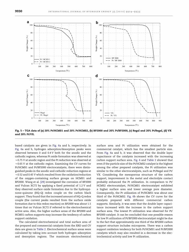
Fig. 5 – TGA data of (a) 20% Pt/HCMS1 and 20% Pt/HCMS2, (b) BP2000 and 20% Pt/BP2000, (c) Regal and 20% Pt/Regal, (d) VX
and 20% Pt/VX.
i n t e r n a t i o n a l j o u r n a l o f h y d r o g e n e n e r g y 3 5 ( 2 0 1 0 ) 9 9 2 4 – 9 9 3 39930
based catalysts are given in Fig. 6a and b, respectively. In
Fig. 6a and b, hydrogen adsorption/desorption peaks were
observed between 0 and 0.4 V both for the anodic and the
cathodic regions, whereas Pt oxide formation was observed at
w0.75 V at anodic region and the Pt reduction was observed at
w0.65 V at the cathodic region. Examining the CV curves for
Pt/HCMS1 and Pt/BP2000 electrocatalysts, there were distin-
guished peaks in the anodic and cathodic reduction regions at
w0.52 and 0.45 V which resulted from the oxidation/reduction
of the oxygen-containing surface groups on HCMS1 and
BP2000. Wang et al. [29] investigated the corrosion of BP2000
and Vulcan XC72 by applying a fixed potential of 1.2 V and
they observed surface oxide formation due to the hydroqui-
none–quinone (HQ–Q) redox couple on the carbon black
support. They found that the increased amount of HQ–Q redox
couple (the current peaks resulted from the surface oxide
formation due to this redox reaction) on BP2000 was about 1.5
times that on Vulcan XC72 if referred to the electrochemical
active area. Also, the higher surface areas of the BP2000 and
HCMS1 carbon supports may increase the tendency of carbon
support oxidation.
The calculated electrochemical and total surface area of
the prepared and commercial catalysts from the XRD and CV
data are given in Table 2. Electrochemical surface areas were
calculated by taking into account both hydrogen adsorption
and desorption regions. The maximum electrochemical
surface area and Pt utilization were obtained for the
commercial catalyst, which has the smallest particle size.
From Fig. 6a and b, it was observed that the double layer
capacitance of the catalysts increased with the increasing
carbon support surface area. Fig. 6 and Table 2 showed that
even if the particle size of the Pt/HCMS2 catalyst is the highest
among the other prepared catalysts, the Pt utilization was
similar to the other electrocatalysts, such as Pt/Regal and Pt/
VX. Considering the mesoporous structure of the carbon
support, improvement in the metal and electrolyte contact
probably enhanced the Pt utilization. In comparison to Pt/
HCMS2 electrocatalyst, Pt/HCMS1 electrocatalyst exhibited
a higher surface area and lower average pore diameter.
Consequently, the Pt utilization of Pt/HCMS1 was about one
third of the Pt/HCMS2. Fig. 6b shows the CV curve for the
catalysts prepared with different commercial carbon
supports. Similarly, it was seen that the double layer capaci-
tance increased with the increase in the carbon support
surface area. The lowest Pt utilization was observed for Pt/
BP2000 catalyst. It can be concluded that one possible reason
for low Pt utilization of Pt/BP2000 electrocatalyst might be due
to the fact that approximately one third of the BP2000 carbon
support structure includes micropores. There was a carbon
support oxidation tendency for both Pt/HCMS1 and Pt/BP2000
catalysts which may also resulted in a decrease in the elec-
trochemical activity and low Pt utilization.
Pt/HCMS2
Pt/HCMS1
Pt/C (ETEK)
0.0 0.2 0.4 0.6 0.8 1.0 1.2 1.4
E, V vs NHE
I, A
cm
-2I,
A c
m-2
-0.003
-0.001
0.000
0.001
0.002
0.003
0.0 0.2 0.4 0.6 0.8 1.0 1.2 1.4
E, V vs NHE
-0.002
-0.001
0.000
0.001
0.002
Pt/BP2000
Pt/VX
Pt/Regal
-0.002
a
b
Fig. 6 – Cyclic voltammogram for the catalysts prepared with
(a) the synthesized carbon supports and commercial catalyst
(Pt/C, ETEK�) in 0.1 M HClO4 in N2 atmosphere at a scan rate
of 50 mV sL1, (b) the commercial carbon supports in 0.1 M
HClO4 in N2 atmosphere at a scan rate of 50 mV sL1.
0 200 400 600 800
Current density, mA/cm2
Pote
ntia
l, V
Pow
er d
ensi
ty, W
/cm
2
0.0
0.2
0.4
0.6
0.8
1.050 s 60 s 120 s 150 s
0.00
0.05
0.10
0.15
0.20
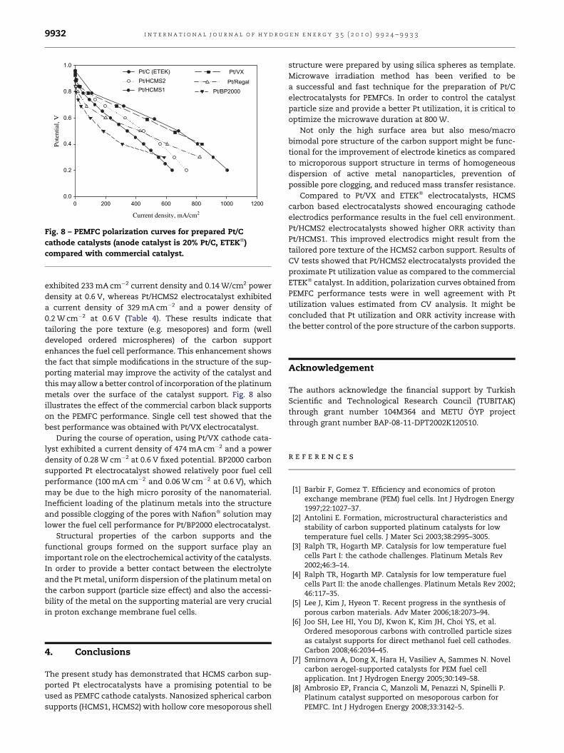
Fig. 7 – PEMFC polarization curves for Pt/HCMS1 cathode
catalysts synthesized with different microwave durations
(anode catalyst is 20% Pt/C, ETEK�).
Table 4 – Current and power densities for the preparedand commercial catalysts.
Electrocatalyst @0.6 V @0.4 V
Currentdensity
(mA cm�2)
Powerdensity
(W cm�2)
Currentdensity
(mA cm�2)
Powerdensity
(W cm�2)
Pt/HCMS1 233 0.14 451 0.18
Pt/HCMS2 329 0.20 560 0.22
Pt/BP2000 100 0.06 310 0.12
Pt/Regal 200 0.12 606 0.24
Pt/VX 474 0.28 836 0.33
Pt/C (ETEK�)18 524 0.31 808 0.32
i n t e r n a t i o n a l j o u r n a l o f h y d r o g e n e n e r g y 3 5 ( 2 0 1 0 ) 9 9 2 4 – 9 9 3 3 9931
3.3. PEMFC performance tests
For the achievement of improved PEM fuel cell performance,
microwave synthesis conditions were optimized. For this
purpose, microwave duration in the synthesis conditions was
changed in a range of 50–150 s for HCMS1 carbon based
catalysts.
Fig. 7 shows the effect of microwave duration on PEMFC
performance for Pt/HCMS1 catalysts. As the microwave
duration was increased from 50 to 150 s, fuel cell performance
was improved up to 120 s; however, further increase in the
microwave duration decreased the fuel cell performance. It
should be emphasized that the best fuel cell performance was
obtained with microwave duration of 120 s. For the optimized
(microwave duration is 120 s) synthesis conditions, single cell
tests showed that 233 mA cm�2 current density and
0.14 W cm�2 power density can be drawn for the fixed poten-
tial of 0.6 V for Pt/HCMS1 electrocatalyst. Moreover, it is also
clearly seen from the figure that the current density and
power density values were approximately doubled as the
microwave synthesis duration was increased from 50 to 120 s.
Similar results were obtained for Vulcan XC72 carbon
support based Pt/C catalysts [18]. As the microwave duration
was increased from 50 to 60 s catalyst particle growth was
observed and the particle diameter increased from 3.3 nm to
4.6 nm. It was also reported that in comparison to a micro-
wave synthesis duration of 120 s, fuel cell performance of Pt/
VX catalysts was improved for the microwave duration of 60 s
at relatively higher current densities (>400 mA cm�2). This
may indicate a better control of mass transfer issues (e.g.
water management) by optimizing the synthesis conditions.
Current and power densities of the HCMS carbon based and
the carbon black based 20% Pt/C electrocatalysts at 0.6 V and
0.4 V are presented in Table 4. It should be noted that with the
slight modification of the pore structure of the HCMS2 carbon,
Pt utilization of the electrocatalyst was increased sharply
compared to the HCMS1 carbon based catalysts (Table 2).
Promising single cell fuel cell performance results were
measured with respect to the commercial Pt/C (20%, ETEK�)
electrocatalyst. Catalysts synthesized with HCMS2 carbon
exhibit significant PEMFC performance and have a potential to
be a promising cathode electrode.
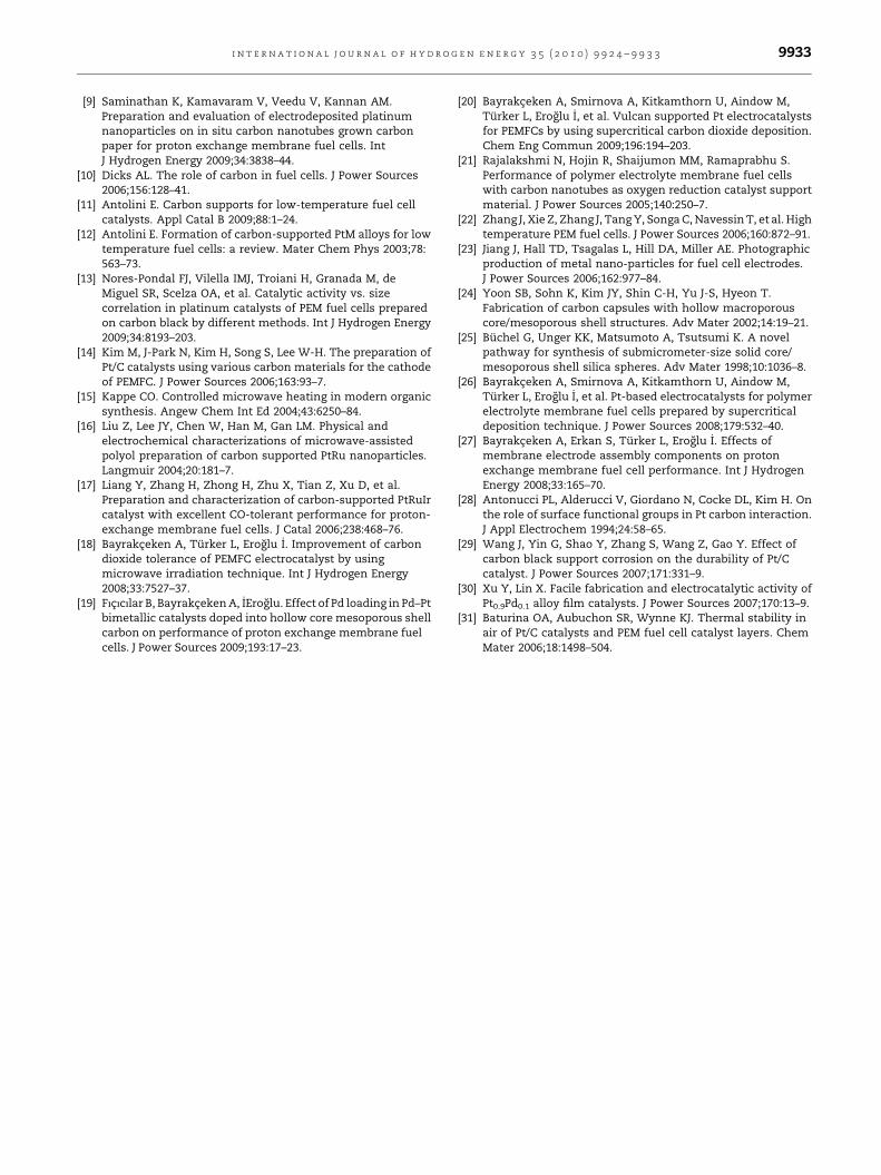
With the use of two different carbon precursors, carbon
supports exhibiting different pore textures were obtained
(HCMS1 and HCMS2). For HCMS carbon based catalysts, effect
of structural changes on the fuel cell performance is shown in
Fig. 8. Slight enhancement of average pore diameter of carbon
supports from 3.0 nm to 3.9 nm showed a significant increase
on the fuel cell performance of Pt/HCMS electrocatalysts. Single
cell performance tests showed that Pt/HCMS1 electrocatalyst
0 200 400 600 800 1000 1200
Current density, mA/cm2
0.0
0.2
0.4
0.6
0.8
1.0
Pote
ntia
l, V
Pt/C (ETEK)Pt/HCMS2
Pt/BP2000Pt/Regal
Pt/VX
Pt/HCMS1
Fig. 8 – PEMFC polarization curves for prepared Pt/C
cathode catalysts (anode catalyst is 20% Pt/C, ETEK�)
compared with commercial catalyst.
i n t e r n a t i o n a l j o u r n a l o f h y d r o g e n e n e r g y 3 5 ( 2 0 1 0 ) 9 9 2 4 – 9 9 3 39932
exhibited 233 mA cm�2 current density and 0.14 W/cm2 power
density at 0.6 V, whereas Pt/HCMS2 electrocatalyst exhibited
a current density of 329 mA cm�2 and a power density of
0.2 W cm�2 at 0.6 V (Table 4). These results indicate that
tailoring the pore texture (e.g. mesopores) and form (well
developed ordered microspheres) of the carbon support
enhances the fuel cell performance. This enhancement shows
the fact that simple modifications in the structure of the sup-
porting material may improve the activity of the catalyst and
this may allow a better control of incorporation of the platinum
metals over the surface of the catalyst support. Fig. 8 also
illustrates the effect of the commercial carbon black supports
on the PEMFC performance. Single cell test showed that the
best performance was obtained with Pt/VX electrocatalyst.
During the course of operation, using Pt/VX cathode cata-
lyst exhibited a current density of 474 mA cm�2 and a power
density of 0.28 W cm�2 at 0.6 V fixed potential. BP2000 carbon
supported Pt electrocatalyst showed relatively poor fuel cell
performance (100 mA cm�2 and 0.06 W cm�2 at 0.6 V), which
may be due to the high micro porosity of the nanomaterial.
Inefficient loading of the platinum metals into the structure
and possible clogging of the pores with Nafion� solution may
lower the fuel cell performance for Pt/BP2000 electrocatalyst.
Structural properties of the carbon supports and the
functional groups formed on the support surface play an
important role on the electrochemical activity of the catalysts.
In order to provide a better contact between the electrolyte
and the Pt metal, uniform dispersion of the platinum metal on
the carbon support (particle size effect) and also the accessi-
bility of the metal on the supporting material are very crucial
in proton exchange membrane fuel cells.
4. Conclusions
The present study has demonstrated that HCMS carbon sup-
ported Pt electrocatalysts have a promising potential to be
used as PEMFC cathode catalysts. Nanosized spherical carbon
supports (HCMS1, HCMS2) with hollow core mesoporous shell
structure were prepared by using silica spheres as template.
Microwave irradiation method has been verified to be
a successful and fast technique for the preparation of Pt/C
electrocatalysts for PEMFCs. In order to control the catalyst
particle size and provide a better Pt utilization, it is critical to
optimize the microwave duration at 800 W.
Not only the high surface area but also meso/macro
bimodal pore structure of the carbon support might be func-
tional for the improvement of electrode kinetics as compared
to microporous support structure in terms of homogeneous
dispersion of active metal nanoparticles, prevention of
possible pore clogging, and reduced mass transfer resistance.
Compared to Pt/VX and ETEK� electrocatalysts, HCMS
carbon based electrocatalysts showed encouraging cathode
electrodics performance results in the fuel cell environment.
Pt/HCMS2 electrocatalysts showed higher ORR activity than
Pt/HCMS1. This improved electrodics might result from the
tailored pore texture of the HCMS2 carbon support. Results of
CV tests showed that Pt/HCMS2 electrocatalysts provided the
proximate Pt utilization value as compared to the commercial
ETEK� catalyst. In addition, polarization curves obtained from
PEMFC performance tests were in well agreement with Pt
utilization values estimated from CV analysis. It might be
concluded that Pt utilization and ORR activity increase with
the better control of the pore structure of the carbon supports.
Acknowledgement
The authors acknowledge the financial support by Turkish
Scientific and Technological Research Council (TUBITAK)
through grant number 104M364 and METU OYP project
through grant number BAP-08-11-DPT2002K120510.
r e f e r e n c e s
[1] Barbir F, Gomez T. Efficiency and economics of protonexchange membrane (PEM) fuel cells. Int J Hydrogen Energy1997;22:1027–37.
[2] Antolini E. Formation, microstructural characteristics andstability of carbon supported platinum catalysts for lowtemperature fuel cells. J Mater Sci 2003;38:2995–3005.
[3] Ralph TR, Hogarth MP. Catalysis for low temperature fuelcells Part I: the cathode challenges. Platinum Metals Rev2002;46:3–14.
[4] Ralph TR, Hogarth MP. Catalysis for low temperature fuelcells Part II: the anode challenges. Platinum Metals Rev 2002;46:117–35.
[5] Lee J, Kim J, Hyeon T. Recent progress in the synthesis ofporous carbon materials. Adv Mater 2006;18:2073–94.
[6] Joo SH, Lee HI, You DJ, Kwon K, Kim JH, Choi YS, et al.Ordered mesoporous carbons with controlled particle sizesas catalyst supports for direct methanol fuel cell cathodes.Carbon 2008;46:2034–45.
[7] Smirnova A, Dong X, Hara H, Vasiliev A, Sammes N. Novelcarbon aerogel-supported catalysts for PEM fuel cellapplication. Int J Hydrogen Energy 2005;30:149–58.
[8] Ambrosio EP, Francia C, Manzoli M, Penazzi N, Spinelli P.Platinum catalyst supported on mesoporous carbon forPEMFC. Int J Hydrogen Energy 2008;33:3142–5.
i n t e r n a t i o n a l j o u r n a l o f h y d r o g e n e n e r g y 3 5 ( 2 0 1 0 ) 9 9 2 4 – 9 9 3 3 9933
[9] Saminathan K, Kamavaram V, Veedu V, Kannan AM.Preparation and evaluation of electrodeposited platinumnanoparticles on in situ carbon nanotubes grown carbonpaper for proton exchange membrane fuel cells. IntJ Hydrogen Energy 2009;34:3838–44.
[10] Dicks AL. The role of carbon in fuel cells. J Power Sources2006;156:128–41.
[11] Antolini E. Carbon supports for low-temperature fuel cellcatalysts. Appl Catal B 2009;88:1–24.
[12] Antolini E. Formation of carbon-supported PtM alloys for lowtemperature fuel cells: a review. Mater Chem Phys 2003;78:563–73.
[13] Nores-Pondal FJ, Vilella IMJ, Troiani H, Granada M, deMiguel SR, Scelza OA, et al. Catalytic activity vs. sizecorrelation in platinum catalysts of PEM fuel cells preparedon carbon black by different methods. Int J Hydrogen Energy2009;34:8193–203.
[14] Kim M, J-Park N, Kim H, Song S, Lee W-H. The preparation ofPt/C catalysts using various carbon materials for the cathodeof PEMFC. J Power Sources 2006;163:93–7.
[15] Kappe CO. Controlled microwave heating in modern organicsynthesis. Angew Chem Int Ed 2004;43:6250–84.
[16] Liu Z, Lee JY, Chen W, Han M, Gan LM. Physical andelectrochemical characterizations of microwave-assistedpolyol preparation of carbon supported PtRu nanoparticles.Langmuir 2004;20:181–7.
[17] Liang Y, Zhang H, Zhong H, Zhu X, Tian Z, Xu D, et al.Preparation and characterization of carbon-supported PtRuIrcatalyst with excellent CO-tolerant performance for proton-exchange membrane fuel cells. J Catal 2006;238:468–76.
[18] Bayrakceken A, Turker L, Eroglu _I. Improvement of carbondioxide tolerance of PEMFC electrocatalyst by usingmicrowave irradiation technique. Int J Hydrogen Energy2008;33:7527–37.
[19] Fıcıcılar B, Bayrakceken A, _IEroglu. Effect of Pd loading in Pd–Ptbimetallic catalysts doped into hollow core mesoporous shellcarbon on performance of proton exchange membrane fuelcells. J Power Sources 2009;193:17–23.
[20] Bayrakceken A, Smirnova A, Kitkamthorn U, Aindow M,Turker L, Eroglu _I, et al. Vulcan supported Pt electrocatalystsfor PEMFCs by using supercritical carbon dioxide deposition.Chem Eng Commun 2009;196:194–203.
[21] Rajalakshmi N, Hojin R, Shaijumon MM, Ramaprabhu S.Performance of polymer electrolyte membrane fuel cellswith carbon nanotubes as oxygen reduction catalyst supportmaterial. J Power Sources 2005;140:250–7.
[22] Zhang J, Xie Z, Zhang J, Tang Y, Songa C, Navessin T, et al. Hightemperature PEM fuel cells. J Power Sources 2006;160:872–91.
[23] Jiang J, Hall TD, Tsagalas L, Hill DA, Miller AE. Photographicproduction of metal nano-particles for fuel cell electrodes.J Power Sources 2006;162:977–84.
[24] Yoon SB, Sohn K, Kim JY, Shin C-H, Yu J-S, Hyeon T.Fabrication of carbon capsules with hollow macroporouscore/mesoporous shell structures. Adv Mater 2002;14:19–21.
[25] Buchel G, Unger KK, Matsumoto A, Tsutsumi K. A novelpathway for synthesis of submicrometer-size solid core/mesoporous shell silica spheres. Adv Mater 1998;10:1036–8.
[26] Bayrakceken A, Smirnova A, Kitkamthorn U, Aindow M,Turker L, Eroglu _I, et al. Pt-based electrocatalysts for polymerelectrolyte membrane fuel cells prepared by supercriticaldeposition technique. J Power Sources 2008;179:532–40.
[27] Bayrakceken A, Erkan S, Turker L, Eroglu _I. Effects ofmembrane electrode assembly components on protonexchange membrane fuel cell performance. Int J HydrogenEnergy 2008;33:165–70.
[28] Antonucci PL, Alderucci V, Giordano N, Cocke DL, Kim H. Onthe role of surface functional groups in Pt carbon interaction.J Appl Electrochem 1994;24:58–65.
[29] Wang J, Yin G, Shao Y, Zhang S, Wang Z, Gao Y. Effect ofcarbon black support corrosion on the durability of Pt/Ccatalyst. J Power Sources 2007;171:331–9.
[30] Xu Y, Lin X. Facile fabrication and electrocatalytic activity ofPt0.9Pd0.1 alloy film catalysts. J Power Sources 2007;170:13–9.
[31] Baturina OA, Aubuchon SR, Wynne KJ. Thermal stability inair of Pt/C catalysts and PEM fuel cell catalyst layers. ChemMater 2006;18:1498–504.