Proton Conducting Organic/Inorganic Sol–Gel Membranes Produced from Phenyltriethoxysilane and...
7
Journal of Sol-Gel Science and Technology 34, 233–239, 2005 c 2005 Springer Science + Business Media, Inc. Manufactured in The Netherlands. Proton Conducting Organic/Inorganic Sol–Gel Membranes Produced from Phenyltriethoxysilane and 3-Methacryloxypropyl Trimethoxysilane M. APARICIO Instituto de Cer ´ amica y Vidrio (C.S.I.C.), Madrid, Spain [email protected] E. LECOQ Universit´ e de Rennes 1, St. Brieuc Cedex 01, France [email protected] Y. CASTRO AND A. DURAN ∗ Instituto de Cer ´ amica y Vidrio (C.S.I.C.), Madrid, Spain [email protected] [email protected] Received April 6, 2004; Accepted October 22, 2004 Abstract. The increase of the operation temperature in Proton Exchange Membrane Fuel Cells (PEMFC) above 100 ◦ C would be an important breakthrough for the application of this type of fuel cell in electric vehicles. Hybrid organic-inorganic membranes with nano-sized interfaces can combine all the properties to meet this objective. Membranes using phenyltriethoxysilane and 3-methacryloxypropyl trimethoxysilane have been synthesised by polymerisation of methacrylate groups and inorganic condensation of silanol groups. Sulfonation process to provide proton conductivity affects both proton conductivity and chemical stability of hybrid membranes. Liquid sulfonation during the sol preparation and chlorosulfonic acid as sulfonating agent leads to chain cleavage while trimethylsilyl chlorosulfonate does not affect the polymer backbone. The increase of temperature (up to 120–130 ◦ C) and relative humidity leads to an increase of proton conductivity close to 10 −3 S/cm. Keywords: PEMFC, hybrid conductor, sol–gel technique, proton conductivity, membrane Introduction There is a great interest in proton exchange membrane fuel cells (PEMFC) for different applications, espe- cially for transportation. The major limitations of actual PEMFCs that use polymeric “Nafion” type membranes are CO poisoning of Pt anode etectrocatalysts, a com- plex water management, and problems associated with the use of hydrogen as fuel (fabrication, storage and ∗ To whom all correspondence should be addressed. safety). Also, these membranes remain expensive and have several limiting factors such as low conductivity at low relative humidity, high methanol permeability and a low T g (glass transition temperature) which re- stricts its application to below 100 ◦ C [1]. If the mem- branes would be capable of operation at temperatures above 100 ◦ C without substantial humidification, the CO poisoning would be reduced and it would also al- leviate the water management problems in PEMFCs. Moreover, the increase of PEMFC operation tempera- ture would allow increased fuel cell reaction kinetics,
Transcript of Proton Conducting Organic/Inorganic Sol–Gel Membranes Produced from Phenyltriethoxysilane and...
Journal of Sol-Gel Science and Technology 34, 233–239, 2005c© 2005 Springer Science + Business Media, Inc. Manufactured in The Netherlands.
Proton Conducting Organic/Inorganic Sol–Gel Membranes Producedfrom Phenyltriethoxysilane and 3-Methacryloxypropyl Trimethoxysilane
M. APARICIOInstituto de Ceramica y Vidrio (C.S.I.C.), Madrid, Spain
E. LECOQUniversite de Rennes 1, St. Brieuc Cedex 01, France
Y. CASTRO AND A. DURAN∗
Instituto de Ceramica y Vidrio (C.S.I.C.), Madrid, [email protected]
Received April 6, 2004; Accepted October 22, 2004
Abstract. The increase of the operation temperature in Proton Exchange Membrane Fuel Cells (PEMFC) above100◦C would be an important breakthrough for the application of this type of fuel cell in electric vehicles. Hybridorganic-inorganic membranes with nano-sized interfaces can combine all the properties to meet this objective.Membranes using phenyltriethoxysilane and 3-methacryloxypropyl trimethoxysilane have been synthesised bypolymerisation of methacrylate groups and inorganic condensation of silanol groups. Sulfonation process to provideproton conductivity affects both proton conductivity and chemical stability of hybrid membranes. Liquid sulfonationduring the sol preparation and chlorosulfonic acid as sulfonating agent leads to chain cleavage while trimethylsilylchlorosulfonate does not affect the polymer backbone. The increase of temperature (up to 120–130◦C) and relativehumidity leads to an increase of proton conductivity close to 10−3 S/cm.
Keywords: PEMFC, hybrid conductor, sol–gel technique, proton conductivity, membrane
Introduction
There is a great interest in proton exchange membranefuel cells (PEMFC) for different applications, espe-cially for transportation. The major limitations of actualPEMFCs that use polymeric “Nafion” type membranesare CO poisoning of Pt anode etectrocatalysts, a com-plex water management, and problems associated withthe use of hydrogen as fuel (fabrication, storage and
∗To whom all correspondence should be addressed.
safety). Also, these membranes remain expensive andhave several limiting factors such as low conductivityat low relative humidity, high methanol permeabilityand a low Tg (glass transition temperature) which re-stricts its application to below 100◦C [1]. If the mem-branes would be capable of operation at temperaturesabove 100◦C without substantial humidification, theCO poisoning would be reduced and it would also al-leviate the water management problems in PEMFCs.Moreover, the increase of PEMFC operation tempera-ture would allow increased fuel cell reaction kinetics,
234 Aparicio et al.
lower consumption of platinum catalyst, and direct useof low-temperature fuels such as methanol. However,water and methanol crossover remarkably increasewith temperature, reducing the fuel cell efficiency[2, 3].
Nano-ordered composite materials consisting oforganic polymers and inorganic components havebeen attracting attention for their use in new high-performance materials. One interesting alternative topolymeric membranes in order to reach higher fuel celloperation temperature is the hybrid organic-inorganicmembranes with nano-sized phases and interfaces. Theinorganic component allows the thermal stability to beincreased and combines it with the mechanical and pro-ton conductivity properties of the organic component.Similarly, the inorganic phase can improve chemicalstability and high temperature proton conductivity ofthe membrane by the increase of water retention up tohigher temperatures [4, 5].
Hybrid compounds made by the formation of silox-ane (Si O Si) bonds are an important body of mate-rials, ranging from inorganic silicates to organicallymodified polysiloxanes. All of these siloxane-basedmaterials are prepared by hydrolysis and condensationreactions of sol–gel precursors [6]. When the mechan-ical stability is an important parameter, as in case ofthe preparation of membranes with thickness between100 and 200 µm, one or more additional polymerisablegroups must be attached to the silicon to permit poly-meric cross-linking. The homogeneity of the inorganicand organic phases allows for molecular engineeringof the bulk properties of the hybrid organic/inorganicmaterials without nanoscale phase separation. The or-ganic group, covalently attached to the silicon atom,can be varied in length, rigidity, geometry of substitu-tion, and functionality. This variability contributes tobulk properties such as porosity, thermal stability, opti-cal clarity, chemical resistance, mechanical properties,permeability, and electrical properties.
The aim of this work has been the synthe-sis and characterization of proton conducting or-ganic/inorganic membranes using phenyltriethoxysi-lane and 3-methacryloxypropyl trimethoxysilane. Bothof them can polymerize through hydrolysis and con-densation reactions to produce a Si O Si network.The latter has also a vinyl group in his structure thatpermits an organic polymerization in order to produce amore flexible material. Phenyltriethoxysilane containsan aromatic ring attached to silicon atom suitable for asulfonation process to produce SO−
3 groups responsible
for high proton conductivity. Two different sulfonatingagents have been used in this process: chlorosulfonicacid and trimethylsilyl chlorosulfonate. The former is astrong sulfonating agent that can produce side reactionsincluding crosslinking and cleavage of the polymerchains. Trimethylsilyl chlorosulfonate does not usu-ally induce chain cleavage, even at high sulfonationdegree [7–9]. The optimal composition and synthesisconditions to promote organic polymerisation and sol–gel condensation, avoiding phase separation, are im-portant issues of this work. TGA-DTA, FTIR, XRDand EIS have been used for characterising the obtainedmembranes.
Experimental
Phenyltriethoxysilane (PTES) and 3-methacryloxy-propyl trimethoxysilane (MPS) both from ABCR wereused as precursors. Four different compositions wereprepared with 0, 25, 50 and 75 molar percentage ofMPS. Sols were prepared by mixing two solutions(A and B) except for the sol without MPS. SolutionA was prepared by mixing absolute ethanol, calcu-lated amounts of PTES and HNO3 1N (molar ratio ofwater/PTES = 1.5), stirring at 50◦C for 2 h. A variationin the preparation of solution A was also studied: thesulfonation process of PTES alternatively with chloro-sulfonic acid (HSO3Cl) and trimethylsilyl chlorosul-fonate [(CH3)3SiSO3Cl] in equimolar conditions for3 h at room temperature. Then, absolute ethanol andHNO3 1N was added and stirred at 50◦C for 2 h. Solu-tion B was prepared by mixing absolute ethanol, cal-culated amounts of MPS and HNO3 1N (molar ratioof water/MPS = 1.5), stirring at 50◦C for 2 h. Then,1,1′-azobis(cyclohexanecarbonitrile) from ALDRICHin 0.5 wt% with respect of MPS as initiator of the free-radical polymerization was added with an additionalstirring at room temperature for 30 min. Solutions Aand B were mixed, and H2O was added (total molarratio of water/PTES + MPS = 3) and stirred at roomtemperature for 30 min.
The solutions were cast in glass and polytetrafluo-roethylen moulds, placed at 60◦C to initiate the free-radical polymerization of MPS, and continue the sol–gel reactions to produce solid materials after 24 h. Theso obtained hybrid membranes were further treated at120◦C. Additionally, the membranes without sulfona-tion process in the step of sol preparation were sul-fonated alternatively by immersion for six hours in0.3 M solutions of HSO3Cl and (CH3)3SiSO3Cl in
Proton Conducting Organic/Inorganic Sol–Gel Membranes 235
1,2-dichloroethane. Then, membranes were washed indistilled water and heated at 50◦C for several hours.
The thermal behaviour (TGA-DTA) was followedusing a SEIKO TGA/DTA 320U with a heating rateof 10◦C/min in air. X-ray diffraction (XRD) was per-formed using a Siemens Model D5000 on samplesheat-treated at 120◦C. FT-IR spectroscopy was used tostudy hydrolysis reaction of PTES and MPS. A Perkin-Elmer model 1720X with a resolution of 2 cm−1 anda frequency range of 400–4000 cm−1 was used. Eachspectrum was obtained by adding a drop of about 1microlitre of solution between two KRS-5 windowcrystals by using a microburete. Each spectrum wasobtained at different reaction times. The same spec-trometer was used to analyze crushed samples usingKBr pellets. The proton conductivity of hybrid mem-branes was obtained by Electrochemical ImpedanceSpectroscopy (EIS) using a HEWLETT PACKARD4192A impedance analyser. The measurements wereconducted as a function of both relative humidity (RH)and temperature. The samples were allowed to equili-brate at the desired RH for 24 h inside a sealed chambercontaining saturated solution of KNO3 for the 80–92%RH range, and water vapour for the 100% [10]. The fre-quency was varied from 10 Hz to 10 MHz, and the EIScurves were resolved using Equivalent Circuit version3.97 software (IBM-CGA screen).
Results and Discussion
All the hybrid membranes, prepared without sulfona-tion process, are homogeneous and transparent afterthe polymerisation process at 60◦C with a thicknessbetween 100 and 200 µm. The incorporation of thesulfonation process in the preparation of sol, with bothHSO3Cl and (CH3)3SiSO3Cl, changes the membranecolour from yellow to brown with loss of transparency.The thermal treatment at 120◦C produces a little darkermembrane. The increase of PTES content leads to amore brittle material because a lower percentage ofMPS produces a smaller organic network. However,an enough percentage of PTES is necessary in order toproduce adequate proton conducting membranes withapplication in PEMFC. Since a compromise betweenthese properties (mechanical stability and proton con-ductivity) has to be achieved, the equimolar compo-sition PTES-MPS seems to be the best solution. Thesolid sulfonation process of membranes with HSO3Clsolution produces a loss of transparency and a changeof membrane colour from yellow to dark brown. How-
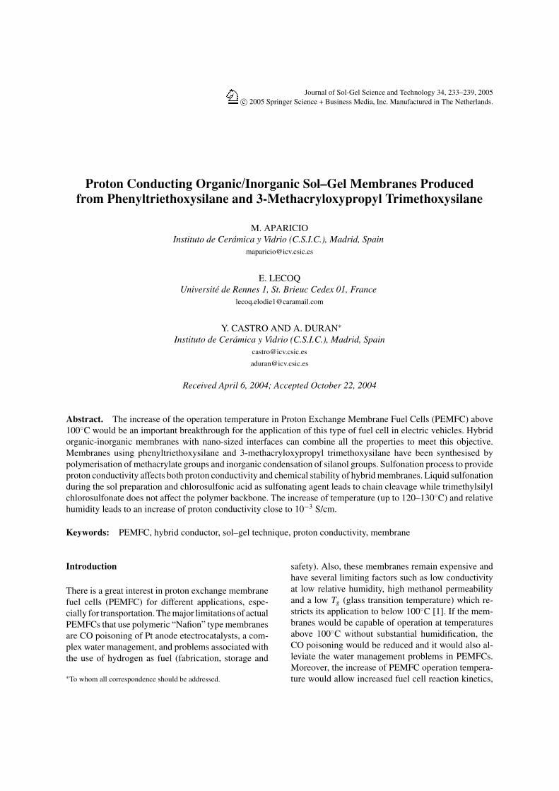
Figure 1. FT-IR spectra of pure PTES and PTES—HNO3 1M—PrOH solution at different reaction times.
ever, the sulfonation process with (CH3)3SiSO3Cl solu-tion only produces a slight loss of transparency withoutcolour variation.
FT-IR transmission spectra in the 1900–400 cm−1
range for PTES—HNO3 1 M—PrOH solution at dif-ferent reaction times are shown in Fig. 1. PrOH wasselected in this case in order to identify EtOH, one ofsubproduct of the hydrolysis reaction. A FT-IR spec-trum of pure PTES is also included in this figure forcomparison. All the bands present in the spectra arein good agreement with those coming from precur-sors and are assigned using literature data [11–13].The bands located at 700, 740, 1385, 1430, 1470 and1590 cm−1, attributed to characteristic vibrations ofthe benzene group, does not change with reaction timeshowing this group is stable to the hydrolysis reac-tion. The band at 1160 cm−1, assigned to the Si O Cbond of PTES, has a lower intensity after 1 min ofreaction compared with pure PTES showing that thehydrolysis reaction proceeds fast at the beginning. Theincrease of reaction time only produces a slightly fur-ther reduction of this band intensity. The subprod-uct of the hydrolysis reaction, EtOH, has two char-acteristic bands at 880 and 1050 cm−1. The presenceof these bands after only one min of reaction con-firm that the hydrolysis reaction begin instantly. Bothbands increase with reaction time indicating that the hy-drolysis reaction is not completely finished after twoh The increase of EtOH with reaction time is sus-tained by condensation reactions to produce Si O Sibonds. The reaction between two hydrolyzed PTESmolecules generates a water molecule that reacts withother PTES molecules producing EtOH. On the otherhand, a hydrolyzed PTES molecule can react with an

236 Aparicio et al.
Figure 2. FT-IR spectra of PTES—HSO3Cl solution at differentreaction times.
unmodified PTES molecule leading directly to an EtOHmolecule.
The study of hydrolysis reactions of MPS by FT-IRshows a similar behaviour (not shown). After only onemin of reaction, a reduction of Si O C band is ob-served, as well as the presence of an intense band as-signed to MeOH. Both facts indicate a very rapid hy-drolysis reaction of MPS. No changes can be observedin the spectra at higher reaction times. The FT-IR studyof the last step of sol preparation, i.e., mixing of pre-hydrolysed PTES, pre-hydrolysed MPS and remainingwater, did not show important changes. There is a slightincrease of EtOH and MeOH bands consequence of hy-drolysis and condensation reactions of both precursors.
Figure 2 shows FT-IR transmission spectra in the1900–400 cm−1 range of PTES-HSO3Cl solution atdifferent reaction times. The sulfonation process doesnot seem to affect the PTES structure, and after 3 hof reaction the figure presents a combination of bandsrelated with PTES and others assigned to SO−
3 groups(1035 and 1200 cm−1) and S O bond (920 cm−1) [14].The sulfonation process during sol preparation using(CH3)3SiSO3Cl leads to similar spectra. Both treat-ments lead to viscous, yellowish and transparent sols.
XRD patterns of membranes treated at 120◦C onlyshow the typical amorphous broad peak at 2θ valuesaround 25◦, characteristic of silicate gels. TGA-DTAcurves of 50% MPS samples with and without sul-fonation process with HSO3Cl in the sol preparationare shown in Fig. 3. The thermogravimetric curve ofthe sample without sulfonation (Fig. 3(a)) has threesteps with different weight loss. There is no apprecia-ble weight loss between room temperature and 250◦C,consequence of the hydrophobic character of this mem-
Figure 3. TGA-DTA curves of 50% MPS samples with (a) andwithout (b) sulfonation process with HSO3Cl in sol preparation.
brane with any adsorption of water. The decompositionof the organic component of the hybrid material startsat 250◦C which points out the thermal stability limit.The second step, between 250 and 525◦C, shows animportant weight loss (40%) attributed to the pyroly-sis of methacrylate part and the loss of solvents andwater generated during the condensation reaction ofsilanols. Correspondingly, three exothermic peaks ap-pear at 300, 375 and 460◦C in the DTA curve. The lastweight loss (23%), between 525 and 700◦C, is assignedto the final decomposition of the polymeric network,mainly the aromatic ring. A sharp exothermic peak cen-tred at 660◦C corresponds to this weight loss.
The incorporation of the sulfonation process duringthe preparation of the sol produces significant changesin the TGA-DTA curve (Fig. 3(b)). The TGA curveshows a continuous weight loss from 50 to 700◦C. Theweight loss between 50 and 150◦C (11%) is attributedto desorption of physically adsorbed water and smallorganic molecules in the membrane. This loss pointsout the first difference with the membrane without sul-fonation process indicating that this process producessulfonic groups attached to the aromatic rings that re-act with water. An endothermic peak at 100◦C con-firms the evaporation of water bounded to the sulfonicgroups. The second step, between 150 and 275◦C, is be-lieved to be due to the decomposition of sulfonic acid
Proton Conducting Organic/Inorganic Sol–Gel Membranes 237
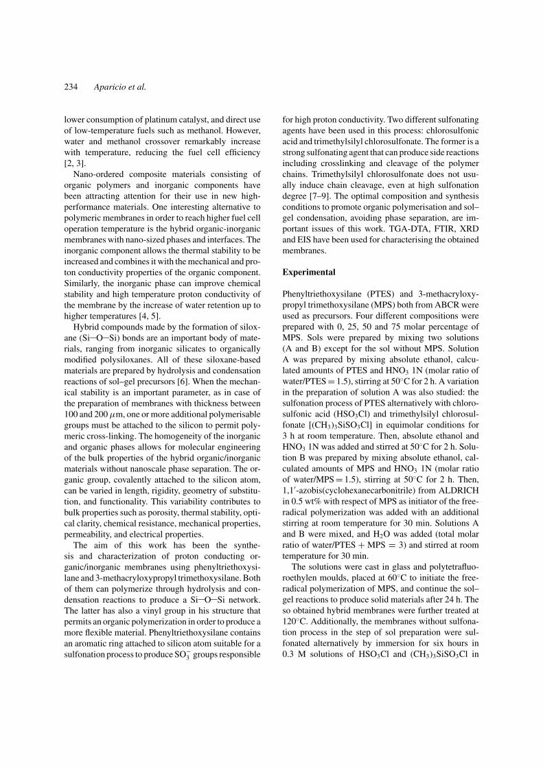
Figure 4. FT-IR spectra of different hybrid membranes: (a) 100PTES, (b) 25 PTES-75 MPS, (c) 75 PTES-25 MPS, (d) sulfonated50 PTES-50 MPS, (e) sulfonated 75 PTES-25 MPS.
groups [14–17], reducing the thermal stability up to170◦C approximately. The last step, from 275 to 700◦C,shows a continuous weight loss attributed mainly tothe decomposition of the polymeric component. Corre-spondingly, very broad exothermic peaks appear witha maximum at 325, 425 and 560◦C (Fig. 3(b)). Thehigh temperature exothermic peak shifts from 660◦Cfor samples without sulfonation process to 560◦C. Thisbehaviour indicates that the process has partially dam-aged the aromatic ring structure.
Figure 4 shows FT-IR spectra of hybrid membraneswith different compositions with and without sulfona-tion process with HSO3Cl in the sol preparation. Thethree samples without sulfonation and different per-centages of PTES and MPS (curves a, b and c) presentthe characteristic bands of these compounds: 700, 740,1395, 1430, 1480 and 1595 cm−1 for the benzenegroup, 1730 cm−1 for the C O bond and 1635 cm−1
for C C bond [11–13]. 50PTES-50MPS and 75PTES-25MPS membranes with sulfonation process usingHSO3Cl (curves d and e) show significant changesas compared with membranes without sulfonation. Al-though the sulfonation process did not seem to affectthe PTES structure when the solution A was prepared,this treatment together with the posterior preparationsteps of the sol and the thermal treatments at 60 and120◦C have produced a severe attack of HSO3Cl onbenzene, methacrylate groups and propyl chains lead-ing to the partial elimination of their characteristicbands. This behaviour explains the colour change, lossof transparency and the thermal stability reduction ofthe aromatic rings observed in samples sulfonated dur-ing the sol preparation.
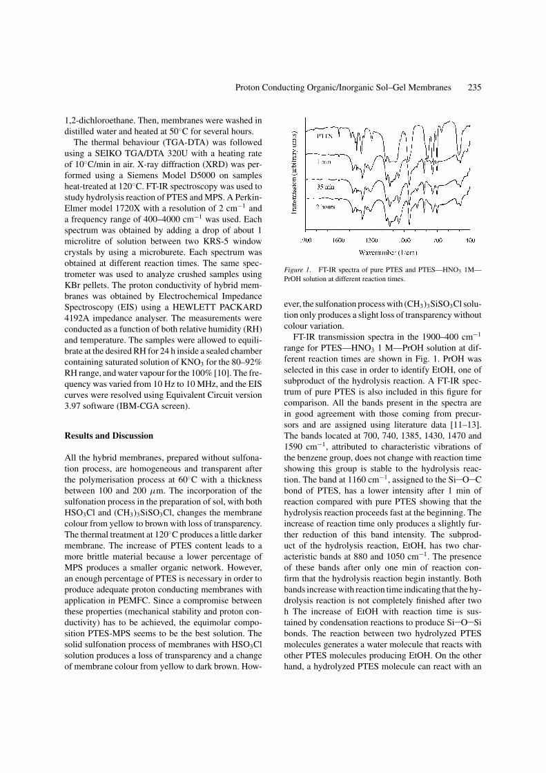
Figure 5. Impedance spectra at different temperatures in the 81–90% RH range of the 50 PTES-50 MPS membrane sulfonated byimmersion in the trimethylsilyl chlorosulfonate solution. The highfrequency region is shown in an expanded view.
The proton conductivity study only shows appre-ciable values with membranes sulfonated by immer-sion in the trimethylsilyl chlorosulfonate solution. Theremaining sulfonation processes used: immersion ofmembranes in the chlorosulfonic acid solution and thepre-treatment of PTES with trimethylsilyl chlorosul-fonate or chlorosulfonic acid during the sol preparation,did not provide any conductivity value. This behaviouris explained by the deterioration of the internal struc-ture of membranes. As an example, Fig. 5 shows theNyquist plots of the 50 PTES-50 MPS membrane sul-fonated by immersion in the trimethylsilyl chlorosul-fonate solution at different temperatures in the 81–90%RH range. The spectra present a semicircle throughthe origin at high frequencies and small inclined linesat low frequencies. The semicircle represents a typi-cal equivalent circuit of a resistor and a capacitor con-nected in parallel corresponding to the bulk electricalproperties, and the line a Warburg impedance caused bythe diffusion process of protons. The conductivity σ ofthe samples in the transverse direction was calculatedfrom the impedance data, using the relation σ = t/RS.In this equation t and S are the thickness and electrodearea of the sample, respectively. R was obtained fromthe intersect of the high frequency semicircle with theRe(z) axis calculated using the Equivalent Circuit 3.97software.
Figure 6 shows a 3D plot of conductivity values asa function of temperature and relative humidity of the75 PTES-25 MPS and 50 PTES-50 MPS membranes
238 Aparicio et al.
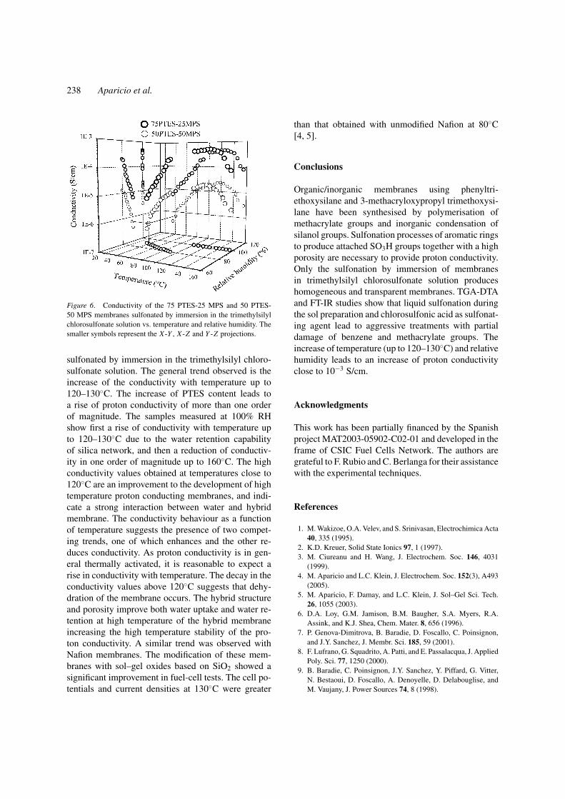
Figure 6. Conductivity of the 75 PTES-25 MPS and 50 PTES-50 MPS membranes sulfonated by immersion in the trimethylsilylchlorosulfonate solution vs. temperature and relative humidity. Thesmaller symbols represent the X -Y , X -Z and Y -Z projections.
sulfonated by immersion in the trimethylsilyl chloro-sulfonate solution. The general trend observed is theincrease of the conductivity with temperature up to120–130◦C. The increase of PTES content leads toa rise of proton conductivity of more than one orderof magnitude. The samples measured at 100% RHshow first a rise of conductivity with temperature upto 120–130◦C due to the water retention capabilityof silica network, and then a reduction of conductiv-ity in one order of magnitude up to 160◦C. The highconductivity values obtained at temperatures close to120◦C are an improvement to the development of hightemperature proton conducting membranes, and indi-cate a strong interaction between water and hybridmembrane. The conductivity behaviour as a functionof temperature suggests the presence of two compet-ing trends, one of which enhances and the other re-duces conductivity. As proton conductivity is in gen-eral thermally activated, it is reasonable to expect arise in conductivity with temperature. The decay in theconductivity values above 120◦C suggests that dehy-dration of the membrane occurs. The hybrid structureand porosity improve both water uptake and water re-tention at high temperature of the hybrid membraneincreasing the high temperature stability of the pro-ton conductivity. A similar trend was observed withNafion membranes. The modification of these mem-branes with sol–gel oxides based on SiO2 showed asignificant improvement in fuel-cell tests. The cell po-tentials and current densities at 130◦C were greater
than that obtained with unmodified Nafion at 80◦C[4, 5].
Conclusions
Organic/inorganic membranes using phenyltri-ethoxysilane and 3-methacryloxypropyl trimethoxysi-lane have been synthesised by polymerisation ofmethacrylate groups and inorganic condensation ofsilanol groups. Sulfonation processes of aromatic ringsto produce attached SO3H groups together with a highporosity are necessary to provide proton conductivity.Only the sulfonation by immersion of membranesin trimethylsilyl chlorosulfonate solution produceshomogeneous and transparent membranes. TGA-DTAand FT-IR studies show that liquid sulfonation duringthe sol preparation and chlorosulfonic acid as sulfonat-ing agent lead to aggressive treatments with partialdamage of benzene and methacrylate groups. Theincrease of temperature (up to 120–130◦C) and relativehumidity leads to an increase of proton conductivityclose to 10−3 S/cm.
Acknowledgments
This work has been partially financed by the Spanishproject MAT2003-05902-C02-01 and developed in theframe of CSIC Fuel Cells Network. The authors aregrateful to F. Rubio and C. Berlanga for their assistancewith the experimental techniques.
References
1. M. Wakizoe, O.A. Velev, and S. Srinivasan, Electrochimica Acta40, 335 (1995).
2. K.D. Kreuer, Solid State Ionics 97, 1 (1997).3. M. Ciureanu and H. Wang, J. Electrochem. Soc. 146, 4031
(1999).4. M. Aparicio and L.C. Klein, J. Electrochem. Soc. 152(3), A493
(2005).5. M. Aparicio, F. Damay, and L.C. Klein, J. Sol–Gel Sci. Tech.
26, 1055 (2003).6. D.A. Loy, G.M. Jamison, B.M. Baugher, S.A. Myers, R.A.
Assink, and K.J. Shea, Chem. Mater. 8, 656 (1996).7. P. Genova-Dimitrova, B. Baradie, D. Foscallo, C. Poinsignon,
and J.Y. Sanchez, J. Membr. Sci. 185, 59 (2001).8. F. Lufrano, G. Squadrito, A. Patti, and E. Passalacqua, J. Applied
Poly. Sci. 77, 1250 (2000).9. B. Baradie, C. Poinsignon, J.Y. Sanchez, Y. Piffard, G. Vitter,
N. Bestaoui, D. Foscallo, A. Denoyelle, D. Delabouglise, andM. Vaujany, J. Power Sources 74, 8 (1998).

Proton Conducting Organic/Inorganic Sol–Gel Membranes 239
10. Handbook of Chemistry and Physics, David R. Lide, 80th Edi-tion 1999–2000.
11. Y. Wei, D. Yang, L. Tang, and M.K. Hutchins, J. Mat. Res. 8,1143 (1993).
12. Y. Wei, D. Jin, C. Yang, and G. Wei, J. Sol–Gel Sci. Tech. 7, 191(1996).
13. V.D. Ramos, D. Derouet, and L.L.Y. Visconte, Poly. Testing 22,297 (2003).
14. H. Wang, B.A. Holmberg, L. Huang, Z. Wang, A.Mitra, J.M. Norbeck, and Y. Yan., J. Mater. Chem. 12, 834(2002).
15. S. Li and M. Liu, Electrochimica Acta 48, 4271 (2003).16. I. Gautier-Luneau, A. Denoyelle, J.Y. Sanchez, and C.
Poinsignon, Electrochimica Acta 37, 1615 (1992).17. S.M. L. Zaidi, S.D. Mikhailenko, G.P. Robertson, M.D. Guiver,
and S. Kaliaguine, J. Memb. Sci. 173, 17 (2000).