Project report template
38
College of Engineering Department of Mechanical Engineering Fall 2020 -2021 Senior Design Project Report 3D PRINTED DRONE Team Members Student Name Student ID 1 ABDULLAH AL-HAMDAN 201303975 2 NEDAAL BEMBI 201500216 3 IBRAHIM HAYAZ 201403285 4 ABDULKHALIQAL-SHAMRANI 201401637 Project Advisors: Advisor Name: DR. NASSIM KHALID
-
Upload
khangminh22 -
Category
Documents
-
view
0 -
download
0
Transcript of Project report template
College of Engineering
Department of Mechanical Engineering
Fall 2020 -2021
Senior Design Project Report
3D PRINTED DRONE
Team Members
Student Name Student ID
1 ABDULLAH AL-HAMDAN 201303975
2 NEDAAL BEMBI 201500216
3 IBRAHIM HAYAZ 201403285
4 ABDULKHALIQAL-SHAMRANI 201401637
Project Advisors:
Advisor Name: DR. NASSIM KHALID

Page | 2
Declaration.
We hereby declare that the thesis titled “Design and Development of 3D PRINTED DRONE for
Mechanical Applications” is submitted to the Department of Mechanical Engineering partial
fulfillment of the Bachelor of Science in Mechanical Engineering. This is work was not
submitted elsewhere for the award of any other degree or any other publication.
________________________ ________________________
ABDULLAH ALHAMDAN NEDAAL BEMBI
Student ID: 201303975 Student ID: 201500216
________________________ ________________________
IBRAHIM AL-HAIZ ABDULKHALIQ AL-SHAMRANI
Student ID: 201403285 Student ID: 201401637
Supervisor:
_____________________
DR. NASSIM KHALID
Professor, Department of Mechanical Engineering

Page | 3
Abstract.
Nowadays, there is a growing need for flying drones with diverse capabilities for
both civilian and military applications. There is also a significant interest in the development of
novel drones which can autonomously fly in different environments and locations and can
perform various missions. In the past decade, the broad spectrum of applications of these drones
has received most attention which led to the invention of various types of drones with different
sizes and weights. In this review paper, we selected a drone was ready designed on solid work
as conceptual design. We reviewed the design and noticed that there are a lot of mistakes that
could be developed and enhanced to make the drone work with better efficiency and more flight
time with less power consumption. As we also made huge changes in the way of working. We
also changed some parts or canceled some to make the best possible design. We will test each
part and provide the data sheet and how it was affecting the drone efficiency.

Page | 4
Acknowledgment.
First of all, we would like to express our appreciation to our advisor Dr. Nassim
Khalid for his unlimited support for our project and his encouragement. Also, we express thanks
to Dr. Faramarz Djavanroodi, chair of the Mechanical Engineering Department at PMU, for his
continued encouragement. Finally, we thank our parents for their endless support, and attention.

Page | 5
List of Acronyms (Symbols) used in the report:
Symbol Symbol Description
φ Roll angle
θ Pitch angle
ψ Yaw angle
RPM Revolutions per minute
F Actual thrust applied plus weight of rotor.
C Thrust rating from chart for 106 revolutions of life.
Y Bearing thrust factor from chart
N RPM of motor.
CI Lift coefficient
V Speed of moving object
𝜌 Density of fluid
A Area of the wing
KV Constant velocity of a motor

Page | 6
Table of Contents Abstract………………………………………….………………………………………………………...….…...3
Acknowledgment………………………………………………………………………………………………….4
List of Acronyms (Symbols) used in the report…………………………………………………...……….…....5
Chapter 1: Introduction………………………………………………………………………………………..…8
1.1 Project Definition…………………………………………………………………………….........9
1.2 Project Objectives……………………………………………………………………..…….....…10
1.3 Advantages of Quadcopter…………………………………………………………………….....10
1.3.1: Environmentally……………………………………...…………...…………………...…..10
1.3.2: Economically …………………………...……………………………………………....…11
1.4 Project Specifications…………………………………………………………………………….11
1.5 Applications………………………………………………………………………………….…...13
Chapter 2: Literature Review……………………….…………………………………………………….…….15
2.1 Project background……………………………………………….……………………………......15
2.2 Modelling of a Quadcopter dynamics.……………………………………...………………,……..17
Chapter 3: System Design…………………………………………………………………………...…………..20
3.1 Design Constraints and Design Methodology:……………………………………………………..20
3.1.1: Sustainability…………………………………………………………….…………………..20
3.1.2: Safety: ………………………………………………………………………….……………20
3.1.3: Ethical: …………………………………………………..…………………………….…….20
3.2: Design Engineering Standard:………………………………………………………………………21
3.3: Theory and Theoretical Calculations:………………………………………………………….……21
3.3.1: Thrust Application:……………………………………………………………………….…..22
3.3.2 : Brushless motor and reason for using it instead of normal motors:…………………………25
3.3.3: Calculation thrust for motors………………………………………………………………....26
3.3.4:Power Lift Calculation:……………………………………………………………………….26
3.3.5 :Flight time calculation formula for our drone :………...…………………………….…...… 27
3.3.6 :Relation of Power consumption in drone and number of fan blades:………………………..27
3.3.7: making graph and data table of thrust power and power consumption to get flight time
data:……………………………………………………………………………………………....28
3.3.8 Stability and body rigidity…………………………………………………….……………….28
Chapter 4: System analysis and testing………………………………………………………………………..29
4.1 Programming and celebration………………………………………………………………...…29
4.2 PID Profile setting ………………………………………………………………………......…..29
4.3: transmitter setting………………………………………………………………………...……..31
Chapter 5: Project Management………………………………………………………………………………..32
5.1: Choosing the project……………………………………………………………………………..32
5.2: Scheduling and Planning……………………………...…………………………………………32
5.3: Project materials and Badgat…………………………………………………………………….33

Page | 7
Chapter 6: Project Analysis…………………………………………………………………………………….34
6.1: Experiments and results…………………………………………………………………………34
6.1.1: EXP #1: using 5-inch propellers made from glass……………………………………….34
6.1.2: EXP #2: using 6-inch propellers made from glass……………………………………….34
6.1.3: EXP #3: using 6-inch propellers made from glass…………………………………….…34
6.2 Lesson learn………………………………………………………………………………………35
Conclusion………………………………………………………………………………………………………..36
References…………………………………………………………………………………………………..……37

Page | 8
Chapter 1: Introduction.
Unmanned aerial vehicles (UAV) are another name for Drone. drone is a flying
robot. Sometime featured with GPS, the flying machine may be remotely controlled or can fly
autonomously by programed controlling flight systems. Drones are most often used in military
services. However, it is also used for weather monitoring, firefighting, search and rescue,
surveillance and traffic monitoring etc. In recent years, the drone has come into attention for a
number of commercial uses. In late 2013, Amazon announced a plan to use unmanned aerial
vehicles for delivery in the nearby area’s future. It is known as Amazon Prime Air; it is estimated
to deliver the orders within 30 minutes inside 10 miles of distance. So, it is clear that domestic
usage of UAV has vast future possibility in different fields rather than military usage.
Drones for military use were started in the mid-1990s with the High-Altitude Endurance
Unmanned Aerial Vehicle Advanced Concept Technology Demonstrator (HAE UAV ACTD)
program managed by the Defense Advanced Research Projects Agency (DARPA) and Defense
Airborne Reconnaissance Office (DARO). This ACTD placed the base for the improvement of
the Global Hawk. The Global Hawk hovers at heights up to 65,000 feet and flying duration is up
to 35 hours at speeds approaching 340 knots and it costs approximately 200 million dollars. The
wingspan is 116 feet and it can fly 13.8094 miles which is significant distance. Motherland
security and drug prohibition are the main needs Global Hawk was designed for. Another very
successful drone is the Predator which was also built in the mid-1990s but has since been
improved with Hellfire missiles. “Named by Smithsonian’s Air & Space magazine as one of the
top ten aircraft that changed the world, Predator is the most combat-proven Unmanned Aircraft
System (UAS) in the world”. The original version of the Predator, built by General Atomics, can
fly at 25,000 feet for 40 hours at a maximum airspeed of 120. As we know all these names of
drone and how powerful it is. Drone was classified into 4 major types.
1. Multi Rotor Drones
2. Fixed Wing Drones
3. Single Rotor Helicopter
4. Fixed Wing Hybrid VTOL
Page | 9
Multi Rotor Drones is classified also into types based on how many motors is attached to it.
1- Tricopter (3 rotors).
2- Quadcopter (4 rotors).
3- Hexacopter (6 rotors).
4- Octocopter (8 rotors).
We have selected the Quadcopter as to be designed, tested, and modified in our project.
1.1: Project Definition.
Quadcopter is a kind of unmanned aerial vehicle (UAV). UAV can generally be
defined as a device used or intended to be used for flight in the air that has no onboard pilot.
These devices are sometimes referred to as drones, which are programmed for autonomous
flight, and remotely piloted vehicles (RPVs), which are flown remotely by a ground control
operator. This fact in many cases can result in high maintenance and deployment costs
particularly speaking in the industrial domain applications. Some applications implement an
autonomous flight mode, however the autonomy here is intended as a simple path planning
through several given points. Quadcopter can be used in applications such as aerial recognition,
search-and-rescue, industrial monitoring missions among others. Dimensions of quadcopters can
vary from the size of an insect to a size of a professional aerial vehicle. Dimensions differ
according to the type of application in which this UAV are going to be implemented and the
equipment they are taking., quadcopter needs to be equipped with sensors (in most cases they
are light) so the quadcopter can be small., where the quadcopter needs to be equipped with
camera, sensors, and sometimes weapons, quadcopter needs to be much larger. Camera and
adequate software can be used to provide imaging-based automatic inspection and analysis for
such applications as automatic inspection, process control, and robot guidance in industry. A
quadcopter is a multirotor UAV that is lifted and propelled by four rotors. Quadcopters are
classified as rotorcraft, as opposed to fixed-wing aircraft, because their lift is generated by a set
of rotors (vertically oriented propellers).

Page | 10
1.2: Project Objectives.
The objective from designing the Quadcopter and make research & consider problem solving
and start to do several experiments to approach:
- Develop a wing equipped with legs to be more valuable and more stability to the design
that can sit with different application under one design.
- Maximize the flight time for drone with low cost and minor changes in design to develop
a better usage for those who are using the drone for long time such as monitoring proposes.
- Understand the design of propeller angels and numbers can create a change in the drone
flight efficiency, which can help those are working with the drone to deliver packages or
unexpected increase of weight.
- Improve Sensors selection optimization & Analysis of the performance requirements of
Quadcopter.
- Studying the changes in the system and get the best valuable result in improving the design
based on the experiment that will implements will help the future researcher or drone
manufacturers make their drone project with based data can guide them to make the best
design without studying the project from zero and make their testing just for the data.
1.3: Advantages of Quadcopter.
There are several advantages to Quadcopter. First, Quadcopter do not require
mechanical linkages to vary the rotor blade pitch angle as they spin. This simplifies the design
and maintenance of the vehicle. Secondly, the use of four rotors allows each individual rotor to
have a smaller diameter, allowing them to possess less kinetic energy during flight. This reduces
the damage caused should the rotors hit anything. For small-scale UAVs this makes the vehicle
safer for close interaction. Some small-scale Quadcopter have frames that enclose the rotors,
permitting flights through more challenging environments, with lower risk of damaging the
vehicle or its surroundings.
1.3.1: Environmentally.
Recently, many countries are going in using the 3D printed drone technology. The benefits that
drones offer the fields of environmental monitoring and conservation are being realized by an
ever-increasing number of researchers, students and environmental engineers. Drones offer
quick, easy and cost-effective insights, on demand. Their application meanwhile varies widely.
So, we can see United States is the first one of the biggest countries in the world in manufacturing
drone.

Page | 11
1.3.2: Economically.
In economic side, our system helps to save money & time by increasing the quality on usage
which the most needed in the companies in current time such as marketing delivery. Moreover,
it will as replacement of traditional works.
1.4: Project Specifications.
This project is applicable to Quadcopter drone types such as Multi Rotor Drones, Fixed Wing
Drones. The parts have been selected for this project which has the specifications as listed in
table 1.1.
Table 1.1: The system measurements
Weight in
grams Quantity Name Item
251 1 Lower body 1
270 1 Upper body 2
400 4 Motor holder 3
44 4 Propeller 4
439 1 Lithium Polymer Battery 6000 mAh 5
124 4 Brushless motors 6
18 1 Flysky FS-i6x transmitter 7
7 1 CAM ESP Wi-Fi Bluetooth 8
26 1 Flight controller FC Built-in TCMMRC F4 9
12 1 Mini PDB - Power distribution board 10
4 1 TTL Adapter board - Cam Adapter 11
92 4 bolts 12
1687 g
Total estimated
weight
How to select our part in the drone?
We have 4 different models; the selection of models will be based on the application of done
usage. To select the application, we should know the two words.
1- Weight force: is the force of gravity. It acts in a downward direction—toward the center
of the Earth. This will be about two part (Model weight and object weight)
2- Thrust force is opposite direction of the weight force and in the same direction of the
fan (Propeller).

Page | 12
The main component of the drone and the model e used:-
1- Brushless DC motor: Crazepony 4pcs BLHeli_32 35A ESC 2-5S Dshot 150/300 /
600/1200 for FPV Drone Quadcopter Multicopter
2- Propeller: RCGEEK Compatible with DJI Mavic 2 Pro Carbon Fiber Propellers
3- Electronic speed controller: Crazepony 4pcs BLHeli_32 35A ESC 2-5S Electronic
Speed Controller
4- Lipo battery : Zeee 3S 11.1V 60C 6000mah RC
5- Flight controller kit : TCMMRC F4 10V 2-5s
6- PDB : ICQUANZX V3.1
7- RC (Transmitter & Receiver).: Flysky FS-i6X
Selection of the weight component will assure you the flight of drone. Here important note that
total weight shall not exceed the thrust force required.
How we calculate and know the thrust force for motor and propeller?
By Pinch test, the manufacturer will conduct this test on the many propeller and will give you
the thrust on each propeller.
The Main parameter affecting the thrust force:
1- 3 Parameter in the propeller (Pitch, Diameter, material)
2- One Parameter in the Motor (RPM)
3- One parameter in the atmosphere. (Air)
I will start with
1- RPM:
RPM will be function in two thighs
A -KV
B -volt in the battery.
This will let me know the RPM for the motor. For example, 600 KV motor powered by 11.1,
the max RPM= 11.1 x 600= 6,660 RPM.
2- Propeller
The size of propeller will contain two number example 10 x 4.5 inch that mean 10 is diameter
of propeller and 4.5 is the pitch. In the theory the diameter is related to Thrust force, if the
diameter increased the Thrust force will increase. Also, the pitch related to the speed of the

Page | 13
drone, if we increased the pitch the speed will be increased but the problem if we increase
the pitch the turbulent will occurred.
Flight time
Before procured any battery, 3 you need to know
1- mAh
2- 2- number of C which is the maximum discharge rate can produce by battery
3- 3- the Volt, we should know this number to multiply with KV to get the Max RPO like
example above.
How we can select the battery?
The main information that you need to know to select the write battery:
1- Lip Cells: example in the batter we have 3s that meat 1 Cell = 4.7V so, 3 Cells=
4.7x3=11.1V. that mean you can`t apply more that 11.1 volt in this battery.
2- Maximum Current: X Number of Motor = Max Ampere required ( Battery must deliver
this Ampere which is mentioned in the data specification)
1.5: Applications.
There many purposes of the applications for the project are to be used on:
- Research Platform: Quadcopter are a useful tool for university researchers to test and
evaluate new ideas in a number of different fields, including flight control theory,
navigation, real time systems, and robotics.
- Investigating Purpose: Since Quadcopter is small in size and light in weight, they can get
into places, where people cannot get into like caves, holes and tunnels.

Page | 14
- Shipping and delivery: Major companies in favor of drone delivery. Drones could save a
lot of manpower and shift unnecessary road traffic to the sky. Besides, they can be used
over smaller distances to deliver small packages, food, letters, medicines, beverages and
the like.
- Geographic mapping: Available to amateurs and professionals, drones can acquire very
high-resolution data and download imagery in difficult to reach locations like coastlines,
mountaintops, and islands. They are also used to create 3D maps and contribute to crowd
sourced mapping applications.
- Search and rescue: Drones are able to discover the location of lost persons and
unfortunate victims, especially in harsh conditions or challenging terrains. Besides
locating victims.

Page | 15
Chapter 2: Literature Review.
2.1: Project background.
Drone now a days has become the future of many businesses and took a huge
place to be used by individuals and the government. It still needs a lot of permissions to be used
and there is limitation in Saudi Arabia to use it specially inside the city. The challenges start
when a company or an individual think of using a drone or test it without official permit which
will Couse him to be stopped immediately. Another challenge is when wanting to program the
Arduino by the individual himself, he will need a high skill in programming plus a WIFI Arduino
which could be unavailable in Saudi Arabia. All the boards and the digitals equipment's that are
related to the drones are not available in Saudi Arabia. All equipment's should be bought from
amazon or another web site which will take more time to provide all the needed equipment.
Batteries are not allowed to be shipped in normal ways; it should be shipped by airplane which
will add some extra cost for shipping. Another challenge is having all our connection done in the
right way so we don’t connect the wrong voltage in the wrong port which can damage the board.
This is the main body which is formed of two main parts upper and lower. it was
scaled up in a way that fits the 3D printer to be printed as one piece. To have a dimensions of 30
cm X 40 cm. we avoided making it larger due to the limitation of the printing machine the
company will use. If it was going to be larger that mean it will be made into halves then it will
be glowed which we didn't accept in our prototype.
Figure 1 show the body design, that we used before modification
Figure 1

Page | 16
it will be the joint that connect the motor fan with the body to make them fly as one solid part.
It was modified to be lighter and empty from inside. The original leg was designed wrongly by
not respecting the motor base bolts and the motor shaft area. Also, it didn’t consider the weight
of it as it was designed to have an unneeded large gear which will add weight on the drone and
add load on the shaft. That’s why it was modified to work without a gear.
Figure 2 & 3 show that the design of the body holder which we called body leg #1.
Figure 4 show the propeller was designed to fit in the gear. The central area was modified
to be attached directly to the shaft of the motor.
Figure 5 shows the specification for the brushless motor we will use in our drone.
Figure 2
Figure 4
Figure 3
Figure 5

Page | 17
Figure 6 & 7 show that the transmitter and receiver we will use to control the drone
Figure 8 show the board we will use to reduce the power consumption and see how it is
going to affect the flight time and drone efficiency.
2.2: Modelling of a Quadcopter dynamics.
This section presents the basic Quadcopter dynamics. The basic idea of the
movement of the Quadcopter is shown in the following figure. It can be seen from the figure that
the Quadcopter is simple in mechanical design compared to helicopters. Movement in horizontal
frame is achieved by tilting the platform whereas vertical movement is achieved by changing the
total thrust of the motors. But Quadcopter arise certain difficulties with the control design.
Figure 7
Figure 8
Figure 2
Figure 6

Page | 18
Figure 9: Basic Flight movements of a Quadcopter
A coordinate frame of the Quadcopter is shown in the figure below.
Figure 10: Quadcopter coordinate system
The Quadcopter is designed on the following assumptions:
The structure is supposed to be rigid.
The Centre of Gravity and the body fixed frame origin are assumed to coincide.
Thrust and drag are proportional to the square of the propeller’s speed.
The propellers are supposed to be rigid.
The structure is supposed to be axis symmetrical
Rotation matrix defined to transform the coordinates from Body to Earth co-ordinates
using Euler angles φ- roll angle, θ- pitch angle, ψ- yaw angle.
About by φ, by θ and by ψ

Page | 19
Special attention should be given in the difference between the body rate measured p, q, r in
Body Fixed Frame and the Tait- Bryan angle rates expressed in Earth Fixed Frame. The
transformation matrix from [ φ θ ψ]T to [p q r ]T is given by:
Moreover, the rotation matrix of the Quadcopter’s body must also be compensated during
position control. The compensation is achieved using the transpose of the rotation matrix.

Page | 20
Chapter 3: System Design.
3.1: Design Constraints and Design Methodology.
When we started our design and plan for the project, we faced some challenges
that are lack of the parts and hard to have them in short period for our project such as special
type of motors and control system to assist the lifting of the design. Moreover, most of parts have
been bought from out of kingdom due to they are not available in local market, Furthermore, the
different companies that refuse to work in making the design , because they do not have official
authority to make it. Finally, one company accept to do the design in shape only without making
any programming for the control system and we informed them, that design was requested from
PMU for the student of senior graduation project and all experiments will be done inside the
campus of the university for developing the movement of drone. However, we should take
considerations on the weight of design and focused on the thrust strength of the motor to rise the
design without cause any over load so, we can fly it in easily method.
3.1.1: Sustainability.
We may face a problem in terms of sustainability due to chance of little vibration Because the
thickness & angle of the blades of the fan and to avoid this problem, we used smaller fan with
high efficiency to be suitable with the motor movement in the thrust.
3.1.2: Safety.
One of the important of our system is safety of parts. keeping the motor running not over loaded,
this will increase the efficiency of the quadrat rising and keep the movement of the fan stable.
3.1.3: Ethical.
This project almost looks like the previous kind of works. So, we searched to get some general
ideas to improve the design by our own ideas in terms of safety, economically, and sustainability.

Page | 21
3.2: Design Engineering Standard.
Engineering standards should be followed in each components of our system. In this section, we
described each component that have been selected for our project.
Component Engineering standards Details
Lithium Polymer Battery 6000 mah Capacity of 6000 mah - cell number 3S Power supply for our drone
Brushless motors 2300kv with 1025 MAX thrust Motors to rotate the propeller and
left the drone
Flysky FS-i6x 2.4 ghz : 10 Channels To control the drone wirelessly.
Electronic speed controller 35 a Speed controller
Flight controller FC Built-in TCMMRC
F4 10V, 2-5s. To monitor the drone operations
Propellers 5 inch glass made propellers To generate the thrust power.
CAM ESP WIFI Bluetooth 2MP To transfer the vision
Mini PDB - Power distribution board 3-6s - 5 and 12 Volt To reduce the power consumption
3.3: Theory and Theoretical Calculations.
The calculation of the Quadcopter based on seven factors which given as:
1. Force and moments.
Fi = Kf x ωi²
Mi= Km x ωi²
My= (F1-F2) x L
MX= (F3-F4) x L
Weight= mg
2. Newton’s second law of motion.
* for linear motion:
Force = mass x linear acceleration.
* for rotational motion:
Torque = Inertia x angular acceleration
.
3. Hover condition.
mg=F1+F2+F3+F4
All Moments= 0
Figure 11
Page | 22
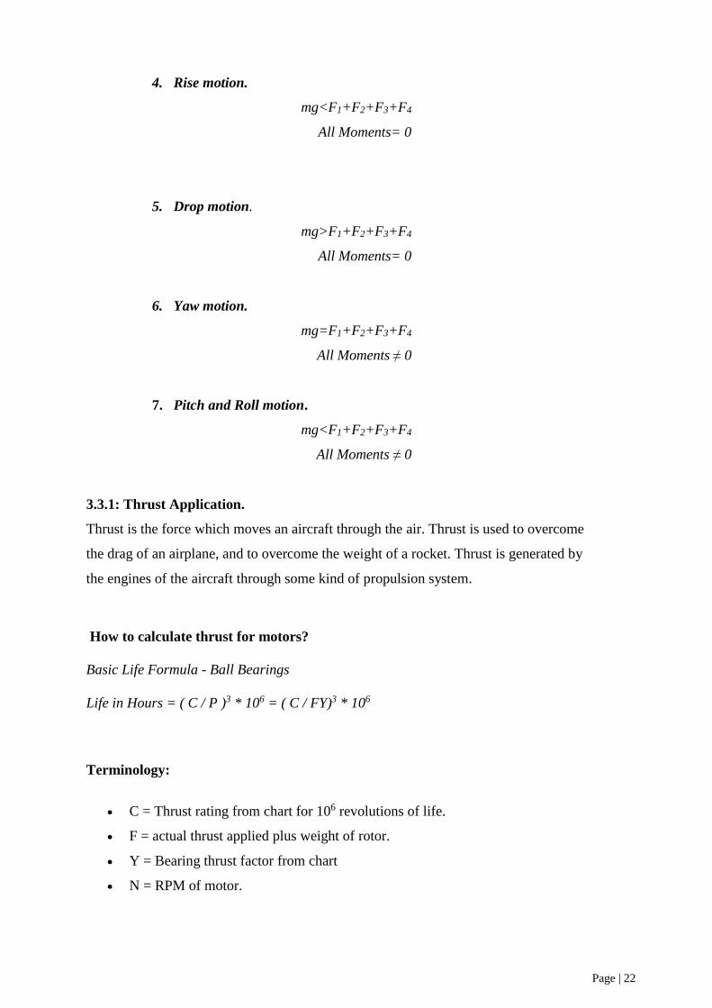
4. Rise motion.
mg<F1+F2+F3+F4
All Moments= 0
5. Drop motion.
mg>F1+F2+F3+F4
All Moments= 0
6. Yaw motion.
mg=F1+F2+F3+F4
All Moments ≠ 0
7. Pitch and Roll motion.
mg<F1+F2+F3+F4
All Moments ≠ 0
3.3.1: Thrust Application.
Thrust is the force which moves an aircraft through the air. Thrust is used to overcome
the drag of an airplane, and to overcome the weight of a rocket. Thrust is generated by
the engines of the aircraft through some kind of propulsion system.
How to calculate thrust for motors?
Basic Life Formula - Ball Bearings
Life in Hours = ( C / P )3 * 106 = ( C / FY)3 * 106
Terminology:
C = Thrust rating from chart for 106 revolutions of life.
F = actual thrust applied plus weight of rotor.
Y = Bearing thrust factor from chart
N = RPM of motor.

Page | 23
Theoretical calculation for selecting out motors thrust power:
Weight of Drone = 1700 g
Calculated weight = 2 X 1700g = 3400g
Total weight = 3400 + 20% = 4080 g
Thrust for each motor = 4080 / 4 = 1020
So each motor must be able to generate a thrust
power of 1020 g
Based on our calculation
We have selected the motors with the required
thrust specification which is equal to 1024g. see
figure 12
DUCTING EFFECT ON PROPELLER EFFECIECNCY AND THRUST
According to Bernoulli's equation, the pressure is low where the airspeed is high, and high where
the airspeed is low in the case of a flat sheet or aero-foil. In the case of aero-foil, the speed of the
air passing at the upper portion is high causing the pressure drop as compared to the bottom
portion of aero-foil where the pressure is higher. This effect causes the aero-foil lift due to
pressure difference.
Figure 13: Aero-foil design and profile
The construction of the propeller consists of several blades that are attached to the hub or boss.
The attachment is done by either forging or welding. The blades/ aero-foils are at an inclined
angle and organized in such a way that the blades are rotated in any direction depending upon
the way the thrust should come out. These blades behave like a wing moving through the air
causes lift when the air streamlines passing through wing air will be deflected down and the
reaction will cause lift of a wing. Propeller works on the principle of Newton’s third law of
Figure 12

Page | 24
motion that “Action and reaction are equal in magnitude but opposite in direction”. According
to Bernoulli, the air passing at the top portion of the aero-foil moves quickly as compared to
lower portion cases the pressure drop at the top portion.
This effect is another cause of aero-foil lift. Propeller blades block the flow of air moving from
top to bottom and spinning due to centrifugal force. When the air from the higher pressure region
(bottom portion) to the lower pressure region (top potion) it causes the vortex creation at the tip
of aero-foil where the high and low-pressure mixes and causes heated the air and noise is created
due to molecular movement of air, hence making noise, and a large amount of energy is wasted.
To prevent the formation of vortex we provide a fence against the blades, prevent the mixing of
high-pressure air with low-pressure air. However, the energy that is previously wasted into
vortex creation is now used in the lifting of aero-foil, because of protecting it from mixing and
causes stronger lift. There are two ways of increasing the efficiency of the propeller by placing
it in a duct.
Figure 14
When the propeller is placed inside the tube it will prevent vortex formation because the gap
between the tip of the aero-foil and the wall of the tube is very small and little leakage occurred.
Due to this construction the efficiency of the propeller in a duct increase. Therefore, the propeller
operating in the duct is more efficient than the propeller working in the free region. The second
way is to make a curved portion at the edges of the duct, hence causing more lift. The curve
portion looks like an annular wing at the top of the duct. The air passing through the annular
wing/ curve portion is very quick causes the low-pressure region near the curve. The pressure
behind the curve portion of the duct is normal atmospheric pressure because no air is moving
behind the curve portion. Due to the pressure difference, the whole duct will move forward and
causes it to lift the whole duct. It will cause the aero-foil lift in the forward direction as that of
the propeller itself without any expense, no input energy is used, and get more free energy thus
increasing the efficiency of the propeller. The combination of lip (Annular wing) and the duct
itself increases the performance of the propeller. If the clearance between the duct and the tip of
the blade is too much it will cause the turbulent flow around the tip of the blade and hence much
power is a loss. This gap should be kept very small.

Page | 25
3.3.2 : Brushless motor and reason for using it instead of normal motors.
Brushed DC motors depend on a mechanical system to transfer current, while AC and brushless
DC gear motors use an electronic mechanism to control current. We used brushless motor
instead of normal motors due to the following:
1- Motor Construction: see figure 15 for more explanation
2- Efficiency: in figure 16, we can see the different efficiency between DC & AC motors.
3- Service and Maintenance:
4- Speed Stability.
5- High Speed Operation: As shown in figure 17
Figure 15: shows the motor construction
Figure 16

Page | 26
3.3.3: Calculation thrust for motors.
Thrust for motors is calculated by following procedure:
1. First of all, calculate the weight of drone including the objects that will drone carry during
its flight. Multiply the weight of drone by two to determine the minimum thrust. Again
add 20% of this calculated weight to get total weight.
Calculated weight = 2× [weight of drone + weight of carried objects]
Total weight =2× [weight of drone + weight of carried objects] + [0.2×calculated weight]
2. And finally divide total weight by number of motors
𝑐𝑎𝑙𝑐𝑢𝑙𝑎𝑡𝑒𝑑 𝑤𝑒𝑖𝑔ℎ𝑡 + [0.2 × 𝑐𝑎𝑙𝑐𝑢𝑙𝑎𝑡𝑒𝑑 𝑤𝑒𝑖𝑔ℎ𝑡 ]
𝑁𝑢𝑚𝑏𝑒𝑟𝑠 𝑜𝑓 𝑚𝑜𝑡𝑜𝑟𝑠
3.3.4: Power Lift Calculation.
When a body move through a fluid, fluid always apply a force on the surface of the moving body.
Lift is one component of that applied force. Lift always applied perpendicular to the direction of
motion of the object. On an airfoil shape moves through the air, the stream lines on the upper
side of airfoil are closer than the lower side of the airfoil. According to the where streamline are
closer, pressure will be lower. This pressure difference creates a lift. Power of lift is calculated
by the following formula:
Power of Lift = 𝐶𝐼 ×𝜌.𝑉2
2× 𝐴
Where ‘CI’ is lift coefficient, ρ is density of fluid, V is speed of moving object and arear of
wing.
Figure 17

Page | 27
3.3.5: Flight time calculation formula for our drone.
Time of flight can be calculated by using following formula
Time of flight of drone = t = 𝐵𝑎𝑡𝑡𝑒𝑟𝑦 𝑐𝑎𝑝𝑎𝑐𝑖𝑡𝑦×𝐵𝑎𝑡𝑡𝑒𝑟𝑦 𝑑𝑖𝑠𝑐ℎ𝑎𝑟𝑔𝑒
𝐴𝑣𝑒𝑟𝑎𝑔𝑒 𝑎𝑚𝑝.
Where ‘t’ is the time of flight in hours. To get time of flight in minutes divide it by 60.
Average Amp are amperes of batteries.
Time of flight of drone = t = 𝐵𝑎𝑡𝑡𝑒𝑟𝑦 𝑐𝑎𝑝𝑎𝑐𝑖𝑡𝑦(60)×𝐵𝑎𝑡𝑡𝑒𝑟𝑦 𝑑𝑖𝑠𝑐ℎ𝑎𝑟𝑔𝑒(11.1)
𝐴𝑣𝑒𝑟𝑎𝑔𝑒 𝑎𝑚𝑝(100 ).= 6.6 ℎ𝑜𝑢𝑟𝑠
3.3.6: Relation of Power consumption in drone and number of propellers blades.
Number of propellers blade vary according to the situation of carried load. Higher number of
propellers blades will make an addition to the carried load. As weight of drone increases the
power consumption of drone will also increase. Smaller blades are installed on smaller motors
having high KV rating. Larger fan blades are installed with motors which have low KV rating.
In figure 18, it explains how the propellers works in the drone.
Figure 18

Page | 28
3.3.7: making graph and data table of thrust power and power consumption to get flight
time data.
Power consumption of a drone can be calculated by the following formula:
Power consumption=Battery capacity × Battery discharged
By taking power consumption on y-axis and average amperes on x-axis a graph can be drawn.
The slope of this graphs will give time of flight of that drone.
3.3.8 Stability and body rigidity.
When building drone, two rules should be taken in consider having a stable flight.
1- The first rule is to have a rigid body.
If the body were fixable. Flying won't be stable and the drone will face a lot of unbalanced
movement and angular movement.
A rigid harness support should be added to the drone if the body were fixable as it is low
cost solution and highly increasing the stability and rigidity.
2- The harness support we used in our drone is designed as X shape. Made of Fiberglass
and has a 5 mm thickness. It is two supports one on the top and the other one is at the
bottom all tightened through the fixable plastic drone body by long 8 bolts.
3- The second rule is to have the flight controller board installed and attached completely
in the body where it doesn’t move or tilt while flying and moving the drone, because
once it tilt slightly it will react by increasing the motor power to be in the level that it was
celebrated in.

Page | 29
Chapter 4: System analysis and testing.
4.1 Programming and celebration.
This is the celebration of the fly sky shown in the flight controller using beta flight program.
3D model simulation should be stable as you can test and simulate the controlling of the
drone here in this window in Figure 19.
4.2 PID Profile setting.
After making the drone stable and test the simulation. Movment of the drone would be
very fast and the sinsivity would react strongly. So the setting should be modified and
calebrated as the user wishes to use the drone. If it was for racing and expert droners,
keep the setting as shown in Figure 20.
Figure 19: 3D model simulation can test and simulate the controlling of the drone
Figure 20: setting modification and celebration that used in drone

Page | 30
But if it was for beginner users. we recommend to change the setting to the following data to
make it easy to be controlled as shown in figure 21.
Make sure your drone is on level and if it is not leveld. Press on calebrate to make the flight
controller understant that this is the normal level for the drone to be land. See figure 22.
Figure 21
Figure 22:How to make balancing of the drone in on level

Page | 31
4.3: transmitter setting .
For using the transmiter Flysky, use the following set up to make it working with you reciver.
As shown in figure 23-1, 23-2 & 23-3
Figure 23-1
Figure 23-2
Figure 23-3

Page | 32
Chapter 5: Project Management.
The purpose of this words is to share experiences on our project in management part. begins by
identifying some of the early issues examined and how these studies helped identify and explain
some of the underlying managerial and theoretical foundations of project management.
5.1: Choosing the project.
As part of PMU strategies in improving the development for the senior project that assign their
doctors to make proposal for making researches and experiments by their students to show their
achievement during the studying period in the university. Our project was guided by Assistant
Professor Dr. Nassim Khaled and when we see the proposal of the project, it was very interested
to us because this project has combined of our major that is mechanical Engineering and
matching with the control system technologies in the same time which has recently a lot of usage
in different application in the world.
5.2: Scheduling and Planning.
Each project to be implemented should have study plan and to be succussed must be developed,
starting from the first step that will be taken. However, to process our project that have four
members in the team and due to Covid-19 pandemic, we distributed the tasks between us as
following:
Member name Task
Abdullah Al-Hamdan
(Group leader)
Review all activities that given to the members, follow the Gannt chart strategies,
link between the members and our advisor, prepare online meetings to see and
discuss where the member stands on. Make some Cad designs, Review the reports
and make submission as the last station of the team.
Nedaal Bembi Requesting materials, manage the budget, make communication with the
companies to receive the parts. Make designing & report for the task that assign
to him. Assigned to get course in control system and make knowledge transfer to
the remain team to work together in programming of control system of the drone.
Abdul-Khaliq AL-
Shamrani
Assist with Nedaal as back up, make the reports in part that assign to him, make
Cad designing in some parts that needed. Fill the monthly progress reports and
send it to group leader to be reviewed.
Ibrahim Al-Hayaz Make reports in part that given to him and assigned to search for all calculation
data of the drone to be used in our project and reliance on it in application mode
while doing experiments references.

Page | 33
However, all the members were attended the experiments to get the result and see the progress
inside PMU campus after we got the approval from mechanical engineering department as part
of the planning and management due to the sensitivity of flying of the drone required government
authority approval.
5.3: Project materials and Badgat.
In the table below, we can see the actual paid cost in SAR which is 7138.5 and our estimated
cost for the project is 10,000 SAR.
price name item
5000 Printing 3D model + modifications + rebuilding 1
300 Lithium Polymer Battery 6000 mAh 2
763 4 Brushless motors x3 3
64.5 Flysky FS-i6x 4
350 Electronic speed controller x2 5
114 Flight controller FC Built-in TCMMRC F4 6
198 Carbon fiber propellers x2 7
68 5 inches glass propellers 8
65 CAM ESP WIFI Bluetooth 9
53 Battery charger 10
50 Weight scale 11
91 Mini PDB - Power distribution board x2 12
22 TTL Adapter board - Cam Adapter 13
7138.5 total

Page | 34
Chapter 6: Project Analysis.
6.1: Experiments and results.
6.1.1: EXP #1: using 5-inch propellers made from glass.
Experiment #1 shows Fail in lifting the drone and making it able to be flying and it shows a small
high which is approximated by 0.25 m.
That is why we decided to change the propeller to 6 inches made from carbon fiber.
6.1.2: EXP #2: using 6-inch propellers made from glass.
Experiment #2 showed a good and significant lifting for our drone, but the drone was
experiencing a rotation on its self as the celebration weren’t completed and it showed a angler
unbalanced lift due to the flexible body.
Due to that mistakes, our drone hit wall of the university when it was out of control.
6.1.3: EXP #3: using 6-inch propellers made from glass.
After recalibrating and adding the fiberglass supports to increase the rigidity, our drone fly into
more than 13-meter-high and had a stable flight on the air.
But when it was landing it crushed and it experienced lots of damages.
So, we decided to celebrate the movement and to reduce the reacting sensitivity to make the
controlling easier.
0
2
4
6
8
10
12
14
16
EXP #1 EXP #2 EXP #3
hight in Meter
hight in Meter

Page | 35
6.2: Lesson learn.
Make sure to use the suitable length of motor base bolts. It the bolt were to long it might
smash the winding wires inside the motor generating high heat or damaging the whole
motor.
Make sure to use open area for the motor to make it able to be cooled by the flow of air
it generates from rotation.
Make sure to use high melting temperature material on the motor area to prevent it from
being melt due to the heat comes from the motors.
Do not use large propellers with high KV motors as it could burn the motor. Make sure
to use the recommended size and to track and monitor the current it uses.
Select Speed controller that is larger than the motor capacity by 5 to 10 A to prevent it
from getting burn if motor were working on its maximum efficiency.
Avoid making threads using 3D printing - PLA plastic. It is very soft material where the
threads.

Page | 36
Conclusion:
The main intention of our project is to familiarize ourselves with the complete design process
from engineering requirement to finalize the product. our goal to make a design of a quadcopter
which can be used in the market for commercial use. With the support of our advisor we have
the resources and technical knowledge to complete this project successfully. We chose the
quadcopter for our UAV design since it has interesting design elements and potential for
marketable gains. At this point the project could go in a variety of directions since the platform
seems to be as flexible. This flexibility allows changing the functions it performs and also allows
integration of any technology that would prove to be useful. This project will clearly demonstrate
the goals of proving that small scale UAVs are useful across a broad range of applications.

Page | 37
References.
1) CFD study of an annular-ducted fan lift system for VTOL aircraft 2015 by
Yun Jiang , Bo Zhang & Tao Huang
https://www.researchgate.net/publication/282350303_CFD_study_of_an_annul ar-
ducted_fan_lift_system_for_VTOL_aircraft
2) Quadcopter thrust optimization with ducted-propeller 2017 by
Endrowednes Kuantama & Radu Catalin Tarca
https://www.researchgate.net/publication/320285199_Quadcopter_thrust_optimization_with_d
ucted-propeller
3) How ducting a propeller increases efficiency and thrust
https://www.youtube.com/watch?v=Cew5JF8q6eY
4) Standardization December 2018roadmapFor Unmanned Aircraft Systems, Version 1.0
Prepared by the ANSI Unmanned Aircraft Systems Standardization Collaborative (UASSC)
5) Brushless DC Motor vs. AC Motor vs. Brushed Motor in oriental motor.
https://www.orientalmotor.com/brushless-dc-motors-gear-motors/technology/AC-brushless-
brushed-motors.html
6) Brushless Motors vs. Brushed Motors - What's the Difference
https://www.thomasnet.com/articles/machinery-tools-supplies/brushless-motors-vs-brushed-
motors/
7) https://www.amazon.com/RSII2206-Brushless-Support-Compatible-Quadcopter/product-
reviews/B07HJ3C5TR?reviewerType=all_reviews
8) All About a Multirotor FPV Drone Power Distribution Board | GetFPV Learn
https://www.getfpv.com/learn/new-to-fpv/all-about-multirotor-fpv-drone-power-distribution-
board/
9) https://dronenodes.com/drone-flight-controller-fpv/
10) Drone Transmitter and Receiver – Radio Control System Guide - Drone Nodes
https://dronenodes.com/drone-transmitter-receiver-fpv/
11) How to build your own drone - DIY Drones - The Case Farm
https://www.thecasefarm.co.uk/how-to-build-your-own-drone/

Page | 38
12) How To: Setup FlySky i6 for Multirotor Drone Eachine i6 Turnigy i6 and More –
YouTube
https://www.youtube.com/watch?v=cGYFRCEQ2Ps&list=WL&index=2
13) What's a beginner do with his Flysky transmitter?? – YouTube
https://www.youtube.com/watch?v=bPD4EvXyov0&list=WL
14) Amazon.com: Customer reviews: 4pcs Emax RSII2206 2700KV Brushless Motor Support
3-4s Lipo CW CCW Motor Compatible with 210 215 220 250 Frame for FPV Racing Drone
Quadcopter.
https://www.amazon.com/RSII2206-Brushless-Support-Compatible-Quadcopter/product-
reviews/B07HJ3C5TR?rev