
Project #2019/20-15 Stein Continuation HS – Portables Addition
257
{} TRACY UNIFIED SCHOOL DISTRICT Project #2019/20-15 Stein Continuation HS – Portables Addition – Electrical and Low Voltage March 24, 2020
-
Upload
khangminh22 -
Category
Documents
-
view
0 -
download
0
Transcript of Project #2019/20-15 Stein Continuation HS – Portables Addition

{}
TRACY UNIFIED SCHOOL
DISTRICT
Project #2019/20-15
Stein Continuation HS – Portables
Addition – Electrical and Low
Voltage
March 24, 2020

DOCUMENT INDEX:
1. Notice Inviting Informal Bids
2. Instructions to Bidder
3. Bid Form and Proposal
4. Bid Bond
5. Designated Subcontractors List
6. Site Visit Certification
7. Non-Collusion Declaration
8. Agreement for Construction Services
9. Performance Bond
10. Payment Bond
11. Special Conditions
12. Workers’ Compensation Certification
13. Prevailing Wage Certification
14. Drug-Free Workplace Certification
15. Tobacco-Free Environment Certification
16. Hazardous Materials Certification
17. Lead Base Material Certification
18. Criminal Background Investigation / Fingerprinting Certification
Scope of Work
Fire Alarm Submittal
Specifications
26 0000 Electrical Work 26 0519 Low Voltage Electrical Power Conductors and Cables
26 0526 Grounding and Bonding for Electrical Systems 26 0529 Hangers and Supports for Electrical Systems
26 0533 Raceway and Boxes for Electrical Systems 26 0553 Identification for Electrical Systems
26 0583 Wiring Connections 26 2400 Switchboards and Panelboards
26 2716 Wiring Devices
26 2816 Enclosed Switches 27 1000 Data Communications
31 2333 Trenching and Backfilling 02510 Asphalt Concrete Paving
02520 Portland Cement Concrete Paving (Site Work)
Site Plan Electrical Fire Alarm Plans – SE0.1 – SE1.2

TRACY UNIFIED SCHOOL DISTRICT
Project #2019/20-15
Stein Continuation High School – Portables Addition – Electrical and Low
Voltage
INFORMAL BID PACKET – CUPCCAA NOTICE INVITING INFORMAL BIDS - 1
NOTICE INVITING INFORMAL BIDS
Notice is hereby given that the Governing Board (“Board”) of the Tracy Unified School District
(“District”) will receive sealed bids for the following project,
Project #2019/20-15, Stein Continuation High School – Portables Addition –
Electrical and Low Voltage
(“Project” or “Contract”). The Project consists of all labor, materials equipment and services necessary to Supply and install a complete electrical and low voltage system for the
addition of two (2) portable buildings, inclusive of all electrical, data, intrusion and fire
alarm systems.
Contract Documents are available as of March 24, 2020, for review at the District Education
Center (“District Office”, 1875 W. Lowell Ave., Tracy, CA 95376 and may be downloaded from the District’s Facilities website, https://www.tracy.k12.ca.us/departments/facilities, using the
Current Bid Projects tab.
Sealed Bids will be received until 2:00 p.m., April 7, 2020, at the District’s Office, 1875 W. Lowell
Ave., Tracy, CA 95376, at or after which time the bids will be opened and publicly read aloud. All
bids shall be on the form provided by the District and must be responsive.
To bid on this Project, the Bidder is required to be registered as a public works contractor with the
Department of Industrial Relations and to possess one or more of the following State of California Contractor Licenses: C-7/C-10, The Bidder's license(s) must remain active and in good standing
throughout the term of the Contract.
A mandatory pre-bid conference and site visit will be held on March 27, 2020, at 1:00 p.m. at Stein Continuation School, 650 W 10th St. Tracy, CA 95376, (“Site Visit”). All participants are
required to sign-in. Failure to attend or tardiness will render bid ineligible. The Site Visit
Certification will be provided at the end of the Site Visit and must be submitted with the Bid.
The successful Bidder shall be required to furnish a 100% Performance Bond and a 100% Payment
Bond if it is awarded the contract for the Work. The successful Bidder may substitute securities for any monies withheld by the District to ensure performance under the Contract, in accordance with
the provisions of section 22300 of the Public Contract Code.
The successful Bidder shall comply with all requirements of Division 2, Part 7, Chapter 1, of the
Labor Code and Title 8 of the California Code of Regulations. For all work performed pursuant to this Contract, the Contractor and all subcontractors shall pay all workers not less than the general
prevailing rate of per diem wages and for holiday and overtime work as determined by the Director of the Department of Industrial Relations, State of California, (“DIR”) for the type of work
performed and the locality in which the work is to be performed within the boundaries of the
District, pursuant to sections 1770 et seq. of the California Labor Code. Prevailing wage rates are also available from the District or the DIR website at: http://www.dir.ca.gov. This Project is
subject to labor compliance monitoring and enforcement by the DIR.
The District’s Board has found and determined pursuant to Public Contract Code section 3400(c)
that the following item(s) shall be used on this Project based on the purpose(s) indicated:

TRACY UNIFIED SCHOOL DISTRICT
Project #2019/20-15
Stein Continuation High School – Portables Addition – Electrical and Low
Voltage
INFORMAL BID PACKET – CUPCCAA NOTICE INVITING INFORMAL BIDS - 2
In order to match other products in use on a particular public improvement either completed or in
the course of completion:
Fire Alarm System Sound and Communications
Intrusion Alarm Data System
The Board reserves the right to reject any and all bids and/or waive any irregularity in any bid
received. Unless otherwise required by law, no bidder may withdraw its bid for ninety (90) days
after the date of the bid opening.
END OF DOCUMENT
TRACY UNIFIED SCHOOL DISTRICT
Project #2019/20-15
Stein Continuation High School – Portables Addition – Electrical and Low
Voltage
INFORMAL BID PACKET - CUPCCAA INSTRUCTIONS TO BIDDERS - 1
INSTRUCTIONS TO BIDDERS
Contractors shall follow the instructions in this document, and shall submit all documents,
forms, and information required for consideration of a Bid.
Tracy Unified School District (“District”) will evaluate information submitted by the Bidder
and if incomplete, or unsatisfactory to the District, Bidder’s bid may be rejected at the sole
discretion of District.
1. Bids are requested for a general construction contract, or work described in general,
(“Work”) for the following project:
Project No.: 2019/20-15
Stein Continuation High School – Portables Addition – Electrical and Low
Voltage (“Project”).
2. District will receive sealed Bids from Bidders as stipulated in the Notice to Bidders.
3. Per the California Uniform Public Construction Cost Accounting Act – California Public
Contract Code § 22000-22045, Contractors submitting proper documentation will be included in the District’s informal bid construction list for projects less than
$200,000.00.
4. District will receive sealed bids from bidders as stipulated in the Notice to Bidders.
a. All bids must be sealed in an envelope, marked with the name and address of
the Bidder, name of the Project, the Project Number and/or bid number, and
time of bid opening.
b. Bids must be submitted to the District Office by date and time shown in the
Notice to Bidders.
c. Bids must contain all documents as required herein.
5. Bidders are advised that on the date that bids are opened, telephones will not be
available at the District Office for use by bidders or their representatives.
6. Bids will be opened at or after the time indicated for receipt of bids.
7. Bidders must submit Bids on the documents titled Bid Form and/or Proposal and
must submit all other required District forms. Bids not submitted on the District's required forms shall be deemed nonresponsive and shall not be considered.
Additional sheets required to fully respond to requested information are permissible.
8. Bidders shall not modify the Bid Form and/or Proposal or qualify their bids. Bidders
shall not submit to the District a re-formatted, re-typed, altered, modified, or otherwise recreated version of the Bid Form and/or Proposal or other District-
provided document.

TRACY UNIFIED SCHOOL DISTRICT
Project #2019/20-15
Stein Continuation High School – Portables Addition – Electrical and Low
Voltage
INFORMAL BID PACKET - CUPCCAA INSTRUCTIONS TO BIDDERS - 2
9. Bids shall be clearly written and without erasure or deletions. District reserves the
right to reject any bid containing erasures, deletions, or illegible contents.
10. Bidders must supply all information required by each Bid Document. Bids must be full and complete. District reserves the right in its sole discretion to reject any Bid as
non-responsive as a result of any error or omission in the Bid. Bidders must
complete and submit all of the following documents with the Bid Form and Proposal:
a. Bid Bond on the District's form, or other security.
b. Designated Subcontractors List.
c. Site Visit Certification, if a site visit was required.
d. Non-Collusion Declaration.
11. Bidders must submit with their Bids a cashier's check or a certified check payable to
District, or a bid bond by an admitted surety insurer of not less than ten percent (10%) of amount of base Bid, plus all additive alternates (“Bid Bond”). If Bidder
chooses to provide a Bid Bond as security, Bidder must use the required form of corporate surety provided by District. The Surety on Bidder’s Bid Bond must be an
insurer admitted in the State of California and authorized to issue surety bonds in the State of California. Bids submitted without necessary bid security will be deemed
non-responsive and will not be considered.
12. If Bidder to whom a contract is awarded (“Contract” or “Agreement”) fails or neglects to enter into Contract and submit required bonds, insurance certificates, and all
other required documents, within SEVEN (7) calendar days after the date of the Notice of Award, District may deposit Bid Bond, cash, cashier's check, or certified
check for collection, and proceeds thereof may be retained by District as liquidated damages for failure of Bidder to enter into Contract, in the sole discretion of District.
It is agreed that calculation of damages District may suffer as a result of Bidder's failure to enter into the Contract would be extremely difficult and impractical to
determine and that the amount of the Bidder’s required bid security shall be the
agreed and conclusively presumed amount of damages.
13. Bidders must submit with the Bid the Designated Subcontractors List for those
subcontractors who will perform any portion of the Project, (“Subcontractor”) including labor, rendering of service, or specially fabricating and installing a portion
of the Work or improvement according to detailed drawings contained in the plans and specifications, in excess of one half of one percent (0.5%) of the total Bid.
Failure to submit this list when required by law shall result in bid being deemed
nonresponsive and the bid will not be considered.
14. All of the listed subcontractors are required to be registered as a public works
contractor with the Department of Industrial Relations pursuant to the Labor Code.
a. An inadvertent error in listing the California contractor license number on the
Designated Subcontractors List shall not be grounds for filing a bid protest or grounds for considering the bid nonresponsive if the correct contractor’s
license number is submitted to the District within 24 hours after the bid

TRACY UNIFIED SCHOOL DISTRICT
Project #2019/20-15
Stein Continuation High School – Portables Addition – Electrical and Low
Voltage
INFORMAL BID PACKET - CUPCCAA INSTRUCTIONS TO BIDDERS - 3
opening and the corrected number corresponds with the submitted name and
location for that subcontractor.
b. An inadvertent error listing an unregistered subcontractor shall not be grounds for filing a bid protest or grounds for considering the bid
nonresponsive provided that any of the following apply:
(1) The subcontractor is registered prior to the bid opening.
(2) The subcontractor is registered and has paid the penalty registration
fee within 24 hours after the bid opening.
(3) The subcontractor is replaced by another registered subcontractor
pursuant to Public Contract Code section 4107.
15. If a mandatory pre-bid conference and site visit (“Site Visit”) is required as
referenced in the Notice to Bidders, then Bidders must submit the Site Visit Certification with their Bid. District will transmit to all prospective Bidders of record
such Addenda as District in its discretion considers necessary in response to questions arising at the Site Visit. Oral statements shall not be relied upon and will
not be binding or legally effective. Addenda issued by the District as a result of the Site Visit, if any, shall constitute the sole and exclusive record and statement of the
results of the Site Visit.
16. Bidders shall submit the Non-Collusion Declaration with their Bids. Bids submitted without the Non-Collusion Declaration shall be deemed non-responsive and will not
be considered.
17. The Contractor and all Subcontractors under the Contractor shall pay all workers on
all work performed pursuant to this Contract not less than the general prevailing rate of per diem wages and the general prevailing rate for holiday and overtime work as
determined by the Director of the Department of Industrial Relations, State of California, for the type of work performed and the locality in which the work is to be
performed within the boundaries of the District, pursuant to sections 1770 et seq. of
the California Labor Code. Copies of the general prevailing rates of per diem wages for each craft, classification, or type of worker needed to execute the Contract, as
determined by Director of the Department of Industrial Relations, are available upon request at the District’s principal office. Prevailing wage rates are also available on
the internet at http://www.dir.ca.gov.
18. Submission of Bid signifies careful examination of the District’s proposed Contract
Documents for the Project and complete understanding of the nature, extent, and location of Work to be performed. Bidders must complete the tasks listed below as a
condition to bidding, and submission of a Bid shall constitute the Bidder's express
representation to District that Bidder has fully completed the following:
a. Bidder has visited the Site, if required, and has examined thoroughly and
understood the nature and extent of the Contract Documents, Work, Project and Work sites, locality, actual conditions, as-built conditions, and all local
conditions and federal, state and local laws, and regulations that in any manner may affect cost, progress, performance, or furnishing of Work or that
relate to any aspect of the means, methods, techniques, sequences, or

TRACY UNIFIED SCHOOL DISTRICT
Project #2019/20-15
Stein Continuation High School – Portables Addition – Electrical and Low
Voltage
INFORMAL BID PACKET - CUPCCAA INSTRUCTIONS TO BIDDERS - 4
procedures of construction to be employed by Bidder and safety precautions
and programs incident thereto;
b. Bidder has conducted or obtained and has understood all examinations, investigations, explorations, tests, reports, and studies that pertain to the
subsurface conditions, as-built conditions, underground facilities, and all other physical conditions at or contiguous to the Work Site or otherwise that may
affect the cost, progress, performance, or furnishing of Work, as Bidder considers necessary for the performance or furnishing of Work at the Contract
Sum, within the Contract Time, and in accordance with the other terms and
conditions of Contract Documents, including specifically the provisions of the General Conditions; and no additional examinations, investigations,
explorations, tests, reports, studies, or similar information or data are or will
be required by Bidder for such purposes;
c. Bidder has correlated its knowledge and the results of all such observations, examinations, investigations, explorations, tests, reports, and studies with the
terms and conditions of the Contract Documents;
d. Bidder has given the District prompt written notice of all conflicts, errors,
ambiguities, or discrepancies that it has discovered in or among the Contract
Documents and the actual conditions, and the written resolution(s) thereof by
the District is/are acceptable to Bidder;
e. Bidder has made a complete disclosure in writing to the District of all facts bearing upon any possible interest, direct or indirect, that Bidder believes any
representative of the District or other officer or employee of the District presently has or will have in this Contract or in the performance thereof or in
any portion of the profits thereof;
f. Bidder must, prior to bidding, perform the work, investigations, research, and
analysis required by this document and that Bidder represented in its Bid
Form and Proposal and the Contract that it performed prior to bidding. Contractor under this Contract is charged with all information and knowledge
that a reasonable bidder would ascertain from having performed this required work, investigation, research, and analysis. Bid prices must include entire
cost of all work “incidental” to completion of the Work.
g. Conditions Shown on the Contract Documents: Information as to
underground conditions, as-built conditions, or other conditions or obstructions, indicated in the Contract Documents, e.g., on Drawings or in
Specifications, has been obtained with reasonable care, and has been
recorded in good faith. However, District only warrants, and Contractor may
only rely, on the accuracy of limited types of information.
(1) As to above-ground conditions or as-built conditions shown or indicated in the Contract Documents, there is no warranty, express or
implied, or any representation express or implied, that such information is correctly shown or indicated. This information is
verifiable by independent investigation and Contractor is required to make such verification as a condition to bidding. In submitting its Bid,
Contractor shall rely on the results of its own independent

TRACY UNIFIED SCHOOL DISTRICT
Project #2019/20-15
Stein Continuation High School – Portables Addition – Electrical and Low
Voltage
INFORMAL BID PACKET - CUPCCAA INSTRUCTIONS TO BIDDERS - 5
investigation. In submitting its Bid, Contractor shall not rely on District-supplied information regarding above-ground conditions or as-
built conditions.
(2) As to any subsurface condition shown or indicated in the Contract
Documents, Contractor may rely only upon the general accuracy of actual reported depths, actual reported character of materials, actual
reported soil types, actual reported water conditions, or actual obstructions shown or indicated. District is not responsible for the
completeness of such information for bidding or construction; nor is
District responsible in any way for any conclusions or opinions that the Contractor has drawn from such information; nor is the District
responsible for subsurface conditions that are not specifically shown (for example, District is not responsible for soil conditions in areas
contiguous to areas where a subsurface condition is shown).
h. Conditions Shown in Reports and Drawings Supplied for Informational
Purposes: Reference is made to the document entitled Geotechnical Data, and
the document entitled Existing Conditions, for identification of:
(1) Subsurface Conditions: Those reports of explorations and tests of
subsurface conditions at or contiguous to the Site that have been
utilized by Architect in preparing the Contract Documents; and
(2) Physical Conditions: Those drawings of physical conditions in or relating to existing surface or subsurface structures at or contiguous to
the Site that has been utilized by Architect in preparing the Contract
Documents.
(3) These reports and drawings are not Contract Documents and, except for any “technical” data regarding subsurface conditions specifically
identified in Geotechnical Data and Existing Conditions, and
underground facilities data, Contractor may not in any manner rely on the information in these reports and drawings. Subject to the
foregoing, Contractor must make its own independent investigation of all conditions affecting the Work and must not rely on information
provided by District.
19. Bids shall be based on products and systems specified in Contract Documents or
listed by name in Addenda. Whenever in the Specifications any materials, process, or article is indicated or specified by grade, patent, or proprietary name, or by name
of manufacturer, that Specification shall be deemed to be followed by the words “or
equal.” Bidder may, unless otherwise stated, offer any material, process, or article that shall be substantially equal or better in every respect to that so indicated or
specified. The District is not responsible and/or liable in any way for a Contractor’s damages and/or claims related, in any way, to that Contractor’s basing its bid on any
requested substitution that the District has not approved in advance and in writing. Contractors and materials suppliers who submit requests for substitutions prior to
the award of the Contract must do so in writing and in compliance with Public
Contract Code section 3400. All requests must comply with the following:

TRACY UNIFIED SCHOOL DISTRICT
Project #2019/20-15
Stein Continuation High School – Portables Addition – Electrical and Low
Voltage
INFORMAL BID PACKET - CUPCCAA INSTRUCTIONS TO BIDDERS - 6
a. District must receive any notice of request for substitution of a specified item a minimum of TEN (10) calendar days prior to bid opening. The Successful
Bidder will not be allowed to substitute specified items unless properly
noticed.
b. Within 35 days after the date of the Notice of Award, the Successful Bidder shall submit data substantiating the request(s) for all substitution(s)
containing sufficient information to assess acceptability of product or system and impact on Project, including, without limitation, the requirements
specified in the Special Conditions and the Specifications. Insufficient
information shall be grounds for rejection of substitution.
c. Approved substitutions, if any, shall be listed in Addenda. District reserves
the right not to act upon submittals of substitutions until after bid opening.
d. Substitutions may be requested after Contract has been awarded only if
indicated in and in accordance with requirements specified in the Special
Conditions and the Specifications.
20. Bidders may examine any available “as-built” drawings of previous work by giving District reasonable advance notice. District will not be responsible for accuracy of
“as-built” drawings. The document entitled Existing Conditions applies to all supplied
“as-built” drawings.
21. All questions about the meaning or intent of the Contract Documents are to be
directed via email to the District to [email protected]. Interpretations or clarifications considered necessary by the District in response to such questions will
be issued in writing by Addenda and emailed, faxed, mailed, or delivered to all parties recorded by the District as having received the Contract Documents or posted
on the District’s website at https://www.tracy.k12.ca.us/departments/facilities. Questions received less than SEVEN (7) calendar days prior to the date for opening
Bids may not be answered. Only questions answered by formal written Addenda will
be binding. Oral and other interpretations or clarifications will be without legal
effect.
22. Addenda may also be issued to modify other parts of the Contract Documents, as
deemed advisable by the District.
23. Each Bidder must acknowledge each Addendum in its Bid Form and Proposal by number or its Bid shall be considered non-responsive. Each Addendum shall be part
of the Contract Documents. A complete listing of Addenda may be obtained from the
District.
24. The Contract may include alternates. Alternates are defined as alternate products,
materials, equipment, systems, methods, or major elements of the construction that may, at the District's option and under terms established in the Contract and
pursuant to section 20103.8 of the Public Contract Code, be selected for the Work.
25. The District shall award the Contract, if it awards it at all, to the lowest responsive
responsible bidder based on the criteria as indicated in the Notice to Bidders. In the event two or more responsible bidders submit identical bids, the District shall select
the Bidder to whom to award the Contract by lot. In the event all Bids exceed the

TRACY UNIFIED SCHOOL DISTRICT
Project #2019/20-15
Stein Continuation High School – Portables Addition – Electrical and Low
Voltage
INFORMAL BID PACKET - CUPCCAA INSTRUCTIONS TO BIDDERS - 7
informal bid threshold of $200,000, the District’s Governing Board may elect to pass a resolution to award the Contract at $212,500 or less to the lowest responsible
Bidder, in accordance with Public Contract Code section 22034(d).
26. Time for Completion: District may issue a Notice to Proceed within NINETY (90)
days from the date of the Notice of Award. Once Contractor has received the Notice to Proceed, Contractor shall complete the Work within the period of time indicated in
the Contract Documents.
a. In the event that the District desires to postpone issuing the Notice to
Proceed beyond this 90-day period, it is expressly understood that with
reasonable notice to the Contractor, the District may postpone issuing the
Notice to Proceed.
b. It is further expressly understood by Contractor that Contractor shall not be entitled to any claim of additional compensation as a result of the
postponement of the issuance of the Notice to Proceed beyond a 90-day period. If the Contractor believes that a postponement of issuance of the
Notice to Proceed will cause a hardship to the Contractor, the Contractor may terminate the Contract. Contractor’s termination due to a postponement
beyond this 90-day period shall be by written notice to District within TEN
(10) calendar days after receipt by Contractor of District's notice of
postponement.
c. It is further understood by the Contractor that in the event that Contractor terminates the Contract as a result of postponement by the District, the
District shall only be obligated to pay Contractor for the Work that Contractor had performed at the time of notification of postponement and which the
District had in writing authorized Contractor to perform prior to issuing a
Notice to Proceed.
d. Should the Contractor terminate the Contract as a result of a notice of
postponement, District shall have the authority to award the Contract to the
next lowest responsive responsible Bidder.
27. The Bidder to whom a Contract is awarded shall execute and submit the following documents by 5:00 p.m. of the SEVENTH (7th) calendar day following the date of
the Notice of Award. Failure to properly and timely submit these documents entitles
District to reject the bid as non-responsive.
a. Agreement: To be executed by successful Bidder. Submit two (2) copies,
each bearing an original signature.
b. Performance Bond (100% of Contract Price): On the form provided in the
Contract Documents and fully executed as indicated on the form.
c. Payment Bond (100%) (Contractor's Labor and Material Bond): On the form
provided in the Contract Documents and fully executed as indicated on the
form.
d. Insurance Certificates and Endorsements, as required.

TRACY UNIFIED SCHOOL DISTRICT
Project #2019/20-15
Stein Continuation High School – Portables Addition – Electrical and Low
Voltage
INFORMAL BID PACKET - CUPCCAA INSTRUCTIONS TO BIDDERS - 8
e. Workers’ Compensation Certification.
f. Prevailing Wage and Related Labor Requirements Certification.
g. Drug-Free Workplace Certification.
h. Tobacco-Free Environment Certification.
i. Hazardous Materials Certification.
j. Lead Base Certification.
k. Criminal Background Investigation/Fingerprinting Certification.
28. Any Bid protest by any Bidder regarding any other Bid must be submitted in writing
to the District, before 5:00 p.m. of the THIRD (3rd) business day following Bid
opening.
a. Only a Bidder who has actually submitted a Bid, and who could be awarded
the Contract if the bid protest is upheld, is eligible to submit a Bid protest. Subcontractors are not eligible to submit Bid protests. A Bidder may not rely
on the bid protest submitted by another Bidder.
b. A Bid protest must contain a complete statement of any and all bases for the
protest and all supporting documentation. Materials submitted after the Bid
protest deadline will not be considered.
c. The protest must refer to the specific portions of all documents that form the
basis for the protest.
(1) Without limitation to any other basis for protest, an inadvertent error
in listing the California contractor’s license number on the Designated Subcontractors List shall not be grounds for filing a Bid protest or
grounds for considering the Bid nonresponsive if the correct contractor’s license number is submitted to the District within 24 hours
after the bid opening and the corrected number corresponds with the
submitted name and location for that subcontractor.
(2) Without limitation to any other basis for protest, an inadvertent error
listing an unregistered subcontractor shall not be grounds for filing a Bid protest or grounds for considering the bid nonresponsive provided
that any of the following apply:
(i) The Subcontractor is registered prior to the Bid opening.
(ii) The Subcontractor is registered and has paid the penalty
registration fee within 24 hours after the Bid opening.
(iii) The subcontractor is replaced by another registered
Subcontractor pursuant to Public Contract Code section 4107.

TRACY UNIFIED SCHOOL DISTRICT
Project #2019/20-15
Stein Continuation High School – Portables Addition – Electrical and Low
Voltage
INFORMAL BID PACKET - CUPCCAA INSTRUCTIONS TO BIDDERS - 9
d. The protest must include the name, address and telephone number of the
person representing the protesting party.
e. The party filing the protest must concurrently transmit a copy of the protest and any attached documentation to all other parties with a direct financial
interest that may be adversely affected by the outcome of the protest. Such parties shall include all other Bidders or proposers who appear to have a
reasonable prospect of receiving an award depending upon the outcome of
the protest.
f. The procedure and time limits set forth in this paragraph are mandatory and
are each Bidder’s sole and exclusive remedy in the event of Bid protest. Failure to comply with these procedures shall constitute a waiver of any right
to further pursue the Bid protest, including filing a Government Code Claim or
legal proceedings.
29. District reserves the right to reject any or all Bids, including without limitation the right to reject any or all nonconforming, non-responsive, unbalanced, or conditional
Bids, to re-bid, and to reject the Bid of any Bidder if District believes that it would not be in the best interest of the District to make an award to that Bidder, whether
because the Bid is not responsive or the Bidder is unqualified or of doubtful financial
ability or fails to meet any other pertinent standard or criteria established by District. District also reserves the right to waive any inconsequential deviations or
irregularities in any bid. For purposes of this paragraph, an “unbalanced bid” is one having nominal prices for some work items and/or enhanced prices for other work
items.
30. Discrepancies between written words and figures, or words and numerals, will be
resolved in favor of figures or numerals.
31. It is the policy of the District that no qualified person shall be excluded from
participating in, be denied the benefits of, or otherwise be subjected to
discrimination in any consideration leading to the award of contract, based on race, color, gender, sexual orientation, political affiliation, age, ancestry, religion, marital
status, national origin, medical condition or disability. The Successful Bidder and its subcontractors shall comply with applicable federal and state laws, including, but not
limited to the California Fair Employment and Housing Act, beginning with
Government Code section 12900, and Labor Code section 1735.
32. Prior to the award of Contract, District reserves the right to consider the responsibility of the Bidder. District may conduct investigations as District deems
necessary to assist in the evaluation of any bid and to establish the responsibility,
including, without limitation, qualifications and financial ability of Bidders, proposed subcontractors, suppliers, and other persons and organizations to perform and
furnish the Work in accordance with the Contract Documents to District's satisfaction
within the prescribed time.
END OF DOCUMENT

TRACY UNIFIED SCHOOL DISTRICT
Project #2019/20-15
Stein Continuation High School – Portables Addition – Electrical and Low
Voltage
INFORMAL BID PACKET - CUPCCAA BID FORM AND PROPOSAL - 1
BID FORM AND PROPOSAL
To: Governing Board of Tracy Unified School District (“District” or “Owner”)
From: (Proper Name of Bidder)
The undersigned declares that the Contract Documents, including, without limitation, the
Notice to Bidders and the Instructions to Bidders, have been read, and agrees and proposes to furnish all necessary labor, materials, and equipment to perform and furnish all work in
accordance with the terms and conditions of the Contract Documents, including, without limitation, the Drawings and Specifications of Project No. 2019/20-15 (“Work”) for the
following project known as:
Stein Continuation High School – Portables Addition – Electrical and Low Voltage
(“Project”) and will accept in full payment for that Work the following total lump sum
amount, all taxes included:
dollars $
BASE BID
[REMAINDER OF PAGE INTENTIONALLY LEFT BLANK]

TRACY UNIFIED SCHOOL DISTRICT
Project #2019/20-15
Stein Continuation High School – Portables Addition – Electrical and Low
Voltage
INFORMAL BID PACKET - CUPCCAA BID FORM AND PROPOSAL - 2
1. The undersigned has reviewed the Work outlined in the Contract Documents and fully understands the scope of Work required in this Proposal, understands the
construction and project management function(s) as described in the Contract Documents, and that each Bidder who is awarded a contract shall be in fact a prime
contractor, not a subcontractor, to the District, and agrees that its Proposal, if accepted by the District, will be the basis for the Bidder to enter into a contract with
the District in accordance with the intent of the Contract Documents.
2. The undersigned has notified the District in writing of any discrepancies or omissions
or of any doubt, questions, or ambiguities about the meaning of any of the Contract
Documents, and has contacted the Construction Manager or other official point of contact for the District before Bid date to verify the issuance of any clarifying
Addenda.
3. The undersigned agrees to commence work under this Contract on the date
established in the Contract Documents and to complete all Work within the time
specified in the Contract Documents.
4. The liquidated damages clause of the Agreement is hereby acknowledged.
5. It is understood that the District reserves the right to reject this Bid and that the Bid
shall remain open to acceptance and is irrevocable for a period of ninety (90) days.
6. The following documents are attached with this Bid Form and Proposal:
Bid Bond on the District's form or other security
Registered Subcontractors List Site Visit Certification
Non-Collusion Declaration
7. Receipt and acceptance of the following Addenda is hereby acknowledged:
No. , Dated
No. , Dated
No. , Dated
No. , Dated
No. , Dated
No. , Dated
8. Bidder acknowledges that the license required for performance of the Work is a C-7
/ C-10 license.
9. Bidder hereby certifies that Bidder is able to furnish labor that can work in harmony
with all other elements of labor employed or to be employed on the Work.

TRACY UNIFIED SCHOOL DISTRICT
Project #2019/20-15
Stein Continuation High School – Portables Addition – Electrical and Low
Voltage
INFORMAL BID PACKET - CUPCCAA BID FORM AND PROPOSAL - 3
10. Bidder specifically acknowledges and understands that if it is awarded the Contract, that it shall perform the Work of the Project while complying with all requirements of
the Department of Industrial Relations.
11. Bidder hereby certifies that its bid includes sufficient funds to permit Bidder to
comply with all local, state or federal labor laws or regulations during the Project, including payment of prevailing wage, and that Bidder will comply with the provisions
of Labor Code section 2810(d) if awarded the Contract.
12. Bidder represents that it is competent, knowledgeable, and has special skills with
respect to the nature, extent, and inherent conditions of the Work to be performed.
Bidder further acknowledges that there are certain peculiar and inherent conditions existent in the construction of the Work that may create, during the Work, unusual
or peculiar unsafe conditions hazardous to persons and property.
13. Bidder expressly acknowledges that it is aware of such peculiar risks and that it has
the skill and experience to foresee and to adopt protective measures to adequately
and safely perform the Work with respect to such hazards.
14. Bidder expressly acknowledges that it is aware that if a false claim is knowingly submitted (as the terms “claim” and “knowingly” are defined in the California False
Claims Act, Gov. Code, § 12650 et seq.), the District will be entitled to civil remedies
set forth in the California False Claim Act. It may also be considered fraud and the
Contractor may be subject to criminal prosecution.
15. The undersigned Bidder certifies that it is, at the time of bidding, and shall be throughout the period of the contract, licensed by the State of California to do the
type of work required under the terms of the Contract Documents and registered as a public works contractor with the Department of Industrial Relations. Bidder further
certifies that it is regularly engaged in the general class and type of work called for in
the Contract Documents.
Furthermore, Bidder hereby certifies to the District that all representations, certifications,
and statements made by Bidder, as set forth in this bid form, are true and correct and are
made under penalty of perjury.
Dated this day of 20
Name of Bidder
Type of Organization
Signed by
Title of Signer
Address of Bidder
Taxpayer's Identification No. of Bidder

TRACY UNIFIED SCHOOL DISTRICT
Project #2019/20-15
Stein Continuation High School – Portables Addition – Electrical and Low
Voltage
INFORMAL BID PACKET - CUPCCAA BID FORM AND PROPOSAL - 4
Telephone Number
Fax Number
E-mail Web page
Contractor's License No(s): No.: Class: Expiration Date:
No.: Class: Expiration Date:
No.: Class: Expiration Date:
Public Works Contractor Registration No.:
END OF DOCUMENT

TRACY UNIFIED SCHOOL DISTRICT
Project #2019/20-15
Stein Continuation High School – Portables Addition – Electrical and Low
Voltage
INFORMAL BID PACKET - CUPCCAA BID BOND - 1
BID BOND
(Note: If Bidder is providing a bid bond as its bid security, Bidder must use this form,
NOT a surety company form.)
KNOW ALL PERSONS BY THESE PRESENTS:
That the undersigned, , as Principal (“Principal”),
and , as
Surety (“Surety”), a corporation organized and existing under and by virtue of the laws of the State of California and authorized to do business as a surety in the State of California, are held
and firmly bound unto the Tracy Unified School District (“District”) of San Joaquin County,
State of California, as Obligee, in an amount equal to ten percent (10%) of the Base Bid plus
alternates, in the sum of
Dollars ($ )
lawful money of the United States of America, for the payment of which sum well and truly to
be made, we, and each of us, bind ourselves, our heirs, executors, administrators, successors,
and assigns, jointly and severally, firmly by these presents.
THE CONDITION OF THIS OBLIGATION IS SUCH that whereas the Principal has submitted a bid to the District for all Work specifically described in the accompanying bid for the following
project: #2019/20-15, Stein Continuation High School – Portables Addition –
Electrical and Low Voltage (“Project” or “Contract”).
NOW, THEREFORE, if the Principal is awarded the Contract and, within the time and manner
required under the Contract Documents, after the prescribed forms are presented to Principal for signature, enters into a written contract, in the prescribed form in accordance with the bid,
and files two bonds, one guaranteeing faithful performance and the other guaranteeing payment for labor and materials as required by law, and meets all other conditions to the
Contract between the Principal and the Obligee becoming effective, or if the Principal shall fully reimburse and save harmless the Obligee from any damage sustained by the Obligee through
failure of the Principal to enter into the written contract and to file the required performance
and labor and material bonds, and to meet all other conditions to the Contract between the Principal and the Obligee becoming effective, then this obligation shall be null and void;
otherwise, it shall be and remain in full force and effect. The full payment of the sum stated above shall be due immediately if Principal fails to execute the Contract within seven (7) days
of the date of the District's Notice of Award to Principal.
Surety, for value received, hereby stipulates and agrees that no change, extension of time,
alteration or addition to the terms of the Contract or the call for bids, or to the work to be performed thereunder, or the specifications accompanying the same, shall in any way affect its
obligation under this bond, and it does hereby waive notice of any such change, extension of
time, alteration or addition to the terms of the Contract or the call for bids, or to the work, or
to the specifications.

TRACY UNIFIED SCHOOL DISTRICT
Project #2019/20-15
Stein Continuation High School – Portables Addition – Electrical and Low
Voltage
INFORMAL BID PACKET - CUPCCAA BID BOND - 2
In the event suit is brought upon this bond by the Obligee and judgment is recovered, the Surety shall pay all costs incurred by the Obligee in such suit, including a reasonable attorneys'
fee to be fixed by the Court.
If the District awards the bid, the security of unsuccessful bidder(s) shall be returned within
sixty (60) days from the time the award is made. Unless otherwise required by law, no bidder
may withdraw its bid for ninety (90) days after the date of the bid opening.
IN WITNESS WHEREOF, this instrument has been duty executed by the Principal and Surety
above named, on the day of , 20___.
Principal
By
Surety
By
Name of California Agent of Surety
Address of California Agent of Surety
Telephone Number of California Agent of Surety
Bidder must attach Power of Attorney and Certificate of Authority for Surety and a
Notarial Acknowledgment for all Surety's signatures. The California Department of
Insurance must authorize the Surety to be an admitted Surety Insurer.
END OF DOCUMENT

TRACY UNIFIED SCHOOL DISTRICT
Project #2019/20-15
Stein Continuation High School – Portables Addition – Electrical and Low
Voltage
INFORMAL BID PACKET - CUPCCAA DESIGNATED SUBCONTRACTORS LIST - 1
DESIGNATED SUBCONTRACTORS LIST (Public Contact Code Sections 4100-4114)
Bidder acknowledges and agrees that it must clearly set forth below the name, location and
California contractor license number of each subcontractor who will perform work or labor or render service to the Bidder in or about the construction of the Work or who will specially
fabricate and install a portion of the Work according to detailed drawings contained in the plans and specifications in an amount in excess of one-half of one percent (0.5%) of Bidder’s
total Base Bid and the kind of Work that each will perform. Vendors or suppliers of materials
only do not need to be listed.
Bidder acknowledges and agrees that, if Bidder fails to list as to any portion of Work, or if
Bidder lists more than one subcontractor to perform the same portion of Work, Bidder must perform that portion itself or be subjected to penalty under applicable law. In case more than
one subcontractor is named for the same kind of Work, state the portion of the kind of Work
that each subcontractor will perform.
If alternate bid(s) is/are called for and Bidder intends to use subcontractors different from or in addition to those subcontractors listed for work under the Base Bid, Bidder must list
subcontractors that will perform Work in an amount in excess of one half of one percent
(0.5%) of Bidder’s total Base Bid plus alternate(s).
If further space is required for the list of proposed subcontractors, attach additional copies of
page 2 showing the required information, as indicated below.
Subcontractor Name:
CA Cont. Lic. #: Location:
DIR Reg. #:
Portion of Work:
Subcontractor Name:
CA Cont. Lic. #: Location:
DIR Reg. #:
Portion of Work:
Subcontractor Name:
CA Cont. Lic. #: Location:
DIR Reg. #:
Portion of Work:

TRACY UNIFIED SCHOOL DISTRICT
Project #2019/20-15
Stein Continuation High School – Portables Addition – Electrical and Low
Voltage
INFORMAL BID PACKET - CUPCCAA DESIGNATED SUBCONTRACTORS LIST - 2
Subcontractor Name:
CA Cont. Lic. #: Location:
DIR Reg. #:
Portion of Work:
Subcontractor Name:
CA Cont. Lic. #: Location:
DIR Reg. #:
Portion of Work:
Subcontractor Name:
CA Cont. Lic. #: Location:
DIR Reg. #:
Portion of Work:
Subcontractor Name:
CA Cont. Lic. #: Location:
DIR Reg. #:
Portion of Work:
Subcontractor Name:
CA Cont. Lic. #: Location:
DIR Reg. #:
Portion of Work:
Date:
Proper Name of Bidder:
Signature:
Print Name:
Title:
END OF DOCUMENT

TRACY UNIFIED SCHOOL DISTRICT
Project #2019/20-15
Stein Continuation High School – Portables Addition – Electrical and Low
Voltage
INFORMAL BID PACKET - CUPCCAA SITE VISIT CERTIFICATION - 1
SITE VISIT CERTIFICATION TO BE EXECUTED BY BIDDER AND SUBMITTED WITH BID
IF SITE VISIT WAS MANDATORY
PROJECT: #2019/20-15, Stein Continuation High School – Portables Addition – Electrical and Low Voltage
Check option that applies:
_____ I certify that I visited the Site of the proposed Work, received the attached ___ pages of information, and became fully acquainted with the conditions relating to
construction and labor. I fully understand the facilities, difficulties, and restrictions attending the execution of the Work under contract.
_____ I certify that (Bidder's representative) visited the Site
of the proposed Work, received the attached _____ pages of information, and became fully acquainted with the conditions relating to construction and labor. The Bidder's
representative fully understood the facilities, difficulties, and restrictions attending the
execution of the Work under contract.
Bidder fully indemnifies the Tracy Unified School District, its Architect, its Engineers, its Construction Manager, and all of their respective officers, agents, employees, and consultants
from any damage, or omissions, related to conditions that could have been identified during my visit and/or the Bidder's representative’s visit to the Site.
I certify under penalty of perjury under the laws of the State of California that the foregoing
is true and correct.
Date:
Proper Name of Bidder:
Signature:
Print Name:
Title:

TRACY UNIFIED SCHOOL DISTRICT
Project #2019/20-15
Stein Continuation High School – Portables Addition – Electrical and Low
Voltage
INFORMAL BID PACKET - CUPCCAA SITE VISIT CERTIFICATION - 2
ATTACHMENTS:
1.
2.
3.
END OF DOCUMENT

TRACY UNIFIED SCHOOL DISTRICT
Project #2019/20-15
Stein Continuation High School – Portables Addition – Electrical and Low
Voltage
INFORMAL BID PACKET - CUPCCAA NON-COLLUSION DECLARATION
NON-COLLUSION DECLARATION To Be Executed By Bidder And Submitted With Bid
Public Contract Code Section 7106
The undersigned declares:
I am the of , the
party making the foregoing Bid.
The Bid is not made in the interest of, or on behalf of, any undisclosed person, partnership, company, association, organization, or corporation. The Bid is genuine and not collusive or
sham. The Bidder has not directly or indirectly induced or solicited any other Bidder to put
in a false or sham Bid. The Bidder has not directly or indirectly colluded, conspired, connived, or agreed with any Bidder or anyone else to put in a sham Bid, or to refrain from
bidding. The Bidder has not in any manner, directly or indirectly, sought by agreement, communication, or conference with anyone to fix the Bid price of the Bidder or any other
Bidder, or to fix any overhead, profit, or cost element of the Bid price, or of that of any other Bidder. All statements contained in the Bid are true. The Bidder has not, directly or
indirectly, submitted his or her Bid price or any breakdown thereof, or the contents thereof, or divulged information or data relative thereto, to any corporation, partnership, company,
association, organization, bid depository, or to any member or agent thereof, to effectuate a
collusive or sham Bid, and has not paid, and will not pay, any person or entity for such
purpose.
Any person executing this declaration on behalf of a Bidder that is a corporation, partnership, joint venture, limited liability company, limited liability partnership, or any
other entity, hereby represents that he or she has full power to execute, and does execute,
this declaration on behalf of the Bidder.
I declare under penalty of perjury under the laws of the State of California that the foregoing is true and correct and that this declaration is executed on [date],
at [city], [state].
Date:
Proper Name of Bidder:
Signature:
Print Name:
Title:
END OF DOCUMENT

TRACY UNIFIED SCHOOL DISTRICT
Project #2019/20-15 Stein Continuation High School –
Portables Addition – Electrical and Low Voltage
INFORMAL BID PACKET - CUPCCAA
AGREEMENT – 1
AGREEMENT FOR CONSTRUCTION SERVICES
#2019/20-15, Stein Continuation High School – Portables Addition – Electrical and Low Voltage
THIS AGREEMENT is made and entered into this day of
, 20___, by and between (“Contractor”) and Tracy Unified School District (“District”) (“Contract”).
1. The Contractor shall furnish to the District for a total price of Dollars ($ )
(“Contract Price”), the following services (“Services” or “Work”):
Supply and install a complete electrical and low voltage system for the addition of two (2) portable buildings, inclusive of all electrical, data, intrusion and fire
alarm systems.
2. Contractor shall perform the Work at Stein Continuation High School, 650 W. 10th St., Tracy, CA 95376 (“Site”). The Project is the scope of Work performed at the Site.
3. Work shall be completed within Ninety (90) consecutive calendar days (“Contract
Time”) from the date specified in the District’s Notice to Proceed.
It is understood and agreed that the Work shall be performed and completed as required
in the Contract Documents (as defined herein) including, without limitation, the Drawings and Specifications and submission of all documents required to secure funding
or by the Division of the State Architect (“DSA”) for close-out of the Project, under the direction and supervision of, and subject to the approval of, the District or its authorized
representative.
4. Contractor agrees that if the Work is not completed within the Contract Time and/or
pursuant to the completion schedule, construction schedule, or project milestones developed pursuant to provisions of the Contract, it is understood, acknowledged, and
agreed that the District will suffer damage which is not capable of being calculated. Pursuant to Government Code section 53069.85, Contractor shall pay to the District, as
fixed and liquidated damages for these incalculable damages, the sum of Five Hundred Dollars ($ 500) per day for each and every calendar day of delay beyond the Contract
Time or beyond any completion schedule, construction schedule, or project milestones established pursuant to the Contract.
5. This Contract incorporates by this reference the Terms and Conditions attached hereto. Contractor, by executing this Contract, agrees to comply with all the Terms and
Conditions.
[REMAINDER OF PAGE INTENTIONALLY BLANK]

TRACY UNIFIED SCHOOL DISTRICT
Project #2019/20-15 Stein Continuation High School –
Portables Addition – Electrical and Low Voltage
INFORMAL BID PACKET - CUPCCAA
AGREEMENT – 2
6. This Contract incorporates by this reference the Contract Documents attached hereto. Contractor, by executing this Contract, agrees to comply with all obligations set forth in
the Contract Documents. The Contract Documents include only the following documents, as indicated:
_X_ Notice to Bidders
_X_ Instructions to Bidders
_X__ Bid Form and Proposal
_X__ Bid Bond
_X__ Noncollusion Declaration
_X__ Designated Subcontractors List
_X__ Notice to Proceed
_X__ Prevailing Wage Certification
_X__ Workers’ Compensation
Certification
_X__ Criminal Background Investigation
/ Fingerprinting Certification
_X__ Drug-Free Workplace Certification
_X__ Tobacco-Free Environment
Certification
_X__ Asbestos & Other Hazardous
Materials Certification
_X__ Lead-Product(s) Certification
_X__ Insurance Certificates and
Endorsements
_X__ Performance Bond
_X__ Payment Bond
_X__ Specifications
_X__ Plans
_X__ Exhibit “A” (“Scope of Work”)
_X__ Exhibit “B” (Site Layout)
____ [Other]
7. Contractor shall not commence the Work under this Contract until the Contractor has submitted and the District has approved the performance bond, payment (labor and
material) bond, the certificate(s) and the endorsement(s) of insurance required under the Terms and Conditions and the District has issued a Notice to Proceed.
8. Payment for the Work shall be made in accordance with the Terms and Conditions.
9. The Design Professional In General Responsible Charge for the Project is Norm Wilson, Wilson Architecture, Inc. (“Architect”), the construction manager on the Project is
Orlando Delgadillo, RGM Kramer Inc. (“Construction Manager”), and the project inspector on the Project is Denise Hampton, Hampton Inspection Service (“Project
Inspector”). Contractor hereby acknowledges that the Architect, the Construction Manager, the Project Inspector, and the Division of the State Architect have authority to
approve and/or suspend Work if the Contractor’s Work does not comply with the
requirements of the Contract Documents, Title 24 of the California Code of Regulations, and all applicable laws. No work shall be carried on except with the knowledge and
under the inspection of said Project Inspector. Project Inspector shall have free access to any or all parts of work at any time. Contractor shall furnish Project Inspector
reasonable opportunities for obtaining such information as may be necessary to keep Project Inspector fully informed respecting progress, manner of work, and character of
materials. The Contractor shall be liable for any delay caused by its non-compliant Work or its failure to provide proper notification for inspection.
10. Inspection and acceptance of the Work shall be performed by Orlando Delgadillo, Construction Manager of the District.

TRACY UNIFIED SCHOOL DISTRICT
Project #2019/20-15 Stein Continuation High School –
Portables Addition – Electrical and Low Voltage
INFORMAL BID PACKET - CUPCCAA
AGREEMENT – 3
11. Any notice required or permitted to be given under this Contract shall be deemed to have been given, served, and received if given in writing and either personally delivered
or deposited in the United States mail, registered or certified mail, postage prepaid, return receipt required, or sent by overnight delivery service, or facsimile or email,
addressed as follows:
District
Tracy Unified School District
ATTN: Jaime Quintana 1875 W. Lowell Ave., Tracy, CA 95376
FAX: (209) 830-3249 EMAIL: [email protected]
Contractor
Name: ____________________
ATTN: ____________________ [ADDRESS]
[FAX] [EMAIL]
Any notice personally given or sent by facsimile or email shall be effective upon receipt.
Any notice sent by overnight delivery service shall be effective the business day next following delivery to the overnight delivery service. Any notice given by mail shall be
effective three (3) days after deposit in the United States mail.
12. Contractor shall guarantee all labor and material used in the performance of this
Contract for a period of two (2) years from the date of the District’s written approval of the Work.
13. Each party has the full power and authority to enter into and perform this Contract, and
the person signing this Contract on behalf of each party has been properly authority and empowered to enter into this Contract.
14. By signing this Contract, Contractor certifies, under penalty of perjury, that all the information provided in the Contract Documents is true, complete, and correct.
ACCEPTED AND AGREED on the date indicated below:
Dated: , 20___
TRACY UNIFIED SCHOOL DISTRICT
Signature:
Print Name:
Print Title:
Address:
Telephone:
Facsimile:
E-Mail:
Dated: , 20___
Contractor:
Signature:
Print Name:
Print Title:
License No.:
Registration No.:
Address:
Telephone:
Facsimile:
E-Mail:

TRACY UNIFIED SCHOOL DISTRICT
Project #2019/20-15 Stein Continuation High School –
Portables Addition – Electrical and Low Voltage
INFORMAL BID PACKET - CUPCCAA
AGREEMENT – 4
[REMAINDER OF PAGE INTENTIONALLY BLANK; INFORMATION REGARDING CONTRACTOR FOLLOWS]
Information regarding Contractor:
Type of Business Entity: ____ Individual
____ Sole Proprietorship ____ Partnership
____ Limited Partnership
____ Corporation, State: _ ____ Limited Liability Company
____ Other:
____________________________: Employer Identification and/or
Social Security Number
NOTE: Section 6041 of the Internal
Revenue Code (26 U.S.C. 6041) and Section 1.6041-1 of Title 26 of the
Code of Federal Regulations (26 C.F.R. 1.6041-1) requires the
recipients of $600.00 or more to furnish their taxpayer information
to the payer. In order to comply with these requirements, the
District requires the Contractor to
furnish the information requested in this section.
[REMAINDER OF PAGE INTENTIONALLY BLANK; TERMS AND CONDITIONS FOLLOW]

TRACY UNIFIED SCHOOL DISTRICT
Project #2019/20-15 Stein Continuation High School –
Portables Addition – Electrical and Low Voltage
INFORMAL BID PACKET - CUPCCAA
AGREEMENT – 5
TERMS AND CONDITIONS TO AGREEMENT
1. NOTICE TO PROCEED: District shall provide a Notice to Proceed to Contractor pursuant to the Contract at which time Contractor shall proceed with the Work.
2. STANDARD OF CARE: Contractor shall perform, diligently prosecute and complete the Work in a
good and workmanlike manner within the Contract Time, and in strict conformity with all Contract Documents.
3. SITE EXAMINATION: Contractor has examined the Site and certifies that it accepts all measurements, specifications and conditions affecting the Work to be performed at the Site. By
submitting its quote, Contractor warrants that it has made all Site examination(s) that it deems necessary as to the condition of the Site, its accessibility for materials, workers and utilities, and Contractor’s ability to protect existing surface and subsurface improvements. No claim for allowance
of time or money will be allowed as to any other undiscovered condition on the Site.
4. PERMITS, LICENSES AND REGISTRATION: Contractor and all of its employees, agents, and subcontractors shall secure and maintain in force, at Contractor’s sole cost and expense, all licenses, registration and permits as are required by law, in connection with the furnishing of materials, supplies, or services herein listed.
5. PROJECT INSPECTION CARD: Contractor shall verify that forms DSA 152 Project Inspection Card (or current version) are issued for the Project prior to commencement of construction.
6. NOTIFICATION: Contractor shall notify the Architect and Project Inspector, in writing, of the commencement and completion of construction of each and every aspect of the work at least 48 hours in advance by submitting form DSA 156 (or current version) to the Project Inspector. Forms
are available on the DSA’s website at: http://www.dgs.ca.gov/dsa/Forms.aspx.
7. LABOR, MATERIALS AND EQUIPMENT: Contractor shall furnish all tools, equipment, apparatus, facilities, transportation, labor, and material necessary to furnish the services herein described, the services to be performed at such times and places as directed by and subject to the approval of the authorized District representative indicated in the Work specifications attached hereto. Unless
otherwise specified, all materials shall be new and previously unused, and of the manufacturer’s latest model or the best of their respective kinds and grades as noted or specified, and workmanship
shall be of good quality.
8. SUBSTITUTIONS: No substitutions of material from those specified in the Work Specifications shall be made without the prior written approval of the District. Contractor shall be responsible for any re-design costs occasioned by District’s acceptance and/or approval of any substitute, as well as any costs that the District incurs for professional services, including DSA fees. District may deduct
those costs from any amounts owing to Contractor for the review of the request for substitution, even if the request for substitution is not approved. Contractor shall, in the event that a substitute is less costly than that specified, credit the District with one-hundred percent (100%) of the net difference between the substitute and the originally specified material.
9. INDEPENDENT CONTRACTOR STATUS: While engaged in carrying out the Services of this Contract, the Contractor is an independent contractor, and not an officer, employee, agent, partner, or joint venture of the District. Contractor shall be solely responsible for its own Workers’ Compensation insurance, taxes, and other similar charges or obligations. Contractor shall be liable
for its own actions, including its negligence or gross negligence, and shall be liable for the acts, omissions, or errors of its agents or employees.
10. CONTRACTOR SUPERVISION: Contractor shall provide competent supervision of personnel employed on the job Site, use of equipment, and quality of workmanship.
11. WORKERS: Contractor shall at all times enforce strict discipline and good order among its employees and the employees of its subcontractors and shall not employ or work any unfit person
or anyone not skilled in work assigned to him or her. Any person in the employ of the Contractor or a subcontractor whom the District may deem incompetent or unfit shall be dismissed from the Site and shall not again be employed at Site without written consent from the District.
12. SUBCONTRACTORS: Subcontractors, if any, engaged by the Contractor for any Service or Work

TRACY UNIFIED SCHOOL DISTRICT
Project #2019/20-15 Stein Continuation High School –
Portables Addition – Electrical and Low Voltage
INFORMAL BID PACKET - CUPCCAA
AGREEMENT – 6
under this Contract shall be subject to the approval of the District. Contractor agrees to bind every subcontractor by the terms of the Contract as far as such terms are applicable to subcontractor’s
work, including, without limitation, all registration, indemnification, insurance, bond, and warranty requirements. If Contractor shall subcontract any part of this Contract, Contractor shall be fully responsible to the District for acts and omissions of its subcontractor and of persons either directly or indirectly employed by itself. Nothing contained in the Contract Documents shall create any
contractual relations between any subcontractor and the District.
13. SAFETY AND SECURITY: Contractor is responsible for maintaining safety in the performance of this Contract. Contractor shall be responsible to ascertain from the District the rules and regulations pertaining to safety, security, and driving on school grounds, particularly when children are present.
14. CLEAN UP: Debris shall be removed from the Site. The Site shall be in order at all times when work is not actually being performed and shall be maintained in a reasonably clean condition.
15. PROTECTION OF WORK AND PROPERTY: Contractor shall erect and properly maintain at all times, as required by conditions and progress of the Work, all necessary safeguards, signs, barriers, lights, and security persons for protection of workers and the public, and shall post danger signs warning against hazards created by the Work. In an emergency affecting life and safety of life or
of Work or of adjoining property, Contractor, without special instruction or authorization from District, is permitted to act at his discretion to prevent such threatened loss or injury.
16. FORCE MAJEURE: The Contractor shall be excused from performance hereunder during the time and to the extent that it is prevented from obtaining delivery, or performing by act of God, fire,
strike, loss, or shortage of transportation facilities, lock-out, commandeering of materials, products, plants, or facilities by the government, when satisfactory evidence thereof is presented to the District, provided that it is satisfactorily established that the non-performance is not due to the fault
or neglect of the Contractor.
17. CORRECTION OF ERRORS: Contractor shall perform, at its own cost and expense and without reimbursement from the District, any work necessary to correct errors or omissions which are caused by the Contractor’s failure to comply with the standard of care required herein.
18. DISTRICT’S RIGHT TO PERFORM WORK: If the Contractor should neglect to prosecute the Work properly or fail to perform any provisions of this Contract, the District, after FORTY-EIGHT
(48) hours’ written notice to the Contractor, may make good such deficiencies, without prejudice to any other remedy it may have, including but not limited to the District hiring its own forces or another contractor to replace the Contractor’s nonconforming Work, in which case the District shall
either issue a deductive Change Order, a Construction Change Directive, or invoice the Contractor for the cost of that work. Contractor shall pay any invoices within thirty (30) days of receipt of same or District may withhold those amounts from payment(s) to Contractor.
19. ACCESS TO WORK: District representatives, Architect, and Project Inspector shall at all times have access to the Work wherever it is in preparation or in progress. Contractor shall provide safe and
proper facilities for such access.
20. OCCUPANCY: District reserves the right to occupy buildings at any time before formal Contract completion and such occupancy shall not constitute final acceptance or approval of any part of the Work covered by this Contract, nor shall such occupancy extend the date specified for completion
of the Work.
21. PAYMENT: On a monthly basis, Contractor shall submit an application for payment based upon the estimated value for materials delivered or services performed under the Contract as of the date of submission (“Application for Payment”). Within thirty (30) days after District’s approval of the Application for Payment, Contractor shall be paid a sum equal to ninety-five percent (95%) of the
value of the Work performed (as verified by Architect and Inspector and certified by Contractor) up to the last day of the previous month, less the aggregate of previous payments and amount to be withheld. The District may withhold or deduct from any payment an amount necessary to protect
the District from loss because of: (1) liquidated damages which have accrued as of the date of the application for payment; (2) any sums expended by the District in performing any of Contractor’s obligations under the Contract which Contractor has failed to perform or has performed
inadequately; (3) defective Work not remedied; (4) stop payment notices as allowed by state law;

TRACY UNIFIED SCHOOL DISTRICT
Project #2019/20-15 Stein Continuation High School –
Portables Addition – Electrical and Low Voltage
INFORMAL BID PACKET - CUPCCAA
AGREEMENT – 7
(5) reasonable doubt that the Work can be completed for the unpaid balance of the Total Contract price or by the scheduled completion date; (6) unsatisfactory prosecution of the Work by Contractor;
(7) unauthorized deviations from the Contract; (8) failure of the Contractor to maintain or submit on a timely basis proper and sufficient documentation as required by the Contract or by District during the prosecution of the Work; (9) erroneous or false estimates by the Contractor of the value of the Work performed; (10) any sums representing expenses, losses, or damages, as determined
by the District, incurred by the District for which Contractor is liable under the Contract; and (11) any other sums which the District is entitled to recover from Contractor under the terms of the Contract or pursuant to state law, including section 1727 of the California Labor Code. The failure
by the District to deduct any of these sums from a progress payment shall not constitute a waiver of the District’s right to such sums. The District shall retain five percent (5%) from all amounts owing as retention. Retention shall be paid pursuant to Public Contract Code sections 7107, 7200
and 7201.
22. CHANGE IN SCOPE OF WORK: Any change in the scope of the Work, method of performance, nature of materials or price thereof, or any other matter materially affecting the performance or nature of the Work shall not be paid for or accepted unless such change, addition, or deletion is approved in advance and in writing by a valid change order executed by the District. Contractor
specifically understands, acknowledges, and agrees that the District shall have the right to request any alterations, deviations, reductions, or additions to the Project or Work, and the cost thereof shall be added to or deducted from the amount of the Contract Price by fair and reasonable
valuations. Contractor also agrees to provide the District with all information requested to substantiate the cost of the change order and to inform the District whether the Work will be done by the Contractor or a subcontractor. In addition to any other information requested, Contractor
shall submit, prior to approval of the change order, its request for a time extension (if any), as well as all information necessary to substantiate its belief that such change will delay the completion of the Work. If Contractor fails to submit its request for a time extension or the necessary supporting information, it shall be deemed to have waived its right to request such extension.
23. INDEMNIFICATION:
23.1. To the furthest extent permitted by California law, Contractor shall indemnify and hold
harmless the District, its agents, representatives, officers, consultants, employees, and volunteers (the “Indemnified Parties”) from any and all demands, injuries, losses, expenses, liabilities, claims,
suits and actions (the “Claims”) of any kind, nature, and description, including, but not limited to, attorneys’ fees and costs, directly or indirectly arising from, arising out of, connected with, or resulting from, in whole or in part, the performance of this Contract unless the Claims are caused wholly by the sole or active negligence or willful misconduct of the Indemnified Parties and/or defects
in design furnished by the Architect, as found by a court or arbitrator of competent jurisdiction, in which case the Contractor’s indemnification and hold harmless obligation shall be reduced by the proportion of the Indemnitees’ and/or Architect’s liability.
23.2. Contractor shall also, to the furthest extent permitted by California law, defend the Indemnified Parties at Contractor’s own expense, including attorneys’ fees and costs, from any and all Claims directly or indirectly arising from, arising out of, connected with, or resulting from the
performance of this Contract unless the claims are caused wholly by the sole or active negligence or willful misconduct of the Indemnified Parties and/or defects in design furnished by the Architect, as found by a court or arbitrator of competent jurisdiction, in which case, without impacting Contractor’s obligation to provide an immediate and ongoing defense of the Indemnified Parties, the
Contractor’s defense obligation shall be retroactively reduced by the proportion of the Indemnitees’ and/or Architect’s liability. The District shall have the right to accept or reject any legal representation that Contractor proposes to defend the District.
23.3. Pursuant to Public Contract Code section 9201, the District shall provide timely notification to Contractor of the receipt of any third-party claim relating to this Contract. The District shall be entitled to recover its reasonable costs incurred in providing said notification.
23.4. If the Indemnitees provide their own defense due to failure to timely respond to tender of

TRACY UNIFIED SCHOOL DISTRICT
Project #2019/20-15 Stein Continuation High School –
Portables Addition – Electrical and Low Voltage
INFORMAL BID PACKET - CUPCCAA
AGREEMENT – 8
defense, rejection of tender of defense, or conflict of interest of proposed counsel, Contractor shall reimburse Indemnitees for any expenditures, including reasonable attorney’s fees and costs.
23.5. The District may retain so much of the moneys due the Contractor as shall be considered necessary, until disposition of any such suit, claims or actions for damages or until the District has received written agreement from the Contractor that it will unconditionally defend the Indemnified
Parties, and pay any damages due by reason of settlement or judgment.
23.6. The Contractor’s defense and indemnification obligations hereunder shall survive the completion of Work, including the warranty/guarantee period, and the termination of the Contract.
24. PAYMENT BOND AND PERFORMANCE BOND: Contractor shall not commence the Work until it has provided to the District, in a form acceptable to the District, a Payment (Labor and Material)
Bond and a Performance Bond, each in an amount equivalent to one hundred percent (100%) of the Contract Price issued by a surety admitted to issue bonds in the State of California and otherwise acceptable to the District.
25. CONTRACTOR’S INSURANCE:
25.1. The Contractor shall procure and maintain at all times it performs any portion of the Services the following insurance with minimum limits not less than the amount indicated below. If Contractor normally carries insurance in an amount greater than the minimum amounts required by District, that greater amount shall become the minimum required amount of insurance for purposes
of the Contract. Therefore, Contractor hereby acknowledges and agrees that all insurance carried by it shall be deemed liability coverage for all actions it performs in connection with the Contract.
Type of Coverage Minimum Requirement
Commercial General Liability Insurance, including Bodily Injury, Personal Injury, Property Damage, Advertising Injury, and Medical Payments
Each Occurrence
General Aggregate
$1,000,000
$2,000,000
Automobile Liability Insurance - Any Auto
Combined Single Limit
$1,000,000
Workers’ Compensation Statutory Limits
Employer’s Liability $1,000,000
25.1.1. Commercial General Liability and Automobile Liability
Insurance. Commercial General Liability Insurance and Any Automobile Liability Insurance that shall protect the Contractor, the District, and the State from all claims of bodily injury, property damage, personal injury, death, advertising injury, and medical payments arising performing any portion of the Services. (Form CG 0001 and
CA 0001, or forms substantially similar, if approved by the District.)
25.1.2. Workers’ Compensation and Employers’ Liability Insurance. Workers’ Compensation Insurance and Employers’ Liability Insurance for all of its
employees performing any portion of the Services. In accordance with provisions of section 3700 of the California Labor Code, the Contractor shall be required to secure workers’ compensation coverage for its employees. If any class of employee or
employees engaged in performing any portion of the Services under this Contract are not protected under the Workers’ Compensation Statute, adequate insurance coverage for the protection of any employee(s) not otherwise protected must be obtained before any of those employee(s) commence performing any portion of the Services.
25.2. Proof of Insurance. The Contractor shall not commence performing any portion of the Services until all required insurance has been obtained and certificates indicating the required coverage have been delivered in duplicate to the District and

TRACY UNIFIED SCHOOL DISTRICT
Project #2019/20-15 Stein Continuation High School –
Portables Addition – Electrical and Low Voltage
INFORMAL BID PACKET - CUPCCAA
AGREEMENT – 9
approved by the District. Certificates and insurance policies shall include the following:
25.3. A clause stating: “This policy shall not be canceled until notice has been mailed
to the District, stating date of cancellation. Date of cancellation shall not be less than thirty (30) days after date of mailing notice.”
25.4. Language stating in particular those insured, extent of insurance, location and
operation to which insurance applies, expiration date, to whom cancellation notice will be
sent, and length of notice period.
25.5. An endorsement stating that the District and its Governing Board, agents, representatives, employees, trustees, officers, consultants, and volunteers are named
additional insured under all policies except Workers’ Compensation Insurance, and Employers’ Liability Insurance.
25.6. All policies except the Workers’ Compensation Insurance, and Employers’
Liability Insurance Policies shall be written on an occurrence form.
25.7. An endorsement stating that Contractor’s insurance policies shall be primary to any insurance or self-insurance maintained by District.
25.8. An endorsement stating that there shall be a waiver of any subrogation.
25.9. Contractor’s insurance limit shall apply separately to each insured against whom a claim is made or suit is brought.
25.10. Acceptability of Insurers. Insurance is to be placed with insurers with a current A.M. Best’s rating of no less than A:VII, unless otherwise acceptable to the District.
26. WARRANTY/QUALITY: Unless a longer warranty is called for elsewhere in the Contract
Documents, the Contractor, manufacturer, or their assigned agents shall guarantee the workmanship, product or service performed against defective workmanship, defects or failures of materials for a minimum period of two (2) years from filing the Notice of Completion with the county
in which the Site is located. All workmanship and merchandise must be warranted to be in compliance with applicable California energy, conservation, environmental, and educational
standards.
27. CONFIDENTIALITY: The Contractor shall maintain the confidentiality of all information, documents, programs, procedures, and all other items that Contractor encounters while performing
the Contractor’s Work to the extent allowed by law. This requirement shall be ongoing and shall survive the expiration or termination of this Contract and specifically includes all student, parent, and disciplinary information.
28. LIMITATION OF DISTRICT LIABILITY: District’s financial obligations under this Contract shall be limited to the payment of the compensation provided in this Contract. Notwithstanding any other provision of this Contract, in no event shall District be liable, regardless of whether any claim is based on contract or tort, for any special, consequential, indirect or incidental damages, including, but not limited to, lost profits or revenue, or lost bonding capacity, arising out of or in connection
with this Contract for the services performed in connection with this Contract.
29. COMPLIANCE WITH LAWS: Contractor shall give all notices and comply with all laws, ordinance, rules and regulations bearing on conduct of the Work as indicated or specified. If Contractor observes that any of the Work required by this Contract is at variance with any such laws, ordinance,
rules or regulations, Contractor shall notify the District, in writing, and, at the sole option of the District, any necessary changes to the scope of the Work shall be made and this Contract shall be appropriately amended in writing, or this Contract shall be terminated effective upon Contractor’s
receipt of a written termination notice from the District. If Contractor performs any work that is in violation of any laws, ordinances, rules or regulations, without first notifying the District of the violation, Contractor shall bear all costs arising therefrom.
30. LABOR CODE REQUIREMENTS: The Contractor shall comply with all applicable provisions of the California Labor Code, Division 3, Part 7, Chapter 1, Articles 1 – 5, including, without limitation, the
payment of the general prevailing per diem wage rates for public work projects of more than one

TRACY UNIFIED SCHOOL DISTRICT
Project #2019/20-15 Stein Continuation High School –
Portables Addition – Electrical and Low Voltage
INFORMAL BID PACKET - CUPCCAA
AGREEMENT – 10
thousand dollars ($1,000). Copies of the prevailing rate of per diem wages are on file with the District or available online at http://www.dir.ca.gov/. In addition, the Contractor and each
subcontractor shall comply with Chapter 1 of Division 2, Part 7 of the California Labor Code, beginning with Section 1720, and including Section 1735, 1777.5 and 1777.6, forbidding discrimination, and Sections 1776, 1777.5 and 1777.6 concerning the employment of apprentices by Contractor or subcontractors. Willful failure to comply may result in penalties, including loss of
the right to bid on or receive public works contracts.
30.1. Registration: Contractor and its subcontractor(s) shall be registered with the Department of Industrial Relations pursuant to Labor Code section 1725.5 and in accordance with
Labor Code section 1771.1.
30.2. Registered Subcontractor List: Within 30 days of the award of contract or prior to commencing the Work under this Contract, whichever occurs first, Contractor shall provide District
all information required by Labor Code section 1773.3, as amended by Stats. 2017, Ch. 28, Sec. 21, for Company and all tiers of Subcontractors to enable District to provide notice to the Department of Industrial Relations (DIR) of the Contract (PWC-100 form). Contractor shall submit and maintain an updated Registered Subcontractor List including all Subcontractors of any tier
furnishing labor, material, or equipment to the Project.
30.3. Certified Payroll Records: Contractor and its subcontractor(s) shall upload certified payroll records (“CPR”) electronically using California Department of Industrial Relations’ (DIR) eCPR
System by uploading the CPRs by electronic XML file or entering each record manually using the DIR’s iform (or current form) online on a weekly basis and within ten (10) days of any request by the District or Labor Commissioner at http://www.dir.ca.gov/Public-Works/Certified-Payroll-
Reporting.html or current application and URL, showing the name, address, social security number, work classification, straight time, and overtime hours worked each day and week, and the actual per diem wages paid to each journeyman, apprentice, worker, or other employee employed by the Contractor and/or each subcontractor in connection with the Work.
30.4. Labor Compliance: Contractor shall perform the Work of the Project while complying with all the applicable regulations, including section 16000, et seq., of Title 8 of the California Code of Regulations and is subject to labor compliance monitoring and enforcement by the Department
of Industrial Relations.
31. ANTI-DISCRIMINATION: Contractor herein agrees to comply with the provisions of the California Fair Employment and Housing Act as set forth in part 2.8 of division 3 of the California Government Code, commencing at section 12900; the Federal Civil Rights Act of 1964, as set forth in Public Law
88-352, and all amendments thereto; Executive Order 11246; and all administrative rules and regulations found to be applicable to Contractor and all of its subcontractors. In addition, the Contractor agrees to require like compliance by all its subcontractor(s).
32. ANTI-TRUST CLAIM: Contractor and its subcontractor(s) agree to assign to the District all rights, title, and interest in and to all causes of action they may have under Section 4 of the Clayton Act
(15 U.S.C. Sec. 15) or under the Cartwright Act (Chapter 2 (commencing with Section 16700) of Part 2 of Division 7 of the Business and Professions Code), arising from purchases of goods, services, or materials pursuant to the Contract or a subcontract. This assignment shall be made and become
effective at the time the District tenders final payment to the Contractor, without further acknowledgment by the parties.
33. CONTRACTOR CLAIMS: In the event of any demand by Contractor for (A) a time extension, including, without limitation, for relief from damages or penalties for delay assessed by the District under the Contract, (B) payment by the District of money or damages arising from work done by,
or on behalf of, the Contractor pursuant to the Contract and payment of which is not otherwise expressly provided for or to which Contractor is not otherwise entitled to, or (C) an amount of payment disputed by the District, the parties shall attempt to resolve the dispute by those
procedures set forth in Public Contract Code section 9204 and/or Article 1.5 (commencing with section 20104) of Chapter 1, Part, 3, Division 2, of the Public Contract Code, if applicable, the provisions of which are each attached hereto and incorporated herein by this reference. If a claim,
or any portion thereof, remains in dispute upon satisfaction of all applicable dispute resolution

TRACY UNIFIED SCHOOL DISTRICT
Project #2019/20-15 Stein Continuation High School –
Portables Addition – Electrical and Low Voltage
INFORMAL BID PACKET - CUPCCAA
AGREEMENT – 11
requirements, the Contractor shall comply with all claims presentation requirements as provided in Chapter 1 (commencing with section 900) and Chapter 2 (commencing with section 910) of Part 3
of Division 3.6 of Title 1 of Government Code as a condition precedent to the Contractor’s right to bring a civil action against the District. For purposes of those provisions, the running of the time within which a claim must be presented to the District shall be tolled from the time the Contractor submits its written claim until the time the claim is denied, including any time utilized by any
applicable meet and confer process. Pending resolution of the dispute, Contractor and its subcontractors shall continue to perform the Work under the Contract and shall not cause a delay of the Work, including the disputed work, during any dispute, claim, negotiation, mediation, or
arbitration proceeding, except by written agreement of the District.
34. ATTORNEY FEES/COSTS: Should litigation be necessary to enforce any terms or provisions of this Contract, then each party shall bear its own litigation and collection expenses, witness fees, court costs and attorney’s fees.
35. TERMINATION: If Contractor fails to perform the Services and Contractor’s duties to the satisfaction of the District, or if Contractor fails to fulfill in a timely and professional manner Contractor’s obligations under this Contract, or if Contractor violates any of the terms or provisions of this Contract, District shall have the right to terminate this Contract and/or Contractor’s right to perform the Work of the Contract for cause effective immediately upon the District giving written
notice thereof to the Contractor. The Contractor and its performance bond surety, if any, shall be liable for all damages caused to the District by reason of the Contractor’s failure to perform and complete the Contract. District shall also have the right in its sole discretion to terminate the
Contract and/or Contractor’s right to perform the Work of the Contract for its own convenience upon District giving three (3) days’ written notice thereof to the Contractor. In case of a termination for convenience, Contractor shall be paid for the actual cost for labor, materials, and services performed
including, without limitation, Contractor’s and its subcontractor(s)’ mobilization and or demobilization costs, that is unpaid and can be documented through timesheets, invoices, receipts, or otherwise. Termination shall have no effect upon any of the rights and obligations of the parties arising out of any transaction occurring prior to the effective date of termination. In the event
termination for cause is determined to have not been for cause, the termination shall be deemed to have been a termination for convenience effective as of the same date as the purported termination for cause.
36. ASSIGNMENT OF CONTRACT: Contractor shall not assign or transfer in any way any or all of its rights, burdens, duties, or obligations under this Contract without the prior written consent of the District.
37. TIME IS OF THE ESSENCE: Time is of the essence in the performance of and compliance with each of the provisions and conditions of this Contract.
38. CALCULATION OF TIME: For the purposes of this Contract, “days” refers to calendar days unless otherwise specified.
39. GOVERNING LAW: This Contract shall be governed by and construed in accordance with the laws of the State of California with venue of any action in a County in which the District administration office is located.
40. BINDING CONTRACT: This Contract shall be binding upon the parties hereto and upon their successors and assigns, and shall inure to the benefit of said parties and their successors and
assigns.
41. DISTRICT WAIVER: District's waiver of any term, condition, covenant or waiver of a breach of any term, condition or covenant shall not constitute the waiver of any other term, condition or covenant or the waiver of a breach of any other term, condition or covenant.
42. CAPTIONS AND INTERPRETATIONS: Paragraph headings in this Contract are used solely for convenience, and shall be wholly disregarded in the construction of this Contract. No provision of
this Contract shall be interpreted for or against a party because that party or its legal representative drafted such provision, and this Contract shall be construed as if jointly prepared by the parties.
43. INVALID TERM: If any provision of this Contract is declared or determined by any court of competent jurisdiction to be illegal, invalid or unenforceable, the legality, validity or enforceability

TRACY UNIFIED SCHOOL DISTRICT
Project #2019/20-15 Stein Continuation High School –
Portables Addition – Electrical and Low Voltage
INFORMAL BID PACKET - CUPCCAA
AGREEMENT – 12
of the remaining parts, terms and provisions shall not be affected thereby, and said illegal, unenforceable or invalid part, term or provision will be deemed not to be a part of this Contract.
44. PROVISIONS REQUIRED BY LAW DEEMED INSERTED: Each and every provision of law and clause required by law to be inserted in this Contract shall be deemed to be inserted herein and this Contract shall be read and enforced as though it were included therein.
45. ENTIRE CONTRACT: This Contract sets forth the entire agreement between the parties hereto and fully supersedes any and all prior agreements, understandings, written or oral, between the parties hereto pertaining to the subject matter thereof.
46. NO ORAL MODIFICATIONS: No oral agreement or conversation with any officer, agent, or employee of District, either before or after execution of Contract, shall affect or modify any of the terms or obligations contained in any of the documents comprising the Contract.

TRACY UNIFIED SCHOOL DISTRICT
Project #2019/20-15 Stein Continuation High School –
Portables Addition – Electrical and Low Voltage
INFORMAL BID PACKET - CUPCCAA
AGREEMENT – 13
Public Contract Code section 9204
(a) The Legislature finds and declares that it is in the best interests of the state and its citizens to ensure that all
construction business performed on a public works project in the state that is complete and not in dispute is paid in
full and in a timely manner.
(b) Notwithstanding any other law, including, but not limited to, Article 7.1 (commencing with Section 10240) of
Chapter 1 of Part 2, Chapter 10 (commencing with Section 19100) of Part 2, and Article 1.5 (commencing with
Section 20104) of Chapter 1 of Part 3, this section shall apply to any claim by a contractor in connection with a public
works project.
(c) For purposes of this section:
(1) “Claim” means a separate demand by a contractor sent by registered mail or certified mail with return receipt
requested, for one or more of the following:
(A) A time extension, including, without limitation, for relief from damages or penalties for delay assessed by a public
entity under a contract for a public works project.
(B) Payment by the public entity of money or damages arising from work done by, or on behalf of, the contractor
pursuant to the contract for a public works project and payment for which is not otherwise expressly provided or to
which the claimant is not otherwise entitled.
(C) Payment of an amount that is disputed by the public entity.
(2) “Contractor” means any type of contractor within the meaning of Chapter 9 (commencing with Section 7000) of
Division 3 of the Business and Professions Code who has entered into a direct contract with a public entity for a public
works project.
(3) (A) “Public entity” means, without limitation, except as provided in subparagraph (B), a state agency, department,
office, division, bureau, board, or commission, the California State University, the University of California, a city,
including a charter city, county, including a charter county, city and county, including a charter city and county,
district, special district, public authority, political subdivision, public corporation, or nonprofit transit corporation
wholly owned by a public agency and formed to carry out the purposes of the public agency.
(B) “Public entity” shall not include the following:
(i) The Department of Water Resources as to any project under the jurisdiction of that department.
(ii) The Department of Transportation as to any project under the jurisdiction of that department.
(iii) The Department of Parks and Recreation as to any project under the jurisdiction of that department.
(iv) The Department of Corrections and Rehabilitation with respect to any project under its jurisdiction pursuant to
Chapter 11 (commencing with Section 7000) of Title 7 of Part 3 of the Penal Code.
(v) The Military Department as to any project under the jurisdiction of that department.
(vi) The Department of General Services as to all other projects.
(vii) The High-Speed Rail Authority.
(4) “Public works project” means the erection, construction, alteration, repair, or improvement of any public
structure, building, road, or other public improvement of any kind.
(5) “Subcontractor” means any type of contractor within the meaning of Chapter 9 (commencing with Section 7000)
of Division 3 of the Business and Professions Code who either is in direct contract with a contractor or is a lower tier
subcontractor.
(d) (1) (A) Upon receipt of a claim pursuant to this section, the public entity to which the claim applies shall conduct
a reasonable review of the claim and, within a period not to exceed 45 days, shall provide the claimant a written
statement identifying what portion of the claim is disputed and what portion is undisputed. Upon receipt of a claim,
a public entity and a contractor may, by mutual agreement, extend the time period provided in this subdivision.
(B) The claimant shall furnish reasonable documentation to support the claim.
(C) If the public entity needs approval from its governing body to provide the claimant a written statement identifying
the disputed portion and the undisputed portion of the claim, and the governing body does not meet within the 45
days or within the mutually agreed to extension of time following receipt of a claim sent by registered mail or certified
mail, return receipt requested, the public entity shall have up to three days following the next duly publicly noticed
meeting of the governing body after the 45-day period, or extension, expires to provide the claimant a written
statement identifying the disputed portion and the undisputed portion.

TRACY UNIFIED SCHOOL DISTRICT
Project #2019/20-15 Stein Continuation High School –
Portables Addition – Electrical and Low Voltage
INFORMAL BID PACKET - CUPCCAA
AGREEMENT – 14
(D) Any payment due on an undisputed portion of the claim shall be processed and made within 60 days after the
public entity issues its written statement. If the public entity fails to issue a written statement, paragraph (3) shall
apply.
(2) (A) If the claimant disputes the public entity’s written response, or if the public entity fails to respond to a claim
issued pursuant to this section within the time prescribed, the claimant may demand in writing an informal conference
to meet and confer for settlement of the issues in dispute. Upon receipt of a demand in writing sent by registered
mail or certified mail, return receipt requested, the public entity shall schedule a meet and confer conference within
30 days for settlement of the dispute.
(B) Within 10 business days following the conclusion of the meet and confer conference, if the claim or any portion
of the claim remains in dispute, the public entity shall provide the claimant a written statement identifying the portion
of the claim that remains in dispute and the portion that is undisputed. Any payment due on an undisputed portion
of the claim shall be processed and made within 60 days after the public entity issues its written statement. Any
disputed portion of the claim, as identified by the contractor in writing, shall be submitted to nonbinding mediation,
with the public entity and the claimant sharing the associated costs equally. The public entity and claimant shall
mutually agree to a mediator within 10 business days after the disputed portion of the claim has been identified in
writing. If the parties cannot agree upon a mediator, each party shall select a mediator and those mediators shall
select a qualified neutral third party to mediate with regard to the disputed portion of the claim. Each party shall
bear the fees and costs charged by its respective mediator in connection with the selection of the neutral mediator.
If mediation is unsuccessful, the parts of the claim remaining in dispute shall be subject to applicable procedures
outside this section.
(C) For purposes of this section, mediation includes any nonbinding process, including, but not limited to, neutral
evaluation or a dispute review board, in which an independent third party or board assists the parties in dispute
resolution through negotiation or by issuance of an evaluation. Any mediation utilized shall conform to the timeframes
in this section.
(D) Unless otherwise agreed to by the public entity and the contractor in writing, the mediation conducted pursuant
to this section shall excuse any further obligation under Section 20104.4 to mediate after litigation has been
commenced.
(E) This section does not preclude a public entity from requiring arbitration of disputes under private arbitration or
the Public Works Contract Arbitration Program, if mediation under this section does not resolve the parties’ dispute.
(3) Failure by the public entity to respond to a claim from a contractor within the time periods described in this
subdivision or to otherwise meet the time requirements of this section shall result in the claim being deemed rejected
in its entirety. A claim that is denied by reason of the public entity’s failure to have responded to a claim, or its failure
to otherwise meet the time requirements of this section, shall not constitute an adverse finding with regard to the
merits of the claim or the responsibility or qualifications of the claimant.
(4) Amounts not paid in a timely manner as required by this section shall bear interest at 7 percent per annum.
(5) If a subcontractor or a lower tier subcontractor lacks legal standing to assert a claim against a public entity
because privity of contract does not exist, the contractor may present to the public entity a claim on behalf of a
subcontractor or lower tier subcontractor. A subcontractor may request in writing, either on their own behalf or on
behalf of a lower tier subcontractor, that the contractor present a claim for work which was performed by the
subcontractor or by a lower tier subcontractor on behalf of the subcontractor. The subcontractor requesting that the
claim be presented to the public entity shall furnish reasonable documentation to support the claim. Within 45 days
of receipt of this written request, the contractor shall notify the subcontractor in writing as to whether the contractor
presented the claim to the public entity and, if the original contractor did not present the claim, provide the
subcontractor with a statement of the reasons for not having done so.
(e) The text of this section or a summary of it shall be set forth in the plans or specifications for any public works
project that may give rise to a claim under this section.
(f) A waiver of the rights granted by this section is void and contrary to public policy, provided, however, that (1)
upon receipt of a claim, the parties may mutually agree to waive, in writing, mediation and proceed directly to the
commencement of a civil action or binding arbitration, as applicable; and (2) a public entity may prescribe reasonable
change order, claim, and dispute resolution procedures and requirements in addition to the provisions of this section,
so long as the contractual provisions do not conflict with or otherwise impair the timeframes and procedures set forth
in this section.
(g) This section applies to contracts entered into on or after January 1, 2017.
(h) Nothing in this section shall impose liability upon a public entity that makes loans or grants available through a
competitive application process, for the failure of an awardee to meet its contractual obligations.
(i) This section shall remain in effect only until January 1, 2027, and as of that date is repealed, unless a later enacted

TRACY UNIFIED SCHOOL DISTRICT
Project #2019/20-15 Stein Continuation High School –
Portables Addition – Electrical and Low Voltage
INFORMAL BID PACKET - CUPCCAA
AGREEMENT – 15
statute that is enacted before January 1, 2027, deletes or extends that date..
Public Contract Code sections 20104 – 20104.6
§ 20104.
(a) (1) This article applies to all public works claims of three hundred seventy-five thousand dollars ($375,000) or
less which arise between a contractor and a local agency.
(2) This article shall not apply to any claims resulting from a contract between a contractor and a public agency when
the public agency has elected to resolve any disputes pursuant to Article 7.1 (commencing with Section 10240) of
Chapter 1 of Part 2.
(b) (1) “Public work” means “public works contract” as defined in Section 1101 but does not include any work or
improvement contracted for by the state or the Regents of the University of California.
(2) “Claim” means a separate demand by the contractor for (A) a time extension, (B) payment of money or damages
arising from work done by, or on behalf of, the contractor pursuant to the contract for a public work and payment of
which is not otherwise expressly provided for or the claimant is not otherwise entitled to, or (C) an amount the
payment of which is disputed by the local agency.
(c) The provisions of this article or a summary thereof shall be set forth in the plans or specifications for any work
which may give rise to a claim under this article.
(d) This article applies only to contracts entered into on or after January 1, 1991.
§ 20104.2.
For any claim subject to this article, the following requirements apply:
(a) The claim shall be in writing and include the documents necessary to substantiate the claim. Claims must be filed
on or before the date of final payment. Nothing in this subdivision is intended to extend the time limit or supersede
notice requirements otherwise provided by contract for the filing of claims.
(b) (1) For claims of less than fifty thousand dollars ($50,000), the local agency shall respond in writing to any
written claim within 45 days of receipt of the claim, or may request, in writing, within 30 days of receipt of the claim,
any additional documentation supporting the claim or relating to defenses to the claim the local agency may have
against the claimant.
(2) If additional information is thereafter required, it shall be requested and provided pursuant to this subdivision,
upon mutual agreement of the local agency and the claimant.
(3) The local agency’s written response to the claim, as further documented, shall be submitted to the claimant within
15 days after receipt of the further documentation or within a period of time no greater than that taken by the
claimant in producing the additional information, whichever is greater.
(c) (1) For claims of over fifty thousand dollars ($50,000) and less than or equal to three hundred seventy-five
thousand dollars ($375,000), the local agency shall respond in writing to all written claims within 60 days of receipt
of the claim, or may request, in writing, within 30 days of receipt of the claim, any additional documentation
supporting the claim or relating to defenses to the claim the local agency may have against the claimant.
(2) If additional information is thereafter required, it shall be requested and provided pursuant to this subdivision,
upon mutual agreement of the local agency and the claimant.
(3) The local agency’s written response to the claim, as further documented, shall be submitted to the claimant within
30 days after receipt of the further documentation, or within a period of time no greater than that taken by the
claimant in producing the additional information or requested documentation, whichever is greater.
(d) If the claimant disputes the local agency’s written response, or the local agency fails to respond within the time
prescribed, the claimant may so notify the local agency, in writing, either within 15 days of receipt of the local
agency’s response or within 15 days of the local agency’s failure to respond within the time prescribed, respectively,
and demand an informal conference to meet and confer for settlement of the issues in dispute. Upon a demand, the
local agency shall schedule a meet and confer conference within 30 days for settlement of the dispute.
(e) Following the meet and confer conference, if the claim or any portion remains in dispute, the claimant may file a
claim as provided in Chapter 1 (commencing with Section 900) and Chapter 2 (commencing with Section 910) of
Part 3 of Division 3.6 of Title 1 of the Government Code. For purposes of those provisions, the running of the period
of time within which a claim must be filed shall be tolled from the time the claimant submits his or her written claim
pursuant to subdivision (a) until the time that claim is denied as a result of the meet and confer process, including

TRACY UNIFIED SCHOOL DISTRICT
Project #2019/20-15 Stein Continuation High School –
Portables Addition – Electrical and Low Voltage
INFORMAL BID PACKET - CUPCCAA
AGREEMENT – 16
any period of time utilized by the meet and confer process.
(f) This article does not apply to tort claims and nothing in this article is intended nor shall be construed to change
the time periods for filing tort claims or actions specified by Chapter 1 (commencing with Section 900) and Chapter
2 (commencing with Section 910) of Part 3 of Division 3.6 of Title 1 of the Government Code.
§ 20104.4.
The following procedures are established for all civil actions filed to resolve claims subject to this article:
(a) Within 60 days, but no earlier than 30 days, following the filing or responsive pleadings, the court shall submit
the matter to nonbinding mediation unless waived by mutual stipulation of both parties. The mediation process shall
provide for the selection within 15 days by both parties of a disinterested third person as mediator, shall be
commenced within 30 days of the submittal, and shall be concluded within 15 days from the commencement of the
mediation unless a time requirement is extended upon a good cause showing to the court or by stipulation of both
parties. If the parties fail to select a mediator within the 15-day period, any party may petition the court to appoint
the mediator.
(b) (1) If the matter remains in dispute, the case shall be submitted to judicial arbitration pursuant to Chapter 2.5
(commencing with Section 1141.10) of Title 3 of Part 3 of the Code of Civil Procedure, notwithstanding Section
1141.11 of that code. The Civil Discovery Act (Title 4 (commencing with Section 2016.010) of Part 4 of the Code of
Civil Procedure) shall apply to any proceeding brought under this subdivision consistent with the rules pertaining to
judicial arbitration.
(2) Notwithstanding any other provision of law, upon stipulation of the parties, arbitrators appointed for purposes of
this article shall be experienced in construction law, and, upon stipulation of the parties, mediators and arbitrators
shall be paid necessary and reasonable hourly rates of pay not to exceed their customary rate, and such fees and
expenses shall be paid equally by the parties, except in the case of arbitration where the arbitrator, for good cause,
determines a different division. In no event shall these fees or expenses be paid by state or county funds.
(3) In addition to Chapter 2.5 (commencing with Section 1141.10) of Title 3 of Part 3 of the Code of Civil Procedure,
any party who after receiving an arbitration award requests a trial de novo but does not obtain a more favorable
judgment shall, in addition to payment of costs and fees under that chapter, pay the attorney’s fees of the other
party arising out of the trial de novo.
(c) The court may, upon request by any party, order any witnesses to participate in the mediation or arbitration
process.
§ 20104.6.
(a) No local agency shall fail to pay money as to any portion of a claim which is undisputed except as otherwise
provided in the contract.
(b) In any suit filed under Section 20104.4, the local agency shall pay interest at the legal rate on any arbitration
award or judgment. The interest shall begin to accrue on the date the suit is filed in a court of law.
END OF DOCUMENT

TRACY UNIFIED SCHOOL DISTRICT
Project #2019/20-15
Stein Continuation High School – Portables Addition – Electrical and Low
Voltage
INFORMAL BID PACKET - CUPCCAA PERFORMANCE BOND – 1
PERFORMANCE BOND
(100% OF CONTRACT PRICE)
(Note: Contractor must use this form, NOT a surety company form.)
KNOW ALL PERSONS BY THESE PRESENTS:
WHEREAS, the governing board (“Board”) of the Tracy Unified School District (“District”) and (“Principal”) have entered into a contract
(“Agreement”) for the furnishing of all materials and labor, services and transportation,
necessary, convenient, and proper to perform the following project:
#2019/20-15, Stein Continuation High School – Portables Addition – Electrical and
Low Voltage (“Project”) which Agreement dated , 20___, and all of the Contract Documents attached to or forming a part of the Agreement, are hereby
referred to and made a part hereof; and WHEREAS, said Principal is required under the terms of the Agreement to furnish a bond for
the faithful performance of the Agreement.
NOW, THEREFORE, the Principal and
(“Surety”)
are held and firmly bound unto the Board of the District in the penal sum of
Dollars ($ ), lawful money of the United States, for the payment of which sum well and truly to be made we bind ourselves, our heirs, executors, administrators,
successors, and assigns jointly and severally, firmly by these presents, to:
- Perform all the work required to complete the Project; and
- Pay to the District all damages the District incurs as a result of the Principal’s
failure to perform all the Work required to complete the Project.
The condition of the obligation is such that, if the above bounden Principal, his or its heirs, executors, administrators, successors, or assigns, shall in all things stand to and abide by,
and well and truly keep and perform the covenants, conditions, and agreements in the
Agreement and any alteration thereof made as therein provided, on his or its part to be kept and performed at the time and in the intent and meaning, including all contractual
guarantees and warrantees of materials and workmanship, and shall indemnify and save harmless the District, its trustees, officers and agents, as therein stipulated, then this
obligation shall become null and void, otherwise it shall be and remain in full force and
virtue.
Surety expressly agrees that the District may reject any contractor or subcontractor proposed by Surety to fulfill its obligations in the event of default by the Principal. Surety
shall not utilize Principal in completing the Work nor shall Surety accept a Bid from Principal
for completion of the Work if the District declares the Principal to be in default and notifies Surety of the District’s objection to Principal’s further participation in the completion of the
Work.

TRACY UNIFIED SCHOOL DISTRICT
Project #2019/20-15
Stein Continuation High School – Portables Addition – Electrical and Low
Voltage
INFORMAL BID PACKET - CUPCCAA PERFORMANCE BOND – 2
As a condition precedent to the satisfactory completion of the Agreement, the above obligation shall hold good for a period equal to the warranty and/or guarantee period of the
Agreement, during which time Surety’s obligation shall continue if Contractor shall fail to make full, complete, and satisfactory repair and replacements and totally protect the District
from loss or damage resulting from or caused by defective materials or faulty workmanship. The obligations of Surety hereunder shall continue so long as any obligation of Contractor
remains. Nothing herein shall limit the District’s rights or the Contractor or Surety’s obligations under the Agreement, law or equity, including, but not limited to, California Code
of Civil Procedure section 337.15.
The Surety, for value received, hereby stipulates and agrees that no change, extension of time, alteration, or addition to the terms of the Agreement or to the Work to be performed
thereunder or the specifications accompanying the same shall in any way affect its obligation on this bond, and it does hereby waive notice of any such change, extension of
time, alteration, or addition to the terms of the Agreement or to the work or to the
specifications.
IN WITNESS WHEREOF, two (2) identical counterparts of this instrument, each of which shall for all purposes be deemed an original thereof, have been duly executed by the
Principal and Surety above named, on the day of , 20___.
(Affix Corporate Seal)
Principal
By
Surety
By
Name of California Agent of Surety
Address of California Agent of Surety
Telephone No. of California Agent of Surety
Contractor must attach a Notarial Acknowledgment for all Surety's signatures and
a Power of Attorney and Certificate of Authority for Surety. The California
Department of Insurance must authorize the Surety to be an admitted surety
insurer.
END OF DOCUMENT

TRACY UNIFIED SCHOOL DISTRICT
Project #2019/20-15
Stein Continuation High School – Portables Addition – Electrical and Low
Voltage
INFORMAL BID PACKET - CUPCCAA PAYMENT BOND – 1
PAYMENT BOND Contractor's Labor & Material Bond
(100% Of Contract Price)
(Note: Contractor MUST use this form, NOT a surety company form.)
KNOW ALL PERSONS BY THESE PRESENTS:
WHEREAS, the governing board (“Board”) of the Tracy Unified School District (or “District”)
and , (“Principal”) have entered into a contract (“Agreement”) for the furnishing of all materials and labor, services and
transportation, necessary, convenient, and proper to perform the following project:
#2019/20-15, Stein Continuation High School – Portables Addition – Electrical and Low Voltage (“Project”) which Agreement dated , 20___, and
all of the Contract Documents attached to or forming a part of the Agreement, are hereby
referred to and made a part hereof; and
WHEREAS, pursuant to law and the Contract, the Principal is required, before entering upon the performance of the Work, to file a good and sufficient bond with the body by which the
Agreement is awarded in an amount equal to one hundred percent (100%) of the Contract price, to secure the claims to which reference is made in sections 9000 through 9510 and
9550 through 9566 of the Civil Code, and division 2, part 7, of the Labor Code.
NOW, THEREFORE, the Principal and (“Surety”)
are held and firmly bound unto all laborers, material men, and other persons referred to in said statutes in the sum of
Dollars ($ ), lawful money of the United States, being a sum not less than the total amount payable by the terms of Contract, for the payment of which sum well and truly
to be made, we bind ourselves, our heirs, executors, administrators, successors, or assigns,
jointly and severally, by these presents.
The condition of this obligation is that if the Principal or any of his or its subcontractors, of
the heirs, executors, administrators, successors, or assigns of any, all, or either of them shall fail to pay for any labor, materials, provisions, provender, or other supplies, used in,
upon, for or about the performance of the work contracted to be done, or for any work or labor thereon of any kind, or for amounts required to be deducted, withheld, and paid over
to the Employment Development Department from the wages of employees of the Principal or any of his or its subcontractors of any tier under Section 13020 of the Unemployment
Insurance Code with respect to such work or labor, that the Surety will pay the same in an amount not exceeding the amount herein above set forth, and also in case suit is brought
upon this bond, will pay a reasonable attorney’s fee to be awarded and fixed by the Court,
and to be taxed as costs and to be included in the judgment therein rendered.
It is hereby expressly stipulated and agreed that this bond shall inure to the benefit of any
and all persons, companies, and corporations entitled to file claims under section 9100 of

TRACY UNIFIED SCHOOL DISTRICT
Project #2019/20-15
Stein Continuation High School – Portables Addition – Electrical and Low
Voltage
INFORMAL BID PACKET - CUPCCAA PAYMENT BOND – 2
the Civil Code, so as to give a right of action to them or their assigns in any suit brought
upon this bond.
Should the condition of this bond be fully performed, then this obligation shall become null
and void; otherwise it shall be and remain in full force and affect.
And the Surety, for value received, hereby stipulates and agrees that no change, extension
of time, alteration, or addition to the terms of Agreement or the specifications accompanying the same shall in any manner affect its obligations on this bond, and it does
hereby waive notice of any such change, extension, alteration, or addition.
IN WITNESS WHEREOF, two (2) identical counterparts of this instrument, each of which shall for all purposes be deemed an original thereof, have been duly executed by the
Principal and Surety above named, on the day of , 20___.
(Affix Corporate Seal)
Principal
By
Surety
By
Name of California Agent of Surety
Address of California Agent of Surety
Telephone No. of California Agent of Surety
Contractor must attach a Notarial Acknowledgment for all Surety's signatures and
a Power of Attorney and Certificate of Authority for Surety. The California Department of Insurance must authorize the Surety to be an admitted surety
insurer.
END OF DOCUMENT

TRACY UNIFIED SCHOOL DISTRICT
Project #2019/20-15
Stein Continuation High School – Portables Addition – Electrical and Low
Voltage
INFORMAL BID PACKET - CUPCCAA SPECIAL CONDITIONS – 1
SPECIAL CONDITIONS
1. Modernization Projects
1.1. Access. Access to the school buildings and entry to buildings, classrooms, restrooms, mechanical rooms, electrical rooms, or other rooms, for construction
purposes, must be coordinated with District and onsite District personnel before Work is to start. Unless agreed to otherwise in writing, only a school custodian will be allowed to
unlock and lock doors in existing building(s). The custodian will be available only while school is in session. If a custodian is required to arrive before 7:00 a.m. or leave after
3:30 p.m. to accommodate Contractor’s Work, the overtime wages for the custodian will
be paid by the Contractor, unless at the discretion of the District, other arrangements
are made in advance.
1.2. Master Key. Upon request, the District may, at its own discretion, provide a master key to the school site for the convenience of the Contractor. The Contractor
agrees to pay all expenses to re-key the entire school site and all other affected District buildings if the master key is lost or stolen, or if any unauthorized party obtains a copy
of the key or access to the school.
1.3. Maintaining Services. The Contractor is advised that Work is to be
performed in spaces regularly scheduled for instruction. Interruption and/or periods of
shutdown of public access, electrical service, water service, lighting, or other utilities shall be only as arranged in advance with the District. Contractor shall provide
temporary services to all facilities interrupted by Contractor’s Work.
1.4. Maintaining Utilities. The Contractor shall maintain in operation during
duration of Contract, drainage lines, storm drains, sewers, water, gas, electrical, steam,
and other utility service lines within working area.
1.5. Confidentiality. Contractor shall maintain the confidentiality of all information, documents, programs, procedures and all other items that Contractor
encounters while performing the Work. This requirement shall be ongoing and shall
survive the expiration or termination of this Agreement and specifically includes, without limitation, all student, parent, and employee disciplinary information and health
information.
1.6. Work During Instructional Time. By submitting its bid, Contractor affirms
that Work may be performed during ongoing instruction in existing facilities. If so, Contractor agrees to cooperate to the best of its ability to minimize any disruption to
school operations and any use of school facilities by the public up to, and including,
rescheduling specific work activities, at no additional cost to District.
1.7. No Work During Student Testing. Contractor shall, at no additional cost to
the District and at the District’s request, coordinate its Work to not disturb District students including, without limitation, not performing any Work when students at the
Site are taking State or Federally-required tests.

TRACY UNIFIED SCHOOL DISTRICT
Project #2019/20-15
Stein Continuation High School – Portables Addition – Electrical and Low
Voltage
INFORMAL BID PACKET - CUPCCAA SPECIAL CONDITIONS – 2
2. Badge Policy For Contractors
2.1. All Contractors doing work for the District will provide their workers with
identification badges. These badges will be worn by all members of the Contractor's staff who are working in a District facility. Badges must be filled out in full and contain
the following information:
2.1.1. Name of Contractor
2.1.2. Name of Employee
2.1.3. Contractor's address and phone number
2.2. Badges are to be worn when the Contractor or his/her employees are on site
and must be visible at all times. Contractors must inform their employees that they are required to allow District employees, the Architect, the Construction Manager, the
Program Manager, or the Project Inspector to review the information on the badges
upon request.
2.3. Continued failure to display identification badges as required by this policy may result in the individual being removed from the Project or assessment of fines
against the Contractor.
3. Substitution for Specified Items
3.1. Whenever in the Specifications any materials, process, or article is indicated
or specified by grade, patent, or proprietary name, or by name of manufacturer, that Specification shall be deemed to be followed by the words “or equal.” Contractor may,
unless otherwise stated, offer any material, process, or article that shall be substantially
equal or better in every respect to that so indicated or specified.
3.1.1. If the material, process, or article offered by Contractor is not, in the opinion of the District, substantially equal or better in every respect to that specified, then
Contractor shall furnish the material, process, or article specified in the Specifications
without any additional compensation or change order.
3.1.2. This provision shall not be applicable with respect to any material, product,
thing or service for which District made findings and gave notice in accordance with Public Contract Code section 3400(c); therefore, Contractor shall not be entitled to
request a substitution with respect to those materials, products or services.
3.2. A request for a substitution shall be submitted as follows:
3.2.1. Contractor shall notify the District in writing of any request for a substitution
at least ten (10) days prior to bid opening as indicated in the Instructions to Bidders.
3.3. Within 35 days after the date of the Notice of Award, Contractor shall provide data substantiating a request for substitution of “an equal” item, including but not
limited to the following:

TRACY UNIFIED SCHOOL DISTRICT
Project #2019/20-15
Stein Continuation High School – Portables Addition – Electrical and Low
Voltage
INFORMAL BID PACKET - CUPCCAA SPECIAL CONDITIONS – 3
3.3.1. All variations of the proposed substitute from the material specified including, but not limited to, principles of operation, materials, or construction finish, thickness
or gauge of materials, dimensions, weight, and tolerances;
3.3.2. Available maintenance, repair or replacement services;
3.3.3. Increases or decreases in operating, maintenance, repair, replacement, and
spare parts costs;
3.3.4. Whether or not acceptance of the substitute will require other changes in the Work (or in work performed by the District or others under Contract with the
District); and
3.3.5. The time impact on any part of the Work resulting directly or indirectly from
acceptance of the proposed substitute.
3.4. No substitutions shall be made until approved, in writing, by the District. The burden of proof as to equality of any material, process, or article shall rest with
Contractor. The Contractor warrants that if substitutes are approved:
3.4.1. The proposed substitute is equal or superior in all respects to that specified,
and that such proposed substitute is suitable and fit for the intended purpose and will perform adequately the function and achieve the results called for by the general
design and the Contract Documents;
3.4.2. The Contractor provides the same warranties and guarantees for the
substitute that would be provided for that specified;
3.4.3. The Contractor shall be fully responsible for the installation of the substitute and any changes in the Work required, either directly or indirectly, because of the
acceptance of such substitute, with no increase in Contract Price or Contract Time. Incidental changes or extra component parts required to accommodate the
substitute will be made by the Contractor without a change in the Contract Price or
Contract Time;
3.4.4. The Contractor shall be responsible for any re-design costs occasioned by
District's acceptance and/or approval of any substitute; and
3.4.5. The Contractor shall, in the event that a substitute is less costly than that
specified, credit the District with one hundred percent (100%) of the net difference between the substitute and the originally specified material. In this event, the
Contractor agrees to execute a deductive Change Order to reflect that credit.
3.5. In the event Contractor furnishes a material, process, or article more
expensive than that specified, the difference in the cost of that material, process, or
article so furnished shall be borne by Contractor.
3.6. In no event shall the District be liable for any increase in Contract Price or
Contract Time due to any claimed delay in the evaluation of any proposed substitute or
in the acceptance or rejection of any proposed substitute.

TRACY UNIFIED SCHOOL DISTRICT
Project #2019/20-15
Stein Continuation High School – Portables Addition – Electrical and Low
Voltage
INFORMAL BID PACKET - CUPCCAA SPECIAL CONDITIONS – 4
3.7. Contractor shall be responsible for any costs the District incurs for professional services, DSA fees, or delay to the Project Schedule, if applicable, while
DSA reviews changes for the convenience of Contractor and/or to accommodate Contractor’s means and methods. District may deduct those costs from any amounts
owing to the Contractor for the review of the request for substitution, even if the request for substitution is not approved. District, at its sole discretion, shall deduct from the
payments due to and/or invoice Contractor for all the professional services and/or DSA fees or delay to the Project Schedule, if applicable, while DSA reviews changes for the
convenience of Contractor and/or to accommodate Contractor’s means and methods
arising herein.
4. Weather Days
Adverse Weather conditions are those wherein the weather satisfies all of the following conditions: (1) unusually severe precipitation, sleet, snow, hail, heat, or cold conditions in
excess of the norm for the location and time of year it occurred, (2) unanticipated, and (3) at the Project. Delays due to Adverse Weather will only be permitted in compliance with any
applicable provisions in the Agreement and only if the number of days of Adverse Weather exceeds the following parameters and Contractor can verify that the excess days of Adverse
Weather caused delays: [ADJUST NUMBER OF DAYS FOR YOUR LOCATION]
January 6 July 0
February 7 August 0
March 5 September 1
April 3 October 2
May 2 November 2
June 1 December 4
5. Permits, Certificates, Licenses, Fees, Approvals
5.1. Payment for Permits, Certificates, Licenses, Approvals and Fees. Contractor
shall secure and pay for all permits, licenses, approvals, and certificates necessary for
the prosecution of the Work.
5.2. General Permit For Storm Water Discharges Associated With Construction and
Land Disturbance Activities
5.2.1. Contractor acknowledges that all California school districts are obligated to
develop and implement the following requirements for the discharge of storm water to surface waters from its construction and land disturbance activities (storm water
requirements), without limitation:
5.2.1.1. Projects that disturb less than one acre of land and are not part of a
larger common plan of development or sale, in accordance with Title 24, Chapter 5.106.1, shall prevent the pollution of stormwater runoff from the construction
activities through one or more of the following measures:
5.2.1.1.1. Comply with lawfully enacted stormwater management and/or
erosion control ordinance.

TRACY UNIFIED SCHOOL DISTRICT
Project #2019/20-15
Stein Continuation High School – Portables Addition – Electrical and Low
Voltage
INFORMAL BID PACKET - CUPCCAA SPECIAL CONDITIONS – 5
5.2.1.1.2. Prevent loss of soil through wind or water erosion by adhering to a Storm Water Pollution Prevention Plan (“SWPPP”) implementing an
effective combination of erosion and sediment control and good housekeeping
best management practices (“BMPs”).
5.2.1.1.2.1. Soil loss BMP’s that should be considered for implementation as appropriate for each project include, but are not limited
to, the following:
5.2.1.1.2.1.1. Scheduling construction activity during dry weather,
when possible.
5.2.1.1.2.1.2. Preservation of natural features, vegetation, soil, and
buffers around surface waters.
5.2.1.1.2.1.3. Drainage swales or lined ditches to control stormwater
flow.
5.2.1.1.2.1.4. Mulching or hydroseeding to stabilize disturbed soils.
5.2.1.1.2.1.5. Erosion control to protect slopes.
5.2.1.1.2.1.6. Protection of storm drain inlets (gravel bags or catch
basin inserts).
5.2.1.1.2.1.7. Perimeter sediment control (perimeter silt fence, fiber
rolls).
5.2.1.1.2.1.8. Sediment trap or sediment basin to retain sediment on
site.
5.2.1.1.2.1.9. Stabilized construction exits.
5.2.1.1.2.1.10. Wind erosion control.
5.2.1.1.2.1.11. Other soil loss BMP’s acceptable to the enforcing agency.
5.2.1.1.2.2. Good housekeeping BMP’s to manage construction equipment, materials, non-stormwater discharges, and wastes that should
be considered for implementation as appropriate for each project include,
but are not limited to, the following:
5.2.1.1.2.2.1. Dewatering activities.
5.2.1.1.2.2.2. Material handling and waste management.
5.2.1.1.2.2.3. Building materials stockpile management.
5.2.1.1.2.2.4. Management of washout areas (concrete, paints, stucco,
etc.).

TRACY UNIFIED SCHOOL DISTRICT
Project #2019/20-15
Stein Continuation High School – Portables Addition – Electrical and Low
Voltage
INFORMAL BID PACKET - CUPCCAA SPECIAL CONDITIONS – 6
5.2.1.1.2.2.5. Control of vehicle/equipment fueling to contractor’s
staging area.
5.2.1.1.2.2.6. Vehicle and equipment cleaning performed off site.
5.2.1.1.2.2.7. Spill prevention and control.
5.2.1.1.2.2.8. Other housekeeping BMP’s acceptable to the enforcing
agency.
5.2.1.2. Projects that disturb one acre or more of land, or disturb less than one acre of land but are part of a larger common plan of development or sale shall
comply with all lawfully enacted stormwater discharge regulations in accordance with
Title 24, Chapter 5.106.2.
5.3. Contractor shall comply with any District storm water requirements that are
approved by the District and applicable to the Project, at no additional cost to the
District.
5.4. At no additional cost to the District, Contractor shall provide a Qualified Storm Water Practitioner who shall be onsite and implement and monitor any and all SWPPP
requirements applicable to the Project, including but not limited to:
5.4.1. At least forty eight (48) hours prior to a forecasted rain event, implementing
the Rain Event Action Plan (REAP) for any rain event requiring implementation of the
REAP, including any erosion and sediment control measures needed to protect all
exposed portions of the site; and
5.4.2. Monitoring any Numeric Action Levels (NALs), if applicable.
6. As-Builts and Record Drawings
When called for by Division 1, Contractor shall submit As Built Drawings pursuant to the
Contract Documents.
Contractor shall record the following information:
(1) Locations of Work buried under or outside each building, including,
without limitation, all utilities, plumbing and electrical lines, and
conduits.
(2) Actual numbering of each electrical circuit to match panel schedule.
(3) Locations of significant Work concealed inside each building whose general locations are changed from those shown on the Contract
Drawings.
(4) Locations of all items, not necessarily concealed, which vary from the
Contract Documents.

TRACY UNIFIED SCHOOL DISTRICT
Project #2019/20-15
Stein Continuation High School – Portables Addition – Electrical and Low
Voltage
INFORMAL BID PACKET - CUPCCAA SPECIAL CONDITIONS – 7
(5) Deviations from the sizes, locations, and other features of installations
shown in the Contract Documents.
(6) Locations of underground work, points of connection with existing utilities, changes in direction, valves, manholes, catch basins, capped
stubouts, invert elevations, etc.
(7) Sufficient information to locate Work concealed in each building with
reasonable ease and accuracy.
In some instances, this information may be recorded by dimension. In other
instances, it may be recorded in relation to the spaces in the building near
which it was installed.
Contractor shall provide additional drawings as necessary for clarification.
Contractor shall provide reproducible record drawings, made from final Shop Drawings
marked "No Exceptions Taken" or "Approved as Noted."
After review and approval of the marked-up specifications by the Project Inspector, Contractor shall provide one (1) hard copy and one (1) electronic copy of the drawings (in
PDF format) into one file with all of the sheets and one set of individual sheet files at the
conclusion of the Project.
END OF DOCUMENT

TRACY UNIFIED SCHOOL DISTRICT
Project #2019/20-15
Stein Continuation High School – Portables Addition – Electrical and Low
Voltage
INFORMAL BID PACKET - CUPCCAA WORKERS’ COMPENSATION CERTIFICATION
WORKERS' COMPENSATION CERTIFICATION
#2019/20-15, Stein Continuation High School – Portables Addition – Electrical and Low Voltage between Tracy Unified School District (“District”) and
(“Contractor” or “Bidder”) (“Contract” or “Project”).
Labor Code section 3700, in relevant part, provides:
Every employer except the State shall secure the payment of compensation in one or
more of the following ways:
a. By being insured against liability to pay compensation by one or more insurers duly authorized to write compensation insurance in this state; and/or
b. By securing from the Director of Industrial Relations a certificate of consent to
self-insure, which may be given upon furnishing proof satisfactory to the Director of Industrial Relations of ability to self-insure and to pay any
compensation that may become due to his employees.
I am aware of the provisions of section 3700 of the Labor Code which require every employer
to be insured against liability for workers' compensation or to undertake self-insurance in accordance with the provisions of that code, and I will comply with such provisions before
commencing the performance of the Work of this Contract.
Date:
Proper Name of Contractor:
Signature:
Print Name:
Title:
(In accordance with Labor Code sections 1860 and 1861, the above certificate must be signed
and filed with the awarding body prior to performing any Work under this Contract.)
END OF DOCUMENT

TRACY UNIFIED SCHOOL DISTRICT
Project #2019/20-15
Stein Continuation High School – Portables Addition – Electrical and Low
Voltage
INFORMAL BID PACKET - CUPCCAA PREVAILING WAGE AND RELATED LABOR
REQUIREMENTS CERTIFICATION
PREVAILING WAGE AND RELATED LABOR REQUIREMENTS CERTIFICATION
#2019/20-15, Stein Continuation High School – Portables Addition – Electrical and
Low Voltage between Tracy Unified School District (“District”) and (“Contractor” or “Bidder”) (“Contract” or “Project”).
I hereby certify that I will conform to the State of California Public Works Contract
requirements regarding prevailing wages, benefits, on-site audits with 48-hours’ notice,
payroll records, and apprentice and trainee employment requirements, for all Work on the above Project including, without limitation, labor compliance monitoring and enforcement by
the Department of Industrial Relations.
Date:
Proper Name of Contractor:
Signature:
Print Name:
Title:
END OF DOCUMENT

TRACY UNIFIED SCHOOL DISTRICT
Project #2019/20-15
Stein Continuation High School – Portables Addition – Electrical and Low
Voltage
INFORMAL BID PACKET - CUPCCAA DRUG-FREE WORKPLACE CERTIFICATION - 1
DRUG-FREE WORKPLACE CERTIFICATION
#2019/20-15, Stein Continuation High School – Portables Addition – Electrical and Low Voltage between Tracy Unified School District (“District”) and
(“Contractor” or “Bidder”) (“Contract” or “Project”).
This Drug-Free Workplace Certification form is required from the successful Bidder pursuant to Government Code section 8350 et seq., the Drug-Free Workplace Act of 1990. The Drug-
Free Workplace Act of 1990 requires that every person or organization awarded a contract or
grant for the procurement of any property or service from any state agency must certify that it will provide a drug-free workplace by doing certain specified acts. In addition, the Act
provides that each contract or grant awarded by a state agency may be subject to suspension of payments or termination of the contract or grant, and the contractor or grantee may be
subject to debarment from future contracting, if the contracting agency determines that specified acts have occurred.
The District is not a “state agency” as defined in the applicable section(s) of the Government
Code, but the District is a local agency and public school district under California law and
requires all contractors on District projects to comply with the provisions and requirements of Government Code section 8350 et seq., the Drug-Free Workplace Act of 1990.
Contractor must also comply with the provisions of Health & Safety Code section 11362.3
which prohibits the consumption or possession of cannabis or cannabis products in any public place, including school grounds, and specifically on school grounds while children are
present.
Contractor shall certify that it will provide a drug-free workplace by doing all of the following:
a. Publishing a statement notifying employees that the unlawful manufacture,
distribution, dispensation, possession, or use of a controlled substance is prohibited in the person’s or organization’s workplace and specifying actions
which will be taken against employees for violations of the prohibition.
b. Establishing a drug-free awareness program to inform employees about all of the following:
(1) The dangers of drug abuse in the workplace. (2) The person’s or organization’s policy of maintaining a drug-free
workplace. (3) The availability of drug counseling, rehabilitation, and employee-
assistance programs. (4) The penalties that may be imposed upon employees for drug abuse
violations.
c. Requiring that each employee engaged in the performance of the contract or
grant be given a copy of the statement required above, and that, as a condition of employment on the contract or grant, the employee agrees to abide by the
terms of the statement.

TRACY UNIFIED SCHOOL DISTRICT
Project #2019/20-15
Stein Continuation High School – Portables Addition – Electrical and Low
Voltage
INFORMAL BID PACKET - CUPCCAA DRUG-FREE WORKPLACE CERTIFICATION - 2
I, the undersigned, agree to fulfill the terms and requirements of Government Code section 8355 listed above and will publish a statement notifying employees concerning (a) the
prohibition of controlled substance at the workplace, (b) establishing a drug-free awareness program, and (c) requiring that each employee engaged in the performance of the Contract
be given a copy of the statement required by section 8355(a), and requiring that the employee agree to abide by the terms of that statement.
I also understand that if the District determines that I have either (a) made a false certification
herein, or (b) violated this certification by failing to carry out the requirements of section
8355, that the Contract awarded herein is subject to termination, suspension of payments, or both. I further understand that, should I violate the terms of the Drug-Free Workplace Act
of 1990, I may be subject to debarment in accordance with the requirements of the aforementioned Act.
I acknowledge that I am aware of the provisions of Government Code section 8350 et seq.
and hereby certify that I will adhere to the requirements of the Drug-Free Workplace Act of 1990 and Health and Safety Code section 11362.3.
Date:
Proper Name of Contractor:
Signature:
Print Name:
Title:
END OF DOCUMENT

TRACY UNIFIED SCHOOL DISTRICT
Project #2019/20-15
Stein Continuation High School – Portables Addition – Electrical and Low
Voltage
INFORMAL BID PACKET - CUPCCAA TOBACCO-FREE WORKPLACE CERTIFICATION
TOBACCO-FREE ENVIRONMENT CERTIFICATION
#2019/20-15, Stein Continuation High School – Portables Addition – Electrical and Low Voltage between Tracy Unified School District (“District”) and
(“Contractor” or “Bidder”) (“Contract” or “Project”).
This Tobacco-Free Environment Certification form is required from the successful Bidder.
Pursuant to, without limitation, 20 U.S.C. section 6083, Labor Code section 6400 et seq.,
Health & Safety Code section 104350 et seq.,Business and Professions Code section 22950 et seq. and District Board Policies, all District sites, including the Project site, are tobacco-free
environments. Smoking and the use of tobacco products by all persons is prohibited on or in District property. District property includes school buildings, school grounds, school owned
vehicles and vehicles owned by others while on District property. The prohibition on smoking includes the use of any electronic smoking device that creates an aerosol or vapor, in any
manner or in any form, and the use of any oral smoking device for the purpose of circumventing the prohibition of tobacco smoking. Further, Health & Safety Code section
11362.3 prohibits the smoking or use of cannabis or cannabis products in any place where
smoking tobacco is prohibited.
I acknowledge that I am aware of the District’s policy regarding tobacco-free environments
at District sites, including the Project site and hereby certify that I will adhere to the requirements of that policy and not permit any of my firm’s employees, agents,
subcontractors, or my firm’s subcontractors’ employees or agents to use tobacco and/or smoke on the Project site.
Date:
Proper Name of Contractor:
Signature:
Print Name:
Title:
END OF DOCUMENT

TRACY UNIFIED SCHOOL DISTRICT INFORMAL BID PACKET - CUPCCAA
LEAD-BASED MATERIALS CERTIFICATION - 1
HAZARDOUS MATERIALS CERTIFICATION
#2019/20-15, Stein Continuation High School – Portables Addition – Electrical and Low Voltage between Tracy Unified School District (“District”) and
(“Contractor” or “Bidder”) (“Contract” or “Project”).
1. Contractor hereby certifies that no Asbestos, or Asbestos-Containing Materials, polychlorinated biphenyl (PCB), or any material listed by the federal or state
Environmental Protection Agency or federal or state health agencies as a hazardous
material, or any other material defined as being hazardous under federal or state laws, rules, or regulations (“New Hazardous Material”), shall be furnished, installed, or
incorporated in any way into the Project or in any tools, devices, clothing, or equipment used to affect any portion of Contractor's work on the Project for District.
2. Contractor further certifies that it has instructed its employees with respect to the
above-mentioned standards, hazards, risks, and liabilities.
3. Asbestos and/or asbestos-containing material shall be defined as all items containing
but not limited to chrysotile, crocidolite, amosite, anthophyllite, tremolite, and actinolite. Any or all material containing greater than one-tenth of one percent (0.1%)
asbestos shall be defined as asbestos-containing material.
4. Any disputes involving the question of whether or not material is New Hazardous Material shall be settled by electron microscopy or other appropriate and recognized
testing procedure, at the District’s determination. The costs of any such tests shall be paid by Contractor if the material is found to be New Hazardous Material.
5. All Work or materials found to be New Hazardous Material or Work or material installed with equipment containing “New Hazardous Material” will be immediately rejected and
this Work will be removed at Contractor's expense at no additional cost to the District.
6. Contractor has read and understood the document Hazardous Materials Procedures & Requirements, and shall comply with all the provisions outlined therein.
Date:
Proper Name of Contractor:
Signature:
Print Name:
Title:
END OF DOCUMENT

TRACY UNIFIED SCHOOL DISTRICT INFORMAL BID PACKET - CUPCCAA
LEAD-BASED MATERIALS CERTIFICATION - 2
LEAD-BASED MATERIALS CERTIFICATION
#2019/20-15, Stein Continuation High School – Portables Addition – Electrical and Low Voltage between Tracy Unified School District (“District”) and
(“Contractor” or “Bidder”) (“Contract” or “Project”). This certification provides notice to the Contractor that:
(1) Contractor's work may disturb lead-containing building materials.
(2) Contractor shall notify the District if any work may result in the disturbance of
lead-containing building materials.
(3) Contractor shall comply with the Renovation, Repair and Painting Rule, if lead-
based paint is disturbed in a six-square-foot or greater area indoors or a 20-square-foot or greater area outdoors.
1. Lead as a Health Hazard
Lead poisoning is recognized as a serious environmental health hazard facing children today.
Even at low levels of exposure, much lower than previously believed, lead can impair the
development of a child's central nervous system, causing learning disabilities, and leading to serious behavioral problems. Lead enters the environment as tiny lead particles and lead
dust disburses when paint chips, chalks, peels, wears away over time, or is otherwise disturbed. Ingestion of lead dust is the most common pathway of childhood poisoning; lead
dust gets on a child’s hands and toys and then into a child’s mouth through common hand-to-mouth activity. Exposures may result from construction or remodeling activities that
disturb lead paint, from ordinary wear and tear of windows and doors, or from friction on other surfaces.
Ordinary construction and renovation or repainting activities carried out without lead-safe work practices can disturb lead-based paint and create significant hazards. Improper removal
practices, such as dry scraping, sanding, or water blasting painted surfaces, are likely to generate high volumes of lead dust.
Because the Contractor and its employees will be providing services for the District, and
because the Contractor's work may disturb lead-containing building materials, CONTRACTOR IS HEREBY NOTIFIED of the potential presence of lead-containing materials located within
certain buildings utilized by the District. All school buildings built prior to 1978 are presumed
to contain some lead-based paint until sampling proves otherwise.
2. Overview of California Law
Education Code section 32240 et seq. is known as the Lead-Safe Schools Protection Act. Under this act, the Department of Health Services is to conduct a sample survey of schools in the
State of California for the purpose of developing risk factors to predict lead contamination in public schools. (Ed. Code, § 32241.)
Any school that undertakes any action to abate existing risk factors for lead is required to utilize trained and state-certified contractors, inspectors, and workers. (Ed. Code, § 32243,
subd. (b).) Moreover, lead-based paint, lead plumbing, and solders, or other potential sources of lead contamination, shall not be utilized in the construction of any new school
facility or the modernization or renovation of any existing school facility. (Ed. Code, § 32244.)

TRACY UNIFIED SCHOOL DISTRICT INFORMAL BID PACKET - CUPCCAA
LEAD-BASED MATERIALS CERTIFICATION - 3
Both the Federal Occupational Safety and Health Administration ("Fed/OSHA") and the California Division of Occupational Safety and Health ("Cal/OSHA") have implemented safety
orders applicable to all construction work where a contractor's employee may be occupationally exposed to lead.
The OSHA Regulations apply to all construction work where a contractor's employee may be
occupationally exposed to lead. The OSHA Regulations contain specific and detailed requirements imposed on contractors subject to that regulation. The OSHA Regulations define
construction work as work for construction, alteration, and/or repair, including painting and
decorating. It includes, but is not limited to, the following:
a. Demolition or salvage of structures where lead or materials containing lead are present;
b. Removal or encapsulation of materials containing lead;
c. New construction, alteration, repair, or renovation of structures, substrates, or
portions thereof, that contain lead, or materials containing lead;
d. Installation of products containing lead;
e. Lead contamination/emergency cleanup;
f. Transportation, disposal, storage, or containment of lead or materials containing lead on the site or location at which construction activities are
performed; and
g. Maintenance operations associated with the construction activities described in
the subsection.
Because it is assumed by the District that all painted surfaces (interior as well as exterior) within the District contain some level of lead, it is imperative that the Contractor, its workers
and subcontractors fully and adequately comply with all applicable laws, rules and regulations
governing lead-based materials (including title 8, California Code of Regulations, section 1532.1).
Contractor shall notify the District if any Work may result in the disturbance of lead-containing
building materials. Any and all Work that may result in the disturbance of lead-containing building materials shall be coordinated through the District. A signed copy of this Certification
shall be on file prior to beginning Work on the Project, along with all current insurance certificates.
3. Renovation, Repair and Painting Rule, Section 402(c)(3) of the Toxic Substances Control Act
The EPA requires lead safe work practices to reduce exposure to lead hazards created by renovation, repair and painting activities that disturb lead-based paint. Pursuant to the
Renovation, Repair and Painting Rule (RRP), renovations in homes, childcare facilities, and schools built prior to 1978 must be conducted by certified renovations firms, using renovators
with training by a EPA-accredited training provider, and fully and adequately complying with all applicable laws, rules and regulations governing lead-based materials, including those rules
and regulations appearing within title 40 of the Code of Federal Regulations as part 745 (40
CFR 745).
The RRP requirements apply to all contractors who disturb lead-based paint in a six-square-
foot or greater area indoors or a 20-square-foot or greater area outdoors. If a DPH-certified

TRACY UNIFIED SCHOOL DISTRICT INFORMAL BID PACKET - CUPCCAA
LEAD-BASED MATERIALS CERTIFICATION - 4
inspector or risk assessor determines that a home constructed before 1978 is lead-free, the federal certification is not required for anyone working on that particular building.
4. Contractor’s Liability
If the Contractor fails to comply with any applicable laws, rules, or regulations, and that failure results in a site or worker contamination, the Contractor will be held solely responsible for all
costs involved in any required corrective actions, and shall defend, indemnify, and hold harmless the District, pursuant to the indemnification provisions of the Contract, for all
damages and other claims arising therefrom.
If lead disturbance is anticipated in the Work, only persons with appropriate accreditation,
registrations, licenses, and training shall conduct this Work.
It shall be the responsibility of the Contractor to properly dispose of any and all waste products, including, but not limited to, paint chips, any collected residue, or any other visual
material that may occur from the prepping of any painted surface. It will be the responsibility of the Contractor to provide the proper disposal of any hazardous waste by a certified
hazardous waste hauler. This company shall be registered with the Department of
Transportation (DOT) and shall be able to issue a current manifest number upon transporting any hazardous material from any school site within the District.
The Contractor shall provide the District with any sample results prior to beginning Work,
during the Work, and after the completion of the Work. The District may request to examine, prior to the commencement of the Work, the lead training records of each employee of the
Contractor.
THE CONTRACTOR HEREBY ACKNOWLEDGES, UNDER PENALTY OF PERJURY, THAT IT:
1. HAS RECEIVED NOTIFICATION OF POTENTIAL LEAD-BASED MATERIALS ON THE OWNER'S PROPERTY;
2. IS KNOWLEDGEABLE REGARDING AND WILL COMPLY WITH ALL APPLICABLE LAWS, RULES, AND REGULATIONS GOVERNING WORK WITH, AND DISPOSAL,
OF LEAD.
THE UNDERSIGNED WARRANTS THAT HE/SHE HAS THE AUTHORITY TO SIGN ON BEHALF OF AND BIND THE CONTRACTOR. THE DISTRICT MAY REQUIRE PROOF OF SUCH AUTHORITY.
Date:
Proper Name of Contractor:
Signature:
Print Name:
Title:
END OF DOCUMENT

TRACY UNIFIED SCHOOL DISTRICT
Project #2019/20-15 Stein Continuation High School –
Portables Addition – Electrical and Low Voltage
INFORMAL BID PACKET - CUPCCAA
CRIMINAL BACKGROUND/FINGERPRINTING–1
CRIMINAL BACKGROUND
INVESTIGATION/ FINGERPRINTING CERTIFICATION
#2019/20-15, Stein Continuation High School – Portables Addition – Electrical and Low Voltage between the Tracy Unified School District (“District”) and
(“Contractor”); Agreement dated, ______________,
20__ (“Agreement”).
The undersigned does hereby certify to the governing board of the District as follows:
That I am a representative of the Contractor currently under contract with the District; that I am familiar
with the facts herein certified; and that I am authorized and qualified to execute this certificate on behalf
of Contractor. Contractor certifies that it has taken at least one of the following actions with respect to
the work that is the subject of the Agreement (“Work”) (check all that applies):
Contractor certifies that it has taken at least one of the following actions with respect to the construction
Project that is the subject of the Contract (check all that apply):
The Contractor is a sole proprietor and intends to comply with the fingerprinting requirements of Education Code section 45125.1(k) with respect to all Contractor’s employees who may have
contact with District pupils in the course of providing services pursuant to the Contract, and hereby
agrees to the District’s preparation and submission of fingerprints such that the California Department of Justice may determine that none of those employees has been convicted of a felony,
as that term is defined in Education Code section 45122.1. No work shall commence until such
determination by DOJ has been made.
As an authorized District official, I am familiar with the facts herein certified, and am authorized to execute this certificate on behalf of the District and undertake to prepare and submit
Contractor’s fingerprints as if he or she was an employee of the District.
Date: _____________________________________________________________
District Representative’s Name and Title: _________________________________
District Representative’s Signature: _____________________________________
The Contractor, who is not a sole proprietor, has complied with the fingerprinting requirements of
Education Code section 45125.1 with respect to all Contractor’s employees and all of its Subcontractors’ employees who may have contact with District pupils in the course of providing
services pursuant to the Contract, and the California Department of Justice has determined that
none of those employees has been convicted of a felony, as that term is defined in Education Code section 45122.1. A complete and accurate list of Contractor's employees and of all of its
subcontractors' employees who may come in contact with District pupils during the course and
scope of the Contract is attached hereto; and/or
Pursuant to Education Code section 45125.2, Contractor has installed or will install, prior to commencement of Work, a physical barrier at the Work Site, that will limit contact between
Contractor's employees and District pupils at all times; and/or
Pursuant to Education Code section 45125.2, Contractor certifies that all employees will be under the continual supervision of, and monitored by, an employee of the Contractor who the California
Department of Justice has ascertained, or as described below, will ascertain, has not been convicted

TRACY UNIFIED SCHOOL DISTRICT
Project #2019/20-15 Stein Continuation High School –
Portables Addition – Electrical and Low Voltage
INFORMAL BID PACKET - CUPCCAA
CRIMINAL BACKGROUND/FINGERPRINTING–2
of a violent or serious felony. The name and title of the employee who will be supervising Contractor's and its subcontractors' employees is:
Name:
Title:
NOTE: If the Contractor is a sole proprietor, and elects the above option, Contractor must have the
above-named employee’s fingerprints prepared and submitted by the District, in accordance with
Education Code section 45125.1(k). No work shall commence until such determination by DOJ has been made.
As an authorized District official, I am familiar with the facts herein certified, and am authorized
to execute this certificate on behalf of the District and undertake to prepare and submit Contractor’s fingerprints as if he or she was an employee of the District.
Date: _____________________________________________________________
District Representative’s Name and Title: __________________________________
District Representative’s Signature: ______________________________________
The Work on the Contract is either (i) at an unoccupied school site and no employee and/or
subcontractor or supplier of any tier of the Contract shall come in contact with the District pupils or
(ii) Contractor’s employees or any subcontractor or supplier of any tier of the Contract will have only limited contact, if any, with District pupils and the District will take appropriate steps to protect the
safety of any pupils that may come in contact with Consultant’s employees, subcontractors or suppliers so that the fingerprinting and criminal background investigation requirements of Education
Code section 45125.1 shall not apply to Contractor under the Contract.
As an authorized District official, I am familiar with the facts herein certified, and am authorized
to execute this certificate on behalf of the District.
Date: _____________________________________________________________
District Representative’s Name and Title: _________________________________
District Representative’s Signature: _____________________________________
Contractor’s responsibility for background clearance extends to all of its employees, Subcontractors,
and employees of Subcontractors coming into contact with District pupils regardless of whether they
are designated as employees or acting as independent contractors of the Contractor.
Date:
Proper Name of Contractor:
Signature:
Print Name:
Title:
END OF DOCUMENT

1
Scope of Work
1. Work is scheduled for a 5-day work week. Overtime and weekend work is not mandatory
unless where designated on the project schedule, however contractor shall ensure
sufficient straight time manpower is provided to complete tasks within the durations
indicated. If work is delayed due to circumstances beyond the contractor’s control, then
the construction manager may adjust the schedule.
2. Provide required submittals and shop drawings.
3. Provide layout of Electrical Trades Contractor’s work.
4. Provide one day of utility locating service.
5. Protect all existing utilities, trees, buildings, hardscape and landscaping to remain.
6. Electrical Trades Contractor shall provide safe-off of electrical and all electrical
demolition.
7. Electrical Trades Contractor will match all existing Fire Alarm, Clocks Bells and Speakers
and Intrusion systems on campus.
8. Electrical Trades Contractor will provide and install all required conduit, raceways, wiring,
infrastructure and terminations for power and data systems per plans and specifications.
9. Electrical Trades Contractor will provide and install all conduit and wiring and make
terminations at existing panels.
10. Electrical Trades Contractor will provide and install all conduits, J-hooks, data cabling,
data jacks and terminations between new portables and MDF. (Electrical Trades
Contractor responsible for removing and replacing T-bar ceiling in portables).
11. Electrical Trades Contractor will provide all required tests and inspections.
12. Electrical Trades Contractor will provide and install all required joint sealants and fire
caulking related to electrical work.
13. Electrical Trades Contractor will sawcut demo and replace in kind asphalt and concrete
areas removed for their work. Including but not limited to fill and compaction of disturbed
soils.
14. All programming of the systems shall be based on actual room numbers and names and
not as shown on the plans. Please coordinate with the District's project manager prior to
any programming.
15. Contractor to provide a hard copy as well as a soft copy school site program for
verification of correct device locations and room names.
16. Contractor to perform a 100% test of each system in the presence of the District's DSA
IOR and project manager. This is to occur after the Contractor has performed its own
pre-test.
17. The project award will be based on the lowest responsible base bid.
18. Provide for costs of insurance, secure equipment and materials storage, provide
supervision of sub-trade contractor labor, coordination with other trade contractors,
safety, Cal-OSHA approved protection, costs for DOJ background checks, copying,
telephones and fax service.

HCS ENGINEERING, INC.
FEBURARY 2020
STEIN SCHOOLTRACY, CA
FIRE ALARM SYSTEM SUBMITTALFOR TWO CLASSROOMS
WILSON ARCHITECTURE

DEVICE DESCRIPTION MANUFACTURER MODEL # CSFM #EXIST FIRE ALARM CONTROL PANEL EDWARDS EST3 7165-1657:186
3-CPU3 CPU 3-RS485B COMMUNICATION CARD 3-LED DISPLAY 3-PPS/M POWER SUPPLY 3-SSDC1 SIGNATURE LOOP MODULE
ADD 3-ASU/4 AUDIO SOURCE UNIT ADD 3-AZA40B ZONE AMPLIFIED
3-MODCOM DACT MODULEUPGRADE 3-CAB15B CABINETUPGRADE 3-CHAS7 CHASSISUPGRADE 3-12/SIGY 12 SWITCH, 24 LED DISPLAY MOD
EXIST NAC PANEL EDWARDS BPS10A 7300-1657:229
1 SMOKE DETECTOR EDWARDS SIGA2-PS 7272-1657:299BASE SIGA-SB 7300-1657:120
2 ATTIC HEAT DETECTORINPUT MODULE EDWARDS SIGA-CT1HT 7300-1657:121194 DEGREE HEAT DETECTOR SYSTEM SENSOR 5604 7270-1653:167
3 MODULESINPUT MODULE EDWARDS SIGA-CT 7300-1657:121RELAY MODULE SIGA-CR 7300-1657:121NAC MODULE (SPEAK CIRCUITS) SIGA-CC1 7300-1657:121NAC MODULE SYNC FOR BPS10A SIGA-CC1S 7300-1657:121
4 SIGNALLING DEVICESSPEAKER STROBE SYSTEM SENSOR SPSRL 7320-1653:505
FIRE ALARM SYSTEM COMPONENTS

EST3 BATTERY CALCULATIONSStandby Total Alarm Total
Description Qty. Current (mA) Standby (mA) Current (mA) Alarm (mA)
3-PPS/M Power Supply 1 N/A N/A N/A N/A
3-BPS/M Booster Power Supply 1 50 50 50 50
3-CPU3 Central Processor 1 155 155 165 165
3-RS485B Communications Card 1 55 55 55 55
3-LCD LCD Module 1 38 38 38 38
3-SDDC1 Dual SIGA Controller * 1 264 264 336 336
3-ASU Audio Source Unit 1 80 80 80 80
3-MODCOM DACT Module 1 60 60 95 95
3-ZA40x 40W Zone Amplifier 4 62 248 2480 9920
3-12/S1GY Annunciation Module 1 2 2 36 363-4ANN Annun. with 3-LCD 1 202 202 202 2023-REMICA (Mounted in Annun.) 1 64 64 64 64NAC CIRCUIT N1 1 -- 0 318 318EXIST NAC CIRCUIT 1 -- -- 1200 1200TOTALS -- -- 1218 -- 12559
* NOTE: The SIGA Device Controller is calculated with the maximum Signature addressable device load
Battery Requirement Calculation for 24 Hours Standby and 10 Minutes Alarm:Ampere Hours = [(Standby Current x Time)+(Alarm Current x Time)] x 1.2Ampere Hours =Ampere Hours = 35.1
UPGRADE BATTERIES:
[(1.218A x 24 hrs)+(12.559A x 0.25 hrs)] x 1.2
(4) 12 Volts, 40 Ampere Hours (24 Volts, 40 Ampere Hours)

NAC VOLTAGE DROP CALCULATIONSCALCULATION: dV = V - (2L x K x dI)
Where: dV = device VoltageV = previous device voltage (Source Voltage = 24 VDC)K = wire AWG constant (Ω/k') at 167ºF: #8 = 0.81, #10 = 1.29, #12 = 2.05, #14 = 3.26 (stranded/worst case)L = wire lengthdI = current
DEVICE LEGEND: S(x) = Strobe (where 'x' is candela)HS(x) = Horn/Strobe (where 'x' is candela)H = HornWPH = Weatherproof Horn
CEIL = Ceiling MountedCIRCUIT: N1S15DEVICE DEVICE DEVICE SECTION WIRE LENGTH DEVICE PERCENTID NO. TYPE CURRENT (mA) CURRENT (mA) AWG (ft) VDC DROPN101 SS75 159 318 12 380 23.50 2.06N102 SS75 159 159 12 105 23.44 2.35

SPEAKER NAC VOLTAGE DROP CALCULATIONSCALCULATION (LUMP SUM METHOD): VD = (2L x K x I)
Where: VD = voltage dropL = wire lengthK = wire AWG constant (Ω/k') at 167ºF: #16 = 4.73, #18 = 7.51, #20 = 11.90, #22 = 19.00 (stranded)I = total current (Note: Total current is derived by Ohm's Law,
dividing the total power by the source voltage: I = P/E)
AUDIO LOSS: dB = 20 x log (Vc/Vs)Where: dB = audio loss
Vc = calculated voltage (source voltage minus voltage drop)Vs = source voltage
CIRCUIT TOTAL SOURCE CURRENT WIRE LENGTH VOLTAGE PERCENT AUDIONUMBER PWR (W) VOLTAGE (A) AWG (ft) DROP DROP LOSS (dB)
S1 1 70 0.01 16 420 0.03 0.04 0.00S2 70 0.00 16 0.00 0.00 0.00

Page 1 of 4 D A T A S H E E T 85010-0145 Not to be used for installation purposes. Issue 3.1
EST Catalog u EST3 Life Safety Platform
01-08-14
OverviewEST3 is a modular control platform uniquely designed to meet the needs of applications ranging from standalone single panel fire alarm systems to multi-panel networks with unified fire alarm, security, and Mass Notification functions. Each function uses many of the same components, simplifying system layouts.
Virtually all EST3 operating features are software-controlled. A powerful System Definition Utility program helps define system operations in a fraction of the time required by previous meth-ods. This gives EST3 great site flexibility and ensures operational changes and upgrades will be possible years after the initial instal-lation.
EST3 is uniquely designed to meet the life safety needs of any size facility. The function of each panel can be customized by using an extensive selection of plug and play local rail modules.
With support for 64 nodes of up to 2,500 devices each, this network’s multi-priority peer-to-peer token ring protocol delivers a fast alarm response time across any size network. Add to that the ability to network panels with fiber or copper connections with an overall length of 160000 ft - that’s 30 miles - and you’ve got virtu-ally unlimited networking options.
Standard Features• Listed for Mass Notification/Emergency Communication, Fire,
Security, and Emergency Voice Alarm
• 168-character LCD
• Exceptional alarm response times
• Network supports copper, multi-mode fiber, single-mode fiber, or a combination of all three
• Total network wiring over 160,000 feet
• Eight channels of multiplexed digital audio on a single pair of wires or fiber filiment
• Zoned, distributed and banked audio amplifier options
• Local, Proprietary, and Central Station system operations
• In retrofit applications, existing wiring may be used if code compliant
• Supports Edwards Signature Series detectors and modules
• Designed in accordance with ISO-9000 quality standards
• UL864 Ninth Edition Listed
• UL2572 Listed for Mass Notification
• Optional earthquake hardening: OSHPD seismic pre-approval for component Importance Factor 1.5
EST3 Base PlatformWith Signature Series Fire Alarm
The EST3 is modularly listed under the following standards: UL 864 categories: UOJZ, UOXX, UUKL and SYZV, UL 294 category ALVY, UL 609 category AOTX, UL 636 category ANET, UL 1076 category APOU, UL 365 category APAW, UL 1610 category AMCX, UL 1635 category AMCX, UL2572 Mass Notification.In Canada it is listed to ULC-S527, ULC-S303, and ULC/ORD-C1076.In Europe it is listed to EN 54-2: 1997 + A1: 2006, EN 54-4: 1997 + A1: 2002 + A2: 2006, and to EN 54-16: 2008.

Page 2 of 4 D A T A S H E E T 85010-0145 Not to be used for installation purposes. Issue 3.1
Outstanding FeaturesEST3 system components are arranged in layers, starting with the backbox and finishing with inner and outer doors. Cabinets are available with room for up to 20 modules and system batteries up to 65 AH. A single 24-volt battery can act as the secondary power supply for all four internal power supplies. Once the backbox is installed, up to four power supplies can be installed in the chassis assembly. The power supplies use a unique paralleling arrange-ment that ensures the optimum use of each supply. Each supply has the capacity to deliver up to 7 amps at 24 Vdc (28 amps total).
The function of each life safety network panel is determined by the Local Rail Modules (LRMs) plugged into the panel’s chassis. An extensive variety of modules are avail-able, including central processing units, input/output circuit modules, communica-tion modules, security modules, and audio amplifier modules.
The top layer of the LRMs is referred to as the user interface layer. This layer is made up of the Main Display Interface module and a system of generic control/display modules. Any control/display module can mount on any LRM. This maximizes flexibility of design for custom sys-tems. The inner and outer doors finish and secure the enclosure.
A single panel can support up to 2,500 addressable points, provide 28 amps @ 24 Vdc and still have room for future expan-sion. If a single panel is not large enough or you need to distribute functionality throughout the project, then you can network up to 64 panels together!
Networking/CommunicationsThe EST3 Life Safety Network uses a multi-priority peer-to-peer token ring protocol. The protocol gives EST3 the exceptionally fast alarm response time of less than three seconds across the network, virtually independent of the total number of nodes. The EST3 token ring network configuration also affords long distances between panels. The distance between any three panels on #18 AWG (1.0 mm²) is 5,000 ft (1,523m) for both network control and digital audio signals. Supporting a maximum of 64 panels on a network, the total network length can be in excess of 160000 ft (48768m). Network and audio communication are via RS-485 serial ports. Each two-wire circuit supports Class A (Style 7) or Class B (Style 4) wiring configurations. Fiber optic media is also available.
As an indication of the high level of system integration, off-premise communications is handled by the Modcom modem communica-tor module. This module provides the Digital Alarm Communicator Transmitter (DACT) function, sending system status signals for up to 255 accounts to up to 80 different central monitoring stations and/or commercial paging carriers.
Digital AudioEST3 digitized audio can deliver up to eight audio messages simultaneously over a single pair of wires! This is plenty of capacity for both live and pre-recorded messages. EST3 easily supports the needs of mass notification messaging, and fire alarm messag-ing by providing the ability to bring not only pre-recorded messag-es but also live voice messaging supporting not only evacuation announcments but the messaging needed to support the risks that may require shelter-in-place and relocation messaging.
All audio messages and live pages originate at the Audio Source Unit (ASU) that can store up to 100 minutes pre-recorded audio
messages as .wav files. These mes-sages can be auto-matically directed to various areas in a fa-cility under program control. On the receiving end, zoned amplifiers installed in remote fire alarm cabinets receive and decode the dig-ital messages. The messages are then amplified and sent out to the speakers.
The availability of eight different channels opens a number of new simultaneous notification possibilities:
1) Live voice page for MNEC or fire-related instructions;2) Emergency floor evacuation/notification message;3) Alert message on floors above and below the emergency;4) Stairwell evacuation reinforcement message;5) Elevator cab information messages;6) Lobby message instructing occupants to exit the building;7) Concourse instructions to occupants not to enter the lobby;8) Other instructions to areas not directly affected by the emer-
gency.
Any combination of the eight audio channels can be automatically directed to any or all areas of the building, with total manual over-ride as required. Eight channel capability assures that one mes-sage is never interrupted in order to process another, a common fault with two-channel systems. This eliminates any chance of confusing the occupants with conflicting messages.
Survivability is also an integral part of EST3’s digitized audio system. Default audio messages are continuously transmitted to all network amplifiers by the ASU. These messages provide audio supervision for the digital audio chain, and act as a default signal if the network data circuit fails or should message control infor-mation fail to reach the ASU. If the audio data circuit fails, each amplifier generates a 1KHz temporal (3-3-3) tone that is transmit-ted during an alarm. In the event of an amplifier failure, a backup audio amplifier is automatically substituted for the failed amplifier in the cabinet, restoring audio capability. In the unlikely event of multiple amplifier failures, the backup amp replaces the amplifier actively processing the highest priority message in the cabinet. When messages are no longer directed to a failed amplifier such as when a high priority page message ends, the backup amp is dynamically reassigned to the next highest priority failed amplifier actively processing messages
BOX
LOCALRAI L
MODULESCHASSI S
CONTR OLDISPL AYMODULES
INNERDOORCO VER
OUTE RDOOR

Page 3 of 4 D A T A S H E E T 85010-0145 Not to be used for installation purposes. Issue 3.1
Typical Wiring
F
FMM
CC
CC
CC
MM
MM
J
J S
JJ
J
CR
CR
CRF
J
FF
F
2 Tw. Pr.1 Tw/Sh Pr.
2 Tw. Pr.1 Tw/Sh Pr.
1 Tw/Sh Pr.
1 Pr & 2 Tw/Sh Pr.
1 Pr &2 Tw/Sh Pr. 1 Tw/Sh Pr.
1 Tw/Sh Pr.
1 Pr &2 Tw/Sh Pr.
1 Pr
3 Pr. 3 Pr.
3 Pr.
1 Pr.
3 Pr.
3 Pr.
1 Pr.
To next remotefloor panel
3 Pr.
3rd FLOOR
2nd FLOOR
PrimaryPowerSource
4th FLOOR
Network control,audio, & telephone
WATERFLOW SWITCH
ELEVATOR CAPTURE
HVAC CONTROL
HVACCONTROL
HVAC MONITOR
HVACMONITOR
FIREDAMPER
WATER LEVEL
MONITOR
CRITICAL PROCESSMONITOR
SPRINKLER SUPERVISORY
SWITCH
RemoteFloor Panel(Node)
J
F MM
J
J
CC
CC
MMJ
J
J
CRF
J
FF
F
1 Tw/Sh Pr.
1 Tw/Sh Pr.
1 Pr &2 Tw/Sh Pr.
1 Pr &2 Tw/Sh Pr.
3 Pr. 3 Pr.
3 Pr.
1 Pr.
1 Pr.
3 Pr.
GROUND FLOOR
PrimaryPowerSource
1st FLOOR
HVACCONTROL
HVACMONITOR
FIREDAMPER
WATER LEVEL
MONITOR
J
F MM
J
J
CPU w/display, power supply & booster,dual loop module, audio source module w/masterfirefighter's telephone, 2 amplifiers, & batteries
Printer
CPU, power supply
& booster,dual loop module
3 amplifiers, & batteries
S S
S S S SS
SIS RS
S SS S SIS
S S S
S S S
SS
SS
S
IS
S SS S
S S SIS RSS S
SS S S SS
S S
S S S
S
S S
IS
F
F
IS
F
FS S S
S
S
S
TELCOCentral
Monitoring Station
CT CT
The Firefighters Telephone Control unit (FTCU) provides two-way communications between remotely located phones and the fire command center. The alphanumeric display makes operation intuitive, and a single switch permits the phone signals to be used to issue pages in the facility.
Digitized audio increases notification mes-saging flexibility, reduces wiring and instal-lation costs, provides enhanced supervi-sion and survivability, and is easy to use.
Enhanced Reliability & SurvivabilityThe EST3 uses distributed technology, designed to survive expected and un-expected events including earthquakes. Simple-to-install kits provide internal hard-ening that meets ;requirements defined by Uniform Building Code (UBC 1997); Inter-national Building Code (IBC 2006); and, Acceptance Criteria for Seismic Qualifica-tion by Shake-Table Testing of Nonstruc-tural Components and Systems (AC-156). Seismic component importance factor of 1.5 can be met by adding appropriate anchorage for local conditions. There is no need for special installation methods for EST3 field devices including signals and detection devises. By following standard mounting methods, along with any local requirements, seismic Importance Fac-tor 1.5 may be gained in order to further enhance system survivability.
On the initiating side, intelligent Signature Series detectors can make alarm deci-sions on their own, and do not involve other system components in this important decision-making process. Sensor-based technology must communicate data to a remotely located common panel where alarm decisions are made. Failure of this centralized processor can cripple sensor-based systems. With EST3, a panel CPU failure does not disable a panel’s ability to provide protection. In the event of a CPU failure, the intelligent device controllers can still receive alarms and distribute the alarm information to all other modules in the panel. Modules in the panel are capable of responding with a programmed standalone alarm response.
When a network is wired in a Class B configuration, a single break or short on the wiring isolates the system into two groups of panels. Each group continues to function as a peer-to-peer network, working with their combined databases. When wired using a Class A configuration, a single break or short on the network wiring causes the system to isolate the fault, and network communication con-tinues uninterrupted – without any loss of

Page 4 of 4 D A T A S H E E T 85010-0145 Not to be used for installation purposes. Issue 3.1
01-08-14
Contact us...
Email: [email protected]: www.est-fire.com
EST is an EDWARDS brand.
1016 Corporate Park Drive Mebane, NC 27302
In Canada, contact Chubb Edwards... Email: [email protected] Web: www.chubbedwards.com
© 2014 UTC Fire & Security Americas Corporation, Inc. All rights reserved. Specifications subject to change without notice. Edwards is part of UTC Climate, Controls & Security, a unit of United Technologies Corporation.
function. Should multiple wiring faults occur, the network re-configures into many sub-networks and continues to respond to alarm events from every panel that can transmit and receive network messages. Survivabil-ity is maximized as responses originating and executed by a single panel are always carried out because a copy of the system database is stored in the panel’s memory.
Scheduled maintenance improves system availability, and EST3 is designed to make system maintenance easy. System compo-nents are designed to assist in routine and time-consuming service functions.
· EST3 service groups are defined by loca-tion, not by system wiring. There is no need to disable an entire floor to test a single device.
· According to their UL listings, Signature Series detectors do not require routine sensitivity testing – a real timesaver.
· Comprehensive internal and external mon-itoring quickly identifies most problems to a component level, including ground faults that can be identified down to the module.
· Parts are easy to replace. Modules plug in and use automatic addressing and plug-in field wiring. No DIP switches are used.
· Firmware in system modules and Signa-ture devices is easily upgraded as new advances in detection and control technol-ogy are made available.
· Advanced system diagnostics are pro-vided in the EST3 System Definition Utility.
User FriendlyA comprehensive survey of users resulted in system features and controls that are easy to use.
The main display interface shows the opera-tor the first and most recent system events – without ever touching a single control! All system events are sent to one of four mes-sage queues. Alarm messages are never in-termixed with trouble or supervisory signals, eliminating confusion. For more informa-tion the Details switch provides additional information about the highlighted device. The operator can easily review supervisory, trouble, and monitor messages by simply selecting the appropriate message queue. After a few minutes of inactivity, the system automatically returns to displaying the first and most recent events.
Optional manual control switches and dis-play modules can be arranged on the system operator layer to suit the application. These modules can be used to provide additional HVAC controls, manual selection of audio circuits, or other required manual control functions.
The digital audio system uses only five basic controls to direct all paging messages.
· ALL CALL directs page messages to all zones in the facility.
· Page to EVACUATION automatically directs page messages to the fire area.
· Page to ALERT automatically directs page messages to the areas receiving the alert message.
· All Call Minus automatically directs page messages to the areas NOT receiving the evacuation or alert messages.
· Page by Phone selects the firefighters’ tel-ephone system as the source for paging.
The Firefighters’ Telephone Control Unit (FTCU) uses an alphanumeric display to indicate the source of incoming calls. Opera-tors simply scroll through the list and hit the “Connect” button when the desired call is highlighted. There is no need to look through rows of lamps and switches to determine the source of calls. Up to five remote locations can be in simultaneous two-way communi-cations with the FTCU.
System ConfigurationThe powerful EST3 System Definition Utility (SDU) helps define flexible system opera-tions in a fraction of the time required by other systems. Based on an object-oriented system of rules, virtually all EST3 operating features are software-controlled. This gives the designer great flexibility in integrating mass notification, fire, and security functions into a single seamless design.
A report generator provides a complete library of system reports that are invaluable for troubleshooting, including a printout of Signature device connections as the devices are actually wired.
Use of software-based components permits the SDU to add new features to the system. Even the Signature Series devices are capable of upgrading firmware as new detection algorithms become available.

Page 1 of 4 D A T A S H E E T 85010-0133 Not to be used for installation purposes. Issue 6.1
EST Catalog u EST3 Life Safety Platform
01-08-14
Standard Features• Up to 1,000 history events
• RS-485 local rail communications
• Multiplexed audio channels
• Network communication media can consist of twisted copper RS485, short-haul modems and/or single or multimode fiber optic cables
• RS-232 communication card
• Form ‘C’ contacts for: Alarm, Supervisory and Trouble
• Low voltage memory write protection
• Non-volatile memory
OverviewThe 3-CPU3 is the Central Processing Unit Module monitoring the status of all modules and providing the link for network commu-nications. Although each local rail card contains their own micro-processor, the 3-CPU3 provides all inter-module communication and has the ability to download rail module operating parameters. Upon power up the 3-CPU3 automatically learns all local rail module attributes and locations. Site specific software is loaded into the 3-CPU3 which then downloads data to each local rail module. Firmware upgrades are also done from the 3-CPU3 eliminating the need to unplug chips on rail modules.
Mounting must be in the first two local rail spaces of the upper 3-CHAS7 (module chassis). Options for the 3-CPU3 include the addition of an LCD display and User Interface, RS-232 Communi-cation Card, and RS-485 Series Network Communication Cards.
The 3-CPU3 is fully compatible on the same network with the 3-CPU and 3-CPU1 modules.
EN 54-2: 1997 + A1: 2006EN 54-4: 1997 + A1: 2002 + A2: 2006
EN 54-16: 2008
EST3 Central Processor Unit3-CPU3, 3-RS485A, 3-RS485B, 3-RS232
7165-1657: 0186
S3000
COA 6086
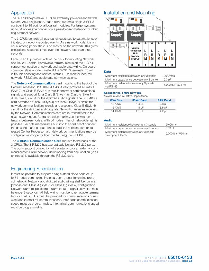
Page 2 of 4 D A T A S H E E T 85010-0133 Not to be used for installation purposes. Issue 6.1
Installation and Mounting
PowerSupply
PowerSupply
J8J9
J10
J11
J8J9
J10
J11
CentralProcessor
UnitModule3-CPU3
LRM
LRM
LRM
LRM
LRM
DataMaximum resistance between any 3 panels 90 OhmsMaximum capacitance between any 3 panels 0.3 µFMaximum distance between any 3 panels via RS485 5,000 ft. (1,524 m)
Capacitance, entire networkMaximum Accumulative Capacitance
Wire Size 38.4K Baud 19.2K Baud18 AWG 1.4 µF 2.8 µF16 AWG 1.8 µF 3.6 µF14 AWG 2.1 µF 4.2 µF
AudioMaximum resistance between any 3 panels 90 OhmsMaximum capacitance between any 3 panels 0.09 µFMaximum distance between any 3 panels via copper RS485 5,000 ft. (1,524 m)
ApplicationThe 3-CPU3 helps make EST3 an extremely powerful and flexible system. As a single node, stand alone system a single 3-CPU3 controls 1 to 19 additional local rail modules. For larger systems, up to 64 nodes interconnect on a peer-to-peer multi-priority token ring protocol network.
The 3-CPU3 controls all local panel responses to automatic, user initiated, or network reported events. As a network node, it is an equal among peers, there is no master on the network. This gives exceptional response times over the network, less than three seconds.
Each 3-CPU3 provides slots at the back for mounting Network, and RS-232, cards. Removable terminal blocks on the 3-CPU3 support connection of network and audio data wiring. On board common relays also terminate at the 3-CPU3 terminals. To aid in trouble shooting and service, status LEDs monitor local rail, network, RS232 and audio data communications.
The Network Communications card mounts to the back of the Central Processor Unit. The 3-RS485A card provides a Class A (Style 7) or Class B (Style 4) circuit for network communications signals and support for a Class B (Style 4) or Class A (Style 7 - dual Style 4) circuit for the digitized audio signals. The 3-RS485B card provides a Class B (Style 4) or Class A (Style 7) circuit for network communications signals and a second Class B (Style 4) circuit for the digitized audio signals. Network messages received by the Network Communications card are re-transmitted to the next network node. Re-transmission maximizes the wire run lengths between nodes. With 64 nodes miles of network length is possible. Fail safe mechanisms built into the card direct connect the data input and output ports should the network card or its related Central Processor fail. Network communications may be configured via copper or fiber media using the 3-FIBMB.
The 3-RS232 Communication Card mounts to the back of the 3-CPU3. The 3-RS232 has two optically isolated RS-232 ports. The ports support connection of a printer and/or an external com-mand center. Entire network downloading from one location (to all 64 nodes) is available through the RS-232 card.
Engineering SpecificationIt must be possible to support a single stand alone node or up to 64 nodes communicating on a peer-to-peer token ring proto-col network. Network and digitized audio wiring shall be run in a [choose one: Class A (Style 7) or Class B (Style 4)] configuration. Network alarm response from alarm input to signal activation must be under 3 seconds. All field wiring must be to removable terminal blocks. Status LEDs must be provided for communications of net-work and internal rail communications. Inter-node communication speed must be programmable. Internal rail communications speed must be programmable.

Page 3 of 4 D A T A S H E E T 85010-0133 Not to be used for installation purposes. Issue 6.1
CENTRAL
PROCESSING
UNIT MODULE
11 112 214 413 315 516 617 718 819 920 10
OR
Ne
two
rkD
ata
Ris
er
Network Audio Riser
Class A only
Cla
ssA
on
ly
Ne
two
rkA
ud
ioR
ise
r
To/F
rom
pre
vio
us
pa
ne
lo
ra
3-A
SU
3-C
PU
(1)(
3)
Top
revi
ou
spa
ne
lM
od
ule
or
a3
-AS
U3
-CP
U(1
)(3
)
To/F
rom
ne
xtpa
ne
lM
od
ule
3-C
PU
(1)(
3)
Fro
mn
ext
pa
ne
l3
-CP
U(1
)(3
)M
od
ule
PIN 1
PIN 14
PIN 13 PIN 25
PIN 1
PIN 9
(2) TXD
(2) RXD
Connect to TB1 on 3-CPU3 Module
Connect to TB2 on 3-CPU3 Module
(3) RXD
(3) TXD
(7) COM
(5) COM
DB25 FEMALE(REAR VIEW)
DB9 FEMALE(REAR VIEW)
PL
UG
PIN
#
PIN
FU
NC
TIO
N
TO PRINTER OR REMOTECOMMAND SYSTEM,
TO PRINTER OR REMOTECOMMAND SYSTEM,
ISOLATED PORTTO PRINTER OR REMOTECOMMAND SYSTEM.
PORT #2(isolated)
PORT #2(isolated)
PORT #1
PIN 1
PIN 14
PIN 13 PIN 25
(2) TXD(3) RXD
(7) COM
DB25 FEMALE(REAR VIEW)
NC C NO NO C NC NO C NCTROUBLE ALARM SUP
N/A
To external troubleinput circuit
To external alarminput circuit
To external supervisoryinput circuit
Typical Wiring
Notes
1. Maximum #14 AWG (1.5 mm2) wire; minimum #18 AWG (0.75 mm2).
2. All shields, if used, must be continuous and insulated from ground, except at the originating panel.
3. Class A network data requires one pair of wires connecting the last node to the first node.
4. Class A audio data requires two pairs of wires running in opposite directions, originating at the node containing the ASU.

Page 4 of 4 D A T A S H E E T 85010-0133 Not to be used for installation purposes. Issue 6.1
01-08-14
Contact us...
Email: [email protected]: www.est-fire.com
EST is an EDWARDS brand.
1016 Corporate Park Drive Mebane, NC 27302
In Canada, contact Chubb Edwards... Email: [email protected] Web: www.chubbedwards.com
© 2014 UTC Fire & Security Americas Corporation, Inc. All rights reserved. Specifications subject to change without notice. Edwards is part of UTC Climate, Controls & Security, a unit of United Technologies Corporation.
Ordering Information
Specifications3-CPU3Agency Listings UL, ULC, CSFM, CE, LPCB EN54*.Mounting 2 - Left most local rail spacesTerminal Size 18-12 AWG (1.0mm² to 2.5mm²)Standby Current 155 mAAlarm Current 165 mAContact Ratings Nonbypassable Alarm, Supervisory and Trouble Form ‘C’ 1A at 30 VdcData Down Loading RJ14 JackOperating Environment 0°C - 49°C (32° F - 120° F); 93% at 40° C Non-Condensing*EN 54-2: 1997 + A1: 2006, EN 54-4: 1997 + A1: 2002 + A2: 2006, and EN 54-16: 2008Note: CPU current includes the main power supply, since the CPU and PPS cannot be measured separately.
Option CardsCatalog number 3-RS232 3-RS485A 3-RS485BStandby Current 58 mA 98 mA 98 mAAlarm Current 58 mA 98 mA 98 mA
Communication Ports Two optically isolated RS-232
Three RS-485 Class A (Style 7)
One Class B (Style 4) or Class A (Style 7) network data circuit
and one Class B (Style 4) audio data circuit
Agency Listings UL, ULC. CSFM, CE, LPCB. EN54*.Mounting Back of 3-CPU3Operating Environment 0° C - 49° C (32° F - 120° F); 93% at 40° C Non-Condensing*EN 54-2: 1997 + A1: 2006, EN 54-4: 1997 + A1: 2002 + A2: 2006, and EN 54-16: 2008
Catalog Number Description Ship Wt.
lb (kg)3-CPU3 Central Processor Unit Module 0.7lb (0.32kg)
3-RS485A Network Communications Card, Class A (Style 7) 0.33lb (0.15kg)
3-RS485B One Class A/B network data circuit and one Class B audio data circuit
0.33lb (0.15kg)
3-RS232 RS-232 Communication Card 0.33lb (0.15kg)
3-CPUDR CPU doors with filler plates. Order separately, one required per CPU where no LCD display is installed.
0.25lb (0.11kg)

Page 1 of 4 D A T A S H E E T 85010-0071 Not to be used for installation purposes. Issue 5.2
EST Catalog u EST3 Life Safety Platform
01-08-14
OverviewThe Main Display interface is the primary user interface in the EST3 Life Safety System. The main display interface focuses on the emergency user by putting information important to the user up front. Hands free, the first highest priority event is shown. The display always gives the last highest priority event. Arriving at the panel and without opening the door the first and last alarm is given. Simple to understand lights and switches help the emer-gency user execute system commands with confidence.A menu system supports maintenance functions such as disables or reports for use by staff or service personnel.
Standard Features• Uses simple lights and switches
• Displays information important to user
• Hands free first alarm display
• Last event of highest priority always displays
• Eight lines by 21 character graphic LCD display — 168 characters total
• Multlingual Supports English, French, Spanish, and Russian
• Uses queues to sort events A queue is a list of messages Alarm, Supervisory, Trouble and Monitor
• Slide in LED and switch labels Makes customization for regional language easy
CHINAS
Liquid Crystal Display Module3-LCD
7165-1657: 0186
S3000
COA 6086
EN 54-2: 1997 + A1: 2006EN 54-4: 1997 + A1: 2002 + A2: 2006
EN 54-16: 2008

Page 2 of 4 D A T A S H E E T 85010-0071 Not to be used for installation purposes. Issue 5.2
ApplicationThe 3-LCD module mounts to the local rail over the nodes Central Processing Unit Module (3-CPU). The 3-LCD module is optional in any network node.Ensuring information clarity the 3-LCD uses a backlit high contrast supertwist graphical display. Eight lines of 21 characters provide the room needed to convey emergency information in a useful format.The 3-LCD always displays the last highest priority event even when the user is viewing other message queues. Further message flexibility is provided with EST3’s message routing ability. Messag-es from a node can display at every node on the network or mes-sages can route to specific nodes only. Routing can be initiated at a specific time/shift change. There is no need to have messages display in areas that are not affected by an event.The 3-LCD can display messages in English, Spanish, French, and Russian. The bilingual display lets the operator select between either of two languages. Consult your representative for available language combinations.The EST3 system configures for Proprietary, Local or EN54 market operations. The mode of operation is selected through the System Definition Utility (SDU) which may adjust the following operations slightly to fit the system operation selected.
LEDs and SwitchesFurther enhancing the 3-LCD user interface are easy to read and understand lights and switches. All functions are laid out in a logi-cal order. At the top of the 3-LCD are five system status LEDs. Here determining the general condition of the system is easy.
Power Test CPU
FailGnd Fault
Disable
Power LED: Green, on when AC power is on.Test LED: Yellow, on when any portion of the system (Group) is under test.
Reset Alarm Silence
Panel SilenceDrill
CPU Fail LED: Yellow, on when CPU stops running.Gnd Fault LED: Yellow, on when a ground exists on the system (group)Disable LED: Yellow, on when any point or zone is disabled by a user.Below the general status LEDs are located four, LED / Switch common controls. The versatility of EST3 allows system design-ers to define the features as affecting a domain (defined group of nodes) or as global (affects all nodes) across the network. This feature is very useful when configuring systems with multiple build-ings on one network. As an example, operating the reset in one building may have adverse effect in other buildings. With EST3 having operational differences between buildings on the same network is not a problem.
Pressing Reset starts the system’s reset operation. The yellow LED has three flash rates during reset. The LED flashes fast during the smoke power down phase of reset, flashes slow during the re-start phase, and turns on steady for the restoral phase. The Reset LED turns off when the system is normal.
Pressing Alarm Silence turns off all Notification Appliance Circuits defined as audible. The yellow LED turns on when silence is active
via the Alarm Silence switch or via alarm silence software timers.
Pressing Panel Silence turns off the system’s internal audible signal. The yellow LED turns on when panel silence is active. The EST3 panel buzzer has user programmable signal rates for alarm, supervisory, trouble and monitor conditions.
Pressing Drill turns on the drill LED and all signals sound evacua-tion. Drill does not activate city tie connections. Auxiliary relays will not activate unless programmed to do so with drill.
In the center of the 3-LCD is the Liquid Crystal Display. In the normal condition the date and time plus a definable system title display on the LCD. The last line of the display gives an alarm history. This total equals the number of
times the system has entered the alarm state from the normal state.
When active events are on display, the LCD formats into four logical windows.
In the system status window, the display shows the time and the status of active and disabled points.
The current event window, lines 2, 3, 4 automatically display the first active event of the highest priority if the user has not taken control of the system. Once the emergency user takes control, this window displays user message selections.
The second line of the display shows system event information. In the example above the display shows the chronological number of the event (0001 is the first alarm) followed by the event type (Alarm Active). EST3 supports over 45 event type messages from which system designers choose. The last two lines of the current event window are custom programmable location message lines with space for 42 characters.
The last event window shows the last highest priority event. This window is always displayed and updated automatically by the sys-tem. Here the emergency user can monitor the progress of a fire.
Previous
Message
Next
When EST3 is configured for a local mode system viewing the second alarm message is easy, just press the NEXT key. The next message scrolls into the current event window. The last highest priority event always remains
on view. No matter what queue the user selects for viewing, the LCD always displays the most recent alarm. A new alarm event resounds the panel audible signal and appears immediately on display without overwriting information the user selected for view.
The final window of the LCD the type status window shows the total number of active events by queue type. A is alarm, S is supervisory, T is trouble, and M is monitor. The number following each letter is the number of active events existing in each queue.
EST3 breaks down event types into queues and automatically displays the first event of the highest priority type.

Page 3 of 4 D A T A S H E E T 85010-0071 Not to be used for installation purposes. Issue 5.2
EN54 ComplianceEST3 has passed the British-based Loss Prevention Certification Board (LPCB) certified EST3 control panels and power supplies as having surpassed the requirements of the pivotal EN54 standard, parts two and four as well as part 16. LPCB Certificate #262ab In order to meet these standards, display and control functions have undergone slight modifications for the EN54 marketplace. These differences are highlighted below. All other control and annunciation features remain unchanged.
Note: EN 54-2: 1997 + A1: 2006, EN 54-4: 1997 + A1: 2002 + A2: 2006, and EN 54-16: 2008.
System Status LEDs
Power Test CPU
FaultSounder Disable
Power LED (Green): on when DC power is on.
Test LED (Yellow): on when any portion of the system (Group) is under test.
CPU Fault LED (Yellow): on when CPU stops running (processor failures must be manually reset).
Gnd Fault LED: Not available.
Sounder LED (Yellow): flashing indicates fault on sounder circuit. Steady indicates a disabled sounder circuit.
Disable LED (Yellow): on when any point or zone is disabled by a user (disabled conditions have priority over fault conditions).
Switch Functions
Reset Sounder On/Off
Panel Silence
Drill
Pressing Sounder On/Off turns off all sounder circuits defined as audible. The yellow LED turns on when silence is activated via the Sounder On/Off or via the alarm silence software timers.
See Page 2 for descriptions of Reset, Panel Silence, and Drill func-tions.
Event Queues
Fire Fault Disable Monitor
For EN54 compliance, EST3 configures for remote proprietary system operation. This requires that every event must be acknowl-edged by viewing them before the internal buzzer will silence. The priority order is Fire, Fault, Disable, Monitor. EN54-2:1997+A1 and EN54-4:1997+A1:2002+A2 approval is pending.
Alarm Supervisory Trouble Monitor
Priority order is alarm, supervisory, trouble, monitor. By using queues an emergency user does not waste time scrolling through a mixed event list looking for alarms or confusing an alarm mes-sage with other message types.
EST3 configures for Remote proprietary system operation where every event must be acknowledged by viewing them before the internal buzzer will silence. Or the EST3 will configure for Local operation. Here the internal buzzer silences by pressing panel silence. If any events exist in queues that have not been viewed the queue LED continues to flash informing the user of un-seen events.
When all events in a queue are acknowledged or ‘seen’, the LED associated with the queue turns on steady. If a new event is added to the queue, the EST3 internal buzzer resounds and the queue LED flashes.
EST3 allows device grouping into logical group zones. Here two or more alarm devices (such as detectors or pull stations) make up the zone. When a device in the zone activates, the LCD displays the zone description. Each zone only displays once, regardless of the number of devices active within the zone.
Details To display device information the user presses the Details key. The device with the lowest
address displays in the first window.
If multiple devices are active each is available for viewing by using the arrow associated with the Previous Message Next key and scrolling through the device list.
The common controls easily expand beyond the Main Display interface by adding a Control Display Module and assigning features to its switch controls.
For Maintenance users, the EST3 provides a smooth operating
menu system providing powerful tools for system management, reports, and trouble shooting.
Installation and Mounting
Central Processor
Unit 3-CPU1
L R M

Page 4 of 4 D A T A S H E E T 85010-0071 Not to be used for installation purposes. Issue 5.2
01-08-14
Contact us...
Email: [email protected]: www.est-fire.com
EST is an EDWARDS brand.
1016 Corporate Park Drive Mebane, NC 27302
In Canada, contact Chubb Edwards... Email: [email protected] Web: www.chubbedwards.com
© 2014 UTC Fire & Security Americas Corporation, Inc. All rights reserved. Specifications subject to change without notice. Edwards is part of UTC Climate, Controls & Security, a unit of United Technologies Corporation.
Engineering SpecificationThe system shall provide a user interface that displays system events in a text format, and supports basic common control LEDs and switches. The Common Control Switches and LEDs provided as minimum will be; Reset switch and LED, Alarm Silence switch and LED, Panel Silence switch and LED, Drill switch and LED. It must be possible to add additional common controls as required through the use of modular display units. The user interface must provide an LCD that will allow custom event messages of up to 42 characters. The interface must provide a minimum of eight lines by 21 characters and provide the emer-gency user, hands free viewing of the first and last highest priority event. The last highest priority event must always display and update automatically. Events shall be automati-cally placed in easy to access queues. It shall be possible to view specific event types separately. Having to scroll through a mixed list of event types is not acceptable. The total number of active events by type must be displayed. Visual indication must be provided of any event type which has not been acknowledged or viewed. It must be possible to cus-tomize the designation of all user interface LEDs and Switches for local language require-ments. It shall be possible to have a custom message for each device in addition to zone messages. Custom device messages must support a minimum of 42 characters each. Instructional text messages support a maximum of 1,000 characters each. The display shall be capable of displaying English, Spanish, French, or Russian messages.
Technical SpecificationsCatalog Number 3-LCDAgency Listings UL, ULC, FM, CE, LPCB, EN54*.LCD Display Eight lines by 21 characters backlit LCDMounting Two local rail spaces on top of 3-CPU
Common Control Switches and LEDs
Reset switch and LED Alarm Silence switch and LED Panel Silence switch and LED Drill Switch and LED
Alarm Current 42mAStandby Current 40mA* EN 54-2: 1997 + A1: 2006, EN 54-4: 1997 + A1: 2002 + A2: 2006, and EN 54-16: 2008.
Ordering InformationCatalog Number Description Shipping Weight, lb. (kg)3-LCD Liquid Crystal Display Module .8 (.36)3-LKE UK English Label Kit .25 (.11)3-LKF French Label Kit .25 (.11)3-LKR Russian Label Kit .25 (.11)3-LKS Spanish Label Kit .25 (.11)

Page 1 of 4 D A T A S H E E T 85010-0059 Not to be used for installation purposes. Issue 10.2
EST Catalog u EST3 Life Safety Platform
01-08-14
Standard Features• High efficiency switch mode
• Increased power distribution efficiency - power supplies parallel allowing up to 28 amps in a single node
• 120 or 230 Vac operation
• 7 AMP filtered and regulated
• Two 3.5 AMP outputs
• Temperature compensated, dual rated battery charger
• Electronic power limiting
• Automatic load testing of batteries
• Fully approved UL, ULC and EN standards (see Specifications section)
OverviewEST3 Power supplies consist of two assemblies, a high efficiency switch mode power supply card and a power supply monitor module. The monitor module mounts to the local rail and distrib-utes the power from its supply to the local rail. The local rail dis-tributes power from all power supplies to other local rail modules and user interface cards resulting in “Shared Power” throughout the system. By paralleling the power supplies on a rail maximum utilization of available power is possible, resulting in fewer power supplies. Up to four power supplies combine in a single enclosure providing up to 28 amps of available power. Battery backup is provided using from one to four sets of batteries, depending on standby power requirements.
Power supplies mount to the back of the chassis units or wall-boxes. The associated power supply monitor module mounts on the local rail providing system power distribution and mounting space for any control display module. Access to auxiliary power is via easily accessible terminal blocks located on the power sup-ply monitor module. Each power supply produces 7 Amps of filtered and regulated power. With four power supplies located in an enclosure (one primary and three booster power supplies) 28 amps of current is available for local rail modules, control display modules and the eight auxiliary 3.5 amp power outputs (two per supply).
Power Supply
Monitor Module
EST3 Power Supplies3-PPS/M series, 3-BPS/M series, 3-BBC/M series
EN54-2: (1997) +A1: (2006)
EN54-4: (1997) +A1: (2002) +A2: (2006)
EN54-16:(2008)
7165-1657: 0186
S3000
COA 6086

Page 2 of 4 D A T A S H E E T 85010-0059 Not to be used for installation purposes. Issue 10.2
Power Supply Rules1. Each battery set needs one charger, either a 3-PPS/M or a 3-BBC/M.
2. Each power supply must be connected to a battery set using an identical length and gauge of wire to keep voltage drops identical.
3. Distribute power supplies and loads evenly across rails.
4. All battery sets for a panel must be the same capacity (AH), same manufacturer, and same manufacturing date code.
The Table below illustrates the combinations of power supplies and batteries that meet all the power supply rules.
24 VDC Power Supply Output Current7A 14A 21A 28A
Battery Requirements
One Set, 65 AH max
One Set, 65 AH max
Two Identical Sets, 65 AH
max
One Set, 65 AH max
Three Identical Sets, 65 AH
max
One Set, 65 AH max
Four Identical Sets, 65 AH
maxRequired Modules 1 3-PPS/M 1 3-PPS/M
1 3-BPS/M1 3-PPS/M 1 3-BBC/M
1 3-PPS/M 2 3-BPS/M
1 3-PPS/M 2 3-BBC/M
1 3-PPS/M 3 3-BPS/M
1 3-PPS/M 3 3-BBC/M
ApplicationThe primary power supply provides the system with battery charging and voltage regulation. Software configures the charger to either 10-24 AH batteries or 30-65 AH batteries and controls the high/low charge rates. Batteries mounted in the same en-closure as the power supply, have their charge rate monitored and adjusted based on the local enclosure temperature, keeping charging rates within battery specification. For remote batteries a temperature probe is monitored in the remote battery cabinet and charge rates are adjusted automatically. Battery damage is unlikely to occur when environmental short term conditions are outside of normal operating ranges.
The EST3 power supplies automatically load test batteries by shutting down the battery charger and placing a load across the battery. If the battery voltage is outside the specification range the power supply reports a trouble. The trouble clears if the battery is able to recover and pass future load tests.
Battery leads are electronically short circuit protected. If a short occurs in the battery leads the charger automatically disables itself and causes a trouble. The system will constantly look to see if the short has cleared. If the short clears the system automatically restores.
During operation on standby batteries, battery voltage is constant-ly monitored. A trouble is reported if the battery voltage falls below a specified value.
EST3 power supplies provide specific information back to the 3-CPU(1) designed to help speed trouble shooting of system functions. Should a power supply detect a fault, specific diagnos-tic codes are available to speed trouble shooting. The 3-LCD will display the power supplies address, a specific trouble code, and a text message describing the specific trouble. Text messages are easy to understand and include items like: Battery Trouble, Aux Power Overload Circuit 1, Aux Power Overload Circuit 2.
Engineering SpecificationThe fire alarm power supplies must be capable of being paralleled and to load share. Multiple power supplies must be capable of be-ing backed up with a single 24 volt battery set. Each power supply shall be capable of charging up to 65 AH batteries. The power supply must be able to perform an automatic load test of batteries and return a trouble if the batteries fall outside a predetermined range. Power supplies must incorporate the ability to adjust the charge rate of batteries based on ambient temperatures. It shall be possible to adjust for ambient temperature changes in local cabinets as well as remote cabinets.
Installation and MountingJ8
J9
J10J11
J8J9
J10J11
PowerSupply
LRM
PowerSupply
J8J9
J10J11
J8J9
J10J11
LRM
PowerDistribution
Module(EN-54 only)
J8J9
J10J11
J8J9
J10J11
PowerSupply
LRM
PowerSupply
J8J9
J10J11
J8J9
J10J11
LRM
PowerDistribution
Module(EN-54 only)

Page 3 of 4 D A T A S H E E T 85010-0059 Not to be used for installation purposes. Issue 10.2
PrimaryPowerSupply
BoosterPowerSupply
24Vdc *2 x 3.5A
24Vdc *2 x 3.5A
124 3
UtilityPower
PowerTo Rail
AuxillaryPowerTakeoff2 x 3.5A
PrimaryPower SupplyMonitor Module
PowerSupplyMonitoring
Rails
[1] From battery temperature probe terminals.
[2] From battery and from temperature probe terminals if 3-BTSEN-E used.
* Nominal Voltage
124 3
AuxillaryPowerTakeoff2 x 3.5A
BoosterPowerSupply
BoosterPowerSupply
24Vdc *2 x 3.5A
24Vdc *2 x 3.5A
124 3
AuxillaryPowerTakeoff2 x 3.5A
BoosterPower SupplyMonitor Module
Rails
124 3
AuxillaryPowerTakeoff2 x 3.5A
[1] [2] [2] [2]
Typical Wiring
Catalog Number 3-PPS/M & 3-BBC/M 3-BPS/M 3-PPS/M-230 &
3-BBC/M-230 3-BPS/M-230 3-PPS/M-230-E & 3-BBC/M-230-E 3-BPS/M-230-E
Agency Approvals UL, ULC U L, ULC UL, ULC UL, ULC LPCB EN54*, CE EN54*Input Voltage 120 Vac (+10%, -15%), 50-60 Hz 230 Vac (+10%, -15%), 50-60 HzBrownout Level < or = 102 Vac 96 Vac < or = 195 Vac 184 Vac < or = 195 Vac 188 Vac
Current Requirements
3-PPS/M included with 3-CPU3 current
3-BBC/M
Alarm: 70 mA Standby: 70 mA
Alarm 50mA Standby 50mA
3-PPS/M-230 included with
3-CPU3 current
3-BBC/M-230 Alarm: 70 mA
Standby: 70 mA
Alarm: 50 mA Standby: 50 mA
3-PPS/M-230-E included with
3-CPU3 current
3-BBC/M-230-E Alarm: 70 mA
Standby: 70 mA
Alarm: 50 mA Standby: 50 mA
Input Current 3.0 A 1.5 ATotal Output Current Special Applications: 7.0 AmpsBattery Charging Capacity
65 AH Sealed Lead-Acid None 65 AH Sealed
Lead-Acid None 30 AH Sealed Lead-Acid None
Low Battery Trouble 24 Vdc 22.5 VdcDeep Discharge Cutoff 19.5 Vdc 20.0 Vdc
Mounting Requirements
1 LRM space, 1 chassis footprint
1 LRM Space + 3-PPS: 2 footprints 3-BBC: 1 footprint
1 LRM space, 1 chassis footprint
Output Voltage 24 Vdc NominalAuxiliary Output Current Two sources of 3.5 Amps each taken from total output current
Auxiliary Output Terminal Capacity 18 AWG to 12 AWG (1 mm² to 2.5 mm²)
Output Protection Electronic power limiting & heat sink temperatureGround Fault Detection < 10K Ohms
Specifications
* EN54-2: (1997) +A1: (2006) Control and Indicating Equipment; EN54-4: (1997) +A1: (2002) +A2: (2006) Power Supply Equipment; EN54-16:(2008) Voice Alarm Control and Indicating Equipment
EST3 is listed to the following UL and ULC standards:UL 864, Control Units and Accessories for Fire Alarm Systems; UL294, Access Control System Units; UL365, Police Station Connected Burglar Alarm Units and Systems; UL609, Local Burglar Alarm Units and Systems; UL636, Police Station Connected Burglar Alarm Units and Systems; UL1076, Proprietary Burglar Alarm Units and Sys-tems; UL1610, Central Station Burglar Alarm Units; UL1635, Digital Alarm Communicator System Units; UL2017, General-Purpose Signaling Devices and Systems; ULC-S303-M91, Local Burglar Alarm Units and Systems; ULC-S527-99, Control Units for Fire Alarm Systems; ULC/ORD-C1076, Proprietary Burglar Alarm Units and Systems; CAN/ULC-S559-04, Equipment for Fire Signal Receiving Centres and System; ULC/ORD-C100, Smoke Control System Equipment

Page 4 of 4 D A T A S H E E T 85010-0059 Not to be used for installation purposes. Issue 10.2
01-08-14
Contact us...
Email: [email protected]: www.est-fire.com
EST is an EDWARDS brand.
1016 Corporate Park Drive Mebane, NC 27302
In Canada, contact Chubb Edwards... Email: [email protected] Web: www.chubbedwards.com
© 2014 UTC Fire & Security Americas Corporation, Inc. All rights reserved. Specifications subject to change without notice. Edwards is part of UTC Climate, Controls & Security, a unit of United Technologies Corporation.
Ordering InformationCatalog Number Description Ship Wt., lb.
(kg)3-PPS/M Primary Power Supply w/ local rail module 120V 50/60 Hz 5 (2.3)3-BPS/M Booster Power Supply w/ local rail module 120V 50/60 Hz 5 (2.3)3-PPS/M-230 Primary Power Supply w/ local rail module 230V 50/60 Hz 5 (2.3)3-BPS/M-230 Booster Power Supply w/ local rail module 230V 50/60 Hz 5 (2.3)
3-PPS/ M-230-E Primary Power Supply w/local rail module 230V 50 Hz, EN54* Certified, CE. Comes with one EFM-2 and 15 ferrite clamps. 5 (2.3)
3-BPS/ M-230-E Booster Power Supply w/local rail module 230V 50 Hz, EN54* Certified, CE 5 (2.3)
3-BBC/M Booster/Charger Supply w/local rail module 120V 50/60Hz 5 (2.3)3-BBC/M-230 Booster/Charger Supply w/local rail module 230V 50/60Hz 5 (2.3)
3-BBC/ M-230-E Booster/Charger Supply w/local rail module, 230V 50Hz, EN54* Certified, CE 5 (2.3)
3-BBCMON(-E) Booster/Charger Monitor Module with charger capability (upgrade 3-BPS/M(-230)(-E) to 3-BBC/M-(230)(-E)) 5 (2.3)
3-BTSEN Distribution Module required when battery installed in remote cabinet .5 (.22)
3-BTSEN-E Distribution and Temperature Sensor Module. Required in EN54* Markets when battery installed in a remote cabinet. .5 (.22)
EFM-2
Data filter board, ships with 3-PPS/M-230-E. Provides filtering for network data. For distributed audio applications refer to model EFM-10. Additional ferrite clamp kits may be ordered separately. See European Marketplace Manual P/N 270925 for details on ferrite clamp locations, quantities and wiring.
EFM-10
Data Filter board order separately for distributed audio. Order one EFM-10 for each node receiving audio in the network. Additional ferrite clamp kits may be ordered separately. See European Marketplace Manual P/N 270925 for details on ferrite clamp locations and quantities.
7300172 Ferrite Kit includes 2 ferrites for EN54 applications.7300173 Ferrite Kit includes 15 ferrites for EN54 applications.7300174 Ferrite Kit includes 4 ferrites for EN54 applications.7300175 Ferrite Kit includes 8 ferrites for EN54 applications.
3-FP Filler Plate, order separately when no LED or LED/Switch module installed. 0.1 (0.05)
* EN54-2: (1997) +A1: (2006) Control and Indicating Equipment; EN54-4: (1997) +A1: (2002) +A2: (2006) Power Supply Equipment; EN54-16:(2008) Voice Alarm Control and Indicating Equipment

Page 1 of 4 D A T A S H E E T 85010-0129 Not to be used for installation purposes. Issue 6.1
EST Catalog u EST3 Life Safety Platform
01-08-14
Overview The 3-SSDC1 and 3-SDDC1 Signature Driver Controller modules provide an intelligent interface between the 3-CPU3 module and Signature Series devices. Each module contains its own micro-processor used to coordinate, process and interpret information received from and sent to Signature devices. Power and commu-nications is received directly from the control panel rail assembly. The 3-SSDC1 Single Signature Driver Controller module supports one Signature Data circuit, while the 3-SDDC1 Signature Dual Driver Controller module supports two Signature circuits. Both modules occupy one rail space in the fire alarm control cabinet and provide removable field wiring terminals to aid installation.
Innovative design gives the 3-SSDC1/3-SDDC1 and Signature devices truly “distributed intelligence”. Signature detectors and modules have their own on-board microprocessor communicating with the loop controller in a fully digital communication format. This increases the accuracy of the information coming to and from the loop controller by reducing the effects of capacitance and noise.
With decentralized intelligence much of the decision making moves from the loop controller to the devices. Advanced fire detection algorithms processed within the Signature devices effectively end unwanted alarms. Environmental compensation and multiple sens-ing element decision making operations are resident in the devices. Intelligent devices allow the Signature Controllers to execute commu-nication and system functions with greater speed and low baud rates, increasing the accuracy of information transmitted between the loop controller and devices.
Standard Features• One or two circuit versions
• Dedicated microprocessor control
• Full digital communication
• Specialized communication protocol – Less sensitive to cable characteristics – Utilize existing wiring in most applications
• Loop alarm in under 750 milliseconds
• Device location supervision – Unexpected additional device addresses – Missing device addresses – Switched device locations – Programmed device parameters
• Automatic nonvolatile as-built mapping – Stores “actual” and “expected” device data – Stores physical connection sequence including “T” taps
• Automatic day/night sensitivity
• Supports up to 250 intelligent Signature detectors and 250 Intelligent Signature Modules
• Up to five 3-SDDC1s per node – Total of 10 Signature circuits
• Removable field wiring terminal blocks
• Multiple survival modes — stand alone
• Fully backward compatible with 3-SSDC and 3-SDDC
• Supports the full line of Signature II devices, including carbon monixide detection
Signature Driver Controller Modules3-SSDC1, 3-SDDC1, 3-SDC1
7165-1657: 0186/0306
S3000
COA 6086
EN 54-2: 1997 + A1: 2006EN 54-4: 1997 + A1: 2002 + A2: 2006
EN 54-16: 2008

Page 2 of 4 D A T A S H E E T 85010-0129 Not to be used for installation purposes. Issue 6.1
ApplicationUp to 125 detectors and 125 modules are supported over a single pair of wires by the 3-SDC1 Signature Cards that plug into the Signature controller modules. Both Class A wiring (style 6 or style 7) and Class B (style 4) wiring are supported. Loop distances over 11,000 feet (3300m) are possible.
The 3-SSDC1 and 3-SDDC1 use advanced communication for-mats that provide exceptional response. Using a “BROADCAST POLL” the loop controller checks the entire device circuit for any changes of state. Should one or more devices report a change the 3-SSDC1/3-SDDC1 uses “DIRECT ADDRESS SEARCH” to find reporting device(s). Devices that have entered the alarm state or become active are located nearly instantaneously.
The unique use of “BROADCAST POLLING” combined with “DI-RECT ADDRESS SEARCH” ensures that only new information is transmitted allowing a reduced baud rate with fast response time. The low baud rate is ideal for retrofit applications since in most applications existing wiring can be used.
To enhance survivability of the system the 3-SSDC1/3-SDDC1 supports a standalone mode for Signature devices. Two cata-strophic failure modes are supported. If the 3-CPU(1/3) fails, the loop controller will continue to poll its devices. If an alarm is detected it will be sent on the local rail communication bus and received by other local rail modules. A common alarm condition throughout the panel will result. If the local rail mod-ule (3-SSDC1/3-SDDC1) fails, and a device (smoke or module) detects an alarm, specialized circuitry will make the node aware of the alarm condition. The 3-CPU(1/3) will communicate the alarm condition to the rest of the network. Having multiple redundant modes is paramount in a life safety system.
Every time the 3-SSDC1/3-SDDC1 communicates with a detector a green LED on the detector flashes. Normal green LED activity is not disturbing to building occupants, but can be quickly spotted by a maintenance technician. A red LED on the detector turns on only in the alarm condition.
The 3-SSDC1/3-SDDC1 also supervises the device wiring, physi-cal location of each device and the programmed device charac-teristics. This Edwards/Signature Series unique characteristic is accomplished by “MAPPING” the Signature circuit and committing the map to memory. Upon power up the loop controller will scan device serial numbers and map their physical location sequence on the loop, including “T” taps. After mapping is complete the controller automatically addresses each detector and module through downloading over the loop. There are no switches or dials to set. Each device is assigned a unique soft address generated by the site specific program.
The 3-SSDC1/3-SDDC1 then compares the “Actual” physical device data to the “Expected” site specific program data. If any correlations are different, the loop controller issues a trouble to the CPU identifying the devices which do not match and posting a map fault. Through the 3-CPU3’s RS-232 port a graphical map of the loop can be uploaded depicting each device’s location on the loop, including branches (T-Taps) and all of the physical attributes associated with the device. This diagnostic information is unparal-leled in the fire detection industry and vital for keeping accurate records on how the system was installed.
During installation a common problem with analog/ addressable systems is locating ground faults. The 3-SSDC1 and 3-SDDC1 controllers have the ability to locate ground faults by specific mod-ule, speeding up the troubleshooting process. Another significant advantage of the 3-SSDC1/3-SDDC1 controllers during com-missioning is electronic addressing and mapping. This eliminates duplicate addresses, which are also very difficult for most systems to locate.
During maintenance, should groups of detector heads be removed for service and returned into the wrong smoke detector base (location), the 3-SSDC1/3-SDDC1 will automatically detect the problem. If the attributes of the switched devices are the same, the system will automatically download the correct soft addresses and algorithms to the devices (maintaining location supervision).
If the attributes are not the same the 3-SSDC1/3-SDDC1 will send a map fault indication to the 3-CPU3 and post a trouble indicating the specific devices in fault.
The 3-SSDC1/3-SDDC1 also monitors the Signature Series devices for maintenance and trouble conditions. Each smoke de-tector contains intelligence to adjust with environmental changes. This expands the amount of time required between cleaning while maintaining a constant alarm threshold. As the detector begins to exhaust the environmental compensation, and reaches the 80% level, the 3-SSDC1/3-SDDC1 will indicate a maintenance alert or dirty condition to the 3-CPU and indicate the specific device requiring cleaning. If cleaning is not performed the detector will continue to operate until all of its environmental compensation is
Typical Wiring
TB1
3-SDDC1
SIGNATURE
DRIVER
CONTROLLER
MODULE
DUAL
TB2
Class A Configuration Shown (Typical)
Class A Configuration Shown (Typical)
3
6
Circuit #1
To TB1 on 3-SDDC1 Module
SDC #1 SmokePower
1 2 43 5 6 7 8 9 10
1 4
++
3
6
Circuit #2
To TB2 on 3-SDDC1 Module
SDC #2 SmokePower
1 2 43 5 6 7 8 9 10
1 4
+ +
Wiring Notes
Maximum #12 AWG (1.5 mm ) wire;minimum #18 AWG (0.75 mm ).
Shields (if used) must be continuous andfree from Earth Ground.
Class A wiring.
Class B wiring.
To Universal Module or MAB modulewhen 2-wire smokes are powered fromthe module.
2
2
All wiring supervised and power limited.2.
1
3
4
5
6
To TB2 on 3-SDDC1 Module
TB1
3-SDDC1
SIGNATURE
DRIVER
CONTROLLER
MODULE
DUAL
TB2
Class B Configuration Shown (Typical)
To TB1 on 3-SDDC1 Module
3
6
SDC #1 SmokePower
1 2 43 5 6 7 8 9 10
1 5+
3
6
SDC #2 SmokePower
1 2 43 5 6 7 8 9 10
1 5
+
Circuit #2
Circuit #1

Page 3 of 4 D A T A S H E E T 85010-0129 Not to be used for installation purposes. Issue 6.1
utilized. At this point the 3-SSDC1/3-SDDC1 sends a dirty trouble indication to the 3-CPU and posts a trouble condition. If mainte-nance is still not performed the Signature detector will automati-cally remove itself from service once the programmed threshold window has been breached (preventing a false alarm).
When a detector includes carbon monoxide (CO) detection, the detector monitors its CO life remaining for the CO sensor element and provides this information automatically to the panel. For main-tenance of the system the CO life remaining is also available by simply running a maintenance report at the panel or through the FireWorks graphical interface. A unique CO maintenance signal is automatically generated by the panel when there is 8% (several months) of CO element life remaining. Should the CO sensor ele-ment not be replaced after the maintenance signal is reported, an
“End of Life” trouble automatically posts on the panel when the CO sensor detection capability is exhausted.
Remote test capability permits devices to be put in alarm, pre-alarm, supervisory, monitor, or security alarm, or trouble from the panel menu or controls. This facilitates testing of smoke and heat detectors as well as monitor and security devices. Fast test is also provided for CO detectors allowing these devices to be tested quickly in the field.
The 3-SSDC1 and 3-SDDC1 local rail modules modules are fully backwards compatible with the 3-SSDC and 3-SDDC local rail modules. 3-SSDC1 and 3-SDDC1 modules provide additional onboard memory to facilitate future Synergy functions. To upgrade a 3-SSDC/3-SDDC to a 3-SSDC1/3-SDDC1 respectively, replace the 3-SSDC/3-SDDC Local Rail Module with a 3-SDDC1-MB Local Rail Module and reuse the 3-SDC Signature Device Cards and filters.
Specifications (Signature Circuits)Charts assume wire and devices are evenly distributed over length of circuit
Non-twisted, non shielded wire
Device type # of Detectors # of Module Addresses
#14 AWG (20pf/foot) (2.53 Ohm/1000ft)
#16 AWG (20pf/foot) (4.02 Ohm/1000ft)
#18 AWG (20pf/foot) (6.38 Ohm/1000ft)
Detectors only 125 0 14,752 feet (4,497 meters)
9,275 feet (2,827 meters)
5,839 feet (1,780 meters)
Modules only 0 125 12,599 feet (3,840 meters)
7,921 feet (2,414 meters)
4,986 feet (1,520 meters)
Detectors and Modules 125 125 5,738 feet (1,749 meters)
3,608 feet (1,100 meters)
2,271 feet (692 meters)
Detectors and Modules with 2-wire smokes 63 55 + 9 SIGA-UM 7,623 feet
(2,324 meters)4,793 feet
(1,461 meters)3,017 feet
(920 meters)Modules with 2-wire smokes 0 107 + 9 SIGA-UM 3,798 feet
(1,158 meters)2,388 feet
(728 meters)1,503 feet
(458 meters)
Twisted pair non shielded wire
Device Type # of Detectors # of Module Addresses
#14 AWG (38pf/foot)
(2.53 Ohm/1000ft)
1.5mm² (36pf/foot)
(3.75 Ohm/1000ft)
#16 AWG (36pf/foot)
(4.02 Ohm/1000ft)
1.0mm² (25pf/foot)
(5.51 Ohm/1000ft)
#18 AWG (25pf/foot)
(6.38 Ohm/1000ft)
Detectors only 125 0 13,157 feet (4,010 m)
9,933 feet (3,028 m)
9,275 feet (2,827 m)
6,760 feet (2,061 m)
5,839 feet (1,780 m)
Modules Only 0 125 12,599 feet (3,840 m)
8,483 feet (2,586 m)
7,921 feet (2,414 m)
5,774 feet (1,760 m)
4,986 feet (1,520 m)
Detectors & Modules 125 125 5,738 feet
(1,749 m)3,864 feet (1,178 m)
3,608 feet (1,100 m)
2,630 feet (802 m)
2,271 feet (692 m)
Detectors and modules with 2-wire smokes
63 55 + 9 SIGA-UM 7,623 feet (2,324 m)
5,133 feet (1,565 m)
4,793 feet (1,461 m)
3,494 feet (1,065 m)
3,017 feet (920 m)
Modules with 2-wire smokes 0 107 + 9 SIGA-
UM3,798 feet (1,158 m)
2,558 feet (780 m)
2,388 feet (728 m)
1,741 feet (531 m)
1,503 feet (458 m)
Twisted pair shielded wire
Device Type # of Detectors # of Module Addresses
#14 AWG (84pf/foot) (2.53 Ohm/1,000ft)
#16 AWG (82pf/foot) (4.02 Ohm/1,000ft)
#18 AWG (58pf/foot) (6.38 Ohm/1,000ft)
Detectors only 125 0 5,952 feet (1,814 meters)
6,098 feet (1,859 meters)
5,839 feet (1,780 meters)
Modules Only 0 125 5,952 feet (1,814 meters)
6,098 feet (1,859 meters)
4,986 feet (1,520 meters)
Detectors & Modules 125 125 5,738 feet (1,749 meters)
3,608 feet (1,100 meters)
2,271 feet (692 meters)
Detectors and modules with 2-wire smokes 63 55 + 9 SIGA-UM 5,952 feet
(1,814 meters)4,793 feet
(1,461 meters)3,017 feet
(920 meters)Modules with 2-wire smokes 0 107 + 9 SIGA-UM 2,558 feet
(780 meters)2,388 feet
(728 meters)1,503 feet
(458 meters)

Page 4 of 4 D A T A S H E E T 85010-0129 Not to be used for installation purposes. Issue 6.1
01-08-14
Contact us...
Email: [email protected]: www.est-fire.com
EST is an EDWARDS brand.
1016 Corporate Park Drive Mebane, NC 27302
In Canada, contact Chubb Edwards... Email: [email protected] Web: www.chubbedwards.com
© 2014 UTC Fire & Security Americas Corporation, Inc. All rights reserved. Specifications subject to change without notice. Edwards is part of UTC Climate, Controls & Security, a unit of United Technologies Corporation.
Catalog Number 3-SSDC1 3-SDDC1Installation 1 LRM Space 1 LRM Space
Module Configuration 1 Addressable circuit (3-SDC1 Card) expandable to 2 circuits.
2 Addressable circuits (3-SDC1 Cards)
Operating Current [Note 2] Standby 144 mA Alarm 204 mA Standby 264 mA Alarm 336 mAOperating Voltage 24 Vdc, NominalAddress Requirements AutomaticDetectors Supported 125 per 3-SDC1 CardModules Supported 125 Module Addresses per 3-SDC1 Card2-Wire Smoke Power Output 100 mA per 3-SDC1 Card (not included in Operating Current aboveConventional detectors supported 150 of 100 µA type per circuit.
Signature Circuit Voltage 20 VDC +/- 5%Maximum Signature Circuit Resistance 100 Ohms
Maximum Signature Circuit Capacitance 0.33 µF
Communications Format 100% DigitalCircuit Wiring Styles Class A or Class BTermination Removable plug-in terminal strip(s) on modulePermissable Wire Size 18 to 12 AWG (0.75 to 2.5 mm²)Agency Listings UL, ULC (see Note 1); CE, LPCB, EN54 (see Note 3). Operating Environment 32 °F (0 °C) to 120 °F (49 °C) 93% RH, non-condensingNote 1: Other EST3 components are modularly listed under the following standards: UL 864 categories: UOJZ, UOXX, UUKL and SYZV, UL 294 category ALVY, UL 609 category AOTX, UL 636 category ANET, UL 1076 category APOU, UL 365 category APAW, UL 1610 category AMCX, UL 1635 category AMCX ULC-S527, ULC-S301, ULC-S302, ULC-S303, ULC-S306, ULC/ORD-C1076, ULC/ORD-C693 Please refer to EST3 Installation and Service Manual for complete system requirements.Note 2: Current shown Includes full loop of devices.Note 3: *For EN 54-2: 1997 + A1: 2006, EN 54-4: 1997 + A1: 2002 + A2: 2006, and EN 54-16: 2008 compliant product add suffix -E to model eg. 3-SSDC1-E (verify device and loop controller compatibility).
Ordering Information
Specifications (controllers)
Catalog Number Description Shipping
Wt. lb (kg)
3-SSDC1 Single Signature Driver Controller. Comes with one 3-SDC1 Device Card. Mounts to Local Rail. Add suffix “-E” for EN54 compliant versions. 0.5 (0.23)
3-SDDC1 Dual Signature Driver Controller. Comes with two 3-SDC1s. Mounts to Local Rail. Add suffix “-E” for EN54 compliant versions. 0.5 (0.23)
3-SDC1 Signature Device Card - upgrades a 3-SSDC1 to a 3-SDDC1. Add suffix “-E” for EN54 compliant versions. 0.25 (0.11)
3-FP Filler Plate, order separately when no LED or LED/Switch module installed. 0.1 (0.05)
Engineering SpecificationThe communication format between the control panel and analog devices shall be 100% digital.
Loop alarm recognition must be within 750 milliseconds of a device going into the alarm state, with system response time no greater than 3 seconds. All devices shall support remote testing.
It must be possible to wire the circuit as Class A or Class B with non-shielded, non-twisted wire. It must be possible to wire branches (T-taps) with Class B wiring.
The driver controller must be manufactured in accordance with ISO 9001 standards.
The system must have tolerance to mul-tiple failures. There must be a standalone mode of operation that will ensure the system is aware of alarms even if the local rail or main CPU fails.

Page 1 of 6 D A T A S H E E T 85010-0063 Not to be used for installation purposes. Issue 13
EST Catalog u EST3 Life Safety Platform
01-08-1401-08-14
Standard Features• Eight channels for audio source selection
• Audio data to remote EST3 panels with amplifiers can be transmitted over twisted copper wires or fiber optic cables (see Data Sheet 85010-0131 for details on EST3 fiber optic com-munications)
• Listed for Mass Notification/Emergency Communications
• UL2572 as CCS or ACU or LOC.
• Auxiliary audio input interface for campus paging, telephone interface, etc.
• Single fiber optic filament or one twisted pair of wires between nodes
• VU display shows paging output level
• Ready-to-page LED
• Digital transmission of audio signals - greater noise immunity - high quality signal transmission
• On board storage of programmed messages and tones
• Optional LCD display of fire phone calls
• Optional earthquake hardening: OSHPD seismic pre-approval for component Importance Factor 1.5
OverviewThe efficient EST3 audio system provides for intuitive local and remote audio control for Mass Notification/Emergency Com-munications (MNEC), Life Safety and other approved uses. EST3 audio builds from standard modules that fit together easily. Audio components use standard EST3 cabinets and power supplies.
Taking full advantage of digital technology, up to eight channels of audio sources transmit over a single twisted pair of wires or fiber optic cables between nodes. Coupling the inherent reliability and performance of zoned amplifiers with EST3 simplified user interfaces makes audio system design and operation easy and dependable.
The 3-ASU is seamlessly integrated into an EST3 system to pro-vide for a rugged and reliable communications package that can be configured for Mass Notification/Emergency Communication (MNEC), as well as fire alarm and other emergency functions. The 3-ASU audio source unit supports eight channels of clear digital audio that is easily distributed to panels containing 3-ZA rail ampli-fiers. The 3-ASU supports digital storage and playback of pre-recorded messages as well as live paging. The optional 3-FTCU provides a unique, space-saving and easy-to-operate control point for dedicated emergency/firefighter two-way telephones.
Audio and Telephone Masters3-ASU series
7165-1657: 0186
S3000
COA 6086
EN 54-2: 1997 + A1: 2006EN 54-4: 1997 + A1: 2002 + A2: 2006
EN 54-16: 2008

Page 2 of 6 D A T A S H E E T 85010-0063 Not to be used for installation purposes. Issue 13
ApplicationEST3 audio is accomplished by selecting modular components for installation in standard fire alarm cabinet assemblies. At the main control panel location mounting audio control equipment provides an emergency user interface for “Paging” and optionally a “Fire-fighters Master Telephone”. Zoned amplifiers mount in the main control panel and/or in remote nodes. By mounting amplifiers in remote nodes, wire runs and space requirements are reduced at the main control panel.
The heart of the EST3 audio package is the Audio Source Unit (ASU). The Audio Source unit converts analog signals to digital signals. On board audio memory stores signal tones and/or alarm-alert verbal messages.
These digitally-stored messages can be recorded onsite using standard PC audio components or downloaded from a library of pre-recorded messages and tones. Messages can be in any language or combination of languages. The ASU comes standard with two minutes of memory for tone and message storage. Avail-able message memory expands easily to 100 minutes with the optional 3-ASUMX/100 memory expansion card.
Audio Source units support connection of a local microphone, remote microphone, telephone voice line , and Mass Notification/Emergency Communication (MNEC) audio feed. With eight audio channels to choose from combinations of paging, alert, evacuation signaling and automatic messages are available for simultaneous delivery to different parts of a building or to different buildings.
There are two main audio user interface modules: the paging microphone, and the firefighter’s telephone, which supports three-state and four-state firefighter telephones. Available individually or in a set, EST3 audio modules open system design possibilities.
When the Life Safety system requires paging only the 3-ASU or 3-ASU/4 Audio Source Units provides a Master Paging micro-phone with common controls. Switch labeling makes the opera-tion intuitive. Six LEDs and five switches cover paging operations. Three of the five paging switches, All Call, Page to Evacuation, and Page to Alert, cover most paging operations. A VU display shows the user the output level of the page in process. The 3-ASU series mount in one chassis space of a EST3 Lobby enclosure. In addition to the paging microphone the 3-ASU/4 has mounting space for up to four local rail modules, including 20, 40, and 95 watt zone amplifiers and up to four Control Display modules allow-ing layout flexibility. The 3-ASU provides the same functionality as the 3-ASU/4 but is supplied with an inner door filler plate and no local rail module spaces.
ALL CALL
READY TOPAGE
PAGE TOEVAC
PAGE TOALERT
ALL CALLMINUS
PAGE BYPHONE
Paging Microphone
Ready-to-Page LED turns on after the pre-announce tone has finished indicating the system is ready to page.
All Call selects all amplifiers for page delivery.
Page to EVAC selects all amplifiers cur-rently delivering evacuation signaling for page delivery.
Page to ALERT selects all amplifiers currently delivering alert signaling for page delivery.
All Call Minus selects all amplifiers not programmed for alarm signaling for page delivery (typically stairwells).
Page by Phone selects the telephone voice line as the paging source.
Operating the Microphone Talk Key stops alarm signaling to se-lected zones and starts pre-announce tone delivery.
When the pre-announce tone finishes, the Ready to Page LED turns on.
When system design calls for paging with Firefighters telephone the 3-ASU/FT provides all the paging features of the 3-ASU series with the added benefit of a master handset assembly. The 3-ASU/FT brings to the emergency user easy to understand switches and text messages displaying on a backlit 8 x 20 character LCD display.

Page 3 of 6 D A T A S H E E T 85010-0063 Not to be used for installation purposes. Issue 13
Installation and Mounting
ALL CALL
READY TOPAGE
Page toEvac
Page toAlert
All CallMinus
Page byPhone
0 call(s) pending
DISCONNECT REVIEW CONNECTED
CONNECT REVIEW PENDING ACK
EMERGENCY TELEPHONE
J7BOUT
J6DIN
J3 J4
BIN
J2
J5
J1
J8 J9
COUT DOUT
AOUT
AIN CIN
RAILEXPCARD
J4
J2
J1
TR RX RXTX PRIMARY
AUDIO DATA REMOTE MIC
SECONDARY TELEPHONE
PAGEOUT KEY AUDIO AUX
TX
1 2 3 4
TB11 14
AudioSource
Card
J1
TB1TX RX
J3
J2
FirePhoneCard
3-ASU/FT has Chassis Assembly /wAudio Source Unit, Paging CommonControl and Fire Phone Controls
ALL CALL
READY TOPAGE
Page toEvac
Page toAlert
All CallMinus
Page byPhone
J7BOUT
J6DIN
J3 J4
BIN
J2
J5
J1
J8 J9
COUT DOUT
AOUT
AIN CIN
J8J9
J10
J11
J8
J9
J10
J11
3-ASU/4 has Chassis, Audio Source Unit,Paging Common Control and rail spacefor four Local Rail Modules. Mounts inlobby enclosure.
Firefighters telephone
CONNECT switch selects phone circuits shown in the Calls Pending Window.
REVIEW PENDING stops auto-matic display of pending calls and allows the operator to step through each message at his own pace.
ACK (acknowledge) silences the telephone systems audible signal. The signal resounds for any new call.
DISCONNECT disconnects the highlighted call in the calls con-nected list.
REVIEW CONNECTED scrolls a reverse highlight through the calls connected list.
0 calls pending
1 calls connectedFirst Basement Level
1 calls pending
1 calls connectedFirst Basement Level
engineering office
0 Calls Pending
unit: OK
emergency telephone
1 calls pending
0 calls connectedFirst Basement Level
The Firefighters telephone LCD is very similar to the 3-LCD. When there is no active telephone calls the LCD shows a title screen. Active calls display a text message referenc-ing the remote phone location.
When a remote handset is lifted the LCD display updates to show the calls pending and the call-in signal sounds to alert the user of a pending call.
The user answers the call by press-ing the Connect switch. The location message moves from the pending line to the connected line. The call in signal silences. The user simply uses the master telephone to talk with the connected telephone.
If another call comes in the location message appears in the calls pending line and audible signal resounds. The user can silence the signal by answer-
ing the call or by pressing the ACK (acknowledge) switch.
Up to five remote telephone handset assemblies connect to the system simultaneously without any degradation of audio quality.

Page 4 of 6 D A T A S H E E T 85010-0063 Not to be used for installation purposes. Issue 13
Engineering SpecificationThe audio system shall provide eight simultaneous and distinct audio channels. These shall consist of a minimum of: Local Page, Emergency Communication, Multiple Evacuation, Alert, Auxiliary, and General Signaling. Channels shall support hierarchical opera-tion and be controllable from system programming. The audio system also provides Elevator, Stairwell and Auxiliary signaling. Systems that cause signaling devices to go silent while performing any signaling functions will not be accepted.
The system must provide operation to 25Vrms or 70.7Vrms speak-ers. The system must provide as a minimum the following paging common controls and indicators: Ready to page LED, VU display of paging output level, single switch function for paging to all — Alert zones, Evacuation zones, and areas not programmed for signaling. The system must provide high quality analog to digital conversion of paging sources. Digital transmission of paging must be provided between system nodes. The analog sources must be sampled and converted to digital with a sampling rate no less than 9600 samples per second. It must be possible to transmit signal sources (Alert, Alarm, Page, etc.) together over a single pair of wires between nodes.System amplifiers must be distributed zoned type. Centrally banked systems are not acceptable. The circuit must carry a minimum rating of 3.5 Amps for operating 24 Vdc signals. The system shall provide fully integrated fire fighters’ telephone system that shall provide 2-way communication between the fire alarm control panel and any fire fighters’ telephone station. <<The Audio Source Unit and Firefighters Telephone shall be installed so that a seismic component Importance Factor of 1.5 is achieved.>> The system shall include an alphanumeric user display and controls. When a telephone is activated, a call-in buzzer shall sound, and the location of the phone shall be shown on the alphanumeric display. The display shall be capable of bilingual operation, displaying Eng-lish, Dutch, Finnish, French, German, Italian, Portuguese or Spanish messages. The incoming call shall be selected by activating a single button. All subsequent telephone call locations shall be displayed in full text. The system shall display all incoming calls, all connected phone(s) on the alphanumeric display. The system shall be configured so that page messages may be issued from any firefighter’s telephone con-nected to the system, as directed by the emergency operator.
Dashed Wires Requiredfor Class 'A' Wiring Only
Typical Fire Fighter's Telephone Circuit
Telephone RiserTwisted Shielded Pair
Twisted Shielded Pairif run with other wiring
Connect Shield toEarth Ground onlyat the panel. Maintainshield continuity.
To SignatureData Circuit
To SignatureData Circuit
To Phones
ULI/ULC Listed47K ohm EOL Resistor
48 37 26
10
15
9
CC1
48 37 26
10
15
9
CC1
MAIN PROCESSOR MODULE
11 112 214 413 315 516 617 718 819 920 10
Netw
ork
Data
Ris
er
From previous panel3-CPU Module
To next panel3-CPU Module
Netw
ork
Audio
Ris
er
Connect to TB2 on 3-CPU Module
3-CPU3
Connect to TB1 on 3-CPU3 Module
NC C NO NO C NC NO C NCTROUBLE ALARM SUP
N/A
Control Panel
Audio Source Unit
3-ASUor
3-ASUFT
Typical Wiring
Mass Notification
Audio DataPrimary Secondary
Telephone PageOut
Remote MicKey Audio
Aux
3 4 5 6 7 8 9 10 11 12 13 141 2
To MN-FVPN or AUX Input (1V) for Remote Paging from UL listed compatible Fire or MNEC system.
Key-Out
Audio-Out(Shielded)
3-REMICAor
3-3REMICP
To CPU ModuleTB2 - Audio A IN
ASU TB1

Page 5 of 6 D A T A S H E E T 85010-0063 Not to be used for installation purposes. Issue 13
SpecificationsCatalog Number 3-ASU 3-ASU/4 3-ASU/FT(RC) 3-FTCUAgency Listings UL, ULC, CE, EN54 (see note 3)Ambient Temp. 0°C-49°C (32°F-120°F)Ambient Humidity 93% Non-condensing @ 32°C Mounting One Chassis Space
Wire Size
Network Data Riser - One pair twisted 18-12AWG (1.0mm²-2.5mm²)
Network Audio Riser - One pair twisted 18-12AWG (1.0mm²-2.5mm²)
Network Data Riser- 18-12AWG (1.0-2.5mm²)(3-ASU/FT only)
Network Audio Riser- 18-12AWG (1.0-2.5mm²)(3-ASU/FT only)
Telephone Riser - One pair twisted shielded 18 -14 AWG (1.0mm² to 1.5mm²)
Current Rating 80 mA in Alarm and Supervisory 112 mA Supervisory and Alarm
32 mA Supervisory and Alarm
Audio InputsLocal Microphone (isolated and supervised); Remote
Microphone (isolated and supervised); One MNEC audio input.
Local microphone (isolated and supervised); Remote microphone (isolated and supervised); Firefighters’
telephone (isolated and supervised; One MNEC audio input.
Pre-recorded Message Storage
Two minutes standard expandable to 100 minutes with optional 3-ASUMX/100. Max. message length 40 seconds. N/A
Supported Message Count 255 N/AAuxiliary Input impedance 1K Ohm N/ABilingual Support English, Dutch, Finnish, French, German, Italian, Portuguese, Spanish
Telephone RiserActive Telephones N/A Five Maximum
Wire size N/A One pair twisted shielded 18 -14 AWG (1.0mm² to1.5mm²)
Line Resistance N/A 50 OhmEOL Resistance N/A 15K Ohm

Page 6 of 6 D A T A S H E E T 85010-0063 Not to be used for installation purposes. Issue 13
01-08-1401-08-14
Contact us...
Email: [email protected]: www.est-fire.com
EST is an EDWARDS brand.
1016 Corporate Park Drive Mebane, NC 27302
In Canada, contact Chubb Edwards... Email: [email protected] Web: www.chubbedwards.com
© 2014 UTC Fire & Security Americas Corporation, Inc. All rights reserved. Specifications subject to change without notice. Edwards is part of UTC Climate, Controls & Security, a unit of United Technologies Corporation.
Ordering InformationCatalog Number Description
Ship Wt. lb.
(kg)3-ASU/FT 1,3 Audio Source Unit with Local Microphone and Firefighters Telephone. 20 (9.1)
3-ASU/FTRC Audio Source Unit with Local Microphone, Firefighters Telephone and call in buzzer control. 20 (9.1)
3-ASU/4 1,3 Audio Source Unit w/Local Microphone. Provides four local rail spaces. 15 (6.8)3-ASU 1,3 Audio Source Unit w/Local Microphone. Inner door filler plate 15 (6.8)3-FTCU 1,3 Firefighters Telephone Control Unit inner door filler plate. 15 (6.8)
3-ASUMX/100 Audio Source Unit Memory Expansion. Provides 100 minutes of message time. 0.5 (.23)
3-FTEQ Seismic hardening kit for 3-ASU/FT or 3-FTCU telephone handset 2
RC-BRKT Redundant command center relay bracket3-LKE UK English Label Kit .25 (.11)3-LKF French Label Kit .25 (.11)3-LKR Russian Label Kit .25 (.11)3-LKS Spanish Label Kit .25 (.11)
EFM-2
Data filter board, ships with 3-PPS/M-230-E. Provides filtering for network data. For distributed audio applications refer to model EFM-10. Additional ferrite clamp kits may be ordered separately. See European Marketplace Manual P/N 270925 for details on ferrite clamp locations, quantities and wiring.
EFM-10
Data Filter board order separately for distributed audio. Order one EFM-10 for each node receiving audio in the network. Additional ferrite clamp kits may be ordered separately. See European Marketplace Manual P/N 270925 for details on ferrite clamp locations and quantities.
7300172 Ferrite Kit includes 2 ferrites for EN54 applications.7300173 Ferrite Kit includes 15 ferrites for EN54 applications.7300174 Ferrite Kit includes 4 ferrites for EN54 applications.7300175 Ferrite Kit includes 8 ferrites for EN54 applications.
1. Add “-CC” for City of Chicago
2. For earthquake anchorage, including detailed mounting weights and center of gravity detail, please refer to Seismic Application Guide 3101676. Approval of panel anchorage to site structure may require local AHJ, structural, or civil engineer review.
3. For EN54 compliance, add the suffix -E (e.g.: 3-ASU-E). For 3-ASU/FT, order 3-ASU/FT-EN, for GOST R compliant order 3-ASU/FT-E. Noise immunity in accordance with CE requirements dictate that an EFM-2 or EFM-10 be installed along with ferrite clamps. EFM-2 data filter board and 15 ferrite clamps, ship with the 3-PPS/M-230-E. Order one EFM-10 for each node receiving audio in the network. Additional ferrite clamp kits can be ordered separately. See European Marketplace Manual P/N 270925 for details on ferrite clamp locations and quantities. .

Page 1 of 4 D A T A S H E E T 85010-0057 Not to be used for installation purposes. Issue 9.1
EST Catalog u EST3 Life Safety Platform
01-08-14
Standard Features• Three Sizes Available
-20 Watts -40 Watts -95 Watts
• Simultaneous eight channel digital audio- Superior sound quality - Each amplifier does it’s own decoding
• Speaker circuit built into amplifier- Selectable for 70 or 25 VRMS output - Class A (Style Z) or Class B (Style Y) output models available - Power limited
• 3.5 amp 24 Vdc notification appliance circuit on 20 and 40 watt amplifiers- Class A (Style Z) or Class B (Style Y) output models available - Power limited
• Network software control of channel selection
• Integral backup tone generator- 1 KHz temporal (3-3-3) tone evac
Overview The EST3 audio amplifiers take full advantage of proven digital technology to deliver highly intelligible voice audio for evacua-tion and Mass Notification/Emergency Communication (MNEC) purposes. Digital messages generated by the Audio Source Unit (ASU) and live paging messages are multiplexed into eight separate channels transmitted over fiber optic cable or a single twisted pair of wires. Each zoned amplifier contains integrated de-multiplexing circuitry that allows any one of the eight digital audio channels to place messages or signals on the amplifier’s built-in speaker circuit.
Audio channel selection is network software controlled, and audio amplifiers mount in the same enclosures as other EST3 equipment. Power for the amplifiers comes from standard sys-tem power supplies through the local rail. Field wiring connects to removable terminal blocks on the amplifier module. Amplifiers support either 25 VRMS or 70 VRMS power limited speaker circuits. For visual signaling, each 20 or 40 watt amplifier comes standard with one 24 Vdc power limited Notification Appliance Circuit.
Zoned Audio Amplifiers3-ZA20A, 3-ZA20B, 3-ZA40A, 3-ZA40B, 3-ZA95
7165-1657: 0186/0306
S3000
COA 6086
EN 54-2: 1997 + A1: 2006EN 54-4: 1997 + A1: 2002 + A2: 2006
EN 54-16: 2008

Page 2 of 4 D A T A S H E E T 85010-0057 Not to be used for installation purposes. Issue 9.1
ApplicationEST3 zoned amplifier configurations offer improved reliability and performance. Configuration provides improved survivability in the event of wiring faults that result in a loss of signaling. In the exam-ple shown in the diagram, a fault on the system using a central backed-up amplifier disables multiple signal/page circuits, and the standby amplifier is not able to bypass the fault. With EST3, the same fault removes the Audio Source Unit riser.
Short on Riserdisables signalsource
Standby Amplifiersare local in nodes
Standby EvacuationTone at each Amplifier
ZonedAmplifiers
Short on Riserdisables allcircuits
CentralAmplifier
Because all EST3 zoned amplifiers have an integrated backup 1000 Hz temporal tone generator, the locally-generated alarm tones notify occupants of a hazard – even with the primary riser out of commission. The backup tone also operates if the ASU or the audio distribution system fails. To further enhance system survivability, a single standby amplifier can backup any zoned amplifier in the same cabinet.
Zoned amplifiers can be housed in remote cabinets close to the speakers. This minimizes the voltage drop between the amplifier and the load, and permits the use of a smaller wire size than is possible with centrally-located amplification systems.
EST3 easily outperforms banked audio systems with its ability to simultaneously deliver up to eight different signals. When using centrally-banked amplifiers, paging and alert channels typically share a common amplifier. Consequently, when paging, the alert signal goes silent in all alerted areas when a Page is issued. At the end of the Page, the alert signal resumes in the alert area, which could cause confusion because occupants did not receive the page message and do not know why the Page stopped and restarted.
With EST3, simultaneous page, alert, and evacuation signal capa-bility is engineered into the system. With eight channels to choose from, dedicated messages can be delivered to stairwells, elevator cabs, etc. while alert, evacuation, and page instructions are simul-taneously being sent to the rest of the building. The eight audio channels allow messages to be automatically routed, and provide specific instructions based on the alarm’s location.
PageAlertEvacuationAuxiliaryStairwellElevatorEnvironmentalEmergency
PageAlertEvacuation
DualBankCentral
DistributedZonedAmplifiers
For example, with an alarm on Floor Eight, the following automatic message instructions could be given concurrently. Note: A Page could also be sent to any other location in the building – without interrupting any of the messages below.
FLOOR 9 HEARS: “A fire alarm has been reported on the floor below. Please evacuate using the stairwell.”
FLOOR 8 HEARS: “A fire alarm has been reported on this floor. Please evacuate using the stairwell.”
OTHER FLOORS HEAR: “An emergency has been reported on floor 8. Please remain in the building and await further instruc-tions.”
ELEVATOR: “A fire alarm has been reported in the building. The elevator is being returned to the ground floor for emergency use. Please evacuate the building.”
STAIRWELLS: “Please remain calm and walk down the stairs to evacuate the building in a safe manner.”
In addition to robust paging, EST3 provides UL-listed Mass Notification/Emergency Communication (MNEC), which overrides fire alarm functions. This capability allows emergency response commanders to advise building occupants of the safest action to take while an emergency is unfolding. Occupants can be in-structed to leave, relocate, or seek immediate shelter, depending on the situation. This provides the flexibility for communications to mesh with the facility’s risk analysis needs — without the risk of an unexpected fire alarm or general evacuation signal interfering with established emergency response protocols.

Page 3 of 4 D A T A S H E E T 85010-0057 Not to be used for installation purposes. Issue 9.1
Specifications3-ZA20A 3-ZA20B 3-ZA40A 3-ZA40B 3-ZA95
Agency Listing UL, ULC, CE, EN54 EN 54-2: 1997 + A1: 2006, EN 54-4: 1997 + A1: 2002 + A2: 2006, and EN 54-16: 2008 UL, ULC
Environmental 0°C - 49°C (32°F - 120°F) 93% RH, Non-condensingFrequency Response 400Hz to 4KHz @ +/- 3dBOutput Voltage 25 VRMS or 70 VRMSTHD (distortion) < 7%Wire Size 18 to 12 AWG (1.0 to 2.5 mm²)Internal Tone Generator 1KHz Temporal (3-3-3) Tone (evacuation); 20 PPM (alert)
SIGA-CC1/2 Support 10 Units, Maximum
Standby Current 62mA for 20 and 40 watt amps; 64mA for the 3-ZA95 watt amp
Alarm Current 1120mA 1120mA 2480mA 2480mA 5540mAPwr. Ltd. Audio Output Wiring Configuration EOL Resistor
Class A or B (Style Z or Y)
15K Ohms in Class B
Class B (Style Y) 15K Ohms
Class A or B (Style Z or Y)
15K Ohms in Class B
Class B (Style Y) 15K Ohms
Class A or B (Style Z or Y)
15K Ohms in Class BPwr. Ltd. 24 Vdc NAC
Wiring Configuration
Line Resistance, Max.* EOL Resistor Line Capacitance, Max
Class A or B (Style Z or Y)
50 Ohms, Max. N/A
0.33µF
Class B (Style Y)
50 Ohms, Max. 15 K Ohms
0.33µF
Class A or B (Style Z or Y)
50 Ohms, Max. N/A
0.33µF
Class B (Style Y)
50 Ohms, Max. 15K Ohms
0.33µF
N/A
Space Requirements 1 LRM Space 2 LRM Spaces
Maximum Speaker Circuit Distance at 0.5 dB loss*70 VRMS Output 3-ZA20A 3-ZA20B 3-ZA40A 3-ZA40B 3-ZA95#12 AWG (3.2 Ohm/1000 ft pair) 4,536 ft (1,382 m) 2,268 ft (691 m) 955 ft (290 m)
#14 AWG (5.2 Ohm/1000 ft pair) 2,792 ft (850 m) 1,396 ft (425 m) 588 ft (179 m)
#16 AWG (8.0 Ohm/1000 ft pair) 1,815 ft (553 m) 907 ft (276 m) 382 ft (116 m)
#18 AWG (13 Ohm/1000 ft pair) 1,117 ft (340 m) 558 ft (170 m) 235 ft (71 m)
25 VRMS Output 3-ZA20A 3-ZA20B 3-ZA40A 3-ZA40B 3-ZA95#12 AWG (3.2 Ohm/1000 ft pair) 579 ft (176 m) 289 ft (88 m) 122 ft (37 m)
#14 AWG (5.2 Ohm/1000 ft pair) 356 ft (108 m) 178 ft (54 m) 75 ft (22 m)
#16 AWG (8.0 Ohm/1000 ft pair) 231 ft (70 m) 116 ft (35 m) 49 ft (14 m)
#18 AWG (13 Ohm/1000 ft pair) 142 ft (43 m) 71 ft (21 m) Not supported
by 18 AWG* Refer to product manual for wire run calculations.
Engineering SpecificationThe audio system shall provide eight simultaneous and distinct audio channels. These shall consist of a minimum of: Local Page, Emergency Communication, Multiple Evacuation, Alert, Auxiliary, and General Signaling. Channels shall support hierarchical opera-tion and be controllable from system programming. The audio system also provides Elevator, Stairwell and Auxiliary signaling. Systems that cause signaling devices to go silent while performing any signaling functions will not be accepted.
The audio system zoned amplifiers must be able to operate 25 VRMS or 70 VRMS speakers. The amplifier output must be power limited, and wired in a <Class A (Style Z)> <Class B (Style Y)> configuration. The amplifiers shall provide an integral backup 1000 KHz temporal tone generator which shall operate in the event signal primary audio signals are lost and the amplifier is instructed to broadcast alarm information. It shall be possible to backup multiple zoned amplifiers with a common backup amplifier.
Typical Wiring
15K EOLW
To TB2 on Audio Amplifier To TB2 on Audio Amplifier To TB2 on Audio Amplifier
Field wiring identicalto amplifier #1
Field wiring identicalto amplifier #1
Field wiring identicalto amplifier #1
Field wiringidentical toamplifier #1
To TB1 on Audio AmplifierTo TB1 on Audio Amplifier To TB1 on Audio Amplifier To TB1 on Audio Amplifier
COMMON ENCLOSURE
TB1TB1
AUDIO
AMPLIFIER
MODULE
(ZONE #1)
AUDIO
AMPLIFIER
MODULE
(Zone #2)
AUDIO
AMPLIFIER
MODULE
(Zone #3)
AUDIO
AMPLIFIER
MODULE
(Backup)
TB2TB2
1 2 43 5 6 7 8 9 101 2 43 5 6 7 8 9 10 1 2 43 5 6 7 8 9 10 1 2 43 5 6 7 8 9 10
124 35678910 124 35678910 124 35678910124 35678910
UL/ULC Listed 15KW EOLFor Class B circuits onlyVISUAL NOTIFICATION APPLIANCE CIRCUIT
Not available on 3-ZA95+ +
- -+ +
- -
+ +
- -
UL/ULC Listed 15K EOLFor Class B circuits only
W
Class A circuits only
Class A circuits only
AUDIO NOTIFICATION APPLIANCE CIRCUIT
Speaker EOL ResistorVisual NotificationAppliance
Legend
+ +
- -
Connection for Shield when used

Page 4 of 4 D A T A S H E E T 85010-0057 Not to be used for installation purposes. Issue 9.1
01-08-14
Contact us...
Email: [email protected]: www.est-fire.com
EST is an EDWARDS brand.
1016 Corporate Park Drive Mebane, NC 27302
In Canada, contact Chubb Edwards... Email: [email protected] Web: www.chubbedwards.com
© 2014 UTC Fire & Security Americas Corporation, Inc. All rights reserved. Specifications subject to change without notice. Edwards is part of UTC Climate, Controls & Security, a unit of United Technologies Corporation.
Catalog Number Description Ship Wt., lb.
(kg)
3-ZA20A 20 Watt Zoned Amplifier w/Class A/B (Style Z/Y) Audio & Class A/B (Style Z/Y) 24 VDC outputs 1.55 (0.7)
3-ZA20B 20 Watt Zoned Amplifier w/Class B (Style Y) Audio & Class B (Style Y) 24 VDC outputs 1.55 (0.7)
3-ZA40A 40 Watt Zoned Amplifier w/Class A/B (Style Z/Y) Audio & Class A/B (Style Z/Y) 24 VDC outputs 1.55 (0.7)
3-ZA40B 40 Watt Zoned Amplifier w/Class B (Style Y) Audio & Class B (Style Y) 24 VDC outputs 1.55 (0.7)
3-ZA95 95 Watt Zoned Amplifier w/Class A/B (Style Z/Y) Audio output 3.0 (1.5)
3-FP Filler Plate, order separately one required per amplifier when no LED or LED/Switch module installed on operator layer. 0.1 (0.05)
Ordering Information

Page 1 of 4 D A T A S H E E T 85010-0107 Not to be used for installation purposes. Issue 5.1
EST Catalog u EST3 Life Safety Platform
06-27-13
Overview The Modem Communicator is a two-way local rail module that performs a variety of off-premise communications functions for the EST3 system.
Using the latest in digital signal processing (DSP) techniques, the Modcom provides off premise communication features unavailable on any other system.
The module has provisions for supervising two loop-start tele-phone lines. The module features a modular jack for telephone line connections. The Modcom’s configuration and firmware can also be updated from any network node.
Modcom series modules occupy a single local rail space and can be mounted in any node on the network. Any EST3 Control/Display module can be mounted on the face of a Modcom series module. Power for the Modcom is supplied by the EST3 system supply.
The Modcom provides an enhanced level of survivability in the event of a network CPU failure by notifying the Central Monitoring Station of the failure and entering a degraded mode of operation. In degraded mode, the Modcom can transmit a default fire alarm message during a fire alarm condition.
Standard Features• Listed for fire, security and access control
• V.32bis 14.4K full duplex modem
• Digital alarm communicator transmitter supporting: SIA DCS protocol, Contact ID protocol, 3/1 and 4/2 pulse format proto-col
• Supports “tap” alphanumeric pager protocol
• Fully programmable messages
• Alarm override of upload/download
• Two phone line capability
• Field upgradable firmware
• Split and multiple reporting to as many as 80 different receivers
• 255 subscriber accounts
• Supports control/display modules
• Supervised by the network controller
Modem Communicator3-MODCOM, 3-MODCOMP
Hinged Bracket
Module
Filler plate (ordered separately)
7165-1657: 0186/0306
S3000
COA 6086

Page 2 of 4 D A T A S H E E T 85010-0107 Not to be used for installation purposes. Issue 5.1
Application Two versions of the Modcom are available:
3-MODCOM - Has an internal V.32bis 14.4K baud full duplex modem. The modem permits upload and download of system data remotely via a telephone line. In addition, the 3-MODCOM has a Digital Alarm Communications Transmitter (DACT) or dialer function that transmits network status information to Central Monitoring Stations (CMS) via telephone. Four DACT protocols are available:
1. Digital Communicator Standard (DCS) “SIA forma” Dialer – 300 baud format, which transmits alphanumeric system status data to the CMS;
2. Contact ID; 3. SIA 3/1 dialer; and,4. SIA 4/2 dialer.
Alarm code content is determined by system rules.
3-MODCOMP – In addition to all modem and dialer (DACT) func-tions of the 3-MODCOM, the 3-MODCOMP can dial directly into paging systems using Telelocator Alphanumeric Protocol (TAP). Al-phanumeric system data can be sent to a single pager or group(s) of pagers. Some pager services can forward messages via e-mail and Fax.
Multiple PriorityEach Modcom can buffer up to 500 events in its event queue. It re-views all active events in the queue and identifies the highest priority event and dials the associated receiver. When the receiver is con-tacted, the MODCOM will transmit the highest priority message for that receiver. If the message is successfully received, the MODCOM identifies the next highest priority message and the process repeats.
Phone Line FriendlyThe Modcom series has been designed for installation on the same phone lines with other devices such as phones and faxes. The module makes its first dial out attempt on either of the two phone lines that is not in use. This prevents unnecessary interrup-tion of calls in progress by the line seizure relays. In the event that both lines are busy, the module seizes line one.
A fixed DACT testing time can be set at an off-hour, e.g. 2:00am, again minimizing interruptions and phone line costs. The call time is programmable, and allows testing of the DACT with the central station.
The Modcom series also has the ability to detect Type 1, Type 2 and Type 3 distinctive ringing patterns, permitting it to share its phone lines with other devices and still have a unique phone number for incoming modem calls.
Multiple Modcoms per NetworkMultiple Modcoms can be installed in a single cabinet or located in nodes throughout the network to provide added availability and enhanced redundancy of off premise communications.
Multiple Receiver CapabilityIn large system applications the EST3 system may be partitioned such that it supports a number of different customers, each using different Central Monitoring Stations and/or paging companies. The Modcom can accommodate up to 255 different accounts us-ing up to 80 different receivers.
The Modcom supports split reporting, a process where the system directs the Modcom to send some events or event types to one receiver, and different events to alternate receivers. The module’s
multi-dial reporting capability permits an individual event to be transmitted to multiple receivers, including pagers.
Remote Data Upload/DownloadThe modem permits data to be downloaded into the memories of the various components making up an EST3 system. Data can be remotely uploaded and downloaded for use with the Edwards Access Control Database Program. In the event that an alarm is received during upload/download activity, the Modcom automati-cally terminates the call and transmits the alarm events to the appropriate receivers. When completed sending the events, the download will continue where it left off.
Engineering SpecificationThe system shall provided an off premise communications module capable of transmitting system events to multiple Central Monitor-ing Station (CMS) receivers. The module shall provide the CMS with point identification of system events via 4/2, Contact ID or SIA DCS protocols. <The module shall also be capable of trans-mitting alphanumeric system activity by event to a commercial paging system using TAP Pager protocol.> The dialer shall have the capability to support up to 255 individual accounts and to send account information to eighty (80) different receivers, each having a primary and secondary telephone access number. System events shall be capable of being directed to one or more receivers depending on event type or location as specified by the system designer. The module shall have a degrade mode capable of transmitting fire alarm signals to the CMS in the event of system CPU failure. The module shall provide a high speed (V.32bis or greater) modem function in order to upload and download system data to/from a remote location.
Typical Wiring
Notes:Connect Line 1 and Line 2 to RJ31X or RJ38X(CA31A or CA38A in Canada) telephone jacksinstalled by an authorized telephone companyrepresentative. Jacks (not supplied) must beinstalled within 5 ft. (1.5 m) of the panel.
Phone Cord (P/N 360137) supplied) issupervised and non-power limited.
1
2
RJ31X8 PIN MODULARCONNECTOR FORPHONE LINE #2
TO PHONE LINE #2(WIRED SAME ASPHONE LINE #1)
1 8
7
654
3
2
RING(RED)
TIP(GREEN)
RJ31X8 PIN MODULARCONNECTOR FORPHONE LINE #1
PREMISESPHONES
7 Ft.(2.13 M)
RED
GREEN
SURGEPROTECTOR
1 8
7
654
3
2
NO T-TAPSPERMITTED
LINE 1 LINE 2
1
2
MODCOM(front view)

Page 3 of 4 D A T A S H E E T 85010-0107 Not to be used for installation purposes. Issue 5.1
Ordering Information
SpecificationsAgency Listings UL, FCC Part 68 / CFR 47, ULC. See Note 1.Installation Takes up one LRM space in 3-CHAS7 Input Power 24 Vdc @ 60mA standby, 95 mA activeModem Protocol ITU - V.32bis 14.4K baud full duplex using standard PC modem compatible data
Dialer Protocol SIA 3/1 (format P2) and 4/2 (format P3): 20 pulses per second, double round Contact ID (DTMF format) Digital Communications Standard (DCS) “SIA format”: Level 2 (300 baud, Bell 103)
Pager Protocol (3-MODCOMP only) Telocator Alphanumeric Protocol (TAP), Version 1.8, 300 baud, Bell 103Telephone
DialingConnector
Pulse or Tone (DTMF)Two 8-position modular phone jacks
CMS Telephone NumbersQuantity
Available DigitsTwo per receiver - 160 max.Up to 24 digits per number
Receivers Supports up to 80 individual receivers. Event Buffer 500 eventsOperating Environment 32°F (0°C) to 120°F (49°C), 93% RH Non-condensing
Receivers TestedFormat Manufacturer Model Receiver Card4/2 and 3/1 Ademco 685 685-1 or 685-8
FBI (Fire Burglary Instruments) CP220Osborne-Hoffman OH2000Radionics D6600Silent Knight 9000 9032Sur-Gard MLR2, SG-SLRMCDI TLR, TLR+
Contact ID Ademco 685 685-8Osborne-Hoffman OH2000Sur-Gard MLR2, SG-SLRRadionics D6600Silent Knight 9000 9032MCDI TLR, TLR+
SIA DCS Sur-Gard MLR2, SG-SLRNote 1:The EST3 is modularly listed under the following standards: UL 864 categories: UOJZ, UOXX, UUKL and SYZV, UL 294 category ALVY, UL 609 category AOTX, UL 636 category ANET, UL 1076 category APOU, UL 365 category APAW, UL 1610 category AMCX, UL 1635 category AMCX ULC-S527, ULC-S301, ULC-S302, ULC-S303, ULC-S306, ULC/ORD-C1076 and ULC/ORD-C693 Please refer to EST3 Installation and Service Manual for complete system requirements.
Catalog Number Description Ship Wt.
lb (kg)3-MODCOM Modem/Dialer (DACT) version 0.5 (0.23)
3-MODCOMP Modem/Dialer (DACT) w/TAP Pager Protocol 0.5 (0.23)
3-FP Filler Plate, order separately when no LED or LED/Switch module installed. 0.1 (0.05)

Page 4 of 4 D A T A S H E E T 85010-0107 Not to be used for installation purposes. Issue 5.1
06-27-13
Contact us...
Email: [email protected]: www.est-fire.com
EST is an EDWARDS brand.
1016 Corporate Park Drive Mebane, NC 27302
In Canada, contact Chubb Edwards... Email: [email protected] Web: www.chubbedwards.com
© 2013 UTC Fire & Security Americas Corporation, Inc. All rights reserved. Specifications subject to change without notice. Edwards is part of UTC Climate, Controls & Security, a unit of United Technologies Corporation.

Page 1 of 4 D A T A S H E E T 85010-0067 Not to be used for installation purposes. Issue 10
EST Catalog u EST3 Life Safety Platform
06-27-13
Standard Features• Right or left hand hinging of doors
• Lag and Keyway holes for quick mounting
• Attack rated door for security applications
• Knockouts for 3/4 inch conduit
• Attractive contour door design on lobby enclosures
• Combination flush or surface mounting lobby enclosure design
• Remote closet cabinets for electrical closet mounting support up to 65 AMP hour batteries
• Optional earthquake hardening: OSHPD seismic pre-approval for component Importance Factor 1.5
OverviewEST3 has a wide selection of cabinet arrangements allowing the greatest use of EST3’s flexible modular design. Lobby enclosure wallboxes are manufactured from #14 AWG cold rolled steel with a gray baked enamel finish. Lobby enclosure doors are manu-factured from #14 AWG cold rolled steel and have a modern contoured door design with integral viewing window. The excep-tion is the small lobby enclosure 3-CAB5. The 3-CAB5 wallbox and non-contoured door are #16 AWG cold rolled steel. Lobby enclosure doors come with gray baked enamel or optional red baked enamel finishes. The EST3 lobby enclosures back boxes, doors and chassis units are ordered and shipped separately. The 3-CAB5 lobby enclosure comes complete with door and back box providing space to mount five local rail modules.
The EST3 remote closet cabinet design allows the installation of control panel electronics in electrical closets. The remote closet cabinets have left hand hinged doors and are available with red finish only. Optional display modules used for system diagnostics display, mount behind the closet cabinet door and are not visible with the door closed.
3-RCC Series
3-CAB Series
EST3 Cabinets and Chassis3-CAB series, 3-RCC series, 3-CHAS7 series, BC-1 EN54-2:1997+A1 and
EN54-4:1997+A1:2002+A2 pending
7165-1657: 0186
S3000
COA 6086

Page 2 of 4 D A T A S H E E T 85010-0067 Not to be used for installation purposes. Issue 10
Installation and MountingLobby Enclosure 3-cab5B
ApplicationLobby EnclosuresEST3 lobby enclosures provide space for control, monitoring and display modules where they remain visible even with the door closed and secure. Ideal for mounting in lobby’s where appear-ance is important, maximum mounting flexibility is provided with doors that will mount for right or left hand opening. Lobby enclo-sures come in several sizes to match individual project require-ments.
The 3-CAB5 series semi-flush or surface mounts. A built in rail assembly provides space for up to five local rail modules, no chassis assembly needed. Back space for 1-1/2 footprints gives room for a power supply and a 1/2 footprint module and 10 AH batteries. The local rail module spaces provide room for amplifiers, common control and annunciation modules.
The 3-CAB7 semi-flush or surface mounts and has a contoured front door with viewing window. Space is provided for two 17 AH batteries and one chassis assembly providing seven local rail module spaces.
The 3-CAB14 semi-flush or surface mounting and has a con-toured front door with viewing window. Space is provided for two 17AH batteries and two chassis assemblies each providing seven local rail module spaces.
The 3-CAB21 semi-flush or surface mounts and has a contoured front door with viewing window. Space is provided for two 17AH batteries and three chassis assemblies each providing seven local rail module spaces.
Remote Closet CabinetsRemote closet cabinets provide an economical way of installing equipment in locations where esthetics are not paramount, like electrical closets. You can have optional display modules used for system diagnostics display mounted behind the front door. These display modules will not be visible with the door closed. Remote closet cabinets are surface mounting and come in sizes providing space for one to three chassis with room for standby batteries. A UL Listed attack rated door having a 2-minute rating is available for the 3-RCC7R cabinet. This door is required for security applications.
OUTER DOOR
ALL KNOCKOUTSFOR 3/4" CONDUIT
(1.9 cm)
BATTERY AREADO NOT INSTALL CONDUIT
[3RCC.CDR]
5.64 in(14.3 cm)
1.3 in(3.3 cm)
4.4 in(11.2 cm)
14.1
75 in
(36
cm
)23
.95
in (
60.8
3 cm
)
3-R
CC
7 2
3.25
in
(59.
10 c
m)
36.2
in (
91.9
5 cm
)
3-R
CC
14 3
5.47
in (
90.1
0 cm
)
3-R
CC
21 4
7.72
in (
121.
21 c
m)
1.75 in(4.45 cm)
2 in(5.1 cm)
6 in(15.2 cm)
3.55 in(9.01 cm) 21.44 in (54.46 cm)
1.25 in (3.18 cm)
21 in (53.3 cm)
23.25 in (59.03 cm)25.0 in (63.5 cm)
3-R
CC
7 2
3.87
5 in
(60
.64
cm)
3-R
CC
14 3
6.12
5 in
(91
.76
cm)
3-R
CC
21 4
8.37
5 in
(12
2.87
cm
)
Chassis
Chassis
Chassis
Surface MountedRemote Closet Cabinets
3-RCC7R3-RCC14R3-RCC21R
.625 in(1.6 cm)
* The lower mounting space can be used for an MN-BRKT1 bracket, which holds MNEC interface equipment including an MN-NETSW1 Ethernet network switch, an MN-ABPM Audio bridge, an MN-FVPN VoIP module, and an MN-COM1S Communications module.
*
*

Page 3 of 4 D A T A S H E E T 85010-0067 Not to be used for installation purposes. Issue 10
Ordering InformationCatalog Number Description Equipment
Mounting Space Battery Space Ship Wt. lb. (Kg)
Lobby Enclosures — Outer doors with viewing window
3-CAB5 Cabinet w/Wallbox, door and chassisFive local rail modules
One footprint and ½ footprint module
Two - 12V10A 30 (13.6)
3-CAB7B Wallbox only One Chassis Four - 6V8A Two - 12V10A Two - 12V17A
30 (13.6)3-CAB7B-E Wallbox only, EN54* certified CE 1 Chassis 30 (13.6)3-CAB7D(R) Inner and outer doors for 3-CAB7B
N/A10 (4.5)
3-CAB7D(R)-E Inner & outer doors for 3-CAB7B, EN54*, CE 10 (4.5)3-CAB14B Wallbox only Two Chassis Four - 6V8A Two - 12V10A Two -
12V17A42 (19.1)
3-CAB14B-E Wallbox only, EN54* certified CE 2 Chassis 42 (19.1)3-CAB14D(R) Inner and outer doors for 3-CAB14B
N/A15 (6.8)
3-CAB14D(R)-E Inner & outer doors for 3-CAB14B, EN54*, CE 15 (6.8)3-CAB21B Wallbox only Three Chassis Four - 6V8A Two - 12V10A Two -
12V17A55 (25)
3-CAB21B-E Wallbox only, EN54* certified CE 3 Chassis 55 (25)3-CAB21D(R) Inner and outer doors for 3-CAB21B
N/A20 (9.1)
3-CAB21D(R)-E Inner & outer doors for 3-CAB21B, EN54*, CE 20 (9.1)
Remote Closet Enclosure — No viewing window3-RCC7R Red wallbox and door
One Chassis Four - 6V8A, Two - 12V10A Two - 12V17A, Two - 12V50A
37.5 (17)3-RCC7R-E Red wallbox and door, EN54* certified CE 37.5 (17)ATCK Attack rated door for 3-RCC7R N/A 26 (11.8)3-RCC14R Red wallbox and door
Two Chassis Four - 6V8A Two - 12V10A, Two - 12V17A Two - 12V50A, Two - 12V65²
53 (24)3-RCC14R-E Red wallbox and door, EN54* certified CE 53(24)3-RCC21R Red wallbox and door
Three Chassis70 (31.8)
3-RCC21R-E Red wallbox and door, EN54* certified CE 70 (31.8)
Chassis Assemblies
3-CHAS7 Takes one chassis space in wallbox, provides space for 7 local rail modules, up to two power supplies, and a ½ footprint module. 8.4 (3.8)
3-ASU** Takes one chassis space in wallbox, provides an audio source unit /w microphone and an inner door filler plate. 15 (6.8)3-ASU/4** Takes one chassis space in wallbox, provides an audio source unit /w microphone and four local rail module spaces. 15 (6.8)3-ASU/FT** Takes one chassis space in wallbox, provides an audio source unit /w microphone and Firefighters Telephone 20 (9.1)3-FTCU** Takes one chassis space in wallbox, provides Firefighters Telephone Control unit and inner door filler plate. 15 (6.8)MN-BRKT1 Takes one chassis space in wallbox, provides mounting for MNEC interface equipment 4.0 (1.8)FSB-BRKT Mounting bracket for FSB-PC communications bridge. Allows FSB-PC to mount on the side of a Chass7 1.0 (0.45)
more...
Notes:
1. All lobby enclosures, wallboxes and doors have a textured gray enamel finish; outer doors are available in red by adding the suffix “R” to the catalog number, i.e. 3-CAB7DR.
2. Remote closet cabinets will support 65 AH batteries with the use of the 3-BATS Battery Shelf, which reduces the enclosure’s chassis capacity by one chassis.
3. The EST3 is modularly listed under the following standards: UL 864 categories: UOJZ, UOXX, UUKL and SYZV, UL 2572, UL 294 category ALVY, UL 609 category AOTX, UL 636 category ANET, UL 1076 category APOU,
UL 365 category APAW, UL 1610 category AMCX, UL 1635 category AMCX ULC-S527, ULC-S301, ULC-S302, ULC-S303, ULC-S306, ULC/ORD-C1076, ULC/ORD-C693 Please refer to EST3 Installation and Service Manual for complete system require-ments.
* EN54-2:1997+A1 and EN54-4:1997+A1:2002+A2 pending
** Add “-CC” for City of Chicago.
BC-1 Dimensions

Page 4 of 4 D A T A S H E E T 85010-0067 Not to be used for installation purposes. Issue 10
06-27-13
Contact us...
Email: [email protected]: www.est-fire.com
EST is an EDWARDS brand.
1016 Corporate Park Drive Mebane, NC 27302
In Canada, contact Chubb Edwards... Email: [email protected] Web: www.chubbedwards.com
© 2013 UTC Fire & Security Americas Corporation, Inc. All rights reserved. Specifications subject to change without notice. Edwards is part of UTC Climate, Controls & Security, a unit of United Technologies Corporation.
Accessories
3-BATS Battery Shelf for RCC Enclosures. Takes one chassis space. Room for up to one 65 AH or two 50 AH batteries. 3 (1.36)
BC-1 Battery Cabinet - supports up to two 40 amp hour batteries.3-BTSEN Battery sensor/distribution module 0.5 (.2)
BC-1EQ BC-1 - Seismic Battery hold down for BC-1. Supports up to two 40 Ahr batteries. Order BC-1 Separately.
3-CABEQ3-CAB - Seismic Battery hold-down for 3-CAB 7, 14 or 21. Supports two 1 2V batteries from 10 Ah up to 18 Ah. Comes with EST3 Chassis hardening hardware and instructions. Order 3-CAB7, 3-CAB14 or 3-CAB21 separately. See note 1.
3-RCCEQ503-RCC series - Seismic Battery hold-down. Supports one set of two 50 Ah batteries. Comes with EST3 Chassis hardening hardware and instructions. Order 3-RCCxxR separately. See note 1.
3-RCCEQ653-RCC series cabinet - Seismic Battery hold-down. Supports one set of two 65 Ah batteries (one battery in bottom of cabinet, one battery mounted on 3-BATS). Order 3-RCCxxR cabinet and 3-BATS separately. See note 1.
3-TAMP Tamper switch for 3-CAB7, 3-CAB14 and 3-CAB21 cabinets. Mounts to side of cabinet. 0.5 (.2)
3-TAMP5 Tamper switch for 3-CAB5. Mounts to side of cabinet. 0.5 (.2)
3-TAMPRCC 3-TAMPRCC Tamper Switch for RCC series cabinets. Mounts to side of cabinet. 0.5 (.2)
1. For earthquake anchorage, including detailed mounting weights and center of gravity detail, please refer to Seismic Application Guide 3101676. Approval of panel anchorage to site structure may require local AHJ, structural, or civil engineer review.

Page 1 of 4 D A T A S H E E T 85010-0055 Not to be used for installation purposes. Issue 6.1
EST Catalog u EST3 Life Safety Platform
01-08-1401-08-14
Control Display Modules3-LDSM, 3-24x series, 3-12xx series, 3-6/3S1xxx series
OverviewThe EST3 Control Display modules provide the emergency user with the simplest of interfaces, lights and switch control. The Con-trol Display modules install over local rail modules. The local rail modules supply the power and drivers via a ribbon cable connec-tion to the control display modules. The displays mount over any local rail module maximizing the flexibility of design layout. When a display module is required where no local rail module exists, an LED Display Support Module 3-LDSM mounts to the local rail providing support for one Control Display Module.
Surface mount technology used to minimize space, also reduces the power requirements of display modules. Slide-in labels keep the control display modules flexible and allow labeling for local languages.
Module lamp test can be programmed to any spare control switch or a local node lamp test is initiated by simultaneously operating the Alarm Silence and Trouble Silence switches on the 3-CPU.
Standard Features• Programmable LED flash rates
• Membrane style tactile pushbuttons
• Software supported for toggle, and latching interlock switch action
• Slide in labels
• Lamp test
7165-1657: 0186/0193
S3000
COA 6086
EN 54-2: 1997 + A1: 2006EN 54-4: 1997 + A1: 2002 + A2: 2006
EN 54-16: 2008

Page 2 of 4 D A T A S H E E T 85010-0055 Not to be used for installation purposes. Issue 6.1
Application NotesControl Display Modules come in a variety of types providing op-erational flexibility. There are five types of display modules available with EST3.
Typically alarm zone annunciation appears on any of the first four module types shown. The first module supports simple zone annunciation; the second, zone annunciation with zone disable; the third, alarm and trouble zone annunciation, the fourth alarm and trouble zone annunciation with zone disable. From a simple one LED annunciation point to higher functionality, EST3 fills the
requirements.
The fifth module is very adaptable to system requirements for audio or remote equipment control. Each module contains 18 LEDs and 18 switches. Each group of three switches has a latching-interlock to support operations that must be kept separated. The interlock is under software control so only one switch is active at a given time. EST3 software makes meeting the wide variety of ap-plications needed with today’s codes and building system opera-tions easy.
For fan control the emergency user assumes control of the remote device by selecting “On”
Installation and Mounting
ON
AUTO
OFF
F a n # 5
OPEN
AUTO
CLOSE
Damper 5th Flr
Simple Control Examples
Engineering SpecificationThe Life Safety system shall incorporate annunciation of Alarm, Supervisory, Trouble and Monitor operations. Annunciation must be through the use of LED display strips complete with a means to custom label each LED as to its function. Where applicable control of remote smoke control devices must be made available at the control center. Switches with LEDs must provide positive feed back to the operator of remote equipment status. Where voice au-dio is required a means of paging individual zones must be made. The status of each paging zone must be annunciated. It must be possible to selectively page into specific zones. It shall be possible to manipulate the evacuation of the building from the main control center. It must be possible for the emergency operator to put specific zones into evacuation manually.
or “Off.” Programming of the switches to multiple relays keeps operational design choices open. The user returns the system control of the remote device to the Life Safety system by simply pressing Auto. The Auto LED programs to its related switch and gives positive feed back to the user by turning on yellow when the system has active control of remote devices.
Individual switch LEDs are also programmable. As an example the “Open” or “On” LED (green) could program to follow its related switch or, program to follow a remote monitor input and provide positive feedback of the remote devices control status. If budget restrictions prevent “sail type” positive feedback, EST’s unique command processing satisfy requirements for positive feedback of HVAC control systems. Any switch command will send a signal to the 3-CPU for processing. While in this state the LED associated with the switch will flash. Once the command has been received by a remote Signature Series Module, the module (since it is intelligent with its own microprocessor) will issue a “Processed” command back to the 3-CPU which will latch the LED associ-ated with the switch “ON” steady. This same process is used for all audio speaker selections ensuring the circuit is connected. A variety of switch and associated LED colors are available to meet the demands of the specifiers application.
Life Safety Systems are generally passive requiring only occasional operation. Yet, in an emergency the user must be able to identify system operation and status quickly and easily. LCD displays are excellent for identifying specific information, but even a large LCD can not display overall “system” status as effectively as LEDs and Switches. The EST3 Control Display modules are designed to pro-vide simple identification and operation of system functions for the emergency user. They provide positive feedback of control activity with unrivaled selection of display configurations and mounting location options.

Page 3 of 4 D A T A S H E E T 85010-0055 Not to be used for installation purposes. Issue 6.1
Technical SpecificationsCatalog Number
Number of LEDs LED Colors Switches Applications Standby
CurrentAlarm
Current3-LDSM N/A N/A N/A Provides interface for one Control Display Module 5 mA
Electrical Room
Alarm
Trouble
MainElectrical
Room
3-24R
24
red
0
Alarm Annunciation2 mA base
+ 1.5 mA per active LED
3-24Y yellow Supervisory and Trouble Annunciation3-24G green Monitor Annunciation
3-12RY 12 red over 12 yellow pairs
Red LEDs Alarm Annunciation Yellow LEDs Supervisory Annunciation
5th Floor
EVACMessage
SHELTERMessage
3-12SR12
red12
Alarm Annunciation with enable/disable operation 2 mA base + 1.5 mA per active LED
3-12SY yellow Supervisory Annunciation with enable/disable operation3-12SG green Monitor Annunciation, Page select
5th Floor
EVACStrobe
AMBERStrobe
3-12/S1GY 12 groups of two w/
switch
green/ yellow12
Zone Page select with Trouble Annunciation 2 mA base + 1.5 mA per active LED
3-12/S1RY red/yellow Alarm and Trouble Annunciation with enable/disable3-12/S2Y yellow/ yellow Supervisory and Trouble Annunciation with enable/disable
ON
AUTO
OFF
DAMPER
OPEN
AUTO
CLOSE
3-4/3SGYWR 4 LEDs Green /Yellow and White/Red
1 2 3 switches
On-Auto-Off fan and Open-Auto-Close Damper Control with Trouble and Normal LED indicators
2mA base + 1.5mA
per active LED
FLOOR
ALERT
PAGE
EVAC
5th
AHU
ON
AUTO
OFF #4
OPEN
AUTO
CLOSE
DAMPER
3-6/3S1G2Y6 groups of 3 w/switch
green/yellow /yellow Six
groups of three
On-Auto-Off fan and Open-Auto-Close Damper Control 2 mA base + 1.5 mA per active LED3-6/3S1GYR green/yellow /
red Page and Evacuation select with zone trouble
Notes:1) All Control Display Modules are UL and ULC listed.
2) All Control Display Modules mount over one Local Rail Module. If no local rail module exists the 3-LDSM mounts to local rail and supports one control display module.

Page 4 of 4 D A T A S H E E T 85010-0055 Not to be used for installation purposes. Issue 6.1
01-08-1401-08-14
Contact us...
Email: [email protected]: www.est-fire.com
EST is an EDWARDS brand.
1016 Corporate Park Drive Mebane, NC 27302
In Canada, contact Chubb Edwards... Email: [email protected] Web: www.chubbedwards.com
© 2014 UTC Fire & Security Americas Corporation, Inc. All rights reserved. Specifications subject to change without notice. Edwards is part of UTC Climate, Controls & Security, a unit of United Technologies Corporation.
Ordering InformationCatalog Number Description Shipping
Weight
3-LDSM LED Display Support Module 0.45lb (.2kg)
3-24R 24 Red LED Display Module
0.35lb (.12kg)
3-24Y 24 Yellow LED Display Module3-24G 24 Green LED Display Module3-12SR 12 switches with 12 Red LED Display/Control Module3-12SY 12 switches with 12 Yellow LED Display/Control Module3-12SG 12 switches with 12 Green LED Display/Control Module3-12RY 12 Red LED and 12 Yellow LED Display Module
3-12/S1GY 12 switches with one Green and one Yellow LED per switch Display/Control Module
3-12/S1RY 12 switches with one Red and one Yellow LED per switch Display/Control Module
3-12/S2Y 12 switches with two Yellow LEDs per switch Display/Control Module
3-6/3S1G2Y Six groups of three switches. Each switch with one LED. LEDs provided Green, Yellow, Yellow.
3-4/3SGYWR12 switches in four groups of three switches, switch one with a green LED, switch two with yellow and white LEDs and switch three with a red LED
3-6/3S1GYR Six groups of three switches. Each switch with one LED. LEDs provided Green, Yellow, Red

Page 1 of 4 D A T A S H E E T 85010-0069 Not to be used for installation purposes. Issue 10.1
EST Catalog u EST3 Life Safety Platform
04-17-14
Application Display
Label
Annunciator SupportModule
Use EST3 remote annunciators when a compact system status display is need-ed. Annunciator configurations include: LCD only display, LED only displays or combination LED and LCD display in a single enclosure.
The LCD display uses either the 3-LCD or 3-LCDXL1 Liquid crystal display mod-ule. The 3-LCD has a 128 x 64 graphi-cal display typically used to display eight lines of 21 characters on its LCD display while the 3-LCDXL1 has a larger 240 x 320 pixel backlit display that supports 24 lines of 40 characters. Both LDC displays pro-vide the room needed to convey emergency information in a useful format.
The 3-LCD always displays the last highest priority event even when the user is viewing other message queues. To give the greatest message flexibility EST3 event messages can route to specific annunciators. Routing can be initiated at a specific time/shift change. Messages need only display in areas having to respond to an event.
For LED display, the full line of EST3 Control/Display Modules support event display. Control/Display modules install over any an-nunciator support module maximizing annunciator design flexibility. A Lamptest feature can program to any spare control switch. If an LCD display is installed in the annunciator, simply operate the Alarm Silence and Trouble Silence switches simultaneously to lamptest all LEDs.
Overview EST3 supports a full range of annunciator options for Mass Notification/Emergency Communication (MNEC), Life Safety and other purposes. Annunciator cabinets are constructed from 16 gauge cold rolled steel. The gray textured enamel finish of the annunciators complements any decor. Both surface and semi-flush mounting cabinet configurations maximize mounting flexibility and esthetic appeal. Cabinet arrangements allow both LED and LCD annunciation to easily combine in a single enclosure. Slide in labeling for LEDs and switches provides designation flexibility for labeling in local languages. For graphic annunciation EST3 offers LED driver boards perfectly suited to operate in most graphic an-nunciators.
EST3 annunciators are perfect for MNEC applications. They can be used in Central Control Stations (CCS), Autonomous Control Units (ACU), Local Operating Console (LOC) and combination units. In these applications, annunciators are configured to oper-ate as Local Operation Consoles, or even Central Command Sta-tions, from which MNEC is initiated and controlled.
Standard Features• Standard 3-LCD (168 characters) and large-format 3-LCDXL1
(960 character) display options
• LCD uses queues to sort events
• Variety of wallbox configurations
• Programmable LED flash rates
• Slide-in labels Makes customization for regional language easy
• Full line of driver boards for graphic annunciators
EST3 Remote Annunciators3-ANNCPU3, 3-LCDANN, 3-6ANN, 3-10ANN, 3-EVxxx, 3-4ANN
EN54-2:1997+A1 and EN54-4:1997+A1:2002+A2
pending
7120-1657: 0193
S3424
COA 6086

Page 2 of 4 D A T A S H E E T 85010-0069 Not to be used for installation purposes. Issue 10.1
TX RX
TXRXTX RX
TXRXTX RX
TXRXTX RX
TXRX
NOTES:1. All wiring except earthground supervised and powerlimited.2. 24 VDC available fromPrimary or Booster Powersupply.3. Uses RS-485 Networkcommunication format4. Network wiring Twisted Pair
EA
RT
H G
RO
UN
D To BackboxGround Lead
24V
DC
24V
DC
NE
TW
OR
K A
NE
TW
OR
K B
SPA
RE
To TB1 on 3-ANNCPU3
1 2 43 5 6 7 8 9 10
Typical WiringRear view 3-ANNCPU3 Field Wiring 3-6ANN Shown
POWER RISER24VDC FROM 3-PPS/M OR 3-BPS/M
FROM PREVIOUS PANELRS-485 NETWORK DATA
1
1
POWER MODULE
RS-485 NETWORK DATATO NEXT PANEL
24VDC TO NEXT
Graphic AnnunciatorPower limitedcircuit
1
Graphic Annunciator Field Wiring
Wire Specifications Network Data Communications - RS485 Format
Minimum Twisted Pair 18 AWG (0.75 mm²). Maximum Circuit Resistance 90 Ohms Maximum Circuit Capacitance 0.3 µF Maximum Distance between any 3 panels 5,000 ft. (1,524 m).
Capacitance, entire networkMaximum Accumulative Capacitance
Wire Size 38.4K Baud 19.2K Baud18 AWG 1.4 µF 2.8 µF16 AWG 1.8 µF 3.6 µF14 AWG 2.1 µF 4.2 µF
Distance limits are determined using the maximum allowable circuit resistance and capacitance, and manufacturer’s cable specifications.
Engineering SpecificationThe Life Safety system shall incorporate annunciation of Alarm, Supervisory, Trouble and Monitor operations. Annunciation must be through the use of both LED display strips complete with a means to custom label each LED as to its function. Where ap-plicable control switches must be provided. Switches with LEDs must provide positive feed back to the operator of remote equip-ment status. An LCD display with basic common control LEDs and switches shall be provided. The Common Control Switches and LEDs provided as minimum will be: Reset switch and LED, Alarm Silence switch and LED, Panel Silence switch and LED, Drill switch and LED. It must be possible to add additional common controls as required though the use of modular display / control
units. The LCD interface must provide the ability to display custom event messages of a minimum of 40 characters. The LCD must provide the emergency user, hands free viewing of the first and last highest priority event. The last highest priority event must always display and update automatically. System events must automatically be placed in queues. It shall be possible to view specific event types separately. Having to scroll through a mixed list of events types is not acceptable. The total number of active events by type must be displayed. It must be possible to custom-ize the designations of all user interface LEDs and switches for local language requirements. It must be possible to route system event messages to specific annunciator locations.
Power RiserCalculate wire size for a maximum 3.4 Vdc total line loss from the 24 Vdc nominal voltage.
SpecificationsCatalog Number 3-ANNCPU3 3-ANNSM 3-LCD 3-LCDXL1Agency Listings UL, ULC, FM, CE, LPCB EN54* pending.
Mounting Space Two Spaces One Space Mounts over 3-ANNCPU Mounts over 3-ANNCPU plus two spaces.
Communication Format RS-485 N/A N/A N/ACurrent @ 24 Vdc
Standby Alarm
144 mA 144 mA
10mA 10mA
40mA 42mA
48mA 50mA
Wiring Termination Plug in terminal strip
N/AWiring Size Twisted Pair 18-14 AWG (0.75-1.5 mm²)
Max. Wire Distance 5000 ft (1524m) between any 3 panels
Relative Humidity 93% non condensing at 90° F (32° C)Temperature Rating 0-49° C (32 - 120° F)Wiring Styles Class A or Class BNote: For a complete list of EST3 annunciator display and control modules please refer to Edwards literature sheet part number 85010-0055. * EN54-2:1997+A1 and EN54-4:1997+A1:2002+A2 pending

Page 3 of 4 D A T A S H E E T 85010-0069 Not to be used for installation purposes. Issue 10.1
Dimensions
Semiflush
10.1 in. (25.7 cm)
2.75 in. (7.0 cm)
11.6 in. (29.4 cm)
13.19 in.(33.5 cm)
12.1 in.(30.7 cm)
Surface mount
11.6 in. (29.4 cm)
2.75 in. (7.0 cm)
13.19 in.(33.5 cm)
13.19 in.(33.5 cm)
Surface mount
16.1 in. (40.9 cm)
2.75 in. (7.0 cm)
Semiflush
14.5 in. (36.8 cm)
13.19 in.(33.5 cm)
12.1 in.(30.7 cm)
16.1 in. (40.9 cm)
2.75 in. (7.0 cm)
10ANN/B(-S)
6ANN/B(-S)
4ANN/B(-S)
25.47 in. (64.7 cm)
25.47 in. (64.7 cm)
23.86 in. (60.60 cm)Surface mount
13.19 in.(33.5 cm)
Semiflush
2.75 in. (7.0 cm)
12.1 in.(30.7 cm)
12.1 in.(30.7 cm)
12.95 in(32.9 cm)
2.75 in(6.99 cm)
7.60 in(19.31 cm)
TOP
0.46 in (1.17 cm)
2.75 in(6.99 cm)
6.12 in(15.55 cm)
12.95 in(32.9 cm)
12.07 in(30.66 cm)
TOP
7.60 in(19.31 cm)
Earth ground stud locatedon inside upper left cornernext to knockout
Earth ground stud locatedon inside upper left cornernext to knockout
Surface MountSemiflush Mount
RLCM/B(-S)

Page 4 of 4 D A T A S H E E T 85010-0069 Not to be used for installation purposes. Issue 10.1
04-17-14
Contact us...
Email: [email protected]: www.est-fire.com
EST is an EDWARDS brand.
1016 Corporate Park Drive Mebane, NC 27302
In Canada, contact Chubb Edwards... Email: [email protected] Web: www.chubbedwards.com
© 2013 UTC Fire & Security Americas Corporation, Inc. All rights reserved. Specifications subject to change without notice. Edwards is part of UTC Climate, Controls & Security, a unit of United Technologies Corporation.
Ordering InformationCatalog Number Description Ship Wt.
lb (kg)Command Module Annunciators (c/w CPU, LCD display and doors. Order wallbox separately.)3-LCDANN Remote LCD Command Module Annunciator. 3.8 (1.7)3-LCDANN-E Remote LCD Command Module Annunciator. For EN54* market only, CE. 3.8 (1.7)Base Annunciators (Come with two 3-ANNSM annunciator support modules, a CPU, and doors. Order Display/Control modules, additional support modules & wallbox separately.)
3-4ANN Four Position Base Annunciator.3-4ANN-E Four Position Base Annunciator. For EN54* market only, CE.3-6ANN Six Position Base Annunciator. 6.28 (2.85)3-6ANN-E Six Position Base Annunciator. For EN54* market only, CE. 6.28 (2.85)3-10ANN 10 Position Base Annunciator. 10.5 (4.8)3-10ANN-E 10 Position Base Annunciator. For EN54* market only, CE. 10.5 (4.8)*EN54-2:1997+A1 and EN54-4:1997+A1:2002+A2 pendingCPU, Support Module, & LCD Displays3-ANNCPU3 Annunciator CPU 1 (.45)
3-CPUDR CPU doors with filler plates. Order separately, one required per CPU where no LCD display is installed. 0.25 (.11)
3-ANNSM Annunciator Support Module .45 (.2)3-LCD Liquid Crystal Display Module, eight lines. .8 (.36)
3-LCDXL1Liquid Crystal Display Module, 40 lines mounts in 3-4ANN, 3-6ANN or 3-10ANN anunciators. Note one 3-LCDXL1KBL, (ordered separately) is required for each 3-LCDXL1 mounting into 3-6ANN or 3-10ANN annunicator boxes.
3-LCDXL1KBL Cable for 3-LCDXL1 (Use to connect from 3-ANNCPU3 to the first annuciator support model. Not required with 3-4ANN and 3-LCDXL1 applications.)
Control/Display Modules3-CPUDR Two blank filler plates suitable for any annunciator blank space. .5 (.22)3-24R 24 Red LED Display Module .35 (.12)3-24Y 24 Yellow LED Display Module .35 (.12)3-24G 24 Green LED Display Module .35 (.12)3-12SR 12 switches with 12 Red LED Display/Control Module .35 (.12)3-12SY 12 switches with 12 Yellow LED Display/Control Module .35 (.12)3-12SG 12 switches with 12 Green LED Display/Control Module .35 (.12)3-12RY 12 Red LED and 12 Yellow LED Display Module .35 (.12)3-12/S1GY 12 switches with one Green and one Yellow LED per switch .35 (.12)3-12/S1RY 12 switches with one Red and one Yellow LED per switch .35 (.12)3-12/S2Y 12 switches with two Yellow LEDs per switch .35 (.12)3-6/3S1G2Y 6 groups of 3 switches. Each switch with one LED: Green, Yellow, Yellow. .35 (.12)3-6/3S1GYR 6 groups of 3 switches. Each switch with one LED: Green, Yellow, Red. .35 (.12)3-REMICA Remote microphone for use in 3-ANN series annunciator cabinets 15 (6.8)
3-FP Filler Plate, order separately one required per 3-ANNSM when no LED or LED/Switch module installed on operator layer. 0.1 (0.05)
Driver Modules, Power Supplies3-EVDVR LED/SWITCH Driver Module, For Edwards Graphics .35 (.12)3-EVDVRA LED/SWITCH Driver Module Assembly for Third-party Graphics .35 (.12)3-EVPWR Power Supply for Edwards Graphics .5 (.22)
3-EVPWRA Power Supply Assembly c/w 19 inch rail mounting chassis assembly space for one 3-ANNCPU3 for Third-party Graphics 2.5 (1.2)
3-EVDVRX Plastic mounting extrusion 19" mounting - for up to 3 3-EVDVRAs .35 (.12)EnclosuresRLCM/B Remote Command module flush mount LCD wallbox 2.5 (1.2)RLCM/B-S Remote Command module surface mount LCD wallbox 2.5 (1.2)3-RLCM/D Inner and outer doors for RLCM/B(-S) 2.0 (0.9)4ANN/B Four Position LED/LCD flush mount wallbox. 6.0 (2.7)4ANN/B-S Four position LED/LCD surface mount wallbox. 6.0 (2.7)6ANN/B Six position LED/LCD flush mount wallbox 7.0 (3.2)6ANN/B-S Six position LED/LCD surface mount wallbox 7.0 (3.2)10ANN/B Ten position LED/LCD flush mount wallbox 9.0 (4.1)10ANN/B-S Ten position LED/LCD surface mount wallbox 9.0 (4.1)3-4ANN/D Inner and outer doors for four position wallboxes 2.0 (0.9)3-6ANN/D Inner and outer doors for six position wallboxes 2.0 (0.9)3-10ANN/D Inner and outer doors for ten position wallboxes 2.5 (1.2)

Page 1 of 4 D A T A S H E E T 85010-0071 Not to be used for installation purposes. Issue 5.2
EST Catalog u EST3 Life Safety Platform
01-08-14
OverviewThe Main Display interface is the primary user interface in the EST3 Life Safety System. The main display interface focuses on the emergency user by putting information important to the user up front. Hands free, the first highest priority event is shown. The display always gives the last highest priority event. Arriving at the panel and without opening the door the first and last alarm is given. Simple to understand lights and switches help the emer-gency user execute system commands with confidence.A menu system supports maintenance functions such as disables or reports for use by staff or service personnel.
Standard Features• Uses simple lights and switches
• Displays information important to user
• Hands free first alarm display
• Last event of highest priority always displays
• Eight lines by 21 character graphic LCD display — 168 characters total
• Multlingual Supports English, French, Spanish, and Russian
• Uses queues to sort events A queue is a list of messages Alarm, Supervisory, Trouble and Monitor
• Slide in LED and switch labels Makes customization for regional language easy
CHINAS
Liquid Crystal Display Module3-LCD
7165-1657: 0186
S3000
COA 6086
EN 54-2: 1997 + A1: 2006EN 54-4: 1997 + A1: 2002 + A2: 2006
EN 54-16: 2008

Page 2 of 4 D A T A S H E E T 85010-0071 Not to be used for installation purposes. Issue 5.2
ApplicationThe 3-LCD module mounts to the local rail over the nodes Central Processing Unit Module (3-CPU). The 3-LCD module is optional in any network node.Ensuring information clarity the 3-LCD uses a backlit high contrast supertwist graphical display. Eight lines of 21 characters provide the room needed to convey emergency information in a useful format.The 3-LCD always displays the last highest priority event even when the user is viewing other message queues. Further message flexibility is provided with EST3’s message routing ability. Messag-es from a node can display at every node on the network or mes-sages can route to specific nodes only. Routing can be initiated at a specific time/shift change. There is no need to have messages display in areas that are not affected by an event.The 3-LCD can display messages in English, Spanish, French, and Russian. The bilingual display lets the operator select between either of two languages. Consult your representative for available language combinations.The EST3 system configures for Proprietary, Local or EN54 market operations. The mode of operation is selected through the System Definition Utility (SDU) which may adjust the following operations slightly to fit the system operation selected.
LEDs and SwitchesFurther enhancing the 3-LCD user interface are easy to read and understand lights and switches. All functions are laid out in a logi-cal order. At the top of the 3-LCD are five system status LEDs. Here determining the general condition of the system is easy.
Power Test CPU
FailGnd Fault
Disable
Power LED: Green, on when AC power is on.Test LED: Yellow, on when any portion of the system (Group) is under test.
Reset Alarm Silence
Panel SilenceDrill
CPU Fail LED: Yellow, on when CPU stops running.Gnd Fault LED: Yellow, on when a ground exists on the system (group)Disable LED: Yellow, on when any point or zone is disabled by a user.Below the general status LEDs are located four, LED / Switch common controls. The versatility of EST3 allows system design-ers to define the features as affecting a domain (defined group of nodes) or as global (affects all nodes) across the network. This feature is very useful when configuring systems with multiple build-ings on one network. As an example, operating the reset in one building may have adverse effect in other buildings. With EST3 having operational differences between buildings on the same network is not a problem.
Pressing Reset starts the system’s reset operation. The yellow LED has three flash rates during reset. The LED flashes fast during the smoke power down phase of reset, flashes slow during the re-start phase, and turns on steady for the restoral phase. The Reset LED turns off when the system is normal.
Pressing Alarm Silence turns off all Notification Appliance Circuits defined as audible. The yellow LED turns on when silence is active
via the Alarm Silence switch or via alarm silence software timers.
Pressing Panel Silence turns off the system’s internal audible signal. The yellow LED turns on when panel silence is active. The EST3 panel buzzer has user programmable signal rates for alarm, supervisory, trouble and monitor conditions.
Pressing Drill turns on the drill LED and all signals sound evacua-tion. Drill does not activate city tie connections. Auxiliary relays will not activate unless programmed to do so with drill.
In the center of the 3-LCD is the Liquid Crystal Display. In the normal condition the date and time plus a definable system title display on the LCD. The last line of the display gives an alarm history. This total equals the number of
times the system has entered the alarm state from the normal state.
When active events are on display, the LCD formats into four logical windows.
In the system status window, the display shows the time and the status of active and disabled points.
The current event window, lines 2, 3, 4 automatically display the first active event of the highest priority if the user has not taken control of the system. Once the emergency user takes control, this window displays user message selections.
The second line of the display shows system event information. In the example above the display shows the chronological number of the event (0001 is the first alarm) followed by the event type (Alarm Active). EST3 supports over 45 event type messages from which system designers choose. The last two lines of the current event window are custom programmable location message lines with space for 42 characters.
The last event window shows the last highest priority event. This window is always displayed and updated automatically by the sys-tem. Here the emergency user can monitor the progress of a fire.
Previous
Message
Next
When EST3 is configured for a local mode system viewing the second alarm message is easy, just press the NEXT key. The next message scrolls into the current event window. The last highest priority event always remains
on view. No matter what queue the user selects for viewing, the LCD always displays the most recent alarm. A new alarm event resounds the panel audible signal and appears immediately on display without overwriting information the user selected for view.
The final window of the LCD the type status window shows the total number of active events by queue type. A is alarm, S is supervisory, T is trouble, and M is monitor. The number following each letter is the number of active events existing in each queue.
EST3 breaks down event types into queues and automatically displays the first event of the highest priority type.

Page 3 of 4 D A T A S H E E T 85010-0071 Not to be used for installation purposes. Issue 5.2
EN54 ComplianceEST3 has passed the British-based Loss Prevention Certification Board (LPCB) certified EST3 control panels and power supplies as having surpassed the requirements of the pivotal EN54 standard, parts two and four as well as part 16. LPCB Certificate #262ab In order to meet these standards, display and control functions have undergone slight modifications for the EN54 marketplace. These differences are highlighted below. All other control and annunciation features remain unchanged.
Note: EN 54-2: 1997 + A1: 2006, EN 54-4: 1997 + A1: 2002 + A2: 2006, and EN 54-16: 2008.
System Status LEDs
Power Test CPU
FaultSounder Disable
Power LED (Green): on when DC power is on.
Test LED (Yellow): on when any portion of the system (Group) is under test.
CPU Fault LED (Yellow): on when CPU stops running (processor failures must be manually reset).
Gnd Fault LED: Not available.
Sounder LED (Yellow): flashing indicates fault on sounder circuit. Steady indicates a disabled sounder circuit.
Disable LED (Yellow): on when any point or zone is disabled by a user (disabled conditions have priority over fault conditions).
Switch Functions
Reset Sounder On/Off
Panel Silence
Drill
Pressing Sounder On/Off turns off all sounder circuits defined as audible. The yellow LED turns on when silence is activated via the Sounder On/Off or via the alarm silence software timers.
See Page 2 for descriptions of Reset, Panel Silence, and Drill func-tions.
Event Queues
Fire Fault Disable Monitor
For EN54 compliance, EST3 configures for remote proprietary system operation. This requires that every event must be acknowl-edged by viewing them before the internal buzzer will silence. The priority order is Fire, Fault, Disable, Monitor. EN54-2:1997+A1 and EN54-4:1997+A1:2002+A2 approval is pending.
Alarm Supervisory Trouble Monitor
Priority order is alarm, supervisory, trouble, monitor. By using queues an emergency user does not waste time scrolling through a mixed event list looking for alarms or confusing an alarm mes-sage with other message types.
EST3 configures for Remote proprietary system operation where every event must be acknowledged by viewing them before the internal buzzer will silence. Or the EST3 will configure for Local operation. Here the internal buzzer silences by pressing panel silence. If any events exist in queues that have not been viewed the queue LED continues to flash informing the user of un-seen events.
When all events in a queue are acknowledged or ‘seen’, the LED associated with the queue turns on steady. If a new event is added to the queue, the EST3 internal buzzer resounds and the queue LED flashes.
EST3 allows device grouping into logical group zones. Here two or more alarm devices (such as detectors or pull stations) make up the zone. When a device in the zone activates, the LCD displays the zone description. Each zone only displays once, regardless of the number of devices active within the zone.
Details To display device information the user presses the Details key. The device with the lowest
address displays in the first window.
If multiple devices are active each is available for viewing by using the arrow associated with the Previous Message Next key and scrolling through the device list.
The common controls easily expand beyond the Main Display interface by adding a Control Display Module and assigning features to its switch controls.
For Maintenance users, the EST3 provides a smooth operating
menu system providing powerful tools for system management, reports, and trouble shooting.
Installation and Mounting
Central Processor
Unit 3-CPU1
L R M

Page 4 of 4 D A T A S H E E T 85010-0071 Not to be used for installation purposes. Issue 5.2
01-08-14
Contact us...
Email: [email protected]: www.est-fire.com
EST is an EDWARDS brand.
1016 Corporate Park Drive Mebane, NC 27302
In Canada, contact Chubb Edwards... Email: [email protected] Web: www.chubbedwards.com
© 2014 UTC Fire & Security Americas Corporation, Inc. All rights reserved. Specifications subject to change without notice. Edwards is part of UTC Climate, Controls & Security, a unit of United Technologies Corporation.
Engineering SpecificationThe system shall provide a user interface that displays system events in a text format, and supports basic common control LEDs and switches. The Common Control Switches and LEDs provided as minimum will be; Reset switch and LED, Alarm Silence switch and LED, Panel Silence switch and LED, Drill switch and LED. It must be possible to add additional common controls as required through the use of modular display units. The user interface must provide an LCD that will allow custom event messages of up to 42 characters. The interface must provide a minimum of eight lines by 21 characters and provide the emer-gency user, hands free viewing of the first and last highest priority event. The last highest priority event must always display and update automatically. Events shall be automati-cally placed in easy to access queues. It shall be possible to view specific event types separately. Having to scroll through a mixed list of event types is not acceptable. The total number of active events by type must be displayed. Visual indication must be provided of any event type which has not been acknowledged or viewed. It must be possible to cus-tomize the designation of all user interface LEDs and Switches for local language require-ments. It shall be possible to have a custom message for each device in addition to zone messages. Custom device messages must support a minimum of 42 characters each. Instructional text messages support a maximum of 1,000 characters each. The display shall be capable of displaying English, Spanish, French, or Russian messages.
Technical SpecificationsCatalog Number 3-LCDAgency Listings UL, ULC, FM, CE, LPCB, EN54*.LCD Display Eight lines by 21 characters backlit LCDMounting Two local rail spaces on top of 3-CPU
Common Control Switches and LEDs
Reset switch and LED Alarm Silence switch and LED Panel Silence switch and LED Drill Switch and LED
Alarm Current 42mAStandby Current 40mA* EN 54-2: 1997 + A1: 2006, EN 54-4: 1997 + A1: 2002 + A2: 2006, and EN 54-16: 2008.
Ordering InformationCatalog Number Description Shipping Weight, lb. (kg)3-LCD Liquid Crystal Display Module .8 (.36)3-LKE UK English Label Kit .25 (.11)3-LKF French Label Kit .25 (.11)3-LKR Russian Label Kit .25 (.11)3-LKS Spanish Label Kit .25 (.11)

Page 1 of 2 D A T A S H E E T 85010-0105 Not to be used for installation purposes. Issue 3
EST Catalog u EST3 Life Safety Platform
01-08-14
Standard Features• Up to 63 remote microphones per ASU
• Annunciator or cabinet mounting
• VU meter and status LEDs
• Active remote mic has priority with ASU priority override
• All wiring is supervised
ApplicationThe 3-REMICA and 3-REMICP are designed to add remote pag-ing capability at network nodes or remote annunciators that are remotely located from the Audio Source Unit. These areas are typically alternate fire command stations, security desks, or other areas where public messages are issued during an emergency. Selection of paging areas is done with standard EST3 Control Display Modules, which can be programmed as required for each paging application.
Overview The remote microphone panel is a supervised remote microphone, used with the Audio Source Unit’s (3-ASU) remote microphone input. The remote microphone panel is available in two packages. The 3-REMICA is designed to mount in two spaces of a 3-ANN series annunciator enclosure. Model 3-REMICP mounts in a CAB series enclosure on a 3-CHASS4 rail assembly. Both panels include a dynamic push-to-talk microphone and operator interface panel.
Each microphone panel has two external audio inputs. Using the external inputs, up to 63 microphone panels can be connected to a single 3-ASU. The first panel to initiate a page seizes control of the remote 3-ASU input and automatically prevents the other remote panels from issuing a page while the first unit is in use. The built-in 3-ASU microphone has a higher priority than any remote microphone, and will override a remote page.
The front panel provides Local Page Active, Remote Page Active, and Trouble LED indicators as well as an integral VU (Volume Unit) meter to indicate page volume level.
All panels utilize a 24 Vdc power source. Provisions are made for redundant power supplies. All wiring is supervised. A form C trouble contact is provided for use with a Signature input module to report trouble back to the system.
Remote Microphones 3-REMICA, 3-REMICP
3-REMICA 3-REMICP
7165-1657: 0186
S3424
COA 6086

Page 2 of 2 D A T A S H E E T 85010-0105 Not to be used for installation purposes. Issue 3
01-08-14
Contact us...
Email: [email protected]: www.est-fire.com
EST is an EDWARDS brand.
1016 Corporate Park Drive Mebane, NC 27302
In Canada, contact Chubb Edwards... Email: [email protected] Web: www.chubbedwards.com
© 2014 UTC Fire & Security Americas Corporation, Inc. All rights reserved. Specifications subject to change without notice. Edwards is part of UTC Climate, Controls & Security, a unit of United Technologies Corporation.
AUDIO IN
KEY IN
From Remote Microphone
From Remote Microphone
NC
C
NO
To trouble relayinterface circuit
1.8 KOhm EOL if not connectedto another remote microphone
From primary24VDC riser
From secondary24VDC riser
AUDIO IN
KEY IN
AUDIO OUT
KEY OUTTo Audio Source Unit or
next Remote Microphone Unit
TB1 1 2 3 4 5 6 7 8 9 10 11 12 13 14 15 16 17 18 19 20
Engineering SpecificationsRemote paging microphones shall be provided at the locations specified on the drawings. Each remote microphone shall provide a dynamic Push-to-Talk microphone, Page level meter, Local Page Active LED, Remote Page Active LED, and Trouble LED. Selection of paging areas shall be provided using Control Display Modules, which can be programmed as required for each paging application. The system shall support up to 63 remote micro-phones.
Ordering Information
Typical Wiring
Technical SpecificationsInstallation
3-REMICA 3-REMICP
3-REMICA-E
- Takes up two spaces in the 3-ANN series of annunciator cabinets. - Remote microphone in chassis for use in CAB series cabinets. - Takes up to two spaces in a 3-ANN series annunciator cabinet, EN54 listed, CE compliant (see Agency Listings below).
Input Power 21 to 27 VDC Current: 64 mAMicrophone Dynamic, PTTAudio Output 1 VRMS into 1K OhmsAudio Input 1 VRMS into 1K OhmsFrequency Response 100 - 4,000 HzSupervision Audio Key (PTT) 1 KHz Tone Pulse DC for opens and shortsWiring
Maximum Resistance
Wire Type
210 ohms max. from output of last cascaded remote microphone to 3-ASU remote microphone input Audio = Twisted-shielded pair, 14 - 26 AWG Key (PTT) = Twisted pair, 14 - 26 AWG
Indicators Page level meter, Local Page Active LED, Remote Page Active LED, Trouble LED
Agency Listings UL, ULC, EN 54-2: 1997 + A1: 2006, EN 54-4: 1997 + A1: 2002 + A2: 2006, and EN 54-16: 2008
Operating Environment 32°F (0°C) to 120°F (49°C), 93% RH Non-condensing
Catalog Number Description Ship Wt.
lb (kg)3-REMICA Remote microphone for use in 3-ANN series annunciator cabinets 15 (6.8)
3-REMICA-E Remote microphone for use in 3-ANN series annunciator cabinets for EN54-16 Applications 15 (6.8)
3-REMICP Remote microphone in chassis for use in CAB series cabinets 15 (6.8)
3-CHASS4 Chassis, with space for a 3-REMICP or 3-ASU and four local rail modules, for use in CAB series cabinets 8.5 (3.9)

CALIFORNIA DEPARTMENT OF FORESTRY & FIRE PROTECTION
OFFICE OF THE STATE FIRE MARSHAL
FIRE ENGINEERING - BUILDING MATERIALS LISTING PROGRAM
LISTING SERVICE
LISTING No. 7165-1657:0186 Page 1 of 3
CATEGORY: 7165 -- FIRE ALARM CONTROL UNIT (COMMERCIAL)
LISTEE: EDWARDS, A Division of UTC Fire & Security Americas Corporation, Inc.8985 Town Center
Parkway, Bradenton, 34202 United States
Contact: Jewell Conover (941) 739-4358 Fax (941) 308-8123
Email: [email protected]
DESIGN: Models EST3, EST3R, EST3-230, EST3R-230, EST200, EST200R, EST200-2 and
EST200R-2 fire alarm control units. Power limited. Automatic, manual, coded, noncoded,
local, auxiliary, remote station, (DACT),(reverse polarity), proprietary (multiplex), central
station, waterflow, sprinkler supervisory service and releasing device. Model EST3 is also
suitable for mass notification system and smoke control. Refer to listee's data sheet for
additional detailed product description and operational considerations. System components:
3-BPS/M, 3-BPS/M/230; Booster Power Supply
3-PPS/M, 3-PPS/M-230; Primary Power Supply
3-BBC, /230, /M, /M-230; Battery Booster Charger Power Supply
3-RS232; CPU RS232 Comm
3-XMEM; CPU Memory Option
3-IDC8/4; Zone Card
3-CPU, 3-CPU1, 3-CPU2, 3-CPU3; Central Processing Unit
3-LCD, 3-LCDXL, 3-LCDXL1; CPU LCD Display
3-OPS; Off Premises Signaling Module
3-LDSM; LED Display Module
3-LRMF; Blank LRM Filler
3-CHAS4, -CHAS-5, -CHAS-7, -CHASS; Module Chassis
3-CAB-5(R),-7(R),-14(R),-21(R) ; Module Cabinet (red)
3-TAMP, 3-TAMP5; Tamper Switch
3-TAMPRCC; Tamper Switch
3-RCC7(R),-RCC14(R),-RCC21(R); Closet Cabinet (red)
3-PSMON; Power Supply Drive Monitor
3-BPMON; Power Supply Booster Monitor
3-BBCMON; Battery Booster Charger Monitor
3-24G,-24R,-24Y,-12RY,-12SY,-12SR,-12SG; LED Display
3-12/RY,-12/2Y,-12/2S2Y,-12/S1GY, *-12/S2R; LED Display
3-12/S1RY,-18S1G2Y,-6/3S1G2Y; LED Display
3-6/3S1GYR,-18S1GYR, -6/3S3L, *-6/3S2RY; LED Display
3-4/3SGYWR; LED Display
4X-12/S1GY, 4X-12/S1RY, 4X-12SR, 4X-24R;LED Display
4X-6/3S1G2Y, 4X-6/3S1GYR, 4X-4/3SGYWR; LED Display
*Rev. 11-19-15 gt
July 01, 2019Date Issued: Listing Expires June 30, 2020
Authorized By:
Fire Engineering Division
This listing is based upon technical data submitted by the applicant. CSFM Fire Engineering staff has reviewed
the test results and/or other data but does not make an independent verification of any claims. This listing is not
an endorsement or recommendation of the item listed. This listing should not be used to verify correct
operational requirements or installation criteria. Refer to listee’s data sheet, installation instructions and/or other
DAVID CASTILLO, Program Coordinator

Listing No.
Page 2 of 3
7165-1657:0186
4X24Y, 4X-12RY; LED Display
*4X-LRMF: Blank Plate
3X-NET, 3X-NET8, 3X-FIB8; LED Display
3X-FIB; Fiber Network Option Module
3-CAB5BR; Enclosure
3-SSDC, 3-SSDC1, 3-SDDC1; Single Loop Controller Module
3-SDC, 3-SDC1, *3-SDC1-HC, *VM-SLC-HC; Signature Data Card
3-ASU, 3-ASU/4, 3-ASUMX/100, /MM; Audio Source Module
3-FTCU; Firefighter Phone Module
3-ASU/FT; Audio/Firefighter Module
3-ZA15, 20, 30, 40, 95; Amplifier
3-RS485(130316/130410-01); Network Communication Card
3-RS485A, 3-RS485B, 3-RS485R; Network Communication Card
3-DSDC, 3-DSDC1; Dual Loop Controller Module
3-FIB, 3-FIBA; Fiber/Copper Data Com Module
3-FIBMB; Fiber Optic Interface Card
3-CCI; City Interface
CDR-3; Coded Output Module
URSM; Universal Riser Supervisor Module
RM1; Supervisory Module
3-AADC, 3-AADC1; Analog Addressable Communication Module
3-ATPINT, MN-ABPM; ATPC Interface Module
3-REMICA, 3-REMICP; Remote Microphone
PT1-S; System Printer
PT1-P; System Printer Parallel
3-ZA90, 3-ZA20A, 3-ZA20B; Zone Amplifiers
3-ZA40A, 3-ZA40B, 3-ZA95; Zone Amplifiers
ATCK; Attack Kit Cover for 3-RCC7R cabinet
3-MODCOM, 3-MODCOMP; Modem communicator/pager interface
3-NSHM1, 3-NSHM2; Modem Communication Cards
3-SAC; Security Access Control Module
3-ASUXM/100; Audio and Telephone Masters
MN-COM1S; Interface Module
MN-NETSW1,MN-NETSW2; Network Switching Hub
MN-FNS8C2F3, MN-FNS4C2F3, MN-FNS8C18F2, MN-FNS8C18F3; Network Switching Hub
MN-FNS8C18FAC; AC Power Supply
MN-FNS8C18FDC; DC Power Supply
MN-FNSGBDSM70K, MN-FNSFEDSM10K, MN-FNSFEMM2K; Fiber Optic Modules
*MN-FNSGBDSMDR-XX, *MN-FNSGBDSM10K, *MN-FNSGBSSM10KD,
*MN-FNSGBSSM10KU: Fiber Optic Modules
MN-FNS4HDK1, MN-FNS8HDK1; Mounting Bracket
MN-PASM,MN-PASM2; Audio Preamp Module
MN-FVPN; VoIP Encoding/Decoding Unit
MN-BRK1, MN-BRKT8C18F, *MN-BRKT4F; Mounting Bracket
*MN-NRBK1, MN-BRKT1, 1F, 2, 3, 3F; Mounting Bracket
*Rev. 11-19-15 gt
July 01, 2019Date Issued: Listing Expires June 30, 2020
Authorized By:
Fire Engineering Division
This listing is based upon technical data submitted by the applicant. CSFM Fire Engineering staff has reviewed
the test results and/or other data but does not make an independent verification of any claims. This listing is not
an endorsement or recommendation of the item listed. This listing should not be used to verify correct
operational requirements or installation criteria. Refer to listee’s data sheet, installation instructions and/or other
DAVID CASTILLO, Program Coordinator

Listing No.
Page 3 of 3
7165-1657:0186
RC-BRKT; Mounting Bracket
3-RCCEQ50, 3-RCCEQ65, 3-FTEQ, 3-CABEQ; Seismic Kits
SMXL02, SMXHI2; Fiber Tranceivers
3-FIBMB2, MN-ABPM; Interface Module
MN-NETRLY4; Network Relay Module
NETCOM-BRKT, MN-NRBRT; Mounting Bracket
SMXLO, SMXH, MMXVR; Fiber Tansceiver
3-CPUDR; CPU Door
3-BTSEN; Battery backup distribution bus
RATING: EST3, EST3R, EST200, EST200-2, EST200R, EST200R-2:120 VAC
EST3-230, EST3R-230: 220 VAC
INSTALLATION: In accordance with listee's printed installation instructions, applicable codes and ordinances
and in a manner acceptable to the authority having jurisdiction.
MARKING: Listee's name, model number, electrical rating, and UL label.
APPROVAL: Listed as fire alarm control units for use with separately listed electrically and functionally
compatible initiating and indicating devices. Also suitable for high-rise application. Refer to
listee’s Installation Instructions Manual for details.
These control units can generate a distinctive three-pulse Temporal Pattern Fire Alarm
Evacuation Signal (for total evacuation) in accordance with NFPA 72, 2002 Edition.
This control unit meets the requirements of UL-864, 9th Edition Standard.
NOTE: 1. For Fire Alarm Verification Feature (delay of fire alarm signal), the maximum
Retard/Reset/Restart period shall not exceed 30 seconds.
2. Formerly 7165-1591:186 and 7165-1388:211
3. Combined with 7170-1657:187
*Rev. 11-19-15 gt
July 01, 2019Date Issued: Listing Expires June 30, 2020
Authorized By:
Fire Engineering Division
This listing is based upon technical data submitted by the applicant. CSFM Fire Engineering staff has reviewed
the test results and/or other data but does not make an independent verification of any claims. This listing is not
an endorsement or recommendation of the item listed. This listing should not be used to verify correct
operational requirements or installation criteria. Refer to listee’s data sheet, installation instructions and/or other
DAVID CASTILLO, Program Coordinator

CALIFORNIA DEPARTMENT OF FORESTRY & FIRE PROTECTION
OFFICE OF THE STATE FIRE MARSHAL
FIRE ENGINEERING - BUILDING MATERIALS LISTING PROGRAM
LISTING SERVICE
LISTING No. 7300-1657:0229 Page 1 of 1
CATEGORY: 7300 -- FIRE ALARM CONTROL UNIT ACCESSORIES/MISC. DEVICES
LISTEE: EDWARDS, A Division of UTC Fire & Security Americas Corporation, Inc.8985 Town Center
Parkway, Bradenton, 34202 United States
Contact: Jewell Conover (941) 739-4358 Fax (941) 308-8123
Email: [email protected]
DESIGN: Models BPS6A, BPS10A, BPS6A/230, BPS10A/230, BPS6CAA, and BPS10CAA
remote booster power supplies.
Models APS6A, APS6A/230, APS6CAA, APS10A, and APS10A/230 Auxiliary Power
Supply.
*Models BPSEQ and APSEQ Seismic Kits.
Refer to listee's data sheet for detailed product description and operational considerations.
RATING: 120 V/240 V, 60 Hz, 50 Hz
INSTALLATION: In accordance with listee's printed installation instruction, applicable codes and ordinances
and in a manner acceptable to the authority having jurisdiction.
MARKING: Listee's name, model number, rating, and UL label.
APPROVAL: Listed as remote booster power supplies for use with listee's separately listed compatible fire
alarm control units to extend the notification appliance circuit. Refer to listee’s Installation
Instruction Manual for details.
NOTE: Formerly 7300-1591:229
*Rev 07-23-19 gt
July 01, 2019Date Issued: Listing Expires June 30, 2020
Authorized By:
Fire Engineering Division
This listing is based upon technical data submitted by the applicant. CSFM Fire Engineering staff has reviewed
the test results and/or other data but does not make an independent verification of any claims. This listing is not
an endorsement or recommendation of the item listed. This listing should not be used to verify correct
operational requirements or installation criteria. Refer to listee’s data sheet, installation instructions and/or other
DAVID CASTILLO, Program Coordinator

06-27-13 Page 1 of 4 D A T A S H E E T 85001-0620 Not to be used for installation purposes. Issue 2.2
EST Catalog Intelligent Initiating Devices
Overview Signature Series fixed temperature and rate-of-rise heat detec-tors bring advanced sensing technology to a practical design that increases efficiency, saves installation time, cuts costs, and extends property protection capabilities. Continuous self-diagnos-tics ensure reliability over the long-haul, while the latest thermister technology makes these detectors ideal whereever dependable heat detection is required. With their modular CO sensor, these devices pull double-duty — continually monitoring the environ-ment for heat from combustion, as well as its invisible yet deadly companion, carbon monoxide.
Like all Signature Series detectors, these are intelligent device that gather analog information from their heat and CO sensor (if present), converting this data into digital signals. To make an alarm decision, the detector’s on-board microprocessor measures and analyzes sensor readings and compares this information to histori-cal data. Digital filters remove signal patterns that are not typical of fires, thus virtually eliminating unwanted alarms.
The SIGA2-HCOS is a fixed temperature heat detector that includes an advanced carbon monoxide sensor and daughter-board. When the electrochemical cell reaches its end of life after approximately six years, the detector signals a trouble condition to the control panel. The sensor/daughterboard module is field-replaceable.
Standard FeaturesNote: Some features described here may not be supported by all control systems. Check your control panel’s Installation and Operation Guide for details.
• Fixed temperature or rate-of-rise heat detection with optional carbon monoxide sensor
• Field-replacable carbon monoxide sensor/daughterboard module
• Uses existing wiring
• Automatic device mapping
• Ground fault detection by module
• Up to 250 devices per loop
• Non-volatile memory
• Electronic addressing
• Bicolor (green/red) status LED
• Standard, relay, fault isolator, and audible mounting bases
• 50 foot (15.2 meter) spacing
• 15 °F (9 °C) per minute rate-of-rise alarm point (HRS)
• 135 °F (57 °C) fixed temperature alarm point (HFS/HRS/HCOS)
Intelligent Heat Detectors with Optional CO SensorsSIGA2-HFS, SIGA2-HRS, SIGA2-HCOS
5278-1657: 0300 S853

Page 2 of 4 D A T A S H E E T 85001-0620 Not to be used for installation purposes. Issue 2.2
ApplicationHeat detectionSIGA2-HRS combination fixed temperature/rate-of-rise heat de-tectors provide a 15 °F (9 °C) per minute rate-of-rise heat sensor for the detection of fast-developing fires, as well as a 135°F (57°C) fixed temperature sensor for slow building-fires. The heat sensor monitors the temperature of the air and determines whether an alarm should be initiated.
SIGA2-HFS and SIGA2-HCOS fixed temperature heat detectors provide a 135°F (57°C) fixed-temperature heat sensor for the detec-tion of heat due to fire. The heat sensor monitors the temperature of the air and determines whether an alarm should be initiated.
Carbon monoxide detectionThe SIGA2-HCOS includes a replaceable chemical cell for the de-tection of carbon monoxide (CO). CO detection has rapidly become a standard part of life safety strategies everywhere. Monitored CO detection is becoming mandated with increasing frequency in all types of commercial applications, but particularly in occupancies such as hotels, rooming houses, dormitories, day care facilities, schools, hospitals, assisted living facilities, and nursing homes. In fact, more than half of the U.S. population already lives in states requiring the installation of CO detectors in some commercial occu-pancies. This is because carbon monoxide is the leading cause of accidental poisoning deaths in America. Known as the “Silent Killer,” CO is odorless, tasteless, and colorless. It claims nearly 500 lives, and results in more than 15,000 hospital visits annually.
InstallationSignature Series detectors mount to North American 1-gang boxes, 3-1/2 inch or 4 inch octagon boxes, and to 4 inch square electri-cal boxes 1-1/2 inches (38 mm) deep. They mount to European BESA and 1-gang boxes with 60.3 mm fixing centers. See mounting base installation and wiring for more information.
Testing & MaintenanceThe user-friendly maintenance program shows the current state of each detector and other pertinent messages. Single detectors may be turned off temporarily from the control panel. Availability of maintenance features is dependent on the fire alarm system used. When the CO sensor’s electrochemical cell reaches its end of life, the detector signals a trouble condition to the control panel. The sensor/daughterboard module is field-replaceable. Scheduled maintenance (Regular or Selected) for proper detector operation should be planned to meet the requirements of the Authority Hav-ing Jurisdiction (AHJ). Refer to current NFPA 72, NFPA 720, and ULC CAN/ULC 536 standards.
CompatibilitySIGA2 series detectors are compatible only with the Signature Loop Controller.
Sensing and reporting technologyThe microprocessor in each detector provides four additional ben-efits - Self-diagnostics and History Log, Automatic Device Map-ping, Stand-alone Operation and Fast, Stable Communication.
Self-diagnostics and History Log - Each Signature Series detector constantly runs self-checks to provide important mainte-nance information. The results of the self-check are automatically updated and permanently stored in the detector’s non-volatile memory
Automatic Device Mapping - The loop controller learns where each device’s serial number address is installed relative to other devices on the circuit. The mapping feature provides supervision of each device’s installed location to prevent a detector from being reinstalled (after cleaning etc.) in a different location from where it was originally.
Stand-alone Operation - A decentralized alarm decision by the detector is guaranteed. On-board intelligence permits the detector to operate in stand-alone mode. If loop controller CPU communi-cations fail for more than four seconds, all devices on that circuit go into stand-alone mode. The circuit acts like a conventional alarm receiving circuit.
Fast Stable Communication - On-board intelligence means less information needs to be sent between the detector and the loop controller. Other than regular supervisory polling response, the detector only needs to communicate with the loop controller when it has something new to report.
AccessoriesDetector mounting bases have wiring terminals that are acces-sible from the “room-side” after mounting the base to the electrical box. The bases mount to North American 1-gang boxes and to 3½ inch or 4 inch octagon boxes, 1½ inches (38 mm) deep. They also mount to European BESA and 1-gang boxes with 60.3 mm fixing centers. The SIGA-SB4, SIGA-RB4, and SIGA-IB4 mount to North American 4 inch sq. electrical boxes in addition to the above boxes. They include the SIGA-TS4 Trim Skirt which is used to cover the “mounting ears” on the base. The SIGA-AB4G mounts to a 4” square box only.
SIGA-IB Isolator Base
SIGA-LED Remote LED
SIGA-RB Relay Base
SIGA-SB Standard Base
SIGA-AB4G/T Audible Base
Remote LED SIGA-LED - The remote LED connects to the SIGA-SB or SIGA-SB4 Standard Base only. It features a North American size 1-gang plastic faceplate with a white finish and red alarm LED.
SIGA-TS4 Trim Skirt - Supplied with 4 inch bases, it can also be ordered separately to use with the other bases to help hide surface imperfections not covered by the smaller bases.
SIGA-AB4G and SIGA-AB4GT - These sounder bases are de-signed for use where localized or group alarm signaling is required. The SIGA-AB4G is compatible with Signature Series smoke and heat detectors. The SIGA-AB4GT sounder base, when used with the SIGA-TCDR Temporal Pattern Generator module, adds an audible output function to any Signature Series detector, including fire and CO detectors.
Installation
1
2
1. Tamper-resist lever arm on base (Break off to disable.)
2. Access slot for tamper-resist mechanism

Page 3 of 4 D A T A S H E E T 85001-0620 Not to be used for installation purposes. Issue 2.2
Typical WiringThe detector mounting bases accept #18 AWG (0.75mm2), #16 (1.0mm2), #14 AWG (1.5mm2), and #12 AWG (2.5mm²) wire sizes. Note: Sizes #16 AWG (1.0mm2) and #18 AWG (0.75mm2) are preferred for ease of installation. See Signature Loop Controller catalog sheet for detailed wiring requirement specifications.
Audible Detector Base, SIGA-AB4G
This base is designed for use where localized or group alarm sig-naling is required. When the detector senses an alarm condition, the audible base emits a local alarm signal. The optional SIGA-CRR Polarity Reversal Relay can be used for sounding to other audible bases on the same 24 Vdc circuit.
SIG+ SIG-DATA-OUT
DATA-IN
DATA+IN/OUT
24 Vdc in
From power supply orprevious base
Data in
From Signature controller orprevious device
24 Vdc out
To next base or EOL relay
Data out
To next Signature device+
-
+
-
Volume setting
Default = High volumeCut for low volume
Tone setting
Default = Temporal patternCut for steady tone
+
-
+
-
To configure output volumeor tone, cut the circuit board
as shown.
Relay and Audible Bases operate as follows:- at system power-up or reset, the relay is de-energized- when a detector is installed in the base with the power
on, the relay energizes for four seconds, then de-energizes- when a detector is removed from a base with the power on,
the relay is de-energized- when the detector enters the alarm state, the relay is energized.
Standard Detector Base, SIGA-SB, SIGA-SB4
This is the basic mounting base for Edwards Signature Series de-tectors. The SIGA-LED Remote LED is supported by the Stan-dard Base.
Term Description 1 Not Used 2 DATA IN/OUT (+) 3 Not Used 4 DATA IN (-) 5 Remote LED (-) 6 Remote LED (+) 7 Not Used 8 DATA OUT (-)
Max resistanceper wire
must not exceed10 Ohms
DATA IN (-)
DATA IN (+)From Signature Controlleror Previous Device
DATA OUT (-)
DATA OUT (+)To Next Device
Remote LED
Relay Detector Base, SIGA-RB, SIGA-RB4
This base includes a relay. Nor-mally open or closed operation is selected during installation. The dry contact is rated for 1 amp (pilot duty) @ 30 Vdc. The relay’s position is supervised to avoid ac-cidentally jarring it out of position. The SIGA-RB can be operated as a control relay if programmed to do so at the control panel (EST3 V.2 only). The relay base does not support the SIGA-LED Remote LED. CONTACT RATING
1.0 Amp @ 30 VDC(Pilot Duty)
Term Description 1 Normally Open 2 DATA IN/OUT (+) 3 Common 4 DATA IN (-) 5 Not Used 6 Normally-Closed 7 DATA OUT (-)
Isolator Detector Base, SIGA-IB, SIGA-IB4
This base includes a built-in line fault isolator for use on Class A circuits. A detector must be installed for it to operate. The isolator base does not support the SIGA-LED Remote LED.
The isolator operates as follows:- a short on the line causes all iso-
lators to open within 23 msec- at 10 msec intervals,
beginning on one side of the Class A circuit nearest the loop controller, the isolators close to provide the next isolator down the line with power
- when the isolator next to the short closes, reopens within 10 msec.
The process repeats beginning on the other side of the loop controller.
Term Description 1 Not Used 2 DATA IN/OUT (+) 3 DATA IN (-) 4 Not Used 5 Not Used 6 DATA OUT (-) 7 Not Used
Audible Detector Base for CO and Fire Detectors, SIGA-AB4GT
The Signature Series AB4GT sounder base, when used with the SIGA-TCDR Temporal Pattern Generator, adds an audible output function to any Signature Series detector. For more information on this device, refer to Data Sheet 85001-0623 -- Sounder Base for CO and Fire Detectors.
TCDR Riser +TCDR Riser -
SLC +SLC -
TCDR Riser +TCDR Riser -SLC +
SLC -
4
1. Volume setting. Default is high volume. For low volume, cut trace per item 4.
2. Reserved for future use. Do not cut.
3. Reserved for future use. Do not cut.
4. To configure output volume, cut trace as shown.
5. To next SIGA-AB4GT sounder base or EOL relay.
6. SLC_OUT to next intelligent addressable device.
7. SLC_IN from intelligent addressable controller or previous device.
8. From SIGA-TCDR Temporal Pattern Generator or previous SIGA-AB4GT sounder base.

06-27-13Page 4 of 4 D A T A S H E E T 85001-0620 Not to be used for installation purposes. Issue 2.2
Contact us...
Email: [email protected]: www.est-fire.com
EST is an EDWARDS brand.
1016 Corporate Park Drive Mebane, NC 27302
In Canada, contact Chubb Edwards... Email: [email protected] Web: www.chubbedwards.com
© 2013 UTC Fire & Security Americas Corporation, Inc. All rights reserved. Specifications subject to change without notice. Edwards is part of UTC Climate, Controls & Security, a unit of United Technologies Corporation.
Warnings & Cautions• This detector does not operate without electrical power. As fires frequently cause
power interruption, discuss further safeguards with the local fire protection specialist.
• This detector does not sense fires in areas where heat cannot reach the detector. Heat from fires in walls, roofs, or on the opposite side of closed doors may not reach the detector.
• This heat detector by itself does not provide life safety protection Use this detector with ionization and/or photoelectric smoke detectors.
• This detector does not detect oxygen levels, smoke, toxic gases, or flames. Use this device as part of a broad-based life safety program which includes a variety of infor-mation sources pertaining to heat and smoke levels, extinguishment systems, visual and audible devices, and other safety measures.
• Independent studies indicate that heat detectors should only be used when property protection alone is involved. Never rely on heat detectors as the sole means of fire protection.
SpecificationsSIGA2-HRS SIGA2-HFS SIGA2-HCOS
Normal operating current 45 µA 45 µA 45 µAStandalone alarm current 18 mA 18 mA 18 mAAlarm Current 45 µA 45 µA 45 µARate-of-rise alarm point 15°F (9°C)/min. N/A N/AFixed temperature alarm point 130 to 140°F (54 to 60°C)Operating voltage 15.20 to 19.95 VDCMaximum spacing 50 ft. (15.2 m) centers*Construction High impact engineering polymerMounting Plug-inShipping weight 0.44 lb. (164 g)Compatible bases See Ordering InformationOperating environment 32 °F to 100 °F (0 °C to 38 °C), 0 to 93% RH, noncondensingStorage temperature − 4 °F to 140 °F (− 20 °C to 60 °C)
*When replacing SIGA-HRS/HFS ensure spacing is 50ft or less.
Ordering InformationCatalog Number Description Ship Wt.
lbs (kg)SIGA2-HRS Intelligent combination fixed temperature/rate-of-rise heat detector 0.4 (0.16)SIGA2-HFS Intelligent fixed temperature heat detector 0.4 (0.16)SIGA2-HCOS Intelligent fixed temperature heat detector with CO sensor 0.4 (0.16)
SIGA2-HCOS-CA Intelligent fixed temperature heat detector with CO sensor (for use in Canadian markets only) 0.4 (0.16)
AccessoriesSIGA-SB Detector Mounting Base - Standard
0.2 (.09)
SIGA-SB4 4-inch Detector Mounting Base c/w Trim SkirtSIGA-RB Detector Mounting Base w/Relay SIGA-RB4 4-inch Detector Mounting Base w/Relay, c/w Trim Skirt SIGA-IB Detector Mounting Base w/Fault Isolator SIGA-IB4 4-inch Detector Mounting Base w/ Fault Isolator, c/w Trim SkirtSIGA-LED Remote Alarm LED (not for EN54 applications)SIGA-AB4G Audible (Sounder) Base for Fire Detectors 0.3 (0.15)SIGA-AB4GT Audible (Sounder) Base for CO and Fire Detectors 0.3 (0.15)SIGA-TCDR Temporal Pattern Generator 0.3 (0.15)SIGA-TS4 Trim Skirt (supplied with 4-inch bases) 0.1 (.04)2-CORPL Replacement CO Sensor 0.1 (.04)

CALIFORNIA DEPARTMENT OF FORESTRY & FIRE PROTECTION
OFFICE OF THE STATE FIRE MARSHAL
FIRE ENGINEERING - BUILDING MATERIALS LISTING PROGRAM
LISTING SERVICE
LISTING No. 7300-1657:0229 Page 1 of 1
CATEGORY: 7300 -- FIRE ALARM CONTROL UNIT ACCESSORIES/MISC. DEVICES
LISTEE: EDWARDS, A Division of UTC Fire & Security Americas Corporation, Inc.8985 Town Center
Parkway, Bradenton, 34202 United States
Contact: Jewell Conover (941) 739-4358 Fax (941) 308-8123
Email: [email protected]
DESIGN: Models BPS6A, BPS10A, BPS6A/230, BPS10A/230, BPS6CAA, and BPS10CAA
remote booster power supplies.
Models APS6A, APS6A/230, APS6CAA, APS10A, and APS10A/230 Auxiliary Power
Supply.
*Models BPSEQ and APSEQ Seismic Kits.
Refer to listee's data sheet for detailed product description and operational considerations.
RATING: 120 V/240 V, 60 Hz, 50 Hz
INSTALLATION: In accordance with listee's printed installation instruction, applicable codes and ordinances
and in a manner acceptable to the authority having jurisdiction.
MARKING: Listee's name, model number, rating, and UL label.
APPROVAL: Listed as remote booster power supplies for use with listee's separately listed compatible fire
alarm control units to extend the notification appliance circuit. Refer to listee’s Installation
Instruction Manual for details.
NOTE: Formerly 7300-1591:229
*Rev 07-23-19 gt
July 01, 2019Date Issued: Listing Expires June 30, 2020
Authorized By:
Fire Engineering Division
This listing is based upon technical data submitted by the applicant. CSFM Fire Engineering staff has reviewed
the test results and/or other data but does not make an independent verification of any claims. This listing is not
an endorsement or recommendation of the item listed. This listing should not be used to verify correct
operational requirements or installation criteria. Refer to listee’s data sheet, installation instructions and/or other
DAVID CASTILLO, Program Coordinator

Agency Listings
5600 Series Mechanical Heat Detectors
System Sensor’s 5600 series mechanical heat detectors
offer a low-cost means for property protection against fire,
and for non-life-safety installations where smoke detectors
are inappropriate.
Features
• Multipleconfigurationsforinstallations: –Single-anddual-circuitmodels –Fixedtempandcombinationfixed-temp/rate-of-rise
135°For194°Fratings.
• Plainhousingforresidentialinstallations(Model5601P)
• Easy-to-useterminalscrews
• Abroadrangeofbackboxmountingoptions: –Singlegang –3.5˝and4˝Octagonal –4˝squarewithsquaretoroundplasterring
• Reversiblemountingbracket
Multiple configurations.The5600seriesoffersafull-lineofconfigurationstoaccommodateabroadrangeofapplications.Bothsingle-anddual-circuitmodelsareavailableforlow-andhigh-temperatureratingswitheitherfixedtemperatureorcombinationfixedtemperature/rate-of-rise(ROR)activation.TheRORelementofthefixed/RORmodelsisrestorabletoaccommodatefield-testing.
Installation flexibility.Tosatisfyavarietyofinstallationneeds,the5600serieseasilymountstosingle-gangandoctagonalbackboxes.Andthesemodelsaccommodatefour-squarebackboxes,whenusedwithasquaretoroundplasterring.Thereversiblemountingbracketpermitsbothflush-andsurface-mountbackboxinstallations.
Visual identification.The5600seriesprovidesclearmarkingsontheexterioroftheunittoensurethattheproperdetectorisbeingused.Alphanumericcharactersidentifytheactivationmethod,aswellasthetemperaturerating,inFahrenheitandCelsiusdegrees.FixedtemperaturemodelsareidentifiedFX,whilecombinationfixed/rate-of-riseunitsaremarkedFX/ROR.The5600seriesalsoprovidesapost-activationindicatorintheformofacollector.Whenthedetectorisactivated,thecollectordropsfromtheunit,makingiteasytoidentifytheunitinalarm.
S2101 3016008 CS630 7270-1653:0167
5601P
5621

3825OhioAvenue•St.Charles,IL60174Phone:800-SENSOR2•Fax:630-377-6495
www.systemsensor.com
©2013SystemSensor.Productspecificationssubjecttochangewithoutnotice.Visitsystemsensor.comforcurrentproductinformation,includingthelatestversionofthisdatasheet.
SPDS30001•7/13
SpecificationsArchitectural/Engineering Specifications
MechanicalheatdetectorshallbeaSystemSensor5600seriesmodelnumber_________,listedtoUnderwritersLaboratoriesUL521forHeatDetectorsforFireProtectiveSignalingSystems.Thedetectorshallbeeitherasingle-circuitoradual-circuittype,normallyopen.Thedetectorshallberatedforactivationateither135°F(57°C)or194°F(90°C),andshallactivatebymeansofafixedtemperaturethermalsensor,oracombinationfixedtemperature/rate-of-risethermalsensor.Therate-of-riseelementshallbeactivatedbyarapidriseintemperature,approximately15°F(8.3°C)perminute.Thedetectorshallincludeareversiblemountingbracketformountingto3½-inchand4-inchoctagonal,singlegang,and4-inchsquarebackboxeswithasquaretoroundplasterring.WiringconnectionsshallbemadebymeansofSEMSscrewsthatshallaccommodate14–22AWGwire.Thedetectorshallcontainalphanumericmarkingsontheexteriorofthehousingtoidentifyitstemperatureratingandactivationmethod.Therate-of-riseelementofcombinationfixedtemperature/rate-of-risemodelsshallberestorable,toallowforfield-testing.Thedetectorsshallincludeanexternalcollectorthatshalldropuponactivationtoidentifytheunitinalarm.Physical/Operating Specifications
Maximum Installation Temperature 5601P,5603,5621,and5623:100°F(38°C)5602,5604,5622,and5624:150°F(65.6°C)
Operating Humidity Range 5to95%RHnon-condensingDimensions with mounting bracket Diameter:4.57inches(11.6cm)
Height:1.69inches(4.3cm)Alarm Temperature 5601P,5603,5621,and5623:135°F(57°C)
5602,5604,5622,and5624:194°F(90°C)Weight 6oz.(170grams)Rate-of-Rise Threshold 15°F(8.3°C)riseperminute(models5601P,5602,5621,and5622only)Mounting 3½-inchoctagonalbackbox
4-inchoctagonalbackboxSinglegangbackbox4-inchsquarebackboxwithasquaretoroundplasterring
Electrical Specifications
Operating Voltage / Contact Ratings
6–125VAC/3A6–28VDC/1A125VDC/0.3A250VDC/0.1A
Input Terminals 14–22AWG
Ordering Information
Model Circuit
Identification Methodon Exterior
TemperatureRating Activation
UL Protected Spacing – 10 Foot Ceiling*
5601P Single None 135°F(57°C) FixedTemperature/Rate-of-Rise 50feet×50feet(15.24m×15.2m)
5602 Single Lettering 194°F(90°C) FixedTemperature/Rate-of-Rise 50feet×50feet(15.24m×15.2m)
5603 Single Lettering 135°F(57°C) FixedTemperature 25feet×25feet(7.62m×7.62m)
5604 Single Lettering 194°F(90°C) FixedTemperature 25feet×25feet(7.62m×7.62m)
5621 Dual Lettering 135°F(57°C) FixedTemperature/Rate-of-Rise 50feet×50feet(15.24m×15.2m)
5622 Dual Lettering 194°F(90°C) FixedTemperature/Rate-of-Rise 50feet×50feet(15.24m×15.2m)
5623 Dual Lettering 135°F(57°C) FixedTemperature 25feet×25feet(7.62m×7.62m)
5624 Dual Lettering 194°F(90°C) FixedTemperature 25feet×25feet(7.62m×7.62m)
*NOTE:RefertoNFPA72guidelinesforspacingreductionswhenceilingheightsexceed10feet.
5601P
FX/ROR
1 9 4 ° F / 9 0 ° C5602, 5622
FX
1 3 5 ° F / 5 7 ° C5603, 5623
FX
1 9 4 ° F / 9 0 ° C5604, 5624
FX/ROR
1 3 5 ° F / 5 7 ° C5621

CALIFORNIA DEPARTMENT OF FORESTRY & FIRE PROTECTION
OFFICE OF THE STATE FIRE MARSHAL
FIRE ENGINEERING - BUILDING MATERIALS LISTING PROGRAM
LISTING SERVICE
LISTING No. 7270-1653:0167 Page 1 of 1
CATEGORY: 7270 -- HEAT DETECTOR
LISTEE: System Sensor, Unincorporated Div of Honeywell Int'l Inc.3825 Ohio Ave, St. Charles, IL
60174
Contact: Megan Sisson (630) 762-5362 Fax (203) 484-7309
Email: [email protected]
DESIGN: Models 5601, 5601P, 5602, 5621, and 5622 combination fixed-temperature and rate-of-rise
type and Models 5603, 5604, 5623, and 5624 fixed-temperature mechanical heat detectors.
Refer to listee's data sheet for detailed product description and operational considerations.
RATING: Models 5601, 5601P, 5603, 5621, & 5623 have a fixed temperature of 135°F.
Models 5602, 5604, 5622, & 5624 have a fixed temperature of 194°F.
INSTALLATION: In accordance with listee's printed installation instructions, applicable codes & ordinances
and in a manner acceptable to the authority having jurisdiction.
MARKING: Listee's name, model number, temperature/electrical rating, and UL label.
APPROVAL: Listed as heat detectors for use with separately listed compatible fire alarm control units.
Refer to listee’s Installation Instruction Manual for details and UL directory for dimensions.
NOTE: Formerly 7270-1209:227
06-20-05
July 01, 2019Date Issued: Listing Expires June 30, 2020
Authorized By:
Fire Engineering Division
This listing is based upon technical data submitted by the applicant. CSFM Fire Engineering staff has reviewed
the test results and/or other data but does not make an independent verification of any claims. This listing is not
an endorsement or recommendation of the item listed. This listing should not be used to verify correct
operational requirements or installation criteria. Refer to listee’s data sheet, installation instructions and/or other
DAVID CASTILLO, Program Coordinator

Page 1 of 4 D A T A S H E E T E85001-0241 Not to be used for installation purposes. Issue 1
EDWARDS® Catalog u Intelligent Input-Output
12-18-17
L I F E S A F E T Y & I N C I D E N T M A N A G E M E N T
OverviewThe SIGA-CT1 Single Input Module, SIGA-CT1HT High Tem-perature Single Input Module and SIGA-CT2/SIGA-MCT2 Dual Input Modules are intelligent analog addressable devices used to connect one or two Class B normally-open Alarm, Supervisory, or Monitor type dry contact Initiating Device Circuits (IDC).
The actual function of these modules is determined by the “personal-ity code” selected by the installer. This code is downloaded to the module from the Signature loop controller during system configura-tion.
The input modules gather analog information from the initiating devices connected to them and convert it into digital signals. The module’s on-board microprocessor analyzes the signal and decides whether or not to input an alarm.
The SIGA-CT1, SIGA-CT1HT and SIGA-CT2 mount to standard North American 1-gang electrical boxes, making them ideal for lo-cations where only one module is required. Separate I/O and data loop connections are made to each module.
The SIGA-CT1HT module operates at an expanded temperature range of 32 ºF to 158 ºF (0 ºC to 70 ºC) for those applications requiring more extreme environmental temperature variation.
The SIGA-MCT2 is part of the UIO family of plug-in Signature Series modules. It functions identically to the SIGA-CT2, but takes advantage of the modular flexibility and easy installation that characterizes all UIO modules. Two- and six-module UIO mother-boards are available. All wiring connections are made to terminal blocks on the motherboard. UIO assemblies may be mounted in EDWARDS enclosures.
Standard Features• Multiple applications
Including Alarm, Alarm with delayed latching (retard) for water-flow applications, Supervisory, and Monitor. The installer selects one of four “personality codes” to be downloaded to the mod-ule through the loop controller.
• SIGA-CT1HT rated for high temperature environments Suitable for attic installation and monitoring high temperature heat detectors.
• Plug-in (UIO) or standard 1-gang mount UIO versions allow quick installation where multiple modules are required. The 1-gang mount version is ideal for remote loca-tions that require a single module.
• Automatic device mapping Signature modules transmit information to the loop controller regarding their circuit locations with respect to other Signature devices on the wire loop.
• Electronic addressing Programmable addresses are downloaded from the loop con-troller, a PC, or the SIGA-PRO Signature Program/Service Tool. There are no switches or dials to set.
• Ground fault detection by address Detects ground faults right down to the device level.
Input ModulesSIGA-CT1, SIGA-CT1HT, SIGA-CT2, SIGA-MCT2
SIGA-CT1/2
SIGA-MCT2
MEAS3424
7300-1657: 0121

Page 2 of 4 D A T A S H E E T E85001-0241 Not to be used for installation purposes. Issue 1
InstallationSIGA-CT1, SIGA-CT1HT and SIGA-CT2: modules mount to North American 2½ inch(64 mm) deep 1-gang boxes and 1½ inch (38 mm) deep 4 inch square boxes with 1-gang covers and SIGA-MP mounting plates. The terminals are suited for #12 to #18 AWG (2.5 mm2 to 0.75 mm2) wire size.
ApplicationThe duty performed by the SIGA-CT1 and SIGA-CT2/MCT2 is de-termined by their sub-type code or “Personality Code”. The code is selected by the installer depending upon the desired application and is downloaded from the loop controller.
One personality code can be assigned to the SIGA-CT1. Two per-sonality codes can be assigned to the SIGA-CT2/MCT2. Codes 1, 2, 3 and 4 can be mixed on SIGA-CT2/MCT2 modules only. For example, personality code 1 can be assigned to the first address (circuit A) and code 4 can be assigned to the second address (circuit B).
NORMALLY-OPEN ALARM - LATCHING (Personality Code 1) - Assign to one or both circuits. Configures either circuit A or B or both for Class B normally open dry contact initiating devices such as Pull Stations, Heat Detectors, etc. An ALARM signal is sent to the loop controller when the input contact is closed. The alarm condition is latched at the module.
NORMALLY-OPEN ALARM - DELAYED LATCHING (Person-ality Code 2) - Assign to one or both circuits. Configures either circuit A or B or both for Class B normally-open dry contact initiat-ing devices such as Waterflow Alarm Switches. An ALARM signal is sent to the loop controller when the input contact is closed for approximately 16 seconds. The alarm condition is latched at the module.
NORMALLY-OPEN ACTIVE - NON-LATCHING (Personality Code 3) - Assign to one or both circuits. Configures either circuit A or B or both for Class B normally-open dry contact monitoring input such as from Fans, Dampers, Doors, etc. An ACTIVE signal is sent to the loop controller when the input contact is closed. The active condition is not latched at the module.
NORMALLY-OPEN ACTIVE - LATCHING (Personality Code 4) - Assign to one or both circuits. Configures either circuit A or B or both for Class B normally open dry contact monitoring input such as from Supervisory and Tamper Switches. An ACTIVE signal is sent to the loop controller when the input contact is closed. The active condition is latched at the module.
FIRE ALARM
MODULE
Compatible electrical box
Wall plate, white(1-gang)
Status LEDs
LED viewing ports
SIGA-MCT2: mount the UIO motherboard inside a suitable ED-WARDS enclosure with screws and washers provided. Plug the SIGA-MCT2 into any available position on the motherboard and secure the module to the motherboard with the captive screws. Wiring connections are made to the terminals on the motherboard (see wiring diagram). UIO motherboard terminals are suited for #12 to #18 AWG (2.5 mm2 to 0.75 mm2) wire size.
Signature Series OverviewThe Signature Series intelligent analog-addressable system from EDWARDS Security is an entire family of multi-sensor detectors and mounting bases, multiple-function input and output modules, network and non-network control panels, and user-friendly mainte-nance and service tools. Analog information from equipment con-nected to Signature devices is gathered and converted into digital signals. An onboard microprocessor in each Signature device measures and analyzes the signal and decides whether or not to input an alarm. The microprocessor in each Signature device pro-vides four additional benefits – Self-diagnostics and History Log, Automatic Device Mapping, and Fast, Stable Communication.Self-diagnostics and History Log – Each Signature Series device constantly runs self-checks to provide important mainte-nance information. The results of the self-check are automatically updated and permanently stored in its non-volatile memory. This information is accessible for review any time at the control panel, PC, or using the SIGA-PRO Signature Program/Service Tool.Automatic Device Mapping –The Signature Data Control-ler (SDC) learns where each device’s serial number address is installed relative to other devices on the circuit. The SDC keeps a map of all Signature Series devices connected to it. The Signature Series Data Entry Program also uses the mapping feature. With interactive menus and graphic support, the wired circuits be-tween each device can be examined. Layout or “as-built” drawing information showing branch wiring (T-taps), device types and their address are stored on disk for printing hard copy.
#6 Flat washers
6-32Self-tappingscrews
UIO Motherboard
Plug-in (UIO)Module
Captivescrews
Cabinet or electrical enclosure
Electronic Addressing - The loop controller electronically ad-dresses each module, saving valuable time during system com-missioning. Setting complicated switches or dials is not required. Each module has its own unique serial number stored in its on-board memory. The loop controller identifies each device on the loop and assigns a “soft” address to each serial number. If desired, the modules can be addressed using the SIGA-PRO Signature Program/Service Tool.EDWARDS recommends that this module be installed according to latest recognized edition of national and local fire alarm codes.

Page 3 of 4 D A T A S H E E T E85001-0241 Not to be used for installation purposes. Issue 1
Typical Wiring Modules will accept #18 AWG (0.75mm2), #16 (1.0mm2), and #14AWG (1.50mm2), and #12 AWG (2.50mm2) wire sizes.
Note: Sizes #16 AWG (1.0mm2) and #18 AWG (0.75mm2) are preferred for ease of installation. See Signature Loop Controller catalog sheet for detailed wiring requirement specifications.
Warnings & CautionsThis module will not operate without electrical power. As fires fre-quently cause power interruption, we suggest you discuss further safeguards with your local fire protection specialist.
CompatibilityThese modules are part of EDWARDS’s Signature Series intelligent processing and control platform. They are compatible with EST3, EST3X and iO Series control panels.
SIGA-CT1, SIGA-CT1HT
UL/ULC Listed47KW EOL
1 2 4
1 2 3 4
4321
4321
TB14
TB15Green LED (Normal)
MCT2
UIO(R) series motherboard
No connections required forMCT2
Other modules may requireconnections.
No connections or jumper settingsrequired for MCT2.
UL/ULC Listed47KW EOL
Red LED (Active)
1 2 3 4
CAT
NO
.M
CT2
4733
8735
1
Data In
3
TB7
SignatureDataCircuit
Data Out
4321
Typical NO Initiating Device
Input 2 Input 1
5
SIGA-MCT2
SIGA-CT2
Initiating (Slave) Device Circuit Wire SpecificationsMaximum Allowable Wire Resistance 50 ohms (25 ohms per wire) per CircuitMaximum Allowable Wire Capacitance 0.1µF per Circuit
For Design Reference: Wire Size Maximum Distance to EOLR
#18 AWG (0.75 mm²)
4,000 ft (1,219 m)#16 AWG (1.00 mm²)#14 AWG (1.50 mm²)#12 AWG (1.50 mm²)
NOTES
1 Maximum 25 Ohm resistance per wire.
2 Maximum #12 AWG (2.5 mm² ) wire; Minimum #18 AWG (0.75 mm2).
3 Refer to Signature controller installation sheet for wiring specifications.
4 Maximum 10 Vdc @ 350 µA
5 The SIGA-UIO6R and the SIGA-UIO2R do not come with TB14.
6 All wiring is supervised and power-limited.
7 These modules will not support 2-wire smoke detectors.

Page 4 of 4 D A T A S H E E T E85001-0241 Not to be used for installation purposes. Issue 1
12-18-17
LIFE SAFETY & INCIDENT MANAGEMENT
Contact us...
Email: [email protected]: edwards-fire.com
1016 Corporate Park Drive Mebane, NC 27302
EDWARDS is a registered mark in the United States and other countries.
© 2018 United Technologies Corporation. All rights reserved.
Specifications
Ordering InformationCatalog Number Description Ship Wt.
lbs (kg)SIGA-CT1 Single Input Module — UL/ULC Listed 0.4 (0.15)SIGA-CT1HT Single Input Module High Temperature Operation UL/ULC Listed 0.4 (0.15)SIGA-CT2 Dual Input Module — UL/ULC Listed 0.4 (0.15)SIGA-MCT2 Dual Input Plug-in (UIO) Module — UL, ULC Listed 0.1 (0.05)
Related Equipment27193-11 Surface Mount Box - Red, 1-gang 1.0 (0.6)27193-16 Surface Mount Box - White, 1-gang 1.0 (0.6)
SIGA-UIO2R Universal Input-Output Module Board w/Riser Inputs — Two Module Positions 0.32 (0.15)
SIGA-UIO6R Universal Input-Output Module Board w/Riser Inputs — Six Module Positions 0.62 (0.28)
SIGA-UIO6 Universal Input-Output Module Board — Six Module Positions 0.56 (0.25)
MFC-A Multifunction Fire Cabinet — Red, supports Signature Module Mounting Plates 7.0 (3.1)
SIGA-MB4 Transponder Mounting Bracket (allows for mounting two 1-gang modules in a 2-gang box) 0.4 (0.15)
SIGA-MP1 Signature Module Mounting Plate, 1 footprint 1.5 (0.70)SIGA-MP2 Signature Module Mounting Plate, 1/2 footprint 0.5 (0.23)SIGA-MP2L Signature Module Mounting Plate, 1/2 extended footprint 1.02 (0.46)
Catalog Number SIGA-CT1HT SIGA-CT1 SIGA-CT2 SIGA-MCT2Description Single Input Module Dual Input Module
Type Code 48 (factory set) Four sub-types (personality codes) are available
49 (factory set) Four sub-types (personality codes) are available
Address Requirements Uses One Module Address Uses Two Module Addresses
Operating Current Standby = 250µA; Activated = 400µA
Standby = 396µA; Activated = 680µA
Operating Voltage 15.2 to 19.95 Vdc (19 Vdc nominal)
Construction High Impact Engineering Polymer
Mounting North American 2½ inch (64 mm) deep one-gang box-es and 1½ inch (38 mm) deep 4 inch square boxes
with one-gang covers and SIGA-MP mounting plates
UIO2R/6R/6 Motherboard
Operating Environment 32°F to 158°F (0°C to 70°C) 32°F to 120°F (0°C to 49°C)
Storage Environment -4°F to 140°F (-20°C to 60°C); Humidity: 0 to 93% RH
LED Operation On-board Green LED - Flashes when polled; On-board Red LED - Flashes when in alarm/active.
Compatibility Use with Signature Loop Controller
Agency Listings UL, ULC, MEA, CSFM

CALIFORNIA DEPARTMENT OF FORESTRY & FIRE PROTECTION
OFFICE OF THE STATE FIRE MARSHAL
FIRE ENGINEERING - BUILDING MATERIALS LISTING PROGRAM
LISTING SERVICE
LISTING No. 7300-1657:0121 Page 1 of 1
CATEGORY: 7300 -- FIRE ALARM CONTROL UNIT ACCESSORIES/MISC. DEVICES
LISTEE: EDWARDS, A Division of UTC Fire & Security Americas Corporation, Inc.8985 Town Center
Parkway, Bradenton, 34202 United States
Contact: Jewell Conover (941) 739-4358 Fax (941) 308-8123
Email: [email protected]
DESIGN: Models SIGA-CC1, SIGA-CC2, SIGA-CT1, SIGA-CT1HT, SIGA-CT2, SIGA-CR, SIGA-CRR,
SIGA-UM, SIGA-MM1, SIGA-WTM, SIGA-IM, SIGA-MDM, SIGA-MAB, SIGA-MCT2,
SIGA-MCC1, SIGA-MCC2, SIGA-MCR and SIGA-MCRR remote transponders. Models
SIGA-AA30 and SIGA-AA50 audio amplifiers. Models SIGA-APS and SIGA-APS-220 power
supplies. Models SIGA-MB4, SIGA-MP1, SIGA-MP2 and SIGA-MP2L mounting plates.
Models SIGA-UIO2R, SIGA-UIO6 and SIGA-UIO6R motherboards. Model CS-SIGA-CC1P
releasing module. Models SIGA-CC1S and SIGA-MCC1S Auto-Sync Output Modules.
Models MFC-A and MFC-AD Enclosures. Model SIGA-CR2 Control Relay Module. Model
SIGA-CT1HT; Signature Series High Temperature Single Input Module. *SIGA-CRH High
Power Control Relay Module.
Refer to listee's data sheet for additional detailed product description and operational
consideration.
RATING: 15.2 - 19.95 VDC
INSTALLATION: In accordance with listee's printed installation instructions, applicable codes & ordinances
and in a manner acceptable to the authority having jurisdiction.
MARKING: Listee's name, model number, electrical rating, and UL label.
APPROVAL: Listed as control unit accessories for use with separately listed compatible fire alarm control
units. Refer to listee’s Installation Instruction Manual for details.
NOTE: Formerly 7300-1591:121 and 7300-1388:178
*Rev 01-11-16 gt
July 01, 2019Date Issued: Listing Expires June 30, 2020
Authorized By:
Fire Engineering Division
This listing is based upon technical data submitted by the applicant. CSFM Fire Engineering staff has reviewed
the test results and/or other data but does not make an independent verification of any claims. This listing is not
an endorsement or recommendation of the item listed. This listing should not be used to verify correct
operational requirements or installation criteria. Refer to listee’s data sheet, installation instructions and/or other
DAVID CASTILLO, Program Coordinator

Agency Listings
7320-1653:0505S4048 FM approved except for ALERT models
3057493
AVDS867-02 • 03/23/2018 • Page 1
Indoor Selectable- Output Speaker Strobes and Dual Voltage Evacuation Speakers for WallApplicationsSystem Sensor L-Series selectable output speaker strobes
and dual-voltage evacuation speakers can reduce ground
faults and enable faster installation with lower current draw
and modern aesthetics.
Features
• Plug-in design and protective cover reduce ground faults
• Universal mounting plate with an onboard shorting spring tests wiring continuity before installation
• No extension ring required
• Field selectable candela settings on wall units: 15, 30, 75, 95, 110, 135, 185
• Automatic selection of 12- or 24-volt operation at 15 and 30 candela
• Rotary switch simplifies field selection of speaker voltage (25 and 70.7 Vrms) and power settings (¼, ½, 1 and 2 watts)
• Speakers offer high fidelity and high volume sound output
• 520 Hz +/- 10% square wave tone capable with compatible FACP
• Compatible with System Sensor synchronization protocol
• Electrical compatibility with existing SpectrAlert and SpectrAlert Advance products
• Tamper-resistant construction
• Updated modern aesthetics
The System Sensor L-Series of speakers and speaker strobes reduce costly ground faults using a plug-in design and universal mounting plate that allow the installer to pre-wire mounting plates, dress the wires, and confirm wiring continuity before plugging in the speakers. In addition, a protective plastic cover prevents nicked wires by covering exposed speaker components.
These devices also enable faster installations by providing instant feedback to ensure that wiring is properly connected, rotary switches to select voltage and power settings, and 7 field-selectable candela settings for wall speaker strobes.
The low total harmonic distortion of the speaker offers high fidelity sound output while still offering high volume sound output for use in high ambient noise applications.
System Sensor L-Series makes installation easy• Attach a universal mounting plate to a 4 × 4 × 21/8 inch back box.
Flush-mount applications do not require an extension ring.• Connect the notification appliance circuit or speaker wiring to the
terminals on the mounting plate.• Attach the speaker or speaker strobe to the mounting plate by
inserting the product tabs into the mounting plate grooves. Hinge the device into position to lock the product pins into the mounting plate terminals. The device will temporarily hold in place with a catch until it is secured with a captured mounting screw.

AVDS867-02 • 03/23/2018 • Page 2
L-Series Speaker and Speaker Strobe SpecificationsArchitectural/Engineering Specifications
GeneralL-Series speaker and speaker strobes shall mount to a 4 × 4 × 21/8-inch back box. A universal mounting plate shall be used for mounting ceiling and wall products. The notification appliance circuit and amplifier wiring shall terminate at the universal mounting plate. Also, L-Series speaker strobes, when used with the Sync•Circuit™ Module accessory, shall be powered from a non-coded notification appliance circuit output and shall operate on a nominal 12 or 24 volts. When used with the Sync•Circuit Module, 12-volt rated notification appliance circuit outputs shall operate between 8.5 and 17.5 volts; 24-volt rated notification appliance circuit outputs shall operate between 16.5 and 33 volts. Indoor L-Series products shall operate between 32°F and 120°F from a regulated DC, or full-wave rectified, unfiltered power supply. Wall-mount speaker strobes shall have field-selectable candela settings including 15, 30, 75, 95, 110, 135, 185.
SpeakerThe speaker shall be aSp System Sensor L-Series model _______ dual-voltage transformer speaker capable of operating at 25.0 or 70.7 nominal Vrms. It should be listed to UL 1480 and shall be approved for fire protective service. The speaker shall have a frequency range of 400 to 4,000 Hz and shall have an operating temperature between 32°F and 120°F. The speaker shall have power taps and voltage that are selected by rotary switches.
Speaker Strobe combinationThe speaker strobe shall be a System Sensor L-Series model __________ listed to UL1480 and UL 1971 and be approved for fire protective signaling systems. The speaker shall be capable of operating at 25.0 or 70.7 nominal Vrms selected via rotary switch, and shall have a frequency range of 400 to 4,000 Hz. The speaker shall have power taps that are selected by rotary switch. The strobe shall comply with the NFPA 72 requirements for visible signaling appliances, flashing at 1 Hz over the strobe’s entire operating voltage range. The strobe light shall consist of a xenon flash tube and associated lens/reflector system.
Synchronization ModuleThe module shall be a System Sensor Sync•Circuit model MDL3 listed to UL 464 and shall be approved for fire protective service. The module shall synchronize strobes at 1 Hz. The module shall mount to a 411/16 × 411/16 × 21/8-inch back box. The module shall also control two Style Y (class B) circuits or one Style Z (class A) circuit. The module shall synchronize multiple zones. Daisy chaining two or more synchronization modules together will synchronize all the zones they control. The module shall not operate on a coded power supply.
Physical Specifications
Operating Temperature 32°F to 120°F (0°C to 49°C)Humidity Range 10 to 93% non-condensingDimensions, Wall-Mount Length Width Depth
SPL Speaker 6.5 in, 165 mm 5 in, 127 mm 0.97 in,23 mmWith Surface Mount Back Box 6.6 in, 168 mm 5.1 in, 130 mm 3.2 in, 82 mmSPSL Speaker/Strobe (including lens and speaker)
6.5 in, 165 mm 5.0 in, 127 mm 2.3 in, 58 mm
With Surface Mount Back Box 6.6 in, 168 mm 5.1 in, 130 mm 4.5 in, 116 mm*When using 12AWG, 14 AWG, or adding extra wires in the box, a deeper box or extension ring is recommended.
Electrical/Operating Specifications
Nominal Voltage (speakers) 25 Volts or 70.7 Volts (nominal)Maximum Supervisory Voltage (speakers) 50 VDCStrobe Flash Rate 1 flash per secondNominal Voltage (strobes) Regulated 12 VDC or regulated 24 DC/FWR1,2
Operating Voltage Range (includes fire alarm panels with built in sync)
8 to 17.5 V (12 V nominal) or 16 to 33 V (24 V nominal)
Operating Voltage with MDL3 Sync Module 8.5 to 17.5 V (12 V nominal) or 16.5 to 33 V (24 V nominal)
Frequency Range 400 to 4000 Hz3
Power ¼, ½, 1, 2 watts
1. Full Wave Rectified (FWR) voltage is a non-regulated, time-varying power source that is used on some power supply and panel outputs.2. Strobe products will operate at 12 V nominal only for 15 and 30 cd3. 520 Hz +/- 10% square wave tone capable with compatible FACP.

AVDS867-02 • 03/23/2018 • Page 3
UL Current Draw DataUL Max Strobe Current Draw (mA RMS)
Candela
8 to 17.5 Volts 16 to 33 Volts
DC DC FWR
15 88 43 6030 143 63 8375 N/A 107 13695 N/A 121 155110 N/A 148 179135 N/A 172 209185 N/A 222 257
Sound Output Speaker Strobe¼ W ½ W 1 W 2 W
UL Reverberant (dBA @10 ft) 77 80 83 86UL Anechoic (dBA @10 ft) 77 80 83 86
Sound Output Speaker¼ W ½ W 1 W 2 W
UL Reverberant (dBA @10 ft) 79 82 85 88UL Anechoic (dBA @10 ft) 79 82 85 88
L-Series Dimensions
Wall-Mount Speaker Wall-Mount Speaker Strobe
5" (127 mm)
0.97" (24.64 mm)
1.63" (41.66 mm)
6.5" (165 mm)
1.39" (35.31 mm)
6.5" (165 mm)
5" (127 mm)
1.63" (41.66 mm)
2.3" (58 mm)
A0555-01 A0556-01

3825 Ohio Avenue • St. Charles, IL 60174 Phone: 800-SENSOR2 • Fax: 630-377-6495
www.systemsensor.com
©2018 System Sensor.Product specifications subject to change without notice. Visit systemsensor.com
for current product information, including the latest version of this data sheet.AVDS867-02 • 03/23/2018
L-Series Ordering InformationWall MountWhite Red DescriptionSPWL SPRL Speaker onlySPSWL SPSRL Speaker StrobeSPSWL-P SPSRL-P Plain Speaker StrobeSPSWL-ALERT — Speaker Strobe, Amber LensSPSWL-CLR-ALERT — Speaker Strobe Clear Lens— SPSRL-SP Speaker Strobe, Fuego
AccessoriesWhite Red DescriptionRFPW RFP 7 in × 9.5 in Retrofit PlateSBBSPWL SBBSPRL Surface Mount Back Box for Speakers and Speaker StrobesTR-2W TR-2 Wall Mount Trim Ring
Notes:All -P models have a plain housing (no “FIRE” marking on the cover)
Surface Mounting
Wall-Mount Speaker Strobe with SBBSPRL/ SBBSPWL Surface Mount Back Box
A0523-01

CALIFORNIA DEPARTMENT OF FORESTRY & FIRE PROTECTION
OFFICE OF THE STATE FIRE MARSHAL
FIRE ENGINEERING - BUILDING MATERIALS LISTING PROGRAM
LISTING SERVICE
LISTING No. 7320-1653:0505 Page 1 of 2
CATEGORY: 7320 -- SPEAKERS
LISTEE: System Sensor, Unincorporated Div of Honeywell Int'l Inc.3825 Ohio Ave, St. Charles, IL
60174
Contact: Megan Sisson (630) 762-5362 Fax (203) 484-7309
Email: [email protected]
DESIGN: System Sensor Indoor Models:
SPRL and SPWL Wall Speakers;
SPCRL and SPCWL Ceiling Speakers;
SPSRL, SPSWL, SPSRL-P, SPSRL-SP, SPSWL-P, SPSWL-ALERT and
SPSWL-CLR-ALERT Wall Speaker Stobes;
SPSCRL, SPSCWL, SPSCWL-P, SPSCWL-SP and SPSCWL-CLR-ALERT Ceiling Speaker
Strobes.
Wall Bezel Parts:
BZSPR-P, BZSPR-AL, BZSPR-EV, BZSPR-AG, BZSPR-PG, BZSPR-F and BZSPR-SP,
BZSPW-P, BZSPW-AL, BZSPW-EV, BZSPW-AG, BZSPW-PG, BZSPW-F and
BZSPW-SP,
Ceiling Bezel Parts:
BZSPRC-P, BZSPRC-AL, BZSPRC-EV, BZSPRC-AG, BZSPRC-PG, BZSPRC-F and
BZSPRC-SP,
BZSPWC-P, BZSPWC-AL, BZSPWC-EV, BZSPWC-AG, BZSPWC-PG, BZSPWC-F and
BZSPWC-SP,
WallTrim Rings for Speaker Strobes:
TR2 and TR2W
CeilingTrim Rings for Speaker Strobes:
TRC2 and TRC2W.
Wall Surface Mounted Back Boxes:
SBBSPRL and SBBSPWL,
Ceiling Surface Mounted Back Boxes:
SBBCRL and SBBCWL
Refer to listee's data sheet for detailed product description and operational considerations.
02-27-17 gt
July 01, 2019Date Issued: Listing Expires June 30, 2020
Authorized By:
Fire Engineering Division
This listing is based upon technical data submitted by the applicant. CSFM Fire Engineering staff has reviewed
the test results and/or other data but does not make an independent verification of any claims. This listing is not
an endorsement or recommendation of the item listed. This listing should not be used to verify correct
operational requirements or installation criteria. Refer to listee’s data sheet, installation instructions and/or other
DAVID CASTILLO, Program Coordinator

Listing No.
Page 2 of 2
7320-1653:0505
RATING: 25 or 70.7 VAC, 1/4, 1/2, 1, 2 Watt outputs.
Regulated 12 VDC and 24 VDC/FWR is for 2-wire strobe portion.
INSTALLATION: In accordance with listee's printed installation instructions, NFPA 72, applicable codes &
ordinances and in a manner acceptable to the authority having jurisdiction.
MARKING: Listee's name, model number, electrical rating, and UL label.
APPROVAL: Listed as speakers and speaker-strobes when used with separately listed compatible fire
alarm control units. Suitable for indoor use, dry and damp environments. *Listed with
software code, S05-0048-001 for low temperature compensation. Authority having
jurisdiction should be consulted prior to installation. Refer to listee’s Installation Instruction
Manual for details.
02-27-17 gt
July 01, 2019Date Issued: Listing Expires June 30, 2020
Authorized By:
Fire Engineering Division
This listing is based upon technical data submitted by the applicant. CSFM Fire Engineering staff has reviewed
the test results and/or other data but does not make an independent verification of any claims. This listing is not
an endorsement or recommendation of the item listed. This listing should not be used to verify correct
operational requirements or installation criteria. Refer to listee’s data sheet, installation instructions and/or other
DAVID CASTILLO, Program Coordinator

ELECTRICAL WORK SECTION 26 0000 15-1200
1
PART 1 - GENERAL
1.1 SUMMARY
A. The Requirements of General Conditions and Special Conditions apply to Work of this Section as if fully repeated herein.
1.2 WORK INCLUDED
A. Provide a complete working installation with all material and equipment as shown and specified.
B. Provide submittals and shop drawings.
C. Make electrical connections for equipment furnished as part of Work of other Sections.
D. Include sealing and fireproofing of conduits and cables.
E. Electrical products shall be anchored and fastened to building elements and finishes as follows:
1. Concrete Structural Elements: Provide expansion anchors and powder actuated anchors.
2. Steel Structural Elements: Provide beam clamps and spring steel clips.
3. Concrete Surfaces: Provide expansion anchors.
4. Solid Masonry Walls: Provide expansion anchors.
5. Sheet Metal: Provide sheet metal screws.
6. Wood Elements: Provide wood screws.
F. Provide as-built drawings.
1.3 QUALITY ASSURANCES
A. Requirements of Regulatory Agencies:
1. Nothing in the Contract Documents shall be construed to permit Work not conforming to applicable codes, laws, ordinances, rules or regulations.
2. All installed or connected equipment shall be labeled or certified for its use by a nationally recognized testing laboratory.
3. All materials and equipment shall be installed in accordance with manufacturer’s recommendations and in accordance with the National Electrical Contractors Association (NECA) Standard of Installation.
1.4 PERMITS, FEES AND INSPECTIONS
A. Contractor shall obtain all permits and arrange for Owner to pay required fees to any governmental agency or utility company having jurisdiction over the work of this Section.

ELECTRICAL WORK SECTION 26 0000 15-1200
2
Inspections required by any local ordinances or utility companies during construction shall be arranged by the Contractor.
B. All work and materials covered by these specifications and accompanying drawings shall at all times be subject to inspection by the Architect or his representative. Any material not in accordance with the plans and specifications, or not installed in a neat and workmanlike manner, shall, upon order from the Architect, be removed from the premises or corrective action taken within three (3) days; and if material in question has been installed, the entire expense for removing and reinstalling shall be borne by the Contractor.
C. On completion of the work, satisfactory evidence shall be furnished to the Architect to show that all work has been installed in accordance with the Codes.
1.5 SPECIFICATIONS AND CONTRACT DRAWINGS
A. Accuracy of data given herein and on the drawings is as exact as could be secured, but their extreme accuracy is not guaranteed. The drawings and specifications are for the assistance and guidance of the Contractor and exact locations, distances, levels, etc., will be governed by the construction and the Contractor shall accept same with this understanding.
B. Layouts of equipment, accessories and wiring systems are diagrammatic (not pictorial and not exact), but shall be followed as closely as possible. Architectural, structural, mechanical, and other drawings shall be examined noting all conditions that may affect this work. Where connections to equipment provided by other divisions are shown on electrical drawings, refer to drawings of respective division for exact locations and electrical requirements of equipment.
C. Report conflicting conditions to the Architect for adjustment before proceeding with work. Should Contractor proceed with work without reporting conflict(s), he does so on his own responsibility, and shall alter work if directed by the Architect, at his own expense.
D. Right is reserved to make minor changes in locations of equipment and wiring systems shown, providing change is ordered before conduit runs and/or work directly connected to same Is Installed and no extra materials are required.
E. Drawings and specifications may be superseded by later detail specification and detail drawings prepared by the Architect, and the Contractor shall conform to them and to such reasonable changes in the contract drawings as may be called for by these revised drawings without extra cost to the Owner.
F. Contractor may request additional detail(s) and such shall be conformed to, without additional cost. Contractor may offer alternate detail(s), but such detail(s) shall be approved by Architect and authority having jurisdiction
1.6 SUBMITTALS
A. Submission Requirements

ELECTRICAL WORK SECTION 26 0000 15-1200
3
1. Contractor is responsible for the scheduling of submittals in order to avoid detrimental impact to the construction schedule and to support the timely sequence of the Work. Allow a minimum of 15-working days for submittal review by the Engineer. Complex submittals or submittals which are not provided as complete packages may take longer than 15-working days for review. Contractor should allow time for potential rejection and re-submittal of submittals which are being offered as substitution to the specified products.
2. Contractor shall review submittals for completeness, coordination and conflicts between subcontractors and other work in the Contract Documents. Submittals made by Contractor which are not thoroughly reviewed by the Contractor will be returned. Submittals which vary significantly from the Contract Documents and are not so identified prior to submission, will be returned to the Contractor without review.
3. Make submissions within following number of days from issuance of Notice to Proceed or Start Letter
a. Items needed in initial stages of Work or requiring long lead-time for ordering: 15 calendar days.
b. All other items: 21 calendar days.
4. Before submitting a shop drawing or any related material, Contractor shall: review each such submission for conformance with the means, methods, techniques, sequences, and operations of construction, and safety precautions and programs incidental thereto, all of which are the sole responsibility of the Contractor; approve each such submission before submitting it; and stamp each such submission before submitting it. Engineer shall assume that no shop drawing or related submittal comprises a variation unless the Contractor advises the Engineer otherwise via a written instrument which is acknowledged by the Engineer in writing.
5. Engineer will check submittals for conformance with design concepts of project. Approval covers only such conformance. Effort will be made by Engineer to discover any errors, but responsibility for accuracy and correctness of all submittals shall be with the Contractor.
6. Approval of submittals will be on a general basis only and shall not relieve the Contractor from their responsibility for proper fitting and construction of the Work, nor from furnishing materials and labor required by the Contract which may not be indicated on the submittals when approved.
7. No portion of the work requiring submittals shall be commenced until the submittal for that portion of the work has been approved by Engineer. All such portions of work shall be in accordance with the approved submittal. Any work performed without approved submittals will be done so at the Contractor's own risk. Work found not to be in compliance with the approved submittals shall be removed and corrected at the Contractor's own expense.
8. Number of Copies Required - Contractor shall submit following number of copies:
a. Shop Drawings: 1-electronic copy in PDF format.
b. Product Data/Material Lists: 1-electronic copy in PDF format.
c. Samples: As specifically indicated in pertinent specification section.
d. Substitution Request: 1-copy in PDF format

ELECTRICAL WORK SECTION 26 0000 15-1200
4
9. Submittals shall include (where applicable):
a. Date and revision dates.
b. Project title and number.
c. The names of Architect, Engineer, Contractor, Subcontractor and supplier or manufacturer.
d. Identification of product or material.
e. Relation to adjacent structure or material.
f. Field dimensions, clearly identified as such.
g. Specification section number.
h. A blank space for Engineer's stamp.
i. Contractor's stamp on each, initialed or signed, certifying that submittal was reviewed, field measurements have been verified and submittal is in compliance with the applicable specification section and the overall Contract Documents.
10. Incomplete, inaccurate or non-complying submittals requiring revisions, re-submittal and additional review time, shall not be considered as a basis for Contract time extension.
11. Two reviews will be made for each submittal. Additional reviews will be charged to the Contractor. A rejection of a submittal or review of a partially presented submittal constitutes one submittal review. Incomplete submittals, such as product data submitted without required shop drawings, will be returned without review.
B. Required Submittals
1. Various specification sections may state additional information to be submitted.
2. Submittals are required for all materials even though the submitted material may be exactly as specified in the Project Manual.
3. Electrical Materials Submittal:
a. Submit product data only for materials that are being substituted. Product data is not required for materials that are being provided as specified.
b. Electrical materials include raceway, boxes, supports, finish material, etc.
4. Electrical Equipment Submittal:
a. Submit product data for all equipment.
b. Electrical equipment includes panelboards, switchboards, transformers, underground pullboxes, floor boxes, light fixtures, etc.
5. Low Voltage and Control Systems Submittals:
a. Provide product data for each item in the system.
b. Provide shop drawings for each system.
c. Low voltage and control systems include lighting controls, sound communications, fire alarm, etc.
C. Product Data
1. Manufacturer's Standard Schematic Drawings:

ELECTRICAL WORK SECTION 26 0000 15-1200
5
a. Modify drawings to delete information which is not applicable to the Project.
b. Supplement standard information to provide additional information which is applicable to the Project.
2. Manufacturer's catalog sheets, brochures, diagrams, schedules, performance charts, illustrations and other standard descriptive data.
a. Clearly mark each copy to identify pertinent materials, products or models. Mark out or remove all extraneous information.
b. Show dimensions and clearances required.
c. Show performance characteristics and capacities.
d. Show wiring diagrams and controls.
D. Shop Drawings
1. Submit shop drawings as a copy of the original set maintained by the Contractor. Shop drawings are to include the name of the project, the name of Contractor and are to be numbered consecutively. Provide legible and complete copies in every respect. Provide quantity as described below. Do not reproduce bid document drawings in lieu of Contractor or subcontractor produced shop drawings.
2. Contract documents define the general scope of work. Contractor’s submittal shall not be a duplication of the contract drawings, but shall be a result of site and system investigation and shall show all the work required. Do not reproduce bid document drawings in lieu of Contractor or subcontractor produced shop drawings.
3. If shop drawings show variations from Contract requirements because of standard shop practice or other reason, make specific mention of such variations in letter of transmittal, as well as on drawings, in order that (if acceptable) suitable action may be taken for proper adjustment of the Contract Documents. Unless specific changes have been noted and approved, no deviations from Contract Documents will be accepted.
4. If the shop drawings are accepted or rejected, all reviewed and stamped copies will be distributed to all parties. If corrections are required, the Contractor is responsible for making the necessary corrections and re-submitting the shop drawings in a timely fashion as to not affect the project schedule. The Contractor must secure final acceptance prior to commencing work involved.
E. Substitutions
1. Engineer's Approval Required:
a. Contract is based on materials, equipment and methods described in Contract Documents. Substitutions will not be reviewed and approved prior to the award of the contract.
b. Engineer will consider proposals during the submittal process for substitution of materials, equipment and methods only when such proposals are accompanied by full and complete technical data and all other information required by Engineer to evaluate proposed substitution. Substitution shall be submitted with completed Substitution Request Form.
c. Do not substitute materials, equipment or methods unless such substitution has been specifically approved for this work by Engineer.

ELECTRICAL WORK SECTION 26 0000 15-1200
6
2. "Or Equal": Whenever, in Contract Documents, any material, process or specified patent or proprietary name and/or by name of manufacturer is indicated, such name shall be deemed to be used for purpose of facilitating description of material and/or process desired, and shall be deemed to be followed by the words "or equal", or “accepted equal”, and Contractor may offer any material or process which shall be equal in every respect to that so indicated or specified; provided, however, that if material, process or article offered by Contractor is not, in opinion of Architect, equal in every respect to that specified, then Contractor must furnish material, process or article specified or one that in opinion of Engineer is equal thereof in every respect.
3. “No Substitutions”: Items indicated as “No Substitutions” must be provided as specified and no alternates will be allowed. These items are required either due to District standards by the Board or to match materials recently installed by others.
4. Coordination: Approval of substitution shall not relieve Contractor from responsibility for compliance with all requirements of Drawings and Project Manual, and Contractor shall be responsible at his own expense for any changes in other parts of his own work or work of others which may be caused by approved substitution.
5. DSA Approval: Substitutions of certain items may cause such items to require a Deferred Approval by DSA. Should a DSA Deferred Approval be required, the Contractor shall provide all information and documents necessary to complete the Deferred Approval process without any additional costs to the Owner, including engineering, calculation and modification of substitute products.
1.7 OPERATION AND MAINTENANCE MANUALS
A. General: Contractor shall incorporate in Maintenance/Operation Manual(s) all brochures, manufacturer's catalogs and written instructions for equipment and materials needing regular care or maintenance and other items as required elsewhere in project documents. Prepare all such manuals in durable plastic loose leaf binders size to accommodate 8-1/2 x 11 sheets with following minimum data:
1. Identification on or readable through, front cover stating general nature of manual.
2. Neatly typewritten index of all contents.
3. Site plan and building plans indicating location of equipment referenced (reduced scale).
4. Complete instructions regarding operation, maintenance, replacement instructions and programming instructions of all equipment involved.
5. Complete nomenclature of all replaceable parts, their part numbers, current cost and name and address of nearest vendor of parts.
6. Copy of all guarantees and warranties issued, in a separate binder as specified in this section.
7. Copy of approved shop drawings (reduced scale) with all data concerning changes made during construction.
B. Extraneous Data:

ELECTRICAL WORK SECTION 26 0000 15-1200
7
1. Where contents of manuals include manufacturer's catalog pages, clearly indicate precise items included in the Project installation and delete, or otherwise clearly indicate, all manufacturer's data with which the Project installation is not concerned.
C. Materials shall be organized in a logical and consistent manner, by specification section number, with separating tabs clearly marked.
D. Data shall be provided for:
1. Panelboards
2. Switchboards
3. Transformers
4. Lighting Fixtures
5. Lighting Control System
6. Stage Lighting System
7. Emergency Lighting System
8. Sound and Signal Systems
9. Intrusion Alarm System
10. Clock System
11. Fire Alarm System
12. AV Systems
13. Telephone System
E. In addition to the requirements above, contractor shall provide final programming information to District on disk for all systems requiring programming.
1.8 RECORD DRAWINGS (AS-BUILTS)
A. At time of installation, installed locations of all underground work shall be recorded on prints by Contractor, and reviewed with Inspector. Record drawings are to be maintained and adjusted on a daily basis by the Contractor.
B. All information entered on drawings copy shall be neat, legible and emphasized by drawing "clouds" around changed items. Changes shall be made in an accurate manner by a qualified draftsperson acceptable to Architect. Completed Record Drawings shall be signed by the Contractor.
C. Locate and dimension all major equipment and underground work, including stubs and pullboxes. Provide dimensions from curbs, foundations, or other permanent landmarks.
D. All symbols and designations used in preparing record drawings shall match those used in the Contract Drawings.
E. Record drawing shall be up-dated monthly.
F. Record drawing signoff:

ELECTRICAL WORK SECTION 26 0000 15-1200
8
1. At such time that the underground work has been completed, all the contractors and sub contractors notes, sketch and miscellaneous drawings documenting installed locations not currently part of the ongoing record drawing set shall be transferred. These updates shall be reviewed for accuracy by the inspector of record and architect. Once all corrections have been completed the inspector shall sign and date the record set coversheet noting it as acceptance of the underground phase of record drawings.
2. At project completion, the record drawings shall be submitted by the contractor for project inspector and architect review and comment. These will be returned to the contractor for revisions. Once all corrections have been completed the inspector shall sign and date the record set coversheet noting it as acceptance of the completed record drawings. The original record drawings are to be resubmitted to the architect along with a scanned electronic file set in PDF format with file names matching the drawing titles.
1.9 GUARANTEES
A. Standard Guarantee: Provide individual as well as overall guarantees for all work executed under this Contract or any extra work to be absolutely free of all defects of workmanship and materials for a period of two years from the date of filing of notice of completion and acceptance by Owner. Repair and make good all such defects and repair any damage to other work caused thereby which may occur during same period at no cost to the owner.
B. Indicate on Guarantee Form specific provisions required by individual specification sections. List all special requirements, extended periods, bonding, etc.
C. Additional Guarantees: Provide additional guarantees (in excess of year(s) required by Standard Guarantee) where specifically required by pertinent Specification Sections.
D. Binder: Provide a binder with all guarantees placed in the order in which they occur in the project manual. Include an Index of Guarantees listing each specification section, specific items covered and length of guarantee for each item.
1.10 SITE EXAMINATION AND CONDITIONS
A. Examine site; verify dimensions and locations against Drawings and become informed of all conditions under which Work is to be done before submitting proposals.
B. Where signal systems exist, and services of other firms are required, Contractor shall instruct those firms to investigate existing systems and determine labor and materials needed to add devices or modify systems.
C. Where new conduits are to be run underground at existing sites, contractor shall visit site prior to bidding and walk routes of new underground conduits, note areas of concrete and asphalt being crossed, and include in bid all costs for cutting and patching.
D. Where existing conduits are shown, their location is diagrammatic and their exact location may not be known.

ELECTRICAL WORK SECTION 26 0000 15-1200
9
E. No allowances shall subsequently be made in Contractor’s behalf for any extra expense to which he or his “subs” may be put due to failure or neglect to discover conditions affecting the work.
1.11 UTILITY COMPANY COORDINATION:
A. Immediately after award of contract, Contractor shall contact utility company representatives for power, telephone, and TV services. Contractor shall obtain specific requirements and details from respective representative. Contractor shall discuss the aspects of the project related to services and coordinate scheduling of the work and inspections required by utility companies.
1.12 UNDERGROUND UTILITIES:
A. Existing underground utilities, services, circuits, piping, irrigation piping, etc., are present, but their exact locations are not known. Contractor shall locate and protect before trenching or excavating in any area. Consult utility companies, “as-built drawings” and Owner’s maintenance personnel for location of existing underground work. If existing piping or utilities are damaged during construction. Contractor shall repair immediately at own expense. New underground work shall be modified as necessary to conform to existing conditions.
1.13 CLEANING AND CLEANUP
A. After all work has been accomplished such as sanding, painting, etc., lighting fixtures, panelboards, and switchboards shall be cleaned to remove all dust, dirt, grease, paint, or other marks. All electrical equipment shall be left in a clean condition inside and out, satisfactory to the Architect. Keep buildings and premises free from accumulated waste materials, rubbish, and debris resulting from work herein, and, upon completion of said work, remove tools, appliances, surplus materials, waste materials, rubbish, debris, and accessory items used in or resulting from said work and legally dispose of off the site.
1.14 PROTECTION
A. The Contractor shall protect from damage during construction the work and materials of other trades as well as the electrical work and material. Electrical equipment stored and installed on the job site shall be protected from dust, water, or any other damage.
1.15 WORKING SPACE
A. Adequate working space shall be provided around electrical equipment in strict compliance with the Codes. In general, provide 6'6" of headroom and 36" minimum clear work space in front of switchboards, panelboards, transformers, disconnect switches and controls for 120/208 volts and 42" for 277/480 volts. Carefully coordinate locations and orientation of electrical equipment with other divisions to ensure that working space will be clear of piping, conduits, and equipment provided by others.

ELECTRICAL WORK SECTION 26 0000 15-1200
10
1.16 COOPERATION AND COORDINATION
A. Cooperate and coordinate with other crafts in putting the installation in place at a time when the space required by this installation is accessible. Work done without regard to other crafts shall be moved at the Contractor’s expense.
1.17 INSPECTION
A. The Contractor shall cooperate with the Architect and shall provide assistance at all times for the inspection of the electrical work performed under this contract. He shall remove covers, operate machinery, or perform any reasonable work which, in the opinion of the Engineer, will be necessary to determine the quality and adequacy of the work.
1.18 MANUFACTURER’S DIRECTIONS
A. Follow manufacturer's directions where these directions cover points not included on the drawings or in the specifications. When equipment is provided by other divisions, obtain directions from respective supplier.
1.19 WORKMANSHIP
A. Good workmanship shall be evidenced in the installation of all electrical materials and equipment. Equipment shall be level, plumb and true with the structure and other equipment. All materials shall be firmly secured in place and adequately supported and permanent. The recommendations of the National Electrical Contractors Association Standard of installation shall be followed except where otherwise specifically directed.
1.20 OPERATING TEST
A. After the installation is complete, and at such time as the Engineer and other authorities having jurisdiction may request, the Contractor shall conduct an operating test for approval.
PART 2 - PRODUCTS
2.1 NOT USED
PART 3 - EXECUTION
3.1 GENERAL
A. Manufacturer's Directions: Follow manufacturer's directions where manufacturers of articles used furnish directions covering points not specified or shown.
B. All Work shall be done in orderly, workmanlike manner and present neat appearing installation when completed.

ELECTRICAL WORK SECTION 26 0000 15-1200
11
C. Provide metal backing plates, anchor plates, and similar items that are required for anchorage for the Work of this Section; securely weld or bolt to metal framing. Wood blocking or backing will not be permitted in combination with metal framing.
D. Equipment: Accurately set and level, neatly place support and anchor properly. Anchorage shall conform to the requirements of California Building Code. No allowance will be made for negligence to foresee means of placing, installing or supporting equipment in position.
E. Electrical products shall be anchored and fastened to building elements and finishes as follows:
1. Concrete Structural Elements: Provide expansion anchors and powder actuated anchors.
2. Steel Structural Elements: Provide beam clamps and spring steel clips.
3. Concrete Surfaces: Provide expansion anchors.
4. Solid Masonry Walls: Provide expansion anchors.
5. Sheet Metal: Provide sheet metal screws.
6. Wood Elements: Provide wood screws.
3.2 TESTING AND ADJUSTING
A. Furnish all labor and test equipment required for the Work of this Division. Testing work is defined as that work necessary to establish that equipment has been properly assembled, connected, and checked to verify that intent and purpose of Drawings, manufacturer's instruction manuals, and directions of Architect have been accomplished in satisfactory manner.
B. Test each individual circuit at panel with equipment connected for proper operation.
C. Test each individual receptacle device for proper polarity and grounding.
D. Test each ground fault circuit interrupter for proper operation.
- END OF SECTION -

LOW VOLTAGE ELECTRICAL POWER CONDUCTORS AND CABLES SECTION 26 0519 15-1200
1
PART 1 - GENERAL
1.1 SUMMARY
1. Section includes building wire and cable, wiring connectors and connections.
1.2 REFERENCES
A. International Electrical Testing Association:
1. NETA ATS - Acceptance Testing Specifications for Electrical Power Distribution Equipment and Systems.
B. National Fire Protection Association:
1. NFPA 70 - National Electrical Code with California Amendments.
2. NFPA 262 - Standard Method of Test for Flame Travel and Smoke of Wires and Cables for Use in Air-Handling Spaces.
C. Underwriters Laboratories, Inc.:
1. UL 1277 - Standard for Safety for Electrical Power and Control Tray Cables with Optional Optical-Fiber Members.
1.3 SYSTEM DESCRIPTION
A. Product Requirements: Provide products as follows:
1. All wiring shall be copper.
2. All wiring shall be installed in raceway.
3. Solid conductor for feeders and branch circuits 10 AWG and smaller.
4. Stranded conductors for control circuits.
5. Conductor not smaller than 12 AWG for power and lighting circuits.
6. Conductor not smaller than 14 AWG for control circuits.
7. Increase wire size in branch circuits to limit voltage drop to a maximum of 3 percent.
8. 10 AWG conductors for 20 ampere or larger as designated on plans for 120 volt branch circuit home runs longer than 75 feet.
9. 10 AWG conductors for 20 ampere or larger as designated on plans for 277 volt branch circuit home runs longer than 200 feet.
1.4 WIRING METHODS: PROVIDE THE FOLLOWING WIRING METHODS:
A. Concealed Dry Interior Locations: Use only building wire, Type THHN/THWN-2 insulation, in raceway.

LOW VOLTAGE ELECTRICAL POWER CONDUCTORS AND CABLES SECTION 26 0519 15-1200
2
B. Exposed Dry Interior Locations: Use only building wire, Type THHN/THWN-2 insulation, in raceway.
C. Above Accessible Ceilings: Use only building wire, Type THHN/THWN-2 insulation, in raceway.
D. Wet or Damp Interior Locations: Use only building wire, Type THHN/THWN-2 insulation, in raceway.
E. Exterior Locations: Use only building wire, Type XHHW-2 insulation, in raceway.
F. Underground Locations: Use only building wire, Type XHHW-2 insulation, in raceway.
1.5 DESIGN REQUIREMENTS
A. Conductor sizes are based on copper.
1.6 SUBMITTALS
A. Refer to 26 0000.
1.7 QUALITY ASSURANCE
A. Provide wiring materials located in plenums with peak optical density not greater than 0.5, average optical density not greater than 0.15, and flame spread not greater than 5 feet when tested in accordance with NFPA 262.
B. Perform Work in accordance with State, Municipality, Highways, and Public Work's standard.
C. Maintain one copy of each document on site.
1.8 QUALIFICATIONS
A. Manufacturer: Company specializing in manufacturing products specified in this section with minimum three years documented experience.
1.9 FIELD MEASUREMENTS
A. Verify field measurements are as indicated on Drawings.
1.10 COORDINATION
A. Where wire and cable destination is indicated and routing is not shown, determine routing and lengths required.
B. Wire and cable routing indicated is approximate unless dimensioned.

LOW VOLTAGE ELECTRICAL POWER CONDUCTORS AND CABLES SECTION 26 0519 15-1200
3
C. Determine required separation between wire, cable and other work. Determine cable routing to avoid interference with other work.
PART 2 - PRODUCTS
2.1 BUILDING WIRE
A. Product Description: Single conductor insulated wire.
B. Conductor: Copper.
C. Insulation Voltage Rating: 600 volts.
D. Insulation Temperature Rating: 75 or 90 degrees C.
E. Insulation Material: Thermoplastic.
2.2 PLASTIC TAPE:
A. Black 7 mil thick general purpose electrical tape, Scotch 33 plus or equal.
2.3 INSULATING RESIN:
A. Use two part liquid epoxy resin with resin and catalyst in premeasured, sealed mixing pouch. Scotchcast 4 or equivalent.
2.4 REDUCING ADAPTERS:
A. Burndy, Thomas and Betts or approved equal.
2.5 TERMINATIONS
A. Terminal Lugs for Wires 6 AWG and Smaller: Solderless, compression type copper.
B. Lugs for Wires 4 AWG and Larger: Color keyed, compression type copper, with insulating sealing collars.
2.6 SPLICES:
A. #10 and smaller, including fixture taps - pre-insulated coiled-spring type connectors, 3M Scotchloks, T&B Piggys, or equal.
B. #8 to #4, Split bolt service connectors, T&B locktite, Burndy Servit, or equal, insulated with Scotch #88, Okoweld four purpose tape, or equal.
C. #2 and larger, bolted pressure connectors, OZ ST, Burndy OKLIP, or equal, insulated with "Scotchfill" and Scotch #88 or Okoweld four purpose tape.

LOW VOLTAGE ELECTRICAL POWER CONDUCTORS AND CABLES SECTION 26 0519 15-1200
4
PART 3 - EXECUTION
3.1 EXAMINATION
A. Verify interior of building has been protected from weather.
B. Verify mechanical work likely to damage wire and cable has been completed.
C. Verify raceway installation is complete and supported.
3.2 PREPARATION
A. Completely and thoroughly swab raceway before installing wire.
3.3 EXISTING WORK
A. Remove exposed abandoned wire and cable, including abandoned wire and cable above accessible ceiling finishes. Patch surfaces where removed cables pass through building finishes.
B. Disconnect abandoned circuits and remove circuit wire and cable. Remove abandoned boxes when wire and cable servicing boxes is abandoned and removed. Install blank cover for abandoned boxes not removed.
C. Provide access to existing wiring connections remaining active and requiring access. Modify installation or install access panel.
D. Extend existing circuits using materials and methods as specified.
E. Clean and repair existing wire and cable remaining or wire and cable to be reinstalled.
3.4 INSTALLATION
A. Route wire and cable to meet Project conditions.
1. Wire and cable routing indicated is approximate unless dimensioned.
2. Where wire and cable destination is indicated and routing is not shown, determine exact routing and lengths required.
3. Include wire and cable of lengths required to install connected devices within 10 ft. of location shown.
B. Neatly train and lace wiring inside boxes, equipment, and panelboards.
C. Identify and color code wire and cable. Identify each conductor with its circuit number or other designation indicated.
D. Special Techniques--Building Wire in Raceway:
1. Pull conductors into raceway at same time.

LOW VOLTAGE ELECTRICAL POWER CONDUCTORS AND CABLES SECTION 26 0519 15-1200
5
2. Install building wire 4 AWG and larger with pulling equipment.
3. Use suitable cable fittings and connectors.
E. Special Techniques - Wiring Connections:
1. Clean conductor surfaces before installing lugs and connectors.
2. Make splices, taps, and terminations to carry full ampacity of conductors with no perceptible temperature rise.
3. Tape uninsulated conductors and connectors with electrical tape to 150 percent of insulation rating of conductor.
4. Install bolted pressure connectors for copper conductor splices and taps, 2 AWG and larger.
5. Install split bolt connectors with for copper conductor splices and taps, 8 AWG to 4 AWG.
6. Install insulated spring wire connectors with plastic caps for copper conductor splices and taps, 10 AWG and smaller.
7. Install suitable reducing connectors or mechanical connector adaptors for connecting aluminum conductors to copper conductors.
8. Encapsulate below grade splices at outlet, pull and junction boxes with specified insulating resin kits. Make all splices watertight.
9. Install waterproof wire connectors with plastic caps for copper conductor splices and taps, 10 AWG and smaller in outdoor or wet locations.
10. Where oversized cables are used to accommodate voltage drop, whether a single or parallel feeder, provide appropriate reducing adapter and conductors for termination.
F. Install stranded conductors for branch circuits 10 AWG and smaller. Install crimp on fork terminals for device terminations. Do not place bare stranded conductors directly under screws.
G. Install terminal lugs on ends of 600 volt wires unless lugs are furnished on connected device, such as circuit breakers.
H. Size lugs in accordance with manufacturer's recommendations terminating wire sizes. Install 2-hole type lugs to connect wires 4 AWG and larger to copper bus bars.
I. For terminal lugs fastened together such as on motors, transformers, and other apparatus, or when space between studs is small enough that lugs can turn and touch each other, insulate for dielectric strength of 2-1/2 times normal potential of circuit.
3.5 WIRE COLOR
A. General:
1. For wire sizes 10 AWG and smaller, install wire colors in accordance with the following:

LOW VOLTAGE ELECTRICAL POWER CONDUCTORS AND CABLES SECTION 26 0519 15-1200
6
2. Black and red for single phase circuits at 120/240 volts.
3. Black, red, and blue for circuits at 120/208 volts single or three phase.
4. Orange, brown, and yellow for circuits at 277/480 volts single or three phase.
5. For wire sizes 8 AWG and larger, identify wire with colored tape at terminals, splices and boxes. Colors are as follows:
6. Black and red for single phase circuits at 120/240 volts.
7. Black, red, and blue for circuits at 120/208 volts single or three phase.
8. Orange, brown, and yellow for circuits at 277/480 volts single or three phase.
B. Neutral Conductors: White. When two or more neutrals are located in one conduit, individually identify each with proper circuit number.
C. Branch Circuit Conductors: Install three or four wire home runs with each phase uniquely color coded.
D. Feeder Circuit Conductors: Uniquely color code each phase.
E. Ground Conductors:
1. For 6 AWG and smaller: Green.
2. For 4 AWG and larger: Identify with green tape at both ends and visible points including junction boxes.
3.6 FIELD QUALITY CONTROL
A. Inspect and test in accordance with NETA ATS, except Section 4.
B. Perform inspections and tests listed in NETA ATS, Section 7.3.1.
- END OF SECTION -

GROUNDING AND BONDING FOR ELECTRICAL SYSTEMS SECTION 26 0526 15-1200
1
PART 1 - GENERAL
1.1 SECTION INCLUDES:
A. Rod electrodes.
B. Wire.
C. Grounding well components.
D. Mechanical connectors.
E. Exothermic connections.
1.2 REFERENCES
A. Institute of Electrical and Electronics Engineers:
B. IEEE 142 - Recommended Practice for Grounding of Industrial and Commercial Power Systems.
C. IEEE 1100 - Recommended Practice for Powering and Grounding Electronic Equipment.
D. International Electrical Testing Association:
E. NETA ATS - Acceptance Testing Specifications for Electrical Power Distribution Equipment and Systems.
F. National Fire Protection Association:
G. NFPA 70 - National Electrical Code, with California Amendments.
H. NFPA 99 - Standard for Health Care Facilities.
1.3 SYSTEM DESCRIPTION
A. Grounding systems use the following elements as grounding electrodes:
B. Metal underground water pipe.
C. Metal building frame.
D. Concrete-encased electrode.
E. Ground ring.
F. Rod electrode.

GROUNDING AND BONDING FOR ELECTRICAL SYSTEMS SECTION 26 0526 15-1200
2
G. Plate electrode.
1.4 PERFORMANCE REQUIREMENTS
A. Grounding System Resistance: 25 ohms maximum.
1.5 SUBMITTALS
A. Product Data: Submit data on grounding electrodes and connections.
1.6 CLOSEOUT SUBMITTALS
A. Project Record Documents: Record actual locations of components and grounding electrodes.
B. Test Reports: Indicate overall resistance to ground and resistance of each electrode.
1.7 QUALITY ASSURANCE
A. Provide grounding materials conforming to requirements of NEC, IEEE 142, and UL labeled.
B. Perform Work in accordance with State, Municipality, Highways, and Public Work's standard.
C. Maintain one copy of each document on site.
1.8 QUALIFICATIONS
A. Manufacturer: Company specializing in manufacturing Products specified in this section with minimum three years documented experience.
B. Installer: Company specializing in performing work of this section with minimum 3 years documented experience.
1.9 PRE-INSTALLATION MEETINGS
A. Convene minimum one week prior to commencing work of this section.
1.10 DELIVERY, STORAGE, AND HANDLING
A. Accept materials on site in original factory packaging, labeled with manufacturer's identification.
B. Protect from weather and construction traffic, dirt, water, chemical, and mechanical damage, by storing in original packaging.
C. Do not deliver items to project before time of installation. Limit shipment of bulk and multiple-use materials to quantities needed for immediate installation.

GROUNDING AND BONDING FOR ELECTRICAL SYSTEMS SECTION 26 0526 15-1200
3
1.11 COORDINATION
A. Complete grounding and bonding of building reinforcing steel prior concrete placement.
PART 2 - PRODUCTS
2.1 ROD ELECTRODES
A. Product Description:
B. Material: Copper.
C. Diameter: 0.75 inch.
D. Length: 10 feet.
E. Connector: Connector for exothermic welded connection.
2.2 WIRE
A. Material: Stranded copper.
B. Foundation Electrodes: 4/0 AWG or as indicated on drawings.
C. Grounding Electrode Conductor: Copper conductor insulated.
D. Bonding Conductor: Copper conductor insulated.
2.3 GROUNDING WELL COMPONENTS
A. Well Pipe: 8 inches by 24 inches long concrete pipe with belled end.
B. Well Cover: Cast iron with legend "GROUND" embossed on cover.
2.4 MECHANICAL CONNECTORS
A. Description: Bronze connectors, suitable for grounding and bonding applications, in configurations required for particular installation.
2.5 EXOTHERMIC CONNECTIONS
A. Product Description: Exothermic materials, accessories, and tools for preparing and making permanent field connections between grounding system components.

GROUNDING AND BONDING FOR ELECTRICAL SYSTEMS SECTION 26 0526 15-1200
4
PART 3 - EXECUTION
3.1 EXAMINATION
A. Verify final backfill and compaction has been completed before driving rod electrodes.
3.2 PREPARATION
A. Remove paint, rust, mill oils, surface contaminants at connection points.
3.3 EXISTING WORK
A. Modify existing grounding system to maintain continuity to accommodate renovations.
B. Extend existing grounding system using materials and methods as specified.
3.4 INSTALLATION
A. Install in accordance with IEEE 142 and 1100.
B. Accomplish grounding of electrical system by using insulated grounding conductor installed with feeders and branch circuit conductors in conduits. Size grounding conductors in accordance with NEC. Install from grounding bus of serving panel to ground bus of served panel, grounding screw of receptacles, lighting fixture housing, light switch outlet boxes or metal enclosures of service equipment. Ground conduits by means of grounding bushings on terminations at panelboards with installed number 12 conductor to grounding bus.
C. Permanently ground entire light and power system in accordance with NEC, including service equipment, distribution panels, lighting panelboards, switch and starter enclosures, motor frames, grounding type receptacles, and other exposed non-current carrying metal parts of electrical equipment.
D. Each building shall have its own grounding electrode. Metal water and gas piping, and building structural steel, shall be bonded to grounding electrode at first panel ground bus unless detailed otherwise on the Drawings.
E. Unless detailed otherwise on drawings, grounding electrode(s) shall be foundation ground grid(s) consisting of two opposing runs of 25' lengths of #4/0 soft drawn bare copper conductors installed at bottom of foundation with 2" of concrete between conductors and earth, encased in concrete their entire length exclusive of tails for connections to equipment. Keep conductors separated from reinforcing steel by use of insulating tape. Conductors shall be interconnected by the Cadweld process using molds and charges according to manufacturer's recommendations. Tails for connection to equipment where shown or called for on drawings shall provide not less than 24" length above finished floor level. Protect all tails against damage.

GROUNDING AND BONDING FOR ELECTRICAL SYSTEMS SECTION 26 0526 15-1200
5
F. Grounding electrodes and connections to building water and gas mains or building structural steel shall have insulated conductors run in conduit directly to service ground bus separate from any other grounding conductor.
G. Install rod electrodes at locations as indicated on Drawings. Install additional rod electrodes to achieve specified resistance to ground.
H. Install grounding and bonding conductors concealed from view.
I. Provide grounding bar in electrical room, closet, etc. for grounding of low voltage (LV) equipment, racks and the like. Refer to drawings for detail. Locate grounding bar adjacent to data communication rack.
J. Install grounding well pipe with cover at each rod location. Install well pipe top flush with finished grade.
K. Bond together metal siding not attached to grounded structure; bond to ground.
L. Bond together reinforcing steel and metal accessories in pool and fountain structures.
M. Install ground grid under access floors. Construct grid of 4 AWG bare copper wire installed on 24 inch centers both ways. Bond each access floor pedestal to grid.
N. Bond together each metallic raceway, pipe, duct and other metal object entering space under access floors. Bond to underfloor ground grid. Install 2 AWG bare copper bonding conductor.
O. Equipment Grounding Conductor: Install separate, insulated conductor within each feeder and branch circuit raceway. Terminate each end on suitable lug, bus, or bushing.
P. All grounding type receptacles shall have grounding contact connected to a grounding conductor. Grounding conductor may be code size green insulated copper conductor installed in circuit raceway or may be metallic raceway. If metallic raceway is used as grounding conductor, a green insulated copper conductor must connect receptacle grounding contact to lug or screw terminal in outlet box or to grounding bushing at raceway. Isolated grounding type receptacles shall have code sized green insulated copper conductor installed in circuit raceway.
Q. Connect to site grounding system.
R. Install continuous grounding using underground cold water system and building steel as grounding electrode. Where water piping is not available, install artificial station ground by means of driven rods or buried electrodes.
S. Install branch circuits feeding isolated ground receptacles with separate insulated grounding conductor, connected only at isolated ground receptacle, ground terminals, and at ground bus of serving panel.

GROUNDING AND BONDING FOR ELECTRICAL SYSTEMS SECTION 26 0526 15-1200
6
T. Grounding electrical system using continuous metal raceway system enclosing circuit conductors in accordance with NEC.
U. Permanently attach equipment and grounding conductors prior to energizing equipment.
3.5 FIELD QUALITY CONTROL
A. Inspect and test in accordance with NETA ATS, except Section 4.
B. Grounding and Bonding: Perform inspections and tests listed in NETA ATS, Section 7.13.
C. Perform ground resistance testing in accordance with IEEE 142.
D. Perform leakage current tests in accordance with NFPA 99.
E. Perform continuity testing in accordance with IEEE 142.
F. When improper grounding is found on receptacles, check receptacles in entire project and correct. Perform retest.
3.6 INDEPENDENT TESTING ORGANIZATION AND PERSONNEL
A. Obtain the services of an independent third-party testing organization to perform electrical tests.
B. Independent testing organization and personnel shall meet the requirements of NETA ATS 3.1 and 3.2.
C. Tests shall be performed using a Megger Earth Tester or equivalent.
D. Provide written test results and a final report of electrical tests per NETA ATS 5.4 to Engineer.
E.
- END OF SECTION -

HANGERS AND SUPPORTS FOR ELECTRICAL SYSTEMS SECTION 26 0529 15-1200
1
PART 1 - GENERAL
1.1 SUMMARY
A. Section Includes:
1. Conduit supports.
2. Formed steel channel.
3. Spring steel clips.
4. Sleeves.
5. Mechanical sleeve seals.
6. Firestopping relating to electrical work.
7. Firestopping accessories.
8. Equipment bases and supports.
1.2 REFERENCES
A. ASTM International:
1. ASTM E84 - Standard Test Method for Surface Burning Characteristics of Building Materials.
2. ASTM E119 - Standard Test Methods for Fire Tests of Building Construction and Materials.
3. ASTM E814 - Standard Test Method for Fire Tests of Through-Penetration Fire Stops.
4. ASTM E1966 - Standard Test Method for Fire-Resistive Joint Systems.
B. FM Global:
1. FM - Approval Guide, A Guide to Equipment, Materials & Services Approved by Factory Mutual Research for Property Conservation.
C. National Fire Protection Association:
1. NFPA 70 - National Electrical Code with California Amendments.
D. Underwriters Laboratories Inc.:
1. UL 263 - Fire Tests of Building Construction and Materials.
2. UL 723 - Tests for Surface Burning Characteristics of Building Materials.
3. UL 1479 - Fire Tests of Through-Penetration Firestops.
4. UL 2079 - Tests for Fire Resistance of Building Joint Systems.
5. UL - Fire Resistance Directory.

HANGERS AND SUPPORTS FOR ELECTRICAL SYSTEMS SECTION 26 0529 15-1200
2
1.3 DEFINITIONS
A. Firestopping (Through-Penetration Protection System): Sealing or stuffing material or assembly placed in spaces between and penetrations through building materials to arrest movement of fire, smoke, heat, and hot gases through fire rated construction.
1.4 SYSTEM DESCRIPTION
A. Firestopping Materials: ASTM E119, ASTM E814, UL 263, UL 1479, to achieve fire ratings of adjacent construction in accordance with FM and UL Design Numbers noted on Drawings.
B. Firestop interruptions to fire rated assemblies, materials, and components.
1.5 PERFORMANCE REQUIREMENTS
A. Firestopping: Conform to applicable code, FM, and UL for fire resistance ratings and surface burning characteristics.
B. Firestopping: Provide certificate of compliance from authority having jurisdiction indicating approval of materials used.
1.6 SUBMITTALS
A. Shop Drawings: Indicate system layout with location and detail of trapeze hangers.
B. Product Data:
1. Hangers and Supports: Submit manufacturers catalog data including load capacity.
2. Firestopping: Submit data on product characteristics, performance and limitation criteria.
C. Firestopping Schedule: Submit schedule of opening locations and sizes, penetrating items, and required listed design numbers to seal openings to maintain fire resistance rating of adjacent assembly.
D. Design Data: Indicate load carrying capacity of trapeze hangers and hangers and supports.
E. Submit details and calculations for support and anchors that are not specifically detailed on the Drawings where required by California Building Standards Code, California Code of Regulations, Title 24. Pre-approved systems may be used as noted below only if the pre-approval is current and accepted by the local agency having jurisdiction.
F. Where pre-approved bracing systems will be employed, submit:
1. System component brochure describing components used and detailed installation instructions.

HANGERS AND SUPPORTS FOR ELECTRICAL SYSTEMS SECTION 26 0529 15-1200
3
2. Loads to be transmitted to the structure at anchor points.
G. Where pre-approved bracing systems are not used, submit details and calculations of proposed systems. Include:
1. Detailed drawings and calculations showing system to be installed, stamped by a Structural Engineer registered in the state of California.
2. Loads to be transmitted to the structure at anchor points.
3. Submit detailed routing and installation drawings of all raceway systems requiring seismic supports for review. Include attachment points, raceway sizes and methods proposed for securing and attaching.
H. Manufacturer's Installation Instructions:
1. Hangers and Supports: Submit special procedures and assembly of components.
2. Firestopping: Submit preparation and installation instructions.
I. Manufacturer's Certificate: Certify products meet or exceed specified requirements.
J. Firestopping Engineering Judgments: For conditions not covered by UL listed designs, submit judgments by licensed professional engineer suitable for presentation to authority having jurisdiction for acceptance as meeting code fire protection requirements.
1.7 QUALITY ASSURANCE
A. Through Penetration Firestopping of Fire Rated Assemblies: UL 1479 or ASTM E814 with 0.10-inch water gage minimum positive pressure differential to achieve fire F-Ratings and temperature T-Ratings as indicated on Drawings, but not less than 1-hour.
1. Wall Penetrations: Fire F-Ratings as indicated on Drawings, but not less than 1-hour.
2. Floor and Roof Penetrations: Fire F-Ratings and temperature T-Ratings as indicated on Drawings, but not less than 1-hour.
a. Floor Penetrations Within Wall Cavities: T-Rating is not required.
B. Through Penetration Firestopping of Non-Fire Rated Floor and Roof Assemblies: Materials to resist free passage of flame and products of combustion.
1. Noncombustible Penetrating Items: Noncombustible materials for penetrating items connecting maximum of three stories.
2. Penetrating Items: Materials approved by authorities having jurisdiction for penetrating items connecting maximum of two stories.
C. Fire Resistant Joints in Fire Rated Floor, Roof, and Wall Assemblies: ASTM E1966 or UL 2079 to achieve fire resistant rating as indicated on Drawings for assembly in which joint is installed.

HANGERS AND SUPPORTS FOR ELECTRICAL SYSTEMS SECTION 26 0529 15-1200
4
D. Fire Resistant Joints Between Floor Slabs and Exterior Walls: ASTM E119 with 0.10-inch water gage minimum positive pressure differential to achieve fire resistant rating as indicated on Drawings for floor assembly.
E. Surface Burning Characteristics: Maximum 25/450 flame spread/smoke developed index when tested in accordance with ASTM E84.
F. Perform Work in accordance with State, Municipality, Highways, and Public Work's standard.
G. Maintain one copy of each document on site.
1.8 QUALIFICATIONS
A. Manufacturer: Company specializing in manufacturing Products specified in this section with minimum three years documented experience.
B. Installer: Company specializing in performing work of this section with minimum 3 years documented experience.
1.9 PRE-INSTALLATION MEETINGS
A. Convene minimum one week prior to commencing work of this section.
1.10 DELIVERY, STORAGE, AND HANDLING
A. Accept materials on site in original factory packaging, labeled with manufacturer's identification.
B. Protect from weather and construction traffic, dirt, water, chemical, and mechanical damage, by storing in original packaging.
1.11 ENVIRONMENTAL REQUIREMENTS
A. Do not apply firestopping materials when temperature of substrate material and ambient air is below 60 degrees F.
B. Maintain this minimum temperature before, during, and for minimum 3 days after installation of firestopping materials.
C. Provide ventilation in areas to receive solvent cured materials.
PART 2 - PRODUCTS
2.1 CONDUIT SUPPORTS
A. Hanger Rods: Threaded high tensile strength galvanized carbon steel with free running threads.

HANGERS AND SUPPORTS FOR ELECTRICAL SYSTEMS SECTION 26 0529 15-1200
5
B. Beam Clamps: Malleable Iron, with tapered hole in base and back to accept either bolt or hanger rod. Set screw: hardened steel.
C. Conduit clamps for trapeze hangers: Galvanized steel, notched to fit trapeze with single bolt to tighten.
D. Conduit clamps - general purpose: One-hole malleable iron for surface mounted conduits.
E. Cable Ties: High strength nylon temperature rated to 185 degrees F. Self-locking.
2.2 FORMED STEEL CHANNEL
A. Product Description: Galvanized 12 gage thick steel.
2.3 SPRING STEEL CLIPS
A. Product Description: Mounting hole and screw closure.
2.4 SLEEVES
A. Sleeves for Through Non-fire Rated Floors: 18 gage thick galvanized steel.
B. Sleeves for Through Non-fire Rated Beams, Walls, Footings, and Potentially Wet Floors: Steel pipe or 18 gage thick galvanized steel.
C. Sleeves for Through Fire Rated and Fire Resistive Floors and Walls, and Fire Proofing: Prefabricated fire rated sleeves including seals, UL listed.
D. Fire-stopping Insulation: Glass fiber type, non-combustible.
2.5 MECHANICAL SLEEVE SEALS
A. Product Description: Modular mechanical type, consisting of interlocking synthetic rubber links shaped to continuously fill annular space between object and sleeve, connected with bolts and pressure plates causing rubber sealing elements to expand when tightened, providing watertight seal and electrical insulation.
2.6 FIRESTOPPING
A. Product Description: Different types of products by multiple manufacturers are acceptable as required to meet specified system description and performance requirements; provide only one type for each similar application.
1. Silicone Firestopping Elastomeric Firestopping: Single component silicone elastomeric compound and compatible silicone sealant.
2. Foam Firestopping Compounds: Single component foam compound.
3. Formulated Firestopping Compound of Incombustible Fibers: Formulated compound mixed with incombustible non-asbestos fibers.

HANGERS AND SUPPORTS FOR ELECTRICAL SYSTEMS SECTION 26 0529 15-1200
6
4. Fiber Stuffing and Sealant Firestopping: Composite of mineral fiber stuffing insulation with silicone elastomer for smoke stopping.
5. Mechanical Firestopping Device with Fillers: Mechanical device with incombustible fillers and silicone elastomer, covered with sheet stainless steel jacket, joined with collars, penetration sealed with flanged stops.
6. Intumescent Firestopping: Intumescent putty compound which expands on exposure to surface heat gain.
7. Firestop Pillows: Formed mineral fiber pillows.
B. Color: Dark gray.
2.7 FIRESTOPPING ACCESSORIES
A. Primer: Type recommended by firestopping manufacturer for specific substrate surfaces and suitable for required fire ratings.
B. Dam Material: Permanent:
1. Mineral fiberboard.
2. Mineral fiber matting.
3. Sheet metal.
4. Plywood or particle board.
5. Alumina silicate fire board.
C. Installation Accessories: Provide clips, collars, fasteners, temporary stops or dams, and other devices required to position and retain materials in place.
D. General:
1. Furnish UL listed products.
2. Select products with rating not less than rating of wall or floor being penetrated.
E. Non-Rated Surfaces:
1. Stamped steel, chrome plated, hinged, split ring escutcheons or floor plates or ceiling plates for covering openings in occupied areas where conduit is exposed.
2. For exterior wall openings below grade, furnish modular mechanical type seal consisting of interlocking synthetic rubber links shaped to continuously fill annular space between conduit and cored opening or water-stop type wall sleeve.
PART 3 - EXECUTION
3.1 EXAMINATION
A. Verify openings are ready to receive sleeves.

HANGERS AND SUPPORTS FOR ELECTRICAL SYSTEMS SECTION 26 0529 15-1200
7
B. Verify openings are ready to receive firestopping.
3.2 PREPARATION
A. Clean substrate surfaces of dirt, dust, grease, oil, loose material, or other matter affecting bond of firestopping material.
B. Remove incompatible materials affecting bond.
C. Install backing materials to arrest liquid material leakage.
D. Obtain permission from Architect/Engineer before using powder-actuated anchors.
E. Obtain permission from Architect/Engineer before drilling or cutting structural members.
3.3 INSTALLATION - HANGERS AND SUPPORTS
A. Anchors and Fasteners:
1. Concrete Structural Elements: Provide precast inserts and expansion anchors.
2. Steel Structural Elements: Provide beam clamps, spring steel clips, steel ramset fasteners, and welded fasteners.
3. Concrete Surfaces: Provide self-drilling anchors and expansion anchors.
4. Hollow Masonry, Plaster, and Gypsum Board Partitions: Provide toggle bolts.
5. Solid Masonry Walls: Provide expansion anchors and preset inserts.
6. Sheet Metal: Provide sheet metal screws.
7. Wood Elements: Provide wood screws.
B. Inserts:
1. Install inserts for placement in concrete forms.
2. Install inserts for suspending hangers from reinforced concrete slabs and sides of reinforced concrete beams.
3. Provide hooked rod to concrete reinforcement section for inserts carrying pipe over 4 inches.
4. Where concrete slabs form finished ceiling, locate inserts flush with slab surface.
5. Where inserts are omitted, drill through concrete slab from below and provide through-bolt with recessed square steel plate and nut flush with top of slab.
C. Install conduit and raceway support and spacing in accordance with NEC.
D. Do not fasten supports to pipes, ducts, mechanical equipment, or conduit.
E. Install multiple conduit runs on common hangers.
F. Supports:

HANGERS AND SUPPORTS FOR ELECTRICAL SYSTEMS SECTION 26 0529 15-1200
8
1. Fabricate supports from structural steel or formed steel channel. Install hexagon head bolts to present neat appearance with adequate strength and rigidity. Install spring lock washers under nuts.
2. Install surface mounted cabinets and panelboards with minimum of four anchors.
3. In wet and damp locations install steel channel supports to stand cabinets and panelboards 1 inch off wall.
4. Support vertical conduit at every floor.
3.4 INSTALLATION - FIRESTOPPING
A. Install material at fire rated construction perimeters and openings containing penetrating sleeves, piping, ductwork, conduit and other items, requiring firestopping.
B. Apply primer where recommended by manufacturer for type of firestopping material and substrate involved, and as required for compliance with required fire ratings.
C. Apply firestopping material in sufficient thickness to achieve required fire and smoke rating.
D. Place intumescent coating in sufficient coats to achieve rating required.
E. Remove dam material after firestopping material has cured.
F. Fire Rated Surface:
1. Seal opening at floor, wall, partition, ceiling, and roof as follows:
a. Install sleeve through opening and extending beyond minimum of 1 inch on both sides of building element.
b. Size sleeve allowing minimum of 1-inch void between sleeve and building element.
c. Pack void with backing material.
d. Seal ends of sleeve with UL listed fire resistive silicone compound to meet fire rating of structure penetrated.
2. Where cable tray, bus, cable bus, conduit, wireway, and trough penetrates fire rated surface, install firestopping product in accordance with manufacturer's instructions.
G. Non-Rated Surfaces:
1. Seal opening through non-fire rated wall, partition, floor, ceiling, and roof opening as follows:
a. Install sleeve through opening and extending beyond minimum of 1 inch on both sides of building element.
b. Size sleeve allowing minimum of 1-inch void between sleeve and building element.
c. Install type of firestopping material recommended by manufacturer.

HANGERS AND SUPPORTS FOR ELECTRICAL SYSTEMS SECTION 26 0529 15-1200
9
2. Install floor plates or ceiling plates where conduit, penetrates non-fire rated surfaces in occupied spaces. Occupied spaces include rooms with finished ceilings and where penetration occurs below finished ceiling.
3. Exterior wall openings below grade: Assemble rubber links of mechanical seal to size of conduit and tighten in place, in accordance with manufacturer's instructions.
4. Interior partitions: Seal pipe penetrations at clean rooms, laboratories, hospital spaces, computer rooms, telecommunication rooms, and data rooms. Apply sealant to both sides of penetration to completely fill annular space between sleeve and conduit.
3.5 INSTALLATION - EQUIPMENT BASES AND SUPPORTS
A. Provide housekeeping pads of concrete, minimum 3-1/2 inches thick and extending 6 inches beyond supported equipment.
B. Using templates furnished with equipment, install anchor bolts, and accessories for mounting and anchoring equipment.
C. Construct supports of formed steel channel. Brace and fasten with flanges bolted to structure.
3.6 INSTALLATION - SLEEVES
A. Exterior watertight entries: Seal with adjustable interlocking rubber links.
B. Conduit penetrations not required to be watertight: Sleeve and fill with silicon foam.
C. Set sleeves in position in forms. Provide reinforcing around sleeves.
D. Size sleeves large enough to allow for movement due to expansion and contraction. Provide for continuous insulation wrapping.
E. Extend sleeves through floors 1 inch above finished floor level. Caulk sleeves.
F. Where conduit or raceway penetrates floor, ceiling, or wall, close off space between conduit or raceway and adjacent work with fire stopping insulation and caulk airtight. Provide close fitting metal collar or escutcheon covers at both sides of penetration.
G. Install chrome plated steel escutcheons at finished surfaces.
3.7 FIELD QUALITY CONTROL
A. Inspect installed firestopping for compliance with specifications and submitted schedule.
3.8 CLEANING
A. Clean adjacent surfaces of firestopping materials.
HANGERS AND SUPPORTS FOR ELECTRICAL SYSTEMS SECTION 26 0529 15-1200
10
3.9 PROTECTION OF FINISHED WORK
A. Protect adjacent surfaces from damage by material installation.
- END OF SECTION -

RACEWAY AND BOXES FOR ELECTRICAL SYSTEMS SECTION 26 0533 15-1200
1
PART 1 - GENERAL
1.1 SUMMARY
A. Section includes conduit, surface raceways, J-hooks, wireways, outlet boxes, pull and junction boxes, concrete pullboxes and vaults, floor boxes.
1.2 REFERENCES
1.3 AMERICAN NATIONAL STANDARDS INSTITUTE:
A. ANSI C80.1 - Rigid Steel Conduit, Zinc Coated.
B. ANSI C80.3 - Specification for Electrical Metallic Tubing, Zinc Coated.
1.4 NATIONAL ELECTRICAL MANUFACTURERS ASSOCIATION:
A. NEMA 250 - Enclosures for Electrical Equipment (1000 Volts Maximum).
B. NEMA FB 1 - Fittings, Cast Metal Boxes, and Conduit Bodies for Conduit and Cable Assemblies.
C. NEMA OS 1 - Sheet Steel Outlet Boxes, Device Boxes, Covers, and Box Supports.
D. NEMA OS 2 - Nonmetallic Outlet Boxes, Device Boxes, Covers, and Box Supports.
E. NEMA RN 1 - Polyvinyl Chloride (PVC) Externally Coated Galvanized Rigid Steel Conduit and Intermediate Metal Conduit.
F. NEMA TC 2 - Electrical Polyvinyl Chloride (PVC) Tubing and Conduit.
G. NEMA TC 3 - PVC Fittings for Use with Rigid PVC Conduit and Tubing.
1.5 SYSTEM DESCRIPTION
A. Raceway and boxes located as indicated on Drawings, and at other locations required for splices, taps, wire pulling, equipment connections, and compliance with regulatory requirements. Raceway and boxes are shown in approximate locations unless dimensioned. Provide raceway to complete wiring system.
B. All wiring shall be installed in raceway.
C. Provide raceway as follows:
1. Underground: Provide thickwall nonmetallic conduit. Provide cast metal boxes or nonmetallic handhole.
2. In Slab Above Grade: Not permitted.

RACEWAY AND BOXES FOR ELECTRICAL SYSTEMS SECTION 26 0533 15-1200
2
3. Below Slab on Grade: Use thickwall nonmetallic conduit. Terminate with coated rigid steel elbows and short length of coated rigid steel conduit out of concrete.
4. Outdoor Locations, Above Grade: Provide galvanized rigid steel conduit. Provide cast metal outlet, pull, and junction boxes.
5. Wet and Damp Locations: Provide galvanized rigid steel conduit. Provide cast metal outlet, junction, and pull boxes. Provide flush mounting outlet box in finished areas.
6. Concealed Dry Locations: Provide electrical metallic tubing. Provide sheet-metal boxes. Provide flush mounting outlet box in finished areas. Provide hinged enclosure for large pull boxes where shown on drawings. Provide J-hooks when shown on plans.
7. Exposed Interior Dry Locations: Use rigid steel conduit or intermediate metal conduit below eight feet or where subject to damage. Use rigid steel conduit, intermediate metal conduit, or electrical metallic tubing above eight feet or in electrical, mechanical or telecommunication rooms. Use sheet-metal or cast metal boxes. Use flush mounting outlet box in finished areas. Provide hinged enclosure for large pull boxes.
1.6 DESIGN REQUIREMENTS
A. Minimum Raceway Size: 0.75 inch unless otherwise specified.
B. Minimum Raceway Size for Data Communications: 1.00 inch unless otherwise specified.
C. Minimum Raceway Size for Telecommunications: 1.00 inch unless otherwise specified.
D. Minimum Raceway Size for AV Systems: 1.00 inch unless otherwise specified.
1.7 SUBMITTALS
A. Refer to Section 26 0000.
1.8 CLOSEOUT SUBMITTALS
A. Project Record Documents:
1. Record actual routing of conduits larger than 2 inches.
2. Record actual locations and mounting heights of outlet, pull, and junction boxes.
1.9 DELIVERY, STORAGE, AND HANDLING
A. Protect conduit from corrosion and entrance of debris by storing above grade. Provide appropriate covering.
B. Protect PVC conduit from sunlight.

RACEWAY AND BOXES FOR ELECTRICAL SYSTEMS SECTION 26 0533 15-1200
3
1.10 COORDINATION
A. Coordinate mounting heights, orientation and locations of outlets mounted above counters, benches, and backsplashes.
B. Coordinate Work of this Division and Work of other Divisions in advance of installation. Provide additional Work to overcome tight conditions at no increase in Contract Sum.
C. Coordinate installation of outlet boxes for equipment specified in other divisions.
PART 2 - PRODUCTS
2.1 METAL CONDUIT
A. Rigid Steel Conduit: ANSI C80.1.
B. Rigid Aluminum Conduit: ANSI C80.5.
C. Intermediate Metal Conduit (IMC): Rigid steel.
D. Fittings and Conduit Bodies: NEMA FB 1. Fittings shall be steel/malleable iron with threaded fittings. Use insulated metallic bushings with lug where ground connections are required. Use plastic bushing for non-bonding applications.
2.2 PVC COATED METAL CONDUIT
A. Product Description: NEMA RN 1; rigid steel conduit with external PVC coating, 40 mil thick.
B. Fittings and Conduit Bodies: NEMA FB 1; steel fittings with external PVC coating to match conduit.
2.3 FLEXIBLE METAL CONDUIT
A. Product Description: Interlocked steel construction.
B. Fittings: NEMA FB 1.
2.4 LIQUIDTIGHT FLEXIBLE METAL CONDUIT
A. Product Description: Interlocked steel construction with PVC jacket.
B. Fittings: NEMA FB 1.
2.5 ELECTRICAL METALLIC TUBING (EMT)
A. Product Description: ANSI C80.3; galvanized tubing.

RACEWAY AND BOXES FOR ELECTRICAL SYSTEMS SECTION 26 0533 15-1200
4
B. Fittings and Conduit Bodies: NEMA FB 1; steel couplings and connectors. Box connectors shall have with insulated throat. Set screw type couplings.
2.6 NONMETALLIC CONDUIT
A. Product Description: NEMA TC 2; Schedule 40 PVC.
B. Fittings and Conduit Bodies: NEMA TC 3.
2.7 SURFACE RACEWAY (WIREMOLD)
A. Product Description: Surface raceway as shown on plans. Raceway shall be Wiremold or equal.
B. Fittings: Provide all supports, adapters, clips, elbows, covers, device fittings, and other hardware as required for a complete installation. Provide B-Line “transition” boxes to clear offset surfaces. Supports shall be concealed, exposed straps are not allowed.
C. Finish:
1. Steel raceway and associated transition boxes and exposed hardware shall be spray painted with two coats of semi-gloss acrylic enamel paint, color as directed by Architect.
2. Aluminum raceway shall be provided with factory finish, color as directed by Architect. Transition boxes shall be spray painted with two coats of semi-gloss acrylic enamel paint, color as directed by Architect.
3. Plastic raceway shall be provided with factory finish, color as directed by Architect. Transition boxes shall be spray painted with two coats of semi-gloss acrylic enamel paint, color as directed by Architect.
4. Coordinate all colors with Architect prior to ordering.
2.8 J-HOOKS
A. Product Description: Low voltage signal cable J-Hooks shall be Caddy CableCat CAT425 for main runs. From main runs, provide Caddy CableCat CAT21 or CAT32 J-Hooks. Provide with support device for construction encountered.
2.9 WIREWAY
A. Product Description: General purpose for indoor applications and raintight type for outdoor locations wire way.
B. Knockouts: Manufacturer's standard.
C. Cover: Hinged cover with full gaskets.
D. Connector: Flanged.

RACEWAY AND BOXES FOR ELECTRICAL SYSTEMS SECTION 26 0533 15-1200
5
E. Fittings: Lay-in type with removable top, bottom, and side; captive screws and drip shield for outdoor.
F. Finish: Rust inhibiting primer coating with gray enamel finish.
2.10 OUTLET BOXES
A. All boxes shall be suitable for the environment in which they are installed.
B. Sheet Metal Outlet Boxes: NEMA OS 1, galvanized steel.
1. Luminaire and Equipment Supporting Boxes: Rated for weight of equipment supported; furnish 0.5-inch male fixture studs where required.
2. Boxes for shall be 1.5-inch-deep by 4-inch square minimum for single devices.
3. Boxes for shall be 1.5-inch-deep by 4-11/16 inch square minimum for two devices.
4. Boxes for data and signal outlets shall be 2-1/8-inch-deep by 4-11/16-inch square minimum.
5. Concrete Ceiling Boxes: Concrete type.
6. Provide rings as required.
C. Cast Boxes: NEMA FB 1, Type FD, aluminum. Furnish gasketed cover by box manufacturer. Furnish threaded hubs.
2.11 BOX EXTENSIONS
A. At rooms being remodeled and where existing walls are to receive new finish material, replace existing plaster rings with new rings.
2.12 PULL AND JUNCTION BOXES
A. Boxes having an internal volume less than 100 cubic inches shall be as specified for outlet boxes. Boxes having internal volume greater than 100 cubic inches shall be of panelboard type construction except that covers shall be secured by screws or bolts.
B. Boxes exposed to rain or installed in wet locations shall be specifically designed for the purpose.
C. All boxes shall be installed so that covers are accessible after completion of the installation.
D. Boxes shall not be installed in finished areas unless specific approval for such installation is granted by Architect.
2.13 CONCRETE PULLBOXES AND VAULTS
A. Boxes: Boxes shall be precast, high density reinforced concrete. In areas of vehicular traffic, boxes shall be H20 rated.

RACEWAY AND BOXES FOR ELECTRICAL SYSTEMS SECTION 26 0533 15-1200
6
B. Extensions: Extensions shall be provided at each pullbox. Provide a minimum of (1) extension. Provide additional extension(s) as required to provide space in box for code required cable bending.
C. Covers: Covers in concrete or asphalt shall be galvanized. In all other areas, covers shall be steel checker plate. In areas of vehicular traffic, lids shall be galvanized steel, H20 rated. All covers shall be provided with hold-down bolts.
D. Floor: Provide poured concrete slab as detailed on plans. At H20 rated boxes, provide manufacturer’s concrete slab.
E. Size: Provide size as noted on plans. If size is not shown, provide boxes sized per codes.
F. Labeling: Covers shall be factory marked as shown on plans.
2.14 FLUSH MULTI SERVICE FLOOR BOXES (4 PORT)
A. Floor boxes shall be cast iron, fully adjustable, Walker RFB4-CI-1 with FPBTCAL cover. Provide brackets required to mount devices shown on plans. Provide blank plates at unused ports.
2.15 FLUSH MULTI SERVICE FLOOR BOXES (11 GANG):
A. Floor boxes shall be steel, fully adjustable, Walker RFB11 with RFB119BTCAL cover. Provide brackets required to mount devices shown on plans. Provide blank plates at unused ports.
PART 3 - EXECUTION
3.1 EXAMINATION
A. Verify outlet locations and routing and termination locations of raceway prior to rough-in.
3.2 EXISTING WORK
A. Remove exposed abandoned raceway, including abandoned raceway above accessible ceiling finishes. Cut raceway flush with walls and floors, and patch surfaces.
B. Remove concealed abandoned raceway to its source.
C. Disconnect abandoned outlets and remove devices. Remove abandoned outlets when raceway is abandoned and removed. Install blank cover for abandoned outlets not removed.
D. Maintain access to existing boxes and other installations remaining active and requiring access. Modify installation or provide access panel.

RACEWAY AND BOXES FOR ELECTRICAL SYSTEMS SECTION 26 0533 15-1200
7
E. Extend existing raceway and box installations using materials and methods [compatible with existing electrical installations, or] as specified.
F. Clean and repair existing raceway and boxes to remain or to be reinstalled.
G. At rooms being remodeled and where existing walls are to receive new finish material, replace existing plaster rings with new rings with depth required to bring box flush with new finish. Contractor shall review Architectural drawings prior to bid to note walls receiving new finishes (tackboards, sheetrock, etc.) and include the necessary work in bid.
3.3 INSTALLATION
A. Ground and bond raceway and boxes.
B. Fasten raceway and box supports to structure and finishes.
C. Identify raceway and boxes.
D. Arrange raceway and boxes to maintain headroom and present neat appearance.
3.4 INSTALLATION - RACEWAY
A. Raceway routing is shown in approximate locations unless dimensioned. Route to complete wiring system.
B. Unless otherwise specified, all raceway shall be installed concealed. Raceway may be run exposed on unfinished walls, in attic spaces, in electrical rooms and when routed to surface panels, cabinets or gutters.
C. Arrange raceway supports to prevent misalignment during wiring installation.
D. Support raceway using coated steel or malleable iron straps, lay-in adjustable hangers, clevis hangers, and split hangers.
E. Group related raceway; support using conduit rack. Construct rack using steel channel and provide space on each for 25 percent additional raceways.
F. Do not support raceway with wire or perforated pipe straps. Remove wire used for temporary supports
G. Do not attach raceway to ceiling support wires or other piping systems.
H. Construct wire way supports from steel channel.
I. Route exposed raceway parallel and perpendicular to walls.
J. Route raceway installed above accessible ceilings parallel and perpendicular to walls.
K. Route conduit in and under slab from point-to-point.

RACEWAY AND BOXES FOR ELECTRICAL SYSTEMS SECTION 26 0533 15-1200
8
L. Maintain clearance between raceway and piping for maintenance purposes.
M. Maintain 12-inch clearance between raceway and surfaces with temperatures exceeding 104 degrees F.
N. Cut conduit square using saw or pipe cutter; de-burr cut ends.
O. Bring conduit to shoulder of fittings; fasten securely.
P. Join nonmetallic conduit using cement as recommended by manufacturer. Wipe nonmetallic conduit dry and clean before joining. Apply full even coat of cement to entire area inserted in fitting. Allow joint to cure for minimum 20 minutes.
Q. Install conduit hubs to fasten conduit to sheet metal boxes in damp and wet locations and to cast boxes.
R. Install no more than equivalent of three 90-degree bends between boxes. Install conduit bodies to make sharp changes in direction, as around beams. Install factory elbows for bends in metal conduit larger than 2-inch size.
S. Avoid moisture traps; install junction box with drain fitting at low points in conduit system.
T. Install fittings to accommodate expansion and deflection where raceway crosses seismic and expansion joints.
U. Install suitable pull string or cord in each empty raceway except sleeves and nipples.
V. Install suitable caps to protect installed conduit against entrance of dirt and moisture.
W. Surface Raceway:
1. Anchor raceway to structural members using screws. Supports shall be concealed. Space screws 24” maximum on center. Each run shall have a minimum of (2) screws.
2. Mount plumb and level.
3. Install insulating bushings and inserts at connections to outlets and corner fittings.
4. Raceway shown on plans is schematic. Contractor shall coordinate exact routing and installation with building conditions and provide all parts, pieces, elbows, transition boxes and other items as required for a complete, closed and professionally installed installation.
5. Coordinate exact routing with Architect prior to installation.
X. J-Hooks:
1. Provide J-hooks 48” maximum on center.
2. All cable to be run parallel and perpendicular to building lines.
3. Provide mounting hardware as required.
4. Provide Unistrut channels between structural members as required.

RACEWAY AND BOXES FOR ELECTRICAL SYSTEMS SECTION 26 0533 15-1200
9
5. Provide 24” long 2” conduit sleeves through walls, draft stops, etc. Provide as many as necessary to accommodate cables in contract plus two extra capped at each end for future cabling. All conduits shall be provided with bushed ends.
Y. Close ends and unused openings in wire way.
3.5 EXCAVATING AND TRENCHING:
A. Perform all excavations as required for the installation of the work included under this Section, including shoring of earth banks to prevent cave-ins and to protect workmen and equipment.
B. Restore all surfaces, roadways, walks, curbs, walls, existing underground installation, etc., damaged or cut as a result of the excavations to their original condition in a manner approved by the Architect.
C. Stop machine excavation for trenches, in solid ground, several inches above required grade line, then trim trench bottom by hand to accurate grade so that a firm and uniform bearing throughout entire length of duct is provided. In lieu of above hand excavation in bottom of trench, Contractor may excavate to depth no less than 6" below required grade line and place a bed of sand or granular soil, properly compacted to provide a uniform grade and to provide a firm support for duct throughout its entire length.
D. Minimum conduit depth of pipe crown shall be 2'0" below finished or natural grade, unless detailed otherwise on Drawings. Conduits under parking lots, roadways, driveways, fire truck access routes, and other areas subject to vehicular traffic shall be installed a minimum of 24" below grade.
3.6 BACKFILLING:
A. No backfilling operations shall begin until the required tests and inspection has been made. Should any of the work be enclosed or covered up before it has been approved, Contractor shall, at his expense, uncover the work.
B. After it has been inspected, tested, and approved, he shall make all repairs necessary to restore the work of other contractors to the condition in which it was found at the time of uncovering.
C. Except under existing paved area, walks, roads, or similar surfaces, and in cases where rock is encountered, backfill more than 12" above the top of the pipe shall be made using suitable excavated material placed in 6" layers measured before compaction, and tamped by machine.
D. Surface work shall be replaced to match the existing.
E. Entire backfill for bored excavations under existing pavement, walks, roads, or similar surfaces, shall be made with clean sand compacted by flooding.

RACEWAY AND BOXES FOR ELECTRICAL SYSTEMS SECTION 26 0533 15-1200
10
F. The contractor shall install a marking tape 6” below grade and directly above all electrical conduits. The tape shall consist of a 4 mil insert plastic film specifically formulated for prolonged use underground. It shall be highly resistant to alkalis, acids and other destructive agents found in the soil. Tape shall have a minimum tensile strength of 20 lbs. per 3” with strips and a minimum elongation of 500%. Tape shall bear a continuous painted message repeated every 16” to 36” warning of the installation buried below. The message shall read “CAUTION – ELECTRICAL POWER LINE BURIED BELOW” or “CAUTION – ELECTRICAL SIGNAL LINES BURIED BELOW” as applies. Installation instruction for the tape shall be printed with each message along the entire length. The tape shall be as that manufactured by Reef Industries, Inc., or approved equal. For those installations involving non-metallic pipe, tape shall be aluminum foil encased in two layers of inert plastic film enabling the tape to be inductively located. Terre Tape “D” Warning Tapes are acceptable. When conduit below is plastic, tape shall have metallic content and shall respond to metal detectors. Do not exclude this. It will be required to verify the installation of this tape.
3.7 FLASHING AND SEALING:
A. Flash and counterflash roof and wall penetrations in manner described under other applicable sections of this Specification and as approved by the Architect.
B. Conduits, ducts, etc., passing through finished walls and ceilings shall be fitted with steel escutcheon plates, chrome or paint finish as directed.
C. Conduits which penetrate floor slabs and concrete or masonry walls shall be grouted and sealed watertight at penetration.
D. Conduits penetrating exterior walls other than concrete or masonry shall be sealed watertight with polyurethane sealant.
E. Underground conduits stubbing up into a room shall be sealed around cables or pullstring with foam sealant.
F. All flashing and sealing shall be provided by this Contractor.
3.8 INSTALLATION – BOXES
A. Boxes shall be accurately placed as shown on Drawings or as close thereto as possible. Contractor shall refer to Drawings, specifications, and submittals covering work of the other trades to coordinate outlet location. In the event of conflict between planned locations of outlet and other equipment or furnishing, Contractor shall not proceed until direction has been given by Architect.
B. Unless otherwise specified or shown on Drawings, boxes shall be flush mounted with front edge of box or ring flush with wall or ceiling finish. Use plaster ring of appropriate depth in plastered or gypboard applications. Contractor shall review architectural drawings and note wall and ceiling construction and finishes for each wall.

RACEWAY AND BOXES FOR ELECTRICAL SYSTEMS SECTION 26 0533 15-1200
11
C. Boxes shall not be installed back-to-back in walls. To prevent sound transfer, outlets, switches, etc. shown on opposing sides of the same wall shall be installed in separate stud spaces, except that outlets installed at different elevations may occupy the same stud space when box separation exceeds 18". Where these requirements cannot be met, Contractor shall provide insulation material between boxes.
D. Orient boxes to accommodate wiring devices.
E. Install pull boxes and junction boxes above accessible ceilings and in unfinished areas only.
F. In Accessible Ceiling Areas: Install outlet and junction boxes no more than 6 inches from ceiling access panel or from removable recessed luminaire.
G. Locate flush mounting box in masonry wall to require cutting of masonry unit corner only. Coordinate masonry cutting to achieve neat opening.
H. Install stamped steel bridges to fasten flush mounting outlet box between studs.
I. Install flush mounting box without damaging wall insulation or reducing its effectiveness.
J. Install adjustable steel channel fasteners for hung ceiling outlet box.
K. Do not fasten boxes to ceiling support wires or other piping systems.
L. Support boxes independently of conduit.
M. Install gang box where more than one device is mounted together. Do not use sectional box.
N. Install gang box with plaster ring for single device outlets.
3.9 INSTALLATION CONCRETE PULLBOXES AND VAULTS
A. Install boxes flush with finished grade or surface material.
B. Install hold down bolts for all covers.
C. Ground bond steel cover plate with insulated green grounding conductor.
D. Grout between box and extension(s).
E. Any box installed in areas of vehicular traffic shall be H20 rated. Contractor shall verify this requirement prior to ordering.
3.10 INTERFACE WITH OTHER PRODUCTS
A. Install conduit to preserve fire resistance rating of partitions and other elements.

RACEWAY AND BOXES FOR ELECTRICAL SYSTEMS SECTION 26 0533 15-1200
12
B. Route conduit through roof openings for piping and ductwork or through suitable roof jack with pitch pocket. Coordinate location with roofing installation.
C. Locate outlet boxes to allow luminaires positioned as indicated on reflected ceiling plan.
D. Align adjacent wall mounted outlet boxes for switches, thermostats, and similar devices.
3.11 ADJUSTING
A. Adjust flush-mounting outlets to make front flush with finished wall material.
B. Install knockout closures in unused openings in boxes.
3.12 CLEANING
A. Clean interior of boxes to remove dust, debris, and other material.
B. Clean exposed surfaces and restore finish.
- END OF SECTION -

IDENTIFICATION FOR ELECTRICAL SYSTEMS SECTION 26 0553 15-1200
1
PART 1 - GENERAL
1.1 SUMMARY
A. Section Includes:
1. Nameplates.
2. Device labels.
3. Wire markers.
4. Low voltage cable markers.
5. Underground warning tape.
6. Brass tags.
1.2 SUBMITTALS
A. Product Data:
1. Refer to section 26 0000.
1.3 QUALITY ASSURANCE
A. Perform Work in accordance with State, Municipality, Highways, Public Work's standard.
1.4 DELIVERY, STORAGE, AND HANDLING
A. Accept identification products on site in original containers. Inspect for damage.
B. Protect insulation from weather and construction traffic, dirt, water, chemical, and mechanical damage, by storing in original wrapping.
1.5 ENVIRONMENTAL REQUIREMENTS
A. Install labels and nameplates only when ambient temperature and humidity conditions for adhesive are within range recommended by manufacturer.
PART 2 - PRODUCTS
2.1 NAMEPLATES
A. Product Description: Laminated three-layer plastic with engraved white letters on black contrasting background color.
B. Letter Size:
1. 0.125 inch high letters for identifying individual equipment and loads.
2. 0.25 inch high letters for identifying grouped equipment and loads.

IDENTIFICATION FOR ELECTRICAL SYSTEMS SECTION 26 0553 15-1200
2
C. Minimum nameplate thickness: 0.125 inch.
2.2 DEVICE LABELS
A. Labels: Embossed adhesive tape, with 0.125 inch white letters on black background.
2.3 WIRE MARKERS
A. Description: Self-adhering, pre-printed, machine printable or write-on, self-laminating vinyl wrap around strips. Blank markers shall be inscribed using the printer or pen recommended by manufacturer for this purpose.
2.4 LOW VOLTAGE CABLE MARKERS
A. Small markers: Open marker sleeve with label pocket for snap mounting on cable, yellow with white label, T&B PTC Series or as noted on Plans.
B. Large markers: Nomex, yellow, Brady B-508.
2.5 UNDERGROUND WARNING TAPE
A. Refer to applicable specification section for underground conduit or detail on plans.
2.6 BRASS TAGS
A. Description: 2” Round, 20 gauge brass.
B. Letter Size: 0.25 inch minimum.
PART 3 - EXECUTION
3.1 PREPARATION
A. Degrease and clean surfaces to receive adhesive for identification materials.
3.2 EXISTING WORK
A. Install identification on existing equipment to remain in accordance with this section.
B. Install identification on unmarked existing equipment.
C. Replace lost nameplates, labels, and markers.
3.3 INSTALLATION
A. Install identifying devices after completion of painting.
B. Nameplates
1. Install nameplate parallel to equipment lines.

IDENTIFICATION FOR ELECTRICAL SYSTEMS SECTION 26 0553 15-1200
3
2. Install nameplates with screws or rivets.
3. Secure nameplate to the front of equipment.
4. Install nameplates for the following:
a. Switchboards.
b. Switchgear.
c. Motor Control Centers.
d. Distribution Panelboards.
e. Breakers at individual breakers in switchboards, switchgear and distribution panelboards.
f. Panelboards.
g. Transformers.
h. Service Disconnects.
i. Fused and Non-Fused Disconnects.
j. Automatic Transfer Switches.
k. Signal terminal backboards.
l. Signal terminal cabinets.
m. Terminal blocks at terminal backboards and cabinets.
n. Boxes and cabinets containing control equipment.
o. Signal system control panels, power supplies, amplifiers, etc.
5. Provide nameplates that present, as applicable, the following information:
a. Equipment or device designation.
b. Amperage, kVA, or horsepower rating where applicable.
c. Voltage or signal system name.
d. Source or power or control.
e. Examples:
1) Boards: PANEL HA; 1000A; 277/480V, 3-Phase, 4-Wire.
2) Transformers: TRANSFORMER T-1; 112.5kVA; 480V to 120/208V, 3-Phase, 4-Wire; Served from H2A; Load Served L2A.
3) Disconnects and Individual Motor Starters: AC-A1; 25HP; 480V, 3-Phase, 3-Wires; Served from HA-4/6/8.
4) Available Fault Current: XX,XXX Amperes. Date Calculated: XX/XX/XX.
5) Breakers: 200A; 3-POLE.
6) Terminal Backboards: SIGNAL TERMINAL BACKBOARD STB-A.
7) Terminal Cabinets: SIGNAL TERMINAL CABINET STC-A.
C. Device Labels
1. Install label parallel to equipment lines.
2. Install labels for permanent adhesion and seal with clear lacquer.
3. Install labels on device faceplate.

IDENTIFICATION FOR ELECTRICAL SYSTEMS SECTION 26 0553 15-1200
4
4. Install labels to indicate the circuit number of device.
5. Install labels for the following:
a. Receptacles
b. Controlled receptacles
c. Fire alarm devices located above ceilings. Install label on access door or on t-bay at lay-in ceilings.
d. As noted on plans.
6. Examples:
a. Receptacle: LA1-15.
b. Controlled Receptacle: CONTROLLED.
c. FA device above ceiling: DETECTOR ABOVE CEILING.
D. Wire Markers
1. Install wire marker for each conductor at panelboard gutters, pull boxes, outlet and junction boxes, and each load connection.
2. Power and Lighting Circuits: Branch circuit or feeder number as indicated on Drawings.
3. Signal and Control Circuits: Control wire number as indicated on shop drawings.
E. Low Voltage Cable Markers
1. Install at each cable in terminal cabinets and terminal backboards.
2. Install at each bundle of cables in each underground vault or pullbox. Provide one marker for each system.
F. Junction Boxes
1. Identify all junction boxes located above suspended ceilings and below ceilings in non-public areas.
2. Boxes shall be identified with permanent felt tip marker on cover indicating panel and circuit numbers or signal system.
G. Underground Warning Tape
1. Refer to applicable specification section for underground conduit or to detail on plans.
H. Brass Tags:
1. Provide brass tags for all feeder cables in underground vaults and pull boxes.
2. Example: PANEL LA FEEDER.

IDENTIFICATION FOR ELECTRICAL SYSTEMS SECTION 26 0553 15-1200
5
- END OF SECTION -

WIRING CONNECTIONS SECTION 26 0583 15-1200
1
PART 1 - GENERAL
1.1 SUMMARY
A. Section includes electrical connections to equipment.
1.2 REFERENCES
A. National Electrical Manufacturers Association:
1. NEMA WD 1 - General Requirements for Wiring Devices.
2. NEMA WD 6 - Wiring Devices-Dimensional Requirements.
1.3 SUBMITTALS
A. Product Data: Submit wiring device manufacturer's catalog information showing dimensions, configurations, and construction.
B. Manufacturer's installation instructions.
1.4 CLOSEOUT SUBMITTALS
A. Project Record Documents: Record actual locations, sizes, and configurations of equipment connections.
1.5 COORDINATION
A. Obtain and review shop drawings, product data, manufacturer's wiring diagrams, and manufacturer's instructions for equipment furnished under other sections.
B. Determine connection locations and requirements.
C. Sequence rough-in of electrical connections to coordinate with installation of equipment.
D. Sequence electrical connections to coordinate with start-up of equipment.
PART 2 - PRODUCTS
2.1 CORD AND PLUGS
A. Attachment Plug Construction: Conform to NEMA WD 1.
B. Configuration: NEMA WD 6; match receptacle configuration at outlet furnished for equipment.
C. Cord Construction: Type SO multiconductor flexible cord with identified equipment grounding conductor, suitable for use in damp locations.

WIRING CONNECTIONS SECTION 26 0583 15-1200
2
D. Size: Suitable for connected load of equipment, length of cord, and rating of branch circuit overcurrent protection.
PART 3 - EXECUTION
3.1 EXAMINATION
A. Verify equipment is ready for electrical connection, for wiring, and to be energized.
3.2 EXISTING WORK
A. Remove exposed abandoned equipment wiring connections, including abandoned connections above accessible ceiling finishes.
B. Disconnect abandoned utilization equipment and remove wiring connections. Remove abandoned components when connected raceway is abandoned and removed. Install blank cover for abandoned boxes and enclosures not removed.
C. Extend existing equipment connections using materials and methods as specified.
3.3 INSTALLATION
A. Make electrical connections.
B. Make conduit connections to equipment using flexible conduit. Use liquid tight flexible conduit with watertight connectors in damp or wet locations.
C. Connect heat producing equipment using wire and cable with insulation suitable for temperatures encountered.
D. Install receptacle outlet to accommodate connection with attachment plug.
E. Install cord and cap for field-supplied attachment plug.
F. Install suitable strain-relief clamps and fittings for cord connections at outlet boxes and equipment connection boxes.
G. Install disconnect switches, controllers, control stations, and control devices to complete equipment wiring requirements.
H. Install terminal block jumpers to complete equipment wiring requirements.
I. Install interconnecting conduit and wiring between devices and equipment to complete equipment wiring requirements.
J. Coolers and Freezers: Cut and seal conduit openings in freezer and cooler walls, floor, and ceilings.

WIRING CONNECTIONS SECTION 26 0583 15-1200
3
3.4 ADJUSTING
A. Cooperate with utilization equipment installers and field service personnel during checkout and starting of equipment to allow testing and balancing and other startup operations. Provide personnel to operate electrical system and checkout wiring connection components and configurations.
- END OF SECTION -

SWITCHBOARDS AND PANELBOARDS SECTION 26 2400 15-1200
1
PART 1 - GENERAL
1.1 SUMMARY
A. Section includes:
1. Main and distribution switchboards.
2. Distribution and branch circuit panelboards.
1.2 REFERENCES
A. American National Standards Institute:
1. ANSI C12.1 - Code for Electricity Metering.
2. ANSI C39.1 - Requirements, Electrical Analog Indicating Instruments.
B. Institute of Electrical and Electronics Engineers:
1. IEEE C57.13 - Standard Requirements for Instrument Transformers.
2. IEEE C62.41 - Recommended Practice on Surge Voltages in Low-Voltage AC Power Circuits.
C. National Electrical Manufacturers Association:
1. NEMA FU 1 - Low Voltage Cartridge Fuses.
2. NEMA KS 1 - Enclosed and Miscellaneous Distribution Equipment Switches (600 Volts Maximum).
3. NEMA PB 2 - Deadfront Distribution Switchboards.
4. NEMA PB 2.1 - General Instructions for Proper Handling, Installation, Operation, and Maintenance of Deadfront Distribution Switchboards Rated 600 Volts or Less.
5. NEMA ICS 2 - Industrial Control and Systems: Controllers, Contactors, and Overload Relays, Rated Not More Than 2000 Volts AC or 750 Volts DC.
6. NEMA ICS 5 - Industrial Control and Systems: Control Circuit and Pilot Devices.
7. NEMA PB 1 - Panelboards.
8. NEMA PB 1.1 - General Instructions for Proper Installation, Operation, and Maintenance of Panelboards Rated 600 Volts or Less.
D. International Electrical Testing Association:
1. NETA ATS - Acceptance Testing Specifications for Electrical Power Distribution Equipment and Systems.
E. National Fire Protection Association:
1. NFPA 70 - National Electrical Code with California Amendments.
F. Underwriters Laboratories Inc.:
1. UL 489 - Molded-Case Circuit Breakers, Molded-Case Switches, and Circuit-Breaker Enclosures.

SWITCHBOARDS AND PANELBOARDS SECTION 26 2400 15-1200
2
2. UL 891 - Dead-Front Switchboards.
3. UL 50 - Cabinets and Boxes
4. UL 67 - Safety for Panelboards.
5. UL 489 - Molded-Case Circuit Breakers, Molded-Case Switches, and Circuit-Breaker Enclosures.
1.3 SUBMITTALS
A. Shop Drawings: Indicate front and side views of enclosures with overall dimensions shown; conduit entrance locations and requirements; nameplate legends; size and number of bus bars for each phase, neutral, and ground; and switchboard instrument details.
B. Product Data: Submit electrical characteristics including voltage, frame size and trip ratings, fault current withstand ratings, and time-current curves of equipment and components.
C. Test Reports: Indicate results of factory production and field tests.
1.4 CLOSEOUT SUBMITTALS
A. Project Record Documents: Record actual locations, configurations, and ratings of switchboards and their components on single line diagrams and plan layouts.
B. Operation and Maintenance Data: Submit spare parts data listing; source and current prices of replacement parts and supplies; and recommended maintenance procedures and intervals.
1.5 QUALIFICATIONS
A. Manufacturer: Company specializing in manufacturing products specified in this section with minimum three years documented experience.
1.6 DELIVERY, STORAGE, AND HANDLING
A. Deliver in 48-inch maximum width shipping splits, individually wrapped for protection and mounted on shipping skids.
B. Accept switchboards on site. Inspect for damage.
C. Store in clean, dry space. Maintain factory wrapping or provide additional canvas or plastic cover to protect units from dirt, water, construction debris, and traffic.
D. Handle in accordance with NEMA PB 2.1. Lift only with lugs provided. Handle carefully to avoid damage to switchboard internal components, enclosure, and finish.
1.7 ENVIRONMENTAL REQUIREMENTS
A. Conform to NEMA PB 2 service conditions during and after installation of switchboards.

SWITCHBOARDS AND PANELBOARDS SECTION 26 2400 15-1200
3
1.8 FIELD MEASUREMENTS
A. Verify field measurements prior to fabrication.
1.9 SEQUENCING
A. Sequence Work to avoid interferences with building finishes and installation of other products.
PART 2 - PRODUCTS
2.1 DISTRIBUTION SWITCHBOARDS
A. Product Description: NEMA PB 2, enclosed switchboard with electrical ratings and configurations as indicated on Drawings.
B. Device Mounting:
1. Main Section: Individually mounted and compartmented.
2. Distribution Section: Individually mounted.
3. Auxiliary Section: Individually mounted.
C. Bus:
D. Material: Copper standard size.
E. Connections: Bolted, accessible from front for maintenance.
F. Insulation: Fully insulate load side bus bars. Do not reduce spacing of insulated bus.
G. Ground Bus: Insulated, extend length of switchboard.
H. Minimum Short Circuit Rating: 65,000 symmetrical amperes rms, fully rated or as indicated on drawing.
I. Line and Load Terminations: Accessible from front of switchboard, suitable for conductor materials and sizes as indicated on Drawings.
J. Utility Metering Compartment: Furnish metering transformer compartment for Utility Company's use, in accordance with Utility Company requirements.
K. Pull Section: Size as indicated on Drawings.
L. Pull Box: Removable top and sides, same construction as switchboard size as indicated on Drawings.
M. Future Provisions: Fully equip spaces for future devices with bussing and bus connections, insulated and braced for short circuit currents. Furnish continuous current rating as indicated on Drawings.

SWITCHBOARDS AND PANELBOARDS SECTION 26 2400 15-1200
4
N. Enclosure: Type 1 - General Purpose for indoor and Type 3R – Raintight for outdoor.
O. Align sections at front and rear.
P. Switchboard Height: 90 inches, excluding floor sills, lifting members and pull boxes.
Q. Finish: Manufacturer's standard light gray enamel over external surfaces. Coat internal surfaces with minimum one coat corrosion-resisting paint, or plate with cadmium or zinc.
R. Mimic Bus: Show bussing, connections and devices in single line form on front panels of switchboard using black color factory painting, fastened flat against panel face with screws.
2.2 DISTRIBUTION PANELBOARDS
A. Description: NEMA PB 1, circuit breaker type panelboard.
B. Operation:
C. Minimum integrated short circuit rating as indicated on Drawings.
D. Materials
E. Panelboard Bus: Copper current carrying components, ratings as indicated on Drawings. Furnish copper ground bus in each panelboard.
F. Molded Case Circuit Breakers: UL 489, circuit breakers with integral thermal and instantaneous magnetic trip in each pole. Furnish circuit breakers UL listed as Type HACR for air conditioning equipment branch circuits.
G. Molded Case Circuit Breakers with Current Limiters: UL 489, circuit breakers with replaceable current limiting elements, in addition to integral thermal and instantaneous magnetic trip in each pole.
H. Current Limiting Molded Case Circuit Breakers: UL 489, circuit breakers with integral thermal and instantaneous magnetic trip in each pole, coordinated with automatically resetting current limiting elements in each pole. Interrupting rating 100,000 symmetrical A, let-through current and energy level less than permitted for same size NEMA FU 1, Class RK-5 fuse.
I. Circuit Breaker Accessories: Trip units and auxiliary switches as indicated on Drawings.
J. Enclosure: NEMA PB 1, Type 1 for indoor and 3R for outdoor applications.
K. Cabinet Front: Surface door-in-door type, fastened with concealed trim clamps, hinged door with flush lock, and metal directory frame.
L. Finishes:
M. Manufacturer's standard gray enamel.

SWITCHBOARDS AND PANELBOARDS SECTION 26 2400 15-1200
5
2.3 BRANCH CIRCUIT PANELBOARDS
A. Description: NEMA PB1, circuit breaker type, lighting and appliance branch circuit panelboard.
B. Materials:
C. Panelboard Bus: Copper current carrying components, ratings as indicated on Drawings. Furnish copper ground bus in each panelboard.
D. For non-linear load applications subject to harmonics furnish 200 percent rated, plated copper, solid neutral.
E. Minimum Integrated Short Circuit Rating or as indicated on Drawings.
F. Molded Case Circuit Breakers: UL 489, bolt-on type thermal magnetic trip circuit breakers, with common trip handle for all poles, listed as Type SWD for lighting circuits, Type HACR for air conditioning equipment circuits, Class A ground fault interrupter circuit breakers as indicated on Drawings. Provide UL class 760 arc-fault interrupter circuit breakers as indicated on Drawings. Do not use tandem circuit breakers..
G. Current Limiting Molded Case Circuit Breakers: UL 489, circuit breakers with integral thermal and instantaneous magnetic trip in each pole, coordinated with automatically resetting current limiting elements in each pole. Interrupting rating 100,000 symmetrical A, let-through current and energy level less than permitted for same size NEMA FU 1, Class RK-5 fuse.
H. Directory holder shall be metal with clear plastic cover. Holder shall be welded to the inside of the door or epoxied in place by the contractor.
I. Directories shall be type-written
J. Circuit breaker numbers shall be adhesive backed engraved or stamped into deadfront. Snap-in plastic numbers or stick-on labels are not acceptable.
K. Provide panel skirts when called for on plans.
L. Enclosure:
1. NEMA PB 1, Type 1 for indoor and Type 3R outdoor applications.
2. 6 inches deep, 20 inches.
3. Finish in manufacturer’s standard gray enamel.
4. Exterior of surface mounted enclosures shall be factory painted to match the front.
M. Cabinet Front: Flush or surface cabinet front as indicated on drawings with door-in-door concealed trim clamps, concealed hinge, metal directory frame, and flush lock keyed alike. Finishes:
N. Finish in manufacturer's standard gray enamel.

SWITCHBOARDS AND PANELBOARDS SECTION 26 2400 15-1200
6
2.4 CIRCUIT BREAKERS
A. Product Description: UL 489, molded-case circuit breaker.
B. All circuit breakers shall be bolt-on type.
C. Field-Adjustable Trip Circuit Breaker: Circuit breakers with frame sizes 200 amperes and larger have mechanism for adjusting long time delay, short time delay, continuous current, short time pickup, long time pickup, instantaneous pickup setting for automatic operation. Range of Adjustment: seconds, amperes, percent.
D. Field-Changeable Ampere Rating Circuit Breaker: Circuit breakers with frame sizes 200 amperes and larger have changeable trip units.
E. Current Limiting Circuit Breaker: Circuit breaker indicated as current-limiting have automatically-resetting current limiting elements in each pole. Let-through Current and Energy: Less than permitted for same size Class RK-5 fuse.
F. Solid-State Circuit Breaker: Electronic sensing, timing, and tripping circuits for adjustable current settings; ground fault trip with integral ground fault sensing and zero sequence type ground fault sensor; instantaneous trip; and adjustable short time trip.
G. Current Limiter: Designed for application with molded case circuit breaker.
H. Coordinate limiter size with trip rating of circuit breaker to prevent nuisance tripping and to achieve interrupting current rating specified for circuit breaker.
I. Interlocks trip circuit breaker and prevent closing circuit breaker when limiter compartment cover is removed or when one or more limiter is not in place or has operated.
2.5 GROUND FAULT DEVICES
A. Ground Fault Sensor: Zero sequence type.
B. Ground Fault Relay: Adjustable ground fault sensitivity from 200 to 1200 amperes, time delay adjustable from 0 to 15 seconds. Furnish monitor panel with lamp to indicate relay operation, TEST and RESET control switches.
2.6 POWER METERS
A. Watt-hour Meters and Wattmeters: ANSI C12.1; three phase induction type with two stators, each with current and potential coil, rated 5 amperes and 120 volts at 60 Hertz. Meter suitable for connection to 3- and 4-wire circuits. Furnish potential indicating lamps; adjustments for light and full load, phase balance, and power factor; four-dial clock register; integral demand indicator and contact devices to operate remote impulse-totalizing demand meter; ratchets to prevent reverse rotation; removable meter with draw-out test plug; semi-flush mounted case with matching cover.

SWITCHBOARDS AND PANELBOARDS SECTION 26 2400 15-1200
7
B. Impulse-Totalizing Demand Meter: ANSI C12.1; suitable for use with switchboard watt-hour meter, including two circuit totalizing relay; cyclometer; four dial totalizing kilowatt-hour register; positive chart drive mechanism; capillary pen holding minimum one-month ink supply; and roll chart with minimum 31-day capacity. Indicate and record fifteen minute integrated demand of totalized system.
C. Furnish meters with appropriate multiplier tags.
2.7 METERING TRANSFORMERS
A. Current Transformers: IEEE C57.13; 5 ampere secondary, wound type, with single secondary winding and secondary shorting device, primary/secondary ratio as indicated on Drawings, burden and accuracy consistent with connected metering and relay devices, 60 Hertz.
B. Potential Transformers: IEEE C57.13; 120 volt single secondary, disconnecting type with integral fuse mountings, primary/secondary ratio as indicated on Drawings, burden and accuracy consistent with connected metering and relay devices, 60 Hertz.
2.8 ACCESSORIES
A. Circuit Breaker Lifting Device: Portable, floor supported, elevating carriage with roller base, for movement of circuit breakers in and out of switchboard structure.
B. Furnish thermostatically controlled electric heaters in each section, sized to prevent condensation under expected weather conditions at Project site. Furnish terminals for separate connection of heater power circuit. Voltage Rating: 120 volts.
C. Concrete: 3,000 psi.
2.9 SOURCE QUALITY CONTROL
A. Furnish shop inspection and testing in accordance with NEMA PB 2.
B. Make completed switchboard available for inspection at manufacturer's factory prior to packaging for shipment. Notify Owner at least seven days before inspection is allowed.
C. Allow witnessing of factory inspections and tests at manufacturer's test facility. Notify Owner at least seven days before inspections and tests are scheduled.
PART 3 - EXECUTION
3.1 EXAMINATION
A. Verify surface is suitable for switchboard installation.

SWITCHBOARDS AND PANELBOARDS SECTION 26 2400 15-1200
8
3.2 DEMOLITION
A. Disconnect abandoned panelboards. Remove abandoned panelboards and load centers.
B. Maintain access to existing panelboard and load centers remaining active and requiring access. Modify installation or provide access panel.
3.3 EXISTING WORK
A. Disconnect and remove abandoned switchboards.
B. Maintain access to existing switchboards and other installations remaining active.
C. Clean and repair existing switchboards to remain or to be reinstalled.
3.4 INSTALLATION
A. Install in accordance with NEMA PB 2.1.
B. Tighten accessible bus connections and mechanical fasteners after placing switchboard.
C. Install fuses in each switch and coordinate sizes with connected load.
D. Install engraved plastic nameplates.
E. Install breaker circuit directory.
F. Ground and bond switchboards.
G. Install panelboards according to NEMA PB 1.1.
H. Install panelboards plumb.
I. Install recessed panelboards flush with wall finishes.
J. Height: 6 feet to top of panelboard; install panelboards taller than 6 feet with bottom no more than 4 inches above floor.
K. Install filler plates for unused spaces in panelboards.
L. Provide typed circuit directory for each branch circuit panelboard. Revise directory to reflect circuiting changes to balance phase loads. Identify each circuit as to its clear, evident and specific purpose of use.
M. Install spare conduits out of each recessed panelboard to accessible location above ceiling. Minimum spare conduits: five empty 1 inch. Identify each as spare.
N. Ground and bond panelboard enclosure. Connect equipment ground bars of panels according to NFPA 70.

SWITCHBOARDS AND PANELBOARDS SECTION 26 2400 15-1200
9
O. Modifications to existing equipment shall be as indicated on the Drawings. New equipment shall match existing where possible and in all cases be compatible with existing. Where new breakers are installed in existing equipment, provide all hardware and trim pieces as required for a complete closed installation. Provide new nameplates at equipment where existing breakers are identified by nameplates and provide new breaker identification in directory where existing breakers are identified in a directory.
P. Where new breakers are indicated to be installed in existing equipment, but insufficient space exists, provide enclosed circuit breakers externally and tap existing bussing. Tap conduit and wire sizes shall be same as breaker line side conduit and wire.
3.5 FIELD QUALITY CONTROL
A. Inspect and test in accordance with NETA ATS, except Section 4.
B. Perform inspections and tests listed in NETA ATS, Section 7.1.
C. Perform circuit breaker inspections and tests listed in NETA ATS, Section 7.6.
D. Perform switch inspections and tests listed in NETA ATS, Section 7.5.
E. Perform controller inspections and tests listed in NETA ATS, Section 7.16.1.
3.6 ADJUSTING
A. Adjust operating mechanisms for free mechanical movement.
B. Tighten bolted bus connections.
C. Adjust circuit breaker trip and time delay settings to values as indicated on Fault, Coordination, and ArcFlash Study.
D. Measure steady state load currents at each panelboard feeder; rearrange circuits in panelboard to balance phase loads to within 20 percent of each other. Maintain proper phasing for multi-wire branch circuits.
3.7 CLEANING
A. Touch up scratched or marred surfaces to match original finish.
B. Clean existing panelboards and load centers to remain or to be reinstalled.
- END OF SECTION -

ELECTRICAL CABINETS AND ENCLOSURES SECTION 26 2716 15-1200
1
PART 1 - GENERAL
1.1 SUMMARY
A. Section Includes:
1. Hinged cover enclosures.
2. Terminal and control equipment cabinets.
3. Terminal backboards.
1.2 REFERENCE STANDARDS
A. National Electrical Manufacturers Association:
1. NEMA 250 - Enclosures for Electrical Equipment (1000 Volts Maximum).
2. NEMA ICS 4 - Industrial Control and Systems: Terminal Blocks.
1.3 SUBMITTALS
A. Product Data: Submit manufacturer's standard data for enclosures, and terminal cabinets.
B. Manufacturer's Instructions: Submit application conditions and limitations of use stipulated by product testing agency specified under Regulatory Requirements. Include instructions for storage, handling, protection, examination, preparation, and installation of product.
PART 2 - PRODUCTS
2.1 HINGED COVER ENCLOSURES
A. Description: NEMA 250, Type 1 (Interior) and 3R (Exterior) steel enclosure.
1. Covers: Continuous hinge, held closed by flush latch operable by key.
2. Furnish interior plywood panel for mounting terminal blocks and electrical components; finish with white enamel.
3. Enclosure Finish: Manufacturer's standard enamel.
2.2 TERMINAL AND CONTROL EQUIPMENT CABINETS
A. Description:
1. Interior locations: NEMA 1.
2. Exterior locations: NEMA 3R.
3. Boxes: Steel.
4. Box Size: As required to house all conduits, wiring terminal blocks, modules, etc. or as indicated on drawings.

ELECTRICAL CABINETS AND ENCLOSURES SECTION 26 2716 15-1200
2
5. Backboard: Furnish 5/8-inch-thick plywood backboard for mounting terminal blocks. Paint with (3) coats of fire retardant white paint.
6. Fronts: Hinged steel, flush or surface type with concealed trim clamps door with concealed hinge, to match branch circuit panelboard. Provide key lock at interior cabinets. Provide padlock hasp at exterior locations.
B. Finish: Finish with gray baked enamel.
2.3 SIGNAL TERMINAL BACKBOARDS
A. Description: 0.75” Architectural grade plywood, 8’ high x width shown on plans.
B. Finish: Paint with (3) coats of fire-retardant white paint.
PART 3 - EXECUTION
3.1 DEMOLITION
A. Remove abandoned cabinets and enclosures, including abandoned cabinets and enclosures above accessible ceiling finishes. Patch surfaces.
B. Maintain access to existing cabinets and enclosures and other installations remaining active and requiring access. Modify installation or provide access panel.
C. Extend existing cabinets and enclosures using materials and methods as specified.
3.2 REPAIR/RESTORATION
A. Repair existing cabinets and enclosures to remain or to be reinstalled.
3.3 INSTALLATION
A. Install enclosures and boxes plumb. Anchor securely to wall and structural supports at each corner.
B. Install cabinet fronts plumb.
C. Install interior cabinets with top of enclosure 6’6” above finished floor.
D. Install exterior cabinets with top of enclosure 6’6” above finished grade.
E. Install terminal backboards with sanded side exposed.
F. Provide ground bus at each terminal backboard.
3.4 CLEANING
A. Clean existing cabinets and enclosures to remain or to be reinstalled.
B. Clean electrical parts to remove conductive and harmful materials.

ELECTRICAL CABINETS AND ENCLOSURES SECTION 26 2716 15-1200
3
C. Remove dirt and debris from enclosure.
D. Clean finishes and touch up damage.
- END OF SECTION -

WIRING DEVICES SECTION 26 2726 15-1200
1
PART 1 - GENERAL
1.1 SUMMARY
A. Section includes wall switches; receptacles; device plates; and decorative box covers.
1.2 REFERENCES
A. National Electrical Manufacturers Association:
1. NEMA WD 1 - General Requirements for Wiring Devices.
2. NEMA WD 6 - Wiring Devices-Dimensional Requirements.
1.3 SUBMITTALS
A. Product Data: Submit manufacturer's catalog information showing dimensions, colors, and configurations.
PART 2 - PRODUCTS
2.1 WALL SWITCHES
A. Product Description: NEMA WD 1, Heavy-Duty, AC only general-use snap switch.
B. Body and Handle: Gray plastic with toggle handle.
C. Ratings:
1. Voltage: 120-277 volts, AC.
2. Current: 20 amperes.
D. Wiring: Back and side wired. Back wiring with clamp type terminals suitable for stranded or solid wire.
2.2 LOW VOLTAGE SWITCHES/DIMMERS
A. Refer to lighting control details and/or specifications.
B. Color: Gray.
2.3 RECEPTACLES
A. Product Description: NEMA 5-20, 20 amp, decora, unless noted otherwise.
B. Color: Gray, unless noted otherwise.
C. Wiring: Back and side wired. Back wiring with clamp type terminals suitable for stranded or solid wire.

WIRING DEVICES SECTION 26 2726 15-1200
2
D. Standard Receptacles: Commercial Grade, Heavy-Duty, Tamper-Resistant, Leviton TDR20-GY.
E. Controlled Receptacles:
1. Half Controlled: Commercial Grade, Tamper-Resistant, White, Leviton TDR20-S1W.
2. Dual Controlled: Commercial Grade, Tamper-Resistant, White, Leviton TDR20-S2W.
F. Ground Fault Interrupting (GFI) Receptacles: Commercial Grade, Tamper-Resistant, Lockout Feature (disables receptacle when GFI protection is compromised), Self Testing, LED Indicator Light
1. Interior Dry Locations: Leviton GFTR2-GY
2. Exterior, Wet or Damp Locations: Weather-Resistant, Leviton GFWT2-GY
3. Receptacles for Refrigerators and Freezers: Audible Trip Alert, Ivory, Leviton GFTA2-I.
G. Receptacles for Computer Use: Commercial Grade, Tamper-Resistant, Surge Protected, Indicator Light, Leviton T5380-GY.
H. Special Purpose Receptacles: Type and rating and number of poles indicated or required for the anticipated purpose.
2.4 WALL PLATES
A. Decorative Cover Plates: Stainless Steel.
B. Weatherproof Cover Plates:
1. For devices at grade or areas accessible to pedestrians: Cast aluminum cover with spring-loaded door and appropriate mounting plate, Legrand 4600-26.
2. For devices on roof or where not accessible to pedestrians: While-in-use cover, metal, Cooper WIUMV-1.
PART 3 - EXECUTION
3.1 EXAMINATION
A. Verify outlet boxes are installed at proper height.
B. Verify wall openings are neatly cut and completely covered by wall plates.
C. Verify branch circuit wiring installation is completed, tested, and ready for connection to wiring devices.
3.2 PREPARATION
A. Clean debris from outlet boxes.

WIRING DEVICES SECTION 26 2726 15-1200
3
3.3 EXISTING WORK
A. Disconnect and remove abandoned wiring devices.
B. Modify installation to maintain access to existing wiring devices to remain active.
C. Clean and repair existing wiring devices to remain or to be reinstalled.
3.4 INSTALLATION
A. Install devices plumb and level.
B. Install switches with OFF position down.
C. Install wall dimmers to achieve full rating specified and indicated after derating for ganging as instructed by manufacturer.
D. Do not share neutral conductor on load side of dimmers.
E. Install receptacles with grounding pole on top.
F. Connect wiring device grounding terminal to outlet box with bonding jumper and branch circuit equipment grounding conductor.
G. Install wall plates on flush mounted switches, receptacles, and blank outlets.
H. Install decorative plates on switch, receptacle, and blank outlets in finished areas.
I. Connect wiring devices by wrapping solid conductor around screw terminal. Install stranded conductor for branch circuits 10 AWG and smaller. When stranded conductors are used in lieu of solid, use crimp on fork terminals for device terminations. Do not place bare stranded conductors directly under device screws.
J. Use jumbo size plates for outlets installed in masonry walls.
K. Install galvanized steel plates on outlet boxes and junction boxes in unfinished areas, above accessible ceilings, and on surface mounted outlets.
L. Provide weather resistant GFI receptacles with specified weatherproof covers for all receptacles installed outdoors or in damp or wet locations.
M. Whether indicated on the plans or not, provide GFI receptacles for the following conditions:
1. Within 6 feet of sinks.
2. In toilet rooms.
3. In kitchens.
4. Serving electric drinking fountains.

WIRING DEVICES SECTION 26 2726 15-1200
4
N. Where receptacles are to be GFI type or surge suppression, each receptacle shall be GFI or surge suppression. Contractor may not use standard receptacles connected for “downstream” protection.
O. Unless noted otherwise, do not use combination switch/receptacle devices.
3.5 INTERFACE WITH OTHER PRODUCTS
A. Coordinate locations of outlet boxes to obtain mounting heights as specified and as indicated on Architectural elevations.
B. Install wall switch 44 inches to center of box above finished floor.
C. Install convenience receptacle 18 inches to center of box above finished floor.
D. Install convenience receptacle 6 inches to center of box above counter or back splash of counter.
E. Install dimmer 44 inches to center of box above finished floor.
3.6 FIELD QUALITY CONTROL
A. Inspect each wiring device for defects.
B. Operate each wall switch with circuit energized and verify proper operation.
C. Verify each receptacle device is energized.
D. Test each receptacle device for proper polarity.
E. Test each GFCI receptacle device for proper operation.
3.7 ADJUSTING
A. Adjust devices and wall plates to be flush and level.
3.8 CLEANING
A. Clean exposed surfaces to remove splatters and restore finish.
- END OF SECTION -

ENCLOSED SWITCHES SECTION 26 2816 15-1200
1
PART 1 - GENERAL
1.1 SUMMARY
A. Section Includes:
1. Fusible.
2. Nonfusible switches.
1.2 REFERENCE STANDARDS
A. National Electrical Manufacturers Association:
1. NEMA FU 1 - Low Voltage Cartridge Fuses.
2. NEMA KS 1 - Enclosed and Miscellaneous Distribution Equipment Switches (600 Volts Maximum).
B. International Electrical Testing Association:
1. NETA ATS - Acceptance Testing Specifications for Electrical Power Distribution Equipment and Systems.
1.3 SUBMITTALS
A. Product Data: Submit switch ratings and enclosure dimensions.
1.4 CLOSEOUT SUBMITTALS
A. Project Record Documents: Record actual locations of enclosed switches and ratings of installed fuses.
1.5 QUALIFICATIONS
A. Manufacturer: Company specializing in manufacturing products specified in this section with minimum three years documented experience.
PART 2 - PRODUCTS
2.1 FUSIBLE SWITCH ASSEMBLIES
A. Description: NEMA KS 1, Type HD with externally operable handle interlocked to prevent opening front cover with switch in ON position, enclosed load interrupter knife switch. Handle lockable in OFF position.
B. Operation:
1. Switch Ratings
a. Switch Rating: Horsepower rated for AC or DC as indicated on Drawings.

ENCLOSED SWITCHES SECTION 26 2816 15-1200
2
b. Short Circuit Current Rating: UL listed for 10,000 rms symmetrical amperes when used with or protected by Class H or K fuses (30-600 ampere). 200,000 rms symmetrical amperes when used with or protected by Class R or Class J fuses 30-600 ampere switches employing appropriate fuse rejection schemes). 200,000 rms symmetrical amperes when used with or protected by Class L fuses (800-1200 ampere).
C. Materials:
1. Fuse clips: Designed to accommodate NEMA FU 1, Class R fuses.
2. Enclosure: NEMA KS 1, to meet conditions. Fabricate enclosure from steel finished with manufacturer's standard gray enamel.
a. Interior Dry Locations: Type 1.
b. Exterior Locations: Type 3R.
3. Service Entrance: Switches identified for use as service equipment are to be labeled for this application. Furnish solid neutral assembly and equipment ground bar.
4. Furnish switches with entirely copper current carrying parts.
2.2 NONFUSIBLE SWITCH ASSEMBLIES
A. Description: NEMA KS 1, Type HD with externally operable handle interlocked to prevent opening front cover with switch in ON position enclosed load interrupter knife switch. Handle lockable in OFF position.
B. Operation:
1. Switch Ratings
a. Switch Rating: Horsepower rated for AC or DC as indicated on Drawings.
b. Short Circuit Current Rating: UL listed for 10,000 rms symmetrical amperes when used with or protected by Class H or K fuses (30-600 ampere). 200,000 rms symmetrical amperes when used with or protected by Class R or Class J fuses 30-600 ampere switches employing appropriate fuse rejection schemes). 200,000 rms symmetrical amperes when used with or protected by Class L fuses (800-1200 ampere).
C. Materials:
1. Enclosure: NEMA KS 1, to meet conditions. Fabricate enclosure from steel finished with manufacturer's standard gray enamel.
a. Interior Dry Locations: Type 1.
b. Exterior Locations: Type 3R.
2. Service Entrance: Switches identified for use as service equipment are to be labeled for this application. Furnish solid neutral assembly and equipment ground bar.
3. Furnish switches with entirely copper current carrying parts.

ENCLOSED SWITCHES SECTION 26 2816 15-1200
3
PART 3 - EXECUTION
3.1 DEMOLITION
A. Disconnect and remove abandoned enclosed switches.
B. Maintain access to existing enclosed switches and other installations remaining active and requiring access. Modify installation or provide access panel.
3.2 INSTALLATION
A. Install enclosed switches where indicated.
B. Install enclosed switches plumb. Provide supports.
C. Height: 5 feet to operating handle.
D. Install fuses for fusible disconnect switches.
E. Install engraved plastic nameplates. Engrave nameplates with the equipment served and the panel and circuit number supplying the switch.
F. Apply adhesive tag on inside door of each fused switch indicating NEMA fuse class and size installed.
3.3 REPAIR/RESTORATION
A. Repair existing enclosed switches to remain or to be reinstalled.
3.4 FIELD QUALITY CONTROL
A. Inspect and test in accordance with NETA ATS, except Section 4.
B. Perform inspections and tests listed in NETA ATS, Section 7.5.
3.5 CLEANING
A. Clean existing enclosed switches to remain or to be reinstalled.
- END OF SECTION -

DATA COMMUNICATIONS SECTION 27 1000 15-1200
1
PART 1 - GENERAL REQUIREMENTS
1.1 OVERVIEW
A. Copper cabling will be Panduit with a 25 year Pan-Net warranty.
1. At project completion, the contractor shall present to owner a single project binder with electronic and hard copies of test results, as built drawings, pictures, bill of materials listing part numbers, etc and a Visio 2007 drawing electronic provided to owner’s Information Services and Educational Technology (ISET) office which identifies all Data jack locations and port assigned numbers.
B. The installing contractor shall furnish and install all hardware, cables, devices, and other materials even though not specifically mentioned herein, which are necessary for the proper integration of the system so that the system shall perform the functions listed herein in compliance with all specified requirements.
C. A Contractor may use up to ONE sub-contractor to install all CAT6 data cabling. Contractor will provide ‘As Builts’ and warranty information to ISET department.
1. The contract shall have a minimum of five years professional field experience pulling/terminating fiber and Cat6 cable.
2. The contractor shall possess a valid C-7 California State contractor’s license. This license shall have been issued two (2) years prior to the date of the bid. No other license classification is acceptable.
3. The contractor and/or sub-contractors shall have Panduit Certified Installers as well as Corning Certified NPI Installers.
D. The contractor and/or sub-contractors shall have at least half BICSI installers and one RCDD who will work on the project.
1. The contractor shall provide a twenty-five (25) year application performance warranty for all Panduit Pan-Net copper cable and connectivity products. The system shall be installed to meet all TIA/EIA commercial building wiring standards and installed per appropriate Panduit instruction sheets. If any Panduit product fails to perform as stated above, Panduit will provide new components at no charge.
1.2 ABBREVIATIONS
A. A.P. - Wireless Access Point
B. AFF - Above the finished floor
C. BKBRD - Backboard
D. E.F. - Entrance Facility (formerly called MPOE or MPOP)

DATA COMMUNICATIONS SECTION 27 1000 15-1200
2
E. E.R. - Equipment Room. A building/campus serving facility connecting backbone to horizontal cabling and housing the building/campus’ core system equipment.
F. IDF – Intermediate Distribution Facility
G. ISP - Inside Plant
H. MAC - Moves, Adds, and Changes
I. MDF – Main Distribution Facility
J. MM - Multimode fiber
K. NEXT - Near End Crosstalk
L. OSP - Outside Plant
M. SM - Single mode fiber
N. T.R./T.E. - Telecommunications Room/Enclosure. A floor serving facility connecting backbone and E.R. to horizontal cabling in a region on each floor.
O. TBB - Telecommunications Bonding Backbone
P. TGB - Telecommunications Ground Buss Bar
Q. TMGB - Telecommunications Main Ground Buss Bar
R. U.O.N. - Unless otherwise noted
1.3 RELATED DOCUMENTS
A. In addition to these specifications, the contractor shall reference the following drawings and documents:
1. Architectural / Engineer drawings
2. Detail Visio 2007 As Built Drawings and Diagrams.
3. Any addendum, hereafter release of specifications
4. Panduit Pan-Net 25 year Warranty
B. Contractor shall ensure that, manufacture, ANSI/TIA/EIA-586-B cable testing, and install of the telecommunications cabling network is per manufacturer’s requirements and in accordance with NFPA-70 (National Electrical Code®), state codes, local codes, requirements of authorities having jurisdiction, and particularly the following standards:
1. ANSI/TIA/EIA-568-B.1 - Commercial Building Telecommunications Cabling Standard, Part 1: General Requirements
2. ANSI/TIA/EIA-568-B.2 - Commercial Building Telecommunications Cabling Standard, Part 2: Balanced Twisted Pair Cabling Components
3. ANSI/TIA/EIA-568-B.3 - Optical Fiber Cabling Components Standard

DATA COMMUNICATIONS SECTION 27 1000 15-1200
3
4. ANSI/TIA/EIA-569-A - Commercial Building Standard for Telecommunications Pathways and Spaces
5. ANSI/TIA/EIA-606(A) - The Administration Standard for the Telecommunications Infrastructure of Commercial Buildings
6. ANSI/TIA/EIA-607(A) - Commercial Building Grounding and Bonding Requirements for Telecommunications
7. ANSI/TIA/EIA-758(A) Customer-Owned Outside Plant Telecommunications Cabling Standard
8. ISO/IEC 11801:2002 ed 2- International standard for Class F (Cat7)
9. IEC 61076-3-104:2002- International standard for RJ quad jack
10. ISO/IEC CD14165-114 - International standard for duplex gigabit on two pair Ethernet
11. TIA TSB 155 - 10G Ethernet over existing Cat6 up to 50 meters
12. ANSI/TIA/EIA 565.B.2,10 - Standard for Cat6
13. Cal/OSHA-Pocket Guide for the Construction Industry (recent edition)
C. Contractor shall install cabling in accordance with the most recent edition of BICSI publications:
1. BICSI - Telecommunications Distribution Methods Manual (TDMM)
2. BICSI - Cabling Installation Manual
3. BICSI - Customer-Owned Outside Plant Design Manual
D. Federal, state, and local codes, rules, regulations, and ordinances governing the work, are as fully part of the specifications as if herein repeated or hereto attached. If the contractor shall note items in the drawings or the specifications, construction of which would be code violations, promptly call them to the attention of the owner’s representative in writing. Where the requirements of other sections of the specifications are more stringent than applicable codes, rules, regulations, and ordinances, the specifications shall apply.
1.4 PRE-INSTALLATION MEETING
A. Schedule a meeting a minimum of five calendar days prior to beginning work.
B. Agenda: Clarify questions related to work to be performed, scheduling, coordination, labeling for data jacks, data jack layout on telco racks in MDF and IDFs, etc.
C. Attendance: Communications systems installer, general contractor, architects representatives, and other parties affected by work.
D. A copy of manufacturer warranty application shall be provided at this meeting.
1.5 WARRANTY
A. The project shall be pre-registered with manufacturer before installation has begun.
B. The installation will have to pass scan tests by a certified contractor.

DATA COMMUNICATIONS SECTION 27 1000 15-1200
4
C. The installation will have to be documented with labels and drawings.
D. A 25-year PAN-NET manufacturer warranty covering all components, equipment and workmanship shall be passed through in writing with system documentation. The warranty period shall begin on the system’s first use by the owner.
1.6 APPROVED PARTS LIST
The following is an approved parts list: Wire Management Manufacturer Part Number Description Panduit J-Hooks shall be Panduit Panduit WMP1E 2U Horizontal Wire management Panduit WMPSE 1U Horizontal Wire Management Panduit CLT100F-C3 1" Split Loom Tubing Orange Panduit CLT188F-X3 1.88" Split Loom Tubing Orange 1" Fiber Innerduct 2" Fiber Innerduct Panduit CWF400N 4" Conduit Waterfalls Panduit CCMKIT1 Cable Management Kit Panduit WMPVHC45E Vertical Cable Manager Front & Rear Panduit NCMH2 2U Horizontal Cable Manager Front & Rear Trilobular Taptite II thread Twisted Pair Products Manufacturer Part Number Description Panduit PUR6004BU-U Cat 6 Riser Blue Panduit PUR6004WH-U Cat 6 Riser White Panduit PUR6004OR-U Cat 6 Riser Orange Panduit PUR6004RD-U Cat 6 Riser Red Panduit PUR6004YL-U Cat 6 Riser Yellow Panduit PUR6004VL-U Cat 6 Riser Violet Panduit PUP6004BU-U Cat6 Plenum Blue Panduit PUP6004WH-U Cat6 Plenum White Panduit PUP6004OR-U Cat6 Plenum Orange Panduit PUP6004RD-U Cat6 Plenum Red Panduit PUP6004YL-U Cat6 Plenum Yellow Panduit PUP6004VL-U Cat6 Plenum Violet General Cable 7136100 Outside Plant Cat 6 Panduit CFPE1WHY 1 Port White Faceplate Panduit CFPE2WHY 2 Port White Faceplate Panduit CFPE4WHY 4 Port White Faceplate Panduit CFPE6WHY 6 Port White Faceplate Panduit CFP2SY Stainless Steel 2 Port Faceplate Panduit CJ688TGWH Cat 6 Jack White Panduit CJ688TGOR Cat 6 Jack Orange Panduit CJ699TGYL Cat 6 Jack Yellow Panduit CJ688TGBL Cat 6 Jack Blue Panduit CJ688TGVL Cat 6 Jack Violet

DATA COMMUNICATIONS SECTION 27 1000 15-1200
5
Panduit CJ688TGRD Cat 6 Jack Red Panduit CPPL24WBLY Blank, Minicom, 24 port patch panel Panduit CPPL48WBLY Blank, Minicom, 48 Port Patch Panel Panduit SRBWCY Strain Relief for Patch Panel Panduit PSL-DCJB Black out Module Red (Need White, Red Listed) Panduit PSL-DCJB-IW Black out Module White Panduit PSL-DCJB Black out Module Panduit C4PPLK Replacement Label Kit Panduit UTPSP3RD 3 Foot Cat 6 Red Patch Cord Panduit UTPSP5RD 5 Foot Cat 6 Red Patch Cord Panduit UTPSP3OR 3 Foot Cat 6 Orange Patch Cord Panduit UTPSP6OR 5 Foot Cat 6 Orange Patch Cord Raceway Manufacturer Part Number Description Panduit LD3WH6-A LD3 Raceway (Substitute 6 with 8 and 10, for Longer Lengths Panduit LD5WH6-A LD5 Raceway (Substitute 6 with 8 and 10, for Longer Lengths) Panduit LD10WH6-A LD10 Raceway (Substitute 6 with 8 and 10, for Longer Lengths) Panduit CFXWH-E Raceway Coupler (Replace 'X' with 3, 5, or 10 for the different size raceway) Panduit RAFXWH-E Right Angle Fitting (Replace 'X' with 3, 5, or 10 for the different size raceway) Panduit ICFXWH-E Inside Corner Fitting (Replace 'X' with 3, 5, or 10 for the different size raceway) Panduit OCFXWH-E Outside Corner Fitting (Replace 'X' with 3, 5, or 10 for the different size raceway) Panduit DCFXWH-E Drop Ceiling Fitting (Replace 'X' with 3, 5, or 10 for the different size raceway) Panduit JBX3510WH-A Single Gang Outlet for LD Raceway Tools Manufacturer Part Number Description Panduit CGJT Panduit EGJT Panduit CWST Panduit CJAST Panduit TTS-20R0 Tak Tape Rolls Panduit HLS-75R0 Bulk Velcro

DATA COMMUNICATIONS SECTION 27 1000 15-1200
6
PART 2 - PRODUCTS
2.1 MANUFACTURERS
A. The acceptable manufacturer for the cabling connectivity is Panduit/General copper or Panduit/Panduit copper.
B. Part listed are the owner’s standards and any substitutions shall be approved in writing through submittal.
C. Panduit 25 year Pan-Net.
2.2 QUANTITIES
A. Distances mentioned and shown on drawings or spreadsheets are approximate. Field verification shall be made prior to install.
B. Quantities listed here and in “parts list” document take precedence over drawing quantities.
2.3 SYSTEM COMPONENTS
A. Materials provided shall meet or exceed the standards/description listed below.
B. Horizontal Cable (Cat6):
1. Solid copper, 24 AWG, 100 balanced twisted-pair (UTP) Category 6 cables with four individually twisted-pairs, which meet or exceed the mechanical and transmission performance specifications in ANSI/TIA/EIA-568-B.2 to 250 MHz. General Cables Genspeed 6000 Enhanced CAT6E meets the specification.
2. Use plenum rated cable in PLENUM air environments only.
3. Use gel-filled cables in OSP environments as under slab concrete, outside near water, etc.
4. Use outdoor plant cable when going in slab or in areas with moisture.
C. Connectors (Cat6):
1. 8-pin modular, category 6, pinned to T5689B standard.
D. Faceplates:
1. Provide 1, 2, 4 or 6 port faceplates and use classic style with label window. Fill unused ports with blank inserts.
E. Patch Frames:
1. Data frame is to be 19” rack mountable, 24 or 48 empty ports for 8-pin modular jacks. Panels shall include a window for labels. Note: unused ports are to be filled in with black blank inserts.
F. Wire management:

DATA COMMUNICATIONS SECTION 27 1000 15-1200
7
1. On racks the horizontal cable managers shall be Panduit center mounting brackets (WMPF1E) for the wire managers in front for easy access during MACs. Horizontal managers shall be a minimum 1 RU.
2. Vertical cable managers (WMPVHC45E) are to be same height as rack. With fingers in the rear and in the front. They shall to have a bend radius control or strain relief clips. Panduit vertical managers are to be used for extra capacity.
3. Cable runway shall be ladder style or mesh /solid cable tray with a 12” width and 4” depth. The runway shall be mounted to a support loading wall as well as supported to the rack. An angle transition shall be used for adjoining runways or 90 degree bends. A cable drop shall be used to protect cables transitioning from runway to point of termination. If using a ladder style, use cable fingers attached to the sides to prevent spilling of cable over the sides.
G. Cable Pathways:
1. J-hooks will be used for suspending cables. These hooks shall have a 50 cable capacity and optional mounting. Preferred hooks have a wheel attachment capability so cables will not be dragged across during installation. Ensure that bends and edges will not pinch or cut cable sheath. Provide enough J-hooks to keep pathway along walls, J-hooks shall not cross the room.
2. Penetrations through fire rated walls shall utilize a metallic assembly with fire stop built into the assembly. EZ Path mechanical fire stop by Specified Technologies meets this requirement and shall be used. There is no exception to this.
H. Miscellaneous:
1. Cable ties shall be Velcro with a loop strap. Nylon cable ties shall not be used. If they are they shall be black and strapped with a loose tie so as not to pinch the cable sheath and with enough slack to get snips and fingers between tie and cable. The end of the tie shall be cut off after strapping.
2. Labels for patch panels, faceplates, and cables shall be by one manufacturer. Ex: Label Ware, EasyMark, Brady, LabelMo, etc.
3. All conduits shall have a maximum fill ratio of 60%.
4. All labels including the cable label shall be laser printed.
5. Labeling (Wire and Wall Jacks): All Labeling shall follow the “Tracy U.S.D. Labeling Format” (See “Tracy U.S.D. Labeling Format” Spreadsheet) with exception of workstation cables (i.e. patch cords). Hand written labels are not acceptable. All labels shall be machine printed black lettering on opaque white tape, stenciled onto adhesive labels, or type written onto adhesive labels. The font shall be at least one-eighth inch (1/8") in height, block characters, and legible. Patch panels shall be assembled and terminated in a sequential order, exhibiting room and workstation numbers for all workstations served by the MDF or IDF.
6. Each fiber optics cable segment shall be labeled at each end with its respective IDF identifier. Each fiber interconnect device shall be labeled with its respective IDF identifier.
7. Each telecommunication outlet shall be labeled with its respective workstation number respective (machine labels only).
DATA COMMUNICATIONS SECTION 27 1000 15-1200
8
8. Workstation Terminal Outlets are to be installed within single-gang or double-gang electrical boxes. No mud-rings are to be used. WAO faceplates are to have labeling which identifies connected IDF.
9. Each copper backbone cable shall be machine labeled and printed EIA/TIA-606 Section 8 compliant only at each end with its respective IDF number/letter. Each binder group shall be tied off with its respective identifying ribbon at each breakout point.
10. Labeling will be completed before testing shall begin; discrepancies during inspection with the labeling will void all test results.
PART 3 - EXECUTION
3.1 SYSTEM SPECFIC INSTRUCTIONS
A. Horizontal Cable:
1. Contractor shall label cables in 2 locations 12” apart.
2. Contractor is to terminate using the 568B pin out.
3. Contractor is to leave 10 feet of slack for all cables at the station in the accessible ceiling.
4. All cables will terminate at the stations with RJ45 connectors and shall be housed in a faceplate. IF the connector is in the ceiling or behind a faceplate (such as the AV control panel) the connector shall be installed in a surface housing.
B. Closet/Rack:
1. All cables will terminate on the rack on a modular patch panel with an RJ45 connector.
2. A horizontal manager shall be installed above and below every 48 ports of patch panels (CPPL48WBLY) and switches.
3. A service coil shall be created above the rack on the wall of the closet. Do not place a service coil within the vertical and horizontal wire management. Cables within those managers shall be kept straight with proper bend radius.
4. The service coil shall be long enough to reach the farthest corner of the room and then down to the floor.
5. Patch frames shall be rack mounted using grounding screws and washers.
6. Note: unused ports on the patch frames are to be filled in with black blank inserts. Also, 1-2 blanks will be installed after each student data, teacher, admin, ceiling, and paging outlet with less than 4 cables to allow for future MACs.
7. Contractor shall place a drawing next to the data rack showing a floor plan with outlet locations and labels that match the rack labels. These drawings are to be laminated or in a plastic casing.
3.2 NSTALLATION PROCEDURES
A. The following are installation practices that ensure superior performance and aesthetics.

DATA COMMUNICATIONS SECTION 27 1000 15-1200
9
B. NOTE: References to conduit, raceway and electrical are for contractors information. Actual installation of these components is included in another specification. If contractor notices a difference between actual install and the specs below, the contractor shall bring that immediately to the attention of the electrical contractor.
C. Work Area Outlet
1. The 10 ft coil shall not be a traditional service loop. Rather, the cable shall be extended along the wall then brought back at a lower height.
2. A pull string for MACs shall be pulled with cable into accessible ceiling space or length of conduit. Label strings to indicate destination of conduit.
3. Fill and label faceplates starting in the top left then moving right and downward.
4. In addition to labeling, jacks shall be quickly identifiable by the following color:
a. Paging Jack Blue
5. All jacks are to be terminated using 568B pin assignment.
6. Minimize the amount of untwisting in a pair as a result of termination to connecting hardware. The amount of twisting shall not exceed 1/2” for category 6 and higher cables. Cable sheath shall touch the back of jack after termination (leave no portion of the cable exposed).
7. A classic series faceplate (or surface mount box if needed) with a label window shall be used or the Jack itself labeled (Easy Mark #PLL-46-Y3C-1 or equal).
8. The cable behind the faceplate shall also be labeled to match faceplate.
9. ALL labels are to be machine generated, laminated, and adhesive.
10. Each faceplate shall be labeled with its respective workstation number.
D. Cable Pathways
1. Acceptable Pathways:
a. All horizontal cable shall have support, the cable shall never be lain freely and resting on structural supports nor shall they use ceiling grid or lighting support wires.
b. The pathway to the work area shall allow for a minimum of 3 cable runs per individual work area.
c. Pathways shall ensure that a maximum pulling tension 25 lb-f is not exceeded and pathways (or installers) shall not deform the cable jacket. If cable becomes kinked, contractor shall replace the cable.
d. Acceptable pathways above ceiling, raceway floor unless outdoor plant going to drop location on wall. No floor mounted boxes are: cable tray, j-hooks, conduit, and surface mount raceway.
2. J-hooks - responsibility of cable installer
a. Cables shall not be attached to ceiling grid or lighting support wires. Instead cable pathway shall be along walls. Cables shall never cross a room. The pathway shall always be along a wall. This makes for easier MAC as any tile next to a wall can be moved to access.

DATA COMMUNICATIONS SECTION 27 1000 15-1200
10
b. For large quantities of cables (50 to 75) that converge at the TR and other areas, provide cables trays that are specifically designed to support the required cable weight and volume. When more than 50 cables are in a pathway j-hooks shall not be used or a second pathway shall be created. (NOTE: It is recommended that no more than 25 UTP Cat6 cables be placed in a single J-hook).
c. If cable tray is used follow manufacturer guidelines for installation and use a product that is designed specifically for communications cabling. The depth of the tray shall not exceed 4”.
d. When using J-hooks, locate them staggered between 4 ft to 5 ft to adequately support and distribute the cable’s weight. Do not evenly space the hooks, vary between 4 to 5 feet between each hook to prevent signal disruption.
e. When using J-hooks install cable with a wheel pulley system that will remove after cable is in place.
f. Contractor shall not strap the cables in between hooks to enable easier MACs and to lessen possibility of alien crosstalk.
3. Conduit
a. When pulling through conduit, cable pulling lubricants shall be continuously applied to all cables and be specifically approved by the cable manufacturer.
b. Pull string shall be installed in conduit to allow future MACs. If more than one sting is installed in a conduit, the strings shall be labeled for identification of destination.
c. Conduits shall have grommets on end to protect the cable.
d. No more than (2) 90 degree turns in a given length
4. Fill capacities
a. Cable pathways shall not be filled greater than the NEC maximum fill for the particular pathway type.
b. he fill cable capacity for conduit shall not exceed the following and be no more than 60% full:
1) ½ “ 0 – Do not use
2) ¾ “ 0 – Do not use
3) 1” 4 – Do not use
4) 1 ¼ “ 6
5) 1 ½” 8
6) 2 “ 12
7) 2 ½ “ 16
8) 3 “ 24
c. Fill capacity for raceway: (See Manufacturer Specs and Size by Cat6 requirements or 8.4mm/.33in diameter cable)
5. Distance Limitations
a. Horizontal cable distance (Outlet to Panel) is not to exceed 298 feet.

DATA COMMUNICATIONS SECTION 27 1000 15-1200
11
b. Premise cable distance (Outlet to Panel) shall be no less than 55 ft for any cable installed. Coil excess in ceiling if physically closer than 55 ft.
6. Arial cable shall not be utilized.
E. Bend Radius Limits
1. The minimum bend radius for copper cable 4x cable diameter which is approximately 1.24 inches (31 mm).
2. The minimum bend radius for indoor (ISP) backbone optical fiber when under no load is 10 times the cable diameter and while it is being pulled it is 15 times.
F. EMI Avoidance
1. Cabling shall be installed to avoid devices that cause electromagnetic interference, such as Microwaves, Refrigerators, lighting, ballasts, power panels, etc.
2. Keep a minimum of 6” from electrical conductor cable.
3. Telecommunications conductors shall not be routed closer than 6 ft. from any lightning protection system conductor.
G. Cabinets and Racks
1. Only black Velcro cable ties shall be used for bundling and routing. Bundles shall be loose and Velcro ties shall have at least 18 inches between and the bundle shall be loose enough to place two fingers between the cable and the ties.
2. The service coil at the rack shall be located above the rack on the ladder rack/cable tray system or on the wall. Do not place the service coil within the vertical and horizontal wire management.
3. Entrances to cabinets shall be protected with grommets and shall have a conduit stubbed to ceiling space.
4. Installer shall create a detailed floor drawing designating jack locations and labels. A copy shall be attached inside the cabinet or back wall of the rack. The drawing shall also have the date and contractors contact information.
5. Installer shall ensure that every telco rack/cabinet shall have separate and individual patch panels for workstation data cabling for each classroom, office or room space. In-addition, separate and individual patch panels shall be installed for each individual system such as: Extron A/V, Valcom IP Paging, Security Surveillance, and Wireless Access Point devices.
H. Wire Management
1. When bringing cable into the data rack, keep the bundle size small (optimum size may be 12 cables no more than 24 cables).
2. Velcro Ties shall be used in place of cable ties. Do not cinch cables so tightly to deform the cable in any way. It is recommended to leave Velcro ties loose enough to get fingers in between without deforming cable. Velcro ties shall be placed no less than 18 inches from other Velcro straps.

DATA COMMUNICATIONS SECTION 27 1000 15-1200
12
3. Every 48 ports of patch frame shall have its own wire manager below and above (except angled patch frames). The manager shall be d-rings on the front for easy access for MACs. Rear management shall also be used and may be finger style or bar style.
4. In addition to the horizontal managers, the installer shall either install a vertical (WMPVHC45E) Panduit center mounting brackets for the wire managers for vertical management.
5. In addition to binding in Velcro ties, ring runs shall be used for cables run in corners and for drop and rise on walls. These bundles shall be labeled indicating the destination of the bundle (i.e. floor horizontal cables, to TR2, etc.).
6. When cable bundles transition from wall to a floor rack a cable tray or ladder rack shall be utilized. Install brackets on sides to prevent cables from falling off the rack if ladder rack is used.
I. Fire stopping
1. All procedures in this category shall be done in accordance with authority having jurisdiction (AHJ), local codes, CEC, and insurance underwriter’s requirements. If a procedure in one of these effects performance, the AHJ shall be alerted immediately in writing.
2. Ensure that materials used are U.L. Listed.
3. For sleeves through ALL walls, EZ Path by Specified Technologies shall be used to ensure a fire stopped pathway on future MAC.
4. Contractor shall put a label per ANSL1IA/EIA 569 with warning to not remove, company name and phone number, and date next to each penetration. Contractor shall also place a label stating how many cables can fit within the EZ Path. It initial install fills the firestop, the label shall read “Capacity full — DO NOT ADD CABLES”. Do this labeling and take a picture to include in close out doors. Cabling will not exceed 60% fill.
5. If the firestop capacity is filled more than 85% during initial, contractor shall install an additional EZ Path.
J. Grounding and Bonding
1. All network equipment, shielded cables, patch panels, racks, and tray/ladder rack segments shall be Bonded and Grounded according to TJNEIA 607, BICSI guidelines, CEC, insurance underwriter’s requirements, and local code (AHJ). The purpose is to provide a path to ground for all components to ensure personal safety and equipment protection.
2. Ensure that materials used are U.L. Listed.
3. Conduits that contain grounding backbone conductors shall be bonded to the grounding conductor at each end of the conduit. This negates the high impedance choke” effect while the cable carries lightning currents.
4. All Racks, trays, and electronics shall be grounded.
5. Contractor shall install on rack an ESD Port Kit on each rack in front and back.
6. The use of aluminum conductors is discouraged in the establishment of grounding scenarios. Aluminum does not provide the lowest resistive path. Additionally,

DATA COMMUNICATIONS SECTION 27 1000 15-1200
13
aluminum conductors can become loose from mechanical screw/bolt connections due to vibration from carrying AC current.
7. Panduit’s Data Center Grounding Solution and components shall be used. The following components shall be used to form a complete system (see the detailed drawing): Cabinet Grounding Complete Kit, Common Bonding Network Jumper (CBN) Kit, Surge Suppressor Jumper Kit, Front to Back Rail Jumper Kit, Rack Ground Strip Kit, Grounding Bus bar Kit, Paint Piercing Grounding Washers Kit, Thread Forming Screws, and Electrostatic Discharge (ESD) Discharge Port Kit.
8. Contractor shall test the ground system to ensure it has less than 5 Ohms. The test results shall be documented and submitted in close out docs.
9. Documentation: Contractor shall provide a single set of documentation to include test results and Visio “As-built” drawings in both soft copy and hard copy format.
a. Workstation Cable: The results of the workstation cable tests shall be provided in the form of printouts from the test equipment as well as computer file copies on CD with the software to read the results included. Test results shall be in PDF format.
b. As-Built Drawings: Contractor shall produce drawings depicting data outlet locations as they are actually installed. The drawings shall indicate actual cable routing, work station locations and workstation numbers, to be submitted before final inspection for punch list. Incorrect Visio drawings are punch list items and are to be corrected before re-inspection. “Tracy Unified School District's Telecommunications Jack Legend” shall be applied to all drawings. Results shall be returned to ISET within 30 days.
3.3 TESTING
A. Testing shall be done with a Fluke Level IV cable tester (DTX 1800 meets this specification) and an Optical Time-Domain Reflectometer (OTDR). The new Fluke DTX 1800 unit is one test set that is capable of testing all frequencies through 900 MHz. If another manufacturer provides this test, contractor shall submit spec sheets and receive written approval for the tester prior to testing.
B. Contractor shall ensure that the tester has been manufacturer calibrated within nine months of testing and has the latest software version downloaded.
C. Prior to testing, the tester shall be set for the specific cable and jack used on the project.
D. A summary test report shall be submitted as well as detailed reports for each cable.
E. All test results shall have the individual cable label and project name in the header along with the date and time of testing.
F. Test results shall clearly indicate a Pass or Fail on the report. If a cable fails in one parameter the test is considered a Fail. Marginal Pass cables (indicated with an asterisk) are not acceptable and will be considered as a Fail.
G. Any cable damaged or exceeding recommended installation parameters during installation shall be replaced by the contractor prior to final acceptance at no cost to the Owner.

DATA COMMUNICATIONS SECTION 27 1000 15-1200
14
H. Test reports shall show a pass result for network standards, continuity, length, cross-talk, attenuation, and ambient noise.
I. No Splices will be accepted.
3.4 EXAMINATION I FIELD QUALITY CONTROL
A. On a daily basis, the contractor’s project manager shall inspect the installation to ensure that installers are following the specifications and quality craftsmanship.
B. Throughout the project regular, interval inspections will be completed by an architect representative to eliminate “unchangeable” installations.
C. If the representative inspects the site and makes a change to the design or installation, this shall be noted in writing. The contractor shall not complete this change until approval is given.
D. After installation, the architect representative will first inspect the site and create a closeout punch list for contractor to complete.
E. After completion, the representative and contractor will inspect the site together.
3.5 IDENTIFICATION
A. The labels are to be laser printed onto adhesive labels using software and labels by Label Ware, Easy Mark, Brady, LabelMo, etc.
B. Each cable is to be labeled using the following pattern: XXX-A##
1. Segment XXX: Designates the location where the other end of the cable is. That is, at the station it says what room the patch panel is, and at the patch panel it says what room the station is.
2. Segment A: Designates which patch panel the cable is terminated. This allows 26 patch panels per closet.
3. Segment ##: Designates which port on the patch panel the cable is terminated.
C. Segment A and ## shall be the same on both sides of the cable.
D. Contractor is to place labels onto the faceplates and panels. In addition, contractor shall place an adhesive label on each end of the cable.
E. Layout of an IDF rack (not to scale)

DATA COMMUNICATIONS SECTION 27 1000 15-1200
15
Panduit 2-Post Telco RackTop 1U Space Open
UTILSTAT
DUPLEXSPEED
SYSTEMRPS
CATALYST 3550
2
1
35
36
37
38
39
40
41
42
33
34
43
44
45
46
47
48
19
20
21
22
23
24
25
26
17
18
27
28
29
30
31
32
3
4
5
6
7
8
9
10
1
2
11
12
13
14
15
16
Panduit 2U 48-Port
Patch Panel
(24 ports for Access
Points -
coded yellow)
(24 ports for Paging –
Coded blue)
Panduit 2U 48-Port
Patch Panel
(24 ports for Extron –
Coded violet)
Cisco Switch
Liebert UPS
Panduit Vertical Cable
Management
2U Wire Mgmt
(coded green)
UTILSTAT
DUPLEXSPEED
SYSTEMRPS
CATALYST 3550
2
1
35
36
37
38
39
40
41
42
33
34
43
44
45
46
47
48
19
20
21
22
23
24
25
26
17
18
27
28
29
30
31
32
3
4
5
6
7
8
9
10
1
2
11
12
13
14
15
16
Panduit 2U 48-Port
Patch Panel
(Workstations -
coded white)
2U Wire Mgmt
(24 ports for Security
Cameras – coded red)
Corning 1U Fiber Tray

DATA COMMUNICATIONS SECTION 27 1000 15-1200
16
F. Labeling Format
1. All data cables at both the patch panel and the data jacks shall be labeled using the following standard labeling format. The labels are to be laser printed onto adhesive labels using software and labels by Label Ware, Easy Mark, Brady, LabelMo, etc.
2. Telecommunication outlets for a Valcom IP Paging horn, speaker or clock/speaker shall be labeled with its respective Valcom IP device number (machine labels only). Valcom numbers shall be comprised of the room number (i.e. C1, C2, etc.) and Valcom IP device number/drop number (i.e. PA1, PA2, etc.). Each data cable at a telecommunications outlet shall have an alpha identifier for the data jack (i.e. A). No biscuit shall be used and the data jack should be placed inside the Valcom back box. The labeling will start from the main door entering the room and go clockwise around the room. Each workstation cable shall be neatly labeled at each end with its respective workstation number.
3. Labeling for the respective port on the MDF/IDF patch panel shall be:
a. C1 – PA1 – A
3.6 CLEANING
A. All work shall be cleaned to remove all dust, dirt, grease, paint or other marks. All electrical equipment shall be left in a clean condition inside and out, satisfactory to the owner. Keep buildings and premises free from accumulated waste materials, rubbish and debris resulting from work herein, and upon completion of said work, remove tools, appliances, surplus materials, waste materials, rubbish debris, and accessory items used in or resulting from work and legally disposed of offsite. For lead and asbestos dust removal, refer to "Safe School Standards" documentation.
3.7 CLOSEOUT
A. The contractor will submit to owner within thirty days of completion a closeout package containing:
1. Hard copy and electronic test results.
2. Hard copy and electronic as-built drawings with labels (with extra copies to be posted in the E.R. and T.E.s).
3. Warranty information and manuals.
4. A bill of materials with part numbers to be used for later MAC.
5. Hard copy and electronic pictures.
B. As prerequisite to final acceptance, supply to the owner certificates of inspection from IOR and owner designated RCDD.
- END OF SECTION -

TRENCHING AND BACKFILLING SECTION 31 2333 15-1200
1
PART 1 - GENERAL
1.1 INCLUSION OF OTHER CONTRACT DOCUMENTS
A. The General Conditions, Supplementary Conditions and Division 1 are fully applicable to this Section, as if repeated herein.
1.2 RELATED WORK SPECIFIED ELSEWHERE
A. Section 01 5000, Temporary Facilities and Controls.
B. Section 01 8113, Sustainable Design Requirements.
C. Section 31 0000, Earthwork.
D. Section 32 8000, Irrigation.
E. Section 33 0000, Utilities
F. Section 33 4000, Storm Drainage Utilities.
1.3 QUALITY ASSURANCE
A. Use only new materials and products, unless existing materials or products are specifically shown otherwise on the Drawings to be salvaged and re-used.
B. All materials, components, assemblies, workmanship and installation are to be observed by the Owner's Inspector of Record. Work not so inspected is subject to uncovering and replacement.
C. Contractor / Installer shall have been in business for five (5) years providing/finishing similar size projects and complexity.
1.4 SUBMITTALS
A. Refer to Section 01 3300.
B. Submit Manufacturers data and shop drawings.
1.5 GUARANTEE
A. Submit fully executed Guarantee for work and materials in this Section per 01 3300.
1.6 REFERENCES AND STANDARDS
A. California Building Code (CBC), edition as noted on the drawings, as adopted by the California Division of the State Architect (DSA).
B. California Green Building Standards Code, edition as noted on the drawings, as adopted by the California Division of the State Architect (DSA).

TRENCHING AND BACKFILLING SECTION 31 2333 15-1200
2
C. California Plumbing Code (CPC), edition as noted on the drawings.
1.7 DELIVERY, STORAGE AND HANDLING
A. Transport, store and handle in strict accord with the local jurisdiction.
B. Make delivery to job when notified by Contractor verifying that the job is ready to receive the work of this Section and that arrangements have been made to properly store, handle and protect such materials and work.
1.8 PROJECT CONDITIONS
A. Contractor shall acquaint himself with all existing site conditions. If unknown active utilities are encountered during work, notify Architect promptly for instructions. Failure to notify will make Contractor liable for damage to these utilities arising from Contractor's operations subsequent to discovery of such unknown active utilities.
B. Field verify that all components, backing, etc. by others are installed correctly to proceed with installation of products as herein specified.
C. Trench dewatering may be necessary. Contractor shall provide any and all tools, equipment and labor necessary for trench dewatering no matter what the source. Dewatering shall be continuous until all site utilities are installed and backfilled.
1.9 PROTECTION
A. Adequate protection measures shall be provided to protect workers and passers-by on and off the site. Adjacent property shall be fully protected throughout the operations. Blasting will not be permitted. Prevent damage to adjoining improvements and properties both above and below grade. Restore such improvements to original condition should damage occur. Replace trees and shrubs outside building area disturbed by operations. Repair all trenches in grass areas with new sod (seeding not permitted) and "stake-off" for protection.
B. Contractor shall be solely and completely responsible for working conditions at the job site, including safety of all persons and property during performance of the work. This requirement shall apply continuously and shall not be limited to normal working hours.
C. Any construction review of the Contractor's performance conducted by the Architect or Owner is not intended to include review of the adequacy of the Contractor's safety measures, in, on or near the construction site.
D. Provide shoring, sheeting, sheet piles and or bracing to prevent caving, erosion or gullying of sides of excavation.
E. Surface Drainage: Provide for surface drainage during period of construction in manner to avoid creating nuisance to adjacent areas. Keep all excavations free from water during entire progress of work, regardless of cause, source or nature of water.
F. Adjacent streets and sidewalks shall be kept free of mud, dirt or similar nuisances resulting from earthwork operations.

TRENCHING AND BACKFILLING SECTION 31 2333 15-1200
3
G. The site and adjacent influenced areas shall be watered as required to suppress dust nuisance.
H. Trees: Carefully protect existing trees which are to remain.
1.10 TRENCH SAFETY PROVISIONS
A. General Contractor shall be solely responsible for safety design, construction and coordination with agencies having jurisdiction. If such plan varies from shoring system standards established by Construction Safety Orders, plan shall be prepared by registered civil or structural engineer.
B. Nothing herein shall be deemed to allow use of shoring, sloping or protective system less effective than that required by Construction Safety Orders of California State Division of Industrial Safety.
C. When trenching through paved surface, provide steel trench plates to cover open trenches daily until trenches are backfilled.
1.11 SEASONAL LIMITS
A. No backfill material shall be placed, spread or rolled during unfavorable weather conditions. When work is interrupted by heavy rains, full operations shall not be resumed until field tests indicate that moisture content and density of fill are satisfactory.
B. Material above optimum moisture shall be processed per Section 31 0000, 3.8, B.
1.12 TESTING
A. General: Refer to Section 31 0000 – Quality Requirements.
PART 2 - PRODUCTS
2.1 MATERIALS
A. Backfill materials: Pipeline and conduit trench backfill as shown on the plans and as specified below.
1. ¾ inch crush rock.
2. Native Materials: Soil native to Project Site, free of wood, organics, and other deleterious substances. Rocks shall not be greater than 3-inches.
3. Sand: Fine granular material, free of organic matter, mica, loam or clay.
4. Lean Mix Concrete: 3 sacks of cement per yard plus sand.
5. Class 2 aggregate base, ¾” rock, per Caltrans Section 26-1.02B
6. Controlled Density Fill: 3 sack slurry backfill.
B. Water: Furnish all required water for construction purposes, including compaction and dust control. Water shall be potable.

TRENCHING AND BACKFILLING SECTION 31 2333 15-1200
4
C. Provide other bedding and backfill materials as described and specified in Section 33 0000, Section 33 4000 and Divisions 22 and 26.
PART 3 - EXECUTION
3.1 INSPECTION
A. Verification of Conditions:
1. Examine areas and conditions under which work is to be performed.
2. Identify conditions detrimental to proper or timely completion of work and coordinate with General Contractor to rectify.
3.2 COORDINATION
A. General Contractor shall coordinate work as herein specified, in accordance with drawings and as required to complete scope of work with all related trades.
3.3 INSTALLATION
A. Perform work in accordance with pipe manufacturer’s recommendations, as herein specified and in accordance with drawings.
3.4 TRENCHING
A. Make all trenches open vertical construction with sufficient width to provide free working space at both sides of trench around installed item as required for caulking, joining, backfilling and compacting; not less than 12 inches wider than pipe or conduit diameter, unless otherwise noted.
B. Carefully excavate around existing utilities to avoid unnecessary damage. The contractor shall anticipate and perform hand work near existing utilities as shown on the survey, without additional claims or cost.
C. Trench straight and true to line and grade with bottom smooth and free of edges or rock points.
D. Where depths are not shown on the plans, trench to sufficient depth to give minimum fill above top of installed item measured from finish grade above the utility as follows:
1. Sewer pipe: depth to vary
2. Storm drain pipe: depth to vary
3. Water pipe - Fire Supply: 36 inches
4. Water pipe – Domestic Supply: 30 inches
E. Where trench through existing pavement saw cut existing pavement in straight lines.
Grind existing asphalt on each side of trench 3” wide x ½ the depth of the section. Apply tact coat to vertical surfaces before installing new asphalt. Replace asphalt and concrete pavement sections to matched existing conditions. In concrete pavement

TRENCHING AND BACKFILLING SECTION 31 2333 15-1200
5
provide expansion and control joints to match existing joint layout.
3.5 BACKFILL
A. Pipe Trench Backfill is divided into three zones:
1. Bedding: Layer of material directly under the pipe upon which the pipe is laid.
2. Pipe Zone: Backfill from the top of the bedding to 6 inches (compacted) over the top of the pipe.
3. Upper Zone: Backfill between top of Pipe Zone and to surface of subgrade.
B. Bedding: Type of material and degree of compaction for bedding backfill shall be as defined in the Details and Specifications.
C. Pipe Zone and Upper Zone Backfill:
1. Type of material and degree of compaction Pipe Zone and Upper Zone Backfill shall be as required by Drawings, Details, & Specifications.
2. Upper Zone Backfill shall not be placed until conformance of Bedding and Pipe Zone Backfill with specified compaction test requirements has been confirmed.
3. Backfill shall be brought up at substantially the same rate on both sides of the pipe and care shall be taken so that the pipe is not floated or displaced. Material shall not be dropped directly on pipe.
D. Backfill Compaction:
1. Backfill shall be placed in layers which, when compacted shall not exceed 6 inches in thickness. Each layer shall be spread evenly and thoroughly mixed to insure uniformity. Do not backfill over, wet, frozen or soft subgrade surfaces. Employ a placement method that does not disturb or damage foundation walls, perimeter drainage, foundation damp-proofing, waterproofing or protective cover.
2. When moisture content of fill material is below that required to achieve specified density, add water until proper moisture content is achieved. When moisture content is above that required, aerate by blading or other methods until specified moisture content is met, see section 31 0000, 3.8, B.
3. After each layer has been placed, mixed and spread evenly, it shall be thoroughly compacted to 90% of maximum dry density while at specified moisture content. Compact each layer over its entire area until desired density has been obtained.
4. Compaction: All backfill operations shall be observed by the Inspector of Record and/or Geotechnical Engineer. Field density tests shall be made to check compaction of fill material. If densities are not satisfactory, Contractor will be required to change equipment or procedure or both, as required to obtain specified densities. Notify Inspector and Architect at least 24 hours in advance of any operation.
E. Backfill in Areas Previously Lime or Cement Treated

TRENCHING AND BACKFILLING SECTION 31 2333 15-1200
6
1. Where trenching occurs in areas that have been lime or cement treated, class 2 aggregate bases or approved controlled density backfill material shall be used for the top 12-inches minimum of the trench or thickness shall match the depth of treated material.
3.6 TRENCH AND SITE RESTORATION
A. Finished surface of trenches shall be restored to a condition equal to, or better than the condition as existed prior to excavation work.
3.7 PROTECTION
A. Protect existing surfaces, structures, and utilities from damage. Protect work by others from damage. In the event of damage, immediately repair or replace to satisfaction of Owner.
B. Repair existing landscaped areas to as new condition. Replant trees, shrubs or groundcover with existing materials if not damaged or with new materials if required. Replace damaged lawn areas with sod, no seeding will be permitted.
C. Replace damaged pavement with new compatible matching materials. Concrete walks to be removed to nearest expansion joint and entire panel replaced. Asphalt to be cute neatly and replaced with new materials.
D. Any existing materials removed or damaged due to trenching to be returned to new condition.
3.8 SURPLUS MATERIAL
A. Remove excess excavated material, unused materials, damaged or unsuitable materials from site.
3.9 CLEANING
A. Refer to Section 01 7700.
B. Contractor will keep the work areas in a clean and safe condition so his rubbish, waste, and debris do not interfere with the work of others throughout the project and at the completion of work.
C. After completion of work in this section, remove all equipment, materials, and debris. Leave entire area in a neat, clean, acceptable condition.
- END OF SECTION - i:\1200 north school - modernization\4.06 projman\consultants\civil\31 2333_trenching and backfilling.docx Received from WCEI: October 20, 2012


STEIN CONTINUATION HIGH SCHOOL
650 W 1Oth ST
TRACY, CA 95376
SITE PLAN

SCALE: N.T.S.
PORTABLE CONNECTION DETAIL
CHKD:
DRAWN:
SHEET NO.
JOB NO:
DATE:
DO NOT SCALE DRAWINGS
ALL IDEAS, DESIGNS, ARRANGEMENTS AND PLANSINDICATED OR REPRESENTED BY THIS DRAWING AREOWNED BY AND ARE THE PROPERTY OF WILSONARCHITECTURE, INC. AND WERE CREATED, EVOLVEDAND DEVELOPED FOR USE ON AND IN CONJUNCTIONWITH THIS SPECIFIED PROJECT. NONE OF THE IDEAS,DESIGNS, ARRANGEMENTS OR PLANS SHALL BE USEDBY OR DISCLOSED TO ANY PERSON, FIRM OR CORP-PORATION FOR ANY PURPOSE WHATSOEVER WITH-OUT THE EXPRESS WRITTEN PERMISSION OF WILSONARCHITECTURE, INC.
COPYRIGHT, C 2009
REVISIONS:
SHEET TITLE:
PROJECT TITLE:
WILSON
NORMAN E. WILSON, AIA
FAX: (209)577-0116 TEL: (209)577-0114
MODESTO, CALIFORNIA 95354 609 15th STREET
ARCHITECTURE, INC.
EMAIL ADDRESS: [email protected]
HCS
Engineering
50 years
4512 Feather River Dr #F, Stockton, CA 95219
209-478-8270 | www.hcs-eng.com
Richard C. Smith, PE [email protected]
Bhupendra Patel, PE [email protected]
Elizabeth Aguilar [email protected]
PROJECT # 2020.026
LEGEND
ABBREVIATIONS
ELECTRICAL SPECIFICATIONS
SCALE: N.T.S.
PORTABLE GROUNDING DETAIL
SCALE: N.T.S.
TRENCH DETAIL (TYP.)
SCALE: N.T.S.
ELECTRICAL CONCRETE PULLBOX DETAIL
MDF/IDF CONFIGURATION
AutoCAD SHX Text
RCS
AutoCAD SHX Text
BA
AutoCAD SHX Text
FEB 2020
AutoCAD SHX Text
2020.026
AutoCAD SHX Text
650 W 10TH STREET
AutoCAD SHX Text
R
AutoCAD SHX Text
E
AutoCAD SHX Text
G
AutoCAD SHX Text
I
AutoCAD SHX Text
S
AutoCAD SHX Text
T
AutoCAD SHX Text
E
AutoCAD SHX Text
R
AutoCAD SHX Text
E
AutoCAD SHX Text
D
AutoCAD SHX Text
P
AutoCAD SHX Text
R
AutoCAD SHX Text
O
AutoCAD SHX Text
F
AutoCAD SHX Text
E
AutoCAD SHX Text
S
AutoCAD SHX Text
S
AutoCAD SHX Text
I
AutoCAD SHX Text
O
AutoCAD SHX Text
N
AutoCAD SHX Text
A
AutoCAD SHX Text
L
AutoCAD SHX Text
E
AutoCAD SHX Text
N
AutoCAD SHX Text
G
AutoCAD SHX Text
I
AutoCAD SHX Text
N
AutoCAD SHX Text
E
AutoCAD SHX Text
E
AutoCAD SHX Text
R
AutoCAD SHX Text
E
AutoCAD SHX Text
O
AutoCAD SHX Text
F
AutoCAD SHX Text
C
AutoCAD SHX Text
A
AutoCAD SHX Text
L
AutoCAD SHX Text
I
AutoCAD SHX Text
F
AutoCAD SHX Text
O
AutoCAD SHX Text
R
AutoCAD SHX Text
N
AutoCAD SHX Text
I
AutoCAD SHX Text
A
AutoCAD SHX Text
S
AutoCAD SHX Text
T
AutoCAD SHX Text
A
AutoCAD SHX Text
T
AutoCAD SHX Text
H
AutoCAD SHX Text
T
AutoCAD SHX Text
I
AutoCAD SHX Text
M
AutoCAD SHX Text
S
AutoCAD SHX Text
C.
AutoCAD SHX Text
D
AutoCAD SHX Text
R
AutoCAD SHX Text
A
AutoCAD SHX Text
H
AutoCAD SHX Text
C
AutoCAD SHX Text
I
AutoCAD SHX Text
R
AutoCAD SHX Text
No. E14303
AutoCAD SHX Text
Exp. 6-30-21
AutoCAD SHX Text
E
AutoCAD SHX Text
L
AutoCAD SHX Text
E
AutoCAD SHX Text
C
AutoCAD SHX Text
T
AutoCAD SHX Text
R
AutoCAD SHX Text
I
AutoCAD SHX Text
C
AutoCAD SHX Text
A
AutoCAD SHX Text
L
AutoCAD SHX Text
TRACY, CA 95376
AutoCAD SHX Text
STEIN CONTINUATION HIGH SCHOOL
AutoCAD SHX Text
GENERAL NOTES, ELECTRICAL DETAILS AND LEGEND
AutoCAD SHX Text
SE0.1
AutoCAD SHX Text
FLUSH
AutoCAD SHX Text
NO TICS=2#12 U.O.N.
AutoCAD SHX Text
TICS=NO OF #12 WIRES
AutoCAD SHX Text
MIN. SIZE=1/2"C
AutoCAD SHX Text
UNLESS ISOLATED
AutoCAD SHX Text
GROUND NOT SHOWN
AutoCAD SHX Text
FLUORESCENT LIGHT FIXTURE, RECESSED MOUNT
AutoCAD SHX Text
CEILING LIGHT FIXTURE
AutoCAD SHX Text
RECESSED LIGHT FIXTURE
AutoCAD SHX Text
FLUORESCENT LIGHT FIXTURE, SURFACE MOUNT
AutoCAD SHX Text
B
AutoCAD SHX Text
B
AutoCAD SHX Text
WALL BRACKET LIGHT FIXTURE
AutoCAD SHX Text
LIGHT FIXTURE ON EMERGENCY POWER CIRCUIT WITH INTEGRAL EMERGENCY BATTERY PACK
AutoCAD SHX Text
LIGHT FIXTURE ON EMERGENCY POWER CIRCUIT WITH INTEGRAL EMERGENCY BATTERY PACK
AutoCAD SHX Text
RECESSED LIGHT FIXTURE POWER CIRCUIT WITH INTEGRAL EMERGENCY BATTERY PACK
AutoCAD SHX Text
B
AutoCAD SHX Text
LIGHT SWITCH - SPST UP 48" U.O.N.
AutoCAD SHX Text
ALTERNATE DESIGNATION OF LIGHT FIXTURE SHOWING TYPE & LAMPS
AutoCAD SHX Text
EXIT LIGHT-HIGH LEVEL
AutoCAD SHX Text
S
AutoCAD SHX Text
OCCUPANCY SENSOR LIGHT SWITCH W/MANNUAL SWITCH
AutoCAD SHX Text
LIGHT SWITCH - 3-WAY
AutoCAD SHX Text
OCCUPANCY SENSOR LIGHT SWITCH
AutoCAD SHX Text
DIMMER SWITCH
AutoCAD SHX Text
S
AutoCAD SHX Text
3
AutoCAD SHX Text
D
AutoCAD SHX Text
S
AutoCAD SHX Text
S
AutoCAD SHX Text
A
AutoCAD SHX Text
120 VOLT DUPLEX WALL OUTLET UP 18" U.O.N.
AutoCAD SHX Text
120V DUPLEX OUTLET MOUNTED AT +42" A.F.F. OR +4" ABOVE
AutoCAD SHX Text
120 VOLT FOURPLEX OUTLET
AutoCAD SHX Text
COUNTERTOP AS APPLICABLE
AutoCAD SHX Text
120 VOLT DUPLEX WALL OUTLET FOR VIEWBOX
AutoCAD SHX Text
V
AutoCAD SHX Text
#
AutoCAD SHX Text
WATT
AutoCAD SHX Text
120V DUPLEX OUTLET, HALF-SWITCHED, +18" A.F.F. U.O.N., FLUSH
AutoCAD SHX Text
120V DUPLEX OUTLET ON EMERGENCY POWER CIRCUIT, +18"
AutoCAD SHX Text
SPECIAL PURPOSE OUTLET. TYPE & RATING TO SUIT LOAD SERVED
AutoCAD SHX Text
A.F.F. U.O.N., FLUSH
AutoCAD SHX Text
TELEPHONE WALL OUTLET UP 18" U.O.N.
AutoCAD SHX Text
TELEPHONE WALL OUTLET UP 54" U.O.N.
AutoCAD SHX Text
COMPUTER SYSTEM WALL OUTLET UP 18" U.O.N.
AutoCAD SHX Text
TELEPHONE WALL OUTLET
AutoCAD SHX Text
INDICATES GROUND FAULT INTERRUPTER OUTLET
AutoCAD SHX Text
FLUSH
AutoCAD SHX Text
FLOOR DUPLEX OUTLET
AutoCAD SHX Text
FLUSH
AutoCAD SHX Text
FLUSH
AutoCAD SHX Text
GFI
AutoCAD SHX Text
W
AutoCAD SHX Text
INTERCOM SYSTEM STATION
AutoCAD SHX Text
TIME CLOCK
AutoCAD SHX Text
JUNCTION BOX
AutoCAD SHX Text
MOTOR OUTLET
AutoCAD SHX Text
MANUAL MOTOR STARTER/DISCONNECT
AutoCAD SHX Text
FUSED DISCONNECT
AutoCAD SHX Text
I
AutoCAD SHX Text
J
AutoCAD SHX Text
TC
AutoCAD SHX Text
F
AutoCAD SHX Text
CONDUIT CONCEALED IN FLOOR OR UNDERGROUND
AutoCAD SHX Text
CONDUIT CONCEALED IN WALL OR CEILING
AutoCAD SHX Text
CONDUIT WITH INSULATED GROUND WIRE
AutoCAD SHX Text
FLEXIBLE CONDUIT FOR LIGHTING ABOVE CEILING
AutoCAD SHX Text
WALL MOUNT EMERGENCY LIGHT FIXTURE W/BATTERY BACKUP
AutoCAD SHX Text
SIGNAL CABINET AS DESIGNATED
AutoCAD SHX Text
LIGHTING PANEL
AutoCAD SHX Text
DISTRIBUTION PANEL
AutoCAD SHX Text
PUSH BUTTON. FUNCTION AS INDICATED ON FLOOR PLAN
AutoCAD SHX Text
MOTION SENSITIVE OCCUPANCY SENSOR, CEILING MOUNT
AutoCAD SHX Text
POWER PACK FOR OCCUPANCY SENSOR. MOUNT IN CEILING SPACE
AutoCAD SHX Text
DIMMING RELAY CONTROLLER
AutoCAD SHX Text
PHOTOCELL
AutoCAD SHX Text
US
AutoCAD SHX Text
PP
AutoCAD SHX Text
DRC
AutoCAD SHX Text
NUMBER=CIRCUIT
AutoCAD SHX Text
SM. LETTER=SWITCHING
AutoCAD SHX Text
CAP. LETTER=TYPE
AutoCAD SHX Text
S
AutoCAD SHX Text
MECHANICAL CONTRACTOR
AutoCAD SHX Text
UNLESS OTHERWISE NOTED
AutoCAD SHX Text
AMPERE INTERRUPTING CAPACITY
AutoCAD SHX Text
GROUND FAULT INTERRUPTER
AutoCAD SHX Text
REMOVE, RELOCATE AND RECONNECT AT LOCATION SHOWN
AutoCAD SHX Text
LIGHTING CONTACTOR
AutoCAD SHX Text
NIGHT LIGHT
AutoCAD SHX Text
GENERAL CONTRACTOR
AutoCAD SHX Text
ELECTRICAL CONTRACTOR
AutoCAD SHX Text
PLUMBING CONTRACTOR
AutoCAD SHX Text
KILOVOLT AMPERE
AutoCAD SHX Text
ALUMINUM
AutoCAD SHX Text
CONDUIT ONLY
AutoCAD SHX Text
WEATHERPROOF
AutoCAD SHX Text
ABOVE FINISHED FLOOR
AutoCAD SHX Text
ABOVE FINISHED GRADE
AutoCAD SHX Text
UNDERGROUND
AutoCAD SHX Text
M.C.
AutoCAD SHX Text
G.C.
AutoCAD SHX Text
P.C.
AutoCAD SHX Text
E.C.
AutoCAD SHX Text
AMPERE
AutoCAD SHX Text
A, AMP
AutoCAD SHX Text
V
AutoCAD SHX Text
VOLT
AutoCAD SHX Text
CKT.
AutoCAD SHX Text
KVA
AutoCAD SHX Text
CU
AutoCAD SHX Text
COPPER
AutoCAD SHX Text
PULLBOX
AutoCAD SHX Text
LC
AutoCAD SHX Text
NL
AutoCAD SHX Text
PB
AutoCAD SHX Text
AL
AutoCAD SHX Text
CIRCUIT
AutoCAD SHX Text
KILOWATT
AutoCAD SHX Text
SPACE
AutoCAD SHX Text
SP
AutoCAD SHX Text
KW
AutoCAD SHX Text
(e),(E)
AutoCAD SHX Text
A.I.C.
AutoCAD SHX Text
(RR)
AutoCAD SHX Text
GRD.
AutoCAD SHX Text
REMOVE
AutoCAD SHX Text
GROUND
AutoCAD SHX Text
(R)
AutoCAD SHX Text
AND
AutoCAD SHX Text
WITH
AutoCAD SHX Text
EXISTING
AutoCAD SHX Text
GFI
AutoCAD SHX Text
&
AutoCAD SHX Text
W/
AutoCAD SHX Text
MIN.
AutoCAD SHX Text
U.O.N.
AutoCAD SHX Text
A.F.F.
AutoCAD SHX Text
MAX.
AutoCAD SHX Text
C
AutoCAD SHX Text
CONDUIT
AutoCAD SHX Text
MINIMUM
AutoCAD SHX Text
NUMBER
AutoCAD SHX Text
MAXIMUM
AutoCAD SHX Text
NO.
AutoCAD SHX Text
WP
AutoCAD SHX Text
CO
AutoCAD SHX Text
UG
AutoCAD SHX Text
A.F.G.
AutoCAD SHX Text
ELECTRICAL NOTES: GENERAL NOTES: 1. ELECTRICAL INSTALLATION SHALL COMPLY WITH TITLE 24, CALIFORNIA CODE OF REGULATION, INCLUDING THE FOLLOWING: TITLE 24, CCR, PART 2, 2019 CBC TITLE 24, CCR, PART 3, 2019 CEC TITLE 24, CCR, PART 4, 2019 CMC TITLE 24, CCR, PART 9, 2019 CFC ALL APPLICABLE LOCAL CODES. 2. ELECTRICAL CONTRACTOR SHALL PROCURE AND PAY FOR ALL LICENSES, PERMITS, ETC. REQUIRED TO CARRY ON AND COMPLETE THE WORK. 3. PROVIDE ALL LABOR, MATERIALS, TOOLS, PLANT EQUIPMENT, TRANSPORTATION AND PERFORM ALL OPERATIONS NECESSARY FOR ANY REASONABLE INCIDENTAL TO PROPER EXECUTION AND COMPLETION OF ALL "ELECTRICAL WORK" WHETHER SPECIFICALLY MENTIONED OR NOT; ALL AS INDICATED, SPECIFIED HEREIN, AND/OR IMPLIED THEREBY TO CARRY OUT THE APPARENT INTENT THEREOF. 4. ALL ELECTRICAL MATERIALS SHALL BE NEW AND LISTED WITH THE UNDERWRITERS' LABORATORIES, INC., SHALL MEET THEIR REQUIREMENTS AND SHALL BEAR THEIR LABEL WHEREVER STANDARDS HAVE BEEN ESTABLISHED AND LABEL SERVICE IS REGULARLY FURNISHED BY THAT AGENCY. 5. ELECTRICAL DRAWINGS ARE ESSENTIALLY DIAGRAMMATIC AND ALTHOUGH THE SIZE AND LOCATIONS OF EQUIPMENT ARE SHOWN TO SCALE WHEREVER POSSIBLE, CONTRACTOR SHALL MAKE USE OF ALL DATA IN ALL CONTRACT DOCUMENTS AND VERIFY THIS INFORMATION AT THE SITE. CONTRACTOR SHALL BE RESPONSIBLE FOR LAYING OUT AND INSTALLING HIS WORK TO AVOID INTERFERENCE WITH OTHER TRADES. 6. CONDUCTORS SHALL BE COPPER CONDUCTORS TYPE THWN UNLESS OTHERWISE NOTED OR REQUIRED BY CODE. 7. FLASH AND COUNTERFLASH ALL ITEMS PASSING THROUGH THE ROOF. FLASHING SHALL BE COMPATIBLE WITH ROOFING SYSTEM. 8. THE OWNER RESERVES THE RIGHT TO RELOCATE ALL LIGHTING, OUTLETS AND SWITCHES BEFORE THEY ARE ROUGHED IN AT NO EXTRA COST. 9. RECEPTACLES IN RATED WALLS SHALL HAVE A MINIMUM OF 24" HORIZONTAL SEPARATION FROM THOSE IN ADJACENT ROOMS AT THE OTHER SIDE OF WALL IN ACCORDANCE WITH C.B.C. SECTION 709.7. 10. WORK SHOWN ON THE DRAWINGS TO BE INSTALLED UNDERGROUND SHALL BE INSTALLED AT LEAST 24" BELOW GRADE. BACKFILL IN 6" THICK, PROPERLY MOISTEN LAYERS, SOLIDLY PACKED & IRON STAMPED TO A DENSITY NOT LESS THAN THAT OF ADJACENT, UNDISTURBED EARTH. RESTORE SURFACES, ROADWAYS, WALKS, CURBS, WALLS & EXISTING UNDERGROUND INSTALLATIONS TO ORIGINAL CONDITION IN AN ACCEPTABLE MANNER. 11. MINIMUM CONDUIT SIZE FOR SITE LIGHTING SHALL BE 3/4" & MINIMUM WIRE SIZE SHALL BE #10 UNLESS OTHERWISE SHOWN. LIGHTING: 1. ALL LUMINAIRES AND BALLASTS SHALL BE CERTIFIED BY THE MANUFACTURER TO THE CALIFORNIA ENERGY COMMISSION: A. ALL FLUORESCENT FIXTURES SHALL BE LAMPED WITH FLUORESCENT LAMPS IN ACCORDANCE WITH THE "LIGHT FIXTURE SCHEDULE" OR APPROVED EQUAL. B. ALL FLUORESCENT FIXTURES SHALL HAVE AN ENERGY SAVING, ELECTRONIC BALLAST(S) IN ACCORDANCE WITH THE "LIGHT FIXTURE SCHEDULE" OR APPROVED EQUAL. C. ALL H.I.D. LIGHT FIXTURES SHALL HAVE HIGH POWER FACTOR ELECTRONIC BALLASTS. 2. EACH FLUORESCENT LUMINAIRE SHALL HAVE AN INTERNAL OR EXTERNAL DISCONNECT IN COMPLIANCE WITH CEC SECTION 410.73(G). 3. ALL EMERGENCY LIGHTS AND EXIT SIGNS SHALL BE PROVIDED WITH AN UNSWITCHED HOT WIRE. PENETRATIONS: 1. PENETRATIONS IN EXTERIOR WALLS SHALL BE SEALED AND RENDERED AS WATERTIGHT AS POSSIBLE. HVAC SYSTEMS: 1. ELECTRICAL CONTRACTOR SHALL COORDINATE WITH MECHANICAL CONTRACTOR FOR EXACT LOCATIONS OF ALL HVAC UNITS, DISCONNECTS AND DEVICES IN FIELD. COORDINATE ROOF PENETRATIONS AND STUB UPS FOR DISCONNECTS WITH ELECTRICAL CONNECTION POINTS ON THE UNITS TO KEEP FLEXIBLE CONDUIT LENGTH TO A MINIMUM (36" MAXIMUM). VERIFY AND CONFIRM WITH THE MECHANICAL CONTRACTOR THE ACTUAL MOUNTING LOCATION FOR THE DISCONNECT PRIOR TO ROUGH-IN. ENSURE CODE REQUIRED WORKING CLEARANCES IN FRONT OF THE DISCONNECTS. 2. THE RATING OF THE DISCONNECT SHALL BE SUCH AS TO ENABLE THE LARGEST FUSE SIZE ON THE UNIT NAMEPLATE TO BE INSTALLED IN THE DISCONNECT. VERIFY WITH M.C. THIS INFORMATION PRIOR TO BUYING AND INSTALLING THE DISCONNECT. PROVIDE FUSES OF THIS RATING. 3. FURNISH AND INSTALL ALL LINE VOLTAGE CONDUITS AND LINE VOLTAGE WIRING (LOW VOLTAGE WIRING AND RELATED CONDUITS BY OTHERS) TO HVAC EQUIPMENT AND ASSOCIATED CONTROLS AND DEVICES AS SHOWN ON THE ELECTRICAL AND MECHANICAL PLANS, UNLESS OTHERWISE NOTED. 4. RUN ALL CONDUITS FOR ROOFTOP EQUIPMENT WITHIN CEILING BELOW. SURFACE CONDUIT RUNS ON THE ROOF ARE NOT PERMITTED ON THIS PROJECT. 5. DISCONNECTS SHALL NOT BE USED AS THROUGH RACEWAYS FOR WIRING NOT DIRECTLY SERVING THE DISCONNECTS. SERVICING OUTLETS SHALL NOT BE MOUNTED ON DISCONNECTS. GROUNDING: 1. GROUND AND BOND ALL EQUIPMENT AS REQUIRED BY GOVERNING CODES AND SPECIFICALLY INCLUDING SWITCHBOARD, PANEL BOARDS, MOTOR CASES, ETC. 2. PROVIDE GROUND WIRES IN ALL FEEDERS AND BRANCH CIRCUITS. 3. ALL GROUND WIRES SHALL BE INSULATED GROUND WIRES. SEISMIC BRACING FOR SUSPENDED FIXTURES: 1. PROVIDE SEISMIC BRACING, USING 1/16" STEEL AIRPLANE CABLES, FOR SUSPENDED FIXTURES PER CODE. BRACING SHALL BE BOTH IN "SWAY" MODE AND "SWING" MODE AS APPLICABLE.
AutoCAD SHX Text
PC
AutoCAD SHX Text
CEILING
AutoCAD SHX Text
PORTABLE BUILDING
AutoCAD SHX Text
FINISHED GRADE
AutoCAD SHX Text
R.T. TYPE LA FLEX FOR 6" MOVEMENT EACH WAY PER OSA
AutoCAD SHX Text
IMC RISERS TO J BOX 1" MIN. OR AS NOTED ON PLAN
AutoCAD SHX Text
IMC RISERS TO L.B. SECURE W/2 HOLE STRAPS-5' O.C.
AutoCAD SHX Text
L.B. INTO BLDG. ABOVE CEILING-TYP. SEAL PENETRATIONS
AutoCAD SHX Text
MYERS HUB AT J BOX-TYPICAL
AutoCAD SHX Text
R.T. NEMA 3R J BOX 6"x8"x4"-TYPICAL VERIFY EXACT CONN. POINT
AutoCAD SHX Text
RISERS PER PLANS 1" MIN.
AutoCAD SHX Text
GROUND RESISTANCE COMPLIANCE SHALL BE TESTED BY A
AutoCAD SHX Text
INDEPENDENT TESTING AGENCY HIRED BY THIS CONTRACTOR.
AutoCAD SHX Text
DISC. ENCLOSURE
AutoCAD SHX Text
CONN. TO GROUND ROD
AutoCAD SHX Text
W/HIGH COMPRESSION
AutoCAD SHX Text
FITTING-COPPER. BURNDY
AutoCAD SHX Text
OR APPROVED EQUAL
AutoCAD SHX Text
2"
AutoCAD SHX Text
1"
AutoCAD SHX Text
FINISHED GRADE
AutoCAD SHX Text
PER CEC ART. 250-95
AutoCAD SHX Text
INCOMING POWER FEEDER
AutoCAD SHX Text
W/ FULL SIZE REDUNDANT
AutoCAD SHX Text
GROUNDING CONDUCTOR
AutoCAD SHX Text
SECURE TO BUILDING
AutoCAD SHX Text
SIZE PER CEC ART. 250-94
AutoCAD SHX Text
W/ ARMORED COVERING
AutoCAD SHX Text
SOLID COPPER GROUND
AutoCAD SHX Text
TYPICAL AT 12" O.C.
AutoCAD SHX Text
MIN. GALV. SCREWS
AutoCAD SHX Text
STRAPS-3/8" W/#10
AutoCAD SHX Text
GALV. 2 HOLE TYPE
AutoCAD SHX Text
PRIOR TO INSTALLATION
AutoCAD SHX Text
REMOVE ALL PAINT AND PRIMER
AutoCAD SHX Text
TO METAL BUILDING FRAME
AutoCAD SHX Text
NEMA TYPE GND. LUG BOLTED
AutoCAD SHX Text
BY OWNER
AutoCAD SHX Text
PAD LOCK
AutoCAD SHX Text
R.T. DISC. SW. W/
AutoCAD SHX Text
GND. BUS BY E.C.
AutoCAD SHX Text
DISC. SW. BOND THE
AutoCAD SHX Text
INSTALL GND. LUG AT
AutoCAD SHX Text
BLDG. FRAME
AutoCAD SHX Text
FOLLOWING:
AutoCAD SHX Text
ELECTRODE
AutoCAD SHX Text
FEEDER
AutoCAD SHX Text
AND RAMP
AutoCAD SHX Text
BLDG. PNL.
AutoCAD SHX Text
ELECTRICAL AND OTHER UTILITIES (GAS, WATER, ETC.).
AutoCAD SHX Text
NOTE: PROVIDE MIN 12" CLEARANCE BETWEEN
AutoCAD SHX Text
SAND OR SELECT BACKFILL
AutoCAD SHX Text
POWER CONDUITS
AutoCAD SHX Text
PHONE CONDUITS
AutoCAD SHX Text
PER PLANS
AutoCAD SHX Text
PER PLANS
AutoCAD SHX Text
GRADE SURFACE
AutoCAD SHX Text
2"MIN.
AutoCAD SHX Text
CONCRETE ENCASEMENT
AutoCAD SHX Text
WIDTH TO SUIT
AutoCAD SHX Text
6"MIN.
AutoCAD SHX Text
2"MIN.
AutoCAD SHX Text
PARKING AREAS)
AutoCAD SHX Text
(36"MIN. IN DRIVEWAY,
AutoCAD SHX Text
2"MIN.
AutoCAD SHX Text
24"MIN.
AutoCAD SHX Text
(TRAFFIC LID WHERE REQUIRED).
AutoCAD SHX Text
W/CONCRETE LID AND TIE DOWN BOLTS
AutoCAD SHX Text
PULLBOX -CONCRETE-SIZE AS NOTED
AutoCAD SHX Text
COVER
AutoCAD SHX Text
30"
AutoCAD SHX Text
8" LAYER MINIMUM
AutoCAD SHX Text
-SIZE AS REQUIRED
AutoCAD SHX Text
PRE-CAST CONC. BOX
AutoCAD SHX Text
6"x6" CONT. CONC.
AutoCAD SHX Text
FOOTING
AutoCAD SHX Text
DRAIN ROCK -1/2" AGG.
AutoCAD SHX Text
EXTENSION AS REQ'D.
AutoCAD SHX Text
PRE-CAST CONCRETE
AutoCAD SHX Text
48 PORT PATCH PANEL
AutoCAD SHX Text
PANDUIT #DP485881106
AutoCAD SHX Text
DRAWER PANDUIT #FMD24
AutoCAD SHX Text
24 PORT FIBER OPTIC
AutoCAD SHX Text
WITH 3 BLANKS
AutoCAD SHX Text
MDF/IDF DESIGNATION
AutoCAD SHX Text
AXIAL FAN
AutoCAD SHX Text
FIBER TERMINAL
AutoCAD SHX Text
DESCRIPTION
AutoCAD SHX Text
CABINET
AutoCAD SHX Text
LOCATION
AutoCAD SHX Text
PANDUIT
AutoCAD SHX Text
SOUTHWEST DATA PRODUCTS
AutoCAD SHX Text
MANUFACTURER
AutoCAD SHX Text
1
AutoCAD SHX Text
1
AutoCAD SHX Text
PANDUIT
AutoCAD SHX Text
1
AutoCAD SHX Text
CLASSROOM
AutoCAD SHX Text
Qty.
AutoCAD SHX Text
IDF
AutoCAD SHX Text
#SWE 706
AutoCAD SHX Text
CAT. #
AutoCAD SHX Text
PANDUIT #WMPF1
AutoCAD SHX Text
WIRE MANAGER
AutoCAD SHX Text
WIREMOLD #JSO6BOB
AutoCAD SHX Text
SURGE PROTECTOR
AutoCAD SHX Text
POWER STRIP W/ SURGE SUP
AutoCAD SHX Text
WIRE MANAGER
AutoCAD SHX Text
WIREMOLD 2600 TO CEILING
AutoCAD SHX Text
ATTACH W/ 1/4" X 3"HEX HEAD LAG SCREWS W/ WASHER.
AutoCAD SHX Text
36"x36"x3/4" MDD. PLYWOOD BACKBOARD
AutoCAD SHX Text
SWE 455 BOX MOUNT W/(6) 1/4" #14 FLAT HEAD WOOD SKREWS
AutoCAD SHX Text
NOTE: TEST GND. SYSTEM TEST GND. SYSTEM PER DSA AND CEC ART. 250 REQMTS. FOR 25 MAX. OR PER SPECS. ADD ELECTRODES AT 6'-0" SPACING ALONG BLDG. AS NEEDED TO OBTAIN <25 FILE WRITTEN REPORT WRITTEN REPORT WRITTEN REPORT W/ OWNER
AutoCAD SHX Text
BOND GND. BUS AT BLDG. PNL. TO BUS AT DISC. SW. PER CEC ART. 250-95
AutoCAD SHX Text
PANEL "A" BY BLDG. MFG.
AutoCAD SHX Text
BOND ALL METAL RAMPS TO FRAME W/ NEMA LUGS AND #6 CU. BOND. CLEAN PAINT FROM FRAME PRIOR TO INSTALLATION
AutoCAD SHX Text
METAL BUILDING FRAME
AutoCAD SHX Text
ARMORED CU. GROUND CABLE W/SLACK TO ALLOW 6" MOVEMENT EACH WAY PER DSA
AutoCAD SHX Text
COPPER CLAD GND. ROD 5/8"x8'-0" SEE NOTE ABOVE
AutoCAD SHX Text
1/2"x1/2"x16"x16" GALV. WWF RODENT SCREEN
AutoCAD SHX Text
BELL END TYPICAL
AutoCAD SHX Text
FEEDER CONDUIT
AutoCAD SHX Text
FINISHED GRADE
AutoCAD SHX Text
PANDUIT
AutoCAD SHX Text
1
AutoCAD SHX Text
CAT 6

CHKD:
DRAWN:
SHEET NO.
JOB NO:
DATE:
DO NOT SCALE DRAWINGS
ALL IDEAS, DESIGNS, ARRANGEMENTS AND PLANSINDICATED OR REPRESENTED BY THIS DRAWING AREOWNED BY AND ARE THE PROPERTY OF WILSONARCHITECTURE, INC. AND WERE CREATED, EVOLVEDAND DEVELOPED FOR USE ON AND IN CONJUNCTIONWITH THIS SPECIFIED PROJECT. NONE OF THE IDEAS,DESIGNS, ARRANGEMENTS OR PLANS SHALL BE USEDBY OR DISCLOSED TO ANY PERSON, FIRM OR CORP-PORATION FOR ANY PURPOSE WHATSOEVER WITH-OUT THE EXPRESS WRITTEN PERMISSION OF WILSONARCHITECTURE, INC.
COPYRIGHT, C 2009
REVISIONS:
SHEET TITLE:
PROJECT TITLE:
WILSON
NORMAN E. WILSON, AIA
FAX: (209)577-0116 TEL: (209)577-0114
MODESTO, CALIFORNIA 95354 609 15th STREET
ARCHITECTURE, INC.
EMAIL ADDRESS: [email protected]
HCS
Engineering
50 years
4512 Feather River Dr #F, Stockton, CA 95219
209-478-8270 | www.hcs-eng.com
Richard C. Smith, PE [email protected]
Bhupendra Patel, PE [email protected]
Elizabeth Aguilar [email protected]
PROJECT # 2020.026
SCALE: N.T.S.
FIRE ALARM ELEVATION
FIRE ALARM SYSTEM NOTES FIRE ALARM LEGEND
FIRE ALARM SYSTEM WIRING SCHEDULE
FIRE ALARM SYSTEM OPERATION MATRIX
N1/1
75cd
1/2W
N1/2
75cd
1/2W
SCALE: N.T.S.
FIRE ALARM SYSTEM RISER DIAGRAM
AutoCAD SHX Text
RCS
AutoCAD SHX Text
BA
AutoCAD SHX Text
FEB 2020
AutoCAD SHX Text
2020.026
AutoCAD SHX Text
650 W 10TH STREET
AutoCAD SHX Text
R
AutoCAD SHX Text
E
AutoCAD SHX Text
G
AutoCAD SHX Text
I
AutoCAD SHX Text
S
AutoCAD SHX Text
T
AutoCAD SHX Text
E
AutoCAD SHX Text
R
AutoCAD SHX Text
E
AutoCAD SHX Text
D
AutoCAD SHX Text
P
AutoCAD SHX Text
R
AutoCAD SHX Text
O
AutoCAD SHX Text
F
AutoCAD SHX Text
E
AutoCAD SHX Text
S
AutoCAD SHX Text
S
AutoCAD SHX Text
I
AutoCAD SHX Text
O
AutoCAD SHX Text
N
AutoCAD SHX Text
A
AutoCAD SHX Text
L
AutoCAD SHX Text
E
AutoCAD SHX Text
N
AutoCAD SHX Text
G
AutoCAD SHX Text
I
AutoCAD SHX Text
N
AutoCAD SHX Text
E
AutoCAD SHX Text
E
AutoCAD SHX Text
R
AutoCAD SHX Text
E
AutoCAD SHX Text
O
AutoCAD SHX Text
F
AutoCAD SHX Text
C
AutoCAD SHX Text
A
AutoCAD SHX Text
L
AutoCAD SHX Text
I
AutoCAD SHX Text
F
AutoCAD SHX Text
O
AutoCAD SHX Text
R
AutoCAD SHX Text
N
AutoCAD SHX Text
I
AutoCAD SHX Text
A
AutoCAD SHX Text
S
AutoCAD SHX Text
T
AutoCAD SHX Text
A
AutoCAD SHX Text
T
AutoCAD SHX Text
H
AutoCAD SHX Text
T
AutoCAD SHX Text
I
AutoCAD SHX Text
M
AutoCAD SHX Text
S
AutoCAD SHX Text
C.
AutoCAD SHX Text
D
AutoCAD SHX Text
R
AutoCAD SHX Text
A
AutoCAD SHX Text
H
AutoCAD SHX Text
C
AutoCAD SHX Text
I
AutoCAD SHX Text
R
AutoCAD SHX Text
No. E14303
AutoCAD SHX Text
Exp. 6-30-21
AutoCAD SHX Text
E
AutoCAD SHX Text
L
AutoCAD SHX Text
E
AutoCAD SHX Text
C
AutoCAD SHX Text
T
AutoCAD SHX Text
R
AutoCAD SHX Text
I
AutoCAD SHX Text
C
AutoCAD SHX Text
A
AutoCAD SHX Text
L
AutoCAD SHX Text
TRACY, CA 95376
AutoCAD SHX Text
STEIN CONTINUATION HIGH SCHOOL
AutoCAD SHX Text
FIRE ALARM SYSTEM DETAILS
AutoCAD SHX Text
SE0.2
AutoCAD SHX Text
NOTIFIER APPLIANCE CIRCUIT POWER BOOSTER (NAC)
AutoCAD SHX Text
CONDUIT CONCEALED IN FLOOR OR UNDERGROUND
AutoCAD SHX Text
FLEXIBLE CONDUIT FOR LIGHTING ABOVE CEILING
AutoCAD SHX Text
FIRE ALRM TERMINAL CABINET (FATC)
AutoCAD SHX Text
FIRE ALARM SYSTEM END OF DEVICE
AutoCAD SHX Text
FIRE ALARM SYSTEM STROBE LIGHT
AutoCAD SHX Text
FIRE ALARM SYSTEM PULL STATION
AutoCAD SHX Text
JUNCTION BOX
AutoCAD SHX Text
WEATHER PROOF
AutoCAD SHX Text
SMOKE DETECTOR
AutoCAD SHX Text
FIRE ALARM INPUT MODULE
AutoCAD SHX Text
ANNUNCIATOR FOR FIRE ALARM SYSTEM
AutoCAD SHX Text
WP
AutoCAD SHX Text
MM
AutoCAD SHX Text
J
AutoCAD SHX Text
FIRE ALARM CONTROL PANEL (FACP)
AutoCAD SHX Text
FIRE ALARM SYSTEM SPEAKER STROBE
AutoCAD SHX Text
CO
AutoCAD SHX Text
HEAT DETECTOR
AutoCAD SHX Text
CARBON MONOXIDE DETECTOR
AutoCAD SHX Text
ATTIC HEAT DETECTOR (194 DEGREE)
AutoCAD SHX Text
A
AutoCAD SHX Text
80"-96"
AutoCAD SHX Text
AFF MAX., TO BOTTOM
AutoCAD SHX Text
6" BELOW CEILING
AutoCAD SHX Text
MANUAL PULL STATION
AutoCAD SHX Text
NOT LESS THAN 90"AFF OR AT LEAST
AutoCAD SHX Text
AUDIBLE APPLIANCE TO BE MOUNTED
AutoCAD SHX Text
NOT LESS THAN 80"AFF MIN., 96"
AutoCAD SHX Text
VISUAL APPLIANCE TO BE MOUNTED
AutoCAD SHX Text
FINISHED FLOOR
AutoCAD SHX Text
CEILING LINE
AutoCAD SHX Text
4'-0"
AutoCAD SHX Text
M
AutoCAD SHX Text
L
AutoCAD SHX Text
6"
AutoCAD SHX Text
90"
AutoCAD SHX Text
DEVICE ARE NON ADDRESSABLE
AutoCAD SHX Text
A. GENERAL: 1. PROVIDE A NEW, COMPLETE FIRE ALARM SYSTEM FOR THIS BUILDING THE SYSTEM SHALL CONFORM TO ARTICLE 760 OF THE CALIFORNIA ELECTRICAL CODE AND NFPA 72. 2. UPON COMPLETION OF THE INSTALLATION OF THE FIRE ALARM SYSTEM, PA SATISFACTORY TEST OF THE ENTIRE SYSTEM SHALL BE PERFORMED IN THE PRESENCE OF THE LOCAL FIRE MARSHAL. 3. ALL DEVICES OF THE FIRE ALARM SYSTEM SHALL BE APPROVED AND LISTED BY THE CALIFORNIA STATE FIRE MARSHAL. ALL STROBES ARE TO COMPLY WITH ADA REQUIREMENTS. THE SYSTEM SHALL BE AS MANUFACTURED BY SIMPLEX, NOTIFIER, EFT, OR APPROVED EQUAL. 4. THE CONTRACTOR SHALL BE RESPONSIBLE FOR PRODUCING AND PROVIDING FIRE ALARM SUBMITTAL DRAWINGS, DEVICE CUT SHEETS/LISTING PAGES AND CALCULATIONS FOR APPROVAL BY THE OWNER/ENGINEER AND FIRE DEPT. FIRE MARSHAL. THIS SHALL BE DONE IN A TIMELY MANNER SUCH AS NOT TO DELAY THE CONSTRUCTION SCHEDULE. SUBMITTALS SHALL BE IN A MANNER AND TYPE ACCEPTABLE TO THE FIRE MARSHAL. 5. A STAMPED SET OF APPROVED FIRE ALARM PLANS SHALL BE ON THE JOB SITE AND USED FOR INSTALLATION. ANY DEVIATION FROM APPROVED PLANS, INCLUDING THE SUBSTITUTION OF DEVICES, SHALL BE APPROVED BY THE FIRE MARSHAL. 6. ANY DISCREPANCIES BETWEEN THE DRAWINGS AND THE CODE OR RECOGNIZED STANDARDS SHALL BE BROUGHT TO THE ATTENTION OF THE INSPECTOR OF RECORD. 7. A CERTIFICATE OF COMPLIANCE SHALL BE PREPARED BY THE INSTALLER AND GIVEN TO THE FIRE MARSHAL UPON COMPLETION OF THE INSTALLATION. 8. ALL DRAWINGS ARE DIAGRAMMATIC ONLY AND ARE NOT TO BE USED IN DETERMINING ACTUAL CONDUIT ROUTES. 9. NO WORK SHALL BEGIN UNTIL DETAILED PLANS AND SPECIFICATIONS INCLUDING CSFM LISTING NUMBERS FOR EACH COMPONENT HAVE BEEN REVIEWED AND APPROVED BY THE FIRE MARSHAL. 10. ALL FIRE ALARM CIRCUITS ARE CONTINUOUS FROM DEVICE TO DEVICE. SPLICES ARE NOT ALLOWED UNLESS IN COVERED JUNCTION BOXES ON APPROVED TERMINAL BLOCKS. 11. ACTUAL HEIGHTS OF SYSTEM DEVICES TO BE PER CODE. B. WIRING: 1. MINIMUM WIRE SIZE FOR STROBE LIGHTS AND HORNS/MINI-HORNS SHALL BE #12 THWN COPPER. COLOR CODE AUDIBLE CABLES BLUE/BROWN AND STROBE LIGHT CABLES ORANGE/YELLOW. 2. COMMUNICATION CABLE PER SYSTEM REQUIREMENTS. C. VOLTAGE DROP CALCULATIONS: 1. PROVIDE VOLTAGE DROP CALCULATIONS FOR SIGNAL CIRCUITS. WORST CASE VOLTAGE DROP SHALL NOT EXCEED 7%%% OF NOMINAL SYSTEM VOLTAGE AT THE FARTHEST DEVICE PER SECTION 14.103(b) OF C.F.C. PART 9. INCREASE WIRE SIZE OR ADD MORE SIGNAL CIRCUIT MODULES AS NEEDED TO COMPLY WITH THIS REQUIREMENT. D. BATTERY CAPACITY CALCULATIONS: 1. PROVIDE BATTERY CAPACITY CALCULATIONS TO COMPLY WITH 24 HOUR STANDBY AND 5 MINUTE FULL ALARM CONDITIONS. E. DEFERRED APPROVAL: 1. THE ELECTRICAL CONTRACTOR, THROUGH HIS FIRE ALARM SYSTEM SUB CONTRACTOR SHALL PRODUCE AND PROVIDE DESIGN BUILD SUBMITTALS FOR REVIEW BY THE ENGINEER AND FIRE MARSHAL. SEE NOTE #A.4 ABOVE. 2. PROVIDE THE FOLLOWING AS A MINIMUM. EQUIPMENT INFORMATION A. MANUFACTURER'S CUT SHEETS B. EQUIPMENT APPLICATION PER LISTING C. CSFM LISTING PAGES GENERAL INFORMATION: A. APPROPRIATE CODES & STANDARDS INCLUDING EDITIONS. B. TYPE OF SYSTEM OR SERVICE INVOLVED. C. VOICE EVACUATION, IF REQUIRED. D. OPERATIONAL MATRIX E. COMBINATION SYSTEMS (SPECIFIC ADDITIONAL USES) F. HVAC DUCT DECTECTOR CONNECTIONS FOR ALL HVAC UNITS > 2000 CFM. G. SPECIAL SYSTEM FEATURES. H. REQUIRED PLACARDING. PLANS AND DRAWINGS A. SCALED FLOOR PLANS INCLUDING NORTH ARROW B. COMPLED TITLE BLOCK WITH SITE ADDRESS, CONTRACTOR'S C-10 LICENSE #, CONTRACTOR'S NAME, ADDRESS, PHONE NUMBER. C. OWNER NAME AND ROOM IDENTIFICATION. D. LOCATION OF ALL COMPONENTS INCLUDING END OF LINE DEVICES E. SYMBOL LEGEND, INCLUDING QUANTITIES, MANUFACTURER'S NAME, MODEL NUMBER, ETC. F. IDENTIFICATION OF CIRCUIT STYLES, DESIGNATIONS AND METHODS. G. DESCRIPTION OF ZONES ASSIGNMENTS, DEVICE ADDRESSES. H. COMPLETE BUILDING CROSS SECTION INCLUDING ATTIC SOFFIT OR CEILINGS. I. LOCATION OF SPRINKLER SYSTEM CONNECTIONS J. SPECIFICATIONS AND DETAILS OF WALL PENETRATIONS, FIRE STOPPING, ETC. K. DEVICE MOUNTING HEIGHTS L. POWER SUPPLY DETAILS M. BATTERY CALCULATIONS N. VOLTAGE DROP CALCULATIONS. SINGLE LINE (RISER) DIAGRAMS A. CONDUCTOR INFORMATION, INCLUDING SIZE, STRANDS, INSULATION TYPE, ETC. B. CONDUIT FILL OR NEC REFERENCES. C. LOCATION OF END OF LINE DEVICES. INSTALLATION NOTES: 1. IT IS THE RESPONSIBILITY OF THE INSTALLING CONTRACTOR TO COMPLY WITH TITLE 24, CALIFORNIA CODE OF REGULATIONS (CCR) FOR THE INSTALLATION OF THE CONDUIT AND WIRE SYSTEM IN COMPLIANCE WITH CODES LISTED ON COVER SHEET. 2. ON FACTORY PROVIDED BACK BOXES, NO ENLARGEMENTS TO THE STANDARD KNOCKOUTS SHALL BE MADE, NOR MAY THE INSTALLER ATTACH CONDUIT TO A NON-FACTORY PROVIDED KNOCKOUT WITHOUT THE EXPRESS WRITTEN CONSENT OF THE SIMPLEX TIME RECORDER COMPANY. 3. ALL CONDUCTORS SHALL BE BRADY OR EQUAL LABELED. 4. IT IS THE RESPONSIBILITY OF THE INSTALLING CONTRACTOR TO MAINTAIN AND UPDATE HIS CONSTRUCTION DRAWINGS WITH A HIGH DEGREE OF ACCURACY. 5. PENETRATIONS OF FIRE-RATED ASSEMBLIES SHALL BE PROTECTED IN ACCORDANCE WITH CBC CHAPTER 7.
AutoCAD SHX Text
YES
AutoCAD SHX Text
NO
AutoCAD SHX Text
YES
AutoCAD SHX Text
YES
AutoCAD SHX Text
N/A
AutoCAD SHX Text
NO
AutoCAD SHX Text
NO
AutoCAD SHX Text
YES
AutoCAD SHX Text
YES
AutoCAD SHX Text
YES
AutoCAD SHX Text
YES
AutoCAD SHX Text
YES
AutoCAD SHX Text
NO
AutoCAD SHX Text
YES
AutoCAD SHX Text
YES
AutoCAD SHX Text
YES
AutoCAD SHX Text
YES
AutoCAD SHX Text
YES
AutoCAD SHX Text
VOICE
AutoCAD SHX Text
Z
AutoCAD SHX Text
2#12
AutoCAD SHX Text
RED/BLACK
AutoCAD SHX Text
COMPLETE FIRE ALARM SYSTEM SUBMITTALS ATTACHED. NO SUBSTITUTES.
AutoCAD SHX Text
VISUALS
AutoCAD SHX Text
A
AutoCAD SHX Text
Y
AutoCAD SHX Text
TAG
AutoCAD SHX Text
COLOR CODE
AutoCAD SHX Text
BLUE/BROWN
AutoCAD SHX Text
TSP #18
AutoCAD SHX Text
2#12
AutoCAD SHX Text
CABLE
AutoCAD SHX Text
RED/BLACK
AutoCAD SHX Text
FOR
AutoCAD SHX Text
"TROUBLE" LIGHT
AutoCAD SHX Text
LIGHT UP
AutoCAD SHX Text
NO
AutoCAD SHX Text
YES
AutoCAD SHX Text
YES
AutoCAD SHX Text
REMOTE ANNUCIATOR
AutoCAD SHX Text
DEVICE
AutoCAD SHX Text
ANNUNCIATE AT
AutoCAD SHX Text
"ALARM" LIGHT
AutoCAD SHX Text
LIGHT UP
AutoCAD SHX Text
ANNUNCIATE AT
AutoCAD SHX Text
FACP
AutoCAD SHX Text
VISUALS
AutoCAD SHX Text
ACTIVATE
AutoCAD SHX Text
ACTIVATE HORNS,
AutoCAD SHX Text
MINI-HORNS
AutoCAD SHX Text
RESULTS
AutoCAD SHX Text
SMOKE & HEAT
AutoCAD SHX Text
YES
AutoCAD SHX Text
YES
AutoCAD SHX Text
YES
AutoCAD SHX Text
YES
AutoCAD SHX Text
PULL STATION
AutoCAD SHX Text
YES
AutoCAD SHX Text
MANUAL
AutoCAD SHX Text
DETECTORS
AutoCAD SHX Text
WATER
AutoCAD SHX Text
FLOW
AutoCAD SHX Text
TAMPER SWITCH
AutoCAD SHX Text
(SUPERVISORY)
AutoCAD SHX Text
NO
AutoCAD SHX Text
YES
AutoCAD SHX Text
YES
AutoCAD SHX Text
N/A
AutoCAD SHX Text
NO
AutoCAD SHX Text
YES
AutoCAD SHX Text
YES
AutoCAD SHX Text
N/A
AutoCAD SHX Text
OPENS, SHORTS
AutoCAD SHX Text
GROUND FAULT,
AutoCAD SHX Text
NO
AutoCAD SHX Text
POWER
AutoCAD SHX Text
LOSS
AutoCAD SHX Text
NO
AutoCAD SHX Text
PULL STATION & SMOKE & HEAT DETECTORS
AutoCAD SHX Text
NEW RELOCATABLE
AutoCAD SHX Text
1/A
AutoCAD SHX Text
PULLBOX
AutoCAD SHX Text
J
AutoCAD SHX Text
(e) RELOCATABLES
AutoCAD SHX Text
NEW RELOCATABLE
AutoCAD SHX Text
1/A
AutoCAD SHX Text
1/A
AutoCAD SHX Text
1/A
AutoCAD SHX Text
1/A
AutoCAD SHX Text
1/A
AutoCAD SHX Text
1/A
AutoCAD SHX Text
1/A
AutoCAD SHX Text
PULLBOX
AutoCAD SHX Text
"FACP"
AutoCAD SHX Text
(e)
AutoCAD SHX Text
SD
AutoCAD SHX Text
(e)SMOKE DETECTOR TO MONITOR FACP
AutoCAD SHX Text
REPLACE CABINET TO ADD VOICE EVAC AMP
AutoCAD SHX Text
(e)120V
AutoCAD SHX Text
(e)CENTRAL STATION MONITORING
AutoCAD SHX Text
ADD VOICE EVAC CIRCUIT AND NAC CIRCUIT

SCALE: 1"=30'-0"
NORTH
ELECTRICAL SITE PLAN
CHKD:
DRAWN:
SHEET NO.
JOB NO:
DATE:
DO NOT SCALE DRAWINGS
ALL IDEAS, DESIGNS, ARRANGEMENTS AND PLANSINDICATED OR REPRESENTED BY THIS DRAWING AREOWNED BY AND ARE THE PROPERTY OF WILSONARCHITECTURE, INC. AND WERE CREATED, EVOLVEDAND DEVELOPED FOR USE ON AND IN CONJUNCTIONWITH THIS SPECIFIED PROJECT. NONE OF THE IDEAS,DESIGNS, ARRANGEMENTS OR PLANS SHALL BE USEDBY OR DISCLOSED TO ANY PERSON, FIRM OR CORP-PORATION FOR ANY PURPOSE WHATSOEVER WITH-OUT THE EXPRESS WRITTEN PERMISSION OF WILSONARCHITECTURE, INC.
COPYRIGHT, C 2009
REVISIONS:
SHEET TITLE:
PROJECT TITLE:
WILSON
NORMAN E. WILSON, AIA
FAX: (209)577-0116 TEL: (209)577-0114
MODESTO, CALIFORNIA 95354 609 15th STREET
ARCHITECTURE, INC.
EMAIL ADDRESS: [email protected]
HCS
Engineering
50 years
4512 Feather River Dr #F, Stockton, CA 95219
209-478-8270 | www.hcs-eng.com
Richard C. Smith, PE [email protected]
Bhupendra Patel, PE [email protected]
Elizabeth Aguilar [email protected]
PROJECT # 2020.026
WIRE LEGEND
AutoCAD SHX Text
EXISTING
AutoCAD SHX Text
CLASSRM
AutoCAD SHX Text
MAIN PARKING LOT
AutoCAD SHX Text
WEST 10th STREET
AutoCAD SHX Text
VISITOR CTR/OFFICES
AutoCAD SHX Text
CLASSROOMS
AutoCAD SHX Text
MULTIPURPOSE
AutoCAD SHX Text
TRACY BLVD
AutoCAD SHX Text
STOP
AutoCAD SHX Text
STOP
AutoCAD SHX Text
CLASSRM
AutoCAD SHX Text
CLASSRM
AutoCAD SHX Text
CLASSRM
AutoCAD SHX Text
(E) RESTROOMS
AutoCAD SHX Text
(E) RESTROOMS
AutoCAD SHX Text
NO PARKING
AutoCAD SHX Text
NO PARKING
AutoCAD SHX Text
NO PARKING
AutoCAD SHX Text
CLASSRM
AutoCAD SHX Text
CLASSRM
AutoCAD SHX Text
NEW RELO
AutoCAD SHX Text
NEW RELO
AutoCAD SHX Text
PULLBOX
AutoCAD SHX Text
CHRISTY N36
AutoCAD SHX Text
PULLBOX
AutoCAD SHX Text
CHRISTY N36
AutoCAD SHX Text
PULLBOX
AutoCAD SHX Text
CHRISTY N24
AutoCAD SHX Text
(2)3"C-4#350MCM
AutoCAD SHX Text
1#1/0GRD
AutoCAD SHX Text
PANEL "DP"
AutoCAD SHX Text
24x36x8
AutoCAD SHX Text
NEMA 3R
AutoCAD SHX Text
SINGLE CABINET
AutoCAD SHX Text
MAIN SERVICE
AutoCAD SHX Text
ADD CB PER ONE LINE.
AutoCAD SHX Text
(e)"MDF"
AutoCAD SHX Text
1
AutoCAD SHX Text
(2)3"C INSTALL FEEDER PER ONELINE
AutoCAD SHX Text
(e)"FACP"
AutoCAD SHX Text
(e)CONDUITS. ADD 1A,1Y,1Z FROM FACP. ADD FIBER, ADD INTERCOM/CLOCK
AutoCAD SHX Text
(e)PULLBOX
AutoCAD SHX Text
(2)3"C INSTALL FEEDER PER ONELINE
AutoCAD SHX Text
2"C-1A,1Y,1Z 2"C-1 FIBER 2"C-2B,(INTERCOM/CLOCK CABLE)
AutoCAD SHX Text
2"C-1A,1Y,1Z 2"C-1 FIBER 2"C-2B,(INTERCOM/CLOCK CABLE)
AutoCAD SHX Text
RCS
AutoCAD SHX Text
BA
AutoCAD SHX Text
FEB 2020
AutoCAD SHX Text
2020.026
AutoCAD SHX Text
650 W 10TH STREET
AutoCAD SHX Text
R
AutoCAD SHX Text
E
AutoCAD SHX Text
G
AutoCAD SHX Text
I
AutoCAD SHX Text
S
AutoCAD SHX Text
T
AutoCAD SHX Text
E
AutoCAD SHX Text
R
AutoCAD SHX Text
E
AutoCAD SHX Text
D
AutoCAD SHX Text
P
AutoCAD SHX Text
R
AutoCAD SHX Text
O
AutoCAD SHX Text
F
AutoCAD SHX Text
E
AutoCAD SHX Text
S
AutoCAD SHX Text
S
AutoCAD SHX Text
I
AutoCAD SHX Text
O
AutoCAD SHX Text
N
AutoCAD SHX Text
A
AutoCAD SHX Text
L
AutoCAD SHX Text
E
AutoCAD SHX Text
N
AutoCAD SHX Text
G
AutoCAD SHX Text
I
AutoCAD SHX Text
N
AutoCAD SHX Text
E
AutoCAD SHX Text
E
AutoCAD SHX Text
R
AutoCAD SHX Text
E
AutoCAD SHX Text
O
AutoCAD SHX Text
F
AutoCAD SHX Text
C
AutoCAD SHX Text
A
AutoCAD SHX Text
L
AutoCAD SHX Text
I
AutoCAD SHX Text
F
AutoCAD SHX Text
O
AutoCAD SHX Text
R
AutoCAD SHX Text
N
AutoCAD SHX Text
I
AutoCAD SHX Text
A
AutoCAD SHX Text
S
AutoCAD SHX Text
T
AutoCAD SHX Text
A
AutoCAD SHX Text
T
AutoCAD SHX Text
H
AutoCAD SHX Text
T
AutoCAD SHX Text
I
AutoCAD SHX Text
M
AutoCAD SHX Text
S
AutoCAD SHX Text
C.
AutoCAD SHX Text
D
AutoCAD SHX Text
R
AutoCAD SHX Text
A
AutoCAD SHX Text
H
AutoCAD SHX Text
C
AutoCAD SHX Text
I
AutoCAD SHX Text
R
AutoCAD SHX Text
No. E14303
AutoCAD SHX Text
Exp. 6-30-21
AutoCAD SHX Text
E
AutoCAD SHX Text
L
AutoCAD SHX Text
E
AutoCAD SHX Text
C
AutoCAD SHX Text
T
AutoCAD SHX Text
R
AutoCAD SHX Text
I
AutoCAD SHX Text
C
AutoCAD SHX Text
A
AutoCAD SHX Text
L
AutoCAD SHX Text
TRACY, CA 95376
AutoCAD SHX Text
STEIN CONTINUATION HIGH SCHOOL
AutoCAD SHX Text
ELECTRICAL SITE PLAN
AutoCAD SHX Text
SE1.1
AutoCAD SHX Text
%%UNUMBERED NOTES THIS SHEET:
AutoCAD SHX Text
1
AutoCAD SHX Text
SAW CUT & PATCH SURFACES TO INSTALL FEEDER 24" BELOW GRADE
AutoCAD SHX Text
#B
AutoCAD SHX Text
AC 355 SPEAKER CABLE
AutoCAD SHX Text
#C
AutoCAD SHX Text
A,Y,W
AutoCAD SHX Text
TAG
AutoCAD SHX Text
SEE FIRE ALARM LEGEND
AutoCAD SHX Text
CABLE
AutoCAD SHX Text
CAT-6 CABLES, QTY INDICATED. INDOOR/OUTDOOR
AutoCAD SHX Text
#D
AutoCAD SHX Text
3A 14 CLOCK CABLE
AutoCAD SHX Text
BREAKER IN EXISTING SPACE
AutoCAD SHX Text
PROVIDE 400A 3P CIRCUIT
AutoCAD SHX Text
(e)120/208V, 3%%C, 4W BUS
AutoCAD SHX Text
(e)SERVICE
AutoCAD SHX Text
ADD 400
AutoCAD SHX Text
3
AutoCAD SHX Text
SCALE: N.T.S.
AutoCAD SHX Text
%%UONE LINE DIAGRAM
AutoCAD SHX Text
(e)GROUND
AutoCAD SHX Text
(2)3"C-4#350MCM+1#1/0 GND
AutoCAD SHX Text
50
AutoCAD SHX Text
2
AutoCAD SHX Text
100
AutoCAD SHX Text
2
AutoCAD SHX Text
PANEL DP: NEMA 3R
AutoCAD SHX Text
400
AutoCAD SHX Text
3
AutoCAD SHX Text
100
AutoCAD SHX Text
2
AutoCAD SHX Text
50A RANGE OUTLET
AutoCAD SHX Text
1"C-3#6+#8 GND
AutoCAD SHX Text
1-1/2"C-3#1+#6 GND
AutoCAD SHX Text
GROUND PER DETAIL
AutoCAD SHX Text
GROUND PER DETAIL

CHKD:
DRAWN:
SHEET NO.
JOB NO:
DATE:
DO NOT SCALE DRAWINGS
ALL IDEAS, DESIGNS, ARRANGEMENTS AND PLANSINDICATED OR REPRESENTED BY THIS DRAWING AREOWNED BY AND ARE THE PROPERTY OF WILSONARCHITECTURE, INC. AND WERE CREATED, EVOLVEDAND DEVELOPED FOR USE ON AND IN CONJUNCTIONWITH THIS SPECIFIED PROJECT. NONE OF THE IDEAS,DESIGNS, ARRANGEMENTS OR PLANS SHALL BE USEDBY OR DISCLOSED TO ANY PERSON, FIRM OR CORP-PORATION FOR ANY PURPOSE WHATSOEVER WITH-OUT THE EXPRESS WRITTEN PERMISSION OF WILSONARCHITECTURE, INC.
COPYRIGHT, C 2009
REVISIONS:
SHEET TITLE:
PROJECT TITLE:
WILSON
NORMAN E. WILSON, AIA
FAX: (209)577-0116 TEL: (209)577-0114
MODESTO, CALIFORNIA 95354 609 15th STREET
ARCHITECTURE, INC.
EMAIL ADDRESS: [email protected]
HCS
Engineering
50 years
4512 Feather River Dr #F, Stockton, CA 95219
209-478-8270 | www.hcs-eng.com
Richard C. Smith, PE [email protected]
Bhupendra Patel, PE [email protected]
Elizabeth Aguilar [email protected]
PROJECT # 2020.026
SCALE: 1/8"=1'-0"
NORTH
FIRE ALARM SYSTEM PLAN
SCALE: 1/8"=1'-0"
NORTH
ELECTRICAL FLOOR PLAN
SCALE: 1/8"=1'-0"
NORTH
SIGNAL FLOOR PLAN
AutoCAD SHX Text
(e)CLASSROOM
AutoCAD SHX Text
NEW RELO
AutoCAD SHX Text
NEW RELO
AutoCAD SHX Text
1
AutoCAD SHX Text
1
AutoCAD SHX Text
2
AutoCAD SHX Text
2
AutoCAD SHX Text
HOOD
AutoCAD SHX Text
(2)ADD 20A 1P FOR HOOD & IDF
AutoCAD SHX Text
ADD QUAD OUTLET AT HIGH LEVEL FOR "IDF".
AutoCAD SHX Text
20/1
AutoCAD SHX Text
J
AutoCAD SHX Text
S
AutoCAD SHX Text
"DP"
AutoCAD SHX Text
#8
AutoCAD SHX Text
20/1
AutoCAD SHX Text
REINSTALL RANG OUTLET 240V, 1 , 50A
AutoCAD SHX Text
DISTRIBUTION PANEL "DP"
AutoCAD SHX Text
(e)CLASSROOM
AutoCAD SHX Text
NEW RELO
AutoCAD SHX Text
NEW RELO
AutoCAD SHX Text
2
AutoCAD SHX Text
2
AutoCAD SHX Text
2
AutoCAD SHX Text
2
AutoCAD SHX Text
2
AutoCAD SHX Text
2
AutoCAD SHX Text
S
AutoCAD SHX Text
2
AutoCAD SHX Text
2
AutoCAD SHX Text
2
AutoCAD SHX Text
2
AutoCAD SHX Text
2
AutoCAD SHX Text
2
AutoCAD SHX Text
S
AutoCAD SHX Text
INSTALL DATA DROPS NEXT TO POWER OUTLETS. PRE-WIRE WITH CAT6 AND TERMINATE ALL DATA DROPS AND TEST, TYPICAL.
AutoCAD SHX Text
WAP
AutoCAD SHX Text
WAP
AutoCAD SHX Text
SIGNAL CABINET
AutoCAD SHX Text
NEW IDF
AutoCAD SHX Text
J
AutoCAD SHX Text
2"C-13C 2"C-1B,1D
AutoCAD SHX Text
PROVIDE CLOCK/SPEAKERS TO MATCH THE REST OF THE CAMPUS. PREWIRE WITH 1B, 1D TO MAIN INTERCOM RACK IN MAIN OFFICE PROGRAM SYSTEM AS REQUIRED.
AutoCAD SHX Text
(e)CLASSROOM
AutoCAD SHX Text
NEW RELO
AutoCAD SHX Text
NEW RELO
AutoCAD SHX Text
I/A
AutoCAD SHX Text
A
AutoCAD SHX Text
I/A
AutoCAD SHX Text
A
AutoCAD SHX Text
I/A
AutoCAD SHX Text
I/A
AutoCAD SHX Text
N1/1 75cd 1/2W
AutoCAD SHX Text
N1/2 75cd 1/2W
AutoCAD SHX Text
I/A
AutoCAD SHX Text
A
AutoCAD SHX Text
I/A
AutoCAD SHX Text
A
AutoCAD SHX Text
I/A
AutoCAD SHX Text
I/A
AutoCAD SHX Text
J
AutoCAD SHX Text
1A,2Y,2Z
AutoCAD SHX Text
1A
AutoCAD SHX Text
1A
AutoCAD SHX Text
1A
AutoCAD SHX Text
1A
AutoCAD SHX Text
1A
AutoCAD SHX Text
1A
AutoCAD SHX Text
1A
AutoCAD SHX Text
1A
AutoCAD SHX Text
1A,2Y,2Z
AutoCAD SHX Text
EOL
AutoCAD SHX Text
+18" FOR INPUT
AutoCAD SHX Text
RCS
AutoCAD SHX Text
BA
AutoCAD SHX Text
FEB 2020
AutoCAD SHX Text
2020.026
AutoCAD SHX Text
650 W 10TH STREET
AutoCAD SHX Text
R
AutoCAD SHX Text
E
AutoCAD SHX Text
G
AutoCAD SHX Text
I
AutoCAD SHX Text
S
AutoCAD SHX Text
T
AutoCAD SHX Text
E
AutoCAD SHX Text
R
AutoCAD SHX Text
E
AutoCAD SHX Text
D
AutoCAD SHX Text
P
AutoCAD SHX Text
R
AutoCAD SHX Text
O
AutoCAD SHX Text
F
AutoCAD SHX Text
E
AutoCAD SHX Text
S
AutoCAD SHX Text
S
AutoCAD SHX Text
I
AutoCAD SHX Text
O
AutoCAD SHX Text
N
AutoCAD SHX Text
A
AutoCAD SHX Text
L
AutoCAD SHX Text
E
AutoCAD SHX Text
N
AutoCAD SHX Text
G
AutoCAD SHX Text
I
AutoCAD SHX Text
N
AutoCAD SHX Text
E
AutoCAD SHX Text
E
AutoCAD SHX Text
R
AutoCAD SHX Text
E
AutoCAD SHX Text
O
AutoCAD SHX Text
F
AutoCAD SHX Text
C
AutoCAD SHX Text
A
AutoCAD SHX Text
L
AutoCAD SHX Text
I
AutoCAD SHX Text
F
AutoCAD SHX Text
O
AutoCAD SHX Text
R
AutoCAD SHX Text
N
AutoCAD SHX Text
I
AutoCAD SHX Text
A
AutoCAD SHX Text
S
AutoCAD SHX Text
T
AutoCAD SHX Text
A
AutoCAD SHX Text
T
AutoCAD SHX Text
H
AutoCAD SHX Text
T
AutoCAD SHX Text
I
AutoCAD SHX Text
M
AutoCAD SHX Text
S
AutoCAD SHX Text
C.
AutoCAD SHX Text
D
AutoCAD SHX Text
R
AutoCAD SHX Text
A
AutoCAD SHX Text
H
AutoCAD SHX Text
C
AutoCAD SHX Text
I
AutoCAD SHX Text
R
AutoCAD SHX Text
No. E14303
AutoCAD SHX Text
Exp. 6-30-21
AutoCAD SHX Text
E
AutoCAD SHX Text
L
AutoCAD SHX Text
E
AutoCAD SHX Text
C
AutoCAD SHX Text
T
AutoCAD SHX Text
R
AutoCAD SHX Text
I
AutoCAD SHX Text
C
AutoCAD SHX Text
A
AutoCAD SHX Text
L
AutoCAD SHX Text
TRACY, CA 95376
AutoCAD SHX Text
STEIN CONTINUATION HIGH SCHOOL
AutoCAD SHX Text
ELECTRICAL, SIGNAL AND FIRE ALARM SYSTEM FLOOR PLANS
AutoCAD SHX Text
SE1.2
AutoCAD SHX Text
%%UNOTES THIS SHEET:
AutoCAD SHX Text
AC UNITS ARE HEAT PUMPS, THERE ARE NO BURNING FUEL SOURCES SO THERE ARE NO CO DETECTIONS.