Profile detection in multiuser digital subscriber line systems
10
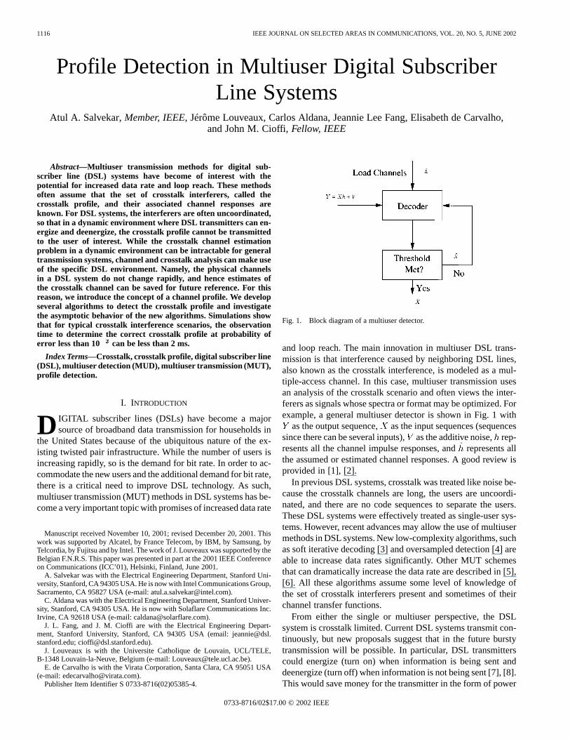
1116 IEEE JOURNAL ON SELECTED AREAS IN COMMUNICATIONS, VOL. 20, NO. 5, JUNE 2002 Profile Detection in Multiuser Digital Subscriber Line Systems Atul A. Salvekar, Member, IEEE, Jérôme Louveaux, Carlos Aldana, Jeannie Lee Fang, Elisabeth de Carvalho, and John M. Cioffi, Fellow, IEEE Abstract—Multiuser transmission methods for digital sub- scriber line (DSL) systems have become of interest with the potential for increased data rate and loop reach. These methods often assume that the set of crosstalk interferers, called the crosstalk profile, and their associated channel responses are known. For DSL systems, the interferers are often uncoordinated, so that in a dynamic environment where DSL transmitters can en- ergize and deenergize, the crosstalk profile cannot be transmitted to the user of interest. While the crosstalk channel estimation problem in a dynamic environment can be intractable for general transmission systems, channel and crosstalk analysis can make use of the specific DSL environment. Namely, the physical channels in a DSL system do not change rapidly, and hence estimates of the crosstalk channel can be saved for future reference. For this reason, we introduce the concept of a channel profile. We develop several algorithms to detect the crosstalk profile and investigate the asymptotic behavior of the new algorithms. Simulations show that for typical crosstalk interference scenarios, the observation time to determine the correct crosstalk profile at probability of error less than 10 can be less than 2 ms. Index Terms—Crosstalk, crosstalk profile, digital subscriber line (DSL), multiuser detection (MUD), multiuser transmission (MUT), profile detection. I. INTRODUCTION D IGITAL subscriber lines (DSLs) have become a major source of broadband data transmission for households in the United States because of the ubiquitous nature of the ex- isting twisted pair infrastructure. While the number of users is increasing rapidly, so is the demand for bit rate. In order to ac- commodate the new users and the additional demand for bit rate, there is a critical need to improve DSL technology. As such, multiuser transmission (MUT) methods in DSL systems has be- come a very important topic with promises of increased data rate Manuscript received November 10, 2001; revised December 20, 2001. This work was supported by Alcatel, by France Telecom, by IBM, by Samsung, by Telcordia, by Fujitsu and by Intel. The work of J. Louveaux was supported by the Belgian F.N.R.S. This paper was presented in part at the 2001 IEEE Conference on Communications (ICC’01), Helsinki, Finland, June 2001. A. Salvekar was with the Electrical Engineering Department, Stanford Uni- versity, Stanford, CA 94305 USA. He is now with Intel Communications Group, Sacramento, CA 95827 USA (e-mail: [email protected]). C. Aldana was with the Electrical Engineering Department, Stanford Univer- sity, Stanford, CA 94305 USA. He is now with Solaflare Communications Inc. Irvine, CA 92618 USA (e-mail: [email protected]). J. L. Fang, and J. M. Cioffi are with the Electrical Engineering Depart- ment, Stanford University, Stanford, CA 94305 USA (email: jeannie@dsl. stanford.edu; [email protected]). J. Louveaux is with the Universite Catholique de Louvain, UCL/TELE, B-1348 Louvain-la-Neuve, Belgium (e-mail: [email protected]). E. de Carvalho is with the Virata Corporation, Santa Clara, CA 95051 USA (e-mail: [email protected]). Publisher Item Identifier S 0733-8716(02)05385-4. Fig. 1. Block diagram of a multiuser detector. and loop reach. The main innovation in multiuser DSL trans- mission is that interference caused by neighboring DSL lines, also known as the crosstalk interference, is modeled as a mul- tiple-access channel. In this case, multiuser transmission uses an analysis of the crosstalk scenario and often views the inter- ferers as signals whose spectra or format may be optimized. For example, a general multiuser detector is shown in Fig. 1 with as the output sequence, as the input sequences (sequences since there can be several inputs), as the additive noise, rep- resents all the channel impulse responses, and represents all the assumed or estimated channel responses. A good review is provided in [1], [2]. In previous DSL systems, crosstalk was treated like noise be- cause the crosstalk channels are long, the users are uncoordi- nated, and there are no code sequences to separate the users. These DSL systems were effectively treated as single-user sys- tems. However, recent advances may allow the use of multiuser methods in DSL systems. New low-complexity algorithms, such as soft iterative decoding [3] and oversampled detection [4] are able to increase data rates significantly. Other MUT schemes that can dramatically increase the data rate are described in [5], [6]. All these algorithms assume some level of knowledge of the set of crosstalk interferers present and sometimes of their channel transfer functions. From either the single or multiuser perspective, the DSL system is crosstalk limited. Current DSL systems transmit con- tinuously, but new proposals suggest that in the future bursty transmission will be possible. In particular, DSL transmitters could energize (turn on) when information is being sent and deenergize (turn off) when information is not being sent [7], [8]. This would save money for the transmitter in the form of power 0733-8716/02$17.00 © 2002 IEEE
-
Upload
independent -
Category
Documents
-
view
0 -
download
0
Transcript of Profile detection in multiuser digital subscriber line systems
1116 IEEE JOURNAL ON SELECTED AREAS IN COMMUNICATIONS, VOL. 20, NO. 5, JUNE 2002
Profile Detection in Multiuser Digital SubscriberLine Systems
Atul A. Salvekar, Member, IEEE, Jérôme Louveaux, Carlos Aldana, Jeannie Lee Fang, Elisabeth de Carvalho,and John M. Cioffi, Fellow, IEEE
Abstract—Multiuser transmission methods for digital sub-scriber line (DSL) systems have become of interest with thepotential for increased data rate and loop reach. These methodsoften assume that the set of crosstalk interferers, called thecrosstalk profile, and their associated channel responses areknown. For DSL systems, the interferers are often uncoordinated,so that in a dynamic environment where DSL transmitters can en-ergize and deenergize, the crosstalk profile cannot be transmittedto the user of interest. While the crosstalk channel estimationproblem in a dynamic environment can be intractable for generaltransmission systems, channel and crosstalk analysis can make useof the specific DSL environment. Namely, the physical channelsin a DSL system do not change rapidly, and hence estimates ofthe crosstalk channel can be saved for future reference. For thisreason, we introduce the concept of a channel profile. We developseveral algorithms to detect the crosstalk profile and investigatethe asymptotic behavior of the new algorithms. Simulations showthat for typical crosstalk interference scenarios, the observationtime to determine the correct crosstalk profile at probability oferror less than 10 3 can be less than 2 ms.
Index Terms—Crosstalk, crosstalk profile, digital subscriber line(DSL), multiuser detection (MUD), multiuser transmission (MUT),profile detection.
I. INTRODUCTION
D IGITAL subscriber lines (DSLs) have become a majorsource of broadband data transmission for households in
the United States because of the ubiquitous nature of the ex-isting twisted pair infrastructure. While the number of users isincreasing rapidly, so is the demand for bit rate. In order to ac-commodate the new users and the additional demand for bit rate,there is a critical need to improve DSL technology. As such,multiuser transmission (MUT) methods in DSL systems has be-come a very important topic with promises of increased data rate
Manuscript received November 10, 2001; revised December 20, 2001. Thiswork was supported by Alcatel, by France Telecom, by IBM, by Samsung, byTelcordia, by Fujitsu and by Intel. The work of J. Louveaux was supported by theBelgian F.N.R.S. This paper was presented in part at the 2001 IEEE Conferenceon Communications (ICC’01), Helsinki, Finland, June 2001.
A. Salvekar was with the Electrical Engineering Department, Stanford Uni-versity, Stanford, CA 94305 USA. He is now with Intel Communications Group,Sacramento, CA 95827 USA (e-mail: [email protected]).
C. Aldana was with the Electrical Engineering Department, Stanford Univer-sity, Stanford, CA 94305 USA. He is now with Solaflare Communications Inc.Irvine, CA 92618 USA (e-mail: [email protected]).
J. L. Fang, and J. M. Cioffi are with the Electrical Engineering Depart-ment, Stanford University, Stanford, CA 94305 USA (email: [email protected]; [email protected]).
J. Louveaux is with the Universite Catholique de Louvain, UCL/TELE,B-1348 Louvain-la-Neuve, Belgium (e-mail: [email protected]).
E. de Carvalho is with the Virata Corporation, Santa Clara, CA 95051 USA(e-mail: [email protected]).
Publisher Item Identifier S 0733-8716(02)05385-4.
Fig. 1. Block diagram of a multiuser detector.
and loop reach. The main innovation in multiuser DSL trans-mission is that interference caused by neighboring DSL lines,also known as the crosstalk interference, is modeled as a mul-tiple-access channel. In this case, multiuser transmission usesan analysis of the crosstalk scenario and often views the inter-ferers as signals whose spectra or format may be optimized. Forexample, a general multiuser detector is shown in Fig. 1 with
as the output sequence,as the input sequences (sequencessince there can be several inputs),as the additive noise,rep-resents all the channel impulse responses, andrepresents allthe assumed or estimated channel responses. A good review isprovided in [1], [2].
In previous DSL systems, crosstalk was treated like noise be-cause the crosstalk channels are long, the users are uncoordi-nated, and there are no code sequences to separate the users.These DSL systems were effectively treated as single-user sys-tems. However, recent advances may allow the use of multiusermethods in DSL systems. New low-complexity algorithms, suchas soft iterative decoding [3] and oversampled detection [4] areable to increase data rates significantly. Other MUT schemesthat can dramatically increase the data rate are described in [5],[6]. All these algorithms assume some level of knowledge ofthe set of crosstalk interferers present and sometimes of theirchannel transfer functions.
From either the single or multiuser perspective, the DSLsystem is crosstalk limited. Current DSL systems transmit con-tinuously, but new proposals suggest that in the future burstytransmission will be possible. In particular, DSL transmitterscould energize (turn on) when information is being sent anddeenergize (turn off) when information is not being sent [7], [8].This would save money for the transmitter in the form of power
0733-8716/02$17.00 © 2002 IEEE
SALVEKAR et al.: PROFILE DETECTION IN MULTIUSER DIGITAL SUBSCRIBER LINE SYSTEMS 1117
reduction and allow rate adaptive systems to increase their datarates when the neighboring crosstalk is deenergized. For a DSLsystem to take advantage of a bursty crosstalk environment,it must be able to quickly determine which crosstalkers arepresent and adapt its parameters.
However, as a result of the process of unbundling [9], the dif-ferent xDSL services can act in an uncoordinated manner evenif they are the same type of service. So, crosstalk informationthat can be useful for transmission purposes in a coordinatedsystem cannot always be used [2]. Obtaining the crosstalk in-formation necessary for adjusting the system parameters can beextremely difficult if it is assumed that the crosstalk informa-tion is completely new each time a crosstalk signal energizes ordeenergizes.
If treated as a completely new transmission environment, theissues of long channel lengths, possible lack of transmissioncoordination, and no use of code sequences, significantly com-plicate the estimation of the channel responses of several inter-ferers simultaneously. However, in contrast to the generic trans-mission system environment which is time-varying, the DSLphysical channels do not change quickly. So, if a DSL modemwere to monitor the crosstalk interference intermittently, it couldacquire crosstalk channel responses by using the crosstalk inter-ferer’s synchronization patterns over a long period of time whilethe signal of interest were inactive. A method to provide evenbetter channel estimates is to use a network maintenance center[10].
Once the DSL crosstalk channels are estimated, they can bestored and used to detect which crosstalk interferers are trans-mitting or “present.” This will be called crosstalk profile detec-tion. There are slow variations in the transmission media, but forthe remainder of the paper a static physical channel is assumed.If the crosstalk channels have been stored from recent measure-ments, then except for the timing offsets that the crosstalk chan-nels have with respect to some nominal reference, the multiusertransmission scheme can be loaded appropriately just by de-tecting the presence of the crosstalker profile. Timing issues canbe addressed separately and are left considered in future work[11]. So, a detection scheme that is independent of timing is-sues is desired. For this purpose, we devise several algorithmsthat under very mild conditions, can detect the crosstalk profilewithout knowledge of the timing information.
The outline of the paper is as follows. Section II describes theconcept of channel profiles which are used in Section III to de-tect the crosstalk scenario (crosstalk profile). Sections IV and Vintroduce and analyze methods for crosstalk profile detection.Simulation results are provided in Section VI. Section VII con-cludes the paper.
II. CHANNEL PROFILES
A channel profile describes the physical state of the trans-mission environment. An example of a channel profile is a setof possible crosstalk interferers, also called a crosstalk profile.To account for the influence they have on the physical system,crosstalk profiles could consist of the possible scenarios thatmost influence the performance of the DSL link or occur mostoften. For instance, the set of interferers that have the widest
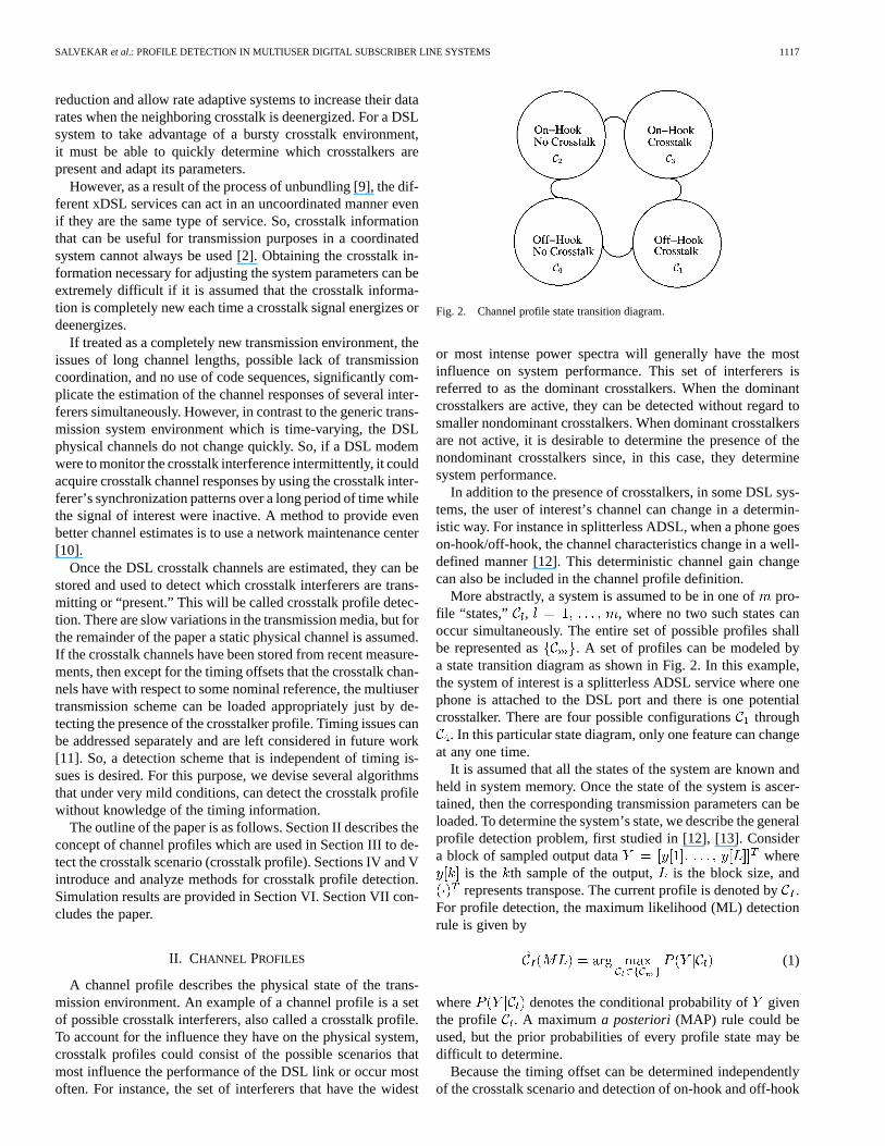
Fig. 2. Channel profile state transition diagram.
or most intense power spectra will generally have the mostinfluence on system performance. This set of interferers isreferred to as the dominant crosstalkers. When the dominantcrosstalkers are active, they can be detected without regard tosmaller nondominant crosstalkers. When dominant crosstalkersare not active, it is desirable to determine the presence of thenondominant crosstalkers since, in this case, they determinesystem performance.
In addition to the presence of crosstalkers, in some DSL sys-tems, the user of interest’s channel can change in a determin-istic way. For instance in splitterless ADSL, when a phone goeson-hook/off-hook, the channel characteristics change in a well-defined manner [12]. This deterministic channel gain changecan also be included in the channel profile definition.
More abstractly, a system is assumed to be in one ofpro-file “states,” , , where no two such states canoccur simultaneously. The entire set of possible profiles shallbe represented as . A set of profiles can be modeled bya state transition diagram as shown in Fig. 2. In this example,the system of interest is a splitterless ADSL service where onephone is attached to the DSL port and there is one potentialcrosstalker. There are four possible configurationsthrough
. In this particular state diagram, only one feature can changeat any one time.
It is assumed that all the states of the system are known andheld in system memory. Once the state of the system is ascer-tained, then the corresponding transmission parameters can beloaded. To determine the system’s state, we describe the generalprofile detection problem, first studied in [12], [13]. Considera block of sampled output data where
is the th sample of the output, is the block size, andrepresents transpose. The current profile is denoted by.
For profile detection, the maximum likelihood (ML) detectionrule is given by
(1)
where denotes the conditional probability of giventhe profile . A maximuma posteriori (MAP) rule could beused, but the prior probabilities of every profile state may bedifficult to determine.
Because the timing offset can be determined independentlyof the crosstalk scenario and detection of on-hook and off-hook

1118 IEEE JOURNAL ON SELECTED AREAS IN COMMUNICATIONS, VOL. 20, NO. 5, JUNE 2002
events have been extensively studied, we investigate theproblem of determining which crosstalkers are present. Thiswill be known as crosstalk profile detection.
III. CROSSTALK PROFILE DETECTION
To determine the crosstalk interferers that are present, we firstdescribe the crosstalk interference scenario. The DSL crosstalkinterference scenario consists of several different services thatcan interfere with the line of interest. These services includehigh-speed digital subscriber lines (HDSL), asymmetric dig-ital subscriber lines (ADSL), symmetric digital subscriber lines(SDSL), integrated services digital network (ISDN), and T1services. Typically, the user of interest has access to only oneoutput, so this environment can be described by a multiple-inputsingle-output (MISO) model. For the remainder of the paper, weconcentrate on the MISO crosstalk channel environment, whichis typical for DSL systems.
The different symbol rates of the different services leads tosome additional complexity in the system model. Assume thereare lines in the model. There arecrosstalkers into eachline. Let be the samples sent on line(or equivalently sentby user ). The input symbol rate of this user is denoted by .The crosstalk channel response from lineinto is denoted by
. This response includes both the shaping filter of userand the receive filter of user. For the remainder of the paper,
will also be known as the transmit pulse from crosstalkerto user . The crosstalk interference is given by
(2)
At the receiver, this signal is sampled and becomes
(3)
(4)
where accounts for the timing offset between userand user.Without loss of generality, the subscript 0 is the desired
signal. For the user of interest, the sampled aggregatecrosstalk signal can be written as
(5)
where if crosstalker is active and 0 otherwise andare the samples of the noise, assumed to be additive white
Gaussian noise (AWGN) with variance. Notice that doesnot include the user signal. The user’s signal is separated fromthe crosstalk signal because later in the paper, the line is mon-itored at start-up or in decision directed mode, when the user’ssignal can be cleanly subtracted and only the crosstalk remains.A set of output samples can be written in matrix notationas where
(6)
where is the crosstalk channel matrix depending on
, is the column vector of input samples ,and is a column vector of noise samples. For synchronizationand estimation purposes, the input samples may contain not onlydata but also some known sequences such as synchronization ortraining sequences. For example, in ADSL, a fixed synchroniza-tion sequence is sent every 69 discrete multitone (DMT) sym-bols. Equation (6) can be separated into the contributions of theknown symbols (synchronization sequence) with the subscript
and the unknown symbols (the data) with the subscript.The set of received samplescan be rewritten as
(7)
By concatenating the input symbols of all users into bigger vec-tors and and by grouping the crosstalk channelsinto bigger matrices and , where stands for “all,”we get
(8)
For notational convenience, every configuration has beenrepresented by an integer whose binary expansion is
. Every such binary expansion refers to adifferent crosstalk channel profile. Similarly, refers to the setof all timing informations .
The determination of the conditional probabilities isnot straightforward due to the possibly different sampling ratesused by the different users and due to the unknown timing off-sets between users. There are various ML criteria based on dif-ferent assumptions for the input data [11], [13], [14]. In ourproblem, the simplest of these criteria is the Gaussian max-imum likelihood (GML) detector, which treats input symbolsas Gaussian random variables, so that the output waveform is aGaussian random variable. Since the channels are long and thetransmit constellations are multilevel, treating the outputto be Gaussian is acceptable [15]. Then, from (8), under thethprofile,
(9)
where represents a normal random vector with meanand covariance matrix and
(10)
where is the expectation operator, andis the identity ma-trix. Then, the GML test can be written as:
(11)
where is the determinant of matrix .While GML is less complex than the other ML criteria, it is
still very complex due to the effects of the timing information.

SALVEKAR et al.: PROFILE DETECTION IN MULTIUSER DIGITAL SUBSCRIBER LINE SYSTEMS 1119
The timing offsets influence the mean of the output samplevector through the position of the synchronization sequencesand affect the covariance matrix through the sampling phaseof the crosstalk channels . Since this paper is interestedin the presence or absence of the crosstalk interferers, timinginformation is not relevant. Therefore, we can simplify thedetection with the following observations. First, we ignore thepresence of the synchronization sequences which are typicallydesigned to have low cross-correlation properties and haveaverage energy equal to the expected input symbol energy ofthe interfering DSL. Second, we note that practical multiusertransmission schemes will sample the output waveform ata rate at least as high as the largest effective bandwidth ofany crosstalker. This allows for the design of timing offsetindependent crosstalk profile detectors.
To design the profile detectors, we consider two bandlimitingcases.
1) In the “ideal” case all the crosstalkers have an ef-fective bandwidth smaller than their symbol rate,i.e., for crosstalker , the bandwidth is within
, hence the sampled output processis stationary. Since the crosstalk is stationary, a simplemaximum likelihood detector can be designed. Becauseof excess bandwidth, this bandlimiting scenario is notmet in practice. However, these detectors form a basisfor the detectors in the following more realistic scenario.
2) In a more realistic scenario, the crosstalk interference willhave excess bandwidth making the crosstalk responsecyclostationary. A multiuser transmission system willlikely oversample the crosstalk signal. In particular, thecrosstalkers are effectively bandlimited to a bandwidthsmaller than , where is thesampling rate of the user of interest. An analysis of thiscrosstalk scenario will yield crosstalk profile detectors.
IV. PROFILE DETECTION IN BANDLIMITING CASE 1)
A. Bandlimited Maximum Likelihood Detection
In bandlimiting case 1), ignoring the effects of the synchro-nization sequences, is not a function of since the autocor-relation is not a function of , as shown in Appendix A. Thebandlimited GML detector becomes
(12)
where is given by (10) when there is no known sequence.We shall call this bandlimited maximum likelihood detection(BMLD).
While BMLD looks complex, it is in reality simple. For fixedblock lengths , and can be precomputed.Then, the complexity of the detection scheme is only a matrixmultiply. Furthermore, simulations show that by using severalsuch estimates together, even small block sizescan be usedto reliably detect the crosstalkers present, thus making the com-plexity reasonable.
The detector performance can be analyzed for either a fixednumber of blocks, known as the fixed block length detector, ora sequential method. The fixed block detection method and the
sequential detection method are analyzed in Section IV-A1 andSection IV-A2.
1) Fixed Block Length Detection:This section roughly ana-lyzes the number of data blocks,, used in (12) needed to attaina specific probability of error, , where an error denotes thatthe incorrect profile has been chosen. We note that a Toeplitzmatrix is asymptotically circulant, and then apply the centrallimit theorem to achieve a given performance level.
If is the current profile, and is any other profile, thenan error occurs if
(13)
For large enough blocks of data, the Toeplitz autocorrela-tion matrix is approximately circulant, and hence, can nearlybe diagonalized by the discrete Fourier transform (DFT) matrix,
. Making the transformation, , (13) can be approx-imated by
(14)
where denotes conjugate transpose andis a diagonalmatrix whose th diagonal entry is given by
(15)
where , is the th element of the binaryexpansion of , and is the th element of the DFTof the sequence . Using the central limit theorem [16],
(16)
(17)
Hence, using the properties of Gaussian random variables, theprobability of (14) can be written as , where, ifblocks are averaged,
(18)
Using the union bound, the number of blocks needed for aparticular , is given by
(19)
This analysis is somewhat rough since the noise is not exactlyGaussian and the autocorrelation matrix is not exactly Circulant.
2) Sequential Detection:Sequential detection consists ofselecting a crosstalk profile after a given performance metricis met, for instance the probability of misclassification [17]. Inthis case, the number of blocks is not fixed. Sequential methodsare of interest since typically they have smaller wait times then
1120 IEEE JOURNAL ON SELECTED AREAS IN COMMUNICATIONS, VOL. 20, NO. 5, JUNE 2002
fixed methods for a given performance level. Moreover, ourperformance analysis for the sequential detection method ismore exact since besides the assumption that the crosstalk isGaussian, no other approximations are made.
Let denote the negative log-likelihood of crosstalk pro-file given the th data vector . This is given by
(20)
If the blocks of data are spaced far enough apart, the log-likelihood can be summed, as the likelihood functions are ef-fectively from independent samples. So, the log-likelihood ofblocks 1 through are given by
(21)
When the difference between the maximum log-likelihoodfunction and all other log-likelihood functions is greater thansome threshold , the largest likelihood is chosen as thecrosstalk profile. So, if is the smallest negative likelihoodfunction (largest likelihood) at step, then a decision is madeat time , when
(22)
The decision as to the crosstalk profile is then .If , this is known as an Armitage scheme and the
theory of sequential analysis can help in choosing a threshold forany particular [18]. Using an Armitage scheme, the proba-bility of misclassification is given by the Armitage bound:
misclassification (23)
B. DFT Method
Many of the high speed DSL modems that could potentiallyuse multiuser transmission schemes already employ a discreteFourier transform (DFT) for signal processing. Examplesinclude ADSL, ADSL-lite, and DMT-VDSL. As such, thesquared output of the DFT, also known as a periodogram
, where are equally spaced points between1/2and 1/2, can be used for profile detection. The periodogram isa biased estimate of the spectrum of the signal of interest andhas mean value
(24)
where is the Fourier transform of the Bartlett windowof size and is the power spectrum of the sampledcrosstalker output [19].
Using the fact that the covariance of and isabout equal to 0 [19] and recognizing that asymptotically thesamples of the periodogram are chi-square random variablesformed from a circularly symmetric Gaussian random processso that the variance of is , then by averaging
periodograms, the central limit theorem can be invoked, leadingto the new detection rule
(25)
where is the expected periodogram under profile.Using other windows can increase performance by reducingthe variance per sample [19].
C. Discussion
The BMLD and DFT methods developed in this section arefor crosstalk interferers whose symbol rates are greater than theeffective bandwidth of the transmit pulse. Because the transmitpulse has excess bandwidth, this bandlimiting scenario is notmet in practice. However, in multiuser systems, the crosstalkwill likely be oversampled. In the next section new detectorswill be developed for this case. Some of the new detectors willuse the detectors of Section IV as a starting point.
V. PROFILE DETECTION IN BANDLIMITING CASE 2)
Practical multiuser systems will oversample the crosstalk in-terference. Using this fact, two methodologies are used to deter-mine the crosstalk scenario. In Section V-A, detection schemesbased on the principles of Section IV are argued to work in theoversampled case with minor adjustments even when bandlim-iting case 1 is not satisfied. Then, in Section V-B, a detectionscheme based only on the assumption that the crosstalk inter-ference is oversampled is developed. The methods of Section Vare used for simulations in Section VI.
A. Approximate Methods
While the methods in Section IV cannot be directly applied tothe DSL crosstalk scenarios due to the excess bandwidth of thecrosstalk interference, it can be argued that the blocks of data,
, used for detection are similar to blocks of data from thetime-shifted version of the crosstalk interference.
If the s are formed from output samples sufficiently sep-arated in time, then these blocks are independent. Hence, as-suming ergodicity, block by block processing corresponds to thecase of a time-shifted process.
As a review, if is the crosstalk output, then the time-shifted version is , where is a uniform randomvariable between and is the least common multipleof the s.
As the time-shifted process is stationary, the GML criterioncan be applied to this process. The power spectral density (PSD)of is given by [20]:
(26)
where is the frequency response of the crosstalk channeland is an indicator variable of whether the crosstalker
is present. For the time-shifted process all the methods in

SALVEKAR et al.: PROFILE DETECTION IN MULTIUSER DIGITAL SUBSCRIBER LINE SYSTEMS 1121
Section IV can be applied, except that the autocorrelation thatis used would be the inverse Fourier transform of (26). It isassumed that the crosstalk channel responses are known up toa timing offset so that can be calculated for any crosstalkscenario. Even if the crosstalk channel responses are not known,it is shown in Appendix B that the measured autocorrelationfunction asymptotically corresponds to the autocorrelation ofthe time-shifted version of the crosstalk interference process.Hence, can be calculated from the waveform itself withoutthe assumption of known channel responses. Thus, the methodsin Section IV can be used in the presence of practical crosstalkprovided that the time-shifted PSD is used. These adjustedmethods will be called the modified bandlimited maximumlikelihood detector (MBMLD) and the modified DFT (MDFT)method.
B. Sample Autocorrelation Matching
In bandlimiting case 2, the ML detector is no longer simplebecause the autocorrelation function of is no longer widesense stationary. In general, it is cyclostationary, so thatis nowa function of . However, even though is a function of , itcan be shown (Appendix B) that the expected limiting sampleautocorrelation function, , defined as
(27)
is a constant independent of the timing offset. The measuredsample autocorrelation function is given by
(28)
If the process is covariance ergodic
(29)
The asymptotic behavior of the autocorrelation estimate iscomplicated. So, instead of defining a GML criterion, we simplyminimize the mean square error between the expected limitingsample autocorrelation and the measured sample autocorrela-tion. This is written as
(30)
where is the number of autocorrelation terms used andis the th autocorrelation lag of (27) given is the
current profile.We call this method the sample autocorrelation matching
(SAM) method. A degenerate version of this algorithm wouldbe to match the measured power to the closest expected power.This shall be referred to as power matching (PM). We turn toMonte Carlo simulations to show that for reasonable observa-tion lengths the current profile can be determined by the SAMmethod.
Fig. 3. The power spectral density of the first crosstalk scenario.
Fig. 4. The power spectral density of the second crosstalk scenario.
VI. SIMULATION RESULTS
For the simulations, the signal of interest is assumed to be anADSL modem with sampling rate 2.208 MHz. We assume twopossible crosstalk scenarios. In scenario one, there are three nearend crosstalkers (NEXT) whose symbol rate (392 kHz), constel-lation (4-PAM), and spectral mask are defined as in the HDSLstandard [21]. Their individual crosstalk power spectral densi-ties (PSDs) are given in Fig. 3. These PSDs are representativeof the actual characteristics of HDSL for typical transmissionlines. Scenario two has one NEXT interferer whose symbol rate,constellation size, and spectral mask are defined as in the HDSLstandard and one NEXT interferers whose symbol rate (80 kHz),constellation size (4-PAM), and spectral mask are defined as inthe ISDN standard [22]. They have crosstalk PSDs as seen inFig. 4. In this case there are two dominant crosstalkers, and anondominant one; crosstalk three in Fig. 4 is nondominant sinceits PSD is dominated by the PSD of crosstalkers one and two.We, therefore, define a profile such that only the set of domi-nant crosstalkers needs to be correctly identified when at leastone dominant crosstalker is active. When a dominant crosstalkeris not active, a profile is defined as the nondominant crosstalker.

1122 IEEE JOURNAL ON SELECTED AREAS IN COMMUNICATIONS, VOL. 20, NO. 5, JUNE 2002
Fig. 5. Probability of error versus block size for a total of 1024 samples.
Fig. 6. Probability of error versus total number of symbols for 3 HDSLcrosstalkers.
For scenarios one and two, there is background AWGN noise of140 dBm/Hz.The excess bandwidth of the crosstalk preclude directly using
the detectors of bandlimiting case 1, but the strong dropoff in thespectral energy upto the ADSL sampling rate make the detectorsof bandlimiting case 2) applicable.
In order to choose the block sizes for the various methods,we examine the performance of the detectors versus block sizein an example where a total of 1024 samples are used. Fig. 5shows that for scenario one, a block length of 100 samples pro-vides nearly maximum performance for the SAM and MBMLDdetectors. We therefore choose block lengths of 100 for all sim-ulations. For the MDFT method, we choose a DFT size of 512which corresponds to the DFT size for traditional ADSL [23].For testing purposes, the minimum total number of samples waschosen to be 512 so that a fair comparison with the MDFTmethod was possible.
The results of the simulations in scenario one is given inFig. 6. As expected, the modified bandlimited maximum like-lihood detector performs best out of all the detection methods.The MDFT method is not as good as the SAM method. One
Fig. 7. Probability of error versus total number of symbols for 1 HDSL and 2ISDN crosstalkers.
possible reason for this is that the covariance terms that wereassumed to be zero were actually significant. As expected thepower method has the least detection capability. Recall that anerror denotes that the incorrect profile has been chosen. For aprobability of error of 10 , within 10 ms, the PM method ex-cluded, all the methods can detect the crosstalk profile and forMBMLD, the detection time is less than 2 ms.
In scenario two, as shown in Fig. 7, the MBMLD detectionscheme again performs extremely well. In fact, the proba-bility of error is less than 10 for total number of samplesgreater than 512. Hence there is no line for the MBMLDmethod in Fig. 7. The MDFT method also has extremely goodperformance, since in this case, the two dominant crosstalkprofiles have very different power spectral densities, so thismethod can easily distinguish between the different possiblesets of crosstalkers. Notice that the SAM method is also ableto quickly determine the crosstalk scenario. All the methods,excluding the PM method, can detect the crosstalk profile withprobability of error less than 10 in less than 2 ms.
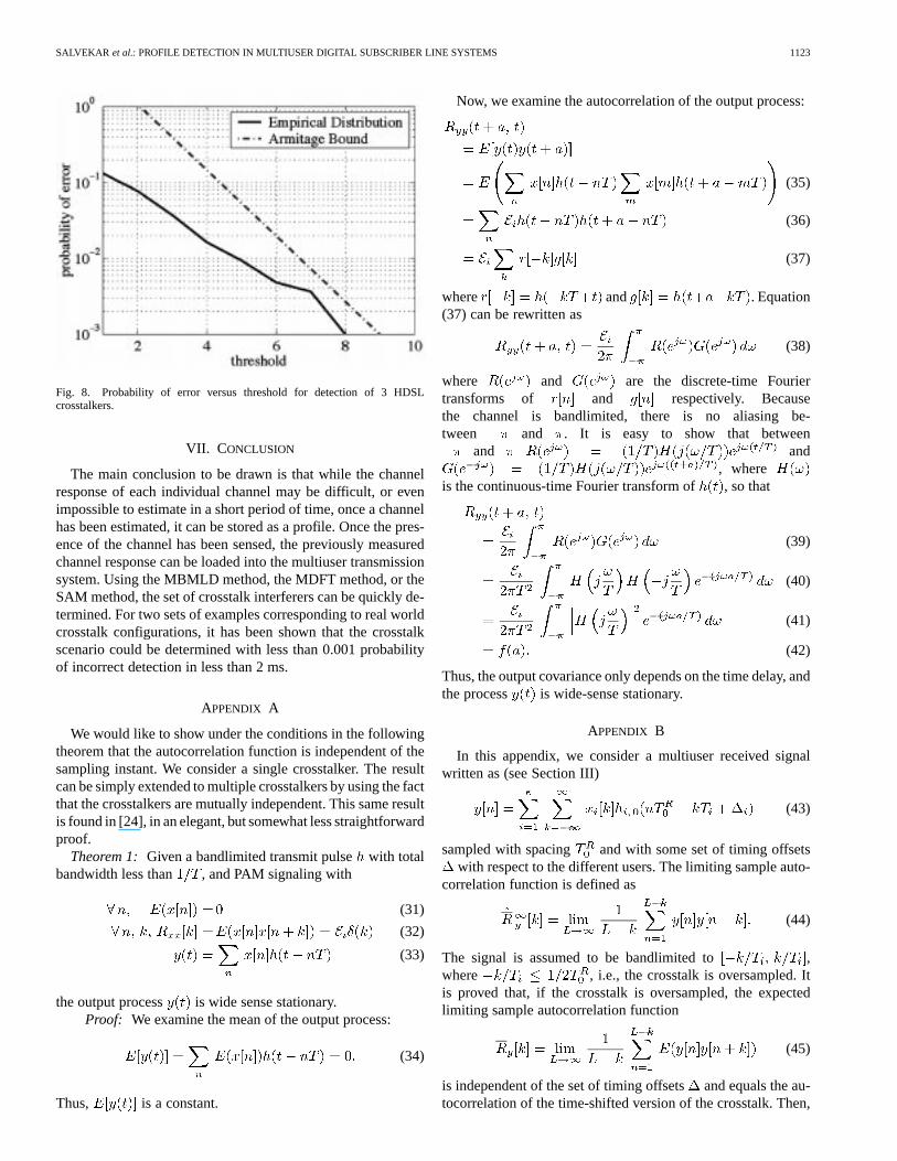
Next, we examine the error rate versus threshold level for theMBMLD detector used in the first scenario. This is shown inFig. 8. Note the important quality that as the threshold level isincreased, the error rate decreases exponentially as would beexpected since a linear increase in the log-likelihood functionimplies an exponential decrease in the probability of error. Thisis expressed in (23). So, the error rate can be made arbitrarilyclose to zero by increasing the threshold, at the cost of increasedlatency.
At the expense of complexity, the MBMLD method providesthe best performance among the detectors. This method hasorder complexity where is the block length. The SAMmethod and the MDFT methods do not have any clear per-formance distinction between them and both have low com-plexity, and log respectively, where is the numberof autocorrelation terms. Finally, the simplest and least reliablemethod is the power matching method which has ordercom-plexity. Therefore, there is a tradeoff between complexity andperformance.
SALVEKAR et al.: PROFILE DETECTION IN MULTIUSER DIGITAL SUBSCRIBER LINE SYSTEMS 1123
Fig. 8. Probability of error versus threshold for detection of 3 HDSLcrosstalkers.
VII. CONCLUSION
The main conclusion to be drawn is that while the channelresponse of each individual channel may be difficult, or evenimpossible to estimate in a short period of time, once a channelhas been estimated, it can be stored as a profile. Once the pres-ence of the channel has been sensed, the previously measuredchannel response can be loaded into the multiuser transmissionsystem. Using the MBMLD method, the MDFT method, or theSAM method, the set of crosstalk interferers can be quickly de-termined. For two sets of examples corresponding to real worldcrosstalk configurations, it has been shown that the crosstalkscenario could be determined with less than 0.001 probabilityof incorrect detection in less than 2 ms.
APPENDIX A
We would like to show under the conditions in the followingtheorem that the autocorrelation function is independent of thesampling instant. We consider a single crosstalker. The resultcan be simply extended to multiple crosstalkers by using the factthat the crosstalkers are mutually independent. This same resultis found in [24], in an elegant, but somewhat less straightforwardproof.
Theorem 1: Given a bandlimited transmit pulsewith totalbandwidth less than , and PAM signaling with
(31)
(32)
(33)
the output process is wide sense stationary.Proof: We examine the mean of the output process:
(34)
Thus, is a constant.
Now, we examine the autocorrelation of the output process:
(35)
(36)
(37)
where and . Equation(37) can be rewritten as
(38)
where and are the discrete-time Fouriertransforms of and respectively. Becausethe channel is bandlimited, there is no aliasing be-tween and . It is easy to show that between
and and, where
is the continuous-time Fourier transform of , so that
(39)
(40)
(41)
(42)
Thus, the output covariance only depends on the time delay, andthe process is wide-sense stationary.
APPENDIX B
In this appendix, we consider a multiuser received signalwritten as (see Section III)
(43)
sampled with spacing and with some set of timing offsetswith respect to the different users. The limiting sample auto-
correlation function is defined as
(44)
The signal is assumed to be bandlimited to ,where , i.e., the crosstalk is oversampled. Itis proved that, if the crosstalk is oversampled, the expectedlimiting sample autocorrelation function
(45)
is independent of the set of timing offsetsand equals the au-tocorrelation of the time-shifted version of the crosstalk. Then,

1124 IEEE JOURNAL ON SELECTED AREAS IN COMMUNICATIONS, VOL. 20, NO. 5, JUNE 2002
by assuming, the sample autocorrelation function converges tothe expected limiting sample autocorrelation function.
This result basically means that the average over all avail-able samples provides the same effect as the expectation overall possible timing offsets even though the timing offset isfixed in the real system. This is obviously not true if
because, in this case, becomes indepen-dent of but depends on (unless the bandwidth is limited to
). However, in the actual system, the receivedsignal is generally oversampled in order to catch all the infor-mation on the signal. Thus, we can apply the above stated re-sult. This result is intuitive when and are irreciprocalbecause the average overwill “scan” all the possible sam-pling positions. This is less obvious for typical values such as
. A proof for discrete time random pro-cesses that does not include the effects of timing offsets is shownin [25]. We present the proof hereunder.
Proof: First develop
(46)
assuming all symbols are independent (in time and be-tween users) with variance. We denote by
(47)
the Fourier transform of the sequencefor and for fixed . The correlation given by(46) may then be rewritten as
(48)
Expressing the discrete-time Fourier transform in terms of thecontinuous-time Fourier transform, we have
(49)
where is the Fourier transform of the correspondingchannel. We get
(50)
(51)
which is a function of .
Now, the expected sample autocorrelation functionbecomes
(52)
The behavior of (52) as a function of the timing offsetsde-pends on the bandwidth of the transmitted signals. Let us as-sume that the signal transmitted by useris bandlimited to
. For , the integral can be nonzero for, therefore, if ,
i.e., if the receiver oversamples the output, then for these
(53)
The only terms that remains corresponds to , and hence,the dependence upon also vanishes. The expected limitingsample autocorrelation function becomes
(54)
(55)
which is also the expected autocorrelation for uniformly dis-tributed timing offsets , i.e., the autocorrelation for the time-shifted version. Now, we assume ergodicity, and conclude thatthe measured sample autocorrelation is asymptotically indepen-dent of the timing offset and converges to the expected limitingsample autocorrelation function.
ACKNOWLEDGMENT
The authors would like to thank the anonymous reviewers fortheir constructive criticism and comments, which greatly im-proved the quality of the paper.
REFERENCES
[1] S. Verdu,Multiuser Detection. Cambridge, U.K.: Cambridge Univ.Press, 1998.
[2] J. Cioffi, G. Ginis, W. Yu, and C. Zeng, “Example improvements of dy-namic spectrum management,” ANSI Contribution, Los Angeles, CA,T1E1.4/2001-089, Feb. 2001.
[3] K. W. Cheong, “Multiuser detection for DSL applications,” Ph.D. dis-sertation, Stanford Univ., Stanford, CA, 2000.
[4] C. Zeng and J. M. Cioffi, “Crosstalk cancellation in xDSL systems,”.[5] G. Ginis and J. Cioffi, “Vectored DMT: A FEXT-cancelling modulation
scheme for coordinating users,” inProc. ICC, vol. 1, 2001, pp. 305–309.[6] W. Yu, G. Ginis, and J. Cioffi, “An adaptive multiuser power control
algorithm for VDSL,” inProc. Globecom, vol. 1, 2001, pp. 394–398.[7] A. A. Salvekar, “State detection techniques for DSL systems,” Ph.D.
dissertation, Stanford Univ., Stanford, CA, 2002.[8] C. H. Aldana, “Interference estimation in multicarrier systems,” Ph.D.
dissertation, Stanford Univ., Stanford, CA, 2002.

SALVEKAR et al.: PROFILE DETECTION IN MULTIUSER DIGITAL SUBSCRIBER LINE SYSTEMS 1125
[9] P. Odling, B. Mayr, and S. Palm, “The technical impact of the un-bundling process and regulatory action,”IEEE Commun. Mag., vol. 38,pp. 74–80, May 2000.
[10] C. Zeng, C. Aldana, A. Salvekar, and J. M. Cioffi, “Crosstalk identifi-cation in xDSL systems,”IEEE J. Select. Areas Commun., vol. 19, pp.1488–1496, Aug. 2001.
[11] A. Salvekar, C. Aldana, E. de Carvalho, and J. Cioffi, “Crosstalk profiledetection for use in multiuser detection,” inProc. ICC, vol. 7, 2001, pp.2171–2175.
[12] A. Salvekar, C. Aldana, J. Tellado, and J. Cioffi, “Channel gain changedetection and channel profile selection in a multicarrier system,” inProc.Globecom, vol. 2, 1999, pp. 1133–1138.
[13] C. Aldana, A. Salvekar, J. Tellado, and J. Cioffi, “MAP crosstalk profilematching for multicarrier systems,” inProc. ICT, 2001.
[14] L. Tong and S. Perreau, “Multichannel blind identification: Fromsubspace to maximum likelihood methods,”Proc. IEEE, vol. 86, pp.1951–1968, Oct. 1998.
[15] K. J. Kerpez, “Near end crosstalk is almost Gaussian,”IEEE Trans.Commun., vol. 41, pp. 670–672, May 1993.
[16] S. Ross,Stochastic Processes, 2 ed. New York: Wiley, 1996.[17] D. Siegmund, Sequential Analysis: Tests and Confidence Inter-
vals. New York: Springer-Verlag, 1985.[18] P. Armitage, “Sequential analysis with more than two alternative hypoth-
esis,”J. Roy. Stat. Soc. B, vol. 12, pp. 137–144, 1950.[19] S. M. Kay, Modern Spectral Estimation: Theory and Applica-
tion. Englewood Cliffs, NJ: Prentice-Hall, 1988.[20] A. Papoulis,Probability, Random Variables, and Stochastic Processes,
3 ed. New York: McGraw-Hill Inc., 1991.[21] “High bit rate Digital Subscriber Line (HDSL) transceivers,”, G.991.1,
Oct. 1998.[22] ISDN-basic access interface for use on metallic loops for application on
the network side of the NT (layer 1 specification), ANSI T1.601, 1999.[23] “Asymmetric Digital Subscriber Line (ADSL) transceivers,”, ITU-T
Rec. G.992.2.[24] W. A. Gardner and L. E. Franks, “Characterization of cyclostationary
random signal processes,”IEEE Trans. Inform. Theory, vol. IT–21, pp.4–14, May 1975.
[25] G. B. Giannakis, “Cyclostationary signal analysis,” inStatistical SignalProcessing Section of Digital Signal Processing Handbook, V. K. Madis-etti and D. Williams, Eds. Boca Raton, FL: CRC Press, 1998.
Atul Salvekar (S’98–M’02) received the B.S.degree in electrical engineering from the CaliforniaInstitute of Technology, Pasadena, CA in 1996,the M.S. degree in electrical engineering in 1998,the M.S. degree in statistics in 2001, and the Ph.D.degree in electrical engineering in 2002, all fromStanford University, Stanford, CA.
He is currently working for Intel Corporation. Hisresearch interests lie in the digital communicationand signal processing.
Jérôme Louveaux was born in Belgium in 1974.He received the electrical engineering degree andthe Ph.D. degree from the Universite catholiquede Louvain (UCL, Belgium) in 1996 and 2000,respectively.
From 2000 to 2001, he has been a visitor at theElectrical Engineering Department, Stanford Univer-sity, CA. He is currently a Postdoctoral researcherat the UCL funded by the Belgian National Fundsfor Scientific Research (F.N.R.S.). His research in-terests include signal processing for digital commu-
nications, mainly high bit rate multicarrier transmission by means of filter banks,synchronization and MIMO systems.
Dr. Louveaux was a co-recipient of the 2000 Biennial Siemens Award fromthe Belgian NSF.
Carlos Aldana received the B.S. degree in electricalengineering from the California Institute of Tech-nology, Pasadena, CA, and is working toward thePh.D. degree at Stanford University, Stanford, CA.
He is currently working for Solarfare Commu-nications Inc. His current research interests includemultiuser channel identification, statistical signalprocessing, multiuser detection, nonlinear systems,and adaptive algorithms.
Jeannie Lee Fang received the B.S. degree inelectrical engineering (summa cum laude) fromthe University of Texas at Austin in 1995 and theM.S. degree in electrical engineering from StanfordUniversity, Stanford, CA, in 1997. She is workingtoward the Ph.D. degree in electrical engineering atStanford University.
Her research interests lie in the areas of digitalcommunications and signal processing, includingmulticarrier systems, channel modeling, and channelidentification.
Elisabeth de Carvalho received the M.Sc. degreein electrical engineering from the National Instituteof Telecommunications (INT), Evry, France, in 1994and the Ph.D. degree in electrical engineering fromthe Ecole Nationale Superieure des Telecommunica-tions (Telecom Paris), Paris, France, in 1999.
From 1995 to 1998, she was with Laboratoiresd’Electronique PHILIPS supported by a CIFREscholarship. Her Ph.D. work was on receiveralgorithms for wireless communications, withemphasis on blind and semi-blind equalization.
From October 1999 to June 2001, she was a postdoctoral fellow at Star Lab,Stanford University in the group of Prof. J. M. Cioffi, working on signalprocessing issues for DSL communications. From October 1999 to September2000, she was the recipient of a Lavoisier scholarship from the French Ministryof Foreign Affairs. Since July 2001, she has been with Virata Corporation,Santa Clara, CA. Her research interests are the area of signal processing fordigital communications, synchronization, equalization for wireless and DSLcommunications.
John M. Cioffi (S’77–M’78–SM’90–F’96) receivedthe B.S.E.E. degree from the University of Illinois,Urbana-Champaign, in 1978, and the Ph.D.E.E.degree from Stanford University, Stanford, CA, in1984.
He was with Bell Laboratories, Holmdel, NJ, from1978 to 1984 and IBM Research, San Jose, CA, from1984 to 1986. He has been with Stanford Universityas an Electrical Engineering Professor from 1986 tothe present. He founded Amati Communications Cor-poration, Palto Alto, CA, in 1991 (it was purchased
by Texas Instruments, Incorporated in 1997) and was Officer/Director from1991 to 1997. He is currently on the boards or advisory boards of BigBand Net-works, Coppercom, GoDigital, Ikanos, Ionospan, Ishoni, IteX, Marvell, Kestrel,Charter Ventures, and Portview Ventures. He is a Member of the U.S. NationalResearch Council’s CSTB. His specific interests are in the area of high-perfor-mance digital transmission.
Dr. Cioffi has received the following awards: the National Academy of Engi-neering in 2001, IEEE Kobayashi Medal in 2001, IEEE Millennium Medal in2000, IEE JJ Tomson Medal in 2000, 1999 University of Illinois OutstandingAlumnus, 1991 IEEE COMMUNICATIONS MAGAZINE best paper; 1995 ANSI T1Outstanding Achievement Award, and NSF Presidential Investigator from 1987to 1992. He became a member of the National Academy of Engineering in 2001.He has published over 200 papers and holds over 40 patents, most of which arewidely licensed, including basic patents on DMT, VDSL, and V-OFDM.