MEF 61 - IP Subscriber Service Attributes
218
MEF 61 © MEF Forum 2018. Any reproduction of this document, or any portion thereof, shall contain the following statement: "Reproduced with permission of MEF Forum." No user of this document is authorized to modify any of the information contained herein. MEF Specification MEF 61 IP Service Attributes for Subscriber IP Services Technical Specification April 2018
-
Upload
khangminh22 -
Category
Documents
-
view
2 -
download
0
Transcript of MEF 61 - IP Subscriber Service Attributes

MEF 61 © MEF Forum 2018. Any reproduction of this document, or any portion thereof, shall contain the following statement: "Reproduced with permission of MEF Forum." No user of this document is authorized to modify any of the information contained herein.
MEF Specification
MEF 61
IP Service Attributes for Subscriber IP Services
Technical Specification
April 2018

MEF 61 © MEF Forum 2018. Any reproduction of this document, or any portion thereof, shall contain the following statement: "Reproduced with permission of MEF Forum." No user of this document is authorized to modify any of the information contained herein.
Disclaimer
The information in this publication is freely available for reproduction and use by any recipient and is believed to be accurate as of its publication date. Such information is subject to change without notice and MEF Forum (MEF) is not responsible for any errors. MEF does not assume responsibility to update or correct any information in this publication. No representation or war-ranty, expressed or implied, is made by MEF concerning the completeness, accuracy, or applica-bility of any information contained herein and no liability of any kind shall be assumed by MEF as a result of reliance upon such information.
The information contained herein is intended to be used without modification by the recipient or user of this document. MEF is not responsible or liable for any modifications to this document made by any other party.
The receipt or any use of this document or its contents does not in any way create, by implication or otherwise:
a) any express or implied license or right to or under any patent, copyright, trademark or trade secret rights held or claimed by any MEF member which are or may be associated with the ideas, techniques, concepts or expressions contained herein; nor
b) any warranty or representation that any MEF members will announce any product(s) and/or service(s) related thereto, or if such announcements are made, that such an-nounced product(s) and/or service(s) embody any or all of the ideas, technologies, or concepts contained herein; nor
c) any form of relationship between any MEF member and the recipient or user of this document.
Implementation or use of specific MEF standards or recommendations and MEF specifications will be voluntary, and no Member shall be obliged to implement them by virtue of participation in MEF Forum. MEF is a non-profit international organization to enable the development and world-wide adoption of agile, assured and orchestrated network services. MEF does not, expressly or otherwise, endorse or promote any specific products or services.
© MEF Forum 2018. All Rights Reserved.

IP Service Attributes for Subscriber IP Services
MEF 61 © MEF Forum 2018. Any reproduction of this document, or any portion thereof, shall contain the following statement: "Reproduced with permission of MEF Forum." No user of this document is authorized to modify any of the information contained herein.
Page iii
Table of Contents
1 List of Contributing Members ........................................................................................... 1
2 Abstract ................................................................................................................................ 1
3 Terminology and Abbreviations ........................................................................................ 2
4 Compliance Levels .............................................................................................................. 7
5 Numerical Prefix Conventions ........................................................................................... 7
6 Introduction ......................................................................................................................... 8
7 Key Concepts ..................................................................................................................... 10
7.1 Subscriber IP Services ..................................................................................................... 10 7.2 Service Attributes ............................................................................................................ 11 7.3 UNIs and UNI Access Links ........................................................................................... 12 7.4 IP Virtual Connections and IPVC End Points ................................................................. 16 7.5 Subscriber-Managed and Provider-Managed CEs .......................................................... 17 7.6 Service Assurance ............................................................................................................ 20 7.7 Virtual Private Network (VPN) Services ........................................................................ 20 7.8 Extranet Services ............................................................................................................. 21 7.9 Internet and Cloud Access Services ................................................................................ 24
7.9.1 Internet Access ...................................................................................................................... 25 7.9.2 Private Cloud Access ............................................................................................................ 26
7.10 IP Services Framework .................................................................................................... 26 7.11 IP Packets ........................................................................................................................ 26
8 Routing and Packet Delivery in a Subscriber IPVC...................................................... 28
8.1 IP Routing ........................................................................................................................ 28 8.1.1 UNI Routing Information Database ...................................................................................... 29 8.1.2 IPVC EP Local Routing Information Database .................................................................... 30 8.1.3 IPVC EP Remote Routing Information Database ................................................................. 30 8.1.4 IPVC EP Routing Table ........................................................................................................ 31 8.1.5 Summary ............................................................................................................................... 31
8.2 IP Packet Delivery ........................................................................................................... 33 8.2.1 Selecting an Ingress IPVC EP ............................................................................................... 33 8.2.2 Delivering IP Packets across an IPVC .................................................................................. 38
9 Subscriber IPVC Service Attributes ............................................................................... 40
9.1 IPVC Identifier Service Attribute .................................................................................... 41 9.2 IPVC Topology Service Attribute ................................................................................... 41 9.3 IPVC End Point List Service Attribute............................................................................ 41 9.4 IPVC Packet Delivery Service Attribute ......................................................................... 42
9.4.1 IP Data Packet Transparency ................................................................................................ 43 9.5 IPVC Maximum Number of IPv4 Routes Service Attribute ........................................... 46 9.6 IPVC Maximum Number of IPv6 Routes Service Attribute ........................................... 47 9.7 IPVC DSCP Preservation Service Attribute .................................................................... 48 9.8 IPVC List of Class of Service Names Service Attribute ................................................. 48 9.9 IPVC Service Level Specification Service Attribute ...................................................... 49
9.9.1 SLS Reference Points ............................................................................................................ 51

IP Service Attributes for Subscriber IP Services
MEF 61 © MEF Forum 2018. Any reproduction of this document, or any portion thereof, shall contain the following statement: "Reproduced with permission of MEF Forum." No user of this document is authorized to modify any of the information contained herein.
Page iv
9.9.2 Qualified Packets .................................................................................................................. 54 9.9.3 One-way Packet Delay .......................................................................................................... 55 9.9.4 One-way Packet Delay Percentile Performance Metric ........................................................ 56 9.9.5 One-way Mean Packet Delay Performance Metric ............................................................... 57 9.9.6 One-way Inter-Packet Delay Variation Performance Metric ................................................ 57 9.9.7 One-way Packet Delay Range Performance Metric .............................................................. 59 9.9.8 One-way Packet Loss Ratio Performance Metric ................................................................. 60 9.9.9 Service Uptime Performance Metric ..................................................................................... 61
9.10 IPVC MTU Service Attribute .......................................................................................... 62 9.11 IPVC Path MTU Discovery Service Attribute ................................................................ 63 9.12 IPVC Fragmentation Service Attribute ........................................................................... 63 9.13 IPVC Cloud Service Attribute ......................................................................................... 64
9.13.1 Cloud Type ............................................................................................................................ 64 9.13.2 Cloud Ingress Class of Service Map ..................................................................................... 65 9.13.3 Cloud Data Limit ................................................................................................................... 67 9.13.4 Cloud Network Address Translation ..................................................................................... 68 9.13.5 Cloud DNS Service ............................................................................................................... 68 9.13.6 Cloud Subscriber Prefix List ................................................................................................. 69
9.14 IPVC Reserved Prefixes Service Attribute ...................................................................... 70
10 Subscriber IPVC End Point Service Attributes ............................................................. 71
10.1 IPVC EP Identifier Service Attribute .............................................................................. 71 10.2 IPVC EP UNI Service Attribute ...................................................................................... 72 10.3 IPVC EP Role Service Attribute ..................................................................................... 72 10.4 IPVC EP Prefix Mapping Service Attribute .................................................................... 72
10.4.1 Mapping IP Data Packets to an IPVC ................................................................................... 73 10.5 IPVC EP Maximum Number of IPv4 Routes Service Attribute ..................................... 76 10.6 IPVC EP Maximum Number of IPv6 Routes Service Attribute ..................................... 77 10.7 IPVC EP Ingress Class of Service Map Service Attribute .............................................. 77 10.8 IPVC EP Egress Class of Service Map Service Attribute ............................................... 80 10.9 IPVC EP Ingress Bandwidth Profile Envelope Service Attribute ................................... 80 10.10 IPVC EP Egress Bandwidth Profile Envelope Service Attribute .................................... 80
11 Subscriber UNI Service Attributes.................................................................................. 81
11.1 UNI Identifier Service Attribute ...................................................................................... 81 11.2 UNI Management Type Service Attribute ....................................................................... 81 11.3 UNI List of UNI Access Links Service Attribute............................................................ 82 11.4 UNI Ingress Bandwidth Profile Envelope Service Attribute ........................................... 82 11.5 UNI Egress Bandwidth Profile Envelope Service Attribute ........................................... 82 11.6 UNI List of Control Protocols Service Attribute ............................................................. 83 11.7 UNI Routing Protocols Service Attribute ........................................................................ 86
11.7.1 Static ...................................................................................................................................... 87 11.7.2 OSPF ..................................................................................................................................... 88 11.7.3 BGP ....................................................................................................................................... 89
11.8 UNI Reverse Path Forwarding Service Attribute ............................................................ 92
12 Subscriber UNI Access Link Service Attributes ............................................................ 93
12.1 UNI Access Link Identifier Service Attribute ................................................................. 94 12.2 UNI Access Link Connection Type Service Attribute .................................................... 94

IP Service Attributes for Subscriber IP Services
MEF 61 © MEF Forum 2018. Any reproduction of this document, or any portion thereof, shall contain the following statement: "Reproduced with permission of MEF Forum." No user of this document is authorized to modify any of the information contained herein.
Page v
12.3 UNI Access Link L2 Technology Service Attribute ....................................................... 94 12.3.1 Physical Point-to-Point Ethernet Link ................................................................................... 95 12.3.2 Multipoint Ethernet Link over WiFi ..................................................................................... 95 12.3.3 VLAN over an Ethernet Link Aggregation Group ................................................................ 96 12.3.4 Physical Ethernet Link using VRRP ..................................................................................... 96 12.3.5 Point to Point Protocol (PPP) ................................................................................................ 97 12.3.6 Point-to-Point Ethernet Link using an E-Access service ...................................................... 98
12.4 UNI Access Link IPv4 Connection Addressing Service Attribute .................................. 98 12.5 UNI Access Link IPv6 Connection Addressing Service Attribute ................................ 101 12.6 UNI Access Link DHCP Relay Service Attribute ......................................................... 104 12.7 UNI Access Link Prefix Delegation Service Attribute ................................................. 105 12.8 UNI Access Link BFD Service Attribute ...................................................................... 106 12.9 UNI Access Link IP MTU Service Attribute ................................................................ 109 12.10 UNI Access Link Ingress Bandwidth Profile Envelope Service Attribute .................... 110 12.11 UNI Access Link Egress Bandwidth Profile Envelope Service Attribute ..................... 110 12.12 UNI Access Link Reserved VRIDs Service Attribute................................................... 111
13 Bandwidth Profiles.......................................................................................................... 112
13.1 Structure of Bandwidth Profiles .................................................................................... 112 13.2 Bandwidth Profile Flows ............................................................................................... 113 13.3 Bandwidth Profile Envelopes ........................................................................................ 118 13.4 Bandwidth Profile Behavior .......................................................................................... 119
13.4.1 Packet Bursts ....................................................................................................................... 122 13.4.2 Ingress Bandwidth Profiles ................................................................................................. 123 13.4.3 Egress Bandwidth Profiles .................................................................................................. 124
14 References ........................................................................................................................ 126
Appendix A Using RFC 8299 for MEF IP Services (Informative) .................................... 132
A.1 Terminology Alignment ................................................................................................ 132 A.2 Representing MEF IP Services ...................................................................................... 133 A.3 IPVC Service Attributes ................................................................................................ 135 A.4 IPVC End Point Service Attributes ............................................................................... 137
A.4.1 Class of Service Classification ............................................................................................ 139 A.5 UNI Service Attributes .................................................................................................. 140 A.6 UNI Access Link Service Attributes ............................................................................. 143 A.7 Bandwidth Profiles ........................................................................................................ 149
Appendix B Examples (Informative) .................................................................................... 152
B.1 Multiple Subscriber Networks ....................................................................................... 152 B.2 Packet Delivery with Multiple IPVCs ........................................................................... 154 B.3 Packet Delivery with an Extranet .................................................................................. 160 B.4 Packet Delivery with Multiple UNIs ............................................................................. 165 B.5 Class of Service Examples ............................................................................................ 168
B.5.1 Ingress CoS Map Examples ................................................................................................ 168 B.5.2 Class of Service Handling with DSCP Preservation ........................................................... 170 B.5.3 Class of Service Handling with an Egress CoS Map .......................................................... 172
B.6 SLS Examples................................................................................................................ 175 B.7 Bandwidth Profile and Traffic Shaping Examples ........................................................ 176

IP Service Attributes for Subscriber IP Services
MEF 61 © MEF Forum 2018. Any reproduction of this document, or any portion thereof, shall contain the following statement: "Reproduced with permission of MEF Forum." No user of this document is authorized to modify any of the information contained herein.
Page vi
B.7.1 Bandwidth Profile Use Cases .............................................................................................. 176 B.7.2 Bandwidth Profile with Multiple IPVC EPs ....................................................................... 178 B.7.3 Bandwidth Profile Implementation ..................................................................................... 180
B.8 Subscriber Provided Access .......................................................................................... 184
Appendix C Implementation Examples (Informative) ....................................................... 187
C.1 Multipoint IPVC Example ............................................................................................. 187 C.2 Rooted Multipoint IPVC Example ................................................................................ 197 C.3 Internet Access Example ............................................................................................... 199
Appendix D OAM Methods Supporting IP Services (Informative) .................................. 204
D.1 OAM tools specified by IETF ....................................................................................... 204 D.2 OAM Fault Management ............................................................................................... 205
D.2.1 Proactive Continuity Check and Connectivity Verification ................................................ 205 D.2.2 On-demand Continuity Check and Connectivity Verification ............................................ 205
D.3 OAM Performance Measurement .................................................................................. 205 D.3.1 Alternate Marking ............................................................................................................... 206 D.3.2 Alternate Marking Method Application to MPLS PM ........................................................ 207

IP Service Attributes for Subscriber IP Services
MEF 61 © MEF Forum 2018. Any reproduction of this document, or any portion thereof, shall contain the following statement: "Reproduced with permission of MEF Forum." No user of this document is authorized to modify any of the information contained herein.
Page vii
List of Figures
Figure 1 – Subscriber IP Service connecting 3 Subscriber locations ........................................... 10 Figure 2 – Subscriber IP Service providing Internet access ......................................................... 11 Figure 3 – Examples of UNI Access Links in a Single UNI ........................................................ 14 Figure 4 – Example of UNIs and UNI Access Links.................................................................... 15 Figure 5 – Example of an IPVC and IPVC End Points ................................................................ 16 Figure 6 – Relationship of UNIs and IPVC EPs ........................................................................... 17 Figure 7 – Subscriber-managed and Provider-managed CEs ....................................................... 19 Figure 8 – Example of Subscriber VPN services .......................................................................... 21 Figure 9 – Extranet example ......................................................................................................... 22 Figure 10 – Extranet Example showing IPVCs ............................................................................ 23 Figure 11 – Cloud Access Service ................................................................................................ 25 Figure 12 – Routing Information Databases at a UNI .................................................................. 32 Figure 13 – IP Packet Delivery overview ..................................................................................... 33 Figure 14 – Selecting an Ingress IPVC EP ................................................................................... 35 Figure 15 – Example of a Bump-in-the-Wire Service .................................................................. 46 Figure 16 – Example of SLS specified using locations ................................................................ 52 Figure 17 – Impact of SLS reference locations ............................................................................ 53 Figure 18 – UNI Access Link using VRRP .................................................................................. 97 Figure 19 – DHCPv6 Prefix Delegation ..................................................................................... 106 Figure 20 – Example of Multiple Subscriber Networks – Logical View ................................... 152 Figure 21 – Example of Multiple Subscriber Networks – Physical Topology ........................... 153 Figure 22 – Example of Multiple Subscriber Networks – Setup at one Location ...................... 154 Figure 23 – Example IP Service ................................................................................................. 155 Figure 24 – Example IP Service Showing Three IPVCs ............................................................ 156 Figure 25 – Example IP Service – Subnets and Prefix Mapping ................................................ 157 Figure 26 – Example IP Service – Reachable Prefixes ............................................................... 158 Figure 27 – Example IP Service – Per-IPVC EP Routing .......................................................... 158 Figure 28 – Example IP Service – Combined Routing ............................................................... 160 Figure 29 – Extranet Example showing IPVCs .......................................................................... 161 Figure 30 – Extranet Example showing IP Prefixes ................................................................... 162 Figure 31 – Extranet Example showing Routing Information Databases................................... 164 Figure 32 – Extranet Example showing Routing Tables ............................................................ 165 Figure 33 – Example IP Service ................................................................................................. 166 Figure 34 – Example IP Service showing IPVCs ....................................................................... 167 Figure 35 – Example with DSCP Preservation ........................................................................... 171 Figure 36 – Example with DSCP Preservation showing Service Attributes .............................. 171 Figure 37 – Example with DSCP Preservation showing packet handling .................................. 172 Figure 38 – Example of an Egress CoS Map .............................................................................. 173 Figure 39 – Example of an Egress CoS Map showing Service Attributes ................................. 174 Figure 40 – Example of an Egress CoS Map showing packet handling ..................................... 174 Figure 41 – Example SLS using IPVC EPs ................................................................................ 175 Figure 42 – Example SLS using Locations................................................................................. 176 Figure 43 – Bandwidth Profile Example for an IP VPN Service ............................................... 177 Figure 44 – Bandwidth Profile Example for an Internet Access Service ................................... 178 Figure 45 – Bandwidth Profile Example with Multiple IPVC EPs ............................................ 179
IP Service Attributes for Subscriber IP Services
MEF 61 © MEF Forum 2018. Any reproduction of this document, or any portion thereof, shall contain the following statement: "Reproduced with permission of MEF Forum." No user of this document is authorized to modify any of the information contained herein.
Page viii
Figure 46 – Example Traffic Conditioning Location for a Single IPVC .................................... 181 Figure 47 – Example per-IPVC Traffic Conditioning Location for Multiple IPVCs ................. 182 Figure 48 – Example per-UNI Traffic Conditioning Location for Multiple IPVCs ................... 183 Figure 49 – Example Traffic Conditioning Location for a Provider-Managed CE .................... 184 Figure 50 – Example of Subscriber Provided Access ................................................................. 185 Figure 51 – SP Co-location Facility ........................................................................................... 186 Figure 52 – Example Multipoint IPVPN .................................................................................... 188 Figure 53 – Example Cloud Access IPVC .................................................................................. 200 Figure 54 – Alternate Marking method for OAM ...................................................................... 206
IP Service Attributes for Subscriber IP Services
MEF 61 © MEF Forum 2018. Any reproduction of this document, or any portion thereof, shall contain the following statement: "Reproduced with permission of MEF Forum." No user of this document is authorized to modify any of the information contained herein.
Page ix
List of Tables
Table 1 – Terminology and Abbreviations ..................................................................................... 6 Table 2 – Numerical Prefix Conventions ........................................................................................ 7 Table 3 – Subscriber IPVC Service Attributes ............................................................................. 40 Table 4 – Parameters for One-way Packet Delay Percentile ........................................................ 56 Table 5 – Parameters for One-way Mean Packet Delay ............................................................... 57 Table 6 – Parameters for One-way Inter-Packet Delay Variation ................................................ 58 Table 7 – Parameters for One-way Packet Delay Range .............................................................. 59 Table 8 – Parameters for One-way Packet Loss Ratio ................................................................. 60 Table 9 – Parameters for Service Uptime ..................................................................................... 61 Table 10 – Subscriber IPVC Cloud Service Attribute parameters ............................................... 64 Table 11 – Values for the Cloud Ingress Class of Service Map ................................................... 65 Table 12 – Matching Criteria for the Cloud Ingress Class of Service Map .................................. 66 Table 13 – Subscriber IPVC EP Service Attributes...................................................................... 71 Table 14 – Values for the IPVC EP Ingress Class of Service Map .............................................. 78 Table 15 – Matching Criteria for the IPVC EP Ingress Class of Service Map ............................. 79 Table 16 – Subscriber UNI Service Attributes ............................................................................. 81 Table 17 – Example value of the UNI List of Control Protocols Service Attribute ..................... 84 Table 18 – Example value of the UNI List of Control Protocols Service Attribute ..................... 84 Table 19 – Examples of IP Control Protocols .............................................................................. 86 Table 20 – Subscriber UNI Access Link Service Attributes ........................................................ 93 Table 21 – BWP Flow Criteria and Parameters .......................................................................... 117 Table 22 – Bandwidth Profile Parameters for a Bandwidth Profile Flow .................................. 119 Table 23 – Example of BWP Flow Parameters .......................................................................... 122 Table 24 – Terminology Comparison with RFC 8299 ............................................................... 133 Table 25 – IPVC Service Attributes Comparison with RFC 8299 ............................................. 137 Table 26 – IPVC EP Service Attributes Comparison with RFC 8299 ....................................... 138 Table 27 – Comparison of Fields for Class of Service Map ....................................................... 140 Table 28 – UNI Service Attributes Comparison with RFC 8299 ............................................... 143 Table 29 – UNI Access Link Service Attributes Comparison with RFC 8299 .......................... 149 Table 30 – Representing Envelope CIR using QoS Profiles ...................................................... 150 Table 31 – Bandwidth Profile Flow Parameter Comparison with RFC 8299 ............................ 151 Table 32 – Selected Service Attributes for an Extranet .............................................................. 163 Table 33 – Example BWP Flow Parameters for Multiple IPVC EPs ......................................... 180 Table 34 – Example of Subscriber IPVC Service Attributes for a Multipoint IPVPN............... 189 Table 35 – Example of UNI Service Attributes for the London UNI ......................................... 190 Table 36 – Example of UNI Access Link Service Attributes for the London UNI .................... 191 Table 37 – Example of IPVC EP Service Attributes at the London UNI ................................... 191 Table 38 – Example of UNI Service Attributes for the Tokyo UNI ........................................... 192 Table 39 – Example of UNI Access Link Service Attributes for the Tokyo UNI ...................... 192 Table 40 – Example of IPVC EP Service Attributes at the Tokyo UNI ..................................... 193 Table 41 – Example of UNI Service Attributes for the San Francisco UNI............................... 194 Table 42 – Example of UNI Access Link Service Attributes for the San Francsico UNI (Link 1)
............................................................................................................................................. 195 Table 43 – Example of UNI Access Link Service Attributes for the San Francisco UNI (Link 2)
............................................................................................................................................. 196

IP Service Attributes for Subscriber IP Services
MEF 61 © MEF Forum 2018. Any reproduction of this document, or any portion thereof, shall contain the following statement: "Reproduced with permission of MEF Forum." No user of this document is authorized to modify any of the information contained herein.
Page x
Table 44 – Example of IPVC EP Service Attributes at the San Francisco UNI ......................... 197 Table 45 – Example of Subscriber IPVC Service Attributes for a Rooted Multipoint IPVPN .. 198 Table 46 – Example of IPVC EP Service Attributes at the London UNI for Rooted Multipoint
............................................................................................................................................. 198 Table 47 – Example of IPVC EP Service Attributes at the Tokyo UNI for Rooted Multipoint 199 Table 48 – Example of IPVC EP Service Attributes at the San Francisco UNI for Rooted
Multipoint ........................................................................................................................... 199 Table 49 – Example of Subscriber IPVC Service Attributes for a Cloud Access IPVC ............ 201 Table 50 – Example of UNI Service Attributes for a Cloud Access service .............................. 202 Table 51 – Example of UNI Access Link Service Attributes for a Cloud Access Service ........ 203 Table 52 – Example of IPVC EP Service Attributes for a Cloud Access service ...................... 203

IP Service Attributes for Subscriber IP Services
MEF 61 © MEF Forum 2018. Any reproduction of this document, or any portion thereof, shall contain the following statement: "Reproduced with permission of MEF Forum." No user of this document is authorized to modify any of the information contained herein.
Page 1
1 List of Contributing Members
The following members of the MEF participated in the development of this document and have requested to be included in this list.
x Albis-Elcon x Ceragon x Ciena x Cisco x Coriant x Cox Communications x Ericsson x HFR x RAD x TELUS x TIM x Verizon x Zayo x ZTE
2 Abstract
This document specifies the Service Attributes that need to be agreed between a Service Provider and a Subscriber for IP Services, including IP VPNs, cloud access1 and Internet access. Some key concepts are introduced, including IP UNIs, IP Virtual Connections, IP Virtual Connection End Points and IP UNI Access Links. Specific Service Attributes and corresponding behavioral re-quirements are defined for each of these entities. These include support for assured services, e.g. multiple Classes of Service, performance objectives specified in a Service Level Specification, and Bandwidth Profiles.
1 Private cloud access is deferred to a future revision of this document.

IP Service Attributes for Subscriber IP Services
MEF 61 © MEF Forum 2018. Any reproduction of this document, or any portion thereof, shall contain the following statement: "Reproduced with permission of MEF Forum." No user of this document is authorized to modify any of the information contained herein.
Page 2
3 Terminology and Abbreviations
This section defines the terms used in this document. In many cases, the normative definitions to terms are found in other documents. In these cases, the third column is used to provide the refer-ence that is controlling, in other MEF or external documents.
Note: Terms marked with * are adapted from terms in MEF 4 [79], MEF 10.3 [80], MEF 23.2 [81] and MEF 26.2 [82], to ensure they apply generically to IP or Carrier Ethernet services. Term Definition Reference Bandwidth Profile A specification of the temporal properties of a sequence
of IP Packets at an EI, along with rules for determining the level of conformance to the specification for each IP Packet in the sequence.
This document *
Bandwidth Profile Envelope
A set of one or more Bandwidth Profile Flows, and cor-responding parameters, that are associated such that the amount of traffic for one flow can affect the amount that is permitted for another flow.
This document
Bandwidth Profile Flow
A stream of IP Packets that meet certain criteria. This document
BWP Envelope Bandwidth Profile Envelope. This document BWP Flow Bandwidth Profile Flow. This document CE Customer Edge. RFC 4364 [35] Class of Service Name
An administrative name assigned to a particular set of performance objectives, and related Bandwidth Profiles, that applies to traffic mapped to the Class of Service Name.
This document *
Cloud Provider A person, organization or entity responsible for making cloud services available to Subscribers.
MEF 47 [84]
CoS Name Class of Service Name. For the avoidance of doubt, note that in this document, the term “CoS” does not refer to the Ethernet Priority Code Point (PCP) field.
This document
Customer Edge Physical or Virtual Equipment that is dedicated to a par-ticular Subscriber and is directly adjacent (at Layer 3) to one or more PE devices. The CE might or might not be managed by the Subscriber.
Note: this specification uses the IETF definition of Customer Edge that is common parlance in the con-text of IP. With this definition, the CE is the equip-ment that is directly adjacent (at Layer 3) to the PE, regardless of who owns and manages it. This is dif-ferent to the definition of Customer Edge used in other MEF specifications.
RFC 4364 [35], RFC 8299 [75]

IP Service Attributes for Subscriber IP Services
MEF 61 © MEF Forum 2018. Any reproduction of this document, or any portion thereof, shall contain the following statement: "Reproduced with permission of MEF Forum." No user of this document is authorized to modify any of the information contained herein.
Page 3
Term Definition Reference Differentiated Services Field
In an IP Packet, the six most significant bits of the (for-mer) IPv4 Type Of Service (TOS) octet or the (former) IPv6 Traffic Class octet.
RFC 3260 [24]
DNS Domain Name System. RFC 1034 [3] Domain Name System
The system and infrastructure for mapping between IP addresses and domain names.
RFC 1034 [3]
DS Field Differentiated Services Field. RFC 3260 [24] Egress IP Packet An IP Packet transmitted towards the Subscriber at a
UNI or towards another Operator at an ENNI. This document
EI External Interface. This document * ENNI External Network Network Interface. This document * External Network Network Interface
The demarcation point marking the boundary of respon-sibility between two Operators whose networks are op-erated as separate administrative domains. In this document, “External Network Network Inter-face” should be read as meaning “IP External Network Network Interface”.
This document *
External Interface Either a UNI or an ENNI. In this document, “External Interface” should be read as meaning “IP External Interface”.
This document *
Ingress IP Packet An IP Packet received from the Subscriber at a UNI or from another Operator at an ENNI.
This document
Internet Protocol A protocol for transmitting blocks of data from source to destination hosts within an interconnected system of packet-switched computer communication networks.
RFC 791 [1]
IP Internet Protocol. RFC 791 [1] IP Attachment Circuit
A means of connecting a CE and a PE at Layer 3, such that they are Layer 3 peers (i.e. over a single IP hop).
RFC 4364 [35]
IP Control Protocol Packet
An IP Packet traversing an EI that is identified as be-longing to a control protocol used between the Sub-scriber and the SP or Operator (at a UNI) or between two Operators (at an ENNI), e.g. a routing protocol or OAM protocol.
This document
IP Data Packet An IP Packet traversing an EI that is not an IP Control Protocol Packet.
This document
IP External Inter-face
An EI at which an IP Service is accessed. This document
IP External Network Network Interface
An ENNI at which an IP Service is accessed. This document
IP Operator An Operator for an IP Service. This document IP Packet Either an IPv4 Packet or an IPv6 Packet, from the start
of the IP Version field to the end of the IP data field. RFC 791 [1], RFC 2460 [15]

IP Service Attributes for Subscriber IP Services
MEF 61 © MEF Forum 2018. Any reproduction of this document, or any portion thereof, shall contain the following statement: "Reproduced with permission of MEF Forum." No user of this document is authorized to modify any of the information contained herein.
Page 4
Term Definition Reference IP Prefix A set of IP addresses, containing the contiguous range
of IP addresses whose initial n bits all have the same value, for some value of n. Typically this is expressed by giving the first address in the range and the value of n (the “prefix length”).
This document
IP Service A connectivity service that carries IP Packets irrespec-tive of the underlying Layer 2 technology, and that is specified using Service Attributes as defined in a MEF Specification.
This document
IP Service Provider
A Service Provider for an IP Service. This document
IP Subscriber A Subscriber of an IP Service. This document IP Subscriber Network
A Subscriber Network that is an IP network connected to the SP via IP UNIs.
This document
IP UNI Access Link
A UNI Access Link for an IP Service, i.e. a subnetwork corresponding to a distinct IP subnet, that forms part of a UNI. The subnet might use both IPv4 and IPv6 ad-dressing.
This document
IP User Network Interface
A UNI at which an IP Service is accessed. This document
IP Virtual Connection
An association of two or more IPVC EPs that limits the exchange of IP Packets to IPVC EPs for the IPVC.
This document
IPv4 IP version 4. RFC 791 [1] IPv6 IP version 6. RFC 2460 [15] IPVC IP Virtual Connection. This document IPVC End Point A logical entity at a given External Interface to which a
distinct subset of IP Packets passing over that External Interface is mapped.
This document
IPVC EP IPVC End Point. This document L1 .. L7 Layer 1 .. 7. ISO OSI [86] Layer 1 .. 7 The layers of the ISO OSI model. ISO OSI [86] Operator An organization with administrative control over a net-
work, and which provides wholesale services to other Operators or to Service Providers. In this document, “Operator” should be read as meaning “IP Operator”.
This document *
Operator IPVC An IPVC used to provide an Operator IP Service. This document Operator IP Service
A wholesale IP Service that is provided by an Operator to another Operator or a Service Provider, between 2 or more EIs, specified using Service Attributes.
This document
PE Provider Edge. RFC 4364 [35] Performance Metric
One of a number of performance-related properties of an IPVC, that can be measured and for which objectives can be specified in an SLS.
This document

IP Service Attributes for Subscriber IP Services
MEF 61 © MEF Forum 2018. Any reproduction of this document, or any portion thereof, shall contain the following statement: "Reproduced with permission of MEF Forum." No user of this document is authorized to modify any of the information contained herein.
Page 5
Term Definition Reference Provider Edge Physical or Virtual Equipment that the SP is responsible
for, that can support multiple IP Services for different customers, and is directly adjacent (at Layer 3) to one or more CE devices. The PE is logically part of the SP Network and is managed by the SP.
RFC 4364 [35], RFC 8299 [75]
Service Attribute Specific information agreed between the provider and the user of a service, as described in a MEF specifica-tion, that describes some aspect of the service behavior.
This document
Service Level Agreement
The contract between the Subscriber and Service Pro-vider specifying the service level commitments and re-lated business agreements for a service.
This document *
Service Level Specification
The technical details of the service level, in terms of performance objectives, agreed between the Service Provider and the Subscriber as part of the SLA.
This document *
Service Provider An organization that provides services to Subscribers. In this document, “Service Provider” should be read as meaning “IP Service Provider”.
This document *
Service Provider Network
An interconnected network used by the Service Provider to provide services to one or more Subscribers.
This document
SLA Service Level Agreement This document SLS Service Level Specification. This document SLS-RP SLS Reference Point. This document SLS Reference Point
A point from or to which performance objectives are specified as part of an SLS; either an IPVC End Point or a location specified in the SLS Service Attribute.
This document
SP Service Provider. This document * Subscriber The end-user of a service.
In this document, “Subscriber” should be read as mean-ing “IP Subscriber”.
This document *
Subscriber IPVC An IPVC used to provide a Subscriber IP Service. This document Subscriber IP Service
An IP Service that is provided by a Service Provider to a Subscriber between two or more UNIs, or between one or more UNIs and a cloud service, specified using the Service Attributes described in this document.
This document
Subscriber Network
An interconnected network belonging to a given Sub-scriber, which is connected to the Service Provider at one or more UNIs. In this document, “Subscriber Network” should be read as meaning “IP Subscriber Network”.
This document
Traffic Class An alternative term for Class of Service Name. In this document, Class of Service Name (CoS Name) is used. For the avoidance of doubt, note that in this document, the term “CoS” does not refer to the Ethernet Priority Code Point (PCP) field.
This document
UNI User Network Interface. This document *

IP Service Attributes for Subscriber IP Services
MEF 61 © MEF Forum 2018. Any reproduction of this document, or any portion thereof, shall contain the following statement: "Reproduced with permission of MEF Forum." No user of this document is authorized to modify any of the information contained herein.
Page 6
Term Definition Reference UNI Access Link An individual connection between the Subscriber and
the SP that forms part of a UNI. In this document, “UNI Access Link” should be read as meaning “IP UNI Access Link”.
This document
User Network Interface
The demarcation point between the responsibility of the Service Provider and the responsibility of the Sub-scriber. In this document, “User Network Interface” should be read as meaning “IP User Network Interface”.
This document *
Table 1 – Terminology and Abbreviations

IP Service Attributes for Subscriber IP Services
MEF 61 © MEF Forum 2018. Any reproduction of this document, or any portion thereof, shall contain the following statement: "Reproduced with permission of MEF Forum." No user of this document is authorized to modify any of the information contained herein.
Page 7
4 Compliance Levels
The key words "MUST", "MUST NOT", "REQUIRED", "SHALL", "SHALL NOT", "SHOULD", "SHOULD NOT", "RECOMMENDED", "NOT RECOMMENDED", "MAY", and "OPTIONAL" in this document are to be interpreted as described in BCP 14 (RFC 2119 [8], RFC 8174 [74]) when, and only when, they appear in all capitals, as shown here. All key words must be in bold text.
Items that are REQUIRED (contain the words MUST or MUST NOT) are labeled as [Rx] for required. Items that are RECOMMENDED (contain the words SHOULD or SHOULD NOT) are labeled as [Dx] for desirable. Items that are OPTIONAL (contain the words MAY or OP-TIONAL) are labeled as [Ox] for optional.
5 Numerical Prefix Conventions
This document uses the prefix notation to indicate multiplier values as shown in Table 2.
Decimal Binary Symbol Value Symbol Value k 103 Ki 210
M 106 Mi 220 G 109 Gi 230 T 1012 Ti 240 P 1015 Pi 250 E 1018 Ei 260 Z 1021 Zi 270 Y 1024 Yi 280
Table 2 – Numerical Prefix Conventions
IP Service Attributes for Subscriber IP Services
MEF 61 © MEF Forum 2018. Any reproduction of this document, or any portion thereof, shall contain the following statement: "Reproduced with permission of MEF Forum." No user of this document is authorized to modify any of the information contained herein.
Page 8
6 Introduction
IP Services have been widely deployed by Service Providers for many years, both in the form of the public Internet and in Virtual Private Networks (VPNs) – see IETF STD 5 [77] and RFC 4364 [35]. However, there is no standard framework that specifies how such services are described from the perspective of the user of the service. While Internet access is ubiquitous, Internet access services rarely provide any level of assured connectivity or performance. Even for VPN services, each Service Provider specifies their services in a different way, with respect to terminology, clas-ses of service, service level agreements, etc. Furthermore, SPs might combine their VPN service with other value-added services (e.g., spam filtering), which can make comparison even more dif-ficult, especially if such value-added services are at a different OSI layer.
For end users of IP Services, this makes selecting a Service Provider a very difficult task, as it is often impossible to compare service offerings from different providers when they use different terminology and specifications. Similarly, interactions between different Service Providers, in order to provide end-to-end services across different geographies, for example, are extremely chal-lenging. Each Service Provider has to make a bilateral agreement with each Operator that it part-ners with, and has to map its internal terminology and methodology to that of each partner.
All of this means that service definition and activation, especially across multiple Operators, is extremely complex and consequently very hard to automate and orchestrate. This results in long lead times, leading to lack of service and higher costs for the Subscriber, and potential lost revenue for the Service Provider.
MEF has addressed similar issues for Ethernet services by creating a series of Carrier Ethernet specifications that define standard terminology and standard attributes for describing Carrier Ethernet services. From these specifications, information models, data models and APIs can be created within the MEF LSO reference architecture. This allows for much easier orchestration and automation of Carrier Ethernet services. The same approach can also be applied for IP Services.
This document is the first MEF IP Services specification, and specifies Service Attributes for de-scribing Subscriber IP Services. This document is consistent with IETF STD 5 [77].
MEF Subscriber IP Services are IP Services described using the Service Attributes specified in this document. This includes private cloud access, Internet access, and managed VPN services. It does not include Internet peering between ISPs.
This document focuses on services for unicast traffic. Multicast traffic could be covered in a future revision. IPv4, IPv6 and “dual stack” services are supported.
The service attributes defined in this document can be used to support multiple redundant access links that connect a given Subscriber Network to the Service Provider. However, multiple redun-dant access links that connect to different Service Providers, as part of the same IP Service, are beyond the scope of this document. (A Subscriber can of course connect a given network to two different SPs by obtaining a separate IP Service from each of them).
The remainder of this document gives an overview of some key concepts (section 7), details of routing and packet delivery in an IP Service (section 8), the specification of the Service Attributes

IP Service Attributes for Subscriber IP Services
MEF 61 © MEF Forum 2018. Any reproduction of this document, or any portion thereof, shall contain the following statement: "Reproduced with permission of MEF Forum." No user of this document is authorized to modify any of the information contained herein.
Page 9
for MEF Subscriber IP Services (sections 9 – 12), and details regarding Bandwidth Profiles (sec-tion 13). Appendix A compares this document to RFC 8299 [75]. Examples showing how to use various Service Attributes are in Appendix B and Appendix C, and a description of IP OAM Per-formance Measurement mechanisms is given in Appendix D.
In the main body of the document, informative notes, including on possible implementation choices, are given in blue italic type.

IP Service Attributes for Subscriber IP Services
MEF 61 © MEF Forum 2018. Any reproduction of this document, or any portion thereof, shall contain the following statement: "Reproduced with permission of MEF Forum." No user of this document is authorized to modify any of the information contained herein.
Page 10
7 Key Concepts
This section explains some key concepts necessary for understanding IP Services.
7.1 Subscriber IP Services
A Subscriber IP Service is an IP Service provided to an end user (the Subscriber) by a Service Provider. There is no restriction on the type of organization that can act as a Subscriber; for ex-ample, a Subscriber can be a mobile operator, IT system integrator, government department, etc. At its most basic, a Subscriber IP Service provides connectivity for IP Packets between different parts of the Subscriber’s network (usually at different physical locations) or between the Sub-scriber’s network and an external network (such as the public Internet).
An example of a Subscriber IP Service connecting parts of the Subscriber’s network at 3 different locations is shown in Figure 1.
Figure 1 – Subscriber IP Service connecting 3 Subscriber locations
An example of a Subscriber IP Service connecting the Subscriber to the Internet is shown in Figure 2.

IP Service Attributes for Subscriber IP Services
MEF 61 © MEF Forum 2018. Any reproduction of this document, or any portion thereof, shall contain the following statement: "Reproduced with permission of MEF Forum." No user of this document is authorized to modify any of the information contained herein.
Page 11
Figure 2 – Subscriber IP Service providing Internet access
Note that details regarding the interface between the SP and the Internet are outside the scope of this document.
7.2 Service Attributes
MEF services are specified using Service Attributes. A Service Attribute captures specific infor-mation that is agreed between the provider and the user of a service, that describes some aspect of the service behavior. How such an agreement is reached is outside the scope of this document. Some examples of how agreement could be reached are given below, but this is not an exhaustive list.
x The provider of the service mandates a particular value. x The user of the service selects from a set of options specified by the provider. x The user of the service requests a particular value, and the provider indicates whether
they accept it. x The user and the provider of the service negotiate to reach a mutually acceptable value.
How the agreement is reached, and the specific values agreed, might have an impact on the price of the service or on other business or commercial aspects of the relationship between the Sub-scriber and the Service Provider; this is outside the scope of this document.

IP Service Attributes for Subscriber IP Services
MEF 61 © MEF Forum 2018. Any reproduction of this document, or any portion thereof, shall contain the following statement: "Reproduced with permission of MEF Forum." No user of this document is authorized to modify any of the information contained herein.
Page 12
Service Attributes describe the externally visible behavior of the service; they do not constrain how the service is implemented by the Service Provider, or how the Subscriber implements their network.
Service Attributes for Subscriber IP Services are categorized as follows:
x Subscriber IPVC Service Attributes (section 9) x Subscriber IPVC End Point Service Attributes (section 10) x Subscriber UNI Service Attributes (section 11) x Subscriber UNI Access Link Service Attributes (section 12)
Note: UNIs and UNI Access Links are described in section 7.3; IPVCs and IPVC End Points are described in section 7.4.
Note: some Service Attributes might also apply to Operator IP Services; this document describes the Service Attributes for Subscriber IP Services, categorized as above.
7.3 UNIs and UNI Access Links
A User Network Interface (UNI) is the demarcation point between the responsibility of the SP and the responsibility of the Subscriber.
A Subscriber Network is an interconnected IP network belonging to a single Subscriber – different parts of a Subscriber Network can be connected to each other directly, or via a Subscriber IP Ser-vice obtained from a Service Provider. A Subscriber Network is connected to the Service Provider at one or more UNIs. A given UNI can only connect one Subscriber Network to the SP.
A given UNI consists of one or more distinct IP links, each of which is a single IP hop from a service perspective (i.e., there is no intermediate router that processes the IP Packets traversing the link). Each such IP link is known as a UNI Access Link, and is a subnetwork corresponding to a distinct IP subnet (which can have both IPv4 and IPv6 addressing). Some examples of UNI Access Links are as follows (this is not an exhaustive list):
x a distinct physical connection x a logical Layer 2 connection (for example, an Ethernet VLAN with a given VLAN ID).
Such a Layer 2 connection might be over a single physical link, an aggregation of physi-cal links (e.g. an Ethernet Link Aggregation Group) or an entire Layer 2 network (e.g. an Ethernet Switch or a Carrier Ethernet E-Access service).
x An IP tunnel (e.g. using GRE) over another IP network (e.g. over the Internet). In this case the UNI Access Link is the tunnel (which is a single IP hop), not the underlying IP network.
When a Subscriber Network is connected to an SP Network by a number of UNI Access Links, the Subscriber and SP need to agree how the UNI Access Links are grouped together to form UNIs (via the UNI List of UNI Access Links Service Attribute, section 11.3). Each UNI Access Link belongs to exactly one UNI.

IP Service Attributes for Subscriber IP Services
MEF 61 © MEF Forum 2018. Any reproduction of this document, or any portion thereof, shall contain the following statement: "Reproduced with permission of MEF Forum." No user of this document is authorized to modify any of the information contained herein.
Page 13
This document does not constrain how UNI Access Links for a given Subscriber Network are grouped into UNIs. Typically, UNI Access Links that terminate at the same physical location in the Subscriber Network, and which have similar properties in terms of intended use, are grouped into a single UNI. UNI Access Links that terminate at a remote physical location in the Subscriber Network, or which have a different intended use (such as for a backup link) are typically treated as separate UNIs. Note that the choice of how UNI Access Links are assigned to UNIs can affect how traffic is forwarded over them, as well as how assurance-related attributes such as Bandwidth Profiles and SLS performance objectives can be applied.
UNI Access Links in a given UNI can be connected to one or multiple devices at the Subscriber and at the Service Provider. Some examples are shown in Figure 3 – other arrangements are also possible. Note that the various examples shown can have different pros and cons; this document does not state a preference for any particular arrangement.

IP Service Attributes for Subscriber IP Services
MEF 61 © MEF Forum 2018. Any reproduction of this document, or any portion thereof, shall contain the following statement: "Reproduced with permission of MEF Forum." No user of this document is authorized to modify any of the information contained herein.
Page 14
Figure 3 – Examples of UNI Access Links in a Single UNI
Figure 4 shows an example of a Subscriber, Bank of MEF, connecting to the SP in a variety of ways at different locations where they have offices. At the San Francisco office, Bank of MEF has three UNI Access Links. Two are grouped together in a single UNI, and these are used as the

IP Service Attributes for Subscriber IP Services
MEF 61 © MEF Forum 2018. Any reproduction of this document, or any portion thereof, shall contain the following statement: "Reproduced with permission of MEF Forum." No user of this document is authorized to modify any of the information contained herein.
Page 15
main connection to the SP and hence to the other parts of Bank of MEF’s Subscriber Network in London and Tokyo. The third UNI Access Link is assigned to a separate UNI and is used as a backup link, i.e. traffic is only directed over this link when the main links fail (this can be achieved, for example, by setting routing protocol metrics appropriately). At the London office, there are two UNI Access Links grouped in a single UNI, and at the Tokyo office, there is a single UNI Access Link. There is also a “backdoor” link between the London and Tokyo offices, that is used as a backup when the main connection from either of those offices to the SP fails. The backdoor link is not part of the IP Service provided by the SP, but is shown to illustrate that there are no restrictions on how different parts of the Subscriber Network are connected to each other.
Figure 4 – Example of UNIs and UNI Access Links
It is possible for a Subscriber to have multiple independent Subscriber Networks. In this case, each Subscriber Network is connected to the Service Provider by distinct UNIs (which could share the same physical interface), that are attached to distinct IPVCs (see section 7.4).
As a UNI Access Link corresponds to a distinct IP link, it is also possible for multiple UNI Access Links to traverse the same physical medium, regardless of whether they belong to the same or different UNIs. For example, two UNI Access Links might be implemented as different VLANs on the same physical Ethernet link.
These two points are illustrated in the example in Appendix B.1.

IP Service Attributes for Subscriber IP Services
MEF 61 © MEF Forum 2018. Any reproduction of this document, or any portion thereof, shall contain the following statement: "Reproduced with permission of MEF Forum." No user of this document is authorized to modify any of the information contained herein.
Page 16
7.4 IP Virtual Connections and IPVC End Points
An IP Service is formed of an IP Virtual Connection (IPVC) that links together IPVC End Points at External Interfaces (EIs). In the case of a Subscriber IP Service, the IPVC End Points are spe-cifically at UNIs. An IPVC End Point (IPVC EP) is a logical entity at an EI, to which a particular subset of packets that traverse the EI is mapped. The particular subset is identified by fields in the packet (typically the source IP address and/or destination IP address). Note that at a UNI, an IPVC EP is associated with the UNI as a whole, not with a particular UNI Access Link in the UNI. The subset of packets that are mapped to an IPVC EP is therefore independent of which UNI Access Link in the UNI the packets traverse. If it is desired to segregate traffic for different IPVCs on different UNI Access Links, then the UNI Access Links can be assigned to different UNIs.
If an IPVC has an IPVC EP at a given EI, we say that the EI is attached to the IPVC.
A Subscriber IPVC restricts the transmission of packets across the Service Provider Network to only those IPVC EPs that belong to the IPVC.
Figure 5 shows an example of an IPVC and IPVC EPs for a Subscriber:
Figure 5 – Example of an IPVC and IPVC End Points
Figure 6 shows a slightly more complex example with two Subscriber IPVCs. IPVC 1 connects the head office to two branch offices, and a separate IPVC (IPVC 2) with a stricter SLS connects

IP Service Attributes for Subscriber IP Services
MEF 61 © MEF Forum 2018. Any reproduction of this document, or any portion thereof, shall contain the following statement: "Reproduced with permission of MEF Forum." No user of this document is authorized to modify any of the information contained herein.
Page 17
the head office to the data center. The view of the UNI on the left shows the relationship of UNIs, UNI Access Links, IPVCs and IPVC EPs. At this UNI, four UNI Access Links are shown. Inde-pendently, each of the two IPVCs has an IPVC EP at the UNI. Packets that arrive over any UNI Access Link are mapped to at most one of the IPVC EPs, depending on their destination addresses or other fields, as described in section 8. Note that packets that are mapped to different IPVC EPs might originate at the same device in the Subscriber Network, and hence have the same source IP address.
Figure 6 – Relationship of UNIs and IPVC EPs
7.5 Subscriber-Managed and Provider-Managed CEs
Implementation of an IP Service typically involves one or more Customer Edge (CE) devices and one or more Provider Edge (PE) devices for each Subscriber site. These devices can be physical or virtual. A physical CE device is dedicated to a single Subscriber, and in most cases only carries traffic for one Subscriber Network and is located at the Subscriber’s premises. A virtual CE device performs the same role but might not be located at the Subscriber’s premises. A PE device (phys-ical or virtual) normally carries traffic for multiple Subscribers and is typically located at the SP’s premises.
Note: this specification uses the IETF definition of CE that is common parlance in the context of IP. With this definition, the CE is the equipment that is directly adjacent (at Layer 3) to

IP Service Attributes for Subscriber IP Services
MEF 61 © MEF Forum 2018. Any reproduction of this document, or any portion thereof, shall contain the following statement: "Reproduced with permission of MEF Forum." No user of this document is authorized to modify any of the information contained herein.
Page 18
the PE, regardless of who owns and manages it. This is different to the definition of Cus-tomer Edge used in other MEF specifications.
There are two options for where the UNI and the CE device are placed with respect to each other. In the first option (originally defined in RFC 4364 [35]), the CE device is managed by the Sub-scriber, and the PE device is managed by the SP. In this case, the UNI (which is the demarcation point of responsibilities) is aligned with the IP Attachment Circuits between the PE and the CE – each IP Attachment Circuit corresponds to a UNI Access Link. This arrangement is known as a Subscriber-managed CE.
In the second option, which has also become popular, the SP manages the CE device (which is still typically located at the Subscriber’s premises), and the Subscriber has their own router connected to the CE, or connects L3 end devices to it (directly or over an intervening L2 network)2. In this case, the UNI (the demarcation of responsibility) consists of UNI Access Links between the CE and the Subscriber’s network or end stations; the IP Attachment Circuits between the CE and the PE are part of the SP’s internal network in this case. This arrangement is known as a Provider-managed CE.
These two options are illustrated in Figure 7.
2 In this case the CE is often referred to as a “managed router” or “managed CPE”.

IP Service Attributes for Subscriber IP Services
MEF 61 © MEF Forum 2018. Any reproduction of this document, or any portion thereof, shall contain the following statement: "Reproduced with permission of MEF Forum." No user of this document is authorized to modify any of the information contained herein.
Page 19
Figure 7 – Subscriber-managed and Provider-managed CEs

IP Service Attributes for Subscriber IP Services
MEF 61 © MEF Forum 2018. Any reproduction of this document, or any portion thereof, shall contain the following statement: "Reproduced with permission of MEF Forum." No user of this document is authorized to modify any of the information contained herein.
Page 20
Note that the location of the UNI with respect to the PE and CE devices is different in the two cases. Also, in the Provider-managed case, the IP Attachment Circuit and the CE are internal to the SP Network. In the Subscriber-managed case, the SP might still place some equipment at the Subscriber premises, such as an L2 Network Interface Device (NID).
7.6 Service Assurance
Service Assurance is provided for MEF services via two mechanisms:
x A Service Level Specification (SLS), which sets out performance objectives for the service. Performance objectives can be specified for a variety of Performance Metrics, such as mean packet delay and packet loss ratio. Different objectives can be specified for different classes of service. See section 9.9.
x A set of Bandwidth Profiles, which specify the amount of traffic that the SP will accept at each UNI, and identify how much of that traffic is subject to the SLS objectives. See section 13.
The SLS is generally specified as part of a wider Service Level Agreement (SLA), which might specify financial penalties for the SP if the SLS performance objectives are not met, and can also specify other aspects of the service level experienced by the Subscriber such as the lead time for service modifications or the response time for trouble tickets. Such details are outside the scope of this document.
7.7 Virtual Private Network (VPN) Services
A Virtual Private Network service is obtained by a Subscriber to connect together several parts of a Subscriber Network, typically in different physical locations, to create a single “virtual” network. This virtual network is also “private”, in that although the traffic crosses the SP Network, it is segregated from other traffic, such as traffic for other Subscribers and from traffic on the public Internet. This segregation extends to the addressing: the Subscriber need only ensure that IP ad-dresses are unique within their own VPN, and the segregation within the SP Network ensures there is no conflict with other Subscribers, even if they use the same addresses. A Subscriber can obtain several VPN services to connect different parts of the Subscriber Network together in different ways (e.g. creating different topologies or with different bandwidth constraints and performance objectives). This includes accessing multiple VPNs over the same UNI, although in this case it's the Subscriber's responsibility to ensure there is no conflict between the IP Addresses used in the different VPNs.
VPNs are typically implemented by the SP using BGP/MPLS as described in IETF RFC 4364 [35]. However, this document does not require that BGP/MPLS is used; any implementation that exhib-its the same external behavior to the Subscriber is acceptable.
Figure 8 shows an example of VPN services for two Subscribers using separate Subscriber IPVCs across the SP Network. “Bank of MEF” has two Subscriber IPVCs, one connecting their head office to two branch offices and another connecting their head office to a data center. “MEF Print-ing” has one Subscriber IPVC connecting their head office to a branch office.

IP Service Attributes for Subscriber IP Services
MEF 61 © MEF Forum 2018. Any reproduction of this document, or any portion thereof, shall contain the following statement: "Reproduced with permission of MEF Forum." No user of this document is authorized to modify any of the information contained herein.
Page 21
Figure 8 – Example of Subscriber VPN services
Note that in this document, a VPN is the same as a Subscriber IPVC, insofar as traffic separation between different VPNs is required. However, in some cases the IP addresses used in different IPVCs are not independent – for example IPVC 1 and IPVC 2 in Figure 8 each have an IPVC EP at the same UNI and therefore the IP addresses used in these IPVCs have to be coordinated.
7.8 Extranet Services
A common enhancement to VPN Services is to add additional connectivity between a Subscriber’s VPN and some external network or host, for example in another Subscriber’s VPN. This is com-monly known as an “extranet”. An example of this is to enable an enterprise to access a supplier’s ordering portal through their own VPN, as shown in Figure 9 below, where an enterprise “Bank of MEF” needs to access an ordering portal in one of their suppliers, “MEF Printing”.

IP Service Attributes for Subscriber IP Services
MEF 61 © MEF Forum 2018. Any reproduction of this document, or any portion thereof, shall contain the following statement: "Reproduced with permission of MEF Forum." No user of this document is authorized to modify any of the information contained herein.
Page 22
Figure 9 – Extranet example
An extranet is created by instantiating an additional Subscriber IPVC that links the Bank of MEF Subscriber Network to the MEF Printing Subscriber Network at the UNI where the ordering portal is located. This is shown in Figure 10. Note that as described in this document, this is only possible when Bank of MEF and MEF Printing obtain services from the same Service Provider. Extranets between Subscribers that have different Service Providers are out of scope for this revision of the document and could be addressed in a future revision.

IP Service Attributes for Subscriber IP Services
MEF 61 © MEF Forum 2018. Any reproduction of this document, or any portion thereof, shall contain the following statement: "Reproduced with permission of MEF Forum." No user of this document is authorized to modify any of the information contained herein.
Page 23
Figure 10 – Extranet Example showing IPVCs
In this example, the green extranet IPVC could be a rooted multipoint IPVC (see section 9.2), with the root at the MEF Printing UNI and leaves at the Bank of MEF UNIs; this would prevent it being used for traffic flowing between the Bank of MEF UNIs, which is supposed to use the red Bank of MEF IPVC. At each Bank of MEF UNI, there are two IPVC EPs, and each ingress packet is mapped to one or other of the IPVCs according to the packet’s destination address or other fields. At the MEF Printing UNI where the ordering portal is located, there are again two IPVC EPs and ingress packets can be mapped to the correct one based on the destination address. However, in this case, it is desirable to restrict traffic to and from the IPVC EP for the Extranet IPVC so that it can only be used to access the ordering portal, but not any other devices within MEF Printing’s network. This can be achieved by applying a filter to the IPVC EP based on one or more IP Prefixes, such that only ingress traffic from this IP Prefix or egress traffic destined to it is mapped to the IPVC EP. Further details on packet delivery can be found in section 8, and their application to this example is shown in Appendix B.3.
Note that as the extranet is a separate IPVC, it has its own set of Service Attributes, including the SLS and performance objectives. Note also that when an extranet is used, the IP addresses exposed by the different Subscribers involved in the extranet need to be distinct.

IP Service Attributes for Subscriber IP Services
MEF 61 © MEF Forum 2018. Any reproduction of this document, or any portion thereof, shall contain the following statement: "Reproduced with permission of MEF Forum." No user of this document is authorized to modify any of the information contained herein.
Page 24
When BGP/MPLS VPNs are used, extranets are typically implemented (from a routing perspec-tive) by leaking routes from one VPN to another, by judicious use of Route Targets by the SP3. This avoids the need for multiple routing lookups, one for each IPVC EP, which would be needed in a simplistic implementation. However, the implementation is not constrained by this specifica-tion and any implementation exhibiting the correct externally-visible behavior is acceptable.
In the example above, each Bank of MEF office uses a single UNI to attach to both the enterprise IPVC and the extranet IPVC. An alternative approach is to use a separate UNI to attach to each IPVC. The choice of approach might have an impact on the service that is agreed, for example on the types of Bandwidth Profile (see section 13) that the SP is able to support.
7.9 Internet and Cloud Access Services
An Internet access service or cloud access service differs from a normal VPN service in that rather than connecting multiple parts of a Subscriber Network to each other, the service connects a Sub-scriber Network to an external network, as illustrated in Figure 11. Note that such a service might only have a single UNI.
3 See RFC 4364 [35] for an explanation of the use of Route Targets.

IP Service Attributes for Subscriber IP Services
MEF 61 © MEF Forum 2018. Any reproduction of this document, or any portion thereof, shall contain the following statement: "Reproduced with permission of MEF Forum." No user of this document is authorized to modify any of the information contained herein.
Page 25
Figure 11 – Cloud Access Service
The mechanism by which the SP connects to the cloud service is opaque to the Subscriber and hence is outside the scope of this document. In particular, this means there is no IPVC EP at the connection between the SP and the cloud service, as there is no need for the Subscriber and the SP to agree any Service Attribute values that would apply at that point.
Internet access services and private cloud access services are described further in the subsections below.
7.9.1 Internet Access
An IPVC used for an Internet access service provides the Subscriber with connectivity to the global Internet4. If there is a single UNI attached to the IPVC, then it provides Internet access for the Subscriber Network connected at that UNI. If there are multiple UNIs attached to the IPVC, it provides Internet access for the part of the Subscriber Network connected at each UNI, as well as also potentially connecting them to each other.
4 In this case the Service Provider is acting as an Internet Service Provider.

IP Service Attributes for Subscriber IP Services
MEF 61 © MEF Forum 2018. Any reproduction of this document, or any portion thereof, shall contain the following statement: "Reproduced with permission of MEF Forum." No user of this document is authorized to modify any of the information contained herein.
Page 26
An Internet access service can include Network Address Translation (NAT) to enable the Sub-scriber to use private IP addresses within their networks.
7.9.2 Private Cloud Access
A private cloud access service connects the Subscriber to a cloud service such as Amazon Web Services, Google Cloud Platform or Microsoft Azure, directly over the SP’s network. While these cloud services can generally be accessed over the public Internet, a private cloud access service can provide better performance, security and assurance for the Subscriber. Typically a Service Provider only offers such a service if they have a direct connection to the Cloud Provider’s net-work.
Note: the behavior, Service Attributes and requirements for private cloud access services are de-ferred to a future revision of this specification.
7.10 IP Services Framework
A complete MEF IP Subscriber Service consists of:
x Exactly one IPVC, with a corresponding set of IPVC Service Attributes (see section 9) x One or more UNIs where the Subscriber accesses the service, each with a corresponding
set of UNI Service Attributes (see section 11) x Exactly one IPVC EP for the IPVC at each of those UNIs, where each IPVC EP has a
corresponding set of IPVC EP Service Attributes (see section 10) x One or more UNI Access Links in each UNI, each with a corresponding set of UNI Ac-
cess Link Service Attributes (see section 12)
There is a one-to-one relationship between an IP Service and an IPVC. Note that the IPVC and IPVC EPs (and their Service Attributes) are specific to a given IP Service, whereas the UNIs and UNI Access Links (and their Service Attributes) may be common between multiple IP Services (i.e. if there is more than one IPVC EP at a UNI).
Some examples showing all of the Service Attributes for a service can be found in Appendix C.
7.11 IP Packets
An IP Packet is either an IPv4 packet as defined in RFC 791 [1], or an IPv6 packet as defined in RFC 2460 [15], from the start of the IP Version field to the end of the IP data field, inclusive.
An IP Packet received from a Subscriber at a UNI (or from another Operator at an ENNI) is called an Ingress IP Packet. An IP Packet transmitted towards a Subscriber at a UNI (or towards another Operator at an ENNI) is called an Egress IP Packet.
IP Packets at an EI can be classified as follows:
x IP Control Protocol Packets. These are packets identified as belonging to a particular control protocol, such as a routing protocol or OAM protocol – optionally with a specific destination (for Ingress IP Packets) or source (for Egress IP Packets) address within the

IP Service Attributes for Subscriber IP Services
MEF 61 © MEF Forum 2018. Any reproduction of this document, or any portion thereof, shall contain the following statement: "Reproduced with permission of MEF Forum." No user of this document is authorized to modify any of the information contained herein.
Page 27
SP’s network – as specified in the IP UNI List of Control Protocols Service Attribute (see section 11.6). Ingress IP Control Protocol Packets meeting these criteria are either peered or discarded, and are not forwarded across the IPVC. Egress IP Control Protocol Packets meeting these criteria are generated within the SP’s network.
x IP Data Packets. All other packets are considered to be data packets, which are intended to be forwarded across the IPVC from the ingress EI to the egress EI, and are subject to the SLS and other requirements. This includes IP Packets for control protocols not iden-tified in the UNI List of Control Protocols Service Attribute.
Note that although the delivery of multicast IP packets is deferred to a future version of this spec-ification, multicast IP Packets at an EI are still categorized as IP Control Protocol Packets or as IP Data Packets per the definitions above.

IP Service Attributes for Subscriber IP Services
MEF 61 © MEF Forum 2018. Any reproduction of this document, or any portion thereof, shall contain the following statement: "Reproduced with permission of MEF Forum." No user of this document is authorized to modify any of the information contained herein.
Page 28
8 Routing and Packet Delivery in a Subscriber IPVC
There are various Service Attributes described in the following sections that affect how Ingress IP Packets are delivered – that is, how an IPVC EP is chosen at the ingress UNI, how an egress IPVC EP is chosen from among the IPVC EPs for the IPVC corresponding to the ingress IPVC EP, and finally how a specific UNI Access Link is selected from among those in the UNI where the egress IPVC EP is located. This section summarizes how these attributes are used together (the normative definitions and requirements can be found later in the document).
The IPVC Packet Delivery Service Attribute (section 9.4) is used to select whether packet delivery in an IPVC uses standard IP routing, or some other mechanism such as policy-based routing (i.e., routing based on something other than only the reachability of the destination IP address). When standard IP routing is used, the selection of ingress and egress IPVC EPs and egress UNI Access Links is based on the reachability of the destination address in the IP Packet.
The IPVC EP Prefix Mapping Service Attribute (section 10.4) is used to restrict which hosts in the Subscriber Network can access an IPVC via an IPVC EP at a given UNI. It is either empty (no restrictions), or contains a list of IP Prefixes that describe the set of addresses that can access the IPVC via the IPVC EP.
The subsections below describe IP Routing and Packet Delivery for IP Services based on these attributes. Some examples can be found in Appendix B.
Note that definition of Service Attributes related to route manipulation that affects the Subscriber are deferred to a future version of this specification.
8.1 IP Routing
Packet delivery using standard IP routing is described using the concept of routing information databases and routing tables. A routing information database is, essentially, a list of IP Prefixes that represents a set of reachable IP addresses, along with one or more potential next-hops (and other attributes) for each IP Prefix that each describe either a next-hop IP address and/or interface which can be used to reach IP addresses within the IP Prefix. A routing table contains the neces-sary information from a routing information database that is used for delivering IP Packets.
The IP Prefixes and their associated nexthops in a routing information database are known as routes. Other information or attributes can also be associated with a route, typically specific to a given routing protocol; this further information is outside the scope of this document. Routes can be added (and changed or removed) from a routing information database in a number of ways:
x Statically configured (i.e., static routing). x Taken from the IP Address and subnet assigned to a UNI Access Link (i.e. “connected”
routes) x Learned dynamically via a routing protocol or other protocol (e.g. DHCP). x Propagated from another routing information database.

IP Service Attributes for Subscriber IP Services
MEF 61 © MEF Forum 2018. Any reproduction of this document, or any portion thereof, shall contain the following statement: "Reproduced with permission of MEF Forum." No user of this document is authorized to modify any of the information contained herein.
Page 29
A route is propagated from one routing information database to another by copying the IP Prefix, and one or more of the nexthops and other information and attributes. The nexthops may be mod-ified, but only such that IP Packets destined for the IP Prefix are delivered via the same egress UNI as they would have been according to the information in the routing information database from which the route was propagated. Other information and attributes associated with the route may also be modified.
Routes in a routing information database can be active or inactive. A route where the nexthop is an interface (for example, a connected route) is only active when the nexthop interface is opera-tional. In a routing table, a route where the nexthop is an IP address (e.g. a BGP route) is only active when the routing table also contains an active route for a prefix containing that nexthop IP address.
The specific routing information databases and routing tables described in the following subsec-tions are abstract concepts used to explain the behavior of an IP Service; they do not necessarily reflect the implementation used in the actual devices that implement the service (e.g. PE devices). It is not required that the SP use any particular implementation of routing information databases to implement an IP Service.
For the purpose of this document, a “default route” is considered to be represented by the IPv4 Prefix 0/0 or the IPv6 Prefix ::/0. Any reference to an IP Prefix includes the possibility that the prefix is 0/0 or ::/0, unless otherwise stated.
The subsections below describe a number of abstract routing information databases that are used to form routing tables, and hence to describe the overall packet delivery behavior.
8.1.1 UNI Routing Information Database
For each UNI, a routing information database, denoted RIDUNI, is maintained which contains routes to prefixes in the Subscriber Network that can be reached over the UNI Access Links in the UNI. These include:
x the IP Prefixes described by the IPv4 and IPv6 Connection Addressing Service Attributes (sections 12.4 and 12.5) for each UNI Access Link in the UNI – these are commonly called “connected routes”.
x the IP Prefixes that are listed for static routing over the UNI (per section 11.7.1) x the IP Prefixes advertised from the Subscriber Network towards the SP as reachable over
the UNI by a dynamic routing protocol (e.g. OSPF or BGP), if one is being used (see sec-tions 11.7.2 and 11.7.3).
x any IP Prefixes dynamically allocated to the Subscriber using DHCPv6 Prefix Delegation over UNI Access Links in the UNI (per section 12.7).
Note that the set of routes in RIDUNI can change over time, particularly if a dynamic routing pro-tocol is used. Note also that the status of a route (active or inactive) can change based on network events, for example if a UNI Access Link becomes non-operational.

IP Service Attributes for Subscriber IP Services
MEF 61 © MEF Forum 2018. Any reproduction of this document, or any portion thereof, shall contain the following statement: "Reproduced with permission of MEF Forum." No user of this document is authorized to modify any of the information contained herein.
Page 30
8.1.2 IPVC EP Local Routing Information Database
For each IPVC EP for an IPVC that uses standard IP routing (that is, where the IPVC Packet Delivery Service Attribute (section 9.4) is Standard Routing), a routing information database, de-noted RIDL, is maintained which contains routes to prefixes in the Subscriber Network that can be reached via the UNI Access Links in the UNI where the IPVC EP is located, and that are permitted for use in the IPVC. In other words, RIDL contains the prefixes for which the IPVC EP can be used as an egress IPVC EP. This is controlled by the IPVC EP Prefix Mapping Service Attribute (section 10.4):
x If the IPVC EP Prefix Mapping Service Attribute is not set (that is, it is an empty list), then RIDL for the IPVC EP contains all of the active routes in RIDUNI.
x If the IPVC EP Prefix Mapping Service Attribute is set, then RIDL for the IPVC EP con-tains the subset of active routes in RIDUNI that have IP Prefixes matching an entry in the IPVC EP Prefix Mapping Service Attribute.
o If the IP Prefix in an active route is the same as or a subset of an IP Prefix in the IPVC EP Prefix Mapping Service Attribute, the route is propagated directly from RIDUNI to RIDL
o If the IP Prefix in an active route is a superset of an IP Prefix in the IPVC EP Pre-fix Mapping Service Attribute, a route is created in RIDL for the IP Prefix in the IPVC EP Prefix Mapping Service Attribute, with the nexthop and other attributes derived from the route in RIDUNI. That is, only the subnet(s) of the original route that match the value of the IPVC EP Prefix Mapping Service Attribute are propa-gated.
In other words, one of the effects of setting the IPVC EP Prefix Mapping Service Attribute (section 10.4) for a given IPVC EP at a UNI is to limit which of the routes towards the Subscriber Network at that UNI are available in the IPVC for the IPVC EP. Only IP prefixes that are listed in the IPVC EP Prefix Mapping Service Attribute are exposed to that IPVC. This can be useful in the case of an extranet IPVC, to ensure that only hosts that are intended to be made available to other organi-zations are reachable via the extranet IPVC. Note that the IPVC EP Prefix Mapping Service At-tribute can also affect the IP Packets received at the UNI, as described in section 8.2.1 below.
Note that regardless of the value of the IPVC EP Prefix Mapping Service Attribute, only active routes are added to RIDL.
In a cloud access IPVC, an instance of RIDL is also maintained for the cloud service, containing all IP Prefixes that are reachable in the cloud service. How the SP determines whether an IP Prefix is reachable in the cloud service is outside the scope of this document.
8.1.3 IPVC EP Remote Routing Information Database
For each IPVC EP for an IPVC that uses standard IP routing (that is, where the IPVC Packet Delivery Service Attribute (section 9.4) is Standard Routing), a routing information database, de-noted RIDR, is maintained which contains routes to prefixes in the Subscriber Network that can be reached via other IPVC EPs for the IPVC. For a given IPVC EP, RIDR is formed by propagating routes from RIDL for each other IPVC EP for the IPVC, as follows:

IP Service Attributes for Subscriber IP Services
MEF 61 © MEF Forum 2018. Any reproduction of this document, or any portion thereof, shall contain the following statement: "Reproduced with permission of MEF Forum." No user of this document is authorized to modify any of the information contained herein.
Page 31
x If the IPVC EP has root role (see section 10.3), then RIDL for each other IPVC EP for the IPVC is considered.
x If the IPVC EP has leaf role, then only RIDLs for IPVC EPs for the IPVC that have root role are considered.
x If it is a cloud access IPVC, then RIDL for the cloud service is also considered. x For each remote RIDL considered in the steps above, the active route (or routes) for each
IP Prefix are propagated into RIDR for the IPVC EP. The nexthop information for the routes is modified to reflect the internal routing within the SP.
In a cloud access IPVC, an instance of RIDR is also maintained for the cloud, formed by propagat-ing routes from RIDL for each IPVC EP for the IPVC in a similar way as described above.
8.1.4 IPVC EP Routing Table
For an IPVC EP for an IPVC that uses standard IP routing (that is, where the IPVC Packet Delivery Service Attribute (section 9.4) is Standard Routing), the IPVC EP Routing Table, denoted RTIPVCEP, is a routing information database that contains all the routes that are reachable from that IPVC EP. It is formed by merging RIDL and RIDR for the IPVC EP, by selecting the best active route (or routes) for each IP Prefix that is contained in either RIDL or RIDR. Note that RIDL and RIDR might both contain routes to the same IP Prefix, if it is reachable both via the UNI where the IPVC EP is located, and via some other UNI that has an IPVC EP for the IPVC. In this case, the best route (or routes) overall for that IP Prefix is added to RTIPVCEP.
Determining which routes are the best is, in general, beyond the scope of this specification; typi-cally it depends on routing protocol metrics and costs, and the SP's internal routing policies. How-ever, there are some requirements relating to the administrative distance that constrain the choice of best route in certain cases – see section 11.7.
Note that as RIDL and RIDR only contain active routes, RTIPVCEP also only contains active routes.
Again, in a cloud access service there is an instance of RTIPVCEP for the cloud service, formed by merging RIDL and RIDR for the cloud service. Note that there is no IPVC EP at the interface between the SP and the cloud service; however, for convenience we use the same terminology to refer to the routing table RTIPVCEP.
8.1.5 Summary
Figure 12 illustrates the flow of routes between the various routing information databases de-scribed above. It shows a single UNI containing two UNI Access Links and that has two IPVC EPs (for two different IPVCs).

IP Service Attributes for Subscriber IP Services
MEF 61 © MEF Forum 2018. Any reproduction of this document, or any portion thereof, shall contain the following statement: "Reproduced with permission of MEF Forum." No user of this document is authorized to modify any of the information contained herein.
Page 32
Figure 12 – Routing Information Databases at a UNI
Note that as illustrated in Figure 12, RIDUNI contains routes over both the UNI Access Links. It is not possible to restrict the propagation of routes from RIDUNI into RIDL for a given IPVC EP based on the UNI Access Link the route points to or was received over; restricting the routes is only possible based on the target IP Prefix, using the IPVC EP Prefix Mapping Service Attribute. If it is desired to distinguish between UNI Access Links, they can be placed in different UNIs.
It can be seen that the SP must distribute routes between the IPVC EPs for an IPVC, in order to populate RIDR at each IPVC EP from RIDL at all other IPVC EPs. How this is achieved is not limited by this specification and any method that yields the required behavior is acceptable. How-ever, it is noted that this is typically achieved using MPLS/BGP VPNs per RFC 4364 [35], where each IPVC is represented as a separate BGP VPN, and route targets and optionally other BGP attributes are used appropriately to control the distribution of routes.
The description above results in a separate instance of RTIPVCEP for each IPVC EP at a UNI (recall each IPVC EP is for a different IPVC). As described below, this routing table is used to select the IPVC EP to which to map an Ingress IP Packet, and is subsequently used to deliver the packet across the IPVC. However, implementations are not required to actually maintain separate routing tables for each IPVC EP, so long as the externally visible behavior is as described. Typically, a UNI is associated with a particular routing table (i.e., a VRF) containing routes for all of the
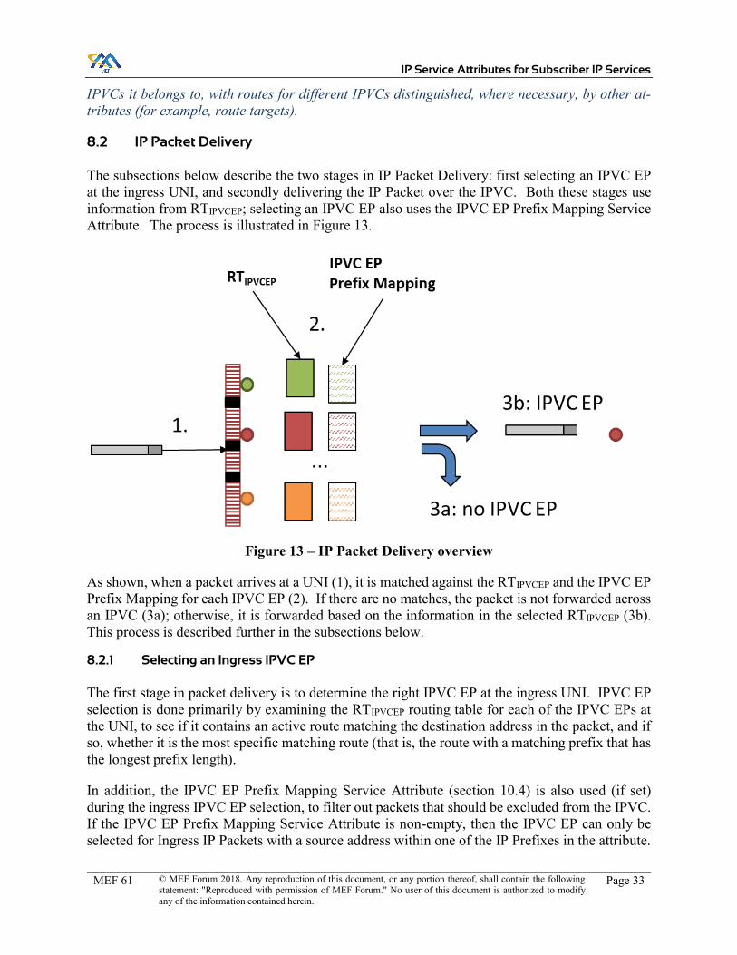
IP Service Attributes for Subscriber IP Services
MEF 61 © MEF Forum 2018. Any reproduction of this document, or any portion thereof, shall contain the following statement: "Reproduced with permission of MEF Forum." No user of this document is authorized to modify any of the information contained herein.
Page 33
IPVCs it belongs to, with routes for different IPVCs distinguished, where necessary, by other at-tributes (for example, route targets).
8.2 IP Packet Delivery
The subsections below describe the two stages in IP Packet Delivery: first selecting an IPVC EP at the ingress UNI, and secondly delivering the IP Packet over the IPVC. Both these stages use information from RTIPVCEP; selecting an IPVC EP also uses the IPVC EP Prefix Mapping Service Attribute. The process is illustrated in Figure 13.
Figure 13 – IP Packet Delivery overview
As shown, when a packet arrives at a UNI (1), it is matched against the RTIPVCEP and the IPVC EP Prefix Mapping for each IPVC EP (2). If there are no matches, the packet is not forwarded across an IPVC (3a); otherwise, it is forwarded based on the information in the selected RTIPVCEP (3b). This process is described further in the subsections below.
8.2.1 Selecting an Ingress IPVC EP
The first stage in packet delivery is to determine the right IPVC EP at the ingress UNI. IPVC EP selection is done primarily by examining the RTIPVCEP routing table for each of the IPVC EPs at the UNI, to see if it contains an active route matching the destination address in the packet, and if so, whether it is the most specific matching route (that is, the route with a matching prefix that has the longest prefix length).
In addition, the IPVC EP Prefix Mapping Service Attribute (section 10.4) is also used (if set) during the ingress IPVC EP selection, to filter out packets that should be excluded from the IPVC. If the IPVC EP Prefix Mapping Service Attribute is non-empty, then the IPVC EP can only be selected for Ingress IP Packets with a source address within one of the IP Prefixes in the attribute.

IP Service Attributes for Subscriber IP Services
MEF 61 © MEF Forum 2018. Any reproduction of this document, or any portion thereof, shall contain the following statement: "Reproduced with permission of MEF Forum." No user of this document is authorized to modify any of the information contained herein.
Page 34
In certain cases, the IPVC EP Prefix Mapping Service Attribute must be properly set to make the IPVC EP selection possible.
Note that the effect of the IPVC EP Prefix Mapping Service Attribute described here is different to the effect it has on routing, as described in section 8.1.2. As described above, one case where this can be useful is in the case of an extranet IPVC, to limit the Ingress IP Packets that can access the IPVC for the extranet to only those originating at hosts that are intended to be exposed to other organizations.
The IPVC EPs present at a given UNI (which are necessarily for different IPVCs) may have the following relationships:
1. The UNI has only a single IPVC EP. 2. Multiple IPVC EPs are sharing the UNI, and routing of the corresponding IPVCs is:
a. Non-overlapping: each IPVC has routes for different IP Prefixes. b. Overlapping: at least some of the same routes/IP Prefixes are used by multiple
IPVCs.
In the first two cases (1 and 2a), a single IPVC EP can be selected based on route lookup(s) in the RTIPVCEP table(s). The role of the IPVC EP Prefix Mapping (if set) is simply to filter out unwanted packets.
However the case of overlapping IPVC EPs (case 2b) is more complex. There are two further sub-cases:
i. The egress UNI to which an ingress IP Packet should be delivered can be determined solely by longest match routing based on the destination address.
ii. The egress UNI to which an ingress IP Packet should be delivered depends on both the routing based on the destination address, and on matching the source address in the packet against the IPVC EP Prefix Mapping Service Attribute for the IPVC EPs.
In both cases (i) and (ii), the IPVC EP Prefix Mapping Service Attribute for each IPVC EP is directly involved in the ingress IPVC EP selection, and therefore the values of the IP Prefix Map-ping Service Attribute must be non-overlapping, such that a single IPVC EP can be deterministi-cally selected. However, in case (i), this does not affect the egress UNI to which the packet is delivered, whereas in case (ii), it may do.
Implementing case (ii) requires more advanced capabilities in the Service Provider (i.e., routing based on more than just the destination address), which might not be supported. If such capabilities are not supported, the requirements in this specification ensure that case (ii) is avoided. This is achieved by mandating, in this case, that the IPVCs agreed between the Subscriber and the SP are such that if two IPVC EPs at a given UNI both have a route to a given IP Prefix, it is a route via the same egress UNI in both IPVCs.
The behavior and requirements if case (ii) is supported by the SP are outside the scope of this document, and may be specified in a future revision.
The overall process (applicable to all the cases above) is illustrated in Figure 14.

IP Service Attributes for Subscriber IP Services
MEF 61 © MEF Forum 2018. Any reproduction of this document, or any portion thereof, shall contain the following statement: "Reproduced with permission of MEF Forum." No user of this document is authorized to modify any of the information contained herein.
Page 35
Figure 14 – Selecting an Ingress IPVC EP
In the case where two or more IPVC EPs both have the most specific matching route to a given destination address, and at least one of these routes is towards a UNI Access Link in a different UNI to the one where the Ingress IP Data Packet has been received, the requirements of this spec-ification mean that the IPVC EPs always have non-empty, non-overlapping values for the IPVC EP Prefix Mapping Service Attribute. This means an IPVC EP can be uniquely chosen using the values of the prefix mapping attribute.
In case (i) described above, the requirements of this specification mean that the routes in the dif-ferent IPVC EPs must all point to the same egress UNI – that is, they must result in traffic for that destination being directed out of a UNI Access Link in the same egress UNI, regardless of which IPVC EP it is mapped to on ingress.
These constraints allow for the following possibilities for a given IP Prefix, at a UNI where all of the attached IPVCs use standard routing, and with reference to the routing tables described above.
x None of the IPVC EPs have a route to the IP Prefix in their RTIPVCEP. x Exactly one of the IPVC EPs has a route to the IP Prefix in its RTIPVCEP x Two or more of the IPVC EPs have a route to the IP Prefix in their RTIPVCEP, and the best
active route in at least one of these points to a UNI Access Link in a remote UNI – that is, it comes from a route in RIDR. In addition, all of the IPVC EPs have the IPVC EP Prefix Mapping attribute set, with disjoint lists of IP Prefixes.

IP Service Attributes for Subscriber IP Services
MEF 61 © MEF Forum 2018. Any reproduction of this document, or any portion thereof, shall contain the following statement: "Reproduced with permission of MEF Forum." No user of this document is authorized to modify any of the information contained herein.
Page 36
x Two or more of the IPVC EPs have a route to the IP Prefix in their RTIPVCEP, and the best active route in all of these points to a UNI Access Link in the UNI where the IPVC EPs are located – that is, it comes from a route in RIDL.
Given this, an ingress IPVC EP can be chosen for Ingress IP Data Packets as follows:
x When a unicast Ingress IP Data Packet is received at a UNI, the destination IP address in the packet is looked up in the RTIPVCEP routing table for each of the IPVC EPs at the UNI, to see if there is a matching route.
x If none of the IPVC EPs at the UNI have a route in their RTIPVCEP matching the destina-tion address in the packet, the packet is not mapped to any IPVC EP.
x Otherwise, the IPVC EPs that have the most specific such route (that is, with the longest prefix length) are considered. Any IPVC EPs that have a route that is less specific than the route in another IPVC EP are not considered further.
x For each of the IPVC EPs, if the IPVC EP Prefix Mapping Service Attribute is not an empty list, and the source address in the packet does not match any of the IP Prefixes listed in the value of the attribute, remove the IPVC EP from consideration.
x If there is exactly one IPVC EP still under consideration, then the packet is mapped to this IPVC EP. This can be the case if:
o Only one IPVC EP had the most specific route (or perhaps any route at all) matching the destination address in the packet, and that IPVC EP had an empty list for the IPVC EP Prefix Mapping Service Attribute.
o Only one IPVC EP had the most specific route (or perhaps any route at all) matching the destination address in the packet, that IPVC EP had a non-empty value for the IPVC EP Prefix Mapping Service Attribute, and the source address in the packet matched one of the IP Prefixes in the attribute value.
o More than one IPVC EP had the most specific route matching the destination ad-dress in the packet, all of them had a non-empty value for the IPVC EP Prefix Mapping Service Attribute, but the source address in the packet matched an IP Prefix in the attribute value for only one of the IPVC EPs.
x If there is more than one IPVC EP still under consideration, then the packet is mapped to any one of them. This can only be the case if more than one IPVC EP had the most spe-cific route matching the destination address in the packet, all those routes pointed to UNI Access Links in the ingress UNI, and for each of the IPVC EPs, either the IPVC EP Pre-fix Mapping Service Attribute was an empty list, or the source address in the packet matched one of the IP Prefixes listed in the attribute.
In the case where multiple IPVC EPs have a route to the destination address, the selection of a particular IPVC EP to which to map an Ingress IP Packet can affect the attributes that apply to it (for example, which Ingress Class of Service Map applies (see section 10.7) and which SLS ob-jectives apply (see section 9.9)). In case (i) described above, it does not affect the egress UNI that the packet will be transmitted over, because the routes in all the possible IPVC EPs are required to be such that the egress UNI is the same (see section 10.4.1). This requirement enables imple-mentations to use a single routing table for all IPVC EPs at the UNI, or to perform routing lookups before determining the IPVC EP. However, this specification does not constrain implementations and any implementation exhibiting the required behavior is acceptable. In particular, routing based

IP Service Attributes for Subscriber IP Services
MEF 61 © MEF Forum 2018. Any reproduction of this document, or any portion thereof, shall contain the following statement: "Reproduced with permission of MEF Forum." No user of this document is authorized to modify any of the information contained herein.
Page 37
on the source IP address or other fields is not precluded, and the routes taken within the SP Net-work by packets for different IPVCs may be different even if the packet are eventually transmitted out of the same egress UNI.
Note that an Ingress IP Data Packet does not have to be discarded if it cannot be mapped to any IPVC EP; it could, for example, be mapped to some other type of service and hence delivered or consumed by some other means.
The above process can only be followed when all of the IPVC EPs at a UNI are for IPVCs that use standard IP routing (that is, have the IPVC Packet Delivery Service Attribute (section 9.4) set to Standard Routing), as otherwise they might not maintain an RTIPVCEP routing table. When this is not the case – that is, when there is an IPVC EP at the UNI for an IPVC that does not use standard routing – mapping of Ingress IP Packets to IPVC EPs is beyond the scope of this document (but could be addressed in a future version).
The mechanism by which IP Packets received from a cloud service are mapped to the correct cloud access IPVC are beyond the scope of this document. However, a similar process to that described above could be used, by considering the RTIPVCEP for the cloud service, across every cloud access IPVC supported by the SP.
It is important to note that the IPVC EP Prefix Mapping Service Attribute (further described in section 10.4) has two separate effects, when non-empty:
x It prevents Ingress IP packets at a given UNI with a source address that is not in one of the listed IP Prefixes being mapped to the IPVC EP. This has two impacts, both affecting the data plane:
o If the source address in an Ingress IP Packet at the UNI is not included in the IPVC EP Prefix Mapping for any of the IPVC EPs through which the packet’s destination is reachable, then the packet is discarded (or more accurately, it is not mapped to any IPVC EP) – in other words, the union of the Prefix Mapping for all of the IPVC EPs at a UNI acts as a source address filter on Ingress IP Packets.
o If the destination address in an Ingress IP Packet is reachable via multiple IPVC EPs at a given UNI, the IPVC EP Prefix Mapping affects which IPVC EP the packet is mapped to.
x It prevents IP Packets that are not destined for an address in one of the listed IP Prefixes being transmitted as Egress IP Packets at this UNI (via the IPVC EP).
o For IPVCs that use standard routing, this is done by limiting which IP Prefixes that are reachable over a given UNI (that is, that are present in RIDUNI) are made available in the IPVC for the IPVC EP. Only IP Prefixes listed in the attribute are exported into the IPVC. This behavior is in the control plane in the SP (i.e., the propagation of routing information); it therefore affects whether IP Packets re-ceived at other UNIs can be mapped to the IPVC at all. There is no need for data plane filtering of the Egress IP Packets (although this is not precluded), as the destination prefixes are not reachable.
o For IPVCs that use policy-based routing, the same can be done, but data plane fil-tering of the Egress IP Packets may also be needed.

IP Service Attributes for Subscriber IP Services
MEF 61 © MEF Forum 2018. Any reproduction of this document, or any portion thereof, shall contain the following statement: "Reproduced with permission of MEF Forum." No user of this document is authorized to modify any of the information contained herein.
Page 38
The control plane aspect of the IPVC EP Prefix Mapping Service Attribute behavior can be imple-mented, for example, by appropriate use of BGP Route Targets, and other than in case (ii) above, the data plane aspect can be implemented, for example, using QoS policies and/or access control lists (ACLs) that match on the source and destination addresses in IP Packets. Other than in case (ii), the constraints in this specification ensure that it is not necessary to consider the source IP address to determine how to route packets. In all cases, the implementation of any aspect of the behavior is not constrained by this implementation and any implementation that exhibits the re-quired behavior is acceptable.
Note that the IPVC EP Prefix Mapping Service Attribute is unrelated to the use of Reverse Path Forwarding (RPF), but can be used in combination with it. The IPVC EP Prefix Mapping Service Attribute is a static list that limits, as a matter of policy, the IP Prefixes that can access a particular IPVC that is attached to the UNI – i.e., it affects a particular IPVC EP. RPF checks (as described in RFC 3704 [29]) use dynamic reachability information to filter out IP Packets that appear to have a spoofed source IP address, and affect the UNI as a whole. RPF checks can be enabled using the UNI Reverse Path Forwarding Service Attribute (section 11.8).
8.2.2 Delivering IP Packets across an IPVC
Once an ingress IPVC EP has been selected, this identifies the IPVC that is used to deliver the IP Packet. Assuming the IPVC uses standard IP routing (that is, it has the IPVC Packet Delivery Service Attribute (section 9.4) set to Standard Routing), this means there is at least one active route in RTIPVCEP at the ingress IPVC EP that matches the destination address in the IP Packet. However, there could be more than one such route:
x There could be multiple IP Prefixes in the routing table that match the destination ad-dress. In this case, the most specific IP Prefix is used (i.e. “longest prefix matching”).
x There could be multiple paths to reach the IP Prefix. In this case, the best path is chosen. How the best path is determined is outside the scope of this document, and typically de-pends on routing protocol metrics and costs.
In the latter case, it is also possible that different paths are selected for different packets that match the same IP Prefix, for example using Equal Cost Multipath (ECMP). In this case, care is needed to ensure that packets within a given flow are not re-ordered as they traverse the IPVC.
Note that the distribution of routing information ensures that the destination can only be reachable via a UNI that has an IPVC EP in the same IPVC as the ingress IPVC EP, and that in the case of a rooted multipoint IPVC (see section 9.2), if the ingress IPVC EP has leaf role, the destination is not reachable via a UNI that has another IPVC EP with leaf role.
When a route is selected from RTIPVCEP at the ingress IPVC EP, the SP is responsible for ulti-mately delivering the IP Packet over a corresponding egress UNI Access Link towards the Sub-scriber, or in a Cloud Access service, delivering the IP Packet to the cloud service. It might be that the route in RTIPVCEP at the ingress IPVC EP includes sufficient information to identify the egress UNI Access Link (along with the appropriate nexthop information in the Subscriber Net-work) or cloud service. Alternatively, it may only identify a point within the SP Network (for example, the egress UNI or a remote PE device), with further routing lookups performed at that point. In this case, the information about the egress UNI Access Link or cloud service does not all

IP Service Attributes for Subscriber IP Services
MEF 61 © MEF Forum 2018. Any reproduction of this document, or any portion thereof, shall contain the following statement: "Reproduced with permission of MEF Forum." No user of this document is authorized to modify any of the information contained herein.
Page 39
need to be known at the ingress UNI. This specification does not constrain the implementation of the service by the SP; any implementation that ensures that packets are delivered using the best route is acceptable.

IP Service Attributes for Subscriber IP Services
MEF 61 © MEF Forum 2018. Any reproduction of this document, or any portion thereof, shall contain the following statement: "Reproduced with permission of MEF Forum." No user of this document is authorized to modify any of the information contained herein.
Page 40
9 Subscriber IPVC Service Attributes
This section specifies Service Attributes for Subscriber IP Services that apply to the Subscriber IPVC as a whole. There is one instance of these attributes for each Subscriber IPVC supported by the SP. The attributes are summarized in the table below and described in more detail in the following subsections.
Attribute Name Summary Description Possible Values IPVC Identifier Unique identifier for the IPVC for man-
agement purposes. Printable string that is unique across the SP’s network.
IPVC Topology An indication of the way that IPVC EPs for the IPVC are connected together
Multipoint, Rooted Multipoint or Cloud Access
IPVC End Point List
List of IPVC EPs for the IPVC List of IPVC EP identifiers
IPVC Packet De-livery
Indicates whether packets are delivered per standard IP routing behavior or by some other means.
Standard Routing or Policy-Based Routing
IPVC Maximum Number of IPv4 Routes
Maximum number of IPv4 routes sup-ported by the service as a whole.
Integer ≥ 0 or Unlimited
IPVC Maximum Number of IPv6 Routes
Maximum number of IPv6 routes sup-ported by the service as a whole.
Integer ≥ 0 or Unlimited
IPVC DSCP Preservation
Indicates whether the SP is allowed to modify the value of the IP DS field in the IP header of the Subscriber’s traffic as it traverses the IPVC.
Enabled or Disabled.
IPVC List of Class of Service Names
List of CoS Names supported by the IPVC
List of string names.
IPVC Service Level Specification
Set of performance objectives for each CoS Name in the IPVC
None, or a set of objectives as described in section 9.9.
IPVC MTU Maximum size (in octets) of an IP Packet that can traverse the IPVC with-out fragmentation.
Integer ≥ 576
IPVC Path MTU Discovery
Indicates whether Path MTU Discovery is supported for the IPVC
Enabled or Disabled
IPVC Fragmenta-tion
Indicates whether IPv4 Packets can be fragmented
Enabled or Disabled
IPVC Cloud For cloud access services, details of the cloud service being accessed
None, or parameters for the cloud service as described in section 9.12.
IPVC Reserved Prefixes
IP Prefixes reserved for use by the SP List of IP Prefixes
Table 3 – Subscriber IPVC Service Attributes

IP Service Attributes for Subscriber IP Services
MEF 61 © MEF Forum 2018. Any reproduction of this document, or any portion thereof, shall contain the following statement: "Reproduced with permission of MEF Forum." No user of this document is authorized to modify any of the information contained herein.
Page 41
9.1 IPVC Identifier Service Attribute
The IPVC Identifier is a unique string identifier for the IPVC, consisting of ASCII characters in the range 32-126 inclusive. It can be used by the Subscriber and the SP to identify the service to each other.
[R1] The value of the IPVC Identifier MUST be unique among all such identifiers for IPVCs supported by the Service Provider.
[R2] The length of the IPVC Identifier MUST be less than or equal to 53 characters.
9.2 IPVC Topology Service Attribute
The IPVC Topology Service Attribute takes one of three possible values: Multipoint, Rooted Mul-tipoint and Cloud Access. A multipoint IPVC allows packets to flow between any of the IPVC EPs for the IPVC – in this case, every IPVC EP has root role. The IPVC EP Role is further described in section 10.3. If a multipoint IPVC has only two IPVC EPs, it can be thought of as a point-to-point service. A rooted multipoint service is used to implement a hub-and-spoke topol-ogy. In a rooted multipoint service, each IPVC EP is assigned either root or leaf role. The rooted multipoint IPVC prevents packets flowing directly between IPVC EPs that have leaf role, but al-lows them to flow between roots and leaves or between roots. A cloud access IPVC allows traffic to flow between one or more IPVC EPs and the public Internet or a private cloud service. Cloud access IPVCs are described further in section 9.12.
An IPVC with the IPVC Topology set to Multipoint is known as a multipoint IPVC.
An IPVC with the IPVC Topology set to Rooted Multipoint is known as a rooted multipoint IPVC.
An IPVC with the IPVC Topology set to Cloud Access is known as a cloud access IPVC.
9.3 IPVC End Point List Service Attribute
The IPVC End Point List Service Attribute is a list of IPVC EP Identifiers (section 10.1) for the IPVC EPs that are connected by the IPVC.
A given IPVC can only have one IPVC EP at a given UNI; however, it is still possible for IP Data Packets received at a given UNI to be transmitted out of the same UNI (see section 9.4).
[R3] An IPVC MUST NOT have more than one IPVC EP at a given UNI.
[R4] An Ingress IP Data Packet that is not mapped to any IPVC EP MUST NOT result in a corresponding Egress IP Data Packet at any EI.
[R5] If an Egress IP Data Packet transmitted at an EI via a given IPVC EP results from an Ingress IP Data Packet received at a different EI (and therefore mapped to a different IPVC EP), the two IPVC EPs MUST be for the same IPVC.

IP Service Attributes for Subscriber IP Services
MEF 61 © MEF Forum 2018. Any reproduction of this document, or any portion thereof, shall contain the following statement: "Reproduced with permission of MEF Forum." No user of this document is authorized to modify any of the information contained herein.
Page 42
[R6] If an Ingress IP Data Packet mapped to an IPVC EP is transmitted as an IP Packet towards a cloud service, there MUST be an IPVC with IPVC Topology set to Cloud Access that connects the IPVC EP to the cloud service.
[R7] If an IP Packet received from a cloud service is transmitted as an Egress IP Data Packet mapped to an IPVC EP, there MUST be an IPVC with IPVC To-pology set to Cloud Access that connects the IPVC EP to the cloud service.
9.4 IPVC Packet Delivery Service Attribute
The primary purpose of an IPVC is to deliver IP Data Packets from an ingress UNI to an egress UNI, or between a UNI and a cloud service. The IPVC Packet Delivery Service Attribute specifies how the SP determines the egress UNI (and UNI Access Link) for each Ingress IP Data Packet that is mapped to one of the IPVC EPs for the IPVC. It takes one of the two values Standard Routing, or Policy-Based Routing. In the case of Policy-Based Routing some additional details of the policy are also specified.
Note: the behavior and requirements when the IPVC Packet Delivery Service Attribute is set to Policy-Based Routing are deferred to a future revision of this specification. Similarly, the behavior and requirements for delivering multicast IP Data Packets are deferred to a future revision of this specification.
If the IPVC Packet Delivery is Standard Routing, the egress UNI and UNI Access Link are gen-erally selected by examining the destination IP address in the packet and matching it to an IP Prefix reachable via the IPVC EP at the egress UNI – in other words, by normal IP routing. In some cases, other fields in the IP Packet can also be used, for example for ECMP. This is described in section 8.
[R8] When the IPVC Packet Delivery Service Attribute is set to Standard Routing, if a unicast Ingress IP Data Packet is mapped to an IPVC EP for the IPVC, the SP MUST select, for delivery of the packet, either an egress UNI Access Link or, in a cloud access IPVC, the cloud service, as described in section 8.
The requirement above applies when a unicast Ingress IP Data Packet is mapped to an IPVC. The mechanism by which this is done is described in section 10.4.1.
[R9] When the IPVC Packet Delivery Service Attribute is set to Standard Routing, if a unicast IP Data Packet is received from a cloud service and is mapped to the IPVC, the SP MUST select, for delivery of the packet, an egress UNI Ac-cess Link as described in section 8.
How an IP Packet received from a cloud service is mapped to the correct cloud access IPVC is outside the scope of this document.
Note that, as described in section 8, if there is more than one possible egress UNI Access Link for an IP Packet, the SP chooses the best one to use. Typically, this is done based on routing protocol cost/metric data, including that received from the Subscriber if a dynamic routing protocol is in use at the UNIs (see section 11.7). The SP might also choose to use Equal Cost Multipath or

IP Service Attributes for Subscriber IP Services
MEF 61 © MEF Forum 2018. Any reproduction of this document, or any portion thereof, shall contain the following statement: "Reproduced with permission of MEF Forum." No user of this document is authorized to modify any of the information contained herein.
Page 43
Unequal Cost Multipath to select an egress UNI Access Link, although in this case care is needed to ensure no issues arise due to the potential for re-ordering of packets within a flow.
[D1] IP Packets mapped to an IPVC EP and belonging to the same packet flow SHOULD be delivered in the same order that they were received.
A packet flow in this context is identified by fields in the IP Packet header, including the Source Address, Destination Address, Protocol, and any applicable fields in the L4 header; for example, for IP Packets carrying TCP or UDP datagrams, this includes the source port number and destina-tion port number.
The description in section 8 means that if standard routing is used in the IPVC, adhering to [R8] and [R9] automatically ensures compliance with [R5], [R6] and [R7] – that is, the packet is either delivered to an egress UNI Access Link in a UNI that is attached to the IPVC, or to a cloud service for the IPVC if it is a cloud access IPVC. Note that this does not preclude a UNI Access Link in the ingress UNI from being selected as the egress UNI Access Link.
9.4.1 IP Data Packet Transparency
In general, an IPVC conveys IP Packets without modifying the contents; however, there are some exceptions:
x The TTL/Hop Limit field is decremented by at least 1 x The DS (RFC 3260 [24]) and ECN (RFC 3168 [23]) fields can be modified x IPv4 packets can be fragmented x The value of IPv6 Hop-by-Hop options with an option type that has the third high-order
bit set can be modified x The Loose Source and Record Route, the Strict Source and Record Route, and the Record
Route options in an IPv4 packet can be modified, and if either of the first two are present, the destination address can also be modified. (RFC 791 [1])
x The IPv4 header checksum can be updated to reflect changes in other IPv4 header fields
An IP Service is generally concerned only with the transport of IP Packets across the IPVC; how-ever, the SP and the Subscriber might also agree to other “value-add” services on top of an IP Service (for instance, Security as a Service (SECaaS)), which could modify the contents of an IP Packet. The details of such services are outside the scope of this document.
These exceptions are captured in the following requirements:
[R10] If an Ingress IPv4 Data Packet is mapped to an IPVC and delivered as a Egress IPv4 Data Packet, and the packet has not been fragmented as described in RFC 791 [1], the Egress IPv4 Data Packet MUST be identical to the Ingress IPv4 Data Packet except that the following fields in the IPv4 header can be changed, and other changes can be made as described in [O1]:
x The TTL field (RFC 791 [1]). x The DS (RFC 3260 [24]) and ECN (RFC 3168 [23]) fields.
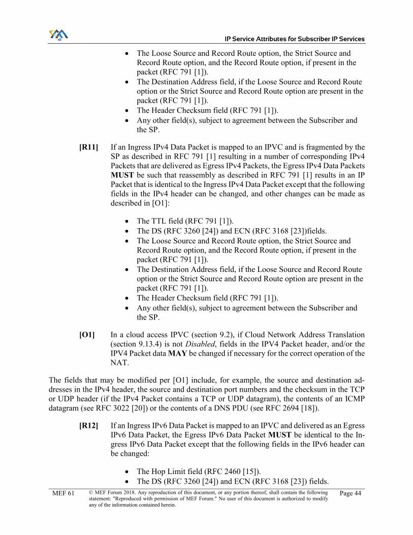
IP Service Attributes for Subscriber IP Services
MEF 61 © MEF Forum 2018. Any reproduction of this document, or any portion thereof, shall contain the following statement: "Reproduced with permission of MEF Forum." No user of this document is authorized to modify any of the information contained herein.
Page 44
x The Loose Source and Record Route option, the Strict Source and Record Route option, and the Record Route option, if present in the packet (RFC 791 [1]).
x The Destination Address field, if the Loose Source and Record Route option or the Strict Source and Record Route option are present in the packet (RFC 791 [1]).
x The Header Checksum field (RFC 791 [1]). x Any other field(s), subject to agreement between the Subscriber and
the SP.
[R11] If an Ingress IPv4 Data Packet is mapped to an IPVC and is fragmented by the SP as described in RFC 791 [1] resulting in a number of corresponding IPv4 Packets that are delivered as Egress IPv4 Packets, the Egress IPv4 Data Packets MUST be such that reassembly as described in RFC 791 [1] results in an IP Packet that is identical to the Ingress IPv4 Data Packet except that the following fields in the IPv4 header can be changed, and other changes can be made as described in [O1]:
x The TTL field (RFC 791 [1]). x The DS (RFC 3260 [24]) and ECN (RFC 3168 [23])fields. x The Loose Source and Record Route option, the Strict Source and
Record Route option, and the Record Route option, if present in the packet (RFC 791 [1]).
x The Destination Address field, if the Loose Source and Record Route option or the Strict Source and Record Route option are present in the packet (RFC 791 [1]).
x The Header Checksum field (RFC 791 [1]). x Any other field(s), subject to agreement between the Subscriber and
the SP.
[O1] In a cloud access IPVC (section 9.2), if Cloud Network Address Translation (section 9.13.4) is not Disabled, fields in the IPV4 Packet header, and/or the IPV4 Packet data MAY be changed if necessary for the correct operation of the NAT.
The fields that may be modified per [O1] include, for example, the source and destination ad-dresses in the IPv4 header, the source and destination port numbers and the checksum in the TCP or UDP header (if the IPv4 Packet contains a TCP or UDP datagram), the contents of an ICMP datagram (see RFC 3022 [20]) or the contents of a DNS PDU (see RFC 2694 [18]).
[R12] If an Ingress IPv6 Data Packet is mapped to an IPVC and delivered as an Egress IPv6 Data Packet, the Egress IPv6 Data Packet MUST be identical to the In-gress IPv6 Data Packet except that the following fields in the IPv6 header can be changed:
x The Hop Limit field (RFC 2460 [15]). x The DS (RFC 3260 [24]) and ECN (RFC 3168 [23]) fields.

IP Service Attributes for Subscriber IP Services
MEF 61 © MEF Forum 2018. Any reproduction of this document, or any portion thereof, shall contain the following statement: "Reproduced with permission of MEF Forum." No user of this document is authorized to modify any of the information contained herein.
Page 45
x The value of any options within a Hop-by-Hop Options header (if present) that have the third high-order bit in the option type field set (RFC 2460 [15]).
x Any other field(s), subject to agreement between the Subscriber and the SP.
Note that modifications to the DS field can be further restricted according to the IPVC DSCP Preservation Service Attribute (see section 9.7).
The use of the Loose Source and Record Route option, the Strict Source and Record Route option, and the Record Route option in IPv4 packets can cause problems due to the additional processing needed at each hop along the path. In addition, the Loose Source and Record Route option and the Strict Source and Record Route option open up a number of potential security risks, as docu-mented in RFC 6274 [57], which outweigh any legitimate use.
[O2] The Service Provider MAY discard Ingress IPv4 Packets that contain the Loose Source and Record Route option, the Strict Source and Record Route option, or the Record Route option.
The requirements above allow any field to be changed subject to agreement between the SP and the Subscriber. This is intended to allow for “bump-in-the-wire” services (for example an appli-cation-level gateway or proxy service), which could modify certain packets, as shown in Figure 15. Note that such application-layer services are separate to the connectivity provided by the IP Service, but could be offered as a bundle by the SP.

IP Service Attributes for Subscriber IP Services
MEF 61 © MEF Forum 2018. Any reproduction of this document, or any portion thereof, shall contain the following statement: "Reproduced with permission of MEF Forum." No user of this document is authorized to modify any of the information contained herein.
Page 46
Figure 15 – Example of a Bump-in-the-Wire Service
9.5 IPVC Maximum Number of IPv4 Routes Service Attribute
The IPVC Maximum Number of IPv4 Routes Service Attribute limits the total number of IPv4 Prefixes that can be associated with IPVC EPs for the IPVC. It is an integer ≥0 or the special value Unlimited. With reference to the description in section 8, it is a limit on the number of unique IPv4 Prefixes contained in RIDL across all the IPVC EPs in the IPVC.
[D2] If the IPVC Maximum Number of IPv4 Routes Service Attribute is not Unlim-ited, the SP SHOULD disregard any IPv4 Prefixes associated with IPVC EPs for the IPVC above the limit specified by the IPVC Maximum Number of IPv4 Routes Service Attribute.
[D3] When the limit specified by the IPVC Maximum Number of IPv4 Routes Ser-vice Attribute is reached or exceeded, the SP SHOULD select IPv4 Prefixes to disregard so as to minimize disruption to the service.
[D2] means that if the Subscriber advertises too many routes to the SP, the SP can disregard some of them. This can lead to blackholing of some of the Subscriber’s traffic, or other undesirable

IP Service Attributes for Subscriber IP Services
MEF 61 © MEF Forum 2018. Any reproduction of this document, or any portion thereof, shall contain the following statement: "Reproduced with permission of MEF Forum." No user of this document is authorized to modify any of the information contained herein.
Page 47
behavior. The SP can minimize disruption by disregarding the most recently received IPv4 Pre-fixes so as to maintain the paths that were previously working.
If the IPVC Maximum Number of IPv4 Routes Service Attribute is set to 0, the effect is to disable IPv4 routing for the service, i.e. to create a service that is IPv6-only, or that uses policy-based routing (PBR, see section 9.4) to direct traffic between IPVC EPs. Note that PBR is not precluded when the value is greater than 0.
Note that the IPVC Maximum Number of IPv4 Routes Service Attribute limits the total number of IPv4 routes in the IPVC. This document also specifies a limit per IPVC EP – see section 10.5.
It can be useful for the SP to notify the Subscriber when the total number of IPv4 Prefixes that are associated with IPVC EPs for the IPVC is approaching the limit specified by the IPVC Maximum Number of IPv4 Routes Service Attribute, or has crossed it. The details of how this is done are outside the scope of this document.
[D4] The SP SHOULD notify the Subscriber when the total number of IPv4 Prefixes that are associated with IPVC EPs for the IPVC reaches the value of the IPVC Maximum Number of IPv4 Routes Service Attribute.
[O3] The SP MAY notify the Subscriber when the total number of IPv4 Prefixes that are associated with IPVC EPs for the IPVC is approaching the value of the IPVC Maximum Number of IPv4 Routes Service Attribute.
9.6 IPVC Maximum Number of IPv6 Routes Service Attribute
The IPVC Maximum Number of IPv6 Routes Service Attribute limits the total number of IPv6 Prefixes that can be associated with IPVC EPs for the IPVC. It is an integer ≥0 or the special value Unlimited. With reference to the description in section 8, it is a limit on the number of unique IPv6 Prefixes contained in RIDL across all the IPVC EPs in the IPVC.
[D5] If the IPVC Maximum Number of IPv6 Routes Service Attribute is not Unlim-ited, the SP SHOULD disregard any IPv6 Prefixes associated with IPVC EPs for the IPVC above the limit specified by the IPVC Maximum Number of IPv6 Routes Service Attribute.
[D6] When the limit specified by the IPVC Maximum Number of IPv6 Routes Ser-vice Attribute is reached or exceeded, the SP SHOULD select IPv6 Prefixes to disregard so as to minimize disruption to the service.
[D5] means that if the Subscriber advertises too many routes to the SP, the SP can disregard some of them. This can lead to blackholing of some of the Subscriber’s traffic, or other undesirable behavior. The SP can minimize disruption by disregarding the most recently received IPv6 Pre-fixes so as to maintain the paths that were previously working.
If the IPVC Maximum Number of IPv6 Routes Service Attribute is set to 0, the effect is to disable IPv6 routing for the service, i.e. to create a service that is IPv4-only, or that uses policy-based

IP Service Attributes for Subscriber IP Services
MEF 61 © MEF Forum 2018. Any reproduction of this document, or any portion thereof, shall contain the following statement: "Reproduced with permission of MEF Forum." No user of this document is authorized to modify any of the information contained herein.
Page 48
routing (PBR, see section 9.4) to direct traffic between IPVC EPs. Note that PBR is not precluded when the value is greater than 0.
Note that the IPVC Maximum Number of IPv6 Routes Service Attribute limits the total number of IPv6 routes in the IPVC. This document also specifies a limit per IPVC EP – see section 10.6.
It can be useful for the SP to notify the Subscriber when the total number of IPv6 Prefixes that are associated with IPVC EPs for the IPVC is approaching the limit specified by the IPVC Maximum Number of IPv6 Routes Service Attribute, or has crossed it. The details of how this is done are outside the scope of this document.
[D7] The SP SHOULD notify the Subscriber when the total number of IPv6 Prefixes that are associated with IPVC EPs for the IPVC reaches the value of the IPVC Maximum Number of IPv6 Routes Service Attribute.
[O4] The SP MAY notify the Subscriber when the total number of IPv6 Prefixes that are associated with IPVC EPs for the IPVC is approaching the value of the IPVC Maximum Number of IPv6 Routes Service Attribute.
9.7 IPVC DSCP Preservation Service Attribute
The IPVC DSCP Preservation Service Attribute specifies whether the SP is allowed to modify the value of the DS field (see RFC 3260 [24]) in Ingress IP Data Packets. It takes one of two values: Enabled or Disabled. Preserving the value of the DSCP field can be useful if the Subscriber uses the DS field for their own purposes and does not want the SP to modify it. This does not prevent the SP from mapping ingress IP Data Packets to different Classes of Service, and/or marking the packets in some other way as they traverse the SP Network (for example, using the MPLS TC bits, if the SP implements the IPVC using MPLS).
[R13] If the value of the IPVC DSCP Preservation Service Attribute is Enabled, the value of the DS Field in an Egress IP Data Packet MUST be identical to the value of the DS Field in the corresponding Ingress IP Data Packet.
Note that the 3 most significant bits of the DS Field correspond to the (historic) IP Precedence field.
If the value of the IPVC DSCP Preservation Service Attribute is Disabled, the SP is not required to preserve the value of the DS Field received in an Ingress IP Packets when transmitting the corresponding Egress IP Packet.
9.8 IPVC List of Class of Service Names Service Attribute
The IPVC List of Class of Service Names Service Attribute is a list of CoS Names (also known as “Traffic Classes”) used in the IPVC. A CoS Name is an arbitrary string, and represents the end-to-end behavior across the IPVC for traffic mapped to the CoS Name (see section 10.7), as speci-fied through the use of per-CoS Name Bandwidth Profile Flows (see section 13.2) and per-CoS Name SLS Performance Objectives (see section 9.9).

IP Service Attributes for Subscriber IP Services
MEF 61 © MEF Forum 2018. Any reproduction of this document, or any portion thereof, shall contain the following statement: "Reproduced with permission of MEF Forum." No user of this document is authorized to modify any of the information contained herein.
Page 49
Note that there are a set of standard DSCP names registered with IANA [78], which can (but do not have to be) used as CoS Names for an IPVC: CS0, CS1, CS2, CS3, CS4, CS5, CS6, CS7, AF11, AF12, AF13, AF21, AF22, AF23, AF31, AF32, AF33, AF41, AF42, AF43, EF, VOICE-ADMIT. These standard names above can refer to two different concepts:
x The name for a particular Differentiated Services Code Point, i.e. a particular value of the DS Field in IP Packets.
x The name for a particular “per-hop behavior” (PHB). As described in RFC 2474 [16] and RFC 2475 [17], DSCP values are mapped to a PHB at each node that forwards the packet, and it is recommended that each DSCP value is mapped to the corresponding PHB. PHBs are composed as the packet is forwarded over the network so as to give the desired end-to-end behavior.
An exception to the above is that the set of “class selector” names (CS0 to CS7) cannot refer to a PHB – there are no specific PHBs defined with these names, although RFC 2474 [16] places some requirements on the PHBs that the corresponding DSCP values map to.
Since CoS Names are arbitrary, the standard DSCP names can also be used as CoS Names (for example, a CoS Name ‘EF’ could be defined). However, this does not imply that any particular DSCP values are used (either at the UNI or within the SP Network), or that any particular PHB is applied within the SP Network. To avoid confusion, Subscribers and SPs may wish to avoid using the standard DSCP names as CoS Names.
[R14] In the context of Differentiated Services, the end-to-end behavior across an IPVC MUST be the same as if a Differentiated Services Domain as specified in RFC 2474 [16] corresponds to the IPVC.
Note that, as described in RFC 2475 [17], traffic is mapped to a CoS Name on ingress to the DS Domain; that is, at the ingress UNI. This mapping is specified in the IPVC EP Ingress Class of Service Map Service Attribute (section 10.7). The RFCs recommend that within the DS Domain, such traffic is marked with the corresponding DSCP value as specified by IANA [78]; however, other than as required by the IPVC DSCP Preservation Service Attribute (section 9.7), the use of specific DSCP values within the SP Network is outside the scope of this document.
9.9 IPVC Service Level Specification Service Attribute
The IPVC Service Level Specification (SLS) is either None, or a four-tuple of the form (s, T, E, L) where s is the start time, T is a period of time, E is a set of SLS entries, and L is a set of locations as described in section 9.9.1. Each SLS entry in E contains the Performance Metric, the CoS Name, and number of other parameters specific to the Performance Metric, as described in the subsections below.
The IPVC SLS describes the performance objectives for the performance of conformant IP Data Packets that flow over the IPVC – in other words, of IP Data Packets that are Qualified Packets (see 9.9.2). For example, objectives might be specified for packet loss or packet delay (latency). The performance objectives specified in the SLS often form part of a Service Level Agreement (SLA), which can also specify penalties for the SP if the objectives are not met, along with other

IP Service Attributes for Subscriber IP Services
MEF 61 © MEF Forum 2018. Any reproduction of this document, or any portion thereof, shall contain the following statement: "Reproduced with permission of MEF Forum." No user of this document is authorized to modify any of the information contained herein.
Page 50
details such as the service bringup time or the time to respond to customer queries. Such details are beyond the scope of this document.
Some examples showing the structure and value of the IPVC Service Level Specification Service Attribute can be found in Appendix B.6.
The IPVC SLS allows objectives to be specified for a number of Performance Metrics. These Performance Metrics describe the performance experienced by the Subscriber. The methods used (by the SP or the Subscriber) to measure the IPVC performance are beyond the scope of this doc-ument (some examples can be found in Appendix D).
Each performance objective is specific to a given CoS Name. Multiple objectives can be specified for the same Performance Metric, e.g. for different CoS Names or between different sets of IPVC EPs. Note that this is only useful if at least one of the parameters is different.
[R15] Each SLS Entry MUST be for one of the following Performance Metrics:
x One-way Packet Delay Percentile (section 9.9.4) x One-way Mean Packet Delay (section 9.9.5) x One-way Inter-Packet Delay Variation (section 9.9.6) x One-way Packet Delay Range (section 9.9.7) x One-way Packet Loss Ratio (section 9.9.8) x Service Uptime (section 9.9.9)
The SLS performance objectives are evaluated over a series of consecutive time periods. These time periods are specified by the parameters s and T in the value of the IPVC SLS Service Attrib-ute. One time period, denoted T0, starts at time s and has duration T. Each subsequent time period, denoted Tk, starts at time s + kT where k is an integer, and has duration T; in other words, each new time period starts as soon as the previous one ends. Each Performance Metric is evaluated for each time period Tk, so one can say that for a given Tk, the performance objective is either met or not met.
Note that T can be specified using any time units; in particular, calendar months are allowable. In this case, if s is specified as, for example, midnight on the 5th of January and T is 1 calendar month, then each subsequent Tk will start at midnight on the 5th of the month.
The third parameter of the IPVC SLS Service Attribute is a set, E, of SLS entries. Each entry consists of the Performance Metric, the CoS Name, and number of other parameters specific to the Performance Metric, as described in the subsections below.
[R16] The CoS Name specified in an SLS Entry MUST be one of the CoS Names specified in the IPVC List of Class of Service Names (section 9.8).
Performance objectives can be specified between a number of different network locations, as de-scribed in section 9.9.1 below. Most performance objectives apply to Qualified Packets, as de-scribed in section 9.9.2 below.
IP Service Attributes for Subscriber IP Services
MEF 61 © MEF Forum 2018. Any reproduction of this document, or any portion thereof, shall contain the following statement: "Reproduced with permission of MEF Forum." No user of this document is authorized to modify any of the information contained herein.
Page 51
Note: ITU-T Recommendation Y.1540 [88] defines parameters that can be used in specifying and assessing the performance of speed, accuracy, dependability and availability of IP Packet transfer of Internet Protocol (IP) data communication services. The defined parameters apply to an end-to-end, point-to-point IP Service. These are similar in intent to the Performance Metrics defined in this specification. In addition ITU-T Recommendation Y.1541 [89] specifies network (UNI to UNI) IP performance objectives for each of the performance parameters defined in ITU-T Y.1540 [88]. The specific performance objectives vary, depending on the network QoS class. The net-work QoS classes defined are intended to be the basis of agreements between end-users and net-work Service Providers, and between Service Providers. Definition of specific values for perfor-mance objectives is outside the scope of this document.
9.9.1 SLS Reference Points
In a multipoint or rooted multipoint IPVC, performance objectives are ideally specified as applying between pairs of IPVC EPs – in other words, they apply to the performance that IP Data Packets experience as they flow from one EI to another. However, in many cases there are practical diffi-culties in measuring performance between EIs – and in particular between UNIs – so as to deter-mine whether the objective has been met, for example due to limitations in the equipment used or because of the number of UNIs to which an IPVC is attached. It might also be difficult to deter-mine exactly where the EI is located, for example in the case where a UNI Access Link is an IPSec tunnel over the public Internet.
In a cloud access IPVC, as well as specifying performance objectives between UNIs, it can be desirable to specify performance objectives for traffic flowing to or from the cloud service.
In all these cases, the performance objectives can be specified as applying between pairs of loca-tions rather than pairs of IPVC EPs, where each location is associated with one or more IPVC EPs or with a cloud service. A location can refer to a specific address (such as the SP’s premises where the PE is located), a city, a region, or even a country.
For ease of description, many of the Performance Metrics described in the sections below are de-fined between pairs of SLS Reference Points (SLS-RPs). An SLS-RP is defined to be one of:
x An IPVC EP for the IPVC. x A location that is associated with one or more of the IPVC EPs for the IPVC. x For a cloud access IPVC, a location that is associated with the corresponding cloud ser-
vice.
If the SLS includes any entries where one or both of the SLS-RPs is a location, then the IPVC SLS Service Attribute includes a set L with one entry for each location, containing:
x Location Name. x Description of the Location. x List of IPVC EP Identifiers (see section 10.1) of IPVC EPs for the IPVC, that are associ-
ated with this location. x For a cloud access IPVC, an indication of whether the corresponding cloud service (see
section 9.13) is associated with this location.

IP Service Attributes for Subscriber IP Services
MEF 61 © MEF Forum 2018. Any reproduction of this document, or any portion thereof, shall contain the following statement: "Reproduced with permission of MEF Forum." No user of this document is authorized to modify any of the information contained herein.
Page 52
[R17] A given entry in L MUST either have a non-empty list of IPVC EP Identifiers, or for a cloud access service, indicate that the cloud service is associated with this location.
[R18] A given IPVC EP MUST appear in at most one entry in set L.
If all of the SLS-RPs used in the SLS entries are IPVC EPs, then the set L can be empty.
An SLS performance objective that is specified between locations applies to the performance be-tween reference points chosen by the SP in those locations; it gives no guarantees about the loss or delay experienced between the EI and the associated location reference point. This is illustrated in Figure 16.
Figure 16 – Example of SLS specified using locations

IP Service Attributes for Subscriber IP Services
MEF 61 © MEF Forum 2018. Any reproduction of this document, or any portion thereof, shall contain the following statement: "Reproduced with permission of MEF Forum." No user of this document is authorized to modify any of the information contained herein.
Page 53
When agreeing to an SLS using locations, the Subscriber and the SP need to consider the nature of the network between the EI for the IPVC EPs, and the reference point in the corresponding location, as illustrated in Figure 17. If the EI is “close” to the reference point – for example, in the case of a Subscriber-Managed CE where the UNI consists of a short dedicated fiber connection between the CE and the PE, and the PE is the reference point in the location – the difference between the EI to EI performance and the location to location performance might be negligible. Conversely, if the EI is “far away” from the reference point – for example in the case of a Provider-Managed CE where the UNI is on the Subscriber side of the CE, and the CE is connected to the reference point across an intervening Carrier Ethernet access network, which could span across an entire continent – the difference might be highly significant. Note that the EI might not be “con-nected” to the reference point in its location at all, for instance if the reference point is a different PE to the one the UNI is connected to, but in the same city.
Figure 17 – Impact of SLS reference locations
There are two factors that can mitigate the difference between the EI to EI performance and the location to location performance:
IP Service Attributes for Subscriber IP Services
MEF 61 © MEF Forum 2018. Any reproduction of this document, or any portion thereof, shall contain the following statement: "Reproduced with permission of MEF Forum." No user of this document is authorized to modify any of the information contained herein.
Page 54
x If SP and the Subscriber agree to associate each EI with a location that is physically close to it (for instance, in the same city as the EI), and each cloud service with locations that are physically close to where the SP is connected to the cloud service, then the location to location performance will more closely match the EI to EI performance.
x Further performance objectives can be defined that apply between an IPVC EP at an EI and its associated location. By combining these objectives with the location to location objectives, the overall EI to EI performance can be approximated.
Many of the Performance Metrics described in the sections below are based on a set S of ordered pairs of SLS-RPs. In such cases, the following requirement applies:
[R19] If an ordered pair of SLS-RPs is specified as part of a set S, they MUST NOT both be IPVC EPs with the IPVC EP Role (section 10.3) equal to Leaf.
[R19] prevents a case where both of the SLS-RPs in a pair are leaves – this is not useful since no traffic can flow between leaves. All other cases are allowed, i.e. where one of the SLS-RPs is a leaf IPVC EP and the other is a root IPVC EP or a location, or where both SLS-RPs in a pair are root IPVC EPs or locations. In particular, [R19] does not preclude a case where both SLS-RPs in a pair are locations that only have leaf IPVC EPs associated with them, although this case is also not useful.
IP Services are generally bidirectional, and so it is recommended that both orders of a given pair of SLS-RPs are included in set S.
[D8] If an ordered pair of SLS-RPs <i, j> is specified as part of a set S, an ordered pair containing the same SLS-RPs in the opposite order, i.e. <j, i>, SHOULD also be included in set S.
Note that in a cloud access IPVC, the cloud service might be associated with multiple locations. This means that even if there is only one IPVC EP at a UNI in the service, there could be more than two possible ordered pairs of SLS-RPs.
Some examples showing the structure and value of the IPVC Service Level Specification Service Attribute, including locations, can be found in Appendix B.6.
9.9.2 Qualified Packets
Many of the Performance Metrics specified in the sections below apply to Qualified Packets. A Qualified Packet is any unicast IP Data Packet that satisfies the following criteria for a given period Tk, a given CoS Name C, and a given pair of SLS-RPs <i, j> contained in S:
x The IP Data Packet ingresses at a UNI associated with SLS-RP i. That is: o If i is an IPVC EP, then the IP Data Packet ingress at the UNI where the IPVC EP
is located. o If i is a location, then the IP Data Packet ingresses at a UNI that has an IPVC EP
that is associated with that location as specified in set L, or is received from a cloud service associated with that location as specified in set L.

IP Service Attributes for Subscriber IP Services
MEF 61 © MEF Forum 2018. Any reproduction of this document, or any portion thereof, shall contain the following statement: "Reproduced with permission of MEF Forum." No user of this document is authorized to modify any of the information contained herein.
Page 55
x The IP Data Packet is mapped to this IPVC as described in section 10.4.1, and to CoS Name C as described in section 10.7 or 9.13.2.
x The IP Data Packet should be delivered to the UNI associated with SLS-RP j, per the packet delivery requirements of section 9.4. That is:
o If j is an IPVC EP, then the IP Data Packet should be delivered to the UNI where the IPVC EP is located.
o If j is a location, then the IP Data Packet should be delivered to a UNI that has an IPVC EP that is associated with that location as specified in set L, or to a cloud service associated with that location as specified in set L.
x The IP Data Packet is not discarded per requirements [O2], [O5], [R38], [R42], [O6], [O7], [O8], [O9], [R59], [R61], [R67], [R94] or [R158], or to comply with the require-ments of RFC 791 [1] or RFC 2460 [15].
x The IP Data Packet is not discarded as a result of another agreement between the SP and the Subscriber, for example as part of a value-added over the top service offering.
x The length of the IP Data Packet is less than or equal to the value of the IPVC MTU Ser-vice Attribute (section 9.10).
x The first bit of the Ingress IP Data Packet arrives at the UNI associated with SLS-RP i, or was received from the cloud service associated with SLS-RP i, within time interval Tk.
The definition above ensures that IP Packets that are discarded for any of the following reasons are not Qualified Packets; hence, they do not contribute to the Packet Loss Ratio (section 9.9.8) or other performance objectives specified in the SLS:
x IPv4 Packets with the Source Route or Record Route options. x IP Packets larger than the IPVC MTU (section 9.10). x IP Packets flowing between Leaf IPVC EPs, in a rooted multipoint IPVC or a cloud ac-
cess IPVC. x IP Packets mapped to CoS Name Discard. x IP Packets discarded due to an ingress or egress Bandwidth Profile (section 13.4). x IP Packets in excess of the Cloud Data Limit in a cloud access IPVC (section 9.13.3).
9.9.3 One-way Packet Delay
The one-way packet delay for an IP Data Packet that flows between SLS-RP i and SLS-RP j is defined as the time elapsed from the reception of the first bit of the packet at SLS-RP i until the transmission of the last bit of the first corresponding egress packet at SLS-RP j. If the packet is erroneously duplicated as it traverses the network, the delay is based on the first copy that is de-livered.
Note: If the SLS-RPs are locations, they should be chosen such that sufficient data packets traverse them that a representative view of the performance of the service can be gained.
If the IP Data Packet incurs additional delay as a result of another agreement between the SP and the Subscriber, this additional delay is not included in the one-way packet delay for the IP Service. Such additional delay might result, for example, from the application of a value-added service to the IP Data Packet.

IP Service Attributes for Subscriber IP Services
MEF 61 © MEF Forum 2018. Any reproduction of this document, or any portion thereof, shall contain the following statement: "Reproduced with permission of MEF Forum." No user of this document is authorized to modify any of the information contained herein.
Page 56
Note that this definition of One-way Packet Delay for a packet includes the delays encountered as a result of transmission across the ingress and egress SLS-RPs as well as that introduced by the network that connects them.
One-way packet delay is used in the definition of several Performance Metrics as defined below.
9.9.4 One-way Packet Delay Percentile Performance Metric
The One-way Packet Delay Percentile Performance Metric is the maximum, over all the ordered pairs of SLS-RPs in a given set S, of the pth percentile of one-way packet delay for Qualified Packets for a given ordered pair of SLS-RPs, a given CoS Name, and a given time period Tk.
Table 4 lists the contents of an SLS entry for the One-way Packet Delay Percentile Performance Metric.
Item Description Values Performance Metric Name of the Performance
Metric One-way Packet Delay Percentile
C CoS Name One of the values in the IPVC List of Class of Service Names Service Attrib-ute (section 9.8)
S Set of ordered SLS-RP pairs A set of ordered SLS-RP pairs as de-fined in section 9.9.1.
p Packet Delay Percentile A real number between 0 and 100 𝑑 Packet Delay Objective A real number >0 in time units
Table 4 – Parameters for One-way Packet Delay Percentile
[R20] If the SLS contains an entry for the One-way Packet Delay Percentile Perfor-mance Metric, it MUST be defined as follows, for a given set of parameters as defined in Table 4 and a given time period Tk:
x Let δ(Tk, C, <i, j>, p) represent the pth percentile of one-way packet delay for all Qualified Packets for time period Tk, CoS Name C and ordered pair of SLS-RPs <i, j> in S that are delivered to SLS-RP j. If there are no such packets, let δ(Tk, C, <i, j>, p) equal 0.
x Then the One-way Packet Delay Percentile Performance Metric d(Tk, C, S, p) is the maximum of the values δ(Tk, C, <i, j>, p) for all <i, j> in S.
[R21] If the SLS contains an entry for the One-way Packet Delay Percentile Perfor-mance Metric, it MUST define the objective as being met over time period Tk for an SLS entry of the form specified in Table 4 if and only if d(Tk, C, S, p) ≤ 𝑑.

IP Service Attributes for Subscriber IP Services
MEF 61 © MEF Forum 2018. Any reproduction of this document, or any portion thereof, shall contain the following statement: "Reproduced with permission of MEF Forum." No user of this document is authorized to modify any of the information contained herein.
Page 57
9.9.5 One-way Mean Packet Delay Performance Metric
The One-way Mean Packet Delay Performance Metric is the maximum, over all the ordered pairs of SLS-RPs in a given set S, of the arithmetic mean of one-way packet delay for Qualified Packets for a given ordered pair of SLS-RPs, a given CoS Name, and a given time period Tk.
Table 5 lists the contents of an SLS entry for the One-way Mean Packet Delay Performance Metric.
Item Description Values Performance Metric Name of the Performance
Metric One-way Mean Packet Delay
C CoS Name One of the values in the IPVC List of Class of Service Names Service Attrib-ute (section 9.8)
S Set of ordered SLS-RP pairs A set of ordered SLS-RP pairs as de-fined in section 9.9.1.
𝑢 Mean Packet Delay Objec-tive
A real number >0 in time units
Table 5 – Parameters for One-way Mean Packet Delay
[R22] If the SLS contains an entry for the One-way Mean Packet Delay Performance Metric, it MUST be defined as follows, for a given set of parameters as defined in Table 5 and a given time period Tk:
x Let µ(Tk, C, <i, j>) represent the arithmetic mean of one-way packet delay for all Qualified Packets for time period Tk, CoS Name C and ordered pair of SLS-RPs <i, j> in S that are delivered to SLS-RP j. If there are no such packets, let µ(Tk, C, <i, j>) equal 0.
x Then the One-way Mean Packet Delay Performance Metric u(Tk, C, S) is the maximum of the values µ(Tk, C, <i, j>) for all <i, j> in S.
[R23] If the SLS contains an entry for the One-way Mean Packet Delay Performance Metric, it MUST define the objective as being met over time period Tk for an SLS entry of the form specified in Table 5 if and only if u(Tk, C, S) ≤ 𝑢.
9.9.6 One-way Inter-Packet Delay Variation Performance Metric
The One-way Inter-Packet Delay Variation Performance Metric is the maximum, over all the or-dered pairs of SLS-RPs in a given set S, of the vth percentile of differences between the one-way packet delays of Qualified Packets that arrive at times separated by a given interval W, for a given ordered pair of SLS-RPs, a given CoS Name, and a given time period Tk.
Table 6 lists the contents of an SLS entry for the One-way Inter-Packet Delay Variation Perfor-mance Metric.

IP Service Attributes for Subscriber IP Services
MEF 61 © MEF Forum 2018. Any reproduction of this document, or any portion thereof, shall contain the following statement: "Reproduced with permission of MEF Forum." No user of this document is authorized to modify any of the information contained herein.
Page 58
Item Description Values Performance Metric Name of the Performance
Metric One-way Inter-Packet Delay Variation
C CoS Name One of the values in the IPVC List of Class of Service Names Service Attrib-ute (section 9.8)
S Set of ordered SLS-RP pairs A set of ordered SLS-RP pairs as de-fined in section 9.9.1.
W Difference in the time of ar-rival of packets
A real number >0 in time units
v Inter-Packet Delay Variation Percentile
A real number between 0 and 100
𝑤 Inter-Packet Delay Variation Objective
A real number >0 in time units
Table 6 – Parameters for One-way Inter-Packet Delay Variation
[R24] If the SLS contains an entry for the One-way Inter-Packet Delay Variation Per-formance Metric, it MUST be defined as follows, for a given set of parameters as specified in Table 6 and a given time period Tk:
x Let a(P, Q, Tk, C, <i, j>) be the absolute difference between the one-way packet delay of packet P and the one-way packet delay of packet Q where P and Q are Qualified Packets for time period Tk, CoS Name C and ordered pair of SLS-RPs <i, j> in S, P arrives at SLS-RP i be-fore Q, and both P and Q are delivered to SLS-RP j.
x Let Z(Tk, C, <i, j>, W, v) represent the vth percentile of the values of a(P, Q, Tk, C, <i, j>) for all packets P and Q where the difference be-tween the time packet P arrives at SLS-RP i and the time packet Q arrives at SLS-RP i is equal to W and both P and Q are delivered to SLS-RP j. If there are no such packets, let Z(Tk, C, <i, j>, W, v) equal 0.
x Then the One-way Inter-Packet Delay Variation Performance Metric w(Tk, C, S, W, v) is the maximum of all the values Z(Tk, C, <i, j>, W, v) for all <i, j> in S.
The definition of IPDV can be thought of as being determined by selecting pairs of packets, P and Q, whose arrival time differs by W, and then calculating the absolute difference in their one-way packet delays. Note that if P takes longer than Q, the difference in one-way packet delay will be negative, whereas if P takes less time than Q, the difference will be positive. However, since the absolute value of the difference is used in the calculation, these cases are treated identically.
[R25] If the SLS contains an entry for the One-way Inter-Packet Delay Variation Per-formance Metric, it MUST define the objective as being met over time period Tk for an SLS entry of the form specified in Table 6 if and only if w(Tk, C, S, �W, v) ≤ 𝑤.
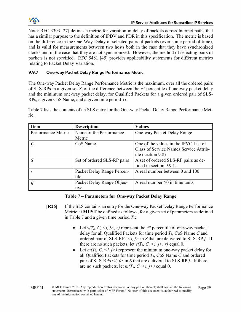
IP Service Attributes for Subscriber IP Services
MEF 61 © MEF Forum 2018. Any reproduction of this document, or any portion thereof, shall contain the following statement: "Reproduced with permission of MEF Forum." No user of this document is authorized to modify any of the information contained herein.
Page 59
Note: RFC 3393 [27] defines a metric for variation in delay of packets across Internet paths that has a similar purpose to the definition of IPDV and PDR in this specification. The metric is based on the difference in the One-Way-Delay of selected pairs of packets (over some period of time), and is valid for measurements between two hosts both in the case that they have synchronized clocks and in the case that they are not synchronized. However, the method of selecting pairs of packets is not specified. RFC 5481 [45] provides applicability statements for different metrics relating to Packet Delay Variation.
9.9.7 One-way Packet Delay Range Performance Metric
The One-way Packet Delay Range Performance Metric is the maximum, over all the ordered pairs of SLS-RPs in a given set S, of the difference between the rth percentile of one-way packet delay and the minimum one-way packet delay, for Qualified Packets for a given ordered pair of SLS-RPs, a given CoS Name, and a given time period Tk.
Table 7 lists the contents of an SLS entry for the One-way Packet Delay Range Performance Met-ric.
Item Description Values Performance Metric Name of the Performance
Metric One-way Packet Delay Range
C CoS Name One of the values in the IPVC List of Class of Service Names Service Attrib-ute (section 9.8)
S Set of ordered SLS-RP pairs A set of ordered SLS-RP pairs as de-fined in section 9.9.1.
r Packet Delay Range Percen-tile
A real number between 0 and 100
𝑔 Packet Delay Range Objec-tive
A real number >0 in time units
Table 7 – Parameters for One-way Packet Delay Range
[R26] If the SLS contains an entry for the One-way Packet Delay Range Performance Metric, it MUST be defined as follows, for a given set of parameters as defined in Table 7 and a given time period Tk:
x Let γ(Tk, C, <i, j>, r) represent the rth percentile of one-way packet delay for all Qualified Packets for time period Tk, CoS Name C and ordered pair of SLS-RPs <i, j> in S that are delivered to SLS-RP j. If there are no such packets, let γ(Tk, C, <i, j>, r) equal 0.
x Let m(Tk, C, <i, j>) represent the minimum one-way packet delay for all Qualified Packets for time period Tk, CoS Name C and ordered pair of SLS-RPs <i, j> in S that are delivered to SLS-RP j. If there are no such packets, let m(Tk, C, <i, j>) equal 0.

IP Service Attributes for Subscriber IP Services
MEF 61 © MEF Forum 2018. Any reproduction of this document, or any portion thereof, shall contain the following statement: "Reproduced with permission of MEF Forum." No user of this document is authorized to modify any of the information contained herein.
Page 60
x Then the One-way Packet Delay Range Performance Metric g(Tk, C, S, r) is the maximum of the values γ(Tk, C, <i, j>, r) - m(Tk, C, <i, j>) for all <i, j> in S.
[R27] If the SLS contains an entry for the One-way Packet Delay Range Performance Metric, it MUST define the objective as being met over time period Tk for an SLS entry of the form specified in Table 7 if and only if g(Tk, C, S, r) ≤ 𝑔.
As noted above RFC 3393 [27] defines a metric for variation in delay of packets across Internet paths that has a similar purpose to the definition of IPDV and PDR in this specification. ITU-T Y.1540 [88] also contains a similar definition (the metric is referred to as “PDV”).
9.9.8 One-way Packet Loss Ratio Performance Metric
The One-way Packet Loss Ratio Performance Metric is the maximum, over all the ordered pairs of SLS-RPs in a given set S, of the ratio of lost packets to transmitted packets for a given ordered pair of SLS-RPs, a given CoS Name, and a given time period Tk.
Table 8 lists the contents of an SLS entry for the One-way Packet Loss Ratio Performance Metric.
Item Description Values Performance Metric Name of the Performance
Metric One-way Packet Loss Ratio
C CoS Name One of the values in the IPVC List of Class of Service Names Service Attrib-ute (section 9.8)
S Set of ordered SLS-RP pairs A set of ordered SLS-RP pairs as de-fined in section 9.9.1.
𝐹 Packet Loss Ratio Objective Percentage expressed as a real number between 0 and 100%
Table 8 – Parameters for One-way Packet Loss Ratio
[R28] If the SLS contains an entry for the One-way Packet Loss Ratio Performance Metric, it MUST be defined as follows, for a given set of parameters as speci-fied in Table 8 and a given time period Tk:
x Let I(Tk, C, <i, j>) be the number of Qualified Packets for time pe-riod Tk, CoS Name C and ordered pair of SLS-RPs <i, j> in S that are received at SLS-RP i.
x Let J(Tk, C, <i, j>) be the number of unique (not duplicate) Qualified Packets for time period Tk, CoS Name C and ordered pair of SLS-RPs <i, j> in S that are transmitted at SLS-RP j.
x Let f(Tk, C, <i, j>) be defined as: f(Tk, C, <i, j>) = 𝐼( ,𝐶, , ) ( ,𝐶, , )
𝐼( ,𝐶, , ) if I(Tk, C, <i, j>) > 0
f(Tk, C, <i, j>) = 0 otherwise.

IP Service Attributes for Subscriber IP Services
MEF 61 © MEF Forum 2018. Any reproduction of this document, or any portion thereof, shall contain the following statement: "Reproduced with permission of MEF Forum." No user of this document is authorized to modify any of the information contained herein.
Page 61
x Then the One-way Packet Loss Ratio Performance Metric F(Tk, C, S) is the maximum of all the values f(Tk, C, <i, j>) for all <i, j> in S.
Note that “Qualified Packets for time period Tk” always means that the packet arrives at the ingress UNI or from the cloud service associated with the SLS-RP during time interval Tk. Therefore, J(Tk, C, <i, j>) includes IP Packets that arrived at the UNI associated with SLS-RP i during interval Tk and were transmitted at the egress UNI or towards the cloud service associated with SLS-RP j, regardless of when they were transmitted.
The Packet Loss Ratio is usually expressed as a percentage.
[R29] If the SLS contains an entry for the One-way Packet Loss Ratio Performance Metric, it MUST define the objective as being met over time period Tk for an SLS entry of the form specified in Table 8 if and only if F(Tk, C, S) ≤ 𝐹.
Note that per the definition above, packets that are eventually delivered are not considered lost, no matter how long the packet delay is.
Note: RFC 7680 [67] defines a metric for one-way loss of packets across Internet paths that is similar to the definition of Packet Loss Ratio in this specification. It builds on notions introduced and discussed in the IP Performance Metrics (IPPM) Framework document, RFC 2330 [12].
9.9.9 Service Uptime Performance Metric
The Service Uptime Performance Metric is the proportion of time, during a given time period Tk, that the service is working from the perspective of the Subscriber, excluding any pre-agreed ex-ceptions, for example maintenance intervals.
Table 9 lists the contents of an SLS entry for the Service Uptime Performance Metric.
Item Description Values Performance Metric Name of the Performance
Metric Service Uptime
𝑈 Service Uptime Objective Percentage between 0 and 100%
Table 9 – Parameters for Service Uptime
[R30] If the SLS contains an entry for the Service Uptime Performance Metric, it MUST be defined as follows, for a given time period Tk:
x Let O(Tk) be the total duration of outages during time period Tk. x Let M(Tk) be the total duration of maintenance periods during time
period Tk. x Then the Service Uptime, U(Tk) is defined as:
U(Tk) = (𝑀( ) ( ))𝑀( )

IP Service Attributes for Subscriber IP Services
MEF 61 © MEF Forum 2018. Any reproduction of this document, or any portion thereof, shall contain the following statement: "Reproduced with permission of MEF Forum." No user of this document is authorized to modify any of the information contained herein.
Page 62
Note the value T used in [R30] comes from the four-tuple value of the IPVC SLS Service Attrib-ute (see section 9.9).
[R31] If the SLS includes an entry for the Service Uptime Performance Metric, the Subscriber and SP MUST agree on the definition of an outage, including de-termining when an outage starts and ends.
The definition of what constitutes an outage is often (but does not have to be) based on the raising and resolution of customer complaints (“trouble tickets”) rather than the actual performance of data traffic through the network. This definition can be refined based on further commercial con-siderations, such as exceptions for acts of god or other events beyond the Service Provider’s con-trol. The exact definition is outside the scope of this document.
Service Uptime is generally expressed as a percentage.
[R32] If the SLS contains an entry for the Service Uptime Performance Metric, it MUST define the objective as being met over time period Tk for an SLS entry of the form specified in Table 9 if and only if U(Tk) ≥ 𝑈.
9.10 IPVC MTU Service Attribute
The IPVC Maximum Transmit Unit (MTU) Service Attribute is an integer ≥ 576 that specifies the maximum length in octets of IP Data Packets that the SP guarantees to be able to carry across the IPVC.
[R33] The value of the IPVC MTU Service Attribute MUST be less than or equal to the minimum of the values of the UNI Access Link IP MTU Service Attribute (see section 12.9) for all of the UNI Access Links in UNIs that the IPVC is attached to.
RFC 791 [1] specifies the minimum MTU for IPv4 Packets as 68 octets; however, it also requires that all devices can handle a packet of length 576 octets (possibly fragmented). This specification strengthens the requirements from RFC 791 [1], by defining the minimum MTU as 576 octets – that is, IPv4 Packets that are shorter than this are guaranteed not to be fragmented or discarded.
RFC 2460 [15] specifies the minimum MTU for IPv6 Packets as 1280 octets; therefore this value is recommended in all cases, and if IPv6 is enabled for this IPVC, it is required.
[D9] The IPVC MTU SHOULD be greater than or equal to 1280 octets.
[R34] If the IPVC Maximum Number of IPv6 Routes (section 9.6) is greater than 0, the IPVC MTU MUST be greater than or equal to 1280 octets.
IP Data Packets with a length greater than the IPVC MTU can be delivered as is, discarded by the SP, or in the case of IPv4 packets, fragmented within the SP Network (providing fragmentation is enabled, see section 9.12). Note that in a multipoint service, it might be that packets longer than the IPVC MTU can be delivered between certain pairs of IPVC EPs, but not between others. If

IP Service Attributes for Subscriber IP Services
MEF 61 © MEF Forum 2018. Any reproduction of this document, or any portion thereof, shall contain the following statement: "Reproduced with permission of MEF Forum." No user of this document is authorized to modify any of the information contained herein.
Page 63
the SP delivers such packets where possible, the Subscriber can make use of this by using Path MTU Discovery (see section 9.11).
[R35] Ingress IP Data Packets with a length less than or equal to the value of the IPVC MTU Service Attribute MUST NOT be discarded or fragmented due to their length.
[O5] Ingress IP Data Packets with a length strictly greater than the value of the IPVC MTU Service Attribute MAY be discarded or (for IPv4) fragmented.
If the SP receives an IP Data Packet longer than the IPVC MTU, they can choose to discard it or fragment it, if it cannot be delivered. However, fragmentation can impact performance, and hence this can be disabled via the IPVC Fragmentation Service Attribute (section 9.12).
9.11 IPVC Path MTU Discovery Service Attribute
The IPVC Path MTU Discovery Service Attribute indicates whether the Service Provider supports the use of ICMP-based Path MTU Discovery, as specified in RFC 1191 [4] and RFC 1981 [6]. It takes one of two values, Enabled or Disabled.
[R36] When the IPVC Path MTU Discovery Service Attribute is Enabled, IP routers within the SP Network MUST generate the relevant ICMP error messages when an IP Packet is received that is discarded due to its length (per require-ments [O5] and [R38]).
Note that [O5] allows packets longer than the IPVC MTU to be discarded or fragmented if they are not delivered; however, [R38] only allows them to be discarded, if fragmentation is disabled.
[R37] When the IPVC Path MTU Discovery Service Attribute is Enabled, ICMP error messages destined towards a Subscriber Network MUST NOT be filtered or discarded.
When IPVC Path MTU Discovery is Enabled, hosts within the Subscriber Network can rely on using the mechanisms of RFC 1191 [4] and RFC 1981 [6] to discover the MTU that can be used for transmission of IP Packets to each remote host. Regardless of the value of the IPVC Path MTU Discovery Service Attribute, hosts can use the mechanism of RFC 4821 [39] for path MTU dis-covery. Depending on the host implementation, hosts might be capable of using a different MTU for each remote host they transmit to, or might select the minimum value of all the hosts they transmit to.
9.12 IPVC Fragmentation Service Attribute
The IPVC Fragmentation Service Attribute specifies whether IPv4 Packets that are longer than the IPVC MTU can be fragmented (as described in RFC 791 [1]) as they traverse the IPVC. It takes one of two values, Enabled or Disabled.

IP Service Attributes for Subscriber IP Services
MEF 61 © MEF Forum 2018. Any reproduction of this document, or any portion thereof, shall contain the following statement: "Reproduced with permission of MEF Forum." No user of this document is authorized to modify any of the information contained herein.
Page 64
[R38] When the IPVC Fragmentation Service Attribute is Disabled, Ingress IPv4 Data Packets with a length strictly greater than the value of the IPVC MTU Service Attribute MUST NOT be fragmented.
Note that when the value is Enabled, IP Data Packets that are longer than the IPVC MTU might be delivered, fragmented or discarded, per [O5]. When the value is Disabled, such packets are delivered or discarded.
9.13 IPVC Cloud Service Attribute
The IPVC Cloud Service Attribute is either None, or a set of parameters describing the cloud ser-vice as detailed in Table 10 below.
[R39] If the IPVC Topology Service Attribute (see section 9.2) is Cloud Access, the parameters shown in Table 10 MUST be specified.
[R40] If the IPVC Topology Service Attribute (see section 9.2) is not Cloud Access, the IPVC Cloud Service Attribute MUST be None.
The parameters of a cloud access IPVC are summarized in the table below and described in more detail in the following subsections.
Parameter Name Summary Description Possible Values Cloud Type Indicates the type of cloud service being
accessed. Internet Access or Private
Cloud Ingress Class of Service Map
Specification of how ingress packets are mapped to different CoS Names
See section 9.13.2.
Cloud Data Limit Limit on the amount of Data traffic sent to/received from the cloud service
Unlimited or a 4-tuple (scdl, Tcdl, ucdl, dcdl) as described in section 9.13.3.
Cloud Network Address Transla-tion
Whether Network Address Translation is used, and if so the IPv4 Prefix.
Disabled or an IPv4 Prefix.
Cloud DNS Whether and how DNS is provided for the service.
None, DHCP, PPP or Static plus a list of DNS Server Ad-dresses
Cloud Subscriber Prefix List
List of Public IP Prefixes used in the Subscriber Network.
List of IP Prefixes
Table 10 – Subscriber IPVC Cloud Service Attribute parameters
9.13.1 Cloud Type
The Cloud Type parameter is Internet Access or Private. If the value is Internet Access, this indi-cates the cloud access IPVC is used to access the public Internet. If the value is Private, this indicates the cloud access IPVC provides a direct connection over the Service Provider’s network to a cloud service such as Amazon Web Services, Google Cloud or Microsoft Azure.

IP Service Attributes for Subscriber IP Services
MEF 61 © MEF Forum 2018. Any reproduction of this document, or any portion thereof, shall contain the following statement: "Reproduced with permission of MEF Forum." No user of this document is authorized to modify any of the information contained herein.
Page 65
Note: the behavior, parameters and requirements for private cloud access services are deferred to a future revision of this specification.
9.13.2 Cloud Ingress Class of Service Map
The Cloud Ingress Class of Service Map is a triple (F, M, D) where F is a list of one or more fields in the packet header that are used to determine the CoS Name, M is a mapping from combinations of values of those fields to CoS Names, and D is a default CoS Name used when the map cannot be applied. CoS Names are also known as “Traffic Classes”. The Cloud Ingress Class of Service Map is applied to IP Data Packets that are received from the cloud service. The IPVC EP Ingress Class of Service Map defined in section 10.7 is applied to IP Data Packets received at a UNI and mapped to the IPVC EP.
The possible values that can be included in list F are:
x Source IP Address x Destination IP Address x L4 Protocol x Source L4 Port x Destination L4 Port
Note that IP DS is not included in the possible fields, as the DSCP value in IP Packets received from the Internet cannot be relied upon. Matching on the IP DS field might be added in future work on private cloud services.
The map M is a set of (key, value) pairs where the key is a tuple containing possible values for the fields specified in list F, and the value is one of the CoS Names specified in the IPVC List of Class of Service Names Service Attribute (section 9.8). For example, if F contains only Source IP Ad-dress, then M comprises entries of the form (<IP Prefix>, <CoS Name>), such as (192.0.2.176/32, “Best Effort”); if F comprises L4 Protocol and Destination L4 Port, then M comprises entries of the form ((<L4 protocol>, <Port Number>), <CoS Name>), such as ((6, 25), “Best Effort”). Note that 6 is the protocol number for TCP, and 25 is the TCP port number for SMTP, so this entry would map email traffic to the “Best Effort” class. Further examples can be found in Appendix B.5.
The value that is included in the key in map M for each field specified in list F is shown in Table 11, along with the corresponding field in the IP Packet header
Field in F Values in the key in M Source IP Address IP Prefix Destination IP Address IP Prefix L4 Protocol Protocol Number (integer from 0 to 255) Source L4 Port Port Number (integer from 0 to 65535) Destination L4 Port Port Number (integer from 0 to 65535)
Table 11 – Values for the Cloud Ingress Class of Service Map

IP Service Attributes for Subscriber IP Services
MEF 61 © MEF Forum 2018. Any reproduction of this document, or any portion thereof, shall contain the following statement: "Reproduced with permission of MEF Forum." No user of this document is authorized to modify any of the information contained herein.
Page 66
Note that the Cloud Ingress Class of Service Map does not explicitly distinguish between the han-dling for IPv4 and IPv6 packets. However, different handling can be specified by including entries in the map that match on Source IP Address with the IP Prefix set to 0.0.0.0/0 or ::/0.
The default CoS Name, D, is used when the map M cannot be applied to the packet, as described below.
[R41] The CoS Names used in the map M and default D in the Cloud Ingress Class of Service Map MUST be present in the IPVC List of Class of Service Names (section 9.8) for the corresponding IPVC, or be the special value Discard.
[R42] IP Data Packets received from the cloud service, that are mapped to the special CoS Name Discard, MUST be discarded.
Table 12 below shows the criteria for whether an IP Data Packet received from the cloud service matches an entry in map M if a given field is included in list F.
Field in F Criteria for matching Source IP Ad-dress
The Source Address in the IP Data Packet is within the IP Prefix in the key in map M, and there is no other matching entry in M that has a more specific IP Prefix.
Destination IP Address
The Destination Address in the IP Data Packet is within the IP Prefix in the key in map M, and there is no other matching entry in M that has a more spe-cific IP Prefix.
L4 Protocol The Protocol field in the IPv4 header of an IPv4 Data Packet, or the last “Next Header” field in an IPv6 Data Packet matches the value in the key in map M.
Source L4 Port
The IP Data Packet contains a TCP or UDP packet and the Source Port in the TCP or UDP header matches the value in the key in map M.
Destination L4 Port
The IP Data Packet contains a TCP or UDP packet and the Destination Port in the TCP or UDP header matches the value in the key in map M.
Table 12 – Matching Criteria for the Cloud Ingress Class of Service Map
In the case of L4 Protocol, for an IPv6 Packet, the relevant field is the “Next Header” field in the IPv6 header, if it does not indicate an IPv6 extension header, otherwise the “Next Header” field in the last IPv6 extension header.
When establishing a TCP connection to a server, the destination port is normally well known whereas the source port is typically chosen arbitrarily by the client. However, responses from the server to the client use the well known number as the source port, and the arbitrarily chosen num-ber as the destination port. In this case, matching the source port can be useful.
The criteria for matching the source or destination address allow for the case where map M con-tains entries with overlapping IP Prefixes (and the same values for any other fields). In this case, the entry with the most specific IP Prefix (i.e. the longest prefix length) is used (“longest prefix matching”). The following requirement ensures that when both source and destination addresses are matched, a single entry can be selected unambiguously.

IP Service Attributes for Subscriber IP Services
MEF 61 © MEF Forum 2018. Any reproduction of this document, or any portion thereof, shall contain the following statement: "Reproduced with permission of MEF Forum." No user of this document is authorized to modify any of the information contained herein.
Page 67
[R43] If list F contains both Source IP Address and Destination IP Address, map M MUST NOT contain any pair of entries in which the IP Prefixes for Source IP Address overlap, the IP Prefixes for Destination IP Address overlap, the IP Pre-fix for the Source Address is more specific in one entry and the IP Prefix for the Destination Address is more specific in the other entry.
[R44] An IP Data Packet received from the cloud service that matches an entry in map M as specified in Table 12, for the fields specified in list F, MUST be assigned the corresponding CoS Name from the map M.
[R45] An IP Data Packet received from the cloud service that does not match any entry in map M as specified in Table 12, for the fields specified in list F, MUST be assigned the default CoS Name, D.
Note that the Ingress Class of Service Map is often implemented with an ACL or QoS marking policy; however, this specification does not mandate any particular implementation.
9.13.3 Cloud Data Limit
The Cloud Data Limit parameter specifies an absolute limit on the amount of data the Subscriber can transmit to, or receive from, the cloud service in a given time period. It is either Unlimited or a 4-tuple (scdl, Tcdl, ucdl, dcdl) where:
x scdl (for start time) specifies a start time. x Tcdl (for duration) specifies a duration (for example, 1 month). Together with the start
time, it describes a series of contiguous time intervals, starting at the specified start time and each lasting for the specified duration.
x ucdl (for upload) is an integer indicating a limit, in octets, on the amount of IP traffic that can be transmitted towards the cloud service during each time interval described by scdl and Tcdl.
x dcdl (for download) is an integer indicating a limit, in octets, on the amount of IP traffic received from the cloud service that can be delivered to the Subscriber during each time interval described by scdl and Tcdl.
In this context, the amount of IP traffic is calculated by summing the lengths of the IP Data Packets transmitted towards or received from the cloud service, as appropriate.
[O6] If the Cloud Data Limit for an IPVC is a 4-tuple (scdl, Tcdl, ucdl, dcdl), within each time interval described by scdl and Tcdl, an Ingress IP Data Packet mapped to an IPVC EP for the IPVC MAY be discarded if the sum of the lengths of all pre-vious Ingress IP Data Packets mapped to an IPVC EP for this IPVC and trans-mitted towards the cloud service during the same time interval exceeds the limit ucdl.
[O7] If the Cloud Data Limit for an IPVC is a 4-tuple (scdl, Tcdl, ucdl, dcdl), within each time interval described by scdl and Tcdl, an IP Data Packet received from the cloud service MAY be discarded if the sum of the lengths of all previous IP

IP Service Attributes for Subscriber IP Services
MEF 61 © MEF Forum 2018. Any reproduction of this document, or any portion thereof, shall contain the following statement: "Reproduced with permission of MEF Forum." No user of this document is authorized to modify any of the information contained herein.
Page 68
Data Packets received from the cloud service and mapped to an egress IPVC EP for this IPVC during the same time interval exceeds the limit dcdl.
When the limit is exceeded, the SP might discard all packets (e.g. unless and until the Subscriber obtains an extension to the service), or they might restrict the bandwidth, resulting in some but not all packets being discarded. They might not discard any packets if, for example, they have the facility to automatically bill the Subscriber for the extra usage above the limit. Such details are typically specified in an SLA and are outside the scope of this document.
Note that this limit is agreed between the SP and the Subscriber. If the Subscriber is accessing a content provider within the cloud service, the content provider might also have their own limits. These would likely be unknown to the SP; it is the Subscriber’s responsibility to make sure the limits agreed with the SP are sufficient for their needs.
9.13.4 Cloud Network Address Translation
The Cloud Network Address Translation (NAT) parameter is either Disabled or an IPv4 Prefix. An IPv4 Prefix can be specified for Internet access services, in which case NAT is enabled and any IPv4 addresses used by the Subscriber are translated to an address in the given IPv4 Prefix. Note that the IPv4 Prefix can be specified with a prefix length of 32, in which case it corresponds to a single IPv4 address. This can be useful, for example, when the Subscriber needs a fixed IPv4 address.
[R46] If the Cloud Type parameter is Internet Access, when the Cloud NAT parameter is not Disabled, it MUST be a publicly assigned IPv4 Prefix.
[R47] When the Cloud NAT parameter is an IPv4 Prefix, IPv4 Packets transmitted towards or received from the cloud service MUST be subject to behavior con-sistent with Network Address Translation and Network Address Port Transla-tion as described in RFC 3022 [20], using an IPv4 address in the specified IPv4 Prefix.
Note that the SP might perform multiple stages of NAT; this is consistent with RFC 3022 [20] and hence compliant with [R47] provided that the IP address eventually used to send/receive IP packets to/from the Internet is within the specified IPv4 Prefix. The IPv4 address used in any intermediate stages of NAT need not be from a publicly assigned IPv4 Prefix.
[R48] When the Cloud NAT parameter is an IPv4 Prefix, the SP MUST ensure that the best current practice documented in RFC 4787 [38], RFC 5382 [43], RFC 5508 [46], RFC 5597 [47] and RFC 7857 [72] is followed.
Note that if different NAT is required at different UNIs that all have internet access, this can be achieved by instantiating a separate cloud access IPVC for each UNI.
9.13.5 Cloud DNS Service
The Cloud DNS Service parameter indicates whether and how a DNS service (as described in RFC 1034 [3]) is provided to the Subscriber by the SP. The possible values are None, DHCP, SLAAC,

IP Service Attributes for Subscriber IP Services
MEF 61 © MEF Forum 2018. Any reproduction of this document, or any portion thereof, shall contain the following statement: "Reproduced with permission of MEF Forum." No user of this document is authorized to modify any of the information contained herein.
Page 69
PPP or Static, plus in the case of Static, a list of DNS server IP addresses. If the value is None, the SP does not provide a DNS service. If the value is DHCP, the SP provides DNS server ad-dresses via DHCP at each UNI (this is only possible if DHCP is used for the connection address-ing). If the value is SLAAC, the SP provides DNS server addresses via SLAAC Router Advertise-ment options (per RFC 8106 [73]) at each UNI (this is only possible if SLAAC is used for the connection addressing). If the value is PPP, the SP provides DNS server addresses via PPP at each UNI (this is only possible if the underlying L2 Technology uses PPP – see section 12.3). If the value is Static, the DNS server addresses are listed explicitly.
[R49] If the value of the Cloud DNS Service parameter is DHCP, every UNI that the IPVC is attached to MUST contain at least one UNI Access Link with IPv4 Connection Addressing Type (see section 12.4) equal to DHCP and IPv6 Con-nection Addressing Type (see section 12.5) equal to DHCP.
[R50] If the value of the Cloud DNS Service parameter is SLAAC, every UNI that the IPVC is attached to MUST contain at least one UNI Access Link with IPv6 Connection Addressing Type (see section 12.5) equal to SLAAC.
[R51] If the Cloud Type parameter (see section 9.13.1) is not Internet Access, the Cloud DNS Service parameter MUST be None.
9.13.6 Cloud Subscriber Prefix List
The Cloud Subscriber Prefix List parameter is a list of public IP Prefixes that are used in the Sub-scriber Network. Agreeing on this list allows the SP to implement security filtering for traffic to or from IP addresses that are not within the listed prefixes.
The list can be empty, or can contain IPv4 or IPv6 Prefixes or both. The listed prefixes might have been allocated to the Subscriber by the SP, or from some other source (e.g. another SP or a Re-gional Internet Registry).
[R52] If the Cloud Type parameter (see section 9.13.1) is not Internet Access, the Cloud Subscriber Prefix List MUST be empty.
If NAT is enabled, the Subscriber’s addresses are translated by the SP so this parameter is not needed.
[R53] If the Cloud Network Address Translation parameter (see section 9.13.4) is not Disabled, the Cloud Subscriber Prefix List MUST be empty.
It is not necessary to list the IP Prefixes corresponding to the UNI Access Link connection ad-dresses – these addresses are always allowed by the SP. IP Data Packets from outside the connec-tion subnets, that are not listed in the Subscriber Prefix List, can be discarded.
[O8] If the Cloud Type parameter (see section 9.13.1) for a cloud access IPVC is Internet Access, an Ingress IP Data Packet that is mapped to the IPVC at a UNI, with a source IP address that is not within the IP Prefix identified by the UNI Access Link Connection Addressing Service Attributes (see sections 12.4 and

IP Service Attributes for Subscriber IP Services
MEF 61 © MEF Forum 2018. Any reproduction of this document, or any portion thereof, shall contain the following statement: "Reproduced with permission of MEF Forum." No user of this document is authorized to modify any of the information contained herein.
Page 70
12.5) and is not within an IP Prefix contained in the Cloud Subscriber Prefix List, MAY be discarded.
[O9] If the Cloud Type parameter (see section 9.13.1) for a cloud access IPVC is Internet Access, an Egress IP Data Packet that is mapped to the IPVC at a UNI, with a destination IP address that is not within the IP Prefix identified by the UNI Access Link Connection Addressing Service Attributes (see sections 12.4 and 12.5) and is not within an IP Prefix contained in the Cloud Subscriber Pre-fix List, MAY be discarded.
Note that if different filtering is required at different UNIs that all have internet access, this can be achieved by instantiating a separate cloud access IPVC for each UNI.
9.14 IPVC Reserved Prefixes Service Attribute
The IPVC Reserved Prefixes Service Attribute specifies a list of IP Prefixes that the SP reserves for use for the IPVC within their own network, but which are nevertheless exposed to the Sub-scriber, for example for diagnostics purposes. The list can be empty, or can contain IPv4 or IPv6 Prefixes or both. These IP Prefixes need to be agreed so as to ensure they do not overlap with IP Prefixes used by the Subscriber inside the Subscriber Network.
[R54] The Subscriber MUST NOT use IP addresses that are within the IP Prefixes listed in the IPVC Reserved Prefixes Service Attribute for devices in the Sub-scriber Network.
One possible use for the IPVC Reserved Prefixes Service Attribute is if the SP exposes the IP addresses for loopback interfaces on their PE devices (or at Provider-Managed UNIs, their CE devices) to the Subscriber; this can help the Subscriber diagnose network problems using tools like ping and traceroute.
Note that it is not necessary to reserve the SP’s IP address on the directly connected subnet for a UNI Access Link using this attribute; such addresses are automatically reserved. See sections 12.4 and 12.5.

IP Service Attributes for Subscriber IP Services
MEF 61 © MEF Forum 2018. Any reproduction of this document, or any portion thereof, shall contain the following statement: "Reproduced with permission of MEF Forum." No user of this document is authorized to modify any of the information contained herein.
Page 71
10 Subscriber IPVC End Point Service Attributes
This section specifies the Service Attributes for Subscriber IP Services that apply to each Sub-scriber IPVC attached to a given UNI, i.e. to each IPVC EP. There is one instance of these attrib-utes for each IPVC EP at the UNI. The attributes are summarized in the table below and described in more detail in the following subsections.
Attribute Name Summary Description Possible Values IPVC EP Identifier Unique identifier for the IPVC EP for
management purposes. Printable string that is unique across the SP’s network.
IPVC EP UNI The UNI where the IPVC EP is located UNI Identifier of a UNI IPVC EP Role Role of the IPVC EP in a rooted mul-
tipoint IPVC Root or Leaf
IPVC EP Prefix Mapping
Indicates which IP Prefixes can send and receive traffic to/from the IPVC
List of IP Prefixes
IPVC EP Maxi-mum Number of IPv4 Routes
Maximum number of IPv4 routes sup-ported by this IPVC EP.
Integer ≥ 0 or Unlimited
IPVC EP Maxi-mum Number of IPv6 Routes
Maximum number of IPv6 routes sup-ported by this IPVC EP.
Integer ≥ 0 or Unlimited
IPVC EP Ingress Class of Service Map
Specification of how ingress packets are mapped to different CoS Names
See section 10.7.
IPVC EP Egress Class of Service Map
Specification of how Class of Service is indicated in egress packets
See section 10.8
IPVC EP Ingress Bandwidth Profile Envelope
Ingress Bandwidth Profile Envelope for the IPVC EP
None or a set of parameters as described in section 13.3.
IPVC EP Egress Bandwidth Profile Envelope
Egress Bandwidth Profile Envelope for the IPVC EP
None or a set of parameters as described in section 13.3.
Table 13 – Subscriber IPVC EP Service Attributes
10.1 IPVC EP Identifier Service Attribute
The IPVC EP Identifier is a unique string identifier for the IPVC EP, consisting of ASCII charac-ters in the range 32-126 inclusive. It can be used by the Subscriber and the SP to identify the IPVC EP to each other.
[R55] The value of the IPVC EP Identifier MUST be unique among all such identifi-ers for IPVC EPs supported by the Service Provider.
[R56] The length of the IPVC EP Identifier MUST be less than or equal to 53 char-acters.

IP Service Attributes for Subscriber IP Services
MEF 61 © MEF Forum 2018. Any reproduction of this document, or any portion thereof, shall contain the following statement: "Reproduced with permission of MEF Forum." No user of this document is authorized to modify any of the information contained herein.
Page 72
10.2 IPVC EP UNI Service Attribute
The IPVC EP UNI Service Attribute specifies the UNI where this IPVC EP is located. Its value is a UNI Identifier (see section 11.1) for one of the UNIs supported by the SP.
10.3 IPVC EP Role Service Attribute
The IPVC EP Role Service Attribute is either Root or Leaf, and specifies the role the IPVC EP plays in the IPVC topology.
[R57] An IPVC EP for a multipoint IPVC MUST have an IPVC EP Role of Root.
[R58] A rooted multipoint IPVC MUST have at least one IPVC EP with a role of Root and at least one IPVC EP with a role of Leaf.
IPVC EPs for a cloud access IPVC can have either Root or Leaf role. The cloud service itself always acts as if it has Root role.
In a rooted multipoint or cloud access IPVC, traffic can flow between roots and leaves, or between two roots, but not between two leaves.
[R59] An Ingress IP Data Packet mapped to an IPVC EP with IPVC EP Role of Leaf MUST NOT be transmitted as an Egress IP Data Packet at an IPVC EP with IPVC EP Role of Leaf.
Note: The description in section 8 means that if standard routing is used in the IPVC, adhering to [R8] and [R9] automatically ensures compliance with [R59].
10.4 IPVC EP Prefix Mapping Service Attribute
The IPVC EP Prefix Mapping Service Attribute is a list, possibly empty, of IP Prefixes (that is, subnet and prefix length). It is used to specify which subnets within the Subscriber Network can access the IPVC via this IPVC EP. If the list is empty, there are no restrictions and packets to or from any address within the Subscriber Network can be mapped to this IPVC EP on ingress or delivered to this IPVC EP on egress. If the list is non-empty, Ingress IP Packets that are not from within one of the specified IP Prefixes are not mapped to this IPVC EP, and only IP Packets de-livered across the IPVC that are destined towards one of the specified IP Prefixes are delivered to this IPVC EP on egress. As described in section 8, in IPVCs that use standard routing, this is achieved by only making the specified IP Prefixes available for routing in the IPVC.
The IPVC EP Prefix Mapping attribute can also affect how IP Packets are mapped to an IPVC EP. An overview of this is given in section 8.2. In particular, when there are multiple IPVC EPs at a UNI (for different IPVCs), it is possible for an Ingress IP Data Packet at a UNI to be eligible to be mapped to more than one IPVC EP at that UNI. Section 10.4.1 describes how the appropriate IPVC EP is chosen, based on the value of the IPVC EP Prefix Mapping Service Attribute.
The following requirements describe the effect of the IPVC EP Prefix Mapping Service Attribute.

IP Service Attributes for Subscriber IP Services
MEF 61 © MEF Forum 2018. Any reproduction of this document, or any portion thereof, shall contain the following statement: "Reproduced with permission of MEF Forum." No user of this document is authorized to modify any of the information contained herein.
Page 73
[R60] For an IPVC EP for an IPVC with IPVC Packet Delivery (section 9.4) set to Standard Routing, if the IPVC EP Prefix Mapping Service Attribute is not an empty list, an IP Prefix MUST NOT be made available for routing within the IPVC unless either the IP Prefix or a superset of it is included in the list.
Referring to the description in section 8, [R60] could be equivalently stated as saying that if the IPVC EP Prefix Mapping Service Attribute is set, routes for IP Prefixes that are not specified in the IPVC EP Prefix Mapping Service Attribute are not propagated from RIDUNI for the UNI where the IPVC EP is located into RIDL for the IPVC EP.
[R61] If the IPVC EP Prefix Mapping Service Attribute is not an empty list, IP Data Packets delivered across the IPVC for the IPVC EP, that have a Destination Address that is not within any of the listed IP Prefixes, MUST NOT be deliv-ered as Egress IP Packets at the UNI where the IPVC EP is located.
Note that in IPVCs that use standard IP routing, [R60] ensures that only IP Prefixes included in the Prefix Mapping list (if it is not empty) are added to the list of IP Prefixes that are reachable via this IPVC EP. In addition, [R8] and [R9] mean that a unicast packet with a destination address that is not reachable via any IPVC EP for the IPVC is discarded. Together, this means that a unicast IP Data Packet with a destination address that is not within any of the listed IP Prefixes cannot be delivered to this IPVC EP; and thus [R61] is always met in this case. In an IPVC that uses policy based routing (PBR), [R60] does not apply but [R61] must still be met.
[R62] If the IPVC EP Prefix Mapping Service Attribute is not an empty list, Ingress IP Data Packets with a Source Address that is not within any of the listed IP Prefixes MUST NOT be mapped to the IPVC EP.
If the IPVC EP Prefix Mapping Service Attribute is an empty list, this has the same effect as if the attribute value contains two entries, for 0.0.0.0/0 (IPv4) and ::/0 (IPv6). In the latter case, all IP packets match one of these entries and can therefore access the IPVC via this IPVC EP, just as if the attribute were not set.
Some examples illustrating the use of the IPVC EP Prefix Mapping Service Attribute can be found in Appendix B.
10.4.1 Mapping IP Data Packets to an IPVC
When there are multiple IPVC EPs at a UNI (each corresponding to a different IPVC), an Ingress IP Data Packet is eligible to be mapped to any of them. However, only one IPVC EP is chosen as the ingress IPVC EP for the packet. Assuming all of the corresponding IPVCs use standard IP routing, this is done by finding the IPVC in which the destination address in the IP Packet is reach-able – that is, the IPVC with an IPVC EP that has an IP Prefix best matching the destination address in its routing table RTIPVCEP (see section 8). This is typically implemented by a routing lookup. When there is more than one such IPVC EP, the source address in the packet is matched against the IPVC EP Prefix Mapping Service Attribute to determine which IPVC EP the packet is to be mapped to.

IP Service Attributes for Subscriber IP Services
MEF 61 © MEF Forum 2018. Any reproduction of this document, or any portion thereof, shall contain the following statement: "Reproduced with permission of MEF Forum." No user of this document is authorized to modify any of the information contained herein.
Page 74
It is important that there is only one IPVC that can be chosen, so that the correct IPVC attributes (e.g. the IPVC SLS) are applied to the packet. When all the IPVCs attached to a UNI use standard routing, the requirements below ensure that a single IPVC EP can be chosen for each Ingress IP Packet. Selection of the ingress IPVC EP when one or more of the corresponding IPVCs uses Policy-Based Routing (see section 9.4), is deferred to a future version of this specification.
The requirements below apply to unicast IP Packets. Handling of multicast IP Packets is deferred and could be addressed in a future version of this specification.
In the case where a given prefix is reachable in more than one IPVC EP, the SP might or might not be able to route the packet differently depending on the IPVC selected, as described in section 8.2.1. If the SP does not have this capability, the routes in all the IPVC EPs are required to point to the same egress UNI; this enables the route to be determined independently of the IPVC EP.
[O10] When there are multiple IPVC EPs at a UNI that all have IPVC Packet Delivery (section 9.4) set to Standard Routing, and when a given IP Prefix is reachable in more than one of the IPVC EPs, the SP MAY support the capability to de-liver ingress IP Data Packets at the UNI via different egress UNIs based on which IPVC EP the packet is mapped to on ingress.
[R63] If the SP does not support the capability described in [O10], then for any pair of IPVC EPs at a given UNI, for IPVCs that both have IPVC Packet Delivery (section 9.4) set to Standard Routing, if a given IP Prefix is reachable in both IPVC EPs, the best active route for the IP Prefix via one IPVC EP MUST be through a UNI Access Link in the same UNI as the best active route for the IP Prefix via the other IPVC EP.
Referring to the description in section 8, an IP Prefix is reachable in an IPVC EP if it has an active route in RTIPVCEP. [R63] can be equivalently stated as meaning that if two IPVC EPs at a UNI each have a route for the same IP Prefix in their RTIPVCEP Routing Tables, they have to both be routes towards the same egress UNI. The egress UNI could be the same as the ingress UNI (i.e. the UNI where the IPVC EPs are located), or it could be a different UNI – the requirement applies either way. Note that implementations are not required to use the routing information databases described in section 8, provided that the external behavior is the same.
[R63] allows for overlapping, but not identical, IP Prefixes to be reachable via different routes in different IPVCs – in this case the most specific matching IP Prefix is preferred (“longest prefix matching”). Note that this precludes a default route (i.e. 0/0 or ::/0) being reachable from a given UNI via different routes in different IPVCs.
[R64] If:
x Two IPVCs each have an IPVC EP at a given UNI; and x Both IPVCs have IPVC Packet Delivery (section 9.4) set to Standard
Routing; and x There is an IP Prefix that is reachable from both IPVC EPs, and in at
least one of them, this is via a UNI Access Link that is not in the UNI where the IPVC EPs are located;

IP Service Attributes for Subscriber IP Services
MEF 61 © MEF Forum 2018. Any reproduction of this document, or any portion thereof, shall contain the following statement: "Reproduced with permission of MEF Forum." No user of this document is authorized to modify any of the information contained herein.
Page 75
Then the following conditions MUST be met:
x Each IPVC EP has a non-empty value for the IPVC EP Prefix Map-ping Service Attribute; and
x The values of the IPVC EP Prefix Mapping Service Attribute for the two IPVC EPs do not contain any IP Prefixes that overlap.
[R64] means that if an IP Prefix is reachable in two different IPVCs, then it is always possible to use the IPVC EP Prefix Mapping values to determine which IPVC EP to map an Ingress IP Packet to, because each of the IPVCs has to have the attribute set (i.e. non-empty), and the same prefix can only appear in the attribute value for one of the IPVC EPs.
There is an important exception case in [R64]: when multiple IPVC EPs all have a route to an IP Prefix that directs packets back out of the ingress UNI, the requirement does not apply. In this case, it is not possible to unambiguously choose a particular IPVC EP to map the packet to, and there is no way for the Subscriber to determine which IPVC EP was selected. Typically this does not matter as the externally-visible behavior is the same whichever IPVC EP is selected – i.e., packets will be transmitted back out of the UNI where they were received (although not necessarily over the same UNI Access Link), rather than being transmitted across the SP Network.
The above requirement allows for four possibilities for a given IP Prefix, as described in section 8.2.1 and with reference to the routing information databases described in section 8.1:
x None of the IPVC EPs have a route to the IP Prefix in their RTIPVCEP. x Exactly one of the IPVC EPs has a route to the IP Prefix in its RTIPVCEP. x Two or more of the IPVC EPs have a route to the IP Prefix in their RTIPVCEP, and the best
active route in at least one of these points to a UNI Access Link in a remote UNI – that is, it comes from a route in RIDR. In addition, all of the IPVC EPs have the IPVC EP Prefix Mapping attribute set, with disjoint lists of IP Prefixes.
x Two or more of the IPVC EPs have a route to the IP Prefix in their RTIPVCEP, and the best active route in all of these points to a UNI Access Link in the UNI where the IPVC EPs are located – that is, it comes from a route in RIDL.
Given these constraints, an ingress IPVC EP is chosen for Ingress IP Data Packets as described in section 8.2.1. Note that there is no need to select an IPVC EP for Ingress IP Control Protocol Packets (as identified by the UNI List of Control Protocols Service Attribute, see section 11.6).
[R65] When all of the IPVC EPs at a given UNI are for IPVCs with the IPVC Packet Delivery (section 9.4) set to Standard Routing, a unicast Ingress IP Data Packet at the UNI MUST be mapped to an IPVC EP in accordance with the description in section 8.2.1.
[R65] does not require that implementations follow the exact steps in section 8.2.1, or that imple-mentations maintain routing information databases per IPVC EP as described in section 8.1. Any implementation that exhibits the same externally-visible behavior is acceptable.
Note that the requirements above do not necessitate that multiple routing lookups be performed in order to determine the correct IPVC EP; a common implementation is to insert the IP Prefixes

IP Service Attributes for Subscriber IP Services
MEF 61 © MEF Forum 2018. Any reproduction of this document, or any portion thereof, shall contain the following statement: "Reproduced with permission of MEF Forum." No user of this document is authorized to modify any of the information contained herein.
Page 76
associated with the IPVC EPs for all of the IPVCs attached to a given UNI into a single routing table (VRF) and use this single table for routing lookups. [R63] ensures that if a prefix is reach-able in multiple IPVCs, it is reachable via the same path; hence it is not necessary to consider the IPVC EP Prefix Mapping attribute in order to determine how to route a packet, unless the SP supports this capability. Depending on the SP’s network and service implementation, it might be necessary to use the prefix mapping attribute to filter the packet (e.g. using an Access Control List) or to affect quality of service (e.g. using a QoS policy to mark packets differently depending on the IPVC EP Ingress CoS Map (see section 10.7) for different IPVC EPs). Details of the implemen-tation are outside the scope of this document.
10.5 IPVC EP Maximum Number of IPv4 Routes Service Attribute
The IPVC EP Maximum Number of IPv4 Routes Service Attribute limits the total number of IPv4 Prefixes that can be associated with this IPVC EP. It is an integer ≥0 or the special value Unlim-ited. With reference to the description in section 8, it is a limit on the number of unique IPv4 Prefixes contained in RIDL for the IPVC EP.
[D10] If the IPVC EP Maximum Number of IPv4 Routes Service Attribute is not Un-limited, the SP SHOULD disregard any IPv4 Prefixes associated with the IPVC EP above the limit specified by the IPVC EP Maximum Number of IPv4 Routes Service Attribute.
[D11] When the limit specified by the IPVC EP Maximum Number of IPv4 Routes Service Attribute is reached or exceeded, the SP SHOULD select IPv4 Prefixes to disregard so as to minimize disruption to the service.
[D10] means that if the Subscriber advertises too many routes to the SP, the SP might disregard some of them. This can lead to blackholing of some of the Subscriber’s traffic, or other undesirable behavior. The SP can minimize disruption by disregarding the most recently received IPv4 Pre-fixes so as to maintain the paths that were previously working.
Note that the IPVC EP Maximum Number of IPv4 Routes Service Attribute limits the number of IPv4 routes at this IPVC EP, over the UNI where the IPVC EP is located. This document also specifies a limit on the total number of IPv4 routes in the IPVC – see section 9.5.
It can be useful for the SP to notify the Subscriber when the total number of IPv4 Prefixes that are associated with the IPVC EP is approaching the limit specified by the IPVC EP Maximum Number of IPv4 Routes Service Attribute, or has crossed it. The details of how this is done are outside the scope of this document.
[D12] The SP SHOULD notify the Subscriber when the total number of IPv4 Prefixes that are associated with the IPVC EP reaches the value of the IPVC EP Maxi-mum Number of IPv4 Routes Service Attribute.
[O11] The SP MAY notify the Subscriber when the total number of IPv4 Prefixes that are associated with the IPVC EP is approaching the value of the IPVC EP Max-imum Number of IPv4 Routes Service Attribute.

IP Service Attributes for Subscriber IP Services
MEF 61 © MEF Forum 2018. Any reproduction of this document, or any portion thereof, shall contain the following statement: "Reproduced with permission of MEF Forum." No user of this document is authorized to modify any of the information contained herein.
Page 77
10.6 IPVC EP Maximum Number of IPv6 Routes Service Attribute
The IPVC EP Maximum Number of IPv6 Routes Service Attribute limits the total number of IPv6 Prefixes that can be associated with this IPVC EP. It is an integer ≥0 or the special value Unlim-ited. With reference to the description in section 8, it is a limit on the number of unique IPv6 Prefixes contained in RIDL for the IPVC EP.
[D13] If the IPVC EP Maximum Number of IPv6 Routes Service Attribute is not Un-limited, the SP SHOULD disregard any IPv6 Prefixes associated with the IPVC EP above the limit specified by the IPVC EP Maximum Number of IPv6 Routes Service Attribute.
[D14] When the limit specified by the IPVC EP Maximum Number of IPv6 Routes Service Attribute is reached or exceeded, the SP SHOULD select IPv6 Prefixes to disregard so as to minimize disruption to the service.
[D13] means that if the Subscriber advertises too many routes to the SP, the SP might disregard some of them. This can lead to blackholing of some of the Subscriber’s traffic, or other undesirable behavior. The SP can minimize disruption by disregarding the most recently received IPv6 Pre-fixes so as to maintain the paths that were previously working.
Note that the IPVC EP Maximum Number of IPv6 Routes Service Attribute limits the number of IPv6 routes at this IPVC EP, over the UNI where the IPVC EP is located. This document also specifies a limit on the total number of IPv6 routes in the IPVC – see section 9.6.
It can be useful for the SP to notify the Subscriber when the total number of IPv6 Prefixes that are associated with the IPVC EP is approaching the limit specified by the IPVC EP Maximum Number of IPv6 Routes Service Attribute, or has crossed it. The details of how this is done are outside the scope of this document.
[D15] The SP SHOULD notify the Subscriber when the total number of IPv6 Prefixes that are associated with the IPVC EP reaches the value of the IPVC EP Maxi-mum Number of IPv6 Routes Service Attribute.
[O12] The SP MAY notify the Subscriber when the total number of IPv6 Prefixes that are associated with the IPVC EP is approaching the value of the IPVC EP Max-imum Number of IPv6 Routes Service Attribute.
10.7 IPVC EP Ingress Class of Service Map Service Attribute
The IPVC EP Ingress Class of Service Map Service Attribute is a triple (F, M, D) where F is a list of one or more fields in the packet header that are used to determine the CoS Name, M is a mapping from combinations of values of those fields to CoS Names, and D is a default CoS Name used when the map cannot be applied. CoS Names are also known as “Traffic Classes”. The IPVC EP Ingress Class of Service Map is applied to Ingress IP Data Packets that are mapped to the IPVC EP. The Cloud Ingress Class of Service Map defined in section 9.13.2 is applied to IP Data Packets received from a cloud service.

IP Service Attributes for Subscriber IP Services
MEF 61 © MEF Forum 2018. Any reproduction of this document, or any portion thereof, shall contain the following statement: "Reproduced with permission of MEF Forum." No user of this document is authorized to modify any of the information contained herein.
Page 78
The possible values that can be included in list F are:
x IP DS x Source IP Address x Destination IP Address x L4 Protocol x Source L4 Port x Destination L4 Port
The map M is a set of (key, value) pairs where the key is a tuple containing possible values for the fields specified in list F, and the value is one of the CoS Names specified in the IPVC List of Class of Service Names Service Attribute (section 9.8). For example, if F contains only IP DS, then M comprises entries of the form (<DSCP value>, <CoS Name>), such as (10, “Voice”). Note that 10 is the DSCP value for DSCP Name ‘AF11’, so this entry would map traffic marked with AF11 to the “Voice” class. Another example: If F comprises L4 Protocol and Destination L4 Port, then M comprises entries of the form ((<L4 protocol>, <Port Number>), <CoS Name>), such as ((6, 22), “Interactive”). Note that 6 is the protocol number for TCP, and 22 is the TCP port number for SSH, so this entry would map SSH traffic to the “Interactive” class. Further examples can be found in Appendix B.5.
The value that is included in the key in map M for each field specified in list F is shown in Table 14, along with the corresponding field in the IP Packet header
Field in F Values in the key in M IP DS DSCP value (integer from 0 to 63) Source IP Address IP Prefix Destination IP Address IP Prefix L4 Protocol Protocol Number (integer from 0 to 255) Source L4 Port Port Number (integer from 0 to 65535) Destination L4 Port Port Number (integer from 0 to 65535)
Table 14 – Values for the IPVC EP Ingress Class of Service Map
Note that the IPVC EP Ingress Class of Service Map does not explicitly distinguish between the handling for IPv4 and IPv6 packets. However, different handling can be specified by including entries in the map that match on Source IP Address with the IP Prefix set to 0.0.0.0/0 or ::/0.
Note that the value of map M described here is an abstraction; it does not constrain how the map can be described in a protocol, database, service order form, etc. For example, shorthand descrip-tions such as using a range of port numbers are allowed, although this logically corresponds to a separate entry in map M for each port number in the description above.
The default CoS Name, D, is used when the map M cannot be applied to the packet, as described below.
[R66] The CoS Names used in the map M and default D in the IPVC EP Ingress Class of Service Map Service Attribute MUST be present in the IPVC List of Class

IP Service Attributes for Subscriber IP Services
MEF 61 © MEF Forum 2018. Any reproduction of this document, or any portion thereof, shall contain the following statement: "Reproduced with permission of MEF Forum." No user of this document is authorized to modify any of the information contained herein.
Page 79
of Service Names (section 9.8) for the corresponding IPVC, or be the special value Discard.
[R67] Ingress IP Data Packets that are mapped to the special CoS Name Discard MUST be discarded.
Table 15 below shows the criteria for whether an Ingress IP Data Packet matches an entry in map M if a given field is included in list F.
Field in F Criteria for matching IP DS Value in the DS Field (as defined in RFC 3260 [24]) in the IP Data Packet
matches the value in the key in map M. Source IP Ad-dress
The Source Address in the IP Data Packet is within the IP Prefix in the key in map M, and there is no other matching entry in M that has a more specific IP Prefix.
Destination IP Address
The Destination Address in the IP Data Packet is within the IP Prefix in the key in map M, and there is no other matching entry in M that has a more spe-cific IP Prefix.
L4 Protocol The Protocol field in the IPv4 header of an IPv4 Data Packet, or the last “Next Header” field in an IPv6 Data Packet matches the value in the key in map M.
Source L4 Port
The IP Data Packet contains a TCP or UDP packet and the Source Port in the TCP or UDP header matches the value in the key in map M.
Destination L4 Port
The IP Data Packet contains a TCP or UDP packet and the Destination Port in the TCP or UDP header matches the value in the key in map M.
Table 15 – Matching Criteria for the IPVC EP Ingress Class of Service Map
In the case of L4 Protocol, for an IPv6 Packet, the relevant field is the “Next Header” field in the IPv6 header, if it does not indicate an IPv6 extension header, otherwise the “Next Header” field in the last IPv6 extension header.
When establishing a TCP connection to a server, the destination port is normally well known whereas the source port is typically chosen arbitrarily by the client. However, responses from the server to the client use the well known number as the source port, and the arbitrarily chosen num-ber as the destination port. In this case, matching the source port can be useful.
The criteria for matching the source or destination address allow for the case where map M con-tains entries with overlapping IP Prefixes (and the same values for any other fields). In this case, the entry with the most specific IP Prefix (i.e. the longest prefix length) is used (“longest prefix matching”). The following requirement ensures that when both source and destination addresses are matched, a single entry can be selected unambiguously.
[R68] If list F contains both Source IP Address and Destination IP Address, map M MUST NOT contain any pair of entries in which the IP Prefixes for Source IP Address overlap, the IP Prefixes for Destination IP Address overlap, the IP Pre-fix for the Source Address is more specific in one entry and the IP Prefix for the Destination Address is more specific in the other entry.

IP Service Attributes for Subscriber IP Services
MEF 61 © MEF Forum 2018. Any reproduction of this document, or any portion thereof, shall contain the following statement: "Reproduced with permission of MEF Forum." No user of this document is authorized to modify any of the information contained herein.
Page 80
[R69] An Ingress IP Data Packet that matches an entry in map M as specified in Table 15, for the fields specified in list F, MUST be assigned the corresponding CoS Name from the map M.
[R70] An Ingress IP Data Packet that does not match any entry in map M as specified in Table 15, for the fields specified in list F, MUST be assigned the default CoS Name, D.
Note that the IPVC EP Ingress Class of Service Map is an IPVC EP attribute. This means that when there are multiple IPVC EPs at a given UNI, the correct IPVC EP needs to be determined before the IPVC EP Ingress Class of Service Map can be applied and the CoS Name determined. As finding the correct IPVC EP can involve a routing lookup (see sections 8.2.1 and 10.4.1), this can be difficult to implement in some cases. However, if the IPVC EP Ingress Class of Service Map Service Attribute has the same value at all IPVC EPs at the UNI, it is not necessary to find the IPVC EP before determining the CoS Name.
[O13] When there are multiple IPVC EPs at a given UNI, the SP MAY require that the value of the IPVC EP Ingress Class of Service Map Service Attribute is the same at all of the IPVC EPs.
Note that the Ingress Class of Service Map is often implemented with an ACL or QoS marking policy; however, this specification does not mandate any particular implementation.
10.8 IPVC EP Egress Class of Service Map Service Attribute
Specification of the IPVC EP Egress Class of Service Map Service Attribute, that specifies how to set the DS field in Egress IP Packets based on the CoS Name, is deferred to a future version of this specification.
10.9 IPVC EP Ingress Bandwidth Profile Envelope Service Attribute
The IPVC EP Ingress Bandwidth Profile Envelope Service Attribute is either None, or a single Bandwidth Profile Envelope consisting of parameters and Bandwidth Profile Flow specifications, as described in section 13.3. If specified, the BWP Envelope is used for an ingress Bandwidth Profile.
An Ingress Bandwidth Profile Envelope can be specified for one of a UNI, a UNI Access Link, or an IPVC EP – this follows from [R76] and [R143].
10.10 IPVC EP Egress Bandwidth Profile Envelope Service Attribute
The IPVC EP Egress Bandwidth Profile Envelope Service Attribute is either None, or a single Bandwidth Profile Envelope consisting of parameters and Bandwidth Profile Flow specifications, as described in section 13.3. If specified, the BWP Envelope is used for an egress Bandwidth Profile.
An Egress Bandwidth Profile Envelope can be specified for one of a UNI, a UNI Access Link, or an IPVC EP – this follows from [R78] and [R144].

IP Service Attributes for Subscriber IP Services
MEF 61 © MEF Forum 2018. Any reproduction of this document, or any portion thereof, shall contain the following statement: "Reproduced with permission of MEF Forum." No user of this document is authorized to modify any of the information contained herein.
Page 81
11 Subscriber UNI Service Attributes
This section specifies the Service Attributes for Subscriber IP Services that apply to each UNI. There is one instance of these attributes for each UNI supported by the SP. The attributes are summarized in the table below and described in more detail in the following subsections.
Attribute Name Summary Description Possible Values UNI Identifier Unique identifier for the UNI for man-
agement purposes. Printable string that is unique across the SP’s network.
UNI Management Type
Indication of who manages the CE Subscriber-Managed or Pro-vider-Managed
UNI List of UNI Access Links
List of UNI Access Links in the UNI List of UNI Access Link identifiers
UNI Ingress Band-width Profile Enve-lope
Bandwidth Profile Envelope used for an ingress Bandwidth Profile
None or a set of parameters as specified in section 13.3
UNI Egress Band-width Profile Enve-lope
Bandwidth Profile Envelope used for an egress Bandwidth Profile
None or a set of parameters as specified in section 13.3
UNI List of Con-trol Protocols
Indication of IP Control Protocols that are not forwarded transparently by the SP
See section 11.6
UNI Routing Pro-tocols
List of Routing Protocols used across the UNI
See section 11.7
UNI Reverse Path Forwarding
Indicates whether RPF checks are used by the SP at the UNI
Enabled or Disabled
Table 16 – Subscriber UNI Service Attributes
11.1 UNI Identifier Service Attribute
The UNI Identifier is a unique string identifier for the UNI, consisting of ASCII characters in the range 32-126 inclusive. It can be used by the Subscriber and the SP to identify the UNI to each other.
[R71] The value of the UNI Identifier MUST be unique among all such identifiers for UNIs supported by the Service Provider.
[R72] The length of the UNI Identifier MUST be less than or equal to 53 characters.
11.2 UNI Management Type Service Attribute
The UNI Management Type is either Subscriber-Managed or Provider-Managed, and indicates whether the CE is the responsibility of the Subscriber or the Service Provider, as described in section 7.5. If the UNI Management Type is Subscriber-Managed, the CE is managed by the Subscriber, and the UNI Access Links correspond with the IP Attachment Circuits between the CE and the PE. If the UNI Management Type is Provider-Managed, the CE is managed by the

IP Service Attributes for Subscriber IP Services
MEF 61 © MEF Forum 2018. Any reproduction of this document, or any portion thereof, shall contain the following statement: "Reproduced with permission of MEF Forum." No user of this document is authorized to modify any of the information contained herein.
Page 82
SP, and the UNI Access Links correspond with the links from the CE to the devices within the Subscriber Network. In this latter case, the IP Attachment Circuits between the CE and the PE are internal to the SP Network and hence outside the scope of this document.
Subscriber-Managed and Provider-Managed CEs are illustrated in Figure 7 in section 7.5.
Note: this specification uses the IETF definition of CE that is common parlance in the context of IP. With this definition, the CE is the equipment that is directly adjacent (at Layer 3) to the PE, regardless of who owns and manages it. This is different to the definition of Cus-tomer Edge used in other MEF specifications.
11.3 UNI List of UNI Access Links Service Attribute
The UNI List of UNI Access Links Service Attribute is a list of UNI Access Link Identifiers (see section 12.1) for the UNI Access Links in this UNI. A UNI Access Link is an IP subnetwork corresponding to a distinct IP subnet (which might use both IPv4 and IPv6 addressing), and con-sisting of a single IP hop from a service perspective (i.e., there is no intermediate router that pro-cesses the IP Packets traversing the link (see section 7.3)).
[R73] A UNI Access Link MUST belong to exactly one UNI.
[R74] The UNI Access Links listed in the UNI List of UNI Access Links Service Attribute MUST all be connected to the same Subscriber Network.
11.4 UNI Ingress Bandwidth Profile Envelope Service Attribute
The UNI Ingress Bandwidth Profile Envelope Service Attribute is either None, or a single Band-width Profile Envelope consisting of parameters and Bandwidth Profile Flow specifications, as described in section 13.3. If specified, the BWP Envelope is used for an ingress Bandwidth Profile. Note that Bandwidth Profile Flows can be defined per UNI, per IPVC EP, per UNI Access Link, per CoS Name, etc. – see section 13.1.
An Ingress Bandwidth Profile Envelope can be specified for one of a UNI, a UNI Access Link, or an IPVC EP.
[R75] If the UNI Ingress Bandwidth Profile Envelope Service Attribute is not None, the UNI Access List Ingress Bandwidth Profile Envelope Service Attribute (section 12.8) MUST be None for all UNI Access Links in the UNI.
[R76] If the UNI Ingress Bandwidth Profile Envelope Service Attribute is not None, the IPVC EP Ingress Bandwidth Profile Envelope Service Attribute (section 10.9) MUST be None for all IPVC EPs at the UNI.
11.5 UNI Egress Bandwidth Profile Envelope Service Attribute
The UNI Egress Bandwidth Profile Envelope Service Attribute is either None, or a single Band-width Profile Envelope consisting of parameters and Bandwidth Profile Flow specifications, as described in section 13.3. If specified, the BWP Envelope is used for an egress Bandwidth Profile.

IP Service Attributes for Subscriber IP Services
MEF 61 © MEF Forum 2018. Any reproduction of this document, or any portion thereof, shall contain the following statement: "Reproduced with permission of MEF Forum." No user of this document is authorized to modify any of the information contained herein.
Page 83
Note that Bandwidth Profile Flows can be defined per UNI, per IPVC EP, per UNI Access Link, per CoS Name, etc. – see section 13.1.
An Egress Bandwidth Profile Envelope can be specified for one of a UNI, a UNI Access Link, or an IPVC EP.
[R77] If the UNI Egress Bandwidth Profile Envelope Service Attribute is not None, the UNI Access List Egress Bandwidth Profile Envelope Service Attribute (section 12.11) MUST be None for all UNI Access Links in the UNI.
[R78] If the UNI Egress Bandwidth Profile Envelope Service Attribute is not None, the IPVC EP Egress Bandwidth Profile Envelope Service Attribute (section 10.10) MUST be None for all IPVC EPs at the UNI.
11.6 UNI List of Control Protocols Service Attribute
The UNI List of Control Protocols Service Attribute is a list of control protocols, along with cor-responding addressing and references, that identifies packets that are IP Control Protocol Packets rather than IP Data Packets. Each entry in the list consists of a 3-tuple containing the protocol name, addressing information (either SP Addresses or Any), and one or more references.
Any IP Packet matching an entry in the list is considered to be an IP Control Protocol Packet. IP Control Protocol Packets are not forwarded across the IPVC (i.e., the packet delivery requirements and packet transparency requirements in section 9.4 do not apply); they are either peered or dis-carded.
Some protocols can be used both between the SP and the Subscriber across a UNI, and by the Subscriber between different parts of the Subscriber Network; for example, a Subscriber might use BGP at a UNI to advertise routes to the SP, and also use BGP between their own routers in different sites to exchange other information. In such cases, the IP Packets that are intended to be peered by the SP and the IP Packets that are intended to be carried over the IPVC and delivered to another UNI are typically distinguished by the source or destination IP address.
To accommodate this, each entry in the UNI List of Control Protocols contains addressing infor-mation that identifies which unicast addresses are matched when determining whether an IP Packet is an IP Control Protocol Packet. If the addressing information is SP Addresses, then Ingress IP Packets for the specified protocol that have a multicast or broadcast destination address, or a unicast destination address that is reachable within the SP’s network, are considered to be IP Con-trol Protocol Packets, and Egress IP Packets for the specified protocol that have a source address that is reachable within the SP’s network are considered to be IP Control Protocol Packets. If the addressing information is Any, then all IP Packets for the specified protocol that cross the UNI are considered to be IP Control Protocol Packets.
Delivery of multicast IP Packets across the IPVC is outside the scope of this specification (and could be addressed in a future version); hence all multicast IP Packets for the specified protocols are considered to be IP Control Protocol Packets regardless of the specified addressing infor-mation.

IP Service Attributes for Subscriber IP Services
MEF 61 © MEF Forum 2018. Any reproduction of this document, or any portion thereof, shall contain the following statement: "Reproduced with permission of MEF Forum." No user of this document is authorized to modify any of the information contained herein.
Page 84
Any IP Packets that cross the UNI that are not considered to be IP Control Protocol Packets are IP Data Packets, and hence the packet delivery and packet transparency requirements in section 9.4 apply.
Each entry in the UNI List of Control Protocols includes a reference to a standard or other speci-fication that describes how packets belonging to the protocol are identified.
An example of the UNI List of Control Protocols Service Attribute is shown in Table 17.
Protocol Addressing Reference ICMP SP Addresses IETF RFC 792 BGP SP Addresses IETF RFC 4271 OSPF Any IETF RFC 2328 and RFC 5340
Table 17 – Example value of the UNI List of Control Protocols Service Attribute
In this example, BGP is used at the UNI, and the SP also allows the Subscriber to ping their internal addresses with ICMP. OSPF is also listed because the SP wants to explicitly filter (discard) all OSPF packets. All other protocols are delivered across the IPVC as data packets.
Another example is shown in Table 18.
Protocol Addressing Reference OSPF Any IETF RFC 2328 and IETF RFC 5340 DHCP (IPv4) Any IETF RFC 2131 and IETF RFC 2132 BFD Any IETF RFC 5880 and IETF RFC 5881 SLAAC Any IETF RFC 4862 IGMP Any IETF RFC 3376 MLD Any IETF RFC 3810
Table 18 – Example value of the UNI List of Control Protocols Service Attribute
In this example, OSPF, DHCP (for IPv4), SLAAC (for IPv6) and BFD are used at the UNI. IGMP and MLD are also listed because the SP wants to explicitly filter (discard) all IGMP and MLD packets. All other protocols are delivered across the IPVC as data packets.
As described above, packets relating to a protocol that is not included in the UNI List of Control Protocols Service Attribute at a given UNI are considered to be IP Data Packets.
Note that although multicast routing is outside the scope of this specification, control protocols related to multicast routing (e.g. IGMP, MLD, and PIM) can be included in the list of control protocols. This can be useful if the SP wishes to discard all IP Packets relating to such protocols, to ensure they do not disrupt the operation of the SP Network.
[R79] An Ingress IP Packet that matches an entry in the UNI List of Control Protocols Service Attribute MUST NOT be delivered as an Egress IP Packet at any UNI.

IP Service Attributes for Subscriber IP Services
MEF 61 © MEF Forum 2018. Any reproduction of this document, or any portion thereof, shall contain the following statement: "Reproduced with permission of MEF Forum." No user of this document is authorized to modify any of the information contained herein.
Page 85
Note that if a protocol is peered, an Ingress IP Packet might result in a different IP Packet being sent in response. [R79] means that an Ingress IP Packet cannot result in an unmodified (other than as described in section 9.4.1) Egress IP Packet.
[O14] IP Control Protocol Packets MAY be peered or discarded by the SP.
Whether a protocol is peered or discarded is at the discretion of the SP; but some protocols have to be peered if they correspond with Service Attributes that have been agreed.
[R80] The following protocols MUST be included in the UNI List of Control Proto-cols if they are enabled per the corresponding Service Attributes as shown be-low:
x OSPF: UNI Routing Protocols Service Attribute (section 11.7). x BGP: UNI Routing Protocols Service Attribute (section 11.7). x BFD: UNI Access Link BFD Service Attribute (section 12.8) for any
UNI Access Link in the UNI. x DHCP (IPv4): UNI Access Link IPv4 Connection Addressing Service
Attribute (section 12.4) for any UNI Access Link in the UNI. x DHCP (IPv6): UNI Access Link IPv6 Connection Addressing Service
Attribute (section 12.5) for any UNI Access Link in the UNI. x DHCP (IPv4 and/or IPv6): UNI Access Link DHCP Relay Service
Attribute (section 12.6) for any UNI Access Link in the UNI. x DHCP (IPv6): UNI Access Link Prefix Delegation Service Attribute
for any UNI Access Link in the UNI. x ICMP: IPVC Path MTU Discovery Service Attribute (section 9.11)
for any IPVC attached to the UNI.
Note that for certain protocols, such as OSPF, it does not make sense to deliver protocol packets over the IPVC even if the protocol is not enabled at a UNI. This can be prevented by including such protocols in the value of the UNI List of Control Protocols Service Attribute.
For convenience, references for some common IP Control Protocols are given in Table 19 – these might or might not be included in the UNI List of Control Protocols for a given UNI. Note that this is not an exhaustive list; other IP Control Protocols can be included in the UNI List of Control Protocols.

IP Service Attributes for Subscriber IP Services
MEF 61 © MEF Forum 2018. Any reproduction of this document, or any portion thereof, shall contain the following statement: "Reproduced with permission of MEF Forum." No user of this document is authorized to modify any of the information contained herein.
Page 86
Protocol Reference BGP RFC 4271 [33] OSPF RFC 2328 [11] and RFC 5340 [41] RIP RFC 2453 [14] BFD RFC 5880 [50] and RFC 5881 [51] ICMP RFC 792 [2] and RFC 4443 [36] IGMP RFC 3376 [26] MLD RFC 3810 [30] PIM RFC 7761 [70] and RFC 3973 [32] DHCP (IPv4) RFC 2131 [9] and RFC 2132 [10] DHCP (IPv6) RFC 3315 [25] SLAAC RFC 4862 [40] … …
Table 19 – Examples of IP Control Protocols
The value of the UNI List of Control Protocols Service Attribute might include none, some or all of the protocols listed in Table 19, and might include other IP protocols not listed in Table 19.
11.7 UNI Routing Protocols Service Attribute
The UNI Routing Protocols Service Attribute specifies the routing protocols and associated pa-rameters that are used to exchange IP routes across the UNI. The value is a list of protocols (pos-sibly empty), where each entry consists of the protocol name (one of Static, OSPF or BGP), the type of routes that will be exchanged (one of IPv4, IPv6 or Both), and a set of additional parameters as specified in the subsections below.
[R81] The value of the UNI Routing Protocols Service Attribute MUST NOT contain more than one entry for the same protocol name, except when there are exactly two entries with a given protocol name, one with route type IPv4 and one with route type IPv6.
Note that regardless of the routing protocol in use, the SP directs traffic destined for an address within the IP Prefixes identified by the UNI Access Link IPv4 Connection Addressing Service Attribute (see section 12.4) and the UNI Access Link IPv6 Connection Addressing Service Attrib-ute (see section 12.5) towards the corresponding UNI Access Link, as described in section 8.
The UNI Routing Protocols Service Attribute applies to all UNI Access Links in a UNI. If there are multiple UNI Access Links connecting the SP to a given part of the Subscriber Network, and it is desired to use different routing protocols or parameters on different UNI Access Links, the UNI Access Links can be assigned to different UNIs, as described in section 7.3.
When all of the end hosts in the Subscriber Network that are reachable at a given UNI are directly adjacent (at Layer 3) to the UNI Access Links in that UNI (i.e. there is no router on the Subscriber’s side of the UNI), and therefore only use IP addresses within the IP Prefixes identified by the UNI Access Link IPv4 Connection Addressing Service Attribute (see section 12.4) and the UNI Access Link IPv6 Connection Addressing Service Attribute (see section 12.5), there is no need to specify

IP Service Attributes for Subscriber IP Services
MEF 61 © MEF Forum 2018. Any reproduction of this document, or any portion thereof, shall contain the following statement: "Reproduced with permission of MEF Forum." No user of this document is authorized to modify any of the information contained herein.
Page 87
any additional routing information (static routing or dynamic routing protocols). This is likely only useful when the UNI contains a single UNI Access Link. In that case, the Subscriber can use a “default gateway”, i.e. a default route towards the single UNI Access Link. As above, the SP directs traffic that is destined for an IP address within the IP Prefix identified by the connection addressing attributes towards the UNI Access Link.
Each of the routing protocols specified below has a parameter for setting the administrative dis-tance. This is a numeric metric used to control which routes are selected, when there are multiple routes for the same IP Prefix. A lower number indicates a more preferable route. For the purpose of this specification, IP Prefixes identified by the UNI Access Link IPv4 Connection Addressing Service Attribute (see section 12.4) and the UNI Access Link IPv6 Connection Addressing Service Attribute (see section 12.5) are considered to have administrative distance of 0, and for an IPVC EP at a given UNI, routes towards other IPVC EPs for the IPVC are considered to have adminis-trative distance 200.
[R82] When selecting the best route for packet delivery as described in section 8, the SP MUST prefer routes with a lower administrative distance.
Note that the administrative distance values used in this document and specified in the value of the UNI Routing Protocols Service Attribute are only related to each other, to specify the relative preference of routes. They might or might not correspond with administrative distance values actually used in the SP’s devices to implement the behavior.
For BGP and OSPF, setting a different administrative distance for different IP Prefixes is not sup-ported in this version of the specification.
Examples showing the value of the UNI Routing Protocols Service Attribute can be found in Ap-pendix C.
11.7.1 Static
When an entry in the UNI Routing Protocols list is for Static, the IP Prefixes used in the Subscriber Network that are reachable via this UNI are specified as additional parameters in the entry. These are known as Static IP Prefixes. For each Static IP Prefix, the following information is also spec-ified:
x Forwarding information, consisting of either a nexthop IP address in the Subscriber Net-work (if the access medium is multipoint capable, e.g. Ethernet), or a specific UNI Ac-cess Link (if the access medium is strictly point-to-point, e.g. HDLC, PPP over DSL).
x Administrative Distance, an integer greater than 0.
The SP directs traffic destined for an address within any of the Static IP Prefixes towards the UNI, using the nexthop address or UNI Access Link specified for that IP Prefix. The Subscriber routes traffic towards the UNI Access Links that make up the UNI (e.g. by using a default or aggregate route).
The same IP Prefix can be specified more than once in the list of Static IP Prefixes, if it has differ-ent forwarding information.

IP Service Attributes for Subscriber IP Services
MEF 61 © MEF Forum 2018. Any reproduction of this document, or any portion thereof, shall contain the following statement: "Reproduced with permission of MEF Forum." No user of this document is authorized to modify any of the information contained herein.
Page 88
If a static prefix is specified with a nexthop address that is not reachable over this UNI, or with a UNI Access Link that is non-operational, the static route is considered inactive and hence is not used by the SP for directing traffic. In particular, the static route is not used if the specified nexthop can only be reached via a different UNI.
Note that if the UNI consists of point-to-point UNI Access Links on a multipoint-capable medium (e.g., Ethernet), the specified nexthop is likely to be the Subscriber Address specified as part of the UNI Access Link IPv4 Connection Addressing Service Attribute (see section 12.4) or the UNI Ac-cess Link IPv6 Connection Addressing Service Attribute (see section 12.5) for one of the UNI Access Links.
Note: if a Static IP Prefix is specified that matches the IP Prefix for the connection addresses on one of the UNI Access Links (see sections 12.4 and 12.5), the connected route is always preferred as it has administrative distance fixed to 0.
11.7.2 OSPF
When an entry in the UNI Routing Protocols is for OSPF, OSPF as specified in RFC 2328 [11] (for IPv4) and/or RFC 5340 [41] (for IPv6) is used across each UNI Access Link to exchange routing information. The Subscriber uses OSPF to advertise IP Prefixes used within the Subscriber Network, that are reachable via the UNI Access Link, to the SP, which consequently directs traffic destined for any IP address within those IP Prefixes towards the UNI Access Link(s) over which the IP Prefixes were advertised. The SP uses OSPF to advertise IP Prefixes that are reachable via other UNIs that the IPVC is attached to, so that the Subscriber can direct traffic towards those IP Prefixes over the corresponding UNI Access Links.
The additional parameters that need to be agreed when OSPF is used are:
x Area ID (0 – 4294967295, normally expressed as an IPv4 address) x Area type (Normal, Stub or NSSA) x Authentication Type (None, Password or Message Digest) x Hello Interval (0 – 65535, in seconds) x Dead Interval (0 – 4294967295, in seconds) x Retransmit Interval (integer greater than 0, in seconds) x Administrative Distance (integer greater than 0)
The Area ID is a 32 bit number (typically written as an IPv4 address) that specifies the OSPF Area.
If the Area ID is 0 (0.0.0.0), the area is the OSPF Backbone area. This can be used at the UNI, for example, if the Subscriber wishes for the Service Provider to implement a “super backbone” con-figuration, which allows the remote networks to appear to be in the same OSPF Backbone Area (Area ID 0), preserving the Subscriber’s route types. If a “super-backbone” is not used, the Sub-scriber’s routes from the remote locations will be learned as external, which can affect the routing within the Subscriber Network.
The Area Type indicates the type of OSPF Area. An Area Type of Normal means the area is not a stub or NSSA (see RFC 3101 [22]) area.

IP Service Attributes for Subscriber IP Services
MEF 61 © MEF Forum 2018. Any reproduction of this document, or any portion thereof, shall contain the following statement: "Reproduced with permission of MEF Forum." No user of this document is authorized to modify any of the information contained herein.
Page 89
The Authentication Type indicates the type of authentication used for OSPF adjacencies. Simi-larly, the Hello Interval, Dead Interval and Retransmit Interval specify the various timers that are used to create OSPF adjacencies.
The Administrative Distance is an integer greater than 0, and is applied by the SP to all IP Prefixes advertised by the Subscriber over the UNI using OSPF.
Note: parameters, behavior and requirements relating to the use of OSPF Sham links, and further parameters relating to authentication, are deferred to a future version of this specification.
11.7.3 BGP
When an entry in the UNI Routing Protocols is for BGP, BGP as specified in RFC 4271 [33] is used across the UNI to exchange routing information. The Subscriber uses BGP to advertise IP Prefixes used within the Subscriber Network that are reachable over the UNI to the SP, which consequently directs traffic destined for any IP address within those IP Prefixes towards the UNI Access Link(s) corresponding to the nexthop associated with the IP Prefix. The SP uses BGP to advertise IP Prefixes that are reachable via other UNIs that the IPVC is attached to the Subscriber, so that the Subscriber can direct traffic destined for those IP Prefixes towards the SP, over the UNI Access Link(s) corresponding to the nexthop associated with the IP Prefix.
The additional parameters that need to be agreed when BGP is used are:
x Subscriber’s AS Number x SP’s AS Number x Connection Address Family (IPv4 or IPv6) x Peering Addresses (Connection Addresses, or Loopbacks plus a list of pairs of IP ad-
dresses) x Authentication (None or MD5 plus a password) x BGP Community List (see below) x BGP Extended Community List (see below) x Hold Time (time in seconds) x Damping (None or a set of damping parameters) x AS Override (Enabled or Disabled) x Administrative Distance (integer greater than 0)
The Subscriber’s and SP’s AS Numbers are used to establish BGP peerings. BGP can be run over the UNI in two ways: either a separate BGP session can be established over each UNI Access Link, or one or more BGP sessions can be established over the UNI as a whole. In the latter case, each session is typically established between locally assigned “loopback” addresses on the Subscriber’s and SP’s routers, and the reachability of these loopback addresses is established by other means (e.g. using static routing or OSPF).
If the Peering Addresses parameter is Connection Addresses, a separate BGP peering session is established over each UNI Access Link, using the primary IPv4 addresses in the UNI Access Link IPv4 Connection Addressing Service Attribute (section 12.4) or the first IPv6 addresses in the UNI Access Link IPv6 Connection Addressing Service Attribute (section 12.5), as indicated by the

IP Service Attributes for Subscriber IP Services
MEF 61 © MEF Forum 2018. Any reproduction of this document, or any portion thereof, shall contain the following statement: "Reproduced with permission of MEF Forum." No user of this document is authorized to modify any of the information contained herein.
Page 90
Connection Address Family parameter. These peering sessions are single-hop eBGP connections. Note in this case that the same values for the parameters above apply to each of these BGP peering sessions; if this is not desired, the UNI Access Links can be assigned to different UNIs.
If the Peering Addresses parameter is Loopbacks, a list of pairs of IP addresses is additionally specified, each pair containing the Subscriber’s loopback address and the SP’s loopback address. A single BGP peering session is established for each pair of addresses. These peering sessions are multihop eBGP connections. Again, the same values for the parameters above apply to all of the BGP peering sessions.
[R83] If an entry in the UNI Routing Protocols list for BGP has Connection Address Family set to IPv4 and Peering Addresses set to Connection Addresses, the UNI Access Link IPv4 Connection Addressing Service Attribute (section 12.4) MUST be Static with a Primary Subnet Subscriber IPv4 Address specified, at every UNI Access Link in the UNI.
[R84] If an entry in the UNI Routing Protocols list for BGP has Connection Address Family set to IPv6 and Peering Addresses set to Connection Addresses, the UNI Access Link IPv6 Connection Addressing Service Attribute (section 12.5) MUST be Static with a Subscriber IPv6 Address specified, at every UNI Ac-cess Link in the UNI.
[R85] If an entry in the UNI Routing Protocols list for BGP has Peering Addresses set to Loopbacks, the IP addresses specified MUST be for the address family specified in the Connection Addressing parameter.
When a BGP session is established using loopback addresses, the SP and the Subscriber each need to know how to reach the other’s loopback addresses. If OSPF is used across the UNI as well as BGP (as described in section 11.7.2), for the appropriate address family, then this can be used to advertise the reachability of the loopback addresses. Alternatively, a Static entry can be used (as described in section 11.7.1) to provide the reachability of the Subscriber’s loopback address to the SP, and the Subscriber can assume that the SP’s loopback address can be reached over any opera-tional UNI Access Link, and install their own local routes accordingly.
[R86] When an entry in the UNI Routing Protocols is for BGP, the SP and the Sub-scriber MUST support 4-octet AS Numbers as described in RFC 6793 [60].
[R87] When an entry in the UNI Routing Protocols is for BGP, if the Authentication parameter is MD5, authentication using MD5 MUST be used as described in RFC 4271 [33] using the specified password.
Note that RFC 4271 [33] mandates support for MD5 passwords in BGP implementations.
The SP can configure BGP to wait passively for the Subscriber’s devices to connect to it; this is helpful if it is not known whether the Subscriber devices are available yet. To ensure this works, the Subscriber has to use active mode.

IP Service Attributes for Subscriber IP Services
MEF 61 © MEF Forum 2018. Any reproduction of this document, or any portion thereof, shall contain the following statement: "Reproduced with permission of MEF Forum." No user of this document is authorized to modify any of the information contained herein.
Page 91
[R88] The Subscriber MUST NOT use passive TCP establishment for BGP sessions with the SP.
BGP Communities and Extended Communities allow additional metadata to be attached to route advertisements. Except in the case of the few standardized well-known values, this additional metadata has no intrinsic meaning. However, it is common for SPs to define a set of Communities or Extended Communities with associated semantics, that the Subscriber can attach to their route advertisements in order to affect how they are handled by the SP.
[R89] The BGP Community List and BGP Extended Community List parameters MUST only contain values that are allocated by the SP as described in RFC 1997 [7] and RFC 4360 [34].
[R90] Each entry in the BGP Community List and BGP Extended Community List parameters MUST have an associated semantic that describes how the SP will handle routes advertised with that value.
The Hold Time parameter indicates the agreed Hold Time used for the BGP sessions.
The SP can apply route flap damping to advertisements from the Subscriber, but in this case the parameters have to be agreed.
[R91] When the Damping parameter is not None, the SP MUST apply route flap damping as described in RFC 2439 [13].
[R92] When the Damping parameter is not None, a single set of parameters as de-scribed in section 4.2 of RFC 2439 [13] MUST be agreed.
In cases where the Subscriber uses the same AS number in different parts of the Subscriber Net-work, it is necessary to tweak the normal handling of AS Paths in routes advertised to the Sub-scriber at each UNI, so as to prevent the routes being discarded due to BGP’s loop prevention mechanisms. Two mechanisms are commonly used for this:
x The Subscriber can configure their BGP routers so as to disable the loop prevention mechanism in the case where their own AS Number appears in the AS Path (this is com-monly known as “Allow-AS-in”). In this case, the SP does not need to be aware that this is being done and hence no parameters need to be agreed.
x The SP can overwrite instances of the Subscriber’s AS Number at the beginning of the AS Path with their own AS Number, when advertising routes to the Subscriber (this is commonly known as “AS Override”). This needs to be explicitly agreed between the SP and the Subscriber.
[R93] When the AS Override parameter is Enabled, the SP MUST overwrite in-stances of the Subscriber’s AS Number at the beginning of the AS Path with their own AS Number, in routes advertised to the Subscriber.
The Administrative Distance is an integer greater than 0, and is applied by the SP to all IP Pre-fixes advertised by the Subscriber over the UNI using BGP.

IP Service Attributes for Subscriber IP Services
MEF 61 © MEF Forum 2018. Any reproduction of this document, or any portion thereof, shall contain the following statement: "Reproduced with permission of MEF Forum." No user of this document is authorized to modify any of the information contained herein.
Page 92
11.8 UNI Reverse Path Forwarding Service Attribute
The UNI Reverse Path Forwarding Service Attribute takes the values Enabled or Disabled and indicates whether Reverse Path Forwarding (RPF) checks are used at the UNI by the SP. The Service Provider might want to use RPF checks when an Ingress IP Packet is received at a UNI, to prevent Denial of Service attacks.
[R94] If the UNI Reverse Path Forwarding Service Attribute is Enabled, when an Ingress IP Data Packet is received at the UNI, the Service Provider MUST use Reverse Path Forwarding checks as described in RFC 3704 [29], and discard the IP Packet if the checks fail.

IP Service Attributes for Subscriber IP Services
MEF 61 © MEF Forum 2018. Any reproduction of this document, or any portion thereof, shall contain the following statement: "Reproduced with permission of MEF Forum." No user of this document is authorized to modify any of the information contained herein.
Page 93
12 Subscriber UNI Access Link Service Attributes
This section specifies the Service Attributes for Subscriber IP Services that apply to each UNI Access Link. There is one instance of these attributes for each UNI Access Link supported by the SP. The attributes are summarized in the table below and described in more detail in the following subsections.
Attribute Name Summary Description Possible Values UNI Access Link Identifier
Unique identifier for the UNI Access Link for management purposes.
Printable string that is unique across the SP’s network.
UNI Access Link Connection Type
Indicates whether the UNI Access Link is point-to-point or multipoint
P2P or Multipoint
UNI Access Link L2 Technology
Describes the underlying L2 technology for the UNI Access Link
See section 12.3
UNI Access Link IPv4 Connection Addressing
IPv4 Connection Addressing None, Static, DHCP or Un-numbered plus associated pa-rameters
UNI Access Link IPv6 Connection Addressing
IPv6 Connection Addressing None, Static, DHCP, SLAAC or LL-only plus associated pa-rameters
UNI Access Link DHCP Relay
Indicates whether DHCP Relay func-tionality is enabled.
Disabled, or an IPVC EP Identifier and a non-empty list of the Subscriber’s DHCP servers.
UNI Access Link Prefix Delegation
Indicates whether DHCP Prefix delega-tion is enabled
Enabled or Disabled
UNI Access Link BFD
Indication of whether BFD is used on the UNI Access Link
None, or a set of parameters as described in section 12.8.
UNI Access Link IP MTU
Maximum size, in octets, of an IP Packet that can traverse the UNI Access Link
Integer ≥ 576
UNI Access Link Ingress Bandwidth Profile Envelope
Ingress Bandwidth Profile Envelope for the UNI Access Link
None or a set of parameters as described in section 13.3.
UNI Access Link Egress Bandwidth Profile Envelope
Egress Bandwidth Profile Envelope for the UNI Access Link
None or a set of parameters as described in section 13.3.
UNI Access Link Reserved VRIDs Service Attribute
List of VRRP VRIDs reserved for use by the SP.
List of integers (possibly empty), each between 1 and 255.
Table 20 – Subscriber UNI Access Link Service Attributes

IP Service Attributes for Subscriber IP Services
MEF 61 © MEF Forum 2018. Any reproduction of this document, or any portion thereof, shall contain the following statement: "Reproduced with permission of MEF Forum." No user of this document is authorized to modify any of the information contained herein.
Page 94
12.1 UNI Access Link Identifier Service Attribute
The UNI Access Link Identifier is a unique string identifier for the UNI Access Link, consisting of ASCII characters in the range 32-126 inclusive. It can be used by the Subscriber and the SP to identify the UNI Access Link to each other.
[R95] The value of the UNI Access Link Identifier MUST be unique among all such identifiers for UNI Access Links supported by the Service Provider.
[R96] The length of the UNI Access Link Identifier MUST be less than or equal to 53 characters.
12.2 UNI Access Link Connection Type Service Attribute
The UNI Access Link Connection Type is either P2P or Multipoint, and indicates the number of interfaces that can be attached to the UNI Access Link.
If the UNI Access Link Connection Type is P2P, this indicates that the link is logically point to point; that is, it provides an L3 link between, conceptually, a single Subscriber interface and a single SP interface. Note that in some cases, there can in fact be multiple interfaces, potentially on different devices (especially in the SP) that behave as if they were a single interface at L3, and in particular share a single IP address, for example by using VRRP (see section 12.3.4).
If the UNI Access Link Connection Type is Multipoint, this indicates that the link is multipoint; that is, it provides L2 connectivity between multiple L3 interfaces and in particular, allows multi-ple Subscriber devices or multiple SP devices to connect to each other over the same IP subnet (i.e. over a single IP hop). This is only possible if the underlying L2 connectivity is capable of multipoint, for example an Ethernet LAN using bridges, repeaters or wireless access points. Note that if traffic from multiple devices or interfaces is separated at L2, for example using Ethernet VLANs, this does not constitute a multipoint UNI Access Link; instead it is considered to be a number of separate UNI Access Links that happen to share the same physical media (an example is shown in appendix B.1).
A UNI can contain more than one UNI Access Link with type Multipoint; one example would be where the UNI Access Links are WiFi networks with different Service Set Identifiers (SSIDs). This might be useful, for example, in an enterprise Internet access service, where multiple SSIDs are used to control access for different groups of users.
12.3 UNI Access Link L2 Technology Service Attribute
The UNI Access Link L2 Technology Service Attribute describes the underlying network layers that carry IP Packets across the UNI. The fundamental property of a UNI Access Link is to be able to convey IP Packets between the Subscriber and the SP; however, there are many possible ways to do this, and hence the details of this attribute are beyond the scope of this document. Nevertheless some examples are given below.
The details of the immediately-lower network layer always need to be agreed and hence specified in this Service Attribute. The number of other layers that need to be specified depends on the

IP Service Attributes for Subscriber IP Services
MEF 61 © MEF Forum 2018. Any reproduction of this document, or any portion thereof, shall contain the following statement: "Reproduced with permission of MEF Forum." No user of this document is authorized to modify any of the information contained herein.
Page 95
scenario; for example if the SP supplies a physical connection to the Subscriber, then the details of the physical layer (L1) and the datalink layer (L2) need to be specified. Conversely, if the SP and the Subscriber connect using an IP-Sec tunnel over the public Internet, then the details of the IP-Sec tunnel need to be agreed, but the details of how the SP connects to the Internet and how the Subscriber connects to the Internet do not need to be agreed or specified as part of this attribute.
In general, sufficient parameters need to be specified to describe the responsibility of the SP as viewed by the Subscriber. Anything which is entirely within the SP’s domain and is not visible to the Subscriber does not need to be specified. For example, if the SP provides a physical Ethernet link, then the attributes of the link need to be specified, but what is connected to the SP’s end of the link does not. The SP could connect their PE directly to the physical Ethernet connection, or they might carry the IP Packets over an intervening Carrier Ethernet access network before they reach the PE. As this is opaque to the Subscriber, it does not need to be specified.
Either the immediately-lower L2 layer, or some even lower layer, might provide resiliency over some or all of the UNI Access Link. For example, if the L2 Technology is Ethernet, the Virtual Router Redundancy Protocol (VRRP, as defined in RFC 5798 [49]) can be used to attach redundant devices to the UNI and have them behave, at the IP layer, as if they were a single device. Such resiliency mechanisms are opaque at the IP layer; for example, if the SP uses VRRP on the UNI Access Link, the Subscriber does not need to be aware of it (although they might be able to detect it), unless they also use VRRP (see section 12.12). Therefore, the use of such techniques does not need to be specified as part of this attribute.
The subsections below give some more detailed examples of the UNI Access Link L2 Technology. It is stressed that this set of examples is not in any way exhaustive. In particular, the L2 Technol-ogy is not restricted to Ethernet – other examples include ATM, PPP (over ISDN, or SDH), HDLC over SDH, PPPoE, etc.
12.3.1 Physical Point-to-Point Ethernet Link
One of the simplest cases is where the SP provides a single physical point-to-point Ethernet con-nection to the Subscriber, over which IP Packets are carried. No VLANs are used.
In this case, the L2 Technology would be Ethernet, and no additional L2 parameters are needed. However some additional L2 parameters can be agreed if desired, for example Ethernet OAM protocols could be agreed to be used.
The only lower layer in this case is the physical layer, and here the type of Ethernet PHY needs to be specified, along with any other physical layer attributes such as auto-negotiation and the type of optical fiber.
12.3.2 Multipoint Ethernet Link over WiFi
It is possible that the UNI Access Link is a multipoint link, as described in section 12.2. One common case is for residential Internet access services, where the SP supplies a CPE device that contains an Ethernet switch and WiFi access point, along with a Cable or DSL modem. If this is a Provider-managed CE, then the UNI Access Link is the multipoint Ethernet LAN comprising the switch ports and WiFi.

IP Service Attributes for Subscriber IP Services
MEF 61 © MEF Forum 2018. Any reproduction of this document, or any portion thereof, shall contain the following statement: "Reproduced with permission of MEF Forum." No user of this document is authorized to modify any of the information contained herein.
Page 96
The L2 Technology in this case is Ethernet, and it is unlikely that any additional L2 parameters are needed. The lower layer comprises the physical Ethernet ports, where the type of Ethernet PHY would need to be specified, and the WiFi access point, where the supported WiFi standards (i.e. 802.11a/b/g/n) and the authentication details would need to be specified.
12.3.3 VLAN over an Ethernet Link Aggregation Group
A more complex example, for the purpose of illustration, is where the UNI Access Link is an Ethernet VLAN over a set of physical Ethernet interfaces forming a Link Aggregation Group (LAG). Note that although there are multiple physical interfaces in this case, this is a single UNI Access Link because the use of LAG makes it appear as a single connection at Layer 2, and hence also at Layer 3. Note also that the LAG only exists at the UNI, i.e. at the demarcation point of responsibilities. On the SP side, the LAG might connect to a Carrier Ethernet access network which carries traffic to the PE; the LAG is only the first Ethernet hop, so the PE would be unaware of it.
In this case, the L2 Technology is again Ethernet, and the VLAN type (C-VLAN or S-VLAN) as well as the VLAN ID for this UNI Access Link need to be agreed. Note that other VLAN IDs can be used on the same link, for other UNI Access Links or for non-IP services.
There are two lower layers here, i.e. the LAG and the underlying physical interfaces. Certain details might need to be specified for the LAG, for example the number of links or the use of LACP. The physical layer details also need to be agreed for each underlying physical interface.
12.3.4 Physical Ethernet Link using VRRP
A common scenario for Subscriber-managed CEs is for the SP to provide PE redundancy using a mechanism such as Virtual Router Redundancy Protocol (VRRP, see RFC 5798 [49]). An exam-ple is shown in Figure 18 below.

IP Service Attributes for Subscriber IP Services
MEF 61 © MEF Forum 2018. Any reproduction of this document, or any portion thereof, shall contain the following statement: "Reproduced with permission of MEF Forum." No user of this document is authorized to modify any of the information contained herein.
Page 97
Figure 18 – UNI Access Link using VRRP
Using VRRP, the PEs conspire so as to appear as if there is a single PE; they share a single IP address and when one fails, the other takes over. This is mostly transparent to the CE, and hence the use of VRRP or similar mechanisms does not need to be agreed with the Subscriber (although the VRIDs may need to be reserved to avoid conflict with the Subscriber’s own use of VRRP, see section 12.12). The UNI Access Link in this case is a single physical point-to-point Ethernet connection, and so the parameters that need to be agreed for the L2 Technology Service Attribute are the same as those described in section 12.3.1.
12.3.5 Point to Point Protocol (PPP)
For many years, wireline access networks have been used to provide connections between Sub-scribers and Service Providers using point-to-point links. RFC 1661 [5] defines the Point-to-Point Protocol (PPP), which remains widely used, as PPP components are still essential in many access network scenarios. In particular, it provides: (1) a method for encapsulating multi-protocol data-grams, (2) a Link Control Protocol (LCP) for establishing, configuring, and testing the data-link connection and (3) a family of Network Control Protocols (NCPs) for establishing and configuring different network-layer protocols.

IP Service Attributes for Subscriber IP Services
MEF 61 © MEF Forum 2018. Any reproduction of this document, or any portion thereof, shall contain the following statement: "Reproduced with permission of MEF Forum." No user of this document is authorized to modify any of the information contained herein.
Page 98
PPP based dial-up service for Internet access was an essential part of Internet history. With the advent of Broadband Internet access using DSL, new variants of PPP were developed, e.g., PPP over ATM (PPPoA) and PPP over Ethernet (PPPoE). PPPoE enables Ethernet infrastructure to be merged with the PPP components described above.
In these cases, the UNI Access Link L2 Technology Service Attribute is set to PPP, and the ap-propriate PPP parameters (including LCP and NCP parameters) need to be agreed. The only lower layer is the physical layer over which PPP is running (e.g. DSL, Ethernet or ATM), and any char-acteristics of the physical layer nee d to be agreed.
12.3.6 Point-to-Point Ethernet Link using an E-Access service
A common case is where the SP provides a single physical point-to-point Ethernet connection to the Subscriber, but uses an Access E-Line Service (MEF 51 [85]) to connect the IP UNI to the SP’s IP PE.
From the Subscriber’s perspective, this case is identical to the example in section 12.3.1, and hence the same information is needed in the value of the Service Attribute: the L2 Technology would be Ethernet, and no additional L2 parameters are needed but here the type of Ethernet PHY needs to be specified, along with any other physical layer attributes such as auto-negotiation and whether Synchronous Ethernet is supported.
The details of the Access E-Line service are invisible to the Subscriber and hence are not part of the definition of the IP Service. They are agreed between the SP and the Access Provider.
Note that the SP could instead use an Access E-LAN Service or an E-Access O-Tree Service (MEF 51 [85]) to connect multiple IP UNI Access Links to the SP’s IP PE. Again, from the Subscriber’s perspective, this is identical to a physical Ethernet connection; the existence and details of the E-Access service are agreed between the SP and the Access Provider, and are invisible to the Sub-scriber.
12.4 UNI Access Link IPv4 Connection Addressing Service Attribute
The UNI Access Link IPv4 Connection Addressing specifies how IPv4 addresses are allocated to the devices connected to the UNI Access Link. It is one of the four values None, DHCP, Static or Unnumbered, plus in the case of DHCP or Static, some additional parameters.
If the IPv4 Connection Addressing is None, no IPv4 addresses are used by the devices connected to the UNI Access Link and IPv4 is disabled on the link. Note that in this case IPv6 connection addresses are needed.
[R97] The UNI Access Link IPv4 Connection Addressing Service Attribute and the UNI Access Link IPv6 Connection Addressing Service Attribute (section 12.5) MUST NOT both have the value None.
If the IPv4 Connection Addressing is DHCP, then DHCP is used by the Subscriber devices to request IPv4 addresses in a given subnet from the SP as described in RFC 2131 [9] and RFC 2132 [10]. The SP device acts as the DHCP server and the Subscriber devices act as the DHCP clients.

IP Service Attributes for Subscriber IP Services
MEF 61 © MEF Forum 2018. Any reproduction of this document, or any portion thereof, shall contain the following statement: "Reproduced with permission of MEF Forum." No user of this document is authorized to modify any of the information contained herein.
Page 99
[R98] When the IPv4 Connection Addressing is DHCP, the SP MUST use DHCP to convey to the Subscriber, in addition to the IPv4 address, the subnet mask and router address.
If the IPv4 Connection Addressing is Static, then IPv4 addresses in a given IPv4 subnet are stati-cally assigned to the SP and the Subscriber.
For DHCP and Static, a number of further parameters have to be agreed:
x Primary Subnet: o IPv4 Prefix (IPv4 address prefix and mask length between 0 and 31, in bits) o Service Provider IPv4 Addresses (Non-empty list of IPv4 addresses) o Subscriber IPv4 Address (IPv4 address or Not Specified) o Reserved Prefixes List (List of IPv4 Prefixes, possibly empty)
x Secondary Subnet List; each entry containing: o IPv4 Prefix (IPv4 address prefix and mask length between 0 and 31, in bits) o Service Provider IPv4 Addresses (Non-empty list of IPv4 addresses) o Reserved Prefixes List (List of IPv4 Prefixes, possibly empty)
The parameters consist of a primary subnet and zero or more secondary subnets. In each case, the IP Prefix is specified, along with the SP’s IPv4 addresses. In the case of the primary subnet, this IP Prefix is referred to as the Connection Primary IPv4 Prefix, and for a secondary subnet, the Connection Secondary IPv4 Prefix.
Note that the IPv4 Prefix and SP addresses need to be agreed even when DHCP is used, so that the Subscriber can ensure they do not conflict with any other addressing used within the Subscriber Network.
For the primary subnet, if Static addressing is used, the Subscriber’s IPv4 address can also be specified.
A list (possibly empty) of reserved IP Prefixes can be specified; these specify IP addresses that are not available for the Subscriber to assign statically. If DHCP is used, the IPv4 address range from which addresses are dynamically assigned is taken from this pool of reserved addresses.
When Static addressing is used, the SP’s addresses are assumed to also be the router/gateway addresses, via which the Subscriber can route traffic over this UNI Access Link.
[R99] If the UNI Access Link Connection Type (section 12.2) is P2P and the UNI Access Link IPv4 Connection Addressing is Static or DHCP, for the Primary Subnet and for each Secondary Subnet, there MUST be only one Service Pro-vider IPv4 Address specified.
If the connection type is Multipoint, there could be many Subscriber devices attached to the UNI Access Link, all with different IPv4 addresses. In this case the Subscriber’s IPv4 address can be set to Not Specified. Alternatively, there could be a single Subscriber device and multiple SP devices.

IP Service Attributes for Subscriber IP Services
MEF 61 © MEF Forum 2018. Any reproduction of this document, or any portion thereof, shall contain the following statement: "Reproduced with permission of MEF Forum." No user of this document is authorized to modify any of the information contained herein.
Page 100
[R100] If the IPv4 Connection Addressing is Static or DHCP, for the Primary Subnet and for each Secondary Subnet, the Service Provider IPv4 Addresses MUST be within the specified IPv4 Prefix.
[R101] If the UNI Access Link IPv4 Connection Addressing is Static, and the Primary Subnet Subscriber IPv4 Address is an IPv4 address, it MUST be an IPv4 ad-dress within the Connection Primary IPv4 Prefix, that is different to the Primary Subnet Service Provider IPv4 Addresses.
[R102] If the UNI Access Link IPv4 Connection Addressing is DHCP, the Primary Subnet Subscriber IPv4 Address MUST be Not Specified.
[R103] IP Prefixes contained in the Primary Subnet Reserved Prefixes List MUST contain a subset of IPv4 addresses that are within the Connection Primary IPv4 Prefix.
[R104] If the UNI Access Link IPv4 Connection Addressing is DHCP, addresses that are dynamically assigned by DHCP within the Connection Primary IPv4 Prefix MUST be taken from within one of the IP Prefixes in the Primary Subnet Re-served Prefixes List.
[R105] IP Prefixes contained in the Reserved Prefixes List in an entry in the Secondary Subnet List MUST contain a subset of IPv4 addresses that are within the Con-nection Secondary IPv4 Prefix for that entry in the Secondary Subnet List.
[R106] If the UNI Access Link IPv4 Connection Addressing is DHCP, addresses that are dynamically assigned by DHCP within the Connection Secondary IPv4 Pre-fix for an entry in the Secondary Subnet List MUST be taken from within one of the IP Prefixes in the Reserved Prefixes List for that entry in the Secondary Subnet List.
The Subscriber can statically assign any IPv4 address within the subnets identified by the Connec-tion IPv4 Prefixes, other than the SP address itself, the lowest and highest possible addresses, which are generally reserved, and any addresses reserved for dynamic assignment.
[R107] If the UNI Access Link IPv4 Connection Addressing is DHCP or Static, the Subscriber MUST NOT statically assign any of the following for use on the UNI Access Link by Subscriber devices:
x Any IPv4 address that is neither within the Connection Primary IPv4 Prefix nor within the Connection Secondary IPv4 Prefix for an entry in the Secondary Subnet List.
x Any IPv4 address within the Connection Primary IPv4 Prefix other than the Primary Subnet Subscriber IPv4 Address, unless it is Not Specified.
x Any of the Primary Subnet Service Provider IPv4 Addresses. x Any of the Service Provider IPv4 Addresses specified an entry in the
Secondary Subnet List.
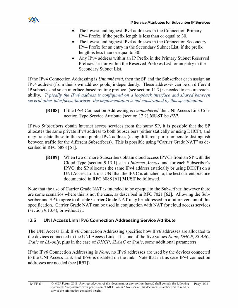
IP Service Attributes for Subscriber IP Services
MEF 61 © MEF Forum 2018. Any reproduction of this document, or any portion thereof, shall contain the following statement: "Reproduced with permission of MEF Forum." No user of this document is authorized to modify any of the information contained herein.
Page 101
x The lowest and highest IPv4 addresses in the Connection Primary IPv4 Prefix, if the prefix length is less than or equal to 30.
x The lowest and highest IPv4 addresses in the Connection Secondary IPv4 Prefix for an entry in the Secondary Subnet List, if the prefix length is less than or equal to 30.
x Any IPv4 address within an IP Prefix in the Primary Subnet Reserved Prefixes List or within the Reserved Prefixes List for an entry in the Secondary Subnet List.
If the IPv4 Connection Addressing is Unnumbered, then the SP and the Subscriber each assign an IPv4 address (from their own address pools) independently. These addresses can be on different IP subnets, and so an interface-based routing protocol (see section 11.7) is needed to ensure reach-ability. Typically the IPv4 address is configured on a loopback interface and shared between several other interfaces; however, the implementation is not constrained by this specification.
[R108] If the IPv4 Connection Addressing is Unnumbered, the UNI Access Link Con-nection Type Service Attribute (section 12.2) MUST be P2P.
If two Subscribers obtain Internet access services from the same SP, it is possible that the SP allocates the same private IPv4 address to both Subscribers (either statically or using DHCP), and may translate these to the same public IPv4 address (using different port numbers to distinguish between traffic for the different Subscribers). This is possible using “Carrier Grade NAT” as de-scribed in RFC 6888 [61].
[R109] When two or more Subscribers obtain cloud access IPVCs from an SP with the Cloud Type (section 9.13.1) set to Internet Access, and for each Subscriber’s IPVC, the SP allocates the same IPv4 address (statically or using DHCP) on a UNI Access Link in a UNI that the IPVC is attached to, the best current practice documented in RFC 6888 [61] MUST be followed.
Note that the use of Carrier Grade NAT is intended to be opaque to the Subscriber; however there are some scenarios where this is not the case, as described in RFC 7021 [62]. Allowing the Sub-scriber and SP to agree to disable Carrier Grade NAT may be addressed in a future version of this specification. Carrier Grade NAT can be used in conjunction with NAT for cloud access services (section 9.13.4), or without it.
12.5 UNI Access Link IPv6 Connection Addressing Service Attribute
The UNI Access Link IPv6 Connection Addressing specifies how IPv6 addresses are allocated to the devices connected to the UNI Access Link. It is one of the five values None, DHCP, SLAAC, Static or LL-only, plus in the case of DHCP, SLAAC or Static, some additional parameters.
If the IPv6 Connection Addressing is None, no IPv6 addresses are used by the devices connected to the UNI Access Link and IPv6 is disabled on the link. Note that in this case IPv4 connection addresses are needed (see [R97]).

IP Service Attributes for Subscriber IP Services
MEF 61 © MEF Forum 2018. Any reproduction of this document, or any portion thereof, shall contain the following statement: "Reproduced with permission of MEF Forum." No user of this document is authorized to modify any of the information contained herein.
Page 102
If the IPv6 Connection Addressing is not None, then IPv6 link local addresses are used on the UNI Access Link. If the value is LL-only, these are the only IPv6 addresses used on the UNI Access Link.
If the IPv6 Connection Addressing is DHCP, then DHCPv6 is used by the Subscriber devices to request IPv6 addresses in a given subnet from the SP as described in RFC 3315 [25]. The SP device acts as the DHCP server and the Subscriber devices act as the DHCP clients.
[R110] When the IPv6 Connection Addressing is DHCP, the SP MUST use DHCP to convey to the Subscriber, in addition to the IPv6 address, the subnet mask and router address.
If the IPv6 Connection Addressing is Static, then IPv6 addresses in a given IPv6 subnet are stati-cally assigned to the SP and the Subscriber.
If the IPv6 Connection Addressing is SLAAC, then Stateless Address Autoconfiguration (SLAAC) is used by the Subscriber devices to create unique IPv6 global addresses within an IP Prefix ad-vertised by the SP as described in RFC 4862 [40]. The Router Advertisements that convey the IP Prefix can also be used to determine the subnet mask and router address.
For DHCP, SLAAC and Static, a number of further parameters have to be agreed:
x Subnet List of one or more subnets, each comprising: o IPv6 Prefix (IPv6 address prefix and mask length between 0 and 127, in bits) o Service Provider IPv6 Addresses (Non-empty list of IPv6 addresses) o Reserved Prefixes List (List of IPv6 Prefixes, possibly empty)
x For Static, Subscriber IPv6 Address (IPv6 address or Not Specified)
The parameters consist of a list of one or more subnets. For each subnet, the IPv6 prefix and the SP’s IPv6 address are specified. The IPv6 Prefix is referred to as the Connection IPv6 Prefix. Note that an IP Prefix and SP addresses need to be agreed even when DHCP or SLAAC is used, so that the Subscriber can ensure they do not conflict with any other addressing used within the Subscriber Network.
If Static addressing is used, the Subscriber’s IPv6 address can also be specified.
A list (possibly empty) of reserved IP Prefixes can be specified; these specify IP addresses that are not available for the Subscriber to assign statically. If DHCP is used, the IPv6 address range from which addresses are dynamically assigned is taken from this pool of reserved addresses.
When Static addressing is used, the SP’s addresses are assumed to also be the router/gateway addresses, via which the Subscriber can route traffic over this UNI Access Link.
[R111] If the UNI Access Link Connection Type (section 12.2) is P2P and the UNI Access Link IPv6 Connection Addressing is Static, DHCP or SLAAC, for each subnet, there MUST be only one Service Provider IPv6 Address specified.

IP Service Attributes for Subscriber IP Services
MEF 61 © MEF Forum 2018. Any reproduction of this document, or any portion thereof, shall contain the following statement: "Reproduced with permission of MEF Forum." No user of this document is authorized to modify any of the information contained herein.
Page 103
If the connection type is Multipoint, there could be many Subscriber devices attached to the UNI Access Link, all with different IPv6 addresses. In this case the Subscriber’s IPv6 address can be set to Not Specified. Alternatively, there could be a single Subscriber device and multiple SP devices.
[R112] If the IPv6 Connection Addressing is Static, DHCP or SLAAC, for each entry in the Subnet List, the Service Provider IPv6 Addresses MUST be within the Connection IPv6 Prefix for that entry.
[R113] If the UNI Access Link IPv6 Connection Addressing is Static, and the Sub-scriber IPv6 Address is an IPv6 address, it MUST be an IPv6 address within the Connection IPv6 Prefix for the first entry in the Subnet List, that is different to the Service Provider IPv6 Addresses for that entry.
[R114] If the UNI Access Link IPv6 Connection Addressing is DHCP or SLAAC, the Subscriber IPv6 Address MUST be Not Specified.
[R115] For a given entry in the Subnet List, IP Prefixes contained in the Reserved Pre-fixes List MUST contain a subset of IPv6 addresses that are within the Con-nection IPv6 Prefix for that entry.
[R116] If the UNI Access Link IPv6 Connection Addressing is DHCP, addresses that are dynamically assigned by DHCP MUST be taken from within one of the IP Prefixes in the Reserved Prefixes List for one of the entries in the Subnet List.
[R117] If the UNI Access Link IPv6 Connection Addressing is SLAAC, the IP Prefix advertised by the SP as described in RFC 4862 [40] using Router Advertise-ments MUST be the Connection IPv6 Prefix for the first entry in the Subnet List.
The Subscriber can statically assign any IPv6 address within the subnets identified by the Connec-tion IPv6 Prefix in each entry, other than the SP address itself, the lowest and highest possible addresses, which are generally reserved, and any addresses reserved for dynamic assignment.
[R118] If the UNI Access Link IPv6 Connection Addressing is DHCP, SLAAC or Static, the Subscriber MUST NOT statically assign any of the following for use on the UNI Access Link by Subscriber devices:
x Any IPv6 address that is not within the Connection IPv6 Prefix for an entry in the Subnet List.
x Any IPv6 address within the Connection IPv6 Prefix for the first en-try in the Subnet List, if the UNI Access Link IPv6 Connection Ad-dressing is SLAAC.
x Any IPv6 address within the Connection IPv6 Prefix for the first en-try in the Subnet List other than the Subscriber IPv6 Address, unless it is Not Specified.
x Any of the Service Provider IPv6 Addresses specified in an entry in the Subnet List.

IP Service Attributes for Subscriber IP Services
MEF 61 © MEF Forum 2018. Any reproduction of this document, or any portion thereof, shall contain the following statement: "Reproduced with permission of MEF Forum." No user of this document is authorized to modify any of the information contained herein.
Page 104
x The lowest and highest IPv6 addresses in the Connection IPv6 Prefix for an entry in the Subnet List, if the prefix length is less than or equal to 126.
x Any IPv6 address within an IP Prefix in the Reserved Prefixes in an entry in the Subnet List.
12.6 UNI Access Link DHCP Relay Service Attribute
The UNI Access Link DHCP Relay Service Attribute is either Disabled or a pair containing an IPVC EP Identifier (section 10.1) for one of the IPVC EPs at the UNI that the UNI Access Link is in, and a non-empty list of IP addresses for DHCP Servers belonging to the Subscriber. If the value is Disabled, DHCP Relay functionality for the Subscriber is disabled.
If the value is not Disabled, then the SP enables DHCP Relay functionality on the UNI Access Link, as described in RFC 3046 [21]. DHCP Relay functionality is useful when the Subscriber uses DHCP (per RFC 2131 [9] and RFC 3315 [25]) in the Subscriber Network, but does not want to place a DHCP server (or possibly a pair of redundant DHCP servers) in each part of the network. As DHCP packets do not traverse routers, additional functionality needs to be provided by the SP, to enable hosts in one part of the Subscriber Network to access DHCP servers in another part of the Subscriber Network.
In brief, DHCP relay functionality works by listening for multicast DHCP requests on the local LAN, but actually forwarding (using unicast packets) the request to one or more remote DHCP servers rather than responding to it directly. An additional DHCP option (per RFC 3046 [21]) is inserted into the request so that the remote server can unicast a response, and the option is stripped out of the response before being forwarded back to the local LAN.
Note that DHCP relay functionality is relevant when the Subscriber uses their own DHCP servers; this is distinct from the case where DHCP is used for the connection addressing (sections 12.4 and 12.5)– in the latter case, it is the SP that has the DHCP servers.
[R119] When the UNI Access Link DHCP Relay Service Attribute is not Disabled, the SP MUST enable DHCP Relay functionality as described in RFC 3046 [21] on the UNI Access Link, so that DHCP requests are forwarded to the DHCP serv-ers specified by the IP addresses in the value of the attribute, via the IPVC EP specified in the value of the attribute.
The reachability of the listed DHCP server addresses is determined in the same way as for Ingress IP Data Packets at the UNI that are mapped to the given IPVC EP.
[R120] When the UNI Access Link DHCP Relay Service Attribute is not Disabled, DHCP requests that are forwarded to an IP address specified in the value of the attribute MUST be delivered in the same way as an Ingress IP Data Packet on the UNI Access Link with a destination address equal to the IP address in the attribute, that is mapped to the IPVC EP specified in the value of the attribute.
[O15] The SP MAY add additional DHCP Options in the forwarded DHCP request.

IP Service Attributes for Subscriber IP Services
MEF 61 © MEF Forum 2018. Any reproduction of this document, or any portion thereof, shall contain the following statement: "Reproduced with permission of MEF Forum." No user of this document is authorized to modify any of the information contained herein.
Page 105
[R121] The SP MUST NOT remove any DHCP Options from the forwarded DHCP request.
[O16] The SP MAY modify the value of DHCP Options in the forwarded DHCP re-quest.
[R122] If the UNI Access Link DHCP Relay Service Attribute is not Disabled, and the list of DHCP servers includes at least one IPv4 address, the UNI Access Link IPv4 Connection Addressing (section 12.4) MUST be set to Static or Unnum-bered.
[R123] If the UNI Access Link DHCP Relay Service Attribute is not Disabled, and the list of DHCP servers includes at least one IPv6 address, the UNI Access Link IPv6 Connection Addressing (section 12.5) MUST be set to Static or LL-only.
To protect their network and ensure it performs sufficiently well, the SP might want to limit the rate at which requests are forwarded. This does not need to be agreed with the Subscriber, since the DHCP protocol is robust against not receiving a response, and will retry.
[O17] The SP MAY limit the rate of DHCP requests that are forwarded.
12.7 UNI Access Link Prefix Delegation Service Attribute
In certain situations (particularly for Internet access), a Subscriber might not have their own IP Prefixes for use in the Subscriber Network, but instead be allocated IP Prefixes dynamically by the SP when they first connect. For IPv6 Prefixes, this can be done using DHCPv6 Prefix Dele-gation as described in RFC 3633 [28]. The UNI Access Link Prefix Delegation Service Attribute indicates whether DHCPv6 Prefix Delegation is enabled over the UNI Access Link, and takes values Enabled or Disabled. It is typically used in combination with DHCP or SLAAC for the UNI Access Link IPv6 Connection Addressing (section 12.5).
[R124] When the UNI Access Link Prefix Delegation Service Attribute is Enabled, DHCPv6 Prefix Delegation as described in RFC 3633 [28] MUST be enabled for the UNI Access Link.
[R125] When the UNI Access Link Prefix Delegation Service Attribute is Enabled, the UNI Access Link IPv6 Connection Addressing (section 12.5) MUST NOT be None.
[R126] When the UNI Access Link Prefix Delegation Service Attribute is Enabled, the UNI Access Link MUST be the only UNI Access Link in the UNI with UNI Access Link Prefix Delegation Service Attribute set to Enabled.
A possible scenario for the use of DHCPv6 Prefix Delegation is illustrated in Figure 19.

IP Service Attributes for Subscriber IP Services
MEF 61 © MEF Forum 2018. Any reproduction of this document, or any portion thereof, shall contain the following statement: "Reproduced with permission of MEF Forum." No user of this document is authorized to modify any of the information contained herein.
Page 106
Figure 19 – DHCPv6 Prefix Delegation
In this example, SLAAC is used for the connection addresses across the UNI Access Link, and DHCPv6 Prefix Delegation is used to delegate an IPv6 Prefix from the SP to the Subscriber. The Subscriber’s router can then use DHCPv6 to allocate IPv6 addresses taken from this delegated prefix to hosts within the Subscriber Network.
Note that for correct operation, the SP adds a route towards the delegated prefix over the UNI Access Link – in other words, it adds the route to the UNIL routing information database, as de-scribed in section 8.
DHCPv6 Prefix Delegation is more commonly used with a Subscriber-Managed CE; however, use with a Provider-Managed CE (i.e. between the CE and a router in the Subscriber Network) is not precluded. Note that use of Prefix Delegation between a Provider-Managed CE and a PE would be internal to the SP Network and hence outside the scope of this specification.
12.8 UNI Access Link BFD Service Attribute
The UNI Access Link BFD Service Attribute indicates whether Bidirectional Forwarding Detec-tion (BFD) is enabled on the UNI Access Link, and if so the parameters that need to be agreed. It is either None or a set of parameters consisting of:

IP Service Attributes for Subscriber IP Services
MEF 61 © MEF Forum 2018. Any reproduction of this document, or any portion thereof, shall contain the following statement: "Reproduced with permission of MEF Forum." No user of this document is authorized to modify any of the information contained herein.
Page 107
x Connection Address Family (IPv4, IPv6 or Both) x Transmission Interval (time in ms) x Detect Multiplier (integer) x Active End (Subscriber, SP or Both) x Authentication Type (None, Simple Password, Keyed MD5, Meticulous Keyed MD5,
Keyed SHA1, Meticulous Keyed SHA1)
Note that although BFD implementations often have many configurable parameters, the above parameters are restricted to those that need to be agreed between the Subscriber and the SP in order to operate BFD across the UNI Access Link.
The Connection Address Family parameter specifies whether the session is established over IPv4 or IPv6, or whether two separate sessions are established using IPv4 and IPv6. The sessions are established using the addresses in the UNI Access Link IPv4 Connection Addressing Service At-tribute (section 12.4) or the UNI Access Link IPv6 Connection Addressing Service Attribute (sec-tion 12.5). Note that when DHCP is used, BFD sessions cannot be established until the Sub-scriber’s IP address has been allocated via DHCP.
[R127] When the UNI Access Link BFD Service Attribute is not None and the Con-nection Address Family parameter is IPv4 or Both, the UNI Access Link IPv4 Connection Addressing Service Attribute (section 12.4) MUST be Static or DHCP.
[R128] When the UNI Access Link BFD Service Attribute is not None and the Con-nection Address Family parameter is IPv4 or Both, BFD as specified in RFC 5880 [50] and RFC 5881 [51], or where applicable, as specified in RFC 7130 [63], MUST be enabled using the Primary Subnet IPv4 addresses specified in the UNI Access Link IPv4 Connection Addressing Service Attribute (section 12.4), if the UNI Access Link IPv4 Connection Addressing Service Attribute is Static.
[R129] When the UNI Access Link BFD Service Attribute is not None and the Con-nection Address Family parameter is IPv4 or Both, BFD as specified in RFC 5880 [50] and RFC 5881 [51], or where applicable, as specified in RFC 7130 [63], MUST be enabled using the Primary Subnet SP IPv4 addresses specified in the UNI Access Link IPv4 Connection Addressing Service Attribute (section 12.4), and the Primary Subnet IPv4 address allocated to the Subscriber using DHCP, if the UNI Access Link IPv4 Connection Addressing Service Attribute is DHCP.
[R130] When the UNI Access Link BFD Service Attribute is not None and the Con-nection Address Family parameter is IPv6 or Both, the UNI Access Link IPv6 Connection Addressing Service Attribute (section 12.5) MUST NOT be None.
[R131] When the UNI Access Link BFD Service Attribute is not None and the Con-nection Address Family parameter is IPv6 or Both, BFD as specified in RFC 5880 [50] and RFC 5881 [51], or where applicable, as specified in RFC 7130

IP Service Attributes for Subscriber IP Services
MEF 61 © MEF Forum 2018. Any reproduction of this document, or any portion thereof, shall contain the following statement: "Reproduced with permission of MEF Forum." No user of this document is authorized to modify any of the information contained herein.
Page 108
[63], MUST be enabled using the IPv6 addresses for the first entry in the Sub-net List specified in the UNI Access Link IPv6 Connection Addressing Service Attribute (section 12.5), if the UNI Access Link IPv6 Connection Addressing Service Attribute is Static.
[R132] When the UNI Access Link BFD Service Attribute is not None and the Con-nection Address Family parameter is IPv6 or Both, BFD as specified in RFC 5880 [50] and RFC 5881 [51], or where applicable, as specified in RFC 7130 [63], MUST be enabled using the IPv6 link local addresses on the UNI Access Link if the UNI Access Link IPv6 Connection Addressing Service Attribute (section 12.5) is not Static.
BFD has two operating modes: asynchronous mode, and demand mode. As described in RFC 5880 [50], BFD sessions are initially established in asynchronous mode; thereafter, either peer can independently switch to demand mode. As this is negotiated in-band within the protocol, there is nothing that needs to be agreed beforehand between the SP and the Subscriber.
[R133] If the Subscriber or the SP support a value for the UNI Access Link BFD Ser-vice Attribute other than None, they MUST support asynchronous mode.
[O18] If the Subscriber or the SP support a value for the UNI Access Link BFD Ser-vice Attribute other than None, they MAY support demand mode.
BFD allows for asymmetrical operation, where packets can be sent at different intervals in each direction, and a different detect multiplier can be used. For simplicity, this specification mandates symmetrical operation.
[R134] When the UNI Access Link BFD Service Attribute is not None, the Desired Minimum Transmit Interval and the Required Minimum Receive Interval MUST be set to the specified Transmission Interval in normal operation.
[O19] A longer transmission interval MAY be used during abnormal periods.
Optional Requirement [O19] allows for implementations that adjust the interval temporarily to keep the session up in certain cases.
RFC 7419 [65] specifies a set of common intervals which are used to ensure interoperability: 3.3ms, 10ms, 20ms, 50ms, 100ms and 1s.
[R135] If the Subscriber or the SP support a value for the UNI Access Link BFD Ser-vice Attribute other than None, they MUST support a Transmission interval of 1s.
[R136] If the Subscriber or the SP support a value for the UNI Access Link BFD Ser-vice Attribute other than None and one of the common intervals specified in RFC 7419 [65] is supported, all of the longer common intervals specified in RFC 7419 [65] MUST be supported.

IP Service Attributes for Subscriber IP Services
MEF 61 © MEF Forum 2018. Any reproduction of this document, or any portion thereof, shall contain the following statement: "Reproduced with permission of MEF Forum." No user of this document is authorized to modify any of the information contained herein.
Page 109
[R137] When the UNI Access Link BFD Service Attribute is not None, the Detect Multiplier MUST be set to the specified value.
At least one end of the BFD session has to have an active role, meaning that it sends out asynchro-nous control messages regardless of whether it has received any.
[R138] When the UNI Access Link BFD Service Attribute is not None, the Subscriber device MUST take an Active role if the Active End is Subscriber or Both, and a Passive role otherwise.
[R139] When the UNI Access Link BFD Service Attribute is not None, the SP device MUST take an Active role if the Active End is SP or Both, and a Passive role otherwise.
The BFD Echo function can be supported, in the sense of being able to receive and loop back echo packets, by the Subscriber, the SP or both.
[O20] The Subscriber and the SP MAY support the BFD Echo function.
BFD has several options for authentication.
[R140] When the UNI Access Link BFD Service Attribute is not None, and the Au-thentication Type is not None, the specified authentication type MUST be used as described in RFC 5880 [50].
Note: the additional parameters that need to be agreed for each authentication type are deferred to a future version of this specification.
12.9 UNI Access Link IP MTU Service Attribute
The UNI Access Link IP Maximum Transmit Unit (MTU) Service Attribute is an integer ≥ 576 that specifies the maximum length in octets of IP Packets that can be conveyed across the UNI Access Link. It is used to determine the maximum value of the IPVC MTU (see section 9.10) for IPVCs attached to the UNI containing the UNI Access Link, and also affects IP Control Protocol Packets at the UNI Access Link.
RFC 791 [1] specifies the minimum MTU for IPv4 Packets as 68 octets; however, it also requires that all devices can handle a packet of length 576 octets (possibly fragmented). This specification strengthens the requirements from RFC 791 [1], by defining the minimum MTU as 576 octets – that is, IPv4 Packets that are shorter than this are guaranteed not to be fragmented or discarded.
RFC 2460 [15] specifies the minimum MTU for IPv6 Packets as 1280 octets; therefore this value is recommended in all cases.
[D16] The UNI Access Link IP MTU SHOULD be greater than or equal to 1280 octets.

IP Service Attributes for Subscriber IP Services
MEF 61 © MEF Forum 2018. Any reproduction of this document, or any portion thereof, shall contain the following statement: "Reproduced with permission of MEF Forum." No user of this document is authorized to modify any of the information contained herein.
Page 110
Note that if the UNI Access Link is in a UNI that has an IPVC with IPv6 enabled attached to it, the combination of [R33] and [R34] means that the UNI Access Link IP MTU has to be greater than or equal to 1280.
If an SP transmits IP Control Protocol Packets across a UNI Access Link, they cannot exceed the UNI Access Link IP MTU. Similarly, Ingress IP Control Protocol Packets with a length greater than the UNI Access Link IP MTU can be discarded by the SP, even if the corresponding protocol is normally peered. Note that the corresponding requirements for IP Data Packets can be found in section 9.10.
[R141] Egress IP Control Protocol Packets MUST have a length less than or equal to the value of the UNI Access Link IP MTU Service Attribute.
[R142] Ingress IP Control Protocol Packets with a length less than or equal to the value of the UNI Access Link IP MTU Service Attribute MUST NOT be discarded due to their length.
[O21] Ingress IP Control Protocol Packets with a length strictly greater than the value of the UNI Access Link IP MTU Service Attribute MAY be discarded.
12.10 UNI Access Link Ingress Bandwidth Profile Envelope Service Attribute
The UNI Access Link Ingress Bandwidth Profile Envelope Service Attribute is either None, or a single Bandwidth Profile Envelope consisting of parameters and Bandwidth Profile Flow specifi-cations, as described in section 13.3. If specified, the BWP Envelope is used for an ingress Band-width Profile.
An Ingress Bandwidth Profile Envelope can be specified for one of a UNI, a UNI Access Link, or an IPVC EP.
[R143] For a UNI Access Link in a given UNI, if the UNI Access Link Ingress Band-width Profile Envelope Service Attribute is not None, the IPVC EP Ingress Bandwidth Profile Envelope Service Attribute (section 10.9) MUST be None for all IPVC EPs at the UNI.
Note that if the UNI Access Link Ingress Bandwidth Profile Service Attribute is not None, it fol-lows from [R75] that the UNI Ingress Bandwidth Profile Service Attribute is None.
12.11 UNI Access Link Egress Bandwidth Profile Envelope Service Attribute
The UNI Access Link Egress Bandwidth Profile Envelope Service Attribute is either None, or a single Bandwidth Profile Envelope consisting of parameters and Bandwidth Profile Flow specifi-cations, as described in section 13.3. If specified, the BWP Envelope is used for an egress Band-width Profile.
An Egress Bandwidth Profile Envelope can be specified for one of a UNI, a UNI Access Link, or an IPVC EP.

IP Service Attributes for Subscriber IP Services
MEF 61 © MEF Forum 2018. Any reproduction of this document, or any portion thereof, shall contain the following statement: "Reproduced with permission of MEF Forum." No user of this document is authorized to modify any of the information contained herein.
Page 111
[R144] For a UNI Access Link in a given UNI, if the UNI Access Link Egress Band-width Profile Envelope Service Attribute is not None, the IPVC EP Egress Bandwidth Profile Envelope Service Attribute (section 10.10) MUST be None for all IPVC EPs at the UNI.
Note that if the UNI Access Link Egress Bandwidth Profile Service Attribute is not None, it fol-lows from [R77] that the UNI Egress Bandwidth Profile Service Attribute is None.
12.12 UNI Access Link Reserved VRIDs Service Attribute
As described in section 12.3.4, the SP can use the Virtual Router Redundancy Protocol (VRRP) specified in RFC 5798 [49] to implement a pair of redundant devices on the SP side of a UNI Access Link. The VRRP protocol supports multiple VRRP instances on the same IP subnet, each with a unique ID known as a VRID. A VRID, as defined in RFC 5798 [49], is a number between 1 and 255.
Since the protocol supports multiple instances, the Subscriber might also use VRRP on the UNI Access Link, for instance to provide redundant access to some service that is being provided to other Subscriber hosts on that subnet. To ensure there is no conflict, it is necessary to ensure that the SP and the Subscriber use different VRIDs.
The UNI Access Link Reserved VRIDs Service Attribute consists of a list of VRIDs (possibly empty) that are reserved for use by the SP. These VRIDs can be used for IPv4 or IPv6.
[R145] If the SP enables VRRP on the UNI Access Link, they MUST use VRIDs that are included in the UNI Access Link Reserved VRIDs Service Attribute.
[R146] If the Subscriber enables VRRP on the UNI Access Link, they MUST NOT use VRIDs that are included in the UNI Access Link Reserved VRIDs Service Attribute.
Note that if a VRID is included in the list, it does not mean that the SP has to use it. Whether or not the SP is using VRRP is opaque to the Subscriber, other than that if the UNI Access Link Reserved VRIDs Service Attribute is an empty list, the Subscriber can deduce that the SP is not using VRRP.
When the SP uses VRRP, only the common IP address that is shared between the redundant routers is visible to the Subscriber (i.e. it is the Service Provider IPv4 Address in the UNI Access Link IPv4 Connection Addressing Service Attribute (section 12.4), or the Service Provider IPv6 Ad-dress in the UNI Access Link IPv6 Connection Addressing Service Attribute (section 12.5)). How-ever, the SP needs to ensure the Subscriber does not allocate to one of their devices the IP addresses used individually by each of the redundant routers. This can be achieved by ensuring these ad-dresses are included in the Reserved Prefixes List in the UNI Access Link IPv4 Connection Ad-dressing Service Attribute or the UNI Access Link IPv6 Connection Addressing Service Attribute as appropriate.

IP Service Attributes for Subscriber IP Services
MEF 61 © MEF Forum 2018. Any reproduction of this document, or any portion thereof, shall contain the following statement: "Reproduced with permission of MEF Forum." No user of this document is authorized to modify any of the information contained herein.
Page 112
13 Bandwidth Profiles
A Bandwidth Profile is a specification of the temporal properties of a sequence of IP Packets at an EI (in the case of Subscriber IP Services, at a UNI). The specification is in terms of a set of parameters. A real sequence of IP Packets can be checked against a Bandwidth Profile with a given set of parameters (a process called ‘metering’), and further action can be taken depending on the outcome of this check: for instance, discarding packets (policing) or delaying certain packets (shaping) in order to bring the sequence closer to conformance with the Bandwidth Profile speci-fication. The metering, based on the Bandwidth Profile parameters, and the associated policing and/or shaping, can together provide guarantees and limits on the amount of traffic that can flow over a UNI, while ensuring the available bandwidth is divided fairly among multiple flows.
The specification of Bandwidth Profiles is based on Bandwidth Profile Flows and Bandwidth Pro-file Envelopes. A Bandwidth Profile Flow (BWP Flow) is a stream of IP Packets that meet certain criteria, and for which the amount of traffic is metered, policed and/or shaped. A Bandwidth Pro-file Envelope (BWP Envelope) is a set of one or more Bandwidth Profile Flows that are associated such that the amount of traffic for one flow can affect the amount that is permitted for another flow.
Bandwidth Profiles can be applied to Ingress IP Data Packets or Egress IP Data Packets. When applied to Ingress IP Data Packets, the Bandwidth Profile is applied to the traffic flowing across the UNI from the Subscriber towards the SP. When a Bandwidth is applied to Egress IP Data Packets, it is applied to traffic that is eligible to be transmitted across the UNI from the SP towards the Subscriber.
Some examples showing possible locations for implementation of Bandwidth Profiles can be found in Appendix B.7.3.
The subsections below describe the structure of Bandwidth Profiles, and then describe BWP Flows and BWP Envelopes in more detail.
13.1 Structure of Bandwidth Profiles
At each UNI, Bandwidth Profile Envelopes can be specified in one of three ways. Ingress and Egress Bandwidth Profiles are specified separately, and can be specified in different ways. The three possibilities are:
x A single BWP Envelope for the UNI (sections 11.4 and 11.5). x One BWP Envelope per UNI Access Link (sections 12.8 and 12.11). Note that if the
UNI only contains a single UNI Access Link, then this option is the same as the first op-tion.
x One BWP Envelope per IPVC EP (sections 10.9 and 10.10). Note that if the UNI only has a single IPVC EP, then this option is the same as the first option.
Each BWP Envelope consists of a list of Bandwidth Profile Flows (and other parameters), and each Bandwidth Profile Flow specifies a stream of IP Packets. A given Bandwidth Profile Flow matches either Ingress IP Packets or Egress IP Packets.

IP Service Attributes for Subscriber IP Services
MEF 61 © MEF Forum 2018. Any reproduction of this document, or any portion thereof, shall contain the following statement: "Reproduced with permission of MEF Forum." No user of this document is authorized to modify any of the information contained herein.
Page 113
An ingress Bandwidth Profile applies to Ingress IP Data Packets at a UNI. An egress Bandwidth Profile applies to Egress-Eligible IP Packets at a UNI. An Egress-Eligible Packet at a given UNI is an IP Data Packet that meets all of the following criteria:
x The IP Data Packet is mapped to a Subscriber IPVC on ingress, as described in section 10.4.1.
x The IP Data Packet should be delivered to the specified UNI (i.e., should be transmitted over one of the UNI Access Links in the UNI), per the packet delivery requirements of section 9.4.
x The IP Data Packet is not discarded per requirements [O2], [O5], [R38], [R42], [O6], [O7], [O8], [O9], [R59], [R61], [R67], [R94]; per requirement [R158] to comply with an ingress Bandwidth Profile; or to comply with the requirements of RFC 791 [1] or RFC 2460 [15].
x The IP Data Packet is not discarded as a result of another agreement between the SP and the Subscriber, for example as part of a value-added over-the-top service offering.
Note the similarity (and differences) of these criteria to the specification of Qualified Packets in section 9.9.2.
13.2 Bandwidth Profile Flows
A Bandwidth Profile Flow is a stream of IP Packets meeting certain criteria. The criteria that can be used depend on which BWP Envelope the BWP Flow is part of.
[R147] Each Bandwidth Profile Flow MUST belong to exactly one BWP Envelope.
BWP Envelope BWP Flow Criteria BWP Flow Parameters UNI Ingress BWP Envelope (section 11.4)
All Ingress IP Data Packets at the UNI. None All Ingress IP Data Packets at the UNI that are mapped to any of a given set of IPVC EPs.
A set, each entry comprising: x IPVC EP Identifier
(section 10.1) for an IPVC EP located at the UNI.
All Ingress IP Data Packets at the UNI that are mapped to any of a given set of (IPVC EP, CoS Name) pairs.
A set, each entry comprising: x IPVC EP Identifier
(section 10.1) for an IPVC EP located at the UNI.
x CoS Name from the IPVC List of Class of Service Names (sec-tion 9.8) for the IPVC that has the IPVC EP.

IP Service Attributes for Subscriber IP Services
MEF 61 © MEF Forum 2018. Any reproduction of this document, or any portion thereof, shall contain the following statement: "Reproduced with permission of MEF Forum." No user of this document is authorized to modify any of the information contained herein.
Page 114
BWP Envelope BWP Flow Criteria BWP Flow Parameters All Ingress IP Data Packets at the UNI that are received over one of a given set of UNI Access Links.
A set, each entry comprising: x UNI Access Link
Identifier (section 12.1) for a UNI Ac-cess Link in the UNI.
All Ingress IP Data Packets at the UNI that are received over one of a given set of UNI Access Links, and that are mapped to any of a given set of IPVC EPs.
A set, each entry comprising: x UNI Access Link
Identifier (section 12.1) for a UNI Ac-cess Link in the UNI.
A set, each entry comprising: x IPVC EP Identifier
(section 10.1) for an IPVC EP located at the UNI.
All Ingress IP Data Packets at the UNI that are received over one of a given set of UNI Access Links, and that are mapped to the any of a given set of (IPVC EP, CoS Name) pairs.
A set, each entry comprising: x UNI Access Link
Identifier (section 12.1) for a UNI Ac-cess Link in the UNI.
A set, each entry comprising: x IPVC EP Identifier
(section 10.1) for an IPVC EP located at the UNI.
x CoS Name from the IPVC List of Class of Service Names (sec-tion 9.8) for the IPVC that has the IPVC EP.
UNI Egress BWP Envelope (section 11.5)
All Egress-Eligible IP Packets at the UNI. None All Egress-Eligible IP Packets at the UNI that are mapped to any of a given set of IPVC EPs.
A set, each entry comprising: x IPVC EP Identifier
(section 10.1) for an IPVC EP located at the UNI.

IP Service Attributes for Subscriber IP Services
MEF 61 © MEF Forum 2018. Any reproduction of this document, or any portion thereof, shall contain the following statement: "Reproduced with permission of MEF Forum." No user of this document is authorized to modify any of the information contained herein.
Page 115
BWP Envelope BWP Flow Criteria BWP Flow Parameters All Egress-Eligible IP Packets at the UNI that, for any of a given set of (IPVC EP, CoS Name) pairs, are mapped to the IPVC EP and were mapped on ingress to the CoS Name.
A set, each entry comprising: x IPVC EP Identifier
(section 10.1) for an IPVC EP located at the UNI.
x CoS Name from the IPVC List of Class of Service Names (sec-tion 9.8) for the IPVC that has the IPVC EP.
All Egress-Eligible IP Packets at the UNI that if transmitted, would be transmitted over one of a given set of UNI Access Links.
A set, each entry comprising: x UNI Access Link
Identifier (section 12.1) for a UNI Ac-cess Link in the UNI.
All Egress-Eligible IP Packets at the UNI that if transmitted, would be transmitted over one of a given set of UNI Access Links, and that are mapped to any of a given set of IPVC EPs.
A set, each entry comprising: x UNI Access Link
Identifier (section 12.1) for a UNI Ac-cess Link in the UNI.
A set, each entry comprising: x IPVC EP Identifier
(section 10.1) for an IPVC EP located at the UNI.
All Egress-Eligible IP Packets at the UNI that if transmitted, would be transmitted over one of a given set of UNI Access Links, and that for any of a given set of (IPVC EP, CoS Name) pairs, are mapped to the IPVC EP and were mapped on ingress to the CoS Name.
A set, each entry comprising: x UNI Access Link
Identifier (section 12.1) for a UNI Ac-cess Link in the UNI.
A set, each entry comprising: x IPVC EP Identifier
(section 10.1) for an IPVC EP located at the UNI.
x CoS Name from the IPVC List of Class of Service Names (sec-tion 9.8) for the IPVC that has the IPVC EP.
UNI Access Link Ingress
All Ingress IP Data Packets at the UNI that are received over the UNI Access Link.
None

IP Service Attributes for Subscriber IP Services
MEF 61 © MEF Forum 2018. Any reproduction of this document, or any portion thereof, shall contain the following statement: "Reproduced with permission of MEF Forum." No user of this document is authorized to modify any of the information contained herein.
Page 116
BWP Envelope BWP Flow Criteria BWP Flow Parameters BWP Envelope (section 12.8)
All Ingress IP Data Packets at the UNI that are received over the UNI Access Link, and are mapped to any of a given set of IPVC EPs.
A set, each entry comprising: x IPVC EP Identifier
(section 10.1) for an IPVC EP located at the UNI.
All Ingress IP Data Packets at the UNI that are received over the UNI Access Link, and are mapped to any of a given set of (IPVC EP, CoS Name) pairs.
A set, each entry comprising: x IPVC EP Identifier
(section 10.1) for an IPVC EP located at the UNI.
x CoS Name from the IPVC List of Class of Service Names (sec-tion 9.8) for the IPVC that has the IPVC EP.
UNI Access Link Egress BWP Envelope (section 12.11)
All Egress-Eligible IP Packets at the UNI that if transmitted, would be transmitted over the UNI Access Link.
None
All Egress-Eligible IP Packets at the UNI that if transmitted, would be transmitted over the UNI Access Link, and are mapped to any of a given set of IPVC EPs.
A set, each entry comprising: x IPVC EP Identifier
(section 10.1) for an IPVC EP located at the UNI.
All Egress-Eligible IP Packets at the UNI that if transmitted, would be transmitted over the UNI Access Link, and that, for any of a given set of (IPVC EP, CoS Name) pairs, are mapped to the IPVC EP and were mapped on ingress to the CoS Name.
A set, each entry comprising: x IPVC EP Identifier
(section 10.1) for an IPVC EP located at the UNI.
x CoS Name from the IPVC List of Class of Service Names (sec-tion 9.8) for the IPVC that has the IPVC EP.
IPVC EP Ingress BWP Envelope (section 10.9)
All Ingress IP Data Packets at the UNI that are mapped to the IPVC EP.
None
All Ingress IP Data Packets at the UNI that are mapped to the IPVC EP and to any of a given set of CoS Names.
A set, each entry comprising: x CoS Name from the
IPVC List of Class of Service Names (sec-tion 9.8) for the IPVC that has the IPVC EP.

IP Service Attributes for Subscriber IP Services
MEF 61 © MEF Forum 2018. Any reproduction of this document, or any portion thereof, shall contain the following statement: "Reproduced with permission of MEF Forum." No user of this document is authorized to modify any of the information contained herein.
Page 117
BWP Envelope BWP Flow Criteria BWP Flow Parameters IPVC EP Egress BWP Envelope (section 10.10)
All Egress-Eligible IP Packets at the UNI that are mapped to the IPVC EPs.
None
All Egress-Eligible IP Packets at the UNI that are mapped to the IPVC EP were mapped on ingress to any of a given set of CoS Names.
A set, each entry comprising: x CoS Name from the
IPVC List of Class of Service Names (sec-tion 9.8) for the IPVC that has the IPVC EP.
Table 21 – BWP Flow Criteria and Parameters
[R148] A Bandwidth Profile Flow used at a given UNI MUST be specified using one of the criteria shown in Table 21, depending on the BWP Envelope it belongs to.
Further details of how packets are mapped to a given IPVC EP can be found in section 10.4.1, and of how packets are mapped to a given CoS Name in section 10.7. Note that since CoS Names are specified to a given IPVC, it is not possible to explicitly specify a Bandwidth Profile Flow that matches all packets received or transmitted at a given UNI that match a given CoS Name, regard-less of the IPVC EP to which they are mapped. However, if all of the IPVC EPs at a UNI use the same CoS Names, then for each CoS Name a Bandwidth Profile Flow can be specified that matches that CoS Name at every IPVC EP. An examples of this is shown in Appendix B.7.2.
Each Bandwidth Profile Flow has a number of parameters that need to be specified in order to define it.
[R149] When a Bandwidth Profile Flow is specified using one of the criteria from Ta-ble 21, the corresponding parameters listed in Table 21 MUST also be speci-fied.
[R150] The Bandwidth Profile Flows specified at a given UNI MUST be such that each Ingress IP Packet is mapped to at most one Bandwidth Profile Flow.
[R151] The Bandwidth Profile Flows specified at a given UNI MUST be such that each Egress-Eligible IP Packet is mapped to at most one Bandwidth Profile Flow.
Requirements [R150] and [R151] prohibit Bandwidth Profile Flows that overlap. For example, if a Bandwidth Profile Flow is specified using a criterion of All Ingress IP Data Packets at a UNI, then no Bandwidth Profile Flows can be specified using other criteria that match ingress packets, as an ingress packet would then map to both of them.
Note that a given IP Packet does not necessarily map to any Bandwidth Profile Flows, e.g. if no egress Bandwidth Profile is specified, there is no need to define any Bandwidth Profile Flows for egress packets, and so an Egress IP Packet will not map to any Bandwidth Profile Flow.

IP Service Attributes for Subscriber IP Services
MEF 61 © MEF Forum 2018. Any reproduction of this document, or any portion thereof, shall contain the following statement: "Reproduced with permission of MEF Forum." No user of this document is authorized to modify any of the information contained herein.
Page 118
13.3 Bandwidth Profile Envelopes
A BWP Envelope is a list of Bandwidth Profile Flows, plus additional parameters for the BWP Envelope as a whole.
[R152] All Bandwidth Profile Flows in a given BWP Envelope MUST be specified using the same criterion from Table 21.
Since an IP Packet is mapped to at most one BWP Flow on ingress and at most one BWP Flow on egress, and each BWP Flow belongs to exactly one BWP Envelope, the packet is metered against a Bandwidth Profile at most once on ingress and once on egress. Another perspective is that at ingress and at egress, the set of all IP Packets that flow across the UNI is partitioned first into BWP Envelopes, and then each BWP Envelope is partitioned into BWP Flows, with the proviso that there might be some IP Packets that are not mapped to any BWP Envelope or BWP Flow.
As described above, there are six BWP Envelope Service Attributes, corresponding to the three possible ways that BWP Envelopes can be specified, each for ingress and egress. In each case, if the Service Attribute is not None, the following parameters are specified:
x The Envelope Maximum Information Rate (denoted MaxIRE), in bits per second. This is the limit on the total aggregate information rate of traffic across all BWP Flows in the Envelope.
x The Envelope IR Time (denoted TE), in milliseconds. This is the time period over which average Information Rates are calculated, and thus it limits the size of a burst.
x The list of Bandwidth Profile Flows contained in the BWP Envelope, along with the pa-rameters for each BWP Flow as specified below.
A number of additional parameters are specified for each Bandwidth Profile Flow as shown in Table 22.
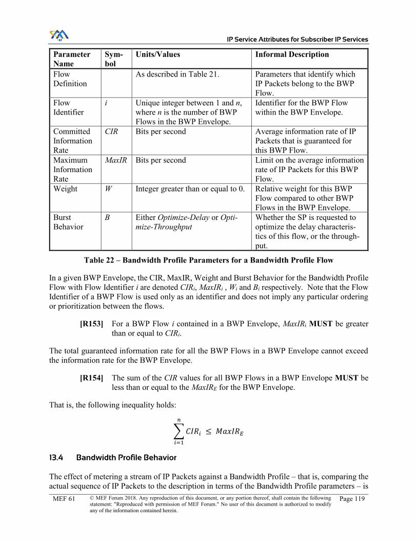
IP Service Attributes for Subscriber IP Services
MEF 61 © MEF Forum 2018. Any reproduction of this document, or any portion thereof, shall contain the following statement: "Reproduced with permission of MEF Forum." No user of this document is authorized to modify any of the information contained herein.
Page 119
Parameter Name
Sym-bol
Units/Values Informal Description
Flow Definition
As described in Table 21. Parameters that identify which IP Packets belong to the BWP Flow.
Flow Identifier
i Unique integer between 1 and n, where n is the number of BWP Flows in the BWP Envelope.
Identifier for the BWP Flow within the BWP Envelope.
Committed Information Rate
CIR Bits per second Average information rate of IP Packets that is guaranteed for this BWP Flow.
Maximum Information Rate
MaxIR Bits per second Limit on the average information rate of IP Packets for this BWP Flow.
Weight W Integer greater than or equal to 0. Relative weight for this BWP Flow compared to other BWP Flows in the BWP Envelope.
Burst Behavior
B Either Optimize-Delay or Opti-mize-Throughput
Whether the SP is requested to optimize the delay characteris-tics of this flow, or the through-put.
Table 22 – Bandwidth Profile Parameters for a Bandwidth Profile Flow
In a given BWP Envelope, the CIR, MaxIR, Weight and Burst Behavior for the Bandwidth Profile Flow with Flow Identifier i are denoted CIRi, MaxIRi , Wi and Bi respectively. Note that the Flow Identifier of a BWP Flow is used only as an identifier and does not imply any particular ordering or prioritization between the flows.
[R153] For a BWP Flow i contained in a BWP Envelope, MaxIRi MUST be greater than or equal to CIRi.
The total guaranteed information rate for all the BWP Flows in a BWP Envelope cannot exceed the information rate for the BWP Envelope.
[R154] The sum of the CIR values for all BWP Flows in a BWP Envelope MUST be less than or equal to the MaxIRE for the BWP Envelope.
That is, the following inequality holds:
𝐶𝐼𝑅=
≤ 𝑀𝑎𝑥𝐼𝑅
13.4 Bandwidth Profile Behavior
The effect of metering a stream of IP Packets against a Bandwidth Profile – that is, comparing the actual sequence of IP Packets to the description in terms of the Bandwidth Profile parameters – is

IP Service Attributes for Subscriber IP Services
MEF 61 © MEF Forum 2018. Any reproduction of this document, or any portion thereof, shall contain the following statement: "Reproduced with permission of MEF Forum." No user of this document is authorized to modify any of the information contained herein.
Page 120
to declare each packet either conformant or non-conformant. This information can be used to take further action, for example policing or shaping. The combined effect is such that each packet has one of three outcomes:
x The packet is discarded. x The packet is passed immediately. x The packet is passed after a short delay.
The combined effect of metering a stream of IP Packets against a Bandwidth Profile with a given set of parameters, and then taking any consequent action, is typically implemented using policers (e.g. a token bucket policer as described in RFC 2698 [19] or MEF 41 [83]) or shapers; however, this specification does not constrain the implementation, and the SP can implement the behavior using policers, shapers, other mechanisms, or a mixture of these.
The desired behavior described by a Bandwidth Profile is specified in terms of average information rates. The average information rate of a stream of IP Packets over a given time is defined to be the sum of the lengths of the IP Packets in the stream (in octets), multiplied by 8, and divided by the time in seconds. In other words, if N is the number of IP Packets in a stream of IP Packets that passes a reference point (e.g. a UNI) during a time interval of duration t, and Lp is the length of the pth such IP Packet, the average information rate is:
𝐼𝑅 = 8∑ 𝐿=
𝑡
Recall that an IP Packet is defined to be from the start of the IP Version field to the end of the IP data field, inclusive, and the length is therefore calculated accordingly.
Defining the average information rate in this way means that bursts of IP Packets are possible; for instance, a burst of IP Packets might pass the reference point at a rate much higher than the average information rate, but for a time much shorter than t, provided that IP packets pass the reference point at a rate lower than the average information rate for the remainder of t. The maximum size of such a burst is constrained by the time interval t.
Informally, the behavior of a Bandwidth Profile meter is as follows:
x For each BWP Flow i in a BWP Envelope, allocate up to CIRi to that flow, if necessary (i.e. if at least that much traffic for the BWP Flow is arriving at the reference point).
x Determine how much available bandwidth remains, by subtracting the amounts allocated in step one from the MaxIRE for the Envelope.
x Allocate this remainder across all the BWP Flows, such that: o No more is allocated to a given BWP Flow than the amount of traffic arriving for
that flow at the reference point. o No more is allocated to a given BWP Flow than the MaxIR for that flow. o Taking into account the amount allocated in the first step above, the ratio of band-
width allocated to contended flows is equal to the ratio of their Weights.

IP Service Attributes for Subscriber IP Services
MEF 61 © MEF Forum 2018. Any reproduction of this document, or any portion thereof, shall contain the following statement: "Reproduced with permission of MEF Forum." No user of this document is authorized to modify any of the information contained herein.
Page 121
This behavior ensures that traffic is divided fairly between the BWP Flows according to their rel-ative weights.
The behavior is captured in the following requirements.
[R155] The average information rate for IP Packets in BWP Flow i over any time in-terval of duration TE that are declared conformant by the Bandwidth Profile meter MUST be at least the lower of the average information rate for IP Packets in BWP Flow i over that time interval that are received by the Bandwidth Pro-file meter, and CIRi.
[O22] IP Packets in BWP Flow i MAY be declared non-conformant in order to ensure that the average information rate for such packets over any time interval of duration TE that are declared conformant by the Bandwidth Profile meter is at most MaxIRi.
[O23] IP Packets in BWP Flows contained in a given BWP Envelope MAY be de-clared non-conformant in order to ensure that the average information rate for all such packets over any time interval of duration TE that are declared con-formant by the Bandwidth Profile meter is at most MaxIRE.
[R156] If IP Packets in BWP Flows contained in a given BWP Envelope are declared non-conformant per [O23], this MUST be done in such a way that [R155] is met for each such BWP Flow, and the ratio of the average information rates over any time interval of duration TE for packets that are declared conformant across all BWP Flows in the Envelope is equal to the ratio of the weights for those BWP Flows, except when the average information rate for IP Packets in a BWP Flow over that time interval that are received by the Bandwidth Profile meter is less than the ratio of weights would otherwise indicate.
Note that the above requirements specify constraints over any time interval of duration TE – i.e., they suggest a ‘sliding window’. Constraining bandwidth using a fixed, recurring, window can have the effect of allowing double the amount of traffic as intended, as described in MEF 23.2 [81] Appendix H.2.
[R157] An IP Packet in a BWP Flow MUST be declared conformant unless it meets one of the conditions in requirements [O22], [O23] or [R156].
[R158] IP Packets that are declared non-conformant by a Bandwidth Profile meter MUST be discarded.
Note that IP Packets discarded as a result of the above requirements are not considered Qualified IP Packets, and hence do not contribute to any Packet Loss Ratio objective that might be specified in the SLS. Conversely, IP Packets that are declared conformant by the Bandwidth Profile meter do constitute Qualified IP Packets (provided they meet the other criteria specified in section 9.9.2), and hence cannot be discarded without risk of failing to meet a Packet Loss Ratio objective in the SLS.

IP Service Attributes for Subscriber IP Services
MEF 61 © MEF Forum 2018. Any reproduction of this document, or any portion thereof, shall contain the following statement: "Reproduced with permission of MEF Forum." No user of this document is authorized to modify any of the information contained herein.
Page 122
[D17] When IP Packets are discarded as a result of applying a Bandwidth Profile, the SP SHOULD use techniques such as Weighted Random Early Detect (WRED) to determine which IP Packets to discard.
As an illustration of the above behavior, consider a Bandwidth Profile with MaxIRE = 100Mb/s, and the following BWP Flows:
Rank CIR MaxIR Weight 1 20Mb/s 20Mb/s 0 2 0 40Mb/s 1 3 0 100Mb/s 5 4 0 100Mb/s 2
Table 23 – Example of BWP Flow Parameters
Now, for various traffic patterns, the following behavior is observed per the above requirements:
x Traffic offered for flow 1 at 200Mb/s, no traffic for other flows: traffic passed for flow 1 at 20Mb/s.
x Traffic offered for flow 2 at 200Mb/s, no traffic for other flows: traffic passed for flow 2 at 40Mb/s.
x Traffic offered for flow 3 at 200Mb/s, no traffic for other flows: traffic passed for flow 3 at 100Mb/s.
x Traffic offered for all flows at 200Mb/s each: traffic passed for flow 1 at 20Mb/s; for flow 2 at 10Mb/s, for flow 3 at 50Mb/s and for flow 4 at 20Mb/s. In this case, the amount of traffic passed in flows 2, 3 and 4 is in ratio 1:5:2, matching the ratio of their weights.
x Traffic offered for flow 1 at 8Mb/s, flow 2 at 8Mb/s, flow 3 at 200Mb/s and flow 4 at 200Mb/s: traffic passed at 8Mb/s for flow 1, 8Mb/s for flow 2, 60Mb/s for flow 3 and 24Mb/s for flow 4. In this case, the traffic offered in flow 2 is less than the ratio of weights would otherwise allocate to it, so all of it is passed. The amount of traffic passed in flows 3 and 4, which are contended, is in the ratio 5:2, matching the ratio of their weights.
Note that in this example, the BWP Flow with rank 1 has a weight of 0. This is because it has CIR greater than 0 and hence is always guaranteed some amount of bandwidth. In addition, the MaxIR is equal to its CIR, so it cannot get any additional bandwidth once the CIR bandwidth has been apportioned. Therefore, the weight value has no effect.
13.4.1 Packet Bursts
When a burst of packets is received – that is, a number of IP Packets in quick succession such that the IR over a short time exceeds the average IR over TE – it can be beneficial to delay some of the packets such that the burst is “smoothed out”. This is typically implemented by queuing packets (up to some maximum), and servicing the queue at the desired rate – in other words, by shaping.

IP Service Attributes for Subscriber IP Services
MEF 61 © MEF Forum 2018. Any reproduction of this document, or any portion thereof, shall contain the following statement: "Reproduced with permission of MEF Forum." No user of this document is authorized to modify any of the information contained herein.
Page 123
The benefits of this “smoothing” behavior are twofold: firstly, it means that the aggregate of all traffic flows across the SPs network is more predictable, and hence the network can be imple-mented with smaller buffers; and secondly, the overall throughput for a given flow can be im-proved. The latter comes about because of the particular interaction between the behavior of TCP and round trip time – see, for example, Appendix G of MEF 23.2 [81], for analysis of this.
The disadvantage of “smoothing” bursty traffic is that packet delay and inter-packet delay variation are adversely affected. If packets are queued for transmission, then the average end-to-end delay will of course increase. Additionally, as different packets can be queued for different lengths of time, the delay variation is also increased.
To accommodate this, the final parameter for each BWP Flow in a BWP Envelope is the Burst Behavior. If the BWP Flow comprises traffic that is sensitive to delay and delay variation, such as voice or video traffic, then the Burst Behavior can be set to Optimize-Delay. Conversely, if for example, the BWP Flow comprises predominantly TCP traffic or is more sensitive to loss, the Burst Behavior can be set to Optimize-Throughput.
There are no specific requirements specifically relating to the Burst Behavior parameter; it is in-cluded as a guide for the SP as to how to implement the Bandwidth Profile behavior so as to meet the Subscriber’s needs and provide them with a good quality of experience; for example, whether to apply shaping, policing or a combination of these to the BWP Flow.
[O24] The SP MAY delay certain IP Packets in a given BWP Flow before applying the Bandwidth profile meter, in order to increase the number of IP Packets in the BWP Flow that are declared conformant.
Note that such a delay is included in the One-way Packet Delay (section 9.9.3), if it is specified between SLS-RPs that are IPVC EPs. The formal agreement on permissible delay, delay variation, and loss is agreed through the IPVC SLS Service Attribute (section 9.9).
Whether packets are delayed or not, they cannot be re-ordered.
[R159] The application of a Bandwidth Profile MUST NOT change the order of IP Packets within a given BWP Flow.
13.4.2 Ingress Bandwidth Profiles
An ingress Bandwidth Profile is used as a mechanism for the Subscriber and the SP to agree how the SP will regulate the amount of ingress traffic for each ingress Bandwidth Profile Flow at a UNI. It is applied to the sequence of Ingress IP Data Packets received at a UNI, possibly over a given UNI Access Link (in the case of the UNI Access Link Ingress Bandwidth Profile Envelope, section 12.10), or mapped to a given IPVC EP (in the case of the IPVC EP Ingress Bandwidth Profile Envelope, section 10.9). It can be applied after any shaping that is performed by the SP rather than directly to the sequence of packets received, per requirement [O24].
Note that there are no constraints on how an SP implements ingress Bandwidth Profile behavior; they might choose to discard sufficient packets as close to the ingress UNI as possible, or they might choose only to mark packets at the ingress UNI with a different drop-eligibility, and only

IP Service Attributes for Subscriber IP Services
MEF 61 © MEF Forum 2018. Any reproduction of this document, or any portion thereof, shall contain the following statement: "Reproduced with permission of MEF Forum." No user of this document is authorized to modify any of the information contained herein.
Page 124
discard them further into the network if there is congestion. This marking can be achieved, for example, by inserting a different DSCP into the packet.
13.4.3 Egress Bandwidth Profiles
An egress Bandwidth Profile is used as a mechanism for the Subscriber and the SP to agree how the SP will regulate the amount of egress traffic for each egress Bandwidth Profile Flow at a UNI. As with all Service Attributes, the values that are agreed might affect the cost of the service or other aspects of the business relationship between the SP and the Subscriber – such details are outside the scope of this document. However, in a multipoint IP Service with 3 or more UNIs, or in a cloud access service, an egress Bandwidth Profile can also be specified to help handle a “fo-cused overload” condition – that is, a condition where traffic received at multiple ingress UNIs (or from a cloud service) is delivered to the same egress UNI, per the packet delivery requirements of section 9.4. This might exceed the capacity of the egress UNI. An egress Bandwidth Profile allows the SP and the Subscriber to agree on how much of such traffic can be discarded, while still complying with the IPVC SLS (see section 9.9).
An egress Bandwidth Profile is applied to the sequence of Egress-Eligible IP Packets at a UNI, possibly for a given UNI Access Link (in the case of the UNI Access Link Egress Bandwidth Profile Envelope, section 12.11), or a given IPVC EP (in the case of the IPVC EP Egress Band-width Profile Envelope, section 10.10). It can be applied after any shaping that is performed by the SP rather than directly to the sequence of Egress-Eligible packets, per requirement [O24]. As in the case of ingress Bandwidth Profiles, there are no constraints on how an SP implements an egress Bandwidth Profile; they might choose to delay or discard packets close to the egress UNI, or they might choose to delay or discard packets within the network, if it can be determined that they would otherwise be delayed or discarded at the egress UNI.
Note that when the egress UNI is oversubscribed – that is, when the Subscriber is sending more traffic into the SP Network that is delivered to a given UNI than the egress Bandwidth Profile at that UNI allows – the Subscriber cannot distinguish between IP Packets discarded due to the egress Bandwidth Profile and IP Packets that were lost within the SP Network for some other reason. In this case the Subscriber cannot independently measure the Packet Loss Ratio (see section 9.9.8), since packets discarded due to the egress Bandwidth Profile are not consider Qualified Packets (see section 9.9.2). Consequently, they cannot determine whether any PLR objective in the SLS (section 9.9) has been met. Under such circumstances, the Subscriber can only rely on the SP’s measurements of PLR or on other information supplied by the SP, such as the number of packets discarded due to the egress Bandwidth Profile.
A Subscriber can detect that an oversubscription may be occurring if the average information rate of traffic received over the egress UNI for BWP Flows in a given BWP Envelope, over a time period of duration TE, reaches or exceeds MaxIRE for the envelope, or if the average information rate of traffic received for a given BWP Flow over a time period of duration TE reaches or exceeds MaxIR for the BWP Flow. If neither of these are occurring – that is, if the total information rate of traffic for all flows in the BWP Envelope is less than MaxIRE, and the information rate for each BWP Flow is less than MaxIR for the BWP Flow, then the egress Bandwidth Profile meter must have declared all IP Packets conformant, and hence the Subscriber can be sure that any packet loss is not due to the egress Bandwidth Profile and so can measure the PLR.

IP Service Attributes for Subscriber IP Services
MEF 61 © MEF Forum 2018. Any reproduction of this document, or any portion thereof, shall contain the following statement: "Reproduced with permission of MEF Forum." No user of this document is authorized to modify any of the information contained herein.
Page 125
Avoiding focused overload scenarios may require over-dimensioning or complex functionality in the SP Network (e.g., CAC (call admission control), dynamic correlated shaping, etc.) and/or de-tailed knowledge of traffic matrix inside the IPVC. Both options suffer from disadvantages and may not be accepted by the Subscriber and/or Service Provider. An Egress BWP can be used to limit the impact of a focused overload scenarios to only the Subscriber’s less important/critical traffic.
In such scenarios, it can be ensured that focused overload is allowed to happen only to a given traffic class (e.g., best-effort), but other classes are not overloaded, e.g., Voice over IP (VoIP). For example, the CAC function of the VoIP controller(s) can ensure that VoIP traffic is not overloaded. Using separate BWP Flows for VoIP and best-effort packets and properly defining BWP Flow parameters in the egress BWP can protect VoIP traffic from the impact of the overload in the best-effort.

IP Service Attributes for Subscriber IP Services
MEF 61 © MEF Forum 2018. Any reproduction of this document, or any portion thereof, shall contain the following statement: "Reproduced with permission of MEF Forum." No user of this document is authorized to modify any of the information contained herein.
Page 126
14 References
[1] Internet Engineering Task Force RFC 791, Internet Protocol, September 1981
[2] Internet Engineering Task Force RFC 792, Internet Control Message Protocol, Septem-ber 1981
[3] Internet Engineering Task Force RFC 1034, Domain Names – Concepts and Facilities, November 1987
[4] Internet Engineering Task Force RFC 1191, Path MTU Discovery, November 1990
[5] Internet Engineering Task Force RFC 1661, The Point-to-Point Protocol (PPP), July 1994
[6] Internet Engineering Task Force RFC 1981, Path MTU Discovery for IP version 6, Au-gust 1996
[7] Internet Engineering Task Force RFC 1997, BGP Communities Attribute, August 1996
[8] Internet Engineering Task Force RFC 2119, Key words for use in RFCs to Indicate Re-quirement Levels, March 1997
[9] Internet Engineering Task Force RFC 2131, Dynamic Host Configuration Protocol, March 1997
[10] Internet Engineering Task Force RFC 2132, DHCP Options and BOOTP Vendor Ex-tensions, March 1997
[11] Internet Engineering Task Force RFC 2328, OSPF Version 2, April 1998
[12] Internet Engineering Task Force RFC 2330, Framework for IP Performance Metrics, May 1998
[13] Internet Engineering Task Force RFC 2439, BGP Route Flap Damping, November 1998
[14] Internet Engineering Task Force RFC 2453, RIP Version 2, November 1998
[15] Internet Engineering Task Force RFC 2460, Internet Protocol, Version 6 (IPv6) Specifi-cation, December 1998
[16] Internet Engineering Task Force RFC 2474, Definition of the Differentiated Services Field (DS Field) in the IPv4 and IPv6 Headers, December 1998
[17] Internet Engineering Task Force RFC 2475, An Architecture for Differentiated Ser-vices, December 1998

IP Service Attributes for Subscriber IP Services
MEF 61 © MEF Forum 2018. Any reproduction of this document, or any portion thereof, shall contain the following statement: "Reproduced with permission of MEF Forum." No user of this document is authorized to modify any of the information contained herein.
Page 127
[18] Internet Engineering Task Force RFC 2694, DNS extensions to Network Address Trans-lators (DNS_ALG), September 1999
[19] Internet Engineering Task Force RFC 2698, A Two Rate Three Color Marker, Septem-ber 1999
[20] Internet Engineering Task Force RFC 3022, Traditional IP Network Address Translator (Traditional NAT), January 2001
[21] Internet Engineering Task Force RFC 3046, DHCP Relay Agent Information Option, January 2001
[22] Internet Engineering Task Force RFC 3101, The OSPF Not-So-Stubby Area (NSSA) Option, January 2003
[23] Internet Engineering Task Force RFC 3168, The Addition of Explicit Congestion Notifi-cation (ECN) to IP, September 2001
[24] Internet Engineering Task Force RFC 3260, New Terminology and Clarifications for Diffserv, April 2002
[25] Internet Engineering Task Force RFC 3315, Dynamic Host Configuration Protocol for IPv6 (DHCPv6), July 2003
[26] Internet Engineering Task Force RFC 3376, Internet Group Management Protocol, Version 3, October 2002
[27] Internet Engineering Task Force RFC 3393, IP Packet Delay Variation Metric for IP Performance Metrics (IPPM), November 2002
[28] Internet Engineering Task Force RFC 3633, IPv6 Prefix Options for Dynamic Host Configuration Protocol (DHCP) version 6, December 2003
[29] Internet Engineering Task Force RFC 3704, Ingress Filtering for Multihomed Net-works, March 2004
[30] Internet Engineering Task Force RFC 3810, Multicast Listener Discovery Version 2 (MLDv2) for IPv6, June 2004
[31] Internet Engineering Task Force RFC 3849, IPv6 Address Prefix Reserved for Docu-mentation, July 2004
[32] Internet Engineering Task Force RFC 3973, Protocol Independent Multicast – Dense Mode (PIM-DM): Protocol Specification (Revised), January 2005
[33] Internet Engineering Task Force RFC 4271, A Border Gateway Protocol 4 (BGP-4), January 2006

IP Service Attributes for Subscriber IP Services
MEF 61 © MEF Forum 2018. Any reproduction of this document, or any portion thereof, shall contain the following statement: "Reproduced with permission of MEF Forum." No user of this document is authorized to modify any of the information contained herein.
Page 128
[34] Internet Engineering Task Force RFC 4360, BGP Extended Communities Attribute, February 2006
[35] Internet Engineering Task Force RFC 4364, BGP/MPLS IP Virtual Private Networks (VPNs), February 2006
[36] Internet Engineering Task Force RFC 4443, Internet Control Message Protocol (IC-MPv6) for the Internet Protocol Version 6 (IPv6) Specification, March 2006
[37] Internet Engineering Task Force RFC 4656, A One-way Active Measurement Protocol (OWAMP), September 2006
[38] Internet Engineering Task Force RFC 4787, Network Address Translation (NAT) Be-havioral Requirements for Unicast UDP, January 2007
[39] Internet Engineering Task Force RFC 4821, Packetization Layer Path MTU Discovery, March 2007
[40] Internet Engineering Task Force RFC 4862, IPv6 Stateless Address Autoconfiguration, September 2007
[41] Internet Engineering Task Force RFC 5340, OSPF for IPv6, July 2008
[42] Internet Engineering Task Force RFC 5357, A Two-Way Active Measurement Protocol (TWAMP), October 2008
[43] Internet Engineering Task Force RFC 5382, NAT Behavioral Requirements for TCP, October 2008
[44] Internet Engineering Task Force RFC 5398, Autonomous System (AS) Number Reserva-tion for Documentation Use, December 2008
[45] Internet Engineering Task Force RFC 5481, Packet Delay Variation Applicability Statement, March 2009
[46] Internet Engineering Task Force RFC 5508, NAT Behavioral Requirements for ICMP, April 2009
[47] Internet Engineering Task Force RFC 5597, Network Address Translation (NAT) Be-havioral Requirements for the Datagram Congestion Control Protocol, September 2009
[48] Internet Engineering Task Force RFC 5737, IPv4 Address Blocks Reserved for Docu-mentation, January 2010
[49] Internet Engineering Task Force RFC 5798, Virtual Router Redundancy Protocol (VRRP) Version 3 for IPv4 and IPv6, March 2010

IP Service Attributes for Subscriber IP Services
MEF 61 © MEF Forum 2018. Any reproduction of this document, or any portion thereof, shall contain the following statement: "Reproduced with permission of MEF Forum." No user of this document is authorized to modify any of the information contained herein.
Page 129
[50] Internet Engineering Task Force RFC 5880, Bidirectional Forwarding Detection (BFD), June 2010
[51] Internet Engineering Task Force RFC 5881, Bidirectional Forwarding Detection (BFD) for IPv4 and IPv6 (Single Hop), June 2010
[52] Internet Engineering Task Force RFC 5882, Generic Application of Bidirectional For-warding Detection (BFD), June 2010
[53] Internet Engineering Task Force RFC 5883, Bidirectional Forwarding Detection (BFD) for Multihop Paths, June 2010
[54] Internet Engineering Task Force RFC 5884, Bidirectional Forwarding Detection (BFD) for MPLS Label Switched Paths (LSPs), June 2010
[55] Internet Engineering Task Force RFC 5885, Bidirectional Forwarding Detection (BFD) for the Pseudowire Virtual Circuit Connectivity Verification (VCCV), June 2010
[56] Internet Engineering Task Force RFC 6038, Two-Way Active Measurement Protocol (TWAMP) Reflect Octets and Symmetrical Size Features, October 2010
[57] Internet Engineering Task Force RFC 6274, Security Assessment of the Internet Proto-col Version 4, July 2011
[58] Internet Engineering Task Force RFC 6374, Packet Loss and Delay Measurement for MPLS Networks, September 2011
[59] Internet Engineering Task Force RFC 6428, Proactive Connectivity Verification, Conti-nuity Check, and Remote Defect Indication for the MPLS Transport Profile, November 2011
[60] Internet Engineering Task Force RFC 6793, BGP Support for Four-Octet Autonomous System (AS) Number Space, December 2012
[61] Internet Engineering Task Force RFC 6888, Common Requirements for Carrier-Grade NATs (CGNs), April 2013
[62] Internet Engineering Task Force RFC 7021, Assessing the Impact of Carrier-Grade NAT on Network Applications, September 2013
[63] Internet Engineering Task Force RFC 7130, Bidirectional Forwarding Detection (BFD) on Link Aggregation Group (LAG) Interfaces, February 2014
[64] Internet Engineering Task Force RFC 7276, An Overview of Operations, Administra-tion, and Maintenance (OAM) Tools, June 2014
[65] Internet Engineering Task Force RFC 7419, Common Interval Support in Bidirectional Forwarding Detection, December 2014

IP Service Attributes for Subscriber IP Services
MEF 61 © MEF Forum 2018. Any reproduction of this document, or any portion thereof, shall contain the following statement: "Reproduced with permission of MEF Forum." No user of this document is authorized to modify any of the information contained herein.
Page 130
[66] Internet Engineering Task Force RFC 7540, Hypertext Transfer Protocol Version 2 (HTTP/2), May 2015
[67] Internet Engineering Task Force RFC 7680, A One-Way Loss Metric for IP Perfor-mance Metrics (IPPM), January 2016
[68] Internet Engineering Task Force RFC 7726, Clarifying Procedures for Establishing BFD Sessions for MPLS Label Switched Paths (LSPs), January 2016
[69] Internet Engineering Task Force RFC 7750, Differentiated Service Code Point and Ex-plicit Congestion Notification Monitoring in the Two-Way Active Measurement Proto-col (TWAMP), February 2016
[70] Internet Engineering Task Force RFC 7761, Protocol Independent Multicast – Sparse Mode (PIM-SM): Protocol Specification (Revised), March 2016
[71] Internet Engineering Task Force RFC 7799, Active and Passive Metrics and Methods (with Hybrid Types In-Between), May 2016
[72] Internet Engineering Task Force RFC 7857, Updates to Network Address Translation (NAT) Behavioral Requirements, April 2016
[73] Internet Engineering Task Force RFC 8106, IPv6 Router Advertisement Options for DNS Configuration, March 2017
[74] Internet Engineering Task Force RFC 8174, Ambiguity of Uppercase vs Lowercase in RFC 2119 Key Words, May 2017
[75] Internet Engineering Task Force RFC 8299, YANG Data Model for L3VPN service de-livery, October 2017
[76] Internet Engineering Task Force RFC 8321, Alternate Marking method for passive and hybrid performance monitoring, January 2018
[77] Internet Engineering Task Force STD 5, consists of RFC 791, RFC 792, RFC 919, RFC 922, RFC 950 and RFC 1112.
[78] IANA DSCP Registry, http://www.iana.org/assignments/dscp-registry/dscp-registry.xhtml
[79] MEF 4, Metro Ethernet Network Architecture Framework – Part 1: Generic Frame-work, May 2004
[80] MEF 10.3, Ethernet Service Attributes Phase 3, October 2013
[81] MEF 23.2, Carrier Ethernet Class of Service, Phase 3, August 2016
[82] MEF 26.2, External Network Interfaces (ENNI) and Operator Service Attributes, Au-gust 2016

IP Service Attributes for Subscriber IP Services
MEF 61 © MEF Forum 2018. Any reproduction of this document, or any portion thereof, shall contain the following statement: "Reproduced with permission of MEF Forum." No user of this document is authorized to modify any of the information contained herein.
Page 131
[83] MEF 41, Generic Token Bucket Algorithm, October 2013
[84] MEF 47, Carrier Ethernet Services for Cloud Implementation Agreement, October 2014
[85] MEF 51, OVC Services Definitions, August 2015
[86] International Organization for Standardization ISO/IEC 7498-1, Information Technol-ogy – Open Systems Interconnection – Basic Reference Model: The Basic Model, No-vember 1994
[87] ITU-T Recommendation G.8013/Y.1731, Operation, administration and maintenance (OAM) functions and mechanisms for Ethernet-based networks, August 2015
[88] ITU-T Recommendation Y.1540, Internet protocol data communication service – IP packet transfer and availability performance parameters, July 2016
[89] ITU-T Recommendation Y.1541, Network performance objectives for IP-based ser-vices, December 2011

IP Service Attributes for Subscriber IP Services
MEF 61 © MEF Forum 2018. Any reproduction of this document, or any portion thereof, shall contain the following statement: "Reproduced with permission of MEF Forum." No user of this document is authorized to modify any of the information contained herein.
Page 132
Appendix A Using RFC 8299 for MEF IP Services (Informative)
IETF RFC 8299 [75] contains a Yang data model for L3VPN service delivery, that can be used for communication between Subscribers and SPs to deliver L3 VPN services. Consequently, many of the nodes specified in the Yang module are similar to Service Attributes specified in this document. This Appendix describes how the Yang module specified in RFC 8299 could be used to represent an IP Service specified per this document. In this Appendix, an IP Service specified using the Service Attributes defined in this document is referred to as a MEF IP Service.
One important difference between the definition of Service Attributes in this specification and the definition of the Yang module in RFC 8299 concerns how information is exchanged between the two parties. In common with other MEF specifications, the Service Attributes defined in this document are intended to cover all of the information that needs to be agreed between the Sub-scriber and the SP for a service, but the method by which such agreement is reached is not specified (see section 7.2). In contrast, RFC 8299 divides the information that needs to be exchanged into two categories:
x Requests from the Subscriber to the SP; the SP can accept or reject the request. x Information made available to the Subscriber by the SP.
The RFC 8299 Yang module only covers the first of these. Consequently, much of the information specified in the Service Attributes in this document is not included in the Yang module.
There are several other differences in scope between this specification and RFC 8299:
x This specification only covers Subscriber IP Services, but RFC 8299 also includes Opera-tor services.
x Multicast is included in RFC 8299 but is out of scope for this specification. x Access Link Encryption is included in RFC 8299 but is out of scope for this specification. x The RFC 8299 Yang module allows a Subscriber to request particular constraints on how
the SP implements service, but for a MEF IP Service it is the performance objectives for the service that are agreed (via the SLS), and the SP is always free to implement the ser-vice however they choose provided they meet the performance objectives.
x Private Cloud Access is included in RFC 8299 but is deferred from this specification.
The first subsection below describes differences in terminology between this document and RFC 8299; the second describes how a MEF IP Service can be represented using the RFC 8299 Yang module; and the subsequent subsections compare the Service Attributes for IPVCs, IPVC EPs, UNIs and UNI Access Links with the corresponding nodes in the Yang module.
Note that aspects of a MEF IP Service that cannot be represented using the RFC 8299 Yang module might be able to be represented using an augmentation of that module.
A.1 Terminology Alignment
Table 24 describes some of the terms used in this specification, and the closest equivalent term in RFC 8299.
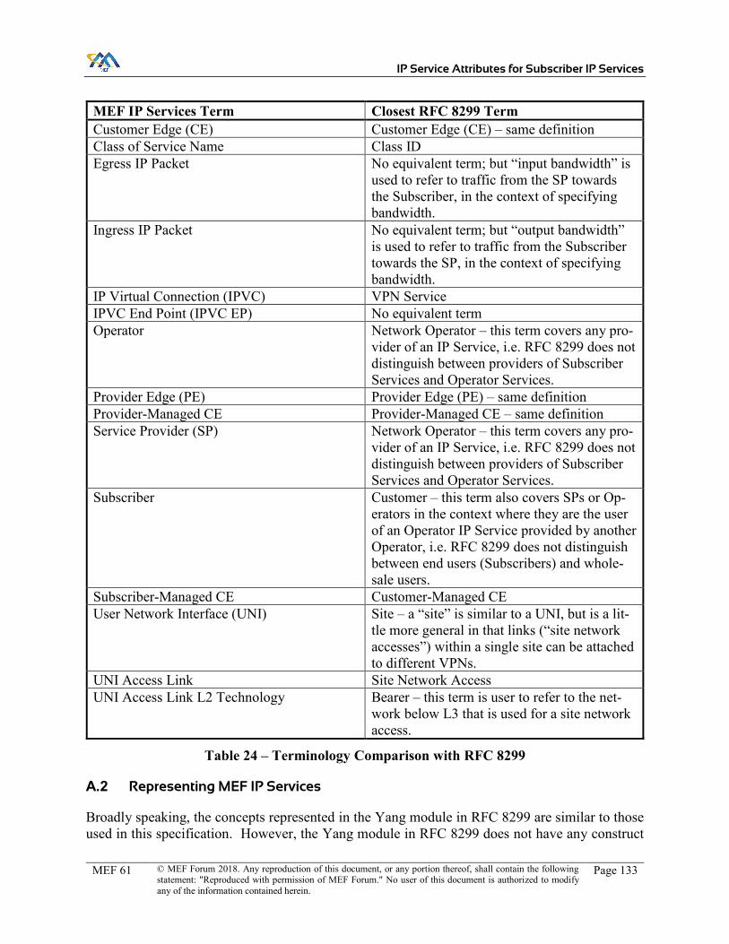
IP Service Attributes for Subscriber IP Services
MEF 61 © MEF Forum 2018. Any reproduction of this document, or any portion thereof, shall contain the following statement: "Reproduced with permission of MEF Forum." No user of this document is authorized to modify any of the information contained herein.
Page 133
MEF IP Services Term Closest RFC 8299 Term Customer Edge (CE) Customer Edge (CE) – same definition Class of Service Name Class ID Egress IP Packet No equivalent term; but “input bandwidth” is
used to refer to traffic from the SP towards the Subscriber, in the context of specifying bandwidth.
Ingress IP Packet No equivalent term; but “output bandwidth” is used to refer to traffic from the Subscriber towards the SP, in the context of specifying bandwidth.
IP Virtual Connection (IPVC) VPN Service IPVC End Point (IPVC EP) No equivalent term Operator Network Operator – this term covers any pro-
vider of an IP Service, i.e. RFC 8299 does not distinguish between providers of Subscriber Services and Operator Services.
Provider Edge (PE) Provider Edge (PE) – same definition Provider-Managed CE Provider-Managed CE – same definition Service Provider (SP) Network Operator – this term covers any pro-
vider of an IP Service, i.e. RFC 8299 does not distinguish between providers of Subscriber Services and Operator Services.
Subscriber Customer – this term also covers SPs or Op-erators in the context where they are the user of an Operator IP Service provided by another Operator, i.e. RFC 8299 does not distinguish between end users (Subscribers) and whole-sale users.
Subscriber-Managed CE Customer-Managed CE User Network Interface (UNI) Site – a “site” is similar to a UNI, but is a lit-
tle more general in that links (“site network accesses”) within a single site can be attached to different VPNs.
UNI Access Link Site Network Access UNI Access Link L2 Technology Bearer – this term is user to refer to the net-
work below L3 that is used for a site network access.
Table 24 – Terminology Comparison with RFC 8299
A.2 Representing MEF IP Services
Broadly speaking, the concepts represented in the Yang module in RFC 8299 are similar to those used in this specification. However, the Yang module in RFC 8299 does not have any construct

IP Service Attributes for Subscriber IP Services
MEF 61 © MEF Forum 2018. Any reproduction of this document, or any portion thereof, shall contain the following statement: "Reproduced with permission of MEF Forum." No user of this document is authorized to modify any of the information contained herein.
Page 134
that is equivalent to an IPVC End Point. Instead, VPN Services (IPVCs) are associated with Sites (UNIs) via a number of other nodes.
Firstly, each site has a “VPN flavor”:
x Single – the site belongs to a single VPN. x Multi – the site belongs to multiple VPNs, but all site network accesses belong to the
same set of VPNs. x Sub – the site belongs to multiple VPNs, and different site network access belong to dif-
ferent VPNs.
In addition, each site network access is associated with one or more VPNs via a “VPN attachment”. This can be specified in one of two ways:
x If the site network access is associated with a single VPN (i.e. in the “Single” or “Sub” flavors of site), then it can be referenced directly. The role that the site network access plays in the VPN can also be specified (any-to-any, hub or spoke).
x Alternatively, a “VPN Policy” is specified, which is a list where each entry contains a reference to a VPN, the role of the site network access within that VPN, and a list of IP Prefixes in the Subscriber Network that can access the VPN.
Given this, a MEF IP Service can be represented in the Yang module as follows:
x The UNI is represented as a site. x Each UNI Access Link is represented as a site network access. x The site flavor is set to “Single” if there is only one IPVC EP at the UNI, or “Multi” if
there is more than one. (The value “Sub” is not used to represent a MEF IP Service). x A single VPN Policy is defined for the site, containing one entry for each IPVC EP at the
UNI: o The VPN ID is for the VPN corresponding to the IPVC for the IPVC EP. o The role is:
� any-to-any if the IPVC EP is for a Multipoint IPVC, or is for a Cloud Access IPVC where every IPVC EP has Root role.
� hub if the IPVC EP is in a Rooted Multipoint IPVC and the IPVC EP has Root role, or the IPVC EP is in Cloud Access IPVC where this IPVC EP has Root role and there is at least one IPVC EP that has Leaf role.
� spoke if the IPVC EP has Leaf Role (and it is in a Rooted Multipoint IPVC or a Cloud Access IPVC).
o The list of prefixes corresponds with the IPVC EP Prefix Mapping Service Attrib-ute.
x Each site network access references this VPN Policy in its VPN Attachment.
In a MEF IP Service, the UNI Access Links in a given UNI are always all associated with the same set of IPVCs (there is no equivalent of a “Sub” flavored site). If it desirable to associate different UNI Access Links with different IPVCs, then they can be assigned to different UNIs (i.e. different sites).

IP Service Attributes for Subscriber IP Services
MEF 61 © MEF Forum 2018. Any reproduction of this document, or any portion thereof, shall contain the following statement: "Reproduced with permission of MEF Forum." No user of this document is authorized to modify any of the information contained herein.
Page 135
A.3 IPVC Service Attributes
Each IPVC for a MEF IP Service can be represented in the RFC 8299 Yang module as a VPN Service. Table 25 shows the IPVC Service Attributes defined in section 9, and how these can be represented in the Yang module. It also includes other nodes that are defined in the Yang module that do not correspond with MEF IP Service Attributes.
Service Attribute RFC 8299 Yang Node (un-der /l3vpn-svc/vpn-ser-vices/vpn-service)
Notes
IPVC Identifier vpn-id Equivalent IPVC Topology vpn-service-topology Multipoint is equivalent to
any-to-any. Rooted Multipoint is equiva-lent to hub-spoke. Cloud Access can be repre-sented as any-to-any (if it only contains IPVC EPs with Root role) or hub-spoke (if it contains any IPVC EPs with Leaf role) The value hub-spoke-disjoint is not used for MEF IP Ser-vices. The same effect can be achieved by instantiating two Rooted Multipoint IPVCs.
IPVC End Point List No equivalent See Section A.2. In RFC 8299, each IPVC EP specifies the IPVC (VPN) it is part of, rather than vice versa, using the VPN Policy.
IPVC Packet Delivery No equivalent RFC 8299 assumes Standard Routing; a value of Policy-Based Routing cannot be rep-resented in the Yang module.
IPVC Maximum Number of IPv4 Routes
No equivalent Cannot be represented in the Yang module
IPVC Maximum Number of IPv6 Routes
No equivalent Cannot be represented in the Yang module
IPVC DSCP Preservation No equivalent Cannot be represented in the Yang module
IPVC List of Class of Service Names
No equivalent Cannot be represented in the Yang module
IPVC Service Level Specification
No equivalent Cannot be represented in the Yang module
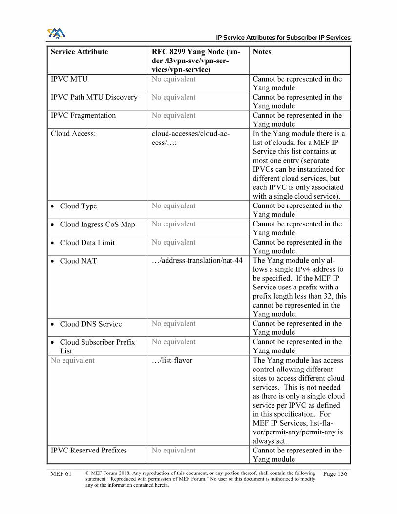
IP Service Attributes for Subscriber IP Services
MEF 61 © MEF Forum 2018. Any reproduction of this document, or any portion thereof, shall contain the following statement: "Reproduced with permission of MEF Forum." No user of this document is authorized to modify any of the information contained herein.
Page 136
Service Attribute RFC 8299 Yang Node (un-der /l3vpn-svc/vpn-ser-vices/vpn-service)
Notes
IPVC MTU No equivalent Cannot be represented in the Yang module
IPVC Path MTU Discovery No equivalent Cannot be represented in the Yang module
IPVC Fragmentation No equivalent Cannot be represented in the Yang module
Cloud Access: cloud-accesses/cloud-ac-cess/…:
In the Yang module there is a list of clouds; for a MEF IP Service this list contains at most one entry (separate IPVCs can be instantiated for different cloud services, but each IPVC is only associated with a single cloud service).
x Cloud Type No equivalent Cannot be represented in the Yang module
x Cloud Ingress CoS Map No equivalent Cannot be represented in the Yang module
x Cloud Data Limit No equivalent Cannot be represented in the Yang module
x Cloud NAT …/address-translation/nat-44 The Yang module only al-lows a single IPv4 address to be specified. If the MEF IP Service uses a prefix with a prefix length less than 32, this cannot be represented in the Yang module.
x Cloud DNS Service No equivalent Cannot be represented in the Yang module
x Cloud Subscriber Prefix List
No equivalent Cannot be represented in the Yang module
No equivalent …/list-flavor The Yang module has access control allowing different sites to access different cloud services. This is not needed as there is only a single cloud service per IPVC as defined in this specification. For MEF IP Services, list-fla-vor/permit-any/permit-any is always set.
IPVC Reserved Prefixes No equivalent Cannot be represented in the Yang module

IP Service Attributes for Subscriber IP Services
MEF 61 © MEF Forum 2018. Any reproduction of this document, or any portion thereof, shall contain the following statement: "Reproduced with permission of MEF Forum." No user of this document is authorized to modify any of the information contained herein.
Page 137
Service Attribute RFC 8299 Yang Node (un-der /l3vpn-svc/vpn-ser-vices/vpn-service)
Notes
No equivalent customer-name In the Yang module, this field is intended to be used when an SP uses a service provided by an Operator, to specify the name of the end user cus-tomer. In the MEF model, the Operator does not have a business relationship with the end user so this is not needed, and therefore this leaf is never set.
No equivalent multicast Not in scope for this specifi-cation – for MEF IP Services, the container is always empty.
No equivalent carriers-carrier Not in scope for this specifi-cation – for MEF IP Services, this leaf is always false.
No equivalent extranet-vpns In the Yang module, these nodes can be used to specify a number of other VPN ser-vices for which this one is an extranet. This is a shortcut for a common case of extra-nets. For MEF IP Services, an extranet is always repre-sented as an additional IPVC, so this container is always empty.
Table 25 – IPVC Service Attributes Comparison with RFC 8299
A.4 IPVC End Point Service Attributes
Table 26 shows the IPVC End Point Service Attributes defined in section 10, and how these can be represented in the RFC 8299 Yang module.
Service Attribute RFC 8299 Yang Node (under /l3vpn-svc/sites/site/vpn-policies/vpn-pol-icy/entries)
Notes
IPVC EP Identifier id Equivalent
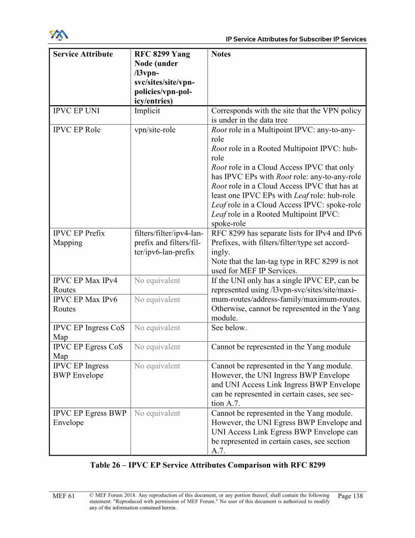
IP Service Attributes for Subscriber IP Services
MEF 61 © MEF Forum 2018. Any reproduction of this document, or any portion thereof, shall contain the following statement: "Reproduced with permission of MEF Forum." No user of this document is authorized to modify any of the information contained herein.
Page 138
Service Attribute RFC 8299 Yang Node (under /l3vpn-svc/sites/site/vpn-policies/vpn-pol-icy/entries)
Notes
IPVC EP UNI Implicit Corresponds with the site that the VPN policy is under in the data tree
IPVC EP Role vpn/site-role Root role in a Multipoint IPVC: any-to-any-role Root role in a Rooted Multipoint IPVC: hub-role Root role in a Cloud Access IPVC that only has IPVC EPs with Root role: any-to-any-role Root role in a Cloud Access IPVC that has at least one IPVC EPs with Leaf role: hub-role Leaf role in a Cloud Access IPVC: spoke-role Leaf role in a Rooted Multipoint IPVC: spoke-role
IPVC EP Prefix Mapping
filters/filter/ipv4-lan-prefix and filters/fil-ter/ipv6-lan-prefix
RFC 8299 has separate lists for IPv4 and IPv6 Prefixes, with filters/filter/type set accord-ingly. Note that the lan-tag type in RFC 8299 is not used for MEF IP Services.
IPVC EP Max IPv4 Routes
No equivalent If the UNI only has a single IPVC EP, can be represented using /l3vpn-svc/sites/site/maxi-mum-routes/address-family/maximum-routes. Otherwise, cannot be represented in the Yang module.
IPVC EP Max IPv6 Routes
No equivalent
IPVC EP Ingress CoS Map
No equivalent See below.
IPVC EP Egress CoS Map
No equivalent Cannot be represented in the Yang module
IPVC EP Ingress BWP Envelope
No equivalent Cannot be represented in the Yang module. However, the UNI Ingress BWP Envelope and UNI Access Link Ingress BWP Envelope can be represented in certain cases, see sec-tion A.7.
IPVC EP Egress BWP Envelope
No equivalent Cannot be represented in the Yang module. However, the UNI Egress BWP Envelope and UNI Access Link Egress BWP Envelope can be represented in certain cases, see section A.7.
Table 26 – IPVC EP Service Attributes Comparison with RFC 8299

IP Service Attributes for Subscriber IP Services
MEF 61 © MEF Forum 2018. Any reproduction of this document, or any portion thereof, shall contain the following statement: "Reproduced with permission of MEF Forum." No user of this document is authorized to modify any of the information contained herein.
Page 139
A.4.1 Class of Service Classification
The IPVC EP Ingress Class of Service Map Service Attribute describes how to map Ingress IP Data Packets to a class of service name. In the RFC 8299 Yang module, the QoS Classification Policy performs a similar function; however, this is specified per site. The IPVC EP Ingress Class of Service Map Service Attribute can be represented using this per-site QoS Classification Policy as described below.
The QoS Classification Policy described in RFC 8299 consists of a list of rule entries. For a UNI that has only a single IPVC EP, the per-site QoS classification policy can easily be used to repre-sent the IPVC EP Ingress Class of Service Map for that IPVC EP. However, for a UNI that has multiple IPVC EPs, it is more difficult. In this case, additional filters need to be added to the rule entries in the QoS Classification policy to ensure they only match packets mapped to a particular IPVC. This can be done in a number of ways:
x If the set of IPVCs containing the IPVC EPs at the UNI do not have any remote UNIs in common, then the target-sites list in the QoS Classification policy can be used to distin-guish entries for the different IPVC EPs; that is, for each IPVC EP, the corresponding rule entries in the QoS Classification policy should each specify a list of target-sites con-taining all of the sites that correspond with other UNIs that have IPVC EPs in the same IPVC as this IPVC EP.
x If two (or more) of the IPVCs containing the IPVC EPs at the UNI have at least one re-mote UNI in common, it may be possible to use a combination of specifying the target sites, source IP prefixes and destination IP prefixes for each entry in the QoS Classifica-tion Policy to ensure it only matches IP Packets mapped to the corresponding IPVC EP. However, in this situation, the choice of IPVC EP may be dynamic, depending on the current routing information, so specifying a static list of prefixes may be undesirable. In this case, the IPVC EP Ingress Class of Service Maps for the IPVC EPs at the UNI can-not be reliably represented in the Yang module.
The IPVC EP Ingress Class of Service Map Service Attribute can be represented using the QoS Classification policy (/l2vpn-svc/sites/site/service/qos/qos-classification-policy) as follows:
x Each entry in M in the IPVC EP Ingress Class of Service Map Service Attribute is repre-sented by an entry in the rule list in the Yang module:
o The id can be set to any arbitrary index value. o The match-type/match-flow option is always used; the match-type/match-applica-
tion is not used. o Under match-flow, a set of yang leaves are specified, with values taken from the
entry in M. Which leaves in the yang module are used is determined from F in the IPVC EP Ingress Class of Service Map Service Attribute, as shown in Table 27. In addition, the target-sites and the source and destination prefix leaves may be set to fixed values in every entry for this IPVC EP in the rule list, as described above.
o The target-class-id is set equal to the CoS Name from the entry in M.

IP Service Attributes for Subscriber IP Services
MEF 61 © MEF Forum 2018. Any reproduction of this document, or any portion thereof, shall contain the following statement: "Reproduced with permission of MEF Forum." No user of this document is authorized to modify any of the information contained herein.
Page 140
x An additional entry in the rule list is added to represent the value of D the IPVC EP In-gress Class of Service Map Service Attribute. This entry has an arbitrary id and has tar-get-class-id set to the value of D. It does not have any match-type specified.
Field included in F in the IPVC EP Ingress CoS Map
Leaf included in the rule entry in the QoS Classification Policy (under match-flow/)
IP DS dscp Source IP Address ipv4-src-prefix or ipv6-src-prefix Destination IP Address ipv4-dst-prefix or ipv6-dst-prefix L4 Protocol protocol-field (specified as a uint8) Source L4 port l4-src-port Destination L4 port l4-dst-port
Table 27 – Comparison of Fields for Class of Service Map The dot1p, l4-src-port-range and l4-dst-port-range nodes in the Yang module are not used to rep-resent a MEF IP Service.
A.5 UNI Service Attributes
Each UNI for a MEF IP Service can be represented in the RFC 8299 Yang module as a site. Table 28 shows the UNI Service Attributes defined in section 11, and how these can be represented in the Yang module. It also includes other nodes that are defined in the Yang module that do not correspond with MEF IP Service Attributes.
Service Attribute RFC 8299 Yang Node (under /l3vpn-svc/sites/site)
Notes
UNI Identifier site-id Equivalent UNI Management Type
management/type Subscriber-Managed is equivalent to cus-tomer-managed. Provider-Managed is equivalent to provider-managed. The value co-managed is not used for MEF IP Services.
UNI List of UNI Access Links
site-network-ac-cesses/site-network-access
Equivalent
UNI Ingress Bandwidth Profile Envelope
See section A.7 See section A.7
UNI Egress Bandwidth Profile Envelope
See section A.7 See section A.7
UNI List of Control Protocols
No equivalent Cannot be represented in the Yang module

IP Service Attributes for Subscriber IP Services
MEF 61 © MEF Forum 2018. Any reproduction of this document, or any portion thereof, shall contain the following statement: "Reproduced with permission of MEF Forum." No user of this document is authorized to modify any of the information contained herein.
Page 141
Service Attribute RFC 8299 Yang Node (under /l3vpn-svc/sites/site)
Notes
UNI Routing Protocols
routing-proto-cols/routing-proto-col/…
x Protocol …/type Static, BGP and OSPF values are equivalent. Other values defined in RFC 8299 (rip, vrrp, direct) are not used for MEF IP Services.
x Address Family …/ospf/address-fam-ily or …/bgp/ad-dress-family
RFC 8299 uses a leaf-list containing one or both of IPv4 and IPv6 – a MEF IP Service with value Both is represented by including both IPv4 and IPv6 in the list. For static routing, the address families are represented in the yang simply by having sep-arate lists for IPv4 and IPv6 prefixes.
x Static: list of: o Prefix o Nexthop o Admin Distance
…/static/cascaded-lan/prefixes/ipv4-lan-prefixes/… or …/static/cascaded-lan/prefixes/ipv6-lan-prefixes/… x …/lan x …/next-hop
RFC 8299 has separate lists for IPv4 and IPv6 routes. A nexthop that specifies a specific UNI Ac-cess Link cannot be represented in the yang module. The admin distance cannot be represented in the yang module.
x OSPF o Area ID o Area Type o Authentication o Hello Interval o Dead Interval o Retransmit In-
terval o Admin Distance
…/ospf/… x area-address
Area ID is equivalent to area-address; other parameters of a MEF IP Service cannot be represented in the Yang module.
No equivalent …/ospf/… x metric x sham-links
OSPF metric is not specified explicitly for MEF IP Services since that would constrain the SP’s implementation. It is always unset for MEF IP Services. Sham links are deferred to a future version of this specification.

IP Service Attributes for Subscriber IP Services
MEF 61 © MEF Forum 2018. Any reproduction of this document, or any portion thereof, shall contain the following statement: "Reproduced with permission of MEF Forum." No user of this document is authorized to modify any of the information contained herein.
Page 142
Service Attribute RFC 8299 Yang Node (under /l3vpn-svc/sites/site)
Notes
x BGP o Subscriber’s AS
Number o SP’s AS Num-
ber o Connection Ad-
dress Family o Peering Ad-
dresses o Authentication o BGP Commu-
nity List o BGP Extended
Community List o Hold Time o Damping o AS Override o Admin Distance
…/bgp/… x autonomous-sys-
tem
Subscriber’s AS Number is represented by bgp/autonomous-system; other parameters of a MEF IP Service cannot be represented in the Yang module.
No equivalent requested-site-start Out of scope for MEF IP Service Attributes as this pertains to the use of the service not the definition of the service; it would be han-dled at the Product layer. This is always un-set for MEF IP Services.
No equivalent requested-site-stop Out of scope for MEF IP Service Attributes as this pertains to the use of the service not the definition of the service; it would be han-dled at the Product layer. This is always un-set for MEF IP Services.
No equivalent locations Out of scope for MEF IP Service Attributes as this pertains to the use of the service not the definition of the service; it would be han-dled at the Product layer. It is always an empty list for MEF IP Services.
No equivalent devices Out of scope for MEF IP Service Attributes as this pertains to the use of the service not the definition of the service; it would be han-dled at the Product layer. It is always an empty list for MEF IP Services.
No equivalent site-diversity Not used for MEF IP Services, as this relates to specification of constraints on the SP im-plementation (see introduction to Appendix A). It is always an empty list for MEF IP Services.

IP Service Attributes for Subscriber IP Services
MEF 61 © MEF Forum 2018. Any reproduction of this document, or any portion thereof, shall contain the following statement: "Reproduced with permission of MEF Forum." No user of this document is authorized to modify any of the information contained herein.
Page 143
Service Attribute RFC 8299 Yang Node (under /l3vpn-svc/sites/site)
Notes
No equivalent vpn-policies See section A.2 No equivalent site-vpn-flavor See section A.2 No equivalent maximum-routes If there is only one VPN at the site, then this
is equivalent to the IPVC EP Maximum IPv4/IPv6 routes. Otherwise, there is no equivalent as this specification has a per-IPVC EP limit rather than a per-UNI limit.
No equivalent security Not in scope for MEF IP Services. This is al-ways empty for MEF IP Services.
No equivalent service/qos/qos-clas-sification-policy
See section A.4.1
No equivalent service/qos/qos-pro-file
See section A.7
No equivalent service/carrierscar-rier/signalling-type
Not applicable for Subscriber services; this is always unset for MEF IP Services
No equivalent service/multicast Not in scope for MEF IP Services. This is al-ways empty for MEF IP Services.
No equivalent traffic-protection This is a constraint on the SP implementation; for MEF IP Services, it is handled by specify-ing SLS objectives. Always unset for MEF IP Services.
No equivalent actual-site-start (read-only)
Out of scope for MEF IP Service Attributes as this pertains to the use of the service not the definition of the service; it would be han-dled at the Product layer.
No equivalent actual-site-stop (read-only)
Out of scope for MEF IP Service Attributes as this pertains to the use of the service not the definition of the service; it would be han-dled at the Product layer.
Table 28 – UNI Service Attributes Comparison with RFC 8299
A.6 UNI Access Link Service Attributes
Each UNI Access Link for a MEF IP Service can be represented in the RFC 8299 Yang module as a Site Network Access. Table 29 shows the UNI Access Link Service Attributes defined in section 12, and how these can be represented in the Yang module. It also includes other nodes that are defined in the Yang module that do not correspond with MEF IP Service Attributes.

IP Service Attributes for Subscriber IP Services
MEF 61 © MEF Forum 2018. Any reproduction of this document, or any portion thereof, shall contain the following statement: "Reproduced with permission of MEF Forum." No user of this document is authorized to modify any of the information contained herein.
Page 144
Service Attribute RFC 8299 Yang Node (under /l3vpn-svc/sites/site/site-network-ac-cesses/site-network-access)
Notes
UNI Access Link Identifier
site-network-access-id
Equivalent
UNI Access Link Connection Type
site-network-access-type
Equivalent
UNI Access Link L2 Technology
bearer/ Although these are equivalent concepts, the parameters specified in the RFC 8299 Yang module are in the context of a request from the customer to the SP, so may not be appli-cable to a MEF IP Service and are therefore not set. The Yang module notes that the bearer container is to be augmented with bearer-specific parameters; this is aligned with the UNI Access Link L2 Technology Service Attribute, for which the details are not specified in this document.
UNI Access Link IPv4 Connection Addressing
ip-connec-tion/ipv4/… …/address-alloca-tion-type
None can be represented by not setting this leaf. DHCP is equivalent to provider-dhcp. Static is equivalent to static-address, or pro-vider-dhcp-relay as described below. There is no equivalent in the RFC 8299 Yang module for Unnumbered. A MEF IP Service using Unnumbered cannot be represented, ex-cept where DHCP Relay is used as described below. The value provider-dhcp-relay is used to rep-resent a MEF IP Service when the UNI Ac-cess Link DHCP Relay Service Attribute con-tains any IPv4 addresses – see below.
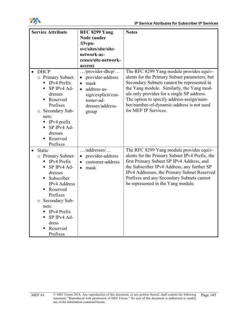
IP Service Attributes for Subscriber IP Services
MEF 61 © MEF Forum 2018. Any reproduction of this document, or any portion thereof, shall contain the following statement: "Reproduced with permission of MEF Forum." No user of this document is authorized to modify any of the information contained herein.
Page 145
Service Attribute RFC 8299 Yang Node (under /l3vpn-svc/sites/site/site-network-ac-cesses/site-network-access)
Notes
x DHCP o Primary Subnet: � IPv4 Prefix � SP IPv4 Ad-
dresses � Reserved
Prefixes o Secondary Sub-
nets: � IPv4 prefix � SP IPv4 Ad-
dresses � Reserved
Prefixes
…/provider-dhcp/… x provider-address x mask x address-as-
sign/explicit/cus-tomer-ad-dresses/address-group
The RFC 8299 Yang module provides equiv-alents for the Primary Subnet parameters, but Secondary Subnets cannot be represented in the Yang module. Similarly, the Yang mod-ule only provides for a single SP address. The option to specify address-assign/num-ber/number-of-dynamic-address is not used for MEF IP Services.
x Static o Primary Subnet: � IPv4 Prefix � SP IPv4 Ad-
dresses � Subscriber
IPv4 Address � Reserved
Prefixes o Secondary Sub-
nets: � IPv4 Prefix � SP IPv4 Ad-
dress � Reserved
Prefixes
…/addresses/… x provider-address x customer-address x mask
The RFC 8299 Yang module provides equiv-alents for the Primary Subnet IPv4 Prefix, the first Primary Subnet SP IPv4 Address, and the Subscriber IPv4 Address; any further SP IPv4 Addresses, the Primary Subnet Reserved Prefixes and any Secondary Subnets cannot be represented in the Yang module.

IP Service Attributes for Subscriber IP Services
MEF 61 © MEF Forum 2018. Any reproduction of this document, or any portion thereof, shall contain the following statement: "Reproduced with permission of MEF Forum." No user of this document is authorized to modify any of the information contained herein.
Page 146
Service Attribute RFC 8299 Yang Node (under /l3vpn-svc/sites/site/site-network-ac-cesses/site-network-access)
Notes
UNI Access Link IPv6 Connection Addressing
ip-connec-tion/ipv6/… …/address-alloca-tion-type
None can be represented by not setting this leaf. DHCP is equivalent to provider-dhcp. Static is equivalent to static-address, or pro-vider-dhcp-relay as described below. SLAAC is equivalent to slaac. There is no equivalent in the RFC 8299 Yang module for LL-only. A MEF IP Service using LL-only cannot be represented, except where DHCP Relay is used as described below. The value provider-dhcp-relay is used to rep-resent a MEF IP Service when the UNI Ac-cess Link DHCP Relay Service Attribute con-tains any IPv6 addresses – see below.
x DHCP o Subnet List: � IPv6 Prefix � SP IPv6 Ad-
dresses � Reserved
Prefixes
…/provider-dhcp/… x provider-address x mask x address-as-
sign/explicit/cus-tomer-ad-dresses/address-group
The RFC 8299 Yang module provides equiv-alents for the Subnet parameters, but only for a single subnet with a single SP address. Multiple subnets or multiple SP addresses cannot be represented in the Yang module. The option to specify address-assign/num-ber/number-of-dynamic-address is not used for MEF IP Services.
x Static o Subnet List: � IPv6 Prefix � SP IPv6 Ad-
dresses � Reserved
Prefixes o Subscriber IPv4
Address
…/addresses/… x provider-address x customer-address x mask
The RFC 8299 Yang module provides equiv-alents for Subscriber IPv6 Address, and the first SP IPv6 Address and Subnet Mask length for a single subnet. The Subnet Re-served Prefixes, any further SP addresses and any further Subnets, cannot be represented in the Yang module.
x SLAAC o Subnet List: � IPv6 Prefix � SP IPv6 Ad-
dresses � Reserved
Prefixes
No equivalent SLAAC parameters cannot be represented in the Yang module.

IP Service Attributes for Subscriber IP Services
MEF 61 © MEF Forum 2018. Any reproduction of this document, or any portion thereof, shall contain the following statement: "Reproduced with permission of MEF Forum." No user of this document is authorized to modify any of the information contained herein.
Page 147
Service Attribute RFC 8299 Yang Node (under /l3vpn-svc/sites/site/site-network-ac-cesses/site-network-access)
Notes
UNI Access Link DHCP Relay
ip-connec-tion/ipv4/dhcp-re-lay/customer-dhcp-servers/server-ip-ad-dress and ip-connec-tion/ipv6/dhcp-re-lay/customer-dhcp-servers/server-ip-ad-dress
The RFC 8299 Yang module treats DHCP Relay as part of the connection addressing. If the DHCP Relay Service Attribute contains any IPv4 addresses, this can be represented by setting ip-connection/ipv4/address-alloca-tion-type to provider-dhcp-relay and filling in the parameters under dhcp-relay as follows. Note that the UNI Access Link IPv4 Connec-tion Addressing is Unnumbered or Static in this case. x provider-address: first Primary Subnet Ser-
vice Provider IPv4 Address from the UNI Access Link IPv4 Connection Addressing Service Attribute, if specified; otherwise not set.
x mask: Primary Subnet IPv4 Prefix length from the UNI Access Link IPv4 Connec-tion Addressing Service Attribute, if speci-fied; otherwise not set.
x customer-dhcp-services/server-ip-address: IPv4 Addresses from the UNI Access Link DHCP Relay Service Attribute.
A similar approach can be taken if the DHCP Relay Service Attribute contains any IPv6 ad-dresses.
UNI Access Link Prefix Delegation
No equivalent Cannot be represented in the yang module.
UNI Access Link BFD
ip-connec-tion/oam/bfd/…
None is represented by setting …/enabled to false, otherwise it is true.
x Connection Ad-dress Family
No equivalent Cannot be represented in the Yang module
x Transmission Inter-val
No equivalent Cannot be represented in the Yang module; however, the “hold time” (i.e. the Transmis-sion Interval multiplied by the Detect Multi-plier) can be specified using …/hold-time/fixed/fixed-value.

IP Service Attributes for Subscriber IP Services
MEF 61 © MEF Forum 2018. Any reproduction of this document, or any portion thereof, shall contain the following statement: "Reproduced with permission of MEF Forum." No user of this document is authorized to modify any of the information contained herein.
Page 148
Service Attribute RFC 8299 Yang Node (under /l3vpn-svc/sites/site/site-network-ac-cesses/site-network-access)
Notes
x Detect Multiplier No equivalent Cannot be represented in the Yang module; however, the “hold time” (i.e. the Transmis-sion Interval multiplied by the Detect Multi-plier) can be specified using …/hold-time/fixed/fixed-value.
x Active End No equivalent Cannot be represented in the Yang module x Authentication
Type No equivalent Cannot be represented in the Yang module
UNI Access Link IP MTU
service/svc-mtu Equivalent
UNI Access Link Ingress Bandwidth Profile Envelope
See section A.7 See section A.7
UNI Access Link Egress Bandwidth Profile Envelope
See section A.7 See section A.7
UNI Access Link Reserved VRIDs
No equivalent Cannot be represented in the Yang module
No equivalent location-flavor This choice is mandatory, but for a MEF IP Service a dummy value can be used.
No equivalent access-diversity Not used for MEF IP Services, as this relates to specification of constraints on the SP im-plementation (see introduction to Appendix A). It is always an empty list for MEF IP Services.
No equivalent service/service-in-put-bandwidth
See section A.5
No equivalent service/service-out-put-bandwidth
See section A.5
No equivalent availability/access-priority
This node is used to specify active/standby or load-balancing between multiple site-net-work-accesses in a site. For MEF IP Ser-vices, that is controlled by setting routing pro-tocol metrics appropriately. This is always unset for a MEF IP Service.
No equivalent vpn-attachment See section A.2 No equivalent service/qos/qos-pro-
file See section A.7
No equivalent Security

IP Service Attributes for Subscriber IP Services
MEF 61 © MEF Forum 2018. Any reproduction of this document, or any portion thereof, shall contain the following statement: "Reproduced with permission of MEF Forum." No user of this document is authorized to modify any of the information contained herein.
Page 149
Service Attribute RFC 8299 Yang Node (under /l3vpn-svc/sites/site/site-network-ac-cesses/site-network-access)
Notes
No equivalent service/qos/qos-clas-sification-policy
These nodes under the site-network-access in the Yang module duplicate equivalent nodes under the site. They are not used to represent a MEF IP Service; instead, the per-site ver-sions are used where applicable, as described in section A.5.
No equivalent service/carrierscar-rier/signalling-type
No equivalent service/multicast No equivalent routing-protocols
Table 29 – UNI Access Link Service Attributes Comparison with RFC 8299
A.7 Bandwidth Profiles
Bandwidth Profiles are used to specify the temporal properties of a sequence of IP Packets that flow over a UNI. In RFC 8299, QoS Profiles are used for the same purpose; however, the QoS profiles described in RFC 8299 are much less flexible than the Bandwidth Profiles described in this document; consequently, there are only a few cases where a MEF IP Service with a Bandwidth Profile can be represented using the RFC 8299 Yang module.
A QoS profile corresponds with a Bandwidth Profile Envelope. QoS Profiles can be specified per site or per site-network access – a per-site QoS Profile can represent a UNI Bandwidth Profile Envelope. A per-site-network-access QoS Profile can represent a UNI Access Link Bandwidth Profile Envelope. IPVC EP Bandwidth Profile Envelopes cannot be represented in the Yang mod-ule; however, if the UNI has a single IPVC EP, the IPVC EP Bandwidth Profile Envelope is equiv-alent to a UNI Bandwidth Profile Envelope, which can be represented.
Each QoS Profile has a direction, which is “Site-to-WAN”, “WAN-to-Site” or “both”. Ingress Bandwidth Profiles can be represented by setting the direction to “Site-to-WAN”. Egress Band-width Profiles can be represented by setting the direction to “WAN-to-Site”. The “both” direction is not used to represent MEF IP Services.
A QoS Profile is always defined with a flow per Class of Service. Therefore, only Bandwidth Profile Envelopes that contain BWP Flows defined using a list of (IPVC EP, CoS Name) pairs can be represented, and only if in each case the list contains entries which all have the same value for CoS Name and include all the IPVC EPs at the UNI for IPVCs that use that CoS Name. Note that there are several common cases where this condition is met:
x There is only one IPVC EP at the UNI, and each BWP Flow is defined per CoS Name. x Every IPVC attached to the UNI uses different CoS Names, and each BWP Flow is de-
fined using a single (IPVC EP, CoS Name) pair. x Every IPVC attached to the UNI uses the same CoS Names, and each BWP Flow is de-
fined by including an (IPVC EP, CoS Name) pair for a given CoS Name for every IPVC EP at the UNI.

IP Service Attributes for Subscriber IP Services
MEF 61 © MEF Forum 2018. Any reproduction of this document, or any portion thereof, shall contain the following statement: "Reproduced with permission of MEF Forum." No user of this document is authorized to modify any of the information contained herein.
Page 150
A Bandwidth Profile Envelope has two parameters, in addition to the list of BWP Flows: the En-velope CIR and the Envelope IR Time. The Envelope Maximum IR (MaxIRE) can be represented by the service-input-bandwidth and service-output-bandwidth as shown in Table 30. The Enve-lope IR Time has no equivalent and cannot be represented in the Yang module.
MEF IP Service Attribute Representation of MaxIRE in the RFC 8299 Yang module UNI Ingress Bandwidth Profile Envelope
MaxIRE can be represented by setting /l3vpn-svc/sites/site/site-network-accesses/site-network-access/ser-vice/svc-output-bandwidth to MaxIRE/N on each site-net-work-access in the site, where N is the number of UNI Ac-cess Links in the UNI. Note that svc-output-bandwidth can only be specified per site-network-access, but the QoS Profile is applied to the ag-gregate across all site network accesses.
UNI Egress Bandwidth Profile Envelope
MaxIRE can be represented by setting /l3vpn-svc/sites/site/site-network-accesses/site-network-access/ser-vice/svc-input-bandwidth to MaxIRE/N on each site-network-access in the site, where N is the number of UNI Access Links in the UNI. Note that svc-input-bandwidth can only be specified per site-network-access, but the QoS Profile is applied to the aggre-gate across all site network accesses.
UNI Access Link Ingress Bandwidth Profile Envelope
MaxIRE can be represented by setting /l3vpn-svc/sites/site/site-network-accesses/site-network-access/ser-vice/svc-output-bandwidth to MaxIRE on the site-network-ac-cess that represents the UNI Access Link.
UNI Access Link Egress Bandwidth Profile Envelope
MaxIRE can be represented by setting /l3vpn-svc/sites/site/site-network-accesses/site-network-access/ser-vice/svc-input-bandwidth to MaxIRE on the site-network-ac-cess that represents the UNI Access Link.
Table 30 – Representing Envelope CIR using QoS Profiles
A QoS Profile can be either a “standard” profile or a “custom” profile. For MEF IP Services, the “custom” option is used. Table 31 shows how Bandwidth Profile Flow parameters are related to QoS Profile parameters.

IP Service Attributes for Subscriber IP Services
MEF 61 © MEF Forum 2018. Any reproduction of this document, or any portion thereof, shall contain the following statement: "Reproduced with permission of MEF Forum." No user of this document is authorized to modify any of the information contained herein.
Page 151
Bandwidth Profile Flow parameter
RFC 8299 Yang Node (under /l3vpn-svc/sites/site/ser-vice/qos/qos-pro-file/qos-profile/cus-tom/classes/class)
Notes
Flow Definition class-id As described above, only Envelopes that con-tain flows defined for a given CoS Name and all IPVC EPs can be represented; therefore it is sufficient to specify the CoS Name, which is equivalent to the class id.
Flow Identifier No equivalent Cannot be represented in the Yang module Committed Information Rate
bandwidth/guaran-teed-bw-percent
Equivalent; but note that the Yang module is specified as a percentage rather than an abso-lute value.
Maximum Information Rate
rate-limit Equivalent; but note that the Yang module is specified as a percentage rather than an abso-lute value.
Weight No equivalent Cannot be represented in the Yang module Burst Behavior No equivalent Cannot be represented in the Yang module No equivalent direction Indicates whether the QoS Policy applies to
ingress or egress traffic, i.e. whether it repre-sents an Ingress or Egress Bandwidth Profile; see above.
No equivalent latency Not applicable in a MEF IP Service since per-formance objectives are specified in the SLS. This is always unset for a MEF IP Service.
No equivalent jitter Not applicable in a MEF IP Service since per-formance objectives are specified in the SLS. This is always unset for a MEF IP Service.
No equivalent bandwidth/end-to-end
Not applicable in a MEF IP Service since per-formance objectives are specified in the SLS. This is always false for a MEF IP Service.
Table 31 – Bandwidth Profile Flow Parameter Comparison with RFC 8299

IP Service Attributes for Subscriber IP Services
MEF 61 © MEF Forum 2018. Any reproduction of this document, or any portion thereof, shall contain the following statement: "Reproduced with permission of MEF Forum." No user of this document is authorized to modify any of the information contained herein.
Page 152
Appendix B Examples (Informative)
This Appendix contains several examples showing the use of various Service Attributes to imple-ment different aspects of IP Services. Note that these examples use IPv4 Documentation Space per RFC 5737 [48].
B.1 Multiple Subscriber Networks
This section describes an example where a Subscriber, Bank of MEF, has two departments, ac-counting and marketing, that have separate IP networks. These use IP addresses within same IP Prefix space, but are separated at Layer 2 by the use of Ethernet VLANs. Bank of MEF has offices in several locations, each of which has both accounting and marketing functions, and so they obtain IP Services from a Service Provider to connect the accounting and marketing networks at the var-ious locations together. The accounting and marketing networks are separate Subscriber Networks and hence are connected using distinct UNIs. Figure 20 shows a logical view of the UNIs con-necting to the Subscriber Networks.
Figure 20 – Example of Multiple Subscriber Networks – Logical View
Physically, Bank of MEF connects to the Service Provider with a single physical Ethernet link in each location. Figure 21 shows the physical topology.

IP Service Attributes for Subscriber IP Services
MEF 61 © MEF Forum 2018. Any reproduction of this document, or any portion thereof, shall contain the following statement: "Reproduced with permission of MEF Forum." No user of this document is authorized to modify any of the information contained herein.
Page 153
Figure 21 – Example of Multiple Subscriber Networks – Physical Topology
At each location, there are two UNIs. Each UNI contains a single UNI Access Link, which is implemented using a different Ethernet VLAN on the same physical Ethernet link that connects that location to the SP Network. Bank of MEF uses an Ethernet switch to separate IP traffic on the two VLANs and direct it to two different routers for the accounting and marketing networks. Figure 22 shows an example of this setup at one of the locations.

IP Service Attributes for Subscriber IP Services
MEF 61 © MEF Forum 2018. Any reproduction of this document, or any portion thereof, shall contain the following statement: "Reproduced with permission of MEF Forum." No user of this document is authorized to modify any of the information contained herein.
Page 154
Figure 22 – Example of Multiple Subscriber Networks – Setup at one Location
Note that the example shown above is distinct from the case where different VLANs are used to create multiple UNI Access Links that connect to the same Subscriber Network. In the example above, there are two independent Subscriber Networks, for the two different departments in Bank of MEF.
B.2 Packet Delivery with Multiple IPVCs
Figure 23 shows a Subscriber, Bank of MEF, who has three sites, and wants to connect them together using an IP Service. One site is the head office and also houses a private data center; the other two sites are branches.

IP Service Attributes for Subscriber IP Services
MEF 61 © MEF Forum 2018. Any reproduction of this document, or any portion thereof, shall contain the following statement: "Reproduced with permission of MEF Forum." No user of this document is authorized to modify any of the information contained herein.
Page 155
Figure 23 – Example IP Service
Bank of MEF wants to generally connect their head office and branches together. They also want a dedicated connection from each branch to the private data center, with a stricter SLA (lower latency and higher guaranteed bandwidth). They therefore decide to obtain three IPVCs from the SP, as shown in Figure 24.

IP Service Attributes for Subscriber IP Services
MEF 61 © MEF Forum 2018. Any reproduction of this document, or any portion thereof, shall contain the following statement: "Reproduced with permission of MEF Forum." No user of this document is authorized to modify any of the information contained herein.
Page 156
Figure 24 – Example IP Service Showing Three IPVCs
IPVC A (in red) connects all the sites together. IPVCs B and C (in purple and green) connect each branch to the data center, and have a stricter SLA.
Bank of MEF agrees with the SP that they will use OSPF at each UNI (per the UNI Routing Protocols Service Attribute, section 11.7). Bank of MEF uses this to advertise the IP Prefixes reachable at each site to the SP, as follows:
x UNI ‘SFO’: o Head Office subnet: 192.0.2.0/26 o Data Center subnet: 203.0.113.0/24
x UNI ‘NYC’: o Branch subnet: 192.0.2.64/26
x UNI ‘ATL’: o Branch subnet: 192.0.2.128/26
To ensure traffic is routed over the correct IPVC, Bank of MEF also agrees to use a prefix mapping for each IPVC EP at UNI ‘SFO’ (per the IPVC EP Prefix Mapping Service Attribute, section 10.4), as follows:
x IPVC EP for IPVC A: o IPVC EP Prefix Mapping: 192.0.2.0/26

IP Service Attributes for Subscriber IP Services
MEF 61 © MEF Forum 2018. Any reproduction of this document, or any portion thereof, shall contain the following statement: "Reproduced with permission of MEF Forum." No user of this document is authorized to modify any of the information contained herein.
Page 157
x IPVC EP for IPVC B: o IPVC EP Prefix Mapping: 203.0.113.0/24
x IPVC EP for IPVC C: o IPVC EP Prefix Mapping: 203.0.113.0/24
The effect of this is that at UNI ‘SFO’, only hosts in the head office subnet can access IPVC A, and only hosts in the data center subnet can access IPVCs B and C.
No prefix mapping is used at UNI ‘NYC’ or UNI ‘ATL’ – that is, the IPVC EP Prefix Mapping is an empty list for each of the IPVC EPs at those UNIs. This means that hosts in each branch office can access any of the IPVCs that have IPVC EPs at the corresponding UNI.
This is shown in Figure 25:
Figure 25 – Example IP Service – Subnets and Prefix Mapping
All of the IPVCs use Standard IP Routing for packet delivery (section 9.4). For the purpose of illustration, we will assume initially that the SP implements this using the routing information databases described in section 8 (other possibilities are discussed below). Figure 26 shows the contents of RIDUNI at each UNI and RIDL at each IPVC EP. Recall that RIDL contains the same routes as RIDUNI if the IPVC EP Prefix Mapping Service Attribute is not set (i.e. at UNIs ‘NYC’ and ‘ATL’), and otherwise the subset of routes in RIDUNI that match the prefix mapping (i.e. at UNI ‘SFO’).

IP Service Attributes for Subscriber IP Services
MEF 61 © MEF Forum 2018. Any reproduction of this document, or any portion thereof, shall contain the following statement: "Reproduced with permission of MEF Forum." No user of this document is authorized to modify any of the information contained herein.
Page 158
Figure 26 – Example IP Service – Reachable Prefixes
In order to deliver IP Packets per the requirements in section 9.4, the SP distributes the information about the IP Prefixes that are reachable at each IPVC EP to all other IPVC EPs for the IPVC. This allows RTIPVCEP to be constructed for each IPVC EP, as shown in Figure 27.
Figure 27 – Example IP Service – Per-IPVC EP Routing

IP Service Attributes for Subscriber IP Services
MEF 61 © MEF Forum 2018. Any reproduction of this document, or any portion thereof, shall contain the following statement: "Reproduced with permission of MEF Forum." No user of this document is authorized to modify any of the information contained herein.
Page 159
To illustrate how packet delivery works, consider the handling of the following IP Packets. Recall that, in this example, OSPF is used at each UNI by the Subscriber to advertise the IP Prefixes that are reachable at that UNI.
x Ingress IP Packet at UNI ‘SFO’, source address 192.0.2.1, destination address 192.0.2.65: o At UNI ‘SFO’, due to the prefix mapping, a packet with source address 192.0.2.1
can only access IPVC A. o Looking at the IP Prefixes that are reachable via IPVC A, the destination
192.0.2.65 matches the IP Prefix 192.0.2.64/26, which can only be reached via the IPVC EP at UNI ‘NYC’.
o Therefore, the packet is mapped to IPVC A and delivered to UNI ‘NYC’. x Ingress IP Packet at UNI ‘SFO’, source address 203.0.113.1, destination address
192.0.2.129: o At UNI ‘SFO’, due to the prefix mapping, a packet with source address
203.0.113.1 can access IPVC B or IPVC C. o Looking at the IP Prefixes reachable via IPVC B and IPVC C, the destination ad-
dress 192.0.2.129 is only reachable in IPVC C, via UNI ‘ATL’. o Therefore, the packet is mapped to IPVC C and delivered to UNI ‘ATL’.
x Ingress IP Packet at UNI ‘NYC’, source address 192.0.2.65, destination address 203.0.113.1:
o The prefix mapping at UNI ‘NYC’ is empty, so the packet can access both IPVC A and IPVC B (as they have IPVC EPs at the UNI).
o Looking at the IP Prefixes reachable via IPVC A and IPVC B, the destination ad-dress 203.0.113.1 is only reachable in IPVC B, via UNI ‘SFO’.
o Therefore, the packet is mapped to IPVC B and delivered to UNI ‘SFO’. x Ingress IP Packet at UNI ’ATL’, source address 192.0.2.129, destination address
192.0.2.1: o The prefix mapping at UNI ‘ATL’ is empty, so the packet can access both IPVC
A and IPVC C (as they have IPVC EPs at the UNI). o Looking at the IP Prefixes reachable via IPVC A and IPVC C, the destination ad-
dress 192.0.2.1 is only reachable in IPVC A, via UNI ‘SFO’. o Therefore, the packet is mapped to IPVC A and delivered to UNI ‘SFO’.
x Ingress IP Packet at UNI ‘NYC’, source address 192.0.2.65, destination address 192.0.2.66:
o The prefix mapping at UNI ‘NYC’ is empty, so the packet can access both IPVC A and IPVC B (as they have IPVC EPs at the UNI).
o Looking at the IP Prefixes reachable via IPVC A and IPVC B, the destination ad-dress 192.0.2.66 is reachable in both of them, via UNI ‘NYC’.
o Therefore, the packet can be mapped to either IPVC A or IPVC B, but in either case is transmitted back out of UNI ‘NYC’.
It can be seen that both the source and destination addresses in each Ingress IP Packet need to be considered in order to determine the correct IPVC to map the packet to, and the correct IPVC EP for that IPVC to deliver it to.
Looking again at Figure 27, it can be noted that whenever the same IP Prefix is present in two or more RTIPVCEP routing tables for IPVC EPs at the same UNI, the nexthop also points to the same

IP Service Attributes for Subscriber IP Services
MEF 61 © MEF Forum 2018. Any reproduction of this document, or any portion thereof, shall contain the following statement: "Reproduced with permission of MEF Forum." No user of this document is authorized to modify any of the information contained herein.
Page 160
UNI. For example, prefix 192.0.2.64/26 is present in RTIPVCEP for both IPVC EPs A and B at UNI ‘SFO’, and in both cases the nexthop is UNI ‘NYC’. This property is required in certain cases due to [R63]. It means that the separate routing tables per IPVC EP could in fact be combined into a single routing table at the UNI, since whenever there is a duplicate prefix, the nexthop is also the same (or at least, points to a UNI Access Link in the same UNI). This is shown in Figure 28.
Figure 28 – Example IP Service – Combined Routing
Using this combined routing table, the handling of packets described above could be reversed: rather than considering the prefix mapping and only then looking up the routes, the route lookup can be done first and only then is the prefix mapping considered. For example, consider again an Ingress IP Packet at UNI ‘SFO’, with source address 192.0.2.1 and destination address 192.0.2.65. As shown in the combined routing table, this can be reached through UNI ‘NYC’ via either IPVC EP A or IPVC EP B. The IPVC EP Prefix Mapping for these two IPVC EPs can then be examined: the source address 192.0.2.1 is only included in the prefixes for IPVC A, so the packet is mapped to IPVC EP A, and consequently the SLS for IPVC A is applied.
Note that this document does not recommend any particular implementation, and neither of the approaches described here are mandatory. Any implementation that exhibits the correct behavior is acceptable.
B.3 Packet Delivery with an Extranet
Figure 29 shows the example introduced in section 7.8, where two Subscribers have an extranet between them. In this example, an enterprise “Bank of MEF” needs to access an ordering portal in one of their suppliers, “MEF Printing”.

IP Service Attributes for Subscriber IP Services
MEF 61 © MEF Forum 2018. Any reproduction of this document, or any portion thereof, shall contain the following statement: "Reproduced with permission of MEF Forum." No user of this document is authorized to modify any of the information contained herein.
Page 161
Figure 29 – Extranet Example showing IPVCs
As shown, each enterprise has their own IPVC, and a third IPVC is instantiated for the extranet. In this case, the green extranet IPVC is a rooted multipoint IPVC, with a root at MEF Printing’s ordering portal, and leaves at Bank of MEF’s offices. This prevents the extranet IPVC from being used for traffic between Bank of MEF’s offices, which should use their own IPVC (shown in red).
Figure 30 shows the IP Prefixes used at each site. Both Bank of MEF and MEF Printing use OSPF to advertise these IP Prefixes to the SP at each UNI, per the UNI Routing Protocols Service At-tribute (section 11.7).

IP Service Attributes for Subscriber IP Services
MEF 61 © MEF Forum 2018. Any reproduction of this document, or any portion thereof, shall contain the following statement: "Reproduced with permission of MEF Forum." No user of this document is authorized to modify any of the information contained herein.
Page 162
Figure 30 – Extranet Example showing IP Prefixes
At UNI ‘Print-HO’, MEF Printing additionally agrees a prefix mapping for IPVC EP ‘A’ for the Extranet IPVC, using the IPVC EP Prefix Mapping Service Attribute (section 10.4). This enables Bank of MEF to access the ordering portal via the extranet IPVC, but prevents them accessing MEF Printing’s head office network. Similarly, it allows the ordering portal to access Bank of MEF, but prevents hosts in the MEF Printing head office from accessing Bank of MEF.
The relevant Service Attributes are shown in Table 32.

IP Service Attributes for Subscriber IP Services
MEF 61 © MEF Forum 2018. Any reproduction of this document, or any portion thereof, shall contain the following statement: "Reproduced with permission of MEF Forum." No user of this document is authorized to modify any of the information contained herein.
Page 163
IPVC / IPVC EP Service Attribute Value Bank of MEF (red) IPVC Topology Multipoint
IPVC Packet Delivery Standard Routing G (Bank of MEF at UNI ‘Bank-HO’)
IPVC EP Role Root IPVC EP Prefix Mapping [ ]
H (Bank of MEF at UNI ‘Bank-B1’)
IPVC EP Role Root IPVC EP Prefix Mapping [ ]
E (Bank of MEF at UNI ‘Bank-B2’)
IPVC EP Role Root IPVC EP Prefix Mapping [ ]
MEF Printing (orange) IPVC Topology Multipoint IPVC Packet Delivery Standard Routing
B (MEF Printing at UNI ‘Print-HO’)
IPVC EP Role Root IPVC EP Prefix Mapping [ ]
C (MEF Printing at UNI ‘Print-B’)
IPVC EP Role Root IPVC EP Prefix Mapping [ ]
Extranet (green) IPVC Topology Rooted Multipoint IPVC Packet Delivery Standard Routing
A (Extranet at UNI ‘Print-HO’)
IPVC EP Role Root IPVC EP Prefix Mapping [ 192.0.2.128/27 ]
F (Extranet at UNI ‘Bank-HO’)
IPVC EP Role Leaf IPVC EP Prefix Mapping [ ]
I (Extranet at UNI ‘Bank-B1’)
IPVC EP Role Leaf IPVC EP Prefix Mapping [ ]
D (Extranet at UNI ‘Bank-B2’)
IPVC EP Role Leaf IPVC EP Prefix Mapping [ ]
Table 32 – Selected Service Attributes for an Extranet
For the purpose of illustration, we assume that the SP implements their network using the routing information databases described in section 8. Given the attribute values above, Figure 31 shows the contents of RIDUNI at each UNI and RIDL at each IPVC EP. Recall that RIDL contains the same routes as RIDUNI if the IPVC EP Prefix Mapping Service Attribute is not set, and otherwise the subset of routes in RIDUNI that match the prefix mapping (i.e. at the Extranet IPVC EP ‘A’ at UNI ‘Print-HO’).

IP Service Attributes for Subscriber IP Services
MEF 61 © MEF Forum 2018. Any reproduction of this document, or any portion thereof, shall contain the following statement: "Reproduced with permission of MEF Forum." No user of this document is authorized to modify any of the information contained herein.
Page 164
Figure 31 – Extranet Example showing Routing Information Databases
In order to deliver IP Packets per the requirements in section 9.4, the SP distributes the information about the IP Prefixes that are reachable at each IPVC EP to other IPVC EPs for the IPVC. Note that IP Prefixes are not distributed from leaf IPVC EPs to other leaf IPVC EPs – this affects IPVC EPs D, F and I in the Extranet IPVC. The distribution allows RTIPVCEP to be constructed for each IPVC EP, as shown in Figure 32.

IP Service Attributes for Subscriber IP Services
MEF 61 © MEF Forum 2018. Any reproduction of this document, or any portion thereof, shall contain the following statement: "Reproduced with permission of MEF Forum." No user of this document is authorized to modify any of the information contained herein.
Page 165
Figure 32 – Extranet Example showing Routing Tables
Note that the RTIPVCEP for IPVC EPs E, G and H in the Bank of MEF IPVC are all the same; and likewise, the RTIPVCEP for IPVC EPs B and C in the MEF Printing IPVC are the same. The inter-esting case is the Extranet IPVC. IPVC EPs D, F and I each contain a route toward their local UNI, and a route towards the ordering portal at UNI ‘Print-HO’, in their RTIPVCEP. They don’t contain routes towards each other because the Extranet IPVC is a rooted multipoint IPVC, and IPVC EPs D, F and I are all leaves. They don’t contain a route towards the MEF Printing head office (192.0.2.0/25) because the IPVC EP Prefix Mapping at IPVC EP A prevents this route being exposed to the Extranet IPVC. For the same reason, RTIPVCEP for IPVC EP A does not contain that route either; however, as it is a root, it does contain routes to all of the Bank of MEF UNIs.
The distribution of routing information as described above prevents hosts in Bank of MEF access-ing any subnets in MEF Printing other than the ordering portal – it can be seen that at the Bank of MEF UNIs, there is simply no route present to the other IP Prefixes for MEF Printing. However, the IPVC EP Prefix Mapping at IPVC EP A also prevents hosts in MEF Printing (other than the ordering portal) from accessing Bank of MEF. For example, an IP Packet received at UNI ‘Print-HO’ with a source address of 192.0.2.1 and a destination of 203.0.113.1 is not mapped to IPVC EP A, even though IPVC EP A has a route to that destination, because the source address does not match the IPVC EP Prefix Mapping. The packet cannot be mapped to IPVC EP B either (as that does not have a route to the destination), and hence it is discarded.
B.4 Packet Delivery with Multiple UNIs
Figure 33 shows a Subscriber, Bank of MEF, who has three sites that they want to connect using an IP Service. Bank of MEF has two departments, an accounting department and a marketing

IP Service Attributes for Subscriber IP Services
MEF 61 © MEF Forum 2018. Any reproduction of this document, or any portion thereof, shall contain the following statement: "Reproduced with permission of MEF Forum." No user of this document is authorized to modify any of the information contained herein.
Page 166
department. At the head office, both departments are present, whereas at the other two sites, only one department is present.
At the head office, Bank of MEF uses Ethernet VLANs to separate traffic for the two departments. Although all hosts use IP addresses in the same IP Prefix, the network is configured so as to assign each host to one or the other VLAN. Bank of MEF has a single physical link to the SP at the head office site, but extends their VLANs over this link, thus creating two separate IP UNIs.
At the other two sites, there are no VLANs and only a single IP UNI.
Figure 33 – Example IP Service
Bank of MEF connects their sites using two IPVCs, as shown in Figure 34.

IP Service Attributes for Subscriber IP Services
MEF 61 © MEF Forum 2018. Any reproduction of this document, or any portion thereof, shall contain the following statement: "Reproduced with permission of MEF Forum." No user of this document is authorized to modify any of the information contained herein.
Page 167
Figure 34 – Example IP Service showing IPVCs
Both of the IPVCs use Standard IP Routing for packet delivery (section 9.4). With reference to the routing information databases described in section 8, in this example, a single IP Prefix is reachable via each UNI and contained in RIDUNI:
x UNI ‘HO-A’: 192.0.2.0/26 x UNI ‘AO’: 192.0.2.64/26 x UNI ‘HO-M’: 192.0.2.0/26 x UNI ‘MO’: 192.0.2.128/26
In this example, all of the IPVC EPs have the IPVC EP Prefix Matching Service Attribute (section 10.4) set to an empty list, so RIDL for each IPVC EP is the same as RIDUNI for the corresponding UNI. RTIPVCEP in each case contains two routes: a route out of the local UNI from RIDL, and a route out of the other UNI that the IPVC is attached to, from RIDL for the other IPVC EP.
Packet delivery per the requirements in section 9.4 is therefore straightforward: when an Ingress IP Packet is received at a UNI, it is mapped to the only IPVC EP at that UNI, provided that the destination address is reachable. The packet is then delivered to the appropriate IPVC EP (most likely, the other IPVC EP for this IPVC).

IP Service Attributes for Subscriber IP Services
MEF 61 © MEF Forum 2018. Any reproduction of this document, or any portion thereof, shall contain the following statement: "Reproduced with permission of MEF Forum." No user of this document is authorized to modify any of the information contained herein.
Page 168
Note that in this example, the VLAN with which a packet is received from the head office is used to determine which UNI it is received on. This happens at Layer 2 and hence is outside the scope of the IP Service, other than that the VLAN for each UNI needs to be specified (see section 12.3).
B.5 Class of Service Examples
There are a number of Service Attributes relating to the handling of Classes of Service for IP Data Packets:
x IPVC List of CoS Names (section 9.8) – this is a simple list of CoS Names used in the IPVC.
x IPVC DSCP Preservation (section 9.7) – this determines whether the SP can modify the value in the DS field in IP Data Packets.
x UNI List of Control Protocols (section 11.6) – this determines which Ingress IP Packets at a UNI are considered to be IP Control Protocol Packets and which are considered to be IP Data Packets.
x IPVC EP Ingress Class of Service Map (section 10.7) – this describes how Ingress IP Packets are mapped to a particular CoS Name.
x IPVC EP Egress Class of Service Map (section 10.8) – this described how the DS Field is set in Egress IP Packets; however, the details are deferred to a future version of this spec-ification.
The first subsection below shows some examples of the IPVC EP Ingress Class of Service Map (section 10.7). The subsequent subsections show two examples of the use of the above attributes in combination.
B.5.1 Ingress CoS Map Examples
The IPVC EP Ingress Class of Service Map Service Attribute (section 10.7) provides a flexible way to map Ingress IP Data Packets to Class of Service Names (CoS Names). As a result of this flexibility, the structure and value of the attribute can be somewhat complex; however, in simple cases, the value of the attribute can also be straightforward. Several examples are given below, roughly in order of increasing complexity.
Note: This appendix refers to the IPVC EP Ingress Class of Service Map Service Attribute (section 10.7), however the same points can equally be applied to the Cloud Ingress Class of Service Map in the IPVC Cloud Service Attribute (section 9.13.2).
The IPVC EP Ingress Class of Service Map Service Attribute is a three-tuple consisting of a list of fields, F; a mapping from values of those fields to CoS Names, M; and a default CoS Name, D. It is important to note that the attribute applies only to Ingress IP Data Packets – that is, to IP Packets as they cross the UNI from the Subscriber to the SP – and that the map assigns a CoS Name to each such packet. This document does not specify whether or how the SP marks packets assigned a given CoS Name within the SP Network.
CoS Names should not be confused with the names assigned to particular values of the DS Field (that is, with DSCP names) or with named “per-hop behaviors” (PHBs), even though the same names are often used for all three purposes. To avoid such confusion in the following examples,

IP Service Attributes for Subscriber IP Services
MEF 61 © MEF Forum 2018. Any reproduction of this document, or any portion thereof, shall contain the following statement: "Reproduced with permission of MEF Forum." No user of this document is authorized to modify any of the information contained herein.
Page 169
values of the DS Field are given numerically rather than using DSCP names, and CoS Names that mimic DSCP or PHB names are avoided.
The CoS Names used in the Ingress CoS Map are taken from the IPVC List of Class of Service Names Service Attribute (section 9.8).
The simplest example of an Ingress CoS Map is when the IPVC only has a single CoS Name, and all Ingress IP Data Packets are mapped to it. For example, suppose the IPVC List of CoS Names contains the single entry “Single”. In this case, the Ingress CoS Map can be set as follows (alt-hough note that the value of F in this case is arbitrary and has no effect):
x F = [ IP DS ] x M = [ ] (i.e., empty) x D = “Single”
When an IPVC has more than one CoS Name, a non-empty mapping is needed. The most straight-forward way to map packets to different CoS Names is to base this on only a single field. The following example uses the IP DS Field, and maps different values to one of two CoS Names, “High” and “Low”:
x F = [ IP DS ] x M = [ (46) Æ “High” ] x D = “Low”
In this case, a single DSCP, 46, is mapped to CoS Name “High”, and all other values are mapped to the default CoS Name, “Low”. The example below shows a similar case, but this time there are multiple DSCPs mapped to “High”:
x F = [ IP DS ] x M = [ (10) Æ “High”, (18) Æ “High”, (48) Æ “High” ] x D = “Low”
The next example uses the Source IP Address field to determine the CoS Name, rather than the IP DS Field. This could be used to ensure traffic originating on different subnets in the Subscriber Network is handled differently. In this case, the IPVC has three classes of service: “High”, “Nor-mal” and “Data”:
x F = [ Source IP Address ] x M = [ (203.0.113.0/24) Æ “High”, (2001:0DB8:0001::/56) Æ “High”,
(192.0.2.0/24) Æ “Data”, (2001:0DB8:2002::/56) Æ “Data” ] x D = “Normal”
In the above examples, the CoS Name can be determined by looking at a single field in the Ingress IP Data Packet. However, in some cases it is necessary to consider multiple fields. A common instance of this is to identify a particular protocol by matching on a TCP or UDP port number – this requires matching on the L4 Protocol along with the source or destination port. The following example illustrates how traffic for different protocols can be assigned different CoS Names. Note
IP Service Attributes for Subscriber IP Services
MEF 61 © MEF Forum 2018. Any reproduction of this document, or any portion thereof, shall contain the following statement: "Reproduced with permission of MEF Forum." No user of this document is authorized to modify any of the information contained herein.
Page 170
that F contains two fields L4 Protocol and Destination L4 Port, and each entry in M maps a pair of (L4 Protocol, Destination L4 Port) values to a CoS Name. For illustration, the protocol corre-sponding to each (L4 Protocol, Destination L4 Port) pair is shown, but this is not part of the attrib-ute value.
x F = [ L4 Protocol, Destination L4 Port ] x M = [ (6, 25) Æ “Bulk”, (TCP/SMTP)
(6, 22) Æ “Interactive” (TCP/SSH) (6, 69) Æ “Bulk” (TCP/TFTP) (6, 80) Æ “Interactive” (TCP/HTTP) (17, 5060) Æ “Voice” (UDP/SIP) (17, 5061) Æ “Voice” (UDP/SIP) (6, 5222) Æ “Interactive” (TCP/XMPP) ]
x D = “Normal”
In this example, TCP packets destined for ports 25 or 69 are mapped to CoS Name “Bulk”, TCP packets destined for ports 22, 80 or 5222 are mapped to CoS Name “Interactive”, UDP packets destined for ports 5060 or 5061 are mapped to CoS Name “Voice”, and all other packets are mapped to CoS Name “Normal” – this includes IP Packets that do not contain a TCP or UDP datagram.
The final example below shows a case where three fields are considered to determine the CoS Name: the Source IP Address, L4 Protocol and Source L4 Port. Again, the protocol corresponding to each entry in M is shown for illustration, but this is not part of the attribute value.
x F = [ Source IP Address, L4 Protocol, Source L4 Port ] x M = [ (203.0.113.0/24, 6, 80) Æ “Web”, (TCP/HTTP)
(203.0.113.128/26, 6, 80) Æ “Normal” (TCP/HTTP) (203.0.113.0/24, 6, 443) Æ “Web” (TCP/HTTPS) (203.0.113.0/24, 6, 8080) Æ “Web” (TCP/HTTP Cache) (203.0.113.0, 17, 63) Æ “High” (UDP/DNS) (192.0.2.0/24, 17, 63) Æ “High” (UDP/DNS) ]
x D = “Normal”
A notable aspect of this example is that there are multiple entries for TCP port 80, where one of the IP Prefixes specified for the Source IP Address is more specific than the other. In this case, the most specific entry is used, so traffic from TCP port 80 from hosts in 203.0.113.128/26 or hosts outside 203.0.113.0/24 is mapped to CoS Name “Normal”, while traffic from TCP port 80 from other hosts in 203.0.113.0/24 (i.e., hosts that are not in 203.0.113.128/26) is mapped to CoS Name “Web”.
B.5.2 Class of Service Handling with DSCP Preservation
Figure 35 illustrates an example where the Subscriber wants to reserve some specific DSCP values for control protocols, and otherwise preserve the DSCP values in IP Data Packets. Ingress IP Data

IP Service Attributes for Subscriber IP Services
MEF 61 © MEF Forum 2018. Any reproduction of this document, or any portion thereof, shall contain the following statement: "Reproduced with permission of MEF Forum." No user of this document is authorized to modify any of the information contained herein.
Page 171
Packets with the reserved DSCP values are to be discarded. Three CoS Names are defined for the IPVC: ‘H’, ‘M’ and ‘L’:
Figure 35 – Example with DSCP Preservation
The values for the Service Attributes that are agreed in order to implement the above are shown in Figure 36.
Figure 36 – Example with DSCP Preservation showing Service Attributes
The IPVC List of CoS Names contains the three CoS Names used in the IPVC, and IPVC DSCP Preservation is set to Enabled. At each UNI, the UNI List of Control Protocols includes BGP and SNMP, with the addressing information set to Any. The IPVC EP Ingress Class of Service Map uses DSCP as the only field in the packet, and maps DSCP values to CoS Names as shown.

IP Service Attributes for Subscriber IP Services
MEF 61 © MEF Forum 2018. Any reproduction of this document, or any portion thereof, shall contain the following statement: "Reproduced with permission of MEF Forum." No user of this document is authorized to modify any of the information contained herein.
Page 172
Using these attribute values, shows how various packets arriving at the UNI on the left are handled:
Figure 37 – Example with DSCP Preservation showing packet handling
B.5.3 Class of Service Handling with an Egress CoS Map
Figure 38 shows an example of a Subscriber who has an IPVC using three Classes of Service. The Subscriber uses DSCP in Ingress IP Packets to indicate the desired class of service to the SP. This

IP Service Attributes for Subscriber IP Services
MEF 61 © MEF Forum 2018. Any reproduction of this document, or any portion thereof, shall contain the following statement: "Reproduced with permission of MEF Forum." No user of this document is authorized to modify any of the information contained herein.
Page 173
example shows a case where the Subscriber also wants specific DSCP values to be set in Egress IP Packets, which requires an Egress Class of Service Map.
Full specification of the Egress Class of Service Map Service Attribute is deferred to a future version of this specification; however, this section shows an example of how such an attribute might be used.
Figure 38 – Example of an Egress CoS Map
The attribute values used to implement the above are shown in Figure 39. The IPVC List of CoS Names includes the three CoS Names, ‘H’, ‘M’ and ‘L’, and IPVC DSCP preservation is Disabled. In this example, there are no IP Control Protocols defined. In the Ingress CoS Map, only the DS field is used in Ingress IP Data Packets to determine the CoS Name, and some specific values map to CoS Names ‘H’ and ‘M’; all other values map to ‘L’. For Egress IP Data Packets, an Egress CoS Map is shown that maps each of the CoS Names to a DSCP value that will be set in corre-sponding egress packets.

IP Service Attributes for Subscriber IP Services
MEF 61 © MEF Forum 2018. Any reproduction of this document, or any portion thereof, shall contain the following statement: "Reproduced with permission of MEF Forum." No user of this document is authorized to modify any of the information contained herein.
Page 174
Figure 39 – Example of an Egress CoS Map showing Service Attributes
The effect of the above attributes on various IP Data Packets is shown in Figure 40.
Figure 40 – Example of an Egress CoS Map showing packet handling

IP Service Attributes for Subscriber IP Services
MEF 61 © MEF Forum 2018. Any reproduction of this document, or any portion thereof, shall contain the following statement: "Reproduced with permission of MEF Forum." No user of this document is authorized to modify any of the information contained herein.
Page 175
B.6 SLS Examples
The structure of the IPVC Service Level Specification Service Attribute, and the use of SLS-RPs, are illustrated by the following examples. Figure 41 shows an example of the SLS for an IPVC with two IPVC EPs, “EP1” and “EP2”. The SLS is specified using the IPVC EPs directly as the SLS-RPs, hence the set of locations, L, is empty. The set of SLS entries, E, contains entries for two CoS Names, “H” and “M”. For CoS Name “H”, there are objectives for One-way Packet Delay Percentile (PD), One-way Inter-Packet Delay Variation (IPDV) and One-way Packet Loss Ratio (PLR). For CoS Name “M”, there is only an objective for PD. All of the objectives are specified as applying to both directions – that is, from EP1 to EP2 and from EP2 to EP1.
Figure 41 – Example SLS using IPVC EPs
Figure 42 shows a different example, of the SLS for a cloud access IPVC with IPVC EPs at three UNIs. In this case, the SLS is specified using locations: three locations are defined in set L: “LON”, “AMS” and “SFO”. Two UNIs (“UNI1” and “UNI2”) are in London and the correspond-ing IPVC EPs are associated with location “LON”, and one UNI is in San Francisco and the cor-responding IPVC EP is associated with location “SFO”. In addition, the SP connects to the cloud

IP Service Attributes for Subscriber IP Services
MEF 61 © MEF Forum 2018. Any reproduction of this document, or any portion thereof, shall contain the following statement: "Reproduced with permission of MEF Forum." No user of this document is authorized to modify any of the information contained herein.
Page 176
service at two locations, “AMS” and “SFO”. Note that there are no UNIs associated with the “AMS” location.
There are three entries in set E, all for CoS Name “Best Effort”. Two entries are for One-way Packet Delay Percentile (PD): one applies between London and Amsterdam, and the other between London and San Francisco. They have different objectives, perhaps reflecting the different geo-graphical distances involved. The third objective is for One-way Packet Loss Ratio, and applies both between London and Amsterdam and between London and San Francisco. In this example, the SP and the Subscriber have not agreed to any performance objectives for traffic between San Francisco and Amsterdam, perhaps because they do not expect any traffic to flow between these locations.
Figure 42 – Example SLS using Locations
Further examples of the SLS can be found in Appendix C.
B.7 Bandwidth Profile and Traffic Shaping Examples
The subsections below describe some use cases for Bandwidth Profiles, and suggest some possible ways to implement a shaping function.
B.7.1 Bandwidth Profile Use Cases
Two uses cases are described here: the first showing the use of symmetric ingress and egress Band-width Profiles for an IP VPN service, and the second showing an ingress Bandwidth Profile for an Internet access service.

IP Service Attributes for Subscriber IP Services
MEF 61 © MEF Forum 2018. Any reproduction of this document, or any portion thereof, shall contain the following statement: "Reproduced with permission of MEF Forum." No user of this document is authorized to modify any of the information contained herein.
Page 177
In the first use case, there is a single IPVC with an IPVC EP at each UNI. The IPVC has four classes of service (‘Gold’, ‘Silver’, ‘Bronze’ and ‘Lead’), and a Bandwidth Profile Flow is defined for each CoS Name. In this example, most of the Subscriber’s traffic is best-effort and is mapped to Lead, and there is only a small amount mapped to Silver. The Bandwidth Profile has a priority class for ‘Gold’ (with the Burst Behavior set to Optimize-Delay) and hints at shaping for the other CoS Names (with the Burst Behavior set to Optimize-Throughput), as shown in Figure 43.
Figure 43 – Bandwidth Profile Example for an IP VPN Service
The effect of this configuration is that traffic in the Gold class can use up to 50Mb/s, and is guar-anteed this amount; traffic in the Silver class is guaranteed 10% [i.e. 1/(1 + 3 + 6)] of the remaining available bandwidth; Bronze class is guaranteed 30% [i.e. 3/(1 + 3 + 6)] of the remaining available bandwidth; and Lead class is guaranteed 60% [i.e. 6/(1 + 3 + 6)] of the remaining available band-width.
For each of Silver, Bronze and Lead, when there is no contention between traffic for that class and traffic from other classes, traffic for that class can use up to the full available bandwidth (i.e. up to 1000Mb/s).
If there is contention, then traffic is distributed according to the weights; for example, if traffic is received for classes Silver and Bronze, then Silver would get 25% of the available bandwidth (250Mb/s) and Bronze would get 75% (750Mb/s), i.e. in ratio 1:3. Similarly, if traffic is received for classes Bronze and Lead, then Bronze would get 33% and Lead would get 67%, i.e. in ratio 3:6, or equivalently 1:2.
These Bandwidth Profiles could be implemented using symmetrical traffic shapers, with a priority queue for ‘Gold’ and weighted queues for the other classes. Such traffic shaping can be useful to the SP if the UNI is implemented over a bandwidth-constrained access network. By applying traffic shaping profiles, bursts of traffic are ‘smoothed out’, thus reducing the probability that packets are dropped as they traverse the access network. Without shaping, a burst of traffic might

IP Service Attributes for Subscriber IP Services
MEF 61 © MEF Forum 2018. Any reproduction of this document, or any portion thereof, shall contain the following statement: "Reproduced with permission of MEF Forum." No user of this document is authorized to modify any of the information contained herein.
Page 178
exceed the maximum capacity of the access network, leading to packet loss (which might cause the SP to fail to meet a packet loss objective in the SLS).
Note that in this example, the ingress and egress Bandwidth Profiles are symmetrical. In a mul-tipoint service with three or more IPVC EPs, higher classes of service might need an increased weigh in the egress Bandwidth Profile to accommodate ingress traffic from multiple sources.
The second use case shows an Internet access service, with a single class of service. An Ingress Bandwidth Profile is used, with a single Bandwidth Profile Flow for the whole UNI.
Figure 44 – Bandwidth Profile Example for an Internet Access Service
As there is only a single Bandwidth Profile Flow here, the effect of the any shaping is only to provide the “smoothing” behavior. This can provide a more consistent service experience for the Subscriber, and improves end-to-end TCP behavior.
B.7.2 Bandwidth Profile with Multiple IPVC EPs
When there are multiple IPVC EPs at a UNI, it is often desirable to use an ingress Bandwidth Profile at the UNI that has one BWP Flow per CoS Name. This cannot be specified directly, as CoS Names are specific to an IPVC EP. However, if all of the IPVCs use the same CoS Names, BWP Flows can be defined that match each CoS Name across all the IPVC EPs. This is illustrated by the example below, with reference to Figure 45.

IP Service Attributes for Subscriber IP Services
MEF 61 © MEF Forum 2018. Any reproduction of this document, or any portion thereof, shall contain the following statement: "Reproduced with permission of MEF Forum." No user of this document is authorized to modify any of the information contained herein.
Page 179
Figure 45 – Bandwidth Profile Example with Multiple IPVC EPs
In this example, Bank of MEF has agreed three IPVCs to connect their head office to three branches. All three IPVCs have the same value for the IPVC List of CoS Names Service Attribute (section 9.8), listing three CoS Names: High, Medium and Low.
At UNI ‘NYC’, a UNI Ingress Bandwidth Profile Envelope Service Attribute (section 11.4) is agreed, containing BWP Flows that match on a set of (IPVC EP, CoS Name) pairs (see Table 21). The value of the attribute is shown below:
x MaxIRE: 1000Mb/s x TE: 5 minutes x BWP Flows: As shown in Table 33.

IP Service Attributes for Subscriber IP Services
MEF 61 © MEF Forum 2018. Any reproduction of this document, or any portion thereof, shall contain the following statement: "Reproduced with permission of MEF Forum." No user of this document is authorized to modify any of the information contained herein.
Page 180
Flow ID
Flow Definition CIR (Mb/s)
MaxIR (Mb/s)
Weight Burst Behavior
1 {(A, High), (B, High), (C, High)} 50 100 1 Optimize-Delay
2 {(A, Medium), (B, Medium), (C, Medium)}
200 1000 3 Optimize-Throughput
3 {(A, Low), (B, Low), (C, Low)} 0 1000 6 Optimize-Throughput
Table 33 – Example BWP Flow Parameters for Multiple IPVC EPs
The Flow Definitions above have the effect of creating a BWP Flow for each of the three CoS Names, that matches all IP Packets mapped to that CoS Name, regardless of which IPVC EP they are mapped to.
B.7.3 Bandwidth Profile Implementation
This specification does not constrain how, or even whether, traffic metering, policing and shaping are implemented by an SP. However, this section shows some possible locations that such func-tions could be implemented. This is not an exhaustive list. Such functions are referred to collec-tively in this appendix as traffic conditioning functions.
Figure 46 shows a case where there is a Subscriber-Managed CE, and a single IPVC EP at the UNI. The SP implements ingress and egress traffic conditioning functions for the whole UNI, on the PE.

IP Service Attributes for Subscriber IP Services
MEF 61 © MEF Forum 2018. Any reproduction of this document, or any portion thereof, shall contain the following statement: "Reproduced with permission of MEF Forum." No user of this document is authorized to modify any of the information contained herein.
Page 181
Figure 46 – Example Traffic Conditioning Location for a Single IPVC
Figure 47 again shows a case of a Subscriber-Managed CE, but with three IPVC EPs. In this case, a separate BWP Envelope has been agreed for ingress and egress for each IPVC, and the SP im-plements this with corresponding traffic conditioning functions.

IP Service Attributes for Subscriber IP Services
MEF 61 © MEF Forum 2018. Any reproduction of this document, or any portion thereof, shall contain the following statement: "Reproduced with permission of MEF Forum." No user of this document is authorized to modify any of the information contained herein.
Page 182
Figure 47 – Example per-IPVC Traffic Conditioning Location for Multiple IPVCs
Figure 48 is a similar scenario, but in this case there is a single BWP Envelope for ingress and egress, containing flows for all of the IPVCs. Again, the SP could use corresponding traffic con-ditioning functions.

IP Service Attributes for Subscriber IP Services
MEF 61 © MEF Forum 2018. Any reproduction of this document, or any portion thereof, shall contain the following statement: "Reproduced with permission of MEF Forum." No user of this document is authorized to modify any of the information contained herein.
Page 183
Figure 48 – Example per-UNI Traffic Conditioning Location for Multiple IPVCs
Figure 49 shows a case where there is a Provider-Managed CE. In this case, the SP implements ingress traffic conditioning on the CE, and egress traffic conditioning on the PE.

IP Service Attributes for Subscriber IP Services
MEF 61 © MEF Forum 2018. Any reproduction of this document, or any portion thereof, shall contain the following statement: "Reproduced with permission of MEF Forum." No user of this document is authorized to modify any of the information contained herein.
Page 184
Figure 49 – Example Traffic Conditioning Location for a Provider-Managed CE
B.8 Subscriber Provided Access
In some cases, Subscribers have communications networks of their own and provide connections between their locations and the Service Provider Network. An example of this might be a company in the financial industry that has installed their own network facilities such as fiber or radio, be-tween their locations in a metropolitan area. This network is owned and operated by the Sub-scriber. The Subscriber desires a connection from this network to the Service Provider for IP Services. Instead of ordering an SP provided access connection, the Subscriber can instead con-nect with the SP via a co-location between their network and the SP Network. An example of this is shown in Figure 50.

IP Service Attributes for Subscriber IP Services
MEF 61 © MEF Forum 2018. Any reproduction of this document, or any portion thereof, shall contain the following statement: "Reproduced with permission of MEF Forum." No user of this document is authorized to modify any of the information contained herein.
Page 185
Figure 50 – Example of Subscriber Provided Access
As shown in Figure 50, the Subscriber connects to the SP at an SP operated and maintained loca-tion. Within the SP co-location facility, the Subscriber places their equipment and a UNI connects the Subscriber Network to the Service Provider Network. This is shown in Figure 51.

IP Service Attributes for Subscriber IP Services
MEF 61 © MEF Forum 2018. Any reproduction of this document, or any portion thereof, shall contain the following statement: "Reproduced with permission of MEF Forum." No user of this document is authorized to modify any of the information contained herein.
Page 186
Figure 51 – SP Co-location Facility
The connection shown in Figure 51 represents a UNI similar to the other UNIs shown in this specification. It can contain one or more UNI Access Links and have multiple IPVC EPs. The only difference in this configuration is that the Subscriber maintains the connections, within their network, from the SP’s location to one or more Subscriber locations versus the SP providing these connections.

IP Service Attributes for Subscriber IP Services
MEF 61 © MEF Forum 2018. Any reproduction of this document, or any portion thereof, shall contain the following statement: "Reproduced with permission of MEF Forum." No user of this document is authorized to modify any of the information contained herein.
Page 187
Appendix C Implementation Examples (Informative)
This appendix provides some informative examples showing values for all of the IP Service At-tributes, and indicating how they are typically implemented. Note that this specification does not constrain the implementation of IP Services; however, certain implementation approaches are suf-ficiently common that it is useful to describe how they relate to the Service Attributes described in this document. The examples shown are illustrative and are not intended to indicate particular best practice, or to show how Service Attributes might best be presented.
Note that these examples use IPv4 Documentation Space per RFC 5737 [48], IPv6 Documentation Space per RFC 3849 [31], and Documentation AS Numbers per RFC 5398 [44].
In the following subsections, values that are lists are shown as enclosed in square brackets [], with list entries separated by commas. An empty list is shown as “[ ]”. Values that are sets are shown as enclosed in braces {}, with entries separated by commas. An empty set is shown as “{ }”. Values that are tuples, i.e. that consist of several parameters, are enclosed in parentheses (), with parameter name/value pairs separated by commas.
C.1 Multipoint IPVC Example
In this example, the Bank of MEF has three locations that it would like to connect with an IPVPN Service. As they would like all sites to have reachability to each other, they request a Multipoint IPVC.

IP Service Attributes for Subscriber IP Services
MEF 61 © MEF Forum 2018. Any reproduction of this document, or any portion thereof, shall contain the following statement: "Reproduced with permission of MEF Forum." No user of this document is authorized to modify any of the information contained herein.
Page 188
Figure 52 – Example Multipoint IPVPN
The tables below show the values of all of the Service Attributes. The Identifiers in this example are all arbitrarily chosen; in practice, Service Providers typically have a standard in place to ensure uniqueness. The Multipoint IPVC in this example uses standard IP routing with no per site filters or prefix mapping. The Subscriber has been assigned a /24 and a /25 IPv4 Prefix in a manner which is outside of the scope of this example. Documentation space is used here, but these could be private addresses, public addresses owned by the Subscriber, public addresses owned by the Service Provider and assigned to the Subscriber, or a combination of these. The IP Prefixes would only need to be listed in the Service Attributes if the Subscriber requests them from the Service Provider, or if the Subscriber needs the Service Provider to act on them in some way (such as per site address filtering). The Service Provider and Subscriber agree on allowing a total of 400 IPv4 routes to be learned by the IPVC, which can be used for any prefix length, and this service is not using IPv6 routing. To simplify this example, only a single Class of Service is used - “Basic”.
The IP MTU for this IPVC has been identified by the Service Provider as 1500 Bytes, which for simplicity is identical throughout this example.
Table 34 shows the values of the Subscriber IPVC Service Attributes for the IPVC.
Service Attribute Name Service Attribute Value IPVC Identifier IPVC.000001

IP Service Attributes for Subscriber IP Services
MEF 61 © MEF Forum 2018. Any reproduction of this document, or any portion thereof, shall contain the following statement: "Reproduced with permission of MEF Forum." No user of this document is authorized to modify any of the information contained herein.
Page 189
Service Attribute Name Service Attribute Value IPVC Topology Multipoint IPVC End Point List [ IPVCEP.LONDON.01.01,
IPVCEP.SANFRANCISCO.01.01, IPVCEP.TOKYO.01.01 ]
IPVC Packet Delivery Standard Routing IPVC Maximum Number of IPv4 Routes 400 IPVC Maximum Number of IPv6 Routes 0 IPVC DSCP Preservation Enabled IPVC List of Class of Service Names [ Basic ] IPVC Service Level Specification ( s: 00:00:00 on 1 July 2017,
T: 1 Calendar Month, E: { ( Metric: One-way Packet Loss Ratio, C: Basic, S: {(IPVCEP.TOKYO.01.01, London), (London, IPVCEP.TOKYO.01.01)}, 𝐹: 0.1% ) }, L: { ( Name: London, Description: London Docklands IPVC EPs: [ IPVCEP.LONDON.01.01 ] ) } )
IPVC MTU 1500 IPVC Path MTU Discovery Enabled IPVC Fragmentation Enabled IPVC Cloud None IPVC Reserved Prefixes [ 203.0.113.0/27 ]
Table 34 – Example of Subscriber IPVC Service Attributes for a Multipoint IPVPN
The Service Level Specification shows that the Service Provider and Subscriber agreed that there must be less than 0.1% One-way Packet Loss Ratio between the Tokyo IPVC EP and the “London” location in both directions. How this is measured is outside the scope of this document. The value of L identifies all the UNIs associated with the location “London”, in this case only “UNI.LON-DON.01”. This is a necessary component as the location “London” is somewhere within the SP Network, not at the actual UNI. Field E can be expanded to include additional SLS metrics, and field L can be expanded to include additional Location to UNI associations, should that be re-quired.
The next three tables show the Service Attributes at the London office. Table 35 shows the values of the UNI Service Attributes for the London UNI.
Service Attribute Name Service Attribute Value UNI Identifier UNI.LONDON.01 UNI Management Type Subscriber-Managed

IP Service Attributes for Subscriber IP Services
MEF 61 © MEF Forum 2018. Any reproduction of this document, or any portion thereof, shall contain the following statement: "Reproduced with permission of MEF Forum." No user of this document is authorized to modify any of the information contained herein.
Page 190
Service Attribute Name Service Attribute Value UNI List of UNI Access Links [ UNIAL.LONDON.01.01 ] UNI Ingress Bandwidth Profile Envelope None UNI Egress Bandwidth Profile Envelope None UNI List of Control Protocols [ ( Protocol: ICMP,
Addressing: SP Addresses, Reference: RFC 792 ), ( Protocol: OSPF, Addressing: Any Reference: RFC 2328 ) ]
UNI Routing Protocols [ ( Protocol: OSPF, Address Family: IPv4, Area ID: 100.100.100.1, Area Type: Normal, Authentication Type: Message Digest, Hello Interval: 10, Dead Interval: 40, Retransmit Interval: 5, Administrative Distance: 50 ) ]
UNI Reverse Path Forwarding Enabled
Table 35 – Example of UNI Service Attributes for the London UNI
In this example, the Bank of MEF London location has a Subscriber managed router on site and they intend to peer OSPF with the Service Provider. OSPF, therefore, shows up in the UNI List of Control Protocols, as does any other protocol that the Subscriber and the Service Provider agree upon, such as ICMP to test local connectivity via ping. As ICMP is listed as a Control Protocol for SP Addresses, any ICMP packet not destined within the Service Provider’s network must be treated as an IP Data Packet. Additionally, parameters for OSPF have been documented.
Table 36 shows the values of the UNI Access Link Service Attributes for the London UNI.
Service Attribute Name Service Attribute Value UNI Access Link Identifier UNIAL.LONDON.01.01 UNI Access Link Connection Type P2P UNI Access Link L2 Technology Ethernet, no C-tag, no S-tag, 1000 Base-T with
Autonegotiation UNI Access Link IPv4 Connection Addressing
( Type: Static, Primary IPv4 Prefix: 203.0.113.32/31, Primary SP IPv4 Addresses: [203.0.113.32], Primary Subscriber IPv4 Address: 203.0.113.33, Primary Reserved Prefixes: [ ], Secondary Subnets: [ ] )
UNI Access Link IPv6 Connection Addressing
None
UNI Access Link DHCP Relay Disabled

IP Service Attributes for Subscriber IP Services
MEF 61 © MEF Forum 2018. Any reproduction of this document, or any portion thereof, shall contain the following statement: "Reproduced with permission of MEF Forum." No user of this document is authorized to modify any of the information contained herein.
Page 191
Service Attribute Name Service Attribute Value UNI Access Link BFD None UNI Access Link IP MTU 1500 UNI Access Link Ingress Bandwidth Profile Envelope
None
UNI Access Link Egress Bandwidth Profile Envelope
None
UNI Access Link Reserved VRIDs [ ]
Table 36 – Example of UNI Access Link Service Attributes for the London UNI
The UNI Access link for the London location identifies the static IP addresses supplied by the Service Provider as well as any other properties needed to connect to the Service Provider. In this case, a non-encapsulated Ethernet connection over a copper gigabit Ethernet cable.
Table 36 shows the values of the IPVC EP Service Attributes for the IPVC EP at the London UNI.
Service Attribute Name Service Attribute Value IPVC EP Identifier IPVCEP.LONDON.01.01 IPVC EP UNI UNI.LONDON.01 IPVC EP Role Root IPVC EP Prefix Mapping [ ] IPVC EP Maximum Number of IPv4 Routes 150 IPVC EP Maximum Number of IPv6 Routes 0 IPVC EP Ingress Class of Service Map ( F: IP DS,
M: [ ], D: Basic )
IPVC EP Egress Class of Service Map N/A IPVC EP Ingress Bandwidth Profile Envelope None IPVC EP Egress Bandwidth Profile Envelope None
Table 37 – Example of IPVC EP Service Attributes at the London UNI
The Subscriber IPVC End Point Attributes at this location show that the Role of this IPVC EP is Root, and that this IPVC EP may learn a maximum of 150 routes. The IPVC EP Prefix Mapping attribute is an empty list, indicating that there are no restrictions on which routes it may learn within the IPVC. As there is only a single Class of Service identified by the Service Provider, the IPVC Ingress Class of Service Map identifies that the CoS Name “Basic” is the default Class of Service for this IPVC EP, with no further definitions.
The next three tables show the Service Attributes at the Tokyo office. Table 38 shows the values of the UNI Service Attributes for the Tokyo UNI.
Service Attribute Name Service Attribute Value UNI Identifier UNI.TOKYO.01 UNI Management Type Provider-Managed UNI List of UNI Access Links [ UNIAL.TOKYO.01.01 ]

IP Service Attributes for Subscriber IP Services
MEF 61 © MEF Forum 2018. Any reproduction of this document, or any portion thereof, shall contain the following statement: "Reproduced with permission of MEF Forum." No user of this document is authorized to modify any of the information contained herein.
Page 192
Service Attribute Name Service Attribute Value UNI Ingress Bandwidth Profile Envelope None UNI Egress Bandwidth Profile Envelope None UNI List of Control Protocols [ ( Protocol: ICMP,
Addressing: SP Addresses, Reference: RFC 792 ) ]
UNI Routing Protocols [ ] UNI Reverse Path Forwarding Enabled
Table 38 – Example of UNI Service Attributes for the Tokyo UNI
In this example, the Tokyo office is using a Provider Managed CE Router with the statically as-signed IP addresses. Again, the Subscriber and the Service Provider have agreed to identify ICMP in the UNI List of Control Protocols, but no other Control Protocols are identified.
No routing protocols are agreed as the Subscriber is directly connected. The Subscriber devices may need to be provided with a default gateway, which will be the UNI Access Link IPv4 Con-nection Address on the Primary Subnet.
Table 39 shows the values of the UNI Access Link Service Attributes for the Tokyo UNI.
Service Attribute Name Service Attribute Value UNI Access Link Identifier UNIAL.TOKYO.01.01 UNI Access Link Connection Type Multipoint UNI Access Link L2 Technology Ethernet, no C-tag, no S-tag, 1000 Base-T with
Autonegotiation UNI Access Link IPv4 Connection Addressing
( Type: Static, Primary IPv4 Prefix: 203.0.113.192/26, Primary SP IPv4 Addresses: [203.0.113.193], Primary Subscriber IPv4 Address: Not Specified, Primary Reserved Prefixes: [ ], Secondary Subnets: [ ] )
UNI Access Link IPv6 Connection Addressing
None
UNI Access Link DHCP Relay Disabled UNI Access Link BFD None UNI Access Link IP MTU 1500 UNI Access Link Ingress Bandwidth Profile Envelope
None
UNI Access Link Egress Bandwidth Profile Envelope
None
UNI Access Link Reserved VRIDs [ ]
Table 39 – Example of UNI Access Link Service Attributes for the Tokyo UNI

IP Service Attributes for Subscriber IP Services
MEF 61 © MEF Forum 2018. Any reproduction of this document, or any portion thereof, shall contain the following statement: "Reproduced with permission of MEF Forum." No user of this document is authorized to modify any of the information contained herein.
Page 193
Again, the UNI Access Link is identified as a Gigabit Ethernet cable, but as this UNI Access Link is identified as a UNI Access Link Type “Multipoint”, the Subscriber addresses are not specified. The subscriber may use any or all of the useable Primary Subnet IPv4 Addresses on the directly connected (at Layer 3) devices, except for 203.0.113.193, which is the address of the Service Pro-vider’s interface, and should be used as the Subscriber’s nexthop.
Table 40 shows the values of the IPVC EP Service Attributes for the IPVC EP at the Tokyo UNI.
Service Attribute Name Service Attribute Value IPVC EP Identifier IPVCEP.TOKYO.01.01 IPVC EP UNI UNI.TOKYO.01 IPVC EP Role Root IPVC EP Prefix Mapping [ ] IPVC EP Maximum Number of IPv4 Routes 1 IPVC EP Maximum Number of IPv6 Routes 0 IPVC EP Ingress Class of Service Map ( F: IP DS,
M: [ ], D: Basic )
IPVC EP Egress Class of Service Map N/A IPVC EP Ingress Bandwidth Profile Envelope None IPVC EP Egress Bandwidth Profile Envelope None
Table 40 – Example of IPVC EP Service Attributes at the Tokyo UNI
The Subscriber IPVC End Point Attributes for Tokyo again identify the IPVC EP as having the role of Root, in keeping with the Multipoint topology of the IPVC, and the IPVC EP Prefix Map-ping attribute is an empty list. The IPVC EP Maximum Number of IPv4 Routes attribute has been set to 1, as the Service Provider will only advertise the aggregate prefix of 203.0.113.192/26.
Again, the Class of Service Name “Basic” is designated as the default CoS.
The next four tables show the Service Attributes at the San Francisco office. The San Francisco office has two UNI Access Links attached to the same UNI. Each of the UNI Access Links has a unique identifier. Table 41 shows the values of the UNI Service Attributes for the San Francisco UNI.
Service Attribute Name Service Attribute Value UNI Identifier UNI.SFO.01 UNI Management Type Subscriber-Managed UNI List of UNI Access Links [ UNIAL.SFO.01.01,
UNIAL.SFO.01.02 ] UNI Ingress Bandwidth Profile Envelope None UNI Egress Bandwidth Profile Envelope None

IP Service Attributes for Subscriber IP Services
MEF 61 © MEF Forum 2018. Any reproduction of this document, or any portion thereof, shall contain the following statement: "Reproduced with permission of MEF Forum." No user of this document is authorized to modify any of the information contained herein.
Page 194
Service Attribute Name Service Attribute Value UNI List of Control Protocols [ ( Protocol: ICMP,
Addressing: SP Addresses, Reference: RFC 792 ), ( Protocol: BGP, Addressing: SP Addresses, Reference: RFC 4271 ), ( Protocol: BFD, Addressing: Any, Reference: RFC 5880 and RFC 5881 ) ]
UNI Routing Protocols [ ( Protocol: BGP, Address Family: IPv4, Subscriber’s AS Number: 65536, SP’s AS Number: 64496, Connection Address Family: IPv4, Peering Addresses: Connection Addresses, Authentication: None, BGP Community List: [ ( 64496:90, Set Local Preference to 90 ), ( 64496:120, Set Local Preference to 120 ) ], BGP Extended Community List: [ ], Hold Time: 90, Damping: None, AS Override: Disabled Administrative Distance: 80 ) ]
UNI Reverse Path Forwarding Enabled
Table 41 – Example of UNI Service Attributes for the San Francisco UNI
At this location, quick determination of a UNI Access Link fault is important to the Subscriber, and so BFD has been requested, and the required attributes have been agreed upon as shown below. BFD has been added to the UNI List of Control Protocols, along with ICMP.
The Subscriber has requested BGP routing protocol at this location, and so BGP has been added to the UNI List of Control Protocols. Additionally, the required BGP Attributes have been docu-mented. As an example of the use of communities, this Service Provider has informed the Sub-scriber that they have communities for setting the Local Preference Attribute. This is particularly useful in this example where the Subscriber may want to load balance traffic on a per-prefix case. A real world solution will likely have a variety of communities or extended communities that are communicated between the Service Provider and the Subscriber. Note that the BGP Peering Ad-dresses parameter is set to Connection Addresses, so there is a separate BGP session on each of the two UNI Access Links. The same values for the other parameters are used for both BGP sessions.
Table 42 and Table 43 show the values of the UNI Access Link Service Attributes for the two UNI Access Links in the San Francisco UNI.
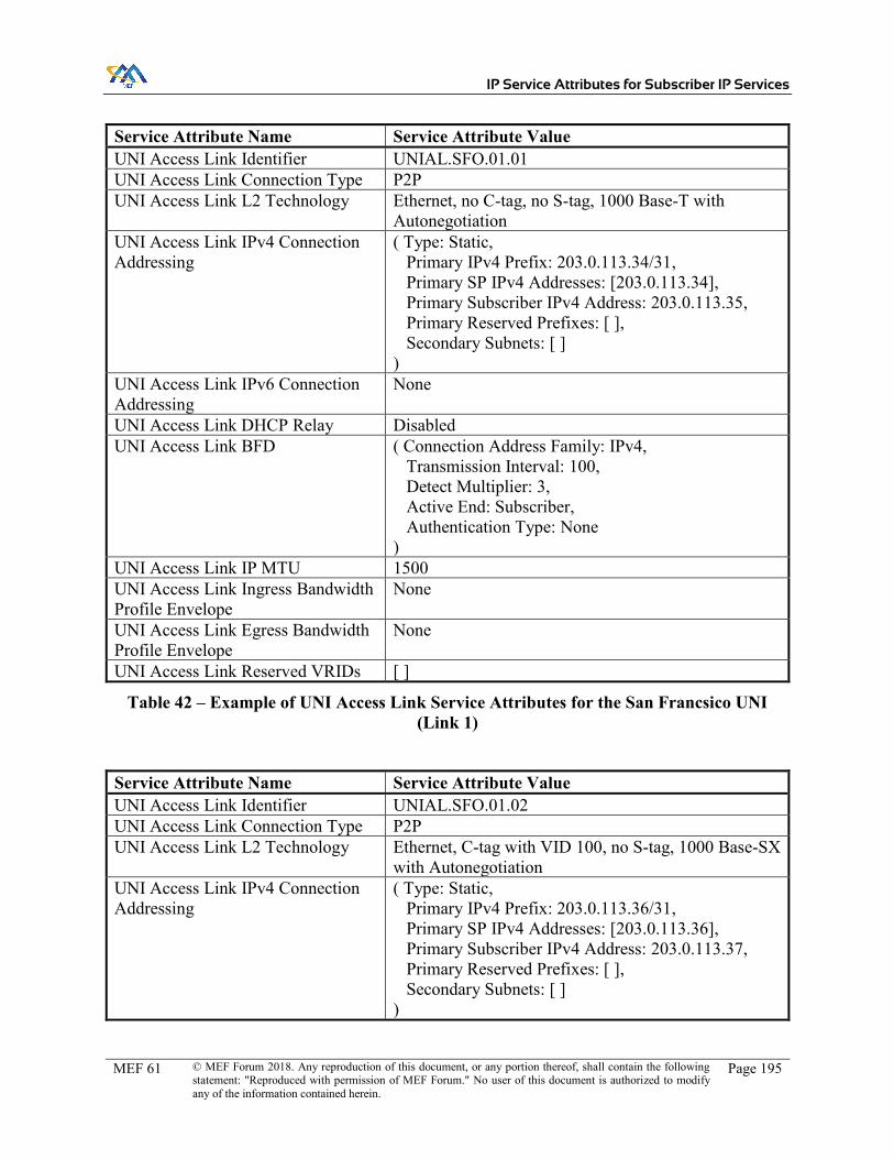
IP Service Attributes for Subscriber IP Services
MEF 61 © MEF Forum 2018. Any reproduction of this document, or any portion thereof, shall contain the following statement: "Reproduced with permission of MEF Forum." No user of this document is authorized to modify any of the information contained herein.
Page 195
Service Attribute Name Service Attribute Value UNI Access Link Identifier UNIAL.SFO.01.01 UNI Access Link Connection Type P2P UNI Access Link L2 Technology Ethernet, no C-tag, no S-tag, 1000 Base-T with
Autonegotiation UNI Access Link IPv4 Connection Addressing
( Type: Static, Primary IPv4 Prefix: 203.0.113.34/31, Primary SP IPv4 Addresses: [203.0.113.34], Primary Subscriber IPv4 Address: 203.0.113.35, Primary Reserved Prefixes: [ ], Secondary Subnets: [ ] )
UNI Access Link IPv6 Connection Addressing
None
UNI Access Link DHCP Relay Disabled UNI Access Link BFD ( Connection Address Family: IPv4,
Transmission Interval: 100, Detect Multiplier: 3, Active End: Subscriber, Authentication Type: None )
UNI Access Link IP MTU 1500 UNI Access Link Ingress Bandwidth Profile Envelope
None
UNI Access Link Egress Bandwidth Profile Envelope
None
UNI Access Link Reserved VRIDs [ ]
Table 42 – Example of UNI Access Link Service Attributes for the San Francsico UNI (Link 1)
Service Attribute Name Service Attribute Value UNI Access Link Identifier UNIAL.SFO.01.02 UNI Access Link Connection Type P2P UNI Access Link L2 Technology Ethernet, C-tag with VID 100, no S-tag, 1000 Base-SX
with Autonegotiation UNI Access Link IPv4 Connection Addressing
( Type: Static, Primary IPv4 Prefix: 203.0.113.36/31, Primary SP IPv4 Addresses: [203.0.113.36], Primary Subscriber IPv4 Address: 203.0.113.37, Primary Reserved Prefixes: [ ], Secondary Subnets: [ ] )

IP Service Attributes for Subscriber IP Services
MEF 61 © MEF Forum 2018. Any reproduction of this document, or any portion thereof, shall contain the following statement: "Reproduced with permission of MEF Forum." No user of this document is authorized to modify any of the information contained herein.
Page 196
Service Attribute Name Service Attribute Value UNI Access Link IPv6 Connection Addressing
None
UNI Access Link DHCP Relay Disabled UNI Access Link BFD ( Connection Address Family: IPv4,
Transmission Interval: 100, Detect Multiplier: 3, Active End: Subscriber, Authentication Type: None )
UNI Access Link IP MTU 1500 UNI Access Link Ingress Bandwidth Profile Envelope
None
UNI Access Link Egress Bandwidth Profile Envelope
None
UNI Access Link Reserved VRIDs [ ]
Table 43 – Example of UNI Access Link Service Attributes for the San Francisco UNI (Link 2)
As shown above, each UNI Access Link has a unique identifier, connection address scheme and Layer 2 information. The UNI Access Link IPv4 Connection Addressing Primary Subnet Ad-dresses are used to establish the BGP session over each of the UNI Access Links.
For illustration, different media have been identified for the two UNI Access Links. The IP Service Attributes do not specify whether these UNI Access Links connect to the same CE router or dif-ferent CE routers, or whether they connect to the same PE router or different PE routers, though the SP and the Subscriber may have reasons to communicate this information (such as in the case of IP unnumbered links). One possible way to achieve this with no additional communication is to imbed the information in the UNI Access Link Identifier.
Table 44 shows the values of the IPVC EP Service Attributes for the IPVC EP at the San Francisco UNI.
Service Attribute Name Service Attribute Value IPVC EP Identifier IPVCEP.SFO.01.01 IPVC EP UNI UNI.SFO.01 IPVC EP Role Root IPVC EP Prefix Mapping [ ] IPVC EP Maximum Number of IPv4 Routes 300 IPVC EP Maximum Number of IPv6 Routes 0 IPVC EP Ingress Class of Service Map ( F: IP DS,
M: [ ], D: Basic )
IPVC EP Egress Class of Service Map N/A IPVC EP Ingress Bandwidth Profile Envelope None

IP Service Attributes for Subscriber IP Services
MEF 61 © MEF Forum 2018. Any reproduction of this document, or any portion thereof, shall contain the following statement: "Reproduced with permission of MEF Forum." No user of this document is authorized to modify any of the information contained herein.
Page 197
Service Attribute Name Service Attribute Value IPVC EP Egress Bandwidth Profile Envelope None
Table 44 – Example of IPVC EP Service Attributes at the San Francisco UNI
In this example of a standard routing Multipoint IPVC with a single Class of Service Name, the IPVC EP attributes look similar to those at the other sites. A higher number of IPv4 routes is specified than would be necessary for aggregate routing to accommodate longer prefix matching, though that detail is up to the discretion of the Service Provider.
One way to implement a fully meshed Multipoint IPVC with no prefix filtering is to use a single VRF using an MP-BGP based VPN using the VPNv4 address family. Each site will have a Route Distinguisher assigned. A single Route Target can be used to simplify the implementation. In the simplest implementation, each UNI Access Link would be an interface in the same VRF.
Alternatively, each UNI Access Link could be in its own VRF, and the Service Provider may then assign a different Route Distinguisher for prefixes learned over each UNI Access Link at the San Francisco location, which would ensure that duplicate IPv4 addresses would have unique VPNv4 addresses. This could enable the Subscriber to advertise routes from both UNI Access Links to enable the Subscriber to use ECMP, for example.
C.2 Rooted Multipoint IPVC Example
This example uses the same Subscriber as above, Bank of MEF, with sites at San Francisco, Lon-don, and Tokyo. The Subscriber has modified their request, however, such that all traffic may not be passed directly between London and Tokyo. In this instance, the values for the Subscriber IPVC Service Attributes for IPVC Topology are changed to reflect a value of Rooted Multipoint. The values of the Subscriber UNI Attributes and Subscriber UNI Access Link Attributes could all be the same (assuming no other parameters have been requested to be modified). The Subscriber IPVC End Point Attributes are modified such that the roles of the IPVC EPs at London and at Tokyo are changed to “Leaf”.
Table 45, Table 46, Table 47 and Table 48 show the values of the Subscriber IPVC Service At-tributes for the IPVC and the value of the IPVC EP Service Attributes for the three IPVC EPs. The values that are changed, compared to the previous example, are shown in bold.
Service Attribute Name Service Attribute Value IPVC Identifier IPVC.000001 IPVC Topology Rooted Multipoint IPVC End Point List [ IPVCEP.LONDON.01.01,
IPVCEP.SANFRANCISCO.01.01, IPVCEP.TOKYO.01.01 ]
IPVC Packet Delivery Standard Routing IPVC Maximum Number of IPv4 Routes 400 IPVC Maximum Number of IPv6 Routes 0 IPVC DSCP Preservation Enabled IPVC List of Class of Service Names [ Basic ]

IP Service Attributes for Subscriber IP Services
MEF 61 © MEF Forum 2018. Any reproduction of this document, or any portion thereof, shall contain the following statement: "Reproduced with permission of MEF Forum." No user of this document is authorized to modify any of the information contained herein.
Page 198
Service Attribute Name Service Attribute Value IPVC Service Level Specification ( s: 00:00:00 on 1 July 2017,
T: 1 Calendar Month, E: { ( Metric: One-way Packet Loss Ratio, C: Basic, S: {(IPVCEP.TOKYO.01.01, London), (London, IPVCEP.TOKYO.01.01)}, 𝐹: 0.1% ) }, L: { ( Name: London, Description: London Docklands IPVC EPs: [ IPVCEP.LONDON.01.01 ] ) } )
IPVC MTU 1500 IPVC Path MTU Discovery Enabled IPVC Fragmentation Enabled IPVC Cloud None IPVC Reserved Prefixes [ 203.0.113.0/27 ]
Table 45 – Example of Subscriber IPVC Service Attributes for a Rooted Multipoint IPVPN
Service Attribute Name Service Attribute Value IPVC EP Identifier IPVCEP.LONDON.01.01 IPVC EP UNI UNI.LONDON.01 IPVC EP Role Leaf IPVC EP Prefix Mapping [ ] IPVC EP Maximum Number of IPv4 Routes 150 IPVC EP Maximum Number of IPv6 Routes 0 IPVC EP Ingress Class of Service Map ( F: IP DS,
M: [ ], D: Basic )
IPVC EP Egress Class of Service Map N/A IPVC EP Ingress Bandwidth Profile Envelope None IPVC EP Egress Bandwidth Profile Envelope None
Table 46 – Example of IPVC EP Service Attributes at the London UNI for Rooted Multipoint
Service Attribute Name Service Attribute Value IPVC EP Identifier IPVCEP.TOKYO.01.01 IPVC EP UNI UNI.TOKYO.01 IPVC EP Role Leaf IPVC EP Prefix Mapping [ ] IPVC EP Maximum Number of IPv4 Routes 1

IP Service Attributes for Subscriber IP Services
MEF 61 © MEF Forum 2018. Any reproduction of this document, or any portion thereof, shall contain the following statement: "Reproduced with permission of MEF Forum." No user of this document is authorized to modify any of the information contained herein.
Page 199
Service Attribute Name Service Attribute Value IPVC EP Maximum Number of IPv6 Routes 0 IPVC EP Ingress Class of Service Map ( F: IP DS,
M: [ ], D: Basic )
IPVC EP Egress Class of Service Map N/A IPVC EP Ingress Bandwidth Profile Envelope None IPVC EP Egress Bandwidth Profile Envelope None
Table 47 – Example of IPVC EP Service Attributes at the Tokyo UNI for Rooted Multipoint
Service Attribute Name Service Attribute Value IPVC EP Identifier IPVCEP.SFO.01.01 IPVC EP UNI UNI.SFO.01 IPVC EP Role Root IPVC EP Prefix Mapping [ ] IPVC EP Maximum Number of IPv4 Routes 300 IPVC EP Maximum Number of IPv6 Routes 0 IPVC EP Ingress Class of Service Map ( F: IP DS,
M: [ ], D: Basic )
IPVC EP Egress Class of Service Map N/A IPVC EP Ingress Bandwidth Profile Envelope None IPVC EP Egress Bandwidth Profile Envelope None
Table 48 – Example of IPVC EP Service Attributes at the San Francisco UNI for Rooted Multipoint
A Service Provider could implement this solution using an MP-BGP based VPN. One implemen-tation would have two Route Targets assigned, one would be assigned to the Root(s), the other would be assigned to the Leaf(s). A Route Target policy would be used to ensure that prefixes learned from Leaf Route Targets could only be advertised to the Root(s) while each site could advertise the prefixes learned from the Root Route Targets.
Alternatively, each location could be assigned its own Route Target, and a more detailed policy could be used to allow the Root(s) to learn the prefixes advertised by the Leaf(s).
C.3 Internet Access Example
In this example, the Bank of MEF would like to connect their head office to the public Internet. They therefore request a cloud access IPVC.

IP Service Attributes for Subscriber IP Services
MEF 61 © MEF Forum 2018. Any reproduction of this document, or any portion thereof, shall contain the following statement: "Reproduced with permission of MEF Forum." No user of this document is authorized to modify any of the information contained herein.
Page 200
Figure 53 – Example Cloud Access IPVC
The tables below show the values of all of the Service Attributes. In this example, the Internet access service provides dual-stack connectivity. The Subscriber has been assigned a /29 (IPv4) prefix and a /56 (IPv6) prefix. Again, documentation space is used here, but in reality these would be taken from public address space. The Service Provider and Subscriber do not exchange Internet routing information. The service provides a single best-effort Class of Service. The IP MTU for this IPVC is 1500 bytes. NAT for IPv4 traffic is performed by the Subscriber. DNS service is provided by the Service Provider, with the DNS servers sent via DHCP.
Table 49 shows the values of the Subscriber IPVC Service Attributes for the IPVC.
Service Attribute Name Service Attribute Value IPVC Identifier IPVC.00066.1 IPVC Topology Cloud Access IPVC End Point List [ IPVCEP.Budapest.66.01 ] IPVC Packet Delivery Standard Routing IPVC Maximum Number of IPv4 Routes 1 IPVC Maximum Number of IPv6 Routes 1 IPVC DSCP Preservation Disabled
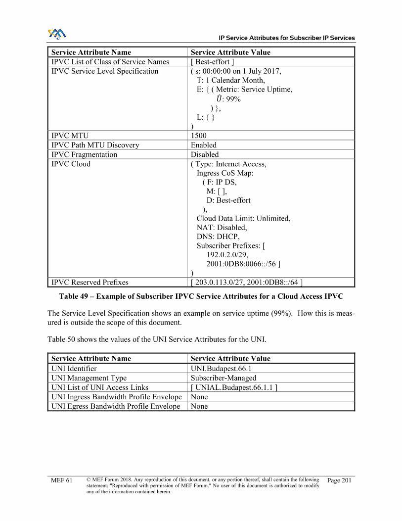
IP Service Attributes for Subscriber IP Services
MEF 61 © MEF Forum 2018. Any reproduction of this document, or any portion thereof, shall contain the following statement: "Reproduced with permission of MEF Forum." No user of this document is authorized to modify any of the information contained herein.
Page 201
Service Attribute Name Service Attribute Value IPVC List of Class of Service Names [ Best-effort ] IPVC Service Level Specification ( s: 00:00:00 on 1 July 2017,
T: 1 Calendar Month, E: { ( Metric: Service Uptime, 𝑈: 99% ) }, L: { } )
IPVC MTU 1500 IPVC Path MTU Discovery Enabled IPVC Fragmentation Disabled IPVC Cloud ( Type: Internet Access,
Ingress CoS Map: ( F: IP DS, M: [ ], D: Best-effort ), Cloud Data Limit: Unlimited, NAT: Disabled, DNS: DHCP, Subscriber Prefixes: [ 192.0.2.0/29, 2001:0DB8:0066::/56 ] )
IPVC Reserved Prefixes [ 203.0.113.0/27, 2001:0DB8::/64 ]
Table 49 – Example of Subscriber IPVC Service Attributes for a Cloud Access IPVC
The Service Level Specification shows an example on service uptime (99%). How this is meas-ured is outside the scope of this document.
Table 50 shows the values of the UNI Service Attributes for the UNI.
Service Attribute Name Service Attribute Value UNI Identifier UNI.Budapest.66.1 UNI Management Type Subscriber-Managed UNI List of UNI Access Links [ UNIAL.Budapest.66.1.1 ] UNI Ingress Bandwidth Profile Envelope None UNI Egress Bandwidth Profile Envelope None

IP Service Attributes for Subscriber IP Services
MEF 61 © MEF Forum 2018. Any reproduction of this document, or any portion thereof, shall contain the following statement: "Reproduced with permission of MEF Forum." No user of this document is authorized to modify any of the information contained herein.
Page 202
Service Attribute Name Service Attribute Value UNI List of Control Protocols [ ( Protocol: ICMP,
Addressing: SP Addresses, Reference: RFC 792 ), ( Protocol: DHCP, Addressing: Any, Reference: RFC 2131 and RFC 2132 ), ( Protocol: DHCPv6, Addressing: Any, Reference: RFC 3315 ) ]
UNI Routing Protocols [ ( Type: Static, Address Family: Both, Prefixes: [ ( Prefix: 192.0.2.0/29, Nexthop: 203.0.113.1, Admin Distance: 10 ), ( Prefix: 2001:0DB8:0066::/56, Nexthop: 2001:0DB8:0066::2, Admin Distance: 10 ) ] ) ]
UNI Reverse Path Forwarding Enabled
Table 50 – Example of UNI Service Attributes for a Cloud Access service
In this example, the Subscriber location has a Subscriber managed router on site. Static routing is used; for IPv6, this is with an aggregate prefix that is a superset of the IP Prefix used for connection addressing (see below).
Table 51 shows the values of the UNI Access Link Service Attributes.
Service Attribute Name Service Attribute Value UNI Access Link Identifier UNIAL.Budapest.66.1.1 UNI Access Link Connection Type P2P UNI Access Link L2 Technology Ethernet, C-tag with VID 66, no S-tag, 1000 Base-SX,
GE/FD UNI Access Link IPv4 Connection Addressing
( Type: Static, Primary IPv4 Prefix: 203.0.113.0/31, Primary SP IPv4 Addresses: [203.0.113.0], Primary Subscriber IPv4 Address: 203.0.113.1, Primary Reserved Prefixes: [ ], Secondary Subnets: [ ] )

IP Service Attributes for Subscriber IP Services
MEF 61 © MEF Forum 2018. Any reproduction of this document, or any portion thereof, shall contain the following statement: "Reproduced with permission of MEF Forum." No user of this document is authorized to modify any of the information contained herein.
Page 203
Service Attribute Name Service Attribute Value UNI Access Link IPv6 Connection Addressing
( Type: DHCP, Subnets: [ ( IPv6 Prefix: 2001:0DB8:0066::/64, SP IPv6 Address: [2001:0DB8:0066::1], Reserved Prefixes: [ 2001:0DB8:0066:0:1::/80 ] ) ] )
UNI Access Link DHCP Relay Disabled UNI Access Link BFD None UNI Access Link IP MTU 1500 UNI Access Link Ingress Bandwidth Profile Envelope
None
UNI Access Link Egress Bandwidth Profile Envelope
None
UNI Access Link Reserved VRIDs [ ]
Table 51 – Example of UNI Access Link Service Attributes for a Cloud Access Service
The UNI Access link for the Budapest location receives IP addresses via DHCP over an optical Gigabit Ethernet connection.
Table 52 shows the values of the IPVC EP Service Attributes for the IPVC EP.
Service Attribute Name Service Attribute Value IPVC EP Identifier IPVCEP.Budapest.66.1 IPVC EP UNI UNI.Budapest.66.1 IPVC EP Role Root IPVC EP Prefix Mapping [ ] IPVC EP Maximum Number of IPv4 Routes 1 IPVC EP Maximum Number of IPv6 Routes 1 IPVC EP Ingress Class of Service Map ( F: IP DS,
M: [ ], D: Best-effort )
IPVC EP Egress Class of Service Map N/A IPVC EP Ingress Bandwidth Profile Envelope None IPVC EP Egress Bandwidth Profile Envelope None
Table 52 – Example of IPVC EP Service Attributes for a Cloud Access service

IP Service Attributes for Subscriber IP Services
MEF 61 © MEF Forum 2018. Any reproduction of this document, or any portion thereof, shall contain the following statement: "Reproduced with permission of MEF Forum." No user of this document is authorized to modify any of the information contained herein.
Page 204
Appendix D OAM Methods Supporting IP Services (Informative)
This appendix describes some Operation Administration & Maintenance (OAM) solutions and methodologies that can be used to support IP Services, both by the Subscriber and within the SP Network. OAM, considering both Fault Management (FM) and Performance Monitoring (PM), is one of the most important aspects of IP Services. For both SPs and Subscribers, the importance of PM in particular, for monitoring the SLAs/SLSs defined for the service, is self-evident. Note that this Appendix considers OAM for technologies (e.g. MPLS) that can be used to implement IP Services, as well as IP-based OAM; the former are only applicable to OAM within the SP Network.
As the possible mix of applications running on a connectivity service and the associated perfor-mance objectives (e.g. for delay, delay variation, loss) become more and more complex, SPs are being asked to implement a sound strategy both to set the required performance objectives and to monitor that the production network assures such SLSs.
MEF 23.2 [81] is an Implementation Agreement that an SP can apply to Carrier Ethernet services. The requirements have been developed based on the needs of Subscribers and their applications more than on technologies or connectivity solutions adopted, so the principles in such an IA can be applied also to IP Services. MEF 23.2 [81] specifies CoS Performance Objectives (CPOs) for different applications, CoS models and Performance Tiers.
Having MEF 23.2 [81] as a reference guide to set CPOs, SPs need OAM methodologies and tools to measure performance on their production network, in order to support both their internal quality processes and to ensure they are meeting the SLSs agreed with their Subscribers.
MEF does not define measuring tools, algorithms or solutions but makes reference to standards from other SDOs whose mandate or mission is focused on these subjects. IETF, and in particular the IPPM, MPLS and related Working Groups, are particularly relevant for IP Services.
The subsections below cover an overview of the OAM tools specified by IETF, followed by more detail on Fault Management and Performance Monitoring.
D.1 OAM tools specified by IETF
An Operations, Administration, and Maintenance (OAM) toolset provides methods for fault man-agement and performance monitoring in each layer of the network, in order to improve their ability to support services with guaranteed and strict Service Level Agreements (SLAs) while reducing operational costs. OAM provides instrumentation tools for measuring and monitoring the data plane. OAM tools often use control-plane functions, e.g., to initialize OAM sessions and to ex-change various parameters. The OAM tools communicate with the management plane to raise alarms, and often OAM tools are activated by the management plane (as well as by the control plane), e.g., to locate and localize problems. The considerations of the control-plane maintenance tools and the functionality of the management plane are out of scope for this specification; this appendix concentrates on presenting the data-plane tools that are specified for OAM by IETF.

IP Service Attributes for Subscriber IP Services
MEF 61 © MEF Forum 2018. Any reproduction of this document, or any portion thereof, shall contain the following statement: "Reproduced with permission of MEF Forum." No user of this document is authorized to modify any of the information contained herein.
Page 205
D.2 OAM Fault Management
Protocols for Fault Management functions of OAM toolset can be categorized as protocols that perform proactive defect detection and failure localization, vs those that perform these functions on-demand. These are described in the subsections below.
D.2.1 Proactive Continuity Check and Connectivity Verification
Bidirectional Forwarding Detection (BFD) has been designed as a proactive Continuity Check protocol for IP, as described in the following RFCs: RFC 5880 [50], RFC 5882 [52], RFC 5883 [53], RFC 5884 [54], RFC 5885 [55], RFC 6428 [59] and RFC 7726 [68].
D.2.2 On-demand Continuity Check and Connectivity Verification
On-demand Continuity Check and Connectivity Verification protocols for IP include:
x Ping (RFC 7276 [64]) using ICMP x Traceroute (RFC 7276 [64]) using ICMP and UDP x HTTP Ping (RFC 7540 [66])
Depending on the technology used to implement the IP Service, other tools may also be available to the SP; for example, if the service is implemented using MPLS, then MPLS OAM tools can be used.
D.3 OAM Performance Measurement
The construction of Performance Metrics and Methods can be categorized as either "Active" or "Passive", as described in RFC 7799 [71]. Some methods use a subset of both Active and Passive attributes, and we refer to these as "Hybrid” methods.
x An Active method depends on a dedicated measurement packet stream and observations of the packets in that stream.
x A Passive method depends solely on observation of one or more existing packet streams. The streams are only used for measurement when they are observed for that purpose, but are present whether or not measurements take place.
x Hybrid methods use a combination of Active methods and Passive methods.
Among other well-known PM methodologies, an introduction of the latest IETF PM methodology, Alternate Marking, is provided below. The Alternate Marking method is the IETF’s preferred mechanism for Passive and Hybrid PM for IP.
The following protocols are considered for IP Performance Measurement:
x One-Way Active Measurement Protocol (OWAMP), as defined in RFC 4656 [37], and Two-Way Active Measurement Protocol (TWAMP), as defined in RFC 5357 [42], RFC 6038 [56], and RFC 7750 [69].

IP Service Attributes for Subscriber IP Services
MEF 61 © MEF Forum 2018. Any reproduction of this document, or any portion thereof, shall contain the following statement: "Reproduced with permission of MEF Forum." No user of this document is authorized to modify any of the information contained herein.
Page 206
x Use of the Alternate Marking method (as described below). If supported by the overlay layer, this behaves as closely as technically possible to a Passive method for measuring performance.
Again, depending on the technology used to implement the service, other options may be available to the SP. For example, if the service is implemented using MPLS, packet loss and delay meas-urement cane be performed as defined in RFC 6374 [58].
D.3.1 Alternate Marking
Deployment of traditional methods for measuring Performance Metrics has certain limitations and challenges, whether Active or Passive methods are used.
This has resulted in a new method, Alternate Marking, for monitoring the performance of live data traffic, that is intended to be more accurate and easier to implement and deploy. This method is a Passive/Hybrid method, that can, in theory, be applied to any kind of packet based traffic, in-cluding Ethernet, IP, and MPLS, both unicast and multicast. However, note there are currently no standard methods for applying it to Ethernet or IP traffic in practice. The method is primarily intended for packet loss measurement, but the principles can be extended for use with one-way delay and delay variation measurements as well.
Passive methods for measuring packet loss typically work by splitting the packet stream into dis-tinct blocks, so that the number of packets sent and received within each block can be compared. The Alternate Marking method doesn't use additional packets to virtually split the flow in blocks (as in ITU-T G.8013 [87] LMM or RFC 6374 [58] DLM). Instead, it “marks” the packets so that the packets belonging to the same block will have the same “color”, whilst consecutive blocks will have different colors. For example one implementation of alternate marking method could change the value of a bit in the packet header for this kind of measurement. Each change of color repre-sents a sort of auto-synchronization signal that guarantees the consistency of measurements taken by different devices along the path.
The Alternate Marking method (specified in RFC 8321 [76]) is illustrated in Figure 54.
Figure 54 – Alternate Marking method for OAM
As shown in the figure:
x Every x minutes (e.g. 5) the packet marking is changed (e.g.: Red & Blue). x Each router maintains separate counts for red and blue packets. x When the Red packet counters are running the Blue counters are still and vice versa;

IP Service Attributes for Subscriber IP Services
MEF 61 © MEF Forum 2018. Any reproduction of this document, or any portion thereof, shall contain the following statement: "Reproduced with permission of MEF Forum." No user of this document is authorized to modify any of the information contained herein.
Page 207
x When the Blue packet counters are still, the NMC (Network Management Centre) col-lects all routers’ Blue data and vice versa.
The Alternate Marking Method could be considered Hybrid or Passive depending on the case. In cases where the marking is done by changing values of existing fields in the packets (e.g. DSCP field), the technique is Hybrid. In cases where the marking field is a dedicated, reserved field that is included in the protocol specification, the Alternate Marking technique can be considered as Passive.
The same principle used to measure packet loss can be applied also to one-way delay and delay variation measurements. The options are: Single marking and Double marking methodology as described in RFC 8321 [76].
It is possible to compare packet loss and delay measurement with Alternate Marking with other OAM methodologies (e.g. RFC 6374 [58]):
x OAM Packet insertion (c.f. RFC 6374 [58]) doesn’t work if packets are re-ordered as they flow across the network. In fact, RFC 6374 [58] gives rise to a number of problems that can lead to significant packet accounting errors.
x OAM Packets have to be inserted in the right place in the router architecture, which is hard to implement in hardware.
x OAM Packet insertion doesn’t work with multipoint flows (packet batch boundaries dis-appear).
x Alternate Marking works in case of re-ordering (e.g. due to Equal Cost Multi-Path (ECMP)), with low computational load.
x Alternate Marking permits to define “a posteriori” the monitored flow (you can mark all the traffic at the starting point and then you can aggregate data at the intermediate and ending points by choosing the matching criteria).
x Alternate Marking works with multipoint flows (packet batch boundaries are still valid).
The Alternate Marking methodology can also be generalized and expanded to measure any kind of unicast flow, even when packets can follow several different paths in the network.
D.3.2 Alternate Marking Method Application to MPLS PM
This section describes an example showing how Alternate Marking can be used in the context of MPLS OAM Performance Measurement. Note that this specification does not require MPLS to be used to implement IP Services.
Alternative Marking can be applied to RFC 6374 [58] MPLS PM for loss measurement by intro-ducing the concept of flow identities. In summary RFC 6374 [58] uses the loss-measurement (LM) packet as the packet accounting demarcation point. Unfortunately this gives rise to a number of problems that can lead to significant packet accounting errors in certain situations. For example:
x Where a flow is subjected to Equal Cost Multi-Path (ECMP) treatment packets can arrive out of order with respect to the LM packet.

IP Service Attributes for Subscriber IP Services
MEF 61 © MEF Forum 2018. Any reproduction of this document, or any portion thereof, shall contain the following statement: "Reproduced with permission of MEF Forum." No user of this document is authorized to modify any of the information contained herein.
Page 208
x Where a flow is subjected to ECMP treatment, packets can arrive at different hardware interfaces, thus requiring reception of an LM packet on one interface to trigger a packet accounting action on a different interface which might not be co-located with it. This is a difficult technical problem to address with the required degree of accuracy.
x Even where there is no ECMP (for example on RSVP-TE, MPLS-TP LSPs and PWs) lo-cal processing might be distributed over a number of processor cores, leading to synchro-nization problems.
x Link aggregation techniques can also lead to synchronization issues. x Some forwarder implementations have a long pipeline between processing a packet and
incrementing the associated counter again leading to synchronization difficulties.
An approach to mitigating these synchronization issues is for the sender to batch packets and to mark each batch in some way such that adjacent batches can be easily recognized by the receiver.
Network management operations require the measurement of packet loss between a source and destination. It is thus necessary to introduce some source specific information into the packet to identify packet batches from a specific source. This can be done by encoding per flow instructions in an MPLS label stack using a technique called Synonymous Flow Labels (SFL) in which labels which mimic the behavior of other labels provide the packet batch identifiers and enable the per batch packet accounting.
The Synonymous Flow Label is defined ad hoc and improves loss and delay measurement when compared with the techniques of RFC 6374 [58].
For example, consider an MPLS pseudowire (PW), where two labels are defined as synonymous flow labels for the PW. By alternating between these SLs and using them in place of the normal PW label, the PW packets can be batched for counting without any impact on the PW forwarding behavior.
To measure loss, the sender counts the number of packets transmitted in each batch. Similarly, the receiver counts packets received in the batch. When the batch has completed and the sender is confident that all of the packets in that batch will have been received, the sender issues an RFC 6374 [58] Query message to determine the number actually received and hence the number of packets lost. The RFC 6374 [58] Query message is sent using the same SFL as the corresponding batch of data service packets.
Where it is desired to more thoroughly instrument a packet flow to determine the delay of a number of packets, it is undesirable to send a large number of RFC 6374 [58] packets acting as proxy data service packets. A method of directly measuring the delay characteristics in a hybrid/passive way is therefore needed. This can be achieved by marking some packets with a different SFL, so that they are recognized along the path and dedicated for delay measurements.