Production of Utilizable Energy from Renewable Resources: Mechanism, Machinery and Effect on...
32
Production of Utilizable Energy from Renewable Resources: Mechanism, Machinery and Effect on Environment Neelima Mahato, Mohd. Omaish Ansari and Moo Hwan Cho School of Chemical Engineering, Yeungnam University, Republic of Korea-712 749 Email: [email protected] (corresponding author) Keywords: Renewable energy, solar energy, wind energy, wave energy, biomass. Abstract. The renewable energy sources had been known to humankind since the very beginning of the human civilization, though practiced in very primitive forms. The first civilization and subsequent greater civilizations, came up, existed, and flourished at or near river valley/basins. Rivers provided water for irrigation, domestic utilization, transportation; overall development of the entire civilization. In the latter years, the increase in the human population and certain revolutionary inventions and discoveries like fire, the wheel, and domestication of cattle and animals led the movement and spread of the human populations in the other parts of the globe far from river irrigated lands. Humans learnt to utilize underground waters and harvest rainwater for living and survival. In the course of development, there also increased demand for more energy and its storage so that it can be utilized as and when required. This brought humankind to discover the laws of thermodynamics, emergence of combustion engines, electromagnetic induction, electricity and storage devices, such as batteries and supercapacitors. The development has been revolutionized since last few centuries with increasing demand of energy with growing industries and a faster life. Nowadays, because of massive exploitation of fossil resources for fuel and electricity, and concerns of global warming, exploring renewable energy alternatives are gaining momentum. Of many renewable resources, viz., sun, wind, water, geothermal, biomass, etc., the biomass energy is the most widely studied one in terms of both, published literature and wide social acceptance across the globe followed by solar and wind energy. The chapter presents the potential alternatives to non-renewable energy resources, mechanism and machinery to draw and exploit the energy in the usable or utilizable form; past, present, recent progresses and future scope of the ongoing researches on this subject. The chapter also deals with the relative merits or pros and cons of the massive and large scale installation of machinery to produce electricity from some of the noteworthy renewable energy resources, such as, wind, water and sun, which is affecting the local environment or natural habitats, flora and fauna; overall influence on the delicate balance of the ecosystem. Introduction Renewable energy resources are those resources which can be replenished again and again on a human time scale by natural processes and remains constant. These resources are sunlight, wind, water, oceans (tides, waves, ocean currents), geothermal heat and biomass. The overgrowing population and development has increased the crisis in resources as well as energy at an alarming rate. The industrial revolution and after years has witnessed huge utility of the non-renewable resources, such as fossil fuels like coal, petrol, diesel, natural gases, etc., for energy production and transportation. Slowly, but certainly, the usage of fossil fuels, and in the latter years, the overuse of the same erupted huge environmental risks, such as environmental pollution, global warming, destruction of the ecosystem, the loss of the innumerable species of flora and fauna across the entire globe. Global warming, on one hand, destructed the natural balance of the atmosphere and the ecosystem; on the other hand, initiated the melting of the polar ice caps resulting in the rise of the sea level which is submerging the coastal soils and causing shrinkage of the lands. It is beyond any doubt that the utilization of fossil fuels also led to many interesting inventions and discoveries of technologies and machineries for the production of energy and transportation. During the past two centuries, there had been the maximum utilization of the non-renewable resources as well as maximum degradation to the environment, the ecosystem and disappearance of Advanced Materials Research Vol. 1116 (2015) pp 1-32 © (2015) Trans Tech Publications, Switzerland doi:10.4028/www.scientific.net/AMR.1116.1 All rights reserved. No part of contents of this paper may be reproduced or transmitted in any form or by any means without the written permission of Trans Tech Publications, www.ttp.net. (ID: 165.229.67.182-15/06/15,10:48:18)
Transcript of Production of Utilizable Energy from Renewable Resources: Mechanism, Machinery and Effect on...

Production of Utilizable Energy from Renewable Resources: Mechanism, Machinery and Effect on Environment
Neelima Mahato, Mohd. Omaish Ansari and Moo Hwan Cho
School of Chemical Engineering, Yeungnam University, Republic of Korea-712 749 Email: [email protected] (corresponding author)
Keywords: Renewable energy, solar energy, wind energy, wave energy, biomass.
Abstract. The renewable energy sources had been known to humankind since the very beginning of
the human civilization, though practiced in very primitive forms. The first civilization and
subsequent greater civilizations, came up, existed, and flourished at or near river valley/basins.
Rivers provided water for irrigation, domestic utilization, transportation; overall development of the
entire civilization. In the latter years, the increase in the human population and certain revolutionary
inventions and discoveries like fire, the wheel, and domestication of cattle and animals led the
movement and spread of the human populations in the other parts of the globe far from river irrigated
lands. Humans learnt to utilize underground waters and harvest rainwater for living and survival. In
the course of development, there also increased demand for more energy and its storage so that it can
be utilized as and when required. This brought humankind to discover the laws of thermodynamics,
emergence of combustion engines, electromagnetic induction, electricity and storage devices, such as
batteries and supercapacitors. The development has been revolutionized since last few centuries with
increasing demand of energy with growing industries and a faster life. Nowadays, because of
massive exploitation of fossil resources for fuel and electricity, and concerns of global warming,
exploring renewable energy alternatives are gaining momentum. Of many renewable resources, viz.,
sun, wind, water, geothermal, biomass, etc., the biomass energy is the most widely studied one in
terms of both, published literature and wide social acceptance across the globe followed by solar and
wind energy.
The chapter presents the potential alternatives to non-renewable energy resources, mechanism and
machinery to draw and exploit the energy in the usable or utilizable form; past, present, recent
progresses and future scope of the ongoing researches on this subject. The chapter also deals with the
relative merits or pros and cons of the massive and large scale installation of machinery to produce
electricity from some of the noteworthy renewable energy resources, such as, wind, water and sun,
which is affecting the local environment or natural habitats, flora and fauna; overall influence on the
delicate balance of the ecosystem.
Introduction
Renewable energy resources are those resources which can be replenished again and again on a
human time scale by natural processes and remains constant. These resources are sunlight, wind,
water, oceans (tides, waves, ocean currents), geothermal heat and biomass. The overgrowing
population and development has increased the crisis in resources as well as energy at an alarming
rate. The industrial revolution and after years has witnessed huge utility of the non-renewable
resources, such as fossil fuels like coal, petrol, diesel, natural gases, etc., for energy production and
transportation. Slowly, but certainly, the usage of fossil fuels, and in the latter years, the overuse of
the same erupted huge environmental risks, such as environmental pollution, global warming,
destruction of the ecosystem, the loss of the innumerable species of flora and fauna across the entire
globe. Global warming, on one hand, destructed the natural balance of the atmosphere and the
ecosystem; on the other hand, initiated the melting of the polar ice caps resulting in the rise of the sea
level which is submerging the coastal soils and causing shrinkage of the lands. It is beyond any
doubt that the utilization of fossil fuels also led to many interesting inventions and discoveries of
technologies and machineries for the production of energy and transportation.
During the past two centuries, there had been the maximum utilization of the non-renewable
resources as well as maximum degradation to the environment, the ecosystem and disappearance of
Advanced Materials Research Vol. 1116 (2015) pp 1-32© (2015) Trans Tech Publications, Switzerlanddoi:10.4028/www.scientific.net/AMR.1116.1
All rights reserved. No part of contents of this paper may be reproduced or transmitted in any form or by any means without the written permission of TransTech Publications, www.ttp.net. (ID: 165.229.67.182-15/06/15,10:48:18)

innumerable plant and animal species. In short, it has disturbed the delicate balance of the nature.
Not only this, it also alarmingly increased the energy as well as fuel crisis, challenging the economic
and social diaspora at national and international levels. With increasing pollution of air, water and
land, there is also introduced several diseases in human, cattle and livestock, animals, birds, plants
and trees, leading to extinction of many plant and animal species. The human health is also at great
risk at the places where pollution level is very high.
The rising concerns on pollution, diseases and limiting fossil fuel resources led the scientists,
researchers and philosophers across the world to focus on the importance and utility of renewable
energy resources. The use of renewable energy resources though had been known since the very
beginning of the human civilization, but never thought to be exploited in a commercial way until the
present century. In 21st century, inventions and discoveries are largely focused to utilize the
renewable energy resources for power/electricity generation, heating and transportation. The
mainstream technologies are, Solar power, Wind energy, Hydro energy, Marine energy, Geothermal
energy and Biomass energy. In this chapter, these mainstream energy resources and machinery to
harness energy and power has been discussed. It was believed that the utilization of the renewable
energy resources is practically not a threat to the environment and are ecofriendly. But, with time, it
is discovered and realized that the utility of the renewable energy resources also cause problems to
the environment and the ecosystem to little or large extent. There exists a deep relation on how the
machinery of renewable energy system works and how does the functioning of the machinery affects
the environment. This chapter deals with the mechanism of energy production from the renewable
resources, working machinery, its functioning, efficacy and potential effect on the environment.
Solar Energy
Solar energy is the energy from the sun in the form of light, heat or electricity. Sun is the primary
source of energy to the earth. Solar energy can be harvested either directly or indirectly. For
example, the energy harvested from wind and biomass is an indirect form of solar energy. In this
section, we discuss about the different approaches to harvest the direct form of solar energy. The
topic includes a description on ‘solar heating of houses during winter season and solar architecture’,
‘solar thermal electricity’, ‘solar photovoltaics’, ‘solar water disinfection system’, ‘solar kitchen or
community kitchen’, ‘greenhouse effect and vernalization’.
Solar Heating of Houses During Winter and Solar Architecture. The idea of trapping and
utilizing sunlight has influenced the architecture of houses and building designs from the very
beginning of the human civilization. One of the oldest civilizations, “Mezhirich” which existed
during 24000 to 12000 BC, somewhere in the modern Ukraine were known to build houses with
various mammoth bones and tusks. These materials were known to be acting as an efficient thermal
mass and used to be covered with insulating layers of hides or leather skins or furs. Also, these
houses had south facing openings covered with stretched skin pieces to allow low level solar
radiations from the setting sun to reach the interior as shown in the schematics in Fig. 1. South facing
courtyard houses were also built by the ancient Chinese and Greeks.
2 Recent Advances in Renewable Energy Research

Fig. 1. Course of the sun during summer and winter seasons. The knowledge about the movement of
the sun during the two extreme seasons led the ancient civilizations build south facing dwellings. On
the below, left side is shown the architecture of the housing made of mammoth bones and tusks
(from one of the oldest civilizations “Mezhirich” during 24000 to 12000 BC) and on the right side is
the ancient Chinese House with south facing architecture so that every house had a courtyard and
rooms capable of receiving solar heat during the winter season. Adapted from [1].
Ancient Romans discovered that the caves have arch like structure at the entrance and replicated the
same on the windows and door tops of their houses. This added an advantage in terms of stronger
structure that requires less building material compared to the horizontal or straight stones or woods.
Fig. 2. Building of wedge shape door and window designs. It was an inspiration derived from the
natural caves which helped the houses to receive more sunlight as well as saving construction
materials. Adapted from [2].
Advanced Materials Research Vol. 1116 3

Fig. 3. Remains of ancient Heliocaminus Baths built during 120 AD at villa Adriana, near Rome.
Heliocaminus”, in ancient Greek language literally means “solar furnace”. These architectures
incorporated large rooms with wide areas enclosed by equator-facing huge clear windows. This
design was efficient in keeping interiors hotter than the outside air temperature during the winter
season. On the other hand, during summers, the solar gain could be blocked using movable shades
on the glasses. Adapted from [2].
One more similar example of harvesting solar energy effortlessly is of cliff dwelling from Ancient
America, which existed during the 12th
century AD. The ancient Puebloan village (Navajo National
monument, AZ) was built in a cave with an overhanging cliff facing towards the southwest direction.
The overhanging cliff allowed solar radiations strike the buildings during the winter season and kept
those warm, but shaded from the scorching sun during the summer season. The cliff palace in Mosa
Verde National Park, Colorado, North America is known as the largest cliff dwelling created by
humankind. In modern times, solar architecture is being designed in various innovative ways [3-8].
Some of the designs are illustrated here.
4 Recent Advances in Renewable Energy Research

Fig. 4. The concept of Cliff dwellings in the 12th
century AD and modern houses (below) with
innovative solar walls to adjust solar energy for heating during the winters and cooling during the
summers.
These designs are innovated according to the need of the growing population and limited resources
like space and building material. Houses are preferred to be equipped with both mechanisms, e.g.,
heating during winters and cooling during summers [9].
Solar Water Heating and Solar Kitchen. With increasing human population and soaring prices of
oil and natural gas and other fossil fuels, innovation in the direction of creating a workable design of
solar water heating systems and solar kitchens is believed to be a boon [10-11]. This not only
provides an efficient mechanism in cutting prices of the cooked food, but also a safe alternative for
the environment as these techniques does not produce emission gases, CO2, CO, etc. In the diagram
shown below is a parabolic dish concentrator shell fitted with white glass pieces which receives and
reflects the solar radiation falling on it, and focuses it to heating the water in the pipeline. The hot
boiling water in the pipeline generates steam with temperature up to 600 C, which is used for
cooking food. Subsequently, the heated water can also be utilized for other household purposes [12-
14].
Advanced Materials Research Vol. 1116 5

Fig. 5. Dish and mirror concentrators to focus the solar radiation on the fluid flowing through the
pipeline for storing the solar thermal energy and producing electricity.
Based on similar mechanism, machinery for community kitchen can also be installed. A huge solar
kitchen set up at Taleti, near Mount Abu, Rajasthan at an altitude of 1219 m above sea level, at
present, is the world’s largest solar steam cooking kitchen. It consists of a six-module solar steam
cooking system and a total of 84 parabolic dish concentrators or shell type receivers, each with a
surface area of 9.2 sq. m. to heat up the water and generate steam. The system has the capacity of
generating 3500-4000 kg of steam of temperature ~ 650 C and cook up to 20,000-38,000 meals per
day when solar radiation is received maximum.
Fig. 6. The concept of a community kitchen where a large number of dish concentrators heat up the
water flowing in the pipelines and collectively produce huge amounts of steam that can be utilized
for cooking large number of meals.
Solar Photovoltics and Solar Thermal Energy. A photovoltaic device works on the principle of
“photoelectric effect”, a theory which earned Albert Einstein, the Nobel Prize in Physics in 1921.
The word photovoltaic is composed of two words, “photo” indicating light and “voltaic” indicating
electromotive force created by light. Photovoltaic cells are made of semiconductor materials, such as
6 Recent Advances in Renewable Energy Research

silicon, germanium and doped semiconductor materials. When light of sufficient energy falls on the
surface of a photovoltaic cell, electrons get ejected out of the surface atoms, leaving behind holes or
positive centers (nucleus), thus, creating electron hole pairs or excitons. In a solar cell, the
photoelectric effect works in a little different way to produce electricity. Since, the ejected electrons
have a tendency of recombining back to previous state instantaneously. For drawing electrical
energy, it is an important prerequisite to keep these charges separate. Therefore, not all materials are
suitable for making solar cells. In this regard, semiconductor materials serve the best. In a crystalline
arrangement of atoms in a lattice, with each atom influencing the other. Theoretically the electron
energy levels of all the atoms combine to become two bands. These bands are either partially or
completely occupied by electrons or empty as and when the case may be. Depending upon the
energy of the electrons, the bands are separated into energy levels, namely the valence band (when
electrons remain within the atomic orbitals) and conduction band (when electrons move out of the
boundaries of atomic orbitals and wander within the material). The energy bands for the three types
of materials, viz., metals, non-metals and semiconductor materials are shown in the picture below.
Fig. 7. The band gap diagram of a conductor, semiconductor and an insulator.
In case of metals, the valence band overlaps within the conduction band, therefore, recombination
of the ejected photoelectrons back to the atomic orbitals is instantaneous. In case of insulators, the
difference between the energies of the two bands is huge and electrons never reach to the level of the
conduction band, and hence, remain insulated. In semiconductors, the difference between the two
energy levels is small (~1 volt) and the electrons can reach to fill the conduction bands after
absorbing energy from the solar radiation falling on it. Radiation with an energy of 1 eV is, hence,
the minimum requirement to impel an electron from the valence band to the conduction band.
Further, the energy gap is tunable when doped with atoms of other elements, e.g., arsenic or
phosphorus.
Advanced Materials Research Vol. 1116 7

Fig. 8. N-and P- doping of a semiconductor material.
A typical solar cell uses two different types of doped semiconductors. These are n- and p- type
semiconductor. A p-type semiconductor is obtained by doping pure silicon with acceptor atoms or
atoms with fewer electrons in its outermost atomic orbital or holes, e.g., Arsenic. On the other hand,
in a n-type semiconductor, the pure silicon is doped with donor type atoms or atoms with excess
electrons in the outermost atomic orbital, e.g., phosphorus. The two together create a p-n junction,
where the electrons from n-type region combine with the holes in the p-type region at the boundary
between the two. This helps in eliminating the free charges and building up an internal electric field
within the semiconductor which averts the movement of other charges. When solar radiation strikes
on the surface of the photovoltaic cell, electrons are liberated in the p-type region and holes are
produced in the n-type region. This lowers the potential energy barrier at the p-n junction and the
moving electrons build up an external potential difference. The assembly of p-n junction makes
certain that if either of the two types of materials undergo the photoelectric effect and produces free
electrons to move, the electrons can flow in only a single direction, i.e., through an external circuit to
reach the other side of the p-n junction and combine with the opposite charge.
An assembly of multiple photovoltaic cells or solar cells in an array make a solar panel. Solar
panels are constructed to utilize the maximum amount of radiations and convert it into a sufficient
quantity of utilizable electrical energy to conveniently run electrical appliances for long durations
[15]. Every year, each square kilometer of the desert belonging to these places receives solar energy
equivalent to 1.5 barrels of oil. In this regard it is possible to install solar panels of great capacity
producing energy several hundred times the entire current energy consumption of the world. World’s
largest solar power plant is being planned to be built in the Mojave Desert in California with $ 168
million investment from Google [16].
8 Recent Advances in Renewable Energy Research

Fig. 9. Solar panel for operating street light. Pictures from Yeungnam University campus,
Gyeongsan, S.Korea.
Solar Thermal Electricity. Solar thermal energy (STE), developed during 1980s, is a form of
energy harnessed from the sun to generate thermal energy for drying purposes [17-18], brine
distillation [19-21] or producing electrical energy. For this, flat or disc shape collectors or
mirrors/lens are used. Solar radiation is concentrated to heat the molten salt or nano fluids (22), filled
in pipelines, and the temperature can be raised up to 700-800 ºC. This large amount of heat is then
utilized to generate steam, which in turn, runs turbines to produce electricity. The main advantage of
commercial concentrating solar thermal power (CSP) plants is the ability of thermal storage that
facilitates dispatching of electricity over up to a 24 h period [23-26].
Solar Water Disinfection and Waste Water Treatment System. Solar water disinfection is a
method of potable water purification using solar energy. Water which is contaminated with
biological contaminants, such as microorganisms, like bacteria, viruses, protozoa, worms, and
harmful toxic chemicals like heavy metals, dyes, etc., making is completely unsafe for drinking is
treated with solar radiation. This technique is becoming popular in developing countries in order to
make the water safe for drinking purposes. This is carried out by three primary steps:
It is well known that UV radiations denature the DNA of microorganisms and kill them. Direct
solar disinfection (SODIS) method is therefore, considered very convenient, inexpensive and
effective method of water purification. It uses a combination of UV light and increased temperature
for disinfecting water. For this water is taken in PET bottles (which do not block UV radiations) and
exposed directly to the solar radiation.
Heat treatment to the water by solar thermal energy. Raising the temperature to 70-100 C for a
short period of time and pasteurized.
Electricity generated by the photovoltaic panels induces electrolysis process that generates
oxidative free radicals which kill the pathogens by denaturing its nuclear material.
Similarly, the harmful and toxic heavy metals like arsenic can also be removed. It is carried out in a
two-step process. In the 1st step, Fe (II) hydroxide and a few drops of lemon juice is added to water.
The Fe (II) hydroxide may also be present naturally in the water. The As (III) present in the water
have a tendency to get weakly adsorbed to iron hydroxides, and in turn, get oxidized to As (IV) and
the latter is strongly adsorbed to the iron hydroxide. The precipitate is then allowed to settle to the
bottom of the container with adsorbed As (V) and the clear water is decanted. As (III) can also be
oxidized to As (V) by photochemical oxidation brought upon by the free radicals generated by the
UV radiation of the solar spectrum as shown in the schematic below.
Advanced Materials Research Vol. 1116 9

Fig. 10. Solar energy utilization in the removal of toxic arsenic from water.
This method of disinfecting potable water proved very useful in Bangladesh, where ground water is
made safe for drinking at virtually no cost. SODIS is an effective method at the places, where fuel
and electricity is either unavailable or very expensive to bear. It is completely environmentally
friendly and clean method. However, additional filtration methods and appliances are required if the
water is turbid. Solar sewage treatment plants are being developed to be installed in the developing
nations to fight the problem of sanitation. Sunlight induces an electrochemical reaction with human
waste and generates free radicals that kill microbes and release hydrogen.
The Greenhouse Effect. The concept of greenhouse is a very interesting natural phenomenon. Solar
radiation falling on the earth is distributed unevenly between the atmosphere and surface. On an
average, the planet receives 343 Watt/m2 of solar radiation. The earth’s surface and the atmosphere
reflect back a large portion of the radiation to the space and some amount heats up the earth’s
surface. The earth’s surface absorbs a part of this radiation and again reflects back the remaining.
Some part of this radiation is absorbed by the gases present in the atmosphere and trapped as heat.
This natural phenomenon keeps the planet warm during the night. The greenhouse effect is also
believed to be one of the greatest reasons that makes the planet earth habitable for life. The gases
which trap the heat are also known as greenhouse gases [27]. These are ozone (3-7%), methane (4-
9%), carbon dioxide (9-26%), and water vapor (36-70%). Industrialization and increased usage of oil
and fossil fuels are believed to have raised the amount of carbon dioxide in the atmosphere, which in
turn, has caused global warming. It is anticipated that the continuous increase in the global warming
with the present rate may cause the polar ice caps to melt and rise in the sea level which might
submerge the coastal areas. On the other hand, this phenomenon of the green house effect is utilized
to build artificial greenhouses to preserve plants and herbs during freezing winters. To a more
ambitious extent, green houses have been adopted by the people living in cold regions for farming
vegetables and even the entire crop. It was almost impossible to believe that an entire length of the
crop could be grown in a greenhouse before the concept of vernalization was discovered. The term
“vernalization” was coined by Lysenko, who actually demonstrated how important the dark period of
flowering in some plants. He used the chilling process to make the seeds of winter cereals behave
like spring cereals.
Since, Lysenko’s paper on vernalization and plant physiology published in 1928, it attracted huge
attention in Russia. Since, severe cold, snow and Siberian winds destroys the winter crops, especially
wheat seedlings, vernalization has proven a very efficient and beneficial method of saving crops
during winters. Seedlings are germinated, stored and petri dishes and then kept in a fridge for around
7 weeks to provide the cold period (vernalization) required to stimulate the growth in young plants to
10 Recent Advances in Renewable Energy Research

reproduce. This cold treatment or vernalization is given in order to make crosses over the winter to
save the young plants from the freezing winter. When spring arrives after the winter, the vernalized
plants are either potted in a greenhouse for some time or directly transferred to the field depending
upon the temperature. These plants, then grow normally and flower in next 6 weeks. This method
enables the people living in cold regions to grow their crops despite of long freezing winters.
Construction of greenhouses has also been utilized for preserving delicate and sensitive plants for
conducting various research.
Fig. 11. Vernalization and green house farming; An efficient utilization of solar energy.
In this regard research institutes install greenhouses to carry out studies on plants, crops, pathological
diseases and effect of medicines. The world’s largest greenhouse complex is built in Cornwall,
England under Eden project. Inside these greenhouses artificial biomes have been created and
thousands of plants have been collected from all over the world. This is known to be the hugest effort
till so far by the researchers for preserving the endangered species of plants from across the world.
Relative Merits and Environmental Aspects of Solar Energy. Installing a utility scale solar
energy power plant is though considered a very clean source of energy, but is generally expensive
compared to any other renewable energy resources. Moreover, solar radiation is intermittent, i.e., not
constant throughout the year; not even in a day (morning and night). Therefore, it has to be
accompanied with some additional power sources or an efficient energy storage system for a
continuous supply of energy. The storage systems that can be applied is either batteries or
supercapacitors, which further enhances the cost.
Solar energy is not polluting as the burning of fossil fuels, but some challenges cannot be ruled
out. There occurs emission of greenhouse gases like nitrogen trifluoride and sulfur hexafluoride
during the manufacturing of materials required for fabricating the solar panels. Sometimes, this also
causes poisoning of the water and land, e.g., wreckage, decommissioning and dumping of the
materials or recycling of cadmium telluride (CdTe) or copper indium gallium selenide (CIGS)
materials [28].
Installing of the utility scale solar systems requires large land areas, which may sometimes cause
disturbance to the local ecosystem and indirectly influence the regional biodiversity, e.g., birds,
insects and population of small amphibians.
Wind Energy
Moving air is called wind and wind energy is the utilizable energy harnessed from the kinetic energy
of the moving air. Wind is an indirect form of solar energy. It is created during the heating of the
atmosphere by solar energy, earth and oceans. It is estimated that 1-2% of the solar radiation
Advanced Materials Research Vol. 1116 11

reaching the earth is converted to wind energy. The early forms of wind turbines were wind mills.
The history of windmills is very old. Windmills are known to exist since the 1st century AD and
these were used for grinding grains. Wind turbines are the new designs invented during 19th
century
AD. Modern turbines, which exist at the present time were created after years of innovations and
scientific research. Modern turbines are designed to produce electricity [29-31].
Since, wind turbines can provide maximum output when wind speed is considerably large.
Therefore, the most effective and economic wind turbines are installed in the windiest areas, such as
sea shores and usually mounted on tall towers. It is possible to install wind turbines at both locations,
onshore as well as offshore. The towers are built strong on either gravity foundations or sited on steel
monopoles. Gravity foundations are mostly made of concrete structures which remain stable in
corrosive saline waters of the ocean and sand. Such structures or the monopoles, are on the other
hand, built on long steel tubes, drilled or vibrated into the sea bed, and secure platforms are installed
on the top. The main disadvantage of such structures is the high cost [32]. The picture shown below
illustrates different kinds of base designs / pedestals on which the wind turbines can be installed.
Fig. 12. Different designs of the base/pedestals for the onshore and offshore wind turbine
installations.
Wind Turbine: Design and Machinery. A wind turbine is equipped with suitable machinery to
generate utilizable energy by converting the kinetic energy of the wind into mechanical energy and
mechanical energy into electricity. In earlier days when the concept of electricity was not there, the
mechanical energy of the wind was utilized in direct applications, such as grinding stones or grains
and such structures were called wind mills. Nowadays, the modern wind turbines generate
electricity, and therefore, called a wind generator, wind power unit (WPU) or wind energy converter
(WEC) or aero generator. A typical wind turbine has one, two or three blades, uses the horizontal
axis configuration and operates either downwind or upwind direction. The maximum efficiency of a
modern wind turbine ranges between 30-50%, depending upon the speed of the wind. The internal
components and machinery of a typical wind turbine is shown in the Fig. 13, below
12 Recent Advances in Renewable Energy Research
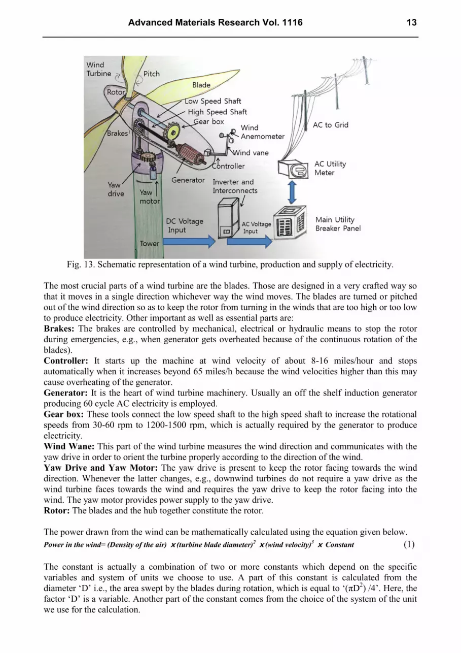
Fig. 13. Schematic representation of a wind turbine, production and supply of electricity.
The most crucial parts of a wind turbine are the blades. Those are designed in a very crafted way so
that it moves in a single direction whichever way the wind moves. The blades are turned or pitched
out of the wind direction so as to keep the rotor from turning in the winds that are too high or too low
to produce electricity. Other important as well as essential parts are:
Brakes: The brakes are controlled by mechanical, electrical or hydraulic means to stop the rotor
during emergencies, e.g., when generator gets overheated because of the continuous rotation of the
blades).
Controller: It starts up the machine at wind velocity of about 8-16 miles/hour and stops
automatically when it increases beyond 65 miles/h because the wind velocities higher than this may
cause overheating of the generator.
Generator: It is the heart of wind turbine machinery. Usually an off the shelf induction generator
producing 60 cycle AC electricity is employed.
Gear box: These tools connect the low speed shaft to the high speed shaft to increase the rotational
speeds from 30-60 rpm to 1200-1500 rpm, which is actually required by the generator to produce
electricity.
Wind Wane: This part of the wind turbine measures the wind direction and communicates with the
yaw drive in order to orient the turbine properly according to the direction of the wind.
Yaw Drive and Yaw Motor: The yaw drive is present to keep the rotor facing towards the wind
direction. Whenever the latter changes, e.g., downwind turbines do not require a yaw drive as the
wind turbine faces towards the wind and requires the yaw drive to keep the rotor facing into the
wind. The yaw motor provides power supply to the yaw drive.
Rotor: The blades and the hub together constitute the rotor.
The power drawn from the wind can be mathematically calculated using the equation given below.
Power in the wind= (Density of the air) ⅹ(turbine blade diameter)2 ⅹ(wind velocity)
3 ⅹ Constant (1)
The constant is actually a combination of two or more constants which depend on the specific
variables and system of units we choose to use. A part of this constant is calculated from the
diameter ‘D’ i.e., the area swept by the blades during rotation, which is equal to ‘(πD2) /4’. Here, the
factor ‘D’ is a variable. Another part of the constant comes from the choice of the system of the unit
we use for the calculation.
Advanced Materials Research Vol. 1116 13

Relative Merits of Wind Power and Environmental Aspects.The technology of wind power
requires a high initial investment for installation compared to the fossil fueled generators. Moreover,
the wind energy cannot be stored (unless batteries are used). Since, the constant availability of the
wind with appropriate velocity has been highly unlikely and it is intermittent and not all winds can
be harnessed to fulfill the requirements of electricity generation. Wind turbines are mostly installed
at windy locations which includes onshore and offshore regions of the oceans. Although, wind power
is considered to be a very clean technology in view of environmental aspects, but there may be some
issues related to noise and visual impact. Offshore (shallow waters off the coast) winds tend to blow
at higher velocities compared with the onshore (coastal region) winds, and hence, possess a greater
capacity of producing electricity. But, offshore, wind power technology requires various
modifications in the designs of their base which include more robust structure from tower to cape
and extra protection (protective coatings) to the essential components to protect those from corrosive
sea air and application of bright paints for navigation. Offshore turbines are usually protected by
good quality covers and paints and well equipped for corrosion protection., e.g., anodic protection,
etc. these are also equipped with (a) automatic greasing system to lubricate bearings and blades, (b)
pre-heating and cooling system to maintain and regulate the gear oil temperature, (c) lightening
protection system, and (d) navigation and aerial warning lights for the passing ships or boats.
Offshore turbines are often built with larger blades (30-40 m long) to take advantage of steadier
winds. The power generation on an average from an offshore unit is between 2-4 MW. Since, wind is
an inexhaustible resource unlike fossil fuels and can be harnessed anywhere and everywhere with an
additional advantage of being completely pollution free. Wind energy, along with solar power can
fulfill the requirements for energy in remote areas where connection to main electricity grids are
unavoidably expensive or not possible to reach. Furthermore, it can help in creating jobs in
numerous areas, i.e., manufacturing, construction, and environmental management services in the
remote areas and upgrade the living standards of the people. An increase in the quality of wind and
solar energy can reduce the burning of fossil fuels, reduce pollution and can help combat with global
warming as well as its consequences. It is considered to be a boon to the developing nations, where
the population is usually large and people are relatively underprivileged. At present China stands at
the top of the chart of offshore wind power countries followed by USA, Germany and India. China’s
wind power production capacity is ~ 91,424 MW in the year 2013 followed by 61,091 MW (USA),
34,250 MW (Germany) and 28,150 MW (India). In the list of onshore wind power production
countries, China again stands at the top followed by USA and India. The wind power installations
sometimes cause killing of the migratory birds which accidentally collide to the moving blades and
possibly a threat to the endangered species. Electromagnetic fields created by the transmitting cables,
noise of the rotating blades and vibrations spreading inside ground or water could affect the
orientation, natural breeding grounds and navigational ability of small animals, e.g., reptiles,
amphibians, fishes and migratory birds. The foundation of the wind turbine installation has also been
found to create potential regions for the artificial reefs that may help increase in the fish population,
and in turn, stimulate the population of the birds in the area. But, collisions between birds and rotors
is a negative aspect. This may ultimately cause an alteration of natural environments and diminution
of habitats.
Hydro Power and Marine Energy
Hydro power is the power in the form of mechanical energy or electricity harnessed from running or
falling water [33]. A typical representative of the hydro power generation is shown in the picture
below.
14 Recent Advances in Renewable Energy Research

Fig. 14. A typical representation of hydro power generation.
Like windmills, the history of hydro power generation dates back to about the 4th
century BC where
people used water power for irrigation and running water clocks in India, Mesopotamia, Ancient
Egypt, Persia and China. There are many more evidences from other parts of the globe, viz., during
620 AD in Europe, where people used to harness energy from tides to rotate the grinders of the grain
mills for milling grains into flour. The first technical document featuring the methodical details of
the engineering elements was compiled by a French Engineer Bernard Forest de Belidor in
“Architecture Hydraulique”. He described about the vertical- and horizontal- axis hydraulic
machines in this document and published the same in 1753. There are available several other
technologies of generating hydropower, viz., conventional hydroelectricity by means of hydal power
dams, electricity from run-of-the-river water or streams without the use of dams, small (10MW or
less) and microhydroelectricity (few KW to few hundred KWs) for isolated homes, villages and
industries, conduit hydroelectricity from diverted water (e.g., municipal water) and pumped storage
hydroelectricity, which stores water during the time when demand for electricity is low and
programmed to be released when demand is high.
The amount of hydropower available from a power source can be calculated from the equation
below-
(2)
Where, ‘P’ is the power in Watts, ‘η’ is the dimensionless efficiency of the turbine, ‘ρ’ is the density
in Kg/m3, ‘Q’ is the flow in m
3/s, ‘g’ is the acceleration due to gravity and ‘h’ is the height difference
between the inlet and outlet of the flowing water column. And, we see that power is directly
proportional to the height of the falling water. However, some hydropower systems, e.g., water
wheels are capable of drawing power from flowing water without necessarily changing the height of
the fall and depending largely on its kinetic energy.
Marine Energy. Earth, the blue planet is abundant in water resources. Approximately, 70% of the
globe is covered by oceans, which represents a huge source of energy that can be tapped and
harvested in different ways, e.g., electricity can be produced from the surface waves, fluid flow,
salinity gradients and ocean thermal energy [34-36].
Wave Energy. Waves are created by the natural transfer of wind energy on the surface of the sea.
The wind is, in turn, created by solar energy. When the kinetic energy of the wind is greater, the
waves created on the surface of the sea is higher, and hence, also called gravity waves as their
potential energy is due to the gravitational pull of the earth. The movement and motion of the waves
are periodic or oscillatory in nature and forms a basis for designing different wave energy devices
[37-38]. However, the devices are known for producing energy in less amounts as the oscillator
frequency of an ocean wave is relatively very slow, much less than 100 revolutions/min which is a
Advanced Materials Research Vol. 1116 15

minimum requirement for an uninterrupted power generation. Therefore, newer and more efficient
designs were invented to convert the slow-acting devices into high speed, i.e., unidirectional rotation
of a generator shaft. The three fundamental machineries are
Wave Profile Device- These turn the oscillating height of the ocean surface into mechanical energy.
These devices float on the sea surface and move according to the motion and shape of the incident
waves.
Fig. 15. Point and linear absorbers for wave power generation.
These are of two or more types depending upon the size, such as ‘point absorbers’ if its size is very
small compared to the periodic length of the wave and ‘linear absorbers’ if its size is appreciably
longer than the typical wave in the ocean. These devices are collectively called as “wave
attenuators”. The difference in the working of the two device types lies in the technique by which
energy is produced, i.e., either floating mechanism of an oscillating solid device or by oscillating
wave waters inside the device itself. The designs of the two device types, viz., Linear and point
absorbers are shown in Fig. 15.
As we see in the figure, the components of the devices, the ‘heaves’ absorb the vertical motion of the
wave energy, ‘surge’ receive energy from the horizontal motion of the waves, ‘pitch’ catches the
angular motion about the central axis parallel to the wave crests and ‘yaw’ collects the angular
motion about the vertical axis. The four work in unison generating energy from the different
movements of the wave motion by reacting via some kind of fixed resistance built within the device
called a reaction point. The reaction points are special designs, built within the devices, that can be
inertial masses, such as heavy suspended ballast plates, sea floor anchors or a fixed dead weight or
pile; efficient enough to react with the moving waves and generate as much energy as it can. In Fig.
15, we see the smaller structures, e.g., ‘buoys’ and linear longer structures or ‘linear absorbers’ with
fitted hydraulic Ram joints and all the structures are fixed at the base of the sea or sea bed with fixed
heavy weights to prevent it from being floated away. The devices are a combination of an absorber
and a reaction point, and the relative motion between the two components is created by the pitching
and heaving motion of the waves. As the buoy bobs in a vertical direction, i.e., up and down on the
sea surface, an oscillatory force reaction is generated between the absorbers and the reaction point.
Here, the reaction point is the heavy plate fitted with a hydraulic pump, and in between, there is a
generator. The up and down movement rotates the generator to produce electricity. On the other
hand, the linear absorber (wave attenuator) is tethered, i.e., joints at several points, so that it can
move like a snake according to the coming waves. The joints contain a device or hydraulic ram that
16 Recent Advances in Renewable Energy Research

drives oil through a hydraulic motor which drives the generator and produces electricity. Since, these
devices are required to be fixed to the sea bed, therefore, the operation is restricted to the seashore
[39-40].
Oscillating Water Columns- To convert wave energy into air pressure. It is a shoreline device
normally fixed on to the rocks or cliffs near or next to the sea. The design consists of a partly
submerged hollow chamber. The latter converts wave energy into air pressure as shown in the Fig.
16.
Fig. 16. Oscillating water columns for electricity generation.
As the approaching waves enter and exit the chamber, the water level oscillates up and down and
pushes a gust of wind/air like a heavy piston, which in turn, is compressed and decompressed that
rotates the turbine and sits on the generator to produce electricity. But, since the air movement is in
both the directions, the turbine used in these device systems is ‘Well Turbine’ which has the property
of rotating in the same direction no matter whichever direction the air flows in the column. The
speed of the air flow through the turbine, i.e., the kinetic energy of the moving air can be enhanced
by narrowing the cross sectional area of the wave turbine duct. The advantage of this machinery is
the ease of monitoring, repair and maintenance, as it is installed on the land. But, on the other hand,
the energy generation and output is largely dependent on the level of wave energy which varies
everyday and does not remain constant.
Wave Capture Device- To convert the wave energy into potential energy. This device is also known
as ‘Overtopping wave power device’. It captures the movement of the tides or waves and lifts the
water to a higher level, thus converting into potential energy. The water is collected in a funnel
shaped channel which narrows towards the bottom. As the water moves in, the height is little lifted
up, and thus acquires the potential energy. Fig. 17 shows the outline design of the device. The
advantage of this device is that, these are floating, but, there are no moving parts. Therefore, these
are useful for the places where the sea shoreline is having deep waters and low tidal range. But, these
devices face several challenges, such as low efficiency of ~ 30% and prone to wreckage during
extreme weather conditions, e.g., storms.
Advanced Materials Research Vol. 1116 17

Fig. 17. Capture wave device for electricity production.
Marine Current Power. Marine current power is the form of marine energy harnessed from the
kinetic energy of the huge marine or ocean currents, e.g., Gulf stream. Ocean currents are
comparatively more predictable than any other known parameters, such as wind or waves, and
supply a constant source for generating energy. A report from the US Department of the Interior
(2006), states that if 1/1,000th
of the energy from Gulf stream is harnessed, which constitutes 21,000
times more energy than the Niagra Falls, it would be possible to provide 35% of the electricity
requirement of the entire Florida [41].
Ocean currents are huge in magnitude and very strong, generated primarily from the sun and from
the combined effects of temperature, wind, salinity, bathymetry and the rotation of the earth. Unlike
atmosphere, there are only small fluctuations in the current speed and almost no change in direction,
therefore, the huge kinetic energy of the ocean currents can be systematically converted into
electricity by means of powerful turbines. The main advantages of marine current power are (1) High
load factors due to the huge magnitude of the ocean currents as well as fluid properties, (2)
Predictability, (3) Large resources of the untapped energy, (4) Little or no environmental impact
unless there is a migration of ocean creatures in the currents, and (5) saving lands.
Tidal Power.Tides are created from the periodic variations in the gravitational attraction by the
moon and the earth. Due to strong gravitational pull, huge bulges in the oceanic waters are created
which cause temporary risings of the sea level at random sites [42]. The risen waters move towards
the shoreline with a force and this continue to occur without fail. The tidal energy can be harnessed
in three main forms, viz., (a) tidal stream power, (b) tidal barrage power, and (c) dynamic tidal
power (43).
Tidal Stream Power. The flow of the water as the tide moves towards shore or ebbs and floods to
form a current is called tidal stream. The kinetic energy of the progressing tides can be further
magnified by forcing it to move through narrow channels fitted with turbines in multiple locations
and generate electricity. One such establishment has been built on the coastline of the UK as the tidal
stream resources are huge at many places. Fig. 18 demonstrates the entire machinery of tidal power
generation.
18 Recent Advances in Renewable Energy Research

Fig. 18. Tidal stream power and tidal barrage.
Tidal Barrage. Tidal barrages are the modern form of tidal mills of old times. Tidal mills are known
to have existed since the middle ages in Roman history. At that time the mills were usually situated
on river estuaries in such a way that the effect of waves is minimized and at the same time keeping a
suitable distance from the sea so that it is capable of acquiring a reasonable tidal range. It is a dome
like structure made for capturing the tidal energy when the water moves inward and backward of a
bay, estuary basin or river. It is different from the structure of a conventional dam. The barrage
structure first allows the water to flow inward when the tides are high and release it back when it
declines. The barrage structure is fitted with sluice gates and turbines [44-45]. The sluice gates are
controlled at key times during the tidal cycle and the turbines are rotated by the moving water to
generate electricity. During the high tides, the water flows inward and the sluice gates as well as the
turbine gates are closed. There can be possible an additional structure for further pumping and
raising the water level in the basin. The gates are kept closed until the water level declines and there
is created sufficient head across the barrage. Once the sea level is sufficiently low, the sluice gates
are opened and water is allowed to fall on the turbine blades to generate electricity. The energy
generated from a barrage system is directly proportional to the volume of the water and the potential
energy it acquires when it is stored in the basin during the forward movement of water [46]. The
equation below can be used to calculate the energy available from a barrage system.
(3)
Where, ‘h’ is the vertical height of the tidal basin, ‘A’ is the horizontal area holding the tidal waters,
‘ρ’ is the density (=1025 Kg/m3) and ‘g’ is the acceleration due to gravity. The factor ‘1/2’ is
included due to the fact that the maximum difference of the height of water level in the basin is
obtained only during the lowest level of the sea after tidal decline and it is assumed that the high
Advanced Materials Research Vol. 1116 19

water level still remains available in the basin after the temporarily stored water flows empty through
the turbine.
Tidal barrages are one of the oldest technologies to generate electricity and date back as early as
the 1960s. One of the famous power projects is the Kislaya Guba Tidal Power station in Kislaya
Guba, Russia generates 1.7 MW of electricity. Other projects are Rance Tidal Power station on
Rance river, France (240 MW), Sihwa lake, Korea (254 MW) and some more to become functional
in the near future, e.g., Severn Barrage across River Severn in England and Lavernock point in
Wales [47].
Dynamic Tidal Power. This technology is still to be introduced, but explained and expected to be
very efficient in harnessing the immense stock of the tidal energy. This technique is about exploiting
the interaction between the potential energy and kinetic energy in the tidal flows by means of very
long (~ 30-50 km) dams built straight and parallel across the coastline without enclosing an area. The
tidal water level difference introduced during the oscillating forward and backward movement of the
sea water creates water level difference and allowing the backflowing waterfall to the turbines fitted
at the sluice gates to generate electricity [47-48].
Some Recent Designs of the Ocean Power Technology.
Salter’s Duck: It is a very efficient device capable of converting 90% of the wave motion into
electricity. The design was though proposed in the beginning of the 20th
century intentionally
ignored and killed by the nuclear and fossil fuel lobbyists. In the later years, it was realized that the
device installation is much more economical and convenient compared to its contemporaries. The
device consists of an electricity generating system based on a pendulum connected to a generator. As
the device moves or ‘bobs’ up and down according to the motion of the waves, the pendulum swings
forward and backward to rotate the generator to produce electricity
Limpet: Limpet is Land Installed Marine Power Energy Transformer. Electricity is generated as
the wave enters the open cavity and concentrates that pushes the air through the chamber on the top
of the device installed or through the backside according to the design. The concentrated air turns the
turbine, which in turn, sets on the generator and produces electricity.
Pelamis: This device is very long (~ 160 m) snake like structures floating on the sea surface. It has
joints or hinges fitted with hydraulic rams. As it bobs up and down with the motion of the moving
waves, the hinges bend accordingly to pump the hydraulic fluid and drive the generator to produce
electricity.
Mighty Whale: This is a huge device set on for experimentation in Japan recently. This device is
given the shape of a mighty whale with painted mouth and eyes.
BioSTREAM and BioWAVE: These are biomimetic devices. The BioSTREAM is a device that
mimics the movement of the wagging tails of shark or tuna. This is basically an active weatherwane
fitted with a generator. As the wave moves across it, the BioSTREAM automatically orients itself to
the waves and acquires a streamlined configuration. This is to avoid excess loading as well as to
enable the device in mimicking the motion and mechanism of the fish tail, and convert the
propulsion of the waves into energy. The BioSTREAM device has good efficiency (0.5-2 MW) and
has been found to be useful for generating electricity for domestic consumption [49].
20 Recent Advances in Renewable Energy Research

Fig. 19. BioSTREAM and BioWAVE [49].
BioWAVE is a kelp like structure capable of capturing the widest and deepest swath of the wave
energy from the ocean. It automatically orients itself along the wave motion. It can rotate freely, lay
flat on the sea floor (to avoid massive forces that could break it apart). The diagram shown in Fig.
19, illustrates the design and function of the two devices. Both the designs have common functions,
i.e., to associate back and forth according to the periodic motion of the waves. In the course, these
devices convert low speed, high torque oscillations into high speed, low torque rotations of a
permanent magnet motor. The devices are fixed or anchored to the ocean floor in a biologically
inspired design and tend to make oscillatory movements rather than rotating. This makes them more
ecofriendly and less dangerous to sea creatures. Furthermore, these are more economic.
Osmotic Energy
It is also called salinity gradient power. It is the form of energy extracted from the salinity gradient
of the difference in the salt concentration between seawater and fresh or river water [50]. This
technique relies on the phenomenon of osmosis across a semipermeable membrane and implied by
utilizing two main practical methods, viz., Reverse Electrodialysis (RED) and Pressure Retarded
Osmosis (PRO). Osmosis is a natural phenomenon observed when salty water or concentrated
solution is exposed to a less concentrated solution (i.e., with less salt) across a semipermeable
membrane, water molecules tend to move towards the higher concentration solution and dilute it.
This process continues till concentrations of the two solutions become equal on the either sides. The
semipermeable membrane is specific for allowing water molecules only. It rejects the solute or salt
ions (the dissolved anions and cations) to pass through. These membranes are customarily made of
thin film composite membranes (TMC or TFM). The TFM material is a complex molecular sieve
constructed in the form of film of single-, bi-, or multilayered materials. The first practical synthetic
semipermeable membrane was invented and developed by Prof. Sidney Loeb and Srinivasa
Sourirajan in Israel [51-52].
Reverse Electrodialysis. Reverse Electrodialysis or simply reverse dialysis forms the basis of a salt
battery. The system can be designated by making an array of alternating anion and cation exchange
membranes that can be made to function in a synchronized manner to generate electricity. The
working mechanism of the reverse osmosis power generation is shown in Fig. 20.
The chemical potential difference, created during osmosis process between the more salty and
less salty (fresh water), creates a voltage or potential difference over the respective membranes and
the total potential of the system is the sum of the potential differences over all the membranes. A
Advanced Materials Research Vol. 1116 21

commercial RED, with an energy production capacity of 250 KW occupies a volume of a shipping
container. The membranes used in reverse osmosis process are usually made of polyamides. Other
commonly used membranes are cation exchange membranes (CEM), charge mosaic membranes
(CMM), bipolar membranes (BPM), anion exchange membranes (AEM), alkali anion exchange
membranes (AAEM), proton exchange membranes (PEM), etc. In recent years semipermeable
membranes made of boron nitride nanotubes are also being used.
Fig. 20. The concept of reverse electrodialysis and production of electricity.
Pressure Retarded Osmosis. In this method the brackish water with a high salt content is pumped
into a pressure chamber which is at the low pressure side, i.e., the pressure created during the
osmosis process between the saline water and fresh water across the semipermeable membrane as
shown in the Fig. 21.
Fig. 21. Natural osmosis process and pressure retarded osmosis.
The semipermeable membrane, as said previously, allows the solvent or water molecules to pass
through it towards the more concentrated side during a natural osmosis process. In pressure retarded
osmosis, an external pressure is applied from the less pressure side to push the water molecules from
more concentrated sea water side to fresh water side across a semi-permeable membrane. The height
of the water column is thus raised as above as 270 m and stored as potential energy. Now this water
is allowed to fall from the height (and the stored potential energy of the water is converted to kinetic
energy) on a turbine fitted with a generator to produce electricity. In Fig. 22, the mechanism of
power generation is shown. This method was invented by Professor Sydney Loeb in 1973.
22 Recent Advances in Renewable Energy Research

Fig. 22. Pressure retarded osmsis and power generation.
Ocean Thermal Energy Conversion (OTEC)
Oceans are the largest collector for solar energy. There exists a natural thermal gradient of ~20 C
between the warm water at the surface and cold water in the deep. OTEC utilizes this thermal
gradient to generate electricity. It is a base load electricity generation system that works continuously
24 h a day and round the year. Furthermore, the resources for OTEC is much larger than any other
known ocean energy forms. According to the estimations, OTECs can generate up to 88,000 TWh or
power in a year [53]. The OTEC designs are of two types, viz., open cycle system and closed cycle
system. The close cycle OTECs use refrigerants, such as ammonia or R-134a as working fluids as
these have low boiling points. In addition, it employs the most commonly used heat cycles, i.e.,
Rankin cycle via a low pressure turbine. The Rankin cycle is named after William John Macquorn
Rankine, a Scottish polymath and professor in Glasgow University. Rankin cycle is an idealized
thermodynamic cycle of a heat engine to convert heat energy into mechanical work as shown below.
It works as a model to predict the performance of a steam turbine system. In this model the heat is
supplied externally to a closed loop containing a working fluid as shown in the Fig. 23. The heat
source is external and can be either a nuclear fission reaction, or combustion of fossil fuels, biomass,
natural gas etc.
Fig. 23. Ocean Thermal Energy Conversion and its applications.
Advanced Materials Research Vol. 1116 23

On the other hand, the open cycle engines utilize vapor from the seawater as working fluid. The
warm surface water is pumped into a vacuum chamber where it is flash evaporated to produce steam.
The absolute pressure of this steam is about 2.4 kilo Pascals (kPa). This steam condenses into
desalinated water, or in other words, distilled water from the saline sea water. OTECs during
operation produces huge quantities of cold water as by product that can be utilized for air
conditioning of the houses and refrigeration for domestic purposes. It also produces fresh or distilled
water from the brackish sea water, which can be utilized for drinking, agriculture, aquaculture and
cosmetic uses.
Relative Merits and Environmental Aspects of the Marine Power Generation. As we discuss the
relative merits of the hydro- or marine power, we come across several real time effects of the
installed devices and experimentations on the environment and ecosystem. Though, the designs are
continuously being improved, scientifically and thoroughly, but still, there are observed several
negative consequences of the installations. Some are discussed here.
Hydro power or marine power is a clean and pollution free source of energy. It does not create or
leave any waste and is convenient to store. Further, it is observed that the water stored in the
reservoir, built at an altitude, permit the regulation of the flow of the river. On the other hand, in
terms of cost and economy, the resources required for the construction of a dam or hydroelectric
power plant are expensive. Also, it is required to be connected by large network cables to transfer the
electricity to distant places.
Constructing reservoir causes loss of the productive soil meant for agriculture and disturbs the
ecosystem of that place.
Dams and reservoirs are also found to face problems of sedimentation because of the flowing mud
and sand carried by river waters. This occasionally causes flooding of the nearby natural habitats and
decreasing the water velocity in rivers and streams, sometimes altering the quality of the water as
well.
Similarly, marine power plants are no exceptions. Marine mammals and fishes often get struck by
the tidal turbine blades and killed.
The effects of the electromotive forces produced by the devices and underwater noise also disturbs
the natural environment of the inhabitant sea creatures and many time degrades the water quality as
well as disrupts the sedimentation processes.
The movement of water through the devices also causes additional turbidity (suspended solids) and
decline in the sea water salinity. This may automatically kill the marine fishes even if these do not
collide or struck into the devices. This, in turn, also affects the vital food resources for birds and
mammals as well as their breeding grounds.
Construction of huge installations for wave or tidal energy, e.g., barrage or lagoons, restricts the
movement of ships or boats/ steamers/ ferries in the locality. This is found to be less disadvantageous
in terms of business and trade, but at the same time, improves the local economy by constructing an
additional structure to the barrage, i.e., bridge, and increasing the connectivity to a larger area of that
particular land. In addition, the relatively calmer waters are supportive for flourishing estuarine
fishes, and diversified flora and fauna.
Saline waters of the sea causes corrosion of the metal parts of the devices, resulting in failure of the
system. Therefore, it is very difficult to monitor the underwater or submerged devices as well as
those which are floating on the sea surface. But, the problem can be handled to a large extent by
using corrosion resistant materials, e.g., stainless steels, high-nickel alloys, copper-nickel alloys,
nickel-copper alloys, titanium and chrome alloys, paints and fiber based devices.
The attack on the surface of the power devices by sea barnacles and microorganisms causes
biofouling or microbial corrosion. To ensure the devices to be protected from biofouling, researchers
are developing and further investigating better coating materials.
Tidal power plants have a long economic life and expected to remain functional for 75-100 yrs.
Furthermore, it does not require any fossil fuel to run its machinery. It is free, renewable and clean
source of energy. It can accommodate and exercise various technological devices ranging from 30-
24 Recent Advances in Renewable Energy Research

80% efficiency according to the requirement. Since, tides are active 24 h a day and round the year, it
is possible to harvest approximately 60 billion Watts of energy.
For sustainable tidal power generations, tidal range of more than 7 m is required and not all
seashores are suitable for power generation.
The flora and fauna of marine and river water are very sensitive to the salinity level of the
surrounding waters. The main waste or byproduct of the osmosis power station is the highly saline
brackish water, which is being continuously released in huge amounts. This is considered to be very
disturbing to the local ecosystem.
The cold waters in the deep ocean have high pressure layers with high amounts of dissolved carbon
dioxide. The deep waters are hence oxygen deficient and carry huge reservoirs (~ 20-40 times more
than shallow waters) of nitrate and nitrite rich nutrients. OTECs function as to bring this to the
surface and release in the warm waters. This mixing of the two water types facilitates bringing up the
nutrients and make it available to the shallower water levels (to the flora and fauna). Alternatively,
the concept is exploited in terms of cultivation of aquariums, fisheries and commercial aquaculture
of oceanic weeds and sea foods. However, it is also believed that this may create imbalance to the
delicate ecological system near the power plants.
OTECs provide a constant source of renewable energy as it uses the vast supply of large resources
and runs continuously for several years.
As the deep waters are pumped upwards, the pressure decreases and causes the simultaneous
release of the dissolved gases. Therefore, gas traps of good efficiency are to be fitted along the
pump/pipe tubings to trap the gases before these come in the direct contact to the heat exchangers.
The system components are therefore supposed to be carefully sealed and made leakage proof for
proper functioning.
The OTEC pipeline pumps and heat exchangers are prone to biofouling. Microbial layers of up to
25-50 μm can degrade the fluctuating as well as damage the heat exchangers. Furthermore, warm
saline water also leaves chlorine scales on the pipelines. Therefore, nowadays tubings made of
aluminium are being utilized, the oxide layer on the aluminium surface have been found to impart
resistance to the growth of microbial life as well as to facilitate easy cleaning.
Geothermal Energy
Thermal energy determines the temperature of a matter. The geothermal energy is the energy of the
earth in the form of heat stored in its core and mantle. This energy comes from two main sources,
viz., 20% originating from the original formation of the planet earth, i.e., from the process of
continuous heat loss and the rest 80% comes from the radioactive decay of the isotopes. Therefore,
there exists a thermal gradient between the temperature of the earth’s crust and the core which forms
the basis of energy production from the stored heat inside the earth (~ 4000 at the core mantle
boundary) or the geothermal energy. Geothermal energy has been known to be exploited since
ancient times (Paleolithic times) in many different ways, e.g., as a hot bath springs by the Romans,
as spa pools by Chinese (Han Dynasty; 3rd
century BC), public baths by English people, cooking
food heating floors in homes by Maori villagers in New Zealand, as geysers in Italy, and so on.
Nowadays, it is better known for electricity generation. Approximately, 11,700 MW of energy has
been reported to be produced during the year 2013. Besides electricity, it is also utilized to provide
district heating,space heating running sauna and spas, industrial processes, desalination and
agricultural applications. It is identified as one of the most cost effective, reliable, sustainable and
environment friendly technology. Geothermal energy is harnessed by two techniques, either by vapor
dominated or by liquid-dominated forms. The vapor dominated plants produce superheated steam,
work at 240-600 C and are located near natural geysers. On the other hand, liquid dominated plants
or reservoirs operate at temperatures higher than 200 C and are constructed near young volcanoes
surrounding the Pacifc ocean or the rift zones. One common way of generating electricity is through
Flash plants and a layout is shown in Fig. 24. It does not require pumps.
Advanced Materials Research Vol. 1116 25

Fig. 24. Working mechanism of Vapor and Liquid Dominated Geothermal energy power plants.
The steam for running the turbines and generators is separated from the liquid by cyclone separators
and the liquid is then returned to the reservoir for other uses, such as heating purposes or reheating
for steam production. This system, at an average, generates electricity of about 2-10 MW. One of the
largest liquid system has been constructed in Mexico, which operates at 350 C. Another huge plant
is in the Salton sea field (USA) which generates 2000 MWe. A very popular technology of
harnessing Geothermal energy is lower temperature LDRs which work at a temperature range of
120-200 C. This system requires pumps and are mostly located in extensional terrains where
heating is achieved by deep circulation along faults. Water is passed through a heat exchanger in a
Rankin cycle binary plant where it is utilized to vaporize an organic (low boiling fluid) and drive a
turbine fitted with a generator. These plants have no emission. This technology produces an energy
equivalent to 100 M BBL per year. The energy generated at temperature 35-150 C, and without
converting into electricity, it is utilized for district heating, greenhouses, fisheries, mineral recovery,
industrial processes, heating and bathing complexes. Approximately, 75 countries across the world
are utilizing this technology for various purposes.
There is one more technology to harness the geothermal energy and that is enhanced geothermal
plants. This technology requires huge infrastructure. In this system, water is injected into rock
fissures under high pressure and allowed to expand upon heating by the geothermal energy. This
expansion enables the free flow of water, in and out. This technique is somewhat similar to that
26 Recent Advances in Renewable Energy Research

adopted for the extraction of oil and gas. The heated water is then pumped out for generating
electricity. Since no toxic chemicals are used in this process, there is no known damage to the
environment.
Fig. 25. A typical Flash plant (above), an Enhanced geothermal system for producing electricity and
low temperature thermal resources for heating houses.
Relative Merits and Environmental Aspects of the Geothermal Energy.
The earth has a huge reservoir of internal heat content of approximately 1031
Joules (3ⅹ1015
TW.h), which is estimated to be 100 billion times the requirements of energy consumption in the
current time world wide. Hence, the geothermal energy is being considered with great concern and
optimism for the growing human population and economy of many nations.
The molten fluid down deep into the earth is rich in many gases like carbon dioxide, carbon
monoxide, hydrogen sulfide, methane and ammonia, which contribute to global warming and acid
rain. Furthermore, its noxious smells alters the quality of the local atmosphere. It is estimated that an
operational geothermal electric plant emits approximately 122 kg (269 lb) of CO2 on every
Advanced Materials Research Vol. 1116 27

Megawatt-hour production of electricity. Therefore, such plants are required to be equipped with
proper emission-control systems to reduce the exhausts [53-54].
The hot water pumped from the deep down earth also carries, in variable amounts, toxic chemicals,
such as arsenic, mercury, boron and antimony. These exist in molten form in the hot water, but
precipitates or deposits when it cools down. This causes serious environmental problems in terms of
leaching into the underground water table, poisoning the lands and air. To combat this issue,
nowadays, scientists are advocating and focusing their research on sending the hot water back to the
deep earth after utilization under minimum or no exposure and thus minimizing the environmental
risks.
Direct geothermal heating system consumes energy supplied with additional power generating
systems for running pumps and compressors which may be polluting (in the case of thermal power
plants). In the latter case, the pollution to the environment cannot be ruled out [56].
Geothermal plant construction and related infrastructure have also been discovered to destabilize
the lands and adversely affecting the soil quality. There had been several incidences of subsidence
(motion of the earth’s surface in the downward direction in an uneven manner), e.g., in the Wairakei
field in New Zealand [57], and tectonic uplift (swelling of the earth), e.g., in Staufen in Breisgau,
Germany [58-60]. Furthermore, the enhanced geothermal systems can initiate earthquakes as it
requires pumping of water under pressure into the rock fissures inside the deep earth. This causes
hydraulic fractures. One such incident occurred in Basel, Switzerland that resulted in closure of the
entire project. It caused more than 10,000 seismic vibrations and shocks which were measured up to
3.4 on the Richter scale within the first six days of water injection (61).
Biomass Energy
Biomass is biological materials\ created from living organisms, e.g., human and animal waste, or
recently living organisms e.g., plants or plant products after utilization. Plant based products are
largely lignocellulosic biomass, which is the stored solar energy in the form of chemical energy.
These include wood, wood waste, straw, husk, manure, sugarcane remains, molasses, etc., primarily
the remains of agricultural processes. Apart from macroscopic plants and plant products,
microscopic plant, such as algae and fungus derived biomass (that sometimes also constitute food
resources), especially the non-food resources are capable of producing biomass at a rate 5-10 times
faster than the land based conventional agricultural biomass. Biomass have been utilized to produce
electricity and the yield largely depends on the type of biomass utilized, e.g., in the USA, it is wood
and similar residues; in Mauritius and Brazil, it is sugarcane residue; and in Asia, it is rice husks,
sugarcane, animal and poultry litters. Apart from this, biomass are also converted into methane gas,
ethanol and biodiesel which are useful for transportation. Biodiesel is also produced from the left
over vegetable wastes, vegetable oils,cellulose and animal fats [62-64].
Biomass conversion into energy is usually carried out by three main techniques, viz., thermal
conversion, chemical conversions and biochemical conversions. The thermal conversion is carried
out via different combustion methods, such as torrifaction, pyrolysis and gasification. This method is
very popular in tropical and subtropical developing countries. The Chemical conversion technique
includes coal base process, e.g., Fischer-Tropsch synthesis, methanol production and olefins
(ethylene ad propylene). The first step in this process is usually gasification, which is an expensive
process and involves technical risks [65]. It takes a great deal of challenges to feed the biomass in
pressure vessel for gasification compared to other resources like coal or liquid fuels. Gasification
produces a mixture of different gases, viz., CO2, H2, CH4, and together, are also known as producer
gas. The producer gas is useful for internal combustion engines a well as a substitute for furnace oil
and direct heating applications [66]. Other chemical conversions of biomass include the selective
conversion of particular components of the biomass, e.g., cellulose of biomass can be selectively
decomposed to sorbitol [67], glucose or carbohydrates [68] and hydroxymethyfurfural [69], and
these can be further processed to produce hydrogen or hydrocarbon fuels [70-71]. Biomass,
especially the vegetable oils are also directly converted into biodiesel by transesterification [72)] The
biochemical conversion is natural biodegradation of biomass by means of microorganisms like
28 Recent Advances in Renewable Energy Research

bacteria, which acts upon dead and decaying biomass. The bacterial enzymes break down the
complex organic molecules of the biomass into simpler molecules and produce methanol, ethanol,
methane, etc. the various breakdown processes are properly defined and termed as anaerobic
digestion, fermentation and composting.
The biomass is an inevitable fact of human civilization. With continuously increasing human
population, the quantity of biomass is also increasing alarmingly. In cold countries, it is being
utilized for floor heating of the houses. The dry biomass are burnt in large ovens and the heat is
utilized to heat water, which, later on, is circulated through pipelines across the homes in the city,
and thus, providing heating. Alternatively, the dry biomass are also utilized to run the thermal power
stations to produce electricity by just incorporating a simple modification. The heated water
produces steam and the latter is utilized to run the turbines fitted with a generator to produce
electricity.
Relative merits and Environmental Aspects of Biomass Energy
The burning of biomass as fuel produces greenhouse gases, such as carbon dioxide, methane,
carbon monoxide, nitrogen oxides (NOx), Sulfur oxides (SOx), volatile organic compounds (VOCs),
suspended particulate matter and other pollutants. The level of pollutants created by burning the
biomass is higher than that produced from other sources, such as coal or natural gas [72].
Biomass crops are also known for carbon dioxide sequestration, thus, the carbon dioxide released
upon burning down the biomass for electricity production is absorbed by the growing plants, thus
balancing the atmosphere and the ecosystem.
Summary and Conclusions
In this chapter, the mainstream technologies in renewable energy resources, like solar, wind, hydro,
marine, geothermal and biomass energy and machinery to harness energy and power have been
discussed. Research and development has been revolutionized since last few decades in order to find
a sustainable solution to the growing energy crisis across the globe. Also, the increasing dangers to
the environment and human health because of the rising pollution from burning of fossil fuels.
Further, global warming is causing melting of polar ice caps, shrinkage or disappearance of glaciers
and frequent climate changes. Of many renewable resources, the biomass energy is popular as the
most widely accepted alternative across the globe followed by solar and wind energy. It is believed
that the utilization of the renewable energy resources is economical, clean, pollution free, practically
not a threat to the environment and is ecofriendly. But, with time, it is being discovered and realized
that the utility of the renewable energy resources also cause certain noticeable problems to the
environment especially to the local ecosystems to little or large extent. There exists a deep relation
on how the machinery of renewable energy system works and how does the functioning of the
machinery affects the environment and have been elaborately discussed in this chapter. It is
anticipated that in the coming times, the increase in the usage and utilization of renewable energy
resources will effectively slow down the rate of pollution as well as reduce the global warming. At
the same time there, will be substantial changes in the ecosystems across the major installations,
especially flora and fauna as well as the emergence of new habitats.
References
[1] D.R. Holloway. Sun Tempered Architecture: A Simple Design Methodology For Passive
Solar Houses. [Online] 2009.
http://www.dennisrhollowayarchitect.com/simpledesignmethodology.html.
[2] R.M. Hartweg. Standing on the Shoulders of Giants. www.ZeroEnergyDesign.com. [Online]
2010.
http://www.emeraldecocity.com/Standing%20on%20the%20Shoulders%20of%20Giants.html.
[3] K.H. Solangib, M.R. Islamb, R. Saidura, N.A. Rahimb, H. Fayazb. A review on global solar
energy policy, Renewable Sustainable Energy Rev. 15 (2011) 2149-2163.
Advanced Materials Research Vol. 1116 29

[4] A. Bahadori, C. Nwaoha, A review on solar energy utilisation in Australia, Renewable
Sustainable Energy Rev. 18 (2013) 1-5.
[5] H.B. Khalil, S.J.H. Zaidi, Energy crisis and potential of solar energy in Pakistan, Renewable
Sustainable Energy Rev. 31 (2014) 194-201.
[6] M.P. Pablo-Romero, A. Sa´nchez-Braza, M. Pe´rez, Incentives to promote solar thermal
energy in Spain, Renewable Sustainable Energy Rev. 22 (2013) 198-208.
[7] Z. Abdin, M.A. Alim, R. Saidur, M.R. Islam, W. Rashmi, S. Mekhilef, A. Wadi, Solar energy
harvesting with the application of nanotechnology, Renewable Sustainable Energy Rev. 26
(20113) 837-852.
[8] N.R. Moheimani, D. Parlevliet, Sustainable solar energy conversion to chemical and electrical
energy, Renewable Sustainable Energy Rev. 27 (2013) 494-504.
[9] V.V. Tyagia, N.L. Panwar, N.A. Rahima, R. Kothari, Review on solar air heating system with
and without thermal energy storage, Renewable Sustainable Energy Rev. 16 (2012) 2289-2303.
[10] A. Saxenaa, Varun, S.P. Pandey, G. Srivastava. A thermodynamic review on solar box type
cookers, Renewable Sustainable Energy Rev. 15 (2011) 3301-3318.
[11] A. Sharma, C.R. Chen, V.V.S. Murty, A. Shukla, Solar cooker with latent heat storage
systems: A review, Renewable Sustainable Energy Rev. 13 (2009) 1599-1605.
[12] V. Klevas, L. Murauskaite, A. Kleviene, E. Perednis, Measures for increasing demand of solar
energy, Renewable Sustainable Energy Rev. 27 (2013) 55-64.
[13] M. Shatat, M. Worall, S. Riffat, Opportunities for solar water desalination worldwide:
Review, Sustainable Cities and Society 9 (2013) 67-80.
[14] I. Sarbu, C. Sebarchievici.Review of solar refrigeration and cooling systems, Energy and
Build. 67 (2013) 286-297.
[15] X. Zhang, X. Zhao, S. Smith, J. Xu, X. Yu, Review of R&D progress and practical
application of the solar, Renewable Sustainable Energy Rev. 16 (2012) 599- 617.
[16] G. Pirasteh, R. Saidur, S.M.A. Rahman, N.A. Rahim, A review on development of solar
drying applications, Renewable Sustainable Energy Rev. 31 (2014) 133-148.
[17] L.M. Bal, S. Satya, S.N. Naik, Solar dryer with thermal energy storage systems for drying
agricultural food, Renewable Sustainable Energy Rev. 14 (2010) 2298-2314.
[18] G. Xiao, X. Wang, M. Ni, F. Wang, W.Zhu, Z. Luo, K. Cen, A review on solar stills for brine
desalination, Appl. Energy 103 (2013) 642-652.
[19] K.R. Ranjan, S.C. Kaushik, Energy, exergy and thermo-economic analysis of solar
distillation, Renewable Sustainable Energy Rev. 27 (2013) 709-723.
[20] V. Sivakumar, E.G. Sundaram, Improvement techniques of solar still efficiency: A review,
Renewable Sustainable Energy Rev. 28 (2013) 246-264.
[21] O. Mahian, A. Kianifar, S.A. Kalogirou, I. Pop, S. Wongwises, A review of the applications
of nanofluids in solar energy, Int. J. Heat Mass Transfer 57 (2013) 582-594.
[22] H. Singh, R.P. Saini, J.S. Saini, A review on packed bed solar energy storage systems,
Renewable Sustainable Energy Rev. 14 (2010) 1059-1069.
[23] O. Ozgener, A. Hepbasli, A review on the energy and exergy analysis of solar. 2007,
Renewable Sustainable Energy Rev. 11 (2007) 482-496.
[24] C. Castr, M. Mediavilla, L. Miguel, F. Frechoso.Global solar electric potential: A review of
their technical and sustainable limits, Renewable Sustainable Energy Rev. 28 (2013) 824-835.
[25] N. Yu, R.Z. Wang, L.W. Wang, Sorption thermal storage for solar energy, Prog. Energy
Combust. Sci. 39 (2013) 489-514.
[26] O. Prakash, A. Kumar, Solar greenhouse drying: A review, Renewable Sustainable Energy
Rev. 29 (2014) 905-910.
[27] R.R. Hernandez, S.B. Easter, M.L. Murphy-Mariscal, F.T.Maestre, M.Tavassoli,
Environmental impacts of utility-scale solar energy, Renewable Sustainable Energy Rev. 29
(2014) 766-779.
[28] M. Simas, S. Pacca, Assessing employment in renewable energy technologies: A case study,
Renewable Sustainable Energy Rev. 31 (2014) 83-90.
30 Recent Advances in Renewable Energy Research

[29] S. Chingulpitak, S. Wongwises, Critical review of the current status of wind energy in
Thailand, Renewable Sustainable Energy Rev. 31 (2014) 312-318.
[30] X. Sun, D. Huang, G. Wu, The current state of offshore wind energy technology development,
Energy 41 (2012) 298-312.
[31] P.-C. Ma, Y. Zhang, Perspectives of carbon nanotubes/ polymer nanocomposites, Renewable
Sustainable Energy Rev. 30 (2014) 651-660.
[32] Darmawi, R. Sipahutar, S.M. Bernas, M.S. Imanuddin, Renewable energy and hydro power
utilization tendency worldwide, Renewable Sustainable Energy Rev. 17 (2013) 213-215.
[33] R. H. Charlier, Ocean alternative energy: The view from China—‘small is beautiful’,
Renewable Sustainable Energy Rev. 5 (2001) 403-409.
[34] H.-Y. Chong, W.-H. Lam, Ocean renewable energy in Malaysia:The potential of the Straits of
Malacca, Renewable Sustainable Energy Rev. 13 (2013) 169-178.
[35] G. Kim, M.E. Lee, K.S. Lee, J.-S. Park, W.M. Jeong, S.K. Kang, J.-G. Soh, H. Kim, An
overview of ocean renewable energy resources in Korea, Renewable Sustainable Energy Rev.
16 (2012) 2278-2288.
[36] Y. Hong, R. Waters, C. Boström, M. Eriksson, J. Engström, Review on electrical control
strategies for wave energy, Renewable Sustainable Energy Rev. 31 (2014) 329-342.
[37] I. López, J. Andreu, S. Ceballos, I.M. Alegría, Review of wave energy technologies and the
necessary power-equipment. Renewable Sustainable Energy Rev. 27 (2013) 413-434.
[38] M. Fadaeenejad, R. Shamsipour, S.D. Rokni, C. Gomes.New approaches in harnessing wave
energy: With special attention, Renewable Sustainable Energy Rev. 29 (2014) 345-354.
[39] A.F. de O. Falca˜o, Wave energy utilization: A review of the technologies, Renewable
Sustainable Energy Rev. 14 (2010) 899-918.
[40] Z. Defne, K.A. Haas, H.M. Fritz, GIS based multi-criteria assessment of tidal stream power
potential: A case study, Renewable Sustainable Energy Rev. 15 (2011) 2310-2321.
[41] US Department of the Interior (May 2006). "Ocean Current Energy Potential on the U.S.
Outer Continental Shelf” (2006).
[42] M. Grabbe, E. Lalander, S. Lundin, M. Leijon, A review of the tidal current energy resource
in Norway, Renewable Sustainable Energy Rev. 13 (2009) 1898-1909.
[43] W.-H. Lam, A. Bhatia, Folding tidal turbine as an innovative concept toward the new era of
turbines, Renewable Sustainable Energy Rev. 28 (2013) 463-473.
[44] M.J. Khan, G. Bhuyan, M.T. Iqbal, J.E. Quaicoe, Hydrokinetic energy conversion systems
and assessment of horizontal and vertical axis turbines for river and tidal applications: A
technology status review, Appl. Energy 86 (2009) 1823-1835.
[45] T. Hooper, M. Austen, Tidal barrages in the UK: Ecological and social impacts, potential
mitigation, and tools to support barrage planning, Renewable Sustainable Energy Rev. 23
(2013) 289-298.
[46] T. Nguyen, Tidal Power:Alternative Source of Energy. 2008. COSMOS 2008 UCD.
[47] A. Shah, “ List of tidal power plants and future tidal stations facing difficult times” (2011)
http://www.greenworldinvestor.com/2011/03/13/list-of-tidal-power-plants-and-future-tidal-
stations-facing-difficult-times [Online].
[48] C. Frid, E. Andonegi, J. Depestele, A. Judd, D. Rihan, S.I. Rogers, E. Kenchington, The
environmental interactions of tidal and wave energy generation devices, Environ. Impact
Assess. Rev. 32 (2012) 133-139.
[49] Raunekk, Lamar Stonecypher, “Imitating Nature; Biomimicry” (2009)
http://www.brighthub.com/environment/renewable-energy/articles/39996.aspx [Online].
[50] R. E. Pattle, Production of Electric Power by mixing Fresh and Salt Water in the
Hydroelectric Pile, Nature 174 (1954) 660.
[51] L. Sidney, S. Srinivasa, US 3133132 A Israel, 1964.
[52] 52. S. Loeb, Osmotic power plants, Science 189 (1975) 654-655.
Advanced Materials Research Vol. 1116 31

[53] R. Bertani, I. Thain, Geothermal Power Generating Plant CO2 Emission Survey,
(http://www.geothermal-energy.org/documenti/IGA/newsletter/n49.pdf), IGA News
(International Geothermal Association) (49) (2002) 1-3.
[54] Lewis, Anthony, et al. IPCC: Special Report on Renewable Energy Sources and Climate
Change Mitigation, 2011.
[55] J. Hanova, H. Dowlatabadi, Strategic GHG reduction through the use of ground source heat
pump technology, Environ. Res. Lett. 2(4) (2007) 044001 (8pp) (doi:10.1088/1748-
9326/2/4/044001).
[56] I.A. Thain, A Brief History of the Wairakei Geothermal Power Project, Geo-Heat Centre
Quarterly Bulletin 19(3) (1998) 1-4.
[57] Staufen: Risse: Hoffnung in Staufen: Quellvorgänge lassen nach. badische-zeitung.de.
Retrieived in 2014.
[58] DLR Portal – TerraSAR-X image of the month: Ground uplift under Staufen's Old Town.
Dlr.de . 2009.
[59] WECHSELWIRKUNG – Numerische Geotechnik. Wechselwirkung.eu. . Retrieved on 2013-
04-24.
[60] N. Deichmann, M. Mai, et al. Seismicity Induced by Water Injection for Geothermal
Reservoir Stimulation 5 km Below the City of Basel, Switzerland. s.l. : American Geophysical
Union (American Geophysical Union), 2007. p. 53 (08).
[61] http://www.eia.gov/kids/energy.cfm?page=biomass_home-basics-k.cfm. Energy Kids:
Renewable Biomass. [Online].
[62] Fuel Ethanol Production: GSP Systems Biology Research. s.l. : U.S. Department of Energy
Office of Science, 2010.
[63] Breaking the Biological Barriers to Cellulosic Ethanol: A Joint Research Agenda. 2006.
[64] G. Liu, E. D. Larson, R. H. Williams, T. G. Kreutz, X. Guo, Making fischer-tropsch fuels and
electricity from coal and biomass: Performance and cost analysis, Energy & Fuels 25 (2011)
415-437.
[65] A.K. Rajvanshi, Biomass Gasification, in: D. Yogi Goswami (Eds.), Alternative Energy in
Agriculture, Vol-II, CRC Press, 1986, pp. 83-102.
[66] A. Shrotri, A. Tanksale, J.N. Beltramini, H. Gurav, S.V. Chilukuri, Conversion of cellulose to
polyols over promoted nickel catalysts, Catal. Sci. Technol. 2 (2012) 1852-1858.
[67] H. Kobayashi, M. Yabushita, T. Komanoya, K. Hara, I. Fujita, A. Fukuoka, High-Yielding
One-Pot Synthesis of Glucose from Cellulose Using Simple Activated Carbons and Trace
Hydrochloric Acid, ACS Catalysis 3(4) (2013) 581-587.
[68] J.N. Chheda, Y. Román-Leshkov, J.A. Dumesic, Production of 5-hydroxymethylfurfural and
furfural by dehydration of biomass-derived mono- and poly-saccharides, Green Chem. 9 (2007)
342-350.
[69] G.W. Huber, S. Iborra, A. Corma, Synthesis of Transportation Fuels from Biomass:
Chemistry, Catalysts, and Engineering, Chem. Rev. Vol. 106 (2006) 4044-4098.
[70] A.-L. Marshall, P.J. Alaimo, Useful Products from Complex Starting Materials: Common
Chemicals from Biomass Feedstocks, Chem. Eur. J. 16(17) (2010) 4970-4980.
[71] Biomass Energy Center.
http://www.biomassenergycentre.org.uk/portal/page?_pageid=75,15179&_dad=portal&_
schema=PORTAL. [Online] www.direct.gov.uk.
[72] J. Zhang, K.R. Smith, Household Air Pollution from Coal and Biomass Fuels in China:
Measurements, Health Impacts, and Interventions, Environ. Health Perspect. 115(6) (2007)
848-855.
32 Recent Advances in Renewable Energy Research