The Interdependence model of grain nucleation: A numerical analysis of the Nucleation-Free Zone
Upload
independentCategory
view
0download
0
Production of Nanoparticles in ThermalPlasmas: A Model Including Evaporation,
Nucleation, Condensation, and FractalAggregation
Norma Yadira Mendoza Gonzalez, Mbark El Morsli, and Pierre Proulx
(Submitted March 20, 2008; in revised form June 20, 2008)
In this work a coupled model for the production of nanoparticles in an inductively coupled plasmareactor is proposed. A Lagrangian approach is used to describe the evaporation of precursor particlesand an Eulerian model accounting for particle nucleation, condensation, and fractal aggregation. Themodels of the precursor and nanoparticles are coupled with the magneto-hydrodynamic equationsdescribing the plasma. The purpose of this study is to develop a model for the synthesis of particles in athermal plasma reactor, which can be used to optimize industrial reactors. The growth of aggregates isconsidered by introducing a power law exponent Df. Results are compared qualitatively and quantita-tively with existing experimental data from plasma reactors at a relatively large laboratory scale. Theresults obtained from the model confirm the previously observed importance of the quench strategy indefining the morphology of the nanoparticles.
Keywords CFD modeling, fractal particles, ICP plasmas,method of moments, nanoparticle synthesis
1. Introduction
Nanoparticles are a very important building block ofthe new nanotechnologies because of their often unusualoptical, mechanical, catalytic, and electrical properties,and remarkably high specific surface areas (Ref 1). Theprocesses used for generating nanoparticles play animportant role on the product purity, size distribution,particle size, and particle morphology. Among the existingprocesses, high-frequency inductively coupled plasma(ICP) is an attractive method for synthesizing (Ref 2, 3).Good quality of particles including narrow size distribu-tion, spherical shape, pure powder, and high productionrates are the main features of the powders produced usingthis technology. Much improved control over temperatureand gaseous mixtures over conventional flame technolo-gies are also a very important feature of ICPs.
Detailed modeling of nanoparticle formation in plasmareactor has advanced in recent years to a degree thatcomparison with experimental results has becomequantitative, as reported in the works of Ref 4-8.
The experimental study of Goortani et al. (Ref 9) showedthat the presence of agglomerates was largely controlledby the quench position and geometry of the reactor. Infact, in most cases of particle synthesis processes, there isthe formation of agglomerates of individual sphericalprimary particles (Ref 10). The formation of particlesconsists of an initial phase of coalescent growth, wherecoagulation with small particles caused by high particleformation and rapid surface growth makes the particles togrow into near-spherical ‘‘primary’’ particles. The coales-cent regime is followed by particle aggregation, when theparticles take the form of fractal aggregates (Ref 11). Thevolume of the agglomerates can be related to their radiusof gyration (Rg) by a power law, which can be used toexplain the relationship between the mass and size. Theexponent of this power law is called the mass fractaldimension (MFD), Df (Ref 12). The MFD Df determinesthe collision diameter of the agglomerates and subse-quently their growth rate (Ref 13, 14). In addition, thedynamic behavior of these agglomerates is considerablydifferent from their spherical counterparts. Severalinvestigations of nonspherical particles in high-tempera-ture synthesis of materials where agglomerates of indi-vidual spherical (primary) particles are formed have beenreported (Ref 15-18).
Till date, different models have been used to explainthe nature of the nanopowders produced in thermalplasma technology, where the nanoparticles are regardedas ideal spheres (Ref 6, 19, 20). In the present work, basedon the ideas of Bilodeau (Ref 21), a Moment model isused to describe the initial evolution of the populationof aerosol in the coalescent regime. To describe theaggregation regime, two other Moments equations are
Norma Yadira Mendoza Gonzalez, Mbark El Morsli, and PierreProulx, Laboratoire de Modelisation Mathematique des ProcedesChimiques OPPUS, Chemical Engineering Department, Univer-site de Sherbrooke, Sherbrooke, QC, Canada J1K 2R1. Contacte-mail: [email protected].
JTTEE5 17:533–550
DOI: 10.1007/s11666-008-9209-x
1059-9630/$19.00 � ASM International
Journal of Thermal Spray Technology Volume 17(4) December 2008—533
Peer
Revie
wed
introduced, as suggested by Kazakov and Frenklach (Ref11). The power law exponent Df, which defines the type ofirregular, fractal shape aggregates, is used.
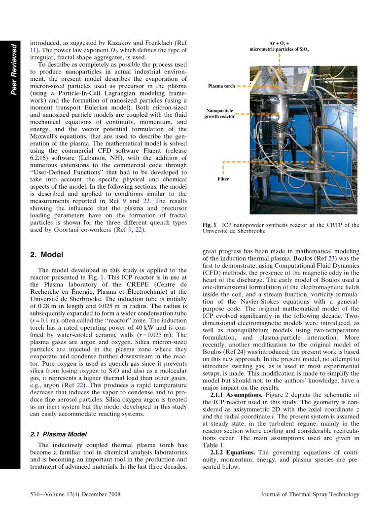
To describe as completely as possible the process usedto produce nanoparticles in actual industrial environ-ment, the present model describes the evaporation ofmicron-sized particles used as precursor in the plasma(using a Particle-In-Cell Lagrangian modeling frame-work) and the formation of nanosized particles (using amoment transport Eulerian model). Both micron-sizedand nanosized particle models are coupled with the fluidmechanical equations of continuity, momentum, andenergy, and the vector potential formulation of theMaxwell�s equations, that are used to describe the gen-eration of the plasma. The mathematical model is solvedusing the commercial CFD software Fluent (release6.2.16) software (Lebanon, NH), with the addition ofnumerous extensions to the commercial code through‘‘User-Defined Functions’’ that had to be developed totake into account the specific physical and chemicalaspects of the model. In the following sections, the modelis described and applied to conditions similar to themeasurements reported in Ref 9 and 22. The resultsshowing the influence that the plasma and precursorloading parameters have on the formation of fractalparticles is shown for the three different quench typesused by Goortani co-workers (Ref 9, 22).
2. Model
The model developed in this study is applied to thereactor presented in Fig. 1. This ICP reactor is in use atthe Plasma laboratory of the CREPE (Centre deRecherche en Energie, Plasma et Electrochimie) at theUniversite de Sherbrooke. The induction tube is initiallyof 0.28 m in length and 0.025 m in radius. The radius issubsequently expanded to form a wider condensation tube(r = 0.1 m), often called the ‘‘reactor’’ zone. The inductiontorch has a rated operating power of 40 kW and is con-fined by water-cooled ceramic walls (r = 0.025 m). Theplasma gases are argon and oxygen. Silica micron-sizedparticles are injected in the plasma zone where theyevaporate and condense further downstream in the reac-tor. Pure oxygen is used as quench gas since it preventssilica from losing oxygen to SiO and also as a moleculargas, it represents a higher thermal load than other gases,e.g., argon (Ref 22). This produces a rapid temperaturedecrease that induces the vapor to condense and to pro-duce fine aerosol particles. Silica-oxygen-argon is treatedas an inert system but the model developed in this studycan easily accommodate reacting systems.
2.1 Plasma Model
The inductively coupled thermal plasma torch hasbecome a familiar tool in chemical analysis laboratoriesand is becoming an important tool in the production andtreatment of advanced materials. In the last three decades,
great progress has been made in mathematical modelingof the induction thermal plasma. Boulos (Ref 23) was thefirst to demonstrate, using Computational Fluid Dynamics(CFD) methods, the presence of the magnetic eddy in theheart of the discharge. The early model of Boulos used aone-dimensional formulation of the electromagnetic fieldsinside the coil, and a stream function, vorticity formula-tion of the Navier-Stokes equations with a general-purpose code. The original mathematical model of theICP evolved significantly in the following decade. Two-dimensional electromagnetic models were introduced, aswell as nonequilibrium models using two-temperatureformulation, and plasma-particle interaction. Morerecently, another modification to the original model ofBoulos (Ref 24) was introduced; the present work is basedon this new approach. In the present model, no attempt tointroduce swirling gas, as is used in most experimentalsetups, is made. This modification is made to simplify themodel but should not, to the authors� knowledge, have amajor impact on the results.
2.1.1 Assumptions. Figure 2 depicts the schematic ofthe ICP reactor used in this study. The geometry is con-sidered as axisymmetric 2D with the axial coordinate zand the radial coordinate r. The present system is assumedat steady state, in the turbulent regime, mainly in thereactor section where cooling and considerable recircula-tions occur. The main assumptions used are given inTable 1.
2.1.2 Equations. The governing equations of conti-nuity, momentum, energy, and plasma species are pre-sented below.
Ar + O2 +micrometric particles of SiO2
Plasma torch
Nanoparticle
Filter
growth reactor
Fig. 1 ICP nanopowder synthesis reactor at the CRTP of theUniversite de Sherbrooke
534—Volume 17(4) December 2008 Journal of Thermal Spray Technology
Peer
Revie
wed

Continuity:
@ quð Þ@zþ 1
r
@ qrvð Þ@r
¼ Sm ðEq 1Þ
In Eq 1, Sm is the source term representing the massadded to the continuous phase from the dispersed phase(due to vaporization of the precursor micron-sizedparticles).
Momentum:
@ðquuÞ@z
þ 1
r
@ðrqvuÞ@r
¼ @
@zleff
@u
@z
� �þ 1
r
@
@rrleff
@u
@r
� �
� @p
@zþ @
@zleff
@u
@z
� �þ 1
r
@
@rrleff
@v
@z
� �
þFz þFzbþ Smpz ðEq 2Þ
@ðquvÞ@z
þ 1
r
@ðrquuÞ@r
¼ @
@zleff
@v
@z
� �þ 1
r
@
@rrleff
@v
@r
� �
� @p
@rþ @
@zleff
@u
@r
� �þ 1
r
@
@rrleff
@v
@r
� �
� 2leff
v
r2þFrþFrbþSm
pr ðEq 3Þ
Energy:
@
@zquX
i
hi
!þ 1
r
@
@rrqv
Xi
hi
!
¼ @
@z
keff
Cp
@
@z
Xi
hi
! !þ 1
r
@
@rrkeff
Cp
@
@r
Xi
hi
! !
þX
i
@
@zqDihi
@Yi
@z
� �þ 1
r
@
@rrqDihi
@Yi
@r
� �� �
þ P� þ Rþ SEp ðEq 4Þ
where u and v are the axial and radial velocity components.q, l, k, and Cp are the density, viscosity, thermal conduc-tivity, and specific heat at constant pressure, respectively, his the enthalpy, p is the pressure, and P* and R are theOhmic heating power and the volumetric radiation heatloss, respectively. The fluxes Jj are the individual speciesmass fluxes. Fzb is an artificial source term used to freeze theflow outside the plasma torch, a method not very elegantbut efficient to fix flow conditions where it is not of interest,while solving some of the equations (electromagnetic) inthe same region. leff ¼ ll=lt is the effective viscosity, whichis the combination of molecular and turbulent viscosities.
The Lorentz forces and Ohmic heating power areexpressed as:
Fr ¼1
2l0rRe EhH�z
� �ðEq 5Þ
Fz ¼ �1
2l0rRe EhH�r
� �ðEq 6Þ
P ¼ 1
2l0rRe EhE�h
� �ðEq 7Þ
where l0 is the magnetic permeability of free space, r isthe electric conductivity, and Re denotes the real part of acomplex number. The superscript * denotes the conjugate.
The electromagnetic fields can be obtained by the fol-lowing relations after solving the vector potential equations:
Eh ¼ �ixAh ðEq 8Þ
l0Hz ¼1
r
@ rAhð Þ@r
ðEq 9Þ
where x is the angle frequency.
Fig. 2 Schematic illustration of the ICP synthesis reactor
Table 1 Fluid flow and temperature field assumptions
� Steady state� Axisymmetric flow at atmospheric pressure� Turbulence modeled by the k-epsilon model
modification proposed by Bolot et al. (Ref 25)� The axial component of the coil current is neglected� Radiative losses calculated from net emission coefficient,
under local thermodynamic equilibrium (LTE) conditions� Viscous dissipation and pressure work in the energy
equation are neglected� Negligible displacement current� Nanoparticles do not affect the flow field or the
turbulent quantities
Journal of Thermal Spray Technology Volume 17(4) December 2008—535
Peer
Revie
wed

l0Hr ¼ �@Ah
@rðEq 10Þ
Ah is the tangential component of vector potential, whichcan be calculated as:
r2Ah � Ah�
r2� �
¼ �l0 Jcoil þ Jindð Þ ðEq 11Þ
where
r2 ¼ 1
r
@
@rr@
@r
� �þ @2
@z2ðEq 12Þ
Jcoil is the current density induced by the oscillating volt-age applied to the two ends of the coil and Jind is thecurrent density developed in the plasma and the coil bythe induced electric field.
2.2 Turbulence Model
Turbulent mixing may play an important role in particleprocesses in ICP torches but mostly in the reactor section(Ref 26). Recently, it was reported by Shigeta and Nishiy-ama (Ref 27) that turbulence must be accounted for eventhough the overall Reynolds number is relatively small. It iswell known that plasma flame is often wavering andunstable accompanied with drastic heat/species transfer.The presence of strong turbulence in the particle formationzone, the reactor, is expected to affect the transport of thevapors and thus the trajectories of nanoparticles. Strongturbulent eddies may be present in the plasma reactor(mostly limited to the edges of the plasma) and their effecton the effective transport properties cannot be neglected.
In the present study, the k-epsilon model is selected. Thechoice of a more sophisticated model is difficult to justifysince the amount of precise results of turbulent thermalplasmas that would be sufficient to distinguish the modelsare still today very scarce. The correction on the source termof the kinetic energy equation, proposed by Bolot et al.(Ref 25) is applied to this turbulent model; it was not orig-inally adapted for high-temperature situations in Fluent 6.2.
The turbulent viscosity, lt is computed using j and � asfollows:
lt ¼ qClj2
�ðEq 13Þ
where j is the turbulent kinetic energy, � is the dissipationrate, and Cl is a constant. The source term implementedfor the correction in Fluent is:
Sð�Þ ¼ C3G2
qjðEq 14Þ
This sink term has no effect on most flows at low tem-perature, but it has a significant effect for turbulent plasmaflows. It contributes to decrease the production of turbu-lent kinetic energy in the core of the jet, hence providing alonger core.
2.3 Particle Evaporation Model
In the synthesis of nanoparticles by thermal plasma, theprecursor micron-sized particles are injected into the
fireball to be evaporated. The particles are introduced inthe model as a discrete second phase which consists ofspherical particles dispersed in the continuous phase; thevolume fraction occupied by the secondary phase is con-sidered negligible. The trajectories of the discrete phaseentities are computed using the equations describing themovement of a rigid particle in a fluid.
2.3.1 Assumptions. Table 2 summarizes the assump-tions considered on the discrete phase model.
The discrete phase model considers the trajectory andheat-mass transfer coupling of particles with the contin-uum phase, this is the so-called PSI-Cell approach (Ref28). Thus, the trajectory and heat-mass transfer calcula-tions are based on the force balance on the particle and onthe convective heat and mass transfer from the particle,using the local continuous phase conditions as the particlemoves through the flow.
The thermophoresis effect is considered as an externalforce on the transport of particles. This effect is respon-sible for small particles in a temperature gradient drivenfrom high to low temperature regions.
2.3.2 Equations. In the discrete phase model, the par-ticle phase is regarded as a source of mass, momentum,and energy to the gaseous phase. The following equationsare used to calculate the set of heat and mass transfer lawsinvolved.
Particle Motion: Firstly, the trajectory of a discretephase particle is calculated by integrating the force bal-ance on the particle. This force balance equates the par-ticle inertia with the forces acting on the particle and canbe written as:
mpdup
dt¼ CD
1
2q
1
4pd2
p
� �u� up
� �u� up
�� ��þ Fth þmpgþmpFbðtÞ (Eq 15)
where u is the fluid phase velocity, mp is the particle mass,up is the particle velocity, l is the molecular viscosity ofthe fluid, q is the fluid density, qp is the density of theparticle, dp is the particle diameter, Fb(t) is the Brownianforce per unit mass, and Fth is the thermophoretic force.
The drag coefficient CD depends on the particle formand the relative Reynolds number Re, which is definedas:
Re �qdp up � u�� ��l
ðEq 16Þ
Table 2 Particle evaporation model assumptions
� Particles are spheres and the fluid is an ideal gas� Dispersion of particle due to turbulence by stochastic tracking
model� Dilute gas-particle system� Continuous phase with a well-defined entrance and exit conditions� Discrete phase solved in a Lagrangian frame of reference� Coupling for momentum, heat, and mass between the plasma
and the precursor microparticles� Thermophoretic force and Brownian motion for submicron
particles� Gravity and turbulence have no influence
536—Volume 17(4) December 2008 Journal of Thermal Spray Technology
Peer
Revie
wed

For a spherical particle, the drag coefficient CD is deter-mined from:
CD ¼24
Re
� �f ðReÞ ðEq 17Þ
where the f(Re) functions are given according to theparticle�s boundary layer regime. As the Reynolds numberincreases, the Stokes and Oseen laws, and the empiricalrelations proposed by Boulos and Gauvin (Ref 29). Thethermophoresis effect Fth is included in the particle forcebalance following Ref 30. Besides, the Brownian motionFb(t) is considered since it becomes important for submi-cron particles. For the present study Fb(t) is calculated as aGaussian white noise random process (Ref 31) withspectral intensity Snij given by (Ref 32):
Sn;ij ¼ S0dij ðEq 18Þ
where dij is the Kronecker delta function, and
S0 ¼216mkBT
p2qd5p
qp
q
2
Cc
ðEq 19Þ
where T is the absolute temperature of the fluid, m is thekinematic viscosity, kB is the Boltzmann constant, and Cc
is the Stokes-Cunningham slip correction which can becomputed from:
Cc ¼ 1þ 2kdp
1:257þ 0:4e� 1:1dp=2kð Þ
ðEq 20Þ
Amplitudes of the Brownian force components are of theform:
Fbi¼ fi
ffiffiffiffiffiffiffiffipSo
Dt
rðEq 21Þ
where fi are zero-mean, unit-variance-independent Gaussianrandom numbers.
Heat and Mass Transfer Calculations: The particletemperature is determined through an energy balance asdescribed in Ref 28. The total heat flux on a particle sur-face in the plasma QT is given by:
QT ¼ hcpd2p T � Tp
� �� pd2
prs� T4p � T4
a
ðEq 22Þ
where dp, hc, T, Tp, rs, �; and Ta, are the particle diameter(m), convective heat transfer coefficient (W/m2ÆK), localtemperature of the continuous phase (K), particle tem-perature, Stephan-Boltzmann constant, emissivity, andambient temperature, respectively.
The heat transfer coefficient, hc, is evaluated using thecorrelation of Ranz and Marshall (Ref 33, 34):
Nu ¼ hdp
k1¼ 2:0þ 0:6Re
1=2d Pr1=3 ðEq 23Þ
where k¥ is the thermal conductivity of the continuousphase (W/mÆK), Red is the Reynolds number based on theparticle diameter and the relative velocity, and Pr is thePrandtl number of the continuous phase (Cpl/k¥).
The mass transfer during vaporization is predicted by aboiling rate. During droplet vaporization, the rate of
vaporization is governed by gradient diffusion, with theflux of droplet vapor into the gas phase related to thegradient of the vapor concentration between the dropletsurface and the bulk gas:
Ni ¼ kc Ci;s � Ci;1� �
ðEq 24Þ
where Ni is the molar flux of vapor (kgmol/m2s), kc is themass transfer coefficient (m/s), Ci,s is the vapor concen-tration at the droplet surface (kgmol/m3), and Ci,¥ repre-sents the vapor concentration in the bulk gas (kgmol/m3).The concentration of vapor at the droplet surface isevaluated by assuming that the partial pressure of vapor atthe interface is equal to the saturated vapor pressure, psat,at the particle droplet temperature, Tp:
Ci;s ¼psatðTpÞ
RTpðEq 25Þ
where R is the universal gas constant. The concentration ofvapor in the bulk gas is known from solution of the trans-port equation for species i. The mass transfer coefficient inEq 24 is calculated from a Nusselt correlation (Ref 33, 34):
NuAB ¼kcdp
Di;m¼ 2:0þ 0:6Re
1=2d Sc1=3 ðEq 26Þ
where Di,m is the diffusion coefficient of vapor in the bulk(m2/s); Sc is the Schmidt number, and dp is the particlediameter (m). The mass of the particle is reducedaccording to:
mpðt þ DtÞ ¼ mpðtÞ �NiApMw;iDt ðEq 27Þ
where Mw,i is the molecular weight of species i (kg/kgmol);mp is the mass of the droplet (kg), and Ap is the surfacearea of the particle (m2).
2.4 Nanoparticle Model
The growth of particles is considered from nucleationto coalescent to aggregation (fractal) regimes, withsimultaneously occurring nucleation and condensation ofprimary particles and coagulation of both primary andfractal particles. The different mechanisms of transportand growth are also considered.
2.4.1 Equations. Nucleation: Nucleation is caused bythe fast cooling of the gas when it enters the condensationzone of the reactor. This phenomenon is strongly depen-dent of the vapor pressure of species in function of tem-perature. For the present model, the nucleation rate isformulated using the expression developed by Girshick(Ref 35). This expression is derived from a self-consistentequilibrium cluster distribution which results in a correc-tion to the classical nucleation theory by a factor of eH/S,where H is a dimensionless surface energy defined by:
H ¼ rs1
kTðEq 28Þ
where r is the surface tension (under the capillarityapproximation), s1 is the surface area of a monomer (inthis case a silica atom), k is Boltzmann�s constant, T isabsolute temperature, and S is the vapor saturation ratio,
Journal of Thermal Spray Technology Volume 17(4) December 2008—537
Peer
Revie
wed

S = n1/ns; n1 is the vapor concentration (m-3) and ns is thevapor concentration at saturation (m-3). The resultingexpression for the nucleation rate is:
I ¼ b11n2sS
12
ffiffiffiffiffiffiH2p
rH� 4H3
27ln2S
� �ðEq 29Þ
where b11 is the Brownian coagulation coefficient betweentwo monomers. The equation describing the evolution ofthe concentration nj of stable particle of size j by nucle-ation is as follows:
dnj
dt¼ Idðj�j�Þ ðEq 30Þ
The Kronecker delta dj�j� is defined as 1 for the criticalsize j* and zero otherwise.
Condensation: Surface condensation is the deposition ofmonomers on a stable particle of size equal to or larger thanthe critical size. Assuming that the size of a monomer isnegligible compared to that of the particle, the growth law ofa spherical particle in the free molecular regime is given by:
dvj
dt¼ B1v1j2=3ðS� 1Þ ðEq 31Þ
with
B1 ¼ ð36pÞ1=3nsv2=31 kT=2pm1ð Þ1=2 ðEq 32Þ
where vj is the particle volume (m3), v1 and m1 are thevolume (m3) and the mass (kg) of one monomer.
Fractal Coagulation: The dynamics of coagulation isfundamentally described by the Smoluchowski masterequations, an enormous number of differential equationsdescribing the population of different size particles. Theevolution of the concentration (nj) of stable particles ofsize j is described by the following balance equation:
@nj
@t¼ 1
2
Xiþj¼k
abijninj � nk
X1j¼1
abjknj ðEq 33Þ
where a is the sticking coefficient which means the fractionof interparticle collisions that result in coalescence. bi,j isthe coagulation coefficient classified on the basis of theKnudsen number: Kn = 2k/d, where k is the gas mean freepath and d is the particle diameter (Ref 36). Because mostof the particles are in the ultrafine range (i.e.,20 < Kn < 2000 for the cases studied), and are smallerthan the mean free path of flow gas, the collision fre-quency function due to Brownian motion is assumed in thefree molecular regime. It is characterized by Kn� 1; inthis situation, the following expression provided byKazakov and Frenklach (Ref 11) expresses the collisionfrequency of particles:
bi;j ¼ 2:2
ffiffiffiffiffiffiffiffiffiffiffiffi6kBT
q
s3msilica
4pq
� �1=6ffiffiffiffiffiffiffiffiffiffiffiffiffiffiffiffiffi1
miþ 1
mj
sm
1=3i þm
1=3j
2
ðEq 34Þ
where kB is the Boltzmann constant, T is the temperature,q is the density of particle material, m is the particle mass
(atomic mass units), msilica is the mass of a silica atom, andthe multiplier 2.2 is the van der Waals enhancementfactor.
Thermophoresis: The advection of particles is the resultof the aerodynamic drag and the thermophoresis devia-tion. According to Ref 37, the thermophoretical velocity isindependent of the particle size in the free molecularregime and the vectorial form is represented as follows:
~uth ¼ �0:55lqT
~rT ðEq 35Þ
Brownian Diffusion: The diffusion coefficient dependsrather strongly on the particle size. Therefore, an averagecoefficient cannot be applied over the distribution ofmoments. In the case of small particles flowing in the high-temperature zones downstream of an ICP reactor, theBrownian motion becomes important. The evolution ofthe concentration nj of stable particle of size j byBrownian diffusion is given by:
@nj
@t¼ ~r � Dj
~rnj
ðEq 36Þ
in which Dj is the diffusion coefficient of particles of size dj
and the expression proposed by Phanse and Pratsinis (Ref37) is used:
Dj ¼kBT
3pldj1þ 3:314k
dj
� �ðEq 37Þ
2.4.2 Assumptions. Several assumptions have to bemade to make the model�s equation tractable. Amongthese, the system must be a diluted system, where bulkvapor concentrations are smaller than 10-3 (kg/kg). Freemolecular regime is considered because of the small sizeof the particles. Among the most important simplificationsof the model is the assumption of a lognormal particle sizedistribution function. Using this hypothesis, it is possibleto calculate the different moments of the particle sizedistribution in a closed form using only the first threemoments of the distribution. The main outcome is thesimplification of the equations to be solved, from a partialintegro-differential equation to a set of three partial dif-ferential equations. Equally important, the agglomerationof particles is described by a power law. These assump-tions are largely justified under the conditions used togenerate nanoparticles in thermal plasmas (Ref 21). Theassumptions are summarized in Table 3.
The contribution of the different mechanisms (nucle-ation, condensation, fractal coagulation, thermophoresis)are integrated in the general dynamic equation (GDE) foraerosol growth:
~r� ð~unjÞ ¼�~r� ð~uthnjÞþ~r� ðDj~rnjÞþ Ij�dðj�j�Þ
þGj�1nj�1�Gjnjþ1
2
Xj�1
i¼j�bi;j�ininj�1�nj
X1i¼j�
bi;jni
ðEq 38Þ
This equation must be solved to obtain the particle sizedistribution function (PSDF) of nanoparticles.
538—Volume 17(4) December 2008 Journal of Thermal Spray Technology
Peer
Revie
wed

2.5 The Method of Moments
The population of different size particles is describedby a finite but extremely large number of differentialequations of the type of Eq 38 (Ref 36). Analytical solu-tions are possible for idealized, simple cases (as inSmoluchowski�s solution) but the numerical integration ofthe equations as written up to this point is computationallyuntractable. The method of moments reformulates theproblem into a small set of differential equationsdescribing evolution of the moments of the PSDF. Themethod of moments is presented briefly in this section.
The first step in deriving the moment equations is todefine the moments. The moment of the size distributionof order k is defined as:
Mk ¼1
qn0
X1j¼j�
jknj ðEq 39Þ
where n0 is a constant of normalization. In the presentmodel, the moments of the size distribution are normalizedwith respect to the density q and the reference concentra-tion of monomers n0 at the entrance of the reactor. Thenumber concentration, surface, and mass of particles in agiven volume are obtained, respectively, from the momentsM of order 0, 2/3, and 1. The moments of order 0, 1, and 2 aresolved simultaneously with moments P described below.
For the moment of an arbitrary order k, the contribu-tion of nucleation and surface condensation can beobtained directly by integrating Eq 30 and 31:
d qMkð Þdt
ðnucl; condÞ ¼ I
n0j�ð Þk þ qkB1 S� 1ð ÞMk�1=3
ðEq 40ÞAfter the initial period of nucleation followed by coales-cent growth, particles begin to agglomerate. Agglomeratesare assumed in the present work to take the form of
chain-like structures composed of nearly spherical equal-sized primary particles and are described by the well-known fractal relationship (Ref 38):
n ¼ kf2Rg
dp
� �Df
ðEq 41Þ
where n is the number of primary particles in an aggre-gate, dp is the diameter of primary particle, Rg is the radiusof gyration of an aggregate, Df is the fractal dimension,and kf is the fractal prefactor. In the present model, par-ticle agglomeration is considered at a fully developedregime of particle aggregation obeying Eq 41 with con-stants values of Df and kf.
bi;j ¼ 2:2
ffiffiffiffiffiffiffiffiffiffiffiffiffiffiffiffiffiffiffiffiffiffiffiffiffiffiffiffiffiffiffiffiffiffiffiffipkBT
2mc
1
miþ 1
mj
� �sdc;i þ dc;j
� �2 ðEq 42Þ
where bi,j is the aggregate collision frequency in the freemolecular regime, dc is the collision diameter of a particleaggregate, and dci,j represent the mobility diameters.Equation 42 is valid for Df ‡ 2 or for aggregates of similarsizes (Ref 39). The collision diameter of an aggregate, dc,is proportional to the radius of gyration; the latter is givenas:
Rg ¼1
k1=Df
f
3mc
4pq
� �1=3
m1=3n1=Df�1=3 ðEq 43Þ
which is obtained from Eq 41 expressing the primaryparticle diameter through the total aggregate mass m andthe number of primary particle in the aggregate n:
dp ¼6mim
pqn
� �1=3
ðEq 44Þ
The model for the aggregation is developed with the col-lision frequencies reflecting the fractal character of col-liding particles (Ref 39):
bai;j ¼ 2:2
ffiffiffiffiffiffiffiffiffiffiffiffiffiffiffiffiffiffiffiffiffiffiffiffiffiffiffiffiffiffiffiffiffiffiffiffiffiffipkBT
2msilica
1
miþ 1
mj
� �sdc;i þ dc;j
� �2 ðEq 45Þ
where bi,j is the aggregate collision frequencies in the freemolecular regime and dc is the collision diameter of aparticle aggregate.
Values of Df for silica particles around 2.2 are reportedby the experimental works of Ref 40. As well, the exper-imental and numerical tests of Ref 41, related to thegrowth of silica particles influenced by high temperature,report values around 2.0. And additionally, values close to2.4 are published from the numerical studies of Ref 42. Inthis work a constant value for Df = 2.0 is used. Theinfluence of this parameter should be elucidated furtherbut is not within the scope of the present study.
Assuming that in the limit of a single spherical particledc becomes equal to the particle diameter:
dc ¼ dpn1=Df ¼ 6mc
pq
� �1=3
m1=3n1=Df�1=3 ðEq 46Þ
Table 3 Silica vapor concentration and nanoparticlemodel assumptions
� Particles are smaller that the mean free path of the gas:free molecular regime� Coagulation of particles in the free molecular regime� The condensible vapor is chemically inert� The kinetic nucleation rate developed by Girshick and Chiu
(Ref 35) is used� The particle size distribution is approximated
by a lognormal distribution� The Kelvin effect is neglected� Thermophoresis is accounted for as an external force
in the transport of particles� Particles follow the fluid flow (and thermophoretic deviation)
and diffuse stochastically� Because of Brownian diffusion� Turbulence effect on particles is neglected� Particle aggregation obeys a power law with constant
fractal dimension Df
� Five moments of the distribution are used to solvethe fractal particle growth� Three moments (Mk) solve for the primary particles
and two moments (Pr)� For the particle aggregation� No surface growth terms are included in the aggregation regime
Journal of Thermal Spray Technology Volume 17(4) December 2008—539
Peer
Revie
wed
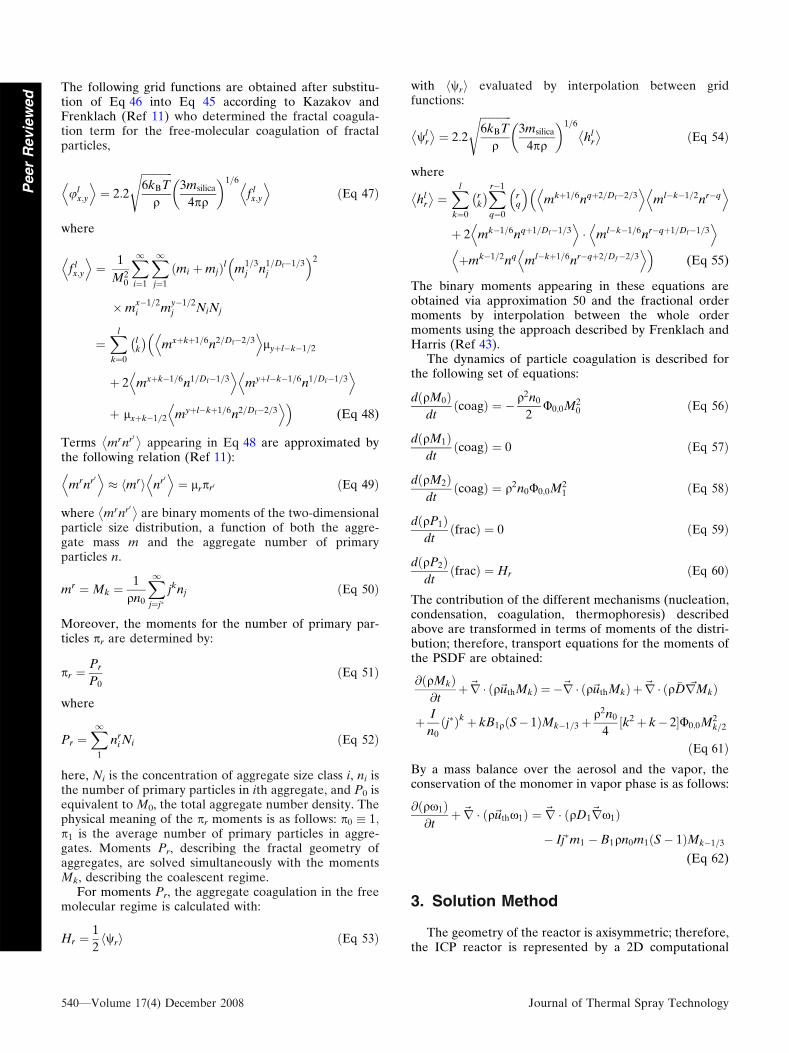
The following grid functions are obtained after substitu-tion of Eq 46 into Eq 45 according to Kazakov andFrenklach (Ref 11) who determined the fractal coagula-tion term for the free-molecular coagulation of fractalparticles,
ulx;y
D E¼ 2:2
ffiffiffiffiffiffiffiffiffiffiffiffi6kBT
q
s3msilica
4pq
� �1=6
f lx;y
D EðEq 47Þ
where
f lx;y
D E¼ 1
M20
X1i¼1
X1j¼1
ðmi þmjÞl m1=3j n
1=Df�1=3j
2
�mx�1=2i m
y�1=2j NiNj
¼Xl
k¼0
lk
� �mxþkþ1=6n2=Df�2=3D E
lyþl�k�1=2
þ 2 mxþk�1=6n1=Df�1=3D E
myþl�k�1=6n1=Df�1=3D E
þ lxþk�1=2 myþl�kþ1=6n2=Df�2=3D E
(Eq 48)
Terms mrnr0�
appearing in Eq 48 are approximated bythe following relation (Ref 11):
mrnr0D E
� mrh i nr0D E
¼ lrpr0 ðEq 49Þ
where mrnr0�
are binary moments of the two-dimensionalparticle size distribution, a function of both the aggre-gate mass m and the aggregate number of primaryparticles n.
mr ¼Mk ¼1
qn0
X1j¼j�
jknj ðEq 50Þ
Moreover, the moments for the number of primary par-ticles pr are determined by:
pr ¼Pr
P0ðEq 51Þ
where
Pr ¼X1
1
nri Ni ðEq 52Þ
here, Ni is the concentration of aggregate size class i, ni isthe number of primary particles in ith aggregate, and P0 isequivalent to M0, the total aggregate number density. Thephysical meaning of the pr moments is as follows: p0 � 1;p1 is the average number of primary particles in aggre-gates. Moments Pr, describing the fractal geometry ofaggregates, are solved simultaneously with the momentsMk, describing the coalescent regime.
For moments Pr, the aggregate coagulation in the freemolecular regime is calculated with:
Hr ¼1
2wrh i ðEq 53Þ
with wrh i evaluated by interpolation between gridfunctions:
wlr
� ¼ 2:2
ffiffiffiffiffiffiffiffiffiffiffiffi6kBT
q
s3msilica
4pq
� �1=6
hlr
� ðEq 54Þ
where
hlr
� ¼Xl
k¼0
rk
� �Xr�1
q¼0
rq
mkþ1=6nqþ2=Df�2=3D E
ml�k�1=2nr�qD E
þ 2 mk�1=6nqþ1=Df�1=3D E
� ml�k�1=6nr�qþ1=Df�1=3D E
þmk�1=2nq ml�kþ1=6nr�qþ2=Df�2=3DD E
(Eq 55)
The binary moments appearing in these equations areobtained via approximation 50 and the fractional ordermoments by interpolation between the whole ordermoments using the approach described by Frenklach andHarris (Ref 43).
The dynamics of particle coagulation is described forthe following set of equations:
dðqM0Þdt
ðcoagÞ ¼ � q2n0
2U0;0M2
0 ðEq 56Þ
dðqM1Þdt
ðcoagÞ ¼ 0 ðEq 57Þ
dðqM2Þdt
ðcoagÞ ¼ q2n0U0;0M21 ðEq 58Þ
dðqP1Þdt
ðfracÞ ¼ 0 ðEq 59Þ
dðqP2Þdt
ðfracÞ ¼ Hr ðEq 60Þ
The contribution of the different mechanisms (nucleation,condensation, coagulation, thermophoresis) describedabove are transformed in terms of moments of the distri-bution; therefore, transport equations for the moments ofthe PSDF are obtained:
@ðqMkÞ@t
þ~r � ðq~uthMkÞ ¼ �~r � ðq~uthMkÞ þ~r � ðq �D ~rMkÞ
þ I
n0ðj�Þkþ kB1qðS� 1ÞMk�1=3þ
q2n0
4½k2þ k� 2U0;0M2
k=2
ðEq 61ÞBy a mass balance over the aerosol and the vapor, theconservation of the monomer in vapor phase is as follows:
@ðqx1Þ@t
þ~r � ðq~uthx1Þ ¼ ~r � ðqD1~rx1Þ
� Ij�m1 � B1qn0m1ðS� 1ÞMk�1=3
(Eq 62)
3. Solution Method
The geometry of the reactor is axisymmetric; therefore,the ICP reactor is represented by a 2D computational
540—Volume 17(4) December 2008 Journal of Thermal Spray Technology
Peer
Revie
wed
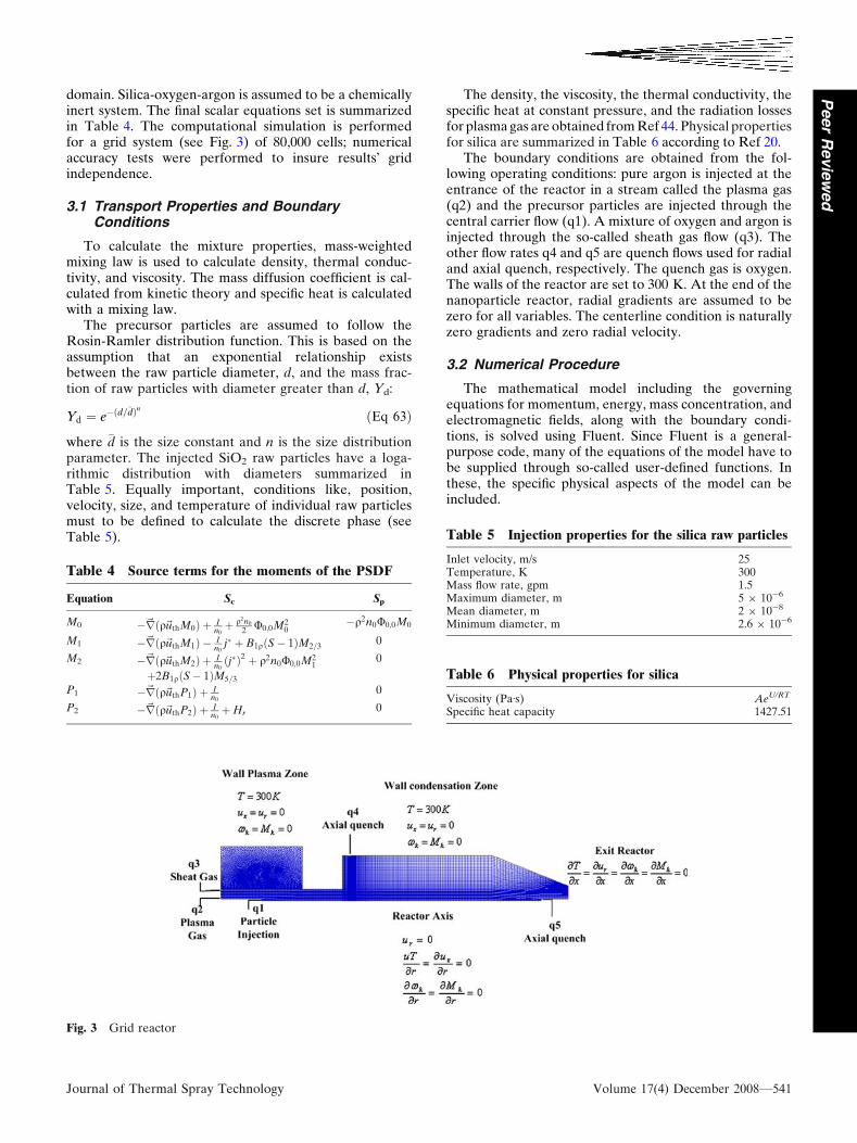
domain. Silica-oxygen-argon is assumed to be a chemicallyinert system. The final scalar equations set is summarizedin Table 4. The computational simulation is performedfor a grid system (see Fig. 3) of 80,000 cells; numericalaccuracy tests were performed to insure results� gridindependence.
3.1 Transport Properties and BoundaryConditions
To calculate the mixture properties, mass-weightedmixing law is used to calculate density, thermal conduc-tivity, and viscosity. The mass diffusion coefficient is cal-culated from kinetic theory and specific heat is calculatedwith a mixing law.
The precursor particles are assumed to follow theRosin-Ramler distribution function. This is based on theassumption that an exponential relationship existsbetween the raw particle diameter, d, and the mass frac-tion of raw particles with diameter greater than d, Yd:
Yd ¼ e�ðd=�dÞn ðEq 63Þ
where �d is the size constant and n is the size distributionparameter. The injected SiO2 raw particles have a loga-rithmic distribution with diameters summarized inTable 5. Equally important, conditions like, position,velocity, size, and temperature of individual raw particlesmust to be defined to calculate the discrete phase (seeTable 5).
The density, the viscosity, the thermal conductivity, thespecific heat at constant pressure, and the radiation lossesfor plasma gas are obtained from Ref 44. Physical propertiesfor silica are summarized in Table 6 according to Ref 20.
The boundary conditions are obtained from the fol-lowing operating conditions: pure argon is injected at theentrance of the reactor in a stream called the plasma gas(q2) and the precursor particles are injected through thecentral carrier flow (q1). A mixture of oxygen and argon isinjected through the so-called sheath gas flow (q3). Theother flow rates q4 and q5 are quench flows used for radialand axial quench, respectively. The quench gas is oxygen.The walls of the reactor are set to 300 K. At the end of thenanoparticle reactor, radial gradients are assumed to bezero for all variables. The centerline condition is naturallyzero gradients and zero radial velocity.
3.2 Numerical Procedure
The mathematical model including the governingequations for momentum, energy, mass concentration, andelectromagnetic fields, along with the boundary condi-tions, is solved using Fluent. Since Fluent is a general-purpose code, many of the equations of the model have tobe supplied through so-called user-defined functions. Inthese, the specific physical aspects of the model can beincluded.
Table 4 Source terms for the moments of the PSDF
Equation Sc Sp
M0 �~rðq~uthM0Þ þ In0þ q2n0
2 U0;0M20
�q2n0U0;0M0
M1 �~rðq~uthM1Þ � In0
j� þ B1qðS� 1ÞM2=30
M2 �~rðq~uthM2Þ þ In0ðj�Þ2 þ q2n0U0;0M2
1
þ2B1qðS� 1ÞM5=3
0
P1 �~rðq~uthP1Þ þ In0
0
P2 �~rðq~uthP2Þ þ In0þHr
0
Fig. 3 Grid reactor
Table 5 Injection properties for the silica raw particles
Inlet velocity, m/s 25Temperature, K 300Mass flow rate, gpm 1.5Maximum diameter, m 5 9 10-6
Mean diameter, m 2 9 10-8
Minimum diameter, m 2.6 9 10-6
Table 6 Physical properties for silica
Viscosity (PaÆs) AeU/RT
Specific heat capacity 1427.51
Journal of Thermal Spray Technology Volume 17(4) December 2008—541
Peer
Revie
wed

To obtain satisfactory convergence and stability, sincethere is a very strong coupling between all the physicalphenomena involved in the model (electromagnetic, heat,momentum and heat transfer, nucleation), the followingmodel solution procedure was used:
(1) Solve the continuous phase: electromagnetic, fluidflow, heat, and mass transfer equations.
(2) Create the discrete-phase injections.
(3) Solve the plasma-particle coupled flow.
(4) Track the discrete-phase injections.
(5) Solve the 5 moments with species equation withoutany nanoparticle source terms.
(6) Include the source terms for nucleation.
(7) Include the condensation term.
(8) Include the fractal coagulation term.
For the nanoparticle model solution, starting at step 5, themoments are activated only once the fluid flow is con-verged. Convergence is assumed when the relative resi-dues for the vector potential equations, the continuity,velocities, energy and moments are, respectively, under10-8, l0-4, l0-5, l0-6, and 10-7. Typical solution time is ofthe order of 5 h in a single Pentium IV.
4. Results and Discussion
The model is applied to the ICP reactor presented inFig. 1. Three different designs are studied based on theexperimental studies of Goortani and coworkers (Ref 9,22). The first reactor (‘‘No quench’’) does not have anyquench, only cold walls in the condensation zone. In thesecond reactor, quench gas is injected radially (sincethe geometry is axisymmetrical, it corresponds to anannular quench) from the top of the reactor, zone (q4),(‘‘Radial quench’’). The third design uses an axial counter-current quench from zone (q5), (‘‘Axial quench’’).
4.1 Plasma Generation and Particle Evaporation
4.1.1 Temperature and Flow Fields. The Fig. 4 pre-sents the temperature field in the three different reactorgeometries. In the plasma zone, the highest values of thosetemperatures are of the order of 10,000 K as expected.Downstream of the plasma zone, where nanoparticles willform by nucleation, lower temperature values are due tocold walls and/or because of the application of quench. Thistemperature drop combined with the strong convectionrapidly leads to highly supersaturated vapors which inducesthe nucleation burst. The temperature field and the silica
Fig. 4 Temperature contours (K)
542—Volume 17(4) December 2008 Journal of Thermal Spray Technology
Peer
Revie
wed

vapor concentration indicate where the particles areformed or grow by nucleation and/or condensation. Thetemperature fields in the ‘‘reactor,’’ or condensation zone,will largely determine the vapor pressure, the condensationrate, the coagulation rate, and the thermophoretic term.
In the cases with radial or axial quench, the hot gas ismixed with the quenching stream and the temperature atthe recirculation zone decreases rapidly. After the recir-culation zone, the hot gas in the center of the reactor isstrongly mixed by turbulence with the cold gas from therecirculation. The exit temperature of the reactor is almostuniform at 1500 K for the ‘‘No quench’’ and the ‘‘Radialquench’’ cases. On the other hand, the ‘‘Axial quench’’case shows a lower temperature value at the exit, around500 K, it seems to be a more efficient quench. At thistemperature the vapor pressure of the silica is very lowleaving most of the material condensed.
The streamlines are shown in Fig. 5. An importantrecirculation is observed above the coil region. The centralinjection tube splits this recirculation, so that the powdersof the precursors can be injected directly into the high-temperature region. The turbulence is shown through theturbulence viscosity ratio contours in Fig. 6. The ratio ofthe turbulent viscosity to the molecular viscosity indicateswell the high level of mixing attained in particular in thereactor with axial quench.
4.1.2 Mass Fraction Fields. After injecting the pre-cursor particles in the plasma torch, they are carried by theargon flow to the plasma zone where they rapidly evapo-rate. Figure 7 shows the mass fraction for the three cases.It is observed that for the three cases, evaporation ispractically the same as indicated by the mass fractioncontours but the quench method has little influenceupstream. However, there are important differences in thecondensation zone of the reactor due to the quenchmethod applied.
The high vapor concentration created in the plasmazone is transported further into the condensation zone ofthe reactor. The concentration of silica vapor is depletedwhen the nucleation burst begins. This concentration willalso decrease due to the condensation of species vapor onexisting particles at the wall and by dilution in the case ofquench injection. Once again the ‘‘Axial quench’’ methodseems to be more efficient in terms of mass fractiondecrease.
Figure 8-10 shows the particle (precursor) temperatureas a function of the distance traveled in the axial directionof the reactor for the three studied cases: No quench,Radial quench, and Axial quench, respectively. Fromthese figures, two lines are observed representing a firstgroup of particles evaporated immediately entering theplasma zone and a second group further when they reach
Fig. 5 Stream function contours (kg/s)
Journal of Thermal Spray Technology Volume 17(4) December 2008—543
Peer
Revie
wed

their boiling point (2800 K). There is a similitude of thelocation for the first evaporated group but the second onebehaves differently. Figure 8 shows that the secondevaporation takes place around 9 cm after injection, whilein Fig. 9 and 10, the second evaporation takes place at theend of the torch around 18 cm after injection. This showsthat the quench has an upstream effect in the presentconfiguration; it affects also the evaporation zone. It isalso noted that the injection rate of particles has animportant influence on the temperature fields of theplasma zone. A high particle rate injection produces atemperature decrease as observed in Fig. 11. This effectwas first predicted by mathematical modeling by Proulxet al. (Ref 45) who studied the plasma-particle interactionunder dense loading conditions in induction plasmas.
4.2 Effect of Nanoparticle Growth
In the first stage of particle growth, the nucleation burstis observed clearly through the numerical mean diameterpresented in Fig. 12. Nucleation is the formation of newparticles and therefore increases the density of particles.Following that, the mean numerical diameter of primaryparticles (dnum) is depicted to observe the formation andgrowth mechanism effects. The mean numerical diameteris a physical property of the PSDF in terms of the
moments, dnum ¼ d1 M1=3
�M0
� �(Ref 21). Where d1 is the
atomic size of a silica particle, M1/3 and M0 are calculatedmoments of the PSDF.
After nucleation, the primary particles continue togrow by condensation and coagulation processes.Figure 13 shows the particle size attained after nucleationand condensation growth. In the case without quench,large particles are formed near the walls and close to theexit with sizes over the 100 nm, contrary, cases withquench injection show smaller sizes. This fact confirmsthat using quench strongly promotes the nanoparticleformation with a controlled size range. The advantage ofquench is also observed by Shigeta and Watanabe (Ref 46)where the effect of radial and counterflow cooling gasinjection is studied.
The final size of primary particles at the onset of fractalcoagulation is depicted on Fig. 14. The coagulation pro-duces an increase in the final particle size; nevertheless,the condensation mechanism seems to have a dominantcontribution in the growth of nanoparticles subsequent tonucleation, as already observed by Bilodeau and Proulx(Ref 47). This fact can be dependent also on the kinds ofmaterials as reported by Shigeta and Watanabe (Ref 48),who showed that for the case of nonmetals such as boronand silicon, the dominant growth process is the hetero-geneous condensation.
Fig. 6 Turbulent viscosity ratio
544—Volume 17(4) December 2008 Journal of Thermal Spray Technology
Peer
Revie
wed

4.3 Effect of Nanoparticle Aggregation
The initial number of primary particles per aggregate isshown in Fig. 15 for the three cases studied. After theaggregation is switched on in the model, the average pri-mary particle diameter starts to increase, due to surfacegrowth, and remains nearly constant once the surfacegrowth rate decreases. If we relate Fig. 14 and 15, we can
see that the average number of primary particles peraggregate is larger where primary diameters are smaller.
The quench has a direct influence on the volume dis-tribution and structure of fractal aggregates. This isbecause recirculations produce more collisions amongprimary particles and hence bigger agglomerates areformed. This fact is observed in the radial and axialquench cases. Contrary, the case of the ‘‘No quench’’
Fig. 7 Mass fraction contours
Fig. 8 Temperature history of silica particles injected intoargon/oxygen plasma (No quench)
Fig. 9 Temperature history of silica particles injected intoargon/oxygen plasma (Radial quench)
Journal of Thermal Spray Technology Volume 17(4) December 2008—545
Peer
Revie
wed
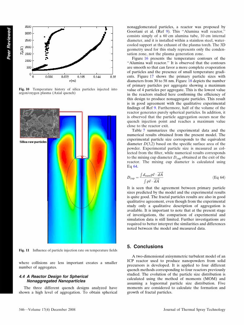
where collisions are less important creates a smallernumber of aggregates.
4.4 A Reactor Design for SphericalNonaggregated Nanoparticles
The three different quench designs analyzed haveshown a high level of aggregation. To obtain spherical
nonagglomerated particles, a reactor was proposed byGoortani et al. (Ref 9). This ‘‘Alumina wall reactor,’’consists simply of a 60 cm alumina tube, 10 cm internaldiameter, and it is installed within a stainless steel, water-cooled support at the exhaust of the plasma torch. The 3Dgeometry used for this study represents only the conden-sation zone, not the plasma generation zone.
Figure 16 presents the temperature contours of the‘‘Alumina wall reactor.’’ It is observed that the contoursare smooth so that can favor a more complete evaporationof particles and the presence of small temperature gradi-ents. Figure 17 shows the primary particle sizes withdiameters from 30 to 58 nm. Figure 18 depicts the numberof primary particles per aggregate showing a maximumvalue of 4 particles per aggregate. This is the lowest valuein the reactors studied here confirming the efficiency ofthis design to produce nonaggregate particles. This resultis in good agreement with the qualitative experimentalfindings of Ref 9. Furthermore, half of the volume of thereactor generates purely spherical particles. In addition, itis observed that the particle aggregation occurs near thequench injection point and reaches a maximum valueclose to the reactor exit.
Table 7 summarizes the experimental data and thenumerical results obtained from the present model. Theexperimental particle size corresponds to the equivalentdiameter D(3,2) based on the specific surface area of thepowder. Experimental particle size is measured as col-lected from the filter, while numerical results correspondsto the mixing cup diameter Dcup obtained at the exit of thereactor. The mixing cup diameter is calculated usingEq 64.
Dcup ¼R
dnumq~v � dA�!
Rq~v � dA
�! ðEq 64Þ
It is seen that the agreement between primary particlesizes predicted by the model and the experimental resultsis quite good. The fractal particles results are also in goodqualitative agreement, even though from the experimentalstudy only a qualitative description of aggregation isavailable. It is important to note that at the present stageof investigations, the comparison of experimental andsimulation data is still limited. Further investigations arerequired to better interpret the similarities and differencesnoted between the model and measured data.
5. Conclusions
A two-dimensional axisymmetric turbulent model of anICP reactor used to produce nanopowders from solidprecursors is developed. It is applied to four differentquench methods corresponding to four reactors previouslystudied. The evolution of the particle size distribution iscalculated using the method of moments (MOM) andassuming a lognormal particle size distribution. Fivemoments are considered to calculate the formation andgrowth of fractal particles.
Fig. 11 Influence of particle injection rate on temperature fields
Fig. 10 Temperature history of silica particles injected intoargon/oxygen plasma (Axial quench)
546—Volume 17(4) December 2008 Journal of Thermal Spray Technology
Peer
Revie
wed

Fig. 12 Numerical diameter (m) after nucleation
Fig. 13 Numerical diameter (m) after nucleation + condensation
Journal of Thermal Spray Technology Volume 17(4) December 2008—547
Peer
Revie
wed

The results show that the quench strongly affects thetemperature distribution inside the reactor. Consequently,the role of quench design is clearly shown to have adecisive impact on the final particle size and morphology.Moreover, it is observed that the particle injection rate hasa cooling effect on plasma temperature, but in the range of
precursor mass flow rates used in this study, this is notsufficient to reduce silica evaporation rates significantly.For the case without quench the level of turbulence is lowbut not negligible. The results show significant amount ofsilica vapor in the plasma zone, where the silica micro-particles are evaporated. It is also observed that the
Fig. 14 Numerical diameter (m) after nucleation + condensation + coagulation
Fig. 15 Average number of primary particles per aggregate
548—Volume 17(4) December 2008 Journal of Thermal Spray Technology
Peer
Revie
wed

nucleation mechanism is located early in the flame frontand the post flame zone and the areas downstream thecondensation reactor. The results obtained experimentallyby Goortani et al. (Ref 9) are confirmed using the fractalaggregation model, namely, that it is possible to obtainspherical particles using an adequate quench and reactorconfiguration design. Growth mechanisms are governedby condensation and fractal coagulation processes.
Formation of particles is directly affected by temperatureand velocity recirculation. Near the wall, Brownian dif-fusion and thermophoresis are responsible for particledeposition. More fluid recirculation leads to more colli-sions between the particles and consequently more levelsof aggregation among particles are observed (Ref 9). Thissuggests that the quench injection rate is one of the mostimportant process parameters since it directly affects thelocation and final size of aggregates. Fractal particles aremore present in the case of axial quench because of theincreased number of possible interparticle collisions.
The present model is limited to particles in the freemolecular regime and low raw material vapor concentra-tions; consequently, refinements in model predictions willlead to more accurate and precise predictions. The presentparticle aggregation model is developed assuming a con-stant aggregate fractal dimension Df. A comparison ofdifferent values of Df could give a better approach to thefractal shape of particles. Since the quench strongly affectsthe particle size and morphology, a parametric studychanging the flow rate of quench is suggested. The systemsilica-oxygen-argon is proposed as nonreactional system tosimplify this study. A complete analysis of the reactionalmechanism could improve the predictions of the presentmodel.
The present work provides a qualitative and quantita-tive description of fractal growth of silica particles inthermal plasmas. Reported results are in good agreementwith experimental findings of Goortani and co-workers(Ref 9, 22). This five-moment model used appears as auseful and practical method to assist scientists and engi-neers in the design of proper reactors to control the sizeand morphology of nanopowders produced using thermalplasma technology.
References
1. F.E. Kruis, H. Fissan, and A. Peled, Synthesis of Nanoparticles inthe Gas Phase for Electronic, Optical and Magnetic Applica-tions—A Review, J. Aerosol Sci., 1998, 29(5-6), p 511-535
2. P.C. Kong and E. Pfender, Thermal Plasma Synthesis ofCeramics—A Review, Heat Transfer Therm. Plasma Process.ASME, 1991, 161, p 1-8
3. G. Vissokov, I. Grancharov, and T. Tsvetanov, On the Plasma-Chemical Synthesis of Nanopowders, Plasma Sci. Technol., 2003,5, p 2039-2050
4. N.Y. Mendoza-Gonzalez, B.M. Goortani, and P. Proulx, Numer-ical Simulation of Silica Nanoparticles Production in a RF PlasmaRector: Effect of Quench, Mater. Sci. Eng. C, 2007, 27(5-8),p 1265-1269
5. N.Y. Mendoza-Gonzalez, B.M. Goortani, and P. Proulx,Numerical Study of the Synthesis of Nanoparticles in an Induc-tively Coupled Plasma Reactor, Czech. J. Phys., 2006, 56-B,p B1263-B1270
6.46e+036.15e+035.84e+035.53e+035.23e+034.92e+034.61e+034.30e+033.99e+033.69e+033.38e+033.07e+032.76e+032.45e+032.15e+031.84e+031.53e+031.22e+039.16e+026.08e+023.00e+02
YZ
X
Fig. 16 Wall tube temperature contours (K)
5.85e-085.71e-085.56e-085.42e-085.28e-085.14e-085.00e-084.85e-084.71e-084.57e-084.43e-084.28e-084.14e-084.00e-083.86e-083.71e-083.57e-083.43e-083.29e-083.14e-083.00e-08
X
Y Z
Fig. 17 Wall tube numerical diameter contours (m)
4.31e+004.14e+003.98e+003.81e+003.65e+003.48e+003.32e+003.15e+002.99e+002.82e+002.66e+002.49e+002.33e+002.16e+001.99e+001.83e+001.66e+001.50e+001.33e+001.17e+001.00e+00
X
ZY
Fig. 18 Wall tube number of primary particles per aggregate
Table 7 Summary of comparison between numerical and experimental results
Parameter No quench Axial quench Radial quench Wall tube
Diameter (Experimental) 37 25 25 90Morphology (Experimental) Spherical—partially aggregated Large aggregated Highly aggregated SphericalDiameter (Modeling) 38 17 23 58Morphology (Modeling) 20 44 32 4
Journal of Thermal Spray Technology Volume 17(4) December 2008—549
Peer
Revie
wed

6. M. Shigeta, T. Watanabe, and H. Nishiyama, Numerical Investi-gation for Nanoparticle Synthesis in an RF Inductively CoupledPlasma, Thin Solid Films, 2004, 457, p 192-200
7. R. Bolot, C. Coddet, C. Schreuders, M. Leparoux, and S.Siegmann, Modeling of an Inductively Coupled Plasma for theSynthesis of Nanoparticles, J. Therm. Spray Technol., 2007, 16(5-6),p 690-697
8. R. Ye, J.G. Lian, and T. Ishigaki, Controlled Synthesis of Alu-mina Nanoparticles Using Inductively Coupled Thermal Plasmawith Enhanced Quenching., Thin Solid Fims, 2007, 515(9),p 4251-4257
9. B.M. Goortani, P. Proulx, S. Xue, and N.Y. Mendoza-Gonzalez,Controlling Nanostructure in Thermal Plasma Processing: Mov-ing from Highly Aggregated Porous Structure to Spherical SilicaNanoparticles, Powder Technol., 2007, 175, p 22-32
10. C.R. Kaplan and J.W. Gentry, Agglomeration of Chain-LikeCombustion Aerosols due to Brownian Motion, Aerosol Sci.Technol., 1988, 8, p 11-28
11. A. Kazakov and M. Frenklach, Dynamic Modeling of Soot Par-ticle Coagulation and Aggregation: Implementation with theMethods of Moments and Application to High-Pressure LaminarPremixed Flames, Combust. Flame, 1998, 114, p 484-501
12. R.J. Samson, G.W. Mulholland, and J.W. Gentry, StructuralAnalysis of Soot Aggregates, Langmuir, 1987, 3, p 272-281
13. T. Matsoukas and S.K. Friedlander, Dynamics of AerosolAgglomerate Formation, J. Colloid Interface Sci., 1991, 146(2),p 495-506
14. M.K. Wu and S.K. Friedlander, Enhanced Power Law Agglom-erate Growth in the Free Molecular Regime, J. Aerosol Sci.,1993, 24, p 273-282
15. Y. Xiong and S.E. Pratsinis, Formation of Agglomerate Particlesby Coagulation and Sintering part I: A Two Dimensional Solu-tion of the Population Balance Equation, J. Aerosol Sci., 1993, 24,p 283-300
16. F. Kruis, K. Kusters, and S. Pratsinis, Simple Model for theEvolution of the Characteristics of Aggregate Particles Under-going Coagulation and Sintering, Aerosol Sci. Technol., 1993, 19,p 514-526
17. J. I. Jeong and M. Choi, A Sectional Method for the Analysis ofGrowth of Polydisperse Non-Spherical Particles UndergoingCoagulation and Coalescence, J. Aerosol Sci., 2001, 32, p 565-582
18. J.I. Jeong and M. Choi, Analysis of Non-Spherical PolydisperseParticle Growth in a Two-Dimensional Tubular Reactor,J. Aerosol Sci., 2003, 34, p 713-732
19. F. Aristizabal, R.J. Munz, and D. Berk, Modeling of the Pro-duction of Ultra Fine Aluminium Particles in Rapid QuenchingTurbulent Flow, Aerosol Sci. Technol., 2006, 37, p 162–189
20. T. Adona, ‘‘The Study of a Novel Thermal Process for theProduction of Fumed Silica,’’ PhD Thesis, McGill University,Canada, 1998
21. J.F. Bilodeau, ‘‘Modelisation de la Croissance de PoudresUltrafines en Reacteur a Plasma Thermique (Modeling of theUltra Fine Particle Growth in a Thermal Plasma Reactor),’’ PhDThesis, Universite de Sherbrooke, Canada, 1994, in French
22. B.M. Goortani, N.Y. Mendoza, and P. Proulx, Synthesis of SiO2
Nanoparticles in RF Plasma Reactors: Effect of Feed Rate andQuench Gas Injection, Int. J. Chem. Reactor Eng., 2006, 4:A33, p 1-18
23. M.I. Boulos, Flow Temperature Fields in the Fire-Ball of anInductively Coupled Plasma, IEEE Trans. Plasma Sci., 1976, 4,p 28-39
24. S. Xue, P. Proulx, and M.I. Boulos, Extended-Field Electro-magnetic Model for Inductively Coupled Plasma, J. Phys. D:Appl. Phys., 2001, 34, p 1897-1906
25. R. Bolot, J. Li, and C. Coddet, Some Key Advices for theModeling of Plasma Jets using Fluent, Proceedings of the Inter-national Thermal Spray Conference, ITSC 2005, 2-4 May 2005,(Basel, Switzerland), DVS Verlag GmbH, Dusseldorf, Germany,CD-Room, ISBN: 3-87155-793-5
26. R. Ye, P. Proulx, and M.I. Boulos, Particle Turbulent Dispersionand Loading Effects in an Inductively Coupled Radio FrequencyPlasma, J. Phys. D: Appl. Phys., 2000, 33(17), p 2154-2162
27. M. Shigeta and H. Nishiyama, Numerical Analysis of MetallicNanoparticle Synthesis Using RF Inductively Coupled PlasmaFlows, Trans. ASME, 2005, 127, p 1222-1230
28. P. Proulx, J. Mostaghimi, and M.I. Boulos, Heating of Powers inan RF Inductively Coupled Plasma Under Dense Loading Con-ditions, Plasma Chem. Plasma Process., 1987, 7(1), p 29-53
29. M.I. Boulos and W.H. Gauvin, The Plasma Jet as a ChemicalReactor, a Proposed Model, Can. J. Chem. Eng., 1974, 52(3),p 355-363
30. L. Talbot, R.K. Chen, R.W. Schefer, and D.R. Willis, Thermo-phoresis of Particles in a Heated Boundary Layer, J. Fluid Mech.,1980, 101(4), p 737-758
31. H. Ounis, G. Ahmadi, and J.B. McLaughlin, Brownian Diffusionof Submicrometer Particles in the Viscous Sublayer, J. ColloidInterface Sci., 1991, 143(1), p 266-277
32. A. Li and G. Ahmadi, Dispersion and Deposition of SphericalParticles from Point Sources in a Turbulent Channel Flow,Aerosol Sci. Technol., 1992, 16(4), p 209-226
33. W.E. Ranz and W.R. Marshall, Evaporation from Drops, Part I,Chem. Eng. Prog., 1952, 48(3), p 141-146
34. W.E Ranz and W.R Marshall, Evaporation from Drops, Part II,Chem. Eng. Prog., 1952, 48(4), p 173-180
35. S.L. Girshick and C.P. Chiu, Kinetic Nucleation Theory: A NewExpression for the Rate of Homogeneous Nucleation from anIdeal Supersaturated Vapor, J. Chem. Phys., 1990, 93, p 1273-1277
36. J.H. Seinfeld, Atmospheric Chemistry and Physics of Air Pollu-tion. John Wiley & Sons, New York, 1986
37. G.M. Phanse and S.E. Pratsinis, Theory for Aerosol Generationin Laminar Flow Condensers, Aerosol Sci. Technol., 1989, 11(2),p 100-119
38. S. Vemury and S. Pratsinis, Self-Preserving Size Distributions ofAgglomerates, J. Aerosol Sci., 1995, 26, p 175-185
39. G.W. Mulholland, R.J Samson, R.D. Mountain, and M.H. Ernst,Cluster Size Distribution for Free Molecular Agglomeration,Energy Fuels, 1988, 2, p 481-486
40. D. Lindackers, M. Strecker, P. Roth, C. Janzen, and S.E.Pratsinis, Formation and Growth of SiO2 Particles in Low Pres-sure H2/O2/Ar Flames Doped with SiH4, Combust. Sci. Technol.,1997, 123, p 287-315
41. E. Pantos, J.B. West, W.H. Dokter, H.F. Van Garderen, and R.A.Van Santen, Growth and Aging Phenomena in Silica Gels, J. Sol-Gel Sci. Technol., 1994, 2, p 273-276
42. C.G. Wells, N.M. Morgan, M. Kraft, and W. Wagner, A NewMethod for Calculating the Diameter of Partially-SinteredNanoparticles and its Effect on Simulated Particle Properties,Chem. Eng. Sci., 2006, 64(1), p 158-166
43. M. Frenklach and S.J. Harris, Aerosol Dynamics Modeling Usingthe Method of Moments, J. Colloid Interface Sci., 1987, 118,p 252-261
44. M.I. Boulos, P. Fauchais, and E. Pfender, Thermal Plasmas:Fundamentals and Applications, Plenum Press, New York, 1994
45. P. Proulx, J. Mostaghimi, and M.I. Boulos, Plasma-ParticleInteraction Effects in Induction Plasma Modeling Under DenseLoading Conditions, Int. J. Heat Mass Transfer, 1985, 28, p 1327-1336
46. M. Shigeta and T. Watanabe, Numerical Investigation of CoolingEffect on Platinum Nanoparticle Formation in Inductively Cou-pled Thermal Plasmas, J. Appl. Phys., 2008, 103, p 074903
47. J.F. Bilodeau and P. Proulx, A Mathematical Model for UltrafineIron Powder Growth in a Thermal Plasma, Aerosol Sci. Technol.,1996, 24, p 175-189
48. M. Shigeta and T. Watanabe, Two Dimensional Analysis ofNanoparticle Formation in Induction Thermal Plasmas withCounterflow Cooling, Thin Solid Films, 2008, 103, p 4415-4422
550—Volume 17(4) December 2008 Journal of Thermal Spray Technology
Peer
Revie
wed
Copyright © 2022 FDOKUMEN