Product Catalog - MCDI - LTD
193
DC TO MMWAVE Product Catalog 2021 7,500+ products across 27 product lines 400+ new products every year Minimal end-of-life and low returns
-
Upload
khangminh22 -
Category
Documents
-
view
1 -
download
0
Transcript of Product Catalog - MCDI - LTD
D C T O M M W AV E
Product Catalog2021
7,500+ productsacross 27 product lines
400+ new productsevery year
Minimal end-of-lifeand low returns
User
Typewritten text
Local Sales & Technical Support: Email: [email protected] Tel: 077-5406075 Website: www.mcdi-ltd.com
User
Typewritten text
User
Typewritten text
Local Sales & Technical Support: Email: [email protected] Tel: 077-5406075 Website: www.mcdi-ltd.com
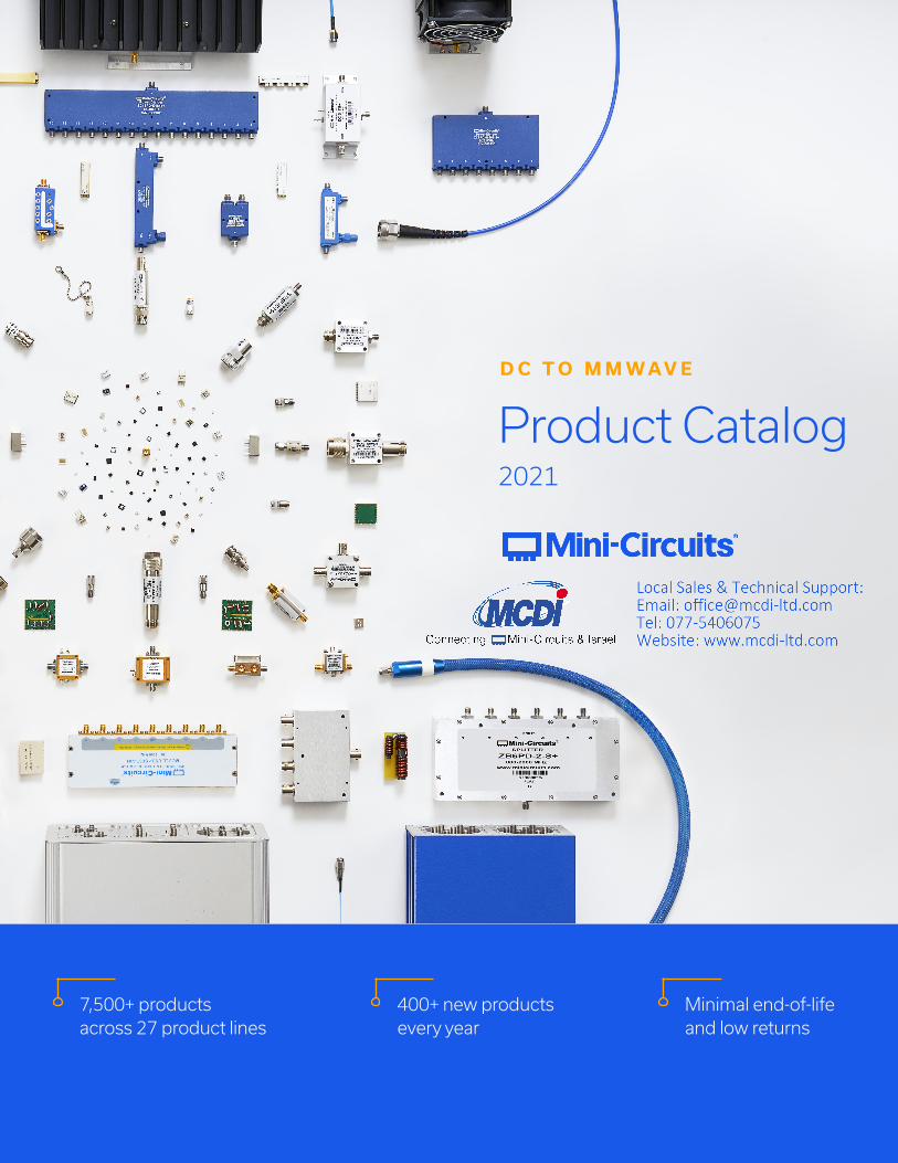
Peace of Mind
Quality and reliability are in our DNA. That’s why the world’s largest and most innovative technology companies recognize Mini-Circuits as a top supplier year after year. When failure isn’t an option, customers trust us because they know our products perform as expected. They also know that no supplier does more than we do to protect them from supply chain disruptions and product obsolescence. We’ve built a reputation with our policy to provide product support through the life of your system and minimize end-of- life for every product in active use. That trust, and the peace of mind that comes with it, sets us apart from the rest.
Mini-Circuits is the only supplier in the industry that gives you the in-stock selection and convenience of a catalog company with the technical capabilities of a custom house and leading manufacturer. With 27 product lines comprising 7,500+ models in stock and growing, chances are we have the right part for your needs. For everything else, we put the full capability of our world-class design and manufacturing facilities to work for you. From special screening requirements to fully custom components and integrated assemblies, our engineers work with you every step of the way with competitive pricing and fast turnaround.
Selection Meets Solutions Constant Innovation
For over 50 years, we’ve grown with the industry by adapting to your needs. With hundreds of new catalog releases each year, a growing portfolio of active patents, and recent investments in new design facilities and world-class technical talent, we’re not just keeping up with the pace of innovation—we’re setting it.
Service Beyond Normal
When you choose Mini-Circuits, you’re getting more than the right part for your system. You’re getting the right partner for your long-term success. Our commitment to you means same- day shipping with on-time delivery, short lead times, easy access to knowledgeable engineering support, local reps and service anywhere in the world—everything you expect from a good partner. With 20,000+ customers, we know that every customer’s needs are unique, so we go beyond normal expectations to collaborate with our customers in solving problems and getting results.
T H E M I N I - C I R C U I T S D I F F E R E N C E | 3| T H E M I N I - C I R C U I T S D I F F E R E N C E2
The World’s Preferred Supplier from DC to mmWave
TA B L E O F C O N T E N T S | 5
T H E M I N I - C I R C U I T S D I F F E R E N C E 20–23
Partner Program
EZ-Samples
Buy It Your Way
Global Presence, Local Service
Application Engineering
Custom Designs
In-House Upscreening
E N G I N E E R I N G R E S O U R C E S 24–27
Microwave Calculator
Yoni2 Advanced Search
The Mini-Circuits Blog
Modelithics
X-Microwave
C O R E T E C H N O L O G I E S 28–31
Amplifier Technologies
Filter Technologies
Low Temperature Co-Fired Ceramic (LTCC)
Magnetic Core & Wire
MMIC
M A R K E T S 32–37
Aerospace & Defense
CATV & Broadband
Education
Industrial
Medical & Diagnostic
Space & SatCom
Telecom
Test & Measurement
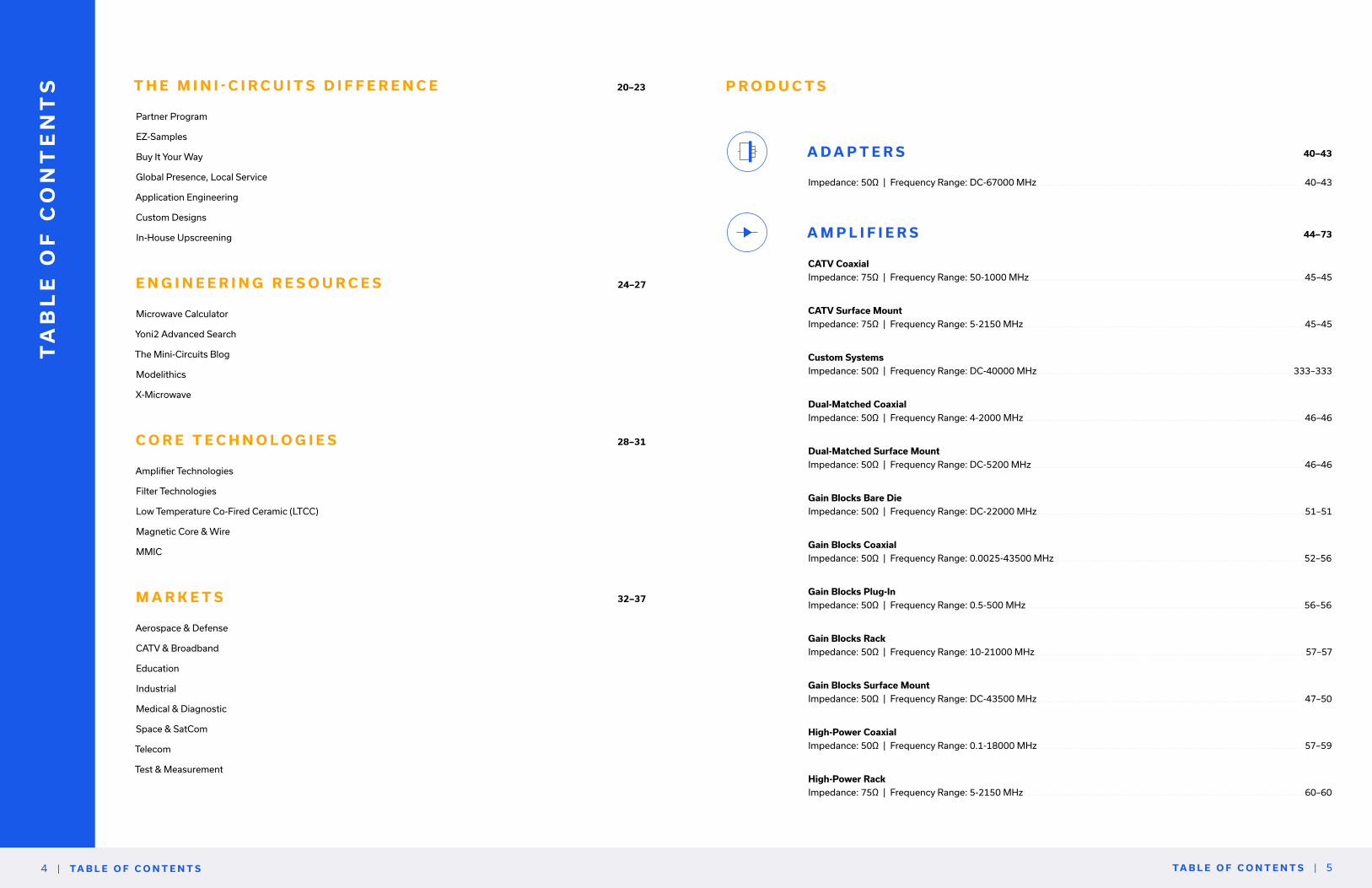
A D A P T E R S 40–43
Impedance: 50Ω | Frequency Range: DC-67000 MHz ...................................................................................................... 40–43
A M P L I F I E R S 44–73
CATV Coaxial
Impedance: 75Ω | Frequency Range: 50-1000 MHz .......................................................................................................... 45–45
CATV Surface Mount
Impedance: 75Ω | Frequency Range: 5-2150 MHz ............................................................................................................ 45–45
Custom Systems
Impedance: 50Ω | Frequency Range: DC-40000 MHz ...................................................................................................333–333
Dual-Matched Coaxial
Impedance: 50Ω | Frequency Range: 4-2000 MHz ............................................................................................................ 46–46
Dual-Matched Surface Mount
Impedance: 50Ω | Frequency Range: DC-5200 MHz ......................................................................................................... 46–46
Gain Blocks Bare Die
Impedance: 50Ω | Frequency Range: DC-22000 MHz ....................................................................................................... 51–51
Gain Blocks Coaxial
Impedance: 50Ω | Frequency Range: 0.0025-43500 MHz ................................................................................................52–56
Gain Blocks Plug-In
Impedance: 50Ω | Frequency Range: 0.5-500 MHz ...........................................................................................................56–56
Gain Blocks Rack
Impedance: 50Ω | Frequency Range: 10-21000 MHz ........................................................................................................ 57–57
Gain Blocks Surface Mount
Impedance: 50Ω | Frequency Range: DC-43500 MHz ....................................................................................................... 47–50
High-Power Coaxial
Impedance: 50Ω | Frequency Range: 0.1-18000 MHz ...................................................................................................... 57–59
High-Power Rack
Impedance: 75Ω | Frequency Range: 5-2150 MHz ............................................................................................................ 60–60
| TA B L E O F C O N T E N T S4
TA
BL
E O
F C
ON
TE
NT
S P R O D U C T S
Linear Bare Die
Impedance: 50Ω | Frequency Range: 30-6000 MHz .......................................................................................................... 61–61
Linear Surface Mount
Impedance: 50Ω | Frequency Range: 30-6000 MHz .......................................................................................................... 60–60
Low Noise Bare Die
Impedance: 50Ω | Frequency Range: DC-18000 MHz ....................................................................................................... 64–65
Low Noise Coaxial
Impedance: 50Ω | Frequency Range: 0.1-43500 MHz ....................................................................................................... 65–68
Low Noise Plug-In
Impedance: 50Ω | Frequency Range: 5-2400 MHz ............................................................................................................ 68–68
Low Noise Surface Mount
Impedance: 50Ω | Frequency Range: DC-18000 MHz ....................................................................................................... 61–64
Pulse Coaxial
Impedance: 50Ω | Frequency Range: 0.0025-700 MHz ..................................................................................................... 68–68
RF Transistors Bare Die
Impedance: 50Ω | Frequency Range: 50-10000 MHz ........................................................................................................ 69–69
RF Transistors Surface Mount
Impedance: 50Ω | Frequency Range: 10-10000 MHz ........................................................................................................ 69–69
Variable Gain Coaxial
Impedance: 50Ω | Frequency Range: 10-2000 MHz .......................................................................................................... 70–70
Variable Gain Surface Mount
Impedance: 50Ω | Frequency Range: 50-3000 MHz .......................................................................................................... 70–70
AT T E N U AT O R S 74–100
Custom Rack Mount
Impedance: 50Ω | Frequency Range: DC-40000 MHz ...................................................................................................336–336
Digital Step Coaxial
Impedance: 50Ω | Frequency Range: DC-6000 MHz ......................................................................................................... 76–76
Digital Step Plug-In
Impedance: 50Ω | Frequency Range: 10-1000 MHz .......................................................................................................... 77–77
Digital Step Surface Mount
Impedance: 75Ω | Frequency Range: 1-2500 MHz ............................................................................................................ 75–76
Digital Step Surface Mount
Impedance: 50Ω | Frequency Range: DC-4000 MHz ......................................................................................................... 75–75
Fixed Bare Die
Impedance: 50Ω | Frequency Range: DC-43500 MHz ....................................................................................................... 82–83
Fixed Coaxial
Impedance: 75Ω | Frequency Range: DC-2000 MHz ......................................................................................................... 90–90
Fixed Coaxial
Impedance: 50Ω | Frequency Range: DC-65000 MHz ....................................................................................................... 83–90
Fixed Surface Mount
Impedance: 50Ω | Frequency Range: DC-50000 MHz ....................................................................................................... 77–81
Programmable
Impedance: 50Ω | Frequency Range: 1-40000 MHz .......................................................................................................... 91–92
Voltage Variable Coaxial
Impedance: 50Ω | Frequency Range: 0.1-12000 MHz ....................................................................................................... 93–93
Voltage Variable Surface Mount
Impedance: 75Ω | Frequency Range: 10-2500 MHz .......................................................................................................... 93–93
Voltage Variable Surface Mount
Impedance: 50Ω | Frequency Range: 10-7000 MHz .......................................................................................................... 92–92
B I A S T E E S 102–105
Bare Die
Impedance: 50Ω | Frequency Range: 1500-28000 MHz 103–103
Coaxial
Impedance: 50Ω | Frequency Range: 0.1-12000 MHz ...................................................................................................103–104
Mux-Tees Coaxial
Impedance: 50Ω | Frequency Range: 10-2150 MHz ......................................................................................................105–105
Plug-In
Impedance: 50Ω | Frequency Range: 0.1-3000 MHz .....................................................................................................104–104
Surface Mount
Impedance: 50Ω | Frequency Range: 0.1-28000 MHz ...................................................................................................103–103
TA B L E O F C O N T E N T S | 7| TA B L E O F C O N T E N T S6
Attenuators ContinuedAmplifiers Continued

C A B L E S 106–131
Interconnect
Impedance: 50/75Ω | Frequency Range: DC-40000 MHz .............................................................................................110–121
Test
Impedance: 50Ω | Frequency Range: DC-67000 MHz ...................................................................................................121–128
VNA
Impedance: 50Ω | Frequency Range: DC-67000 MHz ...................................................................................................128–129
C O U P L E R S 132–154
Bi-Directional Bare Die
Impedance: 50Ω | Frequency Range: 5000-43500 MHz ...............................................................................................150–150
Bi-Directional Coaxial
Impedance: 75Ω | Frequency Range: 700-2500 MHz ....................................................................................................151–151
Bi-Directional Coaxial
Impedance: 50Ω | Frequency Range: 0.4-9000 MHz .....................................................................................................150–151
Bi-Directional Plug-In
Impedance: 50Ω | Frequency Range: 0.2-400 MHz .......................................................................................................151–151
Bi-Directional Surface Mount
Impedance: 50Ω | Frequency Range: 1.5-10500 MHz ...................................................................................................146–149
Directional Bare Die
Impedance: 50Ω | Frequency Range: 4-43500 MHz ......................................................................................................140–140
Directional Coaxial
Impedance: 75Ω | Frequency Range: 1-1750 MHz ........................................................................................................145–145
Directional Coaxial
Impedance: 50Ω | Frequency Range: 0.005-2000 MHz .................................................................................................140–145
Directional Plug-In
Impedance: 75Ω | Frequency Range: 1-150 MHz ..........................................................................................................146–146
Directional Plug-In
Impedance: 50Ω | Frequency Range: 0.005-2000 MHz .................................................................................................146–146
Directional Surface Mount
Impedance: 75Ω | Frequency Range: 2-2000 MHz ........................................................................................................137–139
Directional Surface Mount
Impedance: 50Ω | Frequency Range: 1.5-10500 MHz ...................................................................................................134–137
Dual Directional Coaxial
Impedance: 50Ω | Frequency Range: 500-40000 MHz..................................................................................................151–151
RF Tap Bare Die
Impedance: 50Ω | Frequency Range: DC-50000 MHz ...................................................................................................152–152
RF Tap Coaxial
Impedance: 50Ω | Frequency Range: 20-6000 MHz ......................................................................................................152–152
RF Tap Surface Mount
Impedance: 50Ω | Frequency Range: DC-50000 MHz ...................................................................................................152–152
D C B L O C K S 156–156
Coaxial
Impedance: 50Ω | Frequency Range: 0.1-65000 MHz ...................................................................................................157–157
E Q U A L I Z E R S 158–165
Fixed Slope Bare Die
Impedance: 50Ω | Frequency Range: DC-45000 MHz ...................................................................................................160–161
Fixed Slope Coaxial
Impedance: 50Ω | Frequency Range: DC-20000 MHz ...................................................................................................161–161
Fixed Slope Surface Mount
Impedance: 50Ω | Frequency Range: DC-45000 MHz ...................................................................................................159–160
Voltage Variable Surface Mount
Impedance: 50Ω | Frequency Range: 50-2150 MHz ......................................................................................................162–162
F I LT E R S 166–235
Band Pass + Balun Surface Mount
Impedance: 50Ω | Frequency Range: 690-5875 MHz ....................................................................................................204–204
Band Pass Bare Die
Impedance: 50Ω | Frequency Range: 3800-32000 MHz ...............................................................................................205–205
TA B L E O F C O N T E N T S | 9| TA B L E O F C O N T E N T S8
Couplers Continued

Band Pass Coaxial
Impedance: 75Ω | Frequency Range: 12.3-13.8 MHz ....................................................................................................211–211
Band Pass Coaxial
Impedance: 50Ω | Frequency Range: 0.063-43500 MHz ..............................................................................................205–211
Band Pass Plug-In
Impedance: 50Ω | Frequency Range: 9.5-82 MHz .........................................................................................................211–212
Band Pass Surface Mount
Impedance: 75Ω | Frequency Range: 5-2250 MHz ........................................................................................................204–204
Band Pass Surface Mount
Impedance: 50Ω | Frequency Range: 2-29500 MHz ......................................................................................................193–204
Band Pass Waveguide
Impedance: 50Ω | Frequency Range: 27500-86000 MHz .............................................................................................212–212
Band Stop Coaxial
Impedance: 50Ω | Frequency Range: DC-1000 MHz .....................................................................................................225–225
Band Stop Surface Mount
Impedance: 50Ω | Frequency Range: DC-1200 MHz .....................................................................................................224–224
Diplexer Coaxial
Impedance: 75Ω | Frequency Range: DC-1700 MHz .....................................................................................................229–229
Diplexer Coaxial
Impedance: 50Ω | Frequency Range: DC-7500 MHz .....................................................................................................228–229
Diplexer Plug-In
Impedance: 75Ω | Frequency Range: DC-1225 MHz .....................................................................................................229–230
Diplexer Surface Mount
Impedance: 75Ω | Frequency Range: DC-1220 MHz .....................................................................................................227–228
Diplexer Surface Mount
Impedance: 50Ω | Frequency Range: DC-6500 MHz .....................................................................................................226–227
Dual Passband Surface Mount
Impedance: 50Ω | Frequency Range: 470-960 MHz ......................................................................................................225–225
High Pass Bare Die
Impedance: 50Ω | Frequency Range: 2010-40000 MHz ...............................................................................................217–218
High Pass Coaxial
Impedance: 50Ω | Frequency Range: 0.07-40000 MHz .................................................................................................218–223
High Pass Plug-In
Impedance: 50Ω | Frequency Range: 13-720 MHz ........................................................................................................223–224
High Pass Surface Mount
Impedance: 50Ω | Frequency Range: 2-30000 MHz ......................................................................................................213–217
Low Pass Dual Differential Surface Mount
Impedance: 50Ω | Frequency Range: DC-1750 MHz .....................................................................................................180–180
Low Pass Flat Time Delay Coax
Impedance: 50Ω | Frequency Range: 23-1870 MHz ......................................................................................................191–191
Low Pass Flat Time Delay Plug-In
Impedance: 50Ω | Frequency Range: 23-200 MHz ........................................................................................................192–193
Low Pass Bare Die
Impedance: 50Ω | Frequency Range: DC-17000 MHz ...................................................................................................180–181
Low Pass Coaxial
Impedance: 75Ω | Frequency Range: 7-640 MHz ..........................................................................................................191–191
Low Pass Coaxial
Impedance: 50Ω | Frequency Range: DC-24000 MHz ...................................................................................................182–190
Low Pass Plug-In
Impedance: 75Ω | Frequency Range: 7-640 MHz ..........................................................................................................193–193
Low Pass Plug-In
Impedance: 50Ω | Frequency Range: 1.9-1200 MHz .....................................................................................................192–192
Low Pass Surface Mount
Impedance: 75Ω | Frequency Range: 5-700 MHz ..........................................................................................................179–179
Low Pass Surface Mount
Impedance: 50Ω | Frequency Range: DC-17000 MHz ...................................................................................................169–179
Triplexers Coaxial
Impedance: 50Ω | Frequency Range: DC-7000 MHz .....................................................................................................231–231
Triplexers Surface Mount
Impedance: 50Ω | Frequency Range: 1-2700 MHz ........................................................................................................230–230
TA B L E O F C O N T E N T S | 11| TA B L E O F C O N T E N T S10
Filters ContinuedFilters Continued
H Y B R I D S 9 0 / 1 8 0 ° 236–242
Bare Die
Impedance: 50Ω | Frequency Range: 5000-14000 MHz ...............................................................................................240–240
Coaxial
Impedance: 50Ω | Frequency Range: 0.01-4200 MHz ...................................................................................................241–242
Plug-In
Impedance: 50Ω | Frequency Range: 3.5-600 MHz .......................................................................................................242–242
Surface Mount
Impedance: 75Ω | Frequency Range: 5-1250 MHz ........................................................................................................240–240
Surface Mount
Impedance: 50Ω | Frequency Range: 1-14500 MHz ......................................................................................................237–240
I M P E D A N C E M AT C H I N G PA D S 244–245
Coaxial
Impedance: 50Ω | Frequency Range: DC-3000 MHz .....................................................................................................245–245
Surface Mount
Impedance: 50Ω | Frequency Range: DC-3000 MHz .....................................................................................................245–245
L I M I T E R S 246–247
Coaxial
Impedance: 50Ω | Frequency Range: 0.2-8200 MHz .....................................................................................................247–247
Plug-In
Impedance: 50Ω | Frequency Range: 0.1-900 MHz .......................................................................................................247–247
Surface Mount
Impedance: 50Ω | Frequency Range: 0.2-8200 MHz .....................................................................................................246–247
M I X E R S 248–271
Bare Die
Impedance: 50Ω | Frequency Range: 2200-65000 MHz ...............................................................................................261–261
Coaxial
Impedance: 50Ω | Frequency Range: 0.0005-40000 MHz ............................................................................................261–266
Plug-In
Impedance: 50Ω | Frequency Range: 0.0005-4300 MHz ..............................................................................................266–269
Surface Mount
Impedance: 50Ω | Frequency Range: 0.05-40000 MHz .................................................................................................250–260
Surface Mount Active
Impedance: 50Ω | Frequency Range: 0.2-8200 MHz .....................................................................................................261–261
M O D U L AT O R S & D E M O D U L AT O R S 272–275
Bi-Phase Coaxial
Impedance: 50Ω | Frequency Range: 1-2000 MHz ........................................................................................................275–275
Bi-Phase Plug-In
Impedance: 50Ω | Frequency Range: 1-2000 MHz ........................................................................................................275–275
Bi-Phase Surface Mount
Impedance: 50Ω | Frequency Range: 2-1000 MHz ........................................................................................................274–274
I&Q Demodulators Coaxial
Impedance: 50Ω | Frequency Range: 66-73 MHz ..........................................................................................................274–274
I&Q Demodulators Plug-In
Impedance: 50Ω | Frequency Range: 23-23 MHz ..........................................................................................................274–274
I&Q Demodulators Surface Mount
Impedance: 50Ω | Frequency Range: 104-176 MHz ......................................................................................................273–273
I&Q Modulators Coaxial
Impedance: 50Ω | Frequency Range: 66-73 MHz ..........................................................................................................273–273
I&Q Modulators Plug-In
Impedance: 50Ω | Frequency Range: 20-23 MHz ..........................................................................................................273–273
I&Q Modulators Surface Mount
Impedance: 50Ω | Frequency Range: 52-176 MHz ........................................................................................................273–273
M U LT I P L I E R S 276–280
Bare Die
Impedance: 50Ω | Frequency Range: 0.05-1500 MHz ...................................................................................................279–279
TA B L E O F C O N T E N T S | 13| TA B L E O F C O N T E N T S12
Mixers Continued

Coaxial
Impedance: 50Ω | Frequency Range: 0.1-20000MHz ....................................................................................................279–279
Plug-In
Impedance: 50Ω | Frequency Range: 0.1-3000 MHz .....................................................................................................280–280
Surface Mount
Impedance: 50Ω | Frequency Range: 20-40000 MHz ....................................................................................................277–278
P H A S E D E T E C T O R S 282–284
Coaxial
Impedance: 50Ω | Frequency Range: 1-100 MHz ..........................................................................................................283–283
Plug-In
Impedance: 50Ω | Frequency Range: 1-400 MHz ..........................................................................................................283–283
Surface Mount
Impedance: 50Ω | Frequency Range: 1-650 MHz ..........................................................................................................283–283
P H A S E S H I F T E R S 286–287
Coaxial 360°
Impedance: 50Ω | Frequency Range: 250-430 MHz ......................................................................................................287–287
Surface Mount 180°
Impedance: 50Ω | Frequency Range: 36-2484 MHz ......................................................................................................287–287
Surface Mount 360°
Impedance: 50Ω | Frequency Range: 210-1500 MHz ....................................................................................................287–287
P O W E R D E T E C T O R S 288–289
Coaxial
Impedance: 50Ω | Frequency Range: 10-43500 MHz ....................................................................................................289–289
P O W E R S E N S O R S & F R E Q U E N C Y C O U N T E R S 338–338
Frequency Counter
Impedance: 50Ω | Frequency Range: 1-6000 MHz ........................................................................................................338–338
Power Sensors
Impedance: 50Ω | Frequency Range: 0.009-8000 MHz .................................................................................................338–338
Power Sensor Frequency Counter
Impedance: 50Ω | Frequency Range: 1-6000 MHz ........................................................................................................338–338
R F C H O K E S 290–290
Surface Mount
Impedance: 50Ω | Frequency Range: 5-10000 MHz ......................................................................................................290–290
S I G N A L G E N E R AT O R S 337–337
Coaxial
Impedance: 50Ω | Frequency Range: 1-15000 MHz ......................................................................................................337–337
S P L I T T E R S & C O M B I N E R S 292–316
Bare Die
Impedance: 50Ω | Frequency Range: DC-43500 MHz ...................................................................................................302–302
Coaxial
Impedance: 75Ω | Frequency Range: 0.002-2500 MHz .................................................................................................313–314
Coaxial
Impedance: 50Ω | Frequency Range: DC-65000 MHz ...................................................................................................303–313
Plug-In
Impedance: 50Ω | Frequency Range: 0.004-2000 MHz .................................................................................................315–315
Surface Mount
Impedance: 75Ω | Frequency Range: 1-2750 MHz ........................................................................................................300–302
Surface Mount
Impedance: 50Ω | Frequency Range: DC-43500 MHz ...................................................................................................294–300
TA B L E O F C O N T E N T S | 15| TA B L E O F C O N T E N T S14
Multipliers Continued
S W I T C H E S 318–324
Bare Die
Impedance: 50Ω | Frequency Range: DC-6000 MHz .....................................................................................................323–323
Custom Switch Systems
Impedance: 50Ω | Frequency Range: DC-50000 MHz ...................................................................................................340–342
Electromechanical Coaxial
Impedance: 50Ω | Frequency Range: DC-18000 MHz ...................................................................................................319–319
MMIC Surface Mount
Impedance: 75Ω | Frequency Range: 5-3000 MHz ........................................................................................................322–322
MMIC Surface Mount
Impedance: 50Ω | Frequency Range: DC-6000 MHz .....................................................................................................321–322
MMIC Surface Mount Low Video Leakage
Impedance: 50Ω | Frequency Range: DC-2000 MHz .....................................................................................................322–322
Pin Diode Coaxial
Impedance: 50Ω | Frequency Range: 10-3000 MHz ......................................................................................................324–324
Pin Diode Plug-In
Impedance: 50Ω | Frequency Range: 10-3000 MHz ......................................................................................................324–324
Solid State Coaxial TTL
Impedance: 50Ω | Frequency Range: DC-6000 MHz .....................................................................................................23–324
USB Ethernet Mechanical Modules
Impedance: 50Ω | Frequency Range: DC-50000 MHz ...................................................................................................319–320
USB Ethernet Solid State Modules
Impedance: 50Ω | Frequency Range: DC-8000 MHz .....................................................................................................323–323
S Y N T H E S I Z E R S 326–327
Surface Mount
Impedance: 50Ω | Frequency Range: 1520-2346 MHz ..................................................................................................327–327
T E R M I N AT I O N S 328–330
Coaxial
Impedance: 50Ω | Frequency Range: 65000 MHz .........................................................................................................329–330
T R A N S F O R M E R S & B A L U N S 344–365
Bare Die
Impedance: 50Ω | Frequency Range: 2000-24000 MHz ...............................................................................................361–361
Coaxial
Impedance: 50/75Ω | Frequency Range: 0.004-24000 MHz .........................................................................................359–359
Plug-In
Impedance: 50Ω | Frequency Range: 0.1-800 MHz .......................................................................................................359–361
Surface Mount
Impedance: 75Ω | Frequency Range: 0.3-3000 MHz .....................................................................................................357–358
Surface Mount
Impedance: 50Ω | Frequency Range: 0.005-24000 MHz...............................................................................................345–357
V O LTA G E C O N T R O L L E D O S C I L L AT O R S 366–379
Dual Output Coaxial
Impedance: 50Ω | Frequency Range: 37.7-1025 MHz....................................................................................................379–379
Linear Tuning Wideband Plug-In
Impedance: 50Ω | Frequency Range: 37.5-2120 MHz ...................................................................................................378–378
Linear Tuning Wideband Surface Mount
Impedance: 50Ω | Frequency Range: 37.5-6840 MHz ...................................................................................................374–377
5V Tuning for PLLs Surface Mount
Impedance: 50Ω | Frequency Range: 35-6520 MHz ......................................................................................................370–373
T E S T S O L U T I O N S 332–342
Custom Test Systems
Impedance: 50Ω | Frequency Range: DC-65000 MHz ...................................................................................................333–333
Instrumentation Amplifiers
Impedance: 50Ω | Frequency Range: 0.0025-43500 MHz ............................................................................................333–333
Mesh Network Simulation Racks
Impedance: 50Ω | Frequency Range: 30-6000 MHz ......................................................................................................333–334
Modular Test Systems
Impedance: 50Ω | Frequency Range: DC-40000 MHz ...................................................................................................334–334
TA B L E O F C O N T E N T S | 17| TA B L E O F C O N T E N T S16
PLL
Patch Panel Systems
Impedance: 50Ω | Frequency Range: DC-67000 MHz ...................................................................................................335–335
Signal Conditioning & Attenuation, Custom
Impedance: 50Ω | Frequency Range: DC-40000 MHz ...................................................................................................336–336
Signal Distribution
Impedance: 50Ω | Frequency Range: DC-65000 MHz ...................................................................................................339–339
Signal Generation & Measurement
Impedance: 50Ω | Frequency Range: 0.009-15000 MHz...............................................................................................337–337
Power Sensors & Frequency Counters
Impedance: 50Ω | Frequency Range: 0.009-8000 MHz .................................................................................................338–338
Switching & Routing
Impedance: 50Ω | Frequency Range: DC-50000 MHz ...................................................................................................340–341
R E S E A R C H & E D U C AT I O N 380–381
4D Imaging Kit
Impedance: 50Ω | Frequency Range: 62000-69000 MHz .............................................................................................381–381
DIY VNA Kit
Impedance: 50Ω | Frequency Range: DC-6000 MHz .....................................................................................................381–381
R E S E A R C H & E D U C AT I O N 382–383
TA B L E O F C O N T E N T S | 19| TA B L E O F C O N T E N T S18
Test Solutions Continued

T H E M I N I - C I R C U I T S D I F F E R E N C E | 21| T H E M I N I - C I R C U I T S D I F F E R E N C E20
Partner Program
Preferred Pricing and Long-Term Savings Try It Before You Buy It Ship from Mini-Circuits or Mouser Corporate Offices and Authorized Reps Worldwide
Nothing matters more to us than building and maintaining strong, long-term relationships with our customers. We established Mini-Circuits’ Partner Program to reward your loyalty with preferred pricing based on cumulative purchases for each model you buy.
Here’s how it works:
• You’re automatically enrolled in the program when you make a purchase from us
• Your preferred pricing is based on the volume pricing at the accumulated total of all purchases of a model while enrolled in the program
• This rewards all subsequent orders, large or small, with higher volume pricing
• You remain enrolled in the program for each model as long as you purchase at least 2% of the prior year’s cumulative total
See full program terms
*See minicircuits.com/partners/partners
for terms and conditions
*Additional models may be available on request. Check
with your Mini-Circuits sales rep or account manager
*Shipping times and product availability may vary by location
EZ-Sample Buy It Your Way Global Presence, Local Service
EZ-Sample is Mini-Circuits’ free, online sample request program for RF components. We offer a wide selection of our surface mount parts in small-quantity samples to support your product selection and design validation efforts, so you can make an informed decision at no cost.
• 1300+ models available to sample for free*
• Free shipping to 200+ countries
• Choose from a wide selection of amplifiers, attenuators, bias tees, couplers, equalizers, filters, limiters, mixers, multipliers, RF chokes, switches, splitter/combiners and transformers
Mini-Circuits is your preferred supplier from DC to mmWave for components, custom assemblies and test solutions. We’ve partnered with Mouser to give customers the flexibility to choose their point of sale for our products, expand the availability of parts from stock and accelerate delivery times across the globe.
• 1300+ Mini-Circuits components and growing
• Same-day shipping to 200+ countries*
• Approved vendor for many of our customers
Being the world’s preferred supplier means personal, locally accessible service and technical support wherever you’re doing business. Whether you need help with logistics or technical support from a qualified engineer, almost anywhere in the world, there’s a Mini-Circuits team member nearby to help you meet your goals.
• 14 corporate locations in 8 countries
• 300+ authorized sales rep offices and distributors worldwide
• Company-owned warehouses and shipping hubs in the U.S., Europe and Asia-Pacific regions
Shop Mini-Circuits on Mouser
Browse free sample parts
Find a Mini-Circuits
rep in your area

Applications Engineering
Space Flight Launch Prep
• Mil-Spec or equivalent qualifications
• 30+ years of space-level screening and testing heritage
• In-stock and custom components
• EEE-INST-002 compliant workflows
Standard capabilities:
Burn-in, thermal cycling and shock, vibration*, radiographic inspection*, destructive physical analysis (DPA)*, mechanical shock, hermeticity with accompanying acceptance testprocedure (ATP).
Engineer-to-Engineer Technical Support
First and foremost, we’re a company of RF engineers supporting other RF engineers. We’re committed to making the technical expertise of our organization a resource to the industry and collaborating at the engineering level with all customers, small and large, from the early stages of product selection through integration and troubleshooting long after your order ships.
• Dedicated staff of qualified RF engineers
• Product selection assistance
• Custom designs and special requirements
• Integration support
• Technical troubleshooting
Contact Our Engineers: [email protected]
*While Mini-Circuits performs most of its testing and upscreening
in-house, we use specialist partners for a limited selection of tests.
Components and Integrated Assemblies
Custom Designs
Our offering goes way beyond the catalog. Put the full capability of our 50+ years of design and manufacturing experience to work for you. Whether you need a modification of an existing part or a fully custom component or integrated sub-system, our engineers work closely with you to realize innovative solutions from definition to delivery.
• 50+ years design and manufacturing experience
• Broad range of design capabilities across 27 product categories
• 7 design centers and 8 company-owned manufacturing facilities
Hi-Rel and Space Applications
In-House Upscreening
Mini-Circuits has decades of experience supporting hi-rel military applications and space missions with a wide range of upscreening requirements. Most of our catalog and custom components can be upscreened in-house for Mil-Spec or equivalent qualification in as little as 90 days.
Hi-Rel
• Qualification for the toughest operating environments
• Broad selection off-the-shelf + custom designs
• MMICs in ceramic, plastic and bare die formats
Capable of meeting MIL requirements for:
Gross leak, fine leak, thermal shock, vibration, acceleration, mechanical shock and HTOL. Additional screening available on request.
T H E M I N I - C I R C U I T S D I F F E R E N C E | 23| T H E M I N I - C I R C U I T S D I F F E R E N C E22
M I N I - C I R C U I T S 2 0 2 1 | 25| M I N I - C I R C U I T S 2 0 2 124
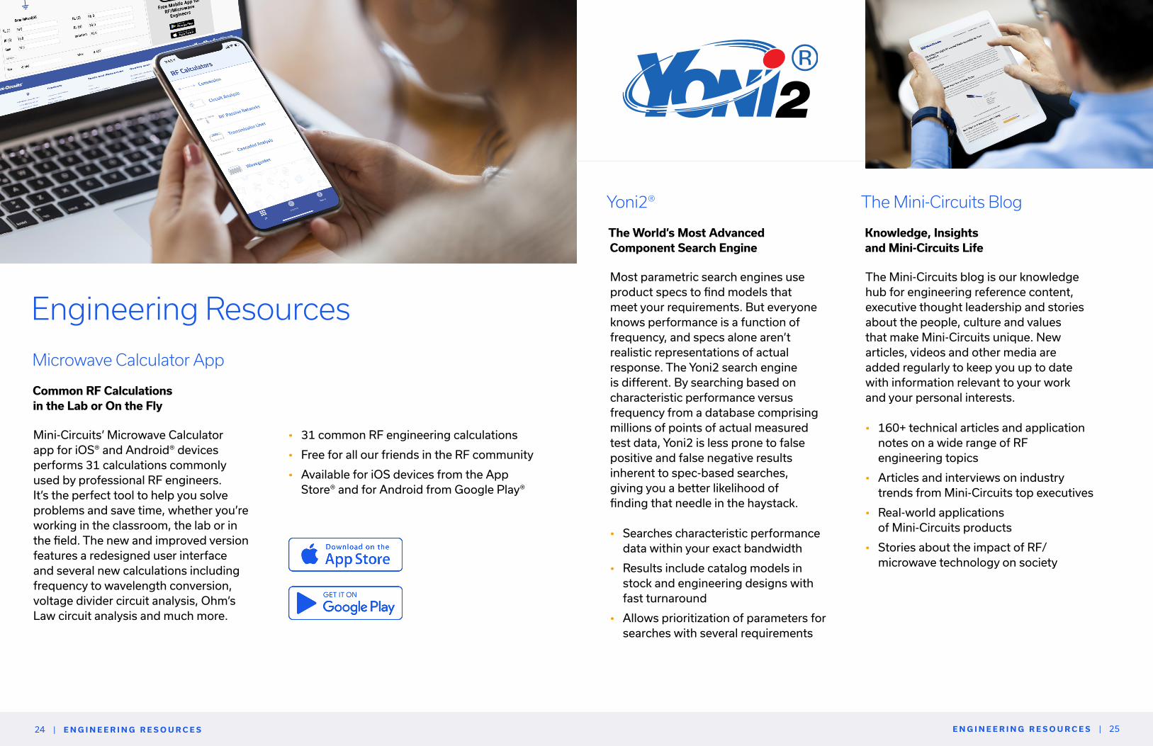
• 31 common RF engineering calculations
• Free for all our friends in the RF community
• Available for iOS devices from the App Store® and for Android from Google Play®
E N G I N E E R I N G R E S O U R C E S | 25| E N G I N E E R I N G R E S O U R C E S24
Engineering Resources
Microwave Calculator App
Common RF Calculations in the Lab or On the Fly
Mini-Circuits’ Microwave Calculator app for iOS® and Android® devices performs 31 calculations commonly used by professional RF engineers. It’s the perfect tool to help you solve problems and save time, whether you’re working in the classroom, the lab or in the field. The new and improved version features a redesigned user interface and several new calculations including frequency to wavelength conversion, voltage divider circuit analysis, Ohm’s Law circuit analysis and much more.
The World’s Most Advanced Component Search Engine
Yoni2®
Most parametric search engines use product specs to find models that meet your requirements. But everyone knows performance is a function of frequency, and specs alone aren’t realistic representations of actual response. The Yoni2 search engine is different. By searching based on characteristic performance versus frequency from a database comprising millions of points of actual measured test data, Yoni2 is less prone to false positive and false negative results inherent to spec-based searches, giving you a better likelihood of finding that needle in the haystack.
• Searches characteristic performance data within your exact bandwidth
• Results include catalog models in stock and engineering designs with fast turnaround
• Allows prioritization of parameters for searches with several requirements
Knowledge, Insights and Mini-Circuits Life
The Mini-Circuits Blog
The Mini-Circuits blog is our knowledge hub for engineering reference content, executive thought leadership and stories about the people, culture and values that make Mini-Circuits unique. New articles, videos and other media are added regularly to keep you up to date with information relevant to your work and your personal interests.
• 160+ technical articles and application notes on a wide range of RF engineering topics
• Articles and interviews on industry trends from Mini-Circuits top executives
• Real-world applications of Mini-Circuits products
• Stories about the impact of RF/ microwave technology on society
| M O D E L I T H I C S M O D E L I T H I C S |
Download the models for free from the Mini-Circuits
partner page on the Modelithics website
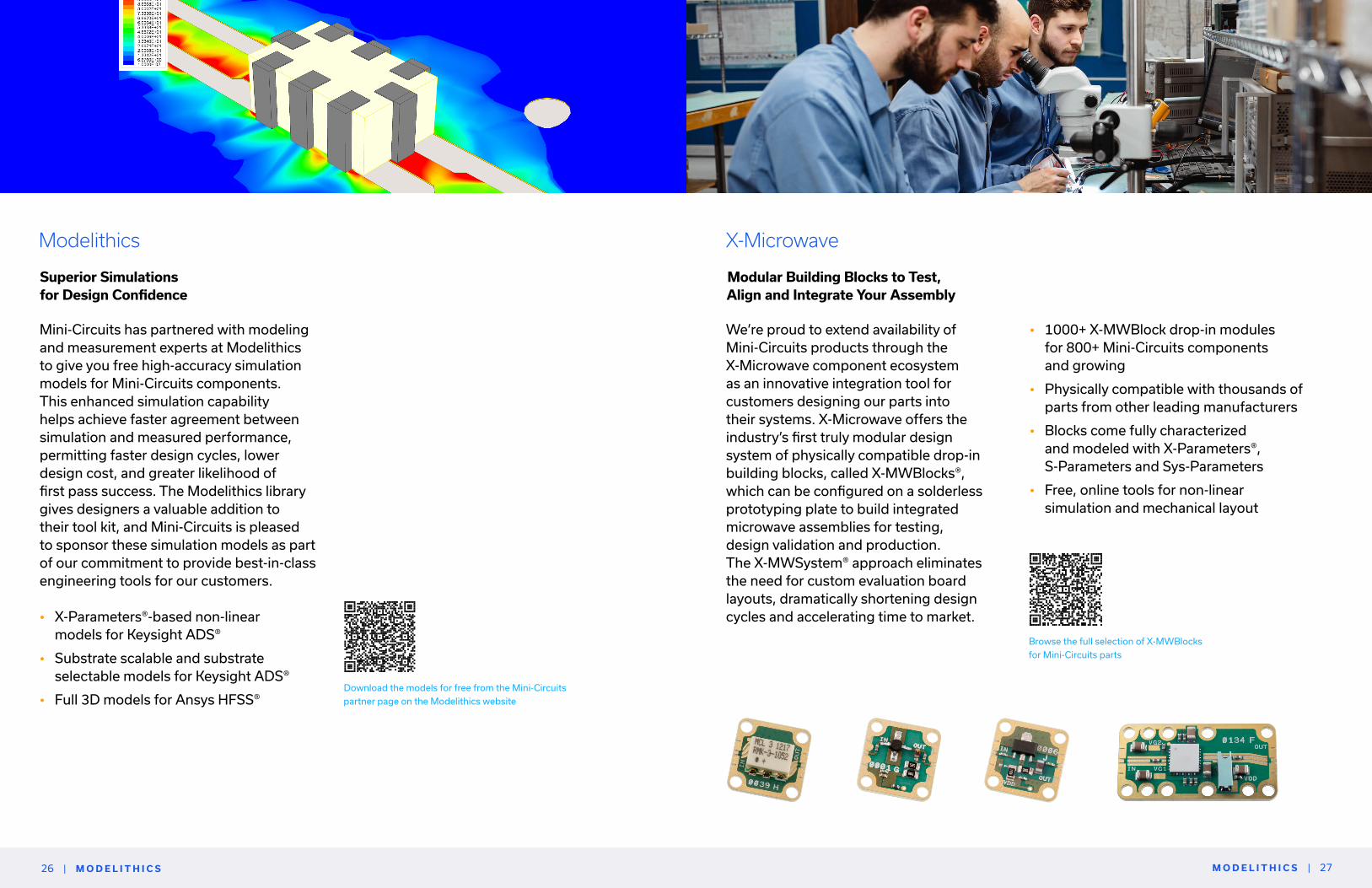
Superior Simulations for Design Confidence
Modelithics
Mini-Circuits has partnered with modeling and measurement experts at Modelithics to give you free high-accuracy simulation models for Mini-Circuits components. This enhanced simulation capability helps achieve faster agreement between simulation and measured performance, permitting faster design cycles, lower design cost, and greater likelihood of first pass success. The Modelithics library gives designers a valuable addition to their tool kit, and Mini-Circuits is pleased to sponsor these simulation models as part of our commitment to provide best-in-class engineering tools for our customers.
• X-Parameters®-based non-linear models for Keysight ADS®
• Substrate scalable and substrate selectable models for Keysight ADS®
• Full 3D models for Ansys HFSS®
2726
X-Microwave
Modular Building Blocks to Test, Align and Integrate Your Assembly
We’re proud to extend availability of Mini-Circuits products through the X-Microwave component ecosystem as an innovative integration tool for customers designing our parts into their systems. X-Microwave offers the industry’s first truly modular design system of physically compatible drop-in building blocks, called X-MWBlocks®, which can be configured on a solderless prototyping plate to build integrated microwave assemblies for testing, design validation and production. The X-MWSystem® approach eliminates the need for custom evaluation board layouts, dramatically shortening design cycles and accelerating time to market.
Browse the full selection of X-MWBlocks
for Mini-Circuits parts
• 1000+ X-MWBlock drop-in modules for 800+ Mini-Circuits components and growing
• Physically compatible with thousands of parts from other leading manufacturers
• Blocks come fully characterized and modeled with X-Parameters®, S-Parameters and Sys-Parameters
• Free, online tools for non-linear simulation and mechanical layout
| C O R E T E C H N O L O G I E S C O R E T E C H N O L O G I E S | 2928
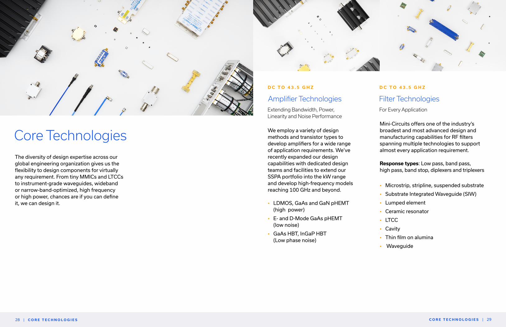
Mini-Circuits offers one of the industry’s broadest and most advanced design and manufacturing capabilities for RF filters spanning multiple technologies to support almost every application requirement.
Response types: Low pass, band pass, high pass, band stop, diplexers and triplexers
• Microstrip, stripline, suspended substrate
• Substrate Integrated Waveguide (SIW)
• Lumped element
• Ceramic resonator
• LTCC
• Cavity
• Thin film on alumina
• Waveguide
Filter TechnologiesFor Every Application
D C T O 4 3 . 5 G H Z
Amplifier TechnologiesExtending Bandwidth, Power, Linearity and Noise Performance
D C T O 4 3 . 5 G H Z
We employ a variety of design methods and transistor types to develop amplifiers for a wide range of application requirements. We’ve recently expanded our design capabilities with dedicated design teams and facilities to extend our SSPA portfolio into the kW range and develop high-frequency models reaching 100 GHz and beyond.
• LDMOS, GaAs and GaN pHEMT (high power)
• E- and D-Mode GaAs pHEMT (low noise)
• GaAs HBT, InGaP HBT (Low phase noise)
Core TechnologiesThe diversity of design expertise across our global engineering organization gives us the flexibility to design components for virtually any requirement. From tiny MMICs and LTCCs to instrument-grade waveguides, wideband or narrow-band-optimized, high frequency or high power, chances are if you can define it, we can design it.

C O R E T E C H N O L O G I E S | | C O R E T E C H N O L O G I E S 3130
MMICs are integrated circuits fabricated from semiconductor material and enclosed in a surface-mount package or sold as bare die for chip-and-wire assembly. Mini-Circuits MMICs utilize PHEMT, HBT and IPD abrication processes on gallium arsenide (GaAs), designed and packaged in our own facilities.
Product lines: Amplifiers, attenuators, bias tees, couplers, equalizers, reflectionless filters, mixers, multipliers, power splitters, transformers and baluns
• 700+ models in stock and growing
• Wideband and band-optimized designs
• Industry-leading quality and reliability
• All models available in QFN or bare die format
MMIC
In-House Design and Packaging
D C T O 5 0 G H Z
Core and wire designs consist of twisted wire-coupled structures wound around toroidal ferrite cores utilizing inductive coupling between conductors to achieve a desired function. Mini-Circuits performs all wire twisting, winding and welding in- house with tight process control to ensure the highest quality and repeatability.
Product lines: Directional couplers, filters, power splitters, transformers and baluns
• Footprint as small as 0.15 x 0.15”
• Top Hat® feature improves speed and accuracy of pick-and-place assembly
• Outstanding repeatability, unit-to-unit and lot-to-lot
• In-house wire twisting and winding
• All welded connections
Magnetic Core & Wire
Quality and Repeatability You Can Count On
D C T O 8 G H Z
LTCC devices are fabricated with capacitors, inductors and distributed structures embedded in multi-layered ceramic substrate and sintered into a single monolithic component. Our design team has the most advanced knowledge of LTCC technology in the industry building on 20+ years of R&D and multiple active patents.
Product lines: Couplers, filters, power splitters, transformers and baluns
• The world’s broadest portfolio
• 750+ in-stock models
• Custom designs with fast turnaround
• Packages as small as 0202
• Patented mmWave surface mount packaging solutions
Low Temperature Co-Fired Ceramic (LTCC)
Industry-Leading Design Capability
D C T O 6 0 G H Z

Key MarketsMini-Circuits serves 20,000+ customers worldwide encompassing virtually every corner of the wireless world. That diversity of our customer base and our product line makes us unique in the RF industry. The wide distribution of our business across markets gives stability through business cycles and enables our continuous growth. It also gives us the experience and flexibility to work with our customers on almost any problem. Below are just some of the major industries we serve, but whatever you’re working on, if it relies on wireless connectivity, we have a solution for you.
CATV & Broadband
K E Y M A R K E T S |
As consumer demand for higher data speed and capacity continues to intensify, network operators deploying optical and hybrid fiber-coaxial (HFC) infrastructure are pushing the limits of their equipment under the DOCSIS® 3.1 and 4.0 standards. Many Mini-Circuits products have been successfully designed into these applications from the head end to subscriber premises, and we’re continuously expanding our portfolio of parts developed specifically for the broadband market.
• Hundreds of models supporting DOCSIS 3.0, 3.1 and 4.0 bandwidth requirements
• State-of-the-art, in-house testing and characterization for 75Ω products
• Amplifiers, couplers, filters and diplexers, splitter/combiners, switches, transformers, voltage variable attenuators, voltage variable equalizers, matching pads and test cables
| K E Y M A R K E T S
Aerospace & Defense
Our products enable advanced solutions that governments and private enterprise depend on to keep the world safe and connected. From aviation to defense communications, radar, electronic warfare and more, we’re proud to be a trusted partner to government agencies and industry leaders in solving tomorrow’s biggest challenges.
• COTS and custom solutions
• Hi-rel products for the toughest environments
• In-house upscreening capabilities
• ITAR registered
• Best-in-industry supply chain security—no EOL targe
3332

K E Y M A R K E T S |
Industrial
| K E Y M A R K E T S
Medical & Diagnostic
From the industrial IoT to the next generation of applications for RF energy, Mini-Circuits offers innovative solutions you need to redefine what’s possible with the guaranteed quality, service and dependability you expect from a strategic partner. We offer an extensive selection of products in-stock for all the primary ISM bands as well as cost-effective custom designs for special requirements. Our dedicated in-house design team for RF power products is setting a new standard for flexible, turnkey solid-state power amplifiers to simplify and accelerate your design process.
• Broad selection of in-stock products covering ISM bands
• Dedicated in-house PA design expertise
• 50+ years of manufacturing, supply chain and quality management experience
Whether for advanced diagnostic imaging, minimally invasive surgical techniques or other life-saving technologies, the unique requirements of applications in the medical field make RF component selection especially challenging. Mini-Circuits has decades of experience working with customers developing medical and diagnostic systems to choose the right components, meet special screening requirements and develop custom designs with fast turnaround.
• Wide selection of standard catalog parts
• Non-magnetic parts successfully designed into MRI systems
• Turnkey PA solutions for RF energy
• In-house capability for additional screening and custom designs
• Product support through the life of your system
• Second-sourcing and replacements for EOL models from other manufacturers
3534
Space & SatCom
Mini-Circuits’ space heritage spans some of the earliest government missions all the way through to modern, independent enterprises. We offer an extensive selection of off-the-shelf components from L-Band to Ka Band, suitable for earth station and spaceborne systems with in-house custom design capabilities and upscreening services to meet special requirements.
• 30+ years of experience supporting commercial and government applications
• Extensive selection of COTS components
• Custom components and integrated subassemblies
• In-house space-level screening and testing workflows IAW EEE-INST-002
Learn more about our space heritage and upscreening services on p. 23
Education
University programs, educators, researchers and students aren’t just customers. They’re at the forefront of the advances revolutionizing the RF and microwave field, and they’re cultivating the future generations of engineering talent to keep our industry growing. We’re proud of our track record supporting the academic community in their mission to prepare bright minds to be the innovators and leaders we need to solve tomorrow’s toughest problems and build a smarter, more sustainable world.
• Academic discounts for educators and university staff
• Hands-on project kits to connect classroom theory with practical, real-world applications (see Research & Education section on p. 380)
• Annual equipment donations to university labs
• Career development opportunities for students including research partnerships, summer internships and campus visits from our engineers

K E Y M A R K E T S | | K E Y M A R K E T S 3736
Test & Measurement
Mini-Circuits partners closely with leading manufacturers of the world’s most sophisticated electronic measurement instrumentation. Our strategic design approach of developing high-performance, wideband products aligns naturally with the demanding requirements of test and measurement applications, and the breadth of our product line provides a complete solution set, covering more of the signal chain than other suppliers in the industry.
• Design focus on high performance over ultra-wide bandwidths from DC to mmWave
• Single source for most active and passive elements in the signal chain
• Long-term supply chain security and minimization of product change
Telecom
From the earliest days of cellular communications to the rollout of the 5G revolution, Mini-Circuits is built into the history and the future of the global telecom industry. We offer industry-leading performance for all the established telecom bands, and we’ve rapidly expanded our product line to support ongoing development in the millimeter-wave range. Mini-Circuits products support everything from R&D and design verification testing in the lab all the way through to macro base stations, small cells and optical backhaul in the field.
• Outstanding RF performance covering all telecom application bands
• Rapidly expanding mmWave portfolio in surface mount and connectorized formats
• Innovative solutions for R&D, design verification and high-throughput production testing
• Competitive pricing
• Short lead times of your system
• Second-sourcing and replacements for EOL models from other manufacturers

P R O D U C T S | 39| P R O D U C T S38
Catalog ProductsCustom solutions available
7, 5 0 0 + S T O C K E D C O M P O N E N T S

A D A P T E R S | 41| A D A P T E R S40
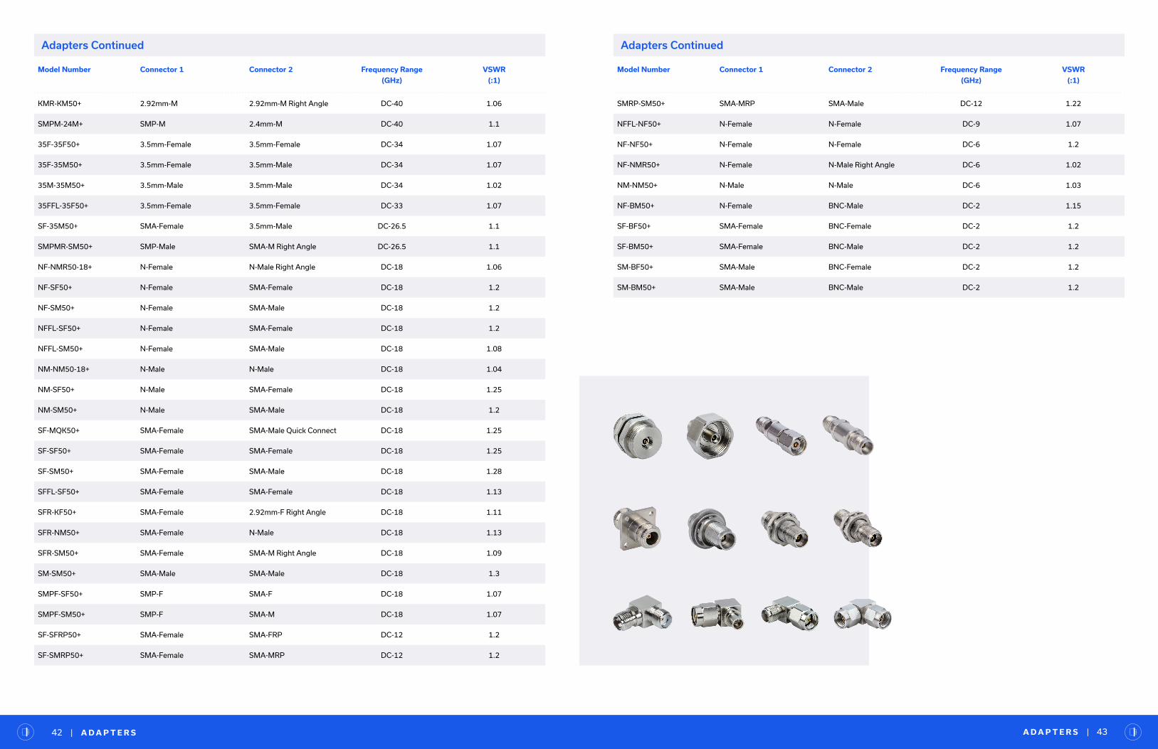
• Wide variety of connector options
• All gender combinations
• Straight, right-angle, bulkhead and NMD formats
AdaptersD C T O 6 7 G H Z
Model Number Connector 1 Connector 2 Frequency Range
(GHz)
VSWR
(:1)
185F-185F+ 1.85mm-F 1.85mm-F DC-67 1.05
185M-185F+ 1.85mm-M 1.85mm-F DC-67 1.04
185M-185M+ 1.85mm-M 1.85mm-M DC-67 1.04
24F-24F+ 2.4mm-F 2.4mm-F DC-50 1.03
24F-24M+ 2.4mm-F 2.4mm-M DC-50 1.06
24M-24M+ 2.4mm-M 2.4mm-M DC-50 1.04
Model Number Connector 1 Connector 2 Frequency Range
(GHz)
VSWR
(:1)
24FPM-24F+ 2.4mm-F 2.4mm-F DC-50 1.04
185F-24F+ 1.85mm-F 2.4mm-F DC-50 1.08
185F-24M+ 1.85mm-F 2.4mm-M DC-50 1.08
185M-24F+ 1.85mm-M 2.4mm-F DC-50 1.06
185M-24M+ 1.85mm-M 2.4mm-M DC-50 1.04
24B-KB+ 2.92mm-F 2.4mm-F DC-40 1.05
185F-KF+ 1.85mm-F 2.92mm-F DC-40 1.05
185F-KM+ 1.85mm-F 2.92mm-M DC-40 1.04
185M-KF+ 1.85mm-M 2.92mm-F DC-40 1.04
185M-KM+ 1.85mm-M 2.92mm-M DC-40 1.03
KB-KB50+ 2.92mm-F 2.92mm-F DC-40 1.03
KF-24F+ 2.92mm-F 2.4mm-F DC-40 1.1
KF-24M+ 2.92mm-F 2.4mm-M DC-40 1.1
KF-24MNMD+ 2.92mm-F 2.4mm NMD-M DC-40 1.06
KF-KF50+ 2.92mm-F 2.92mm-F DC-40 1.03
KF-KM50+ 2.92mm-F 2.92mm-M DC-40 1.04
KFFL-KF50+ 2.92mm-F 2.92mm-F DC-40 1.05
KFNMD-24MNMD+ 2.92mm NMD-F 2.4mm NMD-M DC-40 1.08
KFNMD-KM+ 2.92mm NMD-F 2.92mm-M DC-40 1.06
KFNMD-KMNMD+ 2.92mm NMD-F 2.92mm NMD-M DC-40 1.05
KFPM-KF50+ 2.92mm-F 2.92mm-F DC-40 1.08
KFR-KM50+ 2.92mm-M 2.92mm-F Right Angle DC-40 1.07
KM-24F+ 2.92mm-M 2.4mm-F DC-40 1.1
KM-24M+ 2.92mm-M 2.4mm-M DC-40 1.1
KM-24MNMD+ 2.92mm-M 2.4mm NMD-M DC-40 1.04
KM-KM50+ 2.92mm-M 2.92mm-M DC-40 1.02
KMNMD-24MNMD+ 2.92mm NMD-M 2.4mm NMD-M DC-40 1.06
KMR-24F+ 2.4mm-F 2.92mm-M Right Angle DC-40 1.09
Adapters Continued
Adapters
• Low loss and excellent VSWR
• Rugged construction
Model Number Connector 1 Connector 2 Frequency Range
(GHz)
VSWR
(:1)
KMR-KM50+ 2.92mm-M 2.92mm-M Right Angle DC-40 1.06
SMPM-24M+ SMP-M 2.4mm-M DC-40 1.1
35F-35F50+ 3.5mm-Female 3.5mm-Female DC-34 1.07
35F-35M50+ 3.5mm-Female 3.5mm-Male DC-34 1.07
35M-35M50+ 3.5mm-Male 3.5mm-Male DC-34 1.02
35FFL-35F50+ 3.5mm-Female 3.5mm-Female DC-33 1.07
SF-35M50+ SMA-Female 3.5mm-Male DC-26.5 1.1
SMPMR-SM50+ SMP-Male SMA-M Right Angle DC-26.5 1.1
NF-NMR50-18+ N-Female N-Male Right Angle DC-18 1.06
NF-SF50+ N-Female SMA-Female DC-18 1.2
NF-SM50+ N-Female SMA-Male DC-18 1.2
NFFL-SF50+ N-Female SMA-Female DC-18 1.2
NFFL-SM50+ N-Female SMA-Male DC-18 1.08
NM-NM50-18+ N-Male N-Male DC-18 1.04
NM-SF50+ N-Male SMA-Female DC-18 1.25
NM-SM50+ N-Male SMA-Male DC-18 1.2
SF-MQK50+ SMA-Female SMA-Male Quick Connect DC-18 1.25
SF-SF50+ SMA-Female SMA-Female DC-18 1.25
SF-SM50+ SMA-Female SMA-Male DC-18 1.28
SFFL-SF50+ SMA-Female SMA-Female DC-18 1.13
SFR-KF50+ SMA-Female 2.92mm-F Right Angle DC-18 1.11
SFR-NM50+ SMA-Female N-Male DC-18 1.13
SFR-SM50+ SMA-Female SMA-M Right Angle DC-18 1.09
SM-SM50+ SMA-Male SMA-Male DC-18 1.3
SMPF-SF50+ SMP-F SMA-F DC-18 1.07
SMPF-SM50+ SMP-F SMA-M DC-18 1.07
SF-SFRP50+ SMA-Female SMA-FRP DC-12 1.2
SF-SMRP50+ SMA-Female SMA-MRP DC-12 1.2
Model Number Connector 1 Connector 2 Frequency Range
(GHz)
VSWR
(:1)
SMRP-SM50+ SMA-MRP SMA-Male DC-12 1.22
NFFL-NF50+ N-Female N-Female DC-9 1.07
NF-NF50+ N-Female N-Female DC-6 1.2
NF-NMR50+ N-Female N-Male Right Angle DC-6 1.02
NM-NM50+ N-Male N-Male DC-6 1.03
NF-BM50+ N-Female BNC-Male DC-2 1.15
SF-BF50+ SMA-Female BNC-Female DC-2 1.2
SF-BM50+ SMA-Female BNC-Male DC-2 1.2
SM-BF50+ SMA-Male BNC-Female DC-2 1.2
SM-BM50+ SMA-Male BNC-Male DC-2 1.2
A D A P T E R S | 43| A D A P T E R S42
Adapters Continued Adapters Continued
A M P L I F I E R S | 45| A M P L I F I E R S44
• Connectorized, MMIC surface mount and bare die interfaces
• In-house design and manufacturing
• Industry-leading quality and reliability
• Cost-effective custom solutions (see Test Solutions section)
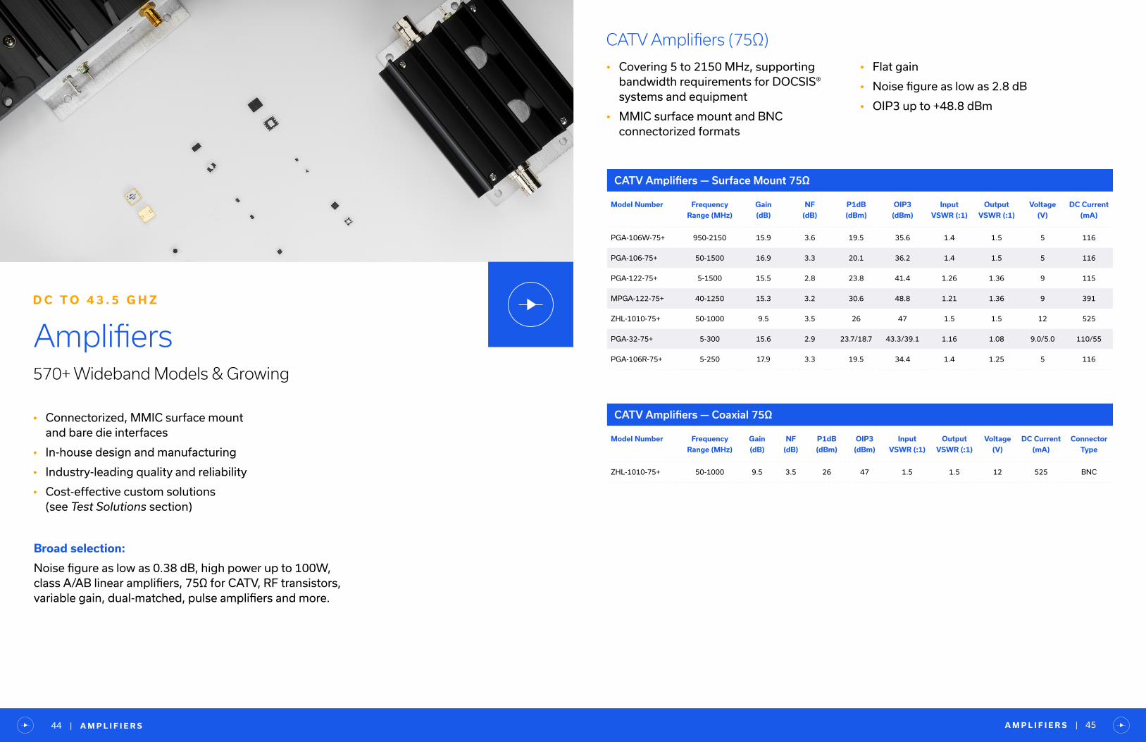
Amplifiers570+ Wideband Models & Growing
D C T O 4 3 . 5 G H Z
Broad selection:
Noise figure as low as 0.38 dB, high power up to 100W, class A/AB linear amplifiers, 75Ω for CATV, RF transistors,variable gain, dual-matched, pulse amplifiers and more.
CATV Amplifiers (75Ω)
• Covering 5 to 2150 MHz, supporting bandwidth requirements for DOCSIS® systems and equipment
• MMIC surface mount and BNC connectorized formats
Model Number Frequency
Range (MHz)
Gain
(dB)
NF
(dB)
P1dB
(dBm)
OIP3
(dBm)
Input
VSWR (:1)
Output
VSWR (:1)
Voltage
(V)
DC Current
(mA)
PGA-106W-75+ 950-2150 15.9 3.6 19.5 35.6 1.4 1.5 5 116
PGA-106-75+ 50-1500 16.9 3.3 20.1 36.2 1.4 1.5 5 116
PGA-122-75+ 5-1500 15.5 2.8 23.8 41.4 1.26 1.36 9 115
MPGA-122-75+ 40-1250 15.3 3.2 30.6 48.8 1.21 1.36 9 391
ZHL-1010-75+ 50-1000 9.5 3.5 26 47 1.5 1.5 12 525
PGA-32-75+ 5-300 15.6 2.9 23.7/18.7 43.3/39.1 1.16 1.08 9.0/5.0 110/55
PGA-106R-75+ 5-250 17.9 3.3 19.5 34.4 1.4 1.25 5 116
Model Number Frequency
Range (MHz)
Gain
(dB)
NF
(dB)
P1dB
(dBm)
OIP3
(dBm)
Input
VSWR (:1)
Output
VSWR (:1)
Voltage
(V)
DC Current
(mA)
Connector
Type
ZHL-1010-75+ 50-1000 9.5 3.5 26 47 1.5 1.5 12 525 BNC
• Flat gain
• Noise figure as low as 2.8 dB
• OIP3 up to +48.8 dBm
CATV Amplifiers — Surface Mount 75Ω
CATV Amplifiers — Coaxial 75Ω
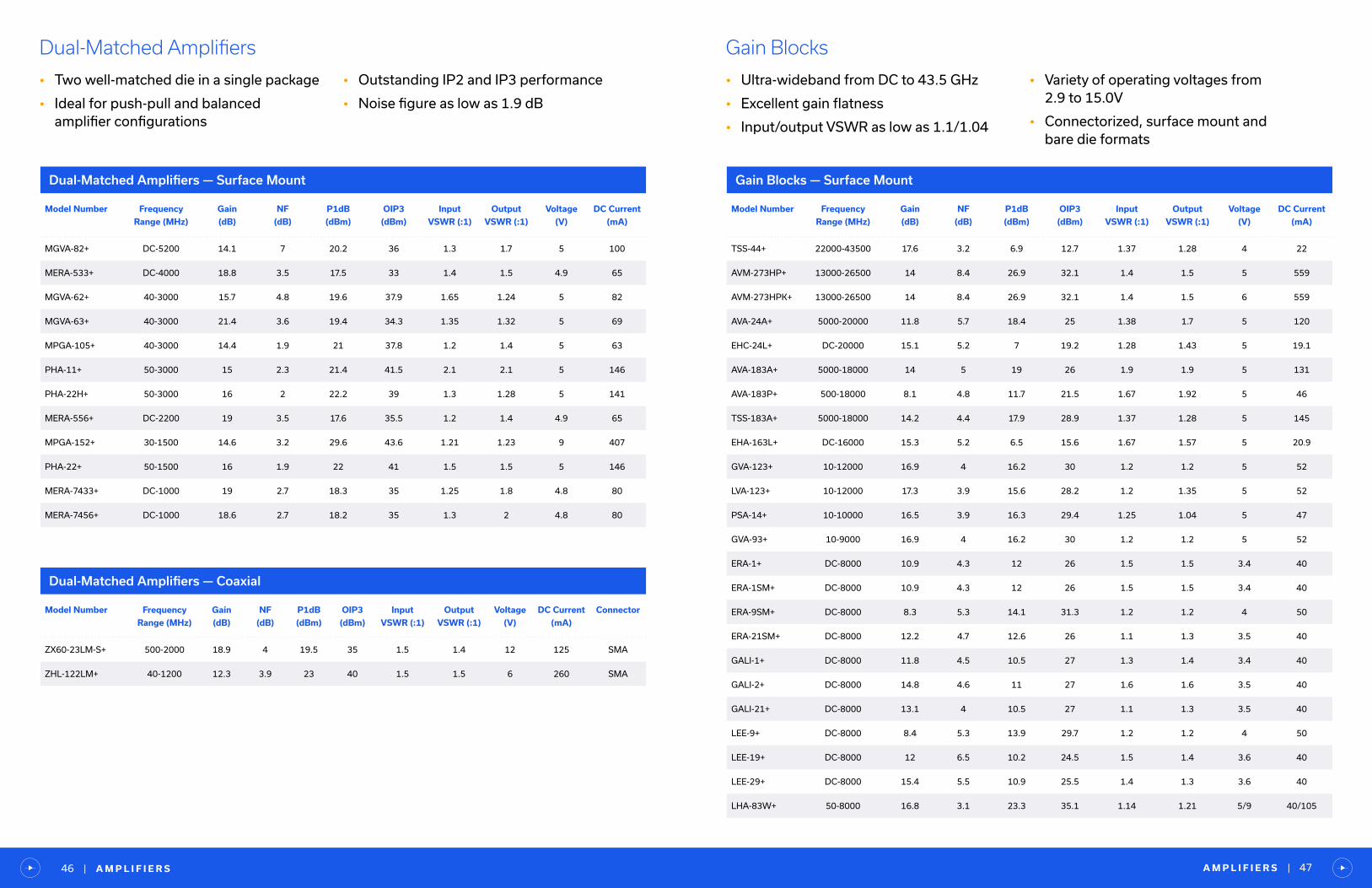
Dual-Matched Amplifiers
• Two well-matched die in a single package
• Ideal for push-pull and balanced amplifier configurations
• Outstanding IP2 and IP3 performance
• Noise figure as low as 1.9 dB
Model Number Frequency
Range (MHz)
Gain
(dB)
NF
(dB)
P1dB
(dBm)
OIP3
(dBm)
Input
VSWR (:1)
Output
VSWR (:1)
Voltage
(V)
DC Current
(mA)
MGVA-82+ DC-5200 14.1 7 20.2 36 1.3 1.7 5 100
MERA-533+ DC-4000 18.8 3.5 17.5 33 1.4 1.5 4.9 65
MGVA-62+ 40-3000 15.7 4.8 19.6 37.9 1.65 1.24 5 82
MGVA-63+ 40-3000 21.4 3.6 19.4 34.3 1.35 1.32 5 69
MPGA-105+ 40-3000 14.4 1.9 21 37.8 1.2 1.4 5 63
PHA-11+ 50-3000 15 2.3 21.4 41.5 2.1 2.1 5 146
PHA-22H+ 50-3000 16 2 22.2 39 1.3 1.28 5 141
MERA-556+ DC-2200 19 3.5 17.6 35.5 1.2 1.4 4.9 65
MPGA-152+ 30-1500 14.6 3.2 29.6 43.6 1.21 1.23 9 407
PHA-22+ 50-1500 16 1.9 22 41 1.5 1.5 5 146
MERA-7433+ DC-1000 19 2.7 18.3 35 1.25 1.8 4.8 80
MERA-7456+ DC-1000 18.6 2.7 18.2 35 1.3 2 4.8 80
Dual-Matched Amplifiers — Surface Mount
Model Number Frequency
Range (MHz)
Gain
(dB)
NF
(dB)
P1dB
(dBm)
OIP3
(dBm)
Input
VSWR (:1)
Output
VSWR (:1)
Voltage
(V)
DC Current
(mA)
Connector
ZX60-23LM-S+ 500-2000 18.9 4 19.5 35 1.5 1.4 12 125 SMA
ZHL-122LM+ 40-1200 12.3 3.9 23 40 1.5 1.5 6 260 SMA
Dual-Matched Amplifiers — Coaxial
Model Number Frequency
Range (MHz)
Gain
(dB)
NF
(dB)
P1dB
(dBm)
OIP3
(dBm)
Input
VSWR (:1)
Output
VSWR (:1)
Voltage
(V)
DC Current
(mA)
TSS-44+ 22000-43500 17.6 3.2 6.9 12.7 1.37 1.28 4 22
AVM-273HP+ 13000-26500 14 8.4 26.9 32.1 1.4 1.5 5 559
AVM-273HPK+ 13000-26500 14 8.4 26.9 32.1 1.4 1.5 6 559
AVA-24A+ 5000-20000 11.8 5.7 18.4 25 1.38 1.7 5 120
EHC-24L+ DC-20000 15.1 5.2 7 19.2 1.28 1.43 5 19.1
AVA-183A+ 5000-18000 14 5 19 26 1.9 1.9 5 131
AVA-183P+ 500-18000 8.1 4.8 11.7 21.5 1.67 1.92 5 46
TSS-183A+ 5000-18000 14.2 4.4 17.9 28.9 1.37 1.28 5 145
EHA-163L+ DC-16000 15.3 5.2 6.5 15.6 1.67 1.57 5 20.9
GVA-123+ 10-12000 16.9 4 16.2 30 1.2 1.2 5 52
LVA-123+ 10-12000 17.3 3.9 15.6 28.2 1.2 1.35 5 52
PSA-14+ 10-10000 16.5 3.9 16.3 29.4 1.25 1.04 5 47
GVA-93+ 10-9000 16.9 4 16.2 30 1.2 1.2 5 52
ERA-1+ DC-8000 10.9 4.3 12 26 1.5 1.5 3.4 40
ERA-1SM+ DC-8000 10.9 4.3 12 26 1.5 1.5 3.4 40
ERA-9SM+ DC-8000 8.3 5.3 14.1 31.3 1.2 1.2 4 50
ERA-21SM+ DC-8000 12.2 4.7 12.6 26 1.1 1.3 3.5 40
GALI-1+ DC-8000 11.8 4.5 10.5 27 1.3 1.4 3.4 40
GALI-2+ DC-8000 14.8 4.6 11 27 1.6 1.6 3.5 40
GALI-21+ DC-8000 13.1 4 10.5 27 1.1 1.3 3.5 40
LEE-9+ DC-8000 8.4 5.3 13.9 29.7 1.2 1.2 4 50
LEE-19+ DC-8000 12 6.5 10.2 24.5 1.5 1.4 3.6 40
LEE-29+ DC-8000 15.4 5.5 10.9 25.5 1.4 1.3 3.6 40
LHA-83W+ 50-8000 16.8 3.1 23.3 35.1 1.14 1.21 5/9 40/105
Gain Blocks
• Ultra-wideband from DC to 43.5 GHz
• Excellent gain flatness
• Input/output VSWR as low as 1.1/1.04
• Variety of operating voltages from 2.9 to 15.0V
• Connectorized, surface mount and bare die formats
Gain Blocks — Surface Mount
A M P L I F I E R S | 47| A M P L I F I E R S46
A M P L I F I E R S | 49| A M P L I F I E R S48
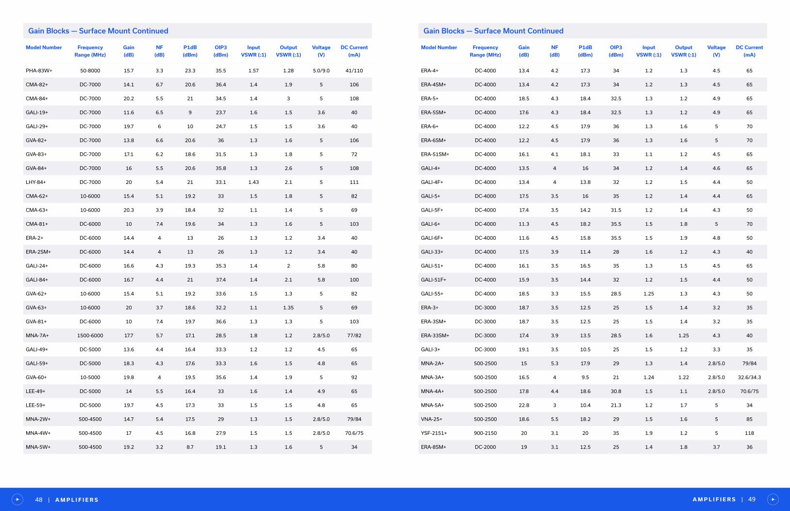
Gain Blocks — Surface Mount Continued
Model Number Frequency
Range (MHz)
Gain
(dB)
NF
(dB)
P1dB
(dBm)
OIP3
(dBm)
Input
VSWR (:1)
Output
VSWR (:1)
Voltage
(V)
DC Current
(mA)
PHA-83W+ 50-8000 15.7 3.3 23.3 35.5 1.57 1.28 5.0/9.0 41/110
CMA-82+ DC-7000 14.1 6.7 20.6 36.4 1.4 1.9 5 106
CMA-84+ DC-7000 20.2 5.5 21 34.5 1.4 3 5 108
GALI-19+ DC-7000 11.6 6.5 9 23.7 1.6 1.5 3.6 40
GALI-29+ DC-7000 19.7 6 10 24.7 1.5 1.5 3.6 40
GVA-82+ DC-7000 13.8 6.6 20.6 36 1.3 1.6 5 106
GVA-83+ DC-7000 17.1 6.2 18.6 31.5 1.3 1.8 5 72
GVA-84+ DC-7000 16 5.5 20.6 35.8 1.3 2.6 5 108
LHY-84+ DC-7000 20 5.4 21 33.1 1.43 2.1 5 111
CMA-62+ 10-6000 15.4 5.1 19.2 33 1.5 1.8 5 82
CMA-63+ 10-6000 20.3 3.9 18.4 32 1.1 1.4 5 69
CMA-81+ DC-6000 10 7.4 19.6 34 1.3 1.6 5 103
ERA-2+ DC-6000 14.4 4 13 26 1.3 1.2 3.4 40
ERA-2SM+ DC-6000 14.4 4 13 26 1.3 1.2 3.4 40
GALI-24+ DC-6000 16.6 4.3 19.3 35.3 1.4 2 5.8 80
GALI-84+ DC-6000 16.7 4.4 21 37.4 1.4 2.1 5.8 100
GVA-62+ 10-6000 15.4 5.1 19.2 33.6 1.5 1.3 5 82
GVA-63+ 10-6000 20 3.7 18.6 32.2 1.1 1.35 5 69
GVA-81+ DC-6000 10 7.4 19.7 36.6 1.3 1.3 5 103
MNA-7A+ 1500-6000 17.7 5.7 17.1 28.5 1.8 1.2 2.8/5.0 77/82
GALI-49+ DC-5000 13.6 4.4 16.4 33.3 1.2 1.2 4.5 65
GALI-59+ DC-5000 18.3 4.3 17.6 33.3 1.6 1.5 4.8 65
GVA-60+ 10-5000 19.8 4 19.5 35.6 1.4 1.9 5 92
LEE-49+ DC-5000 14 5.5 16.4 33 1.6 1.4 4.9 65
LEE-59+ DC-5000 19.7 4.5 17.3 33 1.5 1.5 4.8 65
MNA-2W+ 500-4500 14.7 5.4 17.5 29 1.3 1.5 2.8/5.0 79/84
MNA-4W+ 500-4500 17 4.5 16.8 27.9 1.5 1.5 2.8/5.0 70.6/75
MNA-5W+ 500-4500 19.2 3.2 8.7 19.1 1.3 1.6 5 34
Model Number Frequency
Range (MHz)
Gain
(dB)
NF
(dB)
P1dB
(dBm)
OIP3
(dBm)
Input
VSWR (:1)
Output
VSWR (:1)
Voltage
(V)
DC Current
(mA)
ERA-4+ DC-4000 13.4 4.2 17.3 34 1.2 1.3 4.5 65
ERA-4SM+ DC-4000 13.4 4.2 17.3 34 1.2 1.3 4.5 65
ERA-5+ DC-4000 18.5 4.3 18.4 32.5 1.3 1.2 4.9 65
ERA-5SM+ DC-4000 17.6 4.3 18.4 32.5 1.3 1.2 4.9 65
ERA-6+ DC-4000 12.2 4.5 17.9 36 1.3 1.6 5 70
ERA-6SM+ DC-4000 12.2 4.5 17.9 36 1.3 1.6 5 70
ERA-51SM+ DC-4000 16.1 4.1 18.1 33 1.1 1.2 4.5 65
GALI-4+ DC-4000 13.5 4 16 34 1.2 1.4 4.6 65
GALI-4F+ DC-4000 13.4 4 13.8 32 1.2 1.5 4.4 50
GALI-5+ DC-4000 17.5 3.5 16 35 1.2 1.4 4.4 65
GALI-5F+ DC-4000 17.4 3.5 14.2 31.5 1.2 1.4 4.3 50
GALI-6+ DC-4000 11.3 4.5 18.2 35.5 1.5 1.8 5 70
GALI-6F+ DC-4000 11.6 4.5 15.8 35.5 1.5 1.9 4.8 50
GALI-33+ DC-4000 17.5 3.9 11.4 28 1.6 1.2 4.3 40
GALI-51+ DC-4000 16.1 3.5 16.5 35 1.3 1.5 4.5 65
GALI-51F+ DC-4000 15.9 3.5 14.4 32 1.2 1.5 4.4 50
GALI-55+ DC-4000 18.5 3.3 15.5 28.5 1.25 1.3 4.3 50
ERA-3+ DC-3000 18.7 3.5 12.5 25 1.5 1.4 3.2 35
ERA-3SM+ DC-3000 18.7 3.5 12.5 25 1.5 1.4 3.2 35
ERA-33SM+ DC-3000 17.4 3.9 13.5 28.5 1.6 1.25 4.3 40
GALI-3+ DC-3000 19.1 3.5 10.5 25 1.5 1.2 3.3 35
MNA-2A+ 500-2500 15 5.3 17.9 29 1.3 1.4 2.8/5.0 79/84
MNA-3A+ 500-2500 16.5 4 9.5 21 1.24 1.22 2.8/5.0 32.6/34.3
MNA-4A+ 500-2500 17.8 4.4 18.6 30.8 1.5 1.1 2.8/5.0 70.6/75
MNA-5A+ 500-2500 22.8 3 10.4 21.3 1.2 1.7 5 34
VNA-25+ 500-2500 18.6 5.5 18.2 29 1.5 1.6 5 85
YSF-2151+ 900-2150 20 3.1 20 35 1.9 1.2 5 118
ERA-8SM+ DC-2000 19 3.1 12.5 25 1.4 1.8 3.7 36
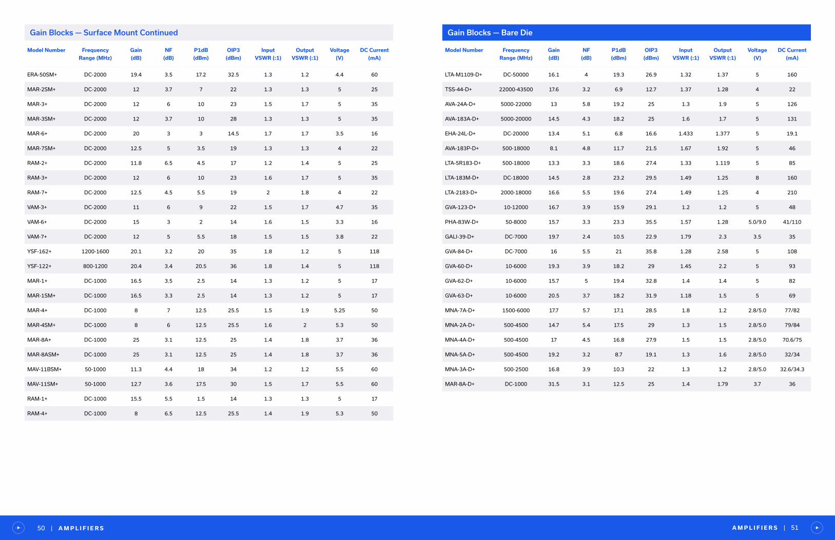
Gain Blocks — Surface Mount Continued
Model Number Frequency
Range (MHz)
Gain
(dB)
NF
(dB)
P1dB
(dBm)
OIP3
(dBm)
Input
VSWR (:1)
Output
VSWR (:1)
Voltage
(V)
DC Current
(mA)
ERA-50SM+ DC-2000 19.4 3.5 17.2 32.5 1.3 1.2 4.4 60
MAR-2SM+ DC-2000 12 3.7 7 22 1.3 1.3 5 25
MAR-3+ DC-2000 12 6 10 23 1.5 1.7 5 35
MAR-3SM+ DC-2000 12 3.7 10 28 1.3 1.3 5 35
MAR-6+ DC-2000 20 3 3 14.5 1.7 1.7 3.5 16
MAR-7SM+ DC-2000 12.5 5 3.5 19 1.3 1.3 4 22
RAM-2+ DC-2000 11.8 6.5 4.5 17 1.2 1.4 5 25
RAM-3+ DC-2000 12 6 10 23 1.6 1.7 5 35
RAM-7+ DC-2000 12.5 4.5 5.5 19 2 1.8 4 22
VAM-3+ DC-2000 11 6 9 22 1.5 1.7 4.7 35
VAM-6+ DC-2000 15 3 2 14 1.6 1.5 3.3 16
VAM-7+ DC-2000 12 5 5.5 18 1.5 1.5 3.8 22
YSF-162+ 1200-1600 20.1 3.2 20 35 1.8 1.2 5 118
YSF-122+ 800-1200 20.4 3.4 20.5 36 1.8 1.4 5 118
MAR-1+ DC-1000 16.5 3.5 2.5 14 1.3 1.2 5 17
MAR-1SM+ DC-1000 16.5 3.3 2.5 14 1.3 1.2 5 17
MAR-4+ DC-1000 8 7 12.5 25.5 1.5 1.9 5.25 50
MAR-4SM+ DC-1000 8 6 12.5 25.5 1.6 2 5.3 50
MAR-8A+ DC-1000 25 3.1 12.5 25 1.4 1.8 3.7 36
MAR-8ASM+ DC-1000 25 3.1 12.5 25 1.4 1.8 3.7 36
MAV-11BSM+ 50-1000 11.3 4.4 18 34 1.2 1.2 5.5 60
MAV-11SM+ 50-1000 12.7 3.6 17.5 30 1.5 1.7 5.5 60
RAM-1+ DC-1000 15.5 5.5 1.5 14 1.3 1.3 5 17
RAM-4+ DC-1000 8 6.5 12.5 25.5 1.4 1.9 5.3 50
A M P L I F I E R S | 51| A M P L I F I E R S50
Gain Blocks — Surface Mount Continued
Model Number Frequency
Range (MHz)
Gain
(dB)
NF
(dB)
P1dB
(dBm)
OIP3
(dBm)
Input
VSWR (:1)
Output
VSWR (:1)
Voltage
(V)
DC Current
(mA)
LTA-M1109-D+ DC-50000 16.1 4 19.3 26.9 1.32 1.37 5 160
TSS-44-D+ 22000-43500 17.6 3.2 6.9 12.7 1.37 1.28 4 22
AVA-24A-D+ 5000-22000 13 5.8 19.2 25 1.3 1.9 5 126
AVA-183A-D+ 5000-20000 14.5 4.3 18.2 25 1.6 1.7 5 131
EHA-24L-D+ DC-20000 13.4 5.1 6.8 16.6 1.433 1.377 5 19.1
AVA-183P-D+ 500-18000 8.1 4.8 11.7 21.5 1.67 1.92 5 46
LTA-5R183-D+ 500-18000 13.3 3.3 18.6 27.4 1.33 1.119 5 85
LTA-183M-D+ DC-18000 14.5 2.8 23.2 29.5 1.49 1.25 8 160
LTA-2183-D+ 2000-18000 16.6 5.5 19.6 27.4 1.49 1.25 4 210
GVA-123-D+ 10-12000 16.7 3.9 15.9 29.1 1.2 1.2 5 48
PHA-83W-D+ 50-8000 15.7 3.3 23.3 35.5 1.57 1.28 5.0/9.0 41/110
GALI-39-D+ DC-7000 19.7 2.4 10.5 22.9 1.79 2.3 3.5 35
GVA-84-D+ DC-7000 16 5.5 21 35.8 1.28 2.58 5 108
GVA-60-D+ 10-6000 19.3 3.9 18.2 29 1.45 2.2 5 93
GVA-62-D+ 10-6000 15.7 5 19.4 32.8 1.4 1.4 5 82
GVA-63-D+ 10-6000 20.5 3.7 18.2 31.9 1.18 1.5 5 69
MNA-7A-D+ 1500-6000 17.7 5.7 17.1 28.5 1.8 1.2 2.8/5.0 77/82
MNA-2A-D+ 500-4500 14.7 5.4 17.5 29 1.3 1.5 2.8/5.0 79/84
MNA-4A-D+ 500-4500 17 4.5 16.8 27.9 1.5 1.5 2.8/5.0 70.6/75
MNA-5A-D+ 500-4500 19.2 3.2 8.7 19.1 1.3 1.6 2.8/5.0 32/34
MNA-3A-D+ 500-2500 16.8 3.9 10.3 22 1.3 1.2 2.8/5.0 32.6/34.3
MAR-8A-D+ DC-1000 31.5 3.1 12.5 25 1.4 1.79 3.7 36
Gain Blocks — Bare Die

Gain Blocks — Coaxial
Model Number Frequency
Range (MHz)
Gain
(dB)
NF
(dB)
P1dB
(dBm)
OIP3
(dBm)
Input
VSWR (:1)
Output
VSWR (:1)
Voltage
(V)
DC Current
(mA)
Connector Option
ZVA-443HGX+ 10-43500 33 5 9 18 1.5 1.8 15 170 2.92mm -
ZVA-443X+ 0.05-43500 11 4.5 10 22 1.8 1.9 5 80 2.4mm -
ZVA-02443HP+ 2000-43500 37 5 17 25 1.5 2.5 15 280 2.92mmHeat
Sink
ZVA-403GX+ 0.05-40000 11 4.5 11 21 1.45 1.6 5 100 2.92mm -
ZVE-403-K+ 26000-40000 22 9 19 21 2 2 12 300 2.92mmHeat
Sink
ZVM-273HP+ 13000-26500 14.5 9 25 34 1.1 1.5 12 559 2.92mmHeat
Sink
ZVM-273HPX+ 13000-26500 14.5 9 25 34 1.1 1.5 12 559 2.92mm -
ZVA-01243+ 1000-22000 12.8 5 21.6 27.5 1.7 1.4 8 170 2.92mm -
ZVA-213-S+ 800-21000 26 3 24 33 1.35 1.25 12 400 SMAHeat
Sink
ZVA-213X-S+ 800-21000 26 3 24 33 1.35 1.25 12 400 SMA -
ZVA-213UWX+ 100-20000 14 3 16 29 1.3 1.4 +12, -5 84 2.92mm -
ZX60-24-S+ 5000-20000 24 6.8 18 27 1.4 1.4 5 260 SMA -
ZX60-24A-S+ 5000-20000 24 6.4 18.3 25.4 1.2 1.6 5 270 SMA -
ZX60-02203+ 2000-20000 21.5 6.5 14.6 28 1.75 1.55 5 154 SMA -
ZX60-02203LPN+ 2000-20000 16 5 17 31 1.92 1.67 5 79 SMA -
ZVA-183-S+ 700-18000 26 3 24 33 1.35 1.25 12 400 SMAHeat
Sink
ZVA-183G-S+ 500-18000 38 3 25 36 1.9 2 15 770 SMAHeat
Sink
ZVA-183W-S+ 100-18000 28 3 26 34.5 1.3 1.6 15 625 SMAHeat
Sink
ZVA-183X-S+ 700-18000 26 3 24 33 1.35 1.25 12 400 SMA -
ZVA-183GX-S+ 500-18000 38 3 25 36 1.9 2 15 770 SMA -
ZVA-183WX-S+ 100-18000 28 3 26 34.5 1.3 1.6 15 625 SMA -
ZX60-183-S+ 6000-18000 23.5 6.9 18.1 27.2 1.4 1.4 5 260 SMA -
ZX60-183A-S+ 6000-18000 28 5 18 27 1.4 1.4 5 260 SMA -
ZJL-153+ 5000-15000 13 6 18 23 1.7 1.7 5 180 SMA -
ZVE-143-S+ 8000-14000 19 4.5 28 35 1.5 1.5 12 450 SMAHeat
Sink
ZVE-143X-S+ 8000-14000 19 4.5 28 35 1.5 1.5 12 450 SMA -
ZX60-14012L-S+ 0.3-14000 12 5.5 11 20 1.3 1.7 12 62 SMA -
ZRON-8G+ 2000-8000 20 6 20 30 2 2 15 310 SMAHeat
Sink
A M P L I F I E R S | 53| A M P L I F I E R S52
Model Number Frequency
Range (MHz)
Gain
(dB)
NF
(dB)
P1dB
(dBm)
OIP3
(dBm)
Input
VSWR (:1)
Output
VSWR (:1)
Voltage
(V)
DC Current
(mA)
Connector Option
ZRON-8GX+ 2000-8000 20 6 20 30 2 2 15 310 SMA -
ZVE-8G+ 2000-8000 30 4 30 40 2 2 12 1200 SMAHeat
Sink
ZVE-8GX+ 2000-8000 30 4 30 40 2 2 12 1200 SMA -
ZX60-8008E-S+ 20-8000 9 4.1 9.3 24 1.4 1.7 12 39 SMA -
ZJL-7G+ 20-7000 10 5 9 24 1.5 1.5 12 50 SMA -
ZJL-6G+ 20-6000 13 4.5 10 24 1.5 1.4 12 50 SMA -
ZX60-5916MA-S+ 1500-6000 18 6.6 16.5 27 1.6 1.7 2.8/5.0 103 SMA -
ZX60-6013E-S+ 20-6000 14 3.3 10.3 28.7 1.5 1.2 12 39 SMA -
ZX60-V62+ 50-6000 15.4 5.1 19 33.4 1.3 1.8 5 82 SMA -
ZX60-V63+ 50-6000 20.3 3.7 17.8 31.2 1.5 1.5 5 69 SMA -
ZX60-V81-S+ 20-6000 9.7 8 18.5 36 1.2 1.25 5 103 SMA -
ZX60-V82-S+ 20-6000 13.5 6.8 20 35.8 1.3 1.5 5 100 SMA -
ZJL-5G+ 20-5000 9 8.5 15 32 1.6 1.3 12 80 SMA -
ZX60-V83-S+ 20-4700 16.8 6 17 31 1.25 1.7 5 72 SMA -
ZHL-42+ 600-4200 34 8 30 38 2.5 2.5 15 1000 SMAHeat
Sink
ZHL-42W+ 10-4200 30 8 28 38 2.5 2.5 15 880 SMAHeat
Sink
ZHL-42WX+ 10-4200 30 8 28 38 2.5 2.5 15 880 SMA -
ZHL-42X+ 600-4200 34 8 30 38 2.5 2.5 15 1000 SMA -
ZHL-1042J+ 10-4200 25 6 20 30 2.5 2.5 15 330 SMAHeat
Sink
ZHL-1042JX+ 10-4200 25 6 20 30 2.5 2.5 15 330 SMA -
ZHL-4240+ 600-4200 42 8 30 38 2.5 2.5 15 1000 SMAHeat
Sink
ZHL-4240W+ 10-4200 42 6 30 38 2.5 2.5 15 1000 SMAHeat
Sink
ZHL-4240WX+ 10-4200 42 6 30 38 2.5 2.5 15 1000 SMA -
ZHL-4240X+ 600-4200 42 8 30 38 2.5 2.5 15 1000 SMA -
ZJL-4G+ 20-4000 12.4 5.5 14 30.5 1.4 1.6 12 75 SMA -
ZJL-4HG+ 20-4000 17 4.5 15 30 1.5 1.4 12 75 SMA -
ZX60-43-S+ 0.5-4000 17 5.4 17.3 33 1.2 2 5 110 SMA -
ZX60-4016E-S+ 20-4000 18 3.9 16.5 30 1.3 1.3 12 65 SMA -
Gain Blocks — Coaxial Continued

A M P L I F I E R S | 55| A M P L I F I E R S54
Model Number Frequency
Range (MHz)
Gain
(dB)
NF
(dB)
P1dB
(dBm)
OIP3
(dBm)
Input
VSWR (:1)
Output
VSWR (:1)
Voltage
(V)
DC Current
(mA)
Connector Option
ZJL-3G+ 20-3000 14 3.8 8 22 1.4 1.6 12 45 SMA -
ZFL-272VH+ 30-2700 16.9 3.4 24.5 47.2 1.13 1.31 15 350 SMA -
ZKL-2R7+ 10-2700 24 5 13 30 1.3 1.4 12 120 SMA -
ZFL-2500+ 500-2500 28 8 15 27 2.5 2.5 5 220 SMA -
ZFL-2500B+ 500-2500 28 8 15 27 2.5 2.5 5 220 SMA Bracket
ZFL-2500VH+ 10-2500 20 5.5 23 35 1.7 2 15 300 SMA -
ZFL-2500VHB+ 10-2500 20 5.5 23 35 1.7 2 15 300 SMA Bracket
ZFL-2500VHX+ 10-2500 20 5.5 23 35 1.7 2 15 300 SMA -
ZKL-2R5+ 10-2500 30 5 15 31 1.4 1.4 12 120 SMA -
ZX60-2510MA-S+ 500-2500 15 5.4 20 32 1.4 1.4 2.8/5.0 104 SMA -
ZX60-2514MA-S+ 500-2500 17.8 4.5 19 31 1.4 1.5 2.8/5.0 94 SMA -
ZX60-2531MA-S+ 500-2500 40 3.1 19 26 1.3 1.7 2.8/5.0 130 SMA -
ZX60-2411BM-S+ 800-2400 11.5 3.5 24 46.5 1.2 1.2 5 280 SMA -
ZX60-H242+ 700-2400 14.5 3 23 46 1.4 1.5 5.5 145 SMA -
ZHL-2150+ 950-2150 30 3.5 11 25 1.3 1.3 12 110 SMA -
ZFL-11AD+ 2-2000 8 6.5 -2 14 2.5 2 15 22 SMA -
ZFL-11ADB+ 2-2000 8 6.5 -2 14 2.5 2 15 22 SMA Bracket
ZFL-2000+ 10-2000 20 7 16 25 2 2 15 120 SMA -
ZFL-2000B+ 10-2000 20 7 16 25 2 2 15 120 SMA Bracket
ZFL-2000X+ 10-2000 20 7 16 25 2 2 15 120 SMA -
ZKL-2+ 10-2000 33.5 4 15 31 1.4 1.4 12 120 SMA -
ZKL-1R5+ 10-1500 40 3 15 31 1.4 1.6 12 115 SMA -
ZHL-2-12+ 10-1200 26 5 29 45 2.2 2.2 24 750 SMA -
ZHL-2-12X+ 10-1200 26 5 29 45 2.2 2.2 24 750 SMA -
ZFL-2AD+ 2-1000 9 6.5 -2 14 2 2 15 22 SMA -
ZFL-2ADB+ 2-1000 9 6.5 -2 14 2 2 15 22 SMA Bracket
ZFL-2HAD+ 50-1000 12 6 20 35 1.5 1.5 15 115 SMA -
ZFL-2HADB+ 50-1000 12 6 20 35 1.5 1.5 15 115 SMA Bracket
Gain Blocks — Coaxial Continued
Model Number Frequency
Range (MHz)
Gain
(dB)
NF
(dB)
P1dB
(dBm)
OIP3
(dBm)
Input
VSWR (:1)
Output
VSWR (:1)
Voltage
(V)
DC Current
(mA)
Connector Option
ZFL-2HADX+ 50-1000 12 6 20 35 1.5 1.5 15 115 SMA -
ZFL-1000+ 0.1-1000 17 6 9 18 1.5 2 15 105 SMA -
ZFL-1000B+ 0.1-1000 17 6 9 18 1.5 2 15 105 SMA Bracket
ZFL-1000H+ 10-1000 28 4 20 33 1.4 1.4 15 160 SMAHeat
Sink
ZFL-1000HB+ 10-1000 28 4 20 33 1.4 1.4 15 160 SMA Bracket
ZFL-1000HX+ 10-1000 28 4 20 33 1.4 1.4 15 160 SMA -
ZFL-1000VH+ 10-1000 20 4.5 25 38 2 2.5 15 320 SMA -
ZFL-1000VH2+ 10-1000 28 5 25 38 2 2.5 15 320 SMA -
ZFL-1000VH2X+ 10-1000 28 5 25 38 2 2.5 15 320 SMA -
ZFL-1000VHB+ 10-1000 20 4.5 25 38 2 2.5 15 320 SMA Bracket
ZFL-1000VHX+ 10-1000 20 4.5 25 38 2 2.5 15 320 SMA -
ZHL-2-8-S+ 10-1000 34 7 29 42 2 2 24 700 SMA -
ZHL-2-8X-S+ 10-1000 34 7 29 42 2 2 24 700 SMA -
ZHL-2-S+ 10-1000 20 9 29 42 2 2.1 24 600 SMA -
ZHL-2X-S+ 10-1000 20 9 29 42 2 2.1 24 600 SMA -
ZHL-1010+ 50-1000 9.5 3.5 26 46 2 2 12 525 SMA -
ZHL-2010+ 50-1000 20 3.7 26 46 2 2 12 900 SMA -
ZHL-3010+ 50-1000 30 5.5 26 46 2 1.6 12 1000 SMA -
ZFL-750+ 0.2-750 18 6 9 18 1.5 2 15 90 SMA -
ZFL-750B+ 0.2-750 18 6 9 18 1.5 2 15 90 SMA Bracket
ZFL-500+ 0.05-500 20 4.2 9 18 1.9 1.9 15 80 SMA -
ZFL-500-BNC+ 0.05-500 20 4.2 9 18 1.9 1.9 15 80 BNC -
ZFL-500B+ 0.05-500 20 4.2 9 18 1.9 1.9 15 80 SMA Bracket
ZFL-500HLN+ 10-500 19 3.8 16 30 1.5 1.5 15 110 SMA -
ZFL-500HLNB+ 10-500 19 3.8 16 30 1.5 1.5 15 110 SMA Bracket
ZHL-1-2W+ 5-500 29 7 33 44 2.1 2.1 24 900 BNC -
ZHL-1-2W-N+ 5-500 29 7 33 44 2.1 2.1 24 900 N -
ZHL-1-2W-S+ 5-500 29 7 33 44 2.1 2.1 24 900 SMA -
Gain Blocks — Coaxial Continued

A M P L I F I E R S | 57| A M P L I F I E R S56
Model Number Frequency
Range (MHz)
Gain
(dB)
NF
(dB)
P1dB
(dBm)
OIP3
(dBm)
Input
VSWR (:1)
Output
VSWR (:1)
Voltage
(V)
DC Current
(mA)
Connector Option
ZHL-1-2WX+ 5-500 29 7 33 44 2.1 2.1 24 900 BNC -
ZHL-1-2WX-S+ 5-500 29 7 33 44 2.1 2.1 24 900 SMA -
ZHL-1A+ 2-500 16 11 28 38 2 2 24 600 BNC -
ZHL-1A-S+ 2-500 16 11 28 38 2 2 24 600 SMA -
ZHL-6A+ 0.0025-500 25 9.5 22 34 1.8 2 24 350 BNC -
ZHL-6A-S+ 0.0025-500 25 9.5 22 34 1.8 2 24 350 SMA -
ZHL-3A+ 0.4-150 24 11 29.5 38 2 2 24 600 BNC -
ZHL-3A-S+ 0.4-150 24 11 29.5 38 2 2 24 600 SMA -
ZHL-32A+ 0.05-130 25 10 29 38 2 2 24 600 BNC -
ZHL-32A-S+ 0.05-130 25 10 29 38 2 2 24 600 SMA -
ZX60-100VH+ 0.3-100 36 4 30 43 1.6 1.5 12 370 SMAHeat Sink
ZX60-100VHX+ 0.3-100 36 4 30 43 1.6 1.5 12 370 SMA -
Gain Blocks — Coaxial Continued
Model Number Frequency
Range (MHz)
Gain
(dB)
NF
(dB)
P1dB
(dBm)
OIP3
(dBm)
Input
VSWR (:1)
Output
VSWR (:1)
Voltage
(V)
DC Current
(mA)
AMP-76+ 5-500 26 3.1 13.5 28 2 2 15 71
AMP-77+ 5-500 15 3.3 16 32 2 2 15 56
MAN-1 0.5-500 28 4.5 8 18 1.8 1.8 12 60
MAN-1HLN+ 10-500 10 3.7 15 30 1.8 1.8 12 70
MAN-1LN 0.5-500 28 3 7 18 1.8 1.8 12 60
Gain Blocks — Plug-In
Model Number Frequency
Range (MHz)
Gain
(dB)
NF
(dB)
P1dB
(dBm)
OIP3
(dBm)
Input
VSWR (:1)
Output
VSWR (:1)
Voltage
(V)
DC Current
(mA)
TVA-82-213A+ 800-21000 25 3 24 30 1.35 1.4 110/220 AC SMA
TVA-63-183 6000-18000 23.6 6.9 18 26 1.5 1.25 110/220 AC SMA
TVA-63-183A+ 6000-18000 24 6.4 17 26 1.5 1.25 110/220 AC SMA
TVA-11-422A+ 10-4200 39 10.5 30 40 1.7 1.8 110/220 AC N
Gain Blocks — Modules for Test Racks
Model Number Frequency
Range (MHz)
Gain
(dB)
NF
(dB)
P1dB
(dBm)
OIP3
(dBm)
Input
VSWR (:1)
Output
VSWR (:1)
Volt-
age (V)
DC Current
(mA)
Connector
Type
Option
ZVE-3W-183+ 5900-18000 35 5.5 34 44 1.5 1.2 15 2200 SMA Heat Sink
ZVE-3W-83+ 2000-8000 35 5.8 33 42 1.5 1.4 15 1500 SMA Heat Sink
ZVE-3W-83X+ 2000-8000 35 5.8 33 42 1.5 1.4 15 1500 SMA -
ZVE-6W-83+ 2000-8000 33 10 37 40 1.9 1.4 15 5000 SMA Heat Sink
ZVE-6W-83X+ 2000-8000 33 10 37 40 1.9 1.4 15 5000 SMA -
ZHL-1W-63-S+ 600-6000 35 12 30 35 2.5 3.5 15 1000 SMA Heat Sink
ZHL-1W-63X-S+ 600-6000 35 12 30 35 2.5 3.5 15 1000 SMA -
ZHL-2W-63-S+ 600-6000 42 12 33 38 2.5 3.5 28 2000 SMA Heat Sink
ZHL-2W-63X-S+ 600-6000 42 12 33 38 2.5 3.5 28 2000 SMA -
ZHL-5W-63-S+ 600-6000 45 12 37 42 2.5 3.5 28 3500 SMA Heat Sink
ZHL-5W-63X-S+ 600-6000 45 12 37 42 2.5 3.5 28 3500 SMA -
ZHL-25W-63+ 700-6000 53 13 37 45 1.8 2 24 12000 SMA Heat Sink
High Power Amplifiers
• POUT up to 100W
• Wideband up to 18 GHz
• Excellent OIP3 performance, up to +60 dBm
• Rugged designs with built-in protections
• Connectorized and rack mount housings
High Power Amplifiers — Coaxial
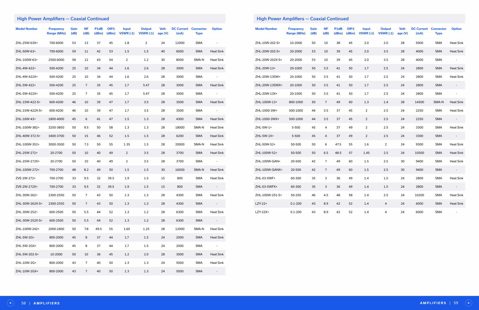
A M P L I F I E R S | 59| A M P L I F I E R S58
Model Number Frequency
Range (MHz)
Gain
(dB)
NF
(dB)
P1dB
(dBm)
OIP3
(dBm)
Input
VSWR (:1)
Output
VSWR (:1)
Volt-
age (V)
DC Current
(mA)
Connector
Type
Option
ZHL-25W-63X+ 700-6000 53 13 37 45 1.8 2 24 12000 SMA -
ZHL-50W-63+ 700-6000 59 11 42 53 1.5 1.5 40 6000 SMA Heat Sink
ZHL-100W-63+ 2500-6000 58 12 43 54 2 1.2 30 8000 SMA-N Heat Sink
ZHL-4W-422+ 500-4200 25 10 34 44 1.6 2.6 28 3000 SMA Heat Sink
ZHL-4W-422X+ 500-4200 25 10 34 44 1.6 2.6 28 3000 SMA -
ZHL-5W-422+ 500-4200 25 7 35 45 1.7 5.47 28 3000 SMA Heat Sink
ZHL-5W-422X+ 500-4200 25 7 35 45 1.7 5.47 28 3000 SMA -
ZHL-15W-422-S+ 600-4200 46 10 39 47 1.7 3.5 28 3500 SMA Heat Sink
ZHL-15W-422X-S+ 600-4200 46 10 39 47 1.7 3.5 28 3500 SMA -
ZHL-16W-43+ 1800-4000 45 6 41 47 1.5 1.3 28 4300 SMA Heat Sink
ZHL-100W-382+ 3250-3850 50 9.5 50 58 1.3 1.3 28 18000 SMA-N Heat Sink
ZHL-40W-372-S+ 3400-3700 50 15 46 52 1.5 1.5 28 6200 SMA Heat Sink
ZHL-100W-352+ 3000-3500 50 7.3 50 55 1.35 1.5 28 20000 SMA-N Heat Sink
ZHL-25W-272+ 20-2700 50 10 40 49 2 3.5 28 3700 SMA Heat Sink
ZHL-25W-272X+ 20-2700 50 10 40 49 2 3.5 28 3700 SMA -
ZHL-100W-272+ 700-2700 48 8.2 49 50 1.5 1.5 30 16000 SMA-N Heat Sink
ZVE-2W-272+ 700-2700 33 9.5 32 39.5 1.9 1.5 15 800 SMA Heat Sink
ZVE-2W-272X+ 700-2700 33 9.5 32 39.5 1.9 1.5 15 800 SMA -
ZHL-30W-262+ 2300-2550 50 7 43 50 1.3 1.3 28 4300 SMA Heat Sink
ZHL-30W-262X-S+ 2300-2550 50 7 43 50 1.3 1.3 28 4300 SMA -
ZHL-30W-252+ 600-2500 50 5.5 44 52 1.3 1.2 28 6300 SMA Heat Sink
ZHL-30W-252X-S+ 600-2500 50 5.5 44 52 1.3 1.2 28 6300 SMA -
ZHL-100W-242+ 2000-2400 50 7.8 49.5 55 1.65 1.25 28 12000 SMA-N Heat Sink
ZHL-5W-2G+ 800-2000 45 8 37 44 1.7 1.5 24 2000 SMA Heat Sink
ZHL-5W-2GX+ 800-2000 45 8 37 44 1.7 1.5 24 2000 SMA -
ZHL-5W-202-S+ 10-2000 50 10 36 45 1.2 2.0 28 3000 SMA Heat Sink
ZHL-10W-2G+ 800-2000 43 7 40 50 1.3 1.3 24 5000 SMA Heat Sink
ZHL-10W-2GX+ 800-2000 43 7 40 50 1.3 1.3 24 5000 SMA -
High Power Amplifiers — Coaxial Continued
Model Number Frequency
Range (MHz)
Gain
(dB)
NF
(dB)
P1dB
(dBm)
OIP3
(dBm)
Input
VSWR (:1)
Output
VSWR (:1)
Volt-
age (V)
DC Current
(mA)
Connector
Type
Option
ZHL-10W-202-S+ 10-2000 50 10 38 45 2.0 2.0 28 5000 SMA Heat Sink
ZHL-20W-202-S+ 20-2000 53 10 39 45 2.0 3.5 28 4000 SMA Heat Sink
ZHL-20W-202X-S+ 20-2000 53 10 39 45 2.0 3.5 28 4000 SMA -
ZHL-20W-13+ 20-1000 50 3.5 41 50 1.7 2.5 24 2800 SMA Heat Sink
ZHL-20W-13SW+ 20-1000 50 3.5 41 50 1.7 2.5 24 2800 SMA Heat Sink
ZHL-20W-13SWX+ 20-1000 50 3.5 41 50 1.7 2.5 24 2800 SMA -
ZHL-20W-13X+ 20-1000 50 3.5 41 50 1.7 2.5 24 2800 SMA -
ZHL-100W-13+ 800-1000 50 7 49 60 1.3 1.4 28 14500 SMA-N Heat Sink
ZHL-1000-3W+ 500-1000 44 3.5 37 45 2 2.5 24 2250 SMA Heat Sink
ZHL-1000-3WX+ 500-1000 44 3.5 37 45 2 2.5 24 2250 SMA -
ZHL-5W-1+ 5-500 45 4 37 49 2 2.5 24 3300 SMA Heat Sink
ZHL-5W-1X+ 5-500 45 4 37 49 2 2.5 24 3300 SMA -
ZHL-50W-52+ 50-500 50 6 47.5 55 1.6 2 24 9300 SMA Heat Sink
ZHL-100W-52+ 50-500 50 6.5 48.5 57 1.45 2.5 24 10500 SMA Heat Sink
ZHL-100W-GAN+ 20-500 42 7 49 60 1.5 2.5 30 9400 SMA Heat Sink
ZHL-100W-GANX+ 20-500 42 7 49 60 1.5 2.5 30 9400 SMA -
ZHL-03-5WF+ 60-300 35 3 36 49 1.4 1.5 24 2800 SMA Heat Sink
ZHL-03-5WFX+ 60-300 35 3 36 49 1.4 1.5 24 2800 SMA -
ZHL-100W-251-S+ 50-250 46 4.5 48 58 1.4 2.5 24 10200 SMA Heat Sink
LZY-22+ 0.1-200 43 8.9 42 52 1.4 4 24 6000 SMA Heat Sink
LZY-22X+ 0.1-200 43 8.9 42 52 1.4 4 24 6000 SMA -
High Power Amplifiers — Coaxial Continued
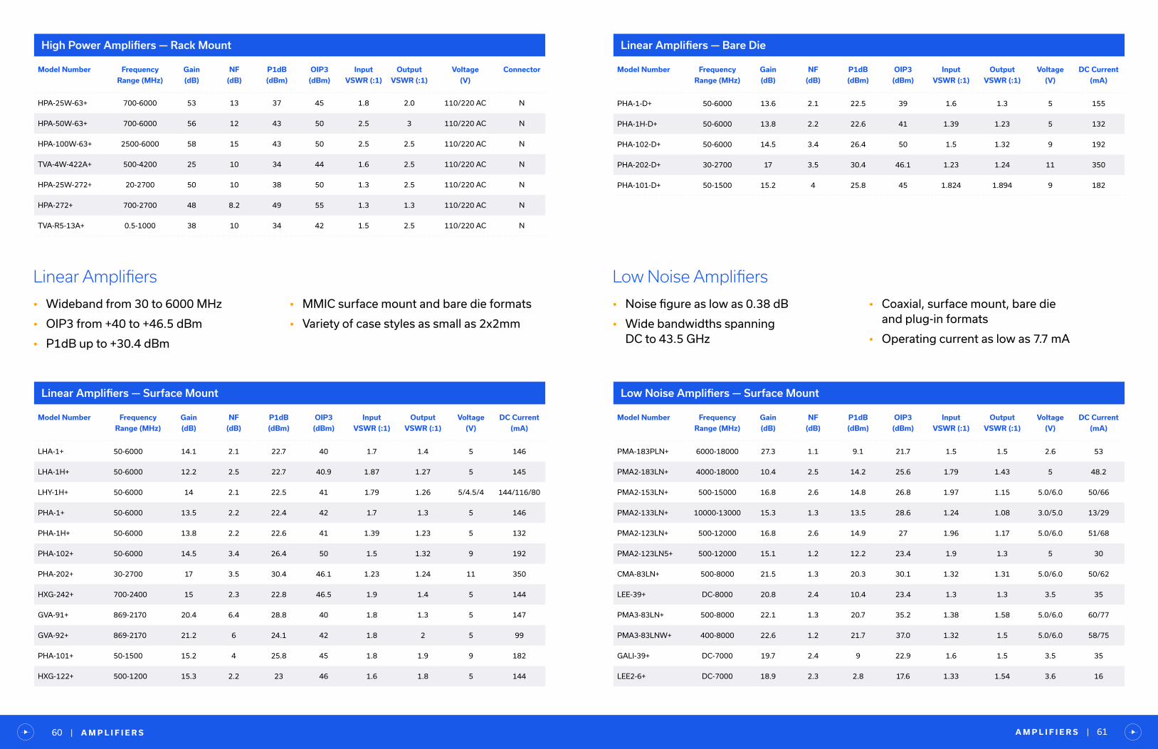
A M P L I F I E R S | 61| A M P L I F I E R S60
Model Number Frequency
Range (MHz)
Gain
(dB)
NF
(dB)
P1dB
(dBm)
OIP3
(dBm)
Input
VSWR (:1)
Output
VSWR (:1)
Voltage
(V)
Connector
HPA-25W-63+ 700-6000 53 13 37 45 1.8 2.0 110/220 AC N
HPA-50W-63+ 700-6000 56 12 43 50 2.5 3 110/220 AC N
HPA-100W-63+ 2500-6000 58 15 43 50 2.5 2.5 110/220 AC N
TVA-4W-422A+ 500-4200 25 10 34 44 1.6 2.5 110/220 AC N
HPA-25W-272+ 20-2700 50 10 38 50 1.3 2.5 110/220 AC N
HPA-272+ 700-2700 48 8.2 49 55 1.3 1.3 110/220 AC N
TVA-R5-13A+ 0.5-1000 38 10 34 42 1.5 2.5 110/220 AC N
High Power Amplifiers — Rack Mount
Model Number Frequency
Range (MHz)
Gain
(dB)
NF
(dB)
P1dB
(dBm)
OIP3
(dBm)
Input
VSWR (:1)
Output
VSWR (:1)
Voltage
(V)
DC Current
(mA)
LHA-1+ 50-6000 14.1 2.1 22.7 40 1.7 1.4 5 146
LHA-1H+ 50-6000 12.2 2.5 22.7 40.9 1.87 1.27 5 145
LHY-1H+ 50-6000 14 2.1 22.5 41 1.79 1.26 5/4.5/4 144/116/80
PHA-1+ 50-6000 13.5 2.2 22.4 42 1.7 1.3 5 146
PHA-1H+ 50-6000 13.8 2.2 22.6 41 1.39 1.23 5 132
PHA-102+ 50-6000 14.5 3.4 26.4 50 1.5 1.32 9 192
PHA-202+ 30-2700 17 3.5 30.4 46.1 1.23 1.24 11 350
HXG-242+ 700-2400 15 2.3 22.8 46.5 1.9 1.4 5 144
GVA-91+ 869-2170 20.4 6.4 28.8 40 1.8 1.3 5 147
GVA-92+ 869-2170 21.2 6 24.1 42 1.8 2 5 99
PHA-101+ 50-1500 15.2 4 25.8 45 1.8 1.9 9 182
HXG-122+ 500-1200 15.3 2.2 23 46 1.6 1.8 5 144
Linear Amplifiers — Surface Mount
Linear Amplifiers
• Wideband from 30 to 6000 MHz
• OIP3 from +40 to +46.5 dBm
• P1dB up to +30.4 dBm
• MMIC surface mount and bare die formats
• Variety of case styles as small as 2x2mm
Model Number Frequency
Range (MHz)
Gain
(dB)
NF
(dB)
P1dB
(dBm)
OIP3
(dBm)
Input
VSWR (:1)
Output
VSWR (:1)
Voltage
(V)
DC Current
(mA)
PHA-1-D+ 50-6000 13.6 2.1 22.5 39 1.6 1.3 5 155
PHA-1H-D+ 50-6000 13.8 2.2 22.6 41 1.39 1.23 5 132
PHA-102-D+ 50-6000 14.5 3.4 26.4 50 1.5 1.32 9 192
PHA-202-D+ 30-2700 17 3.5 30.4 46.1 1.23 1.24 11 350
PHA-101-D+ 50-1500 15.2 4 25.8 45 1.824 1.894 9 182
Linear Amplifiers — Bare Die
Low Noise Amplifiers
• Noise figure as low as 0.38 dB
• Wide bandwidths spanning DC to 43.5 GHz
• Coaxial, surface mount, bare die and plug-in formats
• Operating current as low as 7.7 mA
Model Number Frequency
Range (MHz)
Gain
(dB)
NF
(dB)
P1dB
(dBm)
OIP3
(dBm)
Input
VSWR (:1)
Output
VSWR (:1)
Voltage
(V)
DC Current
(mA)
PMA-183PLN+ 6000-18000 27.3 1.1 9.1 21.7 1.5 1.5 2.6 53
PMA2-183LN+ 4000-18000 10.4 2.5 14.2 25.6 1.79 1.43 5 48.2
PMA2-153LN+ 500-15000 16.8 2.6 14.8 26.8 1.97 1.15 5.0/6.0 50/66
PMA2-133LN+ 10000-13000 15.3 1.3 13.5 28.6 1.24 1.08 3.0/5.0 13/29
PMA2-123LN+ 500-12000 16.8 2.6 14.9 27 1.96 1.17 5.0/6.0 51/68
PMA2-123LN5+ 500-12000 15.1 1.2 12.2 23.4 1.9 1.3 5 30
CMA-83LN+ 500-8000 21.5 1.3 20.3 30.1 1.32 1.31 5.0/6.0 50/62
LEE-39+ DC-8000 20.8 2.4 10.4 23.4 1.3 1.3 3.5 35
PMA3-83LN+ 500-8000 22.1 1.3 20.7 35.2 1.38 1.58 5.0/6.0 60/77
PMA3-83LNW+ 400-8000 22.6 1.2 21.7 37.0 1.32 1.5 5.0/6.0 58/75
GALI-39+ DC-7000 19.7 2.4 9 22.9 1.6 1.5 3.5 35
LEE2-6+ DC-7000 18.9 2.3 2.8 17.6 1.33 1.54 3.6 16
Low Noise Amplifiers — Surface Mount
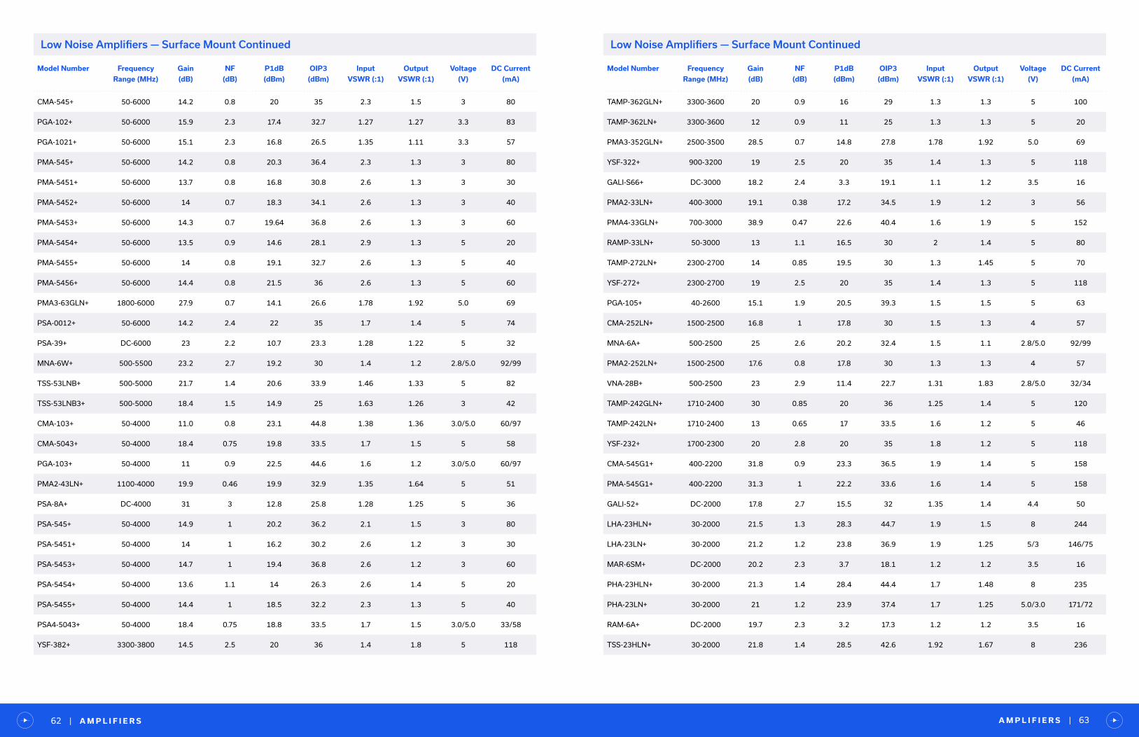
A M P L I F I E R S | 63| A M P L I F I E R S62
Model Number Frequency
Range (MHz)
Gain
(dB)
NF
(dB)
P1dB
(dBm)
OIP3
(dBm)
Input
VSWR (:1)
Output
VSWR (:1)
Voltage
(V)
DC Current
(mA)
CMA-545+ 50-6000 14.2 0.8 20 35 2.3 1.5 3 80
PGA-102+ 50-6000 15.9 2.3 17.4 32.7 1.27 1.27 3.3 83
PGA-1021+ 50-6000 15.1 2.3 16.8 26.5 1.35 1.11 3.3 57
PMA-545+ 50-6000 14.2 0.8 20.3 36.4 2.3 1.3 3 80
PMA-5451+ 50-6000 13.7 0.8 16.8 30.8 2.6 1.3 3 30
PMA-5452+ 50-6000 14 0.7 18.3 34.1 2.6 1.3 3 40
PMA-5453+ 50-6000 14.3 0.7 19.64 36.8 2.6 1.3 3 60
PMA-5454+ 50-6000 13.5 0.9 14.6 28.1 2.9 1.3 5 20
PMA-5455+ 50-6000 14 0.8 19.1 32.7 2.6 1.3 5 40
PMA-5456+ 50-6000 14.4 0.8 21.5 36 2.6 1.3 5 60
PMA3-63GLN+ 1800-6000 27.9 0.7 14.1 26.6 1.78 1.92 5.0 69
PSA-0012+ 50-6000 14.2 2.4 22 35 1.7 1.4 5 74
PSA-39+ DC-6000 23 2.2 10.7 23.3 1.28 1.22 5 32
MNA-6W+ 500-5500 23.2 2.7 19.2 30 1.4 1.2 2.8/5.0 92/99
TSS-53LNB+ 500-5000 21.7 1.4 20.6 33.9 1.46 1.33 5 82
TSS-53LNB3+ 500-5000 18.4 1.5 14.9 25 1.63 1.26 3 42
CMA-103+ 50-4000 11.0 0.8 23.1 44.8 1.38 1.36 3.0/5.0 60/97
CMA-5043+ 50-4000 18.4 0.75 19.8 33.5 1.7 1.5 5 58
PGA-103+ 50-4000 11 0.9 22.5 44.6 1.6 1.2 3.0/5.0 60/97
PMA2-43LN+ 1100-4000 19.9 0.46 19.9 32.9 1.35 1.64 5 51
PSA-8A+ DC-4000 31 3 12.8 25.8 1.28 1.25 5 36
PSA-545+ 50-4000 14.9 1 20.2 36.2 2.1 1.5 3 80
PSA-5451+ 50-4000 14 1 16.2 30.2 2.6 1.2 3 30
PSA-5453+ 50-4000 14.7 1 19.4 36.8 2.6 1.2 3 60
PSA-5454+ 50-4000 13.6 1.1 14 26.3 2.6 1.4 5 20
PSA-5455+ 50-4000 14.4 1 18.5 32.2 2.3 1.3 5 40
PSA4-5043+ 50-4000 18.4 0.75 18.8 33.5 1.7 1.5 3.0/5.0 33/58
YSF-382+ 3300-3800 14.5 2.5 20 36 1.4 1.8 5 118
Low Noise Amplifiers — Surface Mount Continued
Model Number Frequency
Range (MHz)
Gain
(dB)
NF
(dB)
P1dB
(dBm)
OIP3
(dBm)
Input
VSWR (:1)
Output
VSWR (:1)
Voltage
(V)
DC Current
(mA)
TAMP-362GLN+ 3300-3600 20 0.9 16 29 1.3 1.3 5 100
TAMP-362LN+ 3300-3600 12 0.9 11 25 1.3 1.3 5 20
PMA3-352GLN+ 2500-3500 28.5 0.7 14.8 27.8 1.78 1.92 5.0 69
YSF-322+ 900-3200 19 2.5 20 35 1.4 1.3 5 118
GALI-S66+ DC-3000 18.2 2.4 3.3 19.1 1.1 1.2 3.5 16
PMA2-33LN+ 400-3000 19.1 0.38 17.2 34.5 1.9 1.2 3 56
PMA4-33GLN+ 700-3000 38.9 0.47 22.6 40.4 1.6 1.9 5 152
RAMP-33LN+ 50-3000 13 1.1 16.5 30 2 1.4 5 80
TAMP-272LN+ 2300-2700 14 0.85 19.5 30 1.3 1.45 5 70
YSF-272+ 2300-2700 19 2.5 20 35 1.4 1.3 5 118
PGA-105+ 40-2600 15.1 1.9 20.5 39.3 1.5 1.5 5 63
CMA-252LN+ 1500-2500 16.8 1 17.8 30 1.5 1.3 4 57
MNA-6A+ 500-2500 25 2.6 20.2 32.4 1.5 1.1 2.8/5.0 92/99
PMA2-252LN+ 1500-2500 17.6 0.8 17.8 30 1.3 1.3 4 57
VNA-28B+ 500-2500 23 2.9 11.4 22.7 1.31 1.83 2.8/5.0 32/34
TAMP-242GLN+ 1710-2400 30 0.85 20 36 1.25 1.4 5 120
TAMP-242LN+ 1710-2400 13 0.65 17 33.5 1.6 1.2 5 46
YSF-232+ 1700-2300 20 2.8 20 35 1.8 1.2 5 118
CMA-545G1+ 400-2200 31.8 0.9 23.3 36.5 1.9 1.4 5 158
PMA-545G1+ 400-2200 31.3 1 22.2 33.6 1.6 1.4 5 158
GALI-52+ DC-2000 17.8 2.7 15.5 32 1.35 1.4 4.4 50
LHA-23HLN+ 30-2000 21.5 1.3 28.3 44.7 1.9 1.5 8 244
LHA-23LN+ 30-2000 21.2 1.2 23.8 36.9 1.9 1.25 5/3 146/75
MAR-6SM+ DC-2000 20.2 2.3 3.7 18.1 1.2 1.2 3.5 16
PHA-23HLN+ 30-2000 21.3 1.4 28.4 44.4 1.7 1.48 8 235
PHA-23LN+ 30-2000 21 1.2 23.9 37.4 1.7 1.25 5.0/3.0 171/72
RAM-6A+ DC-2000 19.7 2.3 3.2 17.3 1.2 1.2 3.5 16
TSS-23HLN+ 30-2000 21.8 1.4 28.5 42.6 1.92 1.67 8 236
Low Noise Amplifiers — Surface Mount Continued

A M P L I F I E R S | 65| A M P L I F I E R S64
Model Number Frequency
Range (MHz)
Gain
(dB)
NF
(dB)
P1dB
(dBm)
OIP3
(dBm)
Input
VSWR (:1)
Output
VSWR (:1)
Voltage
(V)
DC Current
(mA)
TSS-23LN+ 30-2000 21.5 1.2 24.1 36.4 1.92 1.67 5/3 139/74
TSY-172LNB+ 30-1700 13.1 1.4 17.5 24.7 1.9 1.5 2.7 7.7
CMA-162LN+ 700-1600 23.2 0.49 19.9 30.3 1.4 1.2 4 55
PMA-545G2+ 1100-1600 30.4 1 22 33.6 1.6 1.4 5 158
PMA2-162LN+ 700-1600 22.7 0.5 20 30 1.3 1.3 4 55
TAMP-1521GLN+ 1380-1520 35 0.6 13.5 27.5 1.2 1.15 5 50
GALI-74+ DC-1000 21.8 2.7 18.3 38 1.2 1.6 4.8 80
LHA-13HLN+ 1-1000 22.7 1.2 28 43.3 1.28 1.32 8 239
LHA-13LN+ 1-1000 22.4 1.1 23.3 38.3 1.28 1.28 5/3 143/73
PHA-13HLN+ 1-1000 22.7 1.1 28.7 43 1.3 1.3 8 234
PHA-13LN+ 1-1000 22.4 1 24.5 39 1.3 1.3 5.0/3/0 138/71
PMA-545G3+ 700-1000 31.3 0.9 21.9 33.4 1.6 1.4 5 158
RAM-8A+ DC-1000 28 2.6 12.6 24.4 1.6 1.8 3.7 36
TSS-13HLN+ 1-1000 23 1.4 28.4 42.9 1.43 1.37 8 234
TSS-13LN+ 1-1000 22.8 1.1 24.5 39.2 1.28 1.32 5/3 142/72
TSY-13LNB+ 30-1000 14.7 1.2 17.1 26.4 1.5 1.3 2.7 7.7
TAMP-960LN+ 824-960 18 0.55 16.5 30 1.1 1.4 5 45
TAMP-72LN+ 400-700 20 1 21.5 36 1.35 1.15 5 90
YSIF-421+ 220-380 37.2 1.6 22.2 38.3 1.78 1.08 5 189
Low Noise Amplifiers — Surface Mount Continued
Model Number Frequency
Range (MHz)
Gain
(dB)
NF
(dB)
P1dB
(dBm)
OIP3
(dBm)
Input
VSWR (:1)
Output
VSWR (:1)
Voltage
(V)
DC Current
(mA)
PMA2-183LN-D+ 4000-18000 10.4 2.5 14.2 25.6 1.79 1.43 5 48.2
PMA2-153LN-D+ 500-15000 16.8 2.6 14.8 26.8 1.97 1.15 5.0/6.0 50/66
PMA2-133LN-D+ 10000-13000 15.3 1.3 13.5 28.6 1.24 1.08 3.0/5.0 13/29
PMA2-123LN5-D+ 500-12000 15.1 1.2 12.2 23.4 1.9 1.3 5 30
PMA3-83LN-D+ 500-8000 21.9 1.2 21.2 35 1.4 1.8 5.0/6.0 60/77
Low Noise Amplifiers — Bare Die
Low Noise Amplifiers — Bare Die Continued
Model Number Frequency
Range (MHz)
Gain
(dB)
NF
(dB)
P1dB
(dBm)
OIP3
(dBm)
Input
VSWR (:1)
Output
VSWR (:1)
Voltage
(V)
DC Current
(mA)
PMA3-83LNW-D+ 400-8000 22.6 1.2 21.7 37.0 1.32 1.5 5.0/6.0 58/75
PMA3-63GLN-D+ 1800-6000 27.9 0.7 14.1 26.6 1.78 1.92 5.0 69
PSA-0012-D+ 50-6000 15.6 2.4 22.2 35 1.51 1.34 5 92
TSS-53LNB-D+ 500-6000 21.4 1.3 19.4 35 1.2 1.4 5 82
MNA-6A-D+ 500-5500 23.2 2.7 19.2 30 1.4 1.2 2.8/5.0 92/99
PGA-103-D+ 50-4000 11.3 0.8 22.3 41.6 1.5 1.4 5 60/97
PMA2-43LN-D+ 1100-4000 19.4 0.6 20.4 32.9 1.3 1.7 5 53
PSA4-5043-D+ 50-4000 18.4 0.8 19 34 1.7 1.5 5 33/58
GALI-S66-D+ DC-3000 18.2 2.4 3.3 19.1 1.1 1.2 3.5 16
PMA2-33LN-D+ 400-3000 18.4 0.47 17.6 33.8 1.5 1.1 3 58
PGA-105-D+ 40-2600 15.1 1.9 18.4 36.9 1.2 1.2 5 65
PMA-545G1-D+ 400-2200 31.1 1 23.4 36.1 1.92 1.33 5 158
PHA-23HLN-D+ 30-2000 21 1.2 19/24/28 31/37/44 1.94 1.48 3.0/5.0/8.0 72/141/235
TSS-23HLN-D+ 30-2000 21.8 1.4 28.5 42.6 1.92 1.67 8/5/3 236/139/74
TSY-172LNB-D+ 30-1700 13.1 1.4 17.5 24.7 1.9 1.5 2.7 7.7
PMA2-162LN-D+ 700-1600 22.7 0.5 20 30 1.3 1.3 4 55
PHA-13HLN-D+ 1-1000 23 1.1 19/24/18 33/40/43 1.34 1.3 3.0/5.0/8.0 71/138/234
TSS-13HLN-D+ 1-1000 23 1.4 28.4 42.9 1.43 1.37 8/5/3 234/142/72
Low Noise Amplifiers — Coaxial
Model Number Frequency
Range (MHz)
Gain
(dB)
NF
(dB)
P1dB
(dBm)
OIP3
(dBm)
Input
VSWR (:1)
Output
VSWR (:1)
Voltage
(V)
DC Current
(mA)
Connector Option
ZEL-0812LN 24000-43500 45 1.7 20 27 2 2.5 15 160 2.92mmHeat
Sink
ZEL-1217LN+ 18000-32000 20 3 10 23 1.9 1.8 12 50 2.92mmHeat
Sink
ZEL-1724LN+ 18000-32000 20 3 10 23 1.9 1.8 12 50 2.92mm -
ZFL-500LN+ 1500-21000 29 3 15.5 27.5 1.5 1.6 5 450 2.92mm -
ZFL-500LN-BNC+ 500-15000 16 2.8 15 27 2 1.5 12 82 SMA -
ZFL-500LNB+ 500-12000 17 2.4 16 28 1.45 1.3 12 82 SMA -
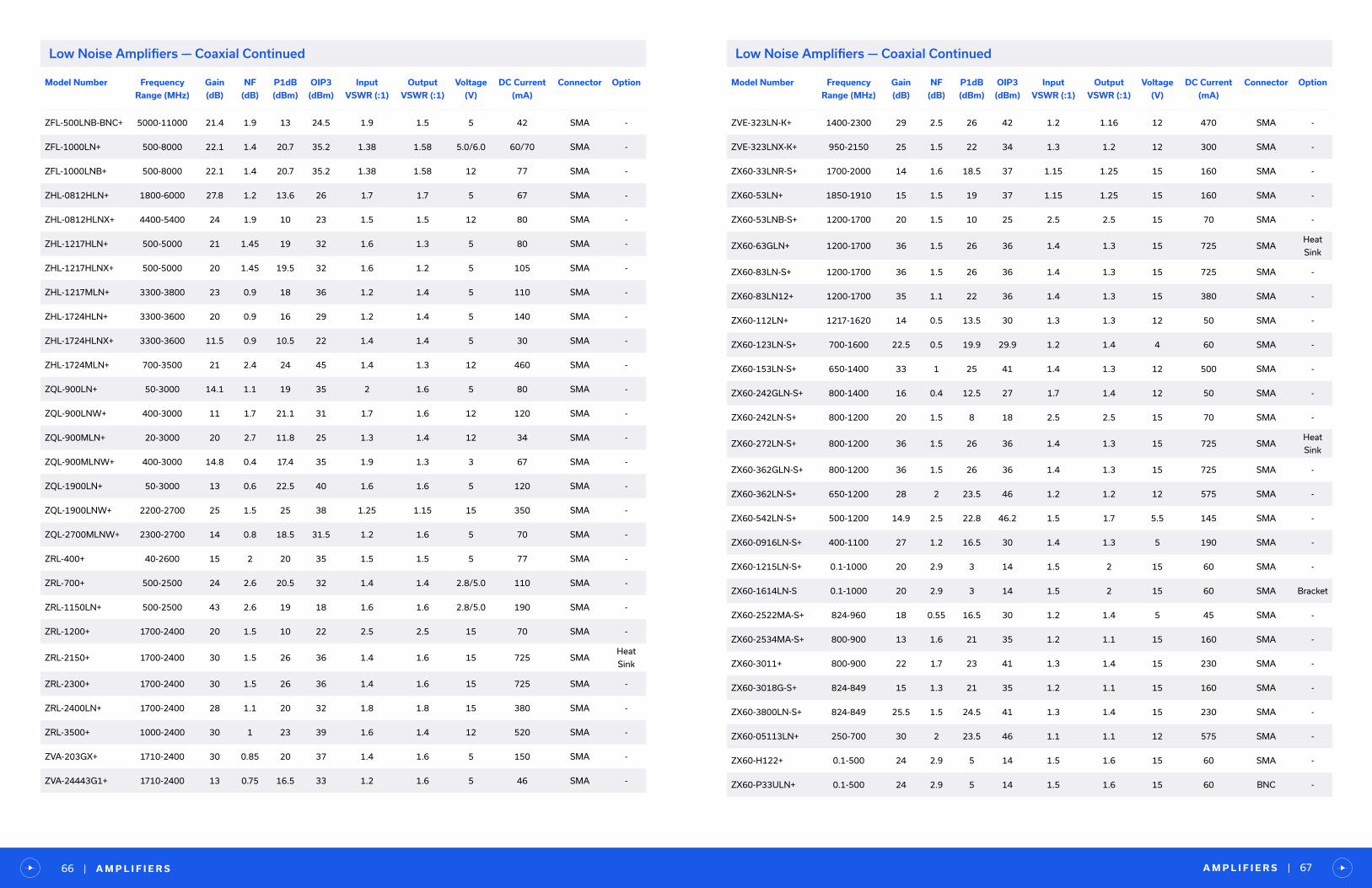
A M P L I F I E R S | 67| A M P L I F I E R S66
Model Number Frequency
Range (MHz)
Gain
(dB)
NF
(dB)
P1dB
(dBm)
OIP3
(dBm)
Input
VSWR (:1)
Output
VSWR (:1)
Voltage
(V)
DC Current
(mA)
Connector Option
ZFL-500LNB-BNC+ 5000-11000 21.4 1.9 13 24.5 1.9 1.5 5 42 SMA -
ZFL-1000LN+ 500-8000 22.1 1.4 20.7 35.2 1.38 1.58 5.0/6.0 60/70 SMA -
ZFL-1000LNB+ 500-8000 22.1 1.4 20.7 35.2 1.38 1.58 12 77 SMA -
ZHL-0812HLN+ 1800-6000 27.8 1.2 13.6 26 1.7 1.7 5 67 SMA -
ZHL-0812HLNX+ 4400-5400 24 1.9 10 23 1.5 1.5 12 80 SMA -
ZHL-1217HLN+ 500-5000 21 1.45 19 32 1.6 1.3 5 80 SMA -
ZHL-1217HLNX+ 500-5000 20 1.45 19.5 32 1.6 1.2 5 105 SMA -
ZHL-1217MLN+ 3300-3800 23 0.9 18 36 1.2 1.4 5 110 SMA -
ZHL-1724HLN+ 3300-3600 20 0.9 16 29 1.2 1.4 5 140 SMA -
ZHL-1724HLNX+ 3300-3600 11.5 0.9 10.5 22 1.4 1.4 5 30 SMA -
ZHL-1724MLN+ 700-3500 21 2.4 24 45 1.4 1.3 12 460 SMA -
ZQL-900LN+ 50-3000 14.1 1.1 19 35 2 1.6 5 80 SMA -
ZQL-900LNW+ 400-3000 11 1.7 21.1 31 1.7 1.6 12 120 SMA -
ZQL-900MLN+ 20-3000 20 2.7 11.8 25 1.3 1.4 12 34 SMA -
ZQL-900MLNW+ 400-3000 14.8 0.4 17.4 35 1.9 1.3 3 67 SMA -
ZQL-1900LN+ 50-3000 13 0.6 22.5 40 1.6 1.6 5 120 SMA -
ZQL-1900LNW+ 2200-2700 25 1.5 25 38 1.25 1.15 15 350 SMA -
ZQL-2700MLNW+ 2300-2700 14 0.8 18.5 31.5 1.2 1.6 5 70 SMA -
ZRL-400+ 40-2600 15 2 20 35 1.5 1.5 5 77 SMA -
ZRL-700+ 500-2500 24 2.6 20.5 32 1.4 1.4 2.8/5.0 110 SMA -
ZRL-1150LN+ 500-2500 43 2.6 19 18 1.6 1.6 2.8/5.0 190 SMA -
ZRL-1200+ 1700-2400 20 1.5 10 22 2.5 2.5 15 70 SMA -
ZRL-2150+ 1700-2400 30 1.5 26 36 1.4 1.6 15 725 SMAHeat
Sink
ZRL-2300+ 1700-2400 30 1.5 26 36 1.4 1.6 15 725 SMA -
ZRL-2400LN+ 1700-2400 28 1.1 20 32 1.8 1.8 15 380 SMA -
ZRL-3500+ 1000-2400 30 1 23 39 1.6 1.4 12 520 SMA -
ZVA-203GX+ 1710-2400 30 0.85 20 37 1.4 1.6 5 150 SMA -
ZVA-24443G1+ 1710-2400 13 0.75 16.5 33 1.2 1.6 5 46 SMA -
Low Noise Amplifiers — Coaxial Continued Low Noise Amplifiers — Coaxial Continued
Model Number Frequency
Range (MHz)
Gain
(dB)
NF
(dB)
P1dB
(dBm)
OIP3
(dBm)
Input
VSWR (:1)
Output
VSWR (:1)
Voltage
(V)
DC Current
(mA)
Connector Option
ZVE-323LN-K+ 1400-2300 29 2.5 26 42 1.2 1.16 12 470 SMA -
ZVE-323LNX-K+ 950-2150 25 1.5 22 34 1.3 1.2 12 300 SMA -
ZX60-33LNR-S+ 1700-2000 14 1.6 18.5 37 1.15 1.25 15 160 SMA -
ZX60-53LN+ 1850-1910 15 1.5 19 37 1.15 1.25 15 160 SMA -
ZX60-53LNB-S+ 1200-1700 20 1.5 10 25 2.5 2.5 15 70 SMA -
ZX60-63GLN+ 1200-1700 36 1.5 26 36 1.4 1.3 15 725 SMAHeat
Sink
ZX60-83LN-S+ 1200-1700 36 1.5 26 36 1.4 1.3 15 725 SMA -
ZX60-83LN12+ 1200-1700 35 1.1 22 36 1.4 1.3 15 380 SMA -
ZX60-112LN+ 1217-1620 14 0.5 13.5 30 1.3 1.3 12 50 SMA -
ZX60-123LN-S+ 700-1600 22.5 0.5 19.9 29.9 1.2 1.4 4 60 SMA -
ZX60-153LN-S+ 650-1400 33 1 25 41 1.4 1.3 12 500 SMA -
ZX60-242GLN-S+ 800-1400 16 0.4 12.5 27 1.7 1.4 12 50 SMA -
ZX60-242LN-S+ 800-1200 20 1.5 8 18 2.5 2.5 15 70 SMA -
ZX60-272LN-S+ 800-1200 36 1.5 26 36 1.4 1.3 15 725 SMAHeat
Sink
ZX60-362GLN-S+ 800-1200 36 1.5 26 36 1.4 1.3 15 725 SMA -
ZX60-362LN-S+ 650-1200 28 2 23.5 46 1.2 1.2 12 575 SMA -
ZX60-542LN-S+ 500-1200 14.9 2.5 22.8 46.2 1.5 1.7 5.5 145 SMA -
ZX60-0916LN-S+ 400-1100 27 1.2 16.5 30 1.4 1.3 5 190 SMA -
ZX60-1215LN-S+ 0.1-1000 20 2.9 3 14 1.5 2 15 60 SMA -
ZX60-1614LN-S 0.1-1000 20 2.9 3 14 1.5 2 15 60 SMA Bracket
ZX60-2522MA-S+ 824-960 18 0.55 16.5 30 1.2 1.4 5 45 SMA -
ZX60-2534MA-S+ 800-900 13 1.6 21 35 1.2 1.1 15 160 SMA -
ZX60-3011+ 800-900 22 1.7 23 41 1.3 1.4 15 230 SMA -
ZX60-3018G-S+ 824-849 15 1.3 21 35 1.2 1.1 15 160 SMA -
ZX60-3800LN-S+ 824-849 25.5 1.5 24.5 41 1.3 1.4 15 230 SMA -
ZX60-05113LN+ 250-700 30 2 23.5 46 1.1 1.1 12 575 SMA -
ZX60-H122+ 0.1-500 24 2.9 5 14 1.5 1.6 15 60 SMA -
ZX60-P33ULN+ 0.1-500 24 2.9 5 14 1.5 1.6 15 60 BNC -

A M P L I F I E R S | 69| A M P L I F I E R S68
Model Number Frequency
Range (MHz)
Gain
(dB)
NF
(dB)
P1dB
(dBm)
OIP3
(dBm)
Input
VSWR (:1)
Output
VSWR (:1)
Voltage
(V)
DC Current
(mA)
Connector Option
ZX60-P103LN+ 0.1-500 24 2.9 5 14 1.5 1.6 15 60 SMA Bracket
ZX60-P105LN+ 0.1-500 24 2.9 5 14 1.5 1.6 15 60 BNC Bracket
ZX60-P162LN+ 150-400 31 2.5 25 42 1.5 1.25 12 450 SMA -
Low Noise Amplifiers — Coaxial Continued
Low Noise Amplifiers — Plug-In
Pulse Amplifiers — Coaxial
Model Number Frequency
Range (MHz)
F Low
(MHz)
F High
(MHz)
Gain
(dB)
NF
(dB)
P1dB
(dBm)
OIP3
(dBm)
Input
VSWR (:1)
Output
VSWR (:1)
Voltage
(V)
DC Current
(mA)
TO-1724LN+ 1700-2400 1700 2400 20 1.6 10 22 2.5 2.5 15 70
TO-1217LN+ 1200-1700 1200 1700 20 1.6 10 25 2.5 2.5 15 70
TAMP-112-2W+ 650-1200 650 1200 31 2.8 30 41 1.9 2.1 5 750
AMP-15 5-1000 5 1000 13 2.8 8 22 2 2 15 29
AMP-75+ 5-500 5 500 19 2.4 12 28 2 2 15 31
Model Number Frequency
Range (MHz)
Gain
(dB)
NF
(dB)
P1dB
(dBm)
OIP3
(dBm)
Input
VSWR (:1)
Output
VSWR (:1)
Voltage
(V)
DC Current
(mA)
Connector
ZHL-72A+ 0.0025-700 35 7.7 24 34 2 2 24 350 BNC
ZPUL-30P+ 0.0025-700 35 7.7 22 34 2 2 24 400 BNC
Pulse Amplifiers
• 0.0025 to 700 MHz
• Gain up to 35 dB with excellent flatness, ±0.6 dB typ.
• Capable of handling pulse widths up to 15µs with any kind of modulation
• Fast rise/fall time, 1.1 ns
RF Transistors — Surface Mount
RF Transistors
• Wide bandwidths from 10 to 10000 MHz
• Noise figure as low as 0.38 dB
• Multiple case style options, 3 x 3 mm and 1.4 x 1.2 mm QFN, SOT-343 and bare die
• Footprint compatible replacements for EOL Avago parts
• Suitable for medical / MRI applications (non-magnetic)
• Design your own external biasing and matching
Model Number Frequency
Range (MHz)
Gain
(dB)
NF
(dB)
P1dB
(dBm)
OIP3
(dBm)
Input
VSWR (:1)
Output
VSWR (:1)
Voltage
(V)
DC Current
(mA)
TAV2-14LN+ 50-10000 16.4 0.7 18.8 30.9 2.615 1.577 2/4 20/40
SAV-541+ 45-6000 23.2 0.5 19.2 33.1 - - 3 60
SAV-551+ 45-6000 20.9 0.5 17.5 24.3 - - 3 15
SAV-581+ 45-6000 22.3 0.5 19 30.6 - - 3 30
TAV-541+ 45-6000 23.8 0.5 19.1 33.6 - - 3 60
TAV-551+ 45-6000 21.3 0.5 17.5 23.5 - - 3 15
TAV-581+ 45-6000 22.9 0.5 18.3 30.3 - - 3 30
TAV1-541+ 45-6000 23.2 0.5 19.2 33.1 - - 3 60
TAV1-551+ 45-6000 21.6 0.5 16 23.9 - - 3 15
SAV-331+ 10-4000 24.1 0.5 19.6 32.3 - - 4 60
TAV1-331+ 10-4000 24.1 0.6 20.1 31.8 - - 4 60
TAV2-501+ 400-3900 15.1 1.3 27.7 42.9 - - 4.5 280
RF Transistors — Bare Die
Model Number Frequency
Range (MHz)
Gain
(dB)
NF
(dB)
P1dB
(dBm)
OIP3
(dBm)
Input
VSWR (:1)
Output
VSWR (:1)
Voltage
(V)
DC Current
(mA)
TAV2-14LN-D+ 50-10000 16.4 0.7 18.8 30.9 2.615 1.577 2/4 20/40
SAV-541-D+ 450-6000 19.1 0.38 21 33.1 - - 3/4 15/30/60
TAV2-501-D+ 400-3900 15.1 1.3 27.7 42.9 - - 4.5 280

T E S T I M O N I A L | 71| A M P L I F I E R S70
Digital Variable Gain Amplifiers — Surface Mount
Voltage Variable Gain Amplifiers — Coaxial
Variable Gain Amplifiers
• Models covering 10 to 3000 MHz
• MMIC digital variable gain amplifiers with 6-bit serial and parallel control
• Coaxial voltage-controlled variable gain amplifiers
• Gain control range as wide as 60 dB
Model Number Frequency
Range (MHz)
Gain Max.
(dB)
NF
(dB)
P1dB
(dBm)
OIP3
(dBm)
Input
VSWR (:1)
Output
VSWR (:1)
Voltage
(V)
DC Current
(mA)
DVGA2-33A+ 50-3000 18.1 5.3 18 31.3 1.6 1.43 5 91
DVGA2-33APP+ 50-3000 19.3 5.3 16.4 31.5 1.53 1.39 3 & 5 91
DVGA1-242A+ 450-2400 29.3 2.4 22.9 35.9 2.43 1.66 5 155
DVGA1-242APP+ 450-2400 29.5 2.6 22.8 35.5 2.54 1.39 5 158
DVGA3-122+ 900-1200 20 0.5 15.6 28 1.92 2.6 5 52.2
Model Number Frequency
Range (MHz)
Gain Max.
(dB)
NF
(dB)
P1dB
(dBm)
OIP3
(dBm)
Input
VSWR (:1)
Output
VSWR (:1)
Voltage
(V)
DC Current
(mA)
Connector Option
ZFL-2000G+ 10-2000 20 7.5 7 17 1.5 1.5 15 180 SMA -
ZFL-2000GB+ 10-2000 20 7.5 7 17 1.5 1.5 15 180 SMA Bracket
ZFL-2000GH+ 10-2000 27 5.5 14 25 1.4 1.5 15 230 SMA -
ZFL-2000GHB+ 10-2000 27 5.5 14 25 1.4 1.5 15 230 SMA Bracket
ZFL-1200G+ 10-1200 23 6.5 8 22 1.25 1.5 15 180 SMA -
ZFL-1200GB+ 10-1200 23 6.5 8 22 1.25 1.5 15 180 SMA Bracket
ZFL-1200GH+ 10-1200 29 5.5 13 28 1.25 1.5 15 230 SMA -
ZFL-1200GHB+ 10-1200 29 5.5 13 28 1.25 1.5 15 230 SMA Bracket
“TSR Engineering
Yo u g u y s m a k e s o m e o f t h e b e s t R F c o m p o n e n t s i n t h e w o r l d — a n d a l w a y s a t a f a n t a s t i c p r i c e ! . . .Yo u r s t a f f . . . h a v e a l w a y s
b e e n o n t o p o f i t a n d e x t r e m e l y h e l p f u l . I t ’ s a p l e a s u r e d o i n g b u s i n e s s w i t h y o u .
— E N G I N E E R
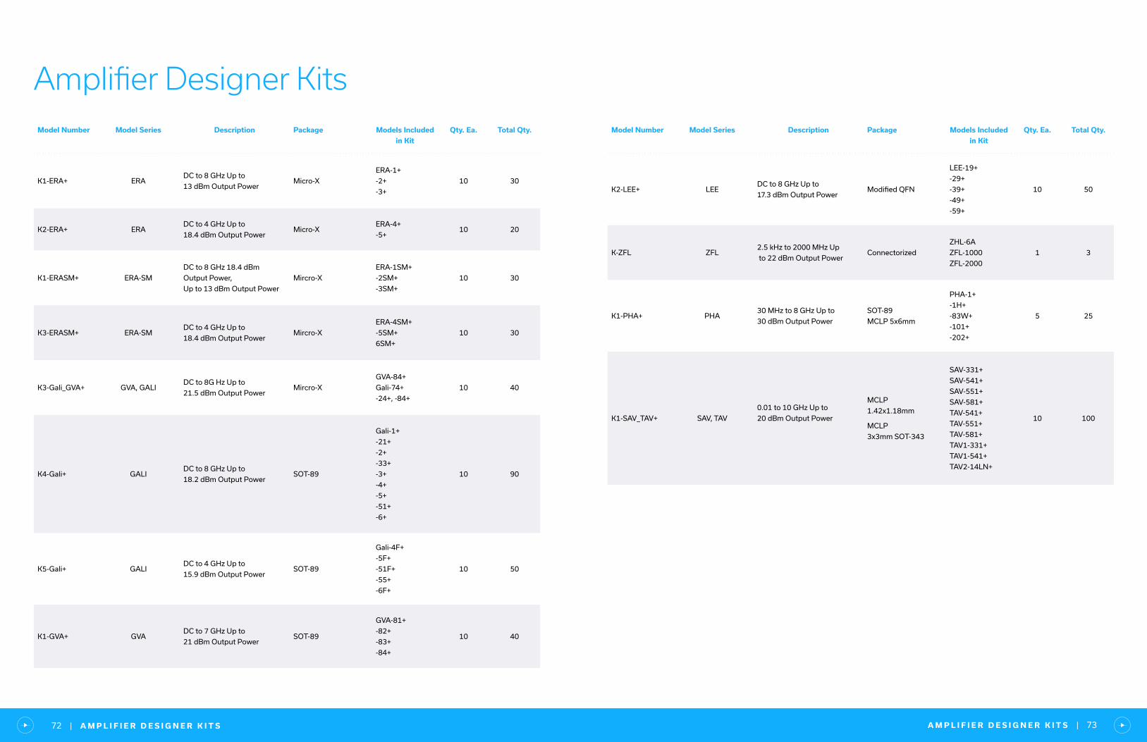
A M P L I F I E R D E S I G N E R K I T S | 73| A M P L I F I E R D E S I G N E R K I T S72
Amplifier Designer KitsModel Number Model Series Description Package Models Included
in Kit
Qty. Ea. Total Qty.
K1-ERA+ ERADC to 8 GHz Up to
13 dBm Output PowerMicro-X
ERA-1+
-2+
-3+
10 30
K2-ERA+ ERADC to 4 GHz Up to
18.4 dBm Output PowerMicro-X
ERA-4+
-5+10 20
K1-ERASM+ ERA-SM
DC to 8 GHz 18.4 dBm
Output Power,
Up to 13 dBm Output Power
Mircro-X
ERA-1SM+
-2SM+
-3SM+
10 30
K3-ERASM+ ERA-SMDC to 4 GHz Up to
18.4 dBm Output PowerMircro-X
ERA-4SM+
-5SM+
6SM+
10 30
K3-Gali_GVA+ GVA, GALIDC to 8G Hz Up to
21.5 dBm Output PowerMircro-X
GVA-84+
Gali-74+
-24+, -84+
10 40
K4-Gali+ GALIDC to 8 GHz Up to
18.2 dBm Output PowerSOT-89
Gali-1+
-21+
-2+
-33+
-3+
-4+
-5+
-51+
-6+
10 90
K5-Gali+ GALIDC to 4 GHz Up to
15.9 dBm Output PowerSOT-89
Gali-4F+
-5F+
-51F+
-55+
-6F+
10 50
K1-GVA+ GVADC to 7 GHz Up to
21 dBm Output PowerSOT-89
GVA-81+
-82+
-83+
-84+
10 40
Model Number Model Series Description Package Models Included
in Kit
Qty. Ea. Total Qty.
K2-LEE+ LEEDC to 8 GHz Up to
17.3 dBm Output PowerModified QFN
LEE-19+
-29+
-39+
-49+
-59+
10 50
K-ZFL ZFL2.5 kHz to 2000 MHz Up
to 22 dBm Output PowerConnectorized
ZHL-6A
ZFL-1000
ZFL-2000
1 3
K1-PHA+ PHA30 MHz to 8 GHz Up to
30 dBm Output Power
SOT-89
MCLP 5x6mm
PHA-1+
-1H+
-83W+
-101+
-202+
5 25
K1-SAV_TAV+ SAV, TAV
0.01 to 10 GHz Up to
20 dBm Output Power
MCLP
1.42x1.18mm
MCLP
3x3mm SOT-343
SAV-331+
SAV-541+
SAV-551+
SAV-581+
TAV-541+
TAV-551+
TAV-581+
TAV1-331+
TAV1-541+
TAV2-14LN+
10 100
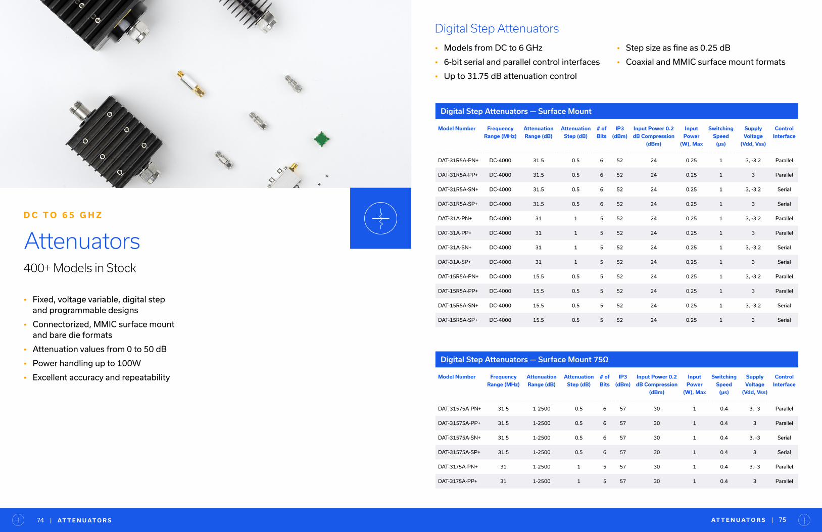
AT T E N U AT O R S | 75| AT T E N U AT O R S74
• Fixed, voltage variable, digital step and programmable designs
• Connectorized, MMIC surface mount and bare die formats
• Attenuation values from 0 to 50 dB
• Power handling up to 100W
• Excellent accuracy and repeatability
Attenuators400+ Models in Stock
D C T O 6 5 G H Z
Digital Step Attenuators
• Models from DC to 6 GHz
• 6-bit serial and parallel control interfaces
• Up to 31.75 dB attenuation control
• Step size as fine as 0.25 dB
• Coaxial and MMIC surface mount formats
Digital Step Attenuators — Surface Mount
Model Number Frequency
Range (MHz)
Attenuation
Range (dB)
Attenuation
Step (dB)
# of
Bits
IP3
(dBm)
Input Power 0.2
dB Compression
(dBm)
Input
Power
(W), Max
Switching
Speed
(μs)
Supply
Voltage
(Vdd, Vss)
Control
Interface
DAT-31R5A-PN+ DC-4000 31.5 0.5 6 52 24 0.25 1 3, -3.2 Parallel
DAT-31R5A-PP+ DC-4000 31.5 0.5 6 52 24 0.25 1 3 Parallel
DAT-31R5A-SN+ DC-4000 31.5 0.5 6 52 24 0.25 1 3, -3.2 Serial
DAT-31R5A-SP+ DC-4000 31.5 0.5 6 52 24 0.25 1 3 Serial
DAT-31A-PN+ DC-4000 31 1 5 52 24 0.25 1 3, -3.2 Parallel
DAT-31A-PP+ DC-4000 31 1 5 52 24 0.25 1 3 Parallel
DAT-31A-SN+ DC-4000 31 1 5 52 24 0.25 1 3, -3.2 Serial
DAT-31A-SP+ DC-4000 31 1 5 52 24 0.25 1 3 Serial
DAT-15R5A-PN+ DC-4000 15.5 0.5 5 52 24 0.25 1 3, -3.2 Parallel
DAT-15R5A-PP+ DC-4000 15.5 0.5 5 52 24 0.25 1 3 Parallel
DAT-15R5A-SN+ DC-4000 15.5 0.5 5 52 24 0.25 1 3, -3.2 Serial
DAT-15R5A-SP+ DC-4000 15.5 0.5 5 52 24 0.25 1 3 Serial
Digital Step Attenuators — Surface Mount 75Ω
Model Number Frequency
Range (MHz)
Attenuation
Range (dB)
Attenuation
Step (dB)
# of
Bits
IP3
(dBm)
Input Power 0.2
dB Compression
(dBm)
Input
Power
(W), Max
Switching
Speed
(μs)
Supply
Voltage
(Vdd, Vss)
Control
Interface
DAT-31575A-PN+ 31.5 1-2500 0.5 6 57 30 1 0.4 3, -3 Parallel
DAT-31575A-PP+ 31.5 1-2500 0.5 6 57 30 1 0.4 3 Parallel
DAT-31575A-SN+ 31.5 1-2500 0.5 6 57 30 1 0.4 3, -3 Serial
DAT-31575A-SP+ 31.5 1-2500 0.5 6 57 30 1 0.4 3 Serial
DAT-3175A-PN+ 31 1-2500 1 5 57 30 1 0.4 3, -3 Parallel
DAT-3175A-PP+ 31 1-2500 1 5 57 30 1 0.4 3 Parallel
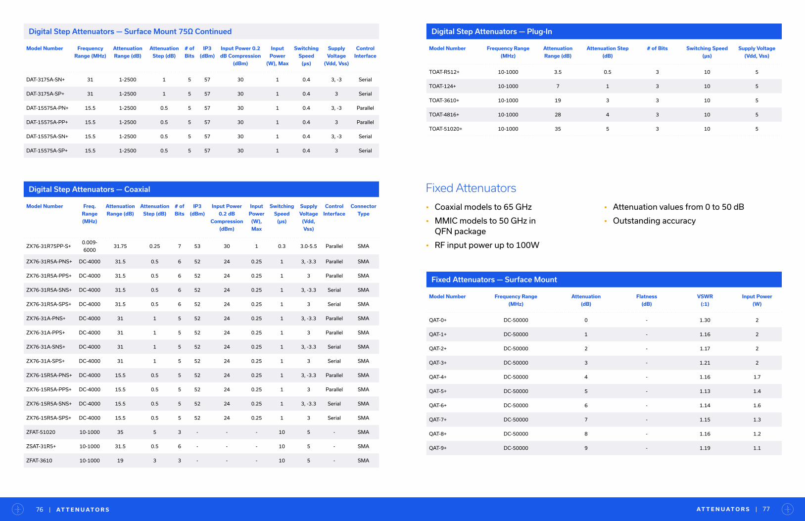
Model Number Frequency
Range (MHz)
Attenuation
Range (dB)
Attenuation
Step (dB)
# of
Bits
IP3
(dBm)
Input Power 0.2
dB Compression
(dBm)
Input
Power
(W), Max
Switching
Speed
(μs)
Supply
Voltage
(Vdd, Vss)
Control
Interface
DAT-3175A-SN+ 31 1-2500 1 5 57 30 1 0.4 3, -3 Serial
DAT-3175A-SP+ 31 1-2500 1 5 57 30 1 0.4 3 Serial
DAT-15575A-PN+ 15.5 1-2500 0.5 5 57 30 1 0.4 3, -3 Parallel
DAT-15575A-PP+ 15.5 1-2500 0.5 5 57 30 1 0.4 3 Parallel
DAT-15575A-SN+ 15.5 1-2500 0.5 5 57 30 1 0.4 3, -3 Serial
DAT-15575A-SP+ 15.5 1-2500 0.5 5 57 30 1 0.4 3 Serial
Digital Step Attenuators — Plug-In
Model Number Frequency Range
(MHz)
Attenuation
Range (dB)
Attenuation Step
(dB)
# of Bits Switching Speed
(μs)
Supply Voltage
(Vdd, Vss)
TOAT-R512+ 10-1000 3.5 0.5 3 10 5
TOAT-124+ 10-1000 7 1 3 10 5
TOAT-3610+ 10-1000 19 3 3 10 5
TOAT-4816+ 10-1000 28 4 3 10 5
TOAT-51020+ 10-1000 35 5 3 10 5
Digital Step Attenuators — Coaxial
Model Number Freq.
Range
(MHz)
Attenuation
Range (dB)
Attenuation
Step (dB)
# of
Bits
IP3
(dBm)
Input Power
0.2 dB
Compression
(dBm)
Input
Power
(W),
Max
Switching
Speed
(μs)
Supply
Voltage
(Vdd,
Vss)
Control
Interface
Connector
Type
ZX76-31R75PP-S+0.009-
600031.75 0.25 7 53 30 1 0.3 3.0-5.5 Parallel SMA
ZX76-31R5A-PNS+ DC-4000 31.5 0.5 6 52 24 0.25 1 3, -3.3 Parallel SMA
ZX76-31R5A-PPS+ DC-4000 31.5 0.5 6 52 24 0.25 1 3 Parallel SMA
ZX76-31R5A-SNS+ DC-4000 31.5 0.5 6 52 24 0.25 1 3, -3.3 Serial SMA
ZX76-31R5A-SPS+ DC-4000 31.5 0.5 6 52 24 0.25 1 3 Serial SMA
ZX76-31A-PNS+ DC-4000 31 1 5 52 24 0.25 1 3, -3.3 Parallel SMA
ZX76-31A-PPS+ DC-4000 31 1 5 52 24 0.25 1 3 Parallel SMA
ZX76-31A-SNS+ DC-4000 31 1 5 52 24 0.25 1 3, -3.3 Serial SMA
ZX76-31A-SPS+ DC-4000 31 1 5 52 24 0.25 1 3 Serial SMA
ZX76-15R5A-PNS+ DC-4000 15.5 0.5 5 52 24 0.25 1 3, -3.3 Parallel SMA
ZX76-15R5A-PPS+ DC-4000 15.5 0.5 5 52 24 0.25 1 3 Parallel SMA
ZX76-15R5A-SNS+ DC-4000 15.5 0.5 5 52 24 0.25 1 3, -3.3 Serial SMA
ZX76-15R5A-SPS+ DC-4000 15.5 0.5 5 52 24 0.25 1 3 Serial SMA
ZFAT-51020 10-1000 35 5 3 - - - 10 5 - SMA
ZSAT-31R5+ 10-1000 31.5 0.5 6 - - - 10 5 - SMA
ZFAT-3610 10-1000 19 3 3 - - - 10 5 - SMA
AT T E N U AT O R S | 77| AT T E N U AT O R S76
Fixed Attenuators
• Coaxial models to 65 GHz
• MMIC models to 50 GHz in QFN package
• RF input power up to 100W
• Attenuation values from 0 to 50 dB
• Outstanding accuracy
Fixed Attenuators — Surface Mount
Model Number Frequency Range
(MHz)
Attenuation
(dB)
Flatness
(dB)
VSWR
(:1)
Input Power
(W)
QAT-0+ DC-50000 0 - 1.30 2
QAT-1+ DC-50000 1 - 1.16 2
QAT-2+ DC-50000 2 - 1.17 2
QAT-3+ DC-50000 3 - 1.21 2
QAT-4+ DC-50000 4 - 1.16 1.7
QAT-5+ DC-50000 5 - 1.13 1.4
QAT-6+ DC-50000 6 - 1.14 1.6
QAT-7+ DC-50000 7 - 1.15 1.3
QAT-8+ DC-50000 8 - 1.16 1.2
QAT-9+ DC-50000 9 - 1.19 1.1
Digital Step Attenuators — Surface Mount 75Ω Continued
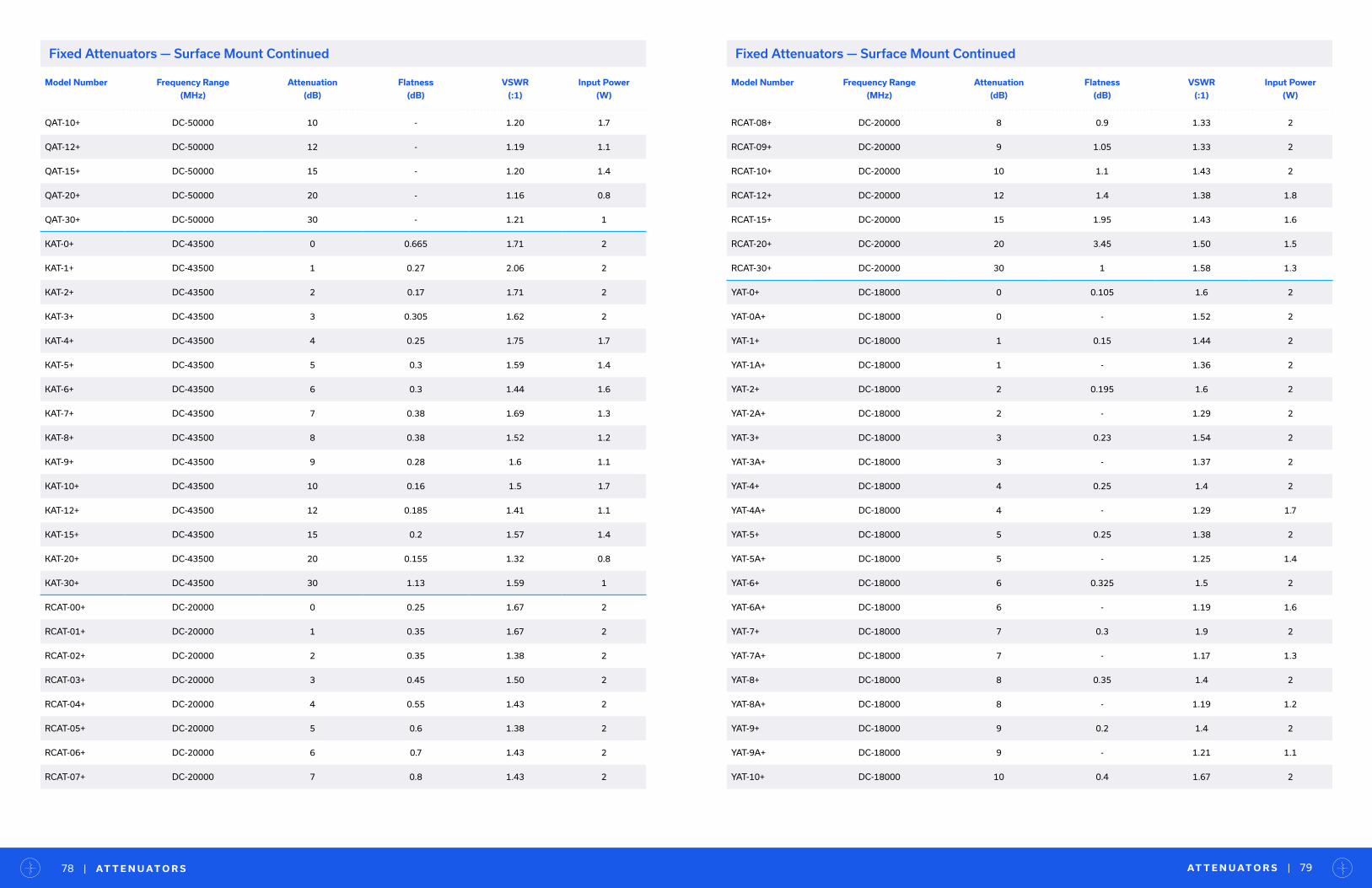
Model Number Frequency Range
(MHz)
Attenuation
(dB)
Flatness
(dB)
VSWR
(:1)
Input Power
(W)
QAT-10+ DC-50000 10 - 1.20 1.7
QAT-12+ DC-50000 12 - 1.19 1.1
QAT-15+ DC-50000 15 - 1.20 1.4
QAT-20+ DC-50000 20 - 1.16 0.8
QAT-30+ DC-50000 30 - 1.21 1
KAT-0+ DC-43500 0 0.665 1.71 2
KAT-1+ DC-43500 1 0.27 2.06 2
KAT-2+ DC-43500 2 0.17 1.71 2
KAT-3+ DC-43500 3 0.305 1.62 2
KAT-4+ DC-43500 4 0.25 1.75 1.7
KAT-5+ DC-43500 5 0.3 1.59 1.4
KAT-6+ DC-43500 6 0.3 1.44 1.6
KAT-7+ DC-43500 7 0.38 1.69 1.3
KAT-8+ DC-43500 8 0.38 1.52 1.2
KAT-9+ DC-43500 9 0.28 1.6 1.1
KAT-10+ DC-43500 10 0.16 1.5 1.7
KAT-12+ DC-43500 12 0.185 1.41 1.1
KAT-15+ DC-43500 15 0.2 1.57 1.4
KAT-20+ DC-43500 20 0.155 1.32 0.8
KAT-30+ DC-43500 30 1.13 1.59 1
RCAT-00+ DC-20000 0 0.25 1.67 2
RCAT-01+ DC-20000 1 0.35 1.67 2
RCAT-02+ DC-20000 2 0.35 1.38 2
RCAT-03+ DC-20000 3 0.45 1.50 2
RCAT-04+ DC-20000 4 0.55 1.43 2
RCAT-05+ DC-20000 5 0.6 1.38 2
RCAT-06+ DC-20000 6 0.7 1.43 2
RCAT-07+ DC-20000 7 0.8 1.43 2
Model Number Frequency Range
(MHz)
Attenuation
(dB)
Flatness
(dB)
VSWR
(:1)
Input Power
(W)
RCAT-08+ DC-20000 8 0.9 1.33 2
RCAT-09+ DC-20000 9 1.05 1.33 2
RCAT-10+ DC-20000 10 1.1 1.43 2
RCAT-12+ DC-20000 12 1.4 1.38 1.8
RCAT-15+ DC-20000 15 1.95 1.43 1.6
RCAT-20+ DC-20000 20 3.45 1.50 1.5
RCAT-30+ DC-20000 30 1 1.58 1.3
YAT-0+ DC-18000 0 0.105 1.6 2
YAT-0A+ DC-18000 0 - 1.52 2
YAT-1+ DC-18000 1 0.15 1.44 2
YAT-1A+ DC-18000 1 - 1.36 2
YAT-2+ DC-18000 2 0.195 1.6 2
YAT-2A+ DC-18000 2 - 1.29 2
YAT-3+ DC-18000 3 0.23 1.54 2
YAT-3A+ DC-18000 3 - 1.37 2
YAT-4+ DC-18000 4 0.25 1.4 2
YAT-4A+ DC-18000 4 - 1.29 1.7
YAT-5+ DC-18000 5 0.25 1.38 2
YAT-5A+ DC-18000 5 - 1.25 1.4
YAT-6+ DC-18000 6 0.325 1.5 2
YAT-6A+ DC-18000 6 - 1.19 1.6
YAT-7+ DC-18000 7 0.3 1.9 2
YAT-7A+ DC-18000 7 - 1.17 1.3
YAT-8+ DC-18000 8 0.35 1.4 2
YAT-8A+ DC-18000 8 - 1.19 1.2
YAT-9+ DC-18000 9 0.2 1.4 2
YAT-9A+ DC-18000 9 - 1.21 1.1
YAT-10+ DC-18000 10 0.4 1.67 2
AT T E N U AT O R S | 79| AT T E N U AT O R S78
Fixed Attenuators — Surface Mount Continued Fixed Attenuators — Surface Mount Continued
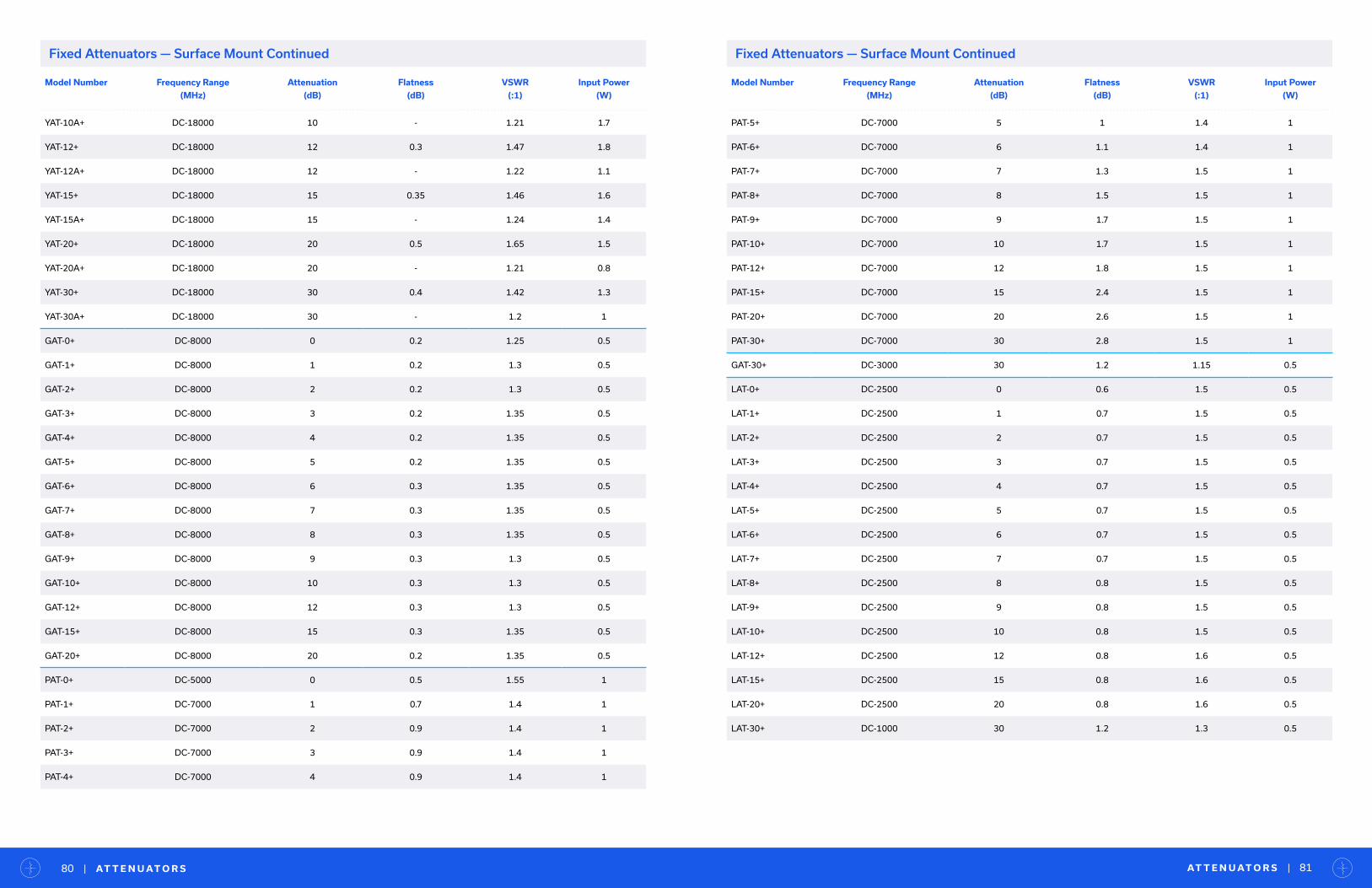
Model Number Frequency Range
(MHz)
Attenuation
(dB)
Flatness
(dB)
VSWR
(:1)
Input Power
(W)
YAT-10A+ DC-18000 10 - 1.21 1.7
YAT-12+ DC-18000 12 0.3 1.47 1.8
YAT-12A+ DC-18000 12 - 1.22 1.1
YAT-15+ DC-18000 15 0.35 1.46 1.6
YAT-15A+ DC-18000 15 - 1.24 1.4
YAT-20+ DC-18000 20 0.5 1.65 1.5
YAT-20A+ DC-18000 20 - 1.21 0.8
YAT-30+ DC-18000 30 0.4 1.42 1.3
YAT-30A+ DC-18000 30 - 1.2 1
GAT-0+ DC-8000 0 0.2 1.25 0.5
GAT-1+ DC-8000 1 0.2 1.3 0.5
GAT-2+ DC-8000 2 0.2 1.3 0.5
GAT-3+ DC-8000 3 0.2 1.35 0.5
GAT-4+ DC-8000 4 0.2 1.35 0.5
GAT-5+ DC-8000 5 0.2 1.35 0.5
GAT-6+ DC-8000 6 0.3 1.35 0.5
GAT-7+ DC-8000 7 0.3 1.35 0.5
GAT-8+ DC-8000 8 0.3 1.35 0.5
GAT-9+ DC-8000 9 0.3 1.3 0.5
GAT-10+ DC-8000 10 0.3 1.3 0.5
GAT-12+ DC-8000 12 0.3 1.3 0.5
GAT-15+ DC-8000 15 0.3 1.35 0.5
GAT-20+ DC-8000 20 0.2 1.35 0.5
PAT-0+ DC-5000 0 0.5 1.55 1
PAT-1+ DC-7000 1 0.7 1.4 1
PAT-2+ DC-7000 2 0.9 1.4 1
PAT-3+ DC-7000 3 0.9 1.4 1
PAT-4+ DC-7000 4 0.9 1.4 1
AT T E N U AT O R S | 81| AT T E N U AT O R S80
Model Number Frequency Range
(MHz)
Attenuation
(dB)
Flatness
(dB)
VSWR
(:1)
Input Power
(W)
PAT-5+ DC-7000 5 1 1.4 1
PAT-6+ DC-7000 6 1.1 1.4 1
PAT-7+ DC-7000 7 1.3 1.5 1
PAT-8+ DC-7000 8 1.5 1.5 1
PAT-9+ DC-7000 9 1.7 1.5 1
PAT-10+ DC-7000 10 1.7 1.5 1
PAT-12+ DC-7000 12 1.8 1.5 1
PAT-15+ DC-7000 15 2.4 1.5 1
PAT-20+ DC-7000 20 2.6 1.5 1
PAT-30+ DC-7000 30 2.8 1.5 1
GAT-30+ DC-3000 30 1.2 1.15 0.5
LAT-0+ DC-2500 0 0.6 1.5 0.5
LAT-1+ DC-2500 1 0.7 1.5 0.5
LAT-2+ DC-2500 2 0.7 1.5 0.5
LAT-3+ DC-2500 3 0.7 1.5 0.5
LAT-4+ DC-2500 4 0.7 1.5 0.5
LAT-5+ DC-2500 5 0.7 1.5 0.5
LAT-6+ DC-2500 6 0.7 1.5 0.5
LAT-7+ DC-2500 7 0.7 1.5 0.5
LAT-8+ DC-2500 8 0.8 1.5 0.5
LAT-9+ DC-2500 9 0.8 1.5 0.5
LAT-10+ DC-2500 10 0.8 1.5 0.5
LAT-12+ DC-2500 12 0.8 1.6 0.5
LAT-15+ DC-2500 15 0.8 1.6 0.5
LAT-20+ DC-2500 20 0.8 1.6 0.5
LAT-30+ DC-1000 30 1.2 1.3 0.5
Fixed Attenuators — Surface Mount Continued Fixed Attenuators — Surface Mount Continued
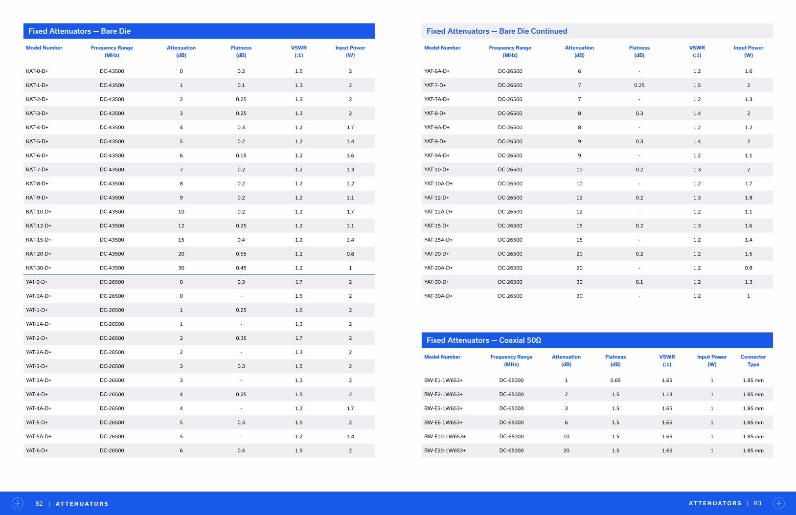
Fixed Attenuators — Bare Die Fixed Attenuators — Bare Die Continued
Model Number Frequency Range
(MHz)
Attenuation
(dB)
Flatness
(dB)
VSWR
(:1)
Input Power
(W)
KAT-0-D+ DC-43500 0 0.2 1.5 2
KAT-1-D+ DC-43500 1 0.1 1.3 2
KAT-2-D+ DC-43500 2 0.25 1.3 2
KAT-3-D+ DC-43500 3 0.25 1.3 2
KAT-4-D+ DC-43500 4 0.3 1.2 1.7
KAT-5-D+ DC-43500 5 0.2 1.2 1.4
KAT-6-D+ DC-43500 6 0.15 1.2 1.6
KAT-7-D+ DC-43500 7 0.2 1.2 1.3
KAT-8-D+ DC-43500 8 0.2 1.2 1.2
KAT-9-D+ DC-43500 9 0.2 1.2 1.1
KAT-10-D+ DC-43500 10 0.2 1.2 1.7
KAT-12-D+ DC-43500 12 0.25 1.2 1.1
KAT-15-D+ DC-43500 15 0.4 1.2 1.4
KAT-20-D+ DC-43500 20 0.65 1.2 0.8
KAT-30-D+ DC-43500 30 0.45 1.2 1
YAT-0-D+ DC-26500 0 0.3 1.7 2
YAT-0A-D+ DC-26500 0 - 1.5 2
YAT-1-D+ DC-26500 1 0.25 1.6 2
YAT-1A-D+ DC-26500 1 - 1.3 2
YAT-2-D+ DC-26500 2 0.35 1.7 2
YAT-2A-D+ DC-26500 2 - 1.3 2
YAT-3-D+ DC-26500 3 0.3 1.5 2
YAT-3A-D+ DC-26500 3 - 1.3 2
YAT-4-D+ DC-26500 4 0.25 1.5 2
YAT-4A-D+ DC-26500 4 - 1.2 1.7
YAT-5-D+ DC-26500 5 0.3 1.5 2
YAT-5A-D+ DC-26500 5 - 1.2 1.4
YAT-6-D+ DC-26500 6 0.4 1.5 2
AT T E N U AT O R S | 83| AT T E N U AT O R S82
Model Number Frequency Range
(MHz)
Attenuation
(dB)
Flatness
(dB)
VSWR
(:1)
Input Power
(W)
YAT-6A-D+ DC-26500 6 - 1.2 1.6
YAT-7-D+ DC-26500 7 0.25 1.5 2
YAT-7A-D+ DC-26500 7 - 1.2 1.3
YAT-8-D+ DC-26500 8 0.3 1.4 2
YAT-8A-D+ DC-26500 8 - 1.2 1.2
YAT-9-D+ DC-26500 9 0.3 1.4 2
YAT-9A-D+ DC-26500 9 - 1.2 1.1
YAT-10-D+ DC-26500 10 0.2 1.3 2
YAT-10A-D+ DC-26500 10 - 1.2 1.7
YAT-12-D+ DC-26500 12 0.2 1.3 1.8
YAT-12A-D+ DC-26500 12 - 1.2 1.1
YAT-15-D+ DC-26500 15 0.2 1.3 1.6
YAT-15A-D+ DC-26500 15 - 1.2 1.4
YAT-20-D+ DC-26500 20 0.2 1.2 1.5
YAT-20A-D+ DC-26500 20 - 1.2 0.8
YAT-30-D+ DC-26500 30 0.1 1.2 1.3
YAT-30A-D+ DC-26500 30 - 1.2 1
Model Number Frequency Range
(MHz)
Attenuation
(dB)
Flatness
(dB)
VSWR
(:1)
Input Power
(W)
Connector
Type
BW-E1-1W653+ DC-65000 1 0.65 1.65 1 1.85 mm
BW-E2-1W653+ DC-65000 2 1.5 1.13 1 1.85 mm
BW-E3-1W653+ DC-65000 3 1.5 1.65 1 1.85 mm
BW-E6-1W653+ DC-65000 6 1.5 1.65 1 1.85 mm
BW-E10-1W653+ DC-65000 10 1.5 1.65 1 1.85 mm
BW-E20-1W653+ DC-65000 20 1.5 1.65 1 1.85 mm
Fixed Attenuators — Coaxial 50Ω
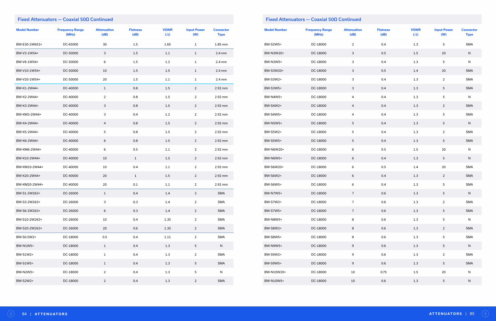
AT T E N U AT O R S | 85| AT T E N U AT O R S84
Fixed Attenuators — Coaxial 50Ω Continued
Model Number Frequency Range
(MHz)
Attenuation
(dB)
Flatness
(dB)
VSWR
(:1)
Input Power
(W)
Connector
Type
BW-E30-1W653+ DC-65000 30 1.5 1.65 1 1.85 mm
BW-V3-1W54+ DC-50000 3 1.5 1.1 1 2.4 mm
BW-V6-1W54+ DC-50000 6 1.5 1.2 1 2.4 mm
BW-V10-1W54+ DC-50000 10 1.5 1.5 1 2.4 mm
BW-V20-1W54+ DC-50000 20 1.5 1.1 1 2.4 mm
BW-K1-2W44+ DC-40000 1 0.8 1.5 2 2.92 mm
BW-K2-2W44+ DC-40000 2 0.8 1.5 2 2.92 mm
BW-K3-2W44+ DC-40000 3 0.8 1.5 2 2.92 mm
BW-KM3-2W44+ DC-40000 3 0.4 1.2 2 2.92 mm
BW-K4-2W44+ DC-40000 4 0.8 1.5 2 2.92 mm
BW-K5-2W44+ DC-40000 5 0.8 1.5 2 2.92 mm
BW-K6-2W44+ DC-40000 6 0.8 1.5 2 2.92 mm
BW-KM6-2W44+ DC-40000 6 0.5 1.1 2 2.92 mm
BW-K10-2W44+ DC-40000 10 1 1.5 2 2.92 mm
BW-KM10-2W44+ DC-40000 10 0.4 1.1 2 2.92 mm
BW-K20-2W44+ DC-40000 20 1 1.5 2 2.92 mm
BW-KM20-2W44+ DC-40000 20 0.1 1.1 2 2.92 mm
BW-S1-2W263+ DC-26000 1 0.4 1.4 2 SMA
BW-S3-2W263+ DC-26000 3 0.3 1.4 2 SMA
BW-S6-2W263+ DC-26000 6 0.3 1.4 2 SMA
BW-S10-2W263+ DC-26000 10 0.4 1.35 2 SMA
BW-S20-2W263+ DC-26000 20 0.6 1.35 2 SMA
BW-S0.5W2+ DC-18000 0.5 0.4 1.11 2 SMA
BW-N1W5+ DC-18000 1 0.4 1.3 5 N
BW-S1W2+ DC-18000 1 0.4 1.3 2 SMA
BW-S1W5+ DC-18000 1 0.4 1.3 5 SMA
BW-N2W5+ DC-18000 2 0.4 1.3 5 N
BW-S2W2+ DC-18000 2 0.4 1.3 2 SMA
Model Number Frequency Range
(MHz)
Attenuation
(dB)
Flatness
(dB)
VSWR
(:1)
Input Power
(W)
Connector
Type
BW-S2W5+ DC-18000 2 0.4 1.3 5 SMA
BW-N3W20+ DC-18000 3 0.5 1.5 20 N
BW-N3W5+ DC-18000 3 0.4 1.3 5 N
BW-S3W20+ DC-18000 3 0.5 1.4 20 SMA
BW-S3W2+ DC-18000 3 0.4 1.3 2 SMA
BW-S3W5+ DC-18000 3 0.4 1.3 5 SMA
BW-N4W5+ DC-18000 4 0.4 1.3 5 N
BW-S4W2+ DC-18000 4 0.4 1.3 2 SMA
BW-S4W5+ DC-18000 4 0.4 1.3 5 SMA
BW-N5W5+ DC-18000 5 0.4 1.3 5 N
BW-S5W2+ DC-18000 5 0.4 1.3 2 SMA
BW-S5W5+ DC-18000 5 0.4 1.3 5 SMA
BW-N6W20+ DC-18000 6 0.5 1.5 20 N
BW-N6W5+ DC-18000 6 0.4 1.3 5 N
BW-S6W20+ DC-18000 6 0.5 1.4 20 SMA
BW-S6W2+ DC-18000 6 0.4 1.3 2 SMA
BW-S6W5+ DC-18000 6 0.4 1.3 5 SMA
BW-N7W5+ DC-18000 7 0.6 1.3 5 N
BW-S7W2+ DC-18000 7 0.6 1.3 2 SMA
BW-S7W5+ DC-18000 7 0.6 1.3 5 SMA
BW-N8W5+ DC-18000 8 0.6 1.3 5 N
BW-S8W2+ DC-18000 8 0.6 1.3 2 SMA
BW-S8W5+ DC-18000 8 0.6 1.3 5 SMA
BW-N9W5+ DC-18000 9 0.6 1.3 5 N
BW-S9W2+ DC-18000 9 0.6 1.3 2 SMA
BW-S9W5+ DC-18000 9 0.6 1.3 5 SMA
BW-N10W20+ DC-18000 10 0.75 1.5 20 N
BW-N10W5+ DC-18000 10 0.6 1.3 5 N
Fixed Attenuators — Coaxial 50Ω Continued
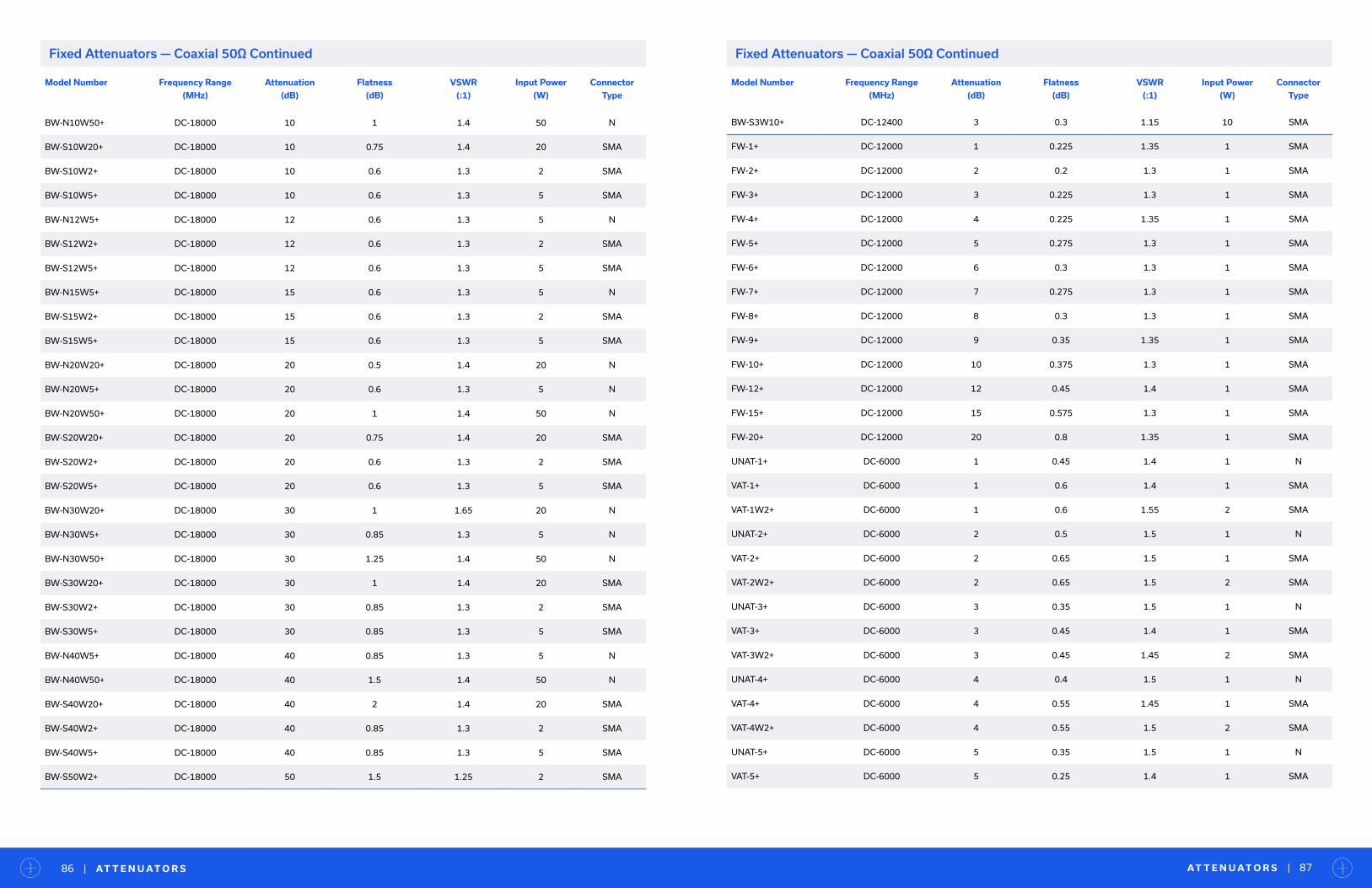
AT T E N U AT O R S | 87| AT T E N U AT O R S86
Fixed Attenuators — Coaxial 50Ω Continued
Model Number Frequency Range
(MHz)
Attenuation
(dB)
Flatness
(dB)
VSWR
(:1)
Input Power
(W)
Connector
Type
BW-N10W50+ DC-18000 10 1 1.4 50 N
BW-S10W20+ DC-18000 10 0.75 1.4 20 SMA
BW-S10W2+ DC-18000 10 0.6 1.3 2 SMA
BW-S10W5+ DC-18000 10 0.6 1.3 5 SMA
BW-N12W5+ DC-18000 12 0.6 1.3 5 N
BW-S12W2+ DC-18000 12 0.6 1.3 2 SMA
BW-S12W5+ DC-18000 12 0.6 1.3 5 SMA
BW-N15W5+ DC-18000 15 0.6 1.3 5 N
BW-S15W2+ DC-18000 15 0.6 1.3 2 SMA
BW-S15W5+ DC-18000 15 0.6 1.3 5 SMA
BW-N20W20+ DC-18000 20 0.5 1.4 20 N
BW-N20W5+ DC-18000 20 0.6 1.3 5 N
BW-N20W50+ DC-18000 20 1 1.4 50 N
BW-S20W20+ DC-18000 20 0.75 1.4 20 SMA
BW-S20W2+ DC-18000 20 0.6 1.3 2 SMA
BW-S20W5+ DC-18000 20 0.6 1.3 5 SMA
BW-N30W20+ DC-18000 30 1 1.65 20 N
BW-N30W5+ DC-18000 30 0.85 1.3 5 N
BW-N30W50+ DC-18000 30 1.25 1.4 50 N
BW-S30W20+ DC-18000 30 1 1.4 20 SMA
BW-S30W2+ DC-18000 30 0.85 1.3 2 SMA
BW-S30W5+ DC-18000 30 0.85 1.3 5 SMA
BW-N40W5+ DC-18000 40 0.85 1.3 5 N
BW-N40W50+ DC-18000 40 1.5 1.4 50 N
BW-S40W20+ DC-18000 40 2 1.4 20 SMA
BW-S40W2+ DC-18000 40 0.85 1.3 2 SMA
BW-S40W5+ DC-18000 40 0.85 1.3 5 SMA
BW-S50W2+ DC-18000 50 1.5 1.25 2 SMA
Model Number Frequency Range
(MHz)
Attenuation
(dB)
Flatness
(dB)
VSWR
(:1)
Input Power
(W)
Connector
Type
BW-S3W10+ DC-12400 3 0.3 1.15 10 SMA
FW-1+ DC-12000 1 0.225 1.35 1 SMA
FW-2+ DC-12000 2 0.2 1.3 1 SMA
FW-3+ DC-12000 3 0.225 1.3 1 SMA
FW-4+ DC-12000 4 0.225 1.35 1 SMA
FW-5+ DC-12000 5 0.275 1.3 1 SMA
FW-6+ DC-12000 6 0.3 1.3 1 SMA
FW-7+ DC-12000 7 0.275 1.3 1 SMA
FW-8+ DC-12000 8 0.3 1.3 1 SMA
FW-9+ DC-12000 9 0.35 1.35 1 SMA
FW-10+ DC-12000 10 0.375 1.3 1 SMA
FW-12+ DC-12000 12 0.45 1.4 1 SMA
FW-15+ DC-12000 15 0.575 1.3 1 SMA
FW-20+ DC-12000 20 0.8 1.35 1 SMA
UNAT-1+ DC-6000 1 0.45 1.4 1 N
VAT-1+ DC-6000 1 0.6 1.4 1 SMA
VAT-1W2+ DC-6000 1 0.6 1.55 2 SMA
UNAT-2+ DC-6000 2 0.5 1.5 1 N
VAT-2+ DC-6000 2 0.65 1.5 1 SMA
VAT-2W2+ DC-6000 2 0.65 1.5 2 SMA
UNAT-3+ DC-6000 3 0.35 1.5 1 N
VAT-3+ DC-6000 3 0.45 1.4 1 SMA
VAT-3W2+ DC-6000 3 0.45 1.45 2 SMA
UNAT-4+ DC-6000 4 0.4 1.5 1 N
VAT-4+ DC-6000 4 0.55 1.45 1 SMA
VAT-4W2+ DC-6000 4 0.55 1.5 2 SMA
UNAT-5+ DC-6000 5 0.35 1.5 1 N
VAT-5+ DC-6000 5 0.25 1.4 1 SMA
Fixed Attenuators — Coaxial 50Ω Continued
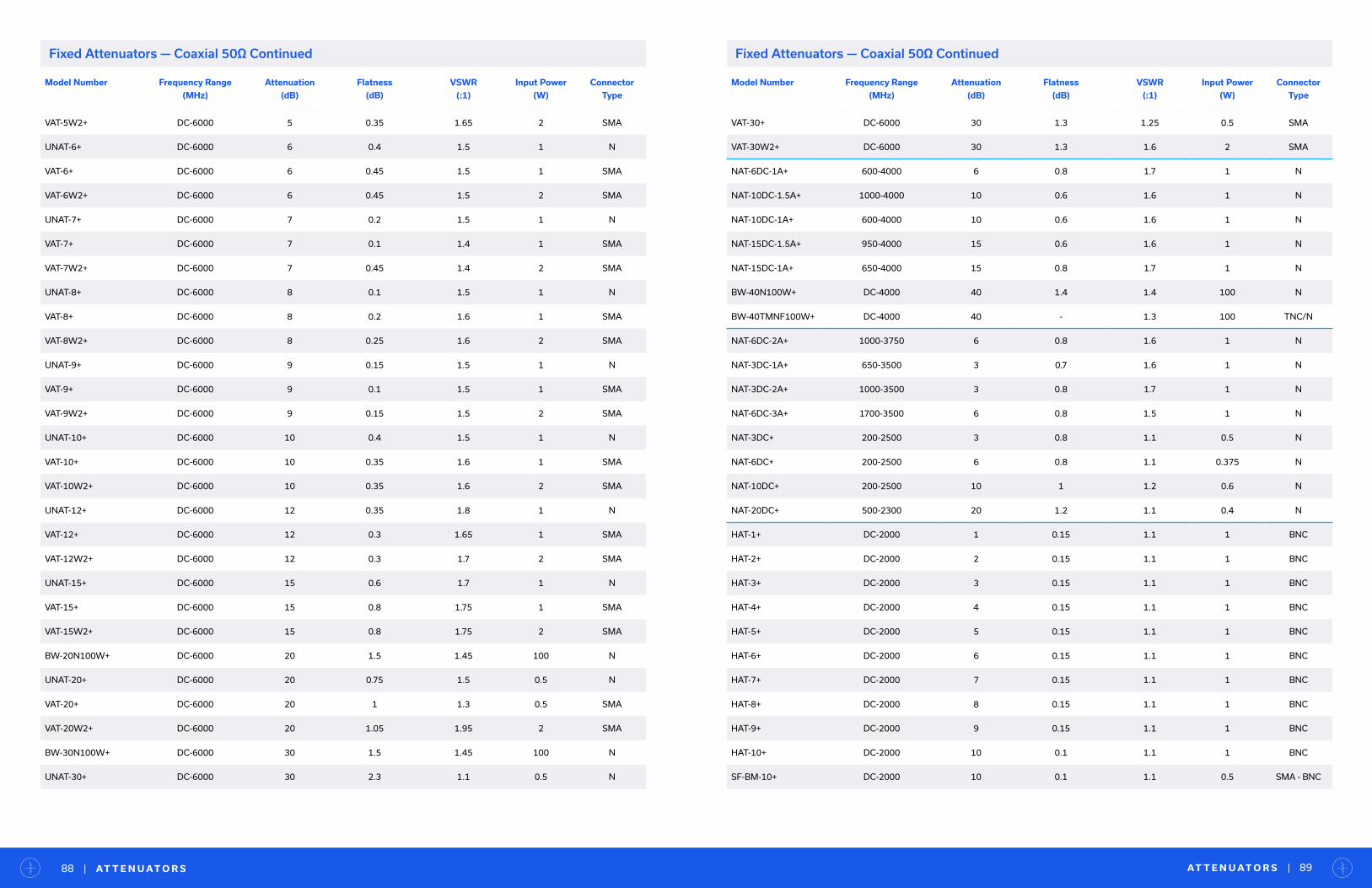
AT T E N U AT O R S | 89| AT T E N U AT O R S88
Fixed Attenuators — Coaxial 50Ω Continued
Model Number Frequency Range
(MHz)
Attenuation
(dB)
Flatness
(dB)
VSWR
(:1)
Input Power
(W)
Connector
Type
VAT-5W2+ DC-6000 5 0.35 1.65 2 SMA
UNAT-6+ DC-6000 6 0.4 1.5 1 N
VAT-6+ DC-6000 6 0.45 1.5 1 SMA
VAT-6W2+ DC-6000 6 0.45 1.5 2 SMA
UNAT-7+ DC-6000 7 0.2 1.5 1 N
VAT-7+ DC-6000 7 0.1 1.4 1 SMA
VAT-7W2+ DC-6000 7 0.45 1.4 2 SMA
UNAT-8+ DC-6000 8 0.1 1.5 1 N
VAT-8+ DC-6000 8 0.2 1.6 1 SMA
VAT-8W2+ DC-6000 8 0.25 1.6 2 SMA
UNAT-9+ DC-6000 9 0.15 1.5 1 N
VAT-9+ DC-6000 9 0.1 1.5 1 SMA
VAT-9W2+ DC-6000 9 0.15 1.5 2 SMA
UNAT-10+ DC-6000 10 0.4 1.5 1 N
VAT-10+ DC-6000 10 0.35 1.6 1 SMA
VAT-10W2+ DC-6000 10 0.35 1.6 2 SMA
UNAT-12+ DC-6000 12 0.35 1.8 1 N
VAT-12+ DC-6000 12 0.3 1.65 1 SMA
VAT-12W2+ DC-6000 12 0.3 1.7 2 SMA
UNAT-15+ DC-6000 15 0.6 1.7 1 N
VAT-15+ DC-6000 15 0.8 1.75 1 SMA
VAT-15W2+ DC-6000 15 0.8 1.75 2 SMA
BW-20N100W+ DC-6000 20 1.5 1.45 100 N
UNAT-20+ DC-6000 20 0.75 1.5 0.5 N
VAT-20+ DC-6000 20 1 1.3 0.5 SMA
VAT-20W2+ DC-6000 20 1.05 1.95 2 SMA
BW-30N100W+ DC-6000 30 1.5 1.45 100 N
UNAT-30+ DC-6000 30 2.3 1.1 0.5 N
Model Number Frequency Range
(MHz)
Attenuation
(dB)
Flatness
(dB)
VSWR
(:1)
Input Power
(W)
Connector
Type
VAT-30+ DC-6000 30 1.3 1.25 0.5 SMA
VAT-30W2+ DC-6000 30 1.3 1.6 2 SMA
NAT-6DC-1A+ 600-4000 6 0.8 1.7 1 N
NAT-10DC-1.5A+ 1000-4000 10 0.6 1.6 1 N
NAT-10DC-1A+ 600-4000 10 0.6 1.6 1 N
NAT-15DC-1.5A+ 950-4000 15 0.6 1.6 1 N
NAT-15DC-1A+ 650-4000 15 0.8 1.7 1 N
BW-40N100W+ DC-4000 40 1.4 1.4 100 N
BW-40TMNF100W+ DC-4000 40 - 1.3 100 TNC/N
NAT-6DC-2A+ 1000-3750 6 0.8 1.6 1 N
NAT-3DC-1A+ 650-3500 3 0.7 1.6 1 N
NAT-3DC-2A+ 1000-3500 3 0.8 1.7 1 N
NAT-6DC-3A+ 1700-3500 6 0.8 1.5 1 N
NAT-3DC+ 200-2500 3 0.8 1.1 0.5 N
NAT-6DC+ 200-2500 6 0.8 1.1 0.375 N
NAT-10DC+ 200-2500 10 1 1.2 0.6 N
NAT-20DC+ 500-2300 20 1.2 1.1 0.4 N
HAT-1+ DC-2000 1 0.15 1.1 1 BNC
HAT-2+ DC-2000 2 0.15 1.1 1 BNC
HAT-3+ DC-2000 3 0.15 1.1 1 BNC
HAT-4+ DC-2000 4 0.15 1.1 1 BNC
HAT-5+ DC-2000 5 0.15 1.1 1 BNC
HAT-6+ DC-2000 6 0.15 1.1 1 BNC
HAT-7+ DC-2000 7 0.15 1.1 1 BNC
HAT-8+ DC-2000 8 0.15 1.1 1 BNC
HAT-9+ DC-2000 9 0.15 1.1 1 BNC
HAT-10+ DC-2000 10 0.1 1.1 1 BNC
SF-BM-10+ DC-2000 10 0.1 1.1 0.5 SMA - BNC
Fixed Attenuators — Coaxial 50Ω Continued

AT T E N U AT O R S | 91| AT T E N U AT O R S90
Fixed Attenuators — Coaxial 50Ω Continued
Model Number # of
Channels
Frequency
Range (MHz)
Attenuation
Range (dB)
Attenuation
Step (dB)
Attenuation
Accuracy (dB)
Input Power
(dBm), Max
IP3
(dB)
Control
Interface
Connector
Type
RCDAT-50G-30 1 100-50000 31.5 0.5 1.0 28 50USB &
Ethernet2.92 mm
RCDAT-40G-30 1 100-40000 30 0.5 1.0 24 38USB &
Ethernet2.92mm
RUDAT-13G-90 1 10-13000 90 0.5 0.6 23 41USB, SPI &
RS232SMA
RUDAT-13G-60 1 10-13000 60 0.5 0.5 23 41USB, SPI &
RS232SMA
RC4DAT-8G-95 4 1-8000 95 0.25 0.8 28 51USB &
EthernetSMA
RC8DAT-8G-95 8 1-8000 95 0.25 1.8 28 51USB &
EthernetSMA
RCDAT-8000-90 1 1-8000 90 0.25 0.8 28 51USB &
EthernetSMA
RCDAT-8000-60 1 1-8000 60 0.25 0.75 28 51USB &
EthernetSMA
RCDAT-8000-30 1 1-8000 30 0.25 0.4 28 52USB &
EthernetSMA
RCDAT-6G-120H 1 200-6000 120 0.05 1.0 23 51USB &
EthernetSMA
RC4DAT-6G-95 4 1-6000 95 0.25 0.4 20 54USB &
EthernetSMA
RC4DAT-6G-60 4 1-6000 63 0.25 0.6 23 53USB &
EthernetSMA
RC4DAT-6G-30 4 1-6000 30 0.25 0.35 23 53USB &
EthernetSMA
RCDAT-6000-110 1 1-6000 110 0.25 0.45 20 53USB &
EthernetSMA
RCDAT-6000-90 1 1-6000 90 0.25 0.4 20 54USB &
EthernetSMA
RCDAT-6000-60 1 1-6000 60 0.25 0.3 20 55USB &
EthernetSMA
RCDAT-6000-30 1 1-6000 30 0.25 0.4 20 56USB &
EthernetSMA
RUDAT-6000-110 1 1-6000 110 0.25 0.45 20 53USB &
RS232SMA
Programmable Attenuators — Coaxial, USB / Ethernet / RS232
Programmable Attenuators
• USB, Ethernet, SPI and RS232 control options
• Models up to 40 GHz
• Attenuation ranges from 0 up to 120 dB
• Step size as small as 0.1 dB
• User-friendly GUI and full API included
• See more details in Test Solutions
Model Number Frequency Range
(MHz)
Attenuation
(dB)
Flatness
(dB)
VSWR
(:1)
Input Power
(W)
Connector
Type
HAT-3-75 DC-2000 3 0.15 1.22 0.5 BNC
HAT-3-75+ DC-2000 3 0.15 1.22 0.5 BNC
HAT-6-75+ DC-2000 6 0.15 1.15 0.5 BNC
HAT-10-75+ DC-2000 10 0.05 1.1 0.5 BNC
HAT-15-75+ DC-2000 15 0.05 1.1 0.5 BNC
HAT-20-75+ DC-2000 20 0.05 1.1 0.5 BNC
Fixed Attenuators — Coaxial 75Ω
Model Number Frequency Range
(MHz)
Attenuation
(dB)
Flatness
(dB)
VSWR
(:1)
Input Power
(W)
Connector
Type
SM-BF-10+ DC-2000 10 0.1 1.1 0.5 SMA - BNC
HAT-12+ DC-2000 12 0.1 1.15 1 BNC
HAT-15+ DC-2000 15 0.2 1.15 1 BNC
HAT-20+ DC-2000 20 0.25 1.15 0.5 BNC
HAT-30+ DC-2000 30 0.8 1.15 1 BNC
SAT-3DC-3A+ 100-500 3 0.7 1.1 0.01 SMA
SAT-6DC-3A+ 100-500 6 0.7 1.1 0.01 SMA
SAT-10DC-3A+ 100-500 10 0.6 1.1 0.01 SMA

AT T E N U AT O R S | 93| AT T E N U AT O R S92
Voltage Variable Attenuators — Surface Mount
Voltage Variable Attenuators — Surface Mount Continued
Voltage Variable Attenuators
• Models from 10 MHz to 7 GHz
• Precise attenuation control up to 47 dB
• Good return loss, up to 25 dB
• High IP3, up to +53 dBm
• Connectorized and surface mount formats
Model Number Frequency Range
(MHz)
Attenuation
(dB)
IP3
(dBm)
Return Loss
(dB)
Max Control
Voltage (V)
Max Control
Voltage (mA)
HVA-73+ 5500-7000 27 48 17 6 10
RVA-6000+ 2000-6000 32.7 43 20 12 10
EVA-3000+ 50-3000 29 45 22 8 40
RVA-33+ 20-3000 45 50 18 5 45
RVA-3000R+ 20-3000 44 56 21 17 30
RVA-2500+ 10-2500 41 43 20 17 30
VACC-22+ 1600-2200 23 42 20 5 10
MVA-2000+ 10-2000 28 48 23 12 15
Voltage Variable Attenuators — Surface Mount 75Ω
Voltage Variable Attenuators — Coaxial
Model Number Frequency Range
(MHz)
Attenuation
(dB)
IP3
(dBm)
Return Loss
(dB)
Max Control
Voltage (V)
Max Control
Voltage (mA)
RVA-2500-75+ 10-2500 40 45 15 15 20
EVA-23-75+ 10-2000 33 50 16 8 15
EVA-2-75+ 50-2000 30 49 25 8 40
Model Number Frequency Range
(MHz)
Attenuation
(dB)
IP3
(dBm)
Return Loss
(dB)
Max Control
Voltage (V)
Max Control
Voltage (mA)
ZX73-123+ 6000-12000 20 23 15 0.9 40
ZX73-2500-S+ 10-2500 40 43 20 17 30
Model Number # of
Channels
Frequency
Range (MHz)
Attenuation
Range (dB)
Attenuation
Step (dB)
Attenuation
Accuracy (dB)
Input Power
(dBm), Max
IP3
(dB)
Control
Interface
Connector
Type
RUDAT-6000-90 1 1-6000 90 0.25 0.4 20 50USB &
RS232SMA
RUDAT-6000-60 1 1-6000 60 0.25 0.3 20 50USB &
RS232SMA
RUDAT-6000-30 1 1-6000 30 0.25 0.3 20 50USB &
RS232SMA
RCDAT-4000-120 1 1-4000 120 0.25 0.5 20 53USB &
EthernetSMA
RUDAT-4000-120 1 1-4000 120 0.25 0.5 20 53USB &
RS232SMA
RCDAT-3000-63W2 1 50-3000 63 1 0.4 33 54USB &
EthernetSMA
ZVVA-3000 1 20-3000 25 0.1 0.7 23 52USB &
RS232SMA
Model Number Frequency Range
(MHz)
Attenuation
(dB)
IP3
(dBm)
Return Loss
(dB)
Max Control
Voltage (V)
Max Control
Voltage (mA)
RVA-2000+ 150-2000 35 56 22 17 30
RVA-2000V3+ 50-2000 43 49 23 10 20
RVA-2000V35+ 50-2000 47 53 19 5 20
SVA-2000+ 50-2000 29 44 21 12 5
EVA-1500+ 100-1500 30 50 20 5 7
VACC-09+ 600-1200 20 48 20 6 10
MVA-1000+ 50-1000 13 52 20 5 15
RVA-800+ 50-800 9 18 23 5 17
HVA-451+ 250-450 32 50 22 6 10
SYVA-30+ 16-30 32 48 25 4 4
Programmable Attenuators — Coaxial, USB / Ethernet / RS232 Continued

AT T E N U AT O R D E S I G N E R K I T S | 95| AT T E N U AT O R D E S I G N E R K I T S94
Attenuator Designer KitsModel Number Model Series Description Package Models Included
in Kit
Qty. Ea. Total Qty.
K2-BW1+ BWDC to 18 GHz
2 WattsSMA Connectorized
BW-S3W2+
-S6W2+
-S10W2+
2 6
K2-BW2+ BWDC to 18 GHz
2 WattsSMA Connectorized
BW-S3W2+
-S6W2+
-S10W2+
-S20W2+
-S30W2+
-S40W2+
1 6
K2-BW3+ BWDC to 18 GHz
2 WattsSMA Connectorized
BW-S1W2+
-S2W2+
-S3W2+
-S4W2+
-S5W2+
-S6W2+
-S7W2+
-S8W2+
-S9W2+
-S10W2+
1 10
K5-BW1+ BWDC to 18 GHz
5 WattsSMA Connectorized
BW-S1W5+
-S2W5+
-S3W5+
-S4W5+
-S5W5+
-S6W5+
-S8W5+
-S10W5+
1 8
K5-BW2+ BWDC to 18 GHz
5 WattsSMA Connectorized
BW-S3W5+
BW-S6W5+
BW-S10W5+
1
24
K5N-BW3+ BWDC to 18 GHz
5 WattsN Connectorized
BW-N3W5+
BW-N6W5+
BW-N10W5+
1
24
Model Number Model Series Description Package Models Included
in Kit
Qty. Ea. Total Qty.
K1-GAT+ GATDC to 8 GHz
0.5 WattsModified QFN
GAT-2+
-3+
-4+
-6+
-8+
-10+
-15+
-20+
-30+
5 45
K2-GAT+ GATDC to 8 GHz
0.5 WattsModified QFN
GAT-3+
-6+
-10+
-15+
-20+
5 25
K3-GAT+ GATDC to 8 GHz
0.5 WattsModified QFN
GAT-0+
-1+
-2+
-3+
-4+
-5+
-6+
-7+
-8+
-9+
-10+
-12+
-15+
-20+
-30+
5 75
K1-HAT+ HATDC to 2 GHz
1 WattsBNC Connectorized
HAT-3+
-6+
-10+
-20+
-30+
1 5
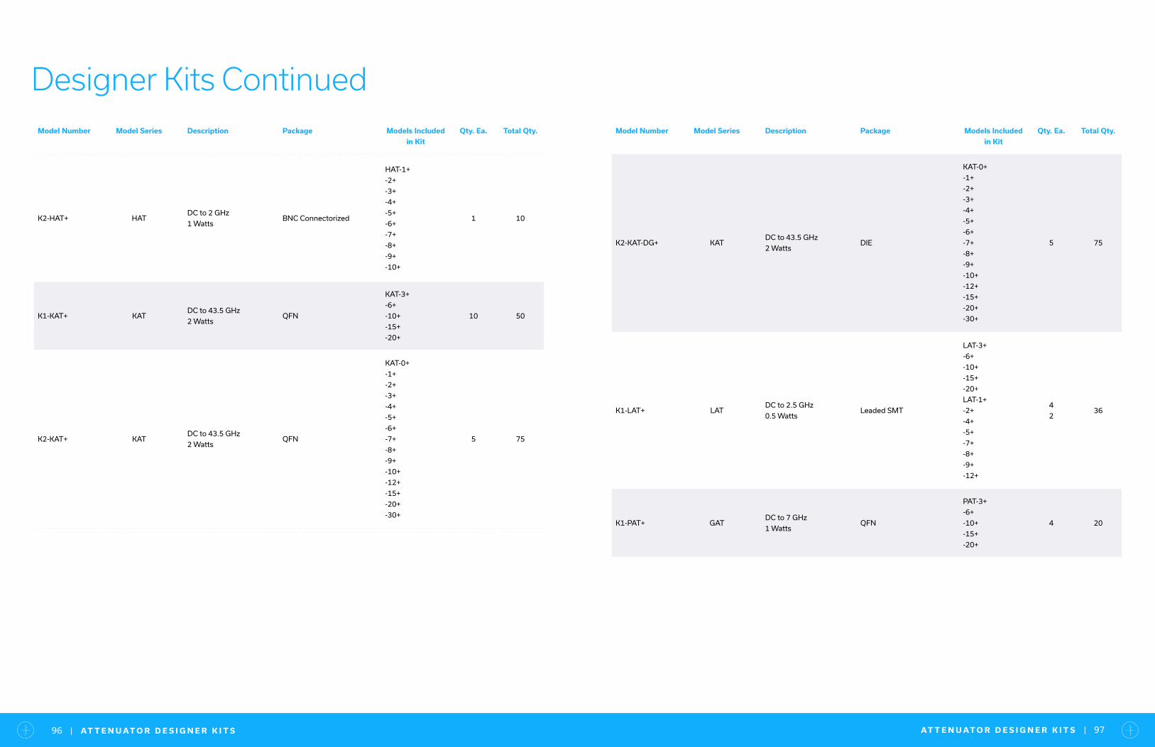
Model Number Model Series Description Package Models Included
in Kit
Qty. Ea. Total Qty.
K2-HAT+ HATDC to 2 GHz
1 WattsBNC Connectorized
HAT-1+
-2+
-3+
-4+
-5+
-6+
-7+
-8+
-9+
-10+
1 10
K1-KAT+ KATDC to 43.5 GHz
2 WattsQFN
KAT-3+
-6+
-10+
-15+
-20+
10 50
K2-KAT+ KATDC to 43.5 GHz
2 WattsQFN
KAT-0+
-1+
-2+
-3+
-4+
-5+
-6+
-7+
-8+
-9+
-10+
-12+
-15+
-20+
-30+
5 75
Designer Kits Continued
AT T E N U AT O R D E S I G N E R K I T S | 97| AT T E N U AT O R D E S I G N E R K I T S96
Model Number Model Series Description Package Models Included
in Kit
Qty. Ea. Total Qty.
K2-KAT-DG+ KATDC to 43.5 GHz
2 WattsDIE
KAT-0+
-1+
-2+
-3+
-4+
-5+
-6+
-7+
-8+
-9+
-10+
-12+
-15+
-20+
-30+
5 75
K1-LAT+ LATDC to 2.5 GHz
0.5 WattsLeaded SMT
LAT-3+
-6+
-10+
-15+
-20+
LAT-1+
-2+
-4+
-5+
-7+
-8+
-9+
-12+
4
236
K1-PAT+ GATDC to 7 GHz
1 WattsQFN
PAT-3+
-6+
-10+
-15+
-20+
4 20

Model Number Model Series Description Package Models Included
in Kit
Qty. Ea. Total Qty.
K2-KAT-DG+ KATDC to 43.5GHz
2 Watts,DIE
KAT-0+
-1+
-2+
-3+
-4+
-5+
-6+
-7+
-8+
-9+
-10+
-12+
-15+
-20+
-30+
5 75
K1-LAT+ LATDC to 2.5GHz
0.5 WattsLeaded SMT
LAT-3+
-6+
-10+
-15+
-20+
LAT-1+
-2+
-4+
-5+
-7+
-8+
-9+
-12+
4
236
K1-PAT+ GATDC to 7GHz
1 WattsQFN
PAT-3+
-6+
-10+
-15+
-20+
4 20
Model Number Model Series Description Package Models Included
in Kit
Qty. Ea. Total Qty.
K1-VAT2+ VATDC to 6 GHz
2 WattsSMA Connectorized
VAT-3W2+
-6W2+
-10W2+
-20W2+
-30W2+
1 5
K2-VAT2+ VATDC to 6 GHz
2 WattsSMA Connectorized
VAT-1W2+
-2W2+
-3W2+
-4W2+
-5W2+
-6W2+
-7W2+
-8W2+
-9W2+
-10W2+
1 10
K3-VAT2+ VATDC to 6 GHz
2 WattsSMA Connectorized
VAT-3W2+
-6W2+
-10W2+
2 6
K4-VAT2+ VATDC to 6 GHz
2 WattsSMA Connectorized
VAT-3W2+
-6W2+
-10W2+
-20W2+
1 4
K1-UNAT+ UNATDC to 6 GHz
0.5 and 1 WattsN Connectorized
UNAT-3+
-6+
-10+
-15+
-20+
2 10
K2-UNAT+ UNATDC to 6 GHz
0.5 and 1 WattsN Connectorized
UNAT-1+
-2+
-3+
-4+
-5+
-6+
-7+
-8+
-9+
-10+
-15+
-20+
-30+
1 13
Designer Kits Continued
AT T E N U AT O R D E S I G N E R K I T S | 99| AT T E N U AT O R D E S I G N E R K I T S98
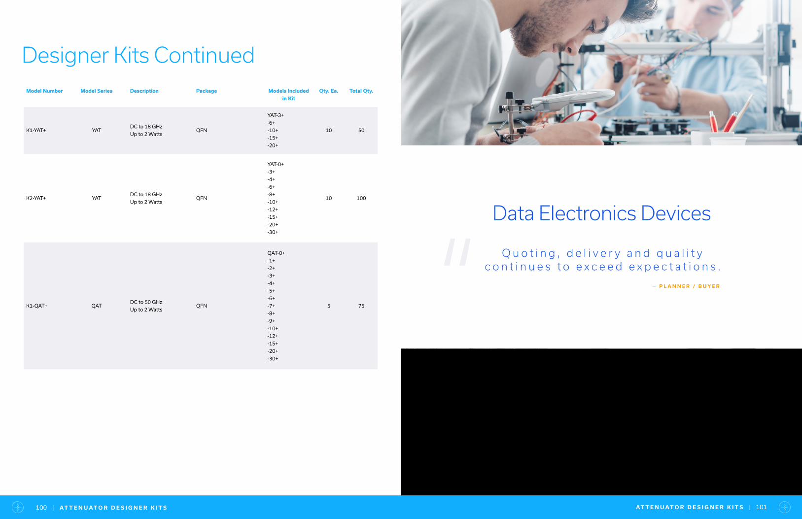
AT T E N U AT O R D E S I G N E R K I T S | 101| AT T E N U AT O R D E S I G N E R K I T S100
Model Number Model Series Description Package Models Included
in Kit
Qty. Ea. Total Qty.
K1-YAT+ YATDC to 18 GHz
Up to 2 WattsQFN
YAT-3+
-6+
-10+
-15+
-20+
10 50
K2-YAT+ YATDC to 18 GHz
Up to 2 WattsQFN
YAT-0+
-3+
-4+
-6+
-8+
-10+
-12+
-15+
-20+
-30+
10 100
K1-QAT+ QATDC to 50 GHz
Up to 2 WattsQFN
QAT-0+
-1+
-2+
-3+
-4+
-5+
-6+
-7+
-8+
-9+
-10+
-12+
-15+
-20+
-30+
5 75
Designer Kits Continued
“Data Electronics Devices
Q u o t i n g , d e l i v e r y a n d q u a l i t y c o n t i n u e s t o e x c e e d e x p e c t a t i o n s .
— P L A N N E R / B U Y E R

B I A S T E E S | 103| B I A S T E E S102
• DC current up to 5A
• RF power up to 40W
• Mux-tees (bias tee + diplexers)
• Insertion loss as low as 0.15 dB
• Bandwidth as wide as 1.5 to 28 GHz in a single model
Bias TeesWideband, High-Current
1 0 0 K H Z T O 2 8 G H Z
Bias Tees — Surface Mount
Bias Tees — Bare Die
Model Number Frequency Range
(MHz)
Insertion Loss
(dB)
Input Current
(mA) Max.
DC port Isolation
(dB)
VSWR
(:1)
MBT-283+ 1500-28000 0.7 500 47 1.22
TCBT-123+ 10-12000 0.3 200 33 1.2
TCBT-14R+ 10-10000 0.6 200 33 1.2
TCBT-14+ 10-10000 0.35 200 33 1.2
TCBT-6G+ 50-6000 0.7 200 28 1.1
RCBT-63+ 10-6000 1 500 20 1.25
JEBT-4R2GW+ 0.1-4200 0.6 500 40 1.1
JEBT-4R2G+ 10-4200 0.6 500 40 1.1
TCBT-2R5G+ 20-2500 0.35 200 44 1.05
Model Number Frequency Range
(MHz)
Insertion Loss
(dB)
Input Current
(mA) Max.
DC Port Isolation
(dB)
VSWR
(:1)
MBT-283-283-D+ 1500-20000 0.7 500 47 1.22
Bias Tees — Coaxial
Model Number Frequency Range
(MHz)
Input Current (mA)
Max.
Insertion Loss
(dB)
DC port Isolation
(dB)
VSWR
(:1)
Connector Type
ZX85-12G-S+ 0.2-12000 400 0.6 - 1.2 SMA
ZFBT-6G+ 10-6000 500 0.6 40 1.13 SMA
ZFBT-6G-FT+ 10-6000 500 0.6 - 1.13 SMA
ZFBT-6GW+ 0.1-6000 500 0.6 40 1.13 SMA
ZFBT-6GW-FT+ 0.1-6000 500 0.6 - 1.13 SMA
ZNBT-60-1W+ 2.5-6000 500 0.6 45 1.1 BNC
ZX85-40W-63-S+ 1000-6000 1000 0.5 - 1.4 SMA
ZFBT-4R2G+ 10-4200 500 0.6 40 1.13 SMA
ZFBT-4R2G-FT+ 10-4200 500 0.6 - 1.13 SMA
ZFBT-4R2GW+ 0.1-4200 500 0.6 40 1.13 SMA
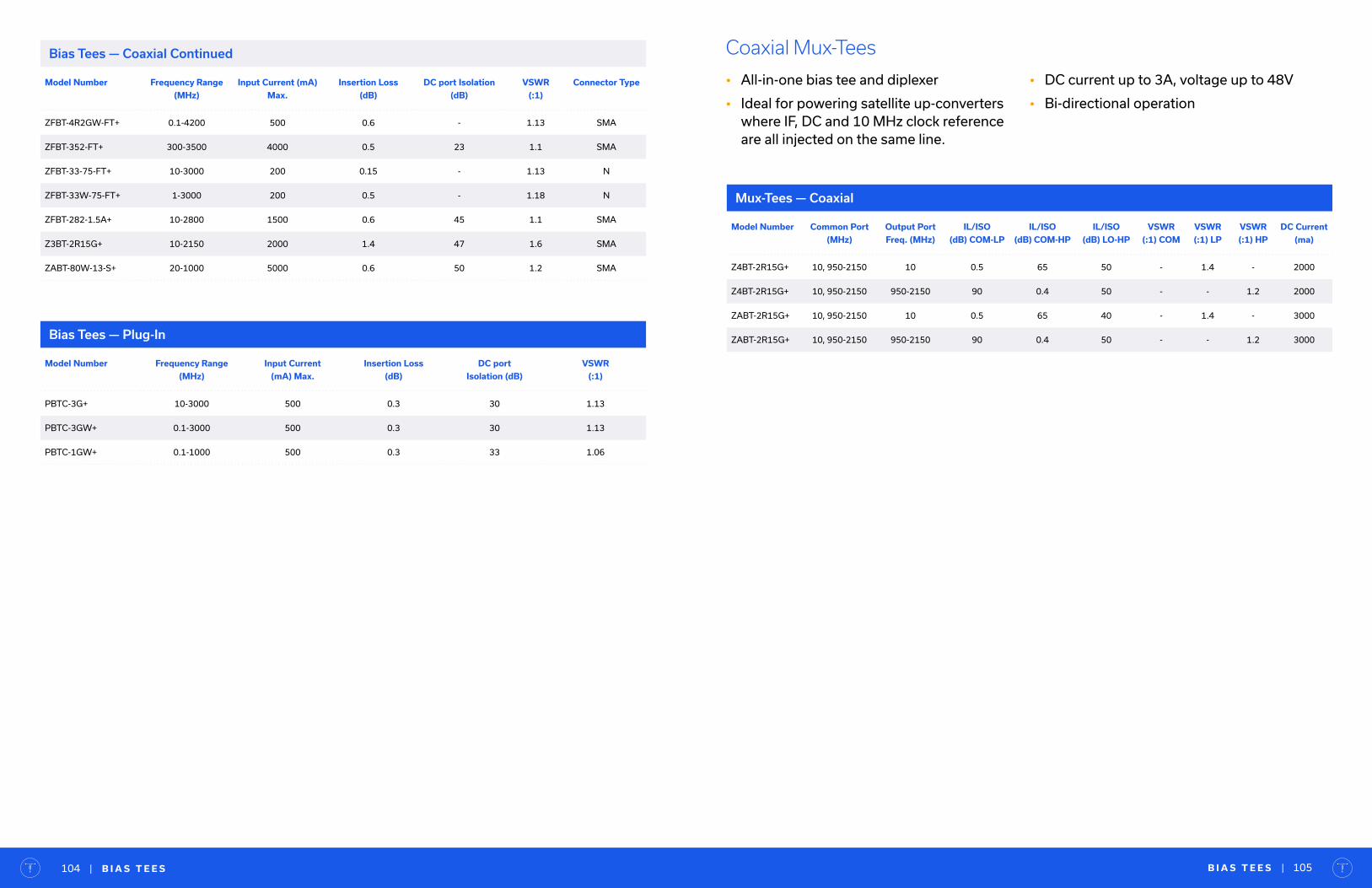
B I A S T E E S | 105| B I A S T E E S104
Coaxial Mux-Tees
• All-in-one bias tee and diplexer
• Ideal for powering satellite up-converters where IF, DC and 10 MHz clock reference are all injected on the same line.
Bias Tees — Plug-In
Bias Tees — Coaxial Continued
Mux-Tees — Coaxial
Model Number Frequency Range
(MHz)
Input Current
(mA) Max.
Insertion Loss
(dB)
DC port
Isolation (dB)
VSWR
(:1)
PBTC-3G+ 10-3000 500 0.3 30 1.13
PBTC-3GW+ 0.1-3000 500 0.3 30 1.13
PBTC-1GW+ 0.1-1000 500 0.3 33 1.06
Model Number Common Port
(MHz)
Output Port
Freq. (MHz)
IL/ISO
(dB) COM-LP
IL/ISO
(dB) COM-HP
IL/ISO
(dB) LO-HP
VSWR
(:1) COM
VSWR
(:1) LP
VSWR
(:1) HP
DC Current
(ma)
Z4BT-2R15G+ 10, 950-2150 10 0.5 65 50 - 1.4 - 2000
Z4BT-2R15G+ 10, 950-2150 950-2150 90 0.4 50 - - 1.2 2000
ZABT-2R15G+ 10, 950-2150 10 0.5 65 40 - 1.4 - 3000
ZABT-2R15G+ 10, 950-2150 950-2150 90 0.4 50 - - 1.2 3000
• DC current up to 3A, voltage up to 48V
• Bi-directional operation
Model Number Frequency Range
(MHz)
Input Current (mA)
Max.
Insertion Loss
(dB)
DC port Isolation
(dB)
VSWR
(:1)
Connector Type
ZFBT-4R2GW-FT+ 0.1-4200 500 0.6 - 1.13 SMA
ZFBT-352-FT+ 300-3500 4000 0.5 23 1.1 SMA
ZFBT-33-75-FT+ 10-3000 200 0.15 - 1.13 N
ZFBT-33W-75-FT+ 1-3000 200 0.5 - 1.18 N
ZFBT-282-1.5A+ 10-2800 1500 0.6 45 1.1 SMA
Z3BT-2R15G+ 10-2150 2000 1.4 47 1.6 SMA
ZABT-80W-13-S+ 20-1000 5000 0.6 50 1.2 SMA
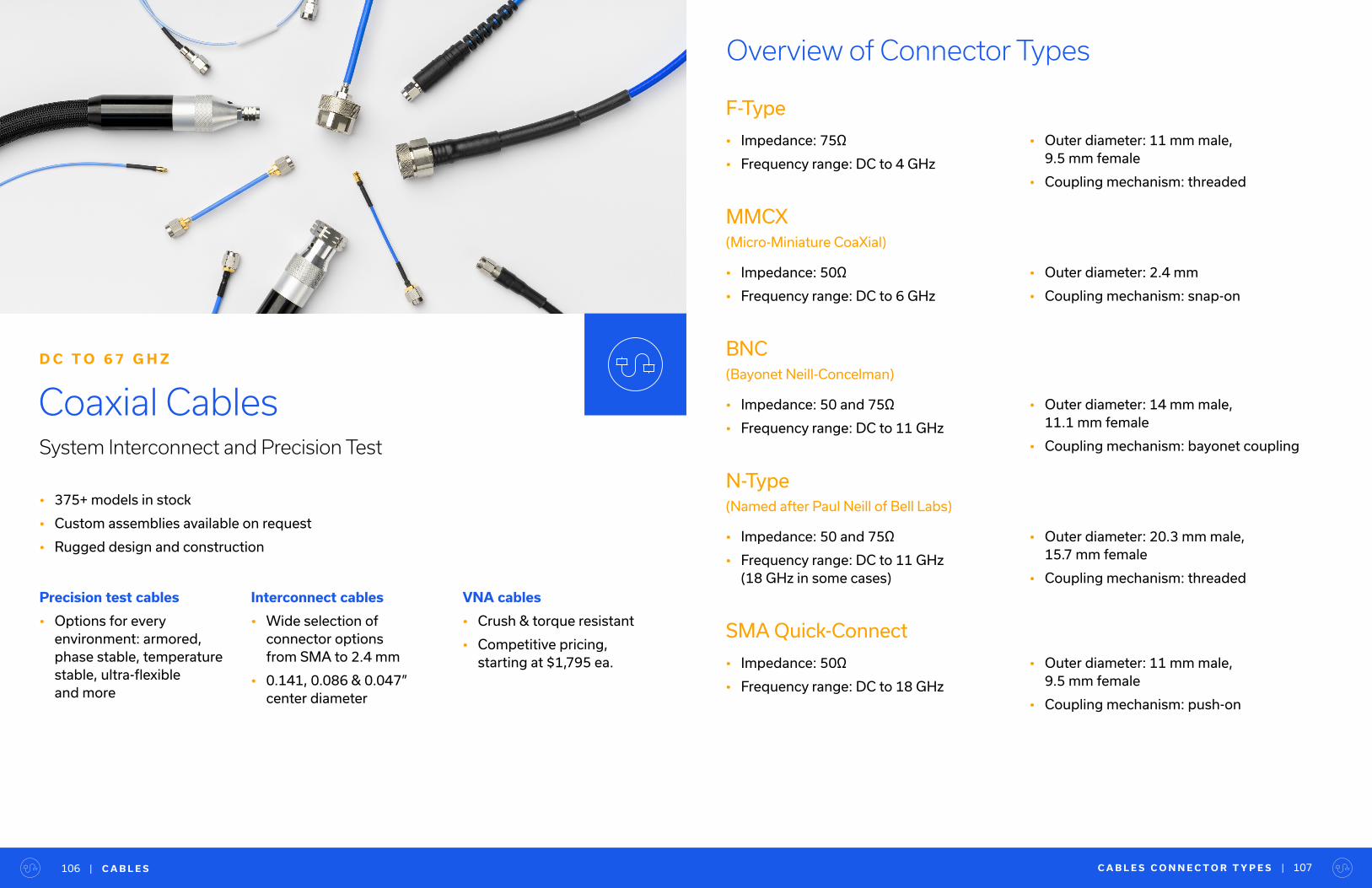
Overview of Connector Types
F-Type
• Impedance: 75Ω
• Frequency range: DC to 4 GHz
MMCX (Micro-Miniature CoaXial)
• Impedance: 50Ω
• Frequency range: DC to 6 GHz
C A B L E S C O N N E C T O R T Y P E S |
BNC (Bayonet Neill-Concelman)
• Impedance: 50 and 75Ω
• Frequency range: DC to 11 GHz
N-Type (Named after Paul Neill of Bell Labs)
• Impedance: 50 and 75Ω
• Frequency range: DC to 11 GHz (18 GHz in some cases)
• Outer diameter: 11 mm male, 9.5 mm female
• Coupling mechanism: threaded
• Outer diameter: 2.4 mm
• Coupling mechanism: snap-on
• Outer diameter: 14 mm male, 11.1 mm female
• Coupling mechanism: bayonet coupling
• Outer diameter: 20.3 mm male, 15.7 mm female
• Coupling mechanism: threaded
107
• 375+ models in stock
• Custom assemblies available on request
• Rugged design and construction
Coaxial CablesSystem Interconnect and Precision Test
D C T O 6 7 G H Z
Precision test cables
• Options for every environment: armored, phase stable, temperature stable, ultra-flexible and more
Interconnect cables
• Wide selection of connector options from SMA to 2.4 mm
• 0.141, 0.086 & 0.047” center diameter
VNA cables
• Crush & torque resistant
• Competitive pricing, starting at $1,795 ea.
| C A B L E S106
SMA Quick-Connect
• Impedance: 50Ω
• Frequency range: DC to 18 GHz
• Outer diameter: 11 mm male, 9.5 mm female
• Coupling mechanism: push-on
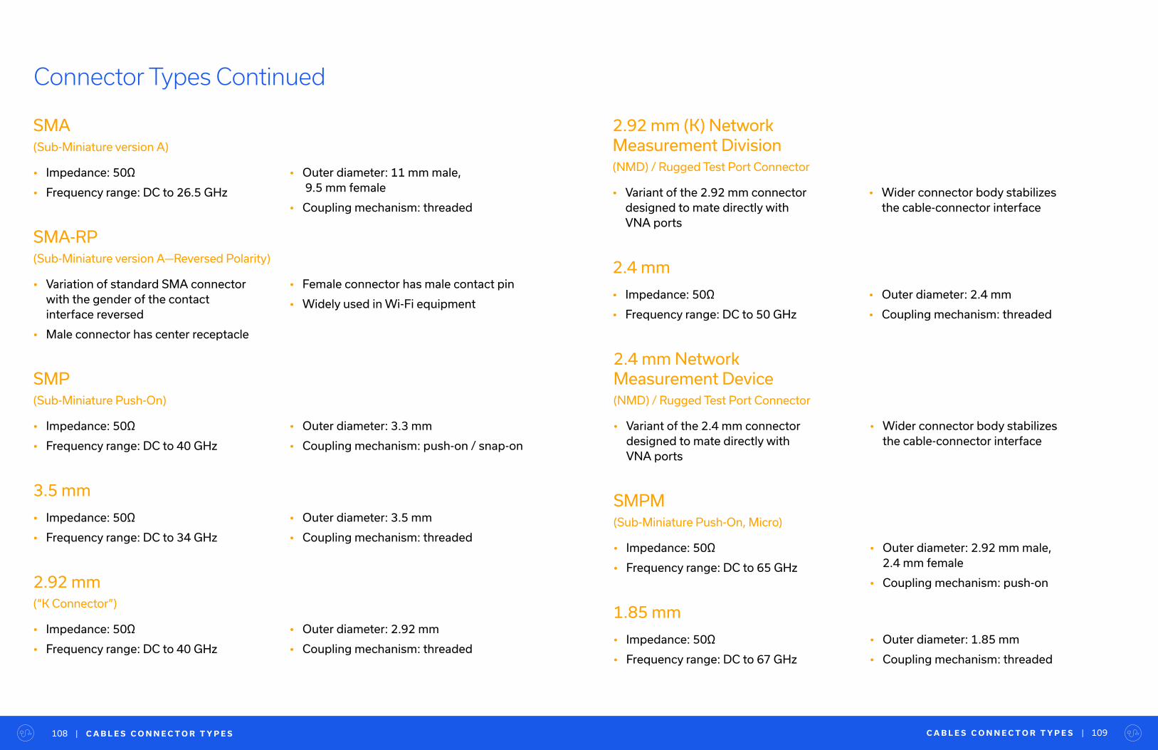
C A B L E S C O N N E C T O R T Y P E S | 109| C A B L E S C O N N E C T O R T Y P E S108
Connector Types Continued
SMA(Sub-Miniature version A)
• Impedance: 50Ω
• Frequency range: DC to 26.5 GHz
2.92 mm
(“K Connector”)
• Impedance: 50Ω
• Frequency range: DC to 40 GHz
SMA-RP(Sub-Miniature version A—Reversed Polarity)
• Variation of standard SMA connector with the gender of the contact interface reversed
• Male connector has center receptacle
2.92 mm (K) NetworkMeasurement Division(NMD) / Rugged Test Port Connector
• Variant of the 2.92 mm connector designed to mate directly with VNA ports
SMP(Sub-Miniature Push-On)
• Impedance: 50Ω
• Frequency range: DC to 40 GHz
2.4 mm
• Impedance: 50Ω
• Frequency range: DC to 50 GHz
3.5 mm
• Impedance: 50Ω
• Frequency range: DC to 34 GHz
• Outer diameter: 11 mm male, 9.5 mm female
• Coupling mechanism: threaded
• Outer diameter: 2.92 mm
• Coupling mechanism: threaded
• Female connector has male contact pin
• Widely used in Wi-Fi equipment
• Wider connector body stabilizes the cable-connector interface
• Outer diameter: 3.3 mm
• Coupling mechanism: push-on / snap-on
• Outer diameter: 2.4 mm
• Coupling mechanism: threaded
• Outer diameter: 3.5 mm
• Coupling mechanism: threaded
SMPM
(Sub-Miniature Push-On, Micro)
• Impedance: 50Ω
• Frequency range: DC to 65 GHz
1.85 mm
• Impedance: 50Ω
• Frequency range: DC to 67 GHz
• Outer diameter: 2.92 mm male, 2.4 mm female
• Coupling mechanism: push-on
• Outer diameter: 1.85 mm
• Coupling mechanism: threaded
2.4 mm Network Measurement Device
(NMD) / Rugged Test Port Connector
• Variant of the 2.4 mm connector designed to mate directly with VNA ports
• Wider connector body stabilizes the cable-connector interface

Flexible Interconnect Cables
• Designed for interconnection of coaxial components and sub-systems
• Flexible construction with excellent shielding up to 40 GHz
Model Number Connector 1 Connector 2 Diameter
(In.)
Length
(Ft.)
Frequency High
(GHz)
Insertion Loss
(dB)
FL47-12VM+ 2.4mm Male 2.4mm Male 0.047 1.0 50.0 3.2
FL47-6VM+ 2.4mm Male 2.4mm Male 0.047 0.5 50.0 2.36
FL86-12VM+ 2.4mm Male 2.4mm Male 0.086 1.0 50.0 1.96
FL47-12KM+ 2.92mm Male 2.92mm Male 0.047 1.0 40.0 2.7
FL47-12KMVM+ 2.92mm Male 2.4mm Male 0.047 1.0 40.0 2.8
FL47-12SSMP+ SMPM Female SMPM Female 0.047 1.0 40.0 2.7
FL47-12SSMPKM+ SMPM Female 2.92mm Male 0.047 1.0 40.0 2.7
FL47-12SSMPVM+ SMPM Female 2.4mm Male 0.047 1.0 40.0 2.8
FL47-6KM+ 2.92mm Male 2.92mm Male 0.047 0.5 40.0 2.1
FL47-6SSMP+ SMPM Female SMPM Female 0.047 0.5 40.0 2.5
FL47-6SSMPKM+ SMPM Female 2.92mm Male 0.047 0.5 40.0 2.36
FL47-6SSMPVM+ SMPM Female 2.4mm Male 0.047 0.5 40.0 2.36
FL086-12KM+ 2.92mm Male 2.92mm Male 0.086 1.0 40.0 1.5
FL086-3KM+ 2.92mm Male 2.92mm Male 0.086 0.25 40.0 0.5
FL086-4KM+ 2.92mm Male 2.92mm Male 0.086 0.33 40.0 0.6
FL086-6KM+ 2.92mm Male 2.92mm Male 0.086 0.5 40.0 0.8
FL86-12KMVM+ 2.92mm Male 2.4mm Male 0.086 1.0 40.0 1.6
FL86-12SSMP+ SMPM Female SMPM Female 0.086 1.0 40.0 1.86
FL86-12SSMPKM+ SMPM Female 2.92mm Male 0.086 1.0 40.0 1.79
FL86-12SSMPVM+ SMPM Female 2.4mm Male 0.086 1.0 40.0 1.81
FL86-12SMPKM+ SMP Female 2.92mm Male 0.086 1.0 33.0 1.46
FL86-12SMPVM+ SMP Female 2.4mm Male 0.086 1.0 33.0 1.45
• 0.141”, 0.086” and 0.047” diameters
• N-type, SMA, SMP, 3.5, 2.92 and 2.4 mm connector options
Flexible Interconnect Cables
C A B L E S | 111| C A B L E S C O N N E C T O R T Y P E S110
Model Number Connector 1 Connector 2 Diameter
(In.)
Length
(Ft.)
Frequency High
(GHz)
Insertion Loss
(dB)
FL86-12SSMPSMP+ SMPM Female SMP Female 0.086 1.0 33.0 1.45
FL086-12-35M+ 3.5mm Male 3.5mm Male 0.086 1.0 26.5 1.2
FL086-6-35M+ 3.5mm Male 3.5mm Male 0.086 0.5 26.5 0.6
FL86-12SMP+ SMP Female SMP Female 0.086 1.0 26.5 1.45
FL086-12NM+ N-Type Male N-Type Male 0.086 1.0 18.0 0.6
FL086-12SM+ SMA Male SMA Male 0.086 1.0 18.0 0.9
FL086-12SMNM+ N-Type Male SMA Male 0.086 1.0 18.0 0.7
FL086-24NM+ N-Type Male N-Type Male 0.086 2.0 18.0 1.4
FL086-24SM+ SMA Male SMA Male 0.086 2.0 18.0 1.5
FL086-24SMNM+ N-Type Male SMA Male 0.086 2.0 18.0 1.4
FL086-6NM+ N-Type Male N-Type Male 0.086 0.5 18.0 0.3
FL086-6SM+ SMA Male SMA Male 0.086 0.5 18.0 0.4
FL086-6SMNM+ N-Type Male SMA Male 0.086 0.5 18.0 0.3
FL086-9SM+ SMA Male SMA Male 0.086 0.75 18.0 0.64
FL141-12NM+ N-Type Male N-Type Male 0.141 1.0 18.0 0.4
FL141-12SM+ SMA Male SMA Male 0.141 1.0 18.0 0.5
FL141-12SMNM+ N-Type Male SMA Male 0.141 1.0 18.0 0.4
FL141-24NM+ N-Type Male N-Type Male 0.141 2.0 18.0 0.9
FL141-24SM+ SMA Male SMA Male 0.141 2.0 18.0 1.0
FL141-24SMNM+ N-Type Male SMA Male 0.141 2.0 18.0 0.9
FL141-6NM+ N-Type Male N-Type Male 0.141 0.5 18.0 0.2
FL141-6SM+ SMA Male SMA Male 0.141 0.5 18.0 0.3
FL141-6SMNM+ N-Type Male SMA Male 0.141 0.5 18.0 0.2
FL141-9SM+ SMA Male SMA Male 0.141 0.75 18.0 0.37
Flexible Interconnect Cables Continued
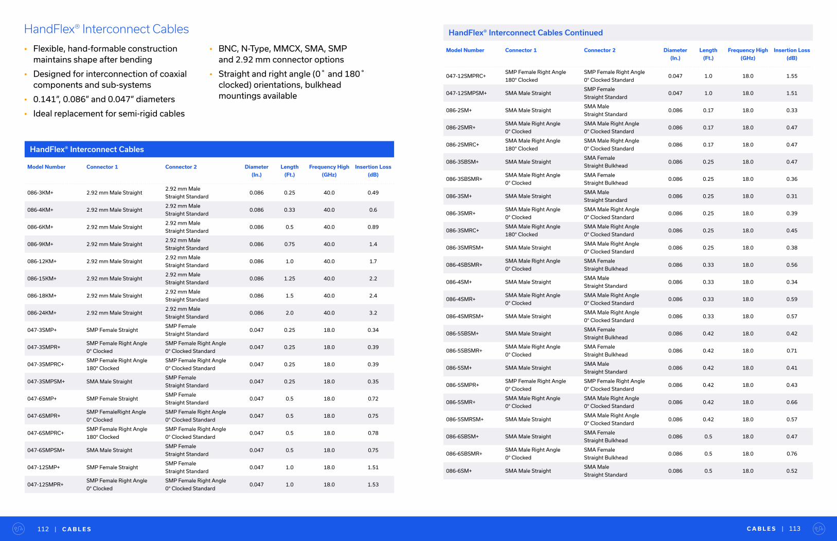
Model Number Connector 1 Connector 2 Diameter
(In.)
Length
(Ft.)
Frequency High
(GHz)
Insertion Loss
(dB)
086-3KM+ 2.92 mm Male Straight 2.92 mm Male
Straight Standard0.086 0.25 40.0 0.49
086-4KM+ 2.92 mm Male Straight 2.92 mm Male
Straight Standard0.086 0.33 40.0 0.6
086-6KM+ 2.92 mm Male Straight 2.92 mm Male
Straight Standard0.086 0.5 40.0 0.89
086-9KM+ 2.92 mm Male Straight 2.92 mm Male
Straight Standard0.086 0.75 40.0 1.4
086-12KM+ 2.92 mm Male Straight 2.92 mm Male
Straight Standard0.086 1.0 40.0 1.7
086-15KM+ 2.92 mm Male Straight 2.92 mm Male
Straight Standard0.086 1.25 40.0 2.2
086-18KM+ 2.92 mm Male Straight 2.92 mm Male
Straight Standard0.086 1.5 40.0 2.4
086-24KM+ 2.92 mm Male Straight 2.92 mm Male
Straight Standard0.086 2.0 40.0 3.2
047-3SMP+ SMP Female Straight SMP Female
Straight Standard0.047 0.25 18.0 0.34
047-3SMPR+SMP Female Right Angle
0° Clocked
SMP Female Right Angle
0° Clocked Standard0.047 0.25 18.0 0.39
047-3SMPRC+SMP Female Right Angle
180° Clocked
SMP Female Right Angle
0° Clocked Standard0.047 0.25 18.0 0.39
047-3SMPSM+ SMA Male Straight SMP Female
Straight Standard0.047 0.25 18.0 0.35
047-6SMP+ SMP Female Straight SMP Female
Straight Standard0.047 0.5 18.0 0.72
047-6SMPR+SMP FemaleRight Angle
0° Clocked
SMP Female Right Angle
0° Clocked Standard0.047 0.5 18.0 0.75
047-6SMPRC+SMP Female Right Angle
180° Clocked
SMP Female Right Angle
0° Clocked Standard0.047 0.5 18.0 0.78
047-6SMPSM+ SMA Male Straight SMP Female
Straight Standard0.047 0.5 18.0 0.75
047-12SMP+ SMP Female Straight SMP Female
Straight Standard0.047 1.0 18.0 1.51
047-12SMPR+SMP Female Right Angle
0° Clocked
SMP Female Right Angle
0° Clocked Standard0.047 1.0 18.0 1.53
HandFlex® Interconnect Cables
• Flexible, hand-formable construction maintains shape after bending
• Designed for interconnection of coaxial components and sub-systems
• 0.141”, 0.086” and 0.047” diameters
• Ideal replacement for semi-rigid cables
• BNC, N-Type, MMCX, SMA, SMP and 2.92 mm connector options
• Straight and right angle (0˚ and 180˚ clocked) orientations, bulkhead mountings available
HandFlex® Interconnect Cables
C A B L E S | 113| C A B L E S112
Model Number Connector 1 Connector 2 Diameter
(In.)
Length
(Ft.)
Frequency High
(GHz)
Insertion Loss
(dB)
047-12SMPRC+SMP Female Right Angle
180° Clocked
SMP Female Right Angle
0° Clocked Standard0.047 1.0 18.0 1.55
047-12SMPSM+ SMA Male Straight SMP Female
Straight Standard0.047 1.0 18.0 1.51
086-2SM+ SMA Male Straight SMA Male
Straight Standard0.086 0.17 18.0 0.33
086-2SMR+SMA Male Right Angle
0° Clocked
SMA Male Right Angle
0° Clocked Standard0.086 0.17 18.0 0.47
086-2SMRC+SMA Male Right Angle
180° Clocked
SMA Male Right Angle
0° Clocked Standard0.086 0.17 18.0 0.47
086-3SBSM+ SMA Male Straight SMA Female
Straight Bulkhead0.086 0.25 18.0 0.47
086-3SBSMR+SMA Male Right Angle
0° Clocked
SMA Female
Straight Bulkhead0.086 0.25 18.0 0.36
086-3SM+ SMA Male Straight SMA Male
Straight Standard0.086 0.25 18.0 0.31
086-3SMR+SMA Male Right Angle
0° Clocked
SMA Male Right Angle
0° Clocked Standard0.086 0.25 18.0 0.39
086-3SMRC+SMA Male Right Angle
180° Clocked
SMA Male Right Angle
0° Clocked Standard0.086 0.25 18.0 0.45
086-3SMRSM+ SMA Male Straight SMA Male Right Angle
0° Clocked Standard0.086 0.25 18.0 0.38
086-4SBSMR+SMA Male Right Angle
0° Clocked
SMA Female
Straight Bulkhead0.086 0.33 18.0 0.56
086-4SM+ SMA Male Straight SMA Male
Straight Standard0.086 0.33 18.0 0.34
086-4SMR+SMA Male Right Angle
0° Clocked
SMA Male Right Angle
0° Clocked Standard0.086 0.33 18.0 0.59
086-4SMRSM+ SMA Male Straight SMA Male Right Angle
0° Clocked Standard0.086 0.33 18.0 0.57
086-5SBSM+ SMA Male Straight SMA Female
Straight Bulkhead0.086 0.42 18.0 0.42
086-5SBSMR+SMA Male Right Angle
0° Clocked
SMA Female
Straight Bulkhead0.086 0.42 18.0 0.71
086-5SM+ SMA Male Straight SMA Male
Straight Standard0.086 0.42 18.0 0.41
086-5SMPR+SMP Female Right Angle
0° Clocked
SMP Female Right Angle
0° Clocked Standard0.086 0.42 18.0 0.43
086-5SMR+SMA Male Right Angle
0° Clocked
SMA Male Right Angle
0° Clocked Standard0.086 0.42 18.0 0.66
086-5SMRSM+ SMA Male Straight SMA Male Right Angle
0° Clocked Standard0.086 0.42 18.0 0.57
086-6SBSM+ SMA Male Straight SMA Female
Straight Bulkhead0.086 0.5 18.0 0.47
086-6SBSMR+SMA Male Right Angle
0° Clocked
SMA Female
Straight Bulkhead0.086 0.5 18.0 0.76
086-6SM+ SMA Male Straight SMA Male
Straight Standard0.086 0.5 18.0 0.52
HandFlex® Interconnect Cables Continued
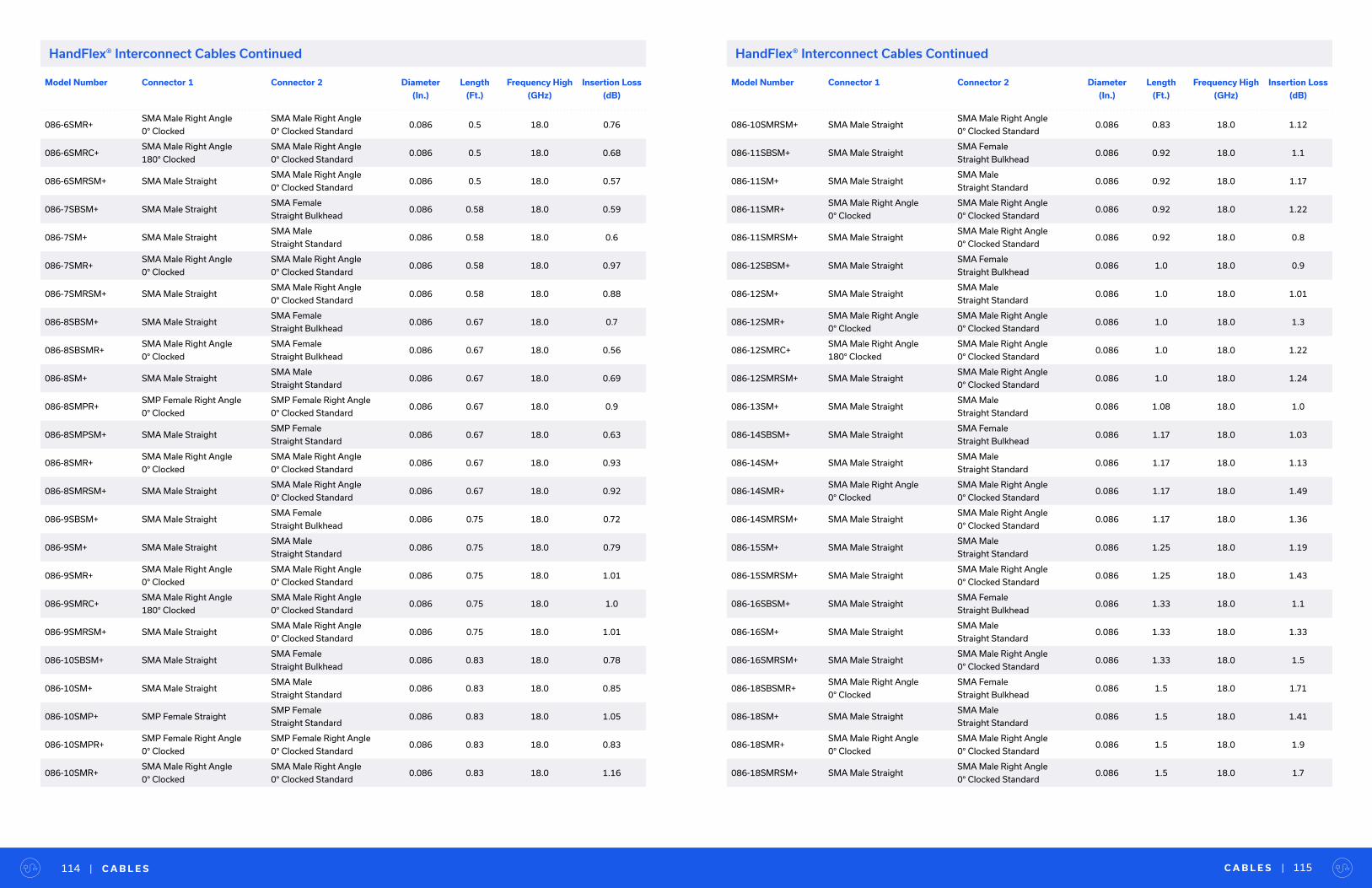
Model Number Connector 1 Connector 2 Diameter
(In.)
Length
(Ft.)
Frequency High
(GHz)
Insertion Loss
(dB)
086-6SMR+SMA Male Right Angle
0° Clocked
SMA Male Right Angle
0° Clocked Standard0.086 0.5 18.0 0.76
086-6SMRC+SMA Male Right Angle
180° Clocked
SMA Male Right Angle
0° Clocked Standard0.086 0.5 18.0 0.68
086-6SMRSM+ SMA Male Straight SMA Male Right Angle
0° Clocked Standard0.086 0.5 18.0 0.57
086-7SBSM+ SMA Male Straight SMA Female
Straight Bulkhead0.086 0.58 18.0 0.59
086-7SM+ SMA Male Straight SMA Male
Straight Standard0.086 0.58 18.0 0.6
086-7SMR+SMA Male Right Angle
0° Clocked
SMA Male Right Angle
0° Clocked Standard0.086 0.58 18.0 0.97
086-7SMRSM+ SMA Male Straight SMA Male Right Angle
0° Clocked Standard0.086 0.58 18.0 0.88
086-8SBSM+ SMA Male Straight SMA Female
Straight Bulkhead0.086 0.67 18.0 0.7
086-8SBSMR+SMA Male Right Angle
0° Clocked
SMA Female
Straight Bulkhead0.086 0.67 18.0 0.56
086-8SM+ SMA Male Straight SMA Male
Straight Standard0.086 0.67 18.0 0.69
086-8SMPR+SMP Female Right Angle
0° Clocked
SMP Female Right Angle
0° Clocked Standard0.086 0.67 18.0 0.9
086-8SMPSM+ SMA Male Straight SMP Female
Straight Standard0.086 0.67 18.0 0.63
086-8SMR+SMA Male Right Angle
0° Clocked
SMA Male Right Angle
0° Clocked Standard0.086 0.67 18.0 0.93
086-8SMRSM+ SMA Male Straight SMA Male Right Angle
0° Clocked Standard0.086 0.67 18.0 0.92
086-9SBSM+ SMA Male Straight SMA Female
Straight Bulkhead0.086 0.75 18.0 0.72
086-9SM+ SMA Male Straight SMA Male
Straight Standard0.086 0.75 18.0 0.79
086-9SMR+SMA Male Right Angle
0° Clocked
SMA Male Right Angle
0° Clocked Standard0.086 0.75 18.0 1.01
086-9SMRC+SMA Male Right Angle
180° Clocked
SMA Male Right Angle
0° Clocked Standard0.086 0.75 18.0 1.0
086-9SMRSM+ SMA Male Straight SMA Male Right Angle
0° Clocked Standard0.086 0.75 18.0 1.01
086-10SBSM+ SMA Male Straight SMA Female
Straight Bulkhead0.086 0.83 18.0 0.78
086-10SM+ SMA Male Straight SMA Male
Straight Standard0.086 0.83 18.0 0.85
086-10SMP+ SMP Female Straight SMP Female
Straight Standard0.086 0.83 18.0 1.05
086-10SMPR+SMP Female Right Angle
0° Clocked
SMP Female Right Angle
0° Clocked Standard0.086 0.83 18.0 0.83
086-10SMR+SMA Male Right Angle
0° Clocked
SMA Male Right Angle
0° Clocked Standard0.086 0.83 18.0 1.16
C A B L E S | 115| C A B L E S114
HandFlex® Interconnect Cables Continued
Model Number Connector 1 Connector 2 Diameter
(In.)
Length
(Ft.)
Frequency High
(GHz)
Insertion Loss
(dB)
086-10SMRSM+ SMA Male Straight SMA Male Right Angle
0° Clocked Standard0.086 0.83 18.0 1.12
086-11SBSM+ SMA Male Straight SMA Female
Straight Bulkhead0.086 0.92 18.0 1.1
086-11SM+ SMA Male Straight SMA Male
Straight Standard0.086 0.92 18.0 1.17
086-11SMR+SMA Male Right Angle
0° Clocked
SMA Male Right Angle
0° Clocked Standard0.086 0.92 18.0 1.22
086-11SMRSM+ SMA Male Straight SMA Male Right Angle
0° Clocked Standard0.086 0.92 18.0 0.8
086-12SBSM+ SMA Male Straight SMA Female
Straight Bulkhead0.086 1.0 18.0 0.9
086-12SM+ SMA Male Straight SMA Male
Straight Standard0.086 1.0 18.0 1.01
086-12SMR+SMA Male Right Angle
0° Clocked
SMA Male Right Angle
0° Clocked Standard0.086 1.0 18.0 1.3
086-12SMRC+SMA Male Right Angle
180° Clocked
SMA Male Right Angle
0° Clocked Standard0.086 1.0 18.0 1.22
086-12SMRSM+ SMA Male Straight SMA Male Right Angle
0° Clocked Standard0.086 1.0 18.0 1.24
086-13SM+ SMA Male Straight SMA Male
Straight Standard0.086 1.08 18.0 1.0
086-14SBSM+ SMA Male Straight SMA Female
Straight Bulkhead0.086 1.17 18.0 1.03
086-14SM+ SMA Male Straight SMA Male
Straight Standard0.086 1.17 18.0 1.13
086-14SMR+SMA Male Right Angle
0° Clocked
SMA Male Right Angle
0° Clocked Standard0.086 1.17 18.0 1.49
086-14SMRSM+ SMA Male Straight SMA Male Right Angle
0° Clocked Standard0.086 1.17 18.0 1.36
086-15SM+ SMA Male Straight SMA Male
Straight Standard0.086 1.25 18.0 1.19
086-15SMRSM+ SMA Male Straight SMA Male Right Angle
0° Clocked Standard0.086 1.25 18.0 1.43
086-16SBSM+ SMA Male Straight SMA Female
Straight Bulkhead0.086 1.33 18.0 1.1
086-16SM+ SMA Male Straight SMA Male
Straight Standard0.086 1.33 18.0 1.33
086-16SMRSM+ SMA Male Straight SMA Male Right Angle
0° Clocked Standard0.086 1.33 18.0 1.5
086-18SBSMR+SMA Male Right Angle
0° Clocked
SMA Female
Straight Bulkhead0.086 1.5 18.0 1.71
086-18SM+ SMA Male Straight SMA Male
Straight Standard0.086 1.5 18.0 1.41
086-18SMR+SMA Male Right Angle
0° Clocked
SMA Male Right Angle
0° Clocked Standard0.086 1.5 18.0 1.9
086-18SMRSM+ SMA Male Straight SMA Male Right Angle
0° Clocked Standard0.086 1.5 18.0 1.7
HandFlex® Interconnect Cables Continued
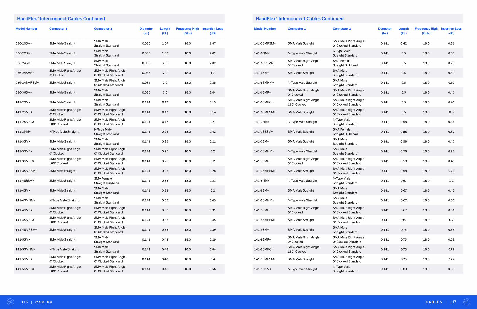
Model Number Connector 1 Connector 2 Diameter
(In.)
Length
(Ft.)
Frequency High
(GHz)
Insertion Loss
(dB)
086-20SM+ SMA Male Straight SMA Male
Straight Standard0.086 1.67 18.0 1.87
086-22SM+ SMA Male Straight SMA Male
Straight Standard0.086 1.83 18.0 2.02
086-24SM+ SMA Male Straight SMA Male
Straight Standard0.086 2.0 18.0 2.02
086-24SMR+SMA Male Right Angle
0° Clocked
SMA Male Right Angle
0° Clocked Standard0.086 2.0 18.0 1.7
086-24SMRSM+ SMA Male Straight SMA Male Right Angle
0° Clocked Standard0.086 2.0 18.0 2.25
086-36SM+ SMA Male Straight SMA Male
Straight Standard0.086 3.0 18.0 2.44
141-2SM+ SMA Male Straight SMA Male
Straight Standard0.141 0.17 18.0 0.15
141-2SMR+SMA Male Right Angle
0° Clocked
SMA Male Right Angle
0° Clocked Standard0.141 0.17 18.0 0.14
141-2SMRC+SMA Male Right Angle
180° Clocked
SMA Male Right Angle
0° Clocked Standard0.141 0.17 18.0 0.21
141-3NM+ N-Type Male Straight N-Type Male
Straight Standard0.141 0.25 18.0 0.42
141-3SM+ SMA Male Straight SMA Male
Straight Standard0.141 0.25 18.0 0.21
141-3SMR+SMA Male Right Angle
0° Clocked
SMA Male Right Angle
0° Clocked Standard0.141 0.25 18.0 0.2
141-3SMRC+SMA Male Right Angle
180° Clocked
SMA Male Right Angle
0° Clocked Standard0.141 0.25 18.0 0.2
141-3SMRSM+ SMA Male Straight SMA Male Right Angle
0° Clocked Standard0.141 0.25 18.0 0.28
141-4SBSM+ SMA Male Straight SMA Female
Straight Bulkhead0.141 0.33 18.0 0.21
141-4SM+ SMA Male Straight SMA Male
Straight Standard0.141 0.33 18.0 0.2
141-4SMNM+ N-Type Male Straight SMA Male
Straight Standard0.141 0.33 18.0 0.49
141-4SMR+SMA Male Right Angle
0° Clocked
SMA Male Right Angle
0° Clocked Standard0.141 0.33 18.0 0.31
141-4SMRC+SMA Male Right Angle
180° Clocked
SMA Male Right Angle
0° Clocked Standard0.141 0.33 18.0 0.45
141-4SMRSM+ SMA Male Straight SMA Male Right Angle
0° Clocked Standard0.141 0.33 18.0 0.39
141-5SM+ SMA Male Straight SMA Male
Straight Standard0.141 0.42 18.0 0.29
141-5SMNM+ N-Type Male Straight SMA Male
Straight Standard0.141 0.42 18.0 0.84
141-5SMR+SMA Male Right Angle
0° Clocked
SMA Male Right Angle
0° Clocked Standard0.141 0.42 18.0 0.4
141-5SMRC+SMA Male Right Angle
180° Clocked
SMA Male Right Angle
0° Clocked Standard0.141 0.42 18.0 0.56
C A B L E S | 117| C A B L E S116
HandFlex® Interconnect Cables Continued
Model Number Connector 1 Connector 2 Diameter
(In.)
Length
(Ft.)
Frequency High
(GHz)
Insertion Loss
(dB)
141-5SMRSM+ SMA Male Straight SMA Male Right Angle
0° Clocked Standard0.141 0.42 18.0 0.31
141-6NM+ N-Type Male Straight N-Type Male
Straight Standard0.141 0.5 18.0 0.35
141-6SBSMR+SMA Male Right Angle
0° Clocked
SMA Female
Straight Bulkhead0.141 0.5 18.0 0.28
141-6SM+ SMA Male Straight SMA Male
Straight Standard0.141 0.5 18.0 0.39
141-6SMNM+ N-Type Male Straight SMA Male
Straight Standard0.141 0.5 18.0 0.67
141-6SMR+SMA Male Right Angle
0° Clocked
SMA Male Right Angle
0° Clocked Standard0.141 0.5 18.0 0.46
141-6SMRC+SMA Male Right Angle
180° Clocked
SMA Male Right Angle
0° Clocked Standard0.141 0.5 18.0 0.46
141-6SMRSM+ SMA Male Straight SMA Male Right Angle
0° Clocked Standard0.141 0.5 18.0 0.5
141-7NM+ N-Type Male Straight N-Type Male
Straight Standard0.141 0.58 18.0 0.46
141-7SBSM+ SMA Male Straight SMA Female
Straight Bulkhead0.141 0.58 18.0 0.37
141-7SM+ SMA Male Straight SMA Male
Straight Standard0.141 0.58 18.0 0.47
141-7SMNM+ N-Type Male Straight SMA Male
Straight Standard0.141 0.58 18.0 0.27
141-7SMR+SMA Male Right Angle
0° Clocked
SMA Male Right Angle
0° Clocked Standard0.141 0.58 18.0 0.45
141-7SMRSM+ SMA Male Straight SMA Male Right Angle
0° Clocked Standard0.141 0.58 18.0 0.72
141-8NM+ N-Type Male Straight N-Type Male
Straight Standard0.141 0.67 18.0 1.2
141-8SM+ SMA Male Straight SMA Male
Straight Standard0.141 0.67 18.0 0.42
141-8SMNM+ N-Type Male Straight SMA Male
Straight Standard0.141 0.67 18.0 0.86
141-8SMR+SMA Male Right Angle
0° Clocked
SMA Male Right Angle
0° Clocked Standard0.141 0.67 18.0 0.51
141-8SMRSM+ SMA Male Straight SMA Male Right Angle
0° Clocked Standard0.141 0.67 18.0 0.7
141-9SM+ SMA Male Straight SMA Male
Straight Standard0.141 0.75 18.0 0.55
141-9SMR+SMA Male Right Angle
0° Clocked
SMA Male Right Angle
0° Clocked Standard0.141 0.75 18.0 0.58
141-9SMRC+SMA Male Right Angle
180° Clocked
SMA Male Right Angle
0° Clocked Standard0.141 0.75 18.0 0.72
141-9SMRSM+ SMA Male Straight SMA Male Right Angle
0° Clocked Standard0.141 0.75 18.0 0.72
141-10NM+ N-Type Male Straight N-Type Male
Straight Standard0.141 0.83 18.0 0.53
HandFlex® Interconnect Cables Continued

Model Number Connector 1 Connector 2 Diameter
(In.)
Length
(Ft.)
Frequency High
(GHz)
Insertion Loss
(dB)
141-10SM+ SMA Male Straight SMA Male
Straight Standard0.141 0.83 18.0 0.59
141-10SMNM+ N-Type Male Straight SMA Male
Straight Standard0.141 0.83 18.0 0.69
141-10SMRNM+ N-Type Male Straight SMA Male Right Angle
0° Clocked Standard0.141 0.83 18.0 0.5
141-10SMRSM+ SMA Male Straight SMA Male Right Angle
0° Clocked Standard0.141 0.83 18.0 0.8
141-11SM+ SMA Male Straight SMA Male
Straight Standard0.141 0.92 18.0 0.57
141-11SMRSM+ SMA Male Straight SMA Male Right Angle
0° Clocked Standard0.141 0.92 18.0 0.8
141-12NM+ N-Type Male Straight N-Type Male
Straight Standard0.141 1.0 18.0 0.69
141-12SM+ SMA Male Straight SMA Male
Straight Standard0.141 1.0 18.0 0.66
141-12SMNM+ N-Type Male Straight SMA Male
Straight Standard0.141 1.0 18.0 0.77
141-12SMR+SMA Male Right Angle
0° Clocked
SMA Male Right Angle
0° Clocked Standard0.141 1.0 18.0 0.76
141-12SMRC+SMA Male Right Angle
180° Clocked
SMA Male Right Angle
0° Clocked Standard0.141 1.0 18.0 0.72
141-12SMRSM+ SMA Male Straight SMA Male Right Angle
0° Clocked Standard0.141 1.0 18.0 0.8
141-13SM+ SMA Male Straight SMA Male
Straight Standard0.141 1.08 18.0 0.5
141-13SMRSM+ SMA Male Straight SMA Male Right Angle
0° Clocked Standard0.141 1.08 18.0 0.92
141-14SM+ SMA Male Straight SMA Male
Straight Standard0.141 1.17 18.0 0.73
141-14SMRSM+ SMA Male Straight SMA Male Right Angle
0° Clocked Standard0.141 1.17 18.0 1.03
141-15SM+ SMA Male Straight SMA Male
Straight Standard0.141 1.25 18.0 0.85
141-15SMRSM+ SMA Male Straight SMA Male Right Angle
0° Clocked Standard0.141 1.25 18.0 1.0
141-16SM+ SMA Male Straight SMA Male
Straight Standard0.141 1.33 18.0 0.9
141-16SMRSM+ SMA Male Straight SMA Male Right Angle
0° Clocked Standard0.141 1.33 18.0 1.04
141-17SM+ SMA Male Straight SMA Male
Straight Standard0.141 1.42 18.0 0.96
141-17SMRSM+ SMA Male Straight SMA Male Right Angle
0° Clocked Standard0.141 1.42 18.0 1.11
141-18SM+ SMA Male Straight SMA Male
Straight Standard0.141 1.5 18.0 0.89
141-18SMNM+ N-Type Male Straight SMA Male
Straight Standard0.141 1.5 18.0 1.19
C A B L E S | 119| C A B L E S118
HandFlex® Interconnect Cables Continued
Model Number Connector 1 Connector 2 Diameter
(In.)
Length
(Ft.)
Frequency High
(GHz)
Insertion Loss
(dB)
141-18SMRSM+ SMA Male Straight SMA Male Right Angle
0° Clocked Standard0.141 1.5 18.0 0.93
141-19SM+ SMA Male Straight SMA Male S
traight Standard0.141 1.58 18.0 0.86
141-0.5MSM+ SMA Male Straight SMA Male
Straight Standard0.141 1.64 18.0 0.86
141-20SM+ SMA Male Straight SMA Male
Straight Standard0.141 1.67 18.0 0.92
141-20SMRSM+ SMA Male Straight SMA Male Right Angle
0° Clocked Standard0.141 1.67 18.0 1.12
141-22SM+ SMA Male Straight SMA Male
Straight Standard0.141 1.83 18.0 1.12
141-24NM+ N-Type Male Straight N-Type Male
Straight Standard0.141 2.0 18.0 1.21
141-24SBSM+ SMA Male Straight SMA Female
Straight Bulkhead0.141 2.0 18.0 1.1
141-24SM+ SMA Male Straight SMA Male
Straight Standard0.141 2.0 18.0 1.12
141-24SMNM+ N-Type Male Straight SMA Male
Straight Standard0.141 2.0 18.0 1.32
141-24SMRSM+ SMA Male Straight SMA Male Right Angle
0° Clocked Standard0.141 2.0 18.0 1.55
141-26SM+ SMA Male Straight SMA Male
Straight Standard0.141 2.17 18.0 1.2
141-30SM+ SMA Male Straight SMA Male
Straight Standard0.141 2.5 18.0 1.27
141-32SM+ SMA Male Straight SMA Male
Straight Standard0.141 2.67 18.0 1.3
141-36SBSMR+SMA Male Right Angle
0° Clocked
SMA Female
Straight Bulkhead0.141 3.0 18.0 1.6
141-36SM+ SMA Male Straight SMA Male
Straight Standard0.141 3.0 18.0 1.51
141-36SMRSM+ SMA Male Straight SMA Male Right Angle
0° Clocked Standard0.141 3.0 18.0 2.19
141-1MSM+ SMA Male Straight SMA Male
Straight Standard0.141 3.28 18.0 1.67
141-40SM+ SMA Male Straight SMA Male
Straight Standard0.141 3.33 18.0 1.9
141-50SM+ SMA Male Straight SMA Male
Straight Standard0.141 4.17 18.0 2.5
141-1.5MSM+ SMA Male Straight SMA Male
Straight Standard0.141 4.92 18.0 3.53
141-60SM+ SMA Male Straight SMA Male
Straight Standard0.141 5.0 18.0 2.5
141-72SM+ SMA Male Straight SMA Male
Straight Standard0.141 6.0 18.0 3.1
141-2MSM+ SMA Male Straight SMA Male
Straight Standard0.141 6.56 18.0 3.36
HandFlex® Interconnect Cables Continued
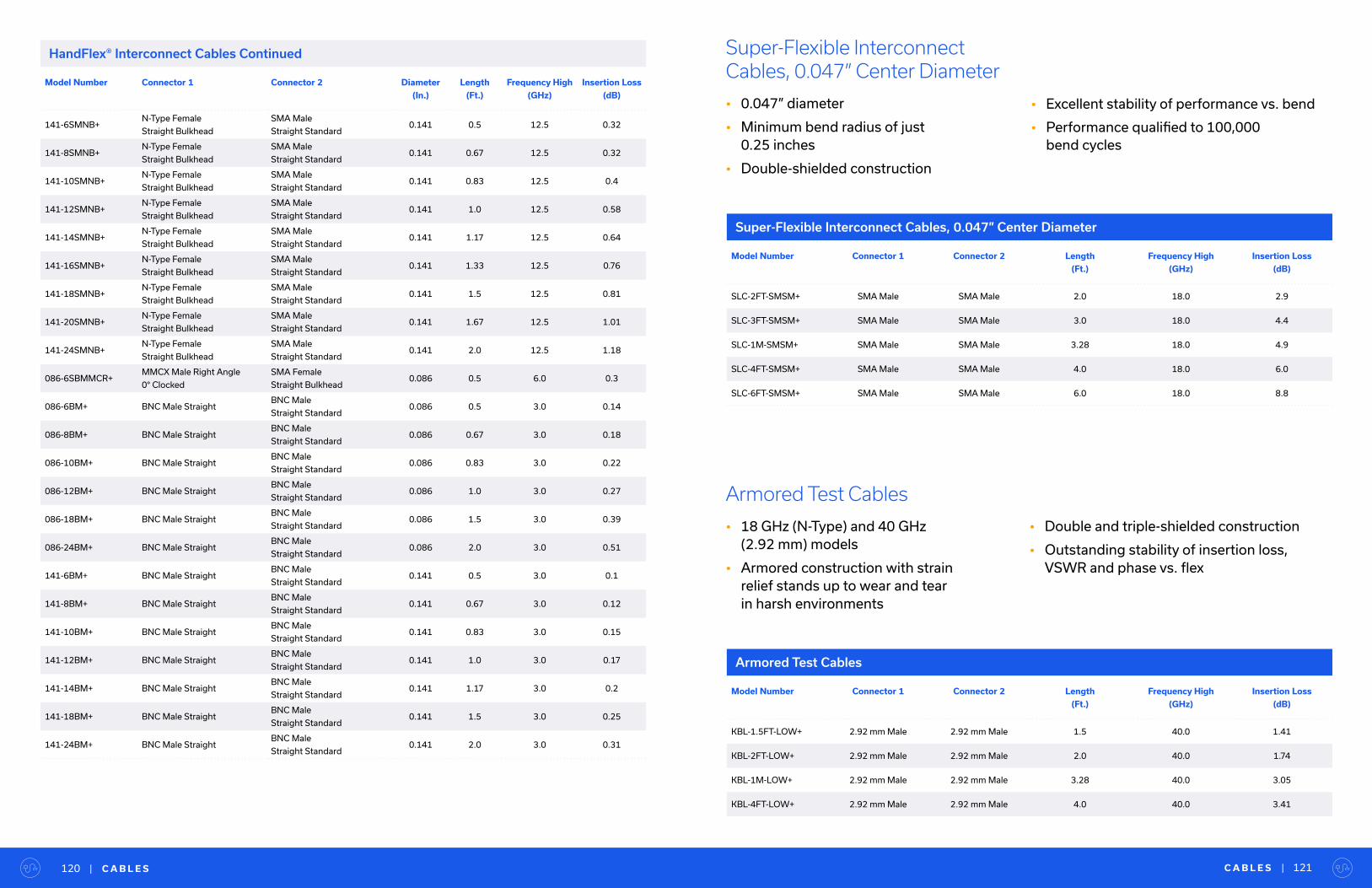
Model Number Connector 1 Connector 2 Diameter
(In.)
Length
(Ft.)
Frequency High
(GHz)
Insertion Loss
(dB)
141-6SMNB+N-Type Female
Straight Bulkhead
SMA Male
Straight Standard0.141 0.5 12.5 0.32
141-8SMNB+N-Type Female
Straight Bulkhead
SMA Male
Straight Standard0.141 0.67 12.5 0.32
141-10SMNB+N-Type Female
Straight Bulkhead
SMA Male
Straight Standard0.141 0.83 12.5 0.4
141-12SMNB+N-Type Female
Straight Bulkhead
SMA Male
Straight Standard0.141 1.0 12.5 0.58
141-14SMNB+N-Type Female
Straight Bulkhead
SMA Male
Straight Standard0.141 1.17 12.5 0.64
141-16SMNB+N-Type Female
Straight Bulkhead
SMA Male
Straight Standard0.141 1.33 12.5 0.76
141-18SMNB+N-Type Female
Straight Bulkhead
SMA Male
Straight Standard0.141 1.5 12.5 0.81
141-20SMNB+N-Type Female
Straight Bulkhead
SMA Male
Straight Standard0.141 1.67 12.5 1.01
141-24SMNB+N-Type Female
Straight Bulkhead
SMA Male
Straight Standard0.141 2.0 12.5 1.18
086-6SBMMCR+MMCX Male Right Angle
0° Clocked
SMA Female
Straight Bulkhead0.086 0.5 6.0 0.3
086-6BM+ BNC Male Straight BNC Male
Straight Standard0.086 0.5 3.0 0.14
086-8BM+ BNC Male Straight BNC Male
Straight Standard0.086 0.67 3.0 0.18
086-10BM+ BNC Male Straight BNC Male
Straight Standard0.086 0.83 3.0 0.22
086-12BM+ BNC Male Straight BNC Male
Straight Standard0.086 1.0 3.0 0.27
086-18BM+ BNC Male Straight BNC Male
Straight Standard0.086 1.5 3.0 0.39
086-24BM+ BNC Male Straight BNC Male
Straight Standard0.086 2.0 3.0 0.51
141-6BM+ BNC Male Straight BNC Male
Straight Standard0.141 0.5 3.0 0.1
141-8BM+ BNC Male Straight BNC Male
Straight Standard0.141 0.67 3.0 0.12
141-10BM+ BNC Male Straight BNC Male
Straight Standard0.141 0.83 3.0 0.15
141-12BM+ BNC Male Straight BNC Male
Straight Standard0.141 1.0 3.0 0.17
141-14BM+ BNC Male Straight BNC Male
Straight Standard0.141 1.17 3.0 0.2
141-18BM+ BNC Male Straight BNC Male
Straight Standard0.141 1.5 3.0 0.25
141-24BM+ BNC Male Straight BNC Male
Straight Standard0.141 2.0 3.0 0.31
C A B L E S | 121| C A B L E S120
HandFlex® Interconnect Cables Continued
Armored Test Cables
• 18 GHz (N-Type) and 40 GHz (2.92 mm) models
• Armored construction with strain relief stands up to wear and tear in harsh environments
• Double and triple-shielded construction
• Outstanding stability of insertion loss, VSWR and phase vs. flex
Model Number Connector 1 Connector 2 Length
(Ft.)
Frequency High
(GHz)
Insertion Loss
(dB)
KBL-1.5FT-LOW+ 2.92 mm Male 2.92 mm Male 1.5 40.0 1.41
KBL-2FT-LOW+ 2.92 mm Male 2.92 mm Male 2.0 40.0 1.74
KBL-1M-LOW+ 2.92 mm Male 2.92 mm Male 3.28 40.0 3.05
KBL-4FT-LOW+ 2.92 mm Male 2.92 mm Male 4.0 40.0 3.41
Armored Test Cables
Model Number Connector 1 Connector 2 Length
(Ft.)
Frequency High
(GHz)
Insertion Loss
(dB)
SLC-2FT-SMSM+ SMA Male SMA Male 2.0 18.0 2.9
SLC-3FT-SMSM+ SMA Male SMA Male 3.0 18.0 4.4
SLC-1M-SMSM+ SMA Male SMA Male 3.28 18.0 4.9
SLC-4FT-SMSM+ SMA Male SMA Male 4.0 18.0 6.0
SLC-6FT-SMSM+ SMA Male SMA Male 6.0 18.0 8.8
Super-Flexible Interconnect Cables, 0.047” Center Diameter
• 0.047” diameter
• Minimum bend radius of just 0.25 inches
• Double-shielded construction
• Excellent stability of performance vs. bend
• Performance qualified to 100,000 bend cycles
Super-Flexible Interconnect Cables, 0.047” Center Diameter

Economy Precision Test Cables
• Cost-effective options for precision measurements up to 67 GHz
• Stable performance in bend radii as tight as 10 mm
• 2.92 mm, 2.4 mm and 1.85 mm connector options
Model Number Connector 1 Connector 2 Length
(Ft.)
Frequency High
(GHz)
Insertion Loss
(dB)
E67-2FT-EMEM+ 1.85 mm Male 1.85 mm Male 2.0 67.0 2.7
E67-3FT-EMEM+ 1.85 mm Male 1.85 mm Male 3.0 67.0 4.2
E67-1M-EMEM+ 1.85 mm Male 1.85 mm Male 3.28 67.0 5.5
E50-2FT-VMVM+ 2.4 mm Male 2.4 mm Male 2.0 50.0 3.5
E50-3FT-VMVM+ 2.4 mm Male 2.4 mm Male 3.0 50.0 6.3
E40-2FT-KMKM+ 2.92 mm Male 2.92 mm Male 2.0 40.0 3.4
E40-3FT-KMKM+ 2.92 mm Male 2.92 mm Male 3.0 40.0 5.1
E40-1M-KMKM+ 2.92 mm Male 2.92 mm Male 3.28 40.0 5.4
E40-6FT-KMKM+ 2.92 mm Male 2.92 mm Male 6.0 40.0 8.7
Armored Test Cables Continued
Economy Precision Test Cables
C A B L E S | 123| C A B L E S122
Model Number Connector 1 Connector 2 Length
(Ft.)
Frequency High
(GHz)
Insertion Loss
(dB)
KBL-2M-LOW+ 2.92 mm Male 2.92 mm Male 6.56 40.0 5.46
APC-4FT-SMNM+ N-Type Male SMA Male 4.0 18.0 2.55
APC-6FT-NMNM+ N-Type Male N-Type Male 6.0 18.0 3.8
APC-10FT-NMNM+ N-Type Male N-Type Male 10.0 18.0 6.3
APC-15FT-NMNM+ N-Type Male N-Type Male 15.0 18.0 9.0
Model Number Connector 1 Connector 2 Length
(Ft.)
Frequency High
(GHz)
Insertion Loss
(dB)
FLC-1FT-SMSM+ SMA Male SMA Male 1.0 26.0 1.1
FLC-1.5FT-SMSM+ SMA Male SMA Male 1.5 26.0 1.26
FLC-2FT-SMSM+ SMA Male SMA Male 2.0 26.0 1.61
FLC-3FT-SMSM+ SMA Male SMA Male 3.0 26.0 2.5
FLC-1M-SMSM+ SMA Male SMA Male 3.28 26.0 2.62
FLC-4FT-SMSM+ SMA Male SMA Male 4.0 26.0 3.55
FLC-6FT-SMSM+ SMA Male SMA Male 6.0 26.0 5.04
FLC-2M-SMSM+ SMA Male SMA Male 6.56 26.0 5.5
FLC-2M-SMNM+ N-Type Male SMA Male 6.56 18.0 4.03
Flexible Test Cables
• DC to 26 GHz
• Stable performance in bend radii as tight as 2.4 inches
• SMA and N-Type connector options
• Performance qualified to 20,000 bend cycles
Flexible Test Cables
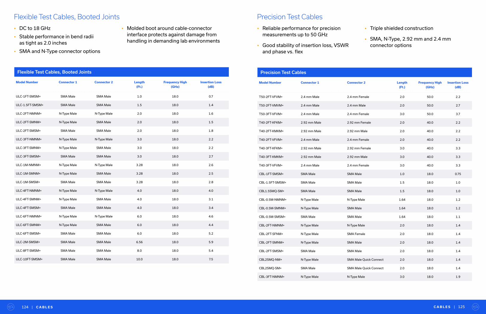
C A B L E S | 125| C A B L E S124
Flexible Test Cables, Booted Joints
• DC to 18 GHz
• Stable performance in bend radii as tight as 2.0 inches
• SMA and N-Type connector options
• Molded boot around cable-connector interface protects against damage from handling in demanding lab environments
Model Number Connector 1 Connector 2 Length
(Ft.)
Frequency High
(GHz)
Insertion Loss
(dB)
ULC-1FT-SMSM+ SMA Male SMA Male 1.0 18.0 0.7
ULC-1.5FT-SMSM+ SMA Male SMA Male 1.5 18.0 1.4
ULC-2FT-NMNM+ N-Type Male N-Type Male 2.0 18.0 1.6
ULC-2FT-SMNM+ N-Type Male SMA Male 2.0 18.0 1.5
ULC-2FT-SMSM+ SMA Male SMA Male 2.0 18.0 1.8
ULC-3FT-NMNM+ N-Type Male N-Type Male 3.0 18.0 2.2
ULC-3FT-SMNM+ N-Type Male SMA Male 3.0 18.0 2.2
ULC-3FT-SMSM+ SMA Male SMA Male 3.0 18.0 2.7
ULC-1M-NMNM+ N-Type Male N-Type Male 3.28 18.0 2.6
ULC-1M-SMNM+ N-Type Male SMA Male 3.28 18.0 2.5
ULC-1M-SMSM+ SMA Male SMA Male 3.28 18.0 2.8
ULC-4FT-NMNM+ N-Type Male N-Type Male 4.0 18.0 4.0
ULC-4FT-SMNM+ N-Type Male SMA Male 4.0 18.0 3.1
ULC-4FT-SMSM+ SMA Male SMA Male 4.0 18.0 3.4
ULC-6FT-NMNM+ N-Type Male N-Type Male 6.0 18.0 4.6
ULC-6FT-SMNM+ N-Type Male SMA Male 6.0 18.0 4.4
ULC-6FT-SMSM+ SMA Male SMA Male 6.0 18.0 5.2
ULC-2M-SMSM+ SMA Male SMA Male 6.56 18.0 5.9
ULC-8FT-SMSM+ SMA Male SMA Male 8.0 18.0 5.4
ULC-10FT-SMSM+ SMA Male SMA Male 10.0 18.0 7.5
Flexible Test Cables, Booted Joints
Precision Test Cables
• Reliable performance for precision measurements up to 50 GHz
• Good stability of insertion loss, VSWR and phase vs. flex
• Triple shielded construction
• SMA, N-Type, 2.92 mm and 2.4 mm connector options
Precision Test Cables
Model Number Connector 1 Connector 2 Length
(Ft.)
Frequency High
(GHz)
Insertion Loss
(dB)
T50-2FT-VFVM+ 2.4 mm Male 2.4 mm Female 2.0 50.0 2.2
T50-2FT-VMVM+ 2.4 mm Male 2.4 mm Male 2.0 50.0 2.7
T50-3FT-VFVM+ 2.4 mm Male 2.4 mm Female 3.0 50.0 3.7
T40-2FT-KFKM+ 2.92 mm Male 2.92 mm Female 2.0 40.0 2.2
T40-2FT-KMKM+ 2.92 mm Male 2.92 mm Male 2.0 40.0 2.2
T40-2FT-VFVM+ 2.4 mm Male 2.4 mm Female 2.0 40.0 2.2
T40-3FT-KFKM+ 2.92 mm Male 2.92 mm Female 3.0 40.0 3.3
T40-3FT-KMKM+ 2.92 mm Male 2.92 mm Male 3.0 40.0 3.3
T40-3FT-VFVM+ 2.4 mm Male 2.4 mm Female 3.0 40.0 3.3
CBL-1FT-SMSM+ SMA Male SMA Male 1.0 18.0 0.75
CBL-1.5FT-SMSM+ SMA Male SMA Male 1.5 18.0 1.0
CBL1.5SMQ-SM+ SMA Male SMA Male 1.5 18.0 1.0
CBL-0.5M-NMNM+ N-Type Male N-Type Male 1.64 18.0 1.2
CBL-0.5M-SMNM+ N-Type Male SMA Male 1.64 18.0 1.2
CBL-0.5M-SMSM+ SMA Male SMA Male 1.64 18.0 1.1
CBL-2FT-NMNM+ N-Type Male N-Type Male 2.0 18.0 1.4
CBL-2FT-SFNM+ N-Type Male SMA Female 2.0 18.0 1.4
CBL-2FT-SMNM+ N-Type Male SMA Male 2.0 18.0 1.4
CBL-2FT-SMSM+ SMA Male SMA Male 2.0 18.0 1.4
CBL2SMQ-NM+ N-Type Male SMA Male Quick Connect 2.0 18.0 1.4
CBL2SMQ-SM+ SMA Male SMA Male Quick Connect 2.0 18.0 1.4
CBL-3FT-NMNM+ N-Type Male N-Type Male 3.0 18.0 1.9
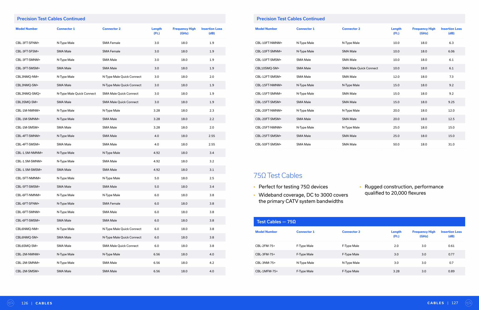
Precision Test Cables Continued
Model Number Connector 1 Connector 2 Length
(Ft.)
Frequency High
(GHz)
Insertion Loss
(dB)
CBL-3FT-SFNM+ N-Type Male SMA Female 3.0 18.0 1.9
CBL-3FT-SFSM+ SMA Male SMA Female 3.0 18.0 1.9
CBL-3FT-SMNM+ N-Type Male SMA Male 3.0 18.0 1.9
CBL-3FT-SMSM+ SMA Male SMA Male 3.0 18.0 1.9
CBL3NMQ-NM+ N-Type Male N-Type Male Quick Connect 3.0 18.0 2.0
CBL3NMQ-SM+ SMA Male N-Type Male Quick Connect 3.0 18.0 1.9
CBL3NMQ-SMQ+ N-Type Male Quick Connect SMA Male Quick Connect 3.0 18.0 1.9
CBL3SMQ-SM+ SMA Male SMA Male Quick Connect 3.0 18.0 1.9
CBL-1M-NMNM+ N-Type Male N-Type Male 3.28 18.0 2.3
CBL-1M-SMNM+ N-Type Male SMA Male 3.28 18.0 2.2
CBL-1M-SMSM+ SMA Male SMA Male 3.28 18.0 2.0
CBL-4FT-SMNM+ N-Type Male SMA Male 4.0 18.0 2.55
CBL-4FT-SMSM+ SMA Male SMA Male 4.0 18.0 2.55
CBL-1.5M-NMNM+ N-Type Male N-Type Male 4.92 18.0 3.4
CBL-1.5M-SMNM+ N-Type Male SMA Male 4.92 18.0 3.2
CBL-1.5M-SMSM+ SMA Male SMA Male 4.92 18.0 3.1
CBL-5FT-NMNM+ N-Type Male N-Type Male 5.0 18.0 2.5
CBL-5FT-SMSM+ SMA Male SMA Male 5.0 18.0 3.4
CBL-6FT-NMNM+ N-Type Male N-Type Male 6.0 18.0 3.8
CBL-6FT-SFNM+ N-Type Male SMA Female 6.0 18.0 3.8
CBL-6FT-SMNM+ N-Type Male SMA Male 6.0 18.0 3.8
CBL-6FT-SMSM+ SMA Male SMA Male 6.0 18.0 3.8
CBL6NMQ-NM+ N-Type Male N-Type Male Quick Connect 6.0 18.0 3.8
CBL6NMQ-SM+ SMA Male N-Type Male Quick Connect 6.0 18.0 3.8
CBL6SMQ-SM+ SMA Male SMA Male Quick Connect 6.0 18.0 3.8
CBL-2M-NMNM+ N-Type Male N-Type Male 6.56 18.0 4.0
CBL-2M-SMNM+ N-Type Male SMA Male 6.56 18.0 4.2
CBL-2M-SMSM+ SMA Male SMA Male 6.56 18.0 4.0
C A B L E S | 127| C A B L E S126
Model Number Connector 1 Connector 2 Length
(Ft.)
Frequency High
(GHz)
Insertion Loss
(dB)
CBL-10FT-NMNM+ N-Type Male N-Type Male 10.0 18.0 6.3
CBL-10FT-SMNM+ N-Type Male SMA Male 10.0 18.0 6.06
CBL-10FT-SMSM+ SMA Male SMA Male 10.0 18.0 6.1
CBL10SMQ-SM+ SMA Male SMA Male Quick Connect 10.0 18.0 6.1
CBL-12FT-SMSM+ SMA Male SMA Male 12.0 18.0 7.3
CBL-15FT-NMNM+ N-Type Male N-Type Male 15.0 18.0 9.2
CBL-15FT-SMNM+ N-Type Male SMA Male 15.0 18.0 9.2
CBL-15FT-SMSM+ SMA Male SMA Male 15.0 18.0 9.25
CBL-20FT-NMNM+ N-Type Male N-Type Male 20.0 18.0 12.0
CBL-20FT-SMSM+ SMA Male SMA Male 20.0 18.0 12.5
CBL-25FT-NMNM+ N-Type Male N-Type Male 25.0 18.0 15.0
CBL-25FT-SMSM+ SMA Male SMA Male 25.0 18.0 15.0
CBL-50FT-SMSM+ SMA Male SMA Male 50.0 18.0 31.0
Precision Test Cables Continued
Model Number Connector 1 Connector 2 Length
(Ft.)
Frequency High
(GHz)
Insertion Loss
(dB)
CBL-2FM-75+ F-Type Male F-Type Male 2.0 3.0 0.61
CBL-3FM-75+ F-Type Male F-Type Male 3.0 3.0 0.77
CBL-3NM-75+ N-Type Male N-Type Male 3.0 3.0 0.7
CBL-1MFM-75+ F-Type Male F-Type Male 3.28 3.0 0.89
75Ω Test Cables
• Perfect for testing 75Ω devices
• Wideband coverage, DC to 3000 covers the primary CATV system bandwidths
• Rugged construction, performance qualified to 20,000 flexures
Test Cables — 75Ω
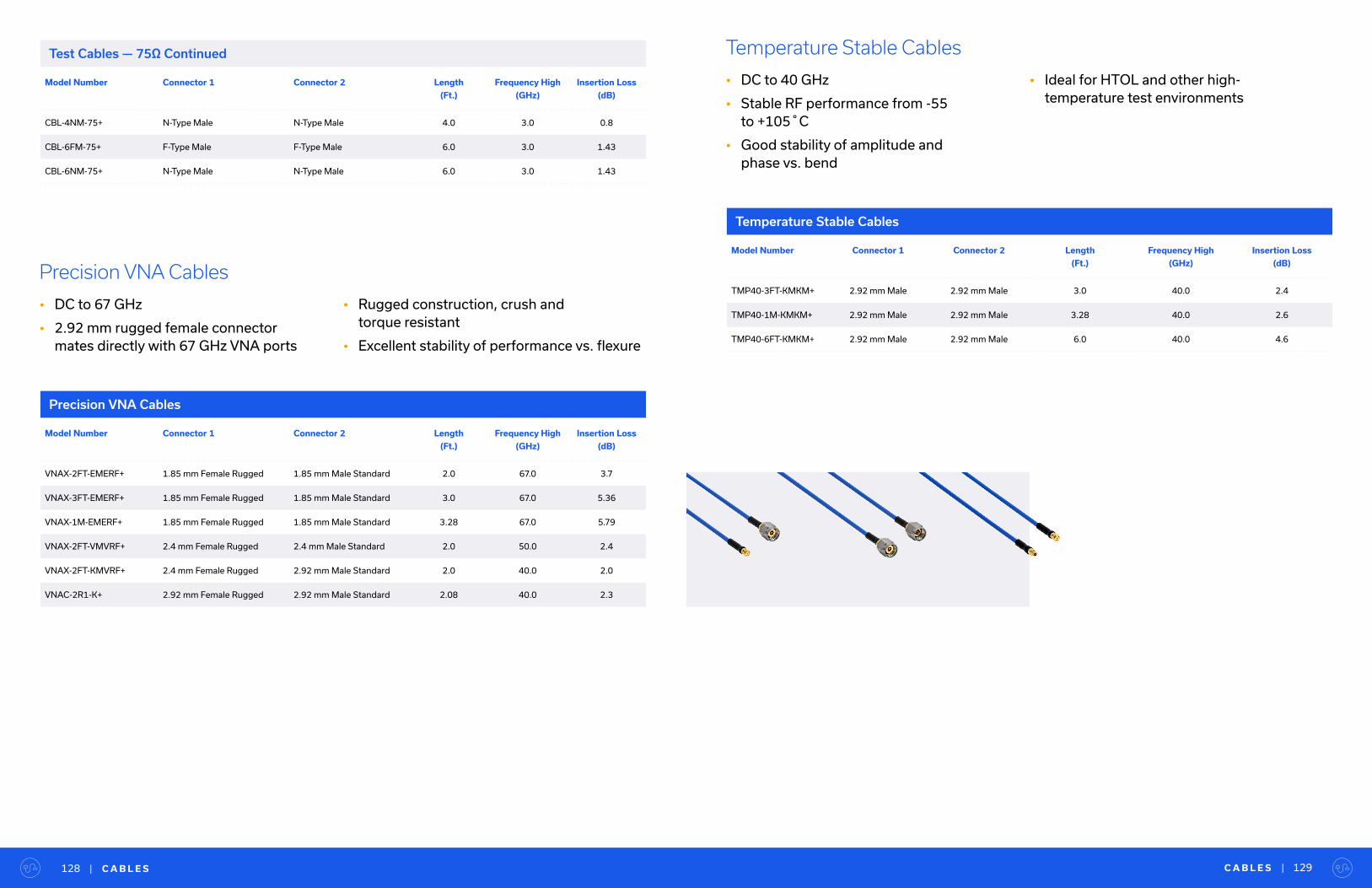
C A B L E S | 129| C A B L E S128
Temperature Stable Cables
• DC to 40 GHz
• Stable RF performance from -55 to +105˚C
• Good stability of amplitude and phase vs. bend
• Ideal for HTOL and other high- temperature test environments
Model Number Connector 1 Connector 2 Length
(Ft.)
Frequency High
(GHz)
Insertion Loss
(dB)
TMP40-3FT-KMKM+ 2.92 mm Male 2.92 mm Male 3.0 40.0 2.4
TMP40-1M-KMKM+ 2.92 mm Male 2.92 mm Male 3.28 40.0 2.6
TMP40-6FT-KMKM+ 2.92 mm Male 2.92 mm Male 6.0 40.0 4.6
Temperature Stable Cables
Model Number Connector 1 Connector 2 Length
(Ft.)
Frequency High
(GHz)
Insertion Loss
(dB)
VNAX-2FT-EMERF+ 1.85 mm Female Rugged 1.85 mm Male Standard 2.0 67.0 3.7
VNAX-3FT-EMERF+ 1.85 mm Female Rugged 1.85 mm Male Standard 3.0 67.0 5.36
VNAX-1M-EMERF+ 1.85 mm Female Rugged 1.85 mm Male Standard 3.28 67.0 5.79
VNAX-2FT-VMVRF+ 2.4 mm Female Rugged 2.4 mm Male Standard 2.0 50.0 2.4
VNAX-2FT-KMVRF+ 2.4 mm Female Rugged 2.92 mm Male Standard 2.0 40.0 2.0
VNAC-2R1-K+ 2.92 mm Female Rugged 2.92 mm Male Standard 2.08 40.0 2.3
Precision VNA Cables
• DC to 67 GHz
• 2.92 mm rugged female connector mates directly with 67 GHz VNA ports
• Rugged construction, crush and torque resistant
• Excellent stability of performance vs. flexure
Precision VNA Cables
Model Number Connector 1 Connector 2 Length
(Ft.)
Frequency High
(GHz)
Insertion Loss
(dB)
CBL-4NM-75+ N-Type Male N-Type Male 4.0 3.0 0.8
CBL-6FM-75+ F-Type Male F-Type Male 6.0 3.0 1.43
CBL-6NM-75+ N-Type Male N-Type Male 6.0 3.0 1.43
Test Cables — 75Ω Continued
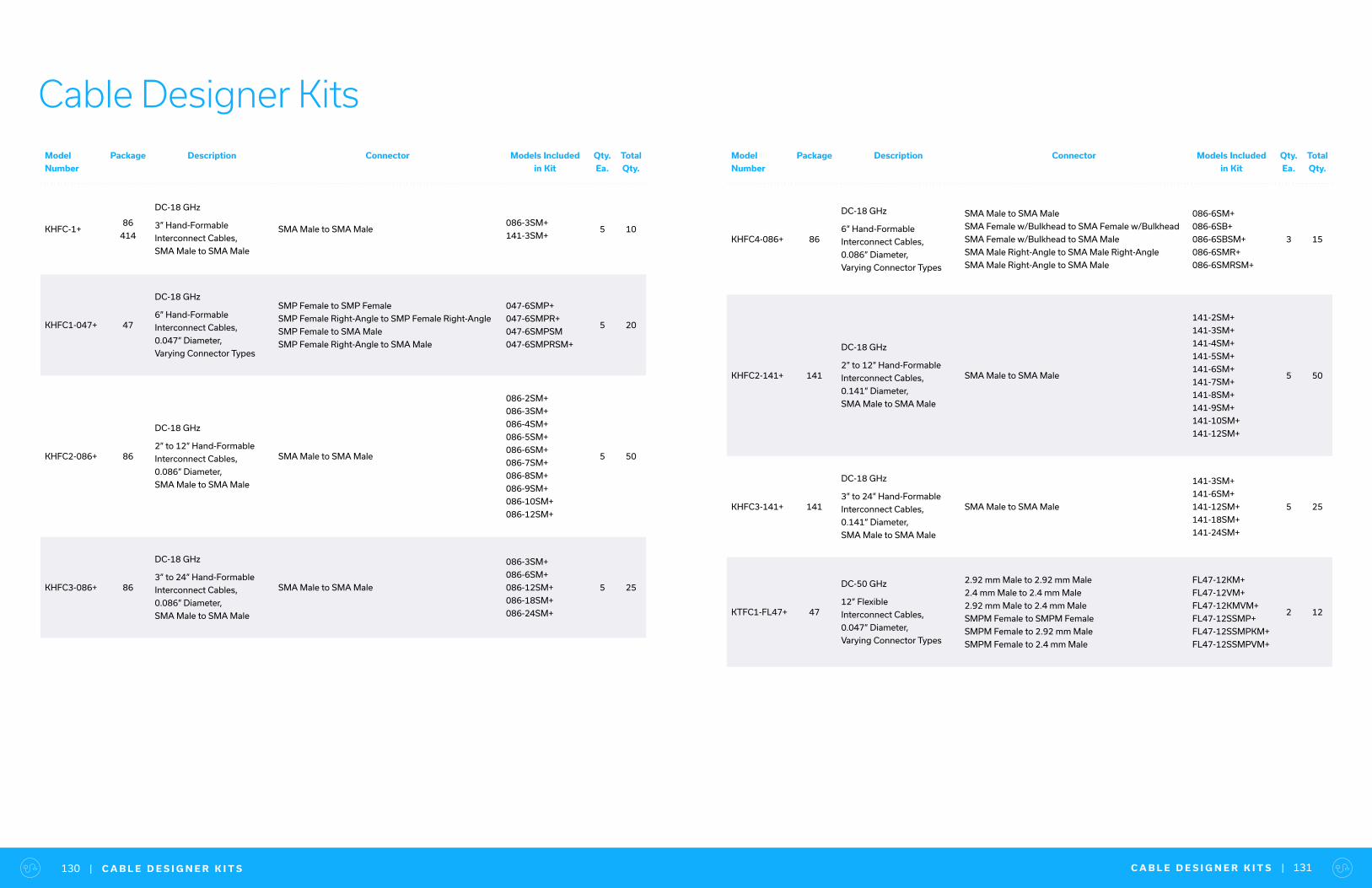
C A B L E D E S I G N E R K I T S | 131| C A B L E D E S I G N E R K I T S130
Cable Designer KitsModel
Number
Package Description Connector Models Included
in Kit
Qty.
Ea.
Total
Qty.
KHFC-1+86
414
DC-18 GHz
3” Hand-Formable
Interconnect Cables,
SMA Male to SMA Male
SMA Male to SMA Male086-3SM+
141-3SM+5 10
KHFC1-047+ 47
DC-18 GHz
6” Hand-Formable
Interconnect Cables,
0.047” Diameter,
Varying Connector Types
SMP Female to SMP Female
SMP Female Right-Angle to SMP Female Right-Angle
SMP Female to SMA Male
SMP Female Right-Angle to SMA Male
047-6SMP+
047-6SMPR+
047-6SMPSM
047-6SMPRSM+
5 20
KHFC2-086+ 86
DC-18 GHz
2” to 12” Hand-Formable
Interconnect Cables,
0.086” Diameter,
SMA Male to SMA Male
SMA Male to SMA Male
086-2SM+
086-3SM+
086-4SM+
086-5SM+
086-6SM+
086-7SM+
086-8SM+
086-9SM+
086-10SM+
086-12SM+
5 50
KHFC3-086+ 86
DC-18 GHz
3” to 24” Hand-Formable
Interconnect Cables,
0.086” Diameter,
SMA Male to SMA Male
SMA Male to SMA Male
086-3SM+
086-6SM+
086-12SM+
086-18SM+
086-24SM+
5 25
Model
Number
Package Description Connector Models Included
in Kit
Qty.
Ea.
Total
Qty.
KHFC4-086+ 86
DC-18 GHz
6” Hand-Formable
Interconnect Cables,
0.086” Diameter,
Varying Connector Types
SMA Male to SMA Male
SMA Female w/Bulkhead to SMA Female w/Bulkhead
SMA Female w/Bulkhead to SMA Male
SMA Male Right-Angle to SMA Male Right-Angle
SMA Male Right-Angle to SMA Male
086-6SM+
086-6SB+
086-6SBSM+
086-6SMR+
086-6SMRSM+
3 15
KHFC2-141+ 141
DC-18 GHz
2” to 12” Hand-Formable
Interconnect Cables,
0.141” Diameter,
SMA Male to SMA Male
SMA Male to SMA Male
141-2SM+
141-3SM+
141-4SM+
141-5SM+
141-6SM+
141-7SM+
141-8SM+
141-9SM+
141-10SM+
141-12SM+
5 50
KHFC3-141+ 141
DC-18 GHz
3” to 24” Hand-Formable
Interconnect Cables,
0.141” Diameter,
SMA Male to SMA Male
SMA Male to SMA Male
141-3SM+
141-6SM+
141-12SM+
141-18SM+
141-24SM+
5 25
KTFC1-FL47+ 47
DC-50 GHz
12” Flexible
Interconnect Cables,
0.047” Diameter,
Varying Connector Types
2.92 mm Male to 2.92 mm Male
2.4 mm Male to 2.4 mm Male
2.92 mm Male to 2.4 mm Male
SMPM Female to SMPM Female
SMPM Female to 2.92 mm Male
SMPM Female to 2.4 mm Male
FL47-12KM+
FL47-12VM+
FL47-12KMVM+
FL47-12SSMP+
FL47-12SSMPKM+
FL47-12SSMPVM+
2 12
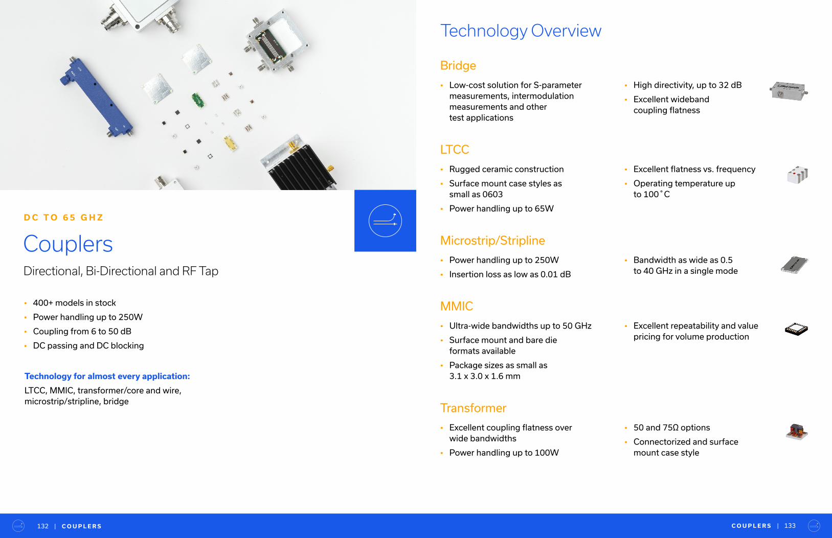
C O U P L E R S | 133| C O U P L E R S132
• 400+ models in stock
• Power handling up to 250W
• Coupling from 6 to 50 dB
• DC passing and DC blocking
Couplers
Technology Overview
Directional, Bi-Directional and RF Tap
D C T O 6 5 G H Z
Technology for almost every application:
LTCC, MMIC, transformer/core and wire, microstrip/stripline, bridge
Bridge
• Low-cost solution for S-parameter measurements, intermodulation measurements and other test applications
LTCC
• Rugged ceramic construction
• Surface mount case styles as small as 0603
• Power handling up to 65W
Microstrip/Stripline
• Power handling up to 250W
• Insertion loss as low as 0.01 dB
MMIC
• Ultra-wide bandwidths up to 50 GHz
• Surface mount and bare die formats available
• Package sizes as small as 3.1 x 3.0 x 1.6 mm
Transformer
• Excellent coupling flatness over wide bandwidths
• Power handling up to 100W
• High directivity, up to 32 dB
• Excellent wideband coupling flatness
• Excellent flatness vs. frequency
• Operating temperature up to 100˚C
• Bandwidth as wide as 0.5 to 40 GHz in a single mode
• Excellent repeatability and value pricing for volume production
• 50 and 75Ω options
• Connectorized and surface mount case style
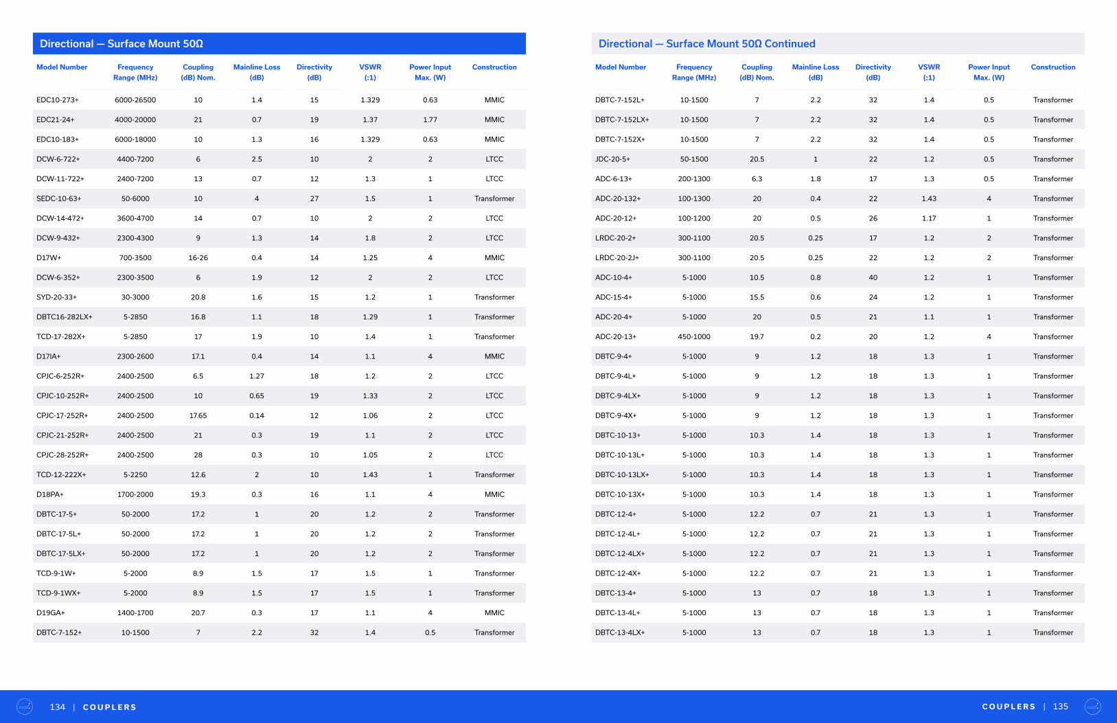
Directional — Surface Mount 50Ω Directional — Surface Mount 50Ω Continued
Model Number Frequency
Range (MHz)
Coupling
(dB) Nom.
Mainline Loss
(dB)
Directivity
(dB)
VSWR
(:1)
Power Input
Max. (W)
Construction
EDC10-273+ 6000-26500 10 1.4 15 1.329 0.63 MMIC
EDC21-24+ 4000-20000 21 0.7 19 1.37 1.77 MMIC
EDC10-183+ 6000-18000 10 1.3 16 1.329 0.63 MMIC
DCW-6-722+ 4400-7200 6 2.5 10 2 2 LTCC
DCW-11-722+ 2400-7200 13 0.7 12 1.3 1 LTCC
SEDC-10-63+ 50-6000 10 4 27 1.5 1 Transformer
DCW-14-472+ 3600-4700 14 0.7 10 2 2 LTCC
DCW-9-432+ 2300-4300 9 1.3 14 1.8 2 LTCC
D17W+ 700-3500 16-26 0.4 14 1.25 4 MMIC
DCW-6-352+ 2300-3500 6 1.9 12 2 2 LTCC
SYD-20-33+ 30-3000 20.8 1.6 15 1.2 1 Transformer
DBTC16-282LX+ 5-2850 16.8 1.1 18 1.29 1 Transformer
TCD-17-282X+ 5-2850 17 1.9 10 1.4 1 Transformer
D17IA+ 2300-2600 17.1 0.4 14 1.1 4 MMIC
CPJC-6-252R+ 2400-2500 6.5 1.27 18 1.2 2 LTCC
CPJC-10-252R+ 2400-2500 10 0.65 19 1.33 2 LTCC
CPJC-17-252R+ 2400-2500 17.65 0.14 12 1.06 2 LTCC
CPJC-21-252R+ 2400-2500 21 0.3 19 1.1 2 LTCC
CPJC-28-252R+ 2400-2500 28 0.3 10 1.05 2 LTCC
TCD-12-222X+ 5-2250 12.6 2 10 1.43 1 Transformer
D18PA+ 1700-2000 19.3 0.3 16 1.1 4 MMIC
DBTC-17-5+ 50-2000 17.2 1 20 1.2 2 Transformer
DBTC-17-5L+ 50-2000 17.2 1 20 1.2 2 Transformer
DBTC-17-5LX+ 50-2000 17.2 1 20 1.2 2 Transformer
TCD-9-1W+ 5-2000 8.9 1.5 17 1.5 1 Transformer
TCD-9-1WX+ 5-2000 8.9 1.5 17 1.5 1 Transformer
D19GA+ 1400-1700 20.7 0.3 17 1.1 4 MMIC
DBTC-7-152+ 10-1500 7 2.2 32 1.4 0.5 Transformer
C O U P L E R S | 135| C O U P L E R S134
Model Number Frequency
Range (MHz)
Coupling
(dB) Nom.
Mainline Loss
(dB)
Directivity
(dB)
VSWR
(:1)
Power Input
Max. (W)
Construction
DBTC-7-152L+ 10-1500 7 2.2 32 1.4 0.5 Transformer
DBTC-7-152LX+ 10-1500 7 2.2 32 1.4 0.5 Transformer
DBTC-7-152X+ 10-1500 7 2.2 32 1.4 0.5 Transformer
JDC-20-5+ 50-1500 20.5 1 22 1.2 0.5 Transformer
ADC-6-13+ 200-1300 6.3 1.8 17 1.3 0.5 Transformer
ADC-20-132+ 100-1300 20 0.4 22 1.43 4 Transformer
ADC-20-12+ 100-1200 20 0.5 26 1.17 1 Transformer
LRDC-20-2+ 300-1100 20.5 0.25 17 1.2 2 Transformer
LRDC-20-2J+ 300-1100 20.5 0.25 22 1.2 2 Transformer
ADC-10-4+ 5-1000 10.5 0.8 40 1.2 1 Transformer
ADC-15-4+ 5-1000 15.5 0.6 24 1.2 1 Transformer
ADC-20-4+ 5-1000 20 0.5 21 1.1 1 Transformer
ADC-20-13+ 450-1000 19.7 0.2 20 1.2 4 Transformer
DBTC-9-4+ 5-1000 9 1.2 18 1.3 1 Transformer
DBTC-9-4L+ 5-1000 9 1.2 18 1.3 1 Transformer
DBTC-9-4LX+ 5-1000 9 1.2 18 1.3 1 Transformer
DBTC-9-4X+ 5-1000 9 1.2 18 1.3 1 Transformer
DBTC-10-13+ 5-1000 10.3 1.4 18 1.3 1 Transformer
DBTC-10-13L+ 5-1000 10.3 1.4 18 1.3 1 Transformer
DBTC-10-13LX+ 5-1000 10.3 1.4 18 1.3 1 Transformer
DBTC-10-13X+ 5-1000 10.3 1.4 18 1.3 1 Transformer
DBTC-12-4+ 5-1000 12.2 0.7 21 1.3 1 Transformer
DBTC-12-4L+ 5-1000 12.2 0.7 21 1.3 1 Transformer
DBTC-12-4LX+ 5-1000 12.2 0.7 21 1.3 1 Transformer
DBTC-12-4X+ 5-1000 12.2 0.7 21 1.3 1 Transformer
DBTC-13-4+ 5-1000 13 0.7 18 1.3 1 Transformer
DBTC-13-4L+ 5-1000 13 0.7 18 1.3 1 Transformer
DBTC-13-4LX+ 5-1000 13 0.7 18 1.3 1 Transformer
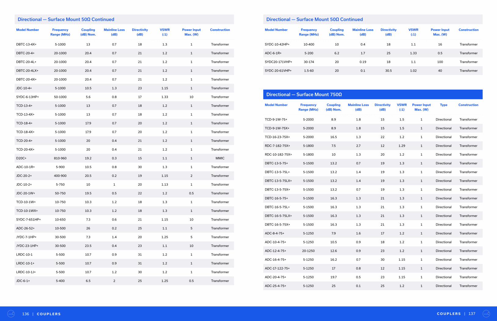
Model Number Frequency
Range (MHz)
Coupling
(dB) Nom.
Mainline Loss
(dB)
Directivity
(dB)
VSWR
(:1)
Power Input
Max. (W)
Construction
DBTC-13-4X+ 5-1000 13 0.7 18 1.3 1 Transformer
DBTC-20-4+ 20-1000 20.4 0.7 21 1.2 1 Transformer
DBTC-20-4L+ 20-1000 20.4 0.7 21 1.2 1 Transformer
DBTC-20-4LX+ 20-1000 20.4 0.7 21 1.2 1 Transformer
DBTC-20-4X+ 20-1000 20.4 0.7 21 1.2 1 Transformer
JDC-10-4+ 5-1000 10.5 1.3 23 1.15 1 Transformer
SYDC-6-13HP+ 50-1000 5.6 0.8 17 1.33 10 Transformer
TCD-13-4+ 5-1000 13 0.7 18 1.2 1 Transformer
TCD-13-4X+ 5-1000 13 0.7 18 1.2 1 Transformer
TCD-18-4+ 5-1000 17.9 0.7 20 1.2 1 Transformer
TCD-18-4X+ 5-1000 17.9 0.7 20 1.2 1 Transformer
TCD-20-4+ 5-1000 20 0.4 21 1.2 1 Transformer
TCD-20-4X+ 5-1000 20 0.4 21 1.2 1 Transformer
D20C+ 810-960 19.2 0.3 15 1.1 1 MMIC
ADC-10-1R+ 5-900 10.5 0.8 30 1.3 1 Transformer
JDC-20-2+ 400-900 20.5 0.2 19 1.15 2 Transformer
JDC-10-2+ 5-750 10 1 20 1.13 1 Transformer
JDC-20-1W+ 50-750 19.5 0.5 22 1.2 0.5 Transformer
TCD-10-1W+ 10-750 10.3 1.2 18 1.3 1 Transformer
TCD-10-1WX+ 10-750 10.3 1.2 18 1.3 1 Transformer
SYDC-7-651HP+ 10-650 7.3 0.6 21 1.15 10 Transformer
ADC-26-52+ 10-500 26 0.2 25 1.1 5 Transformer
JYDC-7-1HP+ 30-500 7.3 1.4 20 1.25 5 Transformer
JYDC-23-1HP+ 30-500 23.5 0.4 23 1.1 10 Transformer
LRDC-10-1 5-500 10.7 0.9 31 1.2 1 Transformer
LRDC-10-1+ 5-500 10.7 0.9 31 1.2 1 Transformer
LRDC-10-1J+ 5-500 10.7 1.2 30 1.2 1 Transformer
JDC-6-1+ 5-400 6.5 2 25 1.25 0.5 Transformer
C O U P L E R S | 137| C O U P L E R S136
Directional — Surface Mount 750Ω
Model Number Frequency
Range (MHz)
Coupling
(dB) Nom.
Mainline Loss
(dB)
Directivity
(dB)
VSWR
(:1)
Power Input
Max. (W)
Type Construction
TCD-9-1W-75+ 5-2000 8.9 1.8 15 1.5 1 Directional Transformer
TCD-9-1W-75X+ 5-2000 8.9 1.8 15 1.5 1 Directional Transformer
TCD-16-23-75X+ 5-2000 16.5 1.3 22 1.2 1 Directional Transformer
RDC-7-182-75X+ 5-1800 7.5 2.7 12 1.29 1 Directional Transformer
RDC-10-182-75X+ 5-1800 10 1.3 20 1.2 1 Directional Transformer
DBTC-13-5-75+ 5-1500 13.2 0.7 19 1.3 1 Directional Transformer
DBTC-13-5-75L+ 5-1500 13.2 1.4 19 1.3 1 Directional Transformer
DBTC-13-5-75LX+ 5-1500 13.2 1.4 19 1.3 1 Directional Transformer
DBTC-13-5-75X+ 5-1500 13.2 0.7 19 1.3 1 Directional Transformer
DBTC-16-5-75+ 5-1500 16.3 1.3 21 1.3 1 Directional Transformer
DBTC-16-5-75L+ 5-1500 16.3 1.3 21 1.3 1 Directional Transformer
DBTC-16-5-75LX+ 5-1500 16.3 1.3 21 1.3 1 Directional Transformer
DBTC-16-5-75X+ 5-1500 16.3 1.3 21 1.3 1 Directional Transformer
ADC-8-4-75+ 5-1250 7.9 1.6 17 1.2 1 Directional Transformer
ADC-10-4-75+ 5-1250 10.5 0.9 18 1.2 1 Directional Transformer
ADC-12-4-75+ 20-1250 12.6 0.9 23 1.2 1 Directional Transformer
ADC-16-4-75+ 5-1250 16.2 0.7 30 1.15 1 Directional Transformer
ADC-17-122-75+ 5-1250 17 0.8 12 1.15 1 Directional Transformer
ADC-20-4-75+ 5-1250 19.7 0.5 23 1.15 1 Directional Transformer
ADC-25-4-75+ 5-1250 25 0.1 25 1.2 1 Directional Transformer
Directional — Surface Mount 50Ω Continued Directional — Surface Mount 50Ω Continued
Model Number Frequency
Range (MHz)
Coupling
(dB) Nom.
Mainline Loss
(dB)
Directivity
(dB)
VSWR
(:1)
Power Input
Max. (W)
Construction
SYDC-10-42HP+ 10-400 10 0.4 18 1.1 16 Transformer
ADC-6-1R+ 5-200 6.2 1.7 25 1.33 0.5 Transformer
SYDC20-171VHP+ 30-174 20 0.19 18 1.1 100 Transformer
SYDC-20-61VHP+ 1.5-60 20 0.1 30.5 1.02 40 Transformer

C O U P L E R S | 139| C O U P L E R S138
Model Number Frequency
Range (MHz)
Coupling
(dB) Nom.
Mainline Loss
(dB)
Directivity
(dB)
VSWR
(:1)
Power Input
Max. (W)
Type Construction
DBTC-6-4-75+ 5-1250 6.8 2.2 17 1.4 1 Directional Transformer
DBTC-6-4-75L+ 5-1250 6.8 2.2 17 1.4 1 Directional Transformer
DBTC-6-4-75LX+ 5-1250 6.8 2.2 17 1.4 1 Directional Transformer
DBTC-6-4-75X+ 5-1250 6.8 2.2 17 1.4 1 Directional Transformer
DBTC-20-4-75+ 5-1250 20.5 0.8 19 1.4 1 Directional Transformer
DBTC-20-4-75L+ 5-1250 20.5 0.8 19 1.4 1 Directional Transformer
DBTC-20-4-75LX+ 5-1250 20.5 0.8 19 1.4 1 Directional Transformer
DBTC-20-4-75X+ 5-1250 20.5 0.8 19 1.4 1 Directional Transformer
RDC-10-122-75X+ 5-1250 10 1.2 20 1.22 1 Directional Transformer
RDC-17-122-75X+ 5-1250 17.6 0.8 20 1.14 1 Directional Transformer
TCD-6-122-75X+ 5-1250 6.7 2.3 12 1.43 0.5 Directional Transformer
TCD-10-122-75X+ 5-1250 10 1.5 15 1.17 1 Directional Transformer
TCD-13-122-75X+ 5-1250 12.7 1 15 1.17 1 Directional Transformer
TCD-16-122-75X+ 5-1250 16.5 1.5 22 1.33 1 Directional Transformer
TCD-18-122-75X+ 5-1250 17.5 1 22 1.17 1 Directional Transformer
TCD-16-12W-75X+ 5-1218 16 0.9 16 1.3 1 Directional Transformer
DBTC-9-4-75+ 5-1200 9.3 1.3 20 1.3 0.7 Directional Transformer
DBTC-9-4-75L+ 5-1200 9.3 1.3 20 1.3 0.7 Directional Transformer
DBTC-9-4-75LX+ 5-1200 9.3 1.3 20 1.3 0.7 Directional Transformer
DBTC-9-4-75X+ 5-1200 9.3 1.3 20 1.3 0.7 Directional Transformer
DBTC-12-4-75+ 5-1200 12 1.1 19 1.3 0.5 Directional Transformer
DBTC-12-4-75L+ 5-1200 12 1.1 19 1.3 0.5 Directional Transformer
DBTC-12-4-75LX+ 5-1200 12 1.1 19 1.3 0.5 Directional Transformer
DBTC-12-4-75X+ 5-1200 12 1.1 19 1.3 0.5 Directional Transformer
TCD-20-4-75+ 40-1200 20 0.6 23 1.15 1 Directional Transformer
TCD-20-4-75X+ 40-1200 20 0.6 23 1.15 1 Directional Transformer
ADC-6-10-75+ 20-1000 6.6 2.1 15 1.3 0.5 Directional Transformer
ADC-10-4-75R+ 5-1000 9.6 1.1 21 1.2 1 Directional Transformer
Model Number Frequency
Range (MHz)
Coupling
(dB) Nom.
Mainline Loss
(dB)
Directivity
(dB)
VSWR
(:1)
Power Input
Max. (W)
Type Construction
ADC-18-4-75+ 20-1000 17.4 0.4 18 1.15 1 Directional Transformer
ADC-18-4-75R+ 20-1000 17.7 0.5 25 1.15 1 Directional Transformer
ADC-20-4-75R+ 40-1000 20.5 0.6 20 1.1 1 Directional Transformer
DBTC-10-4-75+ 5-1000 10.5 0.7 20 1.3 1 Directional Transformer
DBTC-10-4-75L+ 5-1000 10.5 0.7 20 1.3 1 Directional Transformer
DBTC-10-4-75LX+ 5-1000 10.5 0.7 20 1.3 1 Directional Transformer
DBTC-10-4-75X+ 5-1000 10.5 0.7 20 1.3 1 Directional Transformer
DBTC-18-4-75+ 5-1000 18.2 0.8 21 1.3 1 Directional Transformer
DBTC-18-4-75L+ 5-1000 18.2 0.8 21 1.3 1 Directional Transformer
DBTC-18-4-75LX+ 5-1000 18.2 0.8 21 1.3 1 Directional Transformer
DBTC-18-4-75X+ 5-1000 18.2 0.8 21 1.3 1 Directional Transformer
LRDC-10-2-75+ 30-1000 10 1 21 1.3 1 Directional Transformer
LRDC-10-2-75J+ 30-1000 10 1.3 22 1.3 1 Directional Transformer
TCD-10-4-75+ 5-1000 9.9 1.1 20 1.25 1 Directional Transformer
TCD-10-4-75X+ 5-1000 9.9 1.1 20 1.25 1 Directional Transformer
TCD-13-4-75+ 5-1000 13 0.8 15 1.2 1 Directional Transformer
TCD-13-4-75X+ 5-1000 13 0.8 15 1.2 1 Directional Transformer
TCD-18-4-75+ 10-1000 18 0.7 22 1.2 1 Directional Transformer
TCD-18-4-75X+ 10-1000 18 0.7 22 1.2 1 Directional Transformer
JDC20-1W-75+ 50-750 19.5 0.5 23 1.2 0.5 Directional Transformer
TCD-10-1W-75+ 10-750 10.5 1.4 18 1.3 1 Directional Transformer
TCD-10-1W-75X+ 10-750 10.5 1.4 18 1.3 1 Directional Transformer
JDC-20-3-75+ 2-250 19.2 0.4 30 1.1 1 Directional Transformer
Directional — Surface Mount 750Ω Continued Directional — Surface Mount 750Ω Continued
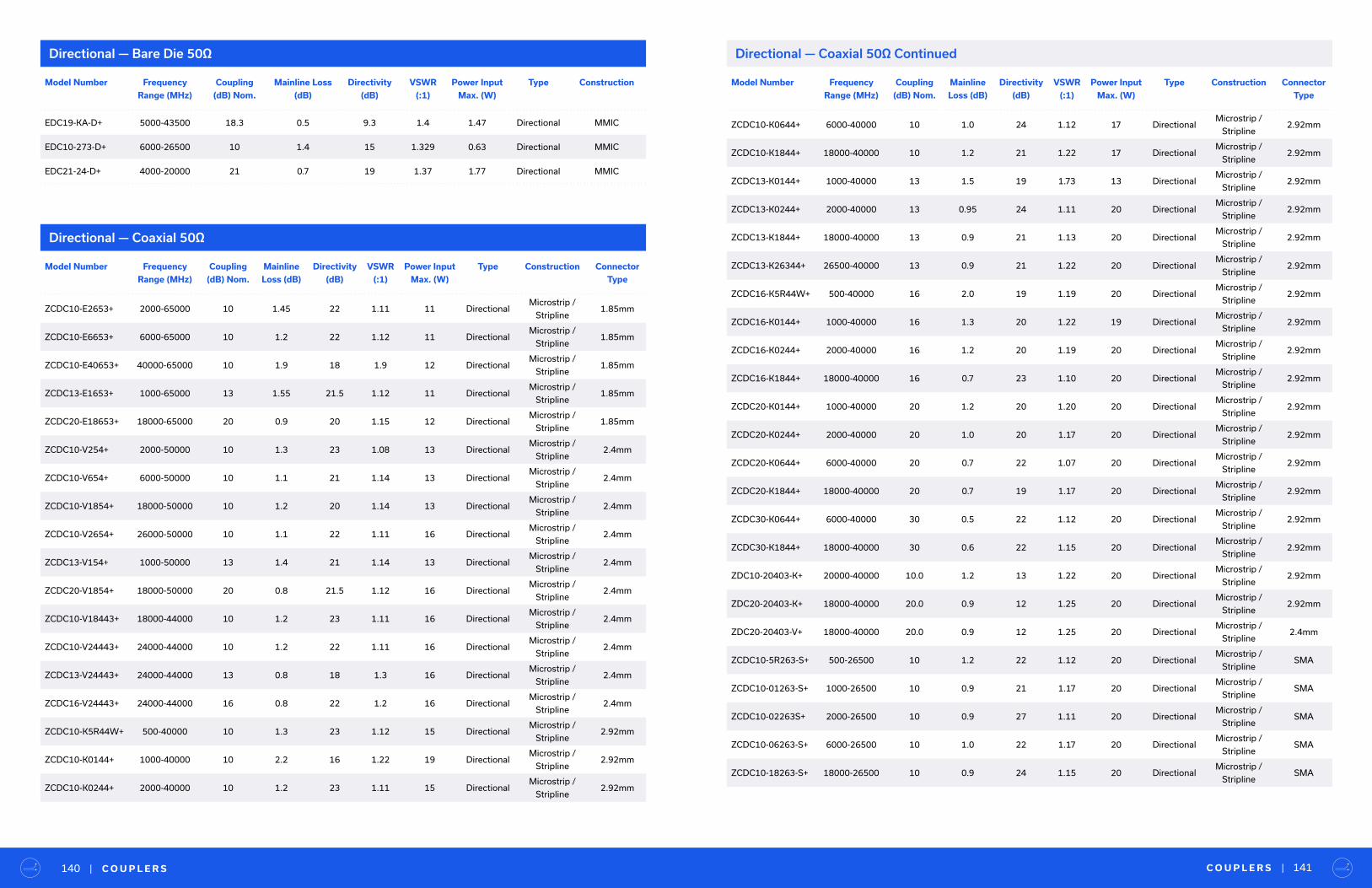
Model Number Frequency
Range (MHz)
Coupling
(dB) Nom.
Mainline
Loss (dB)
Directivity
(dB)
VSWR
(:1)
Power Input
Max. (W)
Type Construction Connector
Type
ZCDC10-E2653+ 2000-65000 10 1.45 22 1.11 11 DirectionalMicrostrip /
Stripline1.85mm
ZCDC10-E6653+ 6000-65000 10 1.2 22 1.12 11 DirectionalMicrostrip /
Stripline1.85mm
ZCDC10-E40653+ 40000-65000 10 1.9 18 1.9 12 DirectionalMicrostrip /
Stripline1.85mm
ZCDC13-E1653+ 1000-65000 13 1.55 21.5 1.12 11 DirectionalMicrostrip /
Stripline1.85mm
ZCDC20-E18653+ 18000-65000 20 0.9 20 1.15 12 DirectionalMicrostrip /
Stripline1.85mm
ZCDC10-V254+ 2000-50000 10 1.3 23 1.08 13 DirectionalMicrostrip /
Stripline2.4mm
ZCDC10-V654+ 6000-50000 10 1.1 21 1.14 13 DirectionalMicrostrip /
Stripline2.4mm
ZCDC10-V1854+ 18000-50000 10 1.2 20 1.14 13 DirectionalMicrostrip /
Stripline2.4mm
ZCDC10-V2654+ 26000-50000 10 1.1 22 1.11 16 DirectionalMicrostrip /
Stripline2.4mm
ZCDC13-V154+ 1000-50000 13 1.4 21 1.14 13 DirectionalMicrostrip /
Stripline2.4mm
ZCDC20-V1854+ 18000-50000 20 0.8 21.5 1.12 16 DirectionalMicrostrip /
Stripline2.4mm
ZCDC10-V18443+ 18000-44000 10 1.2 23 1.11 16 DirectionalMicrostrip /
Stripline2.4mm
ZCDC10-V24443+ 24000-44000 10 1.2 22 1.11 16 DirectionalMicrostrip /
Stripline2.4mm
ZCDC13-V24443+ 24000-44000 13 0.8 18 1.3 16 DirectionalMicrostrip /
Stripline2.4mm
ZCDC16-V24443+ 24000-44000 16 0.8 22 1.2 16 DirectionalMicrostrip /
Stripline2.4mm
ZCDC10-K5R44W+ 500-40000 10 1.3 23 1.12 15 DirectionalMicrostrip /
Stripline2.92mm
ZCDC10-K0144+ 1000-40000 10 2.2 16 1.22 19 DirectionalMicrostrip /
Stripline2.92mm
ZCDC10-K0244+ 2000-40000 10 1.2 23 1.11 15 DirectionalMicrostrip /
Stripline2.92mm
Directional — Coaxial 50Ω
Directional — Coaxial 50Ω ContinuedDirectional — Bare Die 50Ω
Model Number Frequency
Range (MHz)
Coupling
(dB) Nom.
Mainline Loss
(dB)
Directivity
(dB)
VSWR
(:1)
Power Input
Max. (W)
Type Construction
EDC19-KA-D+ 5000-43500 18.3 0.5 9.3 1.4 1.47 Directional MMIC
EDC10-273-D+ 6000-26500 10 1.4 15 1.329 0.63 Directional MMIC
EDC21-24-D+ 4000-20000 21 0.7 19 1.37 1.77 Directional MMIC
C O U P L E R S | 141| C O U P L E R S140
Model Number Frequency
Range (MHz)
Coupling
(dB) Nom.
Mainline
Loss (dB)
Directivity
(dB)
VSWR
(:1)
Power Input
Max. (W)
Type Construction Connector
Type
ZCDC10-K0644+ 6000-40000 10 1.0 24 1.12 17 DirectionalMicrostrip /
Stripline2.92mm
ZCDC10-K1844+ 18000-40000 10 1.2 21 1.22 17 DirectionalMicrostrip /
Stripline2.92mm
ZCDC13-K0144+ 1000-40000 13 1.5 19 1.73 13 DirectionalMicrostrip /
Stripline2.92mm
ZCDC13-K0244+ 2000-40000 13 0.95 24 1.11 20 DirectionalMicrostrip /
Stripline2.92mm
ZCDC13-K1844+ 18000-40000 13 0.9 21 1.13 20 DirectionalMicrostrip /
Stripline2.92mm
ZCDC13-K26344+ 26500-40000 13 0.9 21 1.22 20 DirectionalMicrostrip /
Stripline2.92mm
ZCDC16-K5R44W+ 500-40000 16 2.0 19 1.19 20 DirectionalMicrostrip /
Stripline2.92mm
ZCDC16-K0144+ 1000-40000 16 1.3 20 1.22 19 DirectionalMicrostrip /
Stripline2.92mm
ZCDC16-K0244+ 2000-40000 16 1.2 20 1.19 20 DirectionalMicrostrip /
Stripline2.92mm
ZCDC16-K1844+ 18000-40000 16 0.7 23 1.10 20 DirectionalMicrostrip /
Stripline2.92mm
ZCDC20-K0144+ 1000-40000 20 1.2 20 1.20 20 DirectionalMicrostrip /
Stripline2.92mm
ZCDC20-K0244+ 2000-40000 20 1.0 20 1.17 20 DirectionalMicrostrip /
Stripline2.92mm
ZCDC20-K0644+ 6000-40000 20 0.7 22 1.07 20 DirectionalMicrostrip /
Stripline2.92mm
ZCDC20-K1844+ 18000-40000 20 0.7 19 1.17 20 DirectionalMicrostrip /
Stripline2.92mm
ZCDC30-K0644+ 6000-40000 30 0.5 22 1.12 20 DirectionalMicrostrip /
Stripline2.92mm
ZCDC30-K1844+ 18000-40000 30 0.6 22 1.15 20 DirectionalMicrostrip /
Stripline2.92mm
ZDC10-20403-K+ 20000-40000 10.0 1.2 13 1.22 20 DirectionalMicrostrip /
Stripline2.92mm
ZDC20-20403-K+ 18000-40000 20.0 0.9 12 1.25 20 DirectionalMicrostrip /
Stripline2.92mm
ZDC20-20403-V+ 18000-40000 20.0 0.9 12 1.25 20 DirectionalMicrostrip /
Stripline2.4mm
ZCDC10-5R263-S+ 500-26500 10 1.2 22 1.12 20 DirectionalMicrostrip /
StriplineSMA
ZCDC10-01263-S+ 1000-26500 10 0.9 21 1.17 20 DirectionalMicrostrip /
StriplineSMA
ZCDC10-02263S+ 2000-26500 10 0.9 27 1.11 20 DirectionalMicrostrip /
StriplineSMA
ZCDC10-06263-S+ 6000-26500 10 1.0 22 1.17 20 DirectionalMicrostrip /
StriplineSMA
ZCDC10-18263-S+ 18000-26500 10 0.9 24 1.15 20 DirectionalMicrostrip /
StriplineSMA

C O U P L E R S | 143| C O U P L E R S142
Model Number Frequency
Range (MHz)
Coupling
(dB) Nom.
Mainline
Loss (dB)
Directivity
(dB)
VSWR
(:1)
Power Input
Max. (W)
Type Construction Connector
Type
ZCDC13-5R263-S+ 500-26500 13 1.3 21 1.73 20 DirectionalMicrostrip /
StriplineSMA
ZCDC13-01263-S+ 1000-26500 13 1.2 21 1.17 19 DirectionalMicrostrip /
StriplineSMA
ZCDC16-5R263-S+ 500-26500 16 1.4 23 1.12 20 DirectionalMicrostrip /
StriplineSMA
ZCDC16-01263-S+ 1000-26500 16 0.9 21 1.14 20 DirectionalMicrostrip /
StriplineSMA
ZCDC16-02263-S+ 2000-26500 16 0.6 26 1.09 20 DirectionalMicrostrip /
StriplineSMA
ZCDC20-5R263-S+ 500-26500 20 0.9 25 1.09 20 DirectionalMicrostrip /
StriplineSMA
ZCDC20-01263-S+ 1000-26500 20 0.9 23 1.12 20 DirectionalMicrostrip /
StriplineSMA
ZCDC20-02263S+ 2000-26500 20 0.5 18 1.33 20 DirectionalMicrostrip /
StriplineSMA
ZCDC20-06263-S+ 6000-26500 20 0.5 26 1.14 20 DirectionalMicrostrip /
StriplineSMA
ZCDC20-18263-S+ 18000-26500 20 0.4 24 1.14 20 DirectionalMicrostrip /
StriplineSMA
ZCDC30-5R263-S+ 500-26500 30 0.6 28 1.07 20 DirectionalMicrostrip /
StriplineSMA
ZCDC30-01263-S+ 1000-26500 30 0.8 23 1.14 20 DirectionalMicrostrip /
StriplineSMA
ZCDC30-02263-S+ 2000-26500 30 0.6 23 1.14 20 DirectionalMicrostrip /
StriplineSMA
ZCDC30-06263-S+ 6000-26500 30 0.6 23 1.12 20 DirectionalMicrostrip /
StriplineSMA
ZCDC30-18263-S+ 18000-26500 30 0.6 21 1.14 20 DirectionalMicrostrip /
StriplineSMA
ZCDC10-01203-S+ 1000-20000 10 1.0 23 1.11 20 DirectionalMicrostrip /
StriplineSMA
ZCDC20-01203-S+ 1000-20000 20 0.6 25 1.07 20 DirectionalMicrostrip /
StriplineSMA
ZUDC10-183+ 500-18000 10 1.4 17 1.3 50 DirectionalMicrostrip /
StriplineSMA
ZUDC10-02183-S+ 2000-18000 10 0.3 17 1.43 20 DirectionalMicrostrip /
StriplineSMA
ZUDC10-06183-S+ 6000-18000 10 0.77 21 1.14 50 DirectionalMicrostrip /
StriplineSMA
ZUDC15-02183-S+ 2000-18000 15 0.3 18 1.25 20 DirectionalMicrostrip /
StriplineSMA
ZUDC20-183+ 500-18000 20 0.9 17 1.3 50 DirectionalMicrostrip /
StriplineSMA
ZUDC20-02183-S+ 2000-18000 20 0.5 20 1.22 20 DirectionalMicrostrip /
StriplineSMA
ZUDC20-06183-S+ 6000-18000 20 0.37 21 1.11 50 DirectionalMicrostrip /
StriplineSMA
Model Number Frequency
Range (MHz)
Coupling
(dB) Nom.
Mainline
Loss (dB)
Directivity
(dB)
VSWR
(:1)
Power Input
Max. (W)
Type Construction Connector
Type
ZUDC30-183+ 500-18000 30 0.9 16 1.3 50 DirectionalMicrostrip /
StriplineSMA
ZUDC30-02183-S+ 2000-18000 30 0.3 17 1.33 20 DirectionalMicrostrip /
StriplineSMA
ZX30-14-972HP+ 8300-9700 14 0.8 7 2.3 20 DirectionalMicrostrip /
StriplineSMA
ZGDC35-93HP+ 900-9000 35 0.1 19 1.25 250 DirectionalMicrostrip /
StriplineN
ZUDC10-83-S+ 300-8000 10 0.9 24 1.15 20 DirectionalMicrostrip /
StriplineSMA
ZUDC20-83-S+ 300-8000 20 0.7 24 1.15 20 DirectionalMicrostrip /
StriplineSMA
ZADC-13-73-S+ 2600-7000 13 0.8 18 1.2 4 DirectionalMicrostrip /
StriplineSMA
ZADC-10-63-S+ 2500-6000 11.7 0.6 23 1.11 4 DirectionalMicrostrip /
StriplineSMA
ZHDC-10-63+ 50-6000 10.2 4 32 1.2 1 Directional Bridge N
ZHDC-10-63-NS+ 50-6000 10.2 4 32 1.2 1 Directional Bridge N/SMA
ZHDC-16-63+ 50-6000 16.7 2 32 1.3 0.5 Directional Bridge SMA
ZHDC-16-63-NS+ 50-6000 16 2 24 1.3 0.5 Directional Bridge N/SMA
ZGDC6-372HP+ 380-3700 6 0.2 23 1.09 250 DirectionalMicrostrip /
StriplineN
ZGDC10-372HP+ 380-3700 10 0.17 23 1.09 250 DirectionalMicrostrip /
StriplineN
ZGDC20-372HP+ 300-3700 20 0.15 25 1.06 250 DirectionalMicrostrip /
StriplineN
ZGDC30-372HP+ 380-3700 30 0.16 17 1.07 250 DirectionalMicrostrip /
StriplineN
ZFDC-20-33+ 20-3000 20.5 0.9 15 1.5 1 Directional Transformer BNC
ZADC-40-27HP+ 1400-2700 40 0.19 25 1.2 40 DirectionalMicrostrip /
StriplineN
ZADC-15-252+ 850-2500 15 0.7 14.5 1.15 8 Directional LTCC SMA
ZADC-6-2G-5W-S+ 800-2000 6.7 1.6 25 1.15 5 DirectionalMicrostrip /
StriplineSMA
ZFDC-6-23-S+ 20-2000 6 2.7 18 1.3 0.5 Directional Transformer SMA
ZFDC-10-5+ 1-2000 10.8 1.2 30 1.3 0.5 Directional Transformer BNC
ZFDC-20-5+ 0.1-2000 19.5 0.7 27 1.2 2 Directional Transformer BNC
ZFDC-20-50+ 20-2000 19.5 0.7 25 1.25 1 Directional Transformer BNC
ZNDC-13-2G-S+ 800-2000 13 0.8 20 1.15 3 Directional Transformer SMA
ZNDC-15-2G-S+ 800-2000 15 0.8 22 1.2 3 Directional Transformer SMA
Directional — Coaxial 50Ω ContinuedDirectional — Coaxial 50Ω Continued
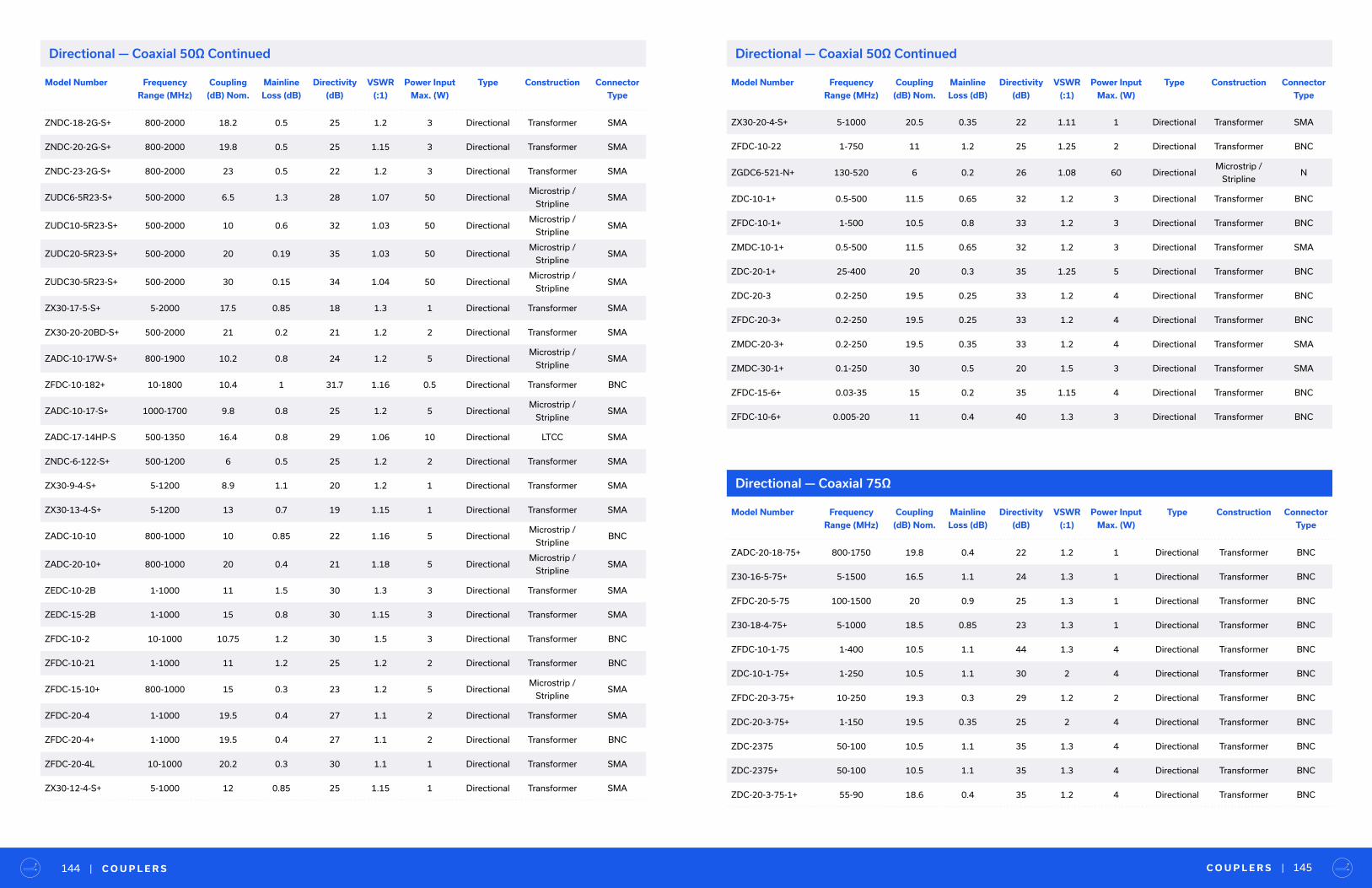
C O U P L E R S | 145| C O U P L E R S144
Model Number Frequency
Range (MHz)
Coupling
(dB) Nom.
Mainline
Loss (dB)
Directivity
(dB)
VSWR
(:1)
Power Input
Max. (W)
Type Construction Connector
Type
ZNDC-18-2G-S+ 800-2000 18.2 0.5 25 1.2 3 Directional Transformer SMA
ZNDC-20-2G-S+ 800-2000 19.8 0.5 25 1.15 3 Directional Transformer SMA
ZNDC-23-2G-S+ 800-2000 23 0.5 22 1.2 3 Directional Transformer SMA
ZUDC6-5R23-S+ 500-2000 6.5 1.3 28 1.07 50 DirectionalMicrostrip /
StriplineSMA
ZUDC10-5R23-S+ 500-2000 10 0.6 32 1.03 50 DirectionalMicrostrip /
StriplineSMA
ZUDC20-5R23-S+ 500-2000 20 0.19 35 1.03 50 DirectionalMicrostrip /
StriplineSMA
ZUDC30-5R23-S+ 500-2000 30 0.15 34 1.04 50 DirectionalMicrostrip /
StriplineSMA
ZX30-17-5-S+ 5-2000 17.5 0.85 18 1.3 1 Directional Transformer SMA
ZX30-20-20BD-S+ 500-2000 21 0.2 21 1.2 2 Directional Transformer SMA
ZADC-10-17W-S+ 800-1900 10.2 0.8 24 1.2 5 DirectionalMicrostrip /
StriplineSMA
ZFDC-10-182+ 10-1800 10.4 1 31.7 1.16 0.5 Directional Transformer BNC
ZADC-10-17-S+ 1000-1700 9.8 0.8 25 1.2 5 DirectionalMicrostrip /
StriplineSMA
ZADC-17-14HP-S 500-1350 16.4 0.8 29 1.06 10 Directional LTCC SMA
ZNDC-6-122-S+ 500-1200 6 0.5 25 1.2 2 Directional Transformer SMA
ZX30-9-4-S+ 5-1200 8.9 1.1 20 1.2 1 Directional Transformer SMA
ZX30-13-4-S+ 5-1200 13 0.7 19 1.15 1 Directional Transformer SMA
ZADC-10-10 800-1000 10 0.85 22 1.16 5 DirectionalMicrostrip /
StriplineBNC
ZADC-20-10+ 800-1000 20 0.4 21 1.18 5 DirectionalMicrostrip /
StriplineSMA
ZEDC-10-2B 1-1000 11 1.5 30 1.3 3 Directional Transformer SMA
ZEDC-15-2B 1-1000 15 0.8 30 1.15 3 Directional Transformer SMA
ZFDC-10-2 10-1000 10.75 1.2 30 1.5 3 Directional Transformer BNC
ZFDC-10-21 1-1000 11 1.2 25 1.2 2 Directional Transformer BNC
ZFDC-15-10+ 800-1000 15 0.3 23 1.2 5 DirectionalMicrostrip /
StriplineSMA
ZFDC-20-4 1-1000 19.5 0.4 27 1.1 2 Directional Transformer SMA
ZFDC-20-4+ 1-1000 19.5 0.4 27 1.1 2 Directional Transformer BNC
ZFDC-20-4L 10-1000 20.2 0.3 30 1.1 1 Directional Transformer SMA
ZX30-12-4-S+ 5-1000 12 0.85 25 1.15 1 Directional Transformer SMA
Directional — Coaxial 50Ω Continued Directional — Coaxial 50Ω Continued
Model Number Frequency
Range (MHz)
Coupling
(dB) Nom.
Mainline
Loss (dB)
Directivity
(dB)
VSWR
(:1)
Power Input
Max. (W)
Type Construction Connector
Type
ZX30-20-4-S+ 5-1000 20.5 0.35 22 1.11 1 Directional Transformer SMA
ZFDC-10-22 1-750 11 1.2 25 1.25 2 Directional Transformer BNC
ZGDC6-521-N+ 130-520 6 0.2 26 1.08 60 DirectionalMicrostrip /
StriplineN
ZDC-10-1+ 0.5-500 11.5 0.65 32 1.2 3 Directional Transformer BNC
ZFDC-10-1+ 1-500 10.5 0.8 33 1.2 3 Directional Transformer BNC
ZMDC-10-1+ 0.5-500 11.5 0.65 32 1.2 3 Directional Transformer SMA
ZDC-20-1+ 25-400 20 0.3 35 1.25 5 Directional Transformer BNC
ZDC-20-3 0.2-250 19.5 0.25 33 1.2 4 Directional Transformer BNC
ZFDC-20-3+ 0.2-250 19.5 0.25 33 1.2 4 Directional Transformer BNC
ZMDC-20-3+ 0.2-250 19.5 0.35 33 1.2 4 Directional Transformer SMA
ZMDC-30-1+ 0.1-250 30 0.5 20 1.5 3 Directional Transformer SMA
ZFDC-15-6+ 0.03-35 15 0.2 35 1.15 4 Directional Transformer BNC
ZFDC-10-6+ 0.005-20 11 0.4 40 1.3 3 Directional Transformer BNC
Model Number Frequency
Range (MHz)
Coupling
(dB) Nom.
Mainline
Loss (dB)
Directivity
(dB)
VSWR
(:1)
Power Input
Max. (W)
Type Construction Connector
Type
ZADC-20-18-75+ 800-1750 19.8 0.4 22 1.2 1 Directional Transformer BNC
Z30-16-5-75+ 5-1500 16.5 1.1 24 1.3 1 Directional Transformer BNC
ZFDC-20-5-75 100-1500 20 0.9 25 1.3 1 Directional Transformer BNC
Z30-18-4-75+ 5-1000 18.5 0.85 23 1.3 1 Directional Transformer BNC
ZFDC-10-1-75 1-400 10.5 1.1 44 1.3 4 Directional Transformer BNC
ZDC-10-1-75+ 1-250 10.5 1.1 30 2 4 Directional Transformer BNC
ZFDC-20-3-75+ 10-250 19.3 0.3 29 1.2 2 Directional Transformer BNC
ZDC-20-3-75+ 1-150 19.5 0.35 25 2 4 Directional Transformer BNC
ZDC-2375 50-100 10.5 1.1 35 1.3 4 Directional Transformer BNC
ZDC-2375+ 50-100 10.5 1.1 35 1.3 4 Directional Transformer BNC
ZDC-20-3-75-1+ 55-90 18.6 0.4 35 1.2 4 Directional Transformer BNC
Directional — Coaxial 75Ω

C O U P L E R S | 147| C O U P L E R S146
Directional — Plug-In 50Ω
Model Number Frequency
Range (MHz)
Coupling
(dB) Nom.
Mainline Loss
(dB)
Directivity
(dB)
VSWR
(:1)
Power Input
Max. (W)
Type Construction
PDC-10-5+ 1-2000 10.5 1.3 30 1.3 0.5 Directional Transformer
PDC-10-54+ 10-1500 10.5 1.3 28 1.3 0.5 Directional Transformer
P4DC-30A-2+ 5-1000 30.5 0.7 32 1.15 2 Directional Transformer
TDC-10-2+ 5-1000 11 1.5 25 1.5 0.5 Directional Transformer
PDC-20-1W+ 10-700 19.2 0.4 27 1.4 2 Directional Transformer
PDC-10-1+ 0.5-500 11.5 0.65 32 1.2 3 Directional Transformer
PDC-15-21+ 1-500 14.7 0.7 35 1.4 2 Directional Transformer
PDC-20-1+ 25-400 21 0.3 35 1.25 5 Directional Transformer
PDC20-400HP+ 40-400 21.5 0.2 30 1.1 10 Directional Transformer
TDC-6-1+ 10-400 6.3 2 30 1.5 2 Directional Transformer
TDC-10-1+ 1-400 10 1 30 1.5 2 Directional Transformer
PDC-20-3+ 0.2-250 19.5 0.25 33 1.2 4 Directional Transformer
PDC-15-6+ 0.01-35 15 0.2 35 1.15 4 Directional Transformer
PDC-10-6+ 0.005-20 11 0.4 40 1.3 3 Directional Transformer
Directional — Plug-In 75Ω
Model Number Frequency
Range (MHz)
Coupling
(dB) Nom.
Mainline Loss
(dB)
Directivity
(dB)
VSWR
(:1)
Power Input
Max. (W)
Type Construction
PDC-20-3-75 1-150 19.5 0.35 25 2 4 Directional Transformer
Bi-Directional — Surface Mount 50Ω
Bi-Directional — Surface Mount 50Ω Continued
Model Number Frequency
Range (MHz)
Coupling
(dB) Nom.
Mainline
Loss (dB)
Directivity
(dB)
VSWR
(:1)
Power Input
Max. (W)
Type Construction Connector
Type
CPL-20-14+ 9200-10500 19.2 0.2 16 1.2 16 Bi-DirectionalMicrostrip /
Stripline
DC
Passthrough
BDCH-10-63 2000-6000 10 0.1 22 1.12 100 Bi-DirectionalMicrostrip /
Stripline
DC
Passthrough
BDCH-20-63+ 2000-6000 19.5 0.15 19 1.2 180 Bi-DirectionalMicrostrip /
Stripline
DC
Passthrough
BDCH-20-63A+ 2000-6000 18 0.15 29 1.1 140 Bi-DirectionalMicrostrip /
Stripline
DC
Passthrough
Model Number Frequency
Range (MHz)
Coupling
(dB) Nom.
Mainline
Loss (dB)
Directivity
(dB)
VSWR
(:1)
Power Input
Max. (W)
Type Construction Connector
Type
MBD-20-63HP+ 5000-6000 20 0.18 20 1.1 20 Bi-DirectionalMicrostrip /
Stripline
DC
Passthrough
MBDC-13-63HP+ 2000-6000 12.8 0.1 23 1.15 100 Bi-DirectionalMicrostrip /
Stripline
DC
Passthrough
MBDC-20-63HP 2000-6000 20.25 0.15 23 1.17 100 Bi-DirectionalMicrostrip /
Stripline
DC
Passthrough
SCBD-10-63HP+ 50-6000 10 0.9 17 1.22 100 Bi-DirectionalMicrostrip /
Stripline
DC
Passthrough
SCBD-16-63HP+ 50-6000 16.2 0.45 23 1.22 100 Bi-DirectionalMicrostrip /
Stripline
DC
Passthrough
SYBD-10-63HP+ 2700-6000 11.8 0.6 20 1.2 25 Bi-DirectionalMicrostrip /
Stripline
DC
Passthrough
SYBD-13-63HP+ 2700-6000 13.3 0.4 21 1.2 25 Bi-DirectionalMicrostrip /
Stripline
DC
Passthrough
SCBD-16-562HP+ 2700-5600 16.2 0.4 18 1.29 75 Bi-DirectionalMicrostrip /
Stripline
DC
Passthrough
SYBD-16-53HP+ 2700-5000 16.3 0.2 18 1.2 25 Bi-DirectionalMicrostrip /
Stripline
DC
Passthrough
BDCA-16-30+ 1800-4200 15.5 0.4 23 1.3 20 Bi-Directional LTCCDC
Passthrough
BDCA1-10-40+ 1600-4000 10 1.05 21 1.1 12 Bi-Directional LTCCDC
Passthrough
BDCN-14-342+ 1700-3400 14 0.4 14 1.22 16 Bi-Directional LTCC -
BDCA1-7-33+ 1600-3300 7 1.6 23 1.15 24 Bi-Directional LTCCDC
Passthrough
DCW-22-332+ 1200-3300 22 0.4 12 1.2 2 Bi-Directional LTCC -
BDCH-15-33+ 500-3000 15.5 0.25 25 1.07 100 Bi-DirectionalMicrostrip /
Stripline
DC
Passthrough
BDCH-25-33+ 800-3000 25 0.2 28 1.2 150 Bi-DirectionalMicrostrip /
Stripline
DC
Passthrough
SCBD-20-272HP+ 1750-2750 18.6 0.25 24 1.08 100 Bi-DirectionalMicrostrip /
Stripline
DC
Passthrough
BDCH-15-272 700-2700 15 0.25 19 1.13 150 Bi-DirectionalMicrostrip /
Stripline
DC
Passthrough
BDCH-20-272 700-2700 21 0.25 21 1.12 150 Bi-DirectionalMicrostrip /
Stripline
DC
Passthrough
BDCH-25-272 700-2700 26 0.2 18 1.2 150 Bi-DirectionalMicrostrip /
Stripline
DC
Passthrough
BDCH-35-272 700-2700 35 0.2 16 1.3 150 Bi-DirectionalMicrostrip /
Stripline
DC
Passthrough
DCW-30-272+ 700-2700 30 0.2 14 1.2 2 Bi-Directional LTCC -
SYBD-14-272HP+ 1750-2700 14.5 0.4 23 1.15 25 Bi-DirectionalMicrostrip /
Stripline
DC
Passthrough
SYBD-16-272HP+ 1750-2700 17.1 0.18 30 1.2 25 Bi-DirectionalMicrostrip /
Stripline
DC
Passthrough
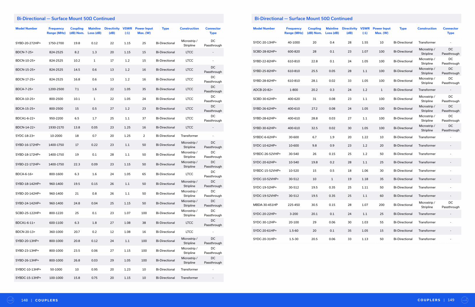
Model Number Frequency
Range (MHz)
Coupling
(dB) Nom.
Mainline
Loss (dB)
Directivity
(dB)
VSWR
(:1)
Power Input
Max. (W)
Type Construction Connector
Type
SYBD-20-272HP+ 1750-2700 19.8 0.12 22 1.15 25 Bi-DirectionalMicrostrip /
Stripline
DC
Passthrough
BDCN-7-25+ 824-2525 8.2 1.3 20 1.15 15 Bi-Directional LTCC -
BDCN-10-25+ 824-2525 10.2 1 17 1.2 15 Bi-Directional LTCC -
BDCN-15-25+ 824-2525 14.5 0.6 13 1.2 16 Bi-Directional LTCCDC
Passthrough
BDCN-17-25+ 824-2525 16.8 0.6 13 1.2 16 Bi-Directional LTCCDC
Passthrough
BDCA-7-25+ 1200-2500 7.1 1.6 22 1.05 35 Bi-Directional LTCCDC
Passthrough
BDCA-10-25+ 800-2500 10.1 1 22 1.05 24 Bi-Directional LTCCDC
Passthrough
BDCA-15-25+ 800-2500 15 0.5 27 1.2 23 Bi-Directional LTCCDC
Passthrough
BDCA1-6-22+ 950-2200 6.5 1.7 25 1.1 37 Bi-Directional LTCCDC
Passthrough
BDCN-14-22+ 1930-2170 13.8 0.05 23 1.25 16 Bi-Directional LTCC -
SYDC-18-23+ 10-2000 18 0.7 20 1.25 2 Bi-Directional Transformer -
SYBD-16-172HP+ 1400-1750 17 0.22 23 1.1 50 Bi-DirectionalMicrostrip /
Stripline
DC
Passthrough
SYBD-18-172HP+ 1400-1750 19 0.1 28 1.1 50 Bi-DirectionalMicrostrip /
Stripline
DC
Passthrough
SYBD-22-172HP+ 1400-1750 22.3 0.09 23 1.15 50 Bi-DirectionalMicrostrip /
Stripline
DC
Passthrough
BDCA-6-16+ 800-1600 6.3 1.6 24 1.05 65 Bi-Directional LTCCDC
Passthrough
SYBD-18-142HP+ 960-1400 19.5 0.15 26 1.1 50 Bi-DirectionalMicrostrip /
Stripline
DC
Passthrough
SYBD-20-142HP+ 960-1400 21 0.8 26 1.1 50 Bi-DirectionalMicrostrip /
Stripline
DC
Passthrough
SYBD-24-142HP+ 960-1400 24.8 0.04 25 1.15 50 Bi-DirectionalMicrostrip /
Stripline
DC
Passthrough
SCBD-25-122HP+ 800-1220 25 0.1 23 1.07 100 Bi-DirectionalMicrostrip /
Stripline
DC
Passthrough
BDCA1-6-11+ 600-1100 6.3 1.8 27 1.08 38 Bi-Directional LTCCDC
Passthrough
BDCN-20-13+ 360-1000 20.7 0.2 12 1.08 16 Bi-Directional LTCC -
SYBD-20-13HP+ 800-1000 20.8 0.12 24 1.1 100 Bi-DirectionalMicrostrip /
Stripline
DC
Passthrough
SYBD-23-13HP+ 800-1000 23.5 0.06 27 1.15 100 Bi-DirectionalMicrostrip /
Stripline
DC
Passthrough
SYBD-26-13HP+ 800-1000 26.8 0.03 29 1.05 100 Bi-DirectionalMicrostrip /
Stripline
DC
Passthrough
SYBDC-10-13HP+ 50-1000 10 0.95 20 1.23 10 Bi-Directional Transformer -
SYBDC-15-13HP+ 100-1000 15.8 0.75 20 1.15 10 Bi-Directional Transformer -
Model Number Frequency
Range (MHz)
Coupling
(dB) Nom.
Mainline
Loss (dB)
Directivity
(dB)
VSWR
(:1)
Power Input
Max. (W)
Type Construction Connector
Type
SYDC-20-13HP+ 40-1000 20 0.4 28 1.55 10 Bi-Directional Transformer -
SCBD-28-82HP+ 600-820 28 0.1 23 1.07 100 Bi-DirectionalMicrostrip /
Stripline
DC
Passthrough
SYBD-22-82HP+ 610-810 22.8 0.1 24 1.05 100 Bi-DirectionalMicrostrip /
Stripline
DC
Passthrough
SYBD-25-82HP+ 610-810 25.5 0.05 28 1.1 100 Bi-DirectionalMicrostrip /
Stripline
DC
Passthrough
SYBD-28-82HP+ 610-810 28.1 0.02 33 1.05 100 Bi-DirectionalMicrostrip /
Stripline
DC
Passthrough
ADCB-20-82+ 1-800 20.2 0.3 24 1.2 1 Bi-Directional Transformer -
SCBD-30-62HP+ 400-620 31 0.08 23 1.1 100 Bi-DirectionalMicrostrip /
Stripline
DC
Passthrough
SYBD-26-62HP+ 400-610 27.2 0.08 24 1.05 100 Bi-DirectionalMicrostrip /
Stripline
DC
Passthrough
SYBD-28-62HP+ 400-610 28.8 0.03 27 1.1 100 Bi-DirectionalMicrostrip /
Stripline
DC
Passthrough
SYBD-30-62HP+ 400-610 32.5 0.02 30 1.05 100 Bi-DirectionalMicrostrip /
Stripline
DC
Passthrough
SYBDC-6-62HP+ 30-600 6.7 1.9 20 1.22 10 Bi-Directional Transformer -
SYDC-10-62HP+ 10-600 9.8 0.9 23 1.2 20 Bi-Directional Transformer -
SYBDC-26-52VHP+ 30-540 26 0.15 25 1.2 50 Bi-Directional Transformer -
SYDC-20-62HP+ 10-540 19.8 0.2 28 1.1 25 Bi-Directional Transformer -
SYBDC-15-52VHP+ 10-520 15 0.5 18 1.06 30 Bi-Directional Transformer -
SYDC-10-52VHP+ 30-512 10 1 19 1.18 35 Bi-Directional Transformer -
SYDC-19-52HP+ 30-512 19.5 0.35 25 1.11 50 Bi-Directional Transformer -
SYDC-19-52VHP+ 30-512 19.5 0.35 25 1.1 60 Bi-Directional Transformer -
MBDA-30-451HP 225-450 30.5 0.15 28 1.07 200 Bi-DirectionalMicrostrip /
Stripline
DC
Passthrough
SYDC-20-22HP+ 3-200 20.1 0.1 24 1.1 25 Bi-Directional Transformer -
SYDC-30-12HP+ 20-100 29 0.06 30 1.03 55 Bi-Directional Transformer -
SYDC-20-61HP+ 1.5-60 20 0.1 35 1.05 15 Bi-Directional Transformer -
SYDC-20-31HP+ 1.5-30 20.5 0.06 33 1.13 50 Bi-Directional Transformer -
C O U P L E R S | 149| C O U P L E R S148
Bi-Directional — Surface Mount 50Ω ContinuedBi-Directional — Surface Mount 50Ω Continued
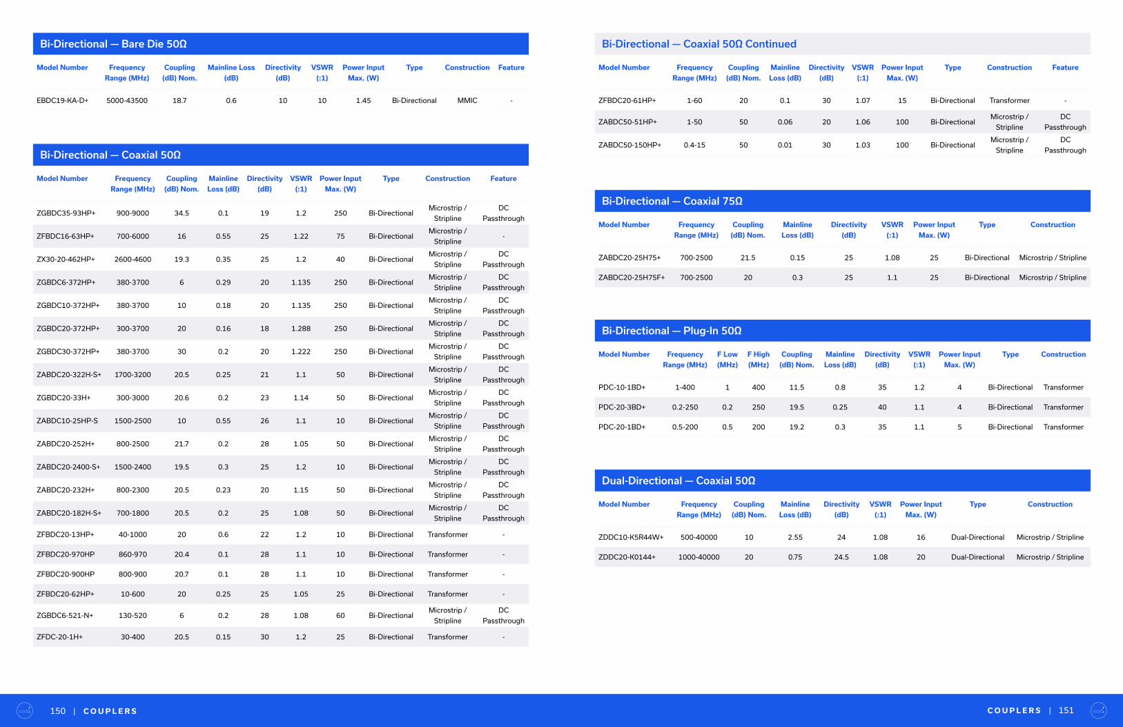
C O U P L E R S | 151| C O U P L E R S150
Model Number Frequency
Range (MHz)
Coupling
(dB) Nom.
Mainline
Loss (dB)
Directivity
(dB)
VSWR
(:1)
Power Input
Max. (W)
Type Construction Feature
ZGBDC35-93HP+ 900-9000 34.5 0.1 19 1.2 250 Bi-DirectionalMicrostrip /
Stripline
DC
Passthrough
ZFBDC16-63HP+ 700-6000 16 0.55 25 1.22 75 Bi-DirectionalMicrostrip /
Stripline-
ZX30-20-462HP+ 2600-4600 19.3 0.35 25 1.2 40 Bi-DirectionalMicrostrip /
Stripline
DC
Passthrough
ZGBDC6-372HP+ 380-3700 6 0.29 20 1.135 250 Bi-DirectionalMicrostrip /
Stripline
DC
Passthrough
ZGBDC10-372HP+ 380-3700 10 0.18 20 1.135 250 Bi-DirectionalMicrostrip /
Stripline
DC
Passthrough
ZGBDC20-372HP+ 300-3700 20 0.16 18 1.288 250 Bi-DirectionalMicrostrip /
Stripline
DC
Passthrough
ZGBDC30-372HP+ 380-3700 30 0.2 20 1.222 250 Bi-DirectionalMicrostrip /
Stripline
DC
Passthrough
ZABDC20-322H-S+ 1700-3200 20.5 0.25 21 1.1 50 Bi-DirectionalMicrostrip /
Stripline
DC
Passthrough
ZGBDC20-33H+ 300-3000 20.6 0.2 23 1.14 50 Bi-DirectionalMicrostrip /
Stripline
DC
Passthrough
ZABDC10-25HP-S 1500-2500 10 0.55 26 1.1 10 Bi-DirectionalMicrostrip /
Stripline
DC
Passthrough
ZABDC20-252H+ 800-2500 21.7 0.2 28 1.05 50 Bi-DirectionalMicrostrip /
Stripline
DC
Passthrough
ZABDC20-2400-S+ 1500-2400 19.5 0.3 25 1.2 10 Bi-DirectionalMicrostrip /
Stripline
DC
Passthrough
ZABDC20-232H+ 800-2300 20.5 0.23 20 1.15 50 Bi-DirectionalMicrostrip /
Stripline
DC
Passthrough
ZABDC20-182H-S+ 700-1800 20.5 0.2 25 1.08 50 Bi-DirectionalMicrostrip /
Stripline
DC
Passthrough
ZFBDC20-13HP+ 40-1000 20 0.6 22 1.2 10 Bi-Directional Transformer -
ZFBDC20-970HP 860-970 20.4 0.1 28 1.1 10 Bi-Directional Transformer -
ZFBDC20-900HP 800-900 20.7 0.1 28 1.1 10 Bi-Directional Transformer -
ZFBDC20-62HP+ 10-600 20 0.25 25 1.05 25 Bi-Directional Transformer -
ZGBDC6-521-N+ 130-520 6 0.2 28 1.08 60 Bi-DirectionalMicrostrip /
Stripline
DC
Passthrough
ZFDC-20-1H+ 30-400 20.5 0.15 30 1.2 25 Bi-Directional Transformer -
Bi-Directional — Bare Die 50Ω
Bi-Directional — Coaxial 50Ω
Bi-Directional — Coaxial 50Ω Continued
Model Number Frequency
Range (MHz)
Coupling
(dB) Nom.
Mainline Loss
(dB)
Directivity
(dB)
VSWR
(:1)
Power Input
Max. (W)
Type Construction Feature
EBDC19-KA-D+ 5000-43500 18.7 0.6 10 10 1.45 Bi-Directional MMIC -
Model Number Frequency
Range (MHz)
Coupling
(dB) Nom.
Mainline
Loss (dB)
Directivity
(dB)
VSWR
(:1)
Power Input
Max. (W)
Type Construction Feature
ZFBDC20-61HP+ 1-60 20 0.1 30 1.07 15 Bi-Directional Transformer -
ZABDC50-51HP+ 1-50 50 0.06 20 1.06 100 Bi-DirectionalMicrostrip /
Stripline
DC
Passthrough
ZABDC50-150HP+ 0.4-15 50 0.01 30 1.03 100 Bi-DirectionalMicrostrip /
Stripline
DC
Passthrough
Bi-Directional — Coaxial 75Ω
Model Number Frequency
Range (MHz)
Coupling
(dB) Nom.
Mainline
Loss (dB)
Directivity
(dB)
VSWR
(:1)
Power Input
Max. (W)
Type Construction
ZABDC20-25H75+ 700-2500 21.5 0.15 25 1.08 25 Bi-Directional Microstrip / Stripline
ZABDC20-25H75F+ 700-2500 20 0.3 25 1.1 25 Bi-Directional Microstrip / Stripline
Bi-Directional — Plug-In 50Ω
Model Number Frequency
Range (MHz)
F Low
(MHz)
F High
(MHz)
Coupling
(dB) Nom.
Mainline
Loss (dB)
Directivity
(dB)
VSWR
(:1)
Power Input
Max. (W)
Type Construction
PDC-10-1BD+ 1-400 1 400 11.5 0.8 35 1.2 4 Bi-Directional Transformer
PDC-20-3BD+ 0.2-250 0.2 250 19.5 0.25 40 1.1 4 Bi-Directional Transformer
PDC-20-1BD+ 0.5-200 0.5 200 19.2 0.3 35 1.1 5 Bi-Directional Transformer
Dual-Directional — Coaxial 50Ω
Model Number Frequency
Range (MHz)
Coupling
(dB) Nom.
Mainline
Loss (dB)
Directivity
(dB)
VSWR
(:1)
Power Input
Max. (W)
Type Construction
ZDDC10-K5R44W+ 500-40000 10 2.55 24 1.08 16 Dual-Directional Microstrip / Stripline
ZDDC20-K0144+ 1000-40000 20 0.75 24.5 1.08 20 Dual-Directional Microstrip / Stripline

T E S T I M O N I A L | 153| C O U P L E R S152
RF Tap — Bare Die 50Ω
RF Tap — Coaxial 50Ω
Model Number Frequency
Range (MHz)
Coupling
(dB) Nom.
Mainline
Loss (dB)
Directivity
(dB)
VSWR
(:1)
Power Input
Max. (W)
Type Construction
ZARC-25-63-S+ 2500-6000 25 0.27 20 0 100 RF Tap Microstrip / Stripline
ZARC-25-252-S+ 550-2500 25 0.15 27 0 100 RF Tap Microstrip / Stripline
ZARC-20-52+ 100-550 20 0.9 21 0 16 RF Tap Microstrip / Stripline
ZARC-25-551-S+ 100-550 25 0.12 23 0 100 RF Tap Microstrip / Stripline
ZARC-26-12-S+ 20-100 26 0.06 27 0 100 RF Tap Microstrip / Stripline
Model Number Frequency
Range (MHz)
Coupling
(dB) Nom.
Mainline
Loss (dB)
Directivity
(dB)
VSWR
(:1)
Power Input
Max. (W)
Type Construction
HK-PT54-D+ DC-50000 26.5 0.8 - 1.27 1 RF Tap MMIC
“General Dynamics Mission Systems
M i n i - C i r c u i t s i s a t e r r i f i c p a r t n e r .
— S R . S U P P LY C H A I N A N A LY S T
RF Tap — Surface Mount 50Ω
Model Number Frequency
Range (MHz)
Coupling
(dB) Nom.
Mainline
Loss (dB)
Directivity
(dB)
VSWR
(:1)
Power Input
Max. (W)
Type Construction
RBDC-20-63+ DC-6000 20 1.35 20 1.30 0.25 RF Tap Microstrip / Stripline
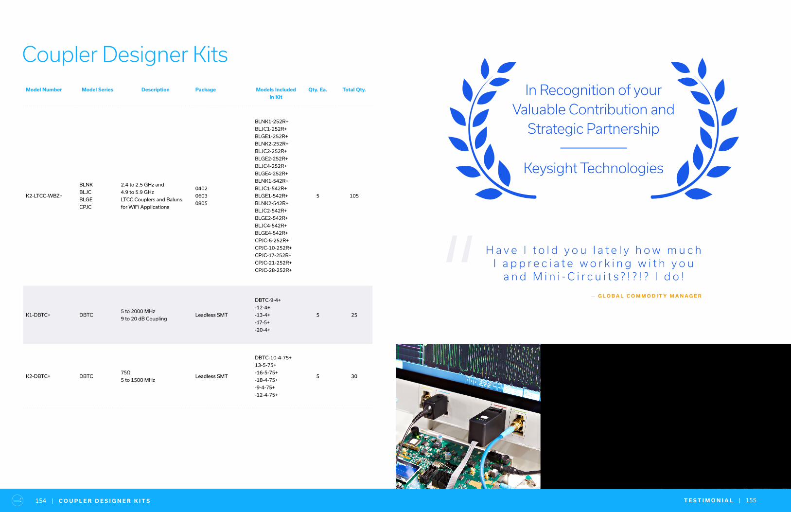
T E S T I M O N I A L | 155| C O U P L E R D E S I G N E R K I T S154
Coupler Designer KitsModel Number Model Series Description Package Models Included
in Kit
Qty. Ea. Total Qty.
K2-LTCC-WBZ+
BLNK
BLJC
BLGE
CPJC
2.4 to 2.5 GHz and
4.9 to 5.9 GHz
LTCC Couplers and Baluns
for WiFi Applications
0402
0603
0805
BLNK1-252R+
BLJC1-252R+
BLGE1-252R+
BLNK2-252R+
BLJC2-252R+
BLGE2-252R+
BLJC4-252R+
BLGE4-252R+
BLNK1-542R+
BLJC1-542R+
BLGE1-542R+
BLNK2-542R+
BLJC2-542R+
BLGE2-542R+
BLJC4-542R+
BLGE4-542R+
CPJC-6-252R+
CPJC-10-252R+
CPJC-17-252R+
CPJC-21-252R+
CPJC-28-252R+
5 105
K1-DBTC+ DBTC5 to 2000 MHz
9 to 20 dB CouplingLeadless SMT
DBTC-9-4+
-12-4+
-13-4+
-17-5+
-20-4+
5 25
K2-DBTC+ DBTC75Ω
5 to 1500 MHzLeadless SMT
DBTC-10-4-75+
13-5-75+
-16-5-75+
-18-4-75+
-9-4-75+
-12-4-75+
5 30
In Recognition of your Valuable Contribution and
Strategic Partnership
Keysight Technologies
H a v e I t o l d y o u l a t e l y h o w m u c h I a p p r e c i a t e w o r k i n g w i t h y o u
a n d M i n i - C i r c u i t s ? ! ? ! ? I d o !
— G L O B A L C O M M O D I T Y M A N A G E R“
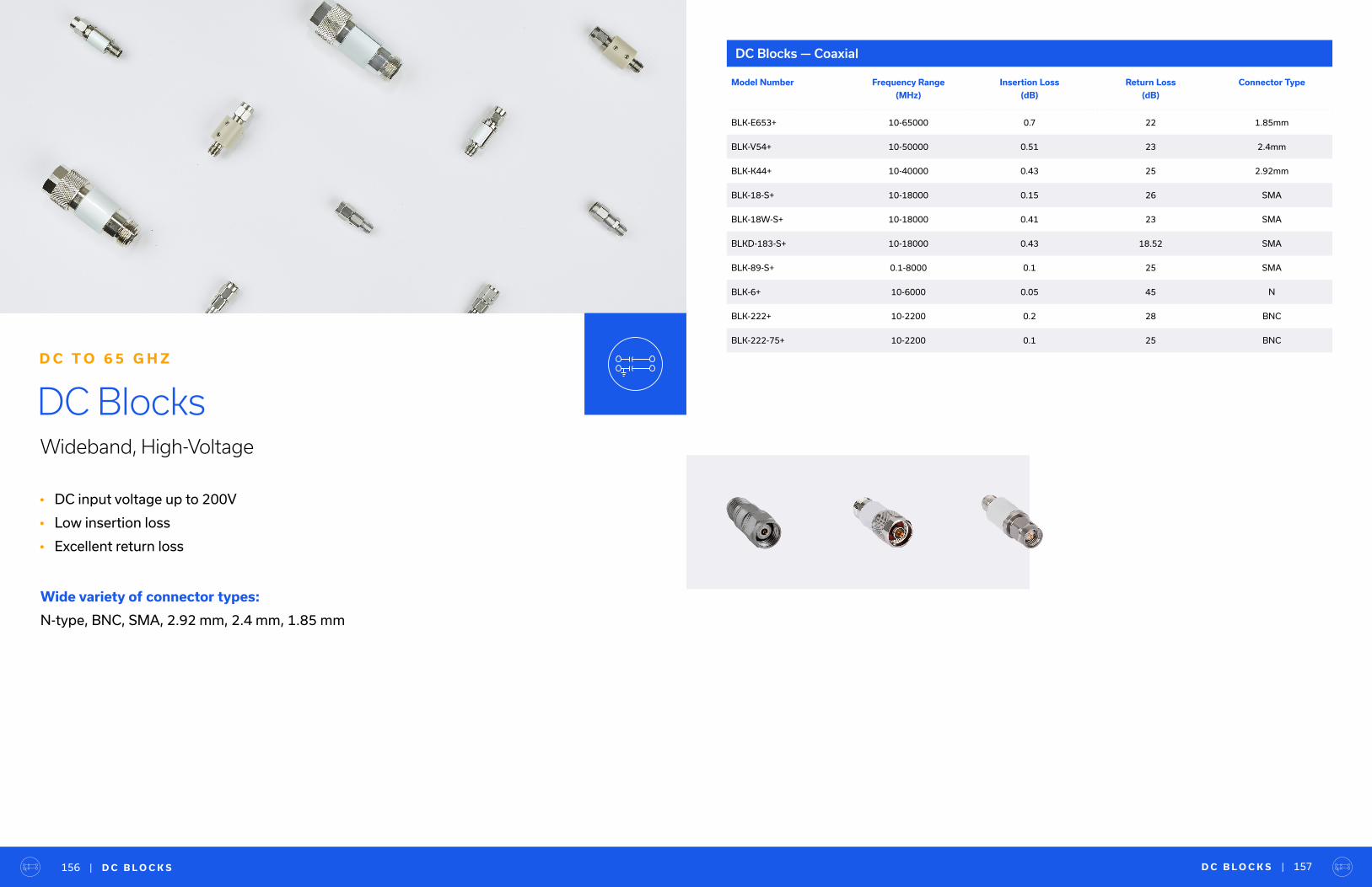
D C B L O C K S | 157| D C B L O C K S156
• DC input voltage up to 200V
• Low insertion loss
• Excellent return loss
DC BlocksWideband, High-Voltage
D C T O 6 5 G H Z
Wide variety of connector types:
N-type, BNC, SMA, 2.92 mm, 2.4 mm, 1.85 mm
DC Blocks — Coaxial
Model Number Frequency Range
(MHz)
Insertion Loss
(dB)
Return Loss
(dB)
Connector Type
BLK-E653+ 10-65000 0.7 22 1.85mm
BLK-V54+ 10-50000 0.51 23 2.4mm
BLK-K44+ 10-40000 0.43 25 2.92mm
BLK-18-S+ 10-18000 0.15 26 SMA
BLK-18W-S+ 10-18000 0.41 23 SMA
BLKD-183-S+ 10-18000 0.43 18.52 SMA
BLK-89-S+ 0.1-8000 0.1 25 SMA
BLK-6+ 10-6000 0.05 45 N
BLK-222+ 10-2200 0.2 28 BNC
BLK-222-75+ 10-2200 0.1 25 BNC
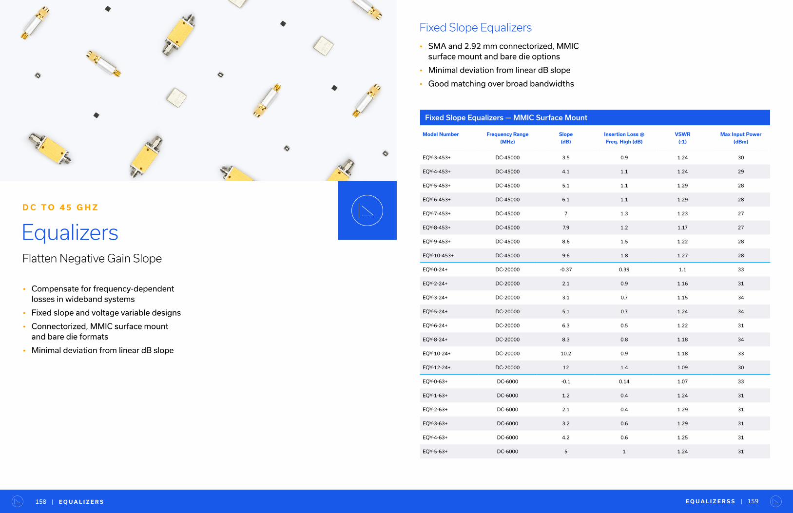
E Q U A L I Z E R S S | 159| E Q U A L I Z E R S158
• Compensate for frequency-dependent losses in wideband systems
• Fixed slope and voltage variable designs
• Connectorized, MMIC surface mount and bare die formats
• Minimal deviation from linear dB slope
EqualizersFlatten Negative Gain Slope
D C T O 4 5 G H Z
Fixed Slope Equalizers
• SMA and 2.92 mm connectorized, MMIC surface mount and bare die options
• Minimal deviation from linear dB slope
• Good matching over broad bandwidths
Fixed Slope Equalizers — MMIC Surface Mount
Model Number Frequency Range
(MHz)
Slope
(dB)
Insertion Loss @
Freq. High (dB)
VSWR
(:1)
Max Input Power
(dBm)
EQY-3-453+ DC-45000 3.5 0.9 1.24 30
EQY-4-453+ DC-45000 4.1 1.1 1.24 29
EQY-5-453+ DC-45000 5.1 1.1 1.29 28
EQY-6-453+ DC-45000 6.1 1.1 1.29 28
EQY-7-453+ DC-45000 7 1.3 1.23 27
EQY-8-453+ DC-45000 7.9 1.2 1.17 27
EQY-9-453+ DC-45000 8.6 1.5 1.22 28
EQY-10-453+ DC-45000 9.6 1.8 1.27 28
EQY-0-24+ DC-20000 -0.37 0.39 1.1 33
EQY-2-24+ DC-20000 2.1 0.9 1.16 31
EQY-3-24+ DC-20000 3.1 0.7 1.15 34
EQY-5-24+ DC-20000 5.1 0.7 1.24 34
EQY-6-24+ DC-20000 6.3 0.5 1.22 31
EQY-8-24+ DC-20000 8.3 0.8 1.18 34
EQY-10-24+ DC-20000 10.2 0.9 1.18 33
EQY-12-24+ DC-20000 12 1.4 1.09 30
EQY-0-63+ DC-6000 -0.1 0.14 1.07 33
EQY-1-63+ DC-6000 1.2 0.4 1.24 31
EQY-2-63+ DC-6000 2.1 0.4 1.29 31
EQY-3-63+ DC-6000 3.2 0.6 1.29 31
EQY-4-63+ DC-6000 4.2 0.6 1.25 31
EQY-5-63+ DC-6000 5 1 1.24 31
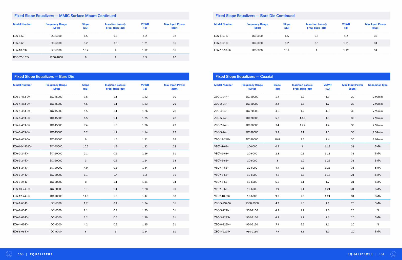
Model Number Frequency Range
(MHz)
Slope
(dB)
Insertion Loss @
Freq. High (dB)
VSWR
(:1)
Max Input Power
(dBm)
EQY-6-63+ DC-6000 6.5 0.5 1.2 32
EQY-8-63+ DC-6000 8.2 0.5 1.21 31
EQY-10-63+ DC-6000 10.2 1 1.12 31
REQ-75-182+ 1200-1800 8 2 1.9 20
E Q U A L I Z E R S S | 161| E Q U A L I Z E R S160
Fixed Slope Equalizers — Bare Die Fixed Slope Equalizers — Coaxial
Model Number Frequency Range
(MHz)
Slope
(dB)
Insertion Loss @
Freq. High (dB)
VSWR
(:1)
Max Input Power
(dBm)
EQY-3-453-D+ DC-45000 3.5 1.1 1.22 30
EQY-4-453-D+ DC-45000 4.5 1.1 1.23 29
EQY-5-453-D+ DC-45000 5.5 1.1 1.26 28
EQY-6-453-D+ DC-45000 6.5 1.1 1.25 28
EQY-7-453-D+ DC-45000 7.4 1.3 1.26 27
EQY-8-453-D+ DC-45000 8.2 1.2 1.14 27
EQY-9-453-D+ DC-45000 9 1.6 1.21 28
EQY-10-453-D+ DC-45000 10.2 1.8 1.22 28
EQY-2-24-D+ DC-20000 2.1 0.9 1.26 31
EQY-3-24-D+ DC-20000 3 0.8 1.24 34
EQY-5-24-D+ DC-20000 4.9 0.8 1.34 34
EQY-6-24-D+ DC-20000 6.1 0.7 1.3 31
EQY-8-24-D+ DC-20000 8 1.1 1.31 34
EQY-10-24-D+ DC-20000 10 1.1 1.28 33
EQY-12-24-D+ DC-20000 11.9 1.5 1.17 30
EQY-1-63-D+ DC-6000 1.2 0.4 1.24 31
EQY-2-63-D+ DC-6000 2.1 0.4 1.29 31
EQY-3-63-D+ DC-6000 3.2 0.6 1.29 31
EQY-4-63-D+ DC-6000 4.2 0.6 1.25 31
EQY-5-63-D+ DC-6000 5 1 1.24 31
Model Number Frequency Range
(MHz)
Slope
(dB)
Insertion Loss @
Freq. High (dB)
VSWR
(:1)
Max Input Power
(dBm)
Connector Type
ZEQ-1-24K+ DC-20000 1.4 1.9 1.3 30 2.92mm
ZEQ-2-24K+ DC-20000 2.4 1.6 1.2 33 2.92mm
ZEQ-4-24K+ DC-20000 4.2 1.7 1.3 33 2.92mm
ZEQ-5-24K+ DC-20000 5.3 1.65 1.3 30 2.92mm
ZEQ-7-24K+ DC-20000 7.4 1.75 1.4 33 2.92mm
ZEQ-9-24K+ DC-20000 9.2 2.1 1.3 33 2.92mm
ZEQ-11-24K+ DC-20000 10.8 2.6 1.4 30 2.92mm
VEQY-1-63+ 10-6000 0.9 1 1.13 31 SMA
VEQY-2-63+ 10-6000 2.3 0.6 1.18 31 SMA
VEQY-3-63+ 10-6000 3 1.2 1.25 31 SMA
VEQY-4-63+ 10-6000 4.4 0.8 1.23 31 SMA
VEQY-5-63+ 10-6000 4.8 1.6 1.16 31 SMA
VEQY-6-63+ 10-6000 6.3 1.1 1.2 31 SMA
VEQY-8-63+ 10-6000 7.9 1.1 1.21 31 SMA
VEQY-10-63+ 10-6000 9.9 1.6 1.21 31 SMA
ZEQ-5-292-S+ 1300-2900 4.7 1.5 1.1 20 SMA
ZEQ-3-222N+ 950-2150 4.2 1.7 1.1 20 N
ZEQ-3-222S+ 950-2150 4.2 1.7 1.1 20 SMA
ZEQ-8-222N+ 950-2150 7.9 6.6 1.1 20 N
ZEQ-8-222S+ 950-2150 7.9 6.6 1.1 20 SMA
Model Number Frequency Range
(MHz)
Slope
(dB)
Insertion Loss @
Freq. High (dB)
VSWR
(:1)
Max Input Power
(dBm)
EQY-6-63-D+ DC-6000 6.5 0.5 1.2 32
EQY-8-63-D+ DC-6000 8.2 0.5 1.21 31
EQY-10-63-D+ DC-6000 10.2 1 1.12 31
Fixed Slope Equalizers — MMIC Surface Mount Continued Fixed Slope Equalizers — Bare Die Continued
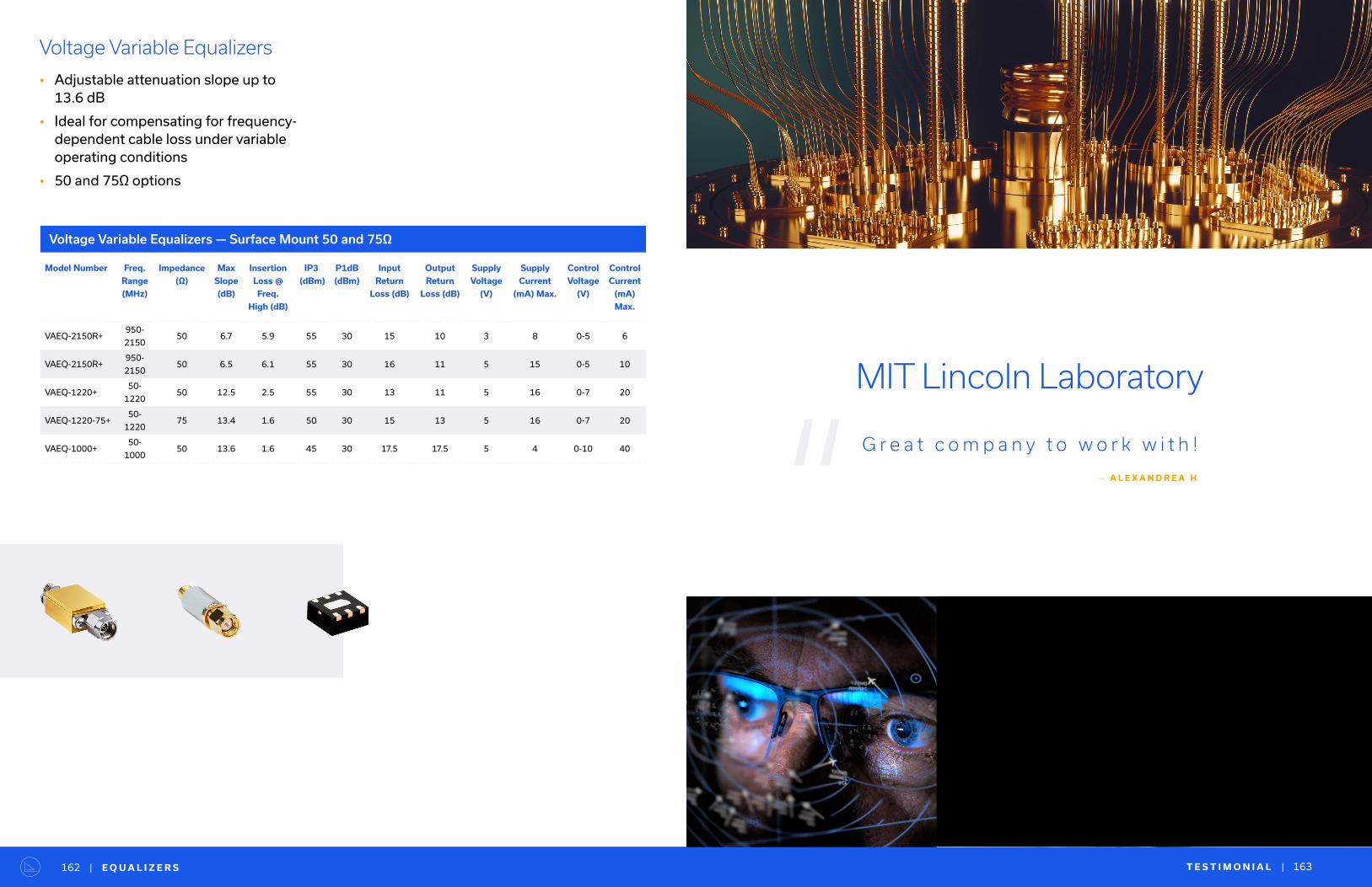
T E S T I M O N I A L | 163| E Q U A L I Z E R S162
Voltage Variable Equalizers
• Adjustable attenuation slope up to 13.6 dB
• Ideal for compensating for frequency-dependent cable loss under variable operating conditions
• 50 and 75Ω options
Voltage Variable Equalizers — Surface Mount 50 and 75Ω
Model Number Freq.
Range
(MHz)
Impedance
(Ω)
Max
Slope
(dB)
Insertion
Loss @
Freq.
High (dB)
IP3
(dBm)
P1dB
(dBm)
Input
Return
Loss (dB)
Output
Return
Loss (dB)
Supply
Voltage
(V)
Supply
Current
(mA) Max.
Control
Voltage
(V)
Control
Current
(mA)
Max.
VAEQ-2150R+950-
215050 6.7 5.9 55 30 15 10 3 8 0-5 6
VAEQ-2150R+950-
215050 6.5 6.1 55 30 16 11 5 15 0-5 10
VAEQ-1220+50-
122050 12.5 2.5 55 30 13 11 5 16 0-7 20
VAEQ-1220-75+50-
122075 13.4 1.6 50 30 15 13 5 16 0-7 20
VAEQ-1000+50-
100050 13.6 1.6 45 30 17.5 17.5 5 4 0-10 40
“MIT Lincoln Laboratory
G r e a t c o m p a n y t o w o r k w i t h !
— A L E X A N D R E A H
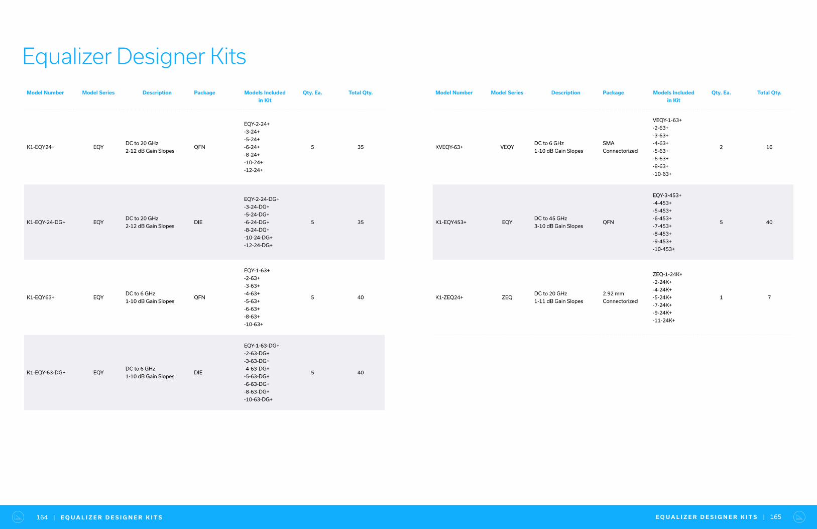
E Q U A L I Z E R D E S I G N E R K I T S | 165| E Q U A L I Z E R D E S I G N E R K I T S164
Equalizer Designer KitsModel Number Model Series Description Package Models Included
in Kit
Qty. Ea. Total Qty.
K1-EQY24+ EQYDC to 20 GHz
2-12 dB Gain SlopesQFN
EQY-2-24+
-3-24+
-5-24+
-6-24+
-8-24+
-10-24+
-12-24+
5 35
K1-EQY-24-DG+ EQYDC to 20 GHz
2-12 dB Gain SlopesDIE
EQY-2-24-DG+
-3-24-DG+
-5-24-DG+
-6-24-DG+
-8-24-DG+
-10-24-DG+
-12-24-DG+
5 35
K1-EQY63+ EQYDC to 6 GHz
1-10 dB Gain SlopesQFN
EQY-1-63+
-2-63+
-3-63+
-4-63+
-5-63+
-6-63+
-8-63+
-10-63+
5 40
K1-EQY-63-DG+ EQYDC to 6 GHz
1-10 dB Gain SlopesDIE
EQY-1-63-DG+
-2-63-DG+
-3-63-DG+
-4-63-DG+
-5-63-DG+
-6-63-DG+
-8-63-DG+
-10-63-DG+
5 40
Model Number Model Series Description Package Models Included
in Kit
Qty. Ea. Total Qty.
KVEQY-63+ VEQYDC to 6 GHz
1-10 dB Gain Slopes
SMA
Connectorized
VEQY-1-63+
-2-63+
-3-63+
-4-63+
-5-63+
-6-63+
-8-63+
-10-63+
2 16
K1-EQY453+ EQYDC to 45 GHz
3-10 dB Gain SlopesQFN
EQY-3-453+
-4-453+
-5-453+
-6-453+
-7-453+
-8-453+
-9-453+
-10-453+
5 40
K1-ZEQ24+ ZEQDC to 20 GHz
1-11 dB Gain Slopes
2.92 mm
Connectorized
ZEQ-1-24K+
-2-24K+
-4-24K+
-5-24K+
-7-24K+
-9-24K+
-11-24K+
1 7
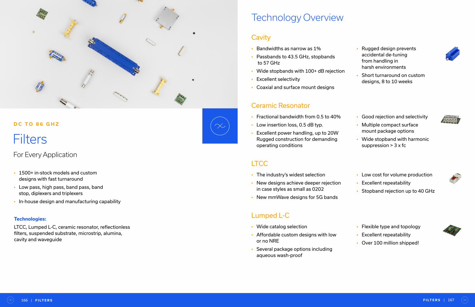
• 1500+ in-stock models and custom designs with fast turnaround
• Low pass, high pass, band pass, band stop, diplexers and triplexers
• In-house design and manufacturing capability
FiltersFor Every Application
D C T O 8 6 G H Z
Technologies:
LTCC, Lumped L-C, ceramic resonator, reflectionless filters, suspended substrate, microstrip, alumina, cavity and waveguide
Technology Overview
Cavity
• Bandwidths as narrow as 1%
• Passbands to 43.5 GHz, stopbands to 57 GHz
• Wide stopbands with 100+ dB rejection
• Excellent selectivity
• Coaxial and surface mount designs
Ceramic Resonator
• Fractional bandwidth from 0.5 to 40%
• Low insertion loss, 0.5 dB typ.
• Excellent power handling, up to 20W Rugged construction for demanding operating conditions
LTCC
• The industry’s widest selection
• New designs achieve deeper rejection in case styles as small as 0202
• New mmWave designs for 5G bands
Lumped L-C
• Wide catalog selection
• Affordable custom designs with low or no NRE
• Several package options including aqueous wash-proof
• Rugged design prevents accidental de-tuning from handling in harsh environments
• Short turnaround on custom designs, 8 to 10 weeks
• Good rejection and selectivity
• Multiple compact surface mount package options
• Wide stopband with harmonic suppression > 3 x fc
• Low cost for volume production
• Excellent repeatability
• Stopband rejection up to 40 GHz
• Flexible type and topology
• Excellent repeatability
• Over 100 million shipped!
F I LT E R S | 167| F I LT E R S166
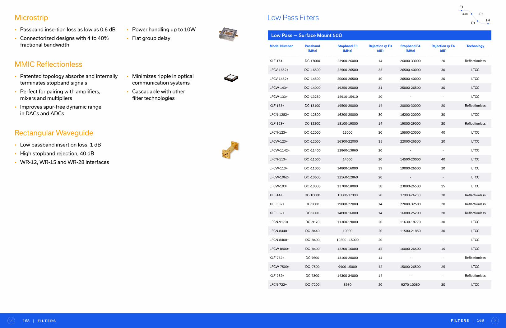
Microstrip
• Passband insertion loss as low as 0.6 dB
• Connectorized designs with 4 to 40% fractional bandwidth
MMIC Reflectionless
• Patented topology absorbs and internally terminates stopband signals
• Perfect for pairing with amplifiers, mixers and multipliers
• Improves spur-free dynamic range in DACs and ADCs
Rectangular Waveguide
• Low passband insertion loss, 1 dB
• High stopband rejection, 40 dB
• WR-12, WR-15 and WR-28 interfaces
• Power handling up to 10W
• Flat group delay
• Minimizes ripple in optical communication systems
• Cascadable with other filter technologies
Low Pass — Surface Mount 50Ω
Model Number Passband
(MHz)
Stopband F3
(MHz)
Rejection @ F3
(dB)
Stopband F4
(MHz)
Rejection @ F4
(dB)
Technology
XLF-173+ DC-17000 23900-26000 14 26000-33000 20 Reflectionless
LFCV-1652+ DC -16500 22500-26500 35 26500-40000 30 LTCC
LFCV-1452+ DC -14500 20000-26500 40 26500-40000 20 LTCC
LFCW-143+ DC -14000 19250-25000 31 25000-26500 30 LTCC
LFCW-133+ DC -13250 14910-15410 20 - - LTCC
XLF-133+ DC-13100 19500-20000 14 20000-30000 20 Reflectionless
LFCN-1282+ DC -12800 16200-20000 30 16200-20000 30 LTCC
XLF-123+ DC-12200 18100-19000 14 19000-29000 20 Reflectionless
LFCN-123+ DC -12000 15000 20 15500-20000 40 LTCC
LFCW-123+ DC -12000 16300-22000 35 22000-26500 20 LTCC
LFCW-1142+ DC -11400 12860-13860 20 - - LTCC
LFCN-113+ DC -11000 14000 20 14500-20000 40 LTCC
LFCW-113+ DC -11000 14800-16000 39 19000-26500 20 LTCC
LFCW-1062+ DC -10600 12160-12860 20 - - LTCC
LFCW-103+ DC -10000 13700-18000 38 23000-26500 15 LTCC
XLF-14+ DC-10000 15800-17000 20 17000-24200 20 Reflectionless
XLF-982+ DC-9800 19000-22000 14 22000-32500 20 Reflectionless
XLF-962+ DC-9600 14800-16000 14 16000-25200 20 Reflectionless
LFCN-9170+ DC -9170 11360-19000 20 11630-18770 30 LTCC
LFCN-8440+ DC -8440 10900 20 11500-21850 30 LTCC
LFCN-8400+ DC -8400 10300 - 15000 20 - - LTCC
LFCW-8400+ DC -8400 12200-16000 45 16000-26500 15 LTCC
XLF-762+ DC-7600 13100-20000 14 - - Reflectionless
LFCW-7500+ DC -7500 9900-15000 42 15000-26500 25 LTCC
XLF-732+ DC-7300 14300-34000 14 - - Reflectionless
LFCN-722+ DC -7200 8980 20 9270-10060 30 LTCC
Low Pass Filters
F I LT E R S | 169| F I LT E R S168
F1
F23 dB
F3F4
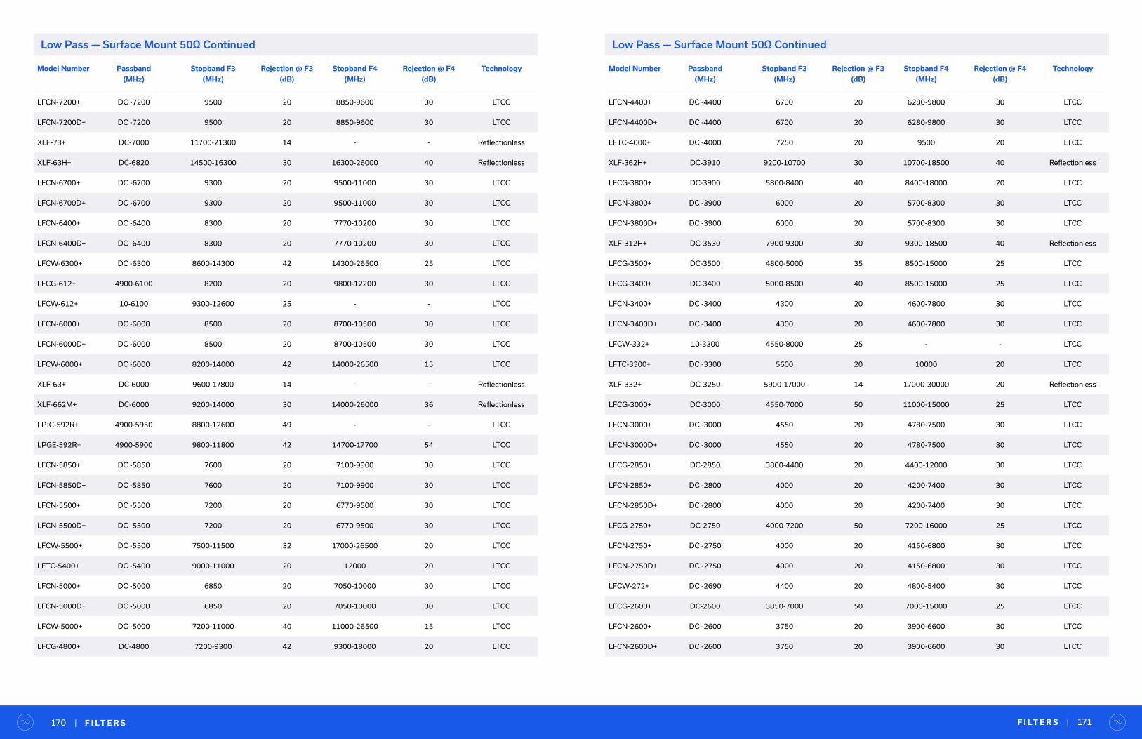
Model Number Passband
(MHz)
Stopband F3
(MHz)
Rejection @ F3
(dB)
Stopband F4
(MHz)
Rejection @ F4
(dB)
Technology
LFCN-7200+ DC -7200 9500 20 8850-9600 30 LTCC
LFCN-7200D+ DC -7200 9500 20 8850-9600 30 LTCC
XLF-73+ DC-7000 11700-21300 14 - - Reflectionless
XLF-63H+ DC-6820 14500-16300 30 16300-26000 40 Reflectionless
LFCN-6700+ DC -6700 9300 20 9500-11000 30 LTCC
LFCN-6700D+ DC -6700 9300 20 9500-11000 30 LTCC
LFCN-6400+ DC -6400 8300 20 7770-10200 30 LTCC
LFCN-6400D+ DC -6400 8300 20 7770-10200 30 LTCC
LFCW-6300+ DC -6300 8600-14300 42 14300-26500 25 LTCC
LFCG-612+ 4900-6100 8200 20 9800-12200 30 LTCC
LFCW-612+ 10-6100 9300-12600 25 - - LTCC
LFCN-6000+ DC -6000 8500 20 8700-10500 30 LTCC
LFCN-6000D+ DC -6000 8500 20 8700-10500 30 LTCC
LFCW-6000+ DC -6000 8200-14000 42 14000-26500 15 LTCC
XLF-63+ DC-6000 9600-17800 14 - - Reflectionless
XLF-662M+ DC-6000 9200-14000 30 14000-26000 36 Reflectionless
LPJC-592R+ 4900-5950 8800-12600 49 - - LTCC
LPGE-592R+ 4900-5900 9800-11800 42 14700-17700 54 LTCC
LFCN-5850+ DC -5850 7600 20 7100-9900 30 LTCC
LFCN-5850D+ DC -5850 7600 20 7100-9900 30 LTCC
LFCN-5500+ DC -5500 7200 20 6770-9500 30 LTCC
LFCN-5500D+ DC -5500 7200 20 6770-9500 30 LTCC
LFCW-5500+ DC -5500 7500-11500 32 17000-26500 20 LTCC
LFTC-5400+ DC -5400 9000-11000 20 12000 20 LTCC
LFCN-5000+ DC -5000 6850 20 7050-10000 30 LTCC
LFCN-5000D+ DC -5000 6850 20 7050-10000 30 LTCC
LFCW-5000+ DC -5000 7200-11000 40 11000-26500 15 LTCC
LFCG-4800+ DC-4800 7200-9300 42 9300-18000 20 LTCC
Model Number Passband
(MHz)
Stopband F3
(MHz)
Rejection @ F3
(dB)
Stopband F4
(MHz)
Rejection @ F4
(dB)
Technology
LFCN-4400+ DC -4400 6700 20 6280-9800 30 LTCC
LFCN-4400D+ DC -4400 6700 20 6280-9800 30 LTCC
LFTC-4000+ DC -4000 7250 20 9500 20 LTCC
XLF-362H+ DC-3910 9200-10700 30 10700-18500 40 Reflectionless
LFCG-3800+ DC-3900 5800-8400 40 8400-18000 20 LTCC
LFCN-3800+ DC -3900 6000 20 5700-8300 30 LTCC
LFCN-3800D+ DC -3900 6000 20 5700-8300 30 LTCC
XLF-312H+ DC-3530 7900-9300 30 9300-18500 40 Reflectionless
LFCG-3500+ DC-3500 4800-5000 35 8500-15000 25 LTCC
LFCG-3400+ DC-3400 5000-8500 40 8500-15000 25 LTCC
LFCN-3400+ DC -3400 4300 20 4600-7800 30 LTCC
LFCN-3400D+ DC -3400 4300 20 4600-7800 30 LTCC
LFCW-332+ 10-3300 4550-8000 25 - - LTCC
LFTC-3300+ DC -3300 5600 20 10000 20 LTCC
XLF-332+ DC-3250 5900-17000 14 17000-30000 20 Reflectionless
LFCG-3000+ DC-3000 4550-7000 50 11000-15000 25 LTCC
LFCN-3000+ DC -3000 4550 20 4780-7500 30 LTCC
LFCN-3000D+ DC -3000 4550 20 4780-7500 30 LTCC
LFCG-2850+ DC-2850 3800-4400 20 4400-12000 30 LTCC
LFCN-2850+ DC -2800 4000 20 4200-7400 30 LTCC
LFCN-2850D+ DC -2800 4000 20 4200-7400 30 LTCC
LFCG-2750+ DC-2750 4000-7200 50 7200-16000 25 LTCC
LFCN-2750+ DC -2750 4000 20 4150-6800 30 LTCC
LFCN-2750D+ DC -2750 4000 20 4150-6800 30 LTCC
LFCW-272+ DC -2690 4400 20 4800-5400 30 LTCC
LFCG-2600+ DC-2600 3850-7000 50 7000-15000 25 LTCC
LFCN-2600+ DC -2600 3750 20 3900-6600 30 LTCC
LFCN-2600D+ DC -2600 3750 20 3900-6600 30 LTCC
F I LT E R S | 171| F I LT E R S170
Low Pass — Surface Mount 50Ω ContinuedLow Pass — Surface Mount 50Ω Continued
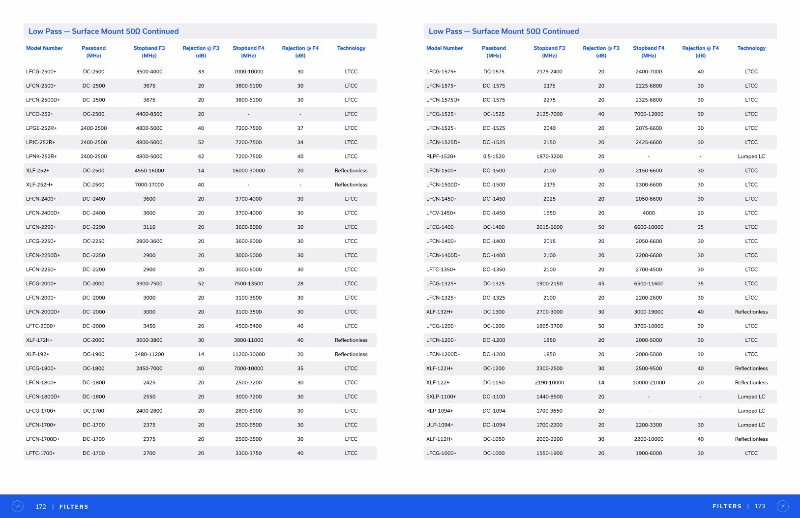
Model Number Passband
(MHz)
Stopband F3
(MHz)
Rejection @ F3
(dB)
Stopband F4
(MHz)
Rejection @ F4
(dB)
Technology
LFCG-2500+ DC-2500 3500-4000 33 7000-10000 30 LTCC
LFCN-2500+ DC -2500 3675 20 3800-6100 30 LTCC
LFCN-2500D+ DC -2500 3675 20 3800-6100 30 LTCC
LFCO-252+ DC-2500 4400-8500 20 - - LTCC
LPGE-252R+ 2400-2500 4800-5000 40 7200-7500 37 LTCC
LPJC-252R+ 2400-2500 4800-5000 52 7200-7500 34 LTCC
LPNK-252R+ 2400-2500 4800-5000 42 7200-7500 40 LTCC
XLF-252+ DC-2500 4550-16000 14 16000-30000 20 Reflectionless
XLF-252H+ DC-2500 7000-17000 40 - - Reflectionless
LFCN-2400+ DC -2400 3600 20 3700-4000 30 LTCC
LFCN-2400D+ DC -2400 3600 20 3700-4000 30 LTCC
LFCN-2290+ DC -2290 3110 20 3600-8000 30 LTCC
LFCG-2250+ DC-2250 2800-3600 20 3600-8000 30 LTCC
LFCN-2250D+ DC -2250 2900 20 3000-5000 30 LTCC
LFCN-2250+ DC -2200 2900 20 3000-5000 30 LTCC
LFCG-2000+ DC-2000 3300-7500 52 7500-13500 28 LTCC
LFCN-2000+ DC -2000 3000 20 3100-3500 30 LTCC
LFCN-2000D+ DC -2000 3000 20 3100-3500 30 LTCC
LFTC-2000+ DC -2000 3450 20 4500-5400 40 LTCC
XLF-172H+ DC-2000 3600-3800 30 3800-11000 40 Reflectionless
XLF-192+ DC-1900 3480-11200 14 11200-30000 20 Reflectionless
LFCG-1800+ DC-1800 2450-7000 40 7000-10000 35 LTCC
LFCN-1800+ DC -1800 2425 20 2500-7200 30 LTCC
LFCN-1800D+ DC -1800 2550 20 3000-7200 30 LTCC
LFCG-1700+ DC-1700 2400-2800 20 2800-8000 30 LTCC
LFCN-1700+ DC -1700 2375 20 2500-6500 30 LTCC
LFCN-1700D+ DC -1700 2375 20 2500-6500 30 LTCC
LFTC-1700+ DC -1700 2700 20 3300-3750 40 LTCC
Model Number Passband
(MHz)
Stopband F3
(MHz)
Rejection @ F3
(dB)
Stopband F4
(MHz)
Rejection @ F4
(dB)
Technology
LFCG-1575+ DC-1575 2175-2400 20 2400-7000 40 LTCC
LFCN-1575+ DC -1575 2175 20 2225-6800 30 LTCC
LFCN-1575D+ DC -1575 2275 20 2325-6800 30 LTCC
LFCG-1525+ DC-1525 2125-7000 40 7000-12000 30 LTCC
LFCN-1525+ DC -1525 2040 20 2075-6600 30 LTCC
LFCN-1525D+ DC -1525 2150 20 2425-6600 30 LTCC
RLPF-1520+ 0.5-1520 1870-3200 20 - - Lumped LC
LFCN-1500+ DC -1500 2100 20 2150-6600 30 LTCC
LFCN-1500D+ DC -1500 2175 20 2300-6600 30 LTCC
LFCN-1450+ DC -1450 2025 20 2050-6600 30 LTCC
LFCV-1450+ DC -1450 1650 20 4000 20 LTCC
LFCG-1400+ DC-1400 2015-6600 50 6600-10000 35 LTCC
LFCN-1400+ DC -1400 2015 20 2050-6600 30 LTCC
LFCN-1400D+ DC -1400 2100 20 2200-6600 30 LTCC
LFTC-1350+ DC -1350 2100 20 2700-4500 30 LTCC
LFCG-1325+ DC-1325 1900-2150 45 6500-11600 35 LTCC
LFCN-1325+ DC -1325 2100 20 2200-2600 30 LTCC
XLF-132H+ DC-1300 2700-3000 30 3000-19000 40 Reflectionless
LFCG-1200+ DC-1200 1865-3700 50 3700-10000 30 LTCC
LFCN-1200+ DC -1200 1850 20 2000-5000 30 LTCC
LFCN-1200D+ DC -1200 1850 20 2000-5000 30 LTCC
XLF-122H+ DC-1200 2300-2500 30 2500-9500 40 Reflectionless
XLF-122+ DC-1150 2190-10000 14 10000-21000 20 Reflectionless
SXLP-1100+ DC -1100 1440-8500 20 - - Lumped LC
RLP-1094+ DC -1094 1700-3650 20 - - Lumped LC
ULP-1094+ DC -1094 1700-2200 20 2200-3300 30 Lumped LC
XLF-112H+ DC-1050 2000-2200 30 2200-10000 40 Reflectionless
LFCG-1000+ DC-1000 1550-1900 20 1900-6000 30 LTCC
F I LT E R S | 173| F I LT E R S172
Low Pass — Surface Mount 50Ω ContinuedLow Pass — Surface Mount 50Ω Continued
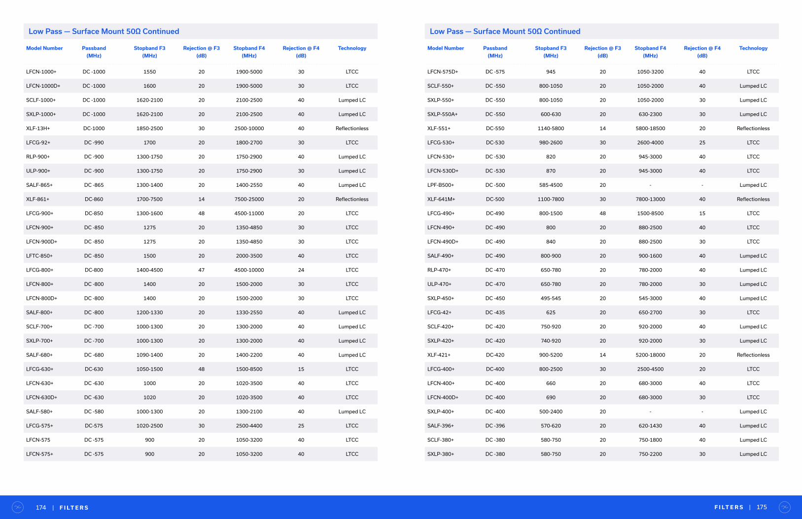
Model Number Passband
(MHz)
Stopband F3
(MHz)
Rejection @ F3
(dB)
Stopband F4
(MHz)
Rejection @ F4
(dB)
Technology
LFCN-1000+ DC -1000 1550 20 1900-5000 30 LTCC
LFCN-1000D+ DC -1000 1600 20 1900-5000 30 LTCC
SCLF-1000+ DC -1000 1620-2100 20 2100-2500 40 Lumped LC
SXLP-1000+ DC -1000 1620-2100 20 2100-2500 40 Lumped LC
XLF-13H+ DC-1000 1850-2500 30 2500-10000 40 Reflectionless
LFCG-92+ DC -990 1700 20 1800-2700 30 LTCC
RLP-900+ DC -900 1300-1750 20 1750-2900 40 Lumped LC
ULP-900+ DC -900 1300-1750 20 1750-2900 30 Lumped LC
SALF-865+ DC -865 1300-1400 20 1400-2550 40 Lumped LC
XLF-861+ DC-860 1700-7500 14 7500-25000 20 Reflectionless
LFCG-900+ DC-850 1300-1600 48 4500-11000 20 LTCC
LFCN-900+ DC -850 1275 20 1350-4850 30 LTCC
LFCN-900D+ DC -850 1275 20 1350-4850 30 LTCC
LFTC-850+ DC -850 1500 20 2000-3500 40 LTCC
LFCG-800+ DC-800 1400-4500 47 4500-10000 24 LTCC
LFCN-800+ DC -800 1400 20 1500-2000 30 LTCC
LFCN-800D+ DC -800 1400 20 1500-2000 30 LTCC
SALF-800+ DC -800 1200-1330 20 1330-2550 40 Lumped LC
SCLF-700+ DC -700 1000-1300 20 1300-2000 40 Lumped LC
SXLP-700+ DC -700 1000-1300 20 1300-2000 40 Lumped LC
SALF-680+ DC -680 1090-1400 20 1400-2200 40 Lumped LC
LFCG-630+ DC-630 1050-1500 48 1500-8500 15 LTCC
LFCN-630+ DC -630 1000 20 1020-3500 40 LTCC
LFCN-630D+ DC -630 1020 20 1020-3500 40 LTCC
SALF-580+ DC -580 1000-1300 20 1300-2100 40 Lumped LC
LFCG-575+ DC-575 1020-2500 30 2500-4400 25 LTCC
LFCN-575 DC -575 900 20 1050-3200 40 LTCC
LFCN-575+ DC -575 900 20 1050-3200 40 LTCC
Model Number Passband
(MHz)
Stopband F3
(MHz)
Rejection @ F3
(dB)
Stopband F4
(MHz)
Rejection @ F4
(dB)
Technology
LFCN-575D+ DC -575 945 20 1050-3200 40 LTCC
SCLF-550+ DC -550 800-1050 20 1050-2000 40 Lumped LC
SXLP-550+ DC -550 800-1050 20 1050-2000 30 Lumped LC
SXLP-550A+ DC -550 600-630 20 630-2300 30 Lumped LC
XLF-551+ DC-550 1140-5800 14 5800-18500 20 Reflectionless
LFCG-530+ DC-530 980-2600 30 2600-4000 25 LTCC
LFCN-530+ DC -530 820 20 945-3000 40 LTCC
LFCN-530D+ DC -530 870 20 945-3000 40 LTCC
LPF-B500+ DC -500 585-4500 20 - - Lumped LC
XLF-641M+ DC-500 1100-7800 30 7800-13000 40 Reflectionless
LFCG-490+ DC-490 800-1500 48 1500-8500 15 LTCC
LFCN-490+ DC -490 800 20 880-2500 40 LTCC
LFCN-490D+ DC -490 840 20 880-2500 30 LTCC
SALF-490+ DC -490 800-900 20 900-1600 40 Lumped LC
RLP-470+ DC -470 650-780 20 780-2000 40 Lumped LC
ULP-470+ DC -470 650-780 20 780-2000 30 Lumped LC
SXLP-450+ DC -450 495-545 20 545-3000 40 Lumped LC
LFCG-42+ DC -435 625 20 650-2700 30 LTCC
SCLF-420+ DC -420 750-920 20 920-2000 40 Lumped LC
SXLP-420+ DC -420 740-920 20 920-2000 30 Lumped LC
XLF-421+ DC-420 900-5200 14 5200-18000 20 Reflectionless
LFCG-400+ DC-400 800-2500 30 2500-4500 20 LTCC
LFCN-400+ DC -400 660 20 680-3000 40 LTCC
LFCN-400D+ DC -400 690 20 680-3000 30 LTCC
SXLP-400+ DC -400 500-2400 20 - - Lumped LC
SALF-396+ DC -396 570-620 20 620-1430 40 Lumped LC
SCLF-380+ DC -380 580-750 20 750-1800 40 Lumped LC
SXLP-380+ DC -380 580-750 20 750-2200 30 Lumped LC
F I LT E R S | 175| F I LT E R S174
Low Pass — Surface Mount 50Ω ContinuedLow Pass — Surface Mount 50Ω Continued

Model Number Passband
(MHz)
Stopband F3
(MHz)
Rejection @ F3
(dB)
Stopband F4
(MHz)
Rejection @ F4
(dB)
Technology
LPF-B375+ DC -375 440-4500 20 - - Lumped LC
RLP-340+ DC -340 475-560 20 560-1500 40 Lumped LC
ULP-340+ DC -340 475-750 20 750-2000 40 Lumped LC
SALF-325+ DC -325 480-580 20 580-1250 40 Lumped LC
LFCG-320+ DC-320 660-2000 33 2000-6000 20 LTCC
LFCN-320+ DC -320 560 20 640-2500 40 LTCC
LFCN-320D+ DC -320 610 20 640-2500 30 LTCC
RLP-320+ DC -320 440-510 20 510-1600 40 Lumped LC
ULP-320+ DC -320 440-510 20 510-1600 40 Lumped LC
XLF-42M+ DC-300 660-6800 30 6800-10000 40 Reflectionless
RLP-290+ DC -290 350-1600 20 - - Lumped LC
RLP-288+ DC -288 390-455 20 455-1500 40 Lumped LC
ULP-288+ DC -288 390-700 20 700-1500 40 Lumped LC
SALF-265+ DC -265 390-470 20 470-1100 40 Lumped LC
RLP-264+ DC -264 365-425 20 425-1500 40 Lumped LC
ULP-264+ DC -264 365-600 20 600-1600 40 Lumped LC
LFCN-225+ DC -225 460 20 510-2500 40 LTCC
LFCN-225D+ DC -225 485 20 510-2500 40 LTCC
SCLF-225+ DC -225 340-440 20 440-1200 40 Lumped LC
SXLP-225+ DC -225 340-440 20 440-1600 40 Lumped LC
XLF-221+ DC-220 570-3500 14 3500-12000 20 Reflectionless
RLP-216+ DC -216 295-340 20 340-1300 40 Lumped LC
ULP-216+ DC -216 295-450 20 450-1300 40 Lumped LC
LFCN-190+ DC -190 400 20 510-2850 40 LTCC
RLP-190+ DC -190 264-300 20 300-1300 40 Lumped LC
SCLF-190+ DC -190 290-390 20 390-800 40 Lumped LC
SXLP-190+ DC -190 290-390 20 390-1000 40 Lumped LC
ULP-190+ DC -190 264-300 20 300-1300 40 Lumped LC
Model Number Passband
(MHz)
Stopband F3
(MHz)
Rejection @ F3
(dB)
Stopband F4
(MHz)
Rejection @ F4
(dB)
Technology
LFCN-180+ DC -180 370 20 525-2350 40 LTCC
RLP-176+ DC -176 245-285 20 285-1000 40 Lumped LC
ULP-176+ DC -176 245-285 20 285-1000 40 Lumped LC
LFCN-160+ DC -160 330 20 480-2700 30 LTCC
RLP-158+ DC -158 220-255 20 255-1000 40 Lumped LC
ULP-158+ DC -158 220-255 20 255-1000 40 Lumped LC
XLF-151+ DC-150 460-2800 14 2800-16000 20 Reflectionless
SALF-146+ DC -146 210-240 20 240-850 40 Lumped LC
RLP-137+ DC -137 190-215 20 215-1000 40 Lumped LC
ULP-137+ DC -137 190-215 20 215-1000 40 Lumped LC
SCLF-135+ DC -135 210-300 20 300-600 40 Lumped LC
SXLP-135+ DC -135 210-300 20 300-1600 40 Lumped LC
LFCN-120+ DC -120 280 20 300-1850 40 LTCC
RLP-120+ DC -120 170-205 20 205-1000 40 Lumped LC
ULP-120+ DC -120 170-205 20 205-1000 40 Lumped LC
SALF-116+ DC -116 182-220 20 220-825 40 Lumped LC
LFCN-105+ DC -105 250 20 265-1650 40 LTCC
RLP-105+ DC -105 145-165 20 165-1000 40 Lumped LC
ULP-105+ DC -105 145-165 20 165-1000 40 Lumped LC
LFCN-95+ DC -95 230 20 255-1600 40 LTCC
SCLF-95+ DC -95 146-189 20 189-400 40 Lumped LC
SXLP-95+ DC -95 146-189 20 189-1400 40 Lumped LC
SXLP-90+ DC -90 105-170 20 170-1000 40 Lumped LC
RLP-83+ DC -83 118-135 20 135-850 40 Lumped LC
ULP-83+ DC -83 118-135 20 135-850 40 Lumped LC
LFCN-80+ DC -80 200 20 225-1550 40 LTCC
SALF-78+ DC -78 120-136 20 136-550 40 Lumped LC
RLP-70+ DC -70 100-115 20 115-1000 40 Lumped LC
F I LT E R S | 177| F I LT E R S176
Low Pass — Surface Mount 50Ω ContinuedLow Pass — Surface Mount 50Ω Continued
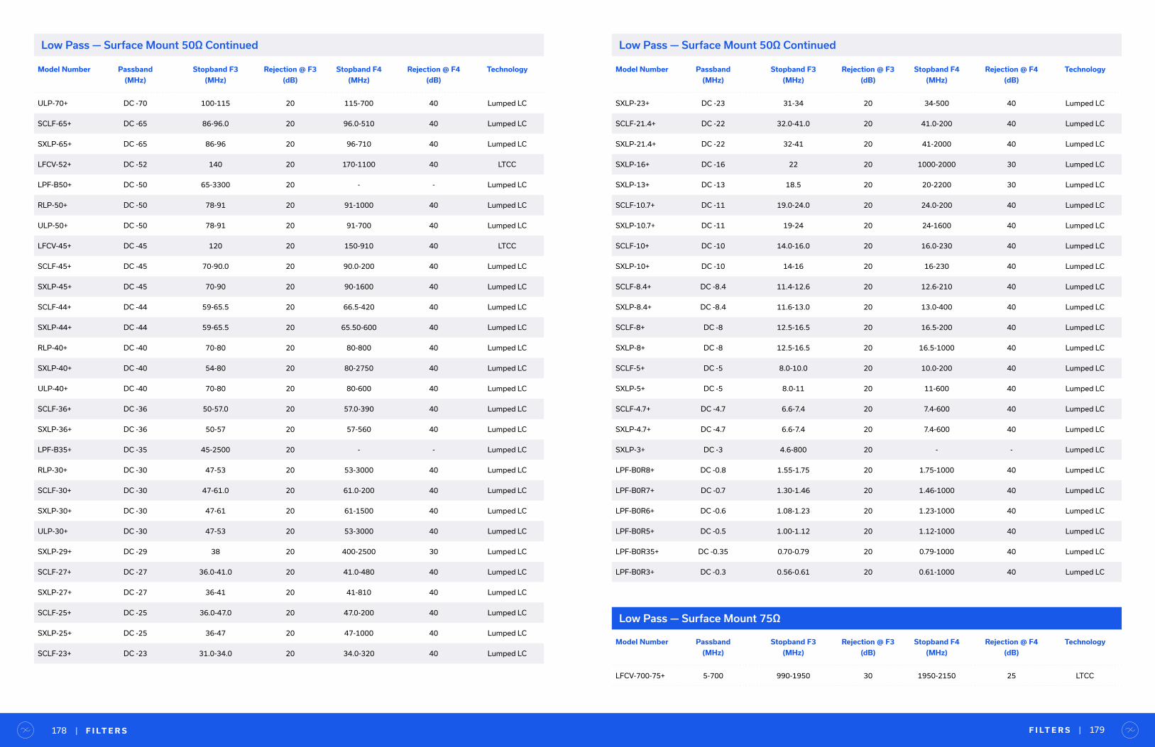
Model Number Passband
(MHz)
Stopband F3
(MHz)
Rejection @ F3
(dB)
Stopband F4
(MHz)
Rejection @ F4
(dB)
Technology
ULP-70+ DC -70 100-115 20 115-700 40 Lumped LC
SCLF-65+ DC -65 86-96.0 20 96.0-510 40 Lumped LC
SXLP-65+ DC -65 86-96 20 96-710 40 Lumped LC
LFCV-52+ DC -52 140 20 170-1100 40 LTCC
LPF-B50+ DC -50 65-3300 20 - - Lumped LC
RLP-50+ DC -50 78-91 20 91-1000 40 Lumped LC
ULP-50+ DC -50 78-91 20 91-700 40 Lumped LC
LFCV-45+ DC -45 120 20 150-910 40 LTCC
SCLF-45+ DC -45 70-90.0 20 90.0-200 40 Lumped LC
SXLP-45+ DC -45 70-90 20 90-1600 40 Lumped LC
SCLF-44+ DC -44 59-65.5 20 66.5-420 40 Lumped LC
SXLP-44+ DC -44 59-65.5 20 65.50-600 40 Lumped LC
RLP-40+ DC -40 70-80 20 80-800 40 Lumped LC
SXLP-40+ DC -40 54-80 20 80-2750 40 Lumped LC
ULP-40+ DC -40 70-80 20 80-600 40 Lumped LC
SCLF-36+ DC -36 50-57.0 20 57.0-390 40 Lumped LC
SXLP-36+ DC -36 50-57 20 57-560 40 Lumped LC
LPF-B35+ DC -35 45-2500 20 - - Lumped LC
RLP-30+ DC -30 47-53 20 53-3000 40 Lumped LC
SCLF-30+ DC -30 47-61.0 20 61.0-200 40 Lumped LC
SXLP-30+ DC -30 47-61 20 61-1500 40 Lumped LC
ULP-30+ DC -30 47-53 20 53-3000 40 Lumped LC
SXLP-29+ DC -29 38 20 400-2500 30 Lumped LC
SCLF-27+ DC -27 36.0-41.0 20 41.0-480 40 Lumped LC
SXLP-27+ DC -27 36-41 20 41-810 40 Lumped LC
SCLF-25+ DC -25 36.0-47.0 20 47.0-200 40 Lumped LC
SXLP-25+ DC -25 36-47 20 47-1000 40 Lumped LC
SCLF-23+ DC -23 31.0-34.0 20 34.0-320 40 Lumped LC
Model Number Passband
(MHz)
Stopband F3
(MHz)
Rejection @ F3
(dB)
Stopband F4
(MHz)
Rejection @ F4
(dB)
Technology
SXLP-23+ DC -23 31-34 20 34-500 40 Lumped LC
SCLF-21.4+ DC -22 32.0-41.0 20 41.0-200 40 Lumped LC
SXLP-21.4+ DC -22 32-41 20 41-2000 40 Lumped LC
SXLP-16+ DC -16 22 20 1000-2000 30 Lumped LC
SXLP-13+ DC -13 18.5 20 20-2200 30 Lumped LC
SCLF-10.7+ DC -11 19.0-24.0 20 24.0-200 40 Lumped LC
SXLP-10.7+ DC -11 19-24 20 24-1600 40 Lumped LC
SCLF-10+ DC -10 14.0-16.0 20 16.0-230 40 Lumped LC
SXLP-10+ DC -10 14-16 20 16-230 40 Lumped LC
SCLF-8.4+ DC -8.4 11.4-12.6 20 12.6-210 40 Lumped LC
SXLP-8.4+ DC -8.4 11.6-13.0 20 13.0-400 40 Lumped LC
SCLF-8+ DC -8 12.5-16.5 20 16.5-200 40 Lumped LC
SXLP-8+ DC -8 12.5-16.5 20 16.5-1000 40 Lumped LC
SCLF-5+ DC -5 8.0-10.0 20 10.0-200 40 Lumped LC
SXLP-5+ DC -5 8.0-11 20 11-600 40 Lumped LC
SCLF-4.7+ DC -4.7 6.6-7.4 20 7.4-600 40 Lumped LC
SXLP-4.7+ DC -4.7 6.6-7.4 20 7.4-600 40 Lumped LC
SXLP-3+ DC -3 4.6-800 20 - - Lumped LC
LPF-B0R8+ DC -0.8 1.55-1.75 20 1.75-1000 40 Lumped LC
LPF-B0R7+ DC -0.7 1.30-1.46 20 1.46-1000 40 Lumped LC
LPF-B0R6+ DC -0.6 1.08-1.23 20 1.23-1000 40 Lumped LC
LPF-B0R5+ DC -0.5 1.00-1.12 20 1.12-1000 40 Lumped LC
LPF-B0R35+ DC -0.35 0.70-0.79 20 0.79-1000 40 Lumped LC
LPF-B0R3+ DC -0.3 0.56-0.61 20 0.61-1000 40 Lumped LC
F I LT E R S | 179| F I LT E R S178
Low Pass — Surface Mount 50Ω ContinuedLow Pass — Surface Mount 50Ω Continued
Low Pass — Surface Mount 75Ω
Model Number Passband
(MHz)
Stopband F3
(MHz)
Rejection @ F3
(dB)
Stopband F4
(MHz)
Rejection @ F4
(dB)
Technology
LFCV-700-75+ 5-700 990-1950 30 1950-2150 25 LTCC
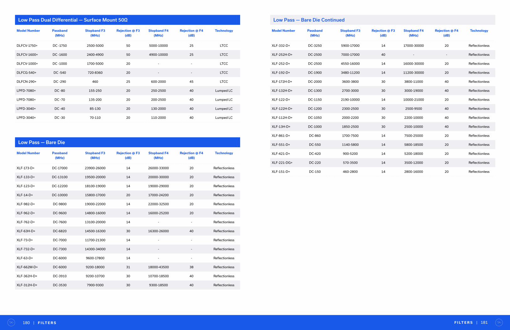
F I LT E R S | 181| F I LT E R S180
Low Pass Dual Differential — Surface Mount 50Ω
Model Number Passband
(MHz)
Stopband F3
(MHz)
Rejection @ F3
(dB)
Stopband F4
(MHz)
Rejection @ F4
(dB)
Technology
DLFCV-1750+ DC -1750 2500-5000 50 5000-10000 25 LTCC
DLFCV-1600+ DC -1600 2400-4900 50 4900-10000 25 LTCC
DLFCV-1000+ DC -1000 1700-5000 20 - - LTCC
DLFCG-540+ DC -540 720-8360 20 - - LTCC
DLFCN-290+ DC -290 460 25 600-2000 45 LTCC
LPFD-7080+ DC -80 155-250 20 250-2500 40 Lumped LC
LPFD-7080+ DC -70 135-200 20 200-2500 40 Lumped LC
LPFD-3040+ DC -40 85-130 20 130-2000 40 Lumped LC
LPFD-3040+ DC -30 70-110 20 110-2000 40 Lumped LC
Low Pass — Bare Die
Low Pass — Bare Die Continued
Model Number Passband
(MHz)
Stopband F3
(MHz)
Rejection @ F3
(dB)
Stopband F4
(MHz)
Rejection @ F4
(dB)
Technology
XLF-173-D+ DC-17000 23900-26000 14 26000-33000 20 Reflectionless
XLF-133-D+ DC-13100 19500-20000 14 20000-30000 20 Reflectionless
XLF-123-D+ DC-12200 18100-19000 14 19000-29000 20 Reflectionless
XLF-14-D+ DC-10000 15800-17000 20 17000-24200 20 Reflectionless
XLF-982-D+ DC-9800 19000-22000 14 22000-32500 20 Reflectionless
XLF-962-D+ DC-9600 14800-16000 14 16000-25200 20 Reflectionless
XLF-762-D+ DC-7600 13100-20000 14 - - Reflectionless
XLF-63H-D+ DC-6820 14500-16300 30 16300-26000 40 Reflectionless
XLF-73-D+ DC-7000 11700-21300 14 - - Reflectionless
XLF-732-D+ DC-7300 14300-34000 14 - - Reflectionless
XLF-63-D+ DC-6000 9600-17800 14 - - Reflectionless
XLF-662M-D+ DC-6000 9200-18000 31 18000-43500 38 Reflectionless
XLF-362H-D+ DC-3910 9200-10700 30 10700-18500 40 Reflectionless
XLF-312H-D+ DC-3530 7900-9300 30 9300-18500 40 Reflectionless
Model Number Passband
(MHz)
Stopband F3
(MHz)
Rejection @ F3
(dB)
Stopband F4
(MHz)
Rejection @ F4
(dB)
Technology
XLF-332-D+ DC-3250 5900-17000 14 17000-30000 20 Reflectionless
XLF-252H-D+ DC-2500 7000-17000 40 - - Reflectionless
XLF-252-D+ DC-2500 4550-16000 14 16000-30000 20 Reflectionless
XLF-192-D+ DC-1900 3480-11200 14 11200-30000 20 Reflectionless
XLF-172H-D+ DC-2000 3600-3800 30 3800-11000 40 Reflectionless
XLF-132H-D+ DC-1300 2700-3000 30 3000-19000 40 Reflectionless
XLF-122-D+ DC-1150 2190-10000 14 10000-21000 20 Reflectionless
XLF-122H-D+ DC-1200 2300-2500 30 2500-9500 40 Reflectionless
XLF-112H-D+ DC-1050 2000-2200 30 2200-10000 40 Reflectionless
XLF-13H-D+ DC-1000 1850-2500 30 2500-10000 40 Reflectionless
XLF-861-D+ DC-860 1700-7500 14 7500-25000 20 Reflectionless
XLF-551-D+ DC-550 1140-5800 14 5800-18500 20 Reflectionless
XLF-421-D+ DC-420 900-5200 14 5200-18000 20 Reflectionless
XLF-221-DG+ DC-220 570-3500 14 3500-12000 20 Reflectionless
XLF-151-D+ DC-150 460-2800 14 2800-16000 20 Reflectionless
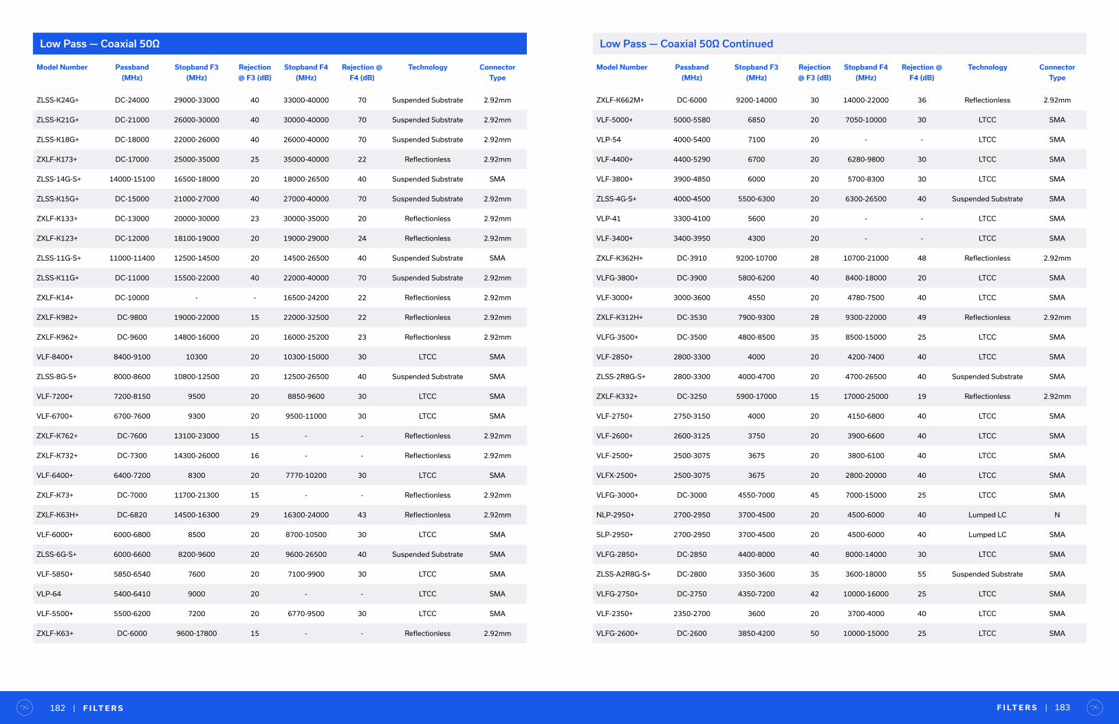
F I LT E R S | 183| F I LT E R S182
Model Number Passband
(MHz)
Stopband F3
(MHz)
Rejection
@ F3 (dB)
Stopband F4
(MHz)
Rejection @
F4 (dB)
Technology Connector
Type
ZLSS-K24G+ DC-24000 29000-33000 40 33000-40000 70 Suspended Substrate 2.92mm
ZLSS-K21G+ DC-21000 26000-30000 40 30000-40000 70 Suspended Substrate 2.92mm
ZLSS-K18G+ DC-18000 22000-26000 40 26000-40000 70 Suspended Substrate 2.92mm
ZXLF-K173+ DC-17000 25000-35000 25 35000-40000 22 Reflectionless 2.92mm
ZLSS-14G-S+ 14000-15100 16500-18000 20 18000-26500 40 Suspended Substrate SMA
ZLSS-K15G+ DC-15000 21000-27000 40 27000-40000 70 Suspended Substrate 2.92mm
ZXLF-K133+ DC-13000 20000-30000 23 30000-35000 20 Reflectionless 2.92mm
ZXLF-K123+ DC-12000 18100-19000 20 19000-29000 24 Reflectionless 2.92mm
ZLSS-11G-S+ 11000-11400 12500-14500 20 14500-26500 40 Suspended Substrate SMA
ZLSS-K11G+ DC-11000 15500-22000 40 22000-40000 70 Suspended Substrate 2.92mm
ZXLF-K14+ DC-10000 - - 16500-24200 22 Reflectionless 2.92mm
ZXLF-K982+ DC-9800 19000-22000 15 22000-32500 22 Reflectionless 2.92mm
ZXLF-K962+ DC-9600 14800-16000 20 16000-25200 23 Reflectionless 2.92mm
VLF-8400+ 8400-9100 10300 20 10300-15000 30 LTCC SMA
ZLSS-8G-S+ 8000-8600 10800-12500 20 12500-26500 40 Suspended Substrate SMA
VLF-7200+ 7200-8150 9500 20 8850-9600 30 LTCC SMA
VLF-6700+ 6700-7600 9300 20 9500-11000 30 LTCC SMA
ZXLF-K762+ DC-7600 13100-23000 15 - - Reflectionless 2.92mm
ZXLF-K732+ DC-7300 14300-26000 16 - - Reflectionless 2.92mm
VLF-6400+ 6400-7200 8300 20 7770-10200 30 LTCC SMA
ZXLF-K73+ DC-7000 11700-21300 15 - - Reflectionless 2.92mm
ZXLF-K63H+ DC-6820 14500-16300 29 16300-24000 43 Reflectionless 2.92mm
VLF-6000+ 6000-6800 8500 20 8700-10500 30 LTCC SMA
ZLSS-6G-S+ 6000-6600 8200-9600 20 9600-26500 40 Suspended Substrate SMA
VLF-5850+ 5850-6540 7600 20 7100-9900 30 LTCC SMA
VLP-64 5400-6410 9000 20 - - LTCC SMA
VLF-5500+ 5500-6200 7200 20 6770-9500 30 LTCC SMA
ZXLF-K63+ DC-6000 9600-17800 15 - - Reflectionless 2.92mm
Low Pass — Coaxial 50Ω
Model Number Passband
(MHz)
Stopband F3
(MHz)
Rejection
@ F3 (dB)
Stopband F4
(MHz)
Rejection @
F4 (dB)
Technology Connector
Type
ZXLF-K662M+ DC-6000 9200-14000 30 14000-22000 36 Reflectionless 2.92mm
VLF-5000+ 5000-5580 6850 20 7050-10000 30 LTCC SMA
VLP-54 4000-5400 7100 20 - - LTCC SMA
VLF-4400+ 4400-5290 6700 20 6280-9800 30 LTCC SMA
VLF-3800+ 3900-4850 6000 20 5700-8300 30 LTCC SMA
ZLSS-4G-S+ 4000-4500 5500-6300 20 6300-26500 40 Suspended Substrate SMA
VLP-41 3300-4100 5600 20 - - LTCC SMA
VLF-3400+ 3400-3950 4300 20 - - LTCC SMA
ZXLF-K362H+ DC-3910 9200-10700 28 10700-21000 48 Reflectionless 2.92mm
VLFG-3800+ DC-3900 5800-6200 40 8400-18000 20 LTCC SMA
VLF-3000+ 3000-3600 4550 20 4780-7500 40 LTCC SMA
ZXLF-K312H+ DC-3530 7900-9300 28 9300-22000 49 Reflectionless 2.92mm
VLFG-3500+ DC-3500 4800-8500 35 8500-15000 25 LTCC SMA
VLF-2850+ 2800-3300 4000 20 4200-7400 40 LTCC SMA
ZLSS-2R8G-S+ 2800-3300 4000-4700 20 4700-26500 40 Suspended Substrate SMA
ZXLF-K332+ DC-3250 5900-17000 15 17000-25000 19 Reflectionless 2.92mm
VLF-2750+ 2750-3150 4000 20 4150-6800 40 LTCC SMA
VLF-2600+ 2600-3125 3750 20 3900-6600 40 LTCC SMA
VLF-2500+ 2500-3075 3675 20 3800-6100 40 LTCC SMA
VLFX-2500+ 2500-3075 3675 20 2800-20000 40 LTCC SMA
VLFG-3000+ DC-3000 4550-7000 45 7000-15000 25 LTCC SMA
NLP-2950+ 2700-2950 3700-4500 20 4500-6000 40 Lumped LC N
SLP-2950+ 2700-2950 3700-4500 20 4500-6000 40 Lumped LC SMA
VLFG-2850+ DC-2850 4400-8000 40 8000-14000 30 LTCC SMA
ZLSS-A2R8G-S+ DC-2800 3350-3600 35 3600-18000 55 Suspended Substrate SMA
VLFG-2750+ DC-2750 4350-7200 42 10000-16000 25 LTCC SMA
VLF-2350+ 2350-2700 3600 20 3700-4000 40 LTCC SMA
VLFG-2600+ DC-2600 3850-4200 50 10000-15000 25 LTCC SMA
Low Pass — Coaxial 50Ω Continued

F I LT E R S | 185| F I LT E R S184
Model Number Passband
(MHz)
Stopband F3
(MHz)
Rejection
@ F3 (dB)
Stopband F4
(MHz)
Rejection @
F4 (dB)
Technology Connector
Type
VLF-2250+ 2200-2575 2900 20 2950-5000 40 LTCC SMA
VLFG-2500+ DC-2500 4000-7000 42 7000-10000 30 LTCC SMA
ZXLF-K252+ DC-2500 4550-16000 15 16000-25000 18 Reflectionless 2.92mm
VLP-24 2000-2430 3400 20 4400 40 LTCC SMA
NLP-2400+ 2200-2400 3150-4000 20 4000-6000 40 Lumped LC N
SLP-2400+ 2200-2400 3150-4000 20 4000-6000 40 Lumped LC SMA
VLFG-2250+ DC-2250 3600-8000 40 8000-15000 26 LTCC SMA
ZLPF-40W-222-S+ DC-2200 2650-3200 29 3200-6300 39 Lumped LC SMA
VLF-1800+ 1800-2125 2425 20 2500-7200 40 LTCC SMA
ZNFLP-2100-S+ 1800-2100 2600-4500 20 - - Microstrip SMA
VLF-1700+ 1700-2050 2375 20 2500-6500 40 LTCC SMA
VLFX-1350+ 1350-2050 2425 20 2600-20000 40 LTCC SMA
VXLF-172H+ DC-2000 3600-3800 28 3800-11000 47 Reflectionless SMA
ZX75LP-2000-S+ DC-2000 2400-4000 35 4000-10000 90 Lumped LC SMA
VLFX-1300+ 1300-1925 2300 20 2500-20000 40 LTCC SMA
VXLF-192+ DC-1900 3480-11200 15 - - Reflectionless SMA
ZXLF-K192+ DC-1900 3480-11200 15 11200-25000 22 Reflectionless 2.92mm
VLF-1575+ 1575-1875 2175 20 2225-6800 40 LTCC SMA
VLFX-1125+ 1125-1850 2200-20000 20 - - LTCC SMA
VLF-1450+ 1450-1825 2025 20 2050-6600 40 LTCC SMA
VLF-1500+ 1500-1825 2100 20 2150-6600 40 LTCC SMA
VLFG-1800+ DC-1800 2450-7000 40 7000-10000 35 LTCC SMA
NLP-1750+ 1500-1750 2400-3000 20 3000-6000 40 Lumped LC N
VLF-1525+ 1525-1750 2040 20 2120-6600 40 LTCC SMA
VLFX-1100+ 1100-1750 2070 20 2300-20000 40 LTCC SMA
VLF-1400+ 1400-1700 2015 20 2100-6600 40 LTCC SMA
VLFG-1700+ DC-1700 2800-8000 40 8000-13000 30 LTCC SMA
VLFX-1050+ 1050-1675 1990 20 2275-20000 40 LTCC SMA
Model Number Passband
(MHz)
Stopband F3
(MHz)
Rejection
@ F3 (dB)
Stopband F4
(MHz)
Rejection @
F4 (dB)
Technology Connector
Type
SLP-1650+ 1400-1650 2300-2900 20 2900-6000 40 Lumped LC SMA
VLFG-1575+ DC-1575 2400-7000 45 7000-12000 35 LTCC SMA
VLP-16 1350-1550 2100 20 2700-4500 30 LTCC SMA
VLF-1200+ 1200-1530 1865 20 2000-5000 40 LTCC SMA
VLFG-1400+ DC-1400 2015-6600 46 6600-10000 35 LTCC SMA
VLFX-950+ 950-1400 1865 20 2250-20000 40 LTCC SMA
VLF-1000+ 1000-1300 1550 20 1900-5000 40 LTCC SMA
VLFX-825+ 825-1275 1550 20 1850-20000 40 LTCC SMA
BLP-1200+ 1000-1200 1620-2100 20 2100-2500 40 Lumped LC BNC
NLP-1200+ 1000-1200 1620-2100 20 2100-2500 40 Lumped LC N
SLP-1200+ 1000-1200 1620-2100 20 2100-2500 40 Lumped LC SMA
VLFG-1200+ DC-1200 1865-3700 50 7000-10000 30 LTCC SMA
ZXLF-K122+ DC-1150 2190-10000 14 10000-21000 21 Reflectionless 2.92mm
VLP-11 850-1125 1500 20 2000-3100 40 LTCC SMA
VLF-800+ 800-1075 1275 20 1350-4850 40 LTCC SMA
ZX75LP-1050-S+ 50-1050 1200 - 2500 43 - - Lumped LC SMA
VLFX-650+ 650-1025 1275 20 1450-20000 40 LTCC SMA
VLFG-1000+ DC-1000 1550-3000 29 3000-10000 34 LTCC SMA
ZX75LP-900-S+ 900-1000 1300-2900 20 - - Lumped LC SMA
BLP-1000+ 900-990 1340-1750 20 1750-2000 40 Lumped LC BNC
NLP-1000+ 900-990 1340-1750 20 1750-2000 40 Lumped LC N
SLP-1000+ 900-990 1340-1750 20 1750-2000 40 Lumped LC SMA
VLFX-780+ 780-950 1450 20 1600-20000 40 LTCC SMA
ZXLF-K861+ DC-860 1700-7500 15 7500-20000 24 Reflectionless 2.92mm
BLP-850+ 780-850 1100-1400 20 1400-2000 40 Lumped LC BNC
NLP-850+ 780-850 1100-1400 20 1400-2000 40 Lumped LC N
SLP-850+ 780-850 1100-1400 20 1400-2000 40 Lumped LC SMA
VLFG-900+ DC-850 1300-4500 45 4500-11000 21 LTCC SMA
Low Pass — Coaxial 50Ω ContinuedLow Pass — Coaxial 50Ω Continued

F I LT E R S | 187| F I LT E R S186
Model Number Passband
(MHz)
Stopband F3
(MHz)
Rejection
@ F3 (dB)
Stopband F4
(MHz)
Rejection @
F4 (dB)
Technology Connector
Type
VLF-630+ 630-830 1000 20 1020-3500 40 LTCC SMA
VLFX-540+ 540-810 1000 20 1100-20000 40 LTCC SMA
BLP-800+ 720-800 1080-1400 20 1400-2000 40 Lumped LC BNC
NLP-800+ 720-800 1080-1400 20 1400-2000 40 Lumped LC N
SLP-800+ 720-800 1080-1400 20 1400-2000 40 Lumped LC SMA
BLP-750+ 700-770 1000-1300 20 1300-2000 40 Lumped LC BNC
NLP-750+ 700-770 1000-1300 20 1300-2000 40 Lumped LC N
SLP-750+ 700-770 1000-1300 20 1300-2000 40 Lumped LC SMA
VLF-575+ 575-770 900 20 1050-3200 40 LTCC SMA
VLFX-500+ 500-750 900 20 1100-20000 40 LTCC SMA
VLF-530+ 530-700 820 20 945-3000 40 LTCC SMA
VLFX-470+ 470-675 820 20 1000-20000 40 LTCC SMA
VLF-490+ 490-650 800 20 880-2500 40 LTCC SMA
BLP-600+ 580-640 840-1120 20 1120-2000 40 Lumped LC BNC
NLP-600+ 580-640 840-1120 20 1120-2000 40 Lumped LC N
SLP-600+ 580-640 840-120 20 1120-2000 40 Lumped LC SMA
VLFX-450+ 450-640 800 20 900-20000 40 LTCC SMA
NLP-500+ 500-630 1000 20 1400-4500 40 Lumped LC N
VLFG-630+ DC-630 1050-1500 50 1500-8500 21 LTCC SMA
VLFG-575+ DC-575 1020-2500 32 2500-4400 25 LTCC SMA
BLP-550+ 520-570 750-920 20 920-2000 40 Lumped LC BNC
NLP-550+ 520-570 750-920 20 920-2000 40 Lumped LC N
SLP-550+ 520-570 750-920 20 920-2000 40 Lumped LC SMA
VLF-400+ 400-560 660 20 680-3000 40 LTCC SMA
ZXLF-K551+ DC-550 1140-5800 15 5800-18500 24 Reflectionless 2.92mm
VLFX-400+ 400-540 670 20 700-20000 40 LTCC SMA
VLFG-530+ DC-530 980-2600 31 2600-4000 27 LTCC SMA
ZX75LP-470-S+ 470-510 650-2000 20 - - Lumped LC SMA
Model Number Passband
(MHz)
Stopband F3
(MHz)
Rejection
@ F3 (dB)
Stopband F4
(MHz)
Rejection @
F4 (dB)
Technology Connector
Type
ZFLP-450-S+ 450-505 640-5000 20 - - Lumped LC SMA
ZXLF-K641M+ DC-500 1100-7800 28 7800-11000 38 Reflectionless 2.92mm
VLFG-490+ DC-490 800-1500 52 1500-8500 17 LTCC SMA
VLF-320+ 320-460 560 20 640-2500 40 LTCC SMA
VLFX-300+ 300-450 580 20 650-20000 40 LTCC SMA
BLP-450+ 400-440 580-750 20 750-1800 40 Lumped LC BNC
NLP-450+ 400-440 580-750 20 750-1800 40 Lumped LC N
SLP-450+ 400-440 580-750 20 750-1800 40 Lumped LC SMA
ZXLF-K421+ DC-420 900-5200 14 5200-18000 24 Reflectionless 2.92mm
VLFG-400+ DC-400 800-2500 31 2500-4500 23 LTCC SMA
ZX75LP-340-S+ 340-365 475-2000 20 - - Lumped LC SMA
VLF-225+ 225-350 460 20 510-2500 40 LTCC SMA
VLFX-225+ 225-350 460 20 520-20000 40 LTCC SMA
ZX75LP-320-S+ 320-345 445-1800 20 - - Lumped LC SMA
VLFG-320+ DC-320 660-2000 33 2000-6000 25 LTCC SMA
ZX75LP-288-S+ 288-312 400-1500 20 - - Lumped LC SMA
ZXLF-K42M+ DC-300 660-6800 32 6800-10000 43 Reflectionless 2.92mm
BLP-300+ 270-297 410-550 20 550-1200 40 Lumped LC BNC
NLP-300+ 270-297 410-550 20 550-1200 40 Lumped LC N
SLP-300+ 270-297 410-550 20 550-1200 40 Lumped LC SMA
ZX75LP-264-S+ 264-288 365-1500 20 - - Lumped LC SMA
VLF-190+ 190-280 400 20 510-2850 40 LTCC SMA
VLF-180+ 180-270 370 20 525-2350 40 LTCC SMA
BLP-250+ 225-250 320-400 20 400-1200 40 Lumped LC BNC
NLP-250+ 225-250 320-400 20 400-1200 40 Lumped LC N
SLP-250+ 225-250 320-400 20 400-1200 40 Lumped LC SMA
ZX75LP-216-S+ 216-232 300-1400 20 - - Lumped LC SMA
VLF-160+ 160-230 330 20 480-2700 40 LTCC SMA
Low Pass — Coaxial 50Ω ContinuedLow Pass — Coaxial 50Ω Continued
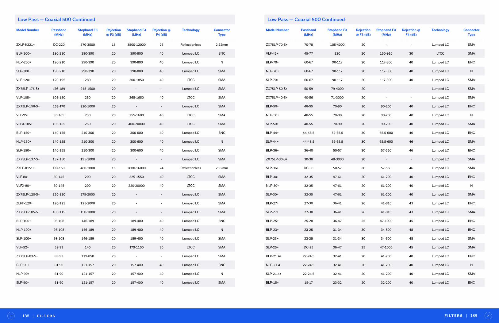
F I LT E R S | 189| F I LT E R S188
Model Number Passband
(MHz)
Stopband F3
(MHz)
Rejection
@ F3 (dB)
Stopband F4
(MHz)
Rejection @
F4 (dB)
Technology Connector
Type
ZXLF-K221+ DC-220 570-3500 15 3500-12000 26 Reflectionless 2.92mm
BLP-200+ 190-210 290-390 20 390-800 40 Lumped LC BNC
NLP-200+ 190-210 290-390 20 390-800 40 Lumped LC N
SLP-200+ 190-210 290-390 20 390-800 40 Lumped LC SMA
VLF-120+ 120-195 280 20 300-1850 40 LTCC SMA
ZX75LP-176-S+ 176-189 245-1500 20 - - Lumped LC SMA
VLF-105+ 105-180 250 20 265-1650 40 LTCC SMA
ZX75LP-158-S+ 158-170 220-1000 20 - - Lumped LC SMA
VLF-95+ 95-165 230 20 255-1600 40 LTCC SMA
VLFX-105+ 105-165 250 20 400-20000 40 LTCC SMA
BLP-150+ 140-155 210-300 20 300-600 40 Lumped LC BNC
NLP-150+ 140-155 210-300 20 300-600 40 Lumped LC N
SLP-150+ 140-155 210-300 20 300-600 40 Lumped LC SMA
ZX75LP-137-S+ 137-150 195-1000 20 - - Lumped LC SMA
ZXLF-K151+ DC-150 460-2800 15 2800-16000 24 Reflectionless 2.92mm
VLF-80+ 80-145 200 20 225-1550 40 LTCC SMA
VLFX-80+ 80-145 200 20 220-20000 40 LTCC SMA
ZX75LP-120-S+ 120-130 175-2000 20 - - Lumped LC SMA
ZLPF-120+ 120-121 125-2000 20 - - Lumped LC SMA
ZX75LP-105-S+ 105-115 150-1000 20 - - Lumped LC SMA
BLP-100+ 98-108 146-189 20 189-400 40 Lumped LC BNC
NLP-100+ 98-108 146-189 20 189-400 40 Lumped LC N
SLP-100+ 98-108 146-189 20 189-400 40 Lumped LC SMA
VLF-52+ 52-93 140 20 170-1100 30 LTCC SMA
ZX75LP-83-S+ 83-93 119-850 20 - - Lumped LC SMA
BLP-90+ 81-90 121-157 20 157-400 40 Lumped LC BNC
NLP-90+ 81-90 121-157 20 157-400 40 Lumped LC N
SLP-90+ 81-90 121-157 20 157-400 40 Lumped LC SMA
Model Number Passband
(MHz)
Stopband F3
(MHz)
Rejection
@ F3 (dB)
Stopband F4
(MHz)
Rejection @
F4 (dB)
Technology Connector
Type
ZX75LP-70-S+ 70-78 105-4000 20 - - Lumped LC SMA
VLF-45+ 45-77 120 20 150-910 30 LTCC SMA
BLP-70+ 60-67 90-117 20 117-300 40 Lumped LC BNC
NLP-70+ 60-67 90-117 20 117-300 40 Lumped LC N
SLP-70+ 60-67 90-117 20 117-300 40 Lumped LC SMA
ZX75LP-50-S+ 50-59 79-4000 20 - - Lumped LC SMA
ZX75LP-40-S+ 40-56 71-3000 20 - - Lumped LC SMA
BLP-50+ 48-55 70-90 20 90-200 40 Lumped LC BNC
NLP-50+ 48-55 70-90 20 90-200 40 Lumped LC N
SLP-50+ 48-55 70-90 20 90-200 40 Lumped LC SMA
BLP-44+ 44-48.5 59-65.5 30 65.5-600 46 Lumped LC BNC
SLP-44+ 44-48.5 59-65.5 30 65.5-600 46 Lumped LC SMA
BLP-36+ 36-40 50-57 30 57-560 46 Lumped LC BNC
ZX75LP-30-S+ 30-38 48-3000 20 - - Lumped LC SMA
SLP-36+ DC-36 50-57 30 57-560 46 Lumped LC SMA
BLP-30+ 32-35 47-61 20 61-200 40 Lumped LC BNC
NLP-30+ 32-35 47-61 20 61-200 40 Lumped LC N
SLP-30+ 32-35 47-61 20 61-200 40 Lumped LC SMA
BLP-27+ 27-30 36-41 26 41-810 43 Lumped LC BNC
SLP-27+ 27-30 36-41 26 41-810 43 Lumped LC SMA
BLP-25+ 25-28 36-47 25 47-1000 45 Lumped LC BNC
BLP-23+ 23-25 31-34 30 34-500 48 Lumped LC BNC
SLP-23+ 23-25 31-34 30 34-500 48 Lumped LC SMA
SLP-25+ DC-25 36-47 25 47-1000 45 Lumped LC SMA
BLP-21.4+ 22-24.5 32-41 20 41-200 40 Lumped LC BNC
NLP-21.4+ 22-24.5 32-41 20 41-200 40 Lumped LC N
SLP-21.4+ 22-24.5 32-41 20 41-200 40 Lumped LC SMA
BLP-15+ 15-17 23-32 20 32-200 40 Lumped LC BNC
Low Pass — Coaxial 50Ω ContinuedLow Pass — Coaxial 50Ω Continued
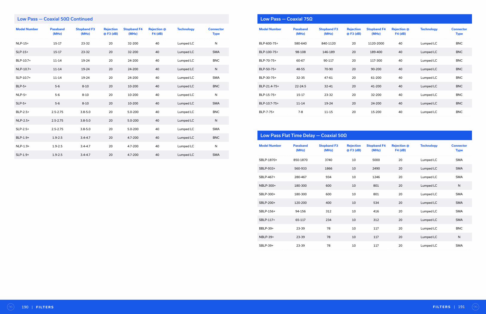
Model Number Passband
(MHz)
Stopband F3
(MHz)
Rejection
@ F3 (dB)
Stopband F4
(MHz)
Rejection @
F4 (dB)
Technology Connector
Type
NLP-15+ 15-17 23-32 20 32-200 40 Lumped LC N
SLP-15+ 15-17 23-32 20 32-200 40 Lumped LC SMA
BLP-10.7+ 11-14 19-24 20 24-200 40 Lumped LC BNC
NLP-10.7+ 11-14 19-24 20 24-200 40 Lumped LC N
SLP-10.7+ 11-14 19-24 20 24-200 40 Lumped LC SMA
BLP-5+ 5-6 8-10 20 10-200 40 Lumped LC BNC
NLP-5+ 5-6 8-10 20 10-200 40 Lumped LC N
SLP-5+ 5-6 8-10 20 10-200 40 Lumped LC SMA
BLP-2.5+ 2.5-2.75 3.8-5.0 20 5.0-200 40 Lumped LC BNC
NLP-2.5+ 2.5-2.75 3.8-5.0 20 5.0-200 40 Lumped LC N
SLP-2.5+ 2.5-2.75 3.8-5.0 20 5.0-200 40 Lumped LC SMA
BLP-1.9+ 1.9-2.5 3.4-4.7 20 4.7-200 40 Lumped LC BNC
NLP-1.9+ 1.9-2.5 3.4-4.7 20 4.7-200 40 Lumped LC N
SLP-1.9+ 1.9-2.5 3.4-4.7 20 4.7-200 40 Lumped LC SMA
Model Number Passband
(MHz)
Stopband F3
(MHz)
Rejection
@ F3 (dB)
Stopband F4
(MHz)
Rejection @
F4 (dB)
Technology Connector
Type
BLP-600-75+ 580-640 840-1120 20 1120-2000 40 Lumped LC BNC
BLP-100-75+ 98-108 146-189 20 189-400 40 Lumped LC BNC
BLP-70-75+ 60-67 90-117 20 117-300 40 Lumped LC BNC
BLP-50-75+ 48-55 70-90 20 90-200 40 Lumped LC BNC
BLP-30-75+ 32-35 47-61 20 61-200 40 Lumped LC BNC
BLP-21.4-75+ 22-24.5 32-41 20 41-200 40 Lumped LC BNC
BLP-15-75+ 15-17 23-32 20 32-200 40 Lumped LC BNC
BLP-10.7-75+ 11-14 19-24 20 24-200 40 Lumped LC BNC
BLP-7-75+ 7-8 11-15 20 15-200 40 Lumped LC BNC
Low Pass — Coaxial 75Ω
F I LT E R S | 191| F I LT E R S190
Model Number Passband
(MHz)
Stopband F3
(MHz)
Rejection
@ F3 (dB)
Stopband F4
(MHz)
Rejection @
F4 (dB)
Technology Connector
Type
SBLP-1870+ 850-1870 3740 10 5000 20 Lumped LC SMA
SBLP-933+ 560-933 1866 10 2490 20 Lumped LC SMA
SBLP-467+ 280-467 934 10 1246 20 Lumped LC SMA
NBLP-300+ 180-300 600 10 801 20 Lumped LC N
SBLP-300+ 180-300 600 10 801 20 Lumped LC SMA
SBLP-200+ 120-200 400 10 534 20 Lumped LC SMA
SBLP-156+ 94-156 312 10 416 20 Lumped LC SMA
SBLP-117+ 65-117 234 10 312 20 Lumped LC SMA
BBLP-39+ 23-39 78 10 117 20 Lumped LC BNC
NBLP-39+ 23-39 78 10 117 20 Lumped LC N
SBLP-39+ 23-39 78 10 117 20 Lumped LC SMA
Low Pass Flat Time Delay — Coaxial 50Ω
Low Pass — Coaxial 50Ω Continued

F I LT E R S | 193| F I LT E R S192
Model Number Passband
(MHz)
Stopband F3
(MHz)
Rejection @ F3
(dB)
Stopband F4
(MHz)
Rejection @ F4
(dB)
Technology
PLP-1200+ 1000-1200 1620-2100 20 2100-2500 40 Lumped LC
PLP-1000+ 900-990 1340-1750 20 1750-2000 40 Lumped LC
PLP-850+ 780-850 1100-1400 20 1400-2000 40 Lumped LC
PLP-800+ 720-800 1080-1400 20 1400-2000 40 Lumped LC
PLP-750+ 700-770 1000-1300 20 1300-2000 40 Lumped LC
PLP-600+ 580-640 840-1120 20 1120-2000 40 Lumped LC
PLP-550+ 520-570 750-920 20 920-2000 40 Lumped LC
PLP-450+ 400-440 580-750 20 750-1800 40 Lumped LC
PLP-300+ 270-297 410-550 20 550-1200 40 Lumped LC
PLP-250+ 225-250 320-400 20 400-1200 40 Lumped LC
PLP-200+ 190-210 290-390 20 390-800 40 Lumped LC
PLP-150+ 140-155 210-300 20 300-600 40 Lumped LC
PLP-100+ 98-108 146-189 20 189-400 40 Lumped LC
PLP-90+ 81-90 121-157 20 157-400 40 Lumped LC
PLP-70+ 60-67 90-117 20 117-300 40 Lumped LC
PLP-50+ 48-55 70-90 20 90-200 40 Lumped LC
PLP-30+ 32-35 47-61 20 61-200 40 Lumped LC
PLP-21.4+ 22-24.5 32-41 20 41-200 40 Lumped LC
PLP-15+ 15-17 23-32 20 32-200 40 Lumped LC
PLP-10.7+ 11-14 19-24 20 24-200 40 Lumped LC
PLP-5+ 5-6 8-10 20 10-200 40 Lumped LC
PLP-2.5+ 2.5-2.75 3.8-5 20 5-200 40 Lumped LC
PLP-1.9+ 1.9-2.5 3.4-4.7 20 4.7-200 40 Lumped LC
Low Pass — Plug-In 50Ω
Model Number Passband
(MHz)
Stopband F3
(MHz)
Rejection @ F3
(dB)
Stopband F4
(MHz)
Rejection @ F4
(dB)
Technology
PLP-600-75+ 580-640 840-1120 20 1120-2000 40 Lumped LC
PLP-70-75+ 60-67 90-117 20 117-300 40 Lumped LC
PLP-30-75+ 32-35 47-61 20 61-200 40 Lumped LC
PLP-21.4-75+ 22-24.5 32-41 20 41-200 40 Lumped LC
PLP-15-75+ 15-17 23-32 20 32-200 40 Lumped LC
PLP-10.7-75+ 11-14 19-24 20 24-200 40 Lumped LC
PLP-7-75+ 7-8 11-15 20 15-200 40 Lumped LC
Model Number Passband
(MHz)
Stopband F3
(MHz)
Rejection @ F3
(dB)
Stopband F4
(MHz)
Rejection @ F4
(dB)
Technology
PBLP-200+ 120-200 400-534 10 534 20 Lumped LC
PBLP-39+ 23-39 78-117 10 117 20 Lumped LC
Low Pass — Plug-In 75Ω
Low Pass Flat Time Delay — Plug-In 50Ω
Model Number Passband
(MHz)
Stopband F3
(MHz)
Rejection @
F3 (dB)
Stopband F4
(MHz)
Rejection @ F4
(dB)
Technology
BFHK-2802+ 26500-29500 DC-24500 25 32000-44000 33 LTCC
BFHK-2582+ 24250-27500 DC-21700 40 29430 30 LTCC
BFCG-1952+ 16800-21000 DC-11900 18 26300-38500 18 LTCC
XBF-24+ 19500-20500 DC - 10000 66 30000 - 32000 55 Reflectionless
BFCG-1902+ 17000-20400 DC-13000 24 24500-39000 28 LTCC
XBF-183+ 17500-18500 DC-9000 55 27000-40000 55 Reflectionless
XBF-163+ 15500-16500 DC-8000 55 24000-40000 55 Reflectionless
BFCN-1262+ 12100-13200 DC-9760 45 15170-25000 30 LTCC
Band Pass — Surface Mount 50Ω
Band PassF1 F2
F3 F4
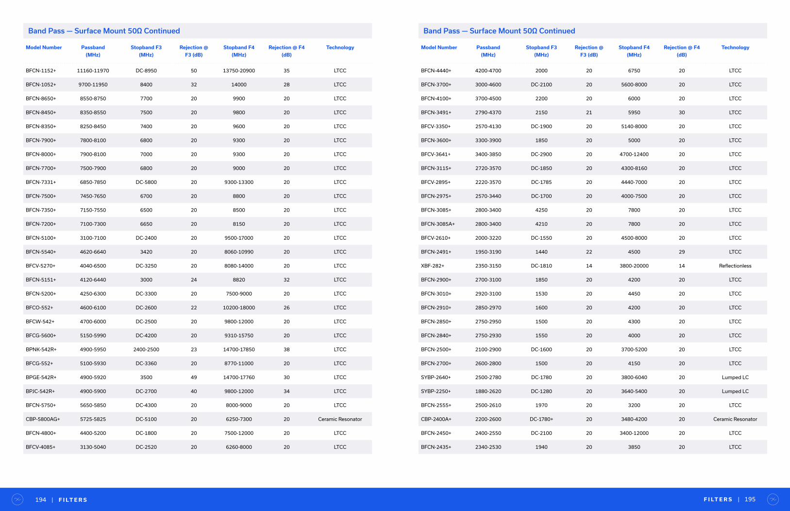
Model Number Passband
(MHz)
Stopband F3
(MHz)
Rejection @
F3 (dB)
Stopband F4
(MHz)
Rejection @ F4
(dB)
Technology
BFCN-4440+ 4200-4700 2000 20 6750 20 LTCC
BFCN-3700+ 3000-4600 DC-2100 20 5600-8000 20 LTCC
BFCN-4100+ 3700-4500 2200 20 6000 20 LTCC
BFCN-3491+ 2790-4370 2150 21 5950 30 LTCC
BFCV-3350+ 2570-4130 DC-1900 20 5140-8000 20 LTCC
BFCN-3600+ 3300-3900 1850 20 5000 20 LTCC
BFCV-3641+ 3400-3850 DC-2900 20 4700-12400 20 LTCC
BFCN-3115+ 2720-3570 DC-1850 20 4300-8160 20 LTCC
BFCV-2895+ 2220-3570 DC-1785 20 4440-7000 20 LTCC
BFCN-2975+ 2570-3440 DC-1700 20 4000-7500 20 LTCC
BFCN-3085+ 2800-3400 4250 20 7800 20 LTCC
BFCN-3085A+ 2800-3400 4210 20 7800 20 LTCC
BFCV-2610+ 2000-3220 DC-1550 20 4500-8000 20 LTCC
BFCN-2491+ 1950-3190 1440 22 4500 29 LTCC
XBF-282+ 2350-3150 DC-1810 14 3800-20000 14 Reflectionless
BFCN-2900+ 2700-3100 1850 20 4200 20 LTCC
BFCN-3010+ 2920-3100 1530 20 4450 20 LTCC
BFCN-2910+ 2850-2970 1600 20 4200 20 LTCC
BFCN-2850+ 2750-2950 1500 20 4300 20 LTCC
BFCN-2840+ 2750-2930 1550 20 4000 20 LTCC
BFCN-2500+ 2100-2900 DC-1600 20 3700-5200 20 LTCC
BFCN-2700+ 2600-2800 1500 20 4150 20 LTCC
SYBP-2640+ 2500-2780 DC-1780 20 3800-6040 20 Lumped LC
SYBP-2250+ 1880-2620 DC-1280 20 3640-5400 20 Lumped LC
BFCN-2555+ 2500-2610 1970 20 3200 20 LTCC
CBP-2400A+ 2200-2600 DC-1780+ 20 3480-4200 20 Ceramic Resonator
BFCN-2450+ 2400-2550 DC-2100 20 3400-12000 20 LTCC
BFCN-2435+ 2340-2530 1940 20 3850 20 LTCC
F I LT E R S | 195| F I LT E R S194
Model Number Passband
(MHz)
Stopband F3
(MHz)
Rejection @
F3 (dB)
Stopband F4
(MHz)
Rejection @ F4
(dB)
Technology
BFCN-1152+ 11160-11970 DC-8950 50 13750-20900 35 LTCC
BFCN-1052+ 9700-11950 8400 32 14000 28 LTCC
BFCN-8650+ 8550-8750 7700 20 9900 20 LTCC
BFCN-8450+ 8350-8550 7500 20 9800 20 LTCC
BFCN-8350+ 8250-8450 7400 20 9600 20 LTCC
BFCN-7900+ 7800-8100 6800 20 9300 20 LTCC
BFCN-8000+ 7900-8100 7000 20 9300 20 LTCC
BFCN-7700+ 7500-7900 6800 20 9000 20 LTCC
BFCN-7331+ 6850-7850 DC-5800 20 9300-13300 20 LTCC
BFCN-7500+ 7450-7650 6700 20 8800 20 LTCC
BFCN-7350+ 7150-7550 6500 20 8500 20 LTCC
BFCN-7200+ 7100-7300 6650 20 8150 20 LTCC
BFCN-5100+ 3100-7100 DC-2400 20 9500-17000 20 LTCC
BFCN-5540+ 4620-6640 3420 20 8060-10990 20 LTCC
BFCV-5270+ 4040-6500 DC-3250 20 8080-14000 20 LTCC
BFCN-5151+ 4120-6440 3000 24 8820 32 LTCC
BFCN-5200+ 4250-6300 DC-3300 20 7500-9000 20 LTCC
BFCO-552+ 4600-6100 DC-2600 22 10200-18000 26 LTCC
BFCW-542+ 4700-6000 DC-2500 20 9800-12000 20 LTCC
BFCG-5600+ 5150-5990 DC-4200 20 9310-15750 20 LTCC
BPNK-542R+ 4900-5950 2400-2500 23 14700-17850 38 LTCC
BFCG-552+ 5100-5930 DC-3360 20 8770-11000 20 LTCC
BPGE-542R+ 4900-5920 3500 49 14700-17760 30 LTCC
BPJC-542R+ 4900-5900 DC-2700 40 9800-12000 34 LTCC
BFCN-5750+ 5650-5850 DC-4300 20 8000-9000 20 LTCC
CBP-5800AG+ 5725-5825 DC-5100 20 6250-7300 20 Ceramic Resonator
BFCN-4800+ 4400-5200 DC-1800 20 7500-12000 20 LTCC
BFCV-4085+ 3130-5040 DC-2520 20 6260-8000 20 LTCC
Band Pass — Surface Mount 50Ω Continued Band Pass — Surface Mount 50Ω Continued

Model Number Passband
(MHz)
Stopband F3
(MHz)
Rejection @
F3 (dB)
Stopband F4
(MHz)
Rejection @ F4
(dB)
Technology
BFCG-252+ 2400-2500 10-1350 25 3400-3800 23 LTCC
BFCO-252+ 2400-2500 DC-1500 30 3200-4500 17 LTCC
BFCW-252+ 2400-2500 DC-1860 20 3100-8000 20 LTCC
BPGE-252R+ 2400-2500 1200-1300 42 3600-3800 43 LTCC
BPJC-252R+ 2400-2500 1910 26 3200 38 LTCC
BPNK-252R+ 2400-2500 692-800 40 4800-5000 23 LTCC
CBP-2250A+ 2000-2500 DC-1630 20 2900-6000 35 Ceramic Resonator
SYBP-232+ 2250-2500 DC-1520 20 3720-4800 20 Lumped LC
BFCN-2360+ 2250-2470 1850 20 3600 20 LTCC
BPF-F1950+ 1450-2450 DC-1100 35 2750-4000 35 Lumped LC
BFCN-2275+ 2170-2380 1800 20 3430 20 LTCC
BFCN-1801+ 1400-2320 1000 25 3110 33 LTCC
CBP-2150AN+ 2000-2300 DC-1700 27 3200-3620 40 Ceramic Resonator
SXBP-2150+ 2050-2250 DC-950 20 2675-5000 20 Lumped LC
BFCG-162W+ 950-2200 DC-770 20 3000-5000 20 LTCC
BFCN-1860+ 1580-2200 DC-1300 20 2600-4800 20 LTCC
SYBP-1950+ 1700-2200 DC-1030 26 2900-4600 20 Lumped LC
SXBP-1940+ 1710-2170 DC-145 20 2900-4700 20 Lumped LC
SXBP-1430+ 950-2150 575 20 2850 20 Lumped LC
CBP-1953AF+ 1858-2048 DC-1500 65 2400-3500 50 Ceramic Resonator
BFCN-1945+ 1850-2040 1400 20 2900 20 LTCC
CBP-1905AN+ 1785-2025 DC-1525 27 2365-3200 26 Ceramic Resonator
BPF-BD1800+ 1600-2000 DC-1400 25 2200-4000 25 Lumped LC
BPNL-1891+ 1790-2000 1090 36 2615-5935 33 LTCC
CBP-1880E+ 1780-1980 DC-1550+ 20 2150-3300 20 Ceramic Resonator
CBP-1950C+ 1920-1980 DC-1740 20 2190-4300 20 Ceramic Resonator
CBP-1820F+ 1680-1960 DC-1510 20 2170-3000 20 Ceramic Resonator
BFCN-1840+ 1750-1930 1480 20 2860 20 LTCC
Model Number Passband
(MHz)
Stopband F3
(MHz)
Rejection @
F3 (dB)
Stopband F4
(MHz)
Rejection @ F4
(dB)
Technology
BFCN-1855+ 1790-1920 1510 20 2810 20 LTCC
BFCN-1900+ 1893-1920 DC-1687 20 2153-5500 20 LTCC
CSBP-A1843+ 1765-1920 DC-1580 20 2095-3300 20 Ceramic Resonator
CBP-1773AF+ 1678-1868 DC-1400 65 2150-2700 60 Ceramic Resonator
BFCN-1690+ 1570-1810 DC-1200 20 2170-4400 20 LTCC
BPF-A1340+ 1000-1800 800 20 2300 20 Lumped LC
BPF-A1600+ 1400-1800 DC-1220 20 1980-3300 20 Lumped LC
SXBP-1200+ 800-1800 535 20 2220 20 Lumped LC
CBP-1748C+ 1710-1785 DC-1580 20 1960-4000 20 Ceramic Resonator
CBP-1630F+ 1500-1760 DC-1320 20 1960-2600 20 Ceramic Resonator
CBP-1598AF+ 1505.5-1690.5 DC-1264 60 1888-2900 60 Ceramic Resonator
CBP-1645J+ 1616-1675 DC-1500 20 1850-3000 20 Ceramic Resonator
SXBP-1500+ 1350-1650 DC-75 20 2160-3700 20 Lumped LC
BFCN-1560+ 1500-1620 1100 20 2100 20 LTCC
BFCN-1575+ 1530-1620 1290 20 2220 20 LTCC
BPF-BD1400+ 1200-1600 DC-1000 25 1800-3000 25 Lumped LC
CBP-1555C+ 1525-1585 DC-1415 20 1700-3600 20 Ceramic Resonator
CBP-1450F+ 1320-1580 DC-1150 20 1775-2350 20 Ceramic Resonator
CBP-1475E+ 1375-1575 DC-1230 40 1750-2600 40 Ceramic Resonator
BFCN-1525+ 1480-1570 1250 20 2180 20 LTCC
SYBP-1420+ 1250-1560 DC-910 20 2000-5000 20 Lumped LC
CBP-1538J+ 1518-1559 DC-1390 20 1750-3000 20 Ceramic Resonator
CBP-1476BD+ 1427-1525 DC-1340 26 1590-2500 26 Ceramic Resonator
CBP-1490A+ 1465-1515 DC-1430 20 1550-3000 20 Ceramic Resonator
CBP-1423AF+ 1333-1513 DC-1113 60 1669-2600 55 Ceramic Resonator
CBP-1400F+ 1300-1500 DC-1090+ 20 1740-2450 20 Ceramic Resonator
CBP-1400BD+ 1320-1480 DC-1224 27 1700-2300 55 Ceramic Resonator
CBP-1400E+ 1320-1480 DC-1150+ 20 1600-2400 20 Ceramic Resonator
F I LT E R S | 197| F I LT E R S196
Band Pass — Surface Mount 50Ω Continued Band Pass — Surface Mount 50Ω Continued
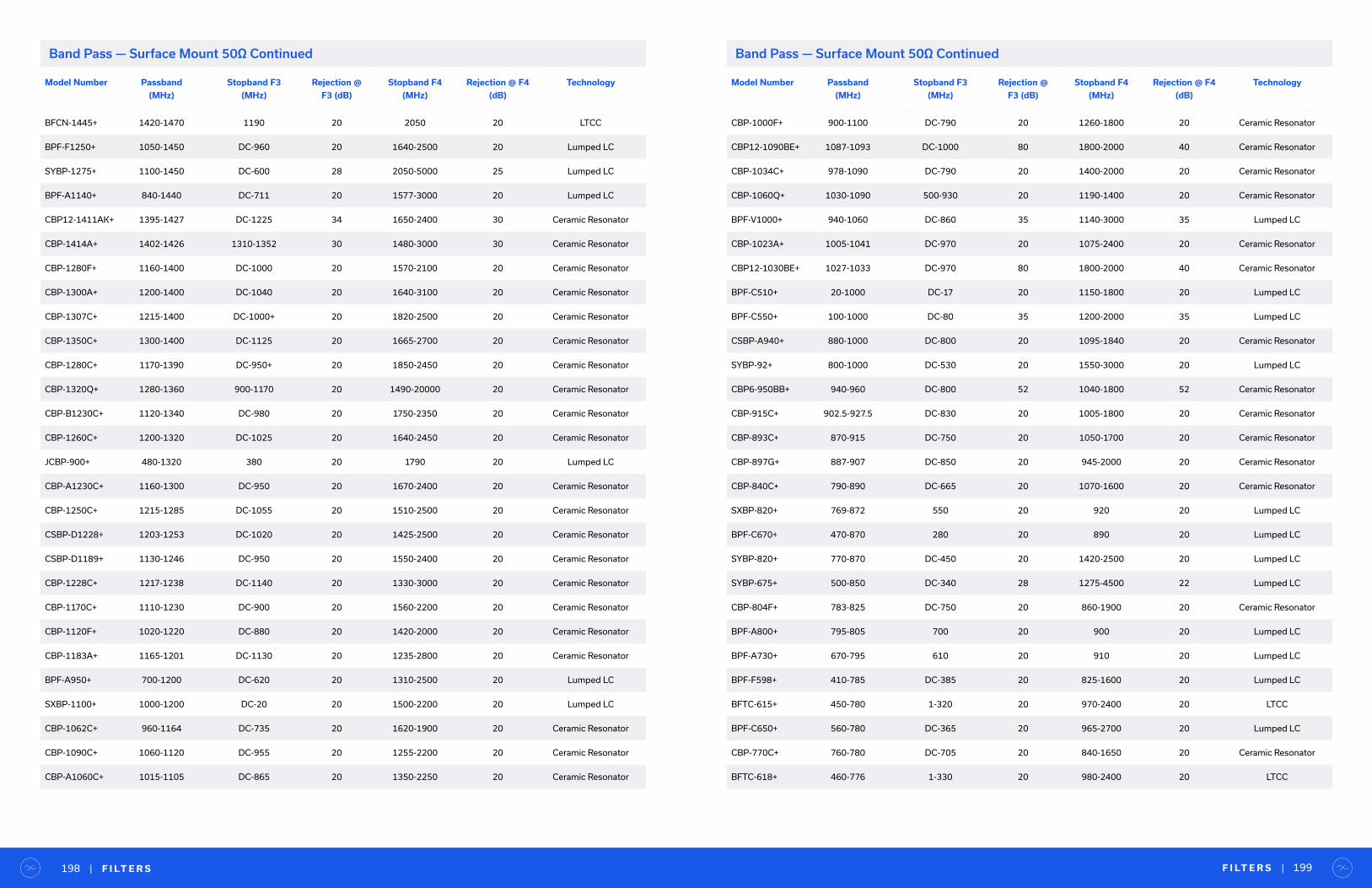
Model Number Passband
(MHz)
Stopband F3
(MHz)
Rejection @
F3 (dB)
Stopband F4
(MHz)
Rejection @ F4
(dB)
Technology
BFCN-1445+ 1420-1470 1190 20 2050 20 LTCC
BPF-F1250+ 1050-1450 DC-960 20 1640-2500 20 Lumped LC
SYBP-1275+ 1100-1450 DC-600 28 2050-5000 25 Lumped LC
BPF-A1140+ 840-1440 DC-711 20 1577-3000 20 Lumped LC
CBP12-1411AK+ 1395-1427 DC-1225 34 1650-2400 30 Ceramic Resonator
CBP-1414A+ 1402-1426 1310-1352 30 1480-3000 30 Ceramic Resonator
CBP-1280F+ 1160-1400 DC-1000 20 1570-2100 20 Ceramic Resonator
CBP-1300A+ 1200-1400 DC-1040 20 1640-3100 20 Ceramic Resonator
CBP-1307C+ 1215-1400 DC-1000+ 20 1820-2500 20 Ceramic Resonator
CBP-1350C+ 1300-1400 DC-1125 20 1665-2700 20 Ceramic Resonator
CBP-1280C+ 1170-1390 DC-950+ 20 1850-2450 20 Ceramic Resonator
CBP-1320Q+ 1280-1360 900-1170 20 1490-20000 20 Ceramic Resonator
CBP-B1230C+ 1120-1340 DC-980 20 1750-2350 20 Ceramic Resonator
CBP-1260C+ 1200-1320 DC-1025 20 1640-2450 20 Ceramic Resonator
JCBP-900+ 480-1320 380 20 1790 20 Lumped LC
CBP-A1230C+ 1160-1300 DC-950 20 1670-2400 20 Ceramic Resonator
CBP-1250C+ 1215-1285 DC-1055 20 1510-2500 20 Ceramic Resonator
CSBP-D1228+ 1203-1253 DC-1020 20 1425-2500 20 Ceramic Resonator
CSBP-D1189+ 1130-1246 DC-950 20 1550-2400 20 Ceramic Resonator
CBP-1228C+ 1217-1238 DC-1140 20 1330-3000 20 Ceramic Resonator
CBP-1170C+ 1110-1230 DC-900 20 1560-2200 20 Ceramic Resonator
CBP-1120F+ 1020-1220 DC-880 20 1420-2000 20 Ceramic Resonator
CBP-1183A+ 1165-1201 DC-1130 20 1235-2800 20 Ceramic Resonator
BPF-A950+ 700-1200 DC-620 20 1310-2500 20 Lumped LC
SXBP-1100+ 1000-1200 DC-20 20 1500-2200 20 Lumped LC
CBP-1062C+ 960-1164 DC-735 20 1620-1900 20 Ceramic Resonator
CBP-1090C+ 1060-1120 DC-955 20 1255-2200 20 Ceramic Resonator
CBP-A1060C+ 1015-1105 DC-865 20 1350-2250 20 Ceramic Resonator
Model Number Passband
(MHz)
Stopband F3
(MHz)
Rejection @
F3 (dB)
Stopband F4
(MHz)
Rejection @ F4
(dB)
Technology
CBP-1000F+ 900-1100 DC-790 20 1260-1800 20 Ceramic Resonator
CBP12-1090BE+ 1087-1093 DC-1000 80 1800-2000 40 Ceramic Resonator
CBP-1034C+ 978-1090 DC-790 20 1400-2000 20 Ceramic Resonator
CBP-1060Q+ 1030-1090 500-930 20 1190-1400 20 Ceramic Resonator
BPF-V1000+ 940-1060 DC-860 35 1140-3000 35 Lumped LC
CBP-1023A+ 1005-1041 DC-970 20 1075-2400 20 Ceramic Resonator
CBP12-1030BE+ 1027-1033 DC-970 80 1800-2000 40 Ceramic Resonator
BPF-C510+ 20-1000 DC-17 20 1150-1800 20 Lumped LC
BPF-C550+ 100-1000 DC-80 35 1200-2000 35 Lumped LC
CSBP-A940+ 880-1000 DC-800 20 1095-1840 20 Ceramic Resonator
SYBP-92+ 800-1000 DC-530 20 1550-3000 20 Lumped LC
CBP6-950BB+ 940-960 DC-800 52 1040-1800 52 Ceramic Resonator
CBP-915C+ 902.5-927.5 DC-830 20 1005-1800 20 Ceramic Resonator
CBP-893C+ 870-915 DC-750 20 1050-1700 20 Ceramic Resonator
CBP-897G+ 887-907 DC-850 20 945-2000 20 Ceramic Resonator
CBP-840C+ 790-890 DC-665 20 1070-1600 20 Ceramic Resonator
SXBP-820+ 769-872 550 20 920 20 Lumped LC
BPF-C670+ 470-870 280 20 890 20 Lumped LC
SYBP-820+ 770-870 DC-450 20 1420-2500 20 Lumped LC
SYBP-675+ 500-850 DC-340 28 1275-4500 22 Lumped LC
CBP-804F+ 783-825 DC-750 20 860-1900 20 Ceramic Resonator
BPF-A800+ 795-805 700 20 900 20 Lumped LC
BPF-A730+ 670-795 610 20 910 20 Lumped LC
BPF-F598+ 410-785 DC-385 20 825-1600 20 Lumped LC
BFTC-615+ 450-780 1-320 20 970-2400 20 LTCC
BPF-C650+ 560-780 DC-365 20 965-2700 20 Lumped LC
CBP-770C+ 760-780 DC-705 20 840-1650 20 Ceramic Resonator
BFTC-618+ 460-776 1-330 20 980-2400 20 LTCC
F I LT E R S | 199| F I LT E R S198
Band Pass — Surface Mount 50Ω Continued Band Pass — Surface Mount 50Ω Continued
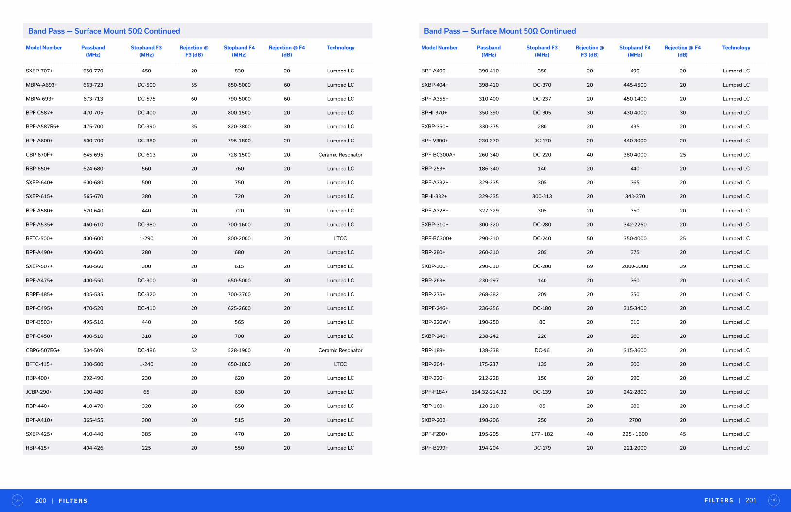
Model Number Passband
(MHz)
Stopband F3
(MHz)
Rejection @
F3 (dB)
Stopband F4
(MHz)
Rejection @ F4
(dB)
Technology
SXBP-707+ 650-770 450 20 830 20 Lumped LC
MBPA-A693+ 663-723 DC-500 55 850-5000 60 Lumped LC
MBPA-693+ 673-713 DC-575 60 790-5000 60 Lumped LC
BPF-C587+ 470-705 DC-400 20 800-1500 20 Lumped LC
BPF-A587R5+ 475-700 DC-390 35 820-3800 30 Lumped LC
BPF-A600+ 500-700 DC-380 20 795-1800 20 Lumped LC
CBP-670F+ 645-695 DC-613 20 728-1500 20 Ceramic Resonator
RBP-650+ 624-680 560 20 760 20 Lumped LC
SXBP-640+ 600-680 500 20 750 20 Lumped LC
SXBP-615+ 565-670 380 20 720 20 Lumped LC
BPF-A580+ 520-640 440 20 720 20 Lumped LC
BPF-A535+ 460-610 DC-380 20 700-1600 20 Lumped LC
BFTC-500+ 400-600 1-290 20 800-2000 20 LTCC
BPF-A490+ 400-600 280 20 680 20 Lumped LC
SXBP-507+ 460-560 300 20 615 20 Lumped LC
BPF-A475+ 400-550 DC-300 30 650-5000 30 Lumped LC
RBPF-485+ 435-535 DC-320 20 700-3700 20 Lumped LC
BPF-C495+ 470-520 DC-410 20 625-2600 20 Lumped LC
BPF-B503+ 495-510 440 20 565 20 Lumped LC
BPF-C450+ 400-510 310 20 700 20 Lumped LC
CBP6-507BG+ 504-509 DC-486 52 528-1900 40 Ceramic Resonator
BFTC-415+ 330-500 1-240 20 650-1800 20 LTCC
RBP-400+ 292-490 230 20 620 20 Lumped LC
JCBP-290+ 100-480 65 20 630 20 Lumped LC
RBP-440+ 410-470 320 20 650 20 Lumped LC
BPF-A410+ 365-455 300 20 515 20 Lumped LC
SXBP-425+ 410-440 385 20 470 20 Lumped LC
RBP-415+ 404-426 225 20 550 20 Lumped LC
Model Number Passband
(MHz)
Stopband F3
(MHz)
Rejection @
F3 (dB)
Stopband F4
(MHz)
Rejection @ F4
(dB)
Technology
BPF-A400+ 390-410 350 20 490 20 Lumped LC
SXBP-404+ 398-410 DC-370 20 445-4500 20 Lumped LC
BPF-A355+ 310-400 DC-237 20 450-1400 20 Lumped LC
BPHI-370+ 350-390 DC-305 30 430-4000 30 Lumped LC
SXBP-350+ 330-375 280 20 435 20 Lumped LC
BPF-V300+ 230-370 DC-170 20 440-3000 20 Lumped LC
BPF-BC300A+ 260-340 DC-220 40 380-4000 25 Lumped LC
RBP-253+ 186-340 140 20 440 20 Lumped LC
BPF-A332+ 329-335 305 20 365 20 Lumped LC
BPHI-332+ 329-335 300-313 20 343-370 20 Lumped LC
BPF-A328+ 327-329 305 20 350 20 Lumped LC
SXBP-310+ 300-320 DC-280 20 342-2250 20 Lumped LC
BPF-BC300+ 290-310 DC-240 50 350-4000 25 Lumped LC
RBP-280+ 260-310 205 20 375 20 Lumped LC
SXBP-300+ 290-310 DC-200 69 2000-3300 39 Lumped LC
RBP-263+ 230-297 140 20 360 20 Lumped LC
RBP-275+ 268-282 209 20 350 20 Lumped LC
RBPF-246+ 236-256 DC-180 20 315-3400 20 Lumped LC
RBP-220W+ 190-250 80 20 310 20 Lumped LC
SXBP-240+ 238-242 220 20 260 20 Lumped LC
RBP-188+ 138-238 DC-96 20 315-3600 20 Lumped LC
RBP-204+ 175-237 135 20 300 20 Lumped LC
RBP-220+ 212-228 150 20 290 20 Lumped LC
BPF-F184+ 154.32-214.32 DC-139 20 242-2800 20 Lumped LC
RBP-160+ 120-210 85 20 280 20 Lumped LC
SXBP-202+ 198-206 250 20 2700 20 Lumped LC
BPF-F200+ 195-205 177 - 182 40 225 - 1600 45 Lumped LC
BPF-B199+ 194-204 DC-179 20 221-2000 20 Lumped LC
F I LT E R S | 201| F I LT E R S200
Band Pass — Surface Mount 50Ω Continued Band Pass — Surface Mount 50Ω Continued

Model Number Passband
(MHz)
Stopband F3
(MHz)
Rejection @
F3 (dB)
Stopband F4
(MHz)
Rejection @ F4
(dB)
Technology
BPF-B190+ 185-195 170 20 212 20 Lumped LC
SXBP-178+ 170-186 150 20 210 20 Lumped LC
BPF-B177+ 170-185 150 20 210 20 Lumped LC
RBP-173+ 160-185 129 20 230 20 Lumped LC
BPF-A175+ 170-180 154 20 200 20 Lumped LC
BPF-C138+ 105-180 87 20 201 20 Lumped LC
BPF-C141+ 110-180 92 20 213 20 Lumped LC
RBP-130+ 95-180 50 20 280 20 Lumped LC
BPF-A176+ 175-177 162 20 190 20 Lumped LC
SXBP-176+ 175-177 DC-155 20 199-1000 20 Lumped LC
SXBP-161R5+ 148-175 DC-130 20 200-2300 20 Lumped LC
TBP-154+ 136-175 DC-108 20 220-3000 20 Lumped LC
SXBP-169+ 164-174 137 20 205 20 Lumped LC
SXBP-162+ 155-169 138 20 200 20 Lumped LC
SXBP-157+ 150-164 131 20 187 20 Lumped LC
BPF-B157+ 151-163 131 20 187 20 Lumped LC
SXBP-150+ 140-160 120 20 190 20 Lumped LC
BPF-F150+ 145-155 DC-133 35 170-1400 35 Lumped LC
RBP-135+ 120-150 85 20 210 20 Lumped LC
RBP-140+ 130-150 DC-100 20 178-3000 20 Lumped LC
SXBP-140+ 130-150 110 20 185 20 Lumped LC
BPF-B140W+ 135-145 117 20 165 20 Lumped LC
BPF-B140N+ 135-143 126 20 154 20 Lumped LC
BPF-A120+ 100-140 DC-82 20 170-3000 20 Lumped LC
BPF-A135+ 132-138 123 20 148 20 Lumped LC
BPF-A127+ 118-137 105 20 155 20 Lumped LC
RBP-98+ 75-131 55 20 170 20 Lumped LC
BPF-A122+ 119-125 111 20 132 20 Lumped LC
Model Number Passband
(MHz)
Stopband F3
(MHz)
Rejection @
F3 (dB)
Stopband F4
(MHz)
Rejection @ F4
(dB)
Technology
BPF-A113+ 108-118 95 20 140 20 Lumped LC
BPF-B113+ 108-118 DC-98 20 132-2000 20 Lumped LC
SXBP-100+ 87-117 66 20 143 20 Lumped LC
SXBP-101+ 94-108 DC-80 20 130-3900 20 Lumped LC
BPF-F100+ 95-105 DC-85 35 120-900 35 Lumped LC
BPF-C75+ 60-90 46 20 102 20 Lumped LC
RBP-75+ 60-90 37 20 122 20 Lumped LC
SXBP-70W+ 50-90 DC-2 20 137-1500 20 Lumped LC
BPF-C59+ 30-88 DC-22 20 115-4500 20 Lumped LC
BPF-C73+ 63-85 45 20 105 20 Lumped LC
BPF-A69+ 55-83 40 20 97 20 Lumped LC
BPF-A75+ 72-78 65 20 88 20 Lumped LC
BPF-A76+ 74-77 65 20 86 20 Lumped LC
SXBP-70+ 63-77 50 20 95 20 Lumped LC
SXBP-69+ 61.9-76.5 DC-55 20 87-3200 20 Lumped LC
SXBP-72+ 68-76 DC-60 20 87-4000 20 Lumped LC
BPF-C70+ 69.5-70.5 DC-66 20 75-1000 20 Lumped LC
BPF-C45+ 30-70 23 20 95 20 Lumped LC
BPF-A60+ 55-65 DC-50 20 75-900 20 Lumped LC
BPF-B63+ 61-65 DC-56 20 72-2800 20 Lumped LC
BPF-B59+ 57-61 DC-52 20 68-2600 20 Lumped LC
JCBP-43+ 26-60 12.5 20 130 20 Lumped LC
BPF-B48+ 47-49 41 20 56 20 Lumped LC
SXBP-35W+ 24-46 16 20 73 20 Lumped LC
SXBP-35N+ 30-40 21 20 60 20 Lumped LC
SXBP-29+ 24-35 DC-17 20 48-1600 20 Lumped LC
SXBP-27R5+ 24-31 DC-19 20 39-900 20 Lumped LC
BPF-E16+ 2-30 DC-1.4 20 35-500 20 Lumped LC
F I LT E R S | 203| F I LT E R S202
Band Pass — Surface Mount 50Ω Continued Band Pass — Surface Mount 50Ω Continued
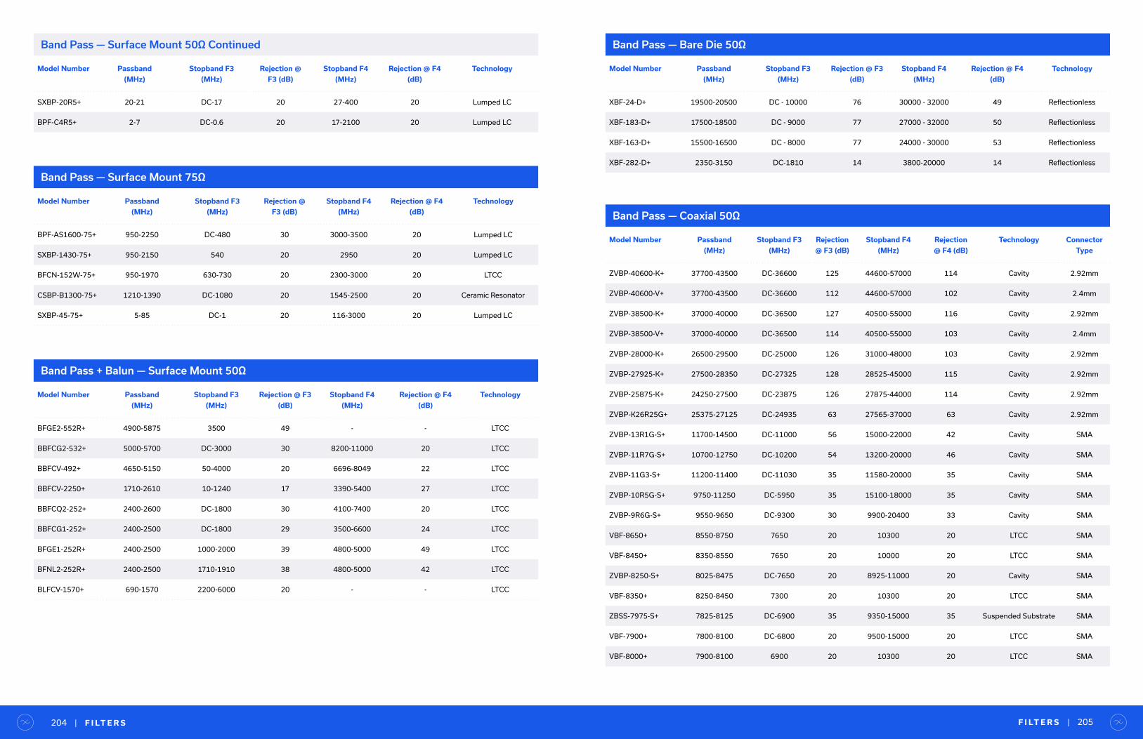
F I LT E R S | 205| F I LT E R S204
Model Number Passband
(MHz)
Stopband F3
(MHz)
Rejection @
F3 (dB)
Stopband F4
(MHz)
Rejection @ F4
(dB)
Technology
BPF-AS1600-75+ 950-2250 DC-480 30 3000-3500 20 Lumped LC
SXBP-1430-75+ 950-2150 540 20 2950 20 Lumped LC
BFCN-152W-75+ 950-1970 630-730 20 2300-3000 20 LTCC
CSBP-B1300-75+ 1210-1390 DC-1080 20 1545-2500 20 Ceramic Resonator
SXBP-45-75+ 5-85 DC-1 20 116-3000 20 Lumped LC
Model Number Passband
(MHz)
Stopband F3
(MHz)
Rejection @ F3
(dB)
Stopband F4
(MHz)
Rejection @ F4
(dB)
Technology
BFGE2-552R+ 4900-5875 3500 49 - - LTCC
BBFCG2-532+ 5000-5700 DC-3000 30 8200-11000 20 LTCC
BBFCV-492+ 4650-5150 50-4000 20 6696-8049 22 LTCC
BBFCV-2250+ 1710-2610 10-1240 17 3390-5400 27 LTCC
BBFCQ2-252+ 2400-2600 DC-1800 30 4100-7400 20 LTCC
BBFCG1-252+ 2400-2500 DC-1800 29 3500-6600 24 LTCC
BFGE1-252R+ 2400-2500 1000-2000 39 4800-5000 49 LTCC
BFNL2-252R+ 2400-2500 1710-1910 38 4800-5000 42 LTCC
BLFCV-1570+ 690-1570 2200-6000 20 - - LTCC
Band Pass — Surface Mount 75Ω
Band Pass + Balun — Surface Mount 50Ω
Model Number Passband
(MHz)
Stopband F3
(MHz)
Rejection @
F3 (dB)
Stopband F4
(MHz)
Rejection @ F4
(dB)
Technology
SXBP-20R5+ 20-21 DC-17 20 27-400 20 Lumped LC
BPF-C4R5+ 2-7 DC-0.6 20 17-2100 20 Lumped LC
Band Pass — Surface Mount 50Ω Continued
Model Number Passband
(MHz)
Stopband F3
(MHz)
Rejection @ F3
(dB)
Stopband F4
(MHz)
Rejection @ F4
(dB)
Technology
XBF-24-D+ 19500-20500 DC - 10000 76 30000 - 32000 49 Reflectionless
XBF-183-D+ 17500-18500 DC - 9000 77 27000 - 32000 50 Reflectionless
XBF-163-D+ 15500-16500 DC - 8000 77 24000 - 30000 53 Reflectionless
XBF-282-D+ 2350-3150 DC-1810 14 3800-20000 14 Reflectionless
Band Pass — Bare Die 50Ω
Band Pass — Coaxial 50Ω
Model Number Passband
(MHz)
Stopband F3
(MHz)
Rejection
@ F3 (dB)
Stopband F4
(MHz)
Rejection
@ F4 (dB)
Technology Connector
Type
ZVBP-40600-K+ 37700-43500 DC-36600 125 44600-57000 114 Cavity 2.92mm
ZVBP-40600-V+ 37700-43500 DC-36600 112 44600-57000 102 Cavity 2.4mm
ZVBP-38500-K+ 37000-40000 DC-36500 127 40500-55000 116 Cavity 2.92mm
ZVBP-38500-V+ 37000-40000 DC-36500 114 40500-55000 103 Cavity 2.4mm
ZVBP-28000-K+ 26500-29500 DC-25000 126 31000-48000 103 Cavity 2.92mm
ZVBP-27925-K+ 27500-28350 DC-27325 128 28525-45000 115 Cavity 2.92mm
ZVBP-25875-K+ 24250-27500 DC-23875 126 27875-44000 114 Cavity 2.92mm
ZVBP-K26R25G+ 25375-27125 DC-24935 63 27565-37000 63 Cavity 2.92mm
ZVBP-13R1G-S+ 11700-14500 DC-11000 56 15000-22000 42 Cavity SMA
ZVBP-11R7G-S+ 10700-12750 DC-10200 54 13200-20000 46 Cavity SMA
ZVBP-11G3-S+ 11200-11400 DC-11030 35 11580-20000 35 Cavity SMA
ZVBP-10R5G-S+ 9750-11250 DC-5950 35 15100-18000 35 Cavity SMA
ZVBP-9R6G-S+ 9550-9650 DC-9300 30 9900-20400 33 Cavity SMA
VBF-8650+ 8550-8750 7650 20 10300 20 LTCC SMA
VBF-8450+ 8350-8550 7650 20 10000 20 LTCC SMA
ZVBP-8250-S+ 8025-8475 DC-7650 20 8925-11000 20 Cavity SMA
VBF-8350+ 8250-8450 7300 20 10300 20 LTCC SMA
ZBSS-7975-S+ 7825-8125 DC-6900 35 9350-15000 35 Suspended Substrate SMA
VBF-7900+ 7800-8100 DC-6800 20 9500-15000 20 LTCC SMA
VBF-8000+ 7900-8100 6900 20 10300 20 LTCC SMA

Model Number Passband
(MHz)
Stopband F3
(MHz)
Rejection
@ F3 (dB)
Stopband F4
(MHz)
Rejection
@ F4 (dB)
Technology Connector
Type
VBF-7700+ 7500-7900 DC-6400 20 9200-14800 20 LTCC SMA
VBF-7331+ 6850-7850 10-5600 23 9300-10500 20 LTCC SMA
VBF-7500+ 7450-7650 6400 20 9000 20 LTCC SMA
VBF-7350+ 7150-7550 6325 20 8700 20 LTCC SMA
VBF-7200+ 7100-7300 6500 20 8400 20 LTCC SMA
ZVBP-7100-S+ 7025-7175 DC-6990 36 7224-14000 35 Cavity SMA
VBFZ-6260-S+ 5600-7000 4200 20 9300 20 LTCC SMA
VBFZ-5500-S+ 4900-6200 3600 20 8600 20 LTCC SMA
ZVBP-5800-S+ 5725-5875 DC-5200 35 6400-14000 35 Cavity SMA
ZVBP-5310-S+ 5250-5370 DC-5080 20 5530-8250 20 Cavity SMA
ZX75BP-4700-S+ 4400-5000 DC-2800 40 6300-8000 30 Ceramic Resonator SMA
ZVBP-4900-S+ 4840-4960 DC-4670 20 5100-9000 20 Cavity SMA
ZVBP-4810-S+ 4750-4870 DC-4600 20 5020-8250 20 Cavity SMA
VBF-4440+ 4200-4700 2000 20 6750 20 LTCC SMA
VBFZ-4000-S+ 3500-4500 2550 20 5700 20 LTCC SMA
ZVBP-4300-S+ 4250-4350 DC-4140 20 4480-8000 20 Cavity SMA
VBFZ-3590-S+ 3000-4300 2250 20 5950 20 LTCC SMA
ZVBP-4000-S+ 3997-4003 DC - 3800 70 4200 - 6000 70 Cavity SMA
ZVBP-3875-S+ 3845-3905 DC-3785 35 3970-8500 35 Cavity SMA
ZAFBP-3200-S+ 3100-3300 DC-2800 20 3550-8500 20 Microstrip SMA
ZXBF-K282+ 2350-3150 DC-1810 15 3800-20000 15 Reflectionless 2.92mm
VBF-2900+ 2700-3100 1850 20 4200 20 LTCC SMA
ZAFBP-2793-S+ 2600-3000 DC-2300 20 3200-7400 20 Microstrip SMA
VBFZ-2575-S+ 2350-2800 1390 20 3850 20 LTCC SMA
VBFZ-2340-S+ 2020-2660 1450 20 3750 20 LTCC SMA
VBF-2555+ 2500-2610 1970 20 3200 20 LTCC SMA
VBF-2435+ 2340-2530 DC-1830 20 4300-5500 30 LTCC SMA
ZFBP-2400-S+ 2300-2500 DC-1800 20 2800-6000 20 Microstrip SMA
F I LT E R S | 207| F I LT E R S206
Band Pass — Coaxial 50Ω Continued
Model Number Passband
(MHz)
Stopband F3
(MHz)
Rejection
@ F3 (dB)
Stopband F4
(MHz)
Rejection
@ F4 (dB)
Technology Connector
Type
ZVBP-2450-S+ 2400-2500 2120-2260 40 2635-2780 40 Cavity SMA
ZVBP-2450A-S+ 2400-2500 DC-2050 57 2850-10000 65 Cavity SMA
ZX75BP-2250-S+ 2000-2500 DC-1630 29 2950-6000 25 Ceramic Resonator SMA
VBF-2360+ 2250-2470 DC-1700 20 4300-6200 30 LTCC SMA
ZVBP-2400-S+ 2375-2425 DC-2250 35 2550-6000 35 Cavity SMA
ZVBP-2300A-S+ 2200-2400 DC-2000 30 2550-8050 30 Cavity SMA
VBF-2275+ 2170-2380 DC-1720 20 4200-6000 30 LTCC SMA
VBFZ-2000-S+ 1730-2270 1210 20 2960 20 LTCC SMA
VBFZ-2130-S+ 2000-2260 1420 20 2950 20 LTCC SMA
ZX75BP-2150-S+ 2050-2250 DC-600 20 2720-4500 20 Lumped LC SMA
ZX75BP-1940-S+ 1710-2170 DC-150 20 2800-4000 20 Lumped LC SMA
ZAFBP-2100-S+ 2050-2150 DC-1800 20 2340-5000 20 Microstrip SMA
ZVBP-2072R5-S+ 2030-2115 DC-1930 48 2220-6000 49 Cavity SMA
ZVBP-2100-S+ 2085-2115 DC-2073 26 2127-5750 26 Cavity SMA
VBF-1945+ 1850-2040 DC-1500 20 3600-5700 30 LTCC SMA
ZX75BP-1842-S+ 1725-1960 1450 20 2350 20 Ceramic Resonator SMA
VBF-1840+ 1750-1930 DC-1460 20 3500-5700 30 LTCC SMA
VBFZ-1690-S+ 1455-1925 930 20 2600 20 LTCC SMA
VBF-1855+ 1790-1920 DC-1400 20 3700-5550 30 LTCC SMA
ZX75BP-1500-S+ 1350-1650 DC-85 20 2030-2800 20 Lumped LC SMA
NBP-1560+ 1500-1620 DC-1060 20 2150-4200 20 Lumped LC N
VBF-1560+ 1500-1620 1100 20 2100 20 LTCC SMA
VBF-1575+ 1530-1620 DC-1200 20 2800-5200 30 LTCC SMA
ZVBP-1575R42-S+ 1550.42-1600.42 DC-1475 68 1675-3000 77 Cavity SMA
ZX75BP-1450-S+ 1320-1580 DC-1100 46 2000-2500 54 Ceramic Resonator SMA
VBF-1525+ 1480-1570 DC-1150 20 2900-5100 30 LTCC SMA
VBF-1445+ 1420-1470 DC-1140 20 2600-4400 30 LTCC SMA
VBFZ-1400-S+ 1350-1450 890 20 1965 20 LTCC SMA
Band Pass — Coaxial 50Ω Continued

Model Number Passband
(MHz)
Stopband F3
(MHz)
Rejection
@ F3 (dB)
Stopband F4
(MHz)
Rejection
@ F4 (dB)
Technology Connector
Type
ZVBP-1420-N+ 1415-1425 DC-1370 81 1470-3000 79 Cavity N
ZX75BP-1307-S+ 1215-1400 DC-1000 20 1820-3000 20 Lumped LC SMA
ZX75BP-1350-S+ 1300-1400 DC-1125 20 1665-2800 20 Lumped LC SMA
ZX75BP-B1280-S+ 1160-1400 DC-955 40 1700-2200 40 Ceramic Resonator SMA
ZX75BP-1280-S+ 1170-1390 DC-950 20 1850-2550 20 Lumped LC SMA
ZX75BP-1135-S+ 900-1370 DC-500 45 2000-5600 40 Lumped LC SMA
ZX75BP-B1230-S+ 1120-1340 DC-940 25 1750-3500 20 Ceramic Resonator SMA
ZX75BP-1260-S+ 1200-1320 DC-1025 20 1640-2500 20 Lumped LC SMA
ZX75BP-A1230-S+ 1160-1300 DC-950 30 1670-3500 20 Ceramic Resonator SMA
ZX75BP-1250-S+ 1215-1285 DC-1055 20 1510-2500 20 Lumped LC SMA
ZX75BP-1205-S+ 1155-1255 DC-1026 20 1435-4500 20 Lumped LC SMA
ZVBP-1227R6-S+ 1202.6-1252.6 DC-1127 67 1327-2500 74 Cavity SMA
ZX75BP-1170-S+ 1110-1230 DC-900 20 1560-2200 20 Lumped LC SMA
ZVBP-1176R45-S+ 1151.45-1201.45 DC-1076 69 1276-2500 76 Cavity SMA
ZX75BP-1100-S+ 1000-1200 DC-25 20 1500-1900 20 Lumped LC SMA
ZX75BP-1062-S+ 960-1164 DC-735 20 1620-2000 20 Lumped LC SMA
VBFZ-1065-S+ 980-1150 630 20 1800 20 LTCC SMA
ZX75BP-1090-S+ 1060-1120 DC-955 20 1255-2200 20 Lumped LC SMA
ZX75BP-A1060-S+ 1015-1105 DC-880 25 1350-4000 30 Ceramic Resonator SMA
ZX75BP-1034-S+ 978-1090 DC-790 20 1400-2000 20 Lumped LC SMA
VBFZ-925-S+ 800-1050 530 20 1550 20 LTCC SMA
ZX75BP-942-S+ 875-1010 750 20 1160 20 Ceramic Resonator SMA
ZABP-510-S+ 20-1000 DC-17 20 1150-2500 20 Lumped LC SMA
ZABP-550-S+ 100-1000 DC-80 35 1200-2000 30 Lumped LC SMA
ZX75BP-915-S+ 902.5-927.5 DC-830 20 1005-1900 20 Lumped LC SMA
ZVBP-909-S+ 902-915 10-895 20 925-2300 20 Cavity SMA
ZVBP-909A-S+ 902-915 DC-895 27 923-2300 35 Cavity SMA
ZX75BP-893-S+ 870-915 DC-750 20 1050-1800 20 Lumped LC SMA
F I LT E R S | 209| F I LT E R S208
Band Pass — Coaxial 50Ω Continued
Model Number Passband
(MHz)
Stopband F3
(MHz)
Rejection
@ F3 (dB)
Stopband F4
(MHz)
Rejection
@ F4 (dB)
Technology Connector
Type
ZX75BP-750-S+ 600-900 DC-500 30 1000-6000 30 Lumped LC SMA
ZX75BP-840-S+ 790-890 DC-665 20 1070-1650 20 Lumped LC SMA
ZABP-670-S+ 470-870 280-365 20 965-1200 20 Lumped LC SMA
VBFZ-780-S+ 710-850 460 20 1300 20 LTCC SMA
ZABP-598-S+ 410-785 DC-385 20 825-1000 20 Lumped LC SMA
ZABP-650-S+ 560-780 185-280 20 890-3500 30 Lumped LC SMA
ZX75BP-770-S+ 760-780 DC-705 20 840-1700 20 Lumped LC SMA
ZABP-587-S+ 470-705 200-400 20 800-1500 20 Lumped LC SMA
ZABP-495-S+ 470-520 300-410 20 625-800 20 Lumped LC SMA
ZABP-450-S+ 400-510 150-310 20 700-760 20 Lumped LC SMA
BBP-240+ 238-242 DC-220 32 260-2000 30 Lumped LC BNC
SBP-240+ 238-242 DC-220 32 260-2000 30 Lumped LC SMA
ZX75BP-204-S+ 175-237 DC-90 60 2500-3500 30 Lumped LC SMA
ZABP-184-S+ 154.32-214.32 DC - 139 20 242 - 750 20 Lumped LC SMA
ZABP-141-S+ 110-180 90-92 20 213-217 20 Lumped LC SMA
BBP-150+ 140-160 DC-120 29 190-2000 30 Lumped LC BNC
SBP-150+ 140-160 DC-120 27 190-2000 32 Lumped LC SMA
BBP-140+ 130-150 DC-110 30 185-2000 30 Lumped LC BNC
SBP-140+ 130-150 DC-110 30 185-2000 30 Lumped LC SMA
BBP-100+ 87-117 DC-66 29 143-1500 28 Lumped LC BNC
SBP-100+ 87-117 DC-66 29 143-1500 28 Lumped LC SMA
BBP-101+ 94-108 DC-80 29 130-2000 28 Lumped LC BNC
SBP-101+ 94-108 DC-80 29 130-3300 28 Lumped LC SMA
ZABP-59-S+ 30-88 16-22 20 115-140 20 Lumped LC SMA
ZX75BP-B70-S+ 52-88 11-29 20 118-200 20 Lumped LC SMA
ZABP-73-S+ 63-85 40-45 20 105-110 20 Lumped LC SMA
SIF-70+ 58-82 4.4 20 490 20 Lumped LC SMA
ZX75BP-A70-S+ 62-78 11-29 20 110-3300 20 Lumped LC SMA
Band Pass — Coaxial 50Ω Continued
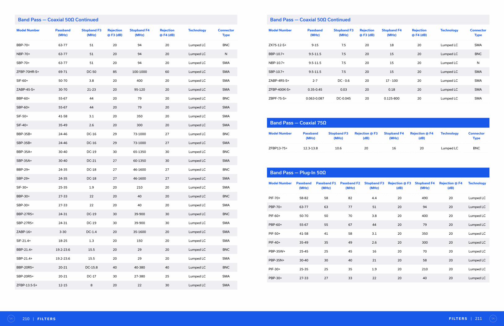
Model Number Passband
(MHz)
Stopband F3
(MHz)
Rejection
@ F3 (dB)
Stopband F4
(MHz)
Rejection
@ F4 (dB)
Technology Connector
Type
BBP-70+ 63-77 51 20 94 20 Lumped LC BNC
NBP-70+ 63-77 51 20 94 20 Lumped LC N
SBP-70+ 63-77 51 20 94 20 Lumped LC SMA
ZFBP-70HR-S+ 69-71 DC-50 85 100-1000 60 Lumped LC SMA
SIF-60+ 50-70 3.8 20 400 20 Lumped LC SMA
ZABP-45-S+ 30-70 21-23 20 95-120 20 Lumped LC SMA
BBP-60+ 55-67 44 20 79 20 Lumped LC BNC
SBP-60+ 55-67 44 20 79 20 Lumped LC SMA
SIF-50+ 41-58 3.1 20 350 20 Lumped LC SMA
SIF-40+ 35-49 2.6 20 300 20 Lumped LC SMA
BBP-35B+ 24-46 DC-16 29 73-1000 27 Lumped LC BNC
SBP-35B+ 24-46 DC-16 29 73-1000 27 Lumped LC SMA
BBP-35A+ 30-40 DC-19 30 65-1350 30 Lumped LC BNC
SBP-35A+ 30-40 DC-21 27 60-1350 30 Lumped LC SMA
BBP-29+ 24-35 DC-18 27 46-1600 27 Lumped LC BNC
SBP-29+ 24-35 DC-18 27 46-1600 27 Lumped LC SMA
SIF-30+ 25-35 1.9 20 210 20 Lumped LC SMA
BBP-30+ 27-33 22 20 40 20 Lumped LC BNC
SBP-30+ 27-33 22 20 40 20 Lumped LC SMA
BBP-27R5+ 24-31 DC-19 30 39-900 30 Lumped LC BNC
SBP-27R5+ 24-31 DC-19 30 39-900 30 Lumped LC SMA
ZABP-16+ 3-30 DC-1.4 20 35-1600 20 Lumped LC SMA
SIF-21.4+ 18-25 1.3 20 150 20 Lumped LC SMA
BBP-21.4+ 19.2-23.6 15.5 20 29 20 Lumped LC BNC
SBP-21.4+ 19.2-23.6 15.5 20 29 20 Lumped LC SMA
BBP-20R5+ 20-21 DC-15.8 40 40-380 40 Lumped LC BNC
SBP-20R5+ 20-21 DC-17 30 27-380 25 Lumped LC SMA
ZFBP-13.5-S+ 12-15 8 20 22 30 Lumped LC SMA
F I LT E R S | 211| F I LT E R S210
Band Pass — Coaxial 50Ω Continued
Model Number Passband
(MHz)
Stopband F3
(MHz)
Rejection
@ F3 (dB)
Stopband F4
(MHz)
Rejection
@ F4 (dB)
Technology Connector
Type
ZX75-12-S+ 9-15 7.5 20 18 20 Lumped LC SMA
BBP-10.7+ 9.5-11.5 7.5 20 15 20 Lumped LC BNC
NBP-10.7+ 9.5-11.5 7.5 20 15 20 Lumped LC N
SBP-10.7+ 9.5-11.5 7.5 20 15 20 Lumped LC SMA
ZABP-4R5-S+ 2-7 DC - 0.6 20 17 - 100 20 Lumped LC SMA
ZFBP-400K-S+ 0.35-0.45 0.03 20 0.18 20 Lumped LC SMA
ZBPF-75-S+ 0.063-0.087 DC-0.045 20 0.125-800 20 Lumped LC SMA
Band Pass — Coaxial 50Ω Continued
Model Number Passband
(MHz)
Stopband F3
(MHz)
Rejection @ F3
(dB)
Stopband F4
(MHz)
Rejection @ F4
(dB)
Technology Connector
Type
ZFBP13-75+ 12.3-13.8 10.6 20 16 20 Lumped LC BNC
Band Pass — Coaxial 75Ω
Band Pass — Plug-In 50Ω
Model Number Passband
(MHz)
Passband F1
(MHz)
Passband F2
(MHz)
Stopband F3
(MHz)
Rejection @ F3
(dB)
Stopband F4
(MHz)
Rejection @ F4
(dB)
Technology
PIF-70+ 58-82 58 82 4.4 20 490 20 Lumped LC
PBP-70+ 63-77 63 77 51 20 94 20 Lumped LC
PIF-60+ 50-70 50 70 3.8 20 400 20 Lumped LC
PBP-60+ 55-67 55 67 44 20 79 20 Lumped LC
PIF-50+ 41-58 41 58 3.1 20 350 20 Lumped LC
PIF-40+ 35-49 35 49 2.6 20 300 20 Lumped LC
PBP-35W+ 25-45 25 45 16 20 70 20 Lumped LC
PBP-35N+ 30-40 30 40 21 20 58 20 Lumped LC
PIF-30+ 25-35 25 35 1.9 20 210 20 Lumped LC
PBP-30+ 27-33 27 33 22 20 40 20 Lumped LC
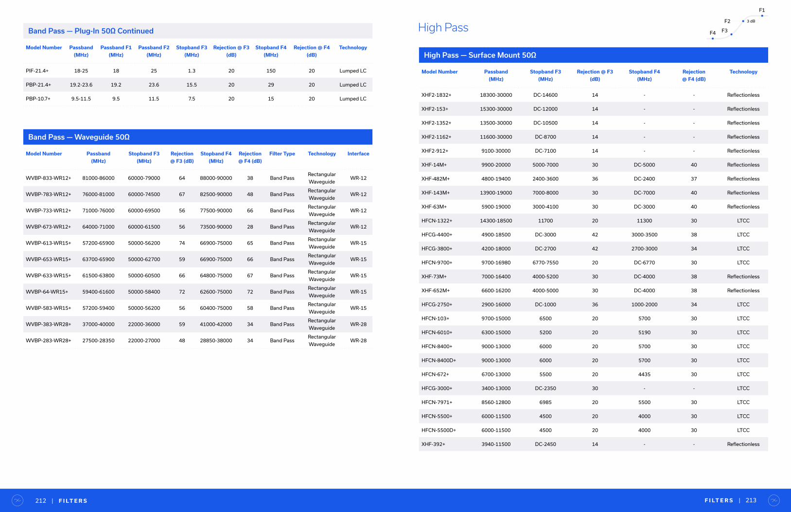
F I LT E R S | 213| F I LT E R S212
Band Pass — Waveguide 50Ω
Model Number Passband
(MHz)
Stopband F3
(MHz)
Rejection
@ F3 (dB)
Stopband F4
(MHz)
Rejection
@ F4 (dB)
Filter Type Technology Interface
WVBP-833-WR12+ 81000-86000 60000-79000 64 88000-90000 38 Band PassRectangular
WaveguideWR-12
WVBP-783-WR12+ 76000-81000 60000-74500 67 82500-90000 48 Band PassRectangular
WaveguideWR-12
WVBP-733-WR12+ 71000-76000 60000-69500 56 77500-90000 66 Band PassRectangular
WaveguideWR-12
WVBP-673-WR12+ 64000-71000 60000-61500 56 73500-90000 28 Band PassRectangular
WaveguideWR-12
WVBP-613-WR15+ 57200-65900 50000-56200 74 66900-75000 65 Band PassRectangular
WaveguideWR-15
WVBP-653-WR15+ 63700-65900 50000-62700 59 66900-75000 66 Band PassRectangular
WaveguideWR-15
WVBP-633-WR15+ 61500-63800 50000-60500 66 64800-75000 67 Band PassRectangular
WaveguideWR-15
WVBP-64-WR15+ 59400-61600 50000-58400 72 62600-75000 72 Band PassRectangular
WaveguideWR-15
WVBP-583-WR15+ 57200-59400 50000-56200 56 60400-75000 58 Band PassRectangular
WaveguideWR-15
WVBP-383-WR28+ 37000-40000 22000-36000 59 41000-42000 34 Band PassRectangular
WaveguideWR-28
WVBP-283-WR28+ 27500-28350 22000-27000 48 28850-38000 34 Band PassRectangular
WaveguideWR-28
Model Number Passband
(MHz)
Passband F1
(MHz)
Passband F2
(MHz)
Stopband F3
(MHz)
Rejection @ F3
(dB)
Stopband F4
(MHz)
Rejection @ F4
(dB)
Technology
PIF-21.4+ 18-25 18 25 1.3 20 150 20 Lumped LC
PBP-21.4+ 19.2-23.6 19.2 23.6 15.5 20 29 20 Lumped LC
PBP-10.7+ 9.5-11.5 9.5 11.5 7.5 20 15 20 Lumped LC
Band Pass — Plug-In 50Ω Continued
High Pass — Surface Mount 50Ω
Model Number Passband
(MHz)
Stopband F3
(MHz)
Rejection @ F3
(dB)
Stopband F4
(MHz)
Rejection
@ F4 (dB)
Technology
XHF2-1832+ 18300-30000 DC-14600 14 - - Reflectionless
XHF2-153+ 15300-30000 DC-12000 14 - - Reflectionless
XHF2-1352+ 13500-30000 DC-10500 14 - - Reflectionless
XHF2-1162+ 11600-30000 DC-8700 14 - - Reflectionless
XHF2-912+ 9100-30000 DC-7100 14 - - Reflectionless
XHF-14M+ 9900-20000 5000-7000 30 DC-5000 40 Reflectionless
XHF-482M+ 4800-19400 2400-3600 36 DC-2400 37 Reflectionless
XHF-143M+ 13900-19000 7000-8000 30 DC-7000 40 Reflectionless
XHF-63M+ 5900-19000 3000-4100 30 DC-3000 40 Reflectionless
HFCN-1322+ 14300-18500 11700 20 11300 30 LTCC
HFCG-4400+ 4900-18500 DC-3000 42 3000-3500 38 LTCC
HFCG-3800+ 4200-18000 DC-2700 42 2700-3000 34 LTCC
HFCN-9700+ 9700-16980 6770-7550 20 DC-6770 30 LTCC
XHF-73M+ 7000-16400 4000-5200 30 DC-4000 38 Reflectionless
XHF-652M+ 6600-16200 4000-5000 30 DC-4000 38 Reflectionless
HFCG-2750+ 2900-16000 DC-1000 36 1000-2000 34 LTCC
HFCN-103+ 9700-15000 6500 20 5700 30 LTCC
HFCN-6010+ 6300-15000 5200 20 5190 30 LTCC
HFCN-8400+ 9000-13000 6000 20 5700 30 LTCC
HFCN-8400D+ 9000-13000 6000 20 5700 30 LTCC
HFCN-672+ 6700-13000 5500 20 4435 30 LTCC
HFCG-3000+ 3400-13000 DC-2350 30 - - LTCC
HFCN-7971+ 8560-12800 6985 20 5500 30 LTCC
HFCN-5500+ 6000-11500 4500 20 4000 30 LTCC
HFCN-5500D+ 6000-11500 4500 20 4000 30 LTCC
XHF-392+ 3940-11500 DC-2450 14 - - Reflectionless
High PassF2
F3
F1
3 dB
F4
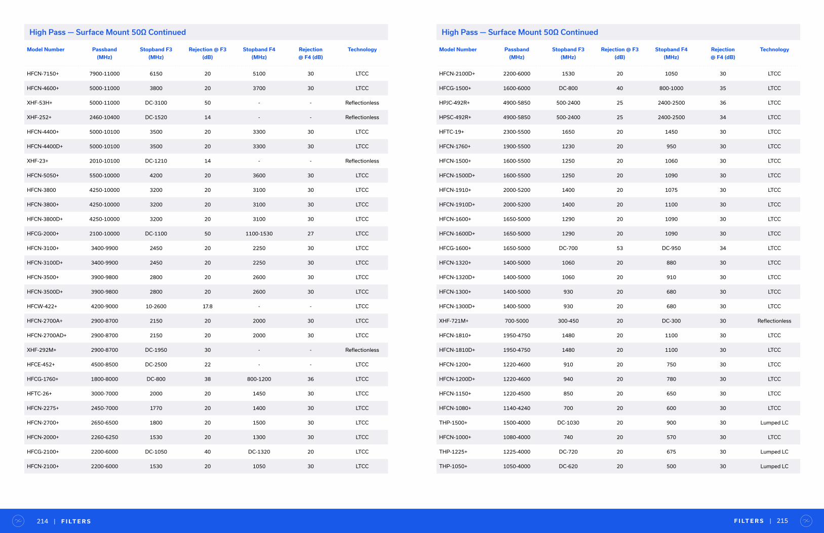
High Pass — Surface Mount 50Ω Continued
F I LT E R S | 215| F I LT E R S214
Model Number Passband
(MHz)
Stopband F3
(MHz)
Rejection @ F3
(dB)
Stopband F4
(MHz)
Rejection
@ F4 (dB)
Technology
HFCN-7150+ 7900-11000 6150 20 5100 30 LTCC
HFCN-4600+ 5000-11000 3800 20 3700 30 LTCC
XHF-53H+ 5000-11000 DC-3100 50 - - Reflectionless
XHF-252+ 2460-10400 DC-1520 14 - - Reflectionless
HFCN-4400+ 5000-10100 3500 20 3300 30 LTCC
HFCN-4400D+ 5000-10100 3500 20 3300 30 LTCC
XHF-23+ 2010-10100 DC-1210 14 - - Reflectionless
HFCN-5050+ 5500-10000 4200 20 3600 30 LTCC
HFCN-3800 4250-10000 3200 20 3100 30 LTCC
HFCN-3800+ 4250-10000 3200 20 3100 30 LTCC
HFCN-3800D+ 4250-10000 3200 20 3100 30 LTCC
HFCG-2000+ 2100-10000 DC-1100 50 1100-1530 27 LTCC
HFCN-3100+ 3400-9900 2450 20 2250 30 LTCC
HFCN-3100D+ 3400-9900 2450 20 2250 30 LTCC
HFCN-3500+ 3900-9800 2800 20 2600 30 LTCC
HFCN-3500D+ 3900-9800 2800 20 2600 30 LTCC
HFCW-422+ 4200-9000 10-2600 17.8 - - LTCC
HFCN-2700A+ 2900-8700 2150 20 2000 30 LTCC
HFCN-2700AD+ 2900-8700 2150 20 2000 30 LTCC
XHF-292M+ 2900-8700 DC-1950 30 - - Reflectionless
HFCE-452+ 4500-8500 DC-2500 22 - - LTCC
HFCG-1760+ 1800-8000 DC-800 38 800-1200 36 LTCC
HFTC-26+ 3000-7000 2000 20 1450 30 LTCC
HFCN-2275+ 2450-7000 1770 20 1400 30 LTCC
HFCN-2700+ 2650-6500 1800 20 1500 30 LTCC
HFCN-2000+ 2260-6250 1530 20 1300 30 LTCC
HFCG-2100+ 2200-6000 DC-1050 40 DC-1320 20 LTCC
HFCN-2100+ 2200-6000 1530 20 1050 30 LTCC
Model Number Passband
(MHz)
Stopband F3
(MHz)
Rejection @ F3
(dB)
Stopband F4
(MHz)
Rejection
@ F4 (dB)
Technology
HFCN-2100D+ 2200-6000 1530 20 1050 30 LTCC
HFCG-1500+ 1600-6000 DC-800 40 800-1000 35 LTCC
HPJC-492R+ 4900-5850 500-2400 25 2400-2500 36 LTCC
HPSC-492R+ 4900-5850 500-2400 25 2400-2500 34 LTCC
HFTC-19+ 2300-5500 1650 20 1450 30 LTCC
HFCN-1760+ 1900-5500 1230 20 950 30 LTCC
HFCN-1500+ 1600-5500 1250 20 1060 30 LTCC
HFCN-1500D+ 1600-5500 1250 20 1090 30 LTCC
HFCN-1910+ 2000-5200 1400 20 1075 30 LTCC
HFCN-1910D+ 2000-5200 1400 20 1100 30 LTCC
HFCN-1600+ 1650-5000 1290 20 1090 30 LTCC
HFCN-1600D+ 1650-5000 1290 20 1090 30 LTCC
HFCG-1600+ 1650-5000 DC-700 53 DC-950 34 LTCC
HFCN-1320+ 1400-5000 1060 20 880 30 LTCC
HFCN-1320D+ 1400-5000 1060 20 910 30 LTCC
HFCN-1300+ 1400-5000 930 20 680 30 LTCC
HFCN-1300D+ 1400-5000 930 20 680 30 LTCC
XHF-721M+ 700-5000 300-450 20 DC-300 30 Reflectionless
HFCN-1810+ 1950-4750 1480 20 1100 30 LTCC
HFCN-1810D+ 1950-4750 1480 20 1100 30 LTCC
HFCN-1200+ 1220-4600 910 20 750 30 LTCC
HFCN-1200D+ 1220-4600 940 20 780 30 LTCC
HFCN-1150+ 1220-4500 850 20 650 30 LTCC
HFCN-1080+ 1140-4240 700 20 600 30 LTCC
THP-1500+ 1500-4000 DC-1030 20 900 30 Lumped LC
HFCN-1000+ 1080-4000 740 20 570 30 LTCC
THP-1225+ 1225-4000 DC-720 20 675 30 Lumped LC
THP-1050+ 1050-4000 DC-620 20 500 30 Lumped LC
High Pass — Surface Mount 50Ω Continued
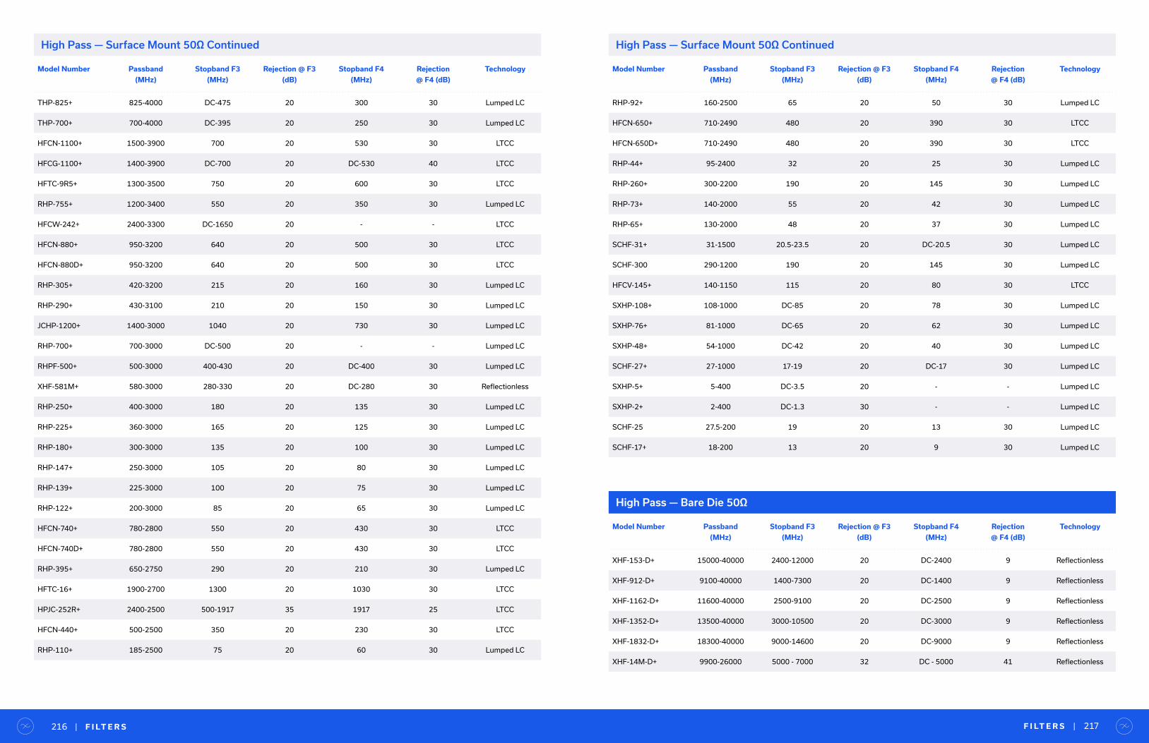
F I LT E R S | 217| F I LT E R S216
Model Number Passband
(MHz)
Stopband F3
(MHz)
Rejection @ F3
(dB)
Stopband F4
(MHz)
Rejection
@ F4 (dB)
Technology
THP-825+ 825-4000 DC-475 20 300 30 Lumped LC
THP-700+ 700-4000 DC-395 20 250 30 Lumped LC
HFCN-1100+ 1500-3900 700 20 530 30 LTCC
HFCG-1100+ 1400-3900 DC-700 20 DC-530 40 LTCC
HFTC-9R5+ 1300-3500 750 20 600 30 LTCC
RHP-755+ 1200-3400 550 20 350 30 Lumped LC
HFCW-242+ 2400-3300 DC-1650 20 - - LTCC
HFCN-880+ 950-3200 640 20 500 30 LTCC
HFCN-880D+ 950-3200 640 20 500 30 LTCC
RHP-305+ 420-3200 215 20 160 30 Lumped LC
RHP-290+ 430-3100 210 20 150 30 Lumped LC
JCHP-1200+ 1400-3000 1040 20 730 30 Lumped LC
RHP-700+ 700-3000 DC-500 20 - - Lumped LC
RHPF-500+ 500-3000 400-430 20 DC-400 30 Lumped LC
XHF-581M+ 580-3000 280-330 20 DC-280 30 Reflectionless
RHP-250+ 400-3000 180 20 135 30 Lumped LC
RHP-225+ 360-3000 165 20 125 30 Lumped LC
RHP-180+ 300-3000 135 20 100 30 Lumped LC
RHP-147+ 250-3000 105 20 80 30 Lumped LC
RHP-139+ 225-3000 100 20 75 30 Lumped LC
RHP-122+ 200-3000 85 20 65 30 Lumped LC
HFCN-740+ 780-2800 550 20 430 30 LTCC
HFCN-740D+ 780-2800 550 20 430 30 LTCC
RHP-395+ 650-2750 290 20 210 30 Lumped LC
HFTC-16+ 1900-2700 1300 20 1030 30 LTCC
HPJC-252R+ 2400-2500 500-1917 35 1917 25 LTCC
HFCN-440+ 500-2500 350 20 230 30 LTCC
RHP-110+ 185-2500 75 20 60 30 Lumped LC
High Pass — Surface Mount 50Ω Continued
Model Number Passband
(MHz)
Stopband F3
(MHz)
Rejection @ F3
(dB)
Stopband F4
(MHz)
Rejection
@ F4 (dB)
Technology
RHP-92+ 160-2500 65 20 50 30 Lumped LC
HFCN-650+ 710-2490 480 20 390 30 LTCC
HFCN-650D+ 710-2490 480 20 390 30 LTCC
RHP-44+ 95-2400 32 20 25 30 Lumped LC
RHP-260+ 300-2200 190 20 145 30 Lumped LC
RHP-73+ 140-2000 55 20 42 30 Lumped LC
RHP-65+ 130-2000 48 20 37 30 Lumped LC
SCHF-31+ 31-1500 20.5-23.5 20 DC-20.5 30 Lumped LC
SCHF-300 290-1200 190 20 145 30 Lumped LC
HFCV-145+ 140-1150 115 20 80 30 LTCC
SXHP-108+ 108-1000 DC-85 20 78 30 Lumped LC
SXHP-76+ 81-1000 DC-65 20 62 30 Lumped LC
SXHP-48+ 54-1000 DC-42 20 40 30 Lumped LC
SCHF-27+ 27-1000 17-19 20 DC-17 30 Lumped LC
SXHP-5+ 5-400 DC-3.5 20 - - Lumped LC
SXHP-2+ 2-400 DC-1.3 30 - - Lumped LC
SCHF-25 27.5-200 19 20 13 30 Lumped LC
SCHF-17+ 18-200 13 20 9 30 Lumped LC
High Pass — Surface Mount 50Ω Continued
High Pass — Bare Die 50Ω
Model Number Passband
(MHz)
Stopband F3
(MHz)
Rejection @ F3
(dB)
Stopband F4
(MHz)
Rejection
@ F4 (dB)
Technology
XHF-153-D+ 15000-40000 2400-12000 20 DC-2400 9 Reflectionless
XHF-912-D+ 9100-40000 1400-7300 20 DC-1400 9 Reflectionless
XHF-1162-D+ 11600-40000 2500-9100 20 DC-2500 9 Reflectionless
XHF-1352-D+ 13500-40000 3000-10500 20 DC-3000 9 Reflectionless
XHF-1832-D+ 18300-40000 9000-14600 20 DC-9000 9 Reflectionless
XHF-14M-D+ 9900-26000 5000 - 7000 32 DC - 5000 41 Reflectionless
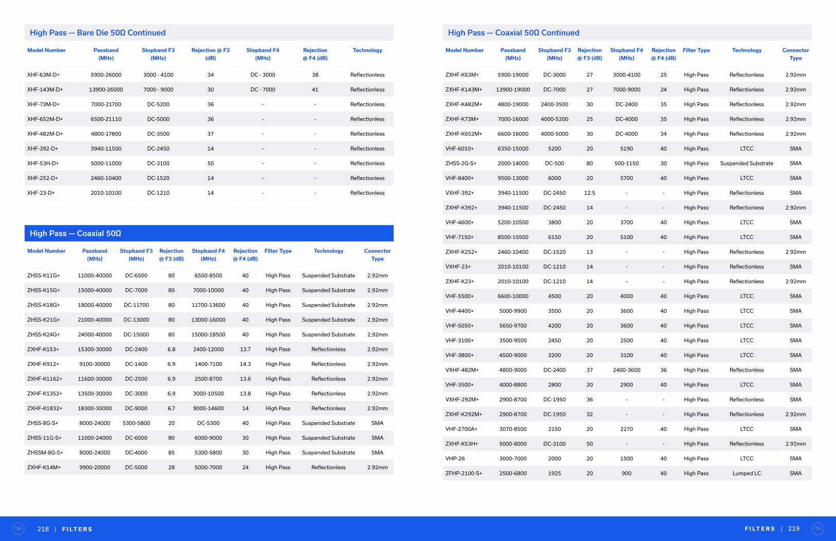
F I LT E R S | 219| F I LT E R S218
Model Number Passband
(MHz)
Stopband F3
(MHz)
Rejection
@ F3 (dB)
Stopband F4
(MHz)
Rejection
@ F4 (dB)
Filter Type Technology Connector
Type
ZHSS-K11G+ 11000-40000 DC-6500 80 6500-8500 40 High Pass Suspended Substrate 2.92mm
ZHSS-K15G+ 15000-40000 DC-7000 80 7000-10000 40 High Pass Suspended Substrate 2.92mm
ZHSS-K18G+ 18000-40000 DC-11700 80 11700-13600 40 High Pass Suspended Substrate 2.92mm
ZHSS-K21G+ 21000-40000 DC-13000 80 13000-16000 40 High Pass Suspended Substrate 2.92mm
ZHSS-K24G+ 24000-40000 DC-15000 80 15000-18500 40 High Pass Suspended Substrate 2.92mm
ZXHF-K153+ 15300-30000 DC-2400 6.8 2400-12000 13.7 High Pass Reflectionless 2.92mm
ZXHF-K912+ 9100-30000 DC-1400 6.9 1400-7100 14.3 High Pass Reflectionless 2.92mm
ZXHF-K1162+ 11600-30000 DC-2500 6.9 2500-8700 13.6 High Pass Reflectionless 2.92mm
ZXHF-K1352+ 13500-30000 DC-3000 6.9 3000-10500 13.8 High Pass Reflectionless 2.92mm
ZXHF-K1832+ 18300-30000 DC-9000 6.7 9000-14600 14 High Pass Reflectionless 2.92mm
ZHSS-8G-S+ 8000-24000 5300-5800 20 DC-5300 40 High Pass Suspended Substrate SMA
ZHSS-11G-S+ 11000-24000 DC-6000 80 6000-9000 30 High Pass Suspended Substrate SMA
ZHSSM-8G-S+ 8000-24000 DC-4000 85 5300-5800 30 High Pass Suspended Substrate SMA
ZXHF-K14M+ 9900-20000 DC-5000 28 5000-7000 24 High Pass Reflectionless 2.92mm
High Pass — Coaxial 50Ω
Model Number Passband
(MHz)
Stopband F3
(MHz)
Rejection @ F3
(dB)
Stopband F4
(MHz)
Rejection
@ F4 (dB)
Technology
XHF-63M-D+ 5900-26000 3000 - 4100 34 DC - 3000 38 Reflectionless
XHF-143M-D+ 13900-26000 7000 - 9000 30 DC - 7000 41 Reflectionless
XHF-73M-D+ 7000-21700 DC-5200 36 - - Reflectionless
XHF-652M-D+ 6500-21110 DC-5000 36 - - Reflectionless
XHF-482M-D+ 4800-17800 DC-3500 37 - - Reflectionless
XHF-392-D+ 3940-11500 DC-2450 14 - - Reflectionless
XHF-53H-D+ 5000-11000 DC-3100 50 - - Reflectionless
XHF-252-D+ 2460-10400 DC-1520 14 - - Reflectionless
XHF-23-D+ 2010-10100 DC-1210 14 - - Reflectionless
High Pass — Bare Die 50Ω Continued
Model Number Passband
(MHz)
Stopband F3
(MHz)
Rejection
@ F3 (dB)
Stopband F4
(MHz)
Rejection
@ F4 (dB)
Filter Type Technology Connector
Type
ZXHF-K63M+ 5900-19000 DC-3000 27 3000-4100 25 High Pass Reflectionless 2.92mm
ZXHF-K143M+ 13900-19000 DC-7000 27 7000-9000 24 High Pass Reflectionless 2.92mm
ZXHF-K482M+ 4800-19000 2400-3500 30 DC-2400 35 High Pass Reflectionless 2.92mm
ZXHF-K73M+ 7000-16000 4000-5200 25 DC-4000 35 High Pass Reflectionless 2.92mm
ZXHF-K652M+ 6600-16000 4000-5000 30 DC-4000 34 High Pass Reflectionless 2.92mm
VHF-6010+ 6350-15000 5200 20 5190 40 High Pass LTCC SMA
ZHSS-2G-S+ 2000-14000 DC-500 80 500-1150 30 High Pass Suspended Substrate SMA
VHF-8400+ 9500-13000 6000 20 5700 40 High Pass LTCC SMA
VXHF-392+ 3940-11500 DC-2450 12.5 - - High Pass Reflectionless SMA
ZXHF-K392+ 3940-11500 DC-2450 14 - - High Pass Reflectionless 2.92mm
VHF-4600+ 5200-10500 3800 20 3700 40 High Pass LTCC SMA
VHF-7150+ 8500-10500 6150 20 5100 40 High Pass LTCC SMA
ZXHF-K252+ 2460-10400 DC-1520 13 - - High Pass Reflectionless 2.92mm
VXHF-23+ 2010-10100 DC-1210 14 - - High Pass Reflectionless SMA
ZXHF-K23+ 2010-10100 DC-1210 14 - - High Pass Reflectionless 2.92mm
VHF-5500+ 6600-10000 4500 20 4000 40 High Pass LTCC SMA
VHF-4400+ 5000-9900 3500 20 3600 40 High Pass LTCC SMA
VHF-5050+ 5650-9700 4200 20 3600 40 High Pass LTCC SMA
VHF-3100+ 3500-9500 2450 20 2500 40 High Pass LTCC SMA
VHF-3800+ 4500-9000 3200 20 3100 40 High Pass LTCC SMA
VXHF-482M+ 4800-9000 DC-2400 37 2400-3600 36 High Pass Reflectionless SMA
VHF-3500+ 4000-8800 2800 20 2900 40 High Pass LTCC SMA
VXHF-292M+ 2900-8700 DC-1950 36 - - High Pass Reflectionless SMA
ZXHF-K292M+ 2900-8700 DC-1950 32 - - High Pass Reflectionless 2.92mm
VHF-2700A+ 3070-8500 2150 20 2270 40 High Pass LTCC SMA
ZXHF-K53H+ 5000-8000 DC-3100 50 - - High Pass Reflectionless 2.92mm
VHP-26 3000-7000 2000 20 1500 40 High Pass LTCC SMA
ZFHP-2100-S+ 2500-6800 1925 20 900 40 High Pass Lumped LC SMA
High Pass — Coaxial 50Ω Continued
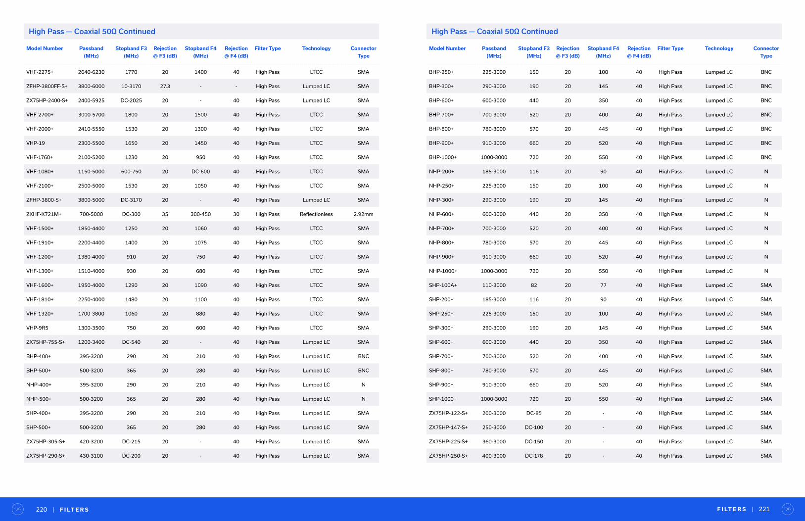
F I LT E R S | 221| F I LT E R S220
Model Number Passband
(MHz)
Stopband F3
(MHz)
Rejection
@ F3 (dB)
Stopband F4
(MHz)
Rejection
@ F4 (dB)
Filter Type Technology Connector
Type
VHF-2275+ 2640-6230 1770 20 1400 40 High Pass LTCC SMA
ZFHP-3800FF-S+ 3800-6000 10-3170 27.3 - - High Pass Lumped LC SMA
ZX75HP-2400-S+ 2400-5925 DC-2025 20 - 40 High Pass Lumped LC SMA
VHF-2700+ 3000-5700 1800 20 1500 40 High Pass LTCC SMA
VHF-2000+ 2410-5550 1530 20 1300 40 High Pass LTCC SMA
VHP-19 2300-5500 1650 20 1450 40 High Pass LTCC SMA
VHF-1760+ 2100-5200 1230 20 950 40 High Pass LTCC SMA
VHF-1080+ 1150-5000 600-750 20 DC-600 40 High Pass LTCC SMA
VHF-2100+ 2500-5000 1530 20 1050 40 High Pass LTCC SMA
ZFHP-3800-S+ 3800-5000 DC-3170 20 - 40 High Pass Lumped LC SMA
ZXHF-K721M+ 700-5000 DC-300 35 300-450 30 High Pass Reflectionless 2.92mm
VHF-1500+ 1850-4400 1250 20 1060 40 High Pass LTCC SMA
VHF-1910+ 2200-4400 1400 20 1075 40 High Pass LTCC SMA
VHF-1200+ 1380-4000 910 20 750 40 High Pass LTCC SMA
VHF-1300+ 1510-4000 930 20 680 40 High Pass LTCC SMA
VHF-1600+ 1950-4000 1290 20 1090 40 High Pass LTCC SMA
VHF-1810+ 2250-4000 1480 20 1100 40 High Pass LTCC SMA
VHF-1320+ 1700-3800 1060 20 880 40 High Pass LTCC SMA
VHP-9R5 1300-3500 750 20 600 40 High Pass LTCC SMA
ZX75HP-755-S+ 1200-3400 DC-540 20 - 40 High Pass Lumped LC SMA
BHP-400+ 395-3200 290 20 210 40 High Pass Lumped LC BNC
BHP-500+ 500-3200 365 20 280 40 High Pass Lumped LC BNC
NHP-400+ 395-3200 290 20 210 40 High Pass Lumped LC N
NHP-500+ 500-3200 365 20 280 40 High Pass Lumped LC N
SHP-400+ 395-3200 290 20 210 40 High Pass Lumped LC SMA
SHP-500+ 500-3200 365 20 280 40 High Pass Lumped LC SMA
ZX75HP-305-S+ 420-3200 DC-215 20 - 40 High Pass Lumped LC SMA
ZX75HP-290-S+ 430-3100 DC-200 20 - 40 High Pass Lumped LC SMA
High Pass — Coaxial 50Ω Continued High Pass — Coaxial 50Ω Continued
Model Number Passband
(MHz)
Stopband F3
(MHz)
Rejection
@ F3 (dB)
Stopband F4
(MHz)
Rejection
@ F4 (dB)
Filter Type Technology Connector
Type
BHP-250+ 225-3000 150 20 100 40 High Pass Lumped LC BNC
BHP-300+ 290-3000 190 20 145 40 High Pass Lumped LC BNC
BHP-600+ 600-3000 440 20 350 40 High Pass Lumped LC BNC
BHP-700+ 700-3000 520 20 400 40 High Pass Lumped LC BNC
BHP-800+ 780-3000 570 20 445 40 High Pass Lumped LC BNC
BHP-900+ 910-3000 660 20 520 40 High Pass Lumped LC BNC
BHP-1000+ 1000-3000 720 20 550 40 High Pass Lumped LC BNC
NHP-200+ 185-3000 116 20 90 40 High Pass Lumped LC N
NHP-250+ 225-3000 150 20 100 40 High Pass Lumped LC N
NHP-300+ 290-3000 190 20 145 40 High Pass Lumped LC N
NHP-600+ 600-3000 440 20 350 40 High Pass Lumped LC N
NHP-700+ 700-3000 520 20 400 40 High Pass Lumped LC N
NHP-800+ 780-3000 570 20 445 40 High Pass Lumped LC N
NHP-900+ 910-3000 660 20 520 40 High Pass Lumped LC N
NHP-1000+ 1000-3000 720 20 550 40 High Pass Lumped LC N
SHP-100A+ 110-3000 82 20 77 40 High Pass Lumped LC SMA
SHP-200+ 185-3000 116 20 90 40 High Pass Lumped LC SMA
SHP-250+ 225-3000 150 20 100 40 High Pass Lumped LC SMA
SHP-300+ 290-3000 190 20 145 40 High Pass Lumped LC SMA
SHP-600+ 600-3000 440 20 350 40 High Pass Lumped LC SMA
SHP-700+ 700-3000 520 20 400 40 High Pass Lumped LC SMA
SHP-800+ 780-3000 570 20 445 40 High Pass Lumped LC SMA
SHP-900+ 910-3000 660 20 520 40 High Pass Lumped LC SMA
SHP-1000+ 1000-3000 720 20 550 40 High Pass Lumped LC SMA
ZX75HP-122-S+ 200-3000 DC-85 20 - 40 High Pass Lumped LC SMA
ZX75HP-147-S+ 250-3000 DC-100 20 - 40 High Pass Lumped LC SMA
ZX75HP-225-S+ 360-3000 DC-150 20 - 40 High Pass Lumped LC SMA
ZX75HP-250-S+ 400-3000 DC-178 20 - 40 High Pass Lumped LC SMA
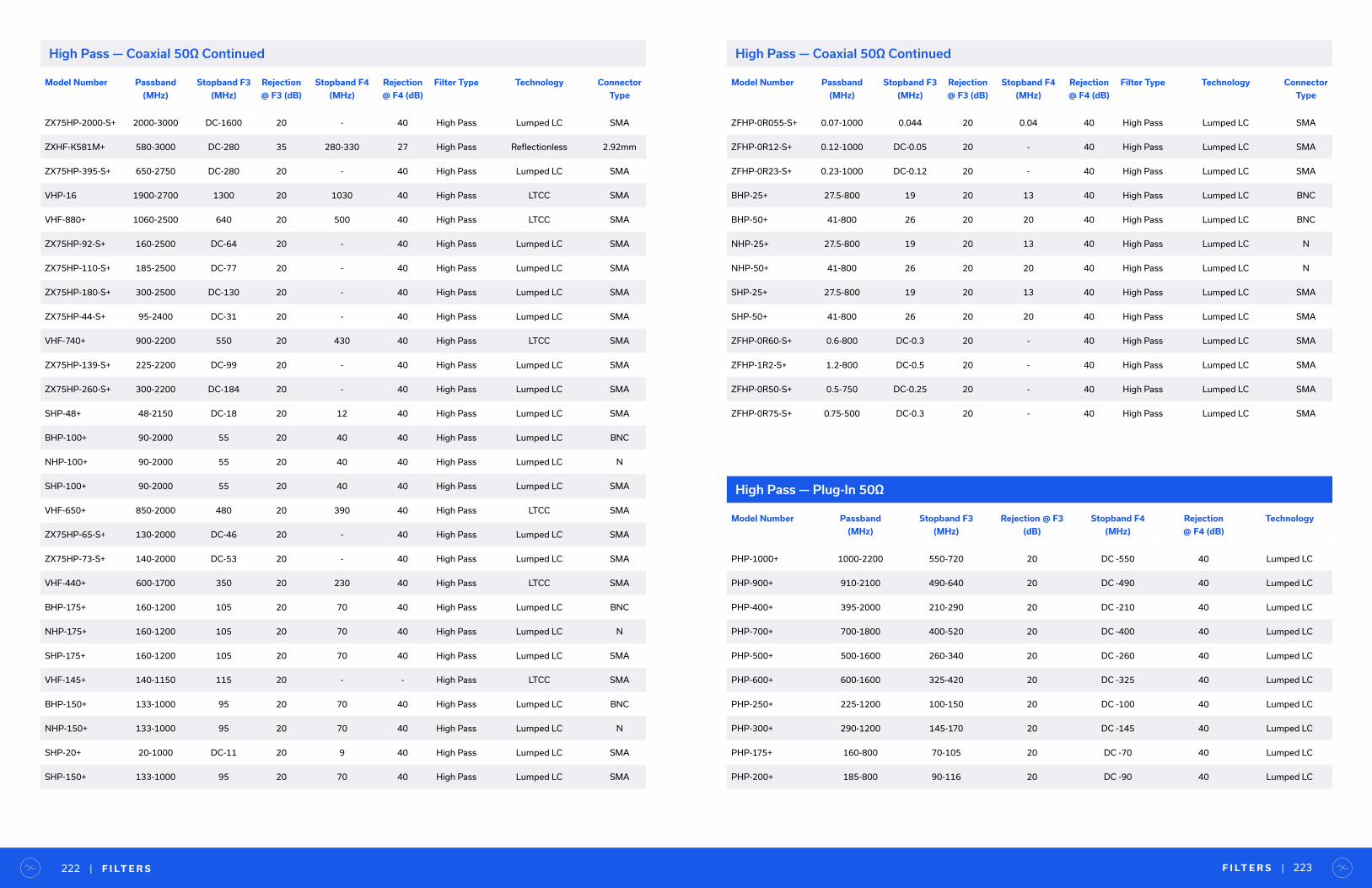
F I LT E R S | 223| F I LT E R S222
Model Number Passband
(MHz)
Stopband F3
(MHz)
Rejection
@ F3 (dB)
Stopband F4
(MHz)
Rejection
@ F4 (dB)
Filter Type Technology Connector
Type
ZX75HP-2000-S+ 2000-3000 DC-1600 20 - 40 High Pass Lumped LC SMA
ZXHF-K581M+ 580-3000 DC-280 35 280-330 27 High Pass Reflectionless 2.92mm
ZX75HP-395-S+ 650-2750 DC-280 20 - 40 High Pass Lumped LC SMA
VHP-16 1900-2700 1300 20 1030 40 High Pass LTCC SMA
VHF-880+ 1060-2500 640 20 500 40 High Pass LTCC SMA
ZX75HP-92-S+ 160-2500 DC-64 20 - 40 High Pass Lumped LC SMA
ZX75HP-110-S+ 185-2500 DC-77 20 - 40 High Pass Lumped LC SMA
ZX75HP-180-S+ 300-2500 DC-130 20 - 40 High Pass Lumped LC SMA
ZX75HP-44-S+ 95-2400 DC-31 20 - 40 High Pass Lumped LC SMA
VHF-740+ 900-2200 550 20 430 40 High Pass LTCC SMA
ZX75HP-139-S+ 225-2200 DC-99 20 - 40 High Pass Lumped LC SMA
ZX75HP-260-S+ 300-2200 DC-184 20 - 40 High Pass Lumped LC SMA
SHP-48+ 48-2150 DC-18 20 12 40 High Pass Lumped LC SMA
BHP-100+ 90-2000 55 20 40 40 High Pass Lumped LC BNC
NHP-100+ 90-2000 55 20 40 40 High Pass Lumped LC N
SHP-100+ 90-2000 55 20 40 40 High Pass Lumped LC SMA
VHF-650+ 850-2000 480 20 390 40 High Pass LTCC SMA
ZX75HP-65-S+ 130-2000 DC-46 20 - 40 High Pass Lumped LC SMA
ZX75HP-73-S+ 140-2000 DC-53 20 - 40 High Pass Lumped LC SMA
VHF-440+ 600-1700 350 20 230 40 High Pass LTCC SMA
BHP-175+ 160-1200 105 20 70 40 High Pass Lumped LC BNC
NHP-175+ 160-1200 105 20 70 40 High Pass Lumped LC N
SHP-175+ 160-1200 105 20 70 40 High Pass Lumped LC SMA
VHF-145+ 140-1150 115 20 - - High Pass LTCC SMA
BHP-150+ 133-1000 95 20 70 40 High Pass Lumped LC BNC
NHP-150+ 133-1000 95 20 70 40 High Pass Lumped LC N
SHP-20+ 20-1000 DC-11 20 9 40 High Pass Lumped LC SMA
SHP-150+ 133-1000 95 20 70 40 High Pass Lumped LC SMA
High Pass — Coaxial 50Ω Continued High Pass — Coaxial 50Ω Continued
Model Number Passband
(MHz)
Stopband F3
(MHz)
Rejection
@ F3 (dB)
Stopband F4
(MHz)
Rejection
@ F4 (dB)
Filter Type Technology Connector
Type
ZFHP-0R055-S+ 0.07-1000 0.044 20 0.04 40 High Pass Lumped LC SMA
ZFHP-0R12-S+ 0.12-1000 DC-0.05 20 - 40 High Pass Lumped LC SMA
ZFHP-0R23-S+ 0.23-1000 DC-0.12 20 - 40 High Pass Lumped LC SMA
BHP-25+ 27.5-800 19 20 13 40 High Pass Lumped LC BNC
BHP-50+ 41-800 26 20 20 40 High Pass Lumped LC BNC
NHP-25+ 27.5-800 19 20 13 40 High Pass Lumped LC N
NHP-50+ 41-800 26 20 20 40 High Pass Lumped LC N
SHP-25+ 27.5-800 19 20 13 40 High Pass Lumped LC SMA
SHP-50+ 41-800 26 20 20 40 High Pass Lumped LC SMA
ZFHP-0R60-S+ 0.6-800 DC-0.3 20 - 40 High Pass Lumped LC SMA
ZFHP-1R2-S+ 1.2-800 DC-0.5 20 - 40 High Pass Lumped LC SMA
ZFHP-0R50-S+ 0.5-750 DC-0.25 20 - 40 High Pass Lumped LC SMA
ZFHP-0R75-S+ 0.75-500 DC-0.3 20 - 40 High Pass Lumped LC SMA
High Pass — Plug-In 50Ω
Model Number Passband
(MHz)
Stopband F3
(MHz)
Rejection @ F3
(dB)
Stopband F4
(MHz)
Rejection
@ F4 (dB)
Technology
PHP-1000+ 1000-2200 550-720 20 DC -550 40 Lumped LC
PHP-900+ 910-2100 490-640 20 DC -490 40 Lumped LC
PHP-400+ 395-2000 210-290 20 DC -210 40 Lumped LC
PHP-700+ 700-1800 400-520 20 DC -400 40 Lumped LC
PHP-500+ 500-1600 260-340 20 DC -260 40 Lumped LC
PHP-600+ 600-1600 325-420 20 DC -325 40 Lumped LC
PHP-250+ 225-1200 100-150 20 DC -100 40 Lumped LC
PHP-300+ 290-1200 145-170 20 DC -145 40 Lumped LC
PHP-175+ 160-800 70-105 20 DC -70 40 Lumped LC
PHP-200+ 185-800 90-116 20 DC -90 40 Lumped LC
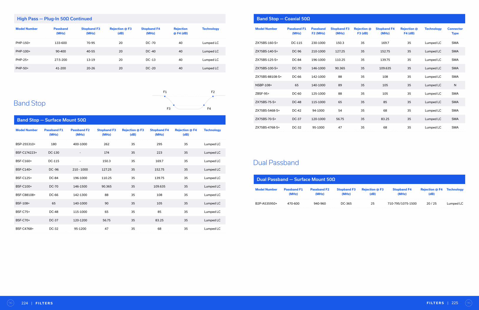
F I LT E R S | 225| F I LT E R S224
Model Number Passband
(MHz)
Stopband F3
(MHz)
Rejection @ F3
(dB)
Stopband F4
(MHz)
Rejection
@ F4 (dB)
Technology
PHP-150+ 133-600 70-95 20 DC -70 40 Lumped LC
PHP-100+ 90-400 40-55 20 DC -40 40 Lumped LC
PHP-25+ 27.5-200 13-19 20 DC -13 40 Lumped LC
PHP-50+ 41-200 20-26 20 DC -20 40 Lumped LC
High Pass — Plug-In 50Ω Continued
Band Stop — Surface Mount 50Ω
Model Number Passband F1
(MHz)
Passband F2
(MHz)
Stopband F3
(MHz)
Rejection @ F3
(dB)
Stopband F4
(MHz)
Rejection @ F4
(dB)
Technology
BSP-255310+ 180 400-1000 262 35 295 35 Lumped LC
BSF-C174223+ DC-130 - 174 35 223 35 Lumped LC
BSF-C160+ DC-115 - 150.3 35 169.7 35 Lumped LC
BSF-C140+ DC -96 210 - 1000 127.25 35 152.75 35 Lumped LC
BSF-C125+ DC-84 196-1000 110.25 35 139.75 35 Lumped LC
BSF-C100+ DC-70 146-1500 90.365 35 109.635 35 Lumped LC
BSF-C88108+ DC-66 142-1300 88 35 108 35 Lumped LC
BSF-108+ 65 140-1000 90 35 105 35 Lumped LC
BSF-C75+ DC-48 115-1000 65 35 85 35 Lumped LC
BSF-C70+ DC-37 120-1200 56.75 35 83.25 35 Lumped LC
BSF-C4768+ DC-32 95-1200 47 35 68 35 Lumped LC
Band StopF3 F4
F1 F2
Band Stop — Coaxial 50Ω
Model Number Passband F1
(MHz)
Passband
F2 (MHz)
Stopband F3
(MHz)
Rejection @
F3 (dB)
Stopband F4
(MHz)
Rejection @
F4 (dB)
Technology Connector
Type
ZX75BS-160-S+ DC-115 230-1000 150.3 35 169.7 35 Lumped LC SMA
ZX75BS-140-S+ DC-96 210-1000 127.25 35 152.75 35 Lumped LC SMA
ZX75BS-125-S+ DC-84 196-1000 110.25 35 139.75 35 Lumped LC SMA
ZX75BS-100-S+ DC-70 146-1000 90.365 35 109.635 35 Lumped LC SMA
ZX75BS-88108-S+ DC-66 142-1000 88 35 108 35 Lumped LC SMA
NSBP-108+ 65 140-1000 89 35 105 35 Lumped LC N
ZBSF-95+ DC-60 125-1000 88 35 105 35 Lumped LC SMA
ZX75BS-75-S+ DC-48 115-1000 65 35 85 35 Lumped LC SMA
ZX75BS-5468-S+ DC-42 94-1000 54 35 68 35 Lumped LC SMA
ZX75BS-70-S+ DC-37 120-1000 56.75 35 83.25 35 Lumped LC SMA
ZX75BS-4768-S+ DC-32 95-1000 47 35 68 35 Lumped LC SMA
Dual Passband — Surface Mount 50Ω
Model Number Passband F1
(MHz)
Passband F2
(MHz)
Stopband F3
(MHz)
Rejection @ F3
(dB)
Stopband F4
(MHz)
Rejection @ F4
(dB)
Technology
B2P-A535950+ 470-600 940-960 DC-365 25 710-795/1075-1500 20 / 25 Lumped LC
Dual Passband
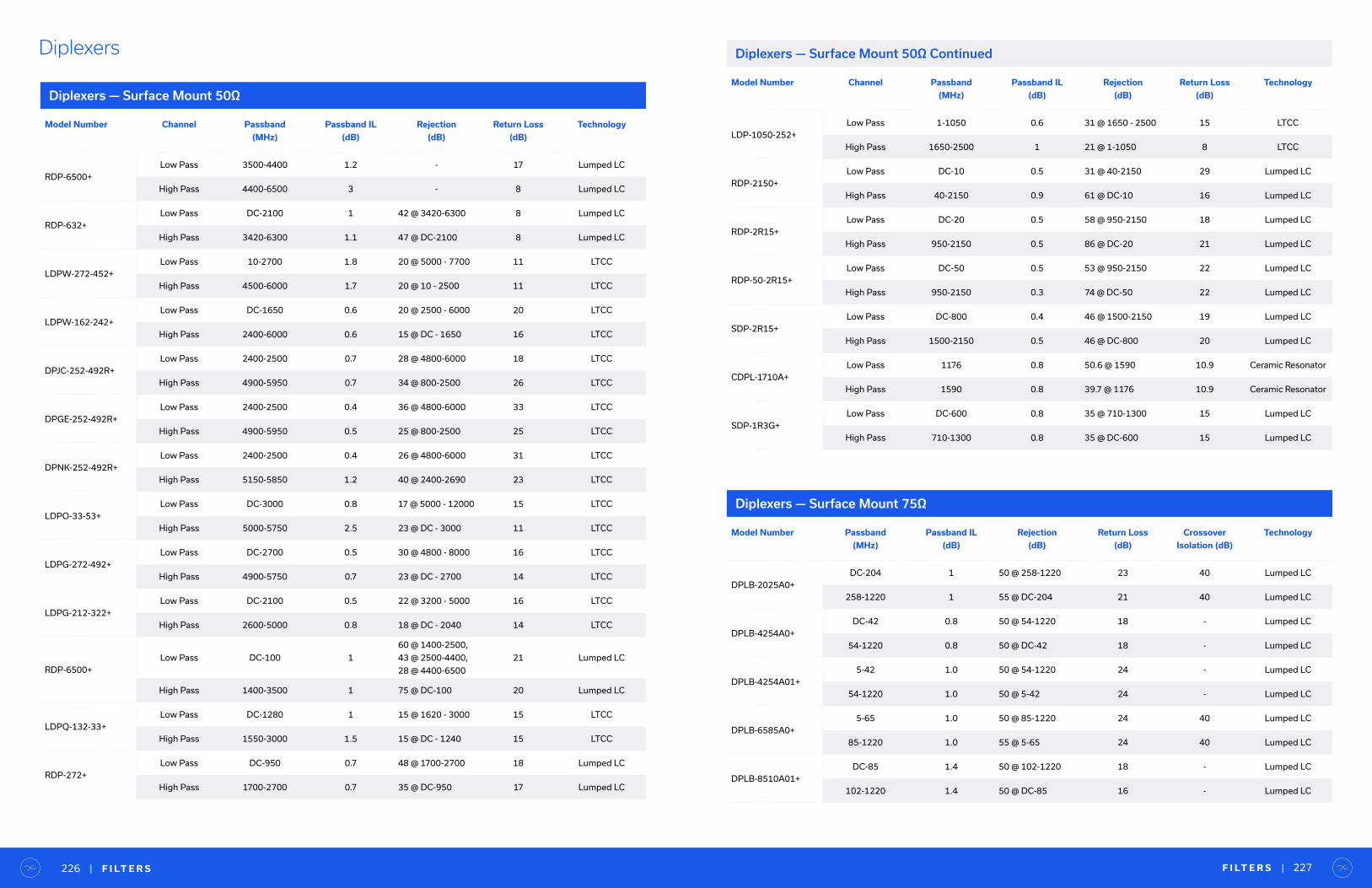
F I LT E R S | 227| F I LT E R S226
Diplexers
Model Number Channel Passband
(MHz)
Passband IL
(dB)
Rejection
(dB)
Return Loss
(dB)
Technology
RDP-6500+
Low Pass 3500-4400 1.2 - 17 Lumped LC
High Pass 4400-6500 3 - 8 Lumped LC
RDP-632+
Low Pass DC-2100 1 42 @ 3420-6300 8 Lumped LC
High Pass 3420-6300 1.1 47 @ DC-2100 8 Lumped LC
LDPW-272-452+
Low Pass 10-2700 1.8 20 @ 5000 - 7700 11 LTCC
High Pass 4500-6000 1.7 20 @ 10 - 2500 11 LTCC
LDPW-162-242+
Low Pass DC-1650 0.6 20 @ 2500 - 6000 20 LTCC
High Pass 2400-6000 0.6 15 @ DC - 1650 16 LTCC
DPJC-252-492R+
Low Pass 2400-2500 0.7 28 @ 4800-6000 18 LTCC
High Pass 4900-5950 0.7 34 @ 800-2500 26 LTCC
DPGE-252-492R+
Low Pass 2400-2500 0.4 36 @ 4800-6000 33 LTCC
High Pass 4900-5950 0.5 25 @ 800-2500 25 LTCC
DPNK-252-492R+
Low Pass 2400-2500 0.4 26 @ 4800-6000 31 LTCC
High Pass 5150-5850 1.2 40 @ 2400-2690 23 LTCC
LDPO-33-53+
Low Pass DC-3000 0.8 17 @ 5000 - 12000 15 LTCC
High Pass 5000-5750 2.5 23 @ DC - 3000 11 LTCC
LDPG-272-492+
Low Pass DC-2700 0.5 30 @ 4800 - 8000 16 LTCC
High Pass 4900-5750 0.7 23 @ DC - 2700 14 LTCC
LDPG-212-322+
Low Pass DC-2100 0.5 22 @ 3200 - 5000 16 LTCC
High Pass 2600-5000 0.8 18 @ DC - 2040 14 LTCC
RDP-6500+
Low Pass DC-100 1
60 @ 1400-2500,
43 @ 2500-4400,
28 @ 4400-6500
21 Lumped LC
High Pass 1400-3500 1 75 @ DC-100 20 Lumped LC
LDPQ-132-33+
Low Pass DC-1280 1 15 @ 1620 - 3000 15 LTCC
High Pass 1550-3000 1.5 15 @ DC - 1240 15 LTCC
RDP-272+
Low Pass DC-950 0.7 48 @ 1700-2700 18 Lumped LC
High Pass 1700-2700 0.7 35 @ DC-950 17 Lumped LC
Diplexers — Surface Mount 50Ω
Diplexers — Surface Mount 50Ω Continued
Model Number Channel Passband
(MHz)
Passband IL
(dB)
Rejection
(dB)
Return Loss
(dB)
Technology
LDP-1050-252+
Low Pass 1-1050 0.6 31 @ 1650 - 2500 15 LTCC
High Pass 1650-2500 1 21 @ 1-1050 8 LTCC
RDP-2150+
Low Pass DC-10 0.5 31 @ 40-2150 29 Lumped LC
High Pass 40-2150 0.9 61 @ DC-10 16 Lumped LC
RDP-2R15+
Low Pass DC-20 0.5 58 @ 950-2150 18 Lumped LC
High Pass 950-2150 0.5 86 @ DC-20 21 Lumped LC
RDP-50-2R15+
Low Pass DC-50 0.5 53 @ 950-2150 22 Lumped LC
High Pass 950-2150 0.3 74 @ DC-50 22 Lumped LC
SDP-2R15+
Low Pass DC-800 0.4 46 @ 1500-2150 19 Lumped LC
High Pass 1500-2150 0.5 46 @ DC-800 20 Lumped LC
CDPL-1710A+
Low Pass 1176 0.8 50.6 @ 1590 10.9 Ceramic Resonator
High Pass 1590 0.8 39.7 @ 1176 10.9 Ceramic Resonator
SDP-1R3G+
Low Pass DC-600 0.8 35 @ 710-1300 15 Lumped LC
High Pass 710-1300 0.8 35 @ DC-600 15 Lumped LC
Model Number Passband
(MHz)
Passband IL
(dB)
Rejection
(dB)
Return Loss
(dB)
Crossover
Isolation (dB)
Technology
DPLB-2025A0+
DC-204 1 50 @ 258-1220 23 40 Lumped LC
258-1220 1 55 @ DC-204 21 40 Lumped LC
DPLB-4254A0+
DC-42 0.8 50 @ 54-1220 18 - Lumped LC
54-1220 0.8 50 @ DC-42 18 - Lumped LC
DPLB-4254A01+
5-42 1.0 50 @ 54-1220 24 - Lumped LC
54-1220 1.0 50 @ 5-42 24 - Lumped LC
DPLB-6585A0+
5-65 1.0 50 @ 85-1220 24 40 Lumped LC
85-1220 1.0 55 @ 5-65 24 40 Lumped LC
DPLB-8510A01+
DC-85 1.4 50 @ 102-1220 18 - Lumped LC
102-1220 1.4 50 @ DC-85 16 - Lumped LC
Diplexers — Surface Mount 75Ω

F I LT E R S | 229| F I LT E R S228
Model Number Passband
(MHz)
Passband IL
(dB)
Rejection
(dB)
Return Loss
(dB)
Crossover
Isolation (dB)
Technology
DPLB-8510A04+
5-85 0.7 48 @ 102-1220 24 9 Lumped LC
102-1220 1 48 @ 5-85 24 9 Lumped LC
DPLB-8510A05+
5-85 1.2 55 @ 5-85 24 41 Lumped LC
102-1220 1.3 45 @ 102-1220 24 41 Lumped LC
DPLX-4254A0+
DC-42 0.9 50 @ 54-1000 20 - Lumped LC
54-1000 0.9 50 @ DC-42 18 - Lumped LC
DPLX-6588A0+
DC-65 1 50 @ 88-1000 18 - Lumped LC
88-1000 1 50 @ DC-65 18 - Lumped LC
Diplexers — Surface Mount 75Ω Continued
Model Number Channel Passband
(MHz)
Passband IL
(dB)
Rejection
(dB)
Return Loss
(dB)
Technology Connector
Type
ZDSS-3G4G-S+
High Pass 4000-20000 1.5 15 @ DC-3000 10
Suspended Substrate SMA
Low Pass DC-3000 1.5 30 @ 4000-20000 10
ZDSS-5G6G-S+
High Pass 6000-20000 2.5 50 @ DC-4000 8
Suspended Substrate SMA
Low Pass DC-5000 1.5 80 @ 7200-20000 10
ZDSS-7G10G-S+
High Pass 10500-20000 1.2 90 @ DC-7500 12
Suspended Substrate SMA
Low Pass DC-7500 0.8 90 @ 13000-20000 12
ZDSS-2R5G5G-S+
High Pass 5100-7500 0.8 65 @ DC-2500 17
Suspended Substrate SMA
Low Pass DC-2500 0.5 50 @ 5100-7500 20
ZDPLX-592-S+
High Pass 5100-5900 0.9 40 @ 2400-2500 12
Lumped LC SMA
Low Pass 2400-2500 0.8 45 @ 5100-5900 16
ZDPLX-2150-S+
High Pass 50-2150 0.9 61 @ DC-10 16
Lumped LC SMA
Low Pass DC-10 0.5 44 @ 50-2150 29
ZX75-2R15-S+
High Pass 950-2150 0.5 91 @ DC-20 26
Lumped LC SMA
Low Pass DC-20 0.4 49 @ 950-2150 26
ZX75-23-S+
High Pass 650-2000 0.5 52 @ 650-2000 18
Lumped LC SMA
Low Pass 9.8-10.2 0.5 90 @ 9.8-10.2 18
Diplexers — Coaxial 50Ω
Diplexers — Coaxial 50Ω Continued
Model Number Channel Passband
(MHz)
Passband IL
(dB)
Rejection
(dB)
Return Loss
(dB)
Technology Connector
Type
ZCDP-1710-S+
High Pass 1590 0.8 40 @ 1176 11
Ceramic Resonator SMA
Low Pass 1176 0.8 50 @ 1590 11
Model Number Channel Passband
(MHz)
Passband IL
(dB)
Rejection
(dB)
Return Loss
(dB)
Crossover Isolation
(dB)
Technology
ZDPL-2025-75-F+
High Pass 258-1700 1 50 @ DC-204 20 37
Lumped LC
Low Pass DC-204 1 65 @ 258-1700 24 37
ZDPL-4254-75-F+
High Pass 54-1700 1 50 @ 5-42 22 40
Lumped LC
Low Pass 5-42 1 50 @ 54-1700 24 40
ZDPL-6588-75-F+
High Pass 88-1700 1.2 50 @ 5-65 20 35
Lumped LC
Low Pass 5-65 1 50 @ 88-1700 20 35
ZDPL-8510-75-F+
High Pass 102-1400 1.6 45 @ 5-85 20 30
Lumped LC
Low Pass 5-85 1.4 50 @ 102-1400 22 30
Diplexers — Coaxial 75Ω
Model Number Channel Passband
(MHz)
Passband IL
(dB)
Rejection
(dB)
Return Loss
(dB)
Crossover Isolation
(dB)
Technology
DPLC-2025A0+
High Pass 258-1220 1 50 @ DC-204 24 40
Lumped LC
Low Pass DC-204 1 45 @ 258-1220 24 40
DPLC-2025A0M+
High Pass 258-1220 1.0 50 @ 5-204 24 40
Lumped LC
Low Pass DC-204 1.0 45 @ 258-1220 24 40
DPLC-4254A0+
High Pass 54-1220 1 50 @ DC-42 24 40
Lumped LC
Low Pass DC-42 1 50 @ 54-1220 24 40
DPLC-4254A0M+
High Pass 54-1220 1.0 50 @ 5-42 24 40
Lumped LC
Low Pass 5-42 1.0 50 @ 54-1220 24 40
DPLC-6585A0+
High Pass 85-1220 1.0 55 @ 5-65 24 40
Lumped LC
Low Pass 5-65 1.0 50 @ 85-1220 24 40
Diplexers — Field Replaceable Plug-In 75Ω

F I LT E R S | 231| F I LT E R S230
Triplexers
Triplexers — Surface Mount 50Ω
Model Number Channel Passband
(MHz)
Passband IL
(dB)
Rejection
(dB)
Return Loss
(dB)
Crossover Isolation
(dB)
Technology
DPLC-6585A0M+
High Pass 85-1220 1.5 55 @ 5-65 24 40
Lumped LC
Low Pass 5-65 1.5 50 @ 85-1220 24 40
DPLC-8510A0+
High Pass 102-1220 1.4 50 @ DC-85 24 15
Lumped LC
Low Pass DC-85 1.1 50 @ 102-1220 24 15
DPLC-8510A01+
High Pass 102-1225 1.75 48 @ 5-84.9 24 38
Lumped LC
Low Pass 5-85 1.3 45 @ 105-1225 24 38
DPLC-8510A01M+
High Pass 102-1225 1.75 48 @ 5-84.9 24 38
Lumped LC
Low Pass 5-85 1.3 45 @ 105-1225 24 38
Diplexers — Field Replaceable Plug-In 75Ω Continued Triplexers — Coaxial 50Ω
Model Number Channel Passband
(MHz)
Passband IL
(dB)
Rejection (dB) Return Loss
(dB)
Technology Connector
Type
Z3SS-7000-S+
High Pass 7000-15000 2 90 @ DC-3400 8 Suspended Substrate SMA
Band Pass 2600-5500 240 @ DC-1600 / 90
@ 10000-1500010 Suspended Substrate SMA
Low Pass DC-1600 1.5 55 @ 3500-4000 10 Suspended Substrate SMA
ZTPL-4620+
High Pass 9.8-10.2 0.5 33 @ 50-4620 17 Lumped LC SMA
Band Pass 852-1872 0.535 @ 1-250
29 @ 3300-462014 Lumped LC SMA
Low Pass 3300-4620 126 @ 1-600
23 @ 600-187215 Lumped LC SMA
Model Number Channel Passband
(MHz)
Passband IL
(dB)
Rejection
(dB)
Return Loss
(dB)
Technology
TPLX-F2700+
High Pass 1400-2700 0.831 @ 1-512
23 @ 608-100014 Lumped LC
Band Pass 608-1000 120 @ 1-512
27 @ 1400-270013 Lumped LC
Low Pass 1-512 1 24 @ 608-2700 14 Lumped LC
TPLX-E2485+
High Pass 1435-2485 0.837 @ 1-460
34 @ 610-115011 Lumped LC
Band Pass 610-1150 0.929 @ 1-460
54 @ 1435-248513 Lumped LC
Low Pass 1-460 0.938 @ 610-1150
26 @ 1435-248516 Lumped LC

Filter Designer KitsModel Number Model Series Description Package Models Included
in Kit
Qty. Ea. Total Qty.
K1-LTCC-WBZ+
LPNK,
LPJC
LPGE
HPJC
HPSC
BPNK
BPJC
BPGE
BFNL
DPNK
DPJC
DPGE
2.4 to 2.5 GHz and
4.9 to 5.9 GHz
LTCC Filters
and Diplexers for
WiFi Applications
0402
0603
0805
LPNK-252R+
LPJC-252R+
LPGE-252R+
LPJC-592R+
LPGE-592R+
HPJC-252R+
HPSC-492R+
HPJC-492R+
BPNK-252R+
BPJC-252R+
BPGE-252R+
BPNK-542R+
BPJC-542R+
BPGE-542R+
BFGE1-252R+
BFGE2-552R+
BFNL2-252R+
DPNK-252-492R+
DPJC-252-492R+
DPGE-252-492R+
5 100
K-SCF+ SCLPDC to 420 MHz
Low PassLeaded SMT
SCLF-21.4+
-30+
-45+
-135+
-190+
-380+
-420+
1 7
K-LHP+SLP
SHP
DC to 1800 MHz
Low Pass and High PassSMA Connectorized
SLP-50+
-100+
-300+
-550+
-1000+
SHP-200+
-400+
-700+
1 8
F I LT E R D E S I G N E R K I T S | 233| F I LT E R D E S I G N E R K I T S232
Model Number Model Series Description Package Models Included
in Kit
Qty. Ea. Total Qty.
K1-HFCN+ HFCN710 to 7000 MHz
High Pass1206
HFCN-650+
-740+
-1200+
-1500+
-1760+
-2000+
-2275+
-2700+
5 40
K2-HFCN+ HFCN950 to 13000 MHz
High Pass1206
HFCN-880+
-1300+
-1320+
-1600+
-1810+
-1910+
-2100+
-3800+
-5500+
-8400+
5 50
K1-LFCN+ LFCNDC to 630 MHz
Low Pass1206
LFCN-225+
-320+
-400+
-490+
-530+
-575+
-630+
5 35
K2-LFCN+ LFCNDC to 6700 MHz
Low Pass1206
LFCN-800+
-900+
-1000+
-1200+
-1325+
-1700+
-2000+
-2250+
-2400+
-5000+
-6000+
-6700+
5 60
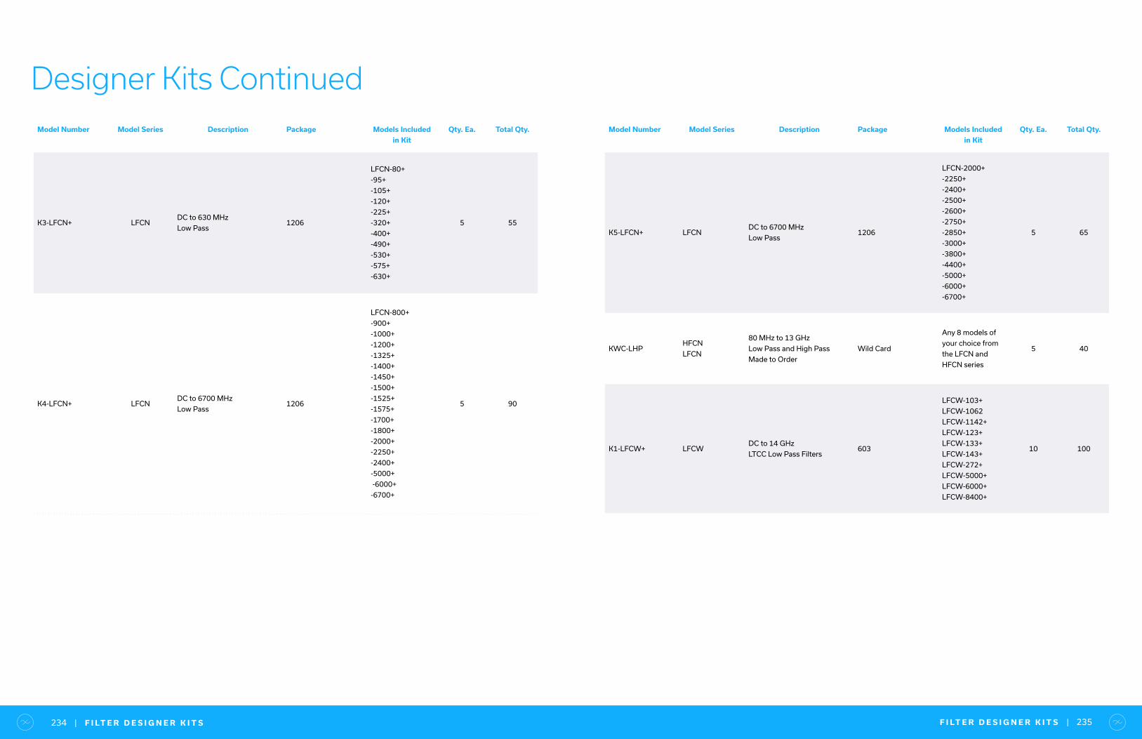
F I LT E R D E S I G N E R K I T S | 235| F I LT E R D E S I G N E R K I T S234
Designer Kits ContinuedModel Number Model Series Description Package Models Included
in Kit
Qty. Ea. Total Qty.
K3-LFCN+ LFCNDC to 630 MHz
Low Pass1206
LFCN-80+
-95+
-105+
-120+
-225+
-320+
-400+
-490+
-530+
-575+
-630+
5 55
K4-LFCN+ LFCNDC to 6700 MHz
Low Pass1206
LFCN-800+
-900+
-1000+
-1200+
-1325+
-1400+
-1450+
-1500+
-1525+
-1575+
-1700+
-1800+
-2000+
-2250+
-2400+
-5000+
-6000+
-6700+
5 90
Model Number Model Series Description Package Models Included
in Kit
Qty. Ea. Total Qty.
K5-LFCN+ LFCNDC to 6700 MHz
Low Pass1206
LFCN-2000+
-2250+
-2400+
-2500+
-2600+
-2750+
-2850+
-3000+
-3800+
-4400+
-5000+
-6000+
-6700+
5 65
KWC-LHPHFCN
LFCN
80 MHz to 13 GHz
Low Pass and High Pass
Made to Order
Wild Card
Any 8 models of
your choice from
the LFCN and
HFCN series
5 40
K1-LFCW+ LFCWDC to 14 GHz
LTCC Low Pass Filters603
LFCW-103+
LFCW-1062
LFCW-1142+
LFCW-123+
LFCW-133+
LFCW-143+
LFCW-272+
LFCW-5000+
LFCW-6000+
LFCW-8400+
10 100

• 160+ models in stock
• 90˚, 180˚ and quadrifilar phase shifts
• Power handling up to 250W
• Low phase and amplitude unbalance
• Connectorized, surface mount and MMIC die formats
90˚ & 180˚ HybridsInsulate Circuits from Reflective Elements
1 0 K H Z T O 1 4 G H Z
90˚ / 180˚ Hybrids — Surface Mount 50Ω
Model Number Frequency
Range (MHz)
Isolation
(dB)
Insertion Loss
(dB) above 3 dB
Phase
Unbalance
(deg)
Amplitude
Unbalance
(dB)
Input Power,
Max.
(W)
Technology
QCH-153+ 3000-14500 13 1 - 1.5 25 Microstrip / Stripline
EPQ-133+ 6000-14000 20 0.6 8.8 1.6 1.58 MMIC
QCH-123+ 8000-12000 23 0.25 - 1 50 Microstrip / Stripline
EPQ-113+ 5000-11000 19 0.6 8.8 1.5 1.59 MMIC
QCH-83 4000-8000 23 0.15 - 1.3 75 Microstrip / Stripline
QCS-83+ 4000-8000 16 0.7 6 1.1 15 LTCC
QCS-722+ 4000-7200 23 0.6 10 1.4 15 LTCC
QCH-652+ 1000-6500 19 0.6 - 1.8 60 Microstrip / Stripline
QCH-63+ 2000-6000 26 0.2 5 1.4 200 Microstrip / Stripline
QCH-63B+ 800-6000 20 0.5 - 2.6 70 Microstrip / Stripline
QCS-592+ 3100-5900 25 0.7 5 1.4 15 LTCC
QCN-45+ 2500-4500 19 0.5 6 2.5 15 LTCC
QCN-45D+ 2500-4500 19 0.5 6 2.5 15 LTCC
QCS-442+ 2800-4400 23 0.5 7 1.1 15 LTCC
QCH-392+ 600-3900 14 0.8 12 2.8 90 Microstrip / Stripline
QCH-382+ 800-3800 28 0.25 7.5 1.3 150 Microstrip / Stripline
QCN-34+ 2500-3400 32 0.4 4 1.2 15 LTCC
QCN-34D+ 2500-3400 32 0.4 4 1.2 15 LTCC
QCS-332+ 1800-3300 18 0.5 5 1.2 15 LTCC
QCS-312+ 1700-3100 25 0.5 7 1.2 15 LTCC
SYPJ-2-33+ 500-3000 16 1.7 4 0.5 0.5 Core & Wire
QCH-272+ 700-2700 22 0.3 5 1 200 Microstrip / Stripline
QCN-27+ 1700-2700 26 0.4 6 1 15 LTCC
QCN-27D+ 1700-2700 26 0.4 6 1 15 LTCC
QCC-22+ 1500-2500 28 0.8 4 1.3 17.5 LTCC
QCN-25+ 1350-2450 25 0.4 5 1.1 15 LTCC
QCN-25D+ 1350-2450 25 0.4 5 1.1 15 LTCC
QBA-24+ 1900-2400 21 0.54 6 0.8 20 LTCC
Choose from:
LTCC, MMC, core and wire, microstrip/stripline designs
9 0 ˚ / 1 8 0 ˚ H Y B R I D S | 237| 9 0 ˚ / 1 8 0 ˚ H Y B R I D S236
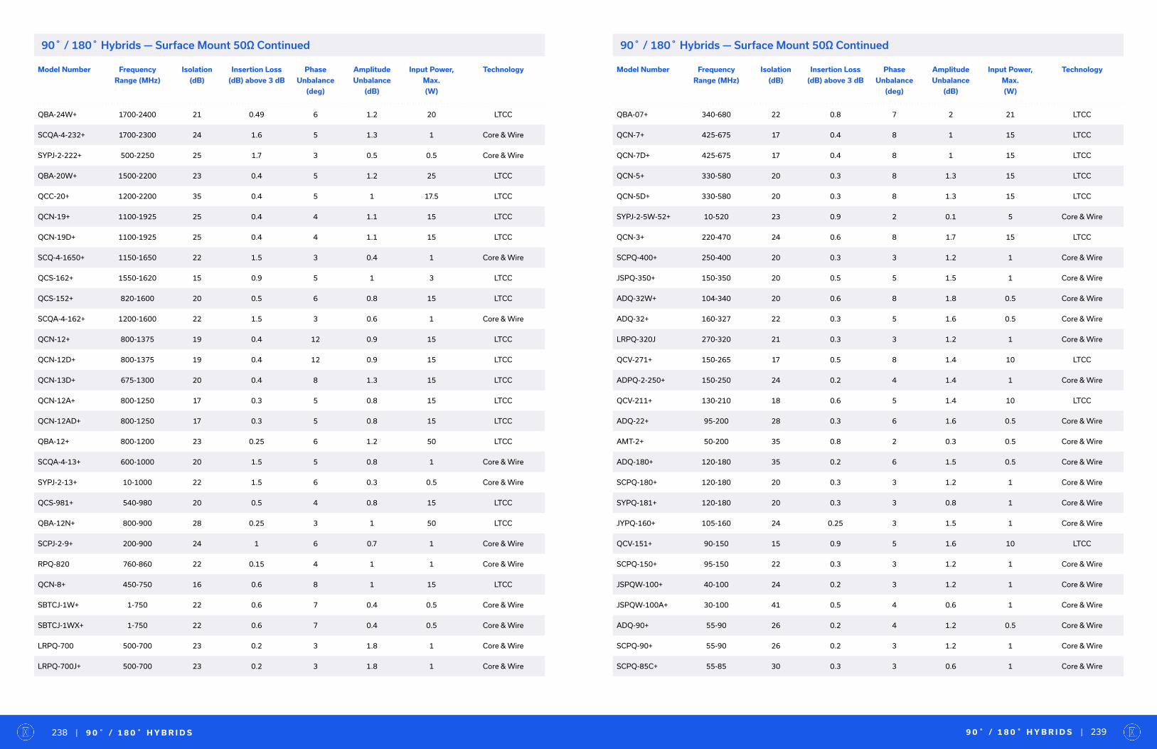
Model Number Frequency
Range (MHz)
Isolation
(dB)
Insertion Loss
(dB) above 3 dB
Phase
Unbalance
(deg)
Amplitude
Unbalance
(dB)
Input Power,
Max.
(W)
Technology
QBA-24W+ 1700-2400 21 0.49 6 1.2 20 LTCC
SCQA-4-232+ 1700-2300 24 1.6 5 1.3 1 Core & Wire
SYPJ-2-222+ 500-2250 25 1.7 3 0.5 0.5 Core & Wire
QBA-20W+ 1500-2200 23 0.4 5 1.2 25 LTCC
QCC-20+ 1200-2200 35 0.4 5 1 17.5 LTCC
QCN-19+ 1100-1925 25 0.4 4 1.1 15 LTCC
QCN-19D+ 1100-1925 25 0.4 4 1.1 15 LTCC
SCQ-4-1650+ 1150-1650 22 1.5 3 0.4 1 Core & Wire
QCS-162+ 1550-1620 15 0.9 5 1 3 LTCC
QCS-152+ 820-1600 20 0.5 6 0.8 15 LTCC
SCQA-4-162+ 1200-1600 22 1.5 3 0.6 1 Core & Wire
QCN-12+ 800-1375 19 0.4 12 0.9 15 LTCC
QCN-12D+ 800-1375 19 0.4 12 0.9 15 LTCC
QCN-13D+ 675-1300 20 0.4 8 1.3 15 LTCC
QCN-12A+ 800-1250 17 0.3 5 0.8 15 LTCC
QCN-12AD+ 800-1250 17 0.3 5 0.8 15 LTCC
QBA-12+ 800-1200 23 0.25 6 1.2 50 LTCC
SCQA-4-13+ 600-1000 20 1.5 5 0.8 1 Core & Wire
SYPJ-2-13+ 10-1000 22 1.5 6 0.3 0.5 Core & Wire
QCS-981+ 540-980 20 0.5 4 0.8 15 LTCC
QBA-12N+ 800-900 28 0.25 3 1 50 LTCC
SCPJ-2-9+ 200-900 24 1 6 0.7 1 Core & Wire
RPQ-820 760-860 22 0.15 4 1 1 Core & Wire
QCN-8+ 450-750 16 0.6 8 1 15 LTCC
SBTCJ-1W+ 1-750 22 0.6 7 0.4 0.5 Core & Wire
SBTCJ-1WX+ 1-750 22 0.6 7 0.4 0.5 Core & Wire
LRPQ-700 500-700 23 0.2 3 1.8 1 Core & Wire
LRPQ-700J+ 500-700 23 0.2 3 1.8 1 Core & Wire
Model Number Frequency
Range (MHz)
Isolation
(dB)
Insertion Loss
(dB) above 3 dB
Phase
Unbalance
(deg)
Amplitude
Unbalance
(dB)
Input Power,
Max.
(W)
Technology
QBA-07+ 340-680 22 0.8 7 2 21 LTCC
QCN-7+ 425-675 17 0.4 8 1 15 LTCC
QCN-7D+ 425-675 17 0.4 8 1 15 LTCC
QCN-5+ 330-580 20 0.3 8 1.3 15 LTCC
QCN-5D+ 330-580 20 0.3 8 1.3 15 LTCC
SYPJ-2-5W-52+ 10-520 23 0.9 2 0.1 5 Core & Wire
QCN-3+ 220-470 24 0.6 8 1.7 15 LTCC
SCPQ-400+ 250-400 20 0.3 3 1.2 1 Core & Wire
JSPQ-350+ 150-350 20 0.5 5 1.5 1 Core & Wire
ADQ-32W+ 104-340 20 0.6 8 1.8 0.5 Core & Wire
ADQ-32+ 160-327 22 0.3 5 1.6 0.5 Core & Wire
LRPQ-320J 270-320 21 0.3 3 1.2 1 Core & Wire
QCV-271+ 150-265 17 0.5 8 1.4 10 LTCC
ADPQ-2-250+ 150-250 24 0.2 4 1.4 1 Core & Wire
QCV-211+ 130-210 18 0.6 5 1.4 10 LTCC
ADQ-22+ 95-200 28 0.3 6 1.6 0.5 Core & Wire
AMT-2+ 50-200 35 0.8 2 0.3 0.5 Core & Wire
ADQ-180+ 120-180 35 0.2 6 1.5 0.5 Core & Wire
SCPQ-180+ 120-180 20 0.3 3 1.2 1 Core & Wire
SYPQ-181+ 120-180 20 0.3 3 0.8 1 Core & Wire
JYPQ-160+ 105-160 24 0.25 3 1.5 1 Core & Wire
QCV-151+ 90-150 15 0.9 5 1.6 10 LTCC
SCPQ-150+ 95-150 22 0.3 3 1.2 1 Core & Wire
JSPQW-100+ 40-100 24 0.2 3 1.2 1 Core & Wire
JSPQW-100A+ 30-100 41 0.5 4 0.6 1 Core & Wire
ADQ-90+ 55-90 26 0.2 4 1.2 0.5 Core & Wire
SCPQ-90+ 55-90 26 0.2 3 1.2 1 Core & Wire
SCPQ-85C+ 55-85 30 0.3 3 0.6 1 Core & Wire
9 0 ˚ / 1 8 0 ˚ H Y B R I D S | 239| 9 0 ˚ / 1 8 0 ˚ H Y B R I D S238
90˚ / 180˚ Hybrids — Surface Mount 50Ω Continued90˚ / 180˚ Hybrids — Surface Mount 50Ω Continued
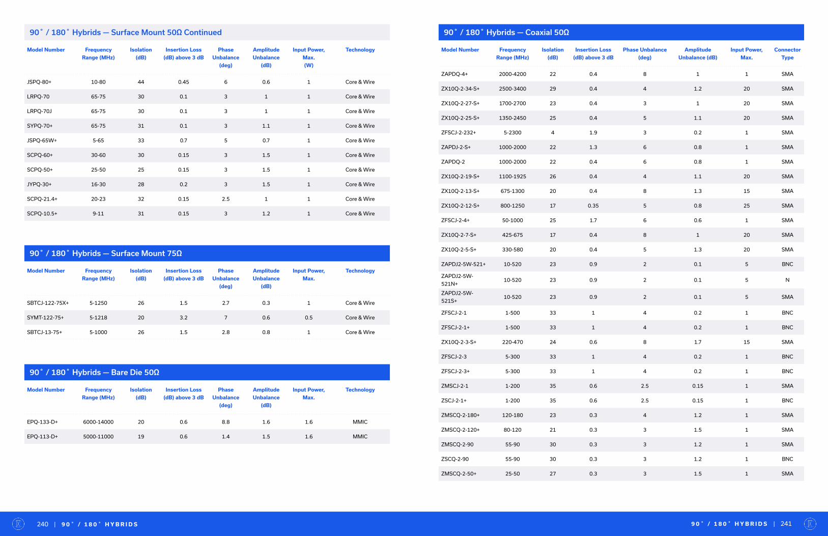
Model Number Frequency
Range (MHz)
Isolation
(dB)
Insertion Loss
(dB) above 3 dB
Phase
Unbalance
(deg)
Amplitude
Unbalance
(dB)
Input Power,
Max.
(W)
Technology
JSPQ-80+ 10-80 44 0.45 6 0.6 1 Core & Wire
LRPQ-70 65-75 30 0.1 3 1 1 Core & Wire
LRPQ-70J 65-75 30 0.1 3 1 1 Core & Wire
SYPQ-70+ 65-75 31 0.1 3 1.1 1 Core & Wire
JSPQ-65W+ 5-65 33 0.7 5 0.7 1 Core & Wire
SCPQ-60+ 30-60 30 0.15 3 1.5 1 Core & Wire
SCPQ-50+ 25-50 25 0.15 3 1.5 1 Core & Wire
JYPQ-30+ 16-30 28 0.2 3 1.5 1 Core & Wire
SCPQ-21.4+ 20-23 32 0.15 2.5 1 1 Core & Wire
SCPQ-10.5+ 9-11 31 0.15 3 1.2 1 Core & Wire
90˚ / 180˚ Hybrids — Surface Mount 75Ω
90˚ / 180˚ Hybrids — Bare Die 50Ω
90˚ / 180˚ Hybrids — Coaxial 50Ω
Model Number Frequency
Range (MHz)
Isolation
(dB)
Insertion Loss
(dB) above 3 dB
Phase
Unbalance
(deg)
Amplitude
Unbalance
(dB)
Input Power,
Max.
Technology
SBTCJ-122-75X+ 5-1250 26 1.5 2.7 0.3 1 Core & Wire
SYMT-122-75+ 5-1218 20 3.2 7 0.6 0.5 Core & Wire
SBTCJ-13-75+ 5-1000 26 1.5 2.8 0.8 1 Core & Wire
Model Number Frequency
Range (MHz)
Isolation
(dB)
Insertion Loss
(dB) above 3 dB
Phase
Unbalance
(deg)
Amplitude
Unbalance
(dB)
Input Power,
Max.
Technology
EPQ-133-D+ 6000-14000 20 0.6 8.8 1.6 1.6 MMIC
EPQ-113-D+ 5000-11000 19 0.6 1.4 1.5 1.6 MMIC
Model Number Frequency
Range (MHz)
Isolation
(dB)
Insertion Loss
(dB) above 3 dB
Phase Unbalance
(deg)
Amplitude
Unbalance (dB)
Input Power,
Max.
Connector
Type
ZAPDQ-4+ 2000-4200 22 0.4 8 1 1 SMA
ZX10Q-2-34-S+ 2500-3400 29 0.4 4 1.2 20 SMA
ZX10Q-2-27-S+ 1700-2700 23 0.4 3 1 20 SMA
ZX10Q-2-25-S+ 1350-2450 25 0.4 5 1.1 20 SMA
ZFSCJ-2-232+ 5-2300 4 1.9 3 0.2 1 SMA
ZAPDJ-2-S+ 1000-2000 22 1.3 6 0.8 1 SMA
ZAPDQ-2 1000-2000 22 0.4 6 0.8 1 SMA
ZX10Q-2-19-S+ 1100-1925 26 0.4 4 1.1 20 SMA
ZX10Q-2-13-S+ 675-1300 20 0.4 8 1.3 15 SMA
ZX10Q-2-12-S+ 800-1250 17 0.35 5 0.8 25 SMA
ZFSCJ-2-4+ 50-1000 25 1.7 6 0.6 1 SMA
ZX10Q-2-7-S+ 425-675 17 0.4 8 1 20 SMA
ZX10Q-2-5-S+ 330-580 20 0.4 5 1.3 20 SMA
ZAPDJ2-5W-521+ 10-520 23 0.9 2 0.1 5 BNC
ZAPDJ2-5W-
521N+10-520 23 0.9 2 0.1 5 N
ZAPDJ2-5W-
521S+10-520 23 0.9 2 0.1 5 SMA
ZFSCJ-2-1 1-500 33 1 4 0.2 1 BNC
ZFSCJ-2-1+ 1-500 33 1 4 0.2 1 BNC
ZX10Q-2-3-S+ 220-470 24 0.6 8 1.7 15 SMA
ZFSCJ-2-3 5-300 33 1 4 0.2 1 BNC
ZFSCJ-2-3+ 5-300 33 1 4 0.2 1 BNC
ZMSCJ-2-1 1-200 35 0.6 2.5 0.15 1 SMA
ZSCJ-2-1+ 1-200 35 0.6 2.5 0.15 1 BNC
ZMSCQ-2-180+ 120-180 23 0.3 4 1.2 1 SMA
ZMSCQ-2-120+ 80-120 21 0.3 3 1.5 1 SMA
ZMSCQ-2-90 55-90 30 0.3 3 1.2 1 SMA
ZSCQ-2-90 55-90 30 0.3 3 1.2 1 BNC
ZMSCQ-2-50+ 25-50 27 0.3 3 1.5 1 SMA
9 0 ˚ / 1 8 0 ˚ H Y B R I D S | 241| 9 0 ˚ / 1 8 0 ˚ H Y B R I D S240
90˚ / 180˚ Hybrids — Surface Mount 50Ω Continued
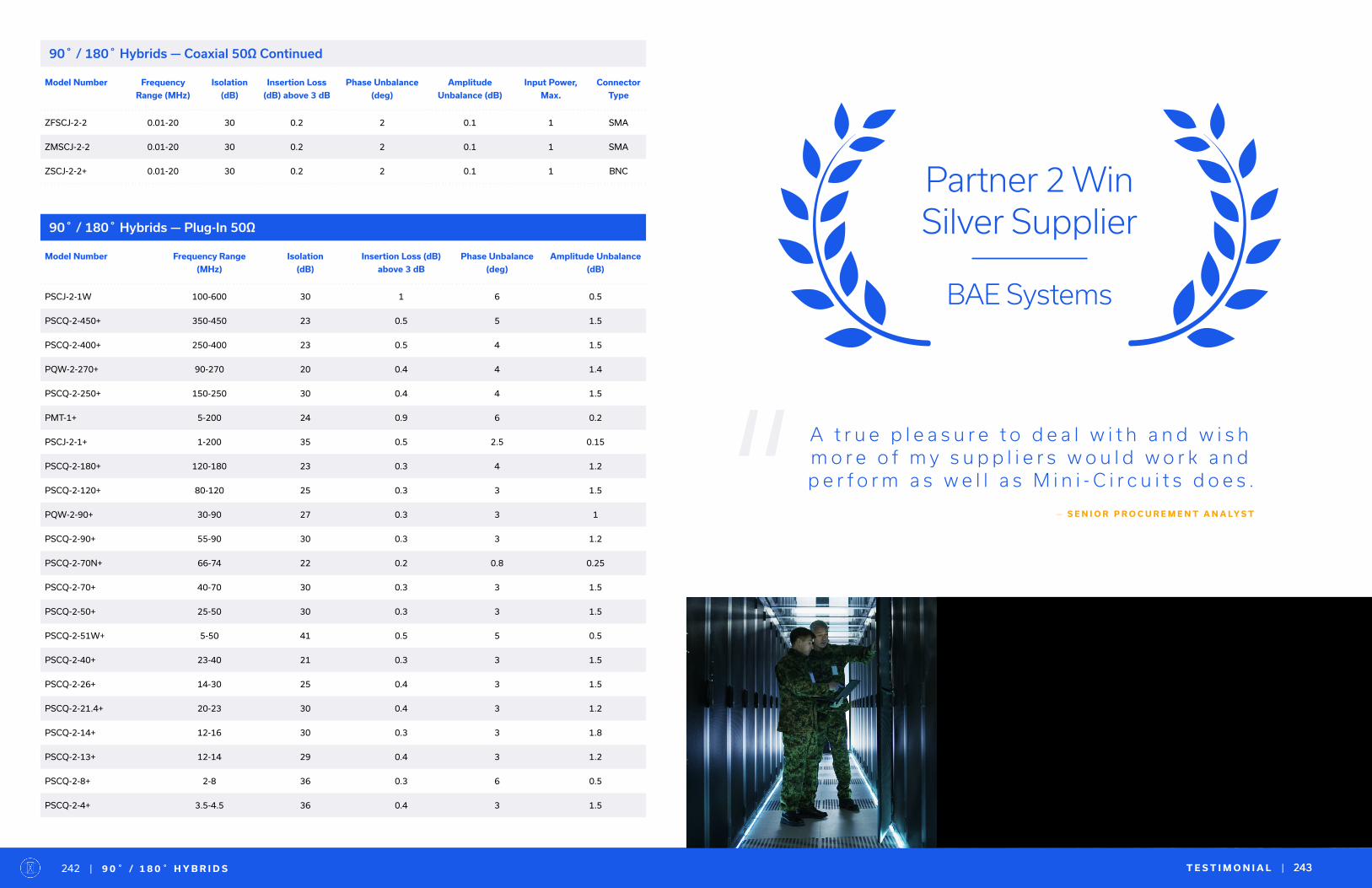
90˚ / 180˚ Hybrids — Plug-In 50Ω
Model Number Frequency Range
(MHz)
Isolation
(dB)
Insertion Loss (dB)
above 3 dB
Phase Unbalance
(deg)
Amplitude Unbalance
(dB)
PSCJ-2-1W 100-600 30 1 6 0.5
PSCQ-2-450+ 350-450 23 0.5 5 1.5
PSCQ-2-400+ 250-400 23 0.5 4 1.5
PQW-2-270+ 90-270 20 0.4 4 1.4
PSCQ-2-250+ 150-250 30 0.4 4 1.5
PMT-1+ 5-200 24 0.9 6 0.2
PSCJ-2-1+ 1-200 35 0.5 2.5 0.15
PSCQ-2-180+ 120-180 23 0.3 4 1.2
PSCQ-2-120+ 80-120 25 0.3 3 1.5
PQW-2-90+ 30-90 27 0.3 3 1
PSCQ-2-90+ 55-90 30 0.3 3 1.2
PSCQ-2-70N+ 66-74 22 0.2 0.8 0.25
PSCQ-2-70+ 40-70 30 0.3 3 1.5
PSCQ-2-50+ 25-50 30 0.3 3 1.5
PSCQ-2-51W+ 5-50 41 0.5 5 0.5
PSCQ-2-40+ 23-40 21 0.3 3 1.5
PSCQ-2-26+ 14-30 25 0.4 3 1.5
PSCQ-2-21.4+ 20-23 30 0.4 3 1.2
PSCQ-2-14+ 12-16 30 0.3 3 1.8
PSCQ-2-13+ 12-14 29 0.4 3 1.2
PSCQ-2-8+ 2-8 36 0.3 6 0.5
PSCQ-2-4+ 3.5-4.5 36 0.4 3 1.5
T E S T I M O N I A L | 243
Partner 2 Win Silver Supplier
BAE Systems
A t r u e p l e a s u r e t o d e a l w i t h a n d w i s h m o r e o f m y s u p p l i e r s w o u l d w o r k a n d p e r f o r m a s w e l l a s M i n i - C i r c u i t s d o e s .
— S E N I O R P R O C U R E M E N T A N A LY S T“
243| 9 0 ˚ / 1 8 0 ˚ H Y B R I D S242
90˚ / 180˚ Hybrids — Coaxial 50Ω Continued
Model Number Frequency
Range (MHz)
Isolation
(dB)
Insertion Loss
(dB) above 3 dB
Phase Unbalance
(deg)
Amplitude
Unbalance (dB)
Input Power,
Max.
Connector
Type
ZFSCJ-2-2 0.01-20 30 0.2 2 0.1 1 SMA
ZMSCJ-2-2 0.01-20 30 0.2 2 0.1 1 SMA
ZSCJ-2-2+ 0.01-20 30 0.2 2 0.1 1 BNC
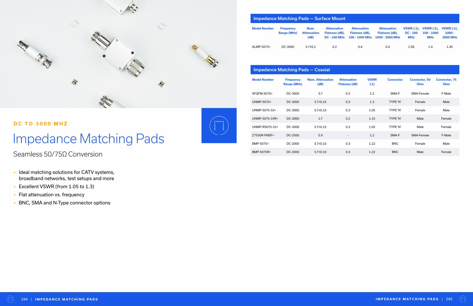
• Ideal matching solutions for CATV systems, broadband networks, test setups and more
• Excellent VSWR (from 1.05 to 1.3)
• Flat attenuation vs. frequency
• BNC, SMA and N-Type connector options
Impedance Matching PadsSeamless 50/75Ω Conversion
D C T O 3 0 0 0 M H Z
Impedance Matching Pads — Surface Mount
Impedance Matching Pads — Coaxial
Model Number Frequency
Range (MHz)
Nom.
Attenuation
(dB)
Attenuation
Flatness (dB),
DC - 100 MHz
Attenuation
Flatness (dB),
100 - 1000 MHz
Attenuation
Flatness (dB),
1000 - 3000 MHz
VSWR (:1),
DC - 100
MHz
VSWR (:1),
100 - 1000
MHz
VSWR (:1),
1000 -
3000 MHz
ALMP-5075+ DC-3000 5.7±0.2 0.2 0.4 0.4 1.06 1.4 1.45
Model Number Frequency
Range (MHz)
Nom. Attenuation
(dB)
Attenuation
Flatness (dB)
VSWR
(:1)
Connector Connector, 50
Ohm
Connector, 75
Ohm
SFQFM-5075+ DC-3000 5.7 0.2 1.2 SMA-F SMA-Female F-Male
UNMP-5075+ DC-3000 5.7±0.15 0.3 1.3 TYPE 'N' Female Male
UNMP-5075-33+ DC-3000 5.7±0.15 0.3 1.05 TYPE 'N' Female Male
UNMP-5075-33R+ DC-3000 1.7 0.2 1.15 TYPE 'N' Male Female
UNMP-R5075-33+ DC-3000 5.7±0.15 0.3 1.05 TYPE 'N' Male Female
Z7550R-FMSF+ DC-2500 5.9 - 1.2 SMA-F SMA-Female F-Male
BMP-5075+ DC-2000 5.7±0.10 0.3 1.22 BNC Female Male
BMP-5075R+ DC-2000 5.7±0.10 0.3 1.22 BNC Male Female
I M P E D A N C E M AT C H I N G PA D S | 245| I M P E D A N C E M AT C H I N G PA D S244
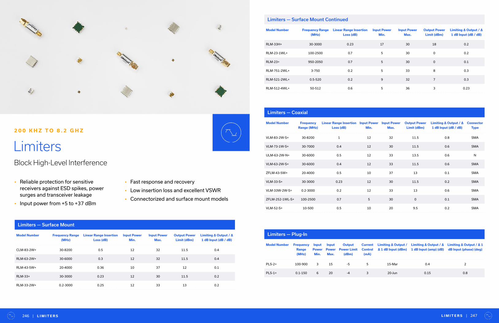
• Reliable protection for sensitive receivers against ESD spikes, power surges and transceiver leakage
• Input power from +5 to +37 dBm
• Fast response and recovery
• Low insertion loss and excellent VSWR
• Connectorized and surface mount models
LimitersBlock High-Level Interference
2 0 0 K H Z T O 8 . 2 G H Z
Limiters — Surface Mount
Limiters — Plug-InModel Number Frequency Range
(MHz)
Linear Range Insertion
Loss (dB)
Input Power
Min.
Input Power
Max.
Output Power
Limit (dBm)
Limiting ∆ Output / ∆
1 dB Input (dB / dB)
CLM-83-2W+ 30-8200 0.5 12 32 11.5 0.4
RLM-63-2W+ 30-6000 0.3 12 32 11.5 0.4
RLM-43-5W+ 20-4000 0.36 10 37 12 0.1
RLM-33+ 30-3000 0.23 12 30 11.5 0.2
RLM-33-2W+ 0.2-3000 0.25 12 33 13 0.2
Limiters — Coaxial
Model Number Frequency
Range (MHz)
Linear Range Insertion
Loss (dB)
Input Power
Min.
Input Power
Max.
Output Power
Limit (dBm)
Limiting ∆ Output / ∆
1 dB Input (dB / dB)
Connector
Type
VLM-83-2W-S+ 30-8200 1 12 32 11.5 0.8 SMA
VLM-73-1W-S+ 30-7000 0.4 12 30 11.5 0.6 SMA
ULM-63-2W-N+ 30-6000 0.5 12 33 13.5 0.6 N
VLM-63-2W-S+ 30-6000 0.4 12 33 11.5 0.6 SMA
ZFLM-43-5W+ 20-4000 0.5 10 37 13 0.1 SMA
VLM-33-S+ 30-3000 0.23 12 30 11.5 0.2 SMA
VLM-33W-2W-S+ 0.2-3000 0.2 12 33 13 0.6 SMA
ZFLM-252-1WL-S+ 100-2500 0.7 5 30 0 0.1 SMA
VLM-52-S+ 10-500 0.5 10 20 9.5 0.2 SMA
Model Number Frequency
Range
(MHz)
Input
Power
Min.
Input
Power
Max.
Output
Power Limit
(dBm)
Current
Control
(mA)
Limiting ∆ Output /
∆ 1 dB Input (dBm)
Limiting ∆ Output / ∆
1 dB Input (amp) (dB)
Limiting ∆ Output / ∆ 1
dB Input (phase) (deg)
PLS-2+ 100-900 3 15 -5 5 15-Mar 0.4 2
PLS-1+ 0.1-150 6 20 -4 3 20-Jun 0.15 0.8
Model Number Frequency Range
(MHz)
Linear Range Insertion
Loss (dB)
Input Power
Min.
Input Power
Max.
Output Power
Limit (dBm)
Limiting ∆ Output / ∆
1 dB Input (dB / dB)
RLM-33H+ 30-3000 0.23 17 30 18 0.2
RLM-23-1WL+ 100-2500 0.7 5 30 0 0.2
RLM-23+ 950-2050 0.7 5 30 0 0.1
RLM-751-2WL+ 3-750 0.2 5 33 8 0.3
RLM-521-2WL+ 0.5-520 0.2 9 32 7 0.3
RLM-512-4WL+ 50-512 0.6 5 36 3 0.23
L I M I T E R S | 247| L I M I T E R S246
Limiters — Surface Mount Continued
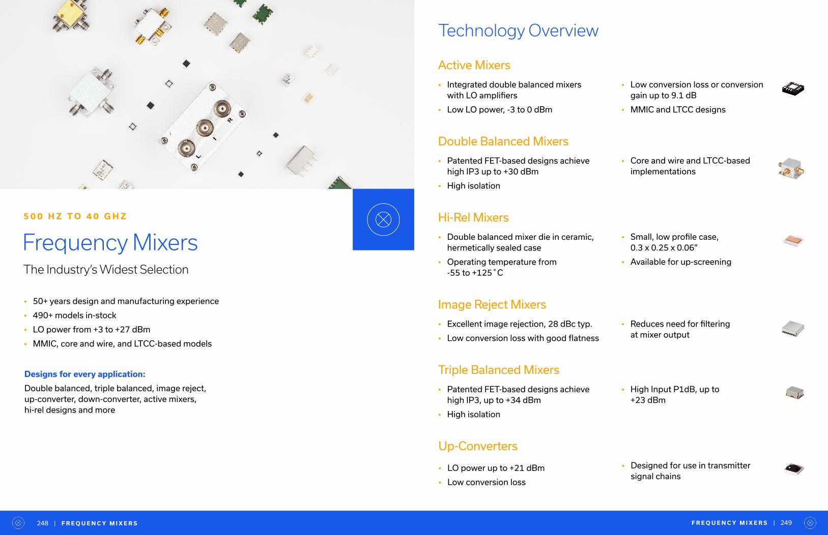
• 50+ years design and manufacturing experience
• 490+ models in-stock
• LO power from +3 to +27 dBm
• MMIC, core and wire, and LTCC-based models
Frequency MixersThe Industry’s Widest Selection
• Low conversion loss or conversion gain up to 9.1 dB
• MMIC and LTCC designs
5 0 0 H Z T O 4 0 G H Z
Designs for every application:
Double balanced, triple balanced, image reject, up-converter, down-converter, active mixers, hi-rel designs and more
Technology Overview
Active Mixers
• Integrated double balanced mixers with LO amplifiers
• Low LO power, -3 to 0 dBm
Double Balanced Mixers
• Patented FET-based designs achieve high IP3 up to +30 dBm
• High isolation
Hi-Rel Mixers
• Double balanced mixer die in ceramic, hermetically sealed case
• Operating temperature from -55 to +125˚C
Image Reject Mixers
• Excellent image rejection, 28 dBc typ.
• Low conversion loss with good flatness
Triple Balanced Mixers
• Patented FET-based designs achieve high IP3, up to +34 dBm
• High isolation
• Core and wire and LTCC-based implementations
• Reduces need for filtering at mixer output
• High Input P1dB, up to +23 dBm
• Small, low profile case, 0.3 x 0.25 x 0.06”
• Available for up-screening
Up-Converters
• LO power up to +21 dBm
• Low conversion loss
• Designed for use in transmitter signal chains
F R E Q U E N C Y M I X E R S | 249| F R E Q U E N C Y M I X E R S248
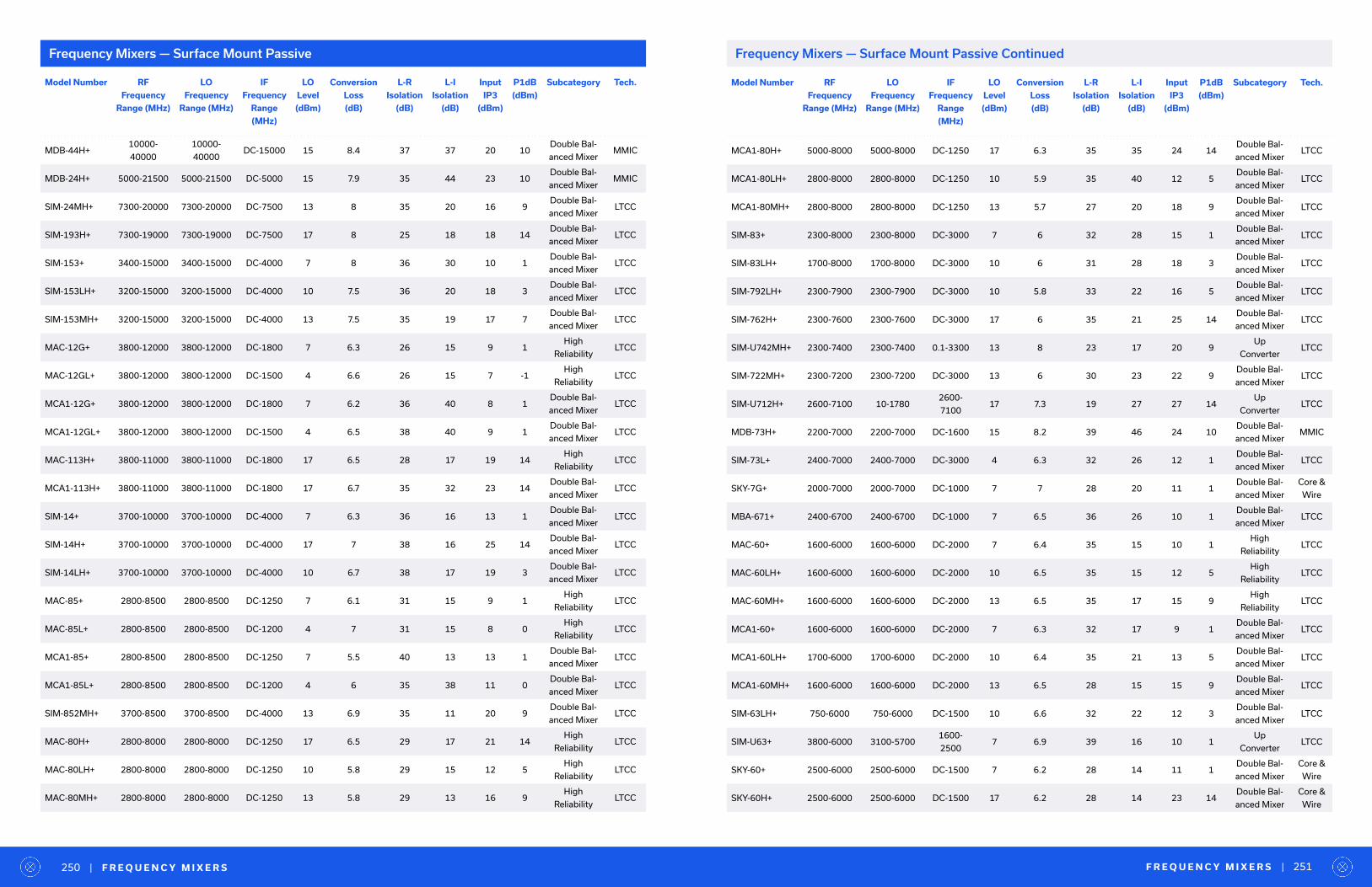
Model Number RF
Frequency
Range (MHz)
LO
Frequency
Range (MHz)
IF
Frequency
Range
(MHz)
LO
Level
(dBm)
Conversion
Loss
(dB)
L-R
Isolation
(dB)
L-I
Isolation
(dB)
Input
IP3
(dBm)
P1dB
(dBm)
Subcategory Tech.
MDB-44H+10000-
40000
10000-
40000DC-15000 15 8.4 37 37 20 10
Double Bal-
anced MixerMMIC
MDB-24H+ 5000-21500 5000-21500 DC-5000 15 7.9 35 44 23 10Double Bal-
anced MixerMMIC
SIM-24MH+ 7300-20000 7300-20000 DC-7500 13 8 35 20 16 9Double Bal-
anced MixerLTCC
SIM-193H+ 7300-19000 7300-19000 DC-7500 17 8 25 18 18 14Double Bal-
anced MixerLTCC
SIM-153+ 3400-15000 3400-15000 DC-4000 7 8 36 30 10 1Double Bal-
anced MixerLTCC
SIM-153LH+ 3200-15000 3200-15000 DC-4000 10 7.5 36 20 18 3Double Bal-
anced MixerLTCC
SIM-153MH+ 3200-15000 3200-15000 DC-4000 13 7.5 35 19 17 7Double Bal-
anced MixerLTCC
MAC-12G+ 3800-12000 3800-12000 DC-1800 7 6.3 26 15 9 1High
ReliabilityLTCC
MAC-12GL+ 3800-12000 3800-12000 DC-1500 4 6.6 26 15 7 -1High
ReliabilityLTCC
MCA1-12G+ 3800-12000 3800-12000 DC-1800 7 6.2 36 40 8 1Double Bal-
anced MixerLTCC
MCA1-12GL+ 3800-12000 3800-12000 DC-1500 4 6.5 38 40 9 1Double Bal-
anced MixerLTCC
MAC-113H+ 3800-11000 3800-11000 DC-1800 17 6.5 28 17 19 14High
ReliabilityLTCC
MCA1-113H+ 3800-11000 3800-11000 DC-1800 17 6.7 35 32 23 14Double Bal-
anced MixerLTCC
SIM-14+ 3700-10000 3700-10000 DC-4000 7 6.3 36 16 13 1Double Bal-
anced MixerLTCC
SIM-14H+ 3700-10000 3700-10000 DC-4000 17 7 38 16 25 14Double Bal-
anced MixerLTCC
SIM-14LH+ 3700-10000 3700-10000 DC-4000 10 6.7 38 17 19 3Double Bal-
anced MixerLTCC
MAC-85+ 2800-8500 2800-8500 DC-1250 7 6.1 31 15 9 1High
ReliabilityLTCC
MAC-85L+ 2800-8500 2800-8500 DC-1200 4 7 31 15 8 0High
ReliabilityLTCC
MCA1-85+ 2800-8500 2800-8500 DC-1250 7 5.5 40 13 13 1Double Bal-
anced MixerLTCC
MCA1-85L+ 2800-8500 2800-8500 DC-1200 4 6 35 38 11 0Double Bal-
anced MixerLTCC
SIM-852MH+ 3700-8500 3700-8500 DC-4000 13 6.9 35 11 20 9Double Bal-
anced MixerLTCC
MAC-80H+ 2800-8000 2800-8000 DC-1250 17 6.5 29 17 21 14High
ReliabilityLTCC
MAC-80LH+ 2800-8000 2800-8000 DC-1250 10 5.8 29 15 12 5High
ReliabilityLTCC
MAC-80MH+ 2800-8000 2800-8000 DC-1250 13 5.8 29 13 16 9High
ReliabilityLTCC
Frequency Mixers — Surface Mount Passive Frequency Mixers — Surface Mount Passive Continued
Model Number RF
Frequency
Range (MHz)
LO
Frequency
Range (MHz)
IF
Frequency
Range
(MHz)
LO
Level
(dBm)
Conversion
Loss
(dB)
L-R
Isolation
(dB)
L-I
Isolation
(dB)
Input
IP3
(dBm)
P1dB
(dBm)
Subcategory Tech.
MCA1-80H+ 5000-8000 5000-8000 DC-1250 17 6.3 35 35 24 14Double Bal-
anced MixerLTCC
MCA1-80LH+ 2800-8000 2800-8000 DC-1250 10 5.9 35 40 12 5Double Bal-
anced MixerLTCC
MCA1-80MH+ 2800-8000 2800-8000 DC-1250 13 5.7 27 20 18 9Double Bal-
anced MixerLTCC
SIM-83+ 2300-8000 2300-8000 DC-3000 7 6 32 28 15 1Double Bal-
anced MixerLTCC
SIM-83LH+ 1700-8000 1700-8000 DC-3000 10 6 31 28 18 3Double Bal-
anced MixerLTCC
SIM-792LH+ 2300-7900 2300-7900 DC-3000 10 5.8 33 22 16 5Double Bal-
anced MixerLTCC
SIM-762H+ 2300-7600 2300-7600 DC-3000 17 6 35 21 25 14Double Bal-
anced MixerLTCC
SIM-U742MH+ 2300-7400 2300-7400 0.1-3300 13 8 23 17 20 9Up
ConverterLTCC
SIM-722MH+ 2300-7200 2300-7200 DC-3000 13 6 30 23 22 9Double Bal-
anced MixerLTCC
SIM-U712H+ 2600-7100 10-17802600-
710017 7.3 19 27 27 14
Up
ConverterLTCC
MDB-73H+ 2200-7000 2200-7000 DC-1600 15 8.2 39 46 24 10Double Bal-
anced MixerMMIC
SIM-73L+ 2400-7000 2400-7000 DC-3000 4 6.3 32 26 12 1Double Bal-
anced MixerLTCC
SKY-7G+ 2000-7000 2000-7000 DC-1000 7 7 28 20 11 1Double Bal-
anced Mixer
Core &
Wire
MBA-671+ 2400-6700 2400-6700 DC-1000 7 6.5 36 26 10 1Double Bal-
anced MixerLTCC
MAC-60+ 1600-6000 1600-6000 DC-2000 7 6.4 35 15 10 1High
ReliabilityLTCC
MAC-60LH+ 1600-6000 1600-6000 DC-2000 10 6.5 35 15 12 5High
ReliabilityLTCC
MAC-60MH+ 1600-6000 1600-6000 DC-2000 13 6.5 35 17 15 9High
ReliabilityLTCC
MCA1-60+ 1600-6000 1600-6000 DC-2000 7 6.3 32 17 9 1Double Bal-
anced MixerLTCC
MCA1-60LH+ 1700-6000 1700-6000 DC-2000 10 6.4 35 21 13 5Double Bal-
anced MixerLTCC
MCA1-60MH+ 1600-6000 1600-6000 DC-2000 13 6.5 28 15 15 9Double Bal-
anced MixerLTCC
SIM-63LH+ 750-6000 750-6000 DC-1500 10 6.6 32 22 12 3Double Bal-
anced MixerLTCC
SIM-U63+ 3800-6000 3100-57001600-
25007 6.9 39 16 10 1
Up
ConverterLTCC
SKY-60+ 2500-6000 2500-6000 DC-1500 7 6.2 28 14 11 1Double Bal-
anced Mixer
Core &
Wire
SKY-60H+ 2500-6000 2500-6000 DC-1500 17 6.2 28 14 23 14Double Bal-
anced Mixer
Core &
Wire
F R E Q U E N C Y M I X E R S | 251| F R E Q U E N C Y M I X E R S250

Model Number RF
Frequency
Range (MHz)
LO
Frequency
Range (MHz)
IF
Frequency
Range
(MHz)
LO
Level
(dBm)
Conversion
Loss
(dB)
L-R
Isolation
(dB)
L-I
Isolation
(dB)
Input
IP3
(dBm)
P1dB
(dBm)
Subcategory Tech.
SKY-60LH+ 2500-6000 2500-6000 DC-1500 10 6.2 28 14 15 5Double Bal-
anced Mixer
Core &
Wire
SKY-60MH+ 2500-6000 2500-6000 DC-1500 13 6.2 28 14 19 9Double Bal-
anced Mixer
Core &
Wire
SYM-63LH+ 1-6000 1-6000 DC-1000 10 7.5 35 25 14 3Double Bal-
anced Mixer
Core &
Wire
MBA-591+ 2800-5900 2800-5900 DC-1000 7 6.5 36 26 10 1Double Bal-
anced MixerLTCC
MBA-591L+ 4950-5900 4950-5900 DC-1000 4 7 35 26 15 1Double Bal-
anced MixerLTCC
SKY-53LHR+ 2800-5300 2800-5300 DC-500 10 5.7 28 12 14 5Double Bal-
anced Mixer
Core &
Wire
MCA-50H+ 1000-5000 1000-5000 10-1500 17 7.3 30 30 23 14Triple Bal-
anced Mixer
Core &
Wire
MCA-50LH+ 1000-5000 1000-5000 10-1500 10 7.3 35 32 18 6Triple Bal-
anced Mixer
Core &
Wire
MCA-50MH+ 1000-5000 1000-5000 10-1500 13 7.3 34 30 21 9Triple Bal-
anced Mixer
Core &
Wire
LAVI-452VH+ 3220-4500 2370-3650 300-1500 23 8.6 36 32 29 20Triple Bal-
anced Mixer
Core &
Wire
ADE-42MH+ 5-4200 5-4200 5-3500 13 7.5 29 26 17 9Double Bal-
anced Mixer
Core &
Wire
MAC-42+ 1000-4200 1000-4200 DC-1500 7 6.1 35 20 10 1High
ReliabilityLTCC
MAC-42LH+ 1000-4200 1000-4200 DC-1500 10 6.1 38 20 12 5High
ReliabilityLTCC
MAC-42MH+ 1000-4200 1000-4200 DC-1500 13 6.1 35 20 16 9High
ReliabilityLTCC
MCA1-42+ 1000-4200 1000-4200 DC-1500 7 6.1 35 20 10 1Double Bal-
anced MixerLTCC
MCA1-42LH+ 1000-4200 1000-4200 DC-1500 10 6 38 20 12 5Double Bal-
anced MixerLTCC
MCA1-42MH+ 1000-4200 1000-4200 DC-1500 13 6.2 32 20 16 9Double Bal-
anced MixerLTCC
RMS-42MH+ 800-4200 800-4200 DC-800 13 5.3 28 15 19 9Double Bal-
anced Mixer
Core &
Wire
SIM-43+ 750-4200 750-4200 DC-1500 7 6.3 37 24 12 1Double Bal-
anced MixerLTCC
SIM-43LH+ 824-4200 824-4200 DC-1500 10 6.3 37 24 14 5Double Bal-
anced MixerLTCC
SIM-43MH+ 824-4200 824-4200 DC-1500 13 6.3 37 24 20 9Double Bal-
anced MixerLTCC
HJK-412H+ 2400-4100 3700-54001200-
180017 10.7 30 35 25 14
Triple Bal-
anced Mixer
Core &
Wire
ADE-30W+ 300-4000 300-4000 DC-950 7 6.8 35 16 12 1Double Bal-
anced Mixer
Core &
Wire
ADE-R30W+ 300-4000 300-4000 DC-950 7 6 38 13 12 1High
Reliability
Core &
Wire
Model Number RF
Frequency
Range (MHz)
LO
Frequency
Range (MHz)
IF
Frequency
Range
(MHz)
LO
Level
(dBm)
Conversion
Loss
(dB)
L-R
Isolation
(dB)
L-I
Isolation
(dB)
Input
IP3
(dBm)
P1dB
(dBm)
Subcategory Tech.
ADE-R30WLH+ 300-4000 300-4000 DC-950 10 7.5 40 16 15 5High
Reliability
Core &
Wire
SIM-43H+ 1000-4000 1000-4000 DC-1500 17 6.5 37 24 22 14Double Bal-
anced MixerLTCC
SIM-U432H+ 1100-3900 1100-4250 0.1-800 17 7.5 36 24 26 14Up
ConverterLTCC
HJK-372H+ 420-3730 610-3920 100-600 17 7.5 35 33 24 14Triple Bal-
anced Mixer
Core &
Wire
MBA-25LH+ 2200-3600 2200-3600 DC-500 10 7 32 20 12 4Double Bal-
anced MixerLTCC
SYM-36H+ 1500-3600 1500-3600 DC-600 17 6.3 30 34 25 14Double Bal-
anced Mixer
Core &
Wire
ADE-18W+ 1750-3500 1750-3500 DC-700 7 5.4 33 12 11 1Double Bal-
anced Mixer
Core &
Wire
ADE-35+ 1600-3500 1600-3500 DC-1500 7 6.3 25 22 11 1Double Bal-
anced Mixer
Core &
Wire
ADE-35MH+ 5-3500 5-3500 5-2500 13 6.9 33 28 18 9Double Bal-
anced Mixer
Core &
Wire
MCA-35H+ 500-3500 500-3500 10-1500 17 6.9 30 30 24 14Triple Bal-
anced Mixer
Core &
Wire
MCA-35MH+ 500-3500 500-3500 10-1500 13 6.9 29 29 20 9Triple Bal-
anced Mixer
Core &
Wire
MBA-18LH+ 1600-3200 1600-3200 DC-500 10 5.8 30 22 12 5Double Bal-
anced MixerLTCC
LAVI-362VH+ 100-3100 1800-3600 500-2500 22 7.5 40 35 33 20Triple Bal-
anced Mixer
Core &
Wire
ADE-30+ 200-3000 200-3000 DC-1000 7 4.5 35 20 14 1Double Bal-
anced Mixer
Core &
Wire
JYM-30H+ 2-3000 2-3000 4-1400 17 6 40 30 24 10Double Bal-
anced Mixer
Core &
Wire
LRMS-30J+ 200-3000 200-3000 DC-1000 7 6.8 30 27 14 1Double Bal-
anced Mixer
Core &
Wire
MBA-25L+ 2000-3000 2000-3000 DC-600 4 6.2 28 15 10 0Double Bal-
anced MixerLTCC
MBA-25MH+ 2000-3000 2000-3000 DC-500 13 6.5 36 20 16 8Double Bal-
anced MixerLTCC
RMS-30+ 200-3000 200-3000 DC-1000 7 6.5 27 20 11 1Double Bal-
anced Mixer
Core &
Wire
SYM-30DHW+ 5-3000 5-3000 5-1500 17 6.5 40 25 29 14Triple Bal-
anced Mixer
Core &
Wire
SYM-30DL-
HW+5-3000 5-3000 5-1500 10 6.5 27 45 19 5
Double Bal-
anced Mixer
Core &
Wire
SYM-30DM-
HW+5-3000 5-3000 5-1500 13 6.5 39 42 22 9
Double Bal-
anced Mixer
Core &
Wire
ADE-R20+ 1500-2800 1500-2800 DC-500 7 5.8 30 28 12 1High
Reliability
Core &
Wire
JYM-28H+ 400-2800 400-2800 4-700 17 6.3 40 30 23 10Double Bal-
anced Mixer
Core &
Wire
F R E Q U E N C Y M I X E R S | 253| F R E Q U E N C Y M I X E R S252
Frequency Mixers — Surface Mount Passive ContinuedFrequency Mixers — Surface Mount Passive Continued

Model Number RF
Frequency
Range (MHz)
LO
Frequency
Range (MHz)
IF
Frequency
Range
(MHz)
LO
Level
(dBm)
Conversion
Loss
(dB)
L-R
Isolation
(dB)
L-I
Isolation
(dB)
Input
IP3
(dBm)
P1dB
(dBm)
Subcategory Tech.
ADE-3G+ 2300-2700 2300-2700 DC-400 7 5.6 36 26 13 1Double Bal-
anced Mixer
Core &
Wire
ADE-R3GLH+ 2000-2700 2000-2700 DC-700 10 5.2 35 23 14 4High
Reliability
Core &
Wire
ADE-R272MH+ 1300-2700 1300-2700 DC-600 13 5.6 34 25 18 9High
Reliability
Core &
Wire
HJK-272H+ 600-2700 600-2700 10-1000 17 7.7 35 23 25 20Double Bal-
anced Mixer
Core &
Wire
HJK-272MH+ 600-2700 600-2700 10-1000 13 7.4 37 27 21 16Double Bal-
anced Mixer
Core &
Wire
ADE-3GL+ 2100-2600 2100-2600 DC-600 7 6 34 20 17 1Double Bal-
anced Mixer
Core &
Wire
ADE-25MH+ 5-2500 5-2500 5-1500 13 6.9 34 32 18 9Double Bal-
anced Mixer
Core &
Wire
LAVI-25VH+ 400-2500 660-2800 70-1500 23 7.8 50 45 32 20Triple Bal-
anced Mixer
Core &
Wire
LAVI-252H+ 200-2500 130-2430 50-2000 17 7.8 40 45 25 17Triple Bal-
anced Mixer
Core &
Wire
LAVI-252VH+ 1850-2500 1920-2570 60-750 20 7.5 45 40 30 20Triple Bal-
anced Mixer
Core &
Wire
LAVI-U252VH+ 1500-2500 1800-2800 10-1300 21 7.8 45 51 30 16Up
Converter
Core &
Wire
LRMS-25J+ 750-2500 750-2500 DC-600 10 5.2 35 20 18 5Double Bal-
anced Mixer
Core &
Wire
RMS-25MH+ 5-2500 5-2500 5-1500 13 7 32 32 17 9Double Bal-
anced Mixer
Core &
Wire
SCM-2500+ 500-2500 500-2500 DC-500 7 5.88 35 18 13 1Double Bal-
anced Mixer
Core &
Wire
SCM-2500LH+ 500-2500 500-2500 DC-500 10 5.6 35 18 16 5Double Bal-
anced Mixer
Core &
Wire
SYM-11+ 1-2500 1-2500 10-600 7 7 40 35 10 1Double Bal-
anced Mixer
Core &
Wire
SYM-25DHW+ 80-2500 80-2500 DC-1000 17 6.4 37 33 30 14Triple Bal-
anced Mixer
Core &
Wire
SYM-25DL-
HW+40-2500 40-2500 DC-1000 10 6.3 40 33 22 5
Double Bal-
anced Mixer
Core &
Wire
SYM-25DM-
HW+40-2500 40-2500 DC-1000 13 6.6 37 38 26 9
Double Bal-
anced Mixer
Core &
Wire
SYM-2500+ 1-2500 1-2500 DC-500 7 6.5 50 30 12 1Double Bal-
anced Mixer
Core &
Wire
SYM-
R252HW+10-2500 10-2500 10-500 17 6.5 40 40 23 14
Double Bal-
anced Mixer
Core &
Wire
MAC-24+ 300-2400 300-2400 DC-700 7 6 40 24 10 1High
ReliabilityLTCC
MAC-24LH+ 300-2400 300-2400 DC-700 10 6.1 40 24 12 5High
ReliabilityLTCC
MAC-24MH+ 300-2400 300-2400 DC-700 13 6.1 40 24 14 9High
ReliabilityLTCC
Model Number RF
Frequency
Range (MHz)
LO
Frequency
Range (MHz)
IF
Frequency
Range
(MHz)
LO
Level
(dBm)
Conversion
Loss
(dB)
L-R
Isolation
(dB)
L-I
Isolation
(dB)
Input
IP3
(dBm)
P1dB
(dBm)
Subcategory Tech.
MBA-15L+ 1200-2400 1200-2400 DC-600 4 6.5 27 14 10 0Double Bal-
anced MixerLTCC
MBA-15LH+ 1200-2400 1200-2400 DC-600 10 5.6 26 22 15 5Double Bal-
anced MixerLTCC
MBA-15MH+ 1400-2400 1400-2400 DC-600 13 5.5 28 16 18 8Double Bal-
anced MixerLTCC
MCA1-24+ 300-2400 300-2400 DC-700 7 6.1 40 25 10 1Double Bal-
anced MixerLTCC
MCA1-24LH+ 300-2400 300-2400 DC-700 10 6.5 40 22 13 5Double Bal-
anced MixerLTCC
MCA1-24MH+ 300-2400 300-2400 DC-700 13 6.1 40 25 13 9Double Bal-
anced MixerLTCC
SYM-24DH+ 1400-2400 1400-2400 10-250 17 7 32 36 29 14Triple Bal-
anced Mixer
Core &
Wire
HJK-U232H+ 1220-2360 370-510 850-1850 17 6.8 46 35 31 20Up
Converter
Core &
Wire
LAVI-22VH+ 425-2200 525-2400 100-700 21 7.7 50 45 31 20Triple Bal-
anced Mixer
Core &
Wire
ADE-11X+ 10-2000 10-2000 5-1000 7 7.1 36 37 9 1Double Bal-
anced Mixer
Core &
Wire
ADE-20+ 1500-2000 1500-2000 DC-300 7 5.4 31 28 14 1Double Bal-
anced Mixer
Core &
Wire
ADE-R11X+ 10-2000 10-2000 10-1000 7 7.5 40 42 10 1High
Reliability
Core &
Wire
ADE-R11XLH+ 10-2000 10-2000 10-1000 10 7.5 36 45 11 5High
Reliability
Core &
Wire
LAVI-23VH+ 1200-2000 1270-2070 50-1000 20 8.4 58 40 30 20Triple Bal-
anced Mixer
Core &
Wire
LRMS-20J+ 1500-2000 1500-2000 DC-500 10 5 35 26 18 5Double Bal-
anced Mixer
Core &
Wire
RMS-11F+ 350-2000 350-2000 DC-400 7 5.5 36 29 12 1Double Bal-
anced Mixer
Core &
Wire
SYM-11LH+ 1-2000 1-2000 10-600 10 7 45 33 14 5Double Bal-
anced Mixer
Core &
Wire
SYM-20DHW+ 10-2000 10-2000 10-1800 17 6.2 40 42 27 14Triple Bal-
anced Mixer
Core &
Wire
HJK-212H+ 1660-1960 1800-2100 10-270 17 6.5 42 35 32 20Triple Bal-
anced Mixer
Core &
Wire
JMS-11X+ 5-1900 5-1900 5-1000 7 6.7 35 37 9 1Double Bal-
anced Mixer
Core &
Wire
RMS-11X+ 5-1900 5-1900 5-1000 7 7.1 35 37 10 1Double Bal-
anced Mixer
Core &
Wire
LAVI-U182H+ 1560-1800 1490-1730 10-250 19 8.3 53 40 32 15Up
Converter
Core &
Wire
SYM-18H+ 5-1800 5-1800 10-1500 17 5.8 45 50 30 14Triple Bal-
anced Mixer
Core &
Wire
TUF-18DHSM+ 100-1800 100-1800 50-750 17 7.3 41 33 27 10Triple Bal-
anced Mixer
Core &
Wire
F R E Q U E N C Y M I X E R S | 255| F R E Q U E N C Y M I X E R S254
Frequency Mixers — Surface Mount Passive ContinuedFrequency Mixers — Surface Mount Passive Continued
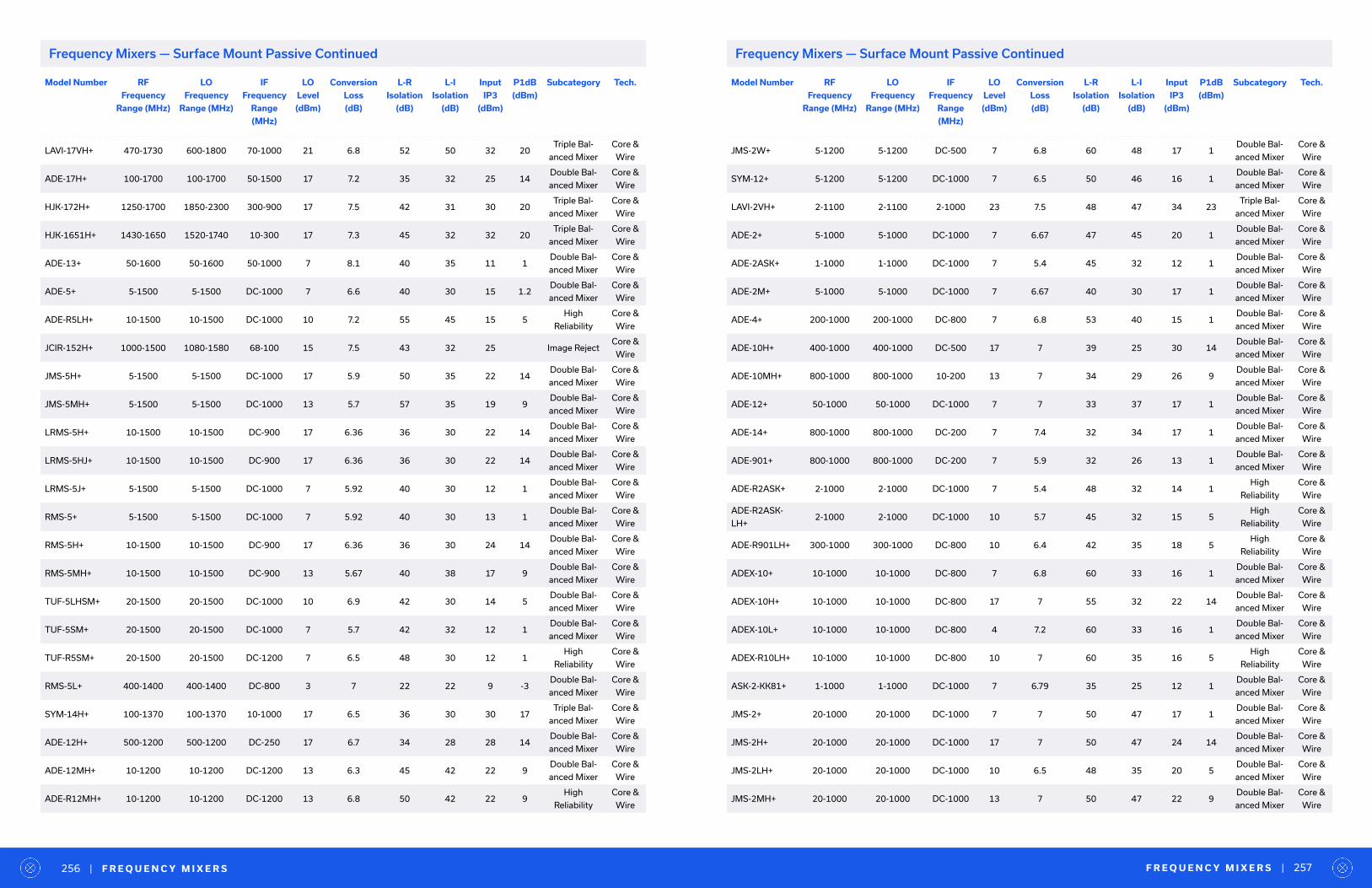
Model Number RF
Frequency
Range (MHz)
LO
Frequency
Range (MHz)
IF
Frequency
Range
(MHz)
LO
Level
(dBm)
Conversion
Loss
(dB)
L-R
Isolation
(dB)
L-I
Isolation
(dB)
Input
IP3
(dBm)
P1dB
(dBm)
Subcategory Tech.
LAVI-17VH+ 470-1730 600-1800 70-1000 21 6.8 52 50 32 20Triple Bal-
anced Mixer
Core &
Wire
ADE-17H+ 100-1700 100-1700 50-1500 17 7.2 35 32 25 14Double Bal-
anced Mixer
Core &
Wire
HJK-172H+ 1250-1700 1850-2300 300-900 17 7.5 42 31 30 20Triple Bal-
anced Mixer
Core &
Wire
HJK-1651H+ 1430-1650 1520-1740 10-300 17 7.3 45 32 32 20Triple Bal-
anced Mixer
Core &
Wire
ADE-13+ 50-1600 50-1600 50-1000 7 8.1 40 35 11 1Double Bal-
anced Mixer
Core &
Wire
ADE-5+ 5-1500 5-1500 DC-1000 7 6.6 40 30 15 1.2Double Bal-
anced Mixer
Core &
Wire
ADE-R5LH+ 10-1500 10-1500 DC-1000 10 7.2 55 45 15 5High
Reliability
Core &
Wire
JCIR-152H+ 1000-1500 1080-1580 68-100 15 7.5 43 32 25 Image RejectCore &
Wire
JMS-5H+ 5-1500 5-1500 DC-1000 17 5.9 50 35 22 14Double Bal-
anced Mixer
Core &
Wire
JMS-5MH+ 5-1500 5-1500 DC-1000 13 5.7 57 35 19 9Double Bal-
anced Mixer
Core &
Wire
LRMS-5H+ 10-1500 10-1500 DC-900 17 6.36 36 30 22 14Double Bal-
anced Mixer
Core &
Wire
LRMS-5HJ+ 10-1500 10-1500 DC-900 17 6.36 36 30 22 14Double Bal-
anced Mixer
Core &
Wire
LRMS-5J+ 5-1500 5-1500 DC-1000 7 5.92 40 30 12 1Double Bal-
anced Mixer
Core &
Wire
RMS-5+ 5-1500 5-1500 DC-1000 7 5.92 40 30 13 1Double Bal-
anced Mixer
Core &
Wire
RMS-5H+ 10-1500 10-1500 DC-900 17 6.36 36 30 24 14Double Bal-
anced Mixer
Core &
Wire
RMS-5MH+ 10-1500 10-1500 DC-900 13 5.67 40 38 17 9Double Bal-
anced Mixer
Core &
Wire
TUF-5LHSM+ 20-1500 20-1500 DC-1000 10 6.9 42 30 14 5Double Bal-
anced Mixer
Core &
Wire
TUF-5SM+ 20-1500 20-1500 DC-1000 7 5.7 42 32 12 1Double Bal-
anced Mixer
Core &
Wire
TUF-R5SM+ 20-1500 20-1500 DC-1200 7 6.5 48 30 12 1High
Reliability
Core &
Wire
RMS-5L+ 400-1400 400-1400 DC-800 3 7 22 22 9 -3Double Bal-
anced Mixer
Core &
Wire
SYM-14H+ 100-1370 100-1370 10-1000 17 6.5 36 30 30 17Triple Bal-
anced Mixer
Core &
Wire
ADE-12H+ 500-1200 500-1200 DC-250 17 6.7 34 28 28 14Double Bal-
anced Mixer
Core &
Wire
ADE-12MH+ 10-1200 10-1200 DC-1200 13 6.3 45 42 22 9Double Bal-
anced Mixer
Core &
Wire
ADE-R12MH+ 10-1200 10-1200 DC-1200 13 6.8 50 42 22 9High
Reliability
Core &
Wire
Model Number RF
Frequency
Range (MHz)
LO
Frequency
Range (MHz)
IF
Frequency
Range
(MHz)
LO
Level
(dBm)
Conversion
Loss
(dB)
L-R
Isolation
(dB)
L-I
Isolation
(dB)
Input
IP3
(dBm)
P1dB
(dBm)
Subcategory Tech.
JMS-2W+ 5-1200 5-1200 DC-500 7 6.8 60 48 17 1Double Bal-
anced Mixer
Core &
Wire
SYM-12+ 5-1200 5-1200 DC-1000 7 6.5 50 46 16 1Double Bal-
anced Mixer
Core &
Wire
LAVI-2VH+ 2-1100 2-1100 2-1000 23 7.5 48 47 34 23Triple Bal-
anced Mixer
Core &
Wire
ADE-2+ 5-1000 5-1000 DC-1000 7 6.67 47 45 20 1Double Bal-
anced Mixer
Core &
Wire
ADE-2ASK+ 1-1000 1-1000 DC-1000 7 5.4 45 32 12 1Double Bal-
anced Mixer
Core &
Wire
ADE-2M+ 5-1000 5-1000 DC-1000 7 6.67 40 30 17 1Double Bal-
anced Mixer
Core &
Wire
ADE-4+ 200-1000 200-1000 DC-800 7 6.8 53 40 15 1Double Bal-
anced Mixer
Core &
Wire
ADE-10H+ 400-1000 400-1000 DC-500 17 7 39 25 30 14Double Bal-
anced Mixer
Core &
Wire
ADE-10MH+ 800-1000 800-1000 10-200 13 7 34 29 26 9Double Bal-
anced Mixer
Core &
Wire
ADE-12+ 50-1000 50-1000 DC-1000 7 7 33 37 17 1Double Bal-
anced Mixer
Core &
Wire
ADE-14+ 800-1000 800-1000 DC-200 7 7.4 32 34 17 1Double Bal-
anced Mixer
Core &
Wire
ADE-901+ 800-1000 800-1000 DC-200 7 5.9 32 26 13 1Double Bal-
anced Mixer
Core &
Wire
ADE-R2ASK+ 2-1000 2-1000 DC-1000 7 5.4 48 32 14 1High
Reliability
Core &
Wire
ADE-R2ASK-
LH+2-1000 2-1000 DC-1000 10 5.7 45 32 15 5
High
Reliability
Core &
Wire
ADE-R901LH+ 300-1000 300-1000 DC-800 10 6.4 42 35 18 5High
Reliability
Core &
Wire
ADEX-10+ 10-1000 10-1000 DC-800 7 6.8 60 33 16 1Double Bal-
anced Mixer
Core &
Wire
ADEX-10H+ 10-1000 10-1000 DC-800 17 7 55 32 22 14Double Bal-
anced Mixer
Core &
Wire
ADEX-10L+ 10-1000 10-1000 DC-800 4 7.2 60 33 16 1Double Bal-
anced Mixer
Core &
Wire
ADEX-R10LH+ 10-1000 10-1000 DC-800 10 7 60 35 16 5High
Reliability
Core &
Wire
ASK-2-KK81+ 1-1000 1-1000 DC-1000 7 6.79 35 25 12 1Double Bal-
anced Mixer
Core &
Wire
JMS-2+ 20-1000 20-1000 DC-1000 7 7 50 47 17 1Double Bal-
anced Mixer
Core &
Wire
JMS-2H+ 20-1000 20-1000 DC-1000 17 7 50 47 24 14Double Bal-
anced Mixer
Core &
Wire
JMS-2LH+ 20-1000 20-1000 DC-1000 10 6.5 48 35 20 5Double Bal-
anced Mixer
Core &
Wire
JMS-2MH+ 20-1000 20-1000 DC-1000 13 7 50 47 22 9Double Bal-
anced Mixer
Core &
Wire
F R E Q U E N C Y M I X E R S | 257| F R E Q U E N C Y M I X E R S256
Frequency Mixers — Surface Mount Passive ContinuedFrequency Mixers — Surface Mount Passive Continued
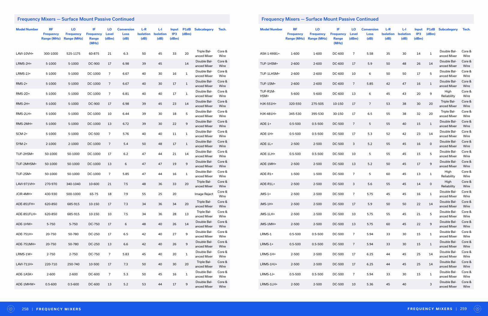
Model Number RF
Frequency
Range (MHz)
LO
Frequency
Range (MHz)
IF
Frequency
Range
(MHz)
LO
Level
(dBm)
Conversion
Loss
(dB)
L-R
Isolation
(dB)
L-I
Isolation
(dB)
Input
IP3
(dBm)
P1dB
(dBm)
Subcategory Tech.
LAVI-10VH+ 300-1000 525-1175 60-875 21 6.3 50 45 33 20Triple Bal-
anced Mixer
Core &
Wire
LRMS-2H+ 5-1000 5-1000 DC-900 17 6.98 39 45 14Double Bal-
anced Mixer
Core &
Wire
LRMS-2J+ 5-1000 5-1000 DC-1000 7 6.67 40 30 16 1Double Bal-
anced Mixer
Core &
Wire
RMS-2+ 5-1000 5-1000 DC-1000 7 6.67 40 30 17 1Double Bal-
anced Mixer
Core &
Wire
RMS-2D+ 5-1000 5-1000 DC-1000 7 6.81 40 40 17 1Double Bal-
anced Mixer
Core &
Wire
RMS-2H+ 5-1000 5-1000 DC-900 17 6.98 39 45 23 14Double Bal-
anced Mixer
Core &
Wire
RMS-2LH+ 5-1000 5-1000 DC-1000 10 6.44 39 30 18 5Double Bal-
anced Mixer
Core &
Wire
RMS-2MH+ 5-1000 5-1000 DC-1000 13 6.72 39 30 22 9Double Bal-
anced Mixer
Core &
Wire
SCM-2+ 5-1000 5-1000 DC-500 7 5.76 40 40 11 1Double Bal-
anced Mixer
Core &
Wire
SYM-2+ 2-1000 2-1000 DC-1000 7 5.4 50 48 17 1Double Bal-
anced Mixer
Core &
Wire
TUF-2HSM+ 50-1000 50-1000 DC-1000 17 6.2 47 44 21 14Double Bal-
anced Mixer
Core &
Wire
TUF-2MHSM+ 50-1000 50-1000 DC-1000 13 6 47 47 19 9Double Bal-
anced Mixer
Core &
Wire
TUF-2SM+ 50-1000 50-1000 DC-1000 7 5.85 47 44 16 1Double Bal-
anced Mixer
Core &
Wire
LAVI-971VH+ 270-970 340-1040 10-600 21 7.5 48 36 33 20Triple Bal-
anced Mixer
Core &
Wire
JCIR-4MH+ 430-930 500-1000 65-75 18 7.9 55 25 20 Image RejectCore &
Wire
ADE-851FH+ 620-850 685-915 10-150 17 7.3 34 36 34 20Triple Bal-
anced Mixer
Core &
Wire
ADE-851FLH+ 620-850 685-915 10-150 10 7.5 34 36 28 13Triple Bal-
anced Mixer
Core &
Wire
ADE-1HW+ 5-750 5-750 DC-750 17 6 48 40 26 14Double Bal-
anced Mixer
Core &
Wire
ADE-751H+ 20-750 50-780 DC-250 17 6.5 42 40 27 9Double Bal-
anced Mixer
Core &
Wire
ADE-751MH+ 20-750 50-780 DC-250 13 6.6 42 40 26 9Double Bal-
anced Mixer
Core &
Wire
LRMS-1W+ 2-750 2-750 DC-750 7 5.83 45 40 20 1Double Bal-
anced Mixer
Core &
Wire
LAVI-711H+ 220-710 250-740 10-500 17 7.3 50 40 30 20Triple Bal-
anced Mixer
Core &
Wire
ADE-1ASK+ 2-600 2-600 DC-600 7 5.3 50 45 16 1Double Bal-
anced Mixer
Core &
Wire
ADE-1MHW+ 0.5-600 0.5-600 DC-600 13 5.2 53 44 17 9Double Bal-
anced Mixer
Core &
Wire
Model Number RF
Frequency
Range (MHz)
LO
Frequency
Range (MHz)
IF
Frequency
Range
(MHz)
LO
Level
(dBm)
Conversion
Loss
(dB)
L-R
Isolation
(dB)
L-I
Isolation
(dB)
Input
IP3
(dBm)
P1dB
(dBm)
Subcategory Tech.
ASK-1-KK81+ 1-600 1-600 DC-600 7 5.58 35 30 14 1Double Bal-
anced Mixer
Core &
Wire
TUF-1HSM+ 2-600 2-600 DC-600 17 5.9 50 48 26 14Double Bal-
anced Mixer
Core &
Wire
TUF-1LHSM+ 2-600 2-600 DC-600 10 6 50 50 17 5Double Bal-
anced Mixer
Core &
Wire
TUF-1SM+ 2-600 2-600 DC-600 7 5.85 42 47 16 1Double Bal-
anced Mixer
Core &
Wire
TUF-R1M-
HSM+5-600 5-600 DC-600 13 6 45 43 20 9
High
Reliability
Core &
Wire
HJK-551H+ 320-550 275-505 10-150 17 7 53 38 30 20Triple Bal-
anced Mixer
Core &
Wire
HJK-481H+ 345-530 395-530 30-150 17 6.5 55 38 32 20Triple Bal-
anced Mixer
Core &
Wire
ADE-1+ 0.5-500 0.5-500 DC-500 7 5 55 40 15 1Double Bal-
anced Mixer
Core &
Wire
ADE-1H+ 0.5-500 0.5-500 DC-500 17 5.3 52 42 23 14Double Bal-
anced Mixer
Core &
Wire
ADE-1L+ 2-500 2-500 DC-500 3 5.2 55 45 16 0Double Bal-
anced Mixer
Core &
Wire
ADE-1LH+ 0.5-500 0.5-500 DC-500 10 5 55 45 15 5Double Bal-
anced Mixer
Core &
Wire
ADE-1MH+ 2-500 2-500 DC-500 13 5.2 50 45 17 9Double Bal-
anced Mixer
Core &
Wire
ADE-R1+ 1-500 1-500 DC-500 7 5 60 45 13 1High
Reliability
Core &
Wire
ADE-R1L+ 2-500 2-500 DC-500 3 5.6 55 45 14 0High
Reliability
Core &
Wire
JMS-1+ 2-500 2-500 DC-500 7 5.75 45 45 16 1Double Bal-
anced Mixer
Core &
Wire
JMS-1H+ 2-500 2-500 DC-500 17 5.9 50 50 22 14Double Bal-
anced Mixer
Core &
Wire
JMS-1LH+ 2-500 2-500 DC-500 10 5.75 55 45 21 5Double Bal-
anced Mixer
Core &
Wire
JMS-1MH+ 2-500 2-500 DC-500 13 5.75 60 45 22 9Double Bal-
anced Mixer
Core &
Wire
LRMS-1 0.5-500 0.5-500 DC-500 7 5.94 33 30 15 1Double Bal-
anced Mixer
Core &
Wire
LRMS-1+ 0.5-500 0.5-500 DC-500 7 5.94 33 30 15 1Double Bal-
anced Mixer
Core &
Wire
LRMS-1H+ 2-500 2-500 DC-500 17 6.25 44 45 25 14Double Bal-
anced Mixer
Core &
Wire
LRMS-1HJ+ 2-500 2-500 DC-500 17 6.25 44 45 25 14Double Bal-
anced Mixer
Core &
Wire
LRMS-1J+ 0.5-500 0.5-500 DC-500 7 5.94 33 30 15 1Double Bal-
anced Mixer
Core &
Wire
LRMS-1LH+ 2-500 2-500 DC-500 10 5.36 45 40 3Double Bal-
anced Mixer
Core &
Wire
F R E Q U E N C Y M I X E R S | 259| F R E Q U E N C Y M I X E R S258
Frequency Mixers — Surface Mount Passive ContinuedFrequency Mixers — Surface Mount Passive Continued
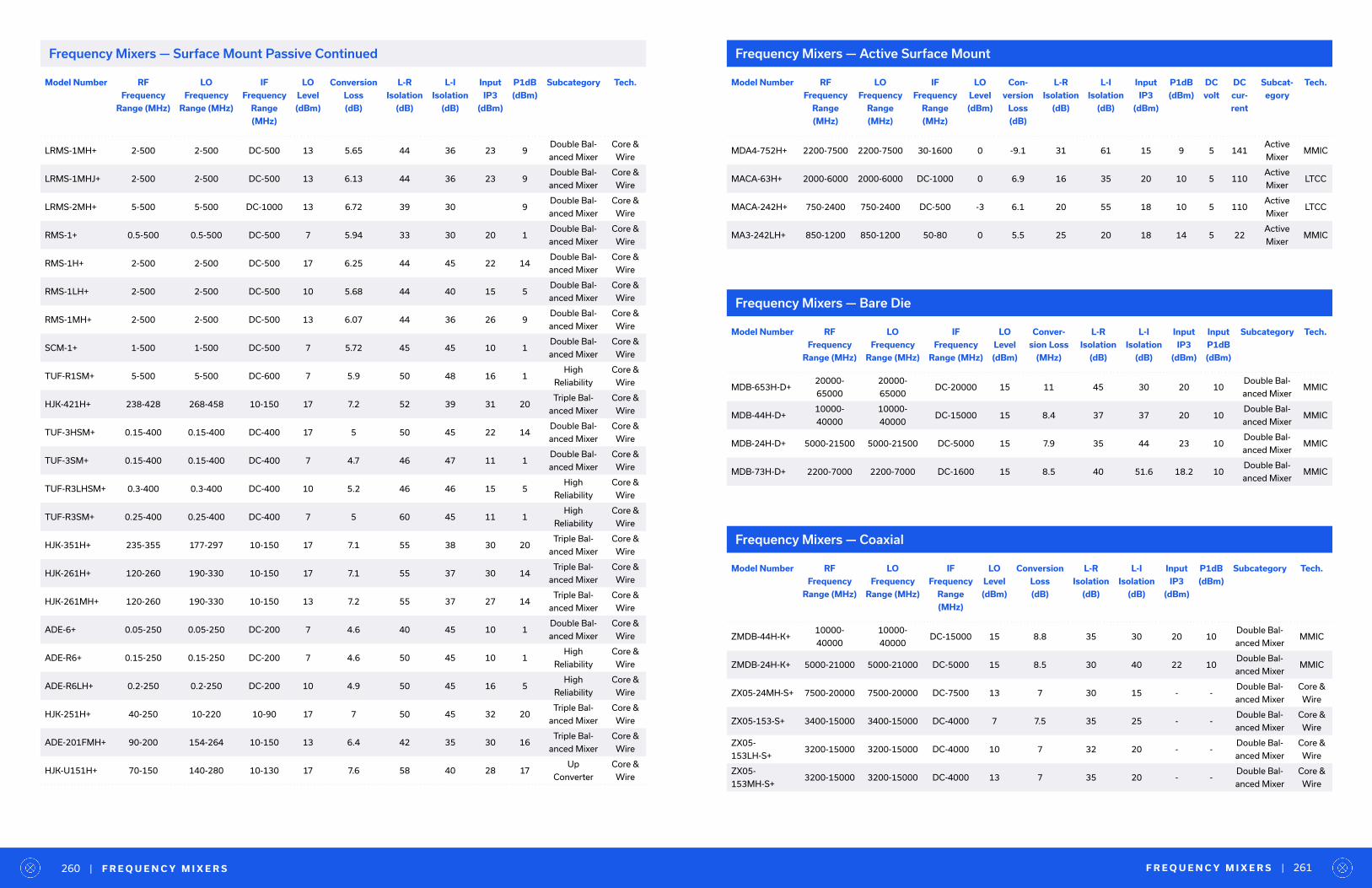
Model Number RF
Frequency
Range (MHz)
LO
Frequency
Range (MHz)
IF
Frequency
Range
(MHz)
LO
Level
(dBm)
Conversion
Loss
(dB)
L-R
Isolation
(dB)
L-I
Isolation
(dB)
Input
IP3
(dBm)
P1dB
(dBm)
Subcategory Tech.
LRMS-1MH+ 2-500 2-500 DC-500 13 5.65 44 36 23 9Double Bal-
anced Mixer
Core &
Wire
LRMS-1MHJ+ 2-500 2-500 DC-500 13 6.13 44 36 23 9Double Bal-
anced Mixer
Core &
Wire
LRMS-2MH+ 5-500 5-500 DC-1000 13 6.72 39 30 9Double Bal-
anced Mixer
Core &
Wire
RMS-1+ 0.5-500 0.5-500 DC-500 7 5.94 33 30 20 1Double Bal-
anced Mixer
Core &
Wire
RMS-1H+ 2-500 2-500 DC-500 17 6.25 44 45 22 14Double Bal-
anced Mixer
Core &
Wire
RMS-1LH+ 2-500 2-500 DC-500 10 5.68 44 40 15 5Double Bal-
anced Mixer
Core &
Wire
RMS-1MH+ 2-500 2-500 DC-500 13 6.07 44 36 26 9Double Bal-
anced Mixer
Core &
Wire
SCM-1+ 1-500 1-500 DC-500 7 5.72 45 45 10 1Double Bal-
anced Mixer
Core &
Wire
TUF-R1SM+ 5-500 5-500 DC-600 7 5.9 50 48 16 1High
Reliability
Core &
Wire
HJK-421H+ 238-428 268-458 10-150 17 7.2 52 39 31 20Triple Bal-
anced Mixer
Core &
Wire
TUF-3HSM+ 0.15-400 0.15-400 DC-400 17 5 50 45 22 14Double Bal-
anced Mixer
Core &
Wire
TUF-3SM+ 0.15-400 0.15-400 DC-400 7 4.7 46 47 11 1Double Bal-
anced Mixer
Core &
Wire
TUF-R3LHSM+ 0.3-400 0.3-400 DC-400 10 5.2 46 46 15 5High
Reliability
Core &
Wire
TUF-R3SM+ 0.25-400 0.25-400 DC-400 7 5 60 45 11 1High
Reliability
Core &
Wire
HJK-351H+ 235-355 177-297 10-150 17 7.1 55 38 30 20Triple Bal-
anced Mixer
Core &
Wire
HJK-261H+ 120-260 190-330 10-150 17 7.1 55 37 30 14Triple Bal-
anced Mixer
Core &
Wire
HJK-261MH+ 120-260 190-330 10-150 13 7.2 55 37 27 14Triple Bal-
anced Mixer
Core &
Wire
ADE-6+ 0.05-250 0.05-250 DC-200 7 4.6 40 45 10 1Double Bal-
anced Mixer
Core &
Wire
ADE-R6+ 0.15-250 0.15-250 DC-200 7 4.6 50 45 10 1High
Reliability
Core &
Wire
ADE-R6LH+ 0.2-250 0.2-250 DC-200 10 4.9 50 45 16 5High
Reliability
Core &
Wire
HJK-251H+ 40-250 10-220 10-90 17 7 50 45 32 20Triple Bal-
anced Mixer
Core &
Wire
ADE-201FMH+ 90-200 154-264 10-150 13 6.4 42 35 30 16Triple Bal-
anced Mixer
Core &
Wire
HJK-U151H+ 70-150 140-280 10-130 17 7.6 58 40 28 17Up
Converter
Core &
Wire
Model Number RF
Frequency
Range (MHz)
LO
Frequency
Range (MHz)
IF
Frequency
Range
(MHz)
LO
Level
(dBm)
Conversion
Loss
(dB)
L-R
Isolation
(dB)
L-I
Isolation
(dB)
Input
IP3
(dBm)
P1dB
(dBm)
Subcategory Tech.
ZMDB-44H-K+10000-
40000
10000-
40000DC-15000 15 8.8 35 30 20 10
Double Bal-
anced MixerMMIC
ZMDB-24H-K+ 5000-21000 5000-21000 DC-5000 15 8.5 30 40 22 10Double Bal-
anced MixerMMIC
ZX05-24MH-S+ 7500-20000 7500-20000 DC-7500 13 7 30 15 - -Double Bal-
anced Mixer
Core &
Wire
ZX05-153-S+ 3400-15000 3400-15000 DC-4000 7 7.5 35 25 - -Double Bal-
anced Mixer
Core &
Wire
ZX05-
153LH-S+3200-15000 3200-15000 DC-4000 10 7 32 20 - -
Double Bal-
anced Mixer
Core &
Wire
ZX05-
153MH-S+3200-15000 3200-15000 DC-4000 13 7 35 20 - -
Double Bal-
anced Mixer
Core &
Wire
Model Number RF
Frequency
Range (MHz)
LO
Frequency
Range (MHz)
IF
Frequency
Range (MHz)
LO
Level
(dBm)
Conver-
sion Loss
(MHz)
L-R
Isolation
(dB)
L-I
Isolation
(dB)
Input
IP3
(dBm)
Input
P1dB
(dBm)
Subcategory Tech.
MDB-653H-D+20000-
65000
20000-
65000DC-20000 15 11 45 30 20 10
Double Bal-
anced MixerMMIC
MDB-44H-D+10000-
40000
10000-
40000DC-15000 15 8.4 37 37 20 10
Double Bal-
anced MixerMMIC
MDB-24H-D+ 5000-21500 5000-21500 DC-5000 15 7.9 35 44 23 10Double Bal-
anced MixerMMIC
MDB-73H-D+ 2200-7000 2200-7000 DC-1600 15 8.5 40 51.6 18.2 10Double Bal-
anced MixerMMIC
Model Number RF
Frequency
Range
(MHz)
LO
Frequency
Range
(MHz)
IF
Frequency
Range
(MHz)
LO
Level
(dBm)
Con-
version
Loss
(dB)
L-R
Isolation
(dB)
L-I
Isolation
(dB)
Input
IP3
(dBm)
P1dB
(dBm)
DC
volt
DC
cur-
rent
Subcat-
egory
Tech.
MDA4-752H+ 2200-7500 2200-7500 30-1600 0 -9.1 31 61 15 9 5 141Active
MixerMMIC
MACA-63H+ 2000-6000 2000-6000 DC-1000 0 6.9 16 35 20 10 5 110Active
MixerLTCC
MACA-242H+ 750-2400 750-2400 DC-500 -3 6.1 20 55 18 10 5 110Active
MixerLTCC
MA3-242LH+ 850-1200 850-1200 50-80 0 5.5 25 20 18 14 5 22Active
MixerMMIC
Frequency Mixers — Active Surface Mount
Frequency Mixers — Bare Die
Frequency Mixers — Coaxial
F R E Q U E N C Y M I X E R S | 261| F R E Q U E N C Y M I X E R S260
Frequency Mixers — Surface Mount Passive Continued
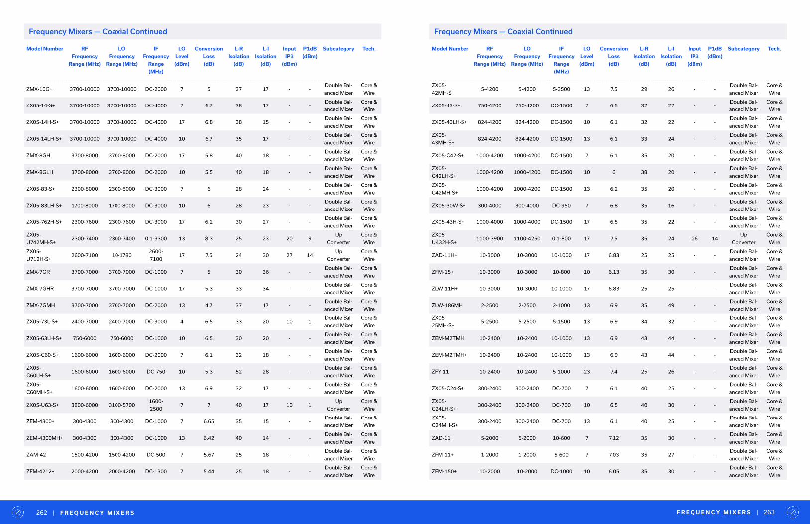
Model Number RF
Frequency
Range (MHz)
LO
Frequency
Range (MHz)
IF
Frequency
Range
(MHz)
LO
Level
(dBm)
Conversion
Loss
(dB)
L-R
Isolation
(dB)
L-I
Isolation
(dB)
Input
IP3
(dBm)
P1dB
(dBm)
Subcategory Tech.
ZMX-10G+ 3700-10000 3700-10000 DC-2000 7 5 37 17 - -Double Bal-
anced Mixer
Core &
Wire
ZX05-14-S+ 3700-10000 3700-10000 DC-4000 7 6.7 38 17 - -Double Bal-
anced Mixer
Core &
Wire
ZX05-14H-S+ 3700-10000 3700-10000 DC-4000 17 6.8 38 15 - -Double Bal-
anced Mixer
Core &
Wire
ZX05-14LH-S+ 3700-10000 3700-10000 DC-4000 10 6.7 35 17 - -Double Bal-
anced Mixer
Core &
Wire
ZMX-8GH 3700-8000 3700-8000 DC-2000 17 5.8 40 18 - -Double Bal-
anced Mixer
Core &
Wire
ZMX-8GLH 3700-8000 3700-8000 DC-2000 10 5.5 40 18 - -Double Bal-
anced Mixer
Core &
Wire
ZX05-83-S+ 2300-8000 2300-8000 DC-3000 7 6 28 24 - -Double Bal-
anced Mixer
Core &
Wire
ZX05-83LH-S+ 1700-8000 1700-8000 DC-3000 10 6 28 23 - -Double Bal-
anced Mixer
Core &
Wire
ZX05-762H-S+ 2300-7600 2300-7600 DC-3000 17 6.2 30 27 - -Double Bal-
anced Mixer
Core &
Wire
ZX05-
U742MH-S+2300-7400 2300-7400 0.1-3300 13 8.3 25 23 20 9
Up
Converter
Core &
Wire
ZX05-
U712H-S+2600-7100 10-1780
2600-
710017 7.5 24 30 27 14
Up
Converter
Core &
Wire
ZMX-7GR 3700-7000 3700-7000 DC-1000 7 5 30 36 - -Double Bal-
anced Mixer
Core &
Wire
ZMX-7GHR 3700-7000 3700-7000 DC-1000 17 5.3 33 34 - -Double Bal-
anced Mixer
Core &
Wire
ZMX-7GMH 3700-7000 3700-7000 DC-2000 13 4.7 37 17 - -Double Bal-
anced Mixer
Core &
Wire
ZX05-73L-S+ 2400-7000 2400-7000 DC-3000 4 6.5 33 20 10 1Double Bal-
anced Mixer
Core &
Wire
ZX05-63LH-S+ 750-6000 750-6000 DC-1000 10 6.5 30 20 - -Double Bal-
anced Mixer
Core &
Wire
ZX05-C60-S+ 1600-6000 1600-6000 DC-2000 7 6.1 32 18 - -Double Bal-
anced Mixer
Core &
Wire
ZX05-
C60LH-S+1600-6000 1600-6000 DC-750 10 5.3 52 28 - -
Double Bal-
anced Mixer
Core &
Wire
ZX05-
C60MH-S+1600-6000 1600-6000 DC-2000 13 6.9 32 17 - -
Double Bal-
anced Mixer
Core &
Wire
ZX05-U63-S+ 3800-6000 3100-57001600-
25007 7 40 17 10 1
Up
Converter
Core &
Wire
ZEM-4300+ 300-4300 300-4300 DC-1000 7 6.65 35 15 - -Double Bal-
anced Mixer
Core &
Wire
ZEM-4300MH+ 300-4300 300-4300 DC-1000 13 6.42 40 14 - -Double Bal-
anced Mixer
Core &
Wire
ZAM-42 1500-4200 1500-4200 DC-500 7 5.67 25 18 - -Double Bal-
anced Mixer
Core &
Wire
ZFM-4212+ 2000-4200 2000-4200 DC-1300 7 5.44 25 18 - -Double Bal-
anced Mixer
Core &
Wire
Model Number RF
Frequency
Range (MHz)
LO
Frequency
Range (MHz)
IF
Frequency
Range
(MHz)
LO
Level
(dBm)
Conversion
Loss
(dB)
L-R
Isolation
(dB)
L-I
Isolation
(dB)
Input
IP3
(dBm)
P1dB
(dBm)
Subcategory Tech.
ZX05-
42MH-S+5-4200 5-4200 5-3500 13 7.5 29 26 - -
Double Bal-
anced Mixer
Core &
Wire
ZX05-43-S+ 750-4200 750-4200 DC-1500 7 6.5 32 22 - -Double Bal-
anced Mixer
Core &
Wire
ZX05-43LH-S+ 824-4200 824-4200 DC-1500 10 6.1 32 22 - -Double Bal-
anced Mixer
Core &
Wire
ZX05-
43MH-S+824-4200 824-4200 DC-1500 13 6.1 33 24 - -
Double Bal-
anced Mixer
Core &
Wire
ZX05-C42-S+ 1000-4200 1000-4200 DC-1500 7 6.1 35 20 - -Double Bal-
anced Mixer
Core &
Wire
ZX05-
C42LH-S+1000-4200 1000-4200 DC-1500 10 6 38 20 - -
Double Bal-
anced Mixer
Core &
Wire
ZX05-
C42MH-S+1000-4200 1000-4200 DC-1500 13 6.2 35 20 - -
Double Bal-
anced Mixer
Core &
Wire
ZX05-30W-S+ 300-4000 300-4000 DC-950 7 6.8 35 16 - -Double Bal-
anced Mixer
Core &
Wire
ZX05-43H-S+ 1000-4000 1000-4000 DC-1500 17 6.5 35 22 - -Double Bal-
anced Mixer
Core &
Wire
ZX05-
U432H-S+1100-3900 1100-4250 0.1-800 17 7.5 35 24 26 14
Up
Converter
Core &
Wire
ZAD-11H+ 10-3000 10-3000 10-1000 17 6.83 25 25 - -Double Bal-
anced Mixer
Core &
Wire
ZFM-15+ 10-3000 10-3000 10-800 10 6.13 35 30 - -Double Bal-
anced Mixer
Core &
Wire
ZLW-11H+ 10-3000 10-3000 10-1000 17 6.83 25 25 - -Double Bal-
anced Mixer
Core &
Wire
ZLW-186MH 2-2500 2-2500 2-1000 13 6.9 35 49 - -Double Bal-
anced Mixer
Core &
Wire
ZX05-
25MH-S+5-2500 5-2500 5-1500 13 6.9 34 32 - -
Double Bal-
anced Mixer
Core &
Wire
ZEM-M2TMH 10-2400 10-2400 10-1000 13 6.9 43 44 - -Double Bal-
anced Mixer
Core &
Wire
ZEM-M2TMH+ 10-2400 10-2400 10-1000 13 6.9 43 44 - -Double Bal-
anced Mixer
Core &
Wire
ZFY-11 10-2400 10-2400 5-1000 23 7.4 25 26 - -Double Bal-
anced Mixer
Core &
Wire
ZX05-C24-S+ 300-2400 300-2400 DC-700 7 6.1 40 25 - -Double Bal-
anced Mixer
Core &
Wire
ZX05-
C24LH-S+300-2400 300-2400 DC-700 10 6.5 40 30 - -
Double Bal-
anced Mixer
Core &
Wire
ZX05-
C24MH-S+300-2400 300-2400 DC-700 13 6.1 40 25 - -
Double Bal-
anced Mixer
Core &
Wire
ZAD-11+ 5-2000 5-2000 10-600 7 7.12 35 30 - -Double Bal-
anced Mixer
Core &
Wire
ZFM-11+ 1-2000 1-2000 5-600 7 7.03 35 27 - -Double Bal-
anced Mixer
Core &
Wire
ZFM-150+ 10-2000 10-2000 DC-1000 10 6.05 35 30 - -Double Bal-
anced Mixer
Core &
Wire
F R E Q U E N C Y M I X E R S | 263| F R E Q U E N C Y M I X E R S262
Frequency Mixers — Coaxial ContinuedFrequency Mixers — Coaxial Continued
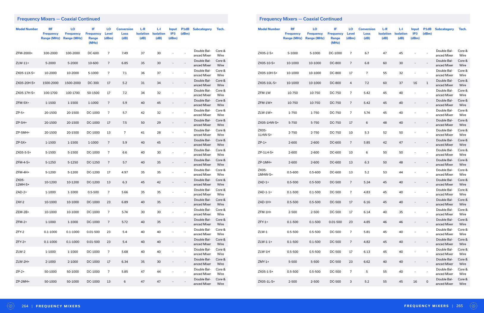
Model Number RF
Frequency
Range (MHz)
LO
Frequency
Range (MHz)
IF
Frequency
Range
(MHz)
LO
Level
(dBm)
Conversion
Loss
(dB)
L-R
Isolation
(dB)
L-I
Isolation
(dB)
Input
IP3
(dBm)
P1dB
(dBm)
Subcategory Tech.
ZFM-2000+ 100-2000 100-2000 DC-600 7 7.49 37 30 - -Double Bal-
anced Mixer
Core &
Wire
ZLW-11+ 5-2000 5-2000 10-600 7 6.85 35 30 - -Double Bal-
anced Mixer
Core &
Wire
ZX05-11X-S+ 10-2000 10-2000 5-1000 7 7.1 36 37 - -Double Bal-
anced Mixer
Core &
Wire
ZX05-20H-S+ 1500-2000 1500-2000 DC-300 17 5.2 31 34 - -Double Bal-
anced Mixer
Core &
Wire
ZX05-17H-S+ 100-1700 100-1700 50-1500 17 7.2 34 32 - -Double Bal-
anced Mixer
Core &
Wire
ZFM-5X+ 1-1500 1-1500 1-1000 7 5.9 40 45 - -Double Bal-
anced Mixer
Core &
Wire
ZP-5+ 20-1500 20-1500 DC-1000 7 5.7 42 32 - -Double Bal-
anced Mixer
Core &
Wire
ZP-5H+ 20-1500 20-1500 DC-1000 17 7.5 50 29 - -Double Bal-
anced Mixer
Core &
Wire
ZP-5MH+ 20-1500 20-1500 DC-1000 13 7 41 28 - -Double Bal-
anced Mixer
Core &
Wire
ZP-5X+ 1-1500 1-1500 1-1000 7 5.9 40 45 - -Double Bal-
anced Mixer
Core &
Wire
ZX05-5-S+ 5-1500 5-1500 DC-1000 7 6.6 40 30 - -Double Bal-
anced Mixer
Core &
Wire
ZFM-4-S+ 5-1250 5-1250 DC-1250 7 5.7 40 35 - -Double Bal-
anced Mixer
Core &
Wire
ZFM-4H+ 5-1200 5-1200 DC-1200 17 4.97 35 35 - -Double Bal-
anced Mixer
Core &
Wire
ZX05-
12MH-S+10-1200 10-1200 DC-1200 13 6.3 45 42 - -
Double Bal-
anced Mixer
Core &
Wire
ZAD-2+ 1-1000 1-1000 0.5-500 7 5.66 35 35 - -Double Bal-
anced Mixer
Core &
Wire
ZAY-2 10-1000 10-1000 DC-1000 23 6.89 40 35 - -Double Bal-
anced Mixer
Core &
Wire
ZEM-2B+ 10-1000 10-1000 DC-1000 7 5.74 30 30 - -Double Bal-
anced Mixer
Core &
Wire
ZFM-2+ 1-1000 1-1000 DC-1000 7 5.72 40 35 - -Double Bal-
anced Mixer
Core &
Wire
ZFY-2 0.1-1000 0.1-1000 0.01-500 23 5.4 40 40 - -Double Bal-
anced Mixer
Core &
Wire
ZFY-2+ 0.1-1000 0.1-1000 0.01-500 23 5.4 40 40 - -Double Bal-
anced Mixer
Core &
Wire
ZLW-2 1-1000 1-1000 DC-1000 7 5.68 40 40 - -Double Bal-
anced Mixer
Core &
Wire
ZLW-2H+ 2-1000 2-1000 DC-1000 17 6.34 35 30 - -Double Bal-
anced Mixer
Core &
Wire
ZP-2+ 50-1000 50-1000 DC-1000 7 5.85 47 44 - -Double Bal-
anced Mixer
Core &
Wire
ZP-2MH+ 50-1000 50-1000 DC-1000 13 6 47 47 - -Double Bal-
anced Mixer
Core &
Wire
Model Number RF
Frequency
Range (MHz)
LO
Frequency
Range (MHz)
IF
Frequency
Range
(MHz)
LO
Level
(dBm)
Conversion
Loss
(dB)
L-R
Isolation
(dB)
L-I
Isolation
(dB)
Input
IP3
(dBm)
P1dB
(dBm)
Subcategory Tech.
ZX05-2-S+ 5-1000 5-1000 DC-1000 7 6.7 47 45 - -Double Bal-
anced Mixer
Core &
Wire
ZX05-10-S+ 10-1000 10-1000 DC-800 7 6.8 60 30 - -Double Bal-
anced Mixer
Core &
Wire
ZX05-10H-S+ 10-1000 10-1000 DC-800 17 7 55 32 - -Double Bal-
anced Mixer
Core &
Wire
ZX05-10L-S+ 10-1000 10-1000 DC-800 4 7.2 60 37 16 1Double Bal-
anced Mixer
Core &
Wire
ZFM-1W 10-750 10-750 DC-750 7 5.42 45 40 - -Double Bal-
anced Mixer
Core &
Wire
ZFM-1W+ 10-750 10-750 DC-750 7 5.42 45 40 - -Double Bal-
anced Mixer
Core &
Wire
ZLW-1W+ 1-750 1-750 DC-750 7 5.74 45 40 - -Double Bal-
anced Mixer
Core &
Wire
ZX05-1HW-S+ 5-750 5-750 DC-750 17 6 48 40 - -Double Bal-
anced Mixer
Core &
Wire
ZX05-
1LHW-S+2-750 2-750 DC-750 10 5.3 52 50 - -
Double Bal-
anced Mixer
Core &
Wire
ZP-1+ 2-600 2-600 DC-600 7 5.85 42 47 - -Double Bal-
anced Mixer
Core &
Wire
ZP-1LH-S+ 2-600 2-600 DC-600 10 6 50 50 - -Double Bal-
anced Mixer
Core &
Wire
ZP-1MH+ 2-600 2-600 DC-600 13 6.3 50 48 - -Double Bal-
anced Mixer
Core &
Wire
ZX05-
1MHW-S+0.5-600 0.5-600 DC-600 13 5.2 53 44 - -
Double Bal-
anced Mixer
Core &
Wire
ZAD-1+ 0.5-500 0.5-500 DC-500 7 5.24 45 40 - -Double Bal-
anced Mixer
Core &
Wire
ZAD-1-1+ 0.1-500 0.1-500 DC-500 7 4.83 45 40 - -Double Bal-
anced Mixer
Core &
Wire
ZAD-1H+ 0.5-500 0.5-500 DC-500 17 6.16 45 40 - -Double Bal-
anced Mixer
Core &
Wire
ZFM-1H+ 2-500 2-500 DC-500 17 6.14 40 35 - -Double Bal-
anced Mixer
Core &
Wire
ZFY-1+ 0.1-500 0.1-500 0.01-500 23 4.85 46 46 - -Double Bal-
anced Mixer
Core &
Wire
ZLW-1 0.5-500 0.5-500 DC-500 7 5.81 45 40 - -Double Bal-
anced Mixer
Core &
Wire
ZLW-1-1+ 0.1-500 0.1-500 DC-500 7 4.82 45 40 - -Double Bal-
anced Mixer
Core &
Wire
ZLW-1H 0.5-500 0.5-500 DC-500 17 6.13 45 40 - -Double Bal-
anced Mixer
Core &
Wire
ZMY-1+ 5-500 5-500 DC-500 23 6.62 40 40 - -Double Bal-
anced Mixer
Core &
Wire
ZX05-1-S+ 0.5-500 0.5-500 DC-500 7 5 55 40 - -Double Bal-
anced Mixer
Core &
Wire
ZX05-1L-S+ 2-500 2-500 DC-500 3 5.2 55 45 16 0Double Bal-
anced Mixer
Core &
Wire
F R E Q U E N C Y M I X E R S | 265| F R E Q U E N C Y M I X E R S264
Frequency Mixers — Coaxial ContinuedFrequency Mixers — Coaxial Continued
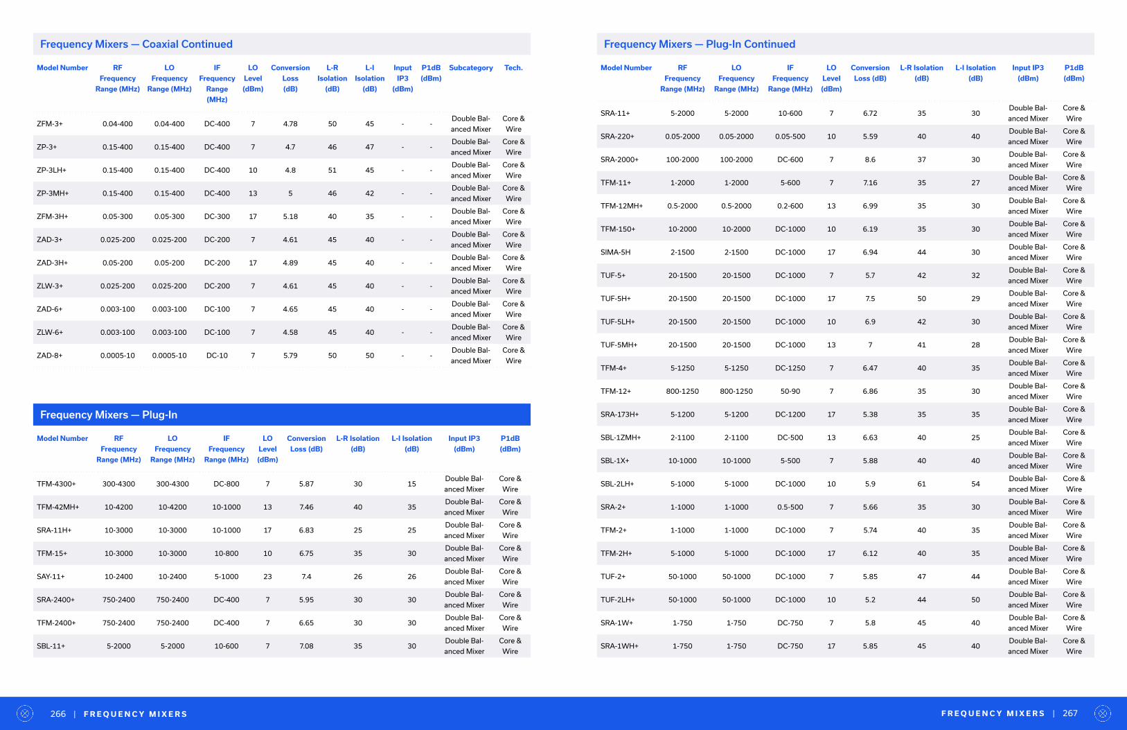
Model Number RF
Frequency
Range (MHz)
LO
Frequency
Range (MHz)
IF
Frequency
Range
(MHz)
LO
Level
(dBm)
Conversion
Loss
(dB)
L-R
Isolation
(dB)
L-I
Isolation
(dB)
Input
IP3
(dBm)
P1dB
(dBm)
Subcategory Tech.
ZFM-3+ 0.04-400 0.04-400 DC-400 7 4.78 50 45 - -Double Bal-
anced Mixer
Core &
Wire
ZP-3+ 0.15-400 0.15-400 DC-400 7 4.7 46 47 - -Double Bal-
anced Mixer
Core &
Wire
ZP-3LH+ 0.15-400 0.15-400 DC-400 10 4.8 51 45 - -Double Bal-
anced Mixer
Core &
Wire
ZP-3MH+ 0.15-400 0.15-400 DC-400 13 5 46 42 - -Double Bal-
anced Mixer
Core &
Wire
ZFM-3H+ 0.05-300 0.05-300 DC-300 17 5.18 40 35 - -Double Bal-
anced Mixer
Core &
Wire
ZAD-3+ 0.025-200 0.025-200 DC-200 7 4.61 45 40 - -Double Bal-
anced Mixer
Core &
Wire
ZAD-3H+ 0.05-200 0.05-200 DC-200 17 4.89 45 40 - -Double Bal-
anced Mixer
Core &
Wire
ZLW-3+ 0.025-200 0.025-200 DC-200 7 4.61 45 40 - -Double Bal-
anced Mixer
Core &
Wire
ZAD-6+ 0.003-100 0.003-100 DC-100 7 4.65 45 40 - -Double Bal-
anced Mixer
Core &
Wire
ZLW-6+ 0.003-100 0.003-100 DC-100 7 4.58 45 40 - -Double Bal-
anced Mixer
Core &
Wire
ZAD-8+ 0.0005-10 0.0005-10 DC-10 7 5.79 50 50 - -Double Bal-
anced Mixer
Core &
Wire
Frequency Mixers — Plug-In
Model Number RF
Frequency
Range (MHz)
LO
Frequency
Range (MHz)
IF
Frequency
Range (MHz)
LO
Level
(dBm)
Conversion
Loss (dB)
L-R Isolation
(dB)
L-I Isolation
(dB)
Input IP3
(dBm)
P1dB
(dBm)
TFM-4300+ 300-4300 300-4300 DC-800 7 5.87 30 15Double Bal-
anced Mixer
Core &
Wire
TFM-42MH+ 10-4200 10-4200 10-1000 13 7.46 40 35Double Bal-
anced Mixer
Core &
Wire
SRA-11H+ 10-3000 10-3000 10-1000 17 6.83 25 25Double Bal-
anced Mixer
Core &
Wire
TFM-15+ 10-3000 10-3000 10-800 10 6.75 35 30Double Bal-
anced Mixer
Core &
Wire
SAY-11+ 10-2400 10-2400 5-1000 23 7.4 26 26Double Bal-
anced Mixer
Core &
Wire
SRA-2400+ 750-2400 750-2400 DC-400 7 5.95 30 30Double Bal-
anced Mixer
Core &
Wire
TFM-2400+ 750-2400 750-2400 DC-400 7 6.65 30 30Double Bal-
anced Mixer
Core &
Wire
SBL-11+ 5-2000 5-2000 10-600 7 7.08 35 30Double Bal-
anced Mixer
Core &
Wire
Model Number RF
Frequency
Range (MHz)
LO
Frequency
Range (MHz)
IF
Frequency
Range (MHz)
LO
Level
(dBm)
Conversion
Loss (dB)
L-R Isolation
(dB)
L-I Isolation
(dB)
Input IP3
(dBm)
P1dB
(dBm)
SRA-11+ 5-2000 5-2000 10-600 7 6.72 35 30Double Bal-
anced Mixer
Core &
Wire
SRA-220+ 0.05-2000 0.05-2000 0.05-500 10 5.59 40 40Double Bal-
anced Mixer
Core &
Wire
SRA-2000+ 100-2000 100-2000 DC-600 7 8.6 37 30Double Bal-
anced Mixer
Core &
Wire
TFM-11+ 1-2000 1-2000 5-600 7 7.16 35 27Double Bal-
anced Mixer
Core &
Wire
TFM-12MH+ 0.5-2000 0.5-2000 0.2-600 13 6.99 35 30Double Bal-
anced Mixer
Core &
Wire
TFM-150+ 10-2000 10-2000 DC-1000 10 6.19 35 30Double Bal-
anced Mixer
Core &
Wire
SIMA-5H 2-1500 2-1500 DC-1000 17 6.94 44 30Double Bal-
anced Mixer
Core &
Wire
TUF-5+ 20-1500 20-1500 DC-1000 7 5.7 42 32Double Bal-
anced Mixer
Core &
Wire
TUF-5H+ 20-1500 20-1500 DC-1000 17 7.5 50 29Double Bal-
anced Mixer
Core &
Wire
TUF-5LH+ 20-1500 20-1500 DC-1000 10 6.9 42 30Double Bal-
anced Mixer
Core &
Wire
TUF-5MH+ 20-1500 20-1500 DC-1000 13 7 41 28Double Bal-
anced Mixer
Core &
Wire
TFM-4+ 5-1250 5-1250 DC-1250 7 6.47 40 35Double Bal-
anced Mixer
Core &
Wire
TFM-12+ 800-1250 800-1250 50-90 7 6.86 35 30Double Bal-
anced Mixer
Core &
Wire
SRA-173H+ 5-1200 5-1200 DC-1200 17 5.38 35 35Double Bal-
anced Mixer
Core &
Wire
SBL-1ZMH+ 2-1100 2-1100 DC-500 13 6.63 40 25Double Bal-
anced Mixer
Core &
Wire
SBL-1X+ 10-1000 10-1000 5-500 7 5.88 40 40Double Bal-
anced Mixer
Core &
Wire
SBL-2LH+ 5-1000 5-1000 DC-1000 10 5.9 61 54Double Bal-
anced Mixer
Core &
Wire
SRA-2+ 1-1000 1-1000 0.5-500 7 5.66 35 30Double Bal-
anced Mixer
Core &
Wire
TFM-2+ 1-1000 1-1000 DC-1000 7 5.74 40 35Double Bal-
anced Mixer
Core &
Wire
TFM-2H+ 5-1000 5-1000 DC-1000 17 6.12 40 35Double Bal-
anced Mixer
Core &
Wire
TUF-2+ 50-1000 50-1000 DC-1000 7 5.85 47 44Double Bal-
anced Mixer
Core &
Wire
TUF-2LH+ 50-1000 50-1000 DC-1000 10 5.2 44 50Double Bal-
anced Mixer
Core &
Wire
SRA-1W+ 1-750 1-750 DC-750 7 5.8 45 40Double Bal-
anced Mixer
Core &
Wire
SRA-1WH+ 1-750 1-750 DC-750 17 5.85 45 40Double Bal-
anced Mixer
Core &
Wire
F R E Q U E N C Y M I X E R S | 267| F R E Q U E N C Y M I X E R S266
Frequency Mixers — Plug-In ContinuedFrequency Mixers — Coaxial Continued
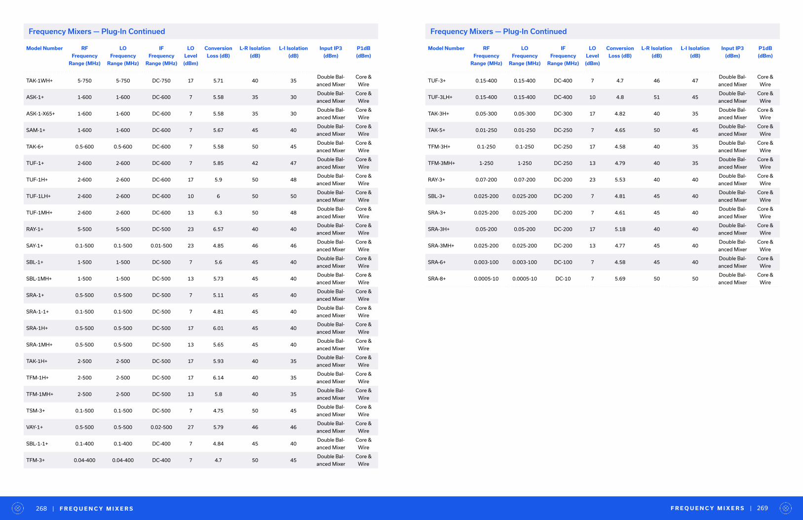
Model Number RF
Frequency
Range (MHz)
LO
Frequency
Range (MHz)
IF
Frequency
Range (MHz)
LO
Level
(dBm)
Conversion
Loss (dB)
L-R Isolation
(dB)
L-I Isolation
(dB)
Input IP3
(dBm)
P1dB
(dBm)
TAK-1WH+ 5-750 5-750 DC-750 17 5.71 40 35Double Bal-
anced Mixer
Core &
Wire
ASK-1+ 1-600 1-600 DC-600 7 5.58 35 30Double Bal-
anced Mixer
Core &
Wire
ASK-1-X65+ 1-600 1-600 DC-600 7 5.58 35 30Double Bal-
anced Mixer
Core &
Wire
SAM-1+ 1-600 1-600 DC-600 7 5.67 45 40Double Bal-
anced Mixer
Core &
Wire
TAK-6+ 0.5-600 0.5-600 DC-600 7 5.58 50 45Double Bal-
anced Mixer
Core &
Wire
TUF-1+ 2-600 2-600 DC-600 7 5.85 42 47Double Bal-
anced Mixer
Core &
Wire
TUF-1H+ 2-600 2-600 DC-600 17 5.9 50 48Double Bal-
anced Mixer
Core &
Wire
TUF-1LH+ 2-600 2-600 DC-600 10 6 50 50Double Bal-
anced Mixer
Core &
Wire
TUF-1MH+ 2-600 2-600 DC-600 13 6.3 50 48Double Bal-
anced Mixer
Core &
Wire
RAY-1+ 5-500 5-500 DC-500 23 6.57 40 40Double Bal-
anced Mixer
Core &
Wire
SAY-1+ 0.1-500 0.1-500 0.01-500 23 4.85 46 46Double Bal-
anced Mixer
Core &
Wire
SBL-1+ 1-500 1-500 DC-500 7 5.6 45 40Double Bal-
anced Mixer
Core &
Wire
SBL-1MH+ 1-500 1-500 DC-500 13 5.73 45 40Double Bal-
anced Mixer
Core &
Wire
SRA-1+ 0.5-500 0.5-500 DC-500 7 5.11 45 40Double Bal-
anced Mixer
Core &
Wire
SRA-1-1+ 0.1-500 0.1-500 DC-500 7 4.81 45 40Double Bal-
anced Mixer
Core &
Wire
SRA-1H+ 0.5-500 0.5-500 DC-500 17 6.01 45 40Double Bal-
anced Mixer
Core &
Wire
SRA-1MH+ 0.5-500 0.5-500 DC-500 13 5.65 45 40Double Bal-
anced Mixer
Core &
Wire
TAK-1H+ 2-500 2-500 DC-500 17 5.93 40 35Double Bal-
anced Mixer
Core &
Wire
TFM-1H+ 2-500 2-500 DC-500 17 6.14 40 35Double Bal-
anced Mixer
Core &
Wire
TFM-1MH+ 2-500 2-500 DC-500 13 5.8 40 35Double Bal-
anced Mixer
Core &
Wire
TSM-3+ 0.1-500 0.1-500 DC-500 7 4.75 50 45Double Bal-
anced Mixer
Core &
Wire
VAY-1+ 0.5-500 0.5-500 0.02-500 27 5.79 46 46Double Bal-
anced Mixer
Core &
Wire
SBL-1-1+ 0.1-400 0.1-400 DC-400 7 4.84 45 40Double Bal-
anced Mixer
Core &
Wire
TFM-3+ 0.04-400 0.04-400 DC-400 7 4.7 50 45Double Bal-
anced Mixer
Core &
Wire
Model Number RF
Frequency
Range (MHz)
LO
Frequency
Range (MHz)
IF
Frequency
Range (MHz)
LO
Level
(dBm)
Conversion
Loss (dB)
L-R Isolation
(dB)
L-I Isolation
(dB)
Input IP3
(dBm)
P1dB
(dBm)
TUF-3+ 0.15-400 0.15-400 DC-400 7 4.7 46 47Double Bal-
anced Mixer
Core &
Wire
TUF-3LH+ 0.15-400 0.15-400 DC-400 10 4.8 51 45Double Bal-
anced Mixer
Core &
Wire
TAK-3H+ 0.05-300 0.05-300 DC-300 17 4.82 40 35Double Bal-
anced Mixer
Core &
Wire
TAK-5+ 0.01-250 0.01-250 DC-250 7 4.65 50 45Double Bal-
anced Mixer
Core &
Wire
TFM-3H+ 0.1-250 0.1-250 DC-250 17 4.58 40 35Double Bal-
anced Mixer
Core &
Wire
TFM-3MH+ 1-250 1-250 DC-250 13 4.79 40 35Double Bal-
anced Mixer
Core &
Wire
RAY-3+ 0.07-200 0.07-200 DC-200 23 5.53 40 40Double Bal-
anced Mixer
Core &
Wire
SBL-3+ 0.025-200 0.025-200 DC-200 7 4.81 45 40Double Bal-
anced Mixer
Core &
Wire
SRA-3+ 0.025-200 0.025-200 DC-200 7 4.61 45 40Double Bal-
anced Mixer
Core &
Wire
SRA-3H+ 0.05-200 0.05-200 DC-200 17 5.18 40 40Double Bal-
anced Mixer
Core &
Wire
SRA-3MH+ 0.025-200 0.025-200 DC-200 13 4.77 45 40Double Bal-
anced Mixer
Core &
Wire
SRA-6+ 0.003-100 0.003-100 DC-100 7 4.58 45 40Double Bal-
anced Mixer
Core &
Wire
SRA-8+ 0.0005-10 0.0005-10 DC-10 7 5.69 50 50Double Bal-
anced Mixer
Core &
Wire
F R E Q U E N C Y M I X E R S | 269| F R E Q U E N C Y M I X E R S268
Frequency Mixers — Plug-In ContinuedFrequency Mixers — Plug-In Continued

Frequency Designer KitsModel Number Model Series Description Package Models Included
in Kit
Qty. Ea. Total Qty.
K1-ADE+ ADE2 to 4000 MHz
3 to 17 dBm LO PowersLeaded SMT
ADE-1L+
-2+
-18W+
-30W+
-35MH+
-17H+
ADEX-10L+
-10H+
5 40
K1-MCA+ MCA
500 to 5000 MHz
10, 13, and 17 dBm
LO Powers
Leaded SMT
MCA-35H+
-35LH+
-35MH+
-50H+
-50LH+
-50MH+
5 30
K2-MCA+ MCA
1760 to 3600 MHz
10, 13, and 17 dBm
LO Powers
Leaded SMT
MCA-19FH+
-19FLH+
-19FMH+
-30FH+
-30FLH+
-30FMH+
-36FH+
-36FLH+
-36FMH+
2 18
K1-MCA1+ MCA1300 to 1200 MHz
4 to 17 dBm LO PowersLeaded SMT
MCA1-12GL+
-24+
-24LH+
-42MH+
-42+
-60+
-60LH+
-80H+
-85L+
-113H+
5 50
Model Number Model Series Description Package Models Included
in Kit
Qty. Ea. Total Qty.
K1-SIM+ SIM
750 to 15000 MHz
4, 7, and 10 dBm
LO Powers
Leadedless SMT
SIM-14+
-43+
-63LH+
-73L+
-83+
-83LH+
-153+
-153LH+
5 40
K1-ZX05+ ZX055 to 15000 MHz
7 dBm LO PowerSMA Connectorized
ZX05-5+
-43+
-153+
1 3
K2-ZX05+ ZX05
0.5 to 15000 MHz
10 and 13 dBm
LO Powers
SMA Connectorized
ZX05-1MHW+
-12MH+
-63LH+
-153MH+
1 4
K3-ZX05+ ZX055 to 10000 MHz
17 dBm LO PowerSMA Connectorized
ZX05-1HW+
-17H+
-43H+
-14H+
1 4
F R E Q U E N C Y M I X E R D E S I G N E R K I T S | 271| F R E Q U E N C Y M I X E R D E S I G N E R K I T S270
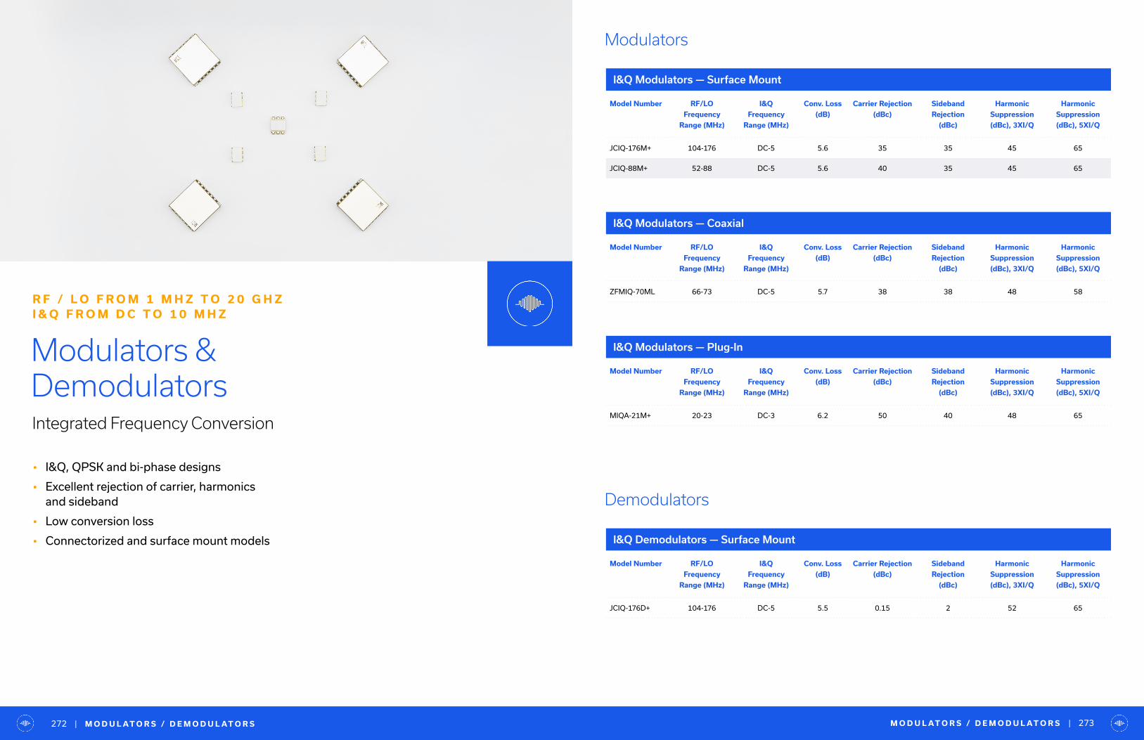
• I&Q, QPSK and bi-phase designs
• Excellent rejection of carrier, harmonics and sideband
• Low conversion loss
• Connectorized and surface mount models
Modulators & DemodulatorsIntegrated Frequency Conversion
R F / L O F R O M 1 M H Z T O 2 0 G H Z I & Q F R O M D C T O 1 0 M H Z
Model Number RF/LO
Frequency
Range (MHz)
I&Q
Frequency
Range (MHz)
Conv. Loss
(dB)
Carrier Rejection
(dBc)
Sideband
Rejection
(dBc)
Harmonic
Suppression
(dBc), 3XI/Q
Harmonic
Suppression
(dBc), 5XI/Q
JCIQ-176M+ 104-176 DC-5 5.6 35 35 45 65
JCIQ-88M+ 52-88 DC-5 5.6 40 35 45 65
Model Number RF/LO
Frequency
Range (MHz)
I&Q
Frequency
Range (MHz)
Conv. Loss
(dB)
Carrier Rejection
(dBc)
Sideband
Rejection
(dBc)
Harmonic
Suppression
(dBc), 3XI/Q
Harmonic
Suppression
(dBc), 5XI/Q
ZFMIQ-70ML 66-73 DC-5 5.7 38 38 48 58
Model Number RF/LO
Frequency
Range (MHz)
I&Q
Frequency
Range (MHz)
Conv. Loss
(dB)
Carrier Rejection
(dBc)
Sideband
Rejection
(dBc)
Harmonic
Suppression
(dBc), 3XI/Q
Harmonic
Suppression
(dBc), 5XI/Q
MIQA-21M+ 20-23 DC-3 6.2 50 40 48 65
Model Number RF/LO
Frequency
Range (MHz)
I&Q
Frequency
Range (MHz)
Conv. Loss
(dB)
Carrier Rejection
(dBc)
Sideband
Rejection
(dBc)
Harmonic
Suppression
(dBc), 3XI/Q
Harmonic
Suppression
(dBc), 5XI/Q
JCIQ-176D+ 104-176 DC-5 5.5 0.15 2 52 65
I&Q Modulators — Surface Mount
I&Q Modulators — Coaxial
I&Q Modulators — Plug-In
I&Q Demodulators — Surface Mount
Demodulators
Modulators
M O D U L AT O R S / D E M O D U L AT O R S | 273| M O D U L AT O R S / D E M O D U L AT O R S272

Model Number RF/LO
Frequency
Range (MHz)
I&Q
Frequency
Range (MHz)
Conv. Loss
(dB)
Carrier Rejection
(dBc)
Sideband
Rejection
(dBc)
Harmonic
Suppression
(dBc), 3XI/Q
Harmonic
Suppression
(dBc), 5XI/Q
ZFMIQ-70D 66-73 DC-2 6.2 0.15 0.7 56 58
Model Number RF/LO
Frequency
Range (MHz)
I&Q
Frequency
Range (MHz)
Conv. Loss
(dB)
Carrier Rejection
(dBc)
Sideband
Rejection
(dBc)
Harmonic
Suppression
(dBc), 3XI/Q
Harmonic
Suppression
(dBc), 5XI/Q
MIQA-21D+ 23-23 DC-3 6.1 0.15 0.7 64 67
I&Q Demodulators — Coaxial
I&Q Demodulators — Plug-In
Model Number Frequency
Range In
(MHz)
Frequency
Range Con
(MHz)
Total Range
Insertion
Loss (dB)
at ±20 mA
Input Power
(dBm) at 1 dB
Compr., at
±20 mA
No Damage
Input Power
(dBm) at
±20 mA
In-Out Isolation
(dB) at 0 mA,
Mid Range
Bi-Phase X
(±20 mA),
Amp (dB),
Total Range
Bi-Phase X (±20
mA), Phase (deg.)
deviation from
180, Total Range
LRAS-2-75 10-1000 DC-0.05 4.5 20 25 42 0.3 3
SYAS-860+ 600-1000 DC-0.5 2.7 14 25 25 0.5 4
TFAS-2SM+ 10-1000 DC-0.5 5 17 25 42 0.2 3
RAS-1+ 2-400 DC-0.05 1.6 20 25 45 0.1 2
SYAS-1+ 2-400 DC-0.05 1.6 20 25 45 0.1 2
TFAS-1SM+ 2-400 DC-0.05 1.6 20 25 45 0.1 2
Model Number Frequency
Range
(MHz)
Control
Frequency
Range
(MHz)
Total-Band
Insertion
Loss (dB)
at ±20 mA,
Input Pwr @
1 dB Compr.
at ±20 mA
Max. No
Damage
Input Pwr
In-Out Isolation
(dB) at 0 mA,
Mid-Range Typ.
Bi-Phase Amp
(dB) at ±20 mA,
Total Range
Bi-Phase Phase
Deviation from
180° at ±20 mA,
Total Range
ZFAS-2000+ 100-2000 DC-0.5 5.4 19R 25 - 0.4 8
ZMAS-1 5-450 DC-0.05 3.5 20 30 55 0.1 1.2
ZAS-3+ 1-200 DC-0.05 1.6 15 30 50 0.1 1
ZMAS-3 1-200 DC-0.05 1.6 15 30 50 0.1 1
Model Number RF
Frequency
Range
(MHz)
Control
Frequency
Range
(MHz)
Total-Band
Insertion
Loss (dB)
at ±20 mA
Input Pwr @
1 dB Compr.
at ±20 mA
Max. No
Damage
Input Pwr
In-Out Isolation
(dB) at 0 mA,
Mid-Range
Bi-Phase Amp
(dB) at ±20 mA,
Total Range
Bi-Phase Phase
Deviation from
180° at ±20 mA,
Total Range
PAS-2000+ 100-2000 DC-0.5 5.4 19 25 - 0.4 8
GAS-2+ 10-1000 DC-0.05 5.2 20 25 35 0.3 3
PAS-2+ 10-1000 DC-0.05 6.5 20 29 40 0.3 1
TFAS-2+ 10-1000 DC-0.5 5 17 25 42 0.2 3
GAS-1+ 5-450 DC-0.05 3.5 20 25 45 0.1 1.5
PAS-1+ 5-450 DC-0.05 3.5 20 29 45 0.1 1.2
TFAS-1+ 2-400 DC-0.05 1.6 20 25 45 0.1 2
PAS-3+ 1-200 DC-0.05 1.6 15 29 50 0.1 1
Bi-Phase — Surface Mount
Bi-Phase — Coaxial
Bi-Phase — Plug-In
Bi-Phase
M O D U L AT O R S / D E M O D U L AT O R S | 275| M O D U L AT O R S / D E M O D U L AT O R S274

• Over 80 models in stock
• Coaxial, surface mount and bare die formats
• Conversion loss as low as 6.5 dB
• Excellent fundamental and harmonic suppression
Frequency MultipliersFrom X2 to X12
1 0 0 K H Z T O 4 0 G H Z
Model Number Multiply
Factor [X]
Input
Frequency
Range (MHz)
Output
Frequency
Range (MHz)
RF Input
Power Range
(dBm)
Conv.
Loss
(dB)
F1 Fundamental
Suppression
Below F[X] (dBc)
F[X-1]
Suppression
Below F[X] (dBc)
F[X+1]
Suppression
Below F[X] (dBc)
CY2-44+ 2 6200-20000 12400-40000 12-18 14 26 - 34
CY2-283+ 2 3500-14000 7000-28000 12-18 13 34 - 40
KSX2-24+ 2 5000-10000 10000-20000 10-16 14 29 - 29
CY2-143+ 2 2000-7000 4000-14000 12-18 12 30 - 32
KC2-50+ 2 3500-5000 7000-10000 7-12 12.5 15 - 28
KSX2-14+ 2 2500-5000 5000-10000 13-17 12 22 - 31
KBA-40 2 2700-4800 5400-9600 10-16 12.3 18 - 26
KBA-40+ 2 2700-4800 5400-9600 10-16 12.3 18 - 26
KC2-36+ 2 1700-3600 3400-7200 8-13 11 18 - 30
KSX2-722+ 2 1300-3600 2600-7200 9-13 12 20 - 28
KBA-20 2 1600-2200 3200-4400 11-15 12 12 - 20
KBA-20+ 2 1600-2200 3200-4400 11-15 12 12 - 20
KSX2-442+ 2 600-2200 1200-4400 7-15 11 22 - 35
KC2-19+ 2 1100-1900 2200-3800 5-10 10.5 24 - 30
LK-3000+ 2 70-1500 140-3000 12-15 10.5 27 - 35
SYK-2-33+ 2 50-1500 100-3000 11-15 11.5 30 - 33
KC2-11+ 2 500-1100 1000-2200 5-10 10.5 27 - 34
SYK-2R 2 10-1000 20-2000 12-16 10.5 35 - 42
SYK-2R+ 2 10-1000 20-2000 12-16 10.5 35 - 42
AMK-2-13+ 2 10-500 20-1000 4-10 11.4 45 - 45
RMK-3-153+ 3 2600-5000 7800-15000 7-11 17 1 48 50
RMK-3-1262+ 3 2250-4200 6750-12600 7-11 15.5 5 45 50
RMK-3-123+ 3 2200-4000 6600-12000 13-17 15.5 5 33 45
RMK-3-1052+ 3 2200-3500 6600-10500 7-11 14.5 6 52 50
RMK-3-14+ 3 2200-3335 6600-10005 13-17 14.5 6 40 37
RMK-3-93+ 3 1800-3000 5400-9000 7-11 15 6 55 55
RMK-3-812+ 3 1800-2700 5400-8100 0-6 16 6 40 37
RMK-3-722+ 3 1525-2400 4575-7200 7-11 14 3 55 55
Frequency Multipliers — Surface Mount
F R E Q U E N C Y M U LT I P L I E R S | 277| F R E Q U E N C Y M U LT I P L I E R S276
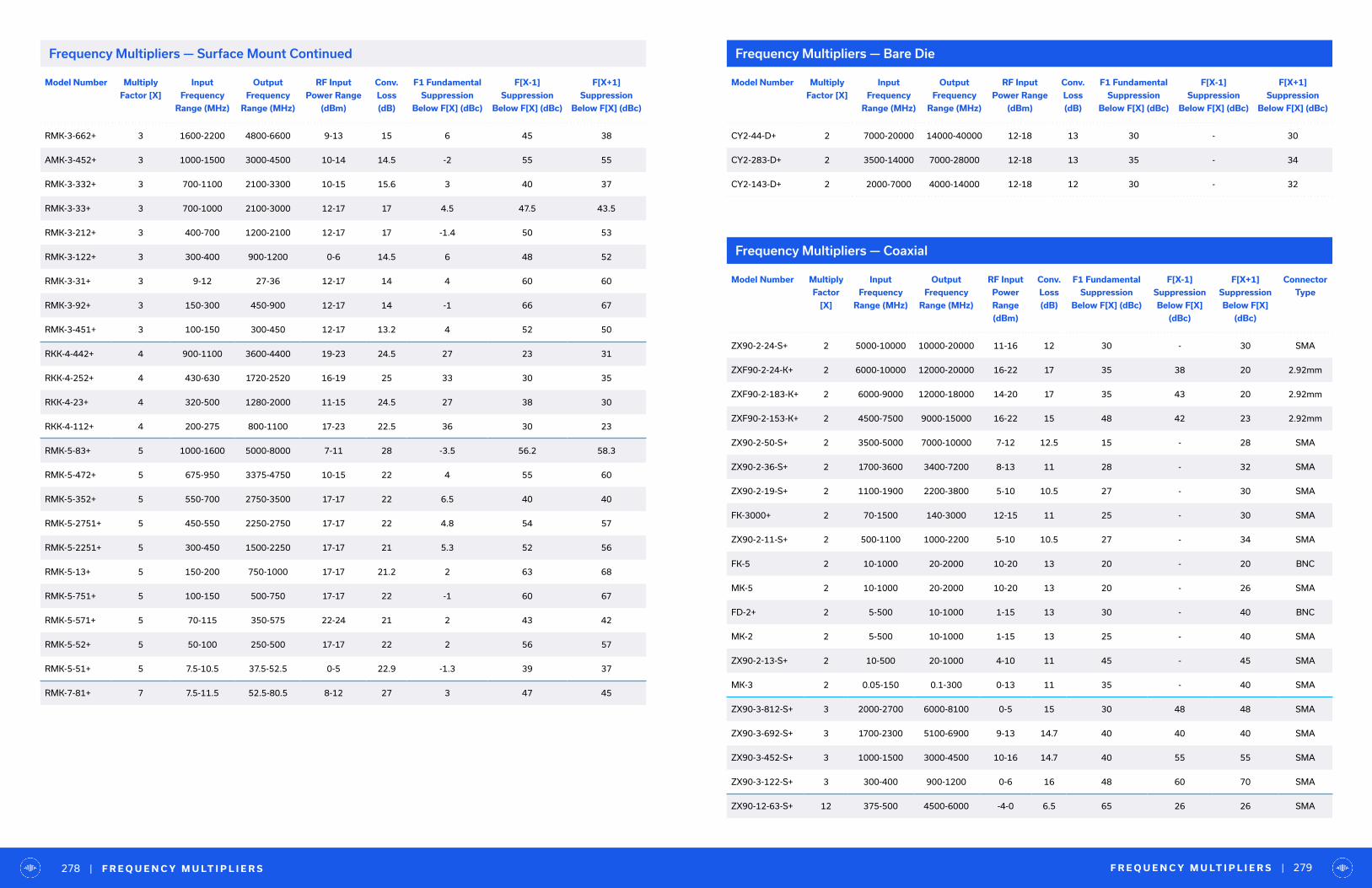
Model Number Multiply
Factor [X]
Input
Frequency
Range (MHz)
Output
Frequency
Range (MHz)
RF Input
Power Range
(dBm)
Conv.
Loss
(dB)
F1 Fundamental
Suppression
Below F[X] (dBc)
F[X-1]
Suppression
Below F[X] (dBc)
F[X+1]
Suppression
Below F[X] (dBc)
RMK-3-662+ 3 1600-2200 4800-6600 9-13 15 6 45 38
AMK-3-452+ 3 1000-1500 3000-4500 10-14 14.5 -2 55 55
RMK-3-332+ 3 700-1100 2100-3300 10-15 15.6 3 40 37
RMK-3-33+ 3 700-1000 2100-3000 12-17 17 4.5 47.5 43.5
RMK-3-212+ 3 400-700 1200-2100 12-17 17 -1.4 50 53
RMK-3-122+ 3 300-400 900-1200 0-6 14.5 6 48 52
RMK-3-31+ 3 9-12 27-36 12-17 14 4 60 60
RMK-3-92+ 3 150-300 450-900 12-17 14 -1 66 67
RMK-3-451+ 3 100-150 300-450 12-17 13.2 4 52 50
RKK-4-442+ 4 900-1100 3600-4400 19-23 24.5 27 23 31
RKK-4-252+ 4 430-630 1720-2520 16-19 25 33 30 35
RKK-4-23+ 4 320-500 1280-2000 11-15 24.5 27 38 30
RKK-4-112+ 4 200-275 800-1100 17-23 22.5 36 30 23
RMK-5-83+ 5 1000-1600 5000-8000 7-11 28 -3.5 56.2 58.3
RMK-5-472+ 5 675-950 3375-4750 10-15 22 4 55 60
RMK-5-352+ 5 550-700 2750-3500 17-17 22 6.5 40 40
RMK-5-2751+ 5 450-550 2250-2750 17-17 22 4.8 54 57
RMK-5-2251+ 5 300-450 1500-2250 17-17 21 5.3 52 56
RMK-5-13+ 5 150-200 750-1000 17-17 21.2 2 63 68
RMK-5-751+ 5 100-150 500-750 17-17 22 -1 60 67
RMK-5-571+ 5 70-115 350-575 22-24 21 2 43 42
RMK-5-52+ 5 50-100 250-500 17-17 22 2 56 57
RMK-5-51+ 5 7.5-10.5 37.5-52.5 0-5 22.9 -1.3 39 37
RMK-7-81+ 7 7.5-11.5 52.5-80.5 8-12 27 3 47 45
Model Number Multiply
Factor [X]
Input
Frequency
Range (MHz)
Output
Frequency
Range (MHz)
RF Input
Power Range
(dBm)
Conv.
Loss
(dB)
F1 Fundamental
Suppression
Below F[X] (dBc)
F[X-1]
Suppression
Below F[X] (dBc)
F[X+1]
Suppression
Below F[X] (dBc)
CY2-44-D+ 2 7000-20000 14000-40000 12-18 13 30 - 30
CY2-283-D+ 2 3500-14000 7000-28000 12-18 13 35 - 34
CY2-143-D+ 2 2000-7000 4000-14000 12-18 12 30 - 32
Frequency Multipliers — Bare Die
Model Number Multiply
Factor
[X]
Input
Frequency
Range (MHz)
Output
Frequency
Range (MHz)
RF Input
Power
Range
(dBm)
Conv.
Loss
(dB)
F1 Fundamental
Suppression
Below F[X] (dBc)
F[X-1]
Suppression
Below F[X]
(dBc)
F[X+1]
Suppression
Below F[X]
(dBc)
Connector
Type
ZX90-2-24-S+ 2 5000-10000 10000-20000 11-16 12 30 - 30 SMA
ZXF90-2-24-K+ 2 6000-10000 12000-20000 16-22 17 35 38 20 2.92mm
ZXF90-2-183-K+ 2 6000-9000 12000-18000 14-20 17 35 43 20 2.92mm
ZXF90-2-153-K+ 2 4500-7500 9000-15000 16-22 15 48 42 23 2.92mm
ZX90-2-50-S+ 2 3500-5000 7000-10000 7-12 12.5 15 - 28 SMA
ZX90-2-36-S+ 2 1700-3600 3400-7200 8-13 11 28 - 32 SMA
ZX90-2-19-S+ 2 1100-1900 2200-3800 5-10 10.5 27 - 30 SMA
FK-3000+ 2 70-1500 140-3000 12-15 11 25 - 30 SMA
ZX90-2-11-S+ 2 500-1100 1000-2200 5-10 10.5 27 - 34 SMA
FK-5 2 10-1000 20-2000 10-20 13 20 - 20 BNC
MK-5 2 10-1000 20-2000 10-20 13 20 - 26 SMA
FD-2+ 2 5-500 10-1000 1-15 13 30 - 40 BNC
MK-2 2 5-500 10-1000 1-15 13 25 - 40 SMA
ZX90-2-13-S+ 2 10-500 20-1000 4-10 11 45 - 45 SMA
MK-3 2 0.05-150 0.1-300 0-13 11 35 - 40 SMA
ZX90-3-812-S+ 3 2000-2700 6000-8100 0-5 15 30 48 48 SMA
ZX90-3-692-S+ 3 1700-2300 5100-6900 9-13 14.7 40 40 40 SMA
ZX90-3-452-S+ 3 1000-1500 3000-4500 10-16 14.7 40 55 55 SMA
ZX90-3-122-S+ 3 300-400 900-1200 0-6 16 48 60 70 SMA
ZX90-12-63-S+ 12 375-500 4500-6000 -4-0 6.5 65 26 26 SMA
Frequency Multipliers — Coaxial
F R E Q U E N C Y M U LT I P L I E R S | 279| F R E Q U E N C Y M U LT I P L I E R S278
Frequency Multipliers — Surface Mount Continued

Frequency Multipliers — Plug-In
Model Number Multiply
Factor [X]
Input
Frequency
Range (MHz)
Output
Frequency
Range (MHz)
RF Input
Power Range
(dBm)
Conv.
Loss
(dB)
F1 Fundamental
Suppression
Below F[X] (dBc)
F[X-1]
Suppression
Below F[X] (dBc)
F[X+1]
Suppression
Below F[X] (dBc)
AK-3000+ 2 70-1500 140-3000 12-15 10.5 25 - 30
RK-5+ 2 10-800 20-1600 10-20 12.5 20 - 30
AK-2+ 2 1-500 2-1000 1-10 13.5 30 - 40
RK-2+ 2 5-500 10-1000 1-15 13.5 30 - 40
SK-2+ 2 1-500 2-1000 1-10 13.5 30 - 40
RK-3+ 2 0.05-150 0.1-300 0-13 11 35 - 40
T E S T I M O N I A L | 281| F R E Q U E N C Y M U LT I P L I E R S280
Vendor Partner Award
Modelithics
Yo u r e x t e n s i v e d e s i g n d a t a i n p a r t i c u l a r m a k e s i t v e r y e a s y t o s e l e c t a n d t h e r e a f t e r s i m u l a t e
a n d e v a l u a t e a d e s i g n . T h a n k y o u !
— K E N N E T H K , A N T R A C O M“
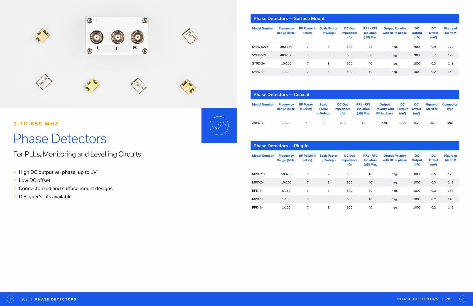
• High DC output vs. phase, up to 1V
• Low DC offset
• Connectorized and surface mount designs
• Designer’s kits available
Phase DetectorsFor PLLs, Monitoring and Levelling Circuits
1 T O 6 5 0 M H Z
Phase Detectors — Surface Mount
Phase Detectors — Coaxial
Phase Detectors — Plug-In
Model Number Frequency
Range (MHz)
RF Power In
(dBm)
Scale Factor
(mV/deg.)
DC Out
Impedance
(Ω)
RF1 - RF2
Isolation
(dB) Min.
Output Polarity
with RF in phase
DC
Output
(mV)
DC
Offset
(mV)
Figure of
Merit M
SYPD-52W+ 300-650 7 8 500 28 neg. 900 0.9 129
SYPD-52+ 400-500 7 8 500 30 neg. 900 0.7 129
SYPD-2+ 10-200 7 8 500 40 neg. 1000 0.3 143
SYPD-1+ 1-100 7 8 500 40 neg. 1000 0.2 143
Model Number Frequency
Range (MHz)
RF Power In
(dBm)
Scale Factor
(mV/deg.)
DC Out
Impedance
(Ω)
RF1 - RF2
Isolation
(dB) Min.
Output Polarity
with RF in phase
DC
Output
(mV)
DC
Offset
(mV)
Figure of
Merit M
MPD-21+ 50-400 7 7 500 40 neg. 800 0.5 120
MPD-2+ 10-200 7 8 500 40 neg. 1000 0.3 143
RPD-2+ 5-150 7 8 500 40 neg. 1000 0.3 143
MPD-1+ 1-100 7 8 500 40 neg. 1000 0.2 143
RPD-1+ 1-100 7 8 500 40 neg. 1000 0.2 143
Model Number Frequency
Range (MHz)
RF Power
In (dBm)
Scale
Factor
(mV/deg.)
DC Out
Impedance
(Ω)
RF1 - RF2
Isolation
(dB) Min.
Output
Polarity with
RF in phase
DC
Output
(mV)
DC
Offset
(mV)
Figure of
Merit M
Connector
Type
ZRPD-1+ 1-100 7 8 500 40 neg. 1000 0.2 143 BNC
| P H A S E D E T E C T O R S282 P H A S E D E T E C T O R S | 283

| P H A S E D E T E C T O R D E S I G N E R K I T S
Phase Detector Designer KitsModel Number Model Series Description Package Models Included
in Kit
Qty. Ea. Total Qty.
K-PDMPD
SYPD1 to 400 MHz
Plug-In,
Leadless SMT
MPD-1+
MPD-2+
MPD-21+
SYPD-1+
SYPD-2+
1 5
284 T E S T I M O N I A L | 285
Supplier Award for Exceptional
Quality and Delivery Performance
General Atomics Aeronautical
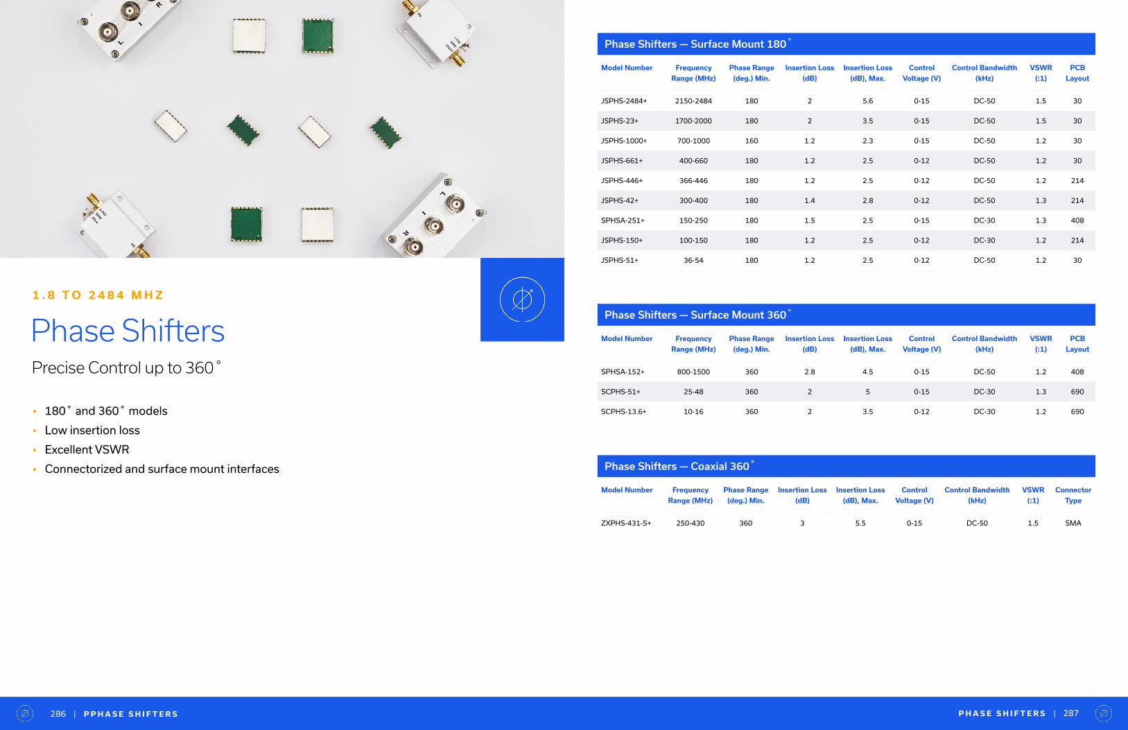
| P P H A S E S H I F T E R S286 P H A S E S H I F T E R S | 287
• 180˚ and 360˚ models
• Low insertion loss
• Excellent VSWR
• Connectorized and surface mount interfaces
Phase ShiftersPrecise Control up to 360˚
1 . 8 T O 2 4 8 4 M H Z
Phase Shifters — Surface Mount 180�Ω
Phase Shifters — Surface Mount 360�
Phase Shifters — Coaxial 360�
Model Number Frequency
Range (MHz)
Phase Range
(deg.) Min.
Insertion Loss
(dB)
Insertion Loss
(dB), Max.
Control
Voltage (V)
Control Bandwidth
(kHz)
VSWR
(:1)
PCB
Layout
JSPHS-2484+ 2150-2484 180 2 5.6 0-15 DC-50 1.5 30
JSPHS-23+ 1700-2000 180 2 3.5 0-15 DC-50 1.5 30
JSPHS-1000+ 700-1000 160 1.2 2.3 0-15 DC-50 1.2 30
JSPHS-661+ 400-660 180 1.2 2.5 0-12 DC-50 1.2 30
JSPHS-446+ 366-446 180 1.2 2.5 0-12 DC-50 1.2 214
JSPHS-42+ 300-400 180 1.4 2.8 0-12 DC-50 1.3 214
SPHSA-251+ 150-250 180 1.5 2.5 0-15 DC-30 1.3 408
JSPHS-150+ 100-150 180 1.2 2.5 0-12 DC-30 1.2 214
JSPHS-51+ 36-54 180 1.2 2.5 0-12 DC-50 1.2 30
Model Number Frequency
Range (MHz)
Phase Range
(deg.) Min.
Insertion Loss
(dB)
Insertion Loss
(dB), Max.
Control
Voltage (V)
Control Bandwidth
(kHz)
VSWR
(:1)
PCB
Layout
SPHSA-152+ 800-1500 360 2.8 4.5 0-15 DC-50 1.2 408
SCPHS-51+ 25-48 360 2 5 0-15 DC-30 1.3 690
SCPHS-13.6+ 10-16 360 2 3.5 0-12 DC-30 1.2 690
Model Number Frequency
Range (MHz)
Phase Range
(deg.) Min.
Insertion Loss
(dB)
Insertion Loss
(dB), Max.
Control
Voltage (V)
Control Bandwidth
(kHz)
VSWR
(:1)
Connector
Type
ZXPHS-431-S+ 250-430 360 3 5.5 0-15 DC-50 1.5 SMA

• Input power range spanning -60 to +20 dBm
• Linear response (in dB)
• Fast response time, as little as 400 nsec rise time and 10 nsec fall time
• Low noise
• Single positive supply voltage
Power DetectorsWide Bandwidth and Dynamic Range
1 0 M H Z T O 4 0 G H Z
Ideal for a wide range of applications:
RF/IF power measurement, transmit/receive power monitoring, RF leakage monitors, fast-feedback levelling circuits, automatic gain control systems and more
Power Detectors — Coaxial
Model Number Frequency
Range (MHz)
Dynamic
Range @ ±1 dB
Error (dBm)
Output
Voltage
Range (V)
VSWR
(:1)
Pulse Response
Rise Time
(nsec)
Pulse Response
Fall Time
(nsec)
Supply
Voltage
(V)
Supply
Current
(mA)
Connector
Type
ZV47-K44+ 500-43500 -30 to +15 0 - 4.30 2.4 4 50 5 3 2.92mm
ZV47-K44RMS+ 100-40000 -35 to 0 0 - 1.20 1.6 2900 8100 3.3 30 2.92mm
ZX47-40-S+ 10-8000 -40 to +20 0.50 - 2.10 1.2 400 10 4.5 100 SMA
ZX47-40LN-S+ 10-8000 -40 to +20 0.50 - 2.10 1.2 800 400 4.5 100 SMA
ZX47-50-S+ 10-8000 -45 to +15 0.50 - 2.10 1.2 400 10 4.5 100 SMA
ZX47-50LN-S+ 10-8000 -45 to +15 0.50 - 2.10 1.2 800 400 4.5 100 SMA
ZX47-55-S+ 10-8000 -50 to +10 0.50 - 2.10 1.4 400 10 4.5 100 SMA
ZX47-55LN-S+ 10-8000 -50 to +10 0.50 - 2.10 1.4 800 400 4.5 100 SMA
ZX47-60-S+ 10-8000 -60 to +5 0.50 - 2.10 1.7 400 10 5.0 100 SMA
ZX47-60LN-S+ 10-8000 -60 to +5 0.50 - 2.10 1.7 800 400 5.0 100 SMA
P O W E R D E T E C T O R S | 289| P O W E R D E T E C T O R S288

• Low DC resistance
• Low parasitic capacitance
• DC current handling up to 15A
• Tiny surface mount packages as small as 0.5 x 0.15 x 0.15”
RF ChokesEffective Wideband Parallel Resistance
5 M H Z T O 1 0 G H Z
RF Chokes — Surface Mount
Model Number Frequency
Range (MHz)
Insertion
Loss (dB)
Insertion Loss
(dB), Max.
VSWR
(:1)
VSWR
(:1), Max.
DC Current
(mA)
Inductance
(µH)
@ 0 mA
Inductance
(µH)
@ 100 mA
Inductance
(µH)
@ 200 mA
ADCH-80+ 50-10000 0.3 2 1.1 1.6 100 7 1 -
ADCH-80A+ 50-10000 0.3 2 1.1 1.6 100 7 1 -
TCCH-80+ 50-8200 0.5 1.1 1.1 1.7 200 4 0.9 0.5
TACH-182-75+ 5-1800 0.4 0.6 - 1.67 15000 5.4 - -
T E S T I M O N I A L | 291| R F C H O K E S290
Supplier of the Year, Presidents Award
Rockwell Collins
Yo u a r e a l l R O C K S TA R S !
— B U Y I N G S P E C I A L I S T“

• 2-Way through 24-Way
• RF input power up to 100W
• Low insertion loss
• High isolation
• Connectorized, surface mount and MMIC die formats
Power Splitters & Combiners600+ in Stock
2 K H Z T O 6 5 G H Z
• Tiny footprint
• Low insertion loss
Technology Overview
Core & Wire
• Top Hat® feature improves speed and accuracy of pick and place assembly
LTCC
• Case styles as small as 0805
• Low insertion loss
Microstrip
• Excellent power handling in small, SMT form factor, up to 5W
MMIC
• Widest surface mount bandwidths in the industry
• Hybrid architecture designs extend coverage down to DC
Resistive
• Wideband coverage down to DC
• Low insertion loss
• Power handling up to 20W
• ESD non-sensitive
• Case styles as small as 1.4 x 2.0 mm
• QFN, SOT-343 and bare die formats
Stripline
• Multi-octave bandwidths up to 65 GHz
• Power handling up to 20W
• Low insertion loss
• High isolation
Technology for every requiremen:
LTCC, MMIC, stripline, microstrip, core and wire, resistive
P O W E R S P L I T T E R / C O M B I N E R S | 293| P O W E R S P L I T T E R / C O M B I N E R S292
• Bandwidths > 1 octave
• High isolation
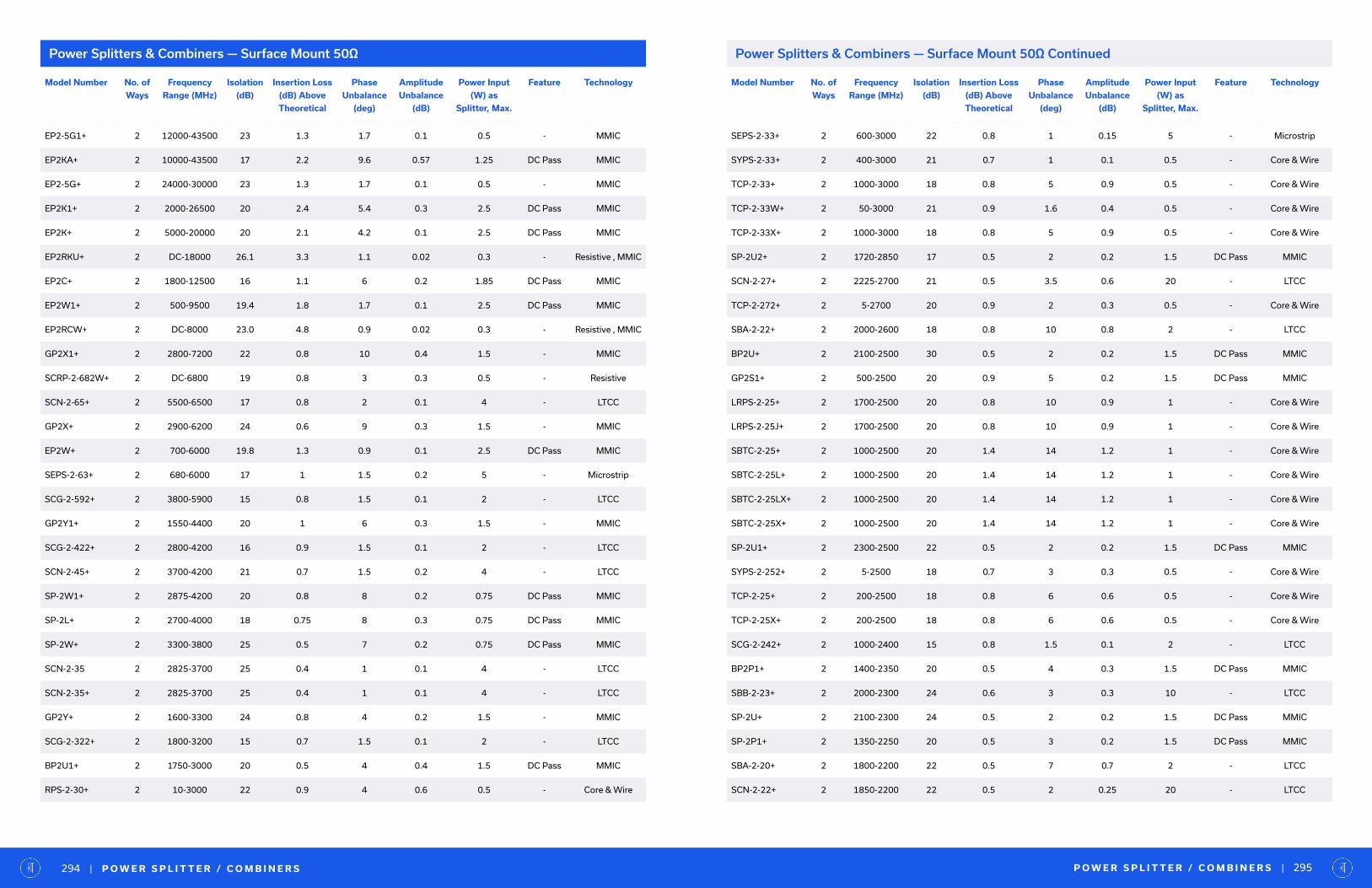
Power Splitters & Combiners — Surface Mount 50Ω
Model Number No. of
Ways
Frequency
Range (MHz)
Isolation
(dB)
Insertion Loss
(dB) Above
Theoretical
Phase
Unbalance
(deg)
Amplitude
Unbalance
(dB)
Power Input
(W) as
Splitter, Max.
Feature Technology
EP2-5G1+ 2 12000-43500 23 1.3 1.7 0.1 0.5 - MMIC
EP2KA+ 2 10000-43500 17 2.2 9.6 0.57 1.25 DC Pass MMIC
EP2-5G+ 2 24000-30000 23 1.3 1.7 0.1 0.5 - MMIC
EP2K1+ 2 2000-26500 20 2.4 5.4 0.3 2.5 DC Pass MMIC
EP2K+ 2 5000-20000 20 2.1 4.2 0.1 2.5 DC Pass MMIC
EP2RKU+ 2 DC-18000 26.1 3.3 1.1 0.02 0.3 - Resistive , MMIC
EP2C+ 2 1800-12500 16 1.1 6 0.2 1.85 DC Pass MMIC
EP2W1+ 2 500-9500 19.4 1.8 1.7 0.1 2.5 DC Pass MMIC
EP2RCW+ 2 DC-8000 23.0 4.8 0.9 0.02 0.3 - Resistive , MMIC
GP2X1+ 2 2800-7200 22 0.8 10 0.4 1.5 - MMIC
SCRP-2-682W+ 2 DC-6800 19 0.8 3 0.3 0.5 - Resistive
SCN-2-65+ 2 5500-6500 17 0.8 2 0.1 4 - LTCC
GP2X+ 2 2900-6200 24 0.6 9 0.3 1.5 - MMIC
EP2W+ 2 700-6000 19.8 1.3 0.9 0.1 2.5 DC Pass MMIC
SEPS-2-63+ 2 680-6000 17 1 1.5 0.2 5 - Microstrip
SCG-2-592+ 2 3800-5900 15 0.8 1.5 0.1 2 - LTCC
GP2Y1+ 2 1550-4400 20 1 6 0.3 1.5 - MMIC
SCG-2-422+ 2 2800-4200 16 0.9 1.5 0.1 2 - LTCC
SCN-2-45+ 2 3700-4200 21 0.7 1.5 0.2 4 - LTCC
SP-2W1+ 2 2875-4200 20 0.8 8 0.2 0.75 DC Pass MMIC
SP-2L+ 2 2700-4000 18 0.75 8 0.3 0.75 DC Pass MMIC
SP-2W+ 2 3300-3800 25 0.5 7 0.2 0.75 DC Pass MMIC
SCN-2-35 2 2825-3700 25 0.4 1 0.1 4 - LTCC
SCN-2-35+ 2 2825-3700 25 0.4 1 0.1 4 - LTCC
GP2Y+ 2 1600-3300 24 0.8 4 0.2 1.5 - MMIC
SCG-2-322+ 2 1800-3200 15 0.7 1.5 0.1 2 - LTCC
BP2U1+ 2 1750-3000 20 0.5 4 0.4 1.5 DC Pass MMIC
RPS-2-30+ 2 10-3000 22 0.9 4 0.6 0.5 - Core & Wire
Model Number No. of
Ways
Frequency
Range (MHz)
Isolation
(dB)
Insertion Loss
(dB) Above
Theoretical
Phase
Unbalance
(deg)
Amplitude
Unbalance
(dB)
Power Input
(W) as
Splitter, Max.
Feature Technology
SEPS-2-33+ 2 600-3000 22 0.8 1 0.15 5 - Microstrip
SYPS-2-33+ 2 400-3000 21 0.7 1 0.1 0.5 - Core & Wire
TCP-2-33+ 2 1000-3000 18 0.8 5 0.9 0.5 - Core & Wire
TCP-2-33W+ 2 50-3000 21 0.9 1.6 0.4 0.5 - Core & Wire
TCP-2-33X+ 2 1000-3000 18 0.8 5 0.9 0.5 - Core & Wire
SP-2U2+ 2 1720-2850 17 0.5 2 0.2 1.5 DC Pass MMIC
SCN-2-27+ 2 2225-2700 21 0.5 3.5 0.6 20 - LTCC
TCP-2-272+ 2 5-2700 20 0.9 2 0.3 0.5 - Core & Wire
SBA-2-22+ 2 2000-2600 18 0.8 10 0.8 2 - LTCC
BP2U+ 2 2100-2500 30 0.5 2 0.2 1.5 DC Pass MMIC
GP2S1+ 2 500-2500 20 0.9 5 0.2 1.5 DC Pass MMIC
LRPS-2-25+ 2 1700-2500 20 0.8 10 0.9 1 - Core & Wire
LRPS-2-25J+ 2 1700-2500 20 0.8 10 0.9 1 - Core & Wire
SBTC-2-25+ 2 1000-2500 20 1.4 14 1.2 1 - Core & Wire
SBTC-2-25L+ 2 1000-2500 20 1.4 14 1.2 1 - Core & Wire
SBTC-2-25LX+ 2 1000-2500 20 1.4 14 1.2 1 - Core & Wire
SBTC-2-25X+ 2 1000-2500 20 1.4 14 1.2 1 - Core & Wire
SP-2U1+ 2 2300-2500 22 0.5 2 0.2 1.5 DC Pass MMIC
SYPS-2-252+ 2 5-2500 18 0.7 3 0.3 0.5 - Core & Wire
TCP-2-25+ 2 200-2500 18 0.8 6 0.6 0.5 - Core & Wire
TCP-2-25X+ 2 200-2500 18 0.8 6 0.6 0.5 - Core & Wire
SCG-2-242+ 2 1000-2400 15 0.8 1.5 0.1 2 - LTCC
BP2P1+ 2 1400-2350 20 0.5 4 0.3 1.5 DC Pass MMIC
SBB-2-23+ 2 2000-2300 24 0.6 3 0.3 10 - LTCC
SP-2U+ 2 2100-2300 24 0.5 2 0.2 1.5 DC Pass MMIC
SP-2P1+ 2 1350-2250 20 0.5 3 0.2 1.5 DC Pass MMIC
SBA-2-20+ 2 1800-2200 22 0.5 7 0.7 2 - LTCC
SCN-2-22+ 2 1850-2200 22 0.5 2 0.25 20 - LTCC
P O W E R S P L I T T E R / C O M B I N E R S | 295| P O W E R S P L I T T E R / C O M B I N E R S294
Power Splitters & Combiners — Surface Mount 50Ω Continued
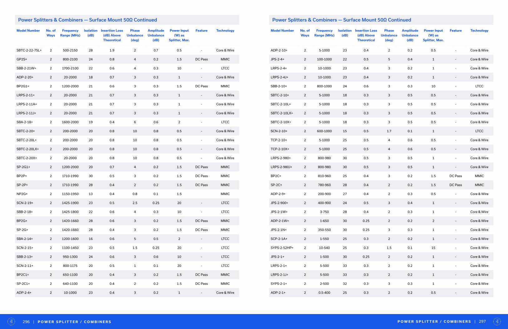
Model Number No. of
Ways
Frequency
Range (MHz)
Isolation
(dB)
Insertion Loss
(dB) Above
Theoretical
Phase
Unbalance
(deg)
Amplitude
Unbalance
(dB)
Power Input
(W) as
Splitter, Max.
Feature Technology
SBTC-2-22-75L+ 2 500-2150 28 1.9 2 0.7 0.5 - Core & Wire
GP2S+ 2 800-2100 24 0.8 4 0.2 1.5 DC Pass MMIC
SBB-2-21W+ 2 1700-2100 22 0.6 4 0.3 10 - LTCC
ADP-2-20+ 2 20-2000 18 0.7 3 0.3 1 - Core & Wire
BP2G1+ 2 1200-2000 21 0.6 3 0.3 1.5 DC Pass MMIC
LRPS-2-11+ 2 20-2000 21 0.7 3 0.3 1 - Core & Wire
LRPS-2-11A+ 2 20-2000 21 0.7 3 0.3 1 - Core & Wire
LRPS-2-11J+ 2 20-2000 21 0.7 3 0.3 1 - Core & Wire
SBA-2-18+ 2 1600-2000 19 0.4 6 0.6 2 - LTCC
SBTC-2-20+ 2 200-2000 20 0.8 10 0.8 0.5 - Core & Wire
SBTC-2-20L+ 2 200-2000 20 0.8 10 0.8 0.5 - Core & Wire
SBTC-2-20LX+ 2 200-2000 20 0.8 10 0.8 0.5 - Core & Wire
SBTC-2-20X+ 2 20-2000 20 0.8 10 0.8 0.5 - Core & Wire
SP-2G1+ 2 1200-2000 20 0.7 4 0.2 1.5 DC Pass MMIC
BP2P+ 2 1710-1990 30 0.5 3 0.2 1.5 DC Pass MMIC
SP-2P+ 2 1710-1990 28 0.4 2 0.2 1.5 DC Pass MMIC
NP2G+ 2 1150-1950 13 0.4 0.8 0.1 1.5 MMIC
SCN-2-19+ 2 1425-1900 23 0.5 2.5 0.25 20 - LTCC
SBB-2-18+ 2 1425-1800 22 0.6 4 0.3 10 - LTCC
BP2G+ 2 1420-1660 28 0.6 3 0.2 1.5 DC Pass MMIC
SP-2G+ 2 1420-1660 28 0.4 3 0.2 1.5 DC Pass MMIC
SBA-2-14+ 2 1200-1600 16 0.6 5 0.5 2 - LTCC
SCN-2-15+ 2 1100-1450 23 0.5 1.5 0.25 20 - LTCC
SBB-2-13+ 2 950-1300 24 0.6 3 0.6 10 - LTCC
SCN-2-11+ 2 800-1175 20 0.5 1 0.1 20 - LTCC
BP2C1+ 2 650-1100 20 0.4 3 0.2 1.5 DC Pass MMIC
SP-2C1+ 2 640-1100 20 0.4 2 0.2 1.5 DC Pass MMIC
ADP-2-4+ 2 10-1000 23 0.4 3 0.2 1 - Core & Wire
Model Number No. of
Ways
Frequency
Range (MHz)
Isolation
(dB)
Insertion Loss
(dB) Above
Theoretical
Phase
Unbalance
(deg)
Amplitude
Unbalance
(dB)
Power Input
(W) as
Splitter, Max.
Feature Technology
ADP-2-10+ 2 5-1000 23 0.4 2 0.2 0.5 - Core & Wire
JPS-2-4+ 2 100-1000 22 0.5 5 0.4 1 - Core & Wire
LRPS-2-4+ 2 10-1000 23 0.4 3 0.2 1 - Core & Wire
LRPS-2-4J+ 2 10-1000 23 0.4 3 0.2 1 - Core & Wire
SBB-2-10+ 2 800-1000 24 0.6 3 0.3 10 - LTCC
SBTC-2-10+ 2 5-1000 18 0.3 3 0.5 0.5 - Core & Wire
SBTC-2-10L+ 2 5-1000 18 0.3 3 0.5 0.5 - Core & Wire
SBTC-2-10LX+ 2 5-1000 18 0.3 3 0.5 0.5 - Core & Wire
SBTC-2-10X+ 2 5-1000 18 0.3 3 0.5 0.5 - Core & Wire
SCN-2-10+ 2 600-1000 15 0.5 1.7 0.1 1 - LTCC
TCP-2-10+ 2 5-1000 25 0.5 4 0.6 0.5 - Core & Wire
TCP-2-10X+ 2 5-1000 25 0.5 4 0.6 0.5 - Core & Wire
LRPS-2-980+ 2 800-980 30 0.5 3 0.5 1 - Core & Wire
LRPS-2-980J+ 2 800-980 30 0.5 3 0.5 1 - Core & Wire
BP2C+ 2 810-960 25 0.4 3 0.2 1.5 DC Pass MMIC
SP-2C+ 2 780-960 28 0.4 2 0.2 1.5 DC Pass MMIC
ADP-2-9+ 2 200-900 27 0.4 2 0.3 0.5 - Core & Wire
JPS-2-900+ 2 400-900 24 0.5 3 0.4 1 - Core & Wire
JPS-2-1W+ 2 3-750 28 0.4 2 0.3 1 - Core & Wire
ADP-2-1W+ 2 1-650 30 0.25 2 0.2 2 - Core & Wire
JPS-2-1N+ 2 350-550 30 0.25 3 0.3 1 - Core & Wire
SCP-2-1A+ 2 1-550 25 0.3 2 0.2 1 - Core & Wire
SYPS-2-52HP+ 2 10-540 25 0.3 1.5 0.1 15 - Core & Wire
JPS-2-1+ 2 1-500 30 0.25 2 0.2 1 - Core & Wire
LRPS-2-1+ 2 5-500 33 0.3 2 0.2 1 - Core & Wire
LRPS-2-1J+ 2 5-500 33 0.3 2 0.2 1 - Core & Wire
SYPS-2-1+ 2 2-500 32 0.3 3 0.3 1 - Core & Wire
ADP-2-1+ 2 0.5-400 25 0.3 2 0.2 0.5 - Core & Wire
P O W E R S P L I T T E R / C O M B I N E R S | 297| P O W E R S P L I T T E R / C O M B I N E R S296
Power Splitters & Combiners — Surface Mount 50Ω ContinuedPower Splitters & Combiners — Surface Mount 50Ω Continued
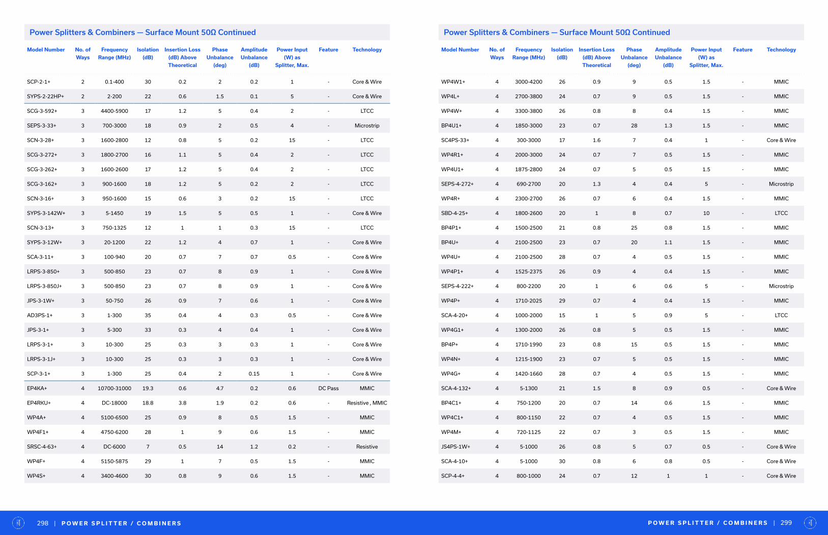
Model Number No. of
Ways
Frequency
Range (MHz)
Isolation
(dB)
Insertion Loss
(dB) Above
Theoretical
Phase
Unbalance
(deg)
Amplitude
Unbalance
(dB)
Power Input
(W) as
Splitter, Max.
Feature Technology
SCP-2-1+ 2 0.1-400 30 0.2 2 0.2 1 - Core & Wire
SYPS-2-22HP+ 2 2-200 22 0.6 1.5 0.1 5 - Core & Wire
SCG-3-592+ 3 4400-5900 17 1.2 5 0.4 2 - LTCC
SEPS-3-33+ 3 700-3000 18 0.9 2 0.5 4 - Microstrip
SCN-3-28+ 3 1600-2800 12 0.8 5 0.2 15 - LTCC
SCG-3-272+ 3 1800-2700 16 1.1 5 0.4 2 - LTCC
SCG-3-262+ 3 1600-2600 17 1.2 5 0.4 2 - LTCC
SCG-3-162+ 3 900-1600 18 1.2 5 0.2 2 - LTCC
SCN-3-16+ 3 950-1600 15 0.6 3 0.2 15 - LTCC
SYPS-3-142W+ 3 5-1450 19 1.5 5 0.5 1 - Core & Wire
SCN-3-13+ 3 750-1325 12 1 1 0.3 15 - LTCC
SYPS-3-12W+ 3 20-1200 22 1.2 4 0.7 1 - Core & Wire
SCA-3-11+ 3 100-940 20 0.7 7 0.7 0.5 - Core & Wire
LRPS-3-850+ 3 500-850 23 0.7 8 0.9 1 - Core & Wire
LRPS-3-850J+ 3 500-850 23 0.7 8 0.9 1 - Core & Wire
JPS-3-1W+ 3 50-750 26 0.9 7 0.6 1 - Core & Wire
AD3PS-1+ 3 1-300 35 0.4 4 0.3 0.5 - Core & Wire
JPS-3-1+ 3 5-300 33 0.3 4 0.4 1 - Core & Wire
LRPS-3-1+ 3 10-300 25 0.3 3 0.3 1 - Core & Wire
LRPS-3-1J+ 3 10-300 25 0.3 3 0.3 1 - Core & Wire
SCP-3-1+ 3 1-300 25 0.4 2 0.15 1 - Core & Wire
EP4KA+ 4 10700-31000 19.3 0.6 4.7 0.2 0.6 DC Pass MMIC
EP4RKU+ 4 DC-18000 18.8 3.8 1.9 0.2 0.6 - Resistive , MMIC
WP4A+ 4 5100-6500 25 0.9 8 0.5 1.5 - MMIC
WP4F1+ 4 4750-6200 28 1 9 0.6 1.5 - MMIC
SRSC-4-63+ 4 DC-6000 7 0.5 14 1.2 0.2 - Resistive
WP4F+ 4 5150-5875 29 1 7 0.5 1.5 - MMIC
WP4S+ 4 3400-4600 30 0.8 9 0.6 1.5 - MMIC
Model Number No. of
Ways
Frequency
Range (MHz)
Isolation
(dB)
Insertion Loss
(dB) Above
Theoretical
Phase
Unbalance
(deg)
Amplitude
Unbalance
(dB)
Power Input
(W) as
Splitter, Max.
Feature Technology
WP4W1+ 4 3000-4200 26 0.9 9 0.5 1.5 - MMIC
WP4L+ 4 2700-3800 24 0.7 9 0.5 1.5 - MMIC
WP4W+ 4 3300-3800 26 0.8 8 0.4 1.5 - MMIC
BP4U1+ 4 1850-3000 23 0.7 28 1.3 1.5 - MMIC
SC4PS-33+ 4 300-3000 17 1.6 7 0.4 1 - Core & Wire
WP4R1+ 4 2000-3000 24 0.7 7 0.5 1.5 - MMIC
WP4U1+ 4 1875-2800 24 0.7 5 0.5 1.5 - MMIC
SEPS-4-272+ 4 690-2700 20 1.3 4 0.4 5 - Microstrip
WP4R+ 4 2300-2700 26 0.7 6 0.4 1.5 - MMIC
SBD-4-25+ 4 1800-2600 20 1 8 0.7 10 - LTCC
BP4P1+ 4 1500-2500 21 0.8 25 0.8 1.5 - MMIC
BP4U+ 4 2100-2500 23 0.7 20 1.1 1.5 - MMIC
WP4U+ 4 2100-2500 28 0.7 4 0.5 1.5 - MMIC
WP4P1+ 4 1525-2375 26 0.9 4 0.4 1.5 - MMIC
SEPS-4-222+ 4 800-2200 20 1 6 0.6 5 - Microstrip
WP4P+ 4 1710-2025 29 0.7 4 0.4 1.5 - MMIC
SCA-4-20+ 4 1000-2000 15 1 5 0.9 5 - LTCC
WP4G1+ 4 1300-2000 26 0.8 5 0.5 1.5 - MMIC
BP4P+ 4 1710-1990 23 0.8 15 0.5 1.5 - MMIC
WP4N+ 4 1215-1900 23 0.7 5 0.5 1.5 - MMIC
WP4G+ 4 1420-1660 28 0.7 4 0.5 1.5 - MMIC
SCA-4-132+ 4 5-1300 21 1.5 8 0.9 0.5 - Core & Wire
BP4C1+ 4 750-1200 20 0.7 14 0.6 1.5 - MMIC
WP4C1+ 4 800-1150 22 0.7 4 0.5 1.5 - MMIC
WP4M+ 4 720-1125 22 0.7 3 0.5 1.5 - MMIC
JS4PS-1W+ 4 5-1000 26 0.8 5 0.7 0.5 - Core & Wire
SCA-4-10+ 4 5-1000 30 0.8 6 0.8 0.5 - Core & Wire
SCP-4-4+ 4 800-1000 24 0.7 12 1 1 - Core & Wire
P O W E R S P L I T T E R / C O M B I N E R S | 299| P O W E R S P L I T T E R / C O M B I N E R S298
Power Splitters & Combiners — Surface Mount 50Ω ContinuedPower Splitters & Combiners — Surface Mount 50Ω Continued
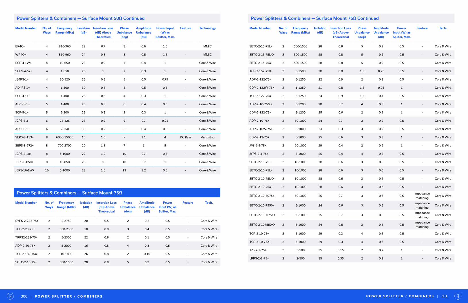
Model Number No. of
Ways
Frequency
Range (MHz)
Isolation
(dB)
Insertion Loss
(dB) Above
Theoretical
Phase
Unbalance
(deg)
Amplitude
Unbalance
(dB)
Power Input
(W) as
Splitter, Max.
Feature Technology
BP4C+ 4 810-960 22 0.7 8 0.6 1.5 MMIC
WP4C+ 4 810-960 24 0.8 3 0.5 1.5 - MMIC
SCP-4-1W+ 4 10-650 23 0.9 7 0.4 1 - Core & Wire
SCPS-4-62+ 4 1-650 26 1 2 0.3 1 - Core & Wire
JS4PS-1+ 4 80-520 36 0.8 5 0.5 0.75 - Core & Wire
AD4PS-1+ 4 1-500 30 0.5 5 0.5 0.5 - Core & Wire
SCP-4-1+ 4 1-400 26 0.6 4 0.3 1 - Core & Wire
AD5PS-1+ 5 1-400 25 0.3 6 0.4 0.5 - Core & Wire
SCP-5-1+ 5 2-200 29 0.3 3 0.3 1 - Core & Wire
JCPS-6-3 6 75-425 23 0.9 9 0.7 0.25 - Core & Wire
AD6PS-1+ 6 2-250 30 0.2 6 0.4 0.5 - Core & Wire
SEPS-8-153+ 8 6000-15000 15 1.6 - 1.1 4 DC Pass Microstrip
SEPS-8-272+ 8 700-2700 20 1.8 7 1 5 - Core & Wire
JCPS-8-10+ 8 5-1000 22 1.2 10 0.7 0.5 - Core & Wire
JCPS-8-850+ 8 10-850 25 1 10 0.7 1 - Core & Wire
JEPS-16-1W+ 16 5-1000 23 1.5 13 1.2 0.5 - Core & Wire
Power Splitters & Combiners — Surface Mount 75Ω
Model Number No. of
Ways
Frequency
Range (MHz)
Isolation
(dB)
Insertion Loss
(dB) Above
Theoretical
Phase
Unbalance
(deg)
Amplitude
Unbalance
(dB)
Power
Input (W) as
Spliter, Max.
Feature Tech.
SYPS-2-282-75+ 2 2-2750 20 0.5 2 0.2 0.5 - Core & Wire
TCP-2-23-75+ 2 900-2300 18 0.8 3 0.4 0.5 - Core & Wire
TRPS2-232-75+ 2 5-2300 22 0.8 2 0.1 0.5 - Core & Wire
ADP-2-20-75+ 2 5-2000 16 0.5 4 0.3 0.5 - Core & Wire
TCP-2-182-75X+ 2 10-1800 26 0.8 2 0.15 0.5 - Core & Wire
SBTC-2-15-75+ 2 500-1500 28 0.8 5 0.9 0.5 - Core & Wire
Model Number No. of
Ways
Frequency
Range (MHz)
Isolation
(dB)
Insertion Loss
(dB) Above
Theoretical
Phase
Unbalance
(deg)
Amplitude
Unbalance
(dB)
Power
Input (W) as
Spliter, Max.
Feature Tech.
SBTC-2-15-75L+ 2 500-1500 28 0.8 5 0.9 0.5 - Core & Wire
SBTC-2-15-75LX+ 2 500-1500 28 0.8 5 0.9 0.5 - Core & Wire
SBTC-2-15-75X+ 2 500-1500 28 0.8 5 0.9 0.5 - Core & Wire
TCP-2-152-75X+ 2 5-1500 28 0.8 1.5 0.25 0.5 - Core & Wire
ADP-2-122-75+ 2 5-1250 22 0.9 2 0.2 0.5 - Core & Wire
CDP-2-122W-75+ 2 1-1250 21 0.8 1.5 0.25 1 - Core & Wire
TCP-2-122-75X+ 2 5-1250 24 0.9 1.5 0.4 0.5 - Core & Wire
ADP-2-10-75M+ 2 5-1200 28 0.7 4 0.3 1 - Core & Wire
CDP-2-122-75+ 2 5-1200 25 0.6 2 0.2 1 - Core & Wire
ADP-2-10-75+ 2 50-1000 24 0.7 2 0.2 0.5 - Core & Wire
ADP-2-10W-75+ 2 5-1000 23 0.3 3 0.2 0.5 - Core & Wire
CDP-2-13-75+ 2 5-1000 25 0.6 3 0.3 1 - Core & Wire
JPS-2-4-75+ 2 20-1000 29 0.4 2 0.2 1 - Core & Wire
JYPS-2-4-75+ 2 5-1000 25 0.4 4 0.3 0.5 - Core & Wire
SBTC-2-10-75+ 2 10-1000 28 0.6 3 0.6 0.5 - Core & Wire
SBTC-2-10-75L+ 2 10-1000 28 0.6 3 0.6 0.5 - Core & Wire
SBTC-2-10-75LX+ 2 10-1000 28 0.6 3 0.6 0.5 - Core & Wire
SBTC-2-10-75X+ 2 10-1000 28 0.6 3 0.6 0.5 - Core & Wire
SBTC-2-10-5075+ 2 50-1000 25 0.7 3 0.6 0.5Impedance
matchingCore & Wire
SBTC-2-10-7550+ 2 5-1000 24 0.6 3 0.5 0.5Impedance
matchingCore & Wire
SBTC-2-105075X+ 2 50-1000 25 0.7 3 0.6 0.5Impedance
matchingCore & Wire
SBTC-2-107550X+ 2 5-1000 24 0.6 3 0.5 0.5Impedance
matchingCore & Wire
TCP-2-10-75+ 2 5-1000 29 0.3 4 0.6 0.5 - Core & Wire
TCP-2-10-75X+ 2 5-1000 29 0.3 4 0.6 0.5 - Core & Wire
JPS-2-1-75+ 2 5-500 35 0.15 2 0.2 1 - Core & Wire
LRPS-2-1-75+ 2 2-500 35 0.35 2 0.2 1 - Core & Wire
P O W E R S P L I T T E R / C O M B I N E R S | 301| P O W E R S P L I T T E R / C O M B I N E R S300
Power Splitters & Combiners — Surface Mount 50Ω Continued Power Splitters & Combiners — Surface Mount 75Ω Continued

Model Number No. of
Ways
Frequency
Range (MHz)
Isolation
(dB)
Insertion Loss
(dB) Above
Theoretical
Phase
Unbalance
(deg)
Amplitude
Unbalance
(dB)
Power Input
(W) as
Splitter, Max.
Feature Technology
EP2KA-D+ 2 10000-43500 22 0.9 6.1 0.22 1.25 DC Pass MMIC
EP2K-D+ 2 2000-26500 18.9 1.6 6 0.2 2.5 DC Pass MMIC
EP2RKU-D+ 2 DC-18000 23 2.9 0.6 0.1 0.6 - Resistive , MMIC
EP2C-D+ 2 1800-12500 19.7 0.9 3.2 0.09 1.85 DC Pass MMIC
EP2W-D+ 2 500-9500 19.4 1.8 1.7 0.1 2.5 DC Pass MMIC
EP2RCW-D+ 2 DC-8000 22.3 4.5 0.1 0.1 0.6 - Resistive , MMIC
EP4KA-D+ 4 10700-31000 18.8 3.8 1.9 0.2 0.6 DC Pass MMIC
EP4RKU-D+ 4 DC-18000 23 4.8 0.9 0.2 0.6 - Resistive , MMIC
WP4R-D+ 4 2000-3000 24 0.7 2 0.1 1.5 - MMIC
WP4P1-D+ 4 1525-2375 26 0.9 2 0.2 1.5 - MMIC
Power Splitters & Combiners — Bare Die 50Ω
Model Number No.
of
Ways
Frequency
Range (MHz)
Isolation
(dB)
Insertion Loss
(dB) Above
Theoretical
Phase
Unbalance
(deg)
Amplitude
Unbalance
(dB)
Power Input
(W) as Spliter,
Max.
Feature Tech. Connector
Type
ZC2PD-E1653+ 2 1000-65000 32 1.8 1.3 0.1 12 DC Pass Stripline 1.85mm
ZC2PD-E2653+ 2 2000-65000 30 1.2 1.9 0.1 12 DC Pass Stripline 1.85mm
ZC2PD-E6653+ 2 6000-65000 31 1 1.7 0.06 12 DC Pass Stripline 1.85mm
ZC2PD-E18653+ 2 18000-65000 29 1.2 2.5 0.13 12 DC Pass Stripline 1.85mm
ZC2PD-E40653+ 2 40000-65000 24 1.2 2.5 0.06 12 DC Pass Stripline 1.85mm
ZN2PD-E653+ 2 10000-65000 22 1.2 10.7 0.64 10 DC Pass - 1.85mm
ZC2PD-E1864+ 2 18000-60000 28 1 1.6 0.1 12 DC Pass Stripline 1.85mm
ZC2PD-V154+ 2 1000-50000 32 1.9 1.2 0.11 16 DC Pass Stripline 2.4mm
ZC2PD-V254+ 2 2000-50000 28 1.0 1.3 0.09 16 DC Pass Stripline 2.4mm
ZC2PD-V654+ 2 6000-50000 27 0.9 0.8 0.06 16 DC Pass Stripline 2.4mm
ZC2PD-V1854+ 2 18000-50000 28 0.75 0.71 0.08 16 DC Pass Stripline 2.4mm
ZC2PD-V2654+ 2 26000-50000 26 1.0 1.1 0.06 16 DC Pass Stripline 2.4mm
ZN2PD-V54+ 2 10000-50000 23 1.8 2.7 0.13 10 DC Pass - 2.4mm
ZC2PD-V18443+ 2 18000-44000 29 0.7 0.9 0.04 20 DC Pass Stripline 2.4mm
ZC2PD-V24443+ 2 24000-44000 30 0.9 1.2 0.04 16 DC Pass Stripline 2.4mm
ZC2PD-K5R44W+ 2 500-40000 35 1.9 1 0.1 20 DC Pass - 2.92mm
ZC2PD-K0144+ 2 1000-40000 36 0.9 1.1 0.05 20 DC Pass - 2.92mm
ZC2PD-K0244+ 2 2000-40000 32 0.8 0.5 0.04 20 DC Pass - 2.92mm
ZC2PD-K0644+ 2 6000-40000 29 0.7 1.3 0.03 20 DC Pass Stripline 2.92mm
ZC2PD-K1844+ 2 18000-40000 27 0.8 1.1 0.05 20 DC Pass - 2.92mm
ZN2PD-44-V+ 2 10000-40000 21 1.0 3.9 0.07 10 DC Pass - 2.4mm
ZN2PD-K44+ 2 10000-40000 20 0.9 10 0.6 10 DC Pass - 2.92mm
ZC2PD-5R263-S+ 2 500-26500 35 1.2 0.6 0.05 14 DC Pass - SMA
ZC2PD-01263-S+ 2 1000-26500 33 0.7 0.7 0.04 14 DC Pass - SMA
ZC2PD-02263-S+ 2 2000-26500 31 0.6 0.69 0.04 14 DC Pass - SMA
ZC2PD-06263-S+ 2 6000-26500 27 0.4 0.4 0.03 14 DC Pass Stripline SMA
ZC2PD-18263-S+ 2 18000-26500 29 0.7 1 0.03 11 DC Pass Stripline SMA
ZFRSC-183+ 2 DC-18000 6.5 0.7 7 0.5 0.16 - Resistive SMA
P O W E R S P L I T T E R / C O M B I N E R S | 303| P O W E R S P L I T T E R / C O M B I N E R S302
Model Number No. of
Ways
Frequency
Range (MHz)
Isolation
(dB)
Insertion Loss
(dB) Above
Theoretical
Phase
Unbalance
(deg)
Amplitude
Unbalance
(dB)
Power
Input (W) as
Spliter, Max.
Feature Tech.
LRPS-2-1-75J+ 2 2-500 35 0.35 2 0.2 1 - Core & Wire
SYPS-3-12W-75+ 3 20-1200 22 1.2 4 0.7 1 - Core & Wire
SCA-4-15-75+ 4 10-1500 19 1.2 9 0.9 0.5 - Core & Wire
SXPS-4-13-75+ 4 5-1300 22 1.2 1 0.15 0.25 - Core & Wire
SCA-4-10-75+ 4 10-1000 30 1.5 9 0.9 0.5 - Core & Wire
SCP-4-4-75+ 4 10-1000 32 0.65 6 0.4 1 - Core & Wire
JS4PS-1W-75 4 5-750 35 0.6 5 0.3 0.25 - Core & Wire
SCP-4-1W-75+ 4 10-750 32 0.65 3 0.4 0.5 - Core & Wire
JCPS-8-850-75+ 8 10-850 25 1 - 0.7 1 - Core & Wire
Power Splitters & Combiners — Surface Mount 75Ω Continued Power Splitters & Combiners — Coaxial 50Ω

Model Number No.
of
Ways
Frequency
Range (MHz)
Isolation
(dB)
Insertion Loss
(dB) Above
Theoretical
Phase
Unbalance
(deg)
Amplitude
Unbalance
(dB)
Power Input
(W) as Spliter,
Max.
Feature Tech. Connector
Type
ZN2PD-183W-S+ 2 500-18000 24 0.8 1.1 0.05 20 DC Pass Stripline SMA
ZN2PD-02183-S+ 2 2000-18000 20 0.5 4 0.3 10 DC Pass - SMA
ZX10-2-183-S+ 2 1500-18000 20 1 4 0.2 30 DC Pass - SMA
ZX10-2-143M-S+ 2 4000-14000 20 1.1 6 0.5 2.5 DC Pass - SMA
ZX10-2-126-S+ 2 7400-12600 23 0.3 10 0.5 1 DC Pass - SMA
ZX10-2-1252-S+ 2 1800-12500 20 1.1 12 0.9 1.85 DC Pass - SMA
ZFRSC-123+ 2 DC-12000 19.5 3.5 3 0.25 0.16 - Resistive SMA
ZN2PD2-14W-S+ 2 500-10500 20 0.9 2 0.1 35 DC Pass - SMA
ZFSC-2-10G+ 2 2000-10000 20 0.6 12 0.5 1 DC Pass SMA
ZX10R-14-S+ 2 DC-10000 6 0.5 3 0.2 0.16 - Resistive SMA
ZX10-2-98-S+ 2 4750-9800 23 0.3 9 0.5 1 DC Pass - SMA
ZFSC-2-9G+ 2 3500-9000 20 0.6 10 0.5 1 DC Pass - SMA
ZN2PD-9G-S+ 2 1700-9000 22 1 2 0.2 30 DC Pass - SMA
ZX10-2-852-S+ 2 500-8500 20 1.9 8 0.9 2.5 DC Pass - SMA
ZN2PD-83W-N+ 2 500-8000 24 0.5 1.3 0.04 20 DC Pass Stripline N
ZX10-2-722-S+ 2 2800-7200 22 0.8 10 0.4 1.5 - - SMA
ZX10-2-71-S+ 2 2950-7100 23 0.25 3 0.4 1 DC Pass - SMA
ZACS622-100W+ 2 650-6200 22 0.5 2 0.1 100 DC Pass - SMA
ZN2PD-622SMP+ 2 350-6200 18 1 2 0.2 10 DC Pass - SMP
ZX10-2-622-S+ 2 2900-6200 24 0.9 9 0.3 1.5 - - SMA
ZAPD-50W+ 2 4200-6000 26 0.3 5 0.7 10 DC Pass - N
ZB2PD-63+ 2 600-6000 19 0.9 2.8 0.2 30 DC Pass - N
ZN2PD-63-S+ 2 1800-6000 24 0.4 4 0.3 10 DC Pass - SMA
ZN2PD1-63+ 2 500-6000 18 0.45 1.5 0.1 30 DC Pass - SMA
ZN2PD2-63-S+ 2 350-6000 20 0.7 1.5 0.2 25 DC Pass - SMA
ZN2PD2-63A+ 2 350-6000 18 0.8 1 0.2 25 DC Pass - SMA
ZAPD-50+ 2 4400-5000 26 0.3 5 0.5 10 DC Pass - SMA
ZN2PD2-50-S+ 2 500-5000 25 0.8 4 0.5 10 DC Pass - SMA
Model Number No.
of
Ways
Frequency
Range (MHz)
Isolation
(dB)
Insertion Loss
(dB) Above
Theoretical
Phase
Unbalance
(deg)
Amplitude
Unbalance
(dB)
Power Input
(W) as Spliter,
Max.
Feature Tech. Connector
Type
ZX10-2-442-S+ 2 1500-4400 20 1 6 0.3 1.5 - - SMA
ZAPD-4+ 2 2000-4200 25 0.4 6 0.4 10 DC Pass - SMA
ZFRSC-42+ 2 DC-4200 6.5 0.1 3 0.2 0.75 - Resistive BNC
ZX10-2-42-S+ 2 1900-4200 23 0.2 3 0.3 1 DC Pass - SMA
ZFSC-2-372+ 2 10-3700 18 0.6 4 0.3 1 - - SMA
ZACS362-100W+ 2 600-3600 18 0.6 1 0.15 100 DC Pass - SMA
ZX10-2-332-S+ 2 1600-3300 24 0.8 5 0.2 1.5 - - SMA
ZAPD-30-S+ 2 20-3000 16 1.1 5 0.4 1 - - SMA
ZN2PD-272SMP+ 2 600-2750 22 0.4 1 0.1 10 DC Pass - SMP
ZAPD-2-272+ 2 800-2700 22 0.3 3 0.3 10 - - SMA
ZAPD-2-252+ 2 5-2500 17 1 3 0.4 1 - - BNC
ZFSC-2-2500+ 2 10-2500 17 0.6 4 0.3 1 - - BNC
ZX10-2-25-S+ 2 1000-2500 20 1.2 10 1.2 1 - - SMA
ZX10-2-252-S+ 2 500-2500 22 0.9 4 0.2 1.5 - - SMA
ZACS242-100W+ 2 500-2450 22 0.8 2 0.1 100 DC Pass - SMA
ZN2PD1-222-S+ 2 600-2200 18 0.2 2 0.2 10 DC Pass - SMA
ZX10-2-222-S+ 2 800-2200 24 0.8 4 0.2 1.5 - - SMA
ZAPD-2DC+ 2 950-2150 22 0.3 5 0.3 10 DC Pass - BNC
ZAPD-2-21-3W+ 2 700-2100 25 0.4 0.7 0.05 10 DC Pass - SMA
ZAPD-2+ 2 1000-2000 25 0.25 2 0.2 10 DC Pass - BNC
ZAPD-20+ 2 700-2000 30 0.3 3 0.4 10 DC Pass - BNC
ZAPD-21+ 2 500-2000 25 0.25 3 0.2 10 DC Pass - BNC
ZAPD-23-S+ 2 700-2000 27 0.4 2 0.2 10 DC Pass - SMA
ZESC-2-11+ 2 10-2000 18 0.5 3 0.3 1 - - SMA
ZFRSC-2050+ 2 DC-2000 6.6 0.3 2 0.2 0.75 - Resistive BNC
ZFSC-2-11+ 2 10-2000 16 1.2 2 0.3 1 - - BNC
ZN2PD-20-S+ 2 750-2000 25 0.2 4 0.3 5 DC Pass - SMA
ZN2PD-1900W+ 2 1500-2000 24 0.2 3 0.3 10 DC Pass - SMA
P O W E R S P L I T T E R / C O M B I N E R S | 305| P O W E R S P L I T T E R / C O M B I N E R S304
Power Splitters & Combiners — Coaxial 50Ω ContinuedPower Splitters & Combiners — Coaxial 50Ω Continued
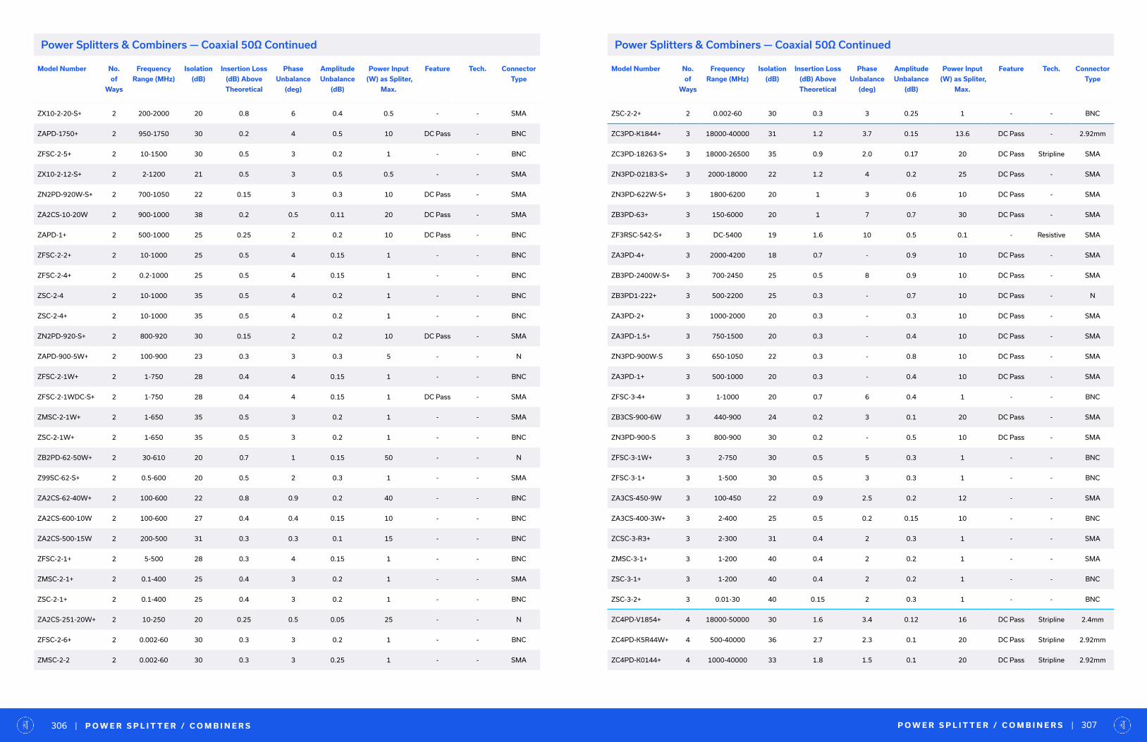
Model Number No.
of
Ways
Frequency
Range (MHz)
Isolation
(dB)
Insertion Loss
(dB) Above
Theoretical
Phase
Unbalance
(deg)
Amplitude
Unbalance
(dB)
Power Input
(W) as Spliter,
Max.
Feature Tech. Connector
Type
ZX10-2-20-S+ 2 200-2000 20 0.8 6 0.4 0.5 - - SMA
ZAPD-1750+ 2 950-1750 30 0.2 4 0.5 10 DC Pass - BNC
ZFSC-2-5+ 2 10-1500 30 0.5 3 0.2 1 - - BNC
ZX10-2-12-S+ 2 2-1200 21 0.5 3 0.5 0.5 - - SMA
ZN2PD-920W-S+ 2 700-1050 22 0.15 3 0.3 10 DC Pass - SMA
ZA2CS-10-20W 2 900-1000 38 0.2 0.5 0.11 20 DC Pass - SMA
ZAPD-1+ 2 500-1000 25 0.25 2 0.2 10 DC Pass - BNC
ZFSC-2-2+ 2 10-1000 25 0.5 4 0.15 1 - - BNC
ZFSC-2-4+ 2 0.2-1000 25 0.5 4 0.15 1 - - BNC
ZSC-2-4 2 10-1000 35 0.5 4 0.2 1 - - BNC
ZSC-2-4+ 2 10-1000 35 0.5 4 0.2 1 - - BNC
ZN2PD-920-S+ 2 800-920 30 0.15 2 0.2 10 DC Pass - SMA
ZAPD-900-5W+ 2 100-900 23 0.3 3 0.3 5 - - N
ZFSC-2-1W+ 2 1-750 28 0.4 4 0.15 1 - - BNC
ZFSC-2-1WDC-S+ 2 1-750 28 0.4 4 0.15 1 DC Pass - SMA
ZMSC-2-1W+ 2 1-650 35 0.5 3 0.2 1 - - SMA
ZSC-2-1W+ 2 1-650 35 0.5 3 0.2 1 - - BNC
ZB2PD-62-50W+ 2 30-610 20 0.7 1 0.15 50 - - N
Z99SC-62-S+ 2 0.5-600 20 0.5 2 0.3 1 - - SMA
ZA2CS-62-40W+ 2 100-600 22 0.8 0.9 0.2 40 - - BNC
ZA2CS-600-10W 2 100-600 27 0.4 0.4 0.15 10 - - BNC
ZA2CS-500-15W 2 200-500 31 0.3 0.3 0.1 15 - - BNC
ZFSC-2-1+ 2 5-500 28 0.3 4 0.15 1 - - BNC
ZMSC-2-1+ 2 0.1-400 25 0.4 3 0.2 1 - - SMA
ZSC-2-1+ 2 0.1-400 25 0.4 3 0.2 1 - - BNC
ZA2CS-251-20W+ 2 10-250 20 0.25 0.5 0.05 25 - - N
ZFSC-2-6+ 2 0.002-60 30 0.3 3 0.2 1 - - BNC
ZMSC-2-2 2 0.002-60 30 0.3 3 0.25 1 - - SMA
Model Number No.
of
Ways
Frequency
Range (MHz)
Isolation
(dB)
Insertion Loss
(dB) Above
Theoretical
Phase
Unbalance
(deg)
Amplitude
Unbalance
(dB)
Power Input
(W) as Spliter,
Max.
Feature Tech. Connector
Type
ZSC-2-2+ 2 0.002-60 30 0.3 3 0.25 1 - - BNC
ZC3PD-K1844+ 3 18000-40000 31 1.2 3.7 0.15 13.6 DC Pass - 2.92mm
ZC3PD-18263-S+ 3 18000-26500 35 0.9 2.0 0.17 20 DC Pass Stripline SMA
ZN3PD-02183-S+ 3 2000-18000 22 1.2 4 0.2 25 DC Pass - SMA
ZN3PD-622W-S+ 3 1800-6200 20 1 3 0.6 10 DC Pass - SMA
ZB3PD-63+ 3 150-6000 20 1 7 0.7 30 DC Pass - SMA
ZF3RSC-542-S+ 3 DC-5400 19 1.6 10 0.5 0.1 - Resistive SMA
ZA3PD-4+ 3 2000-4200 18 0.7 - 0.9 10 DC Pass - SMA
ZB3PD-2400W-S+ 3 700-2450 25 0.5 8 0.9 10 DC Pass - SMA
ZB3PD1-222+ 3 500-2200 25 0.3 - 0.7 10 DC Pass - N
ZA3PD-2+ 3 1000-2000 20 0.3 - 0.3 10 DC Pass - SMA
ZA3PD-1.5+ 3 750-1500 20 0.3 - 0.4 10 DC Pass - SMA
ZN3PD-900W-S 3 650-1050 22 0.3 - 0.8 10 DC Pass - SMA
ZA3PD-1+ 3 500-1000 20 0.3 - 0.4 10 DC Pass - SMA
ZFSC-3-4+ 3 1-1000 20 0.7 6 0.4 1 - - BNC
ZB3CS-900-6W 3 440-900 24 0.2 3 0.1 20 DC Pass - SMA
ZN3PD-900-S 3 800-900 30 0.2 - 0.5 10 DC Pass - SMA
ZFSC-3-1W+ 3 2-750 30 0.5 5 0.3 1 - - BNC
ZFSC-3-1+ 3 1-500 30 0.5 3 0.3 1 - - BNC
ZA3CS-450-9W 3 100-450 22 0.9 2.5 0.2 12 - - SMA
ZA3CS-400-3W+ 3 2-400 25 0.5 0.2 0.15 10 - - BNC
ZCSC-3-R3+ 3 2-300 31 0.4 2 0.3 1 - - SMA
ZMSC-3-1+ 3 1-200 40 0.4 2 0.2 1 - - SMA
ZSC-3-1+ 3 1-200 40 0.4 2 0.2 1 - - BNC
ZSC-3-2+ 3 0.01-30 40 0.15 2 0.3 1 - - BNC
ZC4PD-V1854+ 4 18000-50000 30 1.6 3.4 0.12 16 DC Pass Stripline 2.4mm
ZC4PD-K5R44W+ 4 500-40000 36 2.7 2.3 0.1 20 DC Pass Stripline 2.92mm
ZC4PD-K0144+ 4 1000-40000 33 1.8 1.5 0.1 20 DC Pass Stripline 2.92mm
P O W E R S P L I T T E R / C O M B I N E R S | 307| P O W E R S P L I T T E R / C O M B I N E R S306
Power Splitters & Combiners — Coaxial 50Ω ContinuedPower Splitters & Combiners — Coaxial 50Ω Continued

Model Number No.
of
Ways
Frequency
Range (MHz)
Isolation
(dB)
Insertion Loss
(dB) Above
Theoretical
Phase
Unbalance
(deg)
Amplitude
Unbalance
(dB)
Power Input
(W) as Spliter,
Max.
Feature Tech. Connector
Type
ZC4PD-K0244+ 4 2000-40000 28 2.7 2.8 0.14 20 DC Pass - 2.92mm
ZC4PD-K0644+ 4 6000-40000 26 1.5 2.9 0.13 20 DC Pass Stripline 2.92mm
ZC4PD-K1844+ 4 18000-40000 27 1.2 3.5 0.12 20 DC Pass - 2.92mm
ZN4PD-K44+ 4 10000-40000 22 1.5 6 0.3 20 - - 2.92mm
ZC4PD-5R263-S+ 4 500-26500 34 2.7 1.6 0.15 20 DC Pass Stripline SMA
ZC4PD-01263-S+ 4 1000-26500 33 1.6 1.9 0.06 14 DC Pass - SMA
ZC4PD-02263-S+ 4 2000-26500 31 1.5 1.5 0.07 14 DC Pass - SMA
ZC4PD-06263-S+ 4 6000-26500 26 1.5 2.0 0.13 20 DC Pass Stripline SMA
ZC4PD-18263-S+ 4 18000-26500 28 1.1 2.5 0.1 20 DC Pass Stripline SMA
ZN4PD-5R183-S+ 4 500-18000 25 1.2 3 0.1 20 DC Pass Stripline SMA
ZN4PD-02183-S+ 4 2000-18000 20 1 3.5 0.3 30 DC Pass - SMA
ZN4PD1-183W-S+ 4 4000-18000 22 0.7 3 0.25 30 DC Pass - SMA
ZC4PD-153-S+ 4 6000-15000 22 1.3 8 0.4 10 DC Pass - SMA
ZFRSC-4-842+ 4 DC-8400 6.4 0.3 4 0.3 0.16 - Resistive SMA
ZN4PD1-842-S+ 4 2100-8400 19 1.3 5 0.5 10 DC Pass - SMA
ZB4PD-6.4-S+ 4 5400-6800 25 0.6 9 0.9 10 DC Pass - SMA
ZN4PD-642W-S+ 4 1600-6000 23 0.9 4 0.2 10 DC Pass - SMA
ZN4PD1-63-S+ 4 2000-6000 26 0.7 5 0.4 10 DC Pass - SMA
ZN4PD1-63HP-S+ 4 250-6000 23 1 2 0.2 30 DC Pass - SMA
ZN4PD1-63LW-S+ 4 500-6000 23 0.6 2 0.15 30 DC Pass - SMA
ZB4PD1-5.8+ 4 4600-5800 25 0.4 5 0.4 10 DC Pass - BNC
ZB4PD-462W+ 4 380-4600 22 0.9 2 0.2 30 DC Pass - SMA
ZA4PD-4+ 4 2000-4200 25 0.5 16 0.8 10 DC Pass - SMA
ZB4PD-4+ 4 3700-4200 24 0.6 8 0.8 10 DC Pass - SMA
ZB4PD-42+ 4 1700-4200 23 0.5 8 0.8 10 DC Pass - SMA
ZB4PD-332HP+ 4 500-3300 22 1 3 0.2 100 DC Pass - N
ZN4PD-33SMP+ 4 500-3000 20 0.9 3 0.3 10 DC Pass - SMP
ZB4PD-282-50W+ 4 500-2750 20 1.8 6 0.4 100 DC Pass - N
Model Number No.
of
Ways
Frequency
Range (MHz)
Isolation
(dB)
Insertion Loss
(dB) Above
Theoretical
Phase
Unbalance
(deg)
Amplitude
Unbalance
(dB)
Power Input
(W) as Spliter,
Max.
Feature Tech. Connector
Type
ZN4PD-272-S+ 4 500-2700 22 0.9 3 0.25 10 DC Pass - SMA
ZX10-4-27-S+ 4 2225-2700 20 1 9 1.2 2.5 - - SMA
ZX10-4A-27-S+ 4 2225-2600 23 0.9 6 0.8 2.5 - - SMA
ZX10-4-24-S+ 4 1675-2350 20 0.9 5 0.7 2.5 - - SMA
ZB4PD-232-50W+ 4 600-2300 19 1.1 0.9 0.05 50 DC Pass - SMA
ZX10-4A-24-S+ 4 1675-2200 23 0.8 6 0.6 2.5 - - SMA
ZA4PD-2+ 4 1000-2000 25 0.3 6 0.7 10 DC Pass - SMA
ZB4PD1-2000+ 4 800-2000 25 0.6 - 0.3 10 DC Pass - BNC
ZN4PD-20-S 4 1800-2000 31 0.3 4 0.5 10 DC Pass - SMA
ZX10-4-19-S+ 4 1425-1900 20 0.75 6 0.9 2.5 - - SMA
ZX10-4A-19-S+ 4 1425-1900 22 0.75 4 0.7 2.5 - - SMA
ZC4PD-18-S+ 4 1000-1800 32 0.3 6 0.4 10 DC Pass - SMA
ZX10-4-14-S+ 4 1100-1450 20 0.8 7 0.8 2.5 - - SMA
ZX10-4A-14-S+ 4 1100-1450 25 0.6 4 0.7 2.5 - - SMA
ZX10-4-11-S+ 4 800-1125 20 0.6 3 0.7 2.5 - - SMA
ZX10-4A-11-S+ 4 800-1125 22 0.6 4 0.6 2.5 - - SMA
ZFSC-4-1+ 4 1-1000 23 0.6 8 0.4 1 - - SMA
ZN4PD-920W-S+ 4 670-1000 22 0.3 3 0.2 10 DC Pass - SMA
ZN4PD-920-S+ 4 800-920 30 0.25 2 0.2 10 DC Pass - SMA
ZC4PD-900-S+ 4 800-900 30 0.3 3 0.2 10 - - SMA
ZB4CS-870-10W 4 570-870 28 0.35 0.6 0.1 20 DC Pass - N
ZBSC-413+ 4 10-800 18 1 8 0.4 1 - - SMA
ZB4CS-700-10W 4 400-700 25 0.35 0.6 0.1 20 DC Pass - SMA
ZB4PD-52-20W+ 4 10-500 29 0.4 2 0.1 20 - - BNC
ZB4PD1-500+ 4 5-500 34 0.5 3 0.2 1 - - BNC
ZFSC-4-1W 4 10-500 23 0.6 8 0.3 1 - - SMA
ZFSC-4-1W+ 4 10-500 23 0.6 8 0.3 1 - - SMA
ZB4CS-440-12W 4 100-440 27 0.6 0.8 0.15 10 - - BNC
P O W E R S P L I T T E R / C O M B I N E R S | 309| P O W E R S P L I T T E R / C O M B I N E R S308
Power Splitters & Combiners — Coaxial 50Ω ContinuedPower Splitters & Combiners — Coaxial 50Ω Continued
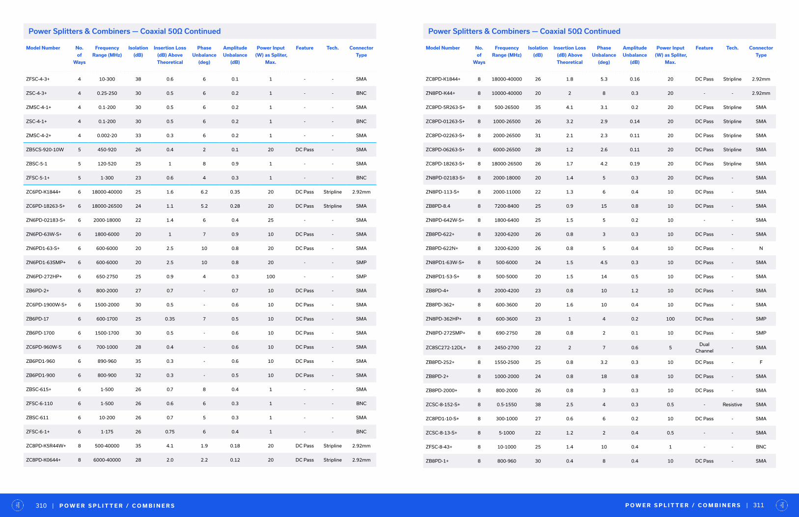
Model Number No.
of
Ways
Frequency
Range (MHz)
Isolation
(dB)
Insertion Loss
(dB) Above
Theoretical
Phase
Unbalance
(deg)
Amplitude
Unbalance
(dB)
Power Input
(W) as Spliter,
Max.
Feature Tech. Connector
Type
ZFSC-4-3+ 4 10-300 38 0.6 6 0.1 1 - - SMA
ZSC-4-3+ 4 0.25-250 30 0.5 6 0.2 1 - - BNC
ZMSC-4-1+ 4 0.1-200 30 0.5 6 0.2 1 - - SMA
ZSC-4-1+ 4 0.1-200 30 0.5 6 0.2 1 - - BNC
ZMSC-4-2+ 4 0.002-20 33 0.3 6 0.2 1 - - SMA
ZB5CS-920-10W 5 450-920 26 0.4 2 0.1 20 DC Pass - SMA
ZBSC-5-1 5 120-520 25 1 8 0.9 1 - - SMA
ZFSC-5-1+ 5 1-300 23 0.6 4 0.3 1 - - BNC
ZC6PD-K1844+ 6 18000-40000 25 1.6 6.2 0.35 20 DC Pass Stripline 2.92mm
ZC6PD-18263-S+ 6 18000-26500 24 1.1 5.2 0.28 20 DC Pass Stripline SMA
ZN6PD-02183-S+ 6 2000-18000 22 1.4 6 0.4 25 - - SMA
ZN6PD-63W-S+ 6 1800-6000 20 1 7 0.9 10 DC Pass - SMA
ZN6PD1-63-S+ 6 600-6000 20 2.5 10 0.8 20 DC Pass - SMA
ZN6PD1-63SMP+ 6 600-6000 20 2.5 10 0.8 20 - - SMP
ZN6PD-272HP+ 6 650-2750 25 0.9 4 0.3 100 - - SMP
ZB6PD-2+ 6 800-2000 27 0.7 - 0.7 10 DC Pass - SMA
ZC6PD-1900W-S+ 6 1500-2000 30 0.5 - 0.6 10 DC Pass - SMA
ZB6PD-17 6 600-1700 25 0.35 7 0.5 10 DC Pass - SMA
ZB6PD-1700 6 1500-1700 30 0.5 - 0.6 10 DC Pass - SMA
ZC6PD-960W-S 6 700-1000 28 0.4 - 0.6 10 DC Pass - SMA
ZB6PD1-960 6 890-960 35 0.3 - 0.6 10 DC Pass - SMA
ZB6PD1-900 6 800-900 32 0.3 - 0.5 10 DC Pass - SMA
ZBSC-615+ 6 1-500 26 0.7 8 0.4 1 - - SMA
ZFSC-6-110 6 1-500 26 0.6 6 0.3 1 - - BNC
ZBSC-611 6 10-200 26 0.7 5 0.3 1 - - SMA
ZFSC-6-1+ 6 1-175 26 0.75 6 0.4 1 - - BNC
ZC8PD-K5R44W+ 8 500-40000 35 4.1 1.9 0.18 20 DC Pass Stripline 2.92mm
ZC8PD-K0644+ 8 6000-40000 28 2.0 2.2 0.12 20 DC Pass Stripline 2.92mm
Model Number No.
of
Ways
Frequency
Range (MHz)
Isolation
(dB)
Insertion Loss
(dB) Above
Theoretical
Phase
Unbalance
(deg)
Amplitude
Unbalance
(dB)
Power Input
(W) as Spliter,
Max.
Feature Tech. Connector
Type
ZC8PD-K1844+ 8 18000-40000 26 1.8 5.3 0.16 20 DC Pass Stripline 2.92mm
ZN8PD-K44+ 8 10000-40000 20 2 8 0.3 20 - - 2.92mm
ZC8PD-5R263-S+ 8 500-26500 35 4.1 3.1 0.2 20 DC Pass Stripline SMA
ZC8PD-01263-S+ 8 1000-26500 26 3.2 2.9 0.14 20 DC Pass Stripline SMA
ZC8PD-02263-S+ 8 2000-26500 31 2.1 2.3 0.11 20 DC Pass Stripline SMA
ZC8PD-06263-S+ 8 6000-26500 28 1.2 2.6 0.11 20 DC Pass Stripline SMA
ZC8PD-18263-S+ 8 18000-26500 26 1.7 4.2 0.19 20 DC Pass Stripline SMA
ZN8PD-02183-S+ 8 2000-18000 20 1.4 5 0.3 20 DC Pass - SMA
ZN8PD-113-S+ 8 2000-11000 22 1.3 6 0.4 10 DC Pass - SMA
ZB8PD-8.4 8 7200-8400 25 0.9 15 0.8 10 DC Pass - SMA
ZN8PD-642W-S+ 8 1800-6400 25 1.5 5 0.2 10 - - SMA
ZB8PD-622+ 8 3200-6200 26 0.8 3 0.3 10 DC Pass - SMA
ZB8PD-622N+ 8 3200-6200 26 0.8 5 0.4 10 DC Pass - N
ZN8PD1-63W-S+ 8 500-6000 24 1.5 4.5 0.3 10 DC Pass - SMA
ZN8PD1-53-S+ 8 500-5000 20 1.5 14 0.5 10 DC Pass - SMA
ZB8PD-4+ 8 2000-4200 23 0.8 10 1.2 10 DC Pass - SMA
ZB8PD-362+ 8 600-3600 20 1.6 10 0.4 10 DC Pass - SMA
ZN8PD-362HP+ 8 600-3600 23 1 4 0.2 100 DC Pass - SMP
ZN8PD-272SMP+ 8 690-2750 28 0.8 2 0.1 10 DC Pass - SMP
ZC8SC272-12DL+ 8 2450-2700 22 2 7 0.6 5Dual
Channel- SMA
ZB8PD-252+ 8 1550-2500 25 0.8 3.2 0.3 10 DC Pass - F
ZB8PD-2+ 8 1000-2000 24 0.8 18 0.8 10 DC Pass - SMA
ZB8PD-2000+ 8 800-2000 26 0.8 3 0.3 10 DC Pass - SMA
ZCSC-8-152-S+ 8 0.5-1550 38 2.5 4 0.3 0.5 - Resistive SMA
ZC8PD1-10-S+ 8 300-1000 27 0.6 6 0.2 10 DC Pass - SMA
ZCSC-8-13-S+ 8 5-1000 22 1.2 2 0.4 0.5 - - SMA
ZFSC-8-43+ 8 10-1000 25 1.4 10 0.4 1 - - BNC
ZB8PD-1+ 8 800-960 30 0.4 8 0.4 10 DC Pass - SMA
P O W E R S P L I T T E R / C O M B I N E R S | 311| P O W E R S P L I T T E R / C O M B I N E R S310
Power Splitters & Combiners — Coaxial 50Ω ContinuedPower Splitters & Combiners — Coaxial 50Ω Continued
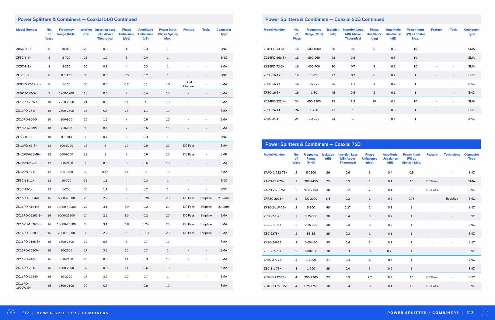
Model Number No.
of
Ways
Frequency
Range (MHz)
Isolation
(dB)
Insertion Loss
(dB) Above
Theoretical
Phase
Unbalance
(deg)
Amplitude
Unbalance
(dB)
Power Input
(W) as Spliter,
Max.
Feature Tech. Connector
Type
ZBSC-8-82+ 8 10-800 26 0.9 4 0.3 1 - - BNC
ZFSC-8-4+ 8 5-700 25 1.2 5 0.4 1 - - BNC
ZCSC-8-1+ 8 2-250 30 0.8 4 0.3 1 - - SMA
ZFSC-8-1+ 8 0.5-175 30 0.8 2.5 0.2 1 - - BNC
ZC8SC272-12DL+ 8 1-100 30 0.5 0.2 0.1 0.5Dual
Channel- SMA
ZC9PD-172-S+ 9 1200-1700 18 0.6 7 0.4 10 - - SMA
ZC10PD-26W-S+ 10 2250-2800 21 0.9 17 1 10 - - SMA
ZC10PD-26-S 10 2300-2600 35 0.7 15 1.1 10 - - SMA
ZC10PD-900-S 10 800-900 25 1.5 - 0.8 10 - - SMA
ZC10PD-900W 10 750-900 30 0.4 - 0.6 10 - - SMA
ZFSC-10-1+ 10 0.5-100 30 0.4 6 0.3 1 - - BNC
ZN12PD-63-S+ 12 600-6000 18 3 10 0.9 20 DC Pass - SMA
ZN12PD-63SMP+ 12 600-6000 19 3 8 0.8 20 DC Pass - SMP
ZN12PD-252-S+ 12 800-2450 30 0.5 6 0.6 10 - - SMA
ZN12PD-17-S 12 800-1700 30 0.45 14 0.7 10 - - SMA
ZFSC-12-11+ 12 10-300 33 1.1 4 0.3 1 - - BNC
ZFSC-12-1+ 12 1-200 35 1.1 8 0.2 1 - - BNC
ZC16PD-K0644+ 16 6000-40000 26 2.2 6 0.28 20 DC Pass Stripline 2.92mm
ZC16PD-K1844+ 16 18000-40000 22 3.1 5.9 0.2 20 DC Pass Stripline 2.92mm
ZC16PD-06263-S+ 16 6000-26500 24 2.2 3.3 0.2 20 DC Pass Stripline SMA
ZC16PD-18263-S+ 16 18000-26500 23 3.1 3.8 0.24 20 DC Pass Stripline SMA
ZC16PD-02183-S+ 16 2000-18000 30 2.2 3.1 0.13 20 DC Pass Stripline SMA
ZC16PD-2185-S+ 16 1800-2600 30 0.5 6 0.7 10 - - SMA
ZC16PD-252-S+ 16 10-2500 17 3.2 10 0.7 1 - - SMA
ZC16PD-24-S+ 16 650-2450 25 0.8 14 0.9 10 - - SMA
ZC16PD-23-S 16 1500-2300 32 0.8 11 0.6 10 - - SMA
ZC16PD-222-S+ 16 10-2200 17 3.2 10 0.7 1 - - SMA
ZC16PD-1900W-S+
16 1500-2100 30 0.7 - 0.8 10 - - SMA
Power Splitters & Combiners — Coaxial 75Ω
P O W E R S P L I T T E R / C O M B I N E R S | 313| P O W E R S P L I T T E R / C O M B I N E R S312
Power Splitters & Combiners — Coaxial 50Ω Continued Power Splitters & Combiners — Coaxial 50Ω Continued
Model Number No.
of
Ways
Frequency
Range (MHz)
Isolation
(dB)
Insertion Loss
(dB) Above
Theoretical
Phase
Unbalance
(deg)
Amplitude
Unbalance
(dB)
Power Input
(W) as Spliter,
Max.
Feature Tech. Connector
Type
ZB16PD-13-S+ 16 500-1000 30 0.6 6 0.6 10 - - SMA
ZC16PD-960-S+ 16 890-960 28 0.5 - 0.5 10 - - SMA
ZB16PD-72-S+ 16 400-700 30 0.7 8 0.6 10 - - SMA
ZFSC-16-12+ 16 0.1-200 27 0.7 6 0.2 1 - - BNC
ZFSC-16-1+ 16 0.5-125 25 1.1 3 0.2 1 - - BNC
ZFSC-16-3+ 16 1-30 45 0.5 2 0.1 1 - - BNC
ZC24PD-222-S+ 24 650-2200 25 1.8 10 0.5 10 - - SMA
ZFSC-24-11 24 1-200 22 1 - 0.8 1 - - BNC
ZFSC-24-1 24 0.2-100 25 1 - 0.4 1 - - BNC
Model Number No. of
Ways
Frequency Range (MHz)
Isolation (dB)
Insertion Loss (dB) Above Theoretical
Phase Unbalance
(deg)
Amplitude Unbalance
(dB)
Power Input (W) as
Splitter, Max.
Feature Technology Connector Type
ZAPD-2-252-75+ 2 5-2500 26 0.6 3 0.4 0.5 - - BNC
ZAPD-232-75+ 2 700-2450 25 0.5 1 0.1 10 DC Pass - SMA
ZAPD-2-22-75+ 2 910-2150 30 0.2 2 0.4 5 DC Pass - BNC
ZFRSC-2075+ 2 DC-2000 6.6 0.3 2 0.2 0.75 - Resistive BNC
ZFSC-2-1W-75+ 2 5-600 45 0.27 2 0.3 1 - - BNC
ZFSC-2-1-75+ 2 0.25-300 30 0.4 3 0.2 1 - - BNC
ZSC-2-1-75+ 2 0.25-300 30 0.4 3 0.2 1 - - BNC
ZSC-2375+ 2 55-85 35 0.3 1 0.1 1 - - BNC
ZFSC-2-6-75 2 0.004-60 35 0.4 2 0.2 1 - - BNC
ZSC-2-2-75+ 2 0.002-60 30 0.3 3 0.25 1 - - BNC
ZFSC-3-4-75+ 3 1-1000 27 0.4 6 0.7 1 - - BNC
ZSC-3-1-75+ 3 1-200 35 0.4 3 0.2 1 - - BNC
ZB4PD-222-75+ 4 950-2200 23 0.9 2.7 0.3 10 DC Pass - BNC
ZB4PD-1750-75+ 4 875-1750 30 0.4 3 0.4 10 DC Pass - BNC
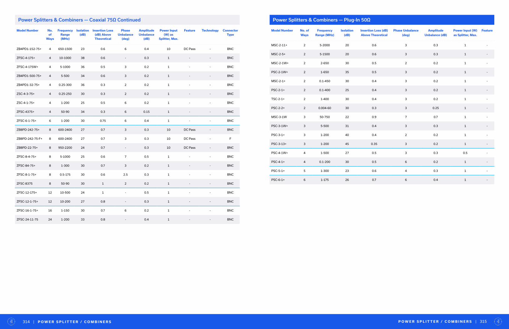
P O W E R S P L I T T E R / C O M B I N E R S | 315| P O W E R S P L I T T E R / C O M B I N E R S314
Model Number No. of
Ways
Frequency
Range (MHz)
Isolation
(dB)
Insertion Loss (dB)
Above Theoretical
Phase Unbalance
(deg)
Amplitude
Unbalance (dB)
Power Input (W)
as Splitter, Max.
Feature
MSC-2-11+ 2 5-2000 20 0.6 3 0.3 1 -
MSC-2-5+ 2 5-1500 20 0.6 3 0.3 1 -
MSC-2-1W+ 2 2-650 30 0.5 2 0.2 1 -
PSC-2-1W+ 2 1-650 35 0.5 3 0.2 1 -
MSC-2-1+ 2 0.1-450 30 0.4 3 0.2 1 -
PSC-2-1+ 2 0.1-400 25 0.4 3 0.2 1 -
TSC-2-1+ 2 1-400 30 0.4 3 0.2 1 -
PSC-2-2+ 2 0.004-60 30 0.3 3 0.25 1 -
MSC-3-1W 3 50-750 22 0.9 7 0.7 1 -
PSC-3-1W+ 3 5-500 31 0.4 3 0.3 1 -
PSC-3-1+ 3 1-200 40 0.4 2 0.2 1 -
PSC-3-13+ 3 1-200 45 0.35 3 0.2 1 -
PSC-4-1W+ 4 1-500 27 0.5 3 0.3 0.5 -
PSC-4-1+ 4 0.1-200 30 0.5 6 0.2 1 -
PSC-5-1+ 5 1-300 23 0.6 4 0.3 1 -
PSC-6-1+ 6 1-175 26 0.7 6 0.4 1 -
Power Splitters & Combiners — Plug-In 50Ω
Model Number No. of
Ways
Frequency Range (MHz)
Isolation (dB)
Insertion Loss (dB) Above Theoretical
Phase Unbalance
(deg)
Amplitude Unbalance
(dB)
Power Input (W) as
Splitter, Max.
Feature Technology Connector Type
ZB4PD1-152-75+ 4 650-1500 23 0.6 6 0.4 10 DC Pass - BNC
ZFSC-4-175+ 4 10-1000 38 0.6 - 0.3 1 - - BNC
ZFSC-4-175W+ 4 5-1000 36 0.5 3 0.2 1 - - BNC
ZB4PD1-500-75+ 4 5-500 34 0.6 3 0.2 1 - - BNC
ZB4PD1-32-75+ 4 0.25-300 36 0.3 2 0.2 1 - - BNC
ZSC-4-3-75+ 4 0.25-250 30 0.3 2 0.2 1 - - BNC
ZSC-4-1-75+ 4 1-200 25 0.5 6 0.2 1 - - BNC
ZFSC-4375+ 4 50-90 34 0.3 6 0.15 1 - - BNC
ZFSC-6-1-75+ 6 1-200 30 0.75 6 0.4 1 - - BNC
ZB8PD-242-75+ 8 600-2400 27 0.7 3 0.3 10 DC Pass - BNC
ZB8PD-242-75-F+ 8 600-2400 27 0.7 3 0.3 10 DC Pass - F
ZB8PD-22-75+ 8 950-2200 24 0.7 - 0.3 10 DC Pass - BNC
ZFSC-8-4-75+ 8 5-1000 25 0.6 7 0.5 1 - - BNC
ZFSC-84-75+ 8 1-300 30 0.7 3 0.2 1 - - BNC
ZFSC-8-1-75+ 8 0.5-175 30 0.6 2.5 0.3 1 - - BNC
ZFSC-8375 8 50-90 30 1 2 0.2 1 - - BNC
ZFSC-12-175+ 12 10-500 24 1 - 0.5 1 - - BNC
ZFSC-12-1-75+ 12 10-200 27 0.8 - 0.3 1 - - BNC
ZFSC-16-1-75+ 16 1-150 30 0.7 6 0.2 1 - - BNC
ZFSC-24-11-75 24 1-200 33 0.8 - 0.4 1 - - BNC
Power Splitters & Combiners — Coaxial 75Ω Continued
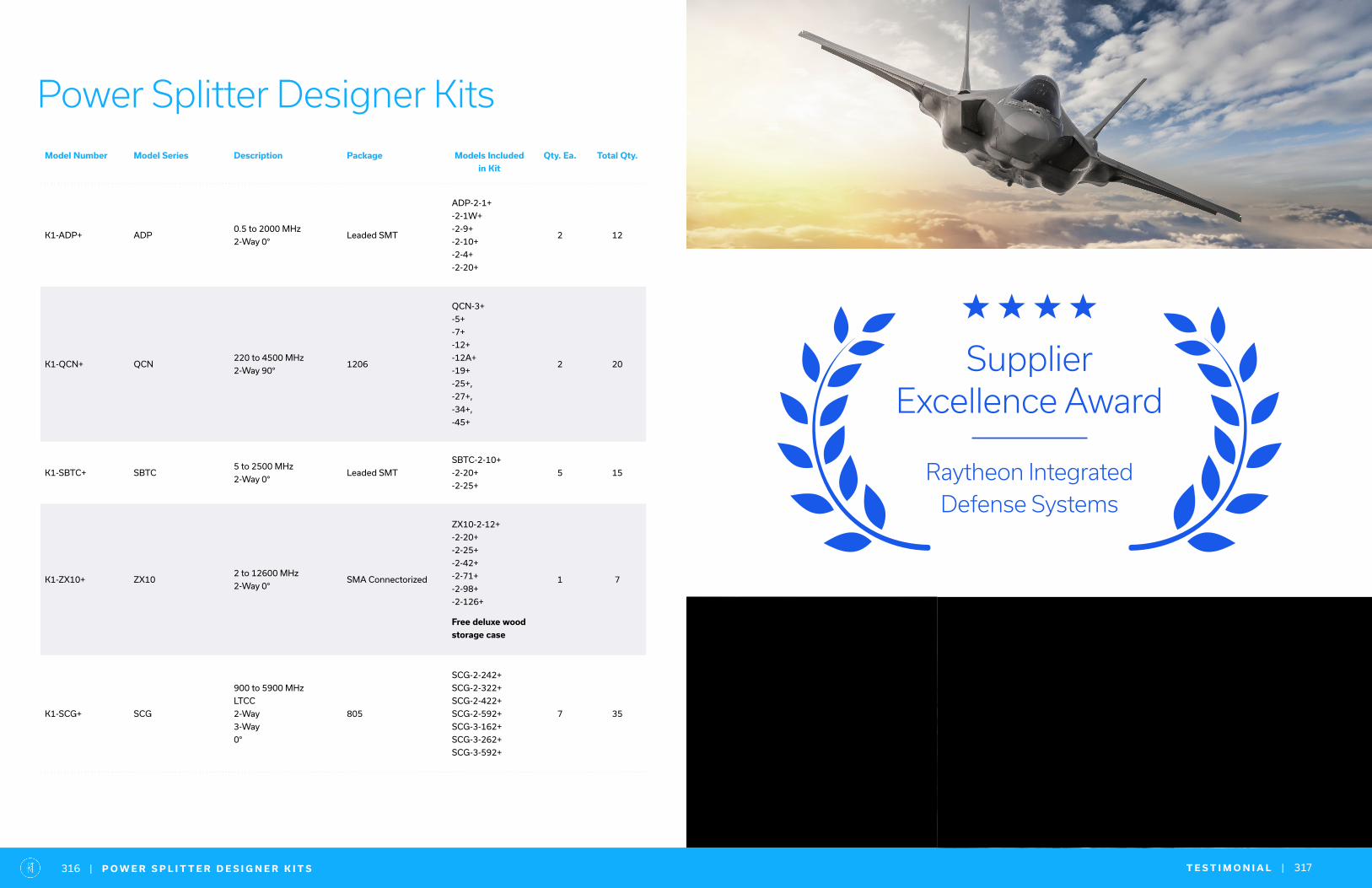
Power Splitter Designer KitsModel Number Model Series Description Package Models Included
in Kit
Qty. Ea. Total Qty.
K1-ADP+ ADP0.5 to 2000 MHz
2-Way 0°Leaded SMT
ADP-2-1+
-2-1W+
-2-9+
-2-10+
-2-4+
-2-20+
2 12
K1-QCN+ QCN220 to 4500 MHz
2-Way 90°1206
QCN-3+
-5+
-7+
-12+
-12A+
-19+
-25+,
-27+,
-34+,
-45+
2 20
K1-SBTC+ SBTC5 to 2500 MHz
2-Way 0°Leaded SMT
SBTC-2-10+
-2-20+
-2-25+
5 15
K1-ZX10+ ZX102 to 12600 MHz
2-Way 0°SMA Connectorized
ZX10-2-12+
-2-20+
-2-25+
-2-42+
-2-71+
-2-98+
-2-126+
Free deluxe wood
storage case
1 7
K1-SCG+ SCG
900 to 5900 MHz
LTCC
2-Way
3-Way
0°
805
SCG-2-242+
SCG-2-322+
SCG-2-422+
SCG-2-592+
SCG-3-162+
SCG-3-262+
SCG-3-592+
7 35
T E S T I M O N I A L | 317| P O W E R S P L I T T E R D E S I G N E R K I T S316
Supplier Excellence Award
Raytheon Integrated
Defense Systems
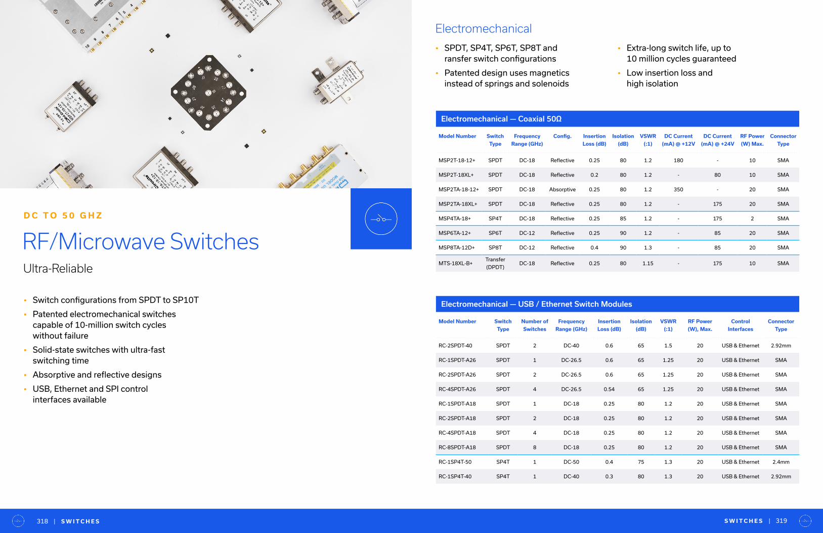
• Switch configurations from SPDT to SP10T
• Patented electromechanical switches capable of 10-million switch cycles without failure
• Solid-state switches with ultra-fast switching time
• Absorptive and reflective designs
• USB, Ethernet and SPI control interfaces available
RF/Microwave SwitchesUltra-Reliable
D C T O 5 0 G H Z
• Extra-long switch life, up to 10 million cycles guaranteed
• Low insertion loss and high isolation
Electromechanical
• SPDT, SP4T, SP6T, SP8T and ransfer switch configurations
• Patented design uses magnetics instead of springs and solenoids
Model Number Switch
Type
Frequency
Range (GHz)
Config. Insertion
Loss (dB)
Isolation
(dB)
VSWR
(:1)
DC Current
(mA) @ +12V
DC Current
(mA) @ +24V
RF Power
(W) Max.
Connector
Type
MSP2T-18-12+ SPDT DC-18 Reflective 0.25 80 1.2 180 - 10 SMA
MSP2T-18XL+ SPDT DC-18 Reflective 0.2 80 1.2 - 80 10 SMA
MSP2TA-18-12+ SPDT DC-18 Absorptive 0.25 80 1.2 350 - 20 SMA
MSP2TA-18XL+ SPDT DC-18 Reflective 0.25 80 1.2 - 175 20 SMA
MSP4TA-18+ SP4T DC-18 Reflective 0.25 85 1.2 - 175 2 SMA
MSP6TA-12+ SP6T DC-12 Reflective 0.25 90 1.2 - 85 20 SMA
MSP8TA-12D+ SP8T DC-12 Reflective 0.4 90 1.3 - 85 20 SMA
MTS-18XL-B+Transfer
(DPDT)DC-18 Reflective 0.25 80 1.15 - 175 10 SMA
Model Number Switch
Type
Number of
Switches
Frequency
Range (GHz)
Insertion
Loss (dB)
Isolation
(dB)
VSWR
(:1)
RF Power
(W), Max.
Control
Interfaces
Connector
Type
RC-2SPDT-40 SPDT 2 DC-40 0.6 65 1.5 20 USB & Ethernet 2.92mm
RC-1SPDT-A26 SPDT 1 DC-26.5 0.6 65 1.25 20 USB & Ethernet SMA
RC-2SPDT-A26 SPDT 2 DC-26.5 0.6 65 1.25 20 USB & Ethernet SMA
RC-4SPDT-A26 SPDT 4 DC-26.5 0.54 65 1.25 20 USB & Ethernet SMA
RC-1SPDT-A18 SPDT 1 DC-18 0.25 80 1.2 20 USB & Ethernet SMA
RC-2SPDT-A18 SPDT 2 DC-18 0.25 80 1.2 20 USB & Ethernet SMA
RC-4SPDT-A18 SPDT 4 DC-18 0.25 80 1.2 20 USB & Ethernet SMA
RC-8SPDT-A18 SPDT 8 DC-18 0.25 80 1.2 20 USB & Ethernet SMA
RC-1SP4T-50 SP4T 1 DC-50 0.4 75 1.3 20 USB & Ethernet 2.4mm
RC-1SP4T-40 SP4T 1 DC-40 0.3 80 1.3 20 USB & Ethernet 2.92mm
Electromechanical — Coaxial 50Ω
Electromechanical — USB / Ethernet Switch Modules
S W I T C H E S | 319| S W I T C H E S318

Solid State
• SPDT, SP4T, SP8T, SP10T and SP16T switch configurations
• Extremely fast switching time, down to 250 ns
• Unique designs achieve high isolation
• USB, Ethernet and SPI control options
Model Number Switch
Type
Number of
Switches
Frequency
Range (GHz)
Insertion
Loss (dB)
Isolation
(dB)
VSWR
(:1)
RF Power
(W), Max.
Control
Interfaces
Connector
Type
RC-2SP4T-40 SP4T 2 DC-40 0.3 80 1.3 20 USB & Ethernet 2.92mm
RC-1SP4T-26 SP4T 1 DC-26.5 0.2 80 1.35 20 USB & Ethernet SMA
RC-2SP4T-26 SP4T 2 DC-26.5 0.2 80 1.35 20 USB & Ethernet SMA
RC-1SP4T-A18 SP4T 1 DC-18 0.25 80 1.2 20 USB & Ethernet SMA
RC-2SP4T-A18 SP4T 2 DC-18 0.25 80 1.2 20 USB & Ethernet SMA
RC-1SP6T-50 SP6T 1 DC-50 0.4 75 1.4 20 USB & Ethernet 2.4mm
RC-1SP6T-40 SP6T 1 DC-40 0.4 80 1.7 20 USB & Ethernet 2.92mm
RC-2SP6T-40 SP6T 2 DC-40 0.4 80 1.7 20 USB & Ethernet 2.92mm
RC-1SP6T-26 SP6T 1 DC-26.5 0.25 90 1.35 20 USB & Ethernet SMA
RC-2SP6T-26 SP6T 2 DC-26.5 0.25 90 1.35 20 USB & Ethernet SMA
RC-2SP6T-A18 SP6T 2 DC-18 0.4 100 1.43 20 USB & Ethernet SMA
RC-1SP6T-A12 SP6T 1 DC-12 0.2 90 1.2 20 USB & Ethernet SMA
RC-2SP6T-A12 SP6T 2 DC-12 0.2 90 1.2 20 USB & Ethernet SMA
RC-2MTS-40Transfer
Switch2 DC-40 0.4 70 1.3 20 USB & Ethernet 2.92mm
RC-2MTS-26Transfer
Switch2 DC-26.5 0.3 75 1.3 20 USB & Ethernet SMA
RC-2MTS-18Transfer
Switch2 DC-18 0.2 86 1.15 10 USB & Ethernet SMA
RC-3MTS-40Transfer
Switch3 DC-40 0.5 70 1.5 20 USB & Ethernet 2.92mm
RC-3MTS-26Transfer
Switch3 DC-26.5 0.5 70 1.7 20 USB & Ethernet SMA
RC-3MTS-18Transfer
Switch3 DC-18 0.2 86 1.15 10 USB & Ethernet SMA
Model Number Switch
Type
Frequency
Range (GHz)
Driver Config. Insertion Loss
(dB)
1 dB Compression
(dBm)
Input IP3
(dBm)
In-Out Isolation
(dB)
KSWHA-1-20+ SPST DC-2 - Absorptive 1.3 26 - 65
CSWA2-63DR+ SPDT 0.5-6 CMOS Absorptive 1.1 27 45 50
HSWA2-63DR+ SPDT 0.1-6 CMOS Absorptive 1 35 65 68
JSW2-63DR+ SPDT 0.005-6 CMOS Reflective 0.33 35 59 35
JSW2-63VHDRG+ SPDT 0.005-6 CMOS Reflective 0.36 37 75 33
JSW2-63VHDRP+ SPDT 0.005-6 CMOS Reflective 0.36 37 75 33
M3SWA2-63DRC+ SPDT DC-6 CMOS Absorptive 0.6 26.2 46.3 56
VSWA2-63DR+ SPDT 0.5-6 CMOS Absorptive 1.2 27 44 46
MSW2-50+ SPDT DC-5 - Reflective 0.7 23 54 53
MSWA2-50+ SPDT DC-5 - Absorptive 0.7 24 54 53
KSW-2-46+ SPDT DC-4.6 - Reflective 1 20 - 50
KSWA-2-46+ SPDT DC-4.6 - Absorptive 0.9 20 - 50
M3SW-2-50DRA+ SPDT DC-4.5 CMOS Reflective 0.6 25 47.3 48
M3SWA-2-50DRA+ SPDT 0.5-4.5 CMOS Absorptive 1.2 27 46 51
M3SWA-2-50DRB+ SPDT DC-4.5 CMOS Absorptive 0.6 25.4 46.5 56
HSWA2-30DR+ SPDT DC-3 CMOS Absorptive 0.9 31 55 55
VSW2-33-10W+ SPDT 0.05-3 - Reflective 0.5 40 56 26
HSW2-272VHDR+ SPDT 0.03-2.7 CMOS Reflective 0.4 45.5 85 28
RSW-2-25PA+ SPDT DC-2.5 - Reflective 0.7 28 39 44
MSW-2-20+ SPDT DC-2 - Reflective 0.5 24 - 34
MSWA-2-20+ SPDT DC-2 - Absorptive 0.95 27 - 40
JSW3-272DR+ SP3T 0.005-2.7 CMOS Reflective 0.6 35 59 30
Solid State — MMIC Surface Mount 50Ω
S W I T C H E S | 321| S W I T C H E S320
Electromechanical — USB / Ethernet Switch Modules Continued
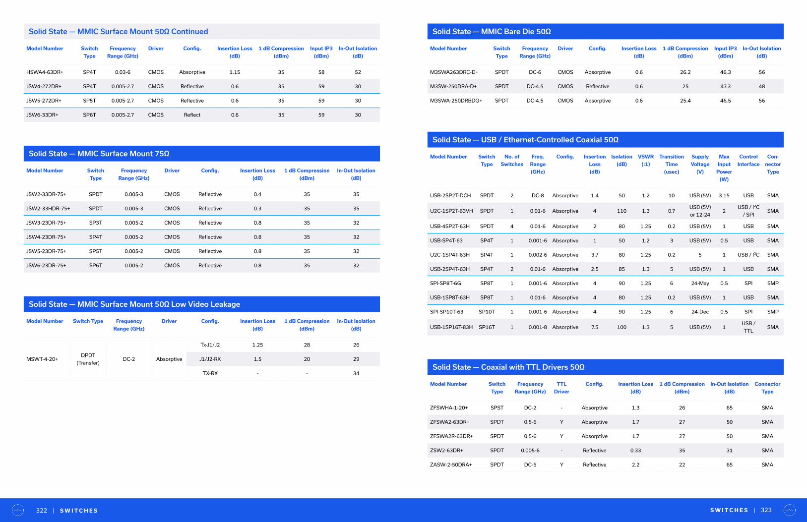
Solid State — MMIC Surface Mount 50Ω Low Video Leakage
Solid State — MMIC Bare Die 50Ω
Solid State — MMIC Surface Mount 75Ω
Solid State — USB / Ethernet-Controlled Coaxial 50Ω
Solid State — Coaxial with TTL Drivers 50Ω
Model Number Switch
Type
Frequency
Range (GHz)
Driver Config. Insertion Loss
(dB)
1 dB Compression
(dBm)
Input IP3
(dBm)
In-Out Isolation
(dB)
HSWA4-63DR+ SP4T 0.03-6 CMOS Absorptive 1.15 35 58 52
JSW4-272DR+ SP4T 0.005-2.7 CMOS Reflective 0.6 35 59 30
JSW5-272DR+ SP5T 0.005-2.7 CMOS Reflective 0.6 35 59 30
JSW6-33DR+ SP6T 0.005-2.7 CMOS Reflect 0.6 35 59 30
Model Number Switch
Type
Frequency
Range (GHz)
Driver Config. Insertion Loss
(dB)
1 dB Compression
(dBm)
In-Out Isolation
(dB)
JSW2-33DR-75+ SPDT 0.005-3 CMOS Reflective 0.4 35 35
JSW2-33HDR-75+ SPDT 0.005-3 CMOS Reflective 0.3 35 35
JSW3-23DR-75+ SP3T 0.005-2 CMOS Reflective 0.8 35 32
JSW4-23DR-75+ SP4T 0.005-2 CMOS Reflective 0.8 35 32
JSW5-23DR-75+ SP5T 0.005-2 CMOS Reflective 0.8 35 32
JSW6-23DR-75+ SP6T 0.005-2 CMOS Reflective 0.8 35 32
Model Number Switch
Type
No. of
Switches
Freq.
Range
(GHz)
Config. Insertion
Loss
(dB)
Isolation
(dB)
VSWR
(:1)
Transition
Time
(usec)
Supply
Voltage
(V)
Max
Input
Power
(W)
Control
Interface
Con-
nector
Type
USB-2SP2T-DCH SPDT 2 DC-8 Absorptive 1.4 50 1.2 10 USB (5V) 3.15 USB SMA
U2C-1SP2T-63VH SPDT 1 0.01-6 Absorptive 4 110 1.3 0.7USB (5V)
or 12-242
USB / I²C
/ SPISMA
USB-4SP2T-63H SPDT 4 0.01-6 Absorptive 2 80 1.25 0.2 USB (5V) 1 USB SMA
USB-SP4T-63 SP4T 1 0.001-6 Absorptive 1 50 1.2 3 USB (5V) 0.5 USB SMA
U2C-1SP4T-63H SP4T 1 0.002-6 Absorptive 3.7 80 1.25 0.2 5 1 USB / I²C SMA
USB-2SP4T-63H SP4T 2 0.01-6 Absorptive 2.5 85 1.3 5 USB (5V) 1 USB SMA
SPI-SP8T-6G SP8T 1 0.001-6 Absorptive 4 90 1.25 6 24-May 0.5 SPI SMP
USB-1SP8T-63H SP8T 1 0.01-6 Absorptive 4 80 1.25 0.2 USB (5V) 1 USB SMA
SPI-SP10T-63 SP10T 1 0.001-6 Absorptive 4 90 1.25 6 24-Dec 0.5 SPI SMP
USB-1SP16T-83H SP16T 1 0.001-8 Absorptive 7.5 100 1.3 5 USB (5V) 1USB /
TTLSMA
Model Number Switch Type Frequency
Range (GHz)
Driver Config. Insertion Loss
(dB)
1 dB Compression
(dBm)
In-Out Isolation
(dB)
MSWT-4-20+ DPDT
(Transfer)DC-2 Absorptive
Tx-J1/J2 1.25 28 26
J1/J2-RX 1.5 20 29
TX-RX - - 34
Model Number Switch
Type
Frequency
Range (GHz)
Driver Config. Insertion Loss
(dB)
1 dB Compression
(dBm)
Input IP3
(dBm)
In-Out Isolation
(dB)
M3SWA263DRC-D+ SPDT DC-6 CMOS Absorptive 0.6 26.2 46.3 56
M3SW-250DRA-D+ SPDT DC-4.5 CMOS Reflective 0.6 25 47.3 48
M3SWA-250DRBDG+ SPDT DC-4.5 CMOS Absorptive 0.6 25.4 46.5 56
Model Number Switch
Type
Frequency
Range (GHz)
TTL
Driver
Config. Insertion Loss
(dB)
1 dB Compression
(dBm)
In-Out Isolation
(dB)
Connector
Type
ZFSWHA-1-20+ SPST DC-2 - Absorptive 1.3 26 65 SMA
ZFSWA2-63DR+ SPDT 0.5-6 Y Absorptive 1.7 27 50 SMA
ZFSWA2R-63DR+ SPDT 0.5-6 Y Absorptive 1.7 27 50 SMA
ZSW2-63DR+ SPDT 0.005-6 - Reflective 0.33 35 31 SMA
ZASW-2-50DRA+ SPDT DC-5 Y Reflective 2.2 22 65 SMA
S W I T C H E S | 323| S W I T C H E S322
Solid State — MMIC Surface Mount 50Ω Continued
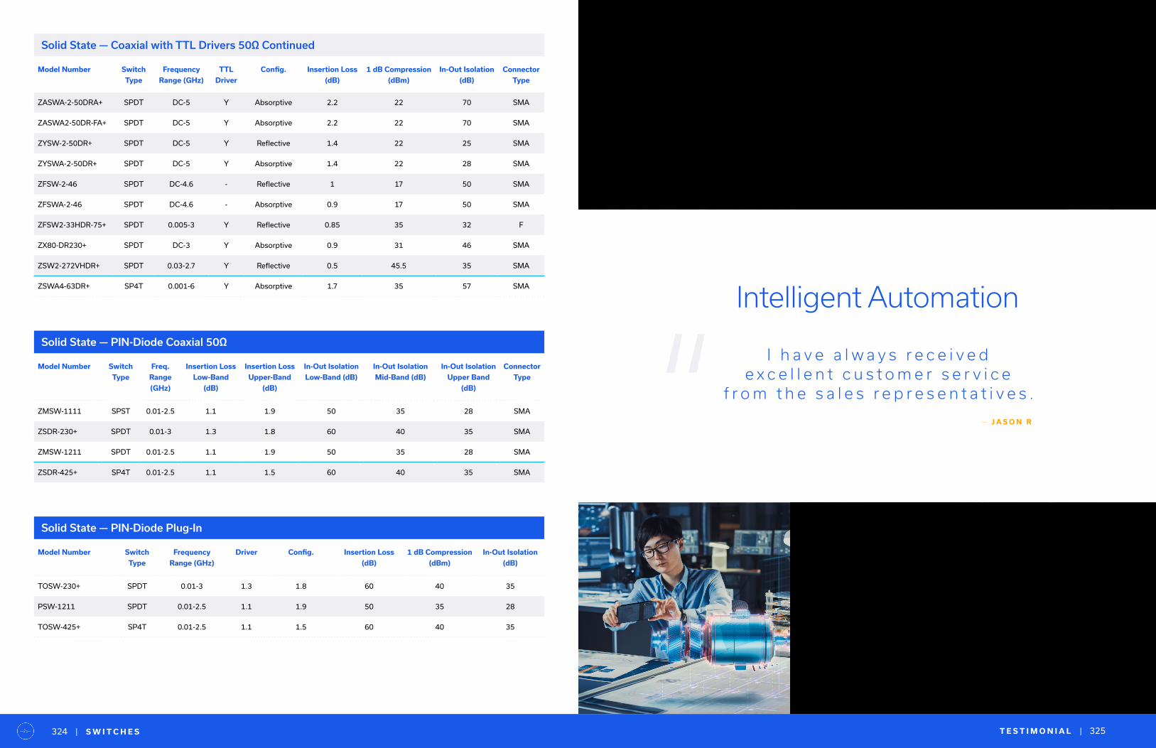
Solid State — PIN-Diode Coaxial 50Ω
Solid State — PIN-Diode Plug-In
Model Number Switch
Type
Frequency
Range (GHz)
TTL
Driver
Config. Insertion Loss
(dB)
1 dB Compression
(dBm)
In-Out Isolation
(dB)
Connector
Type
ZASWA-2-50DRA+ SPDT DC-5 Y Absorptive 2.2 22 70 SMA
ZASWA2-50DR-FA+ SPDT DC-5 Y Absorptive 2.2 22 70 SMA
ZYSW-2-50DR+ SPDT DC-5 Y Reflective 1.4 22 25 SMA
ZYSWA-2-50DR+ SPDT DC-5 Y Absorptive 1.4 22 28 SMA
ZFSW-2-46 SPDT DC-4.6 - Reflective 1 17 50 SMA
ZFSWA-2-46 SPDT DC-4.6 - Absorptive 0.9 17 50 SMA
ZFSW2-33HDR-75+ SPDT 0.005-3 Y Reflective 0.85 35 32 F
ZX80-DR230+ SPDT DC-3 Y Absorptive 0.9 31 46 SMA
ZSW2-272VHDR+ SPDT 0.03-2.7 Y Reflective 0.5 45.5 35 SMA
ZSWA4-63DR+ SP4T 0.001-6 Y Absorptive 1.7 35 57 SMA
Model Number Switch
Type
Freq.
Range
(GHz)
Insertion Loss
Low-Band
(dB)
Insertion Loss
Upper-Band
(dB)
In-Out Isolation
Low-Band (dB)
In-Out Isolation
Mid-Band (dB)
In-Out Isolation
Upper Band
(dB)
Connector
Type
ZMSW-1111 SPST 0.01-2.5 1.1 1.9 50 35 28 SMA
ZSDR-230+ SPDT 0.01-3 1.3 1.8 60 40 35 SMA
ZMSW-1211 SPDT 0.01-2.5 1.1 1.9 50 35 28 SMA
ZSDR-425+ SP4T 0.01-2.5 1.1 1.5 60 40 35 SMA
Model Number Switch
Type
Frequency
Range (GHz)
Driver Config. Insertion Loss
(dB)
1 dB Compression
(dBm)
In-Out Isolation
(dB)
TOSW-230+ SPDT 0.01-3 1.3 1.8 60 40 35
PSW-1211 SPDT 0.01-2.5 1.1 1.9 50 35 28
TOSW-425+ SP4T 0.01-2.5 1.1 1.5 60 40 35
T E S T I M O N I A L | 325| S W I T C H E S324
“Intelligent Automation
I h a v e a l w a y s r e c e i v e d e x c e l l e n t c u s t o m e r s e r v i c e
f r o m t h e s a l e s r e p r e s e n t a t i v e s .
— J A S O N R
Solid State — Coaxial with TTL Drivers 50Ω Continued
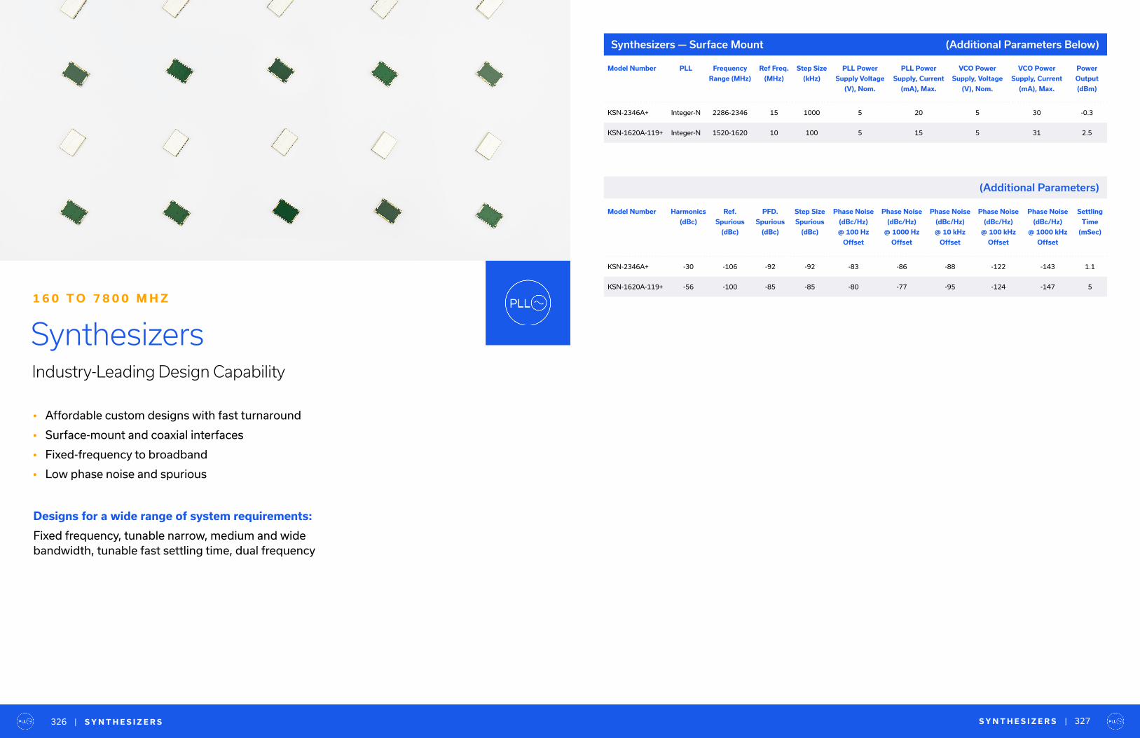
• Affordable custom designs with fast turnaround
• Surface-mount and coaxial interfaces
• Fixed-frequency to broadband
• Low phase noise and spurious
SynthesizersIndustry-Leading Design Capability
1 6 0 T O 7 8 0 0 M H Z
Designs for a wide range of system requirements:
Fixed frequency, tunable narrow, medium and wide bandwidth, tunable fast settling time, dual frequency
Model Number PLL Frequency
Range (MHz)
Ref Freq.
(MHz)
Step Size
(kHz)
PLL Power
Supply Voltage
(V), Nom.
PLL Power
Supply, Current
(mA), Max.
VCO Power
Supply, Voltage
(V), Nom.
VCO Power
Supply, Current
(mA), Max.
Power
Output
(dBm)
KSN-2346A+ Integer-N 2286-2346 15 1000 5 20 5 30 -0.3
KSN-1620A-119+ Integer-N 1520-1620 10 100 5 15 5 31 2.5
Model Number Harmonics
(dBc)
Ref.
Spurious
(dBc)
PFD.
Spurious
(dBc)
Step Size
Spurious
(dBc)
Phase Noise
(dBc/Hz)
@ 100 Hz
Offset
Phase Noise
(dBc/Hz)
@ 1000 Hz
Offset
Phase Noise
(dBc/Hz)
@ 10 kHz
Offset
Phase Noise
(dBc/Hz)
@ 100 kHz
Offset
Phase Noise
(dBc/Hz)
@ 1000 kHz
Offset
Settling
Time
(mSec)
KSN-2346A+ -30 -106 -92 -92 -83 -86 -88 -122 -143 1.1
KSN-1620A-119+ -56 -100 -85 -85 -80 -77 -95 -124 -147 5
Synthesizers — Surface Mount
S Y N T H E S I Z E R S | 327| S Y N T H E S I Z E R S326
(Additional Parameters)
(Additional Parameters Below)
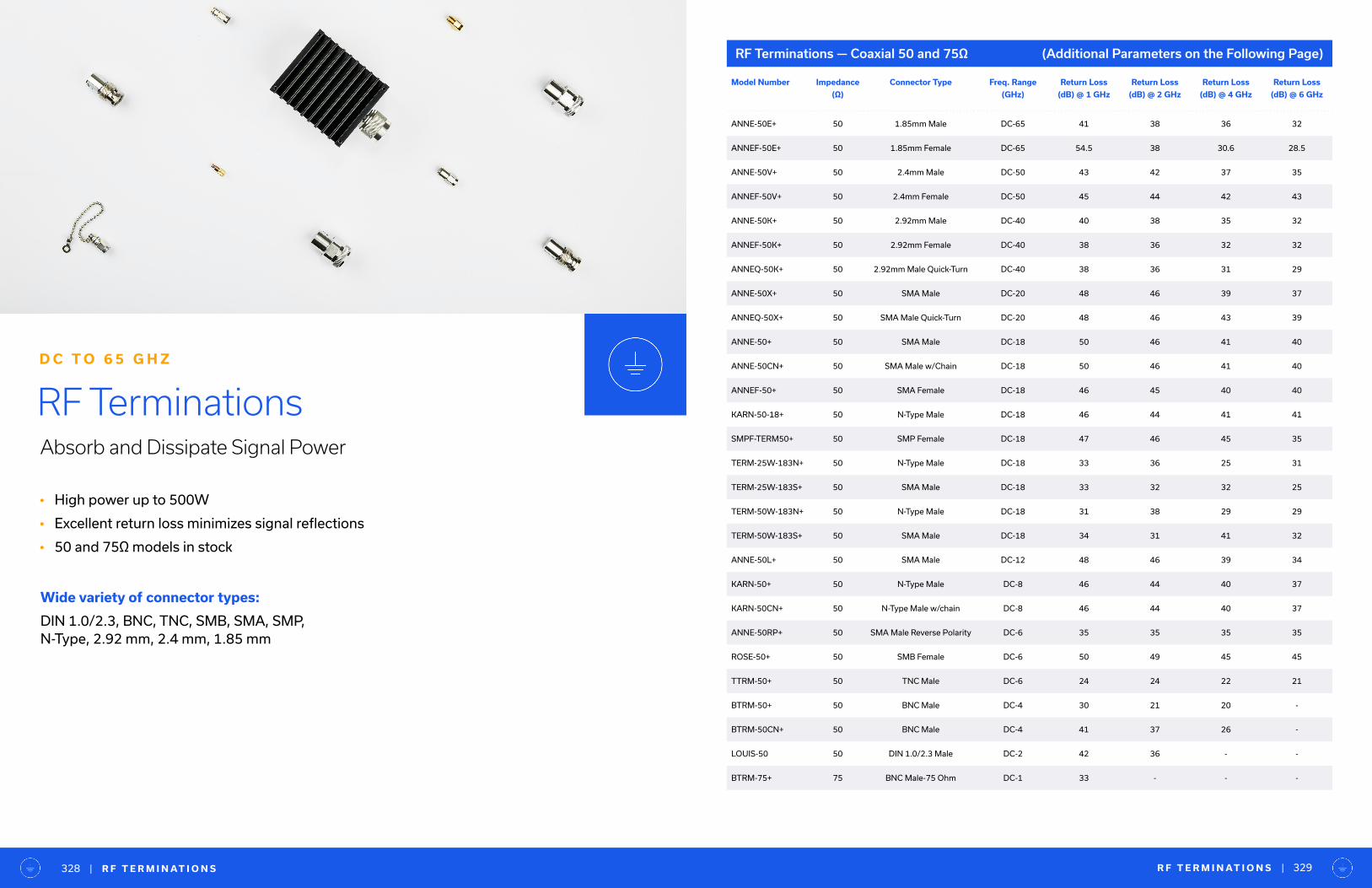
• High power up to 500W
• Excellent return loss minimizes signal reflections
• 50 and 75Ω models in stock
RF TerminationsAbsorb and Dissipate Signal Power
D C T O 6 5 G H Z
Wide variety of connector types:
DIN 1.0/2.3, BNC, TNC, SMB, SMA, SMP,N-Type, 2.92 mm, 2.4 mm, 1.85 mm
RF Terminations — Coaxial 50 and 75Ω (Additional Parameters on the Following Page)
Model Number Impedance
(Ω)
Connector Type Freq. Range
(GHz)
Return Loss
(dB) @ 1 GHz
Return Loss
(dB) @ 2 GHz
Return Loss
(dB) @ 4 GHz
Return Loss
(dB) @ 6 GHz
ANNE-50E+ 50 1.85mm Male DC-65 41 38 36 32
ANNEF-50E+ 50 1.85mm Female DC-65 54.5 38 30.6 28.5
ANNE-50V+ 50 2.4mm Male DC-50 43 42 37 35
ANNEF-50V+ 50 2.4mm Female DC-50 45 44 42 43
ANNE-50K+ 50 2.92mm Male DC-40 40 38 35 32
ANNEF-50K+ 50 2.92mm Female DC-40 38 36 32 32
ANNEQ-50K+ 50 2.92mm Male Quick-Turn DC-40 38 36 31 29
ANNE-50X+ 50 SMA Male DC-20 48 46 39 37
ANNEQ-50X+ 50 SMA Male Quick-Turn DC-20 48 46 43 39
ANNE-50+ 50 SMA Male DC-18 50 46 41 40
ANNE-50CN+ 50 SMA Male w/Chain DC-18 50 46 41 40
ANNEF-50+ 50 SMA Female DC-18 46 45 40 40
KARN-50-18+ 50 N-Type Male DC-18 46 44 41 41
SMPF-TERM50+ 50 SMP Female DC-18 47 46 45 35
TERM-25W-183N+ 50 N-Type Male DC-18 33 36 25 31
TERM-25W-183S+ 50 SMA Male DC-18 33 32 32 25
TERM-50W-183N+ 50 N-Type Male DC-18 31 38 29 29
TERM-50W-183S+ 50 SMA Male DC-18 34 31 41 32
ANNE-50L+ 50 SMA Male DC-12 48 46 39 34
KARN-50+ 50 N-Type Male DC-8 46 44 40 37
KARN-50CN+ 50 N-Type Male w/chain DC-8 46 44 40 37
ANNE-50RP+ 50 SMA Male Reverse Polarity DC-6 35 35 35 35
ROSE-50+ 50 SMB Female DC-6 50 49 45 45
TTRM-50+ 50 TNC Male DC-6 24 24 22 21
BTRM-50+ 50 BNC Male DC-4 30 21 20 -
BTRM-50CN+ 50 BNC Male DC-4 41 37 26 -
LOUIS-50 50 DIN 1.0/2.3 Male DC-2 42 36 - -
BTRM-75+ 75 BNC Male-75 Ohm DC-1 33 - - -
R F T E R M I N AT I O N S | | R F T E R M I N AT I O N S 329328

T E S T I M O N I A L | | R F T E R M I N AT I O N S
Model Number Return Loss
(dB) @ 8 GHz
Return Loss
(dB) @ 12 GHz
Return Loss
(dB) @ 18 GHz
Return Loss
(dB) @ 20 GHz
Return Loss
(dB) @ 40 GHz
Return Loss
(dB) @ 50 GHz
Return Loss
(dB) @ 65 GHz
Power Rating
(W), Max.
ANNE-50E+ 32 33 31 28 32 22 29 1
ANNEF-50E+ 29.5 29.8 26.4 24.2 29.8 25.8 16.1 1
ANNE-50V+ 35 38 29 27 26 19 - 1
ANNEF-50V+ 45 38 31 30 20 24 - 1
ANNE-50K+ 30 30 30 27 20 - - 1.0
ANNEF-50K+ 30 29 26 26 32 - - 1.0
ANNEQ-50K+ 27 26 26 23 25 - - 1.0
ANNE-50X+ 35 35 25 25 - - - 1.0
ANNEQ-50X+ 33 26 26 31 - - - 1.0
ANNE-50+ 38 45 30 - - - - 1.0
ANNE-50CN+ 38 45 30 - - - - 1.0
ANNEF-50+ 41 32 23 - - - - 1.0
KARN-50-18+ 41 41 28 - - - - 2.0
SMPF-TERM50+ 30 24 22 - - - - 1.0
TERM-25W-183N+ 30 36 22 - - - - 25
TERM-25W-183S+ 28 24 29 - - - - 25
TERM-50W-183N+ 21 44 24 - - - - 50
TERM-50W-183S+ 21 30 26 - - - - 50
ANNE-50L+ 31 27 - - - - - 1.0
KARN-50+ 35 - - - - - - 2.0
KARN-50CN+ 35 - - - - - - 2.0
ANNE-50RP+ - - - - - - - 1.0
ROSE-50+ - - - - - - - 0.50
TTRM-50+ - - - - - - - 2
BTRM-50+ - - - - - - - 0.50
BTRM-50CN+ - - - - - - - 0.50
LOUIS-50 - - - - - - - 0.125
BTRM-75+ - - - - - - - 0.50
331330
“EMLinQ
T h e y a r e t h e g r e a t e s t s u p p o r t s t a f f I ’ v e e v e r w o r k e d w i t h .
N o t j u s t 1 o r 2 , A L L o f t h e m .
— B U Y E R
RF Terminations — Coaxial 50 and 75Ω (Additional Parameters)
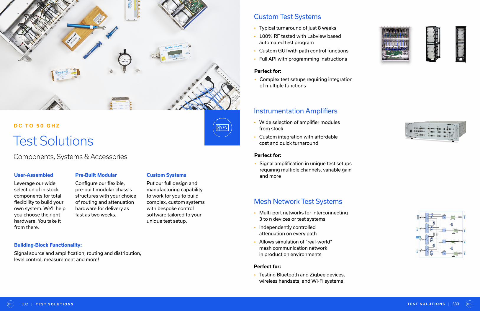
Test SolutionsComponents, Systems & Accessories
D C T O 5 0 G H Z
Building-Block Functionality:
Signal source and amplification, routing and distribution, level control, measurement and more!
User-Assembled
Leverage our wide selection of in stock components for total flexibility to build your own system. We’ll help you choose the right hardware. You take it from there.
Pre-Built Modular
Configure our flexible, pre-built modular chassis structures with your choice of routing and attenuation hardware for delivery as fast as two weeks.
Custom Systems
Put our full design and manufacturing capability to work for you to build complex, custom systems with bespoke control software tailored to your unique test setup.
| T E S T S O L U T I O N S T E S T S O L U T I O N S | 333332
Custom Test Systems
• Typical turnaround of just 8 weeks
• 100% RF tested with Labview based automated test program
• Custom GUI with path control functions
• Full API with programming instructions
Perfect for:
• Complex test setups requiring integration of multiple functions
Mesh Network Test Systems
• Multi-port networks for interconnecting 3 to n devices or test systems
• Independently controlled attenuation on every path
• Allows simulation of “real-world” mesh communication network in production environments
Instrumentation Amplifiers
• Wide selection of amplifier modules from stock
• Custom integration with affordable cost and quick turnaround
Perfect for:
• Signal amplification in unique test setups requiring multiple channels, variable gain and more
Perfect for:
• Testing Bluetooth and Zigbee devices, wireless handsets, and Wi-Fi systems
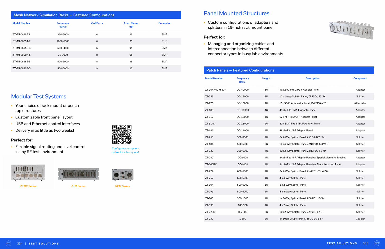
Perfect for:
• Flexible signal routing and level control in any RF test environment
ZTM2 Series RCM SeriesZTM Series
Perfect for:
• Managing and organizing cables and interconnection between different connector types in busy lab environments
Modular Test Systems
• Your choice of rack mount or bench top structures
• Customizable front panel layout
• USB and Ethernet control interfaces
• Delivery in as little as two weeks!
Panel Mounted Structures
• Custom configurations of adapters and splitters in 19-inch rack mount panel
Mesh Network Simulation Racks — Featured Configurations
Patch Panels — Featured Configurations
Model Number Frequency
(MHz)
# of Ports Atten Range
(dB)
Connector
ZTMN-0495AS 350-6000 4 95 SMA
ZTMN-0695A-T 2000-6000 6 95 TNC
ZTMN-0695B-S 600-6000 6 95 SMA
ZTMN-0890A-S 30-3000 8 95 SMA
ZTMN-0895B-S 500-6000 8 95 SMA
ZTMN-0995A-S 500-6000 9 95 SMA
Model Number Frequency
(MHz)
Height Description Component
ZT-96KFFL-KF50+ DC-40000 5U 96x 2.92-F to 2.92-F Adapter Panel Adapter
ZT-256 DC-18000 2U 12x 2-Way Splitter Panel, ZFRSC-183-S+ Splitter
ZT-275 DC-18000 2U 10x 30dB Attenuator Panel, BW-S30W20+ Attenuator
ZT-183 DC -18000 4U 48x N-F to SMA-F Adapter Panel Adapter
ZT-312 DC-18000 1U 12 x N-F to SMA-F Adapter Panel Adapter
ZT-314D DC-18000 2U 80 x SMA-F to SMA-F Adapter Panel Adapter
ZT-182 DC-11000 4U 48x N-F to N-F Adapter Panel Adapter
ZT-255 500-8500 2U 8x 2-Way Splitter Panel, ZX10-2-852-S+ Splitter
ZT-184 500-6000 3U 10x 4-Way Splitter Panel, ZN4PD1-63LW-S+ Splitter
ZT-222 350-6000 4U 20x 2-Way Splitter Panel, ZN2PD2-63-N+ Splitter
ZT-240 DC-6000 4U 24x N-F to N-F Adapter Panel w/ Special Mounting Bracket Adapter
ZT-240BK DC-6000 4U 24x N-F to N-F Adapter Panel w/ Black Anodized Panel Adapter
ZT-277 600-6000 1U 3x 4-Way Splitter Panel, ZN4PD1-63LW-S+ Splitter
ZT-257 600-6000 1U 4 x 4-Way Splitter Panel Splitter
ZT-304 500-6000 1U 8 x 2-Way Splitter Panel Splitter
ZT-299 500-6000 1U 4 x 8-Way Splitter Panel Splitter
ZT-245 300-1000 1U 1x 8-Way Splitter Panel, ZC8PD1-10-S+ Splitter
ZT-333 100-900 1U 4 x 2-Way Splitter Panel Splitter
ZT-229B 0.5-600 2U 16x 2-Way Splitter Panel, Z99SC-62-S+ Splitter
ZT-230 1-500 2U 8x 10dB Coupler Panel, ZFDC-10-1-S+ Coupler
| T E S T S O L U T I O N S T E S T S O L U T I O N S | 335334
Configure your system
online for a fast quote!

Perfect for:
• Fading simulators
• Handover system evaluation
• Telecom network infrastructure testing
• And more!
Signal Conditioning & Attenuation Systems
• Attenuation range up to 120 dB
• USB, Ethernet, RS232 and SPI control options
• Capable of sweeping, hopping and customized attenuation patterns
• 1, 4 and 8 channel models off-the-shelf (See Page 92)
• Customized multi-channel rack mount systems with fast turnaround
Custom Multi-ChannelAttenuator Racks Overview
Mini-Circuits’ ZTDAT-series attenuator racks cater to test systems where multipleprogrammable channels are required. Withmodels operating up to 8 GHz and up to 48 channels in a single, self-contained rack, most wireless test applications in the L, S and C bands can be accommodated.
Learn more about
our multi-channel
attenuator systems
| T E S T S O L U T I O N S T E S T S O L U T I O N S | 337336
Perfect for:
• General lab use, field testing and remote location monitoring, low-cost alternative to high-end generators and power meters
Signal Generation, Measurement & Control
• Synthesized signal generators
• Power sensors and frequency counters
• Control products
USB/Ethernet Controlled Synthesized Signal Generators
Model Number Control Interface Frequency
Range (GHz)
Power Range
(dBm)
Frequency
Resolution
(Hz), Min.
Power Resolution
(dB), Nom.
Harmonics &
Sub-Harmonics
(dBc)
Non-Harmonic
Spurious (dBc) @
100 kHz Step
SSG-15G-RCUSB & Ethernet
(with SSH)0.01-15000 -50-15 0.1 0.1 -25 -70
SSG-6000RC USB & Ethernet 0.025-6000 -65-14 3 0.25 -52 -72
SSG-6001RC USB & Ethernet 0.001-6000 -70-15 3 0.25 -65 -73
Model Number Phase Noise
(dBc/Hz) SSB @
100 Hz Offset
Phase Noise
(dBc/Hz) SSB @
1 kHz Offset
Phase Noise
(dBc/Hz) SSB @
10 kHz Offset
Phase Noise
(dBc/Hz) SSB @
100 kHz Offset
Settling Time
(mSec)
Ext. Ref
(MHz)
Connector Type
SSG-15G-RC -83 -103 -112 -112 3.5 10 SMA
SSG-6000RC -82 -96 -99 -102 1.5 10 N
SSG-6001RC -92 -108 -112 -119 2 10 N
(Additional Parameters Below)
(Additional Parameters)

Power Sensors
Integrated Power Sensor — Frequency Counter
Frequency Counter
Model Number Control Sensor
Type
Impedance
(Ω)
Frequency
Range (MHz)
Input Power
Range (dBm)
Dynamic
Range (dB)
Measurement
Speed (ms)
Connector
Type
PWR-8P-RC USB & Ethernet Peak & Avg. 50 10-8000 -60 to 20 80 0.002 N
PWR-8FS USB CW 50 1-8000 -30 to 20 50 10 N
PWR-8GHS USB CW 50 1-8000 -30 to 20 50 30 N
PWR-8GHS-RC USB & Ethernet CW 50 1-8000 -30 to 20 50 30 N
PWR-6GHS USB CW 50 1-6000 -30 to 20 50 30 N
PWR-6LGHS USB CW 50 50-6000 -45 to 10 55 30 N
PWR-6LRMS-RC USB & Ethernet RMS 50 50-6000 -45 to 10 55 30 N
PWR-6RMS-RC USB & Ethernet RMS 50 50-6000 -35 to 20 55 30 N
PWR-4GHS USB CW 50 0.009-4000 -30 to 20 50 30 N
PWR-2.5GHS-75 USB CW 75 0.1-2500 -30 to 20 50 30 N
Model Number Control Sensor
Type
Frequency
Range (GHz)
Input Power
Range (dBm)
Dynamic
Range (dB)
Power Meas.
Speed (mS)
Freq. Sample
Time (S), Min.
Freq. Sample
Time (S), Max.
FCPM-6000RC USB & Ethernet CW 0.001-6 -30 to 20 50 30 0.1 3
Model Number Control
Interface
Freq.
Range
(MHz)
Frequency
Resolution (Hz)
@ 1-40 MHz
Frequency
Resolution (Hz)
@ 40-190 MHz
Frequency
Resolution (Hz)
@ 190-6000 MHz
Input Power
Range
(dBm)
Sample
Time
(Sec) min.
Sample
Time
(Sec.) Max
Connector
Type
UFC-6000 USB 1-6000 1 10 100 -23 to 13 0.1 3 SMA
| T E S T S O L U T I O N S T E S T S O L U T I O N S | 339338
Perfect for:
• Distributing test signal through multiple channels to support high-volume testing of multiple DUTs simultaneously
Signal Distribution
• Splitter/combiner and directional coupler arrays for distribution of test signals through multiple channels
• Rack mounted, panel mounted and benchtop configurations
• Wide range of splitter configurations
• Wideband splitters up to 65 GHz
• High-power splitters up to 100W
-14 dB(including cabling loss)
12345678910111213141516
16-Way Active Splitter 10 MHz Reference Signal Distribution Module
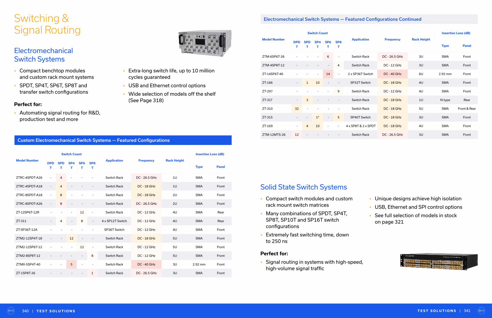
Switching & Signal Routing
Custom Electromechanical Switch Systems — Featured Configurations
Perfect for:
• Automating signal routing for R&D, production test and more
Electromechanical Switch Systems
• Compact benchtop modules and custom rack mount systems
• SPDT, SP4T, SP6T, SP8T and transfer switch configurations
• Extra-long switch life, up to 10 million cycles guaranteed
• USB and Ethernet control options
• Wide selection of models off the shelf (See Page 318)
| T E S T S O L U T I O N S T E S T S O L U T I O N S | 341340
Model Number
Switch Count
Application Frequency Rack Height
Insertion Loss (dB)
DPD
T
SPD
T
SP4
T
SP6
T
SP8
T Type Panel
ZTRC-4SPDT-A26 - 4 - - - Switch Rack DC - 26.5 GHz 1U SMA Front
ZTRC-4SPDT-A18 - 4 - - - Switch Rack DC - 18 GHz 1U SMA Front
ZTRC-8SPDT-A18 - 8 - - - Switch Rack DC - 18 GHz 2U SMA Front
ZTRC-8SPDT-A26 - 8 - - - Switch Rack DC - 26.5 GHz 2U SMA Front
ZT-12SP6T-12R - - - 12 - Switch Rack DC - 12 GHz 4U SMA Rear
ZT-311 - 4 - 8 - 4 x SP12T Switch DC - 12 GHz 4U SMA Rear
ZT-SP36T-12A - - - - - SP36T Switch DC - 12 GHz 4U SMA Front
ZTM2-12SP4T-18 - - 12 - - Switch Rack DC - 18 GHz 5U SMA Front
ZTM2-12SP6T-12 - - - 12 - Switch Rack DC - 12 GHz 5U SMA Front
ZTM2-8SP8T-12 - - - - 8 Switch Rack DC - 12 GHz 5U SMA Front
ZTMX-5SP4T-40 - - 5 - - Switch Rack DC - 40 GHz 3U 2.92 mm Front
ZT-1SP8T-26 - - - - 1 Switch Rack DC - 26.5 GHz 3U SMA Front
• Unique designs achieve high isolation
• USB, Ethernet and SPI control options
• See full selection of models in stock on page 321
Perfect for:
• Signal routing in systems with high-speed, high-volume signal traffic
Solid State Switch Systems
• Compact switch modules and custom rack mount switch matrices
• Many combinations of SPDT, SP4T, SP8T, SP10T and SP16T switch configurations
• Extremely fast switching time, down to 250 ns
Electromechanical Switch Systems — Featured Configurations Continued
Model Number
Switch Count
Application Frequency Rack Height
Insertion Loss (dB)
DPD
T
SPD
T
SP4
T
SP6
T
SP8
T Type Panel
ZTM-6SP6T-26 - - - 6 - Switch Rack DC - 26.5 GHz 3U SMA Front
ZTM-4SP8T-12 - - - - 4 Switch Rack DC - 12 GHz 3U SMA Front
ZT-14SP6T-40 - - - 14 - 2 x SP36T Switch DC - 40 GHz 6U 2.92 mm Front
ZT-166 - 1 10 - - SP32T Switch DC - 18 GHz 4U SMA Front
ZT-297 - - - - 9 Switch Rack DC - 12 GHz 4U SMA Front
ZT-317 - 3 - - - Switch Rack DC - 18 GHz 1U N-type Rear
ZT-310 32 - - - - Switch Rack DC - 18 GHz 5U SMA Front & Rear
ZT-315 - - 1* - 5 SP40T Switch DC - 18 GHz 3U SMA Front
ZT-169 - 4 10 - - 4 x SP8T & 2 x SPDT DC - 18 GHz 4U SMA Front
ZTM-12MTS-26 12 - - - - Switch Rack DC - 26.5 GHz 3U SMA Front
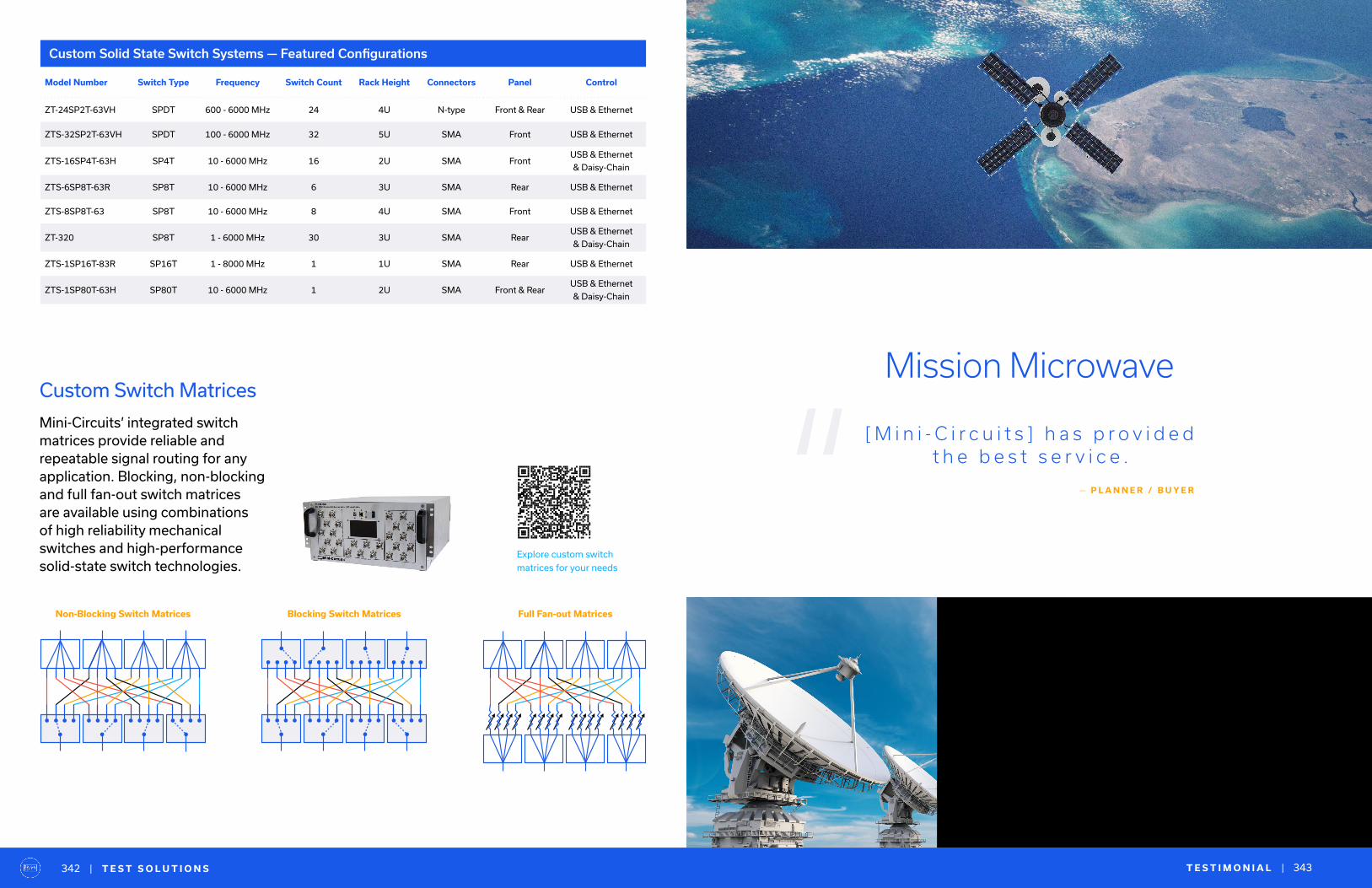
| T E S T S O L U T I O N S T E S T I M O N I A L | 343342
Custom Solid State Switch Systems — Featured Configurations
Model Number Switch Type Frequency Switch Count Rack Height Connectors Panel Control
ZT-24SP2T-63VH SPDT 600 - 6000 MHz 24 4U N-type Front & Rear USB & Ethernet
ZTS-32SP2T-63VH SPDT 100 - 6000 MHz 32 5U SMA Front USB & Ethernet
ZTS-16SP4T-63H SP4T 10 - 6000 MHz 16 2U SMA FrontUSB & Ethernet
& Daisy-Chain
ZTS-6SP8T-63R SP8T 10 - 6000 MHz 6 3U SMA Rear USB & Ethernet
ZTS-8SP8T-63 SP8T 10 - 6000 MHz 8 4U SMA Front USB & Ethernet
ZT-320 SP8T 1 - 6000 MHz 30 3U SMA RearUSB & Ethernet
& Daisy-Chain
ZTS-1SP16T-83R SP16T 1 - 8000 MHz 1 1U SMA Rear USB & Ethernet
ZTS-1SP80T-63H SP80T 10 - 6000 MHz 1 2U SMA Front & RearUSB & Ethernet
& Daisy-Chain
Explore custom switch
matrices for your needs
Non-Blocking Switch Matrices Blocking Switch Matrices Full Fan-out Matrices
Custom Switch Matrices
Mini-Circuits’ integrated switch matrices provide reliable and repeatable signal routing for any application. Blocking, non-blocking and full fan-out switch matrices are available using combinations of high reliability mechanical switches and high-performance solid-state switch technologies.
“Mission Microwave
[ M i n i - C i r c u i t s ] h a s p r o v i d e d t h e b e s t s e r v i c e .
— P L A N N E R / B U Y E R
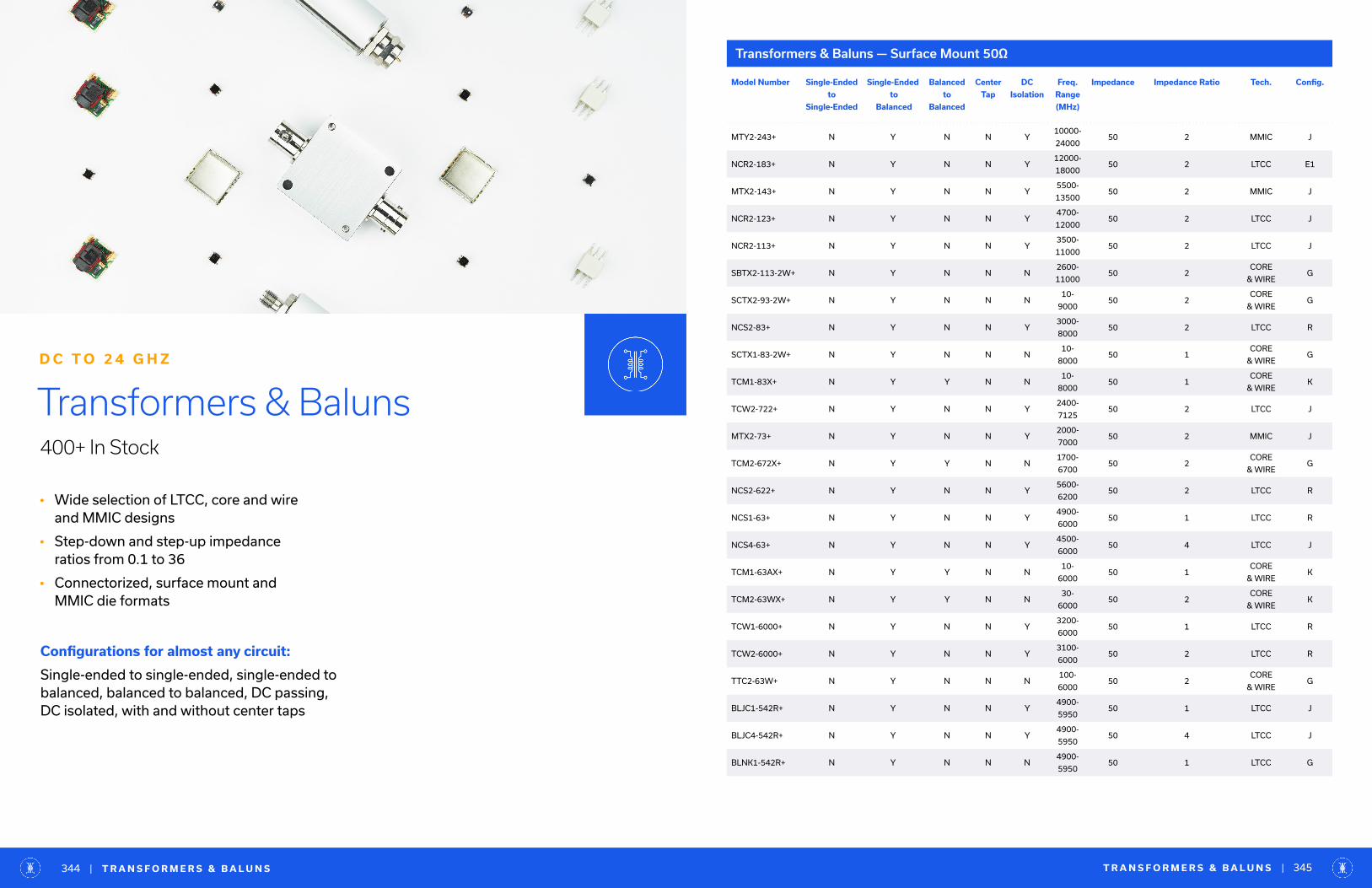
• Wide selection of LTCC, core and wire and MMIC designs
• Step-down and step-up impedance ratios from 0.1 to 36
• Connectorized, surface mount and MMIC die formats
Transformers & Baluns400+ In Stock
D C T O 2 4 G H Z
Configurations for almost any circuit:
Single-ended to single-ended, single-ended tobalanced, balanced to balanced, DC passing, DC isolated, with and without center taps
Transformers & Baluns — Surface Mount 50Ω
Model Number Single-Ended
to
Single-Ended
Single-Ended
to
Balanced
Balanced
to
Balanced
Center
Tap
DC
Isolation
Freq.
Range
(MHz)
Impedance Impedance Ratio Tech. Config.
MTY2-243+ N Y N N Y10000-
2400050 2 MMIC J
NCR2-183+ N Y N N Y12000-
1800050 2 LTCC E1
MTX2-143+ N Y N N Y5500-
1350050 2 MMIC J
NCR2-123+ N Y N N Y4700-
1200050 2 LTCC J
NCR2-113+ N Y N N Y3500-
1100050 2 LTCC J
SBTX2-113-2W+ N Y N N N2600-
1100050 2
CORE
& WIREG
SCTX2-93-2W+ N Y N N N10-
900050 2
CORE
& WIREG
NCS2-83+ N Y N N Y3000-
800050 2 LTCC R
SCTX1-83-2W+ N Y N N N10-
800050 1
CORE
& WIREG
TCM1-83X+ N Y Y N N10-
800050 1
CORE
& WIREK
TCW2-722+ N Y N N Y2400-
712550 2 LTCC J
MTX2-73+ N Y N N Y2000-
700050 2 MMIC J
TCM2-672X+ N Y Y N N1700-
670050 2
CORE
& WIREG
NCS2-622+ N Y N N Y5600-
620050 2 LTCC R
NCS1-63+ N Y N N Y4900-
600050 1 LTCC R
NCS4-63+ N Y N N Y4500-
600050 4 LTCC J
TCM1-63AX+ N Y Y N N10-
600050 1
CORE
& WIREK
TCM2-63WX+ N Y Y N N30-
600050 2
CORE
& WIREK
TCW1-6000+ N Y N N Y3200-
600050 1 LTCC R
TCW2-6000+ N Y N N Y3100-
600050 2 LTCC R
TTC2-63W+ N Y N N N100-
600050 2
CORE
& WIREG
BLJC1-542R+ N Y N N Y4900-
595050 1 LTCC J
BLJC4-542R+ N Y N N Y4900-
595050 4 LTCC J
BLNK1-542R+ N Y N N N4900-
595050 1 LTCC G
T R A N S F O R M E R S & B A L U N S | 345| T R A N S F O R M E R S & B A L U N S344
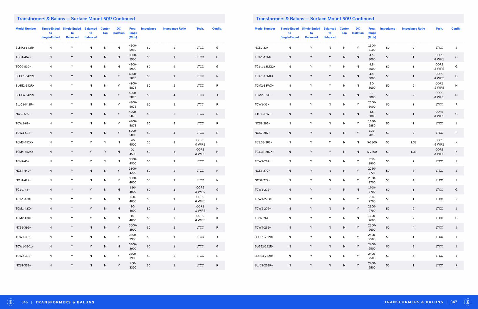
Model Number Single-Ended
to
Single-Ended
Single-Ended
to
Balanced
Balanced
to
Balanced
Center
Tap
DC
Isolation
Freq.
Range
(MHz)
Impedance Impedance Ratio Tech. Config.
BLNK2-542R+ N Y N N N4900-
595050 2 LTCC G
TCO1-462+ N Y N N N3300-
590050 1 LTCC G
TCO2-532+ N Y N N N4600-
590050 2 LTCC G
BLGE1-542R+ N Y N N Y4900-
587550 1 LTCC R
BLGE2-542R+ N Y N N Y4900-
587550 2 LTCC R
BLGE4-542R+ N Y N N Y4900-
587550 4 LTCC J
BLJC2-542R+ N Y N N Y4900-
587550 2 LTCC R
NCS2-592+ N Y N N Y4900-
587550 2 LTCC R
TCW2-63+ N Y N N Y4900-
587550 2 LTCC R
TCW4-582+ N Y N N Y5000-
580050 4 LTCC R
TCM3-452X+ N Y Y Y N20-
450050 3
CORE
& WIREH
TCM4-452X+ N Y Y Y N20-
450050 4
CORE
& WIREH
TCN2-45+ N Y Y Y N3300-
450050 2 LTCC H
NCS4-442+ N Y N N Y3300-
420050 2 LTCC R
NCS1-422+ N Y N N Y3300-
400050 1 LTCC R
TC1-1-43+ N Y Y N N650-
400050 1
CORE
& WIREG
TC1-1-43X+ N Y Y N N650-
400050 1
CORE
& WIREG
TCM1-43X+ N Y Y N N10-
400050 1
CORE
& WIREK
TCM2-43X+ N Y Y N N10-
400050 2
CORE
& WIREK
NCS2-392+ N Y N N Y3000-
390050 2 LTCC R
TCW1-392+ N Y N N Y3300-
390050 1 LTCC J
TCW1-3901+ N Y Y N N3300-
390050 1 LTCC G
TCW2-392+ N Y N N Y3300-
390050 2 LTCC R
NCS1-332+ N Y N N Y700-
330050 1 LTCC R
Model Number Single-Ended
to
Single-Ended
Single-Ended
to
Balanced
Balanced
to
Balanced
Center
Tap
DC
Isolation
Freq.
Range
(MHz)
Impedance Impedance Ratio Tech. Config.
NCS2-33+ N Y N N Y1500-
310050 2 LTCC J
TC1-1-13M+ N Y Y N N4.5-
300050 1
CORE
& WIREG
TC1-1-13MG2+ N Y Y N N4.5-
300050 1
CORE
& WIREG
TC1-1-13MX+ N Y Y N N4.5-
300050 1
CORE
& WIREG
TCM2-33WX+ N Y Y N N10-
300050 2
CORE
& WIREN
TCM2-33X+ N Y Y N N30-
300050 2
CORE
& WIREN
TCW1-33+ N Y N N Y2300-
300050 1 LTCC R
TTC1-33W+ N Y N N N4.5-
300050 1
CORE
& WIREG
NCS1-292+ N Y N N Y1650-
285050 1 LTCC J
NCS2-282+ N Y N N Y625-
281550 2 LTCC R
TC1.33-282+ N Y Y N N 5-2800 50 1.33CORE
& WIREK
TC1.33-282X+ N Y Y N N 5-2800 50 1.33CORE
& WIREK
TCW2-282+ N Y N N Y700-
280050 2 LTCC R
NCS3-272+ N Y N N Y2250-
272550 3 LTCC J
NCS4-272+ N Y N N Y2300-
270050 4 LTCC J
TCW1-272+ N Y Y N N1700-
270050 1 LTCC G
TCW1-2700+ N Y N N Y700-
270050 1 LTCC R
TCW2-272+ N Y N N Y2100-
270050 2 LTCC J
TCN2-26+ N Y Y N N1600-
260050 2 LTCC G
TCW4-262+ N Y N N Y2300-
260050 4 LTCC J
BLGE1-252R+ N Y N N Y2400-
250050 1 LTCC J
BLGE2-252R+ N Y N N Y2400-
250050 2 LTCC J
BLGE4-252R+ N Y N N Y2400-
250050 4 LTCC J
BLJC1-252R+ N Y N N Y2400-
250050 1 LTCC R
T R A N S F O R M E R S & B A L U N S | 347| T R A N S F O R M E R S & B A L U N S346
Transformers & Baluns — Surface Mount 50Ω ContinuedTransformers & Baluns — Surface Mount 50Ω Continued
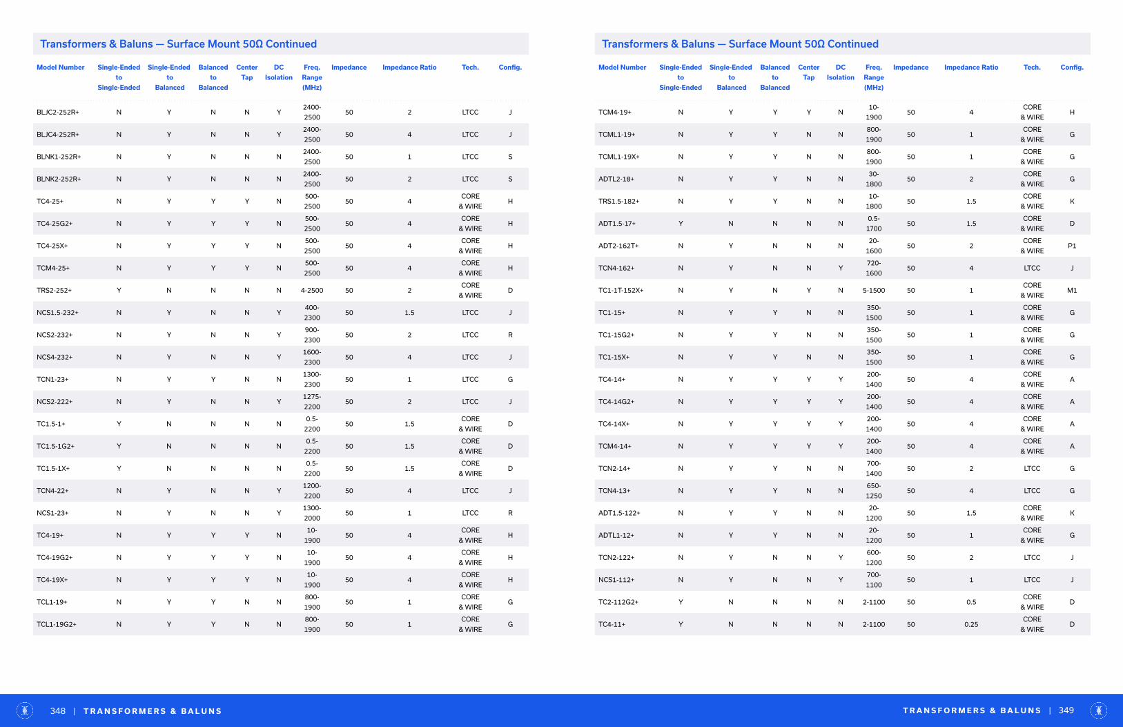
Model Number Single-Ended
to
Single-Ended
Single-Ended
to
Balanced
Balanced
to
Balanced
Center
Tap
DC
Isolation
Freq.
Range
(MHz)
Impedance Impedance Ratio Tech. Config.
BLJC2-252R+ N Y N N Y2400-
250050 2 LTCC J
BLJC4-252R+ N Y N N Y2400-
250050 4 LTCC J
BLNK1-252R+ N Y N N N2400-
250050 1 LTCC S
BLNK2-252R+ N Y N N N2400-
250050 2 LTCC S
TC4-25+ N Y Y Y N500-
250050 4
CORE
& WIREH
TC4-25G2+ N Y Y Y N500-
250050 4
CORE
& WIREH
TC4-25X+ N Y Y Y N500-
250050 4
CORE
& WIREH
TCM4-25+ N Y Y Y N500-
250050 4
CORE
& WIREH
TRS2-252+ Y N N N N 4-2500 50 2CORE
& WIRED
NCS1.5-232+ N Y N N Y400-
230050 1.5 LTCC J
NCS2-232+ N Y N N Y900-
230050 2 LTCC R
NCS4-232+ N Y N N Y1600-
230050 4 LTCC J
TCN1-23+ N Y Y N N1300-
230050 1 LTCC G
NCS2-222+ N Y N N Y1275-
220050 2 LTCC J
TC1.5-1+ Y N N N N0.5-
220050 1.5
CORE
& WIRED
TC1.5-1G2+ Y N N N N0.5-
220050 1.5
CORE
& WIRED
TC1.5-1X+ Y N N N N0.5-
220050 1.5
CORE
& WIRED
TCN4-22+ N Y N N Y1200-
220050 4 LTCC J
NCS1-23+ N Y N N Y1300-
200050 1 LTCC R
TC4-19+ N Y Y Y N10-
190050 4
CORE
& WIREH
TC4-19G2+ N Y Y Y N10-
190050 4
CORE
& WIREH
TC4-19X+ N Y Y Y N10-
190050 4
CORE
& WIREH
TCL1-19+ N Y Y N N800-
190050 1
CORE
& WIREG
TCL1-19G2+ N Y Y N N800-
190050 1
CORE
& WIREG
Model Number Single-Ended
to
Single-Ended
Single-Ended
to
Balanced
Balanced
to
Balanced
Center
Tap
DC
Isolation
Freq.
Range
(MHz)
Impedance Impedance Ratio Tech. Config.
TCM4-19+ N Y Y Y N10-
190050 4
CORE
& WIREH
TCML1-19+ N Y Y N N800-
190050 1
CORE
& WIREG
TCML1-19X+ N Y Y N N800-
190050 1
CORE
& WIREG
ADTL2-18+ N Y Y N N30-
180050 2
CORE
& WIREG
TRS1.5-182+ N Y Y N N10-
180050 1.5
CORE
& WIREK
ADT1.5-17+ Y N N N N0.5-
170050 1.5
CORE
& WIRED
ADT2-162T+ N Y N N N20-
160050 2
CORE
& WIREP1
TCN4-162+ N Y N N Y720-
160050 4 LTCC J
TC1-1T-152X+ N Y N Y N 5-1500 50 1CORE
& WIREM1
TC1-15+ N Y Y N N350-
150050 1
CORE
& WIREG
TC1-15G2+ N Y Y N N350-
150050 1
CORE
& WIREG
TC1-15X+ N Y Y N N350-
150050 1
CORE
& WIREG
TC4-14+ N Y Y Y Y200-
140050 4
CORE
& WIREA
TC4-14G2+ N Y Y Y Y200-
140050 4
CORE
& WIREA
TC4-14X+ N Y Y Y Y200-
140050 4
CORE
& WIREA
TCM4-14+ N Y Y Y Y200-
140050 4
CORE
& WIREA
TCN2-14+ N Y Y N N700-
140050 2 LTCC G
TCN4-13+ N Y Y N N650-
125050 4 LTCC G
ADT1.5-122+ N Y Y N N20-
120050 1.5
CORE
& WIREK
ADTL1-12+ N Y Y N N20-
120050 1
CORE
& WIREG
TCN2-122+ N Y N N Y600-
120050 2 LTCC J
NCS1-112+ N Y N N Y700-
110050 1 LTCC J
TC2-112G2+ Y N N N N 2-1100 50 0.5CORE
& WIRED
TC4-11+ Y N N N N 2-1100 50 0.25CORE
& WIRED
T R A N S F O R M E R S & B A L U N S | 349| T R A N S F O R M E R S & B A L U N S348
Transformers & Baluns — Surface Mount 50Ω ContinuedTransformers & Baluns — Surface Mount 50Ω Continued

Model Number Single-Ended
to
Single-Ended
Single-Ended
to
Balanced
Balanced
to
Balanced
Center
Tap
DC
Isolation
Freq.
Range
(MHz)
Impedance Impedance Ratio Tech. Config.
TC4-11G2+ Y N N N N 2-1100 50 0.25CORE
& WIRED
TC4-11X+ Y N N N N 2-1100 50 0.25CORE
& WIRED
TCL1-11+ N Y Y N N600-
110050 1
CORE
& WIREG
TCML1-11+ N Y Y N N600-
110050 1
CORE
& WIREG
TCML1-11X+ N Y Y N N600-
110050 1
CORE
& WIREG
TCN3-11+ N Y Y N N600-
110050 3 LTCC G
TCN1-10+ N Y Y N N680-
105050 1 LTCC G
JTX-4-10T+ N Y Y Y Y50-
100050 4
CORE
& WIREA
NCS4-102+ N Y N N Y700-
100050 4 LTCC J
SYTX4-13HP+ N Y Y Y N30-
100050 4
CORE
& WIREH
TC4-13TX+ N Y Y Y Y100-
100050 4
CORE
& WIREA
T3-1+ Y N N N N 0.5-800 50 3CORE
& WIRED
T3-1-KK81+ Y N N N N 0.5-800 50 3CORE
& WIRED
TC4-1W+ N Y Y Y Y 3-800 50 4CORE
& WIREA
TC4-1WA+ N Y Y Y Y 3-800 50 4CORE
& WIREA
TC4-1WG2+ N Y Y Y Y 3-800 50 4CORE
& WIREA
TC4-1WX+ N Y Y Y Y 3-800 50 4CORE
& WIREA
TCM4-1W+ N Y Y Y Y 3-800 50 4CORE
& WIREA
TCM4-1WX+ N Y Y Y Y 3-800 50 4CORE
& WIREA
ADT4-1WT+ N Y Y Y Y 2-775 50 4CORE
& WIREA
NCS2-771+ N Y N N Y240-
77050 2 LTCC J
NCS3-72+ N Y N N Y250-
76050 3 LTCC J
TC2-72T+ N Y Y Y Y 10-700 50 2CORE
& WIREA
ADT1.5-1+ N Y Y Y Y 0.5-650 50 1.5CORE
& WIREA
Model Number Single-Ended
to
Single-Ended
Single-Ended
to
Balanced
Balanced
to
Balanced
Center
Tap
DC
Isolation
Freq.
Range
(MHz)
Impedance Impedance Ratio Tech. Config.
ADT4-1T+ N Y Y Y Y 9-625 50 4CORE
& WIREA
ADT2-1T-1P+ N Y Y Y Y 8-600 50 2CORE
& WIREA
ADT4-6WT+ N Y Y Y Y 0.5-600 50 4CORE
& WIREA
SERT4-62HP-
50W+Y N N N N 20-600 12.5/50 0.25
CORE
& WIRED
T2-1+ Y N N N N0.05-
60050 2
CORE
& WIRED
T2-1-KK81+ Y N N N N0.05-
60050 2
CORE
& WIRED
T4-2+ Y N N N N 0.2-600 50 4CORE
& WIRED
T4-2-KK81+ Y N N N N 0.2-600 50 4CORE
& WIRED
TC4-6T+ N Y Y Y Y 1.5-600 50 4CORE
& WIREA
TC4-6TG2+ N Y Y Y Y 1.5-600 50 4CORE
& WIREA
TC4-6TX+ N Y Y Y Y 1.5-600 50 4CORE
& WIREA
TCM4-6T+ N Y Y Y Y 1.5-600 50 4CORE
& WIREA
TX4-62HP+ N Y Y Y N 20-600 50 4CORE
& WIREH
NCS2-62+ N Y N N Y390-
59050 2 LTCC J
TC1.5-52T+ N Y Y Y Y 0.5-550 50 1.5CORE
& WIREA
TC1.5-52TG2+ N Y Y Y Y 0.5-550 50 1.5CORE
& WIREA
TC1.5-52TX+ N Y Y Y Y 0.5-550 50 1.5CORE
& WIREA
NCS1-521+ N Y N N N223-
52050 1 LTCC S
NCS4-521+ N Y N N Y223-
52050 4 LTCC R
SYTX1-52HP-
15W+N Y Y N N 20-520 50 1
CORE
& WIREG
SYTX2-52HP-
20W+Y N N N N 30-520 50 2
CORE
& WIRED
TXA4-512HP+ N Y Y Y N 30-512 50 4CORE
& WIREH
ADT3-1T+ N Y Y Y Y 1-500 50 3CORE
& WIREA
ADT4-5WT+ N Y Y Y Y 0.3-500 50 4CORE
& WIREA
T R A N S F O R M E R S & B A L U N S | 351| T R A N S F O R M E R S & B A L U N S350
Transformers & Baluns — Surface Mount 50Ω ContinuedTransformers & Baluns — Surface Mount 50Ω Continued

Model Number Single-Ended
to
Single-Ended
Single-Ended
to
Balanced
Balanced
to
Balanced
Center
Tap
DC
Isolation
Freq.
Range
(MHz)
Impedance Impedance Ratio Tech. Config.
TC1-1+ N Y Y N Y 1.5-500 50 1CORE
& WIREC
TC1-1G2+ N Y Y N Y 1.5-500 50 1CORE
& WIREC
TC1-1T+ N Y Y Y Y 0.4-500 50 1CORE
& WIREA
TC1-1TG2+ N Y Y Y Y 0.4-500 50 1CORE
& WIREA
TC1-1TX+ N Y Y Y Y 0.4-500 50 1CORE
& WIREA
TC1-1X+ N Y Y N Y 1.5-500 50 1CORE
& WIREC
TC8-1+ N Y Y Y Y 2-500 50 8CORE
& WIREA
TC8-1G2+ N Y Y Y Y 2-500 50 8CORE
& WIREA
TC8-1X+ N Y Y Y Y 2-500 50 8CORE
& WIREA
TCM1-1+ N Y Y N Y 1.5-500 50 1CORE
& WIREC
TCM1-1X+ N Y Y N Y 1.5-500 50 1CORE
& WIREC
TCM3-1T+ N Y Y Y Y 2-500 50 3CORE
& WIREA
TCM3-1TX+ N Y Y Y Y 2-500 50 3CORE
& WIREA
TCM8-1+ N Y Y Y Y 2-500 50 8CORE
& WIREA
TT1.5-1+ N Y Y Y Y0.075-
50050 1.5
CORE
& WIREB
TT1.5-1-KK81+ N Y Y Y Y0.075-
50050 1.5
CORE
& WIREB
TX1-R5+ N Y Y N Y 0.8-500 50 1CORE
& WIREC
ADT2-1T+ N Y Y Y Y 0.4-450 50 2CORE
& WIREA
SYTX2-451-5W+ N Y Y N Y 10-450 50 2CORE
& WIREC
ADT1-1+ N Y Y N Y0.15-
40050 1
CORE
& WIREC
ADT3-6T+ N Y Y Y Y0.06-
40050 3
CORE
& WIREA
T1-1+ N Y Y N Y0.15-
40050 1
CORE
& WIREC
T1-1-KK81+ N Y Y N Y0.15-
40050 1
CORE
& WIREC
TC1-42+ N Y Y N Y0.25-
40050 1
CORE
& WIREC
Model Number Single-Ended
to
Single-Ended
Single-Ended
to
Balanced
Balanced
to
Balanced
Center
Tap
DC
Isolation
Freq.
Range
(MHz)
Impedance Impedance Ratio Tech. Config.
TC1-42X+ N Y Y N Y0.25-
40050 1
CORE
& WIREC
TTCM4-4+ N Y Y Y Y 0.5-400 50 4CORE
& WIREB
TTCM4-4X+ N Y Y Y Y 0.5-400 50 4CORE
& WIREB
TX1-1+ N Y Y N Y 0.3-400 50 1CORE
& WIREC
T4-1+ N Y Y Y Y 0.2-350 50 4CORE
& WIREA
T4-1-KK81+ N Y Y Y Y 0.2-350 50 4CORE
& WIREA
T4-1H+ N Y Y Y Y 10-350 50 4CORE
& WIREA
T4-1H-KK81+ N Y Y Y Y 10-350 50 4CORE
& WIREA
TC1-6+ N Y Y N Y0.15-
35050 1
CORE
& WIREC
TC1-6X+ N Y Y N Y0.15-
35050 1
CORE
& WIREC
SCTX4-32HP-
20W+Y N N N N 1-310 50 4
CORE
& WIRED1
ADT4-6T+ N Y Y Y Y0.06-
30050 4
CORE
& WIREA
ADTT1-1+ N Y Y Y Y 0.3-300 50 1CORE
& WIREB
ADTT1.5-1+ N Y Y Y Y0.25-
30050 1.5
CORE
& WIREB
T1-6T+ N Y Y Y Y0.015-
30050 1
CORE
& WIREA
T1-6T-KK81+ N Y Y Y Y0.015-
30050 1
CORE
& WIREA
T5-1T+ N Y Y Y Y 0.3-300 50 5CORE
& WIREA
T5-1T-KK81+ N Y Y Y Y 0.3-300 50 5CORE
& WIREA
TC2-1T+ N Y Y Y Y 3-300 50 2CORE
& WIREA
TC2-1TG2+ N Y Y Y Y 3-300 50 2CORE
& WIREA
TC2-1TX+ N Y Y Y Y 3-300 50 2CORE
& WIREA
TC3-1T+ N Y Y Y Y 5-300 50 3CORE
& WIREA
TC3-1TG2+ N Y Y Y Y 5-300 50 3CORE
& WIREA
TC3-1TX+ N Y Y Y Y 5-300 50 3CORE
& WIREA
T R A N S F O R M E R S & B A L U N S | 353| T R A N S F O R M E R S & B A L U N S352
Transformers & Baluns — Surface Mount 50Ω ContinuedTransformers & Baluns — Surface Mount 50Ω Continued
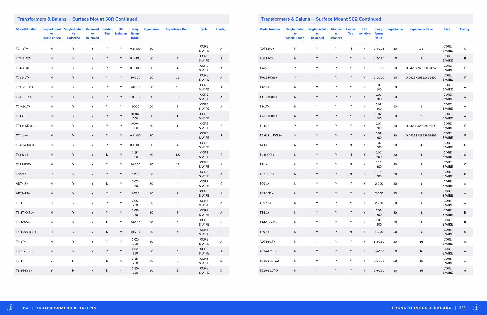
Model Number Single-Ended
to
Single-Ended
Single-Ended
to
Balanced
Balanced
to
Balanced
Center
Tap
DC
Isolation
Freq.
Range
(MHz)
Impedance Impedance Ratio Tech. Config.
TC4-1T+ N Y Y Y Y 0.5-300 50 4CORE
& WIREA
TC4-1TG2+ N Y Y Y Y 0.5-300 50 4CORE
& WIREA
TC4-1TX+ N Y Y Y Y 0.5-300 50 4CORE
& WIREA
TC16-1T+ N Y Y Y Y 20-300 50 16CORE
& WIREA
TC16-1TG2+ N Y Y Y Y 20-300 50 16CORE
& WIREA
TC16-1TX+ N Y Y Y Y 20-300 50 16CORE
& WIREA
TCM2-1T+ N Y Y Y Y 3-300 50 2CORE
& WIREA
TT1-6+ N Y Y Y Y0.004-
30050 1
CORE
& WIREB
TT1-6-KK81+ N Y Y Y Y0.004-
30050 1
CORE
& WIREB
TT4-1A+ N Y Y Y Y 0.1-300 50 4CORE
& WIREB
TT4-1A-KK81+ N Y Y Y Y 0.1-300 50 4CORE
& WIREB
TX1.5-1+ N Y Y N Y0.25-
30050 1.5
CORE
& WIREC
TX16-R3T+ N Y Y Y Y 40-300 50 16CORE
& WIREA
TCM9-1+ N Y Y Y Y 2-280 50 9CORE
& WIREA
ADT4-6+ N Y Y N Y0.07-
25050 4
CORE
& WIREC
ADT9-1T+ N Y Y Y Y 1-250 50 9CORE
& WIREA
T3-1T+ N Y Y Y Y0.05-
25050 3
CORE
& WIREA
T3-1T-KK81+ N Y Y Y Y0.05-
25050 3
CORE
& WIREA
T4-1-2W+ N Y Y N Y 10-250 50 4CORE
& WIREC
T4-1-2W-KK81+ N Y Y N Y 10-250 50 4CORE
& WIREC
T4-6T+ N Y Y Y Y0.02-
25050 4
CORE
& WIREA
T4-6T-KK81+ N Y Y Y Y0.02-
25050 4
CORE
& WIREA
T8-1+ Y N N N N0.15-
25050 8
CORE
& WIRED
T8-1-KK81+ Y N N N N0.15-
25050 8
CORE
& WIRED
Model Number Single-Ended
to
Single-Ended
Single-Ended
to
Balanced
Balanced
to
Balanced
Center
Tap
DC
Isolation
Freq.
Range
(MHz)
Impedance Impedance Ratio Tech. Config.
ADT1.5-2+ N Y Y N Y 0.3-225 50 1.5CORE
& WIREC
ADTT3-2+ N Y Y Y Y 0.2-210 50 3CORE
& WIREB
T-622+ Y Y Y Y Y 0.1-200 50 0.0423726851851852CORE
& WIREF
T-622-KK81+ Y Y Y Y Y 0.1-200 50 0.0423726851851852CORE
& WIREF
T1-1T+ N Y Y Y Y0.08-
20050 1
CORE
& WIREA
T1-1T-KK81+ N Y Y Y Y0.08-
20050 1
CORE
& WIREA
T2-1T+ N Y Y Y Y0.07-
20050 2
CORE
& WIREA
T2-1T-KK81+ N Y Y Y Y0.07-
20050 2
CORE
& WIREA
T2-613-1+ Y Y Y Y Y0.07-
20050 0.0423842592592593
CORE
& WIREF
T2-613-1-KK81+ Y Y Y Y Y0.07-
20050 0.0423842592592593
CORE
& WIREF
T4-6+ N Y Y N Y0.02-
20050 4
CORE
& WIREC
T4-6-KK81+ N Y Y N Y0.02-
20050 4
CORE
& WIREC
T9-1+ N Y Y N Y0.15-
20050 9
CORE
& WIREC
T9-1-KK81+ N Y Y N Y0.15-
20050 9
CORE
& WIREC
TC9-1+ N Y Y Y Y 2-200 50 9CORE
& WIREA
TC9-1G2+ N Y Y Y Y 2-200 50 9CORE
& WIREA
TC9-1X+ N Y Y Y Y 2-200 50 9CORE
& WIREA
TT4-1+ N Y Y Y Y0.05-
20050 3
CORE
& WIREB
TT4-1-KK81+ N Y Y Y Y0.05-
20050 3
CORE
& WIREB
TX9-1+ N Y Y N Y 1-200 50 9CORE
& WIREC
ADT16-1T+ N Y Y Y Y 1.5-160 50 16CORE
& WIREA
TC16-161T+ N Y Y Y Y 0.6-160 50 16CORE
& WIREA
TC16-161TG2+ N Y Y Y Y 0.6-160 50 16CORE
& WIREA
TC16-161TX+ N Y Y Y Y 0.6-160 50 16CORE
& WIREA
T R A N S F O R M E R S & B A L U N S | 355| T R A N S F O R M E R S & B A L U N S354
Transformers & Baluns — Surface Mount 50Ω ContinuedTransformers & Baluns — Surface Mount 50Ω Continued
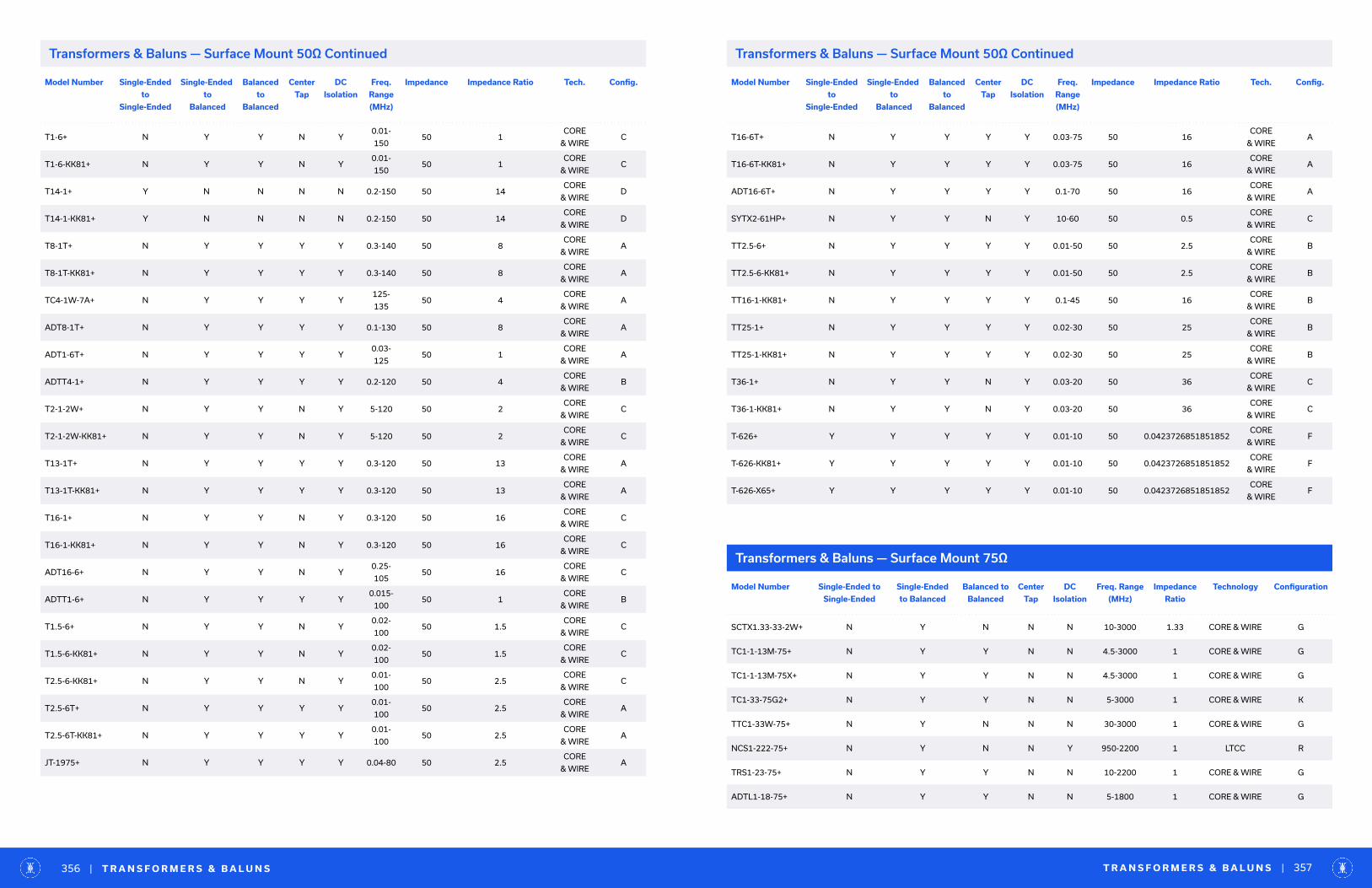
Model Number Single-Ended
to
Single-Ended
Single-Ended
to
Balanced
Balanced
to
Balanced
Center
Tap
DC
Isolation
Freq.
Range
(MHz)
Impedance Impedance Ratio Tech. Config.
T1-6+ N Y Y N Y0.01-
15050 1
CORE
& WIREC
T1-6-KK81+ N Y Y N Y0.01-
15050 1
CORE
& WIREC
T14-1+ Y N N N N 0.2-150 50 14CORE
& WIRED
T14-1-KK81+ Y N N N N 0.2-150 50 14CORE
& WIRED
T8-1T+ N Y Y Y Y 0.3-140 50 8CORE
& WIREA
T8-1T-KK81+ N Y Y Y Y 0.3-140 50 8CORE
& WIREA
TC4-1W-7A+ N Y Y Y Y125-
13550 4
CORE
& WIREA
ADT8-1T+ N Y Y Y Y 0.1-130 50 8CORE
& WIREA
ADT1-6T+ N Y Y Y Y0.03-
12550 1
CORE
& WIREA
ADTT4-1+ N Y Y Y Y 0.2-120 50 4CORE
& WIREB
T2-1-2W+ N Y Y N Y 5-120 50 2CORE
& WIREC
T2-1-2W-KK81+ N Y Y N Y 5-120 50 2CORE
& WIREC
T13-1T+ N Y Y Y Y 0.3-120 50 13CORE
& WIREA
T13-1T-KK81+ N Y Y Y Y 0.3-120 50 13CORE
& WIREA
T16-1+ N Y Y N Y 0.3-120 50 16CORE
& WIREC
T16-1-KK81+ N Y Y N Y 0.3-120 50 16CORE
& WIREC
ADT16-6+ N Y Y N Y0.25-
10550 16
CORE
& WIREC
ADTT1-6+ N Y Y Y Y0.015-
10050 1
CORE
& WIREB
T1.5-6+ N Y Y N Y0.02-
10050 1.5
CORE
& WIREC
T1.5-6-KK81+ N Y Y N Y0.02-
10050 1.5
CORE
& WIREC
T2.5-6-KK81+ N Y Y N Y0.01-
10050 2.5
CORE
& WIREC
T2.5-6T+ N Y Y Y Y0.01-
10050 2.5
CORE
& WIREA
T2.5-6T-KK81+ N Y Y Y Y0.01-
10050 2.5
CORE
& WIREA
JT-1975+ N Y Y Y Y 0.04-80 50 2.5CORE
& WIREA
Transformers & Baluns — Surface Mount 75Ω
Model Number Single-Ended to
Single-Ended
Single-Ended
to Balanced
Balanced to
Balanced
Center
Tap
DC
Isolation
Freq. Range
(MHz)
Impedance
Ratio
Technology Configuration
SCTX1.33-33-2W+ N Y N N N 10-3000 1.33 CORE & WIRE G
TC1-1-13M-75+ N Y Y N N 4.5-3000 1 CORE & WIRE G
TC1-1-13M-75X+ N Y Y N N 4.5-3000 1 CORE & WIRE G
TC1-33-75G2+ N Y Y N N 5-3000 1 CORE & WIRE K
TTC1-33W-75+ N Y N N N 30-3000 1 CORE & WIRE G
NCS1-222-75+ N Y N N Y 950-2200 1 LTCC R
TRS1-23-75+ N Y Y N N 10-2200 1 CORE & WIRE G
ADTL1-18-75+ N Y Y N N 5-1800 1 CORE & WIRE G
T R A N S F O R M E R S & B A L U N S | 357| T R A N S F O R M E R S & B A L U N S356
Transformers & Baluns — Surface Mount 50Ω ContinuedTransformers & Baluns — Surface Mount 50Ω Continued
Model Number Single-Ended
to
Single-Ended
Single-Ended
to
Balanced
Balanced
to
Balanced
Center
Tap
DC
Isolation
Freq.
Range
(MHz)
Impedance Impedance Ratio Tech. Config.
T16-6T+ N Y Y Y Y 0.03-75 50 16CORE
& WIREA
T16-6T-KK81+ N Y Y Y Y 0.03-75 50 16CORE
& WIREA
ADT16-6T+ N Y Y Y Y 0.1-70 50 16CORE
& WIREA
SYTX2-61HP+ N Y Y N Y 10-60 50 0.5CORE
& WIREC
TT2.5-6+ N Y Y Y Y 0.01-50 50 2.5CORE
& WIREB
TT2.5-6-KK81+ N Y Y Y Y 0.01-50 50 2.5CORE
& WIREB
TT16-1-KK81+ N Y Y Y Y 0.1-45 50 16CORE
& WIREB
TT25-1+ N Y Y Y Y 0.02-30 50 25CORE
& WIREB
TT25-1-KK81+ N Y Y Y Y 0.02-30 50 25CORE
& WIREB
T36-1+ N Y Y N Y 0.03-20 50 36CORE
& WIREC
T36-1-KK81+ N Y Y N Y 0.03-20 50 36CORE
& WIREC
T-626+ Y Y Y Y Y 0.01-10 50 0.0423726851851852CORE
& WIREF
T-626-KK81+ Y Y Y Y Y 0.01-10 50 0.0423726851851852CORE
& WIREF
T-626-X65+ Y Y Y Y Y 0.01-10 50 0.0423726851851852CORE
& WIREF
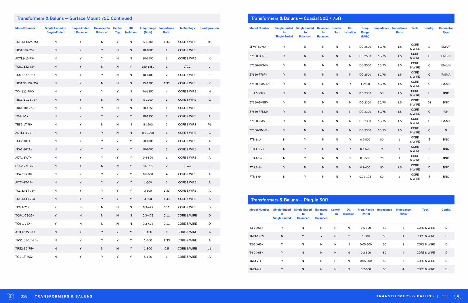
Model Number Single-Ended to
Single-Ended
Single-Ended
to Balanced
Balanced to
Balanced
Center
Tap
DC
Isolation
Freq. Range
(MHz)
Impedance
Ratio
Technology Configuration
TC1.33-182X-75+ N Y N Y N 5-1800 1.33 CORE & WIRE M1
TRS1-182-75+ N Y Y N N 10-1800 1 CORE & WIRE K
ADTL1-15-75+ N Y Y N N 10-1500 1 CORE & WIRE K
TCN1-152-75+ N Y N N Y 950-1450 1 LTCC J
TCM2-142-75X+ N Y Y N N 10-1400 2 CORE & WIRE K
TRS1.33-132-75+ N Y N N N 25-1300 1.33 CORE & WIRE P
TC4-122-75X+ N Y Y Y N 40-1250 4 CORE & WIRE H
TRC1-1-122-75+ N Y N N N 5-1250 1 CORE & WIRE G
TRC1-1K122-75+ N Y Y N N 20-1250 1 CORE & WIRE K
TX-2-5-1+ N Y Y Y Y 20-1250 2 CORE & WIRE A
TRS2-1T-75+ N Y N N N 5-1200 2 CORE & WIRE P1
ADTL1-4-75+ N Y Y N N 0.5-1000 1 CORE & WIRE G
JTX-2-10T+ N Y Y Y Y 50-1000 2 CORE & WIRE A
JTX-2-10TA+ N Y Y Y Y 50-1000 2 CORE & WIRE A
ADT1-1WT+ N Y Y Y Y 0.4-800 1 CORE & WIRE A
NCS2-771-75+ N Y N N Y 240-770 2 LTCC J
TC4-6T-75X+ N Y Y Y Y 0.6-600 4 CORE & WIRE A
ADT3-1T-75+ N Y Y Y Y 1-500 3 CORE & WIRE A
TC1.33-1T-75+ N Y Y Y Y 3-500 1.33 CORE & WIRE A
TC1.33-1T-75X+ N Y Y Y Y 3-500 1.33 CORE & WIRE A
TC9-1-75+ Y N N N N 0.3-475 0.11 CORE & WIRE D
TC9-1-75G2+ Y N N N N 0.3-475 0.11 CORE & WIRE D
TC9-1-75X+ Y N N N N 0.3-475 0.11 CORE & WIRE D
ADT1-1WT-1+ N Y Y Y Y 1-400 1 CORE & WIRE A
TRS1.33-1T-75+ N Y Y Y Y 1-400 1.33 CORE & WIRE A
TRS2-32-75+ N Y N N Y 1-300 0.5 CORE & WIRE J1
TC1-1T-75X+ N Y Y Y Y 5-120 1 CORE & WIRE A
Transformers & Baluns — Surface Mount 75Ω Continued
T R A N S F O R M E R S & B A L U N S | 359| T R A N S F O R M E R S & B A L U N S358
Transformers & Baluns — Coaxial 50Ω / 75Ω
Model Number Single-Ended
to
Single-Ended
Single-Ended
to
Balanced
Balanced
to
Balanced
Center
Tap
DC
Isolation
Freq.
Range
(MHz)
Impedance Impedance
Ratio
Tech. Config. Connector
Type
SFMP-5075+ Y N N N N DC-2500 50/75 1.5CORE
& WIRED SMA/F
Z7550-BFNF+ Y N N N N DC-2500 50/75 1.5CORE
& WIREQ BNC/N
Z7550-BMNF+ Y N N N N DC-2500 50/75 1.5CORE
& WIREQ BNC/N
Z7550-FFSF+ Y N N N N DC-2500 50/75 1.5CORE
& WIREQ F/SMA
Z7550-FMSFDC+ Y N N N Y 1-2500 50/75 1.5CORE
& WIREQ F/SMA
FT-1.5-232+ Y N N N N 0.5-2350 50 1.5CORE
& WIRED BNC
Z7550-BMBF+ Y N N N N DC-2300 50/75 1.5CORE
& WIRED1 BNC
Z7550-FFNM+ Y N N N N DC-2300 50/75 1.5CORE
& WIREQ F/N
Z7550-FMSF+ Y N N N N DC-2300 50/75 1.5CORE
& WIREQ F/SMA
Z7550-NMNF+ Y N N N N DC-2300 50/75 1.5CORE
& WIREQ N
FTB-1-1+ N Y N N Y 0.2-500 50 1CORE
& WIREE BNC
FTB-1-1-75 N Y N N Y 0.5-500 75 1CORE
& WIREE BNC
FTB-1-1-75+ N Y N N Y 0.5-500 75 1CORE
& WIREE BNC
FT-1.5-1+ Y N N N N 0.1-400 50 1.5CORE
& WIRED BNC
FTB-1-6+ N Y N N Y 0.01-125 50 1CORE
& WIREE BNC
Transformers & Baluns — Plug-In 50Ω
Model Number Single-Ended
to
Single-Ended
Single-Ended
to
Balanced
Balanced
to
Balanced
Center
Tap
DC
Isolation
Freq. Range
(MHz)
Impedance Impedance
Ratio
Tech. Config.
T3-1-X65+ Y N N N N 0.5-800 50 3 CORE & WIRE D
TMO-1-02+ N Y Y N Y 1-800 50 1 CORE & WIRE C
T2-1-X65+ Y N N N N 0.05-600 50 2 CORE & WIRE D
T4-2-X65+ Y N N N N 0.2-600 50 4 CORE & WIRE D
TMO-2-1+ Y N N N N 0.05-600 50 2 CORE & WIRE D
TMO-4-2+ Y N N N N 0.2-600 50 4 CORE & WIRE D

Model Number Single-Ended
to
Single-Ended
Single-Ended
to
Balanced
Balanced
to
Balanced
Center
Tap
DC
Isolation
Freq. Range
(MHz)
Impedance Impedance
Ratio
Tech. Config.
TO-75+ N Y Y N Y 10-500 50 1 CORE & WIRE C
TT1.5-1-X65+ N Y Y Y Y 0.075-500 50 1.5 CORE & WIRE B
T1-1-X65+ N Y Y N Y 0.15-400 50 1 CORE & WIRE C
TMO-1-1+ N Y Y N Y 0.15-400 50 1 CORE & WIRE C
T4-1-X65+ N Y Y Y Y 0.2-350 50 4 CORE & WIRE A
TMO-4-1+ N Y Y Y Y 0.2-350 50 4 CORE & WIRE A
T1-6T-X65+ N Y Y Y Y 0.015-300 50 1 CORE & WIRE A
T5-1T-X65+ N Y Y Y Y 0.3-300 50 5 CORE & WIRE A
TMO-5-1T+ N Y Y Y Y 0.3-300 50 5 CORE & WIRE A
TT1-6-X65+ N Y Y Y Y 0.004-300 50 1 CORE & WIRE B
TT4-1A-X65+ N Y Y Y Y 0.1-300 50 4 CORE & WIRE B
TTMO-4-1A+ N Y Y Y Y 0.1-300 50 4 CORE & WIRE B
T3-1T-X65+ N Y Y Y Y 0.05-250 50 3 CORE & WIRE A
T4-1-2W-X65+ N Y Y N Y 10-250 50 4 CORE & WIRE C
T4-6T-X65+ N Y Y Y Y 0.02-250 50 4 CORE & WIRE A
T8-1-X65+ Y N N N N 0.15-250 50 8 CORE & WIRE D
TMO-3-1T+ N Y Y Y Y 0.05-250 50 3 CORE & WIRE A
T-622-X65+ Y Y Y Y Y 0.1-200 50 1:1:1 CORE & WIRE F
T1-1T-X65+ N Y Y Y Y 0.08-200 50 1 CORE & WIRE A
T2-1T-X65+ N Y Y Y Y 0.07-200 50 2 CORE & WIRE A
T2-613-1-X65+ Y Y Y Y Y 0.07-200 50 1:1:2 CORE & WIRE F
T4-6-X65+ N Y Y N Y 0.02-200 50 4 CORE & WIRE C
T9-1-X65+ N Y Y N Y 0.15-200 50 9 CORE & WIRE C
TMO-1-1T+ N Y Y Y Y 0.05-200 50 1 CORE & WIRE A
TMO-2-1T+ N Y Y Y Y 0.07-200 50 2 CORE & WIRE A
TMO-4-6+ N Y Y N Y 0.02-200 50 4 CORE & WIRE C
TMO-9-1+ N Y Y N Y 0.15-200 50 9 CORE & WIRE C
TT4-1-X65+ N Y Y Y Y 0.05-200 50 3 CORE & WIRE B
T R A N S F O R M E R S & B A L U N S | 361| T R A N S F O R M E R S & B A L U N S360
Model Number Single-Ended
to
Single-Ended
Single-Ended
to
Balanced
Balanced
to
Balanced
Center
Tap
DC
Isolation
Freq. Range
(MHz)
Impedance Impedance
Ratio
Tech. Config.
T1-6-X65+ N Y Y N Y 0.01-150 50 1 CORE & WIRE C
T14-1-X65+ Y N N N N 0.2-150 50 14 CORE & WIRE D
TMO-14-1+ Y N N N N 0.2-150 50 14 CORE & WIRE D
T8-1T-X65+ N Y Y Y Y 0.3-140 50 8 CORE & WIRE A
T2-1-2W-X65+ N Y Y N Y 5-120 50 2 CORE & WIRE C
T13-1T-X65+ N Y Y Y Y 0.3-120 50 13 CORE & WIRE A
T16-1-X65+ N Y Y N Y 0.3-120 50 16 CORE & WIRE C
TMO-13-1T+ N Y Y Y Y 0.3-120 50 13 CORE & WIRE A
TMO-16-1+ N Y Y N Y 0.3-120 50 16 CORE & WIRE C
T1.5-6-X65+ N Y Y N Y 0.02-100 50 1.5 CORE & WIRE C
T2.5-6T-X65+ N Y Y Y Y 0.01-100 50 2.5 CORE & WIRE A
TMO-2.5-6T+ N Y Y Y Y 0.01-100 50 2.5 CORE & WIRE A
TMO-2.5-6+ N Y Y N Y 0.01-100 50 2.5 CORE & WIRE C
T16-6T-X65+ N Y Y Y Y 0.03-75 50 16 CORE & WIRE A
TT2.5-6-X65+ N Y Y Y Y 0.01-50 50 2.5 CORE & WIRE B
TT25-1-X65+ N Y Y Y Y 0.02-30 50 25 CORE & WIRE B
T36-1-X65+ N Y Y N Y 0.03-20 50 36 CORE & WIRE C
T-626-X65+ Y Y Y Y Y 0.01-10 50 1:1:1 CORE & WIRE F
Transformers & Baluns — Plug-In 50Ω Continued Transformers & Baluns — Plug-In 50Ω Continued
Transformers & Baluns — Bare Die 50Ω
Model Number Single-Ended to
Single-Ended
Single-Ended
to Balanced
Balanced to
Balanced
Center
Tap
DC
Isolation
Freq. Range
(MHz)
Impedance
Ratio
Technology Configuration
MTY2-243-D+ N Y N N Y 10000-24000 2 MMIC J
MTX2-143-D+ N Y N N Y 5500-13500 2 MMIC J
MTX2-73-D+ N Y N N Y 2000-7000 2 MMIC J
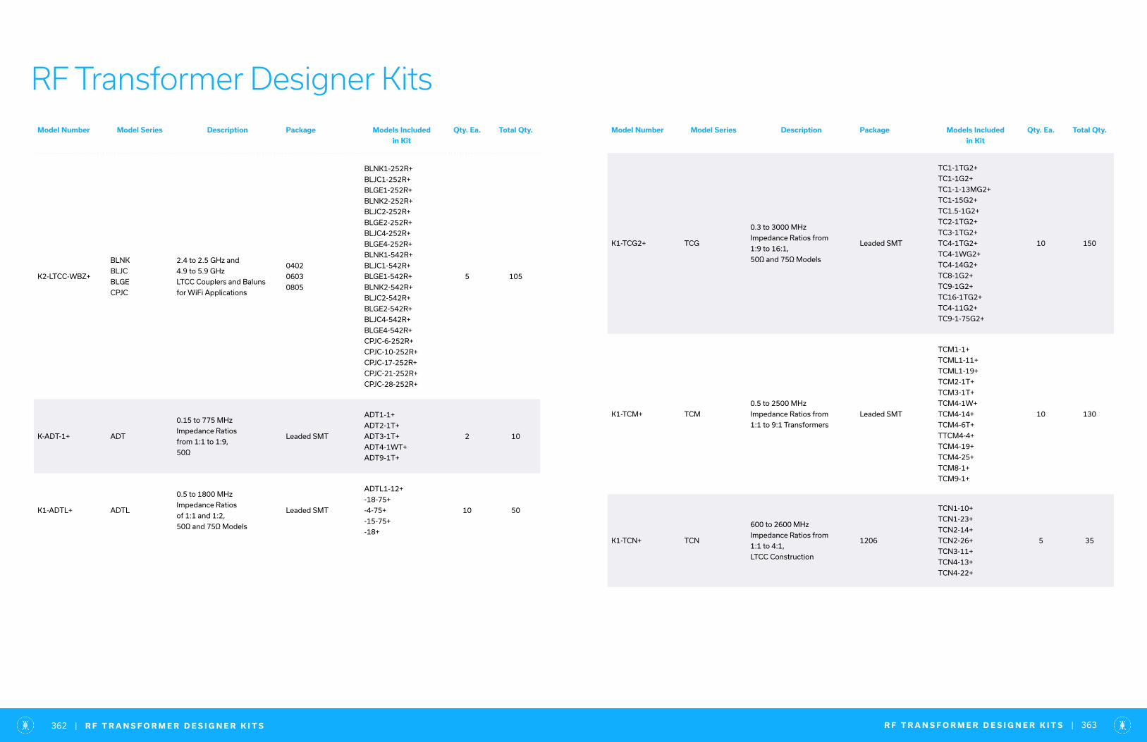
RF Transformer Designer KitsModel Number Model Series Description Package Models Included
in Kit
Qty. Ea. Total Qty.
K2-LTCC-WBZ+
BLNK
BLJC
BLGE
CPJC
2.4 to 2.5 GHz and
4.9 to 5.9 GHz
LTCC Couplers and Baluns
for WiFi Applications
0402
0603
0805
BLNK1-252R+
BLJC1-252R+
BLGE1-252R+
BLNK2-252R+
BLJC2-252R+
BLGE2-252R+
BLJC4-252R+
BLGE4-252R+
BLNK1-542R+
BLJC1-542R+
BLGE1-542R+
BLNK2-542R+
BLJC2-542R+
BLGE2-542R+
BLJC4-542R+
BLGE4-542R+
CPJC-6-252R+
CPJC-10-252R+
CPJC-17-252R+
CPJC-21-252R+
CPJC-28-252R+
5 105
K-ADT-1+ ADT
0.15 to 775 MHz
Impedance Ratios
from 1:1 to 1:9,
50Ω
Leaded SMT
ADT1-1+
ADT2-1T+
ADT3-1T+
ADT4-1WT+
ADT9-1T+
2 10
K1-ADTL+ ADTL
0.5 to 1800 MHz
Impedance Ratios
of 1:1 and 1:2,
50Ω and 75Ω Models
Leaded SMT
ADTL1-12+
-18-75+
-4-75+
-15-75+
-18+
10 50
Model Number Model Series Description Package Models Included
in Kit
Qty. Ea. Total Qty.
K1-TCG2+ TCG
0.3 to 3000 MHz
Impedance Ratios from
1:9 to 16:1,
50Ω and 75Ω Models
Leaded SMT
TC1-1TG2+
TC1-1G2+
TC1-1-13MG2+
TC1-15G2+
TC1.5-1G2+
TC2-1TG2+
TC3-1TG2+
TC4-1TG2+
TC4-1WG2+
TC4-14G2+
TC8-1G2+
TC9-1G2+
TC16-1TG2+
TC4-11G2+
TC9-1-75G2+
10 150
K1-TCM+ TCM
0.5 to 2500 MHz
Impedance Ratios from
1:1 to 9:1 Transformers
Leaded SMT
TCM1-1+
TCML1-11+
TCML1-19+
TCM2-1T+
TCM3-1T+
TCM4-1W+
TCM4-14+
TCM4-6T+
TTCM4-4+
TCM4-19+
TCM4-25+
TCM8-1+
TCM9-1+
10 130
K1-TCN+ TCN
600 to 2600 MHz
Impedance Ratios from
1:1 to 4:1,
LTCC Construction
1206
TCN1-10+
TCN1-23+
TCN2-14+
TCN2-26+
TCN3-11+
TCN4-13+
TCN4-22+
5 35
R F T R A N S F O R M E R D E S I G N E R K I T S | 363| R F T R A N S F O R M E R D E S I G N E R K I T S362

Model Number Model Series Description Package Models Included
in Kit
Qty. Ea. Total Qty.
TK-5+ TK
0.01 to 350 MHz
Impedance Ratios
from 1:1 to 16:1
Leaded SMT
T1-1T+
T1-6T+
T2-1T+
T2.5-6T+
T3-1T+
T4-1T+
T4-6T+
T5-1T+
T8-1T+
T13-1T+
T16-6T+
2 22
K1-NCS+ NCS
223 to 8000 MHz
Impedance Ratios of
1:1, 1:1.5: 1:2, 1:3,
and 1:4 50Ω
805
NCS1-23+
NCS1-292+
NCS1-332+
NCS1-422+
NCS1-521+
NCS1-63+
NCS1.5-232+
NCS2-222+
NCS2-232+
NCS2-282+
NCS2-33+
NCS2-392+
NCS2-592+
NCS2-62+
NCS2-622+
NCS2-771+
NCS2-83+
NCS3-272+
NCS3-72+
NCS4-102+
NCS4-232+
NCS4-272+
NCS4-442+
NCS4-521+
NCS4-63+
5 125
Model Number Model Series Description Package Models Included
in Kit
Qty. Ea. Total Qty.
K1-TCW+ TCW
700 to 7125 MHz
Impedance Ratios from
1:1, 1:2, and 1:4 50Ω
603
TCW1-2700+
TCW1-272+
TCW1-33+
TCW1-3901+
TCW1-392+
TCW1-6000+
TCW2-272+
TCW2-282+
TCW2-392+
TCW2-6000+
TCW2-63+
TCW2-722+
TCW4-262+
TCW4-582+
10 140
K1-TRAN-HP+ SYTX
10 to 1000 MHz
Impedance Ratios
from 1:2 to 4:1 50Ω
Leadless SMT
SYTX2-61HP+
SYTX1-52HP-15W+
SYTX2-451-5W+
SYTX2-52HP-20W+
SYTX4-13HP+
5 25
R F T R A N S F O R M E R D E S I G N E R K I T S | 365| R F T R A N S F O R M E R D E S I G N E R K I T S364
Designer Kits Continued
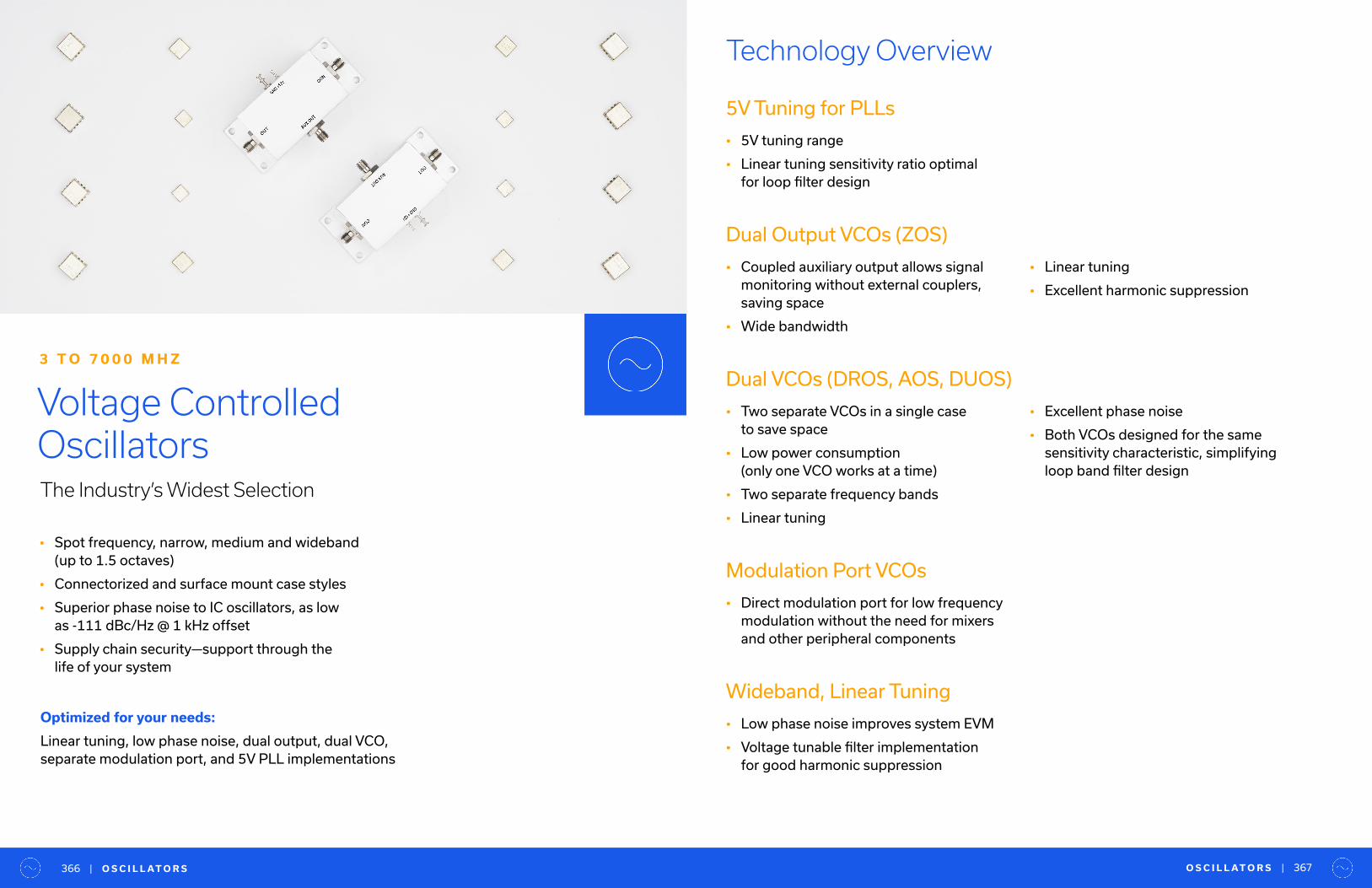
• Spot frequency, narrow, medium and wideband (up to 1.5 octaves)
• Connectorized and surface mount case styles
• Superior phase noise to IC oscillators, as low as -111 dBc/Hz @ 1 kHz offset
• Supply chain security—support through the life of your system
Voltage Controlled OscillatorsThe Industry’s Widest Selection
3 T O 7 0 0 0 M H Z
Optimized for your needs:
Linear tuning, low phase noise, dual output, dual VCO,separate modulation port, and 5V PLL implementations
Technology Overview
5V Tuning for PLLs
• 5V tuning range
• Linear tuning sensitivity ratio optimal for loop filter design
Dual Output VCOs (ZOS)
• Coupled auxiliary output allows signal monitoring without external couplers, saving space
• Wide bandwidth
Dual VCOs (DROS, AOS, DUOS)
• Two separate VCOs in a single case to save space
• Low power consumption (only one VCO works at a time)
• Two separate frequency bands
• Linear tuning
• Linear tuning
• Excellent harmonic suppression
• Excellent phase noise
• Both VCOs designed for the same sensitivity characteristic, simplifying loop band filter design
Modulation Port VCOs
• Direct modulation port for low frequency modulation without the need for mixers and other peripheral components
Wideband, Linear Tuning
• Low phase noise improves system EVM
• Voltage tunable filter implementation for good harmonic suppression
O S C I L L AT O R S | 367| O S C I L L AT O R S366

Family ROS MOS SOS JTOS
Type SMT SMT SMT SMT
Footprint (Inch) 0.5"x0.5" 0.375"x0.375" 0.3"x0.3" 0.505"x0.8"
Standard heights
(Inch)0.1",0.18",0.22" 0.131", 0.14" 0.07", 0.1" 0.25"
Standard Freq. 3.2-6990 MHz 35-3313 MHz 194-6000 MHz 25-3000 MHz
Special featuresModels with Modulation
port available-
Models with Modulation
port available-
Catalog Families Continued
Oscillators — Catalog Model Families Custom Families
Custom Families Continued
Family POS POSA ZX95* ZOS
Type Plug-In Plug-In Connectorized (SMA) Connectorized (SMA)
Footprint(Inch) 0.77"x0.8" 0.71"x0.81" 1.20"x1.18" 3.25"x1.28"
Standard heights
(Inch)0.3" 0.38" 0.46" 1.25"
Standard Freq. 25-2650 MHz 6.75-960 MHz 3.2-6990 MHz 37.5-1025 MHz
Special features Hermetically sealed case Hermetically sealed case Small size connectorized Coupled auxiliary output
Family DROS VOS WOS AOS
Type SMT SMT SMT SMT
Footprint (Inch) 0.5"x0.5" 0.35"x0.35" 0.2"x0.2" 0.563"x0.373"
Standard heights
(Inch)0.1",0.18",0.23" 0.1", 0.15" 0.075" 0.2", 0.14"
Standard Freq. 1445-2088 120-2450 1650-1750 896-1076 MHz
Special featuresDual freq. band VCO,
sharing same RF Output- Small size
Dual freq. band VCO,
sharing same RF Output
Family IOS ROSA DOS JCOS DUOS
Type SMT SMT SMT SMT SMT
Footprint (Inch) 0.175"x0.175" 0.91"x0.91" 0.25"x0.25" 0.87"x0.8" 0.584"x0.8"
Standard heights
(Inch)0.075" 0.25", 0.305" 0.1" 0.25", 0.4" 0.154"
Standard Freq. 10000-11000 MHz 140-1600 MHz 98-6000 MHz 325-1145 MHz 1000-4055 MHz
Special features Smallest size VCODesigned for low Ph.
N at low freq.Small size -
Dual freq. band VCO,
sharing same RF Output
Overview of Functions & Features by Family
*Any SMT model with case size 0.5”x0.5” and smaller from ROS-3-1+ (3MHz) to IOS-11-1 (11 GHz) can housed in ZX95 case on demand.
O S C I L L AT O R S | 369| O S C I L L AT O R S368
VCO specifications tend to be highly specific to the application. We
offer a wide range of models in stock for immediate shipment, but
if you don’t see what you need in our catalog, we have an extensive
library of engineering designs with additional features to meet your
needs. For questions regarding engineering designs or custom
VCOs, contact [email protected]
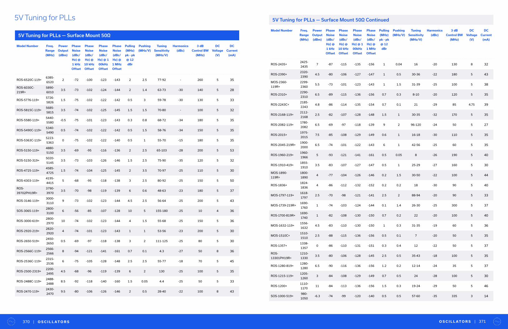
Model Number Freq.
Range
(MHz)
Power
Output
(dBm)
Phase
Noise
(dBc/
Hz) @
1 kHz
Offset
Phase
Noise
(dBc/
Hz) @
10 kHz
Offset
Phase
Noise
(dBc/
Hz) @ 1
00kHz
Offset
Phase
Noise
(dBc/
Hz) @
1 MHz
Offset
Pulling
(MHz)
pk - pk
@ 12
dBr
Pushing
(MHz/V)
Tuning
Sensitivity
(MHz/V)
Harmonics
(dBc)
3 dB
Control BW
(MHz)
DC
Voltage
(V)
DC
Current
(mA)
ROS-6520C-119+6385-
65202 -72 -100 -123 -143 2 2.5 77-92 - 260 5 35
ROS-6030C-
219R+
5890-
60103.5 -73 -102 -124 -144 2 1.4 63-73 -30 140 5 28
ROS-5776-119+5726-
58261.5 -75 -102 -122 -142 0.5 3 59-78 -30 130 5 33
ROS-5815C-119+5685-
58153.5 -74 -102 -125 -145 1.5 1.5 70-80 - 100 5 32
ROS-5580-119+5440-
5580-0.5 -75 -101 -123 -143 0.3 0.8 68-72 -34 180 5 35
ROS-5490C-119+5340-
54900.5 -74 -102 -122 -142 0.5 1.5 58-76 -34 150 5 35
ROS-5363C-119+5223-
53630 -75 -102 -122 -140 0.5 1 55-70 -15 180 5 35
ROS-5150-119+4880-
51503.5 -69 -95 -116 -136 2 2.5 65-103 -28 200 5 53
ROS-5150-319+5020-
51453.5 -73 -103 -126 -146 1.5 2.5 75-90 -35 120 5 32
ROS-4725-119+4585-
47251.5 -74 -104 -125 -145 2 3.5 70-97 -25 110 5 30
ROS-4303-119+4195-
44155 -68 -95 -118 -138 3 2.5 80-92 -25 150 5 50
ROS-
39702PH19R+
3790-
39703.5 -70 -98 -119 -139 6 0.6 48-63 -23 180 5 37
ROS-3146-119+3000-
31109 -73 -102 -123 -144 4.5 2.5 56-64 -25 200 5 43
SOS-3065-119+2800-
31006 -56 -85 -107 -128 10 5 155-180 -25 10 4 36
ROS-3000-619+2800-
297010 -74 -102 -123 -144 4 1.5 55-68 -25 150 5 36
ROS-2920-219+2820-
29204 -74 -101 -123 -143 1 1 53-56 -23 200 5 30
ROS-2650-519+2450-
26500.5 -69 -97 -118 -138 3 2 111-125 -25 80 5 30
ROS-2566C-119+2566-
25668 -94 -121 -141 -161 0.7 0.1 4.3 -27 50 8 36
ROS-2536C-119+2315-
25366 -75 -105 -128 -148 2.5 2.5 55-77 -18 70 5 45
ROS-2500-2319+2200-
24954.5 -68 -96 -119 -139 6 2 130 -25 100 5 35
ROS-2488C-119+2488-
24888.5 -92 -118 -140 -160 1.5 0.05 4.4 -25 50 5 33
ROS-2470-119+2430-
24709.5 -80 -106 -126 -146 2 0.5 28-40 -22 100 8 43
5V Tuning for PLLs
5V Tuning for PLLs — Surface Mount 50Ω
5V Tuning for PLLs — Surface Mount 50Ω Continued
Model Number Freq.
Range
(MHz)
Power
Output
(dBm)
Phase
Noise
(dBc/
Hz) @
1 kHz
Offset
Phase
Noise
(dBc/
Hz) @
10 kHz
Offset
Phase
Noise
(dBc/
Hz) @ 1
00kHz
Offset
Phase
Noise
(dBc/
Hz) @
1 MHz
Offset
Pulling
(MHz)
pk - pk
@ 12
dBr
Pushing
(MHz/V)
Tuning
Sensitivity
(MHz/V)
Harmonics
(dBc)
3 dB
Control BW
(MHz)
DC
Voltage
(V)
DC
Current
(mA)
ROS-2435+2425-
24357 -87 -115 -135 -156 1 0.04 16 -20 130 8 32
ROS-2390+2320-
23904.5 -80 -106 -127 -147 1 0.5 30-36 -22 180 5 43
MOS-2360-
119R+
2299-
23605.5 -73 -101 -123 -143 1 1.5 31-39 -25 100 5 38
ROS-2310+2290-
23106.5 -89 -115 -136 -156 0.7 0.3 8-10 -20 120 5 35
ROS-2243C+2185-
22434.8 -86 -114 -135 -154 0.7 0.1 21 -29 85 4.75 39
ROS-2168-119+2112-
21682.5 -82 -107 -128 -148 1.5 1 30-35 -32 170 5 35
ROS-2082-119+1780-
20826.5 -69 -97 -118 -139 9 2 96-120 -24 50 5 27
ROS-2015+1975-
20157.5 -85 -108 -129 -149 0.6 1 16-18 -30 110 5 35
ROS-2045-219R+1900-
20006.5 -74 -101 -122 -143 6 1 42-56 -25 60 5 35
ROS-1960-219+1960-
19665 -93 -121 -141 -161 0.5 0.05 8 -26 190 5 40
ROS-1910-419+1855-
19103.5 -83 -107 -127 -147 0.5 1 25-29 -27 160 5 30
MOS-1890-
119R+
1800-
18904 -77 -104 -126 -146 0.2 1.5 30-50 -22 100 5 44
ROS-1836+1824-
18364 -86 -112 -132 -152 0.2 0.2 18 -30 90 5 40
MOS-1797-119+1618-
17972.5 -70 -98 -121 -141 2.5 2 88-94 -20 90 5 33
MOS-1739-219R+1690-
17601 -74 -103 -124 -144 0.1 1.4 26-30 -25 300 5 37
ROS-1700-819R+1690-
17401 -82 -108 -130 -150 0.7 0.2 22 -20 100 5 40
MOS-1632-119+1556-
16324.5 -83 -110 -130 -150 1 0.3 31-35 -19 60 5 36
MOS-1510C+1510-
15102.5 -88 -115 -136 -156 0.5 0.1 7 -20 50 5 35
ROS-1357+1338-
13570 -86 -110 -131 -151 0.3 0.4 12 -22 50 5 37
ROS-
13301PH19R+
1210-
13303.5 -80 -106 -128 -145 2.5 0.5 35-43 -18 100 5 35
ROS-1280-819+1280-
12806.5 -90 -116 -136 -156 1.2 0.2 12-14 -24 35 5 37
ROS-1215-119+1205-
12603 -84 -108 -129 -149 0.7 0.5 24 -28 100 5 30
ROS-1200+1110-
117011 -84 -113 -136 -156 1.5 0.3 19-24 -29 50 5 46
SOS-1000-519+980-
1050-6.3 -74 -99 -120 -140 0.5 0.5 57-60 -35 335 3 14
O S C I L L AT O R S | 371| O S C I L L AT O R S370
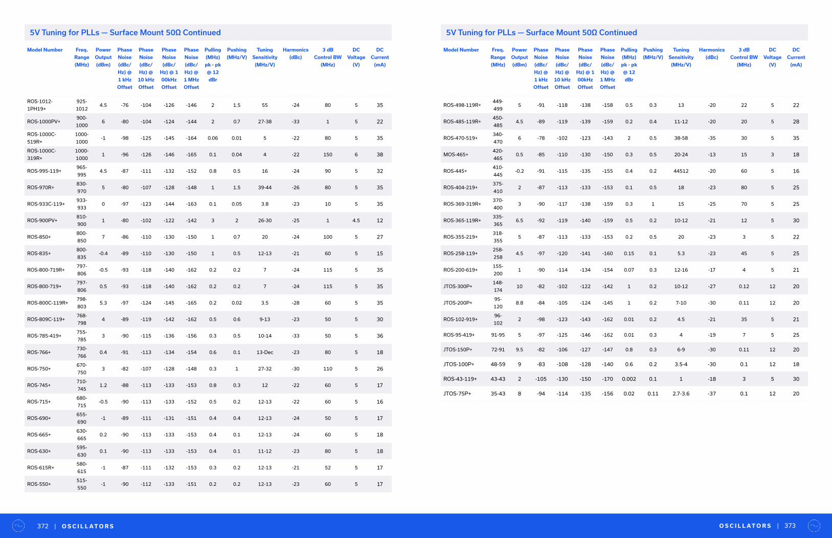
Model Number Freq.
Range
(MHz)
Power
Output
(dBm)
Phase
Noise
(dBc/
Hz) @
1 kHz
Offset
Phase
Noise
(dBc/
Hz) @
10 kHz
Offset
Phase
Noise
(dBc/
Hz) @ 1
00kHz
Offset
Phase
Noise
(dBc/
Hz) @
1 MHz
Offset
Pulling
(MHz)
pk - pk
@ 12
dBr
Pushing
(MHz/V)
Tuning
Sensitivity
(MHz/V)
Harmonics
(dBc)
3 dB
Control BW
(MHz)
DC
Voltage
(V)
DC
Current
(mA)
ROS-1012-
1PH19+
925-
10124.5 -76 -104 -126 -146 2 1.5 55 -24 80 5 35
ROS-1000PV+900-
10006 -80 -104 -124 -144 2 0.7 27-38 -33 1 5 22
ROS-1000C-
519R+
1000-
1000-1 -98 -125 -145 -164 0.06 0.01 5 -22 80 5 35
ROS-1000C-
319R+
1000-
10001 -96 -126 -146 -165 0.1 0.04 4 -22 150 6 38
ROS-995-119+965-
9954.5 -87 -111 -132 -152 0.8 0.5 16 -24 90 5 32
ROS-970R+830-
9705 -80 -107 -128 -148 1 1.5 39-44 -26 80 5 35
ROS-933C-119+933-
9330 -97 -123 -144 -163 0.1 0.05 3.8 -23 10 5 35
ROS-900PV+810-
9001 -80 -102 -122 -142 3 2 26-30 -25 1 4.5 12
ROS-850+800-
8507 -86 -110 -130 -150 1 0.7 20 -24 100 5 27
ROS-835+800-
835-0.4 -89 -110 -130 -150 1 0.5 12-13 -21 60 5 15
ROS-800-719R+797-
806-0.5 -93 -118 -140 -162 0.2 0.2 7 -24 115 5 35
ROS-800-719+797-
8060.5 -93 -118 -140 -162 0.2 0.2 7 -24 115 5 35
ROS-800C-119R+798-
8035.3 -97 -124 -145 -165 0.2 0.02 3.5 -28 60 5 35
ROS-809C-119+768-
7984 -89 -119 -142 -162 0.5 0.6 9-13 -23 50 5 30
ROS-785-419+755-
7853 -90 -115 -136 -156 0.3 0.5 10-14 -33 50 5 36
ROS-766+730-
7660.4 -91 -113 -134 -154 0.6 0.1 13-Dec -23 80 5 18
ROS-750+670-
7503 -82 -107 -128 -148 0.3 1 27-32 -30 110 5 26
ROS-745+710-
7451.2 -88 -113 -133 -153 0.8 0.3 12 -22 60 5 17
ROS-715+680-
715-0.5 -90 -113 -133 -152 0.5 0.2 12-13 -22 60 5 16
ROS-690+655-
690-1 -89 -111 -131 -151 0.4 0.4 12-13 -24 50 5 17
ROS-665+630-
6650.2 -90 -113 -133 -153 0.4 0.1 12-13 -24 60 5 18
ROS-630+595-
6300.1 -90 -113 -133 -153 0.4 0.1 11-12 -23 80 5 18
ROS-615R+580-
615-1 -87 -111 -132 -153 0.3 0.2 12-13 -21 52 5 17
ROS-550+515-
550-1 -90 -112 -133 -151 0.2 0.2 12-13 -23 60 5 17
Model Number Freq.
Range
(MHz)
Power
Output
(dBm)
Phase
Noise
(dBc/
Hz) @
1 kHz
Offset
Phase
Noise
(dBc/
Hz) @
10 kHz
Offset
Phase
Noise
(dBc/
Hz) @ 1
00kHz
Offset
Phase
Noise
(dBc/
Hz) @
1 MHz
Offset
Pulling
(MHz)
pk - pk
@ 12
dBr
Pushing
(MHz/V)
Tuning
Sensitivity
(MHz/V)
Harmonics
(dBc)
3 dB
Control BW
(MHz)
DC
Voltage
(V)
DC
Current
(mA)
ROS-498-119R+449-
4995 -91 -118 -138 -158 0.5 0.3 13 -20 22 5 22
ROS-485-119R+450-
4854.5 -89 -119 -139 -159 0.2 0.4 11-12 -20 20 5 28
ROS-470-519+340-
4706 -78 -102 -123 -143 2 0.5 38-58 -35 30 5 35
MOS-465+420-
4650.5 -85 -110 -130 -150 0.3 0.5 20-24 -13 15 3 18
ROS-445+410-
445-0.2 -91 -115 -135 -155 0.4 0.2 44512 -20 60 5 16
ROS-404-219+375-
4102 -87 -113 -133 -153 0.1 0.5 18 -23 80 5 25
ROS-369-319R+370-
4003 -90 -117 -138 -159 0.3 1 15 -25 70 5 25
ROS-365-119R+335-
3656.5 -92 -119 -140 -159 0.5 0.2 10-12 -21 12 5 30
ROS-355-219+318-
3555 -87 -113 -133 -153 0.2 0.5 20 -23 3 5 22
ROS-258-119+258-
2584.5 -97 -120 -141 -160 0.15 0.1 5.3 -23 45 5 25
ROS-200-619+155-
2001 -90 -114 -134 -154 0.07 0.3 12-16 -17 4 5 21
JTOS-300P+148-
17410 -82 -102 -122 -142 1 0.2 10-12 -27 0.12 12 20
JTOS-200P+95-
1208.8 -84 -105 -124 -145 1 0.2 7-10 -30 0.11 12 20
ROS-102-919+96-
1022 -98 -123 -143 -162 0.01 0.2 4.5 -21 35 5 21
ROS-95-419+ 91-95 5 -97 -125 -146 -162 0.01 0.3 4 -19 7 5 25
JTOS-150P+ 72-91 9.5 -82 -106 -127 -147 0.8 0.3 6-9 -30 0.11 12 20
JTOS-100P+ 48-59 9 -83 -108 -128 -140 0.6 0.2 3.5-4 -30 0.1 12 18
ROS-43-119+ 43-43 2 -105 -130 -150 -170 0.002 0.1 1 -18 3 5 30
JTOS-75P+ 35-43 8 -94 -114 -135 -156 0.02 0.11 2.7-3.6 -37 0.1 12 20
O S C I L L AT O R S | 373| O S C I L L AT O R S372
5V Tuning for PLLs — Surface Mount 50Ω Continued5V Tuning for PLLs — Surface Mount 50Ω Continued
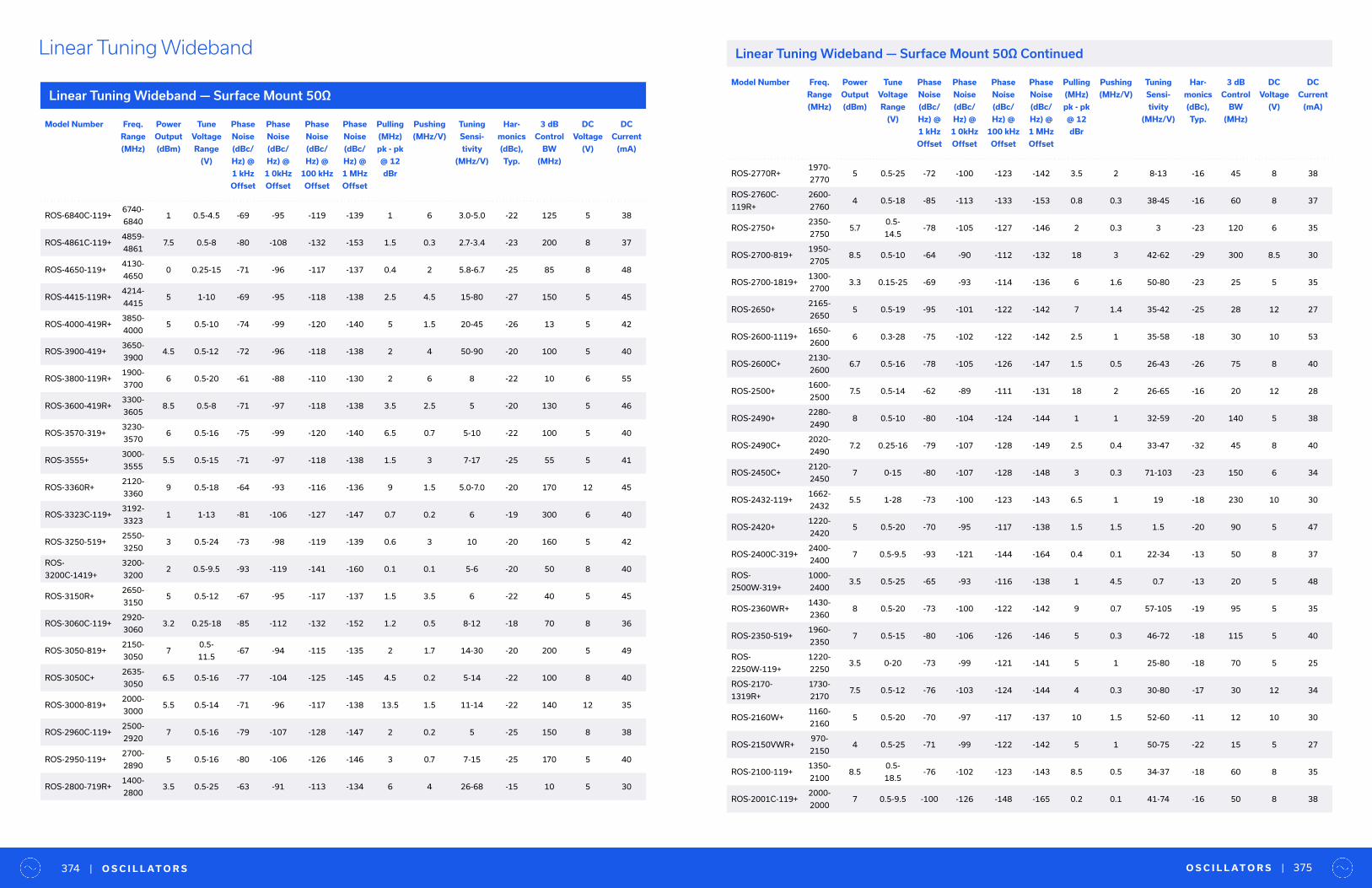
F I LT E R S | 375| F I LT E R S374 O S C I L L AT O R S | 375| O S C I L L AT O R S374
Model Number Freq.
Range
(MHz)
Power
Output
(dBm)
Tune
Voltage
Range
(V)
Phase
Noise
(dBc/
Hz) @
1 kHz
Offset
Phase
Noise
(dBc/
Hz) @
1 0kHz
Offset
Phase
Noise
(dBc/
Hz) @
100 kHz
Offset
Phase
Noise
(dBc/
Hz) @
1 MHz
Offset
Pulling
(MHz)
pk - pk
@ 12
dBr
Pushing
(MHz/V)
Tuning
Sensi-
tivity
(MHz/V)
Har-
monics
(dBc),
Typ.
3 dB
Control
BW
(MHz)
DC
Voltage
(V)
DC
Current
(mA)
ROS-6840C-119+6740-
68401 0.5-4.5 -69 -95 -119 -139 1 6 3.0-5.0 -22 125 5 38
ROS-4861C-119+4859-
48617.5 0.5-8 -80 -108 -132 -153 1.5 0.3 2.7-3.4 -23 200 8 37
ROS-4650-119+4130-
46500 0.25-15 -71 -96 -117 -137 0.4 2 5.8-6.7 -25 85 8 48
ROS-4415-119R+4214-
44155 1-10 -69 -95 -118 -138 2.5 4.5 15-80 -27 150 5 45
ROS-4000-419R+3850-
40005 0.5-10 -74 -99 -120 -140 5 1.5 20-45 -26 13 5 42
ROS-3900-419+3650-
39004.5 0.5-12 -72 -96 -118 -138 2 4 50-90 -20 100 5 40
ROS-3800-119R+1900-
37006 0.5-20 -61 -88 -110 -130 2 6 8 -22 10 6 55
ROS-3600-419R+3300-
36058.5 0.5-8 -71 -97 -118 -138 3.5 2.5 5 -20 130 5 46
ROS-3570-319+3230-
35706 0.5-16 -75 -99 -120 -140 6.5 0.7 5-10 -22 100 5 40
ROS-3555+3000-
35555.5 0.5-15 -71 -97 -118 -138 1.5 3 7-17 -25 55 5 41
ROS-3360R+2120-
33609 0.5-18 -64 -93 -116 -136 9 1.5 5.0-7.0 -20 170 12 45
ROS-3323C-119+3192-
33231 1-13 -81 -106 -127 -147 0.7 0.2 6 -19 300 6 40
ROS-3250-519+2550-
32503 0.5-24 -73 -98 -119 -139 0.6 3 10 -20 160 5 42
ROS-
3200C-1419+
3200-
32002 0.5-9.5 -93 -119 -141 -160 0.1 0.1 5-6 -20 50 8 40
ROS-3150R+2650-
31505 0.5-12 -67 -95 -117 -137 1.5 3.5 6 -22 40 5 45
ROS-3060C-119+2920-
30603.2 0.25-18 -85 -112 -132 -152 1.2 0.5 8-12 -18 70 8 36
ROS-3050-819+2150-
30507
0.5-
11.5-67 -94 -115 -135 2 1.7 14-30 -20 200 5 49
ROS-3050C+2635-
30506.5 0.5-16 -77 -104 -125 -145 4.5 0.2 5-14 -22 100 8 40
ROS-3000-819+2000-
30005.5 0.5-14 -71 -96 -117 -138 13.5 1.5 11-14 -22 140 12 35
ROS-2960C-119+2500-
29207 0.5-16 -79 -107 -128 -147 2 0.2 5 -25 150 8 38
ROS-2950-119+2700-
28905 0.5-16 -80 -106 -126 -146 3 0.7 7-15 -25 170 5 40
ROS-2800-719R+1400-
28003.5 0.5-25 -63 -91 -113 -134 6 4 26-68 -15 10 5 30
Linear Tuning Wideband
Linear Tuning Wideband — Surface Mount 50Ω
Linear Tuning Wideband — Surface Mount 50Ω Continued
Model Number Freq.
Range
(MHz)
Power
Output
(dBm)
Tune
Voltage
Range
(V)
Phase
Noise
(dBc/
Hz) @
1 kHz
Offset
Phase
Noise
(dBc/
Hz) @
1 0kHz
Offset
Phase
Noise
(dBc/
Hz) @
100 kHz
Offset
Phase
Noise
(dBc/
Hz) @
1 MHz
Offset
Pulling
(MHz)
pk - pk
@ 12
dBr
Pushing
(MHz/V)
Tuning
Sensi-
tivity
(MHz/V)
Har-
monics
(dBc),
Typ.
3 dB
Control
BW
(MHz)
DC
Voltage
(V)
DC
Current
(mA)
ROS-2770R+1970-
27705 0.5-25 -72 -100 -123 -142 3.5 2 8-13 -16 45 8 38
ROS-2760C-
119R+
2600-
27604 0.5-18 -85 -113 -133 -153 0.8 0.3 38-45 -16 60 8 37
ROS-2750+2350-
27505.7
0.5-
14.5-78 -105 -127 -146 2 0.3 3 -23 120 6 35
ROS-2700-819+1950-
27058.5 0.5-10 -64 -90 -112 -132 18 3 42-62 -29 300 8.5 30
ROS-2700-1819+1300-
27003.3 0.15-25 -69 -93 -114 -136 6 1.6 50-80 -23 25 5 35
ROS-2650+2165-
26505 0.5-19 -95 -101 -122 -142 7 1.4 35-42 -25 28 12 27
ROS-2600-1119+1650-
26006 0.3-28 -75 -102 -122 -142 2.5 1 35-58 -18 30 10 53
ROS-2600C+2130-
26006.7 0.5-16 -78 -105 -126 -147 1.5 0.5 26-43 -26 75 8 40
ROS-2500+1600-
25007.5 0.5-14 -62 -89 -111 -131 18 2 26-65 -16 20 12 28
ROS-2490+2280-
24908 0.5-10 -80 -104 -124 -144 1 1 32-59 -20 140 5 38
ROS-2490C+2020-
24907.2 0.25-16 -79 -107 -128 -149 2.5 0.4 33-47 -32 45 8 40
ROS-2450C+2120-
24507 0-15 -80 -107 -128 -148 3 0.3 71-103 -23 150 6 34
ROS-2432-119+1662-
24325.5 1-28 -73 -100 -123 -143 6.5 1 19 -18 230 10 30
ROS-2420+1220-
24205 0.5-20 -70 -95 -117 -138 1.5 1.5 1.5 -20 90 5 47
ROS-2400C-319+2400-
24007 0.5-9.5 -93 -121 -144 -164 0.4 0.1 22-34 -13 50 8 37
ROS-
2500W-319+
1000-
24003.5 0.5-25 -65 -93 -116 -138 1 4.5 0.7 -13 20 5 48
ROS-2360WR+1430-
23608 0.5-20 -73 -100 -122 -142 9 0.7 57-105 -19 95 5 35
ROS-2350-519+1960-
23507 0.5-15 -80 -106 -126 -146 5 0.3 46-72 -18 115 5 40
ROS-
2250W-119+
1220-
22503.5 0-20 -73 -99 -121 -141 5 1 25-80 -18 70 5 25
ROS-2170-
1319R+
1730-
21707.5 0.5-12 -76 -103 -124 -144 4 0.3 30-80 -17 30 12 34
ROS-2160W+1160-
21605 0.5-20 -70 -97 -117 -137 10 1.5 52-60 -11 12 10 30
ROS-2150VWR+970-
21504 0.5-25 -71 -99 -122 -142 5 1 50-75 -22 15 5 27
ROS-2100-119+1350-
21008.5
0.5-
18.5-76 -102 -123 -143 8.5 0.5 34-37 -18 60 8 35
ROS-2001C-119+2000-
20007 0.5-9.5 -100 -126 -148 -165 0.2 0.1 41-74 -16 50 8 38
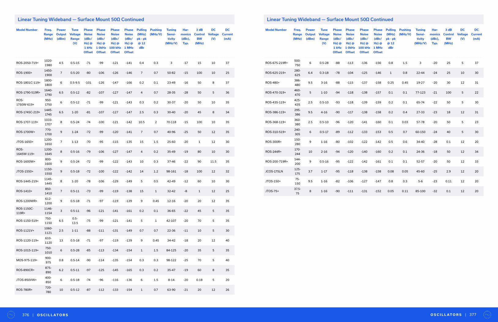
Model Number Freq.
Range
(MHz)
Power
Output
(dBm)
Tune
Voltage
Range
(V)
Phase
Noise
(dBc/
Hz) @
1 kHz
Offset
Phase
Noise
(dBc/
Hz) @
1 0kHz
Offset
Phase
Noise
(dBc/
Hz) @
100 kHz
Offset
Phase
Noise
(dBc/
Hz) @
1 MHz
Offset
Pulling
(MHz)
pk - pk
@ 12
dBr
Pushing
(MHz/V)
Tuning
Sensi-
tivity
(MHz/V)
Har-
monics
(dBc),
Typ.
3 dB
Control
BW
(MHz)
DC
Voltage
(V)
DC
Current
(mA)
ROS-2050-719+1020-
19804.5 0.5-15 -71 -99 -121 -141 0.4 0.3 3 -17 15 10 37
ROS-1900+1450-
19007 0.5-20 -80 -106 -126 -146 7 0.7 50-82 -15 100 10 25
ROS-1801C-119+1800-
18006 0.5-9.5 -101 -126 -147 -166 0.2 0.1 23-49 -16 50 8 37
ROS-1790-519R+1640-
17906.5 0.5-12 -82 -107 -127 -147 4 0.7 28-35 -28 50 5 36
ROS-
1750W-619+
950-
17506 0.5-12 -71 -99 -121 -143 0.3 0.2 30-37 -20 50 10 35
ROS-1745C-219+1445-
17456.5 1-20 -81 -107 -127 -147 2.5 0.3 30-40 -20 45 8 34
ROS-1707-119+1033-
17078 0.5-24 -74 -100 -121 -142 10.5 2 70-118 -15 100 10 35
ROS-1700W+770-
17009 1-24 -72 -99 -120 -141 7 0.7 40-96 -25 50 12 35
JTOS-1650+1200-
16507 1-13 -70 -95 -115 -135 15 1.5 25-60 -20 1 12 30
ROS-
1645W-119+
1200-
16458 0.5-16 -79 -106 -127 -147 4 0.2 35-49 -19 80 10 30
ROS-1600W+800-
16009 0.5-24 -72 -99 -122 -143 10 0.3 37-46 -22 90 11.5 35
JTOS-1550+1150-
15509 0.5-18 -72 -100 -122 -142 14 1.2 98-161 -18 100 12 32
ROS-1445-219+1145-
14458 1-20 -78 -106 -129 -149 5 0.5 42-49 -12 60 10 30
ROS-1410+850-
14107 0.5-11 -73 -99 -119 -138 15 1 32-42 -8 1 12 25
ROS-1200WR+612-
12009 0.5-18 -71 -97 -119 -139 9 0.45 12-16 -20 20 12 35
ROS-1150C-
119R+
1146-
11543 0.5-11 -96 -121 -141 -161 0.2 0.1 36-65 -22 45 5 35
ROS-1150-519+750-
11506.5
0.5-
13.5-75 -99 -121 -141 5 1 42-107 -20 70 5 35
ROS-1121V+1060-
11212.5 1-11 -88 -111 -131 -149 0.7 0.7 22-36 -11 10 5 30
ROS-1120-119+610-
112013 0.5-18 -71 -97 -119 -139 9 0.45 34-42 -18 20 12 40
ROS-1015-119+750-
10106 0.5-28 -85 -113 -134 -154 1 1.5 84-125 -20 35 5 35
MOS-975-119+900-
9750.8 0.5-14 -90 -114 -135 -154 0.3 0.3 98-122 -25 70 5 40
ROS-890CR+875-
8906.2 0.5-11 -97 -125 -145 -165 0.3 0.2 35-47 -19 60 8 35
JTOS-850VW+400-
8506 0.5-18 -74 -96 -116 -136 6 1.5 8-14 -20 0.18 5 20
ROS-780R+720-
78010 0.5-12 -87 -112 -133 -154 1 0.7 63-90 -21 20 12 26
Model Number Freq.
Range
(MHz)
Power
Output
(dBm)
Tune
Voltage
Range
(V)
Phase
Noise
(dBc/
Hz) @
1 kHz
Offset
Phase
Noise
(dBc/
Hz) @
1 0kHz
Offset
Phase
Noise
(dBc/
Hz) @
100 kHz
Offset
Phase
Noise
(dBc/
Hz) @
1 MHz
Offset
Pulling
(MHz)
pk - pk
@ 12
dBr
Pushing
(MHz/V)
Tuning
Sensi-
tivity
(MHz/V)
Har-
monics
(dBc),
Typ.
3 dB
Control
BW
(MHz)
DC
Voltage
(V)
DC
Current
(mA)
ROS-675-219R+500-
7506 0.5-28 -88 -113 -136 -156 0.8 1.5 3 -20 25 5 37
ROS-625-219+280-
6256.4 0.3-18 -78 -104 -125 -146 1 0.8 22-44 -24 25 10 30
ROS-480+386-
4809.5 3-16 -88 -115 -137 -158 0.25 0.45 19-27 -20 30 12 31
ROS-470-319+460-
4705 1-10 -94 -118 -138 -157 0.1 0.1 77-123 -21 100 5 22
ROS-435-119+425-
4352.5 0.5-10 -93 -118 -139 -159 0.2 0.1 65-74 -22 50 5 30
ROS-386-119+295-
3869.5 4-16 -90 -117 -138 -158 0.2 0.4 27-33 -23 18 12 31
ROS-368-119+360-
3802.5 0.5-10 -96 -120 -141 -160 0.1 0.03 57-78 -20 50 5 23
ROS-310-519+240-
3056 0.5-17 -89 -112 -133 -153 0.5 0.7 60-150 -24 40 5 30
ROS-300R+150-
2809 1-16 -80 -102 -122 -142 0.5 0.6 34-40 -28 0.1 12 20
ROS-244R+170-
24410 2-16 -94 -120 -140 -160 0.2 0.1 24-36 -18 50 12 34
ROS-200-719R+144-
2009 0.5-16 -95 -122 -142 -161 0.1 0.1 52-57 -20 50 12 33
JCOS-175LN125-
1753.7 1-17 -95 -118 -138 -158 0.08 0.05 45-60 -25 2.9 12 20
JTOS-150+75-
1509.5 1-16 -82 -106 -127 -147 0.8 0.3 5-6 -23 0.11 12 20
JTOS-75+37.5-
758 1-16 -90 -111 -131 -152 0.05 0.11 85-100 -32 0.1 12 20
O S C I L L AT O R S | 377| O S C I L L AT O R S376
Linear Tuning Wideband — Surface Mount 50Ω ContinuedLinear Tuning Wideband — Surface Mount 50Ω Continued
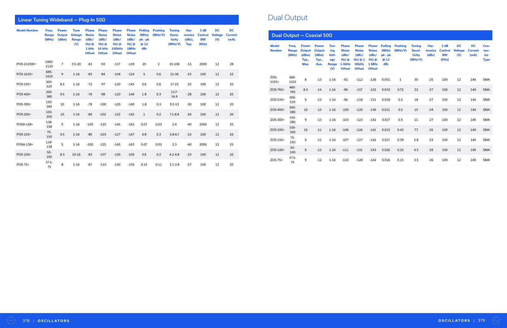
Model
Number
Freq.
Range
(MHz)
Power
Output
(dBm)
Typ.,
Max.
Power
Output
(dBm)
Typ.,
Aux.
Tun-
ing
Volt-
age
Range
(V)
Phase
Noise
(dBc/
Hz) @
1 0kHz
Offset
Phase
Noise
(dBc/
Hz) @ 1
00kHz
Offset
Phase
Noise
(dBc/
Hz) @
1 MHz
Offset
Pulling
(MHz)
pk - pk
@ 12
dBr
Pushing
(MHz/V)
Tuning
Sensi-
tivity
(MHz/V)
Har-
monics
(dBc)
3 dB
Control
BW
(KHz)
DC
Voltage
(V)
DC
Current
(mA)
Con-
nec-
tor
Type
ZOS-
1025+
685-
10258 -13 1-16 -92 -112 -136 0.051 1 30 -25 100 12 140 SMA
ZOS-765+485-
7658.5 -14 1-16 -96 -117 -132 0.033 0.72 22 -27 100 12 140 SMA
ZOS-535+300-
5259 -13 1-16 -96 -118 -131 0.018 0.5 18 -27 100 12 140 SMA
ZOS-400+200-
38010 -13 1-16 -100 -120 -136 0.021 0.5 15 -24 100 12 140 SMA
ZOS-300+150-
2809 -13 1-16 -103 -123 -142 0.017 0.5 11 -27 100 12 140 SMA
ZOS-200+100-
20010 -11 1-16 -106 -126 -141 0.015 0.42 7.7 -25 100 12 140 SMA
ZOS-150+75-
1509 -12 1-16 -107 -127 -142 0.017 0.39 5.8 -23 100 12 140 SMA
ZOS-100+50-
1009 -12 1-16 -111 -131 -143 0.026 0.25 4.5 -29 100 12 140 SMA
ZOS-75+37.5-
759 -12 1-16 -110 -128 -142 0.016 0.15 3.5 -26 100 12 140 SMA
Dual Output
Dual Output — Coaxial 50Ω
O S C I L L AT O R S | 379| O S C I L L AT O R S378
Model Number Freq.
Range
(MHz)
Power
Output
(dBm)
Tune
Voltage
Range
(V)
Phase
Noise
(dBc/
Hz) @
1 kHz
Offset
Phase
Noise
(dBc/
Hz) @
10 kHz
Offset
Phase
Noise
(dBc/
Hz) @
100kHz
Offset
Phase
Noise
(dBc/
Hz) @
1MHz
Offset
Pulling
(MHz)
pk - pk
@ 12
dBr
Pushing
(MHz/V)
Tuning
Sensi-
tivity
(MHz/V)
Har-
monics
(dBc),
Typ.
3 dB
Control
BW
(KHz)
DC
Voltage
(V)
DC
Current
(mA)
POS-2120W+1060-
21207 0.5-20 -63 -93 -117 -139 20 2 25-108 -15 2000 12 28
POS-1025+685-
10259 1-16 -65 -84 -104 -124 5 0.6 21-36 -23 100 12 22
POS-535+300-
5258.5 1-16 -72 -97 -120 -145 0.6 0.6 17-23 -32 100 12 20
POS-400+200-
3809.5 1-16 -76 -98 -120 -140 1.8 0.3
13.7-
16.9-28 100 12 20
POS-300+150-
28010 1-16 -78 -100 -120 -140 1.8 0.3 9.5-13 -30 100 12 20
POS-200+100-
20010 1-16 -80 -102 -122 -142 1 0.2 7.1-8.6 -24 100 12 20
POSA-158+138-
1585 1-16 -100 -125 -145 -163 0.07 0.03 2.4 -40 2000 12 25
POS-150+75-
1509.5 1-16 -80 -103 -127 -147 0.8 0.3 5.8-6.7 -23 100 12 20
POSA-138+118-
1385 1-16 -100 -125 -145 -163 0.07 0.03 2.3 -40 2000 12 25
POS-100+50-
1008.3 10-16 -83 -107 -130 -150 0.6 0.2 4.2-4.8 -23 100 12 20
POS-75+37.5-
758 1-16 -87 -110 -130 -150 0.15 0.11 3.1-3.8 -27 100 12 20
Linear Tuning Wideband — Plug-In 50Ω

R E S E A R C H & E D U C AT I O N | 381| R E S E A R C H & E D U C AT I O N380
Research & EducationInfinite Potential
IMAGEVK-73 4D mmWave Imaging and Sensing Kit
UVNA-63 DIY Vector Network Analyzer Kit
H A N D S - O N T O O L S
Mini-Circuits has partnered with RFIC pioneers at Vayyar to put cutting edge technology into the hands of students, educators and researchers around the world. Our research and education kits give the next generation of technical talent the hardware they need to connect theory with practice, and to innovate new applications for high-resolution radar.
Incorporating Vayyar’s revolutionary RFIC technology and radar IP, Mini-Circuits mmWave imaging and sensing kit gives researchers around the world the advanced to realize new applications with a full API to put the industry’s most advanced mmWave transceiver IC to work.
• 20 Tx and 20 Rx on-board antennas that can be configured to transmit and receive signals anywhere within the 62 to 69 GHz range
• 3 levels of transmit configuration and direct access to the radar returns (IQ and/or phasor)
• Impeccably accurate calculations. Operates on Windows. Compatible with Python or Matlab®
• University discounts available
Mini-Circuits’ DIY vector network analyzer kit includes everything students need to build a fully functioning vector network analyzer, program their own algorithms, and perform actual measurements of RF components.
• Hands-on learning tool for EM course work
• Build your own fully functioning vector network analyzer with RF transceiver board, RF and microwave components, cables and calibration standards
• Open access to the entire VNA RF chain
• Develop real time S-parameter measurements with Python® or Matlab®
• University discounts available
Explore 4D mmWave imaging without the high-cost of mmWave hardware
Bridge the gap between the classroom and the real world
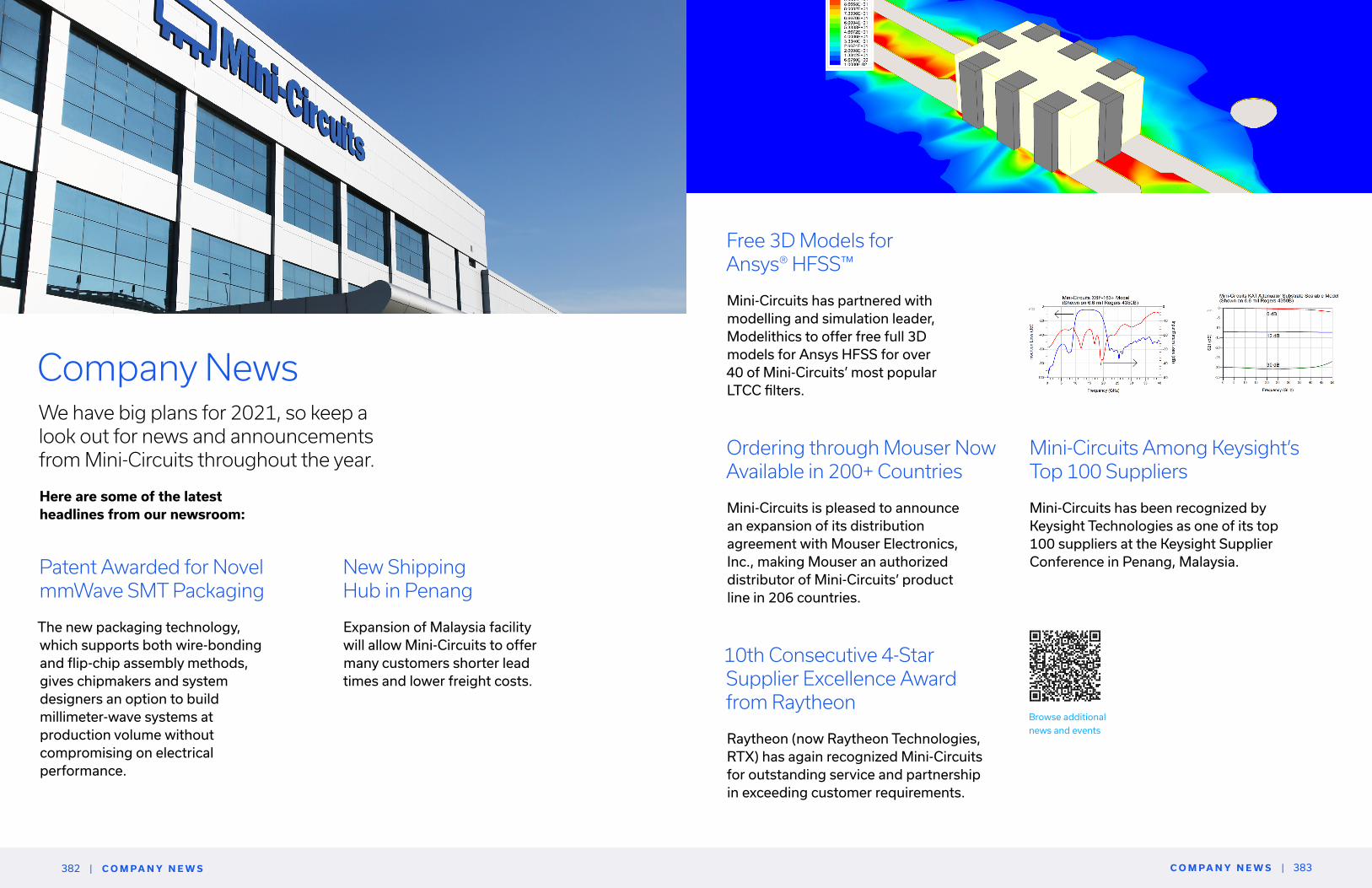
C O M PA N Y N E W S | 383| C O M PA N Y N E W S382
Company NewsWe have big plans for 2021, so keep a look out for news and announcements from Mini-Circuits throughout the year.
Patent Awarded for Novel mmWave SMT Packaging
The new packaging technology, which supports both wire-bonding and flip-chip assembly methods, gives chipmakers and system designers an option to build millimeter-wave systems at production volume without compromising on electrical performance.
Mini-Circuits Among Keysight’s Top 100 Suppliers
Mini-Circuits has been recognized by Keysight Technologies as one of its top 100 suppliers at the Keysight Supplier Conference in Penang, Malaysia.
Here are some of the latest headlines from our newsroom:
New Shipping Hub in Penang
Expansion of Malaysia facility will allow Mini-Circuits to offer many customers shorter lead times and lower freight costs.
Free 3D Models for Ansys®️ HFSS™️
Mini-Circuits has partnered with modelling and simulation leader, Modelithics to offer free full 3D models for Ansys HFSS for over 40 of Mini-Circuits’ most popular LTCC filters.
Ordering through Mouser Now Available in 200+ Countries
Mini-Circuits is pleased to announce an expansion of its distribution agreement with Mouser Electronics, Inc., making Mouser an authorized distributor of Mini-Circuits’ product line in 206 countries.
10th Consecutive 4-Star Supplier Excellence Award from Raytheon
Raytheon (now Raytheon Technologies, RTX) has again recognized Mini-Circuits for outstanding service and partnership in exceeding customer requirements.
Browse additional
news and events
All product information herein is current and
accurate as of the date of publication. Product
availability and specifications may change. Please
consult the Mini-Circuits website, an authorized
sales representative or your Mini-Circuits account
manager for the most up-to-date information.
minicircuits.com
Local Sales &Technical Support