PRODUCT CATALOG - Portescap
214
D I S C M A G N E T M O T O R S D I S C M A G N E T M O T O R S B R U S H D C M O T O R S B R U S H D C M O T O R S BR U S H L E S S D C M O T O R S BR U S H L E S S D C M O T O R S C A N S T A C K L I N E A R A C T U A T O R S C A N S T A C K L I N E A R A C T U A T O R S C A N S T A C K M O T O R S C A N S T A C K M O T O R S G E A R H E A D S G E A R H E A D S PRODUCT CATALOG Miniature Motion Solutions for Miniature Motion Solutions for Performance-Critical Applications Performance-Critical Applications E N C O D E R S E N C O D E R S
-
Upload
khangminh22 -
Category
Documents
-
view
2 -
download
0
Transcript of PRODUCT CATALOG - Portescap

D I S C M A G N E T MO
TO
RS
D I S C M A G N E T MO
TO
RS
B R U S H D C M
OT
OR
S
B R U S H D C M
OT
OR
S
B R U S H L E S S DC
MO
TO
RS
B R U S H L E S S DC
MO
TO
RS
C
A N S TA C K L I N E A R AC
TU
AT
OR
S
C
A N S TA C K L I N E A R AC
TU
AT
OR
S
C A N S TA C K MO
TO
RS
C A N S TA C K MO
TO
RS
G E A R H E AD
S
G E A R H E AD
S
PRODUCT CATALOG
Miniature Motion Solutions for Miniature Motion Solutions for Performance-Critical ApplicationsPerformance-Critical Applications
E N C O DERS
E N C O DERS
Portescap
Prod
uct Catalog
20
21
Portescap
Prod
uct Catalog
20
21
©2021. Portescap. All rights reserved.Specifications subject to change without notice. It is the responsibility of the product user to determine the suitability of a product for a specific application. All trademarks property of their respective owners.
Lit code: 0212 V012021Eng
North America
110 Westtown Road
West Chester, Pennsylvania 19382
Tel: +1 610 235 5499
portescap.com
South America
Avenida João Paulo Ablas, 2970
Jardim da Glória - Cotia, SP
06711-250 – Brasil
Tel: +55 11 3616 0199
portescap.com.br
Europe
Portescap S.A.
Rue Jardinière 157, Case Postale
CH-2301 La Chaux-de-Fonds
Switzerland
Tel: +41 32 925 62 40
portescap.ch
China
4th Floor, Building 9, No 518
North Fuquan Road,
Changning District
Shanghai, 200335
P.R. China
Tel: +86 21 8028 1516
portescapmotor.cn
Japan
28F Shinagawa Intercity Tower A
2-15-1 Konan, Minato-ku
Tokyo 108-6028 Japan
Tel: +81 3 6717 4155
portescap.co.jp
Korea
Rm 3033, 30F ASEM Tower
517 Yeongdong-daero, Gangnam-gu,
Seoul 06164 Korea
Tel: +82 2 6001 3247
portescap.kr
India
Portescap
Unit No. 2, SDF-1
SEEPZ-SEZ
Andheri East, Mumbai 400 096
India
Tel: +91 22 4200 6200
+91 22 4200 6201
portescap.com

Brushless DC Slotless Motors

Brushless DC Slotless Motors
Table of Contents
Welcome To Portescap
Brushless DC Motors
Motors for Surgical Applications
Brush DC Motors
Disc Magnet Motors
Can Stack Motors
Can Stack Linear Actuators
Gearheads & Encoders
Engineer's Appendix
6–8
9–39
44–63
65–117
119–135
137–155
157–171
173–194
196–213

V012021 • © 2021 Portescap. Specifications subject to change without notice.
Product Index
Product IndexBrushless DC Motors 1016BHS 2-wires ................................................................. 1616ECP36 Ultra EC™ ........................................................ 1716ECP36 2-Wire Ultra EC™ ............................................. 1816ECP36 2-Wire Ultra EC™ ............................................. 1916ECS36 Ultra EC™ ........................................................ 2016ECS52 Ultra EC™ ........................................................ 2116ECP52 Ultra EC™ ........................................................ 2216ECP52 2-Wire Ultra EC™ ............................................. 2316ECP52 2-Wire Ultra EC™ ............................................. 2421BF NuvoDisc™ ............................................................. 2522ECP35 Ultra EC™ ........................................................ 2622ECP35 2-Wire Ultra EC™ ............................................. 2722ECP35 2-Wire Ultra EC™ ............................................. 2822ECP45 Ultra EC™ ........................................................ 2922ECP60 Ultra EC™ ........................................................ 3022ECS45 Ultra EC™ ........................................................ 3122ECS60 Ultra EC™ ........................................................ 3222ECT35 Ultra EC™ ........................................................ 3322ECT48 Ultra EC™ ........................................................ 3422ECT60 Ultra EC™ ........................................................ 3522ECT82 Ultra EC™ ........................................................ 3626BC 3C .......................................................................... 3726BC 6A .......................................................................... 3830ECT64 Ultra EC™ ........................................................ 3930ECT90 Ultra EC™ ........................................................ 4032BF nuvoDisc™ ............................................................. 4135ECS60 Ultra EC™ ........................................................ 4235ECS80 Ultra EC™ ........................................................ 43
Motors For Surgical Applications 44B0512N1029 Spine Drill ................................................... 47B0512N4080 ENT Microdebrider ..................................... 48B0512N4081 ENT Microdebrider ..................................... 49B0612H1005 Cannulated Shaver/Microdebrider............... 50B0612H1007 Cannulated Shaver/Microdebrider............... 51B0614H4041 Arthroscopic Shaver ................................... 52B0614H4042 Arthroscopic Shaver ................................... 53B0912N1016 Small Bone Orthopedic Drill ........................ 54B0912N4023 Small Bone Orthopedic Drill ........................ 55B0912N4024 Small Bone Orthopedic Saw ....................... 56B1112N4004 Large Bone Orthopedic Drill/Reamer .......... 57B1210N1021 Large Bone Orthopedic Drill/Wire Driver ...... 58B1210N1023 Large Bone Orthopedic Drill/Wire Driver ...... 59B1210N1025 Large Bone Orthopedic Saw/Reamer ......... 60B1210N1027 Large Bone Orthopedic Saw/Reamer ......... 61CNT1530 ......................................................................... 62
Brush DC Motors 6608GS61 ............................................................................ 6810NS61 Athlonix™ ........................................................... 6912G88 Athlonix™ ............................................................. 7012GS88 Athlonix™ ........................................................... 7113N88 .............................................................................. 7216C18 .............................................................................. 7316DCP Athlonix™ ............................................................ 7416DCP Athlonix™ ............................................................ 7516DCP Athlonix™ ............................................................ 7616DCP Athlonix™ ............................................................ 7716DCT Athlonix™ ............................................................. 7816DCT Athlonix™ ............................................................. 7916DCT Athlonix™ ............................................................. 8016DCT Athlonix™ ............................................................. 8116G88 .............................................................................. 8216N78 Athlonix™ ............................................................. 8316S78 Athlonix™ ............................................................. 8417DCT Athlonix™ ............................................................. 8517DCT Athlonix™ ............................................................. 8617DCT Athlonix™ ............................................................. 8717DCT Athlonix™ ............................................................. 8817N78 .............................................................................. 8917S78 .............................................................................. 9022DCP Athlonix™ ............................................................ 9122DCP Athlonix™ ............................................................ 9222DCP Athlonix™ ............................................................ 9322DCP Athlonix™ ............................................................ 9422DCT Athlonix™ ............................................................. 9522DCT Athlonix™ ............................................................. 9622DCT Athlonix™ ............................................................. 9722DCT Athlonix™ ............................................................. 9822N78 Athlonix™ ............................................................. 9922S28 .............................................................................. 10022S78 .............................................................................. 10123GST2R82 ..................................................................... 10224DCT Athlonix™ ............................................................. 10324DCT Athlonix™ ............................................................. 10424DCT Athlonix™ ............................................................. 10524DCT Athlonix™ ............................................................. 10625GST2R82 ..................................................................... 10725GT2R82 ....................................................................... 10826N58 .............................................................................. 10928DT12 ............................................................................ 11028L28 ............................................................................... 11128LT12 ............................................................................. 11230GT2R82 ....................................................................... 11335NT2R32 ........................................................................ 11435NT2R82 ........................................................................ 11535GLT2R82 ...................................................................... 116
4

V012021 • © 2021 Portescap. Specifications subject to change without notice.
Disc Magnet Motors 120P010 104 (Upon Request) ................................................ 122P010 064 (Upon Request) ................................................ 123PH010 104 (Upon Request) .............................................. 124PH010 064 (Upon Request) .............................................. 125P110 104 ......................................................................... 126P110 064 ......................................................................... 127P310 ................................................................................ 128P430 ................................................................................ 129P520 ................................................................................ 130PP520 .............................................................................. 131P532 ................................................................................ 132P532 with Encoder ........................................................... 133P760 with Encoder ........................................................... 134
Can Stack Motors 13815M020D ......................................................................... 14020M020D ......................................................................... 14126M024B ......................................................................... 14226M024D ......................................................................... 14326M048B ......................................................................... 14426M048D ......................................................................... 14535L048B .......................................................................... 14635L048D .......................................................................... 14735M048B ......................................................................... 14835M048D ......................................................................... 14942L048D .......................................................................... 15042M048C ......................................................................... 15142M048D ......................................................................... 15242M100B ......................................................................... 15360L024B .......................................................................... 154
Can Stack Linear Actuators 15820DAM-K ......................................................................... 16020DAM-L .......................................................................... 16120DBM-K ......................................................................... 16220DBM-L ......................................................................... 16326DAM-K ......................................................................... 16426DAM-L .......................................................................... 16526DBM-K ......................................................................... 16626DBM-L ......................................................................... 16735DBM-K ......................................................................... 16835DBM-L ......................................................................... 16942DBL-K .......................................................................... 17042DBL-L .......................................................................... 171
Gearheads & Encoders 174R10 .................................................................................. 176R13 .................................................................................. 177B16 .................................................................................. 178BA16 ................................................................................ 179R16 .................................................................................. 180R22 .................................................................................. 181R22HT .............................................................................. 182K24 .................................................................................. 183K27 .................................................................................. 184R32 .................................................................................. 185R40 .................................................................................. 186D12 .................................................................................. 188D16 .................................................................................. 189E9 .................................................................................... 190F16 ................................................................................... 191HEDS 5500/5540 ............................................................. 192MR2 ................................................................................. 193M Sense B ....................................................................... 194
5

V012021 • © 2021 Portescap. Specifications subject to change without notice.
Portescap is the innovation leader in miniature motors and precision motion control technologies for performance-critical applications that save, improve and enhance lives. We continually advance the state of the art for power, precision and efficiency in miniature motion. Driven by our passion for innovation, technical excellence and quality service, we deliver best-in-class products and custom engineering services to ensure a perfect fit for your applications.
Brushless DC Motors Optimum speed, torque and life; autoclavable option
Brush DC Motors Outstanding efficiency, power density and acceleration
Disc Magnet Motors Increased resolution with high speed capability
Can Stack Motors Precise, cost-effective open-loop control
Can Stack Linear Actuators Compact package delivers high force with direct linear motion
Power, Precision, Efficiency
Gearheads & Encoders Spur and planetary gearheads, optical and magnetic encoders
Welcome to Portescap
6

V012021 • © 2021 Portescap. Specifications subject to change without notice.
Miniature Motors For Performance-Critical Applications
Innovative motion technologies and custom engineering services that ensure a perfect fit for your individual application.
We leverage our miniature motor technologies and application know-how to serve a
spectrum of motion control applications
SURGICALPOWER TOOLSHigh power and
performance for better surgical outcomes.
INFUSION SYSTEMSHighly efficient mini
motors allow for compact pump design with longer battery life.
INDUSTRIALPOWER TOOLS
High torque-to-weight ratio, lower noise and high
efficiency offer best-in-class performance.
RESPIRATORY CAREBLDC motors provide
responsiveness and efficiency for improved patient
acceptance and extended device life.
CLINICALDIAGNOSTICS
Portescap offers the required breadth of motor technology to optimize movement and
meet your application needs.
AUTOMATION/ROBOTICS
Smooth motion and improved accuracy at higher speeds
increase machine throughput and handling performance.
AEROSPACEHighly powered brushless
and brush DC motors reduce weight and size and
provide high precision.
OTHER INDUSTRIESExtraordinary torque
density, efficiency and reliability for a wide variety
of OEM markets and applications.
7

V012021 • © 2021 Portescap. Specifications subject to change without notice.
Choose the Right Technology for Your Application
Brushless DC Slotted Brushless DC Slotless Brush DC Disc Magnet Can Stack Can Stack Linear Actuator
Efficiency/battery life ++ +++ ++++ + + +Motor lifetime ++++ ++++ ++ ++++ +++ ++
Autoclavability ++++ +Ability to withstand harsh environments ++++ +++ ++ ++ + +
High power/weight ratio ++++ ++++ +++ +++ + +High motor acceleration ++ ++ +++ ++++
Open loop positioning + + ++++ ++ +++Simple control + + ++++ ++ ++ ++
Low noise +++ ++++ +++ ++ ++ +Ease of achieving linear motion ++++
Max rated continuous torque ++++ ++++ +++ ++++ +Max speed ++++ ++++ +++ ++ + +
The Miniature Motion Leader
Continuous innovation to create the highest precision and performance in miniature motion applications.
The widest range of miniature motion technologies to suit virtually any configuration, environment and envelope.
Application-specific customization and rapid prototyping, with research and development teams in strategic locations around the world.
Collaboration to understand your motion control needs and devise a smart, perfect-fit way to do the job better.
A commitment to service and support throughout your application’s lifecycle, worldwide.
Brushless Slotted DCFrame Size: 12.7 to 50.8 mm* Speed: up to 100,000 rpmTorque: up to 6,526.6 mNm*upon request
Brushless Slotless DCFrame Size: 16 to 35 mm Speed: up to 70,000 rpmTorque: up to 225 mNm
Brush DC CorelessFrame Size: 8 to 35 mm Speed: up to 16,000 rpmTorque: up to 160 mNm
Stepper Disc MagnetFrame Size: 10* to 74 mmSpeed: up to 10,000 rpmTorque: up to 325 mNm
Stepper Can StackFrame Size: 15 to 60 mmSpeed: up to 1,000 rpmTorque: up to 300 mNm
Digital Linear ActuatorFrame Size: 20 to 42 mm Speed: up to 500 full stepsForce: up to 102 N
GearheadsFrame Size: 8* to 40 mmSpeed: up to 10,000 rpm Torque: up to 10 Nm*upon request
EncodersFrame Size: 8* to 30 mmTechnology: Magnetic, OpticalLine Count: 1 to 1024*upon request
*upon request
8

Brushless dc motors Brush dc motors Disc magnet motors Can stack motors Can stack linear actuatorsGearheads Encoders
Brushless dc m
otors

V012021 • © 2021 Portescap. Specifications subject to change without notice.
For a Wide Range of Miniature Motion Needs
Feature Details Application Advantages
Slotless or slotted configurations
• Slotless: self-supporting cylindrical coil
• Zero detent torque• Reduced iron losses• High efficiency• Linear torque vs. speed
• Slotted: coils inserted in the slots of the stator
• Excellent torque-to-power ratio• High current capability• Withstands rugged environments• Autoclavable option
Permanent magnet• Linear torque/speed curve (except iron losses)• Torque proportional to current• Speed proportional to voltage
• Ease of position and speed control
Brushless design• Electronic commutation• No brushes to wear or spark
• Long life, limited only by ball bearing wear• Reliable in harsh and dusty environments• Reduced EMI• Quiet operation
Winding attached to stator • Improved heat dissipation via conduction • Superior overload capacity
Autoclavable versions for slotted motors• Motor design optimized to withstand exposure to
harsh environments including high temperature and pressure cycling
• Long life in medical devices that undergo frequent sterilization
Exceptionally Efficient, Powerful and Durable
Medical devices & clinical diagnostics • Arthroscopic shavers • Respiratory and ventilation devices • Miniature pumps • Laboratory automation • Powered ENT instruments• Surgical robots• Diagnostic analyzers• Medical analyzers• Sample prep workstations• Powered orthopedic drills and saws• Powered surgical screwdrivers
Aerospace • Surveillance camera systems• Seat actuation• Valve actuation
Other • Nailers & framing systems• Powered industrial fasteners• Powered assembly screwdrivers• Powered professional pruners
Instrumentation• Dosing & dispensing systems• Gas detection • Explosive trace detection systems
Built for precision, efficiency and reliability, these motors offer the power density needed to deliver top performance in the most compact applications. Available in slotted and slotless designs, they provide exceptional acceleration, speed, torque and position control over a long, trouble-free life.
Brushless DC Motors
10

V012021 • © 2021 Portescap. Specifications subject to change without notice.
Meet your Application’s Working Point Requirements*
For complete product and application details, visit portescap.com/brushless
Motor signal sequence shaft rotation CW seen from front face for BH and EC series of slotless BLDC motors, or CCW for BF series
Electrical degrees
Sensor 1
Sensor 2
Sensor 3
Phase C A
Phase A B
Phase B C
60 300 180120 240 0 360
Max
Co
ntin
uous
To
rque
(mN
m)
Sp
eed
at
Max
Po
wer
(rp
m)
250
200
150
100
50
021
2.9
26 32 16 22 30
Diameter (mm)
13 14
45
98
51
225
25,000
11,000
30,000
35,00036,000
16,00016,000
58,000
7
spee
d op
timiz
ed
pric
e-to
-per
form
ance
torq
ue o
ptim
ized
70,000
60,000
50,000
40,000
30,000
20,000
10,000
0
Max Continuous Torque (mNm)
Speed at Max Power (rpm)
* For Brushless Slotted Working Point Requirements, please refer to chart on page 36.
11

V012021 • © 2021 Portescap. Specifications subject to change without notice.
Glossary (for Brushless Slotless DC Motors)
Nominal voltageThis voltage is used when measuring no-load speed, no-load current and other parameters. It does not represent a recommended voltage or a limitation of the motor.
Optimization direction
Brushless motors equipped with Hall sensors can be tuned so that the sensor positions compensate for the electrical and electronic time response of the commutation sequence. This is especially important for reducing motor losses in high-speed applications.
All the standard motors shown in this catalog are either symmetrical or optimized in the counterclockwise (CCW) direction as seen from the output shaft side of the motor. For optimized motors, optimization speed is mentioned in the specification document. Optimization speed and direction can be customized by request.
No-load speedThis is the motor speed as measured without any attachment or friction on the output shaft, with the driver being supplied by the nominal voltage.
Typical no-load current
This is the average current measured before the driver power stage, without any attachment or friction on the output shaft and with the driver being supplied by the nominal voltage. This parameter can vary significantly depending on the driver used and the motor temperature. All data are measured using the Hall-sensored version of the commutation, when available, after 30 seconds of running the motor at room temperature.
Max continuous mechanical power (@ 25°C)
Within maximum continuous operation specifications (see power curve graph), and with proper selection of speed and torque, this is the highest mechanical power output that can typically be achieved without exceeding the thermal limitation of the motor windings. In some cases, this maximum power can also be limited by the maximum recommended motor speed for the bearing assembly. Maximum continuous power is calculated with the motor in the air at 25°C, with no heat sink or forced air cooling. With improved cooling, it may be possible to exceed this value in short-term operation.
Max continuous current
Within maximum continuous operation specifications (see power curve graph), this is the current drawn at the highest output torque the motor can continuously achieve without exceeding the thermal limitations of the windings. Maximum continuous current is usually reached at a very low speed where iron and friction losses are minimal.
This value is calculated with the motor in the air at 25°C, with no heat sink or forced air cooling. With improved cooling, it may be possible to exceed this value in short-term operation. This value does not apply to the very short peak current at startup, which can typically reach several tens of amps.
Max continuous torque
This is the torque corresponding to the maximum continuous current, usually reached at very low speed. Stall torque, when the motor needs to start from a blocked position, may be lower than this figure due to motor torque ripple.
Electrical Data
12

V012021 • © 2021 Portescap. Specifications subject to change without notice.
Back EMF constant
Back EMF is a voltage generated by the windings of a permanent magnet motor in rotation. Because this voltage increases with speed and is applied in the opposite direction from the input voltage, the back EMF constant can be used to calculate the motor’s speed at any given input voltage, assuming no friction and no loading torque.
The specification document also gives the 0-peak value of the back EMF, which is typically higher than the average value and can be measured on motor phases with an oscilloscope while the motor is back-driven.
Torque constant This value relates the current in the motor phases to the torque created at the rotor level.
Motor regulation R/k2
This value gives the extra joule losses in the motor winding, in watts, multiplied by the torque squared (Nm2). A lower number indicates a better magnetic design for dealing with high torques. The calculation is based on internal phase resistance, not including wire soldering and connector resistance.
Motor regulation k/R1/2This is simply another way of expressing the previous property. In this case, a higher number indicates a more efficient magnetic design for dealing with high torques.
Internal resistance - phase to phaseThis is the coil phase resistance measured at room temperature before the coil is soldered to the motor circuit assembly.
Line to line resistance at connectorsThis is the phase resistance measured for the completed motor at room temperature. It includes solder, wire and (if present) connector resistances. In motors with very low resistance, the line to line resistance may differ significantly from the internal resistance.
Inductance - phase to phase This is the motor phase inductance measured with an inductance meter at 1000 Hz.
Mechanical time constantThis represents the motor’s ability to accelerate quickly at a given voltage and without any current limitation. It typically represents the time needed to reach 63.2% of the motor’s final speed under a constant voltage.
Electrical time constantThis is the time constant L/R (inductance divided by resistance) that is needed to properly size the driver PWM frequency. It represents the motor’s ability to let the current vary quickly. This value is commonly very low in slotless BLDC motors.
13

V012021 • © 2021 Portescap. Specifications subject to change without notice.
Maximum motor speedThis is the maximum recommended speed as limited by the bearing assembly type, taking into account the bearing supplier’s specification, vibration behavior and other factors.
Ambient working temperature range The recommended ambient working temperature range is based on the properties of the bearing lubricant.
Ambient storage temperature range The recommended ambient storage temperature range is based on the properties of the bearing lubricant.
Ball bearings preload
This is the bearing preload force as implemented by design. This might be a static preload in bearings bonded to the shaft after assembly. In that case, it is not possible to measure preload force by applying an external force on the shaft, and there is vey little axial play. To maximize bearing life, we recommend that forces on the shaft during operation do not exceed the preload force.
Axial static force without shaft support (max)
When press-fitting a part onto the shaft without providing support on the opposite end of the shaft, the applied force is supported entirely by the bearing races. This is the maximum pressing force recommended to avoid damage to the bearings.
Maximum winding temperature
This specification is linked to the properties of the thermo-bonding material around the coil copper wires. The maximum winding temperature can be an important consideration for applications that require long product life because operation at high temperatures can lead to failure modes such as fast aging of the bearing lubricant.
Thermal resistance
Thermal resistance is given either directly from the coil to the ambient air surrounding the motor, or in two steps: from coil to housing and then from housing to ambient.
This value is calculated with the motor in the air at 25°C, with no heat sink or forced air cooling. With the motor installed, the value is likely to decrease in many applications, but it could also be higher if the motor is surrounded by a small volume of air that cannot cool down.
Thermal resistance varies with air convection parameters, and is lower at a high temperature of the motor housing. The value can also vary based on speed, especially with flat motors.
This value is measured during operation close to the maximum continuous power zone (see power curve graph).
Thermal time constant
This value is given directly from the coil to the ambient air surrounding the motor. Along with the thermal resistance, the thermal time constant allows for solving thermal differential equations for the motor. It is measured at a constant voltage supply over time, which means the amount of power loss that can be dissipated tends to decrease due to the increase in winding resistance with increasing temperature.
Mass This is the total motor mass, including cables.
Rotor inertia This assumes an unconnected rotor and is used to determine angular acceleration for a given torque.
Hall sensor electrical phasingIn a three-phase BLDC motor with Hall sensors, the sensors are commonly phased at 120° electrically from each other. (See the chart to the right for an example.) This affects driver selection.
General Data
Glossary (for Brushless Slotless DC Motors)
14

V012021 • © 2021 Portescap. Specifications subject to change without notice.
BalancingAll cylinder motors in this section have their rotors dynamically balanced on two planes through a material removal process.
Hall sensors An external pull-up resistor is required on drive electronics.
Power curve
The typical power curve shows the continuous operation working points possible (the colored part of the chart). This is based on purely thermal limitations (the same limitations described under “Max continuous current”) that change depending on the cooling conditions of the application – for example, when the motor is mounted to a metal part.
These power curves are common to all coils presented, and they represent typical motor performance with the understanding that many parameters influencing the curves have tolerances around nominal values (no-load current, resistance, torque constant, etc.). These power curves are not plotted at nominal voltage; each working point illustrated will require matching of coil, voltage and load to reach the indicated speed.
Dotted lines show the torque/speed relationships that deliver a given mechanical power value (in watts) at the motor shaft.
Working points outside of the illustrated continuous operation range are possible depending on the duty cycle.
In some cases, the power curve stops early on the high-speed side before the limitation is reached (the flat portion on top of the curve) because measurement was not possible at higher speeds.
In some cases, the maximum recommended motor speed is lower than the maximum continuous thermal limit shown on the power curve. This recommendation is based on characteristics of the bearing assembly.
Dielectric testA dielectric test (also known as hipot or high potential test) is performed on all motors under 500V phases to the housing and during 5 seconds after voltage ramp up. Maximum allowed leakage is 1mA.
Additional Information
15

V012021 • © 2021 Portescap. Specifications subject to change without notice.
Brushless DC Slotless Motors
Dimensions in mm.
0.1 A40°
R 5.7±0.1
Ø16 ±0.1
R 0.9
Conductor size : AWG24Insulation : UL1061
A
Ø 10
2x M1.6 at 180°2.0 min. depth
32.3±0.2 7±0.4
1±0.1
Ø6
0 -0.0
2
Ø2-0
.006
-0.0
09
300+200
16BHS 2-wires Ø 16 mm • 2-pole • 6 W
Electrical Data Symbol 16BHS 2A-xxx.01 UnitE L P T1 Nominal Voltage UN 12 12 12 12 Volt2 Optimization Direction - n.a. n.a. n.a. n.a. -3 No Load Speed n0 8,740 12,740 17,100 33,770 rpm4 Typical No Load Current I0 55.0 75.0 112.0 235.0 mA5 Max. Continuous Mechanical Power (@25°C) Pmax 6.0 6.0 6.0 6.0 W6 Max. Continuous Current Ie max 0.3 0.4 0.6 1.2 A7 Max. Continuous Torque Me max 3.8 (0.54) 3.6 (0.51) 4 (0.57) 4 (0.57) mNm (oz-in)8 Back EMF Constant kE 1.19 0.84 0.65 0.34 V/1000 rpm9 Torque Constant kM 11.4 8.1 6.2 3.3 mNm/A
10 Motor Regulation R/k2 225.5 251.5 205.5 192.8 103/Nms11 Motor Regulation k/R½ 2.1 (0.3) 2 (0.29) 2.2 (0.32) 2.2 (0.32) mNm/W½ (oz-in/W½)12 Internal Resistance - phase to phase RI 29.30 16.50 7.90 2.10 ohms13 Line to Line Resistance at Connectors RL n.a. n.a. n.a. n.a. ohms14 Inductance Phase to Phase L 1.17 0.66 0.32 0.08 mH15 Mechanical Time Constant τm 11.8 13.2 10.7 10.3 ms16 Electrical Time Constant τe 0.04 0.04 0.04 0.04 ms
General Data17 Maximum Motor Speed nmax 10,900 rpm18 Ambient Working Temperature Range - -30 to + 80 (-22 to + 176) °C (°F)19 Ambient Storage Temperature Range - -40 to + 80 (-40 to + 176) °C (°F)20 Ball Bearings Preload - 2.0 N21 Axial Static Force w/o Shaft Support (max) - 25.0 N22 Maximum Winding Temperature - 125 (257) °C (°F)23 Thermal Resistance Rth 22.0 °C/W24 Thermal Time Constant τw 520 s25 Weight - 33 (1.17) g (oz)26 Rotor Inertia J 0.500 g-cm2
27 Hall Sensor Electrical Phasing - NA Electrical °
Wire DescriptionRed VCC
Black GND
3.5-15V DC for E,L,P windings 3.5-5V DC for T winding
2.6A max - do not reverse polarity
When ordering, please choose CW or CCW for rotation direction seen
from shaft output side
0.00 0.10 0.20 0.30 0.40 0.50 0.60 0.70
0
5,000
10,000
15,000
20,000
0 1 2 3 4 5
Torque [oz-in]
Spee
d [ R
PM]
Torque [mNm]
Max. continuous operation at 25°C
Continuous
Short time
1W2W3W4W5W
16

V012021 • © 2021 Portescap. Specifications subject to change without notice.
Brushless DC Slotless Motors
300+20 0
8 x Flat cable (ribbon)Insulation: PVC according to VDE 0207 Y12 or U18, AWG24
Ø13
6x60°
6x M23.1 min. depth
R1
55°
120°
55°A
0.1 AØ11.5±0.1
36±0.1 10±0.2
8±5
1 0-0.1
Ø10
0 -0.0
2
Ø3-0
.006
-0.0
09
Ø16
+0.0
5-0
.10
twisted & tinned
4±1
Dimensions in mm.
16ECP36 Ultra EC™
Electrical Data Symbol 16ECP36-8B-xxx.01 Unit380 245 108 491 Nominal Voltage UN 24 24 24 12 Volt2 Optimization Direction - Symmetrical Symmetrical Symmetrical Symmetrical -3 No Load Speed n0 8,100 12,420 29,000 31,550 rpm4 Typical No Load Current I0 20 35 85 160 mA5 Max Continuous Mechanical Power (@25°C) Pmax 27.5 27.5 27.5 27.5 W6 Max Continuous Current Ie max 0.3 0.4 0.9 2.1 A7 Max Continuous Torque Me max 7.0 (1) 7.2 (1.02) 7.1 (1.01) 7.5 (1.07) mNm (oz-in)8 Back EMF Constant kE 2.82 1.84 0.80 0.37 V/1000 rpm9 Torque Constant kM 26.9 17.6 7.7 3.5 mNm/A10 Motor Regulation R/k2 71.8 67.9 69.2 62.4 103/Nms11 Motor Regulation k/R½ 3.7 (0.53) 3.8 (0.54) 3.8 (0.54) 4 (0.57) mNm/W½ (oz-in/W½)12 Internal Resistance - phase to phase RI 52.00 21.00 4.05 0.78 ohms13 Line to Line Resistance at Connectors RL 52.10 21.10 4.13 0.82 ohms14 Inductance Phase to Phase L 3.93 1.63 0.32 0.07 mH15 Mechanical Time Constant τm 3.9 3.7 3.8 3.4 ms16 Electrical Time Constant τe 0.08 0.08 0.08 0.08 ms
General Data17 Maximum Motor Speed nmax 63,000 rpm18 Ambient Working Temperature Range - -30 to + 100 (-22 to + 212) °C (°F)19 Ambient Storage Temperature Range - -40 to + 100 (-40 to + 212) °C (°F)20 Ball Bearings Preload - 5.3 N21 Axial Static Force w/o Shaft Support (max) - 34 N22 Maximum Winding Temperature - 125 (257) °C (°F)23 Thermal Resistance Rth 3.5 / 17 °C/W24 Thermal Time Constant τw 580 s25 Weight - 41 (1.45) g (oz)26 Rotor Inertia J 0.60 g-cm2
27 Hall Sensor Electrical Phasing* - 120 Electrical °
Wire DescriptionGray Phase 1
Violet Phase 2
Blue Phase 3
Green 3.5 to 24V DC
Yellow GND
Orange Sensor 1
Red Sensor 2
Brown Sensor 3
with hall effect sensor
Torque [oz-in]
Spee
d [ R
PM]
Torque [mNm]
Max. continuous operation at 25°C
5W10W15W20W
30W
0 0.2 0.4 0.6 0.8 1 1.2
0
10,000
20,000
30,000
40,000
50,000
60,000
70,000
0 1 2 3 4 5 6 7 8
Continuous
Short time
49108
245
3800
10,000
20,000
30,000
40,000
50,000
60,000
0 12 24 36 48
No lo
ad s
peed
(RPM
)
Power supply voltage (V)
No load speed for each coil
*Available without hall sensor
Ø 16 mm • 2-pole • 27 W
17

V012021 • © 2021 Portescap. Specifications subject to change without notice.
Brushless DC Slotless Motors
Dimensions in mm.
16ECP36 2-Wire Ultra EC™
Electrical Data Symbol 16ECP36-2A-** Unit49 108 245 3801 Nominal Voltage UN 12 12 12 12 Volt2 Optimization Direction - CW CW CW CW -3 No Load Speed n0 31,550 14,500 6,200 4,050 rpm4 Typical No Load Current I0 160 80 30 15 mA5 Max Continuous Mechanical Power (@25°C) Pmax 19 9 2 1 W6 Max Continuous Current Ie max 1.80 0.90 0.40 0.30 A7 Max Continuous Torque Me max 7.0 (1) 6.7 (0.95) 6.75 (0.96) 6.75 (0.96) mNm (oz-in)8 Back EMF Constant kE 0.39 0.84 1.93 2.96 V/1000 rpm9 Torque Constant kM 3.5 7.7 17.6 26.9 mNm/A
10 Motor Regulation R/k2 55.4 69.2 67.9 71.9 103/Nms11 Motor Regulation k/R½ 4.2 (0.61) 3.8 (0.54) 3.8 (0.55) 3.7 (0.53) mNm/W½ (oz-in/W½)12 Internal Resistance - phase to phase RI 0.69 4.05 21.00 52.00 ohms13 Line to Line Resistance at Connectors RL NA NA NA NA ohms14 Inductance Phase to Phase L 0.07 0.32 1.63 3.93 mH15 Mechanical Time Constant τm 3.0 3.8 3.7 3.9 ms16 Electrical Time Constant τe 0.09 0.08 0.08 0.08 ms
General Data17 Maximum Motor Speed nmax 39,000 18,000 8,000 5,000 rpm18 Ambient Working Temperature Range - -30 to + 100 (-22 to + 212) °C (°F)19 Ambient Storage Temperature Range - -40 to + 100 (-40 to + 212) °C (°F)20 Ball Bearings Preload - 5.3 N21 Axial Static Force w/o Shaft Support (max) - 34 N22 Maximum Winding Temperature - 125 (257) °C (°F)23 Thermal Resistance Rth 3.5 / 17 °C/W24 Thermal Time Constant τw 587 s25 Weight - 41 (1.45) g (oz)26 Rotor Inertia J 0.60 g-cm2
27 Hall Sensor Electrical Phasing* - NA Electrical °
Wire DescriptionRed 5 to 15V DC
Black GND
A reverse polarity will damage the electronics permanently
PWM not allowed on power supply
When ordering, please choose CW or CCW for rotation direction seen from
shaft output side
*Available without hall sensor
Ø 16 mm • 2-pole • 19 W
Electrical Data Symbol 16ECP36-2A-** Unit49 108 245 3801 Nominal Voltage UN 12 12 12 12 Volt2 Optimization Direction - CW CW CW CW -3 No Load Speed n0 31,550 14,500 6,200 4,050 rpm4 Typical No Load Current I0 160 80 30 15 mA5 Max Continuous Mechanical Power (@25°C) Pmax 19 9 2 1 W6 Max Continuous Current Ie max 1.80 0.90 0.40 0.30 A7 Max Continuous Torque Me max 7.0 (1) 6.7 (0.95) 6.75 (0.96) 6.75 (0.96) mNm (oz-in)8 Back EMF Constant kE 0.39 0.84 1.93 2.96 V/1000 rpm9 Torque Constant kM 3.5 7.7 17.6 26.9 mNm/A10 Motor Regulation R/k2 55.4 69.2 67.9 71.9 103/Nms11 Motor Regulation k/R½ 4.2 (0.61) 3.8 (0.54) 3.8 (0.55) 3.7 (0.53) mNm/W½ (oz-in/W½)12 Internal Resistance - phase to phase RI 0.69 4.05 21.00 52.00 ohms13 Line to Line Resistance at Connectors RL NA NA NA NA ohms14 Inductance Phase to Phase L 0.07 0.32 1.63 3.93 mH15 Mechanical Time Constant τm 3.0 3.8 3.7 3.9 ms16 Electrical Time Constant τe 0.09 0.08 0.08 0.8 ms
General Data17 Maximum Motor Speed nmax 39,000 18,000 8,000 5,000 rpm18 Ambient Working Temperature Range - -30 to + 100 (-22 to + 212) °C (°F)19 Ambient Storage Temperature Range - -40 to + 100 (-40 to + 212) °C (°F)20 Ball Bearings Preload - 5.3 N21 Axial Static Force w/o Shaft Support (max) - 34 N22 Maximum Winding Temperature - 125 (257) °C (°F)23 Thermal Resistance Rth 3.5 / 17 °C/W24 Thermal Time Constant τw 587 s25 Weight - 41 (1.45) g (oz)26 Rotor Inertia J 0.60 g-cm2
27 Hall Sensor Electrical Phasing* - NA Electrical °
6x M23.1 min depth
Motor cables - PVC2x AWG24
A
0.1 A6x60°
twisted & tinned
40°Ø13 4±1
300+20 0
Ø16
+0.0
5-0
.10
8±5
36±0.1
1 0-0.1
10±0.2
Ø3-0
.006
-0.0
09
Ø10
0 -0.0
2 Ø11.5
R1
No lo
ad s
peed
(RPM
)
Power supply voltage (V)
No load speed for each coil
49
108
245
3800
5,000
10,000
15,000
20,000
25,000
30,000
35,000
40,000
3 6 9 12 15
Power curves on following
page
18

V012021 • © 2021 Portescap. Specifications subject to change without notice.
Brushless DC Slotless Motors16ECP36 2-Wire Ultra EC™ Ø 16 mm • 2-pole • 19 W
9 W
15 V
5 V
0 0.2 0.4 0.6 0.8 1 1.2 1.4
02,0004,0006,0008,000
10,00012,00014,00016,00018,00020,000
0 1 2 3 4 5 6 7 8 9 10
Torque [oz-in]
Spee
d [ R
PM]
Torque [mNm]
16ECP36 2A CW 108
ContinuousShort time
2.4 W
15 V
5 V
0 0.2 0.4 0.6 0.8 1 1.2 1.4
01,0002,0003,0004,0005,0006,0007,0008,0009,000
10,000
0 1 2 3 4 5 6 7 8 9 10
Torque [oz-in]
Spee
d [ R
PM]
Torque [mNm]
16ECP36 2A CW 245
Continuous
Short time 1 W
15 V
5 V
0 0.2 0.4 0.6 0.8 1 1.2 1.4
01,0002,0003,0004,0005,0006,0007,0008,0009,000
10,000
0 1 2 3 4 5 6 7 8 9 10
Torque [oz-in]Sp
eed
[ RPM
]
Torque [mNm]
16ECP36 2A CW 380
ContinuousShort time
Torque [oz-in]
Spee
d [ R
PM]
Torque [mNm]
16ECP36 2A CW 49
19 W
15 V
2 A rms
0 0.2 0.4 0.6 0.8 1 1.2 1.4
0
10,000
20,000
30,000
40,000
50,000
60,000
0 1 2 3 4 5 6 7 8 9 10
5 V
Continuous Short time
19

V012021 • © 2021 Portescap. Specifications subject to change without notice.
Brushless DC Slotless Motors
55°
55°
°
8x Flat cable (ribbon)Insulation: PVC, AWG 24, 300V,105° C
6x M23.1 min. Depth
R1
Ø13
0.1 A6x60°
twisted & tinned
300+20 0 36±0.1
4±1
8±5
Ø16
+0.0
5-0
.10
Ø10
0 -0.0
2
Ø3-0
.006
-0.0
09
A
10±0.2
1 0-0.1 120
Ø11.5±0.1
Dimensions in mm.
16ECS36 Ultra EC™
Electrical Data Symbol 16ECS36-8B-xxx.01 Unit108 68 491 Nominal Voltage UN 24 24 24 Volt2 Optimization Direction - Symmetrical Symmetrical Symmetrical -3 No Load Speed n0 29,000 45,900 63,100 rpm4 Typical No Load Current I0 50 80 110 mA5 Max Continuous Mechanical Power (@25°C) Pmax 39.5 39.5 39.5 W6 Max Continuous Current Ie max 0.9 1.6 2.3 A7 Max Continuous Torque Me max 7.1 (1) 7.9 (1.11) 8.2 (1.16) mNm (oz-in)8 Back EMF Constant kE 0.8 0.51 0.37 V/1000 rpm9 Torque Constant kM 7.7 4.85 3.5 mNm/A10 Motor Regulation R/k2 69.2 56.2 52 103/Nms11 Motor Regulation k/R½ 3.8 (0.54) 4.2 (0.59) 4.4 (0.61) mNm/W½ (oz-in/W½)12 Internal Resistance - phase to phase RI 4.05 1.32 0.65 ohms13 Line to Line Resistance at Connectors RL 4.13 1.37 0.70 ohms14 Inductance Phase to Phase L 0.32 0.13 0.07 mH15 Mechanical Time Constant τm 3.8 3.1 2.9 ms16 Electrical Time Constant τe 0.08 0.09 0.1 ms
General Data17 Maximum Motor Speed nmax 73,000 rpm18 Ambient Working Temperature Range - -30 to + 100 (-22 to + 212) °C (°F)19 Ambient Storage Temperature Range - -40 to + 100 (-40 to + 212) °C (°F)20 Ball Bearings Preload - 5.3 N21 Axial Static Force w/o Shaft Support (max) - 34 N22 Maximum Winding Temperature - 125 (257) °C (°F)23 Thermal Resistance Rth 3.5 / 17 °C/W24 Thermal Time Constant τw 580 s25 Weight - 41 (1.45) g (oz)26 Rotor Inertia J 0.6 g-cm2
27 Hall Sensor Electrical Phasing* - 120 Electrical °
Wire DescriptionGray Phase 1
Violet Phase 2
Blue Phase 3
Green 3 to 24V DC
Yellow GND
Orange Sensor 1
Red Sensor 2
Brown Sensor 3
with hall effect sensor
Torque [oz-in]
Spee
d [ R
PM]
Torque [mNm]
Max. continuous operation at 25°C
Continuous
Short time
10W
20W
30W
40W
50W
0 0.2 0.4 0.6 0.8 1 1.2 1.4
0
10,000
20,000
30,000
40,000
50,000
60,000
70,000
0 1 2 3 4 5 6 7 8 9 10
49
108
68
0
10,000
20,000
30,000
40,000
50,000
60,000
70,000
0 12 18 246
No lo
ad s
peed
(RPM
)
Power supply voltage (V)
No load speed for each coil
*Available without hall sensor
Ø 16 mm • 2-pole • 40 W
20

V012021 • © 2021 Portescap. Specifications subject to change without notice.
Brushless DC Slotless Motors
55°
120°
55°
twisted & tinned
8 x Flat cable (ribbon)Insulation : PVC, AWG 24, 300V,105°C
Ø11.5±0.1
6x M23.1 min. depth
6x60°
Ø13
4±1
Ø16
+0.0
5-0
.10
300+20 0 52±0.1
Ø3-0
.006
-0.0
09
Ø10
0 -0.0
2
A
10±0.2
1 0-0.1
16±50.1 A
Dimensions in mm.
16ECS52 Ultra EC™
Electrical Data Symbol 16ECS52-8B-xxx.01 Unit49 30 211 Nominal Voltage UN 24 24 24 Volt2 Optimization Direction - Symmetrical Symmetrical Symmetrical -3 No Load Speed n0 27,800 45,400 66,380 rpm4 Typical No Load Current I0 85 135 240 mA5 Max Continuous Mechanical Power (@25°C) Pmax 62 62 62 W6 Max Continuous Current Ie max 2 3.2 4.6 A7 Max Continuous Torque Me max 16.1 (2.28) 15.9 (2.25) 15.8 (2.23) mNm (oz-in)8 Back EMF Constant kE 0.84 0.52 0.36 V/1000 rpm9 Torque Constant kM 7.99 4.93 3.45 mNm/A10 Motor Regulation R/k2 15.35 15.6 15.9 103/Nms11 Motor Regulation k/R½ 8.1 (1.15) 8 (1.13) 7.9 (1.11) mNm/W½ (oz-in/W½)12 Internal Resistance - phase to phase RI 0.98 0.38 0.19 ohms13 Line to Line Resistance at Connectors RL 1.06 0.43 0.24 ohms14 Inductance Phase to Phase L 0.12 0.02 0.01 mH15 Mechanical Time Constant τm 1.5 1.6 1.6 ms16 Electrical Time Constant τe 0.12 0.06 0.05 ms
General Data17 Maximum Motor Speed nmax 73,000 rpm18 Ambient Working Temperature Range - -30 to + 100 (-22 to + 212) °C (°F)19 Ambient Storage Temperature Range - -40 to + 100 (-40 to + 212) °C (°F)20 Ball Bearings Preload - 5.3 N21 Axial Static Force w/o Shaft Support (max) - 34 N22 Maximum Winding Temperature - 125 (257) °C (°F)23 Thermal Resistance Rth 3 / 15 °C/W24 Thermal Time Constant τw 750 s25 Weight - 62 (2.19) g (oz)26 Rotor Inertia J 1 g-cm2
27 Hall Sensor Electrical Phasing* - 120 Electrical °
Wire DescriptionGray Phase 1
Violet Phase 2
Blue Phase 3
Green 3 to 24V DC
Yellow GND
Orange Sensor 1
Red Sensor 2
Brown Sensor 3
with hall effect sensor
Torque [oz-in]
Spee
d [ R
PM]
Torque [mNm]
Max. continuous operation at 25°C
Continuous
Short time
30W
45W
60W
75W
0 0.25 0.5 0.75 1 1.25 1.5 1.75 2 2.25
0
10,000
20,000
30,000
40,000
50,000
60,000
70,000
0 1 2 3 4 5 6 7 8 9 10 11 12 13 14 15 16 17
15W
21
49
30
0
10,000
20,000
30,000
40,000
50,000
60,000
70,000
0 12 18 246
No lo
ad s
peed
(RPM
)
Power supply voltage (V)
No load speed for each coil
*Available without hall sensor
Ø 16 mm • 2-pole • 68 W
21

V012021 • © 2021 Portescap. Specifications subject to change without notice.
Brushless DC Slotless Motors
4±1
10±0.252±0.1
16±5
Ø11.5±0.1
twisted & tinned
8 x Flat cable (ribbon)Insulation: PVC according to VDE 0207 Y12 or U18, AWG 24
Ø13
6x60°
6x M2 3.1 min. depth
R1
55°
120°
55°A
0.1 A
1 0-0.1
300+200
Ø3+0
.006
-0.0
09
Ø16
+0.0
5-0
.10
Ø10
+0 -0.0
2
16ECP52 Ultra EC™ Ø 16 mm • 2-pole • 37 W
Dimensions in mm.
*Available without hall sensor
Electrical Data Symbol 16ECP52-8B-xxx.01 Unit220 112 491 Nominal Voltage UN 24 24 24 Volt2 Optimization Direction - Symmetrical Symmetrical Symmetrical -3 No Load Speed n0 6,144 12,100 27,800 rpm4 Typical No Load Current I0 19 41 134 mA5 Max. Continuous Mechanical Power (@25°C) Pmax 37.5 37.5 37.5 W6 Max. Continuous Current Ie max 0.4 0.8 2.0 A7 Max. Continuous Torque Me max 14.5 (2.06) 14.7 (2.09) 16.1 (2.28) mNm (oz-in)8 Back EMF Constant kE 3.77 1.93 0.84 V/1000 rpm9 Torque Constant kM 36.0 18.4 8.0 mNm/A
10 Motor Regulation R/k2 18.9 18.3 15.4 103/Nms11 Motor Regulation k/R½ 7.3 (1.04) 7.4 (1.05) 8.1 (1.15) mNm/W½ (oz-in/W½)12 Internal Resistance - phase to phase RI 24.50 6.20 0.98 ohms13 Line to Line Resistance at Connectors RL 24.60 6.30 1.06 ohms14 Inductance Phase to Phase L 2.32 0.60 0.12 mH15 Mechanical Time Constant τm 1.9 1.8 1.5 ms16 Electrical Time Constant τe 0.10 0.10 0.12 ms
General Data17 Maximum Motor Speed nmax 40,000 rpm18 Ambient Working Temperature Range - -30 to + 100 (-22 to + 212) °C (°F)19 Ambient Storage Temperature Range - -40 to + 100 (-40 to + 212) °C (°F)20 Ball Bearings Preload - 5.3 N21 Axial Static Force w/o Shaft Support (max) - 34 N22 Maximum Winding Temperature - 125 (257) °C (°F)23 Thermal Resistance Rth 3 / 15 °C/W24 Thermal Time Constant τw 750 s25 Weight - 62 (2.19) g (oz)26 Rotor Inertia J 1 g-cm2
27 Hall Sensor Electrical Phasing* - 120 Electrical °
Wire DescriptionGray Phase 1
Violet Phase 2
Blue Phase 3
Green 3.5 to 24V DC
Yellow GND
Orange Sensor 1
Red Sensor 2
Brown Sensor 3
with hall effect sensor
0
10,000
20,000
30,000
40,000
5,000
15,000
25,000
35,000
0 12 24 36 48
No lo
ad s
peed
(RPM
)
Power supply voltage (V)
No load speed for each coil
49
112
220
Torque [oz-in]
Spee
d [ R
PM]
Torque [mNm]
Max. continuous operation at 25°C
5W10W20W30W40W
0 0.5 1.0 1.5 2.0 2.5
0
10,000
20,000
30,000
40,000
50,000
0 2 4 6 8 12 14 16 1810
Continuous
Short time
22
V012021 • © 2021 Portescap. Specifications subject to change without notice.
Brushless DC Slotless Motors
Dimensions in mm.
16ECP52 2-Wire Ultra EC™
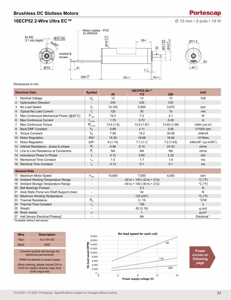
Electrical Data Symbol 16ECP52-2A-** Unit49 112 2201 Nominal Voltage UN 12 12 12 Volt2 Optimization Direction - CW CW CW -3 No Load Speed n0 14,100 5,900 3,070 rpm4 Typical No Load Current I0 120 35 15 mA5 Max Continuous Mechanical Power (@25°C) Pmax 19.3 7.3 2.1 W6 Max Continuous Current Ie max 1.70 0.72 0.39 A7 Max Continuous Torque Me max 13.4 (1.9) 13.9 (1.97) 13.93 (1.98) mNm (oz-in)8 Back EMF Constant kE 0.88 2.11 3.95 V/1000 rpm9 Torque Constant kM 7.99 19.2 35.99 mNm/A
10 Motor Regulation R/k2 15.35 16.68 18.94 103/Nms11 Motor Regulation k/R½ 8 (1.15) 7.7 (1.1) 7.2 (1.03) mNm/W½ (oz-in/W½)12 Internal Resistance - phase to phase RI 0.98 6.15 24.53 ohms13 Line to Line Resistance at Connectors RL NA NA NA ohms14 Inductance Phase to Phase L 0.12 0.60 2.32 mH15 Mechanical Time Constant τm 1.5 1.7 1.9 ms16 Electrical Time Constant τe 0.12 0.1 0.1 ms
General Data17 Maximum Motor Speed nmax 15,900 7,000 4,000 rpm18 Ambient Working Temperature Range - -30 to + 100 (-22 to + 212) °C (°F)19 Ambient Storage Temperature Range - -40 to + 100 (-40 to + 212) °C (°F)20 Ball Bearings Preload - 5.3 N21 Axial Static Force w/o Shaft Support (max) - 34 N22 Maximum Winding Temperature - 125 (257) °C (°F)23 Thermal Resistance Rth 3 / 15 °C/W24 Thermal Time Constant τw 759 s25 Weight - 62 (2.19) g (oz)26 Rotor Inertia J 1 g-cm2
27 Hall Sensor Electrical Phasing* - NA Electrical °
Wire DescriptionRed 5 to 15V DC
Black GND
A reverse polarity will damage the electronics permanently
PWM not allowed on power supply
When ordering, please choose CW or CCW for rotation direction seen from
shaft output side
*Available without hall sensor
Ø 16 mm • 2-pole • 19 W
6x M23.1 min depth
Motor cables - PVC 2x AWG24
A
40°
6x60°
0.1 A
Ø13
twisted & tinned
4±1
300+200 52±0.1
16±5
Ø3+0
.006
-0.0
09
Ø10
+0 -0.0
2
Ø11.5
R1
Ø16
+0.0
5-0
.10
1 0-0.1
10±0.2
No lo
ad s
peed
(RPM
)
Power supply voltage (V)
No load speed for each coil
49
112
220
0
2,000
4,000
6,000
8,000
10,000
12,000
14,000
16,000
18,000
3 6 9 12 15
Power curves on following
page
23

V012021 • © 2021 Portescap. Specifications subject to change without notice.
Brushless DC Slotless Motors16ECP52 2-Wire Ultra EC™ Ø 16 mm • 2-pole • 19 W
V072020 • © 2020 Portescap. Specifications subject to change without notice.
7.3 W
15 V
5 V
0.0 0.2 0.4 0.6 0.8 1.0 1.2 1.4 1.6 1.8 2.0 2.2 2.4 2.6 2.8
01,0002,0003,0004,0005,0006,0007,0008,0009,000
10,000
0 2 4 6 8 10 12 14 16 18 20
Torque [oz-in]
Spee
d [ R
PM]
Torque [mNm]
16ECP52 2A CW 112
ContinuousShort time
2.1 W
15 V
5 V
0.0 0.2 0.4 0.6 0.8 1.0 1.2 1.4 1.6 1.8 2.0 2.2 2.4 2.6 2.8
0500
1,0001,5002,0002,5003,0003,5004,0004,5005,000
0 2 4 6 8 10 12 14 16 18 20
Torque [oz-in]
Spee
d [ R
PM]
Torque [mNm]
16ECP52 2A CW 220
Continuous
Short time
19.3 W
15 V
5 V
2 A rms
0 0.2 0.4 0.6 0.8 1 1.2 1.4 1.6 1.8 2 2.2 2.4 2.6 2.8
02,0004,0006,0008,000
10,00012,00014,00016,00018,00020,000
0 2 4 6 8 10 12 14 16 18 20
Torque [oz-in]
Spee
d [ R
PM]
Torque [mNm]
16ECP52 2A CW 49
ContinuousShort time
24

V012021 • © 2021 Portescap. Specifications subject to change without notice.
Brushless DC Slotless Motors
Ø13.5
12 3
4
A3x M2 at 120°
Max length availablefor screw : 5mm
10
Cable Pitch : 1mm
Ø21
±0.1
1.5±0.04
0.3±0.03
9.3±0.16
60±3
5±0.12
1±0.0410.55±0.11
Ø19
±0.0
5
Ø2-0
.005
-0.0
10
Ø19
+0 -0.1
0
Ø8+0 -0
.02
0.1 A
21BF NuvoDisc™ Ø 21 mm • 8-pole • 4 W
Dimensions in mm.
Electrical Data Symbol 21BF 3C-K.02 Unit
1 Nominal Voltage UN 5 Volt2 Optimization Direction - n.a. -3 No Load Speed n0 3,900 rpm4 Typical No Load Current I0 28.0 mA5 Max Continuous Mechanical Power (@25°C) Pmax 4.0 W6 Max Continuous Current Ie max 0.3 A7 Max Continuous Torque Me max 2.7 (0.39) mNm (oz-in)8 Back EMF Constant kE 0.89 V/1000 rpm9 Torque Constant kM 8.5 mNm/A10 Motor Regulation R/k2 784.0 103/Nms11 Motor Regulation k/R½ 1.1 (0.16) mNm/W½ (oz-in/W½)12 Internal Resistance - phase to phase RI 56.30 ohms13 Line to Line Resistance at Connectors RL 56.30 ohms14 Inductance Phase to Phase L 1.22 mH15 Mechanical Time Constant τm 141.2 ms16 Electrical Time Constant τe 0.02 ms
General Data17 Maximum Motor Speed nmax 25000 rpm18 Ambient Working Temperature Range - -30 to +80 (-22 to +176) °C (°F)19 Ambient Storage Temperature Range - -40 to +80 (-40 to +176) °C (°F)20 Ball Bearings Preload - 2.70 N21 Axial Static Force w/o Shaft Support (max) - 27.00 N22 Maximum Winding Temperature - 125 (257) °C (°F)23 Thermal Resistance Rth 12.00 °C/W24 Thermal Time Constant τw 200.00 s25 Weight - 10 (0.36) g (oz)26 Rotor Inertia J 1.80 g-cm2
27 Hall Sensor Electrical Phasing (Sensorless) - NA Electrical °
Torque [oz-in]
Spee
d [ R
PM]
Torque [mNm]
Max. continuous operation at 25°C
1W
2W
3W
4W
0 0.10 0.300.20 0.40 0.50
0
6,000
4,000
2,000
8,000
10,000
12,000
14,000
0 1 2 3 4
Continuous
Short time
No lo
ad s
peed
(RPM
)
Power supply voltage (V)
No load speed for each coil
K
0
5,000
10,000
15,000
20,000
25,000
0 12 24 36 48
Wire Description1 center point of Y winding
2 Phase 1
3 Phase 2
4 Phase 3
sensorless (3C)
25

V012021 • © 2021 Portescap. Specifications subject to change without notice.
Brushless DC Slotless Motors 1
20°
Ø17
A
35±0.1
1.5±0.1
Ø22
±0.1
10±0.2
Ø3-0
.006
-0.0
09
Ø10
0 -0.0
2
300+20-0
0.1 A3x M2
3.0 min. depth
15°
15°
18°18°
R1.
35
R8.5R1.35
120°
3x
Insulation PVC, 600 V, 105°CRibbon cable 3 x AWG26:Grey,Violet & BlueRibbon cable 5 x AWG26:Green,Yellow, Orange,Red, Brown
22ECP35 Ultra EC™ Ø 22 mm • 2-pole • 55 W
Dimensions in mm.
*Available without hall sensor
Electrical Data Symbol 22ECP35 8B-184.01 Unit
1 Nominal Voltage UN 24 Volt2 Optimization Direction - CW -3 No Load Speed n0 13,200 rpm4 Typical No Load Current I0 30.0 mA5 Max. Continuous Mechanical Power (@25°C) Pmax 55.0 W6 Max. Continuous Current Ie max 0.8 A7 Max. Continuous Torque Me max 14.3 (2.03) mNm (oz-in)8 Back EMF Constant kE 1.82 V/1000 rpm9 Torque Constant kM 17.4 mNm/A10 Motor Regulation R/k2 21.8 103/Nms11 Motor Regulation k/R½ 6.77 (0.96) mNm/W½ (oz-in/W½)12 Internal Resistance - phase to phase RI 6.58 ohms13 Line to Line Resistance at Connectors RL 6.71 ohms14 Inductance Phase to Phase L 0.89 mH15 Mechanical Time Constant τm 3.0 ms16 Electrical Time Constant τe 0.14 ms
General Data17 Maximum Motor Speed nmax 50000 rpm18 Ambient Working Temperature Range - -30 to + 100 (-22 to + 212) °C (°F)19 Ambient Storage Temperature Range - -40 to + 100 (-40 to + 212) °C (°F)20 Ball Bearings Preload - 5.50 N21 Axial Static Force w/o Shaft Support (max) - 34.00 N22 Maximum Winding Temperature - 125 (257) °C (°F)23 Thermal Resistance Rth 3.5/12.5 °C/W24 Thermal Time Constant τw 550 s25 Weight - 64 (2.26) g (oz)26 Rotor Inertia J 1.38 g-cm2
27 Hall Sensor Electrical Phasing* - 120.00 Electrical °
Wire DescriptionGray Phase 1
Violet Phase 2
Blue Phase 3
Green 3.5 to 24V DC
Yellow GND
Orange Sensor 1
Red Sensor 2
Brown Sensor 3
with hall effect sensor
0
10,000
20,000
30,000
40,000
50,000
5,000
15,000
25,000
35,000
45,000
0 12 24 36 48
No lo
ad s
peed
(RPM
)
Power supply voltage (V)
No load speed for each coil
184
Torque [oz-in]
Spee
d [ R
PM]
Torque [mNm]
Max. continuous operation at 25°C
10W20W30W
55W
40W
0 0.5 1.51.0 2.0
0
20,000
10,000
30,000
40,000
50,000
0 2 4 6 8 10 12 14
Continuous
Short time
26

V012021 • © 2021 Portescap. Specifications subject to change without notice.
Brushless DC Slotless Motors
Ø17
A
35±0.1
1.5±0.1
5±1
10±0.2
Ø3-0
.006
-0.0
09
Ø10
+0.0
20.
00Ø22
+0.0
5-0
.10
300+20-0
0.1 A
3x M23.0 min. depth
3x 1
20°
8±2 (9)
stripped and tinned
R8.5
R0.810°
Cable details:2x PVC cable, AWG26 (7x34AWG)Insulation: PVC, 105°C
22ECP35 2-Wire Ultra EC™ Ø 22 mm • 2-pole • 9 W
Dimensions in mm.
Electrical Data Symbol 22ECP35 2A-xxx.01 Unit154 1841 Nominal Voltage UN 12 12 Volt2 Optimization Direction - CW CW -3 No Load Speed n0 7,700 6,600 rpm4 Typical No Load Current I0 63 30 mA5 Max. Continuous Mechanical Power (@25°C) Pmax 9 7.3 W6 Max. Continuous Current Ie max 0.9 0.7 A7 Max. Continuous Torque Me max 12.6 (1.78) 12.6 (1.78) mNm (oz-in)8 Back EMF Constant kE 1.53 1.82 V/1000 rpm9 Torque Constant kM 14.6 17.4 mNm/A10 Motor Regulation R/k2 21.8 21.7 103/Nms11 Motor Regulation k/R½ 6.8 (0.96) 6.8 (0.96) mNm/W½ (oz-in/W½)12 Internal Resistance - phase to phase RI 4.65 6.58 ohms13 Line to Line Resistance at Connectors RL NA NA ohms14 Inductance Phase to Phase L 0.62 0.89 mH15 Mechanical Time Constant τm 3 3 ms16 Electrical Time Constant τe 0.13 0.14 ms
General Data17 Maximum Motor Speed nmax 10000 8000 rpm18 Ambient Working Temperature Range - -30 to + 100 (-22 to + 212) °C (°F)19 Ambient Storage Temperature Range - -40 to + 100 (-40 to + 212) °C (°F)20 Ball Bearings Preload - 5.5 N21 Axial Static Force w/o Shaft Support (max) - 34.00 N22 Maximum Winding Temperature - 125 (257) °C (°F)23 Thermal Resistance Rth 3.5/12.5 °C/W24 Thermal Time Constant τw 550 s25 Weight - 64 (2.26) g (oz)26 Rotor Inertia J 1.38 g-cm2
27 Hall Sensor Electrical Phasing (Sensorless) - NA Electrical °
No lo
ad s
peed
(RPM
)
Power supply voltage (V)
No load speed for each coil
0
2000
4000
6000
8000
10000
0 3 6 9 12 15
184
154
Power curves on following
page
Wire DescriptionRed 5 to 15V DC
Black GND
A reverse polarity will damage the electronics permanently
PWM not allowed on power supply
When ordering, please choose CW or CCW for rotation direction seen from
shaft output side
27

V012021 • © 2021 Portescap. Specifications subject to change without notice.
Brushless DC Slotless Motors22ECP35 2-Wire Ultra EC™ Ø 22 mm • 2-pole • 9 W
0 0.5 1 1.5 2 2.5 3 3.5 4 4.5 5 5.5
01,0002,0003,0004,0005,0006,0007,0008,0009,000
10,000
0 4 8 12 16 20 24 28 32 36 40
7.3 W
15 V
5 V
2 A rms
Torque [oz-in]
Spee
d [ R
PM]
Torque [mNm]
22ECP35 2A 184 TURNS
Continuous
Short time9 W
15 V
5 V
2 A rms
0 0.5 1 1.5 2 2.5 3 3.5 4 4.5 5 5.5
01,0002,0003,0004,0005,0006,0007,0008,0009,000
10,000
0 4 8 12 16 20 24 28 32 36 40
Torque [oz-in]
Spee
d [ R
PM]
Torque [mNm]
22ECP35 2A 154 TURNS
Continuous
Short time
28

V012021 • © 2021 Portescap. Specifications subject to change without notice.
Brushless DC Slotless Motors22ECP45 Ultra EC™ Ø 22 mm • 2-pole • 80 W
Dimensions in mm.
Electrical Data Symbol 22ECP45-8B-xxx.01 Unit154 821 Nominal Voltage UN 24 24 Volt2 Optimization Direction - Symmetrical Symmetrical -3 No Load Speed n0 8,370 15,700 rpm4 Typical No Load Current I0 25 60 mA5 Max Continuous Mechanical Power (@25°C) Pmax 80 80 W6 Max Continuous Current Ie max 1.0 2.0 A7 Max Continuous Torque Me max 27.7 (3.93) 29.4 (4.17) mNm (oz-in)8 Back EMF Constant kE 2.82 1.53 V/1000 rpm9 Torque Constant kM 27.0 14.6 mNm/A10 Motor Regulation R/k2 8.0 7.0 103/Nms11 Motor Regulation k/R½ 11.2 (1.59) 11.9 (1.69) mNm/W½ (oz-in/W½)12 Internal Resistance - phase to phase RI 5.80 1.50 ohms13 Line to Line Resistance at Connectors RL 5.89 1.59 ohms14 Inductance Phase to Phase L 0.94 0.27 mH15 Mechanical Time Constant τm 1.8 1.6 ms16 Electrical Time Constant τe 0.16 0.18 ms
General Data17 Maximum Motor Speed nmax 47,000 rpm18 Ambient Working Temperature Range - -30 to + 100 (-22 to + 212) °C (°F)19 Ambient Storage Temperature Range - -40 to + 100 (-40 to + 212) °C (°F)20 Ball Bearings Preload - 5.5 N21 Axial Static Force w/o Shaft Support (max) - 34 N22 Maximum Winding Temperature - 125 (257) °C (°F)23 Thermal Resistance Rth 2/9.7 °C/W24 Thermal Time Constant τw 850 s25 Weight - 100 (3.53) g (oz)26 Rotor Inertia J 2.30 g-cm2
27 Hall Sensor Electrical Phasing* - 120 Electrical °*Available without hall sensor
Wire DescriptionGray Phase 1
Violet Phase 2
Blue Phase 3
Green 3.5 to 24V DC
Yellow GND
Orange Sensor 1
Red Sensor 2
Brown Sensor 3
with hall effect sensor
3 x M23.0 min. depth
Ø17
3x 12
0° Insulation PVC, 600V. 105°CRibbon cable 3 x AWG26:Gray, Violet, BlueRibbon cable 5 x AWG26:Green, Yellow, Orange,Red, Brown A 120°
R1.35
R1.35
R 8.50
18°
15°1
5°
18°45±0.1 10±0.2
1.5±0.1
Ø22±0.1
300+200
Ø3-0
.006
-0.0
09
Ø10
0 -0.0
2
0.1 A
Torque [oz-in]
Spee
d [ R
PM]
Torque [mNm]
Max. continuous operation at 25°C
20W35W50W
80W65W
0 1.0 3.02.0 4.0
0
20,000
10,000
30,000
40,000
50,000
15,000
5,000
25,000
35,000
45,000
0 10 20 30
Continuous
Short time
0
10,000
20,000
30,000
40,000
5,000
15,000
25,000
35,000
45,000
0 12 24 36 48
No lo
ad s
peed
(RPM
)
Power supply voltage (V)
No load speed for each coil
154
82
29

V012021 • © 2021 Portescap. Specifications subject to change without notice.
Brushless DC Slotless Motors22ECP60 Ultra EC™ Ø 22 mm • 2-pole • 120 W
Dimensions in mm.
Electrical Data Symbol 22ECP60 8B-90.01 Unit
1 Nominal Voltage UN 24 Volt2 Optimization Direction - Symmetrical -3 No Load Speed n0 8,050 rpm4 Typical No Load Current I0 40 mA5 Max. Continuous Mechanical Power (@25°C) Pmax 120 W6 Max. Continuous Current Ie max 1.8 A7 Max. Continuous Torque Me max 50.5 (7.16) mNm (oz-in)8 Back EMF Constant kE 2.96 V/1000 rpm9 Torque Constant kM 28.3 mNm/A10 Motor Regulation R/k2 3.0 103/Nms11 Motor Regulation k/R½ 18.3 (2.6) mNm/W½ (oz-in/W½)12 Internal Resistance - phase to phase RI 2.38 ohms13 Line to Line Resistance at Connectors RL 2.47 ohms14 Inductance Phase to Phase L 0.48 mH15 Mechanical Time Constant τm 1.0 ms16 Electrical Time Constant τe 0.20 ms
General Data17 Maximum Motor Speed nmax 38000 rpm18 Ambient Working Temperature Range - -30 to + 100 (-22 to + 212) °C (°F)19 Ambient Storage Temperature Range - -40 to + 100 (-40 to + 212) °C (°F)20 Ball Bearings Preload - 5.50 N21 Axial Static Force w/o Shaft Support (max) - 34 N22 Maximum Winding Temperature - 125 (257) °C (°F)23 Thermal Resistance Rth 1/8.4 °C/W24 Thermal Time Constant τw 1100 s25 Weight - 140 (4.94) g (oz)26 Rotor Inertia J 3.5 g-cm2
27 Hall Sensor Electrical Phasing* - 120 Electrical °*Available without hall sensor
Wire DescriptionGray Phase 1
Violet Phase 2
Blue Phase 3
Green 3.5 to 24V DC
Yellow GND
Orange Sensor 1
Red Sensor 2
Brown Sensor 3
with hall effect sensor
Ø17
120°
3 x
R1.35
1.358.50
A 120° RR
18°
15°1
5°
18°
0.1 A
60±0.1 10±0.2
1.5±0.1Ø22±0.1
300+200
3 x M23.0 min. depth
Insulation PVC, 600V. 105°CRibbon cable 3 x AWG26:Gray, Violet, BlueRibbon cable 5 x AWG26:Green, Yellow, Orange,Red, Brown
Ø3-0
.006
-0.0
09
Ø10
0 -0.0
2
0
10,000
20,000
30,000
5,000
15,000
25,000
35,000
0 12 24 36 48
No lo
ad s
peed
(RPM
)
Power supply voltage (V)
No load speed for each coil
90
Torque [oz-in]
Spee
d [ R
PM]
Torque [mNm]
Max. continuous operation at 25°C
10W30W
60W
120W
90W
0 1.0 3.02.0 4.0 5.0 6.0 7.0
0
20,000
10,000
30,000
40,000
15,000
5,000
25,000
35,000
0 10 20 30 40 50
Continuous
Short time
30

V012021 • © 2021 Portescap. Specifications subject to change without notice.
Brushless DC Slotless Motors22ECS45 Ultra EC™ Ø 22 mm • 2-pole • 120 W
Dimensions in mm.
Electrical Data Symbol 22ECS45-10B-xxx.01 Unit38 30 24 181 Nominal Voltage UN 24 24 24 24 Volt2 Optimization Direction - CCW CCW CCW CCW -3 No-Load Speed n0 34,500 43,500 51,600 68,500 rpm4 Typical No-Load Current I0 160 195 240 300 mA5 Max Continuous Mechanical Power (@25°C) Pmax 120 120 120 120 W6 Max Continuous Current Ie max 4.0 5.2 6.4 8.2 A7 Max Continuous Torque Me max 26.6 (3.77) 26.8 (3.8) 26.7 (3.79) 26.8 (3.8) mNm (oz-in)8 Back EMF Constant kE 0.69 0.54 0.44 0.34 V/1000 rpm9 Torque Constant kM 6.6 5.2 4.2 3.3 mNm/A
10 Motor Regulation R/k2 8.6 8.5 8.5 8.5 103/Nms11 Motor Regulation k/R½ 10.8 (1.53) 10.8 (1.53) 10.8 (1.53) 10.8 (1.53) mNm/W½ (oz-in/W½)12 Internal Resistance - phase to phase RI 0.38 0.23 0.15 0.09 ohms13 Line to Line Resistance at Connectors RL 0.42 0.25 0.18 0.11 ohms14 Inductance Phase to Phase L 0.057 0.035 0.022 0.013 mH15 Mechanical Time Constant τm 1.9 1.9 1.9 1.9 ms16 Electrical Time Constant τe 0.15 0.15 0.15 0.14 ms
General Data17 Maximum Motor Speed nmax 73,000 rpm18 Ambient Working Temperature Range - -30 to + 100 (-22 to + 212) °C (°F)19 Ambient Storage Temperature Range - -40 to + 100 (-40 to + 212) °C (°F)20 Ball Bearings Preload - 5.5 N21 Axial Static Force w/o Shaft Support (max) - 34 N22 Maximum Winding Temperature - 125 (257) °C (°F)23 Thermal Resistance Rth 2 / 9.7 °C/W24 Thermal Time Constant τw 1,000 s25 Weight - 100 (3.52) g (oz)26 Rotor Inertia J 2.30 g-cm2
27 Hall Sensor Electrical Phasing* - 120 Electrical °*Available without hall sensor
Wire DescriptionGray Phase 1
Violet Phase 2
Blue Phase 3
Green 3.5 to 24V DC
Yellow GND
Orange Sensor 1
Red Sensor 2
Brown Sensor 3
Black NTC 10 kohm
White NTC 10 kohm
with hall effect sensor
3 x M23.0 min. depth
Ø17
3x 12
0° Insulation PVC, 600V. 105°CRibbon cable 3 x AWG26:Gray, Violet, BlueRibbon cable 5 x AWG26:Green, Yellow, Orange,Red, Brown A 120°
R1.35
R1.35
R 8.50
18°
15°1
5°
18°45±0.1 10±0.2
1.5±0.1
Ø22±0.1
300+200
Ø3-0
.006
-0.0
09
Ø10
0 -0.0
2
0.1 A
0
20,000
40,000
60,000
10,000
30,000
50,000
70,000
0 12 24 36 48
No lo
ad s
peed
(RPM
)
Power supply voltage (V)
No load speed for each coil
18 24 3038
Torque [oz-in]
Spee
d [ R
PM]
Torque [mNm]
Max. continuous operation at 25°C
25W50W75W
125W100W
0 1.0 3.02.0 4.0
40,000
20,000
60,000
30,000
10,000
50,000
70,000
0 2 4 6 8 12 14 1610 18 20 22 24 26 28 30
Continuous
Short time
31

V012021 • © 2021 Portescap. Specifications subject to change without notice.
Brushless DC Slotless Motors22ECS60 Ultra EC™ Ø 22 mm • 2-pole • 180 W
Dimensions in mm.
Electrical Data Symbol 22ECS60 10B-xxx.01 Unit24 21 17 161 Nominal Voltage UN 24 24 24 24 Volt2 Optimization Direction - CCW CCW CCW CCW -3 No Load Speed n0 32,000 35,000 43,000 47,000 rpm4 Typical No Load Current I0 120 150 190 210 mA5 Max. Continuous Mechanical Power (@25°C) Pmax 180 180 180 180 W6 Max. Continuous Current Ie max 6.1 7.1 8.7 9.3 A7 Max. Continuous Torque Me max 44.1 (6.25) 45.9 (6.5) 44.5 (6.31) 45 (6.38) mNm (oz-in)8 Back EMF Constant kE 0.76 0.68 0.53 0.51 V/1000 rpm9 Torque Constant kM 7.3 6.5 5.1 4.8 mNm/A
10 Motor Regulation R/k2 3.9 3.6 3.8 3.7 103/Nms11 Motor Regulation k/R½ 16 (2.27) 16.7 (2.37) 16.1 (2.28) 16.3 (2.31) mNm/W½ (oz-in/W½)12 Internal Resistance - phase to phase RI 0.21 0.15 0.10 0.09 ohms13 Line to Line Resistance at Connectors RL 0.23 0.17 0.13 0.12 ohms14 Inductance Phase to Phase L 0.034 0.026 0.017 0.015 mH15 Mechanical Time Constant τm 1.4 1.3 1.3 1.3 ms16 Electrical Time Constant τe 0.17 0.17 0.17 0.17 ms
General Data17 Maximum Motor Speed nmax 60,000 rpm18 Ambient Working Temperature Range - -30 to + 100 (-22 to + 212) °C (°F)19 Ambient Storage Temperature Range - -40 to + 100 (-40 to + 212) °C (°F)20 Ball Bearings Preload - 5.5 N21 Axial Static Force w/o Shaft Support (max) - 34 N22 Maximum Winding Temperature - 125 (257) °C (°F)23 Thermal Resistance Rth 1 / 8.4 °C/W24 Thermal Time Constant τw 1,200 s25 Weight - 140 (4.93) g (oz)26 Rotor Inertia J 3.50 g-cm2
27 Hall Sensor Electrical Phasing* - 120 Electrical °*Available without hall sensor
Wire DescriptionGray Phase 1
Violet Phase 2
Blue Phase 3
Green 3.5 to 24V DC
Yellow GND
Orange Sensor 1
Red Sensor 2
Brown Sensor 3
Black NTC 10 kohm
White NTC 10 kohm
with hall effect sensor
A 30° 50°
120°
R 1.25 R 1
Cables sealed at outlet
R 0.75
Ø17
120°
3 x
0.1 A
60±0.1 10±0.2
1.5±0.1
R 8.5±0.1
R 9±0.1
Ø22±0.1
300+200
3 x M23.0 min. depth
Conductor size: AWG24, AWG20Insulation PVC, 600V. 105°C
Ø3-0
.006
-0.0
09
Ø10
0 -0.0
2
Torque [oz-in]
Spee
d [ R
PM]
Torque [mNm]
Max. continuous operation at 25°C
20W
60W
100W
180W
140W
0 4321 65 7
40,000
20,000
60,000
30,000
10,000
50,000
00
5 10 20 2515 30 35 40 45 50
Continuous
Short time
0
20,000
40,000
60,000
10,000
30,000
50,000
0 12 24 36 48
No lo
ad s
peed
(RPM
)
Power supply voltage (V)
No load speed for each coil
1617
2124
32

V012021 • © 2021 Portescap. Specifications subject to change without notice.
Brushless DC Slotless Motors22ECT35 Ultra EC™ Ø 22 mm • 4-pole • 34 W
Dimensions in mm.
Electrical Data Symbol 22ECT35 10B-xxx.01 Unit32 52 801 Nominal Voltage UN 12 24 24 Volt2 Optimization Direction - Symmetrical Symmetrical Symmetrical -3 No-Load Speed n0 10,330 12,400 8,100 rpm4 Typical No-Load Current I0 100 90 40 mA5 Max Continuous Mechanical Power (@25°C) Pmax 34.0 34.0 34.0 W6 Max Continuous Current Ie max 1.8 1.1 0.7 A7 Max Continuous Torque Me max 20 (2.84) 19.9 (2.82) 19.5 (2.77) mNm (oz-in)8 Back EMF Constant kE 1.14 1.86 2.86 V/1000 rpm9 Torque Constant kM 10.9 17.8 27.3 mNm/A
10 Motor Regulation R/k2 11.8 11.8 12.3 103/Nms11 Motor Regulation k/R½ 9.2 (1.31) 9.2 (1.31) 9 (1.28) mNm/W½ (oz-in/W½)12 Internal Resistance - phase to phase RI 1.40 3.73 9.20 ohms13 Line to Line Resistance at Connectors RL 1.43 3.76 9.23 ohms14 Inductance Phase to Phase L 0.12 0.32 0.75 mH15 Mechanical Time Constant τm 4.2 4.2 4.4 ms16 Electrical Time Constant τe 0.09 0.08 0.08 ms
General Data17 Maximum Motor Speed nmax 20,000 rpm18 Ambient Working Temperature Range - -30 to + 100 (-22 to + 212) °C (°F)19 Ambient Storage Temperature Range - -40 to + 100 (-40 to + 212) °C (°F)20 Ball Bearings Preload - 6.8 N21 Axial Static Force w/o Shaft Support (max) - 45 N22 Maximum Winding Temperature - 125 (257) °C (°F)23 Thermal Resistance Rth 2.3 / 13 °C/W24 Thermal Time Constant τw 829 s25 Weight - 67 (2.37) g (oz)26 Rotor Inertia J 3.6 g-cm2
27 Hall Sensor Electrical Phasing* - 120 Electrical °*Available without hall sensor
Wire DescriptionGray Phase 1
Violet Phase 2
Blue Phase 3
Green 3.5 to 24V DC
Yellow GND
Orange Sensor 1
Red Sensor 2
Brown Sensor 3
Black NTC 10 kohm
White NTC 10 kohm
with hall effect sensor
0.02
A
3x M2 3.0 min36°
30°
120°
R 8
R 1.5
R 1.
25
Ø17
120°
3 x
0.1 A
35±0.15
1.5±0.05 Ø10±0
.02
1.5±0.05
Ø22
±0.1
300+200 10+0.2
-0.1
Ø3-0
.006
-0.0
09
Ø10
0 -0.0
2 Insulation PVC, 600V. 105°CAWG22:Gray, Violet, BlueAWG26:Green, Yellow, Orange,Red, Brown, Black & White
Torque [oz-in]
Spee
d [ R
PM]
Torque [mNm]
Max. continuous operation at 25°C
20W
10W
40W
30W
0 321
16,00014,00012,000
6,000
20,00018,000
10,0008,000
4,0002,000
00
5 10 15 20
Continuous
Short time
0
15,000
20,000
5,000
10,000
0 12 24 36 48
No lo
ad s
peed
(RPM
)
Power supply voltage (V)
No load speed for each coil
5280
32
33

V012021 • © 2021 Portescap. Specifications subject to change without notice.
Brushless DC Slotless Motors22ECT48 Ultra EC™ Ø 22 mm • 4-pole • 54 W
Dimensions in mm.
*Available without hall sensor
Electrical Data Symbol 22ECT48 10B-xxx.01 Unit14 23 351 Nominal Voltage UN 12 24 24 Volt2 Optimization Direction - Symmetrical Symmetrical Symmetrical -3 No Load Speed n0 10,140 11,950 7,950 rpm4 Typical No Load Current I0 155 120 70 mA5 Max. Continuous Mechanical Power (@25°C) Pmax 54.0 54.0 54.0 W6 Max. Continuous Current Ie max 3.7 2.2 1.5 A7 Max. Continuous Torque Me max 41.6 (5.9) 41.1 (5.82) 40.8 (5.78) mNm (oz-in)8 Back EMF Constant kE 1.17 1.95 2.94 V/1000 rpm9 Torque Constant kM 11.2 18.6 28.1 mNm/A
10 Motor Regulation R/k2 2.9 3.0 3.0 103/Nms11 Motor Regulation k/R½ 18.4 (2.61) 18.2 (2.58) 18.1 (2.57) mNm/W½ (oz-in/W½)12 Internal Resistance - phase to phase RI 0.37 1.04 2.40 ohms13 Line to Line Resistance at Connectors RL 0.40 1.07 2.43 ohms14 Inductance Phase to Phase L 0.04 0.11 0.24 mH15 Mechanical Time Constant τm 1.8 1.9 1.9 ms16 Electrical Time Constant τe 0.11 0.10 0.10 ms
General Data17 Maximum Motor Speed nmax 20,000 rpm18 Ambient Working Temperature Range - -30 to + 100 (-22 to + 212) °C (°F)19 Ambient Storage Temperature Range - -40 to + 100 (-40 to + 212) °C (°F)20 Ball Bearings Preload - 6.8 N21 Axial Static Force w/o Shaft Support (max) - 45 N22 Maximum Winding Temperature - 125 (257) °C (°F)23 Thermal Resistance Rth 2.1 / 12 °C/W24 Thermal Time Constant τw 962 s25 Weight - 98 (3.46) g (oz)26 Rotor Inertia J 6.3 g-cm2
27 Hall Sensor Electrical Phasing* - 120 Electrical °
Wire DescriptionGray Phase 1
Violet Phase 2
Blue Phase 3
Green 3.5 to 24V DC
Yellow GND
Orange Sensor 1
Red Sensor 2
Brown Sensor 3
Black NTC 10 kohm
White NTC 10 kohm
with hall effect sensor
A
0.023x M2 3.0 min
36°
30°
120°
Ø17
120°
3 x
0.1 A
48±0.15
1.5±0.05 Ø10±0
.02
1.5±0.05
Ø22
±0.1
300+200 10+0.2
-0.1
Ø3-0
.006
-0.0
09
Ø10
0 -0.0
2 Insulation PVC, 600V. 105°CAWG22:Gray, Violet, BlueAWG26:Green, Yellow, Orange,Red, Brown, Black & White
R 8
R 1.5
R 1.
25
Torque [oz-in]
Spee
d [ R
PM]
Torque [mNm]
Max. continuous operation at 25°C
40W
25W
10W
70W
55W
0 642
16,00014,00012,000
6,000
20,00018,000
10,0008,000
4,0002,000
00
5 201510 3025 4035 45
Continuous
Short time
0
15,000
20,000
5,000
10,000
0 12 24 36 48
No lo
ad s
peed
(RPM
)
Power supply voltage (V)
No load speed for each coil
23
35
14
34

V012021 • © 2021 Portescap. Specifications subject to change without notice.
Brushless DC Slotless Motors22ECT60 Ultra EC™ Ø 22 mm • 4-pole • 86 W
Dimensions in mm.
*Available without hall sensor
Electrical Data Symbol 22ECT60-10B-xxx.01 Unit9 15 211 Nominal Voltage UN 24 24 24 Volt2 Optimization Direction - Symmetrical Symmetrical Symmetrical -3 No-Load Speed n0 20,370 12,350 9,180 rpm4 Typical No-Load Current I0 370 170 115 mA5 Max Continuous Mechanical Power (@25°C) Pmax 86 86 86 W6 Max Continuous Current Ie max 5.9 3.6 2.6 A7 Max Continuous Torque Me max 65.9 (9.34) 66.9 (9.48) 64.3 (9.11) mNm (oz-in)8 Back EMF Constant kE 1.16 1.97 2.72 V/1000 rpm9 Torque Constant kM 11.1 18.8 26.0 mNm/A
10 Motor Regulation R/k2 1.5 1.5 1.6 103/Nms11 Motor Regulation k/R½ 25.5 (3.6) 26 (3.7) 25 (3.5) mNm/W½ (oz-in/W½)12 Internal Resistance - phase to phase RI 0.19 0.52 1.08 ohms13 Line to Line Resistance at Connectors RL 0.22 0.55 1.11 ohms14 Inductance Phase to Phase L 0.02 0.06 0.12 mH15 Mechanical Time Constant τm 1.3 1.3 1.4 ms16 Electrical Time Constant τe 0.12 0.12 0.11 ms
General Data17 Maximum Motor Speed nmax 20,000 rpm18 Ambient Working Temperature Range - -30 to + 100 (-22 to + 212) °C (°F)19 Ambient Storage Temperature Range - -40 to + 100 (-40 to + 212) °C (°F)20 Ball Bearings Preload - 6.8 N21 Axial Static Force w/o Shaft Support (max) - 45.0 N22 Maximum Winding Temperature - 125 (257) °C (°F)23 Thermal Resistance Rth 2.0 / 8.8 °C/W24 Thermal Time Constant τw 980 s25 Weight - 123 (4.34) g (oz)26 Rotor Inertia J 8.71 g-cm2
27 Hall Sensor Electrical Phasing* - 120 Electrical °
Wire DescriptionGray Phase 1
Violet Phase 2
Blue Phase 3
Green 3.5 to 24V DC
Yellow GND
Orange Sensor 1
Red Sensor 2
Brown Sensor 3
Black NTC 10 kohm
White NTC 10 kohm
with hall effect sensor
A
Insulation: PVC, 600V. 105°CAWG22: Gray, Violet & BlueAWG26: Green, Yellow, Orange, Red, Brown, Black & White
R 8
R 1.5
R 1.
25
Ø10±0
.02
0.023x M2 3.0 min
36°
30°
120°
Ø17
120°
3 x
0.1 A
60±0.15
1.5±0.051.5±0.05
Ø22
±0.1
300+200 10+0.2
-0.1
Ø3-0
.006
-0.0
09
Ø10
0 -0.0
2
Torque [oz-in]
Spee
d [ R
PM]
Torque [mNm]
Max. continuous operation at 25°C
60W
40W
20W
100W
80W
0 97 84 5 631 2
16,00014,00012,000
6,000
20,00018,000
10,0008,000
4,0002,000
00
10 3020 5040 60 70
Continuous
Short time
0
15,000
20,000
5,000
10,000
0 12 24 36 48
No lo
ad s
peed
(RPM
)
Power supply voltage (V)
No load speed for each coil
1521
9
35

V012021 • © 2021 Portescap. Specifications subject to change without notice.
Brushless DC Slotless Motors22ECT82 Ultra EC™ Ø 22 mm • 4-pole • 104 W
Dimensions in mm.
Electrical Data Symbol 22ECT82 10B-xxx.01 Unit6 9 151 Nominal Voltage UN 24 24 24 Volt2 Optimization Direction - Symmetrical Symmetrical Symmetrical -3 No Load Speed n0 18,550 12,390 7,800 rpm4 Typical No Load Current I0 435 250 130 mA5 Max. Continuous Mechanical Power (@25°C) Pmax 104 104 104 W6 Max. Continuous Current Ie max 7.9 5.3 3.2 A7 Max. Continuous Torque Me max 98.4 (13.94) 98.8 (14) 98.3 (13.92) mNm (oz-in)8 Back EMF Constant kE 1.30 1.96 3.22 V/1000 rpm9 Torque Constant kM 12.4 18.7 30.8 mNm/A
10 Motor Regulation R/k2 0.8 0.8 0.8 103/Nms11 Motor Regulation k/R½ 35.8 (5.1) 35.9 (5.1) 36 (5.1) mNm/W½ (oz-in/W½)12 Internal Resistance - phase to phase RI 0.13 0.27 0.73 ohms13 Line to Line Resistance at Connectors RL 0.16 0.30 0.76 ohms14 Inductance Phase to Phase L 0.02 0.03 0.09 mH15 Mechanical Time Constant τm 1.1 1.0 1.0 ms16 Electrical Time Constant τe 0.12 0.13 0.13 ms
General Data17 Maximum Motor Speed nmax 20,000 rpm18 Ambient Working Temperature Range - -30 to + 100 (-22 to + 212) °C (°F)19 Ambient Storage Temperature Range - -40 to + 100 (-40 to + 212) °C (°F)20 Ball Bearings Preload - 6.8 N21 Axial Static Force w/o Shaft Support (max) - 45.0 N22 Maximum Winding Temperature - 125 (257) °C (°F)23 Thermal Resistance Rth 1.4 / 8.2 °C/W24 Thermal Time Constant τw 1,140 s25 Weight - 174 (6.14) g (oz)26 Rotor Inertia J 13.17 g-cm2
27 Hall Sensor Electrical Phasing* - 120 Electrical °*Available without hall sensor
Wire DescriptionGray Phase 1
Violet Phase 2
Blue Phase 3
Green 3.5 to 24V DC
Yellow GND
Orange Sensor 1
Red Sensor 2
Brown Sensor 3
Black NTC 10 kohm
White NTC 10 kohm
with hall effect sensor
A R 8
R 1.5
R 1.
25
Insulation: PVC, 600V. 105°CAWG22: Gray, Violet & BlueAWG26: Green, Yellow, Orange, Red, Brown, Black & White
Ø10±0
.02
0.023x M2 3.0 min
36°
30°
120° 120°
3 x
0.1 A
82±0.15
1.5±0.051.5±0.05
Ø22
±0.1
300+200 10+0.2
-0.1
Ø3-0
.006
-0.0
09
Ø10
0 -0.0
2
Ø17
Torque [oz-in]
Spee
d [ R
PM]
Torque [mNm]
Max. continuous operation at 25°C
75W
50W
25W
125W
100W
0 14131210 1165 7 9841 32
16,00014,00012,000
6,000
20,00018,000
10,0008,000
4,0002,000
00
10 3020 5040 60 70 80 90 100
Continuous
Short time
0
15,000
20,000
5,000
10,000
0 12 24 36 48
No lo
ad s
peed
(RPM
)
Power supply voltage (V)
No load speed for each coil
9
15
6
36

V012021 • © 2021 Portescap. Specifications subject to change without notice.
Brushless DC Slotless Motors26BC 3C Ø 26 mm • 2-pole • 8 W
Dimensions in mm.
Electrical Data Symbol 26BC 3C-109P.101 Unit
1 Nominal Voltage UN 12 Volt2 Optimization Direction - n.a. -3 No-Load Speed n0 14,800 rpm4 Typical No-Load Current I0 180.0 mA5 Max Continuous Mechanical Power (@25°C) Pmax 8.0 W6 Max Continuous Current Ie max 0.8 A7 Max Continuous Torque Me max 7 (1) mNm (oz-in)8 Back EMF Constant kE 0.73 V/1000 rpm9 Torque Constant kM 7.0 mNm/A10 Motor Regulation R/k2 102.0 103/Nms11 Motor Regulation k/R½ 3.1 (0.44) mNm/W½ (oz-in/W½)12 Internal Resistance - phase to phase RI 5.00 ohms13 Line to Line Resistance at Connectors RL 5.00 ohms14 Inductance Phase to Phase L 0.09 mH15 Mechanical Time Constant τm 95.0 ms16 Electrical Time Constant τe 0.02 ms
General Data17 Maximum Motor Speed nmax 20,000 rpm18 Ambient Working Temperature Range - 0 to + 70 (+32 to +158) °C (°F)19 Ambient Storage Temperature Range - 0 to + 70 (+32 to +158) °C (°F)20 Ball Bearings Preload - 5.0 N21 Axial Static Force w/o Shaft Support (max) - 45.0 N22 Maximum Winding Temperature - 125 (257) °C (°F)23 Thermal Resistance Rth 14.0 °C/W24 Thermal Time Constant τw 660 s25 Weight - 72 (2.54) g (oz)26 Rotor Inertia J 9.400 g-cm2
27 Hall Sensor Electrical Phasing - NA Electrical °
Wire DescriptionGray Phase 1
Violet Phase 2
Blue Phase 3
sensorless
3.3
M2x2.3
A
120°
3 x
0.2 A
1.5±0.1
10±0.3
12.5±0.332.3±0.05
Ø6±
0.05
Ø3-0
.006
-0.0
09 Ø
260 -0
.1
Ø10
0 -0.0
22
Ø17
Torque [oz-in]
Spee
d [ R
PM]
Torque [mNm]
Max. continuous operation at 25°C
3W2W1W
5W4W
0.00 1.201.000.60 0.800.400.20
6,000
10,000
8,000
4,000
2,000
00
1 32 54 6 7 8
Continuous
Short time
*Depends on coil and electronic 3C / 6A
*
37

V012021 • © 2021 Portescap. Specifications subject to change without notice.
Brushless DC Slotless Motors26BC 6A Ø 26 mm • 2-pole • 4.5 W
Dimensions in mm.
Electrical Data Symbol 26BC 6A-xxx.101 Unit119 113 110 1071 Nominal Voltage UN 7.5 7.5 15 15 Volt2 Optimization Direction - Symmetrical Symmetrical Symmetrical Symmetrical -3 No Load Speed n0 12,500 7,250 9,300 4,700 rpm4 Typical No Load Current I0 250.0 170.0 120.0 50.0 mA5 Max. Continuous Mechanical Power (@25°C) Pmax 4.5 4.5 4.5 4.5 W6 Max. Continuous Current Ie max 1.2 0.6 0.4 0.2 A7 Max. Continuous Torque Me max 4 (0.57) 4.2 (0.6) 4.4 (0.63) 4 (0.57) mNm (oz-in)8 Back EMF Constant kE 0.56 0.96 1.40 2.66 V/1000 rpm9 Torque Constant kM 5.4 9.2 13.4 25.4 mNm/A
10 Motor Regulation R/k2 65.2 80.3 98.0 107.0 103/Nms11 Motor Regulation k/R½ 3.92 (0.56) 3.53 (0.5) 3.19 (0.46) 3.06 (0.44) mNm/W½ (oz-in/W½)12 Internal Resistance - phase to phase RI 1.90 6.80 17.60 69.00 ohms13 Line to Line Resistance at Connectors RL 1.90 6.80 17.60 69.00 ohms14 Inductance Phase to Phase L 0.03 0.12 0.32 1.23 mH15 Mechanical Time Constant τm 61.0 75.0 92.0 100.0 ms16 Electrical Time Constant τe 0.02 0.02 0.02 0.02 ms
General Data17 Maximum Motor Speed nmax 14,000 rpm18 Ambient Working Temperature Range - 0 to + 70 (+32 to +158)) °C (°F)19 Ambient Storage Temperature Range - 0 to + 70 (+32 to +158) °C (°F)20 Ball Bearings Preload - 5.0 N21 Axial Static Force w/o Shaft Support (max) - 45.0 N22 Maximum Winding Temperature - 125 (257) °C (°F)23 Thermal Resistance Rth 14.0 °C/W24 Thermal Time Constant τw 660 s25 Weight - 72 (2.54) g (oz)26 Rotor Inertia J 9.400 g-cm2
27 Hall Sensor Electrical Phasing - NA Electrical °
Wire DescriptionBrown Ground
Red Power supply voltage(2.5 - 18 V)**
Orange Direction CCW/CW
Yellow Enable start / stop***
Green Logic supply voltage(5 - 18 V)
Blue Speed signal****
integrated electronics
Ø6±
0.05
Ø3-0
.006
-0.0
09 Ø26
0 -0.1
Ø10
0 -0.0
22
A
1. Brown2. Red3. Orange4. Yellow5. Green6. Blue123456
3.3
M2x2.3
120°
3 x
0.2 A
1.5±0.1
10±0.3
12.5±0.332.3±0.05210±
0.20
Ø17
Torque [oz-in]
Spee
d [ R
PM]
Torque [mNm]
Max. continuous operation at 25°C
3W2W1W
5W4W
0.00 1.201.000.60 0.800.400.20
6,000
10,000
8,000
4,000
2,000
00
1 32 54 6 7 8
Continuous
Short time
*Depends on coil and electronic 3C / 6A
*
** For coil 119 and 113, do not exceed 7.5 V max.
*** When grounded, motor is not powered**** Speed signal is a square wave voltage with one
pulse per revolution
Do not reverse polarity!
38

V012021 • © 2021 Portescap. Specifications subject to change without notice.
Brushless DC Slotless Motors30ECT64 Ultra EC™ Ø 30 mm • 4-pole • 187 W
Dimensions in mm.
*Available without hall sensor
Electrical Data Symbol 30ECT64-10B-xxx.01 Unit4 7 11 141 Nominal Voltage UN 18 24 36 48 Volt2 Optimization Direction - Symmetrical Symmetrical Symmetrical Symmetrical -3 No-Load Speed n0 28,550 21,930 21,150 22,425 rpm4 Typical No-Load Current I0 1,100 575 425 300 mA5 Max Continuous Mechanical Power (@25°C) Pmax 187.0 187.0 187.0 187.0 W6 Max Continuous Current Ie max 22.8 12.9 8.1 6.5 A7 Max Continuous Torque Me max 137 (19.40) 136 (19.26) 134 (18.98) 133 (18.84) mNm (oz-in)8 Back EMF Constant kE 0.63 1.10 1.74 2.14 V/1000 rpm9 Torque Constant kM 6.0 10.5 16.6 20.5 mNm/A10 Motor Regulation R/k2 0.55 0.57 0.59 0.60 103/Nms11 Motor Regulation k/R½ 42.5 (6.02) 41.8 (5.92) 41.3 (5.85) 40.8 (5.78) mNm/W½ (oz-in/W½)12 Internal Resistance - phase to phase RI 0.02 0.06 0.16 0.25 ohms13 Line to Line Resistance at Connectors RL 0.04 0.08 0.18 0.27 ohms14 Inductance Phase to Phase L 0.01 0.02 0.04 0.06 mH15 Mechanical Time Constant τm 1.6 1.6 1.6 1.7 ms16 Electrical Time Constant τe 0.25 0.23 0.22 0.23 ms
General Data17 Maximum Motor Speed nmax 30,000 rpm18 Ambient Working Temperature Range - -30 to + 100 (-22 to + 212) °C (°F)19 Ambient Storage Temperature Range - -40 to + 100 (-40 to + 212) °C (°F)20 Ball Bearings Preload - 13.5 N21 Axial Static Force w/o Shaft Support (max) - 134 N22 Maximum Winding Temperature - 150 (302) °C (°F)23 Thermal Resistance Rth 0.9/7 °C/W24 Thermal Time Constant τw 1,327 s25 Weight - 263 (9.28) g (oz)26 Rotor Inertia J 28.00 g-cm2
27 Hall Sensor Electrical Phasing* - 120 Electrical °
Wire DescriptionGray Phase 1
Violet Phase 2
Blue Phase 3
Green 4 to 24V DC
Yellow GND
Orange Sensor 1
Red Sensor 2
Brown Sensor 3
White NTC 10 kohm
White NTC 10 kohm
with hall effect sensor
60°
4x M3 4min.
PTFE Cables3x AWG18 (power)5x AWG26 (logic)2x AWG28 (temperature probe)
temp. probe
A
60°
90°
4x
0.1 A
64±0.15292±12 1.5±0.052.1±0.05
Ø30
±0.1
300+200
20+0.22-0.07 Ø
5-0.0
06-0
.009
Ø16
0 -0.0
2
Ø16 0-0.02 Ø22
Ø2.5
R12
R11.1 2x Ø
5.3
Torque [oz-in]
Spee
d [ R
PM]
Torque [mNm]
Max. continuous operation at 25°C
50W
250W200W150W100W
0 2218 201210 16146 842
20,000
15,000
30,000
25,000
10,000
5,000
00
20 6040 10080 120 140 160
Continuous
Short time
0
20,000
30,000
25,000
5,000
15,000
10,000
0 12 24 36 48
No
load
spe
ed (R
PM)
Power supply voltage (V)
No load speed for each coil
1114
74
39

V012021 • © 2021 Portescap. Specifications subject to change without notice.
Brushless DC Slotless Motors30ECT90 Ultra EC™ Ø 30 mm • 4-pole • 244 W
Dimensions in mm.
*Available without hall sensor
Electrical Data Symbol 30ECT90 10B-xxx.01 Unit4 6 81 Nominal Voltage UN 24 36 48 Volt2 Optimization Direction - Symmetrical Symmetrical Symmetrical -3 No Load Speed n0 21,370 21,690 22,100 rpm4 Typical No Load Current I0 1050 640 575 mA5 Max. Continuous Mechanical Power (@25°C) Pmax 244.0 244.0 244.0 W6 Max. Continuous Current Ie max 21.0 14.0 10.4 A7 Max. Continuous Torque Me max 225 (31.86) 221 (31.3) 219 (31.02) mNm (oz-in)8 Back EMF Constant kE 1.12 1.66 2.21 V/1000 rpm9 Torque Constant kM 10.7 15.8 21.1 mNm/A
10 Motor Regulation R/k2 0.2 0.3 0.3 103/Nms11 Motor Regulation k/R½ 63.5 (9) 62.3 (8.83) 61.4 (8.69) mNm/W½ (oz-in/W½)12 Internal Resistance - phase to phase RI 0.03 0.06 0.12 ohms13 Line to Line Resistance at Connectors RL 0.04 0.08 0.13 ohms14 Inductance Phase to Phase L 0.01 0.02 0.03 mH15 Mechanical Time Constant τm 1.1 1.2 1.2 ms16 Electrical Time Constant τe 0.27 0.26 0.25 ms
General Data17 Maximum Motor Speed nmax 25,000 rpm18 Ambient Working Temperature Range - -30 to + 100 (-22 to + 212) °C (°F)19 Ambient Storage Temperature Range - -40 to + 100 (-40 to + 212) °C (°F)20 Ball Bearings Preload - 13.5 N21 Axial Static Force w/o Shaft Support (max) - 134 N22 Maximum Winding Temperature - 150 (302) °C (°F)23 Thermal Resistance Rth 0.7/5.9 °C/W24 Thermal Time Constant τw 1,659 s25 Weight - 380 (13.41) g (oz)26 Rotor Inertia J 45.00 g-cm2
27 Hall Sensor Electrical Phasing - 120 Electrical °
Wire DescriptionGray Phase 1
Violet Phase 2
Blue Phase 3
Green 4 to 24V DC
Yellow GND
Orange Sensor 1
Red Sensor 2
Brown Sensor 3
Black Thermistor (+)
White Thermistor (-)
with hall effect sensor
A
60°
4x M3 4min.
PTFE Cables3x AWG18 (power)5x AWG26 (logic)2x AWG28 (temperature probe)
temp. probe
60°
90°
4x
0.1 A
90±0.15292±12 1.5±0.052.1±0.05
Ø30
±0.1
300+200
20+0.22-0.07 Ø
5-0.0
06-0
.009
Ø16
0 -0.0
2
Ø16 0-0.02 Ø22
Ø2.5
R12
R11.1 2x Ø
5.3
Torque [oz-in]
Spee
d [ R
PM]
Torque [mNm]
Max. continuous operation at 25°C
100W
300W250W200W150W
0 22 24 26 28 30 3218 201210 16146 842
15,000
10,000
25,000
20,000
5,000
00
20 6040 10080 120 140 160 180 200 220
Continuous
Short time
0
20,000
25,000
5,000
15,000
10,000
0 12 24 36 48
No lo
ad s
peed
(RPM
)
Power supply voltage (V)
No load speed for each coil
6
8
4
40

V012021 • © 2021 Portescap. Specifications subject to change without notice.
Brushless DC Slotless Motors32BF nuvoDisc™ Ø 32 mm • 8-pole • 40 W
Dimensions in mm.
Electrical Data Symbol 32BF 3C-K.11 32BF 8B-10 Unit
1 Nominal Voltage UN 12 Volt2 Optimization Direction - Symmetrical -3 No-Load Speed n0 13,600 rpm4 Typical No-Load Current I0 100.0 mA5 Max Continuous Mechanical Power (@25°C) Pmax 40.0 W6 Max Continuous Current Ie max 1.5 A7 Max Continuous Torque Me max 13 (1.85) mNm (oz-in)8 Back EMF Constant kE 0.87 V/1000 rpm9 Torque Constant kM 8.3 mNm/A10 Motor Regulation R/k2 57.5 103/Nms11 Motor Regulation k/R½ 4.2 (0.6) mNm/W½ (oz-in/W½)12 Internal Resistance - phase to phase RI 3.95 ohms13 Line to Line Resistance at Connectors RL 3.95 ohms14 Inductance Phase to Phase L 0.12 mH15 Mechanical Time Constant τm 64.9 ms16 Electrical Time Constant τe 0.03 ms
General Data17 Maximum Motor Speed nmax 30,000 rpm18 Ambient Working Temperature Range - -30 to +80 (-22 to +176) °C (°F)19 Ambient Storage Temperature Range - -40 to +80 (-40 to +176) °C (°F)20 Ball Bearings Preload - 7 N21 Axial Static Force w/o Shaft Support (max) - 27.0 N22 Maximum Winding Temperature - 125 (257) °C (°F)23 Thermal Resistance Rth 13.0 °C/W24 Thermal Time Constant τw 550 s25 Weight - 27 (0.96) g (oz)26 Rotor Inertia J 11.300 g-cm2
27 Hall Sensor Electrical Phasing* - 120 Electrical °*Available without hall sensor
Wire Description1 Phase 1
2 Phase 2
3 Phase 3
4 3.5 to 24V DC
5 GND
6 Sensor 1
7 Sensor 2
8 Sensor 3
with hall effect sensor (8B)
Wire Description1 center point of Y winding
2 Phase 1
3 Phase 2
4 Phase 3
sensorless (3C)
Cable Pitch: 1mm
30°
3x M3 at 120°depth 5.5 mm
12 3
4
B
A
0.07 AB
0.05 A
10±1
3±0.03
0.6±0.111.2±0.15
Ø3-0.006-0.009
Ø8
0 -0.0
3
0.1 A
10.6±0.2
Ø30
±0.0
5
Ø32
±0.1
5±0.2100±
3
Ø22
12345678(8B)
(3C)
Hall Effect Sensor cable option
Torque [oz-in]
Spee
d [ R
PM]
Torque [mNm]
Max. continuous operation at 25°C
5W
40W
30W
20W
10W
0 2.00 2.501.501.000.50
15,000
10,000
25,000
30,000
20,000
5,000
00
2 64 108 12 14 16 18 20
Continuous
Short time
41

V012021 • © 2021 Portescap. Specifications subject to change without notice.
Brushless DC Slotless Motors35ECS60 Ultra EC™ Ø 35 mm • 2-pole • 262 W
Dimensions in mm.
Electrical Data Symbol 35ECS60 10B-xxx.01 Unit8 10 15 201 Nominal Voltage UN 20 24 36 48 Volt2 Optimization Direction - Symmetrical Symmetrical Symmetrical Symmetrical -3 No Load Speed n0 38,900 38,500 39,000 39,300 rpm4 Typical No Load Current I0 1000 900 500 360 mA5 Max. Continuous Mechanical Power (@25°C) Pmax 262 262 262 262 W6 Max. Continuous Current Ie max 25.3 20.1 13.2 9.8 A7 Max. Continuous Torque Me max 120.6 (17.1) 120.6 (17.1) 117.9 (16.7) 115.8 (16.4) mNm (oz-in)8 Back EMF Constant kE 0.51 0.63 0.94 1.24 V/1000 rpm9 Torque Constant kM 4.90 6.01 8.94 11.83 mNm/A10 Motor Regulation R/k2 0.832 0.886 0.928 0.961 103/Nms11 Motor Regulation k/R½ 34.6 (4.9) 33.6 (4.76) 32.8 (4.65) 32.3 (4.57) mNm/W½ (oz-in/W½)12 Internal Resistance - phase to phase RI 0.02 0.032 0.074 0.135 ohms13 Line to Line Resistance at Connectors RL 0.026 0.044 0.086 0.147 ohms14 Inductance Phase to Phase L 0.011 0.017 0.037 0.064 mH15 Mechanical Time Constant τm 1.6 1.8 1.9 2.0 ms16 Electrical Time Constant τe 0.6 0.5 0.5 0.5 ms
General Data17 Maximum Motor Speed nmax 40,000 rpm18 Ambient Working Temperature Range - -30 to + 100 (-22 to + 212) °C (°F)19 Ambient Storage Temperature Range - -40 to + 100 (-40 to + 212) °C (°F)20 Ball Bearings Preload - 9 N21 Axial Static Force w/o Shaft Support (max) - 134 N22 Maximum Winding Temperature - 150 (302) °C (°F)23 Thermal Resistance Rth 0.8/5.7 °C/W24 Thermal Time Constant τw 1,618 s25 Weight - 315 (11.11) g (oz)26 Rotor Inertia J 20.4 g-cm2
27 Hall Sensor Electrical Phasing - 120 Electrical °*Available without hall sensor
Wire DescriptionGray Phase 1
Violet Phase 2
Blue Phase 3
Green 4 to 24V DC
Yellow GND
Orange Sensor 1
Red Sensor 2
Brown Sensor 3
White NTC 10 kohm
White NTC 10 kohm
with hall effect sensor
No
load
spe
ed (R
PM)
Power supply voltage (V)
No load speed for each coil
1520
05,000
10,00015,00020,00025,00030,00035,00040,000
0 12 24 36 48
108Torque [oz-in]
Spee
d [ R
PM]
Torque [mNm]
Max. continuous operation at 25°C
100W
300W250W200W150W
0 1210 16146 842
25,000
20,000
15,000
10,000
40,000
30,000
35,000
5,000
00
20 40 60 80 100 120
Continuous
Short time
Ø29
300+200
Ø16 0-0.02
Ø20
0 -0.0
2
-0.0
06-0
.009
Ø35±0.12.1±0.05
1.5±0.05
20±0.260±0.15
Ø5
291±12
4x 90
°
3x 1
20°
Ø23
3x Ø6
temp. probe
Motor cables - PTFE3x AWG16 (power) + shrink sleeve5x AWG26 (logic)2x AWG28 (temperature probe)
4x M3 4 min. depth
42

V012021 • © 2021 Portescap. Specifications subject to change without notice.
Brushless DC Slotless Motors35ECS80 Ultra EC™ Ø 35 mm • 2-pole • 330 W
Dimensions in mm.
Electrical Data Symbol 35ECS80 10B-xxx.01 Unit8 11 141 Nominal Voltage UN 24 36 48 Volt2 Optimization Direction - Symmetrical Symmetrical Symmetrical -3 No Load Speed n0 27,000 29,500 31,100 rpm4 Typical No Load Current I0 700 550 430 mA5 Max. Continuous Mechanical Power (@25°C) Pmax 330 330 330 W6 Max. Continuous Current Ie max 22.6 16.4 12.9 A7 Max. Continuous Torque Me max 193.4 (27.3) 193.1 (27.3) 193.1 (27.3) mNm (oz-in)8 Back EMF Constant kE 0.9 1.23 1.57 V/1000 rpm9 Torque Constant kM 8.56 11.78 14.98 mNm/A
10 Motor Regulation R/k2 0.367 0.368 0.369 103/Nms11 Motor Regulation k/R½ 52.2 (7.37) 52.1 (7.37) 52.1 (7.37) mNm/W½ (oz-in/W½)12 Internal Resistance - phase to phase RI 0.027 0.051 0.083 ohms13 Line to Line Resistance at Connectors RL 0.039 0.063 0.095 ohms14 Inductance Phase to Phase L 0.017 0.03 0.047 mH15 Mechanical Time Constant τm 1.2 1.2 1.2 ms16 Electrical Time Constant τe 0.4 0.6 0.5 ms
General Data17 Maximum Motor Speed nmax 40000 rpm18 Ambient Working Temperature Range - -30 to + 100 (-22 to + 212) °C (°F)19 Ambient Storage Temperature Range - -40 to + 100 (-40 to + 212) °C (°F)20 Ball Bearings Preload - 9 N21 Axial Static Force w/o Shaft Support (max) - 134 N22 Maximum Winding Temperature - 150 (302) °C (°F)23 Thermal Resistance Rth 0.7/5.4 °C/W24 Thermal Time Constant τw 1,822 s25 Weight - 440 (15.52) g (oz)26 Rotor Inertia J 33 g-cm2
27 Hall Sensor Electrical Phasing - 120 Electrical °*Available without hall sensor
Wire DescriptionGray Phase 1
Violet Phase 2
Blue Phase 3
Green 4 to 24V DC
Yellow GND
Orange Sensor 1
Red Sensor 2
Brown Sensor 3
White NTC 10 kohm
White NTC 10 kohm
with hall effect sensor
No lo
ad s
peed
(RPM
)
Power supply voltage (V)
No load speed for each coil
1114
05,000
10,00015,00020,00025,00030,00035,00040,000
0 12 24 36 48
8
Torque [oz-in]
Spee
d [ R
PM]
Torque [mNm]
Max. continuous operation at 25°C
100W
400W325W250W175W
0 1210 16 18 20 22 24 26146 842
25,000
20,000
15,000
10,000
40,000
30,000
35,000
5,000
00
20 40 60 80 100 120 140 160 180
Continuous
Short time
Ø29
300+200
Ø16 0-0.02
Ø20
0 -0.0
2
Ø35±0.12.1±0.05
1.5±0.05
20±0.280±0.15
Ø54x
90°
3x 1
20°
Ø23
3x Ø6
Motor cables - PTFE3x AWG16 (power) + shrink sleeve5x AWG26 (logic)2x AWG28 (temperature probe)
4x M3 4 min. depth
-0.0
06-0
.009
291±12
temp. probe
43

V012021 • © 2021 Portescap. Specifications subject to change without notice.
Motors For Surgical Applications
Epitomizing the exceptional quality of the Portescap brand, our application specific surgical motors are designed to meet the specialized performance requirements of high-precision powered surgical hand tools.With 20 years of experience designing and manufacturing motors for surgical applications, we understand how speed, torque and efficiency affect the performance of powered surgical hand tools. Portescap’s autoclavable Brushless Direct Current (BLDC) motors are designed to provide high power in a lightweight ergonomic package. Our motors excel at meeting the requirements for exceptional surgical results, and have the durability to withstand sterilization and exposure to saline or other materials encountered in the surgical environment.
ENT MicrodebridersSpine Drills
Arthroscopic Shavers Large Bone Drills
44

V012021 • © 2021 Portescap. Specifications subject to change without notice.
Motors For Surgical Applications
Arthroscopic joint shavers Arthroscopic procedures require high torque, speed and efficiency. Portescap BLDC motors are an ideal solution for powered surgical hand tools used in minimally invasive surgical procedures to repair joints such as the hip, knee, and shoulder.
ENT microdebriders Optimized for ENT microdebrider (ENT shaver) applications, the torque and speed requirements make Portescap motors an ideal solution for powered surgical hand tools used in minimally invasive surgical procedures of the ear, nose and throat.Also see our ENT drill motor for high speed drilling applications.
Large bone orthopedic drills Orthopedic surgery procedures require high torque, speed and efficiency. Portescap BLDC motors enable the design of lightweight and powerful orthopedic drills, screwdrivers and reamers used in joint replacement procedures.
Application Specific Motors For Powered Surgical Hand Tools
Motor performance tailored to your application requirements High and low volume manufacturing
Samples available upon request Vertically integrated design and manufacturing
Working with You to Save, Improve and Enhance Lives
Contact us for more information about our application specific surgical motors or to review requirements of your surgical application.
North America [email protected] America [email protected] Europe, Middle East, Africa [email protected], India [email protected]
Portescap designs and manufactures motors for various medical applications, including arthroscopic shavers, large bone orthopedic drills, ENT microdebriders, ENT drills, high-speed spine and neuro drills, and more.
45

V012021 • © 2021 Portescap. Specifications subject to change without notice.
Meet your Application’s Working Point Requirements
0
10000
20000
30000
40000
50000
60000
70000
80000
90000
100000
0
5
10
15
20
25
30
35
40
45
B0512N4080 B0512N4081 B0512N1029
Spee
d at
Max
Tor
que
(RPM
)
Max
Con
tinuo
us S
tall
Torq
ue (m
Nm)
12.7 mm Diameter
Max Continuous Stall Torque (mNm) Speed at Max Torque (RPM)
37.9 mNm41.6 mNm
9.5 mNm
87906 RPM
12024RPM
11655RPM
Spee
d at
Max
Tor
que
(RPM
)
Max
Con
tinuo
us S
tall
Torq
ue (m
Nm)
Max Continuous Stall Torque (mNm) Speed at Max Torque (RPM)
6400
6600
6800
7000
7200
7400
7600
7800
110
112
114
116
118
120
122
124
126
128
B0614H4041 B0614H4042
16.5 mm Diameter
116.7 mNm
6833 RPM
126.8 mNm7661RPM
Spee
d at
Max
Tor
que
(RPM
)
Max
Con
tinuo
us S
tall
Torq
ue (m
Nm)
Max Continuous Stall Torque (mNm) Speed at Max Torque (RPM)
0
100
200
300
400
500
600
700
800
900
1000
0
100
200
300
400
500
600
700
800
900
1000
B1112N4004
27.94 mm Diameter
869 RPM
937 mNm
Spee
d at
Max
Tor
que
(RPM
)
Max
Con
tinuo
us S
tall
Torq
ue (m
Nm)
Max Continuous Stall Torque (mNm) Speed at Max Torque (RPM)
13500
14000
14500
15000
15500
16000
70
75
80
85
90
95
100
B1210N1025B1210N1021
B1210N1026B1210N1022
B1210N1027B1210N1023
31.5 mm Diameter
83.1 mNm80.8 mNm
95.9 mNm
14527RPM
14903 RPM
15844 RPM
Motors For Surgical Applications
46

V012021 • © 2021 Portescap. Specifications subject to change without notice.
Surgical Motor Solutions
Dimensions in inches [mm]
B0512N1029 Spine Drill Ø 0.5 inch • Brushless Slotted • 48 V
Ø0.375
0.025 [0.64]
0.020 [0.51]
45° X 0.010 [0.25]
.4606-64 UNS-2A
MOTOR & HALL LEADS:6.0 [152] MIN LONG,26 AWG STRANDED
0.500±.009[12.70±0.23]
0.126±.002 [3.20±0.05]
1.921±.004 [48.79±0.10]
+0-0.001
+0-0.03 [9.53 ]
Ø0.500+0-0.002
+0-0.05 [12.70 ]
Ø0.1245+0-0.0005
+0-0.01 [3.16 ]
Ø0.4685+0-0.0005
+0-0.01 [11.90 ]
0.030+0-0.005 [0.76 ]+0
-0.12
Electrical Data SymbolSMX
B0512N1029 Unit1 Nominal Voltage UN 48.0 Volt2 Optimization Direction - Bi-Directional -3 No Load Speed n0 97,400 rpm4 Typical No Load Current I0 120 mA5 Max. Continuous Mechanical Power (@25°C) Pmax 87.4 W6 Max. Continuous Current Ics 2.02 A7 Max. Continuous Torque Tcs 9.5 (1.34) mNm (oz-in)8 Back EMF Constant kE 0.515 V/1000 rpm9 Torque Constant kT 4.92 (0.70) mNm/A (oz-in/A)10 Motor Regulation R/k2 54944 103/Nms11 Peak Torque Tpk 176.1 (24.9) mNm (oz-in)12 Motor Constant kM 4.27 (0.607) mNm/W½ (oz-in/W½)13 Line to Line Resistance RL 1.33 ohms14 Inductance Phase to Phase L 0.094 mH15 Mechanical Time Constant τM 2.62 ms16 Electrical Time Constant τE 0.07 ms
General Data17 Gearhead Ratio - N/A Ratio18 Ambient Working Temperature Range - 25 (77) °C (°F)19 Max Operating Temperature Range - 155 (311) °C (°F)20 Radial Static Force w/o Shaft Support (max) - 15.34 lbs21 Axial Static Force w/o Shaft Support (max) - 3.33 lbs22 Thermal Resistance Rth 15.9 °C/W23 Thermal Time Constant τw 485 s24 Weight - 38.5 (1.36) g (oz)25 Rotor Inertia Jm 3.15 (4.46) kg-cm2 10-4 (oz-in-sec2 10-6)26 Hall Sensor Electrical Phasing - 60 Electrical °27 Autoclave Cycles - 1000+ Cycles
0.010.020.030.040.050.060.070.080.090.0100.0
0.050.0
100.0150.0200.0250.0300.0350.0400.0450.0500.0
0.010.420.831.241.652.062.472.883.393.7104.1114.5124.9135.3145.7156.1166.5176.9
Effic
ienc
y %
Wat
ts
B0512N1029 Output - Efficiency Performance
Load mNm
OutputEfficiency
0.04.08.012.016.020.024.028.032.036.040.0
0100002000030000400005000060000700008000090000
100000
0.010.420.831.241.652.062.472.883.393.7104.1114.5124.9135.3145.7156.1166.5176.9
Am
ps
RPM
B0512N1029 Speed - Current Performance
Load mNm
RPMAmps
Wire DescriptionBlue Phase A
Brown Phase B
Violet Phase C
Red 4.5 to 24 Vdc
Yellow Hall 1
Orange Hall 2
White Hall 3
Black Supply RTN
• Three phase motor with Wye connections• Hall sensors: supply voltage 4.5 V - 24 V• Typical housing material 303 SS
Notes: • Motor type has been designed and tested to achieve the stated number of autoclave cycles• Above parameters specified for 25° C ambient temperature• Typical shaft material 17-4 PH
47

V012021 • © 2021 Portescap. Specifications subject to change without notice.
Surgical Motor Solutions
Dimensions in inches [mm]
Electrical Data SymbolSMX
B0512N4080 Unit1 Nominal Voltage UN 24.0 Volt2 Optimization Direction - Bi-Directional -3 No Load Speed n0 13,385 rpm4 Typical No Load Current I0 340 mA5 Max. Continuous Mechanical Power (@25°C) Pmax 47.8 W6 Max. Continuous Current Ics 2.56 A7 Max. Continuous Torque Tcs 37.9 (5.4) mNm (oz-in)8 Back EMF Constant kE 1.805 V/1000 rpm9 Torque Constant kT 15.51 (2.2) mNm/A (oz-in/A)10 Motor Regulation R/k2 3429 103/Nms11 Peak Torque Tpk 445.3 (63.1) mNm (oz-in)12 Motor Constant kM 17.06 (2.42) mNm/W½ (oz-in/W½)13 Line to Line Resistance RL 0.825 ohms14 Inductance Phase to Phase L 0.058 mH15 Mechanical Time Constant τM 3.30 ms16 Electrical Time Constant τE 0.070 ms
General Data17 Gearhead Ratio - 5:1 Ratio18 Ambient Working Temperature Range - 25 (77) °C (°F)19 Max Operating Temperature Range - 155 (311) °C (°F)20 Radial Static Force w/o Shaft Support (max) - 4.52 lbs21 Axial Static Force w/o Shaft Support (max) - 6.33 lbs22 Thermal Resistance Rth 15.9 °C/W23 Thermal Time Constant τw 485 s24 Weight - 53.8 (1.89) g (oz)25 Rotor Inertia Jm 3.15 (4.46) kg-cm2 10-4 (oz-in-sec2 10-6)26 Hall Sensor Electrical Phasing - 60 Electrical °27 Autoclave Cycles - 1000+ Cycles
[4.75]Ø0.187
.4606-64 UNS-2A
.329±.002[8.36±0.05]
Ø0.2500
MOTOR & HALL LEADS:6.0 [152] MIN LONG,26 AWG STRANDED
0.500±.014[12.70±0.36]
0.129±.004[3.28±0.10]
2.387±.007 [60.63±0.18]
+0-0.0003
+0-0.01 [6.35 ] 3X Ø0.500+0
-0.002 +0-0.05 [12.70 ]
Ø0.1247+0-0.0002
+0-0.01 [3.17 ]
Ø0.4685+0-0.0005
+0-0.01 [11.90 ]
0.032+0-0.008 [0.81 ]+0
-0.2
0.050+0-0.004 [1.27 ]+0
-0.1
B0512N4080 ENT Microdebrider Ø 0.5 inch • Brushless Slotted • 24 V
0.0
9.0
18.0
27.0
36.0
45.0
54.0
63.0
72.0
0.0
20.0
40.0
60.0
80.0
100.0
120.0
140.0
160.0
180.0
0.026.252.578.7105.0131.2157.4183.7209.9236.1262.4288.6314.9341.1367.3393.6419.8446.0
Effic
ienc
y %
Wat
ts
B0512N4080 Output - Efficiency Performance
Load mNm
OutputEfficiency
0.02.14.26.38.410.512.614.716.818.921.023.125.227.329.4
0100020003000400050006000700080009000
1000011000120001300014000
0.026.252.578.7105.0131.2157.4183.7209.9236.1262.4288.6314.9341.1367.3393.6419.8446.0
Am
ps
RPM
B0512N4080 Speed - Current Performance
Load mNm
RPMAmps
Wire DescriptionBlue Phase A
Brown Phase B
Violet Phase C
Red 4.5 to 24 Vdc
Yellow Hall 1
Orange Hall 2
White Hall 3
Black Supply RTN
• Three phase motor with Wye connections• Hall sensors: supply voltage 4.5 V - 24 V• Typical housing material 303 SS
Notes: • Motor type has been designed and tested to achieve the stated number of autoclave cycles• Above parameters specified for 25° C ambient temperature• Typical shaft material 17-4 PH
48

V012021 • © 2021 Portescap. Specifications subject to change without notice.
Surgical Motor Solutions
Dimensions in inches [mm]
[4.75]Ø0.187
.4606-64 UNS-2A
.329±.002[8.36±0.05]
Ø0.2500
MOTOR & HALL LEADS:6.0 [152] MIN LONG,26 AWG STRANDED
0.500±.014[12.70±0.36]
0.129±.004[3.28±0.10]
2.387±.007 [60.63±0.18]
+0-0.0003
+0-0.01 [6.35 ] 3X Ø0.500+0
-0.002 +0-0.05 [12.70 ]
Ø0.1247+0-0.0002
+0-0.01 [3.17 ]
Ø0.4685+0-0.0005
+0-0.01 [11.90 ]
0.032+0-0.008 [0.81 ]+0
-0.2
0.050+0-0.004 [1.27 ]+0
-0.1
B0512N4081 ENT Microdebrider Ø 0.5 inch • Brushless Slotted • 48 V
Electrical Data SymbolSMX
B0512N4081 Unit1 Nominal Voltage UN 48.0 Volt2 Optimization Direction - Bi-Directional -3 No Load Speed n0 12,800 rpm4 Typical No Load Current I0 165 mA5 Max. Continuous Mechanical Power (@25°C) Pmax 50.8 W6 Max. Continuous Current Ics 1.35 A7 Max. Continuous Torque Tcs 41.6 (5.9) mNm (oz-in)8 Back EMF Constant kE 3.75 V/1000 rpm9 Torque Constant kT 32.23 (4.56) mNm/A (oz-in/A)10 Motor Regulation R/k2 2840 103/Nms11 Peak Torque Tpk 518.9 (73.5) mNm (oz-in)12 Motor Constant kM 18.75 (2.68) mNm/W½ (oz-in/W½)13 Line to Line Resistance RL 2.95 ohms14 Inductance Phase to Phase L 0.24 mH15 Mechanical Time Constant τM 2.74 ms16 Electrical Time Constant τE 0.081 ms
General Data17 Gearhead Ratio - 5:1 Ratio18 Ambient Working Temperature Range - 25 (77) °C (°F)19 Max Operating Temperature Range - 155 (311) °C (°F)20 Radial Static Force w/o Shaft Support (max) - 4.52 lbs21 Axial Static Force w/o Shaft Support (max) - 6.33 lbs22 Thermal Resistance Rth 15.9 °C/W23 Thermal Time Constant τw 485 s24 Weight - 48 (1.7) g (oz)25 Rotor Inertia Jm 3.15 (4.46) kg-cm2 10-4 (oz-in-sec2 10-6)26 Hall Sensor Electrical Phasing - 60 Electrical °27 Autoclave Cycles - 1000+ Cycles
0.08.016.024.032.040.048.056.064.072.080.0
0.020.040.060.080.0
100.0120.0140.0160.0180.0200.0
0.030.561.191.6122.1152.7183.2213.8244.3274.8305.4335.9366.4397.0427.5458.1488.6519.1
Effic
ienc
y %
Wat
ts
B0512N4081 Output - Efficiency Performance
Load mNm
OutputEfficiency
0.0
2.5
5.0
7.5
10.0
12.5
15.0
17.5
0
2000
4000
6000
8000
10000
12000
14000
0.030.561.191.6122.1152.7183.2213.8244.3274.8305.4335.9366.4397.0427.5458.1488.6519.1
Am
ps
RPM
B0512N4081 Speed - Current Performance
Load mNm
RPMAmps
Wire DescriptionBlue Phase A
Brown Phase B
Violet Phase C
Red 4.5 to 24 Vdc
Yellow Hall 1
Orange Hall 2
White Hall 3
Black Supply RTN
• Three phase motor with Wye connections• Hall sensors: supply voltage 4.5 V - 24 V• Typical housing material 303 SS
Notes: • Motor type has been designed and tested to achieve the stated number of autoclave cycles• Above parameters specified for 25° C ambient temperature• Typical shaft material 17-4 PH
49

V012021 • © 2021 Portescap. Specifications subject to change without notice.
Surgical Motor Solutions
Dimensions in inches [mm]
.607-56 UNS -2A MOTOR LEADS:6.0 [152] MIN LONG,24 AWG STRANDEDHALL SENSOR LEADS:6.0 [152] MIN LONG,26 AWG STRANDED
0.750±.0082.022 [51.36][19.05±0.20] 0.500±.006 [12.70±0.15]
Ø0.650±.001 [16.51±0.03]
Ø0.1872+0-0.0004
+0-0.01 [4.75 ]
Ø0.4685
Ø0.138 [3.50] THRU
+0-0.0010
+0-0.03 [11.90 ]
Ø0.6095+0-0.0005
+0-0.01 [15.48 ]
Ø0.1872+0-0.0004
+0-0.01 [4.75 ]
0.061±.002 [1.55±0.05]0.219±.002 [5.56±0.05]0.250±.002 [6.35±0.05]
B0612H1005 Cannulated Shaver/Microdebrider Ø 0.65 inch • Brushless Slotted • 48 V
Electrical Data SymbolSMX
B0612H1005 Unit1 Nominal Voltage UN 48.0 Volt2 Optimization Direction - Bi-Directional -3 No Load Speed n0 35,300 rpm4 Typical No Load Current I0 125 mA5 Max. Continuous Mechanical Power (@25°C) Pmax 68.5 W6 Max. Continuous Current Ics 1.80 A7 Max. Continuous Torque Tcs 19.6 (2.78) mNm (oz-in)8 Back EMF Constant kE 1.33 V/1000 rpm9 Torque Constant kT 12.71 (1.8) mNm/A (oz-in/A)10 Motor Regulation R/k2 13321 103/Nms11 Peak Torque Tpk 141.7 (20.1) mNm (oz-in)12 Motor Constant kM 8.69 (1.23) mNm/W½ (oz-in/W½)13 Line to Line Resistance RL 2.152 ohms14 Inductance Phase to Phase L 0.525 mH15 Mechanical Time Constant τM 0.80 ms16 Electrical Time Constant τE 0.244 ms
General Data17 Gearhead Ratio - N/A Ratio18 Ambient Working Temperature Range - 25 (77) °C (°F)19 Max Operating Temperature Range - 155 (311) °C (°F)20 Radial Static Force w/o Shaft Support (max) - 25.99 lbs21 Axial Static Force w/o Shaft Support (max) - 10.33 lbs22 Thermal Resistance Rth 12.0 °C/W23 Thermal Time Constant τw 936 s24 Weight - 75.8 (2.67) g (oz)25 Rotor Inertia Jm 9.79 (13.86) kg-cm2 10-4 (oz-in-sec2 10-6)26 Hall Sensor Electrical Phasing - 60 Electrical °27 Autoclave Cycles - 1000+ Cycles
0.0
15.0
30.0
45.0
60.0
75.0
90.0
0.0
50.0
100.0
150.0
200.0
250.0
300.0
0.016.633.149.766.382.999.4116.0132.6149.1165.7182.3198.9215.4232.0248.6265.1281.7
Effic
ienc
y %
Wat
ts
B0612H1005 Output - Efficiency Performance
Load mNm
OutputEfficiency
0.0
3.0
6.0
9.0
12.0
15.0
18.0
21.0
24.0
0
5000
10000
15000
20000
25000
30000
35000
40000
0.016.633.149.766.382.999.4116.0132.6149.1165.7182.3198.9215.4232.0248.6265.1281.7
Am
ps
RPM
B0612H1005 Speed - Current Performance
Load mNm
RPMAmps
Wire DescriptionBlue Phase A
Brown Phase B
Violet Phase C
Red 4.5 to 24 Vdc
Yellow Hall 1
Orange Hall 2
White Hall 3
Black Supply RTN
• Three phase motor with Wye connections• Hall sensors: supply voltage 4.5 V - 24 V• Typical housing material 303 SS
Notes: • Motor type has been designed and tested to achieve the stated number of autoclave cycles• Above parameters specified for 25° C ambient temperature• Typical shaft material 17-4 PH
50

V012021 • © 2021 Portescap. Specifications subject to change without notice.
Surgical Motor Solutions
Dimensions in inches [mm]
.607-56 UNS -2A MOTOR LEADS:6.0 [152] MIN LONG,24 AWG STRANDEDHALL SENSOR LEADS:6.0 [152] MIN LONG,26 AWG STRANDED
0.750±.0082.022 [51.36][19.05±0.20] 0.500±.006 [12.70±0.15]
Ø0.650±.001 [16.51±0.03]
Ø0.1872+0-0.0004
+0-0.01 [4.75 ]
Ø0.4685
Ø0.138 [3.50] THRU
+0-0.0010
+0-0.03 [11.90 ]
Ø0.6095+0-0.0005
+0-0.01 [15.48 ]
Ø0.1872+0-0.0004
+0-0.01 [4.75 ]
0.061±.002 [1.55±0.05]0.219±.002 [5.56±0.05]0.250±.002 [6.35±0.05]
B0612H1007 Cannulated Shaver/Microdebrider Ø 0.65 inch • Brushless Slotted • 24 V
Electrical Data SymbolSMX
B0612H1007 Unit1 Nominal Voltage UN 24.0 Volt2 Optimization Direction - Bi-Directional -3 No Load Speed n0 35,597 rpm4 Typical No Load Current I0 284 mA5 Max. Continuous Mechanical Power (@25°C) Pmax 68.5 W6 Max. Continuous Current Ics 3.62 A7 Max. Continuous Torque Tcs 19.8 (2.81) mNm (oz-in)8 Back EMF Constant kE 0.671 V/1000 rpm9 Torque Constant kT 6.40 (0.907) mNm/A (oz-in/A)10 Motor Regulation R/k2 13379 103/Nms11 Peak Torque Tpk 278.2 (39.4) mNm (oz-in)12 Motor Constant kM 8.69 (1.23) mNm/W½ (oz-in/W½)13 Line to Line Resistance RL 0.548 ohms14 Inductance Phase to Phase L 0.119 mH15 Mechanical Time Constant τM 0.80 ms16 Electrical Time Constant τE 0.217 ms
General Data17 Gearhead Ratio - N/A Ratio18 Ambient Working Temperature Range - 25 (77) °C (°F)19 Max Operating Temperature Range - 155 (311) °C (°F)20 Radial Static Force w/o Shaft Support (max) - 25.99 lbs21 Axial Static Force w/o Shaft Support (max) - 10.33 lbs22 Thermal Resistance Rth 12.0 °C/W23 Thermal Time Constant τw 936 s24 Weight - 75.8 (2.67) g (oz)25 Rotor Inertia Jm 9.79 (13.86) kg-cm2 10-4 (oz-in-sec2 10-6)26 Hall Sensor Electrical Phasing - 60 Electrical °27 Autoclave Cycles - 1000+ Cycles
0.08.016.024.032.040.048.056.064.072.080.088.0
0.025.050.075.0
100.0125.0150.0175.0200.0225.0250.0275.0
0.016.432.849.265.682.098.4114.8131.2147.6164.0180.4196.8213.2229.6246.0262.4278.8
Effic
ienc
y %
Wat
ts
B0612H1007 Output - Efficiency Performance
Load mNm
OutputEfficiency
0.0
6.0
12.0
18.0
24.0
30.0
36.0
42.0
48.0
0
5000
10000
15000
20000
25000
30000
35000
40000
0.016.432.849.265.682.098.4114.8131.2147.6164.0180.4196.8213.2229.6246.0262.4278.8
Am
ps
RPM
B0612H1007 Speed - Current Performance
Load mNm
RPMAmps
Wire DescriptionBlue Phase A
Brown Phase B
Violet Phase C
Red 4.5 to 24 Vdc
Yellow Hall 1
Orange Hall 2
White Hall 3
Black Supply RTN
• Three phase motor with Wye connections• Hall sensors: supply voltage 4.5 V - 24 V• Typical housing material 303 SS
Notes: • Motor type has been designed and tested to achieve the stated number of autoclave cycles• Above parameters specified for 25° C ambient temperature• Typical shaft material 17-4 PH
51

V012021 • © 2021 Portescap. Specifications subject to change without notice.
Surgical Motor Solutions
Dimensions in inches [mm]
B0614H4041 Arthroscopic Shaver Ø 0.65 inch • Brushless Slotted • 24 V
CONNECTOR/COVER
.607-56 UNS-2A
[15.85±0.30].624±.012
[5.56±0.10].219±.004
.342±.007[8.69±0.18]
Ø0.3750
MOTOR LEADS:6.0 [152] MIN LONG,24 AWG STRANDED
R 0.005 MAX[0.13]
0.03±.004[0.76±0.10]
2.882±.010 [73.2±0.25]
+0-0.0003
+0-0.01 [9.53 ]
3X Ø0.650±0.002 [16.51±0.05]
Ø0.1557+0-0.0005
+0-0.01 [3.95 ]
Ø0.6098+0-0.0005
+0-0.01 [15.49 ]
0.065+0-0.005 [1.65 ]+0
-0.13
HALL SENSOR LEADS:6.0 [152] MIN LONG,26 AWG STRANDED
Electrical Data SymbolSMX
B0614H4041 Unit1 Nominal Voltage UN 24.0 Volt2 Optimization Direction - Bi-Directional -3 No Load Speed n0 7,353 rpm4 Typical No Load Current I0 645 mA5 Max. Continuous Mechanical Power (@25°C) Pmax 83.4 W6 Max. Continuous Current Ics 4.37 A7 Max. Continuous Torque Tcs 116.7 (16.5) mNm (oz-in)8 Back EMF Constant kE 3.26 V/1000 rpm9 Torque Constant kT 28.1 (4.0) mNm/A (oz-in/A)10 Motor Regulation R/k2 460 103/Nms11 Peak Torque Tpk 1846 (261.4) mNm (oz-in)12 Motor Constant kM 46.77 (6.66) mNm/W½ (oz-in/W½)13 Line to Line Resistance RL 0.361 ohms14 Inductance Phase to Phase L 0.05 mH15 Mechanical Time Constant τM 2.55 ms16 Electrical Time Constant τE 0.139 ms
General Data17 Gearhead Ratio - 6:1 Ratio18 Ambient Working Temperature Range - 25 (77) °C (°F)19 Max Operating Temperature Range - 155 (311) °C (°F)20 Radial Static Force w/o Shaft Support (max) - 15.25 lbs21 Axial Static Force w/o Shaft Support (max) - 19.17 lbs22 Thermal Resistance Rth 12.5 °C/W23 Thermal Time Constant τw 950 s24 Weight - 106 (3.74) g (oz)25 Rotor Inertia Jm 12.6 (17.8) kg-cm2 10-4 (oz-in-sec2 10-6)26 Hall Sensor Electrical Phasing - 60 Electrical °27 Autoclave Cycles - 1000+ Cycles
0.0
10.0
20.0
30.0
40.0
50.0
60.0
70.0
80.0
0.0
50.0
100.0
150.0
200.0
250.0
300.0
350.0
400.0
0.0108.5216.9325.4433.8542.3650.7759.2867.6976.11084.51193.01301.41409.91518.31626.81735.21843.7
Effic
ienc
y %
Wat
ts
B0614H4041 Output - Efficiency Performance
Load mNm
OutputEfficiency
0.0
9.0
18.0
27.0
36.0
45.0
54.0
63.0
72.0
0
1000
2000
3000
4000
5000
6000
7000
8000
0.0108.5216.9325.4433.8542.3650.7759.2867.6976.11084.51193.01301.41409.91518.31626.81735.21843.7
Am
ps
RPM
B0614H4041 Speed - Current Performance
Load mNm
RPMAmps
Wire DescriptionBlue Phase A
Brown Phase B
Violet Phase C
Red 4.5 to 24 Vdc
Yellow Hall 1
Orange Hall 2
White Hall 3
Black Supply RTN
• Three phase motor with Wye connections• Hall sensors: supply voltage 4.5 V - 24 V• Typical housing material 303 SS
Notes: • Motor type has been designed and tested to achieve the stated number of autoclave cycles• Above parameters specified for 25° C ambient temperature• Typical shaft material 17-4 PH
52

V012021 • © 2021 Portescap. Specifications subject to change without notice.
Surgical Motor Solutions
Dimensions in inches [mm]
B0614H4042 Arthroscopic Shaver Ø 0.65 inch • Brushless Slotted • 24 V
.607-56 UNS-2A
[15.85±0.30].624±.012
[5.56±0.10].219±.004
.342±.007[8.69±0.18]
Ø0.3750
MOTOR LEADS:6.0 [152] MIN LONG,26 AWG STRANDED
R 0.005 MAX[0.13]
0.03±.004[0.76±0.10]
2.882±.010 [73.2±0.25]
+0-0.0003
+0-0.01 [9.53 ]
3X Ø0.650±.002 [16.51±.05]
Ø0.1557+0-0.0005
+0-0.01 [3.95 ]
Ø0.6098+0-0.0005
+0-0.01 [15.49 ]
0.065+0-0.005 [1.65 ]+0
-0.13
HALL SENSOR LEADS:6.0 [152] MIN LONG,26 AWG STRANDED
Electrical Data SymbolSMX
B0614H4042 Unit1 Nominal Voltage UN 24.0 Volt2 Optimization Direction - Bi-Directional -3 No Load Speed n0 4,082 rpm4 Typical No Load Current I0 450 mA5 Max. Continuous Mechanical Power (@25°C) Pmax 47.6 W6 Max. Continuous Current Ics 2.63 A7 Max. Continuous Torque Tcs 126.8 (18.0) mNm (oz-in)8 Back EMF Constant kE 5.88 V/1000 rpm9 Torque Constant kT 50.54 (7.16) mNm/A (oz-in/A)10 Motor Regulation R/k2 389 103/Nms11 Peak Torque Tpk 1198 (169.6) mNm (oz-in)12 Motor Constant kM 50.68 (7.23) mNm/W½ (oz-in/W½)13 Line to Line Resistance RL 0.993 ohms14 Inductance Phase to Phase L 0.156 mH15 Mechanical Time Constant τM 2.15 ms16 Electrical Time Constant τE 0.157 ms
General Data17 Gearhead Ratio - 6:1 Ratio18 Ambient Working Temperature Range - 25 (77) °C (°F)19 Max Operating Temperature Range - 155 (311) °C (°F)20 Radial Static Force w/o Shaft Support (max) - 15.25 lbs21 Axial Static Force w/o Shaft Support (max) - 19.17 lbs22 Thermal Resistance Rth 12.5 °C/W23 Thermal Time Constant τw 950 s24 Weight - 106 (3.74) g (oz)25 Rotor Inertia Jm 12.6 (17.8) kg-cm2 10-4 (oz-in-sec2 10-6)26 Hall Sensor Electrical Phasing - 60 Electrical °27 Autoclave Cycles - 1000+ Cycles
0.0
10.0
20.0
30.0
40.0
50.0
60.0
70.0
0.0
20.0
40.0
60.0
80.0
100.0
120.0
140.0
0.070.5141.0211.5282.1352.6423.1493.6564.1634.6705.1775.7846.2916.7987.21057.71128.21198.7
Effic
ienc
y %
Wat
ts
B0614H4042 Output - Efficiency Performance
Load mNm
OutputEfficiency
0.0
3.0
6.0
9.0
12.0
15.0
18.0
21.0
24.0
0
500
1000
1500
2000
2500
3000
3500
4000
0.070.5141.0211.5282.1352.6423.1493.6564.1634.6705.1775.7846.2916.7987.21057.71128.21198.7
Am
ps
RPM
B0614H4042 Speed - Current Performance
Load mNm
RPMAmps
Wire DescriptionBlue Phase A
Brown Phase B
Violet Phase C
Red 4.5 to 24 Vdc
Yellow Hall 1
Orange Hall 2
White Hall 3
Black Supply RTN
• Three phase motor with Wye connections• Hall sensors: supply voltage 4.5 V - 24 V• Typical housing material 303 SS
Notes: • Motor type has been designed and tested to achieve the stated number of autoclave cycles• Above parameters specified for 25° C ambient temperature• Typical shaft material 17-4 PH
53

V012021 • © 2021 Portescap. Specifications subject to change without notice.
Surgical Motor Solutions
Dimensions in inches [mm]
B0912N1016 Small Bone Orthopedic Drill Ø 0.872 inch • Brushless Slotted • 9.6 V
45 X 0.03 [0.8]
.8125-32 UN-2A MOTOR LEADS:6.0 [152] MIN LONG,18 AWG STRANDEDHALL SENSOR LEADS:6.0 [152] MIN LONG,26 AWG STRANDED
Ø0.872±.001 [22.15±0.03]
Ø0.499±.001[12.67±0.03]
Ø0.8198+0-0.0005
+0-0.01 [20.82 ]
0.060±.006[1.52±0.15]
Ø0.1575+0-0.0005
+0-0.01 [4.00 ] 0.159±.002 [4.04±0.05]
0.282±.002 [7.16±0.05]0.219±.006 [5.56±0.15]
0.581±.008 [14.76±0.20] 2.231±.005 [56.68±0.13]
Electrical Data SymbolSMX
B0912N1016 Unit1 Nominal Voltage UN 9.6 Volt2 Optimization Direction - Bi-Directional -3 No Load Speed n0 38,633 rpm4 Typical No Load Current I0 1053 mA5 Max. Continuous Mechanical Power (@25°C) Pmax 112.5 W6 Max. Continuous Current Ics 14.48 A7 Max. Continuous Torque Tcs 29.4 (4.16) mNm (oz-in)8 Back EMF Constant kE 0.248 V/1000 rpm9 Torque Constant kT 2.37 (0.336) mNm/A (oz-in/A)10 Motor Regulation R/k2 7121 103/Nms11 Peak Torque Tpk 564.6 (80.0) mNm (oz-in)12 Motor Constant kM 11.84 (1.68) mNm/W½ (oz-in/W½)13 Line to Line Resistance RL 0.040 ohms14 Inductance Phase to Phase L 0.009 mH15 Mechanical Time Constant τM 2.63 ms16 Electrical Time Constant τE 0.225 ms
General Data17 Gearhead Ratio - N/A Ratio18 Ambient Working Temperature Range - 25 (77) °C (°F)19 Max Operating Temperature Range - 155 (311) °C (°F)20 Radial Static Force w/o Shaft Support (max) - 39.48 lbs21 Axial Static Force w/o Shaft Support (max) - 8.50 lbs22 Thermal Resistance Rth 10.0 °C/W23 Thermal Time Constant τw 926 s24 Weight - 145 (5.11) g (oz)25 Rotor Inertia Jm 24.7 (35.0) kg-cm2 10-4 (oz-in-sec2 10-6)26 Hall Sensor Electrical Phasing - 60 Electrical °27 Autoclave Cycles - 1000+ Cycles
0.08.016.024.032.040.048.056.064.072.080.088.096.0
0.050.0
100.0150.0200.0250.0300.0350.0400.0450.0500.0550.0600.0
0.033.366.699.9133.2166.4199.7233.0266.3299.6332.9366.2399.5432.8466.1499.3532.6565.9
Effic
ienc
y %
Wat
ts
B0912N1016 Output - Efficiency Performance
Load mNm
OutputEfficiency
0.0
30.0
60.0
90.0
120.0
150.0
180.0
210.0
240.0
0
5000
10000
15000
20000
25000
30000
35000
40000
0.033.366.699.9133.2166.4199.7233.0266.3299.6332.9366.2399.5432.8466.1499.3532.6565.9
Am
ps
RPM
B0912N1016 Speed - Current Performance
Load mNm
RPMAmps
Wire DescriptionBlue Phase A
Brown Phase B
Violet Phase C
Red 4.5 to 24 Vdc
Yellow Hall 1
Orange Hall 2
White Hall 3
Black Supply RTN
• Three phase motor with Wye connections• Hall sensors: supply voltage 4.5 V - 24 V• Typical housing material 303 SS
Notes: • Motor type has been designed and tested to achieve the stated number of autoclave cycles• Above parameters specified for 25° C ambient temperature• Typical shaft material 17-4 PH
54

V012021 • © 2021 Portescap. Specifications subject to change without notice.
Surgical Motor Solutions
Dimensions in inches [mm]
B0912N4023 Small Bone Orthopedic Drill Ø 0.872 inch • Brushless Slotted • 9.6 V .8125-32 UN-2A
MOTOR LEADS:6.0 [152] MIN LONG,18 AWG STRANDED
HALL SENSOR LEADS:6.0 [152] MIN LONG,26 AWG STRANDED
3X Ø0.872±.001 [22.15±0.03]Ø0.8199+0
-0.0004 +0-0.01 [20.83 ]
0.063±.002 [1.60±0.05]0.479±.002 [12.17±0.05]
3.331±.008 [84.62±0.20]0.787±.011 [19.99±0.28]0.063±.004 [1.61±0.10] 0.218±.004 [5.54±0.10]
0.155±.016 [3.94±0.41]Ø0.2361+0-0.0006
+0-0.02 [6.00 ]
Ø0.5118+0-0.0003
+0-0.01 [13.00 ]
Electrical Data SymbolSMX
B0912N4023 Unit1 Nominal Voltage UN 9.6 Volt2 Optimization Direction - Bi-Directional -3 No Load Speed n0 1,104 rpm4 Typical No Load Current I0 1300 mA5 Max. Continuous Mechanical Power (@25°C) Pmax 90.3 W6 Max. Continuous Current Ics 14.48 A7 Max. Continuous Torque Tcs 833 (118) mNm (oz-in)8 Back EMF Constant kE 8.75 V/1000 rpm9 Torque Constant kT 67.69 (9.59) mNm/A (oz-in/A)10 Motor Regulation R/k2 8.73 103/Nms11 Peak Torque Tpk 16007 (2266) mNm (oz-in)12 Motor Constant kM 11.84 (1.68) mNm/W½ (oz-in/W½)13 Line to Line Resistance RL 0.040 ohms14 Inductance Phase to Phase L 0.009 mH15 Mechanical Time Constant τM 2.63 ms16 Electrical Time Constant τE 0.225 ms
General Data17 Gearhead Ratio - 35:1 Ratio18 Ambient Working Temperature Range - 25 (77) °C (°F)19 Max Operating Temperature Range - 155 (311) °C (°F)20 Radial Static Force w/o Shaft Support (max) - 47.28 lbs21 Axial Static Force w/o Shaft Support (max) - 64.50 lbs22 Thermal Resistance Rth 10.0 °C/W23 Thermal Time Constant τw 950 s24 Weight - 214 (7.55) g (oz)25 Rotor Inertia Jm 24.7 (35.0) kg-cm2 10-4 (oz-in-sec2 10-6)26 Hall Sensor Electrical Phasing - 60 Electrical °27 Autoclave Cycles - 1000+ Cycles
0.010.020.030.040.050.060.070.080.090.0100.0
0.050.0
100.0150.0200.0250.0300.0350.0400.0450.0500.0
0.010.420.831.241.652.062.472.883.393.7104.1114.5124.9135.3145.7156.1166.5176.9
Effic
ienc
y %
Wat
ts
B0912N4023 Output - Efficiency Performance
Load mNm
OutputEfficiency
0.04.08.012.016.020.024.028.032.036.040.0
0100002000030000400005000060000700008000090000
100000
0.010.420.831.241.652.062.472.883.393.7104.1114.5124.9135.3145.7156.1166.5176.9
Am
ps
RPM
B0912N4023 Speed - Current Performance
Load mNm
RPMAmps
Wire DescriptionBlue Phase A
Brown Phase B
Violet Phase C
Red 4.5 to 24 Vdc
Yellow Hall 1
Orange Hall 2
White Hall 3
Black Supply RTN
• Three phase motor with Wye connections• Hall sensors: supply voltage 4.5 V - 24 V• Typical housing material 303 SS
Notes: • Motor type has been designed and tested to achieve the stated number of autoclave cycles• Above parameters specified for 25° C ambient temperature• Typical shaft material 17-4 PH
55

V012021 • © 2021 Portescap. Specifications subject to change without notice.
Surgical Motor Solutions
Dimensions in inches [mm]
.8125-32 UN-2AMOTOR LEADS:6.0 [152] MIN LONG,18 AWG STRANDED
HALL SENSOR LEADS:6.0 [152] MIN LONG,26 AWG STRANDED
3X Ø0.872±.001 [22.15±0.03]Ø0.8199+0
-0.0004 +0-0.01 [20.83 ]
0.063±.002 [1.60±0.05]0.479±.002 [12.17±0.05]
3.004±.008 [76.31±0.20]0.787±.011 [19.99±0.28]0.063±.004 [1.61±0.10] 0.218±.004 [5.54±0.10]
0.155±.016 [3.94±0.41]Ø0.2361+0-0.0006
+0-0.02 [6.00 ]
Ø0.5118+0-0.0003
+0-0.01 [13.00 ]
B0912N4024 Small Bone Orthopedic Saw Ø 0.872 inch • Brushless Slotted • 9.6 V
Electrical Data SymbolSMX
B0912N4024 Unit1 Nominal Voltage UN 9.6 Volt2 Optimization Direction - Bi-Directional -3 No Load Speed n0 12,851 rpm4 Typical No Load Current I0 1250 mA5 Max. Continuous Mechanical Power (@25°C) Pmax 111.6 W6 Max. Continuous Current Ics 14.52 A7 Max. Continuous Torque Tcs 88.8 (12.6) mNm (oz-in)8 Back EMF Constant kE 0.747 V/1000 rpm9 Torque Constant kT 6.42 (0.909) mNm/A (oz-in/A)10 Motor Regulation R/k2 970 103/Nms11 Peak Torque Tpk 1534.5 (217.3) mNm (oz-in)12 Motor Constant kM 11.89 (1.68) mNm/W½ (oz-in/W½)13 Line to Line Resistance RL 0.040 ohms14 Inductance Phase to Phase L 0.009 mH15 Mechanical Time Constant τM 3.77 ms16 Electrical Time Constant τE 0.225 ms
General Data17 Gearhead Ratio - 3:1 Ratio18 Ambient Working Temperature Range - 25 (77) °C (°F)19 Max Operating Temperature Range - 155 (311) °C (°F)20 Radial Static Force w/o Shaft Support (max) - 47.28 lbs21 Axial Static Force w/o Shaft Support (max) - 64.50 lbs22 Thermal Resistance Rth 10.2 °C/W23 Thermal Time Constant τw 926 s24 Weight - 191 (6.74) g (oz)25 Rotor Inertia Jm 24.7 (35.0) kg-cm2 10-4 (oz-in-sec2 10-6)26 Hall Sensor Electrical Phasing - 60 Electrical °27 Autoclave Cycles - 1000+ Cycles
0.010.020.030.040.050.060.070.080.090.0100.0
0.050.0
100.0150.0200.0250.0300.0350.0400.0450.0500.0
0.010.420.831.241.652.062.472.883.393.7104.1114.5124.9135.3145.7156.1166.5176.9
Effic
ienc
y %
Wat
ts
B0912N4024 Output - Efficiency Performance
Load mNm
OutputEfficiency
0.04.08.012.016.020.024.028.032.036.040.0
0100002000030000400005000060000700008000090000
100000
0.010.420.831.241.652.062.472.883.393.7104.1114.5124.9135.3145.7156.1166.5176.9
Am
ps
RPM
B0912N4024 Speed - Current Performance
Load mNm
RPMAmps
Wire DescriptionBlue Phase A
Brown Phase B
Violet Phase C
Red 4.5 to 24 Vdc
Yellow Hall 1
Orange Hall 2
White Hall 3
Black Supply RTN
• Three phase motor with Wye connections• Hall sensors: supply voltage 4.5 V - 24 V• Typical housing material 303 SS
Notes: • Motor type has been designed and tested to achieve the stated number of autoclave cycles• Above parameters specified for 25° C ambient temperature• Typical shaft material 17-4 PH
56

V012021 • © 2021 Portescap. Specifications subject to change without notice.
Surgical Motor Solutions
Dimensions in inches [mm]
Electrical Data SymbolSMX
B1112N4004 Unit1 Nominal Voltage UN 14.4 Volt2 Optimization Direction - Bi-Directional -3 No Load Speed n0 938 rpm4 Typical No Load Current I0 1090 mA5 Max. Continuous Mechanical Power (@25°C) Pmax 85.2 W6 Max. Continuous Current Ics 9.21 A7 Max. Continuous Torque Tcs 937.1 (132.7) mNm (oz-in)8 Back EMF Constant kE 15.34 V/1000 rpm9 Torque Constant kT 118.7 (16.81) mNm/A (oz-in/A)10 Motor Regulation R/k2 8.4 103/Nms11 Peak Torque Tpk 14231 (2015) mNm (oz-in)12 Motor Constant kM 344 (48.7) mNm/W½ (oz-in/W½)13 Line to Line Resistance RL 0.119 ohms14 Inductance Phase to Phase L 0.057 mH15 Mechanical Time Constant τM 1.79 ms16 Electrical Time Constant τE 0.479 ms
General Data17 Gearhead Ratio - 16:1 Ratio18 Ambient Working Temperature Range - 25 (77) °C (°F)19 Max Operating Temperature Range - 155 (311) °C (°F)20 Radial Static Force w/o Shaft Support (max) - 17.46 lbs21 Axial Static Force w/o Shaft Support (max) - 33.83 lbs22 Thermal Resistance Rth 8.3 °C/W23 Thermal Time Constant τw 900 s24 Weight - 354 (12.49) g (oz)25 Rotor Inertia Jm 84.7 (120) kg-cm2 10-4 (oz-in-sec2 10-6)26 Hall Sensor Electrical Phasing - 60 Electrical °27 Autoclave Cycles - 1000+ Cycles
B1112N4004 Large Bone Orthopedic Drill/Reamer Ø 1.1 inch • Brushless Slotted • 14.4 V 1.00-32 UN-2A
Ø 0.135±0.002 THRU [3.43±0.05]
[91.59±0.15]3.606±.006
(Ø.470 [11.94])
[2.08±0.05]0.082±.002[0.58±0.10]0.023±.004
[23.01±0.23]0.906±.009
[4.08±0.05]0.161±.002
[4.33±0.41]0.170±.016
[6.22±0.03]0.245±.001
Ø0.2495
MOTOR LEADS:6.0 [152] MIN LONG,18 AWG STRANDED
+0-0.0005
+0-0.02 [6.34 ]
Ø0.6250+0-0.0003
+0-0.01 [15.88 ]
Ø0.3747+0-0.0002
+0-0.01 [9.52 ]
Ø0.1559+0-0.0009
+0-0.02 [3.96 ]
3X Ø1.100+0-0.003
+0-0.08 [27.94 ]
Ø1.0015+0-0.0004
+0-0.01 [25.44 ]
HALL SENSOR LEADS:6.0 [152] MIN LONG,26 AWG STRANDED
0.584[14.84]
0.0
9.0
18.0
27.0
36.0
45.0
54.0
63.0
72.0
0.0
50.0
100.0
150.0
200.0
250.0
300.0
350.0
400.0
0 8371675251233494186502458616698753583739210100471088511722125591339614234
Effic
ienc
y %
Wat
ts
B1112N4004 Output - Efficiency Performance
Load mNm
OutputEfficiency
0.012.024.036.048.060.072.084.096.0108.0120.0
0100200300400500600700800900
1000
0 8371675251233494186502458616698753583739210100471088511722125591339614234
Am
ps
RPM
B1112N4004 Speed - Current Performance
Load mNm
RPMAmps
Wire DescriptionBlue Phase A
Brown Phase B
Violet Phase C
Red 4.5 to 24 Vdc
Yellow Hall 1
Orange Hall 2
White Hall 3
Black Supply RTN
• Three phase motor with Wye connections• Hall sensors: supply voltage 4.5 V - 24 V• Typical housing material 303 SS
Notes: • Motor type has been designed and tested to achieve the stated number of autoclave cycles• Above parameters specified for 25° C ambient temperature• Typical shaft material 17-4 PH
57

V012021 • © 2021 Portescap. Specifications subject to change without notice.
Surgical Motor Solutions
Dimensions in inches [mm]
Electrical Data SymbolSMX
B1210N1021 Unit1 Nominal Voltage UN 9.6 Volt2 Optimization Direction - Bi-Directional -3 No Load Speed n0 16,800 rpm4 Typical No Load Current I0 1267 mA5 Max. Continuous Mechanical Power (@25°C) Pmax 123.4 W6 Max. Continuous Current Ics 16.1 A7 Max. Continuous Torque Tcs 83.1 (11.77) mNm (oz-in)8 Back EMF Constant kE 0.566 V/1000 rpm9 Torque Constant kT 5.41 (0.77) mNm/A (oz-in/A)10 Motor Regulation R/k2 1298 103/Nms11 Peak Torque Tpk 1365.4 (193.4) mNm (oz-in)12 Motor Constant kM 27.73 (3.93) mNm/W½ (oz-in/W½)13 Line to Line Resistance RL 0.038 ohms14 Inductance Phase to Phase L 0.018 mH15 Mechanical Time Constant τM 1.85 ms16 Electrical Time Constant τE 0.474 ms
General Data17 Gearhead Ratio - N/A Ratio18 Ambient Working Temperature Range - 25 (77) °C (°F)19 Max Operating Temperature Range - 155 (311) °C (°F)20 Radial Static Force w/o Shaft Support (max) - 80.28 lbs21 Axial Static Force w/o Shaft Support (max) - 27.17 lbs22 Thermal Resistance Rth 8.7 °C/W23 Thermal Time Constant τw 975 s24 Weight - 265 (9.35) g (oz)25 Rotor Inertia Jm 133 (189) kg-cm2 10-4 (oz-in-sec2 10-6)26 Hall Sensor Electrical Phasing - 60 Electrical °27 Autoclave Cycles - 1000+ Cycles
B1210N1021 Large Bone Orthopedic Drill/Wire Driver Ø 1.24 inch • Brushless Slotted • 9.6 V
THRUA
B
90°
0.177 [4.5] MIN
0.142 [3.6] MIN
4X M3x0.5-6H
M A M BM A M BØ 0.0047
Ø [.12]
30°±1°
MOTOR LEADS:6.0 [152.4] MIN LONG,18 AWG STRANDED
Ø0.628 +0-0.001
+0-0.02 [15.95 ]
0.173+0-0.006
+0-0.15 [4.39 ]2.358+0
-0.006 +0-0.15 [59.89 ]0.7874+0
-0.0160 +0-0.41 [20.00 ]
R 0.3952+0-0.0030
+0-0.08 [10.04 ]
0.0472+0-0.0039
+0-0.1 [1.2 ]
0.1576+0-0.016
+0-0.4 [4.0 ]
Ø1.240 +0-0.003
+0-0.08 [31.50 ]
2X Ø0.2362+0-0.0003 +0-0.008 [6.000 ]
Ø0.1713+0-0.0059
+0-0.15 [4.35 ]
Ø0.6299+0-0.0005
+0-0.01 [16.00 ]
Ø0.0984+0-0.0005
+0-0.01 [2.50 ]
HALL SENSOR LEADS:6.0 [152.4] MIN LONG,26 AWG STRANDED
Ø 0.8661 [22]
0.0
13.0
26.0
39.0
52.0
65.0
78.0
91.0
0.0
100.0
200.0
300.0
400.0
500.0
600.0
700.0
0.079.9159.8239.8319.7399.6479.5559.5639.4719.3799.2879.2959.11039.01118.91198.91278.81358.7
Effic
ienc
y %
Wat
ts
B1210N1021 Output - Efficiency Performance
Load mNm
OutputEfficiency
0.0
29.0
58.0
87.0
116.0
145.0
174.0
203.0
232.0
261.0
0
2000
4000
6000
8000
10000
12000
14000
16000
18000
0.079.9159.8239.8319.7399.6479.5559.5639.4719.3799.2879.2959.11039.01118.91198.91278.81358.7
Am
ps
RPM
B1210N1021 Speed - Current Performance
Load mNm
RPMAmps
Wire DescriptionBlue Phase A
Brown Phase B
Violet Phase C
Red 4.5 to 24 Vdc
Yellow Hall 1
Orange Hall 2
White Hall 3
Black Supply RTN
• Three phase motor with Wye connections• Hall sensors: supply voltage 4.5 V - 24 V• Typical housing material 303 SS
Notes: • Motor type has been designed and tested to achieve the stated number of autoclave cycles• Above parameters specified for 25° C ambient temperature• Typical shaft material 17-4 PH
58
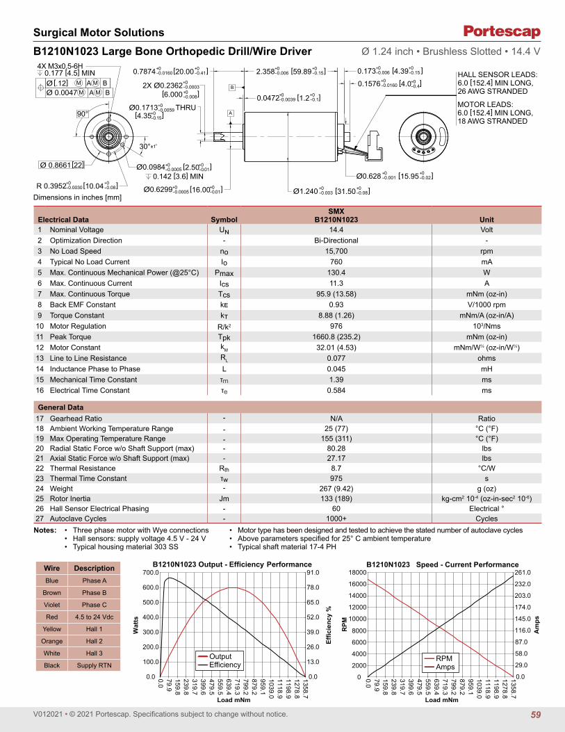
V012021 • © 2021 Portescap. Specifications subject to change without notice.
Surgical Motor Solutions
Dimensions in inches [mm]
Electrical Data SymbolSMX
B1210N1023 Unit1 Nominal Voltage UN 14.4 Volt2 Optimization Direction - Bi-Directional -3 No Load Speed n0 15,700 rpm4 Typical No Load Current I0 760 mA5 Max. Continuous Mechanical Power (@25°C) Pmax 130.4 W6 Max. Continuous Current Ics 11.3 A7 Max. Continuous Torque Tcs 95.9 (13.58) mNm (oz-in)8 Back EMF Constant kE 0.93 V/1000 rpm9 Torque Constant kT 8.88 (1.26) mNm/A (oz-in/A)10 Motor Regulation R/k2 976 103/Nms11 Peak Torque Tpk 1660.8 (235.2) mNm (oz-in)12 Motor Constant kM 32.01 (4.53) mNm/W½ (oz-in/W½)13 Line to Line Resistance RL 0.077 ohms14 Inductance Phase to Phase L 0.045 mH15 Mechanical Time Constant τM 1.39 ms16 Electrical Time Constant τE 0.584 ms
General Data17 Gearhead Ratio - N/A Ratio18 Ambient Working Temperature Range - 25 (77) °C (°F)19 Max Operating Temperature Range - 155 (311) °C (°F)20 Radial Static Force w/o Shaft Support (max) - 80.28 lbs21 Axial Static Force w/o Shaft Support (max) - 27.17 lbs22 Thermal Resistance Rth 8.7 °C/W23 Thermal Time Constant τw 975 s24 Weight - 267 (9.42) g (oz)25 Rotor Inertia Jm 133 (189) kg-cm2 10-4 (oz-in-sec2 10-6)26 Hall Sensor Electrical Phasing - 60 Electrical °27 Autoclave Cycles - 1000+ Cycles
B1210N1023 Large Bone Orthopedic Drill/Wire Driver Ø 1.24 inch • Brushless Slotted • 14.4 V
THRUA
B
90°
0.177 [4.5] MIN
0.142 [3.6] MIN
4X M3x0.5-6H
M A M BM A M BØ 0.0047
Ø [.12]
30°±1°
MOTOR LEADS:6.0 [152.4] MIN LONG,18 AWG STRANDED
Ø0.628 +0-0.001
+0-0.02 [15.95 ]
0.173+0-0.006
+0-0.15 [4.39 ]2.358+0
-0.006 +0-0.15 [59.89 ]0.7874+0
-0.0160 +0-0.41 [20.00 ]
R 0.3952+0-0.0030
+0-0.08 [10.04 ]
0.0472+0-0.0039
+0-0.1 [1.2 ]
0.1576+0-0.0160
+0-0.4 [4.0 ]
Ø1.240 +0-0.003
+0-0.08 [31.50 ]
2X Ø0.2362+0-0.0003 +0-0.008 [6.000 ]
Ø0.1713+0-0.0059
+0-0.15 [4.35 ]
Ø0.6299+0-0.0005
+0-0.01 [16.00 ]
Ø0.0984+0-0.0005
+0-0.01 [2.50 ]
HALL SENSOR LEADS:6.0 [152.4] MIN LONG,26 AWG STRANDED
Ø 0.8661 [22]
0.0
13.0
26.0
39.0
52.0
65.0
78.0
91.0
0.0
100.0
200.0
300.0
400.0
500.0
600.0
700.0
0.079.9159.8239.8319.7399.6479.5559.5639.4719.3799.2879.2959.11039.01118.91198.91278.81358.7
Effic
ienc
y %
Wat
ts
B1210N1023 Output - Efficiency Performance
Load mNm
OutputEfficiency
0.0
29.0
58.0
87.0
116.0
145.0
174.0
203.0
232.0
261.0
0
2000
4000
6000
8000
10000
12000
14000
16000
18000
0.079.9159.8239.8319.7399.6479.5559.5639.4719.3799.2879.2959.11039.01118.91198.91278.81358.7
Am
ps
RPM
B1210N1023 Speed - Current Performance
Load mNm
RPMAmps
Wire DescriptionBlue Phase A
Brown Phase B
Violet Phase C
Red 4.5 to 24 Vdc
Yellow Hall 1
Orange Hall 2
White Hall 3
Black Supply RTN
• Three phase motor with Wye connections• Hall sensors: supply voltage 4.5 V - 24 V• Typical housing material 303 SS
Notes: • Motor type has been designed and tested to achieve the stated number of autoclave cycles• Above parameters specified for 25° C ambient temperature• Typical shaft material 17-4 PH
59

V012021 • © 2021 Portescap. Specifications subject to change without notice.
Surgical Motor Solutions
Dimensions in inches [mm]
B1210N1025 Large Bone Orthopedic Saw/Reamer Ø 1.24 inch • Brushless Slotted • 9.6 V
A
B
90°
0.177 [4.5] MIN
0.142 [3.6] MIN
4X M3x0.5-6H
M A M BM A M BØ 0.0047
Ø [.12]
30°±1°
0.173+0-0.006
+0-0.15[4.39 ]2.358+0
-0.006 +0-0.15 [59.89 ]0.7874+0
-0.0160 +0-0.41 [20.00 ]
R 0.3952+0-0.0030
+0-0.08 [10.04 ]
0.0472+0-0.0039
+0-0.1 [1.2 ]
Ø1.240 +0-0.003
+0-0.08 [31.50 ]
Ø0.2362+0-0.0003 +0-0.008 [6.000 ]
Ø0.6299+0-0.0005
+0-0.01 [16.00 ]
Ø0.0984+0-0.0005
+0-0.01 [2.50 ]Ø 0.8661 [22]
A A MOTOR LEADS:6.0 [152.4] MIN LONG,18 AWG STRANDED
Ø0.628 +0-0.001 +0-0.02 [15.95 ]
HALL SENSOR LEADS:6.0 [152.4] MIN LONG,26 AWG STRANDED
VIEW A-A
(0.02 [0.6])
(Ø0.38 [9.7])
Electrical Data SymbolSMX
B1210N1025 Unit1 Nominal Voltage UN 9.6 Volt2 Optimization Direction - Bi-Directional -3 No Load Speed n0 16,800 rpm4 Typical No Load Current I0 1267 mA5 Max. Continuous Mechanical Power (@25°C) Pmax 123.4 W6 Max. Continuous Current Ics 16.1 A7 Max. Continuous Torque Tcs 83.1 (11.77) mNm (oz-in)8 Back EMF Constant kE 0.566 V/1000 rpm9 Torque Constant kT 5.41 (0.77) mNm/A (oz-in/A)10 Motor Regulation R/k2 1298 103/Nms11 Peak Torque Tpk 1365.4 (193.4) mNm (oz-in)12 Motor Constant kM 27.73 (3.93) mNm/W½ (oz-in/W½)13 Line to Line Resistance RL 0.038 ohms14 Inductance Phase to Phase L 0.018 mH15 Mechanical Time Constant τM 1.85 ms16 Electrical Time Constant τE 0.474 ms
General Data17 Gearhead Ratio - N/A Ratio18 Ambient Working Temperature Range - 25 (77) °C (°F)19 Max Operating Temperature Range - 155 (311) °C (°F)20 Radial Static Force w/o Shaft Support (max) - 80.28 lbs21 Axial Static Force w/o Shaft Support (max) - 27.17 lbs22 Thermal Resistance Rth 8.7 °C/W23 Thermal Time Constant τw 975 s24 Weight - 267 (9.42) g (oz)25 Rotor Inertia Jm 133 (189) kg-cm2 10-4 (oz-in-sec2 10-6)26 Hall Sensor Electrical Phasing - 60 Electrical °27 Autoclave Cycles - 1000+ Cycles
0.0
13.0
26.0
39.0
52.0
65.0
78.0
91.0
0.0
100.0
200.0
300.0
400.0
500.0
600.0
700.0
0.079.9159.8239.8319.7399.6479.5559.5639.4719.3799.2879.2959.11039.01118.91198.91278.81358.7
Effic
ienc
y %
Wat
ts
B1210N1025 Output - Efficiency Performance
Load mNm
OutputEfficiency
0.0
29.0
58.0
87.0
116.0
145.0
174.0
203.0
232.0
261.0
0
2000
4000
6000
8000
10000
12000
14000
16000
18000
0.079.9159.8239.8319.7399.6479.5559.5639.4719.3799.2879.2959.11039.01118.91198.91278.81358.7
Am
ps
RPM
B1210N1025 Speed - Current Performance
Load mNm
RPMAmps
Wire DescriptionBlue Phase A
Brown Phase B
Violet Phase C
Red 4.5 to 24 Vdc
Yellow Hall 1
Orange Hall 2
White Hall 3
Black Supply RTN
• Three phase motor with Wye connections• Hall sensors: supply voltage 4.5 V - 24 V• Typical housing material 303 SS
Notes: • Motor type has been designed and tested to achieve the stated number of autoclave cycles• Above parameters specified for 25° C ambient temperature• Typical shaft material 17-4 PH
60

V012021 • © 2021 Portescap. Specifications subject to change without notice.
Surgical Motor Solutions
Dimensions in inches [mm]
B1210N1027 Large Bone Orthopedic Saw/Reamer Ø 1.24 inch • Brushless Slotted • 14.4 V
[4.39 ]
A
B
90°
0.177 [4.5] MIN
0.142 [3.6] MIN
4X M3x0.5-6H
M A M BM A M BØ 0.0047
Ø [.12]
30°±1°
0.173+0-0.006
+0-0.15 2.358+0
-0.006 +0-0.15 [59.89 ]0.7874+0
-0.0160 +0-0.41 [20.00 ]
R 0.3952+0-0.0030
+0-0.08 [10.04 ]
0.0472+0-0.0039
+0-0.1 [1.2 ]
Ø1.240 +0-0.003
+0-0.08 [31.50 ]
Ø0.2362+0-0.0003 +0-0.008 [6.000 ]
Ø0.6299+0-0.0005
+0-0.01 [16.00 ]
Ø0.0984+0-0.0005
+0-0.01 [2.50 ]Ø 0.8661 [22]
A A MOTOR LEADS:6.0 [152.4] MIN LONG,18 AWG STRANDED
Ø0.628 +0-0.001 +0-0.02 [15.95 ]
HALL SENSOR LEADS:6.0 [152.4] MIN LONG,26 AWG STRANDED
VIEW A-A
(0.02 [0.6])
(Ø0.38 [9.7])
Electrical Data SymbolSMX
B1210N1027 Unit1 Nominal Voltage UN 14.4 Volt2 Optimization Direction - Bi-Directional -3 No Load Speed n0 15,700 rpm4 Typical No Load Current I0 760 mA5 Max. Continuous Mechanical Power (@25°C) Pmax 130.4 W6 Max. Continuous Current Ics 11.19 A7 Max. Continuous Torque Tcs 95.9 (13.58) mNm (oz-in)8 Back EMF Constant kE 0.93 V/1000 rpm9 Torque Constant kT 8.88 (1.26) mNm/A (oz-in/A)10 Motor Regulation R/k2 976 103/Nms11 Peak Torque Tpk 1660.8 (235.2) mNm (oz-in)12 Motor Constant kM 32.01 (4.53) mNm/W½ (oz-in/W½)13 Line to Line Resistance RL 0.077 ohms14 Inductance Phase to Phase L 0.045 mH15 Mechanical Time Constant τM 1.39 ms16 Electrical Time Constant τE 0.584 ms
General Data17 Gearhead Ratio - N/A Ratio18 Ambient Working Temperature Range - 25 (77) °C (°F)19 Max Operating Temperature Range - 155 (311) °C (°F)20 Radial Static Force w/o Shaft Support (max) - 80.28 lbs21 Axial Static Force w/o Shaft Support (max) - 27.17 lbs22 Thermal Resistance Rth 8.7 °C/W23 Thermal Time Constant τw 975 s24 Weight - 267 (9.42) g (oz)25 Rotor Inertia Jm 133 (189) kg-cm2 10-4 (oz-in-sec2 10-6)26 Hall Sensor Electrical Phasing - 60 Electrical °27 Autoclave Cycles - 1000+ Cycles
0.010.020.030.040.050.060.070.080.090.0100.0
0.050.0
100.0150.0200.0250.0300.0350.0400.0450.0500.0
0.010.420.831.241.652.062.472.883.393.7104.1114.5124.9135.3145.7156.1166.5176.9
Effic
ienc
y %
Wat
ts
B1210N1027 Output - Efficiency Performance
Load mNm
OutputEfficiency
0.0
24.0
48.0
72.0
96.0
120.0
144.0
168.0
192.0
0
2000
4000
6000
8000
10000
12000
14000
16000
0.097.3194.6291.9389.2486.5583.8681.1778.5875.8973.11070.41167.71265.01362.31459.61556.91654.2
Am
ps
RPM
B1210N1027 Speed - Current Performance
Load mNm
RPMAmps
Wire DescriptionBlue Phase A
Brown Phase B
Violet Phase C
Red 4.5 to 24 Vdc
Yellow Hall 1
Orange Hall 2
White Hall 3
Black Supply RTN
• Three phase motor with Wye connections• Hall sensors: supply voltage 4.5 V - 24 V• Typical housing material 303 SS
Notes: • Motor type has been designed and tested to achieve the stated number of autoclave cycles• Above parameters specified for 25° C ambient temperature• Typical shaft material 17-4 PH
61

V012021 • © 2021 Portescap. Specifications subject to change without notice.
Controllers
Dimensions in inches [mm]
CNT1530 SMS Controller
Electrical Data CNT1530 Unit1 Min. Operating Voltage 9 Volt2 Max. Operating Voltage 15 Volt3 Standby Current 40 mA DC4 Current Limit 1 >75 for >10 ms A DC5 Max. Continuous Input Power 300 W6 Continuous Output Current 20 A DC
Operating Modes7 Control Method Open Loop Speed8 Switching Waveform Trapezoidal9 Feedback Type Sensored
Inputs10 Hall Sensors H1, H2, H311 Power Input BATT+, BATT-12 Magnetic Triggers Direction (FD/REV), Speed (0-100% PWM)13 Recommended Speed Magnet Grade 2 SmCo 1:514 Recommended Speed Magnet Dimensions 4.76 x 1.52 (0.188" x 0.060") Dia x Thick mm (in)15 Recommended Direction Magnet Grade 2 SmCo 1:516 Recommended Direction Magnet Dimension 3.18 x 3.18 (0.125" x 0.125") Dia x Thick mm (in)
Outputs17 Phase Leads A, B, C
Environmental18 Maximum Storage Temperature 150 (302) °C (°F)19 Autoclave Cycles 1,000
Mechanical20 Housing Material Aluminum21 Dimensions 22.8 x 83.5 x 16.6 (0.90 x 3.29 x 0.66) mm (in)22 Weight 70 (2.5) g (oz)23 Wire Insulation Material PTFE24 Power Lead AWG 1825 Hall Sensor Lead AWG 26
Notes:1. Current limit allows brief excursions beyond 75ADC so long as they are less than 10ms in length. The response time is dependent upon the slew rate of
the current excursion, and the current limit features is intended to prevent against prolonged motor stall conditions from inducing further damage in the system.
2. Recommended SmCo 1:5 Disk Magnets are suggestions for the appropriate magnet to incorporate into the speed trigger and direction switch in the customer’s handpiece. Please contact Portescap with further specification questions.
(0.31 [7.9])(0.75 [18.9])
(3.29 [83.5])
(0.32 [8.2])0.66 [16.6]
SPEED CONTROLHALL SENSORDIE LOCATION
DIRECTION CONTROL HALL SENSOR DIE LOCATION
0.31 [8]SPEED CONTROL
DISTANCE 100% OFF
0.12 [3]SPEED CONTROL
DISTANCE 100% ON
0.90 [22.8]BLACK (BATT–)
RED (BATT+)
BLUEVIOLET
BROWNHALLLEADS
PORTESCAPCNT1530S/N: XXXXXXXBBBBBBB
62

V012021 • © 2021 Portescap. Specifications subject to change without notice.
Notes
63


Brushless dc motors Brush dc motors Disc magnet motors Can stack motors Can stack linear actuatorsGearheads Encoders
Brush dc m
otors

V012021 • © 2021 Portescap. Specifications subject to change without notice.
Feature Details Application Advantages
Ultra-compact design
• Exceptional power density• High torque-to-volume ratio• Lightweight• Excellent heat dissipation
• Greater design flexibility• User comfort and convenience in
handheld applications
Coreless rotor• Ironless, self-supporting coil• Minimal air gaps• No inactive coil heads
• High acceleration, low moment of inertia• Low friction, low starting voltage• No cogging• No iron losses
Precious metal commutation system• Low contact resistance, low friction• Available with REE coils
• Low no-load current, low starting voltage• Reduced electro erosion for longer brush lifetime
Graphite-copper commutation• High current carrying capacity• Available with REE coils
• Perfect for boost in start-stop applications or incremental motions• Reduced electro erosion for longer brush lifetime
Neodymium permanent magnet• High magnetic flux• Exceptional resistance to demagnetization
• High power and efficiency in a small, lightweight package
• Linear speed-torque curve• Consistent power density over the motor lifetime
Alnico permanent magnet • Medium magnetic flux
• Low magnetic flux leakage• Cost-effective• Linear speed-torque curve• Consistent power density over the motor lifetime
Compact, Efficient, Versatile Performance
Featuring a permanent magnet, coreless design, our brush DC motors deliver high efficiency and power density in a small, lightweight package. Built of high-quality materials for optimal performance, these motors offer a low moment of inertia, low friction and a long commutator life. They’re perfect for compact applications requiring high acceleration, torque and efficiency, with no cogging.
Brush DC Motors
66

V012021 • © 2021 Portescap. Specifications subject to change without notice.
Meet your Application’s Working Point Requirements
Max
Co
ntin
uous
To
rque
(mN
m)
For complete product and application details, visit portescap.com/brush-dc
Max Continuous Torque (mNm)
Ideal for Small, Portable and Handheld Devices
Medical devices & clinical diagnostics • Laboratory automation• Infusion systems• Insulin pumps• Diagnostic analyzers• Miniature pumps
Instrumentation• Dosing & dispensing systems• Gas detection• Land surveying• Microscopes• Explosive trace
detection systems
Automation • Humanoid robots
Other • Power hand tools• Rotary tattoo machines• Valve actuation
Diameter (mm)
160
0
140
120
100
80
60
8
20
40
10 12 13 16 17 22 23 25 26 28 30 35
0.95 0.93.5 3.3
6.9 6.14
15.7
22
47
17.9
41
92
160
24
14.97
67

V012021 • © 2021 Portescap. Specifications subject to change without notice.
Brush DC Motors
Motor shaft rotates CW when seen from motor front face when +ve and -ve supply is given to respective terminals.
Dimensions in mm.
08GS61 Ø 8 mm • Precious metal commutation • 0.65 mNm
Electrical Data Symbol 08GS61 •••• .3 Unit107 105 105C1 Nominal Voltage V 2 4.5 6 Volt2 No-Load Speed n0 7,000 10,670 11,000 rpm3 No-Load Current I0 6.0 4.0 3.0 mA4 Terminal Resistance R 12.6 30.0 45.8 Ω5 Output Power P2max. 0.5 0.5 0.5 W6 Stall Torque mNm 0.42 (0.06) 0.59 (0.09) 0.64 (0.1) mNm (oz-in)7 Efficiency hmax. 65 70 72 %8 Max Continuous Speed ne max. 10,000 10,000 10,000 rpm9 Max Continuous Torque Me max. 0.64 (0.1) 0.64 (0.1) 0.66 (0.1) mNm (oz-in)10 Max Continuous Current Ie max. 0.25 0.17 0.13 A11 Back-EMF Constant kE 0.28 0.41 0.53 mV/rpm12 Torque Constant kM 2.63 3.92 5.10 mNm/A13 Motor Regulation R/k2 1,820.0 1,950.0 1,760.0 103/Nms14 Friction Torque TF 0.02 (0.01) 0.02 (0.01) 0.02 (0.01) mNm (oz-in)15 Rotor Inductance L 0.06 0.11 0.20 mH16 Mechanical Time Constant τm 5.5 5.9 5.3 ms17 Rotor Inertia J 0.03 0.03 0.03 g-cm2
General Data18 Thermal Resistance (rotor/body) Rth1/Rth2 20/100 °C/W19 Thermal Time Constant (rotor/stator) tW1/tW2 5/100 S
20 Operating Temperature Range: motor -30°C to 85°C (-22°F to 185°F) °C (°F)rotor 100°C (212°F) °C (°F)
21 Shaft Load Max.: With sleeve bearings(2 mm. from bearing) -radial 0.5 (1.8) N (oz)
-axial 30 (107.9) N (oz)
22 Shaft Play: -radial <0.015 (0.0006) mm (inch)-axial 0.100 (0.0039) mm (inch)
23 Weight g 3.8 (0.14) g (oz)24 Commutation Segments - 5 segments
Execution TableGearbox Single Shaft
R10 16
R08 Upon Request
0.5
0.2
4.3
1.5516.6
1.90.4
25
2.1
1
Ø1.
1±0.
02
Ø6+0 -0
.018Ø
1.5 0 -0
.015
Ø8 0 -0
.08
4.5 0-0.1
M5.
5x0.
5n
(rpm
)
M (mNm)
10000
8000
6000
4000
2000
00 0.7 1.3 2.0 2.6
No Load Speed vs. TorqueMax. Recommended Speed
Max. Continuous Output Power 0.5W
Continuous working rangeTemporary working range
68

V012021 • © 2021 Portescap. Specifications subject to change without notice.
Brush DC Motors
Motor shaft rotates CW when seen from motor front face when +ve and -ve supply is given to respective terminals.
Electrical Data Symbol 10NS61 •••• .5 Unit107C1 Nominal Voltage V 3 Volt2 No-Load Speed n0 10,100 rpm3 No-Load Current I0 11.0 mA4 Terminal Resistance R 10.8 Ω5 Output Power P2max. 0.7 W6 Stall Torque mNm 0.76 (0.11) mNm (oz-in)7 Efficiency hmax. 64 %8 Max Continuous Speed ne max. 10,000 rpm9 Max Continuous Torque Me max. 0.9 (0.13) mNm (oz-in)10 Max Continuous Current Ie max. 0.34 A11 Back-EMF Constant kE 0.29 mV/rpm12 Torque Constant kM 2.72 mNm/A13 Motor Regulation R/k2 1,500.0 103/Nms14 Friction Torque TF 0.02 (0.01) mNm (oz-in)15 Rotor Inductance L 0.01 mH16 Mechanical Time Constant τm 7.3 ms17 Rotor Inertia J 0.05 g-cm2
General Data18 Thermal Resistance (rotor/body) Rth1/Rth2 23/48 °C/W19 Thermal Time Constant (rotor/stator) tW1/tW2 5/150 S
20 Operating Temperature Range: motor -30°C to 85°C (-22°F to 185°F) °C (°F)rotor 100°C (212°F) °C (°F)
21 Shaft Load Max.: With sleeve bearings(2 mm. from bearing) -radial 0.5 (1.8) N (oz)
-axial 30 (107.9) N (oz)
22 Shaft Play: -radial <0.015 (0.0006) mm (inch)-axial 0.100 (0.0039) mm (inch)
23 Weight g 7 (0.25) g (oz)24 Commutation Segments - 9 segments
10NS61 Athlonix™ Ø 10 mm • Precious metal commutation • 0.9 mNm
Execution TableGearbox Single Shaft
R10 3
Dimensions in mm.
2.10.4
17.8
18 max.
1
2 x 0.2thk.
7.4
3.75±0.25
5.6±0.3
Ø4 0 -0
.018
Ø6 0 -0
.018
Ø0.
8 0 -0.0
03
Ø10 0-0.1
M5.
5x0.
5
n (rp
m)
M (mNm)
10000
8000
6000
4000
2000
00 1 2 3 4
No Load Speed vs. TorqueMax. Recommended Speed
Max. Continuous Output Power 0.7W
Continuous working rangeTemporary working range
69

V012021 • © 2021 Portescap. Specifications subject to change without notice.
Brush DC Motors
Motor shaft rotates CW when seen from motor front face when +ve and -ve supply is given to respective terminals.
Electrical Data Symbol 12G88 •••• .1001 Unit215E 210E1 Nominal Voltage V 4.5 9 Volt2 No-Load Speed n0 8,670 9,900 rpm3 No-Load Current I0 16.0 9.0 mA4 Terminal Resistance R 3.2 12.3 Ω5 Output Power P2max. 2.7 2.4 W6 Stall Torque mNm 6.8 (0.97) 6.3 (0.9) mNm (oz-in)7 Efficiency hmax. 80 79 %8 Max Continuous Speed ne max. 10,000 10,000 rpm9 Max Continuous Torque Me max. 3.5 (0.50) 3.1 (0.44) mNm (oz-in)
10 Max Continuous Current Ie max. 0.73 0.37 A11 Back-EMF Constant kE 0.51 0.90 mV/rpm12 Torque Constant kM 4.90 8.60 mNm/A13 Motor Regulation R/k2 130.0 170.0 103/Nms14 Friction Torque TF 0.08 (0.02) 0.08 (0.02) mNm (oz-in)15 Rotor Inductance L 0.08 0.25 mH16 Mechanical Time Constant τm 3.8 4.3 ms17 Rotor Inertia J 0.29 0.26 g-cm2
General Data18 Thermal Resistance (rotor/body) Rth1/Rth2 10/50 °C/W19 Thermal Time Constant (rotor/stator) tW1/tW2 6/300 S
20 Operating Temperature Range: motor -30°C to 85°C (-22°F to 185°F) °C (°F)rotor 100°C (212°F) °C (°F)
21 Shaft Load Max.: With sleeve bearings(5 mm. from bearing) -radial 1.5 (5.4) N (oz)
-axial 150 (539.5) N (oz)
22 Shaft Play: -radial <0.015 (0.0006) mm (inch)-axial 0.300 (0.012) mm (inch)
23 Weight g 15 (0.53) g (oz)24 Commutation Segment - 9 segment
12G88 Athlonix™ Ø 12 mm • Precious metal commutation • 3.5 mNm
Execution TableGearbox Single Shaft MR2
R10 1003 1005
R13 1002 1004
2.5
0.5
28.2
9.4
2
3
(4.5)
7±0.3
Ø1.
5-0.0
06-0
.009
Ø6 0 -0
.018Ø12
0 -0.1
Ø12
0 -0.1
M5.
5x0.
5
Dimensions in mm.
n (rp
m)
M (mNm)
10000
8000
6000
4000
2000
00 4 7 11 15
No Load Speed vs. TorqueMax. Recommended Speed
Max. Continuous Output Power 2.5W
Continuous working rangeTemporary working range
70

V012021 • © 2021 Portescap. Specifications subject to change without notice.
Brush DC Motors
Motor shaft rotates CW when seen from motor front face when +ve and -ve supply is given to respective terminals.
Electrical Data Symbol 12GS88 •••• .1007 Unit210E 208F1 Nominal Voltage V 3 6 Volt2 No-Load Speed n0 7,280 9,000 rpm3 No-Load Current I0 14.0 12.0 mA4 Terminal Resistance R 7.4 20.6 Ω5 Output Power P2max. 1.2 1.1 W6 Stall Torque mNm 1.54 (0.22) 1.78 (0.26) mNm (oz-in)7 Efficiency hmax. 66 64 %8 Max Continuous Speed ne max. 10,000 10,000 rpm9 Max Continuous Torque Me max. 1.51 (0.21) 1.45 (0.21) mNm (oz-in)
10 Max Continuous Current Ie max. 0.41 0.25 A11 Back-EMF Constant kE 0.40 0.64 mV/rpm12 Torque Constant kM 3.80 6.10 mNm/A13 Motor Regulation R/k2 512.0 550.0 103/Nms14 Friction Torque TF 0.07 (0.01) 0.07 (0.01) mNm (oz-in)15 Rotor Inductance L 0.09 0.25 mH16 Mechanical Time Constant τm 9.7 12.0 ms17 Rotor Inertia J 0.19 0.21 g-cm2
General Data18 Thermal Resistance (rotor/body) Rth1/Rth2 14/66 °C/W19 Thermal Time Constant (rotor/stator) tW1/tW2 5/150 S
20 Operating Temperature Range: motor -30°C to 85°C (-22°F to 185°F) °C (°F)rotor 100°C (212°F) °C (°F)
21 Shaft Load Max.: With sleeve bearings(5 mm. from bearing) -radial 1.5 (5.4) N (oz)
-axial 150 (539.5 N (oz)
22 Shaft Play: -radial <0.03 (0.0012) mm (inch)-axial 0.15 (0.0059) mm (inch)
23 Weight g 13.5 (0.48) g (oz)24 Commutation Segment - 9 segment
12GS88 Athlonix™ Ø 12 mm • Precious metal commutation • 1.5 mNm
Dimensions in mm.
Execution TableGearbox Single Shaft MR2
R10 Upon Request Upon Request
R13 Upon Request Upon Request
0.5
2.517.1
9.4
2
20.32.9 7±0.3
Ø12
0 -0.1
Ø12
0 -0.1
Ø6 0 -0
.018
Ø1.
5-0.0
06-0
.009
M5.
5x0.
5n
(rpm
)
M (mNm)
10000
8000
6000
4000
2000
00 1.51 3.02 4.53 6.04
No Load Speed vs. TorqueMax. Recommended Speed
Max. Continuous Output Power 1.2W
Continuous working rangeTemporary working range
71

V012021 • © 2021 Portescap. Specifications subject to change without notice.
Brush DC Motors
Motor shaft rotates CW when seen from motor front face when +ve and -ve supply is given to respective terminals.
Electrical Data Symbol 13N88 •••• .1 Unit213E 110 1071 Nominal Voltage V 6 12 24 Volt2 No-Load Speed n0 12,290 12,400 14,150 rpm3 No-Load Current I0 25.6 13.6 8.8 mA4 Terminal Resistance R 4.2 13.7 47.4 Ω5 Output Power P2max. 2.4 2.6 2.5 W6 Stall Torque mNm 6.5 (0.93) 8 (1.14) 8.2 (1.17) mNm (oz-in)7 Efficiency hmax. 75 77 75 %8 Max Continuous Speed ne max. 9,000 9,000 9,000 rpm9 Max Continuous Torque Me max. 3 (0.47) 3.3 (0.47) 3.2 (0.46) mNm (oz-in)
10 Max Continuous Current Ie max. 0.69 0.38 0.21 A11 Back-EMF Constant kE 0.48 0.95 1.67 mV/rpm12 Torque Constant kM 4.58 9.10 15.90 mNm/A13 Motor Regulation R/k2 200.0 165.0 185.0 103/Nms14 Friction Torque TF 0.12 (0.02) 0.12 (0.02) 0.14 (0.02) mNm (oz-in)15 Rotor Inductance L 0.07 0.25 0.80 mH16 Mechanical Time Constant τm 5.6 5.5 5.3 ms17 Rotor Inertia J 0.28 0.33 0.29 g-cm2
General Data18 Thermal Resistance (rotor/body) Rth1/Rth2 10/40 °C/W19 Thermal Time Constant (rotor/stator) tW1/tW2 6/300 S
20 Operating Temperature Range: motor -30°C to 85°C (-22°F to 185°F) °C (°F)rotor 100°C (212°F) °C (°F)
21 Shaft Load Max.: With sleeve bearings(5 mm. from bearing) -radial 1.5 (5.4) N (oz)
-axial 150 (539.5) N (oz)
22 Shaft Play: -radial <0.03 (0.0012) mm (inch)-axial 0.15 (0.0059) mm (inch)
23 Weight g 18 (0.64) g (oz)24 Commutation Segment - 9 segment
13N88 Ø 13 mm • Precious metal commutation • 3.3 mNm
Execution TableGearbox Single Shaft 13N88D12 MR2
R13 1 3 Upon Request
Dimensions in mm.
2
0.53.1
10
2.6 28.2
3.72.5
6.2±0.3
Ø1.
5-0.0
06-0
.009
Ø6 0 -0
.018
Ø13
0 -0.0
1
M5.
5x0.
5n
(rpm
)
M (mNm)
9000
6750
4500
2250
00 3 7 10 13
No Load Speed vs. TorqueMax. Recommended Speed
Max. Continuous Output Power 2.5W
Continuous working rangeTemporary working range
72

V012021 • © 2021 Portescap. Specifications subject to change without notice.
Brush DC Motors
Motor shaft rotates CW when seen from motor front face when +ve and -ve supply is given to respective terminals.
Electrical Data Symbol 16C18 •••• .67 Unit115 210 207 205 2041 Nominal Voltage V 1.5 4 6 12 15 Volt2 No-Load Speed n0 15,300 14,700 15,700 16,200 16,000 rpm3 No-Load Current I0 74.8 23.0 18.4 10.4 6.9 mA4 Terminal Resistance R 1.2 7.5 18.0 65.0 162.0 Ω5 Output Power P2max. 0.7 0.8 0.7 0.8 0.7 W6 Stall Torque mNm 1.1 1.3 1.1 1.2 0.8 mNm (oz-in)7 Efficiency hmax. 57 63 59 58 53 %8 Max Continuous Speed ne max. 10,000 10,000 10,000 10,000 10,000 rpm9 Max Continuous Torque Me max. 0.98 (0.15) 1.12 (0.15) 1 (0.15) 1 (0.14) 0.79 (0.11) mNm (oz-in)10 Max Continuous Current Ie max. 1.19 0.48 0.31 0.16 0.10 A11 Back-EMF Constant kE 0.09 0.26 0.36 0.70 0.87 mV/rpm12 Torque Constant kM 0.88 2.48 3.44 6.68 8.30 mNm/A13 Motor Regulation R/k2 1555.0 1220.0 1520.0 1460.00 2350.00 103/Nms14 Friction Torque TF 0.07 (0.02) 0.06 (0.01) 0.06 (0.01) 0.07 (0.02) 0.06 (0.01) mNm (oz-in)15 Rotor Inductance L 20.00 150.00 250.00 1000.00 1000.00 mH16 Mechanical Time Constant τm 48.0 50.0 41.0 60.0 63.0 ms17 Rotor Inertia J 0.31 0.41 0.27 0.41 0.27 g-cm2
General Data18 Thermal Resistance (rotor/body) Rth1/Rth2 15/40 °C/W19 Thermal Time Constant (rotor/stator) tW1/tW2 4/230 S
20 Operating Temperature Range: motor -30°C to 85°C (-22°F to 185°F) °C (°F)rotor 100°C (212°F) °C (°F)
21 Shaft Load Max.: With sleeve bearings(5 mm. from bearing) -radial 1.5 (5.4) N (oz)
-axial 100 (359.6) N (oz)
22 Shaft Play: -radial <0.03 (0.0012) mm (inch)-axial 0.15 (0.0059) mm (inch)
23 Weight g 14 (0.49) g (oz)24 Commutation Segment - 5 segment
16C18 Ø 16 mm • Precious metal commutation • 1.12 mNm
Execution TableGearbox Single Shaft F16
B16 67 76
BA16 67 76
R16 30 76
Dimensions in mm.
+-
3.7
2xM1.6x1.4 Max.
5.93.7
4
7.52 15.7
(6.5)1 (5.7)16.72 15.7
Ø15
Ø16
0 -0.1
Ø1.
5-0.0
06-0
.009
150±3
Ø6.
8 0 -0.0
18
Ø15
Ø10
Ø16
0 -0.1
Ø6.
8 0 -0.0
18
Ø1 0 -0
.006
+-
3.7
2xM1.6x1.4 Max.
5.93.7
4
7.52 15.7
(6.5)1 (5.7)16.72 15.7
Ø15
Ø16
0 -0.1
Ø1.
5-0.0
06-0
.009
150±3
Ø6.
8 0 -0.0
18
Ø15
Ø10
Ø16
0 -0.1
Ø6.
8 0 -0.0
18
Ø1 0 -0
.006
+-
3.7
2xM1.6x1.4 Max.
5.93.7
4
7.52 15.7
(6.5)1 (5.7)16.72 15.7
Ø15
Ø16
0 -0.1
Ø1.
5-0.0
06-0
.009
150±3
Ø6.
8 0 -0.0
18
Ø15
Ø10
Ø16
0 -0.1
Ø6.
8 0 -0.0
18
Ø1 0 -0
.006
n (rp
m)
M (mNm)
10000
8000
6000
4000
2000
00 1 2 3 5
No Load Speed vs. TorqueMax. Recommended Speed
Max. Continuous Output Power 0.85W
Continuous working rangeTemporary working range
73

V012021 • © 2021 Portescap. Specifications subject to change without notice.
Brush DC Motors
Motor shaft rotates CW when seen from motor front face when +ve and -ve supply is given to respective terminals.
Electrical Data Symbol 16DCP 26P1/P2 •••• .* Unit211P 208P 209E 205P1 Nominal Voltage V 3 6 9 12 Volt2 No-Load Speed n0 7727 8044 7904 7658 rpm3 No-Load Current I0 19.4 10.1 6.6 4.8 mA4 Terminal Resistance R 3.3 12.1 30.7 51.4 Ω5 Output Power P2max. 1.4 1.4 1.3 1.4 W6 Stall Torque mNm 3.25 (0.47) 3.4 (0.49) 3.04 (0.44) 3.35 (0.48) mNm (oz-in)7 Efficiency hmax. 73 74 72 73 %8 Max Continuous Speed ne max. 10000 10000 10000 10000 rpm9 Max Continuous Torque Me max. 2.58 (0.37) 2.59 (0.37) 2.46 (0.35) 2.63 (0.38) mNm (oz-in)
10 Max Continuous Current Ie max. 0.73 0.38 0.24 0.18 A11 Back-EMF Constant kE 0.38 0.73 1.11 1.53 mV/rpm12 Torque Constant kM 3.63 6.98 10.63 14.65 mNm/A13 Motor Regulation R/k2 248.57 247.65 272.02 239.14 103/Nms14 Friction Torque TF 0.063 (0.009) 0.063 (0.009) 0.063 (0.009) 0.063 (0.009) mNm (oz-in)15 Mechanical Time Constant τm 25.64 25.06 28.22 24.90 ms16 Rotor Inertia J 1.03 1.01 1.04 1.04 g-cm2
General Data17 Thermal Resistance (rotor/body) Rth1/Rth2 7/35 °C/W18 Thermal Time Constant (rotor/stator) tW1/tW2 6/380 S
19 Operating Temperature Range: motor -30°C to 85°C (-22°F to 185°F) °C (°F)rotor 100°C (212°F) °C (°F)
20 Shaft Load Max.: With sleeve bearings(5 mm. from bearing) -radial 1.5 (5.39) N (oz)
-axial 100 (359.6) N (oz)
21 Shaft Play: -radial 0.03 (0.0012) mm (inch)-axial 0.15 (0.0059) mm (inch)
22 Weight g 23 (0.82) g (oz)23 Commutation Segment - 9 segment
16DCP Athlonix™ Ø 16 mm • Precious metal commutation • 2.63 mNm
Execution TableGearbox Single Shaft MR2 M Sense B
R16 1 2 10
B16 3 4 11
BA16 3 4 11
Dimensions in mm.
(2)
(6x
60°)
(M1.6 x 2.5max.)
(1)
(12.
2)
(2)
(2.1)
(1)2±0.4
26±0.5 7.5±0.5
6.35±0.5 6.35±0.5
7.5±0.526±0.58.6±0.5
(Ø9±0.5)
Ø16
+0 -0.1
Ø16
+0 -0.1
Ø4.
5 0 -0.1
Ø4.
5 0 -0.1
Ø6 0 -0
.022
Ø6 0 -0
.022
Ø1.
5-0.0
06-0
.009
Ø1.
5-0.0
06-0
.009
Ø1.
5-0.0
06-0
.009
*Also available with ball bearing
Note:P1: standard commutationP2: special commutation for double shaft version
n (rp
m)
M (mNm)
10000
8000
6000
4000
2000
00 2.59 5.18 7.77 10.36
No Load Speed vs. TorqueMax. Recommended Speed
Max. Continuous Output Power 1.4W
Continuous working rangeTemporary working range
16DCP 26P1 •••• .116DCP 26P2 •••• .2
74

V012021 • © 2021 Portescap. Specifications subject to change without notice.
Brush DC Motors
Motor shaft rotates CW when seen from motor front face when +ve and -ve supply is given to respective terminals.
Electrical Data Symbol 16DCP 26P1/P2 •••• .* Unit107P 106P 205E1 Nominal Voltage V 18 21 24 Volt2 No-Load Speed n0 9684 9259 8022 rpm3 No-Load Current I0 4.0 3.3 2.5 mA4 Terminal Resistance R 76.0 129.4 208.1 Ω5 Output Power P2max. 1.4 1.3 1.3 W6 Stall Torque mNm 4.06 (0.58) 3.37 (0.48) 3.15 (0.45) mNm (oz-in)7 Efficiency hmax. 76 73 73 %8 Max Continuous Speed ne max. 10000 10000 10000 rpm9 Max Continuous Torque Me max. 2.57 (0.37) 2.39 (0.34) 2.49 (0.36) mNm (oz-in)
10 Max Continuous Current Ie max. 0.15 0.12 0.09 A11 Back-EMF Constant kE 1.83 2.22 2.93 mV/rpm12 Torque Constant kM 17.45 21.21 27.94 mNm/A13 Motor Regulation R/k2 249.78 287.47 266.44 103/Nms14 Friction Torque TF 0.063 (0.009) 0.063 (0.009) 0.063 (0.009) mNm (oz-in)15 Mechanical Time Constant τm 24.89 24.87 28.14 ms16 Rotor Inertia J 1.00 0.87 1.06 g-cm2
General Data17 Thermal Resistance (rotor/body) Rth1/Rth2 7/35 °C/W18 Thermal Time Constant (rotor/stator) tW1/tW2 6/380 S
19 Operating Temperature Range: motor -30°C to 85°C (-22°F to 185°F) °C (°F)rotor 100°C (212°F) °C (°F)
20 Shaft Load Max.: With sleeve bearings(5 mm. from bearing) -radial 1.5 (5.39) N (oz)
-axial 100 (359.6) N (oz)
21 Shaft Play: -radial 0.03 (0.0012) mm (inch)-axial 0.15 (0.0059) mm (inch)
22 Weight g 23 (0.82) g (oz)23 Commutation Segment - 9 segment
16DCP Athlonix™ Ø 16 mm • Precious metal commutation • 2.63 mNm
Dimensions in mm.
*Also available with ball bearing
Execution TableGearbox Single Shaft MR2 M Sense B
R16 1 2 10
B16 3 4 11
BA16 3 4 11
Note:P1: standard commutationP2: special commutation for double shaft version
(2)
(6x
60°)
(M1.6 x 2.5max.)
(1)
(12.
2)
(2)
(2.1)
(1)2±0.4
26±0.5 7.5±0.5
6.35±0.5 6.35±0.5
7.5±0.526±0.58.6±0.5
(Ø9±0.5)
Ø16
+0 -0.1
Ø16
+0 -0.1
Ø4.
5 0 -0.1
Ø4.
5 0 -0.1
Ø6 0 -0
.022
Ø6 0 -0
.022
Ø1.
5-0.0
06-0
.009
Ø1.
5-0.0
06-0
.009
Ø1.
5-0.0
06-0
.009
n (rp
m)
M (mNm)
10000
8000
6000
4000
2000
00 2.59 5.18 7.77 10.36
No Load Speed vs. TorqueMax. Recommended Speed
Max. Continuous Output Power 1.4W
Continuous working rangeTemporary working range
16DCP 26P1 •••• .116DCP 26P2 •••• .2
75

V012021 • © 2021 Portescap. Specifications subject to change without notice.
Brush DC Motors
Motor shaft rotates CW when seen from motor front face when +ve and -ve supply is given to respective terminals.
Electrical Data Symbol 16DCP 26G1/G2 •••• .* Unit211P 208P 209E 205P1 Nominal Voltage V 3 6 9 12 Volt2 No-Load Speed n0 7210 7543 7358 7179 rpm3 No-Load Current I0 77.2 40.1 26.3 19.1 mA4 Terminal Resistance R 3.4 12.2 30.8 51.5 Ω5 Output Power P2max. 1.2 1.2 1.2 1.3 W6 Stall Torque mNm 2.94 (0.42) 3.16 (0.45) 2.82 (0.4) 3.13 (0.45) mNm (oz-in)7 Efficiency hmax. 50 51 49 51 %8 Max Continuous Speed ne max. 10000 10000 10000 10000 rpm9 Max Continuous Torque Me max. 2.33 (0.33) 2.36 (0.34) 2.25 (0.32) 2.42 (0.35) mNm (oz-in)
10 Max Continuous Current Ie max. 0.72 0.38 0.24 0.18 A11 Back-EMF Constant kE 0.38 0.73 1.11 1.53 mV/rpm12 Torque Constant kM 3.63 6.98 10.63 14.65 mNm/A13 Motor Regulation R/k2 256.16 249.71 272.91 239.61 103/Nms14 Friction Torque TF 0.25 (0.035) 0.25 (0.035) 0.25 (0.035) 0.25 (0.035) mNm (oz-in)15 Mechanical Time Constant τm 26.42 25.27 28.31 24.95 ms16 Rotor Inertia J 1.03 1.01 1.04 1.04 g-cm2
General Data17 Thermal Resistance (rotor/body) Rth1/Rth2 7/35 °C/W18 Thermal Time Constant (rotor/stator) tW1/tW2 6/380 S
19 Operating Temperature Range: motor -30°C to 85°C (-22°F to 185°F) °C (°F)rotor 100°C (212°F) °C (°F)
20 Shaft Load Max.: With sleeve bearings(5 mm. from bearing) -radial 1.5 (5.39) N (oz)
-axial 100 (359.6) N (oz)
21 Shaft Play: -radial 0.03 (0.0012) mm (inch)-axial 0.15 (0.0059) mm (inch)
22 Weight g 23 (0.82) g (oz)23 Commutation Segment - 9 segment
16DCP Athlonix™ Ø 16 mm • Graphite-Copper commutation • 2.42 mNm
Dimensions in mm.
*Also available with ball bearing
Execution TableGearbox Single Shaft MR2 M Sense B
R16 1 2 10
B16 3 4 11
BA16 3 4 11
Note:G1: standard commutationG2: special commutation for double shaft version
(2) (1)
(12.
2)
(2)
(2.1)
(1)
(6x6
0°)
(6x M1.6 x 2.5 deep)
Ø1.
5-0.0
06-0
.009
Ø1.
5-0.0
06-0
.009
(Ø9±0.05)
Ø16
0 -0.1
Ø16
0 -0.1
Ø6 0 -0
.022
Ø4.
5 0 -0.1
Ø1.
5-0.0
06-0
.009
Ø6 0 -0
.022
Ø4.
5 0 -0.1
2±0.4
8.6±0.5 26±0.5 7.5±0.5 8.6±0.5 26±0.5 7.5±0.5
6.35±0.5 6.35±0.5
n (rp
m)
M (mNm)
10000
8000
6000
4000
2000
00 2.37 4.74 7.11 9.48
No Load Speed vs. TorqueMax. Recommended Speed
Max. Continuous Output Power 1.2W
Continuous working rangeTemporary working range
16DCP 26G2 •••• .2 16DCP 26G1 •••• .1
76

V012021 • © 2021 Portescap. Specifications subject to change without notice.
Brush DC Motors
Motor shaft rotates CW when seen from motor front face when +ve and -ve supply is given to respective terminals.
Electrical Data Symbol 16DCP 26G1/G2 •••• .* Unit107P 106P 205E1 Nominal Voltage V 18 21 24 Volt2 No-Load Speed n0 9184 8684 7489 rpm3 No-Load Current I0 16.0 13.2 10.0 mA4 Terminal Resistance R 76.1 129.5 208.2 Ω5 Output Power P2max. 1.2 1.1 1.2 W6 Stall Torque mNm 3.84 (0.55) 3.16 (0.45) 2.94 (0.42) mNm (oz-in)7 Efficiency hmax. 55 51 50 %8 Max Continuous Speed ne max. 10000 10000 10000 rpm9 Max Continuous Torque Me max. 2.36 (0.34) 2.18 (0.31) 2.28 (0.33) mNm (oz-in)
10 Max Continuous Current Ie max. 0.15 0.12 0.09 A11 Back-EMF Constant kE 1.83 2.22 2.93 mV/rpm12 Torque Constant kM 17.45 21.21 27.94 mNm/A13 Motor Regulation R/k2 250.11 287.70 266.57 103/Nms14 Friction Torque TF 0.25 (0.035) 0.25 (0.035) 0.25 (0.035) mNm (oz-in)15 Mechanical Time Constant τm 24.92 24.89 28.15 ms16 Rotor Inertia J 1.00 0.87 1.06 g-cm2
General Data17 Thermal Resistance (rotor/body) Rth1/Rth2 7/35 °C/W18 Thermal Time Constant (rotor/stator) tW1/tW2 6/380 S
19 Operating Temperature Range: motor -30°C to 85°C (-22°F to 185°F) °C (°F)rotor 100°C (212°F) °C (°F)
20 Shaft Load Max.: With sleeve bearings(5 mm. from bearing) -radial 1.5 (5.39) N (oz)
-axial 100 (359.6) N (oz)
21 Shaft Play: -radial 0.03 (0.0012) mm (inch)-axial 0.15 (0.0059) mm (inch)
22 Weight g 23 (0.82) g (oz)23 Commutation Segment - 9 segment
16DCP Athlonix™ Ø 16 mm • Graphite-Copper commutation • 2.42 mNm
Dimensions in mm.
*Also available with ball bearing
Execution TableGearbox Single Shaft MR2 M Sense B
R16 1 2 10
B16 3 4 11
BA16 3 4 11
Note:G1: standard commutationG2: special commutation for double shaft version
(2)
(6x
60°)
(M1.6 x 2.5max.)
(1)
(12.
2)
(2)
(2.1)
(1)2±0.4
26±0.5 7.5±0.5
6.35±0.5 6.35±0.5
7.5±0.526±0.58.6±0.5
(Ø9±0.5)
Ø16
+0 -0.1
Ø16
+0 -0.1
Ø4.
5 0 -0.1
Ø4.
5 0 -0.1
Ø6 0 -0
.022
Ø6 0 -0
.022
Ø1.
5-0.0
06-0
.009
Ø1.
5-0.0
06-0
.009
Ø1.
5-0.0
06-0
.009
n (rp
m)
M (mNm)
10000
8000
6000
4000
2000
00 2.37 4.74 7.11 9.48
No Load Speed vs. TorqueMax. Recommended Speed
Max. Continuous Output Power 1.2W
Continuous working rangeTemporary working range
16DCP 26G2 •••• .2 16DCP 26G1 •••• .1
77

V012021 • © 2021 Portescap. Specifications subject to change without notice.
Brush DC Motors
Motor shaft rotates CW when seen from motor front face when +ve and -ve supply is given to respective terminals.
Electrical Data Symbol 16DCT 26P1/P2 •••• .* Unit 219P 219E 213E 211E 207P1 Nominal Voltage V 3 6 9 12 15 Volt2 No-Load Speed n0 8081 8600 7970 7968 8599 rpm3 No-Load Current I0 28.6 15.2 9.4 7.1 6.1 mA4 Terminal Resistance R 0.7 2.3 7.5 13.8 18.6 Ω5 Output Power P2max. 4.2 4.2 4.2 4.1 4.1 W6 Stall Torque mNm 16.12 (2.29) 17.13 (2.43) 12.77 (1.81) 12.33 (1.75) 13.21 (1.88) mNm (oz-in)7 Efficiency hmax. 85 85 83 83 83 %8 Max Continuous Speed ne max. 10000 10000 10000 10000 10000 rpm9 Max Continuous Torque Me max. 5.28 (0.75) 5.27 (0.75) 5.36 (0.76) 5.27 (0.75) 5.25 (0.75) mNm (oz-in)
10 Max Continuous Current Ie max. 1.53 0.81 0.51 0.38 0.32 A11 Back-EMF Constant kE 0.37 0.69 1.12 1.49 1.73 mV/rpm12 Torque Constant kM 3.52 6.62 10.70 14.27 16.53 mNm/A13 Motor Regulation R/k2 52.47 52.55 65.35 67.66 68.15 103/Nms14 Friction Torque TF 0.08 (0.011) 0.08 (0.011) 0.08 (0.011) 0.08 (0.011) 0.08 (0.011) mNm (oz-in)15 Mechanical Time Constant τm 7.79 7.80 7.56 7.51 6.63 ms16 Rotor Inertia J 1.48 1.48 1.16 1.11 0.97 g-cm2
General Data17 Thermal Resistance (rotor/body) Rth1/Rth2 7/35 °C/W18 Thermal Time Constant (rotor/stator) tW1/tW2 6/380 S
19 Operating Temperature Range: motor -30°C to 85°C (-22°F to 185°F) °C (°F)rotor 100°C (212°F) °C (°F)
20 Shaft Load Max.: With sleeve bearings(5 mm. from bearing) -radial 1.5 (5.39) N (oz)
-axial 100 (359.6) N (oz)
21 Shaft Play: -radial 0.03 (0.0012) mm (inch)-axial 0.15 (0.0059) mm (inch)
22 Weight g 23 (0.82) g (oz)23 Commutation Segment - 9 segment
16DCT Athlonix™ Ø 16 mm • Precious metal commutation • 5.45 mNm
Dimensions in mm.
*Also available with ball bearing
Execution TableGearbox Single Shaft MR2 M Sense B
R16 1 2 10
B16 3 4 11
BA16 3 4 11
Note:P1: standard commutationP2: special commutation for double shaft version*Special Ball bearing system available for high radial load requirements
(1.5)
(1) (1.5)
(2.1)
(1)
8.29
(6x60°)
(Ø9±0.05)
(6x M1.6 x 2.5 deep)
Ø1.
5-0.0
06-0
.009
Ø16
0 -0.1
Ø1.
5-0.0
06-0
.009
Ø6 0 -0
.022
Ø4.
5 0 -0.1 Ø16
0 -0.1
Ø1.
5-0.0
06-0
.009
Ø6 0 -0
.022
Ø4.
5 0 -0.1
2.5±0.4
5.05±0.525.5±0.5 7.5±0.5
5.05±0.525.5±0.5 7.5±0.5
6.35±0.5 6.35±0.5
n (rp
m)
M (mNm)
10000
8000
6000
4000
2000
00 5.37 10.74 16.11 21.48
No Load Speed vs. TorqueMax. Recommended Speed
Max. Continuous Output Power 4.21W
Continuous working rangeTemporary working range
16DCT 26P2 •••• .2 16DCT 26P1 •••• .1
78

V012021 • © 2021 Portescap. Specifications subject to change without notice.
Brush DC Motors
Motor shaft rotates CW when seen from motor front face when +ve and -ve supply is given to respective terminals.
Electrical Data Symbol 16DCT 26P1/P2 •••• .* Unit209E 205P 207E 205E1 Nominal Voltage V 18 24 36 48 Volt2 No-Load Speed n0 8261 7993 10079 8380 rpm3 No-Load Current I0 4.9 3.5 3.0 1.9 mA4 Terminal Resistance R 30.7 51.4 80.9 208.1 Ω5 Output Power P2max. 4.0 4.3 4.1 4.1 W6 Stall Torque mNm 11.99 (1.7) 13.2 (1.87) 14.97 (2.13) 12.41 (1.76) mNm (oz-in)7 Efficiency hmax. 83 83 84 83 %8 Max Continuous Speed ne max. 10000 10000 10000 10000 rpm9 Max Continuous Torque Me max. 5.1 (0.73) 5.45 (0.78) 5.16 (0.74) 5.15 (0.73) mNm (oz-in)
10 Max Continuous Current Ie max. 0.25 0.19 0.16 0.10 A11 Back-EMF Constant kE 2.16 2.98 3.55 5.68 mV/rpm12 Torque Constant kM 20.63 28.46 33.88 54.26 mNm/A13 Motor Regulation R/k2 72.15 63.00 70.46 70.67 103/Nms14 Friction Torque TF 0.08 (0.011) 0.08 (0.011) 0.08 (0.011) 0.08 (0.011) mNm (oz-in)15 Mechanical Time Constant τm 7.48 6.60 7.47 7.46 ms16 Rotor Inertia J 1.04 1.04 1.06 1.06 g-cm2
General Data17 Thermal Resistance (rotor/body) Rth1/Rth2 7/35 °C/W18 Thermal Time Constant (rotor/stator) tW1/tW2 6/380 S
19 Operating Temperature Range: motor -30°C to 85°C (-22°F to 185°F) °C (°F)rotor 100°C (212°F) °C (°F)
20 Shaft Load Max.: With sleeve bearings(5 mm. from bearing) -radial 1.5 (5.39) N (oz)
-axial 100 (359.6) N (oz)
21 Shaft Play: -radial 0.03 (0.0012) mm (inch)-axial 0.15 (0.0059) mm (inch)
22 Weight g 23 (0.82) g (oz)23 Commutation Segment - 9 segment
16DCT Athlonix™ Ø 16 mm • Precious metal commutation • 5.45 mNm
Dimensions in mm.
*Also available with ball bearing
Execution TableGearbox Single Shaft MR2 M Sense B
R16 1 2 10
B16 3 4 11
BA16 3 4 11
Note:P1: standard commutationP2: special commutation for double shaft version*Special Ball bearing system available for high radial load requirements
(1.5)
(1) (1.5)
(2.1)
(1)
8.29
(6x60°)
(Ø9±0.05)
(6x M1.6 x 2.5 deep)
Ø1.
5-0.0
06-0
.009
Ø16
0 -0.1
Ø1.
5-0.0
06-0
.009
Ø6 0 -0
.022
Ø4.
5 0 -0.1 Ø16
0 -0.1
Ø1.
5-0.0
06-0
.009
Ø6 0 -0
.022
Ø4.
5 0 -0.1
2.5±0.4
5.05±0.525.5±0.5 7.5±0.5
5.05±0.525.5±0.5 7.5±0.5
6.35±0.5 6.35±0.5
n (rp
m)
M (mNm)
10000
8000
6000
4000
2000
00 5.37 10.74 16.11 21.48
No Load Speed vs. TorqueMax. Recommended Speed
Max. Continuous Output Power 4.21W
Continuous working rangeTemporary working range
16DCT 26P2 •••• .2 16DCT 26P1 •••• .1
79

V012021 • © 2021 Portescap. Specifications subject to change without notice.
Brush DC Motors
Motor shaft rotates CW when seen from motor front face when +ve and -ve supply is given to respective terminals.
(2) (1)
(12.
2)
(2)
(2.1)
(1)
(6x6
0°)
(6x M1.6 x 2.5 deep)
Ø1.
5-0.0
06-0
.009
Ø1.
5-0.0
06-0
.009
(Ø9±0.05)
Ø16
0 -0.1
Ø16
0 -0.1
Ø6 0 -0
.022
Ø4.
5 0 -0.1
Ø1.
5-0.0
06-0
.009
Ø6 0 -0
.022
Ø4.
5 0 -0.1
2±0.4
8.6±0.5 26±0.5 7.5±0.5 8.6±0.5 26±0.5 7.5±0.5
6.35±0.5 6.35±0.5
Electrical Data Symbol 16DCT 26G1/G2 •••• .* Unit220P 213P 215E 213E 211E1 Nominal Voltage V 3 6 9 12 15 Volt2 No-Load Speed n0 9311 9798 9648 10427 9749 rpm3 No-Load Current I0 150.3 78.7 51.7 41.9 31.4 mA4 Terminal Resistance R 0.6 2.0 4.8 7.6 13.9 Ω5 Output Power P2max. 3.3 3.5 4.0 3.9 3.9 W6 Stall Torque mNm 13.95 (1.98) 16.24 (2.3) 15.7 (2.23) 16.48 (2.34) 14.98 (2.13) mNm (oz-in)7 Efficiency hmax. 68 70 69 70 69 %8 Max Continuous Speed ne max. 10000 10000 10000 10000 10000 rpm9 Max Continuous Torque Me max. 4.21 (0.6) 4.45 (0.64) 5.06 (0.72) 4.98 (0.71) 4.9 (0.7) mNm (oz-in)
10 Max Continuous Current Ie max. 1.56 0.86 0.64 0.51 0.38 A11 Back-EMF Constant kE 0.31 0.60 0.91 1.12 1.49 mV/rpm12 Torque Constant kM 2.98 5.69 8.66 10.70 14.27 mNm/A13 Motor Regulation R/k2 69.88 63.14 64.34 66.22 68.15 103/Nms14 Friction Torque TF 0.3 (0.042) 0.3 (0.042) 0.3 (0.042) 0.3 (0.042) 0.3 (0.042) mNm (oz-in)15 Mechanical Time Constant τm 9.72 7.31 7.78 7.66 7.57 ms16 Rotor Inertia J 1.39 1.16 1.21 1.16 1.11 g-cm2
General Data17 Thermal Resistance (rotor/body) Rth1/Rth2 7/35 °C/W18 Thermal Time Constant (rotor/stator) tW1/tW2 6/380 S
19 Operating Temperature Range: motor -30°C to 85°C (-22°F to 185°F) °C (°F)rotor 100°C (212°F) °C (°F)
20 Shaft Load Max.: With sleeve bearings(5 mm. from bearing) -radial 1.5 (5.39) N (oz)
-axial 100 (359.6) N (oz)
21 Shaft Play: -radial 0.03 (0.0012) mm (inch)-axial 0.15 (0.0059) mm (inch)
22 Weight g 23 (0.82) g (oz)23 Commutation Segment - 9 segment
16DCT Athlonix™ Ø 16 mm • Graphite-Copper commutation • 5.06 mNm
Dimensions in mm.
*Also available with ball bearing
Execution TableGearbox Single Shaft MR2 M Sense B
R16 1 2 10
B16 3 4 11
BA16 3 4 11
Note:G1: standard commutationG2: special commutation for double shaft version*Special Ball bearing system available for high radial load requirements
n (rp
m)
M (mNm)
10000
8000
6000
4000
2000
00 5.06 10.12 15.18 20.24
No Load Speed vs. TorqueMax. Recommended Speed
Max. Continuous Output Power 3.97W
Continuous working rangeTemporary working range
16DCT 26G2 •••• .2 16DCT 26G1 •••• .1
80

V012021 • © 2021 Portescap. Specifications subject to change without notice.
Brush DC Motors
Motor shaft rotates CW when seen from motor front face when +ve and -ve supply is given to respective terminals.
(2) (1)
(12.
2)
(2)
(2.1)
(1)
(6x6
0°)
(6x M1.6 x 2.5 deep)
Ø1.
5-0.0
06-0
.009
Ø1.
5-0.0
06-0
.009
(Ø9±0.05)
Ø16
0 -0.1
Ø16
0 -0.1
Ø6 0 -0
.022
Ø4.
5 0 -0.1
Ø1.
5-0.0
06-0
.009
Ø6 0 -0
.022
Ø4.
5 0 -0.1
2±0.4
8.6±0.5 26±0.5 7.5±0.5 8.6±0.5 26±0.5 7.5±0.5
6.35±0.5 6.35±0.5
Electrical Data Symbol 16DCT 26G1/G2 •••• .* Unit207P 209F 207E 205E1 Nominal Voltage V 18 24 36 48 Volt2 No-Load Speed n0 10105 10053 9845 8145 rpm3 No-Load Current I0 27.1 20.2 13.2 8.3 mA4 Terminal Resistance R 18.7 33.1 81.0 208.2 Ω5 Output Power P2max. 3.8 3.9 3.8 3.8 W6 Stall Torque mNm 15.44 (2.19) 15.62 (2.22) 14.61 (2.07) 12.06 (1.71) mNm (oz-in)7 Efficiency hmax. 69 69 68 66 %8 Max Continuous Speed ne max. 10000 10000 10000 10000 rpm9 Max Continuous Torque Me max. 4.89 (0.7) 4.93 (0.7) 4.81 (0.69) 4.8 (0.68) mNm (oz-in)
10 Max Continuous Current Ie max. 0.32 0.24 0.16 0.10 A11 Back-EMF Constant kE 1.73 2.32 3.55 5.68 mV/rpm12 Torque Constant kM 16.53 22.16 33.88 54.26 mNm/A13 Motor Regulation R/k2 69.00 67.36 70.55 70.70 103/Nms14 Friction Torque TF 0.3 (0.042) 0.3 (0.042) 0.3 (0.042) 0.3 (0.042) mNm (oz-in)15 Mechanical Time Constant τm 6.66 7.51 7.48 7.47 ms16 Rotor Inertia J 0.97 1.11 1.06 1.06 g-cm2
General Data17 Thermal Resistance (rotor/body) Rth1/Rth2 7/35 °C/W18 Thermal Time Constant (rotor/stator) tW1/tW2 6/380 S
19 Operating Temperature Range: motor -30°C to 85°C (-22°F to 185°F) °C (°F)rotor 100°C (212°F) °C (°F)
20 Shaft Load Max.: With sleeve bearings(5 mm. from bearing) -radial 1.5 (5.39) N (oz)
-axial 100 (359.6) N (oz)
21 Shaft Play: -radial 0.03 (0.0012) mm (inch)-axial 0.15 (0.0059) mm (inch)
22 Weight g 23 (0.82) g (oz)23 Commutation Segment - 9 segment
16DCT Athlonix™ Ø 16 mm • Graphite-Copper commutation • 5.06 mNm
Dimensions in mm.
*Also available with ball bearing
Execution TableGearbox Single Shaft MR2 M Sense B
R16 1 2 10
B16 3 4 11
BA16 3 4 11
Note:G1: standard commutationG2: special commutation for double shaft version*Special Ball bearing system available for high radial load requirements
n (rp
m)
M (mNm)
10000
8000
6000
4000
2000
00 5.06 10.12 15.18 20.24
No Load Speed vs. TorqueMax. Recommended Speed
Max. Continuous Output Power 3.97W
Continuous working rangeTemporary working range
16DCT 26G2 •••• .2 16DCT 26G1 •••• .1
81

V012021 • © 2021 Portescap. Specifications subject to change without notice.
Brush DC Motors
Motor shaft rotates CW when seen from motor front face when +ve and -ve supply is given to respective terminals.
Electrical Data Symbol 16G88 •••• .1 Unit220P 214E 213E 211E 210E 205E1 Nominal Voltage V 3 8 9 12 15 32 Volt2 No-Load Speed n0 11,025 9,250 7,980 8,690 9,000 8,150 rpm3 No-Load Current I0 45.0 10.0 8.0 6.5 5.5 2.0 mA4 Terminal Resistance R 0.5 5.4 7.6 13.0 19.5 135.0 Ω5 Output Power P2max. 4.1 4.2 4.6 4.2 4.2 2.5 W6 Stall Torque mNm 16 (2.27) 12.1 (1.72) 12.7 (1.8) 12.1 (1.72) 12.2 (1.73) 8.8 (1.25) mNm (oz-in)7 Efficiency hmax. 83 84 84 84 84 82 %8 Max Continuous Speed ne max. 10,000 10,000 10,000 10,000 10,000 10,000 rpm9 Max Continuous Torque Me max. 5.5 (0.76) 5.3 (0.76) 5.8 (0.83) 5.4 (0.77) 5.4 (0.77) 4.8 (0.68) mNm (oz-in)10 Max Continuous Current Ie max. 2.20 0.66 0.55 0.42 0.35 0.13 A11 Back-EMF Constant kE 0.27 0.86 1.12 1.37 1.65 3.90 mV/rpm12 Torque Constant kM 2.58 8.20 10.70 13.10 15.80 37.20 mNm/A13 Motor Regulation R/k2 75.1 80.3 66.4 75.75 78.11 97.55 103/Nms14 Friction Torque TF 0.12 (0.02) 0.08 (0.02) 0.09 (0.02) 0.09 (0.02) 0.09 (0.02) 0.07 (0.01) mNm (oz-in)15 Rotor Inductance L 0.01 0.12 0.15 0.26 0.40 1.70 mH16 Mechanical Time Constant τm 6.0 6.4 5.3 6.1 5.8 7.8 ms17 Rotor Inertia J 0.80 0.80 0.80 0.80 0.74 0.80 g-cm2
General Data18 Thermal Resistance (rotor/body) Rth1/Rth2 8/35 °C/W19 Thermal Time Constant (rotor/stator) tW1/tW2 6/500 S
20 Operating Temperature Range: motor -30°C to 85°C (-22°F to 185°F) °C (°F)rotor 100°C (212°F) °C (°F)
21 Shaft Load Max.: With sleeve bearings(5 mm. from bearing) -radial 1.5 (5.4) N (oz)
-axial 100 (359.6) N (oz)
22 Shaft Play: -radial <0.03 (0.0012) mm (inch)-axial 0.15 (0.0059) mm (inch)
23 Weight g 24 (0.85) g (oz)24 Commutation Segment - 9 segment
16G88 Ø 16 mm • Precious metal commutation • 5.8 mNm
Execution TableGearbox Single Shaft MR2
B16 5 Upon Request
BA16 5 Upon Request
R16 1 Upon Request
Dimensions in mm.
10
M1.6x2.8max.
Ø102x Ø1.8x4
6.51
150 28
5 tin
ned
6x60°
(for Auto forming screw K18)
Cable 2 x 0,14mm² PVC insulated at 105°CRed+ / Black -
Ø6 0 -0
.022
Ø16
0 -0.1
Ø1.
5-0.0
06-0
.009
7.5±0.5
5.3±0.5
Ø4.
9 0 -0.1
Ø6.
8 0 -0.0
18
n (rp
m)
M (mNm)
10000
8000
6000
4000
2000
00 6 12 17 23
No Load Speed vs. TorqueMax. Recommended Speed
Max. Continuous Output Power 5W
Continuous working rangeTemporary working range
82

V012021 • © 2021 Portescap. Specifications subject to change without notice.
Brush DC Motors
Motor shaft rotates CW when seen from motor front face when +ve and -ve supply is given to respective terminals.
Electrical Data Symbol 16N78 •••• .1001 Unit135 212P 214E 212E 210E 208E1 Nominal Voltage V 1.5 6 9 12 18 24 Volt2 No-Load Speed n0 7,894 8,350 8,275 8,380 8,530 8,200 rpm3 No-Load Current I0 90.0 18.0 10.0 5.0 5.0 4.0 mA4 Terminal Resistance R 0.2 3.0 7.5 13.2 27.5 60.5 Ω5 Output Power P2max. 4.7 5.4 5.2 5.2 4.9 4.9 W6 Stall Torque mNm 13.5 (1.91) 13.6 (1.93) 12.4 (1.76) 12.4 (1.76) 13.1 (1.86) 11 (1.56) mNm (oz-in)7 Efficiency hmax. 83 82 83 86 83 81 %8 Max Continuous Speed ne max. 10,000 10,000 10,000 10,000 10,000 10,000 rpm9 Max Continuous Torque Me max. 6 (0.98) 6.9 (0.98) 6.6 (0.94) 6.6 (0.94) 6.2 (0.88) 6.3 (0.9) mNm (oz-in)10 Max Continuous Current Ie max. 3.41 1.03 0.65 0.49 0.34 0.23 A11 Back-EMF Constant kE 0.19 0.71 1.08 1.42 2.09 2.90 mV/rpm12 Torque Constant kM 1.80 6.80 10.30 13.60 20.00 27.70 mNm/A13 Motor Regulation R/k2 62.0 64.9 70.7 71.37 69.0 78.85 103/Nms14 Friction Torque TF 0.09 (0.02) 0.12 (0.02) 0.1 (0.02) 0.07 (0.01) 0.09 (0.02) 0.08 (0.02) mNm (oz-in)15 Rotor Inductance L 0.01 0.10 0.30 0.50 1.00 2.40 mH16 Mechanical Time Constant τm 6.8 6.8 8.8 8.6 8.3 9.3 ms17 Rotor Inertia J 1.10 1.05 1.25 1.20 1.20 1.18 g-cm2
General Data18 Thermal Resistance (rotor/body) Rth1/Rth2 6/25 °C/W19 Thermal Time Constant (rotor/stator) tW1/tW2 12/250 S
20 Operating Temperature Range: motor -30°C to 85°C (-22°F to 185°F) °C (°F)rotor 100°C (212°F) °C (°F)
21 Shaft Load Max.: With sleeve bearings(5 mm. from bearing) -radial 1.5 (5.4) N (oz)
-axial 100 (359.6) N (oz)
22 Shaft Play: -radial <0.03 (0.0012) mm (inch)-axial 0.15 (0.0059) mm (inch)
23 Weight g 24 (0.85) g (oz)24 Commutation Segment - 9 segment
16N78 Athlonix™ Ø 16 mm • Precious metal commutation • 6.9 mNm
Execution TableGearbox Single Shaft MR2
B16 1005 1008
BA16 1005 1008
R16 1001 1007
Dimensions in mm.
R
2x M1.6 x 2.5max.
10
2
1(6.5)
5.5 28
Ø15
.4
1.77.5±0.5
6±0.5
Ø16
0 -0.1
Ø6 0 -0
.018
Ø4.
5 0 -0.1
Ø1.
5-0.0
06-0
.009
Ø9±0.05
n (rp
m)
M (mNm)
10000
8000
6000
4000
2000
00 5 10 15 20
No Load Speed vs. TorqueMax. Recommended Speed
Max. Continuous Output Power 4W
Continuous working rangeTemporary working range
83

V012021 • © 2021 Portescap. Specifications subject to change without notice.
Brush DC Motors
Motor shaft rotates CW when seen from motor front face when +ve and -ve supply is given to respective terminals.
Electrical Data Symbol 16S78 •••• .1 Unit208P 210E1 Nominal Voltage V 6 7.5 Volt2 No-Load Speed n0 10,280 10,865 rpm3 No-Load Current I0 25.0 18.0 mA4 Terminal Resistance R 7.5 12.2 Ω5 Output Power P2max. 1.7 1.6 W6 Stall Torque mNm 4.3 3.9 mNm (oz-in)7 Efficiency hmax. 68 69 %8 Max Continuous Speed ne max. 10,000 10,000 rpm9 Max Continuous Torque Me max. 2.6 (0.34) 2.4 (0.34) mNm (oz-in)10 Max Continuous Current Ie max. 0.50 0.38 A11 Back-EMF Constant kE 0.57 0.67 mV/rpm12 Torque Constant kM 5.40 6.40 mNm/A13 Motor Regulation R/k2 255.0 300.0 103/Nms14 Friction Torque TF 0.12 (0.02) 0.12 (0.02) mNm (oz-in)15 Rotor Inductance L 0.15 0.23 mH16 Mechanical Time Constant τm 12.8 15.0 ms17 Rotor Inertia J 0.50 0.50 g-cm2
General Data18 Thermal Resistance (rotor/body) Rth1/Rth2 13/38 °C/W19 Thermal Time Constant (rotor/stator) tW1/tW2 7/400 S
20 Operating Temperature Range: motor -30°C to 85°C (-22°F to 185°F) °C (°F)rotor 100°C (212°F) °C (°F)
21 Shaft Load Max.: With sleeve bearings(5 mm. from bearing) -radial 1.5 (5.4) N (oz)
-axial 100 (359.6) N (oz)
22 Shaft Play: -radial <0.03 (0.0012) mm (inch)-axial 0.15 (0.0059) mm (inch)
23 Weight g 19 (0.68) g (oz)24 Commutation Segment - 9 segment
16S78 Athlonix™ Ø 16 mm • Precious metal commutation • 2.8 mNm
Execution TableGearbox Single Shaft MR2
B16 2 3
BA16 2 3
R16 2 3
Dimensions in mm.5.5
10
2
1.7
18.7
5.7
4
2x M1.6 x 1.5 deep.
Ø15
.4
6.7±0.5
5.2±0.5
Ø16
0 -0.1
Ø6
h8 0 -0
.018
Ø4.
5 0 -0.1
Ø1
h60 -0
.006
Ø10
n (rp
m)
M (mNm)
10000
8000
6000
4000
2000
00 2.8 5.6 8.4 11.2
No Load Speed vs. TorqueMax. Recommended Speed
Max. Continuous Output Power 1.8W
Continuous working rangeTemporary working range
84

V012021 • © 2021 Portescap. Specifications subject to change without notice.
Brush DC Motors
Motor shaft rotates CW when seen from motor front face when +ve and -ve supply is given to respective terminals.
(2.1)
(1.5) (1)
(9)
(6.5)
(8.2
)
Ø17
0 -0.1
Ø16
0 -0.1
Ø16
0 -0.1
Ø17
0 -0.1
Ø1.
5-0.0
06-0
.009
Ø6 0 -0
.022
Ø
4.5
Ø1.
5-0.0
06-0
.009
Ø6 0 -0
.022
Ø
4.5
6.8±0.5 25.5±0.5 7.5±0.5
(1.5) (1)6.8±0.5 25.5±0.5 7.5±0.5
6.35±0.5 6.35±0.5
2.5±0.4
(6x60°)
(Ø9±0.05)
(6x M1.6 x 2.5 deep)Ø
1.5-0
.006
-0.0
09
Electrical Data Symbol 17DCT 26P1/P2 •••• .* Unit216P 211P 209P 208P 207P1 Nominal Voltage V 3 6 9 12 15 Volt2 No-Load Speed n0 7838 7842 7645 8158 8358 rpm3 No-Load Current I0 24.7 12.3 8.0 6.4 5.3 mA4 Terminal Resistance R 0.9 3.3 7.7 12.1 18.6 Ω5 Output Power P2max. 4.6 4.7 4.8 4.7 4.7 W6 Stall Torque mNm 12.31 (1.75) 13.21 (1.88) 13.02 (1.85) 13.79 (1.96) 13.62 (1.93) mNm (oz-in)7 Efficiency hmax. 84 84 84 85 84 %8 Max Continuous Speed ne max. 10000 10000 10000 10000 10000 rpm9 Max Continuous Torque Me max. 5.81 (0.83) 6.02 (0.86) 6.05 (0.86) 6.03 (0.86) 5.92 (0.84) mNm (oz-in)
10 Max Continuous Current Ie max. 1.63 0.84 0.55 0.44 0.35 A11 Back-EMF Constant kE 0.38 0.76 1.17 1.46 1.78 mV/rpm12 Torque Constant kM 3.63 7.26 11.16 13.96 17.03 mNm/A13 Motor Regulation R/k2 66.64 62.15 61.45 61.92 64.25 103/Nms14 Friction Torque TF 0.08 (0.011) 0.08 (0.011) 0.08 (0.011) 0.08 (0.011) 0.08 (0.011) mNm (oz-in)15 Mechanical Time Constant τm 7.01 6.41 6.30 6.27 6.25 ms16 Rotor Inertia J 1.05 1.03 1.02 1.01 0.97 g-cm2
General Data17 Thermal Resistance (rotor/body) Rth1/Rth2 6/25 °C/W18 Thermal Time Constant (rotor/stator) tW1/tW2 12/250 S
19 Operating Temperature Range: motor -30°C to 85°C (-22°F to 185°F) °C (°F)rotor 100°C (212°F) °C (°F)
20 Shaft Load Max.: With sleeve bearings(5 mm. from bearing) -radial 1.5 (5.39) N (oz)
-axial 100 (359.6) N (oz)
21 Shaft Play: -radial 0.03 (0.0012) mm (inch)-axial 0.15 (0.0059) mm (inch)
22 Weight g 27 (0.96) g (oz)23 Commutation Segment - 9 segment
17DCT Athlonix™ Ø 17 mm • Precious metal commutation • 6.14 mNm
Dimensions in mm.
*Also available with ball bearing
Execution TableGearbox Single Shaft MR2 M Sense B
R16 1 2 10
B16 3 4 11
BA16 3 4 11
Note:P1: standard commutationP2: special commutation for double shaft version
n (rp
m)
M (mNm)
10000
8000
6000
4000
2000
00 6.03 12.06 18.09 24.12
No Load Speed vs. TorqueMax. Recommended Speed
Max. Continuous Output Power 4.7W
Continuous working rangeTemporary working range
17DCT 26P2 •••• .2 17DCT 26P1 •••• .1
85

V012021 • © 2021 Portescap. Specifications subject to change without notice.
Brush DC Motors
Motor shaft rotates CW when seen from motor front face when +ve and -ve supply is given to respective terminals.
(2.1)
(1.5) (1)
(9)
(6.5)
(8.2
)
Ø17
0 -0.1
Ø16
0 -0.1
Ø16
0 -0.1
Ø17
0 -0.1
Ø1.
5-0.0
06-0
.009
Ø6 0 -0
.022
Ø
4.5
Ø1.
5-0.0
06-0
.009
Ø6 0 -0
.022
Ø
4.5
6.8±0.5 25.5±0.5 7.5±0.5
(1.5) (1)6.8±0.5 25.5±0.5 7.5±0.5
6.35±0.5 6.35±0.5
2.5±0.4
(6x60°)
(Ø9±0.05)
(6x M1.6 x 2.5 deep)
Ø1.
5-0.0
06-0
.009
Electrical Data Symbol 17DCT 26P1/P2 •••• .* Unit209E 205P 107P 205E1 Nominal Voltage V 18 24 36 48 Volt2 No-Load Speed n0 8030 7769 9800 8145 rpm3 No-Load Current I0 4.2 3.1 2.6 1.6 mA4 Terminal Resistance R 30.7 51.4 76.0 208.1 Ω5 Output Power P2max. 4.5 4.8 4.7 4.6 W6 Stall Torque mNm 12.36 (1.76) 13.6 (1.93) 16.43 (2.33) 12.8 (1.82) mNm (oz-in)7 Efficiency hmax. 84 84 86 84 %8 Max Continuous Speed ne max. 10000 10000 10000 10000 rpm9 Max Continuous Torque Me max. 5.75 (0.82) 6.14 (0.87) 6 (0.85) 5.8 (0.83) mNm (oz-in)
10 Max Continuous Current Ie max. 0.27 0.21 0.17 0.11 A11 Back-EMF Constant kE 2.23 3.07 3.65 5.85 mV/rpm12 Torque Constant kM 21.25 29.31 34.89 55.88 mNm/A13 Motor Regulation R/k2 68.01 59.79 62.45 66.62 103/Nms14 Friction Torque TF 0.08 (0.011) 0.08 (0.011) 0.08 (0.011) 0.08 (0.011) mNm (oz-in)15 Mechanical Time Constant τm 7.06 6.23 6.22 7.04 ms16 Rotor Inertia J 1.04 1.04 1.00 1.06 g-cm2
General Data18 Thermal Resistance (rotor/body) nmax 6/25 °C/W19 Thermal Time Constant (rotor/stator) - 12/250 S
20 Operating Temperature Range: motor -30°C to 85°C (-22°F to 185°F) °C (°F)rotor 100°C (212°F) °C (°F)
21 Shaft Load Max.: With sleeve bearings(5 mm. from bearing) -radial 1.5 (5.39) N (oz)
-axial 100 (359.6) N (oz)
22 Shaft Play: -radial 0.03 (0.0012) mm (inch)-axial 0.15 (0.0059) mm (inch)
23 Weight g 27 (0.96) g (oz)
17DCT Athlonix™ Ø 17 mm • Precious metal commutation • 6.14 mNm
Dimensions in mm.
*Also available with ball bearing
Execution TableGearbox Single Shaft MR2 M Sense B
R16 1 2 10
B16 3 4 11
BA16 3 4 11
Note:P1: standard commutationP2: special commutation for double shaft version
Electrical Data Symbol 17DCT 26P1/P2 •••• .* Unit209E 205P 107P 205E1 Nominal Voltage V 18 24 36 48 Volt2 No-Load Speed n0 8030 7769 9800 8145 rpm3 No-Load Current I0 4.2 3.1 2.6 1.6 mA4 Terminal Resistance R 30.7 51.4 76.0 208.1 Ω5 Output Power P2max. 4.5 4.8 4.7 4.6 W6 Stall Torque mNm 12.36 (1.76) 13.6 (1.93) 16.43 (2.33) 12.8 (1.82) mNm (oz-in)7 Efficiency hmax. 84 84 86 84 %8 Max Continuous Speed ne max. 10000 10000 10000 10000 rpm9 Max Continuous Torque Me max. 5.75 (0.82) 6.14 (0.87) 6 (0.85) 5.8 (0.83) mNm (oz-in)
10 Max Continuous Current Ie max. 0.27 0.21 0.17 0.11 A11 Back-EMF Constant kE 2.23 3.07 3.65 5.85 mV/rpm12 Torque Constant kM 21.25 29.31 34.89 55.88 mNm/A13 Motor Regulation R/k2 68.01 59.79 62.45 66.62 103/Nms14 Friction Torque TF 0.08 (0.011) 0.08 (0.011) 0.08 (0.011) 0.08 (0.011) mNm (oz-in)15 Mechanical Time Constant τm 7.06 6.23 6.22 7.04 ms16 Rotor Inertia J 1.04 1.04 1.00 1.06 g-cm2
General Data17 Thermal Resistance (rotor/body) Rth1/Rth2 6/25 °C/W18 Thermal Time Constant (rotor/stator) tW1/tW2 12/250 S
19 Operating Temperature Range: motor -30°C to 85°C (-22°F to 185°F) °C (°F)rotor 100°C (212°F) °C (°F)
20 Shaft Load Max.: With sleeve bearings(5 mm. from bearing) -radial 1.5 (5.39) N (oz)
-axial 100 (359.6) N (oz)
21 Shaft Play: -radial 0.03 (0.0012) mm (inch)-axial 0.15 (0.0059) mm (inch)
22 Weight g 27 (0.96) g (oz)23 Commutation Segment - 9 segment
n (rp
m)
M (mNm)
10000
8000
6000
4000
2000
00 6.03 12.06 18.09 24.12
No Load Speed vs. TorqueMax. Recommended Speed
Max. Continuous Output Power 4.7W
Continuous working rangeTemporary working range
17DCT 26P2 •••• .2 17DCT 26P1 •••• .1
86

V012021 • © 2021 Portescap. Specifications subject to change without notice.
Brush DC Motors
Motor shaft rotates CW when seen from motor front face when +ve and -ve supply is given to respective terminals.
(M1.6 x 2.5max.)
(2)
(6x
60°)
(1)
(12.
2)
(2.1)
Ø17
0 -0.1
Ø16
0 -0.1
Ø1.
5-0.0
06-0
.009
Ø6 0 -0
.022
Ø4.
5
Ø1.
5-0.0
06-0
.009
(Ø9±0.05)
Ø17
0 -0.1
Ø16
0 -0.1
Ø1.
5-0.0
06-0
.009
Ø6 0 -0
.022
Ø4.
5
8.6±0.5 26±0.5 7.5±0.5
6.35±0.52±0.4
(2) (1)8.6±0.5 26±0.5 7.5±0.5
6.35±0.52±0.4
Electrical Data Symbol 17DCT 26G1/G2 •••• .* Unit216P 211P 209P 208P 207P1 Nominal Voltage V 3 6 9 12 15 Volt2 No-Load Speed n0 7657 7690 7498 8011 8206 rpm3 No-Load Current I0 92.6 46.3 30.1 24.1 19.7 mA4 Terminal Resistance R 1.0 3.4 7.8 12.2 18.7 Ω5 Output Power P2max. 4.1 4.5 4.5 4.5 4.4 W6 Stall Torque mNm 10.8 (1.53) 12.57 (1.79) 12.61 (1.79) 13.43 (1.91) 13.3 (1.89) mNm (oz-in)7 Efficiency hmax. 68 70 70 71 71 %8 Max Continuous Speed ne max. 10000 10000 10000 10000 10000 rpm9 Max Continuous Torque Me max. 5.25 (0.75) 5.68 (0.81) 5.77 (0.82) 5.76 (0.82) 5.65 (0.81) mNm (oz-in)
10 Max Continuous Current Ie max. 1.54 0.83 0.55 0.44 0.35 A11 Back-EMF Constant kE 0.38 0.76 1.17 1.46 1.78 mV/rpm12 Torque Constant kM 3.63 7.26 11.16 13.96 17.03 mNm/A13 Motor Regulation R/k2 74.24 64.05 62.25 62.43 64.59 103/Nms14 Friction Torque TF 0.3 (0.042) 0.3 (0.042) 0.3 (0.042) 0.3 (0.042) 0.3 (0.042) mNm (oz-in)15 Mechanical Time Constant τm 7.81 6.61 6.38 6.32 6.28 ms16 Rotor Inertia J 1.05 1.03 1.02 1.01 0.97 g-cm2
General Data17 Thermal Resistance (rotor/body) Rth1/Rth2 6/25 °C/W18 Thermal Time Constant (rotor/stator) tW1/tW2 12/250 S
19 Operating Temperature Range: motor -30°C to 85°C (-22°F to 185°F) °C (°F)rotor 100°C (212°F) °C (°F)
20 Shaft Load Max.: With sleeve bearings(5 mm. from bearing) -radial 1.5 (5.39) N (oz)
-axial 100 (359.6) N (oz)
21 Shaft Play: -radial 0.03 (0.0012) mm (inch)-axial 0.15 (0.0059) mm (inch)
22 Weight g 27 (0.96) g (oz)23 Commutation Segment - 9 segment
17DCT Athlonix™ Ø 17 mm • Graphite-Copper commutation • 5.88 mNm
Dimensions in mm.
*Also available with ball bearing
Execution TableGearbox Single Shaft MR2 M Sense B
R16 1 2 10
B16 3 4 11
BA16 3 4 11
Note:G1: standard commutationG2: special commutation for double shaft version
n (rp
m)
M (mNm)
10000
8000
6000
4000
2000
00 5.76 11.52 17.28 23.04
No Load Speed vs. TorqueMax. Recommended Speed
Max. Continuous Output Power 4.5W
Continuous working rangeTemporary working range
17DCT 26G2 •••• .2 17DCT 26G1 •••• .1
87

V012021 • © 2021 Portescap. Specifications subject to change without notice.
Brush DC Motors
Motor shaft rotates CW when seen from motor front face when +ve and -ve supply is given to respective terminals.
(M1.6 x 2.5max.)
(2)
(6x
60°)
(1)
(12.
2)
(2.1)
Ø17
0 -0.1
Ø16
0 -0.1
Ø1.
5-0.0
06-0
.009
Ø6 0 -0
.022
Ø4.
5
Ø1.
5-0.0
06-0
.009
(Ø9±0.05)
Ø17
0 -0.1
Ø16
0 -0.1
Ø1.
5-0.0
06-0
.009
Ø6 0 -0
.022
Ø4.
5
8.6±0.5 26±0.5 7.5±0.5
6.35±0.52±0.4
(2) (1)8.6±0.5 26±0.5 7.5±0.5
6.35±0.52±0.4
Electrical Data Symbol 17DCT 26G1/G2 •••• .* Unit209E 205P 107P 205E1 Nominal Voltage V 18 24 36 48 Volt2 No-Load Speed n0 7869 7628 9653 7988 rpm3 No-Load Current I0 15.8 11.5 9.6 6.0 mA4 Terminal Resistance R 30.8 51.5 76.1 208.2 Ω5 Output Power P2max. 4.3 4.6 4.5 4.4 W6 Stall Torque mNm 12.07 (1.71) 13.33 (1.89) 16.16 (2.29) 12.55 (1.78) mNm (oz-in)7 Efficiency hmax. 70 71 73 70 %8 Max Continuous Speed ne max. 10000 10000 10000 10000 rpm9 Max Continuous Torque Me max. 5.49 (0.78) 5.88 (0.84) 5.75 (0.82) 5.56 (0.79) mNm (oz-in)
10 Max Continuous Current Ie max. 0.27 0.21 0.17 0.11 A11 Back-EMF Constant kE 2.23 3.07 3.65 5.85 mV/rpm12 Torque Constant kM 21.25 29.31 34.89 55.88 mNm/A13 Motor Regulation R/k2 68.23 59.91 62.53 66.65 103/Nms14 Friction Torque TF 0.3 (0.042) 0.3 (0.042) 0.3 (0.042) 0.3 (0.042) mNm (oz-in)15 Mechanical Time Constant τm 7.08 6.24 6.23 7.04 ms16 Rotor Inertia J 1.04 1.04 1.00 1.06 g-cm2
General Data17 Thermal Resistance (rotor/body) Rth1/Rth2 6/25 °C/W18 Thermal Time Constant (rotor/stator) tW1/tW2 12/250 S
19 Operating Temperature Range: motor -30°C to 85°C (-22°F to 185°F) °C (°F)rotor 100°C (212°F) °C (°F)
20 Shaft Load Max.: With sleeve bearings(5 mm. from bearing) -radial 1.5 (5.39) N (oz)
-axial 100 (359.6) N (oz)
21 Shaft Play: -radial 0.03 (0.0012) mm (inch)-axial 0.15 (0.0059) mm (inch)
22 Weight g 27 (0.96) g (oz)23 Commutation Segment - 9 segment
17DCT Athlonix™ Ø 17 mm • Graphite-Copper commutation • 5.88 mNm
Dimensions in mm.
*Also available with ball bearing
Execution TableGearbox Single Shaft MR2 M Sense B
R16 1 2 10
B16 3 4 11
BA16 3 4 11
Note:G1: standard commutationG2: special commutation for double shaft version
n (rp
m)
M (mNm)
10000
8000
6000
4000
2000
00 5.76 11.52 17.28 23.04
No Load Speed vs. TorqueMax. Recommended Speed
Max. Continuous Output Power 4.5W
Continuous working rangeTemporary working range
17DCT 26G2 •••• .2 17DCT 26G1 •••• .1
88

V012021 • © 2021 Portescap. Specifications subject to change without notice.
Brush DC Motors
Motor shaft rotates CW when seen from motor front face when +ve and -ve supply is given to respective terminals.
Electrical Data Symbol 17N78 •••• .1 Unit216E 210E 208E 207E1 Nominal Voltage V 6 12 18 24 Volt2 No-Load Speed n0 8,480 8,460 8,460 8,900 rpm3 No-Load Current I0 16.0 7.7 4.9 3.5 mA4 Terminal Resistance R 3.2 17.3 38.4 65.0 Ω5 Output Power P2max. 3.6 3.1 3.2 3.1 W6 Stall Torque mNm 12.5 (1.78) 9.3 (1.32) 9.4 (1.34) 9.4 (1.34) mNm (oz-in)7 Efficiency hmax. 82 80 81 81 %8 Max Continuous Speed ne max. 10,000 10,000 10,000 10,000 rpm9 Max Continuous Torque Me max. 5.7 (0.81) 4.8 (0.68) 4.9 (0.7) 4.8 (0.68) mNm (oz-in)
10 Max Continuous Current Ie max. 0.86 0.37 0.25 0.19 A11 Back-EMF Constant kE 0.70 1.40 2.10 2.67 mV/rpm12 Torque Constant kM 6.70 13.40 20.10 25.50 mNm/A13 Motor Regulation R/k2 71.3 96.3 95.05 99.96 103/Nms14 Friction Torque TF 0.1 (0.02) 0.1 (0.02) 0.1 (0.02) 0.09 (0.02) mNm (oz-in)15 Rotor Inductance L 0.11 0.40 0.90 1.41 mH16 Mechanical Time Constant τm 7.8 7.7 7.2 7.2 ms17 Rotor Inertia J 1.10 0.80 0.76 0.72 g-cm2
General Data18 Thermal Resistance (rotor/body) Rth1/Rth2 10/30 °C/W19 Thermal Time Constant (rotor/stator) tW1/tW2 7/400 S
20 Operating Temperature Range: motor -30°C to 85°C (-22°F to 185°F) °C (°F)rotor 100°C (212°F) °C (°F)
21 Shaft Load Max.: With sleeve bearings(5 mm. from bearing) -radial 1.5 (5.4) N (oz)
-axial 100 (359.6) N (oz)
22 Shaft Play: -radial <0.03 (0.0012) mm (inch)-axial 0.15 (0.0059) mm (inch)
23 Weight g 27 (0.96) g (oz)24 Commutation Segment - 9 segment
17N78 Ø 17 mm • Precious metal commutation • 5.7 mNm
Execution TableGearbox Single Shaft F16 MR2
B16 5 5 Upon Request
BA16 5 5 Upon Request
R16 1 1 Upon Request
Dimensions in mm.5.5
2
10
1 (6.5)
25.9
M1.6x1.5 max.
6x60°
Ø15
.4
Ø16
Ø10
1.7 1.5
7.5±0.5
6±0.5
2.8±0.1
Ø17
0 -0.1
Ø15.985 0-0.015
Ø6 0 -0
.018
Ø1.
5-0.0
06-0
.009
n (rp
m)
M (mNm)
10000
8000
6000
4000
2000
00 6 11 17 23
No Load Speed vs. TorqueMax. Recommended Speed
Max. Continuous Output Power 3.2W
Continuous working rangeTemporary working range
89

V012021 • © 2021 Portescap. Specifications subject to change without notice.
Brush DC Motors
Motor shaft rotates CW when seen from motor front face when +ve and -ve supply is given to respective terminals.
Electrical Data Symbol 17S78 •••• .1 Unit208P 210E 209E1 Nominal Voltage V 6 7.5 12 Volt2 No-Load Speed n0 10,280 10,865 12,430 rpm3 No-Load Current I0 25.0 18.0 8.4 mA4 Terminal Resistance R 7.5 12.2 18.6 Ω5 Output Power P2max. 1.7 1.6 1.8 W6 Stall Torque mNm 4.3 (0.61) 3.9 (0.56) 5.9 (0.84) mNm (oz-in)7 Efficiency hmax. 68 69 78 %8 Max Continuous Speed ne max. 10,000 10,000 10,000 rpm9 Max Continuous Torque Me max. 2.6 (0.34) 2.4 (0.34) 2.8 (0.4) mNm (oz-in)10 Max Continuous Current Ie max. 0.50 0.38 0.32 A11 Back-EMF Constant kE 0.57 0.67 0.95 mV/rpm12 Torque Constant kM 5.40 6.40 9.10 mNm/A13 Motor Regulation R/k2 255.0 300.0 225.0 103/Nms14 Friction Torque TF 0.12 (0.02) 0.12 (0.02) 0.08 (0.02) mNm (oz-in)15 Rotor Inductance L 0.15 0.23 0.35 mH16 Mechanical Time Constant τm 12.8 15.0 11.3 ms17 Rotor Inertia J 0.50 0.50 0.50 g-cm2
General Data18 Thermal Resistance (rotor/body) Rth1/Rth2 13/38 °C/W19 Thermal Time Constant (rotor/stator) tW1/tW2 7/400 S
20 Operating Temperature Range: motor -30°C to 85°C (-22°F to 185°F) °C (°F)rotor 100°C (212°F) °C (°F)
21 Shaft Load Max.: With sleeve bearings(5 mm. from bearing) -radial 1.5 (5.4) N (oz)
-axial 100 (359.6) N (oz)
22 Shaft Play: -radial <0.03 (0.0012) mm (inch)-axial 0.15 (0.0059) mm (inch)
23 Weight g 19 (0.68) g (oz)24 Commutation Segment - 9 segment
17S78 Ø 17 mm • Precious metal commutation • 2.8 mNm
Execution TableGearbox Single Shaft F16 MR2
B16 5 5 Upon Request
BA16 5 5 Upon Request
R16 1 1 96
Dimensions in mm.5.5
2
10
1 (6.5)
18.7
M1.6x1.5max.
1.7 4.5
Ø15
.4
Ø16
Ø10
6±0.5
7.5±0.5
Ø17
0 -0.1
Ø1.
5-0.0
06-0
.009
Ø6 0 -0
.018
n (rp
m)
M (mNm)
10000
8000
6000
4000
2000
00 3 6 8 11
No Load Speed vs. TorqueMax. Recommended Speed
Max. Continuous Output Power 2.4W
Continuous working rangeTemporary working range
90

V012021 • © 2021 Portescap. Specifications subject to change without notice.
Brush DC Motors
Motor shaft rotates CW when seen from motor front face when +ve and -ve supply is given to respective terminals.
Electrical Data Symbol 22DCP 32P2 •••• .2 Unit 221P 216P 213P 211P 210P 209P1 Nominal Voltage V 3 6 9 12 15 18 Volt2 No-Load Speed n0 8321 9739 10022 9741 9741 9348 rpm3 No-Load Current I0 58.9 34.4 23.6 17.2 13.8 11.0 mA4 Terminal Resistance R 0.7 2.0 4.1 7.8 12.1 18.6 Ω5 Output Power P2max. 2.9 4.1 4.4 4.2 4.2 4.0 W6 Stall Torque mNm 13.65 (1.94) 17.47 (2.48) 18.34 (2.6) 17.81 (2.53) 17.83 (2.53) 17.37 (2.46) mNm (oz-in)7 Efficiency hmax. 77 80 80 80 80 80 %8 Max Continuous Speed ne max. 10000 10000 10000 10000 10000 10000 rpm9 Max Continuous Torque Me max. 6.09 (0.87) 6.38 (0.91) 6.45 (0.92) 6.44 (0.92) 6.45 (0.92) 6.5 (0.93) mNm (oz-in)10 Max Continuous Current Ie max. 1.85 1.13 0.78 0.57 0.46 0.37 A11 Back-EMF Constant kE 0.36 0.61 0.89 1.22 1.52 1.90 mV/rpm12 Torque Constant kM 3.39 5.82 8.48 11.63 14.54 18.18 mNm/A13 Motor Regulation R/k2 63.83 58.37 57.22 57.28 57.22 56.34 103/Nms14 Friction Torque TF 0.2 (0.03) 0.2 (0.03) 0.2 (0.03) 0.2 (0.03) 0.2 (0.03) 0.2 (0.03) mNm (oz-in)15 Mechanical Time Constant τm 30.63 27.87 27.12 26.81 26.68 26.60 ms16 Rotor Inertia J 4.80 4.78 4.74 4.68 4.66 4.72 g-cm2
General Data17 Thermal Resistance (rotor/body) Rth1/Rth2 6/22 °C/W18 Thermal Time Constant (rotor/stator) tW1/tW2 9/550 S
19 Operating Temperature Range: motor -30°C to 85°C (-22°F to 185°F) °C (°F)rotor 100°C (212°F) °C (°F)
20 Shaft Load Max.: With sleeve bearings(5 mm. from bearing) -radial 1.5 (5.39) N (oz)
-axial 100 (359.6) N (oz)
21 Shaft Play: -radial 0.03 (0.0012) mm (inch)-axial 0.15 (0.0059) mm (inch)
22 Weight g 58 (2.05) g (oz)23 Commutation Segment - 9 segment
22DCP Athlonix™ Ø 22 mm • Precious metal commutation • 6.5 mNm
Dimensions in mm.
*Also available with ball bearing
Execution TableGearbox Single Shaft MR2 E9
R22 4 5 6
K24 7 8 9
K27 1 2 3
R22HT 11 Upon Request Upon Request
Note:P1: standard commutationP2: special commutation for double shaft version
3
14.4
5
(6.45)
32 max.
1.5
6x60
°
6.63°
6xM2x3 max.
1
7.45±0.5
5.8±0.5
4.7±0.5
Ø12±0.05
4.19±0.4
Ø2-0
.006
-0.0
09
Ø1.
5-0.0
06-0
.009
Ø22
0 -0.1
Ø7
0 -0.0
22
Ø4.
50 -0
.1
n (rp
m)
M (mNm)
10000
8000
6000
4000
2000
00 6.45 12.9 19.35 25.8
No Load Speed vs. TorqueMax. Recommended Speed
Max. Continuous Output Power 4.4W
Continuous working rangeTemporary working range
91

V012021 • © 2021 Portescap. Specifications subject to change without notice.
Brush DC Motors
Motor shaft rotates CW when seen from motor front face when +ve and -ve supply is given to respective terminals.
Execution TableGearbox Single Shaft MR2 E9
R22 4 5 6
K24 7 8 9
K27 1 2 3
R22HT 11 Upon Request Upon Request
Note:P1: standard commutationP2: special commutation for double shaft version
Electrical Data Symbol 22DCP 32P2 •••• .2 Unit 212E 211E 210E 209E 208E1 Nominal Voltage V 21 24 30 36 48 Volt2 No-Load Speed n0 10,357 10,465 10,806 10,281 11,049 rpm3 No-Load Current I0 10.5 9.2 7.6 6.1 4.9 mA4 Terminal Resistance R 23.4 30.4 46.1 71.7 112.6 Ω5 Output Power P2max. 4.2 4.3 4.4 4.1 4.5 W6 Stall Torque mNm 16.95 (2.41) 16.89 (2.4) 16.85 (2.39) 16.39 (2.33) 17.28 (2.45) mNm (oz-in)7 Efficiency hmax. 80 80 80 79 80 %8 Max Continuous Speed ne max. 10,000 10,000 10,000 10,000 10,000 rpm9 Max Continuous Torque Me max. 6.08 (0.86) 6.04 (0.86) 5.93 (0.84) 6 (0.85) 5.94 (0.85) mNm (oz-in)
10 Max Continuous Current Ie max. 0.33 0.29 0.23 0.19 0.15 A11 Back-EMF Constant kE 2.00 2.27 2.74 3.46 4.29 mV/rpm12 Torque Constant kM 19.14 21.64 26.20 33.03 41.01 mNm/A13 Motor Regulation R/k2 64.0 64.9 67.2 65.70 66.95 103/Nms14 Friction Torque TF 0.2 (0.03) 0.2 (0.03) 0.2 (0.03) 0.2 (0.03) 0.2 (0.03) mNm (oz-in)15 Mechanical Time Constant τm 30.1 30.0 30.0 30.0 30.0 ms16 Rotor Inertia J 4.70 4.63 4.47 4.56 4.48 g-cm2
General Data17 Thermal Resistance (rotor/body) Rth1/Rth2 6/22 °C/W18 Thermal Time Constant (rotor/stator) tW1/tW2 9/550 S
19 Operating Temperature Range: motor -30°C to 85°C (-22°F to 185°F) °C (°F)rotor 100°C (212°F) °C (°F)
20 Shaft Load Max.: With sleeve bearings(5 mm. from bearing) -radial 1.5 (5.39) N (oz)
-axial 100 (359.6) N (oz)
21 Shaft Play: -radial 0.03 (0.0012) mm (inch)-axial 0.15 (0.0059) mm (inch)
22 Weight g 58 (2.05) g (oz)23 Commutation Segment - 9 segment
22DCP Athlonix™ Ø 22 mm • Precious metal commutation • 6.5 mNm
Dimensions in mm.
*Also available with ball bearing
3
14.4
5
(6.45)
32 max.
1.5
6x60
°
6.63°
6xM2x3 max.
1
7.45±0.5
5.8±0.5
4.7±0.5
Ø12±0.05
4.19±0.4
Ø2-0
.006
-0.0
09
Ø1.
5-0.0
06-0
.009
Ø22
0 -0.1
Ø7
0 -0.0
22
Ø4.
50 -0
.1
n (rp
m)
M (mNm)
10000
8000
6000
4000
2000
00 6.45 12.9 19.35 25.8
No Load Speed vs. TorqueMax. Recommended Speed
Max. Continuous Output Power 4.4W
Continuous working rangeTemporary working range
92

V012021 • © 2021 Portescap. Specifications subject to change without notice.
Brush DC Motors
Motor shaft rotates CW when seen from motor front face when +ve and -ve supply is given to respective terminals.
Electrical Data Symbol 22DCP 32G1 •••• .1 Unit 221P 216P 213P 211P 210P 209P1 Nominal Voltage V 3 6 9 12 15 18 Volt2 No-Load Speed n0 8094 9574 9874 9598 9600 9211 rpm3 No-Load Current I0 132.6 77.4 53.0 38.7 30.9 24.8 mA4 Terminal Resistance R 0.9 2.2 4.3 8.0 12.3 18.8 Ω5 Output Power P2max. 2.2 3.7 4.1 3.9 4.0 3.8 W6 Stall Torque mNm 10.44 (1.48) 15.6 (2.21) 17.23 (2.45) 17.1 (2.43) 17.29 (2.45) 16.94 (2.4) mNm (oz-in)7 Efficiency hmax. 63 69 71 71 71 70 %8 Max Continuous Speed ne max. 10000 10000 10000 10000 10000 10000 rpm9 Max Continuous Torque Me max. 5.13 (0.73) 5.82 (0.83) 6.04 (0.86) 6.11 (0.87) 6.14 (0.87) 6.21 (0.88) mNm (oz-in)10 Max Continuous Current Ie max. 1.64 1.08 0.77 0.56 0.45 0.37 A11 Back-EMF Constant kE 0.36 0.61 0.89 1.22 1.52 1.90 mV/rpm12 Torque Constant kM 3.39 5.82 8.48 11.63 14.54 18.18 mNm/A13 Motor Regulation R/k2 81.20 64.28 60.00 58.76 58.16 56.95 103/Nms14 Friction Torque TF 0.45 (0.07) 0.45 (0.07) 0.45 (0.07) 0.45 (0.07) 0.45 (0.07) 0.45 (0.07) mNm (oz-in)15 Mechanical Time Constant τm 38.97 30.70 28.44 27.50 27.12 26.89 ms16 Rotor Inertia J 4.80 4.78 4.74 4.68 4.66 4.72 g-cm2
General Data17 Thermal Resistance (rotor/body) Rth1/Rth2 6/22 °C/W18 Thermal Time Constant (rotor/stator) tW1/tW2 9/550 S
19 Operating Temperature Range: motor -30°C to 85°C (-22°F to 185°F) °C (°F)rotor 100°C (212°F) °C (°F)
20 Shaft Load Max.: With sleeve bearings(5 mm. from bearing) -radial 1.5 (5.39) N (oz)
-axial 100 (359.6) N (oz)
21 Shaft Play: -radial 0.03 (0.0012) mm (inch)-axial 0.15 (0.0059) mm (inch)
22 Weight g 58 (2.05) g (oz)23 Commutation Segment - 9 segment
22DCP Athlonix™ Ø 22 mm • Graphite-Copper commutation • 6.21 mNm
Dimensions in mm.
*Also available with ball bearing
Execution TableGearbox Single Shaft MR2 E9
R22 4 5 6
K24 7 8 9
K27 1 2 3
R22HT 11 Upon Request Upon Request
Note:G1: standard commutationG2: special commutation for double shaft version
10.2
(6.45)
28°
6x 60°
32 max.
2.1
6 x M2 x 3mm deep1
5.8±0.5
7.45±0.56.25±0.3
Ø12±0.05
Ø22
0 -0.1
Ø7
0 -0.0
22
Ø4.
50 -0
.1
Ø2-0
.006
-0.0
09
n (rp
m)
M (mNm)
10000
8000
6000
4000
2000
00 6 12 18 24
No Load Speed vs. TorqueMax. Recommended Speed
Max. Continuous Output Power 4W
Continuous working rangeTemporary working range
93

V012021 • © 2021 Portescap. Specifications subject to change without notice.
Brush DC Motors
Motor shaft rotates CW when seen from motor front face when +ve and -ve supply is given to respective terminals.
Execution TableGearbox Single Shaft MR2 E9
R22 4 5 6
K24 7 8 9
K27 1 2 3
R22HT 11 Upon Request Upon Request
Note:G1: standard commutationG2: special commutation for double shaft version
Electrical Data Symbol 22DCP 32G1 •••• .1 Unit 212E 211E 210E 209E 208E1 Nominal Voltage V 21 24 30 36 48 Volt2 No-Load Speed n0 10,201 10,308 10,645 10,123 10,889 rpm3 No-Load Current I0 23.5 20.8 17.2 13.6 11.0 mA4 Terminal Resistance R 23.6 30.6 46.3 71.9 112.8 Ω5 Output Power P2max. 4.0 4.1 4.2 3.9 4.3 W6 Stall Torque mNm 16.56 (2.35) 16.53 (2.35) 16.53 (2.35) 16.09 (2.28) 17 (2.41) mNm (oz-in)7 Efficiency hmax. 70 70 70 70 70 %8 Max Continuous Speed ne max. 10,000 10,000 10,000 10,000 10,000 rpm9 Max Continuous Torque Me max. 5.81 (0.83) 5.77 (0.82) 5.67 (0.81) 5.74 (0.82) 5.69 (0.81) mNm (oz-in)
10 Max Continuous Current Ie max. 0.33 0.29 0.23 0.19 0.15 A11 Back-EMF Constant kE 2.00 2.27 2.74 3.46 4.29 mV/rpm12 Torque Constant kM 19.14 21.64 26.20 33.03 41.01 mNm/A13 Motor Regulation R/k2 64.5 65.3 67.4 65.89 67.07 103/Nms14 Friction Torque TF 0.45 (0.07) 0.45 (0.07) 0.45 (0.07) 0.45 (0.07) 0.45 (0.07) mNm (oz-in)15 Mechanical Time Constant τm 30.3 30.2 30.1 30.1 30.0 ms16 Rotor Inertia J 4.70 4.63 4.47 4.56 4.48 g-cm2
General Data17 Thermal Resistance (rotor/body) Rth1/Rth2 6.22 °C/W18 Thermal Time Constant (rotor/stator) tW1/tW2 9/550 S
19 Operating Temperature Range: motor -30°C to 85°C (-22°F to 185°F) °C (°F)rotor 100°C (212°F) °C (°F)
20 Shaft Load Max.: With sleeve bearings(5 mm. from bearing) -radial 1.5 (5.39) N (oz)
-axial 100 (359.6) N (oz)
21 Shaft Play: -radial 0.03 (0.0012) mm (inch)-axial 0.15 (0.0059) mm (inch)
22 Weight g 58 (2.05) g (oz)23 Commutation Segment - 9 segment
22DCP Athlonix™ Ø 22 mm • Graphite-Copper commutation • 6.21 mNm
Dimensions in mm.
*Also available with ball bearing
10.2
(6.45)
28°
6x 60°
32 max.
2.1
6 x M2 x 3mm deep1
5.8±0.5
7.45±0.56.25±0.3
Ø12±0.05
Ø22
0 -0.1
Ø7
0 -0.0
22
Ø4.
50 -0
.1
Ø2-0
.006
-0.0
09
n (rp
m)
M (mNm)
10000
8000
6000
4000
2000
00 6 12 18 24
No Load Speed vs. TorqueMax. Recommended Speed
Max. Continuous Output Power 4W
Continuous working rangeTemporary working range
94

V012021 • © 2021 Portescap. Specifications subject to change without notice.
Brush DC Motors
Motor shaft rotates CW when seen from motor front face when +ve and -ve supply is given to respective terminals.
Electrical Data Symbol 22DCT 32P2 •••• .* Unit135P 225P 228E 226E 224E 220E1 Nominal Voltage V 3 6 6 9 12 12 Volt2 No-Load Speed n0 5525 8525 5887 7071 8131 6040 rpm3 No-Load Current I0 42.7 32.8 22.7 18.2 15.7 11.6 mA4 Terminal Resistance R 0.4 0.5 1.1 1.6 2.1 4.0 Ω5 Output Power P2max. 4.7 9.6 5.9 7.9 9.4 6.3 W6 Stall Torque mNm 37.59 (5.33) 77.71 (11.01) 51.68 (7.32) 68.82 (9.75) 79.56 (11.27) 56.48 (8) mNm (oz-in)7 Efficiency hmax. 85 90 87 89 90 88 %8 Max Continuous Speed ne max. 10000 10000 10000 10000 10000 10000 rpm9 Max Continuous Torque Me max. 11.04 (1.57) 12.81 (1.82) 12.57 (1.79) 13.25 (1.88) 13.28 (1.89) 12.98 (1.84) mNm (oz-in)10 Max Continuous Current Ie max. 2.19 1.95 1.32 1.11 0.96 0.70 A11 Back-EMF Constant kE 0.54 0.70 1.01 1.27 1.47 1.98 mV/rpm12 Torque Constant kM 5.16 6.70 9.69 12.12 14.05 18.90 mNm/A13 Motor Regulation R/k2 15.00 11.49 11.93 10.76 10.70 11.20 103/Nms14 Friction Torque TF 0.22 (0.04) 0.22 (0.04) 0.22 (0.04) 0.22 (0.04) 0.22 (0.04) 0.22 (0.04) mNm (oz-in)15 Mechanical Time Constant τm 7.54 7.25 7.27 7.07 6.95 6.79 ms16 Rotor Inertia J 4.90 6.32 6.09 6.57 6.49 6.06 g-cm2
General Data17 Thermal Resistance (rotor/body) Rth1/Rth2 6/22 °C/W18 Thermal Time Constant (rotor/stator) tW1/tW2 9/550 S
19 Operating Temperature Range: motor -30°C to 85°C (-22°F to 185°F) °C (°F)rotor 100°C (212°F) °C (°F)
20 Shaft Load Max.: With sleeve bearings(5 mm. from bearing) -radial 3 (10.79) N (oz)
-axial 100 (359.6) N (oz)
21 Shaft Play: -radial 0.03 (0.0012) mm (inch)-axial 0.15 (0.0059) mm (inch)
22 Weight g 65 (2.3) g (oz)23 Commutation Segment - 9 segment
22DCT Athlonix™ Ø 22 mm • Precious metal commutation • 13.28 mNm
Dimensions in mm.
*Also available with ball bearing
Execution TableGearbox Single Shaft MR2 E9
R22 4 5 6
K24 7 8 9
K27 1 2 3
R22HT 20 21 22
Note:P1: standard commutationP2: special commutation for double shaft version
(6.5)(1) (6.5)(1)
(6x60°)
(3)
(14.
45)
(6x M2x3 deep)(Ø12±0.05)
Ø1.
5-0.0
06-0
.009
4.19±0.4
Ø22
+0.0
5-0
.10
Ø2-0
.006
-0.0
09
Ø4.
5 0
-0.1
Ø7 0 -0
.022
Ø22
+0.0
5-0
.10
Ø2-0
.006
-0.0
09
Ø4.
5 0
-0.1
Ø7 0 -0
.022
4.7±0.532±0.5
7.5±0.5
5.85±0.5
4.7±0.532±0.5
7.5±0.5
5.85±0.5
n (rp
m)
M (mNm)
10000
8000
6000
4000
2000
00 13.29 26.58 39.87 53.16
No Load Speed vs. TorqueMax. Recommended Speed
Max. Continuous Output Power 9.4W
Continuous working rangeTemporary working range
22DCT 32P2 •••• .2 22DCT 32P2 •••• .14
95

V012021 • © 2021 Portescap. Specifications subject to change without notice.
Brush DC Motors
Motor shaft rotates CW when seen from motor front face when +ve and -ve supply is given to respective terminals.
Execution TableGearbox Single Shaft MR2 E9
R22 4 5 6
K24 7 8 9
K27 1 2 3
R22HT 20 21 22
Note:P1: standard commutationP2: special commutation for double shaft version
Electrical Data Symbol 22DCT 32P2 •••• .* Unit216E 215E 212E 211E 209E1 Nominal Voltage V 18 24 24 36 48 Volt2 No-Load Speed n0 6666 8569 5600 7437 6493 rpm3 No-Load Current I0 8.6 8.3 5.4 4.8 3.1 mA4 Terminal Resistance R 8.4 9.9 23.4 30.4 71.7 Ω5 Output Power P2max. 6.6 8.6 4.9 7.0 5.9 W6 Stall Torque mNm 54.94 (7.79) 64.54 (9.15) 41.47 (5.88) 54.31 (7.7) 46.82 (6.64) mNm (oz-in)7 Efficiency hmax. 88 89 86 88 87 %8 Max Continuous Speed ne max. 10000 10000 10000 10000 10000 rpm9 Max Continuous Torque Me max. 12.17 (1.73) 11.63 (1.65) 11.53 (1.64) 11.44 (1.63) 11.37 (1.62) mNm (oz-in)
10 Max Continuous Current Ie max. 0.48 0.44 0.29 0.25 0.17 A11 Back-EMF Constant kE 2.69 2.79 4.26 4.82 7.36 mV/rpm12 Torque Constant kM 25.68 26.65 40.71 46.04 70.27 mNm/A13 Motor Regulation R/k2 12.70 13.90 14.14 14.34 14.52 103/Nms14 Friction Torque TF 0.22 (0.04) 0.22 (0.04) 0.22 (0.04) 0.22 (0.04) 0.22 (0.04) mNm (oz-in)15 Mechanical Time Constant τm 6.70 6.69 6.65 6.64 6.63 ms16 Rotor Inertia J 5.27 4.81 4.70 4.63 4.56 g-cm2
General Data17 Thermal Resistance (rotor/body) Rth1/Rth2 6/22 °C/W18 Thermal Time Constant (rotor/stator) tW1/tW2 9/550 S
19 Operating Temperature Range: motor -30°C to 85°C (-22°F to 185°F) °C (°F)rotor 100°C (212°F) °C (°F)
20 Shaft Load Max.: With sleeve bearings(5 mm. from bearing) -radial 3 (10.79) N (oz)
-axial 100 (359.6) N (oz)
21 Shaft Play: -radial 0.03 (0.0012) mm (inch)-axial 0.15 (0.0059) mm (inch)
22 Weight g 65 (2.3) g (oz)23 Commutation Segment - 9 segment
22DCT Athlonix™ Ø 22 mm • Precious metal commutation • 13.28 mNm
Dimensions in mm.
*Also available with ball bearing
(6.5)(1) (6.5)(1)
(6x60°)
(3)
(14.
45)
(6x M2x3 deep)(Ø12±0.05)
Ø1.
5-0.0
06-0
.009
4.19±0.4
Ø22
+0.0
5-0
.10
Ø2-0
.006
-0.0
09
Ø4.
5 0
-0.1
Ø7 0 -0
.022
Ø22
+0.0
5-0
.10
Ø2-0
.006
-0.0
09
Ø4.
5 0
-0.1
Ø7 0 -0
.022
4.7±0.532±0.5
7.5±0.5
5.85±0.5
4.7±0.532±0.5
7.5±0.5
5.85±0.5
n (rp
m)
M (mNm)
10000
8000
6000
4000
2000
00 13.29 26.58 39.87 53.16
No Load Speed vs. TorqueMax. Recommended Speed
Max. Continuous Output Power 9.4W
Continuous working rangeTemporary working range
22DCT 32P2 •••• .2 22DCT 32P2 •••• .14
96

V012021 • © 2021 Portescap. Specifications subject to change without notice.
Brush DC Motors
Motor shaft rotates CW when seen from motor front face when +ve and -ve supply is given to respective terminals.
Electrical Data Symbol 22DCT 32G2 •••• .* Unit135P 225P 228E 226E 224E 220E1 Nominal Voltage V 3 6 6 9 12 12 Volt2 No-Load Speed n0 5475 8490 5856 7045 8106 6014 rpm3 No-Load Current I0 87.3 67.1 46.4 37.1 32.0 23.8 mA4 Terminal Resistance R 0.5 0.6 1.2 1.7 2.2 4.1 Ω5 Output Power P2max. 3.9 8.4 5.4 7.5 9.0 6.1 W6 Stall Torque mNm 29.93 (4.24) 64.83 (9.19) 47.2 (6.69) 64.48 (9.14) 75.72 (10.73) 54.86 (7.77) mNm (oz-in)7 Efficiency hmax. 77 84 82 84 85 83 %8 Max Continuous Speed ne max. 10000 10000 10000 10000 10000 10000 rpm9 Max Continuous Torque Me max. 9.65 (1.37) 11.48 (1.63) 11.8 (1.68) 12.61 (1.79) 12.74 (1.81) 12.59 (1.79) mNm (oz-in)10 Max Continuous Current Ie max. 1.96 1.78 1.26 1.08 0.94 0.69 A11 Back-EMF Constant kE 0.54 0.70 1.01 1.27 1.47 1.98 mV/rpm12 Torque Constant kM 5.16 6.70 9.69 12.12 14.05 18.90 mNm/A13 Motor Regulation R/k2 19.00 13.71 12.99 11.44 11.21 11.48 103/Nms14 Friction Torque TF 0.45 (0.07) 0.45 (0.07) 0.45 (0.07) 0.45 (0.07) 0.45 (0.07) 0.45 (0.07) mNm (oz-in)15 Mechanical Time Constant τm 9.38 8.66 7.92 7.51 7.28 6.96 ms16 Rotor Inertia J 4.90 6.32 6.09 6.57 6.49 6.06 g-cm2
General Data17 Thermal Resistance (rotor/body) Rth1/Rth2 6/22 °C/W18 Thermal Time Constant (rotor/stator) tW1/tW2 9/550 S
19 Operating Temperature Range: motor -30°C to 85°C (-22°F to 185°F) °C (°F)rotor 100°C (212°F) °C (°F)
20 Shaft Load Max.: With sleeve bearings(5 mm. from bearing) -radial 3 (10.79) N (oz)
-axial 100 (359.6) N (oz)
21 Shaft Play: -radial 0.03 (0.0012) mm (inch)-axial 0.15 (0.0059) mm (inch)
22 Weight g 65 (2.3) g (oz)23 Commutation Segment - 9 segment
22DCT Athlonix™ Ø 22 mm • Graphite-Copper commutation • 12.74 mNm
Dimensions in mm.
*Also available with ball bearing
Execution TableGearbox Single Shaft MR2 E9
R22 4 5 6
K24 7 8 9
K27 1 2 3
R22HT 20 21 22
Note:G1: standard commutationG2: special commutation for double shaft version
(6.5)
4.19ā0.4
(1)
(10.
2)
(2.1)
(6x M2x3 deep)
(6x60°)
(Ø12±0.05)
Ø22
+0.0
5-0
.10
Ø1.
5-0.0
06-0
.009
Ø2-0
.006
-0.0
09
Ø4.
5 0
-0.1
Ø7
Ø22
+0.0
5-0
.10
Ø2-0
.006
-0.0
09
Ø4.
5 0
-0.1
Ø7 0 -0
.022
0 -0.0
22
6.25±0.532±0.5
7.5±0.5
5.85±0.5
(6.5)(1)
6.25±0.532±0.5
7.5±0.5
5.85±0.5
n (rp
m)
M (mNm)
10000
8000
6000
4000
2000
00 12.75 25.5 38.25 51
No Load Speed vs. TorqueMax. Recommended Speed
Max. Continuous Output Power 9W
Continuous working rangeTemporary working range
22DCT 32G2 •••• .2 22DCT 32G2 •••• .1
97

V012021 • © 2021 Portescap. Specifications subject to change without notice.
Brush DC Motors
Motor shaft rotates CW when seen from motor front face when +ve and -ve supply is given to respective terminals.
Execution TableGearbox Single Shaft MR2 E9
R22 4 5 6
K24 7 8 9
K27 1 2 3
R22HT 20 21 22
Note:G1: standard commutationG2: special commutation for double shaft version
Electrical Data Symbol 22DCT 32G2 •••• .* Unit216E 215E 212E 211E 209E1 Nominal Voltage V 18 24 24 36 48 Volt2 No-Load Speed n0 6637 8538 5569 7405 6461 rpm3 No-Load Current I0 17.5 16.9 11.1 9.8 6.4 mA4 Terminal Resistance R 8.5 10.0 23.5 30.5 71.8 Ω5 Output Power P2max. 6.4 8.3 4.8 6.9 5.7 W6 Stall Torque mNm 54.06 (7.66) 63.66 (9.02) 41.06 (5.82) 53.9 (7.64) 46.52 (6.59) mNm (oz-in)7 Efficiency hmax. 83 84 80 83 81 %8 Max Continuous Speed ne max. 10000 10000 10000 10000 10000 rpm9 Max Continuous Torque Me max. 11.87 (1.69) 11.34 (1.61) 11.27 (1.6) 11.19 (1.59) 11.13 (1.58) mNm (oz-in)
10 Max Continuous Current Ie max. 0.48 0.44 0.29 0.25 0.16 A11 Back-EMF Constant kE 2.69 2.79 4.26 4.82 7.36 mV/rpm12 Torque Constant kM 25.68 26.65 40.71 46.04 70.27 mNm/A13 Motor Regulation R/k2 12.86 14.04 14.20 14.39 14.54 103/Nms14 Friction Torque TF 0.45 (0.07) 0.45 (0.07) 0.45 (0.07) 0.45 (0.07) 0.45 (0.07) mNm (oz-in)15 Mechanical Time Constant τm 6.78 6.75 6.68 6.66 6.64 ms16 Rotor Inertia J 5.27 4.81 4.70 4.63 4.56 g-cm2
General Data17 Thermal Resistance (rotor/body) Rth1/Rth2 6/22 °C/W18 Thermal Time Constant (rotor/stator) tW1/tW2 9/550 S
19 Operating Temperature Range: motor -30°C to 85°C (-22°F to 185°F) °C (°F)rotor 100°C (212°F) °C (°F)
20 Shaft Load Max.: With sleeve bearings(5 mm. from bearing) -radial 3 (10.79) N (oz)
-axial 100 (359.6) N (oz)
21 Shaft Play: -radial 0.03 (0.0012) mm (inch)-axial 0.15 (0.0059) mm (inch)
22 Weight g 65 (2.3) g (oz)23 Commutation Segment - 9 segment
22DCT Athlonix™ Ø 22 mm • Graphite-Copper commutation • 12.74 mNm
Dimensions in mm.
*Also available with ball bearing
(6.5)
4.19ā0.4
(1)
(10.
2)
(2.1)
(6x M2x3 deep)
(6x60°)
(Ø12±0.05)
Ø22
+0.0
5-0
.10
Ø1.
5-0.0
06-0
.009
Ø2-0
.006
-0.0
09
Ø4.
5 0
-0.1
Ø7
Ø22
+0.0
5-0
.10
Ø2-0
.006
-0.0
09
Ø4.
5 0
-0.1
Ø7 0 -0
.022
0 -0.0
22
6.25±0.532±0.5
7.5±0.5
5.85±0.5
(6.5)(1)
6.25±0.532±0.5
7.5±0.5
5.85±0.5
n (rp
m)
M (mNm)
10000
8000
6000
4000
2000
00 12.75 25.5 38.25 51
No Load Speed vs. TorqueMax. Recommended Speed
Max. Continuous Output Power 9W
Continuous working rangeTemporary working range
22DCT 32G2 •••• .2 22DCT 32G2 •••• .1
98

V012021 • © 2021 Portescap. Specifications subject to change without notice.
Brush DC Motors
Motor shaft rotates CW when seen from motor front face when +ve and -ve supply is given to respective terminals.
Electrical Data Symbol 22N78 •••• .1001 Unit319P 313P 311P 216E 215E 208E1 Nominal Voltage V 6 9 12 18 24 48 Volt2 No-Load Speed n0 8,660 6,860 7,280 8,250 9,075 6,350 rpm3 No-Load Current I0 28.0 20.0 11.0 6.0 5.0 1.5 mA4 Terminal Resistance R 0.6 2.5 3.9 7.7 11.0 107.0 Ω5 Output Power P2max. 13.0 12.0 12.0 11.3 11.5 10.0 W6 Stall Torque mNm 66 (9.35) 45 (6.38) 48 (6.8) 49 (6.94) 55 (7.79) 32 (4.54) mNm (oz-in)7 Efficiency hmax. 90 90 88 90 91 91 %8 Max Continuous Speed ne max. 10,000 10,000 10,000 10,000 10,000 10,000 rpm9 Max Continuous Torque Me max. 15.7 (2.06) 14.5 (2.06) 14.8 (2.1) 13.8 (1.96) 14.5 (2.06) 12.9 (1.83) mNm (oz-in)10 Max Continuous Current Ie max. 2.40 1.18 0.95 0.67 0.58 0.18 A11 Back-EMF Constant kE 0.69 1.31 1.64 2.18 2.64 7.54 mV/rpm12 Torque Constant kM 6.60 12.50 15.70 20.80 25.20 72.00 mNm/A13 Motor Regulation R/k2 13.8 16.0 15.8 17.80 17.32 20.64 103/Nms14 Friction Torque TF 0.07 (0.01) 0.25 (0.04) 0.11 (0.02) 0.12 (0.02) 0.12 (0.02) 0.07 (0.01) mNm (oz-in)15 Rotor Inductance L 0.04 0.16 0.25 0.50 0.60 7.00 mH16 Mechanical Time Constant τm 6.7 7.0 6.6 8.4 7.8 6.9 ms17 Rotor Inertia J 4.90 4.39 4.20 4.74 4.50 3.32 g-cm2
General Data18 Thermal Resistance (rotor/body) Rth1/Rth2 6/22 °C/W19 Thermal Time Constant (rotor/stator) tW1/tW2 9/550 S
20 Operating Temperature Range: motor -30°C to 85°C (-22°F to 185°F) °C (°F)rotor 100°C (212°F) °C (°F)
21 Shaft Load Max.: With sleeve bearings(5 mm. from bearing) -radial 3.0 (10.8) N (oz)
-axial 150 (539.5) N (oz)
22 Shaft Play: -radial <0.03 (0.0012) mm (inch)-axial 0.15 (0.0059) mm (inch)
23 Weight g 53 (1.87) g (oz)24 Commutation Segment - 9 segment
22N78 Athlonix™ Ø 22 mm • Precious metal commutation • 15.7 mNm
Execution TableGearbox Single Shaft MR2 E9
R22 1001 1008 1005
K24 1001 1008 1005
K27 1001 1008 1005
R22HT 1024 Upon Request 1025
Dimensions in mm.
6.51325.5
1.51.2
6x60°
M2x3 max.
10
2
Ø17±0.05
Ø15
.4
Ø21
.8
7.5±0.25
6±0.25 Ø4.
5 0
-0.1
Ø1.
5-0.0
06-0
.009 Ø
10 h
8 0
-0.0
22
Ø22
0 -0.1
0
n (rp
m)
M (mNm)
10000
8000
6000
4000
2000
00 16.5 33 49.5 66
No Load Speed vs. TorqueMax. Recommended Speed
Max. Continuous Output Power 9W
Continuous working rangeTemporary working range
99

V012021 • © 2021 Portescap. Specifications subject to change without notice.
Brush DC Motors
Motor shaft rotates CW when seen from motor front face when +ve and -ve supply is given to respective terminals.
Electrical Data Symbol 22S28 •••• .1 Unit208E 205E1 Nominal Voltage V 15 24 Volt2 No-Load Speed n0 9,600 7,940 rpm3 No-Load Current I0 6.0 2.8 mA4 Terminal Resistance R 35.0 140.0 Ω5 Output Power P2max. 2.5 2.4 W6 Stall Torque mNm 6.3 (0.9) 4.9 (0.7) mNm (oz-in)7 Efficiency hmax. 78 76 %8 Max Continuous Speed ne max. 10,000 10,000 rpm9 Max Continuous Torque Me max. 4.1 (0.56) 3.9 (0.56) mNm (oz-in)10 Max Continuous Current Ie max. 0.29 0.15 A11 Back-EMF Constant kE 1.54 2.97 mV/rpm12 Torque Constant kM 14.70 28.40 mNm/A13 Motor Regulation R/k2 160.0 170.0 103/Nms14 Friction Torque TF 0.09 (0.02) 0.08 (0.02) mNm (oz-in)15 Rotor Inductance L 0.92 3.60 mH16 Mechanical Time Constant τm 25.6 25.5 ms17 Rotor Inertia J 1.60 1.50 g-cm2
General Data18 Thermal Resistance (rotor/body) Rth1/Rth2 5/30 °C/W19 Thermal Time Constant (rotor/stator) tW1/tW2 5/480 S
20 Operating Temperature Range: motor -30°C to 85°C (-22°F to 185°F) °C (°F)rotor 100°C (212°F) °C (°F)
21 Shaft Load Max.: With sleeve bearings(5 mm. from bearing) -radial 1.5 (5.4) N (oz)
-axial 100 (359.6) N (oz)
22 Shaft Play: -radial <0.03 (0.0012) mm (inch)-axial 0.15 (0.0059) mm (inch)
23 Weight g 49 (1.73) g (oz)24 Commutation Segment - 9 segment
22S28 Ø 22 mm • Precious metal commutation • 4.1 mNm
Execution TableGearbox Single Shaft MR2
R22 Upon Request Upon Request
K24 Upon Request Upon Request
K27 Upon Request Upon Request
Dimensions in mm.
R
1 (6.5)
10
2M2x2 max.
5.5 26
3x120°
Ø12
Ø15
.4
Ø21
.8
Ø22
0 -0.1
0
Ø1.
5-0.0
06-0
.009
Ø7
0-0
.022
7.5±0.5
6±0.51 1.7
n (rp
m)
M (mNm)
10000
8000
6000
4000
2000
00 3 7 10 14
No Load Speed vs. TorqueMax. Recommended Speed
Max. Continuous Output Power 2.5W
Continuous working rangeTemporary working range
100

V012021 • © 2021 Portescap. Specifications subject to change without notice.
Brush DC Motors
Motor shaft rotates CW when seen from motor front face when +ve and -ve supply is given to respective terminals.
Electrical Data Symbol 22S78 •••• .1 Unit210E 208E1 Nominal Voltage V 18 24 Volt2 No-Load Speed n0 7,780 8,550 rpm3 No-Load Current I0 4.5 3.3 mA4 Terminal Resistance R 18.0 35.0 Ω5 Output Power P2max. 5.5 4.6 W6 Stall Torque mNm 22 (3.12) 18.3 (2.6) mNm (oz-in)7 Efficiency hmax. 87 87 %8 Max Continuous Speed ne max. 10,000 10,000 rpm9 Max Continuous Torque Me max. 8.9 (1.1) 7.7 (1.1) mNm (oz-in)10 Max Continuous Current Ie max. 0.41 0.29 A11 Back-EMF Constant kE 2.30 2.80 mV/rpm12 Torque Constant kM 22.00 26.70 mNm/A13 Motor Regulation R/k2 37.0 49.0 103/Nms14 Friction Torque TF 0.09 (0.02) 0.09 (0.02) mNm (oz-in)15 Rotor Inductance L 0.50 0.92 mH16 Mechanical Time Constant τm 7.0 7.8 ms17 Rotor Inertia J 1.90 1.60 g-cm2
General Data18 Thermal Resistance (rotor/body) Rth1/Rth2 5/30 °C/W19 Thermal Time Constant (rotor/stator) tW1/tW2 5/480 S
20 Operating Temperature Range: motor -30°C to 85°C (-22°F to 185°F) °C (°F)rotor 100°C (212°F) °C (°F)
21 Shaft Load Max.: With sleeve bearings(5 mm. from bearing) -radial 1.5 (5.4) N (oz)
-axial 100 (359.6) N (oz)
22 Shaft Play: -radial <0.03 (0.0012) mm (inch)-axial 0.15 (0.0059) mm (inch)
23 Weight g 49 (1.73) g (oz)24 Commutation Segment - 9 segment
22S78 Ø 22 mm • Precious metal commutation • 8.9 mNm
Execution TableGearbox Single Shaft
R22 1
Dimensions in mm.
R
1 (6.5)
10
2M2x2 max.
5.5 26
3x120°
Ø12
Ø15
.4
Ø21
.8
Ø22
0 -0.1
0
Ø2.
0-0.0
06-0
.009
Ø7
0-0
.022
7.5±0.5
6±0.51 1.7
n (rp
m)
M (mNm)
10000
8000
6000
4000
2000
00 9 18 27 36
No Load Speed vs. TorqueMax. Recommended Speed
Max. Continuous Output Power 6W
Continuous working rangeTemporary working range
101

V012021 • © 2021 Portescap. Specifications subject to change without notice.
Brush DC Motors
Motor shaft rotates CW when seen from motor front face when +ve and -ve supply is given to respective terminals.
Electrical Data Symbol 23GST2R82 •••• .1 Unit216P 216E1 Nominal Voltage V 12 24 Volt2 No-Load Speed n0 8,690 9,010 rpm3 No-Load Current I0 90.0 60.0 mA4 Terminal Resistance R 2.0 6.9 Ω5 Output Power P2max. 17.2 18.0 W6 Stall Torque mNm 80 (11.33) 87 (12.33) mNm (oz-in)7 Efficiency hmax. 77 76 %8 Max Continuous Speed ne max. 10,000 10,000 rpm9 Max Continuous Torque Me max. 21 (3.12) 22 (3.12) mNm (oz-in)10 Max Continuous Current Ie max. 1.70 0.90 A11 Back-EMF Constant kE 1.36 2.62 mV/rpm12 Torque Constant kM 13.00 25.00 mNm/A13 Motor Regulation R/k2 12.0 11.0 103/Nms14 Friction Torque TF 1.17 (0.17) 1.5 (0.22) mNm (oz-in)15 Rotor Inductance L 0.08 0.30 mH16 Mechanical Time Constant τm 5.6 5.2 ms17 Rotor Inertia J 4.70 4.70 g-cm2
General Data18 Thermal Resistance (rotor/body) Rth1/Rth2 7/16 °C/W19 Thermal Time Constant (rotor/stator) tW1/tW2 12/460 S
20 Operating Temperature Range: motor -30°C to 85°C (-22°F to 185°F) °C (°F)rotor 100°C (212°F) °C (°F)
21 Shaft Load Max.: With ball bearings(5 mm. from bearing) -radial 6.0 (21.6) N (oz)
-axial 250 (899.2) N (oz)
22 Shaft Play: -radial <0.03 (0.0012) mm (inch)-axial 0.15 (0.0059) mm (inch)
23 Weight g 80 (2.83) g (oz)24 Commutation Segment - 9 segment
23GST2R82 Ø 23 mm • Graphite-Copper commutation • 22 mNm
Dimensions in mm.
8.5
39.212 12.5
(11)10
1.51.5
7.5
5.1
M2x2.2 max.
5.7
2 36
1.5
10(11)
12.5
6x60°
35.1
max. 2.8min. 2
168±
3
4x M1.6
40°
40°
Ø18.5Ø17
Ø23
0 -0.1
(6)
Ø23
0
-0.1
Ø10
0
-0.0
22
Ø3-0
.006
-0.0
09
Ø2
0-0
.006
Ø10
0
-0.0
22
Ø3-0
.006
-0.0
09 Ø23
0
-0.1
Ø22
0
-0.1
Ø10
0
-0.0
22
Ø3-0
.006
-0.0
09
7.8
8.5
39.212 12.5
(11)10
1.51.5
7.5
5.1
M2x2.2 max.
5.7
2 36
1.5
10(11)
12.5
6x60°
35.1
max. 2.8min. 2
168±
3
4x M1.6
40°
40°
Ø18.5Ø17
Ø23
0 -0.1
(6)
Ø23
0
-0.1
Ø10
0
-0.0
22
Ø3-0
.006
-0.0
09
Ø2
0-0
.006
Ø10
0
-0.0
22
Ø3-0
.006
-0.0
09 Ø23
0
-0.1
Ø22
0
-0.1
Ø10
0
-0.0
22
Ø3-0
.006
-0.0
09
7.8
8.5
39.212 12.5
(11)10
1.51.5
7.5
5.1
M2x2.2 max.
5.7
2 36
1.5
10(11)
12.5
6x60°
35.1
max. 2.8min. 2
168±
3
4x M1.6
40°
40°
Ø18.5Ø17
Ø23
0 -0.1
(6)
Ø23
0
-0.1
Ø10
0
-0.0
22
Ø3-0
.006
-0.0
09
Ø2
0-0
.006
Ø10
0
-0.0
22
Ø3-0
.006
-0.0
09 Ø23
0
-0.1
Ø22
0
-0.1
Ø10
0
-0.0
22
Ø3-0
.006
-0.0
09
7.8
Execution TableGearbox Single Shaft MR2 E9
R22 2 Upon Request Upon Request
K27 2 Upon Request Upon Request
R22HT 11 12 Upon Request
n (rp
m)
M (mNm)
10000
8000
6000
4000
2000
00 22 44 66 88
No Load Speed vs. TorqueMax. Recommended Speed
Max. Continuous Output Power 18W
Continuous working rangeTemporary working range
102

V012021 • © 2021 Portescap. Specifications subject to change without notice.
Brush DC Motors
Motor shaft rotates CW when seen from motor front face when +ve and -ve supply is given to respective terminals.
Electrical Data Symbol 24DCT 32P2 •••• .* Unit226P 221P 216P 215P 213P 212P1 Nominal Voltage V 3 6 9 12 15 18 Volt2 No-Load Speed n0 5718 7365 6444 7641 7368 7370 rpm3 No-Load Current I0 44.1 28.4 16.6 14.7 11.4 8.6 mA4 Terminal Resistance R 0.4 0.7 2.0 2.5 4.1 5.9 Ω5 Output Power P2max. 5.3 8.5 7.5 9.4 9.1 9.1 W6 Stall Torque mNm 40.6 (5.75) 63.07 (8.94) 60.34 (8.55) 71.54 (10.14) 70.38 (9.97) 70.35 (9.97) mNm (oz-in)7 Efficiency hmax. 86 89 88 89 89 90 %8 Max Continuous Speed ne max. 10000 10000 10000 10000 10000 10000 rpm9 Max Continuous Torque Me max. 12.86 (1.83) 14.15 (2.01) 14.81 (2.1) 14.81 (2.1) 14.96 (2.12) 14.97 (2.13) mNm (oz-in)10 Max Continuous Current Ie max. 2.62 1.85 1.13 1.00 0.78 0.65 A11 Back-EMF Constant kE 0.52 0.81 1.39 1.57 2.03 2.44 mV/rpm12 Torque Constant kM 4.98 7.75 13.29 14.95 19.38 23.26 mNm/A13 Motor Regulation R/k2 14.75 12.23 11.18 11.18 10.96 10.97 103/Nms14 Friction Torque TF 0.22 (0.04) 0.22 (0.04) 0.22 (0.04) 0.22 (0.04) 0.22 (0.04) 0.22 (0.04) mNm (oz-in)15 Mechanical Time Constant τm 6.97 5.87 5.34 5.28 5.20 5.16 ms16 Rotor Inertia J 4.73 4.80 4.78 4.72 4.74 4.70 g-cm2
General Data17 Thermal Resistance (rotor/body) Rth1/Rth2 6/22 °C/W18 Thermal Time Constant (rotor/stator) tW1/tW2 9/550 S
19 Operating Temperature Range: motor -30°C to 85°C (-22°F to 185°F) °C (°F)rotor 100°C (212°F) °C (°F)
20 Shaft Load Max.: With sleeve bearings(5 mm. from bearing) -radial 3 (10.79) N (oz)
-axial 100 (359.6) N (oz)
21 Shaft Play: -radial 0.03 (0.0012) mm (inch)-axial 0.15 (0.0059) mm (inch)
22 Weight g 72 (2.54) g (oz)23 Commutation Segment - 9 segment
24DCT Athlonix™ Ø 24 mm • Precious metal commutation • 14.97 mNm
Dimensions in mm.
*Also available with ball bearing
Execution TableGearbox Single Shaft MR2 E9
R22 4 5 6
K24 7 8 9
K27 1 2 3
R22HT 11 Upon Request Upon Request
Note:P1: standard commutationP2: special commutation for double shaft version
(6.5)(1)
(3)
(14.
45)
(6.5)(1)
(6x60°)
(6xM2x3 deep) 4.19±0.4
4.7±0.5
Ø1.
5
(Ø12±0.05)
-0.0
06-0
.009
Ø24
0 -0.2
Ø22
+0.0
5-0
.10
Ø2-0
.006
-0.0
09
Ø4.
5 0
-0.1
Ø7
Ø24
0 -0.2
Ø22
+0.0
5-0
.10
Ø2-0
.006
-0.0
09
Ø4.
5Ø
7 0 -0.0
22
0
-0.1
0 -0.0
22
32±0.5
7.5±0.5
5.85±0.5
4.7±0.5 32±0.5
7.5±0.5
5.85±0.5
n (rp
m)
M (mNm)
10000
8000
6000
4000
2000
00 14.96 29.92 44.88 59.84
No Load Speed vs. TorqueMax. Recommended Speed
Max. Continuous Output Power 9W
Continuous working rangeTemporary working range
24DCT 32P2 •••• .2 24DCT 32P2 •••• .14
103

V012021 • © 2021 Portescap. Specifications subject to change without notice.
Brush DC Motors
Motor shaft rotates CW when seen from motor front face when +ve and -ve supply is given to respective terminals.
Execution TableGearbox Single Shaft MR2 E9
R22 4 5 6
K24 7 8 9
K27 1 2 3
R22HT 11 Upon Request Upon Request
Note:P1: standard commutationP2: special commutation for double shaft version
Electrical Data Symbol 24DCT 32P2 •••• .* Unit215E 214E 213E 212E 210E1 Nominal Voltage V 21 24 30 36 48 Volt2 No-Load Speed n0 6980 7076 7837 7837 7631 rpm3 No-Load Current I0 7.7 6.8 6.0 5.0 3.7 mA4 Terminal Resistance R 9.9 12.8 16.2 23.4 46.1 Ω5 Output Power P2max. 8.0 8.0 9.2 9.2 8.6 W6 Stall Torque mNm 60.64 (8.59) 60.51 (8.57) 67.38 (9.55) 66.95 (9.49) 62.1 (8.8) mNm (oz-in)7 Efficiency hmax. 88 88 89 89 88 %8 Max Continuous Speed ne max. 10000 10000 10000 10000 10000 rpm9 Max Continuous Torque Me max. 14.25 (2.02) 14.14 (2.01) 14.18 (2.01) 14.13 (2.01) 13.79 (1.96) mNm (oz-in)
10 Max Continuous Current Ie max. 0.50 0.44 0.39 0.32 0.23 A11 Back-EMF Constant kE 3.00 3.38 3.82 4.58 6.27 mV/rpm12 Torque Constant kM 28.63 32.27 36.44 43.72 59.86 mNm/A13 Motor Regulation R/k2 12.05 12.24 12.18 12.26 12.87 103/Nms14 Friction Torque TF 0.22 (0.04) 0.22 (0.04) 0.22 (0.04) 0.22 (0.04) 0.22 (0.04) mNm (oz-in)15 Mechanical Time Constant τm 5.80 5.78 5.77 5.76 5.75 ms16 Rotor Inertia J 4.81 4.72 4.74 4.70 4.47 g-cm2
General Data17 Thermal Resistance (rotor/body) Rth1/Rth2 6/22 °C/W18 Thermal Time Constant (rotor/stator) tW1/tW2 9/550 S
19 Operating Temperature Range: motor -30°C to 85°C (-22°F to 185°F) °C (°F)rotor 100°C (212°F) °C (°F)
20 Shaft Load Max.: With sleeve bearings(5 mm. from bearing) -radial 3 (10.79) N (oz)
-axial 100 (359.6) N (oz)
21 Shaft Play: -radial 0.03 (0.0012) mm (inch)-axial 0.15 (0.0059) mm (inch)
22 Weight g 72 (2.54) g (oz)23 Commutation Segment - 9 segment
24DCT Athlonix™ Ø 24 mm • Precious metal commutation • 14.97 mNm
Dimensions in mm.
*Also available with ball bearing
(6.5)(1)
(3)
(14.
45)
(6.5)(1)
(6x60°)
(6xM2x3 deep) 4.19±0.4
4.7±0.5
Ø1.
5
(Ø12±0.05)
-0.0
06-0
.009
Ø24
0 -0.2
Ø22
+0.0
5-0
.10
Ø2-0
.006
-0.0
09
Ø4.
5 0
-0.1
Ø7
Ø24
0 -0.2
Ø22
+0.0
5-0
.10
Ø2-0
.006
-0.0
09
Ø4.
5Ø
7 0 -0.0
22
0
-0.1
0 -0.0
22
32±0.5
7.5±0.5
5.85±0.5
4.7±0.5 32±0.5
7.5±0.5
5.85±0.5
n (rp
m)
M (mNm)
10000
8000
6000
4000
2000
00 14.96 29.92 44.88 59.84
No Load Speed vs. TorqueMax. Recommended Speed
Max. Continuous Output Power 9W
Continuous working rangeTemporary working range
24DCT 32P2 •••• .2 24DCT 32P2 •••• .14
104

V012021 • © 2021 Portescap. Specifications subject to change without notice.
Brush DC Motors
Motor shaft rotates CW when seen from motor front face when +ve and -ve supply is given to respective terminals.
Electrical Data Symbol 24DCT 32G2 •••• .* Unit226P 221P 216P 215P 213P 212P1 Nominal Voltage V 3 6 9 12 15 18 Volt2 No-Load Speed n0 5651 7324 6414 7613 7342 7342 rpm3 No-Load Current I0 90.3 58.0 33.9 30.1 23.2 19.3 mA4 Terminal Resistance R 0.6 0.9 2.2 2.7 4.3 6.1 Ω5 Output Power P2max. 3.6 7.1 6.9 8.8 8.7 8.8 W6 Stall Torque mNm 25.95 (3.68) 49.3 (6.99) 54.54 (7.73) 66 (9.35) 66.88 (9.48) 67.8 (9.61) mNm (oz-in)7 Efficiency hmax. 76 82 83 84 84 84 %8 Max Continuous Speed ne max. 10000 10000 10000 10000 10000 10000 rpm9 Max Continuous Torque Me max. 10.07 (1.43) 12.29 (1.75) 13.87 (1.97) 14.01 (1.99) 14.37 (2.04) 14.47 (2.05) mNm (oz-in)10 Max Continuous Current Ie max. 2.11 1.64 1.07 0.96 0.76 0.64 A11 Back-EMF Constant kE 0.52 0.81 1.39 1.57 2.03 2.44 mV/rpm12 Torque Constant kM 4.98 7.75 13.29 14.95 19.38 23.26 mNm/A13 Motor Regulation R/k2 22.80 15.56 12.31 12.08 11.49 11.34 103/Nms14 Friction Torque TF 0.45 (0.07) 0.45 (0.07) 0.45 (0.07) 0.45 (0.07) 0.45 (0.07) 0.45 (0.07) mNm (oz-in)15 Mechanical Time Constant τm 10.78 7.47 5.88 5.70 5.45 5.33 ms16 Rotor Inertia J 4.73 4.80 4.78 4.72 4.74 4.70 g-cm2
General Data17 Thermal Resistance (rotor/body) Rth1/Rth2 6/22 °C/W18 Thermal Time Constant (rotor/stator) tW1/tW2 9/550 S
19 Operating Temperature Range: motor -30°C to 85°C (-22°F to 185°F) °C (°F)rotor 100°C (212°F) °C (°F)
20 Shaft Load Max.: With sleeve bearings(5 mm. from bearing) -radial 3 (10.79) N (oz)
-axial 100 (359.6) N (oz)
21 Shaft Play: -radial 0.03 (0.0012) mm (inch)-axial 0.15 (0.0059) mm (inch)
22 Weight g 72 (2.54) g (oz)23 Commutation Segment - 9 segment
24DCT Athlonix™ Ø 24 mm • Graphite-Copper commutation • 14.47 mNm
Dimensions in mm.
*Also available with ball bearing
Execution TableGearbox Single Shaft MR2 E9
R22 4 5 6
K24 7 8 9
K27 1 2 3
R22HT 11 Upon Request Upon Request
Note:G1: standard commutationG2: special commutation for double shaft version
(6xM2x3 deep)(6.5)(1)
(10.
2)
(2.1)
(6.5)(1)
(6x60°)
(Ø12±0.05)4.19±0.4
Ø24
0 -0.2
Ø1.
5-0.0
06-0
.009
Ø22
+0.0
5-0
.10
Ø2-0
.006
-0.0
09
Ø4.
5 0
-0.1
Ø7 0 -0
.022
6.25±0.532±0.5
7.5±0.5
5.85±0.5
Ø24
0 -0.2
Ø22
+0.0
5-0
.10
Ø2-0
.006
-0.0
09
Ø4.
5 0
-0.1
Ø7 0 -0
.022
6.25±0.532±0.5
7.5±0.5
5.85±0.5
n (rp
m)
M (mNm)
10000
8000
6000
4000
2000
00 14.38 28.76 43.14 57.52
No Load Speed vs. TorqueMax. Recommended Speed
Max. Continuous Output Power 8.6W
Continuous working rangeTemporary working range
24DCT 32G2 •••• .2 24DCT 32G2 •••• .1
105

V012021 • © 2021 Portescap. Specifications subject to change without notice.
Brush DC Motors
Motor shaft rotates CW when seen from motor front face when +ve and -ve supply is given to respective terminals.
Execution TableGearbox Single Shaft MR2 E9
R22 4 5 6
K24 7 8 9
K27 1 2 3
R22HT 11 Upon Request Upon Request
Note:G1: standard commutationG2: special commutation for double shaft version
Electrical Data Symbol 24DCT 32G2 •••• .* Unit215E 214E 213E 212E 210E1 Nominal Voltage V 21 24 30 36 48 Volt2 No-Load Speed n0 6952 7048 7810 7810 7602 rpm3 No-Load Current I0 15.7 13.9 12.4 10.3 7.5 mA4 Terminal Resistance R 10.1 13.0 16.4 23.6 46.3 Ω5 Output Power P2max. 7.7 7.8 9.0 9.0 8.4 W6 Stall Torque mNm 59.2 (8.39) 59.34 (8.41) 66.32 (9.4) 66.15 (9.37) 61.6 (8.73) mNm (oz-in)7 Efficiency hmax. 83 83 84 84 84 %8 Max Continuous Speed ne max. 10000 10000 10000 10000 10000 rpm9 Max Continuous Torque Me max. 13.88 (1.97) 13.8 (1.96) 13.86 (1.97) 13.84 (1.97) 13.53 (1.92) mNm (oz-in)
10 Max Continuous Current Ie max. 0.50 0.44 0.39 0.32 0.23 A11 Back-EMF Constant kE 3.00 3.38 3.82 4.58 6.27 mV/rpm12 Torque Constant kM 28.63 32.27 36.44 43.72 59.86 mNm/A13 Motor Regulation R/k2 12.30 12.44 12.33 12.36 12.92 103/Nms14 Friction Torque TF 0.45 (0.07) 0.45 (0.07) 0.45 (0.07) 0.45 (0.07) 0.45 (0.07) mNm (oz-in)15 Mechanical Time Constant τm 5.91 5.87 5.84 5.81 5.77 ms16 Rotor Inertia J 4.81 4.72 4.74 4.70 4.47 g-cm2
General Data17 Thermal Resistance (rotor/body) Rth1/Rth2 6/22 °C/W18 Thermal Time Constant (rotor/stator) tW1/tW2 9/550 S
19 Operating Temperature Range: motor -30°C to 85°C (-22°F to 185°F) °C (°F)rotor 100°C (212°F) °C (°F)
20 Shaft Load Max.: With sleeve bearings(5 mm. from bearing) -radial 3 (10.79) N (oz)
-axial 100 (359.6) N (oz)
21 Shaft Play: -radial 0.03 (0.0012) mm (inch)-axial 0.15 (0.0059) mm (inch)
22 Weight g 72 (2.54) g (oz)23 Commutation Segment - 9 segment
24DCT Athlonix™ Ø 24 mm • Graphite-Copper commutation • 14.47 mNm
Dimensions in mm.
*Also available with ball bearing
(6xM2x3 deep)(6.5)(1)
(10.
2)
(2.1)
(6.5)(1)
(6x60°)
(Ø12±0.05)4.19±0.4
Ø24
0 -0.2
Ø1.
5-0.0
06-0
.009
Ø22
+0.0
5-0
.10
Ø2-0
.006
-0.0
09
Ø4.
5 0
-0.1
Ø7 0 -0
.022
6.25±0.532±0.5
7.5±0.5
5.85±0.5
Ø24
0 -0.2
Ø22
+0.0
5-0
.10
Ø2-0
.006
-0.0
09
Ø4.
5 0
-0.1
Ø7 0 -0
.022
6.25±0.532±0.5
7.5±0.5
5.85±0.5
n (rp
m)
M (mNm)
10000
8000
6000
4000
2000
00 14.38 28.76 43.14 57.52
No Load Speed vs. TorqueMax. Recommended Speed
Max. Continuous Output Power 8.6W
Continuous working rangeTemporary working range
24DCT 32G2 •••• .2 24DCT 32G2 •••• .1
106

V012021 • © 2021 Portescap. Specifications subject to change without notice.
Brush DC Motors
Motor shaft rotates CW when seen from motor front face when +ve and -ve supply is given to respective terminals.
Electrical Data Symbol 25GST2R82 •••• .1 Unit228E 230E 216P 216E1 Nominal Voltage V 18 18 24 35 Volt2 No-Load Speed n0 11,125 11,450 10,320 7,850 rpm3 No-Load Current I0 110.0 110.0 70.0 40.0 mA4 Terminal Resistance R 1.6 1.3 3.3 12.5 Ω5 Output Power P2max. 23.8 26.0 24.0 23.3 W6 Stall Torque mNm 172 (24.36) 206 (29.18) 160 (22.66) 118 (16.72) mNm (oz-in)7 Efficiency hmax. 81 83 81 78 %8 Max Continuous Speed ne max. 10,000 10,000 10,000 10,000 rpm9 Max Continuous Torque Me max. 30 (4.68) 33 (4.68) 30 (4.25) 30 (4.25) mNm (oz-in)10 Max Continuous Current Ie max. 2.10 2.30 1.45 0.75 A11 Back-EMF Constant kE 1.60 1.56 2.30 4.40 mV/rpm12 Torque Constant kM 15.30 14.90 22.00 42.00 mNm/A13 Motor Regulation R/k2 6.9 5.9 6.8 7.10 103/Nms14 Friction Torque TF 1.68 (0.24) 1.64 (0.24) 1.54 (0.22) 1.68 (0.24) mNm (oz-in)15 Rotor Inductance L 0.10 0.10 0.10 0.80 mH16 Mechanical Time Constant τm 6.9 5.9 6.8 7.1 ms17 Rotor Inertia J 10.00 10.00 10.00 10.00 g-cm2
General Data18 Thermal Resistance (rotor/body) Rth1/Rth2 6/13 °C/W19 Thermal Time Constant (rotor/stator) tW1/tW2 10/450 S
20 Operating Temperature Range: motor -30°C to 85°C (-22°F to 185°F) °C (°F)rotor 100°C (212°F) °C (°F)
21 Shaft Load Max.: With ball bearings(5 mm. from bearing) -radial 12.0 (43.2) N (oz)
-axial 68 (244.59) N (oz)
22 Shaft Play: -radial <0.03 (0.0012) mm (inch)-axial 0.15 (0.0059) mm (inch)
23 Weight g 111 (3.92) g (oz)24 Commutation Segment - 9 segment
25GST2R82 Ø 25 mm • Graphite-Copper commutation • 33 mNm
Execution TableGearbox Single Shaft E9 HEDS MR2
R32 1 2 4 Upon Request
R22HT 24 25 Upon Request Upon Request
Dimensions in mm.
0.5
2.8
3
5.5
0.7
43.5(11.5)112.5
4xØ1.2x4.8
2xØ2.1x5.8
2xØ1.5
3x4.8
swissmade
M2x2.740°
21°40°
6x60°
Ø18.5
Ø19Ø18
Ø17
Ø10
0
-0.0
2
Ø25
0
-0.1
Ø22
Ø10
0
-0.0
2
Ø3-0
.006
-0.0
09
0.5
2.8
3
5.5
0.7
43.5(11.5)112.5
4xØ1.2x4.8
2xØ2.1x5.8
2xØ1.5
3x4.8
swissmade
M2x2.740°
21°40°
6x60°
Ø18.5
Ø19Ø18
Ø17
Ø10
0
-0.0
2
Ø25
0
-0.1
Ø22
Ø10
0
-0.0
2
Ø3-0
.006
-0.0
09
0.5
2.8
3
5.5
0.7
43.5(11.5)112.5
4xØ1.2x4.8
2xØ2.1x5.8
2xØ1.5
3x4.8
swissmade
M2x2.740°
21°40°
6x60°
Ø18.5
Ø19Ø18
Ø17
Ø10
0
-0.0
2
Ø25
0
-0.1
Ø22
Ø10
0
-0.0
2
Ø3-0
.006
-0.0
09
n (rp
m)
M (mNm)
10000
8000
6000
4000
2000
00 33 66 99 132
No Load Speed vs. TorqueMax. Recommended Speed
Max. Continuous Output Power 27W
Continuous working rangeTemporary working range
107

V012021 • © 2021 Portescap. Specifications subject to change without notice.
Brush DC Motors
Motor shaft rotates CW when seen from motor front face when +ve and -ve supply is given to respective terminals.
Electrical Data Symbol 25GT2R82 •••• .1 Unit222E 222P 230E 219E1 Nominal Voltage V 15 18 24 36 Volt2 No-Load Speed n0 4,075 9,460 10,000 8,260 rpm3 No-Load Current I0 80.0 140.0 120.0 65.0 mA4 Terminal Resistance R 4.0 1.3 1.8 7.4 Ω5 Output Power P2max. 36.8 33.0 37.0 33.0 W6 Stall Torque mNm 129 (18.27) 249 (35.27) 315 (44.61) 194 (27.48) mNm (oz-in)7 Efficiency hmax. 73 81 82 78 %8 Max Continuous Speed ne max. 10,000 10,000 10,000 10,000 rpm9 Max Continuous Torque Me max. 47 (5.95) 42 (5.95) 47 (6.67) 41 (5.81) mNm (oz-in)10 Max Continuous Current Ie max. 1.44 2.50 2.20 1.06 A11 Back-EMF Constant kE 3.60 1.88 2.40 4.30 mV/rpm12 Torque Constant kM 34.40 18.00 23.00 41.10 mNm/A13 Motor Regulation R/k2 3.4 4.0 4.2 4.40 103/Nms14 Friction Torque TF 2.75 (0.39) 2.5 (0.36) 2.76 (0.4) 2.65 (0.38) mNm (oz-in)15 Rotor Inductance L 0.30 0.08 0.14 0.50 mH16 Mechanical Time Constant τm 4.4 5.2 5.5 5.7 ms17 Rotor Inertia J 13.00 13.00 12.50 13.00 g-cm2
General Data18 Thermal Resistance (rotor/body) Rth1/Rth2 5/11 °C/W19 Thermal Time Constant (rotor/stator) tW1/tW2 10/450 S
20 Operating Temperature Range: motor -30°C to 85°C (-22°F to 185°F) °C (°F)rotor 100°C (212°F) °C (°F)
21 Shaft Load Max.: With ball bearings(5 mm. from bearing) -radial 25.0 (89.9) N (oz)
-axial 100 (359.69) N (oz)
22 Shaft Play: -radial <0.03 (0.0012) mm (inch)-axial 0.15 (0.0059) mm (inch)
23 Weight g 145 (5.12) g (oz)24 Commutation Segment - 9 segment
25GT2R82 Ø 25 mm • Graphite-Copper commutation • 47 mNm
Execution TableGearbox Single Shaft E9 HEDS MR2
R32 6 8 – Upon Request
R40 1 2 4 Upon Request
R22HT 20 21 Upon Request Upon Request
Dimensions in mm.
swissmade
0.5
2.8
35.50.7 53.45
(11.5)1 4xØ1.2x4.8
M3x3.3 40°21°40°
6x60°
Ø20
Ø10
0
-0.0
2
Ø25
0
-0.1
Ø22
Ø14
0
-0.0
2
Ø4-0
.006
-0.0
09
12.5±0.5
Ø18.5
swissmade
0.5
2.8
35.50.7 53.45
(11.5)1 4xØ1.2x4.8
M3x3.3 40°21°40°
6x60°
Ø20
Ø10
0
-0.0
2
Ø25
0
-0.1
Ø22
Ø14
0
-0.0
2
Ø4-0
.006
-0.0
09
12.5±0.5
Ø18.5
swissmade
0.5
2.8
35.50.7 53.45
(11.5)1 4xØ1.2x4.8
M3x3.3 40°21°40°
6x60°
Ø20
Ø10
0
-0.0
2
Ø25
0
-0.1
Ø22
Ø14
0
-0.0
2
Ø4-0
.006
-0.0
09
12.5±0.5
Ø18.5
n (rp
m)
M (mNm)
10000
8000
6000
4000
2000
00 48 96 144 192
No Load Speed vs. TorqueMax. Recommended Speed
Max. Continuous Output Power 40W
Continuous working rangeTemporary working range
108

V012021 • © 2021 Portescap. Specifications subject to change without notice.
Brush DC Motors
Motor shaft rotates CW when seen from motor front face when +ve and -ve supply is given to respective terminals.
Electrical Data Symbol 26N58 •••• .1 Unit216P 216E 113 1101 Nominal Voltage V 6 12 15 24 Volt2 No-Load Speed n0 4,600 4,735 5,470 6,660 rpm3 No-Load Current I0 31.0 16.0 15.0 20.0 mA4 Terminal Resistance R 2.5 10.0 15.2 32.0 Ω5 Output Power P2max. 6.2 6.0 5.2 4.6 W6 Stall Torque mNm 29.6 (4.2) 28.6 (4.06) 25 (3.55) 25 (3.55) mNm (oz-in)7 Efficiency hmax. 79 78 77 70 %8 Max Continuous Speed ne max. 8,000 8,000 8,000 8,000 rpm9 Max Continuous Torque Me max. 17.9 (2.45) 17.3 (2.45) 15.1 (2.14) 13.3 (1.89) mNm (oz-in)10 Max Continuous Current Ie max. 1.47 0.74 0.60 0.41 A11 Back-EMF Constant kE 1.29 2.50 2.70 3.51 mV/rpm12 Torque Constant kM 12.30 23.90 25.80 33.50 mNm/A13 Motor Regulation R/k2 16.5 17.5 22.8 28.51 103/Nms14 Friction Torque TF 0.38 (0.06) 0.38 (0.06) 0.38 (0.06) 0.38 (0.06) mNm (oz-in)15 Rotor Inductance L 0.22 0.80 1.00 1.50 mH16 Mechanical Time Constant τm 9.9 10.5 13.7 17.1 ms17 Rotor Inertia J 6.00 6.00 6.00 6.00 g-cm2
General Data18 Thermal Resistance (rotor/body) Rth1/Rth2 5/12 °C/W19 Thermal Time Constant (rotor/stator) tW1/tW2 10/640 S
20 Operating Temperature Range: motor -30°C to 85°C (-22°F to 185°F) °C (°F)rotor 100°C (212°F) °C (°F)
21 Shaft Load Max.: With sleeve bearings(5 mm. from bearing) -radial 6.0 (21.6) N (oz)
-axial 250 (899.2) N (oz)
22 Shaft Play: -radial <0.03 (0.0012) mm (inch)-axial 0.15 (0.0059) mm (inch)
23 Weight g 114 (4.03) g (oz)24 Commutation Segment - 9 segment
26N58 Ø 26 mm • Precious metal commutation • 17.9 mNm
Execution TableGearbox Single Shaft Double Shaft for E9
R22 5 9
K24 5 9
K27 5 9
Dimensions in mm.
max. 5min. 4
12
1.5
3.2
M2x2.3max.
10.6
42.143.3
10.6(11)
3
17.5
4xM1.6x
(11)
6x60°
38Ø
42Ø
Ø17
1.5
1.8 2.7
Ø26
0 -0.1
Ø3-0
.006
-0.0
09
Ø10
0
-0.0
22
Ø26
0 -0.1
Ø3-0
.006
-0.0
09
Ø10
0
-0.0
22
Ø2
0-0
.006
12.5±0.5 12.5±0.5
150±
3
max. 5min. 4
12
1.5
3.2
M2x2.3max.
10.6
42.143.3
10.6(11)
3
17.5
4xM1.6x
(11)
6x60°
38Ø
42Ø
Ø17
1.5
1.8 2.7
Ø26
0 -0.1
Ø3-0
.006
-0.0
09
Ø10
0
-0.0
22
Ø26
0 -0.1
Ø3-0
.006
-0.0
09
Ø10
0
-0.0
22
Ø2
0-0
.006
12.5±0.5 12.5±0.5
150±
3
max. 5min. 4
12
1.5
3.2
M2x2.3max.
10.6
42.143.3
10.6(11)
3
17.5
4xM1.6x
(11)
6x60°
38Ø
42Ø
Ø17
1.5
1.8 2.7
Ø26
0 -0.1
Ø3-0
.006
-0.0
09
Ø10
0
-0.0
22
Ø26
0 -0.1
Ø3-0
.006
-0.0
09
Ø10
0
-0.0
22
Ø2
0-0
.006
12.5±0.5 12.5±0.5
150±
3
n (rp
m)
M (mNm)
8000
6000
4000
2000
00 18 36 54 72
No Load Speed vs. TorqueMax. Recommended Speed
Max. Continuous Output Power 5.7W
Continuous working rangeTemporary working range
109

V012021 • © 2021 Portescap. Specifications subject to change without notice.
Brush DC Motors
Motor shaft rotates CW when seen from motor front face when +ve and -ve supply is given to respective terminals.
Electrical Data Symbol 28DT12 •••• .1 Unit222P 219P 222E 219E1 Nominal Voltage V 12 15 24 28 Volt2 No-Load Speed n0 6,840 7,100 6,851 6,870 rpm3 No-Load Current I0 210.0 180.0 110.0 90.0 mA4 Terminal Resistance R 1.9 2.9 6.2 9.9 Ω5 Output Power P2max. 24.0 24.0 27.0 24.0 W6 Stall Torque mNm 102 (14.45) 101 (14.31) 126 (17.85) 107 (15.16) mNm (oz-in)7 Efficiency hmax. 67 66 69 68 %8 Max Continuous Speed ne max. 9,000 9,000 9,000 9,000 rpm9 Max Continuous Torque Me max. 37 (5.1) 36 (5.1) 41 (5.81) 37 (5.24) mNm (oz-in)
10 Max Continuous Current Ie max. 2.50 2.00 1.40 1.10 A11 Back-EMF Constant kE 1.70 2.04 3.40 3.95 mV/rpm12 Torque Constant kM 16.20 19.50 32.50 37.70 mNm/A13 Motor Regulation R/k2 7.0 8.0 6.0 7.00 103/Nms14 Friction Torque TF 3.4 (0.49) 3.4 (0.49) 3.4 (0.49) 3.4 (0.49) mNm (oz-in)15 Rotor Inductance L 0.20 0.30 0.75 1.10 mH16 Mechanical Time Constant τm 14.0 14.4 12.0 12.6 ms17 Rotor Inertia J 20.00 18.00 20.00 18.00 g-cm2
General Data18 Thermal Resistance (rotor/body) Rth1/Rth2 3.5/8 °C/W19 Thermal Time Constant (rotor/stator) tW1/tW2 18/630 S
20 Operating Temperature Range: motor -30°C to 85°C (-22°F to 185°F) °C (°F)rotor 100°C (212°F) °C (°F)
21 Shaft Load Max.: With sleeve bearings(5 mm. from bearing) -radial 8.0 (28.8) N (oz)
-axial 500 (1798.5) N (oz)
22 Shaft Play: -radial <0.025 (0.001) mm (inch)-axial 0.15 (0.0059) mm (inch)
23 Weight g 200 (7.06) g (oz)24 Commutation Segment - 13 segment
28DT12 Ø 28 mm • Graphite-Copper commutation • 41 mNm
Execution Table
Gearbox Single Shaft Double Shaft for E9 HEDS
R32 4 106 103
R40 1 98 Upon Request
Dimensions in mm.
9.4
M3x3.8 max.
7
4.6 12.5
(10.5)2
6x60°
61.7
Ø28
Ø20
0 -0.1
Ø27
.75
Ø25
.95
Ø4-0
.006
-0.0
09
Ø14
0
-0.0
27
n (rp
m)
M (mNm)
9000
6750
4500
2250
00 41 82 123 164
No Load Speed vs. TorqueMax. Recommended Speed
Max. Continuous Output Power 24W
Continuous working rangeTemporary working range
110

V012021 • © 2021 Portescap. Specifications subject to change without notice.
Brush DC Motors
Motor shaft rotates CW when seen from motor front face when +ve and -ve supply is given to respective terminals.
Electrical Data Symbol 28L28 •••• .49 Unit219 416E 413E 410E1 Nominal Voltage V 12 24 28 36 Volt2 No-Load Speed n0 5,300 5,590 5,325 5,000 rpm3 No-Load Current I0 22.0 11.0 9.0 6.6 mA4 Terminal Resistance R 6.0 19.5 33.0 71.0 Ω5 Output Power P2max. 9.6 10.0 9.3 9.0 W6 Stall Torque mNm 43 (6.09) 50 (7.09) 32 (4.54) 34 (4.82) mNm (oz-in)7 Efficiency hmax. 80 82 80 78 %8 Max Continuous Speed ne max. 8,000 8,000 8,000 8,000 rpm9 Max Continuous Torque Me max. 19.9 (2.98) 21 (2.98) 19.4 (2.75) 18.5 (2.62) mNm (oz-in)
10 Max Continuous Current Ie max. 0.95 0.53 0.40 0.28 A11 Back-EMF Constant kE 2.24 4.26 5.20 7.10 mV/rpm12 Torque Constant kM 21.40 40.70 49.70 67.80 mNm/A13 Motor Regulation R/k2 13.0 12.0 13.2 15.20 103/Nms14 Friction Torque TF 0.47 (0.07) 0.45 (0.07) 0.45 (0.07) 0.45 (0.07) mNm (oz-in)15 Rotor Inductance L 0.50 2.40 3.20 5.20 mH16 Mechanical Time Constant τm 13.5 21.0 17.8 16.7 ms17 Rotor Inertia J 10.40 17.50 13.50 11.00 g-cm2
General Data18 Thermal Resistance (rotor/body) Rth1/Rth2 5/12 °C/W19 Thermal Time Constant (rotor/stator) tW1/tW2 13/760 S
20 Operating Temperature Range: motor -30°C to 85°C (-22°F to 185°F) °C (°F)rotor 100°C (212°F) °C (°F)
21 Shaft Load Max.: With sleeve bearings(5 mm. from bearing) -radial 6.0 (21.6) N (oz)
-axial 250 (899.2) N (oz)
22 Shaft Play: -radial <0.18 (0.0007) mm (inch)-axial 0.15 (0.0059) mm (inch)
23 Weight g 125 (4.41) g (oz)24 Commutation Segment - 9 segment
28L28 Ø 28 mm • Precious metal commutation • 21 mNm
Execution TableGearbox Single Shaft Double Shaft for E9
R22 164 317
R32 49 315
Dimensions in mm.
150
2
43.5
10
5 Ti
nned
7
12.5(11)
M2x3.6 max.
6x60°
1.5Cable2 x 0.14mm² - long. 150mmPVC insulated at 105°C Red + / Black -
Ø17
Ø28
0 -0.1
Ø10
0 -0.0
15
Ø3-0
.006
-0.0
09n
(rpm
)
M (mNm)
8000
6000
4000
2000
00 21 42 63 84
No Load Speed vs. TorqueMax. Recommended Speed
Max. Continuous Output Power 11W
Continuous working rangeTemporary working range
111

V012021 • © 2021 Portescap. Specifications subject to change without notice.
Brush DC Motors
Motor shaft rotates CW when seen from motor front face when +ve and -ve supply is given to respective terminals.
Electrical Data Symbol 28LT12 •••• .49 Unit219 416E1 Nominal Voltage V 18 32 Volt2 No-Load Speed n0 7,860 7,345 rpm3 No-Load Current I0 65.0 35.0 mA4 Terminal Resistance R 6.2 19.9 Ω5 Output Power P2max. 19.0 20.0 W6 Stall Torque mNm 63 (8.93) 65 (9.21) mNm (oz-in)7 Efficiency hmax. 72 73 %8 Max Continuous Speed ne max. 10,000 10,000 rpm9 Max Continuous Torque Me max. 23 (3.4) 24 (3.4) mNm (oz-in)10 Max Continuous Current Ie max. 1.13 0.63 A11 Back-EMF Constant kE 2.24 4.26 mV/rpm12 Torque Constant kM 21.40 40.70 mNm/A13 Motor Regulation R/k2 13.0 12.0 103/Nms14 Friction Torque TF 1.39 (0.2) 1.42 (0.21) mNm (oz-in)15 Rotor Inductance L 0.50 2.40 mH16 Mechanical Time Constant τm 13.9 21.4 ms17 Rotor Inertia J 10.70 17.80 g-cm2
General Data18 Thermal Resistance (rotor/body) Rth1/Rth2 5/12 °C/W19 Thermal Time Constant (rotor/stator) tW1/tW2 27/760 S
20 Operating Temperature Range: motor -30°C to 85°C (-22°F to 185°F) °C (°F)rotor 100°C (212°F) °C (°F)
21 Shaft Load Max.: With sleeve bearings(5 mm. from bearing) -radial 6.0 (21.6) N (oz)
-axial 250 (899.2) N (oz)
22 Shaft Play: -radial <0.018 (0.0007) mm (inch)-axial 0.15 (0.0059) mm (inch)
23 Weight g 135 (4.77) g (oz)24 Commutation Segment - 9 segment
28LT12 Ø 28 mm • Graphite-Copper commutation • 24 mNm
Execution TableGearbox Single Shaft Double Shaft for E9
R22 164 319
R32 49 316
Dimensions in mm.
M2x3.6 max.
7.8
8.5
6.7
12.5
(11)
10
41.2
6x60°
Ø17
Ø21
2 Ø25
.95
Ø25
.8
Ø28
0 -0.1
Ø10
0 -0.0
15
Ø3-0
.006
-0.0
09
3
21.5
n (rp
m)
M (mNm)
10000
8000
6000
4000
2000
00 24 48 73 97
No Load Speed vs. TorqueMax. Recommended Speed
Max. Continuous Output Power 21W
Continuous working rangeTemporary working range
112

V012021 • © 2021 Portescap. Specifications subject to change without notice.
Brush DC Motors
Motor shaft rotates CW when seen from motor front face when +ve and -ve supply is given to respective terminals.
Electrical Data Symbol 30GT2R82 •••• .4 Unit234P 234E1 Nominal Voltage V 15 35 Volt2 No-Load Speed n0 7,090 8,600 rpm3 No-Load Current I0 180.0 90.0 mA4 Terminal Resistance R 0.5 1.6 Ω5 Output Power P2max. 77.0 82.0 W6 Stall Torque mNm 628 (88.94) 847 (119.95) mNm (oz-in)7 Efficiency hmax. 85 88 %8 Max Continuous Speed ne max. 10,000 10,000 rpm9 Max Continuous Torque Me max. 87 (13.03) 92 (13.03) mNm (oz-in)10 Max Continuous Current Ie max. 4.50 2.50 A11 Back-EMF Constant kE 2.10 4.05 mV/rpm12 Torque Constant kM 20.10 38.70 mNm/A13 Motor Regulation R/k2 1.2 1.1 103/Nms14 Friction Torque TF 3.62 (0.52) 3.48 (0.5) mNm (oz-in)15 Rotor Inductance L 0.06 0.24 mH16 Mechanical Time Constant τm 4.0 3.6 ms17 Rotor Inertia J 33.00 33.00 g-cm2
General Data18 Thermal Resistance (rotor/body) Rth1/Rth2 4.5/9 °C/W19 Thermal Time Constant (rotor/stator) tW1/tW2 18/630 S
20 Operating Temperature Range: motor -30°C to 85°C (-22°F to 185°F) °C (°F)rotor 100°C (212°F) °C (°F)
21 Shaft Load Max.: With ball bearings(5 mm. from bearing) -radial 35.0 (125.9) N (oz)
-axial 100 (359.6) N (oz)
22 Shaft Play: -radial negligible mm (inch)-axial negligible mm (inch)
23 Weight g 310 (10.94) g (oz)24 Commutation Segment - 13 segment
30GT2R82 Ø 30 mm • Graphite-Copper commutation • 92 mNm
Execution TableGearbox Single Shaft E9 HEDS
R32 4 5 20
R40 4 5 Upon Request
Dimensions in mm.
For autoforming screw K14
62.912 12.51.410.4
4xØ1.2x5
2.9
5.8
5.462.9
(11.1) (11.1)1.412.5
5.8
M3x3.2 max.42°
38°
6x60°
Ø3
0-0
.006 Ø30
0
-0.1
Ø29
.5
Ø28
.8Ø20
Ø14
0
-0.0
08
Ø5-0
.006
-0.0
09Ø30
0
-0.1
Ø14
0
-0.0
08
Ø5-0
.006
-0.0
09
Ø18.5
Ø23
For autoforming screw K14
62.912 12.51.410.4
4xØ1.2x5
2.9
5.8
5.462.9
(11.1) (11.1)1.412.5
5.8
M3x3.2 max.
42°
38°
6x60°
Ø3
0-0
.006 Ø30
0
-0.1
Ø29
.5
Ø28
.8
Ø20
Ø14
0
-0.0
08
Ø5-0
.006
-0.0
09Ø30
0
-0.1
Ø14
0
-0.0
08
Ø5-0
.006
-0.0
09
Ø18.5
Ø23
For autoforming screw K14
62.912 12.51.410.4
4xØ1.2x5
2.9
5.8
5.462.9
(11.1) (11.1)1.412.5
5.8
M3x3.2 max.
42°
38°
6x60°
Ø3
0-0
.006 Ø30
0
-0.1
Ø29
.5
Ø28
.8
Ø20
Ø14
0
-0.0
08
Ø5-0
.006
-0.0
09Ø30
0
-0.1
Ø14
0
-0.0
08
Ø5-0
.006
-0.0
09
Ø18.5
Ø23
n (rp
m)
No Load Speed vs. Torque
M (mNm)
10000
8000
6000
4000
2000
00 93 186 279 372
Max. Recommended Speed
Max. Continuous Output Power 83W
Continuous working rangeTemporary working range
113

V012021 • © 2021 Portescap. Specifications subject to change without notice.
Brush DC Motors
Motor shaft rotates CW when seen from motor front face when +ve and -ve supply is given to respective terminals.
Execution TableGearbox Single Shaft E9 HEDS
R32 54 66 Upon Request
R40 1 96 Upon Request
Electrical Data Symbol 35NT2R32 •••• .1 Unit228P 228E 416SP1 Nominal Voltage V 9 15 24 Volt2 No-Load Speed n0 5,020 4,315 4,365 rpm3 No-Load Current I0 180.0 90.0 50.0 mA4 Terminal Resistance R 1.0 3.6 8.3 Ω5 Output Power P2max. 33.0 33.0 35.0 W6 Stall Torque mNm 151 (21.39) 137 (19.41) 150 (21.25) mNm (oz-in)7 Efficiency hmax. 74 73 75 %8 Max Continuous Speed ne max. 9,000 9,000 9,000 rpm9 Max Continuous Torque Me max. 52 (7.65) 54 (7.65) 56 (7.94) mNm (oz-in)
10 Max Continuous Current Ie max. 3.30 1.75 1.18 A11 Back-EMF Constant kE 1.76 3.40 5.40 mV/rpm12 Torque Constant kM 16.80 32.50 51.60 mNm/A13 Motor Regulation R/k2 3.5 3.4 3.1 103/Nms14 Friction Torque TF 3 (0.43) 2.93 (0.42) 2.6 (0.37) mNm (oz-in)15 Rotor Inductance L 0.13 0.52 1.30 mH16 Mechanical Time Constant τm 16.8 16.3 16.2 ms17 Rotor Inertia J 48.00 48.00 52.00 g-cm2
General Data18 Thermal Resistance (rotor/body) Rth1/Rth2 4/8 °C/W19 Thermal Time Constant (rotor/stator) tW1/tW2 40/920 S
20 Operating Temperature Range: motor -30°C to 85°C (-22°F to 185°F) °C (°F)rotor 100°C (212°F) °C (°F)
21 Shaft Load Max.: With ball bearings(5 mm. from bearing) -radial 35.0 (125.9) N (oz)
-axial 100 (359.6) N (oz)
22 Shaft Play: -radial negligible mm (inch)-axial negligible mm (inch)
23 Weight g 310 (10.94) g (oz)24 Commutation Segment - 13 segment
35NT2R32 Ø 35 mm • Graphite-Copper commutation • 56 mNm
Dimensions in mm.
5.4(11.1)
7.5
1.412.5
10.73.2
57.2
M3x3.2 max.Ø22
Ø23.5Ø18.5
For autoforming screw K14
4xØ1.2x542°
38°
4x90°
Ø34
Ø33
.5
Ø16
0 -0.0
08
Ø35
0
-0.1
Ø5-0
.006
-0.0
09
Continuous working rangeTemporary working range
n (rp
m)
M (mNm)
10000
8000
6000
4000
2000
00 58 117 175 233
No Load Speed vs. TorqueMax. Recommended Speed
Max. Continuous Output Power 52W
114

V012021 • © 2021 Portescap. Specifications subject to change without notice.
Brush DC Motors
Motor shaft rotates CW when seen from motor front face when +ve and -ve supply is given to respective terminals.
Execution TableGearbox Single Shaft E9 HEDS
R32 54 66 Upon Request
R40 1 96 Upon Request
Electrical Data Symbol 35NT2R82 •••• .1 Unit426P 226E 426SP 426E1 Nominal Voltage V 18 28 32 60 Volt2 No-Load Speed n0 6,765 6,935 5,850 5,760 rpm3 No-Load Current I0 141.0 80.0 80.0 40.0 mA4 Terminal Resistance R 0.6 1.6 2.2 7.7 Ω5 Output Power P2max. 102.0 91.0 103.0 107.0 W6 Stall Torque mNm 828 (117.26) 676 (95.73) 756 (107.06) 782 (110.75) mNm (oz-in)7 Efficiency hmax. 87 87 86 86 %8 Max Continuous Speed ne max. 9,000 9,000 9,000 9,000 rpm9 Max Continuous Torque Me max. 108 (13.74) 97 (13.74) 109 (15.44) 114 (16.15) mNm (oz-in)10 Max Continuous Current Ie max. 4.40 2.60 2.20 1.19 A11 Back-EMF Constant kE 2.65 4.02 5.45 10.37 mV/rpm12 Torque Constant kM 25.30 38.40 52.00 99.00 mNm/A13 Motor Regulation R/k2 0.9 1.1 0.8 0.77 103/Nms14 Friction Torque TF 3.57 (0.51) 3.07 (0.44) 4.16 (0.59) 3.96 (0.57) mNm (oz-in)15 Rotor Inductance L 0.10 0.22 0.40 1.70 mH16 Mechanical Time Constant τm 6.1 5.9 5.9 5.5 ms17 Rotor Inertia J 71.40 54.00 71.40 71.40 g-cm2
General Data18 Thermal Resistance (rotor/body) Rth1/Rth2 4/8 °C/W19 Thermal Time Constant (rotor/stator) tW1/tW2 40/920 S
20 Operating Temperature Range: motor -30°C to 85°C (-22°F to 185°F) °C (°F)rotor 100°C (212°F) °C (°F)
21 Shaft Load Max.: With ball bearings(5 mm. from bearing) -radial 35.0 (125.9) N (oz)
-axial 100 (359.6) N (oz)
22 Shaft Play: -radial negligible mm (inch)-axial negligible mm (inch)
23 Weight g 310 (10.94) g (oz)24 Commutation Segment - 13 segment
35NT2R82 Ø 35 mm • Graphite-Copper commutation • 114 mNm
Dimensions in mm.
5.4(11.1)
7.5
1.4
M3x3.2 max.
12.510.7
3.2
57.2
Ø22 Ø23.5Ø18.5
For autoforming screw K14
4xØ1.2x542°
38°
4x90°
Ø34
Ø33
.5
Ø16
0 -0.0
08
Ø35
0
-0.1
Ø5-0
.006
-0.0
09
Continuous working rangeTemporary working range
n (rp
m)
M (mNm)
10000
8000
6000
4000
2000
00 115 230 345 460
No Load Speed vs. TorqueMax. Recommended Speed
Max. Continuous Output Power 102W
115

V012021 • © 2021 Portescap. Specifications subject to change without notice.
Brush DC Motors
Motor shaft rotates CW when seen from motor front face when +ve and -ve supply is given to respective terminals.
Execution TableGearbox Single Shaft E9 HEDS
R32 1 50 Upon Request
R40 1 50 Upon Request
Electrical Data Symbol 35GLT2R82 •••• .1 Unit426P 326P 234E 426SP 426E1 Nominal Voltage V 24 24 48 48 90 Volt2 No-Load Speed n0 6,260 5,835 7,490 6,175 5,439 rpm3 No-Load Current I0 120.0 120.0 70.0 60.0 60.0 mA4 Terminal Resistance R 0.7 0.9 2.3 2.5 9.5 Ω5 Output Power P2max. 136.0 124.0 122.0 142.0 150.0 W6 Stall Torque mNm 1327 (187.92) 1043 (147.71) 1300 (184.1) 1409 (199.54) 1487 (210.58) mNm (oz-in)7 Efficiency hmax. 89 87 89 89 85 %8 Max Continuous Speed ne max. 10,000 10,000 10,000 10,000 10,000 rpm9 Max Continuous Torque Me max. 142 (18.7) 132 (18.7) 130 (18.41) 150 (21.25) 160 (22.66) mNm (oz-in)10 Max Continuous Current Ie max. 4.20 3.50 2.20 2.10 1.05 A11 Back-EMF Constant kE 3.82 4.09 6.39 7.75 16.44 mV/rpm12 Torque Constant kM 36.50 39.10 61.00 74.00 157.00 mNm/A13 Motor Regulation R/k2 0.5 0.6 0.6 0.46 0.39 103/Nms14 Friction Torque TF 4.38 (0.63) 4.69 (0.67) 4.27 (0.61) 4.44 (0.63) 9.42 (1.34) mNm (oz-in)15 Rotor Inductance L 0.10 0.15 0.25 0.40 1.70 mH16 Mechanical Time Constant τm 3.9 4.4 4.0 4.0 2.7 ms17 Rotor Inertia J 83.00 75.00 65.00 85.00 70.00 g-cm2
General Data18 Thermal Resistance (rotor/body) Rth1/Rth2 4/8 °C/W19 Thermal Time Constant (rotor/stator) tW1/tW2 75/950 S
20 Operating Temperature Range: motor -30°C to 85°C (-22°F to 185°F) °C (°F)rotor 100°C (212°F) °C (°F)
21 Shaft Load Max.: With ball bearings(5 mm. from bearing) -radial 35.0 (125.9) N (oz)
-axial 100 (359.6) N (oz)
22 Shaft Play: -radial negligible mm (inch)-axial negligible mm (inch)
23 Weight g 360 (12.7) g (oz)24 Commutation Segment - 13 segment
35GLT2R82 Ø 35 mm • Graphite-Copper commutation • 160 mNm
Dimensions in mm.
(11.1) 35.4 3.2
12.5
17
67.2
10.7 1.47.5
For autoforming screw K14
4xØ1.2x5
M3x3.2 max.
42°
38°
4x90°
Ø34
Ø33
.5
Ø22
Ø16
0 -0.0
08
Ø35
0
-0.1
Ø5-0
.006
-0.0
09
Ø18.5
n (rp
m)
M (mNm)
10000
8000
6000
4000
2000
00 139 278 416 555
No Load Speed vs. TorqueMax. Recommended Speed
Max. Continuous Output Power 150W
Continuous working rangeTemporary working range
116

V012021 • © 2021 Portescap. Specifications subject to change without notice.
Notes
117


Brushless dc motors Brush dc motors Disc magnet motors Can stack motors Can stack linear actuatorsGearheads Encoders
Disc m
agnet motors

V012021 • © 2021 Portescap. Specifications subject to change without notice.
Feature Details Application Advantages
Stepper motor design • No need for encoder feedback• Simple open-loop positioning that
can be digitally controlled
Microstepping capability• Axial magnetization with high number of poles• Much smaller step angles compared to
conventional stepper
• Nearly servo-like accuracy in a simpler positioning system
Thin multipolar rare earth disc magnet • Low rotor inertia• High acceleration• High start and stop frequencies• High power rate
Simple magnetic circuit• No coupling between phases• Sinusoidal torque function• Low detent torque
• Superior angular resolution in microstep mode
Optimally dimensioned iron circuit• Torque constant linear up to
two times nominal current• High peak torques• Capability to boost current
Choice of sintered bronze bearings or ball bearings
• Long bearing and lubrication life• Choice of bearing performance characteristics
• Increased service life and reliability for any application
Simple Speed, Power and Precision
Get the simple motion control and precision of a stepper motor with the speed and acceleration of a brushless DC motor. The unique thin disc magnet enables finer step resolutions compared to a conventional permanent magnet stepper, while the low inertia and a shorter magnetic circuit with lower iron losses deliver significantly higher acceleration and maximum speed. These motors can be driven as a servo motor in applications requiring extremely fast incremental motion.
Disc Magnet Motors
120

V012021 • © 2021 Portescap. Specifications subject to change without notice.
Meet your Application’s Working Point Requirements
For complete product and application details, visit portescap.com/disc-magnet
Exceptional Dynamic Performance
Medical devices & clinical diagnostics • Laboratory automation• Medical pipettes• Diagnostic analyzers• Medical analyzers• Sample preparation workstations
Aerospace • Surveillance camera systems• Valve actuation
Security • Access systems• Surveillance
Ho
ldin
g T
orq
ue (m
Nm
)
Holding Torque (mNm)
Diameter (mm)
350
0
250
200
150
50
100
10
2.4
16
7
32
14
52
205
74
325
39
60
300
Other • Electronics assembly• Semiconductor assembly systems
Automation • Textile yarn guide• Pick and place machines
121

V012021 • © 2021 Portescap. Specifications subject to change without notice.
Disc Magnet Stepper Motors
Electrical Data P010 104 Unit020 02 003 021 Resistance per Phase, typ 19.0 3.0 Ohms2 Inductance per Phase, typ 13.7 1.8 mH3 Nominal Phase Current (2 ph. On) 0.17 0.44 A4 Nominal Phase Current (1 ph. On) 0.24 0.62 A5 Back EMF Amplitude 1.10 0.46 V/kstep/s
General Data6 Holding Torque, nominal current 1.5 (0.21) mNm (oz-in)7 Holding Torque, 1.5x nominal current (1) 2.1 (0.3) mNm (oz-in)8 Detent Torque 0.9 (0.13) mNm (oz-in)9 Rotor Inertia 0.070 kgm2 x 10-710 Step Angle 9 Degree11 Absolute Accuracy 2 ph. On, Full step mode +/- 5% % Full Step12 Steps Per Revolution 4013 Ambient Temperature Range (operating) -20 to 50 (-4 to 122) °C (°F)14 Maximum Coil Temperature 130 (266) °C (°F)15 Thermal Resistance Coil-ambient (2) 66 °C/W16 Natural Resonance Frequency (nominal current) 230 Hz17 Electrical Time Constant 0.60 ms18 Angular Acceleration (nominal current) 210,000 rad/s219 Bearing Type Ball20 Dielectric Withstanding Voltage 500 VRMS for 5 seconds VAC21 Radial Shaft Play 30 @ 2N µm22 Axial Shaft Play 40 @ 2N µm23 Maximum Radial Shaft Load 2.5 (9) N (oz)24 Maximum Axial Shaft Load (3) 2.5 (9) N (oz)25 Weight 9 (0.32) g (oz)26 Power Rate (nominal current) 0.5 kW/s
P010 104 (Upon Request) Ø 10 mm • 1.5 mNm
Dimensions in mm.
5
3x2
4 min.
6
8
4x Ø0.6
N° article
Date (mth/yr)M5.5x0.5
6.8±0.1
4.8±0.316.4±0.25
1.9±0.05
29±3
9.75±0.2
Ø1.5-0.006-0.009
Ø6+0-0.018
Ø10 0-0.1 Ø11.25+0.25
+0.1
R10, 0.1 Nm
4.8±0.3
Ø6+0-0.018
Flex CircuitB+
A-A+
B-
Notes:1. Measured with 1 phase ON. The max coil temperature must be respected2. Motor unmounted3. Shaft must be supported when press-fitting a pulley or pinion
0.00
0.30
0.60
0.90
1.20
1.50
1.80
2.10
2.40
0.00
0.04
0.08
0.13
0.17
0.21
0.25
0.29
0.34
200 400 800 1200 1600 2000 2400 2800 3200 3600 10000300 600 1200 1800 2400 3000 3600 4200 4800 5400 6000
mNm
rpm
oz-in
pps
Turbo Disc P010 104 003 Torque vs Speed(full step bipolar drive)
P010 104 003 Pull-Out Torque @ 0.6A, 12V P010 104 003 Pull-In Torque @ 0.6A, 12V
122

V012021 • © 2021 Portescap. Specifications subject to change without notice.
Disc Magnet Stepper Motors
Electrical Data P010 064 Unit020 02 003 021 Resistance per Phase, typ 19.0 3.0 Ohms2 Inductance per Phase, typ 13.7 1.8 mH3 Nominal Phase Current (2 ph. On) 0.17 0.44 A4 Nominal Phase Current (1 ph. On) 0.24 0.62 A5 Back EMF Amplitude 2.20 0.94 V/kstep/s
General Data6 Holding Torque, nominal current 1.8 (0.25) mNm (oz-in)7 Holding Torque, 1.5x nominal current (1) 2.5 (0.35) mNm (oz-in)8 Detent Torque 0.9 (0.13) mNm (oz-in)9 Rotor Inertia 0.070 kgm2 x 10-710 Step Angle 15 Degree11 Absolute Accuracy 2 ph. On, Full step mode +/- 5% % Full Step12 Steps Per Revolution 2413 Ambient Temperature Range (operating) -20 to 50 (-4 to 122) °C (°F)14 Maximum Coil Temperature 130 (266) °C (°F)15 Thermal Resistance Coil-ambient (2) 66 °C/W16 Natural Resonance Frequency (nominal current) 200 Hz17 Electrical Time Constant 0.60 ms18 Angular Acceleration (nominal current) 260,000 rad/s219 Bearing Type Ball20 Dielectric Withstanding Voltage 500 VRMS for 5 seconds VAC21 Radial Shaft Play 30 @ 2N µm22 Axial Shaft Play 40 @ 2N µm23 Maximum Radial Shaft Load 2.5 (9) N (oz)24 Maximum Axial Shaft Load (3) 2.5 (9) N (oz)25 Weight 9 (0.32) g (oz)26 Power Rate (nominal current) 0.5 kW/s
P010 064 (Upon Request) Ø 10 mm • 1.8 mNm
Dimensions in mm.
3x2
4 min.
8
6 5N° article
Date (mth/yr)M5.5x0.5
6.8±0.1
9.75±0.2
1.9±0.054.8±0.3
16.4±0.254.8±0.3
29±3
4x Ø0.6
Ø6+0-0.018
Ø1.5-0.006-0.009
Ø10+0-0.1 Ø11.25+0.25
+0.1 Ø6+0-0.018
R10, 0.1 NmFlex CircuitB+
A- A+B-
Notes:1. Measured with 1 phase ON. The max coil temperature must be respected2. Motor unmounted3. Shaft must be supported when press-fitting a pulley or pinion
0.00
0.60
1.20
1.80
2.40
3.00
3.60
4.20
0.00
0.08
0.17
0.25
0.34
0.42
0.50
0.59
200 400 800 1200 1600 2000 2400 2800 3200 3600 4000500 1000 2000 3000 4000 5000 6000 7000 8000 9000 10000
mNm
rpm
oz-in
pps
Turbo Disc P010 064 003 Torque vs Speed(full step bipolar drive)
P010 064 003 Pull-Out Torque @ 0.6A, 12V P010 064 003 Pull-In Torque @ 0.6A, 12V
123

V012021 • © 2021 Portescap. Specifications subject to change without notice.
Disc Magnet Stepper Motors
Electrical Data PH010 104 Unit020 04 010 04 003 041 Resistance per Phase, typ 19.0 10.0 3.0 Ohms2 Inductance per Phase, typ 8.4 4.2 1.3 mH3 Nominal Phase Current (2 ph. On) 0.17 0.24 0.44 A4 Nominal Phase Current (1 ph. On) 0.24 0.34 0.62 A5 Back EMF Amplitude 1.58 1.18 0.64 V/kstep/s
General Data6 Holding Torque, nominal current 2.1 (0.3) mNm (oz-in)7 Holding Torque, 1.5x nominal current (1) 3.16 (0.45) mNm (oz-in)8 Detent Torque 1 (0.14) mNm (oz-in)9 Rotor Inertia 0.070 kgm2 x 10-710 Step Angle 9 Degree11 Absolute Accuracy 2 ph. On, Full step mode +/- 5% % Full Step12 Steps Per Revolution 4013 Ambient Temperature Range (operating) -20 to 50 (-4 to 122) °C (°F)14 Maximum Coil Temperature 130 (266) °C (°F)15 Thermal Resistance Coil-ambient (2) 66 °C/W16 Natural Resonance Frequency (nominal current) 276 Hz17 Electrical Time Constant 0.42 ms18 Angular Acceleration (nominal current) 301,758 rad/s219 Bearing Type Ball20 Dielectric Withstanding Voltage 500 VRMS for 5 seconds VAC21 Radial Shaft Play 30@2N µm22 Axial Shaft Play 40@2N µm23 Maximum Radial Shaft Load 2.5 (9) N (oz)24 Maximum Axial Shaft Load (3) 2.5 (9) N (oz)25 Weight 9 (0.32) g (oz)26 Power Rate (nominal current) 0.5 kW/s
PH010 104 (Upon Request) Ø 10 mm • 2.1 mNm
Dimensions in mm.
5
3x2
4 min.
6
8
4x Ø0.6
N° article
Date (mth/yr)M5.5x0.5
6.8±0.1
4.8±0.316.4±0.25
1.9±0.05
29±3
9.75±0.2
Ø1.5-0.006-0.009
Ø6+0-0.018
Ø10 0-0.1 Ø11.25+0.25
+0.1
Flex CircuitB+
A- A+B-R10, 0.1 NmPH010
4.8±0.3
Ø6+0-0.018
Notes:1. Measured with 1 phase ON. The max coil temperature must be respected2. Motor unmounted3. Shaft must be supported when press-fitting a pulley or pinion
0.00
0.45
0.90
1.35
1.80
2.25
2.70
3.15
0.00
0.06
0.12
0.18
0.24
0.31
0.37
0.43
0.49
200 400 800 1200 1600 2000 2400 2800 3200 3600 4000300 600 1200 1800 2400 3000 3600 4200 4800 5400 6000
mNm
rpm
oz-in
pps
Turbo Disc PH010 104 003 Torque vs Speed(full step bipolar drive)
PH010 104 003 Pull-Out Torque @ 0.6A, 12V PH010 104 003 Pull-In Torque @ 0.6A, 12V
124

V012021 • © 2021 Portescap. Specifications subject to change without notice.
Disc Magnet Stepper Motors
Electrical Data PH010 064 Unit020 04 010 04 003 041 Resistance per Phase, typ 19.0 10.0 3.0 Ohms2 Inductance per Phase, typ 8.4 4.2 1.3 mH3 Nominal Phase Current (2 ph. On) 0.17 0.24 0.44 A4 Nominal Phase Current (1 ph. On) 0.24 0.34 0.62 A5 Back EMF Amplitude 3.00 2.25 1.21 V/kstep/s
General Data6 Holding Torque, nominal current 2.4 (0.34) mNm (oz-in)7 Holding Torque, 1.5x nominal current (1) 3.6 (0.51) mNm (oz-in)8 Detent Torque 1.1 (0.16) mNm (oz-in)9 Rotor Inertia 0.070 kgm2 x 10-710 Step Angle 15 Degree11 Absolute Accuracy 2 ph. On, Full step mode +/- 5% % Full Step12 Steps Per Revolution 2413 Ambient Temperature Range (operating) -20 to 50 (-4 to 122) °C (°F)14 Maximum Coil Temperature 130 (266) °C (°F)15 Thermal Resistance Coil-ambient (2) 66 °C/W16 Natural Resonance Frequency (nominal current) 229 Hz17 Electrical Time Constant 0.42 ms18 Angular Acceleration (nominal current) 343,775 rad/s219 Bearing Type Ball20 Dielectric Withstanding Voltage 500 VRMS for 5 seconds VAC21 Radial Shaft Play 30@2N µm22 Axial Shaft Play 40@2N µm23 Maximum Radial Shaft Load 2.5 (9) N (oz)24 Maximum Axial Shaft Load (3) 2.5 (9) N (oz)25 Weight 9 (0.32) g (oz)26 Power Rate (nominal current) 0.5 kW/s
PH010 064 (Upon Request) Ø 10 mm • 2.4 mNm
Dimensions in mm.
3x2
4 min.
8
6 5N° article
Date (mth/yr)M5.5x0.5
6.8±0.1
9.75±0.2
1.9±0.054.8±0.3
16.4±0.25
29±3
4x Ø0.6
Ø6+0-0.018
Ø1.5-0.006-0.009
Ø10+0-0.1 Ø11.25+0.25
+0.1
4.8±0.3
Ø6+0-0.018
Flex CircuitB+A- A+
B-R10, 0.1 Nm
Notes:1. Measured with 1 phase ON. The max coil temperature must be respected2. Motor unmounted3. Shaft must be supported when press-fitting a pulley or pinion
0.00
0.90
1.80
2.70
3.60
4.50
5.40
0.00
0.13
0.25
0.38
0.50
0.63
0.76
200 400 800 1200 1600 2000 2400 2800 3200 3600 4000500 1000 2000 3000 4000 5000 6000 7000 8000 9000 10000
mNm
rpm
oz-in
pps
Turbo Disc PH010 064 003 Torque vs Speed(full step bipolar drive)
PH010 064 003 Pull-Out Torque @ 0.6A, 12V PH010 064 003 Pull-In Torque @ 0.6A, 12V
125

V012021 • © 2021 Portescap. Specifications subject to change without notice.
Disc Magnet Stepper Motors
Electrical Data P110 104 Unit068 08/12 015 08/12 2.5 08/121 Resistance per Phase, typ 62.0 15.0 2.5 Ohms2 Inductance per Phase, typ 46.0 12.0 2.2 mH3 Nominal Phase Current (2 ph. On) 0.12 0.25 0.63 A4 Nominal Phase Current (1 ph. On) 0.17 0.35 0.90 A5 Back EMF Amplitude 5.70 2.80 1.10 V/kstep/s
General Data6 Holding Torque, nominal current 6.2 (0.88) mNm (oz-in)7 Holding Torque, 1.5x nominal current (1) 8.7 (1.23) mNm (oz-in)8 Detent Torque 1.65 (0.24) mNm (oz-in)9 Rotor Inertia 0.400 kgm2 x 10-7
10 Step Angle 9 Degree11 Absolute Accuracy 2 ph. On, Full step mode +/- 5% % Full Step12 Steps Per Revolution 4013 Ambient Temperature Range (operating) -20 to 50 (-4 to 122) °C (°F)14 Maximum Coil Temperature 130 (266) °C (°F)15 Thermal Resistance Coil-ambient (2) 45 °C/W16 Natural Resonance Frequency (nominal current) 200 Hz17 Electrical Time Constant 0.80 ms18 Angular Acceleration (nominal current) 155,000 rad/s2
19 Bearing Type Ball20 Dielectric Withstanding Voltage 500 VRMS for 5 seconds VAC21 Radial Shaft Play 30@2N µm22 Axial Shaft Play 40@2N µm23 Maximum Radial Shaft Load 2.5 (9) N (oz)24 Maximum Axial Shaft Load (3) 2.5 (9) N (oz)25 Weight 23 (0.81) g (oz)26 Power Rate (nominal current) 1.2 kW/s
P110 104 Ø 16 mm • 6.2 mNm
Dimensions in mm.
19
41
Ø3.9
19
1.81
Ø16Ø16
1.81
7.5
Ø10
M1.6 x 1.2
brownorange
red yellowP110 064 . . . 08 P110 064 . . . 12P110 104 . . . 08 P110 104 . . . 12
6.5±0.32.3±0.3 7.4±0.37.4±0.3
Ø1.5-0.006-0.009
Ø1.5-0.006-0.009
Ø6+0-0.018
100+0-10
Ø6+0-0.018 Ø6+0
-0.018 Ø6+0-0.018 Ø1+0
-0.006
R16, 0.3 Nm
B16, 0.12 Nm
BA16, 0.15 Nm+
+
–
–
Notes:1. Measured with 1 phase ON. The max coil temperature must be respected2. Motor unmounted3. Shaft must be supported when press-fitting a pulley or pinion
0.000
1.000
2.000
3.000
4.000
5.000
6.000
0.00
0.10
0.20
0.30
0.40
0.50
0.60
0.70
0.80
0 200 400 600 800 1000 1200 1400 1600 1800 20000 300 600 900 1200 1500 1800 2100 2400 2700 3000
mNm
rpm
oz-in
pps
Turbo Disc P110 104 068 Torque vs Speed(full step bipolar voltage drive type L/R)
P110 104 068 @ 12VP110 104 068 @ 24V, 68 Ω series resistor
P110 104 068 @ 12VP110 104 068 @ 24V, 68 Ω series resistor
Pull-In TorquePull-Out Torquerpm
0.000
1.000
2.000
3.000
4.000
5.000
6.000
0.000.100.200.300.400.500.600.700.800.90
0 400 800 1200 1600 2000 2400 2800 3200 3600 40000 600 1200 1800 2400 3000 3600 4200 4800 5400 6000
mNm
oz-in
Turbo Disc P110 104 015 & P110 104 2.5 Torque vs Speed(full step bipolar drive)
rpmpps
P110 104 015 @ 24V, 47 Ω series resistorP110 104 2.5 @ 24V, 0.9 A
P110 104 015 @ 24V, 47 Ω series resistorP110 104 2.5 @ 24V, 0.9 A
Pull-In TorquePull-Out Torque
Current Source drive type
Voltage drive type L/R
P110 104 . . . 08 P110 104 . . . 12
126

V012021 • © 2021 Portescap. Specifications subject to change without notice.
Disc Magnet Stepper Motors
Electrical Data P110 064 Unit068 08/12 015 08/12 2.5 08/121 Resistance per Phase, typ 62.0 15.0 2.5 Ohms2 Inductance per Phase, typ 46.0 12.0 2.2 mH3 Nominal Phase Current (2 ph. On) 0.12 0.25 0.63 A4 Nominal Phase Current (1 ph. On) 0.17 0.35 0.90 A5 Back EMF Amplitude 10.80 5.20 2.00 V/kstep/s
General Data6 Holding Torque, nominal current 7 (0.99) mNm (oz-in)7 Holding Torque, 1.5x nominal current (1) 10 (1.42) mNm (oz-in)8 Detent Torque 1.65 (0.24) mNm (oz-in)9 Rotor Inertia 0.400 kgm2 x 10-7
10 Step Angle 15 Degree11 Absolute Accuracy 2 ph. On, Full step mode +/- 5% % Full Step12 Steps Per Revolution 2413 Ambient Temperature Range (operating) -20 to 50 (-4 to 122) °C (°F)14 Maximum Coil Temperature 130 (266) °C (°F)15 Thermal Resistance Coil-ambient (2) 45 °C/W16 Natural Resonance Frequency (nominal current) 160 Hz17 Electrical Time Constant 0.80 ms18 Angular Acceleration (nominal current) 175,000 rad/s2
19 Bearing Type Ball20 Dielectric Withstanding Voltage 500 VRMS for 5 seconds VAC21 Radial Shaft Play 30@2N µm22 Axial Shaft Play 40@2N µm23 Maximum Radial Shaft Load 2.5 (9) N (oz)24 Maximum Axial Shaft Load (3) 2.5 (9) N (oz)25 Weight 23 (0.81) g (oz)26 Power Rate (nominal current) 1.2 kW/s
P110 064 Ø 16 mm • 7 mNm
Dimensions in mm.
19
41
Ø3.9
19
1.81
Ø16Ø16
1.81
7.5
Ø10
M1.6 x 1.2
P110 064 . . . 08 P110 064 . . . 12P110 104 . . . 08 P110 104 . . . 12
6.5±0.32.3±0.3 7.4±0.3 7.4±0.3
Ø1.5-0.006-0.009
Ø1.5-0.006-0.009
Ø6+0-0.018 Ø6+0
-0.018
Ø6+0-0.018 Ø6+0
-0.018 Ø1+0
-0.006
100+0-10
brownorange
red yellow
R16, 0.3 Nm
B16, 0.12 Nm
BA16, 0.15 Nm
+
+
–
–
Notes:1. Measured with 1 phase ON. The max coil temperature must be respected2. Motor unmounted3. Shaft must be supported when press-fitting a pulley or pinion
0.00
1.00
2.00
3.00
4.00
5.00
6.00
0.00
0.10
0.20
0.30
0.40
0.50
0.60
0.70
0.80
0 200 400 600 800 1000 1200 1400 1600 1800 20000 500 1000 1500 2000 2500 3000 3500 4000 4500 5000
mNm
rpm
oz-in
pps
Turbo Disc P110 064 068 Torque vs Speed(full step bipolar voltage drive type L/R)
P110 064 068 @ 12VP110 064 068 @ 24V, 68 Ω series resistor
P110 064 068 @ 12VP110 064 068 @ 24V, 68 Ω series resistor
Pull-In TorquePull-Out Torquerpm
0.00
1.00
2.00
3.00
4.00
5.00
6.00
0.000.100.200.300.400.500.600.700.800.90
0 400 800 1200 1600 2000 2400 2800 3200 3600 40000 1000 2000 3000 4000 5000 6000 7000 8000 9000 10000
mNm
oz-in
Turbo Disc P110 064 015 & P110 064 2.5 Torque vs Speed(full step bipolar drive)
rpmpps
P110 064 015 @ 24V, 47 Ω series resistorP110 064 2.5 @ 24V, 0.9 A
P110 064 015 @ 24V, 47 Ω series resistorP110 064 2.5 @ 24V, 0.9 A
Pull-In TorquePull-Out Torque
Current Source drive type
Voltage drive type L/R
P110 064 . . . 08 P110 064 . . . 12
127

V012021 • © 2021 Portescap. Specifications subject to change without notice.
Disc Magnet Stepper Motors
Electrical Data P310 158 170 P310 158 005 Unit09/10 (series) 09/10 (parallel) 09/10 (series) 09/10 (parallel)1 Resistance per Phase, typ 332.0 83.0 10.5 2.6 Ohms2 Inductance per Phase, typ 184.0 46.0 6.4 1.6 mH3 Nominal Phase Current (2 ph. On) 0.06 0.12 0.36 0.72 A4 Nominal Phase Current (1 ph. On) 0.09 0.17 0.51 1.00 A5 Back EMF Amplitude 18.00 9.00 3.20 1.60 V/kstep/s
General Data6 Holding Torque, nominal current 14 (2) mNm (oz-in)7 Holding Torque, 1.5x nominal current (1) 20 (2.83) mNm (oz-in)8 Detent Torque 2.6 (0.37) mNm (oz-in)9 Rotor Inertia 0.860 kgm2 x 10-7
10 Step Angle 6 Degree11 Absolute Accuracy 2 ph. On, Full step mode +/- 5% % Full Step12 Steps Per Revolution 6013 Ambient Temperature Range (operating) -20 to 50 (-4 to 122) °C (°F)14 Maximum Coil Temperature 130 (266) °C (°F)15 Thermal Resistance Coil-ambient (2) 25 °C/W16 Natural Resonance Frequency (nominal current) 230 Hz17 Electrical Time Constant 0.60 ms18 Angular Acceleration (nominal current) 140,000 rad/s2
19 Bearing Type Sleeve or Ball20 Dielectric Withstanding Voltage 500 VRMS for 5 seconds VAC21 Radial Shaft Play 35@5N / 15@1N µm22 Axial Shaft Play 100@5N / 10@1N µm23 Maximum Radial Shaft Load 1 / 10 (3.6 / 36) N (oz)24 Maximum Axial Shaft Load (3) 0.5 / 20 ( 1.8 / 72) N (oz)25 Weight 40 (1.4) g (oz)26 Power Rate (nominal current) 1.7 kW/s
P310 Ø 32 mm • 14 mNm
Dimensions in mm.P310 158 . . . 09 P310 158 . . . 10
Ø32
17.4
0.81.5
1.3
Ø32
17.4
0.81.5
1.3
3
47
8
1 2 5 6
45°
35.5
8 7 6 5 4 3 2 1
2.54
Ø26M2 x 6
10.5±0.310.5±0.3
Ø10
-0.0
05-0
.014
Ø2-0
.008
-0.0
14
Ø10
-0.0
05-0
.014
Ø4-0
.008
-0.0
14
+–
–
–
–+
+
+R22, 0.6 Nm
K24, 0.17 Nm
K27, 0. 4 Nm
Notes:1. Measured with 1 phase ON. The max coil temperature must be respected2. Motor unmounted3. Shaft must be supported when press-fitting a pulley or pinion
0.01.02.03.04.05.06.07.08.09.0
0.0
0.2
0.4
0.6
0.8
1.0
1.2
1.4
0 400 800 1200 1600 2000 4000 6000 8000 10000120000 400 800 1200 1600 2000 4000 6000 8000 1000012000
mNm
rpm
oz-in
pps
P310 158 005, P310 158 170 Series Torque vs Speed
P310 158 005 @ 45, 0.5 AP310 158 170 @ 7V
P310 158 005 @ 45V, 0.5 AP310 158 170 @ 7V
Pull-In TorquePull-Out Torquerpm
0.01.02.03.04.05.06.07.08.09.0
0.0
0.2
0.4
0.6
0.8
1.0
1.2
1.4
0 500 1000 2000 4000 6000 8000 100000 500 1000 2000 4000 6000 8000 10000
mNm
oz-in
P310 158 005, P310 158 170 ParallelTorque vs Speed
rpmpps
P310 158 005 @ 24V, 1 AP310 158 170 @ 24V, 120 Ω ext resistor
P310 158 005 @ 24V, 1 AP310 158 170 @ 24V, 120 Ω ext resistor
Pull-In TorquePull-Out Torque
128

V012021 • © 2021 Portescap. Specifications subject to change without notice.
Disc Magnet Stepper Motors
Electrical Data P430 258 013 01 P430 258 005 01 Unit(series) (parallel) (series) (parallel)1 Resistance per Phase, typ 26.0 6.5 10.0 2.5 Ohms2 Inductance per Phase, typ 40.0 10.0 14.0 3.5 mH3 Nominal Phase Current (2 ph. On) 0.34 0.68 0.56 1.12 A4 Nominal Phase Current (1 ph. On) 0.50 1.00 0.80 1.60 A5 Back EMF Amplitude 7.50 3.80 4.70 2.30 V/kstep/s
General Data6 Holding Torque, nominal current 60 (8.5) mNm (oz-in)7 Holding Torque, 1.5x nominal current (1) 86 (12) mNm (oz-in)8 Detent Torque 6.5 (0.93) mNm (oz-in)9 Rotor Inertia 3.000 kgm2 x 10-7
10 Step Angle 4 Degree11 Absolute Accuracy 2 ph. On, Full step mode +/- 5% % Full Step12 Steps Per Revolution 10013 Ambient Temperature Range (operating) -20 to 50 (-4 to 122) °C (°F)14 Maximum Coil Temperature 130 (266) °C (°F)15 Thermal Resistance Coil-ambient (2) 11 °C/W16 Natural Resonance Frequency (nominal current) 360 Hz17 Electrical Time Constant 1.50 ms18 Angular Acceleration (nominal current) 200,000 rad/s2
19 Bearing Type Ball20 Dielectric Withstanding Voltage 500 VRMS for 5 seconds VAC21 Radial Shaft Play 15@5N µm22 Axial Shaft Play 10@5N µm23 Maximum Radial Shaft Load 20 (72) N (oz)24 Maximum Axial Shaft Load (3) 30 (108) N (oz)25 Weight 100 (3.5) g (oz)26 Power Rate (nominal current) 12.0 kW/s
P430 Ø 39 mm • 60 mNm
Dimensions in mm.P430 258 . . . 01
1 2 3 4 5 6 7 8
39
M3
5
217.62
1.5
26.420.5
0.7
3
Ø16
231±0.1
31±0.1Ø22+0-0.04
Ø5-0.008-0.016
1
25
6
3 4 7 8++
+
+–
–
– –
Notes:1. Measured with 1 phase ON. The max coil temperature must be respected2. Motor unmounted3. Shaft must be supported when press-fitting a pulley or pinion
0
10
20
30
40
0.0
1.0
2.0
3.0
4.0
5.0
6.0
0 500 1000 2000 3000 4000 50000 300 600 1200 1800 2400 3000
mNm
rpm
oz-in
pps
P430 258 013, P430 258 005 Series Torque vs Speed, Half-step Mode
P430 258 013 01 @ 36V, 47 Ω ext resistorP430 258 005 01 @ 36V, 33 Ω ext resistor
P430 258 013 01 @ 36V, 47 Ω ext resistorP430 258 005 01 @ 36V, 33 Ω ext resistor
Pull-In TorquePull-Out Torquerpm
0
10
20
30
40
0.0
1.0
2.0
3.0
4.0
5.0
6.0
7.0
0 1000 2000 4000 6000 8000 100000 600 1200 2400 3600 4800 6000
mNm
oz-in
P430 258 013 ParallelTorque vs Speed, Half-step Mode
rpmpps
P430 258 013 @ 24V, 36VP430 258 013 @ 24VP430 258 013 @ 36V
Pull-In TorquePull-Out Torque
129

V012021 • © 2021 Portescap. Specifications subject to change without notice.
Disc Magnet Stepper Motors
Electrical Data P520 254 Unit013 60 004 60 0.7 601 Resistance per Phase, typ 13.5 4.4 0.7 Ohms2 Inductance per Phase, typ 27.0 8.0 1.3 mH3 Nominal Phase Current (2 ph. On) 0.50 0.90 2.30 A4 Nominal Phase Current (1 ph. On) 0.75 1.30 3.30 A5 Back EMF Amplitude 9.80 5.50 2.10 V/kstep/s
General Data6 Holding Torque, nominal current 120 (17) mNm (oz-in)7 Holding Torque, 1.5x nominal current (1) 170 (24) mNm (oz-in)8 Detent Torque 18 (2.55) mNm (oz-in)9 Rotor Inertia 12.000 kgm2 x 10-7
10 Step Angle 3.6 Degree11 Absolute Accuracy 2 ph. On, Full step mode +/- 5% % Full Step12 Steps Per Revolution 10013 Ambient Temperature Range (operating) -20 to 50 (-4 to 122) °C (°F)14 Maximum Coil Temperature 130 (266) °C (°F)15 Thermal Resistance Coil-ambient (2) 9.5 °C/W16 Natural Resonance Frequency (nominal current) 250 Hz17 Electrical Time Constant 1.80 ms18 Angular Acceleration (nominal current) 100,000 rad/s2
19 Bearing Type Ball20 Dielectric Withstanding Voltage 500 VRMS for 5 seconds VAC21 Radial Shaft Play 15@5N µm22 Axial Shaft Play 10@5N µm23 Maximum Radial Shaft Load 20 (72) N (oz)24 Maximum Axial Shaft Load (3) 30 (108) N (oz)25 Weight 180 (6.3) g (oz)26 Power Rate (nominal current) 12.0 kW/s
P520 Ø 52 mm •120 mNm
Dimensions in mm.P520 254 . . . 60
52
23.1
3
Ø52
2
Ø22
42.4±0.1 195±101.35±0.5
20.5±0.5
Ø22+0-0.033
Ø5-0.008-0.016
Ø3.2+0.1-0
orange
orange white
yellow yellowwhite
+
+
–
–
Notes:1. Measured with 1 phase ON. The max coil temperature must be respected2. Motor unmounted3. Shaft must be supported when press-fitting a pulley or pinion
0
20
40
60
80
100
0.0
2.0
4.0
6.0
8.0
10.0
12.0
14.0
16.0
0 500 1000 2000 4000 6000 8000 100000 300 600 1200 2400 3600 4800 6000
mNm
rpm
oz-in
pps
P/PP 520 254 013, P/PP 520 254 004 Series Torque vs Speed, Half-step Mode
P/PP 520 254 013 @ 36V, 33 Ω ext resistorP/PP 520 254 004 @ 36V, 1.3 A
P/PP 520 254 013 @ 36V, 33 Ω ext resistorP/PP 520 254 004 @ 36V, 1.3 A
Pull-In TorquePull-Out Torquerpm
01020304050607080
0.0
2.0
4.0
6.0
8.0
10.0
12.0
2000 4000 6000 8000 100001200 2400 3600 4800 6000
36V24V
45V
mNm
oz-in
P/PP 520 254 0.7 SeriesTorque vs Speed, Half-step Mode
rpmpps
24/36/45V, 3 A24V, 3 A 36V, 3 APull-In TorquePull-Out Torque
45V, 3 A
130

V012021 • © 2021 Portescap. Specifications subject to change without notice.
Disc Magnet Stepper Motors
Electrical Data PP520 258 Unit013 01 004 01 0.7 011 Resistance per Phase, typ 13.5 4.4 0.7 Ohms2 Inductance per Phase, typ 27.0 8.0 1.3 mH3 Nominal Phase Current (2 ph. On) 0.50 0.90 2.30 A4 Nominal Phase Current (1 ph. On) 0.75 1.30 3.30 A5 Back EMF Amplitude 9.80 5.50 2.10 V/kstep/s
General Data6 Holding Torque, nominal current 120 (17) mNm (oz-in)7 Holding Torque, 1.5x nominal current (1) 170 (24) mNm (oz-in)8 Detent Torque 18 (2.55) mNm (oz-in)9 Rotor Inertia 12.000 kgm2 x 10-7
10 Step Angle 3.6 Degree11 Absolute Accuracy 2 ph. On, Full step mode +/- 5% % Full Step12 Steps Per Revolution 10013 Ambient Temperature Range (operating) -20 to 50 (-4 to 122) °C (°F)14 Maximum Coil Temperature 130 (266) °C (°F)15 Thermal Resistance Coil-ambient (2) 9.5 °C/W16 Natural Resonance Frequency (nominal current) 250 Hz17 Electrical Time Constant 1.80 ms18 Angular Acceleration (nominal current) 100,000 rad/s2
19 Bearing Type Ball20 Dielectric Withstanding Voltage 500 VRMS for 5 seconds VAC21 Radial Shaft Play 15@5N µm22 Axial Shaft Play 10@5N µm23 Maximum Radial Shaft Load 20 (72) N (oz)24 Maximum Axial Shaft Load (3) 30 (108) N (oz)25 Weight 180 (6.3) g (oz)26 Power Rate (nominal current) 12.0 kW/s
PP520 Ø 52 mm • 120 mNm
Dimensions in mm.PP520 258 . . . 01
52
8.85
30
31
2.548 7 6 5 4 3 2 1
23.1
3
Ø52
2
Ø22
20.5±0.5
1.35±0.5
42.4±0.1
Ø5-0.008-0.016
Ø22+0-0.033
Ø3.2+0.1-0
4 sensor b
5 sensor a
6 VDD (5...24V)
3 ground
Output open collector
87
1
2
+
+
–
–
Notes:1. Measured with 1 phase ON. The max coil temperature must be respected2. Motor unmounted3. Shaft must be supported when press-fitting a pulley or pinion
0
20
40
60
80
100
0.0
2.0
4.0
6.0
8.0
10.0
12.0
14.0
16.0
0 500 1000 2000 4000 6000 8000 100000 300 600 1200 2400 3600 4800 6000
mNm
rpm
oz-in
pps
P/PP 520 254 013, P/PP 520 254 004 Series Torque vs Speed, Half-step Mode
P/PP 520 254 013 @ 36V, 33 Ω ext resistorP/PP 520 254 004 @ 36V, 1.3 A
P/PP 520 254 013 @ 36V, 33 Ω ext resistorP/PP 520 254 004 @ 36V, 1.3 A
Pull-In TorquePull-Out Torquerpm
01020304050607080
0.0
2.0
4.0
6.0
8.0
10.0
12.0
2000 4000 6000 8000 100001200 2400 3600 4800 6000
36V24V
45V
mNm
oz-in
P/PP 520 254 0.7 SeriesTorque vs Speed, Half-step Mode
rpmpps
24/36/45V, 3 A24V, 3 A 36V, 3 APull-In TorquePull-Out Torque
45V, 3 A
131

V012021 • © 2021 Portescap. Specifications subject to change without notice.
Disc Magnet Stepper Motors
Electrical Data P532 258 012 P532 258 004 P532 258 0.7 Unit10/84 (series) 10/84 (series) 10/84 (parallel) 10/84 (parallel)1 Resistance per Phase, typ 27.0 8.8 2.2 0.35 Ohms2 Inductance per Phase, typ 64.0 20.0 5.0 0.70 mH3 Nominal Phase Current (2 ph. On) 0.40 0.70 1.40 3.70 A4 Nominal Phase Current (1 ph. On) 0.56 1.00 2.00 5.20 A5 Back EMF Amplitude 21.00 12.00 6.00 2.30 V/kstep/s
General Data6 Holding Torque, nominal current 205 (29) mNm (oz-in)7 Holding Torque, 1.5x nominal current (1) 300 (42.5) mNm (oz-in)8 Detent Torque 40 (5.67) mNm (oz-in)9 Rotor Inertia 12.000 kgm2 x 10-7
10 Step Angle 3.6 Degree11 Absolute Accuracy 2 ph. On, Full step mode +/- 5% % Full Step12 Steps Per Revolution 10013 Ambient Temperature Range (operating) -20 to 50 (-4 to 122) °C (°F)14 Maximum Coil Temperature 130 (266) °C (°F)15 Thermal Resistance Coil-ambient (2) 7.3 °C/W16 Natural Resonance Frequency (nominal current) 330 Hz17 Electrical Time Constant 2.30 ms18 Angular Acceleration (nominal current) 195,000 rad/s2
19 Bearing Type Ball20 Dielectric Withstanding Voltage 500 VRMS for 5 seconds VAC21 Radial Shaft Play 25@5N µm22 Axial Shaft Play 25@5N µm23 Maximum Radial Shaft Load 20 (72) N (oz)24 Maximum Axial Shaft Load (3) 30 (108) N (oz)25 Weight 250 (8.8) g (oz)26 Power Rate (nominal current) 35.0 kW/s
P532 Ø 52 mm • 205 mNm
Dimensions in mm.
1.9
P530 258 . . . 10 P530 258 . . . 84P532 258 . . . 10 P532 258 . . . 84
32.6
3
Ø51.8
16.5
brownbrown/white
orangeorange/white
red
red/
whi
teye
llow
yello
w/w
hite
Ø525242.4±0.1
195±10 1.35±0.5
20.50±0.01
3.2+0.1-0
Ø3-0.006-0.016
Ø22+0-0.033
Ø5-0.008-0.016
E9
++
+
+
––
–
–
Notes:1. Measured with 1 phase ON. The max coil temperature must be respected2. Motor unmounted3. Shaft must be supported when press-fitting a pulley or pinion
0
30
60
90
120
150
0.00
4.25
8.50
12.75
17.00
21.25
0 300 600 900 1200 1500 1800 2100 2400 2700 30000 180 360 540 720 900 1080 1260 1440 1620 1800
mNm
rpm
oz-in
pps
Turbo Disc P532 258 004, P532 258 012 Series Torque vs Speed (half-steps bipolar voltage drive type L/R)
P532 258 004 @ 24V, 33 Ω series resistorP532 258 012 @ 36V, 39 Ω series resistor
P532 258 004 @ 24V, 33 Ω series resistorP532 258 012 @ 36V, 39 Ω series resistor
Pull-In TorquePull-Out Torquerpm
P532 258 004 @ 24V, 33 Ω series resistorP532 258 012 @ 36V, 39 Ω series resistor
P532 258 004 @ 24V, 33 Ω series resistorP532 258 012 @ 36V, 39 Ω series resistor
Pull-In TorquePull-Out Torque
0
30
60
90
120
150
0.00
4.25
8.50
12.75
17.00
21.25
0 1000 2000 3000 4000 5000 6000 7000 8000 9000 100000 600 1200 1800 2400 3000 3600 4200 4800 5400 6000
mNm
oz-in
Turbo Disc P530 258 004, P532 258 012 Parallel Torque vs Speed (half-steps bipolar current drive)
rpmpps
P530 258 004 @ 36V, 2 AP532 258 004 @ 36V, 2 A
P530 258 004 @ 36V, 2 AP532 258 004 @ 36V, 2 A
Pull-In TorquePull-Out Torque
P532 258 . . . 10 P532 258 . . . 84
132

V012021 • © 2021 Portescap. Specifications subject to change without notice.
Disc Magnet Stepper Motors
Electrical Data P532 012 150 HEDS P532 004 150 HEDS P532 0.7 150 HEDS Unit5540 A11 (series) 5540 A11 (series) 5540 A11 (parallel) 5540 A11 (parallel)1 Resistance per Phase, typ 27.0 8.80 2.20 0.31 Ohms2 Inductance per Phase, typ 64.0 20.0 5.0 0.70 mH3 Nominal Phase Current (2 ph. On) 0.40 0.70 1.40 3.74 A4 Nominal Phase Current (1 ph. On) 0.56 1.00 2.00 5.29 A5 Back EMF Amplitude 21.00 12.00 6.00 2.30 V/kstep/s
General Data6 Holding Torque, nominal current 205 (29) mNm (oz-in)7 Holding Torque, 1.5x nominal current (1) 300 (42.5) mNm (oz-in)8 Detent Torque 45 (6.4) mNm (oz-in)9 Rotor Inertia 13.0 kgm2 x 10-7
10 Step Angle 3.6 Degree11 Absolute Accuracy 2 ph. On, Full step mode +/- 5% % Full Step12 Steps Per Revolution 10013 Ambient Temperature Range (operating) -20 to 50 (-4 to 122) °C (°F)14 Maximum Coil Temperature 130 (266) °C (°F)15 Thermal Resistance Coil-ambient (2) 7.3 °C/W16 Natural Resonance Frequency (nominal current) 350 Hz17 Electrical Time Constant 2.30 ms18 Angular Acceleration (nominal current) 171,000 rad/s2
19 Bearing Type Ball20 Dielectric Withstanding Voltage 500 VRMS for 5 seconds VAC21 Radial Shaft Play 25@5N µm22 Axial Shaft Play 25@5N µm23 Maximum Radial Shaft Load 20 (72) N (oz)24 Maximum Axial Shaft Load (3) 30 (108) N (oz)25 Weight 260 (9.2) g (oz)26 Power Rate (nominal current) 35.0 kW/s
P532 with Encoder Ø 52 mm • 205 mNm
Dimensions in mm.37.118.3
ENCODERHEDS 5540
3
R15
20.5±0.5
Ø51.8±0.1
195±10
52±0.1
Ø5-0.008-0.016
Ø22+0-0.033
Ø52+0-0.2
4X Ø3+0.1-0
42.4±0.1
brownbrown/white
orangeorange/white
red
red/
whi
teye
llow
yello
w/w
hite
E9
+ +
+
+
– –
–
–
1. Measured with 1 phase ON. The max coil temperature must be respected2. Motor unmounted3. Shaft must be supported when press-fitting a pulley or pinion
4. For encoder specification, please refer to the dedicated encoder catalog page for HEDS 5540
0
30
60
90
120
150
0.00
4.25
8.50
12.75
17.00
21.25
0 300 600 900 1200 1500 1800 2100 2400 2700 30000 180 360 540 720 900 1080 1260 1440 1620 1800
mNm
rpm
oz-in
pps
Turbo Disc P532 258 004, P532 258 012 Series Torque vs Speed (half-steps bipolar voltage drive type L/R)
P532 258 004 @ 24V, 33 Ω series resistorP532 258 012 @ 36V, 39 Ω series resistor
P532 258 004 @ 24V, 33 Ω series resistorP532 258 012 @ 36V, 39 Ω series resistor
Pull-In TorquePull-Out Torquerpm
P532 258 004 @ 24V, 33 Ω series resistorP532 258 012 @ 36V, 39 Ω series resistor
P532 258 004 @ 24V, 33 Ω series resistorP532 258 012 @ 36V, 39 Ω series resistor
Pull-In TorquePull-Out Torque
0
30
60
90
120
150
0.00
4.25
8.50
12.75
17.00
21.25
0 1000 2000 3000 4000 5000 6000 7000 8000 9000 100000 600 1200 1800 2400 3000 3600 4200 4800 5400 6000
mNm
oz-in
Turbo Disc P530 258 004, P532 258 012 Parallel Torque vs Speed (half-steps bipolar current drive)
rpmpps
P530 258 004 @ 36V, 2 AP532 258 004 @ 36V, 2 A
P530 258 004 @ 36V, 2 AP532 258 004 @ 36V, 2 A
Pull-In TorquePull-Out Torque
Notes:
133

V012021 • © 2021 Portescap. Specifications subject to change without notice.
Disc Magnet Stepper Motors
Electrical Data P760 0.4 05 HEDS 5540 A11 Unit
1 Resistance per Phase, typ 0.4 Ohms2 Inductance per Phase, typ 2.1 mH3 Nominal Phase Current (2 ph. On) 4.30 A4 Nominal Phase Current (1 ph. On) 6.00 A5 Back EMF Amplitude 7.10 V/kstep/s
General Data6 Holding Torque, nominal current 325 (46) mNm (oz-in)7 Holding Torque, 1.5x nominal current (1) 485 (68.7) mNm (oz-in)8 Detent Torque 20 (2.8) mNm (oz-in)9 Rotor Inertia 17 kgm2 x 10-7
10 Step Angle 7.5 Degree11 Absolute Accuracy 2 ph. On, Full step mode +/- 5% % Full Step12 Steps Per Revolution 4813 Ambient Temperature Range (operating) -20 to 50 (-4 to 122) °C (°F)14 Maximum Coil Temperature 130 (266) °C (°F)15 Thermal Resistance Coil-ambient (2) 5 °C/W16 Natural Resonance Frequency (nominal current) 240 Hz17 Electrical Time Constant 4.70 ms18 Angular Acceleration (nominal current) 190,000 rad/s2
19 Bearing Type Ball20 Dielectric Withstanding Voltage 500 VRMS for 5 seconds VAC21 Radial Shaft Play 25@5N µm22 Axial Shaft Play 25@5N µm23 Maximum Radial Shaft Load 20 (72) N (oz)24 Maximum Axial Shaft Load (3) 30 (108) N (oz)25 Weight 700 (25) g (oz)26 Power Rate (nominal current) 58.0 kW/s
P760 with Encoder Ø 74 mm • 325 mNm
Dimensions in mm.
41.2MAX
(30)18.3 MAX
4X M4 X6 MAX90Ø APART
PortescapMotor DescriptionDate Code MM YYMade in India
500±15
56±0.5
20±0.5
Ø65±0.05 Ø74 0-0.1
Ø40+0.016-0
Ø5-0.01-0.014
2.5+0.20
Notes:1. Measured with 1 phase ON. The max coil temperature must be respected2. Motor unmounted3. Shaft must be supported when press-fitting a pulley or pinion
0
100
200
300
400
500
600
700
0.0010.0020.0030.0040.0050.0060.0070.0080.0090.00
100.00
800 1600 2400 3200 40001000 2000 3000 4000 5000
mNm
oz-in
pps
P760 0.4 Torque vs Speed65 Vdc, BLDC Mode
rpmP760 0.4 Pull-Out Torque @ 65 Vdc, 12 A driven in BLDC ModeP760 0.4 Pull-In Torque @ 65 Vdc, 12 A driven in BLDC Mode
–
–
+
+
brown
orange
red yellow
134

V012021 • © 2021 Portescap. Specifications subject to change without notice.
Notes
135


Brushless dc motors Brush dc motors Disc magnet motors Can stack motors Can stack linear actuatorsGearheads Encoders
Can stack m
otors

V012021 • © 2021 Portescap. Specifications subject to change without notice.
Feature Details Application Advantages
Stepper motor design • No need for encoder feedback• Simple open-loop positioning that can
be digitally controlled
Step angle variation: 3.6° to 18°• Designed to accommodate coarse to
fine mechanical resolution• Flexibility to meet most application
positioning requirements
Simple construction • Basic mechanical design with proven performance • No brushes to replace
• Compact, reliable, cost-effective motion control
Radially magnetized permanent magnet rotor
• High torque-to-size ratio• Design flexibility• Overall reduction in machine size
Bobbin wound coil design• Unpiolar/bipolar windings designed
for optimum performance• Exceptionally efficient motor output for power input
Sintered bronze bearing design, Ball bearings optional
• Long bearing and lubrication life• Choice of bearing performance characteristics
• Increased service life and reliability for any application
Simple, Cost-Effective, Accurate Positioning
These stepper motors eliminate the need for closed-loop feedback, providing accurate positioning in steps that typically range from 3.6 to 18 degrees (100 to 20 steps per revolution). Our can stack motors are the simplest motion solution for a wide range of applications that require high continuous motor torque but don’t require the absolute positioning of a servo system.
Can Stack Motors
138

V012021 • © 2021 Portescap. Specifications subject to change without notice.
Meet your Application’s Working Point Requirements
For complete product and application details, visit portescap.com/can-stack
A Classic Design with Wide-Ranging Application
Medical devices & clinical diagnostics • Laboratory automation• Infusion systems• Diagnostic analyzers• Miniature pumps• Pipettes
Instrumentation• Dosing & dispensing systems• Gas detection• Land surveying• Microscopes
Security • Access systems• Camera positioning
Other • Damper actuation• Valve actuation
Ho
ldin
g T
orq
ue (m
Nm
)
Holding Torque (mNm)
Diameter (mm)
180
0
150
120
90
30
60
15
3.9
20
11
26
14.5
35
54
42 60
131
169.5
139

V012021 • © 2021 Portescap. Specifications subject to change without notice.
Can Stack Stepper Motors
Electrical Data 15M020D• •• • Unit1B Bipolar1 Operating Voltage 5 VDC2 Resistance per Phase, ± 10% 40.0 Ohms3 Inductance per Phase, typ 14.0 mH4 Rated Current per Phase * 0.13 A
Coil Independent Parameters5 Holding Torque, MIN * 3.87 (0.55) mNm (oz-in)6 Detent Torque, Max 1.62 (0.23) mNm (oz-in)7 Rotor Inertia 0.115 (0.00063) gcm2 (oz-in²)8 Step Angle 18.0 Degree9 Absolute accuracy 2 ph. On, Full step ± 1.5 Degree10 Steps per Revolution 2011 Ambient Temp Range (operating) -20 to +70 (-4 to +158) °C (°F)12 Maximum Coil Temperature 130 (266) °C (°F)13 Bearing Type Sintered Bronze Sleeve14 Insulation Resistance at 500 VDC 100 Mohms15 Dielectric Withstanding Voltage 450 VRMS for 2 Seconds VAC16 Weight 14 (0.5) g (oz)17 Leadwire AWG #28, UL1429 (80° C, 150 V)
15M020D Ø 15 mm • RoHS Compliant • 3.87 mNm
Dimensions in mm. [inches]
Note: All motor data values at 20° C unless otherwise specified* Engergize at rated current, 2-Phase On
0.00
0.50
1.00
1.50
2.00
2.50
3.00
0
0.05
0.1
0.15
0.2
0.25
0.3
0.35
0.4
100 200 300 400300 600 900 1200 rpm
pps
15M020D1B Torque vs Speed5 vdc, full step, bipolar voltage drive
15M020D1B 15M020D1BPull-Out Torque Pull-In Torque
mN
m
oz in
15.50 [0.610] MAX
3.3 [0.13] MAX0.25
[0.010] B
-A-
-B-
0.25[0.010] A B
10.0±0.38[0.393±0.015]
1.500±0.051[0.059±0.002]
8.00±0.10[0.315±0.004]
Ø5.970±0.051[Ø0.235±0.002]
2X Ø2.200±0.051[Ø0.087±0.002]
27.18±0.12[1.070±0.005]
20.0±0.1[0.787±0.004]
6.00±0.10[0.236±0.004] 12.7±3.3 [0.50±0.13]
90±5[3.54±0.19]
15.11±0.12[0.595±0.005]
+0.000-0.010
[Ø0.0590 ]+0.0000-0.0004
Ø1.500
BIPOLAR COILRED GRAY YELLOW BLACK
+ - + -+ - - +- + - +- + + -+ - + -
VIEWED FROM OUTPUT SHAFT
brown
green
black
yello
w
red
oran
ge
yellow
black
red
gray
CW C
CW
140

V012021 • © 2021 Portescap. Specifications subject to change without notice.
Can Stack Stepper Motors
Electrical Data 20M020D• •• • Unit1U Unipolar 2U Unipolar 1B Bipolar 2B Bipolar1 Operating Voltage 5 12 5 12 VDC2 Resistance per Phase, ± 10% 20.0 115.2 20.0 115.2 Ohms3 Inductance per Phase, typ 3.9 20.3 7.8 52.8 mH4 Rated Current per Phase * 0.25 0.10 0.25 0.10 A
Coil Independent Parameters5 Holding Torque, MIN * 7.8 (1.11) 7.8 (1.11) 11.0 (1.56) 11.0 (1.56) mNm (oz-in)6 Detent Torque, Max 3.53 (0.5) mNm (oz-in)7 Rotor Inertia 0.41 (0.00224) gcm2 (oz-in²)8 Step Angle 18.0 Degree9 Absolute accuracy 2 ph. On, Full step ± 1.5 Degree10 Steps per Revolution 2011 Ambient Temp Range (operating) -20 to +70 (-4 to +158) °C (°F)12 Maximum Coil Temperature 130 (266) °C (°F)13 Bearing Type Sintered Bronze Sleeve14 Insulation Resistance at 500 VDC 100 Mohms15 Dielectric Withstanding Voltage 450 VRMS for 2 seconds VAC16 Weight 23.5 (0.832) g (oz)17 Leadwire AWG 28, UL 1429
20M020D Ø 20 mm • RoHS Compliant • 11 mNm
Dimensions in mm. [inches]
Note: All motor data values at 20° C unless otherwise specified* Engergize at rated current, 2-Phase On
0
1
2
3
4
5
0
0.1
0.2
0.3
0.4
0.5
0.6
0.7
0 100 200 300 4000 300 600 900 1200 rpm
oz in
pps
20M020D1U Torque vs Speed5 vdc, full step, unipolar voltage drive
20M020D1U 20M020D1UPull-Out Torque Pull-In Torque
mN
mm
Nm
0
1
2
3
4
5
6
7
00.10.20.30.40.50.60.70.80.9
0 100 200 300 4000 300 600 900 1200 rpm
oz in
pps
20M020D1B Torque vs Speed5 vdc, full step, bipolar voltage drive
20M020D1B 20M020D1BPull-Out Torque Pull-In Torque
mN
m
16.38 [0.645] MAX
Ø20.5 [0.807] MAX
8.50±0.38 [0.335±0.015]
1.50±0.05 [0.059±0.002]
2X Ø2.20±0.05[Ø0.087±0.002]
25.0±0.13[0.984±0.005]
31.0±0.2[1.220±0.008]
6.35±1.50 [0.25±0.06]
127.00±6.35[5.00±0.25]
+0.000-0.010 [Ø0.0590 ]+0.0000
-0.0004Ø1.500
+0.00-0.05 [Ø0.236 ]+0.000
-0.002Ø6.00
UNIPOLAR COILYELLOW ORANGE BROWN BLACK RED/GREEN
+ - + - ++ - - + +- + - + +- + + - ++ - + - +
VIEWED FROM OUTPUT SHAFT
BIPOLAR COILRED GRAY YELLOW BLACK
+ - + -+ - - +- + - +- + + -+ - + -
VIEWED FROM OUTPUT SHAFT
brown
green
black
yello
w
red
oran
ge
yellow
black
red
gray
brown
green
black
yello
w
red
oran
ge
yellow
black
red
gray
CW
CW C
CW
CC
W
141

V012021 • © 2021 Portescap. Specifications subject to change without notice.
Can Stack Stepper Motors
Electrical Data 26M024B• •• • Unit1U Unipolar 2U Unipolar 1B Bipolar 2B Bipolar1 Operating Voltage 5 12 5 12 VDC2 Resistance per Phase, ± 10% 19.6 110.0 19.8 108.0 Ohms3 Inductance per Phase, typ 4.1 29.9 7.7 52.4 mH4 Rated Current per Phase * 0.26 0.11 0.25 0.11 A
Coil Independent Parameters5 Holding Torque, MIN * 6.3 (0.9) 6.3 (0.9) 7.8 (1.1) 7.8 (1.1) mNm (oz-in)6 Detent Torque, Max 1.34 (0.19) mNm (oz-in)7 Rotor Inertia 1.1 (0.00601) gcm2 (oz-in²)8 Step Angle 15.0 Degree9 Absolute accuracy 2 ph. On, Full step ± 1 Degree10 Steps per Revolution 2411 Ambient Temp Range (operating) -20 to +70 (-4 to +158) °C (°F)12 Maximum Coil Temperature 130 (266) °C (°F)13 Bearing Type Sintered Bronze Sleeve14 Insulation Resistance at 500 VDC 100 Mohms15 Dielectric Withstanding Voltage 650 for 2 seconds VAC16 Weight 34 (1.2) g (oz)17 Leadwire AWG #28, UL1429 (80° C, 150 V)
26M024B Ø 26 mm • RoHS Compliant • 7.8 mNm
Dimensions in mm. [inches]
Note: All motor data values at 20° C unless otherwise specified* Engergize at rated current, 2-Phase On
0.00.51.01.52.02.53.03.54.04.55.0
00.10.20.30.40.50.60.7
100 200 300 400 500 600 700250 500 750 1000 1250 1500 1750125 250 375 500 625 750 875 rpm
pps
26M024B1U, 26M048B1U Torque vs Speed5 vdc, full step, unipolar voltage drive
26M024B1U 26M048B1U 26M048BS1U
26M024B1UPull-Out Torque Pull-In Torque
mN
m
oz in
0.01.02.03.04.05.06.07.08.0
0
0.2
0.4
0.6
0.8
1
1.2
100 200 300 400 500 600 700250 500 750 1000 1250 1500 1750125 250 375 500 625 750 875
rpmpps
26M024B1B, 26M048B1B Torque vs Speed5 vdc, full step, bipolar voltage drive
26M048B1B 26M024B1B
26M048B1B 26M024B1B
mN
m
oz in
Pull-Out Torque Pull-In Torque
Ø26.16 [1.03] MAX
3.40 [0.134] MAX
13.72 [0.54] MAX11.3±0.635 [0.445±0.025]
1.56±0.05 [0.060±0.002]
0.81±0.051[0.032±0.002]
2X Ø3.30±0.051[Ø0.130±0.002]
42.9±0.51[1.69±0.02]
34.9±0.102[1.374±0.004]
+0.000-0.025 [Ø0.3937 ]+0.000
-0.001Ø10
+0.0000-0.0051 [Ø0.0787 ]+0.0000
-0.0002Ø2
UNIPOLAR COILYELLOW ORANGE BROWN BLACK RED/GREEN
+ - + - ++ - - + +- + - + +- + + - ++ - + - +
VIEWED FROM OUTPUT SHAFT
BIPOLAR COILRED GRAY YELLOW BLACK
+ - + -+ - - +- + - +- + + -+ - + -
VIEWED FROM OUTPUT SHAFT
brown
green
black
yello
w
red
oran
ge
yellow
black
red
gray
brown
green
black
yello
w
red
oran
ge
yellow
black
red
gray
CW
CW C
CW
CC
W
142

V012021 • © 2021 Portescap. Specifications subject to change without notice.
Can Stack Stepper Motors
Electrical Data 26M024D• •• • Unit1U Unipolar 2U Unipolar 1B Bipolar 2B Bipolar1 Operating Voltage 5 12 5 12 VDC2 Resistance per Phase, ± 10% 19.6 110.0 19.8 108.0 Ohms3 Inductance per Phase, typ 3.8 26.6 9.0 44.3 mH4 Rated Current per Phase * 0.26 0.11 0.25 0.11 A
Coil Independent Parameters5 Holding Torque, MIN * 9.5 (1.35) 9.5 (1.35) 12 (1.7) 12 (1.7) mNm (oz-in)6 Detent Torque, Max 4.2 (0.6) mNm (oz-in)7 Rotor Inertia 1.1 (0.00601) gcm2 (oz-in²)8 Step Angle 15.0 Degree9 Absolute accuracy 2 ph. On, Full step ± 1 Degree10 Steps per Revolution 24.011 Ambient Temp Range (operating) -20 to +70 (-4 to +158) °C (°F)12 Maximum Coil Temperature 130 (266) °C (°F)13 Bearing Type Sintered Bronze Sleeve14 Insulation Resistance at 500 VDC 100.0 Mohms15 Dielectric Withstanding Voltage 650 VRMS for 2 seconds VAC16 Weight 34 (1.2) g (oz)17 Leadwire AWG #28, UL 1429 (80° C, 150 V)
26M024D Ø 26 mm • RoHS Compliant • 12 mNm
Dimensions in mm. [inches]
Note: All motor data values at 20° C unless otherwise specified* Engergize at rated current, 2-Phase On
0
2
4
6
0
0.284
0.568
0.852
100 200 300 400250 500 750 1000 rpm
pps
26M024D1U Torque vs Speed5 vdc, full step, unipolar voltage drive
26M024B1U 26M048B1U Pull-Out Torque Pull-In Torque
mN
m
oz in
0
2
4
6
8
10
12
0
0.284
0.568
0.852
1.136
1.42
1.704
100 200 300 400 500250 500 750 1000 1250 rpm
pps
26M024D1B Torque vs Speed5 vdc, full step, bipolar voltage drive
26M024D1B 26M024D1B Pull-Out Torque Pull-In Torque
mN
m
oz in
13.72 [0.54] MAX
3.40 [0.134] MAX
Ø26.16 [1.03] MAX
11.3±0.64 [0.445±0.025]
1.52±0.13 [0.060±0.005]
0.81±0.05 [0.032±0.002]
2X Ø3.300±0.05[Ø0.130±0.002]
42.9±0.38[1.690±0.015]
34.9±0.101[1.374±0.004]
+0.000-0.051 [Ø0.3937 ]+0.0000
-0.0020Ø10
+0.000-0.005 [Ø0.0787 ]+0.0000
-0.0002Ø2
UNIPOLAR COILYELLOW ORANGE BROWN BLACK RED/GREEN
+ - + - ++ - - + +- + - + +- + + - ++ - + - +
VIEWED FROM OUTPUT SHAFT
BIPOLAR COILRED GRAY YELLOW BLACK
+ - + -+ - - +- + - +- + + -+ - + -
VIEWED FROM OUTPUT SHAFT
brown
green
black
yello
w
red
oran
ge
yellow
black
red
gray
brown
green
black
yello
w
red
oran
ge
yellow
black
red
gray
CW
CW C
CW
CC
W
143

V012021 • © 2021 Portescap. Specifications subject to change without notice.
Can Stack Stepper Motors
Electrical Data 26M048B• •• • Unit1U Unipolar 2U Unipolar 1B Bipolar 2B Bipolar1 Operating Voltage 5 12 5 12 VDC2 Resistance per Phase, ± 10% 19.6 110.0 19.8 108.0 Ohms3 Inductance per Phase, typ 5.3 36.5 13.0 60.7 mH4 Rated Current per Phase * 0.26 0.11 0.25 0.11 A
Coil Independent Parameters5 Holding Torque, MIN * 9.2 (1.3) 9.2 (1.3) 10.6 (1.5) 10.6 (1.5) mNm (oz-in)6 Detent Torque, Max 0.85 (0.12) mNm (oz-in)7 Rotor Inertia 1.1 (0.00601) gcm2 (oz-in²)8 Step Angle 7.5 Degree9 Absolute accuracy 2 ph. On, Full step ± 0.5 Degree10 Steps per Revolution 48.011 Ambient Temp Range (operating) -20 to +70 (-4 to +158) °C (°F)12 Maximum Coil Temperature 130 (266) °C (°F)13 Bearing Type Sintered Bronze Sleeve14 Insulation Resistance at 500 VDC 100.0 Mohms15 Dielectric Withstanding Voltage 650 VRMS for 2 seconds VAC16 Weight 34 (1.2) g (oz)17 Leadwire AWG #28, UL1429 (80° C, 150 V)
26M048B Ø 26 mm • RoHS Compliant • 10.6 mNm
Dimensions in mm. [inches]
Note: All motor data values at 20° C unless otherwise specified* Engergize at rated current, 2-Phase On
0.00.51.01.52.02.53.03.54.04.55.0
00.10.20.30.40.50.60.7
100 200 300 400 500 600 700250 500 750 1000 1250 1500 1750125 250 375 500 625 750 875 rpm
pps
26M024B1U, 26M048B1U Torque vs Speed5 vdc, full step, unipolar voltage drive
26M024B1U 26M048B1U 26M048BS1U
26M024B1UPull-Out Torque Pull-In Torque
mN
m
oz in
42.90±0.38[1.69±0.015]
34.900±0.101[1.374±0.004]
2X Ø3.30±0.05
[Ø0.130±0.002]
11.3±0.64[0.445±0.025]
1.52±0.13 [0.060±0.005]
0.810±0.050[0.032±0.002]
+0.000-0.051 [Ø0.3937 ]+0.0000
-0.0020Ø10
+0.0000-0.0050 [Ø0.0787 ]+0.0000
-0.0002Ø2191±12.7 [7.5±0.5]
12.7±3 [0.50±0.13] STRIPPED
Ø26.16 [1.03] MAX
3.40 [0.134] MAX
13.72 [0.54] MAX
UNIPOLAR COILYELLOW ORANGE BROWN BLACK RED/GREEN
+ - + - ++ - - + +- + - + +- + + - ++ - + - +
VIEWED FROM OUTPUT SHAFT
BIPOLAR COILRED GRAY YELLOW BLACK
+ - + -+ - - +- + - +- + + -+ - + -
VIEWED FROM OUTPUT SHAFT
brown
green
black
yello
w
red
oran
ge
yellow
black
red
gray
brown
green
black
yello
w
red
oran
ge
yellow
black
red
gray
CW
CW C
CW
CC
W
Electrical Data 26M048B• •• • Unit1U Unipolar 2U Unipolar 1B Bipolar 2B Bipolar1 Operating Voltage 5 12 5 12 VDC2 Resistance per Phase, ± 10% 19.6 110.0 19.8 108.0 Ohms3 Inductance per Phase, typ 5.3 36.5 13.0 60.7 mH4 Rated Current per Phase * 0.26 0.11 0.25 0.11 A
Coil Independent Parameters5 Holding Torque, MIN * 9.2 (1.3) 9.2 (1.3) 10.6 (1.5) 10.6 (1.5) mNm (oz-in)6 Detent Torque, Max 0.85 (0.12) mNm (oz-in)7 Rotor Inertia 1.1 (0.00601) gcm2 (oz-in²)8 Step Angle 7.5 Degree9 Absolute accuracy 2 ph. On, Full step ± 0.5 Degree10 Steps per Revolution 48.011 Ambient Temp Range (operating) -20 to +70 (-4 to +158) °C (°F)12 Maximum Coil Temperature 130 (266) °C (°F)13 Bearing Type Sintered Bronze Sleeve14 Insulation Resistance at 500 VDC 100.0 Mohms15 Dielectric Withstanding Voltage 650 VRMS for 2 seconds VAC16 Weight 34 (1.2) g (oz)17 Leadwire AWG #28, UL1429 (80° C, 150 V)
26M048B Ø 26 mm • RoHS Compliant • 10.6 mNm
Dimensions in mm. [inches]
Note: All motor data values at 20° C unless otherwise specified* Engergize at rated current, 2-Phase On
0.01.02.03.04.05.06.07.08.0
0
0.2
0.4
0.6
0.8
1
1.2
100 200 300 400 500 600 700250 500 750 1000 1250 1500 1750125 250 375 500 625 750 875
rpmpps
26M024B1B, 26M048B1B Torque vs Speed5 vdc, full step, bipolar voltage drive
26M048B1B 26M024B1B
26M048B1B 26M024B1B
mN
m
oz in
Pull-Out Torque Pull-In Torque
UNIPOLAR COILYELLOW ORANGE BROWN BLACK RED/GREEN
+ - + - ++ - - + +- + - + +- + + - ++ - + - +
VIEWED FROM OUTPUT SHAFT
BIPOLAR COILRED GRAY YELLOW BLACK
+ - + -+ - - +- + - +- + + -+ - + -
VIEWED FROM OUTPUT SHAFT
brown
green
black
yello
w
red
oran
ge
yellow
black
red
gray
brown
green
black
yello
w
red
oran
ge
yellow
black
red
gray
CW
CW C
CW
CC
W
144

V012021 • © 2021 Portescap. Specifications subject to change without notice.
Can Stack Stepper Motors
Electrical Data 26M048D• •• • Unit1U Unipolar 2U Unipolar 1B Bipolar 2B Bipolar1 Operating Voltage 5 12 5 12 VDC2 Resistance per Phase, ± 10% 19.6 110.0 19.8 108.0 Ohms3 Inductance per Phase, typ 4.9 33.0 12.0 55.0 mH4 Rated Current per Phase * 0.26 0.11 0.25 0.11 A
Coil Independent Parameters5 Holding Torque, MIN * 11.5 (1.63) 11.5 (1.63) 14.5 (2.05) 14.5 (2.05) mNm (oz-in)6 Detent Torque, Max 4.2 (0.6) mNm (oz-in)7 Rotor Inertia 1.1 (0.00601) gcm2 (oz-in²)8 Step Angle 7.5 Degree9 Absolute accuracy 2 ph. On, Full step ± 0.5 Degree10 Steps per Revolution 48.011 Ambient Temp Range (operating) -20 to +70 (-4 to +158) °C (°F)12 Maximum Coil Temperature 130 (266) °C (°F)13 Bearing Type Sintered Bronze Sleeve14 Insulation Resistance at 500 VDC 100.0 Mohms15 Dielectric Withstanding Voltage 650 VRMS for 2 seconds VAC16 Weight 34 (1.2) g (oz)17 Leadwire AWG #28, UL 1429 (80° C, 150 V)
26M048D Ø 26 mm • RoHS Compliant • 14.5 mNm
Dimensions in mm. [inches]
Note: All motor data values at 20° C unless otherwise specified* Engergize at rated current, 2-Phase On
0.00
2.00
4.00
6.00
8.00
10.00
0
0.284
0.568
0.852
1.136
1.42
100 200 300 400 500 600 700125 250 375 500 625 750 875 rpm
pps
26M048D1U Torque vs Speed5 vdc, full step, unipolar voltage drive
26M048D1U 26M048D1U Pull-Out Torque Pull-In Torque
mN
m
oz in
0.00
2.00
4.00
6.00
8.00
10.00
12.00
0
0.284
0.568
0.852
1.136
1.42
1.704
100 200 300 400 500 600 700125 250 375 500 625 750 875 rpm
pps
26M048D1B Torque vs Speed5 vdc, full step, bipolar voltage drive
26M024D1B 26M048D1B Pull-Out Torque Pull-In Torque
mN
m
oz in
UNIPOLAR COILYELLOW ORANGE BROWN BLACK RED/GREEN
+ - + - ++ - - + +- + - + +- + + - ++ - + - +
VIEWED FROM OUTPUT SHAFT
BIPOLAR COILRED GRAY YELLOW BLACK
+ - + -+ - - +- + - +- + + -+ - + -
VIEWED FROM OUTPUT SHAFT
brown
green
black
yello
w
red
oran
ge
yellow
black
red
gray
brown
green
black
yello
w
red
oran
ge
yellow
black
red
gray
CW
CW C
CW
CC
W
Electrical Data 26M048D• •• • Unit1U Unipolar 2U Unipolar 1B Bipolar 2B Bipolar1 Operating Voltage 5 12 5 12 VDC2 Resistance per Phase, ± 10% 19.6 110.0 19.8 108.0 Ohms3 Inductance per Phase, typ 4.9 33.0 12.0 55.0 mH4 Rated Current per Phase * 0.26 0.11 0.25 0.11 A
Coil Independent Parameters5 Holding Torque, MIN * 11.5 (1.63) 11.5 (1.63) 14.5 (2.05) 14.5 (2.05) mNm (oz-in)6 Detent Torque, Max 4.2 (0.6) mNm (oz-in)7 Rotor Inertia 1.1 (0.00601) gcm2 (oz-in²)8 Step Angle 7.5 Degree9 Absolute accuracy 2 ph. On, Full step ± 0.5 Degree10 Steps per Revolution 48.011 Ambient Temp Range (operating) -20 to +70 (-4 to +158) °C (°F)12 Maximum Coil Temperature 130 (266) °C (°F)13 Bearing Type Sintered Bronze Sleeve14 Insulation Resistance at 500 VDC 100.0 Mohms15 Dielectric Withstanding Voltage 650 VRMS for 2 seconds VAC16 Weight 34 (1.2) g (oz)17 Leadwire AWG #28, UL 1429 (80° C, 150 V)
26M048D Ø 26 mm • RoHS Compliant • 14.5 mNm
Dimensions in mm. [inches]
Note: All motor data values at 20° C unless otherwise specified* Engergize at rated current, 2-Phase On
42.90±0.38[1.69±0.015]
34.900±0.101[1.374±0.004]
2X Ø3.30±0.05
[Ø0.130±0.002]
11.3±0.64[0.445±0.025]
191±12.7 [7.5±0.5]
12.7±3 [0.50±0.13] STRIPPED
1.52±0.13 [0.060±0.005]
0.810±0.050[0.032±0.002]
+0.000-0.051 [Ø0.3937 ]+0.0000
-0.0020Ø10
+0.0000-0.0050 [Ø0.0787 ]+0.0000
-0.0002Ø2
Ø26.16 [1.03] MAX
3.40 [0.134] MAX
13.72 [0.54] MAX
UNIPOLAR COILYELLOW ORANGE BROWN BLACK RED/GREEN
+ - + - ++ - - + +- + - + +- + + - ++ - + - +
VIEWED FROM OUTPUT SHAFT
BIPOLAR COILRED GRAY YELLOW BLACK
+ - + -+ - - +- + - +- + + -+ - + -
VIEWED FROM OUTPUT SHAFT
brown
green
black
yello
w
red
oran
ge
yellow
black
red
gray
brown
green
black
yello
w
red
oran
ge
yellow
black
red
gray
CW
CW C
CW
CC
W
145

V012021 • © 2021 Portescap. Specifications subject to change without notice.
Can Stack Stepper Motors
Electrical Data 35L048B• •• • Unit1U Unipolar 2U Unipolar 1B Bipolar 2B Bipolar1 Operating Voltage 5 12 5 12 VDC2 Resistance per Phase, ± 10% 11.0 64.0 11.0 64.0 Ohms3 Inductance per Phase, typ 7.8 40.0 15.0 72.0 mH4 Rated Current per Phase * 0.45 0.19 0.45 0.19 A
Coil Independent Parameters5 Holding Torque, MIN * 25 (3.5) 25 (3.5) 28 (4) 28 (4) mNm (oz-in)6 Detent Torque, Max 4.2 (0.6) mNm (oz-in)7 Rotor Inertia 4 (0.021) gcm2 (oz-in²)8 Step Angle 7.5 Degree9 Absolute accuracy 2 ph. On, Full step ± 0.5 Degree10 Steps per Revolution 48.011 Ambient Temp Range (operating) -20 to +70 (-4 to +158) °C (°F)12 Maximum Coil Temperature 130 (266) °C (°F)13 Bearing Type Sintered Bronze Sleeve14 Insulation Resistance at 500 VDC 100.0 Mohms15 Dielectric Withstanding Voltage 650 VRMS for 2 seconds VAC16 Weight 88 (3.1) g (oz)17 Leadwire AWG #26, UL1430 (105° C, 300 V)
35L048B Ø 35 mm • RoHS Compliant • 28 mNm
Dimensions in mm. [inches]
Note: All motor data values at 20° C unless otherwise specified* Engergize at rated current, 2-Phase On
0.00
4.00
8.00
12.00
16.00
0
0.568
1.136
1.704
2.272
50 100 150 200 250 300 350 40062.5 125 187.5 250 312.5 375 437.5 500 rpm
pps
35L048B1U Torque vs Speed5 vdc, full step, unipolar voltage drive
35L048B1U 35L048B1U Pull-Out Torque Pull-In Torque
mN
m
oz in
0.00
4.00
8.00
12.00
16.00
0
0.568
1.136
1.704
2.272
50 100 150 200 250 300 350 40062.5 125 187.5 250 312.5 375 437.5 500 rpm
pps
35L048D1B Torque vs Speed5 vdc, full step, bipolar voltage drive
35L048D1B 35L048D1B Pull-Out Torque Pull-In Torque
mN
m
oz in
30°
21.08 [0.830] MAX
Ø35.94 [1.415] MAX
11.30±0.64 [0.445±0.025]
1.52±0.13 [0.060±0.005]0.81±0.05 [0.032±0.002]
50.04±0.38 [1.970±0.015]
42.01±0.10 [1.654±0.004]
2X Ø3.20±0.13[0.126±0.005]
190.5±12.7 [7.50±0.50]
12.7±3.3 [0.50±0.13] STRIPPED
+0.000-0.051 [Ø0.3937 ]+0.0000
-0.0020Ø10.000
+0.000-0.005 [Ø0.0787 ]+0.0000
-0.0002Ø2.000
UNIPOLAR COILYELLOW ORANGE BROWN BLACK RED/GREEN
+ - + - ++ - - + +- + - + +- + + - ++ - + - +
VIEWED FROM OUTPUT SHAFT
BIPOLAR COILRED GRAY YELLOW BLACK
+ - + -+ - - +- + - +- + + -+ - + -
VIEWED FROM OUTPUT SHAFT
brown
green
black
yello
w
red
oran
ge
yellow
black
red
gray
brown
green
black
yello
w
red
oran
ge
yellow
black
red
gray
CW
CW C
CW
CC
W
146

V012021 • © 2021 Portescap. Specifications subject to change without notice.
Can Stack Stepper Motors
Electrical Data 35L048D• •• • Unit1U Unipolar 2U Unipolar 1B Bipolar 2B Bipolar1 Operating Voltage 5 12 5 12 VDC2 Resistance per Phase, ± 10% 11.0 64.0 11.0 64.0 Ohms3 Inductance per Phase, typ 7.4 35.0 13.0 60.0 mH4 Rated Current per Phase * 0.45 0.19 0.45 0.19 A
Coil Independent Parameters5 Holding Torque, MIN * 46 (6.5) 46 (6.5) 54 (7.6) 54 (7.6) mNm (oz-in)6 Detent Torque, Max 12.1 (1.8) mNm (oz-in)7 Rotor Inertia 4 (0.021) gcm2 (oz-in²)8 Step Angle 7.5 Degree9 Absolute accuracy 2 ph. On, Full step ± 0.5 Degree10 Steps per Revolution 48.011 Ambient Temp Range (operating) -20 to +70 (-4 to +158) °C (°F)12 Maximum Coil Temperature 130 (266) °C (°F)13 Bearing Type Sintered Bronze Sleeve14 Insulation Resistance at 500 VDC 100.0 Mohms15 Dielectric Withstanding Voltage 650 VRMS for 2 seconds VAC16 Weight 88 (3.1) g (oz)17 Leadwire AWG #26, UL1430 (105° C, 300 V)
35L048D Ø 35 mm • RoHS Compliant • 54 mNm
Dimensions in mm. [inches]
Note: All motor data values at 20° C unless otherwise specified* Engergize at rated current, 2-Phase On
0.00
4.00
8.00
12.00
16.00
20.00
24.00
28.00
0
0.568
1.136
1.704
2.272
2.84
3.408
3.976
50 100 150 200 250 300 350 40062.5 125 187.5 250 312.5 375 437.5 500 rpm
pps
35L048D1U Torque vs Speed5 vdc, full step, unipolar voltage drive
35L048D1U 35L048D1U Pull-Out Torque Pull-In Torque
mN
m
oz in
0.004.008.0012.0016.0020.0024.0028.0032.0036.0040.00
00.5681.1361.7042.2722.843.4083.9764.5445.1125.68
50 100 150 200 250 300 350 40062.5 125 187.5 250 312.5 375 437.5 500 rpm
pps
35L048D1B Torque vs Speed5 vdc, full step, bipolar voltage drive
35L048D1B 35L048D1B Pull-Out Torque Pull-In Torque
mN
m
oz in
30°
21.08 [0.830] MAX
Ø35.94 [1.415] MAX
11.30±0.64 [0.445±0.025]
1.52±0.13 [0.060±0.005]0.81±0.05 [0.032±0.002]
2x Ø3.20±0.13 [0.126±0.005]
50.04±0.38 [1.970±0.015]
42.01±0.10 [1.654±0.004]
190.5±12.7 [7.50±0.5]
12.7±3.3 [0.50±0.13] STRIPPED
+0.000-0.051 [Ø0.3937 ]+0.0000
-0.0002Ø10.000
+0.000-0.005 [Ø0.125 ]+0.0000
-0.0002Ø2.000
UNIPOLAR COILYELLOW ORANGE BROWN BLACK RED/GREEN
+ - + - ++ - - + +- + - + +- + + - ++ - + - +
VIEWED FROM OUTPUT SHAFT
BIPOLAR COILRED GRAY YELLOW BLACK
+ - + -+ - - +- + - +- + + -+ - + -
VIEWED FROM OUTPUT SHAFT
brown
green
black
yello
w
red
oran
ge
yellow
black
red
gray
brown
green
black
yello
w
red
oran
ge
yellow
black
red
gray
CW
CW C
CW
CC
W
147

V012021 • © 2021 Portescap. Specifications subject to change without notice.
Can Stack Stepper Motors
Electrical Data 35M048B• •• • Unit1U Unipolar 2U Unipolar 1B Bipolar 2B Bipolar1 Operating Voltage 5 12 5 12 VDC2 Resistance per Phase, ± 10% 12.5 72.0 12.5 72.0 Ohms3 Inductance per Phase, typ 7.8 36.0 16.4 86.0 mH4 Rated Current per Phase * 0.40 0.17 0.40 0.17 A
Coil Independent Parameters5 Holding Torque, MIN * 18.35 (2.6) 18.35 (2.6) 19.76 (2.8) 19.76 (2.8) mNm (oz-in)6 Detent Torque, Max 2.12 (0.3) mNm (oz-in)7 Rotor Inertia 2 (0.011) gcm2 (oz-in²)8 Step Angle 7.5 Degree9 Absolute accuracy 2 ph. On, Full step ± 0.5 Degree10 Steps per Revolution 48.011 Ambient Temp Range (operating) -20 to +70 (-4 to +158) °C (°F)12 Maximum Coil Temperature 130 (266) °C (°F)13 Bearing Type Sintered Bronze Sleeve14 Insulation Resistance at 500 VDC 100.0 Mohms15 Dielectric Withstanding Voltage 650 VRMS for 2 seconds VAC16 Weight 88 (3.1) g (oz)17 Leadwire AWG #26, UL1430 (105° C, 300 V)
35M048B Ø 35 mm • RoHS Compliant • 20 mNm
Dimensions in mm. [inches]
Note: All motor data values at 20° C unless otherwise specified* Engergize at rated current, 2-Phase On
0.0
2.0
4.0
6.0
8.0
10.0
12.0
0.00.20.40.60.81.01.21.41.61.8
50 100 150 200 250 300 350 400 450 50062.5 125 187.5 250 312.5 375 437.5 500 562.5 625 rpm
pps
35M048B1U Torque vs Speed5 vdc, full step, unipolar voltage drive
35M048B1U 35M048B1U Pull-Out Torque Pull-In Torque
mN
m
oz in
0.0
2.0
4.0
6.0
8.0
10.0
12.0
0.00.20.40.60.81.01.21.41.61.8
50 100 150 200 250 300 350 400 450 50062.5 125 187.5 250 312.5 375 437.5 500 562.5 625 rpm
pps
35M048B1B Torque vs Speed5 vdc, full step, bipolar voltage drive
35M048B1B 35M048B1B Pull-Out Torque Pull-In Torque
mN
m
oz in
18.54 [0.73] MAX
Ø35.941 [1.415] MAX
11.3±0.635 [0.445±0.025]
1.524±0.127 [0.060±0.005]
0.831±0.05 [0.032±0.02]
2X Ø36.32±0.51 [1.43±0.02]
50±0.381 [1.97±0.015]
42.012±0.127 [1.654±0.005]
+0.000-0.010 [Ø0.0787 ]+0.0000
-0.0004Ø2
+0.0000-0.0254 [Ø0.3937 ]+0.000
-0.001Ø10
UNIPOLAR COILYELLOW ORANGE BROWN BLACK RED/GREEN
+ - + - ++ - - + +- + - + +- + + - ++ - + - +
VIEWED FROM OUTPUT SHAFT
BIPOLAR COILRED GRAY YELLOW BLACK
+ - + -+ - - +- + - +- + + -+ - + -
VIEWED FROM OUTPUT SHAFT
brown
green
black
yello
w
red
oran
ge
yellow
black
red
gray
brown
green
black
yello
w
red
oran
ge
yellow
black
red
gray
CW
CW C
CW
CC
W
148

V012021 • © 2021 Portescap. Specifications subject to change without notice.
Can Stack Stepper Motors
Electrical Data 35M048D• •• • Unit1U Unipolar 2U Unipolar 1B Bipolar 2B Bipolar1 Operating Voltage 5 12 5 12 VDC2 Resistance per Phase, ± 10% 12.5 72.0 12.5 72.0 Ohms3 Inductance per Phase, typ 8.5 38.0 16.3 90.0 mH4 Rated Current per Phase * 0.40 0.17 0.40 0.17 A
Coil Independent Parameters5 Holding Torque, MIN * 20 (2.8) 20 (2.8) 25 (3.5) 25 (3.5) mNm (oz-in)6 Detent Torque, Max 6.3 (0.89) mNm (oz-in)7 Rotor Inertia 2 (0.011) gcm2 (oz-in²)8 Step Angle 7.5 Degree9 Absolute accuracy 2 ph. On, Full step ± 0.5 Degree10 Steps per Revolution 48.011 Ambient Temp Range (operating) -20 to +70 (-4 to +158) °C (°F)12 Maximum Coil Temperature 130 (266) °C (°F)13 Bearing Type Sintered Bronze Sleeve14 Insulation Resistance at 500 VDC 100.0 Mohms15 Dielectric Withstanding Voltage 650 VRMS for 2 seconds VAC16 Weight 88 (3.1) g (oz)17 Leadwire AWG #26, UL1430 (105° C, 300 V)
35M048D Ø 35 mm • RoHS Compliant • 25 mNm
Dimensions in mm. [inches]
Note: All motor data values at 20° C unless otherwise specified* Engergize at rated current, 2-Phase On
0.002.004.006.008.0010.0012.0014.0016.0018.00
00.2840.5680.8521.1361.42
1.7041.9882.2722.556
50 100 150 200 250 300 350 40062.5 125 187.5 250 312.5 375 437.5 500 rpm
pps
35M048D1U Torque vs Speed5 vdc, full step, unipolar voltage drive
35M048D1U 35M048D1U Pull-Out Torque Pull-In Torque
mN
m
oz in
0.002.004.006.008.0010.0012.0014.0016.0018.0020.00
00.2840.5680.8521.1361.42
1.7041.9882.2722.5562.84
50 100 150 200 250 300 350 40062.5 125 187.5 250 312.5 375 437.5 500 rpm
pps
35M048D1B Torque vs Speed5 vdc, full step, bipolar voltage drive
35M048D1B 35M048D1B Pull-Out Torque Pull-In Torque
mN
m
oz in
18.54 [0.73] MAX
Ø35.94 [1.415] MAX
50.04±0.38 [1.970±0.015]
42.01±0.10 [1.654±0.004]
11.3±0.64 [0.445±0.025]0.81±0.05[0.032±0.002]
1.52±0.13[0.060±0.005]
2X Ø3.2±0.13 [0.126±0.005] +0.000-0.005 [Ø0.0787 ]+0.0000
-0.0002Ø2
+0.000-0.051 [Ø0.3937 ]+0.0000
-0.0002Ø10
UNIPOLAR COILYELLOW ORANGE BROWN BLACK RED/GREEN
+ - + - ++ - - + +- + - + +- + + - ++ - + - +
VIEWED FROM OUTPUT SHAFT
BIPOLAR COILRED GRAY YELLOW BLACK
+ - + -+ - - +- + - +- + + -+ - + -
VIEWED FROM OUTPUT SHAFT
brown
green
black
yello
w
red
oran
ge
yellow
black
red
gray
brown
green
black
yello
w
red
oran
ge
yellow
black
red
gray
CW
CW C
CW
CC
W
149

V012021 • © 2021 Portescap. Specifications subject to change without notice.
Can Stack Stepper Motors
Electrical Data 42L048D• •• • Unit1U Unipolar 2U Unipolar 1B Bipolar 2B Bipolar1 Operating Voltage 5 12 5 12 VDC2 Resistance per Phase, ± 10% 5.2 30.0 5.2 30.0 Ohms3 Inductance per Phase, typ 2.1 11.3 4.2 22.3 mH4 Rated Current per Phase * 0.96 0.40 0.96 0.40 A
Coil Independent Parameters5 Holding Torque, MIN * 106 (15.1) 106 (15.1) 131 (18.5) 131 (18.5) mNm (oz-in)6 Detent Torque, Max 29.7 (4.2) mNm (oz-in)7 Rotor Inertia 19.5 (0.1066) gcm2 (oz-in²)8 Step Angle 7.5 Degree9 Absolute accuracy 2 ph. On, Full step ± 0.5 Degree10 Steps per Revolution 48.011 Ambient Temp Range (operating) -20 to +70 (-4 to +158) °C (°F)12 Maximum Coil Temperature 130 (266) °C (°F)13 Bearing Type Sintered Bronze Sleeve14 Insulation Resistance at 500 VDC 100.0 Mohms15 Dielectric Withstanding Voltage 650 VRMS for 2 seconds VAC16 Weight 116.4 (4.1) g (oz)17 Leadwire AWG #26, UL1430 (105° C, 300 V)
42L048D Ø 42 mm • RoHS Compliant • 131 mNm
Dimensions in mm. [inches]
Note: All motor data values at 20° C unless otherwise specified* Engergize at rated current, 2-Phase On
0.00
10.00
20.00
30.00
40.00
50.00
60.00
0123456789
50 100 150 20062.5 125 187.5 250 rpm
pps
42L048D1U Torque vs Speed5 vdc, full step, unipolar voltage drive
42L048D1U 42L048D1U Pull-Out Torque Pull-In Torque
mN
m
oz in
0.0010.0020.0030.0040.0050.0060.0070.0080.0090.00
0
2
4
6
8
10
12
14
50 100 150 200 250 30062.5 125 187.5 250 312.5 375 rpm
pps
42L048D1B Torque vs Speed5 vdc, full step, bipolar voltage drive
42L048D1B 42L048D1B Pull-Out Torque Pull-In Torque
mN
m
oz in
21.95 [0.864] MAX
2.21 [0.087] MAX
Ø42.01 [1.654] MAX
11.43±0.38 [0.450±0.015]1.52±0.13 [0.060±0.005]0.81±0.05 [0.032±0.002]
12.7±3.3 [0.50±1.3] STRIPPED
2X Ø3.51±0.13 [0.138±0.005]
56.49±0.38 [2.224±0.015]
49.48±0.13 [1.948±0.005]
304.8±12.7 [12±0.5]+0.00-0.01 [Ø0.1181 ]+0.0000
-0.0004Ø3.00
+0.00-0.05 [Ø0.3937 ]+0.0000
-0.0002Ø10.00
UNIPOLAR COILYELLOW ORANGE BROWN BLACK RED/GREEN
+ - + - ++ - - + +- + - + +- + + - ++ - + - +
VIEWED FROM OUTPUT SHAFT
BIPOLAR COILRED GRAY YELLOW BLACK
+ - + -+ - - +- + - +- + + -+ - + -
VIEWED FROM OUTPUT SHAFT
brown
green
black
yello
w
red
oran
ge
yellow
black
red
gray
brown
green
black
yello
w
red
oran
ge
yellow
black
red
gray
CW
CW C
CW
CC
W
150

V012021 • © 2021 Portescap. Specifications subject to change without notice.
Can Stack Stepper Motors
Electrical Data 42M048C• •• • Unit1U Unipolar 2U Unipolar 1B Bipolar 2B Bipolar1 Operating Voltage 5 12 5 12 VDC2 Resistance per Phase, ± 10% 9.1 52.4 9.1 52.4 Ohms3 Inductance per Phase, typ 8.1 51.7 16.7 85.7 mH4 Rated Current per Phase * 0.55 0.23 0.55 0.23 A
Coil Independent Parameters5 Holding Torque, MIN * 66.2 (9.4) 66.2 (9.4) 83.8 (11.9) 83.8 (11.9) mNm (oz-in)6 Detent Torque, Max 12.7 (1.8) mNm (oz-in)7 Rotor Inertia 12.5 (0.068) gcm2 (oz-in²)8 Step Angle 7.5 Degree9 Absolute accuracy 2 ph. On, Full step ± 0.5 Degree10 Steps per Revolution 48.011 Ambient Temp Range (operating) -20 to +70 (-4 to +158) °C (°F)12 Maximum Coil Temperature 130 (266) °C (°F)13 Bearing Type Sintered Bronze Sleeve14 Insulation Resistance at 500 VDC 100.0 Mohms15 Dielectric Withstanding Voltage 650 VRMS for 2 seconds VAC16 Weight 145 (5.1) g (oz)17 Leadwire AWG #26, UL1430 (105° C, 300 V)
42M048C Ø 42 mm • RoHS Compliant • 83.8 mNm
Dimensions in mm. [inches]
Note: All motor data values at 20° C unless otherwise specified* Engergize at rated current, 2-Phase On
0.005.0010.0015.0020.0025.0030.0035.0040.00
0
1
2
3
4
5
6
50 100 150 200 250 300 350 40062.5 125 187.5 250 312.5 375 437.5 500 rpm
pps
42M048C1U Torque vs Speed5 vdc, full step, unipolar voltage drive
42M048C1U 42M048C1U Pull-Out Torque Pull-In Torque
mN
m
oz in
0.00
10.00
20.00
30.00
40.00
50.00
0
1
2
3
4
5
6
7
8
50 100 150 200 250 300 350 40062.5 125 187.5 250 312.5 375 437.5 500 rpm
pps
42M048C1B Torque vs Speed5 vdc, full step, bipolar voltage drive
42M048C1B 42M048C1B Pull-Out Torque Pull-In Torque
mN
m
oz in
21.95 [0.864] MAX2.21 [0.087] MAX
Ø42.01 [1.654] MAX
11.43±0.38 [0.450±0.015]0.81±0.05 [0.032±0.002]1.52±0.13 [0.060±0.005]
12.7±3.3 [0.50±0.13] STRIPPED
2X Ø3.51±0.13 [0.138±0.005]
56.49±0.38 [2.224±0.015]
49.48±0.10 [1.948±0.004]
304.8±12.7 [12.00±0.50]+0.000-0.010 [Ø0.1181 ]+0.0000
-0.0004Ø3.000
+0.000-0.051 [Ø0.3937 ]+0.000
-0.002Ø10.000
UNIPOLAR COILYELLOW ORANGE BROWN BLACK RED/GREEN
+ - + - ++ - - + +- + - + +- + + - ++ - + - +
VIEWED FROM OUTPUT SHAFT
BIPOLAR COILRED GRAY YELLOW BLACK
+ - + -+ - - +- + - +- + + -+ - + -
VIEWED FROM OUTPUT SHAFT
brown
green
black
yello
w
red
oran
ge
yellow
black
red
gray
brown
green
black
yello
w
red
oran
ge
yellow
black
red
gray
CW
CW C
CW
CC
W
151

V012021 • © 2021 Portescap. Specifications subject to change without notice.
Can Stack Stepper Motors
Electrical Data 42M048D• •• • Unit1U Unipolar 2U Unipolar 1B Bipolar 2B Bipolar1 Operating Voltage 5 12 5 12 VDC2 Resistance per Phase, ± 10% 9.1 52.4 9.1 52.4 Ohms3 Inductance per Phase, typ 6.5 42.6 14.1 69.3 mH4 Rated Current per Phase * 0.55 0.23 0.55 0.23 A
Coil Independent Parameters5 Holding Torque, MIN * 101.7 (14.4) 101.7 (14.4) 114.4 (16.21) 114.4 (16.21) mNm (oz-in)6 Detent Torque, Max 29.66 (4.2) mNm (oz-in)7 Rotor Inertia 9.5 (0.05195) gcm2 (oz-in²)8 Step Angle 7.5 Degree9 Absolute accuracy 2 ph. On, Full step ± 0.5 Degree10 Steps per Revolution 48.011 Ambient Temp Range (operating) -20 to +70 (-4 to +158) °C (°F)12 Maximum Coil Temperature 130 (266) °C (°F)13 Bearing Type Sintered Bronze Sleeve14 Insulation Resistance at 500 VDC 100.0 Mohms15 Dielectric Withstanding Voltage 650 VRMS for 2 seconds VAC16 Weight 144.58 (5.1) g (oz)17 Leadwire AWG #26, UL1430 (105° C, 300 V)
42M048D Ø 42 mm • RoHS Compliant • 114.4 mNm
Dimensions in mm. [inches]
Note: All motor data values at 20° C unless otherwise specified* Engergize at rated current, 2-Phase On
0.00
10.00
20.00
30.00
40.00
50.00
60.00
70.00
0123456789
50 100 150 200 250 300 350 40062.5 125 187.5 250 312.5 375 437.5 500 rpm
pps
42M048D1U Torque vs Speed5 vdc, full step, unipolar voltage drive
42M048D1U 42M048D1U Pull-Out Torque Pull-In Torque
mN
m
oz in
0.00
10.00
20.00
30.00
40.00
50.00
60.00
70.00
0123456789
10
50 100 150 200 250 300 350 40062.5 125 187.5 250 312.5 375 437.5 500 rpm
pps
42M048D1B Torque vs Speed5 vdc, full step, bipolar voltage drive
42M048D1B 42M048D1B Pull-Out Torque Pull-In Torque
mN
m
oz in
0.508 [0.020] MIN
Ø42.012 [1.654] MAX
11.43±0.381[0.450±0.015]0.8128±0.038 [0.0320±0.0015]
1.524±0.05 [0.060±0.002] TYP
56.49±0.38 [2.22±0.015]
49.48±0.10 [1.94±0.004]
2X Ø3.51±0.13 [0.138±0.005]304.8±12.7 [12.00±0.50]
12.7±3.175 [0.500±0.125] STRIPPED
+0.0000-0.0051 [Ø0.1181 ]+0.0000
-0.0002Ø3.000
+0.0000-0.0508 [Ø0.3937 ]+0.0000
-0.0020Ø10.000
+0.254-0.102 [0.848 ]+0.010
-0.00421.539
UNIPOLAR COILYELLOW ORANGE BROWN BLACK RED/GREEN
+ - + - ++ - - + +- + - + +- + + - ++ - + - +
VIEWED FROM OUTPUT SHAFT
BIPOLAR COILRED GRAY YELLOW BLACK
+ - + -+ - - +- + - +- + + -+ - + -
VIEWED FROM OUTPUT SHAFT
brown
green
black
yello
w
red
oran
ge
yellow
black
red
gray
brown
green
black
yello
w
red
oran
ge
yellow
black
red
gray
CW
CW C
CW
CC
W
152

V012021 • © 2021 Portescap. Specifications subject to change without notice.
Can Stack Stepper Motors
Electrical Data 42M100B• •• • Unit1U Unipolar 2U Unipolar 1B Bipolar 2B Bipolar1 Operating Voltage 5 12 5 12 VDC2 Resistance per Phase, ± 10% 12.5 75.0 12.5 75.0 Ohms3 Inductance per Phase, typ 6.6 37.7 11.3 62.1 mH4 Rated Current per Phase * 0.40 0.16 0.40 0.16 A
Coil Independent Parameters5 Holding Torque, MIN * 45.2 (6.4) 45.2 (6.4) 49.4 (7) 49.4 (7) mNm (oz-in)6 Detent Torque, Max 5 (0.7) mNm (oz-in)7 Rotor Inertia 11.8 (0.065) gcm2 (oz-in²)8 Step Angle 3.6 Degree9 Absolute accuracy 2 ph. On, Full step ± 0.5 Degree10 Steps per Revolution 100.011 Ambient Temp Range (operating) -20 to +70 (-4 to +158) °C (°F)12 Maximum Coil Temperature 130 (266) °C (°F)13 Bearing Type Sintered Bronze Sleeve14 Insulation Resistance at 500 VDC 100.0 Mohms15 Dielectric Withstanding Voltage 650 VRMS for 2 seconds VAC16 Weight 87.89 (3.1) g (oz)17 Leadwire AWG #28, UL3265 (125° C, 150 V)
42M100B Ø 42 mm • RoHS Compliant • 49.4 mNm
Dimensions in mm. [inches]
Note: All motor data values at 20° C unless otherwise specified* Engergize at rated current, 2-Phase On
0510152025303540
0
0.5
1
1.5
2
2.5
3
3.5
4
50 100 150 200 250 300 350 40030 60 90 120 150 180 210 240 rpm
pps
42M100B1U Torque vs Speed5 vdc, full step, unipolar voltage drive
42M100B1U 42M100B1U Pull-Out Torque Pull-In Torque
mN
m
oz in
0
10
20
30
40
50
00.51
1.52
2.53
3.54
4.55
50 100 150 200 250 300 350 40030 60 90 120 150 180 210 240 rpm
pps
42M100B1B Torque vs Speed5 vdc, full step, bipolar voltage drive
42M100B1B 42M100B1B Pull-Out Torque Pull-In Torque
mN
m
oz in
45°
15.50 [0.610] MAX
3.40 [0.134] MAX
Ø42.01 [1.654] MAX
11.43±0.38 [0.450±0.015]
0.81±0.05 [0.032±0.002]1.52±0.13 [0.060±0.005]
12.7±3.3 [0.50±0.13] STRIPPED
2X Ø3.51±0.13 [0.138±0.005]
56.49±0.38 [2.224±0.015]
49.48±0.10 [1.948±0.004]
304.8±12.7 [12.00±0.50]+0.000-0.005 [Ø0.1181 ]+0.0000
-0.0002Ø3.000
+0.000-0.051 [Ø0.3937 ]+0.0000
-0.0020Ø10.000
UNIPOLAR COILYELLOW ORANGE BROWN BLACK RED/GREEN
+ - + - ++ - - + +- + - + +- + + - ++ - + - +
VIEWED FROM OUTPUT SHAFT
BIPOLAR COILRED GRAY YELLOW BLACK
+ - + -+ - - +- + - +- + + -+ - + -
VIEWED FROM OUTPUT SHAFT
brown
green
black
yello
w
red
oran
ge
yellow
black
red
gray
brown
green
black
yello
w
red
oran
ge
yellow
black
red
gray
CW
CW C
CW
CC
W
153

V012021 • © 2021 Portescap. Specifications subject to change without notice.
Can Stack Stepper Motors
Electrical Data 60L024B• •• • Unit1U Unipolar 2U Unipolar 1B Bipolar 2B Bipolar1 Operating Voltage 5 12 5 12 VDC2 Resistance per Phase, ± 10% 4.6 26.2 4.6 26.2 Ohms3 Inductance per Phase, typ 6.0 32.0 11.5 65.0 mH4 Rated Current per Phase * 1.09 0.46 1.09 0.46 A
Coil Independent Parameters5 Holding Torque, MIN * 130.64 (18.5) 130.64 (18.5) 169.48 (24) 169.48 (24) mNm (oz-in)6 Detent Torque, Max 28.25 (4) mNm (oz-in)7 Rotor Inertia 95 (0.52) gcm2 (oz-in²)8 Step Angle 15.0 Degree9 Absolute accuracy 2 ph. On, Full step ± 1 Degree10 Steps per Revolution 2411 Ambient Temp Range (operating) -20 to +70 (-4 to +158) °C (°F)12 Maximum Coil Temperature 130 (266) °C (°F)13 Bearing Type Sintered Bronze Sleeve14 Insulation Resistance at 500 VDC 100 Mohms15 Dielectric Withstanding Voltage 650 VRMS for 2 seconds VAC16 Weight 440 (15.5) g (oz)17 Leadwire AWG #24, UL1430 (105° C, 300 V)
60L024B Ø 60 mm • RoHS Compliant • 169.5 mNm
Dimensions in mm. [inches]
Note: All motor data values at 20° C unless otherwise specified* Engergize at rated current, 2-Phase On
0
20
40
60
80
100
0
2
4
6
8
10
12
14
50 100 150 200125 250 375 500 rpm
pps
60L024B1U Torque vs Speed5 vdc, full step, unipolar voltage drive
60L024B1U 60L024B1U Pull-Out Torque Pull-In Torque
mN
m
oz in
0
20
40
60
80
100
120
140
02468101214161820
50 100 150 200 250125 250 375 500 625 rpm
pps
60L024B1B Torque vs Speed5 vdc, full step, bipolar voltage drive
60L024B1B 60L024B1B Pull-Out Torque Pull-In Torque
mN
m
oz in
DECAL
37.85 [1.490] MAX
(X2 MTG HOLES)
3.18 [0.125] MAX
Ø59.18 [2.330] MAX
19.05±0.51 [0.750±0.001]2.03±0.25 [0.080±0.010]1.57±0.13 [0.062±0.005]
12.7±3.3 [0.50±0.13] STRIPPEDØ4.29±0.13 [0.169±0.005]
79.38±0.64 [3.125±0.025]
66.68±0.13 [2.625±0.005]
R 6.35±0.13 [0.250±0.005] 304.8±12.7 [12.00±0.50]+0.000-0.010 [Ø0.2498 ]+0.0000
-0.0004Ø6.345
+0.00-0.05 [Ø0.473 ]+0.000
-0.002Ø12.01
UNIPOLAR COILYELLOW ORANGE BROWN BLACK RED/GREEN
+ - + - ++ - - + +- + - + +- + + - ++ - + - +
VIEWED FROM OUTPUT SHAFT
BIPOLAR COILRED GRAY YELLOW BLACK
+ - + -+ - - +- + - +- + + -+ - + -
VIEWED FROM OUTPUT SHAFT
brown
green
black
yello
w
red
oran
ge
yellow
black
red
gray
brown
green
black
yello
w
red
oran
ge
yellow
black
red
gray
CW
CW C
CW
CC
W
154

V012021 • © 2021 Portescap. Specifications subject to change without notice.
Notes
155


Brushless dc motors Brush dc motors Disc magnet motors Can stack motors Can stack linear actuatorsGearheads Encoders
Can stack linear actuators

V012021 • © 2021 Portescap. Specifications subject to change without notice.
Feature Details Application Advantages
Can stack design with built-in lead screw• No need for separate transmission components• Reversible• Unipolar or bipolar windings
• Compact, cost-effective control of linear positioning and velocity
• Simpler, more reliable machine design• High linear power in compact package• Less maintenance
Operation in single step, half step or microstepping modes
• Open-loop, digitally controlled positioning• No need for feedback devices such as encoders
• Reduced machine cost and complexity• Precise resolution to suit almost any application• Quiet operation
Captive and non-captive actuator designs
• Anti-rotation can be part of machine design (non-captive) or integrated with the actuator (captive)
• Tip of actuator threaded to accept adapters or direct connection to load
• Ease of assembly, longer stroke lengths• Adaptable to application requirements
Brushless commutation • No brushes to wear out or replace• Long life with minimal maintenance• Quiet operation
Ball bearings• Long bearing life• Dependable performance in wide range
of operating conditions
• Reliable, low-maintenance operation for any application
Powerful, Self-Contained Linear Motion
Provide high linear force and accurate positioning in a small package. Our can stack linear actuators combine a 7.5 or 15 degree stepping can stack motor with an integrated lead screw. By eliminating the need for external gears, belts or separate threaded shafts, these compact linear actuators help lower total costs while increasing the performance and reliability of your machine.
Can Stack Linear Actuators
158

V012021 • © 2021 Portescap. Specifications subject to change without notice.
Meet your Application’s Working Point Requirements
For complete product and application details, visit portescap.com/linear-actuators
Medical devices & clinical diagnostics • Infusion systems• Diagnostic analyzers• Medical analyzers• Pipettes• Sample preparation workstations• Dosing and dispensing systems
Other • Stage lighting• Valve actuation• Security & access
Instrumentation• Land surveying• Microscopes
Ho
ldin
g F
orc
e (N
)
Holding Force (N)
Diameter (mm)
140
0
120
100
80
40
60
20
50
26
36
35
112
42
103
20
159

V012021 • © 2021 Portescap. Specifications subject to change without notice.
Can Stack Linear Actuators
Electrical Data 20DAMXX • • •• • • -K UnitD1B Bipolar D2B Bipolar D1U Unipolar D2U Unipolar1 Operating Voltage # 5 12 5 12 VDC2 Resistance per Phase, ± 10% 20.0 115.2 20.0 115.2 Ohms3 Inductance per Phase, typ 7.2 40.8 3.8 20.3 mH4 Rated Current per Phase, 1 Phase ON 0.35 0.14 0.35 0.14 A5 Input Power 2.5 2.5 2.5 2.5 W
General Data XX Linear travel per step
6 Min. Holding Force @ rated current10 @ .001" (0.0254mm) 30.6 (110) 20.9 (75) N (oz)20 @ .002" (0.0508mm) 20.9 (75) 13.9 (50) N (oz)40 @ .004" (0.1016mm) 11.1 (40) 8.3 (30) N (oz)
7 Min. Holding Force (Unenergized)10 @ .001" (0.0254mm) 20.9 (75) N (oz)20 @ .002" (0.0508mm) 11.1 (40) N (oz)40 @ .004" (0.1016mm) 2.8 (10) N (oz)
8 Stroke Length, Typ 15 (0.59) mm (in)9 Linear Travel Accuracy ± 1 Step10 Steps per Revolution 2411 Ambient Temperature Range (operating) -20 to +70 (-4 to +158) °C (°F)12 Maximum Coil Temperature 130 (266) °C (°F)13 Bearing Type Ball Bearing14 Insulation Resistance at 500 VDC 20 Mohms15 Dielectric Withstanding Voltage 650 for 2 seconds VAC16 Weight 25 (0.88) g (oz)17 Leadwire AWG #28, UL1429 (80° C, 150 V)
20DAM-K Ø 20 mm • RoHS Compliant • 30.6 N
Dimensions in mm. [inches]
Notes: 1. All motor data values at 20° C unless otherwise specified – 2. # Voltage in case of voltage driver (indicator R•I)
0.0
5.0
10.0
15.0
20.0
01020304050607080
100 200 300 4000.1 0.2 0.3 0.40.2 0.4 0.6 0.80.4 0.8 1.2 1.6
Noz
20DAMXXDXU-K/LTypical Pull-in Linear Force vs Linear Rate at 20° C
Full Step, Unipolar, L/R Drive
20DAM10DXU-K/L 20DAM20DXU-K/L 20DAM40DXU-K/LPull-In Force
in/secppsin/secpps
0.05.010.015.020.025.030.035.0
020406080
100120
100 200 300 4000.1 0.2 0.3 0.40.2 0.4 0.6 0.80.4 0.8 1.2 1.6
Noz
20DAMXXDXB-K/L
20DAM10DXB-K/L 20DAM20DXB-K/L 20DAM40DXB-K/LPull-In Force
Typical Pull-in Linear Force vs Linear Rate at 20° CFull Step, Bipolar, L/R Drive
in/secpps
Ø20.50 [Ø0.807] MAX
Ø3.51 [Ø0.138] REF
25.60 [1.008] MAX
304.8±10.0 [12±.4] LONG
#2-56 UNC-2A (OTHER UNIFIED AND METRIC
THREADS AVAILABLE)
2X Ø3.66±0.05
Ø7.92±0.13 [Ø0.312±0.005]Ø7.92±0.13 [Ø0.312±0.005]
Ø9.63±0.13 [Ø0.379±0.005]
0.80±0.13 [0.031±0.005]
15.13±0.15 [0.595±0.006]15.76±0.20 [0.620±0.008]4.58±0.20 [0.180±0.008]
3.81±0.13 [0.150±0.005]
31.79±0.64 [1.251±0.025] EXTENDED16.78±0.64 [0.660±0.025] RETRACTED
[Ø0.144±0.002]
33.32±0.51[1.312±0.020]
26.19±0.13[1.331±0.005]
UNIPOLAR COILYELLOW ORANGE BROWN BLACK RED/GREEN
+ - + - ++ - - + +- + - + +- + + - ++ - + - +
VIEWED FROM OUTPUT SHAFT
BIPOLAR COILRED GRAY YELLOW BLACK
+ - + -+ - - +- + - +- + + -+ - + -
VIEWED FROM OUTPUT SHAFT
brown
green
black
yello
w
red
oran
ge
yellow
black
red
gray
brown
green
black
yello
w
red
oran
ge
yellow
black
red
gray
Exte
nd
Exte
nd
Retract
Retract
160

V012021 • © 2021 Portescap. Specifications subject to change without notice.
Can Stack Linear Actuators
Electrical Data 20DAMXX • • •• • • -L UnitD1B Bipolar D2B Bipolar D1U Unipolar D2U Unipolar1 Operating Voltage # 5 12 5 12 VDC2 Resistance per Phase, ± 10% 20.0 115.2 20.0 115.2 Ohms3 Inductance per Phase, typ 7.2 40.8 3.8 20.3 mH4 Rated Current per Phase, 1 Phase ON 0.35 0.14 0.35 0.14 A5 Input Power 2.5 2.5 2.5 2.5 W
General Data XX Linear travel per step
6 Min. Holding Force @ rated current10 @ .001" (0.0254mm) 30.6 (110) 20.9 (75) N (oz)20 @ .002" (0.0508mm) 20.9 (75) 13.9 (50) N (oz)40 @ .004" (0.1016mm) 11.1 (40) 8.3 (30) N (oz)
7 Min. Holding Force (Unenergized)10 @ .001" (0.0254mm) 20.9 (75) N (oz)20 @ .002" (0.0508mm) 11.1 (40) N (oz)40 @ .004" (0.1016mm) 2.8 (10) N (oz)
8 Stroke Length, Typ 50 (1.97) mm (in)9 Linear Travel Accuracy ± 1 Step10 Steps per Revolution 2411 Ambient Temperature Range (operating) -20 to +70 (-4 to +158) °C (°F)12 Maximum Coil Temperature 130 (266) °C (°F)13 Bearing Type Ball Bearing14 Insulation Resistance at 500 VDC 20 Mohms15 Dielectric Withstanding Voltage 650 for 2 seconds VAC16 Weight 25 (0.88) g (oz)17 Leadwire AWG #28, UL1429 (80° C, 150 V)
20DAM-L Ø 20 mm • RoHS Compliant • 30.6 N
Dimensions in mm. [inches]
Notes: 1. All motor data values at 20° C unless otherwise specified – 2. # Voltage in case of voltage driver (indicator R•I)
0.0
5.0
10.0
15.0
20.0
01020304050607080
100 200 300 4000.1 0.2 0.3 0.40.2 0.4 0.6 0.80.4 0.8 1.2 1.6
Noz
20DAMXXDXU-K/LTypical Pull-in Linear Force vs Linear Rate at 20° C
Full Step, Unipolar, L/R Drive
20DAM10DXU-K/L 20DAM20DXU-K/L 20DAM40DXU-K/LPull-In Force
in/secppsin/secpps
0.05.010.015.020.025.030.035.0
020406080
100120
100 200 300 4000.1 0.2 0.3 0.40.2 0.4 0.6 0.80.4 0.8 1.2 1.6
Noz
20DAMXXDXB-K/L
20DAM10DXB-K/L 20DAM20DXB-K/L 20DAM40DXB-K/LPull-In Force
Typical Pull-in Linear Force vs Linear Rate at 20° CFull Step, Bipolar, L/R Drive
in/secpps
2X Ø3.66±0.05[Ø0.144±0.002]
33.32±0.51[1.312±0.020]
26.19±0.13[1.331±0.005]
Ø3.43 [Ø0.135] REF
#2-56 UNC-2A (OTHER UNIFIED AND METRIC
THREADS AVAILABLE)
Ø7.92±0.13 [Ø0.312±0.005]
Ø9.63±0.13 [Ø0.379±0.005]
15.76±0.20 [0.620±0.008]
4.58±0.20 [0.180±0.008]
3.81±0.13 [0.150±0.005]
76.20±0.64 [3.000±0.025]
Ø20.50 [Ø0.807] MAX
25.60 [1.008] MAX
304.8±10.0 [12±1] LONG
Ø7.92±0.13 [Ø0.312±0.005]
0.80±0.13 [0.031±0.005]
15.13±0.15 [0.595±0.006]
UNIPOLAR COILYELLOW ORANGE BROWN BLACK RED/GREEN
+ - + - ++ - - + +- + - + +- + + - ++ - + - +
VIEWED FROM OUTPUT SHAFT
BIPOLAR COILRED GRAY YELLOW BLACK
+ - + -+ - - +- + - +- + + -+ - + -
VIEWED FROM OUTPUT SHAFT
brown
green
black
yello
w
red
oran
ge
yellow
black
red
gray
brown
green
black
yello
w
red
oran
ge
yellow
black
red
gray
Exte
nd
Exte
nd
Retract
Retract
161

V012021 • © 2021 Portescap. Specifications subject to change without notice.
Can Stack Linear Actuators
Electrical Data 20DBMXX • • •• • • -K UnitD2B Bipolar D1B Bipolar D3B Bipolar D4B Bipolar1 Operating Voltage # 12 5 2.9 1.4 VDC2 Resistance per Phase, ± 10% 100.5 17.5 5.7 1.4 Ohms3 Inductance per Phase, typ 45.0 7.0 2.4 0.6 mH4 Rated Current per Phase, 1 Phase ON 0.17 0.41 0.71 1.41 A5 Input Power 2.9 2.9 2.9 2.9 W
General Data XX Linear travel per step
6 Min. Holding Force @ rated current05 @ .0005" (0.0127mm) 50 (180) N (oz)10 @ .001" (0.0254mm) 35 (126) N (oz)20 @ .002" (0.0508mm) 22 (79) N (oz)
7 Min. Holding Force (Unenergized)05 @ .0005" (0.0127mm) 50 (180) N (oz)10 @ .001" (0.0254mm) 13.9 (50) N (oz)20 @ .002" (0.0508mm) 5.5 (20) N (oz)
8 Stroke Length, Typ 20 (0.79) mm (in)9 Linear Travel Accuracy ± 1 Step10 Steps per Revolution 4811 Ambient Temperature Range (operating) -20 to +70 (-4 to +158) °C (°F)12 Maximum Coil Temperature 130 (266) °C (°F)13 Bearing Type Ball Bearing14 Insulation Resistance at 500 VDC 20 Mohms15 Dielectric Withstanding Voltage 650 for 2 seconds VAC16 Weight 35 (1.23) g (oz)17 Leadwire
20DBM-K Ø 20 mm • RoHS Compliant • 50 N
Notes: 1. All motor data values at 20° C unless otherwise specified – 2. # Voltage in case of voltage driver (indicator R•I)
Pull-In Linear Force vs Speed CurvesMicrostepping (8/Full Step), PWM, 1x Rated Current (0-Pk)
Curves created with a 5 V motor and 24 V power supply
0.05.0
10.015.020.025.030.035.040.045.0
0 50 100 150 200 250 300 350 400 450 500 550
Forc
e (N
)
Speed (Full Step/s)20DBM05DXB-K 20DBM10DXB-K 20DBM20DXB-K
Speed (Full Step/s)20DBM05DXB-K 20DBM10DXB-K 20DBM20DXB-K
Forc
e (N
)
Pull-In Linear Force vs Speed CurvesMicrostepping (8/Full Step), PWM, 1.5x Rated Current (0-Pk)
Curves created with a 5 V motor and 24 V power supply
0.0
10.0
20.0
30.0
40.0
50.0
60.0
70.0
0 50 100 150 200 250 300 350 400 450 500 550Speed (Full Step/s)
20DBM05DXB-K 20DBM10DXB-K 20DBM20DXB-K
Forc
e (N
)
'A''B' PIN 1
VIEW 'A'2.54 [0.100] PITCH (3X)
Ø3.657±0.05[Ø0.144±0.002]
33.27±0.5[1.310±0.020]26.16±0.13
[1.030±0.005]11.43±0.13
[0.450±0.005]
DETAIL 'B'
Ø3.5 [Ø0.138] REF
M2 X 0.4g (OTHER UNIFIED AND
METRIC THREADS AVAILABLE)
Ø7.92±0.13 [Ø0.312±0.005]
Ø7.87±0.13 [Ø0.310±0.005]
Ø14.35±0.05 [Ø0.565±0.002]
Ø16.26±0.05 [Ø0.640±0.002]
14.55±0.20 [0.573±0.008]
3.81±0.13 [0.150±0.005]
36.4±0.63 [1.433±0.025] EXTENDED
12.37±0.13 [0.487±0.005] REF
15.7±0.63 [0.618±0.025] RETRACTED
Ø20.50 [Ø0.807] MAX
0.64 [0.0252] SQ. PIN (4X) REF
13.46 [0.530] MAX17.0 [0.670] MAX
3.48 [0.137] REF1.22 [0.048] REF
5.11 [0.201] REF
2.31 [0.091] REF38.23 [1.505] MAX
1.0±0.05 [0.0394±0.0020]3.3±0.05 [0.130±0.002]6.43±0.25 [0.253±0.010]
5.66±0.05 [0.223±0.002]
BIPOLAR COILRED GRAY YELLOW BLACK
+ - + -+ - - +- + - +- + + -+ - + -
VIEWED FROM OUTPUT SHAFT
brown
green
black
yello
w
red
oran
ge
yellow
black
red
gray
Exte
nd
Retract
PIN# COIL LEADWIRE1 Front Start Yellow2 Front End Black3 Rear End Gray4 Rear Start Red
Dimensions in mm. [inches]
162

V012021 • © 2021 Portescap. Specifications subject to change without notice.
Can Stack Linear Actuators
Electrical Data 20DBMXX • • •• • • -L UnitD2B Bipolar D1B Bipolar D3B Bipolar D4B Bipolar1 Operating Voltage # 12 5 2.9 1.4 VDC2 Resistance per Phase, ± 10% 100.5 17.5 5.7 1.4 Ohms3 Inductance per Phase, typ 45.0 7.0 2.4 0.6 mH4 Rated Current per Phase, 1 Phase ON 0.17 0.41 0.71 1.41 A5 Input Power 2.9 2.9 2.9 2.9 W
General Data XX Linear travel per step
6 Min. Holding Force @ rated current05 @ .0005" (0.0127mm) 50 (180) N (oz)10 @ .001" (0.0254mm) 35 (126) N (oz)20 @ .002" (0.0508mm) 22 (79) N (oz)
7 Min. Holding Force (Unenergized)05 @ .0005" (0.0127mm) 50 (180) N (oz)10 @ .001" (0.0254mm) 13.9 (50) N (oz)20 @ .002" (0.0508mm) 5.5 (20) N (oz)
8 Stroke Length, Typ 50 (1.97) mm (in)9 Linear Travel Accuracy ± 1 Step10 Steps per Revolution 4811 Ambient Temperature Range (operating) -20 to +70 (-4 to +158) °C (°F)12 Maximum Coil Temperature 130 (266) °C (°F)13 Bearing Type Ball Bearing14 Insulation Resistance at 500 VDC 20 Mohms15 Dielectric Withstanding Voltage 650 for 2 seconds VAC16 Weight 35 (1.23) g (oz)17 Leadwire
20DBM-L Ø 20 mm • RoHS Compliant • 50 N
Notes: 1. All motor data values at 20° C unless otherwise specified – 2. # Voltage in case of voltage driver (indicator R•I)
Pull-In Linear Force vs Speed CurvesMicrostepping (8/Full Step), PWM, 1x Rated Current (0-Pk)
Curves created with a 5 V motor and 24 V power supply
0.05.0
10.015.020.025.030.035.040.045.0
0 50 100 150 200 250 300 350 400 450 500 550
Forc
e (N
)
Speed (Full Step/s)20DBM05DXB-L 20DBM10DXB-L 20DBM20DXB-L
Speed (Full Step/s)20DBM10DXB
Forc
e (N
)
Pull-In Linear Force vs Speed CurvesMicrostepping (8/Full Step), PWM, 1.5x Rated Current (0-Pk)
Curves created with a 5 V motor and 24 V power supply
0.0
10.0
20.0
30.0
40.0
50.0
60.0
70.0
0 50 100 150 200 250 300 350 400 450 500 550Speed (Full Step/s)
20DBM05DXB-L 20DBM10DXB-L 20DBM20DXB-L
Forc
e (N
)
'A'
PIN 1
VIEW 'A'2.54 [0.100] PITCH (3X)
0.64 [0.0252] SQ. PIN (4X) REF
Ø3.56 [Ø0.140] REF
M2 X 0.4-6g (OTHER UNIFIED AND
METRIC THREADS AVAILABLE)
Ø20.5 [Ø0.807] MAXØ14.35±0.05
[Ø0.565±0.002]Ø16.26±0.05
[Ø0.640±0.002]3.81±0.13 [0.150±0.005]
23.62 [0.930] MAX
17.02 [0.670] MAX
3.48 [0.137] REF1.22 [0.048] REF
5.11 [0.201] REF
2.31 [0.09] REFDETAIL 'B'
'B'
13.46 [0.530] MAX
76.2±0.76 [3.00±0.03]
6.43±0.25 [0.253±0.010]
5.66±0.05 [0.223±0.002]
1.0±0.05 [0.0394±0.0020]3.3±0.05 [0.130±0.002]
12.37±0.13 [0.487±0.005] REF
Ø3.66±0.05[Ø0.144±0.002]
33.27±0.5[1.310±0.020]26.16±0.13
[1.030±0.005]11.43±0.13
[0.450±0.005]
PIN# COIL LEADWIRE1 Front Start Yellow2 Front End Black3 Rear End Gray4 Rear Start Red
BIPOLAR COILRED GRAY YELLOW BLACK
+ - + -+ - - +- + - +- + + -+ - + -
VIEWED FROM OUTPUT SHAFT
brown
green
black
yello
w
red
oran
ge
yellow
black
red
gray
Exte
nd
Retract
Dimensions in mm. [inches]
163

V012021 • © 2021 Portescap. Specifications subject to change without notice.
Can Stack Linear Actuators
Electrical Data 26DAMXX • • •• • • -K UnitD1B Bipolar D2B Bipolar D1U Unipolar D2U Unipolar1 Operating Voltage # 5 12 5 12 VDC2 Resistance per Phase, ± 10% 14.6 84.0 14.6 84.0 Ohms3 Inductance per Phase, typ 6.5 33.6 3.8 20.5 mH4 Rated Current per Phase, 1 Phase ON 0.48 0.20 0.48 0.20 A5 Input Power 3.4 3.4 3.4 3.4 W
General Data XX Linear travel per step
6 Min. Holding Force @ rated current10 @ .001" (0.0254mm) 33.4 (120) 20 (72) N (oz)20 @ .002" (0.0508mm) 25 (90) 15.3 (55) N (oz)40 @ .004" (0.1016mm) 14.5 (52) 8.9 (32)
7 Min. Holding Force (Unenergized)10 @ .001" (0.0254mm) 20 (72) N (oz)20 @ .002" (0.0508mm) 13.9 (50) N (oz)40 @ .004" (0.1016mm) 5.56 (20) N (oz)
8 Stroke Length, Typ 13.2 (0.52) mm (in)9 Linear Travel Accuracy ± 1 Step10 Steps per Revolution 2411 Ambient Temperature Range (operating) -20 to +70 (-4 to +158) °C (°F)12 Maximum Coil Temperature 130 (266) °C (°F)13 Bearing Type Ball Bearing14 Insulation Resistance at 500 VDC 20 Mohms15 Dielectric Withstanding Voltage 650 for 2 seconds VAC16 Weight 34 (1.2) g (oz)17 Leadwire AWG #28, UL1429 (80° C, 150 V)
26DAM-K Ø 26 mm • RoHS Compliant • 33.4 N
Notes: 1. All motor data values at 20° C unless otherwise specified – 2. # Voltage in case of voltage driver (indicator R•I)
0.0
5.0
10.0
15.0
20.0
01020304050607080
100 200 300 4000.1 0.2 0.3 0.40.2 0.4 0.6 0.80.4 0.8 1.2 1.6
N
in/sec
oz
pps
26DAMXXDXU-K/L
26DAM10DXU-K/L 26DAM20DXU-K/L 26DAM40DXU-K/LPull-In Force
Typical Pull-in Linear Force vs Linear Rate at 20° CFull Step, Unipolar, L/R Drive
0.05.010.015.020.025.030.035.0
020406080
100120140
100 200 300 4000.1 0.2 0.3 0.40.2 0.4 0.6 0.80.4 0.8 1.2 1.6
N
in/sec
oz
pps
26DAMXXDXB-K/L
26DAM10DXB-K/L 26DAM20DXB-K/L 26DAM40DXB-K/LPull-In Force
Typical Pull-in Linear Force vs Linear Rate at 20° CFull Step, Bipolar, L/R Drive
2X Ø3.66±0.05[Ø0.144±0.002]
42.82±0.51[1.686±0.020]
34.90±0.13[1.374±0.005]
NOTES :1. NOT RECOMMENDED TO USE AT THE FULLY RETRACTED AND EXTENDED POSITIONS.2. SHAFT AXIAL BACKLASH: 0.15 [.006] MAX.
Ø3.51 [Ø0.138] REF
#2-56 UNC-2A (OTHER UNIFIED AND METRIC
THREADS AVAILABLE)
Ø8.13±0.13 [Ø0.320±0.005]
Ø12.03±0.13 [Ø0.474±0.005]
4.27±0.20 [0.168±0.008]
3.81±0.13 [0.150±0.005]
30.20±0.64 [1.189±0.025] EXTENDED16.99±0.64 [0.669±0.025] RETRACTED
Ø26.16 [Ø1.030] MAX
4 OR 6 LEAD WIRES AWG 28 PVC304.8±10.0 [12±.4] LONGSTRIPPED 10±1 [.40±.4]
Ø8.13±0.13 [Ø0.320±0.005]
0.81±0.13 [0.032±0.005]12.40±0.15 [0.488±0.006]
UNIPOLAR COILYELLOW ORANGE BROWN BLACK RED/GREEN
+ - + - ++ - - + +- + - + +- + + - ++ - + - +
VIEWED FROM OUTPUT SHAFT
BIPOLAR COILRED GRAY YELLOW BLACK
+ - + -+ - - +- + - +- + + -+ - + -
VIEWED FROM OUTPUT SHAFT
brown
green
black
yello
w
red
oran
ge
yellow
black
red
gray
brown
green
black
yello
w
red
oran
ge
yellow
black
red
gray
Exte
nd
Exte
nd
Retract
Retract
Dimensions in mm. [inches]
164

V012021 • © 2021 Portescap. Specifications subject to change without notice.
Can Stack Linear Actuators
Electrical Data 26DAMXX • • •• • • -L UnitD1B Bipolar D2B Bipolar D1U Unipolar D2U Unipolar1 Operating Voltage # 5 12 5 12 VDC2 Resistance per Phase, ± 10% 14.6 84.0 14.6 84.0 Ohms3 Inductance per Phase, typ 6.5 33.6 3.8 20.5 mH4 Rated Current per Phase, 1 Phase ON 0.48 0.20 0.48 0.20 A5 Input Power 3.4 3.4 3.4 3.4 W
General Data XX Linear travel per step
6 Min. Holding Force @ rated current10 @ .001" (0.0254mm) 33.4 (120) 20 (72) N (oz)20 @ .002" (0.0508mm) 25 (90) 15.3 (55) N (oz)40 @ .004" (0.1016mm) 14.5 (52) 8.9 (32)
7 Min. Holding Force (Unenergized)10 @ .001" (0.0254mm) 20 (72) N (oz)20 @ .002" (0.0508mm) 13.9 (50) N (oz)40 @ .004" (0.1016mm) 5.56 (20) N (oz)
8 Stroke Length, Typ 48 (1.89) mm (in)9 Linear Travel Accuracy ± 1 Step10 Steps per Revolution 2411 Ambient Temperature Range (operating) -20 to +70 (-4 to +158) °C (°F)12 Maximum Coil Temperature 130 (266) °C (°F)13 Bearing Type Ball Bearing14 Insulation Resistance at 500 VDC 20 Mohms15 Dielectric Withstanding Voltage 650 for 2 seconds VAC16 Weight 34 (1.2) g (oz)17 Leadwire AWG #28, UL1429 (80° C, 150 V)
26DAM-L Ø 26 mm • RoHS Compliant • 33.4 N
Notes: 1. All motor data values at 20° C unless otherwise specified – 2. # Voltage in case of voltage driver (indicator R•I)
0.0
5.0
10.0
15.0
20.0
01020304050607080
100 200 300 4000.1 0.2 0.3 0.40.2 0.4 0.6 0.80.4 0.8 1.2 1.6
N
in/sec
oz
pps
26DAMXXDXU-K/L
26DAM10DXU-K/L 26DAM20DXU-K/L 26DAM40DXU-K/LPull-In Force
Typical Pull-in Linear Force vs Linear Rate at 20° CFull Step, Unipolar, L/R Drive
0.05.010.015.020.025.030.035.0
020406080
100120140
100 200 300 4000.1 0.2 0.3 0.40.2 0.4 0.6 0.80.4 0.8 1.2 1.6
N
in/sec
oz
pps
26DAMXXDXB-K/L
26DAM10DXB-K/L 26DAM20DXB-K/L 26DAM40DXB-K/LPull-In Force
Typical Pull-in Linear Force vs Linear Rate at 20° CFull Step, Bipolar, L/R Drive
NOTE: SHAFT AXIAL BACKLASH : 0.15 [.006] MAX.
4 OR 6 LEAD WIRES AWG 28 PVC304.8±10.0 [12±.4] LONGSTRIPPED 10±1 [.40±.4]
2X Ø3.66±0.05[Ø0.144±0.002]
42.82±0.51[1.686±0.020]
34.90±0.13[1.374±0.005]
Ø3.43 [Ø0.135] REF
#2-56 UNC-2A (OTHER UNIFIED AND METRIC
THREADS AVAILABLE)
Ø8.13±0.13 [Ø0.320±0.005]
Ø12.03±0.13 [Ø0.474±0.005]
15.18±0.20 [0.597±0.008]4.27±0.20 [0.168±0.008]
3.81±0.13 [0.150±0.005]
76.20±0.76 [3.000±0.030A]
Ø26.16 [Ø1.030] MAX
21.31 [0.839] MAX
Ø8.13±0.13 [Ø0.320±0.005]
0.81±0.13 [0.032±0.005]12.40±0.15 [0.488±0.006]
UNIPOLAR COILYELLOW ORANGE BROWN BLACK RED/GREEN
+ - + - ++ - - + +- + - + +- + + - ++ - + - +
VIEWED FROM OUTPUT SHAFT
BIPOLAR COILRED GRAY YELLOW BLACK
+ - + -+ - - +- + - +- + + -+ - + -
VIEWED FROM OUTPUT SHAFT
brown
green
black
yello
w
red
oran
ge
yellow
black
red
gray
brown
green
black
yello
w
red
oran
ge
yellow
black
red
gray
Exte
nd
Exte
nd
Retract
Retract
Dimensions in mm. [inches]
165

V012021 • © 2021 Portescap. Specifications subject to change without notice.
Can Stack Linear Actuators
Electrical Data 26DBMXX • • •• • • -K UnitD1B Bipolar D2B Bipolar D1U Unipolar D2U Unipolar1 Operating Voltage # 5 12 5 12 VDC2 Resistance per Phase, ± 10% 14.6 84.0 14.6 84.0 Ohms3 Inductance per Phase, typ 8.4 43.3 5.0 26.5 mH4 Rated Current per Phase, 1 Phase ON 0.48 0.20 0.48 0.20 A5 Input Power 3.4 3.4 3.4 3.4 W
General Data XX Linear travel per step
6 Min. Holding Force @ rated current5 @ .001" (0.0254mm) 35.6 (128) 34.2 (123) N (oz)10 @ .002" (0.0508mm) 28.9 (104) 28.1 (101) N (oz)20 @ .004" (0.1016mm) 19.2 (69) 17.8 (64)
7 Min. Holding Force (Unenergized)5 @ .001" (0.0254mm) 34.2 (123) N (oz)10 @ .002" (0.0508mm) 13.9 (50) N (oz)20 @ .004" (0.1016mm) 5.5 (20) N (oz)
8 Stroke Length, Typ 13.2 (0.52) mm (in)9 Linear Travel Accuracy ± 1 Step10 Steps per Revolution 4811 Ambient Temperature Range (operating) -20 to +70 (-4 to +158) °C (°F)12 Maximum Coil Temperature 130 (266) °C (°F)13 Bearing Type Ball Bearing14 Insulation Resistance at 500 VDC 20 Mohms15 Dielectric Withstanding Voltage 650 for 2 seconds VAC16 Weight 34 (1.2) g (oz)17 Leadwire AWG #28, UL1429 (80° C, 150 V)
26DBM-K Ø 26 mm • RoHS Compliant • 35.6 N
Notes: 1. All motor data values at 20° C unless otherwise specified – 2. # Voltage in case of voltage driver (indicator R•I)
0.05.010.015.020.025.030.035.040.0
020406080
100120140
100 200 300 4000.05 0.1 0.15 0.20.1 0.2 0.3 0.40.2 0.4 0.6 0.8
N
in/sec
oz
pps
26DBMXXDXB-K/L
26DBM10DXB-K/L 26DBM10DXB-K/L 26DBM20DXB-K/LPull-In Force
Typical Pull-in Linear Force vs Linear Rate at 20° CFull Step, Bipolar, L/R Drive
Pull-In Force
0.05.010.015.020.025.030.035.040.0
020406080
100120140
100 200 300 4000.05 0.1 0.15 0.20.1 0.2 0.3 0.40.2 0.4 0.6 0.8
N
in/sec
oz
pps
26DBMXXDXB-K/L
26DBM10DXB-K/L 26DBM10DXB-K/L 26DBM20DXB-K/LPull-In Force
Typical Pull-in Linear Force vs Linear Rate at 20° CFull Step, Bipolar, L/R Drive
NOTES :1. NOT RECOMMENDED TO USE AT THE FULLY RETRACTED AND EXTENDED POSITIONS.2. SHAFT AXIAL BACKLASH: 0.15 [.006] MAX.
Ø3.51 [Ø0.138] REF
#2-56 UNC-2A (OTHER UNIFIED AND METRIC
THREADS AVAILABLE)
Ø8.13±0.13 [Ø0.320±0.005]
Ø12.03±0.13 [Ø0.474±0.005]
9.58±0.20 [0.377±0.008]
15.18±0.20 [0.597±0.008]
3.81±0.13 [0.150±0.005]
0.81±0.13 [0.032±0.005]
12.40±0.15 [0.488±0.006]
30.20±0.64 [1.189±0.025] EXTENDED16.99±0.64 [0.669±0.025] RETRACTED
21.31 [0.839] MAX
Ø26.16 [Ø1.030] MAX
Ø8.13±0.13 [Ø0.320±0.005]
4 OR 6 LEAD WIRES AWG 28 PVC304.8±10.0 [12±.4] LONGSTRIPPED 10±1 [.40±.4]
2X Ø3.30±0.05[Ø0.130±0.002]
42.82±0.51[1.686±0.020]
34.90±0.13[1.374±0.005]
UNIPOLAR COILYELLOW ORANGE BROWN BLACK RED/GREEN
+ - + - ++ - - + +- + - + +- + + - ++ - + - +
VIEWED FROM OUTPUT SHAFT
BIPOLAR COILRED GRAY YELLOW BLACK
+ - + -+ - - +- + - +- + + -+ - + -
VIEWED FROM OUTPUT SHAFT
brown
green
black
yello
w
red
oran
ge
yellow
black
red
gray
brown
green
black
yello
w
red
oran
ge
yellow
black
red
gray
Exte
nd
Exte
nd
Retract
Retract
Dimensions in mm. [inches]
166

V012021 • © 2021 Portescap. Specifications subject to change without notice.
Can Stack Linear Actuators
Electrical Data 26DBMXX • • •• • • -L UnitD1B Bipolar D2B Bipolar D1U Unipolar D2U Unipolar1 Operating Voltage # 5 12 5 12 VDC2 Resistance per Phase, ± 10% 14.6 84.0 14.6 84.0 Ohms3 Inductance per Phase, typ 8.4 43.3 5.0 26.5 mH4 Rated Current per Phase, 1 Phase ON 0.48 0.20 0.48 0.20 A5 Input Power 3.4 3.4 3.4 3.4 W
General Data XX Linear travel per step
6 Min. Holding Force @ rated current5 @ .001" (0.0254mm) 35.6 (128) 34.2 (123) N (oz)10 @ .002" (0.0508mm) 28.9 (104) 28.1 (101) N (oz)20 @ .004" (0.1016mm) 19.2 (69) 17.8 (64)
7 Min. Holding Force (Unenergized)5 @ .001" (0.0254mm) 34.2 (123) N (oz)10 @ .002" (0.0508mm) 13.9 (50) N (oz)20 @ .004" (0.1016mm) 5.5 (20) N (oz)
8 Stroke Length, Typ 48 (1.89) mm (in)9 Linear Travel Accuracy ± 1 Step10 Steps per Revolution 4811 Ambient Temperature Range (operating) -20 to +70 (-4 to +158) °C (°F)12 Maximum Coil Temperature 130 (266) °C (°F)13 Bearing Type Ball Bearing14 Insulation Resistance at 500 VDC 20 Mohms15 Dielectric Withstanding Voltage 650 for 2 seconds VAC16 Weight 34 (1.2) g (oz)17 Leadwire AWG #28, UL1429 (80° C, 150 V)
26DBM-L Ø 26 mm • RoHS Compliant • 35.6 N
Notes: 1. All motor data values at 20° C unless otherwise specified – 2. # Voltage in case of voltage driver (indicator R•I)
0.05.010.015.020.025.030.035.040.0
020406080
100120140
100 200 300 4000.05 0.1 0.15 0.20.1 0.2 0.3 0.40.2 0.4 0.6 0.8
N
in/sec
oz
pps
26DBMXXDXB-K/L
26DBM10DXB-K/L 26DBM10DXB-K/L 26DBM20DXB-K/LPull-In Force
Typical Pull-in Linear Force vs Linear Rate at 20° CFull Step, Bipolar, L/R Drive
Pull-In Force
0.05.010.015.020.025.030.035.040.0
020406080
100120140
100 200 300 4000.05 0.1 0.15 0.20.1 0.2 0.3 0.40.2 0.4 0.6 0.8
N
in/sec
oz
pps
26DBMXXDXB-K/L
26DBM10DXB-K/L 26DBM10DXB-K/L 26DBM20DXB-K/LPull-In Force
Typical Pull-in Linear Force vs Linear Rate at 20° CFull Step, Bipolar, L/R Drive
304.8±10.0 [12±.4] LONG
2X Ø3.30±0.05[Ø0.130±0.002]
42.82±0.51[1.686±0.020]
Ø3.43 [Ø0.135] REF
#2-56 UNC-2A (OTHER UNIFIED AND METRIC
THREADS AVAILABLE)
Ø8.13±0.13 [Ø0.320±0.005]Ø12.03±0.13 [Ø0.474±0.005]
15.18±0.20 [0.597±0.008]
9.58±0.20 [0.377±0.008]
3.81±0.13 [0.150±0.005]
76.20±0.76 [3.000±0.030A]
Ø26.16 [Ø1.030] MAX
21.31 [0.839] MAX
Ø8.13±0.13 [Ø0.320±0.005]
0.81±0.13 [0.032±0.005]12.40±0.15 [0.488±0.006]
34.90±0.13[1.374±0.005]
NOTE: SHAFT AXIAL BACKLASH : 0.15 [.006] MAX.
UNIPOLAR COILYELLOW ORANGE BROWN BLACK RED/GREEN
+ - + - ++ - - + +- + - + +- + + - ++ - + - +
VIEWED FROM OUTPUT SHAFT
BIPOLAR COILRED GRAY YELLOW BLACK
+ - + -+ - - +- + - +- + + -+ - + -
VIEWED FROM OUTPUT SHAFT
brown
green
black
yello
w
red
oran
ge
yellow
black
red
gray
brown
green
black
yello
w
red
oran
ge
yellow
black
red
gray
Exte
nd
Exte
nd
Retract
Retract
Dimensions in mm. [inches]
167

V012021 • © 2021 Portescap. Specifications subject to change without notice.
Can Stack Linear Actuators
Electrical Data 35DBMXX • • •• • • -K UnitD1B Bipolar D2B Bipolar D3B Bipolar1 Operating Voltage # 5 12 2.5 VDC2 Resistance per Phase, ± 10% 10.0 58.0 2.5 Ohms3 Inductance per Phase, typ 9.5 51.4 2.4 mH4 Rated Current per Phase, 1 Phase ON 0.71 0.29 1.41 A5 Input Power 5.0 5.0 5.0 W
General Data XX Linear travel per step
6 Min. Holding Force @ rated current 10 @ .001" (0.0254mm) 112 (403) N (oz)20 @ .002" (0.0508mm) 70 (252) N (oz)
7 Min. Holding Force (Unenergized) 10 @ .001" (0.0254mm) 40 (144) N (oz)20 @ .002" (0.0508mm) 10 (36) N (oz)
8 Stroke Length, Typ 17 (0.67) mm (in)9 Linear Travel Accuracy ± 1 Step10 Steps per Revolution 4811 Ambient Temperature Range (operating) -20 to +70 (-4 to +158) °C (°F)12 Maximum Coil Temperature 130 (266) °C (°F)13 Bearing Type Ball Bearing14 Insulation Resistance at 500 VDC 20 Mohms15 Dielectric Withstanding Voltage 650 for 2 seconds VAC16 Weight 85 (3) g (oz)17 Leadwire AWG 26, UL 1429
35DBM-K Ø 35 mm • RoHS Compliant • 112 N
Notes: 1. All motor data values at 20° C unless otherwise specified – 2. # Voltage in case of voltage driver (indicator R•I)
Pull-In Linear Force vs Speed CurvesMicrostepping (8/Full Step), PWM, 1x Rated Current (0-Pk)
Curves created with a 5 V motor and 24 V power supply
0.010.0020.0030.0040.0050.0060.0070.0080.0090.00
100.00
0 100 200 300 400 500 600
Forc
e (N
)
Speed (Full Step/s)35DBM10DXB-L 35DBM20DXB-L
Speed (Full Step/s)
18.54 [0.730] MAX
2X R3.657±0.13[R0.144±0.005]
42.01±0.10[1.654±0.004]
#2-56 UNC-2A (OTHER UNIFIED AND METRIC
THREADS AVAILABLE)2X Ø3.20±0.13[Ø0.126±0.005]
30° REFØ35.941 [Ø1.415] MAX
Ø14.99±0.13 [Ø0.590±0.005]BOTH ENDS
36.83±0.635 [1.450±0.025] EXTENDED18.95±0.635 [0.746±0.025] RETRACTED
Ø7.72±0.13 [Ø0.304±0.0057]BOTH ENDS
3.81±0.13 [0.150±0.005]
8.33±0.25 [0.328±0.010] 8.33±0.25 [0.328±0.010]17.42±0.30 [0.686±0.012] 20.14±0.25 [0.793±0.010]
304.8±10.0 [12±.4] LONG STRIPPED 10±1 [.40±.4]
BIPOLAR COILRED GRAY YELLOW BLACK
+ - + -+ - - +- + - +- + + -+ - + -
VIEWED FROM OUTPUT SHAFT
brown
green
black
yello
w
red
oran
ge
yellow
black
red
gray
Exte
nd
Retract
Dimensions in mm. [inches]
168

V012021 • © 2021 Portescap. Specifications subject to change without notice.
Can Stack Linear Actuators
Electrical Data 35DBMXX • • •• • • -L UnitD1B Bipolar D2B Bipolar D3B Bipolar1 Operating Voltage # 5 12 2.5 VDC2 Resistance per Phase, ± 10% 10.0 58.0 2.5 Ohms3 Inductance per Phase, typ 9.5 51.4 2.4 mH4 Rated Current per Phase, 1 Phase ON 0.71 0.29 1.41 A5 Input Power 5.0 5.0 5.0 W
General Data XX Linear travel per step
6 Min. Holding Force @ rated current 10 @ .001" (0.0254mm) 112 (403) N (oz)20 @ .002" (0.0508mm) 70 (252) N (oz)
7 Min. Holding Force (Unenergized) 10 @ .001" (0.0254mm) 40 (144) N (oz)20 @ .002" (0.0508mm) 10 (36) N (oz)
8 Stroke Length, Typ 63.5 (2.5) mm (in)9 Linear Travel Accuracy ± 1 Step10 Steps per Revolution 4811 Ambient Temperature Range (operating) -20 to +70 (-4 to +158) °C (°F)12 Maximum Coil Temperature 130 (266) °C (°F)13 Bearing Type Ball Bearing14 Insulation Resistance at 500 VDC 20 Mohms15 Dielectric Withstanding Voltage 650 for 2 seconds VAC16 Weight 85 (3) g (oz)17 Leadwire AWG 26, UL 1429
35DBM-L Ø 35 mm • RoHS Compliant • 112 N
Notes: 1. All motor data values at 20° C unless otherwise specified – 2. # Voltage in case of voltage driver (indicator R•I)
Pull-In Linear Force vs Speed CurvesMicrostepping (8/Full Step), PWM, 1x Rated Current (0-Pk)
Curves created with a 5 V motor and 24 V power supply
0.010.0020.0030.0040.0050.0060.0070.0080.0090.00
100.00
0 100 200 300 400 500 600
Forc
e (N
)
Speed (Full Step/s)35DBM10DXB-L 35DBM20DXB-L
Speed (Full Step/s)
#2-56 UNC-2A
2X R3.96±0.13[R0.156±0.005]
42.01±0.10[1.654±0.004]
2X Ø3.20±0.13[Ø0.126±0.005]
30° REF
#2-56 UNC-2A (OTHER UNIFIED AND METRIC
THREADS AVAILABLE)
Ø14.99±0.13 [Ø0.590±0.005]BOTH ENDS
3.81±0.13 [0.150±0.005]
8.33±0.25 [0.328±0.010] 8.33±0.25 [0.328±0.010]
120.4±0.5 [4.75±0.02]
304.8±10.0 [12±.4] LONG STRIPPED 10±1 [.40±.4]
18.54 [0.730] MAX
Ø35.941 [Ø1.415] MAX
Ø3.45 [Ø0.135] REF
BIPOLAR COILRED GRAY YELLOW BLACK
+ - + -+ - - +- + - +- + + -+ - + -
VIEWED FROM OUTPUT SHAFT
brown
green
black
yello
w
red
oran
ge
yellow
black
red
gray
Exte
nd
Retract
Dimensions in mm. [inches]
169

V012021 • © 2021 Portescap. Specifications subject to change without notice.
Can Stack Linear Actuators
Electrical Data 42DBLXX • • •• • • -K UnitC1B Bipolar C2B Bipolar C1U Unipolar C2U Unipolar1 Operating Voltage # 5 12 5 12 VDC2 Resistance per Phase, ± 10% 5.0 28.8 5.0 28.8 Ohms3 Inductance per Phase, typ 5.5 39.3 3.7 15.0 mH4 Rated Current per Phase, 1 Phase ON 1.41 0.59 1.41 0.59 A5 Input Power 10.0 10.0 10.0 10.0 W
General Data XX Linear travel per step
6 Min. Holding Force @ rated current10 @ .001" (0.0254mm) 102.9 (370) 100 (360) N (oz)20 @ .002" (0.0508mm) 83.4 (300) 72.3 (260) N (oz)40 @ .004" (0.1016mm) 55.6 (200) 50 (180) N (oz)
7 Min. Holding Force (Unenergized)10 @ .001" (0.0254mm) 100 (360) N (oz)20 @ .002" (0.0508mm) 83.4 (300) N (oz)40 @ .004" (0.1016mm) 19.5 (70) N (oz)
8 Stroke Length, Typ 24.1 (0.95) mm (in)9 Linear Travel Accuracy ± 1 Step10 Steps per Revolution 4811 Ambient Temperature Range (operating) -20 to +70 (-4 to +158) °C (°F)12 Maximum Coil Temperature 130 (266) °C (°F)13 Bearing Type Ball Bearing14 Insulation Resistance at 500 VDC 20 Mohms15 Dielectric Withstanding Voltage 650 for 2 seconds VAC16 Weight 156 (5.51) g (oz)17 Leadwire AWG 26, UL 1430
42DBL-K Ø 42 mm • RoHS Compliant • 102.9 N
Notes: 1. All motor data values at 20° C unless otherwise specified – 2. # Voltage in case of voltage driver (indicator R•I)
0.0
20.010.0
30.040.050.060.070.080.0
050
100150200250300
100.0 150.0 200.0 250.00.10 0.15 0.20 0.250.20 0.30 0.40 0.500.40 0.60 0.80 1.00
in/secpps
42DBLXXCXU-K/L
42DBL10CXU-K/L 42DBL20CXU-K/L 42DBL40CXU-K/LPull-In Force
Noz
Typical Pull-in Linear Force vs Linear Rate at 20° CFull Step, Unipolar, L/R Drive
0.0
20.010.0
30.040.050.060.070.080.0
050
100150200250300
100.0 150.0 200.0 250.00.10 0.15 0.20 0.250.20 0.30 0.40 0.500.40 0.60 0.80 1.00
20.0
42DBLXXCXB-K/L
42DBL10CXB-K/L 42DBL20CXB-K/L 42DBL40CXB-K/LPull-In Force
Noz
Typical Pull-in Linear Force vs Linear Rate at 20° CFull Step, Bipolar, L/R Drive
in/secpps
NOTES:1. NOT RECOMMENDED TO USE AT THE FULLY RETRACTED AND EXTENDED POSITIONS.
2. SHAFT AXIAL BACKLASH: 0.15 [.006] MAX.
#4-40 UNC-2A (OTHER UNIFIED AND METRIC
THREADS AVAILABLE)
45.97±0.64 [1.810±0.025] EXTENDED21.64±0.64 [0.852±0.025] RETRACTED
Ø20.45±0.13 [Ø0.805±0.005]BOTH ENDS
Ø9.53±0.13 [Ø0.375±0.005]BOTH ENDS
Ø28.09±0.25 [Ø1.106±0.010]1.57±0.13 [0.062±0.005]
5.46±0.25 [0.215±0.010]
4.95±0.20 [0.195±0.008]14.27±0.20 [0.562±0.012]
Ø5.54 [Ø0.218] REF
304.8±10.0 [12±.4] LONG
27.76 [1.093] MAX23.44 [0.923] MAX
21.74 [0.856] MAX
45.11 [1.776] MAX
Ø42.01 [Ø1.654] MAX55.55±0.10
[2.187±0.004]
65.28±0.25[2.570±0.010]
2X Ø3.66±0.13[Ø0.144±0.005]
UNIPOLAR COILYELLOW ORANGE BROWN BLACK RED/GREEN
+ - + - ++ - - + +- + - + +- + + - ++ - + - +
VIEWED FROM OUTPUT SHAFT
BIPOLAR COILRED GRAY YELLOW BLACK
+ - + -+ - - +- + - +- + + -+ - + -
VIEWED FROM OUTPUT SHAFT
brown
green
black
yello
w
red
oran
ge
yellow
black
red
gray
brown
green
black
yello
w
red
oran
ge
yellow
black
red
gray
Exte
nd
Exte
nd
Retract
Retract
Dimensions in mm. [inches]
170

V012021 • © 2021 Portescap. Specifications subject to change without notice.
Can Stack Linear Actuators
Electrical Data 42DBLXX • • •• • • -L UnitC1B Bipolar C2B Bipolar C1U Unipolar C2U Unipolar1 Operating Voltage # 5 12 5 12 VDC2 Resistance per Phase, ± 10% 5.0 28.8 5.0 28.8 Ohms3 Inductance per Phase, typ 5.5 39.3 3.7 15.0 mH4 Rated Current per Phase, 1 Phase ON 1.41 0.59 1.41 0.59 A5 Input Power 10.0 10.0 10.0 10.0 W
General Data XX Linear travel per step
6 Min. Holding Force @ rated current10 @ .001" (0.0254mm) 102.9 (370) 100 (360) N (oz)20 @ .002" (0.0508mm) 83.4 (300) 72.3 (260) N (oz)40 @ .004" (0.1016mm) 55.6 (200) 50 (180) N (oz)
7 Min. Holding Force (Unenergized)10 @ .001" (0.0254mm) 100 (360) N (oz)20 @ .002" (0.0508mm) 83.4 (300) N (oz)40 @ .004" (0.1016mm) 19.5 (70) N (oz)
8 Stroke Length, Typ 76.2 (3) mm (in)9 Linear Travel Accuracy ± 1 Step10 Steps per Revolution 4811 Ambient Temperature Range (operating) -20 to +70 (-4 to +158) °C (°F)12 Maximum Coil Temperature 130 (266) °C (°F)13 Bearing Type Ball Bearing14 Insulation Resistance at 500 VDC 20 Mohms15 Dielectric Withstanding Voltage 650 for 2 seconds VAC16 Weight 156 (5.51) g (oz)17 Leadwire AWG 26, UL 1430
42DBL-L Ø 42 mm • RoHS Compliant • 102.9 N
Notes: 1. All motor data values at 20° C unless otherwise specified – 2. # Voltage in case of voltage driver (indicator R•I)
0.0
20.010.0
30.040.050.060.070.080.0
050
100150200250300
100.0 150.0 200.0 250.00.10 0.15 0.20 0.250.20 0.30 0.40 0.500.40 0.60 0.80 1.00
in/secpps
42DBLXXCXU-K/L
42DBL10CXU-K/L 42DBL20CXU-K/L 42DBL40CXU-K/LPull-In Force
Noz
Typical Pull-in Linear Force vs Linear Rate at 20° CFull Step, Unipolar, L/R Drive
0.0
20.010.0
30.040.050.060.070.080.0
050
100150200250300
100.0 150.0 200.0 250.00.10 0.15 0.20 0.250.20 0.30 0.40 0.500.40 0.60 0.80 1.00
20.0
42DBLXXCXB-K/L
42DBL10CXB-K/L 42DBL20CXB-K/L 42DBL40CXB-K/LPull-In Force
Noz
Typical Pull-in Linear Force vs Linear Rate at 20° CFull Step, Bipolar, L/R Drive
in/secpps
NOTES : 1. SHAFT AXIAL BACKLASH : 0.15 [.006] MAX.
4.57±0.51 [0.180±0.020]
1.57±0.13 [0.062±0.005]55.55±0.10
[2.187±0.004]
65.28±0.25[2.570±0.010]
2X Ø3.66±0.13[Ø0.144±0.005]
#10-32 NF-2A (OTHER UNIFIED AND METRIC
THREADS AVAILABLE)Ø20.45±0.13 [Ø0.805±0.005]
BOTH ENDS
Ø9.53±0.13 [Ø0.375±0.005]BOTH ENDS
142.75±0.25 [5.620±0.010]
Ø28.09±0.25 [Ø1.106±0.010]
4.95±0.20 [0.195±0.008]9.40±0.51 [0.370±0.020]
Ø6.35 [Ø0.250] REF
304.8±25.4 [12±1] LONG
21.74 [0.856] MAX23.44 [0.923] MAX
27.76 [1.093] MAX45.11 [1.776] MAX
4.78 [0.188] REF OVER FLATS
Ø42.01 [Ø1.654] MAX
14.27±0.20 [0.562±0.012]
UNIPOLAR COILYELLOW ORANGE BROWN BLACK RED/GREEN
+ - + - ++ - - + +- + - + +- + + - ++ - + - +
VIEWED FROM OUTPUT SHAFT
BIPOLAR COILRED GRAY YELLOW BLACK
+ - + -+ - - +- + - +- + + -+ - + -
VIEWED FROM OUTPUT SHAFT
brown
green
black
yello
w
red
oran
ge
yellow
black
red
gray
brown
green
black
yello
w
red
oran
ge
yellow
black
red
gray
Exte
nd
Exte
nd
Retract
Retract
Dimensions in mm. [inches]
171


Brushless dc motors Brush dc motors Disc magnet motors Can stack motors Can stack linear actuatorsGearheads Encoders
Gearheads &
Encoders

V012021 • © 2021 Portescap. Specifications subject to change without notice.
Type Details Application Advantages
Spur gear concept: Only one transmission point per train
• Low friction per train• Multiple trains can be configured to suit design intent• Input and output shaft not necessarily in line• Dual output shafts possible• Direction of rotation can be reversed by using an
odd number of reduction stages
• Good efficiency, about 0.9 per train• Long gearbox of smaller diameter or short gearbox of large
diameter• Free choice for placing the motor relative to the output shaft• Accommodates mounting of a sensor, potentiometer, etc.• Low noise
Planetary concept: 3 or 4 transmission points per train
• Higher reduction ratio per train, with a tradeoff of higher friction
• Can transmit higher torques• Input and output of a train have the same direction of rotation• Less backlash
• Higher lifetime due to planetary arrangement• Efficiency about 0.85 per train• Exceptional performance in a very compact gearbox• For any number of trains, the load always rotates in the same
direction as the motor• Less shock in case of a rapid reversal of motor rotation
Spur and Planetary Gearheads
GearheadsGearheads are used between the motor and the load to reduce the speed and/or increase the torque delivered to the load with the best possible efficiency. We offer both planetary and spur gearheads, with each design offering advantages suited to particular applications.
Type Details / Features Advantages for Application
Optical• Transmissive optical system• 3 Channel (A, B, Z) • Optional line driver
• High accuracy• High line count• Ultra low jitter
• Very precise positioning• No sensitivity to external magnetic field
Magnetic: M-Sense
• Hall sensor array interpolated• 3 Channel (A, B, Z)• Integrated RS422 line driver
• Integrated design• High line count
• High resolution in a compact design and low diameter
• Long commutation lines can be handled between encoder and driver
• Axial and radial cable output
Magnetic: MR2
• Magnetoresistive sensor interpolated• 3 Channel (A, B, Z)• Integrated design
• Compact design• High line count
• Insensitive to temperature• Very low sensitivity to unwanted external field• High resolution in a shorter length
Magnetic: Type D/F
• Digital Hall sensor (not interpolated)• 2 Channel (A, B)• Insensititve to hostile environment
• Compact design• Negligible unit length increase for Type F• Very low current consumption
• Very low power consumption• Gamma ray-proof version available on request
Optical, Magnetic and Magnetoresistive Encoders
EncodersEncoders provide feedback for accurate control of speed and positioning. We offer three types – optical, magnetic and magnetoresistive – all featuring a robust design suitable for severe environments. Resolutions from 1 to 1024 lines per revolution are available, with up to 3 channels.
Output shaft
Planet plate
Ring gear
Faceplate
Motor
End cap
Magnet
Encoder chip
Encoder cap
Gearheads & Encoders
174

V012021 • © 2021 Portescap. Specifications subject to change without notice.
Meet your Application’s Working Point Requirements
For complete product and application details, visit portescap.com/gearheads-encoders
Gearheads and Encoders for any Miniature Application
Medical devices & clinical diagnostics • Surgical hand tools• Laboratory automation• Infusion systems• Insulin pumps• Medical analyzers• Sample preparation workstations
Aerospace • Surveillance camera systems• Seat actuation• Valve actuation
Other • Nailers & framing systems• Power hand tools
Enc
od
er R
eso
luti
on
(line
co
unt)
Encoders
Encoder Type
52,000
1,200
0
1,000
400
600
800
200
Max Resolution (line counts)
Gearheads
Nominal Torque (mNm)
Diameter (mm)
10,000
0
8,000
6,000
4,000
2,000
10
100
No
min
al T
orq
ue (m
Nm
)
13
250
16
300
22
3,700
24
170
27
400
32
4,500
40
10,000
D
12 -16
F
16
HEDS
1024
96
E9
512
100
M SENSE
1024
1
MR2
512
4
175

V012021 • © 2021 Portescap. Specifications subject to change without notice.
GearheadsR10 Ø 10 mm • Planetary Gearbox • 0.1 Nm
Ratio 4* 16 64 256* 1024* 4096*1 Number of Gear Stages 1 2 3 4 5 62 Direction of Rotation = = = = = =3 Efficiency 0.9 0.8 0.7 0.65 0.6 0.54 L (mm) 9 12.5 16 19.5 23 26.5
5 Weightg 3 4 5 6 7 8
(oz) (0.105) (0.141) (0.176) (0.211) (0.246) (0.282)
6 Available with Motor – L2 - Length with motor (mm)08GS61 25.6 29.1 32.6 36.1 39.6 43.1P010 25.4 28.9 32.4 35.9 39.4 42.910NS61 27 30.5 34 37.5 41 44.512G88 37.2 40.7 44.2 47.7 51.2 54.7
Characteristics Unit R10 • 200 • ····7 Shaft Bearings Sleeve8 Maximum Static Torque Nm (oz-in) 0.15 (21.2)9 Maximum Radial Force
@ 8mm from mounting face N (lb) 2 (0.45)10 Maximum Axial Force N (lb) 5 (1.125)11 Maximum Press Fit Force N (lb) 10 (2.25)12 Average Backlash @ no-load 1°13 Average Backlash @ 0.3 Nm 3°
Shaft Play:14 -radial μm ≤ 2515 -axial μm 50-15016 Maximum Recommended Input Speed rpm 10,000 17 Operating Temperature Range: °C (°F) -30 to +65 (-22 to +150)
Dimensions in mm.
2.11
2x M1.6x1.5 deepØ7
L
Ø2-0
.006
-0.0
12
Ø4-0
.005
-0.0
20
Ø3.
80 -0
.05
Ø1.
80 -0
.05
Ø10
0 -0.1
4.7±0.05
7.4±0.05
L2
Motor + Gearbox = L2
M (Nm)
Continuous working rangeTemporary working range
Values at the output shaft
Dynamic torquen (rpm)
0.05 0.1 0.15
*Ratio available upon request. Please contact us.
176

V012021 • © 2021 Portescap. Specifications subject to change without notice.
GearheadsR13 Ø 13 mm • Planetary Gearbox • 0.25 Nm
Ratio 5.5 22 30.2 88 121 166 352 484 665.5 9151 Number of Gear Stages 1 2 2 3 3 3 4 4 4 42 Direction of Rotation = = = = = = = = = =3 Efficiency 0.85 0.75 0.75 0.65 0.65 0.65 0.55 0.55 0.55 0.554 L (mm) 14.5 18.6 18.6 22.7 22.7 22.7 26.8 26.8 26.8 26.8
5 Weightg 6 9 9 12 12 12 15 15 15 15
(oz) (0.211) (0.317) (0.317) (0.423) (0.423) (0.423) (0.529) (0.529) (0.529) (0.529)
6 Available with Motor – L2 - Length with motor (mm)13N 88 42.7 46.8 46.8 50.9 50.9 50.9 55 55 55 5512G 88 42.7 46.8 46.8 50.9 50.9 50.9 55 55 55 55
Characteristics Unit R13 • 0 • ···· R13 2R • 0 • ····7 Shaft Bearings Sleeve Ball Bearing8 Maximum Static Torque Nm (oz-in) 0.5 (71) 0.5 (71)9 Maximum Radial Force
@ 8mm from mounting face N (lb) 5 (1.12) 20 (4.5)10 Maximum Axial Force N (lb) 8 (1.8) 10 (2.2)11 Maximum Press Fit Force N (lb) 100 (23) 100 (23)12 Average Backlash @ no-load 1.25° 1.25°13 Average Backlash @ 0.3 Nm 2° 2°
Shaft Play:14 -radial μm ≤ 20 ≤ 1015 -axial μm 50-150 ≤5016 Maximum Recommended Input Speed rpm 7,500 7,500 17 Operating Temperature Range: °C (°F) -30 to +65 (-22 to +150)
Dimensions in mm.
2x M1.6x2.5 deep
6±0.1
8.29±0.5(1)
10±0.5L
Ø9.5
Ø3-0
.006
-0.0
12
Ø7
0 -0.0
15
Ø2.
80 -0
.05
Ø13
0 -0.1
L2
Motor + Gearbox = L2
M (Nm)
Continuous working rangeTemporary working range
Values at the output shaft
Dynamic torquen (rpm)
0.2 0.4 0.6 0.8 1
177

V012021 • © 2021 Portescap. Specifications subject to change without notice.
GearheadsB16 Ø 16 mm • 0.06 Nm
Ratio 5 9 15 27 45 81 135 141 243 405 729 1215 21871 Number of Gear Stages 2 2 3 3 4 4 5 5 5 6 6 7 72 Direction of Rotation = = ≠ ≠ = = ≠ ≠ ≠ = = ≠ ≠3 Efficiency 0.81 0.81 0.73 0.73 0.65 0.65 0.59 0.59 0.59 0.53 0.53 0.48 0.484 L (mm) 10.5 10.5 13 13 15.5 15.5 18 18 18 20.5 20.5 23 23
5 Weightg 7 7 8 8 9 9 10 10 10 11 11 12 12
(oz) (0.246) (0.246) (0.282) (0.282) (0.317) (0.317) (0.352) (0.352) (0.352) (0.388) (0.388) (0.423) (0.423)
6 Available with Motor – L2 - Length with motor (mm)16C18 29.2 29.2 31.7 31.7 34.2 34.2 36.7 36.7 36.7 39.2 39.2 41.7 41.716N78 41.5 41.5 44 44 46.5 46.5 49 49 49 51.5 51.5 54 5416G88 41.5 41.5 44 44 46.5 46.5 49 49 49 51.5 51.5 54 5417S78 32.2 32.2 34.7 34.7 37.2 37.2 39.7 39.7 39.7 42.2 42.2 44.7 44.717N78 39.4 39.4 41.9 41.9 44.4 44.4 47.9 47.9 47.9 49.4 49.4 51.9 51.9P110 29.5 29.5 32 32 34.5 34.5 37 37 37 39.5 39.5 42 4216DCP/16DCT/17DCT CB 39.5 39.5 42 42 44.5 44.5 47 47 47 49.5 49.5 52 5216DCP/16DCT/17DCT PM 39 39 41.5 41.5 44 44 46.5 46.5 46.5 49 49 51.5 51.5
Characteristics 5 B16 • 0 • ···· B16 2R • 0 • ····7 Shaft Bearings Sleeve Ball Bearing8 Maximum Static Torque Nm (oz-in) 0.3 (42) 0.3 (42)9 Maximum Radial Force
@ 8mm from mounting face N (lb) 5 (1.1) 10 (2.2)10 Maximum Axial Force N (lb) 5 (1.1) 10 (2.2)11 Maximum Press Fit Force N (lb) 100 (23) 100 (23)12 Average Backlash @ no-load 1.5° 1.5°13 Average Backlash @ 0.3 Nm 3° 3°
Shaft Play:14 -radial μm ≤ 20 ≤ 1015 -axial μm 50-150 ≤ 10016 Maximum Recommended Input Speed rpm 8000 800017 Operating Temperature Range: °C (°F) -30 to +65 (-22 to +150)
Dimensions in mm.
6.51
5±0.1
2x M2x4.5 deep
Ø111.5
9±0.52.5 L(1.1) 7.9±0.5
Ø11
.8 Ø16
Ø14
.5
Ø3-0
.006
-0.0
12
Ø7
0 -0.0
22
Ø4.
70 -0
.05
Ø2.
70 -0
.05 Ø
160 -0
.1
L2
Motor + Gearbox = L2
M (Nm)
Continuous working rangeTemporary working range
Values at the output shaft
Dynamic torquen (rpm)
0.1 0.2 0.3 0
178

V012021 • © 2021 Portescap. Specifications subject to change without notice.
GearheadsBA16 Ø 16 mm • Gearbox with Spur Gear and Planetary Output • 0.2 Nm
Ratio 22.5 40.5 67.5 121.5 202.5 243 364.5 607.8 1093.5 1822.5 3280.51 Number of Gear Stages 3 3 4 4 5 5 5 6 6 7 72 Direction of Rotation = = ≠ ≠ = = = ≠ ≠ = =3 Efficiency 0.72 0.72 0.65 0.65 0.59 0.59 0.59 0.53 0.53 0.48 0.484 L (mm) 26.7 26.7 29.2 29.2 31.7 31.7 31.7 34.2 34.2 36.7 36.7
5 Weightg 12 12 13 13 14 14 15 15 15 16 16
(oz) (0.423) (0.423) (0.458) (0.458) (0.493) (0.493) (0.529) (0.529) (0.529) (0.564) (0.564)
6 Available with Motor – L2 - Length with motor (mm)16C18 45.4 45.4 47.9 47.9 51.4 51.4 51.4 52.9 52.9 55.4 55.416N78 54.7 54.7 57.2 57.2 59.7 59.7 59.7 62.2 62.2 64.7 64.716G88 54.7 54.7 57.2 57.2 59.7 59.7 59.7 62.2 62.2 64.7 64.717S78 48.4 48.4 50.9 50.9 53.4 53.4 53.4 55.9 55.9 58.4 58.417N78 52.6 52.6 55.1 55.1 57.6 57.6 57.6 60.1 60.1 62.6 62.6P110 45.7 45.7 48.2 48.2 50.7 50.7 50.7 53.2 53.2 55.7 55.716DCP/16DCT/17DCT CB 52.7 52.7 55.2 55.2 57.7 57.7 57.7 60.2 60.2 62.7 62.716DCP/16DCT/17DCT PM 52.2 52.2 54.7 54.7 57.2 57.2 57.2 59.7 59.7 62.2 62.2
Characteristics Unit BA16 • 0 • ···· BA16 2R • 0 • ····7 Shaft Bearings Sleeve Ball Bearing8 Maximum Static Torque Nm (oz-in) 0.4 (57) 0.4 (56)9 Maximum Radial Force
@ 8mm from mounting face N (lb) 5 (1.1) 15 (3.3)10 Maximum Axial Force N (lb) 5 (1.1) 10 (2.2)11 Maximum Press Fit Force N (lb) 200 (44) 200 (44)12 Average Backlash @ no-load 1.5° 1.5°13 Average Backlash @ 0.3 Nm 3° 3°
Shaft Play:14 -radial μm ≤ 30 ≤ 1015 -axial μm ≤ 150 ≤ 10016 Maximum Recommended Input Speed rpm 8000 800017 Operating Temperature Range: °C (°F) -30 to +65 (-22 to +150)
Dimensions in mm.
L
Ø11
6x M2x3 deep
8.2±0.5
5±0.1
(1.2)6x60°
6
Ø16
0 -0.1
Ø7
0 -0.0
22
Ø2.
70 -0
.05
Ø3-0
.006
-0.0
12
L2
Motor + Gearbox = L2
M (Nm)
Continuous working rangeTemporary working range
Values at the output shaft
Dynamic torquen (rpm)
0.1 0.2 0.3 0.4 0.5
179

V012021 • © 2021 Portescap. Specifications subject to change without notice.
GearheadsR16 Ø 16 mm • Planetary Gearbox • 0.3 Nm
Ratio 5.5 22 30.2 88 121 166 352 484 665.5 9151 Number of Gear Stages 1 2 2 3 3 3 4 4 4 42 Direction of Rotation = = = = = = = = = =3 Efficiency 0.85 0.75 0.75 0.65 0.65 0.65 0.55 0.55 0.55 0.554 L (mm) 16 20.1 20.1 24.2 24.2 24.2 28.3 28.3 28.3 28.3
5 Weightg 10 13 13 16 16 16 19 19 19 19
(oz) (0.352) (0.458) (0.458) (0.564) (0.564) (0.564) (0.670) (0.670) (0.670) (0.670)
6 Available with Motor – L2 - Length with motor (mm)16C18 31.7 35.8 35.8 39.9 39.9 39.9 44 44 44 4416N78 44 48.1 48.1 52.2 52.2 52.2 56.3 56.3 56.3 56.316G88 44 48.1 48.1 52.2 52.2 52.2 56.3 56.3 56.3 56.317S78 34.7 38.8 38.8 42.9 42.9 42.9 47 47 47 4717N78 41.9 46 46 50.1 50.1 50.1 54.2 54.2 54.2 54.2P110 35 39.1 39.1 43.2 43.2 43.2 47.3 47.3 47.3 47.316DCP/16DCT/17DCT CB 42 46.1 46.1 50.2 50.2 50.2 54.3 54.3 54.3 54.316DCP/16DCT/17DCT PM 41.5 45.6 45.6 49.7 49.7 49.7 53.8 53.8 53.8 53.816ECP36 50.5 54.6 54.6 58.7 58.7 58.7 62.8 62.8 62.8 62.816ECP52 66.5 70.6 70.6 74.7 74.7 74.7 78.8 78.8 78.8 78.832BF 27.2 31.3 31.3 35.4 35.4 35.4 39.5 39.5 39.5 39.5
Characteristics Unit R16 • 0 • ···· R16 2R • 0 • ····7 Shaft Bearings Sleeve Ball Bearing8 Maximum Static Torque Nm (oz-in) 1 (141) 1 (141)9 Maximum Radial Force
@ 8mm from mounting face N (lb) 5 (1.12) 20 (4.5)10 Maximum Axial Force N (lb) 8 (1.8) 10 (2.2)11 Maximum Press Fit Force N (lb) 100 (23) 100 (23)12 Average Backlash @ no-load 1.25° 1.25°13 Average Backlash @ 0.3 Nm 2° 2°
Shaft Play:14 -radial μm ≤ 20 ≤ 1015 -axial μm 50-150 ≤ 5016 Maximum Recommended Input Speed rpm 7,500 7,500 17 Operating Temperature Range: °C (°F) -30 to +65 (-22 to +150)
Dimensions in mm.
3
L 10±0.5
6±0.1
8.2
9±0.51
2x M2x3 deep
Ø3-0
.006
-0.0
12
Ø7
0 -0.0
15
Ø2.
80 -0
.05 Ø16
0 -0.1
2±0.05 1.5±0.05
Ø14
.5Ø10
L2
Motor + Gearbox = L2
M (Nm)
Continuous working rangeTemporary working range
Values at the output shaft
Dynamic torquen (rpm)
0.2 0.4 0.6 0.8 1
M (Nm)
Continuous working rangeTemporary working range
Values at the output shaft
Dynamic torquen (rpm)
0.2 0.4 0.6 0.8 1
180

V012021 • © 2021 Portescap. Specifications subject to change without notice.
GearheadsR22 Ø 22 mm • Planetary Gearbox • 0.6 Nm
Ratio 5.75 16.2 19.4 27.6 33.1 65.5 93.2 111 132 159 190 376 641 10901 Number of Gear Stages 1 2 2 2 2 3 3 3 3 3 3 4 4 42 Direction of Rotation = = = = = = = = = = = = = =3 Efficiency 0.8 0.7 0.7 0.7 0.7 0.6 0.6 0.6 0.6 0.6 0.6 0.5 0.5 0.54 L (mm) 25 32.5 32.5 32.5 32.5 40 40 40 40 40 40 40 40 40
5 Weightg 20 25 25 25 25 30 30 30 30 30 30 33 33 33
(oz) (0.705) (0.881) (0.881) (0.881) (0.881) (0.881) (1.058) (1.058) (1.058) (1.058) (1.058) (1.164) (1.164) (1.164)
6 Available with Motor – L2 - Length with motor (mm)22S78 51 58.5 58.5 58.5 58.5 66 66 66 66 66 66 66 66 6622N78 57 64.5 64.5 64.5 64.5 72 72 72 72 72 72 72 72 7223GST82 60.1 67.6 67.6 67.6 67.6 75.1 75.1 75.1 75.1 75.1 75.1 75.1 75.1 75.126N58 68.3 75.8 75.8 75.8 75.8 83.3 83.3 83.3 83.3 83.3 83.3 83.3 83.3 83.326N48 67.1 74.6 74.6 74.6 74.6 82.1 82.1 82.1 82.1 82.1 82.1 82.1 82.1 82.128L18/28 68.5 76 76 76 76 83.5 83.5 83.5 83.5 83.5 83.5 83.5 83.5 83.528LT12 66.2 73.7 73.7 73.7 73.7 81.2 81.2 81.2 81.2 81.2 81.2 81.2 81.2 81.2P310 42.4 49.9 49.9 49.9 49.9 57.4 57.4 57.4 57.4 57.4 57.4 57.4 57.4 57.422DCP/22DCT/24DCT 55* 62.5 62.5 62.5 62.5 70 70* 70 70 70 70 70 70 7022ECP35 / 22ECT35 60 67.5 67.5 67.5 67.5 75 75 75 75 75 75 75 75 7522ECP45 70 77.5 77.5 77.5 77.5 85 85 85 85 85 85 85 85 8522ECT48 73 80.5 80.5 80.5 80.5 88 88 88 88 88 88 88 88 8822ECP60 / 22ECT60 85 92.5 92.5 92.5 92.5 100 100 100 100 100 100 100 100 10022ECT82 107 114.5 114.5 114.5 114.5 122 122 122 122 122 122 122 122 122
Characteristics Unit R22 • 0 • ···· R22 2R • 0 • ····7 Shaft Bearings Sleeve Ball Bearing8 Maximum Static Torque Nm (oz-in) 2 (283) 2 (283)9 Maximum Radial Force
@ 8mm from mounting face N (lb) 10 (2.2) 15 (3.3)10 Maximum Axial Force N (lb) 10 (2.2) 10 (2.2)11 Maximum Press Fit Force N (lb) 300 (67.4) 300 (67.4)12 Average Backlash @ no-load 1.5° 1.5°13 Average Backlash @ 0.3 Nm 3° 3°
Shaft Play:14 -radial μm ≤ 25 ≤ 1015 -axial μm 50-150 50-15016 Maximum Recommended Input Speed rpm 5,000 5,000 17 Operating Temperature Range: °C (°F) -30 to +65 (-22 to +150)
Dimensions in mm.
3.2
14±0.5
10
12±0.5
8±0.2
3x M2x4.3 deep
L
(2)3x120°
Ø19
Ø22
/23
Ø14
-0.0
20-0
.038
Ø3.
50 -0
.1
Ø4
0 -0.0
12
Ø22
0 -0.1
L2
Motor + Gearbox = L2
M (Nm)
Continuous working rangeTemporary working range
Values at the output shaft
Dynamic torquen (rpm)
0.4 0.8 1.2 1.4 1.6
181

V012021 • © 2021 Portescap. Specifications subject to change without notice.
GearheadsR22HT Ø 22 mm • Planetary Gearbox • 3.7 Nm
Ratio
10.9 16.4 36.5 61.7 88.8 120.9 211.4 294.4 423.912.4 17.9 41.2 63.7 96.7 136.7 222.6 316.1 455.214.1 19.2 46.6 67.1 103.8 154.6 231.2 320.6 479.514.5 20.2 48.2 72.1 109.4 159.8 239.0 333.0 522.1
23.7 52.7 75.9 127.9 174.8 251.8 344.2 560.629.2 54.5 78.5 157.5 180.8 260.3 362.6 590.5
59.4 84.3 196.8 270.3 369.6 690.4197.8 279.5 389.3 850.3204.4 284.8 410.1
1 Number of Gear Stages 2 2 3 3 3 4 4 4 42 Direction of Rotation = = = = = = = = =3 Efficiency 0.82 0.82 0.72 0.72 0.72 0.62 0.62 0.62 0.624 L (mm) 28.3 28.3 35.1 35.1 35.1 41.9 41.9 41.9 41.9
5 Weightg 52 52 66 66 66 81 81 81 81
(oz) (1.834) (1.834) (2.328) (2.328) (2.328) (2.857) (2.857) (2.857) (2.857)
6 Available with Motor – L2 - Length with motor (mm)22DCP / 22DCT / 22N78 / 24DCT 62.7 62.7 69.5 69.5 69.5 76.3 76.3 76.3 76.322N98 64.6 64.6 71.4 71.4 71.4 78.2 78.2 78.2 78.223GST2R 68.7 68.7 75.5 75.5 75.5 82.3 82.3 82.3 82.325GT2R 84.2 84.2 91 91 91 97.8 97.8 97.8 97.825GST2R 74.2 74.2 81 81 81 87.8 87.8 87.8 87.822ECT35 63.3 63.3 70.1 70.1 70.1 76.9 76.9 76.9 76.922ECP45 73.3 73.3 80.1 80.1 80.1 86.9 86.9 86.9 86.922ECT48 76.3 76.3 83.1 83.1 83.1 89.9 89.9 89.9 89.922ECP60 / 22ECT60 88.3 88.3 95.1 95.1 95.1 101.9 101.9 101.9 101.922ECT82 110.3 110.3 117.1 117.1 117.1 123.9 123.9 123.9 123.9
Characteristics Unit R22HT 2R . 0 .7 Shaft Bearings Ball bearing8 Maximum Continuous Torque Nm (oz-in) 2.4 (340) 2.4 (340) 3.3 (467) 3.3 (467) 3.3 (467) 3.7 (524) 3.7 (524) 3.7 (524) 3.7 (524)9 Maximum Continuous Power W 32.4 32.4 16.2 16.2 16.2 8.7 8.7 8.7 8.710 Maximum Static Torque N (lb) 3 (425) 3 (425) 3.8 (538) 3.8 (538) 3.8 (538) 4.2 (595) 4.2 (595) 4.2 (595) 4.2 (595)
11 Maximum Radial Force @ 10 mm from mounting face N (lb) 150 (33.7)
12 Maximum Axial Force N (lb) 100 (22.4)13 Maximum Press-Fit Force N (lb) 120 (26.9)14 Average Backlash @ no-load (deg) 1.2° 1.2° 1.6° 1.6° 1.6° 1.9° 1.9° 1.9° 1.9°15 Shaft Play:
-Radial (@ 10 mm from flange) μm ≤ 200-Axial μm <30
16 Maximum Recommended Input Speed rpm 12,00017 Operating Temperature Range: °C (°F) -30 to +85 (-22 to +185)
Dimensions in mm.
6x60
°
6x M2x3deep
(1.6)
L1
Ø6-0
.006
-0.0
10Ø22
0 -0.1
Ø22
0 -0.1
10.2+0.20
Ø15
0 -0.0
2
5.4
0 -0.0
5
Ø19±0.05
11.8±0.5
15.5±0.5
13.9±0.5
L2
Motor + Gearbox = L2
M (Nm)
Continuous working rangeTemporary working range
Values at the output shaft
Dynamic torquen (rpm)
1 2 3 400
100
200
300
400
500
600
4 Stage 8.7 W
3 Stage16.2 W
2 Stage32.4 W
182

V012021 • © 2021 Portescap. Specifications subject to change without notice.
GearheadsK24 Ø 24 mm • Spur Gearbox • 0.17 Nm
Ratio 5 8 20 32 64 128 320 800 20481 Number of Gear Stages 2 2 4 4 4 4 6 6 62 Direction of Rotation = = = = = = = = =3 Efficiency 0.85 0.85 0.75 0.75 0.75 0.75 0.65 0.65 0.654 L (mm) 15 15 18 18 18 18 21 21 21
5 Weightg 15 15 18 18 18 18 21 21 21
(oz) (0.529) (0.529) (0.634) (0.634) (0.634) (0.634) (0.705) (0.705) (0.705)
6 Available with Motor – L2 - Length with motor (mm)22N78 47 47 50 50 50 50 53 53 5322N98 48.9 48.9 51.9 51.9 51.9 51.9 54.9 54.9 54.926N58 58.3 58.3 61.3 61.3 61.3 61.3 64.3 64.3 64.326N48 57.1 57.1 60.1 60.1 60.1 60.1 63.1 63.1 63.1P310 32.4 32.4 35.4 35.4 35.4 35.4 38.4 38.4 38.422DCP/22DCT/24DCT 50.2 50.2 53.2 53.2 53.2 53.2 56.2 56.2 56.2
Characteristics Unit K24 • 0 • ···· K24 2R • 0 • ····7 Shaft Bearings Sleeve Ball Bearing8 Maximum Static Torque Nm (oz-in) 0.7 (100) 0.7 (100)9 Maximum Radial Force
@ 8mm from mounting face N (lb) 5 (1.1) 20 (4.5)10 Maximum Axial Force N (lb) 8 (1.8) 10 (2.2)11 Maximum Press Fit Force N (lb) 30 (6.7) 30 (6.7)12 Average Backlash @ no-load 1.5° 1.5°13 Average Backlash @ 0.3 Nm 2.5° 2.5°
Shaft Play:14 -radial μm ≤ 40 ≤ 1015 -axial μm 50-150 ≤ 1016 Maximum Recommended Input Speed rpm 5,000 5,000 17 Operating Temperature Range: °C (°F) -30 to +65 (-22 to +150)
Dimensions in mm.
6.2
5.5±0.1
3x M2x2 deep
L 10.4±0.5
2.8 7.6±0.5
3x120°
Ø17
Ø3
0 -0.0
06
Ø10
0 -0.0
22
Ø2.
70 -0
.05 Ø
24+0
.2-0
.3
L2
Motor + Gearbox = L2
M (Nm)
Continuous working rangeTemporary working range
Values at the output shaft
Dynamic torquen (rpm)
0.14 0.28 0.42 0.56 0.7
183

V012021 • © 2021 Portescap. Specifications subject to change without notice.
GearheadsK27 Ø 27 mm • Spur Gearbox • 0.4 Nm
Ratio 6.2 18.6 27.9 55.7 99.1 198 501 979 29701 Number of Gear Stages 4 4 4 4 6 6 6 6 92 Direction of Rotation = = = = = = = = ≠3 Efficiency 0.65 0.65 0.65 0.65 0.55 0.55 0.55 0.55 0.44 L (mm) 28.5 28.5 28.5 28.5 28.5 28.5 28.5 28.5 28.5
5 Weightg 40 40 40 40 42 42 42 42 48
(oz) (1.410) (1.410) (1.410) (1.410) (1.481) (1.481) (1.481) (1.481) (1.693)
6 Available with Motor – L2 - Length with motor (mm)22N78 60.5 60.5 60.5 60.5 60.5 60.5 60.5 60.5 60.522N98 62.4 62.4 62.4 62.4 62.4 62.4 62.4 62.4 62.423GST82 63.6 63.6 63.6 63.6 63.6 63.6 63.6 63.6 63.626N58 71.8 71.8 71.8 71.8 71.8 71.8 71.8 71.8 71.826N48 70.6 70.6 70.6 70.6 70.6 70.6 70.6 70.6 70.6P310 45.9 45.9 45.9 45.9 45.9 45.9 45.9 45.9 45.922DCP/22DCT/24DCT 60.5 60.5 60.5 60.5 60.5 60.5 60.5 60.5 60.5
Characteristics Unit K27 • 0 • ···· K27 2R • 0 • ····7 Shaft Bearings Sleeve Ball Bearing8 Maximum Static Torque Nm (oz-in) 0.7 (100) 0.7 (100)9 Maximum Radial Force
@ 8mm from mounting face N (lb) 20 (4.5) 25 (5.5)10 Maximum Axial Force N (lb) 8 (1.8) 40 (9)11 Maximum Press Fit Force N (lb) 300 (67.5) 60 (13.5)12 Average Backlash @ no-load 2° 2°13 Average Backlash @ 0.3 Nm 3° 3°
Shaft Play:14 -radial μm ≤ 60 ≤ 2015 -axial μm 50-150 ≤ 10016 Maximum Recommended Input Speed rpm 4,000 4,000 17 Operating Temperature Range: °C (°F) -30 to +65 (-22 to +150)
Dimensions in mm.
(1)
14.8±0.5L1
13.8±0.5
27.5
3x M2x3 deep
3x120°
Ø17
Ø4
0 -0.0
2
Ø10
0 -0.0
3
3.3
0 -0.1
9 0-0.2
Ø27
±0.1
L2
Motor + Gearbox = L2
M (Nm)
Continuous working rangeTemporary working range
Values at the output shaft
Dynamic torquen (rpm)
0.15 0.3 0.45 0.6 0.75
184

V012021 • © 2021 Portescap. Specifications subject to change without notice.
GearheadsR32 Ø 32 mm • Planetary Gearbox • 4.5 Nm
Ratio 5.75 17.4 24 33 72.3 99.8 138 190 301 416 574 792 10901 Number of Gear Stages 1 2 2 2 3 3 3 3 4 4 4 4 42 Direction of Rotation = = = = = = = = = = = = =3 Efficiency 0.8 0.75 0.75 0.75 0.65 0.65 0.65 0.65 0.55 0.55 0.55 0.55 0.554 L (mm) 32 38 38 38 44 44 44 44 50 50 50 50 50
5 Weightg 124 145 145 145 175 175 175 175 205 205 205 205 205
(oz) (4.373) (5.114) (5.114) (5.114) (6.172) (6.172) (6.172) (6.172) (7.231) (7.231) (7.231) (7.231) (7.231)
6 Available with Motor – L2 - Length with motor (mm)25GST82 75.5 81.5 81.5 81.5 87.5 87.5 87.5 87.5 93.5 93.5 93.5 93.5 93.525GT82 85.45 91.45 91.45 91.45 97.45 97.45 97.45 97.45 103.45 103.45 103.45 103.45 103.4528L18/28 75.5 81.5 81.5 81.5 87.5 87.5 87.5 87.5 93.5 93.5 93.5 93.5 93.528LT12 73.2 79.2 79.2 79.2 85.2 85.2 85.2 85.2 91.2 91.2 91.2 91.2 91.228DT12 96.6 102.6 102.6 102.6 108.6 108.6 108.6 108.6 114.6 114.6 114.6 114.6 114.630GT82 94.9 100.9 100.9 100.9 106.9 106.9 106.9 106.9 112.9 112.9 112.9 112.9 112.935NT32/82 89.2 95.2 95.2 95.2 101.2 101.2 101.2 101.2 107.2 107.2 107.2 107.2 107.235GLT2R82 99.2 105.2 105.2 105.2 111.2 111.2 111.2 111.2 117.2 117.2 117.2 117.2 117.222ECT35 67 73 73 73 79 79 79 79 85 85 85 85 8522ECT48 80 86 86 86 92 92 92 92 98 98 98 98 9822ECT60 92 98 98 98 104 104 104 104 110 110 110 110 11022ECT82 114 120 120 120 126 126 126 126 132 132 132 132 13230ECT64 96 102 102 102 108 108 108 108 114 114 114 114 11430ECT90 122 128 128 128 134 134 134 134 140 140 140 140 140
Characteristics Unit R32 2R • 0 • ····7 Shaft Bearings Ball bearing8 Maximum Static Torque Nm (oz-in) 20 (2832)9 Maximum Radial Force
@ 8mm from mounting face N (lb) 180 (40.5)10 Maximum Axial Force N (lb) 150 (33.75)11 Maximum Press Fit Force N (lb) 500 (112.5)12 Average Backlash @ no-load 1°13 Average Backlash @ 0.3 Nm 2°
Shaft Play:14 -radial μm ≤ 1015 -axial μm ≤ 1016 Maximum Recommended Input Speed rpm 6,00017 Operating Temperature Range: °C (°F) -30 to +85 (-22 to +185)
Dimensions in mm.
420.5±0.5
16.5±0.5
15.25
10±0.2
L
4x M3x5.5 deepØ26
Ø8-0
.008
-0.0
17
Ø32
0 -0.1
Ø20
0 -0.0
21
7±0.1
L2
Motor + Gearbox = L2 M (Nm)
Continuous working rangeTemporary working range
Values at the output shaft
Dynamic torquen (rpm)
4 8 12 16 20
185

V012021 • © 2021 Portescap. Specifications subject to change without notice.
GearheadsR40 Ø 40 mm • Planetary Gearbox • 10 Nm
Ratio 3.56 5.6 15.2 24 54.2 85.3 134 193 303 478 7531 Number of Gear Stages 1 1 2 2 3 3 3 4 4 4 42 Direction of Rotation = = = = = = = = = = =3 Efficiency 0.85 0.85 0.7 0.7 0.6 0.6 0.6 0.5 0.5 0.5 0.54 L (mm) 38.3 38.3 46.8 46.8 55.3 55.3 55.3 63.8 63.8 63.8 63.8
5 Weightg 245 245 285 285 340 340 340 400 400 400 400
(oz) (8.642) (8.642) (10.052) (10.052) (11.993) (11.993) (11.993) (14.109) (14.109) (14.109) (14.109)
6 Available with Motor – L2 - Length with motor (mm)25GT82 91.75 91.75 100.25 100.25 108.75 108.75 108.75 117.25 117.25 117.25 117.2528DT12 102.9 102.9 111.4 111.4 119.9 119.9 119.9 128.4 128.4 128.4 128.430GT82 101.2 101.2 109.7 109.7 118.2 118.2 118.2 126.7 126.7 126.7 126.735NT32/82 95.5 95.5 104 104 112.5 112.5 112.5 121 121 121 12135GLT82 105.5 105.5 114 114 122.5 122.5 122.5 131 131 131 131
Characteristics Unit R40 • 0 • ····7 Shaft Bearings Ball Bearing8 Maximum Static Torque Nm (oz-in) 40 (5700)9 Maximum Radial Force
@ 8mm from mounting face N (lb) 600 (135)10 Maximum Axial Force N (lb) 400 (90)11 Maximum Press Fit Force N (lb) 600 (135)12 Average Backlash @ no-load 1°13 Average Backlash @ 0.3 Nm 1.3°
Shaft Play:14 -radial μm ≤ 1015 -axial μm ≤ 1016 Maximum Recommended Input Speed rpm 6,00017 Operating Temperature Range: °C (°F) -30 to +85 (-22 to +185)
Dimensions in mm.
4x Ø4.2
15±0.2
15.5
3.2 max.
4
M3
3 18.5±0.5
L 21.5±0.5
33.5
+0.1 0
Ø30
h7
0 -0.0
21
Ø8
h70 -0
.015
7.5 0-0.1
Ø10
Ø40
0 -0.1
40±0
.1
33.5+0.10
40±0.1
L2
Motor + Gearbox = L2
M (Nm)
Continuous working rangeTemporary working range
Values at the output shaft
Dynamic torquen (rpm)
10 20 30 40 50
186

V012021 • © 2021 Portescap. Specifications subject to change without notice.
Notes
187

V012021 • © 2021 Portescap. Specifications subject to change without notice.
Encoders
Electrical Data Characteristics @ 22° C Unit1 Number of Lines Available 12 LPR2 Supply Voltage 5 Volt3 Supply Current Typical 4 mA4 Rise Time 125 ns5 Fall Time 50 ns6 Output Signal Two channels square wave7 Electrical Phase Shift 90 ± 40 degree8 Signal Ratio 50 ± 25 %9 Maximum Count Frequency 10 kHz10 Operating Temperature Range: -20 to +85 (-4 to +185) °C (°F)11 Code Wheel Moment of Inertia 0.1 10-7 x kgm2
12 Weight Varies by motor size. Contact us. g (oz)
Available on Motor Types 13N88Length with motor mm (in) 40.4 (1.59)
D12 Integrated Magnetic Encoder
Dimensions in mm. 1
2
L
Ø13
150
ØD
Encoder Type D connections 1. Motor +2. Vcc3. Channel A4. Channel B5. GND
6. Motor -7. NC8. NC9. NC10. NC
t1
t2
t3
t5t4
UB
UA
Vcc
>0.9 Vcc
<0.1 Vcc
0
t
Encoder Type D Connections1 Motor +2 Vcc3 Channel A4 Channel B5 GND6 Motor -7 Strobe8 NC9 NC10 NC
t1 Periodt2/t1
Signal Ratio
t3 Phase Shift
t4 Rise Time
t5 Fall Time
Typical Encoder Output Signal
188

V012021 • © 2021 Portescap. Specifications subject to change without notice.
Encoders
Electrical Data Characteristics @ 22° C Unit1 Number of Lines Available 16 LPR2 Supply Voltage 5 Volt3 Supply Current Typical 4 mA4 Rise Time 125 ns5 Fall Time 50 ns6 Output Signal Two channels square wave7 Electrical Phase Shift 90 ± 40 degree8 Signal Ratio 50 ± 25 %9 Maximum Count Frequency 10 kHz10 Operating Temperature Range: -20 to +85 (-4 to +185) °C (°F)11 Code Wheel Moment of Inertia 0.1 10-7 x kgm2
12 Weight Varies by motor size. Contact us. g (oz)
Available upon request 22N88 22V28Length with motor mm (in) 37.8 (1.49) 40.1 (1.58)
D16 Integrated Magnetic Encoder
Dimensions in mm.1
2
9
10
Ø16
ØD
L2
L1
Encoder Type D connections 1. Motor +2. Vcc3. Channel A4. Channel B5. GND
6. Motor -7. Strobe8. NC9. NC10. NC
150±
3
t1
t2
t3
t5t4
UB
UA
Vcc
>0.9 Vcc
<0.1 Vcc
0
t
Encoder Type D Connections1 Motor +2 Vcc3 Channel A4 Channel B5 GND6 Motor -7 Strobe8 NC9 NC10 NC
t1 Periodt2/t1
Signal Ratio
t3 Phase Shift
t4 Rise Time
t5 Fall Time
Typical Encoder Output Signal
189

V012021 • © 2021 Portescap. Specifications subject to change without notice.
Encoders
Electrical Data Characteristics @ 22° C Unit1 Number of Lines Available 100, 144, 200, 256, 300, 360, 500 (1), 512 (1) LPR2 Supply Voltage 5 ± 10% Volt
3 Supply CurrentTypical 10 mAMaximum 20 mAStand-by 50 μA
4 Output Signal Compatible CMOS5 Electrical Phase Shift 90 ± 20 degree6 Signal Ratio 50 ± 10 %7 Maximum Count Frequency 200 kHz8 Operating Temperature Range: -40 to +85 (-40 to +185) °C (°F)
9 Code Wheel Moment of Inertia 0.12 10-7 x kgm2
10 Weight 6.2 (0.22) g (oz)
E9 3 Channel Optical Encoder
Dimensions in mm.
17.2
15
L20
GND
Ø22
1 2
7
36
9810
45
GND
200±3
E9
Connector Quikie II, Dupont or equivalent (on request)
Typical Encoder Output Signal
PIN Output1 GND2 Vcc4 Standby1
6 CH A5 CH A
8 CH B7 CH B
3 DIR
10 CH Z9 CH Z
PIN Output1 GND2 Vcc4 Standby1
6 CH A8 CH B3 DIR10 CH Z9 Pulse5 Up7 Down
Version 1 Version 2
Available on Motor Types 23GST 25GST 25GT 26N58Length with motor mm (in) 69.2 (2.33) 63.7 (2.51) 73.65 (2.9) 62 (2.41)
Available on Motor Types 28L28 28LT12 28DT12 30GT 35NT 35GLTLength with motor mm (in) 61.5 (2.42) 64.4(2.54) 85.8 (3.38) 88.3 (3.48) 82.6 (3.25) 92.6 (3.65)
Features•• 2 channel quadrature ouput & index channel
•• Stand-by function with latched state of channels (to de-activate the stand-by mode, connect pin 4 to the +5 v)
•• Compact size
•• Complementary outputs
•• Up/down pulse signals (on request)
•• Single 5 Vdc supply
•• Integrated direction of rotation dectection
•• CMOS capable – the input Stand-by must be connected to 0 Vdc or +5 Vdc
(1) Ask for the 2R (ball bearing type) motor for use with the E9 in 500 or 512 line version
The input stand-by has to be connected
190

V012021 • © 2021 Portescap. Specifications subject to change without notice.
Encoders
Electrical Data Characteristics @ 22° C Unit1 Number of Lines Available 16 LPR2 Supply Voltage 3.5 to 15 Volt3 Supply Current Typical 6 mA4 Rise Time 5 μs5 Fall Time 0.2 μs6 Output Signal Two channels square wave7 Electrical Phase Shift 90 ± 40 degree8 Signal Ratio 50 ± 25 %9 Maximum Count Frequency 15 kHz10 Operating Temperature Range: -20 to +85 (-4 to +185) °C (°F)11 Code Wheel Moment of Inertia 0.1 10-7 x kgm2
12 Weight Varies by motor size. Contact us. g (oz)
F16 Integrated Magnetic Encoder
Dimensions in mm. 1
2
L1 150±3
L2
ØD
Ø16
9
10
Encoder Type F connections 1. Motor +2. Vcc3. Channel A4. Channel B5. GND
6. Motor -7. NC8. NC9. NC10. NC
Available on Motor Types 16C 18 17S78 17N78Length with motor mm (in) 18.6 (0.73) 20.2 (0.795) 27.8 (1.09)
t1
t2
t3
t5t4
UB
UA
Vcc
>0.9 Vcc
<0.1 Vcc
0
t
t1 Periodt2/t1
Signal Ratio
t3 Phase Shift
t4 Rise Time
t5 Fall Time
Typical Encoder Output Signal
Encoder Type F Connections1 Motor +2 Vcc3 Channel A4 Channel B5 GND6 Motor -7 NC8 NC9 NC10 NC
191

V012021 • © 2021 Portescap. Specifications subject to change without notice.
EncodersA
MPL
ITU
DE
ROTATION
Output WaveformsC
P
P0
t1 t2
S1 S2 S3 S4
2.4 V0.4 VCH A
CH B
CH I
2.4 V0.4 V
2.4 V0.4 V
φ
Phase (φ): This value is nominally 90°e for quadrature output.
Index Pulse Width (P0): This value is nominally 90°e or 1/4 cycle.
State Width (S): Each state is nominally 90°e.
Pulse Width (P): This value is nomimally 180°e or 1/2 cycle.
One Cycle (C): 360°e, 1 bar and window pair.
Channel I rising time (t1): The value is nominally 100 ns.
Channel I falling time (t2): The value is nominally 150 ns.
Electrical Data Characteristics @ 22° C Unit1 Number of Lines Available 96 to 1024 LPR2 Supply Voltage 5 ± 10% Volt3 Supply Current Typical/Maximum 17 - 57 mA4 Output Signal 2 channels, square wave in quadrature 3 Channels (with index)5 Electrical Phase Shift 90 ± 10 degree6 Maximum Count Frequency 100 kHz7 Operating Temperature Range: -40 to +100 (-40 to +212) °C (°F)8 Code Wheel Moment of Inertia 0.6 X 10⁻⁷ 10-7 x kgm2
9 Weight 17 g (oz)
HEDS 5500/5540 3 Channel Optical Encoder
Dimensions in mm.
30
41.1
26.2
18.3 L1
L2
12345
Pin Function 1. Mass 2. N.C
3. Channel A4. Vcc5. Channel B
Available on Motor Types* 22N98 23GST 26N48 28LT12 28DT12Length with motor mm (in) 54.9 (2.16) 58.6 (2.31) 63 (2.48) 63.8 (2.51) 85.2 (3.35)
Available on Motor Types* 35NTLength with motor mm (in) 83.45 (3.29)
Encoder Connections1 Mass2 NC3 Channel A4 Vcc5 Channel B
*On request, encoder available on other motors. Encoder also available with line-driver.
192

V012021 • © 2021 Portescap. Specifications subject to change without notice.
Encoders
Output signals:
Ch A
Ch B
fall time
rise time
t1 = 1 line = 360º electricalt2 t3
t2 / t1 = duty cyclet3 = shift phase
MR2 Integrated Magnetic Encoder
Dimensions in mm.
1. Motor +2. Vcc3. Channel A4. Channel B5. GND6. Motor -
8.8
9.25 R1.257.8L
7. Channel ZRed cable
Position 1
6x60°
6x M1.6x2.8max. Ø12.6
11.6Ø10±0.05
Ø16 0-0.1
1. Motor +2. Vcc3. Channel A4. Channel B5. GND6. Motor -
8.8
9.25 R1.257.8L
7. Channel ZRed cable
Position 1
6x60°
6x M1.6x2.8max. Ø12.6
11.6Ø10±0.05
Ø16 0-0.1
Available on Motor Types* 12G88 13N88 16G88 16N98 17S98 17N98Length with motor mm (in) 33.8 (1.33) 34.35 (1.35) 35.8 (1.41) 33.2 (1.31) 23.9 (0.94) 31.1 (1.22)
Available on Motor Types* 22N98 25GSTLength with motor mm (in) 39.35 (1.55) 53.9 (2.12)
Encoder Connections1 Motor+2 Vcc3 Channel A4 Channel B5 GND6 Motor -7 Channel Z
Electrical Data Characteristics @ 22° C Unit1 Number of Lines Available 512, 500, 400, 256, 250, 200, 160, 128, 100, 80, 64, 50, 40, 32, 20, 16, 8, 4 LPR2 Supply Voltage 5 ± 10% Volt3 Supply Current Typical/Maximum 20/25 mA4 Rise Time 60 ns5 Fall Time 60 ns6 Maximum Count Frequency 1.28 MHz7 Electrical Phase Shift 90 ± 45 degree8 Duty Cycle 50 ± 15 %9 Maximum Speed @ 512 37,500 rpm10 Operating Temperature Range: -25 to +85 (-13 to +185) °C (°F)11 Weight Varies by motor size. Contact us. g (oz)
210
9
Connector 10 poles type Quickie II or equivalent DIN 41651 A (UL E68080)
193

V012021 • © 2021 Portescap. Specifications subject to change without notice.
Encoders
AB
AB
ABZ
100%90%
10%
AB
Lines
TPeriod
TON
VoltageMeasured Angle
Real Angle
IdealReal
TimeRise Time
Line360°
Count Phase shift 90°
Resolution given inLines Per Revolution[LPR]
Index sychronized with A/B channels
Duty Cycle:TON/TPeriod • 100[%]
360°
360°
INL[°]
Electrical Data Characteristics @ 22° C Unit1 Number of Lines Available 1024, 512, 256, 128..1 LPR2 Supply Voltage Min/Max 4.5 / 5.5 Volt3 Supply Current Typical/Max 16/23 mA4 Rise/Fall time (CL=50pF) Max 60 ns5 Output Frequency 0.5 MHz6 Electrical Phase Shift 90 ± 45 up to 256 LPR 90 ± 75 for 512 & 1024 LPR degree7 Duty Cycle 50 ± 15 up to 256 LPR 50 ± 25 for 512 & 1024 LPR %8 INL (Integral Non Linearity) Max 1.5 degree
9 Maximum Speed @ 1024ppr Max 30,000 rpm10 Line Driver Parameters 4mA / 10MHz (default configuration)11 Cable Type AWG28 Ribbon cable pitch 1.27mm12 Operating Temperature Range Min/Max -40 to +100 (-40 to +212) °C13 Weight Varies by motor size. Contact us. g (oz)
M Sense B Magnetic Encoder with RS422 Line Driver
Dimensions in mm.
PIN 1. Motor +PIN 2. VccPIN 3. GndPIN 4. Motor -PIN 5. Channel A/PIN 6. Channel APIN 7. Channel B/PIN 8. Channel BPIN 9. Channel Z/PIN 10. Channel Z
1:1
L1
L2
100±5
Connector 10 poles type Quickie llDIN 41651 A (UL E68080)
910
12
Ø16
+0.1
5-0
.10
Available on Motor Types 17N78 22S48 22N98 22DCP 22DCT 24DCT 23GST 25GSTL1 Length with motor mm (in) 34.4 (1.35) 36.6 (1.44) 46.4 (1.83) ** ** ** ** **L2 Length with motor mm (in) 10 (0.40) 9.45 (0.38) 13.1 (0.52) ** ** ** ** **
Available on Motor Types 30GT 35NT 35GLT P110 16ECP36 16ECP52L1 Length with motor mm (in) ** ** ** 32.4 (1.28) 47.4 (1.86) 63.4 (2.50)L2 Length with motor mm (in) ** ** ** 13.6 (0.54) 11.4 (0.45) 11.4 (0.45)
Encoder Connections1 Motor +2 Vcc3 GND4 Motor -5 Channel A/6 Channel A7 Channel B/8 Channel B9 Channel Z/10 Channel Z
Encoder performance option available on request (contact us):
Optional Line driver type: 4mA-10MHz (default) / 50mA-10MHz / 50mA-300kHz / 20mA-3MHz. 4mA-10MHz is recommanded for use as single ended outputs. Other options are dedicated for use of differential outputs.
Other parameters can be customized: Index synchronization mode, minimal edge distance, direction of rotation, low current mode and other.
**Available on request
Available on Motor Types 16DCP26P1/P2
16DCP26G1/G2
16DCT26P1/P2
16DCT26G1/G2 16S78 16N98 17DCT
26P1/P217DCT26G1/G2
L1 Length with motor mm (in) 36.1 (1.42) 36.6 (1.44) 36.1 (1.42) 36.6 (1.44) 27.1 (1.07) 36.4(1.43) 36.1 (1.42) 36.6 (1.44)L2 Length with motor mm (in) 10 (0.40) 10 (0.40) 10 (0.40) 10 (0.40) 10 (0.39) 10 (0.40) 10 (0.40) 10 (0.40)
194

V012021 • © 2021 Portescap. Specifications subject to change without notice.
Notes
195

V012021 • © 2021 Portescap. Specifications subject to change without notice.
Engineer's Appendix
Examples of DC Coreless Motor CalculationsThis section aims to provide all the information necessary to select a DC Coreless Motor and to calculate the values at the desired operating point.
Example: Direct drive without a gearhead attached to the motor.
For this application we are looking for a DC Coreless Motor for a continuous duty application. The application requirements are:
Available voltage: 10 Vdc Available current: 1 Amp Motor operating point: 2,000 rpm [n] desired motor speed 6 mNm [τ] desired output shaft torque 22° C [Tamb] ambient temperature Continuous operation
Motor dimensions: 45 mm maximum allowable length 25 mm maximum allowable diameter
The Portescap DC Coreless motor 22DCP can deliver 6.21 mNm of torque continuously, and is a good starting point for our calculation.
Let’s examine the motor series 22DCP 32G1 213P.1, which has a nominal voltage of 9 Vdc. The characteristics we are most interested in are the torque constant (k) of 8.48 mNm/A, the terminal resistance (R) of 4.3 Ω and the no-load current (lo) of 53 mA. For a load torque (τ) of 6 mNm the motor current is:
I = τ /k + I0 [A]
I = 6 mNm / (8.48 x10⁻³ mN/A) + 53 mA = 0.76 A
The current value obtained is just below the maximum continuous current of the selected product. Now let's verify that to meet this work-ing point, we have enough supply voltage (U). U = R × I + k × ϖ [Vdc]
ϖ = 2π/60 × n = 2π/60 × 2,000 rpm = 209.44 rad/s [rad/s]
U = 4.3 Ω × .76 A + (8.48 × 10⁻³ Nm/A) × 209.44 rad/s = 5.0 Vdc
With 10V supply voltage available and only 5V required, the motor will be able to meet the required working point. We note that the cur-rent of 0.76 A is quite close to the rated continuous current of 0.77 A. This means the coil temperature reached at this current is likely to be very close the motor specified maximum coil temperature of 100°C. The below chapter explores thermal considerations applied to this case.
196

V012021 • © 2021 Portescap. Specifications subject to change without notice.
Thermal considerations while selecting a motor:
When torque is applied to a motor, joule losses are created (PJoule = R × I2) and the rotor temperature increases. The motor dissipates the heat generated at two levels:
1. From the coil to the motor body (Rth rotor–body) 2. From the motor body to the ambient environment (Rth body–ambient)
The ability for a motor to dissipate heat is determined by these thermal resistances. Moreover, the coil resistance value increases with temperature. Therefore PJoule increases until it reaches a steady state value. In this exercise we would like to check whether at a given continuous operating point the coil temperature stays below the maximum rated coil temperature.
The 22DCP 32G1 213P.1 requires 0.76 A and 5.0 V at a working point 6.45 mNm and 2,000 RPM. The given catalogue parameters are:
Maximum rated coil temperature: 100 [°C]
Thermal resistance Rth rotor–body: 6 [°C/W]
Thermal resistance Rth body–ambient: 22 [°C/W]
Terminal resistance R0*: 4.3 [Ω]
Thermal coefficient of resistance for Copper α: 0.0039 [°C-1]
*The terminal resistance in the catalog is always given at room temperature (22 °C).
The resistance increase with temperature is given by the following equation:
RT Final = R0 × (1 + α × (TFinal – 22 °C))According to the Thermal Law:
∆T = Pdissipated × Rth
In our case, we consider the following thermal law between the coil and the ambient environment. ∆T [°C] is the temperature difference between the coil and the ambient temperature Tcoil – Tamb.
Pdissipated = PJoule = R × I2 = R0 × (1 + α × (Tcoil – 22 °C)) × I2 [W]
Rth = Rth rotor–body + Rth body–ambient = 28 °C/W (total thermal resistance between the coil and ambient)
Thus: Tcoil – Tamb = Rth × R0 × (1 + α × (Tcoil – 22 °C)) × I2 [°C]
Finally, isolating Tcoil gives:
Tamb + Rth x R0 x (1-α x 22° C) x I2
1 - R0 x I2 x Rth x α
22° C + 28° C/W x 4.3Ω x (1 - 0.00339° C-1 x 22° C) x (0.76 A)2
1 - 4.3Ω x (0.76 A)2 x 28° C/W x 0.00339° C-1
Tcoil = 118° C= =
197

V012021 • © 2021 Portescap. Specifications subject to change without notice.
Engineer's Appendix
At steady state, the final coil temperature calculated is 118°C which is above the 100°C limit. In theory this motor coil insulation would burn and create a short-circuit in the coil. However, the thermal resistance Rth body– ambient is usually overestimated. It is measured when the motor is placed in air with no contact with another part. In reality, the motor is always fixed in the application (fixed by the front flange, clamped on the outside diameter, etc.). These fixations usually act as heat sinks and allow the motor to dissipate more heat. Therefore a real value for Rth body–ambient in the application is usually closer to half of the value given in the datasheet. Doing the math with Rth body– ambient = 11°C/W (Rth = 17 °C/W) will give you a final coil temperature of 73°C, providing enough security compared to the 100°C limit.
Let's now take into account the impact of the 73° C coil temperature :
RT Final = R0 × (1 + α × (TFinal – 22 °C)) = 4.3 Ω × (1 + 0.0039 °C × (73° C – 22° C)) = 5.14 Ω
In our case, the resistance has increased and therefore the joule losses have also increased. To keep the same mechanical power output, we need to provide more electrical input:
U = RT Final × I + k × ϖ = 5.14 Ω × 0.76 A + (8.48 × 10⁻³ Nm/A) × 209.44 rad/s = 5.7 V
Thus, to achieve the requested speed at 73° C coil temperature, the voltage has to be increased at 5.7 V. Pmech = 6 mNm × 2,000 rpm × 2π/60 rad-s-1/rpm = 1.25 W
Pelec = 5.7 V × 0.76 A = 4.33 W Pjoule = 5.14 Ω × (0.76 A)2 = 2.97 W Efficiency = Pmech / Pelec = 29%
Note: The above model is only valid for continuous operation. For intermittent duty, a time step model is necessary to estimate the final temperatures.
In conclusion, the 22DCP will be an appropriate choice if the mountings will help dissipate heat. But to achieve better efficiency, another stronger motor can be selected. The below example takes efficiency into consideration for the same working point.
Selecting a DC Brush Motor for better efficiency and temperature regulation:
Let’s consider the fundamental equation of DC motors: U = R × I + k × ϖ
Multiplying both sides of the equation by the current: U × I = R × I2 + k × I × ϖ
From τ = k × I we know that I = τ/k. Substituting into the previous equation and simplifying gives:
U × I = R/k2 × τ2 + τ × ϖ
By examining this equation we can identify the key parameters.
U × I = Pelec is the electrical power supplied
τ × ϖ = Pmech is the mechanical power converted by the motor
R/k2 × τ2 = joule losses
198
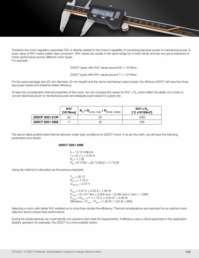
V012021 • © 2021 Portescap. Specifications subject to change without notice.
Therefore the motor regulation parameter R/k2 is directly related to the motor’s capability of converting electrical power to mechanical power. A lower value of R/k2 means better heat conversion. R/k2 values are usually in the same range for a motor family and are very good indicators of motor performance across different motor types.For example:
22DCP types offer R/k2 values around 60 × 103/Nms.
22DCT types offer R/k2 values around 11 × 103/Nms.
For the same package size (22 mm diameter, 32 mm length) and the same mechanical output power, the Athlonix 22DCT will have five times less joules losses and therefore better efficiency.
To take into consideration thermal properties of the motor, we can compare the values for R/k2 × Rth which reflect the ability of a motor to convert electrical power to mechanical power and dissipate joule losses for a given job:
The above table predicts best thermal behavior under load conditions for 22DCT motor. If we do the math, we will have the following parameters and results:
22DCT 32G1 226E
k = 12.12 mNm/A I = τ/k + I0 = 0.53 A R0 = 1.7 Ω Rth = 6 °C/W + (22 °C/W)/2 = 17 °C/W
Using the method of calculation as the previous example: Tcoil = 30 °C R30 °C = 1.75 Ω Urequired = 3.47 V Pelec = 3.47 V × 0.53 A = 1.84 W Pmech = 6 ×10-3 Nm × 2,000 rpm × 2π/60 rad-s-1/rpm = 1.26W PJoule = R30 °C × I2 = 1.75 Ω × 0.53 A2 = 0.49 W Efficiency = Pmech / Pelec = 1.26 W / 1.84 W = 68%.
Selecting a motor with better R/k2 enabled us to more than double the efficiency. Thermal considerations are important for an optimal motor selection and to ensure best performance.
During the whole exercise we could identify two solutions that meet the requirements. If efficiency was a critical parameter in the application (battery operation for example), the 22DCT is a more suitable option.
R/k2
[103/Nms]Rth = Rth rotor - body + Rth body - ambient
R/k2 x Rth[°C x103/(Nm)2]
22DCP 32G1 213P 60 28 1680
22DCT 32G1 226E 11 28 308
199

V012021 • © 2021 Portescap. Specifications subject to change without notice.
Engineer's Appendix
Examples of DC Coreless Gearmotor CalculationsExample: Direct drive with a gearhead attached to the motor.
For this application we are looking for a DC Coreless Motor & Gearhead for a continuous duty application. The application requirements are:
Available voltage: 15 Vdc
Available current: 1.5 Amp
Motor operating point: 30 rpm [n] desired motor speed
500 mNm [τ] desired output shaft torque
22°C [Tamb] ambient temperature
Continuous operation
Motor dimensions: 80 mm maximum allowable length
25 mm maximum allowable diameter
The specification page for the R22 gearhead shows a maximum continuous torque of 600 mNm, so the required 500 mNm can be handled by this planetary gearhead. When choosing the reduction ratio, we should keep in mind that the recommended maximum input speed of the R22 gearhead is 5,000 rpm. We should keep the input speed below this value to assure low wear and low audible noise.
i = nmax / nload
i = 5,000 rpm / 30 rpm = 166.7
The catalog indicates that the closest ratio to the desired value calculated above is 159:1. The efficiency for this ratio is η = 0.6 (or 60%). We may now calculate the motor speed (nm) and the reflected torque (τm) on the motor shaft.
τm = τ / (i × η) [mNm]
τm = 500 mNm / (159 × 0.6) = 5.24 mNm
nm = nload × i = 30 rpm × 159 = 4,770 rpm
The motor data sheet shows the 22DCP family of motors can deliver a torque up to 6.21 mNm continuously and will be our candidate. The 22DCP is available as a standard combination with the planetary gearhead R22. Based on the available voltage let's consider the 211P winding (12 V measuring voltage) and calculate the motor current and voltage the same way as in the previous example.
The motor is required to be driven at a speed of 4,770 rpm under a load of 5.24 mNm. The ambient temperature (Tamb) is 22 °C and the available voltage in the application is 15 Vdc. The characteristics we are most interested in are the torque constant (k) of 11.63 mNm/A, and the terminal resistance of 7.8 Ω. Neglecting the no-load current (lo), for a torque load of 5.24 mNm the motor current is: I = τ / k = 5.24 mNm / 11.63 mNm/A = 0.45 A
Now we can calculate the drive voltage required to run the motor at 22°C, for a desired speed of 4,770 rpm with a load torque of 5.24 mNm:
U = R × I + k × ϖ [Vdc]
ϖ = 2π/60 × n = 2π/60 rad/rpm-s × 4,770 rpm = 499.51 rad/s
U = (7.8 Ω × 0.45 A) + (11.63 × 10⁻³ Nm/A × 499.51 rad/s) = 9.3 Vdc
We note the current of the motor under load is 0.45 A, which is under the rated continuous current of 0.57 A. We therefore can safely assume that the final rotor temperature (Tf) will stay below the maximum rated coil temperature of 100 °C. We can also be sure that the voltage will remain within the 15 Vdc due to raise in coil resistance. The final coil temperature would be 76 °C and the required voltage due to higher coil resistance would be 10 Vdc. Both are well within the limits and our assumptions are justified.
The problem is now solved. The gearmotor 22DCP 32P2 211P.5 R22 0 159 would be a good choice for the application. If the application requires particularly long motor life or if this were a battery application, the 22DCT could also be considered to increase efficiency and extend battery life.
200

V012021 • © 2021 Portescap. Specifications subject to change without notice.
Examples of DC Motor CalculationsExample: Positioning with a DC Coreless Motor.
In this application we are looking for a DC Coreless Motor to move an inertial load (Jload) of 40 × 10-7 kgm2 by an angle of 1 rad in 20 msec.
The application requirements are:
Available voltage: 48 Vdc
Available current: 4 Amp
Motor operating point: 1 rad [Ø] desired motor movement
30 × 10-7 kgm2 [Jload] motor load inertia on output shaft
20 msec [∆t] desired move time
22° C [Tamb] ambient temperature
Motor dimensions: 68 mm maximum allowable length
35 mm maximum allowable diameter
Friction is negligible. With this incremental application we consider a duty cycle of 100% and a triangular speed profile.
The motor must rotate 0.5 rad (Ø/2) in 10 msec (∆t/2) while accelerating, then another 0.5 rad (also Ø/2) in 10 msec (also ∆t/2) while decelerating. First let us calculate the angular acceleration α.
α = (2 × Ø/2 )/(∆t/2)2 [rad/s2]
α = 2 × .5 rad/ (.01 s)2 = 10,000 rad/s2
The torque necessary to accelerate the load is:
τload = Jload × α [mNm]
τload = 30 × 10-7 kgm2 × 10,000 rad/s2 = .030 Nm = 30 mNm
When selecting a motor for incremental motion, it is best if the inertia of the rotor is equal to the inertia of the load. If the rotor inertia is much larger, then a large portion of the mechanical power is used just to move the rotor. The rotor inertia should also not be less than half the load inertia. If it is, then a gearbox should be used to reduce the load inertia felt by the motor. This process is referred to as matching inertias. We will thus select a motor that has a rotor inertia close to 40 × 10-7 kgm2.
According to the motor specification page, the 30GT2R82-234P.4 has a rotor inertia of 33 × 10-7 kgm2 and has a torque constant of 20.1 mNm/A. It can deliver enough continuous torque (87 mNm) to handle the combined load calculated below.
τrotor+road = (30 × 10-7 kgm2 + 33 × 10-7 kgm2) × 10,000 rad/s2 = .063 Nm = 63 mNm
I = τ / k + I0 = 63 mNm / (20.1 mNm/A) + 180 mA = 3.31 A
The coil resistance (at 22° C) is 0.50 Ω, and the thermal resistance is 4.5° C/W + 9° C/W / 2 = 9° C/W. By using the equation from the first example we find:
TF = 83° C R83° C = .62 Ω
Since we are using a triangular speed profile, we must determine the maximum speed of the motor during the move and then calculate the required voltage at that speed for the above coil resistance at operating temperature. This maximum speed will occur at the peak of the triangle (after 10 msec).
ϖmax = α × ∆t [rad/s]
ϖmax = 10,000 rad/s2 × 0.010 sec = 100 rad/s
U = R × I + K × ϖ = 0.62 Ω × 3.31 A + (20.1 × 10⁻³ Nm/A) × 100 rad/s= 4.06 Vdc
The problem is now solved. Since the maximum permissible coil temperature of the 35NT is 155° C, and the available voltage in the application is 48 V, this motor is perfectly capable of performing the required movement.
It is interesting to note here that, had we chosen the larger motor 35NT2R82, the coil temperature would be calculated at over 300° C! Even though the motor is capable of providing more torque, the higher rotor inertia requires it to supply much more power just to move its rotor at the desired speed. This demonstrates the importance of inertia matching.
10 ms 10 msSpeed Profile
201

V012021 • © 2021 Portescap. Specifications subject to change without notice.
Engineer's Appendix
Torque [oz-in]
Spee
d [ R
PM]
Torque [mNm]
Max. continuous operation at 25°C
20W35W50W
80W65W
0 1.0 3.02.0 4.0
0
20,000
10,000
30,000
40,000
50,000
15,000
5,000
25,000
35,000
45,000
0 10 20 30
Continuous
Short time
Examples of BLDC Slotless Motor calculationsThis chapter aims to provide all the information necessary to select a BLDC Slotless motor and to calculate the values at the desired operating point. The following examples are for motor applications running in continuous operation.
1) Example: Brushless application requirements
For this application we are looking for a BLDC motor with high speed capabilities in a continuous duty operation. The motor will be controlled by an amplifier for a motor with Hall Effect sensors.
Available voltage: 30 Vdc Available current: 3 Amps
Motor operating point: 12,000 rpm [ω] desired motor speed 20 mNm [τ] motor shaft output torque 22° C [Tamb] ambient temperature Continuous operation
Motor physical dimensions: 60 mm maximum allowable length 25 mm maximum allowable diameter
Using the speed-torque curve and maximum allowable operating specifications from the data sheet, it is possible to select the correct motor solution. Here we find the BLDC motor 22ECP45 capable of operating at the desired working point.
The motor 22ECP45 is available in 2 different 24 Vdc windings. Windings offer same overall performance (maximum torque, merit factor, etc...) but help using different voltage and current configurations. Since the desired motor speed is 12,000 rpm we will investigate the "82" winding with a no load speed of 15,700 rpm. The torque constant is 14.6 mNm/A and the resistance is 1.59 Ω.
Calculating for the motor current we find: I = τ /k + I0= 20 mNm / 14.6 mNm/A + 60 mA = 1.43 A
The supply current of the system is 3 Amps and therefore current draw is not an issue. Calculating the voltage required to run the motor at 12,000 rpm: U = R × I + k × ω
ω = 2π/60 × n = 2π/60 rad/rpm-s × 12,000 rpm = 1257 rad/s
U = 1.59 Ω × 1.43 A + (14.6 × 10⁻³ Nm/A) × 1257 rad/s = 20.6 Vdc
The problem is now solved. Since the voltage required is less than the available voltage, it is possible to reach the operating point with the BLDC Slotless motor 22ECP45 8B 82 .01. The 22ECP45 with coil "154", despite being able to work at the same working point, would have required higher voltage but lower current.
202

V012021 • © 2021 Portescap. Specifications subject to change without notice.
2) Example: Brushless motor with a Gearhead
For this application we want to drive a load at an extremely low constant speed. The customer needs a combination of a Brushless DC motor with a gearhead.
Available voltage: 20 Vdc Available current: 2 Amps Gearmotor operating point: 60 rpm [ω] desired gearmotor speed 150 mNm [τ] gearmotor shaft output torque 22° C [Tamb] ambient temperature Continuous operation
Motor physical dimensions: 120 mm maximum allowable length 20 mm maximum allowable diameter
Before selecting a motor we must first determine which gearhead is suitable for the application. The important parameters are the specifica-tions relating to the operating point at the shaft of the gearhead. Once an appropriate gearhead has been determined, the working point at the motor shaft can be calculated. From here the motor type can be defined using the same procedure as in the previous example for motor only.
We start the elimination process by comparing the desired gearhead output torque with the data of the various gearheads in continuous op-eration as listed in the catalog specification pages. We find the R16 planetary gearhead (16 mm diameter) capable of operating at the desired working point.
For continuous operation, one of the most important gearhead parameters to be considered is the maximum recommended input speed into the gearhead (nmax input-gearhead). This specification allows us to calculate the maximum reduction ratio (imax) to use for the application.
imax = nmax input – gearhead / noutput – gearhead = 7,500 rpm / 60 rpm = 125
The gearhead can be chosen by selecting the largest available ratio that is below the above result. By reviewing the catalog we choose the 121:1 ratio R16 gearhead.
Motor speed at the shaft:
nmotor = i × noutput – gearhead = 121 × 60 rpm = 7,260 rpm Motor torque at the shaft: η = 0.65 (gearhead efficiency)
τ motor = τ gearhead /i × η = 150 mNm/(121 × .65) = 1.91 mNm
M (Nm)
Continuous working rangeTemporary working range
Values at the output shaft
Dynamic torquen (rpm)
0.2 0.4 0.6 0.8 1
M (Nm)
Continuous working rangeTemporary working range
Values at the output shaft
Dynamic torquen (rpm)
0.2 0.4 0.6 0.8 1
203

V012021 • © 2021 Portescap. Specifications subject to change without notice.
Engineer's Appendix
Since the gearhead has a diameter of 16 mm we will be looking at 16 mm Brushless DC motors. Based on the load torque (τm) the motor will be required to turn, we select the 16ECP36 8B (the 8B refers to the option for Hall Effect Sensors). The 16ECP36 8B is available in 4 different windings. Windings offer same overall performance (maximum torque, merit factor, etc...) but help using different voltage and current configurations. Since the desired motor speed is 7,260 rpm we will investigate the 16ECP36 8 B 245 with a no load speed of 12,420 rpm under a 24V supply voltage. The torque constant is 17.6 mNm/A and the line to line resistance is 21.1 Ω.
Calculating for the motor current we find:
I = τ / k + I0 = 1.91 mNm / (17.6 mNm/A) + 35 mA = 0.14 A
There are no issues with the current because the system is able to supply 2 amps and the maximum recommended continuous current is 0.4 Amps. The voltage required to run the motor at 7,260 rpm is determined by the following formula:
U = R × I + k × ω
ω = 2π/60 × n = 2π/60 rad/rpm-s × 7,260 rpm= 760.3 rad/s
U = 21.1 Ω × 0.14 A + (17.6 × 10⁻³ Nm/A) × 760.3 rad/s = 16.33 Vdc
The problem is now solved. The voltage required is less than the available voltage, therefore the motor 16ECP36 8B 245 with the planetary gearhead R16 0 121 can achieve the desired working point. If the application were very noise sensitive, a lower ratio would help reducing the gearbox input speed which is the main contributor of noise.
Torque [oz-in]
Spee
d [ R
PM]
Torque [mNm]
Max. continuous operation at 25°C
5W10W15W20W
30W
0 0.2 0.4 0.6 0.8 1 1.2
0
10,000
20,000
30,000
40,000
50,000
60,000
70,000
0 1 2 3 4 5 6 7 8
Continuous
Short time
204

V012021 • © 2021 Portescap. Specifications subject to change without notice.
Examples of DMM Stepper Motor CalculationsExample: Positioning with a DMM Stepper Motor
For this application we are looking for a Stepper motor for an intermittent duty application. The applicationrequirements are:
Available voltage: 45 Vdc Available current: 2 Amp Motor operating point: 0.5 rad [θ] desired motor position 20 × 10-7 kgm2 [Jload] motor load inertia on the output shaft 20 msec [∆t] desired move time 40 °C [Tamb] operating temperature Intermittent operation
Motor dimensions: 68 mm maximum allowable length 35 mm maximum allowable diameter
L/R Driver - No Gearbox - No Ramping Acceleration
Let us first see whether the move can be accomplished with a simple L/R drive not featuring ramping acceleration. In this case we need to check whether the motor can start at the required speed and load inertia.
We consider the speed profile to be rectangular with constant speed:
Speed = ω = 0.5 rad / 0.02 sec = 25 rad/s
nmotor = 25 rad/s × 60/2π rpm-s/rad = 239 rpm
The figure shows the pull-in and pull-out torque curves for the P310 motor. We will use a simple L/R drive which provides 7 Vdc in full step mode. Since no ramping is provided (constant speed), the pull-in torque curve shows a maximum starting speed of 800 rpm when accelerating an inertia equal to the motor inertia and without any additional torque (friction torque is zero for example). With a safety factor of 75% the maximum starting frequency is f0 = 600 steps/s.The inertia of the P310 is 0.86 kg-m2 but we need to accelerate 20 kg-m2. Therefore the maximum starting frequency f1 to move this load is:
f1 = f0 × √((2 × Jm )/(Jm + Jload)) f1 = 600 steps/s x √((2 x 0.86 kg-m2) / (20 kg-m2+ 0.86 kg-m2)) = 172 rpm
As a result, P310 with a simple L/R drive would not be able to suit the requirements.
0.01.02.03.04.05.06.07.08.09.0
0.0
0.2
0.4
0.6
0.8
1.0
1.2
1.4
0 400 800 1200 1600 2000 4000 6000 8000 10000120000 400 800 1200 1600 2000 4000 6000 8000 1000012000
mNm
rpm
oz-in
pps
P310 158 005, P310 158 170 Series Torque vs Speed
P310 158 005 @ 45, 0.5 AP310 158 170 @ 7V
P310 158 005 @ 45V, 0.5 AP310 158 170 @ 7V
Pull-In TorquePull-Out Torquerpm
205

V012021 • © 2021 Portescap. Specifications subject to change without notice.
Engineer's Appendix
The stepper motor P430 makes 100 steps/rev. To move the load 0.50 rad with a stepper motor that has a 3.6° step angle, it will take the motor 8 steps to make this move.
0.50 rad = 28.65°
28.65°/3.6° = 7.96 8 steps of the motor needed
The starting frequency equivalent to 25 rad/s is : f = (25 rad/s / 2π rad/rev) x 100 steps/rev = 398 steps/s
With 36 Vdc available in the L/R drive and 47 Ω resistors in series, the P430 can start at up to 1,700 steps/s while moving an inertial load equal to its own rotor inertia without any additional torque required. With 75% safety margin:
f0 = 1,700 x 0.75 =1,275 steps/s
With an inertial load of 20 × 10-7 kg-m2 this pull-in frequency be-comes:
f1 = 1,275 steps/s × √(2 x 3 kgm2/(20 kg-m2+ 3 kgm2) = 651 steps/s
The problem is now solved. The working point of 398 steps/s is well below the pull-in torque curve of the P430, and no ramping is necessary to perform the desired operation.
The move could be made in an even shorter time if we use a starting frequency closer to the maximum allowed:
f = 600 steps/s ω = (600 steps/s / 100 steps/rev) x 2π rad/rev = 38 rad/s ∆t = 0.5 rad / 38 rad/s = 13 msec
0
10
20
30
40
0.0
1.0
2.0
3.0
4.0
5.0
6.0
0 500 1000 2000 3000 4000 50000 300 600 1200 1800 2400 3000
mNm
rpm
oz-in
pps
P430 258 013, P430 258 005 Series Torque vs Speed, Half-step Mode
P430 258 013 01 @ 36V, 47 Ω ext resistorP430 258 005 01 @ 36V, 33 Ω ext resistor
P430 258 013 01 @ 36V, 47 Ω ext resistorP430 258 005 01 @ 36V, 33 Ω ext resistor
Pull-In TorquePull-Out Torquerpm
206

V012021 • © 2021 Portescap. Specifications subject to change without notice.
Chopper Driver – No Gearbox – With Ramping Acceleration
The load inertia of 20 × 10-7 kg-m2 has to be moved by an angle of 0.50 rad (θ) in 20 msec using an acceleration ramp. We will use a triangular speed profile with an acceleration time of 10 msec for a shaft movement of .25 rad. The speed required is calculated as follows.
Acceleration = α = 2 × (θ/∆t2) = 2 × .25 rad /(0.01 sec)2 = 5,000 rad/s2
Speed = ω = (5,000 rad/s2) × 0.01 sec = 50 rad/s
nmotor = 50 rad/s × 60/2π rpm-s/rad = 477.5 rpm
The torque necessary to accelerate the load is:
τload = Jload × α [Nm]
τload = 20 × 10-7 kg-m2× 5,000 rad/s2 = .010 Nm
With a triangular speed profile this requires a peak speed up to 477.5 rpm, with a load torque of 10 mNm. Therefore the peak power required for the load alone is 0.50 W.
P = τ × ω = .010 Nm × 50 rad/s = .50 Watts
Let us first consider the P430 with rotor inertia of 3 × 10⁻⁷ kgm2. We have:
Jtotal = Jload + Jmotor = (20 × 10-7 kg-m2) + (3 × 10⁻⁷ kg-m2) = 23 × 10-7 kg-m2
τtotal = Jtotal × α = 23 × 10-7 kg-m2× 5,000 rad/s2 = .0115 Nm = 11.5 mNm
The curve shows that P430-258-005 with current limit of 1.6 A and 24 V can easily do the job. In fact, at around 500 rpm the motor can provide up to 43 mNm. With a safety factor of 75% we could easily provide 32 mNm with the P430 and the motion time could be reduced as followed:
αmax = τmax / Jtotal = 32 x 10-3 Nm / 23 x 10-7 kg-m2 = 13,913 rad/s2.
∆t = √(2 x θ / αmax) = √(2 x 0.25 rad / 13,913 rad/s2) = 6.0 msec
0
10
20
30
40
0.0
1.0
2.0
3.0
4.0
5.0
6.0
7.0
0 1000 2000 4000 6000 8000 100000 600 1200 2400 3600 4800 6000
mNm
oz-in
P430 258 013 ParallelTorque vs Speed, Half-step Mode
rpmpps
P430 258 013 @ 24V, 36VP430 258 013 @ 24VP430 258 013 @ 36V
Pull-In TorquePull-Out Torque
ω
10 ms 10 msSpeed Profile
207

V012021 • © 2021 Portescap. Specifications subject to change without notice.
Engineer's Appendix
Chopper Driver – With Gearbox – With Ramping Acceleration
The P310 has a holding torque 14 mNm at nominal current and would not be able to directly provide 10 mNm at 477 rpm for accelerating the load. However we could use a gearbox to achieve the work. A first choice consists of matching inertias, and then making sure that with the selected ratio the motor speed remains within a reasonable range and the necessary torque can be delivered. With incremental motion, an inertial match assures the shortest move time, with the motor providing constant torque over the speed range considered. In our example this calls for a desired ratio i0 of:
i0 = √(Jload/Jmotor) = √(20 kg-m2/0.86 kg-m2) = 4.82 [no units]
From the various gearhead models available for combination with the P310 stepper motor, we select the K24. This gearhead offers a ratio of 5:1 which is close enough to our target 4.82, and has an efficiency of 85%.
The load inertia reflected onto the motor shaft is calculated by:
Jload at motor = Jload at gearbox / (i2 x 0.85) = 20 × 10-7 / (52 x 0.85)
Jload at motor = 0.94 × 10⁻⁷ kg-m2.
If we now consider the previous values reflected on the motor shaft, the required motor acceleration, angular speed, and step rate are:
αat motor = α at gearbox x i = 5,000 rad/s2 x 5 = 25,000 rad/s2
ω at motor = ω at gearbox x i = 50 rad/s x 5 = 250 rad/s
f = (250 rad/s)/(2π rad/rev) × 60 steps/rev = 2,387 steps/s
τ = (Jload at motor + Jmotor) x αat motor = (0.94 + 0.86) x 10-7 kgm2 x 25,000 rad/s2 = .0045 Nm = 4.5 mNm
The pull-out torque curve shows that at around 2,000 steps/s the P310-158-005 with coil in series, chopper drive, 45 V Vdc and a 0.5 A current limit can provide up to 8 mNm. With a safety factor of 75% we have up to 6 mNm available and the motor with gearhead can easily perform the job.
Here again, the shortest move time would be:
τ max = 6 mNm α max at motor = τ max / (Jload at motor + Jmotor) = .006 Nm / 1.8 x 10⁻⁷ kg-m2 = 33,333 rad/s2
α max at gearbox = α max at motor / 5 = 6,666 rad/s2
∆t = √(2 x θ / α max at gearbox) = √(2 x 0.25 rad / 7,230 rad/s2) = 8.7 msec
The P310 with K24 0 5 is an excellent alternative to the P430 if a smaller diameter is required. DMM motors feature not only a low inertia rotor, but also a very strong magnetic design which enables use at high speed compared to other multi-pole stepper motors.
0.01.02.03.04.05.06.07.08.09.0
0.0
0.2
0.4
0.6
0.8
1.0
1.2
1.4
0 400 800 1200 1600 2000 4000 6000 8000 10000120000 400 800 1200 1600 2000 4000 6000 8000 1000012000
mNm
rpm
oz-in
pps
P310 158 005, P310 158 170 Series Torque vs Speed
P310 158 005 @ 45, 0.5 AP310 158 170 @ 7V
P310 158 005 @ 45V, 0.5 AP310 158 170 @ 7V
Pull-In TorquePull-Out Torquerpm
208

V012021 • © 2021 Portescap. Specifications subject to change without notice.
Examples of Can Stack Step Motor calculationsExample: Drive with a Can Stack Step Motor with a frictional torque load
For this application we will consider a Step Motor for an intermittent duty application. The application requirements are:
Available voltage: 24 Vdc Available current: 2 Amp
Motor operating point: 67.5° [θ] desired motor position 15 mNm [τ] desired motor torque 0.06 [∆t] desired move time Intermittent operation
If a 7.5° per step motor is used, then the motor would have to take nine steps to move 67.5°.
67.5°/7.5° = 9 steps f = step rate = 9 steps/0.06 sec = 150 steps/s
In the figure below the maximum pull-in rate with a torque of 15 mNm is 275 steps/s. We use the pull-in torque curve for this calculation be-cause the control circuit does not provide any ramping. The maximum speed the motor can reach during operation is limited by the maximum speed the motor can start at without missing any steps. This is what the pull-in torque curve represents.
The problem is now solved. The Can Stack motor 42M048C1U motor could be used at 150 steps/s because this point falls well below the pull-in torque curve.
Use the pull-out torque curve in conjunction with a Torque = Inertia × Acceleration (τ = J × α) analysis when the load is inertial and/or acceler-ation control is provided.
In this equation acceleration or ramping is in rad/s2 α = ∆ω/∆t = rad/s2
Ramping: Acceleration control or ramping is normally accomplished by gating on a voltage controlled oscillator (VCO) and the associated charging capacitor. Varying the RC time constant will give different ramping times. A typical VCO acceleration control frequency plot for an incremental movement with equal acceleration and deceleration time would be as shown below.
0.005.0010.0015.0020.0025.0030.0035.0040.00
0
1
2
3
4
5
6
50 100 150 200 250 300 350 40062.5 125 187.5 250 312.5 375 437.5 500 rpm
pps
42M048C1U Torque vs Speed5 vdc, full step, unipolar voltage drive
42M048C1U 42M048C1U Pull-Out Torque Pull-In Torque
mN
m
oz in
RUN RATE∆t RUN
TIME IN M SEC∆t ACCEL ∆t DECEL
209

V012021 • © 2021 Portescap. Specifications subject to change without notice.
Engineer's Appendix
Acceleration also may be accomplished by changing the timing of the input pulses (frequency). For example, the frequency could start at a ¼ rate; go to ½ rate, ¾ rate and finally the running rate.
For applications where ramping acceleration or deceleration control time is allowed:
τJ = JT × ∆ω/∆t
Where JT = rotor inertia (gm2) + load inertia (gm2)
∆f = step rate change ∆t = time allowed for acceleration in seconds λ = steps per revolution (for Portescap Can Stacks this can be 20 steps/rev, 24 steps/rev, or 48 steps/rev)
ω = f steps/s × 2π rad/rev × 1/(λ steps/rev) [rad/s]
Dividing by ∆t:
∆ω/∆t = ∆f/∆t step/s2 × 2π rad/rev × 1/(λ step/rev) [rad/s2]
Plugging this definition of ∆ω/∆t into the equation for τJ yields:
τJ = JT × ∆f/∆t step/s2 × 2π rad/rev × 1/(λ step/rev) [mNm]
In order to solve an application problem using acceleration ramping, it is usually necessary to make several estimates to avoid needing a pro-cedure similar to the one used in the following example. Example: Frictional torque plus inertial load with acceleration control
For this application we are looking for Stepper Motor for an intermittent duty application. The application requirements are:
Available voltage: 24 Vdc Available current: 3 Amp Motor operating point: 67.5° [θ] - desired motor position 15 mNm [τf] – frictional load < 0.5 [∆t] - desired move time Intermittent operation
Motor dimensions: 60 mm maximum allowable length 60 mm maximum allowable diameter
An assembly device must move 4 mm in less than 0.5 seconds. The motor will drive a lead screw through a gear reduction. The lead screw and gear ratio were selected so that 100 steps of a 7.5° per step motor results in 4 mm of linear motion.
The total inertial load (rotor + gear + screw) = 25 × 10-4 gm2. The frictional load is 15 mNm.
(1) Select a stepper motor pull-out torque curve which allows a torque in excess of 15 mNm at a step rate greater than:
f = 100 steps/0.5 sec = 200 steps/s
210

V012021 • © 2021 Portescap. Specifications subject to change without notice.
At a step rate of 250 steps/s (safely over 200 steps/s) the 42M048C1U is capable of providing 20 mNm.
(2) Make a first an estimate of a working rate (a running rate less than the maximum) and determine the torque available to accelerate the inertia (excess over τF) τA = torque available.
τA − τF = 20 mNm −15 mNm = 5 mNm
(3) Using a 60% safety margin 5 mNm × 0.6 = 3 mNmCalculate ∆t to accelerate.
From the equation:
τJ = JT × ∆f/∆t steps/s2 × 2π rad/rev × 1/(λ steps/rev)
λ = 48 steps/rev (from 7.5° per step)We rearrange to solve for ∆t.
∆t = (25 × 10-4 kgm2 × 250 steps/s × 2π rad/rev × 1/(48 steps/rev)) / 3 mNm = 0.027 sec
Note: The same amount of time is allowed to decelerate the load.
(4) Determine the number of steps used to accelerate and decelerate.
NA + ND = f/2 × ∆t × 2
< OR >
NA + ND = f × ∆t = 250 steps/s × 0.027 sec = 6.75 steps 7 steps needed to complete the move
(5) Calculate the time to move at the run rate.
NT = total steps/revolution – steps required to make the desired move
NT = 100 steps – 7 steps = 93 steps ∆trun = NT/ (NA + ND) = 93 steps / (125 steps + 125 steps) = 0.37 sec
0.005.0010.0015.0020.0025.0030.0035.0040.00
0
1
2
3
4
5
6
50 100 150 200 250 300 350 40062.5 125 187.5 250 312.5 375 437.5 500 rpm
pps
42M048C1U Torque vs Speed5 vdc, full step, unipolar voltage drive
42M048C1U 42M048C1U Pull-Out Torque Pull-In Torque
mN
m
oz in
211

V012021 • © 2021 Portescap. Specifications subject to change without notice.
Engineer's Appendix
(6) The total time to move is determined as follows:
∆trun + ∆taccel + ∆tdecel = ∆ttotal
0.37 sec + 0.027 sec + 0.027 sec = 0.42 sec
The problem is now solved. The Can Stack stepper motor 42M048C1U is a good first estimate. This motor can be moved slower if more of a safety factor is desired. Example: No ramping acceleration or deceleration control is allowed.
Even though no acceleration time is provided, the stepper can lag a maximum of two steps or 180° electrical degrees. If the motor goes from zero steps/sec to f steps/sec the lag time ∆t would be
∆t = 2/f
The torque equation for no acceleration or deceleration is:
τJ = JT × f2/2 × 2π/λ Where: JT = rotor inertia (gm2) + load inertia (gm2) = 25 × 10-4 gm2
f = 250 steps/s
λ = 48 steps/rev (from 7.5° per step)
Example: Friction plus inertia and no acceleration ramping.
For this application we are looking for Stepper motor for a continuous duty application. The application requirements are:
A tape capstan is to be driven by a stepper motor.
Motor operating point: 12 mNm [τf] – frictional load 10 × 10-4 gm2 [JL] – load inertia Continuous operation
The capstan must rotate in 7.5° increments at a rate of 200 steps/s.
Since a torque greater than 12 mNm at 200 steps/s is required, consider the Can Stack stepper motor 42M048C1U.
The total inertia = motor rotor inertia + load inertia
JT = JR + JL
JT = 12.5 × 10⁻⁴ gm2 + 10 × 10-4 gm2
JT = 22.5 × 10⁻⁴ gm2
212

V012021 • © 2021 Portescap. Specifications subject to change without notice.
(1) Since no acceleration ramping will be provided, use the following equation:
τJ = JT× f2/2 × 2π/λ
τJ = 22.5 × 10⁻⁴ gm2 × (200 steps/s)2/2 × 2π/(48 steps/rev)
τJ = 5.85 mNm(2) Total torque
τT = τF + τJ
τT = 12 mNm + 5.85 mNm = 17.85 mNm
(3) Refer to the pull-out torque curve below at a speed of 200 steps/s, where the available torque is 26 mNm.
The problem is now solved. The Can Stack stepper motor 42M048C1U can perform in this application, with a safety factor.
0.005.0010.0015.0020.0025.0030.0035.0040.00
0
1
2
3
4
5
6
50 100 150 200 250 300 350 40062.5 125 187.5 250 312.5 375 437.5 500 rpm
pps
42M048C1U Torque vs Speed5 vdc, full step, unipolar voltage drive
42M048C1U 42M048C1U Pull-Out Torque Pull-In Torque
mN
m
oz in
213

D I S C M A G N E T MO
TO
RS
D I S C M A G N E T MO
TO
RS
B R U S H D C M
OT
OR
S
B R U S H D C M
OT
OR
S
B R U S H L E S S DC
MO
TO
RS
B R U S H L E S S DC
MO
TO
RS
C
A N S TA C K L I N E A R AC
TU
AT
OR
S
C
A N S TA C K L I N E A R AC
TU
AT
OR
S
C A N S TA C K MO
TO
RS
C A N S TA C K MO
TO
RS
G E A R H E AD
S
G E A R H E AD
S
PRODUCT CATALOG
Miniature Motion Solutions for Miniature Motion Solutions for Performance-Critical ApplicationsPerformance-Critical Applications
E N C O DERS
E N C O DERS
Portescap
Prod
uct Catalog
20
21
Portescap
Prod
uct Catalog
20
21
©2021. Portescap. All rights reserved.Specifications subject to change without notice. It is the responsibility of the product user to determine the suitability of a product for a specific application. All trademarks property of their respective owners.
Lit code: 0212 V012021Eng
North America
110 Westtown Road
West Chester, Pennsylvania 19382
Tel: +1 610 235 5499
portescap.com
South America
Avenida João Paulo Ablas, 2970
Jardim da Glória - Cotia, SP
06711-250 – Brasil
Tel: +55 11 3616 0199
portescap.com.br
Europe
Portescap S.A.
Rue Jardinière 157, Case Postale
CH-2301 La Chaux-de-Fonds
Switzerland
Tel: +41 32 925 62 40
portescap.ch
China
4th Floor, Building 9, No 518
North Fuquan Road,
Changning District
Shanghai, 200335
P.R. China
Tel: +86 21 8028 1516
portescapmotor.cn
Japan
28F Shinagawa Intercity Tower A
2-15-1 Konan, Minato-ku
Tokyo 108-6028 Japan
Tel: +81 3 6717 4155
portescap.co.jp
Korea
Rm 3033, 30F ASEM Tower
517 Yeongdong-daero, Gangnam-gu,
Seoul 06164 Korea
Tel: +82 2 6001 3247
portescap.kr
India
Portescap
Unit No. 2, SDF-1
SEEPZ-SEZ
Andheri East, Mumbai 400 096
India
Tel: +91 22 4200 6200
+91 22 4200 6201
portescap.com