product catalog - Unilog
213
product catalog
-
Upload
khangminh22 -
Category
Documents
-
view
0 -
download
0
Transcript of product catalog - Unilog

p r o d u c t c a t a l o g

Simply the Right Choice™
Easy and efficient Robertshaw® Heating Controls are Simply the Right Choice™. Robertshaw Heating products offer kitted solutions and universal features that enable a single product to replace hundreds.
The brands you trust delivering comprehensive solutions.
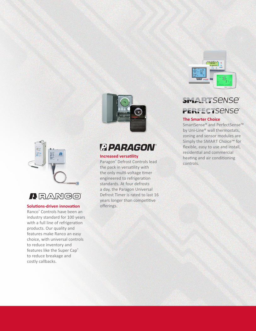
Solutions-driven innovation Ranco® Controls have been an industry standard for 100 years with a full line of refrigeration products. Our quality and features make Ranco an easy choice, with universal controls to reduce inventory and features like the Super Cap® to reduce breakage and costly callbacks.
Increased versatility Paragon® Defrost Controls lead the pack in versatility with the only multi-voltage timer engineered to refrigeration standards. At four defrosts a day, the Paragon Universal Defrost Timer is rated to last 16 years longer than competitive offerings.
The Smarter Choice SmartSense® and PerfectSense™ by Uni-Line® wall thermostats, zoning and sensor modules are Simply the SMART Choice™ for flexible, easy to use and install, residential and commercial heating and air conditioning controls.
TA
BL
E O
F C
ON
TE
NT
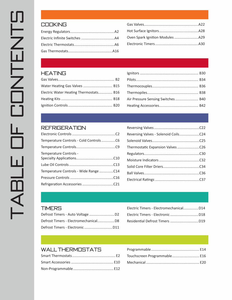
S COOKINGEnergy Regulators ............................................A2
Electric Infinite Switches .................................A4
Electric Thermostats ........................................A6
Gas Thermostats ............................................A16
Gas Valves ......................................................A22
Hot Surface Ignitors .......................................A28
Oven Spark Ignition Modules ........................A29
Electronic Timers ...........................................A30
HEATINGGas Valves ........................................................ B2
Water Heating Gas Valves ............................. B15
Electric Water Heating Thermostats .............. B16
Heating Kits ................................................... B18
Ignition Controls ............................................ B20
Ignitors .......................................................... B30
Pilots .............................................................. B34
Thermocouples .............................................. B36
Thermopiles................................................... B38
Air Pressure Sensing Switches ....................... B40
Heating Accessories ....................................... B42
TIMERSDefrost Timers - Auto Voltage .........................D2
Defrost Timers - Electromechanical.................D8
Defrost Timers - Electronic ............................D11
Electric Timers - Electromechanical ...............D14
Electric Timers - Electronic ............................D18
Residential Defrost Timers ............................D19
WALL THERMOSTATSSmart Thermostats ........................................... E2
Smart Accessories .......................................... E10
Non-Programmable ........................................ E12
Programmable ................................................ E14
Touchscreen Programmable ........................... E16
Mechanical ..................................................... E20
REFRIGERATIONElectronic Controls ...........................................C2
Temperature Controls - Cold Controls ..............C6
Temperature Controls .......................................C9
Temperature Controls - Specialty Applications .....................................C10
Lube Oil Controls ............................................C13
Temperature Controls - Wide Range ..............C14
Pressure Controls ...........................................C16
Refrigeration Accessories ...............................C21
Reversing Valves .............................................C22
Reversing Valves - Solenoid Coils ....................C24
Solenoid Valves ...............................................C25
Thermostatic Expansion Valves ......................C26
Regulators.......................................................C30
Moisture Indicators ........................................C32
Solid Core Filter Driers ....................................C34
Ball Valves .......................................................C36
Electrical Ratings ............................................C37
TA
BL
E O
F C
ON
TE
NT
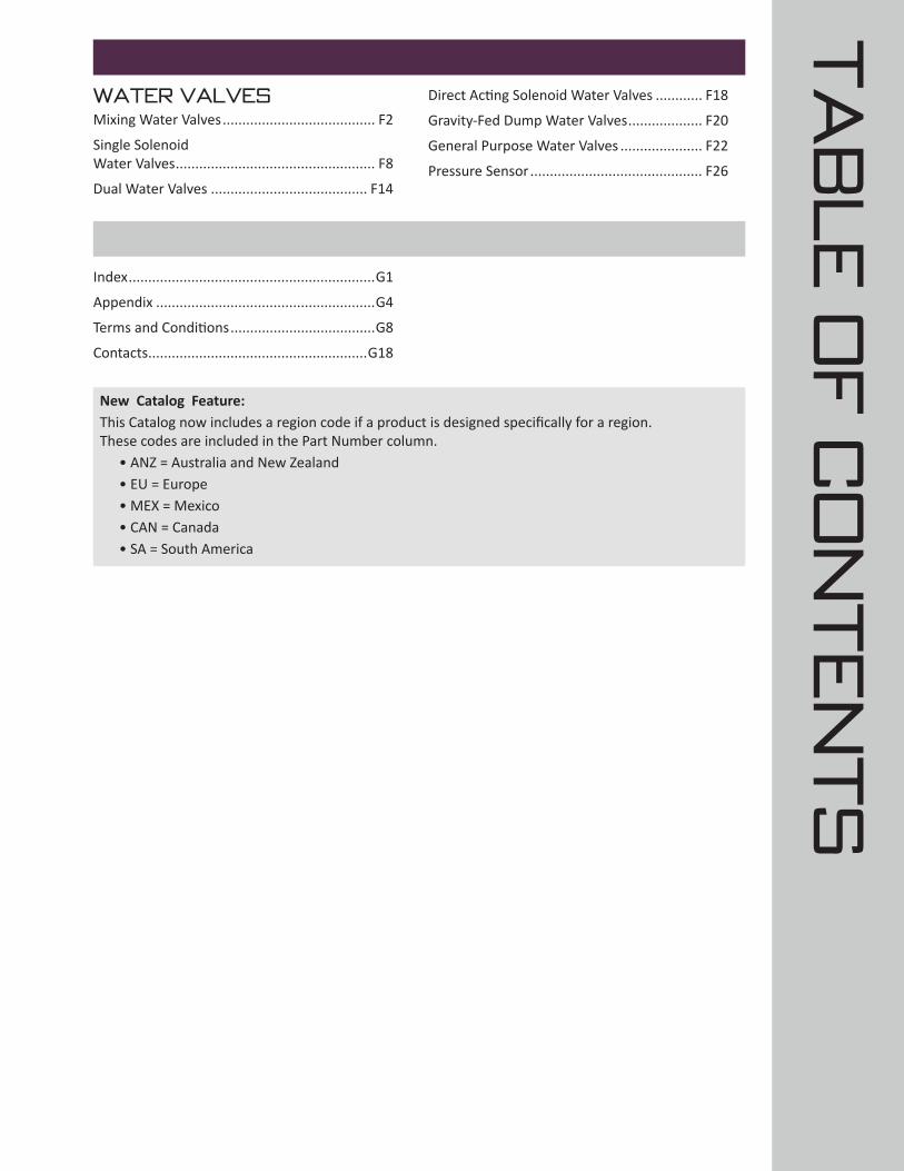
SWATER VALVESMixing Water Valves ....................................... F2
Single Solenoid Water Valves ................................................... F8
Dual Water Valves ........................................ F14
Direct Acting Solenoid Water Valves ............ F18
Gravity-Fed Dump Water Valves ................... F20
General Purpose Water Valves ..................... F22
Pressure Sensor ............................................ F26
Index ...............................................................G1
Appendix ........................................................G4
Terms and Conditions .....................................G8
Contacts ........................................................G18
New Catalog Feature:This Catalog now includes a region code if a product is designed specifically for a region. These codes are included in the Part Number column. • ANZ = Australia and New Zealand • EU = Europe • MEX = Mexico • CAN = Canada • SA = South America

Cooking
Energy Regulators ......................................................................... A2
Electric Infinite Switches .............................................................. A4
Electric Thermostats ..................................................................... A6
Gas Thermostats ......................................................................... A16
Gas Valves ................................................................................... A22
Hot Surface Ignitors .................................................................... A28
Oven Spark Ignition Modules ..................................................... A29
Electronic Timers ........................................................................ A30
Selecting the table setting is as important as the cooking controls used to deliver uncompromising excellence.The Robertshaw® electromechanical and electronic controls offer reliability and custom solutions for setting, controlling and monitoring temperatures in commercial cooking applications.

A2A2
Cooking
Customer Service 1.800.304.6563 www.Uni-Line.comwww.Uni-Line.com Customer Service 1.800.304.6563
M SeriesThe Robertshaw® M Series Energy Regulators are a rotary switch which controls the power dissipated by a heating element.
The M Series are designed to have the lowest terminal height, in the smallest physical package while still providing a fully featured control.
This regulator achieves greater efficiency and reduction of heat for smaller spaces with its controllable range of 5% to 85% power output with a 100% continuous power position. Applications include electric ranges, ceramic cooktops, hot water urns, benchtop grills, oven grills, solid and coil element controls and many applications which call for a proportionate control of a resistive load.
Features and Benefits• Smaller compact design with very low profile• Design flexiblity and material savings• Push-to-Turn option • Low internal energy consumption offers lower operating temperatures in small spaces• Multiple mounting options• Single or dual outputs
ENERGY REGULATORS
Part Numbers
Description % Input at Low
Dial Shaft Type
Dial Shaft Length
Mounting Type
Voltage Electrical Rating
M32314K (ANZ)
Energy Regulator Universal Kit Single Load with Pilot and Neutral Break
2% to 9% (45° arc) Plastic D 14mm + 8mm Bushing
M10 Bushing 230/240V AC 15 Amps
100 to 3600 Watts
M55314K (ANZ)
Energy Regulator Universal Kit Single Load with Phase Break
2% to 9% (45° arc) Metal Square
17.4mm + 8mm Bushing
M10 Bushing 230/240V AC 15 Amps
100 to 3600 Watts
M58314K (ANZ)
Energy Regulator Universal Kit Single Load with Isolated Pilot
2% to 9% (45° arc) Metal Square
17.4mm + 8mm Bushing
M10 Bushing 230/240V AC 15 Amps
100 to 3600 Watts
M82314K (ANZ)
Energy Regulator Universal Kit Dual Load with Phase Break
2% to 9% (30° arc) Metal Square
17.4mm + 8mm Bushing
M10 Bushing 230/240V AC 15 Amps
100 to 3600 Watts
MP101K (ANZ)
Energy Regulator Universal Kit Single Load with Pilot Switch
2% to 9% (45° arc) Plastic D 14mm + 8mm Bushing
M10 Bushing 230/240V AC 15 Amps
100 to 3600 Watts
M601 (EU)
Energy Regulator with Single Load with Isolated Pilot and Neutral Break with Double Wire Connections L1 and L2
2% to 9% (52° arc) Metal D 23mm M4 Screws (x2), 28mm Centerline
230/240V AC 13 Amps
100 to 3100 Watts
M602 (EU)
Energy Regulator with Single / Dual Load Change Over with Isolated Pilot and Neu-tral Break with Double Wire Connections
L1 and L2
2% to 9% (52° arc) Metal D 23mm M4 Screws (x2), 28mm Centerline
230/240V AC 13 Amps
100 to 3100 Watts
M01 (EU)
Energy Regulator with Single Load and Isolated Pilot and Neutral Break
2% to 9% (52° arc) Metal D 23mm M4 Screws (x2), 28mm Centerline
230/240V AC 13 Amps
100 to 3100 Watts
5500-200M Energy Regulator Uni-Kit Push-To-Turn 5% A 2” Break-Off Universal 240V AC 100 Watts to 3600 Watts at 240V AC, 15 Amps max @ 210°F (100°C)
Specifications
M32314K
5500-200M
A3A3
Cooking
Customer Service 1.800.304.6563 www.Uni-Line.comwww.Uni-Line.com Customer Service 1.800.304.6563
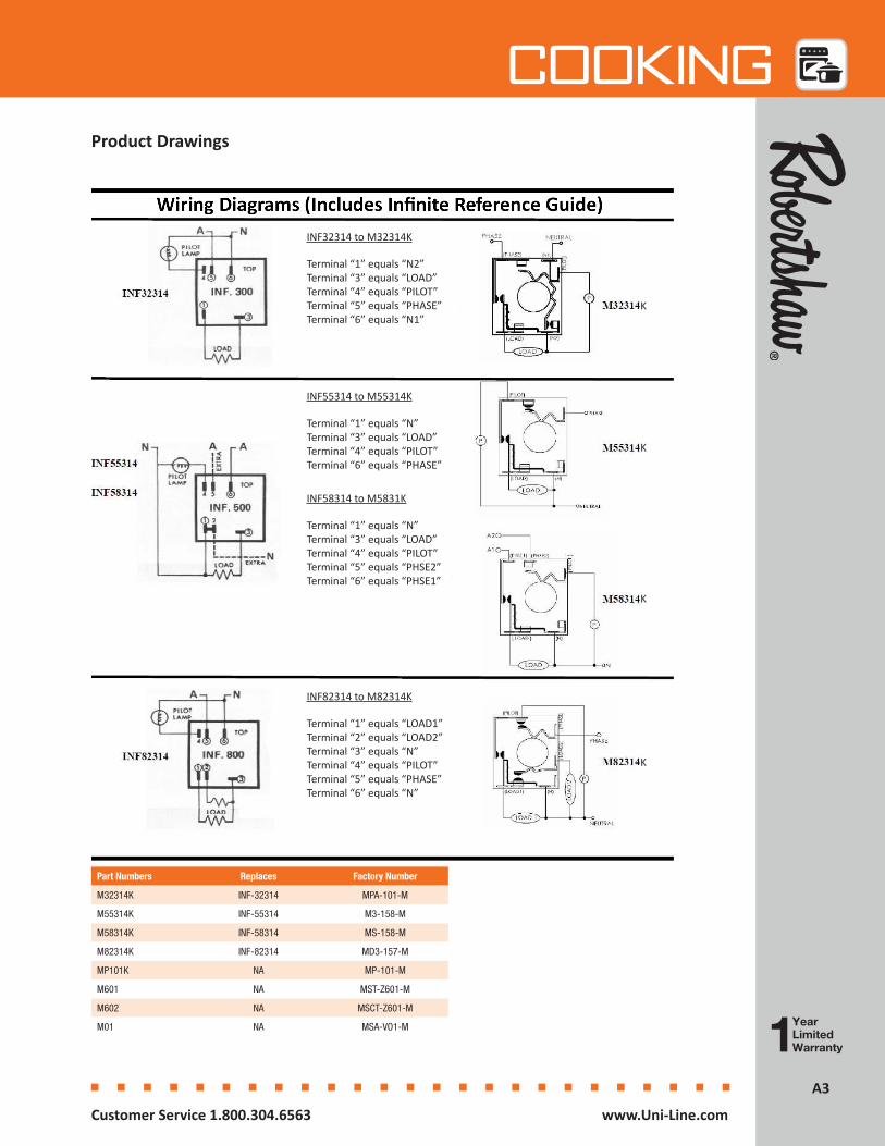
Part Numbers Replaces Factory Number
M32314K INF-32314 MPA-101-M
M55314K INF-55314 M3-158-M
M58314K INF-58314 MS-158-M
M82314K INF-82314 MD3-157-M
MP101K NA MP-101-M
M601 NA MST-Z601-M
M602 NA MSCT-Z601-M
M01 NA MSA-VO1-M
Product Drawings
INF32314 to M32314K
Terminal “1” equals “N2”Terminal “3” equals “LOAD”Terminal “4” equals “PILOT”Terminal “5” equals “PHASE”Terminal “6” equals “N1”
INF55314 to M55314K
Terminal “1” equals “N”Terminal “3” equals “LOAD”Terminal “4” equals “PILOT”Terminal “6” equals “PHASE”
INF58314 to M5831K
Terminal “1” equals “N”Terminal “3” equals “LOAD”Terminal “4” equals “PILOT”Terminal “5” equals “PHSE2”Terminal “6” equals “PHSE1”
INF82314 to M82314K
Terminal “1” equals “LOAD1”Terminal “2” equals “LOAD2”Terminal “3” equals “N”Terminal “4” equals “PILOT”Terminal “5” equals “PHASE”Terminal “6” equals “N”
K
K
K
K
A4A4
Cooking
Customer Service 1.800.304.6563 www.Uni-Line.comwww.Uni-Line.com Customer Service 1.800.304.6563
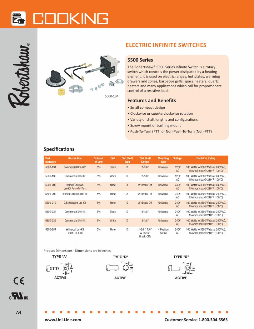
5500 SeriesThe Robertshaw® 5500 Series Infinite Switch is a rotary switch which controls the power dissipated by a heating element. It is used on electric ranges, hot plates, warming drawers and zones, barbecue grills, space heaters, quartz heaters and many applications which call for proportionate control of a resistive load.
Features and Benefits• Small compact design• Clockwise or counterclockwise rotation• Variety of shaft lengths and configurations• Screw mount or bushing mount• Push-To-Turn (PTT) or Non-Push-To-Turn (Non-PTT)
ELECTRIC INFINITE SWITCHES
5500-134
Part Numbers
Description % Input at Low
Dial Dial Shaft Type
Dial Shaft Length
Mounting Type
Voltage Electrical Rating
5500-134 Commercial Uni-Kit® 5% Black D 2-1/8” Universal 120V AC
100 Watts to 3600 Watts at 240V AC, 15 Amps max @ 210°F (100°C)
5500-135 Commercial Uni-Kit 5% White D 2-1/8” Universal 120V AC
100 Watts to 3600 Watts at 240V AC, 15 Amps max @ 210°F (100°C)
5500-200 Infinite Controls Uni-Kit Push-To-Turn
5% None A 2” Break-Off Universal 240V AC
100 Watts to 3600 Watts at 240V AC, 15 Amps max @ 210°F (100°C)
5500-202 Infinite Controls Uni-Kit 5% None A 2” Break-Off Universal 240V AC
100 Watts to 3600 Watts at 240V AC, 15 Amps max @ 210°F (100°C)
5500-212 G.E./Hotpoint Uni-Kit 5% None G 2” Break-Off Universal 240V AC
100 Watts to 3600 Watts at 240V AC, 15 Amps max @ 210°F (100°C)
5500-234 Commercial Uni-Kit 5% Black D 2-1/8” Universal 240V AC
100 Watts to 3600 Watts at 240V AC, 15 Amps max @ 210°F (100°C)
5500-235 Commercial Uni-Kit 5% White D 2-1/8” Universal 240V AC
100 Watts to 3600 Watts at 240V AC, 15 Amps max @ 210°F (100°C)
5500-287 Whirlpool Uni-Kit Push-To-Turn
5% None D 1-3/8”, 7/8” & 11/16”
Break-Offs
4 Position Screw
240V AC
100 Watts to 3600 Watts at 240V AC, 15 Amps max @ 210°F (100°C)
Specifications
Product Dimensions - Dimensions are in inches.
A5A5
Cooking
Customer Service 1.800.304.6563 www.Uni-Line.comwww.Uni-Line.com Customer Service 1.800.304.6563
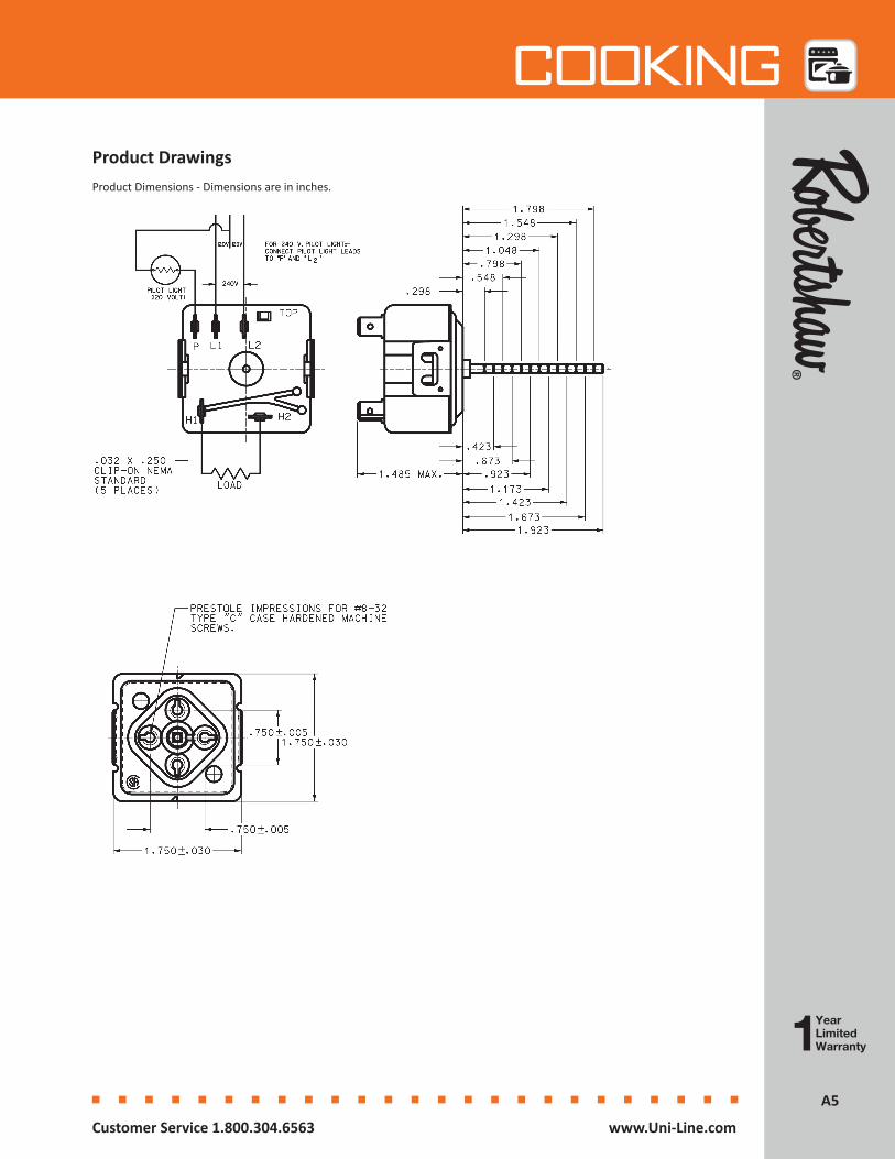
Product Drawings Product Dimensions - Dimensions are in inches.
A6A6
Cooking
Customer Service 1.800.304.6563 www.Uni-Line.comwww.Uni-Line.com Customer Service 1.800.304.6563
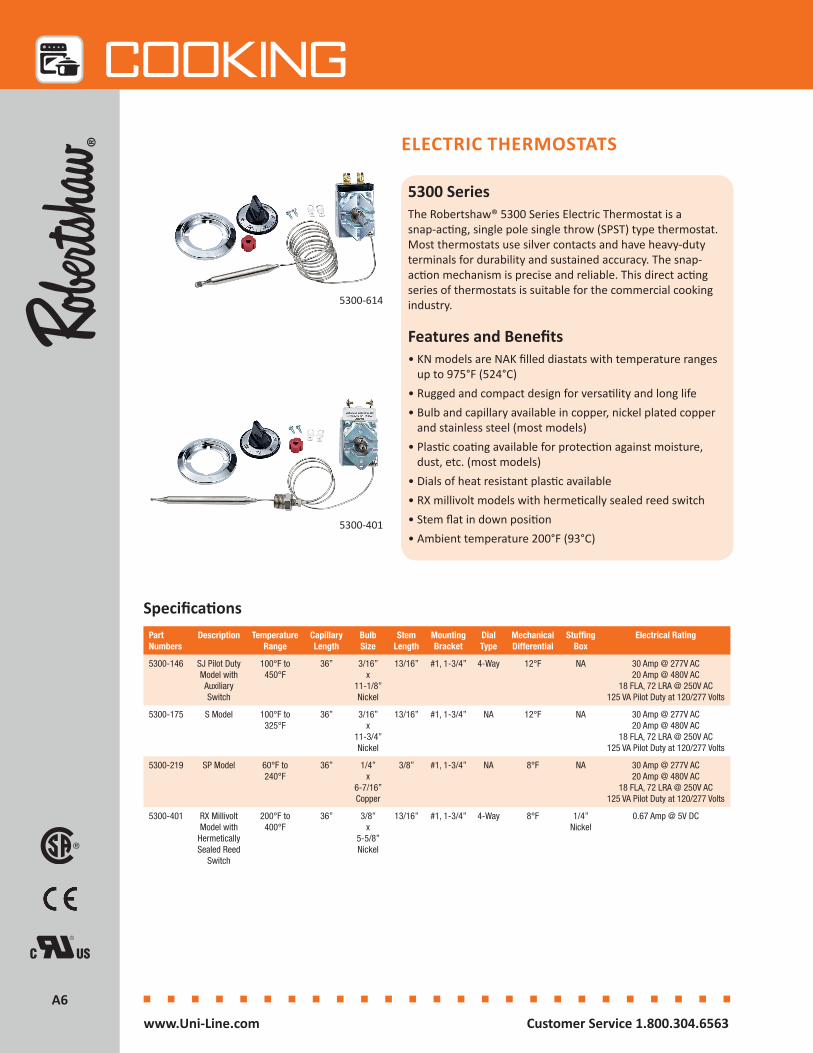
5300 SeriesThe Robertshaw® 5300 Series Electric Thermostat is a snap-acting, single pole single throw (SPST) type thermostat. Most thermostats use silver contacts and have heavy-duty terminals for durability and sustained accuracy. The snap- action mechanism is precise and reliable. This direct acting series of thermostats is suitable for the commercial cooking industry.
Features and Benefits• KN models are NAK filled diastats with temperature ranges
up to 975°F (524°C) • Rugged and compact design for versatility and long life• Bulb and capillary available in copper, nickel plated copper
and stainless steel (most models)• Plastic coating available for protection against moisture,
dust, etc. (most models)• Dials of heat resistant plastic available• RX millivolt models with hermetically sealed reed switch• Stem flat in down position• Ambient temperature 200°F (93°C)
ELECTRIC THERMOSTATS
5300-401
Part Numbers
Description Temperature Range
Capillary Length
Bulb Size
Stem Length
Mounting Bracket
Dial Type
Mechanical Differential
Stuffing Box
Electrical Rating
5300-146 SJ Pilot Duty Model with Auxiliary Switch
100°F to 450°F
36” 3/16” x
11-1/8” Nickel
13/16” #1, 1-3/4” 4-Way 12°F NA 30 Amp @ 277V AC 20 Amp @ 480V AC
18 FLA, 72 LRA @ 250V AC 125 VA Pilot Duty at 120/277 Volts
5300-175 S Model 100°F to 325°F
36” 3/16” x
11-3/4” Nickel
13/16” #1, 1-3/4” NA 12°F NA 30 Amp @ 277V AC 20 Amp @ 480V AC
18 FLA, 72 LRA @ 250V AC 125 VA Pilot Duty at 120/277 Volts
5300-219 SP Model 60°F to 240°F
36” 1/4” x
6-7/16” Copper
3/8” #1, 1-3/4” NA 8°F NA 30 Amp @ 277V AC 20 Amp @ 480V AC
18 FLA, 72 LRA @ 250V AC 125 VA Pilot Duty at 120/277 Volts
5300-401 RX Millivolt Model with
Hermetically Sealed Reed
Switch
200°F to 400°F
36” 3/8” x
5-5/8” Nickel
13/16” #1, 1-3/4” 4-Way 8°F 1/4” Nickel
0.67 Amp @ 5V DC
5300-614
Specifications
A7A7
Cooking
Customer Service 1.800.304.6563 www.Uni-Line.comwww.Uni-Line.com Customer Service 1.800.304.6563
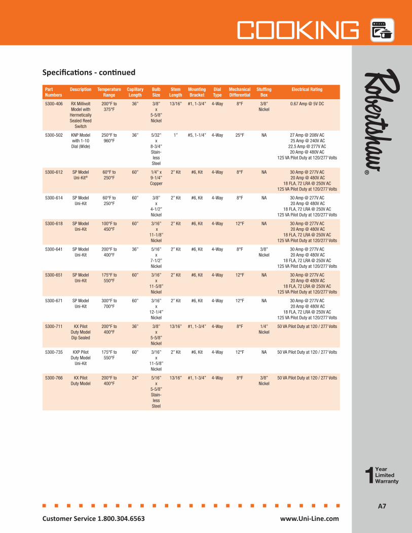
Part Numbers
Description Temperature Range
Capillary Length
Bulb Size
Stem Length
Mounting Bracket
Dial Type
Mechanical Differential
Stuffing Box
Electrical Rating
5300-406 RX Millivolt Model with
Hermetically Sealed Reed
Switch
200°F to 375°F
36” 3/8” x
5-5/8” Nickel
13/16” #1, 1-3/4” 4-Way 8°F 3/8” Nickel
0.67 Amp @ 5V DC
5300-502 KNP Model with 1-10 Dial (Wide)
250°F to 960°F
36” 5/32” x
8-3/4” Stain-less Steel
1” #5, 1-1/4” 4-Way 25°F NA 27 Amp @ 208V AC 25 Amp @ 240V AC 22.5 Amp @ 277V AC 20 Amp @ 480V AC
125 VA Pilot Duty at 120/277 Volts
5300-612 SP Model Uni-Kit®
60°F to 250°F
60” 1/4” x 9-1/4” Copper
2” Kit #6, Kit 4-Way 8°F NA 30 Amp @ 277V AC 20 Amp @ 480V AC
18 FLA, 72 LRA @ 250V AC 125 VA Pilot Duty at 120/277 Volts
5300-614 SP Model Uni-Kit
60°F to 250°F
60” 3/8” x
4-1/2” Nickel
2” Kit #6, Kit 4-Way 8°F NA 30 Amp @ 277V AC 20 Amp @ 480V AC
18 FLA, 72 LRA @ 250V AC 125 VA Pilot Duty at 120/277 Volts
5300-618 SP Model Uni-Kit
100°F to 450°F
60” 3/16” x
11-1/8” Nickel
2” Kit #6, Kit 4-Way 12°F NA 30 Amp @ 277V AC 20 Amp @ 480V AC
18 FLA, 72 LRA @ 250V AC 125 VA Pilot Duty at 120/277 Volts
5300-641 SP ModelUni-Kit
200°F to 400°F
36” 5/16” x
7-1/2” Nickel
2” Kit #6, Kit 4-Way 8°F 3/8” Nickel
30 Amp @ 277V AC 20 Amp @ 480V AC
18 FLA, 72 LRA @ 250V AC 125 VA Pilot Duty at 120/277 Volts
5300-651 SP Model Uni-Kit
175°F to 550°F
60” 3/16” x
11-5/8” Nickel
2” Kit #6, Kit 4-Way 12°F NA 30 Amp @ 277V AC 20 Amp @ 480V AC
18 FLA, 72 LRA @ 250V AC 125 VA Pilot Duty at 120/277 Volts
5300-671 SP Model Uni-Kit
300°F to 700°F
60” 3/16” x
12-1/4” Nickel
2” Kit #6, Kit 4-Way 12°F NA 30 Amp @ 277V AC 20 Amp @ 480V AC
18 FLA, 72 LRA @ 250V AC 125 VA Pilot Duty at 120/277 Volts
5300-711 KX Pilot Duty Model Dip Sealed
200°F to 400°F
36” 3/8” x
5-5/8” Nickel
13/16” #1, 1-3/4” 4-Way 8°F 1/4” Nickel
50 VA Pilot Duty at 120 / 277 Volts
5300-735 KXP Pilot Duty Model
Uni-Kit
175°F to 550°F
60” 3/16” x
11-5/8” Nickel
2” Kit #6, Kit 4-Way 12°F NA 50 VA Pilot Duty at 120 / 277 Volts
5300-766 KX Pilot Duty Model
200°F to 400°F
24” 5/16” x
5-5/8” Stain-less Steel
13/16” #1, 1-3/4” 4-Way 8°F 3/8” Nickel
50 VA Pilot Duty at 120 / 277 Volts
Specifications - continued

A8A8
Cooking
Customer Service 1.800.304.6563 www.Uni-Line.comwww.Uni-Line.com Customer Service 1.800.304.6563
Product DrawingsProduct Dimensions - Dimensions are inches and [millimeters].
A9A9
Cooking
Customer Service 1.800.304.6563 www.Uni-Line.comwww.Uni-Line.com Customer Service 1.800.304.6563
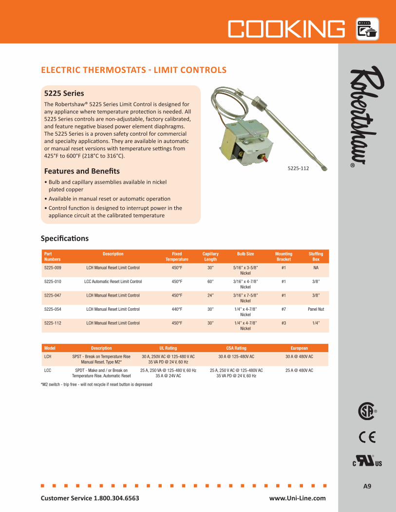
5225 SeriesThe Robertshaw® 5225 Series Limit Control is designed for any appliance where temperature protection is needed. All 5225 Series controls are non-adjustable, factory calibrated, and feature negative biased power element diaphragms. The 5225 Series is a proven safety control for commercial and specialty applications. They are available in automatic or manual reset versions with temperature settings from 425°F to 600°F (218°C to 316°C).
Features and Benefits• Bulb and capillary assemblies available in nickel
plated copper• Available in manual reset or automatic operation• Control function is designed to interrupt power in the
appliance circuit at the calibrated temperature
ELECTRIC THERMOSTATS - LIMIT CONTROLS
Specifications
Part Numbers
Description Fixed Temperature
Capillary Length
Bulb Size Mounting Bracket
Stuffing Box
5225-009 LCH Manual Reset Limit Control 450°F 30” 5/16” x 3-5/8” Nickel
#1 NA
5225-010 LCC Automatic Reset Limit Control 450°F 60” 3/16” x 4-7/8” Nickel
#1 3/8”
5225-047 LCH Manual Reset Limit Control 450°F 24” 3/16” x 7-5/8” Nickel
#1 3/8”
5225-054 LCH Manual Reset Limit Control 440°F 30” 1/4” x 4-7/8” Nickel
#7 Panel Nut
5225-112 LCH Manual Reset Limit Control 450°F 30” 1/4” x 4-7/8” Nickel
#3 1/4”
5225-112
Model Description UL Rating CSA Rating European
LCH SPST - Break on Temperature Rise Manual Reset. Type M2*
30 A, 250V AC @ 125-480 V AC 35 VA PD @ 24 V, 60 Hz
30 A @ 125-480V AC 30 A @ 480V AC
LCC SPDT - Make and / or Break on Temperature Rise. Automatic Reset
25 A, 250 VA @ 125-480 V, 60 Hz 35 A @ 24V AC
25 A, 250 V AC @ 125-480V AC 35 VA PD @ 24 V, 60 Hz
25 A @ 480V AC
*M2 switch - trip free - will not recycle if reset button is depressed
A10A10
Cooking
Customer Service 1.800.304.6563 www.Uni-Line.comwww.Uni-Line.com Customer Service 1.800.304.6563
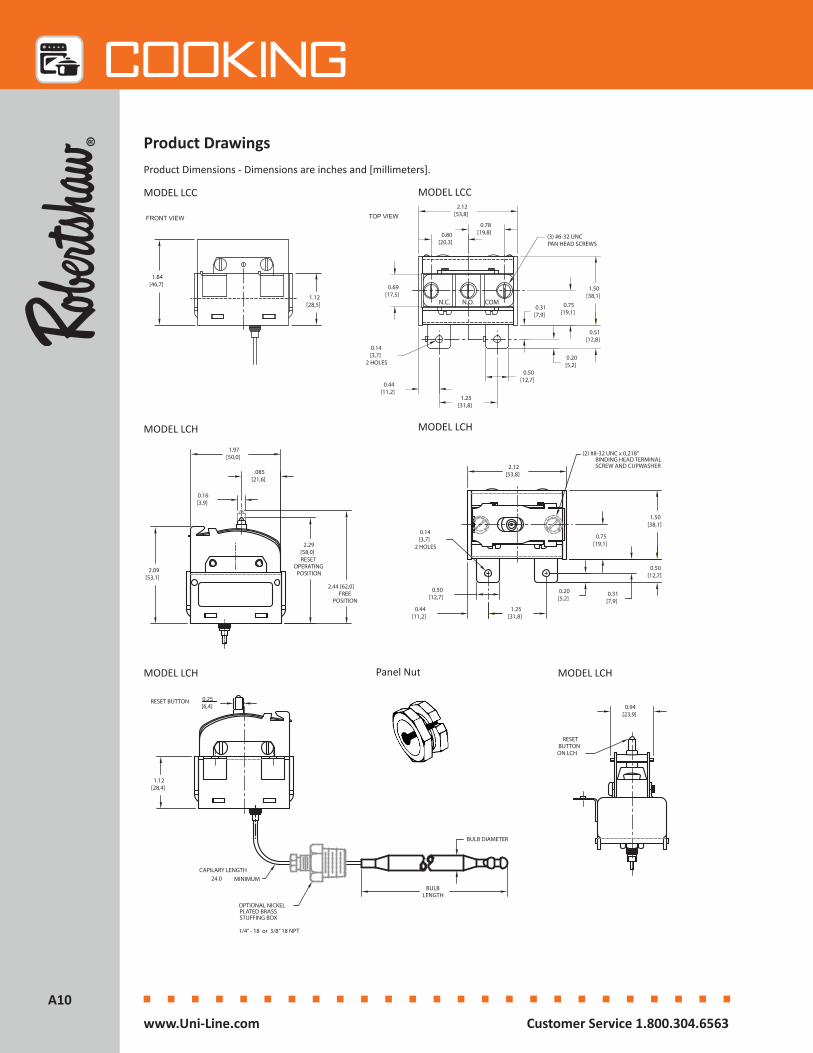
Product Dimensions - Dimensions are inches and [millimeters].
Product Drawings
24.0
PLATED BRASS
0.16 [3,9]
1.12[28,4]
0.50[12,7]
1.97[50,0]
.085[21,6]
OPTIONAL NICKEL
STUFFING BOX
BULBLENGTH
BULB DIAMETER
CAPILARY LENGTHMINIMUM
2.44 [62,0]FREE
POSITION
0.25[6,4]
RESET BUTTON
2.29 [58,0]RESET
OPERATINGPOSITION
RESETBUTTONON LCH
2.12[53,8]
0.14 [3,7]
2 HOLES
0.31[7,9]
PAN HEAD SCREWS(3) #6-32 UNC
1.12 [28,5]
1.84 [46,7]
0.80 [20,3]
0.78 [19,8]
2.12[53,8]TOP VIEW
0.50 [12,7]
0.44 [11,2]
1.25 [31,8]
0.20 [5,2]
1.50[38,1]
0.75[19,1]
0.31[7,9]
0.14 [3,7]
2 HOLES
FRONT VIEW
N.C. N.O. COM
0.69[17,5]
0.51 [12,8]
MODELS LCC & LCCM
MODELS LCH & LCHM
1/4” - 18 or 3/8” 18 NPT
0.94[23,9]
0.50 [12,7]
1.25 [31,8]
0.44 [11,2]
0.20 [5,2]
0.75[19,1]
1.50[38,1]
(2) #8-32 UNC x 0,218" BINDING HEAD TERMINALSCREW AND CUPWASHER
2.09 [53,1]
MODEL LCC MODEL LCC
MODEL LCH
MODEL LCH MODEL LCH
MODEL LCH
Panel Nut
A11A11
Cooking
Customer Service 1.800.304.6563 www.Uni-Line.comwww.Uni-Line.com Customer Service 1.800.304.6563
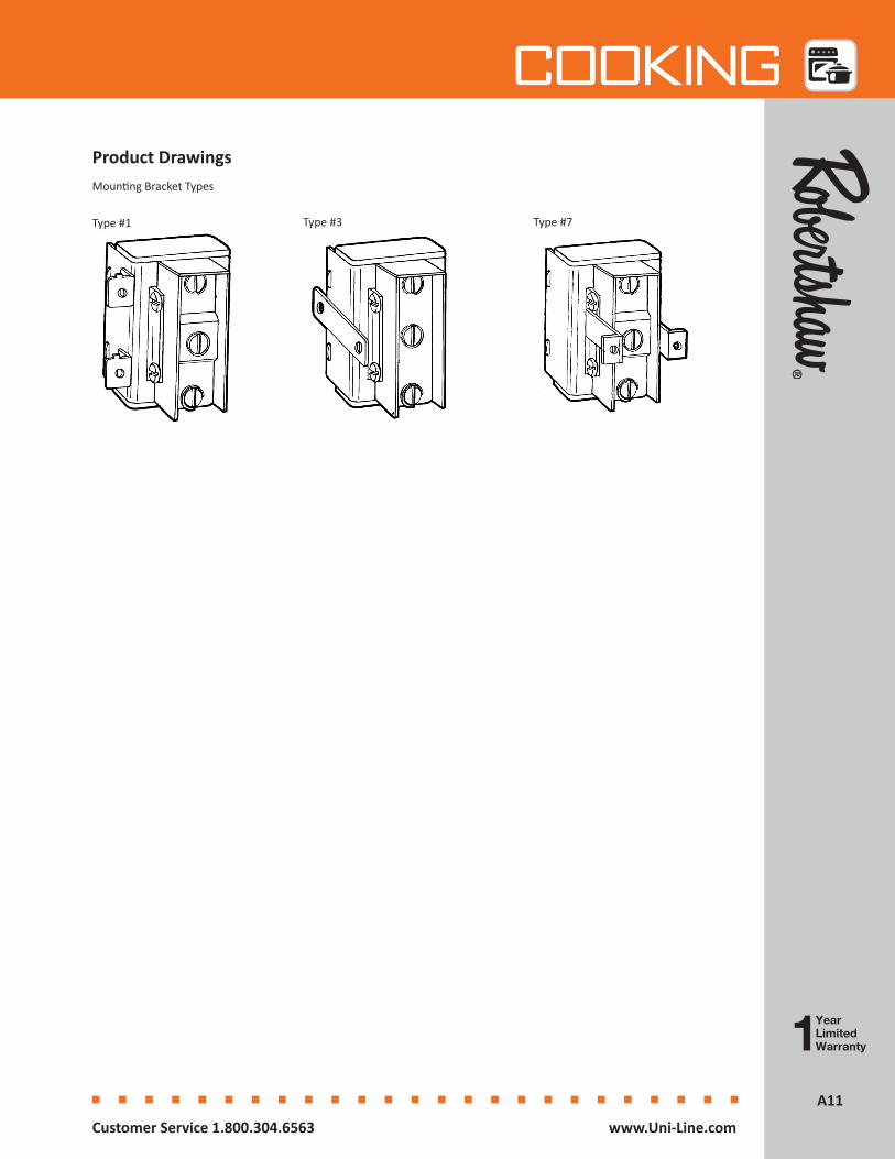
Mounting Bracket Types
Product Drawings
Type #1 Type #3 Type #7
A12A12
Cooking
Customer Service 1.800.304.6563 www.Uni-Line.comwww.Uni-Line.com Customer Service 1.800.304.6563
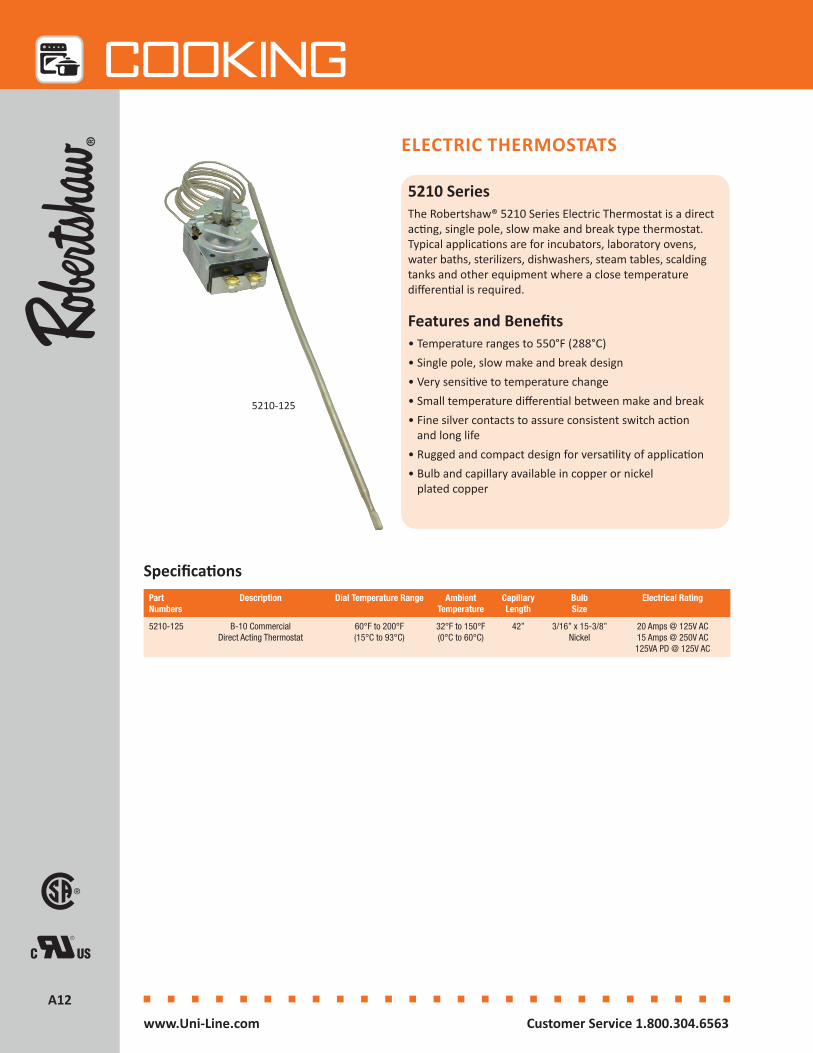
5210 SeriesThe Robertshaw® 5210 Series Electric Thermostat is a direct acting, single pole, slow make and break type thermostat. Typical applications are for incubators, laboratory ovens, water baths, sterilizers, dishwashers, steam tables, scalding tanks and other equipment where a close temperature differential is required.
Features and Benefits• Temperature ranges to 550°F (288°C)• Single pole, slow make and break design• Very sensitive to temperature change• Small temperature differential between make and break• Fine silver contacts to assure consistent switch action
and long life• Rugged and compact design for versatility of application• Bulb and capillary available in copper or nickel
plated copper
ELECTRIC THERMOSTATS
Part Numbers
Description Dial Temperature Range Ambient Temperature
Capillary Length
Bulb Size
Electrical Rating
5210-125 B-10 Commercial Direct Acting Thermostat
60°F to 200°F(15°C to 93°C)
32°F to 150°F (0°C to 60°C)
42” 3/16” x 15-3/8” Nickel
20 Amps @ 125V AC 15 Amps @ 250V AC 125VA PD @ 125V AC
5210-125
Specifications
A13A13
Cooking
Customer Service 1.800.304.6563 www.Uni-Line.comwww.Uni-Line.com Customer Service 1.800.304.6563
DIAL SHAFT DIMENSIONS
DIA.
DIA.
0.188/0.185[4,8/4,7]
0.3[7,6]
0.250/0.248[6,4/6,3]
(2) #8-32 X .25"BRASS SCREWS
(4) #6-32 UNC-2BTAPPED HOLES
1.73[43,9]
2.71[68,8]
1.55[39,4]
0.62[15,7]
STEM LENGTH
0.50[12,7]
.98[24,9]
2.16[54,9]
OPTIONAL NICKEL PLATEDBRASS STUFFING BOX
(1/4"-18 OR 3/8"-18 NPT)
BULB DIAMETER
BULBLENGTH
0.08[2,0]
0.656[16,7]
1.312[33,3]
0.88 [22,2]
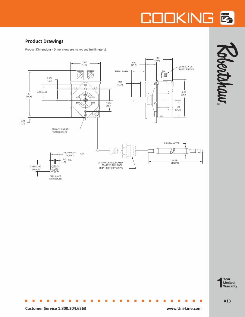
Product Dimensions - Dimensions are inches and [millimeters].
Product Drawings

A14A14
Cooking
Customer Service 1.800.304.6563 www.Uni-Line.comwww.Uni-Line.com Customer Service 1.800.304.6563
5000 SeriesThe Robertshaw® 5000 Series Electric Thermostat is a heavy-duty thermostat designed for use in harsh applications where precise temperature control is required. The control uses a double pole single throw (DPST) snap-action mechanism with a positive OFF switch. It is recommended for use on applications that require double pole operation and accurate temperature control.
Features and Benefits• DPST with positive OFF• Mechanical snap-action is instantaneous, positive and
non-fatiguing • Reacts to exceedingly small movements of the diaphragms
for very close temperature differential• Diaphragm assembly features two stainless steel
diaphragms electrically welded together • Maximum sensitivity without over-stressing the metal• Supplied with terminals mounted in four different positions• Bulb and capillary available in copper, nickel plated
copper, or stainless steel
ELECTRIC THERMOSTATS
Part Numbers
Description Dial Temperature
Range
Capillary Length
Bulb Size Dial Type Mechanical Differential
Electrical Rating
5000-811 D1 & D18 Commercial Electric Thermostat
with Pilot Light, 4-Way Bezel, Uni-Kit®
60°F to 250°F (15°C to 121°C)
60” 3/8” x 4-1/2” 4-Way 6°F (3°C) 120, 277V AC @ 30A 480V AC @ 10A
277V AC @ 250VA 125V AC @ 125VA
5000-851 D1 & D18 Commercial Electric Thermostat
with Pilot Light, 4-Way Bezel, Uni-Kit
100°F to 550°F (38°C to 288°C)
60” 3/16” x 13” Nickel
4-Way 6°F (3°C) 120, 277V AC @ 30A 480V AC @ 10A
277V AC @ 250VA 125V AC @ 125VA
5000-851
Specifications
A15A15
Cooking
Customer Service 1.800.304.6563 www.Uni-Line.comwww.Uni-Line.com Customer Service 1.800.304.6563
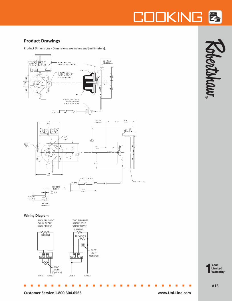
Product Dimensions - Dimensions are inches and [millimeters].
Product Drawings
Wiring DiagramSINGLE ELEMENTDOUBLE POLESINGLE PHASE
TWO ELEMENTSSINGLE POLESINGLE PHASE
ELEMENT
ELEMENT 1
ELEMENT 2
LINE 1 LINE 2LINE 1 LINE 2
PILOTLIGHT
(Optional)
PILOTLIGHT
(Optional)

A16A16
Cooking
Customer Service 1.800.304.6563 www.Uni-Line.comwww.Uni-Line.com Customer Service 1.800.304.6563
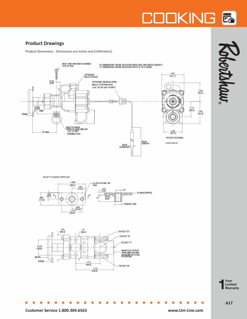
4350 SeriesThe Robertshaw® 4350 Series Gas Thermostat is a combination gas cock and by-pass type thermostat. It is available with both by-pass and pilot adjustments. With these thermostats, the gas is turned on and the temperature setting made with a single turn of the dial. The 4350 Series is available for a wide variety of applications, especially ranges and griddles.
Features and Benefits• Highly adaptable because of multiple orientations and
number of outlets• Mounted, via flange nipple, above or below the manifold • Available with various temperature ranges• Front adjustment for pilot and by-pass• Modulating seat action• Bulb and capillary available in copper, nickel plated copper
and stainless steel
GAS THERMOSTATS
Specifications
4350-028
Part Numbers
Description Max Inlet Pressure
Main Outlet Size
Main Outlet
Position
Housing Rotated
Pilot Outlet
Flange Type
Capillary Length
Sensing Bulb
Capacity (Natural
Gas)
Temperature Range
4350-015 BJWA Control for
Ovens
0.5 PSI 1/4” Pipe B 180° Plug Narrow 48” 3/16” x
11-3/16”
70,000 BTU/HR
250°F to 500°F (121°C to 260°C)
4350-027 BJWA Kit for Ovens
0.5 PSI 1/4” Pipe A, B, C, D No Yes Wide 48” 3/16” x
11-3/16”
70,000 BTU/HR
250°F to 550°F (121°C to 288°C)
4350-028 BJWA Kit for
Griddles
0.5 PSI 1/4” Pipe A, B, C, D No Yes Wide 36” 3/16” x
8-5/8”
70,000 BTU/HR
150°F to 400°F (66°C to 205°C)
4350-029 BJWA Kit for Ovens
0.5 PSI 7/16” Tubing
C No Yes Wide 48” 3/16” x
11-3/16”
70,000 BTU/HR
250°F to 550°F (121°C to 288°C)
4350-040 BJWA Control for
Ovens
0.5 PSI 1/4” Pipe D 90° Clockwise
Plug Narrow 48” 3/16” x
11-3/16”
70,000 BTU/HR
250°F to 550°F (121°C to 288°C)
4350-127 BJWA Kit for Ovens
0.5 PSI 1/4” Pipe A, B, C, D 180° No Wide 48” 3/16” x 11-3/16”
70,000 BTU/HR
250°F to 550°F (121°C to 288°C)
4350-128 BJWA Kit for
Griddles
0.5 PSI 1/4” Pipe A, B, C, D 180° No Wide 48” 3/16” x 8-5/8”
70,000 BTU/HR
150°F to 400°F (66°C to 205°C)
Part Numbers Description
4590-705 BJ Stem Extension (Package of 6)
Accessories
4590-705
A17A17
Cooking
Customer Service 1.800.304.6563 www.Uni-Line.comwww.Uni-Line.com Customer Service 1.800.304.6563
Product Dimensions - Dimensions are inches and [millimeters].
Product Drawings
A18A18
Cooking
Customer Service 1.800.304.6563 www.Uni-Line.comwww.Uni-Line.com Customer Service 1.800.304.6563
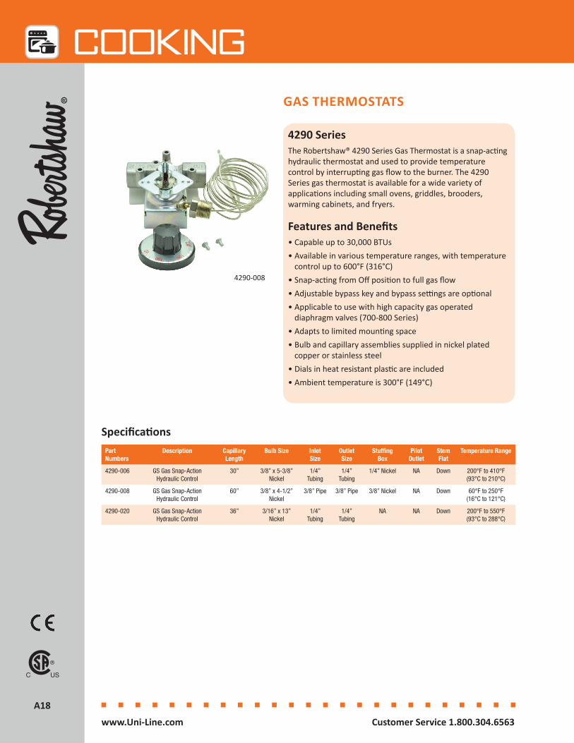
4290 SeriesThe Robertshaw® 4290 Series Gas Thermostat is a snap-acting hydraulic thermostat and used to provide temperature control by interrupting gas flow to the burner. The 4290 Series gas thermostat is available for a wide variety of applications including small ovens, griddles, brooders, warming cabinets, and fryers.
Features and Benefits• Capable up to 30,000 BTUs• Available in various temperature ranges, with temperature
control up to 600°F (316°C)• Snap-acting from Off position to full gas flow • Adjustable bypass key and bypass settings are optional• Applicable to use with high capacity gas operated
diaphragm valves (700-800 Series)• Adapts to limited mounting space• Bulb and capillary assemblies supplied in nickel plated
copper or stainless steel• Dials in heat resistant plastic are included• Ambient temperature is 300°F (149°C)
GAS THERMOSTATS
SpecificationsPart Numbers
Description Capillary Length
Bulb Size Inlet Size
Outlet Size
Stuffing Box
Pilot Outlet
Stem Flat
Temperature Range
4290-006 GS Gas Snap-Action Hydraulic Control
30” 3/8” x 5-3/8” Nickel
1/4” Tubing
1/4” Tubing
1/4” Nickel NA Down 200°F to 410°F (93°C to 210°C)
4290-008 GS Gas Snap-Action Hydraulic Control
60” 3/8” x 4-1/2” Nickel
3/8” Pipe 3/8” Pipe 3/8” Nickel NA Down 60°F to 250°F (16°C to 121°C)
4290-020 GS Gas Snap-Action Hydraulic Control
36” 3/16” x 13” Nickel
1/4” Tubing
1/4” Tubing
NA NA Down 200°F to 550°F (93°C to 288°C)
4290-008
A19A19
Cooking
Customer Service 1.800.304.6563 www.Uni-Line.comwww.Uni-Line.com Customer Service 1.800.304.6563
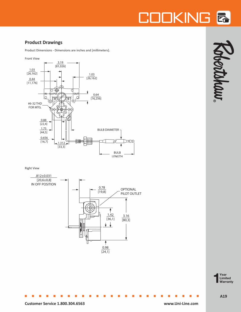
Product Dimensions - Dimensions are inches and [millimeters].
Product Drawings
Front View
Right View
IN 1/2 PSI OUT

A20A20
Cooking
Customer Service 1.800.304.6563 www.Uni-Line.comwww.Uni-Line.com Customer Service 1.800.304.6563
GAS THERMOSTATS
Specifications
4200 SeriesThe Robertshaw® 4200 Series Gas Thermostat is a heavy-duty, high capacity gas thermostat. These units are available with modulating only or with modulating snap-acting bypass. Both pilot and bypass adjustments are provided. Pilot outlets and customized settings are optional. They are available for a wide variety of applications such as deck ovens, convection ovens, baking ovens, and ranges.
Features and Benefits• Heat resistant materials and rugged design • The pilot and bypass keys are accessible and the pilot
and keys are slotted for easy adjustment from the front of the control
• Provides temperature control on most gas appliance systems
• Allows for low temperature control• Modulates the main gas supply and controls the bypass
gas with a snap under the same thermostatic action• Bulb and capillary assemblies supplied in copper,
nickel plated copper or steel• 4-Way mounting position• RoHS Compliant
Part Numbers
Description Inlet Side “F”
Inlet Rear “H”
Outlet Side “E”
Outlet Rear “G”
Pilot Outlet
Capillary Length
Bulb Size Temperature Range
4200-005 FDO Gas Thermostat, Body Type #2
1/2” Pipe NA 1/2” Pipe NA Side 48” 3/16” x 14-3/4” Nickel
150°F to 550°F (66°C to 288°C)
4200-007 FDO Gas Thermostat Body Type #1
1/2” Pipe NA 1/2” Pipe NA Side 48” 1/4” x 8-7/16” Nickel
150°F to 550°F (66°C to 288°C)
4200-011 FDTO Gas Thermostat, Body Type #2
1/2” Pipe NA 1/2” Pipe NA Side 48” 3/16” x 14-3/4” Nickel
200°F to 550°F (93°C to 288°C)
4200-025 FDO Gas Thermostat Uni-Kit® Body Type #1
3/8” Pipe 3/8” Pipe 3/8” Pipe 3/8” Pipe Side & Rear
54” 3/16” x 14-3/4” Nickel
150°F to 550°F (66°C to 288°C)
4200-026 FDTO Gas Thermostat Uni-Kit Body Type #1
3/8” Pipe 3/8” Pipe 3/8” Pipe 3/8” Pipe Side & Rear
54” 3/16” x 14-3/4” Nickel
200°F to 550°F (93°C to 205°C)
4200-503 FDTH Gas Thermostat Body Type #1
1/2” Pipe NA 1/2” Pipe NA Side 48” 3/16” x 15-3/8” Nickel
300°F to 650°F (149°C to 343°C)
4200-505 FDTH Gas Thermostat, Body Type #2
1/2” Pipe NA 1/2” Pipe NA Side 48” 3/16” x 14-3/4” Nickel
300°F to 650°F (149°C to 343°C)
4200-508 FDH Gas Thermostat, Body Type #2
1/2” Pipe NA 1/2” Pipe NA Side 48” 3/16” x 14-3/4” Nickel
300°F to 650°F (149°C to 343°C)
4200-025 Type #1 Body
4200-005 Type #2 Body
A21A21
Cooking
Customer Service 1.800.304.6563 www.Uni-Line.comwww.Uni-Line.com Customer Service 1.800.304.6563
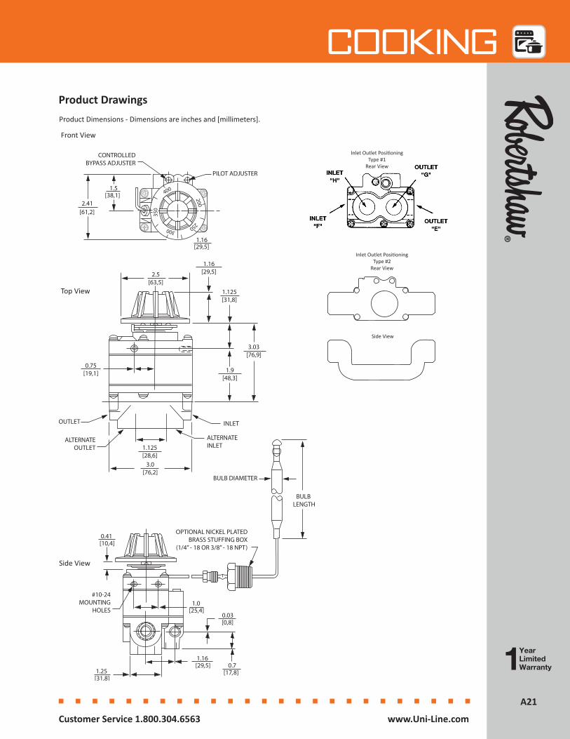
Product DrawingsProduct Dimensions - Dimensions are inches and [millimeters].
Side View
CONTROLLEDBYPASS ADJUSTER
PILOT ADJUSTER
1.5[38,1]
2.41[61,2]
1.16[29,5]
Front View
Inlet Outlet PositioningType #1
Rear View
Inlet Outlet PositioningType #2
Rear View
Side View
Top View
A22A22
Cooking
Customer Service 1.800.304.6563 www.Uni-Line.comwww.Uni-Line.com Customer Service 1.800.304.6563
GAS VALVES - BLEED CONTROL
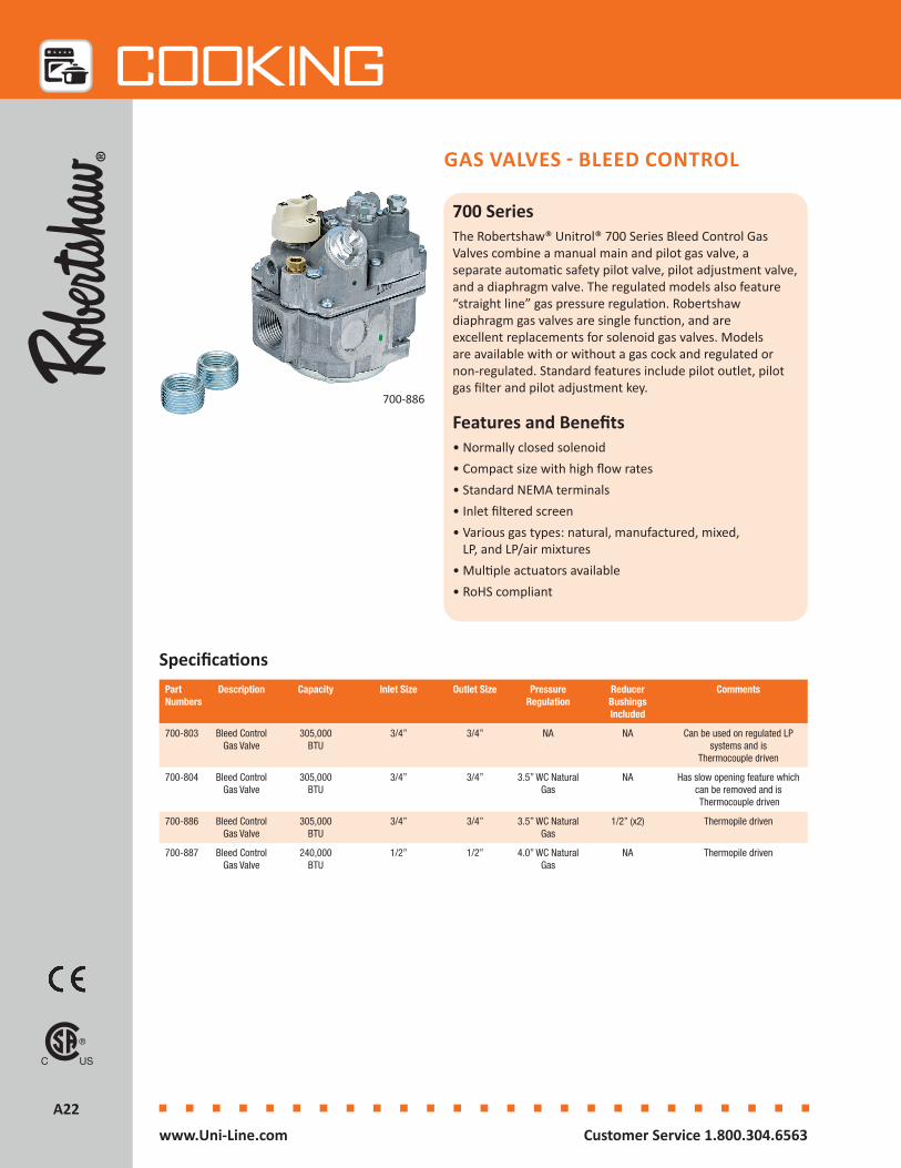
700 SeriesThe Robertshaw® Unitrol® 700 Series Bleed Control Gas Valves combine a manual main and pilot gas valve, a separate automatic safety pilot valve, pilot adjustment valve, and a diaphragm valve. The regulated models also feature “straight line” gas pressure regulation. Robertshaw diaphragm gas valves are single function, and are excellent replacements for solenoid gas valves. Models are available with or without a gas cock and regulated or non-regulated. Standard features include pilot outlet, pilot gas filter and pilot adjustment key.
Features and Benefits• Normally closed solenoid• Compact size with high flow rates• Standard NEMA terminals• Inlet filtered screen• Various gas types: natural, manufactured, mixed,
LP, and LP/air mixtures• Multiple actuators available• RoHS compliant
SpecificationsPart Numbers
Description Capacity Inlet Size Outlet Size Pressure Regulation
Reducer Bushings Included
Comments
700-803 Bleed Control Gas Valve
305,000BTU
3/4” 3/4” NA NA Can be used on regulated LP systems and is
Thermocouple driven
700-804 Bleed Control Gas Valve
305,000BTU
3/4” 3/4” 3.5” WC Natural Gas
NA Has slow opening feature which can be removed and is Thermocouple driven
700-886 Bleed Control Gas Valve
305,000BTU
3/4” 3/4” 3.5” WC Natural Gas
1/2” (x2) Thermopile driven
700-887 Bleed Control Gas Valve
240,000BTU
1/2” 1/2” 4.0” WC Natural Gas
NA Thermopile driven
700-886
A23A23
Cooking
Customer Service 1.800.304.6563 www.Uni-Line.comwww.Uni-Line.com Customer Service 1.800.304.6563
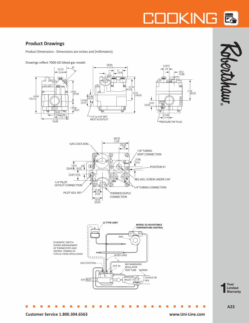
Product DrawingsProduct Dimensions - Dimensions are inches and [millimeters].
OFFON
UN
ITR
OL
IN
VENT
INOUT
THERMOCOUPLECONNECTION
1/4” PILOTOUTLET CONNECTION
PILOT ADJ. KEY
GAS COCK DIAL
1/8” TUBINGVENT CONNECTION
POSITION #1
REG ADJ. SCREW UNDER CAP
1/4” TUBING CONNECTION
15/16
27/32
13/16 3/8
2-3/8
15/16
5/16
7/8
[60,33]
[22,33]
[7,94]
[21,43]
[23,81]
[23,81]
[9,53][20,64]
MODEL GS ADJUSTABLETEMPERATURE CONTROL
LC TYPE LIMIT
IN OUT
DIAL
BLEED LINES
RECOMMENDEDREGULATORVENT TUBE BURNER
T COUPLE ORT PILEGAS INLET
OUT INGAS COCK DIAL
PILOT
SCHEMATIC SKETCH SHOWS ARRANGEMENT OF THERMOSTATS AND UNITROL 7000BGO IN TYPICAL FRYER APPLICATION
1”1”
1/2” or 3/4” NPTINLET & OUTLET
41/64
1-1/21-3/8
3-1/32
4-9/64
2-9/32
1-21/64
2-7/16
4-3/16
3-13/1645º
2-3/8
5/819/32
11/16
23/32
PRESSURE TAP PLUG
FILTE
R 2CF
M
PRESSURETAP
1-21/64
1-29/64
[33,73]
[105,17]
[34,93][38,1]
[76,99]
[36,91]
[57,94]
[33,73]
[16,27]
[61,91]
[106,36]
[25,4][25,4]
[96,84]
[17,46]
[18,20]
[60,33]
[15,08]
[15,875]Drawings reflect 7000 GO bleed gas model.

A24A24
Cooking
Customer Service 1.800.304.6563 www.Uni-Line.comwww.Uni-Line.com Customer Service 1.800.304.6563
GAS VALVES - SOLENOID
4075 SeriesThe Robertshaw® 4075 Series Gas Solenoid is designed to control the flow of gas in cooking appliances. Both single FJT and dual FJTDO models are available for a wide variety of applications such as ovens, griddles and fryers.
Features and Benefits• Normally closed solenoid• Multiple inlet/outlet configurations• 1/8” side pilot outlets available• Compact size with high flow rates• Standard NEMA terminals• Inlet filtered screen• Gas types: natural, manufactured, fixed, LP and
LP/air mixtures• RoHS compliant• AC rectification for silent operation
Specifications Part Numbers
Description Inlet Outlet Pilot Outlet Max Pressure
Capacity Ambient Temperature
Electrical Rating
Comments
4075-029 FJT Single Gas Solenoid
Valve
3/8” Pipe 3/8” Pipe Left and Right 0.5 PSI 119,000 BTU
-40°F to 275°F (-40°C to 135°C)
24 / 120 / 240 Volts
@ 50/60 Hz
Includes (2) 1/8” plugs
4075-200 FJTDO Dual Gas Solenoid
Valve
3/8” Pipe 3/8” Pipe NA 0.5 PSI 165,000 BTU both 110,000 BTU each
-40°F to 275°F (-40°C to 135°C)
24 / 120 / 240 Volts
@ 50/60 Hz
0.10 Amp Coil
4075-200
4075-029
A25A25
Cooking
Customer Service 1.800.304.6563 www.Uni-Line.comwww.Uni-Line.com Customer Service 1.800.304.6563
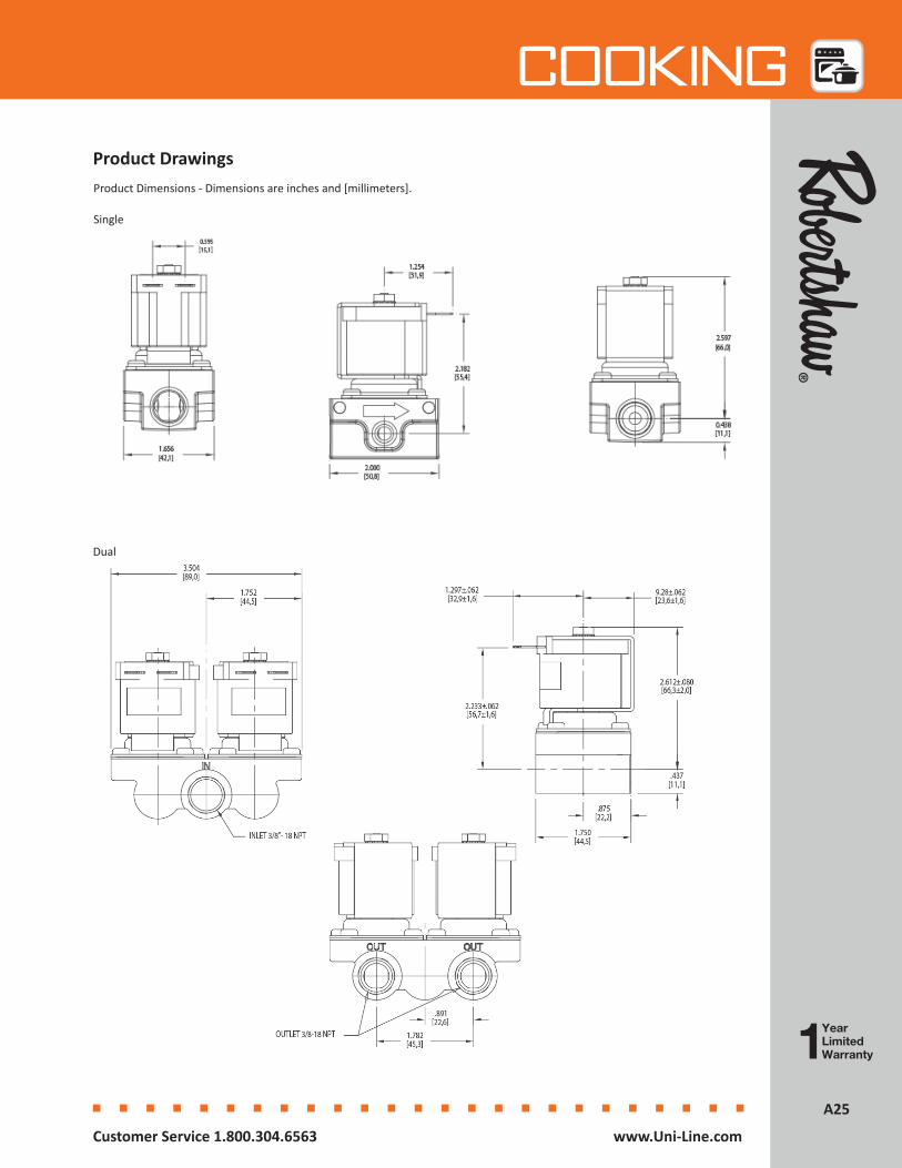
Product DrawingsProduct Dimensions - Dimensions are inches and [millimeters].
Single
Dual
A26A26
Cooking
Customer Service 1.800.304.6563 www.Uni-Line.comwww.Uni-Line.com Customer Service 1.800.304.6563
GAS VALVES - THERMOMAGNETIC SAFETY
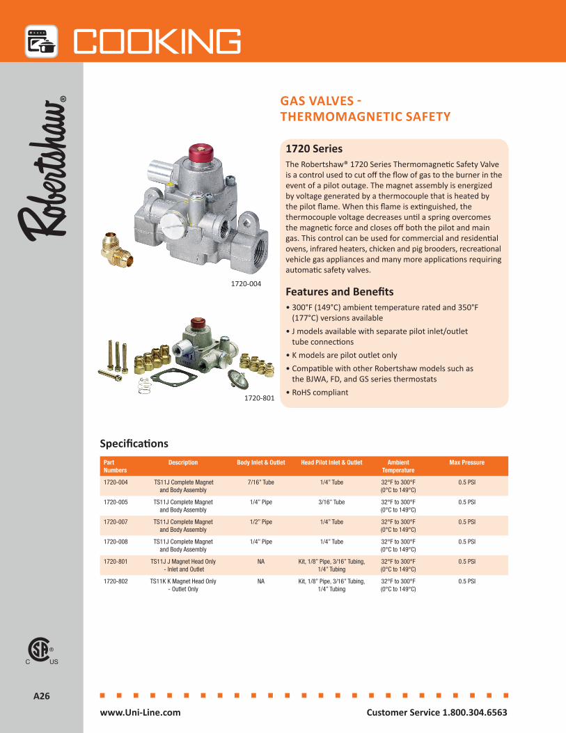
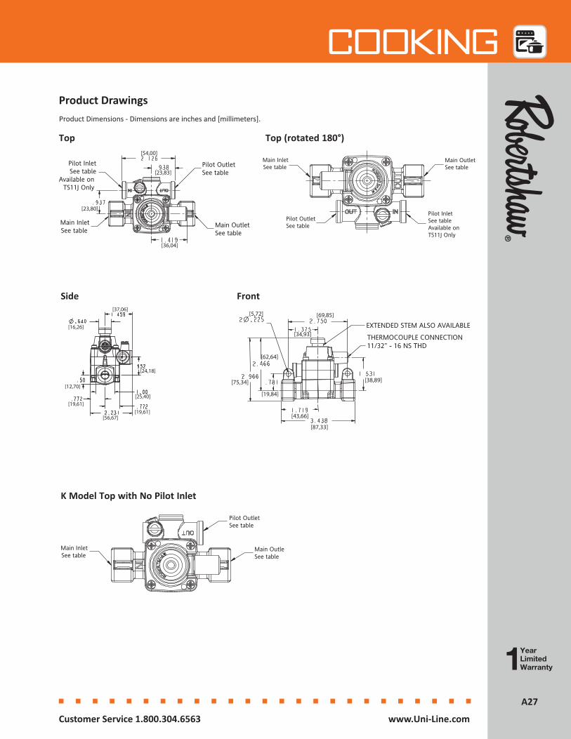
1720 SeriesThe Robertshaw® 1720 Series Thermomagnetic Safety Valve is a control used to cut off the flow of gas to the burner in the event of a pilot outage. The magnet assembly is energized by voltage generated by a thermocouple that is heated by the pilot flame. When this flame is extinguished, the thermocouple voltage decreases until a spring overcomes the magnetic force and closes off both the pilot and main gas. This control can be used for commercial and residential ovens, infrared heaters, chicken and pig brooders, recreational vehicle gas appliances and many more applications requiring automatic safety valves.
Features and Benefits• 300°F (149°C) ambient temperature rated and 350°F
(177°C) versions available• J models available with separate pilot inlet/outlet
tube connections• K models are pilot outlet only• Compatible with other Robertshaw models such as
the BJWA, FD, and GS series thermostats• RoHS compliant
SpecificationsPart Numbers
Description Body Inlet & Outlet Head Pilot Inlet & Outlet Ambient Temperature
Max Pressure
1720-004 TS11J Complete Magnet and Body Assembly
7/16” Tube 1/4” Tube 32°F to 300°F (0°C to 149°C)
0.5 PSI
1720-005 TS11J Complete Magnet and Body Assembly
1/4” Pipe 3/16” Tube 32°F to 300°F (0°C to 149°C)
0.5 PSI
1720-007 TS11J Complete Magnet and Body Assembly
1/2” Pipe 1/4” Tube 32°F to 300°F (0°C to 149°C)
0.5 PSI
1720-008 TS11J Complete Magnet and Body Assembly
1/4” Pipe 1/4” Tube 32°F to 300°F (0°C to 149°C)
0.5 PSI
1720-801 TS11J J Magnet Head Only - Inlet and Outlet
NA Kit, 1/8” Pipe, 3/16” Tubing, 1/4” Tubing
32°F to 300°F (0°C to 149°C)
0.5 PSI
1720-802 TS11K K Magnet Head Only - Outlet Only
NA Kit, 1/8” Pipe, 3/16” Tubing, 1/4” Tubing
32°F to 300°F (0°C to 149°C)
0.5 PSI
1720-004
1720-801
A27A27
Cooking
Customer Service 1.800.304.6563 www.Uni-Line.comwww.Uni-Line.com Customer Service 1.800.304.6563
Product DrawingsProduct Dimensions - Dimensions are inches and [millimeters].
Pilot InletSee table
Available on TS11J Only
Main InletSee table
Pilot OutletSee table
Main OutletSee table
[36,04]
[54,00]
[23,83]
[23,80]
Top
Side
K Model Top with No Pilot Inlet
Front
Top (rotated 180°)
Main InletSee table
Pilot OutletSee table
Main OutletSee table
Pilot InletSee tableAvailable onTS11J Only
[25,40]
[37,06]
[24,18]
[19,61][19,61]
[16,26]
[12,70]
[56,67]
EXTENDED STEM ALSO AVAILABLE
THERMOCOUPLE CONNECTION11/32” - 16 NS THD
[38,89]
[87,33]
[43,66]
[75,34]
[62,64]
[69,85]
[34,93]
[5,72]
[19,84]
Main InletSee table
Pilot OutletSee table
Main OutletSee table
A28A28
Cooking
Customer Service 1.800.304.6563 www.Uni-Line.comwww.Uni-Line.com Customer Service 1.800.304.6563
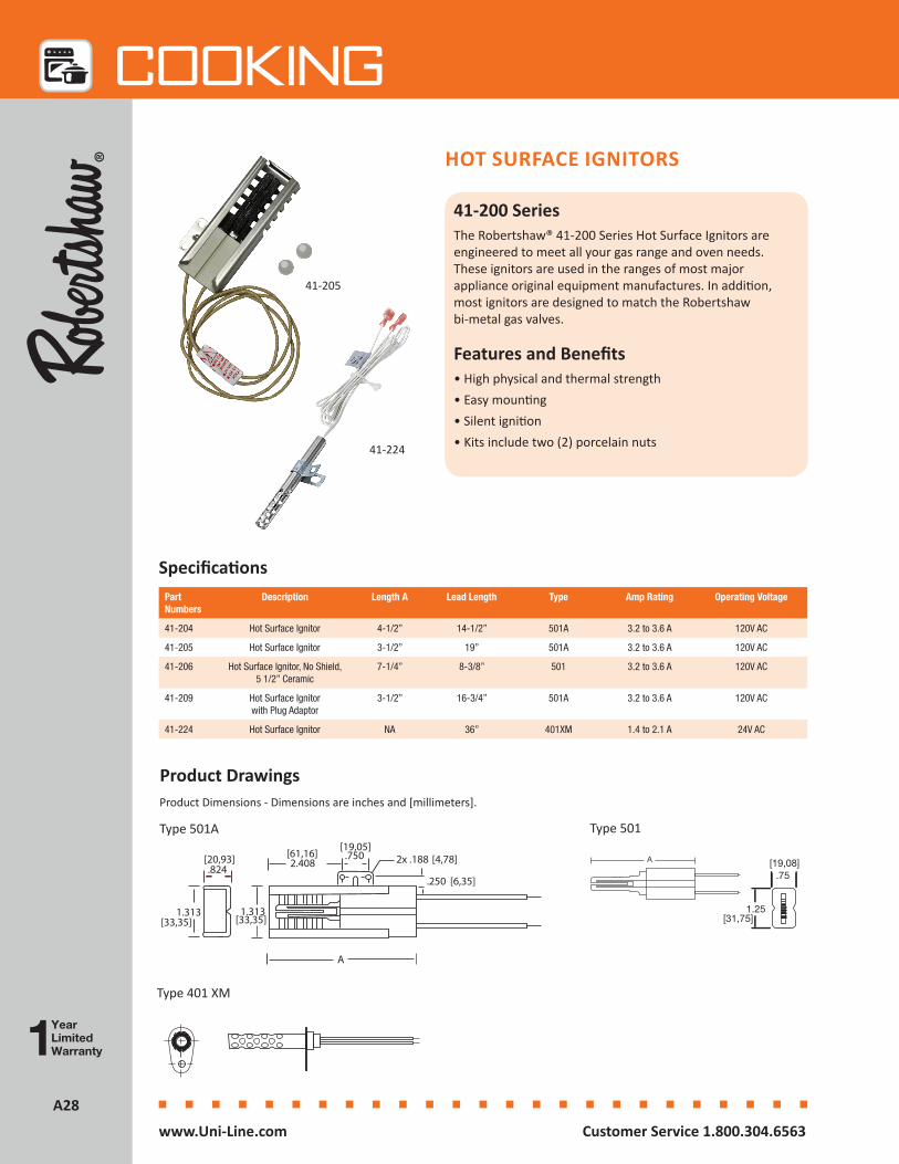
HOT SURFACE IGNITORS
41-200 SeriesThe Robertshaw® 41-200 Series Hot Surface Ignitors are engineered to meet all your gas range and oven needs. These ignitors are used in the ranges of most major appliance original equipment manufactures. In addition, most ignitors are designed to match the Robertshaw bi-metal gas valves.
Features and Benefits• High physical and thermal strength• Easy mounting• Silent ignition• Kits include two (2) porcelain nuts
Specifications
41-205
Part Numbers
Description Length A Lead Length Type Amp Rating Operating Voltage
41-204 Hot Surface Ignitor 4-1/2” 14-1/2” 501A 3.2 to 3.6 A 120V AC
41-205 Hot Surface Ignitor 3-1/2” 19” 501A 3.2 to 3.6 A 120V AC
41-206 Hot Surface Ignitor, No Shield, 5 1/2” Ceramic
7-1/4” 8-3/8” 501 3.2 to 3.6 A 120V AC
41-209 Hot Surface Ignitor with Plug Adaptor
3-1/2” 16-3/4” 501A 3.2 to 3.6 A 120V AC
41-224 Hot Surface Ignitor NA 36” 401XM 1.4 to 2.1 A 24V AC
Product DrawingsProduct Dimensions - Dimensions are inches and [millimeters].
A
1.3131.313
.824 2.408.750 2x .188
.250
[20,93]
[33,35] [33,35]
[61,16][19,05]
[4,78]
[6,35]
A.75
1.25
[19,08]
[31,75]
Type 501A Type 501
Type 401 XM
A.75
1.25
[19,08]
[31,75]
41-224
A29A29
Cooking
Customer Service 1.800.304.6563 www.Uni-Line.comwww.Uni-Line.com Customer Service 1.800.304.6563
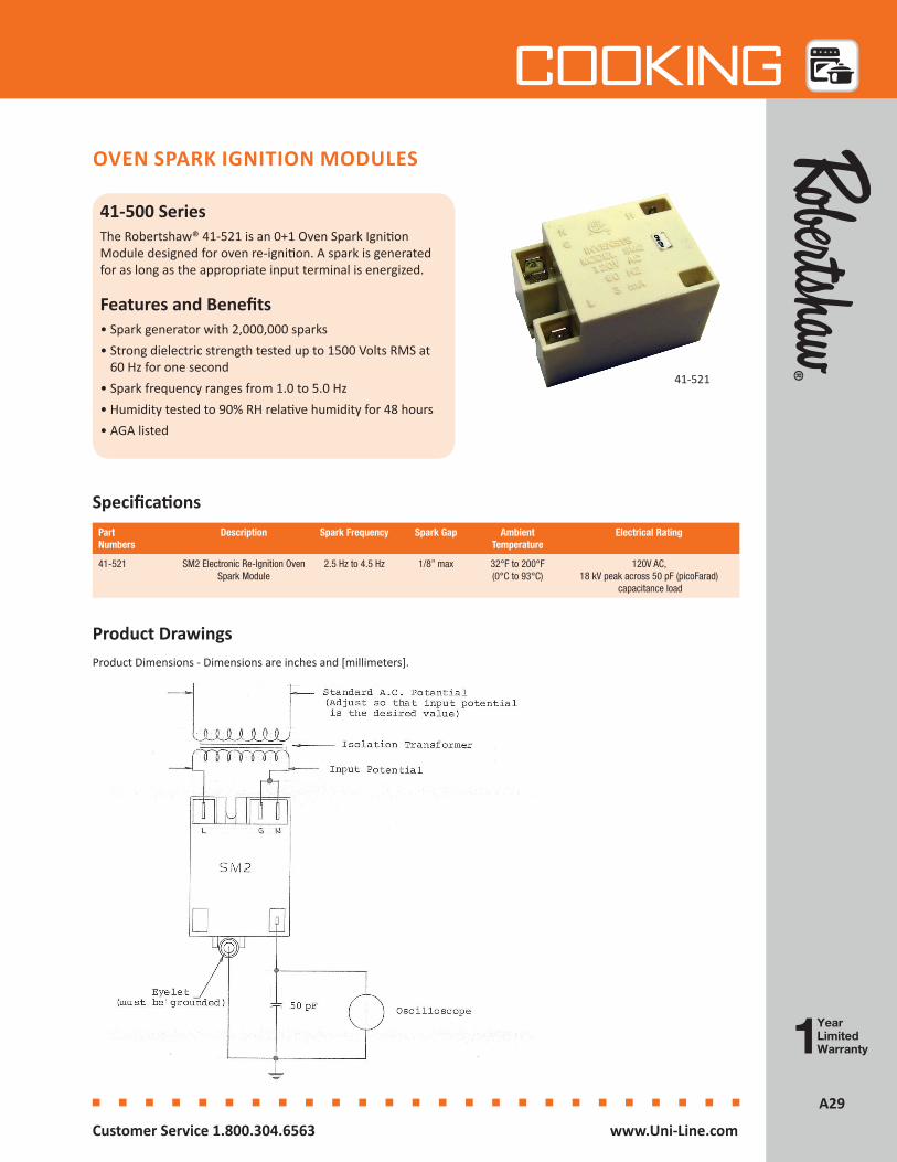
OVEN SPARK IGNITION MODULES
41-500 SeriesThe Robertshaw® 41-521 is an 0+1 Oven Spark Ignition Module designed for oven re-ignition. A spark is generated for as long as the appropriate input terminal is energized.
Features and Benefits• Spark generator with 2,000,000 sparks• Strong dielectric strength tested up to 1500 Volts RMS at
60 Hz for one second • Spark frequency ranges from 1.0 to 5.0 Hz• Humidity tested to 90% RH relative humidity for 48 hours• AGA listed
41-521
Part Numbers
Description Spark Frequency Spark Gap Ambient Temperature
Electrical Rating
41-521 SM2 Electronic Re-Ignition Oven Spark Module
2.5 Hz to 4.5 Hz 1/8” max 32°F to 200°F (0°C to 93°C)
120V AC, 18 kV peak across 50 pF (picoFarad)
capacitance load
Specifications
Product DrawingsProduct Dimensions - Dimensions are inches and [millimeters].

A30A30
Cooking
Customer Service 1.800.304.6563 www.Uni-Line.comwww.Uni-Line.com Customer Service 1.800.304.6563
ELECTRONIC TIMERS
LED145-11 LED193-009The Robertshaw® Electronic Cooker Clock uses colored LEDs to program various time durations with audible alarms.
Mostly found in stove applications where functions include minute minder, duration, end time, and time of day.
Features and Benefits• Easy to set duration and end time
• Audible alarm to indicate end time
• Quality relays are normally closed
• 6.3mm Faston connectors
Specifications
LED193
LED145
Part Numbers Description Buttons Temperature Settings Standard LED Electrical Rating
LED145-11 (EU)
Electronic Cooker Clock 5 105°F (40.5°C) or 120°F (49°C)
Red 230V AC 16A, 50/60 Hz
LED193-009 (EU)
Electronic Cooker Clock 3 105°F (40.5°C) or
120°F (49°C)
Red 230V AC 16A, 50/60 Hz

A31A31
Cooking
Customer Service 1.800.304.6563 www.Uni-Line.comwww.Uni-Line.com Customer Service 1.800.304.6563
Product DrawingsProduct Dimensions - Dimensions are inches and [millimeters].
LED-145 LED-193
Wiring Diagrams
LED-145 LED-193


Heating
Heating, ventilation and air conditioning contractors value quality performance products, while consumers welcome dependable comfort.With Robertshaw® heating products, both are achievable while delivering productivity and environmentally responsible results. Robertshaw heating products offer kitted and universal solutions designed to replace hundreds of products.
Gas Valves ......................................................................................B2
Water Heating Gas Valves ...........................................................B15
Electric Water Heating Thermostats ............................................B16
Heating Kits .................................................................................B18
Ignition Controls ..........................................................................B20
Ignitors ........................................................................................B30
Pilots ............................................................................................B34
Thermocouples ............................................................................B36
Thermopiles.................................................................................B38
Air Pressure Sensing Switches .....................................................B40
Heating Accessories .....................................................................B42

B2B2
HEATing
Customer Service 1.800.304.6563 www.Uni-Line.comwww.Uni-Line.com Customer Service 1.800.304.6563
GAS VALVES
700 Series - Pilot, Hot Surface and Direct SparkThe Robertshaw® 700 Series Universal Gas Valves are designed for intermittent pilot ignition applications. These universal models include all the necessary parts to adapt the valves to direct spark or hot surface applications. Each valve incorporates a manual valve, pilot valve, and a main gas pressure regulator (optional by model). These valves are designed for many residential and commercial applications such as central heating units, wall heaters, boilers and mobile home furnaces.
Features and Benefits• Universal models with pilot, hot surface and direct spark
ignition systems• Maximum inlet pressure 14” WC (0.5 PSI)• Ambient temperature of -40°F to 175°F• Standard NEMA terminals• Inlet filtered screen• Various gas types: natural, manufactured, mixed, LP, and
LP/air mixtures• Multiple actuators available• RoHS compliant
Part Numbers
Description Capacity Inlet Size
Outlet Size
Pressure Regulator Setting
Electrical Rating Comments
700-048 Universal Model 720,000BTU
1” 1” 3.5” WCNatural Gas
24V AC @ 60 Hz High capacity
700-049 Universal Model 300,000BTU
1/2” 1/2” 3.0” WC Natural Gas
24V AC @ 60 Hz Includes pilot plug
700-056 Universal Model 350,000BTU
3/4” 3/4” 3.5” WC Natural Gas
24V AC @ 60 Hz Straight-thru with slow opening feature for soft
ignition. Can be field removed.
700-057 Universal Model 720,000BTU
1” 1” 4.0” WC Natural Gas
24V AC @ 60 Hz Straight-thru
700-059 Universal Model 720,000BTU
1” 1” 4.0” WC Natural Gas
24V AC @ 60 Hz Straight-thru with slow opening feature for soft
ignition. Can be field removed.
Specifications
700-059
B3B3
HEATing
Customer Service 1.800.304.6563 www.Uni-Line.comwww.Uni-Line.com Customer Service 1.800.304.6563
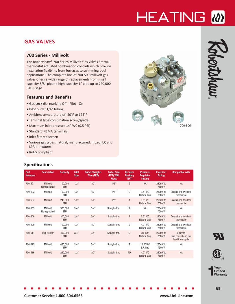
GAS VALVES
700 Series - MillivoltThe Robertshaw® 700 Series Millivolt Gas Valves are wall thermostat actuated combination controls which provide installation flexibility from furnaces to swimming pool applications. The complete line of 700-500 millivolt gas valves offers a wide range of replacements from small capacity 3/8” pipe to high capacity 1” pipe up to 720,000 BTU usage.
Features and Benefits• Gas cock dial marking Off - Pilot - On• Pilot outlet 1/4” tubing• Ambient temperature of -40°F to 175°F• Terminal type combination screw/spade• Maximum inlet pressure 14” WC (0.5 PSI)• Standard NEMA terminals• Inlet filtered screen• Various gas types: natural, manufactured, mixed, LP, and
LP/air mixtures• RoHS compliant
Part Numbers
Description Capacity Inlet Size
Outlet Straight- Thru (FPT)
Outlet Side (FPT) With
Plugs
Reducer Bushing
(NPT)
Pressure Regulator
Setting
Electrical Rating
Compatible with
700-501 MillivoltNonregulated
100,000BTU
1/2” 1/2” 1/2” 2 NA 250mV to 750mV
NA
700-502 Millivolt 100,000BTU
1/2” 1/2” 1/2” 2 3.5” WC Natural Gas
250mV to 750mV
Coaxial and two lead thermopile
700-504 Millivolt 240,000BTU
1/2” 3/4” 1/2” 1 3.5” WC Natural Gas
250mV to 750mV
Coaxial and two lead thermopile
700-505 Millivolt Nonregulated
300,000BTU
3/4” 3/4” Straight-thru 2 NA 250mV to 750mV
NA
700-506 Millivolt 300,000BTU
3/4” 3/4” Straight-thru 2 3.5” WC Natural Gas
250mV to 750mV
Coaxial and two lead thermopile
700-509 Millivolt 100,000BTU
1/2” 1/2” Straight-thru 2 4.0” WC Natural Gas
250mV to 750mV
Coaxial and two lead thermopile
700-511 Pool Heater 400,000BTU
3/4” 3/4” Straight-thru 2 Uni-Kit®
Natural Gas250mV to 750mV
Teledyne-Lars coaxial and two
lead thermopile
700-515 Millivolt 485,000BTU
3/4” 3/4” Straight-thru 2 10.0” WC L.P. Gas
250mV to 750mV
NA
700-516 Millivolt 240,000BTU
1/2” 1/2” Straight-thru NA 4.0” WC Natural Gas
250mV to 750mV
NA
Specifications
700-506
B4B4
HEATing
Customer Service 1.800.304.6563 www.Uni-Line.comwww.Uni-Line.com Customer Service 1.800.304.6563
GAS VALVES
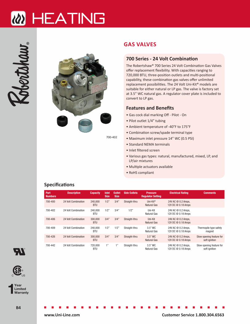
700 Series - 24 Volt CombinationThe Robertshaw® 700 Series 24 Volt Combination Gas Valves offer replacement flexibility. With capacities ranging to 720,000 BTU, three-position outlets and multi-positional capability, these combination gas valves offer unlimited replacement possibilities. The 24 Volt Uni-Kit® models are suitable for either natural or LP gas. The valve is factory set at 3.5” WC natural gas. A regulator cover plate is included to convert to LP gas.
Features and Benefits• Gas cock dial marking Off - Pilot - On• Pilot outlet 1/4” tubing• Ambient temperature of -40°F to 175°F• Combination screw/spade terminal type• Maximum inlet pressure 14” WC (0.5 PSI)• Standard NEMA terminals• Inlet filtered screen• Various gas types: natural, manufactured, mixed, LP, and
LP/air mixtures• Multiple actuators available• RoHS compliant
Specifications
700-402
Part Numbers
Description Capacity Inlet Size
Outlet Size
Side Outlets Pressure Regulator Setting
Electrical Rating Comments
700-400 24 Volt Combination 240,000BTU
1/2” 3/4” Straight-thru Uni-Kit®
Natural Gas24V AC @ 0.2 Amps, 12V DC @ 0.18 Amps
700-402 24 Volt Combination 240,000BTU
1/2” 3/4” 1/2” Uni-Kit Natural Gas
24V AC @ 0.2 Amps, 12V DC @ 0.18 Amps
700-406 24 Volt Combination 300,000BTU
3/4” 3/4” Straight-thru Uni-Kit Natural Gas
24V AC @ 0.2 Amps, 12V DC @ 0.18 Amps
700-409 24 Volt Combination 240,000BTU
1/2” 1/2” Straight-thru 3.5” WC Natural Gas
24V AC @ 0.2 Amps, 12V DC @ 0.18 Amps
Thermopile type safety magnet
700-426 24 Volt Combination 300,000BTU
3/4” 3/4” Straight-thru 3.5” WC Natural Gas
24V AC @ 0.2 Amps, 12V DC @ 0.18 Amps
Slow opening feature for soft ignition
700-442 24 Volt Combination 720,000BTU
1” 1” Straight-thru 3.5” WC Natural Gas
24V AC @ 0.2 Amps, 12V DC @ 0.18 Amps
Slow opening feature for soft ignition
B5B5
HEATing
Customer Service 1.800.304.6563 www.Uni-Line.comwww.Uni-Line.com Customer Service 1.800.304.6563
GAS VALVES
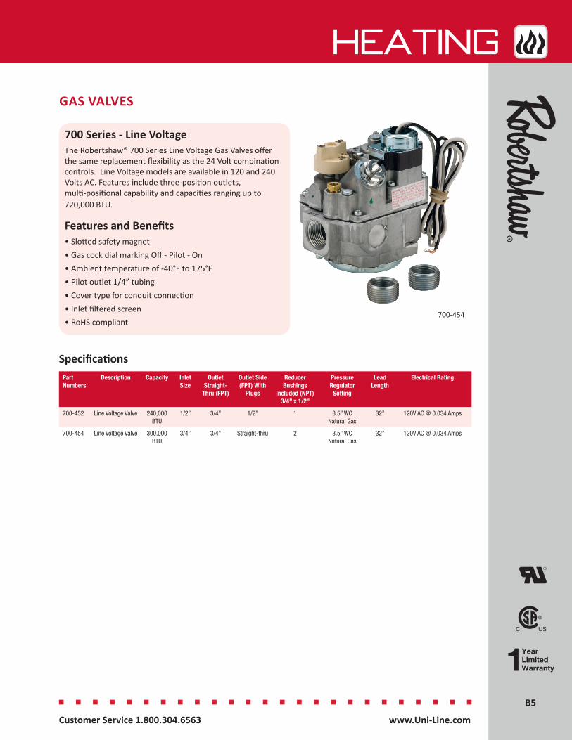
700 Series - Line VoltageThe Robertshaw® 700 Series Line Voltage Gas Valves offer the same replacement flexibility as the 24 Volt combination controls. Line Voltage models are available in 120 and 240 Volts AC. Features include three-position outlets, multi-positional capability and capacities ranging up to 720,000 BTU.
Features and Benefits• Slotted safety magnet• Gas cock dial marking Off - Pilot - On• Ambient temperature of -40°F to 175°F• Pilot outlet 1/4” tubing• Cover type for conduit connection• Inlet filtered screen• RoHS compliant
700-454
Part Numbers
Description Capacity Inlet Size
Outlet Straight-
Thru (FPT)
Outlet Side (FPT) With
Plugs
Reducer Bushings
Included (NPT) 3/4” x 1/2”
Pressure Regulator
Setting
Lead Length
Electrical Rating
700-452 Line Voltage Valve 240,000BTU
1/2” 3/4” 1/2” 1 3.5” WC Natural Gas
32” 120V AC @ 0.034 Amps
700-454 Line Voltage Valve 300,000BTU
3/4” 3/4” Straight-thru 2 3.5” WC Natural Gas
32” 120V AC @ 0.034 Amps
Specifications
B6B6
HEATing
Customer Service 1.800.304.6563 www.Uni-Line.comwww.Uni-Line.com Customer Service 1.800.304.6563
GAS VALVES
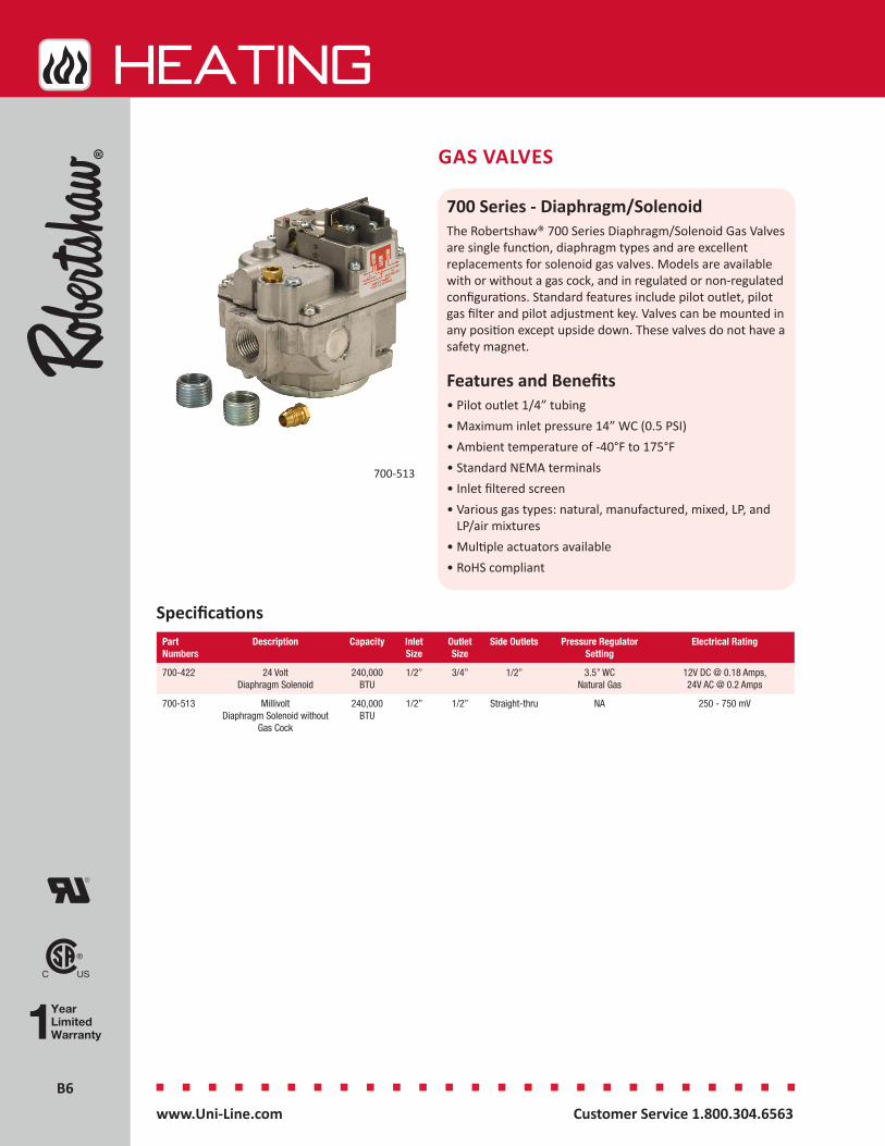
700 Series - Diaphragm/SolenoidThe Robertshaw® 700 Series Diaphragm/Solenoid Gas Valves are single function, diaphragm types and are excellent replacements for solenoid gas valves. Models are available with or without a gas cock, and in regulated or non-regulated configurations. Standard features include pilot outlet, pilot gas filter and pilot adjustment key. Valves can be mounted in any position except upside down. These valves do not have a safety magnet.
Features and Benefits• Pilot outlet 1/4” tubing• Maximum inlet pressure 14” WC (0.5 PSI)• Ambient temperature of -40°F to 175°F• Standard NEMA terminals• Inlet filtered screen• Various gas types: natural, manufactured, mixed, LP, and
LP/air mixtures• Multiple actuators available• RoHS compliant
Specifications
700-513
Part Numbers
Description Capacity Inlet Size
Outlet Size
Side Outlets Pressure Regulator Setting
Electrical Rating
700-422 24 Volt Diaphragm Solenoid
240,000BTU
1/2” 3/4” 1/2” 3.5” WC Natural Gas
12V DC @ 0.18 Amps, 24V AC @ 0.2 Amps
700-513 Millivolt Diaphragm Solenoid without
Gas Cock
240,000BTU
1/2” 1/2” Straight-thru NA 250 - 750 mV
B7B7
HEATing
Customer Service 1.800.304.6563 www.Uni-Line.comwww.Uni-Line.com Customer Service 1.800.304.6563
GAS VALVES
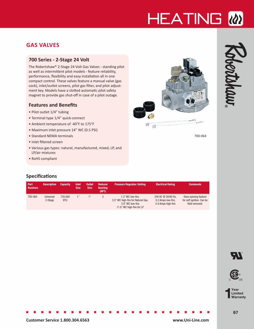
700 Series - 2-Stage 24 VoltThe Robertshaw® 2-Stage 24 Volt Gas Valves - standing pilot as well as intermittent pilot models - feature reliability, performance, flexibility and easy installation all in one compact control. These valves feature a manual valve (gas cock), inlet/outlet screens, pilot gas filter, and pilot adjust-ment key. Models have a slotted automatic pilot safety magnet to provide gas shut-off in case of a pilot outage.
Features and Benefits• Pilot outlet 1/4” tubing• Terminal type 1/4” quick-connect• Ambient temperature of -40°F to 175°F• Maximum inlet pressure 14” WC (0.5 PSI)• Standard NEMA terminals• Inlet filtered screen• Various gas types: natural, manufactured, mixed, LP, and
LP/air mixtures• RoHS compliant
700-064
SpecificationsPart Numbers
Description Capacity Inlet Size
Outlet Size
Reducer Bushing
(NPT)
Pressure Regulator Setting Electrical Rating Comments
700-064 Universal 2-Stage
720,000BTU
1” 1” 2 1.3” WC low-fire, 3.5” WC high-fire for Natural Gas,
2.8” WC low-fire, 11.0” WC high-fire for LP
24V AC @ 50/60 Hz, 0.2 Amps low-fire, 0.4 Amps high-fire
Slow opening feature for soft ignition. Can be
field removed.
B8B8
HEATing
Customer Service 1.800.304.6563 www.Uni-Line.comwww.Uni-Line.com Customer Service 1.800.304.6563
GAS VALVES
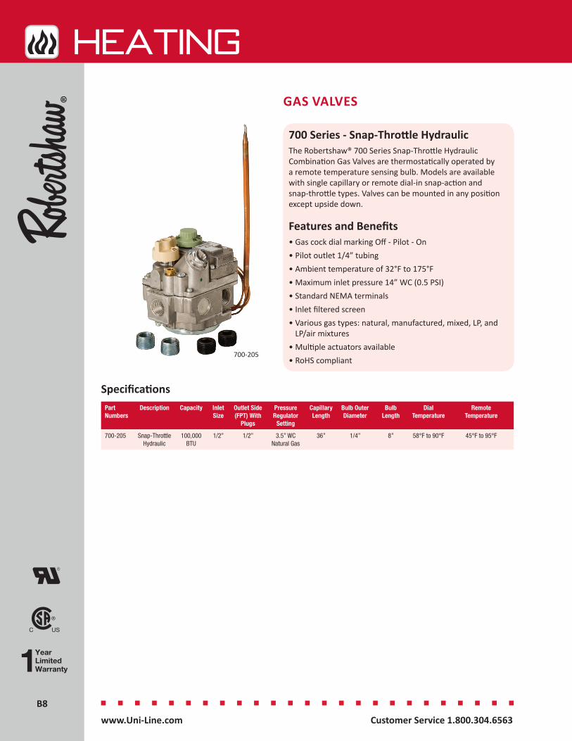
700 Series - Snap-Throttle HydraulicThe Robertshaw® 700 Series Snap-Throttle Hydraulic Combination Gas Valves are thermostatically operated by a remote temperature sensing bulb. Models are available with single capillary or remote dial-in snap-action and snap-throttle types. Valves can be mounted in any position except upside down.
Features and Benefits• Gas cock dial marking Off - Pilot - On• Pilot outlet 1/4” tubing• Ambient temperature of 32°F to 175°F• Maximum inlet pressure 14” WC (0.5 PSI)• Standard NEMA terminals• Inlet filtered screen• Various gas types: natural, manufactured, mixed, LP, and
LP/air mixtures• Multiple actuators available• RoHS compliant
Specifications
700-205
Part Numbers
Description Capacity Inlet Size
Outlet Side (FPT) With
Plugs
Pressure Regulator
Setting
Capillary Length
Bulb Outer Diameter
Bulb Length
Dial Temperature
Remote Temperature
700-205 Snap-Throttle Hydraulic
100,000BTU
1/2” 1/2” 3.5” WC Natural Gas
36” 1/4” 8” 58°F to 90°F 45°F to 95°F
B9B9
HEATing
Customer Service 1.800.304.6563 www.Uni-Line.comwww.Uni-Line.com Customer Service 1.800.304.6563
Millivolt(Gray Top)
24 Volt(Black Top)
Valve Body
120 V or 240 V Line Voltage
(2 Wire)
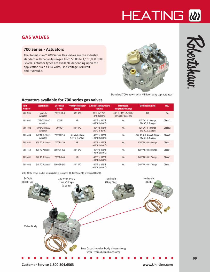
Actuators available for 700 series gas valves
Note: All the above models are available in regulated (R), high/low (RB) or convertible (RC).
Standard 700 shown with Millivolt gray top actuator
GAS VALVES
700 Series - ActuatorsThe Robertshaw® 700 Series Gas Valves are the industry standard with capacity ranges from 5,000 to 1,150,000 BTUs. Several actuator types are available depending upon the application such as 24 Volts, Line Voltage, Millivolt and Hydraulic.
Hydraulic(Bulb)
Low Capacity valve body shown along with Hydraulic bulb actuator
Part Number
Description Gas Valve Model
Pressure Regulator Setting
Ambient Temperature Rating
Thermostat Temperature Range
Electrical Rating NEC
705-205 Hydraulic Actuator
7000STR-4 3.5" WC 32°F to 175°F (0°C to 80°C)
58°F to 90°F (14°C to 32°C) 36" Capillary
NA NA
705-401 12V DC/24V AC Actuator
7000E NR -40°F to 175°F (-40°C to 80°C)
NA 12V DC, 0.18 Amps 24V AC, 0.2 Amps
Class 2
705-402 12V DC/24V AC Actuator
7000ER 3.5" WC -40°F to 175°F (40°C to 80°C)
NA 12V DC, 0.18 Amps 24V AC, 0.2 Amps
Class 2
705-404 24V AC 2-Stage Actuator
7000ER2-4 Hi-Lo Adjustable 1.3" to 3.5" WC
-40°F to 175°F (-40°C to 80°C)
NA 24V AC, 0.2 Amps 2-Stage 24V AC, 0.4 Amps
Class 2
705-451 12V AC Actuator 7000E-120 NR -40°F to 175°F (-40°C to 80°C)
NA 120V AC, 0.034 Amps Class 1
705-452 12V AC Actuator 7000ER-120 3.5" WC -40°F to 175°F (-40°C to 80°C)
NA 120V AC, 0.034 Amps Class 1
705-461 24V AC Actuator 7000E-240 NR -40°F to 175°F (-40°C to 80°C)
NA 240V AC, 0.017 Amps Class 1
705-462 24V AC Actuator 7000ER-240 3.5" WC -40°F to 175°F (-40°C to 80°C)
NA 240V AC, 0.017 Amps Class 1

B10B10
HEATing
Customer Service 1.800.304.6563 www.Uni-Line.comwww.Uni-Line.com Customer Service 1.800.304.6563
GAS VALVES
710 Series - Low CapacityThe Robertshaw® 710 Series Low Capacity Gas Valves feature an extremely compact control designed for low capacity and limited space applications. Features include three-position outlets, multi-positional capability and component replaceability.
Features and Benefits• Low capacity with 3-13/16”H x 4-21/32”L x 1-29/32” W
dimensions• Gas cock dial marking Off - Pilot - On• Ambient temperature of -40°F to 175°F• Pilot outlet 1/4” tubing• Maximum inlet pressure 14” WC (0.5 PSI)• Standard NEMA terminals • Inlet filtered screen• Various gas types: natural, manufactured, mixed, LP, and
LP/air mixtures• Multiple actuators available• RoHS compliant
710-502
B11B11
HEATing
Customer Service 1.800.304.6563 www.Uni-Line.comwww.Uni-Line.com Customer Service 1.800.304.6563
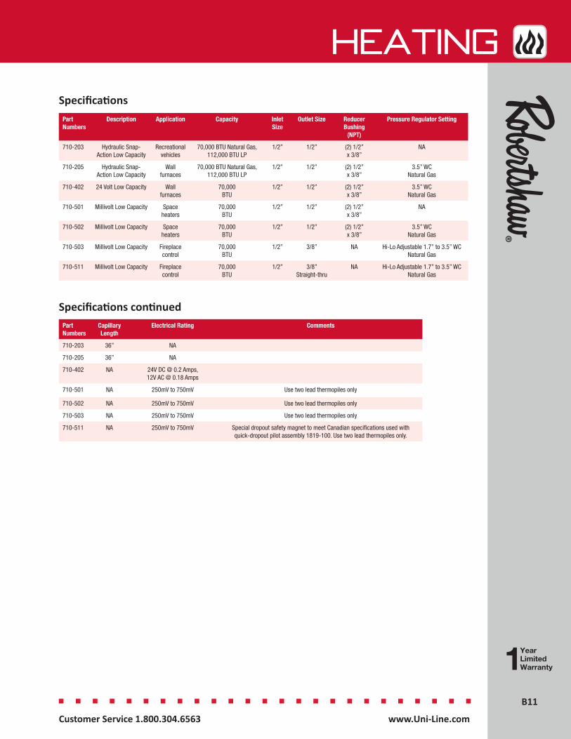
Part Numbers
Description Application Capacity Inlet Size
Outlet Size Reducer Bushing
(NPT)
Pressure Regulator Setting
710-203 Hydraulic Snap- Action Low Capacity
Recreational vehicles
70,000 BTU Natural Gas, 112,000 BTU LP
1/2” 1/2” (2) 1/2” x 3/8”
NA
710-205 Hydraulic Snap- Action Low Capacity
Wall furnaces
70,000 BTU Natural Gas, 112,000 BTU LP
1/2” 1/2” (2) 1/2” x 3/8”
3.5” WC Natural Gas
710-402 24 Volt Low Capacity Wall furnaces
70,000BTU
1/2” 1/2” (2) 1/2” x 3/8”
3.5” WC Natural Gas
710-501 Millivolt Low Capacity Space heaters
70,000BTU
1/2” 1/2” (2) 1/2” x 3/8”
NA
710-502 Millivolt Low Capacity Space heaters
70,000BTU
1/2” 1/2” (2) 1/2” x 3/8”
3.5” WC Natural Gas
710-503 Millivolt Low Capacity Fireplace control
70,000BTU
1/2” 3/8” NA Hi-Lo Adjustable 1.7” to 3.5” WC Natural Gas
710-511 Millivolt Low Capacity Fireplace control
70,000BTU
1/2” 3/8” Straight-thru
NA Hi-Lo Adjustable 1.7” to 3.5” WC Natural Gas
Part Numbers
Capillary Length
Electrical Rating Comments
710-203 36” NA
710-205 36” NA
710-402 NA 24V DC @ 0.2 Amps, 12V AC @ 0.18 Amps
710-501 NA 250mV to 750mV Use two lead thermopiles only
710-502 NA 250mV to 750mV Use two lead thermopiles only
710-503 NA 250mV to 750mV Use two lead thermopiles only
710-511 NA 250mV to 750mV Special dropout safety magnet to meet Canadian specifications used with quick-dropout pilot assembly 1819-100. Use two lead thermopiles only.
Specifications continued
Specifications
B12B12
HEATing
Customer Service 1.800.304.6563 www.Uni-Line.comwww.Uni-Line.com Customer Service 1.800.304.6563
GAS VALVES
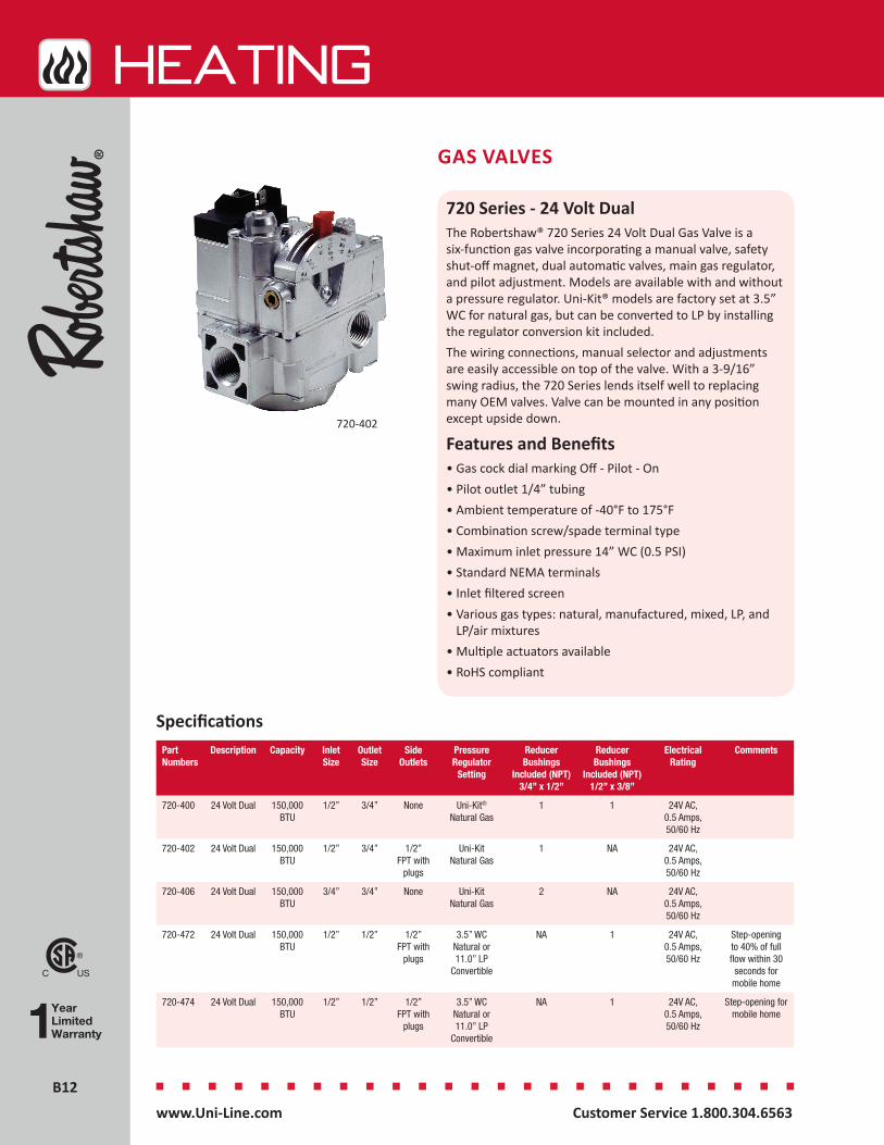
720 Series - 24 Volt DualThe Robertshaw® 720 Series 24 Volt Dual Gas Valve is a six-function gas valve incorporating a manual valve, safety shut-off magnet, dual automatic valves, main gas regulator, and pilot adjustment. Models are available with and without a pressure regulator. Uni-Kit® models are factory set at 3.5” WC for natural gas, but can be converted to LP by installing the regulator conversion kit included.The wiring connections, manual selector and adjustments are easily accessible on top of the valve. With a 3-9/16” swing radius, the 720 Series lends itself well to replacing many OEM valves. Valve can be mounted in any position except upside down.
Features and Benefits• Gas cock dial marking Off - Pilot - On• Pilot outlet 1/4” tubing• Ambient temperature of -40°F to 175°F• Combination screw/spade terminal type• Maximum inlet pressure 14” WC (0.5 PSI)• Standard NEMA terminals• Inlet filtered screen• Various gas types: natural, manufactured, mixed, LP, and
LP/air mixtures• Multiple actuators available• RoHS compliant
Specifications
720-402
Part Numbers
Description Capacity Inlet Size
Outlet Size
Side Outlets
Pressure Regulator
Setting
Reducer Bushings
Included (NPT) 3/4” x 1/2”
Reducer Bushings
Included (NPT) 1/2” x 3/8”
Electrical Rating
Comments
720-400 24 Volt Dual 150,000BTU
1/2” 3/4” None Uni-Kit®
Natural Gas1 1 24V AC,
0.5 Amps, 50/60 Hz
720-402 24 Volt Dual 150,000BTU
1/2” 3/4” 1/2” FPT with
plugs
Uni-Kit Natural Gas
1 NA 24V AC, 0.5 Amps, 50/60 Hz
720-406 24 Volt Dual 150,000BTU
3/4” 3/4” None Uni-KitNatural Gas
2 NA 24V AC, 0.5 Amps, 50/60 Hz
720-472 24 Volt Dual 150,000BTU
1/2” 1/2” 1/2” FPT with
plugs
3.5” WC Natural or 11.0” LP
Convertible
NA 1 24V AC, 0.5 Amps, 50/60 Hz
Step-opening to 40% of full flow within 30 seconds for
mobile home
720-474 24 Volt Dual 150,000BTU
1/2” 1/2” 1/2” FPT with
plugs
3.5” WC Natural or 11.0” LP
Convertible
NA 1 24V AC, 0.5 Amps, 50/60 Hz
Step-opening for mobile home
B13B13
HEATing
Customer Service 1.800.304.6563 www.Uni-Line.comwww.Uni-Line.com Customer Service 1.800.304.6563
GAS VALVES
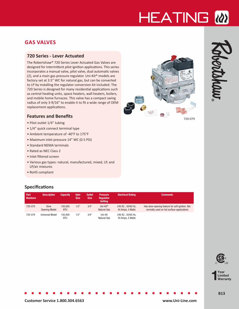
720 Series - Lever ActuatedThe Robertshaw® 720 Series Lever Actuated Gas Valves are designed for intermittent pilot ignition applications. This series incorporates a manual valve, pilot valve, dual automatic valves (2), and a main gas pressure regulator. Uni-Kit® models are factory set at 3.5” WC for natural gas, but can be converted to LP by installing the regulator conversion kit included. The 720 Series is designed for many residential applications such as central heating units, space heaters, wall heaters, boilers, and mobile home furnaces. This valve has a compact swing radius of only 3-9/16” to enable it to fit a wide range of OEM replacement applications.
Features and Benefits• Pilot outlet 1/4” tubing• 1/4” quick connect terminal type• Ambient temperature of -40°F to 175°F• Maximum inlet pressure 14” WC (0.5 PSI)• Standard NEMA terminals• Rated as NEC Class 2• Inlet filtered screen• Various gas types: natural, manufactured, mixed, LP, and
LP/air mixtures• RoHS compliant
SpecificationsPart Numbers
Description Capacity Inlet Size
Outlet Size
Pressure Regulator
Setting
Electrical Rating Comments
720-070 Slow Opening Model
150,000BTU
1/2” 3/4” Uni-Kit®
Natural Gas24V AC , 50/60 Hz, 45 Amps, 5 Watts
Has slow-opening feature for soft ignition. Not normally used on hot surface applications
720-079 Universal Model 150,000BTU
1/2” 3/4” Uni-Kit Natural Gas
24V AC , 50/60 Hz, 45 Amps, 5 Watts
720-079

B14B14
HEATing
Customer Service 1.800.304.6563 www.Uni-Line.comwww.Uni-Line.com Customer Service 1.800.304.6563
GAS VALVES
722 Series - Low Capacity DualThe Robertshaw® 722 Series Low Capacity Dual Gas Valve Uni-Kit® models are designed for a wide variety of intermittent pilot, direct spark or hot surface heating applications.
They incorporate dual automatic valves (redundant) that are pressure regulated and come factory set at 3.5” WC for natural gas. They can be converted to LP by installing the regulator conversion kit that is included.
Features and Benefits• Small, compact size, 3-9/16” swing radius, and 90°
flanged outlet for side outlet applications allow for greater flexibility of installation
• Incorporates a manual selector valve (On-Off), dual automatic valves, main gas regulator and inlet/outlet pressure taps
• Easily accessible wiring connections, manual selector, and adjustments designed to replace many OEM valves
• Multi-positional and can be mounted in any position except upside down
• As a safety feature, special screws are used and replacement parts are not available to prevent unsafe attempts at repair
SpecificationsPart Numbers
Description Capacity Inlet Size Outlet Size Pressure Regulator Setting
Comments
722-051 Hot Surface and Direct Spark Low Capacity Dual
170,000BTU
1/2” 1/2” Uni-Kit®
Natural GasStraight-thru
722-079 Universal Low Capacity Dual
170,000BTU
1/2” 1/2” Uni-Kit Natural Gas
Straight-thru, 1/2” flanged outlet adapts for side outlet applications
722-079
B15B15
HEATing
Customer Service 1.800.304.6563 www.Uni-Line.comwww.Uni-Line.com Customer Service 1.800.304.6563
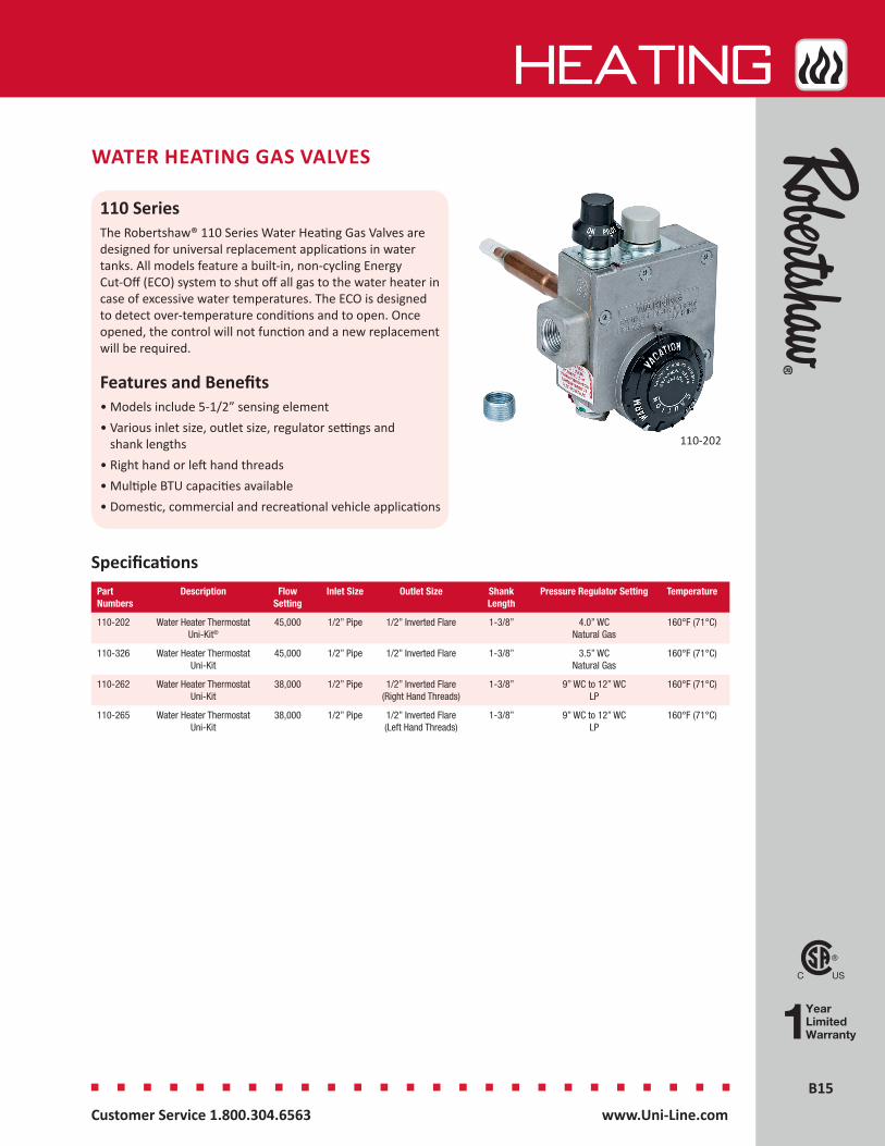
WATER HEATING GAS VALVES
110 Series The Robertshaw® 110 Series Water Heating Gas Valves are designed for universal replacement applications in water tanks. All models feature a built-in, non-cycling Energy Cut-Off (ECO) system to shut off all gas to the water heater in case of excessive water temperatures. The ECO is designed to detect over-temperature conditions and to open. Once opened, the control will not function and a new replacement will be required.
Features and Benefits• Models include 5-1/2” sensing element• Various inlet size, outlet size, regulator settings and
shank lengths• Right hand or left hand threads• Multiple BTU capacities available• Domestic, commercial and recreational vehicle applications
110-202
Part Numbers
Description Flow Setting
Inlet Size Outlet Size Shank Length
Pressure Regulator Setting Temperature
110-202 Water Heater Thermostat Uni-Kit®
45,000 1/2” Pipe 1/2” Inverted Flare 1-3/8” 4.0” WC Natural Gas
160°F (71°C)
110-326 Water Heater Thermostat Uni-Kit
45,000 1/2” Pipe 1/2” Inverted Flare 1-3/8” 3.5” WC Natural Gas
160°F (71°C)
110-262 Water Heater Thermostat Uni-Kit
38,000 1/2” Pipe 1/2” Inverted Flare (Right Hand Threads)
1-3/8” 9” WC to 12” WC LP
160°F (71°C)
110-265 Water Heater Thermostat Uni-Kit
38,000 1/2” Pipe 1/2” Inverted Flare (Left Hand Threads)
1-3/8” 9” WC to 12” WC LP
160°F (71°C)
Specifications
B16B16
HEATing
Customer Service 1.800.304.6563 www.Uni-Line.comwww.Uni-Line.com Customer Service 1.800.304.6563
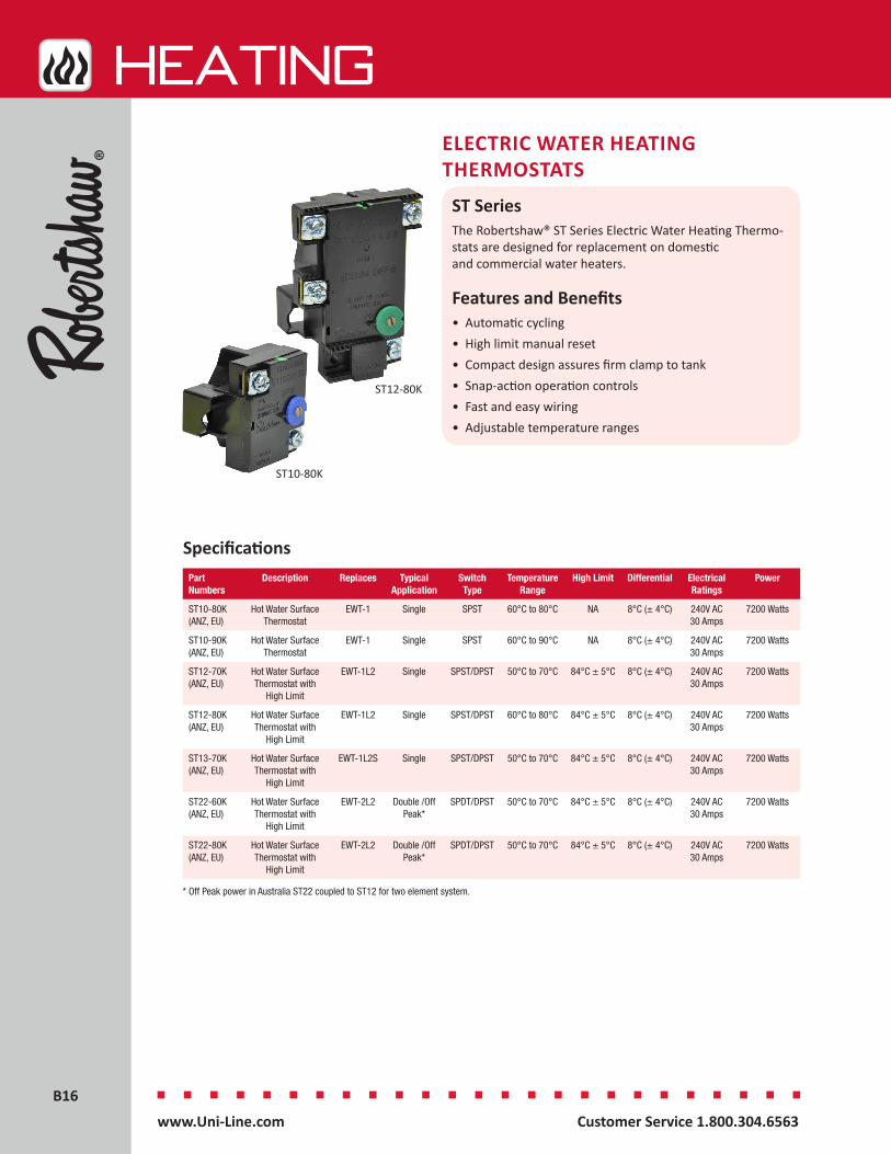
ELECTRIC WATER HEATING THERMOSTATS
ST Series The Robertshaw® ST Series Electric Water Heating Thermo-stats are designed for replacement on domestic and commercial water heaters.
Features and Benefits• Automatic cycling• High limit manual reset • Compact design assures firm clamp to tank• Snap-action operation controls• Fast and easy wiring• Adjustable temperature ranges
SpecificationsPart Numbers
Description Replaces Typical Application
Switch Type
Temperature Range
High Limit Differential Electrical Ratings
Power
ST10-80K (ANZ, EU)
Hot Water Surface Thermostat
EWT-1 Single SPST 60°C to 80°C NA 8°C (± 4°C) 240V AC 30 Amps
7200 Watts
ST10-90K (ANZ, EU)
Hot Water Surface Thermostat
EWT-1 Single SPST 60°C to 90°C NA 8°C (± 4°C) 240V AC 30 Amps
7200 Watts
ST12-70K (ANZ, EU)
Hot Water Surface Thermostat with
High Limit
EWT-1L2 Single SPST/DPST 50°C to 70°C 84°C ± 5°C 8°C (± 4°C) 240V AC 30 Amps
7200 Watts
ST12-80K (ANZ, EU)
Hot Water Surface Thermostat with
High Limit
EWT-1L2 Single SPST/DPST 60°C to 80°C 84°C ± 5°C 8°C (± 4°C) 240V AC 30 Amps
7200 Watts
ST13-70K (ANZ, EU)
Hot Water Surface Thermostat with
High Limit
EWT-1L2S Single SPST/DPST 50°C to 70°C 84°C ± 5°C 8°C (± 4°C) 240V AC 30 Amps
7200 Watts
ST22-60K (ANZ, EU)
Hot Water Surface Thermostat with
High Limit
EWT-2L2 Double /Off Peak*
SPDT/DPST 50°C to 70°C 84°C ± 5°C 8°C (± 4°C) 240V AC 30 Amps
7200 Watts
ST22-80K (ANZ, EU)
Hot Water Surface Thermostat with
High Limit
EWT-2L2 Double /Off Peak*
SPDT/DPST 50°C to 70°C 84°C ± 5°C 8°C (± 4°C) 240V AC 30 Amps
7200 Watts
* Off Peak power in Australia ST22 coupled to ST12 for two element system.
ST12-80K
ST10-80K
B17B17
HEATing
Customer Service 1.800.304.6563 www.Uni-Line.comwww.Uni-Line.com Customer Service 1.800.304.6563
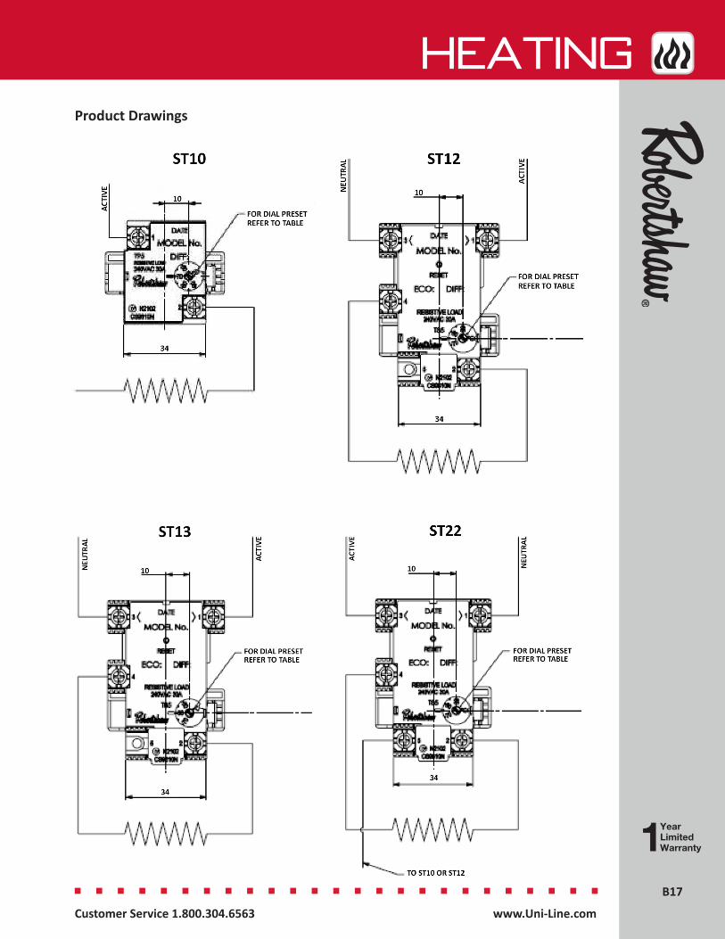
Product Drawings

B18B18
HEATing
Customer Service 1.800.304.6563 www.Uni-Line.comwww.Uni-Line.com Customer Service 1.800.304.6563
HEATING KITS
710 Series - Millivolt KitThe Robertshaw® 710-296 Millivolt Kit includes a low profile millivolt actuated gas valve, a pilot generator kit and an easy-to-use mechanical wall thermostat. The kit includes the Robertshaw gas valve cross reference pocket guide.
Features and Benefits• Most common parts needed in retrofit millivolt applications• Reduces inventory with most common parts• Easy-to-select, use and install
710-296
712 Series - Pilot KitsThe Robertshaw® 712 Series Intermittent Pilot Ignition System Kit features flame rectification with solid-state logic and flame sensing to provide automatic sequencing that will ensure proper operation of an intermittent pilot ignition device. The 712 pilot ignition systems are available with one of four different gas valve types to fit a wide range of furnace applications.
Caution: Do not use on LP gas applications
Features and Benefits• Quick and easy installation• Complete in-depth instructions and trouble
shooting information• Used on natural gas systems only
HEATING KITS
Part Numbers Description Hood Type Thermostat Gas Valve
710-296 Millivolt Kit 1820-009 Pilot Kit 986-1R Thermostat 710-502 Low Profile
Specifications
712-017
SpecificationsPart Numbers
Description Gas Valve
Inlet Outlet Capacity Restart Pressure Regulator Setting
Ignition Control
712-017 Intermittent Pilot Ignition System Kit
720-070 1/2” 3/4” 200,000BTU
Nonlockout 3.5” WC Natural Gas Only
780-715 (Nonlockout)
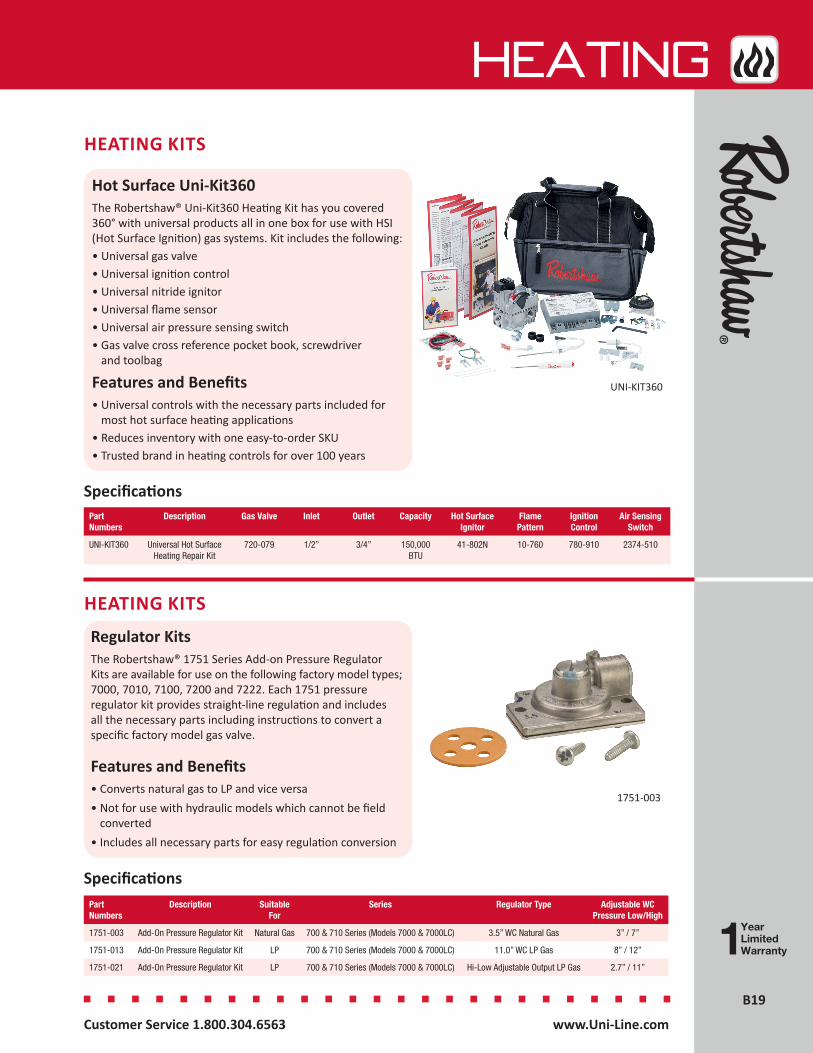
B19B19
HEATing
Customer Service 1.800.304.6563 www.Uni-Line.comwww.Uni-Line.com Customer Service 1.800.304.6563
HEATING KITS
Hot Surface Uni-Kit360The Robertshaw® Uni-Kit360 Heating Kit has you covered 360° with universal products all in one box for use with HSI (Hot Surface Ignition) gas systems. Kit includes the following:• Universal gas valve• Universal ignition control • Universal nitride ignitor• Universal flame sensor• Universal air pressure sensing switch• Gas valve cross reference pocket book, screwdriver
and toolbag
Features and Benefits• Universal controls with the necessary parts included for
most hot surface heating applications• Reduces inventory with one easy-to-order SKU• Trusted brand in heating controls for over 100 years
UNI-KIT360
Regulator KitsThe Robertshaw® 1751 Series Add-on Pressure Regulator Kits are available for use on the following factory model types; 7000, 7010, 7100, 7200 and 7222. Each 1751 pressure regulator kit provides straight-line regulation and includes all the necessary parts including instructions to convert a specific factory model gas valve.
Features and Benefits• Converts natural gas to LP and vice versa• Not for use with hydraulic models which cannot be field
converted• Includes all necessary parts for easy regulation conversion
HEATING KITS
Specifications
1751-003
Specifications
Part Numbers
Description Gas Valve Inlet Outlet Capacity Hot Surface Ignitor
Flame Pattern
Ignition Control
Air Sensing Switch
UNI-KIT360 Universal Hot Surface Heating Repair Kit
720-079 1/2” 3/4” 150,000BTU
41-802N 10-760 780-910 2374-510
Part Numbers
Description Suitable For
Series Regulator Type Adjustable WC Pressure Low/High
1751-003 Add-On Pressure Regulator Kit Natural Gas 700 & 710 Series (Models 7000 & 7000LC) 3.5” WC Natural Gas 3” / 7”
1751-013 Add-On Pressure Regulator Kit LP 700 & 710 Series (Models 7000 & 7000LC) 11.0” WC LP Gas 8” / 12”
1751-021 Add-On Pressure Regulator Kit LP 700 & 710 Series (Models 7000 & 7000LC) Hi-Low Adjustable Output LP Gas 2.7” / 11”
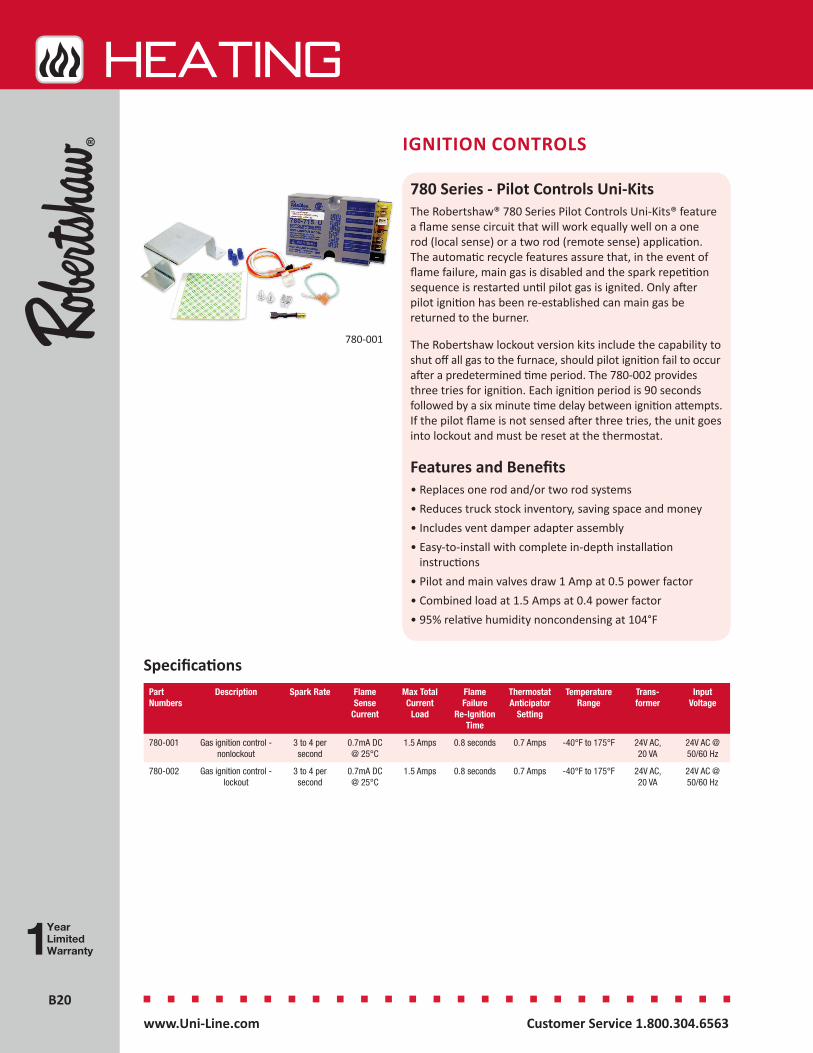
B20B20
HEATing
Customer Service 1.800.304.6563 www.Uni-Line.comwww.Uni-Line.com Customer Service 1.800.304.6563
IGNITION CONTROLS
780 Series - Pilot Controls Uni-KitsThe Robertshaw® 780 Series Pilot Controls Uni-Kits® feature a flame sense circuit that will work equally well on a one rod (local sense) or a two rod (remote sense) application. The automatic recycle features assure that, in the event of flame failure, main gas is disabled and the spark repetition sequence is restarted until pilot gas is ignited. Only after pilot ignition has been re-established can main gas be returned to the burner.
The Robertshaw lockout version kits include the capability to shut off all gas to the furnace, should pilot ignition fail to occur after a predetermined time period. The 780-002 provides three tries for ignition. Each ignition period is 90 seconds followed by a six minute time delay between ignition attempts. If the pilot flame is not sensed after three tries, the unit goes into lockout and must be reset at the thermostat.
Features and Benefits• Replaces one rod and/or two rod systems• Reduces truck stock inventory, saving space and money• Includes vent damper adapter assembly• Easy-to-install with complete in-depth installation
instructions• Pilot and main valves draw 1 Amp at 0.5 power factor• Combined load at 1.5 Amps at 0.4 power factor• 95% relative humidity noncondensing at 104°F
780-001
SpecificationsPart Numbers
Description Spark Rate Flame Sense
Current
Max Total Current
Load
Flame Failure
Re-Ignition Time
Thermostat Anticipator
Setting
Temperature Range
Trans-former
Input Voltage
780-001 Gas ignition control - nonlockout
3 to 4 per second
0.7mA DC @ 25°C
1.5 Amps 0.8 seconds 0.7 Amps -40°F to 175°F 24V AC, 20 VA
24V AC @ 50/60 Hz
780-002 Gas ignition control - lockout
3 to 4 per second
0.7mA DC @ 25°C
1.5 Amps 0.8 seconds 0.7 Amps -40°F to 175°F 24V AC, 20 VA
24V AC @ 50/60 Hz
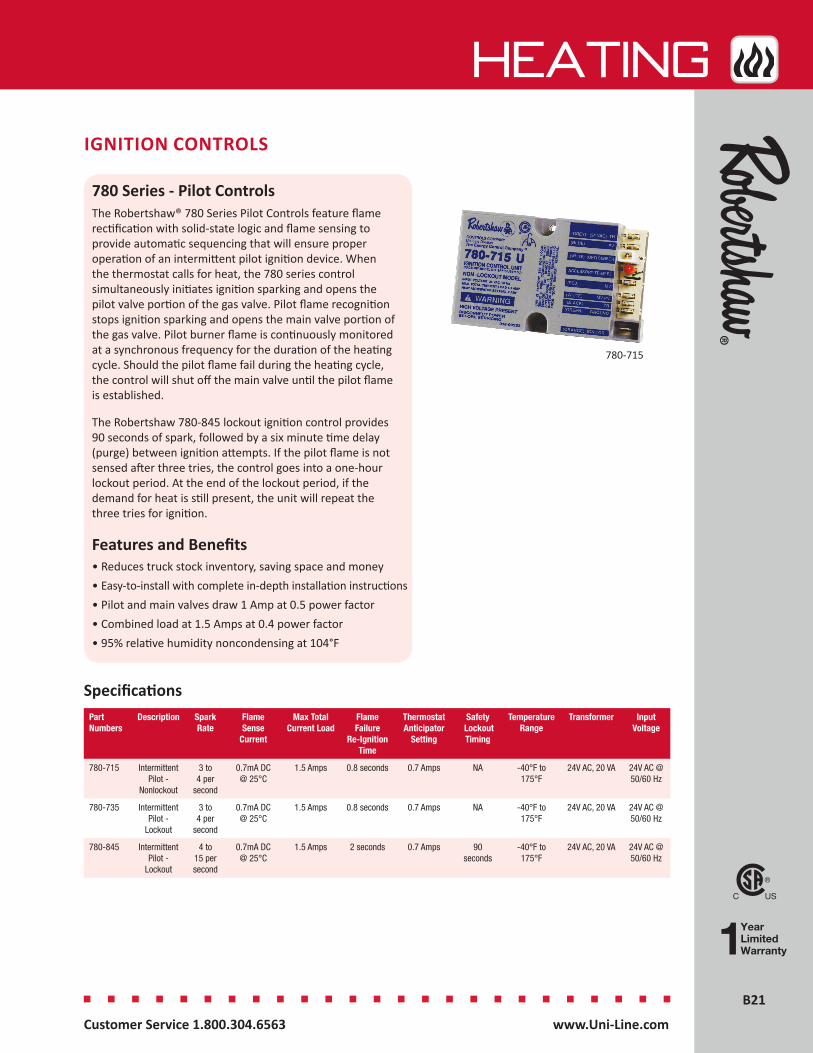
B21B21
HEATing
Customer Service 1.800.304.6563 www.Uni-Line.comwww.Uni-Line.com Customer Service 1.800.304.6563
IGNITION CONTROLS
780 Series - Pilot ControlsThe Robertshaw® 780 Series Pilot Controls feature flame rectification with solid-state logic and flame sensing to provide automatic sequencing that will ensure proper operation of an intermittent pilot ignition device. When the thermostat calls for heat, the 780 series control simultaneously initiates ignition sparking and opens the pilot valve portion of the gas valve. Pilot flame recognition stops ignition sparking and opens the main valve portion of the gas valve. Pilot burner flame is continuously monitored at a synchronous frequency for the duration of the heating cycle. Should the pilot flame fail during the heating cycle, the control will shut off the main valve until the pilot flame is established.
The Robertshaw 780-845 lockout ignition control provides 90 seconds of spark, followed by a six minute time delay (purge) between ignition attempts. If the pilot flame is not sensed after three tries, the control goes into a one-hour lockout period. At the end of the lockout period, if the demand for heat is still present, the unit will repeat the three tries for ignition.
Features and Benefits• Reduces truck stock inventory, saving space and money• Easy-to-install with complete in-depth installation instructions• Pilot and main valves draw 1 Amp at 0.5 power factor• Combined load at 1.5 Amps at 0.4 power factor• 95% relative humidity noncondensing at 104°F
Specifications
780-715
Part Numbers
Description Spark Rate
Flame Sense
Current
Max Total Current Load
Flame Failure
Re-Ignition Time
Thermostat Anticipator
Setting
Safety Lockout Timing
Temperature Range
Transformer Input Voltage
780-715 Intermittent Pilot -
Nonlockout
3 to 4 per
second
0.7mA DC @ 25°C
1.5 Amps 0.8 seconds 0.7 Amps NA -40°F to 175°F
24V AC, 20 VA 24V AC @ 50/60 Hz
780-735 Intermittent Pilot -
Lockout
3 to 4 per
second
0.7mA DC @ 25°C
1.5 Amps 0.8 seconds 0.7 Amps NA -40°F to 175°F
24V AC, 20 VA 24V AC @ 50/60 Hz
780-845 Intermittent Pilot -
Lockout
4 to 15 per second
0.7mA DC @ 25°C
1.5 Amps 2 seconds 0.7 Amps 90 seconds
-40°F to 175°F
24V AC, 20 VA 24V AC @ 50/60 Hz
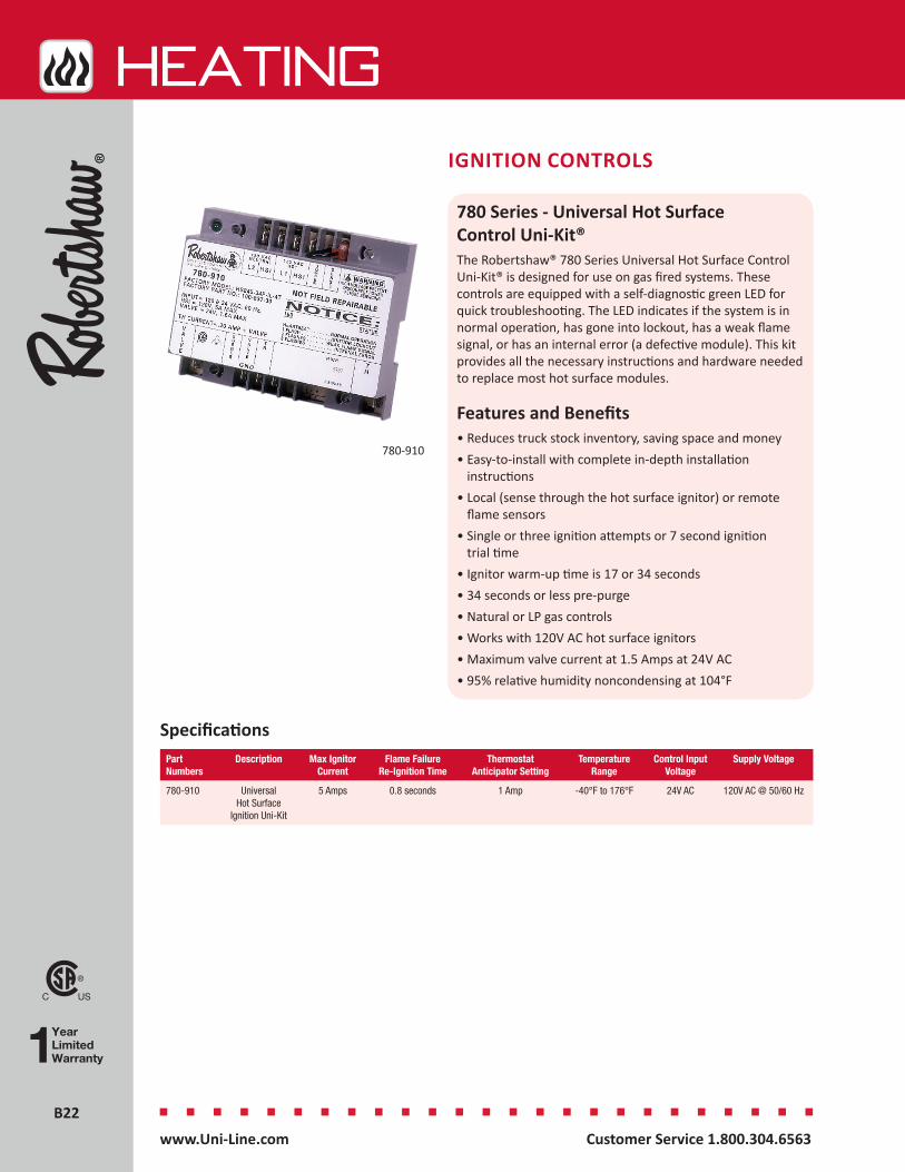
B22B22
HEATing
Customer Service 1.800.304.6563 www.Uni-Line.comwww.Uni-Line.com Customer Service 1.800.304.6563
IGNITION CONTROLS
780 Series - Universal Hot Surface Control Uni-Kit®The Robertshaw® 780 Series Universal Hot Surface Control Uni-Kit® is designed for use on gas fired systems. These controls are equipped with a self-diagnostic green LED for quick troubleshooting. The LED indicates if the system is in normal operation, has gone into lockout, has a weak flame signal, or has an internal error (a defective module). This kit provides all the necessary instructions and hardware needed to replace most hot surface modules.
Features and Benefits• Reduces truck stock inventory, saving space and money• Easy-to-install with complete in-depth installation
instructions• Local (sense through the hot surface ignitor) or remote
flame sensors• Single or three ignition attempts or 7 second ignition
trial time• Ignitor warm-up time is 17 or 34 seconds• 34 seconds or less pre-purge• Natural or LP gas controls• Works with 120V AC hot surface ignitors• Maximum valve current at 1.5 Amps at 24V AC• 95% relative humidity noncondensing at 104°F
780-910
SpecificationsPart Numbers
Description Max Ignitor Current
Flame Failure Re-Ignition Time
Thermostat Anticipator Setting
Temperature Range
Control Input Voltage
Supply Voltage
780-910 Universal Hot Surface
Ignition Uni-Kit
5 Amps 0.8 seconds 1 Amp -40°F to 176°F 24V AC 120V AC @ 50/60 Hz
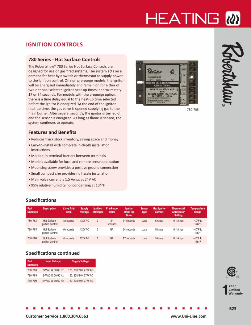
B23B23
HEATing
Customer Service 1.800.304.6563 www.Uni-Line.comwww.Uni-Line.com Customer Service 1.800.304.6563
IGNITION CONTROLS
780 Series - Hot Surface ControlsThe Robertshaw® 780 Series Hot Surface Controls are designed for use on gas fired systems. The system acts on a demand for heat by a switch or thermostat to supply power to the ignition control. On non pre-purge models, the ignitor will be energized immediately and remain on for either of two optional selected ignitor heat-up times: approximately 17 or 34 seconds. For models with the prepurge option, there is a time delay equal to the heat-up time selected before the ignitor is energized. At the end of the ignitor heat-up time, the gas valve is opened supplying gas to the main burner. After several seconds, the ignitor is turned off and the sensor is energized. As long as flame is sensed, the system continues to operate.
Features and Benefits• Reduces truck stock inventory, saving space and money• Easy-to-install with complete in-depth installation
instructions• Molded-in terminal barriers between terminals• Models available for local and remote sense application• Mounting screw provides a positive ground connection• Small compact size provides no hassle installation• Main valve current is 1.5 Amps at 24V AC• 95% relative humidity noncondensing at 104°F
Specifications
780-785
Part Numbers
Description Valve Trial Time
Supply Voltage
Ignition Attempts
Pre-Purge Timer
Ignitor Warm-Up
Timer
Sensor Type
Max Ignitor Current
Thermostat Anticipator
Setting
Temperature Range
780-783 Hot Surface Ignition Control
8 seconds 120V AC 3 34 seconds
34 seconds Local 5 Amps 0.1 Amps -40°F to 176°F
780-785 Hot Surface Ignition Control
6 seconds 120V AC 3 NA 34 seconds Local 5 Amps 0.1 Amps -40°F to 176°F
780-790 Hot Surface Ignition Control
4 seconds 120V AC 1 NA 17 seconds Local 5 Amps 0.1 Amps -40°F to 176°F
Part Numbers
Input Voltage Supply Voltage
780-783 24V AC @ 50/60 Hz 120, 208/240, 277V AC
780-785 24V AC @ 50/60 Hz 120, 208/240, 277V AC
780-790 24V AC @ 50/60 Hz 120, 208/240, 277V AC
Specifications continued
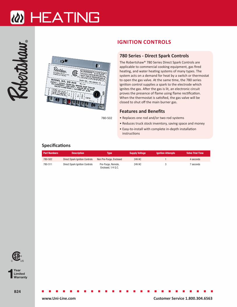
B24B24
HEATing
Customer Service 1.800.304.6563 www.Uni-Line.comwww.Uni-Line.com Customer Service 1.800.304.6563
IGNITION CONTROLS
780 Series - Direct Spark ControlsThe Robertshaw® 780 Series Direct Spark Controls are applicable to commercial cooking equipment, gas fired heating, and water heating systems of many types. The system acts on a demand for heat by a switch or thermostat to open the gas valve. At the same time, the 780 series ignition control supplies a spark to the electrode which ignites the gas. After the gas is lit, an electronic circuit proves the presence of flame using flame rectification. When the thermostat is satisfied, the gas valve will be closed to shut off the main burner gas.
Features and Benefits• Replaces one rod and/or two rod systems• Reduces truck stock inventory, saving space and money• Easy-to-install with complete in-depth installation
instructions
780-502
SpecificationsPart Numbers Description Type Supply Voltage Ignition Attempts Valve Trial Time
780-502 Direct Spark Ignition Controls Non Pre-Purge, Enclosed 24V AC 1 4 seconds
780-511 Direct Spark Ignition Controls Pre-Purge, Remote, Enclosed, 1/4 Q.C.
24V AC 3 7 seconds
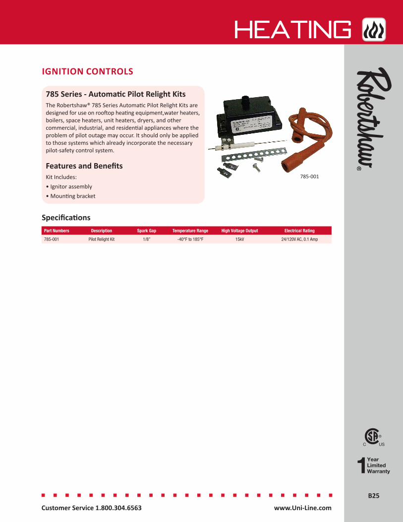
B25B25
HEATing
Customer Service 1.800.304.6563 www.Uni-Line.comwww.Uni-Line.com Customer Service 1.800.304.6563
IGNITION CONTROLS
785 Series - Automatic Pilot Relight KitsThe Robertshaw® 785 Series Automatic Pilot Relight Kits are designed for use on rooftop heating equipment,water heaters, boilers, space heaters, unit heaters, dryers, and other commercial, industrial, and residential appliances where the problem of pilot outage may occur. It should only be applied to those systems which already incorporate the necessary pilot-safety control system.
Features and BenefitsKit Includes:• Ignitor assembly• Mounting bracket
Specifications
785-001
Part Numbers Description Spark Gap Temperature Range High Voltage Output Electrical Rating
785-001 Pilot Relight Kit 1/8” -40°F to 185°F 15kV 24/120V AC, 0.1 Amp
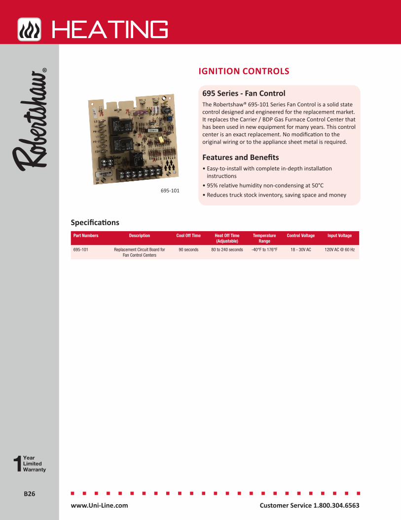
B26B26
HEATing
Customer Service 1.800.304.6563 www.Uni-Line.comwww.Uni-Line.com Customer Service 1.800.304.6563
IGNITION CONTROLS
695 Series - Fan ControlThe Robertshaw® 695-101 Series Fan Control is a solid state control designed and engineered for the replacement market. It replaces the Carrier / BDP Gas Furnace Control Center that has been used in new equipment for many years. This control center is an exact replacement. No modification to the original wiring or to the appliance sheet metal is required.
Features and Benefits• Easy-to-install with complete in-depth installation
instructions• 95% relative humidity non-condensing at 50°C• Reduces truck stock inventory, saving space and money
695-101
SpecificationsPart Numbers Description Cool Off Time Heat Off Time
(Adjustable)Temperature
RangeControl Voltage Input Voltage
695-101 Replacement Circuit Board for Fan Control Centers
90 seconds 80 to 240 seconds -40°F to 176°F 18 - 30V AC 120V AC @ 60 Hz

B27B27
HEATing
Customer Service 1.800.304.6563 www.Uni-Line.comwww.Uni-Line.com Customer Service 1.800.304.6563
IGNITION CONTROLS
35 Series - Fenwal® Intermittent Pilot ControlsThe Fenwal 35 Series Pilot Controls are a 24V AC intermittent pilot ignition control. The microprocessor circuit design provides precise, repeatable timing and operating sequences. The on-board diagnostics with LED output provide assistance with troubleshooting to ensure safe and efficient operation.
Features and Benefits• Quick connect terminals for easy connection• Easy-to-install with complete in-depth installation
instructions• Pilot valve draws 2.0 Amps maximum• Main valve draws 2.0 Amps maximum• Gray enclosure (Noryl N-190) of fire retardant plastic• Reduces truck stock inventory, saving space and money
Specifications
35-630501-001
Part Numbers Description Flame Sense
Method
Auto Reset
Ignition Tries Before Lockout
Trial For Ignition
Pre-Purge
Inter- Purge
Gas Valve Rating (Main
and Pilot)
Control Voltage
Electrical Rating
35-630501-001 Intermittent Pilot Ignition
Control
Remote No 1 15 0 seconds
0 seconds
2.0 Amps @ 24V AC
18 - 30V AC 24V AC @ 300mA
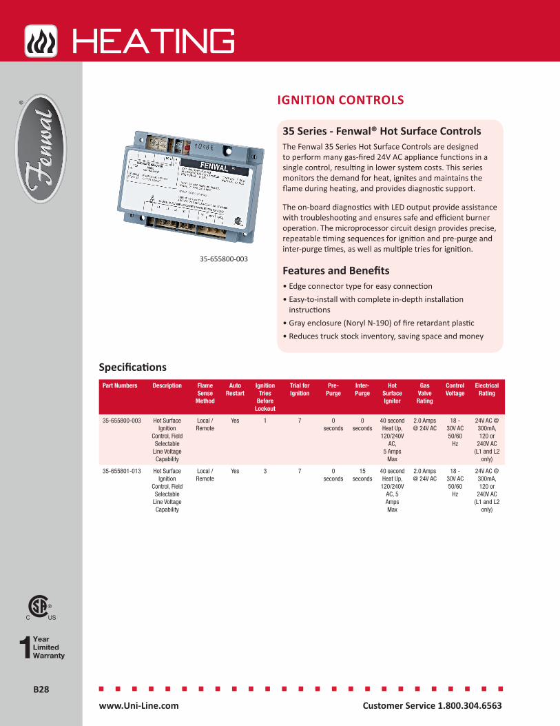
B28B28
HEATing
Customer Service 1.800.304.6563 www.Uni-Line.comwww.Uni-Line.com Customer Service 1.800.304.6563
IGNITION CONTROLS
35 Series - Fenwal® Hot Surface ControlsThe Fenwal 35 Series Hot Surface Controls are designed to perform many gas-fired 24V AC appliance functions in a single control, resulting in lower system costs. This series monitors the demand for heat, ignites and maintains the flame during heating, and provides diagnostic support.
The on-board diagnostics with LED output provide assistance with troubleshooting and ensures safe and efficient burner operation. The microprocessor circuit design provides precise, repeatable timing sequences for ignition and pre-purge and inter-purge times, as well as multiple tries for ignition.
Features and Benefits• Edge connector type for easy connection• Easy-to-install with complete in-depth installation
instructions• Gray enclosure (Noryl N-190) of fire retardant plastic• Reduces truck stock inventory, saving space and money
35-655800-003
SpecificationsPart Numbers Description Flame
Sense Method
Auto Restart
Ignition Tries
Before Lockout
Trial for Ignition
Pre-Purge
Inter- Purge
Hot Surface Ignitor
Gas Valve Rating
Control Voltage
Electrical Rating
35-655800-003 Hot Surface Ignition
Control, Field Selectable
Line Voltage Capability
Local / Remote
Yes 1 7 0 seconds
0 seconds
40 second Heat Up,
120/240V AC,
5 Amps Max
2.0 Amps @ 24V AC
18 - 30V AC 50/60
Hz
24V AC @ 300mA, 120 or
240V AC (L1 and L2
only)
35-655801-013 Hot Surface Ignition
Control, Field Selectable
Line Voltage Capability
Local / Remote
Yes 3 7 0 seconds
15 seconds
40 second Heat Up,
120/240V AC, 5 Amps Max
2.0 Amps @ 24V AC
18 - 30V AC 50/60
Hz
24V AC @ 300mA, 120 or
240V AC (L1 and L2
only)
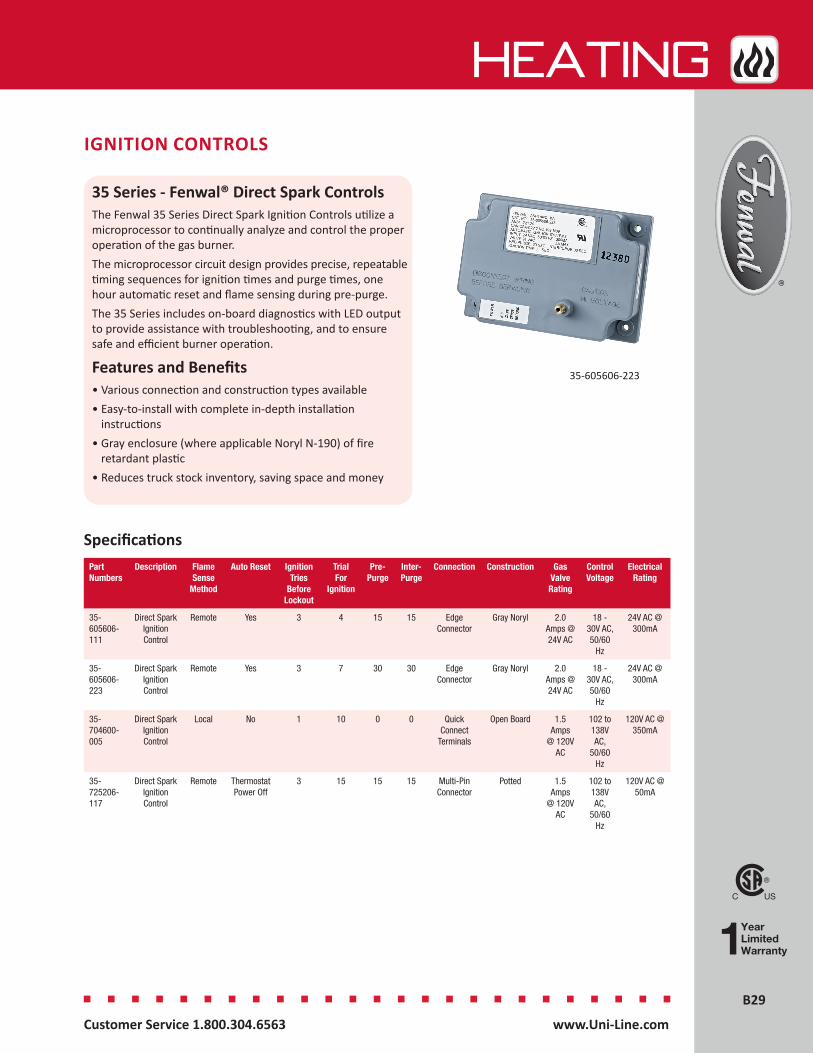
B29B29
HEATing
Customer Service 1.800.304.6563 www.Uni-Line.comwww.Uni-Line.com Customer Service 1.800.304.6563
IGNITION CONTROLS
35 Series - Fenwal® Direct Spark ControlsThe Fenwal 35 Series Direct Spark Ignition Controls utilize a microprocessor to continually analyze and control the proper operation of the gas burner. The microprocessor circuit design provides precise, repeatable timing sequences for ignition times and purge times, one hour automatic reset and flame sensing during pre-purge.The 35 Series includes on-board diagnostics with LED output to provide assistance with troubleshooting, and to ensure safe and efficient burner operation.
Features and Benefits• Various connection and construction types available• Easy-to-install with complete in-depth installation
instructions• Gray enclosure (where applicable Noryl N-190) of fire
retardant plastic• Reduces truck stock inventory, saving space and money
35-605606-223
SpecificationsPart Numbers
Description Flame Sense
Method
Auto Reset Ignition Tries
Before Lockout
Trial For
Ignition
Pre-Purge
Inter- Purge
Connection Construction Gas Valve Rating
Control Voltage
Electrical Rating
35-605606-111
Direct Spark Ignition Control
Remote Yes 3 4 15 15 Edge Connector
Gray Noryl 2.0 Amps @ 24V AC
18 - 30V AC, 50/60
Hz
24V AC @ 300mA
35-605606-223
Direct Spark Ignition Control
Remote Yes 3 7 30 30 Edge Connector
Gray Noryl 2.0 Amps @ 24V AC
18 - 30V AC, 50/60
Hz
24V AC @ 300mA
35-704600-005
Direct Spark Ignition Control
Local No 1 10 0 0 Quick Connect
Terminals
Open Board 1.5 Amps
@ 120V AC
102 to 138V AC,
50/60 Hz
120V AC @ 350mA
35-725206-117
Direct Spark Ignition Control
Remote Thermostat Power Off
3 15 15 15 Multi-Pin Connector
Potted 1.5 Amps
@ 120V AC
102 to 138V AC,
50/60 Hz
120V AC @ 50mA
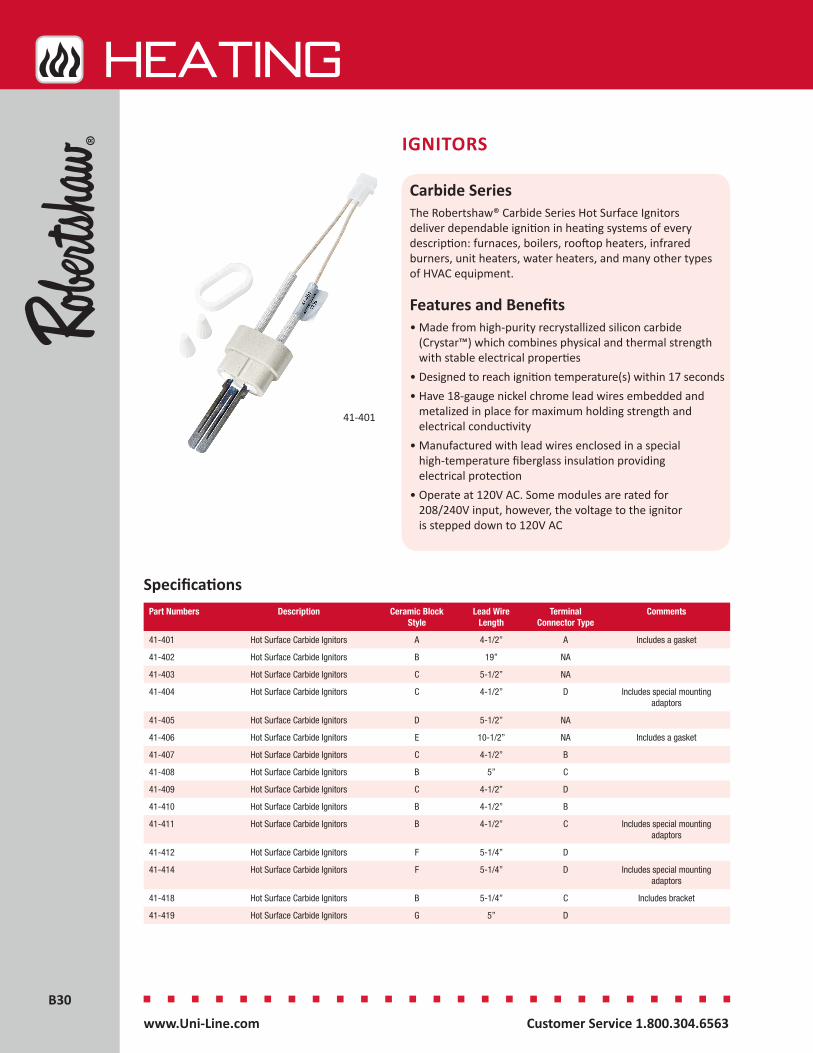
B30B30
HEATing
Customer Service 1.800.304.6563 www.Uni-Line.comwww.Uni-Line.com Customer Service 1.800.304.6563
IGNITORS
Carbide SeriesThe Robertshaw® Carbide Series Hot Surface Ignitors deliver dependable ignition in heating systems of every description: furnaces, boilers, rooftop heaters, infrared burners, unit heaters, water heaters, and many other types of HVAC equipment.
Features and Benefits• Made from high-purity recrystallized silicon carbide
(Crystar™) which combines physical and thermal strength with stable electrical properties
• Designed to reach ignition temperature(s) within 17 seconds• Have 18-gauge nickel chrome lead wires embedded and
metalized in place for maximum holding strength and electrical conductivity
• Manufactured with lead wires enclosed in a special high-temperature fiberglass insulation providing electrical protection
• Operate at 120V AC. Some modules are rated for 208/240V input, however, the voltage to the ignitor is stepped down to 120V AC
Specifications
41-401
Part Numbers Description Ceramic Block Style
Lead Wire Length
Terminal Connector Type
Comments
41-401 Hot Surface Carbide Ignitors A 4-1/2” A Includes a gasket
41-402 Hot Surface Carbide Ignitors B 19” NA
41-403 Hot Surface Carbide Ignitors C 5-1/2” NA
41-404 Hot Surface Carbide Ignitors C 4-1/2” D Includes special mounting adaptors
41-405 Hot Surface Carbide Ignitors D 5-1/2” NA
41-406 Hot Surface Carbide Ignitors E 10-1/2” NA Includes a gasket
41-407 Hot Surface Carbide Ignitors C 4-1/2” B
41-408 Hot Surface Carbide Ignitors B 5” C
41-409 Hot Surface Carbide Ignitors C 4-1/2” D
41-410 Hot Surface Carbide Ignitors B 4-1/2” B
41-411 Hot Surface Carbide Ignitors B 4-1/2” C Includes special mounting adaptors
41-412 Hot Surface Carbide Ignitors F 5-1/4” D
41-414 Hot Surface Carbide Ignitors F 5-1/4” D Includes special mounting adaptors
41-418 Hot Surface Carbide Ignitors B 5-1/4” C Includes bracket
41-419 Hot Surface Carbide Ignitors G 5” D
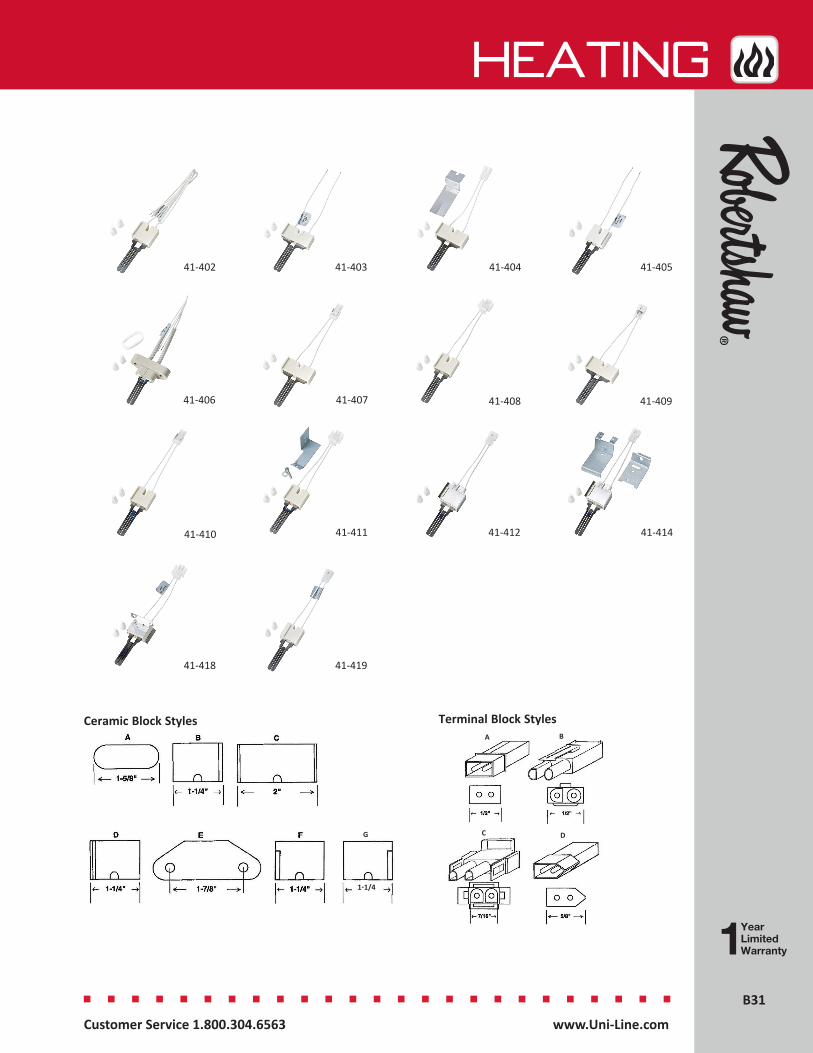
B31B31
HEATing
Customer Service 1.800.304.6563 www.Uni-Line.comwww.Uni-Line.com Customer Service 1.800.304.6563
41-402 41-403 41-404 41-405
41-406 41-407 41-408 41-409
41-410 41-411 41-412 41-414
41-418 41-419
Terminal Block StylesCeramic Block Styles
G
1-1/4
A B
C D

B32B32
HEATing
Customer Service 1.800.304.6563 www.Uni-Line.comwww.Uni-Line.com Customer Service 1.800.304.6563
IGNITORS
Hot Surface Mini-Ignitor SeriesThe Robertshaw® 41-600 Series Hot Surface Mini-Ignitors deliver dependable ignition in all heating systems. The mini-ignitor’s three-second heat-up time, in combination with its small size, have been embraced by gas furnace OEMs.
Features and Benefits• Engineered for easy handling, simple installation and
trouble-free operation• Made of a unique, non-porous, high strength material• Operates at 120V AC
Specifications
41-604
41-605
Part Numbers Description Ceramic Block Style Replaces
41-604 Hot Surface Furnace Mini-Ignitor 4” Armstrong #44744-2
41-605 Hot Surface Furnace Mini-Ignitor 2.5” York Conversion Kit #473-20937-001
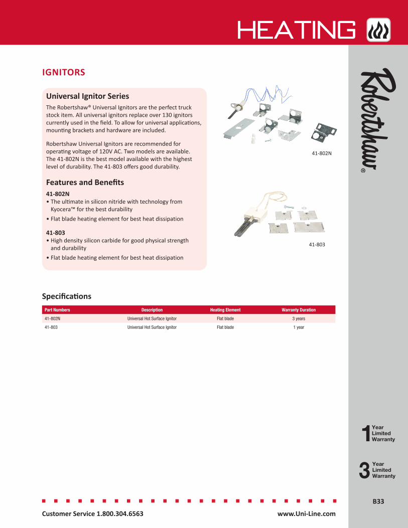
B33B33
HEATing
Customer Service 1.800.304.6563 www.Uni-Line.comwww.Uni-Line.com Customer Service 1.800.304.6563
IGNITORS
Universal Ignitor SeriesThe Robertshaw® Universal Ignitors are the perfect truck stock item. All universal ignitors replace over 130 ignitors currently used in the field. To allow for universal applications, mounting brackets and hardware are included.
Robertshaw Universal Ignitors are recommended for operating voltage of 120V AC. Two models are available. The 41-802N is the best model available with the highest level of durability. The 41-803 offers good durability.
Features and Benefits41-802N• The ultimate in silicon nitride with technology from
Kyocera™ for the best durability• Flat blade heating element for best heat dissipation
41-803• High density silicon carbide for good physical strength
and durability• Flat blade heating element for best heat dissipation
YearLimitedWarranty
Specifications
41-802N
41-803
Part Numbers Description Heating Element Warranty Duration
41-802N Universal Hot Surface Ignitor Flat blade 3 years
41-803 Universal Hot Surface Ignitor Flat blade 1 year

B34B34
HEATing
Customer Service 1.800.304.6563 www.Uni-Line.comwww.Uni-Line.com Customer Service 1.800.304.6563
PILOTS
1820 and 1830 SeriesThe Robertshaw® 1820 Series Pilot Uni-Kit® models are designed to replace hard-to-find ITT-General PG9 type pilots. A special 1/4” tubing adaptor is typically provided with nut and ball sleeve. Uni-Kits are available with and without a 32” [810mm] thermopile.
The 1830 Series Pilot Uni-Kit models are designed to be used with all Robertshaw and most competitive thermocouples. Uni-Kit models include an adaptor that converts a threaded thermocouple/thermopile model 2CH to a snap-in thermocouple type, model 2C.
Features and Benefits• Many flame pattern types available • Thermocouple or thermopile options• Spark electrode available• Horizontal or vertical gas inlet• Several mounting bracket types available• Aerated pilots with non-linting characteristics
Specifications
1820-009
1830-490
Part Numbers Description Hood Type Mounting Bracket Type
Flame Pattern Type Lead Lengths Includes
1800-100 9B Replacement Pilot Uni-Kit®
NA NA NA NA Orifices
1830-702 9B Replacement Pilot Uni-Kit®
STD NA NA NA Orifices
1830-113 9B Replacement Pilot Uni-Kit®
180 STD NA NA NA Orifices
1820-009 PG9 Replacement Pilot Uni-Kit®
NA NA 90° Right Hand 36” 1950-532 Thermopile and Orifices
1820-019 PG9 Replacement Pilot Uni-Kit
NA NA 90° Left Hand 36” 1950-532 Thermopile and Orifices
1830-001 2CH & 2C Incinerator -Target Pilot Uni-Kit
2 6 Standard NA Orifices
1830-210 2CH & 2C Incinerator- Target Pilot Uni-Kit
2 2 Standard NA Orifices
1830-489 2CH & 2C Incinerator- Target Pilot Uni-Kit
6 6 3-Way NA Orifices
1830-490 2CH & 2C Incinerator- Target Pilot Uni-Kit
6 6 3-Way NA Orifices
1830-491 2CH & 2C Incinerator- Target Pilot Uni-Kit
6 6 3-Way NA Orifices
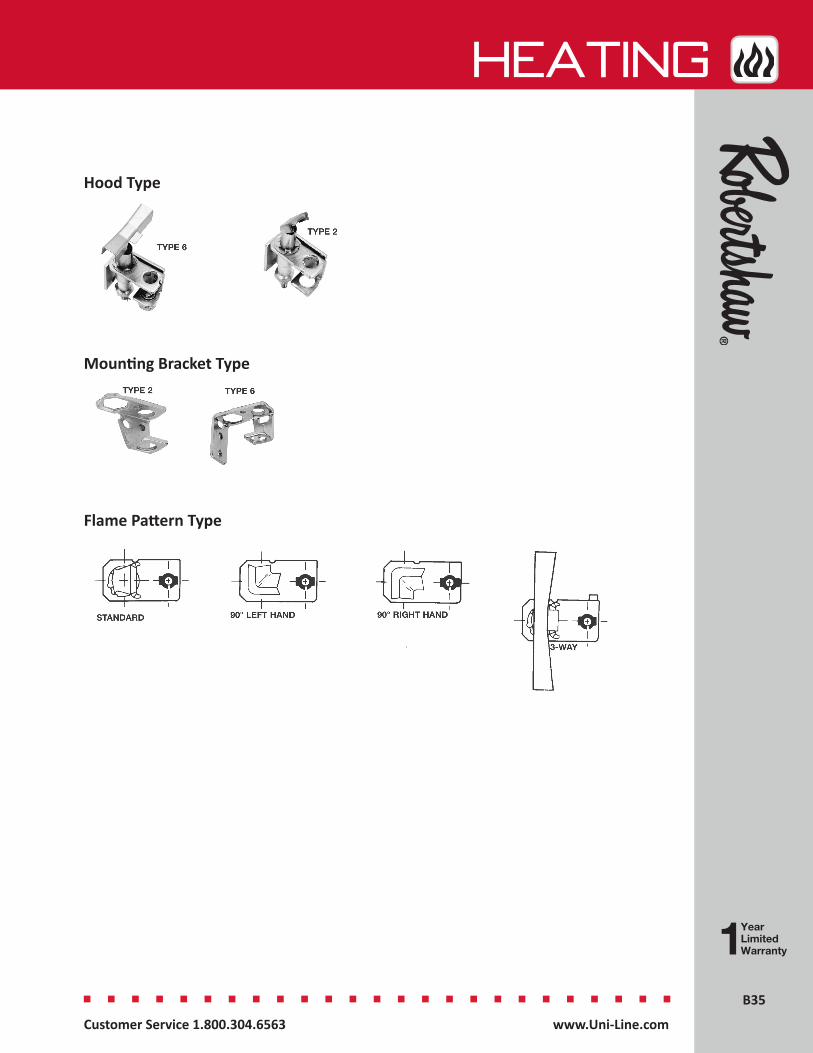
B35B35
HEATing
Customer Service 1.800.304.6563 www.Uni-Line.comwww.Uni-Line.com Customer Service 1.800.304.6563
Hood Type
Mounting Bracket Type
Flame Pattern Type
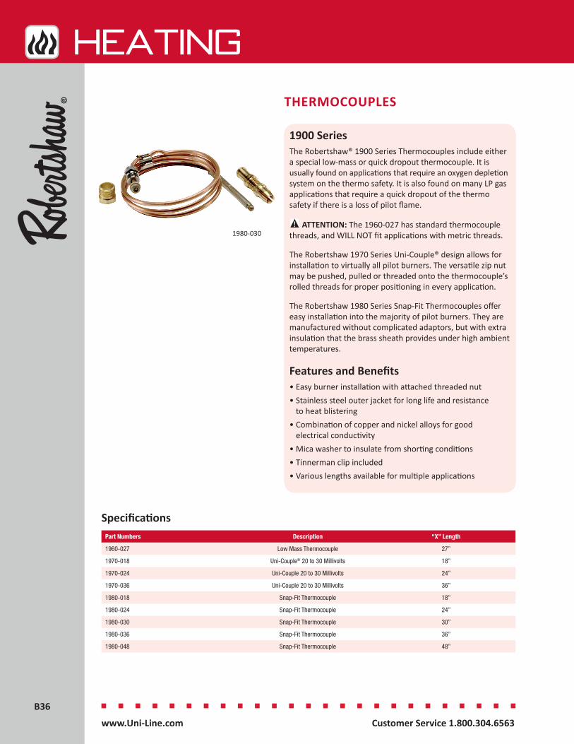
B36B36
HEATing
Customer Service 1.800.304.6563 www.Uni-Line.comwww.Uni-Line.com Customer Service 1.800.304.6563
THERMOCOUPLES
1900 SeriesThe Robertshaw® 1900 Series Thermocouples include either a special low-mass or quick dropout thermocouple. It is usually found on applications that require an oxygen depletion system on the thermo safety. It is also found on many LP gas applications that require a quick dropout of the thermo safety if there is a loss of pilot flame.
ATTENTION: The 1960-027 has standard thermocouple threads, and WILL NOT fit applications with metric threads.
The Robertshaw 1970 Series Uni-Couple® design allows for installation to virtually all pilot burners. The versatile zip nut may be pushed, pulled or threaded onto the thermocouple’s rolled threads for proper positioning in every application.
The Robertshaw 1980 Series Snap-Fit Thermocouples offer easy installation into the majority of pilot burners. They are manufactured without complicated adaptors, but with extra insulation that the brass sheath provides under high ambient temperatures.
Features and Benefits• Easy burner installation with attached threaded nut• Stainless steel outer jacket for long life and resistance
to heat blistering• Combination of copper and nickel alloys for good
electrical conductivity• Mica washer to insulate from shorting conditions• Tinnerman clip included• Various lengths available for multiple applications
SpecificationsPart Numbers Description “X” Length
1960-027 Low Mass Thermocouple 27”
1970-018 Uni-Couple® 20 to 30 Millivolts 18”
1970-024 Uni-Couple 20 to 30 Millivolts 24”
1970-036 Uni-Couple 20 to 30 Millivolts 36”
1980-018 Snap-Fit Thermocouple 18”
1980-024 Snap-Fit Thermocouple 24”
1980-030 Snap-Fit Thermocouple 30”
1980-036 Snap-Fit Thermocouple 36”
1980-048 Snap-Fit Thermocouple 48”
1980-030
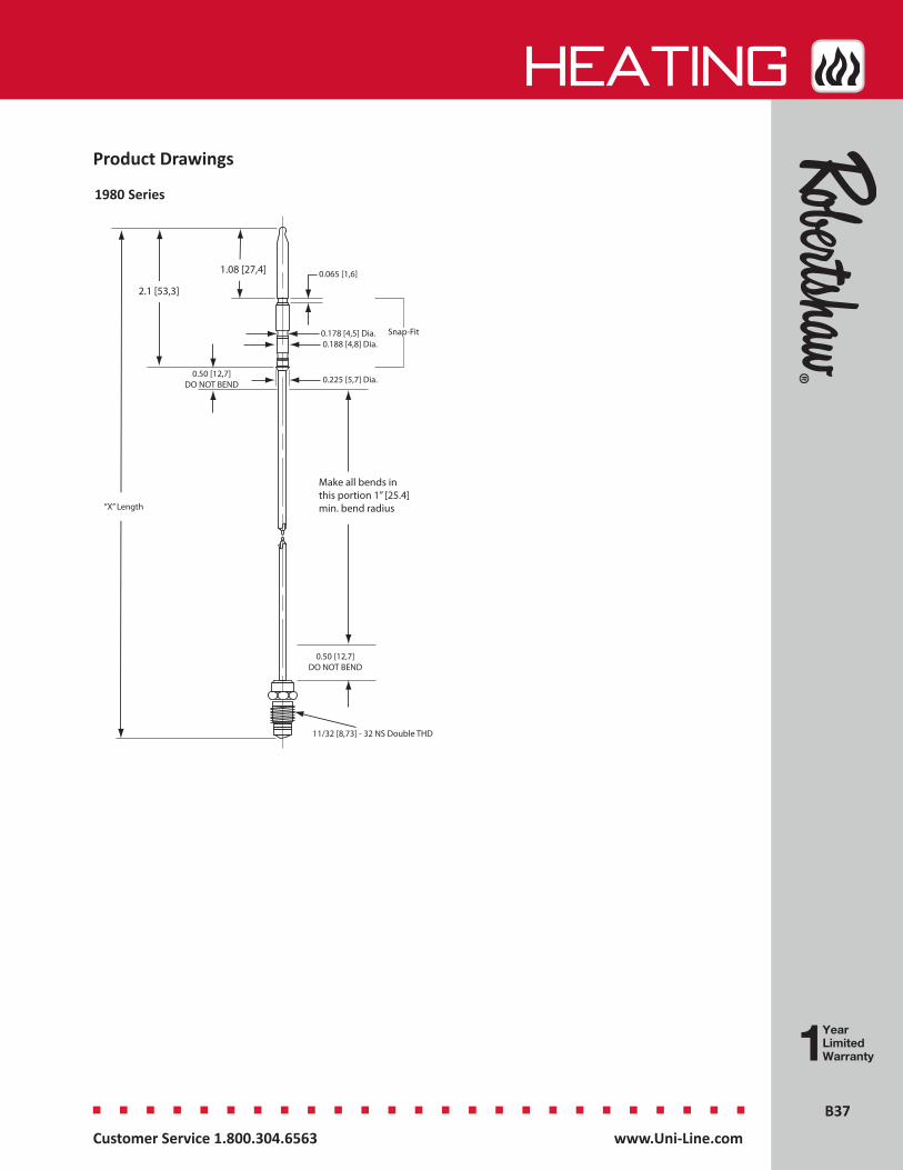
B37B37
HEATing
Customer Service 1.800.304.6563 www.Uni-Line.comwww.Uni-Line.com Customer Service 1.800.304.6563
Product Drawings
11/32 [8,73] - 32 NS Double THD
0.50 [12,7]DO NOT BEND
0.225 [5,7] Dia.
0.065 [1,6]
Make all bends in this portion 1” [25.4] min. bend radius
2.1 [53,3]
0.188 [4,8] Dia.0.178 [4,5] Dia.
1.08 [27,4]
0.50 [12,7]DO NOT BEND
“X” Length
Snap-Fit
1980 Series
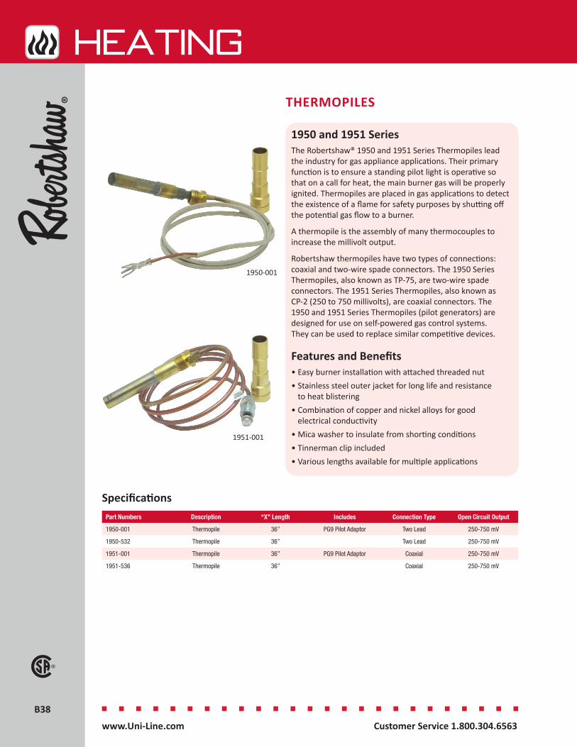
B38B38
HEATing
Customer Service 1.800.304.6563 www.Uni-Line.comwww.Uni-Line.com Customer Service 1.800.304.6563
1950 and 1951 SeriesThe Robertshaw® 1950 and 1951 Series Thermopiles lead the industry for gas appliance applications. Their primary function is to ensure a standing pilot light is operative so that on a call for heat, the main burner gas will be properly ignited. Thermopiles are placed in gas applications to detect the existence of a flame for safety purposes by shutting off the potential gas flow to a burner.
A thermopile is the assembly of many thermocouples to increase the millivolt output.
Robertshaw thermopiles have two types of connections: coaxial and two-wire spade connectors. The 1950 Series Thermopiles, also known as TP-75, are two-wire spade connectors. The 1951 Series Thermopiles, also known as CP-2 (250 to 750 millivolts), are coaxial connectors. The 1950 and 1951 Series Thermopiles (pilot generators) are designed for use on self-powered gas control systems. They can be used to replace similar competitive devices.
Features and Benefits• Easy burner installation with attached threaded nut• Stainless steel outer jacket for long life and resistance
to heat blistering• Combination of copper and nickel alloys for good
electrical conductivity• Mica washer to insulate from shorting conditions• Tinnerman clip included• Various lengths available for multiple applications
Specifications
THERMOPILES
1950-001
1951-001
Part Numbers Description “X” Length Includes Connection Type Open Circuit Output
1950-001 Thermopile 36” PG9 Pilot Adaptor Two Lead 250-750 mV
1950-532 Thermopile 36” Two Lead 250-750 mV
1951-001 Thermopile 36” PG9 Pilot Adaptor Coaxial 250-750 mV
1951-536 Thermopile 36” Coaxial 250-750 mV

B39B39
HEATing
Customer Service 1.800.304.6563 www.Uni-Line.comwww.Uni-Line.com Customer Service 1.800.304.6563
Product Drawings
Assy No. A Length 250 50051020 24 [609.6] x51030 30 [762.0] x51050 36 [914.4] x51022 24 [609.6] x51032 30 [762.0] x61052 36 [914.4] x
51021 24 [609.6] x51031 30 [762.0] x51051 36 [914.4] x51013 18 [457.2] x51041 32 [812.8] x51056 40 [1016.0] x51079 60 [1524.0] x51023 24 [609.6] x51033 30 [762.0] x51053 36 [914.4] x51071 48 [1219.2] x
Millivolt
COAXIAL CONNECTOR NUT3/8”-32 UNEF-2
7/16 Hex
7/16[11,11] -27 NS THD
0.353 [8,9] ± .002 [±0,05] Dia.
CP-1
CP-2
Model
“X” Length
“X” Length
1951 Series1950 Series
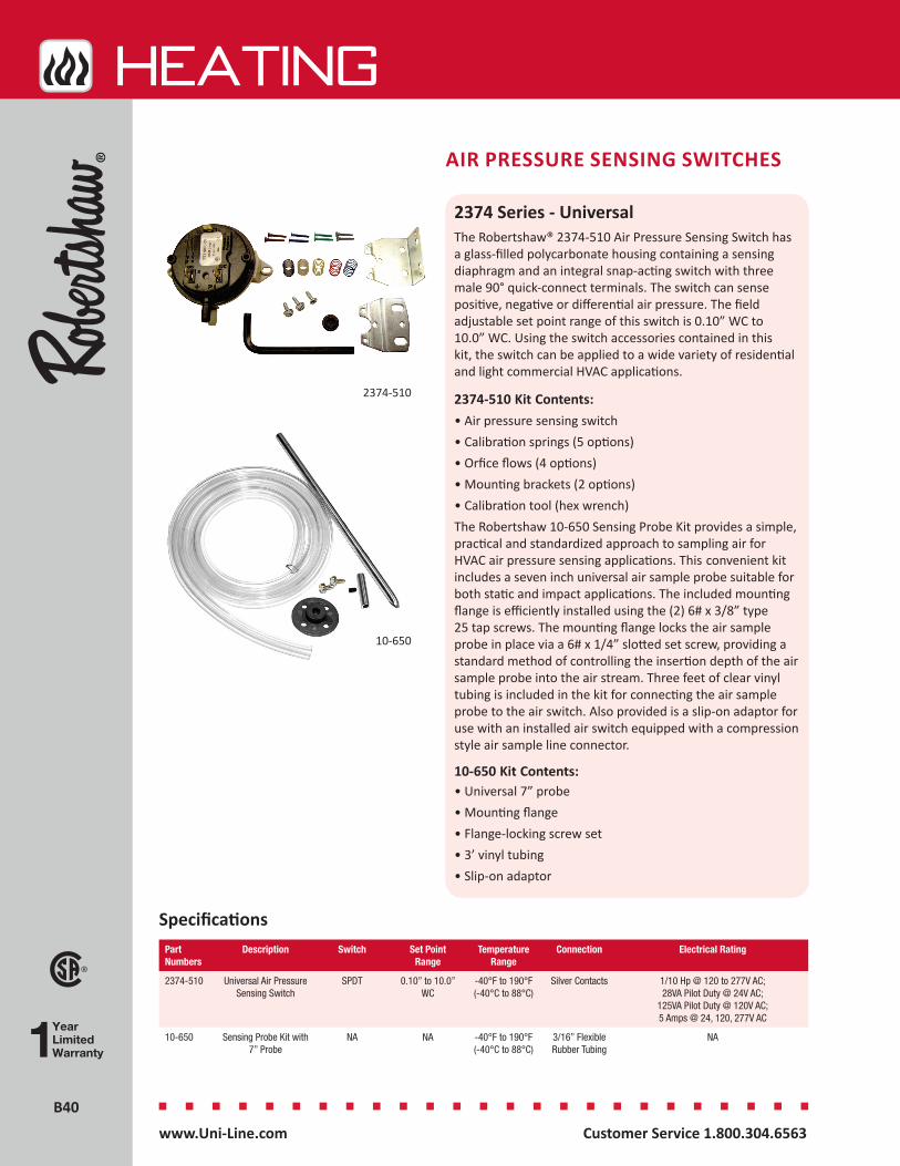
B40B40
HEATing
Customer Service 1.800.304.6563 www.Uni-Line.comwww.Uni-Line.com Customer Service 1.800.304.6563
2374 Series - UniversalThe Robertshaw® 2374-510 Air Pressure Sensing Switch has a glass-filled polycarbonate housing containing a sensing diaphragm and an integral snap-acting switch with three male 90° quick-connect terminals. The switch can sense positive, negative or differential air pressure. The field adjustable set point range of this switch is 0.10” WC to 10.0” WC. Using the switch accessories contained in this kit, the switch can be applied to a wide variety of residential and light commercial HVAC applications.
2374-510 Kit Contents:• Air pressure sensing switch• Calibration springs (5 options)• Orfice flows (4 options)• Mounting brackets (2 options)• Calibration tool (hex wrench)The Robertshaw 10-650 Sensing Probe Kit provides a simple, practical and standardized approach to sampling air for HVAC air pressure sensing applications. This convenient kit includes a seven inch universal air sample probe suitable for both static and impact applications. The included mounting flange is efficiently installed using the (2) 6# x 3/8” type 25 tap screws. The mounting flange locks the air sample probe in place via a 6# x 1/4” slotted set screw, providing a standard method of controlling the insertion depth of the air sample probe into the air stream. Three feet of clear vinyl tubing is included in the kit for connecting the air sample probe to the air switch. Also provided is a slip-on adaptor for use with an installed air switch equipped with a compression style air sample line connector.
10-650 Kit Contents:• Universal 7” probe• Mounting flange• Flange-locking screw set• 3’ vinyl tubing • Slip-on adaptor
AIR PRESSURE SENSING SWITCHES
10-650
2374-510
Part Numbers
Description Switch Set Point Range
Temperature Range
Connection Electrical Rating
2374-510 Universal Air Pressure Sensing Switch
SPDT 0.10” to 10.0” WC
-40°F to 190°F (-40°C to 88°C)
Silver Contacts 1/10 Hp @ 120 to 277V AC; 28VA Pilot Duty @ 24V AC;
125VA Pilot Duty @ 120V AC; 5 Amps @ 24, 120, 277V AC
10-650 Sensing Probe Kit with 7” Probe
NA NA -40°F to 190°F (-40°C to 88°C)
3/16” Flexible Rubber Tubing
NA
Specifications
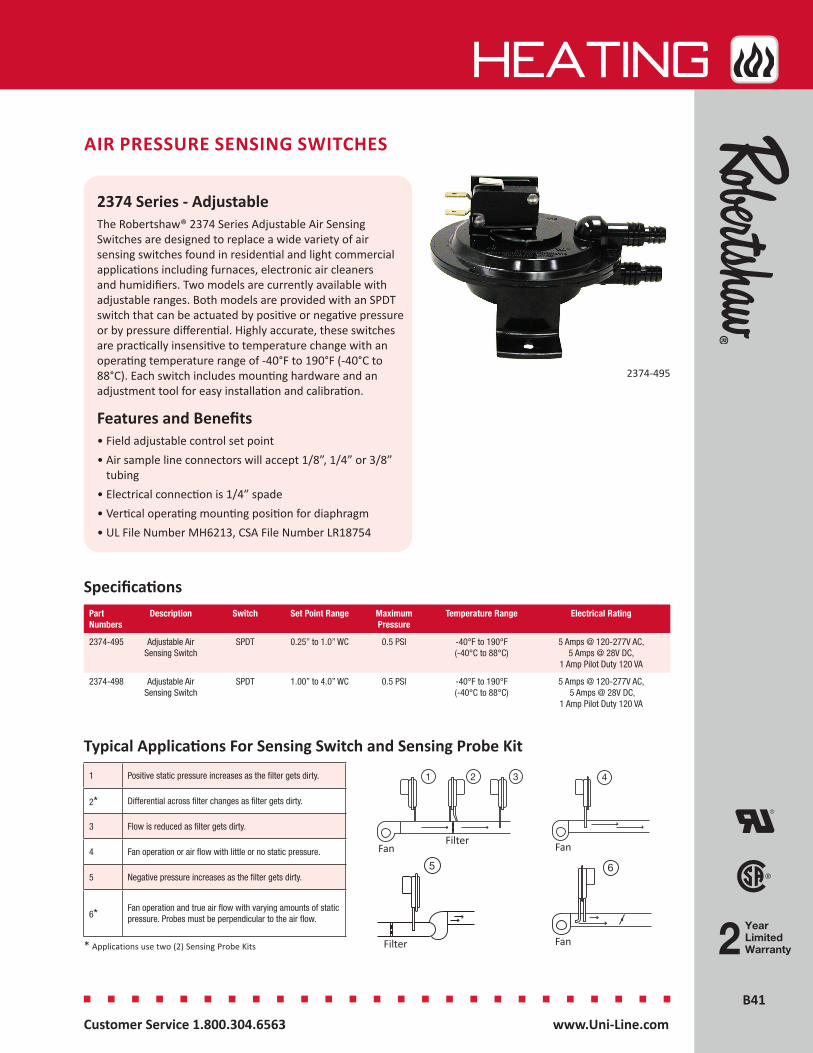
B41B41
HEATing
Customer Service 1.800.304.6563 www.Uni-Line.comwww.Uni-Line.com Customer Service 1.800.304.6563
2374 Series - AdjustableThe Robertshaw® 2374 Series Adjustable Air Sensing Switches are designed to replace a wide variety of air sensing switches found in residential and light commercial applications including furnaces, electronic air cleaners and humidifiers. Two models are currently available with adjustable ranges. Both models are provided with an SPDT switch that can be actuated by positive or negative pressure or by pressure differential. Highly accurate, these switches are practically insensitive to temperature change with an operating temperature range of -40°F to 190°F (-40°C to 88°C). Each switch includes mounting hardware and an adjustment tool for easy installation and calibration.
Features and Benefits• Field adjustable control set point• Air sample line connectors will accept 1/8”, 1/4” or 3/8”
tubing• Electrical connection is 1/4” spade• Vertical operating mounting position for diaphragm• UL File Number MH6213, CSA File Number LR18754
Specifications
AIR PRESSURE SENSING SWITCHES
2374-495
Part Numbers
Description Switch Set Point Range Maximum Pressure
Temperature Range Electrical Rating
2374-495 Adjustable Air Sensing Switch
SPDT 0.25” to 1.0” WC 0.5 PSI -40°F to 190°F (-40°C to 88°C)
5 Amps @ 120-277V AC, 5 Amps @ 28V DC,
1 Amp Pilot Duty 120 VA
2374-498 Adjustable Air Sensing Switch
SPDT 1.00” to 4.0” WC 0.5 PSI -40°F to 190°F (-40°C to 88°C)
5 Amps @ 120-277V AC, 5 Amps @ 28V DC,
1 Amp Pilot Duty 120 VA
YearLimitedWarranty
1 Positive static pressure increases as the filter gets dirty.
2* Differential across filter changes as filter gets dirty.
3 Flow is reduced as filter gets dirty.
4 Fan operation or air flow with little or no static pressure.
5 Negative pressure increases as the filter gets dirty.
6* Fan operation and true air flow with varying amounts of static pressure. Probes must be perpendicular to the air flow.
* Applications use two (2) Sensing Probe Kits
1 2 3
5 6
4
FanFilter
Filter
Fan
Fan
Typical Applications For Sensing Switch and Sensing Probe Kit
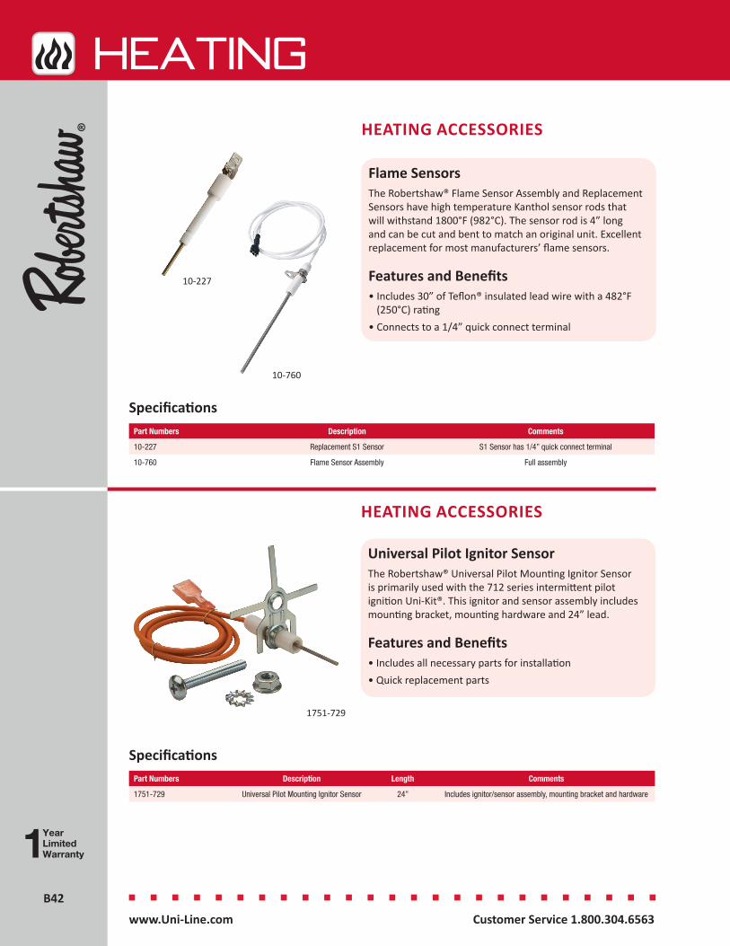
B42B42
HEATing
Customer Service 1.800.304.6563 www.Uni-Line.comwww.Uni-Line.com Customer Service 1.800.304.6563
Flame SensorsThe Robertshaw® Flame Sensor Assembly and Replacement Sensors have high temperature Kanthol sensor rods that will withstand 1800°F (982°C). The sensor rod is 4” long and can be cut and bent to match an original unit. Excellent replacement for most manufacturers’ flame sensors.
Features and Benefits• Includes 30” of Teflon® insulated lead wire with a 482°F
(250°C) rating• Connects to a 1/4” quick connect terminal
Specifications
HEATING ACCESSORIES
Part Numbers Description Comments
10-227 Replacement S1 Sensor S1 Sensor has 1/4” quick connect terminal
10-760 Flame Sensor Assembly Full assembly
10-227
10-760
Universal Pilot Ignitor SensorThe Robertshaw® Universal Pilot Mounting Ignitor Sensor is primarily used with the 712 series intermittent pilot ignition Uni-Kit®. This ignitor and sensor assembly includes mounting bracket, mounting hardware and 24” lead.
Features and Benefits• Includes all necessary parts for installation• Quick replacement parts
HEATING ACCESSORIES
Part Numbers Description Length Comments
1751-729 Universal Pilot Mounting Ignitor Sensor 24” Includes ignitor/sensor assembly, mounting bracket and hardware
Specifications
1751-729
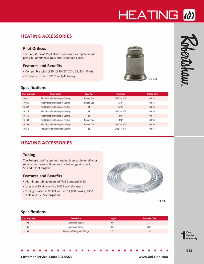
B43B43
HEATing
Customer Service 1.800.304.6563 www.Uni-Line.comwww.Uni-Line.com Customer Service 1.800.304.6563
Pilot OrificesThe Robertshaw® Pilot Orifices are used as replacement parts in Robertshaw 1820 and 1830 type pilots.
Features and Benefits• Compatible with 1820, 1830 (2C, 2CH, 2S, 2SH) Pilots• Orifice can fit into 3/16” or 1/4” tubing
HEATING ACCESSORIES
SpecificationsPart Numbers Description Type Gas Tube Size Orifice Size
10-021 Pilot Orifice for Heating or Cooking Natural Gas 3/16” or 1/4” 0.018”
10-066 Pilot Orifice for Heating or Cooling Natural Gas 3/16” 0.018”
10-067 Pilot Orifice for Heating or Cooling LP 3/16” 0.010”
10-114 Pilot Orifice for Heating or Cooking LP 3/16” or 1/4” 0.010”
10-166 Pilot Orifice for Heating or Cooling LP 1/4” 0.011”
10-168 Pilot Orifice for Heating or Cooling Natural Gas 1/4” 0.018”
10-209 Pilot Orifice for Heating or Cooking Natural Gas 3/16” or 1/4” 0.026”
10-210 Pilot Orifice for Heating or Cooking LP 3/16” or 1/4” 0.016”
10-021
TubingThe Robertshaw® aluminum tubing is versatile for all your replacement needs. It comes in a full range of sizes in 50 and 5 foot lengths.
Features and Benefits• Aluminum tubing meets ASTMB Standard #483• Uses a 1435 alloy with a 0.035 wall thickness • Tubing is rated at 90 PSI with an 11,000 tensile, 9500
yield and a 25% elongation
HEATING ACCESSORIES
Specifications
11-193
Part Numbers Description Length Diameter Size
11-193 Aluminum Tubing 50’ 1/4”
11-195 Aluminum Tubing 50’ 3/8”
11-293 Aluminum Tubing with Fittings 5’ 1/4”
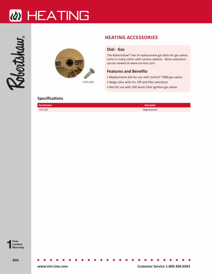
B44B44
HEATing
Customer Service 1.800.304.6563 www.Uni-Line.comwww.Uni-Line.com Customer Service 1.800.304.6563
Dial - GasThe Robertshaw® line of replacement gas dials for gas valves come in many colors with various options. More selections can be viewed at www.uni-line.com.
Features and Benefits• Replacement dial for use with Unitrol® 7000 gas valves• Beige color with On, Off and Pilot selections• Not for use with 700 Series Pilot Ignition gas valves
Specifications
HEATING ACCESSORIES
1751-012
Part Numbers Description
1751-012 Beige knob dial

B45B45
HEATing
Customer Service 1.800.304.6563 www.Uni-Line.comwww.Uni-Line.com Customer Service 1.800.304.6563
4590 Series - Breakaway FerrulesThe Robertshaw® 4590 Series Breakaway Ferrules are used for attaching tubing to gas valves. Applications include heating, cooking and water heating.
Features and Benefits• One breakaway ferrule part replaces the need for an
additional nut• Sold in multiple quantities for convenience• Screw machined brass fittings for quality performance
HEATING ACCESSORIES
Specifications
4590-816
4590-067
4590-071
4590-065
4590-069
Part Numbers Description Size Quantity
4590-065 Breakaway Ferrules For Venting 1/8” Tubing Package of 15
4590-067 Breakaway Ferrules 3/16” Tubing Package of 15
4590-069 Breakaway Ferrules 1/4” Tubing Package of 15
4590-071 Breakaway Ferrules 3/8” Tubing Package of 6
4590-170 Male Compression Nut & Ball Sleeves 1/4 to 3/16” Reducer Package of 12
4590-816 Extended Breakaway Ferrules 1/4” Extended Package of 15


Refrigeration
Installers prefer a vast selection of quality solutions for commercial refrigeration applications while requiring intuitive installation set-up and dependable performance.The Ranco® brand is trusted in commercial refrigeration for ease-of-use, performance, reliability and innovation.
Electronic Controls ........................................................................C2
Temperature Controls - Cold Controls ...........................................C6
Temperature Controls ....................................................................C9
Temperature Controls - Specialty Applications ............................C10
Lube Oil Controls .........................................................................C13
Temperature Controls - Wide Range ...........................................C14
Pressure Controls ........................................................................C16
Refrigeration Accessories ............................................................C21
Reversing Valves ..........................................................................C22
Reversing Valves - Solenoid Coils .................................................C24
Solenoid Valves ............................................................................C25
Thermostatic Expansion Valves ...................................................C26
Regulators....................................................................................C30
Moisture Indicators .....................................................................C32
Solid Core Filter Driers .................................................................C34
Ball Valves ....................................................................................C36
Electrical Ratings .........................................................................C37

Customer Service 1.800.304.6563 www.Uni-Line.comwww.Uni-Line.com Customer Service 1.800.304.6563
C2C2
REFRIGERATION
ERC-2 SeriesThe Paragon® ERC-2 Electronic Refrigeration Control is a microprocessor-based electronic controller designed to manage both the temperature and the defrost functions of a commercial refrigeration unit.
Features and Benefits• Real-time clock for defrost control• Integrated control• Temperature control function• 4 relay outputs 120-240V AC @ 50/60 Hz• Compressor• Evaporator fan• Alarm• Digital display module• Keypad programming• Two temperature sensors (supplied)• Refrigeration cycle• Safe mode operation• Continues operation based on performance average in
the event sensor fails• Power failure recovery• All settings retained in memory• Time-of-day carried over for 100 hours
ELECTRONIC CONTROLS
SpecificationsPart Numbers Description Case Type Temperature
SensorDefrost Cycles Temperature
RangeElectrical Rating
ERC2-212111-370 ERC-2 Electronic Control with integrated display
NEMA 1 NTC thermistor 1 to 8 per day or 1 every 48 hours
-40°F to 60°F (-40°C to 16°C)
120/208/240V AC (+10, -15%), 50/60 Hz
Listed Product
ERC2-212111-370
Recognized Component
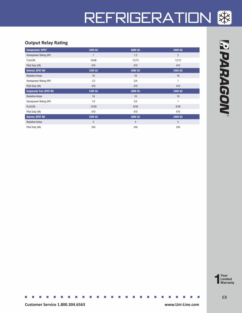
C3Customer Service 1.800.304.6563 www.Uni-Line.comwww.Uni-Line.com Customer Service 1.800.304.6563
C3
REFRIGERATIONOutput Relay Rating
Compressor: SPST 120V AC 208V AC 240V AC
Horsepower Rating (HP) 1 1.5 2
FLA/LRA 16/96 12/72 12/72
Pilot Duty (VA) 470 470 470
Defrost: SPST NO 120V AC 208V AC 240V AC
Resistive Amps 16 16 16
Horsepower Rating (HP) 1/2 3/4 1
Pilot Duty (VA) 470 470 470
Evaporator Fan: SPST NC 120V AC 208V AC 240V AC
Resistive Amps 16 16 16
Horsepower Rating (HP) 1/2 3/4 1
FLA/LRA 10/59 8/48 8/48
Pilot Duty (VA) 470 470 470
Alarms: SPST NO 120V AC 208V AC 240V AC
Resistive Amps 5 5 5
Pilot Duty (VA) 240 240 240
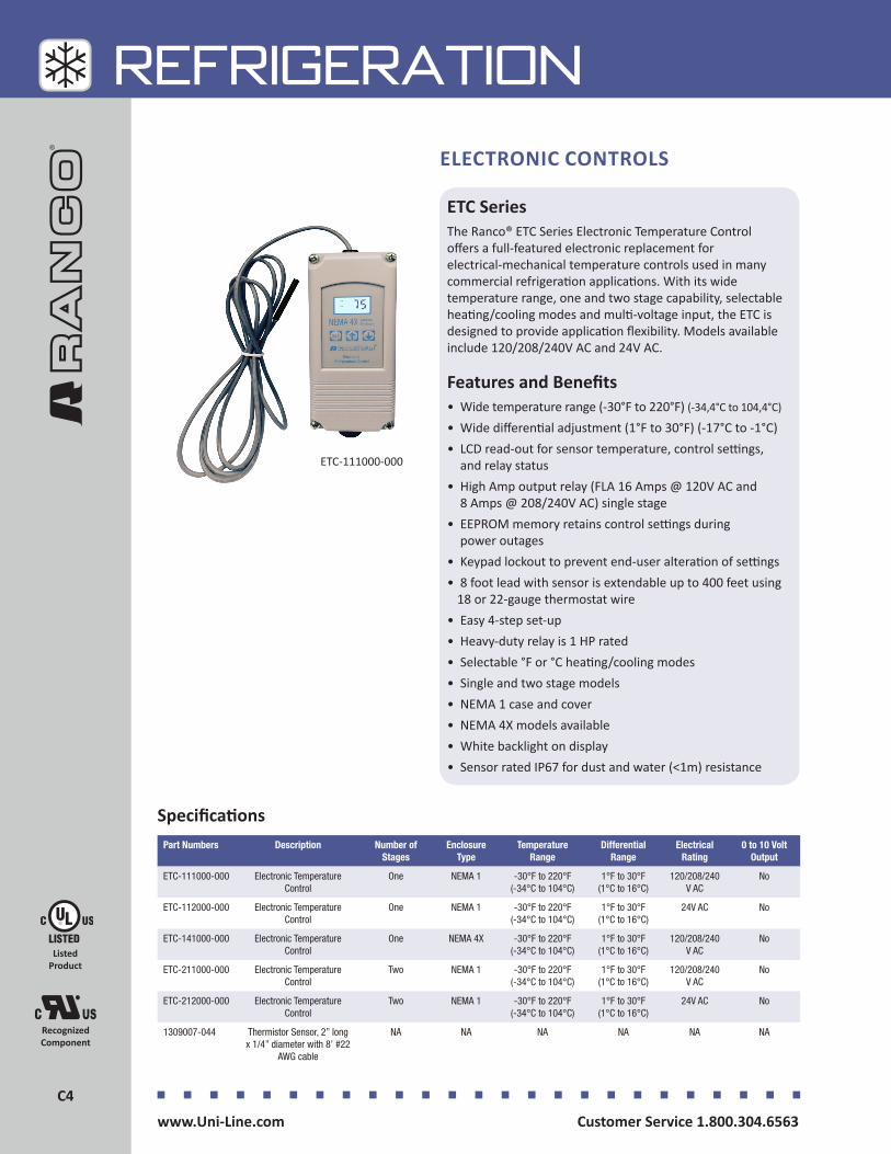
Customer Service 1.800.304.6563 www.Uni-Line.comwww.Uni-Line.com Customer Service 1.800.304.6563
C4C4
REFRIGERATION
ETC SeriesThe Ranco® ETC Series Electronic Temperature Control offers a full-featured electronic replacement for electrical-mechanical temperature controls used in many commercial refrigeration applications. With its wide temperature range, one and two stage capability, selectable heating/cooling modes and multi-voltage input, the ETC is designed to provide application flexibility. Models available include 120/208/240V AC and 24V AC.
Features and Benefits• Wide temperature range (-30°F to 220°F) (-34,4°C to 104,4°C)
• Wide differential adjustment (1°F to 30°F) (-17°C to -1°C)• LCD read-out for sensor temperature, control settings,
and relay status• High Amp output relay (FLA 16 Amps @ 120V AC and
8 Amps @ 208/240V AC) single stage• EEPROM memory retains control settings during
power outages• Keypad lockout to prevent end-user alteration of settings• 8 foot lead with sensor is extendable up to 400 feet using
18 or 22-gauge thermostat wire• Easy 4-step set-up• Heavy-duty relay is 1 HP rated• Selectable °F or °C heating/cooling modes• Single and two stage models• NEMA 1 case and cover• NEMA 4X models available• White backlight on display• Sensor rated IP67 for dust and water (<1m) resistance
ELECTRONIC CONTROLS
Specifications
ETC-111000-000
Part Numbers Description Number of Stages
Enclosure Type
Temperature Range
Differential Range
Electrical Rating
0 to 10 Volt Output
ETC-111000-000 Electronic Temperature Control
One NEMA 1 -30°F to 220°F (-34°C to 104°C)
1°F to 30°F (1°C to 16°C)
120/208/240 V AC
No
ETC-112000-000 Electronic Temperature Control
One NEMA 1 -30°F to 220°F (-34°C to 104°C)
1°F to 30°F (1°C to 16°C)
24V AC No
ETC-141000-000 Electronic Temperature Control
One NEMA 4X -30°F to 220°F (-34°C to 104°C)
1°F to 30°F (1°C to 16°C)
120/208/240 V AC
No
ETC-211000-000 Electronic Temperature Control
Two NEMA 1 -30°F to 220°F (-34°C to 104°C)
1°F to 30°F (1°C to 16°C)
120/208/240 V AC
No
ETC-212000-000 Electronic Temperature Control
Two NEMA 1 -30°F to 220°F (-34°C to 104°C)
1°F to 30°F (1°C to 16°C)
24V AC No
1309007-044 Thermistor Sensor, 2” long x 1/4” diameter with 8’ #22
AWG cable
NA NA NA NA NA NA
Listed Product
Recognized Component

C5Customer Service 1.800.304.6563 www.Uni-Line.comwww.Uni-Line.com Customer Service 1.800.304.6563
C5
REFRIGERATION
Single Stage Models Two Stage Models
120V AC 208/240V AC NO Contact 120V AC 208/240V AC
16 Amps 8 Amps Full-load Amps 9.8 Amps 4.9 Amps
96 Amps 48 Amps Locked Rotor Amps 58.8 Amps 29.4 Amps
15 Amps 8 Amps Resistive Amps 9.8 Amps 4.9 Amps
1 HP 1 HP Horsepower 1/2 HP 1/2 HP
120V AC 208/240V AC NC Contact 120V AC 208/240V AC
5.8 Amps 2.9 Amps Full-load Amps 5.8 Amps 2.9 Amps
34.8 Amps 17.4 Amps Locked Rotor Amps 34.8 Amps 17.4 Amps
5.8 Amps 2.9 Amps Resistive Amps 5.8 Amps 2.9 Amps
1/4 HP 1/4 HP Horsepower 1/4 HP 1/4 HP
Relay Electrical Ratings

Customer Service 1.800.304.6563 www.Uni-Line.comwww.Uni-Line.com Customer Service 1.800.304.6563
C6C6
REFRIGERATION
A12 and 9531 Series - Constant Cut-inThe Ranco® A12 and 9531 Series Constant Cut-in Temperature Controls are designed to switch electrical components of refrigeration systems in response to sensed temperatures.
Features and Benefits• Laser-welded stainless steel bellows• Fixed or adjustable temperature settings• High-amperage contacts• Pneumatic action provided by vapor-filled capillary or
capillary with bulb sensing elements• Constant On or Off positions available• Choice of mounting brackets, adjustment ranges and
cams, and slotted or flatted shafts• Standard 1/4” quick-connect terminals with optional
screw terminals
TEMPERATURE CONTROLS - COLD CONTROLS
Specifications
A12-1560
Part Numbers Description Cold Off Normal Off Warm Off Cut-In Capillary Length
A12-1506 Constant Cut-In Control
9°F 15°F 22°F 38°F 39” x 3/8” x 1-3/8”
A12-1560 Constant Cut-In Control
19°F 24°F 29°F 38°F 72”
A12-700 Constant Cut-In Control
11.5°F 18°F 26°F 37°F 84”
A12-701 Constant Cut-In Control
15°F 23.5°F 31°F 41°F 84”
9531N195 Constant Cut-In Control with Pigtail
5°F NA 29°F 40°F 58.5”
9531N320 Constant Cut-In Control
11°F 16°F 21°F 40°F 20.5”
9531N395(MEX, SA)
Constant Cut-In Control with Pigtail
12°F 19°F 25°F 38°F 48.5”
Recognized Component
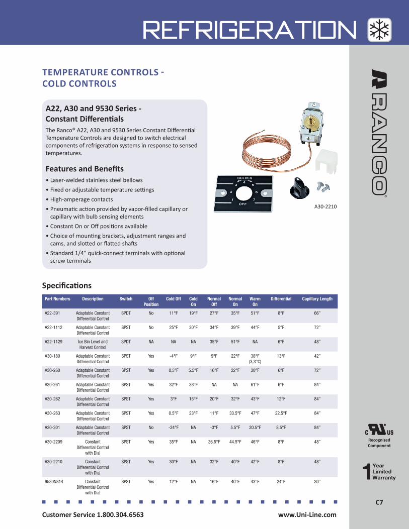
C7Customer Service 1.800.304.6563 www.Uni-Line.comwww.Uni-Line.com Customer Service 1.800.304.6563
C7
REFRIGERATION
A22, A30 and 9530 Series - Constant DifferentialsThe Ranco® A22, A30 and 9530 Series Constant Differential Temperature Controls are designed to switch electrical components of refrigeration systems in response to sensed temperatures.
Features and Benefits• Laser-welded stainless steel bellows• Fixed or adjustable temperature settings• High-amperage contacts• Pneumatic action provided by vapor-filled capillary or
capillary with bulb sensing elements• Constant On or Off positions available• Choice of mounting brackets, adjustment ranges and
cams, and slotted or flatted shafts• Standard 1/4” quick-connect terminals with optional
screw terminals
TEMPERATURE CONTROLS - COLD CONTROLS
SpecificationsPart Numbers Description Switch Off
PositionCold Off Cold
OnNormal
OffNormal
OnWarm
OnDifferential Capillary Length
A22-391 Adaptable Constant Differential Control
SPDT No 11°F 19°F 27°F 35°F 51°F 8°F 66”
A22-1112 Adaptable Constant Differential Control
SPST No 25°F 30°F 34°F 39°F 44°F 5°F 72”
A22-1129 Ice Bin Level and Harvest Control
SPDT NA NA NA 35°F 51°F NA 6°F 48”
A30-180 Adaptable Constant Differential Control
SPST Yes -4°F 9°F 9°F 22°F 38°F (3,3°C)
13°F 42”
A30-260 Adaptable Constant Differential Control
SPST Yes 0.5°F 5.5°F 16°F 22°F 30°F 6°F 72”
A30-261 Adaptable Constant Differential Control
SPST Yes 32°F 38°F NA NA 61°F 6°F 84”
A30-262 Adaptable Constant Differential Control
SPST Yes 3°F 15°F 20°F 32°F 43°F 12°F 84”
A30-263 Adaptable Constant Differential Control
SPST Yes 0.5°F 23°F 11°F 33.5°F 47°F 22.5°F 84”
A30-301 Adaptable Constant Differential Control
SPST No -24°F NA -3°F 5.5°F 20.5°F 8.5°F 84”
A30-2209 Constant Differential Control
with Dial
SPST Yes 35°F NA 36.5°F 44.5°F 46°F 8°F 48”
A30-2210 Constant Differential Control
with Dial
SPST Yes 30°F NA 32°F 40°F 42°F 8°F 48”
9530N814 Constant Differential Control
with Dial
SPST Yes 12°F NA 16°F 40°F 43°F 24°F 30”
Recognized Component
A30-2210

Customer Service 1.800.304.6563 www.Uni-Line.comwww.Uni-Line.com Customer Service 1.800.304.6563
C8C8
REFRIGERATION
K SeriesThe Ranco® K Controls are used all over the globe to control the temperature in commercial and domestic refrigeration, air conditioning and heating applications. Typical uses include refrigerators, freezers, bottle and liquid coolers, and refrigerator display cases.
Features and Benefits• Compact size• Standard mounting configurations• Constant/fixed differential• SPST close-on-rise switching• Various capillary lengths
TEMPERATURE CONTROLS - COLD CONTROLS
K12L-1529-002
SpecificationsPart Numbers Description Country of
OriginSwitch Cold
Cut-InCold
Cut-OutNormal Cut-Out
Warm Cut-In
Warm Cut-Out
Constant Cut-In
Capillary Length
K12L-1529-002 Cold Control International
Models
Czech Republic SPST NA -8.3°C -4.7°C NA -0.8°C 5.5°C 2130mm
K50P-1125-001 Cold Control International
Models
Czech Republic SPST -9°C -18°C NA 9°C NA NA 1200mm
K50P-1126-001 Cold Control International
Models
Czech Republic SPST -18°C -24°C NA -9°C NA NA 1200mm
K50P-1127-001 Cold Control International
Models
Czech Republic SPST 5°C 2°C NA 13°C NA NA 1200mm
K50P-6063-001 Cold Control International
Models
Czech Republic SPST 5°C -6°C NA 11°C NA NA 1200mm
K50Q-1125-001 Cold Control International
Models
China SPST -9°C -18°C NA 9°C NA NA 1200mm
K50Q-1126-001 Cold Control International
Models
China SPST -18°C -24°C NA -9°C NA NA 1200mm
K50Q-1127-001 Cold Control International
Models
China SPST 5°C 2°C NA 13°C NA NA 1200mm
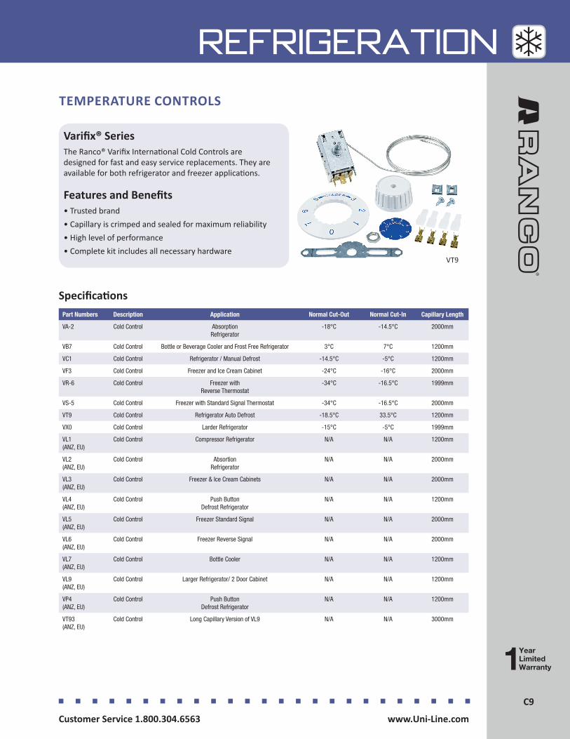
C9Customer Service 1.800.304.6563 www.Uni-Line.comwww.Uni-Line.com Customer Service 1.800.304.6563
C9
REFRIGERATION
Varifix® SeriesThe Ranco® Varifix International Cold Controls are designed for fast and easy service replacements. They are available for both refrigerator and freezer applications.
Features and Benefits• Trusted brand• Capillary is crimped and sealed for maximum reliability• High level of performance• Complete kit includes all necessary hardware
TEMPERATURE CONTROLS
VT9
SpecificationsPart Numbers Description Application Normal Cut-Out Normal Cut-In Capillary Length
VA-2 Cold Control Absorption Refrigerator
-18°C -14.5°C 2000mm
VB7 Cold Control Bottle or Beverage Cooler and Frost Free Refrigerator 3°C 7°C 1200mm
VC1 Cold Control Refrigerator / Manual Defrost -14.5°C -5°C 1200mm
VF3 Cold Control Freezer and Ice Cream Cabinet -24°C -16°C 2000mm
VR-6 Cold Control Freezer with Reverse Thermostat
-34°C -16.5°C 1999mm
VS-5 Cold Control Freezer with Standard Signal Thermostat -34°C -16.5°C 2000mm
VT9 Cold Control Refrigerator Auto Defrost -18.5°C 33.5°C 1200mm
VX0 Cold Control Larder Refrigerator -15°C -5°C 1999mm
VL1(ANZ, EU)
Cold Control Compressor Refrigerator N/A N/A 1200mm
VL2(ANZ, EU)
Cold Control Absortion Refrigerator
N/A N/A 2000mm
VL3(ANZ, EU)
Cold Control Freezer & Ice Cream Cabinets N/A N/A 2000mm
VL4(ANZ, EU)
Cold Control Push Button Defrost Refrigerator
N/A N/A 1200mm
VL5(ANZ, EU)
Cold Control Freezer Standard Signal N/A N/A 2000mm
VL6(ANZ, EU)
Cold Control Freezer Reverse Signal N/A N/A 2000mm
VL7(ANZ, EU)
Cold Control Bottle Cooler N/A N/A 1200mm
VL9(ANZ, EU)
Cold Control Larger Refrigerator/ 2 Door Cabinet N/A N/A 1200mm
VP4(ANZ, EU)
Cold Control Push Button Defrost Refrigerator
N/A N/A 1200mm
VT93(ANZ, EU)
Cold Control Long Capillary Version of VL9 N/A N/A 3000mm
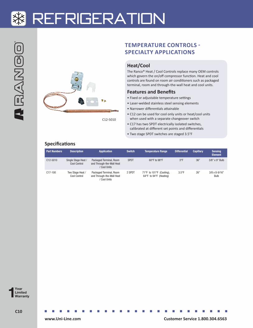
Customer Service 1.800.304.6563 www.Uni-Line.comwww.Uni-Line.com Customer Service 1.800.304.6563
C10C10
REFRIGERATION
Heat/CoolThe Ranco® Heat / Cool Controls replace many OEM controls which govern the on/off compressor function. Heat and cool controls are found on room air conditioners such as packaged terminal, room and through-the-wall heat and cool units.
Features and Benefits• Fixed or adjustable temperature settings• Laser-welded stainless steel sensing elements• Narrower differentials attainable• C12 can be used for cool only units or heat/cool units
when used with a separate changeover switch• C17 has two SPDT electrically isolated switches,
calibrated at different set points and differentials• Two stage SPDT switches are staged 3.5°F
C12-5010
SpecificationsPart Numbers Description Application Switch Temperature Range Differential Capillary Sensing
Element
C12-5010 Single Stage Heat / Cool Control
Packaged Terminal, Room and Through-the-Wall Heat
/ Cool Units
SPDT 60°F to 98°F 3°F 36” 3/8” x 9” Bulb
C17-100 Two Stage Heat / Cool Control
Packaged Terminal, Room and Through-the-Wall Heat
/ Cool Units
2 SPDT 71°F to 101°F (Cooling), 64°F to 94°F (Heating)
3.5°F 26” 3/8 x 8-9/16” Bulb
TEMPERATURE CONTROLS - SPECIALTY APPLICATIONS
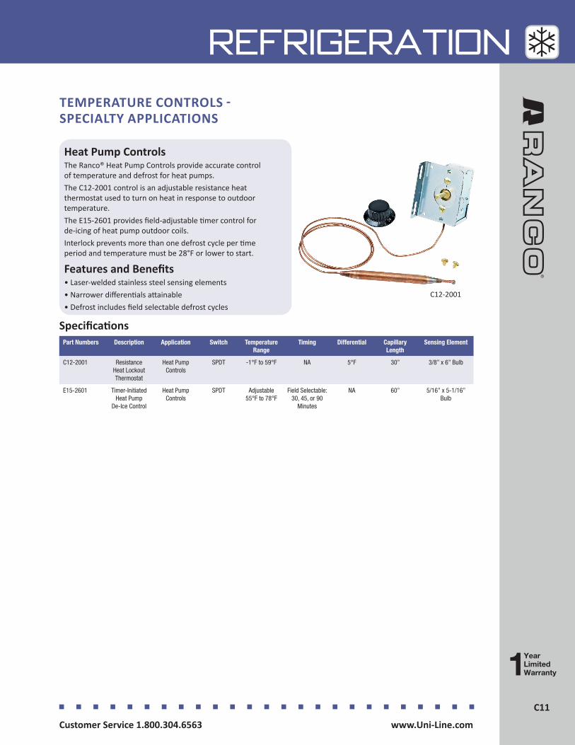
C11Customer Service 1.800.304.6563 www.Uni-Line.comwww.Uni-Line.com Customer Service 1.800.304.6563
C11
REFRIGERATION
Heat Pump ControlsThe Ranco® Heat Pump Controls provide accurate control of temperature and defrost for heat pumps.The C12-2001 control is an adjustable resistance heat thermostat used to turn on heat in response to outdoor temperature.The E15-2601 provides field-adjustable timer control for de-icing of heat pump outdoor coils.Interlock prevents more than one defrost cycle per time period and temperature must be 28°F or lower to start.
Features and Benefits• Laser-welded stainless steel sensing elements• Narrower differentials attainable• Defrost includes field selectable defrost cycles
C12-2001
SpecificationsPart Numbers Description Application Switch Temperature
RangeTiming Differential Capillary
LengthSensing Element
C12-2001 Resistance Heat Lockout Thermostat
Heat Pump Controls
SPDT -1°F to 59°F NA 5°F 30” 3/8” x 6” Bulb
E15-2601 Timer-Initiated Heat Pump
De-Ice Control
Heat Pump Controls
SPDT Adjustable 55°F to 78°F
Field Selectable: 30, 45, or 90
Minutes
NA 60” 5/16” x 5-1/16” Bulb
TEMPERATURE CONTROLS - SPECIALTY APPLICATIONS

Customer Service 1.800.304.6563 www.Uni-Line.comwww.Uni-Line.com Customer Service 1.800.304.6563
C12C12
REFRIGERATION
F Series - Fan Control The Ranco® Fan Controls terminate defrost, and delay the evaporator fan operation on electric heat, hot gas and reverse cycle commercial refrigeration systems.
Features and Benefits• Prevents warm, moist air from being circulated into
the refrigerated space• Remote bulb sensing• Factory-fixed low event for fan delay
TEMPERATURE CONTROLS - SPECIALTY APPLICATIONS
F25-107
SpecificationsPart Numbers Description Application Switch Fan On Defrost Termination
RangeCapillary Length
Sensing Element
F25-107 Defrost Termination / Fan Delay Control
Beverage / Reach-in Medium Temperature
SPDT 20°F Fixed 40°F to 75°F (5°C to 24°C)
60” 3/8” X 4” Cross Ambient Bulb
Water Cooler ControlThe Ranco® Water Cooler Control is designed as a universal replacement for water and beverage cooler applications.
Features and Benefits• Small, compact design• Laser-welded bellows for reliability• Computer calibrated• Patented switch for high performance• Screwdriver adjustment
TEMPERATURE CONTROLS - SPECIALTY APPLICATIONS
K-3001
SpecificationsPart Numbers
Description Application Cold Off Normal Off
Normal On
Warm On
Differential Capillary Length
K-3001 Direct Replacement Water Cooler Control
Ice Equipment, Thermal Storage and Water Cooler Controls
37°F 46°F 53°F 61°F 7°F 48”
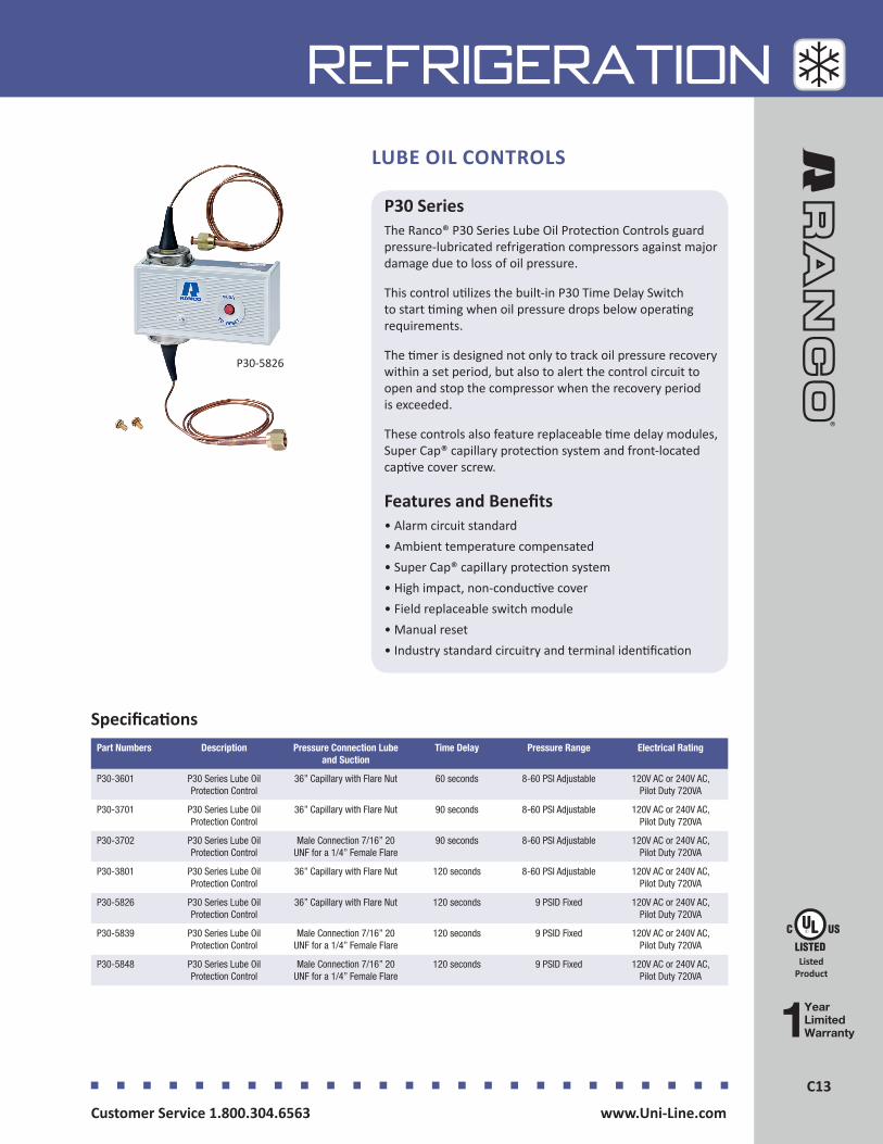
C13Customer Service 1.800.304.6563 www.Uni-Line.comwww.Uni-Line.com Customer Service 1.800.304.6563
C13
REFRIGERATIONLUBE OIL CONTROLS
P30 SeriesThe Ranco® P30 Series Lube Oil Protection Controls guard pressure-lubricated refrigeration compressors against major damage due to loss of oil pressure.
This control utilizes the built-in P30 Time Delay Switch to start timing when oil pressure drops below operating requirements.
The timer is designed not only to track oil pressure recovery within a set period, but also to alert the control circuit to open and stop the compressor when the recovery period is exceeded.
These controls also feature replaceable time delay modules, Super Cap® capillary protection system and front-located captive cover screw.
Features and Benefits• Alarm circuit standard• Ambient temperature compensated• Super Cap® capillary protection system• High impact, non-conductive cover• Field replaceable switch module• Manual reset• Industry standard circuitry and terminal identification
Listed Product
P30-5826
SpecificationsPart Numbers Description Pressure Connection Lube
and SuctionTime Delay Pressure Range Electrical Rating
P30-3601 P30 Series Lube Oil Protection Control
36” Capillary with Flare Nut 60 seconds 8-60 PSI Adjustable 120V AC or 240V AC, Pilot Duty 720VA
P30-3701 P30 Series Lube Oil Protection Control
36” Capillary with Flare Nut 90 seconds 8-60 PSI Adjustable 120V AC or 240V AC, Pilot Duty 720VA
P30-3702 P30 Series Lube Oil Protection Control
Male Connection 7/16” 20 UNF for a 1/4” Female Flare
90 seconds 8-60 PSI Adjustable 120V AC or 240V AC, Pilot Duty 720VA
P30-3801 P30 Series Lube Oil Protection Control
36” Capillary with Flare Nut 120 seconds 8-60 PSI Adjustable 120V AC or 240V AC, Pilot Duty 720VA
P30-5826 P30 Series Lube Oil Protection Control
36” Capillary with Flare Nut 120 seconds 9 PSID Fixed 120V AC or 240V AC, Pilot Duty 720VA
P30-5839 P30 Series Lube Oil Protection Control
Male Connection 7/16” 20 UNF for a 1/4” Female Flare
120 seconds 9 PSID Fixed 120V AC or 240V AC, Pilot Duty 720VA
P30-5848 P30 Series Lube Oil Protection Control
Male Connection 7/16” 20 UNF for a 1/4” Female Flare
120 seconds 9 PSID Fixed 120V AC or 240V AC, Pilot Duty 720VA

Customer Service 1.800.304.6563 www.Uni-Line.comwww.Uni-Line.com Customer Service 1.800.304.6563
C14C14
REFRIGERATION
O SeriesThe Ranco® Wide Range O Series Temperature Controls provide a wide selection of controls customized to allow users exact adjustments within manufacturers’ limits.
The Ranco O Series features heavy-duty plated steel frames, non-conductive covers with front-located captive cover screws, raised screw terminals for fully accessible wiring, and large easy-to-read scales.
Recognizing the need for flexibility in design of refrigeration equipment, these controls offer a wide selection for such products as self-contained refrigerators, freezers, coolers, walk-in units, and refrigeration display cases.
Features and Benefits• Maximum adjustment accuracy with 7 revolution range
adjustment screws• NEMA 1 enclosure with non-conductive cover• Universal mounting and compact design• Laser-welded bellows for extended life• Wide range adjustable differentialThe O60 Series have these additional features:• 10 times setting sensitivity of most other wide
range controls (O60 series only)• Gas-filled, nonposition-sensitive bulb (O60 series only)
TEMPERATURE CONTROLS - WIDE RANGE
O10-1418 with Air Coil
O10-1409 with Coil Capillary
Listed Product
Recognized Component
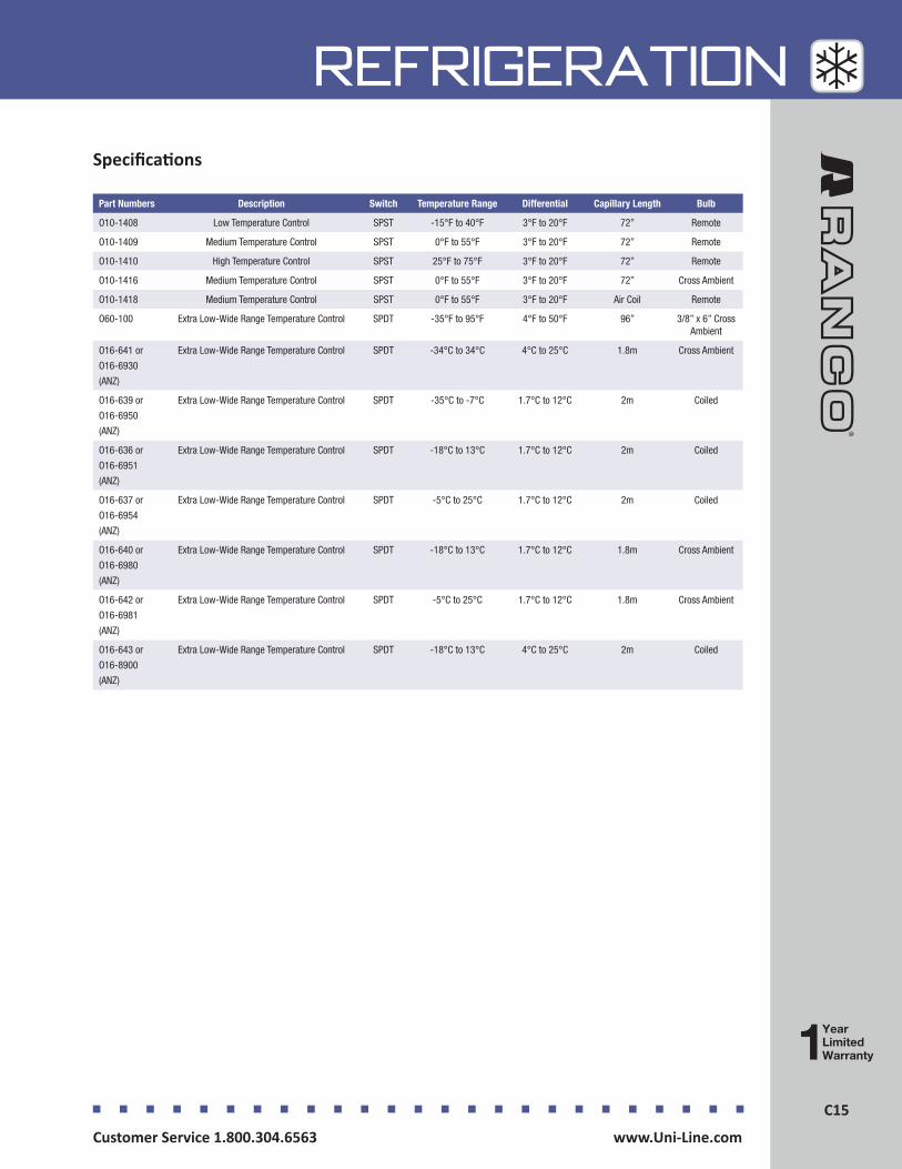
C15Customer Service 1.800.304.6563 www.Uni-Line.comwww.Uni-Line.com Customer Service 1.800.304.6563
C15
REFRIGERATIONSpecifications
Part Numbers Description Switch Temperature Range Differential Capillary Length Bulb
O10-1408 Low Temperature Control SPST -15°F to 40°F 3°F to 20°F 72” Remote
O10-1409 Medium Temperature Control SPST 0°F to 55°F 3°F to 20°F 72” Remote
O10-1410 High Temperature Control SPST 25°F to 75°F 3°F to 20°F 72” Remote
O10-1416 Medium Temperature Control SPST 0°F to 55°F 3°F to 20°F 72” Cross Ambient
O10-1418 Medium Temperature Control SPST 0°F to 55°F 3°F to 20°F Air Coil Remote
O60-100 Extra Low-Wide Range Temperature Control SPDT -35°F to 95°F 4°F to 50°F 96” 3/8” x 6” Cross Ambient
O16-641 or
O16-6930
(ANZ)
Extra Low-Wide Range Temperature Control SPDT -34°C to 34°C 4°C to 25°C 1.8m Cross Ambient
O16-639 or
O16-6950
(ANZ)
Extra Low-Wide Range Temperature Control SPDT -35°C to -7°C 1.7°C to 12°C 2m Coiled
O16-636 or
O16-6951
(ANZ)
Extra Low-Wide Range Temperature Control SPDT -18°C to 13°C 1.7°C to 12°C 2m Coiled
O16-637 or
O16-6954
(ANZ)
Extra Low-Wide Range Temperature Control SPDT -5°C to 25°C 1.7°C to 12°C 2m Coiled
O16-640 or
O16-6980
(ANZ)
Extra Low-Wide Range Temperature Control SPDT -18°C to 13°C 1.7°C to 12°C 1.8m Cross Ambient
O16-642 or
O16-6981
(ANZ)
Extra Low-Wide Range Temperature Control SPDT -5°C to 25°C 1.7°C to 12°C 1.8m Cross Ambient
O16-643 or
O16-8900
(ANZ)
Extra Low-Wide Range Temperature Control SPDT -18°C to 13°C 4°C to 25°C 2m Coiled

Customer Service 1.800.304.6563 www.Uni-Line.comwww.Uni-Line.com Customer Service 1.800.304.6563
C16C16
REFRIGERATION
O Series - Single Low Pressure ControlsThe Ranco® O Series Single Low Pressure Controls offer a variety of pressure ranges and switch action to provide maximum application flexibility.
Features and Benefits• Controls available for most refrigerant types• High-amp rated switch (SPST) design (O10-1402/O10-1483)• Super Cap® capillary vibration protection system• Non-conductive front cover with captive screw• Adjustable differential and range• Easy-to-read scale plate• Vibration cone (absorbs and reduces vibration away
from brazed joint)• Low mass copper alloy capillary tube (reduces
capillary stress caused by equipment vibration)The O16-624 control has additional features:• Compatible with refrigerants 134A, 401A, 401B, 402A,
402B, 403A, 403B and 404A• Originally designed for use with obsolete refrigerants
R12, R22, R500 and R502
PRESSURE CONTROLS
O10-1402
Specifications
Listed Product
Recognized Component
Part
Numbers
Description Reset Switch Pressure Range PSI (bar)
Differential PSI (bar)
Pressure Connection Capillary Length Inches (meters)
Replaces
O10-1402 Low Pressure Control
Auto SPST 12” Hg to 50
(0.4 to 3.5)
5 to 35
(0.3 to 2.4)
1/4” SAE Flare Nut 36” (0.9m)
O10-1483 Low Pressure Control
Auto SPST 10” Hg to 100 (0.3 to 7)
10 to 40
(1 to 3)
1/4” SAE Flare Nut 36” (0.9m)
O16-527 Low Pressure Control
Auto SPDT 10” Hg to 100 (0.3 to 7)
10 to 40
(1 to 3)
1/4” SAE Flare Nut 36” (0.9m)
O16-528 Low Pressure Control
Auto SPDT 10” Hg to 100 (0.3 to 7)
10 to 40
(1 to 3)
Male Connnection 7/16” - 20 UNF for a
1/4” Female Flare
NA O16-H6703-101
O16-8706 (ANZ)
Low Pressure Control
Auto SPDT -33 to 700 kPa 68 to 275 kPa
Male Connnection 7/16” - 20 UNF for a
1/4” Female Flare
NA 016-528
O16-8713 (ANZ)
Low Pressure Control
Auto SPDT -33 to 700 kPa 68 to 275 kPa
1/4” SAE Flare Nut 36” (0.9m) 016-529
O16-624 Low Pressure Control
Auto SPST 12” Hg to 80
(0.4 to 5.5)
5 to 38
(0.3 to 2.6)
1/4” SAE Flare Nut 36” (0.9m)
O16-638 Low Pressure Control
Manual SPDT 10” Hg to 100 (0.3 to 7)
9 (0.6) Fixed Male Connnection 7/16” - 20 UNF for a
1/4” Female Flare
NA O16-H6705-101
O16-8705 (ANZ)
Low Pressure Control
Manual SPDT -33 to 700 kPa 60 kPa Fixed Male Connnection 7/16” - 20 UNF for a
1/4” Female Flare
NA 016-638
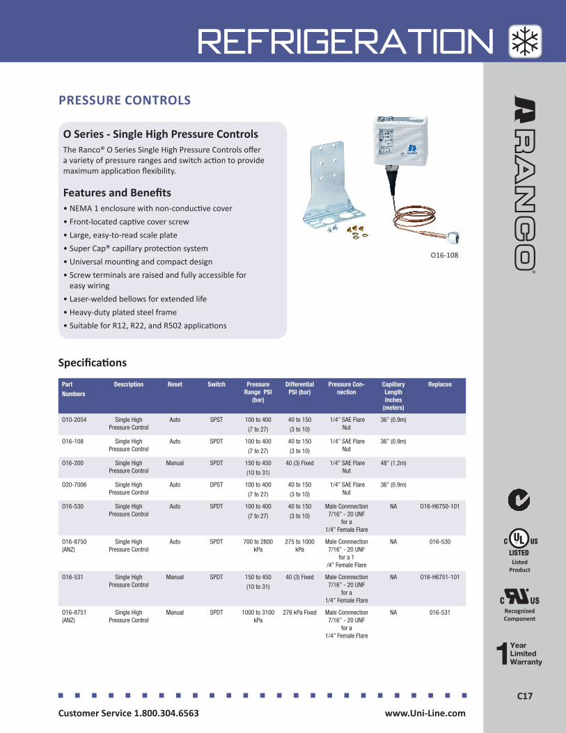
C17Customer Service 1.800.304.6563 www.Uni-Line.comwww.Uni-Line.com Customer Service 1.800.304.6563
C17
REFRIGERATION
O Series - Single High Pressure ControlsThe Ranco® O Series Single High Pressure Controls offer a variety of pressure ranges and switch action to provide maximum application flexibility.
Features and Benefits• NEMA 1 enclosure with non-conductive cover• Front-located captive cover screw• Large, easy-to-read scale plate• Super Cap® capillary protection system• Universal mounting and compact design• Screw terminals are raised and fully accessible for
easy wiring• Laser-welded bellows for extended life• Heavy-duty plated steel frame• Suitable for R12, R22, and R502 applications
PRESSURE CONTROLS
O16-108
Specifications
Part
Numbers
Description Reset Switch Pressure Range PSI
(bar)
Differential PSI (bar)
Pressure Con-nection
Capillary Length Inches
(meters)
Replaces
O10-2054 Single High Pressure Control
Auto SPST 100 to 400
(7 to 27)
40 to 150
(3 to 10)
1/4” SAE Flare Nut
36” (0.9m)
O16-108 Single High Pressure Control
Auto SPDT 100 to 400
(7 to 27)
40 to 150
(3 to 10)
1/4” SAE Flare Nut
36” (0.9m)
O16-200 Single High Pressure Control
Manual SPDT 150 to 450
(10 to 31)
40 (3) Fixed 1/4” SAE Flare Nut
48” (1.2m)
O20-7006 Single High Pressure Control
Auto DPST 100 to 400
(7 to 27)
40 to 150
(3 to 10)
1/4” SAE Flare Nut
36” (0.9m)
O16-530 Single High Pressure Control
Auto SPDT 100 to 400
(7 to 27)
40 to 150
(3 to 10)
Male Connnection 7/16” - 20 UNF
for a 1/4” Female Flare
NA O16-H6750-101
O16-8750 (ANZ)
Single High Pressure Control
Auto SPDT 700 to 2800 kPa
275 to 1000 kPa
Male Connnection 7/16” - 20 UNF
for a 1 /4” Female Flare
NA 016-530
O16-531 Single High Pressure Control
Manual SPDT 150 to 450
(10 to 31)
40 (3) Fixed Male Connnection 7/16” - 20 UNF
for a 1/4” Female Flare
NA O16-H6751-101
O16-8751 (ANZ)
Single High Pressure Control
Manual SPDT 1000 to 3100 kPa
276 kPa Fixed Male Connnection 7/16” - 20 UNF
for a 1/4” Female Flare
NA 016-531
Listed Product
Recognized Component
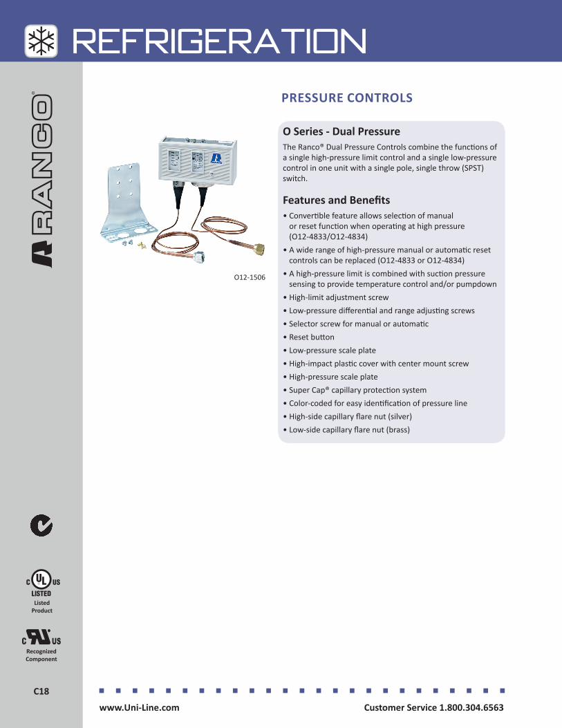
Customer Service 1.800.304.6563 www.Uni-Line.comwww.Uni-Line.com Customer Service 1.800.304.6563
C18C18
REFRIGERATION
O Series - Dual PressureThe Ranco® Dual Pressure Controls combine the functions of a single high-pressure limit control and a single low-pressure control in one unit with a single pole, single throw (SPST) switch.
Features and Benefits• Convertible feature allows selection of manual
or reset function when operating at high pressure (O12-4833/O12-4834)
• A wide range of high-pressure manual or automatic reset controls can be replaced (O12-4833 or O12-4834)
• A high-pressure limit is combined with suction pressure sensing to provide temperature control and/or pumpdown
• High-limit adjustment screw• Low-pressure differential and range adjusting screws• Selector screw for manual or automatic• Reset button• Low-pressure scale plate• High-impact plastic cover with center mount screw• High-pressure scale plate• Super Cap® capillary protection system• Color-coded for easy identification of pressure line• High-side capillary flare nut (silver)• Low-side capillary flare nut (brass)
PRESSURE CONTROLS
O12-1506
Listed Product
Recognized Component
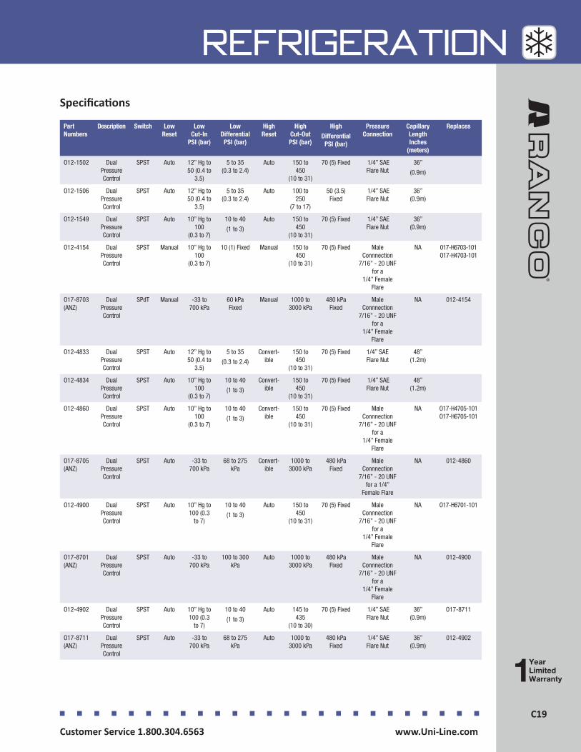
C19Customer Service 1.800.304.6563 www.Uni-Line.comwww.Uni-Line.com Customer Service 1.800.304.6563
C19
REFRIGERATIONSpecifications
Part Numbers
Description Switch Low Reset
Low Cut-In
PSI (bar)
Low Differential
PSI (bar)
High Reset
High Cut-Out PSI (bar)
High
Differential PSI (bar)
Pressure Connection
Capillary Length Inches
(meters)
Replaces
O12-1502 Dual Pressure Control
SPST Auto 12” Hg to 50 (0.4 to
3.5)
5 to 35 (0.3 to 2.4)
Auto 150 to 450
(10 to 31)
70 (5) Fixed 1/4” SAE Flare Nut
36”
(0.9m)
O12-1506 Dual Pressure Control
SPST Auto 12” Hg to 50 (0.4 to
3.5)
5 to 35 (0.3 to 2.4)
Auto 100 to 250
(7 to 17)
50 (3.5) Fixed
1/4” SAE Flare Nut
36” (0.9m)
O12-1549 Dual Pressure Control
SPST Auto 10” Hg to 100
(0.3 to 7)
10 to 40
(1 to 3)
Auto 150 to 450
(10 to 31)
70 (5) Fixed 1/4” SAE Flare Nut
36” (0.9m)
O12-4154 Dual Pressure Control
SPST Manual 10” Hg to 100
(0.3 to 7)
10 (1) Fixed Manual 150 to 450
(10 to 31)
70 (5) Fixed Male Connnection
7/16” - 20 UNF for a
1/4” Female Flare
NA 017-H6703-101 O17-H4703-101
O17-8703 (ANZ)
Dual Pressure Control
SPdT Manual -33 to 700 kPa
60 kPa Fixed
Manual 1000 to 3000 kPa
480 kPa Fixed
Male Connnection
7/16” - 20 UNF for a
1/4” Female Flare
NA 012-4154
O12-4833 Dual Pressure Control
SPST Auto 12” Hg to 50 (0.4 to
3.5)
5 to 35
(0.3 to 2.4)
Convert-ible
150 to 450
(10 to 31)
70 (5) Fixed 1/4” SAE Flare Nut
48” (1.2m)
O12-4834 Dual Pressure Control
SPST Auto 10” Hg to 100
(0.3 to 7)
10 to 40
(1 to 3)
Convert-ible
150 to 450
(10 to 31)
70 (5) Fixed 1/4” SAE Flare Nut
48” (1.2m)
O12-4860 Dual Pressure Control
SPST Auto 10” Hg to 100
(0.3 to 7)
10 to 40
(1 to 3)
Convert-ible
150 to 450
(10 to 31)
70 (5) Fixed Male Connnection
7/16” - 20 UNF for a
1/4” Female Flare
NA O17-H4705-101 O17-H6705-101
O17-8705 (ANZ)
Dual Pressure Control
SPST Auto -33 to 700 kPa
68 to 275 kPa
Convert-ible
1000 to 3000 kPa
480 kPa Fixed
Male Connnection
7/16” - 20 UNF for a 1/4”
Female Flare
NA 012-4860
O12-4900 Dual Pressure Control
SPST Auto 10” Hg to 100 (0.3
to 7)
10 to 40
(1 to 3)
Auto 150 to 450
(10 to 31)
70 (5) Fixed Male Connnection
7/16” - 20 UNF for a
1/4” Female Flare
NA O17-H6701-101
O17-8701 (ANZ)
Dual Pressure Control
SPST Auto -33 to 700 kPa
100 to 300 kPa
Auto 1000 to 3000 kPa
480 kPa Fixed
Male Connnection
7/16” - 20 UNF for a
1/4” Female Flare
NA 012-4900
O12-4902 Dual Pressure Control
SPST Auto 10” Hg to 100 (0.3
to 7)
10 to 40
(1 to 3)
Auto 145 to 435
(10 to 30)
70 (5) Fixed 1/4” SAE Flare Nut
36” (0.9m)
O17-8711
O17-8711 (ANZ)
Dual Pressure Control
SPST Auto -33 to 700 kPa
68 to 275 kPa
Auto 1000 to 3000 kPa
480 kPa Fixed
1/4” SAE Flare Nut
36” (0.9m)
012-4902
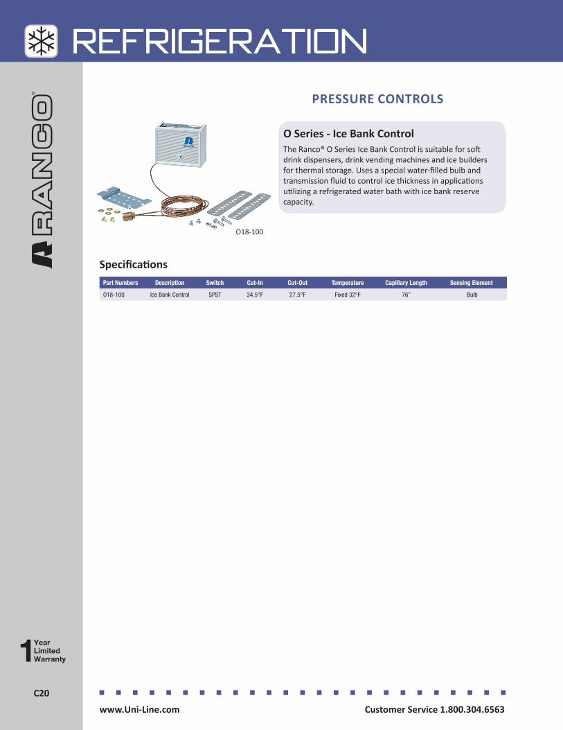
Customer Service 1.800.304.6563 www.Uni-Line.comwww.Uni-Line.com Customer Service 1.800.304.6563
C20C20
REFRIGERATION
O Series - Ice Bank ControlThe Ranco® O Series Ice Bank Control is suitable for soft drink dispensers, drink vending machines and ice builders for thermal storage. Uses a special water-filled bulb and transmission fluid to control ice thickness in applications utilizing a refrigerated water bath with ice bank reserve capacity.
PRESSURE CONTROLS
O18-100
SpecificationsPart Numbers Description Switch Cut-In Cut-Out Temperature Capillary Length Sensing Element
O18-100 Ice Bank Control SPST 34.5°F 27.5°F Fixed 32°F 76” Bulb
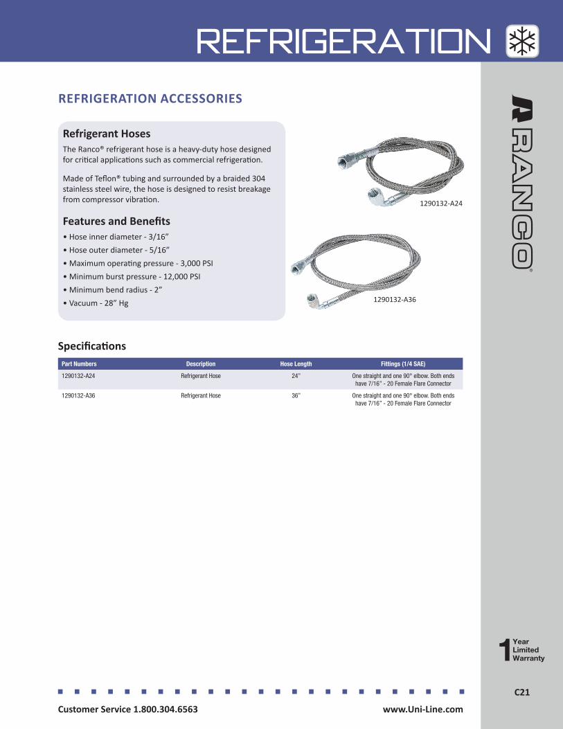
C21Customer Service 1.800.304.6563 www.Uni-Line.comwww.Uni-Line.com Customer Service 1.800.304.6563
C21
REFRIGERATION
Refrigerant HosesThe Ranco® refrigerant hose is a heavy-duty hose designed for critical applications such as commercial refrigeration.
Made of Teflon® tubing and surrounded by a braided 304 stainless steel wire, the hose is designed to resist breakage from compressor vibration.
Features and Benefits• Hose inner diameter - 3/16”• Hose outer diameter - 5/16”• Maximum operating pressure - 3,000 PSI• Minimum burst pressure - 12,000 PSI• Minimum bend radius - 2”• Vacuum - 28” Hg
REFRIGERATION ACCESSORIES
1290132-A24
1290132-A36
SpecificationsPart Numbers Description Hose Length Fittings (1/4 SAE)
1290132-A24 Refrigerant Hose 24” One straight and one 90° elbow. Both ends have 7/16” - 20 Female Flare Connector
1290132-A36 Refrigerant Hose 36” One straight and one 90° elbow. Both ends have 7/16” - 20 Female Flare Connector
PRESSURE CONTROLS
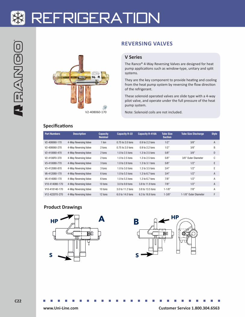
Customer Service 1.800.304.6563 www.Uni-Line.comwww.Uni-Line.com Customer Service 1.800.304.6563
C22C22
REFRIGERATION
Specifications
V SeriesThe Ranco® 4-Way Reversing Valves are designed for heat pump applications such as window-type, unitary and split systems.
They are the key component to provide heating and cooling from the heat pump system by reversing the flow direction of the refrigerant.
These solenoid operated valves are slide type with a 4-way pilot valve, and operate under the full pressure of the heat pump system.
Note: Solenoid coils are not included.
REVERSING VALVES
V2-408060-170
Part Numbers Description Capacity Nominal
Capacity R-22 Capacity R-410A Tube Size Suction
Tube Size Discharge Style
V2-408060-170 4-Way Reversing Valve 1 ton 0.75 to 2.0 tons 0.9 to 2.2 tons 1/2” 3/8” A
V2-408060-270 4-Way Reversing Valve 2 tons 0.75 to 2.0 tons 0.9 to 2.2 tons 1/2” 3/8” B
V2-410060-470 4-Way Reversing Valve 2 tons 1.0 to 2.5 tons 1.3 to 2.5 tons 5/8” 3/8” D
V2-4100F0-370 4-Way Reversing Valve 2 tons 1.0 to 2.5 tons 1.3 to 2.5 tons 5/8” 3/8” Outer Diameter C
V3-410080-770 4-Way Reversing Valve 3 tons 1.0 to 2.8 tons 1.3 to 3.1 tons 5/8” 1/2” E
V3-412080-870 4-Way Reversing Valve 3 tons 1.0 to 3.0 tons 1.3 to 3.5 tons 3/4” 1/2” E
V6-412080-170 4-Way Reversing Valve 6 tons 1.0 to 5.5 tons 1.3 to 6.7 tons 3/4” 1/2” A
V6-414080-170 4-Way Reversing Valve 6 tons 1.0 to 5.5 tons 1.3 to 6.7 tons 7/8” 1/2” A
V10-414080-170 4-Way Reversing Valve 10 tons 3.0 to 9.9 tons 3.8 to 11.9 tons 7/8” 1/2” A
V10-418140-170 4-Way Reversing Valve 10 tons 3.0 to 11.2 tons 3.8 to 13.5 tons 1-1/8” 7/8” A
V12-4220T0-270 4-Way Reversing Valve 12 tons 6.0 to 14.0 tons 6.3 to 16.8 tons 1-3/8” 1-1/8” Outer Diameter F
Product Drawings
HP
S
A HP
S
B

C23Customer Service 1.800.304.6563 www.Uni-Line.comwww.Uni-Line.com Customer Service 1.800.304.6563
C23
REFRIGERATIONProduct Drawings
HP
S
C
S
D HP
EHP
S
F HP
S
Legend
HP: High Pressure
S: Suction

Customer Service 1.800.304.6563 www.Uni-Line.comwww.Uni-Line.com Customer Service 1.800.304.6563
C24C24
REFRIGERATION
Specifications
LDK SeriesThe Ranco® LDK Series Solenoid Coils are designed for use with current production (Generation 4) V0, V1, V2, V3, V6, V10 and V12 Ranco 4-way Reversing Valves.
These color-coded, encapsulated, continuous duty, moisture resistant electro-magnetic coils are designed to operate the pilot valve that controls these reversing valves.
A W29 wiring harness with 48” leads is included with the solenoid coil.
Features and Benefits• Epoxy encapsulated• Continuous duty• Moisture resistant magnetic coils• Includes wiring harness
REVERSING VALVES - SOLENOID COILS
LDK-110000-070
Part Numbers Description Color Code Lead Length Electrical Rating Power
LDK-110000-070 Solenoid Coils for Reversing Valves
Red 48” 24V AC 5 Watts at 50 Hz, 4 Watts at 60 Hz
LDK-310000-070 Solenoid Coils for Reversing Valves
Black 48” 120V AC 5 Watts at 50 Hz, 4 Watts at 60 Hz
LDK-410000-070 Solenoid Coils for Reversing Valves
Green 48” 208/240V AC 5 Watts at 50 Hz, 4 Watts at 60 Hz
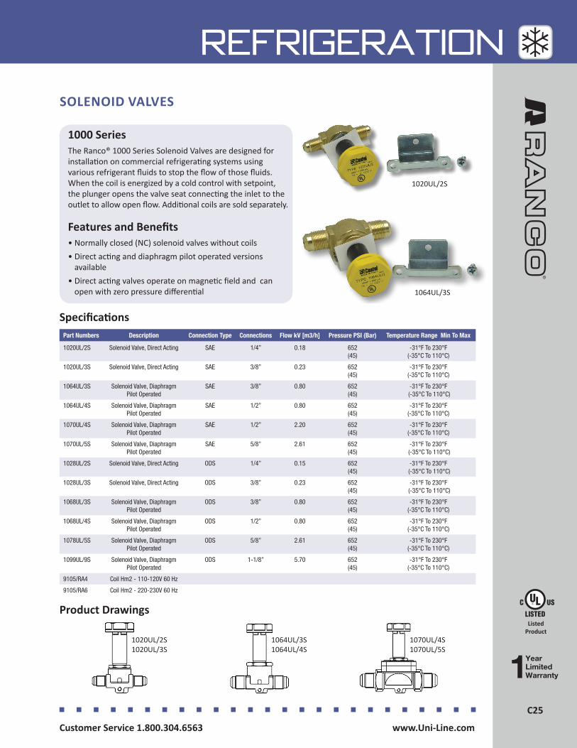
C25Customer Service 1.800.304.6563 www.Uni-Line.comwww.Uni-Line.com Customer Service 1.800.304.6563
C25
REFRIGERATION
Specifications
1000 SeriesThe Ranco® 1000 Series Solenoid Valves are designed for installation on commercial refrigerating systems using various refrigerant fluids to stop the flow of those fluids. When the coil is energized by a cold control with setpoint, the plunger opens the valve seat connecting the inlet to the outlet to allow open flow. Additional coils are sold separately.
Features and Benefits• Normally closed (NC) solenoid valves without coils• Direct acting and diaphragm pilot operated versions
available• Direct acting valves operate on magnetic field and can
open with zero pressure differential
Listed Product
1064UL/3S
1020UL/2S
Part Numbers Description Connection Type Connections Flow kV [m3/h] Pressure PSI (Bar) Temperature Range Min To Max
1020UL/2S Solenoid Valve, Direct Acting SAE 1/4” 0.18 652 (45)
-31°F To 230°F (-35°C To 110°C)
1020UL/3S Solenoid Valve, Direct Acting SAE 3/8” 0.23 652 (45)
-31°F To 230°F (-35°C To 110°C)
1064UL/3S Solenoid Valve, Diaphragm Pilot Operated
SAE 3/8” 0.80 652 (45)
-31°F To 230°F (-35°C To 110°C)
1064UL/4S Solenoid Valve, Diaphragm Pilot Operated
SAE 1/2” 0.80 652 (45)
-31°F To 230°F (-35°C To 110°C)
1070UL/4S Solenoid Valve, Diaphragm Pilot Operated
SAE 1/2” 2.20 652 (45)
-31°F To 230°F (-35°C To 110°C)
1070UL/5S Solenoid Valve, Diaphragm Pilot Operated
SAE 5/8” 2.61 652 (45)
-31°F To 230°F (-35°C To 110°C)
1028UL/2S Solenoid Valve, Direct Acting ODS 1/4” 0.15 652 (45)
-31°F To 230°F (-35°C To 110°C)
1028UL/3S Solenoid Valve, Direct Acting ODS 3/8” 0.23 652 (45)
-31°F To 230°F (-35°C To 110°C)
1068UL/3S Solenoid Valve, Diaphragm Pilot Operated
ODS 3/8” 0.80 652 (45)
-31°F To 230°F (-35°C To 110°C)
1068UL/4S Solenoid Valve, Diaphragm Pilot Operated
ODS 1/2” 0.80 652 (45)
-31°F To 230°F (-35°C To 110°C)
1078UL/5S Solenoid Valve, Diaphragm Pilot Operated
ODS 5/8” 2.61 652 (45)
-31°F To 230°F (-35°C To 110°C)
1099UL/9S Solenoid Valve, Diaphragm Pilot Operated
ODS 1-1/8” 5.70 652 (45)
-31°F To 230°F (-35°C To 110°C)
9105/RA4 Coil Hm2 - 110-120V 60 Hz
9105/RA6 Coil Hm2 - 220-230V 60 Hz
Product Drawings
1064UL/3S 1064UL/4S
1020UL/2S 1020UL/3S
1070UL/4S 1070UL/5S
SOLENOID VALVES

Customer Service 1.800.304.6563 www.Uni-Line.comwww.Uni-Line.com Customer Service 1.800.304.6563
C26C26
REFRIGERATION
2000 SeriesThe Ranco® 2000 Series Thermostatic Expansion Valves (TXVs) are designed for installation on commercial refrigerating systems using various refrigerant fluids to regulate the flow of refrigerant liquid into evaporators. These TXVs are designed to work with interchangeable orifice assemblies to provide flexibility in selection of capacities and can be used in a wide range of applications including refrigeration, air conditioning, heat pump and chiller systems.
Features and Benefits• Accurate throttle device to control superheat to
the setpoint• Body is made of hot forged brass in angle configuration• Interchangeable orifice assembly can easily be replaced
through the inlet connection• Quality materials to ensure proper functionality of
diaphragm and seating• Includes bulb bracket to enable proper placement of
bulb to the pipe• Stainless steel bulb, capillary tubing, diaphragm casing
and rod• Copper tube for solder connection• Solder adaptors sold separately
THERMOSTATIC EXPANSION VALVES
2203/S
2230/4S
2271/2S
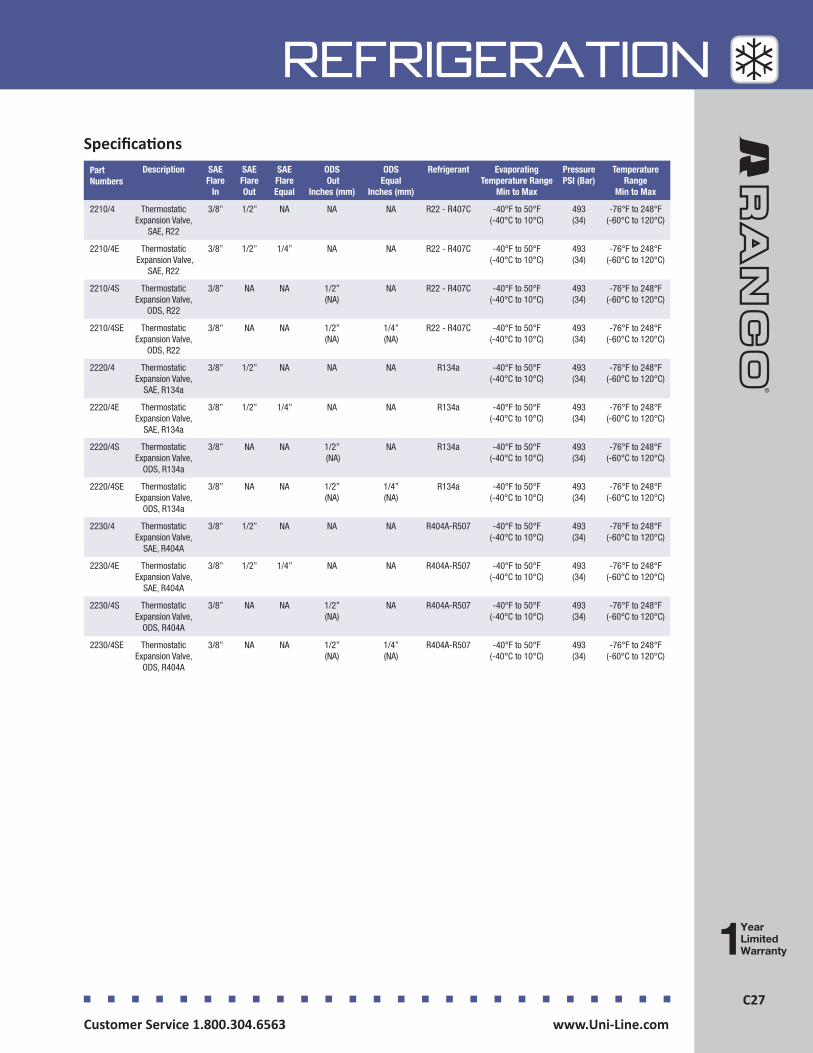
C27Customer Service 1.800.304.6563 www.Uni-Line.comwww.Uni-Line.com Customer Service 1.800.304.6563
C27
REFRIGERATION
Part Numbers
Description SAE Flare
In
SAE Flare Out
SAE Flare Equal
ODS Out
Inches (mm)
ODS Equal
Inches (mm)
Refrigerant Evaporating Temperature Range
Min to Max
Pressure PSI (Bar)
Temperature Range
Min to Max
2210/4 Thermostatic Expansion Valve,
SAE, R22
3/8” 1/2” NA NA NA R22 - R407C -40°F to 50°F (-40°C to 10°C)
493 (34)
-76°F to 248°F (-60°C to 120°C)
2210/4E Thermostatic Expansion Valve,
SAE, R22
3/8” 1/2” 1/4” NA NA R22 - R407C -40°F to 50°F (-40°C to 10°C)
493 (34)
-76°F to 248°F (-60°C to 120°C)
2210/4S Thermostatic Expansion Valve,
ODS, R22
3/8” NA NA 1/2” (NA)
NA R22 - R407C -40°F to 50°F (-40°C to 10°C)
493 (34)
-76°F to 248°F (-60°C to 120°C)
2210/4SE Thermostatic Expansion Valve,
ODS, R22
3/8” NA NA 1/2” (NA)
1/4” (NA)
R22 - R407C -40°F to 50°F (-40°C to 10°C)
493 (34)
-76°F to 248°F (-60°C to 120°C)
2220/4 Thermostatic Expansion Valve,
SAE, R134a
3/8” 1/2” NA NA NA R134a -40°F to 50°F (-40°C to 10°C)
493 (34)
-76°F to 248°F (-60°C to 120°C)
2220/4E Thermostatic Expansion Valve,
SAE, R134a
3/8” 1/2” 1/4” NA NA R134a -40°F to 50°F (-40°C to 10°C)
493 (34)
-76°F to 248°F (-60°C to 120°C)
2220/4S Thermostatic Expansion Valve,
ODS, R134a
3/8” NA NA 1/2” (NA)
NA R134a -40°F to 50°F (-40°C to 10°C)
493 (34)
-76°F to 248°F (-60°C to 120°C)
2220/4SE Thermostatic Expansion Valve,
ODS, R134a
3/8” NA NA 1/2” (NA)
1/4” (NA)
R134a -40°F to 50°F (-40°C to 10°C)
493 (34)
-76°F to 248°F (-60°C to 120°C)
2230/4 Thermostatic Expansion Valve,
SAE, R404A
3/8” 1/2” NA NA NA R404A-R507 -40°F to 50°F (-40°C to 10°C)
493 (34)
-76°F to 248°F (-60°C to 120°C)
2230/4E Thermostatic Expansion Valve,
SAE, R404A
3/8” 1/2” 1/4” NA NA R404A-R507 -40°F to 50°F (-40°C to 10°C)
493 (34)
-76°F to 248°F (-60°C to 120°C)
2230/4S Thermostatic Expansion Valve,
ODS, R404A
3/8” NA NA 1/2” (NA)
NA R404A-R507 -40°F to 50°F (-40°C to 10°C)
493 (34)
-76°F to 248°F (-60°C to 120°C)
2230/4SE Thermostatic Expansion Valve,
ODS, R404A
3/8” NA NA 1/2” (NA)
1/4” (NA)
R404A-R507 -40°F to 50°F (-40°C to 10°C)
493 (34)
-76°F to 248°F (-60°C to 120°C)
Specifications
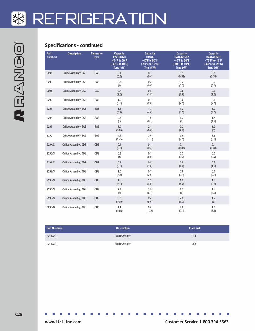
Customer Service 1.800.304.6563 www.Uni-Line.comwww.Uni-Line.com Customer Service 1.800.304.6563
C28C28
REFRIGERATIONSpecifications - continued
Part Numbers
Description Connector Type
Capacity R22/R407C
-40°F to 50°F (-40°C to 10°C)
Tons (kW)
Capacity R134A
-40°F to 50°F (-40°C to 10°C)
Tons (kW)
Capacity R404A/R507 -40°F to 50°F
(-40°C to 10°C) Tons (kW)
Capacity R404A/R507
-76°F to -13°F (-60°C to -25°C)
Tons (kW)
220X Orifice Assembly, SAE SAE 0.1 (0.5)
0.1 (0.4)
0.1 (0.38)
0.1 (0.38)
2200 Orifice Assembly, SAE SAE 0.3 (1)
0.3 (0.9)
0.2 (0.7)
0.2 (0.7)
2201 Orifice Assembly, SAE SAE 0.7 (2.5)
0.5 (1.8)
0.5 (1.6)
0.5 (1.6)
2202 Orifice Assembly, SAE SAE 1.0 (3.5)
0.7 (2.6)
0.6 (2.1)
0.6 (2.1)
2203 Orifice Assembly, SAE SAE 1.5 (5.2)
1.3 (4.6)
1.2 (4.2)
1.0 (3.5)
2204 Orifice Assembly, SAE SAE 2.3 (8)
1.9 (6.7)
1.7 (6)
1.4 (4.9)
2205 Orifice Assembly, SAE SAE 3.0 (10.5)
2.4 (8.6)
2.2 (7.7)
1.7 (6)
2206 Orifice Assembly, SAE SAE 4.4 (15.5)
3.0 (10.5)
2.6 (9.1)
1.9 (6.6)
220X/S Orifice Assembly, ODS ODS 0.1 (0.5)
0.1 (0.4)
0.1 (0.38)
0.1 (0.38)
2200/S Orifice Assembly, ODS ODS 0.3 (1)
0.3 (0.9)
0.2 (0.7)
0.2 (0.7)
2201/S Orifice Assembly, ODS ODS 0.7 (2.5)
0.5 (1.8)
0.5 (1.6)
0.5 (1.6)
2202/S Orifice Assembly, ODS ODS 1.0 (3.5)
0.7 (2.6)
0.6 (2.1)
0.6 (2.1)
2203/S Orifice Assembly, ODS ODS 1.5 (5.2)
1.3 (4.6)
1.2 (4.2)
1.0 (3.5)
2204/S Orifice Assembly, ODS ODS 2.3 (8)
1.9 (6.7)
1.7 (6)
1.4 (4.9)
2205/S Orifice Assembly, ODS ODS 3.0 (10.5)
2.4 (8.6)
2.2 (7.7)
1.7 (6)
2206/S Orifice Assembly, ODS ODS 4.4 (15.5)
3.0 (10.5)
2.6 (9.1)
1.9 (6.6)
Part Numbers Description Flare end
2271/2S Solder Adaptor 1/4”
2271/3S Solder Adaptor 3/8”

C29Customer Service 1.800.304.6563 www.Uni-Line.comwww.Uni-Line.com Customer Service 1.800.304.6563
C29
REFRIGERATIONProduct Drawing
2210/4, 2210/4E, 2220/4, 2220/4E, 2230/4, 2230/4E
2210/4S, 2210/4SE, 220/4S, 2220/4SE, 2230/4S, 2230/4SE
220X, 2200, 2201, 2202, 2203, 2204,
2205, 2206
220X/S, 2200/S, 2201/S, 2202/S, 2203/S, 2204/S, 2205/S, 2206/S
2271/2S, 2271/3S
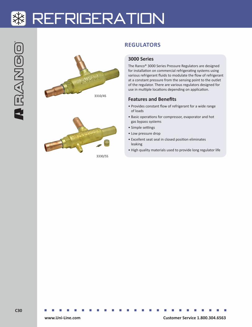
Customer Service 1.800.304.6563 www.Uni-Line.comwww.Uni-Line.com Customer Service 1.800.304.6563
C30C30
REFRIGERATION
3000 SeriesThe Ranco® 3000 Series Pressure Regulators are designed for installation on commercial refrigerating systems using various refrigerant fluids to modulate the flow of refrigerant at a constant pressure from the sensing point to the outlet of the regulator. There are various regulators designed for use in multiple locations depending on application.
Features and Benefits• Provides constant flow of refrigerant for a wide range
of loads • Basic operations for compressor, evaporator and hot
gas bypass systems• Simple settings• Low pressure drop• Excellent seat seal in closed position eliminates
leaking • High quality materials used to provide long regulator life
REGULATORS
3330/5S
3310/4S
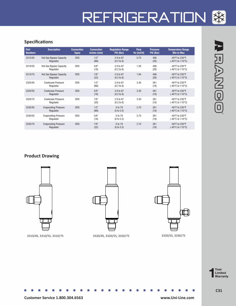
C31Customer Service 1.800.304.6563 www.Uni-Line.comwww.Uni-Line.com Customer Service 1.800.304.6563
C31
REFRIGERATION
Part Numbers
Description Connection Types
Connection Inches (mm)
Regulation Range PSI (Bar)
Flow Kv [m3/h]
Pressure PSI (Bar)
Temperature Range Min to Max
3310/4S Hot Gas Bypass Capacity Regulator
ODS 1/2” (NA)
2.9 to 87 (0.2 to 6)
0.70 406 (28)
-40°F to 230°F(-40°C to 110°C)
3310/5S Hot Gas Bypass Capacity Regulator
ODS 5/8” (16)
2.9 to 87 (0.2 to 6)
1.26 406 (28)
-40°F to 230°F (-40°C to 110°C)
3310/7S Hot Gas Bypass Capacity Regulator
ODS 7/8” (22)
2.9 to 87 (0.2 to 6)
1.84 406 (28)
-40°F to 230°F (-40°C to 110°C)
3320/4S Crankcase Pressure Regulator
ODS 1/2” (NA)
2.9 to 87 (0.2 to 6)
3.30 261 (18)
-40°F to 230°F (-40°C to 110°C)
3320/5S Crankcase Pressure Regulator
ODS 5/8” (16)
2.9 to 87 (0.2 to 6)
3.30 261 (18)
-40°F to 230°F (-40°C to 110°C)
3320/7S Crankcase Pressure Regulator
ODS 7/8” (20)
2.9 to 87 (0.2 to 6)
3.30 261 (18)
-40°F to 230°F (-40°C to 110°C)
3330/4S Evaporating Pressure Regulator
ODS 1/2” (NA)
0 to 79 (0 to 5.5)
2.70 261 (18)
-40°F to 230°F (-40°C to 110°C)
3330/5S Evaporating Pressure Regulator
ODS 5/8” (16)
0 to 79 (0 to 5.5)
2.70 261 (18)
-40°F to 230°F (-40°C to 110°C)
3330/7S Evaporating Pressure Regulator
ODS 7/8” (22)
0 to 79 (0 to 5.5)
2.70 261 (18)
-40°F to 230°F (-40°C to 110°C)
Specifications
Product Drawing
3310/4S, 3310/5S, 3310/7S 3320/4S, 3320/5S, 3320/7S 3330/5S, 3330/7S
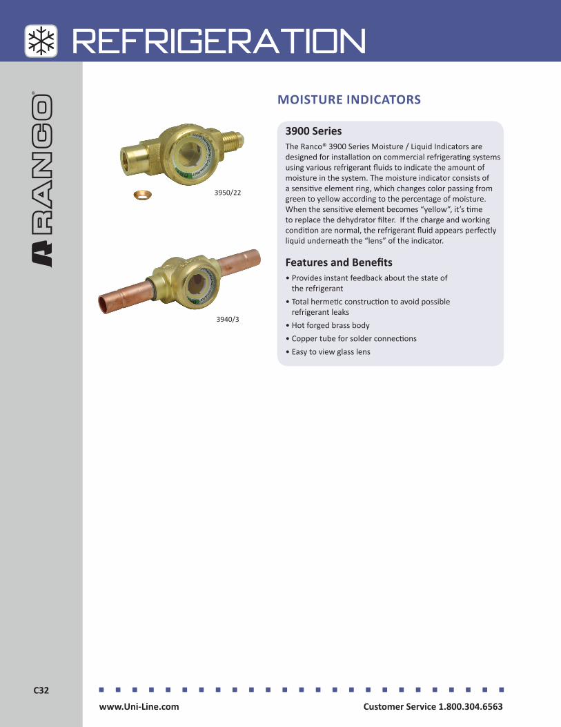
Customer Service 1.800.304.6563 www.Uni-Line.comwww.Uni-Line.com Customer Service 1.800.304.6563
C32C32
REFRIGERATION
3900 SeriesThe Ranco® 3900 Series Moisture / Liquid Indicators are designed for installation on commercial refrigerating systems using various refrigerant fluids to indicate the amount of moisture in the system. The moisture indicator consists of a sensitive element ring, which changes color passing from green to yellow according to the percentage of moisture. When the sensitive element becomes “yellow”, it’s time to replace the dehydrator filter. If the charge and working condition are normal, the refrigerant fluid appears perfectly liquid underneath the “lens” of the indicator.
Features and Benefits• Provides instant feedback about the state of
the refrigerant • Total hermetic construction to avoid possible
refrigerant leaks• Hot forged brass body• Copper tube for solder connections• Easy to view glass lens
MOISTURE INDICATORS
3940/3
3950/22

C33Customer Service 1.800.304.6563 www.Uni-Line.comwww.Uni-Line.com Customer Service 1.800.304.6563
C33
REFRIGERATION
Part Numbers Description Connection Type Connection Inches (mm)
Pressure PSI (Bar)
Temperature Range Min to Max
3910/33 Moisture/Liquid Indicator, SAE, Male-Male
SAE 3/8” (NA)
653 (45)
-22°F to 230°F (-30°C to 110°C)
3950/22 Moisture/Liquid Indicator, SAE, Male-Female
SAE 1/4” (NA)
653 (45)
-22°F to 230°F (-30°C to 110°C)
3950/33 Moisture/Liquid Indicator, SAE, Male-Female
SAE 3/8” (NA)
653 (45)
-22°F to 230°F (-30°C to 110°C)
3940/2 Moisture/Liquid Indicator, ODS, Copper Brazen
ODS 1/4” (NA)
653 (45)
-22°F to 230°F (-30°C to 110°C)
3940/3 Moisture/Liquid Indicator, ODS, Copper Brazen
ODS 3/8” (NA)
653 (45)
-22°F to 230°F (-30°C to 110°C)
3940/5 Moisture/Liquid Indicator, ODS, Copper Brazen
ODS 5/8” (16)
653 (45)
-22°F to 230°F (-30°C to 110°C)
3940/7 Moisture/Liquid Indicator, ODS, Copper Brazen
ODS 7/8” (22)
653 (45)
-22°F to 230°F (-30°C to 110°C)
Specifications
Product Drawing
3910/333950/22, 3950/33
3940/2, 3940/3, 3940/5, 3940/7
Moisture Contained in Fluid Table (ppm)
Color R22 R134a R404A R407C R410A R507
Green <60 <75 <30 <30 <30 <30
Green-Yellow 60 75 30 30 30 30
Yellow >60 >75 >30 >30 >30 >30

Customer Service 1.800.304.6563 www.Uni-Line.comwww.Uni-Line.com Customer Service 1.800.304.6563
C34C34
REFRIGERATION
4300 SeriesThe Ranco® 4300 Series Solid Core Filter Driers are designed for installation on commercial refrigerating systems using various refrigerant fluids to ensure the internal filtering of additives. These solid core filter driers have efficient dehydration with minimum charge loss while blocking oil by-products dragged into the system. Impurities accumulate in the ring between the metal shell and the block to prevent filter clogging.
Features and Benefits• Filter completely manufactured in steel• Nickel plated flare threaded or copper plated solder
connections• Solder connections made of copper tubing• Blocks are molded from a blend of dehydrating charge,
totally made of 3 Å molecular sieves, and a special binding agent in appropriate proportions
• Good deacidifying characteristics with superlative capacity of water absorption
• Compacted and stout manufacturing process making product resistant to shock and abrasions
• Uniform wall thickness for linear flow through the block• Block is chemically inert and does not react with
refrigerant fluids
SOLID CORE FILTER DRIERS
4308/3
4305/2

C35Customer Service 1.800.304.6563 www.Uni-Line.comwww.Uni-Line.com Customer Service 1.800.304.6563
C35
REFRIGERATION
Part Numbers
Description International Code
Connection Type
Connections Inches
ODM Connection
Inches
Volume Inches³ (cm³)
Pressure PSI (Bar)
Temperature Range Min to Max
4303/2 Solid Core Filter Drier SAE, 1/4”, small
032 SAE 1/4” NA 3.05 (50)
653 (45)
-40°F to 176°F (-40°C to 80°C)
4303/3 Solid Core Filter Drier SAE, 3/8”, small
033 SAE 3/8” NA 3.05 (50)
653 (45)
-40°F to 176°F (-40°C to 80°C)
4305/2 Solid Core Filter Drier SAE, 1/4”, medium
052 SAE 1/4” NA 4.88 (80)
653 (45)
-40°F to 176°F (-40°C to 80°C)
4308/2 Solid Core Filter Drier SAE, 1/4”, large
082 SAE 1/4” NA 7.93 (130)
653 (45)
-40°F to 176°F(-40°C to 80°C)
4308/3 Solid Core Filter Drier SAE, 3/8”, large
083 SAE 3/8” NA 7.93 (130)
653 (45)
-40°F to 176°F (-40°C to 80°C)
4316/3 Solid Core Filter Drier SAE, 3/8”, larger
163 SAE 3/8” NA 15.26 (250)
653 (45)
-40°F to 176°F (-40°C to 80°C)
4316/4 Solid Core Filter Drier SAE, 1/2”, larger
164 SAE 1/2” NA 15.26 (250)
653 (45)
-40°F to 176°F (-40°C to 80°C)
4316/5 Solid Core Filter Drier SAE, 5/8”, larger
165 SAE 5/8” NA 15.26 (250)
653 (45)
-40°F to 176°F (-40°C to 80°C)
4303/2S Solid Core Filter Drier ODS, 1/4”, small
032S ODS 1/4” 3/8” 3.05 (50)
653 (45)
-40°F to 176°F (-40°C to 80°C)
4303/3S Solid Core Filter Drier ODS, 3/8”, small
033S ODS 3/8” 1/2” 3.05 (50)
653 (45)
-40°F to 176°F (-40°C to 80°C)
4305/2S Solid Core Filter Drier ODS, 1/4”, medium
052S ODS 1/4” 3/8” 4.88 (80)
653 (45)
-40°F to 176°F (-40°C to 80°C)
4308/3S Solid Core Filter Drier ODS, 3/8”, large
083S ODS 3/8” 1/2” 7.93 (130)
653 (45)
-40°F to 176°F (-40°C to 80°C)
4316/5S Solid Core Filter Drier ODS, 5/8”, larger
165S ODS 5/8” 3/4” 15.26 (250)
653 (45)
-40°F to 176°F (-40°C to 80°C)
4341/7S Solid Core Filter Drier ODS, 7/8”, largest
417S ODS 7/8” 1-1/8” 40.89 (670)
653 (45)
-40°F to 176°F (-40°C to 80°C)
Specifications
Product Drawing
4303/2, 4303/3, 4305/2, 4308/2, 4308/3, 4316/3, 4316/4, 4316/5
4303/2S, 4303/3S, 4305/2S, 4308/3S, 4316/5S

Customer Service 1.800.304.6563 www.Uni-Line.comwww.Uni-Line.com Customer Service 1.800.304.6563
C36C36
REFRIGERATION
6590 SeriesThe Ranco® 6590 Series Ball Valves are designed for installation on commercial refrigerating systems using various refrigerant fluids to ensure the internal equilibrium of pressures when the valve is closed.
Features and Benefits• Permits bi-directional flow of the refrigerant• Prevents risk of ejection or explosion of the spindle• Body is hot forged brass • Ball is chromium plated, hot forged brass • Copper tube solder connections• Spindle is steel with proper surface protection• Chloroprene rubber for outlet seal gaskets• Glass reinforced cap covers the spindle
BALL VALVES
6590/3
Part Numbers Description Ball Port ODS Connections Inches (mm)
Capacity Tons (Kv [m3/h])
Pressure PSI (Bar)
Temperature Range Min to Max
6590/3 Ball Valve 3/8”, 0.8 Tons
10 3/8” (NA)
0.8 (3)
652 (45)
-40°F to 302°F (-40°C to 150°C)
6590/4 Ball Valve 1/2”, 1.4 Tons
10 1/2” (NA)
1.4 (5)
652 (45)
-40°F to 302°F (-40°C to 150°C)
6590/5 Ball Valve 5/8”, 1.4 Tons
15 5/8” (16)
1.4 (5)
652 (45)
-40°F to 302°F(-40°C to 150°C)
6590/6 Ball Valve 3/4”, 4.1 Tons
15 3/4” (NA)
4.1 (14.5)
652 (45)
-40°F to 302°F (-40°C to 150°C)
6590/7 Ball Valve 7/8”, 6.8 Tons
19 7/8” (22)
6.8 (24)
652 (45)
-40°F to 302°F (-40°C to 150°C)
6590/9 Ball Valve 1-1/8”, 11.4 Tons
25 1-1/8” (NA)
11.4 (40)
652 (45)
-40°F to 302°F(-40°C to 150°C)
6590/11 Ball Valve 1-3/8”, 19.3 Tons
32 1-3/8” (35)
19.3 (68)
652 (45)
-40°F to 302°F(-40°C to 150°C)
6590/3
Specifications
Product Drawing
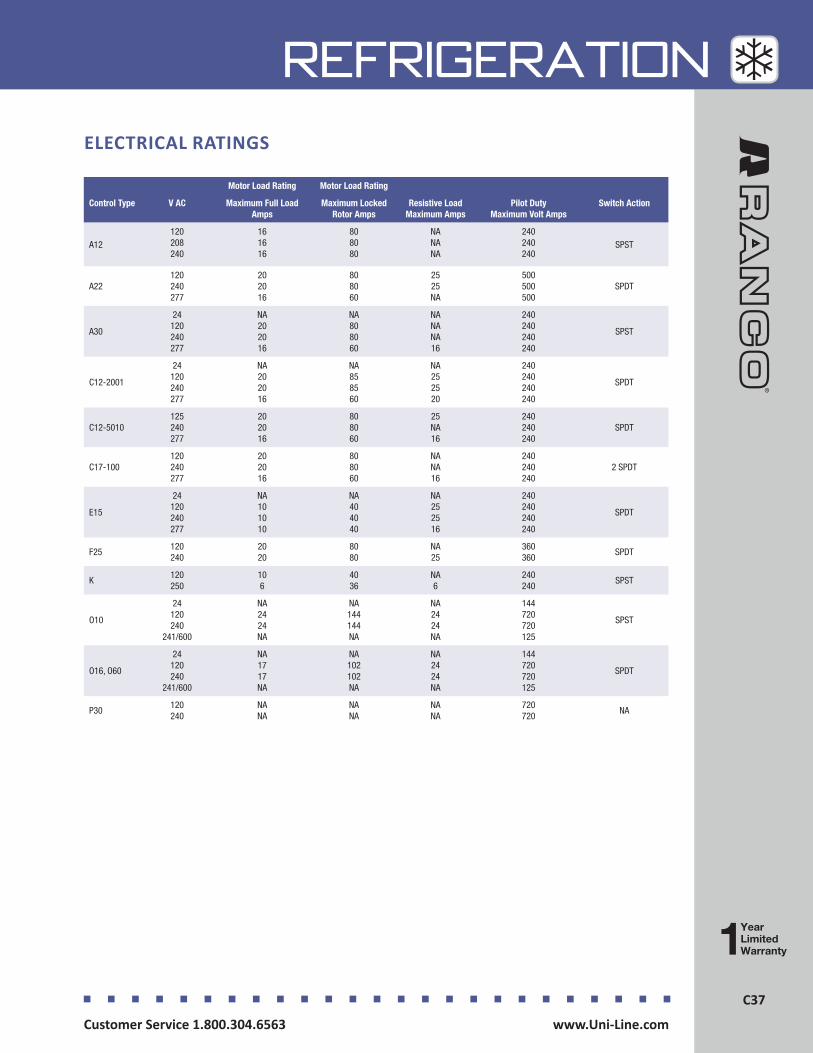
C37Customer Service 1.800.304.6563 www.Uni-Line.comwww.Uni-Line.com Customer Service 1.800.304.6563
C37
REFRIGERATION
Motor Load Rating Motor Load Rating
Control Type V AC Maximum Full Load Amps
Maximum Locked Rotor Amps
Resistive Load Maximum Amps
Pilot Duty Maximum Volt Amps
Switch Action
A12 120 208 240
16 16 16
80 80 80
NA NA NA
240 240 240
SPST
A22 120 240 277
20 20 16
80 80 60
25 25 NA
500 500 500
SPDT
A30
24 120 240 277
NA 20 20 16
NA 80 80 60
NA NA NA 16
240 240 240 240
SPST
C12-2001
24 120 240 277
NA 20 20 16
NA 85 85 60
NA 25 25 20
240 240 240 240
SPDT
C12-5010125 240 277
20 20 16
80 80 60
25 NA 16
240 240 240
SPDT
C17-100120 240 277
20 20 16
80 80 60
NA NA 16
240 240 240
2 SPDT
E15
24 120 240 277
NA 10 10 10
NA 40 40 40
NA 25 25 16
240 240 240 240
SPDT
F25120 240
20 20
80 80
NA 25
360 360
SPDT
K120 250
10 6
40 36
NA 6
240 240
SPST
O10
24 120 240
241/600
NA 24 24 NA
NA 144 144 NA
NA 24 24 NA
144 720 720 125
SPST
O16, O60
24 120 240
241/600
NA 17 17 NA
NA 102 102 NA
NA 24 24 NA
144 720 720 125
SPDT
P30120 240
NA NA
NA NA
NA NA
720 720
NA
ELECTRICAL RATINGS


Timers
Timers, whether used for defrost or electrical systems, are essential for the longevity and energy saving functionality of important equipment. The Paragon® defrost and the Tork® electric timers offer versatility and unbeatable quality to control power and compressor defrost cycles. Defrost products include electromechanical and electronic timers for commercial and residential applications.
Defrost Timers - Auto Voltage ...................................................... D2
Defrost Timers - Electromechanical.............................................. D8
Defrost Timers - Electronic ......................................................... D11
Electric Timers - Electromechanical ............................................ D14
Electric Timers - Electronic ......................................................... D18
Residential Defrost Timers ......................................................... D19
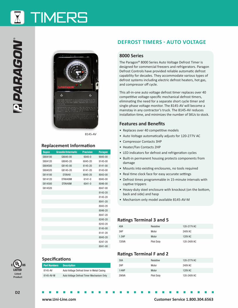
2D2
TIMERS
Customer Service 1.800.304.6563 www.Uni-Line.comwww.Uni-Line.com Customer Service 1.800.304.6563
Listed Product
8000 SeriesThe Paragon® 8000 Series Auto Voltage Defrost Timer is designed for commercial freezers and refrigerators. Paragon Defrost Controls have provided reliable automatic defrost capability for decades. They accommodate various types of defrost systems including electric defrost heaters, hot gas, and compressor off cycle.
This all-in-one auto voltage defrost timer replaces over 40 competitive voltage-specific mechanical defrost timers, eliminating the need for a separate short cycle timer and single-phase voltage monitor. The 8145-AV will become a mainstay in any contractor’s truck. The 8145-AV reduces installation time, and minimizes the number of SKUs to stock.
Features and Benefits• Replaces over 40 competitive models• Auto Voltage automatically adjusts for 120-277V AC• Compressor Contacts 3HP• Heater/Fan Contacts 2HP• LED indicators for defrost and refrigeration cycles• Built-in permanent housing protects components from
damage• Mounts into existing enclosures, no tools required• Real time clock face for easy accurate settings• Defrost times programmable in 15-minute intervals with
captive trippers• Heavy-duty steel enclosure with knockout (on the bottom,
back and side) and hasp• Mechanism only model available 8145-AV-M
8145-AV
DEFROST TIMERS - AUTO VOLTAGE
40A Resistive 120-277V AC
3HP Motor 240V AC
1.5HP Motor 120V AC
720VA Pilot Duty 120-240V AC
Ratings Terminal 3 and 5
30A Resistive 120-277V AC
2HP Motor 240V AC
1/4HP Motor 120V AC
290VA Pilot Duty 120-240V AC
Ratings Terminal F and 2
Part Numbers Description
8145-AV Auto Voltage Defrost timer in Metal Casing
8145-AV-M Auto Voltage Defrost Timer Mechanism Only
Specifications
Replacement InformationSupco Grasslin/Intermatic Precision Paragon
S804100 G8045-00 6045-0 9045-00
S804120 G8045-20 6045-20 9145-00
S804500 G8145-00 6145-20 8141-00
S804520 G8145-20 6141-20 8143-00
S814100 DTAV40 6045-20 8043-00
S814120 DTAV40IM 6141-0 8045-00
S814500 DTAV40M 6041-0 8046-00
S814520 8047-00
8143-20
8145-20
8041-20
8043-20
8046-20
8047-20
8245-20
8243-20
8145-00
8141-20
8045-20
8247-20
8041-00
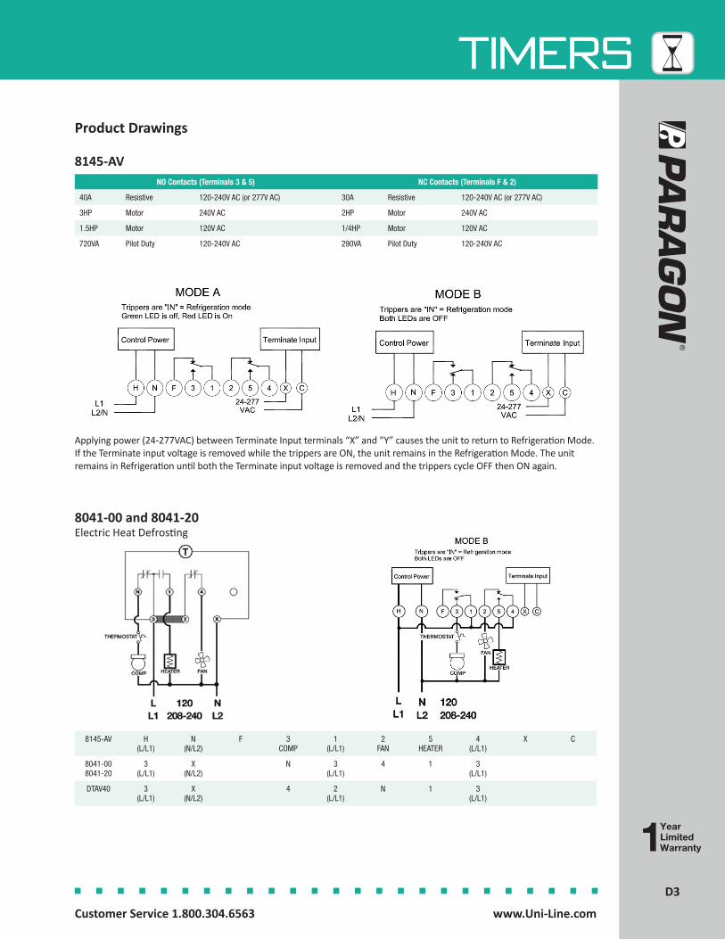
3D3
TIMERS
Customer Service 1.800.304.6563 www.Uni-Line.comwww.Uni-Line.com Customer Service 1.800.304.6563
Product Drawings
8145-AV H(L/L1)
N(N/L2)
F 3COMP
1(L/L1)
2FAN
5HEATER
4(L/L1)
X C
8041-008041-20
3(L/L1)
X(N/L2)
N 3(L/L1)
4 1 3(L/L1)
DTAV40 3(L/L1)
X(N/L2)
4 2(L/L1)
N 1 3(L/L1)
8041-00 and 8041-20 Electric Heat Defrosting
8145-AVNO Contacts (Terminals 3 & 5) NC Contacts (Terminals F & 2)
40A Resistive 120-240V AC (or 277V AC) 30A Resistive 120-240V AC (or 277V AC)
3HP Motor 240V AC 2HP Motor 240V AC
1.5HP Motor 120V AC 1/4HP Motor 120V AC
720VA Pilot Duty 120-240V AC 290VA Pilot Duty 120-240V AC
Applying power (24-277VAC) between Terminate Input terminals “X” and “Y” causes the unit to return to Refrigeration Mode. If the Terminate input voltage is removed while the trippers are ON, the unit remains in the Refrigeration Mode. The unit remains in Refrigeration until both the Terminate input voltage is removed and the trippers cycle OFF then ON again.
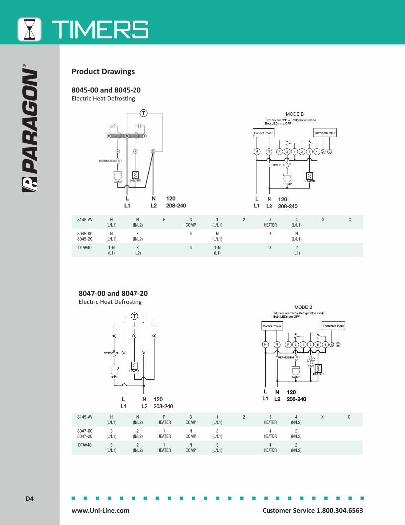
4D4
TIMERS
Customer Service 1.800.304.6563 www.Uni-Line.comwww.Uni-Line.com Customer Service 1.800.304.6563
Product Drawings
8047-00 and 8047-20 Electric Heat Defrosting
8145-AV H(L/L1)
N(N/L2)
FHEATER
3COMP
1(L/L1)
2 5HEATER
4(N/L2)
X C
8047-008047-20
3(L/L1)
2(N/L2)
1HEATER
NCOMP
3(L/L1)
4HEATER
2(N/L2)
DTAV40 3(L/L1)
2(N/L2)
1HEATER
NCOMP
3(L/L1)
4HEATER
2(N/L2)
8145-AV H(L/L1)
N(N/L2)
F 3COMP
1(L/L1)
2 5HEATER
4(L/L1)
X C
8045-008045-20
N(L/L1)
X(N/L2)
4 N(L/L1)
3 N(L/L1)
DTAV40 1-N(L1)
X(L2)
4 1-N(L1)
3 2(L1)
8045-00 and 8045-20 Electric Heat Defrosting
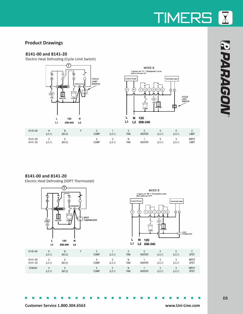
5D5
TIMERS
Customer Service 1.800.304.6563 www.Uni-Line.comwww.Uni-Line.com Customer Service 1.800.304.6563
Product Drawings
8145-AV H(L/L1)
N(N/L2)
F 3COMP
1(L/L1)
2FAN
5HEATER
4(L/L1)
X(L/L1)
CSPDT
8141-008141-20
3(L/L1)
X(N/L2)
4COMP
3(L/L1)
NFAN
1HEATER
3(L/L1)
3(L/L1)
INPUTSPDT
DTAV40 3(L/L1)
X(N/L2)
4COMP
2(L/L1)
NFAN
1HEATER
3(L/L1)
3(L/L1)
INPUTSPDT
8141-00 and 8141-20 Electric Heat Defrosting (SDPT Thermostat)
8145-AV H(L/L1)
N(N/L2)
F 3COMP
1(L/L1)
2FAN
5HEATER
4(L/L1)
X(L/L1)
CLIMIT
8141-008141-20
3(L/L1)
X(N/L2)
4COMP
3(L/L1)
NFAN
1HEATER
3(L/L1)
3(L/L1)
INPUTLIMIT
8141-00 and 8141-20 Electric Heat Defrosting (Cycle Limit Switch)
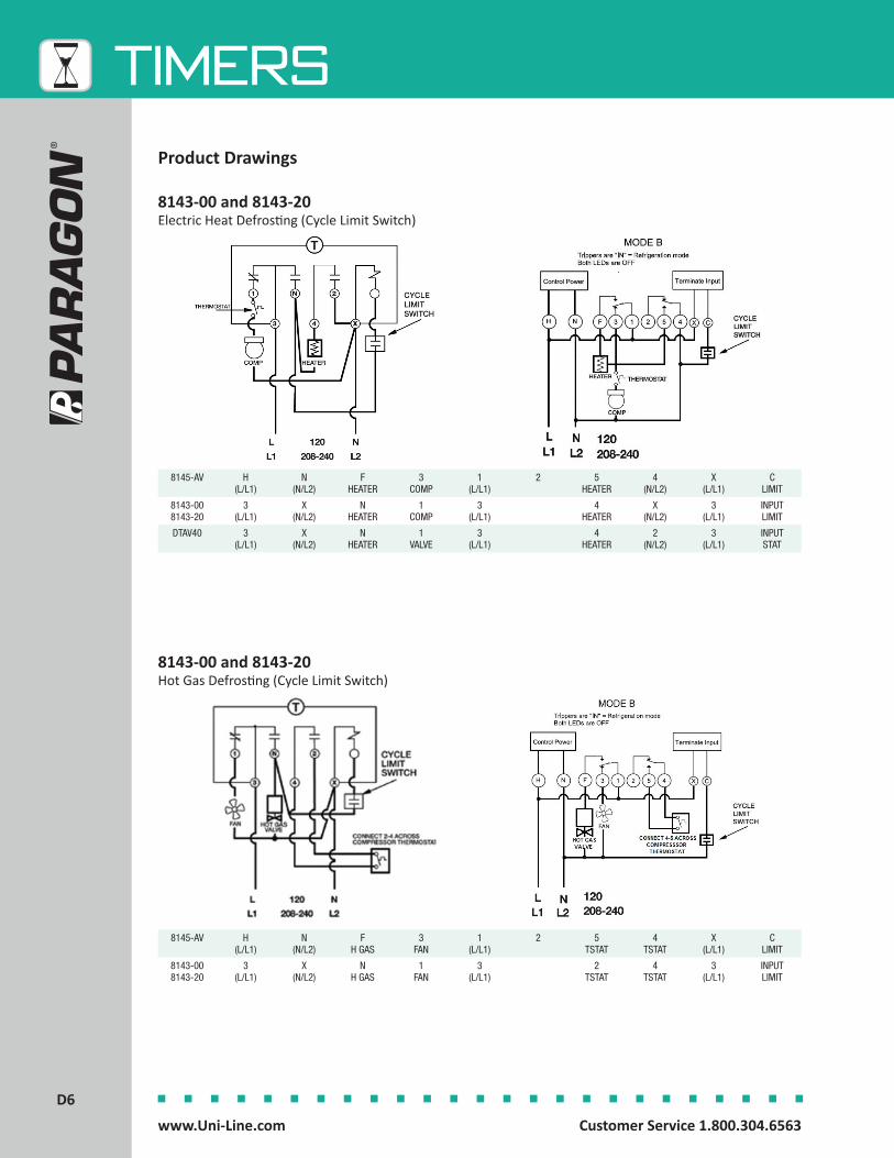
6D6
TIMERS
Customer Service 1.800.304.6563 www.Uni-Line.comwww.Uni-Line.com Customer Service 1.800.304.6563
8145-AV H(L/L1)
N(N/L2)
FHEATER
3COMP
1(L/L1)
2 5HEATER
4(N/L2)
X(L/L1)
CLIMIT
8143-008143-20
3(L/L1)
X(N/L2)
NHEATER
1COMP
3(L/L1)
4HEATER
X(N/L2)
3(L/L1)
INPUTLIMIT
DTAV40 3(L/L1)
X(N/L2)
NHEATER
1VALVE
3(L/L1)
4HEATER
2(N/L2)
3(L/L1)
INPUTSTAT
8143-00 and 8143-20 Electric Heat Defrosting (Cycle Limit Switch)
8145-AV H(L/L1)
N(N/L2)
FH GAS
3FAN
1(L/L1)
2 5TSTAT
4TSTAT
X(L/L1)
CLIMIT
8143-008143-20
3(L/L1)
X(N/L2)
NH GAS
1FAN
3(L/L1)
2TSTAT
4TSTAT
3(L/L1)
INPUTLIMIT
8143-00 and 8143-20 Hot Gas Defrosting (Cycle Limit Switch)
Product Drawings

7D7
TIMERS
Customer Service 1.800.304.6563 www.Uni-Line.comwww.Uni-Line.com Customer Service 1.800.304.6563
8145-AV H(L/L1)
N(N/L2)
FH GAS
3FAN
1(L/L1)
2 5TSTAT
4TSTAT
X(L/L1)
CSPDT
DTAV40 3(L/L1)
X(N/L2)
NH GAS
1FAN
3(L/L1)
2TSTAT
4TSTAT
3(L/L1)
INPUTSPDT
8143-00 and 8143-20 Hot Gas Defrosting (SPDT Thermostat)
Product Drawings
8145-AV H(L/L1)
N(N/L2)
F 3COMPFAN
1(L/L1)
2 5HEAT-
ER
4(L/L1)
X(L/L1)
CSPDT
DTAV40 1(L/L1)
N(N/L2)
4COMPFAN
2(L/L1)
3HEAT-
ER
1(L/L1)
1(L/L1)
XSPDT
8145-00 and 8145-20 Electric Heat Defrosting (SPDT Thermostat)
8145-AV H(L/L1)
N(N/L2)
F 3COMP
1(L/L1)
2 5LIMIT
4(L/L1)
X5/LIMIT
CHEATER/
LIMIT
8145-008145-20
1(L/L1)
N(N/L2)
4COMP
1(L/L1)
3LIMIT
1(L/L1)
XHEATER/
LIMIT
8145-00 and 8145-20 Electric Heat Defrosting (Cycle Limit Switch)

8D8
TIMERS
Customer Service 1.800.304.6563 www.Uni-Line.comwww.Uni-Line.com Customer Service 1.800.304.6563
8000 SeriesThe Paragon® 8000 Series Commercial Defrost Controls are designed for commercial freezers and refrigerators to provide automatic defrost capability. They accommodate various types of defrost systems including electric defrost heaters, hot gas, and compressor off cycle.
Features and Benefits• Time initiated; temperature, pressure or time terminated
models available• High-amp switch contacts: 40 amps, 2 HP• Positive slider bar switch design assures positive electrical
contact and wipes the contact surface of contaminates• Temperature or pressure terminated models are designed
for defrost termination using an external temperature or pressure device
• Safety back-up – mechanical time-driven defrost termination
• Heavy-duty synchronous design drive motor• Choice of three contact arrangements• Adjustable frequency of defrost initiation from 1 to 6
cycles per day with a minimum of 4 hours between successive operations
• Adjustable back-up defrost termination from 4 to 110 minutes in 2 minute increments
• Heavy-duty steel enclosure with knockouts (on the bottom, back and sides) and hasp and staple padlock
• All 8240 models have an adjustable cut-in pressure dial calibrated from 36-110 pounds for R12, R22, R502
8045-00
8245-20
DEFROST TIMERS - ELECTROMECHANICAL
Listed Product
Recognized Component

9D9
TIMERS
Customer Service 1.800.304.6563 www.Uni-Line.comwww.Uni-Line.com Customer Service 1.800.304.6563
Part Numbers Description Switch Arrangement Contacts 2-4
Switch Arrangement Contacts 1-3
Switch Arrangement Contacts 3-N
Termination Type
ElectricalRating
8041-00 Electric Heat Closed Open Closed Time 120V AC 60 Hz
8045-00 Electric Heat, Hot Gas or Compressor Shutdown
Closed Open None Time 120V AC 60 Hz
8045-20 Electric Heat, Hot Gas or Compressor Shutdown
Closed Open None Time 208-240V AC 60 Hz
8141-00 Electric Heat, Hot Gas or Compressor Shutdown
Closed Open Closed Temperature or Pressure
120V AC 60 Hz
8141-20 Electric Heat, Hot Gas or Compressor Shutdown
Closed Open Closed Temperature or Pressure
208-240V AC 60 Hz
8145-00 Electric Heat, Hot Gas or Compressor Shutdown
Closed Open None Temperature or Pressure
120V AC 60 Hz
8145-20 Electric Heat, Hot Gas or Compressor Shutdown
Closed Open None Temperature or Pressure
208-240V AC 60 Hz
8145-20B Electric Heat, Hot Gas or Compressor Shutdown
Closed Open None Temperature or Pressure
208-240V AC 60 Hz
8245-20 Electric Heat, Hot Gas or Compressor Shutdown
Closed Open None Pressure 208-240V AC 60 Hz
D81-8145-00EX(ANZ, EU, MEX, SA)
Electric Heat, Hot Gas or Compressor Shutdown
Closed Open None Temperature or Pressure
120V AC 60 Hz
D81-8145-20EX(ANZ, EU, MEX, SA)
Electric Heat, Hot Gas or Compressor Shutdown
Closed Open None Temperature or Pressure
208-240V AC 60 Hz
D81-8145-21EX (ANZ, EU, MEX, SA)
Electric Heat, Hot Gas or Compressor Shutdown
Closed Open None Temperature or Pressure
208-240 AC 50 Hz
Specifications
Product Drawings
Electric Heat DefrostingModels 8041-00 and 8041-20 - Wiring Diagram
Models 8045-00 and 8045-20 - Wiring Diagram
Heater not to exceed 4000 watts at 120V AC or 8000 watts at 240V AC
Fan and compressor loads not to exceed 2 hp. Heater not to exceed 4000 watts at 120V AC or 8000 watts at 240V AC
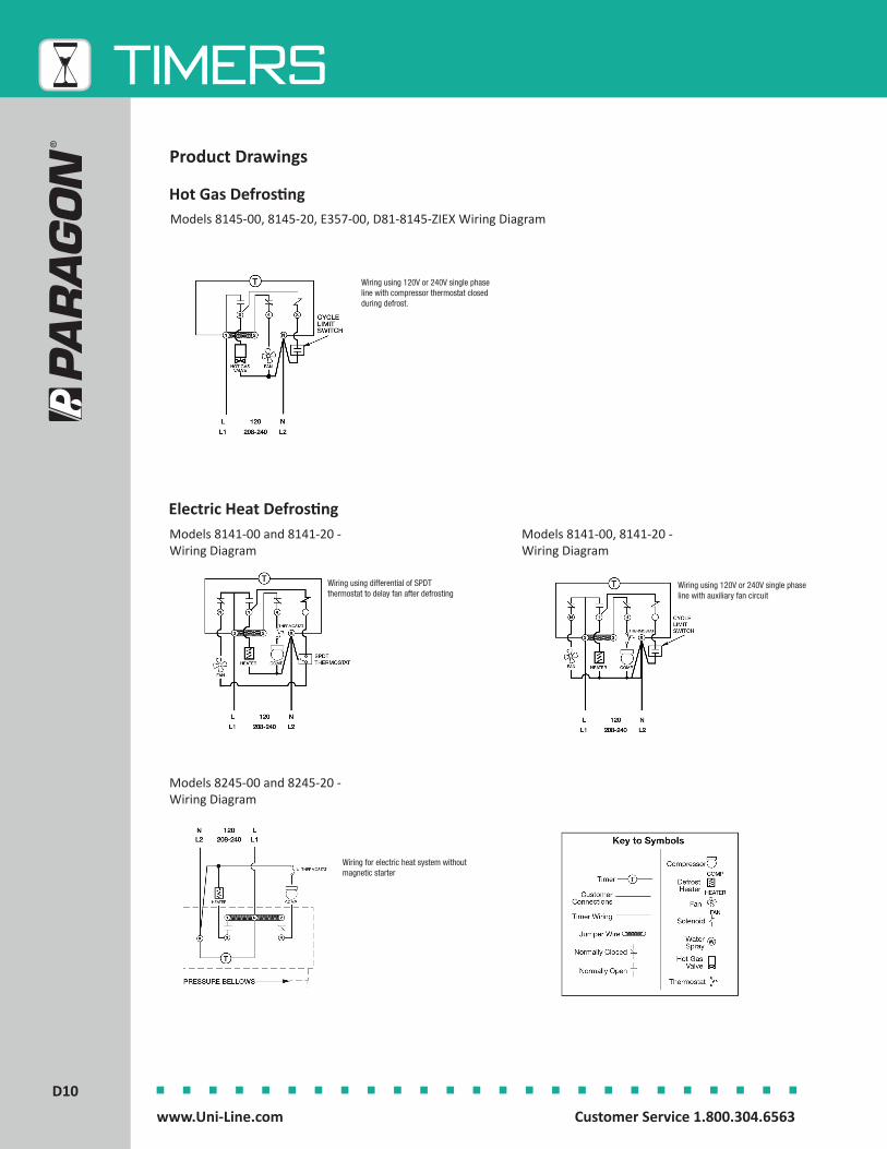
10D10
TIMERS
Customer Service 1.800.304.6563 www.Uni-Line.comwww.Uni-Line.com Customer Service 1.800.304.6563
Product Drawings
Electric Heat DefrostingModels 8141-00 and 8141-20 - Wiring Diagram
Models 8141-00, 8141-20 - Wiring Diagram
Models 8145-00, 8145-20, E357-00, D81-8145-ZIEX Wiring Diagram
Wiring using 120V or 240V single phase line with compressor thermostat closed during defrost.
Hot Gas Defrosting
Models 8245-00 and 8245-20 - Wiring Diagram
Wiring using differential of SPDT thermostat to delay fan after defrosting
Wiring using 120V or 240V single phase line with auxiliary fan circuit
Wiring for electric heat system without magnetic starter
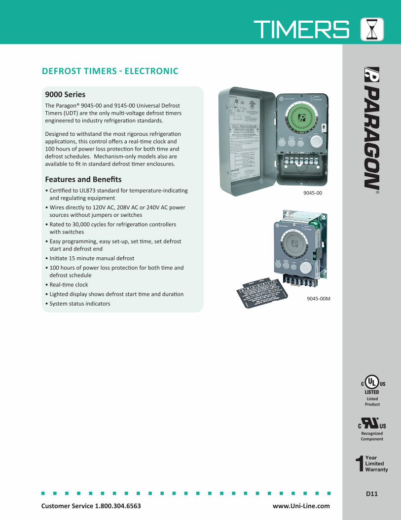
11D11
TIMERS
Customer Service 1.800.304.6563 www.Uni-Line.comwww.Uni-Line.com Customer Service 1.800.304.6563
DEFROST TIMERS - ELECTRONIC
9000 SeriesThe Paragon® 9045-00 and 9145-00 Universal Defrost Timers (UDT) are the only multi-voltage defrost timers engineered to industry refrigeration standards.
Designed to withstand the most rigorous refrigeration applications, this control offers a real-time clock and 100 hours of power loss protection for both time and defrost schedules. Mechanism-only models also are available to fit in standard defrost timer enclosures.
Features and Benefits• Certified to UL873 standard for temperature-indicating
and regulating equipment• Wires directly to 120V AC, 208V AC or 240V AC power
sources without jumpers or switches• Rated to 30,000 cycles for refrigeration controllers
with switches• Easy programming, easy set-up, set time, set defrost
start and defrost end• Initiate 15 minute manual defrost• 100 hours of power loss protection for both time and
defrost schedule• Real-time clock• Lighted display shows defrost start time and duration• System status indicators
9045-00
9045-00M
Listed Product
Recognized Component

12D12
TIMERS
Customer Service 1.800.304.6563 www.Uni-Line.comwww.Uni-Line.com Customer Service 1.800.304.6563
Specifications
Product Drawings
9145 Terminal Data
A B C D E F G
RelayContact
SPDT NC Contact
SPDTNO Contact
SPDTCommon Contact
SPSTNO Contact
SPSTCommonContact
L2/NPower into timer
DefrostTerminationDevice Input
L2/N side
RelayRating
15 A resistive @ 120 to 240V AC
1/4 HP @ 120V AC, 1/2 HP @ 208
to 240V AC
30 A resistive @ 120 to 240V AC 1 HP @ 120V AC
2 HP @ 208 to 240V AC
30 A resistive @ 120 to 240V AC
1 HP @ 120V AC, 2 HP @ 208 to 240 AC
Device Connections
Fan (Typical)Compressor (Optional)
Defrost Device(Typical)
L1 Power to Timer and to
DefrostTermination
Device
Compressor (Typical)
Fan (Optional)
DefrostTermination
Switch
9045 Terminal Data
A B C D E F G
RelayContact
SPST #1 NC Contact
SPST #1 Common Contact
L1 Power in to Timer
SPST #2 No Contact
SPST #2 Common Contact
L2/NPower into timer
No Connection
RelayRating
30 A resistive @ 120 to 240V AC
1 HP @ 120V AC, 2 HP @ 208 to 240V AC
30 A resistive @ 120 to 240V AC
1 HP @ 120V AC, 2 HP @ 208 to 240V AC
Device Connections
Compressor(Typical)
Defrost Device(Typical)
DefrostTermination
Switch
Part Numbers Description Relay Switch Initiation Type Termination Type Voltage
9045-00 Universal Defrost Timer SPST Time Time 120-208-240V AC
9045-00M Mechanism Only SPST Time Time 120-208-240V AC
9145-00 Universal Defrost Timer SPDT Time Time, Temp or Pressure 120-208-240V AC
9145-00M Mechanism Only SPDT Time Time, Temp or Pressure 120-208-240V AC
L, L1 N, L2
A B C D E F G
TIMER
COMPRESSOR
T'STAT
9045 AIR DEFROST - Time Initiated Time Terminated - Wiring Diagram
9045 ELECTRIC DEFROST - Time Initiated Time Terminated - Wiring Diagram
L, L1 N, L2
A B C D E F G
TIMER
COMPRESSOR
T'STAT
HEATER
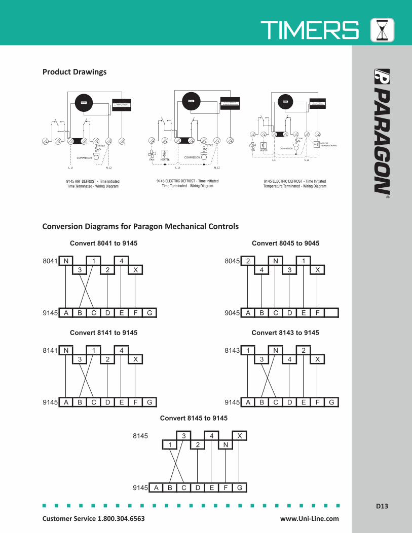
13D13
TIMERS
Customer Service 1.800.304.6563 www.Uni-Line.comwww.Uni-Line.com Customer Service 1.800.304.6563
A B C D E F G
TIMERTerminal "G" Defrost
Termination Sense Circuitry
T'STAT
COMPRESSOR
L, L1 N, L2
A B C D E F G
TIMERTerminal "G" Defrost
Termination Sense Circuitry
FAN
T'STAT
COMPRESSOR
L, L1 N, L2
HEATER
9145 AIR DEFROST - Time Initiated Time Terminated - Wiring Diagram
9145 ELECTRIC DEFROST - Time Initiated Time Terminated - Wiring Diagram
Product Drawings
Conversion Diagrams for Paragon Mechanical Controls
Convert 8041 to 9145
8041 N 1 43 2 X
9145 A B C D E F G
Convert 8141 to 9145
8141 N 1 43 2 X
9145 A B C D E F G
Convert 8145 to 9145
8145 3 4 X1 2 N
9145 A B C D E F G
Convert 8045 to 9045
8045 2 N 14 3 X
9045 A B C D E F
Convert 8143 to 9145
8143 1 N 23 4 X
9145 A B C D E F G
9145 ELECTRIC DEFROST - Time Initiated Temperature Terminated - Wiring Diagram
A B C D E F G
TIMERTerminal "G" Defrost
Termination Sense Circuitry
FAN HEATER
T'STAT
COMPRESSOR
DEFROSTTERMINATION/FAN
L, L1 N, L2
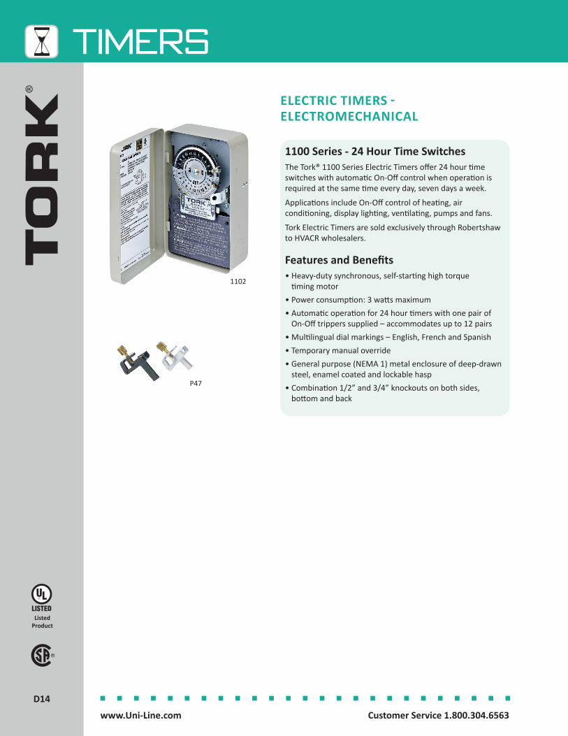
14D14
TIMERS
Customer Service 1.800.304.6563 www.Uni-Line.comwww.Uni-Line.com Customer Service 1.800.304.6563
1100 Series - 24 Hour Time SwitchesThe Tork® 1100 Series Electric Timers offer 24 hour time switches with automatic On-Off control when operation is required at the same time every day, seven days a week.
Applications include On-Off control of heating, air conditioning, display lighting, ventilating, pumps and fans.
Tork Electric Timers are sold exclusively through Robertshaw to HVACR wholesalers.
Features and Benefits• Heavy-duty synchronous, self-starting high torque
timing motor• Power consumption: 3 watts maximum• Automatic operation for 24 hour timers with one pair of
On-Off trippers supplied – accommodates up to 12 pairs • Multilingual dial markings – English, French and Spanish• Temporary manual override• General purpose (NEMA 1) metal enclosure of deep-drawn
steel, enamel coated and lockable hasp• Combination 1/2” and 3/4” knockouts on both sides,
bottom and back
ELECTRIC TIMERS - ELECTROMECHANICAL
1102
P47
Listed Product

15D15
TIMERS
Customer Service 1.800.304.6563 www.Uni-Line.comwww.Uni-Line.com Customer Service 1.800.304.6563
Part Numbers
Description Contact Ratings Automatic Operation
Operating Temperature
Enclosure Switch Voltage
1101 24 Hour Electromechanical Timer
40 A Resistive 20 A Inductive
1000 VA Pilot Duty2HP (24 FLA) 120V AC
MinimumON 20 minutes;OFF 75 minutes
-40°F to 165°F(-40°C to 74°C)
Metal SPST 120V AC
1102 24 Hour Electromechanical Timer
40 A Resistive 20 A Inductive
1000 VA Pilot Duty2HP (24 FLA) 120V AC
MinimumON 20 minutes;OFF 75 minutes
-40°F to 165°F(-40°C to 74°C)
Metal SPST 208-277V AC
1103 24 Hour Electromechanical Timer
40 A Resistive 20 A Inductive
1000 VA Pilot Duty2HP (24 FLA) 120V AC
MinimumON 20 minutes;OFF 75 minutes
-40°F to 165°F (-40°C to 74°C)
Metal DPST 120V AC
1104 24 Hour Electromechanical Timer
40 A Resistive 20 A Inductive
1000 VA Pilot Duty2HP (24 FLA) 120V AC
5HP 240V AC
MinimumON 20 minutes;OFF 75 minutes
-40°F to 165°F(-40°C to 74°C)
Metal DPST 208-277V AC
P47 Accessory trippers for 1100 Series Timers
NA NA NA NA NA NA
Specifications
Product Drawings
Double Pole - Wiring Diagrams
Single Pole - Wiring Diagrams
1101 1102
1103 1104
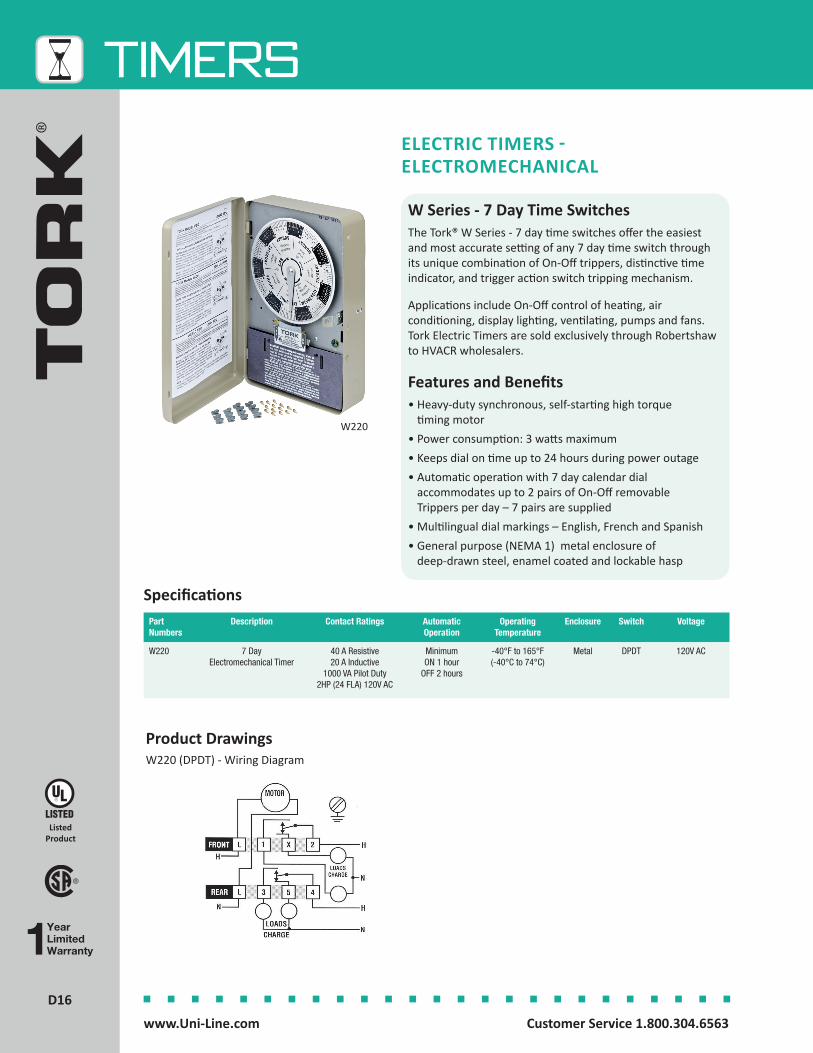
16D16
TIMERS
Customer Service 1.800.304.6563 www.Uni-Line.comwww.Uni-Line.com Customer Service 1.800.304.6563
Product DrawingsW220 (DPDT) - Wiring Diagram
W Series - 7 Day Time SwitchesThe Tork® W Series - 7 day time switches offer the easiest and most accurate setting of any 7 day time switch through its unique combination of On-Off trippers, distinctive time indicator, and trigger action switch tripping mechanism.
Applications include On-Off control of heating, air conditioning, display lighting, ventilating, pumps and fans. Tork Electric Timers are sold exclusively through Robertshaw to HVACR wholesalers.
Features and Benefits• Heavy-duty synchronous, self-starting high torque
timing motor• Power consumption: 3 watts maximum• Keeps dial on time up to 24 hours during power outage • Automatic operation with 7 day calendar dial
accommodates up to 2 pairs of On-Off removable Trippers per day – 7 pairs are supplied
• Multilingual dial markings – English, French and Spanish• General purpose (NEMA 1) metal enclosure of
deep-drawn steel, enamel coated and lockable hasp
ELECTRIC TIMERS - ELECTROMECHANICAL
W220
Part Numbers
Description Contact Ratings Automatic Operation
Operating Temperature
Enclosure Switch Voltage
W220 7 Day Electromechanical Timer
40 A Resistive 20 A Inductive
1000 VA Pilot Duty2HP (24 FLA) 120V AC
Minimum ON 1 hour
OFF 2 hours
-40°F to 165°F(-40°C to 74°C)
Metal DPDT 120V AC
Specifications
Listed Product
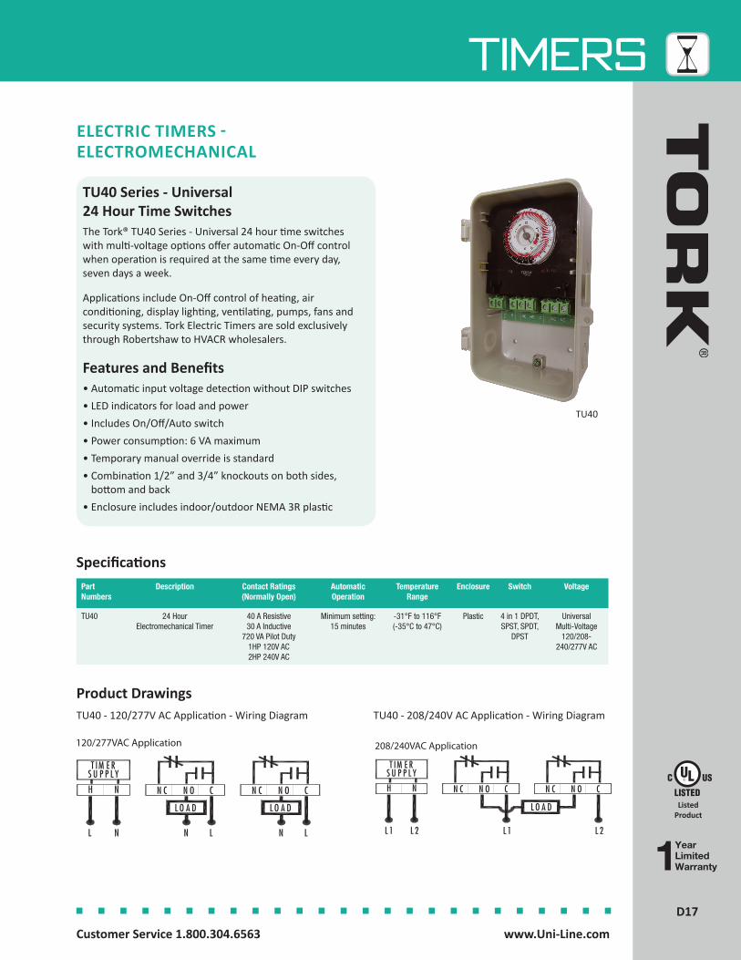
17D17
TIMERS
Customer Service 1.800.304.6563 www.Uni-Line.comwww.Uni-Line.com Customer Service 1.800.304.6563
Product Drawings
TU40 Series - Universal 24 Hour Time SwitchesThe Tork® TU40 Series - Universal 24 hour time switches with multi-voltage options offer automatic On-Off control when operation is required at the same time every day, seven days a week.
Applications include On-Off control of heating, air conditioning, display lighting, ventilating, pumps, fans and security systems. Tork Electric Timers are sold exclusively through Robertshaw to HVACR wholesalers.
Features and Benefits• Automatic input voltage detection without DIP switches• LED indicators for load and power• Includes On/Off/Auto switch• Power consumption: 6 VA maximum• Temporary manual override is standard• Combination 1/2” and 3/4” knockouts on both sides,
bottom and back • Enclosure includes indoor/outdoor NEMA 3R plastic
ELECTRIC TIMERS - ELECTROMECHANICAL
Specifications
TU40 - 120/277V AC Application - Wiring Diagram
TU40
TU40 - 208/240V AC Application - Wiring Diagram
Part Numbers
Description Contact Ratings(Normally Open)
Automatic Operation
TemperatureRange
Enclosure Switch Voltage
TU40 24 Hour Electromechanical Timer
40 A Resistive 30 A Inductive
720 VA Pilot Duty1HP 120V AC 2HP 240V AC
Minimum setting:15 minutes
-31°F to 116°F(-35°C to 47°C)
Plastic 4 in 1 DPDT, SPST, SPDT,
DPST
Universal Multi-Voltage
120/208-240/277V AC
Listed Product
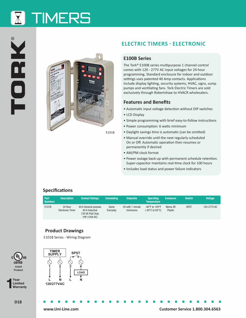
18D18
TIMERS
Customer Service 1.800.304.6563 www.Uni-Line.comwww.Uni-Line.com Customer Service 1.800.304.6563
E101B
Part Numbers
Description Contact Ratings Scheduling Setpoints Operating Temperature
Enclosure Switch Voltage
E101B 24 Hour Electronic Timer
40 A General purpose 40 A Inductive
720 VA Pilot Duty1HP (120V AC)
Same Everyday
20 with 1 minute minimums
-40°F to 149°F(-40°C to 65°C)
Nema 3R Plastic
SPST 120-277V AC
Specifications
E100B SeriesThe Tork® E100B series multipurpose 1 channel control comes with 120 - 277V AC input voltages for 24 hour programming. Standard enclosure for indoor and outdoor settings uses patented 40 Amp contacts. Applications include display lighting, security systems, HVAC, signs, sump pumps and ventilating fans. Tork Electric Timers are sold exclusively through Robertshaw to HVACR wholesalers.
Features and Benefits• Automatic input voltage detection without DIP switches• LCD Display• Simple programming with brief easy-to-follow instructions• Power consumption: 6 watts minimum• Daylight savings time is automatic (can be omitted)• Manual override until the next regularly scheduled
On or Off. Automatic operation then resumes or permanently if desired
• AM/PM clock format• Power outage back-up with permanent schedule retention.
Super-capacitor maintains real-time clock for 100 hours• Includes load status and power failure indicators
ELECTRIC TIMERS - ELECTRONIC
Product DrawingsE101B Series - Wiring Diagram
YearLimitedWarranty
Listed Product

19D19
TIMERS
Customer Service 1.800.304.6563 www.Uni-Line.comwww.Uni-Line.com Customer Service 1.800.304.6563
Domestic Defrost TimersThe Paragon® 1401 Series Defrost Timers are a synchronous motor control that activates an internal SPDT switch to actuate a defrost heater in a refrigerator. These heavy-duty 15 Amp Paragon timers are used by OEM manufacturers to replace both the older classic design timers and the new OEM versions.
Features and Benefits • Bulk quantities must be ordered in multiples of 12• Quiet - synchronous design provides extremely quiet
operation• Position freedom - timer can be mounted in various
locations• Interchangeability - standard mounting allows use in
all applications• Double insulated - requires no earth grounding• RoHS compliant
RESIDENTIAL DEFROST TIMERS
Part Numbers Description Bulk Quantity Timing Electrical Rating
A1401-00 Defrost Timer in Refrigerator 12 6 hours 21 minutes 120V AC 60 Hz 15 Amp 1/2 HP
B1401-00 Defrost Timer in Refrigerator 12 8 hours 20 minutes 120V AC 60 Hz 15 Amp 1/2 HP
G1401-00 Defrost Timer in Refrigerator 12 6 hours 25 minutes 120V AC 60 Hz 15 Amp 1/2 HP
A1401-20 Defrost Timer in Refrigerator 12 6 hours 21 minutes 240V AC 60 Hz 8 Amp 1/2 HP
B1401-20 Defrost Timer in Refrigerator 12 8 hours 20 minutes 240V AC 60 Hz 8 Amp 1/2 HP
G1401-20 Defrost Timer in Refrigerator 12 6 hours 25 minutes 240V AC 60 Hz 8 Amp 1/2 HP
A1401-21 Defrost Timer in Refrigerator 12 6 hours 21 minutes 240V AC 50 Hz 8 Amp 1/2 HP
B1401-21 Defrost Timer in Refrigerator 12 8 hours 20 minutes 240V AC 50 Hz 8 Amp 1/2 HP
G1401-21 Defrost Timer in Refrigerator 12 6 hours 25 minutes 240V AC 50 Hz 8 Amp 1/2 HP
Specifications
A1401-00
Listed Product
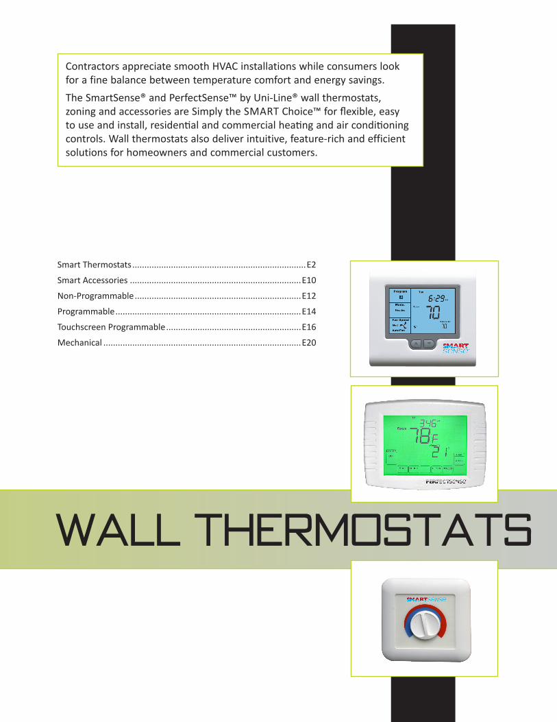
Wall Thermostats
Contractors appreciate smooth HVAC installations while consumers look for a fine balance between temperature comfort and energy savings.The SmartSense® and PerfectSense™ by Uni-Line® wall thermostats, zoning and accessories are Simply the SMART Choice™ for flexible, easy to use and install, residential and commercial heating and air conditioning controls. Wall thermostats also deliver intuitive, feature-rich and efficient solutions for homeowners and commercial customers.
Smart Thermostats ........................................................................E2
Smart Accessories .......................................................................E10
Non-Programmable .....................................................................E12
Programmable .............................................................................E14
Touchscreen Programmable ........................................................E16
Mechanical ..................................................................................E20

Customer Service 1.800.304.6563 www.Uni-Line.comwww.Uni-Line.com Customer Service 1.800.304.6563
E2E2
Wall ThermostatsSMART THERMOSTAT
Smart 1000The SmartSense® SMART 1000 Touchscreen Thermostat is a feature-rich thermostat that can be battery powered or 24V AC common wired to the HVAC equipment. Easy-to-use and install, this thermostat is ideally suited for use in residential or light commercial applications.This installer friendly thermostat is designed for many heating and cooling applications, including heat pump systems, auxiliary and emergency heating, gas and oil systems. It has multiple heating and cooling stages for optimal control.The SMART 1000 is manufactured with default settings to reduce installation time. These settings include temperature scale (F or C), clock scale (12 or 24 hours), high and low balance points, DIP switch settings, and more. All settings are changed easily. Distributed by Uni-Line®, SmartSense Thermostats are Simply The SMART Choice™.
Features and Benefits• 7 day programmable, 2 or 4 events per day• Multi-stage up to 3 heat / 2 cool• Programmable or non-programmable• Manual or auto changeover• Adaptive recovery• Indoor and outdoor sensor options • Keypad lockout• Temperature averaging (with optional indoor sensors)• Outdoor temperature display (with optional outdoor sensor)• Short cycle protection
SMART 1000
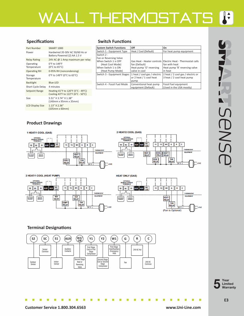
E3Customer Service 1.800.304.6563 www.Uni-Line.comwww.Uni-Line.com Customer Service 1.800.304.6563
E3
Wall Thermostats
Product Drawings
Switch Functions
Terminal Designations
SpecificationsPart Number SMART 1000Power Hardwired 20-30V AC 50/60 Hz or
Battery Powered (2) AA 1.5 VRelay Rating 24V AC @ 1 Amp maximum per relayOperating Temperature
0°F to 149°F (0°C to 65°C)
Operating RH 0-95% RH (noncondensing)Storage Temperature
0°F to 149°F (0°C to 65°C)
Backlight Blue LEDShort Cycle Delay 4 minutesSetpoint Range Heating 41°F to 120°F (5°C - 49°C)
Cooling 43°F to 122°F (6°C - 50°C)Size 5.51” X 3.74” X 1.38”
(140mm x 95mm x 35mm)LCD Display Size 1.13” X 2.36”
(105mm x 60mm)
System Switch Functions Off OnSwitch 1 - Equipment Type Heat / Cool (Default) For heat pump equipmentSwitch 2 - Fan or Reversing Valve When Switch 1 is OFF (Heat Cool Mode) When Switch 1 is ON (Heat Pump Mode)
Gas Heat - Heater controls fan (Default) Heat pump ‘O’ reversing valve in cool
Electric Heat - Thermostat calls fan with heat Heat pump ‘B’ reversing valve in heat
Switch 3 - Equipment Stages 1 heat / cool gas / electric or 2 heat / 1 cool heat pump
2 heat / 2 cool gas / electric or 3 heat / 2 cool heat pump
Switch 4 - Fossil Fuel Mode Conventional heat pump equipment (Default)
Fossil fuel equipment (Used in the USA mostly)
YearLimitedWarranty
Second Stage Cool or Second
Stage Compressor
First Stage Cool or First
Stage Compressor
Fan
First Stage Heat/Auxiliary/Emergency
Heat
Second Stage Heat or
Reversing Valve
AuxiliaryContacts
Indoor Sensor
Sensor Common
24V AC Common
Outdoor Sensor
S2 SC S1 AUX Y1W2/OB Y2 G RW1
24V AC Hot
C
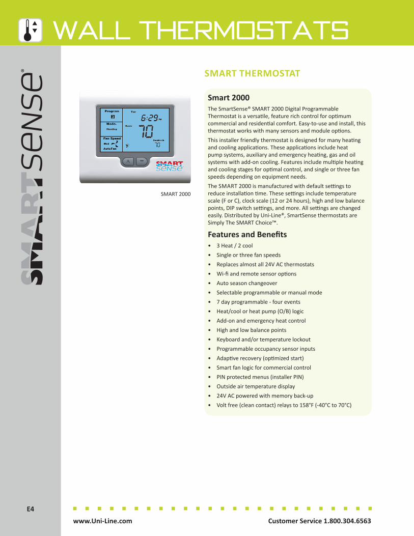
Customer Service 1.800.304.6563 www.Uni-Line.comwww.Uni-Line.com Customer Service 1.800.304.6563
E4E4
Wall ThermostatsSMART THERMOSTAT
Smart 2000The SmartSense® SMART 2000 Digital Programmable Thermostat is a versatile, feature rich control for optimum commercial and residential comfort. Easy-to-use and install, this thermostat works with many sensors and module options.This installer friendly thermostat is designed for many heating and cooling applications. These applications include heat pump systems, auxiliary and emergency heating, gas and oil systems with add-on cooling. Features include multiple heating and cooling stages for optimal control, and single or three fan speeds depending on equipment needs. The SMART 2000 is manufactured with default settings to reduce installation time. These settings include temperature scale (F or C), clock scale (12 or 24 hours), high and low balance points, DIP switch settings, and more. All settings are changed easily. Distributed by Uni-Line®, SmartSense thermostats are Simply The SMART Choice™.
Features and Benefits• 3 Heat / 2 cool• Single or three fan speeds• Replaces almost all 24V AC thermostats• Wi-fi and remote sensor options• Auto season changeover• Selectable programmable or manual mode• 7 day programmable - four events• Heat/cool or heat pump (O/B) logic• Add-on and emergency heat control• High and low balance points• Keyboard and/or temperature lockout• Programmable occupancy sensor inputs• Adaptive recovery (optimized start)• Smart fan logic for commercial control• PIN protected menus (installer PIN)• Outside air temperature display• 24V AC powered with memory back-up• Volt free (clean contact) relays to 158°F (-40°C to 70°C)
SMART 2000
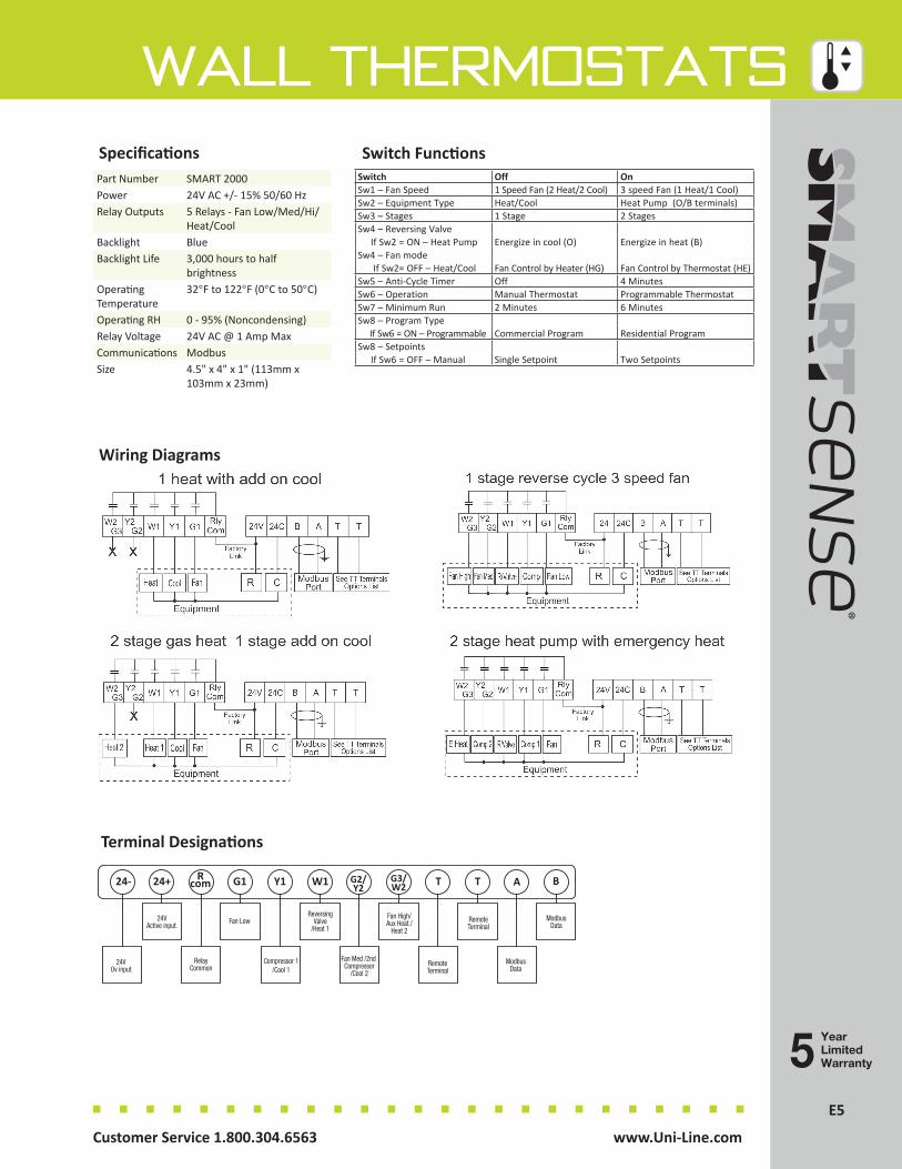
E5Customer Service 1.800.304.6563 www.Uni-Line.comwww.Uni-Line.com Customer Service 1.800.304.6563
E5
Wall Thermostats
Wiring Diagrams
Switch Functions
Terminal Designations
Fan Med /2nd Compressor
/Cool 2
ReversingValve
/Heat 1
RemoteTerminal
Fan High/Aux Heat./
Heat 2
Compressor 1/Cool 1
Fan Low
RelayCommon
24VActive input.
ModbusData
24VOv input
ModbusData
24- 24+ Rcom G1 Y1 W1 G2/
Y2T A BG3/
W2 T
RemoteTerminal
SpecificationsPart Number SMART 2000Power 24V AC +/- 15% 50/60 HzRelay Outputs 5 Relays - Fan Low/Med/Hi/
Heat/CoolBacklight BlueBacklight Life 3,000 hours to half
brightnessOperating Temperature
32°F to 122°F (0°C to 50°C)
Operating RH 0 - 95% (Noncondensing)Relay Voltage 24V AC @ 1 Amp MaxCommunications Modbus Size 4.5" x 4" x 1" (113mm x
103mm x 23mm)
Switch Off OnSw1 – Fan Speed 1 Speed Fan (2 Heat/2 Cool) 3 speed Fan (1 Heat/1 Cool)Sw2 – Equipment Type Heat/Cool Heat Pump (O/B terminals)Sw3 – Stages 1 Stage 2 StagesSw4 – Reversing Valve If Sw2 = ON – Heat Pump Energize in cool (O) Energize in heat (B)Sw4 – Fan mode If Sw2= OFF – Heat/Cool Fan Control by Heater (HG) Fan Control by Thermostat (HE)Sw5 – Anti-Cycle Timer Off 4 MinutesSw6 – Operation Manual Thermostat Programmable ThermostatSw7 – Minimum Run 2 Minutes 6 MinutesSw8 – Program Type If Sw6 = ON – Programmable Commercial Program Residential ProgramSw8 – Setpoints If Sw6 = OFF – Manual Single Setpoint Two Setpoints
YearLimitedWarranty
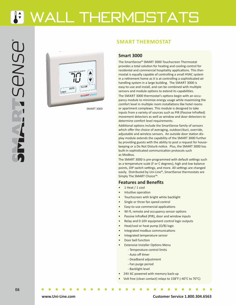
Customer Service 1.800.304.6563 www.Uni-Line.comwww.Uni-Line.com Customer Service 1.800.304.6563
E6E6
Wall ThermostatsSMART THERMOSTAT
Smart 3000The SmartSense® SMART 3000 Touchscreen Thermostat provides a total solution for heating and cooling control for residental and commercial hospitality applications. This ther-mostat is equally capable of controlling a small HVAC system in a retirement home as it is at controlling a sophisticated air handling system in a large building. The SMART 3000 is easy-to-use and install, and can be combined with multiple sensors and module options to extend its capabilities.The SMART 3000 thermostat’s options begin with an occu-pancy module to minimize energy usage while maximizing the comfort level in multiple room installations like hotel rooms or apartment complexes. This module is designed to take inputs from a variety of sources such as PIR (Passive InfraRed) movement detectors as well as window and door detectors to determine comfort level requirements. Additional options include the SmartSense family of sensors which offer the choice of averaging, outdoor/duct, override, adjustable and wireless sensors. An outside door station dis-play module extends the capability of the SMART 3000 further by providing guests with the ability to post a request for house-keeping or a Do Not Disturb notice. Plus, the SMART 3000 has built-in sophisticated communication protocols such as Modbus.The SMART 3000 is pre-programmed with default settings such as a temperature scale (F or C degrees), high and low balance points, DIP switch settings, and more. All settings are changed easily. Distributed by Uni-Line®, SmartSense thermostats are Simply The SMART Choice™.
Features and Benefits• 1 Heat / 1 cool• Intuitive operation• Touchscreen with bright white backlight • Single or three fan speed control • Easy-to-use commercial applications• Wi-fi, remote and occupancy sensor options• Passive InfraRed (PIR), door and window inputs• Relay and 0-10V equipment control logic outputs• Heat/cool or heat pump (O/B) logic• Integrated modbus communications• Integrated temperature sensor• Door bell function• Extensive Installer Options Menu - Temperature control limits - Auto off timer - Deadband adjustment - Fan purge period - Backlight level• 24V AC powered with memory back-up• Volt free (clean contact) relays to 158°F (-40°C to 70°C)
SMART 3000

E7Customer Service 1.800.304.6563 www.Uni-Line.comwww.Uni-Line.com Customer Service 1.800.304.6563
E7
Wall ThermostatsSwitch FunctionsSpecifications
Terminal Wiring
HVAC System Capabilities
Switch Function On Off
Sw1 Indoor Fan Mode 3 Fan Speeds 1 Fan Speed
Sw2 Equipment Type Heat Pump Heat Cool
Sw3 HP Mode (Sw2 = ON)HC Mode (Sw2 = OFF)
Rev Valve Heat (B) HE – Fan With Heat Thermostat Controlled
Rev Valve Cool (O)HG – Heater Fan control by Heater
Sw4 2 / 4 Pipe Mode 2 Pipe Mode 4 Pipe Mode
Sw5 Comp Protection Delay
5 Minute Anti Cycle Immediate Compressor Start
Sw6 Not Used
Sw7 Ventilation Mode Permitted Not Permitted
Sw8 Door Station (Optional) Fitted Door Station Not Used
Part Number SMART 3000Power 24V AC +/- 20% 50/60
HzRelay Outputs 5 Relays - Fan Low/
Med/Hi/ Heat/CoolAnalog Outputs Heat/Cool FanTouch Method "XY" ResistiveBacklight Life 40,000 hours to half
brightnessOperating Temperature 23°F to 77°F (-5°C to
50°C)Operating RH 0 - 95% (Noncondens-
ing)Relay Voltage 24V AC @ 1 Amp Max0-10V Outputs 5mA MaxSensor Accuracy +/-1°F at 77°F (+/1°C
at 25°C)Timer Accuracy +/-2.5 minutes per
yearCommunications Modbus RTU
4.8/9.6/19.2/38.4k Size 4.44"x 4.05" x 0.98"
(113mm X 103mm X 26mm)
YearLimitedWarranty

Customer Service 1.800.304.6563 www.Uni-Line.comwww.Uni-Line.com Customer Service 1.800.304.6563
E8E8
Wall ThermostatsSMART THERMOSTAT
Smart 4000The SmartSense® SMART 4000 Commercial HVAC Controller Thermostat provides a total solution for heating and cooling control, especially in commercial panel builder applications. This multistage thermostat is equally capable of controlling a small HVAC system as it is at controlling a sophisticated air handling system in a large building. The SMART 4000 is DIN rail mounted making it easy-to-install and use for a variety of applications.
The SMART 4000 thermostat offers unmatched flexibility to meet the toughest installation requirements. The versatile input and output options for the SMART 4000 are designed to help minimize energy usage while maximizing comfort. The thermostat includes practical communication protocols such as Modbus which is especially useful for interfacing with PLCs (Programmable Logic Controllers).
The SMART 4000 is pre-programmed with default settings such as temperature scale (F or C degrees), DIP switch settings, and more. All settings are changed easily. Distributed by Uni-Line®, SmartSense thermostats are Simply The SMART Choice™.
Features and Benefits• Up to 4 stages• Intuitive operation• Manual / 7 day / 365 day operation• After hours run timer• 18 to 270 V AC powered• Five dedicated HVAC equipment control relays• Volt free relays outputs for fan (10A max)• 0 to 10V assignable outputs• Integrated modbus communications• Bright green backlight• Wi-fi, remote and occupancy sensor options• Enthalpy based economy function with sensor• Digital / analog inputs and outputs with library of functions• Economy cooling function• Relay and 0-10V equipment control logic outputs• Compressor lead-lag function• Heat / cool or heat pump (O/B) logic
SMART 4000
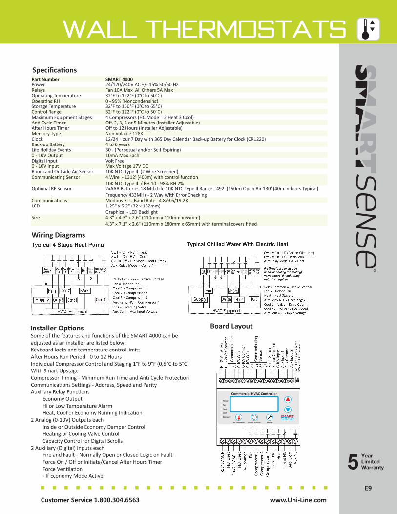
E9Customer Service 1.800.304.6563 www.Uni-Line.comwww.Uni-Line.com Customer Service 1.800.304.6563
E9
Wall ThermostatsSpecifications
Wiring Diagrams
Part Number SMART 4000Power 24/120/240V AC +/- 15% 50/60 HzRelays Fan 10A Max All Others 5A MaxOperating Temperature 32°F to 122°F (0°C to 50°C)Operating RH 0 - 95% (Noncondensing)Storage Temperature 32°F to 150°F (0°C to 65°C)Control Range 32°F to 122°F (0°C to 50°C)Maximum Equipment Stages 4 Compressors (HC Mode = 2 Heat 3 Cool)Anti Cycle Timer Off, 2, 3, 4 or 5 Minutes (Installer Adjustable)After Hours Timer Off to 12 Hours (Installer Adjustable)Memory Type Non Volatile 128KClock 12/24 Hour 7 Day with 365 Day Calendar Back-up Battery for Clock (CR1220)Back-up Battery 4 to 6 yearsLife Holiday Events 30 - (Perpetual and/or Self Expiring)0 - 10V Output 10mA Max EachDigital Input Volt Free0 - 10V Input Max Voltage 17V DCRoom and Outside Air Sensor 10K NTC Type II (2 Wire Screened)Communicating Sensor 4 Wire - 1312' (400m) with control function
10K NTC Type II / RH 10 - 98% RH 2%Optional RF Sensor 2xAAA Batteries 18 Mth Life 10K NTC Type II Range - 492' (150m) Open Air 130' (40m Indoors Typical)
Frequency 433MHz - 2 Way With Error CheckingCommunications Modbus RTU Baud Rate 4.8/9.6/19.2KLCD 1.25" x 5.2" (32 x 132mm)
Graphical - LED BacklightSize 4.3" x 4.3" x 2.6" (110mm x 110mm x 65mm)
4.3" x 7.1" x 2.6" (110mm x 180mm x 65mm) with terminal covers fitted
Board LayoutSome of the features and functions of the SMART 4000 can be adjusted as an installer are listed below:Keyboard locks and temperature control limitsAfter Hours Run Period - 0 to 12 HoursIndividual Compressor Control and Staging 1°F to 9°F (0.5°C to 5°C) With Smart Upstage Compressor Timing - Minimum Run Time and Anti Cycle ProtectionCommunications Settings - Address, Speed and Parity Auxiliary Relay Functions Economy Output Hi or Low Temperature Alarm Heat, Cool or Economy Running Indication2 Analog (0-10V) Outputs each
Inside or Outside Economy Damper Control Heating or Cooling Valve Control Capacity Control for Digital Scrolls
2 Auxiliary (Digital) Inputs each Fire and Fault - Normally Open or Closed Logic on Fault Force On / Off or Initiate/Cancel After Hours Timer Force Ventilation - If Economy Mode Active
Installer Options
Commercial HVAC Controller
Power
Fan
Heat
Cool
Economy
Set Temperature Clock & Schedule Settings
TM
LogoCMYK 12 100 92 3
K100
C100 M0 Y0 K0
C0 M0 Y0 K10
CMYK 12 100 92 3C100 M0 Y0 K0
C100 M0 Y0 K0
YearLimitedWarranty
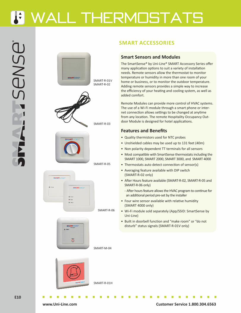
Customer Service 1.800.304.6563 www.Uni-Line.comwww.Uni-Line.com Customer Service 1.800.304.6563
E10E10
Wall ThermostatsSMART ACCESSORIES
Smart Sensors and ModulesThe SmartSense® by Uni-Line® SMART Accessory Series offer many application options to suit a variety of installation needs. Remote sensors allow the thermostat to monitor temperature or humidity in more than one room of your home or business, or to monitor the outdoor temperature. Adding remote sensors provides a simple way to increase the efficiency of your heating and cooling system, as well as added comfort.
Remote Modules can provide more control of HVAC systems. The use of a Wi-Fi module through a smart phone or inter-net connection allows settings to be changed at anytime from any location. The remote Hospitality Occupancy Out-door Module is designed for hotel applications.
Features and Benefits• Quality thermistors used for NTC probes• Unshielded cables may be used up to 131 feet (40m)• Non polarity dependent TT terminals for all sensors• Most compatible with SmartSense thermostats including the SMART 1000, SMART 2000, SMART 3000, and SMART 4000 • Thermostats auto detect connection of sensor(s)• Averaging feature available with DIP switch (SMART-R-02 only)• After Hours feature available (SMART-R-02, SMART-R-05 and SMART-R-06 only) - After hours feature allows the HVAC program to continue for an additional period pre-set by the installer• Four wire sensor available with relative humidity (SMART 4000 only)• Wi-Fi module sold separately (App/SSID: SmartSense by Uni-Line)• Built in doorbell function and “make room” or “do not disturb” status signals (SMART-R-01V only)
SMART-R-05
SMART-R-01H
SMART-R-01VSMART-R-02
SMART-R-03
SMART-R-06
SMART-M-04
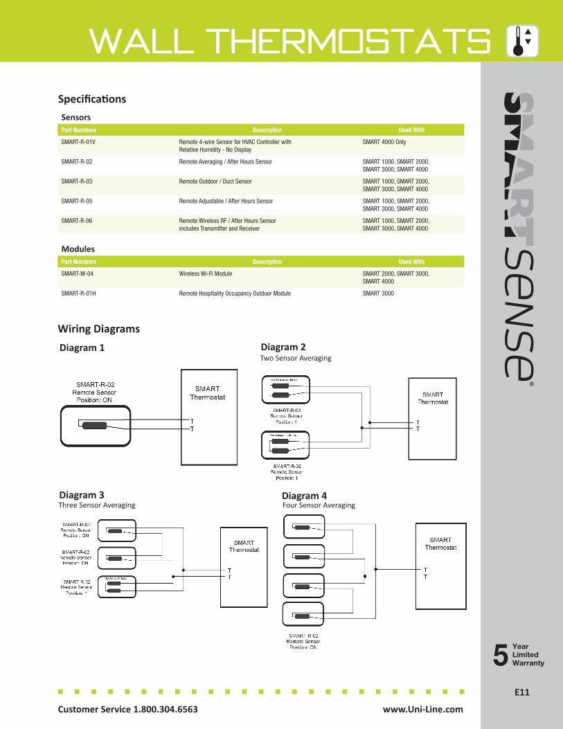
E11Customer Service 1.800.304.6563 www.Uni-Line.comwww.Uni-Line.com Customer Service 1.800.304.6563
E11
Wall Thermostats
YearLimitedWarranty
SensorsPart Numbers Description Used With
SMART-R-01V Remote 4-wire Sensor for HVAC Controller with Relative Humidity - No Display
SMART 4000 Only
SMART-R-02 Remote Averaging / After Hours Sensor SMART 1000, SMART 2000, SMART 3000, SMART 4000
SMART-R-03 Remote Outdoor / Duct Sensor SMART 1000, SMART 2000, SMART 3000, SMART 4000
SMART-R-05 Remote Adjustable / After Hours Sensor SMART 1000, SMART 2000, SMART 3000, SMART 4000
SMART-R-06 Remote Wireless RF / After Hours Sensor includes Transmitter and Receiver
SMART 1000, SMART 2000, SMART 3000, SMART 4000
ModulesPart Numbers Description Used With
SMART-M-04 Wireless Wi-Fi Module SMART 2000, SMART 3000, SMART 4000
SMART-R-01H Remote Hospitality Occupancy Outdoor Module SMART 3000
Specifications
Wiring DiagramsDiagram 1 Diagram 2
Two Sensor Averaging
Diagram 3Three Sensor Averaging
Diagram 4Four Sensor Averaging

Customer Service 1.800.304.6563 www.Uni-Line.comwww.Uni-Line.com Customer Service 1.800.304.6563
E12E12
Wall ThermostatsNON-PROGRAMMABLE
PS2000 SeriesThe PerfectSense™ PS2000 thermostat series is the perfect choice when it comes to non-programmable temperature control.
With the comfort, convenience, and efficiency features that homeowners and contractors want, the PS2000 series pro-vides value-packed thermostats for an economical price.
All PS2000 thermostats are fully compatible with all standard 24V AC heating and cooling systems. Additional compatibility with multi-stage and heat pump systems are available in the PS2210 model.
Add in easy installation, expert technical service, and quality you can depend on, the PerfectSense™ PS2000 thermostat series is the perfect choice in temperature control.
Features and Benefits• Multi-Stage 2 heat / 1 cool – PS2210 only• Bigger brighter backlight• Adjustable temperature differential• Worry-free memory retention – PS2210 only• Filter Monitor• Low temperature freeze protection – PS2110 only• Automatic compressor short cycle protection• O and B terminals• Zone system compatible• Quick wire terminal block
PS2110
PS2210
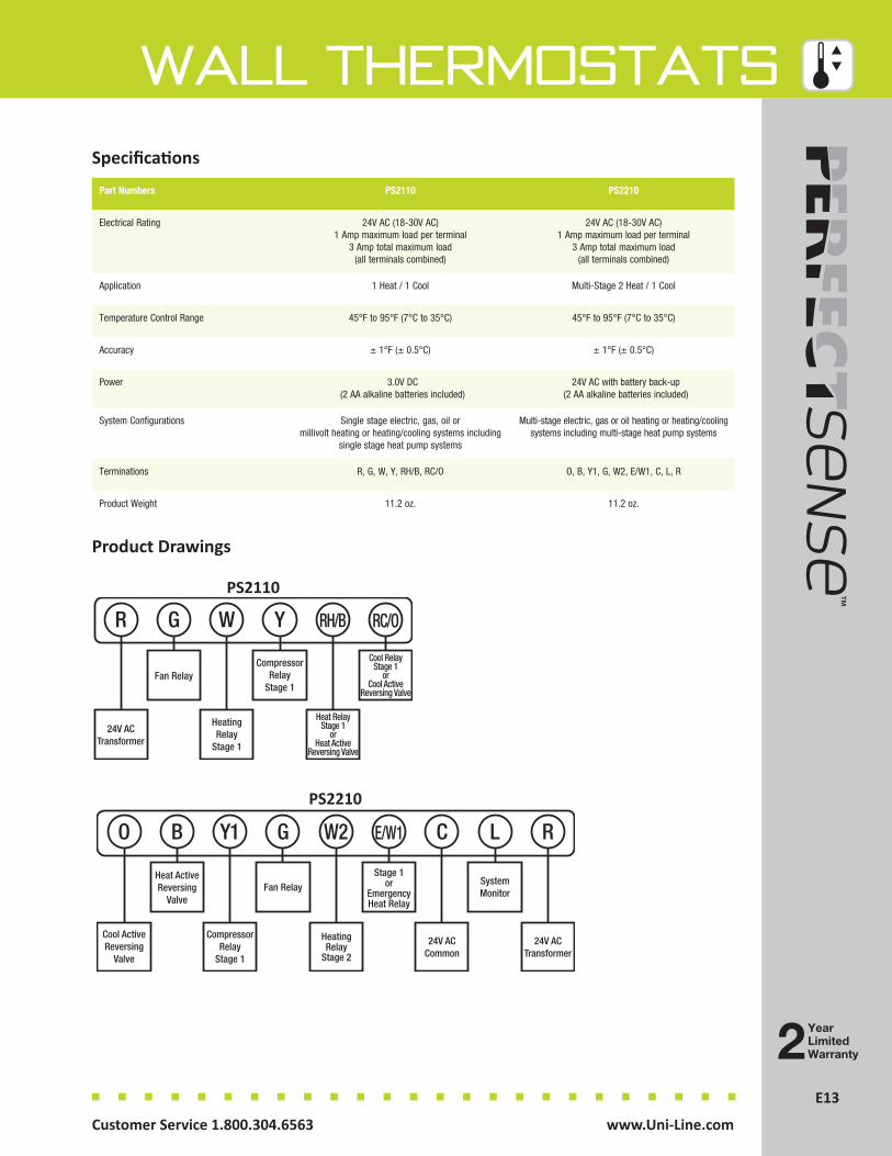
E13Customer Service 1.800.304.6563 www.Uni-Line.comwww.Uni-Line.com Customer Service 1.800.304.6563
E13
Wall Thermostats
Product Drawings
Specifications
Part Numbers PS2110 PS2210
Electrical Rating 24V AC (18-30V AC) 1 Amp maximum load per terminal
3 Amp total maximum load (all terminals combined)
24V AC (18-30V AC) 1 Amp maximum load per terminal
3 Amp total maximum load (all terminals combined)
Application 1 Heat / 1 Cool Multi-Stage 2 Heat / 1 Cool
Temperature Control Range 45°F to 95°F (7°C to 35°C) 45°F to 95°F (7°C to 35°C)
Accuracy ± 1°F (± 0.5°C) ± 1°F (± 0.5°C)
Power 3.0V DC (2 AA alkaline batteries included)
24V AC with battery back-up (2 AA alkaline batteries included)
System Configurations Single stage electric, gas, oil or millivolt heating or heating/cooling systems including
single stage heat pump systems
Multi-stage electric, gas or oil heating or heating/cooling systems including multi-stage heat pump systems
Terminations R, G, W, Y, RH/B, RC/O O, B, Y1, G, W2, E/W1, C, L, R
Product Weight 11.2 oz. 11.2 oz.
R
24V ACTransformer
W
HeatingRelay
Stage 1
G
Fan Relay
Y
CompressorRelay
Stage 1
RH/B
Heat RelayStage 1
orHeat Active
Reversing Valve
RC/O
Cool RelayStage 1
orCool Active
Reversing Valve
PS2110
O
Cool ActiveReversing
Valve
Y1
CompressorRelay
Stage 1
B
Heat ActiveReversing
Valve
G
Fan Relay
W2
HeatingRelay
Stage 2
E/W1
Stage 1or
EmergencyHeat Relay
L
SystemMonitor
C
24V ACCommon
R
24V ACTransformer
PS2210
2YearLimitedWarranty
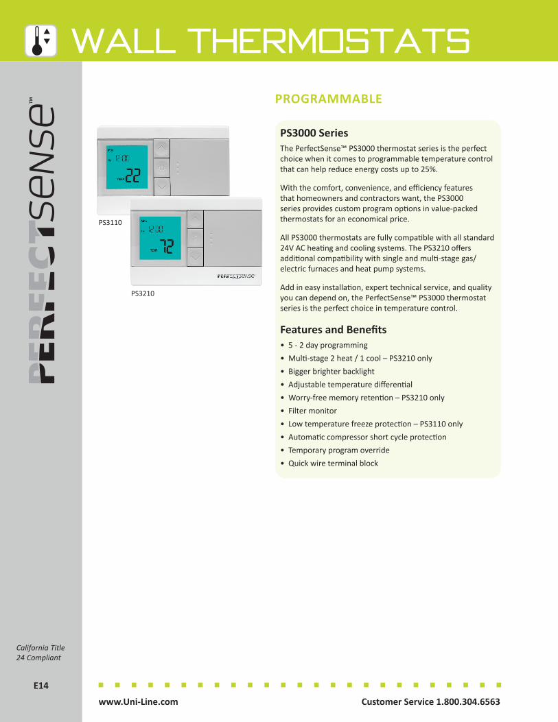
Customer Service 1.800.304.6563 www.Uni-Line.comwww.Uni-Line.com Customer Service 1.800.304.6563
E14E14
Wall ThermostatsPROGRAMMABLE
PS3000 SeriesThe PerfectSense™ PS3000 thermostat series is the perfect choice when it comes to programmable temperature control that can help reduce energy costs up to 25%.
With the comfort, convenience, and efficiency features that homeowners and contractors want, the PS3000 series provides custom program options in value-packed thermostats for an economical price.
All PS3000 thermostats are fully compatible with all standard 24V AC heating and cooling systems. The PS3210 offers additional compatibility with single and multi-stage gas/electric furnaces and heat pump systems.
Add in easy installation, expert technical service, and quality you can depend on, the PerfectSense™ PS3000 thermostat series is the perfect choice in temperature control.
Features and Benefits• 5 - 2 day programming• Multi-stage 2 heat / 1 cool – PS3210 only• Bigger brighter backlight• Adjustable temperature differential• Worry-free memory retention – PS3210 only• Filter monitor• Low temperature freeze protection – PS3110 only• Automatic compressor short cycle protection• Temporary program override• Quick wire terminal block
California Title 24 Compliant
PS3110
PS3210

E15Customer Service 1.800.304.6563 www.Uni-Line.comwww.Uni-Line.com Customer Service 1.800.304.6563
E15
Wall ThermostatsSpecifications
Part Numbers PS3110 PS3210
Electrical Rating 24V AC (18-30V AC) 1 Amp maximum load per terminal
3 Amp total maximum load (all terminals combined)
24V AC (18-30V AC) 1 Amp maximum load per terminal
3 Amp total maximum load (all terminals combined)
Application 1 Heat / 1 Cool Multi-Stage 2 Heat / 1 Cool
Temperature Control Range 45°F to 95°F (7°C to 35°C) 45°F to 95°F (7°C to 35°C)
Accuracy ± 1°F (± 0.5°C) ± 1°F (± 0.5°C)
Power 3.0V DC (2 AA alkaline batteries included)
24V AC with battery back-up (2 AA alkaline batteries included)
System Configurations Single stage electric, gas, oil or millivolt heating or heating/cooling systems including
single stage heat pump systems
Multi-stage electric, gas or oil heating or heating/cooling systems including multi-stage heat pump systems
Terminations G, RC, RH, Y/O, W/B, Y1 O, B, Y1, G, W2, E/W1, C, L, R
Product Weight 11.2 oz. 11.2 oz.
Product Drawings
2YearLimitedWarranty
G
Fan Relay
RH
Heat24V Supply
RC
Cool24V Supply
Y/O
Cool RelayStage 1 orCool ActiveReversing
Valve
W/B
Heat RelayStage 1 orHeat ActiveReversing
Valve
Y1
CompressorRelay
Heat PumpOnly
PS3110
O
Cool ActiveReversing
Valve
Y1
CompressorRelay
Stage 1
B
Heat ActiveReversing
Valve
G
Fan Relay
W2
HeatingRelay
Stage 2
E/W1
Heat RelayStage 1
orEmergencyHeat Relay
L
SystemMonitor
C
24V ACCommon
R
24V ACTransformer
PS3210

Customer Service 1.800.304.6563 www.Uni-Line.comwww.Uni-Line.com Customer Service 1.800.304.6563
E16E16
Wall ThermostatsTOUCHSCREEN PROGRAMMABLE
PS4000 SeriesThe PerfectSense™ PS4000 Touchscreen Programmable Thermostat is a feature-rich comfort control with universal system compatibility. Easy-to-use and install, the PS4000 has a large backlit touchscreen display requested by homeowners and contractors.
This installer-friendly thermostat is designed for 1 heat / 1 cool systems and can be programmed for 2 or 4 events daily. In addition, it offers Wake, Day, Evening, and Sleep settings giving you precise and affordable comfort. Applications include gas, oil, millivolt, electric and heat pump as well as dual fuel units. The PS4000 is powered by 24V AC common wire or two AA batteries.
With a beautiful design, easy installation, and quality you can depend on, the PerfectSense PS4000 Touchscreen thermostat is the perfect choice in temperature control.
Features and Benefits• 7 day programmable, 2 or 4 events per day• 1 Heat / 1 Cool• Touchscreen with large backlit display• Manual or auto changeover• Adaptive recovery• Indoor and outdoor sensor options• Programmable fan option• Filter change indicator• 5 minute compressor delay protection• Keypad lockout• Clock display
PS4000
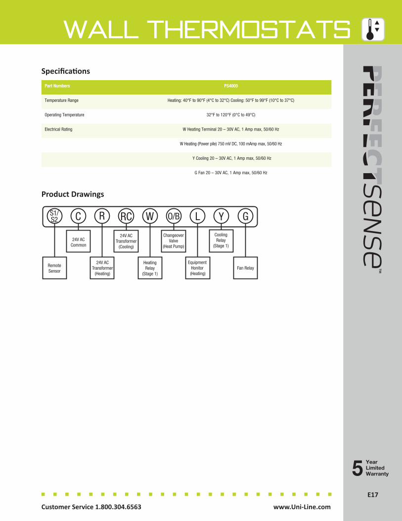
E17Customer Service 1.800.304.6563 www.Uni-Line.comwww.Uni-Line.com Customer Service 1.800.304.6563
E17
Wall Thermostats
YearLimitedWarranty
Specifications
Part Numbers PS4000
Temperature Range Heating: 40°F to 90°F (4°C to 32°C) Cooling: 50°F to 99°F (10°C to 37°C)
Operating Temperature 32°F to 120°F (0°C to 49°C)
Electrical Rating W Heating Terminal 20 – 30V AC, 1 Amp max, 50/60 Hz
W Heating (Power pile) 750 mV DC, 100 mAmp max, 50/60 Hz
Y Cooling 20 – 30V AC, 1 Amp max, 50/60 Hz
G Fan 20 – 30V AC, 1 Amp max, 50/60 Hz
Product Drawings
W
HeatingRelay
(Stage 1)
L
Equipment Honitor (Heating)
S1/S2
RemoteSensor
C
24V ACCommon
R
24V ACTransformer
(Heating)
RC
24V ACTransformer
(Cooling)
O/B
ChangeoverValve
(Heat Pump)
Y
CoolingRelay
(Stage 1)
G
Fan Relay
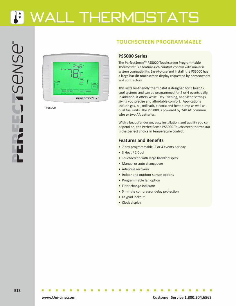
Customer Service 1.800.304.6563 www.Uni-Line.comwww.Uni-Line.com Customer Service 1.800.304.6563
E18E18
Wall ThermostatsTOUCHSCREEN PROGRAMMABLE
PS5000 SeriesThe PerfectSense™ PS5000 Touchscreen Programmable Thermostat is a feature-rich comfort control with universal system compatibility. Easy-to-use and install, the PS5000 has a large backlit touchscreen display requested by homeowners and contractors.
This installer-friendly thermostat is designed for 3 heat / 2 cool systems and can be programmed for 2 or 4 events daily. In addition, it offers Wake, Day, Evening, and Sleep settings giving you precise and affordable comfort. Applications include gas, oil, millivolt, electric and heat pump as well as dual fuel units. The PS5000 is powered by 24V AC common wire or two AA batteries.
With a beautiful design, easy installation, and quality you can depend on, the PerfectSense PS5000 Touchscreen thermostat is the perfect choice in temperature control.
Features and Benefits• 7 day programmable, 2 or 4 events per day• 3 Heat / 2 Cool• Touchscreen with large backlit display• Manual or auto changeover• Adaptive recovery• Indoor and outdoor sensor options• Programmable fan option• Filter change indicator• 5 minute compressor delay protection• Keypad lockout• Clock display
PS5000

E19Customer Service 1.800.304.6563 www.Uni-Line.comwww.Uni-Line.com Customer Service 1.800.304.6563
E19
Wall Thermostats
YearLimitedWarranty
Specifications
Part Numbers PS5000
Temperature Range Heating: 40°F to 90°F (4°C to 32°C) Cooling: 50°F to 99°F (10°C to 37°C)
Operating Temperature 32°F to 120°F (0°C to 49°C)
Electrical Rating W Heating Terminal 20 – 30V AC, 1 Amp max, 50/60 Hz
W Heating (Power pile) 750 mV DC, 100 mAmp max, 50/60 Hz
Y Cooling 20 – 30V AC, 1 Amp max, 50/60 Hz
G Fan 20 – 30V AC, 1 Amp max, 50/60 Hz
Product Drawings
S1/S2
RemoteSensor
R
24V ACTransformer
(Heating)
C
24V ACCommon
RC
24V ACTransformer
(Cooling)
G
Fan Relay
Y
CoolingRelay
(Stage 1)
Y2
CoolingRelay
(Stage 2)
E
EmergencyHeatingRelay
L
SystemMonitor
AUX
AuxiliaryHeatRelay
O/B
ChangeoverValve
(Heat Pump)
W
HeatingRelay
(Stage 1)
HeatingRelay
(Stage 2)
W1

Customer Service 1.800.304.6563 www.Uni-Line.comwww.Uni-Line.com Customer Service 1.800.304.6563
E20E20
Wall Thermostats
900 SeriesThe PerfectSense™ PS900 Series Mechanical Thermostats are a simple two-piece design, so you save time at installation. The large display offers accurate room temperature measurement. Wall plates are available to mask any unsightly marks left by previous thermostats. Install it with confidence.
Features and Benefits• Accurate room temperature• Adjustable heat anticipator• No sub-base required speeds installation.• Mercury-free means no leveling or special disposal required• J-box compatible• Positive off switch assured shutdown of HVAC system• Fixed cooling anticipation (on PS984-1R, PS988-1R only)• Dual temperature scale in Fahrenheit and Celsius
MECHANICAL
YearLimitedWarranty
PS984-1R
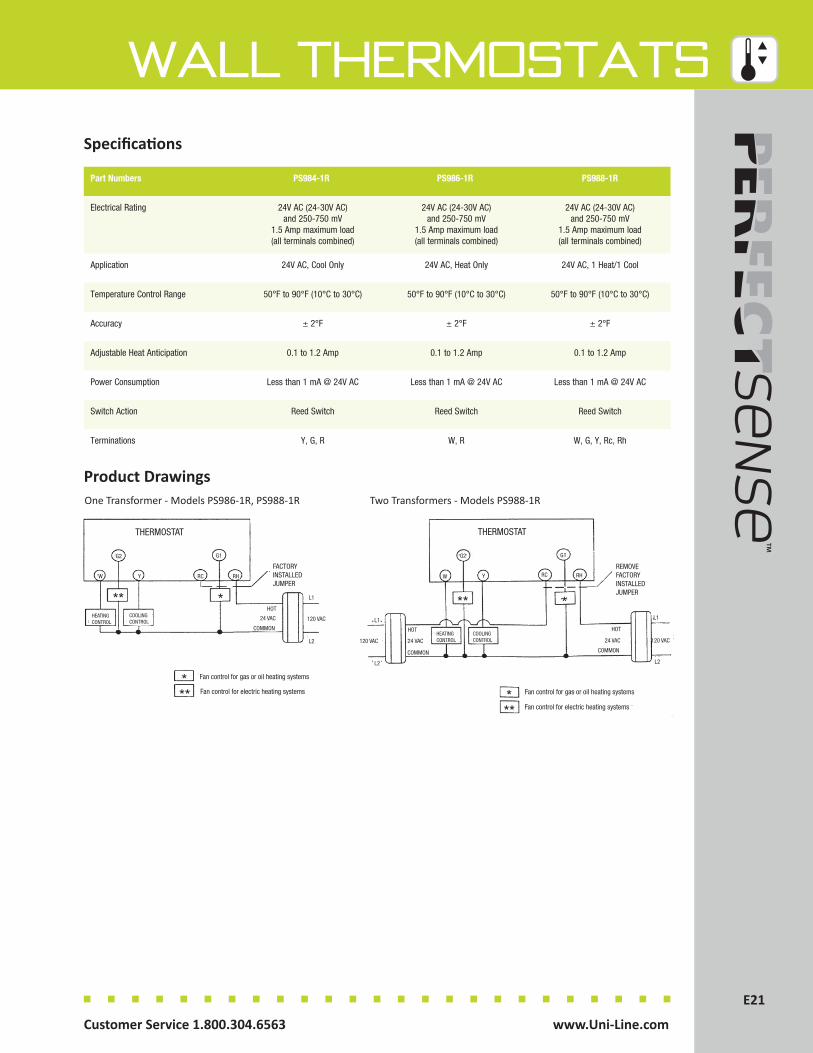
E21Customer Service 1.800.304.6563 www.Uni-Line.comwww.Uni-Line.com Customer Service 1.800.304.6563
E21
Wall ThermostatsSpecifications
Part Numbers PS984-1R PS986-1R PS988-1R
Electrical Rating 24V AC (24-30V AC) and 250-750 mV
1.5 Amp maximum load (all terminals combined)
24V AC (24-30V AC) and 250-750 mV
1.5 Amp maximum load (all terminals combined)
24V AC (24-30V AC) and 250-750 mV
1.5 Amp maximum load (all terminals combined)
Application 24V AC, Cool Only 24V AC, Heat Only 24V AC, 1 Heat/1 Cool
Temperature Control Range 50°F to 90°F (10°C to 30°C) 50°F to 90°F (10°C to 30°C) 50°F to 90°F (10°C to 30°C)
Accuracy ± 2°F ± 2°F ± 2°F
Adjustable Heat Anticipation 0.1 to 1.2 Amp 0.1 to 1.2 Amp 0.1 to 1.2 Amp
Power Consumption Less than 1 mA @ 24V AC Less than 1 mA @ 24V AC Less than 1 mA @ 24V AC
Switch Action Reed Switch Reed Switch Reed Switch
Terminations Y, G, R W, R W, G, Y, Rc, Rh
Product DrawingsMODELS 984-1, 986-1, 988-1 MODEL 988-1Two TransformersOne Transformer
THERMOSTAT
THERMOSTAT
HEATINGCONTROL HEATING
CONTROL
COOLINGCONTROL COOLING
CONTROL
**
** **
** *
**
*
Fan control for gas or oil heating systems Fan control for gas or oil heating systems
Fan control for electric heating systems Fan control for electric heating systems
120 VAC120 VAC120 VAC
24 VAC24 VAC
24 VAC
FACTORYINSTALLEDJUMPER
REMOVEFACTORYINSTALLEDJUMPER
HOTHOT
COMMONCOMMON
L1L1
L2L2
W
WG2
G2
Y
YG1
G1
RC
RC
RH
RH
L1
L2
HOT
COMMON
MODELS 984-1R 986-1R 988-1R MODELS 988-1R
One Transformer - Models PS986-1R, PS988-1RMODELS 984-1, 986-1, 988-1 MODEL 988-1Two TransformersOne Transformer
THERMOSTAT
THERMOSTAT
HEATINGCONTROL HEATING
CONTROL
COOLINGCONTROL COOLING
CONTROL
**
** **
** *
**
*
Fan control for gas or oil heating systems Fan control for gas or oil heating systems
Fan control for electric heating systems Fan control for electric heating systems
120 VAC120 VAC120 VAC
24 VAC24 VAC
24 VAC
FACTORYINSTALLEDJUMPER
REMOVEFACTORYINSTALLEDJUMPER
HOTHOT
COMMONCOMMON
L1L1
L2L2
W
WG2
G2
Y
YG1
G1
RC
RC
RH
RH
L1
L2
HOT
COMMON
MODELS 984-1R 986-1R 988-1R MODELS 988-1RTwo Transformers - Models PS988-1R

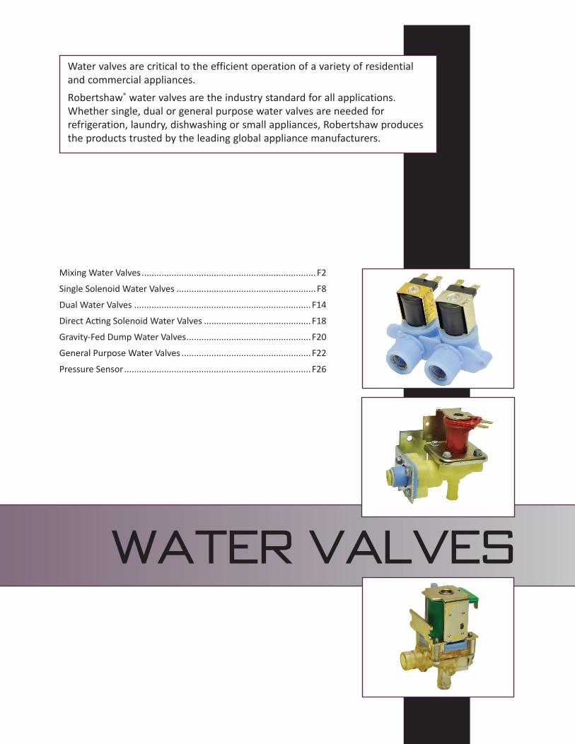
WATER VALVES
Water valves are critical to the efficient operation of a variety of residential and commercial appliances.Robertshaw® water valves are the industry standard for all applications. Whether single, dual or general purpose water valves are needed for refrigeration, laundry, dishwashing or small appliances, Robertshaw produces the products trusted by the leading global appliance manufacturers.
Mixing Water Valves ...................................................................... F2
Single Solenoid Water Valves ........................................................F8
Dual Water Valves ....................................................................... F14
Direct Acting Solenoid Water Valves ...........................................F18
Gravity-Fed Dump Water Valves ..................................................F20
General Purpose Water Valves ....................................................F22
Pressure Sensor ........................................................................... F26
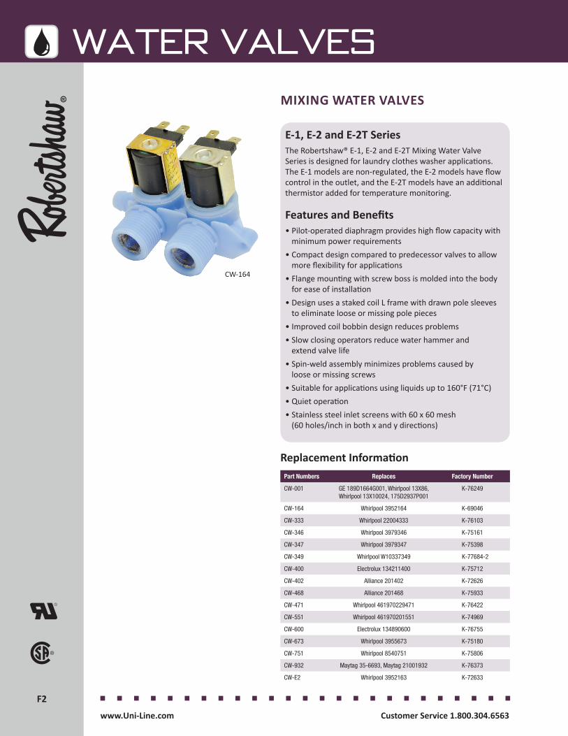
F2F2
WATER VALVES
Customer Service 1.800.304.6563 www.Uni-Line.comwww.Uni-Line.com Customer Service 1.800.304.6563
MIXING WATER VALVES
E-1, E-2 and E-2T SeriesThe Robertshaw® E-1, E-2 and E-2T Mixing Water Valve Series is designed for laundry clothes washer applications. The E-1 models are non-regulated, the E-2 models have flow control in the outlet, and the E-2T models have an additional thermistor added for temperature monitoring.
Features and Benefits• Pilot-operated diaphragm provides high flow capacity with
minimum power requirements• Compact design compared to predecessor valves to allow
more flexibility for applications• Flange mounting with screw boss is molded into the body
for ease of installation• Design uses a staked coil L frame with drawn pole sleeves
to eliminate loose or missing pole pieces• Improved coil bobbin design reduces problems• Slow closing operators reduce water hammer and
extend valve life• Spin-weld assembly minimizes problems caused by
loose or missing screws • Suitable for applications using liquids up to 160°F (71°C)• Quiet operation • Stainless steel inlet screens with 60 x 60 mesh
(60 holes/inch in both x and y directions)
CW-164
Part Numbers Replaces Factory Number
CW-001 GE 189D1664G001, Whirlpool 13X86, Whirlpool 13X10024, 175D2937P001
K-76249
CW-164 Whirlpool 3952164 K-69046
CW-333 Whirlpool 22004333 K-76103
CW-346 Whirlpool 3979346 K-75161
CW-347 Whirlpool 3979347 K-75398
CW-349 Whirlpool W10337349 K-77684-2
CW-400 Electrolux 134211400 K-75712
CW-402 Alliance 201402 K-72626
CW-468 Alliance 201468 K-75933
CW-471 Whirlpool 461970229471 K-76422
CW-551 Whirlpool 461970201551 K-74969
CW-600 Electrolux 134890600 K-76755
CW-673 Whirlpool 3955673 K-75180
CW-751 Whirlpool 8540751 K-75806
CW-932 Maytag 35-6693, Maytag 21001932 K-76373
CW-E2 Whirlpool 3952163 K-72633
Replacement Information
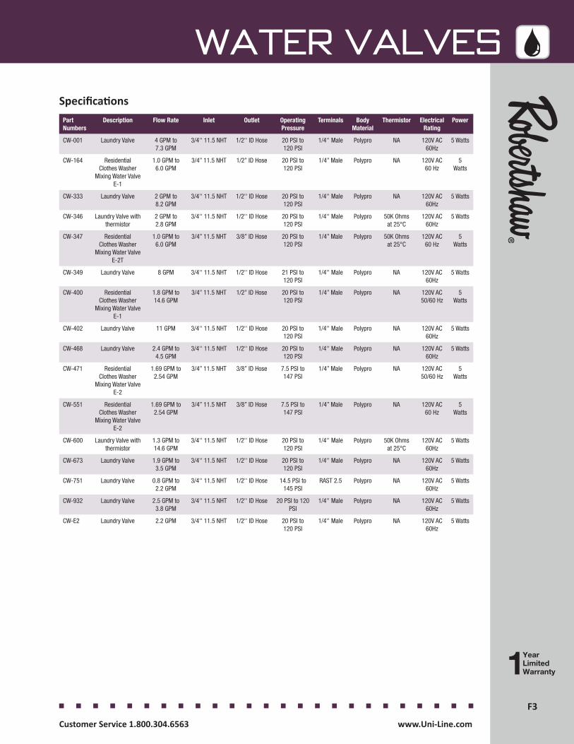
F3F3
WATER VALVES
Customer Service 1.800.304.6563 www.Uni-Line.comwww.Uni-Line.com Customer Service 1.800.304.6563
Part Numbers
Description Flow Rate Inlet Outlet Operating Pressure
Terminals Body Material
Thermistor Electrical Rating
Power
CW-001 Laundry Valve 4 GPM to 7.3 GPM
3/4'' 11.5 NHT 1/2'' ID Hose 20 PSI to 120 PSI
1/4'' Male Polypro NA 120V AC 60Hz
5 Watts
CW-164 ResidentialClothes Washer
Mixing Water Valve E-1
1.0 GPM to 6.0 GPM
3/4” 11.5 NHT 1/2” ID Hose 20 PSI to 120 PSI
1/4” Male Polypro NA 120V AC 60 Hz
5 Watts
CW-333 Laundry Valve 2 GPM to 8.2 GPM
3/4'' 11.5 NHT 1/2'' ID Hose 20 PSI to 120 PSI
1/4'' Male Polypro NA 120V AC 60Hz
5 Watts
CW-346 Laundry Valve with thermistor
2 GPM to 2.8 GPM
3/4'' 11.5 NHT 1/2'' ID Hose 20 PSI to 120 PSI
1/4'' Male Polypro 50K Ohms at 25°C
120V AC 60Hz
5 Watts
CW-347 ResidentialClothes Washer
Mixing Water Valve E-2T
1.0 GPM to 6.0 GPM
3/4” 11.5 NHT 3/8” ID Hose 20 PSI to 120 PSI
1/4” Male Polypro 50K Ohms at 25°C
120V AC 60 Hz
5 Watts
CW-349 Laundry Valve 8 GPM 3/4'' 11.5 NHT 1/2'' ID Hose 21 PSI to 120 PSI
1/4'' Male Polypro NA 120V AC 60Hz
5 Watts
CW-400 ResidentialClothes Washer
Mixing Water Valve E-1
1.8 GPM to 14.6 GPM
3/4” 11.5 NHT 1/2” ID Hose 20 PSI to 120 PSI
1/4” Male Polypro NA 120V AC 50/60 Hz
5 Watts
CW-402 Laundry Valve 11 GPM 3/4'' 11.5 NHT 1/2'' ID Hose 20 PSI to 120 PSI
1/4'' Male Polypro NA 120V AC 60Hz
5 Watts
CW-468 Laundry Valve 2.4 GPM to 4.5 GPM
3/4'' 11.5 NHT 1/2'' ID Hose 20 PSI to 120 PSI
1/4'' Male Polypro NA 120V AC 60Hz
5 Watts
CW-471 ResidentialClothes Washer
Mixing Water Valve E-2
1.69 GPM to 2.54 GPM
3/4” 11.5 NHT 3/8” ID Hose 7.5 PSI to 147 PSI
1/4” Male Polypro NA 120V AC 50/60 Hz
5 Watts
CW-551 ResidentialClothes Washer
Mixing Water Valve E-2
1.69 GPM to 2.54 GPM
3/4” 11.5 NHT 3/8” ID Hose 7.5 PSI to 147 PSI
1/4” Male Polypro NA 120V AC 60 Hz
5 Watts
CW-600 Laundry Valve with thermistor
1.3 GPM to 14.6 GPM
3/4'' 11.5 NHT 1/2'' ID Hose 20 PSI to 120 PSI
1/4'' Male Polypro 50K Ohms at 25°C
120V AC 60Hz
5 Watts
CW-673 Laundry Valve 1.9 GPM to 3.5 GPM
3/4'' 11.5 NHT 1/2'' ID Hose 20 PSI to 120 PSI
1/4'' Male Polypro NA 120V AC 60Hz
5 Watts
CW-751 Laundry Valve 0.8 GPM to 2.2 GPM
3/4'' 11.5 NHT 1/2'' ID Hose 14.5 PSI to 145 PSI
RAST 2.5 Polypro NA 120V AC 60Hz
5 Watts
CW-932 Laundry Valve 2.5 GPM to 3.8 GPM
3/4'' 11.5 NHT 1/2'' ID Hose 20 PSI to 120 PSI
1/4'' Male Polypro NA 120V AC 60Hz
5 Watts
CW-E2 Laundry Valve 2.2 GPM 3/4'' 11.5 NHT 1/2'' ID Hose 20 PSI to 120 PSI
1/4'' Male Polypro NA 120V AC 60Hz
5 Watts
Specifications

F4F4
WATER VALVES
Customer Service 1.800.304.6563 www.Uni-Line.comwww.Uni-Line.com Customer Service 1.800.304.6563
Product Drawings
E-1
E-2

F5F5
WATER VALVES
Customer Service 1.800.304.6563 www.Uni-Line.comwww.Uni-Line.com Customer Service 1.800.304.6563
Product Drawings
E-2T
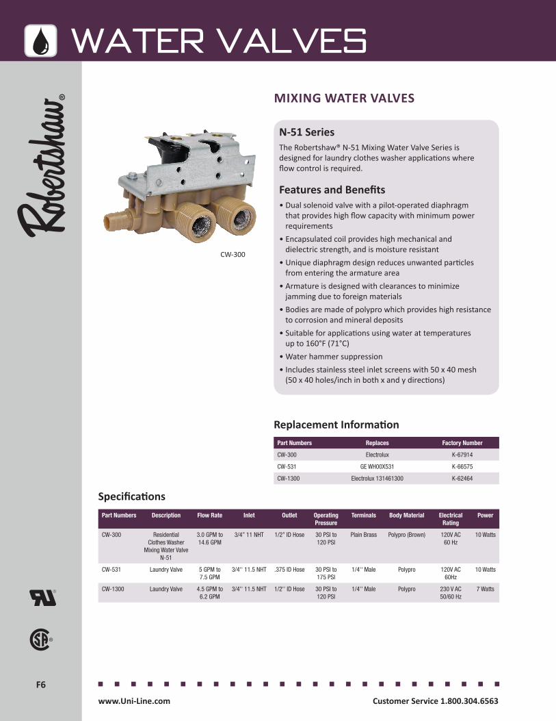
F6F6
WATER VALVES
Customer Service 1.800.304.6563 www.Uni-Line.comwww.Uni-Line.com Customer Service 1.800.304.6563
MIXING WATER VALVES
N-51 SeriesThe Robertshaw® N-51 Mixing Water Valve Series is designed for laundry clothes washer applications where flow control is required.
Features and Benefits• Dual solenoid valve with a pilot-operated diaphragm
that provides high flow capacity with minimum power requirements
• Encapsulated coil provides high mechanical and dielectric strength, and is moisture resistant
• Unique diaphragm design reduces unwanted particles from entering the armature area
• Armature is designed with clearances to minimize jamming due to foreign materials
• Bodies are made of polypro which provides high resistance to corrosion and mineral deposits
• Suitable for applications using water at temperatures up to 160°F (71°C)
• Water hammer suppression• Includes stainless steel inlet screens with 50 x 40 mesh
(50 x 40 holes/inch in both x and y directions)
Specifications
Replacement Information
CW-300
Part Numbers Replaces Factory Number
CW-300 Electrolux K-67914
CW-531 GE WH00X531 K-66575
CW-1300 Electrolux 131461300 K-62464
Part Numbers Description Flow Rate Inlet Outlet Operating Pressure
Terminals Body Material Electrical Rating
Power
CW-300 ResidentialClothes Washer
Mixing Water Valve N-51
3.0 GPM to 14.6 GPM
3/4” 11 NHT 1/2” ID Hose 30 PSI to 120 PSI
Plain Brass Polypro (Brown) 120V AC 60 Hz
10 Watts
CW-531 Laundry Valve 5 GPM to 7.5 GPM
3/4'' 11.5 NHT .375 ID Hose 30 PSI to 175 PSI
1/4'' Male Polypro 120V AC 60Hz
10 Watts
CW-1300 Laundry Valve 4.5 GPM to 6.2 GPM
3/4'' 11.5 NHT 1/2'' ID Hose 30 PSI to 120 PSI
1/4'' Male Polypro 230 V AC 50/60 Hz
7 Watts
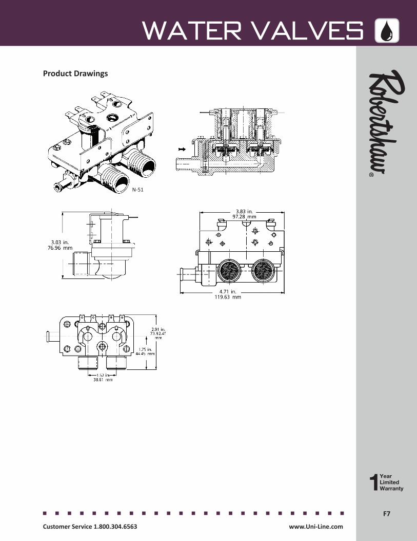
F7F7
WATER VALVES
Customer Service 1.800.304.6563 www.Uni-Line.comwww.Uni-Line.com Customer Service 1.800.304.6563
Product Drawings
N-51
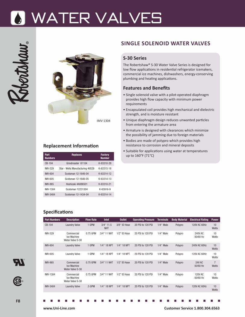
F8F8
WATER VALVES
Customer Service 1.800.304.6563 www.Uni-Line.comwww.Uni-Line.com Customer Service 1.800.304.6563
Specifications
SINGLE SOLENOID WATER VALVES
S-30 SeriesThe Robertshaw® S-30 Water Valve Series is designed for low flow applications in residential refrigerator icemakers, commercial ice machines, dishwashers, energy-conserving plumbing and heating applications.
Features and Benefits• Single solenoid valve with a pilot-operated diaphragm
provides high flow capacity with minimum power requirements
• Encapsulated coil provides high mechanical and dielectric strength, and is moisture resistant
• Unique diaphragm design reduces unwanted particles from entering the armature area
• Armature is designed with clearances which minimize the possibility of jamming due to foreign materials
• Bodies are made of polypro which provides high resistance to corrosion and mineral deposits
• Suitable for applications using water at temperatures up to 160°F (71°C)
IMV-1304
Part Numbers
Replaces Factory Number
CB-104 Grindmaster 61104 K-63310-28
IMV-529 Star - Wells Manufacturing 46529 K-63315-18
IMV-604 Scotsman 12-1646-04 K-63314-12
IMV-605 Scotsman 12-1646-05 K-63314-13
IMV-865 Hoshizaki 4A086501 K-63310-21
IMV-1304 Scotsman 12231304 K-63916-9
IMV-3404 Scotsman 12-1434-04 K-63314-14
Replacement Information
Part Numbers Description Flow Rate Inlet Outlet Operating Pressure Terminals Body Material Electrical Rating Power
CB-104 Laundry Valve 1 GPM 3/4'' 11.5 NHT
3/8'' ID Hose 20 PSI to 120 PSI 1/4'' Male Polypro 120V AC 60Hz 10 Watts
IMV-529 Commercial Ice Machine
Water Valve S-30
0.75 GPM 3/4” 11 NHT 1/2” ID Hose 20 PSI to 120 PSI 1/4” Male Polypro 240V AC 50/60 Hz
10 Watts
IMV-604 Laundry Valve 1 GPM 1/4'' 18 NPT 1/4'' 18 NPT 20 PSI to 120 PSI 1/4'' Male Polypro 240V AC 60Hz 10 Watts
IMV-605 Laundry Valve 1 GPM 1/4'' 18 NPT 1/4'' 18 NPT 20 PSI to 120 PSI 1/4'' Male Polypro 120V AC 60Hz 10 Watts
IMV-865 Commercial Ice Machine
Water Valve S-30
0.75 GPM 3/4” 11 NHT 1/2” ID Hose 20 PSI to 120 PSI 1/4” Male Polypro 24V AC 50/60 Hz
7 Watts
IMV-1304 CommercialIce Machine
Water Valve S-30
0.75 GPM 3/4” 11 NHT 1/2” ID Hose 20 PSI to 120 PSI 1/4” Male Polypro 120V AC 50/60 Hz
10 Watts
IMV-3404 Laundry Valve .5 GPM 1/4'' 18 NPT 1/4'' 18 NPT 20 PSI to 120 PSI 1/4'' Male Polypro 120V AC 60Hz 10 Watts
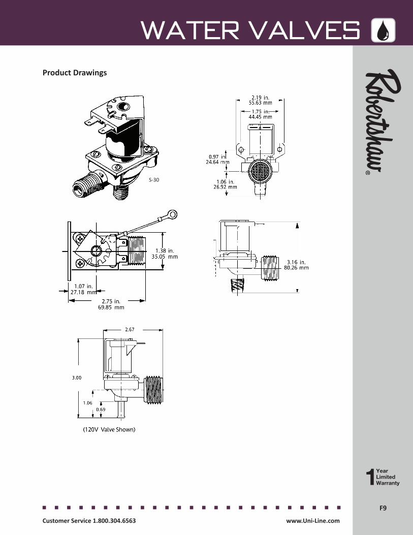
F9F9
WATER VALVES
Customer Service 1.800.304.6563 www.Uni-Line.comwww.Uni-Line.com Customer Service 1.800.304.6563
Product Drawings
S-30
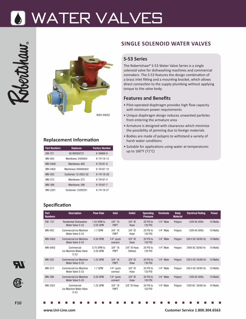
F10F10
WATER VALVES
Customer Service 1.800.304.6563 www.Uni-Line.comwww.Uni-Line.com Customer Service 1.800.304.6563
SINGLE SOLENOID WATER VALVES
S-53 SeriesThe Robertshaw® S-53 Water Valve Series is a single solenoid valve for dishwashing machines and commercial icemakers. The S-53 features the design combination of a brass inlet fitting and a mounting bracket, which allows direct connection to the supply plumbing without applying torque to the valve body.
Features and Benefits• Pilot-operated diaphragm provides high flow capacity
with minimum power requirements • Unique diaphragm design reduces unwanted particles
from entering the armature area• Armature is designed with clearances which minimize
the possibility of jamming due to foreign materials• Bodies are made of polypro to withstand a variety of
harsh water conditions• Suitable for applications using water at temperatures
up to 160°F (71°C)
IMV-0402
Part Numbers Replaces Factory Number
DW-721 GE WD00X721 K-56869-8
IMV-003 Manitowoc 2400003 K-74118-13
IMV-0400 Manitowoc 400 K-76167-8
IMV-0402 Manitowoc 000000402 K-76167-10
IMV-202 Scotsman 12-2922-02 K-74118-28
IMV-373 Manitowoc 373 K-76167-4
IMV-399 Manitowoc 399 K-76167-7
IMV-2201 Scotsman 12292201 K-74118-27
Replacement Information
Part Numbers
Description Flow Rate Inlet Outlet Operating Pressure
Terminals Body Material
Electrical Rating Power
DW -721 Residential Dishwasher Water Valve S-53
1.55 GPM to 2.05 GPM
3/8" 18 FNPT
3/8" ID Hose
20 PSI to 120 PSI
1/4'' Male Polypro 120V AC 60Hz 10 Watts
IMV-003 Commercial Ice Machine Water Valve S-53
1.7 GPM 3/8" 18 FNPT
3/8" ID Hose
20 PSI to 120 PSI
1/4'' Male Polypro 120V AC 60Hz 10 Watts
IMV-0400 Commercial Ice Machine Water Valve S-53
0.50 GPM 1/4" quick connect
3/8" ID Hose
20 PSI to 120 PSI
1/4'' Male Polypro 240 V AC 50/60 Hz 10 Watts
IMV-0402 CommercialIce Machine Water Valve
S-53
0.75 GPM to 3.00 GPM
3/8” 18 FNPT
3/8” ID Hose (Yellow)
20 PSI to 120 PSI
1/4” Male Polypro 240V AC 50/60 Hz 10 Watts
IMV-202 Commercial Ice Machine Water Valve S-53
1.25 GPM 3/8" 18 FNPT
3/8" ID Hose
20 PSI to 120 PSI
1/4'' Male Polypro 230 V AC 50/60 Hz 10 Watts
IMV-373 Commercial Ice Machine Water Valve S-53
1.7 GPM 1/4" quick connect
3/8" ID Hose
20 PSI to 120 PSI
1/4'' Male Polypro 240 V AC 50/60 Hz 10 Watts
IMV-399 Commercial Ice Machine Water Valve S-53
0.50 GPM 1/4" quick connect
3/8" ID Hose
20 PSI to 120 PSI
1/4'' Male Polypro 120V AC 60Hz 10 Watts
IMV-2201 CommercialIce Machine Water Valve
S-53
1.25 GPM 3/8” 18 FNPT
3/8” ID Hose 20 PSI to 120 PSI
1/4” Male Polypro 120V AC 50/60 Hz 10 Watts
Specification
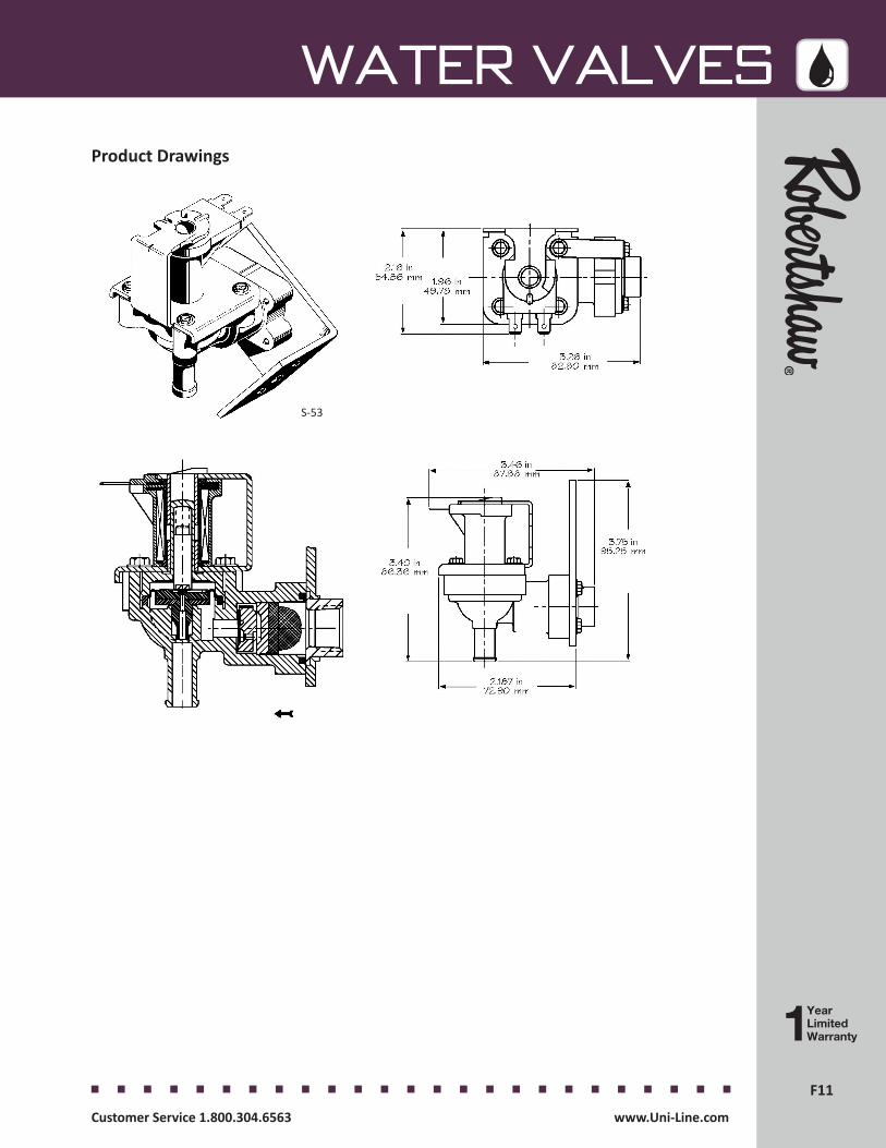
F11F11
WATER VALVES
Customer Service 1.800.304.6563 www.Uni-Line.comwww.Uni-Line.com Customer Service 1.800.304.6563
Product Drawings
S-53
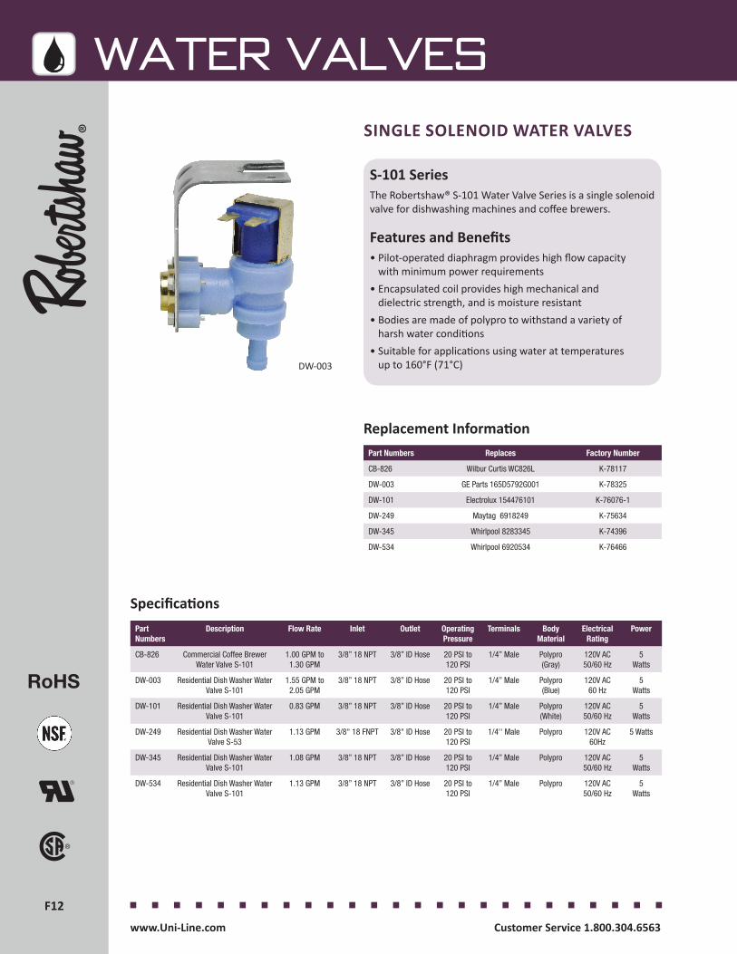
F12F12
WATER VALVES
Customer Service 1.800.304.6563 www.Uni-Line.comwww.Uni-Line.com Customer Service 1.800.304.6563
S-101 SeriesThe Robertshaw® S-101 Water Valve Series is a single solenoid valve for dishwashing machines and coffee brewers.
Features and Benefits• Pilot-operated diaphragm provides high flow capacity
with minimum power requirements • Encapsulated coil provides high mechanical and
dielectric strength, and is moisture resistant• Bodies are made of polypro to withstand a variety of
harsh water conditions• Suitable for applications using water at temperatures
up to 160°F (71°C)
SINGLE SOLENOID WATER VALVES
Replacement Information
RoHS
DW-003
Part Numbers Replaces Factory Number
CB-826 Wilbur Curtis WC826L K-78117
DW-003 GE Parts 165D5792G001 K-78325
DW-101 Electrolux 154476101 K-76076-1
DW-249 Maytag 6918249 K-75634
DW-345 Whirlpool 8283345 K-74396
DW-534 Whirlpool 6920534 K-76466
Part Numbers
Description Flow Rate Inlet Outlet Operating Pressure
Terminals Body Material
Electrical Rating
Power
CB-826 Commercial Coffee Brewer Water Valve S-101
1.00 GPM to 1.30 GPM
3/8” 18 NPT 3/8” ID Hose 20 PSI to 120 PSI
1/4” Male Polypro (Gray)
120V AC 50/60 Hz
5 Watts
DW-003 Residential Dish Washer Water Valve S-101
1.55 GPM to 2.05 GPM
3/8” 18 NPT 3/8” ID Hose 20 PSI to 120 PSI
1/4” Male Polypro (Blue)
120V AC 60 Hz
5 Watts
DW-101 Residential Dish Washer Water Valve S-101
0.83 GPM 3/8” 18 NPT 3/8” ID Hose 20 PSI to 120 PSI
1/4” Male Polypro (White)
120V AC 50/60 Hz
5 Watts
DW-249 Residential Dish Washer Water Valve S-53
1.13 GPM 3/8" 18 FNPT 3/8" ID Hose 20 PSI to 120 PSI
1/4'' Male Polypro 120V AC 60Hz
5 Watts
DW-345 Residential Dish Washer Water Valve S-101
1.08 GPM 3/8” 18 NPT 3/8” ID Hose 20 PSI to 120 PSI
1/4” Male Polypro 120V AC 50/60 Hz
5 Watts
DW-534 Residential Dish Washer Water Valve S-101
1.13 GPM 3/8” 18 NPT 3/8” ID Hose 20 PSI to 120 PSI
1/4” Male Polypro 120V AC 50/60 Hz
5 Watts
Specifications
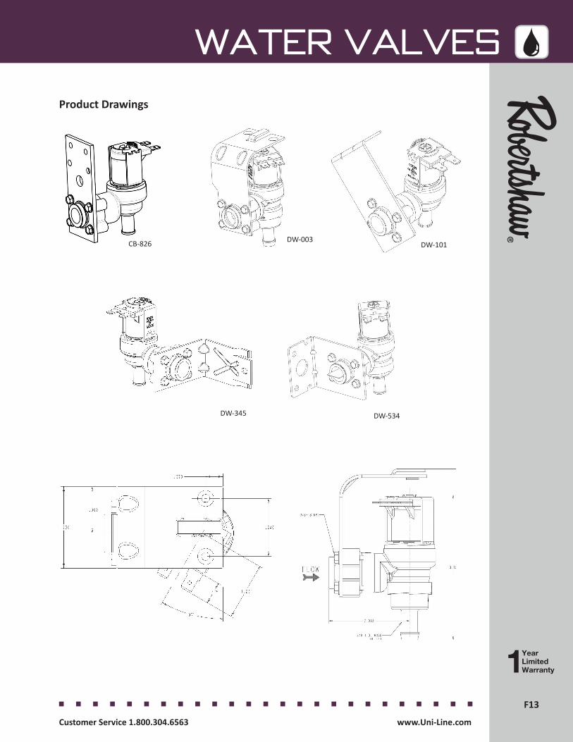
F13F13
WATER VALVES
Customer Service 1.800.304.6563 www.Uni-Line.comwww.Uni-Line.com Customer Service 1.800.304.6563
Product Drawings
DW-101
DW-345 DW-534
CB-826 DW-003
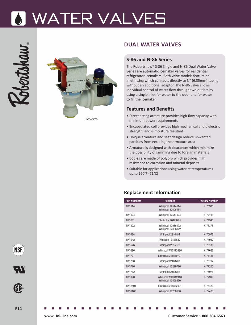
F14F14
WATER VALVES
Customer Service 1.800.304.6563 www.Uni-Line.comwww.Uni-Line.com Customer Service 1.800.304.6563
Replacement Information
S-86 and N-86 SeriesThe Robertshaw® S-86 Single and N-86 Dual Water Valve Series are automatic icemaker valves for residential refrigerator icemakers. Both valve models feature an inlet fitting which connects directly to ¼” (6.35mm) tubing without an additional adaptor. The N-86 valve allows individual control of water flow through two outlets by using a single inlet for water to the door and for water to fill the icemaker.
Features and Benefits• Direct acting armature provides high flow capacity with
minimum power requirements• Encapsulated coil provides high mechanical and dielectric
strength, and is moisture resistant• Unique armature and seat design reduce unwanted
particles from entering the armature area• Armature is designed with clearances which minimize
the possibility of jamming due to foreign materials• Bodies are made of polypro which provides high
resistance to corrosion and mineral deposits• Suitable for applications using water at temperatures
up to 160°F (71°C)
DUAL WATER VALVES
IMV-576
Part Numbers Replaces Factory Number
IMV-114 Whirlpool 12544114 Whirlpool 67005154
K-75985
IMV-124 Whirlpool 12544124 K-77198
IMV-201 Electrolux 40493201 K-74945
IMV-322 Whirlpool 12956102 Whirlpool 67006322
K-76376
IMV-494 Whirlpool 2210494 K-75973
IMV-542 Whirlpool 2188542 K-74982
IMV-576 Whirlpool 2315576 K-78186
IMV-696 Whirlpool W10312696 K-77623
IMV-701 Electrolux 218859701 K-75425
IMV-708 Whirlpool 2188708 K-75717
IMV-716 Whirlpool 10219716 K-77205
IMV-782 Whirlpool 2188782 K-75978
IMV-990 Whirlpool W10342318 Whirlpool 10498990
K-77999
IMV-2401 Electrolux 218832401 K-75423
IMV-8100 Whirlpool 10238100 K-77473

F15F15
WATER VALVES
Customer Service 1.800.304.6563 www.Uni-Line.comwww.Uni-Line.com Customer Service 1.800.304.6563
Part Numbers
Description Flow Rate Inlet Outlet Operating Pressure
Terminals Body Material
Electrical Rating
Power
IMV-114 Residential Ice Machine Water Valve N-86 Dual
115-154 cc in 7.5 seconds, 40-80 cc
per second
5/16" quick connect
1/4” quick connect
5/16” quick connect
20 PSI to 120 PSI
1/4” Male3/16” Male
Polypro 120V AC 60Hz
35 Watts20 Watts
IMV-124 Residential Ice Machine Water Valve N-86 Dual
115-154 cc in 7.5 seconds,
40-80 cc per second
5/16” quick connect
1/4” quick connect
5/16” quick connect”
20 PSI to 120 PSI
1/4” Male 3/16” Male
Polypro 120V AC 60Hz
35 Watts 20 Watts
IMV-201 Residential Ice Machine Water Valve S-86
140 cc in 7.5 seconds 7/16" 24 UNS 7/16" 20 UNF 20 PSI to 120 PSI
1/4” Male Polypro 120V AC 60Hz
35 Watts
IMV-322 Residential Ice Machine Water Valve N-86 Dual
Inline
115-154 cc in 7.5 seconds,
40-80 cc per second
5/16” quick connect
1/4” quick connect 5/16” quick connect
20 PSI to 120 PSI
1/4” Male 3/16” Male
Polypro 120V AC 60Hz
35 Watts 20 Watts
IMV-494 ResidentialIce Machine Water
Valve S-86
0.06 GPM to 0.60 GPM
1/4” flare, loxit or compression
7/16” 20 UNF 20 PSI to 120 PSI
1/4” Male Polypro 120V AC 60 Hz
35 Watts
IMV-542 Residential Ice Machine Water Valve N-86 Dual
113-141 cc in 7.5 seconds,
24-58 cc per second
7/16” 20 UNF 7/16” 20 UNF 1/2” 20 UNF
20 PSI to 120 PSI
1/4” Male 3/16” Male
Polypro 120V AC 60Hz
35 Watts 20 Watts
IMV-576 ResidentialIce Machine Water
Valve S-86
0.06 GPM to 0.60 GPM
1/4” flare, loxit or compression
7/16” 20 UNF 20 PSI to 120 PSI
1/4” Male Polypro 120V AC 60 Hz
35 Watts
IMV-696 Residential Ice Machine Water Valve N-86 Dual
Inline
70 cc in 7.5 seconds, 40-80 cc
per second
5/16” quick connect
1/4”quick connect 5/16” quick connect
20 PSI to 120 PSI
1/4” Male 3/16” Male
Polypro 120V AC 60Hz
35 Watts 20 Watts
IMV-701 Residential Ice Machine Water Valve S-86
No flow control 7/16” 24 UNS 7/16” 20 UNF 20 PSI to 120 PSI
1/4’’ Male Polypro 120V AC 60Hz
15 Watts
IMV-708 ResidentialIce Machine Water Valve N-86 Dual
130 CC in 7.5 seconds,
22-38 CC per second
1/4” flare, loxit or compression
7/16” 20 UNF, 1/2” 20 UNF
20 PSI to 120 PSI
1/4” Male, 3/16” Male
Polypro 120V AC 50/60 Hz
35 Watts 20 Watts
IMV-716 Residential Ice Machine Water Valve S-86
140 cc in 7.5 seconds
7/16” 24 UNS 1/4” quick connect
20 PSI to 120 PSI
1/4’’ Male Polypro 120V AC 60Hz
35 Watts
IMV-782 Residential Ice Machine Water Valve S-86
140 cc in 7.5 seconds
7/16” 24 UNS 7/16” 20 UNF 20 PSI to 120 PSI
1/4’’ Male Polypro 120V AC 60Hz
35 Watts
IMV-990 Residential Ice Machine Water Valve S-86
180-600 cc in 7.5 seconds
7/16" 24 UNS 5/16" quick connect
20 PSI to 120 PSI
1/4” Male Polypro 120V AC 60Hz
20 Watts
IMV-2401 Residential Ice Machine Water Valve N-86 Dual
116 cc in 7.5 seconds
7/16” 20 UNF 7/16” 20 UNF 20 PSI to 120 PSI
1/4’’ Male Polypro 120V AC 60Hz
35 Watts 15 Watts
IMV-8100 Residential Ice Machine Water Valve S-86
180-600 cc in 7.5 seconds
7/16" 24 UNS 5/16" quick connect
20 PSI to 120 PSI
1/4” Male Polypro 120V AC 60Hz
20 Watts
Specifications
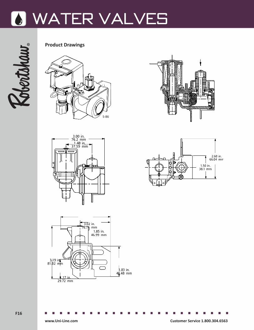
F16F16
WATER VALVES
Customer Service 1.800.304.6563 www.Uni-Line.comwww.Uni-Line.com Customer Service 1.800.304.6563
Product Drawings
S-86

F17F17
WATER VALVES
Customer Service 1.800.304.6563 www.Uni-Line.comwww.Uni-Line.com Customer Service 1.800.304.6563
Product Drawings
N-86
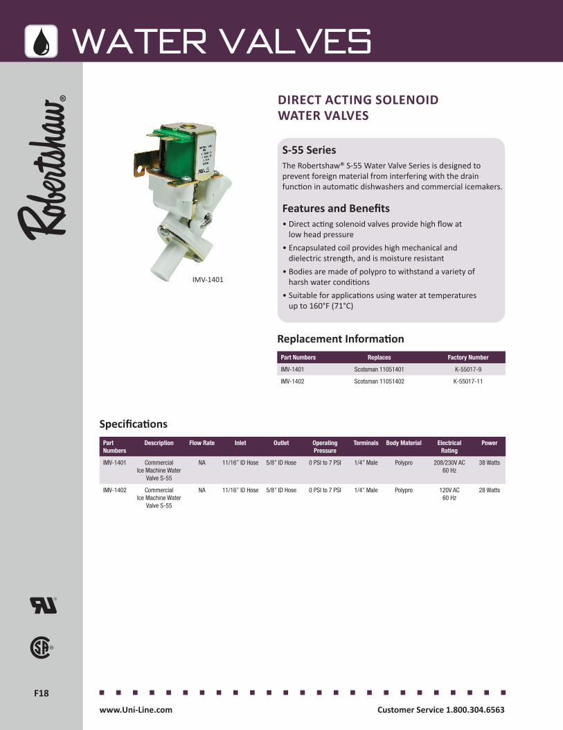
F18F18
WATER VALVES
Customer Service 1.800.304.6563 www.Uni-Line.comwww.Uni-Line.com Customer Service 1.800.304.6563
DIRECT ACTING SOLENOID WATER VALVES
S-55 SeriesThe Robertshaw® S-55 Water Valve Series is designed to prevent foreign material from interfering with the drain function in automatic dishwashers and commercial icemakers.
Features and Benefits• Direct acting solenoid valves provide high flow at
low head pressure• Encapsulated coil provides high mechanical and
dielectric strength, and is moisture resistant• Bodies are made of polypro to withstand a variety of
harsh water conditions• Suitable for applications using water at temperatures
up to 160°F (71°C)
IMV-1401
Part Numbers Replaces Factory Number
IMV-1401 Scotsman 11051401 K-55017-9
IMV-1402 Scotsman 11051402 K-55017-11
Replacement Information
Part Numbers
Description Flow Rate Inlet Outlet Operating Pressure
Terminals Body Material Electrical Rating
Power
IMV-1401 CommercialIce Machine Water
Valve S-55
NA 11/16” ID Hose 5/8” ID Hose 0 PSI to 7 PSI 1/4” Male Polypro 208/230V AC 60 Hz
38 Watts
IMV-1402 CommercialIce Machine Water
Valve S-55
NA 11/16” ID Hose 5/8” ID Hose 0 PSI to 7 PSI 1/4” Male Polypro 120V AC 60 Hz
28 Watts
Specifications

F19F19
WATER VALVES
Customer Service 1.800.304.6563 www.Uni-Line.comwww.Uni-Line.com Customer Service 1.800.304.6563
Product Drawings
S-55

F20F20
WATER VALVES
Customer Service 1.800.304.6563 www.Uni-Line.comwww.Uni-Line.com Customer Service 1.800.304.6563
GS-56 SeriesThe Robertshaw® GS-56 Water Valve Series is designed to dispense water in coffee and other hot beverage vending machines. This direct acting, gravity-fed dump valve is capable of providing low volume liquid flow at a minimum head pressure and a water temperature of 200°F (93°C).
Features and Benefits• Vent tube• External flow adjustment screw slotted or hex• Polysulfone body material for good chemical resistance
and high temperature stability • Maximum water temperature is 200°F (93°C)
GRAVITY-FED DUMP WATER VALVES
CB-880
Part Numbers Replaces Factory Number
CB-102 Grindmaster 61102 K-56778-41
CB-116 Bunn-O-Matic 26116002 K-56778-51
CB-880 Wilbur Curtis WC880E K-56778-35
Replacement Information
Part Numbers
Description Flow Rate Inlet Outlet Operating Pressure
Terminals Body Material
Electrical Rating
Power
CB-102 Commercial Coffee Brewer Water Valve GS-56 with Venting Elbow
1.43 GPM 5/8” OD with O ring groove
1/2” ID Hose 20” Head 1/4” Male Polysulfone 120V AC 50/60 Hz
12 Watts
CB-116 Commercial Coffee Brewer Water Valve
GS-56
1.43 GPM 5/8” OD with O ring groove
1/2” ID Hose 20” Head 1/4” Male, Bent Down 90°
Polysulfone 120V AC 50/60 Hz
12 Watts
CB-880 CommercialCoffee Brewer Water Valve
GS-56
1.43 GPM 5/8” OD with O ring groove
1/2” ID Hose 20” Head 1/4” Male Polysulfone 120V AC 50/60 Hz
12 Watts
Specifications
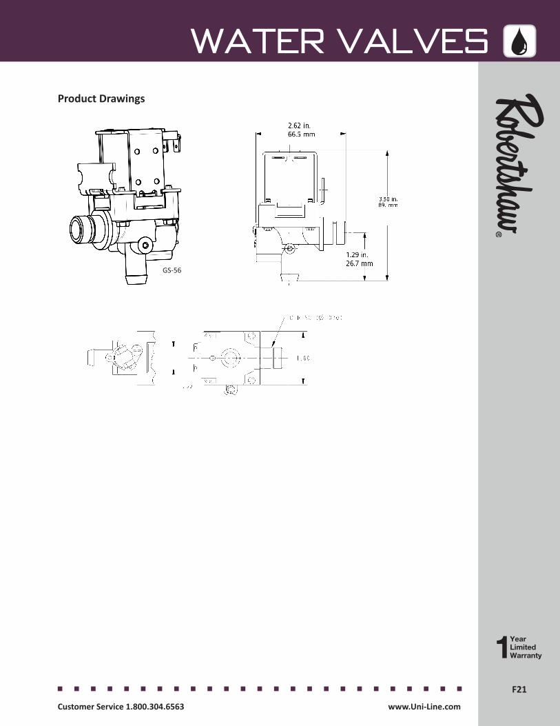
F21F21
WATER VALVES
Customer Service 1.800.304.6563 www.Uni-Line.comwww.Uni-Line.com Customer Service 1.800.304.6563
Product Drawings
GS-56

F22F22
WATER VALVES
Customer Service 1.800.304.6563 www.Uni-Line.comwww.Uni-Line.com Customer Service 1.800.304.6563
S-45 SeriesThe Robertshaw® S-45 Water Valve Series is designed as a general purpose valve for energy conserving plumbing and heating applications.
Features and Benefits• Pilot-operated design provides flow capacity with
minimum power requirements• Serviceable strainer incorporated for the protection of
both the valve and the appliance• Encapsulated coil provides high mechanical and
dielectric strength, and is moisture resistant• UL requirements met for intermittent duty operation• Suitable for applications using water at temperatures
up to 160°F (71°C)
GENERAL PURPOSE WATER VALVES
Part Numbers Replaces Factory Number
DW-952 Moyer Diebel 504952 K-62687-44
IMV-001 Scotsman 12-2990-01 K-62687-128
PL-849 Sloan Valve 0305849 K-77634
Replacement Information
DW-952
Part Numbers
Description Flow Rate Inlet Outlet Operating Pressure
Terminals Body Material
Electrical Rating
Power
DW-952 Commercial Dishwasher Water Valve S-45
Up to 5 GPM 3/8” 18 FNPT 3/8” 18 FNPT 20 PSI to 120 PSI
1/4” Male Brass 120V AC 50/60 Hz
10 Watts
IMV-001 Commercial Ice Maker Water Valve S-45
0.19 GPM 3/8" 18 FNPT 3/8" ID Hose 20 PSI to 120 PSI
1/4'' Male Brass 120V AC 60Hz
15 Watts
PL-849 Commercial Plumbing Water Valve S-45
NA 3/8” 18 FNPT 3/8” 18 FNPT 20 PSI to 120 PSI
1/4” Male Low LeadBrass
24V AC 50/60 Hz
7 Watts
Specifications

F23F23
WATER VALVES
Customer Service 1.800.304.6563 www.Uni-Line.comwww.Uni-Line.com Customer Service 1.800.304.6563
Product Drawings
S-45
S-45with Connector
S-45with Connector
S-45with Connector

F24F24
WATER VALVES
Customer Service 1.800.304.6563 www.Uni-Line.comwww.Uni-Line.com Customer Service 1.800.304.6563
GENERAL PURPOSE WATER VALVES
Specifications
V SeriesThe Robertshaw® V180 and V280 Water Valve Series is designed for use in clothes washers, dishwashers, showers, air condition-ing systems and other domestic or commercial applications.
Flexible and designed and produced to meet the stringent requirements of the markets of today and the future.
Features and Benefits• Easy to rotate, coil to match OEM application• Flexible mounting with four different positions• Hose bard connection• Conversion kit with bracket, screen, popular flow controls, terminals• IEC certified
Part Numbers
Description Flow Regulator
Inlet Outlet Operating Pressure
Terminals Body Material
Thermistor Outlet Orientation
Electrical Rating
Power
V180
(EU)
Clothes Washer and Dishwasher
inlet water valve kit
2.5L/min, 8.0L/min, 10.0L/min
Thread ISO 228 G 3/4 B
10mm 0.02-1 Mpa 6.35mm Male
Polyammide NA 90° 230V AC
50/60 Hz
6 Watts
V190 (EU)
Clothes Washer and Dishwasher
inlet water valve kit
2.5L/min, 8.0L/min, 10.0L/min
Thread ISO 228 G 3/4 B
10mm 0.02-1 Mpa 6.35mm Male
Polyammide NA 180° 230V AC
50/60 Hz
6 Watts
V280 (EU)
Clothes Washer and Dishwasher inlet water valve,
dual kit
2.5L/min, 8.0L/min, 10.0L/min
Thread ISO 228 G 3/4 B
10mm 0.02-1 Mpa 6.35mm Male
Polyammide NA 180° 230V AC
50/60 Hz
6 Watts
V290 (EU)
Clothes Washer and Dishwasher inlet water valve,
dual kit
2.5L/min, 8.0L/min, 10.0L/min
Thread ISO 228 G 3/4 B
10mm 0.02-1 Mpa 6.35mm Male
Polyammide NA 90° 230V AC
50/60 Hz
6 Watts
V180
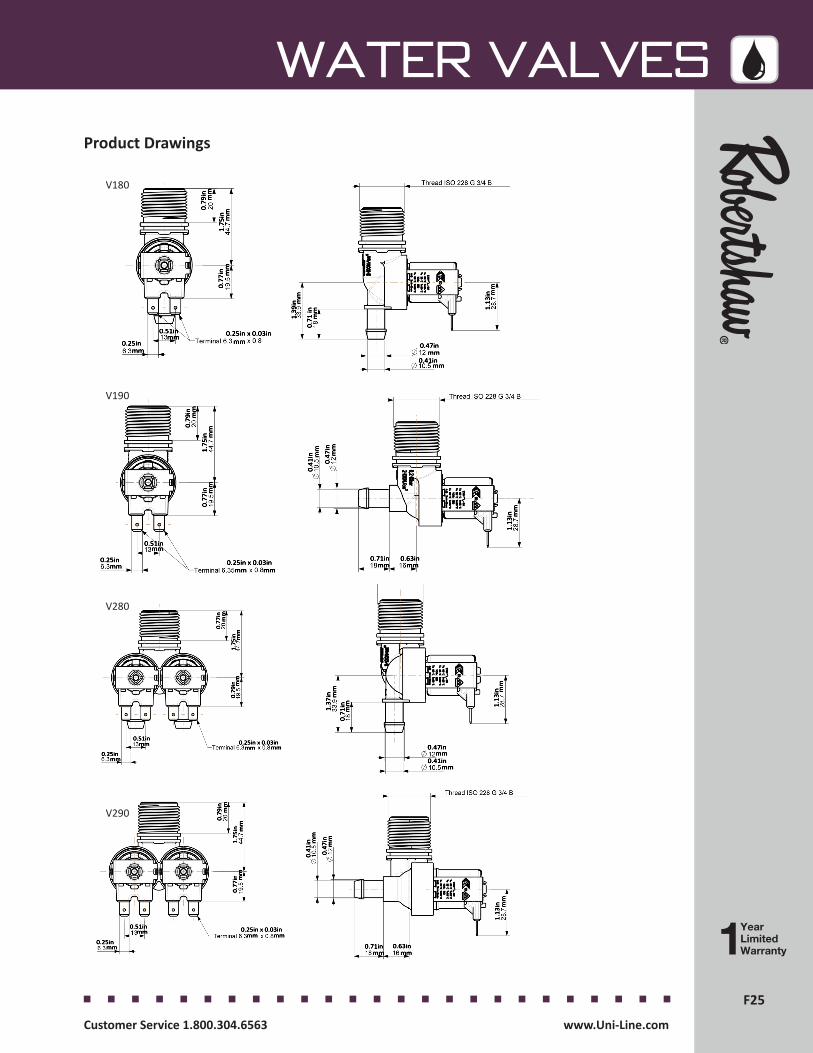
F25F25
WATER VALVES
Customer Service 1.800.304.6563 www.Uni-Line.comwww.Uni-Line.com Customer Service 1.800.304.6563
Product Drawings
0.77
in1.
75in
0.79
in
mm
mm
mm
0.25in x 0.03inmm
mm
mm0.51in
0.25in
1.39
in
0.71
in
1.13
in
mm
mm
mm0.47in
0.41in
mm
mm
mm0.25in x 0.03in0.25in
0.51in
0.77
inm
mm
m1.
75in
mm
0.79
in
mmmm
mm
0.41
in
0.47
in
0.71in 0.63in
1.13
in
mm mm
mm
mmmm
mm0.25in
0.51in0.25in x 0.03in
0.77
in
1.75
in0.
79in
mm
mm
mm
mm
mm
mm
mm
mm
mm
1.13
in
0.71
in1.37
in
mm
mm
0.47in
0.41in
mm
mmmm mm
0.25in x 0.03in0.51in
0.25in
mm
mm
mm
0.79
in
1.75
in0.
77in
mm mm
0.41
in
0.47
in
1.13
in
0.71in 0.63in
mm
mm
mm
V180
V190
V280
V290

F26F26
WATER VALVES
www.Uni-Line.com Customer Service 1.800.304.6563
PRESSURE SENSOR
Specifications
F3 SeriesThe Robertshaw® F3 Linear Pressure Sensor is a transducer for pressure measurement. It has been developed to measure the level of water in the tank of the washing machine. The sensor continuously informs the main electronic control about the water level, allowing the water management control during all phases of the wash program.
Features and Benefits• Replaces previous water level switch without any change in the machine structure• Allows for use by main electronic control units of washing machines by being PEC (Protective Electronic Circuit)• Strong immunity from internal and external interference like EMI and induced magnetic fields
Part Numbers Description
F3 Pressure Sensor
F3
WATER VALVES
YearLimitedWarranty
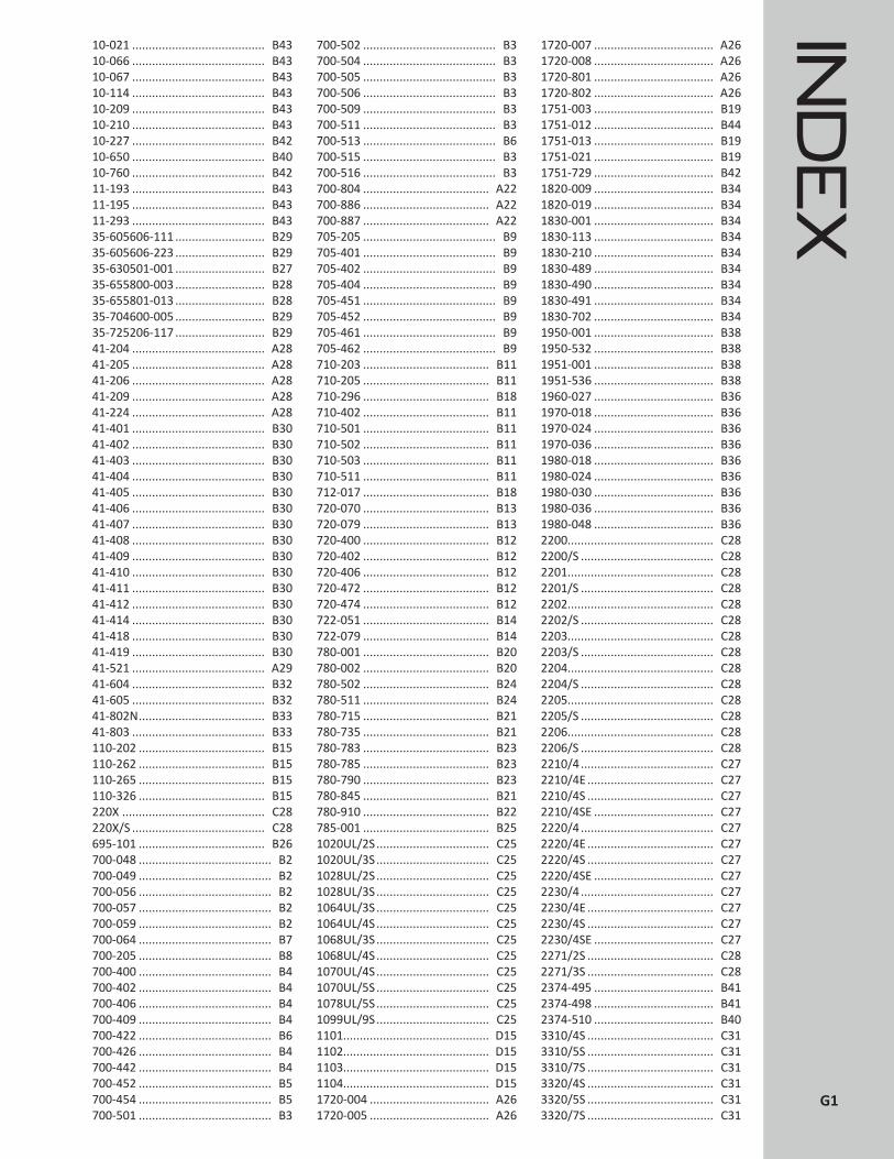
IND
EX
10-021 ........................................ B4310-066 ........................................ B4310-067 ........................................ B4310-114 ........................................ B4310-209 ........................................ B4310-210 ........................................ B4310-227 ........................................ B4210-650 ........................................ B4010-760 ........................................ B4211-193 ........................................ B4311-195 ........................................ B4311-293 ........................................ B4335-605606-111 ........................... B2935-605606-223 ........................... B2935-630501-001 ........................... B2735-655800-003 ........................... B2835-655801-013 ........................... B2835-704600-005 ........................... B2935-725206-117 ........................... B2941-204 ........................................ A2841-205 ........................................ A2841-206 ........................................ A2841-209 ........................................ A2841-224 ........................................ A2841-401 ........................................ B3041-402 ........................................ B3041-403 ........................................ B3041-404 ........................................ B3041-405 ........................................ B3041-406 ........................................ B3041-407 ........................................ B3041-408 ........................................ B3041-409 ........................................ B3041-410 ........................................ B3041-411 ........................................ B3041-412 ........................................ B3041-414 ........................................ B3041-418 ........................................ B3041-419 ........................................ B3041-521 ........................................ A2941-604 ........................................ B3241-605 ........................................ B3241-802N ...................................... B3341-803 ........................................ B33110-202 ...................................... B15110-262 ...................................... B15110-265 ...................................... B15110-326 ...................................... B15220X ........................................... C28220X/S ........................................ C28695-101 ...................................... B26700-048 ........................................ B2700-049 ........................................ B2700-056 ........................................ B2700-057 ........................................ B2700-059 ........................................ B2700-064 ........................................ B7700-205 ........................................ B8700-400 ........................................ B4700-402 ........................................ B4700-406 ........................................ B4700-409 ........................................ B4700-422 ........................................ B6700-426 ........................................ B4700-442 ........................................ B4700-452 ........................................ B5700-454 ........................................ B5700-501 ........................................ B3
700-502 ........................................ B3700-504 ........................................ B3700-505 ........................................ B3700-506 ........................................ B3700-509 ........................................ B3700-511 ........................................ B3700-513 ........................................ B6700-515 ........................................ B3700-516 ........................................ B3700-804 ...................................... A22700-886 ...................................... A22700-887 ...................................... A22705-205 ........................................ B9705-401 ........................................ B9705-402 ........................................ B9705-404 ........................................ B9705-451 ........................................ B9705-452 ........................................ B9705-461 ........................................ B9705-462 ........................................ B9710-203 ...................................... B11710-205 ...................................... B11710-296 ...................................... B18710-402 ...................................... B11710-501 ...................................... B11710-502 ...................................... B11710-503 ...................................... B11710-511 ...................................... B11712-017 ...................................... B18720-070 ...................................... B13720-079 ...................................... B13720-400 ...................................... B12720-402 ...................................... B12720-406 ...................................... B12720-472 ...................................... B12720-474 ...................................... B12722-051 ...................................... B14722-079 ...................................... B14780-001 ...................................... B20780-002 ...................................... B20780-502 ...................................... B24780-511 ...................................... B24780-715 ...................................... B21780-735 ...................................... B21780-783 ...................................... B23780-785 ...................................... B23780-790 ...................................... B23780-845 ...................................... B21780-910 ...................................... B22785-001 ...................................... B251020UL/2S .................................. C251020UL/3S .................................. C251028UL/2S .................................. C251028UL/3S .................................. C251064UL/3S .................................. C251064UL/4S .................................. C251068UL/3S .................................. C251068UL/4S .................................. C251070UL/4S .................................. C251070UL/5S .................................. C251078UL/5S .................................. C251099UL/9S .................................. C251101............................................ D151102............................................ D151103............................................ D151104............................................ D151720-004 .................................... A261720-005 .................................... A26
1720-007 .................................... A261720-008 .................................... A261720-801 .................................... A261720-802 .................................... A261751-003 .................................... B191751-012 .................................... B441751-013 .................................... B191751-021 .................................... B191751-729 .................................... B421820-009 .................................... B341820-019 .................................... B341830-001 .................................... B341830-113 .................................... B341830-210 .................................... B341830-489 .................................... B341830-490 .................................... B341830-491 .................................... B341830-702 .................................... B341950-001 .................................... B381950-532 .................................... B381951-001 .................................... B381951-536 .................................... B381960-027 .................................... B361970-018 .................................... B361970-024 .................................... B361970-036 .................................... B361980-018 .................................... B361980-024 .................................... B361980-030 .................................... B361980-036 .................................... B361980-048 .................................... B362200............................................ C282200/S ........................................ C282201............................................ C282201/S ........................................ C282202............................................ C282202/S ........................................ C282203............................................ C282203/S ........................................ C282204............................................ C282204/S ........................................ C282205............................................ C282205/S ........................................ C282206............................................ C282206/S ........................................ C282210/4 ........................................ C272210/4E ...................................... C272210/4S ...................................... C272210/4SE .................................... C272220/4 ........................................ C272220/4E ...................................... C272220/4S ...................................... C272220/4SE .................................... C272230/4 ........................................ C272230/4E ...................................... C272230/4S ...................................... C272230/4SE .................................... C272271/2S ...................................... C282271/3S ...................................... C282374-495 .................................... B412374-498 .................................... B412374-510 .................................... B403310/4S ...................................... C313310/5S ...................................... C313310/7S ...................................... C313320/4S ...................................... C313320/5S ...................................... C313320/7S ...................................... C31
G1

IND
EX 3330/4S ...................................... C31
3330/5S ...................................... C313330/7S ...................................... C313910/33 ...................................... C333940/2 ........................................ C333940/3 ........................................ C333940/5 ........................................ C333940/7 ........................................ C333950/22 ...................................... C333950/33 ...................................... C334075-029 .................................... A244075-200 .................................... A244200-005 .................................... A204200-007 .................................... A204200-011 .................................... A204200-025 .................................... A204200-026 .................................... A204200-503 .................................... A204200-505 .................................... A204200-508 .................................... A204290-006 .................................... A184290-008 .................................... A184290-020 .................................... A184303/2 ........................................ C354303/2S ...................................... C354303/3 ........................................ C354303/3S ...................................... C354305/2 ........................................ C354305/2S ...................................... C354308/2 ........................................ C354308/3 ........................................ C354308/3S ...................................... C354316/3 ........................................ C354316/4 ........................................ C354316/5 ........................................ C354316/5S ...................................... C354341/7S ...................................... C354350-015 .................................... A164350-027 .................................... A164350-028 .................................... A164350-029 .................................... A164350-040 .................................... A164350-127 .................................... A164350-128 .................................... A164590-065 .................................... B454590-067 .................................... B454590-069 .................................... B454590-071 .................................... B454590-170 .................................... B454590-816 .................................... B455000-811 .................................... A145000-851 .................................... A145210-125 .................................... A125225-009 ...................................... A95225-010 ...................................... A95225-047 ...................................... A95225-054 ...................................... A95225-112 ...................................... A95300-146 ...................................... A65300-175 ...................................... A65300-219 ...................................... A65300-401 ...................................... A65300-406 ...................................... A75300-502 ...................................... A75300-612 ...................................... A75300-614 ...................................... A75300-618 ...................................... A75300-641 ...................................... A75300-651 ...................................... A7
5300-671 ...................................... A75300-711 ...................................... A75300-735 ...................................... A75300-766 ...................................... A75500-134 ...................................... A45500-135 ...................................... A45500-200 ...................................... A45500-200M ................................... A25500-202 ............................... A4, G75500-212 ...................................... A45500-234 ...................................... A45500-235 ...................................... A45500-287 ...................................... A46590/3 ........................................ C366590/4 ........................................ C366590/5 ........................................ C366590/6 ........................................ C366590/7 ........................................ C366590/9 ........................................ C366590/11 ...................................... C368041-00 ........................................ D98045-00 ........................................ D98045-20 ........................................ D98141-00 ........................................ D98141-20 ........................................ D98145-00 ........................................ D98145-20 ........................................ D98145-20B ...................................... D98145-AV ........................................ D28145-AV-M.................................... D28245-20 ........................................ D99045-00 ...................................... D129045-00M ................................... D129105/RA4.................................... C259105/RA6.................................... C259145-00 ...................................... D129145-00M ................................... D129530N814 ..................................... C79531N195 ..................................... C69531N320 ..................................... C69531N395 ..................................... C61290132-A24 .............................. C211290132-A36 .............................. C211309007-044 ................................ C4
AA12-700 ........................................ C6A12-701 ........................................ C6A12-1506 ...................................... C6A12-1560 ...................................... C6A22-391 ........................................ C7A22-1112 ...................................... C7A22-1129 ...................................... C7A30-180 ........................................ C7A30-260 ........................................ C7A30-261 ........................................ C7A30-262 ........................................ C7A30-263 ........................................ C7A30-301 ........................................ C7A30-2209 ...................................... C7A30-2210 ...................................... C7A1401-00 .................................... D19A1401-20 .................................... D19A1401-21 .................................... D19
BB1401-00 .................................... D19B1401-20 .................................... D19B1401-21 .................................... D19
CC12-2001 .................................... C11C12-5010 .................................... C10C17-100 ...................................... C10CB-102 ........................................ F20CB-104 .......................................... F8CB-116 ........................................ F20CB-826 ........................................ F12CB-880 ........................................ F20CW-001 .................................... F2, F3CW-164 .................................... F2, F3CW-300 ......................................... F6CW-333 .................................... F2, F3CW-346 .................................... F2, F3CW-347 .................................... F2, F3CW-349 .................................... F2, F3CW-400 .................................... F2, F3CW-402 .................................... F2, F3CW-468 .................................... F2, F3CW-471 .................................... F2, F3CW-531 ......................................... F6CW-551 .................................... F2, F3CW-600 .................................... F2, F3CW-673 .................................... F2, F3CW-751 .................................... F2, F3CW-932 .................................... F2, F3CW-1300 ....................................... F6CW-E2 ...................................... F2, F3
DD81-8145-00EX ............................. D9D81-8145-20EX ............................. D9D81-8145-21EX ............................. D9DW-003....................................... F12DW-101....................................... F12DW-249....................................... F12DW-345....................................... F12DW-534....................................... F12DW-721....................................... F10DW-952....................................... F22
EE15-2601 .................................... C11E101B ......................................... D18ERC2-212111-370 ......................... C2ETC-111000-000 ........................... C4ETC-112000-000 ........................... C4ETC-141000-000 ........................... C4ETC-211000-000 ........................... C4ETC-212000-000 ........................... C4
FF3 ................................................ F26F25-107 ...................................... C12
GG1401-00 .................................... D19G1401-20 .................................... D19G1401-21 .................................... D19
IIMV-001 ...................................... F22IMV-003 ...................................... F10IMV-114 .............................. F14, F15IMV-124 .............................. F14, F15IMV-201 .............................. F14, F15IMV-202 ...................................... F10IMV-322 .............................. F14, F15IMV-373 ...................................... F10IMV-399 ...................................... F10IMV-0400 .................................... F10
G2
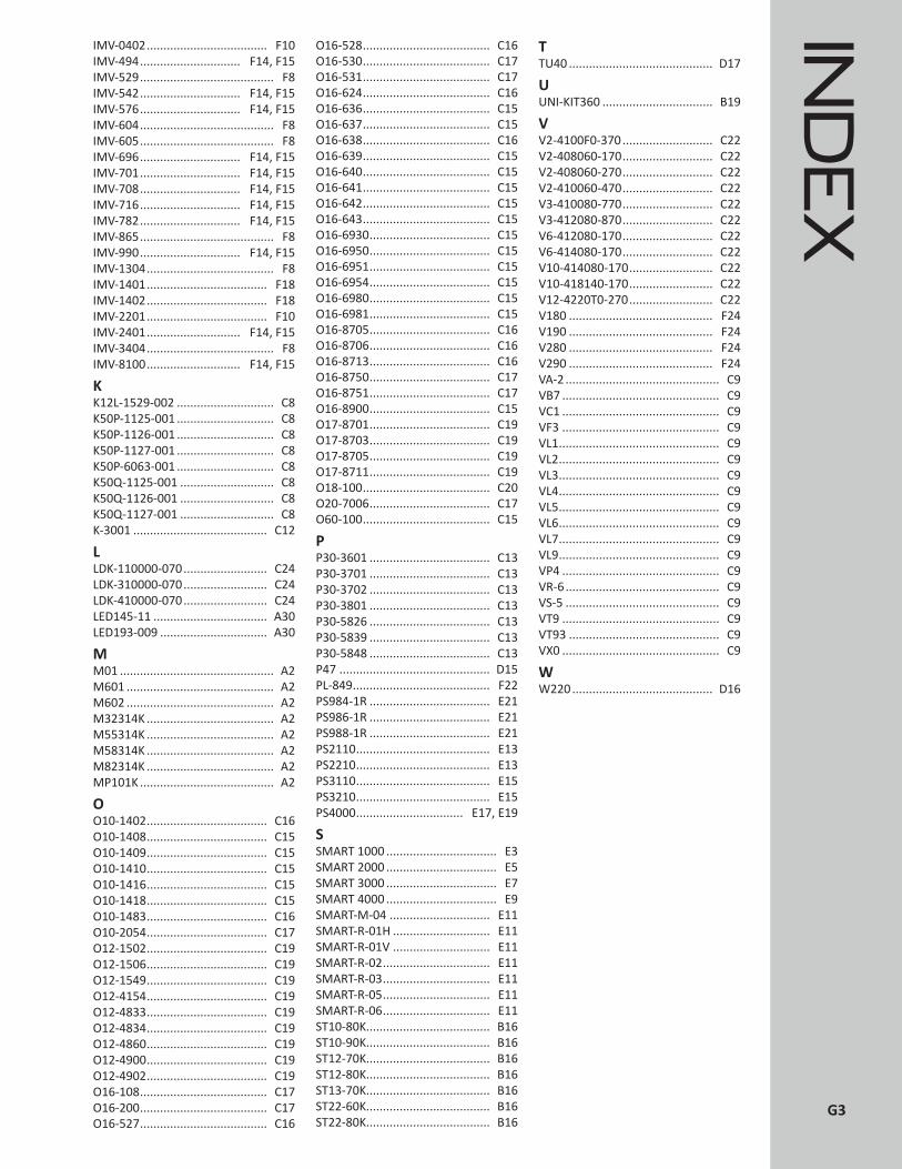
IND
EX
IMV-0402 .................................... F10IMV-494 .............................. F14, F15IMV-529 ........................................ F8IMV-542 .............................. F14, F15IMV-576 .............................. F14, F15IMV-604 ........................................ F8IMV-605 ........................................ F8IMV-696 .............................. F14, F15IMV-701 .............................. F14, F15IMV-708 .............................. F14, F15IMV-716 .............................. F14, F15IMV-782 .............................. F14, F15IMV-865 ........................................ F8IMV-990 .............................. F14, F15IMV-1304 ...................................... F8IMV-1401 .................................... F18IMV-1402 .................................... F18IMV-2201 .................................... F10IMV-2401 ............................ F14, F15IMV-3404 ...................................... F8IMV-8100 ............................ F14, F15
KK12L-1529-002 ............................. C8K50P-1125-001 ............................. C8K50P-1126-001 ............................. C8K50P-1127-001 ............................. C8K50P-6063-001 ............................. C8K50Q-1125-001 ............................ C8K50Q-1126-001 ............................ C8K50Q-1127-001 ............................ C8K-3001 ........................................ C12
LLDK-110000-070 ......................... C24LDK-310000-070 ......................... C24LDK-410000-070 ......................... C24LED145-11 .................................. A30LED193-009 ................................ A30
MM01 .............................................. A2M601 ............................................ A2M602 ............................................ A2M32314K ...................................... A2M55314K ...................................... A2M58314K ...................................... A2M82314K ...................................... A2MP101K ........................................ A2
OO10-1402 .................................... C16O10-1408 .................................... C15O10-1409 .................................... C15O10-1410 .................................... C15O10-1416 .................................... C15O10-1418 .................................... C15O10-1483 .................................... C16O10-2054 .................................... C17O12-1502 .................................... C19O12-1506 .................................... C19O12-1549 .................................... C19O12-4154 .................................... C19O12-4833 .................................... C19O12-4834 .................................... C19O12-4860 .................................... C19O12-4900 .................................... C19O12-4902 .................................... C19O16-108 ...................................... C17O16-200 ...................................... C17O16-527 ...................................... C16
O16-528 ...................................... C16O16-530 ...................................... C17O16-531 ...................................... C17O16-624 ...................................... C16O16-636 ...................................... C15O16-637 ...................................... C15O16-638 ...................................... C16O16-639 ...................................... C15O16-640 ...................................... C15O16-641 ...................................... C15O16-642 ...................................... C15O16-643 ...................................... C15O16-6930 .................................... C15O16-6950 .................................... C15O16-6951 .................................... C15O16-6954 .................................... C15O16-6980 .................................... C15O16-6981 .................................... C15O16-8705 .................................... C16O16-8706 .................................... C16O16-8713 .................................... C16O16-8750 .................................... C17O16-8751 .................................... C17O16-8900 .................................... C15O17-8701 .................................... C19O17-8703 .................................... C19O17-8705 .................................... C19O17-8711 .................................... C19O18-100 ...................................... C20O20-7006 .................................... C17O60-100 ...................................... C15
PP30-3601 .................................... C13P30-3701 .................................... C13P30-3702 .................................... C13P30-3801 .................................... C13P30-5826 .................................... C13P30-5839 .................................... C13P30-5848 .................................... C13P47 ............................................. D15PL-849 ......................................... F22PS984-1R .................................... E21PS986-1R .................................... E21PS988-1R .................................... E21PS2110 ........................................ E13PS2210 ........................................ E13PS3110 ........................................ E15PS3210 ........................................ E15PS4000 ................................ E17, E19
SSMART 1000 ................................. E3SMART 2000 ................................. E5SMART 3000 ................................. E7SMART 4000 ................................. E9SMART-M-04 .............................. E11SMART-R-01H ............................. E11SMART-R-01V ............................. E11SMART-R-02 ................................ E11SMART-R-03 ................................ E11SMART-R-05 ................................ E11SMART-R-06 ................................ E11ST10-80K..................................... B16ST10-90K..................................... B16ST12-70K..................................... B16ST12-80K..................................... B16ST13-70K..................................... B16ST22-60K..................................... B16ST22-80K..................................... B16
TTU40 ........................................... D17
UUNI-KIT360 ................................. B19
VV2-4100F0-370 ........................... C22V2-408060-170 ........................... C22V2-408060-270 ........................... C22V2-410060-470 ........................... C22V3-410080-770 ........................... C22V3-412080-870 ........................... C22V6-412080-170 ........................... C22V6-414080-170 ........................... C22V10-414080-170 ......................... C22V10-418140-170 ......................... C22V12-4220T0-270 ......................... C22V180 ........................................... F24V190 ........................................... F24V280 ........................................... F24V290 ........................................... F24VA-2 .............................................. C9VB7 ............................................... C9VC1 ............................................... C9VF3 ............................................... C9VL1 ................................................ C9VL2 ................................................ C9VL3 ................................................ C9VL4 ................................................ C9VL5 ................................................ C9VL6 ................................................ C9VL7 ................................................ C9VL9 ................................................ C9VP4 ............................................... C9VR-6 .............................................. C9VS-5 .............................................. C9VT9 ............................................... C9VT93 ............................................. C9VX0 ............................................... C9
WW220 .......................................... D16
G3
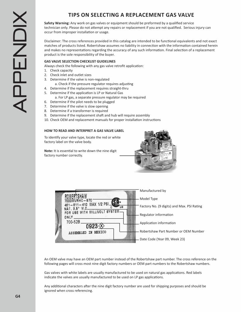
TIPS ON SELECTING A REPLACEMENT GAS VALVE
To identify your valve type, locate the red or white factory label on the valve body.
Note: It is essential to write down the nine digit factory number correctly.
An OEM valve may have an OEM part number instead of the Robertshaw part number. The cross reference on the following pages will cross most nine digit factory numbers or OEM part numbers to the Robertshaw numbers.
Gas valves with white labels are usually manufactured to be used on natural gas applications. Red labels indicate the valves are usually manufactured to be used on LP gas applications.
Any additional characters after the nine digit factory number are used for shipping purposes and should be ignored when cross referencing.
Safety Warning: Any work on gas valves or equipment should be preformed by a qualified service technician only. Please do not attempt any repairs or replacement if you are not qualified. Serious injury can occur from improper installation or usage.
Disclaimer: The cross references provided in this catalog are intended to be functional equivalents and not exact matches of products listed. Robertshaw assumes no liability in connection with the information contained herein and makes no representations regarding the accuracy of any such information. Final selection of a replacement product is the sole responsibility of the buyer.
GAS VALVE SELECTION CHECKLIST GUIDELINESAlways check the following with any gas valve retrofit application:1. Check capacity2. Check inlet and outlet sizes3. Determine if the valve is non-regulated a. Check if the pressure regulator requires adjusting4. Determine if the replacement requires straight-thru5. Determine if the application is LP or Natural Gas a. For LP gas, a separate pressure regulator may be required6. Determine if the pilot needs to be plugged7. Determine if the valve is slow opening8. Determine if a transformer is required9. Determine if the replacement shaft and hub will require assembly10. Check OEM and replacement manuals for proper installation instructions
HOW TO READ AND INTERPRET A GAS VALVE LABEL
Manufactured by
Model Type
Factory No. (9 digits) and Max. PSI Rating
Regulator information
Application information
Robertshaw Part Number or OEM Number
Date Code (Year 09, Week 23)
AP
PE
ND
IX
G4
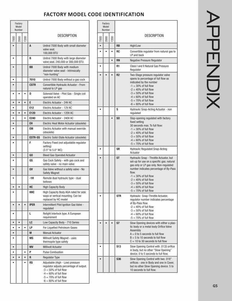
DESCRIPTION
• A Unitrol 7000 Body with small diameter valve seat. 100,000 BTU
• B Unitrol 7000 Body with large diameter valve seat. 240,000 or 300,000 BTU
• BB Unitrol 7000 Body with medium diameter valve seat - Intrinsically “non-hunting”
• 7010 Unitrol 7000 Body without a gas cock
• CSTR Convertible Hydraulic Actuator - From natural to LP gas
• • • D Solenoid Valve - Pilot Gas - Single coil operated on AC
• • • E Electric Actuator - 24V AC
• E12 Electric Actuator - 12V AC
• • • E120 Electric Actuator - 120V AC
• • E240 Electric Actuator - 240V AC
• EH Electric Heat Motor Actuator (obsolete)
• EM Electric Actuator with manual override (obsolete)
• ESTR-SS Electric Solid-State Actuator (obsolete)
• F Factory Fixed (not adjustable regulator setting) (3.5° to 5.0° WC)
• GO Bleed Gas Operated Actuator
• GS Gas Cock Safety - with gas cock and safety valve - no main valve
• GV Gas Valve without a safety valve - No Safety Magnet
• -1H Remote dual hydraulic type - dual bellows
• • HC High Capacity Body
• HHC High Capacity Body AGA rated for side ways or vertical mounting. Can be replaced by HC model
• • • IPER Intermittent Pilot Ignition Gas Valve - regulated
• L Relight Interlock type. A European requirement
• • LC Low Capacity Body - 710 Series
• • • LP For Liquefied Petroleum Gases
• M Manual Actuator
• MS Millivolt Safety Magnet - uses thermopile type safety
• MV Millivolt Actuator
• • P Pulse Combustion
• • • R Regulator Type
• • RS Adjustable (High - Low) pressure regulator adjusts percentage of output.-3 = 50% of full flow-4 = 60% of full flow-5 = 70% of full flow-6 = 80% of full flow
FactoryModel
Number
7000
2000
7200
DESCRIPTION
• RB High/Low
• • • RC Convertible regulator from natural gas to LP and back
• RN Negative Pressure Regulator
• R1 Class I and II Natural Gas Pressure Regulator
• • • R2 Two-Stage pressure regulator valve opens to percentage of full flow as indicated by the number-1 = 30% of full flow-2 = 40% of full flow-3 = 50% of full flow-4 = 60% of full flow-5 = 70% of full flow-6 = 80% of full flow
• S Hydraulic Snap-Acting Actuator - non regulated
• SO Step-opening regulated with factory fixed setting30 seconds max. To full flow:-1 = 30% of full flow-2 = 40% of full flow-3 = 50% of full flow-4 = 60% of full flow-5 = 70% of full flow
• SR Hydraulic Regulated Snap-Acting Actuator
• ST Hydraulic Snap - Throttle Actuator, but set-up for use on a specific gas; natural gas only or LP gas only. Non-regulated number indicates percentage of By-Pass flow.-1 = 30% of full flow-2 = 40% of full flow-3 = 50% of full flow-4 = 60% of full flow-5 = 70% of full flow
• STR Hydraulic Snap-Throttle Actuator, regulator number indicates percentage of By-Pass flow.-2 = 40% of full flow-3 = 50% of full flow-4 = 60% of full flow-5 = 70% of full flow
• • • S7 Slow Opening devices with either a plas-tic body or a metal body Orifice Valve AssemblyA = 0 to 5 seconds to full flowB = 5 to 10 seconds to full flowC = 10 to 30 seconds to full flow
• S13 Slow Opening Control with .0135 orifice in body, but no other “Slow Opening” device. 0 to 5 seconds to full flow.
• S36 Slow Opening Control with two .018” orifices - one in Body and one in Cover, but no other Slow Opening device. 5 to 10 seconds to full flow.
FactoryModel
Number
7000
2000
7200
FACTORY MODEL CODE IDENTIFICATION
AP
PE
ND
IX
G5
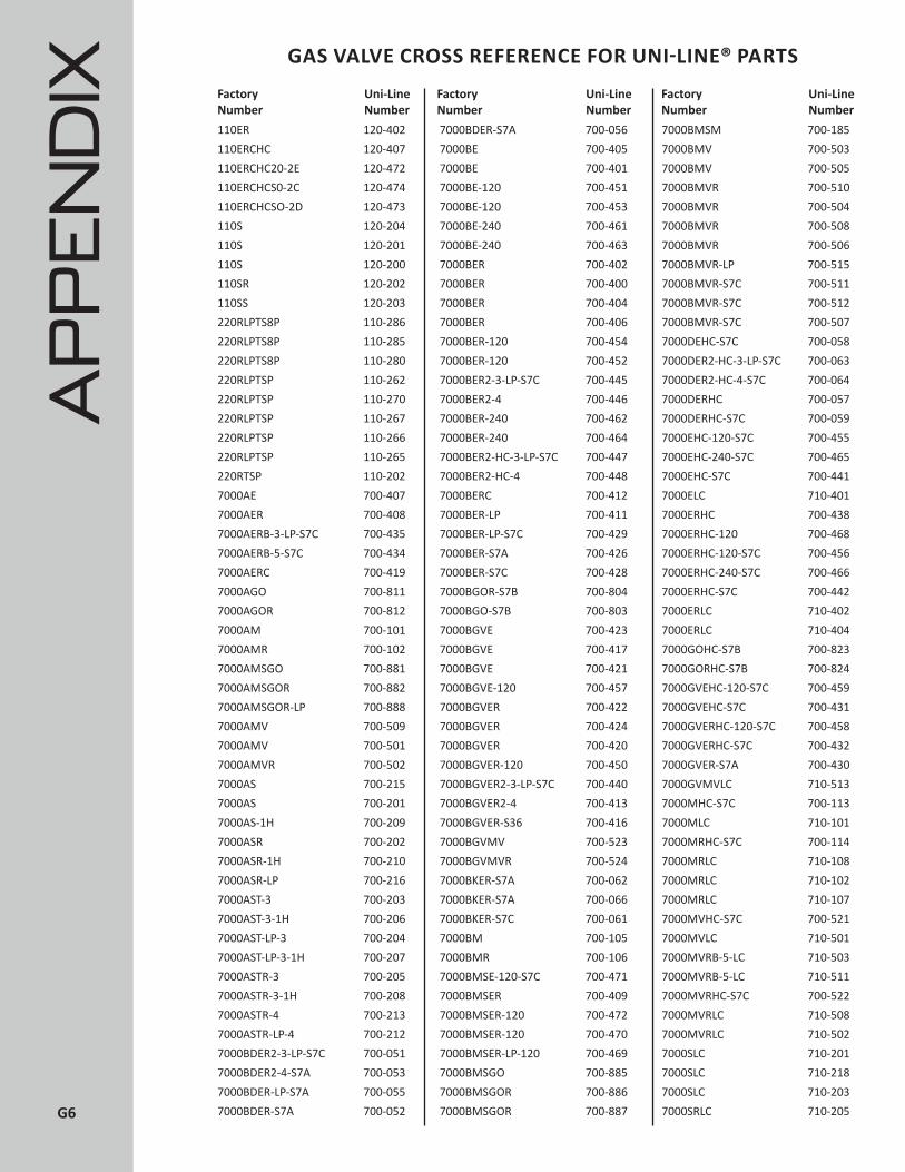
110ER 120-402110ERCHC 120-407110ERCHC20-2E 120-472110ERCHCS0-2C 120-474110ERCHCSO-2D 120-473110S 120-204110S 120-201110S 120-200110SR 120-202110SS 120-203220RLPTS8P 110-286220RLPTS8P 110-285220RLPTS8P 110-280220RLPTSP 110-262220RLPTSP 110-270220RLPTSP 110-267220RLPTSP 110-266220RLPTSP 110-265220RTSP 110-2027000AE 700-4077000AER 700-4087000AERB-3-LP-S7C 700-4357000AERB-5-S7C 700-4347000AERC 700-4197000AGO 700-8117000AGOR 700-8127000AM 700-1017000AMR 700-1027000AMSGO 700-8817000AMSGOR 700-8827000AMSGOR-LP 700-8887000AMV 700-5097000AMV 700-5017000AMVR 700-5027000AS 700-2157000AS 700-2017000AS-1H 700-2097000ASR 700-2027000ASR-1H 700-2107000ASR-LP 700-2167000AST-3 700-2037000AST-3-1H 700-2067000AST-LP-3 700-2047000AST-LP-3-1H 700-2077000ASTR-3 700-2057000ASTR-3-1H 700-2087000ASTR-4 700-2137000ASTR-LP-4 700-2127000BDER2-3-LP-S7C 700-0517000BDER2-4-S7A 700-0537000BDER-LP-S7A 700-0557000BDER-S7A 700-052
7000BDER-S7A 700-0567000BE 700-4057000BE 700-4017000BE-120 700-4517000BE-120 700-4537000BE-240 700-4617000BE-240 700-4637000BER 700-4027000BER 700-4007000BER 700-4047000BER 700-4067000BER-120 700-4547000BER-120 700-4527000BER2-3-LP-S7C 700-4457000BER2-4 700-4467000BER-240 700-4627000BER-240 700-4647000BER2-HC-3-LP-S7C 700-4477000BER2-HC-4 700-4487000BERC 700-4127000BER-LP 700-4117000BER-LP-S7C 700-4297000BER-S7A 700-4267000BER-S7C 700-4287000BGOR-S7B 700-8047000BGO-S7B 700-8037000BGVE 700-4237000BGVE 700-4177000BGVE 700-4217000BGVE-120 700-4577000BGVER 700-4227000BGVER 700-4247000BGVER 700-4207000BGVER-120 700-4507000BGVER2-3-LP-S7C 700-4407000BGVER2-4 700-4137000BGVER-S36 700-4167000BGVMV 700-5237000BGVMVR 700-5247000BKER-S7A 700-0627000BKER-S7A 700-0667000BKER-S7C 700-0617000BM 700-1057000BMR 700-1067000BMSE-120-S7C 700-4717000BMSER 700-4097000BMSER-120 700-4727000BMSER-120 700-4707000BMSER-LP-120 700-4697000BMSGO 700-8857000BMSGOR 700-8867000BMSGOR 700-887
7000BMSM 700-1857000BMV 700-5037000BMV 700-5057000BMVR 700-5107000BMVR 700-5047000BMVR 700-5087000BMVR 700-5067000BMVR-LP 700-5157000BMVR-S7C 700-5117000BMVR-S7C 700-5127000BMVR-S7C 700-5077000DEHC-S7C 700-0587000DER2-HC-3-LP-S7C 700-0637000DER2-HC-4-S7C 700-0647000DERHC 700-0577000DERHC-S7C 700-0597000EHC-120-S7C 700-4557000EHC-240-S7C 700-4657000EHC-S7C 700-4417000ELC 710-4017000ERHC 700-4387000ERHC-120 700-4687000ERHC-120-S7C 700-4567000ERHC-240-S7C 700-4667000ERHC-S7C 700-4427000ERLC 710-4027000ERLC 710-4047000GOHC-S7B 700-8237000GORHC-S7B 700-8247000GVEHC-120-S7C 700-4597000GVEHC-S7C 700-4317000GVERHC-120-S7C 700-4587000GVERHC-S7C 700-4327000GVER-S7A 700-4307000GVMVLC 710-5137000MHC-S7C 700-1137000MLC 710-1017000MRHC-S7C 700-1147000MRLC 710-1087000MRLC 710-1027000MRLC 710-1077000MVHC-S7C 700-5217000MVLC 710-5017000MVRB-5-LC 710-5037000MVRB-5-LC 710-5117000MVRHC-S7C 700-5227000MVRLC 710-5087000MVRLC 710-5027000SLC 710-2017000SLC 710-2187000SLC 710-2037000SRLC 710-205
Uni-Line Number
GAS VALVE CROSS REFERENCE FOR UNI-LINE® PARTS
Factory Number
Uni-Line Number
Factory Number
Uni-Line Number
AP
PE
ND
IX Factory Number
G6

7000SRLC 710-2047010BGVER 700-4187010BGVMV 700-5177010BGVMV 700-5147010BGVMV 700-5137010BGVMV 700-5137100DER 700-0777100DERB-5-S02 700-0787100DER-LP-S7C 700-0737100DER-LP-S7C 700-0717100DERN 700-0747100DERP 700-0767100DER-S7C 700-0707100DER-S7C 700-0727200DER 720-0517200DERB-5-SO-2 720-0787200DERCS-1 720-0557200DERN 720-0747200DER-S7C 720-0507200DER-S7C 720-052
7200DER-SO-3 720-0547200DER-SO-4-120 720-0837200E 720-4017200ER 720-4027200ER 720-4007200ER 720-4067200ER 720-4047200ERC 720-0077200ERCS-2 720-4727200ERCS-2 720-4747200ER-S7C 720-4037200IPER 720-0797200IPER2-4 720-0827200IPER-LP 720-0807200IPER-LP-S7C 720-0737200IPER-LP-S7C 720-0717200IPER-S7C 720-0727200IPER-S7C 720-0707200IPER-SO-4 720-0817222DER 722-051
7222DERC 722-0537222DER-S7A 722-0527222IPER 722-079R103RCTSLP 110-506R103RCTSLPPA 110-503R103RVTSLP 110-507R103RVTSLP 110-509R103RVTSLPP 110-502R103RVTSLPPA 110-505R103RVTSLPPA 110-501R103RVTSLPPA 110-504R103RVTSLPPA 110-508R110RCTS-PC 110-203R110RCTS-PC 110-204R110RTS 110-326R110RTS8P 110-353R110RTSP 110-206R65RRTSP 110-268
Factory Number
Uni-Line Number
Factory Number
Uni-Line Number
Factory Number
Uni-Line Number
401XM 41-224501A 41-204501A 41-205501A 41-2097000BGOR-S7B 700-8047000BMSGOR 700-8867000BMSGOR 700-887BJWA25PB-02-48 4350-015BJWA25PC-09-36 4350-028BJWA25PD-10-48 4350-040BJWA25PM-02-48 4350-127BJWA25PM-03-48 4350-128BJWA25PM-11-48 4350-027BJWA44TC-12-36 4350-029D1-32-060-59-00 5000-851D1-C5-060-59-00 5000-811EA3-44-36 5300-100FDH-1-06-48 4200-508FDO-1-04-48 4200-007FDO-1-07-48 4200-005FDO-3-05-54 4200-025FDTH-1-05-48 4200-505FDTH-1-06-48 4200-503FDTH-3-06-54 4200-026FDTO-1-05-48 4200-011FJT-102-1040 4075-029FJTDO-13 4075-200GS-A6-030-18-00 4290-006
GS-C8-060-00-00 4290-008GS-J1-036-00-00 4290-020INF-120-1152 5500-134INF-120-1152 5500-135INF-240-1153 5500-234INF-240-1153 5500-235INF-240-597 5500-202INF-240P-1047 5500-287INF-240P-1148 5500-212INF-240PX-803 5500-200KA-601-36 5300-015KA-601-72 5300-088KA-604-48 5300-027KNP-6-36 5300-502KX-161-24 5300-766KX-299 5300-401KX-396 5300-402KX-87-36 5300-711KXP-149-60 5300-735LCC-36-060-00-00 5225-010LCH-37-030-00-00 5225-009LCH-68-024-00-00 5225-047LCH-J6-024-00-00 5225-054LCHM-05-030-00-00 5225-112BJWA25PC-01-48 4350-027RX-1-36 5300-401RX-2-24 5300-402RX-6-36 5300-406
S-234-36 5300-175S-23-48 5300-041S-384-36 5300-114SA-245 5300-017SA-382-36 5300-017SJ-157-36 5300-146SJ-328-36 5300-146SM2 41-521SP-184-60 5300-612SP-186-60 5300-614SP-191-60 5300-618SP-192-36 5300-641SP-197-60 5300-651SP-200-60 5300-671SP-390-36 5300-219TS11J-1211-1-0 1720-008TS11J-1311-1-0 1720-005TS11J-3211-1-0 1720-004TS11J-4211-1-0 1720-007Z871470042 5210-125Z950641100 1720-801Z950644100 1720-802
COMMERCIAL COOKING CROSS REFERENCE FOR UNI-LINE® PARTSFactory Number
Uni-Line Number
Factory Number
Uni-Line Number
Factory Number
Uni-Line Number
AP
PE
ND
IX
G7

G8
TERMS AND CONDITIONS OF SALE - NA, SA, ANZ EFFECTIVE NOVEMBER 3, 2014
The following Terms and Conditions are the Terms and Conditions of Sale of the products ("Products") supplied by Robertshaw Controls Company, Robertshaw Canada, Inc., and their affiliates (each hereinafter "Company").
THE TERMS AND CONDITIONS PROVIDED BELOW AND IN ANY ATTACHMENTS HERETO ARE COMPANY'S EXCLUSIVE TERMS AND CONDITIONS OF SALE, SHALL APPLY TO ALL PRODUCTS PROVIDED HEREIN, AND SHALL SUPERSEDE ANY INCONSISTENT, ADDITIONAL OR PREPRINTED TERMS AND CONDITIONS CONTAINED IN DISTRIBUTOR'S PURCHASE ORDER OR ANY OTHER DISTRIBUTOR DOCUMENT. COMPANY DOES NOT AGREE TO ANY PROPOSED ADDITION, MODIFICATION OR DELETION BY DISTRIBUTOR, OR DISTRIBUTOR'S CUSTOMERS, OF THESE TERMS OR TO ANY TERMS OR CONDITIONS SET FORTH IN DISTRIBUTOR'S OR DISTRIBUTOR'S CUSTOMER'S ORDERS. ANY SUCH TERMS AND CONDITIONS ARE HEREBY REJECTED AND CONSIDERED NULL AND VOID.
THESE TERMS AND CONDITIONS CAN BE VARIED ONLY BY A WRITTEN DOCUMENT SIGNED BY COMPANY. COMPANY RESERVES THE RIGHT TO MODIFY THESE TERMS AND CONDITIONS OF SALE AT ANY TIME WITHOUT PRIOR NOTICE TO DISTRIBUTOR. ANY REVISED TERMS AND CONDITIONS, HOWEVER, WILL ONLY AFFECT THOSE ORDERS RECEIVED BY COMPANY AFTER THE EFFECTIVE DATE OF THE REVISION.
Distributor will ensure by its contract with the end user or ultimate owner or its buyer that Company is given the benefit of these Terms and Conditions of Sale, including the exclusions and limitations of liability set forth herein, or as hereafter modified by Company, by all such users, owners and buyers and Distributor will indemnify Company,its officers, directors, shareholders, employees, agents and representatives against any actions, claims, demands, liabilities, damages, losses, costs and expenses including, but not limited to, attorneys and expert witness fees, to the extent that Company would not be liable to Distributor under these Terms and Conditions of Sale if the claim had been made by Distributor. Distributor will ensure that these Terms and Conditions of Sale for the Products are transmitted to its end customer(s) upon resale or transfer of the Product. Accordingly, except as to those terms in Sections I, Distributor Recognition; II, Ordering Information; III, Pricing; IV, Payment Terms; V, Freight and Delivery Terms; VI, Inspection and Acceptance; and VIII, Return Material Authorization, which are exclusive to Distributor, any reference to "Distributor" in these Terms and Conditions shall also include Distributor's customers, transferees, assigns, affiliates, or whoever else takes control or possession of the Product.
I. DISTRIBU TOR RECOGNITION
A. Recognition as a non-exclusive Company distributor is based upon market coverage, product knowledge, and general effectiveness in representing specific Products supplied by Company. Distributor acknowledges that Company may sell directly or to any third party that Company selects as and when Company so desires in its sole and absolute discretion. Distributor represents to Company that Distributor is engaged in business solely as a stocking distributor and its primary customers for Company's Products are HVACR contractors and others who directly engage in the installation and servicing of environmental controls, heating, ventilation and air conditioning controls and equipment. Distributor acknowledges that Company's Products are designed for specific applications and Distributor agrees it shall not market, resell, distribute, or recommend the use of any of Company's Products in any application where the use of the Product is not as intended or designed by Company or does not conform to Company's specifications for use, and shall indemnify Company, its officers, directors, shareholders, employees, agents and representatives for all such unauthorized use. Company shall have no responsibility, and/or liability and the Product Warranty set forth herein shall be void, if Distributor uses or recommends the use of any Product for any application for which it is not intended or designed.
B. Distributor agrees that Company's arrangement with Distributor can be terminated by Company with or without cause, upon fourteen (14) days notice unless otherwise agreed in writing by Company and Distributor. In the event of termination, all of the goodwill and other proprietary and intellectual rights in and to Company's Products shall remain the sole property of Company. Distributor will not be entitled to any compensation or payments including, but not limited to, expenses, lost profits, sales or revenue, loss of goodwill or otherwise, as a result of Company's termination.
C. Distributor agrees to provide a credit application and Tax Resale Certificate, if applicable, to Company's Credit Department to obtain credit approval in order to set up Distributor's account. Distributor also agrees to periodically furnish Company, at Company's request, updated financial information. Recognized distributors must maintain minimum annual net purchases of $5,000 USD or CND, respectively.
II. ORDERING INFORMATION
A. Company will only accept orders from its recognized Distributors, or the Distributor's recognized branches. Possession of Company's product catalog or Price Schedule does not constitute authority or right to purchase items directly from Company.
B. To submit orders, please fax order to: USA and Canada 800.426.0804
International 951.737.8261
C. Orders must state Distributor's account number, ship to address, catalog part number, item description, quantity ordered and unit price. Orders will not be processed without this information confirmed in writing by Distributor.
D. Order changes by Distributor must be made in writing, or verified in writing, before Company can complete processing of the order, and shall be subject to the terms of Section V below.
E. All Products may be combined in a single order for best pricing and freight terms.
F. Products carrying the footnote "@" are only available in the multiples shown. Some items are also noted with a required minimum purchase quantity that must be followed. Company reserves the right to increase the order quantity in compliance to item minimums and multiples without authorization by Distributor or to refuse to accept the order.
G. A minimum net billing of $100 USD or CND, respectively, per order, per branch drop shipment applies (excluding freight and/or applicable taxes).
H. Orders will only be accepted for shipment to one destination. Portions of orders for shipment to other addresses will be considered separately for pricing, freight, and item minimum and multiple requirements.
I. Drop shipments to destinations other than a recognized Distributor's address, or its recognized branch address, will require approval based solely at the discretion of Company. If approved, additional charges may apply. Standard order terms and requirements will apply.
J. Nothing in these Terms and Conditions of Sale requires or is intended to require Company to accept any purchase order from Distributor, and Company shall have no liability to Distributor or to any third party in the event Company decides not to accept any order.
K. All orders are final once shipped to Distributor.
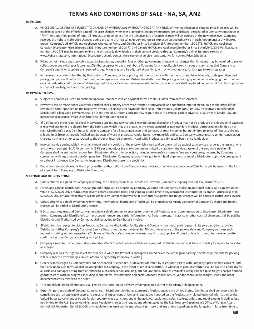
G9
TERMS AND CONDITIONS OF SALE - NA, SA, ANZIII. PRICING
A. PRICES ON ALL ORDERS ARE SUBJECT TO CHANGE OR WITHDRAWAL WITHOUT NOTICE AT ANY TIME. Written notification of pending price increases will be made in advance of the effective date of the price change, whenever practicable. Except where prices are specifically designated in Company's quotation as "Firm" for a specified period of time, all Products shipped on or after the effective date of a price change will be invoiced at the new price level. Company reserves the right to make price changes during the term of an existing Agreement (unless expressly agreed otherwise in such Agreement) or any blanket orders. Company's US HVACR and Appliance Wholesaler Policy and Distributor Price Schedule 157, literature number 150-2476, HVACR and Appliance Canadian Distributor Price Schedule C153, literature number 150-2477, and Canada HVACR and Appliance Distributor Price Schedule C153-BMS, literature number 150-2478 may be ordered online or electronically downloaded in their current versions through Company's online literature service at www.Robertshaw.com. International Distributors should contact their customer service representative for current Price Schedules.
B. Prices do not include any applicable taxes, excises, duties, quotation fees or other government charges or surcharges that Company may be required to pay or collect under any existing or future law. Distributor agrees to pay or reimburse Company for any applicable taxes, charges or surcharges that Company or Company's agents or suppliers are required to pay. Prices may also be adjusted at any time, with or without notice, for changes in exchange rates.
C. In the event any order submitted by Distributor to Company contains pricing not in accordance with the then-current Price Schedule, or its special quoted pricing, Company will notify Distributor of the discrepancy in price and Distributor shall correct the pricing in writing by either acknowledging the correction on a revised order confirmation, a pricing approval form, or by submitting a new order to Company. All orders shall be placed on hold until Distributor provides written acknowledgment of correct pricing.
IV. PAYMENT TERMS
A. Subject to Company's Credit Department approval, standard invoice payment terms are Net 30 days from date of shipment.
B. Payments can be made either via check, certified check, money order, wire transfer, or irrevocable and confirmed letter of credit, paid to the order of the remittance name specified on the respective invoice. All billings and payments shall be in United States Dollars (USD) or CND, respectively. International Distributor's billings and payments shall be in the agreed currency. Company may require check in advance, cash in advance, or a Letter of Credit (LOC) on international accounts, which Distributor shall furnish upon request.
C. If Distributor's order requires check in advance, supplies and raw materials may not be purchased and Product may not be produced or shipped until payment is received and funds are cleared from the bank upon which they are drawn. In the event standard or non-standard Product is produced and funds do not clear Distributor's bank, Distributor is liable to Company for all associated costs and damages thereof including, but not limited to, price of Products already shipped (plus freight charges); finished goods; costs of work-in-progress, vendor items, raw materials and parts Company cannot return, vendor cancellation charges, if any and other costs related to the order or incurred therewith. Applicable Product lead-times will begin once funds clear.
D. Invoices are due and payable in one installment and any portion of the price which is not paid on time shall be subject to a service charge at the lesser of one and one half percent (1-1/2%) per month (18% per annum), or the maximum rate permitted by law, from the due date until the amount is paid in full. Company shall be entitled to recover from Distributor all costs for collection, including reasonable attorneys fees and court costs, incurred by Company in connection with any amount due Company from Distributor. Company reserves the right to withhold shipments or require Distributor to provide prepayment or a check in advance if, in Company's judgment, Distributor presents a credit risk.
E. Deductions are not allowed without prior written authorization from Company. Any invoice corrections or money owed Distributor will be issued in the form of a credit from Company to Distributor's account.
V. FREIGHT AND DELIVERY TERMS
A. Unless otherwise agreed by Company in writing, the delivery terms for all orders are Ex works (Company's shipping point) (EXW, Incoterms 2010).
B. For US and Canada Distributors, regular ground freight will be prepaid by Company via carrier of Company's choice on individual orders with a minimum net value of $2,500.00 USD or CND, respectively, before applicable taxes, and shipping at one time to any recognized Distributor or its branch. Orders less than $2,500.00 USD or CND, respectively, will be prepaid by Company but will be at Distributor's expense and freight charges will be added to Distributor's invoice.
C. Unless otherwise agreed by Company in writing, international Distributor's freight will be prepaid by Company via carrier of Company's choice and freight charges will be added to Distributor's invoice.
D. If Distributor requests and Company agrees, in its sole discretion, to arrange for shipment of Products as an accommodation to Distributor, Distributor must furnish Company with Distributor's carrier account number and carrier information. All freight, storage, insurance or other costs of shipment shall be paid by Distributor and, if advanced by Company, shall be added to Distributor's invoice.
E. Distributor may request to pick up Product at Company's distribution facility site and Company may honor such request, in its sole discretion, provided Distributor notifies Company's Customer Service Department at least forty-eight (48) hours in advance of the pick-up date and Company confirms such request in writing within twenty-four (24) hours of Distributor's notice. In no event may Distributor pick up Product unless Distributor has received written confirmation from Company allowing such pick up.
F. Company agrees to use commercially-reasonable efforts to meet delivery schedules requested by Distributor, but shall have no liability for failure to do so for any reason.
G. Company reserves the right to select the manner in which the Product is packaged. Quoted prices include regular packing. Special requirements for packing will be subject to extra charges, unless otherwise agreed by Company in writing.
H. Orders acknowledged by Company may not be canceled or amended, or deliveries deferred by Distributor, except with Company's prior written consent, and then only upon such terms as shall be acceptable to Company. In the event of order cancellation, in whole or in part, Distributor shall be liable to Company for all costs and damages arising from or related to such cancellation including, but not limited to, price of Products already shipped (plus freight charges finished goods; costs of work-in-progress, including vendor items, raw materials and parts Company cannot return, vendor cancellation charges, if any and other documented costs related to the order.
I. Title and risk of loss to all Products shall pass to Distributor upon delivery by Company to a carrier at Company's shipping point.
J. Export/Import and Code of Conduct Compliance. If Distributor distributes Company's Product outside the United States, Distributor shall be responsible for compliance with all applicable export, re-export and import control laws and regulations imposed on the Product; any related technical information by the United States government or by any foreign country; trade sanctions and embargo laws, regulations, rules, licenses, orders and requirements including, but not limited to, the U.S. Export Administration Regulations, rules and regulations administered by the U.S. Treasury Department's Office of Foreign Assets Control, EU Regulation No. 428/2009, any regulations in force within any relevant territory, and any orders issued under the foregoing in force from time to

G10
TERMS AND CONDITIONS OF SALE - NA, SA, ANZ time. Distributor shall obtain all validated governmental authorizations or licenses, as required. Upon Company's request, Distributor shall furnish statements certifying such compliance either annually or on a per-order basis and shall cooperate in any audit or inspection related to applicable export or import control laws or regulations. Distributor shall comply with the Robertshaw Supplier Code of Conduct and the Robertshaw Code of Conduct, including their Anti-Bribery provisions, copies of both of which are available upon request to Company. Distributor and shall indemnify and hold Company and its directors, officers, shareholders, employees, agents and representatives harmless for any and all liability including, but not limited to, any and all fines, penalties, losses, costs, damages or expenses (including attorneys', expert and witness fees) incurred by Company as a result of, or relating to, Distributor's noncompliance with the terms herein.
K. Harmonized Tariff Schedule (HTS) and export classification numbers such as Schedule B, ECCN, and the like, if provided by Company, represent solely an opinion of Company. Under no circumstances shall Company be liable whatsoever for the validity or any inaccuracies therein. Distributor shall be solely responsible for ensuring the proper classifications are declared on the shipment documents and to the relevant authorities. Company urges Distributor to consult with a subject matter expert, such as an attorney or a licensed Freight Forwarder, to review and determine the correct classification for the imported/ exported Products.
VI. INSPECTION AND ACCEPTANCE
A. Distributor shall inspect all deliveries within two (2) business days of receipt. In the event there is damage to Product or shortage of Product, Distributor shall notify the carrier and Company within the two (2) business-day period and provide a copy of the signed packing list noting the damage or shortage thereon. All other Products shall be deemed to have been finally inspected and accepted by Distributor within ten (10) days after date of invoice, unless a written notice of claim is given by Distributor to Company within the 10-day period. This ten (10) day period applies to all other discrepancies, including discrepancies in invoicing, shortage or damage, and excludes shortage in shipment caused by carrier or damaged shipment caused by carrier, as provided above, which requires two (2) business days notice. No Product subject to a claim may be returned without the prior authorization of Company. Authorized return shipments must be sent to Company accompanied by a packing slip, and include Company's Return Materials Authorization (RMA) Number, purchase order number, Company's invoice number, the number of cartons and items received, condition of cartons and any other relevant facts that would be helpful in tracing the cause of the discrepancy, and must have transportation charges prepaid.
B. Company will verify all reports of shipping discrepancies and, where applicable, will issue a credit invoice. No prior debits will be accepted.
VII. WARRANTY
A. Warranty
1. Company warrants its standard Products listed in the then-current Distributor Price Schedule to be free from defects in workmanship and material under normal use and service and to perform substantially in accordance with published Company specifications (subject to reasonable tolerances) in effect at the time of acceptance of Distributor's order, for a period of twelve (12) months from the date the Product is placed in use (proof of installation is required), or eighteen (18) months from the date of manufacture, whichever occurs first (the "Warranty Period").
2. Exceptions from the Warranty stated above:
Some Products may contain extended warranties. Please refer to the Product's documentation for specific warranty coverage, if applicable. • Plastic items are not warranted for failure after installation in a machine or assembly. • Product subjected to abuse or damage is not warranted. Abuse or damage may be indicated by, but not limited to, one or more of the following: Burned contacts Abuse or tampering Stripped threads Missing parts Water or fire damage Improper installation or application Split castings
3. Products that fail during the Warranty Period and otherwise qualify under the terms of Company's Warranty will, in Company's sole discretion, be (i) credited to Distributor's account at Distributor's lowest net invoice amount, (ii) repaired, or (iii) replaced provided that the Products are returned to Distributor pursuant to Section VIII(B) below. Payment deductions for warranty returns are not allowed. In no event shall the warranty claim exceed the Product price allocated to the Distributor's lowest net invoice price over either the previous twelve (12) months, or since inception of an Agreement between Company and Distributor, if any, whichever is less. If a returned Product is determined by the Company, in its sole discretion, to fall under the Warranty above, and if Distributor has requested on the packing list that a replacement Product be sent to Distributor, then Company will issue a replacement Product in lieu of issuing a credit to Distributor. Company reserves the right to supply suitable substitutes for Warranty Products that are not currently in production or otherwise available. Costs of Product removal or reinstallation, including labor, are not the responsibility of Company and not included in the Warranty.
4. THIS EXPRESS WARRANTY IS IN LIEU OF AND EXCLUDES ALL OTHER EXPRESS OR IMPLIED WARRANTIES, GUARANTEES, OR REPRESENTATIONS, BY OPERATION OF LAW OR OTHERWISE INCLUDING, BUT NOT LIMITED TO, THE IMPLIED WARRANTIES OF MERCHANTABILITY, TITLE, AND FITNESS FOR A PARTICULAR PURPOSE. COMPANY SHALL NOT BE LIABLE FOR ANY CONSEQUENTIAL, INCIDENTAL, SPECIAL, INDIRECT OR PUNITIVE DAMAGES OF ANY NATURE WHATSOEVER INCLUDING, BUT NOT LIMITED TO, LOST SALES, LOST REVENUES OR PROFITS, LOSS OF USE, OR GOODWILL ARISING OUT OF OR RESULTING FROM THE USE OR INABILITY TO USE COMPANY'S PRODUCTS. ANY STATEMENTS OR REPRESENTATIONS MADE BY OTHER PERSONS, ENTITIES, OR ANY THIRD PARTIES ARE SPECIFICALLY DISCLAIMED AND SHALL BE NULL AND VOID.
5. THE FOREGOING REMEDY SHALL BE THE DISTRIBUTOR'S SOLE AND EXCLUSIVE REMEDY AND COMPANY'S SOLE OBLIGATION FOR FAILURE OF PRODUCT TO CONFORM TO THE WARRANTY. B. Return for Warranty Consideration 1. All Products to be considered for warranty must be returned to Company with freight and transportation charges prepaid.
2. Product returned to Company must be packaged in such a manner that will prevent any further damage to the Product during transit. The Warranty terms above shall not apply to any items damaged in transit.
3. An itemized packing slip, including Distributor's name and address, is required for each shipment to Company of Product(s) to be considered for warranty. The packing slip must contain a reference number, items and their quantities being returned, reason for warranty return, date of installation, date of failure, and a contact name at the Distributor in case further information is required.
4. For Distributors within North America (USA and Canada), all cartons must be clearly identified as WARRANTY PRODUCT and returned to: USA Distributors: Canada Distributors: Warranty Department Warranty Department Robertshaw Robertshaw 1921 Anei Circle 4060 Ridgeway Drive, Unit 14 Brownsville, TX 78521 Mississauga, ON L5L5X9

G11
TERMS AND CONDITIONS OF SALE - NA, SA, ANZ For International Distributors, please contact your customer service representative for return authorization and procedures.
C. Inspection of Product 1. Company will inspect each item to confirm that the returned Product qualifies for the Warranty in Section VII. If the inspection by Company does not disclose any defect covered by the Warranty, then Company shall notify Distributor accordingly and the Distributor has the option to request Company to scrap the Product or return it at Distributor's expense. AT COMPANY'S OPTION, COMPANY MAY SCRAP THE PRODUCT WITH NO FURTHER LIABILITY TO DISTRIBUTOR, UNLESS DISTRIBUTOR NOTIFIES COMPANY OTHERWISE WITHIN ONE (1) WEEK OF COMPANY'S NOTIFICATION.
2. In the event Distributor sends Company goods that were not manufactured and/or distributed by Company, Company will notify Distributor. Distributor has the option to request Company to scrap the product or return it at Distributor's expense. AT COMPANY'S OPTION, COMPANY MAY SCRAP THE PRODUCT WITH NO FURTHER LIABILITY TO DISTRIBUTOR, UNLESS DISTRIBUTOR NOTIFIES COMPANY OTHERWISE WITHIN ONE (1) WEEK OF COMPANY'S NOTIFICATION.
D. Final disposition of any warranty claim shall be determined solely by Company and shall be final and binding.
VIII. RETURN MATERIAL AUTHORIZATION (FOR NEW AND UNUSED PRODUCT RETURNS)
A. Returns will not be accepted, nor credits given, without a factory authorized Return Materials Authorization (hereinafter "RMA"). RMAs are only issued to the original point of purchase location for current manufactured and/or distributed items that fall within the Warranty terms and have been purchased within the previous twelve months. Returns will not be accepted for special order or non-stock items (as indicated in the Price Schedule).
B. In order to request an RMA number, Distributors must provide the invoice number, sales order number (or customer's purchase order number), the item numbers and quantities of Products they wish to return, and the reason for return to their Sales or Customer Service Representative.
C. RMA Processing 1. The RMA number is valid only if the Product it refers to is received at the address specified on the RMA form, freight and transportation charges prepaid, within fourteen (14) days from the date of Company's-issued authorization. Company may reject the request if Product is received after fourteen (14) days from the date of Company's-issued authorization.
2. The Product must be received in its original saleable condition (including all accessories and inserts), in its original packaging, and undamaged. Damaged Product will not be accepted for return or replacement, even if a RMA number has been issued.
3. Credit for the return will be based on the lowest net invoice amount for the Distributor over the last 12 months, or per the Agreement between Company and Distributor, if any, unless proof of purchase for the actual shipped Product is provided.
4. All returns are subject to a minimum fifteen percent (15%) restock charge or $15.00 USD, whichever is greater. Company will not accept returns that do not have a proper RMA or are sent to Company in error.
IX. DISCONTINUED PRODUCTS
A. Company reserves the right to discontinue distribution of any Product without notice, or substitute material or complete devices, when items ordered are not currently in production or otherwise available.
X. PERMISSIBLE VARIATIONS
A. Company may, prior to the delivery of Product to Distributor, make changes in the Product including, but not limited to, changes to the model, design, component parts or dimensions. In addition, Company may make any change or variation in the Product that is within industry, government or professional organization standards or specifications applicable at the time of manufacture, without notice to Distributor. Distributor hereby agrees to accept any Product that may incorporate any such changes or variations, and any increase in price resulting from such changes or variations will be for the account of Distributor.
XI. FORCE MAJEURE
A. Company shall not be liable for any delay or failure in performance, or for any damages suffered by the Distributor by reason of such delay, if caused or arising directly or indirectly from any act beyond Company's reasonable control including, but not limited to, acts of God; vandalism; sabotage; accidents; fires; floods; strikes or other labor disputes; mechanical breakdowns; shortages or delays in obtaining suitable parts, equipment, material, labor, power or transportation; acts of suppliers; interruption of utility services; acts of terrorism, or acts of any unit or agency of government. Any delays so occasioned shall affect a corresponding extension of Company's performance dates that are, in any event, understood to be approximate.
XII. LIMITATION OF LIABILITY
Notwithstanding any other provision in these Terms and Conditions, Company's liability shall be limited as follows:
A. IN NO EVENT SHALL COMPANY BE LIABLE FOR ANY CONSEQUENTIAL, INDIRECT, INCIDENTAL, SPECIAL OR PUNITIVE DAMAGES INCLUDING, BUT NOT LIMITED TO, LOSS OF SALES, PROFITS OR REVENUE, LOSS OF USE, LOSS OF GOODWILL OR INCREASE IN OPERATING COSTS.
B. IN NO EVENT SHALL COMPANY'S LIABILITY EXCEED THE AMOUNT PAID TO COMPANY FOR THE PRODUCT FOR THE QUANTITIES OF COMPANY'S PRODUCTS GIVING RISE TO ANY SUCH LIABILITY, EXCEPT WITH RESPECT TO THIRD-PARTY CLAIMS FOR PERSONAL INJURY, WHICH SHALL BE LIMITED TO COMPENSATION FOR SUCH PERSONAL INJURY.
C. COMPANY SHALL NOT BE LIABLE TO DISTRIBUTOR FOR ANY CLAIMS, DAMAGES, EXPENSES, FEES, COSTS, LOSSES, CAUSES OF ACTION, OR SUITS WHICH ARISE OUT OF OR RELATE TO THE SALE OF PRODUCT DUE TO THE DIRECTION, NEGLIGENCE, ACT, OMISSION, OR USE OF THE PRODUCT IN A MANNER NOT SPECIFICALLY AUTHORIZED, INTENDED OR DESIGNED BY COMPANY, WILLFUL MISCONDUCT, OR OTHER FAULT OF ANY NATURE WHATSOEVER OF DISTRIBUTOR, ITS EMPLOYEES, AGENTS, SERVANTS, CUSTOMERS, OR END USERS.
D. THE ABOVE LIMITATIONS OF LIABILITY SHALL APPLY EVEN IF COMPANY HAS BEEN ADVISED OF THE POSSIBILITY OF SUCH DAMAGES, AND REGARDLESS WHETHER THE CLAIM FOR RECOVERY IS BASED ON BREACH OF WARRANTY OR CONTRACT, NEGLIGENCE, INFRINGEMENT, STRICT LIABILITY OR OTHER TORT.
E. THE RIGHT TO RECOVER DAMAGES WITHIN THE LIMITATIONS SPECIFIED ABOVE IS THE DISTRIBUTOR'S EXCLUSIVE ALTERNATIVE REMEDY IN THE EVENT THAT ANY OTHER CONTRACTUAL REMEDY FAILS OF ITS ESSENTIAL PURPOSE.
XIII. CONFIDENTIALITY
A. Company's Price Schedules, quotes and any discounts contained herein are considered confidential and/or proprietary information of Company and Distributor shall in no instance share any Price Schedules or discounts, business discussions, financial information, or other confidential and/or proprietary information of Company with any other person, group, entity, or third party.
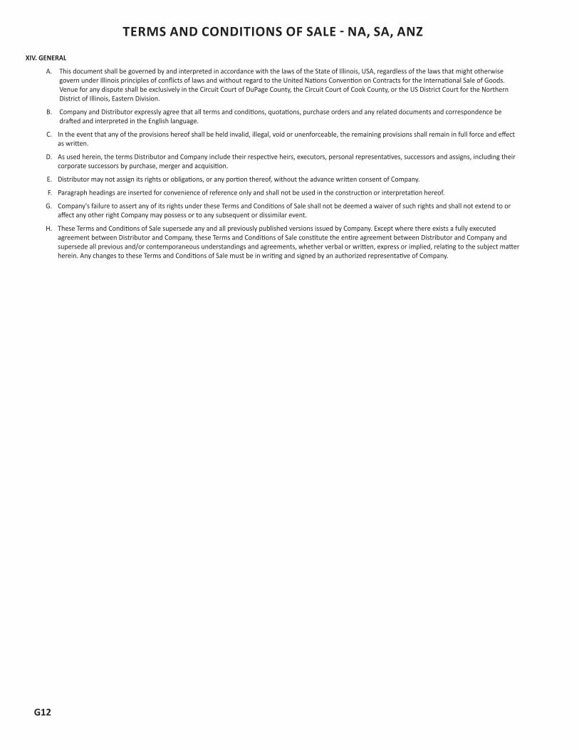
G12
TERMS AND CONDITIONS OF SALE - NA, SA, ANZ
XIV. GENERAL
A. This document shall be governed by and interpreted in accordance with the laws of the State of Illinois, USA, regardless of the laws that might otherwise govern under Illinois principles of conflicts of laws and without regard to the United Nations Convention on Contracts for the International Sale of Goods. Venue for any dispute shall be exclusively in the Circuit Court of DuPage County, the Circuit Court of Cook County, or the US District Court for the Northern District of Illinois, Eastern Division.
B. Company and Distributor expressly agree that all terms and conditions, quotations, purchase orders and any related documents and correspondence be drafted and interpreted in the English language.
C. In the event that any of the provisions hereof shall be held invalid, illegal, void or unenforceable, the remaining provisions shall remain in full force and effect as written.
D. As used herein, the terms Distributor and Company include their respective heirs, executors, personal representatives, successors and assigns, including their corporate successors by purchase, merger and acquisition.
E. Distributor may not assign its rights or obligations, or any portion thereof, without the advance written consent of Company.
F. Paragraph headings are inserted for convenience of reference only and shall not be used in the construction or interpretation hereof.
G. Company's failure to assert any of its rights under these Terms and Conditions of Sale shall not be deemed a waiver of such rights and shall not extend to or affect any other right Company may possess or to any subsequent or dissimilar event.
H. These Terms and Conditions of Sale supersede any and all previously published versions issued by Company. Except where there exists a fully executed agreement between Distributor and Company, these Terms and Conditions of Sale constitute the entire agreement between Distributor and Company and supersede all previous and/or contemporaneous understandings and agreements, whether verbal or written, express or implied, relating to the subject matter herein. Any changes to these Terms and Conditions of Sale must be in writing and signed by an authorized representative of Company.
G13
TERMS AND CONDITIONS OF SALE - EUROPEThe following are the Terms and Conditions of Sale of Robertshaw s.r.o., a Czech Republic company (the “Company”), for those of its products it may agree to sell for distribution (“Products”).
THESE TERMS AND CONDITIONS ARE COMPANY’S EXCLUSIVE TERMS AND CONDITIONS OF SALE BETWEEN COMPANY AND DISTRIBUTOR, AND SHALL APPLY TO ALL PRODUCTS ILLUSTRATED HEREIN AND SUPERSEDE ANY INCONSISTENT, ADDITIONAL, PREPRINTED OR OTHER TERMS AND CONDITIONS CONTAINED IN DISTRIBUTOR’S PURCHASE ORDER OR ANY OTHER DISTRIBUTOR DOCUMENT OR ANY DOCUMENTS DERIVED FROM THE DISTRIBUTOR’S CUSTOMERS AND COMPANY DOES NOT AGREE TO ANY ADDITION, MODIFICATION OR DELETION OF THESE TERMS AND CONDITIONS. ANY OTHER TERMS AND CONDITIONS ARE HEREBY REJECTED AND CONSIDERED NULL AND VOID. THESE TERMS AND CONDITIONS CAN BE VARIED ONLY BY A WRITTEN DOCUMENT SIGNED BY COMPANY. COMPANY RESERVES THE RIGHT TO MODIFY THESE TERMS AND CONDITIONS OF SALE AT ANY TIME WITHOUT PRIOR NOTICE TO DISTRIBUTOR. ANY REVISED TERMS AND CONDITIONS, HOWEVER, WILL ONLY AFFECT THOSE ORDERS RECEIVED BY COMPANY AFTER THE EFFECTIVE DATE OF THE REVISION.
Distributor will ensure by its contract with the end user or ultimate owner or its buyer of the Products, that Company is given the benefit of these Terms and Conditions of Sale, including the exclusions and limitations of liability set forth herein, or as hereafter modified by Company, by all such users, owners and buyers and Distributor will indemnify Company, its officers, directors, shareholders, employees, agents and representatives against any actions, claims, demands, liabilities, damages, losses, costs and expenses including, but not limited to, legal and expert witness fees, to the extent that Company would not be liable to Distributor under these Terms and Conditions of Sale if the claim had been made by Distributor. Accordingly, except as to those terms in Sections I, Distributor Recognition; II, Ordering Information; III, Pricing; IV, Payment Terms; V, Freight and Delivery Terms; VI, Inspection and Acceptance; and VIII, Return Material Authorization, which are exclusive to Distributor, any reference to “Distributor” in these Terms and Conditions shall also include Distributor’s customers, transferee’s, assigns, affiliates, or whoever else takes control or possession of the Product.
I. DISTRIBUTOR RECOGNITION
A. Recognition as a non-exclusive Company distributor is based upon market coverage, product knowledge, and general effectiveness in representing specific products supplied by Company. Distributor acknowledges that Company may sell directly or to any third party that Company selects as and when Company so desires, at Company’s sole and absolute discretion. Distributor represents to Company that Distributor is engaged in business solely as a stocking distributor and its primary customers for Company’s Products are “HVACR” contractors and others who directly engage in the installation and servicing of environmental controls, heating, ventilation and air conditioning controls and equipment. Distributor acknowledges that Company’s Products are designed for specific applications and Distributor agrees it shall not market, resell, distribute, or recommend the use of any of Company’s Products in any application where the use of the Product is not as intended or designed by Company or does not conform to Company’s specifications for use, and shall indemnify Company, its officers, directors, shareholders, employees, agents and representatives for all such unauthorized use.
Company shall have no responsibility and/or liability and the Product Warranty set forth herein shall be void, if Distributor uses or recommends the use of any Product for any application for which it is not intended or designed.
B. Distributor agrees that Company’s arrangement with Distributor can be terminated by Company with or without cause, upon fourteen (14) days’ notice unless otherwise agreed in writing by Company and Distributor. In the event of termination, all of the goodwill and other proprietary and intellectual rights in and to Company’s Products shall remain the sole property of Company. Distributor will not be entitled to any compensation or payments including, but not limited to, expenses, lost profits, sales or revenue, loss of (or Company’s gain of) goodwill or otherwise, as a result of Company’s termination.
C. Distributor agrees to provide a credit application to Company’s Credit Department to obtain credit approval in order to set up Distributor’s account. Distributor also agrees to periodically furnish Company, at Company’s request, updated financial information. Recognized distributors must maintain minimum annual net purchases of €5,000.
II. ORDERING INFORMATION
A. Company will only accept orders from its recognized Distributors, or the Distributor’s recognized branches. Possession of Company’s product catalog or Price Schedule does not constitute authority or right to purchase items directly from Company.
B. To submit orders, please fax order to: +420 587 805 241
C. Orders must state Distributor’s account number, ship to address, catalogue part number, item description, quantity ordered and unit price. Orders will not be processed without this information confirmed in writing by Distributor.
D. Order changes by Distributor must be made in writing, or verified in writing, before Company can complete processing of the order, and shall be subject to the terms of Section V below.
E. All Products may be combined in a single order for best pricing and freight terms.
F. Products carrying the footnote “@” are only available in the multiples shown. Some items are also noted with a required minimum purchase quantity that must be followed. Company reserves the right to increase the order quantity in compliance to item minimums and multiples without authorization by Distributor, or to refuse to accept the order.
G. A minimum net billing of €100 per order, per branch drop shipment applies (excluding freight and/or applicable taxes).
H. Orders will only be accepted for shipment to one destination. Portions of orders for shipment to other addresses will be considered separately for pricing, freight, and item minimum and multiple requirements.
I. Drop shipments to destinations other than a recognized Distributor’s address, or its recognized branch address, will require approval based solely at the discretion of Company. If approved, additional charges may apply. Standard order terms and requirements will apply.
J. Nothing in these Terms and Conditions of Sale requires or is intended to require or shall be construed by Distributor as requiring Company to accept any purchase order from Distributor, and Company shall have no liability to Distributor or to any third party in the event Company decides not to accept any order. K. All orders are final once shipped to Distributor.
EFFECTIVE JANUARY 1, 2015

G14
TERMS AND CONDITIONS OF SALE - EUROPE
III. PRICING
A. PRODUCT PRICES ON ALL ORDERS ARE SUBJECT TO CHANGE OR WITHDRAWAL WITHOUT NOTICE AT ANY TIME. Company reserves the right to make price changes during the term of any blanket orders unless prices are specifically designated in Company’s quotation as “firm” for a specified period of time. Company’s Europe HVACR and Appliance Wholesaler Policy and Distributor Price Schedule 001, literature number 150-2527, US HVACR and Appliance Wholesaler Policy and Distributor Price Schedule 157, literature number 150-2476, HVACR and Appliance Canadian Distributor Price Schedule C153, literature number 150-2477, and Canada HVACR and Appliance Distributor Price Schedule C153-BMS, literature number 150-2478 may be ordered online or electronically downloaded in their current versions through Company’s online literature service at www.Robertshaw.com.
B. Prices do not include any applicable taxes, excises, duties, quotation fees or other government charges or surcharges that Company may be required to pay or collect under any existing or future law. Distributor agrees to pay or reimburse Company for any applicable taxes, charges or surcharges that Company or Company’s agents or suppliers are required to pay.
C. In the event any order submitted by Distributor to Company contains pricing not in accordance with Company’s then-current Price Schedule, or its special quoted pricing, Company will notify Distributor of the discrepancy in price and Distributor shall correct the pricing in writing by either acknowledging the correction on a revised order confirmation, a pricing approval form, or by submitting a new order to Company. All orders shall be placed on hold until Distributor provides written acknowledgment of correct pricing.
IV. PAYMENT TERMS
A. Subject to Company’s Credit Department approval, standard invoice payment terms are Net 30 days from date of shipment.
B. Payments can be made either via money order, wire transfer, or irrevocable and confirmed letter of credit, paid to the order of the remittance name specified on the respective invoice. All billings and payments shall be in Euros (EUR) or such other currency as Company’s Sales Order Acknowledgment may provide for. Company may require cash in advance or an irrevocable letter of credit, which Distributor shall furnish upon request.
C. Distributor’s order requires payment in advance, supplies and raw materials may not be purchased and Product may not be produced or shipped until payment is received and funds are cleared from the bank upon which they are drawn. In the event standard or non-standard Product is produced and funds do not clear Distributor’s bank, Distributor is liable to Company for all associated costs and damages thereof including, but not limited to: price of Products already shipped (plus freight charges); finished goods; costs of work-in-progress, vendor items, raw materials and parts Company cannot return, vendor cancellation charges (if any) and other costs related to the order or incurred therewith. Applicable Product lead-times will begin once funds clear.
D. Invoices are due and payable in one installment and any portion of the price which is not paid on time shall be subject to a service charge equal to 2% above the EURIBOR rate from time to time in force, from the due date until the amount is paid in full (before and after judgment). Company shall be entitled to recover from Distributor all costs for collection, including reasonable legal fees and court costs incurred by Company in connection with any amount due to the Company from Distributor. Company reserves the right to withhold shipments or require Distributor to provide payment in advance if, in Company’s judgment, Distributor presents a credit risk.
E. Deductions are not allowed without prior written authorization from Company. Any invoice corrections or money owed Distributor will be issued in the form of a credit from Company to Distributor’s account.
V. FREIGHT AND DELIVERY TERMS
A. Unless otherwise agreed by Company in writing, the shipment terms for all orders are Ex works (Company’s premises) (EXW, Incoterms 2010).
B. All freight, storage, insurance or other costs of shipment arising outside of an EXW arrangement shall be paid by Distributor and, if advanced by Company, shall be added to Distributor’s invoice.
C. Company agrees to use commercially-reasonable efforts to meet delivery schedules requested by Distributor and agreed to in Company’s Sales Order Acknowledgment, but shall have no liability for failure to do so for any reason and time for delivery shall not be of the essence.
D. Company reserves the right to select the manner in which the Product is packaged. Quoted prices include regular packing. Special requirements for packing will be subject to extra charges, unless otherwise agreed by Company in writing.
E. Orders acknowledged by Company may not be canceled or amended, or deliveries deferred by Distributor, except with Company’s prior written consent, and then only upon such terms as shall be acceptable to Company. In the event of order cancellation, in whole or in part, Distributor shall be liable to Company for all costs and damages arising from or related to such cancellation including, but not limited to: price of Products already shipped (plus freight charges for finished goods); costs of work-in-progress, including vendor items, raw materials and parts Company cannot return; vendor cancellation charges (if any) and other documented costs related to the order.
F. Title and risk of loss to all Products shall pass to Distributor upon delivery.
G. Code of Conduct Compliance. Distributor shall comply with the Robertshaw Supplier Code of Conduct and the Robertshaw Code of Conduct, including their Anti-Bribery provisions, copies of both of which are available upon request to Company. Distributor shall indemnify and hold Company and its directors, officers, shareholders, employees, agents and representatives harmless for any and all liability including, but not limited to, any and all fines, penalties, losses, costs, damages or expenses (including legal, expert and witness fees) incurred by Company as a result of, or relating to, Distributor’s non-compliance with the terms therein.
H. Harmonized Commodity Descriptions and Codes and export classification numbers if provided by Company, represent solely an opinion of Company. Under no circumstances shall Company be liable whatsoever for the validity or any inaccuracies therein. Distributor shall be solely responsible for ensuring the proper classifications are declared on the shipment documents and to the relevant authorities. It is incumbent on Distributor to consult with a trade compliance expert to review and determine the correct classification for the imported/exported Products.
G15
TERMS AND CONDITIONS OF SALE - EUROPEVI. INSPECTION AND ACCEPTANCE
A. Distributor shall inspect all deliveries within two (2) business days of receipt. In the event there is damage to Product or shortage of Product, Distributor shall notify any carrier and Company within the two (2) business-day period and provide a copy of the signed packing list noting the damage or shortage thereon. Products shall be deemed to have been finally inspected and accepted by Distributor within ten (10) days after date of invoice, unless a written notice of claim is given by Distributor to Company within the 10-day period. This ten (10) day period applies to all other discrepancies, including discrepancies in invoicing, shortage or damage, and excludes shortage in shipment caused by carrier or damaged shipment caused by carrier, as provided above, which requires two (2) business days’ notice. No Product subject to a claim may be returned without the prior authorization of Company. Authorized return shipments must be sent to Company accompanied by a packing slip, and include Company’s Return Materials Authorization (RMA) Number, purchase order number, Company’s invoice number, the number of cartons and items received, condition of cartons and any other relevant facts that would be helpful in tracing the cause of the discrepancy, and must have transportation charges prepaid.
B. Company will verify all reports of shipping discrepancies and, where applicable, will issue a credit invoice. No prior debits will be accepted.
VII. WARRANTY
A. Warranty
1. Company warrants its standard Products listed in the then-current Distributor Price Schedule to be free from defects in workmanship and material under normal use and service and to perform substantially in accordance with published Company specifications (subject to reasonable tolerances) in effect at the time of acceptance of Distributor’s order, for a period of twenty-four (24) months from the date the Product is manufactured (the “Warranty Period”).
2. Exceptions from the warranty stated above: Some Products may contain extended warranties. Please refer to the Product’s documentation for specific warranty coverage, if applicable.
• Plastic items are not warranted for failure after installation in a machine or assembly.
• Product subjected to abuse or damage is not warranted. Abuse or damage may be indicated by, but not limited to, one or more of the following:
Burned contacts Abuse or tampering Stripped threads Missing parts Water or fire damage Improper installation or application Split castings
3. Products that fail during the Warranty Period and otherwise qualify under the terms of Company’s Warranty will, in Company’s sole discretion, be (i) credited to Distributor’s account at Distributor’s lowest net invoice amount, (ii) repaired, or (iii) replaced provided that the Products are returned to Distributor pursuant to Section VIII (B) below. Payment deductions for warranty returns are not allowed. In no event shall the warranty claim exceed the Product price allocated to the Distributor’s lowest net invoice price over either the previous twelve (12) months, or since inception of an Agreement between Company and Distributor, if any, whichever is less. If a returned Product is determined by the Company, in its sole discretion, to fall under the Warranty above, and if Distributor has requested on the packing list that a replacement Product be sent to Distributor, then Company will issue a replacement Product in lieu of issuing a credit to Distributor. Company reserves the right to supply suitable substitutes for Warranty Products that are not currently in production or otherwise available. Costs of Product removal or re-installation, including labor, are not the responsibility of Company and not included in the Warranty.
4. THIS EXPRESS WARRANTY IS IN LIEU OF AND EXCLUDES ALL OTHER EXPRESS OR IMPLIED WARRANTIES, GUARANTEES, OR REPRESENTATIONS, BY OPERATION OF LAW OR OTHERWISE INCLUDING, BUT NOT LIMITED TO, THE IMPLIED WARRANTIES OF MERCHANTABILITY, TITLE, AND FITNESS FOR A PARTICULAR PURPOSE. COMPANY SHALL NOT BE LIABLE FOR ANY CONSEQUENTIAL, INCIDENTAL, SPECIAL, INDIRECT OR PUNITIVE DAMAGES OF ANY NATURE WHATSOEVER INCLUDING, BUT NOT LIMITED TO, LOST SALES, LOST REVENUES OR PROFITS, LOSS OF USE, OR GOODWILL ARISING OUT OF OR RESULTING FROM THE USE OR INABILITY TO USE COMPANY’S PRODUCTS. ANY STATEMENTS OR REPRESENTATIONS MADE BY OTHER PERSONS, ENTITIES, OR ANY THIRD PARTIES ARE SPECIFICALLY DISCLAIMED AND SHALL BE NULL AND VOID.
5. THE FOREGOING REMEDY SHALL BE THE DISTRIBUTOR’S SOLE AND EXCLUSIVE REMEDY AND COMPANY’S SOLE OBLIGATION FOR FAILURE OF PRODUCT TO CONFORM TO THE WARRANTY.
B. Return for Warranty Consideration
1. All Products to be considered for warranty must be returned to Company with freight and transportation charges prepaid.
2. Product returned to Company must be packaged in such a manner that will prevent any further damage to the Product during transit. The Warranty terms above shall not apply to any items damaged in transit.
3. An itemized packing slip, including Distributor’s name and address, is required for each shipment to Company of Product(s) to be considered for warranty. The packing slip must contain a reference number, items and their quantities being returned, reason for warranty return, date of installation, date of failure, and a contact name at the Distributor in case further information is required.
4. All cartons must be clearly identified as WARRANTY PRODUCT and returned to:
Warranty Department Robertshaw Dlouhá 4 785 01 Sternberk, Czech Republic
C. Inspection of Product
1. Company will inspect each item to confirm that the returned Product qualifies for the Warranty in Section VII. If the inspection by Company does not disclose any defect covered by the Warranty, then Company shall notify Distributor accordingly and the Distributor has the option to request Company to scrap the Product or return it at Distributor’s expense. AT COMPANY’S OPTION, COMPANY MAY SCRAP THE PRODUCT WITH NO FURTHER LIABILITY TO DISTRIBUTOR, UNLESS DISTRIBUTOR NOTIFIES COMPANY OTHERWISE WITHIN ONE (1) WEEK OF COMPANY’S NOTIFICATION.
2. In the event Distributor sends Company products that were not manufactured and/or distributed by Company, Company will notify Distributor. Distributor has the option to request Company to scrap the product or return it at Distributor’s expense. AT COMPANY’S OPTION, COMPANY MAY SCRAP THE PRODUCT WITH NO FURTHER LIABILITY TO DISTRIBUTOR, UNLESS DISTRIBUTOR NOTIFIES COMPANY OTHERWISE WITHIN ONE (1) WEEK OF COMPANY’S NOTIFICATION.
G16
TERMS AND CONDITIONS OF SALE - EUROPE D. Final disposition of any warranty claim shall be determined solely by Company and shall be final and binding.
VIII. RETURN MATERIAL AUTHORIZATION (FOR NEW AND UNUSED PRODUCT RETURNS)
A. Returns will not be accepted, nor credits given, without a factory authorized Return Materials Authorization (hereinafter “RMA”). RMAs are only issued to the original point of purchase location for current manufactured and/or distributed Products that fall within the Warranty terms and have been purchased within the previous twelve months. Returns will not be accepted for special order or non-stock items (as indicated in the Price Schedule).
B. In order to request an RMA number, Distributors must provide the invoice number, sales order number (or customer’s purchase order number), the item numbers and quantities of Products they wish to return, and the reason for return to their Sales or Customer Service Representative.
C. RMA Processing
1. The RMA number is valid only if the Product it refers to is received at the address specified on the RMA form, freight and transportation charges prepaid, within fourteen (14) days from the date of Company’s issued authorization. Company may reject the request if Product is received after fourteen (14) days from the date of Company’s issued authorization.
2. The Product must be received in its original saleable condition (including all accessories and inserts), in its original packaging, and undamaged. Damaged Product will not be accepted for return or replacement, even if a RMA number has been issued.
3. Credit for the return will be based on the lowest net invoice amount for the Distributor over the last 12 months unless proof of purchase for the a ctual shipped Product is provided.
4. All returns are subject to a minimum fifteen percent (15%) restock charge or €15.00, whichever is greater. Company will not accept returns that do not have a proper RMA or are sent to Company in error.
IX. DISCONTINUED PRODUCTS
A. Company reserves the right to discontinue distribution of any Product without notice, or substitute material or complete devices, when items ordered are not currently in production or otherwise available.
X. PERMISSIBLE VARIATIONS
A. Company may, prior to the delivery of Product to Distributor, make changes in the Product including, but not limited to, changes to the model, design, component parts or dimensions. In addition, Company may make any change or variation in the Product that is within industry, government or professional organization standards or specifications applicable at the time of manufacture, without notice to Distributor. Distributor hereby agrees to accept any Product that may incorporate any such changes or variations, and any increase in price resulting from such changes or variations will be for the account of Distributor.
XI. FORCE MAJEURE
A. Company shall not be liable for any delay or failure in performance, or for any damages suffered by the Distributor by reason of such delay or failure, if caused or arising directly or indirectly from any act beyond Company’s reasonable control including, but not limited to: acts of God; vandalism; sabotage; accidents; fires; floods; strikes or other labor disputes; mechanical breakdowns; shortages or delays in obtaining suitable parts, equipment, material, labor, power or transportation; acts of suppliers; interruption of utility services; acts of terrorism, or acts of any unit or agency of government. Any delays so occasioned shall affect a corresponding extension of Company’s performance dates that are, in any event, understood to be approximate.
XII. LIMITATION OF LIABILITY
A. Subject to clause XII (C), Company shall not in any circumstances be liable for any loss of use, production, profit, business, contracts, revenues or anticipated savings, any increase in operating costs, any product recall or corrective action costs or any other financial or economic loss or any indirect or consequential loss or damage whatsoever whether suffered by Distributor or by any third party.
B. The exclusions and limitations of liability contained in these Terms and Conditions shall apply to all claims of any kind whether in contract tort or otherwise on the part of Company, its employees, agents, sub-contractors or suppliers.
C. No limitation or exclusion contained in these Terms and Conditions shall apply in cases of fraud or fraudulent misrepresentation or in cases of death or personal injury caused by the negligence of Company, or for any other matter for which it would be illegal to exclude or to attempt to exclude Company’s liability.
D. Except as provided under clause XII(C), notwithstanding anything else in these Terms and Conditions or otherwise, the total aggregate liability of Company to Distributor for all claims of any kind for any loss or damage resulting from its performances or lack of performance under this and all other contracts under these Terms and Conditions in any one calendar year will not in any event exceed an amount equal to 50% of the value of the Products delivered to Distributor in that calendar year.
XIII. CONFIDENTIALITY
A. Company’s Price Schedules, quotes and any discounts contained herein are considered confidential and/or proprietary information of Company and Distributor shall in no instance share any Price Schedules or discounts, business discussions, financial information, or other confidential and/or proprietary information of Company with any other person, group, entity, or third party.
XIV. GENERAL
A. This document shall be governed by and construed in accordance with the laws of the Czech Republic without regard to its conflict of laws provisions. The United Nations ‘Convention on Contracts for the International Sale of Goods’ signed in Vienna in 1980 shall not apply. Any disputes, controversies or differences arising out of or in any way connected with this document shall be determined and finally settled by binding arbitration in accordance with the Arbitration Rules of the International Chamber of Commerce “Rules”, by a single arbitrator appointed in accordance with such Rules. The venue of arbitration shall be in London, England and the arbitration proceedings shall be conducted in the English language. Nothing in this arbitration clause shall prevent a party from applying to any appropriate court in the other party’s jurisdiction for any injunction or other like interim remedy to restrain the other party from committing any breach or anticipated breach of these Terms and Conditions.
B. Company and Distributor expressly agree that all terms and conditions, quotations, purchase orders and any related documents and correspondence
G17
be drafted and interpreted in the English language.
C. In the event that any of the provisions hereof shall be held invalid, illegal, void or unenforceable, the remaining provisions shall remain in full force and effect as written.
D. As used herein, the terms Distributor and Company include their respective heirs, executors, personal representatives, successors and assigns, including their corporate successors by purchase, merger and acquisition.
E. Distributor may not assign its rights or obligations, or any portion thereof, without the advance written consent of Company.
F. Paragraph headings are inserted for convenience of reference only and shall not be used in the construction or interpretation hereof.
G. Company’s failure to assert any of its rights under these Terms and Conditions of Sale shall not be deemed a waiver of such rights and shall not extend to or affect any other right Company may possess or to any subsequent or dissimilar event.
H. These Terms and Conditions of Sale supersede any and all previously published versions issued by Company. Except where there exists a fully executed agreement between Distributor and Company, these Terms and Conditions of Sale constitute the entire agreement between Distributor and Company and supersede all previous and/or contemporaneous understandings and agreements, whether verbal or written, express or implied, relating to the subject matter herein. Any changes to these Terms and Conditions of Sale must be in writing and signed by an authorized representative of Company.
TERMS AND CONDITIONS OF SALE - EUROPE
CO
NT
AC
TS EUROPE
AFTERMARKET SALES - EUROPEGermany / Scandinavia / United Kingdom / Ireland / Eastern Europe
Martin FoerdererAftermarket Sales Director
St. Ingbert, Germany+49 162 2645526
France / Belgium / Netherlands / LuxembourgCarlo Songini
Aftermarket Sales DirectorParis, France
+33 782 [email protected]
Italy / Spain / GreeceAngelo Meroni
Aftermarket Sales DirectorMilan, Italy
+39 345 [email protected]
CUSTOMER SERVICE - EUROPERobertshaw, Dlouha 4, 785 01 Sternberk, Czech Republic
Customer Service Telephone: +420 587 805 197Customer Service Facsimile: +420 587 805 [email protected]
TECHNICAL SERVICE - EUROPERobertshaw, Dlouha 4, 785 01 Sternberk, Czech Republic
Technical Service Telephone: +420 587 805 177Jan Hub – Manufacturing Engineering Manager
G18
NORTH AMERICA
AFTERMARKET SALES – NORTH AMERICAWestern USA
Tom CadyOrange County, CA+1.951.534.6991
Inside Sales USAMary Anne Leonido
Itasca, IL+1.630.260.7226
Eastern USAJeremy LevineHopedale, MA
Central USAMatt Balcunas
Itasca, IL +1.630.260.3186
Mexico ExportRocio Cedillo MonroyMexico City, Mexico
+52 712 [email protected]
Mexico / Caribbean / Central AmericaMartin Holguin
Chihuahua, Mexico+52 614 4267055
CUSTOMER SERVICE – NORTH AMERICARobertshaw, 11860 Pierce Street, Suite #200, Riverside, CA 92505, USA
Customer Service Telephone: +1.800.304.6563Customer Service Facsimile: +1.800.426.0804
TECHNICAL SERVICE – NORTH AMERICARobertshaw, 1222 Hamilton Parkway, Itasca, IL 60143, USA
Technical Service Telephone: +1.800.445.8299International Technical Service Telephone: +1.630.260.3400 x7344
CO
NT
AC
TS
G19

G20
CO
NT
AC
TS SOUTH AMERICA
AFTERMARKET SALES – SOUTH AMERICANorthern Cone / Colombia / Venezuela / Ecuador / Peru / Guyana / Suriname / French Guiana
/ Trinidad and TobagoEduardo NavarroBogota, Colombia+57 318 7436053
Southern Cone / Argentina / Bolivia / Chile / Paraguya / Uruguay / BrazilRene Leal
São Paulo, Brazil+55 11 2109 0826
BrazilEdson Timóteo
São Paulo, Brazil+55 11 2109 0828
BrazilReginaldo EgídioSão Paulo, Brazil
+55 11 2109 [email protected]
South AmericaFernando Costa
Aftermarket ManagerSão Paulo, Brazil
+55 11 2109 [email protected]
CUSTOMER SERVICE – SOUTH AMERICARobertshaw, 1370 Tronca Street, Caxias do Sul, RS 95010-100, Brazil
Customer Service Telephone: +55 54 3218 1477Customer Service Facsimile: +55 54 3218 1477
TECHNICAL SERVICE – SOUTH AMERICARobertshaw, 1222 Hamilton Parkway, Itasca, IL 60143, USA
Technical Service Telephone: +1.800.445.8299International Technical Service Telephone: +1.630.260.3400 x7344
CO
NT
AC
TS
AUSTRALIA NEW ZEALAND
AFTERMARKET SALES - ANZAustralia / New Zealand
John DooleyAftermarket Sales
Melbourne, Australia+61 423 630497
CUSTOMER SERVICE - ANZRobertshaw
Customer Service Telephone +61 296 317999Customer Service Facsimile +61 298 963595
TECHNICAL SERVICE - ANZRobertshaw
Technical Service Telephone: [email protected]
G21
Information contained in this catalog is for informational purposes only. Robertshaw® and its affiliates (collectively referred to as “Robertshaw”) do not warrant or make any representations regarding the use or the results of the use of the materials contained in this catalog in terms of their correctness, accuracy, timeliness, reliability or otherwise. Robertshaw will not be responsible for typographical or other errors or omissions regarding prices or other information. New content will be added to this catalog periodically, and while Robertshaw will attempt to keep information accurate, the accuracy of the information provided cannot be guaranteed. Information contained in this catalog is subject to change without notice. All products sold by Robertshaw are designed for specific applications and Robertshaw shall have no responsibility, and the product warranty shall be void, if buyer uses any product for any application for which it is not designed and/or intended. Robertshaw assumes no liability in connection with the information contained in the cross reference of this catalog. Final selection of a replacement product is the sole responsibility of the buyer.
All purchases made through this catalog shall be subject to Robertshaw General Terms and Conditions of Sale, which are located at www.uni-line.com/common/naterms.aspx Under no circumstances shall Robertshaw be liable to any person or business entity for any direct, indirect, special, incidental, consequential, punitive, or other damages based on any use of this catalog including, without limitation, any lost profits or revenue, loss of contracts, loss of anticipated savings, loss of goodwill, loss of production, business interruption, or increase in operating costs, even if Robertshaw has been advised of the possibility of such damages.
No portion of this catalog may be reproduced without the written permission of an authorized representative of Robertshaw.
©2016 Robertshaw

Robertshaw®, Ranco®, Paragon®, SmartSense®, Uni-Kit ®, Super Cap®, Unitrol®, Uni-couple®, Simply the Right Choice™, PerfectSense™ and Uni-Line® are trademarks of Robertshaw, its subsidiaries and/or affiliated companies. All other brands mentioned in this report may be the trademarks of their respective owners.
www.Uni-Line.com www.robertshaw.com©2016 Robertshaw01/16 – 150-2390 RevD
Customer Service Telephone 1.800.304.6563Customer Service Facsimile [email protected]