Processes, microstructure, and mechanical properties of cold ...
145
Processes, microstructure, and mechanical properties of cold-rolled medium-Mn steel Von der Fakultät für Georessourcen und Materialtechnik der Rheinisch-Westfälischen Technischen Hochschule Aachen zur Erlangung des akademischen Grades eines Doktors der Ingenieurwissenschaften genehmigte Dissertation vorgelegt von M. Sc. Yan Ma aus Hohhot Berichter: Univ.-Prof. Dr.-Ing. Wolfgang Bleck Prof. Dr. Emmanuel De Moor Tag der mündlichen Prüfung: 18 Dezember 2019 Diese Dissertation ist auf den Internetseiten der Universitätsbibliothek online verfügbar
-
Upload
khangminh22 -
Category
Documents
-
view
0 -
download
0
Transcript of Processes, microstructure, and mechanical properties of cold ...
Processes, microstructure, and mechanical properties of cold-rolled medium-Mn steel
Von der Fakultät für Georessourcen und Materialtechnik
der Rheinisch-Westfälischen Technischen Hochschule Aachen
zur Erlangung des akademischen Grades eines
Doktors der Ingenieurwissenschaften
genehmigte Dissertation
vorgelegt von M. Sc.
Yan Ma
aus Hohhot
Berichter: Univ.-Prof. Dr.-Ing. Wolfgang Bleck
Prof. Dr. Emmanuel De Moor
Tag der mündlichen Prüfung: 18 Dezember 2019
Diese Dissertation ist auf den Internetseiten der Universitätsbibliothek online verfügbar

Bibliografische Information der Deutschen BibliothekDie Deutsche Bibliothek verzeichnet diese Publikation in derDeutschen Nationalbibliografie; detaillierte bibliografische Da-ten sind im Internet über http://dnb.ddb.de abrufbar.
Vertrieb:
1. Auflage 2020© Verlagshaus Mainz GmbH AachenSüsterfeldstr. 83, 52072 AachenTel. 0241/87 34 34 00www.Verlag-Mainz.de
Herstellung:
Druckerei Mainz GmbH - AachenSüsterfeldstraße 8352072 AachenTel. 0241/87 34 34 00www.DruckereiMainz.de
Satz: nach Druckvorlage des AutorsUmschlaggestaltung: Druckerei Mainz
printed in GermanyD 82 (Diss. RWTH Aachen University, 2019)
Das Werk einschließlich seiner Teile ist urheberrechtlich geschützt. Jede Verwendung ist ohne dieZustimmung des Herausgebers außerhalb der engen Grenzen des Urhebergesetzes unzulässig undstrafbar. Das gilt insbesondere für Vervielfältigungen, Übersetzungen, Mikroverfilmungen und dieEinspeicherung und Verarbeitung in elektronischen Systemen.
Yan MaProcesses, microstructure, and mechanical properties of cold-rolled medium-Mn steel
ISBN: 978-3-95886-328-6

ACKNOWLEDGEMENT
The present work was conducted during my research work within the Collaborative
Research Center SFB 761 'Steel-ab initio: Quantum mechanics guided design of new
Fe-based materials' at the Steel Institute (IEHK) of the RWTH Aachen University.
First of all, I would like to thank my Ph.D. supervisor Prof. Wolfgang Bleck for giving
me the opportunity to work at IEHK and on the sub-project A5 within SFB 761. I would
like to express my deep gratitude to Prof. Bleck for his continuous support and
encouragement through my Ph.D. study. His immense knowledge and patient
guidance helped me in all the time of research and writing my dissertation. I am also
sincerely thankful to Prof. Emmanuel De Moor for co-advising of the present work and
inspiring discussion on the scientific topics.
I am so grateful to my group leader Dr. Wenwen Song for insightful comments, fruitful
discussion, and continuous encouragement during my Ph.D. study and daily work. My
sincere thank also goes to Dr. Bengt Hallstedt (IWM - RWTH Aachen), Dr. Dirk Ponge
(MPIE Düsseldorf), Dr. Alexander Schwedt (GFE - RWTH Aachen), and Dr. Binhan
Sun (MPIE Düsseldorf) for their competent support and helpful discussion on the
scientific topics within the present work.
Besides, I would like to thank our laboratory technicians Mr. Lars Ackermann,
Mrs. Heike Breitbach, Mr. Jürgen Dartenne, Mr. Robert Gier, Mr. Wieslaw Tupiec, and
Mr. Malte Schmachtenberg for their assistance on experimental work. I also
appreciate our secretaries Mrs. Christiane Beumers and Mrs. Martina Sparrer, as well
as administrative staff Mrs. Nicole Olles for their kind support on daily work. I am
grateful to Mr. Björn Faßbänder (IAC - RWTH Aachen) and Mr. Simon Evertz (MCh -
RWTH Aachen) for their support of laboratory XRD measurements and part of ex situ
synchrotron XRD measurements, respectively. Furthermore, I would like to
acknowledge the Deutsches Elektronen-Synchrotron DESY (Hamburg, Germany) for
the provision of synchrotron experimental facilities. My special gratitude goes to
Dr. Martin Etter and Dr. Jozef Bednarčík for their assistance during synchrotron high-
energy X-ray diffraction measurements.
In addition, I would like to gratefully thank my colleagues, in particular, Mr. Marc
Ackermann, Ms. Yuling Chang, Mr. Carsten Drouven, Dr. Fengqin Ji, Dr. Xiaofei Guo,
Dr. Xiaoxiao Li, Dr. Alexandros Serafeim, Mr. Xiao Shen, Mr. Yannik Sparrer,

Mr. Sebastian Wesselmecking, and Mr. Zigan Xu, for the inspiring discussions,
enjoyable time we were working together and all the fun we had in the last four years.
Meanwhile, I am grateful to my master students: Mr. Sven Krupa, Mr. Zhongjian Liu,
Mr. Ismeal Ramos, Ms. Xinzhu Wang, Ms. Rui Zheng, Mr. Bowen Zou, and Mr. Shixin
Zhou, for the time working together and sharing knowledge, experiences as well as
happiness during research work.
Last but not least, I would like to express my most enormous gratitude to my parents
for their endless love and unconditional support throughout my life. It would not be
possible to make it without their long-term encouragement.
Yan Ma
25.09.2019, Aachen

To make it count


KURZZUSAMMENFASSUNG
Mittel Mn Stahl hat in den letzten Jahren aufgrund seiner hervorragenden Kombination
aus hoher Festigkeit und ausgezeichneter Umformbarkeit das Interesse der
Automobilindustrie für Leichtbauanwendungen im Fahrzeugbereich geweckt. Die
vorliegende Arbeit zielt daher auf ein vertieftes Verständnis der Prozess-Mikrostruktur-
Eigenschaftsbeziehungen im Mittel Mn Stahl ab. Der Einfluss unterschiedlicher
Prozessparameter (z.B. Kaltwalzen, Zwischenglühtemperatur, Zwischenglühzeit und
Kühlverfahren nach dem Zwischenglühen) auf die Mikrostruktur und die
mechanischen Eigenschaften wurden im Mittel Mn Stahl Fe-12Mn-3Al-0,05C (Gew.-%)
untersucht. Anhand der Kombination von Rasterelektronenmikroskopie- (REM) und
Elektronenrückstreuunguntersuchungen (EBSD) wurden die mikrostrukturellen
Eigenschaften, wie Korngröße, Kornmorphologie, Orientierungsverteilung und
Phasenanteil des ultrafeinkörnigen (UFG) Mittel Mn Stahls charakterisieren. Um die
Kinetik der Austenitreversion und die mechanische Stabilität von Restaustenit zu
untersuchen, wurde mittels Synchrotron-Hochenergie-Röntgenbeugung (HEXRD) die
Entwicklung des Austenitgehaltes beim interkritischen Glühen bzw. bei der
Zugverformung in situ gemessen. Das Element-Partitioning im Mittel Mn Stahl wurde
durch eine dreidimensionale Atomsonden-Tomographie (3D-APT) charakterisiert.
Die Ergebnisse zeigen, dass Kaltwalzen die homogene Austenitkeimbildung fördert,
welche hauptsächlich für eine schnelle Austenitrevision verantwortlich ist. Neben den
anderen Prozessparametern ist die interkritische Glühtemperatur für die Einstellung
der Gefügeeigenschaften (z.B. Menge und Stabilität von Austenit, Kornmorphologie
und Korngröße etc.) und die daraus resultierenden mechanischen Eigenschaften am
wichtigsten. Die Duktilität des untersuchten Mittel Mn Stahls zeigt eine starke
Abhängigkeit des Restaustenitgehaltes, wohingegen der mechanischen Stabilität des
Restaustenits ein geringer Einfluss zugeschrieben werden kann. Darüber hinaus
wurden erstmals Kohlenstoffseigerungen an Ferrit-Austenit Phasegrenzen im Mittel
Mn Stahl durch Anpassung der Kühlbedingungen nach dem interkritischen Glühen
beobachtet, was zu einem diskontinuierlichen Fließphänomen und zu einer Erhöhung
der Streckgrenze sowie der mechanischen Stabilität von Restaustenit führte. Die
gewonnenen Erkenntnisse bieten neue Möglichkeiten, Mehrphasenstähle im
atomaren Maßstab zu designen, um maßgeschneiderte Eigenschaften einzustellen.

ABSTRACT
Medium-Mn steel has drawn tremendous attention recently for automotive lightweight
applications, because of its excellent combination of high strength and superior
formability. The present work aims at an in-depth understanding of the process-
microstructure-property relationship in medium-Mn steel. The influence of various
process parameters (i.e., cold rolling, intercritical-annealing temperature, intercritical-
annealing time, and cooling procedures after intercritical annealing) on microstructure
and mechanical properties was investigated in medium-Mn steel Fe-12Mn-3Al-
0.05C (wt%). Scanning electron microscopy (SEM) in combination with electron
backscattered diffraction (EBSD) technique was employed to characterize the
microstructural features of the ultrafine-grained (UFG) medium-Mn steel, namely the
grain size, grain morphology, orientation distribution, and phase fraction, etc. In order
to investigate the kinetics of austenite reversion and mechanical stability of retained
austenite, synchrotron high-energy X-ray diffraction (HEXRD) was applied to in situ
monitor the evolution of the amount of austenite during intercritical annealing as well
as tensile deformation, respectively. The elemental partitioning behavior in medium-
Mn steel was characterized by three-dimensional atom probe tomography (3D-APT).
The results indicate that cold rolling promotes homogeneous austenite nucleation,
which is mainly responsible for fast austenite reversion kinetics. Among the other
process parameters, the intercritical-annealing temperature is the most relevant for
determining the microstructure features (e.g. the amount and stability of austenite,
grain morphology, and grain size etc.) and mechanical performance. Ductility of the
investigated medium-Mn steel strongly replies on the amount of retained austenite,
and it is less sensitive to the mechanical stability of retained austenite. In addition,
carbon segregation to the ferrite-austenite phase boundaries was for the first time
observed in medium-Mn steel by adjusting cooling conditions after intercritical
annealing, resulting in a discontinuous yielding phenomenon and an increase in yield
strength as well as mechanical stability of retained austenite. The new insights provide
novel opportunities to engineer interphase boundaries at an atomic scale in multiphase
steel in order to tailor mechanical properties.


TABLE OF CONTENTS I
TABLE OF CONTENTS
CHAPTER 1 INTRODUCTION ................................................................................... 1
CHAPTER 2 STATE OF THE KNOWLEDGE ............................................................ 7
2.1. Introduction to medium-Mn steel .............................................................. 9
2.1.1. Alloying elements ............................................................................... 9
2.1.2. Intercritical annealing ....................................................................... 12
2.1.3. Thermodynamics of austenite reversion .......................................... 14
2.1.4. Ultrafine-grained duplex microstructure ........................................... 16
2.1.5. Mechanical properties and strain-hardening mechanisms .............. 18
2.2. Influence of heat treatment on microstructure and mechanical properties of medium-Mn steel ............................................................... 23
2.2.1. Austenitization prior to intercritical annealing .................................. 23
2.2.2. Intercritical-annealing temperature .................................................. 25
2.2.3. Intercritical-annealing time ............................................................... 26
2.2.4. Heating rate during intercritical annealing ....................................... 27
2.2.5. Cooling conditions after intercritical annealing ................................ 29
CHAPTER 3 MATERIAL AND EXPERIMENTS ....................................................... 31
3.1. Material and manufacturing processes .................................................. 33
3.2. Intercritical-annealing schedules ........................................................... 35
3.3. Experimental methods ............................................................................. 38
3.3.1. Scanning electron microscopy (SEM) .............................................. 38
3.3.2. Electron backscattered diffraction (EBSD) ...................................... 38
3.3.3. Laboratory X-ray diffraction (XRD) .................................................. 39
3.3.4. Synchrotron high-energy X-ray diffraction (HEXRD) ....................... 39
3.3.5. Atom probe tomography (APT) ........................................................ 45
3.3.6. Uniaxial tensile testing ..................................................................... 45
CHAPTER 4 RESULTS ............................................................................................ 47
4.1. Influence of cold rolling on austenite reversion ................................... 49
4.1.1. Microstructure of the medium-Mn steel in homogenized (HG) and
cold-rolled (CR) states ..................................................................... 49
4.1.2. Austenite reversion kinetics during intercritical annealing ............... 52
4.1.3. Martensite recovery kinetics during intercritical annealing .............. 53
II TABLE OF CONTENTS
4.1.4. Microstructure of the HG and CR medium-Mn steel after intercritical
annealing ......................................................................................... 54
4.2. Influence of intercritical-annealing temperature on microstructure and mechanical properties ............................................................................. 56
4.2.1. Influence of intercritical-annealing temperature on microstructure .. 56
4.2.2. The amount of retained austenite as a function of intercritical-
annealing temperature ..................................................................... 60
4.2.3. Intercritical-annealing temperature dependence of mechanical
properties ......................................................................................... 61
4.2.4. Influence of intercritical-annealing temperature on mechanical stability
of retained austenite and strain-hardening behavior ....................... 63
4.3. Influence of intercritical-annealing time on microstructure and mechanical properties ............................................................................. 66
4.3.1. Influence of intercritical-annealing time on microstructure ............... 66
4.3.2. The amount of retained austenite as a function of intercritical-
annealing time ................................................................................. 67
4.3.3. Intercritical-annealing time dependence of mechanical properties .. 68
4.3.4. Influence of intercritical-annealing time on mechanical stability of
retained austenite and strain-hardening behavior ........................... 71
4.4. Influence of cooling conditions on microstructure and mechanical properties .................................................................................................. 73
4.4.1. Influence of cooling conditions on microstructure and the amount of
retained austenite ............................................................................ 73
4.4.2. Elemental partitioning behavior and carbon segregation to ferrite-
austenite interface ........................................................................... 75
4.4.3. Impact of cooling conditions on mechanical properties ................... 77
4.4.4. Influence of cooling conditions on mechanical stability of retained
austenite and strain-hardening behavior ......................................... 79
CHAPTER 5 DISCUSSION ....................................................................................... 81
5.1. Microstructure-property relationship of medium-Mn steel .................. 83
5.2. Relevance of process parameters on microstructure and properties of the cold-rolled medium-Mn steel ............................................................ 87
5.3. Interphase boundary segregation in medium-Mn steel ........................ 90
TABLE OF CONTENTS III
5.3.1. Impact on yielding behavior in medium-Mn steel ............................. 91
5.3.2. Impact on stability of retained austenite .......................................... 94
CHAPTER 6 CONCLUSIONS .................................................................................. 99
REFERENCES ........................................................................................................ 103
LIST OF FIGURES .................................................................................................. 115
LIST OF TABLES ................................................................................................... 123
PUBLICATIONS ..................................................................................................... 125
CURRICULUM VITAE ............................................................................................ 127


LIST OF ABBREVIATIONS V
LIST OF ABBREVIATIONS
3D-APT three-dimensional atom probe tomography
AC air cooling
AHSS advance high-strength steels
AHSS 1.Gen. first-generation advanced high-strength steels
AHSS 2.Gen. second-generation advanced high-strength steels
AHSS 3.Gen. third-generation advanced high-strength steels
APT atom probe tomography
ART austenite reverted transformation
AUS austenitization
BCC body-centered cubic
BCT body-centered tetragonal
CP complex phase
CR cold rolling
DESY Deutsches Elektronen-Synchrotron
DP dual phase
EBSD electron backscattered diffraction
EDXS energy-dispersive X-ray spectroscopy
EU European Union
FC furnace cooling
FCC face-centered cubic
FIB focused ion beam
GBs grain boundaries
GHG greenhouse gases
GND geometrically necessary dislocations
HEXRD high-energy X-ray diffraction
HG homogenized
HMnS high-Mn steels
HR hot rolling
IA intercritical annealing
IF Interstitial free
IPF inverse pole figure

VI LIST OF ABBREVIATIONS
IQ image quality
KAM kernel average misorientation
KM Koistenen-Marburger
LC-TRIP low-carbon transformation-induced plasticity
LD loading direction
LEAP local electrode atom probe
MAUD Materials Analysis Using Diffraction
MBIP microband-induced plasticity
MMnS medium-Mn steel
ND normal direction
Q&P quenching and partitioning
RA retained austenite
ROI region of interest
RT room temperature
SBIP shear-band-induced plasticity
SEM scanning electron microscopy
SFE stacking fault energy
SLIP dislocation slip
TD transverse direction
TEM transmission electron microscopy
TRIP transformation-induced plasticity
TWIP twinning-induced plasticity
UE uniform elongation
UFG ultrafine grained
UTS ultimate tensile strength
WQ water quenching
XRD X-ray diffraction

LIST OF SYMBOLS VII
LIST OF SYMBOLS
α ferrite
α' martensite
α'F fresh martensite α'T tempered martensite
A12, A20, A25 total elongation
Ae yield point elongation
Ae1 boundary temperature between three-phase area (γ + α+ carbide)
and two-phase field (γ + α)
Ae3 boundary temperature between two-phase field (γ + α) and single-
phase field γ
Au uniform elongation
b Burgers vector
BD diffracted beam
BI incident beam
D crystallite size
D detector distance between sample and the 2D detector
∆𝐺%&'()→+ chemical Gibbs free energy change
∆𝐺',,)→+ free energy difference between γ-austenite and ε-martensite
∆𝐺(-.)→+ magnetic Gibbs free energy change
ΔRe yield drop
∆𝑉) change in the amount of austenite during deformation ε microstrain
⟨𝜀𝒉𝒉⟩ (hkl)-dependent strain
Φ sample diameter
𝑓67 fraction of α'-martensite upon cooling
𝑓) fraction of austenite
𝑓)'8 total fraction of austenite under equilibrium condition
𝑓9: fraction of retained austenite
γ austenite
γG globular austenite

VIII LIST OF SYMBOLS
γL lath austenite
𝛾<= stacking fault energy
𝑯 reciprocal-lattice vector
𝐼&@A integrated intensity of XRD peak according to the crystallographic
plane (ℎ𝑘𝑙)
𝐾FAG (𝑥, 𝜑) symmetrized harmonics for the cubic group
λ wavelength of X-ray
L length of elongated austenite grain
L0 initial length of tensile gauge
𝑀N martensite start
Q scattering vector
𝑸 wave-vector transfer
𝜌 dislocation density
𝜌(QQQ) average molar surface density along (111) planes
ReH upper yield point
ReL lower yield point ⟨𝑅𝒉⟩ average crystallite size in the crystal direction 𝒉
𝑅&@A materials-specific factor of XRD according to the crystallographic
plane (ℎ𝑘𝑙)
Rm ultimate tensile strength
Rp0.2 0.2% offset yield strength
Rwp weighted profile R-factor
𝜎) +⁄ γ/ε interfacial energy
𝑇V intercritical-annealing temperature for the maximum fraction of
austenite
𝑇X quenching temperature
𝑉) average volume of austenite grains
𝑉)Y the amount of retained austenite after intercritical annealing
W width of elongated austenite grain

1
CHAPTER 1 INTRODUCTION CHAPTER 1
INTRODUCTION


CHAPTER 1 INTRODUCTION 3
1. Introduction
Climate change, in particular, global warming has become a severe issue worldwide
over the last decades. Greenhouse gases (GHG) have been considered as the
primary reason for climate change. Specifically, CO2 is the most critical GHG, and its
emissions have played a predominant role in climate change. To ease climate change
and ensure the sustainable development of human beings, enormous mitigation
measures have been implemented to reduce CO2 emission in different sectors. As an
example, Figure 1-1a shows the evolution of CO2 emissions in the European Union
(EU) broken down by main source sectors compared with 1990 levels [1]. One can
see that the CO2 emissions in all sectors have been effectively reduced except in the
transport sector. Because the mobility of people has been significantly increasing in
the past decades, CO2 emissions from transport have been considerably rising. As
reported by Eurostat [2], the transport was the second-largest contributor to GHG
emissions with 25% in 2017 in the EU. As shown in Figure 1-1b, passenger cars were
a significant contributor to CO2 emissions with 60.7% from road transport in the EU.
Therefore, the reduction in CO2 emissions in the transport sector is highly demanded
for sustainable development.
Figure 1-1 CO2 emissions in the European Union (EU): (a) evolution of CO2
emission in the EU by sector (*manufacture and construction industry) and (b) transport CO2 emissions in the EU [1].
To reduce CO2 emissions in the transport sector, various strategies for low-emission
mobility have been proposed in the automotive industry. One measure is to improve
fuel efficiency, and this motivation drives the lightweight concepts in the automotive
industry. It was reported that a reduction in automotive weight by 10% could result in
an improvement in fuel economy by 6-8% [3]. To reduce the weight of vehicles,
therefore, is an effective way to enhance fuel efficiency. This concept stimulates

4 CHAPTER 1 INTRODUCTION
materials scientists and engineers to develop new steel grades with high or ultrahigh
strength as well as reasonable formability [4-6]. Three generations of advanced high-
strength steels (AHSS) have been developed with different design concepts. The
formability and strength balance of different steel concepts is illustrated in Figure 1-2.
Figure 1-2 Formability and strength balance of different advanced high-strength
steels (AHSS) concepts [7].
Dual-phase (DP) steel, complex-phase (CP) steel, low-carbon transformation-
induced-plasticity (TRIP) steel, and martensitic steel are generally considered as the
first-generation AHSS (AHSS 1.Gen.) [4, 6, 8]. The combination of the ferritic matrix
and second phases offers the AHSS 1.Gen. high strength yet limited formability.
Austenitic high-Mn steels (HMnS) have been intensively studied since the 2000s and
are referred to as the second-generation AHSS (AHSS 2.Gen.) [9, 10]. The activation
of various deformation modes like dislocation slip (SLIP), TRIP [11-14], twinning-
induced plasticity (TWIP) [11-16], and microband-induced plasticity (MBIP) [17, 18]
facilitates an extraordinary combination of high strength (ultimate tensile strength up
to 1100 MPa) and superior ductility (total elongation up to 60%). However, the high
alloying contents in the AHSS 2.Gen. have raised the production cost and generated
difficulties in industrial production [9]. New concepts for the third-generation AHSS
(AHSS 3.Gen.) have been proposed in the last two decades to fill the gap between
the AHSS 1.Gen. and AHSS 2.Gen. [6, 19]. Medium-Mn steel (MMnS) [19-21] and
quenching and partitioning (Q&P) steel [22-25] are the most promising candidates of
the AHSS 3.Gen. These concepts are based on a high Mn content in combination with
nanostructures as well as local partitioning phenomenon [22, 26, 27]. As a result, a

CHAPTER 1 INTRODUCTION 5
large amount of metastable retained austenite (RA) is introduced into microstructure
and improves mechanical properties via deformation-induced phase transformation.
In AHSS, introducing the austenitic phase to microstructure is key to the enhancement
of strain-hardening behavior and ductility. Different alloying concepts, in combination
with specific annealing processes, have been adopted to stabilize austenite in different
generations of AHSS. The alloying concepts and microstructural constituents of the
typical AHSS grades are shown in Figure 1-3 and Figure 1-4, respectively.
Figure 1-3 Alloying concepts of the typical steel grades in different generations of
advanced high-strength steels (AHSS) [10, 28]. (TRIP stands for transformation-induced plasticity; HMnS for high-Mn steel; Q&P for quenching and partitioning; MMnS for medium-Mn steel.)
Low-carbon TRIP steel consists of 40 vol% - 60 vol% ferrite, 35 vol% - 50 vol%
carbide-free bainite, and 5 vol% - 15 vol% retained austenite, which belongs to the
AHSS 1.Gen. High-Mn steel in the AHSS 2.Gen. contains more than 24 wt% alloying
elements and exhibits single austenitic microstructure. With similar chemistry as low-
carbon TRIP steel, Q&P steel in the AHSS 3.Gen. possess a certain amount of C-
enriched austenite (5 vol% - 20 vol%) embedded in a martensitic matrix via quenching
and carbon partitioning processes. Medium-Mn steel in the AHSS 3.Gen. has been
developed by reducing alloying contents compared with the AHSS 2.Gen. [20]. Mainly
via manganese partitioning during intercritical annealing, a large amount of austenite
can be stabilized. Medium-Mn steel usually exhibits ultrafine-grained (UFG) ferrite-
austenite duplex microstructure. It manifests great potential to achieve an excellent
combination of high strength and superior ductility.

6 CHAPTER 1 INTRODUCTION
Figure 1-4 Microstructural constituents of the typical steel grades in different
generations of advanced high-strength steels (AHSS) [10, 28]. (LC-TRIP stands for low-carbon transformation-induced plasticity; TWIP for twinning-induced plasticity; Q&P for quenching and partitioning; MMnS for medium-Mn steel.)
The first investigation of the medium-Mn steel by Miller [29] dates back to the 1970s.
Cold-rolled medium-Mn steel with 5.7 wt% Mn and 0.11 wt% C was investigated. After
intercritical annealing, UFG microstructure was obtained with grain sizes smaller than
1.1 µm. It manifested attractive mechanical properties, in terms of ultimate tensile
strength and uniform elongation. Since the 2010s, medium-Mn steel has drawn
enormous attention by materials scientists and been considered as one of the most
promising candidates in the AHSS 3.Gen. Albeit, the process-microstructure-property
relationship of medium-Mn steel was not fully understood. The present work aims at
investigating the influence of different process parameters, i.e., cold rolling,
intercritical-annealing temperature, intercritical-annealing time, and cooling conditions
after intercritical annealing on the microstructure and tensile properties in medium-Mn
steel. This study provides new insights into the microstructure-property relationship in
medium-Mn steel and novel opportunities to tailor mechanical properties by micro-
/nanostructure adjustment and process optimization.

7
CHAPTER 2 STATE OF THE KNOWLEDGE CHAPTER 2
STATE OF THE KNOWLEDGE


CHAPTER 2 STATE OF THE KNOWLEDGE 9
2. State of the knowledge
2.1. Introduction to medium-Mn steel
2.1.1. Alloying elements
The main alloying elements in medium-Mn steel are carbon, manganese, aluminum,
and silicon. The significant benefits and potential problems from the main alloying
elements of medium-Mn steel are summarized in Table 2-1.
Table 2-1 Summary of significant benefits from the main alloying elements of medium-Mn steel and potential problems due to alloying.
Element Benefits Problems
C a. austenite stabilization b. solid solution strengthening weldability
Mn
a. austenite stabilization b. solid solution strengthening c. process window for intercritical annealing d. adjustment of critical cooling rate
segregation
Al a. retarding cementite formation b. process window for intercritical annealing casting
Si a. retarding cementite formation b. process window for intercritical annealing c. process window for C enrichment in austenite
surface quality
(1) Carbon
The carbon content is generally around 0.05 wt% - 0.4 wt% in medium-Mn steel [30-
38]. Carbon is a strong austenite stabilizer, and it has a positive impact on solid
solution strengthening of both austenite and ferrite [29]. Nevertheless, the high carbon
content in medium-Mn steel possibly leads to cementite precipitation and cementite
networks could cause intergranular fracture along austenite boundaries [39]. In
addition, the high carbon content has a detrimental effect on the weldability of steels,
when martensite could form during cooling after welding.
(2) Manganese
In medium-Mn steel, manganese is the most important alloying element, as indicated
by the name of this type of steel, which can effectively stabilize the austenite phase [26,

10 CHAPTER 2 STATE OF THE KNOWLEDGE
40]. It usually contains 4 wt% - 12 wt% Mn [30-38, 41]. The addition of manganese
can lower the A1 temperature and enlarge the process window. Furthermore,
manganese is intended to increase the hardenability and strongly reduce the critical
cooling rate in steels [42]. However, the addition of manganese may also result in poor
weldability of steels [42].
Sun et al. [43] studied the influence of different manganese additions on microstructure
and mechanical properties of cold-rolled medium-Mn steel. Under the same
intercritical-annealing conditions, the amount of retained austenite increased with an
increase in manganese content. However, the thermal and mechanical stability of
austenite were reduced by manganese additions. It was proposed that the lower
carbon content partitioned into austenite during intercritical annealing as a
consequence of a higher amount of manganese addition. In other words, an increase
in manganese content resulted in a higher amount and lower stability of retained
austenite, which was beneficial for higher kinetics of deformation-induced martensitic
transformation. This enhanced TRIP effect contributed to superior strain-hardening
rates and a better balance of strength and ductility, which is indicated by the product
of ultimate tensile strength (UTS) and total elongation (TE), as shown in Figure 2-1.
Figure 2-1 Influence of Mn addition on the balance of strength and ductility in cold-
rolled and intercritically annealed medium-Mn steel [43].

CHAPTER 2 STATE OF THE KNOWLEDGE 11
Moreover, the manganese concentration in medium-Mn steel is a crucial parameter
controlling the deformation mechanisms. Medium-Mn steel with manganese content
lower than 9 wt% was reported to exhibit deformation-induced α’-martensite phase
transformation, which was named as medium-Mn TRIP steel [41]. More recently,
medium-Mn steel with a higher manganese content from 6 wt% to 12 wt% was found
to reveal successive deformation-induced twinning and α’-martensite transformation
during deformation, which is referred to as medium-Mn TWIP+TRIP steel [41, 44-47].
According to the enhanced manganese content (> 4 wt%), the classification of steels
is presented in Figure 2-2. There are two categories. One is the high-Mn steels group
with manganese concentrations above 15 wt%, and the other group is medium-Mn
steels with manganese content from 4 wt% to 12 wt%. As illustrated in Figure 2-2, the
microstructure could be adjusted by reducing the manganese content from single
austenite to UFG duplex ferrite and austenite. It can be seen that the manganese
content significantly affects the stacking fault energy in austenite and austenite stability,
and further has an impact on the deformation mechanisms in medium-Mn steels.
Figure 2-2 Classification of the types of steels with enhanced manganese content
(Q&P: quench and partitioning; UFG: ultrafine-grained; SBIP: shear-band-induced plasticity; TWIP: twinning-induced plasticity; TRIP: transformation-induced plasticity; SFE: stacking fault energy) [41, 48-54].

12 CHAPTER 2 STATE OF THE KNOWLEDGE
(3) Aluminum
The addition of aluminum in medium-Mn steel is around 1.5 wt% to 3.0 wt% [41, 45,
46]. Suh et al. [38] reported that the addition of up to 3 wt% aluminum in medium-Mn
steel might lead to an increase in intercritical-annealing temperature, but the annealing
time could be reduced. Moreover, it was reported that the addition of aluminum in Fe-
0.08C-6Mn-2Al-1.5Si-0.08V (wt%) steel resulted in coarse-grained δ-ferrite in the
microstructure [55, 56]. The coarse-grained δ-ferrite was formed during solidification.
It was usually stable and difficult to be refined by following hot rolling [57]. Nevertheless,
the bimodal grain size distribution could effectively eliminate the localized deformation
in medium-Mn steel [55, 56].
(4) Silicon
The addition of silicon in medium-Mn steel is usually around 1.2 wt% to 3.0 wt% [38,
41, 46, 58, 59]. Silicon addition increased austenite transition temperatures and
expanded the intercritical region in medium-Mn steel [58]. The addition of 3 wt% silicon
promoted the formation of a large amount of coarse-grained δ-ferrite in medium-Mn
steel [58]. Besides, an improvement in tensile strength and uniform elongation was
found in Fe-5Mn-0.1C (wt%) steel by addition of 2 wt% silicon [39, 60]. The addition
of silicon reduced dynamic recovery in ferrite. Hence, the strain-hardening rate of
medium-Mn steel could be significantly increased by silicon addition [39, 60].
2.1.2. Intercritical annealing
To achieve a large amount of retained austenite is essential in medium-Mn steel for
an extraordinary balance of strength and ductility. Thanks to a higher amount of
manganese addition in medium-Mn steel compared with the low-C TRIP steel or Q&P
steel, austenite can be more easily retained by a robust annealing process. Intercritical
annealing (IA), which is also known as austenite-reverted-transformation (ART)
annealing for medium-Mn steel, is a unique albeit simple annealing process.
Martensitic microstructure is desirable prior to intercritical annealing to produce the
ultrafine-grained duplex microstructure in medium-Mn steel. In hot-rolled strips,
microstructure is usually quenched martensite [35]. The cold rolling is challenging on
martensitic microstructure, which requests high rolling pressures [61]. Besides, cold
rolling on martensitic microstructure might result in edge cracks on steel strips.
Additional tempering, intercritical annealing, or low-temperature austenitization could

CHAPTER 2 STATE OF THE KNOWLEDGE 13
be applied to improve the cold formability of steel strips prior to cold rolling. Accordingly,
the microstructure before cold rolling might be (tempered) martensite, ferrite and
austenite, or quenched martensite and austenite. During cold rolling, austenite could
transform into martensite. In the cold-rolled state, the material mainly possesses
deformed martensite, as indicated in Figure 2-2 [41].
Both hot-rolled and cold-rolled medium-Mn steel strips can be processed via
intercritical annealing. As an example, Figure 2-3 illustrates an intercritical-annealing
schedule for cold-rolled medium-Mn steel. The cold-rolling process introduces a large
number of defects, e.g., dislocations, in the microstructure, which mainly consists of
deformed α'-martensite. It was stated that the cold rolling significantly increases the
stored energy in medium-Mn steel, resulting in profound nucleation of austenite and
rapid elemental partitioning during subsequent intercritical annealing [29]. The steel
strip is heated to the intercritical-annealing temperature (between A1 and A3) and held
at this elevated temperature to allow austenite reversion. Simultaneously, manganese
and carbon atoms diffuse into austenite, while ferrite (or tempered martensite) is
enriched by aluminum and silicon. The enrichment of carbon and mainly manganese
in austenite significantly enhances the thermal stability of austenite and reduces the
martensite-start (𝑀N) temperature below room temperature. As a consequence, a large
amount of austenite is retained in the microstructure at room temperature.
Figure 2-3 Illustration of intercritical annealing of cold-rolled medium-Mn steel [10].
14 CHAPTER 2 STATE OF THE KNOWLEDGE
2.1.3. Thermodynamics of austenite reversion
During intercritical annealing of medium-Mn steel, it is essential to achieve a large
amount of austenite on the one hand and to ensure the sufficient thermal stability of
austenite on the other hand. In the pioneering work by Miller [29], he pointed out that
the fraction of retained austenite strongly relied on the alloying content of the steel and
intercritical-annealing temperature. From a thermodynamic point of view, the
intercritical-annealing temperature has a noticeable impact on the amount, stability,
and stacking fault energy (SFE) of retained austenite in medium-Mn steel.
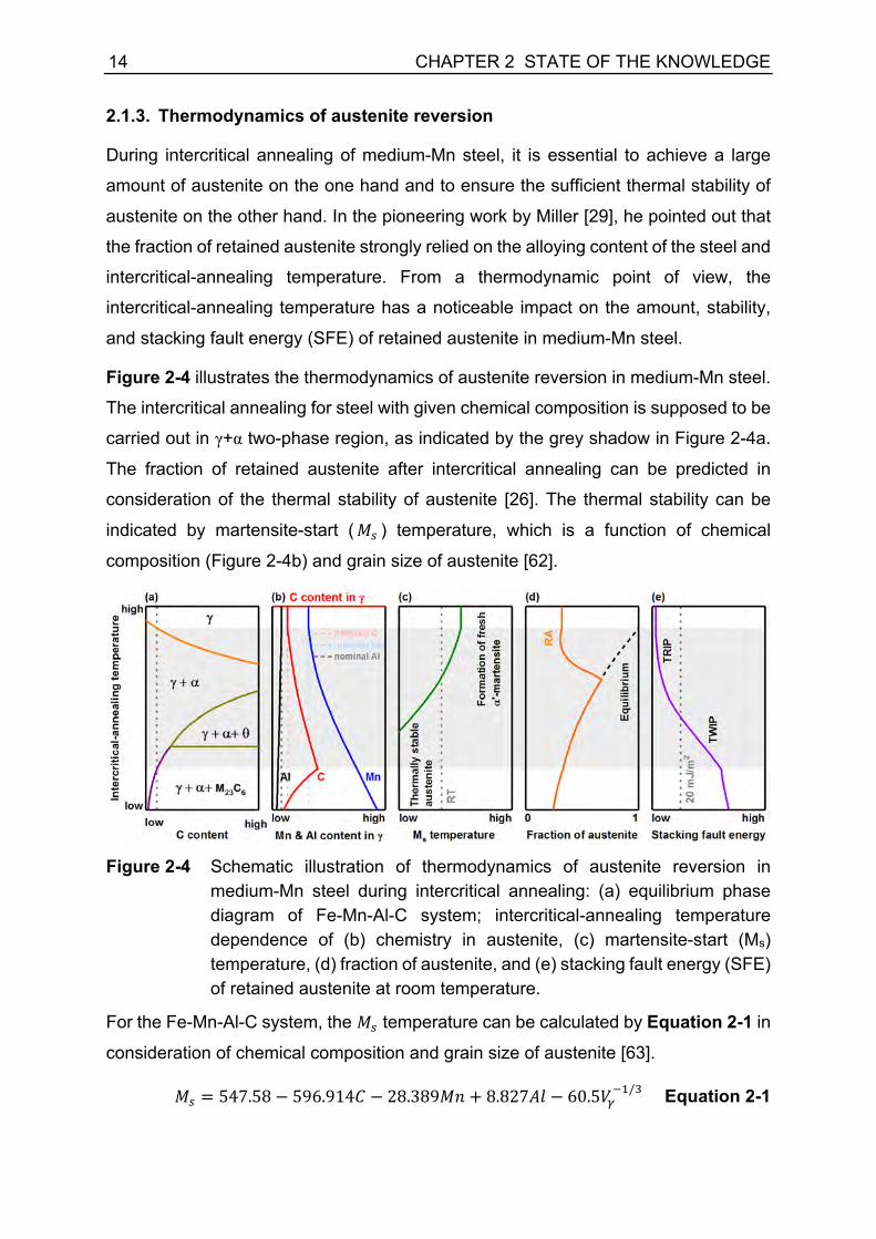
Figure 2-4 illustrates the thermodynamics of austenite reversion in medium-Mn steel.
The intercritical annealing for steel with given chemical composition is supposed to be
carried out in γ+α two-phase region, as indicated by the grey shadow in Figure 2-4a.
The fraction of retained austenite after intercritical annealing can be predicted in
consideration of the thermal stability of austenite [26]. The thermal stability can be
indicated by martensite-start (𝑀N ) temperature, which is a function of chemical
composition (Figure 2-4b) and grain size of austenite [62].
Figure 2-4 Schematic illustration of thermodynamics of austenite reversion in
medium-Mn steel during intercritical annealing: (a) equilibrium phase diagram of Fe-Mn-Al-C system; intercritical-annealing temperature dependence of (b) chemistry in austenite, (c) martensite-start (Ms) temperature, (d) fraction of austenite, and (e) stacking fault energy (SFE) of retained austenite at room temperature.
For the Fe-Mn-Al-C system, the 𝑀N temperature can be calculated by Equation 2-1 in
consideration of chemical composition and grain size of austenite [63].
𝑀N = 547.58 − 596.914𝐶 − 28.389𝑀𝑛 + 8.827𝐴𝑙 − 60.5𝑉)kQ/m Equation 2-1

CHAPTER 2 STATE OF THE KNOWLEDGE 15
where, 𝐶, 𝑀𝑛, and 𝐴𝑙 are in weight percentage in austenite, 𝑉) is the average volume
of austenite grains. The 𝑀N temperature above room temperature denotes poor
thermal stability of austenite and formation of α'-martensite during the cooling process.
In the medium-Mn steel, the 𝑀N temperature manifests a close relation to the
elemental partitioning behavior between austenite and ferrite, which is strongly
dependent on intercritical-annealing temperature (Figure 2-4c).
Empirically, the fraction of α'-martensite upon cooling (𝑓67 ) can be expressed by
Koistinen-Marburger (KM) equation [63-65]. The fraction of athermal α'-martensite is
related to the temperature difference between the 𝑀N temperature and quenching
temperature (𝑇X, usually room temperature), as follows [63]:
𝑓67 = 1 − 𝑒𝑥𝑝[−0.011(𝑀N − 𝑇X)] Equation 2-2
At a given intercritical-annealing temperature, the fraction of retained austenite (𝑓9:),
therefore, can be calculated by subtracting the fraction of fresh martensite during
cooling to room temperature (𝑓67) from the total fraction of austenite under equilibrium
condition (𝑓)'8), as expressed by Equation 2-3.
𝑓9: = 𝑓)'8 − 𝑓67 Equation 2-3
Since the thermal stability of reverted austenite relies on the intercritical-annealing
temperature, the fraction of retained austenite highly depends on the intercritical-
annealing temperature. The intercritical-annealing temperature dependence of the
fraction of retained austenite is schematically illustrated in Figure 2-4d. There is a peak
temperature, which correlates with the largest fraction of retained austenite. It can be
seen that the fraction of austenite in equilibrium increases with increasing intercritical-
annealing temperature (black dash line in Figure 2-4d). On the contrary, the amount
of carbon and manganese in austenite decreases continuously in austenite (Figure
2-4b). Above the peak temperature, the amount of carbon and manganese is not
sufficient to stabilize austenite below room temperature anymore. The insufficient
stability of austenite results in a large amount of newly formed α'-martensite during
cooling.
Lee et al. [66, 67] summarized three main factors that control the thermal stability of
austenite. (1) Chemical composition: it is strongly related to the elemental partitioning
between austenite and ferrite. The enrichment of carbon and manganese stabilizes
austenite. (2) Grain size effect: ultrafine grain size effectively reduces the 𝑀N

16 CHAPTER 2 STATE OF THE KNOWLEDGE
temperature and stabilizes austenite. (3) Mechanical stabilization: reverted austenite
inherits the feature of high dislocation density from the parent martensite, resulting in
mechanical stabilization.
The SFE of austenite is supposed to imply the deformation modes of retained
austenite during plastic deformation. According to thermodynamics, SFE of austenite
is a function of chemical composition and deformation temperature, and it can be
described by Equation 2-4 [68-70]:
𝛾<= = 2𝜌(QQQ)∆𝐺',,)→+ + 2𝜎) +⁄ Equation 2-4
where, 𝜌(QQQ) is the average molar surface density along (111) planes, ∆𝐺',,)→+ is the
free energy difference between γ-austenite and ε-martensite, which can be formulated
by Equation 2-5 [13], and 𝜎) +⁄ is the γ/ε interfacial energy.
∆𝐺',,)→+ = ∆𝐺%&'(
)→+ + ∆𝐺(-.)→+ Equation 2-5
where, ∆𝐺%&'()→+ is the chemical Gibbs free energy change and ∆𝐺(-.
)→+ is the magnetic
Gibbs free energy change. Both of these terms are dependent on the chemistry of
austenite and temperature. As a result, the SFE of retained austenite relies on the
intercritical-annealing temperature, as shown in Figure 2-4e. When the SFE is above
20 mJ/m2, the TWIP effect is supposed to be predominant; while the TRIP effect is the
primary deformation mechanism when the SFE is below 20 mJ/m2.
2.1.4. Ultrafine-grained duplex microstructure
During intercritical annealing, austenite reversion in martensite is usually considered
as a nucleation and diffusion-controlled growth process in medium-Mn steel [27, 40,
71-73]. Generally, the nucleation of austenite takes place along martensite lath
boundaries, martensite block boundaries, or primary austenite boundaries [74],
leading to a pronounced grain refinement [41]. As a consequence, medium-Mn steel
possesses ultrafine-grained (UFG) duplex microstructure containing ferrite (or
tempered martensite) and a large amount of retained austenite. The grain size of both
UFG ferrite and austenite after intercritical annealing was reported to be smaller than
1 µm [31, 75, 76].
The initial microstructure prior to intercritical annealing controls the morphology of
microstructure in medium-Mn steel. It was found that the medium-Mn steel with initial
microstructure under hot-rolling or austenitization conditions showed an elongated or

CHAPTER 2 STATE OF THE KNOWLEDGE 17
lath morphology after intercritical annealing [47, 77-81], as shown in Figure 2-5a. In
such a case, the microstructural morphology of medium-Mn steel inherited the
morphology of martensite. In contrast, the cold-rolled medium-Mn steel manifested an
equiaxed or globular grain morphology after intercritical annealing [79-83], as
displayed in Figure 2-5b. It seems that the cold deformation prior to the intercritical
annealing process provides a driving force for martensite recrystallization. It might
affect the microstructural morphology of medium-Mn steel. Nevertheless, the genesis
of microstructural morphology is still not well understood in medium-Mn steel.
Figure 2-5 Microstructures in medium-Mn steel: (a) ultrafine-grained (UFG)
microstructure with lath morphology [80], (b) UFG microstructure with globular morphology [80], (c) microstructure with bimodal distribution of coarse-grained α-ferrite as well as UFG constituent of equiaxed austenite and ferrite [38], (d) bimodal-grained microstructure with coarse-grained δ-ferrite as well as UFG austenite and ferrite [84], and (d) bimodal-grained microstructure with coarse-grained austenite as well as UFG austenite and ferrite [45].

18 CHAPTER 2 STATE OF THE KNOWLEDGE
Moreover, multi-phase microstructures with bimodal distribution were also observed
in medium-Mn steel. Suh et al. [38] reported a microstructure of Al-alloyed medium-Mn
steel with a bimodal distribution of coarse-grained α-ferrite (recrystallized ferrite) as
well as UFG constituent of equiaxed austenite and ferrite (Figure 2-5c). Han et al. [85]
fabricated a bimodal-grained microstructure in Al-free medium-Mn steel by the
thermomechanical process. The microstructure possessed coarse-grained α-ferrite as
well as UFG constituent of lath-shaped austenite and ferrite. Lee et al. [84] reported a
bimodal-grained microstructure with coarse-grained δ-ferrite as well as UFG
constituent of lath-shaped austenite and ferrite (Figure 2-5d) in hot-rolled medium-Mn
steel by additions of Al and Si. Lee et al. [45] reported a bimodal-grained
microstructure of cold-rolled medium-Mn steel consisting of coarse-grained austenite
as well as UFG austenite and ferrite (Figure 2-5e).
2.1.5. Mechanical properties and strain-hardening mechanisms
The UFG medium-Mn steel studied by Miller [29] in 1972 revealed superb mechanical
properties, which had an ultimate tensile strength of 1145 MPa and a total elongation
of 30.5%. The excellent combination of high strength and good ductility has stimulated
further research on medium-Mn steel. Recently, the development of medium-Mn steel
with various chemical compositions and processing routes has been reported. The
mechanical properties of medium-Mn steel processed by intercritical annealing are
collected and visualized in Figure 2-6, concerning ultimate tensile strength and total
elongation. It can be seen that the ultimate tensile strength of medium-Mn steel covers
a broad spectrum; meanwhile, medium-Mn steel exhibits adequate ductility.
According to the deformation modes in austenite, medium-Mn steel can be
categorized into medium-Mn TRIP steel and medium-Mn TWIP+TRIP steel. The
ultimate tensile strength of medium-Mn TRIP steel was reported in a range of 800 MPa
to 1600 MPa, and the total elongation was usually below 40%. By introducing the
TWIP effect in medium-Mn steel, the ductility can be further improved. In medium-Mn
TWIP+TRIP steel Fe-10Mn-3Al-2Si-0.3C (wt%), an ultimate tensile strength of
1144 MPa in combination with a superior elongation of 65% was reported [44]. In
comparison to high-Mn TWIP steel Fe-18Mn-1.5Al-0.6C (wt%), the reported
mechanical properties of the medium-Mn TWIP+TRIP steel grade are even superior.
The exceptional combination of high strength and superior ductility in medium-Mn steel
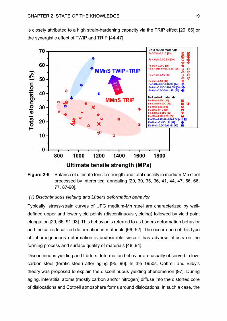
CHAPTER 2 STATE OF THE KNOWLEDGE 19
is closely attributed to a high strain-hardening capacity via the TRIP effect [29, 86] or
the synergistic effect of TWIP and TRIP [44-47].
Figure 2-6 Balance of ultimate tensile strength and total ductility in medium-Mn steel
processed by intercritical annealing [29, 30, 35, 36, 41, 44, 47, 56, 66, 77, 87-90].
(1) Discontinuous yielding and Lüders deformation behavior
Typically, stress-strain curves of UFG medium-Mn steel are characterized by well-
defined upper and lower yield points (discontinuous yielding) followed by yield point
elongation [29, 66, 91-93]. This behavior is referred to as Lüders deformation behavior
and indicates localized deformation in materials [66, 92]. The occurrence of this type
of inhomogeneous deformation is undesirable since it has adverse effects on the
forming process and surface quality of materials [48, 94].
Discontinuous yielding and Lüders deformation behavior are usually observed in low-
carbon steel (ferritic steel) after aging [95, 96]. In the 1950s, Cottrell and Bilby's
theory was proposed to explain the discontinuous yielding phenomenon [97]. During
aging, interstitial atoms (mostly carbon and/or nitrogen) diffuse into the distorted core
of dislocations and Cottrell atmosphere forms around dislocations. In such a case, the

20 CHAPTER 2 STATE OF THE KNOWLEDGE
dislocations turn to immobile dislocations. Due to the lack of mobile dislocations in
materials, the onset of plastic deformation becomes difficult and requests higher stress.
When the applied stress is high enough for dislocations to get rid of interstitial atoms,
the plastic deformation starts, and there is a sudden drop of required stress. Therefore,
steel appears a discontinuous transition from elastic deformation to plastic deformation,
implied by upper and lower yield points in stress-stress curves.
In addition, discontinuous yielding and localized deformation are also found in
ultrafine-grained (UFG) metallic materials, such as Al [98, 99], high-Mn steel [100, 101],
high-entropy alloy [102], TRIP-aided steel [103], and interstitial-free (IF) steel [104,
105]. IF steel is a ferritic steel grade used for automotive applications, due to its
excellent formability. The discontinuous yielding is not expected in coarse-grained IF
steel, because the interstitial solute atoms are fixed by micro-alloying elements, i.e.,
Nb and Ti, during metallurgy process [106, 107]. However, IF steel showed
discontinuous yielding behavior, when its grain size was refined to ultrafine grain size
range, namely smaller than 2 µm - 3 µm [105]. Obviously, the traditional explanation
of the yield point phenomenon in low-carbon steel fails in such a case.
The grain boundaries (GBs) can become both the generation and sink-in sources of
dislocations [108]. The absorption of mobile dislocations is usually more active at small
strains, which is known as dynamic recovery [108]. UFG materials possess a
considerably large area of GBs because of the ultrafine grain size. Hence, the
dislocation density is expected to be very low in UGF materials at small strains due to
the strongly activated dynamic recovery [99]. Nevertheless, an increase in the average
velocity of dislocations and stress is required to satisfy a constant strain-rate condition
during deformation [109]. Once the stress is increased, the generation of dislocations
at GBs becomes promoted. The emission of dislocations from GBs results in a net
increase in dislocation density as well as a decline in dislocation velocity and required
stress, leading to a stress drop and discontinuous yielding. This dislocation
multiplication theory upon loading was first proposed by Johnston and Gilman [110].
The origin of discontinuous yielding behavior in medium-Mn steel is still not well-
understood, due to the complexity of microstructure. On the one hand, medium-Mn
steel has a duplex microstructure, and the formation of Cottrell atmosphere in ferrite
might be responsible for the discontinuous yielding. On the other hand, the
microstructure is characterized by ultrafine grains, and the dislocation multiplication
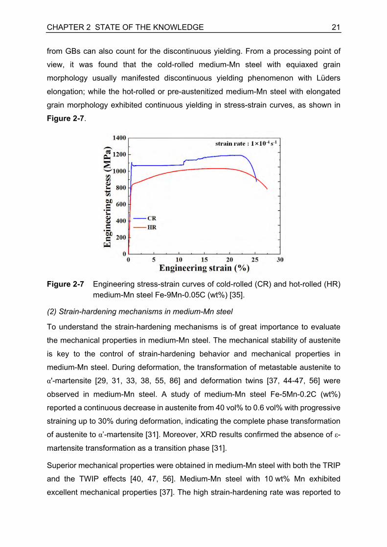
CHAPTER 2 STATE OF THE KNOWLEDGE 21
from GBs can also count for the discontinuous yielding. From a processing point of
view, it was found that the cold-rolled medium-Mn steel with equiaxed grain
morphology usually manifested discontinuous yielding phenomenon with Lüders
elongation; while the hot-rolled or pre-austenitized medium-Mn steel with elongated
grain morphology exhibited continuous yielding in stress-strain curves, as shown in
Figure 2-7.
Figure 2-7 Engineering stress-strain curves of cold-rolled (CR) and hot-rolled (HR)
medium-Mn steel Fe-9Mn-0.05C (wt%) [35].
(2) Strain-hardening mechanisms in medium-Mn steel
To understand the strain-hardening mechanisms is of great importance to evaluate
the mechanical properties in medium-Mn steel. The mechanical stability of austenite
is key to the control of strain-hardening behavior and mechanical properties in
medium-Mn steel. During deformation, the transformation of metastable austenite to
α'-martensite [29, 31, 33, 38, 55, 86] and deformation twins [37, 44-47, 56] were
observed in medium-Mn steel. A study of medium-Mn steel Fe-5Mn-0.2C (wt%)
reported a continuous decrease in austenite from 40 vol% to 0.6 vol% with progressive
straining up to 30% during deformation, indicating the complete phase transformation
of austenite to α’-martensite [31]. Moreover, XRD results confirmed the absence of ε-
martensite transformation as a transition phase [31].
Superior mechanical properties were obtained in medium-Mn steel with both the TRIP
and the TWIP effects [40, 47, 56]. Medium-Mn steel with 10 wt% Mn exhibited
excellent mechanical properties [37]. The high strain-hardening rate was reported to

22 CHAPTER 2 STATE OF THE KNOWLEDGE
be related to a combination of the TWIP and the TRIP effects [37]. During deformation,
primary twins were generated and followed by secondary twins. The twin intersections
acted as nucleation sites for the following deformation-induced α’-martensite
transformation [37, 47]. It was found that SFE is a critical parameter determining
deformation mechanisms, such as the TRIP and the TWIP effects [37, 41, 47]. When
the SFE is in the range of 0 mJ/m2 - 20 mJ/m2, the TRIP effect is dominant, while the
TWIP effect is preferred when the SFE is between 20 mJ/m2 and 35 mJ/m2 [37, 41].

CHAPTER 2 STATE OF THE KNOWLEDGE 23
2.2. Influence of heat treatment on microstructure and mechanical properties of medium-Mn steel
2.2.1. Austenitization prior to intercritical annealing
The austenitization prior to intercritical annealing strongly affects the morphology of
the microstructure in medium-Mn steel and mechanical properties [93, 111]. It was
reported that microstructures in cold-rolled and pre-austenitized medium-Mn steel
were different [93]. An austenitization treatment on the cold-rolled material released
the deformed microstructure and resulted in athermal martensite after quenching.
Consequently, considerable differences in microstructure morphology were observed
in annealed steel with different initial microstructures [93, 111]. Microstructure in cold-
rolled medium-Mn steel exhibited equiaxed/globular morphology, while it manifested
lath-like morphology in the pre-austenitized medium-Mn steel [93, 111]. It was also
reported that lath-like austenite in pre-austenitized steel is more stable than the
globular austenite in cold-rolled steel because of the mechanical stabilization [93].
Besides, austenitization treatment seems beneficial to the mechanical properties of
cold-rolled medium-Mn steel in terms of yielding. It was found that medium-Mn steel
with lath-like morphology showed continuous yielding [35, 93, 111, 112].
A study focused on the effects of austenitization temperature on the morphology of
quenched martensite, which affected the following austenite reverted
transformation [75]. The average packet size and block width of martensite increased
with increasing austenitization temperature [75], as illustrated in Figure 2-8.
Austenitization at different temperatures resulted in the changes in volume fraction
(Figure 2-8d), transformation rate (Figure 2-8e), and grain size (Figure 2-8f) of reverted
austenite [75]. The results indicated that the specimen austenitized at the lower
temperature had a higher volume fraction of retained austenite. The higher
austenitization temperature led to coarsening prior austenite and reducing in the area
of martensite block boundaries, which provided nucleation sites for reverted austenite.
The transformation rate of reverted austenite decreased with an increase in
austenitizing temperature, because of the lower boundary density of the prior austenite
grains and the martensite constituents. The interspacing of the retained austenite laths
became wider with increasing austenitizing temperature, and it was similar to the width
of the blocks [75].

24 CHAPTER 2 STATE OF THE KNOWLEDGE
Figure 2-8 The impact of austenitization temperature on microstructure of quenched
martensite: (a) 800 °C, (b) 900 °C, and (c) 1000 °C (solid and dashed lines are packet and block boundaries, correspondingly) in medium-Mn steel Fe-9Mn-0.05C (wt%); (d) volume fraction and transformation rate of reverted austenite as a function of austenitization temperature; (e) 𝐥𝐧 t𝐥𝐧 u𝒇𝜸
𝒆𝒒/z𝒇𝜸𝒆𝒒 − 𝒇𝜸{|} - lnt plots of specimen austenitized at various
temperatures; (f) dependence of the widths of the martensite blocks and laths, as well as the interspacing of reverted austenite on austenitization temperature [75].

CHAPTER 2 STATE OF THE KNOWLEDGE 25
2.2.2. Intercritical-annealing temperature
The influence of intercritical-annealing temperature on the microstructure and
properties was investigated in various medium-Mn steel alloys [36-38, 40, 60, 87, 93].
It was found that the intercritical-annealing temperature had significant effects on the
amount and stability of reverted austenite. The mechanical properties of medium-Mn
steel appeared to be quite sensitive to intercritical-annealing temperature.
Suh et al. [38] reported that the intercritical-annealing temperature had a vital impact
on the volume fraction and stability of retained austenite. Three alloys with different
alloying contents were investigated at various intercritical-annealing temperatures.
The amount of reverted austenite increased with an increase in annealing temperature
up to 760 °C, but it dramatically dropped for samples annealed at 780 °C, as shown
in Figure 2-9a. The yield strength declined with increasing annealing temperature,
while tensile strength increased, as illustrated in Figure 2-9b. The total elongation
showed a maximal value in alloy 1 and alloy 2 as a function of annealing temperature,
but alloy 3 decreased monotonously with increasing annealing temperature.
Lee et al. [66] found that intercritical-annealing temperature also played a crucial role
in the strain-hardening rate and yielding behavior in medium-Mn steel. Medium-Mn
steel Fe-6.15Mn-1.5Si-0.05C (wt%) was intercritically annealed at 640 °C, 660 °C,
680 °C, and 700 °C for 180 seconds [66]. Pronounced Lüders deformation behavior
was observed in the specimen annealed at 640 °C and 660 °C, indicating an absence
of strain hardening. With an increase in annealing temperature to 700 °C, the localized
deformation was mitigated in the medium-Mn steel and the specimens annealed at
680 °C and 700 °C showed a strong strain-hardening behavior [66]. Furthermore, the
amount of austenite before and after the tensile tests were measured. The results
showed that no deformation-induced α’-martensite occurred during the deformation in
the sample annealed at 640 °C, however, austenite successively transformed into α’-
martensite during the tensile test in the sample annealed above 680 °C [66].
The optimal intercritical-annealing temperature for medium-Mn TRIP steel was
suggested to be slightly lower than the 𝑇V temperature to avoid the presence of
athermal martensite in the microstructure [40]. 𝑇V temperature is defined as the
intercritical temperature for which the maximum volume fraction of austenite can be
retained upon cooling to room temperature [40].

26 CHAPTER 2 STATE OF THE KNOWLEDGE
Figure 2-9 Influence of intercritical-annealing temperature on (a) austenite fraction
(the lines without points represent equilibrium fractions); (b) tensile and yield strength; and (c) total elongation of three medium-Mn steel alloys (alloy 1: Fe-4.5Mn-2.2Al-0.45Si-0.11C (wt%); alloy 2: Fe-5.1Mn-2.1Al-0.49Si-0.075C (wt%); alloy 3: Fe-5.6Mn-2.2Al-0.49Si-0.055C (wt%) [38].
2.2.3. Intercritical-annealing time
The influence of intercritical-annealing time on the grain size [71, 76, 113] and the
amount of retained austenite [30, 71] was reported in medium-Mn steel. In cold-rolled
medium-Mn steel Fe-5Mn-0.1C (wt%), intercritical annealing was carried out at 650 °C
for different durations from 1 min up to 6 h [113]. It was mentioned that the austenite
grain was about 0.4 µm after annealing for 1 min and coarsened slowly to approx.
1 µm after 6 h. The size of the ferrite subgrains was almost identical to the grain size
of austenite under the same annealing condition [113]. In austenitized medium-Mn
steel Fe-5Mn-0.2C (wt%), the thickness of austenite increased from about 0.1 µm
slightly to 0.33 µm with an increase in annealing time from 1 min to 144 h at annealing
temperature of 650 °C, as plotted in Figure 2-10a [71]. The thickness of ferrite did not
change much during the intercritical annealing for 144 h. Even after annealing at
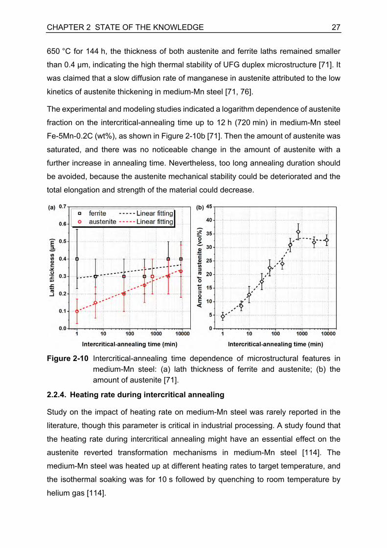
CHAPTER 2 STATE OF THE KNOWLEDGE 27
650 °C for 144 h, the thickness of both austenite and ferrite laths remained smaller
than 0.4 µm, indicating the high thermal stability of UFG duplex microstructure [71]. It
was claimed that a slow diffusion rate of manganese in austenite attributed to the low
kinetics of austenite thickening in medium-Mn steel [71, 76].
The experimental and modeling studies indicated a logarithm dependence of austenite
fraction on the intercritical-annealing time up to 12 h (720 min) in medium-Mn steel
Fe-5Mn-0.2C (wt%), as shown in Figure 2-10b [71]. Then the amount of austenite was
saturated, and there was no noticeable change in the amount of austenite with a
further increase in annealing time. Nevertheless, too long annealing duration should
be avoided, because the austenite mechanical stability could be deteriorated and the
total elongation and strength of the material could decrease.
Figure 2-10 Intercritical-annealing time dependence of microstructural features in
medium-Mn steel: (a) lath thickness of ferrite and austenite; (b) the amount of austenite [71].
2.2.4. Heating rate during intercritical annealing
Study on the impact of heating rate on medium-Mn steel was rarely reported in the
literature, though this parameter is critical in industrial processing. A study found that
the heating rate during intercritical annealing might have an essential effect on the
austenite reverted transformation mechanisms in medium-Mn steel [114]. The
medium-Mn steel was heated up at different heating rates to target temperature, and
the isothermal soaking was for 10 s followed by quenching to room temperature by
helium gas [114].

28 CHAPTER 2 STATE OF THE KNOWLEDGE
It was reported that cementite precipitation in martensite could be an intermediate step
during austenite reversion at a heating rate below 15 °C/s [114]. During the slow
heating process, the cementite formed at first and then dissolved in the matrix.
Cementite formed along various boundaries and then austenite formation occurred
near the Mn-rich cementite particles. As illustrated in Figure 2-11a, globular austenite
(γG) with a low density of dislocations was observed after intercritical annealing. In
such a case, austenite reversion via cementite precipitation resulted in pronounced
manganese partitioning between γG-austenite and α'T-tempered martensite (Figure
2-11c), indicating high stability of austenite [114].
Figure 2-11 Impact of heating rate during intercritical annealing on microstructural
and chemical distribution in medium-Mn steel Fe-9Mn-0.05C (wt%): transmission-electron-microscopy (TEM) bright-field images of (a) specimen annealed at 645 °C with a heating rate of 3 °C/s and (b) specimen annealed at 677 °C with a heating rate of 50 °C/s; (c) the corresponding concentration profiles of Mn determined by energy-dispersive X-ray spectroscopy (EDXS). (γG is globular austenite, γL is lath austenite, α'T is tempered martensite, α'F is fresh martensite, which is from the reverted austenite during quenching, and α' is untempered martensite [114].

CHAPTER 2 STATE OF THE KNOWLEDGE 29
On the contrary, when the heating rate was higher than 15 °C/s, rapid austenite
reversion occurred without precipitation of Mn-rich cementite. This was due to a short
time at elevated temperatures during the heating process. Consequently, the medium-
Mn steel exhibited lath austenite (γL) and untempered martensite (α')/fresh martensite
(α'F) with a high density of dislocations (Figure 2-11b). There was no pronounced
manganese partitioning between γL-austenite and α'/α'F-martensite at the early stage
of austenite reversion, indicated by the concentration profile of manganese in Figure
2-11c. It was presumed that further intercritical annealing could enhance the
partitioning of both manganese and carbon atoms from α'-martensite to γL-austenite,
such that the thermal stability of γL-austenite increased gradually [114].
2.2.5. Cooling conditions after intercritical annealing
From a processing point of view, a robust cooling process after intercritical annealing
would be beneficial for industrial production of medium-Mn steel. Research on the
impact of cooling methods on medium-Mn steel dates back to the 1990s [39]. When
carbon content was below 0.1 wt% in medium-Mn steel with 5 wt% manganese,
furnace cooling did not have a noticeable effect on the amount of retained austenite
compared with water quenching. When carbon content was above 0.1 wt%, however,
there was a pronounced difference in the amount of retained austenite in the medium-
Mn steel cooled by different methods. Furnace cooling led to a considerably lower
amount of retained austenite than water quenching, as shown in Figure 2-12 [39].
Furukawa et al. [39] found that carbide precipitation during furnace cooling in steel
containing a high carbon content (above 0.1 wt%) had a significant impact on the
amount of retained austenite and mechanical properties. The formation of carbide
resulted in a decrease in carbon content in austenite, leading to reduced thermal
stability of austenite [115]. The austenite might transform into martensite during
cooling. Additionally, the network of the precipitates provided fracture nucleation sites
as well as fracture propagation paths. Therefore, the ductility of the samples cooled in
the furnace was lower than that of the samples quenched in water.

30 CHAPTER 2 STATE OF THE KNOWLEDGE
Figure 2-12 Amount of retained austenite as functions of carbon content and cooling
methods in medium-Mn steel with 5 wt% manganese [39]. (WQ stands for water quenching and FC for furnace cooling)

31
CHAPTER 3 MATERIAL AND EXPERIMENTS CHAPTER 3
MATERIAL AND EXPERIMENTS


CHAPTER 3 MATERIAL AND EXPERIMENTS 33
3. Material and experiments
3.1. Material and manufacturing processes
The nominal chemical composition of the investigated medium-Mn steel is Fe-12Mn-
3Al-0.05C (wt%). The actual chemical composition in weight percentage is listed in
Table 3-1, which was determined by wet chemical analysis. The chemical composition
in atomic percentage was converted from weight percentage in consideration of the
atomic weight of each element. The equilibrium phase diagram calculated by
ThermoCalc with TCFE9 database is displayed in Figure 3-1. Due to the low carbon
concentration of the investigated material, there is a considerably large intercritical-
annealing window. The Ae1 temperature is approx. 490 °C and the Ae3 temperature is
approx. 755 °C for the investigated steel.
Table 3-1 Chemical composition of the investigated medium-Mn steel
Element Fe C Si Mn P S Al wt% Bal. 0.064 0.2 11.7 0.006 0.003 2.9 at% Bal. 0.287 0.4 11.5 0.010 0.005 5.8
Figure 3-1 Equilibrium phase diagram of Fe-12Mn-3Al-xC system calculated by
ThermoCal with TCFE9 database.

34 CHAPTER 3 MATERIAL AND EXPERIMENTS
The laboratory-melt alloy was cast into an ingot of 80 kg with dimensions of 140 mm ×
140 mm × 500 mm. Hot forging was conducted afterward at 1150 °C with three passes,
and the cross section achieved 160 mm × 40 mm. Subsequently, hot rolling (HR) at
1150 °C was further performed to reduce the thickness of the material to 2.5 mm with
reheating procedure between rolling passes. To eliminate the microscale segregation
behavior, the steel was then homogenized (HG) at 1100 °C for 2 hours, followed by
water quenching (WQ). The process schedule for the hot-rolled material is displayed
in Figure 3-2a. The received material after homogenization was denoted as HG state.
Before cold rolling (CR), an austenitization (AUS) annealing above A3 temperature at
850 °C for 10 min was carried out additionally to reduce the residual stress, followed
by water quenching (WQ). The cold-rolling degree was approx. 50% and the thickness
of the materials was reduced to 1.25 mm. The received material after CR was referred
to as CR state. The process schedule for the CR materials is shown in Figure 3-2b.
Figure 3-2 Manufacturing processes of (a) the homogenized (HG) and (b) the cold-
rolled (CR) medium-Mn steel.

CHAPTER 3 MATERIAL AND EXPERIMENTS 35
3.2. Intercritical-annealing schedules
For the study of the austenite reversion kinetics and martensite recovery during
intercritical annealing (Chapter 4.1), the heat treatment was carried out on the
synchrotron X-ray diffraction beamline P02.1 of PETRA III at Deutsches Elektronen-
Synchrotron Center (DESY) in Hamburg, Germany. The intercritical annealing was
conducted in a ceramic furnace. The dimensions of rod sample were Φ 0.8 mm ×
10 mm. The temperature-time profile of the intercritical annealing is shown in Figure
3-3. The average heating rate was set as 10 °C/min. The isothermal holding
temperature was 550 °C and the holding time was 10 hours. Afterward, the sample
was slowly cooled in air.
Figure 3-3 Temperature profile as a function of time during intercritical annealing at
550 °C in the ceramic furnace at the synchrotron beamline P02.1.
To investigate the influence of different process parameters on microstructure and
mechanical properties of the cold-rolled medium-Mn steel, the heat treatment on the
cold-rolled medium-Mn steel was conducted in a salt bath in the Steel Institute of the
RWTH Aachen University. The detailed intercritical-annealing schedules will be
introduced below according to the specific process parameters.
For the study of the impact of intercritical-annealing temperature on microstructure and
mechanical properties (Chapter 4.2), the heat treatments were carried out at various
100 101 102 103 1040
100
200
300
400
500
600
Iso-thermalholding
at 550 °Cfor 10 h
HeatingAverage heating rate:
10 °C/minTem
pera
ture
(°C
)
Time (s)

36 CHAPTER 3 MATERIAL AND EXPERIMENTS
temperatures, i.e., 555 °C (which is slightly different from the annealing temperature
during isothermal holding at HEXRD beamline, which is 550 °C), 600 °C, 650 °C,
700 °C, and 750 °C, for 12 hours. After intercritical annealing, the samples were
quenched in water. The annealed samples were referred to as IA555, IA600, IA650,
IA700, and IA750, correspondingly. The intercritical-annealing schedule is
schematically shown in Figure 3-4.
Figure 3-4 Schematic illustration of intercritical-annealing schedule of the cold-
rolled medium-Mn steel at various temperatures. (IA: intercritical annealing, WQ: water quenching).
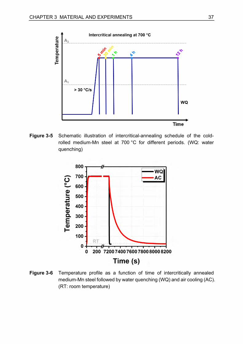
For the study of the effect of intercritical-annealing time on microstructure and
mechanical properties (Chapter 4.3), intercritical annealing was performed at 700 °C
for different durations, i.e., 5 min, 30 min, 1 hour, 4 hours, and 12 hours. The
temperature-time profile of the heat treatment is schematically shown in Figure 3-5.
After intercritical annealing, the samples were quenched in water.
For the study of the influence of cooling conditions after intercritical annealing on
microstructure and mechanical properties (Chapter 4.4), the cold-rolled medium-Mn
steel was intercritically annealed at 700 °C for 2 hours in a salt bath. Subsequently,
the material was quenched into water (WQ) or cooled in the air (AC). The temperature
during the heat treatment was measured by thermal couples attached to the surface
of specimens. The temperature-time profile of the heat treatment is illustrated in
Figure 3-6.
CHAPTER 3 MATERIAL AND EXPERIMENTS 37
Figure 3-5 Schematic illustration of intercritical-annealing schedule of the cold-
rolled medium-Mn steel at 700 °C for different periods. (WQ: water quenching)
Figure 3-6 Temperature profile as a function of time of intercritically annealed
medium-Mn steel followed by water quenching (WQ) and air cooling (AC). (RT: room temperature)

38 CHAPTER 3 MATERIAL AND EXPERIMENTS
3.3. Experimental methods
3.3.1. Scanning electron microscopy (SEM)
The scanning electron microscopy (SEM) was employed for the metallographic
investigation of the medium-Mn steel. The microstructure of the steel after intercritical
annealing was characterized by a Zeiss Sigma field-emission SEM DSM 982. The
metallographic specimens for SEM observation were electropolished after the
mechanical grinding and polishing. Subsequently, the specimens were etched at room
temperature with Nital-3% (HNO3) solution, which is composed of 3 ml concentrated
nitric acid and 97 ml ethanol.
3.3.2. Electron backscattered diffraction (EBSD)
Electron backscattered diffraction (EBSD) technique was used for the detailed
microstructure analysis. For the investigation of the impact of cold rolling on
microstructure before and after intercritical annealing at 550 °C (Chapter 4.1), the
EBSD measurements were performed in FEI® HeliosTM NanolabTM 660 SEM equipped
with an EDAX EBSD detector. In FEI SEM, the EBSD measurements were carried out
using electron energies of 18 keV and a beam current of 6.4 nA. The working distance
was 10 mm. Measurements were conducted in fields of 30 µm × 45 µm with a step
size of 50 nm and in fields of 300 µm × 200 µm with a step size of 200 nm.
To study the influence of intercritical-annealing temperature on microstructure after
intercritical-annealing at 555 °C and 700 °C (Chapter 4.2), the EBSD measurements
were performed in JEOL JSM-7000F field-emission SEM equipped with a Hikari EBSD
camera. In JEOL SEM, the EBSD data were measured using electron energies of
20 keV and a beam current of approx. 30 nA. The working distance was set to 12 mm.
Measurements were conducted in fields of 75 µm × 75 µm with a step size of 50 nm.
The EBSD measurements on the samples cooled under different conditions
(Chapter 4.4) was carried out in JEOL JSM-6500F SEM with an EDAX Digiview
detector. The acceleration voltage was 15 keV, and a beam current was approx. 5 nA.
The working distance was set to 17 mm. The fields of the EBSD measurements were
30 µm × 50 µm with a step size of 50 nm. The EBSD data were collected by software
OIM DataCollection by AMETEK-EDAX. For all the EBSD measurements, the
acquired data, in terms of phase, orientation, misorientation, grain size, and grain
boundaries, were evaluated using software OIM AnalysisTM V8.0 by AMETEK-EDAX.

CHAPTER 3 MATERIAL AND EXPERIMENTS 39
3.3.3. Laboratory X-ray diffraction (XRD)
In order to evaluate the austenite volume fraction in the annealed specimens at
different temperatures for 12 h (Chapter 4.2) and the corresponding deformed
specimens, a power diffractometer Stadi MP with Mo Kα1 radiation source (λMo,Kα1 =
0.70930 Å) was used. The XRD experiments were performed on flat pieces of steel in
reflection geometry, according to Bragg-Brentano. A position-sensitive microstrip X-
ray detector Mythen 1K (450 μm) with steps of 0.015° (2-Theta) recorded the scattered
intensities. The volume fraction of retained austenite was calculated by the following
equation [116]:
𝑓) =~�����~����
9�����9����� ~�
����~����
9�����9����+ ~�����~����
9�����9������ Equation 3-1
where, 𝐼&@A is the integrated intensity of austenite (γ) or ferrite (α) peaks according to
the crystallographic planes, while 𝑅&@A is the corresponding material-specific
factor [116]. The 𝑅&@A value is determined by the crystal structure, composition, and
the diffraction planes. The 𝑅&@A values for Mo radiation source were 𝑅)FFY = 376.7, 𝑅)mQQ
= 390, 𝑅6FYY = 288.6, and 𝑅6FQQ = 530 [116].
3.3.4. Synchrotron high-energy X-ray diffraction (HEXRD)
Synchrotron high-energy X-ray diffraction (HEXRD) was employed to identify phases
and especially to investigate the volumetric phase transformation during intercritical
annealing (Chapter 4.1) and uniaxial tensile deformation (Chapter 4.3) in the medium-
Mn steel. The HEXRD experiments were conducted at beamline P02.1 of PETRA III
at Deutsches Elektronen-Synchrotron Center (DESY) in Hamburg, Germany [117].
The beamline was operated at a fixed energy of 60 keV, supplying a hard X-ray with
a wavelength of approx. 0.207 Å. Thanks to the high flux of synchrotron X-ray, the
HEXRD experiments were performed in transmission geometry. The high photon
energy and flux of the beamline P02.1 enable time-resolved characterization on the
structural transformation in a sub-second regime [117]. For the quantitative
microstructure analysis, a measurement of the standard Si or CeO2 powder sample
was conducted to calibrate the detector distance (D) and the instrument broadening.
(1) In situ HEXRD experiments during intercritical annealing
To investigate the austenite reversion kinetics and martensite recovery kinetics, in situ
HEXRD experiments were conducted during intercritical annealing at 550 °C

40 CHAPTER 3 MATERIAL AND EXPERIMENTS
(Chapter 4.1). The experimental setup is shown in Figure 3-7. A ceramic furnace was
placed in between the incident beam and a two-dimensional detector. The sample was
in the geometry of Φ 0.8 mm × 10 mm. In order to prevent the samples from oxidation
at an elevated temperature, the samples were sealed in quartz capillaries. The sample
to detector distance was set to as approx. one meter. The annealing process followed
the time-temperature profile, as displayed in Figure 3-3. The cubic beam with a size
of 0.5 mm × 0.5 mm penetrated the geometrical center of the samples. The HEXRD
data were acquired every 50 °C during the heating period. During the isothermal holing
period, the HEXRD data were acquired every ten seconds within the first 30 minutes;
afterward, they were acquired with a step of every two minutes. The exposure time for
each acquisition was ten seconds.
Figure 3-7 Schematic illustration of the setup of the in situ synchrotron X-ray
diffraction experiment during heat treatment. BI and BD are the incident and diffracted beams, respectively; D is the detector distance between sample and the two-dimensional detector; 2θhkl is the angle between the incident and diffracted beams; Q is the scattering vector.
(2) In situ HEXRD experiments during tensile deformation
In situ HEXRD experiments were carried during uniaxial tensile deformation in order
to assess the mechanical stability of retained austenite in the medium-Mn steel
(Chapter 4.3). Figure 3-8 illustrates the experimental setup of in situ HEXRD
experiments during tensile deformation. A tensile rig with a max load of 5 kN was
placed in between the incident beam and two-dimensional detector to perform the

CHAPTER 3 MATERIAL AND EXPERIMENTS 41
tensile deformation. The geometry of the sub-sized tensile specimen is shown in
Figure 3-9. The tensile gauge was in parallel to the rolling direction. The tensile tests
were carried out at room temperature with displacement control. The corresponding
initial strain rate was approx. 1 × 10⁻³ s-1. The sample to detector distance was approx.
one meter. The beam size of the incident beam was 0.5 mm × 0.5 mm. The two-
dimensional Debye-Scherrer patterns were recorded by a fast area detector. In order
to capture the deformation-induced martensitic transformation, the HEXRD data were
acquired with high frequency, namely one diffraction pattern per second.
Figure 3-8 Schematic illustration of the setup of the in situ synchrotron X-ray
diffraction experiment during tensile deformation. BI and BD are the incident and diffracted beams, respectively; D is the detector distance between sample and the two-dimensional detector; 2θhkl is the angle between the incident and diffracted beams; Q is the scattering vector; LD stands for loading direction, TD for transverse direction, and ND for normal direction.
Figure 3-9 Geometry of sub-sized tensile test specimen for in situ HEXRD
experiments. (Unit in mm)

42 CHAPTER 3 MATERIAL AND EXPERIMENTS
(3) Ex situ HEXRD experiments
To evaluate the impact of intercritical-annealing time (Chapter 4.3) and cooling
conditions (Chapter 4.4) on microstructure, ex situ HEXRD experiments were
performed to measure the amount of retained austenite in the annealed and
interrupted tensile specimens. The measurements were conducted in a transmission
geometry. The beam size of the incident beam was 1 mm × 1 mm. The sample to
detector distance was approx. one meter. The exposure time was ten seconds for
each measurement. Three measurements were performed under each heat treatment
condition to ensure reliable statistics.
(4) Quantitative microstructure analysis by the Rietveld refinement method
The recorded two-dimensional diffraction patterns were integrated over an azimuth
angle of 360° into intensity-scattering vector Q plots using Fit2D software [118]. The
reduced diffraction profiles were quantitatively analyzed by the Rietveld refinement
method with the aid of Materials Analysis Using Diffraction (MAUD) software [119].
The data reduction and analysis procedures are illustrated in Figure 3-10. It can be
seen that the diffraction peaks of body-centered cubic (BCC) and face-centered cubic
(FCC) were able to be distinguished. The fitted diffraction profile showed a good
agreement with the diffraction profile obtained in the experiment.
For the accurate profile broadening analysis, the pre-analysis on the instrumental
broadening was conducted by using the Si or CeO2 standard sample under the same
experimental conditions as the HEXRD measurements. The instrumental broadening
was subsequently subtracted for every profile analysis. The quantitative description of
profile broadening due to microstructural defects was achieved by the application of
the Popa model [120], which is implemented in the MAUD code as ‘Popa rules’ for the
size-strain model. The flow chart of the HEXRD profile-analysis procedures is
illustrated in Figure 3-11.
According to the Popa model [120], the profile broadening is associated with
microstrain and crystallite size of the material. When the contributions of the
microstrain and crystallite size to the XRD peak profiles are taken into account, the
Voigt function in reciprocal space can be expressed as follows:
𝑉�(𝑸) = ∫𝑑(∆𝑯)𝐿�(𝑸 + 2𝜋∆𝑯)𝐺�(∆𝑯) Equation 3-2
𝐿�(𝑸) = (3⟨𝑅&⟩/4𝜋)[1 + 9⟨𝑅&⟩F(𝑄 − 2𝜋𝑯)F/16]kQ Equation 3-3

CHAPTER 3 MATERIAL AND EXPERIMENTS 43
𝐺�(∆𝑯) = (2𝜋⟨𝜀&&F ⟩)kQ/F𝑯kQ𝑒𝑥𝑝[−(∆𝑯)F/(2𝑯F⟨𝜀&&F ⟩)] Equation 3-4 where, 𝑸 is the wave-vector transfer, 𝑯 is the reciprocal-lattice vector, ⟨𝑅𝒉⟩ represents
the average crystallite size in the crystal direction 𝒉, and the quantity ⟨𝜀𝒉𝒉⟩ denotes
the (hkl)-dependent strain.
Figure 3-10 Illustration of HEXRD data reduction and analysis procedures: (a) two-
dimensional diffraction pattern, (b) integrated diffraction profile by Fit2D, (c) fitted diffraction profile by Rietveld refinement method using MAUD; (d) enlarged region in (c).
In the present study, the average crystallite size and the (hkl)-dependent strain model
for the cubic Laue group are formulated as follows [120]:
⟨𝑅&⟩ = 𝑅Y + 𝑅Q𝐾�Q(𝑥, 𝜑) + 𝑅F𝐾�Q(𝑥, 𝜑) + ⋯ Equation 3-5 ⟨𝜀&&F ⟩𝐸�� = 𝐸Q(ℎ� + 𝑘� + 𝑙�) + 2𝐸F(ℎF𝑘F + 𝑘F𝑙F + 𝑙FℎF) Equation 3-6
where, 𝐾FAG (𝑥, 𝜑) is the symmetrized harmonics for the cubic group, which are listed
below in Equation 3-7 to Equation 3-9. 𝐸Q and 𝐸F are coefficients.
𝐾�Q(𝑥, 𝜑) = 0.3046972𝑃�Y(𝑥) + 0.3641828𝑃��(𝑥) 𝑐𝑜𝑠 4𝜑 Equation 3-7 𝐾�Q(𝑥, 𝜑) = −0.1410474𝑃�Y(𝑥) + 0.527751𝑃��(𝑥) 𝑐𝑜𝑠 4𝜑 Equation 3-8

44 CHAPTER 3 MATERIAL AND EXPERIMENTS
𝐾�F(𝑥, 𝜑) = −0.4678013𝑃�F(𝑥) 𝑐𝑜𝑠 2𝜑 + 0.3153915𝑃��(𝑥) 𝑐𝑜𝑠 6𝜑 Equation 3-9
Figure 3-11 Flow chart of the HEXRD profile-analysis procedures by software
Materials Analysis Using Diffraction (MAUD).
The XRD technique is a powerful tool to assess the dislocation density in a quantitative
manner. According to Williamson−Smallman relationship [121], the dislocation density
can be calculated by the average crystallite size and microstrain, as follows:
𝜌 = m√F�⟨+�⟩�/�
�� Equation 3-10
Where, ρ is dislocation density, ε is microstrain, D is crystallite size, and b is Burgers
vector.
The goodness of refinement is evaluated by weighted profile R-factor (Rwp). The fit
with Rwp value smaller than 10% is usually accepted as a reliable fit. For all the
refinement results in the present work, the Rwp achieved a value smaller than 8%.
Under this circumstance, the uncertainty of the volume percentage of austenite was
within 0.25% by refinement.

CHAPTER 3 MATERIAL AND EXPERIMENTS 45
3.3.5. Atom probe tomography (APT)
Three-dimensional atom probe tomography (3D-APT) was employed to investigate the
elemental partitioning behavior under different cooling conditions (Chapter 4.4). The
APT samples were prepared by lift-out with annular milling procedures using FEI®
HeliosTM NanolabTM 660 focused ion beam (FIB). The atom probe measurements were
conducted by the high-resolution local electrode atom probe (LEAP) 4000X HR
instrument in a pulsed laser mode. The frequency of laser pulse was 250 kHz, and the
laser energies of 30 pJ were employed during the measurements. The specimen base
temperature was 60 K, and the chamber pressure was below 3 x 10-11 bar during the
measurements. The reconstruction of the APT data was carried out using commercial
software IVAS.
3.3.6. Uniaxial tensile testing
To evaluate the mechanical properties, the tensile tests under quasi-static condition
were carried out in a Z4204 tensile machine at room temperature at a constant cross
head speed. The initial strain rate was 1 × 10⁻³ s−1. The geometry of the bone-shaped
tensile specimen is illustrated in Figure 3-12. The initial length (L0) was set to 20 mm
in the middle part of the gauge to measure the elongation. The elongation of a
specimen was measured by optical strain measurement with a video extensometer.
Three tests were performed under each annealing condition for reasonable statistics.
Figure 3-12 Geometry of bone-shaped tensile specimen. (Unit in mm)


47
CHAPTER 4 RESULTS CHAPTER 4
RESULTS


CHAPTER 4 RESULTS 49
4. Results
4.1. Influence of cold rolling on austenite reversion
In this subchapter, the influence of cold rolling on austenite reversion in the medium-
Mn steel Fe-12Mn-3Al-0.05C (wt%) was investigated via in situ synchrotron high-
energy X-ray diffraction (HEXRD) during intercritical annealing at 550 °C for 10 hours.
The austenite reversion kinetics in homogenized (HG) and cold-rolled (CR) medium-
Mn steel was compared in terms of the evolution of the amount of reverted austenite
as a function of intercritical-annealing time. Besides, the martensite recovery kinetics
was revealed by the evolution of dislocation density in martensite in both HG and CR
states. In order to understand the differences in austenite reversion kinetics in HG and
CR states, the microstructure along with manufacturing processes and after
intercritical annealing was characterized by electron backscattered diffraction
technique (EBSD).
4.1.1. Microstructure of the medium-Mn steel in homogenized (HG) and cold-rolled (CR) states
The microstructure of the medium-Mn steel in the HG state is illustrated in Figure 4-1.
It can be recognized that the HG material possessed mainly lath martensite. The
substructures of lath martensite were revealed by boundaries with different
misorientation angles, as shown in Figure 4-1b. A martensite lath is usually considered
as a single martensite crystal, and the misorientation between martensite laths is
subtle. Martensite lath boundaries can be illustrated by the boundaries with small
misorientation angles in a range of 2° to 5° [122], as shown in green color in Figure
4-1b. Parent austenite grain boundaries are high-angle grain boundaries, which can
be presented by the misorientation angle between 15° and 48° [122], as illustrated in
red color in Figure 4-1b. The block and packet boundaries were indicated by the black
lines with a misorientation angle above 48°. The blue lines with a misorientation angle
between 5° and 15° manifested possible block, packet, and parent austenite
boundaries [122]. The quenched martensite showed a large grain size of parent
austenite in approx. 200 µm as well as a large block and packet size in the order of
~10 um. The HEXRD pattern of the HG material is illustrated in Figure 4-1c. There
were merely diffraction peaks of the BCC crystal structure, and no diffraction peak of

50 CHAPTER 4 RESULTS
the FCC crystal structure was observed. The dislocation density of the lath martensite
was evaluated to be 6 × 10¹⁴ m-2 by HEXRD profile analysis.
Figure 4-1 Microstructure of the medium-Mn steel Fe-12Mn-3Al-0.05C (wt%) in the homogenized (HG) state: (a) the inverse pole figure (IPF) maps, (b) the image quality (IQ) map, and (c) the synchrotron high-energy X-ray diffraction (HERXD) profile.
The microstructure of the medium-Mn steel in the CR state is shown in Figure 4-2.
The CR material possessed mainly deformed martensitic microstructure. The cold-
rolling process brought a large number of deformation bands and substructures into
the martensitic microstructure, as illustrated in Figure 4-2b. The HEXRD diffraction
profile indicated that there was a certain amount of retained austenite in the CR
material. The amount of retained austenite was analyzed to be approx. 7.5 ± 0.1 vol%.
The existence of retained austenite was due to the additional austenitization process,
as shown in Figure 3-2b. The austenitization was carried out before cold rolling to
improve the cold formability of the material. Figure 4-3 displays the HEXRD profile of
the material in the austenitized state, and the amount of retained austenite was approx.
30.0 vol%. Since the austenitization was carried out at a relatively lower temperature
(850 ºC) than the temperature for homogenization at 1100 ºC, the grain size of parent
austenite might be refined during the low-temperature austenitization. The thermal
stability of austenite was improved. Consequently, the martensite transformation was
not completed, and a large amount of austenite was maintained, which improved the
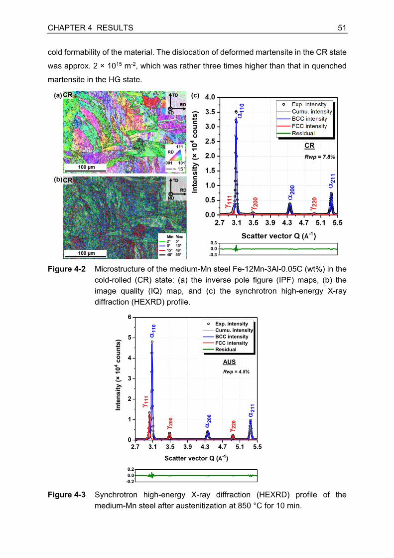
CHAPTER 4 RESULTS 51
cold formability of the material. The dislocation of deformed martensite in the CR state
was approx. 2 × 10¹⁵ m-2, which was rather three times higher than that in quenched
martensite in the HG state.
Figure 4-2 Microstructure of the medium-Mn steel Fe-12Mn-3Al-0.05C (wt%) in the
cold-rolled (CR) state: (a) the inverse pole figure (IPF) maps, (b) the image quality (IQ) map, and (c) the synchrotron high-energy X-ray diffraction (HEXRD) profile.
Figure 4-3 Synchrotron high-energy X-ray diffraction (HEXRD) profile of the
medium-Mn steel after austenitization at 850 °C for 10 min.
2.7 3.1 3.5 3.9 4.3 4.7 5.1 5.50
1
2
3
4
5
6
AUSRwp = 4.5%
Exp. intensity Cumu. intensity BCC intensity FCC intensity Residual
Inte
nsity
(× 1
04 cou
nts)
Scatter vector Q (Å-1)
a11
0
g 111
g 200 a20
0
g 220
a21
1
-0.20.00.2

52 CHAPTER 4 RESULTS
4.1.2. Austenite reversion kinetics during intercritical annealing
Figure 4-4 shows phase evolution measured by HEXRD during intercritical annealing
at 550 °C as a function of annealing time. The intercritical-annealing process can be
divided into two phases, namely (i) heating from room temperature up to 550 °C and
(ii) isothermal holding at 550 °C for 10 hours. It can be seen that there was only a
slight increase in the amount of austenite in the HG specimen during heating and there
was less than 1 vol% austenite detected up to 550 °C. In contrast, the amount of
austenite in the CR specimen started to increase during the heating process in a lower
temperature range of 450 °C - 500 °C. The A1e temperature was estimated to be about
490 °C by ThermoCalc with TCFE9. The results indicated that austenite reversion in
the CR specimen took place immediately when the A1 temperature was reached.
Moreover, the CR specimen showed a fast increment in the amount of austenite during
the heating process up to 550 °C, and there was 20 vol% austenite obtained in the
material when the temperature reached 550 °C during heating.
Figure 4-4 The amount of austenite (γ) and martensite (α') as a function of annealing
time in (a) the homogenized (HG) material and (b) the cold-rolled (CR) material.
During isothermal holding phase, the amount of austenite in HG specimen increased
steadily. After isothermal holding at 550 °C for 10 hours, the amount of austenite
achieved approx. 22.6 vol%. In contrast to the HG specimen, CR specimen manifested
a fast austenite reversion kinetics, and the amount of austenite approached ~40 vol%
after isothermal holding at 550 °C for approx. 2 hours. The amount of retained
austenite continuously increased with a further increase in the annealing time, but the
increment rate became tardy. After isothermal holding for 10 hours, the amount of

CHAPTER 4 RESULTS 53
austenite in the CR specimen achieved approx. 42.5 vol%, which was close to the
equilibrium amount of austenite 43 vol% (estimated by ThermoCalc with TCFE9).
4.1.3. Martensite recovery kinetics during intercritical annealing
The recovery of martensite during intercritical annealing was characterized by the
evolution of the dislocation density of martensite, as shown in Figure 4-5. In the HG
specimen, the recovery started during the heating process at 300 °C. There was a
substantial recovery of martensite between 325 °C and 550 °C, indicated by a rapid
decline in dislocation density. The dislocation density was reduced from 6 × 10¹⁴ m-2
to 1.2 × 10¹⁴ m-2 during the heating process. During isothermal holding, a decrease in
dislocation density was sluggish. After isothermal holding at 550 °C for 10 hours, the
dislocation density of martensite decreased to 7.5 × 10¹³ m-2 in the HG specimen.
In comparison with the HG specimen, recovery of martensite began at a much lower
temperature in the CR specimen during heating. As displayed in Figure 4-5b, recovery
started in the CR specimen at approx. 100 °C. There was a rapid drop in dislocation
density between 275 °C and 550 °C, implying an active recovery of martensite. The
quantity of dislocation density was reduced from 2 × 10¹⁵ m-2 to 2.6 × 10¹⁴ m-2 during
heating. During isothermal holding, the recovery of martensite was moderate. The
dislocation density decreased progressively to 7.8 × 10¹³ m-2 after holding for 10 hours.
The dislocation density of martensite in the CR specimen was higher than that in the
HG specimen along the annealing process, which might contribute to fast elemental
partitioning via pipe diffusion and austenite reversion kinetics.
Figure 4-5 Dislocation density of martensite (α') as a function of annealing time in
(a) the homogenized (HG) material and (b) the cold-rolled (CR) material.
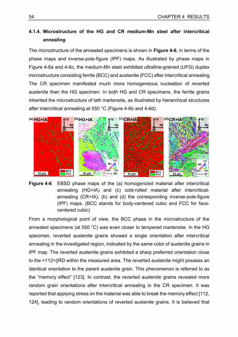
54 CHAPTER 4 RESULTS
4.1.4. Microstructure of the HG and CR medium-Mn steel after intercritical annealing
The microstructure of the annealed specimens is shown in Figure 4-6, in terms of the
phase maps and inverse-pole-figure (IPF) maps. As illustrated by phase maps in
Figure 4-6a and 4-6c, the medium-Mn steel exhibited ultrafine-grained (UFG) duplex
microstructure consisting ferrite (BCC) and austenite (FCC) after intercritical annealing.
The CR specimen manifested much more homogeneous nucleation of reverted
austenite than the HG specimen. In both HG and CR specimens, the ferrite grains
inherited the microstructure of lath martensite, as illustrated by hierarchical structures
after intercritical annealing at 550 °C (Figure 4-6b and 4-6d).
Figure 4-6 EBSD phase maps of the (a) homogenized material after intercritical
annealing (HG+IA) and (c) cold-rolled material after intercritical-annealing (CR+IA); (b) and (d) the corresponding inverse-pole-figure (IPF) maps. (BCC stands for body-centered cubic and FCC for face-centered cubic)
From a morphological point of view, the BCC phase in the microstructure of the
annealed specimens (at 550 °C) was even closer to tempered martensite. In the HG
specimen, reverted austenite grains showed a single orientation after intercritical
annealing in the investigated region, indicated by the same color of austenite grains in
IPF map. The reverted austenite grains exhibited a sharp preferred orientation close
to the <112>||RD within the measured area. The reverted austenite might possess an
identical orientation to the parent austenite grain. This phenomenon is referred to as
the “memory effect” [123]. In contrast, the reverted austenite grains revealed more
random grain orientations after intercritical annealing in the CR specimen. It was
reported that applying stress on the material was able to break the memory effect [112,
124], leading to random orientations of reverted austenite grains. It is believed that

CHAPTER 4 RESULTS 55
cold rolling in this study is responsible for eliminating the memory effect of reverted
austenite grains in the CR specimen.
To further investigate the effect of cold rolling on austenite reversion behavior, the
microstructure characteristics of reverted austenite grains are summarized in Table
4-1. The gamma-to-gamma grain spacing was the distance of nearest austenite grains
in alignment with the substructures (laths and blocks) of ferrite (or tempered
martensite). It can be recognized that the aspect ratio (length/width) of reverted
austenite in the HG specimen was much larger than that in the CR specimen. Besides,
the distance between reverted austenite grains was rather smaller in the CR specimen
than that in the HG specimen. As shown in Figure 4-2b, cold rolling resulted in a large
number of defects in the CR specimen. The defects usually act as nucleation sites for
phase transformation. Therefore, cold rolling promoted homogeneous austenite
nucleation in the medium-Mn steel, which is mainly responsible for the fast austenite
reversion kinetics.
Table 4-1 Microstructure characteristics of reverted austenite after intercritical annealing in the CR and HG specimens.
Characteristics HG+IA CR+IA
γ aspect ratio (L/W) 3.56 ± 1.17 1.95 ± 0.62
γ to γ spacing 1.87 ± 0.86 µm 1.07 ± 0.24 µm

56 CHAPTER 4 RESULTS
4.2. Influence of intercritical-annealing temperature on microstructure and mechanical properties
In this subchapter, the influence of intercritical-annealing temperature on
microstructure and mechanical properties of the medium-Mn steel Fe-12Mn-3Al-0.05C
(wt%) was investigated. Intercritical annealing was carried out in a broad temperature
range from approx. 550 °C to 750 °C. The microstructural morphologies of the
medium-Mn steel were characterized by scanning electron microscopy (SEM) and
electron backscattered diffraction (EBSD) technique. In particular, the large
intercritical-annealing temperature allowed to reveal the recrystallization behavior and
elucidate the genesis of the microstructural morphology of medium-Mn steel. The
tensile properties of the medium-Mn steel were characterized by quasi-static tensile
tests. The amount of retained austenite in the intercritically annealed and deformed
specimens was measured by laboratory X-ray diffraction (XRD) technique. The strain-
hardening behavior of the material was correlated with the microstructure and the
deformation-induced martensite transformation.
4.2.1. Influence of intercritical-annealing temperature on microstructure
The microstructure images of the medium-Mn steel in the intercritically annealed
states at various temperatures are displayed in Figure 4-7. When the cold-rolled
medium-Mn steel was subject to intercritical annealing, austenite reversion took place.
The specimen annealed at 555 °C manifested duplex microstructure consisting of
ferrite (flat grey regions) and austenite (dark crevices). The microstructure showed an
elongated morphology (Figure 4-7b), which inherited the morphology of deformed
martensite. With an increase in intercritical-annealing temperature to 600 °C and
650 °C, the microstructure of the medium-Mn steel revealed a mixture of elongated
and equiaxed morphologies (Figure 4-7c and Figure 4-7d). It indicated that the
microstructure was partially recrystallized in this temperature range. When intercritical-
annealing temperature further increased to 700 °C and 750 °C, the elongated
microstructure vanished. The microstructure was almost fully recrystallized at those
temperatures, resulting in equiaxed ferrite and retained austenite (Figure 4-7e and
Figure 4-7f). However, lath-like martensite was also distinguished in the microstructure,
which could be non-recrystallized martensite or fresh martensite. A high intercritical-
annealing temperature led to a large amount of austenite with poor thermal stability.

CHAPTER 4 RESULTS 57
This austenite might transform back into fresh α’-martensite during quenching.
Besides, the microstructure of the investigated steel was coarsened by an increase in
intercritical-annealing temperature.
Figure 4-7 SEM images of the medium-Mn steel Fe-12Mn-3Al-0.05C (wt%) in (a)
CR state, (b) IA555 state, (c) IA600 state, (d) IA650 state, (e) IA700 state, and (f) IA750 state. (CR stands for cold-rolled, IA for intercritical annealing, RA for retained austenite, F for ferrite, and M for martensite.)
In order to characterize the microstructure in the medium-Mn steel annealed at 555 °C
and 700 °C in detail, EBSD was employed concerning the phase distribution, kernel
average misorientation (KAM) and grain orientation distribution analyses. Figure 4-8a
and Figure 4-8d illustrate the phase distribution in the specimens annealed at 555 °C

58 CHAPTER 4 RESULTS
and 700 °C, respectively. Both specimens contained UFG ferrite and austenite. The
average grain size of ferrite and austenite is about 589 nm and 358 nm in the
specimen annealed at 555 °C, and approx. 1.19 μm and 1.28 μm in the specimens
annealed at 700 °C. Moreover, the microstructure of both specimens showed
differences in morphologies and the amount of austenite. In the steel annealed at
555 °C, there existed an elongated morphology of the ferrite-austenite duplex
microstructure and approx. 17 vol% austenite was indexed in the phase map (Figure
4-8a). Nevertheless, a considerable number of tiny regions were not adequately
indexed by EBSD, which are displayed by black color in the phase map (Figure 4-8a).
The phase in these regions most probably is reverted austenite between ferrite laths.
The retained austenite might be extremely fine, and its size was even within the step
size of EBSD measurement. In addition, the sample was electropolished, and the
shadowing effect from the topography of specimen surface might generate some
difficulties for the identification of tiny austenitic phase nucleated in between of ferrite
laths. The loss of the tiny austenite during phase indexing by EBSD might result in an
underestimation of the austenite fraction. In contrast, the ferrite-austenite duplex
microstructure with an equiaxed morphology was obtained with a large amount of
retained austenite (around 61 vol%) in the steel annealed at 700 °C (Figure 4-8d).
In respect of the KAM distribution, the steel annealed at 555 °C (Figure 4-8b) showed
higher overall values than the steel annealed at 700 °C (Figure 4-8e). This result
indicated a larger number of stored geometrically necessary dislocations (GND) in the
specimen annealed at 555 °C, compared with the specimen annealed at 700 °C.
However, there were some regions in the steel annealed at 700 °C showing relatively
higher KAM values than those in the other regions, which were also correlated with
relatively smaller grain size. This behavior might be attributed to a passive
recrystallization behavior of deformed martensite or the formation of fresh α’-
martensite in the thermally unstable austenite during the quenching process. The
inverse pole figure (IPF) maps (Figure 4-8c) of the steel annealed at 555 °C indicated
a strong rolling texture. In contrast, the grain distribution of the material annealed at
700 °C (Figure 4-8f) was much more random. The detailed analysis of texture requests
a largely enough representative area, which should be carried out in the future with a
large detection area or by other methods, such as X-ray diffraction.

CHAPTER 4 RESULTS 59
Figure 4-8 Electron backscattered diffraction (EBSD) maps of the medium-Mn steel
intercritically annealed at 555 °C and 700 °C: (a) and (d) phase map, (b) and (e) kernel average misorientation (KAM) map with respect to a radius of 100 nm, (c) and (f) inverse pole figure (IPF) maps.

60 CHAPTER 4 RESULTS
4.2.2. The amount of retained austenite as a function of intercritical-annealing temperature
The XRD profiles of the medium-Mn steel Fe-12Mn-3Al-0.05C (wt%) under
intercritically-annealed conditions are shown in Figure 4-9a. When intercritical
annealing was applied to the cold-rolled state, the peaks of FCC structure (γ) appeared
in the XRD profiles, meaning that intercritical annealing results in austenite reversion.
The amount of retained austenite as a function of the intercritical-annealing
temperature of the medium-Mn steel is revealed in Figure 4-9b. The amount of
retained austenite achieved 42.2 vol% in the specimen annealed at 555 °C and
increased to 58.4 vol% with an increase in intercritical-annealing temperature up to
700 °C. A further increase in intercritical-annealing temperature to 750 °C led to a
decrease in the amount of retained austenite to 34.9 vol%. The decrease in the
amount of austenite might be attributed to the formation of a certain amount of fresh
α’-martensite during quenching in the water at room temperature, because a high
intercritical-annealing temperature led to the reduced thermal stability of retained
austenite. Nevertheless, the amount of α’-martensite was not able to be quantified by
laboratory XRD because the peaks of α’-martensite (body-centered tetragonal, BCT)
and ferrite (BCC) were overlapped, due to their similarity in crystal structures.
Figure 4-9 (a) XRD profiles of the medium-Mn steel Fe-12Mn-3Al-0.05C (wt%) in
cold-rolled (CR) state and after intercritical annealing at temperature between 555 °C and 750 °C; (b) the amount of retained austenite in the medium-Mn steel as a function of intercritical-annealing temperature.

CHAPTER 4 RESULTS 61
4.2.3. Intercritical-annealing temperature dependence of mechanical properties
Figure 4-10 shows the engineering stress-engineering strain curves of the medium-
Mn steel Fe-12Mn-3Al-0.05C (wt%) under cold-rolled and intercritically annealed
conditions. The cold-rolled specimen possessed high yield strength of about
1400 MPa, but only small ductility. Intercritical annealing significantly improved the
ductility of the material with a sacrifice of yield strength. The engineering stress-
engineering strain curve of the specimen annealed at 555 °C displayed a continuous
yielding feature and a relatively poor strain-hardening behavior. With an increase in
intercritical-annealing temperature to 600 °C, the specimens showed a discontinuous
yielding behavior with a little amount of localized deformation after yielding. The
specimens annealed above 650 °C did not manifest apparent discontinuous yielding
and localized deformation behavior. It can be seen that an increase in intercritical-
annealing temperature resulted in improved strain-hardening behavior and ductility of
the medium-Mn steel. When the specimen was annealed at 750 °C, it showed a high
ultimate tensile strength with reduced ductility. The influence of the intercritical-
annealing temperature on the characteristic values of mechanical properties is
summarized in Table 4-2.
Figure 4-10 Engineering stress-engineering strain curves of the medium-Mn steel
Fe-12Mn-3Al-0.05C (wt%) after cold rolling (CR) and intercritical annealing at different temperatures (IA555, IA600, IA650, IA700 and IA750).
0 5 10 15 20 25 30 35 400
200
400
600
800
1000
1200
1400
1600 CR IA555 IA600 IA650 IA700 IA750
Engi
neer
ing
stre
ss (M
Pa)
Engineering strain (%)
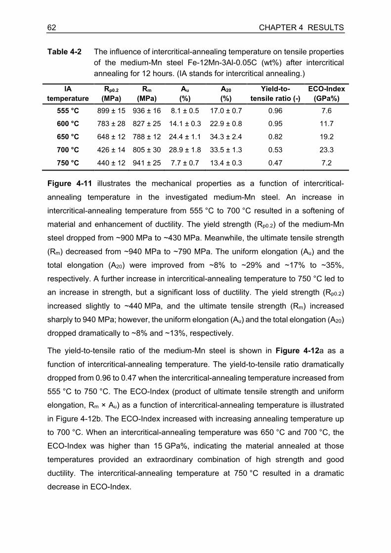
62 CHAPTER 4 RESULTS
Table 4-2 The influence of intercritical-annealing temperature on tensile properties of the medium-Mn steel Fe-12Mn-3Al-0.05C (wt%) after intercritical annealing for 12 hours. (IA stands for intercritical annealing.)
IA temperature
Rp0.2 (MPa)
Rm (MPa)
Au (%)
A20 (%)
Yield-to-tensile ratio (-)
ECO-Index (GPa%)
555 °C 899 ± 15 936 ± 16 8.1 ± 0.5 17.0 ± 0.7 0.96 7.6
600 °C 783 ± 28 827 ± 25 14.1 ± 0.3 22.9 ± 0.8 0.95 11.7
650 °C 648 ± 12 788 ± 12 24.4 ± 1.1 34.3 ± 2.4 0.82 19.2
700 °C 426 ± 14 805 ± 30 28.9 ± 1.8 33.5 ± 1.3 0.53 23.3
750 °C 440 ± 12 941 ± 25 7.7 ± 0.7 13.4 ± 0.3 0.47 7.2
Figure 4-11 illustrates the mechanical properties as a function of intercritical-
annealing temperature in the investigated medium-Mn steel. An increase in
intercritical-annealing temperature from 555 °C to 700 °C resulted in a softening of
material and enhancement of ductility. The yield strength (Rp0.2) of the medium-Mn
steel dropped from ~900 MPa to ~430 MPa. Meanwhile, the ultimate tensile strength
(Rm) decreased from ~940 MPa to ~790 MPa. The uniform elongation (Au) and the
total elongation (A20) were improved from ~8% to ~29% and ~17% to ~35%,
respectively. A further increase in intercritical-annealing temperature to 750 °C led to
an increase in strength, but a significant loss of ductility. The yield strength (Rp0.2)
increased slightly to ~440 MPa, and the ultimate tensile strength (Rm) increased
sharply to 940 MPa; however, the uniform elongation (Au) and the total elongation (A20)
dropped dramatically to ~8% and ~13%, respectively.
The yield-to-tensile ratio of the medium-Mn steel is shown in Figure 4-12a as a
function of intercritical-annealing temperature. The yield-to-tensile ratio dramatically
dropped from 0.96 to 0.47 when the intercritical-annealing temperature increased from
555 °C to 750 °C. The ECO-Index (product of ultimate tensile strength and uniform
elongation, Rm × Au) as a function of intercritical-annealing temperature is illustrated
in Figure 4-12b. The ECO-Index increased with increasing annealing temperature up
to 700 °C. When an intercritical-annealing temperature was 650 °C and 700 °C, the
ECO-Index was higher than 15 GPa%, indicating the material annealed at those
temperatures provided an extraordinary combination of high strength and good
ductility. The intercritical-annealing temperature at 750 °C resulted in a dramatic
decrease in ECO-Index.

CHAPTER 4 RESULTS 63
Figure 4-11 (a) Yield strength (Rp0.2) and ultimate tensile strength (Rm) as well as (b)
uniform elongation (Au) and total elongation (A20) of the medium-Mn steel Fe-12Mn-3Al-0.05C (wt%) as a function of intercritical-annealing temperature.
Figure 4-12 (a) Yield-to-tensile ratio (Rp0.2/Rm) and (b) ECO-Index (Rm × Au) of the
medium-Mn steel Fe-12Mn-3Al-0.05C (wt%) as a function of intercritical-annealing temperature.
4.2.4. Influence of intercritical-annealing temperature on mechanical stability of retained austenite and strain-hardening behavior
Figure 4-13 shows the true stress-true strain curves and corresponding strain-
hardening rates of the medium-Mn steel annealed at various temperatures. The strain-
hardening behavior of the specimens mainly manifested three different stages, except
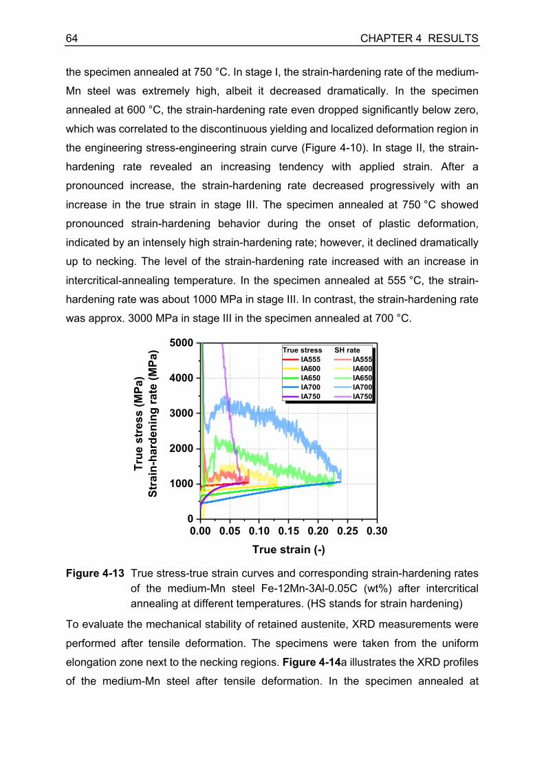
64 CHAPTER 4 RESULTS
the specimen annealed at 750 °C. In stage I, the strain-hardening rate of the medium-
Mn steel was extremely high, albeit it decreased dramatically. In the specimen
annealed at 600 °C, the strain-hardening rate even dropped significantly below zero,
which was correlated to the discontinuous yielding and localized deformation region in
the engineering stress-engineering strain curve (Figure 4-10). In stage II, the strain-
hardening rate revealed an increasing tendency with applied strain. After a
pronounced increase, the strain-hardening rate decreased progressively with an
increase in the true strain in stage III. The specimen annealed at 750 °C showed
pronounced strain-hardening behavior during the onset of plastic deformation,
indicated by an intensely high strain-hardening rate; however, it declined dramatically
up to necking. The level of the strain-hardening rate increased with an increase in
intercritical-annealing temperature. In the specimen annealed at 555 °C, the strain-
hardening rate was about 1000 MPa in stage III. In contrast, the strain-hardening rate
was approx. 3000 MPa in stage III in the specimen annealed at 700 °C.
Figure 4-13 True stress-true strain curves and corresponding strain-hardening rates
of the medium-Mn steel Fe-12Mn-3Al-0.05C (wt%) after intercritical annealing at different temperatures. (HS stands for strain hardening)
To evaluate the mechanical stability of retained austenite, XRD measurements were
performed after tensile deformation. The specimens were taken from the uniform
elongation zone next to the necking regions. Figure 4-14a illustrates the XRD profiles
of the medium-Mn steel after tensile deformation. In the specimen annealed at
0.00 0.05 0.10 0.15 0.20 0.25 0.300
1000
2000
3000
4000
5000
True
str
ess
(MPa
)St
rain
-har
deni
ng ra
te (M
Pa)
True strain (-)
True stress SH rate IA555 IA555 IA600 IA600 IA650 IA650 IA700 IA700 IA750 IA750

CHAPTER 4 RESULTS 65
temperature up to 700 °C, the austenite peaks remained, indicating the existence of
retained austenite after deformation. In contrast, the austenite peaks completely
disappeared in the specimens annealed at 750 °C, meaning that all the retained
austenite transformed into martensite during tensile deformation. Figure 4-14b
displays the amount of retained austenite and its transformation ratio in the specimens
after tensile deformation as a function of intercritical-annealing temperature. The
austenite transformation ratio was defined as the change in the amount of austenite
during deformation (∆𝑉)) divided by the amount of retained austenite after intercritical
annealing (𝑉)Y). More than 40 vol% of austenite remained in the specimens annealed
up to 650 °C, showing a transformation ratio lower than 0.1. It indicates a weak TRIP
effect in the specimens during deformation. With a further increase in the intercritical-
annealing temperature, the austenite transformation ratio increased sharply. The
progressive transformation of austenite into martensite was believed to enhance the
strain-hardening rate effectively in medium-Mn steel [10].
Figure 4-14 (a) XRD profiles of the medium-Mn steel Fe-12Mn-3Al-0.05C (wt%) after
tensile deformation; (b) the amount of retained austenite in the medium-Mn steel specimens after tensile deformation and its transformation ratio as a function of intercritical-annealing temperature.

66 CHAPTER 4 RESULTS
4.3. Influence of intercritical-annealing time on microstructure and mechanical properties
The influence of intercritical-annealing time on microstructure and mechanical
properties of the medium-Mn steel was investigated in this subchapter. The cold-rolled
medium-Mn steel was intercritically annealed at 700 °C for different durations from
5 min up to 12 hours. The microstructure was characterized by scanning electron
microscopy (SEM). In particular, the microstructural morphology was distinguished by
equiaxed and elongated morphologies, indicating recrystallization behavior of
deformed microstructure as a function of intercritical-annealing time. The amount of
retained austenite was characterized by ex situ and in situ synchrotron high-energy X-
ray diffraction (HEXRD) on the material after intercritical annealing and during tensile
deformation, respectively. The mechanical properties were evaluated on sub-sized
tensile specimens by quasi-static tensile tests by a tensile rig at the synchrotron
beamline. The mechanical stability of retained austenite as a function of intercritical-
annealing time was assessed by the transformation ratio of retained austenite, which
was associated with the strain-hardening behavior of the medium-Mn steel.
4.3.1. Influence of intercritical-annealing time on microstructure
Figure 4-15 illustrates the microstructure images of the medium-Mn steel annealed at
700 °C for different durations from 5 min up to 4 hours. The medium-Mn steel after
intercritical annealing showed duplex UFG microstructure consisting of ferrite (raised
grey flat regions) and austenite (sunk dark crevices). It can be seen that there was a
tremendous amount of reverted austenite in the microstructure even after a short
intercritical-annealing period for 5 min at 700 °C. The microstructure manifested
mainly elongated grain morphology (Figure 4-15a), which inherited the morphology of
deformed martensite in the cold-rolled state. With an increase in intercritical-annealing
time to 30 min, the microstructure revealed a mixture of equiaxed and elongated
(marked with white dash lines) grain morphologies (Figure 4-15b). The equiaxed grain
morphology indicated active recrystallization of martensite. A further increase in
intercritical-annealing time resulted in a decrease in the area of elongated grains and
an increase in the area of equiaxed grains. As shown in Figure 4-15d, the
microstructure of the medium-Mn steel displayed almost mainly equiaxed grain
morphology after intercritical annealing for 4 hours.

CHAPTER 4 RESULTS 67
Figure 4-15 SEM images of the medium-Mn steel Fe-12Mn-3Al-0.05C (wt%)
annealed at 700 °C for (a) 5 min, (b) 30 min, (c) 1 hour, and (d) 4 hours. In (b), (c) and (d), the regions marked by white dash lines represent the microstructure with elongated morphology. (RA strands for retained austenite and F for ferrite.)
4.3.2. The amount of retained austenite as a function of intercritical-annealing time
The diffraction patterns of the medium-Mn steel are shown in Figure 4-16a as a
function of annealing time after intercritical annealing at 700 °C. After a short annealing
duration at 700 °C for 5 min, the medium-Mn steel exhibited prominent diffraction
peaks of retained austenite γ111, γ200, and γ220. The intensity of diffraction peaks of
retained austenite further increased with increasing annealing time. By the Rietveld
refinement, the amount of retained austenite was calculated, as shown in Figure 4-16b
as a function of annealing time. The initial amount of retained austenite in the cold-
rolled state was about 7.5 vol% (Figure 4-2). It significantly increased to about 54 vol%
after intercritical annealing for 5 min and further increased to approx. 58 vol% after
intercritical annealing for 30 min. The amount of retained austenite reached approx.
60 vol% after intercritical annealing for 1 hour and there was no discernible change in
the amount of retained austenite with a further increase in intercritical-annealing time.
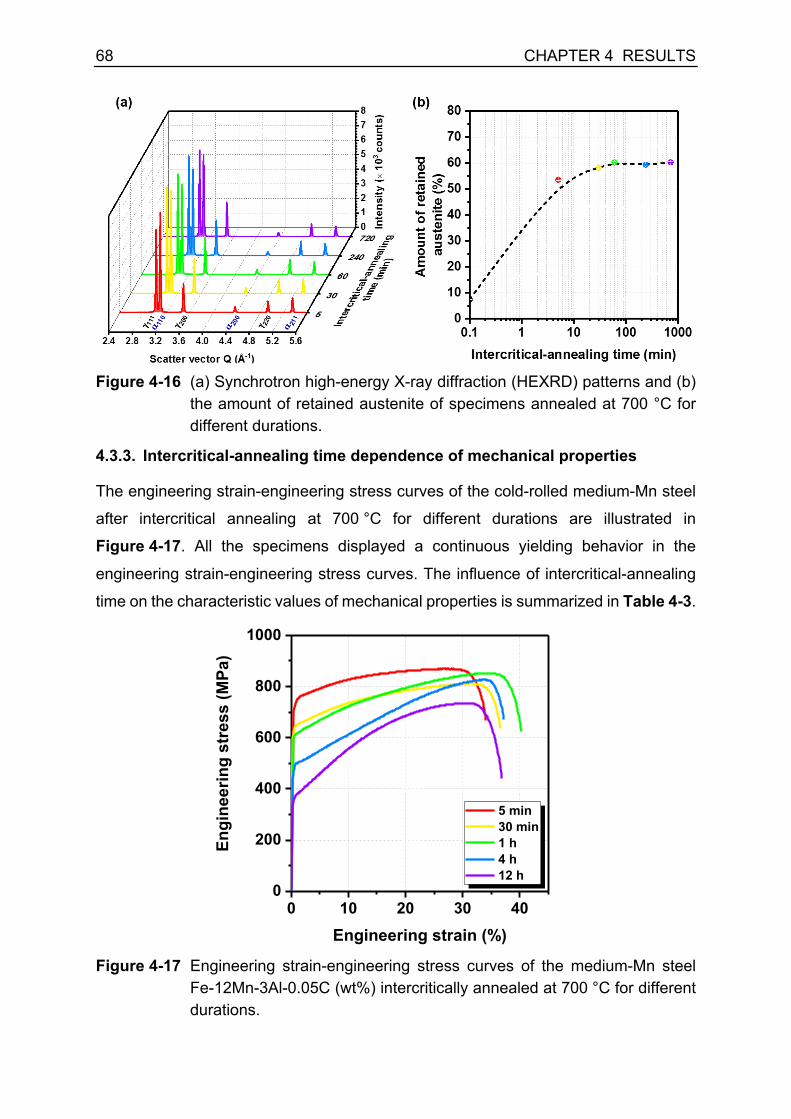
68 CHAPTER 4 RESULTS
Figure 4-16 (a) Synchrotron high-energy X-ray diffraction (HEXRD) patterns and (b)
the amount of retained austenite of specimens annealed at 700 °C for different durations.
4.3.3. Intercritical-annealing time dependence of mechanical properties
The engineering strain-engineering stress curves of the cold-rolled medium-Mn steel
after intercritical annealing at 700 °C for different durations are illustrated in
Figure 4-17. All the specimens displayed a continuous yielding behavior in the
engineering strain-engineering stress curves. The influence of intercritical-annealing
time on the characteristic values of mechanical properties is summarized in Table 4-3.
Figure 4-17 Engineering strain-engineering stress curves of the medium-Mn steel
Fe-12Mn-3Al-0.05C (wt%) intercritically annealed at 700 °C for different durations.
0 10 20 30 400
200
400
600
800
1000
Engi
neer
ing
stre
ss (M
Pa)
Engineering strain (%)
5 min 30 min 1 h 4 h 12 h
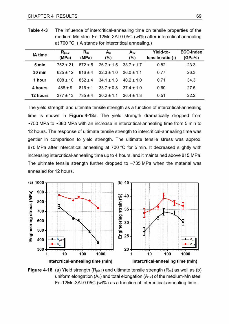
CHAPTER 4 RESULTS 69
Table 4-3 The influence of intercritical-annealing time on tensile properties of the medium-Mn steel Fe-12Mn-3Al-0.05C (wt%) after intercritical annealing at 700 °C. (IA stands for intercritical annealing.)
IA time Rp0.2 (MPa)
Rm (MPa)
Au (%)
A12 (%)
Yield-to-tensile ratio (-)
ECO-Index (GPa%)
5 min 752 ± 21 872 ± 5 26.7 ± 1.5 33.7 ± 1.7 0.82 23.3
30 min 625 ± 12 816 ± 4 32.3 ± 1.0 36.0 ± 1.1 0.77 26.3
1 hour 608 ± 10 852 ± 4 34.1 ± 1.3 40.2 ± 1.0 0.71 34.3
4 hours 488 ± 9 816 ± 1 33.7 ± 0.8 37.4 ± 1.0 0.60 27.5
12 hours 377 ± 13 735 ± 4 30.2 ± 1.1 36.4 ± 1.3 0.51 22.2
The yield strength and ultimate tensile strength as a function of intercritical-annealing
time is shown in Figure 4-18a. The yield strength dramatically dropped from
~750 MPa to ~380 MPa with an increase in intercritical-annealing time from 5 min to
12 hours. The response of ultimate tensile strength to intercritical-annealing time was
gentler in comparison to yield strength. The ultimate tensile stress was approx.
870 MPa after intercritical annealing at 700 °C for 5 min. It decreased slightly with
increasing intercritical-annealing time up to 4 hours, and it maintained above 815 MPa.
The ultimate tensile strength further dropped to ~735 MPa when the material was
annealed for 12 hours.
Figure 4-18 (a) Yield strength (Rp0.2) and ultimate tensile strength (Rm) as well as (b)
uniform elongation (Au) and total elongation (A12) of the medium-Mn steel Fe-12Mn-3Al-0.05C (wt%) as a function of intercritical-annealing time.

70 CHAPTER 4 RESULTS
Intercritical-annealing time dependence of ductility is illustrated in Figure 4-18b. The
material revealed good ductility under all the intercritical-annealing conditions. The
uniform elongation and total elongation increased with an increase in intercritical-
annealing time from 5 min up to 1 hour. The maximal uniform elongation was ~34%,
and total elongation was ~40% when the material annealed for 1 hour at 700 °C. With
a further increase in intercritical-annealing time up to 4 hours, there was only a slight
drop in ductility. Intercritical annealing for 12 hours led to a decline in uniform
elongation to ~30% and total elongation to ~36%. Nevertheless, it is worth noting that
there were some discrepancies of the mechanical properties presented in chapter 4.2
and chapter 4.3 for the medium-Mn steel annealed at 700 °C for 12 hours. These
differences might be due to the geometrical effect of tensile specimens.
The influence of intercritical-annealing time on the yield-to-tensile ratio of the medium-
Mn steel is shown in Figure 4-19a. The yield-to-tensile ratio dramatically decreased
from 0.86 to 0.51, with increasing annealing time. Figure 4-19b displays the ECO-
Index (product of ultimate tensile strength and uniform elongation, Rm × Au) as a
function of annealing time. For all the investigated specimens, the ECO-Index was
higher than 20 GPa%, indicating a good combination of strength and ductility. The
optimal annealing time at 700 °C should be about 1 hour, implied by the maximal ECO-
Index of approx. 35 GPa%.
Figure 4-19 (a) Yield-to-tensile ratio (Rp0.2/Rm) and (b) ECO-Index (Rm × Au) of the
medium-Mn steel Fe-12Mn-3Al-0.05C (wt%) as a function of intercritical-annealing time.

CHAPTER 4 RESULTS 71
4.3.4. Influence of intercritical-annealing time on mechanical stability of retained austenite and strain-hardening behavior
True strain-true stress curves and corresponding strain-hardening rates of the
medium-Mn steel annealed for different periods are illustrated in Figure 4-20. The
strain-hardening behavior of the medium-Mn steel can be divided into multiple stages.
In stage I (εt < ~0.025), all specimens revealed a rapid drop in strain-hardening rate.
In stage II (0.025 < εt < 0.05), strain-hardening rates increased in all specimens with
increasing true strain. After stage II, the medium-Mn exhibited an intercritical-
annealing time dependence of strain-hardening behavior. In the specimens annealed
for 5 min and 30 min, the strain-hardening rates continuously decreased during
deformation in stage III up to necking (εt > 0.05). In the specimen annealed for 1 hour,
after a decline in strain-hardening rate in stage III (0.05 < εt < 0.12) the strain-
hardening rate became steady at a level of ~1800 MPa, which was referred to as
stage IV (0.12 < εt < 0.25). Prolonged annealing for 4 hours resulted in an increase in
strain-hardening rate up to ~2500 MPa in stage III (0.05 < εt < 0.175), followed by a
decrease in strain-hardening rate in stage IV up to necking (εt > 0.175). The annealing
for 12 hours resulted in a high initial strain-hardening rate, and it was at a level of
~2800 MPa in stage II. Then the strain-hardening rate dramatically decreased with
increasing true strain up to necking in stage III.
Figure 4-20 Intercritical-annealing time dependence of true strain-true stress curves
and corresponding strain-hardening rates of specimens annealed at 700 °C. (HS stands for strain hardening)
0.00 0.05 0.10 0.15 0.20 0.25 0.300
500
1000
1500
2000
2500
3000
3500
4000
IV
IVIII
II
III
III
I
True
str
ess
(MPa
)St
rain
-har
deni
ng ra
te (M
Pa)
True strain (-)
True stress SH rate 5 min 5 min 30 min 30 min 1 h 1 h 4 h 4 h 12 h 12 h
II

72 CHAPTER 4 RESULTS
The mechanical stability of retained austenite was represented by the evolution of the
amount of retained austenite and corresponding transformation ratio as a function of
true strain, as shown in Figure 4-21. It can be seen that austenite to martensite
transformation occurred after a small amount of deformation (εt = 0.025) for all the
specimens. The amount of retained austenite progressively decreased with increasing
deformation degree (Figure 4-21a). The transformation ratio of retained austenite is
defined as ∆𝑉)/𝑉)Y , where ∆𝑉) is the amount of retained austenite transformed to
martensite upon deformation, and 𝑉)Y is the initial amount of retained austenite prior to
deformation. As illustrated in Figure 4-21b, the medium-Mn steel annealed for a
prolonged time manifested a higher transformation ratio of retained austenite during
deformation (at a same amount of deformation), implying more reduced mechanical
stability of retained austenite. In particular, the specimens annealed for 4 hours and
12 hours revealed a considerably high transformation ratio at the beginning of
deformation (about 0.1 at 0.025 true strain). This immediate martensitic transformation
should be the reason for the high strain-hardening rate at the beginning of deformation
in the specimens annealed for 4 hours and 12 hours.
Figure 4-21 (a) The evolution of the amount of retained austenite and (b)
transformation ratio of retained austenite during tensile deformation of the medium-Mn steel intercritically annealed for different durations.

CHAPTER 4 RESULTS 73
4.4. Influence of cooling conditions on microstructure and mechanical properties
In this subchapter, the influence of cooling conditions after intercritical annealing on
microstructure and mechanical properties was studied, namely water quenching (WQ)
and air cooling (AC). In particular, the impact of carbon segregation to interphase
boundaries during the cooling process on yielding phenomenon and strain-hardening
behavior was for the first time investigated. The microstructure characteristics, in terms
of morphology and grain size, were measured by electron backscatter diffraction
(EBSD) technique. The amount of retained austenite after intercritical annealing and
deformation was characterized by ex situ synchrotron high-energy X-ray diffraction
(HEXRD). The elemental partitioning and segregation behavior was characterized by
atom probe tomography (APT).
4.4.1. Influence of cooling conditions on microstructure and the amount of retained austenite
The EBSD phase maps of the WQ and AC specimens are shown in Figure 4-22a and
Figure 4-22b, respectively. The medium-Mn steel manifested a duplex microstructure
composed of austenite and ferrite with equiaxed grain morphology after intercritical
annealing. The amount of retained austenite in the WQ and AC specimens was
58.6 vol% and 58.9 vol% measured by EBSD, respectively. The average grain size of
austenite and ferrite in the WQ and AC specimens is displayed in Figure 4-22c, and
there was no noticeable difference in grain size between the WQ and AC specimens.
HEXRD investigation provided a more precise assessment of the amount of austenite
in a representative volume, as shown in Figure 4-23. It can be seen that the
cumulative intensity calculated by the Rietveld refinement method fitted the
experimental data commendably, indicated by the subtle residual in Figure 4-23a and
Figure 4-23b. The FCC structure was indexed as γ-austenite, while the BCC structure
was referred to as α-ferrite in the WQ and AC specimens. No diffraction peak of
carbide was observed in both cases, which suggested that there was no precipitation
of carbide even under the air-cooling condition in the medium-Mn steel.
Correspondingly, the volume percentage of retained austenite in the WQ and AC
specimens was 59.1 ± 0.2 vol% and 58.4 ± 0.7 vol%, which resonated well with the
results from EBSD measurements. Hence, there was no distinct impact of cooling

74 CHAPTER 4 RESULTS
conditions on the microstructure of the medium-Mn steel, in terms of phase fraction,
grain size, and grain morphology.
Figure 4-22 Electron backscattered diffraction (EBSD) phase maps of the medium-
Mn steel after intercritical annealing at 700 °C for 2 hours followed by (a) water quenching (WQ) and (b) air cooling (AC). (c) The average grain size measured by EBSD of the WQ and AC specimens.
Figure 4-23 Synchrotron high-energy X-ray diffraction (HEXRD) profiles of the
medium-Mn steel after intercritical annealing at 700 °C for 2 hours followed by (a) water quenching (WQ) and (b) air cooling (AC); (c) the amount of retained austenite (γ) and ferrite (α) in the WQ and AC specimens.

CHAPTER 4 RESULTS 75
4.4.2. Elemental partitioning behavior and carbon segregation to ferrite-austenite interface
The influence of the cooling conditions on the element distribution is illustrated in
Figure 4-24. Figure 4-24a and Figure 4-24b display the Mn distribution in the WQ and
AC specimens, respectively. The α/γ interphase boundaries were represented by the
11 at% Mn iso-surface. The distribution of C, Mn and Al atoms in the vicinity of the α/γ
phase boundaries was illustrated in detail in the selected regions of interest (ROIs), as
shown in Figure 4-24c and Figure 4-24e. It can be recognized that γ-austenite was
enriched by Mn and C, while α-ferrite was enriched by Al. The cooling conditions had
a negligible impact on Mn and Al distribution; In contrast, they tremendously affected
the distribution of interstitial element C in the vicinity of α/γ phase boundaries. The two-
dimensional concentration maps of C are revealed in Figure 4-24d and Figure 4-24f
along the α/γ phase boundaries in the WQ and AC specimens, respectively. For the
WQ specimen, no C segregation at the α/γ interface was observed. Besides, C was
almost homogeneously distributed in α-ferrite and γ-austenite in the WQ specimen. On
the contrary, the red region in Figure 4-24f demonstrates strong C segregation at the
α/γ interface in the AC specimen. Moreover, the distribution of C in α-ferrite in the AC
specimen appeared evident heterogeneity in the vicinity of the α/γ interface.
To quantify the C distribution behavior at interphase boundaries, one-dimensional
concentration profiles of C atoms relative to the position of the 11 at% Mn iso-surface
are shown in Figure 4-25. The C concentration profile of the WQ specimen inferred
no apparent C segregation at the α/γ phase boundary. As shown in Figure 3-6, it took
only a few seconds (< 10 seconds) when the temperature of the WQ specimen
dropped from 700 °C to the room temperature. The solute elements were frozen in the
phases formed at elevated temperature, and nearly no redistribution of substitutional
and interstitial elements took place during the considerably fast cooling process.
Nevertheless, α-ferrite and γ-austenite under quenched condition were not in
equilibrium at room temperature. In contrast to water quenching, it took about
1000 seconds by air cooling when the temperature declined from 700 °C to room
temperature (Figure 3-6). The air-cooling process provided the steel with a time
window for elemental redistribution, especially interstitial element C, across α/γ phase
boundaries in an attempt to level the gradient in chemical potential. The solubility of C
in α-ferrite decreased with a decline in temperature. This means that C atoms had to

76 CHAPTER 4 RESULTS
partition from α-ferrite into γ-austenite. From the kinetics point of view, C atoms could
be ejected out of α-ferrite quickly due to their high diffusivity in α-ferrite. Albeit, C atoms
were difficult to enter the γ-austenite because of their low mobility in γ-austenite [125].
As a result, C atoms were piled up at α/γ phase boundaries, manifesting strong
segregation to the α-ferrite ahead of the α/γ interfaces (Figure 4-25b). Besides,
carbides should be thermodynamically more stable than γ-austenite in a low-
temperature range (below ~490 °C according to the equilibrium phase diagram
calculated by ThermoCalc with TCFE9). The tendency of carbides nucleation at
interphase boundaries was also possible to raise the local C concentration at α/γ
interfaces, even though the kinetics of formation of carbides was retarded by the Al
addition. Moreover, it was anticipated that solute elements were prone to accumulate
at interphase boundaries in order to reduce the interfacial energy [126].
Figure 4-24 Three-dimensional atom maps of the medium-Mn steel after intercritical
annealing at 700 °C for 2 hours followed by (a) water quenching (WQ) and (b) air cooling (AC). (c) and (e) the distribution of C, Mn, and Al atoms in the selected regions of interest ROI 1 and ROI 2. (d) and (f) the two-dimensional concentration maps of C in ROI 1 and ROI 2.

CHAPTER 4 RESULTS 77
Figure 4-25 C concentration profiles relative to the position of the 11 at% Mn iso-
surface in (a) the WQ specimen and (b) the AC specimen.
4.4.3. Impact of cooling conditions on mechanical properties
The substantial impact of cooling conditions on the mechanical properties was
evaluated by uniaxial tensile tests. Figure 4-26 displays the engineering strain-
engineering stress curves of the WQ and AC specimens. The WQ specimen exhibited
a continuous yielding behavior, while slow cooling resulted in a discontinuous yielding
phenomenon in the AC specimen with a yield point elongation of about 1.4%. The
influence of the cooling conditions on the characteristic values of tensile properties is
shown in Figure 4-27 and summarized in Table 4-4.
Figure 4-27a illustrates the influence of cooling conditions on the strength and ductility
of the medium-Mn steel. It can be seen that the yield strength of the AC specimen
(ReH) was approx. 100 MPa higher than that of the WQ specimen (Rp0.2). There was
no discernible change in the ultimate tensile strength by different cooling conditions.
For the ductility (Figure 4-27b), the slow cooling in the air increased both the uniform
elongation and total elongation of the medium-Mn steel. Compared with the WQ
specimen, the uniform elongation was about 4% larger, and the total elongation was
approx. 5% higher in the AC specimen.

78 CHAPTER 4 RESULTS
Figure 4-26 Engineering strain-engineering stress curves of the medium-Mn steel
after intercritical annealing at 700 °C for 2 h followed by water quenching (WQ) and air cooling (AC).
Figure 4-27 Influence of cooling conditions after intercritical annealing on (a) yield
strength (proof stress Rp0.2 for continuous yielding and upper yield point ReH for discontinuous yielding) and ultimate tensile strength (Rm) as well as (d) uniform elongation (Au) and total elongation (A20).

CHAPTER 4 RESULTS 79
Table 4-4 The influence of cooling conditions on tensile properties of the medium-Mn steel Fe-12Mn-3Al-0.05C (wt%) after intercritical annealing at 700 °C for 2 hours.
Cooling conditions
Rp0.2 (MPa)
ReL (MPa)
ReH (MPa)
Rm (MPa)
Ae (%)
Au (%)
A20 (%)
Water quenching (WQ) 556 ± 14 n.a. n.a. 858 ± 5 n.a. 27.3 ± 3.4 32.5 ± 1.9
Air cooling (AC) n.a. 653 ± 18 656 ± 17 851 ± 22 1.4 ± 0.2 31.5 ± 3.6 37.5 ± 5.1
4.4.4. Influence of cooling conditions on mechanical stability of retained austenite and strain-hardening behavior
The true strain-true stress curves and corresponding strain-hardening behavior of the
WQ and AC specimens are shown in Figure 4-28. There was an apparent difference
in the strain-hardening behavior between the WQ and AC specimens. The WQ
specimen manifests an extremely high strain-hardening rate of approx. 3000 MPa at
the beginning of the plastic deformation, and it is followed by a progressive decrease
in the strain-hardening rate. In contrast, the air-cooling process promotes a steady
strain-hardening rate of approx. 2000 MPa during plastic deformation.
Figure 4-28 True strain-true stress curves and corresponding strain-hardening rates
of the medium-Mn steel after intercritical annealing at 700 °C for 2 h followed by water quenching (WQ) and air cooling (AC). (HS stands for strain hardening)

80 CHAPTER 4 RESULTS
The impact of the cooling conditions on the mechanical stability of retained austenite
was assessed by the evolution of retained austenite in the interrupted specimen during
tensile tests. Figure 4-29a shows the amount of retained austenite as a function of
true strain. It can be seen that in the WQ specimen, the austenite to α'-martensite
transformation occurred in the early stage of deformation. There was a decrease in
retained austenite about 3 vol% after 0.05 true strain. In contrast, retained austenite
in AC specimen was stable, and there was no change in the amount of retained
austenite within 0.05 true strain. In higher strain level, both the WQ and AC specimens
exhibited a pronounced decline in the amount of retained austenite. In order to
quantitatively compare the mechanical stability of retained austenite in the WQ and
AC specimens, the austenite transformation ratio was calculated as a function of true
strain and plotted in Figure 4-29b. The transformation ratio of retained austenite was
nearly zero in the AC specimen at 0.05 true strain, while it was ~0.05 in the WQ
specimen. At ~0.15 true strain, the transformation ratio of retained austenite was ~0.35
in the WQ specimen and ~0.22 in the AC specimen. At the uniform strain, the
transformation ratio of retained austenite in both specimens was ~0.6. Nevertheless,
the AC specimen manifested larger uniform elongation than the WQ specimen. The
results indicated that the AC specimen possessed higher mechanical stability of
retained austenite than WQ specimen.
Figure 4-29 (a) The amount of retained austenite and (b) transformation ratio of
retained austenite as a function of true strain in the medium-Mn steel after intercritical annealing at 700 °C for 2 h followed by water quenching (WQ) and air cooling (AC).

81
CHAPTER 5 DISCUSSION CHAPTER 5
DISCUSSION

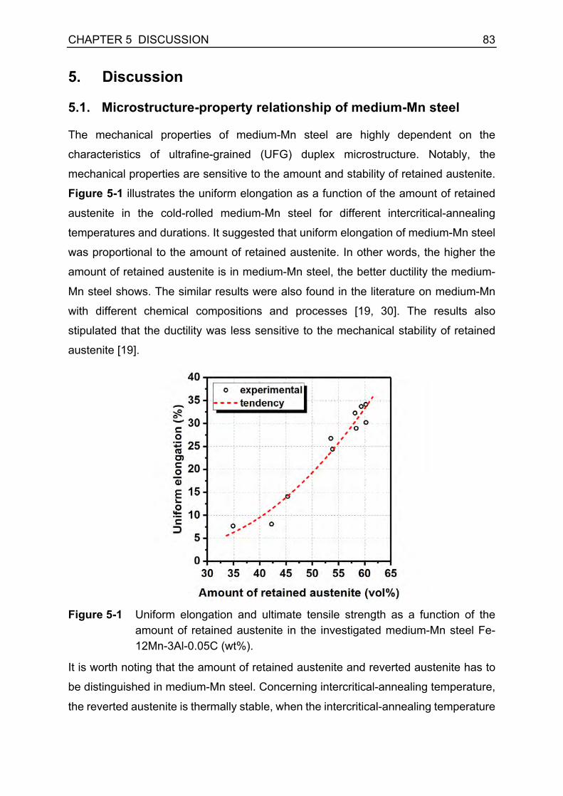
CHAPTER 5 DISCUSSION 83
5. Discussion
5.1. Microstructure-property relationship of medium-Mn steel
The mechanical properties of medium-Mn steel are highly dependent on the
characteristics of ultrafine-grained (UFG) duplex microstructure. Notably, the
mechanical properties are sensitive to the amount and stability of retained austenite.
Figure 5-1 illustrates the uniform elongation as a function of the amount of retained
austenite in the cold-rolled medium-Mn steel for different intercritical-annealing
temperatures and durations. It suggested that uniform elongation of medium-Mn steel
was proportional to the amount of retained austenite. In other words, the higher the
amount of retained austenite is in medium-Mn steel, the better ductility the medium-
Mn steel shows. The similar results were also found in the literature on medium-Mn
with different chemical compositions and processes [19, 30]. The results also
stipulated that the ductility was less sensitive to the mechanical stability of retained
austenite [19].
Figure 5-1 Uniform elongation and ultimate tensile strength as a function of the
amount of retained austenite in the investigated medium-Mn steel Fe-12Mn-3Al-0.05C (wt%).
It is worth noting that the amount of retained austenite and reverted austenite has to
be distinguished in medium-Mn steel. Concerning intercritical-annealing temperature,
the reverted austenite is thermally stable, when the intercritical-annealing temperature

84 CHAPTER 5 DISCUSSION
is below the peak temperature (Figure 2-4d). Thus the amount of retained austenite is
equal to the amount of reverted austenite. However, high intercritical-annealing
temperature above the peak temperature deteriorates the thermal stability of reverted
austenite. Consequently, a part of reverted austenite could be retained after final
cooling. As illustrated in Figure 5-1, the uniform elongation strongly relied on the
amount of retained austenite rather than reverted austenite.
The superior ductility of medium-Mn steel is attributed to the TRIP effect in austenite.
It was stated that the deformation-induced austenite to martensite transformation,
namely, the TRIP effect, can release the stress localization and promote
homogeneous deformation [10, 127]. As a result, the strain-hardening rate of the
medium-Mn steel can be improved, the necking can be postponed, and it hinders the
propagation of cracks [127-130]. In such a case, the larger the amount of retained
austenite could result in the more effective TRIP effect in medium-Mn steel. Therefore,
the ductility of medium-Mn steel is supposed to be proportional to the amount of
retained austenite.
The relationship between the amount of retained austenite and tensile strength of the
medium-Mn steel is shown in Figure 5-2. The ultimate tensile strength (UTS,
engineering strength) slightly decreased with an increase in the amount of retained
austenite, as shown in Figure 5-2a. Besides, the true strength at maximum load (i.e.,
UTS) exhibited a weak increase with increasing the amount of retained austenite. In
general, the dependence of tensile strength on the amount of retained austenite was
subtle. This weak correlation was also reported in the medium-Mn steel with different
chemical compositions and processing schedules [19, 30]. This finding is attributed to
the fact that the tensile strength is not only related to phase composition but the load
partitioning among different phases and strain-hardening behavior as well. In particular,
the transformation kinetics of metastable austenite might play a predominant role in
overall strain-hardening behavior in medium-Mn steel.
ECO-Index is the product of ultimate tensile strength (UTS) and uniform elongation
(UE), which is an indicator of the overall mechanical performance of materials [131].
Figure 5-3 displays the evolution of ECO-Index with the amount of retained austenite
in the investigated medium-Mn steel. The well-grounded tendency suggests that
overall mechanical properties are closely related to the amount of retained austenite
in the medium-Mn steel. To increase the amount of retained austenite seems to be an

CHAPTER 5 DISCUSSION 85
effective way to enhance mechanical performance in medium-Mn steel. Nevertheless,
the increase in ECO-Index with increasing the amount of retained austenite is mainly
ascribed to the positive impact of retained austenite on ductility [19]. Hence, in
medium-Mn steel, a higher amount of retained austenite is beneficial for better ductility
and a combination of high strength and superior ductility.
Figure 5-2 (a) ultimate tensile strength and (b) true strength at maximum load (UTS)
as a function of the amount of retained austenite in the investigated medium-Mn steel Fe-12Mn-3Al-0.05C (wt%).
Figure 5-3 ECO-Index as a function of the amount of retained austenite in the
investigated medium-Mn steel.

86 CHAPTER 5 DISCUSSION
The yield-to-tensile ratio represents the difference between the yield strength and
tensile strength, which reflects the strain-hardening capacity of materials. The yield-
to-tensile ratio manifested a reasonable correlation with the transformation ratio of
austenite at necking in the medium-Mn steel, as shown in Figure 5-4. It can be seen
that the yield-to-tensile ratio decreased with an increase in the transformation ratio of
austenite during deformation. A higher transformation ratio of retained austenite,
namely, the lower mechanical stability of retained austenite implies a more
pronounced strain-hardening capacity, resulting in a lower yield-to-tensile ratio.
Figure 5-4 Dependence of Yield-to-tensile ratio on the transformation ratio of
austenite at necking in the investigated medium-Mn steel.

CHAPTER 5 DISCUSSION 87
5.2. Relevance of process parameters on microstructure and properties of the cold-rolled medium-Mn steel
It was found that the mechanical properties, in particular, the ductility of medium-Mn
mainly relies on the amount of retained austenite. The process parameter which has
the most significant impact on the amount of retained austenite is the most relevant in
medium-Mn steel. According to the present study and the literature, the intercritical-
annealing temperature plays a predominant role in determining the overall
microstructure characteristics and mechanical performance of medium-Mn steel, e.g.,
microstructural morphology, the amount and stability of retained austenite, yield
strength level, as well as strain-hardening behavior. Nevertheless, the other process
parameters are also crucial for the adjustment of microstructure and tailor mechanical
properties. In such a case, the impact of process parameters on the microstructure
features and mechanical properties in the medium-Mn steel Fe-12Mn-3Al-0.05C (wt%)
will be discussed in detail below with a particular focus on the intercritical-annealing
temperature.
During the intercritical annealing of the medium-Mn steel Fe-12Mn-3Al-0.05C (wt%),
not only does the austenite reverse transformation take place, but the microstructure
recovery and recrystallization appear in the cold-rolled medium-Mn steel as well. The
occurrence of recrystallization was responsible for the morphology difference in the
medium-Mn steel annealed at different temperatures. Based on the results presented
in Chapter 4.2, the influence of the intercritical-annealing temperature on the
microstructure and mechanical property features of the cold-rolled medium-Mn steel
is schematically demonstrated in Figure 5-5.
The microstructure of the cold-rolled medium-Mn was deformed α'-martensite, and it
was brittle, showing an intensely high strength of 1400 MPa with a little ductility, as
displayed in Figure 5-5a. The heat treatment of the cold-rolled medium-Mn steel within
the intercritical region (γ+α) led to austenite reversion. In this way, a duplex
microstructure formed, which consisted of ferrite and a large amount of austenite. At
the same time, the intercritical annealing resulted in a softening of the material with
improved ductility. In previous studies, it was pointed out the intercritical-annealing
temperature had a significant effect on the amount and stability of retained
austenite [26, 40, 87, 132]. Consequently, the mechanical properties showed a strong
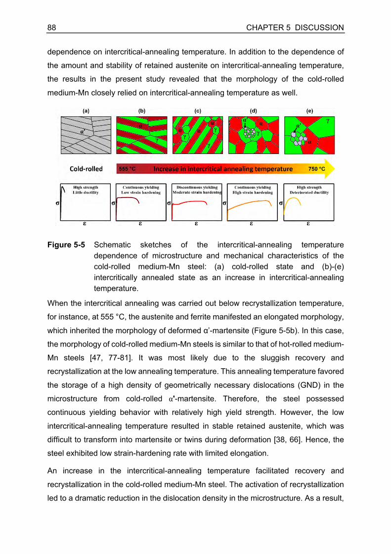
88 CHAPTER 5 DISCUSSION
dependence on intercritical-annealing temperature. In addition to the dependence of
the amount and stability of retained austenite on intercritical-annealing temperature,
the results in the present study revealed that the morphology of the cold-rolled
medium-Mn closely relied on intercritical-annealing temperature as well.
Figure 5-5 Schematic sketches of the intercritical-annealing temperature dependence of microstructure and mechanical characteristics of the cold-rolled medium-Mn steel: (a) cold-rolled state and (b)-(e) intercritically annealed state as an increase in intercritical-annealing temperature.
When the intercritical annealing was carried out below recrystallization temperature,
for instance, at 555 °C, the austenite and ferrite manifested an elongated morphology,
which inherited the morphology of deformed α’-martensite (Figure 5-5b). In this case,
the morphology of cold-rolled medium-Mn steels is similar to that of hot-rolled medium-
Mn steels [47, 77-81]. It was most likely due to the sluggish recovery and
recrystallization at the low annealing temperature. This annealing temperature favored
the storage of a high density of geometrically necessary dislocations (GND) in the
microstructure from cold-rolled α'-martensite. Therefore, the steel possessed
continuous yielding behavior with relatively high yield strength. However, the low
intercritical-annealing temperature resulted in stable retained austenite, which was
difficult to transform into martensite or twins during deformation [38, 66]. Hence, the
steel exhibited low strain-hardening rate with limited elongation.
An increase in the intercritical-annealing temperature facilitated recovery and
recrystallization in the cold-rolled medium-Mn steel. The activation of recrystallization
led to a dramatic reduction in the dislocation density in the microstructure. As a result,

CHAPTER 5 DISCUSSION 89
the steel possessed a decreased yield strength and a discontinuous yielding behavior
(Figure 5-5c). The discontinuous yielding was reported to be due to the UFG
microstructure and the lack of mobile dislocations [29, 66]. Besides, the amount of
austenite increased and austenite stability declined with an increase in the annealing
temperature. During plastic deformation, a decrease in the mechanical stability of
austenite resulted in improved strain-hardening behavior and ductility [29, 66].
When the intercritical-annealing temperature was further increased, ferrite was fully
recrystallized, resulting in equiaxed morphology of microstructure (Figure 5-5d), which
was generally obtained in cold-rolled medium-Mn steels in the literature [29, 79-83].
This equiaxed morphology in cold-rolled medium-Mn steels was explained by the
recrystallization. Due to an increase in the recrystallization degree at a higher
temperature, the yield strength of the material further dropped. However, a relatively
high intercritical-annealing temperature might lead to a further reduction in the stability
of austenite. Some fresh martensite formation from the thermally unstable austenite
may take place during quenching. Besides, the onset of deformation-induced
martensite transformation might become early due to poor mechanical stability of
austenite. Consequently, the formation of the fresh martensite islands brought mobile
dislocations into the microstructure, which might be responsible for the continuous
yielding behavior [66]. Besides, the optimal mechanical stability of austenite promoted
progressive transformation of a large amount of retained austenite in martensite, which
effectively enhanced the strain-hardening behavior and ductility in medium-Mn
steel [10].
A further increase in the intercritical-annealing temperature led to the formation of a
considerable amount of fresh martensite in the microstructure during quenching. Apart
from the poor thermal stability, the austenite possessed deteriorated mechanical
stability as well. The stress-induced martensite transformation might take place during
elastic deformation, and austenite transformed into martensite rapidly during plastic
deformation [66, 133], which was indicated by the extremely high strain-hardening rate.

90 CHAPTER 5 DISCUSSION
5.3. Interphase boundary segregation in medium-Mn steel
Grain boundary segregation in various alloys has been intensively studied [134-138],
because of its significant impact on grain boundary properties, such as cohesion [139-
141], mobility [137, 142, 143], hydrogen embrittlement [144-146] and resistance to or
sources of dislocations [147-150], etc. With respect to the mechanical performance,
to manipulate grain boundary characteristics and utilize grain boundary segregation
phenomenon has been considered as a new pathway to the enhancement of material
behavior [134]. The recent research on medium-Mn steel found that manganese
segregation to martensite lath boundaries enabled the nanoscale austenite reversion,
which opened a pathway to design ductile martensitic steel [151].
However, the solute segregation to interphase boundaries in multiphase steel is rarely
reported. The impact of solute segregation at interphase boundaries on the
mechanical properties is not clear. In the present work, the solute element carbon
segregation to ferrite-austenite interface boundaries was for the first time observed in
duplex medium-Mn steel by altering cooling conditions after intercritical annealing. It
was found that there was a strong partitioning phenomenon of manganese, aluminum,
and carbon between austenite and ferrite during intercritical annealing in the
investigated medium-Mn steel. In the material followed by water quenching (WQ),
there was no obvious segregation of carbon atoms to the α/γ interphase boundaries
(Figure 4-25a). In contrast, conspicuous enrichment of carbon atoms at the α/γ
interphase boundaries was found in the medium-Mn steel followed by air cooling (AC),
as shown in Figure 4-25b.
In medium-Mn steel, there is a considerably large amount of interface area due to the
ultrafine-grained (UFG) microstructure on the one hand; multiple phases can be under
equilibrium condition at the same time on the other hand. These factors provide the
possibility of interphase boundary segregation in medium-Mn steel. The possible
thermodynamic driving force for carbon segregation to the α/γ interphase boundaries
can be summarized as follows:
- Equilibrium-driven carbon partitioning between ferrite and austenite. With a slow
cooling rate after intercritical annealing, elemental partitioning across the α/γ
phase boundaries attempts to level the local gradient in chemical potential, in
order to achieve equilibrium. Nevertheless, only interstitial element carbon is

CHAPTER 5 DISCUSSION 91
feasible to diffuse at low temperature (from 500 °C down to 100 °C) in a reasonable
time window. According to thermodynamics, the solubility of carbon in ferrite
declines with a decrease in temperature. Therefore, carbon atoms have to be
ejected from carbon-supersaturated ferrite. From the kinetics point of view, carbon
atoms can diffuse out of ferrite quickly due to their high mobility in ferrite. Albeit,
carbon atoms are difficult to diffuse into austenite owing to the low diffusivity in
austenite [125]. As a consequence of the equilibrium attempt yet limited diffusivity
of carbon atoms in austenite, the carbon atoms exhibit high potential to pile up at
the α/γ interphase boundaries.
- Reduction in interfacial energy. In general, solute elements are prone to
accumulate at defects, such as interfaces, to reduce the interfacial energy of the
system [126, 152-154].
The factors mentioned above might be the fundamental reasons for the carbon
segregation at interphase boundaries in multiphase medium-Mn steel. Practically, the
slow cooling in the air provided a time window for carbon diffusion. As a result, the
carbon segregation at the α/γ interphase boundaries had a significant impact on the
mechanical stability of retained austenite, yielding phenomenon, and strain-hardening
behavior. The influence of carbon segregation at interphase boundaries on yielding
phenomenon and mechanical stability of retained austenite will be discussed in the
following sub-chapters.
5.3.1. Impact on yielding behavior in medium-Mn steel
The medium-Mn steel is usually characterized by a pronounced discontinuous yielding
behavior followed by a yield point elongation [91-93, 155], which has negative effects
on the surface quality of steel sheets. The complexity of the microstructure features
makes the understanding of the underlying mechanisms of discontinuous yielding
extremely challenging in medium-Mn steel, albeit it is of great importance for further
microstructure adjustment. Since there is a large amount of ferrite (40 vol% - 80 vol%)
in the duplex medium-Mn steel, some researchers thought the Cottrell-Bilby theory
might explain the discontinuous yielding phenomenon. The carbon atoms might diffuse
to dislocation cores and lock the mobile dislocations, which resulted in a pronounced
yielding behavior. However, the hot-rolled medium-Mn steel or medium-Mn steel with
bimodal grain-size distribution generally exhibits continuous yielding phenomenon,

92 CHAPTER 5 DISCUSSION
which makes it doubtful that dislocation locking mechanism is the main reason
accounting for discontinuous yielding in medium-Mn steel.
Recently, several attempts have been made to assess the origin of discontinuous
yielding behavior in medium-Mn steel [48, 94]. It was found that the discontinuous
yielding behavior in medium-Mn steel is mainly attributed to ultrafine-grained
microstructure. The rapid dislocation multiplication mechanism rather than the
classical Cottrell-Bilby theory is the main reason for discontinuous yielding behavior.
Wang et al. [94] proposed that the grain boundary ledges might be the sources of
dislocation nucleation and multiplication in medium-Mn steel. In a recent study on the
discontinuous yielding phenomenon in medium-Mn steel Fe-10Mn-3Al-1Si-0.2C (wt%),
it was found that the α/γ interphase boundaries acted as preferable sources for new
partial dislocations in austenite and full dislocation in ferrite [48]. The rapid and
massive dislocation nucleation and multiplication from α/γ interphase boundaries,
hence, were considered as the origin for discontinuous yielding. In such a case, the
characteristics of the α/γ interphase boundaries have a tremendous effect on yielding
behavior in UFG medium-Mn steel.
In this work, the medium-Mn steel with low-carbon concentration was intentionally
investigated in order to avoid the non-equilibrium segregation of carbon atoms during
water quenching (WQ). In comparison, air cooling (AC) was employed to trigger the
equilibrium and non-equilibrium segregation of carbon atoms to the α/γ interphase
boundaries. The results implied that carbon segregation at the α/γ interphase
boundaries could directly induce discontinuous yielding behavior in UFG medium-Mn
steel. Takaki et al. [147] reported that carbon segregation at interfaces could stabilize
dislocation sources. Some theoretical studies also suggested that solute segregation
at interfaces increased the stress required for dislocation emission [148-150], which
led to an increase in yield strength and the discontinuous yielding behavior.
A more striking result of the impact of cooling conditions on the tensile properties was
observed in medium-Mn steel with higher carbon content Fe-10Mn-3Al-0.2C (wt%), as
shown in Figure 5-6 and Table 5-1. It can be recognized that the medium-Mn steel
manifested discontinuous yielding, which was even quenched in water after
intercritical annealing. For the medium-Mn steel with a higher overall carbon content
(> ~0.1 wt%), the carbon concentration at interfaces could be high enough to suppress
dislocation activities even without pronounced carbon segregation at interfaces (by

CHAPTER 5 DISCUSSION 93
water quenching). Nevertheless, carbon segregation at the α/γ interphase boundaries
could further enhance the discontinuous yielding phenomenon, as illustrated by an
increase in yield strength (~ 120 MPa in upper yield point) and more pronounced yield
drop in the AC specimen compared with the WQ specimen.
Figure 5-6 Engineering strain-engineering stress curves of the medium-Mn steel
Fe-10Mn-3Al-0.2C (wt%) after intercritical annealing at 750 °C for 5 min followed by water quenching (WQ) and air cooling (AC).
Table 5-1 The influence of cooling conditions on tensile properties of the medium-Mn steel Fe-10Mn-3Al-0.2C (wt%) after intercritical annealing at 750 °C for 5 min.
Cooling conditions
ReL (MPa)
ReH (MPa)
ΔRe
(MPa) Rm
(MPa) Ae (%)
Au (%)
A25 (%)
Water quenching (WQ) 675 ± 7 718 ± 12 43 ± 5 1242 ± 32 4.0 ± 0.7 28.4 ± 0.1 32.0 ± 2.6
Air cooling (AC) 745 ± 4 838 ± 8 93 ± 4 1208 ± 3 6.2 ± 0.5 34.6 ± 2.2 35.2 ± 2.5
The microstructural characteristics relevant to the discontinuous yielding phenomenon
and the corresponding strategies for its mitigation in medium-Mn steel are summarized
in Table 5-2. It was reported that medium-Mn steel with lamellar morphology usually
exhibited continuous yielding [35, 93]. This type of microstructural morphology can be
fabricated via austenite reversion from hot-rolled [35] or pre-austenitized [111]
microstructure. Another approach to mitigate discontinuous yielding is to produce
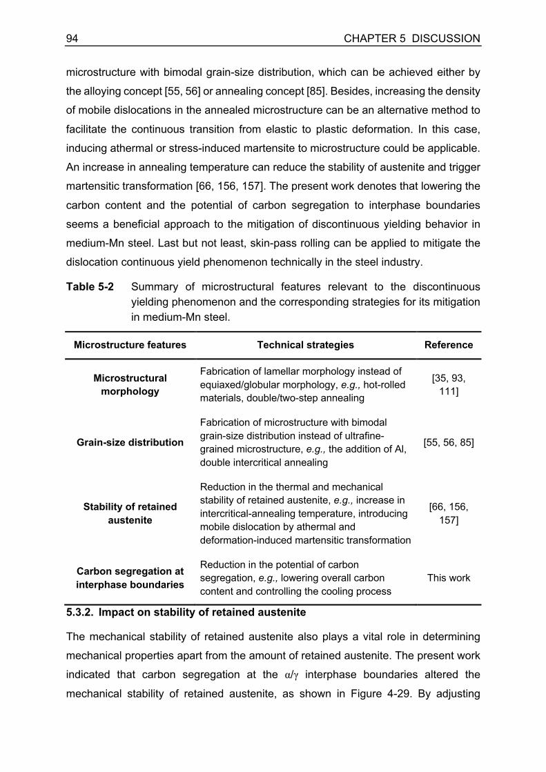
94 CHAPTER 5 DISCUSSION
microstructure with bimodal grain-size distribution, which can be achieved either by
the alloying concept [55, 56] or annealing concept [85]. Besides, increasing the density
of mobile dislocations in the annealed microstructure can be an alternative method to
facilitate the continuous transition from elastic to plastic deformation. In this case,
inducing athermal or stress-induced martensite to microstructure could be applicable.
An increase in annealing temperature can reduce the stability of austenite and trigger
martensitic transformation [66, 156, 157]. The present work denotes that lowering the
carbon content and the potential of carbon segregation to interphase boundaries
seems a beneficial approach to the mitigation of discontinuous yielding behavior in
medium-Mn steel. Last but not least, skin-pass rolling can be applied to mitigate the
dislocation continuous yield phenomenon technically in the steel industry.
Table 5-2 Summary of microstructural features relevant to the discontinuous yielding phenomenon and the corresponding strategies for its mitigation in medium-Mn steel.
Microstructure features Technical strategies Reference
Microstructural morphology
Fabrication of lamellar morphology instead of equiaxed/globular morphology, e.g., hot-rolled materials, double/two-step annealing
[35, 93, 111]
Grain-size distribution
Fabrication of microstructure with bimodal grain-size distribution instead of ultrafine-grained microstructure, e.g., the addition of Al, double intercritical annealing
[55, 56, 85]
Stability of retained austenite
Reduction in the thermal and mechanical stability of retained austenite, e.g., increase in intercritical-annealing temperature, introducing mobile dislocation by athermal and deformation-induced martensitic transformation
[66, 156, 157]
Carbon segregation at interphase boundaries
Reduction in the potential of carbon segregation, e.g., lowering overall carbon content and controlling the cooling process
This work
5.3.2. Impact on stability of retained austenite
The mechanical stability of retained austenite also plays a vital role in determining
mechanical properties apart from the amount of retained austenite. The present work
indicated that carbon segregation at the α/γ interphase boundaries altered the
mechanical stability of retained austenite, as shown in Figure 4-29. By adjusting

CHAPTER 5 DISCUSSION 95
cooling conditions, there was no noticeable change in the fraction and morphology of
retained austenite, as well as grain size. The significant difference was the
characteristics of the α/γ interphase boundaries. The measurement of the amount of
retained austenite on the interrupted tensile specimens implied that the TRIP effect
was postponed to higher strain level due to the carbon segregation at the α/γ
interphase boundaries. In other words, the mechanical stability of retained austenite
was enhanced by carbon segregation at the α/γ interphase boundaries. One the one
hand, carbon segregation can stabilize the dislocation sources for the onset of plastic
deformation [147]; on the other hand, carbon segregation to interface boundaries
could reduce the interfacial energy and stabilize interface. The cohesion of interface
might be enhanced by carbon segregation [139, 140]. Therefore, the carbon-
decorated interphase boundary can act as a buffer zone between austenite and ferrite
or deformation-induced martensite [158], leading to more effective plasticity
accommodations at interphase boundaries.
This new finding in the present work provides a new mechanism controlling the
mechanical stability of retained austenite and a novel pathway to tune the stability of
retained austenite in multiphase materials by interface engineering. Apart from the
segregation behavior (this work), chemical composition, grain size, grain morphology,
dislocation density have been considered as the key factors affecting the stability of
retained austenite. The effects of different factors on the mechanical stability of
retained austenite and practical approaches to adjusting its stability in medium-Mn
steel are summarized in Table 5-3. Nevertheless, it is worth noting that the
assessment of individual factor on the stability of retained austenite is relatively
challenging because several factors are usually coupled and are difficult to be
separated in multiphase medium-Mn steel.
In medium-Mn steel, elemental partitioning between austenite and ferrite during the
intercritical annealing can effectively accumulate the carbon and manganese atoms in
austenite and makes it stabilized at room temperature. Therefore, the amount of
carbon and especially manganese in austenite has a substantial impact on the stability
of retained austenite in medium-Mn steel. To increase the carbon and manganese
contents in austenite can be achieved either by an increase in the overall alloying
contents of carbon and manganese or promoting a stronger elemental partitioning
behavior via a decrease in intercritical-annealing temperature [26, 29, 66, 87]. Beside

96 CHAPTER 5 DISCUSSION
chemical stabilization, the size effect plays a significant role in stabilization of austenite
as well. A reduction in grain size of austenite can result in higher stability of retained
austenite. To manipulate grain size, the control of intercritical-annealing temperature
and intercritical-annealing duration is applicable [29, 67].
Moreover, grain morphology of austenite was found to affect the stability of retained
austenite. It was reported that austenite with lamellar morphology exhibited higher
mechanical stability that the austenite with equiaxed morphology [28, 93, 159]. The
adjustment of grain morphology is feasible by manipulating the initial microstructure of
medium-Mn steel before the intercritical annealing. Hot-rolled material and pre-
austenitized material possess quenched martensite as initial microstructure. Austenite
reversion in the quenched martensite leads to lamellar morphology [35, 93, 111].
The dislocation density in austenite is another critical factor in the mechanical
stabilization of retained austenite. It was stated that retained austenite inherited a high
dislocation density from parent martensite, and this can enhance the stability of
retained austenite [66, 67]. Recently, He et al. [160] reported an approach to resetting
austenite stability via dislocation engineering. Warm rolling was employed after
intercritical annealing to introduce a large number of dislocations in austenite. It was
demonstrated that the high dislocation density could effectively stabilize austenite and
postpone the TRIP effect at large strain regime [160].
The current study implied that carbon segregation at the α/γ interphase boundaries
resulted in more stabilized austenite and postponed the TRIP effect. In addition to the
factors as mentioned above, the mechanical stability of retained austenite can be
further manipulated via interface engineering concept without changing the other
microstructural features in medium-Mn steel.
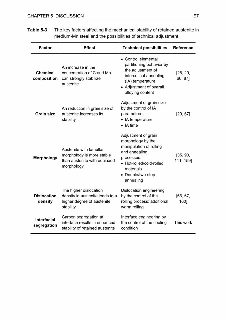
CHAPTER 5 DISCUSSION 97
Table 5-3 The key factors affecting the mechanical stability of retained austenite in medium-Mn steel and the possibilities of technical adjustment.
Factor Effect Technical possibilities Reference
Chemical composition
An increase in the concentration of C and Mn can strongly stabilize austenite
• Control elemental partitioning behavior by the adjustment of intercritical-annealing (IA) temperature
• Adjustment of overall alloying content
[26, 29, 66, 87]
Grain size An reduction in grain size of austenite increases its stability
Adjustment of grain size by the control of IA parameters: • IA temperature • IA time
[29, 67]
Morphology
Austenite with lamellar morphology is more stable than austenite with equiaxed morphology
Adjustment of grain morphology by the manipulation of rolling and annealing processes: • Hot-rolled/cold-rolled
materials • Double/two-step
annealing
[35, 93, 111, 159]
Dislocation density
The higher dislocation density in austenite leads to a higher degree of austenite stability
Dislocation engineering by the control of the rolling process: additional warm rolling
[66, 67, 160]
Interfacial segregation
Carbon segregation at interface results in enhanced stability of retained austenite
Interface engineering by the control of the cooling condition
This work


99
CHAPTER 6 CONCLUSIONS CHAPTER 6
CONCLUSIONS


CHAPTER 6 CONCLUSIONS 101
6. Conclusions
In the present work, a systematic study was conducted to gain an in-depth
understanding of the process-microstructure-property relationship in medium-Mn steel.
The impact of various process parameters, i.e., cold rolling, intercritical-annealing
temperature, intercritical-annealing time, and cooling conditions after intercritical
annealing on microstructure evolution and mechanical properties was investigated in
medium-Mn steel Fe-12Mn-3Al-0.05C (wt%). The notable conclusions drawn from the
present work are listed as follows:
• Cold rolling introduces a large number of defects such as dislocations and high-
angle grain boundaries in microstructure, which promotes homogeneous
austenite nucleation and fast austenite reversion kinetics.
• In both homogenized (HG) and cold-rolled (CR) medium-Mn steel, the recovery
of martensite takes place actively during heating. Nevertheless, the dislocation
density in CR state is higher than that in HG state, which contributes to the fast
austenite reversion kinetics in CR material.
• There is no recrystallization of martensite at 550 °C, indicated by the hierarchical
structure of martensite in the annealed state of both HG and CR specimens.
• Among the other intercritical-annealing parameters, the intercritical-annealing
temperature is the most relevant parameter determining the microstructure
characteristics and mechanical performance of medium-Mn steel.
• An increase in intercritical-annealing temperature leads to the activation of
recrystallization, indicated by a change in microstructure from elongated
morphology to equiaxed morphology.
• A low annealing temperature of approx. 550 °C results in a certain amount of
austenite with high stability, and the material shows low strain-hardening rate.
• An increase in intercritical-annealing temperature up to 700 °C leads to a good
balance between the amount and stability of retained austenite; the more
effective TRIP effect contributes to a raise in strain-hardening rate and ductility.
• Intercritical annealing at a very high temperature (750 °C) leads to a decrease in
the stability of austenite and a deterioration of the mechanical properties.
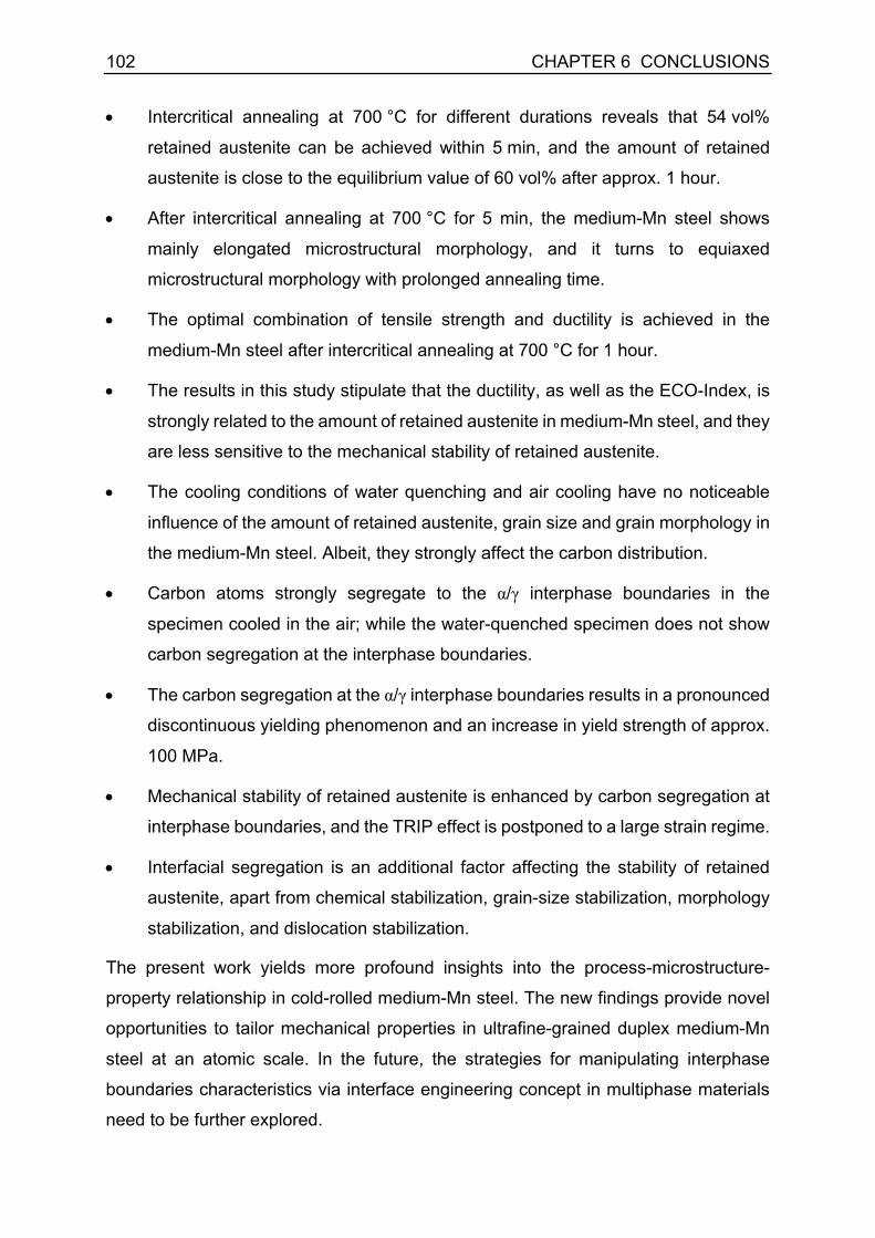
102 CHAPTER 6 CONCLUSIONS
• Intercritical annealing at 700 °C for different durations reveals that 54 vol%
retained austenite can be achieved within 5 min, and the amount of retained
austenite is close to the equilibrium value of 60 vol% after approx. 1 hour.
• After intercritical annealing at 700 °C for 5 min, the medium-Mn steel shows
mainly elongated microstructural morphology, and it turns to equiaxed
microstructural morphology with prolonged annealing time.
• The optimal combination of tensile strength and ductility is achieved in the
medium-Mn steel after intercritical annealing at 700 °C for 1 hour.
• The results in this study stipulate that the ductility, as well as the ECO-Index, is
strongly related to the amount of retained austenite in medium-Mn steel, and they
are less sensitive to the mechanical stability of retained austenite.
• The cooling conditions of water quenching and air cooling have no noticeable
influence of the amount of retained austenite, grain size and grain morphology in
the medium-Mn steel. Albeit, they strongly affect the carbon distribution.
• Carbon atoms strongly segregate to the α/γ interphase boundaries in the
specimen cooled in the air; while the water-quenched specimen does not show
carbon segregation at the interphase boundaries.
• The carbon segregation at the α/γ interphase boundaries results in a pronounced
discontinuous yielding phenomenon and an increase in yield strength of approx.
100 MPa.
• Mechanical stability of retained austenite is enhanced by carbon segregation at
interphase boundaries, and the TRIP effect is postponed to a large strain regime.
• Interfacial segregation is an additional factor affecting the stability of retained
austenite, apart from chemical stabilization, grain-size stabilization, morphology
stabilization, and dislocation stabilization.
The present work yields more profound insights into the process-microstructure-
property relationship in cold-rolled medium-Mn steel. The new findings provide novel
opportunities to tailor mechanical properties in ultrafine-grained duplex medium-Mn
steel at an atomic scale. In the future, the strategies for manipulating interphase
boundaries characteristics via interface engineering concept in multiphase materials
need to be further explored.
REFERENCES 103
REFERENCES
[1] CO2 emissions from cars: facts and figures (infographics), 2019. http://www.europarl.europa.eu/news/en/headlines/society/20190313STO31218/co2-emissions-from-cars-facts-and-figures-infographics. (Accessed 09 July 2019). [2] Greenhouse gas emission statistics - emission inventories, 2019. https://ec.europa.eu/eurostat/statistics-explained/index.php/Greenhouse_gas_emission_statistics_-_emission_inventories. (Accessed 09 July 2019). [3] N. Fonstein, Advanced High Strength Sheet Steels - Physical Metallurgy, Design, Processing, and Properties, Springer International Publishing AG, Basel, 2015. [4] O. Bouaziz, H. Zurob, M. Huang, Driving force and logic of development of advanced high strength steels for automotive applications, Steel Research International, 84(10) (2013), pp. 937-947. [5] O. Kwon, K. Lee, G. Kim, K.-G. Chin, New trends in advanced high strength steel developments for automotive application, Materials Science Forum, 638-642 (2010), pp. 136-141. [6] D.K. Matlock, J.G. Speer, E. De Moor, P.J. Gibbs, Recent developments in advanced high strength sheet steels for automotive applications: An overview, JESTECH, 15(1) (2012), pp. 1-12. [7] W. Bleck, F. Brühl, Y. Ma, C. Sasse, Materials and processes for the third-generation advanced high-strength steels, 4th European Steel Technology and Application Days (ESTAD), Düsseldorf, 2019. [8] R. Kuziak, R. Kawalla, S. Waengler, Advanced high strength steels for automotive industry, Archives of Civil and Mechanical Engineering, 8(2) (2008), pp. 103-117. [9] D.K. Matlock, J.G. Speer, Processing opportunities for new advanced high-strength sheet steels, Materials and Manufacturing Processes, 25(1-3) (2010), pp. 7-13. [10] W. Bleck, X. Guo, Y. Ma, The TRIP effect and its application in cold formable sheet steels, Steel Research International, 88(10) (2017), No. 1700218. [11] U. Brüx, G. Frommeyer, O. Grässel, L.W. Meyer, A. Weise, Development and characterization of high strength impact resistant Fe-Mn-(Al-, Si) TRIP/TWIP steels, Steel Research, 73(6-7) (2002), pp. 294-298. [12] G. Frommeyer, U. Brux, P. Neumann, Supra-ductile and high-strength manganese-TRIP/TWIP steels for high energy absorption purposes, ISIJ International, 43(3) (2003), pp. 438-446. [13] W. Song, T. Ingendahl, W. Bleck, Control of strain hardening behavior in high-Mn austenitic steels, Acta Metallurgica Sinica (English Letters), 27(3) (2014), pp. 546-556. [14] O. Grässel, L. Krüger, G. Frommeyer, L.W. Meyer, High strength Fe–Mn–(Al, Si) TRIP/TWIP steels development — properties — application, International Journal of Plasticity, 16(10-11) (2000), pp. 1391-1409. [15] B.C. De Cooman, O. Kwon, K.G. Chin, State-of-the-knowledge on TWIP steel, Materials Science and Technology, 28(5) (2013), pp. 513-527.

104 REFERENCES
[16] B.C. De Cooman, Y. Estrin, S.K. Kim, Twinning-induced plasticity (TWIP) steels, Acta Materialia, 142 (2018), pp. 283-362. [17] J.D. Yoo, K.-T. Park, Microband-induced plasticity in a high Mn–Al–C light steel, Materials Science and Engineering A, 496(1-2) (2008), pp. 417-424. [18] W. Song, W. Zhang, J. von Appen, R. Dronskowski, W. Bleck, κ-phase formation in Fe-Mn-Al-C austenitic steels, Steel Research International, 86(10) (2015), pp. 1161-1169. [19] D.-W. Suh, S.-J. Kim, Medium Mn transformation-induced plasticity steels: Recent progress and challenges, Scripta Materialia, 126 (2017), pp. 63-67. [20] Y. Ma, Medium-manganese steels processed by austenite-reverted-transformation annealing for automotive applications, Materials Science and Technology, 33(15) (2017), pp. 1713-1727. [21] Y.K. Lee, J. Han, Current opinion in medium manganese steel, Materials Science and Technology, 31(7) (2015), pp. 843-856. [22] J. Speer, D.K. Matlock, B.C. De Cooman, J.G. Schroth, Carbon partitioning into austenite after martensite transformation, Acta Materialia, 51(9) (2003), pp. 2611-2622. [23] D.V. Edmonds, K. He, F.C. Rizzo, B.C. De Cooman, D.K. Matlock, J.G. Speer, Quenching and partitioning martensite—A novel steel heat treatment, Materials Science and Engineering A, 438-440 (2006), pp. 25-34. [24] J.G. Speer, E. De Moor, A.J. Clarke, Critical Assessment 7: Quenching and partitioning, Materials Science and Technology, 31(1) (2015), pp. 3-9. [25] L. Wang, J.G. Speer, Quenching and partitioning steel heat treatment, Metallography, Microstructure, and Analysis, 2(4) (2013), pp. 268-281. [26] E. De Moor, D.K. Matlock, J.G. Speer, M.J. Merwin, Austenite stabilization through manganese enrichment, Scripta Materialia, 64(2) (2011), pp. 185-188. [27] O. Dmitrieva, D. Ponge, G. Inden, J. Millán, P. Choi, J. Sietsma, D. Raabe, Chemical gradients across phase boundaries between martensite and austenite in steel studied by atom probe tomography and simulation, Acta Materialia, 59(1) (2011), pp. 364-374. [28] L. Liu, B. He, M. Huang, The role of transformation-induced plasticity in the development of advanced high strength steels, Advanced Engineering Materials, 20(6) (2018), No. 1701083. [29] R.L. Miller, Ultrafine-grained microstructures and mechanical properties of alloy-steels, Metallurgical Transactions, 3(4) (1972), pp. 905-912. [30] A. Arlazarov, M. Gouné, O. Bouaziz, A. Hazotte, G. Petitgand, P. Barges, Evolution of microstructure and mechanical properties of medium Mn steels during double annealing, Materials Science and Engineering A, 542 (2012), pp. 31-39. [31] C. Wang, W. Cao, J. Shi, C. Huang, H. Dong, Deformation microstructures and strengthening mechanisms of an ultrafine grained duplex medium-Mn steel, Materials Science and Engineering A, 562 (2013), pp. 89-95. [32] R. Zhang, W. Cao, Z. Peng, J. Shi, H. Dong, C. Huang, Intercritical rolling induced ultrafine microstructure and excellent mechanical properties of the medium-Mn steel, Materials Science and Engineering A, 583 (2013), pp. 84-88.

REFERENCES 105
[33] J. Shi, X. Sun, M. Wang, W. Hui, H. Dong, W. Cao, Enhanced work-hardening behavior and mechanical properties in ultrafine-grained steels with large-fractioned metastable austenite, Scripta Materialia, 63(8) (2010), pp. 815-818. [34] S.J. Kim, Effects of manganese content and heat treatment condition on mechanical properties and microstructures of fine-grained low carbon TRIP-aided steels, Materials Science Forum, 638-642 (2010), pp. 3313-3318. [35] J. Han, S.-J. Lee, J.-G. Jung, Y.-K. Lee, The effects of the initial martensite microstructure on the microstructure and tensile properties of intercritically annealed Fe–9Mn–0.05C steel, Acta Materialia, 78 (2014), pp. 369-377. [36] X. Zhao, Y. Shen, L. Qiu, Y. Liu, X. Sun, L. Zuo, Effects of intercritical annealing temperature on mechanical properties of Fe-7.9Mn-0.14Si-0.05Al-0.07C steel, Materials, 7(12) (2014), pp. 7891-7906. [37] S. Lee, B.C. De Cooman, Effect of the intercritical annealing temperature on the mechanical properties of 10 pct Mn multi-phase steel, Metallurgical and Materials Transactions A, 45(11) (2014), pp. 5009-5016. [38] D.-W. Suh, J.-H. Ryu, M.-S. Joo, H.-S. Yang, K. Lee, H.K.D.H. Bhadeshia, Medium-alloy manganese-rich transformation-induced plasticity steels, Metallurgical and Materials Transactions A, 44(1) (2013), pp. 286-293. [39] T. Furukawa, H. Huang, O. Matsumura, Effects of carbon content on mechanical properties of 5%Mn steels exhibiting transformation induced plasticity, Materials Science and Technology, 10(11) (1994), pp. 964-970. [40] S. Lee, B.C. De Cooman, On the selection of the optimal intercritical annealing temperature for medium Mn TRIP steel, Metallurgical and Materials Transactions A, 44a(11) (2013), pp. 5018-5024. [41] S. Lee, B.C. De Cooman, Tensile behavior of intercritically annealed ultra-fine grained 8% Mn multi-phase steel, Steel Research International, 86(10) (2015), pp. 1170-1178. [42] W. Bleck, Materials Science of Steel - Textbook for Students at RWTH Aachen, Steel Institute (IEHK) of RWTH Aachen University, 2016. [43] B. Sun, F. Fazeli, C. Scott, B. Guo, C. Aranas, X. Chu, M. Jahazi, S. Yue, Microstructural characteristics and tensile behavior of medium manganese steels with different manganese additions, Materials Science and Engineering A, 729 (2018), pp. 496-507. [44] S. Lee, B.C. De Cooman, Tensile behavior of intercritically annealed 10 pct Mn multi-phase steel, Metallurgical and Materials Transactions A, 45(2) (2014), pp. 709-716. [45] S. Lee, W. Woo, B.C. De Cooman, Analysis of the tensile behavior of 12 pct Mn multi-phase (α + γ) TWIP + TRIP steel by neutron diffraction, Metallurgical and Materials Transactions A, 47(5) (2016), pp. 2125-2140. [46] M.I. Latypov, S. Shin, B.C. De Cooman, H.S. Kim, Micromechanical finite element analysis of strain partitioning in multiphase medium manganese TWIP+TRIP steel, Acta Materialia, 108 (2016), pp. 219-228.

106 REFERENCES
[47] B. He, H. Luo, M. Huang, Experimental investigation on a novel medium Mn steel combining transformation-induced plasticity and twinning-induced plasticity effects, International Journal of Plasticity, 78 (2016), pp. 173-186. [48] B. Sun, Y. Ma, N. Vanderesse, R.S. Varanasi, W. Song, P. Bocher, D. Ponge, D. Raabe, Macroscopic to nanoscopic in situ investigation on yielding mechanisms in ultrafine grained medium Mn steels: Role of the austenite-ferrite interface, Acta Materialia, 178 (2019), pp. 10-25. [49] Y. Ma, W. Song, W. Bleck, Investigation of the microstructure evolution in a Fe-17Mn-1.5Al-0.3C steel via in situ synchrotron X-ray diffraction during a tensile test, Materials, 10(10) (2017), No. 1129. [50] F. Ji, W. Song, Y. Ma, C. Li, W. Bleck, G. Wang, Recrystallization behavior in a low-density high-Mn high-Al austenitic steel undergone thin strip casting process, Materials Science and Engineering A, 733 (2018), pp. 87-97. [51] Y. Lü, D.A. Molodov, G. Gottstein, Recrystallization kinetics and microstructure evolution during annealing of a cold-rolled Fe–Mn–C alloy, Acta Materialia, 59(8) (2011), pp. 3229-3243. [52] O. Bouaziz, D. Barbier, Benefits of recovery and partial recrystallization of nano-twinned austenitic steels, Advanced Engineering Materials, 15(10) (2013), pp. 976-979. [53] C. Haase, T. Ingendahl, O. Güvenç, M. Bambach, W. Bleck, D.A. Molodov, L.A. Barrales-Mora, On the applicability of recovery-annealed Twinning-Induced Plasticity steels: Potential and limitations, Materials Science and Engineering A, 649 (2016), pp. 74-84. [54] F. Berrenberg, C. Haase, L.A. Barrales-Mora, D.A. Molodov, Enhancement of the strength-ductility combination of twinning-induced/transformation-induced plasticity steels by reversion annealing, Materials Science and Engineering A, 681 (2017), pp. 56-64. [55] S. Lee, Y. Estrin, B.C. De Cooman, Constitutive modeling of the mechanical properties of V-added medium manganese TRIP steel, Metallurgical and Materials Transactions A, 44(7) (2013), pp. 3136-3146. [56] S. Lee, K. Lee, B.C. De Cooman, Observation of the TWIP + TRIP plasticity-enhancement mechanism in Al-added 6 wt pct medium Mn steel, Metallurgical and Materials Transactions A, 46(6) (2015), pp. 2356-2363. [57] B. Hu, H. Luo, F. Yang, H. Dong, Recent progress in medium-Mn steels made with new designing strategies, a review, Journal of Materials Science & Technology, 33(12) (2017), pp. 1457-1464. [58] B. Sun, F. Fazeli, C. Scott, N. Brodusch, R. Gauvin, S. Yue, The influence of silicon additions on the deformation behavior of austenite-ferrite duplex medium manganese steels, Acta Materialia, 148 (2018), pp. 249-262. [59] B. Sun, F. Fazeli, C. Scott, S. Yue, Phase transformation behavior of medium manganese steels with 3 wt pct aluminum and 3 wt pct silicon during intercritical annealing, Metallurgical and Materials Transactions A, 47(10) (2016), pp. 4869-4882.

REFERENCES 107
[60] T. Furukawa, Dependence of strength–ductility characteristics on thermal history in low carbon, 5 wt-%Mn steels, Materials Science and Technology, 5(5) (1989), pp. 465-470. [61] M.F. Buchely, D.M. Field, D.C. van Aken, Analysis of hot- and cold-rolled loads in medium-Mn TRIP steels, Metallurgical and Materials Transactions B, 50(3) (2019), pp. 1180-1192. [62] H. Yang, H. Bhadeshia, Austenite grain size and the martensite-start temperature, Scripta Materialia, 60(7) (2009), pp. 493-495. [63] S. Lee, Contribution to the Physical Metallurgy of Ultrafine-Grained Medium Mn TRIP Steel. Ph.D. Thesis, Pohang University of Science and Technology, Pohang, Korea, 2015. [64] D.P. Koistinen, R.E. Marburger, A general equation prescribing the extent of the austenite-martensite transformation in pure iron-carbon alloys and plain carbon steels, Acta Metallurgica, 7(1) (1959), pp. 59-60. [65] E.A. Wilson, S.F. Medina, Application of Koistinen and Marburger’s athermal equation for volume fraction of martensite to diffusional transformations obtained on continuous cooling 0.13%C high strength low alloy steel, Materials Science and Technology, 16(6) (2000), pp. 630-633. [66] S. Lee, S.-J. Lee, S. Santhosh Kumar, K. Lee, B.C. De Cooman, Localized deformation in multiphase, ultra-fine-grained 6 pct Mn transformation-induced plasticity steel, Metallurgical and Materials Transactions A, 42(12) (2011), pp. 3638-3651. [67] S. Lee, S.-J. Lee, B.C. De Cooman, Austenite stability of ultrafine-grained transformation-induced plasticity steel with Mn partitioning, Scripta Materialia, 65(3) (2011), pp. 225-228. [68] K. Ishida, Direct estimation of stacking fault energy by thermodynamic analysis, physica status solidi (a), 36(2) (1976), pp. 717-728. [69] P.H. Adler, G.B. Olson, W.S. Owen, Strain hardening of hadfield manganese steel, Metallurgical and Materials Transactions A, 17(10) (1986), pp. 1725-1737. [70] A. Saeed-Akbari, J. Imlau, U. Prahl, W. Bleck, Derivation and variation in composition-dependent stacking fault energy maps based on subregular solution model in high-manganese steels, Metallurgical and Materials Transactions A, 40(13) (2009), pp. 3076-3090. [71] H. Luo, J. Shi, C. Wang, W. Cao, X. Sun, H. Dong, Experimental and numerical analysis on formation of stable austenite during the intercritical annealing of 5Mn steel, Acta Materialia, 59(10) (2011), pp. 4002-4014. [72] F. Huyan, J.-Y. Yan, L. Höglund, J. Ågren, A. Borgenstam, Simulation of the growth of austenite from as-quenched martensite in medium Mn steels, Metallurgical and Materials Transactions A, 49(4) (2018), pp. 1053-1060. [73] J.T. Benzing, A. Kwiatkowski da Silva, L. Morsdorf, J. Bentley, D. Ponge, A. Dutta, J. Han, J.R. McBride, B. Van Leer, B. Gault, D. Raabe, J.E. Wittig, Multi-scale characterization of austenite reversion and martensite recovery in a cold-rolled medium-Mn steel, Acta Materialia, 166 (2019), pp. 512-530.

108 REFERENCES
[74] W. Cao, C. Wang, J. Shi, M. Wang, W. Hui, H. Dong, Microstructure and mechanical properties of Fe–0.2C–5Mn steel processed by ART-annealing, Materials Science and Engineering A, 528(22-23) (2011), pp. 6661-6666. [75] J. Han, S.-J. Lee, C.-Y. Lee, S. Lee, S.Y. Jo, Y.-K. Lee, The size effect of initial martensite constituents on the microstructure and tensile properties of intercritically annealed Fe–9Mn–0.05C steel, Materials Science and Engineering A, 633 (2015), pp. 9-16. [76] C. Wang, J. Shi, C. Wang, W. Hui, M. Wang, H. Dong, W. Cao, Development of ultrafine lamellar ferrite and austenite duplex structure in 0.2C5Mn steel during ART-annealing, ISIJ International, 51(4) (2011), pp. 651-656. [77] T. Tsuchiyama, T. Inoue, J. Tobata, D. Akama, S. Takaki, Microstructure and mechanical properties of a medium manganese steel treated with interrupted quenching and intercritical annealing, Scripta Materialia, 122 (2016), pp. 36-39. [78] C. Shao, W. Hui, Y. Zhang, X. Zhao, Y. Weng, Microstructure and mechanical properties of hot-rolled medium-Mn steel containing 3% aluminum, Materials Science and Engineering A, 682 (2017), pp. 45-53. [79] R. Sun, W. Xu, C. Wang, J. Shi, H. Dong, W. Cao, Work hardening behavior of ultrafine grained duplex medium-Mn steels processed by ART-annealing, Steel Research International, 83(4) (2012), pp. 316-321. [80] J. Han, A.K. da Silva, D. Ponge, D. Raabe, S.-M. Lee, Y.-K. Lee, S.-I. Lee, B. Hwang, The effects of prior austenite grain boundaries and microstructural morphology on the impact toughness of intercritically annealed medium Mn steel, Acta Materialia, 122 (2017), pp. 199-206. [81] B. Hu, H. Luo, Microstructures and mechanical properties of 7Mn steel manufactured by different rolling processes, Metals, 7(11) (2017), No. 464. [82] Z. Cai, H. Ding, R.D.K. Misra, Z. Ying, Austenite stability and deformation behavior in a cold-rolled transformation-induced plasticity steel with medium manganese content, Acta Materialia, 84 (2015), pp. 229-236. [83] S. Lee, B.C. De Cooman, Annealing temperature dependence of the tensile behavior of 10 pct Mn multi-phase TWIP-TRIP steel, Metallurgical and Materials Transactions A, 45(13) (2014), pp. 6039-6052. [84] S. Lee, S. Shin, M. Kwon, K. Lee, B.C. De Cooman, Tensile properties of medium Mn steel with a bimodal UFG α + γ and coarse δ-ferrite microstructure, Metallurgical and Materials Transactions A, 48(4) (2017), pp. 1678-1700. [85] J. Han, S.-H. Kang, S.-J. Lee, Y.-K. Lee, Fabrication of bimodal-grained Al-free medium Mn steel by double intercritical annealing and its tensile properties, Journal of Alloys and Compounds, 681 (2016), pp. 580-588. [86] S. Lee, S.-J. Lee, B.C. De Cooman, Work hardening behavior of ultrafine-grained Mn transformation-induced plasticity steel, Acta Materialia, 59(20) (2011), pp. 7546-7553. [87] P.J. Gibbs, E. De Moor, M.J. Merwin, B. Clausen, J.G. Speer, D.K. Matlock, Austenite stability effects on tensile behavior of manganese-enriched-austenite transformation-induced plasticity Steel, Metallurgical and Materials Transactions A, 42(12) (2011), pp. 3691-3702.

REFERENCES 109
[88] J. Han, J.-H. Nam, Y.-K. Lee, The mechanism of hydrogen embrittlement in intercritically annealed medium Mn TRIP steel, Acta Materialia, 113 (2016), pp. 1-10. [89] G. Su, X. Gao, L. Du, D. Zhang, J. Hu, Z. Liu, Influence of Mn on the corrosion behaviour of medium manganese steels in a simulated seawater environment, International Journal of Electrochemical Science, 11(11) (2016), pp. 9447-9461. [90] H. Aydin, I.-H. Jung, E. Essadiqi, S. Yue, Twinning and Tripping in 10% Mn steels, Materials Science and Engineering A, 591 (2014), pp. 90-96. [91] Z. Li, H. Ding, R.D.K. Misra, Z. Cai, Deformation behavior in cold-rolled medium-manganese TRIP steel and effect of pre-strain on the Lüders bands, Materials Science and Engineering A, 679 (2017), pp. 230-239. [92] H. Luo, H. Dong, M. Huang, Effect of intercritical annealing on the Lüders strains of medium Mn transformation-induced plasticity steels, Materials & Design, 83 (2015), pp. 42-48. [93] K. Steineder, D. Krizan, R. Schneider, C. Beal, C. Sommitsch, On the microstructural characteristics influencing the yielding behavior of ultra-fine grained medium-Mn steels, Acta Materialia, 139 (2017), pp. 39-50. [94] X. Wang, B. He, C. Liu, C. Jiang, M. Huang, Extraordinary Lüders-strain-rate in medium Mn steels, Materialia, 6 (2019), No. 100288. [95] S. Gao, A. Shibata, M. Chen, N. Park, N. Tsuji, Correlation between continuous/discontinuous yielding and Hall-Petch slope in high purity iron, Materials Transactions, 55(1) (2014), pp. 69-72. [96] B.Y. Choi, G. Krauss, D.K. Matlock, Bainite formation and deformation-behavior in an intercritically annealed Fe-1.0Mn-0.09C steel, Scripta Metallurgica, 22(9) (1988), pp. 1575-1580. [97] A.H. Cottrell, B.A. Bilby, Dislocation theory of yielding and strain ageing of iron, Proceedings of the Physical Society. Section A, 62(1) (1949), pp. 49-62. [98] N. Kamikawa, X. Huang, N. Tsuji, N. Hansen, Strengthening mechanisms in nanostructured high-purity aluminium deformed to high strain and annealed, Acta Materialia, 57(14) (2009), pp. 4198-4208. [99] C.Y. Yu, P.W. Kao, C.P. Chang, Transition of tensile deformation behaviors in ultrafine-grained aluminum, Acta Materialia, 53(15) (2005), pp. 4019-4028. [100] S. Kang, J.-G. Jung, M. Kang, W. Woo, Y.-K. Lee, The effects of grain size on yielding, strain hardening, and mechanical twinning in Fe–18Mn–0.6C–1.5Al twinning-induced plasticity steel, Materials Science and Engineering A, 652 (2016), pp. 212-220. [101] R. Ueji, N. Tsuchida, D. Terada, N. Tsuji, Y. Tanaka, A. Takeinura, K. Kunishige, Tensile properties and twinning behavior of high manganese austenitic steel with fine-grained structure, Scripta Materialia, 59(9) (2008), pp. 963-966. [102] I.S. Wani, T. Bhattacharjee, S. Sheikh, Y.P. Lu, S. Chatterjee, P.P. Bhattacharjee, S. Guo, N. Tsuji, Ultrafine-grained AlCoCrFeNi2.1 eutectic high-entropy alloy, Materials Research Letters, 4(3) (2016), pp. 174-179. [103] K. Asoo, Y. Tomota, S. Harjo, Y. Okitsu, Tensile behavior of a TRIP-aided ultra-fine grained steel studied by neutron diffraction, ISIJ International, 51(1) (2011), pp. 145-150.

110 REFERENCES
[104] S.S. Hazra, E.V. Pereloma, A.A. Gazder, Microstructure and mechanical properties after annealing of equal-channel angular pressed interstitial-free steel, Acta Materialia, 59(10) (2011), pp. 4015-4029. [105] S. Gao, M. Chen, S. Chen, N. Kamikawa, A. Shibata, N. Tsuji, Yielding behavior and its effect on uniform elongation of fine grained IF steel, Materials Transactions, 55(1) (2014), pp. 73-77. [106] S. Hoile, Processing and properties of mild interstitial free steels, Materials Science and Technology, 16(10) (2010), pp. 1079-1093. [107] H. Takechi, Metallurgical aspects on interstitial-free sheet steel from industrial viewpoints, ISIJ International, 34(1) (1994), pp. 1-8. [108] G. Gottstein, Physical Foundations of Materials Science, Springer, Heidelberg, 2004. [109] H. Mecking, U.F. Kocks, Kinetics of flow and strain-hardening, Acta Metallurgica, 29(11) (1981), pp. 1865-1875. [110] W.G. Johnston, J.J. Gilman, Dislocation velocities, dislocation densities, and plastic flow in lithium fluoride crystals, Journal of Applied Physics, 30(2) (1959), pp. 129-144. [111] R. Schneider, K. Steineder, D. Krizan, C. Sommitsch, Effect of the heat treatment on the microstructure and mechanical properties of medium-Mn-steels, Materials Science and Technology, (2018), DOI: 10.1080/02670836.2018.1548957 [112] A. Dutta, D. Ponge, S. Sandlöbes, D. Raabe, Strain partitioning and strain localization in medium manganese steels measured by in situ microscopic digital image correlation, Materialia, 5 (2019), No. 100252. [113] H. Dong, W. Cao, J. Shi, Formation of an ultrafine-grained austenite-containing microstructure from a cold-rolled medium-manganese steel processed using intercritical annealing, Materials Science Forum, 762 (2013), pp. 31-37. [114] J. Han, Y.-K. Lee, The effects of the heating rate on the reverse transformation mechanism and the phase stability of reverted austenite in medium Mn steels, Acta Materialia, 67 (2014), pp. 354-361. [115] X. Zhang, G. Miyamoto, T. Kaneshita, Y. Yoshida, Y. Toji, T. Furuhara, Growth mode of austenite during reversion from martensite in Fe-2Mn-1.5Si-0.3C alloy: A transition in kinetics and morphology, Acta Materialia, 154 (2018), pp. 1-13. [116] M. De Meyer, D. Vanderschueren, K. De Blauwe, B.C. De Cooman, The characterization of retained austenite in TRIP steels by X-ray diffraction, ISS, 41st Mechanical Working and Steel Processing Conference, Baltimore, 1999, pp. 483–491. [117] A.C. Dippel, H.P. Liermann, J.T. Delitz, P. Walter, H. Schulte-Schrepping, O.H. Seeck, H. Franz, Beamline P02.1 at PETRA III for high-resolution and high-energy powder diffraction, Journal of Synchrotron Radiation, 22(3) (2015), pp. 675-687. [118] A.P. Hammersley, FIT2D: An introduction and overview, 1997. http://www.esrf.eu/computing/scientific/FIT2D/FIT2D_INTRO/fit2d.html. (Accessed 28.06.2019. [119] L. Lutterotti, Total pattern fitting for the combined size–strain–stress–texture determination in thin film diffraction, Nuclear Instruments and Methods in Physics

REFERENCES 111
Research Section B: Beam Interactions with Materials and Atoms, 268(3-4) (2010), pp. 334-340. [120] N. Popa, The (hkl) dependence of diffraction-line broadening caused by strain and size for all Laue groups in Rietveld refinement, Journal of Applied Crystallography, 31(2) (1998), pp. 176-180. [121] G.K. Williamson, R.E. Smallman, III. Dislocation densities in some annealed and cold-worked metals from measurements on the X-ray debye-scherrer spectrum, The Philosophical Magazine: A Journal of Theoretical Experimental and Applied Physics, 1(1) (1956), pp. 34-46. [122] J. Gyhlesten Back, G. Engberg, Investigation of parent austenite grains from martensite structure using EBSD in a wear resistant steel, Materials, 10(5) (2017), No. 453. [123] N. Nakada, R. Fukagawa, T. Tsuchiyama, S. Takaki, D. Ponge, D. Raabe, Inheritance of dislocations and crystallographic texture during martensitic reversion into austenite, ISIJ International, 53(7) (2013), pp. 1286-1288. [124] N. Nakada, T. Tsuchiyama, S. Takaki, S. Hashizume, Variant selection of reversed austenite in lath martensite, ISIJ International, 47(10) (2007), pp. 1527-1532. [125] L. Yuan, D. Ponge, J. Wittig, P. Choi, J.A. Jiménez, D. Raabe, Nanoscale austenite reversion through partitioning, segregation and kinetic freezing: Example of a ductile 2GPa Fe–Cr–C steel, Acta Materialia, 60(6-7) (2012), pp. 2790-2804. [126] G. Bruggeman, E.B. Kula, Segregation at Interphase Boundaries, in: J.J. Burke, N.L. Reed, V. Weiss (Eds.), Surfaces and Interfaces II, Springer, Boston, MA, 1968, pp. 455-480. [127] H. Liu, L. Du, J. Hu, H. Wu, X. Gao, R.D.K. Misra, Interplay between reversed austenite and plastic deformation in a directly quenched and intercritically annealed 0.04C-5Mn low-Al steel, Journal of Alloys and Compounds, 695 (2017), pp. 2072-2082. [128] P.J. Jacques, Transformation-induced plasticity for high strength formable steels, Current Opinion in Solid State and Materials Science, 8(3-4) (2004), pp. 259-265. [129] I. Tamura, Deformation-induced martensitic-transformation and transformation-induced plasticity in steels, Metal Science, 16(5) (1982), pp. 245-253. [130] F.D. Fischer, Q.-P. Sun, K. Tanaka, Transformation-induced plasticity (TRIP), Applied Mechanics Reviews, 49(6) (1996), pp. 317-364. [131] W. Bleck, Characterisation of high Mn steels by numerical and experimental tools, High Manganese Steels Conference 2011, Seoul, Korea, 2011. [132] F. Yang, H. Luo, C. Hu, E. Pu, H. Dong, Effects of intercritical annealing process on microstructures and tensile properties of cold-rolled 7Mn steel, Materials Science and Engineering A, 685 (2017), pp. 115-122. [133] J.H. Ryu, J.I. Kim, H.S. Kim, C.-S. Oh, H.K.D.H. Bhadeshia, D.-W. Suh, Austenite stability and heterogeneous deformation in fine-grained transformation-induced plasticity-assisted steel, Scripta Materialia, 68(12) (2013), pp. 933-936. [134] D. Raabe, M. Herbig, S. Sandlöbes, Y. Li, D. Tytko, M. Kuzmina, D. Ponge, P.-P. Choi, Grain boundary segregation engineering in metallic alloys: A pathway to the design of interfaces, Current Opinion in Solid State and Materials Science, 18(4) (2014), pp. 253-261.
112 REFERENCES
[135] K.T. Aust, Grain boundary studies and their technological significance, Canadian Metallurgical Quarterly, 8(2) (1969), pp. 173-178. [136] E.D. Hondros, Interfacial engineering—a perspective, Materials Science and Engineering A, 166(1) (1993), pp. 1-10. [137] E.D. Hondros, M.P. Seah, Segregation to interfaces, International Metals Reviews, 22(1) (1977), pp. 262-301. [138] M.P. Seah, Surface science in metallurgy, Surface Science, 80 (1979), pp. 8-23. [139] H.J. Grabke, Surface and grain-boundary segregation on and in iron, Steel Research, 57(4) (1986), pp. 178-185. [140] J.R. Rice, J.-S. Wang, Embrittlement of interfaces by solute segregation, Materials Science and Engineering A, 107 (1989), pp. 23-40. [141] M.P. Seah, Interface adsorption, embrittlement and fracture in metallurgy: A review, Surface Science, 53(1) (1975), pp. 168-212. [142] J.W. Cahn, The impurity-drag effect in grain boundary motion, Acta Metallurgica, 10(9) (1962), pp. 789-798. [143] K. Lücke, H.P. Stüwe, On the theory of impurity controlled grain boundary motion, Acta Metallurgica, 19(10) (1971), pp. 1087-1099. [144] M. Aucouturier, Grain boundary segregations and hydrogen embrittlement, Le Journal de Physique Colloques, 43(C6) (1982), pp. C6-175-C6-186. [145] C. Hüter, P. Shanthraj, E. McEniry, R. Spatschek, T. Hickel, A. Tehranchi, X. Guo, F. Roters, Multiscale modelling of hydrogen transport and segregation in polycrystalline steels, Metals, 8(6) (2018), No. 430. [146] O. Barrera, D. Bombac, Y. Chen, T.D. Daff, E. Galindo-Nava, P. Gong, D. Haley, R. Horton, I. Katzarov, J.R. Kermode, C. Liverani, M. Stopher, F. Sweeney, Understanding and mitigating hydrogen embrittlement of steels: a review of experimental, modelling and design progress from atomistic to continuum, Journal of Materials Science, 53(9) (2018), pp. 6251-6290. [147] S. Takaki, D. Akama, N. Nakada, T. Tsuchiyama, Effect of grain boundary segregation of interstitial elements on Hall-Petch coefficient in steels, Materials Transactions, 55(1) (2014), pp. 28-34. [148] V. Borovikov, M.I. Mendelev, A.H. King, Effects of solutes on dislocation nucleation from grain boundaries, International Journal of Plasticity, 90 (2017), pp. 146-155. [149] V. Borovikov, M.I. Mendelev, A.H. King, Solute effects on interfacial dislocation emission in nanomaterials: Nucleation site competition and neutralization, Scripta Materialia, 154 (2018), pp. 12-15. [150] V. Turlo, T.J. Rupert, Grain boundary complexions and the strength of nanocrystalline metals: Dislocation emission and propagation, Acta Materialia, 151 (2018), pp. 100-111. [151] D. Raabe, S. Sandlöbes, J. Millán, D. Ponge, H. Assadi, M. Herbig, P.-P. Choi, Segregation engineering enables nanoscale martensite to austenite phase transformation at grain boundaries: A pathway to ductile martensite, Acta Materialia, 61(16) (2013), pp. 6132-6152.

REFERENCES 113
[152] J. Friedel, B.D. Cullity, C. Crussard, Study of the surface tension of a grainboundary in a metal as a function of the orientation of the two grains which the boundary separates, Acta Metallurgica, 1(1) (1953), pp. 79-92. [153] R. Kirchheim, Reducing grain boundary, dislocation line and vacancy formation energies by solute segregation. I. Theoretical background, Acta Materialia, 55(15) (2007), pp. 5129-5138. [154] S.A. Dregia, P. Wynblatt, Equilibrium segregation and interfacial energy in multicomponent systems, Acta Metallurgica et Materialia, 39(5) (1991), pp. 771-778. [155] M. Zhang, R. Li, J. Ding, H. Chen, J.-S. Park, J. Almer, Y.-D. Wang, In situ high-energy X-ray diffraction mapping of Lüders band propagation in medium-Mn transformation-induced plasticity steels, Materials Research Letters, 6(12) (2018), pp. 662-667. [156] J.-M. Jang, S.-J. Kim, N.H. Kang, K.-M. Cho, D.-W. Suh, Effects of annealing conditions on microstructure and mechanical properties of low carbon, manganese transformation-induced plasticity steel, Metals and Materials International, 15(6) (2009), pp. 909-916. [157] D.-W. Suh, S.-J. Park, T.-H. Lee, C.-S. Oh, S.-J. Kim, Influence of Al on the microstructural evolution and mechanical behavior of low-carbon, manganese transformation-induced-plasticity steel, Metallurgical and Materials Transactions A, 41A(2) (2010), pp. 397-408. [158] C. Song, H. Yu, L. Li, J. Lu, Effect of carbon at interface of austenite on manganese segregation of low carbon and manganese steel, Materials Letters, 174 (2016), pp. 75-78. [159] Z. Li, H. Ding, Z. Cai, Mechanical properties and austenite stability in hot-rolled 0.2C–1.6/3.2Al–6Mn–Fe TRIP steel, Materials Science and Engineering A, 639 (2015), pp. 559-566. [160] B. He, M. Wang, M. Huang, Resetting the austenite stability in a medium Mn steel via dislocation engineering, Metallurgical and Materials Transactions A, 50(6) (2019), pp. 2971-2977.

LIST OF FIGURES 115
LIST OF FIGURES Figure 1-1 CO2 emissions in the European Union (EU): (a) evolution of CO2
emission in the EU by sector (*manufacture and construction industry)
and (b) transport CO2 emissions in the EU [1]. ...................................... 3
Figure 1-2 Formability and strength balance of different advanced high-strength
steels (AHSS) concepts [7]. ................................................................... 4
Figure 1-3 Alloying concepts of the typical steel grades in different generations of
advanced high-strength steels (AHSS) [10, 28]. (TRIP stands for
transformation-induced plasticity; HMnS for high-Mn steel; Q&P for
quenching and partitioning; MMnS for medium-Mn steel.) .................... 5
Figure 1-4 Microstructural constituents of the typical steel grades in different
generations of advanced high-strength steels (AHSS) [10, 28]. (LC-TRIP
stands for low-carbon transformation-induced plasticity; TWIP for
twinning-induced plasticity; Q&P for quenching and partitioning; MMnS
for medium-Mn steel.) ............................................................................ 6
Figure 2-1 Influence of Mn addition on the balance of strength and ductility in cold-
rolled and intercritically annealed medium-Mn steel [43]. .................... 10
Figure 2-2 Classification of the types of steels with enhanced manganese content
(Q&P: quench and partitioning; UFG: ultrafine-grained; SBIP: shear-
band-induced plasticity; TWIP: twinning-induced plasticity; TRIP:
transformation-induced plasticity; SFE: stacking fault energy) [41, 48-54].
........................................................................................................... 11
Figure 2-3 Illustration of intercritical annealing of cold-rolled medium-Mn steel [10].
........................................................................................................... 13
Figure 2-4 Schematic illustration of thermodynamics of austenite reversion in
medium-Mn steel during intercritical annealing: (a) equilibrium phase
diagram of Fe-Mn-Al-C system; intercritical-annealing temperature
dependence of (b) chemistry in austenite, (c) martensite-start (Ms)
temperature, (d) fraction of austenite, and (e) stacking fault energy (SFE)
of retained austenite at room temperature. .......................................... 14
Figure 2-5 Microstructures in medium-Mn steel: (a) ultrafine-grained (UFG)
microstructure with lath morphology [80], (b) UFG microstructure with

116 LIST OF FIGURES
globular morphology [80], (c) microstructure with bimodal distribution of
coarse-grained α-ferrite as well as UFG constituent of equiaxed austenite
and ferrite [38], (d) bimodal-grained microstructure with coarse-grained
δ-ferrite as well as UFG austenite and ferrite [84], and (d) bimodal-
grained microstructure with coarse-grained austenite as well as UFG
austenite and ferrite [45]. ..................................................................... 17
Figure 2-6 Balance of ultimate tensile strength and total ductility in medium-Mn steel
processed by intercritical annealing [29, 30, 35, 36, 41, 44, 47, 56, 66,
77, 87-90]. ............................................................................................ 19
Figure 2-7 Engineering stress-strain curves of cold-rolled (CR) and hot-rolled (HR)
medium-Mn steel Fe-9Mn-0.05C (wt%) [35]. ....................................... 21
Figure 2-8 The impact of austenitization temperature on microstructure of quenched
martensite: (a) 800 °C, (b) 900 °C, and (c) 1000 °C (solid and dashed
lines are packet and block boundaries, correspondingly) in medium-Mn
steel Fe-9Mn-0.05C (wt%); (d) volume fraction and transformation rate
of reverted austenite as a function of austenitization temperature; (e)
𝐥𝐧 t𝐥𝐧 u𝒇𝜸𝒆𝒒/z𝒇𝜸
𝒆𝒒 − 𝒇𝜸{|} - lnt plots of specimen austenitized at various
temperatures; (f) dependence of the widths of the martensite blocks and
laths, as well as the interspacing of reverted austenite on austenitization
temperature [75]. .................................................................................. 24
Figure 2-9 Influence of intercritical-annealing temperature on (a) austenite fraction
(the lines without points represent equilibrium fractions); (b) tensile and
yield strength; and (c) total elongation of three medium-Mn steel alloys
(alloy 1: Fe-4.5Mn-2.2Al-0.45Si-0.11C (wt%); alloy 2: Fe-5.1Mn-2.1Al-
0.49Si-0.075C (wt%); alloy 3: Fe-5.6Mn-2.2Al-0.49Si-0.055C (wt%) [38].
........................................................................................................... 26
Figure 2-10 Intercritical-annealing time dependence of microstructural features in
medium-Mn steel: (a) lath thickness of ferrite and austenite; (b) the
amount of austenite [71]. ..................................................................... 27
Figure 2-11 Impact of heating rate during intercritical annealing on microstructural
and chemical distribution in medium-Mn steel Fe-9Mn-0.05C (wt%):
transmission-electron-microscopy (TEM) bright-field images of (a)

LIST OF FIGURES 117
specimen annealed at 645 °C with a heating rate of 3 °C/s and (b)
specimen annealed at 677 °C with a heating rate of 50 °C/s; (c) the
corresponding concentration profiles of Mn determined by energy-
dispersive X-ray spectroscopy (EDXS). (γG is globular austenite, γL is lath
austenite, α'T is tempered martensite, α'F is fresh martensite, which is
from the reverted austenite during quenching, and α' is untempered
martensite [114]. .................................................................................. 28
Figure 2-12 Amount of retained austenite as functions of carbon content and cooling
methods in medium-Mn steel with 5 wt% manganese [39]. (WQ stands
for water quenching and FC for furnace cooling) ................................. 30
Figure 3-1 Equilibrium phase diagram of Fe-12Mn-3Al-xC system calculated by
ThermoCal with TCFE9 database. ....................................................... 33
Figure 3-2 Manufacturing processes of (a) the homogenized (HG) and (b) the cold-
rolled (CR) medium-Mn steel. .............................................................. 34
Figure 3-3 Temperature profile as a function of time during intercritical annealing at
550 °C in the ceramic furnace at the synchrotron beamline P02.1. ..... 35
Figure 3-4 Schematic illustration of intercritical-annealing schedule of the cold-
rolled medium-Mn steel at various temperatures. (IA: intercritical
annealing, WQ: water quenching). ....................................................... 36
Figure 3-5 Schematic illustration of intercritical-annealing schedule of the cold-
rolled medium-Mn steel at 700 °C for different periods. (WQ: water
quenching) ........................................................................................... 37
Figure 3-6 Temperature profile as a function of time of intercritically annealed
medium-Mn steel followed by water quenching (WQ) and air cooling (AC).
(RT: room temperature) ....................................................................... 37
Figure 3-7 Schematic illustration of the setup of the in situ synchrotron X-ray
diffraction experiment during heat treatment. BI and BD are the incident
and diffracted beams, respectively; D is the detector distance between
sample and the two-dimensional detector; 2θhkl is the angle between the
incident and diffracted beams; Q is the scattering vector. ................... 40
Figure 3-8 Schematic illustration of the setup of the in situ synchrotron X-ray
diffraction experiment during tensile deformation. BI and BD are the

118 LIST OF FIGURES
incident and diffracted beams, respectively; D is the detector distance
between sample and the two-dimensional detector; 2θhkl is the angle
between the incident and diffracted beams; Q is the scattering vector; LD
stands for loading direction, TD for transverse direction, and ND for
normal direction. .................................................................................. 41
Figure 3-9 Geometry of sub-sized tensile test specimen for in situ HEXRD
experiments. (Unit in mm) .................................................................... 41
Figure 3-10 Illustration of HEXRD data reduction and analysis procedures: (a) two-
dimensional diffraction pattern, (b) integrated diffraction profile by Fit2D,
(c) fitted diffraction profile by Rietveld refinement method using MAUD;
(d) enlarged region in (c). ..................................................................... 43
Figure 3-11 Flow chart of the HEXRD profile-analysis procedures by software
Materials Analysis Using Diffraction (MAUD). ...................................... 44
Figure 3-12 Geometry of bone-shaped tensile specimen. (Unit in mm) .................. 45
Figure 4-1 Microstructure of the medium-Mn steel Fe-12Mn-3Al-0.05C (wt%) in the
homogenized (HG) state: (a) the inverse pole figure (IPF) maps, (b) the
image quality (IQ) map, and (c) the synchrotron high-energy X-ray
diffraction (HERXD) profile. .................................................................. 50
Figure 4-2 Microstructure of the medium-Mn steel Fe-12Mn-3Al-0.05C (wt%) in the
cold-rolled (CR) state: (a) the inverse pole figure (IPF) maps, (b) the
image quality (IQ) map, and (c) the synchrotron high-energy X-ray
diffraction (HEXRD) profile. .................................................................. 51
Figure 4-3 Synchrotron high-energy X-ray diffraction (HEXRD) profile of the
medium-Mn steel after austenitization at 850 °C for 10 min. ............... 51
Figure 4-4 The amount of austenite (γ) and martensite (α') as a function of annealing
time in (a) the homogenized (HG) material and (b) the cold-rolled (CR)
material. ............................................................................................... 52
Figure 4-5 Dislocation density of martensite (α') as a function of annealing time in
(a) the homogenized (HG) material and (b) the cold-rolled (CR) material.
........................................................................................................... 53
Figure 4-6 EBSD phase maps of the (a) homogenized material after intercritical
annealing (HG+IA) and (c) cold-rolled material after intercritical-

LIST OF FIGURES 119
annealing (CR+IA); (b) and (d) the corresponding inverse-pole-figure
(IPF) maps. (BCC stands for body-centered cubic and FCC for face-
centered cubic) .................................................................................... 54
Figure 4-7 SEM images of the medium-Mn steel Fe-12Mn-3Al-0.05C (wt%) in (a)
CR state, (b) IA555 state, (c) IA600 state, (d) IA650 state, (e) IA700 state,
and (f) IA750 state. (CR stands for cold-rolled, IA for intercritical
annealing, RA for retained austenite, F for ferrite, and M for martensite.)
........................................................................................................... 57
Figure 4-8 Electron backscattered diffraction (EBSD) maps of the medium-Mn steel
intercritically annealed at 555 °C and 700 °C: (a) and (d) phase map, (b)
and (e) kernel average misorientation (KAM) map with respect to a radius
of 100 nm, (c) and (f) inverse pole figure (IPF) maps. ......................... 59
Figure 4-9 (a) XRD profiles of the medium-Mn steel Fe-12Mn-3Al-0.05C (wt%) in
cold-rolled (CR) state and after intercritical annealing at temperature
between 555 °C and 750 °C; (b) the amount of retained austenite in the
medium-Mn steel as a function of intercritical-annealing temperature. 60
Figure 4-10 Engineering stress-engineering strain curves of the medium-Mn steel
Fe-12Mn-3Al-0.05C (wt%) after cold rolling (CR) and intercritical
annealing at different temperatures (IA555, IA600, IA650, IA700 and
IA750). ................................................................................................. 61
Figure 4-11 (a) Yield strength (Rp0.2) and ultimate tensile strength (Rm) as well as (b)
uniform elongation (Au) and total elongation (A20) of the medium-Mn steel
Fe-12Mn-3Al-0.05C (wt%) as a function of intercritical-annealing
temperature. ......................................................................................... 63
Figure 4-12 (a) Yield-to-tensile ratio (Rp0.2/Rm) and (b) ECO-Index (Rm × Au) of the
medium-Mn steel Fe-12Mn-3Al-0.05C (wt%) as a function of intercritical-
annealing temperature. ........................................................................ 63
Figure 4-13 True stress-true strain curves and corresponding strain-hardening rates
of the medium-Mn steel Fe-12Mn-3Al-0.05C (wt%) after intercritical
annealing at different temperatures. (HS stands for strain hardening) 64
Figure 4-14 (a) XRD profiles of the medium-Mn steel Fe-12Mn-3Al-0.05C (wt%) after
tensile deformation; (b) the amount of retained austenite in the medium-

120 LIST OF FIGURES
Mn steel specimens after tensile deformation and its transformation ratio
as a function of intercritical-annealing temperature. ............................ 65
Figure 4-15 SEM images of the medium-Mn steel Fe-12Mn-3Al-0.05C (wt%)
annealed at 700 °C for (a) 5 min, (b) 30 min, (c) 1 hour, and (d) 4 hours.
In (b), (c) and (d), the regions marked by white dash lines represent the
microstructure with elongated morphology. (RA strands for retained
austenite and F for ferrite.) ................................................................... 67
Figure 4-16 (a) Synchrotron high-energy X-ray diffraction (HEXRD) patterns and (b)
the amount of retained austenite of specimens annealed at 700 °C for
different durations. ............................................................................... 68
Figure 4-17 Engineering strain-engineering stress curves of the medium-Mn steel
Fe-12Mn-3Al-0.05C (wt%) intercritically annealed at 700 °C for different
durations. ............................................................................................. 68
Figure 4-18 (a) Yield strength (Rp0.2) and ultimate tensile strength (Rm) as well as (b)
uniform elongation (Au) and total elongation (A12) of the medium-Mn steel
Fe-12Mn-3Al-0.05C (wt%) as a function of intercritical-annealing time. ..
........................................................................................................... 69
Figure 4-19 (a) Yield-to-tensile ratio (Rp0.2/Rm) and (b) ECO-Index (Rm × Au) of the
medium-Mn steel Fe-12Mn-3Al-0.05C (wt%) as a function of intercritical-
annealing time. ..................................................................................... 70
Figure 4-20 Intercritical-annealing time dependence of true strain-true stress curves
and corresponding strain-hardening rates of specimens annealed at
700 °C. (HS stands for strain hardening) ............................................. 71
Figure 4-21 (a) The evolution of the amount of retained austenite and (b)
transformation ratio of retained austenite during tensile deformation of
the medium-Mn steel intercritically annealed for different durations. ... 72
Figure 4-22 Electron backscattered diffraction (EBSD) phase maps of the medium-
Mn steel after intercritical annealing at 700 °C for 2 hours followed by (a)
water quenching (WQ) and (b) air cooling (AC). (c) The average grain
size measured by EBSD of the WQ and AC specimens. ..................... 74
Figure 4-23 Synchrotron high-energy X-ray diffraction (HEXRD) profiles of the
medium-Mn steel after intercritical annealing at 700 °C for 2 hours

LIST OF FIGURES 121
followed by (a) water quenching (WQ) and (b) air cooling (AC); (c) the
amount of retained austenite (γ) and ferrite (α) in the WQ and AC
specimens. ........................................................................................... 74
Figure 4-24 Three-dimensional atom maps of the medium-Mn steel after intercritical
annealing at 700 °C for 2 hours followed by (a) water quenching (WQ)
and (b) air cooling (AC). (c) and (e) the distribution of C, Mn, and Al atoms
in the selected regions of interest ROI 1 and ROI 2. (d) and (f) the two-
dimensional concentration maps of C in ROI 1 and ROI 2. ................. 76
Figure 4-25 C concentration profiles relative to the position of the 11 at% Mn iso-
surface in (a) the WQ specimen and (b) the AC specimen. ................. 77
Figure 4-26 Engineering strain-engineering stress curves of the medium-Mn steel
after intercritical annealing at 700 °C for 2 h followed by water quenching
(WQ) and air cooling (AC). ................................................................... 78
Figure 4-27 Influence of cooling conditions after intercritical annealing on (a) yield
strength (proof stress Rp0.2 for continuous yielding and upper yield point
ReH for discontinuous yielding) and ultimate tensile strength (Rm) as well
as (d) uniform elongation (Au) and total elongation (A20). .................... 78
Figure 4-28 True strain-true stress curves and corresponding strain-hardening rates
of the medium-Mn steel after intercritical annealing at 700 °C for 2 h
followed by water quenching (WQ) and air cooling (AC). (HS stands for
strain hardening) .................................................................................. 79
Figure 4-29 (a) The amount of retained austenite and (b) transformation ratio of
retained austenite as a function of true strain in the medium-Mn steel
after intercritical annealing at 700 °C for 2 h followed by water quenching
(WQ) and air cooling (AC). ................................................................... 80
Figure 5-1 Uniform elongation and ultimate tensile strength as a function of the
amount of retained austenite in the investigated medium-Mn steel Fe-
12Mn-3Al-0.05C (wt%). ........................................................................ 83
Figure 5-2 (a) ultimate tensile strength and (b) true strength at maximum load (UTS)
as a function of the amount of retained austenite in the investigated
medium-Mn steel Fe-12Mn-3Al-0.05C (wt%). ...................................... 85

122 LIST OF FIGURES
Figure 5-3 ECO-Index as a function of the amount of retained austenite in the
investigated medium-Mn steel. ............................................................ 85
Figure 5-4 Dependence of Yield-to-tensile ratio on the transformation ratio of
austenite at necking in the investigated medium-Mn steel. ................. 86
Figure 5-5 Schematic sketches of the intercritical-annealing temperature
dependence of microstructure and mechanical characteristics of the
cold-rolled medium-Mn steel: (a) cold-rolled state and (b)-(e)
intercritically annealed state as an increase in intercritical-annealing
temperature. ......................................................................................... 88
Figure 5-6 Engineering strain-engineering stress curves of the medium-Mn steel
Fe-10Mn-3Al-0.2C (wt%) after intercritical annealing at 750 °C for 5 min
followed by water quenching (WQ) and air cooling (AC). .................... 93

LIST OF TABLES 123
LIST OF TABLES Table 2-1 Summary of significant benefits from the main alloying elements of
medium-Mn steel and potential problems due to alloying. ..................... 9
Table 3-1 Chemical composition of the investigated medium-Mn steel ............... 33
Table 4-1 Microstructure characteristics of reverted austenite after intercritical
annealing in the CR and HG specimens. ............................................. 55
Table 4-2 The influence of intercritical-annealing temperature on tensile properties
of the medium-Mn steel Fe-12Mn-3Al-0.05C (wt%) after intercritical
annealing for 12 hours. (IA stands for intercritical annealing.) ............. 62
Table 4-3 The influence of intercritical-annealing time on tensile properties of the
medium-Mn steel Fe-12Mn-3Al-0.05C (wt%) after intercritical annealing
at 700 °C. (IA stands for intercritical annealing.) .................................. 69
Table 4-4 The influence of cooling conditions on tensile properties of the medium-
Mn steel Fe-12Mn-3Al-0.05C (wt%) after intercritical annealing at 700 °C
for 2 hours. ........................................................................................... 79
Table 5-1 The influence of cooling conditions on tensile properties of the medium-
Mn steel Fe-10Mn-3Al-0.2C (wt%) after intercritical annealing at 750 °C
for 5 min. .............................................................................................. 93
Table 5-2 Summary of microstructural features relevant to the discontinuous
yielding phenomenon and the corresponding technical strategies for its
mitigation in medium-Mn steel. ............................................................ 94
Table 5-3 The key factors affecting the mechanical stability of retained austenite in
medium-Mn steel and the possibilities of technical adjustment. .......... 97


PUBLICATIONS 125
PUBLICATIONS Related peer-reviewed publications
• Y. Ma: Medium-manganese steels processed by austenite-reverted-
transformation annealing for automotive applications, Materials Science and
Technology, 33 (2017), pp. 1713-1727. (Finalist of the 2017 MST Literature
Review Prize)
• W. Bleck, X. Guo, and Y. Ma: The TRIP effect and its application in cold formable
sheet steels, Steel Research International, 88 (2017), No. 1700218.
• Y. Ma, W. Song, S. Zhou, A. Schwedt, and W. Bleck: Influence of annealing
temperature on the microstructure and mechanical properties of a low-carbon
medium-Mn steel, Metals, 8 (2018), No. 357.
• B. Sun, Y. Ma, N. Vanderesse, R. S. Varanasi, W. Song, P. Bocher, D. Ponge,
and D. Raabe: Macro- to nanoscopic in situ investigation on yielding mechanisms
in ultrafine medium Mn steels: Role of the austenite-ferrite interface, Acta
Materialia, 178 (2019), pp. 10-25.
• Y. Ma, B. Sun, S. Evertz, W. Song, D. Ponge, D. Raabe, and W. Bleck: Carbon
interfacial segregation-induced strengthening and discontinuous yielding in
ultrafine-grained medium-Mn steels, Acta Materialia, in submission
• Y. Ma, W. Song, and W. Bleck: Study on austenite reversion in medium-Mn steel
with different initial microstructures via in situ synchrotron X-ray diffraction during
intercritical annealing, Acta Materialia, in preparation.
• X. Guo, Y. Ma, S. Sevsek, and W. Bleck: Microstructure evolution and mechanical
properties in cold-rolled medium-Mn steel intercritically annealed at 700 °C for
different durations, Materials Science and Engineering A, in preparation.
Related conference proceedings
• Y. Ma, I. R. Ramos, W. Song, and W. Bleck: Investigation of austenite reversion
kinetics in medium manganese steel via in situ synchrotron X-ray diffraction, 4th
International Conference on Medium and High Manganese Steel, 01-03 Apr. 2019,
Aachen, Germany
• W. Bleck, F. Brühl, Y. Ma, and C. Sasse: Materials and processes for the third-
generation advanced high-strength steels, METEC & 4th ESTAD, 24-28 Jun. 2019,
Düsseldorf, Germany

126 PUBLICATIONS
Other publications
• Y. Ma, W. Song, and W. Bleck: Investigation of the microstructure evolution in a
Fe-17Mn-1.5Al-0.3C steel via in situ synchrotron X-ray diffraction during a tensile
test, Materials, 10 (2017), No. 1129.
• S. Wesselmecking, W. Song, Y. Ma, T. Roesler, H. Hofmann, and W. Bleck: Strain
aging behavior of an austenitic high-Mn steel, Steel Research International, 89
(2018), No. 1700515.
• W. Song, U. Prahl, Y. Ma, and W. Bleck: Multiphase-field simulation of cementite
precipitation during isothermal lower bainitic transformation, Steel Research
International, 89 (2018), No. 1800028.
• F. Ji, W. Song, Y. Ma, C. Li, W. Bleck, and G. Wang: Recrystallization behavior in
a low-density high-Mn high-Al austenitic steel undergone thin strip casting process,
Materials Science and Engineering A, 733 (2018), pp. 87-97.
• X. Lu, Y. Ma, M. Zamanzade, Y. Deng, D. Wang, W. Bleck, W. Song, and A.
Barnoush: Insight into hydrogen effect on a dual phase medium-Mn steel revealed
by in-situ nanoindentation test, International Journal of Hydrogen Energy, 44
(2019), pp. 20545-20551.
• X. Shen, W. Song, S. Sevsek, Y. Ma, C. Hüter, R. Spatschek, and W. Bleck:
Influence of microstructural morphology on hydrogen embrittlement in a medium-
Mn steel Fe-12Mn-3Al-0.05C, Metals, 9 (2019), No. 929.
• H. Pan, H. Ding, M. Cai, D. Kibaroglu, Y. Ma, and W. Song: Precipitation behavior
and austenite stability of Nb or Nb-Mo micro-alloyed warm-rolled medium-Mn
steels, Materials Science and Engineering A, 766 (2019), No. 138371.
• Y. Ma, R. Zheng, W. Song, and W. Bleck: Multiphase-field simulation of austenite
reversion in medium-Mn steel, Journal of Materials Science & Technology, in
preparation.

CURRICULUM VITAE 127
CURRICULUM VITAE
Yan Ma
Date of birth: 20th December 1989
Place of birth: Hohhot, PR China
Education
Jan. 2016 – present Ph.D. candidate in Materials Science and Engineering RWTH Aachen University, Germany
Oct. 2013 – Dec. 2015 Master in Metallurgical Engineering (Materials Science of Steel) RWTH Aachen University, Germany
Sep. 2009 – Jun. 2013 Bachelor in Metallurgical Engineering University of Science and Technology Beijing (USTB), China
Sep. 2006 – Jun. 2009 High school Hohhot No.2 High School, China
Research experience
Jul. 2019 – present Project engineer of Exploratory Research Space (ERS) seed fund project 'Short-range ordering in high-entropy alloys' Steel Institute (IEHK), RWTH Aachen University, Germany
Jan. 2016 - Jun. 2019 Project engineer of sub-project A5 “Microstructure and mechanism maps” within Collaborative Research Center SFB 761 “Steel-ab initio: Quantum mechanics guided design of new Fe-based materials” Steel Institute (IEHK), RWTH Aachen University, Germany
Apr. 2016 – Nov. 2016 Project engineer of industrial project “Feasibility study of industrial production of new-generation advanced high-strength steels” Steel Institute (IEHK), RWTH Aachen University, Germany
Mar. 2016 – Jun. 2016 Project engineer of industrial project “Microstructure investigation on C+N alloyed high-Mn stainless steel” Steel Institute (IEHK), RWTH Aachen University, Germany
Apr. 2014 – Sep. 2015 Research assistant Steel Institute (IEHK), RWTH Aachen University, Germany