Effect of heat treatment on the microstructure and mechanical ...
10
© 2021. This is an open access article distributed under the Creative Commons Attribution-NonCommercial-NoDerivatives 4.0 License. (http://creativecommons.org/licenses/by-nc-nd/4.0/) Materials Science-Poland, 39(1), 2021, pp. 103-112 http://www.materialsscience.pwr.wroc.pl/ DOI: 10.2478/msp-2021-0012 Effect of heat treatment on the microstructure and mechanical properties of a low-carbon X80 pipeline steel B.C. Acosta-Cinciri 1 , N.M. López-Granados 1, ∗ , J.A. Ramos-Banderas 1 , C.A. Hernández-Bocanegra 1,2 , P. Garnica-González 1 , J.A. López-Corpus 3 1 TecNM/I.T. Morelia, Tecnológico 1500 Av., 58120, Morelia, Michoacán, México 2 CÁTEDRAS-CONACYT, Insurgentes Sur 1528 Av., 03940, CDMX, México 3 AHMSA, Juárez Av., 25770, Monclova, Coahuila, México In this work, the effect of heat treatment conditions on the microstructure and mechanical properties of an American Petroleum Institute (API) X80 steel with a low carbon content of ∼0.02% wt., destined for the manufacture of pipelines and pipeline transmission systems by welding, was investigated. Samples were heat treated under different conditions and then were characterized by scanning electron microscopy (SEM), orientation image microscopy (OIM), and electron backscattered diffraction (EBSD). The results showed that when the steel is fastly cooled from the austenitic field (990 ◦ C), the mechanical properties increase significantly [ultimate tensile strength (UTS) >1,100 MPa, yield strength (YS) 900 MPa, and elongation 27%] due to the high percentage of martensite (M) present in the microstructure (95%). In contrast, when the cooling rate decreases and the treatment conditions remain at/or above the bainitic/martensitic transformation (from 990 ◦ C to 600 ◦ C and 450 ◦ C), the mechanical properties are decreased by almost 50% because of the decrease in the percentage of martensite (18%). However, the percentage of elongation increases significantly (38%) due to the presence of other micro-constituents resulting from the phase transformation. On the other hand, the best combination of mechanical properties (UTS above 800 MPa and YS between 610 MPa and 720 MPa) was obtained when the steel acquired a dual-phase microstructure [(martensite/austenite)- (ferrite/martensite)] since the amount of martensite is conserved between 45% and 82%, in combination with the other micro- constituent present in the steel that allows us to achieve elongation percentages close to 30%. Keywords: X80 steel, microstructure, mechanical properties, IQ, EBSD 1. Introduction Actually, X80 steels produced under the Amer- ican Petroleum Institute (API) standard have re- ceived great importance due to their ability to with- stand large loads and pressures with the highest possible efficiency in companies which manufac- ture oil and gas transmission pipes [1]. The com- bination of superior strength properties and excel- lent toughness of X80 grade is obtained by chem- ical composition design and controlled thermome- chanical processing [2]. Certainly, the modification in the processing conditions can lead to the forma- tion of multi-phase microstructures such as polyg- onal ferrite, pearlite, bainite, and martensite that result in a great diversity of mechanical proper- ∗ E-mail: [email protected] ties. The use of high finishing temperatures dur- ing rolling in combination with low cooling rates in X70 steel leads to the formation of microstruc- tures composed of polygonal ferrite, Widmanstät- ten ferrite, acicular ferrite, etc., which considerably decrease toughness, while forming phases such as bainitic ferrite and martensite, formed at lower fin- ishing temperatures, improve it considerably [3]. On the other hand, processing under controlled rolling conditions and accelerated cooling has been used to produce steels with phases such as marten- site and bainite since they significantly increase mi- crohardness, resistance, and yield stress [4]. Addi- tionally, the modification of the chemical composi- tion in these steels has given good results due to the generation of phases such as acicular ferrite, which provides good resistance and toughness properties [5]. Actually, various analysis and modeling tech-
-
Upload
khangminh22 -
Category
Documents
-
view
1 -
download
0
Transcript of Effect of heat treatment on the microstructure and mechanical ...

© 2021. This is an open access article distributed under the Creative Commons Attribution-NonCommercial-NoDerivatives 4.0 License.
(http://creativecommons.org/licenses/by-nc-nd/4.0/)
Materials Science-Poland, 39(1), 2021, pp. 103-112http://www.materialsscience.pwr.wroc.pl/DOI: 10.2478/msp-2021-0012
Effect of heat treatment on the microstructure andmechanical properties of a low-carbon X80 pipeline steel
B.C. Acosta-Cinciri1, N.M. López-Granados1,∗, J.A. Ramos-Banderas1, C.A. Hernández-Bocanegra1,2,P. Garnica-González1, J.A. López-Corpus3
1TecNM/I.T. Morelia, Tecnológico 1500 Av., 58120, Morelia, Michoacán, México2CÁTEDRAS-CONACYT, Insurgentes Sur 1528 Av., 03940, CDMX, México
3AHMSA, Juárez Av., 25770, Monclova, Coahuila, México
In this work, the effect of heat treatment conditions on the microstructure and mechanical properties of an AmericanPetroleum Institute (API) X80 steel with a low carbon content of ∼0.02% wt., destined for the manufacture of pipelines andpipeline transmission systems by welding, was investigated. Samples were heat treated under different conditions and thenwere characterized by scanning electron microscopy (SEM), orientation image microscopy (OIM), and electron backscattereddiffraction (EBSD). The results showed that when the steel is fastly cooled from the austenitic field (990◦C), the mechanicalproperties increase significantly [ultimate tensile strength (UTS) >1,100 MPa, yield strength (YS) 900 MPa, and elongation27%] due to the high percentage of martensite (M) present in the microstructure (95%). In contrast, when the cooling ratedecreases and the treatment conditions remain at/or above the bainitic/martensitic transformation (from 990◦C to 600◦C and450◦C), the mechanical properties are decreased by almost 50% because of the decrease in the percentage of martensite (18%).However, the percentage of elongation increases significantly (38%) due to the presence of other micro-constituents resultingfrom the phase transformation. On the other hand, the best combination of mechanical properties (UTS above 800 MPa andYS between 610 MPa and 720 MPa) was obtained when the steel acquired a dual-phase microstructure [(martensite/austenite)-(ferrite/martensite)] since the amount of martensite is conserved between 45% and 82%, in combination with the other micro-constituent present in the steel that allows us to achieve elongation percentages close to 30%.
Keywords: X80 steel, microstructure, mechanical properties, IQ, EBSD
1. Introduction
Actually, X80 steels produced under the Amer-ican Petroleum Institute (API) standard have re-ceived great importance due to their ability to with-stand large loads and pressures with the highestpossible efficiency in companies which manufac-ture oil and gas transmission pipes [1]. The com-bination of superior strength properties and excel-lent toughness of X80 grade is obtained by chem-ical composition design and controlled thermome-chanical processing [2]. Certainly, the modificationin the processing conditions can lead to the forma-tion of multi-phase microstructures such as polyg-onal ferrite, pearlite, bainite, and martensite thatresult in a great diversity of mechanical proper-
∗E-mail: [email protected]
ties. The use of high finishing temperatures dur-ing rolling in combination with low cooling ratesin X70 steel leads to the formation of microstruc-tures composed of polygonal ferrite, Widmanstät-ten ferrite, acicular ferrite, etc., which considerablydecrease toughness, while forming phases such asbainitic ferrite and martensite, formed at lower fin-ishing temperatures, improve it considerably [3].On the other hand, processing under controlledrolling conditions and accelerated cooling has beenused to produce steels with phases such as marten-site and bainite since they significantly increase mi-crohardness, resistance, and yield stress [4]. Addi-tionally, the modification of the chemical composi-tion in these steels has given good results due to thegeneration of phases such as acicular ferrite, whichprovides good resistance and toughness properties[5]. Actually, various analysis and modeling tech-
104 B.C. Acosta-Cinciri et al.
niques have made it possible to establish correla-tions between mechanical properties and chemicalcomposition [6], achieving to predict with excel-lent accuracy the mechanical behavior of API mi-croalloyed steels [7]. The welding process is theessential subsequent stages in the installation ofpipelines, especially when it is required to coverlong distances for the transportation of oil and gas[8]. During the conventional welding fusion pro-cess, steel – mother pipe – is induced to heating cy-cles that cause a significant microstructural changeand decrease not only the transition temperature butalso the tensile strength below the standard require-ments. One of the most important constituents inline pipe steels is the martensite-austenite (M/A)micro-constituent in combination with structuresformed by ferrite-bainite because it has a relevanteffect on the thermally affected zone when they aresubjected to different cooling rates during the weld-ing processes [9]. However, it reduces the elas-tic ratio and toughness [10]. One way to confrontthese problems consists in applying a heat treat-ment before the welding process to obtain a mi-crostructure, which can increase the required ulti-mate tensile strength (UTS) for this type of applica-tion that guarantees this property in a posterior pro-cess [11]. However, the use of heat treatments in-volves phase transformation processes, where eachof the austenite decomposition products is a func-tion of the cooling rate employed, which can leadto the formation of microstructures with a vari-ety of micro-constituents [12]. Conventional char-acterization techniques are normally based on thevisualization of morphology by using optical mi-croscopy (OM) and scanning electron microscopy(SEM). These methods allow the identification ofthe constituents in simple microstructures; how-ever, these techniques fail for mixtures of micro-constituents, i.e., mixtures of ferrite with differentmorphology or bainite/martensite [13]. Recently,the electron backscattered diffraction (EBSD) tech-nique has been used as a tool for identification andquantification phases, taking advantage of the im-age quality (IQ) values that are produced by thedifference between the crystallographic structuregenerated by the cooling rate of the resulting de-composition products [14]. This research shows an
experimental technique for the design and appli-cation of different heat treatment conditions on anAPI X80 steel with low carbon content, as well asthe evaluation and effect of the amount and typeof micro-constituents generated on the mechani-cal properties. The phase transformation productswere analyzed qualitatively and quantitatively bymulti-modal separation processing of the IQ dataobtained from the EBSD characterization.
2. Experimental procedureAn API X80 low-carbon commercial steel un-
der rolling conditions was employed, with 20-mmthickness and a yield point of 600 MPa. Table 1shows the chemical composition determined by op-tical emission spectroscopy based on the AmericanSociety for Testing and Materials (ASTM) E-403standard. The critical transformation temperaturesAc1 and Ac3 were determined by dilatometric ana-lysis whose values were 940◦C and 715◦C, respec-tively.
Based on this information, five experimentalthermal treatments (TT1–TT5) were designed asshown in Figure 1, which consist of heating to theaustenitic region, 990◦C, subsequently a period ofpermanence at this temperature for 12 min, fol-lowed by different cooling conditions. In TT1, thequenching was carried out in water until room tem-perature; in TT2, the cooling was carried out until450◦C in a salt bath with a residence time of 3 min,to later cool in air up to room temperature; in TT3,the cooling was carried out until the beginning ofbainitic transformation, remaining at this temper-ature for 3 min, then it was cooled to reach thebeginning of the martensitic transformation, whereit was kept for 3 min and finally leaded to envi-ronmental temperature; the TT4 was based on thetreatment to obtain dual-phase steels and consistedof cooling up to the intercritical range, with a hold-ing time of 3 min, followed by cooling in waterto room temperature; and the TT5 called quench-ing and partition treatment, cooling was carried outin water from the austenitic field to reach roomtemperature, followed by reheating above the be-ginning of martensitic transformation temperature–Ms–, maintaining for 3 min and subsequent cool-
Effect of heat treatment on the microstructure and mechanical properties of a low-carbon X80pipeline steel 105
Table 1. Chemical composition, % wt.
C Mn P Si Cu Cr Ni Mo V Nb Ti
0.02 1.621 0.0097 0.332 0.026 0.29 0.29 0.014 0.036 0.086 0.024
ing to room temperature. The heat treatment condi-tions used were selected to produce different typesand amounts of micro-constituents.
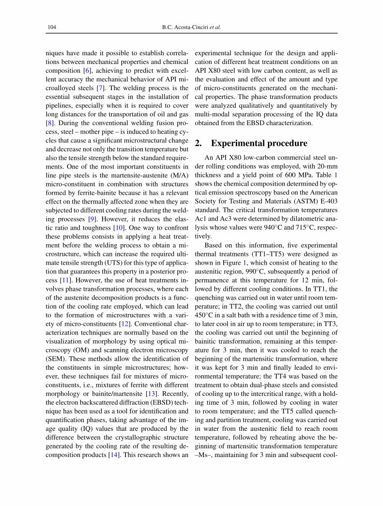
Fig. 1. Schematic diagram of the heat treatments per-formed on steel. TT, thermal treatment.
Figure 2 shows the continuous cooling trans-formation (CCT) diagram calculated through theJMat-Pro® program for the steel studied, in whichthe critical transformation temperatures can be ob-served, as well as the cooling rates necessaryto produce different types of micro-constituents.Some researchers [14] show that in X80 steels,the cooling conditions necessary to obtain the opti-mal microstructural characteristics are establishedin the range of cooling rates between 100◦C/s and10◦C/s.
In this work, five samples of 3 × 3 × 1.1 mmwere cut, which were machined and heat treatedin a rapid induction thermal analysis (RITA) L78model dilatometer to generate the desired micro-constituents. Subsequently, 15 specimens were ma-chined for mechanical tests according to the ASTME8/E8M-09 standard with the objective of carryingout reproducibility tests which were heat treatedin a type muffle furnace. To have a strict controlof the temperature during the thermal cycle, a test
Fig. 2. CCT diagram of the steel studied, calculated bymeans of the JMat-Pro® program. ρ = pearlite,β = bainita. CCT, continuous cooling transfor-mation.
specimen was instrumented with a type K thermo-couple. The thermocouple reading was recorded bymeans of data acquisition system FLUKE model2680. The mechanical tests were carried out in anINSTRON 1995 universal testing machine; threespecimens were analyzed for each of the heat treat-ments performed, and their results were averaged.Finally, the microstructural analysis was carried outusing SEM in a JEOL microscope model JSM-5910LV. Samples of 10 × 10 × 5 mm dimen-sions were cut from both the initial steel and theheat-treated specimens, which were prepared byconventional metallography techniques and etchedwith a 3% solution of nital for 20 s. Samples forEBSD analysis were polished with 1 µm diamondpaste and with 0.04 µm colloidal silica for 15 min.During the measurements, the data were collectedand processed using the Bruker® program. The IQvalues of EBSD patterns acquired by the EBSDanalysis were statistically processed by applyingthe multi-modal distribution method with the helpof a spreadsheet for the phase quantification [15].

106 B.C. Acosta-Cinciri et al.
3. Results and discussion3.1. Effect of the cooling rate on the mi-crostructure
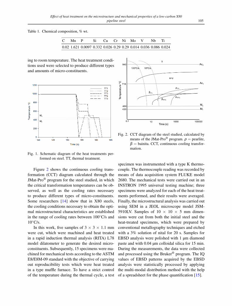
Figure 3 shows the dilatometry graphs obtainedfor the five heat treatments. For each heat treat-ment, when the phase transformation takes placeunder conditions of continuous heating, the relativechange in length recorded in the dilatometric curveis the result of two effects: the intrinsic thermal ex-pansion of the material and the dimensional changeassociated with the transformation. Figure 3 showsa linear behavior with a constant and positive slopeat different temperatures before any transformationtakes place. When the austenitizing temperature isreached and as the transformation progresses, theslope undergoes an alteration due to the longitudi-nal change that occurs in the crystal structure dur-ing phase transformations.
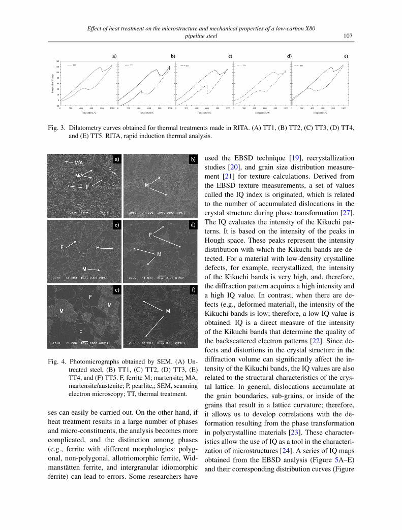
Figure 4A shows the microstructure corre-sponding to the initial steel, which is constitutedof a homogeneously distributed ferritic matrix withnon-uniform grain size, and some regions withsmall grains resulting from the recrystallizationprocess. SEM analysis in the recrystallized re-gions shows the presence of fine islands of micro-constituent MA located at the triple junction offerrite grains, at the grain boundary regions, andeven inside the ferrite grains, with both fine andslender block structures (see Figure 4A). However,the analysis performed by this technique did notallow the identification of another type of micro-constituent or phases of interest such as bainite.Recent studies [16] indicate that steels with mi-crostructures composed of ferrite and bainite incombination with micro-constituent MA raise theyield point of steel, in addition to causing an impor-tant effect on thermally affected zones when steel issubjected to different cooling rates during weldingprocesses [17]. In Figure 4B, the photomicrographcorresponding to TT1 is shown; it can be seenthat the microstructure is entirely constituted bythe martensite phase, which presents lath-like mor-phology characteristic of tempered steels. In con-trast, in Figure 4C corresponding to TT2, the mi-crostructural analysis shows different reliefs, wheresome grains with low gray contrast are observed, in
addition to small areas with plate morphology be-longing to the martensite phase. According to Fig-ure 1, the designed heat treatment involves a mi-crostructure composed mainly of ferrite, marten-site, and small amounts of bainite, of which onlythe first constituents can be seen in the image dueto the similarity in morphology. Additionally, thepresence of other phases is shown since the coolingtemperature is very close to the intercritical range,while the cooling rate is very low, which wouldwarn of the presence of other micro-constituentssuch as pearlite. However, due to the complexityof the microstructure, it is necessary to use anothermethod that allows the identification and quantifi-cation of all the constituents. On the other hand, inFigure 4D, the microstructure referring to TT3 isshowed. According to Figure 1, this treatment wasproposed to obtain a steel composed with bainiteand martensite phases distributed in a ferritic ma-trix. The Figure 4D clearly shows a ferritic matrixand combination with martensitic regions; how-ever, the bainite cannot be identified based only onits morphology. Figure 4E exhibits the photomicro-graph corresponding to the TT4 projected to ob-tain a dual-phase steel. In the image, two areas canbe seen: a dark regions which evidently belongs tothe ferritic matrix and light regions constituted bymartensite. Finally, in Figure 4F, the resulting mi-crostructure of the TT5 is shown, which suggeststhat the resulting microstructure must be consti-tuted of martensite and retained austenite [18]. Ac-cording to the analysis of the microstructure, thepresence of martensite can be clearly appreciated;however, austenite is difficult to identify by thischaracterization technique.
3.2. Phase quantification by IQ-EBSD
When steel is heat treated, the diversity ofmicro-constituents that are produced during con-tinuous cooling from the austenitic field stronglydepends on the cooling conditions used. Mi-crostructural analysis of transformation productsby OM (Optical Microscopy) and SEM is car-ried out by observations based only on morphol-ogy. When transformation products result in oneor two phases, qualitative and quantitative analy-
Effect of heat treatment on the microstructure and mechanical properties of a low-carbon X80pipeline steel 107
Fig. 3. Dilatometry curves obtained for thermal treatments made in RITA. (A) TT1, (B) TT2, (C) TT3, (D) TT4,and (E) TT5. RITA, rapid induction thermal analysis.
Fig. 4. Photomicrographs obtained by SEM. (A) Un-treated steel, (B) TT1, (C) TT2, (D) TT3, (E)TT4, and (F) TT5. F, ferrite M; martensite; MA,martensite/austenite; P, pearlite,; SEM, scanningelectron microscopy; TT, thermal treatment.
ses can easily be carried out. On the other hand, ifheat treatment results in a large number of phasesand micro-constituents, the analysis becomes morecomplicated, and the distinction among phases(e.g., ferrite with different morphologies: polyg-onal, non-polygonal, allotriomorphic ferrite, Wid-manstätten ferrite, and intergranular idiomorphicferrite) can lead to errors. Some researchers have
used the EBSD technique [19], recrystallizationstudies [20], and grain size distribution measure-ment [21] for texture calculations. Derived fromthe EBSD texture measurements, a set of valuescalled the IQ index is originated, which is relatedto the number of accumulated dislocations in thecrystal structure during phase transformation [27].The IQ evaluates the intensity of the Kikuchi pat-terns. It is based on the intensity of the peaks inHough space. These peaks represent the intensitydistribution with which the Kikuchi bands are de-tected. For a material with low-density crystallinedefects, for example, recrystallized, the intensityof the Kikuchi bands is very high, and, therefore,the diffraction pattern acquires a high intensity anda high IQ value. In contrast, when there are de-fects (e.g., deformed material), the intensity of theKikuchi bands is low; therefore, a low IQ value isobtained. IQ is a direct measure of the intensityof the Kikuchi bands that determine the quality ofthe backscattered electron patterns [22]. Since de-fects and distortions in the crystal structure in thediffraction volume can significantly affect the in-tensity of the Kikuchi bands, the IQ values are alsorelated to the structural characteristics of the crys-tal lattice. In general, dislocations accumulate atthe grain boundaries, sub-grains, or inside of thegrains that result in a lattice curvature; therefore,it allows us to develop correlations with the de-formation resulting from the phase transformationin polycrystalline materials [23]. These character-istics allow the use of IQ as a tool in the characteri-zation of microstructures [24]. A series of IQ mapsobtained from the EBSD analysis (Figure 5A–E)and their corresponding distribution curves (Figure
108 B.C. Acosta-Cinciri et al.
5A’–E’) calculated by IQ processing data through astatistical separation method [25] are shown for thefive heat treatments. For TT1, the IQ image doesnot show variations in the gray contrast, which in-dicates that the microstructure is only conformedof one phase, which is in accordance with thatshown in Figure 4B. On the other hand, the cal-culated distribution curve indicates that the high-est percentage (94.48%) corresponds to martensite,while the remaining percentage is associated withlarge-angle boundaries, grain boundaries, and car-bide precipitation. It is important to consider thatthe phase transformation from austenite to marten-site takes place at high cooling rates, which im-plies distortion in the crystalline structure in addi-tion to the accumulation of a large number of lat-tice defects. Therefore, it is evident that the IQ val-ues obtained from the measurement are low whenit comes to this micro-constituent. The IQ imagefor TT2 exhibits important variations in the grayscale, which is related to the presence of differenttypes of micro-constituents produced by the heattreatment conditions used. The multimodal distri-bution results show the presence of four indepen-dent normal curves, which correspond to 42.5%ferrite, 25% pearlite, 21.25% bainite, and 11.25%martensite. The constituents occupy the IQ normal-ized value range according to the degree of crys-talline distortion produced by the phase transfor-mation. The transformation from austenite to fer-rite and/or pearlite does not generate high distor-tion in the crystal lattice, so the IQ values obtainedfrom the analysis are high. However, the trans-formation from austenite to bainite and martensiteproduces a large accumulation of crystalline de-fects and lattice distortions, so their IQ values areset at lower positions on the IQ scale. The IQ ana-lysis performed for the TT3 shows variations in thegray contrast, which indicates the presence of dif-ferent micro-constituents; this result agrees satis-factorily with the distribution graphs shown in Fig-ure 5C’, where it is observed that the percentageof the constituents corresponds to ferrite (59.09%),bainite (22.73%), and martensite (18.18%). The lo-cation of the constituents in the IQ normalized datarange is located according to the phase transforma-tion kinetics associated with the cooling rates em-
ployed. The IQ image for two TT4 contrasting ar-eas is clearly seen: a ferritic constituent (light re-gion) and martensite islands (dark region) homo-geneously distributed in the matrix. Consequently,the two distribution peaks or curves correspondedto ferrite and martensite, with 55% and 45%, re-spectively. Finally, for TT5, the IQ image presentslow contrast in almost the entire image. However,the result of the separation of the distribution curvenotices the presence of two normal curves whichare associated with the ferrite and retained austen-ite phases as a result of the design of this heat treat-ment.
3.3. Mechanical property analysis
The results obtained from the stress vs. straincurves of the heat-treated samples are shown inFigure 6. According to the API-5L standard forgrade X80 and higher, the mechanical propertiesobtained after applying the heat treatment accom-plish the necessary requirements, which establisha UTS value of 600 MPa as a minimum. In thegraph, it can be seen that the best properties ofUTS correspond to TT1 since the UTS is >1,100MPa. However, TT3 and TT4 present the lowestUTS results, in contrast to the high percentage ofdeformation obtained (40%), due to the treatmentconditions used. This behavior is associated withthe presence of martensite since 95% of the struc-ture is composed of this phase; therefore, it repre-sents the appropriate treatment when desired andelevates such properties.
A complete summary of the effect of heat treat-ment on mechanical properties and its relationshipwith martensite content is presented in Figure 7.In the case of the TT1, it not only presents thehighest values of UTS but also presents the yieldstrength (YS) (900 MPa). This behavior is associ-ated with the presence of martensite since 95% ofthe structure is composed of this phase, therefore,it represents the appropriate treatment when whatis required is to raise such properties. However,this microstructure is not suitable since it has highhardness and low ductility for a welding process;the steel resulting from this treatment generated amicrostructure composed of tempered martensite,

Effect of heat treatment on the microstructure and mechanical properties of a low-carbon X80pipeline steel 109
Fig. 5. IQ quality index maps (left) and distribution curves obtained by statistical separation (right) for heat-treatedsteel: (A) TT1, (B) TT2, (C) TT3, (D) TT4, and (E) TT5. IQ, image quality; TT, thermal treatment.
consequently decreasing the tensile strength andhindering any operation given the hardness of thephase. Otherwise, it could improve other propertiessuch as percentage elongation and ductility, that is,the mechanical behavior would be similar to that ofTT5, which resulted in a double-phase microstruc-ture that gives the steel excellent mechanical prop-erties. In Figure 7, in the region corresponding to
TT5, it can be seen that the values of UTS and YSare 810 MPa and 720 MPa, respectively. In con-trast, due to the amount of martensite present in thesteel (82%), it causes the percentage of deforma-tion to decrease considerably to 25%. Despite, thistreatment – TT5 – would be convenient for two rea-sons: first, due to the amount of retained austen-ite, when this material subjected to a reheating pro-

110 B.C. Acosta-Cinciri et al.
Fig. 6. Averaged stress vs. strain curves obtained forheat-treated steel samples. TT, thermal treat-ment.
cess, the austenite could decompose into some ofthe intermediate products, ensuring the prevalenceof the required mechanical properties. Second, themartensite resulting from this treatment is of lowhardness due to the tempering cycle; therefore, itsimplifies the welding stage. Additionally, in Fig-ure 7, it can be seen that the lowest UTS and YSvalues (620 MPa and 440 MPa, respectively) wereobtained for the sample subjected to TT2; this isdue to the fact that the resulting microstructure is amixture of micro-constituents, where some of theseimprove resistance, as in the case of martensite(11%), while the ferrite found in the steel providesmajor ductility increasing the percentage of defor-mation above 30%, though other constituents suchas pearlite counteract the effect caused by the pre-vious ones. On the other hand, the best percentagesof deformation correspond to TT3 (∼38%), dueto the increase in the content of the ferrite phase,in addition to the presence of bainite and marten-site (>18%), which produce a significant effect onthe UTS and YS, reaching values close to the 700MPa and 425 MPa, respectively. The resulting mi-crostructure of TT4 corresponds to a dual-phase(ferritic-martensitic) steel. This type of steels is ofgreat interest to the automotive industry due to theexcellent combination of strength and toughnessand mechanical properties [26]. As a result, theUTS of the sample treated under these conditions
showed resistance values >800 MPa and a defor-mation of ∼30% (see Figures 7), such that the be-havior is due to the effect of the constituents; on theone hand, a ferritic matrix that guarantee ductilityand, moreover, homogeneously distributed marten-site islands provide excellent resistance. In sum-mary, the applied heat treatments show mechanicalproperties superior to those required according tothe standard; therefore, the choice of any of themcould perform satisfactorily. However, the TT5 andTT4 heat treatments are appropriate according tothe application for which the material is intended.
Fig. 7. Effect of heat treatment on mechanical prop-erties and its relationship with the percentageof martensite. TT, thermal treatment; UTS, ul-timate tensile strength; YS, yield strength.
4. Conclusions1. The heat treatment applied allowed to in-
crease the UTS above the minimum necessary ac-cording to the API standard for the manufactureof pipelines transmission. However, in the case ofTT2, TT3, and TT4, the resulting microstructuresmust be treated with caution in the welding stagesof steel processing since they could decrease theUTS in the thermally affected zones due to thephase transformation.
2. The quenching in water (case TT1) producedUTS values above 1,100 MPa due to the presenceof martensite which generates high hardness; how-
Effect of heat treatment on the microstructure and mechanical properties of a low-carbon X80pipeline steel 111
ever, its high percentage significantly affects duc-tility.
3. The appropriate treatment to obtain a sat-isfactory combination of mechanical properties isquenching and partition (TT5), due to the exis-tence of martensite and austenite, since, on the onehand, martensite raises the UTS value above 800MPa without affecting other properties, while theaustenite during the welding stage can transforminto some decomposition product, allowing the me-chanical properties to be maintained.
4. The dual-phase steel obtained (ferrite-martensite) in the TT4 has suitable mechanicalcharacteristics (UTS 800 MPa), despite its low car-bon content. Although not the advisable option forthis type of application, recently, these steels are ofgreat importance for the automotive industry due tothe excellent combination of strength and ductility.
The designed heat treatments generated mi-crostructures where it was difficult to determine theconstituents present by means of OM and SEM,so the EBSD technique using the analysis IQ dataproved to be an excellent option to distinguish andquantify the resulting micro-constituents. In thiswork, it was possible to establish a procedure toraise the UTS of this steel, despite it being inthe minimum range of the carbon content for X80steels.
Acknowledgments
The authors want to acknowledge to theTecNM-ITM, CATEDRAS-CONACyT, AHMSA,Dr. Emmanuel Gutiérrez Castañeda of UAP andSNI for the permanent support to the academicgroups of Modeling of Metallurgical Processes andThermofluids.
References[1] Farhat H, Oguocha INA, Yannacopoulos S. Effect of
welding speed on weld quality and microstructure oftandem submerged arc welded X80 pipeline steel. In:Materials Science and Technology, 2009 Conferenceand Exhibition, Pittsburg, 2009, p. 2457.
[2] Nishioka K, Ichikawa K. Progress in thermomechani-cal control of steel plates and their commercialization.Sci Technol Adv Mater. 2012; https://doi.org/10.1088/14686996/13/2/023001
[3] Byoungchul H, Young MK, Sunghak L, Nack K. Cor-relation of rolling condition, microstructure, and lowtemperature toughness of X70 pipeline steels. J MetallMater Trans A. 2005; https://doi.org/10.1007/s11661-005-0043-1
[4] Rodrigues PCM, Pereloma EV, Santos DB. Me-chanical properties of an HSLA bainitic steel sub-jected to controlled rolling with accelerated cooling.Mater Sci Eng A. 2000; https://doi.org/10.1016/S0921-5093(99)00795-9
[5] Kong J, Zhen L, Guo B, Li P. Influence of Mo con-tent on microstructure and mechanical properties of highstrength pipeline steel. Mater Design. 2004; https://doi.org/10.1016/j.matdes.2004.03.009
[6] Pouraliakbara H, Khalajb G, Jandaghia MR, KhalajbMJ. Study on the correlation of toughness with chem-ical composition and tensile test results in microalloyedAPI pipeline steels. J Min Metall Sect B Metall B. 2015;https://doi.org/10.2298/JMMB140525025P
[7] Faizabadi MJ, Khalaj G, Pouraliakbar H, Jandaghi MR.Prediction of toughness by using chemical compositionand tensile properties in microalloyed line pipe steels.Neural Comput Appl. 2014; https://doi.org/10.1007/s00521-014-1687-9
[8] Wang X, Xiao F-R, Fu Y-H, Chen X-W, Liao B. Materialdevelopment for grade X80 heavy-wall hot inductionsbends. Mater Sci Eng A. 2011; https://doi.org/10.1016/j.msea.2011.10.017
[9] Goldenstein H, Gorni A, González Ramírez MF, Land-graf FJG. Caracterización y Análisis de la Evolucióndel Microconstituyente MA en Aceros Microaleadospara Tubo API X80 Tratado Térmicamente. In: IXCongreso Iberoamericano de Ingeniería Mecánica, SãoPaulo, 2009; 60.
[10] Huda N, Midawi ARH, Gianetto J, Lazor R, GerlichAP. Influence of martensite-austenite (MA) on impacttoughness of X80 line pipe steels. Mater Sci Eng. 2016;https://doi.org/10.1016/j.msea.2016.03.095
[11] Niu J, Qi L-H, Liu Y-L, Ma L, Feng Y-R,Zang J-X. Tempering microstructure and mechani-cals properties of pipeline steel X80. Trans NonferrMet. Soc China. 2009; https://doi.org/10.1016/S1003-6326(10)60111-2
[12] Liu Y-J, Li Y-M, Huang B-Y. Influence on austen-itizing temperature on apparent morphologies of as-quenched microstructures of steels. J Cent SouthUniv Technol, 2006; https://doi.org/10.1007/s11771-006-0142-1
[13] Bhadeshia H. Steels: microstructure and properties. 3rded. New York: Elsevier; 2006.
[14] Zhao J, Hu W, Wang X, Kang J, Cao Y, Yuan G, DiH, Misra RDK. A novel thermo-mechanical controlledprocessing for large-thickness microalloyed 560 MPa(X80) pipeline strip under ultra-fast colling. Mater SciEng A. 2016; https://doi.org/10.1016/j.msea.2016.07.089
[15] López Granados NM. Estudio de las texturas de trans-

112 B.C. Acosta-Cinciri et al.
formación de fase en aceros laminados en calientepara aplicaciones automotrices. Doctoral thesis, México,2015, p. 58.
[16] Han SY, Shin SY, Lee S, Kim NJ, Bae J-H, Kim K.Effects of Cooling Conditions on Tensile and CharpyImpact Properties of API X80 Linepipe Steels. MetallMater Trans A. 2010; https://doi.org/10.1007/s11661-009-0135-4
[17] Sun XJ, Yuan SF, Xie ZJ, Dong LL, Misra RDK.Microstructure-property relationship in a high strength-high toughness combination ultra-heavy gauge offshoreplate steel: The significance of multiphase microstruc-ture. Mater Sci Eng A. 2017; https://doi.org/10.1016/j.msea.2017.02.058
[18] Tottenn GE. Steel heat treatment: metallurgy and tech-nologies. 2nd ed. Oregon: CRC Press; 2007.
[19] Schwarts AJ, Kumar M, Adams BL, Field DP. Electronbackscattering diffraction in material science. 2nd ed.New York: Springer; 2000.
[20] Tarasiuk J, Gerber P, Bacroix B. Estimation ofrecrystallized volume fraction from EBSD data.Act Mater. 2002; https://doi.org/10.1016/S1359-6454(02)00005-8
[21] Humphreys FJ. Review grain and subgrain char-acterization by electron backscatter diffraction. JMater Sci. 2001; https://doi.org/10.1023/A:1017973432592
[22] Lassen K. Automatic high-precision measurementsof the location and width of Kikuchi bands in elec-
tron backscatter diffraction patterns. J Microsc.1998;https://doi.org/10.1046/j.1365-2818.1998.00330.x
[23] Wilson AW, Spanos G. Application of orientation imag-ing microscopy to study phase transformations in steels.Mater Charact. 2001; https://doi.org/10.1016/S1044-5803(01)00140-1
[24] Wu J, Wray PJ, Garcia CI, Hua M, DeArdo AJ. Imagequality analysis: A new method of characterizing mi-crostructures. ISIJ Int. 2005; https://doi.org/10.2355/isijinternational.45.254
[25] Lopez Granados NM, Salinas Rodriguez A. EBSD In-vestigation on Effect of Cooling Rate on Microstruc-ture and Transformation Textures of High Strength Hot-rolled Steel Plates. J Iron Steel Res Int. 2016; https://doi.org/10.1016/S1006-706X(16)30043-7
[26] Barella S, Venturini R, Mapelli C. Crystallographic tex-ture and mechanical properties in high martensitic dualphase steels In: The 1st. International Conference Super-High Strength Steels, Italy, 2005.
[27] Wilson AW, Madison JD, Spanos G, Determining phasevolume fraction in steels by electron backscattereddiffraction. Scr Mater. 2001; https://doi.org/10.1016/S1359-6462(01)01137-X
Received 23-02-2021Accepted 08-05-2021