Process capability study of laser assisted micro milling of a hard-to-machine material
11
Journal of Manufacturing Processes 14 (2012) 41–51 Contents lists available at SciVerse ScienceDirect Journal of Manufacturing Processes j ourna l ho me p age: www.elsevier.com/locate/manpro Process capability study of laser assisted micro milling of a hard-to-machine material Mukund Kumar ∗ , Shreyes N. Melkote The George W. Woodruff School of Mechanical Engineering, Georgia Institute of Technology, Atlanta, GA, USA a r t i c l e i n f o Article history: Received 20 May 2011 Received in revised form 17 September 2011 Accepted 20 September 2011 Available online 14 October 2011 Keywords: Micro milling Laser assisted Hybrid process Tool wear Material removal rate Burrs Surface roughness a b s t r a c t Laser assisted micro milling (LAMM) is capable of generating three-dimensional micro scale features in hard-to-machine materials. This paper compares the process capability of LAMM with conventional micro milling of a hardened tool steel. In particular, the potential advantages of LAMM over micro milling with respect to cutting forces, tool wear, material removal rate, burr formation and surface roughness are investigated when micro milling hardened A2 tool steel (62 HRC). The results show that LAMM has significant advantages over micro milling, especially in terms of cutting forces, material removal rate and tool wear. The average reduction in the resultant cutting force is found to be up to 69% with laser assist. In addition, tool wear is found to be substantially less with laser assist even when the material removal rates are increased by a factor of six over the tool manufacturer recommended cutting conditions. © 2011 The Society of Manufacturing Engineers. Published by Elsevier Ltd. All rights reserved. 1. Introduction Micro milling is increasingly being used to fabricate micro- molds for injection molding of plastic parts [1,2]. Hardened steels and ceramics are the preferred materials for micro-molds because of their ability to withstand high thermal and mechanical cyclic loads [3]. In order to create microscale features in these hard-to- machine materials, new hybrid processes have been developed [4,5]. Laser assisted micro milling (LAMM) is one such process, which uses a low-power laser to locally preheat the material that is then removed by the tool immediately behind it [6]. Recent work on LAMM has demonstrated its potential for micro- machining of hard materials. Singh and Melkote [4] showed that by suitably controlling the laser power, spot size and speed, it is possible to bring about a substantial reduction in the material flow strength and consequently reduction in the cutting forces and tool/stage deflections. Jeon and Pfefferkorn [5] showed that the radial and tangential forces are reduced by 57% and 64%, respectively, when cutting unhardened AISI 1018 steel with laser assist. Recently, Kumar et al. [6] successfully designed and built a LAMM setup capable of producing three-dimensional features in ∗ Corresponding author. E-mail address: [email protected] (M. Kumar). hard materials. They also showed that the resulting groove dimen- sional accuracy is superior and the tool wear rate is lower when machining hardened A2 tool steel with laser assist. Shelton and Shin [7] reported a decrease in the root mean square value of the acoustic emission (AE) signal with machining time in LAMM. They attributed the observed decrease to reduce tool wear. Using finite element modeling, they estimated reductions in cutting forces in laser assisted orthogonal cutting of Ti–6Al–4V and 316 stainless steel materials. The limited prior work on laser assisted micro milling indicates that it leads to a reduction in tool wear and cutting forces. How- ever, a detailed investigation of the process capability of LAMM has not been reported. In particular, the limits of LAMM as far as the potential for higher material removal rate over conventional micro milling when micromachining hard materials have not been investigated. Furthermore, a direct and detailed comparison of tool wear in LAMM versus conventional micro milling and its impact on cutting forces, surface finish and burr formation are lacking. This paper addresses the aforementioned limitations of prior work through a detailed process capability study of LAMM. Specif- ically, a comparison of the material removal rates in LAMM versus conventional micro milling of hardened A2 tool steel (62 HRc) is presented along with the resulting tool wear behavior and its effect on a variety of other process responses including the resultant cut- ting force, burr height, and surface finish. It is also demonstrated that through proper selection of tool size relative to the laser spot 1526-6125/$ – see front matter © 2011 The Society of Manufacturing Engineers. Published by Elsevier Ltd. All rights reserved. doi:10.1016/j.jmapro.2011.09.003
-
Upload
independent -
Category
Documents
-
view
1 -
download
0
Transcript of Process capability study of laser assisted micro milling of a hard-to-machine material

Pm
MT
a
ARR1AA
KMLHTMBS
1
maolm[wi
mbiflatraL
1d
Journal of Manufacturing Processes 14 (2012) 41–51
Contents lists available at SciVerse ScienceDirect
Journal of Manufacturing Processes
j ourna l ho me p age: www.elsev ier .com/ locate /manpro
rocess capability study of laser assisted micro milling of a hard-to-machineaterial
ukund Kumar ∗, Shreyes N. Melkotehe George W. Woodruff School of Mechanical Engineering, Georgia Institute of Technology, Atlanta, GA, USA
r t i c l e i n f o
rticle history:eceived 20 May 2011eceived in revised form7 September 2011ccepted 20 September 2011vailable online 14 October 2011
eywords:
a b s t r a c t
Laser assisted micro milling (LAMM) is capable of generating three-dimensional micro scale featuresin hard-to-machine materials. This paper compares the process capability of LAMM with conventionalmicro milling of a hardened tool steel. In particular, the potential advantages of LAMM over micro millingwith respect to cutting forces, tool wear, material removal rate, burr formation and surface roughnessare investigated when micro milling hardened A2 tool steel (62 HRC). The results show that LAMM hassignificant advantages over micro milling, especially in terms of cutting forces, material removal rate andtool wear. The average reduction in the resultant cutting force is found to be up to 69% with laser assist.
icro millingaser assistedybrid processool wearaterial removal rate
urrsurface roughness
In addition, tool wear is found to be substantially less with laser assist even when the material removalrates are increased by a factor of six over the tool manufacturer recommended cutting conditions.
© 2011 The Society of Manufacturing Engineers. Published by Elsevier Ltd. All rights reserved.
. Introduction
Micro milling is increasingly being used to fabricate micro-olds for injection molding of plastic parts [1,2]. Hardened steels
nd ceramics are the preferred materials for micro-molds becausef their ability to withstand high thermal and mechanical cyclicoads [3]. In order to create microscale features in these hard-to-
achine materials, new hybrid processes have been developed4,5]. Laser assisted micro milling (LAMM) is one such process,hich uses a low-power laser to locally preheat the material that
s then removed by the tool immediately behind it [6].Recent work on LAMM has demonstrated its potential for micro-
achining of hard materials. Singh and Melkote [4] showed thaty suitably controlling the laser power, spot size and speed, it
s possible to bring about a substantial reduction in the materialow strength and consequently reduction in the cutting forcesnd tool/stage deflections. Jeon and Pfefferkorn [5] showed thathe radial and tangential forces are reduced by 57% and 64%,
espectively, when cutting unhardened AISI 1018 steel with laserssist. Recently, Kumar et al. [6] successfully designed and built aAMM setup capable of producing three-dimensional features in∗ Corresponding author.E-mail address: [email protected] (M. Kumar).
526-6125/$ – see front matter © 2011 The Society of Manufacturing Engineers. Publisheoi:10.1016/j.jmapro.2011.09.003
hard materials. They also showed that the resulting groove dimen-sional accuracy is superior and the tool wear rate is lower whenmachining hardened A2 tool steel with laser assist. Shelton andShin [7] reported a decrease in the root mean square value of theacoustic emission (AE) signal with machining time in LAMM. Theyattributed the observed decrease to reduce tool wear. Using finiteelement modeling, they estimated reductions in cutting forces inlaser assisted orthogonal cutting of Ti–6Al–4V and 316 stainlesssteel materials.
The limited prior work on laser assisted micro milling indicatesthat it leads to a reduction in tool wear and cutting forces. How-ever, a detailed investigation of the process capability of LAMMhas not been reported. In particular, the limits of LAMM as far asthe potential for higher material removal rate over conventionalmicro milling when micromachining hard materials have not beeninvestigated. Furthermore, a direct and detailed comparison of toolwear in LAMM versus conventional micro milling and its impact oncutting forces, surface finish and burr formation are lacking.
This paper addresses the aforementioned limitations of priorwork through a detailed process capability study of LAMM. Specif-ically, a comparison of the material removal rates in LAMM versusconventional micro milling of hardened A2 tool steel (62 HRc) is
presented along with the resulting tool wear behavior and its effecton a variety of other process responses including the resultant cut-ting force, burr height, and surface finish. It is also demonstratedthat through proper selection of tool size relative to the laser spotd by Elsevier Ltd. All rights reserved.
42 M. Kumar, S.N. Melkote / Journal of Manufacturing Processes 14 (2012) 41–51
Table 1Nominal chemical composition of A2 tool steel.
C
4
swt
2
dsssmrcpitsud
3
3
0flmwtc
m2ccs
F2
Element C Mn Si
Weight (%) 0.95–1.05 1.00 0.5
ize, a six-fold increase in material rate can be realized in LAMMithout significant increase in tool wear. The following sections of
he paper present details of the LAMM process capability study.
. Experimental setup
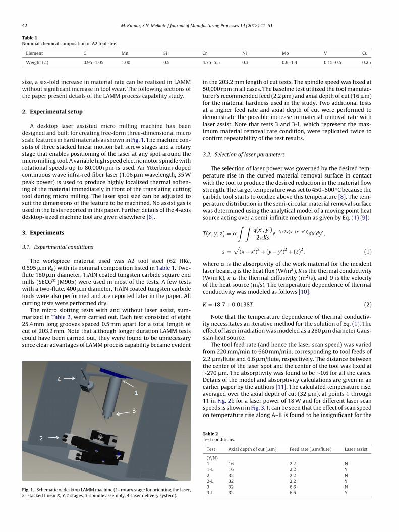
A desktop laser assisted micro milling machine has beenesigned and built for creating free-form three-dimensional microcale features in hard materials as shown in Fig. 1. The machine con-ists of three stacked linear motion ball screw stages and a rotarytage that enables positioning of the laser at any spot around theicro milling tool. A variable high speed electric motor spindle with
otational speeds up to 80,000 rpm is used. An Ytterbium dopedontinuous wave infra-red fiber laser (1.06 �m wavelength, 35 Weak power) is used to produce highly localized thermal soften-
ng of the material immediately in front of the translating cuttingool during micro milling. The laser spot size can be adjusted touit the dimensions of the feature to be machined. No assist gas issed in the tests reported in this paper. Further details of the 4-axisesktop-sized machine tool are given elsewhere [6].
. Experiments
.1. Experimental conditions
The workpiece material used was A2 tool steel (62 HRc,.595 �m Ra) with its nominal composition listed in Table 1. Two-ute 180 �m diameter, TiAlN coated tungsten carbide square endills (SECO® JM905) were used in most of the tests. A few testsith a two-flute, 400 �m diameter, TiAlN coated tungsten carbide
ools were also performed and are reported later in the paper. Allutting tests were performed dry.
The micro slotting tests with and without laser assist, sum-arized in Table 2, were carried out. Each test consisted of eight
5.4 mm long grooves spaced 0.5 mm apart for a total length ofut of 203.2 mm. Note that although longer duration LAMM testsould have been carried out, they were found to be unnecessaryince clear advantages of LAMM process capability became evident
ig. 1. Schematic of desktop LAMM machine (1- rotary stage for orienting the laser,- stacked linear X, Y, Z stages, 3-spindle assembly, 4-laser delivery system).
r Ni Mo V Cu
.75–5.5 0.3 0.9–1.4 0.15–0.5 0.25
in the 203.2 mm length of cut tests. The spindle speed was fixed at50,000 rpm in all cases. The baseline test utilized the tool manufac-turer’s recommended feed (2.2 �m) and axial depth of cut (16 �m)for the material hardness used in the study. Two additional testsat a higher feed rate and axial depth of cut were performed todemonstrate the possible increase in material removal rate withlaser assist. Note that tests 3 and 3-L, which represent the max-imum material removal rate condition, were replicated twice toconfirm repeatability of the test results.
3.2. Selection of laser parameters
The selection of laser power was governed by the desired tem-perature rise in the curved material removal surface in contactwith the tool to produce the desired reduction in the material flowstrength. The target temperature was set to 450–500 ◦C because thecarbide tool starts to oxidize above this temperature [8]. The tem-perature distribution in the semi-circular material removal surfacewas determined using the analytical model of a moving point heatsource acting over a semi-infinite medium as given by Eq. (1) [9]:
T(x, y, z) = ˛
∫ ∫q(x′, y′)2�Ks
e−U/2�(s−(x−x′))dx′dy′,
s =√
(x − x′)2 + (y − y′)2 + (z)2. (1)
where ̨ is the absorptivity of the work material for the incidentlaser beam, q is the heat flux (W/m2), K is the thermal conductivity(W/m K), � is the thermal diffusivity (m2/s), and U is the velocityof the heat source (m/s). The temperature dependence of thermalconductivity was modeled as follows [10]:
K = 18.7 + 0.0138T (2)
Note that the temperature dependence of thermal conductiv-ity necessitates an iterative method for the solution of Eq. (1). Theeffect of laser irradiation was modeled as a 280 �m diameter Gaus-sian heat source.
The tool feed rate (and hence the laser scan speed) was variedfrom 220 mm/min to 660 mm/min, corresponding to tool feeds of2.2 �m/flute and 6.6 �m/flute, respectively. The distance betweenthe center of the laser spot and the center of the tool was fixed at∼270 �m. The absorptivity was found to be ∼0.6 for all the cases.Details of the model and absorptivity calculations are given in anearlier paper by the authors [11]. The calculated temperature rise,averaged over the axial depth of cut (32 �m), at points 1 through
11 in Fig. 2b for a laser power of 18 W and for different laser scanspeeds is shown in Fig. 3. It can be seen that the effect of scan speedon temperature rise along A–B is found to be insignificant for theTable 2Test conditions.
Test Axial depth of cut (�m) Feed rate (�m/flute) Laser assist
(Y/N)1 16 2.2 N1-L 16 2.2 Y2 32 2.2 N2-L 32 2.2 Y3 32 6.6 N3-L 32 6.6 Y

M. Kumar, S.N. Melkote / Journal of Manufacturing Processes 14 (2012) 41–51 43
Fig. 2. (a) Position of the tool with respect to the laser beam (A and B representsthe depth along which temperature is calculated), (b) Actual path of the cutting toolindicating the cutting forces (temperature rise is predicted at points 1 through 11along the periphery).
Fig. 3. Temperature rise (averaged over the axial depth) at points along the cuttingtool path (see Fig. 2).
Fig. 4. SEM Micrograph showing the corner radius of the micro end mill.
range of scan speeds investigated. Therefore, the laser power andspot size were fixed for all tests at 18 W and 280 �m, respectively.
3.3. Measured responses
The measured responses include the maximum resultant force,tool wear, machined groove geometry, burr height, and surfaceroughness, all as a function of the cutting distance. The cutting forcewas measured using a 3-axis piezoelectric platform dynamometer(Kistler Minidyn 9256C2). Note that the lowest quoted natu-ral frequency of the dynamometer is 4 kHz in the X-direction,which is higher than the maximum tooth passing frequency of1.66 kHz. In addition, all the experiments were conducted usingthe same spindle speed, which enables the comparison of forcedata between experiments without accounting for the dynamicsof the dynamometer. Tool wear was characterized optically every50.8 mm of cutting, and was quantified by the change in tool cornerradius (shown in Fig. 4). This change is monitored by measuring theradius of a three-point circle as shown in Fig. 4. Five measurementswere taken after each experiment and the average is reported inthis paper.
The change in geometry of the machined groove with cuttingdistance (and hence tool wear) was measured using a confo-cal laser scanning microscope (Olympus LEXT). The burr heightsreported in the paper were determined from the measured groovegeometry and represent an average of ten measurements for eachgroove. The three-dimensional arithmetic average surface rough-ness height (Sa) reported in this paper was measured over an area of270 �m × 70 �m along the centerline of the groove. Five measure-ments were taken for each experiment and the average is reportedin this paper.
4. Results and discussion
4.1. Cutting forces
Changes in the maximum resultant force per tool revolutionversus groove number (or cutting distance) are shown in Fig. 5(aand b). The resultant cutting force at each time instant is calculatedas,
R =√
F2x + F2
y + F2z . (3)
For all cases without laser assist, the resultant force increases
with increasing groove number/cutting distance primarily becauseof tool wear as shown later in the paper. In contrast, no significantincrease in the resultant force with cutting distance is observedin the tests with laser assist. In addition, the magnitudes of the
44 M. Kumar, S.N. Melkote / Journal of Manufacturing Processes 14 (2012) 41–51
F with gg itions
rsat(tmri
rtth
TR
ig. 5. (a) Changes in the maximum resultant force (averaged over each groove)
roove) with groove number (extensions ‘1’ and ‘2’ in the legend indicate test repet
esultant force with laser assist are much lower than the corre-ponding cases without laser assist, especially in the higher feednd depth of cut tests. Specifically, it can be seen in Fig. 5(a)hat, except Exp 1, the more aggressive non-laser assist testsExp 2 and 3) are characterized by a rapid increase in the resul-ant force, with Exp 3 resulting in catastrophic failure of the tool
uch earlier than any of the laser assist cases. Repeatability of theesults for the most aggressive test cases (Exp 3 and 3-L) are shownn Fig. 5(b).
It can be seen from Table 3 that the average % reduction in theesultant force due to laser assist is higher for Exp 2-L and Exp 3-L
han Exp 1-L. The large percentage reduction in Exp 2-L is due tohe fact that the resultant force in Exp 2 (without laser assist) isigher because of increased tool wear, as shown later in the paper.able 3eduction in the maximum resultant force (averaged over all the machined grooves).
Experiment Average % reduction in the resultant force
1-L 262-L 693-L 43
roove number. (b) Changes in the maximum resultant force (averaged over each).
The variation in specific cutting energy (averaged over eachgroove) with groove number is shown in Fig. 6. The specific cut-ting energy for each groove was calculated by dividing the peakresultant force by the product of the tool feed and the measuredaxial depth of cut. It can be seen that the specific cutting energywith laser assist is lower than the corresponding value obtainedwithout laser assist. In addition, for all cases without laser assist,the specific cutting energy increases with groove number whereasthe increase for the laser assisted cases is significantly less. Theobserved increase in the specific cutting energy for the non-laserassist cases is attributed to increased tool wear as shown in thenext section of the paper. Also note that the specific cutting energyis lowest for tests with the highest feed of 6.6 �m/flute for bothwith and without laser assist cases. This is consistent with thewell-known size effect in machining.
As seen in Figs. 5 and 6, tool life in the conventional micro millingprocess is limited by catastrophic tool failure at the highest feedrate and axial depth of cut. On the other hand, the corresponding
LAMM test shows negligible increase in the resultant force or thespecific cutting energy. It is precisely under such conditions thatLAMM becomes a viable alternative to conventional micro milling.Specifically, the LAMM test at 6.6 �m/flute and 32 �m axial depth
M. Kumar, S.N. Melkote / Journal of Manufacturing Processes 14 (2012) 41–51 45
er (las
o(c
4
ctri3aecp2
Fig. 6. Variation in the average specific cutting energy with groove numb
f cut represents a six-fold increase in the material removal rate11.9 mm3/min) over the tool manufacturer recommended cuttingonditions (1.99 mm3/min).
.2. Tool wear
The change in corner radius of the micro tool as a function ofutting distance is shown in Fig. 7. The increase in corner radius forhe LAMM tests is found to be considerably smaller than in the cor-esponding non-laser assist tests. For instance, the corner radiusncreases from 1.8 �m to 6 �m in Exp. 2-L while it increases to4.2 �m in Exp 2. The change in corner radius is very gradual inll the laser assist cases while only Exp 1 (non-laser assist case)
xhibits a similar trend. For the remaining two non-laser assistases (Exp 2 and 3), severe tool chipping and breakage is observed,reventing a comparison overlong the complete cutting distance of03.2 mm.Fig. 7. Change in tool corner rad
er power: 18 W, spot size: 280 �m, laser-cutting tool distance: 270 �m).
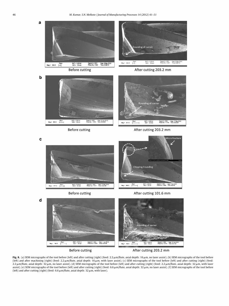
SEM images of the tool before and after cutting are shown inFig. 8(a–f). Fig. 8(a) clearly indicates rounding of the corner due toabrasive wear. This is the only non-laser assist case where gradualwear of the tool was observed.
The SEM micrograph in Fig. 8(b) shows rounding of the toolcorner after 203.2 mm of LAMM. Small amounts of softened workmaterial are found to be adhering to the tool. The tool wear withlaser assist is less than the non-laser assist case (see Fig. 8(a))for the same cutting conditions. Also, as seen in Fig. 7, the toolcorner radius at the end of cut is highest among all LAMMtests.
Fig. 8(c) clearly shows significant tool wear. In addition to grad-ual abrasive wear, some chipping due to micro fracture (see inset)
is also observed. Note that the tool feed for this test is 2.2 �m/flutebut the axial depth of cut is twice that of Exp 1. This suggests thatthe tools perform poorly at higher than recommended axial depthof cut and feed rate.ius with cutting distance.
46 M. Kumar, S.N. Melkote / Journal of Manufacturing Processes 14 (2012) 41–51
Fig. 8. (a) SEM micrographs of the tool before (left) and after cutting (right) (feed: 2.2 �m/flute, axial depth: 16 �m, no laser assist). (b) SEM micrographs of the tool before(left) and after machining (right) (feed: 2.2 �m/flute, axial depth: 16 �m, with laser assist). (c) SEM micrographs of the tool before (left) and after cutting (right) (feed:2.2 �m/flute, axial depth: 32 �m, no laser assist). (d) SEM micrographs of the tool before (left) and after cutting (right) (feed: 2.2 �m/flute, axial depth: 32 �m, with laserassist). (e) SEM micrographs of the tool before (left) and after cutting (right) (feed: 6.6 �m/flute, axial depth: 32 �m, no laser assist). (f) SEM micrographs of the tool before(left) and after cutting (right) (feed: 6.6 �m/flute, axial depth: 32 �m, with laser).

M. Kumar, S.N. Melkote / Journal of Manufacturing Processes 14 (2012) 41–51 47
) (Con
eto
tt
3Tra
teitrabt
4
ftowtcc
trast, in LAMM, the change in groove profile with cutting distance isminimal, indicating reduced tool wear and hence improved groovedimensional accuracy.
Fig. 8. (a
Contrary to expectations, the heat from the laser has a beneficialffect on tool wear as seen in Fig. 8(d) compared to Fig. 8(c). Underhese conditions, the tool wear is less notwithstanding the adhesionf work material to the tool surfaces.
The SEM micrograph in Fig. 8(e) shows substantial rounding ofhe corner after 50.8 mm of cut, indicating rapid wear. The tool shat-ered after 76.2 mm length of cut due to excessive cutting forces.
Under these cutting conditions (feed: 6.6 �m/flute, depth of cut:2 �m), LAMM yields superior tool wear results as seen in Fig. 8(f).his is due to less rubbing and more cutting at the highest tool feedate compared to the 2.2 �m/flute case. This is the best case amongll the experiments carried out.
In addition to changes in tool corner radius, the change in cut-ing edge radius was measured at a location 15 �m away from thend face of the tool for two test cases (Exp 3 and 3-L) and are shownn Fig. 9. Although the tool in the non-laser assist test failed catas-rophically after 50.8 mm of cutting, it can be seen that the edgeadius in the laser assist case does increase with cutting distancend is quite large. This implies that higher tool feed rates shoulde used to minimize the impact of tool edge radius on ploughing ofhe material.
.3. Groove geometry
The groove cross-sectional geometry at the start and end of cutor the different test cases are shown in Fig. 10(a–f). In every casehe groove profile matches the tool profile shown in the previ-us section. Fig. 10(a and b) compare the groove profiles obtained
ith and without laser assist after 5 mm and 203.2 mm of cut-ing, respectively. In the absence of laser heating the groove profilehanges significantly due to rapid tool wear. The profile in Fig. 10(a)learly indicates an increase in the tool corner radius. It can be also
tinued)
discerned that the axial depth of cut is higher than the set depthof cut for all cases with laser assist. This effect is attributed to tooland workpiece thermal expansion, which results in a higher depthof cut. Note that the material removal rate in LAMM is six timeshigher than the recommended conditions suggested by the toolmanufacturer.
Fig. 10(c and d) compares the groove profiles with and with-out laser assist. Fig. 10(c) clearly shows that the impact of toolwear is significant and results in increased ploughing of the workmaterial, as seen from the larger burrs at the groove sides. In con-
Fig. 9. Change in cutting edge radius with cutting distance (feed: 6.6 �m/flute, axialdepth: 32 �m, with laser assist).

48 M. Kumar, S.N. Melkote / Journal of Manufacturing Processes 14 (2012) 41–51
F .2 �ml 3.2 ml l dept
pwEtlr
4
Foa1w
ig. 10. Groove cross section at the start (5 mm) and end (203.2 mm) of cut (feed: 2aser assist (d) with laser assist. Groove cross section at the start (5 mm) and end (20aser assist. Groove cross section at the start and end of cut (feed: 6.6 �m/flute, axia
Fig. 10(e) shows the groove profile after 76.2 mm of cut, at whichoint the tool broke catastrophically. The figure indicates rapid toolear progression at a feed of 6.6 �m/flute and axial depth of 32 �m.
ven after cutting 203.2 mm, the change in groove shape (especiallyhe depth) is small indicating the potential for LAMM to extend toolife while creating accurate features at significantly higher materialemoval rates.
.4. Burr height
The average burr heights with cutting distance are shown inig. 11. It can be seen that, in general, burr height in the presence
f laser assist is larger than without laser assist. Specifically, theverage burr height increases from 5.25 �m in Exp 1 to 10.68 �m in-L. This increase is attributed to the higher ductility of the softenedorkpiece material, which tends to be pushed out at the groove/flute, axial depth: 16 �m). (a) Without laser assist (b) with laser assist. (c) Withoutm) of cut (feed: 2.2 �m/flute, depth of cut: 32 �m). (e) Without laser assist (f) Withh: 32 �m).
edges due to the very low ratio of uncut chip thickness to the tooledge radius at the groove entrance and exit. The burr height at theend of cut (203.2 mm) in Exp 2 is the highest because of large toolwear (see Fig. 8(c)). Significant increase in the tool corner radius andedge chipping as observed in Fig. 8(c) increases the ploughing of thetool into the work material, resulting in higher burr formation.
4.5. Surface roughness
The variation in the groove floor surface roughness with cuttingdistance is shown in Fig. 12. The roughness is seen to generallydecrease with cutting distance for both laser assist and non-laser
assist cases due to the burnishing action of the rounded tool corner.The graph also shows that the surface roughness obtained withlaser assist is higher than the corresponding non-laser assist case.This is consistent with the results for laser assisted micro grooving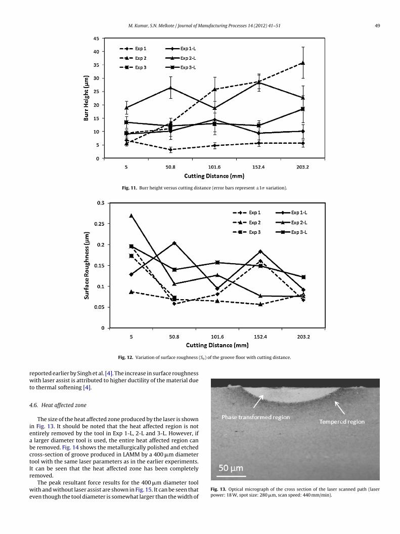
M. Kumar, S.N. Melkote / Journal of Manufacturing Processes 14 (2012) 41–51 49
Fig. 11. Burr height versus cutting distance (error bars represent ±1� variation).
(Sa) of the groove floor with cutting distance.
rwt
4
ieabctIr
we
Fig. 12. Variation of surface roughness
eported earlier by Singh et al. [4]. The increase in surface roughnessith laser assist is attributed to higher ductility of the material due
o thermal softening [4].
.6. Heat affected zone
The size of the heat affected zone produced by the laser is shownn Fig. 13. It should be noted that the heat affected region is notntirely removed by the tool in Exp 1-L, 2-L and 3-L. However, if
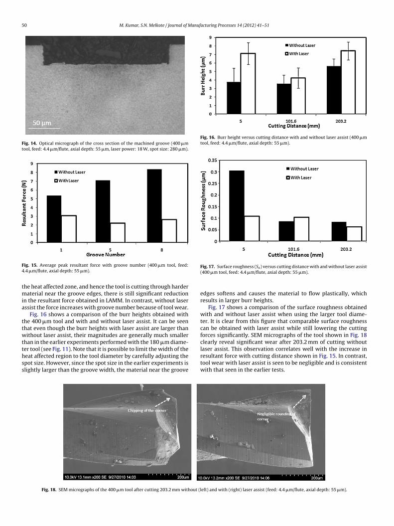
larger diameter tool is used, the entire heat affected region cane removed. Fig. 14 shows the metallurgically polished and etchedross-section of groove produced in LAMM by a 400 �m diameterool with the same laser parameters as in the earlier experiments.t can be seen that the heat affected zone has been completely
emoved.The peak resultant force results for the 400 �m diameter toolith and without laser assist are shown in Fig. 15. It can be seen that
ven though the tool diameter is somewhat larger than the width ofFig. 13. Optical micrograph of the cross section of the laser scanned path (laserpower: 18 W, spot size: 280 �m, scan speed: 440 mm/min).
50 M. Kumar, S.N. Melkote / Journal of Manufacturing Processes 14 (2012) 41–51
Fig. 14. Optical micrograph of the cross section of the machined groove (400 �mtool, feed: 4.4 �m/flute, axial depth: 55 �m, laser power: 18 W, spot size: 280 �m).
F4
tmia
ttwtthss
Fig. 16. Burr height versus cutting distance with and without laser assist (400 �mtool, feed: 4.4 �m/flute, axial depth: 55 �m).
ig. 15. Average peak resultant force with groove number (400 �m tool, feed:.4 �m/flute, axial depth: 55 �m).
he heat affected zone, and hence the tool is cutting through harderaterial near the groove edges, there is still significant reduction
n the resultant force obtained in LAMM. In contrast, without laserssist the force increases with groove number because of tool wear.
Fig. 16 shows a comparison of the burr heights obtained withhe 400 �m tool and with and without laser assist. It can be seenhat even though the burr heights with laser assist are larger thanithout laser assist, their magnitudes are generally much smaller
han in the earlier experiments performed with the 180 �m diame-
er tool (see Fig. 11). Note that it is possible to limit the width of theeat affected region to the tool diameter by carefully adjusting thepot size. However, since the spot size in the earlier experiments islightly larger than the groove width, the material near the grooveFig. 18. SEM micrographs of the 400 �m tool after cutting 203.2 mm without (l
Fig. 17. Surface roughness (Sa) versus cutting distance with and without laser assist(400 �m tool, feed: 4.4 �m/flute, axial depth: 55 �m).
edges softens and causes the material to flow plastically, whichresults in larger burr heights.
Fig. 17 shows a comparison of the surface roughness obtainedwith and without laser assist when using the larger tool diame-ter. It is clear from this figure that comparable surface roughnesscan be obtained with laser assist while still lowering the cuttingforces significantly. SEM micrographs of the tool shown in Fig. 18clearly reveal significant wear after 203.2 mm of cutting withoutlaser assist. This observation correlates well with the increase in
resultant force with cutting distance shown in Fig. 15. In contrast,tool wear with laser assist is seen to be negligible and is consistentwith that seen in the earlier tests.eft) and with (right) laser assist (feed: 4.4 �m/flute, axial depth: 55 �m).

anuf
5
behc
1
2
3
4
lmoww
1959.[10] Cverna F. Thermal Properties of Metals. ASM International; 2002.
M. Kumar, S.N. Melkote / Journal of M
. Conclusions
This paper presented a detailed evaluation of the process capa-ility of LAMM for a hard-to-machine material. Micro end millingxperiments with and without laser assist were carried out onardened A2 tool steel (62 HRc) and yielded the following keyonclusions:
. The peak resultant force decreases with laser assist under allthe conditions with a maximum reduction of 69%. In addition,there is a drop in the average specific cutting energy with laserassist indicating increased cutting through shearing rather thanploughing.
. The amount and rate of tool wear as measured by the roundingof the tool corner are significantly lower with laser assist even atmaterial removal rates that are at least six times higher than thetool manufacturer’s recommendations. Under such conditions,and without laser assist, the carbide tool either wears rapidly orexperiences catastrophic failure.
. When the laser spot size is larger than the tool diameter, the burrheight is found to increase with laser assist. This is attributed tothe thermal softening of the work material. When a tool diameterlarger than the laser spot size is employed, the increase in burrheight is much smaller.
. When the laser spot size is larger than the tool diameter, thesurface roughness is found to increase with laser assist due toincreased thermal softening of the material. When a tool diam-eter larger than the laser spot size is used, comparable surfaceroughness values are obtained.
The results reported in this paper clearly highlight the effect ofaser assist in reducing cutting forces and tool wear when micro
illing hardened A2 tool steel. Similar trends are expected forther hard metals albeit the reductions in forces and tool wearould be different in magnitude. Although only simple groovesere examined in this work, it is expected that similar results
[
acturing Processes 14 (2012) 41–51 51
would be obtained in laser assisted micro milling of more complexshapes, as long as the laser beam is not occluded by the feature orother parts of the workpiece.
Acknowledgments
This work was supported in part by grants from the NationalScience Foundation (CMMI-0654369) and the Timken Company.The authors would like to acknowledge Dr. Rachid M‘saoubi of SECOTools, Fagersta, Sweden, for providing the micro tools used in thisstudy.
References
[1] Dornfeld D, Min S, Takeuchi Y. Recent advances in mechanical micromachining.CIRP Annals – Manufacturing Technology 2007;55(2):745–68.
[2] Masuzawa T. State of the art of micromachining. CIRP Annals – ManufacturingTechnology 2000;49/2:473–88.
[3] Weule H, Huntrup V, Tritschler H. Micro-cutting of steel to meet newrequirements in miniaturization. CIRP Annals – Manufacturing Technology2001;50/1:61–4.
[4] Singh R, Melkote SN. Characterization of a hybrid laser-assisted mechanicalmicromachining (LAMM) process for a difficult-to-machine material. Interna-tional Journal of Machine Tools and Manufacture 2007;47:1139–50.
[5] Jeon Y, Pfefferkorn FE. Effect of Laser Preheating the Workpiece on Micro EndMilling of Metals. ASME Journal of Manufacturing Science and Engineering2008;130:1–9. Paper no. 011004.
[6] Kumar M, Melkote SN, Hashimoto F, Lahoti G. Laser-assisted micro millingof hard-to-machine materials. CIRP Annals – Manufacturing Technology2009;58:45–8.
[7] Shelton JA, Shin YC. Experimental evaluation of laser-assisted micromilling in aslotting configuration. ASME Journal of Manufacturing Science and Engineering2010;132:1–9. Paper no. 021008.
[8] Maekawa K, Obikawa T, Yamane Y, Childs THC. Metal machining: Theory andApplications. John Wiley & Sons; 2000.
[9] Carslaw HC, Jaeger JC. Conduction of Heat in Solids. Oxford Science Publications;
11] Kumar M, Melkote SN. Evaluation of Cutting Tool Coatings for Laser AssistedMicro Milling. In: Proceedings of the 5th International Conference on MicroManufacturingPC U-WM, April 5–8. 2010. p. 297–302.