Proceedings of a meeting on traceability for ionizing radiation ...
196
NATL INST. OF STAND & TECH A111D7 EHSSfifl z \ \ NBS PUBLICATIONS (A / NBS SPECIAL PUBLICATION U.S. DEPARTMENT OF COMMERCE / National Bureau of Standards Proceedings of a Meeting on Traceability for Ionizing Radiation Measurements -QO ' 100 .U57 No, 609 1982 c. 2
-
Upload
khangminh22 -
Category
Documents
-
view
3 -
download
0
Transcript of Proceedings of a meeting on traceability for ionizing radiation ...

NATL INST. OF STAND & TECH
A111D7 EHSSfifl
z
\
\ NBS
PUBLICATIONS(A
/NBS SPECIAL PUBLICATION
U.S. DEPARTMENT OF COMMERCE / National Bureau of Standards
Proceedings of a Meeting on
Traceability for Ionizing
Radiation Measurements
-QO' 100
.U57
No, 609
1982
c. 2

NATIONAL BUREAU OF STANDARDS
The National Bureau of Standards' was established by an act of Congress on March 3, 1901.
The Bureau's overall goal is to strengthen and advance the Nation's science and technology
and facilitate their effective application for public benefit. To this end, the Bureau conducts
research and provides: (1) a basis for the Nation's physical measurement system, (2) scientific
and technological services for industry and government, (3) a technical basis for equity in
trade, and (4) technical services to promote public safety. The Bureau's technical work is per-
formed by the National Measurement Laboratory, the National Engineering Laboratory, and
the Institute for Computer Sciences and Technology.
THE NATIONAL MEASUREMENT LABORATORY provides the national system of
physical and chemical and materials measurement; coordinates the system with measurement
systems of other nations and furnishes essential services leading to accurate and uniform
physical and chemical measurement throughout the Nation's scientific community, industry,
and commerce; conducts materials research leading to improved methods of measurement,
standards, and data on the properties of materials needed by industry, commerce, educational
institutions, and Government; provides advisory and research services to other Government
agencies; develops, produces, and distributes Standard Reference Materials; and provides
calibration services. The Laboratory consists of the following centers:
Absolute Physical Quantities 2 — Radiation Research — Thermodynamics and
Molecular Science — Analytical Chemistry — Materials Science.
THE NATIONAL ENGINEERING LABORATORY provides technology and technical ser-
vices to the public and private sectors to address national needs and to solve national
problems; conducts research in engineering and applied science in support of these efforts;
builds and maintains competence in the necessary disciplines required to carry out this
research and technical service; develops engineering data and measurement capabilities;
provides engineering measurement traceability services; develops test methods and proposes
engineering standards and code changes; develops and proposes new engineering practices;
and develops and improves mechanisms to transfer results of its research to the ultimate user.
The Laboratory consists of the following centers:
Applied Mathematics — Electronics and Electrical Engineering 2 — Mechanical
Engineering and Process Technology 2 — Building Technology — Fire Research —Consumer Product Technology — Field Methods.
THE INSTITUTE FOR COMPUTER SCIENCES AND TECHNOLOGY conducts
research and provides scientific and technical services to aid Federal agencies in the selection,
acquisition, application, and use of computer technology to improve effectiveness and
economy in Government operations in accordance with Public Law 89-306 (40 U.S.C. 759),
relevant Executive Orders, and other directives; carries out this mission by managing the
Federal Information Processing Standards Program, developing Federal ADP standards
guidelines, and managing Federal participation in ADP voluntary standardization activities;
provides scientific and technological advisory services and assistance to Federal agencies; and
provides the technical foundation for computer-related policies of the Federal Government.
The Institute consists of the following centers:
Programming Science and Technology — Computer Systems Engineering.
'Headquarters and Laboratories at Gaithersburg, MD, unless otherwise noted;
mailing address Washington, DC 20234.2Some divisions within the center are located at Boulder, CO 80303.

Proceedings of a Meeting on Traceabiiity
for Ionizing Radiation Measurements
/J 6
Proceedings of a meeting held at
the National Bureau of Standards,
Gaithersburg, MD, on May 8-9, 1980
Edited by:
H. Thompson Heaton, II
Center for Radiation Research
National Measurement Laboratory
National Bureau of Standards
Gaithersburg, MD 20234
National Bureau of Standards
Library, E-Ot Admin. Bide.
MAR 1 W82
ftoi aa- - Culls,
Ocioo
U.S. DEPARTMENT OF COMMERCE, Malcolm Baldrige, Secretary
NATIONAL BUREAU OF STANDARDS, Ernest Ambler, Director
Issued February 1982

Library of Congress Catalog Card Number: 81-600197
National Bureau of Standards Special Publication 609Nat. Bur. Stand. (U.S.), Spec. Publ. 609, 175 pages (Feb. 1982)
CODEN: XNBSAV
U.S. GOVERNMENT PRINTING OFFICEWASHINGTON: 1982

PREFACE
The phrases "traceable to NBS" or "traceableto the national standards" are increasingly beingused in Federal and State regulations, voluntarystandards, technical articles, and advertisements,often without any indications of what is meant bythe phrase or how it is achieved. To provide someguidance on how traceability can be achieved in
the area of ionizing radiation measurements, a
two-day seminar was organized and held at theNational Bureau of Standards, Gaithersburg,Maryland, on May 8-9, 1980. These proceedingsinclude the 21 papers presented at that seminar onTraceability for Ionizing Radiation Measurements.
The first six speakers in this meeting coveredthe basic concepts of traceability from differentperspectives and described the national standardsfor radiation dosimetry, radioactivity measure-ments, and neutron measurements. The remainder ofthe speakers dealt with specific programs forachieving traceability for applications in gov-ernmental laboratories, and for medical, occupa-tional, and environmental radiation measurements.An important point made by many of the speakers is
that the development and use of secondary (inter-mediate level) standards laboratories offers aneffective mechanism for responding to the rapidlyincreasing number of requests for instrument cali-brations, radioactive sources, measurements, etc.which are traceable to national standards.
In order to achieve broad and even coverageof the field, papers were presented by invitationonly, although the meeting was open to anyone.Eight of the speakers were from NBS and 13 fromother organizations. A total of 79 people repre-senting 45 different organizations registered forthe meeting.
The papers are printed in the proceedings as
they were received from the authors and in theorder they were presented in the sessions.However, two of the sessions, Traceability in
Governmental Laboratories and Traceability in
Medical Applications, were actually presented in
the reverse order. For convenience, the seminarnotation for the sessions has been preserved. To
speed publication of the proceedings, all paperswere submitted by the authors in camera-ready form.The editor is greatly indebted to the authors andall those who assisted in the preparation of themanuscript. Their efforts have made it possible toget the proceedings in print much more rapidly thanwould otherwise have been the case.
When commercial equipment, instruments, andmaterials are mentioned or identified in theseproceedings it is intended only to adequatelyspecify experimental procedure. In no case doessuch identification imply recommendation orendorsement by the National Bureau of Standards,nor does it imply that the material or equipmentidentified is necessarily the best available forthe purpose.
The editor gratefully acknowledges the as-sistance of the National Bureau of StandardsTechnical Information and Publications Divisionin the preparation of these proceedings; of Mrs.Kathy Stang of the National Measurement Labora-tory and Miss Jo Ann Lorden of the Public Infor-mation Division for help in the arrangements forthe seminar, and of Mrs. E. Kramer for the excel-lent secretarial assistance.
H. Thompson Heaton, II
Center for Radiation Research
in

ABSTRACT
These proceedings are the compilation of 21 papers presented at a seminar on
Traceabil ity for Ionizing Radiation Measurements held at the National Bureau ofStandards, Gaithersburg, MD, on May 8-9, 1980. General concepts for trace-ability were presented from several perspectives. The national standards forradiation dosimetry, radioactivity measurements, and neutron measurements weredescribed. Specific programs for achieving traceabil ity to the national stan-dards for radiation measurements in medical , occupational , and environmentalapplications were summarized.
Key words: Calibrations, ionizing radiation, measurements, national standards,quality assurance, secondary standard laboratory, traceabil ity.

TABLE OF CONTENTS
Preface iii
Abstract iv
INTRODUCTORY SESSION
Chairperson: R.S. Caswell
Welcoming RemarksC.E. Kuyatt.... 1
Traceability - A View From the NBS Center for RadiationResearchE.H. Eisenhower 3
Traceability of Radiation Measurements: Musings of a UserR.L. Kathren 11
Radiation Measurement Traceability in the United KingdomW.A. Jennings 19
National Standards for Radiaton DosimetryR. Loevinger 29
National Standards for Radioactivity MeasurementsL.M. Cavallo... 31
National Standards for Neutron MeasurementsJ. A. Grundl 39
NBS Services for Ionizing Radiation MeasurementsH.T. Heaton, II 45
TRACEABILITY IN GOVERNMENTAL LABORATORIES
Chairperson: E.H. Eisenhower
The Calibration Program of the Bureau of Radiological HealthT.R. Ohlhaber 59
The EPA National Quality Assurance ProgramA.N. Jarvis 65
The LLL Calibration and Standards FacilityG.W. Campbell 67
State of Illinois Regional Calibration LaboratoryM. Neuweg 77
TRACEABILITY IN MEDICAL APPLICATIONS
Chairperson: R. Loevinger
The American Association of Physicists in Medicine's RegionalCalibration Laboratory SystemR.J. Shalek, L.J. Humphries, and W.F. Hanson 81
NBS Traceability Programs for Radiation TherapyC. G. Soares and M. Ehrlich 89
Traceability Programs for Nuclear MedicineD. B. Golas 99
v

TRACEABILITY IN ENVIRONMENTAL APPLICATIONS
Chairperson: J.M.R. Hutchinson
The Role of Calibration Standards in EnvironmentalThermoluminescence DosimetryT.F. Gesell, M.F. Jones and G. de Planque mi
The National Bureau of Standards Low-Level Radioactivity-Measurements ProgramK.G.W. Inn and J.R. Noyce 117
Nuclear Regulatory Commission Traceability Concerns in
Inspection and Enforcement ProgramL.K. Cohen... 129
Radon and Radon Daughter Field MeasurementsA.C. George 135
TRACEABILITY IN OCCUPATIONAL AND INDUSTRIAL APPLICATIONS
Chairperson: M. Ehrlich
Performance Testing of Personnel Dosimetry ServicesP. A. Plato and C.G. Hudson 145
Occupational Exposure Measurements in NRC Regulatory GuidesA. Brodsky 149
Dosimetry for Industrial Radiation ProcessingW.L. McLaughlin, J.C. Humpreys and A. Miller 171
List of Attendees. 179
vi

WELCOMING REMARKS
Chris E. Kuyatt, DirectorCenter for Radiation ResearchNational Bureau of Standards
Washington, DC 20234
I am happy to have this opportunity to wel-come you to NBS to attend the seminar on "Trace-
ability for Ionizing Radiation Measurements".This meeting is sponsored by the Center for Radia-tion Research and is part of the 1980 series of
"NBS Measurement Seminars". For those of youfamiliar with previous seminars the Center has
organized as part of the NBS series, there areseveral new features of the present meeting. The
biggest difference is that for the first time wehave invited outside speakers. This will allow a
broader view to be presented. Previous meetingshave covered several major topics with detailedtalks on how NBS performed its measurements.Since the specific laboratory techniques that NBS
uses are not necessarily appropriate for others,this seminar will concentrate on a single broadtopic, namely traceabi 1 ity. Speakers have beenrequested to submit written versions of theirpresentations and these will be published as an
NBS Special Publication. You will be receiving a
copy of this publication.
The term "traceabi 1 ity to NBS" or "trace-ability to the national standards" is being usedmore frequently. Several examples include:Federal and state regulations, voluntary standardssuch as those published by the American NationalStandards Institute, contracts (particularlymilitary contracts including MIL specs), interna-tional sales of technical products, advertising(especially involving radioactive sources) internal
quality control, and litigation. If the measure-ment process itself becomes challenged in courtcases, this will probably have the greatest im-
petus in encouraging stronger ties to the nationalstandards. Currently, the major pressure fortraceabi! ity comes from regulatory action.
One of the major problems with the use of the
word traceabi! ity is that it usually is not de-fined in the document in which it is used. In
fact, traceabi 1 ity can be defined in several ways.If one uses a simple definition such as an un-
broken path, one can almost always find some path,no matter how tenuous, which will lead back to the
national standards. I am reminded of an incidenta few years ago in which our storeroom was sellingmeter sticks which not only had a significant bowto them but the printing of the scale was veryinaccurate. Since it came from the NBS storeroom,it would fulfill some definition of traceabi 1 ityto NBS yet it was valueless in its intended func-
tion of measuring distance. Clearly, we mustfirst consider what we want to achieve throughtraceabi 1 ity , and then define traceabi 1 ity so thatit will achieve the desired objective.
If one goes to the other extreme and gives a
very technical definition for a commonly used
word there can still be problems in that manypeople may not realize that the word is being usedin a restricted manner. An example of assigning a
technical meaning to a common word is "the
quantity for measuring the amount of radiation re-
sulting from the exposure of an individual to x
rays is exposure". In this case the word exposureis used in two quite different contexts. Even
though the technical definition of exposure has
existed since 1928, one can look at both the popu-lar press and many scientific articles and observethat the technical application of the word is
being misused. One possibility to avoid similarproblems with the word traceabi 1 ity is to alwaysuse the word with an adjective. Hopefully this
will flag the reader that the word is not beingused in its common sense.
These examples point to the need for everyoneto understand what is meant in a particular situ-ation when using the word "traceabi 1 i ty" . Onefact which should be kept clearly in mind is thatNBS does not have the legal authority to definewhat is meant by "traceabil ity to NBS", and canonly comment as to whether or not mechanisms existwhich would allow the traceabil ity required by
someone else to be demonstrated. It is necessarythat whoever uses the phrase "traceable to NBS"defines it in such a way that the objective of re-
quiring it in the first place can be met.
One problem with having NBS define themeaning of "traceabil ity to NBS" is that like all
organizations NBS is a collection of individuals,each with his own concept of the meaning of trace-ability. These concepts are modified by the needsin each individual's specific measurement area.If one tries to give a general definition it maybe so vague or complicated that it is not of muchuse in specific cases. The problem is somewhateasier if one goes to a specific measurement areasuch as ionizing radiation measurements; but, evenin the past, various members of CRR have used dif-ferent definitions of traceabil ity, not all ofwhich were completely compatible. One of the mainobjectives of this meeting is to examine how thevarious definitions could be made compatible whenthe objective of requiring traceabil ity is toensure that accurate measurements are being made.Several on-going programs will be described as
examples of how traceabil ity is achieved forparticular types of radiation measurements. Thisseminar is intended to stimulate discussion,and hence, the meeting is designed to be somewhatflexible in its schedule to encourage an activeinteraction between the speakers and the audience.I hope all of you will take advantage of this op-portunity and engage in a lively two days of dis-cussion.
1


Traceability - A View From the NBS Center for Radiation Research
Elmer H. EisenhowerOffice of Radiation MeasurementCenter for Radiation ResearchNational Bureau of Standards
Washington, DC 20234
This paper presents general information about the traceabi lity of ionizingradiation measurements to the appropriate national physical measurement standards.It describes fundamental concepts that should serve as the basis of more specificconsiderations of traceability, some common problems encountered in making state-ments about traceability, and the means and methods used to achieve traceability.Distinctions between the two principal types of traceability (instrument andmeasurement) are identified and the differences in the ways they are achieved aresummarized. Some of the ambiguities that may occur in statements about trace-ability are recognized, and preferred ways of making unambiguous statements aregiven. The importance of means and methods for achieving traceability is emphasized,since statements about traceability have limited usefulness unless the specificmeans and methods can be identified for a particular measurement under consideration.The technical and institutional elements that provide these means and methodsconstitute the national measurement support system. Present weaknesses in this
system are identified, and two measurement quality assurance programs are describedas examples of how the system can be improved.
(Calibrations; instruments; ionizing radiation; measurements; measurement supportsystem; quality assurance; standards; traceability)
Introduction
In recent years, it has become apparent that
traceability is desirable but not particularlyunderstandable. The desire arises from a growingnational awareness of the value of quality assur-ance in products and procedures. The limited
understanding results partly from the mistakenbelief that the meaning of traceability is self-
evident and therefore needs no discussion. This
lack of discussion has resulted in a multitude ofmisinterpretations, ambiguous statements, and
considerable confusion. Understanding is furtherlimited by the fact that traceability is an
evolving concept and lacks a universally accepteddefinition [1].
This paper will present some general infor-mation that should be useful in more specificconsiderations of traceability. It will describethe fundamental concepts that should be the foun-dation for such considerations, some problemsencountered in making statements about traceability,and the means and methods used to achieve trace-
ability. To avoid details that may only apply to
a limited situation, the subject will be treated in
a simplified manner and fundamentals will be
emphasized. The views expressed in this paper are
solely those of the author, and do not necessarilyrepresent a consensus of the NBS staff or man-agement. The subject matter will be limited to
measurement of ionizing radiation.
Although any discussion of traceability couldreasonably start at the international level andproceed from there, this paper will consider onlythe national structure. Thus the national physical
measurement standards will be regarded as the
common point to which measurements should be re-
ferred.
Fundamental Concepts
The desirability of measurements that are
nationally consistent (in agreement) was expressedin 1778 by the Articles of Confederation. A morerecent expression of this desire is contained in a
1950 statement of the primary function of theNational Bureau of Standards, which is:
"The custody, maintenance, and development ofthe national standards of measurement, and the
provision of means and methods for making mea-surement consistent with those standards..."
[2]
Although this statement clearly assigns to NBS
the responsibility for providing "means and meth-ods" that enable measurement to be consistent withnational standards, the Bureau has not been givenany authority to require such consistency. Otherorganizations and agencies have, however, insti-tuted requirements of this type. Any such re-
quirements for consistency should be developed in
consultation with NBS because the existing "means
and methods" may not be adequate, and the require-ments may therefore be impractical.
Consistency of measurements with the national
standards may be either demonstrated or implied.
Those who require that measurements be consistentwith standards must decide whether implied con-sistency is adequate, or whether it must be dem-
onstrated. In either case, some action or actions
3

must be taken if consistency is to be achieved.These actions are the "means and methods" employedin the process of achieving consistency. If it
can be shown that such actions have been taken and
that they were appropriate, the measurement is
considered to be consistent with the standard.Regardless of what actions are taken to achievethis consistency, it is essential that they be
documented. Such documentation is the only evi-dence that the process occurred and was appro-
priate. Thus, in a general sense, traceabilitycan be defined as the ability to show that appro-
priate documented actions have been taken to
demonstrate or imply that a measurement is con-
sistent with a standard.
Instrument (Artifact) Traceability
If implied consistency of a measurement with
a standard is sufficient, it can be achievedthrough a calibration process. In this case, the
instrument used to make the measurement is cali-
brated by comparison with the appropriate national
standard, either directly or indirectly through
intermediate calibrations. This is the tradi-
tional type of traceability and, in some cases,
the only type that presently can be achieved.
Although a radiation source is not an in-
strument, it is frequently utilized in the in-
strument calibration process, and should therefore
also be calibrated in a manner that provides
traceability to the appropriate national standard.The term "instrument traceability" may thereforebe used generically to include both instrumentsand sources. (The term "artifact traceability" mayalso be used to include instruments and sourcesgenerically.) It may be defined as the ability toshow that a particular instrument or radiationsource either has been calibrated against the
appropriate national standard or against anotherstandard in a chain or echelon of calibrationsultimately leading to a calibration against the
national standard.
A major disadvantage of instrument trace-ability is the inability to demonstrate that themeasurement made with a traceable instrument is
indeed consistent with the national standard.Since the traceability chain ends with the in-
strument, as shown in Figure 1, the consistency ofthe measurement must be implied. If the instru-ment is used properly, and if the conditions underwhich the measurement is made are favorable, thisimplication may be valid. However, since the
quality of the measurement itself has not beendemonstrated, there remains some degree of un-
certainty about the validity of the result.
Since no calibration of an instrument orsource is valid indefinitely, it should be re-
peated at suitable time intervals. The acceptabletime between subsequent calibrations is dependentupon the circumstances of the particular situation.
INSTRUMENT TRACEABILITY MEASUREMENT TRACEABILITY
NATIONALLEVEL
NATIONALSTANDARD
CALIBRATION
INTERMEDIATELEVEL
TRANSFERSTANDARD
FIELDLEVEL
CALIBRATION
FIELD
INSTRUMENT
NATIONALSTANDARDSLABORATORY
PERFORMANCETEST
INTERMEDIATESTANDARDS
LABORATORY
PERFORMANCETEST
MEASUREMENTMAKER
Figure 1. Schematic indication of the difference between the traceability chains for instrument trace-
ability and measurement traceability.
4

Measurement Traceability
If demonstrated consistency of a measurementwith a standard is desired or required, the trace-ability chain must be extended beyond the instru-ment to the measurement, as indicated in Figure 1.
In this case, traceability is a characteristic ofthe measurement itself, and there is documentedevidence that the measurement is consistent withthe appropriate standard. Thus measurementtraceability may be defined as the ability to showthat a measurement process produces results forwhich the total measurement uncertainty relativeto a national or other designated standard isquantified. This is the most desirable type oftraceability, since it is based on a demonstrationthat the complete measurement process is undercontrol, including the instrument, its user, andthe procedures.
Measurement traceability is usually achievedthrough utilization of a transport standard*,which may be in the form of a radiation source ora dosimetry device that originates from NBS or anintermediate standards laboratory directly trace-able to NBS for the particular measurement underconsideration. When a radiation source is used,its output is measured by the participant whoreceives it, and the result is reported to theoriginating laboratory. If the reported valuecompares favorably with the value determined bythe originating laboratory, a statement of sat-isfactory performance is provided to the par-ticipant.
When the transport standard takes the form ofa dosimetry device, it is sent to the participantwho administers a nominal measured dose (or ex-posure). The device is then returned to theoriginating laboratory, where the administereddose (or exposure) is evaluated. If the par-ticipant's nominal measured value is within theacceptable range of uncertainty, a statement ofsatisfactory performance is provided.
An obvious advantage of measurement trace-ability is that it can be achieved without uti-lization of a transfer standard (instrument orsource) that has been calibrated by NBS. Measure-ment traceability is possible without instrumenttraceability, and the latter can be optional foranyone who demonstrates measurement traceability.Thus periodic demonstration of adequate measure-ment performance through the use of a transportstandard may eliminate, or substantially reduce,the need for (and cost of) periodic instrument orsource calibrations.
Since a demonstration of satisfactory per-formance can not reasonably guarantee similar
performance for an indefinite period of time, the
demonstration process should be repeated period-ically.
In summary, the relationship between the
desired type of consistency of the measurement andstandard, the process by which that consistency is
achieved, and the resultant type of traceabilityis shown in the following table:
Type ofconsistency
desired
Implied
Demonstrated
Process by
which it is
achieved
Calibration
PerformanceTest
Type of trace-ability which
results
Instrument(Artifact)
Measurement
*A transport standard is intended for use in thedetermination of measurement traceability througha performance test. In distinction, a transferstandard has been compared directly or indirectlywith the national standard and is intended to
serve as a reference for calibrations.
Measurement Uncertainty
The objective of a measurement is to de-
termine how many units of a particular radiationquantity are present, within an acceptable rangeof uncertainty. The uncertainty of the measure-ment is meant to be a credible estimate of the
likely limits to its actual error (i.e., the
difference between the measured value and the
"true" value), and is usually expressed as a
percentage of the measured value. This uncer-tainty consists of both random and systematiccomponents, and may be estimated in terms of thedifference between the measured value and thevalue that would be obtained if the nationalstandards themselves were used to make the mea-surement. In effect, the "true" value is definedby the national standards (at least in the legalsense). The uncertainty of the measurement is
therefore an indicator of how consistent it is
with the national standard. In practice, an upperlimit of uncertainty (e.g., 5%, 10%, etc.) is
usually established as that which is deemed to be
acceptable for the particular measurement ofinterest.
For implied consistency of a measurement withthe national standard, the uncertainty of the
measurement is also implied. In this case, thetraceability chain ends with the instrument usedto make the measurement, and the only definitivestatement of uncertainty that can be made is thatwhich applies to calibration of the instrument.It is somewhat presumptuous to assume that themeasurement uncertainty is the same as the cali-bration uncertainty, unless the conditions en-countered during the measurement are identical tothose that existed at the time of calibration.Since this rarely (if ever) happens in practice,the measurement uncertainty is nearly alwaysgreater than the calibration uncertainty.
For demonstrated consistency of a measurementwith a standard, the traceability chain ends withthe measurement itself, and the uncertainty is
determined without implication.
5

Statements About Traceability
The National Bureau of Standards encouragesand supports the concept of traceability, and itsapplication by other organizations and agencies,because it leads to more accurate and uniformmeasurements on a national basis. However, sinceNBS must provide "means and methods" for achieve-ment of traceability, it is an interested (andsometimes concerned) party when others makestatements about traceability. Such statementsare increasingly made in Federal regulations andregulatory guides, state regulations, contracts,voluntary standards, and in advertising.
Sometimes the statements about traceabilityare good, but many times they are vague, am-biguous, and lead to confusion. As a result, NBSis getting increasing numbers of requests fordefinition of traceability, for clarification oftraceability statements made by others, and forrecommended procedures to be used to achievesatisfactory traceability. In an attempt to
study this general problem, and to possiblyidentify better ways to make statements abouttraceability, a cooperative effort was initiatedwith the Nuclear Regulatory Commission. Theobjective is to jointly develop more workable,understandable, and meaningful statements. Thiseffort has resulted in significant improvementsof traceability statements in several regulatoryguides, with additional specific projects cur-rently underway.
An early conclusion resulting from this
cooperative effort was that general definitionsof traceability, such as the one given earlier in
this paper, are relatively easy to state, but arealso of little value. To be more useful, a
definition must be specific to the particularmeasurement and radiation quantity of interest.
In effect, traceability must be defined for each
type of measurement included in the variety ofpossible types of radiation measurements. Ameaningful definition of traceability for a
particular type of measurement must include an
indication of the "means and methods" used to
achieve consistency with the appropriate stan-
dard. These means and methods will be quitedifferent, for example, for the measurement oflow-energy x rays as compared with the measure-ment of radon concentration.
Statements About "Traceable To"
Some ambiguous statements that appeared in
various documents over the past few years namethe following entities as the objectives to whichtraceability is desired:
NBS radiation measurement systemNBS radioactivity measurement systemnational measurement systemnational radioactivity measurement systemNBS standard reference materialsnational system of measurements and standardsnationally accepted measurement system
A basic problem arises from the fact that
nearly all of these objectives are undefined and
therefore are subject to a variety of interpre-tations. The readers must decide for themselveswhat is meant by ambiguous terms such as "sys-tem", "measurement system", "national system","national measurement system", or "nationallyaccepted measurement system", and their interpre-tations will differ significantly.
When such statements are attempted, it is
essential to keep in mind the relevant funda-mental concept, i.e., the ability to show thatactions have been taken to make a measurementconsistent with a standard. If this basicconcept is adhered to, an unambiguous statementis possible, namely "traceable to the nationalstandard". Since national standards and NBS aresynonymous, an alternative statement could be
"traceable to NBS". If an appropriate nationalstandard is not maintained by NBS for the quan-tity of interest and an alternative standardserves as the point of reference, it should be
identified specifically in any statement abouttraceability to it.
Statements About "Traceability Of "
Most statements about traceability take the
general form of "X is traceable to Y" (or shouldbe). This is equivalent to saying that X has thecharacteristic of traceability, and one cantherefore recognize the traceability of X. In
recent statements, the characteristic of trace-ability has been assigned to a range of things,including
a measurementan instrumenta radiation sourcea standarda laboratorya calibrationa measurement systema technique
In descending order, statements about "trace-
ability of" these items range from highly de-
sirable to highly ambiguous. As indicatedearlier in this paper, traceability of a mea-
surement is the best indicator of consistencywith a standard because it is based on demon-strated performance. Traceability of an instru-ment or source results in only implied consis-tency. If "a standard" is actually an instrument
or a source, it can have the characteristic of(generic) instrument traceability.
When considering "traceability of a labo-ratory" the possibility of ambiguity increasessubstantially. This statement has little meaningunless additional information is provided for
clarification, such as the particular type ofmeasurement for which traceability is claimed.Since calibration is a process that provides to
an instrument or radiation source the charac-
teristic of traceability, that characteristic is
a property of the instrument or source, and not
of the process. The term "traceability of a
measurement system" is subject to a variety ofinterpretations and can lead to confusion unlessthe "system" is carefully defined. Finally, the
6

concept of traceability of a technique is invalidbecause there is no national standard techniqueto which one could be traceable. As mentionedearlier, traceability is a characteristic ofeither a measurement, instrument, or source, anda technique is none of these.
To avoid unnecessary confusion and mis-understandings, statements should be limited totraceability of either a measurement, an instru-ment, or a radiation source. It is reasonable tomake statements about traceability of a standardas long as that standard consists of an instru-ment or source. This set of items which can havethe characteristic of traceability (measurement,instrument, source, and standard) should be
sufficient for the purpose of making unambiguousstatements.
Direct and Indirect Traceability
To the extent possible, terms used in state-ments about traceability should be in agreementwith common interpretation and usage. If un-
usual, uncommon meanings are assigned to commonwords, the potential for misinterpretation in-
creases substantially. Thus the definition ofdirect traceability that would be most consistentwith common expectation is "that traceabilitywhich results from direct comparison with a
standard". If the standard under considerationis maintained by NBS, the result is direct trace-ability to the national standard. (One step
removed from the national standard).
In contrast to direct traceability, indirecttraceability results from indirect comparisonwith a standard, through one or more interme-diates. (More than one step removed from the
national standard).
For the majority of field measurements, it is
sufficient to achieve traceability to NBS throughan intermediate level of laboratories whichprovide calibrations and measurement - relatedservices. Ideally, the laboratories at thislevel will have measurement traceability to NBS.
At a minimum, they should have instruments orradiation sources which are either directly orindirectly traceable to the national standards.
Utilization of an intermediate level (or
levels) results in the type of measurement sup-port system (MSS) illustrated in Figure 2. In
concept, this MSS can be an effective mechanismfor providing consistency of measurements withthe national standards. The problem is that the
links between the various levels are presentlyundefined and undeveloped for many types ofradiation measurements. These links consist oftwo basic types of interactions between lev-
els — technical and institutional.
The technical elements of the measurementsupport system are:
"measurement standards, including the nationalstandards and the transfer standards used at
the intermediate level
°ca! ibrations of transfer standards by NBS,
and of field instruments by intermediatelaboratories
"measurement quality assurance programs ,
including performance testing servicesprovided by NBS or by an intermediate labor-atory
"field instruments used to make measurementsat the field (user) level
Means and Methods
It is relatively easy to make the generalobservations that measurements should be con-sistent with standards, that measurement trace-
ability is more desirable than instrument trace-ability, and that statements about traceabilityshould be unambiguous. The achievement of theseobjectives is, however, more difficult. Even
correct statements about traceability have littleor no value unless they are supported by tech-nical programs that provide the means and methodsneeded to enable measurements to be consistentwith standards. An evaluation of existingnational programs leads to the realization thatthere is a key problem, which is that the meansand methods for achieving measurement consistencywith the national standards (i.e., the trace-ability mechanisms) are unspecified and inade-quate in many cases. As a result, many state-ments about traceability will have limitedmeaning and value until the means and methodsbecome adequate.
National Measurement Support System
It is impractical and unnecessary for the
thousands of radiation measurements made each day
to be directly traceable to the national standards..
'procedures used for measurements, calibra-tions, and measurement quality assurance(MQA)
'training of personnel who perform measure-ments, calibrations, and MQA
'records that document specific actions thathave been taken
PRIMARYLEVEL
INTERMEDIATELEVEL
FIELD USELEVEL
PRIVATESECTOR
FEDERALSECTOR
STATESECTOR
INDUSTRY
MEDICINE
PRIME CONTRACTORSOTHER AGENCIES
STATE AND LOCAL
GOVERNMENTS
Figure 2. Schematic showing the national mea-surement support system three-levelconcept.

The institutional elements of the measure-ment support system are the:
"national standards laboratory that maintainsthe national reference standards and pro-
vides related services
" intermediate standards laboratories that use
transfer standards as the basis of calibra-tions and other services provided by them
" field level entities , such as laboratories,companies, or individuals that measureradiation as a user or a concerned party
" voluntary standards-writing organizationsand professional societies that define,
develop, and document various traceabilityinteractions.
Each element, whether of the technical orinstitutional type, is essential for an effectivemeasurement support system. To the extent neces-
sary, the actions of the various institutional
elements should be coordinated and planned.
Measurement Quality Assurance (MQA)
The purpose of a measurement quality as-
surance program is to provide a satisfactorydegree of assurance that the measurer's processis under control at all times. Such a program
includes a variety of periodic actions, depending
upon the specific nature of the measurement. In
a general sense, an MQA program consists ofprocedures that enable a measurer to assure on a
continuing basis that the total measurementuncertainty relative to the national standard is
quantified and sufficiently small to meet re-
quirements.
A performance test can be an important part
of an overall MQA program. As mentioned earlierin this paper, such a test provides an effectivemethod for achieving measurement traceability(demonstrated consistency with national stan-
dards). Each test is specific to a particular
type of measurement, and usually employs a trans-
port standard. If it is administered by NBS, it
results in direct measurement traceability. When
an MQA performance test is administered by some
other laboratory that has traceability to the
national standard for the measurement under
consideration, it results in indirect measurementtraceability.
Since MQA performance tests demonstrateproficiency only at the time a test is taken, it
is desirable to take additional actions that
assure adequate performance between tests. These
can include internal consistency checks, such as
the frequent use of stable radiation sources to
check instrument response, and control chartsthat would warn of unusual response or insta-
bility in the measurement process.
It is important to recognize the desir-
ability of measurement quality assurance, and the
value of MQA performance tests, at all levels of
8
the measurement support sytem -- national,intermediate, and field.
An Ideal Measurement Support System
For many reasons which will not be treatedin this paper, the support system illustrated in
Figure 2 is felt to be highly desirable [3]. It
represents the best conceivable long-term systemfor both technical and political reasons and,
fortunately, comes very close to the presentsituation. The three primary sectors are Fed-
eral, state, and private, and each has a directinteraction with NBS. This arrangement avoidspotential conflicts of interest, and is con-
sistent with the present policies of mostregulatory agencies.
In the interest of accuracy and uniformityfor all measurements made in the United States,the technical nature of interactions between any
two levels of the MSS should depend only on the
radiation quantity of interest, and not on
whether the Federal, state, or private sector is
involved. For example, the interactions withNBS should be identical for intermediate labora-
tories in all sectors for a particular type of
radiation measurement.
Intermediate standards laboratories can
provide a number of services for the fieldlevel. Using transfer standards that werecalibrated by NBS, they can calibrate instru-ments or sources for field use. They can alsoprovide MQA performance tests and advice on MQAprocedures for use at the field level. Inter-
mediate standards laboratories can be convenientsources of education and training for field-level measurers, for example by providing shortcourses or observation of calibration procedures.These laboratories can also test new instrumentsto determine whether stated performance speci-
fications are actually achieved.
A number of intermediate laboratoriesalready exist in the Federal sector, and their
interactions with NBS are being improved. A
recent survey conducted by the Conference of
Radiation Control Program Directors identifiedlaboratories presently existing in the private
sector that can serve as intermediate standardslaboratories [4]. At this time, NBS is co-
operating with several states to develop pilotintermediate laboratories in their sector. Thus
the ideal measurement support system appears to
be feasible, at least in terms of a sufficientnumber of suitable intermediate standardslaboratories.
As it presently exists, the national mea-surement support system has both strengths and
weaknesses. To more nearly approach the ideal
system, the following weaknesses should be
corrected [3]:
"Additional national standards should be
developed, specifically for high-energyphotons, electrons, and neutrons.
"Transfer standards are needed for someradiation quantities.

°More intermediate standards laboratories are
needed in the state sector.
"Many documented procedures (criteria) shouldbe developed for operation of intermediatelaboratories, and for their interactionswith NBS and the field level.
"Suitable measurement quality assuranceprograms should be designed and implemented,
including MQA performance tests, for inter-
mediate laboratories and the field level.
"Training is needed for operators of inter-mediate laboratories and for those who makefield-level measurements.
Coordination of the MSS is needed to achievenational uniformity and consistency ofmeasurement results.
It is encouraging to note that the presentmeasurement support system is gradually being
improved in response to various incentives. This
progress is, however, quite slow and results
primarily from the occasional need to solve
specific, limited problems.
Examples of Specific Traceability Programs
As indicated earlier in this paper, general
definitions of traceability have limited value.
The most valuable statements about traceability
are those that identify the specific means and
methods by which it is achieved for a particular
type of measurement. If the means and methods are
well-documented, and consistency with national
standards is demonstrated, unambiguous trace-
ability statements can be made and defended. Two
examples of national programs that enable such
statements follow.
The American Association of Physicists in
Medicine (AAPM) has an ongoing program for ac-
creditation of laboratories that calibrate ra-
diation-measuring instruments used primarily in
radiation therapy. Three laboratories have been
accredited so far: M.D. Anderson Hospital
(Houston, Texas), Sloan-Kettering Memorial Hos-
pital (New York, N.Y.), and Victoreen InstrumentCompany (Cleveland, Ohio). Accreditation by the
AAPM is based on documented criteria that must be
satisfied by candidate laboratories. Interactions
between NBS and the accredited laboratories are
specified, including calibration of transferstandards by NBS and periodic MQA performancetests. All the technical requirements for un-
ambiguous traceability are satisfied in this
program: standards, calibrations, MQA, proceduresand records. The institutional requirements are
also satisfied, including three good examples of
intermediate standards laboratories.
The second example consists of a national
program that is still under development. Since1973 NBS has cooperated with the states, variousFederal agencies, and the Health Physics Societyin an attempt to establish a performance testingprogram for the organizations that provide per-
sonnel monitoring services. Criteria have been
developed that will form the basis of a future
routine performance testing program [5]. As
the future national program is envisioned,
there will be a testing laboratory at the inter-
mediate level which will periodically test the
performance of personnel monitoring services. The
NBS role will be to ensure that the testing labora-
tory uses procedures that maintain consistency withnational measurement standards. In this qualityassurance role, NBS will periodically calibrate the
radiation sources and instruments used by the
testing laboratory, and will monitor overall
technical performance.
In these two examples, specific, documentedcriteria and intermediate standards laboratoriesserve as the principal ingredients of programs that
result in unambiguous, easily-recognized trace-
ability.
Conclusion
This paper was addressed to general consider-
ations of traceability for measurements of ionizing
radiation. Some of the fundamental concepts which
are relevant to traceability for all types of mea-
surements were identified, and the problem of
ambiguity in statements about traceability was
treated. The "means and methods" by which ra-
diation measurements can be made consistent with
national standards were recognized, and two ex-
amples were given of programs that employ appro-
priate means and methods to achieve unambiguoustraceability.
The most effective national measurement sup-
port system would provide those technical and
institutional elements required to ensure the
continuing adequacy of radiation measurements for
whatever purpose those measurements are made. Some
of the required elements are in place and func-
tioning for some types of measurements, but manyhave not yet been developed. These weaknesses mustbe corrected with additional technical programs and
institutional improvements (particularly inter-mediate standards laboratories) before some presentambiguities about traceability can be eliminated.
References
Belanger, Brian C, "Traceability: An Evo-
lving Concept", ASTM Standardization News, p.
22, January 1980.
Act of 22 July 1950, 64 Stat. 371 (Public
Law 619, 81 Congress), to amend a 1901 Act
to provide basic authority for the per-
formance of certain functions and activitiesof the Department of Commerce.
"Requirements for an Effective National
Ionizing Radiation Measurements Program", a
report to the Congress by the National
Bureau of Standards. NBS Special Publi-
cation 603, March 1981
.
"Directory of Commercial Calibration Ser-
vices for Ionizing Radiation Survey Instru-
ments", prepared by the Conference of

Radiation Control Program Directors, NBS GCR80-296, April 1981.
Draft American National Standard N13.ll,"Criteria for Testing Personnel DosimetryPerformance", prepared by the Health PhysicsSociety Standards Committee, Working Group1.4, April 1981.

TRACEABILITY OF RADIATION MEASUREMENTS: MUSINGS OF A USER
Ronald L. KathrenBattelle, Pacific Northwest Laboratories
Richland, Washington 99352
Although users of radiation desire measurement traceability for a number of
reasons, including legal, regulatory, contractual, and quality assurance require-ments, there exists no real definition of the term in the technical literature.Definitions are proposed for both traceability and traceability to the NationalBureau of Standards. The hierarchy of radiation standards is discussed and allow-able uncertainties are given for each level. Areas of need with respect to radi-ation standards are identified, and a system of secondary radiation calibrationlaboratories is proposed as a means of providing quality calibrations and trace-ability on a routine basis.
(calibration, definitions, hierarchy of standards, National Bureau of Standards,radiation, standards, traceability)
By Way of Introduction: Traceability and the User
Traceability--specif ically traceability to the
National Bureau of Standards— is a much desiredand sought after commodity among users of sourcesof ionizing radiations. Indeed, a 1976 study by
the National Bureau of Standards revealed thatthe provision of transfer standards to "...estab-lish and maintain traceability to NBS primarystandards" was considered to be the most impor-
tant possible NBS service by the Conference of
Radiation Control Program Directors. [1]
While perhaps not all user groups would ranktraceability of prime import within the possiblerange of NBS services, most users do consider NBStraceability important for a variety of reasons,including:
1. Legal and regulatory requirements,including license conditions imposed by
regulatory agencies.
2. Contractual requirements.
3. Quality assurance/quality control.
4. Compliance with voluntary standards,both national and international.
5. Health and safety considerations, includ-ing protection against lawsuits stemmingfrom improperly measured personnel expo-sures to radiation.
6. Legal protection.
7. Achieving a competitive edge.
8. Peace of mind and security in the knowl-edge that the "best" practicable mea-surements have been made.
9. Scientific satisfaction.
Some of the above overlap and the relative valuegiven to each may vary among users, but in themain, the above reasons are explicit and do not
require explanation or amplification.
There has, in recent years, been increasingeffort within the broad area of ionizing radia-tion measurement traceability. Cavallo, Ehrlich,and Hutchinson recently described traceabilityprograms and their resultsL2]; virtually all ofthe programs currently underway are for radio-activity or are applicable to medical (usuallytherapeutic) uses of radiation. U>2] Most nota-ble among the latter is the American Associationof Physicists in the Medicine Regional CalibrationLaboratory program, which provides radiologicalcalibrations primarily for reference class instru-ments used in radiation therapy.
It might be a useful digression at this pointto briefly touch on radioactivity, as opposed to
radiological, standardization. Radioactivitystandardization refers to measurement of the abso-lute or "true" disintegration of emission rate of
a radioactive source; radiological standardizationrefers to dose or exposure rates associated with a
particular source. Radioactivity measurements are
usually made on fairly small (i.e. low activity)sources by direct measurement--i .e. counting—ofthe emitted particle or radiation; radiologicalmeasurements or standardizations are usuallyaccomplished by measuring secondary effects of
the emitted radiation(s) , e.g. energy depositionin the form of heat produced in a specific mediumor current flow or capacitance changes produced by
ionization in a gaseous medium. Hence, radio-activity standardization is usually achieved by
direct means (i.e. counting of emitted particles)and reported in units of activity (becquerels,curies). Radiological standardization is usuallyaccomplished by indirect means, and may be
reported in units of exposure (C/kg or R), doses,fluence rate, or yield (e.g. particles per sec-
ond) instead of activity. The distinction is
important, because while traceability is impor-
tant for both (particularly in health physics),there appear to be greater needs, probably becauseof the greater difficulties of measurement, con-
version, and source characterization in the radio-logical area, and especially the greater uncer-
tainty generally associated with radiologicalmeasurements.

While on the subject of terminology, it mightalso be instructive to examine just what is meantby traceability. The dictionary, as expected, is
of little use for a technical term, merely defin-ing traceability as 'capable of being traced.'However, review of the dictionary also points to
some interesting if unexpected relationships-similarities, that is, between traceability and a
certain type of nonscientif ic endeavor.
On the Similarities Between Traceability andPornography
Interestingly and perhaps surprisingly, por-nography and traceability have certain similari-ties. Pornography, for example, has no true defi-nition. According to the dictionary, pornographyis simply "obscene literature or arf'Pj; andsince there exists no uniform legal definition of
what is obscene,* by logical extension pornographyis also not defined. However, the same juristsand legal scholars who fail at exact definitioncan readily recognize and identify pornography as
such. Thus, they rest their case.
A similar situation exists with regard to
traceability. We all know what it is, and canreadily recognize and identify it, even though no
definition apparently exists. While preparingthis presentation, more than 150 works dealingwith measurement of radiation were checked,including such standard texts as Johns™]; all
four volumes of Attix, Roesch, and Tochil inPJ;such classics as Hine and BrownelU^J; and someolder but still excellent works, such as Glasser'sMedical Physicsl^]; Glasser, Quimby, Taylor andWeatherwaxlPJ ; that yade mecum of the healthphysicist, the Radiological Health Handbook ^],with its excellent and extensive glossary;numerous reports of the National Council on Radia-tion Protection and Measurements and InternationalCommission on Radiological Units; various hand-books, encyclopedias, and dictionaries of physicsand chemistry; ANSI and other standards; and, of
course, various reports of the National Bureau of
Standards. Nowhere was there a definition oftraceability--not even in the ANSI glossaries ofquality assurance of nuclear science and tech-nology terms, l10>11] although the paper byCavallo, Ehrlich and Hutchinson, previously men-tioned, did describe traceability as referring to
the agreement between the measurement of a phys-ical quantity with results of NBS within an accep-table limit of uncertainty. [2] This would seemto be more of a description of intercomparison,for among users, traceability, as used in thevernacular, goes somewhat beyond this description.
There is, however, a most interesting and
germane discussion of traceability in a recentpublication of the National Bureau of Standardswhich bears repetition here:
* The definition of obscenity depends on the pre-
vailing community standards, which, of course,means that what is obscene in one place may bequite proper elsewhere.
"Traceability is a term which a numberof contracting and regulatory agencies haveinvoked to specify the standards used in thecalibration of instruments.
Perhaps the first and most far-reachingtraceability requirement has been that of theDept. of Defense (MIL-C-45662A) , "CalibrationSystems Requirements," which states (sec.3.2.5.1):
'Measuring and test equipment shall becalibrated by the contractor or a commercialfacility utilizing reference standards (orinterim standards) whose calibration is cer-tified as being traceable to the NationalBureau of Standards, has been derived fromaccepted values of natural physical constants,or has been derived by the ratio type of self-calibration techniques.'
This specification does not define theterm 'traceable' (nor do those of any othergovernment agency)." [12]
The first and last sentences of the above quota-tion, taken from NBS Special Publication 250, tellthe whole story, viz. a requirement for trace-ability without a definition of the term. Indeed,NBS points out further along in Publication 250that it gives no special meaning to traceabilityand indeed legally cannot do so, at least in thecontext of procurement contracts or relatedactivities.
Despite the fact that there is apparently nodefinition for traceability or traceable to theNational Bureau of Standards, these terms Irecoming into greater and more widespread use in
science, engineering, industry, and commerce.The increased emphasis on quality assurance hasled to the imposition of traceability require-ments throughout the nuclear power industry and
elsewhere, but the recipient of such requirementshas little to go on other than word of mouth or
vague guidelines.
An exception is the Institute of Electricaland Electronic Engineers standard on calibration,which provides the following statement regardingtraceability:
M&TE (measurement and test equipment)shall be calibrated utilizing reference stan-
dards whose calibration has a known validrelationship to nationally recognized stan-dards or accepted values of natural physicalconstants. If no national standard exists,
the basis for calibration shall be docu-mented.
Reference standards used in the calibra-tion program shall be identified on calibra-tion data records and supported by certifi-cates, reports, or data sheets attesting to
the calibration date, calibration facility,environmental conditions, and data whichshows conformance to accuracy requirements. E13.
This statement provides reasonable guidance as to
how traceabil ity might be achieved, but it fallsshort of being a definition.
12

The concept of traceability has been discussedin a recent paper by Brian Belanger of NBS.LHJIn his presentation before the ASTM, Belangertraced the historical development of traceability,noting its purposes and uses, as well as the legal
and contractual requirements that may be imposed
on the user. In threading his way through the
legal and contractual requirements maze he clearlyunderscores, at least by implication, the need
for a consistent and meaningful definition and
application of traceability among them. Althoughhis discussion is articulate, where definitionsare concerned and with regard to how traceabilitymight be achieved, he neither offers nor suggeststhe adoption of a specific 'universal' definition.
The legal vulnerability and intense frustra-tion of attempting to fulfill traceability re-
quirements is intensified by the lack of a
practical and simple accepted definition. Theapparent purpose of traceability is simply to
assure that measurements are reasonably correct;as for a definition for traceability in the sensein which the word is commonly used (among thoseconcerned with radiological measurements at least)
the following is proposed:
traceabil ity— the means or series of stepsand associated documentation by which a
measurement or measuring instrument is
relatable to a recognized standard.
Similarly, by extension, traceability to NBS can
be defined as
...the means or series of steps and asso-ciated documentation by which a measurementor measuring instrument is relatable to oneor more standards or measurements of theU.S. National Bureau of Standards.
It would seem that acceptance or at least agree-ment with the above definitions would providesome modicum of relief from the present state ofaffairs, and at the same time remove an interest-ing parallel between radiological science and
pornography.
Of Standards and Their Hierarchy
Nearly a quarter century ago, A. G. McNish of
the National Bureau of Standards put forth a
classification scheme for standards of ionizingradiation that expanded the previously acceptedtwo-tier level of primary and secondary stan-dards. [15,16] Tn i S classification scheme, rec-ognized by the National Committee (now Council)on Radiation Protection and Measurements (NCRP)and described in simplified form in NBS Hand-book 80, L17J showed the relationships among fivecategories (prototype, derived, calibration, in-
struments, and materials) and several orders or
levels of standards. The levels or orders were,in effect, a hierarchy of standards.
At the top of the hierarchy, McNish proposedan international standard of a single (or groupof) preparation(s) or radioactivity to be select-ed by an international committee. National stan -
dards , such as those held by NBS or its equivalentin other countries, would be a select group cali-brated against the international one(s). To pro-tect the national standards from wear and tear andto provide backup capability, another set of stan-dards, national reference standards would becreated, these of course being cross-calibratedagainst the national standards. Ordinary calibra-tion work would be carried out with national work-ing standards, cross-calibrated with the referencelevel. Also cross-calibrated with the nationalreference standards would be laboratory referencestandards, maintained by an individual organiza-tion for its own purposes. Day-to-day work wouldinvolve the use of laboratory reference standards ,
these being analogous to the national workingstandards.
Implicit in the McNish scheme is a direct lineof traceability to the NBS, with NBS providinglaboratories with their basic calibrations orstandardization. Recommended in somewhat modi-fied form at least for radioactivity by the NCRPin 1978, [18] the McNish scheme has regretably
never been fully adopted. Although it called fordirect traceability to the NBS, it also hinted,albeit vaguely, at the possibilities of labora-tories calibrating standards for other labora-
. tories, but made no provision for a situationwhere direct traceability to NBS was not pos-sible, as might be the case if a user desired a
different energy, intensity, or geometry thancould be conveniently supplied by the Bureau.
A few years later, a simple hierarchial stan-dards scheme was proposed for radiological mea-surements by Kathren and Larson, [19] and byKathren.[20] This scheme, applicable to radio-activity as well, is reproduced in Figure 1. Itfeatures a six-level hierarchy of standards and
makes allowance for the situation in which directline traceability to NBS is impossible or otherwise not feasible. In this scheme, internationalstandards lie at the top of the hierarchy and arethose fundamental physical standards which serveas the basis for our system of units and measure-ments. These are ordinarily established bytreaty or agreement of international scientificbodies.
National standards are the exclusive provinceof the National Bureau of Standards and representthe highest achievable state-of-the-art. Thus,these would have the minimum of uncertainty andwould represent the fruits of the most sophisti-cated instrumentation and measurement techniques.These would, wherever possible, be related to in-
ternational standards. However, this need not be
the case, for a specific national standard mightbe developed for a need more or less unique to
one country although this situation would be con-sidered exceptional.
Secondary or derived standards would be
sources and instruments directly calibrated by
13

INTERNATIONALSTANDARDS
~~r~NATIONALSTANDARDS
SECONDARY (DERIVED)STANDARDS
- —H- -LABORATORYSTANDARDS
itOPERATIONALSTANDARDS
1
I
NONSTANDARD
< » IMPLIES INTERCOMPARABILITY
IMPLIES NO INTERCOMPARABILITY
FIGURE 1 . A Hierarchy of Standards
[
2°]
the National Bureau of Standards or intercomparedwith NBS sources or instruments with no interven-ing steps. As such, these would have somewhatgreater uncertainty than national standards but
would serve satisfactorily as the basic standardsof industrial and other users.
Instruments and sources calibrated againstsecondary standards, or well recognized instru-ments such as extrapolation chambers utilized forstandardization would have larger allowable errorand would qualify as laboratory standards . In-
cluded in this group are instruments and sourceswhich are not routinely calibrated by NBS butwhich are utilized for standardization. For all
practical purposes, use of these instruments andsources would be restricted to a well -control led
laboratory with known, if not controlled geometry,scattering and other conditions. Free air cham-bers, extrapolation chambers, and long counterscan serve as laboratory standards, as can practi-cally any detector if its response characteristicsare known and the measurement conditions rigidlycontrolled.
Operational standards assume even greater butstill acceptable and known error limits, and pre-sume an instrument or source used under relativelyuncontrolled conditions. As an example, the mea-surement of ionizing electromagnetic radiationlevels inside a reactor containment might be
accomplished with uncontrolled and unknown
scattering conditions, a wide mixture of energies,and perhaps even a mixed radiation field. A widevariety of instruments might be used for opera-tional purposes. Generally, these would have wideresponse characteristics, be simple and easy touse, and permit accumulation of several measure-ments, economically.
Table I sets down what appears to be theachievable uncertainty for various types of mea-surements at each level in the standards hier-archy, based on the present state-of-the-art.
TABLE I . Uncertainty of Measurements with theRadiation Standards Hierarchy
Level Radiation Quantity Allowable CommentsUncertainty
National All Any State of NBS Only
Secondary Alpha, Activity i 1" Must specifyBeta nuclide
IER* Exposure or 2* All directlyDose traceable to
Neutron Fluence Rateor Yield
+ 5* NBS; may be
only certainBeta Dose + 5% specific
energies or
sources
Laboratory Alpha, Activity ± 2* All measure-Beta ments under
IER Exposure or + 5% controlled,Dose specific
IER Dose +10* 1 aboratoryNeutron Fluence Rate +HW conditions;wider
or Yield range of energiesNeutron Dose or Dose +20% and sources than
Equivalent available aboveBeta Dose +10*Beta Fluence rate + 10*
Operational Alpha, Activity + 5* Al lowable errorBeta considered to
IER Exposure or +20* be currentlyDose attainable by
Neutron Dose or Dose +50* measurement in
Equivalent the field underBeta Dose +35* semi-controlled
conditions
*IER = ionizing electromagnetic radiation.For dose measurements, medium must be specified.
Some Areas of Need
Although NBS has, in general, done a fine jobof providing radiological calibrations, the mag-nitude of the task is growing at an enormous rate.The expansion of the nuclear industry, especiallynuclear power, has created a breadth and quantityof calibrations that could not have been foreseena generation ago. Moreover, new and increasedquality assurance requirements and personnel do-simetry demands have put the user in an awkwardsituation, for what the user needs and demands,NBS may be unable to supply. Supply may be out-
side the scope of the NBS mission, or may benighly specialized and out of limited applica-tion, or may be restricted by budgetary or man-power or equipment considerations, or may be
simply not reasonable with the given state-of-the-art.
14
Moreover, the NBS emphasis has been primarilyresearch, and in the case of calibration services,oriented to the medical profession. Those in
industry, and in particular the nuclear industry,
have urgent need for certain types of calibrationand standardization services which NBS does not
now offer. For example, there is a need for highlevel [on the order of 10^ rads (air) per hour]photon calibrations for emergency radiologicalmonitoring instrumentation and for area monitoringinstrumentation as may be installed in power re-
actor containments. In the wake of the accidentat the Three Mile Island Nuclear GeneratingStation, this need may assume critical (pun notintended) dimensions, and capabilities in this
area urgently need to be developed.
Another important area of need relates to the
standardization and development of dose measure-ments. Radiological traceabil ity, if it is to betruly meaningful, must provide the wherewithal of
dose measurement traceabil ity for not onlyphotons— i.e. ionizing electromagnetic radiation(IER)--but also for betas, neutrons, and mixedfields. Dose traceabil ity might also be neces-sary for high energy IER— i.e. photons with ener-gies above a few MeV.
One area, ripe for development, relates to
provision of different energies of IER. For manyyears, the NBS has provided a standard series of
filtered x-ray beams, but these are now inadequateto the needs of greatly expanded user body. Spe-cifically, K-fluorescence x-rays, essentiallymonoeneKjetic, are highly useful and perhapsmandatory for energy dependence and dosimetrystudies, radiological evaluation of monitoringinstruments, calibrating dosimeters, and for a
whole host of activities related to health and
radiological physics. Regretably, this capabil-ity, so easily developed, does not exist withinNBS, although it has been adopted elsewhere. [21]
Hence, there can be no real traceabil ity to NBSin this area, however great the need.
On the other hand, NBS has done an outstand-ing job developing monoenergetic or nearly mono-energetic neutron sources. [22] This valuablework should be extended, and the service adver-tised, so to speak, so that it can be taken ad-
vantage of by a larger segment of the industrialand research community. Greater neutron capabil-ity needs development; additional sources, with a
wider range of neutron exposure rates would be
welcomed by the users in the field. Indeed, cali-bration in units of dose as well as fluence ratewould serve the users well.
Certainly there are many other areas in whichtraceability does not truly exist because of lack
of capability within NBS; some of these includecharacterization of beta energy spectra along withthe establishment of standard beta spectra andsources, standardized pulsed radiation fields, andthe establishment of standards and traceabilityfor instrumentation used for sampling environment-al media for radioactivity. The task, taken in
toto is clearly a herculean one, and not neces-sarily in keeping with the charter or existingcapabilities of NBS. Certainly the NBS charter
15
and funding level can be expanded, but there is
perhaps another solution which may be morepracticable.
Towards a Meaningful and Pragmatic Solution
Many of the above needs could be met by theestablishment of secondary calibration and stan-dards laboratories with appropriate capability.Such laboratories would be chartered by NBS andthus periodically be required to demonstrate theircapabilities and quality in the manner prescribedby, and to the satisfaction of the Bureau. Thesecondary laboratories would be selffunding, andwould not be operated by NBS. Rather they wouldbe operated by appropriate organizations—nationallaboratories or universities, for example, withalready existing specialized capabilities and withno commercial ax to grind. Secondary laboratoriesmight be selected on the basis of location (i.e.
regional) as well as on the basis of specializedcalibrations or measurements (e.g. pulsedradiations) they could perform.
Alternatively, NBS could develop a number of
regional secondary laboratories for the perform-ance of routine calibrations and certain special-ized radiation measurements. However, the costof such a program (not to mention the time neces-sary for their development) would work againstthem. Also, some may question whether or not
this is an appropriate course for NBS. In anyevent, the system of secondary laboratories hasprecedent, namely the Regional Calibration Labo-ratories of the American Association of Physi-cists in Medicine and the Regional RadiologicPhysics Centers of the National Cancer Insti-tute. [23,24] j n either case, the Bureau itselfwould be freed from the need to provide more orless routine calibration services and could betterfullfill its role as the national ionizing radia-tion standards laboratory, providing pioneering,fundamental research in radiological standardiza-tion, as well as specific reference sources andmeasurements.
One might use the word 'esoteric' to describethe NBS role, with the more applied and routinecalibrations performed by a satellite or second-ary laboratory. Although traceability would be
sought wherever possible, in some cases thesources and/or instruments or techniques used bythis laboratory might not be directly traceableto national standards held by NBS. One reasonfor this lack of traceability might be that no
direct pathway exists. However, to serve theexisting needs of the industry and research com-munity, a secondary reference laboratory, provid-ing standardized and precise radiological fieldand pragmatic, often ad hoc calibrations, couldserve. As noted, this secondary laboratory mayor may not be run by the Bureau, but in any caseit must have close ties to the Bureau.
While users in general and in particular the
nuclear power industry need a service facility of
secondary standards level, they must be made to
realize that Bureau "traceability" is not a man-datory or always available goal. Indeed, the
quest to achieve such traceability is often

counterproductive. For example, in nuclear powerplants, a common quality assurance requirement is
"traceabil ity to the National Bureau of Stan-dards." What may well be acceptable is trace-ability through a large number—perhaps as manyas a dozen or even more-- intervening steps, someof which may not even be continuous or relevantto each other. Similarly, "traceabil ity to theNational Bureau of Standards" for gamma spectros-copy may involve only a single source giving a
single energy point, far removed from the energiesthe system is actually used for. These examples,in my view, are a distortion of the meaning of
the phrase "traceable to the National Bureau of
Standards", and may introduce sufficient uncer-tainty as to render the ultimate measurement mean-ingless. In general, the fewer number of stepsthe better, and a system of service orientedsecondary laboratories attuned to the needs of
its users could go a long way towards ensuringthat radiation measurements in the field arewithin reasonable bounds of uncertainty, and thattraceabil ity remains a meaningful and useful con-
cept and activity.
References
1 Eisenhower, E. H., "Report of the National
Bureau of Standards' Survey of State Mea-surement Needs" in Proc. Ninth AnnualNational Conference on Radiation Control ,
Meeting Today's Challenges , June 19-23,
1977, HEW Pub li cat ion "(FDA) 78-8054(April 1978).
2 Cavallo, L. , M. Ehrlich, and
J. M. Hutchinson, "Traceabil ity in IonizingMeasurements Systems" in National and Inter -
national Standardization of Radiation Dosime-
try , Proc. Symp., Atlanta, 5-7 December1977, Vol. 1, International Atomic EnergyAgency, Vienna (1978), pp. 65-88.
3 Barnhai c, C. L., Ed., American College Dic-
tionary , Random House, New York (1960),
p. 944.
4 Johns, H. E., and J. R. Cunningham, ThePhysics of Radiology , Charles C. Thomas,Springfield, Illinois, Third Edition(1974).
5 Attix, F. H., W. C. Roesch, and E. Tochilin,Radiation Dosimetry , Academic Press, NewYork (Vol. 1, 1968; Vol. 2, 1966; Vol. 3,
1969). Also, Topics in Radiation Dosimetry ,
Academic Press, New York (1972).
6 Hine, G. J., and G. F. Brownell, RadiationDosimetry , Academic Press, New York (1956).
7 Glasser, 0., Ed., Medical Physics , YearBookPublishers, Chicago, 3 vols (1944, 1950,
1960).
8 Glasser, 0., E. H. Quimby, L. S. Taylor, and
J. L. Weatherwax, Physical Foundations of
Radiology , Paul B. Hoeber, New York, 2nd
Edition (1952).
9 Radiological Health Handbook , U.S. Depart-ment of Health, Education and Welfare,Revised Edition (January 1970).
10 American National Standard "Glossary ofTerms in Nuclear Science and Technology",ANS-9/ANSI Nl.l - 1976, American NationalStandards Institute, New York.
11 American National Standard "Quality Assur-ance Terms and Definitions", ANSIN45. 2. 10-1973, American Society of Mechani-cal Engineers, New York.
12 National Bureau of Standards, "Calibrationand Related Measurement Services", NBSSpecial Publication 250 (1978), pp. 7-8.
13 Institute of Electrical and Electronic Engi-neers, "Control of Measuring and Test Equip-ment", IEEE Standard 498-1975, New York(1975), p. 9.
14 Belanger, B.C., "Traceability - An EvolvingConcept", Standardization News 8:22 (1980).
15 McNish, A. G. "Classification and Nomen-clature for Standards of Measurement", IRE
Trans. Instr . 1-7:371 (1958).
16 McNish, A. G., "Nomenclature for Standardsof Radioactivity", Int. J. Appl. RadiationRadioisot . 8:145 (1960).
17 National Committee on Radiation Protectionand Measurements, "A Manual of RadioactivityProcedures", U.S. National Bureau of Stan-dards Handbook 80, Washington, D.C.(November 20, 1961).
18 National Council on Radiation Protection andMeasurements, "A Handbook of RadioactivityMeasurements Procedures", NCRP Report No. 58,
Washington, D.C. (November 1, 1978).
19 Kathren, R. L. and H. V. Larson, "Radio-logical Calibration and Standardization forHealth Physics", Health Phys . 16:177(1969).
20 Kathren, R. L., "Standard Sources for HealthPhysics Instrument Calibration", Health
Phys . 29:143 (1975).
21 Thompson, I. M. G., "International StandardReference Radiations and their Applicationto the Type Testing of Dosimetric Appa-ratus", in National and InternationalStandardization of Radiation Dosimetry ,
Proc. Symp., Atlanta, 5-9 December 19/7,Vol. 1, International Atomic Energy Agency,
Vienna (1978), pp. 343-365.
22 Schwartz, R. B., and J. A. Grundl, "NBS
Standard Reference Neutron Fields for
Personnel Dosimetry Calibration", op_. cit .,
pp. 367-376.
16

23 "AAPM Radiological Physics Center: A StatusReport", Medical Phys . 1:41 (1974).
24 ''Regional Radiological Physics Center Coor-dinating Committee: Cancer Control Pro-gram", Medical Phys . 1:287 (1974).
Acknowledgement . The helpful discussions withDale Fleming and Craig Yoder, Battelle, PacificNorthwest Laboratories, and Daniel Garland,Westinghouse Hanford Corporation, are appreciatedand hereby acknowledged.
17


RADIATION MEASUREMENT TRACEABILITY IN THE UNITED KINGDOM
W. A. JenningsNational Physical Laboratory
Teddington, Middlesex, OT11 OLW, UK
The concept of traceability in the UK, along with the role of theNational Physical Laboratory, is presented. In respect of the measurementof ionizing radiations, the legal position in the UK is summarised and a
three-tier system of Regulations, Codes of Practice and Guidance Notes is
described, with particular reference to the field of radiological protection.The impact of the relevant European Directive in this field, and the
preparation of the consequential Ionizing Radiation Regulations in the UK, are
discussed, including the need for type—testing, etc. The role of the
British Calibration Service, including the operation of personal dosimetryservices is introduced. Radiotherapy calibrations, radioactivity measure-ments, and industrial radiation processing are then considered, and finally,the role of the various international links is mentioned.
(Calibrations, codes of practice, ionizing radiation, regulations, standards,traceability, type testing.)
Introduction
delighted to receive, last November, (a) Prom the British Standardsn to participate in this seminar on Institution, we find (4):
I wasan invitatii
traceability in radiation measurement. At thattime, there was reason to believe that someuncertain features in the UK traceability chainwould be clarified by the Spring, but in the
event, the uncertainties in question have yet to
be resolved?' Adding to these the uncertaintiesin the parallel international scene, I can onlypresent the position as I understand it at thismoment in time, partly operational, partlypropositional and partly aspirational, — to coina word or two!'
Traceability
What is meant by 'traceability* in this
context? Looking at the programme, I note thatthis talk will have been preceded by two majorcontributions providing two views on •trace-ability', one from the Centre for RadiationResearch, and the other from the standpoint ofthe user. Moreover, I am aware of several dis-cussions on this topic in the US literature, suchas those by Belanger (1), Daneman (2),Landvater (3), and others. Indeed Belanger dis-cusses the merits of some four possible defini-tions of traceability. Since I am here to reporton the UK scene, I propose to confine myself to
presenting the definitions currently put forwardby two of the interested organisations in mycountry, the British Standards Institution, BSI,
and the British Calibration Service, BCS.
Traceability, "the concept ofestablishing a valid calibration of ameasuring instrument or measurementstandard, by a step-by-step comparisonwith better standards up to an accep-ted or specified standard. Ingeneral, the concept of traceabilityimplies eventual reference to anappropriate national or internationalstandard"
.
In a recent BSI document entitled•Specification for Measurement and CalibrationSystems 1
(5), under 'traceability', furtherprovisos are made; for example, it states that allmeasurement standards in use in the calibrationsystem shall be supported by certificates, reports,
or data sheets attesting to the data, accuracy andconditions under which the results were obtainedand are valid. All documents must be signed by aresponsible person".
(b) My second definition is takenfrom the British CalibrationService, (6)
:
"Traceability to national standardsmeans :
-
(i) That each standard used forcalibration purposes has itselfbeen calibrated against astandard of higher quality upto the level at which the
higher quality instrument is
the accepted national standard".
19

(ii) "That the frequency of such
calibration, which is depen-dent on the type, quality,stability, use and environ-ment of the lower qualitystandard, is such as to
establish reasonable con-fidence that its value will
not move outside the limits
of its specification betweensuccessive calibrations".
(iii) "That the calibration of anyinstrument against a standard
is valid in exact terms onlyat the time of calibration,
and its performance there-after must be inferred from
a knowledge of the factorsmentioned in (ii) above".
The BCS operates through 'ApprovedLaboratories'', and approval entails much more
than the validity of the calibration standards
in use. In addition to the equipment, approval
relates to the quality of the staff, organisation
and procedures employed. Supervision subsequent to
approval includes the operation of an audit
measurement scheme. Such features are con-
sidered necessary to ensure that the concept of
traceability has any real meaning. On the other
hand, traceability does not necessarily imply
high accuracy as such, as sometimes assumed.
Clearly the number of steps, or echelons, in the
calibration chain must be limited, and the pro-
cedure adopted at each step must be consistent
with whatever accuracy is deemed appropriate,
and the accuracy claimed must be specified. It
is perfectly reasonable, for example in rad-
iation protection measurements in the field, to
insist on traceable readings, even at a low
accuracy.
The National Physical Laboratory
In the UK, the National Physical
Laboratory, NFL, develops the techniques for the
realisation of the units of measurement of the
principal physical quantities, and is the
custodian of the resulting national primary
standards. It is responsible both for the com-
parison of these with those of other countries,
and for providing essential calibration services
based upon them, with a view to disseminating
measurement units throughout the UK. Generally,
the NPL endeavours to develop and promote good
measurement practice; and provides advisory ser-
vices to government, industry and others. The
standards which are in service, or under develop-
ment, include the principal ones for the
quantities of interest in the measurement of
ionizing radiations, - namely the quantity
exposure for X and y-rays; absorbed dose for X,
y and 3-rays, and electrons; fluence for
neutrons; and activity for radionuclides.
In addition, in order to disseminate the
units for these quantities, secondary standards
have been developed at NPL as transfer devices
where this was considered necessary. Such
transfer devices may take various forms, such asan instrument with an appropriate probe, as inthe case of X-ray measurements, or calibratedradioactive sources used in a jig to producestandardised fields, as in the case of P-raymeasurements. These different approaches weredescribed in a talk which I gave at a Symposium on•National and International Standardisation inRadiation Dosimetry' held in Atlanta in 1977(Jennings (7)).
Before summarising dissemination pro-cedures, we must first examine the legal require-ments, as these differ in the different fields ofapplication. Thus, the position in the medicalfield, in radiation processing, and in respect ofradiation hazards, will require separate con-sideration.
Legal requirements
Although the national measurementsstandards are located at NFL, and the NFL comesunder the Department of Industry, the NFL is notresponsible for legal metrology as such, - apartfrom the provision of the relevant primarystandards. Responsibility for the Weights andMeasures Act (1963), which lays down legal re-quirements for regular comparisons of secondaryand local standards, and thus effectivelyprovides for a traceability chain, is now vestedin the Department of Trade. However, this doesnot relate to radiation measurement. Indeed, theevolution of radiation control in the UK fromCommon Law to Legislation and Codes of Practice,over the years since 1 94&, would call for a talkon that topic alone, I can only summarise thesalient points.
'Statute Law', embodying Acts ofParliament, differs from 'Common Law', which is
built up from precedents resulting from previousjudgments. Common Law included, for example, thedoctrine of 'strict liability', which imposed aduty on manufacturers, and other persons who arein possession of goods which they know to beunusually dangerous, to exercise reasonable careto make the goods as safe as possible, and toexplain their hidden dangers before parting withthem. More recently, the Health and Safety atWork etc Act, 1974, introduced wider statutoryduties where the goods are for the use of personsat work.
Radiological Protection
Let us consider the position in respect ofradiological protection. The RadioactiveSubstances Act, 1948, gave powers which later re-sulted in regulations regarding the carriage ofradioactive materials. The Factories Act, 1 961
,
resulted in regulations concerning the use ofionizing radiations for both unsealed ( 1 968) andsealed (1969) radioactive sources. In addition,a series of non-statutory Codes of Practice havebeen issued by a number of government departments,official bodies and associations, having a bearingon the radiological protection of persons. Forexample, the Radioactive Substances Advisory
20

Committee, set up under the Radioactive Sub-
stances Act, 1948, sponsored, and the Department
of Health published, a 'Code of Practice for the
Protection of Persons against Ionizing Radiations
arising from Medical and Dental Use* (revised
version, 1972). A similar Code in respect of
teaching establishments was published by the
Department of Employment, in preference to
Regulations (revised version, 1 968)
.
This approach may be difficult at first
to appreciate, but it is demonstrably more
flexible than legislation alone. Indeed, a
three-tier structure is now proposed:-
Regulations, Codes of Practice, and Guidance
Notes:
(i) Regulations set down re-quirements and duties, andprocedures where no choice or
alternative is acceptable.
They specify basic per-missible levels of exposure,
make provision for record
keeping, create a system ofrecognition of qualifiedexperts, and deal in a general
way with the provision ofsuitable plant, facilities and
specialised protection and
medical services.
(ii) Approved Codes of Practiceprovide practical guidance as
to the general requirements to
meet the Regulations. Thisavoids making the Regulationstoo lengthy, or too specific
where alternatives are pos-sible. Such Codes occupy aspecial position in the en-forcement of legal require-ments. If a prosecution is
taken under the Health and
Safety at Work etc Act, duringwhich a person is alleged to
have failed to comply with the
terms of the Code, then such
failure will be prima facieevidence that he has not com-
plied with the Regulations,
However, it will be open to
him to show that he has met
the legislative requirement
in some other way which is
equally effective. Thus a
more flexible approach results,
which can take account of new
developments.
(iii) Guidance Notes may be provided
to give detailed advice inconsiderable depth, whereappropriate. Such Notes canrelate to precautions in par-ticular fields, such as
industry, teaching, medicine,
dentistry or veterinary work.
Guidance Notes do not have a
special legal status, but willnevertheless reflect legal
requirements.
At this point I need to make reference to
the impact in this area of the UK joining the
European Community, an impact which will result
in new ionizing radiation regulations in the UK.
The European Directive and the
HSC Consultative Document
On joining the European Community, the UKbecame subject to the provisions of the Treatyestablishing the European Atomic Energy Community,or Buratom. This treaty requires that basicstandards should be laid down in the Communityfor the health protection of workers and thegeneral public against the dangers arising fromionizing radiations, and the instrument chosenhas been a 'Directive', the contents of whichmust be given effect in member states. TheDirective adopted on 1 June 1 976, (8) , reflectedthe thinking of ICRP Publication 9, (9). Morerecently, the ICRP have revised and updated theirphilosophy, and in 1977 presented this in ICRPPublication 26, (10). In consequence, theDirective is also being revised, and proposals to
amend the Directive have been circulated. In the
meantime, another Directive issued in 1979, (11),extends the time for implementation of the
original 1976 Directive.
These Directives are having direct con-sequences on the UK scene. Fortunately, theHealth and Safety at Work etc Act, already pro-vides comprehensive powers to give effect to manyof the requirements of the Directive. Severalgovernment departments are taking the necessarysteps, and in particular, the Health and SafetyExecutive, HSE, is drafting new Ionizing RadiationRegulations, along with Approved Codes of
Practice and Guidance Notes for publication bythe Health and Safety Commission, HSC. A 'Con-sultative Document' was issued by HSC in 1978,
(12), and following comments received, and theupdating of the Directive, a further ConsultativeDocument is expected later this year (198O).
Such a Consultative Document, making ref-erence to all facets of the problem, enables allinterested parties to react to the proposals made,
in time for account to be taken prior to the finalversion. To give just one example, there is needto designate some individuals as 'Radiation Pro-tection Advisors' (RPAs) , 'Radiation ProtectionSupervisors', and 'Qualified Experts', - withspecified responsibilities. Indeed, interestedbodies like the Society for Radiological Pro-tection, SRP, and the Hospital Physicists' As-sociation, HPA, have been busy devising schemesto provide for the certification of members whomay qualify as RPA's, etc.
According to the current draft proposals,such Advisors and Experts will have a part to
play in respect of traceability, as will theBritish Calibration Service, BCS, at differentstages in the calibration chain. However, whileconsultations continue, I can only refer to someproposals currently under discussion. Thus, to
ensure adequate performance and traceability inrespect of instrumentation, three levels of
21

testing are envisaged, type testing, acceptancetesting, and routine testing:
(i) Type testing relates tospecimens of new instruments,and comprises wide—rangingtests of compliance with, or•conformance to' agreed speci-fications or criteria.
(ii) Acceptance testing relates tomore restricted tests onindividual instruments, priorto "being put into service, and
(iii) Routine testing relates to
simple periodic in-servicechecks on performance.
We must now consider who should carry outthese respective tests, and how the scheme can bemonitored. Calibration may be regarded as a part
of testing, in so far as it constitutes one
aspect, - though a vital aspect, of performanceunder restricted, but specified conditions.
Let us return to the possible role of theBCS, to which reference in regard to LaboratoryApproval, has already been made.
The British Calibration Service
The British Calibration Service, BCS, (6)
was established by the government to provideBritish Industry with a comprehensive service forthe calibration of instruments against recognisedstandards, the calibration work being carried outin existing laboratories which have been specifi-cally approved for the purpose. The Serviceheadquarters is now an integral part of NPL. AnAdvisory Council on Calibration and Measurementadvises on the operation of the service, and aseries of expert panels assist in each field ofactivity, including the drawing up of criteriafor the approval of laboratories. At present,
some 80 laboratories are approved for measure-ments in electrical, mechanical, fluid, thermaland optical fields, and they are currentlyissuing certificates at a rate of about 30,000per year, overall.
It had become clear, even before the
forthcoming Ionizing Radiation Regulations weredrafted, that a national dissemination scheme wasneeded to calibrate the 20,000 or so monitors inuse for protection measurements in the field inthe UK, To this end, 'Radiological Measurements'was added to the BCS list of activities, anotherAdvisory Panel set up, and a series of criteriaprepared in respect of laboratory approval to actas secondary standardising centres. These crit-eria, listed in Table
1 , relate to both protec-tion and therapy—level instruments, and to theiruse for X, y, 3—rays and neutrons. Some detailsregarding the approval procedure were summarisedby Dr M J Rossiter, of FPL, in a paper alsodelivered at the Symposium held in Atlanta in
1977, (13).
TABLE 1
BCS RADIOLOGICAL CRITERIA,INSTRUMENT CALIBRATION
DocumentNumber Title
0802 General Criteria for Laboratory Ap-proval. Calibration of RadiologicalInstruments
.
0811 Supplementary Criteria for LaboratoryApproval. Calibration of RadiologicalProtection-Level Instruments: X-,
Gamma- and Beta-Rays
.
0812 Supplementary Criteria for LaboratoryApproval. Calibration of RadiologicalTherapy-Level Instruments: X- andGamma-Rays
.
0813 Supplementary Criteria for LaboratoryApproval. Calibration of RadiologicalProtection-Level Instruments: Neutrons
DDU1 Calibration of Radiological Instrumentsat Protection and Therapy Levels (Guid-ance Publication)
.
However, no such approvals have yet beenfinalised, pending the outcome of the discussionsinitiated by the HSC Consultative Document prev-iously mentioned. Thus, it may now be necessaryfor such secondary standardising laboratories tobe formally approved by HSE, having met BCScriteria. Moreover, there is now the additionalmatter of type testing, and laboratories carry-ing out this work may also require HSE approval,such approval being based on the assessment ofthe laboratory by BCS in the light of appropriatecriteria for this purpose. Such criteria haveyet to be written, and it has been proposed thatthis should be done by the relevant BCS panel,based no doubt on existing specifications such asthe IEC standards now nearing completion.
Similar proposals are under discussion inrespect of acceptance and routine tests, thelatter being carried out by means of standards,either instruments or radioactive sources, andin either case, they will need to be certified inorder to confirm traceability to nationalstandards. In regard to routine tests, theRadiological Protection Advisors, and others,will clearly have a recognised part to play.
It is difficult to be sure how comprehensivethe final scheme will be, bearing in mind thecosts of implementation, in the present economicclimate in the UK, as well as the need for safety.As far as BCS is concerned, the above proposalsextend its role beyond that of 'calibration'.However, consideration is presently also beinggiven to setting up a broader-based 'nationalTesting Laboratory Accreditation Scheme', NATLAS,also to be based at HPL, which would involve the
22

TABLE 2
BCS RADIOLOGICAL CRITERIA,PERSONAL DOSIMETRY SERVICES
DocumentNumber
Title
0803 General Criteria for Laboratory-Approval. Provision of PersonalDosimetry Services.
0821 Supplementary Criteria forLaboratory Approval. Provision ofPersonal Dosimetry Services usingFilm Dosemeters for Beta, Gamma,X- and Thermal Neutron Radiations.
0822 Supplementary Criteria forLaboratory Approval. Provision ofPersonal Dosimetry using NuclearEmulsion Film Dosemeters forNeutron Radiations.
0823 Supplementary Criteria forLaboratory Approval. Provision ofPersonal Dosimetry Services usingThermoluminescent Dosemeters forBeta, Gamma, X- and NeutronRadiations.
assessment of all kinds of testing laboratoriesto establish whether they are competent to carryout a wide variety of tests.
Personal Dosimetry
Before leaving the topic of radiationhazards, mention must be made of one other area,namely, personal dosimetry services, using eitherTLD or film badges, for X, y, (3—rays and neutronradiations. At present, some 50 laboratories inthe UK supply such services, and these labora-tories are now subject to HSE approval, based oncriteria prepared by the BCS Technical Panel, aslisted in Table 2. Traceability is ensuredthrough intercomparisons, and proposals for anNPL-based audit scheme are under discussion.
Radiotherapy Calibrations
Turning now to radiotherapy—levels, itwill be appreciated that this field is subject toCodes of Practice, rather than regulations, whichhave been elaborated over the years. Indeed, anation-wide scheme for the calibration of X-raytreatment machines was established well beforethe BCS was set up. The scheme is comprehensivein extent, in that it reaches 100 percent of thetreatment machines in use in the UK, with thepossible exception of a few units in privatedermatological practice. On the other hand, thescheme depends on the expertise of the hospitalphysicists involved with very limited centralverification.
The scheme was started in 1 950, soon afterthe UK National Health Service, NHS, was launched,
when the demand for calibrations grew to a level
in excess of the NFL capability to accept all thedosemeters submitted. Following joint consulta-tions between the Department of Health and SocialSecurity, DHSS, the Hospital Physicists' Associa-tion, HPA, and the NFL, a series of Centres weredesignated as 'secondary standardizing centres*and a dosemeter from each one was selected as thetransfer instrument for calibration at NFL. Thereare at present some 30 such centres within the
UK. Each centre became responsible for thecalibration of all the dosemeters in use in its
region. Over the years, this scheme has beenelaborated by the introduction of an NFL—designedsecondary standard instrument, along with a Codeof Practice, agreed between DHSS, HPA and NFL, onits use in the calibration of tertiary standardsor field instruments. The secondary standard wasdeveloped specifically as the link in the NHSdissemination chain, and is produced commercially.Some 30 instruments were centrally purchased byDHSS, and allocated to the 30 designated centres.
This approach, made possible by the operation ofthe NHS, helped NFL to streamline its own pro-cedures, and also provided for a certain measureof control in the system. Thus, these instru-ments are specifically restricted for use as
transfer devices only, and they must be returned,complete with the log—book recording radioactivecheck—source readings taken between calibrations,
to NFL for recalibration every three years. The
Code of Practice recommends in-phantom compari-sons, and the necessary phantoms were also madeavailable to all the centres.
It must be stressed that the designatedcentres are all within competent, long—establishedhospital physics departments, but generally donot possess any X—ray equipment dedicated tostandards work. Indeed, the secondary standardinstrument may be mobile in the region. Thereare no laboratory criteria or approval proceduresat present. Indeed, in the past there has beensome resistance to any form of inspection or
audit. However, there have been occasional fieldtrials in which a number of centres irradiatedTLD and/or Fricke capsules, supplied by NFL,
under specified conditions with encouragingresults. For example, in 1 975» six radiotherapycentres in the UK, all of which were actuallysub—centres of the secondary standardizingcentres, irradiated such capsules in a phantomeach using a single beam of cobalt 60 gamma rays.
The results, taken from a paper by Dr Rossiter
(14) are shown in Table 3.
Recently, seven radiotherapy centres, this
time all possessing a secondary standard instru-ment, were interested in checking the dose
delivered as the basis of a clinical field trialt
this time employing multiple field techniques.This trial is not yet complete, but the availableresults of measurements in a phantom, employingvarious techniques, are given in Table 4-
We would be happy to see more such fieldtrials in the UK, along the lines of theexcellent trials conducted both by NBS, and
23

TABLE 3
FIELD TRIAL. 1 975 (Rossiter, 1975)
UK
Nominal dose *
Measured doseComment
Centre(mean)
ILL)
(mean)
Prieke
1 0.944 0. 954 5$ error in ionchamber reading
2 0.963 1.001 TLD discrepancy-unresolved
3 0. 991 1.002 -
4 1.008 1.018
5 1.004 1.003
6 1.000 o. 991
* based on ionization chamber measurements.
TABLE 4
FIELD TRIAL. 1979-80 (not yet completed)
UKCentre
MachineNPL ' dosestated
Reviseddose — Reason
A Co 60 O.964 0. 980 - Water/Perspex correc-tion, andcobalt 60 decay
B it 1.020 ? - Some evid-ence for being1-2$ high
C it 1.004
D n1 .016 1.006 - Soft
tissue/watercorrection
E ii 1.012
F ti 1.041 ? - Under study
G 4MV 1.020
through the AAPM Regional Laboratory scheme, — tobe described later in this seminar.
Radioactivity Measurements
Next, a few words about the disseminationof standards of activity in the UK. For manyyears, NPL has provided absolute standards of
activity for many radionuclides, along with thedetermination of decay schemes. Such standardsare made available to the user, either by thedespatch of the standards themselves, or throughthe use of the commercially available ionizationchamber, type 1383A, developed at NFL, and forwhich the Laboratory publishes calibrationfactors. This latter approach is particularlyappropriate for short-lived nuclides, and indeed,
an improved NPL calibrator will soon be available.
The Radiochemical Centre, TRC, alsoprovides standards, and traceability to nationalstandards has been maintained through periodictwo-way exchanges of standards between NPL and TRC
for measurement for a large number of nuclides.Recently, it has been proposed that BCS should bedirectly concerned in regard to the certificationof sources (cobalt 60, caesium 1 37 and radium 226)
which may be used for the routine testing of the
large number of protection monitors in the field,as previously mentioned. Such sources are cali-brated in terms of exposure rate, and it is ofinterest to note that the small discrepancyfound between exposure rate measurements and the
activity of the NPL standard radium source, is
within the measurement uncertainties (Read, Burnsand Liquorish, 1978, (15)).
From the legal standpoint, the main pro-visions of the legislation in respect of activityrelate to safety. The Euratom Directive hascalled for some changes. For example the DHSS is
setting up new procedures under the MedicinesAct, 1968, for the authorisation of personsentitled to administer radiopharmaceuticals.However, the principal impact in regard to trace-ability concerns instrumentation for the measure-ment of surface and air contamination. The HSCConsultative Document lists levels of contamina-tion which must not be exceeded, and hence thereis now a clear need for new reference standards
for the calibration of appropriate monitors. NPLhas now commenced a programme of work to thisend, though there is still a debate in relationto the relative merits of surface 'activity 1 and'emission rate' as the quantity of interest.
Industrial Radiation Processing
Facilities are available at NPL for the
calibration of the type of dosemeter normallyused in radiation sterilization processes, suchas polymer, or polymer—dye combinations whichundergo change in optical absorption on irradia-tion. Uniform fields are available in the form
of annular arrays of cobalt 60 rod sources, andthese fields are calibrated in terms of absorbeddose to water by means of chemical dosemetetrs,
which themselves are cross-checked against the
NPL exposure standards. Plant operators cansubmit a sample, from a batch of dosemeters inuse, for irradiation to known dose levels priorto assessment in their reader, and thus achievea calibration of their dosimetry system, ie,
dosemeter material and readout. Two types ofdosimetry material based on polymethylmeth-acrylate are made available by bulk purchase byAERE Harwell, and by the 'UK Panel for Gamma andElectron Irradiation', a body on which the DHSS,
24

industry and NFL have representatives. This panel
has also supported the requirement that sterile
goods supplied to the National Health Service
should receive a minimum dose of 2. 5 Mrad, or
25 kGy; although micro-hiological counts prior to
sterilization must also he kept down to agreed
limits, the DHSS does not accept a safety index
system dependent on biological tests alone.
In addition to the calibration of the
dosemeter material and readout, the establish-
ment of traceability for the dose to the ir-
radiated product depends also on the relation
between the test dose and the product dose, and
routine dosimetry must be carried out on each
batch of products put through the plant. The
adequacy of the dosimetric system employed, and
the competence of the staff, is assessed during
the commissioning of the plant, and test measure-
ments are carried out periodically thereafter,
though no formal audit procedure is in use. If
the plant is to supply sterile goods to the NHS,
DHSS will need to approve the plant prior to re-commending the firm concerned as a recognisedsource of supply. This approval is usuallyexercised under contractual arrangements and is
only statutory when the plant is used for those
few devices which have been deemed medicinal
products under the Medicines Act - and wherepharmaceutical products e.g. eye drops may be
irradiated. Incidentally, UK legislation (The
Pood (Control of Irradiation) Regulation, 1 9^7)prohibits the application of ionizing radiationto food intended for sale for human consumption,except in those cases receiving prior approval,
and in the case of sterile diets for patientsprescribed such diets.
International Links
I cannot close this talk without a briefreference to certain international links, en-tailing NFL involvement, which have a bearing on
traceability, with particular reference to the
possibility of international recognition of
certification. (See Table 5).
I will assume that everyone present is
familiar with (i) the role of CIPM, throughCCEMRI and BIPM, in the comparison of nationalstandards, Sections I, II and III of CCEMRI
covering the areas of dosimetry, activity and
neutron measurements respectively. (ii) the role
of IEC and ISO in regard to specificationstandards:- thus IEC Committees and WorkingParties have much to contribute to good measure-ment practice through improved instrumentation at
both therapy - and protection - level, forphotons, beta rays, and neutron measurements.ISO CoSimittees are recommending optimum referenceradiations, and so on.
The EEC involvement in such activities maybe less familiar to this audience. In additionto the Euratom Directive, the EEC has set upvarious programmes, such as the •Biology andHealth Protection Programme •', and more recently,
the 'Applied Metrology Programme ,. NPL, and PTB
amongst others, participate as contractors onsuch community projects as the comparison of
personal dosemeters for X, (3 rays and neutrons.
TABLE 5
CIPM - International Committee on Weightsand Measures
CCEMRI - Consultative Committee on Standardsfor the Measurement of IonizingRadiations
BIPM — International Bureau on Weights andMeasures
IEC - International ElectrotechnicalCommission
ISO — International Standards Organisation
EEC — European Economic Community
PTB - Physikalisch-Technische Bundesanstalt
ICRU - International Commission on RadiationUnits and Measurements
ICRP — International Commission on Radio-logical Protection
IAEA - International Atomic Energy Agency
OIML — International Organisation for LegalMetrology
WEMC - Western European Metrology Club
TABLE 6
FRACTION OP MAXIMUM PERMISSIBLE FLUENCE
EXPOSURE
AIR KERMA
ABSORBED DOSE TO AIR, free in air
ABSORBED DOSE TO TISSUE, free in air
ABSORBED DOSE INDEX
DOSE EQUIVALENT INDEX
SHALLOW DOSE EQUIVALENT INDEX
DEEP DOSE EQUIVALENT INDEX
SKIN DOSE EQUIVALENT
DEPTH DOSE EQUIVALENT
DOSE EQUIVALENT CEILING
AVERAGE DOSE EQUIVALENT
EFFECTIVE DOSE EQUIVALENT
25

Another group is discussing protection instru-mentation, though they are currently still
debating the merits of various alternative fieldquantities, as listed in Table 6, in respect of
their appropriateness for use with both personaland environmental monitoring. This work overlapsthe interests of other bodies, and I trust thatICRU and ICRP will take the lead in resolvingthese problems.
However, from the standpoint of trace-ability, the position can be dealt with. Allthe 'dose equivalent' quantities can now be
expressed in sieverts, and units for suchquantities can in principle be derived by theapplication of appropriate conversion factors to
the units of the more basic physical quantitiesexposure, fluence or absorbed dose, which arerealised by the Standards laboratories. Asimilar position has arisen in radiotherapycalibrations, where improved factors to convert
from either exposure, or from absorbed dose ingraphite, to "absorbed dose in water underspecified conditions", will need to be estab-lished and agreed. The procedures for boththerapy—level and protection-level calibrationsmay thus run along parallel lines.
The IAEA has a programme for the com-parison of high-dose measurement systems, andthe OIML has an interest in both radiationinstrumentation and calibration. Unlike IAEAor BIPM, OIML has no central laboratory, so pre-sumably their interest relates primarily to
specifications and the contents of calibrationcertificates, from the legal standpoint.
There is one informal body which has takena lead in regard to the international acceptanceof calibration certificates, and that is the
West European Metrology Club, WEMC. This 'club*,
which is broader-based than EEC, comprises some
14 countries represented by the Directors ofnational standards laboratories, or equivalentestablishments, in 'Western' Europe. Amongst itsactivities, it has set up a Calibration Group,and this provides a framework for the co-ordination of BCS—type activities, which are nowbeing established in other countries, such as inthe Federal Republic of Germany and in theNetherlands.
It would clearly be advantageous ifcalibration certificates issued through suchactivities , were mutually acceptable betweencountries. Initially, this would depend on thecomparison of the respective national standardsof the countries concerned, either through BUM,or bi—laterally. For example, as regards the UKand the USA, tables listing comparisons relatingNPL and BBS measurements in respect of activity,neutron fluence and X-ray dosimetry have beenprepared, and all show excellent agreement.
Thus, there are many threads in thetapestry of traceability, — legal, technical,scientific, political ... I believe that it isindeed a tapestry, and not a tangled web?
References
Traceability — An Evolving Concept,Brian C. Belanger, national Bureau ofStandards, Washington, USA, 1979.
Some Aspects of Traceability, H. L. Daneman,Metrology Consultant, 390 Meadowbrook Road,II. Wales, PA 19454, USA. Paper presented to
the Japan Industrial Technology Association,Tokyo, 1975-
Assuring Accurate Measurement and TraceableStandards, J.Landvater, Consultant,Industrial Research Development, Part 1,
p 97, July 1979; Part 2, p 35, August 1979!Part 3, p 129, September 1 979.
Glossary of terms used in Metrology, BS 5233,item 4.4, British Standards Institution,2 Park Street, London W1A 2BS, UnitedKingdom.
Specification for Measurement and CalibrationSystems, BS 5781 , item 4.13, BritishStandards Institution, 2 Park Street, LondonW1A 2BS, United Kingdom.
The British Calibration Service, Document0021
,BCS, National Physical Laboratory,
Teddington, Middlesex TW1 1 OLW, UnitedKingdom.
Standardization in Radiation Dosimetry in theUnited Kingdom, W. A. Jennings, p 119,Proceedings of a Symposium on 'National andInternational Standardization of RadiationDosimetry, Atlanta, USA, 1977, Vol 1,
International Atomic Energy Agency, Vienna,
1978.
Council Directive, 76/579/Euratom, layingdown the basic safety standards for the
health protection of the general public andworkers against the dangers of ionizing rad-iation, Official Journal of the EuropeanCommunities, L187/P19 0 976).
Recommendations of the International Com-mission on Radiological Protection, ICRPPublication 9, Pergammon Press, Oxford, 1 966.
Recommendations of the International Com-mission on Radiological Protection, ICRPPublication 26, Annals of the ICRP, Vol 1,
No 3, Pergammon Press, Oxford, 1977.
Council Directive, 79/343/Euratom, amendingCouncil Directive 76/579/Euratom (see (8)
above), Official Journal of the EuropeanCommunities, L83/pl8 (1979).
26

Ionizing Radiations, Proposals for Provisionson Radiological Protection, A ConsultativeDocument, Health and Safety Commission, HMSO,
1978 (See (16) below).
Activities of the British CalibrationService in the Radiological Field,M.J. Rossi ter, p 1 33, Proceedings of aSymposium or •National and InternationalStandardization of Radiation Dosimetry,Atlanta, USA, 1977, Vol 1, InternationalAtomic Energy Agency, Vienna, 1978.
The Use of Precision ThermoluminescenceDosimetry for Intercomparison of AbsorbedDose, M. J.Rossiter, Physics in Medicine andBiology, p 735, Vol 20, 1975.
Exposure-Rate Calibration of Small Radio-active Sources of °®Go
f^°Ra and 1 ^7(jB|
L.R.Read, J. E. Bums, and R. A. C. Liquorish,Int. Journal of Applied Radiation andIsotopes, p 21, Vol 29, 1978.
The Acts, Regulations, Codes of Practice andGuidance Notes referred to in the text canbe obtained from Her Majesty's StationeryOffice (HMSO); US Agents:- Pendragon Houseof Connecticut Inc., P.O.Box 255, Old Mystic,Connecticut 06372, USA. These Acts, etcserve as examples only; there are manyothers relevant to this field.
Acts and Regulations:
The Radioactive Substances Act, 1948The Ionizing Radiations (Sealed
Sources), Regulations, 1969The Ionizing Radiations (UnsealedRadioactive Sources) Regulations,
1 968.
The Factories Act, 1961.The Health and Safety at Work, etc.
Act, 1974.The Medicines Act, 1968.The Food and Drug Act, 1 955
The Food (Control of Irradiation)Regulations, 1967.
Don-Statutory Codes of Practice and GuidanceNotes
Code of Practice for the Protection ofPersons against Ionizing Radiationsarising from Medical and Dental Use,
1972.
Guidance Notes for the Protection ofPersons exposed to Ionizing Radiationsin Research and Teaching, 1968.
27


NATIONAL STANDARDS FOR RADIATION DOSIMETRY
Robert LoevingerCenter for Radiation ResearchNational Bureau of Standards
Washington, DC 20234
NBS measurement standards for radiation dosimetry, the radiations with which they
are used, and the corresponding calibration uncertainties, are described briefly.
(Calorimeter; cavity ionization chamber; extrapolation chamber; free-air chamber;
ionizing radiation; measurement standards; radiation dosimetry; standards)
In radiation dosimetry we are concerned withthe physical quantities exposure, absorbed dose,
and (rarely) the mass of radium. The word "stan-
dard" is used here in the sense of measurement
standard, i.e., the physical realization of a unit
(of a physical quantity) in terms of its defini-
tion. Since the physical realization of a unit is
independent of its magnitude, the question of
special units versus SI units is irrelevant to the
consideration of standards.
The quantity exposure is limited in its
application to photon beams with energies below a
few MeV. The standards of exposure at the
National Bureau of Standards (NBS) are of two
kinds. A free-air chamber measures the ionizationcurrent in a known wall -less volume of air, under
approximately equilibrium conditions, hence the
name. The mean range of the secondary electrons
increases rapidly with energy, and increases morerapidly with energy than the mean free path of the
photons. As a result, considerations of both sizeand accuracy limit the NBS free-air chambers to
photon beams with energies below several hundredkeV. For higher energy photons, the standard is a
set of graphite cavity ionization chambers, eachof which determines the ionization in a known
volume of air in graphite. Using appropriatephysical factors, that ionization is converted to
absorbed dose to graphite, then to absorbed doseto air under equilibrium conditions, and then toexposure.
A graphite calorimeter is the standard of
absorbed dose for photon beams, at present limited
to cobalt-60 gamma-ray beams, which have a photonenergy of 1.25 MeV. Since it is absorbed dose to
water, not to graphite, that is desired, pro-
cedures have been developed for obtaining absorbeddose to water traceable to a graphite calorimeter.
An extrapolation chamber is the standard of
absorbed dose for beta-particle sources and beams.
This instrument measures the ionization current in
a small volume of air inside tissue-like mate-
rials, under circumstances where the results can
be interpreted as absorbed dose rate to water,
tissue, or similar material.
Gamma-ray brachytherapy sources are cali-
brated in terms of exposure rate at 1 meter, and
the standards are those of exposure described
above. An exception to this is radium-226, for
which the NBS standards are Honigschmid sources
specified in terms of milligrams of radium. At
present these play a relatively minor role in
dosimetry standards activity at NBS.
The NBS dosimetry standards program has
recently been described in detail [1]. The
table that follows illustrates the radiation
beams and sources that are used at NBS with the
radiation dosimetry standards.
The uncertainties listed in the table are the
values associated with an instrument calibration
factor or a source strength obtained by comparison
with the relevant NBS primary standard. The
stated uncertainty represents a combination of the
uncertainty derived from statistical consider-
ations with uncertainties obtained by other
methods. The uncertainties are intended to
represent overall values that have a high prob-
ability of bracketing the final errors, very
roughly corresponding to 95% confidence limits.
The method of obtaining these uncertainties has
been described in part in [16]. The numbers given
in the table are recent estimates and will not in
all cases agree with values quoted in the refer-
ences cited. The quoted uncertainties are subject
to revision, in light of new experience or
techniques.
2 9

National Standard
Free-air chamber 1
Free-air chamber 2
Free-air chamber 3
Graphite cavitychambers
Graphite cavitychambers
Free-air chamber 2
Graphite calorimeter
Extrapolation chamber
Honigschmid sources
PhysicalQuantity
Exposure
Absorbeddose
Mass ofradium
Radiation
10-60 kV x-ray beam
20-100 kV x-ray beam
60-250 kV x-ray beam
Cobalt-60 and cesium-137Y-ray beam
Cobalt-60, cesium-137, andiridium-192 brachytherapy sources
Iodine- 125 brachytherapy sources
Cobalt-60 y-ray beam
(3-particle applicator and beams
Radium brachtherapy sources
CalibrationUncertainty
(%)
1
1
1
1
2
1
5-10
1
Reference
2,3
4
4,5,6,7
8
9,10
11,12
13
14,15
References
[1] Loevinger, R. , Medical Dosimetry StandardsProgramme of the National Bureau of Stan-dards, National and International Standard-ization of Radiation Dosimetry, IAEA-SM-222,International Atomic Energy Agency, Vienna
(1978) 159.
[2] Lamperti, P.J., Wyckoff, H.O., J. Res.
Nat. Bur. Stand. (U.S.) 69C 1 (1965) 39.
[3] Boutillon, M. , Henry, W.H., Lamperti, P.J.,Metrologia 5 1 (1969) 1.
[4] Ritz, V.H., Radiol. 73 6 (1959) 911; J. Res.
Nat. Bur. Stand. (U.ST) 64C (.I960) 49.
[5] Wyckoff, H.O., Attix, F.H., Design of Free-air ionization Chambers, Bur. Stand. (U.S.)Handbook 64 (1957).
[6] Wyckoff, H.O., Aston, G.H., Smith, E.E.,Brit. J. Radiol. 27 (1954) 325.
[7] Aitken, J.H., DeLaVergne, L., Henry, W.H.,Loftus, T.P., Brit. J. Radiol. 35 (1962) 65.
[8] Loftus, T.P., Weaver, J.T., J. Res. Nat.Bur. Stand. (U.S.) 78A4 (1974) 465.
£9] Loftus, T.P., J. Res. Nat. Bur. Stand.
(U.S.) 74A 1 (1970) 1.
[10] Loftus, T.P., J. Res. Nat. Bur. Stand.
(U.S.) 85 1 (1980) 19.
£11] Domen, S.R., Lamperti, P.J., J. Res. Nat.
Bur. Stand. (U.S.) 78A 5 (1974) 595.
£12] Pruitt, J.S., Domen, S.R., Loevinger, R. , J.
Res. Nat. Bur. Stand. 86 5 (1981) 495.
[13] Loevinger, R. , Trott, N.G., Int. J. App.
Rad. Isot. V7 2 (1966) 103.
[14] Honigschmid, 0., Anz. Akad. Wiss. Wien 82 8
and 9 (1945) 30.
[15] Loftus, T.P., Mann, W.B., Paolella, L.F.,
Stockmann, L.L., Youden, W.J., J. Res. Nat.
Bur. Stand. (U.S.) 58 4 (1957) 169.
[16] Loevinger, R. , and Loftus, T.P., Uncertainty
in the Delivery of Absorbed Dose, IonizingRadiation Metrology, (Ed. E. Casnati)
Editrice Campositori Bologna (1977) 459.

NATIONAL STANDARDS FOR RADIOACTIVITY MEASUREMENTS
L. M. CavalloNational Bureau of Standards
Washington, DC 20234
The National Bureau of Standards provides the foundation of the National Radioactivity Measure-
ments System: radioactivity Standard Reference Materials, calibration services, measurementsassurance programs, and traceability to the international radioactivity measurements system.
(Calibration; intercomparisons ; measurements; radioactivity; standards; system)
Introduction
Radioactivity Standard Reference Materials(SRM's) are essential links in representing one
facet of the national and international measure-ments systems. The critical part of the missionof NBS is to provide a basis for a complete andconsistent system of radioactivity measurements.The responsibilities, in addition to the devel-opment and production of SRM's, include partic-ipation in the extension and improvement of theinternational system, overall improvement in thestate of the art of radioactivity measurements,and maintenance of the system to meet national
needs. The systems approach is the only approachthat provides the requisites and flexibilitynecessary to compensate for the lack of permanentstandards of radioactivity.
The specific functions of the RadioactivityGroup are the
1. development, production and dis-
tribution of well -characterizedstandards of radioactivity,
2. provision of calibration, referee,and special services,
3. provision of measurements-assuranceprograms
,
4. participation in international com-parisons and studies programs, and
5. dissemination of information.
Radioactivity Standard Reference Materials (SRM's)
The preparation of good radioactivity SRM'srequires considerable time and continuing effort.Those people experienced in SRM production canprepare standards with overall uncertainties offrom 0.1 to 2%. In order to achieve the lesseruncertainty, extensive knowledge and experienceare required because of
1. the chemical behavior of substancesat low concentrations, such as
a. hydrolysis resultng in
gradual precipitation,
b. sorption of hydrolysis products,
c. polymerization,
d. oxidation of reducing agents by
dissolved oxygen,
e. change in pH if carbon dioxideis or was present,
f. decomposition of some compoundswhen exposed to light,
g. absorption of activity by micro-organisms, and
h. solubility of glass,
2. the possible presence of radionu-clide and radiochemical impurities,
3. complex decay schemes,
4. special requirements for source de-position, and
5. instrumentation problems.
There are many steps in the production anddistribution of NBS radioactivity SRM's. Tobegin with, information on needs is collectedfrom a wide spectrum of contacts. Because theneeds always surpass the Group's resources, a
priority assessment is imperative to selectthose SRM's which will be produced in a givenyear. If there is no need for development work,that is, if SRM's of a particular radionuclidein a specific physical form have already beendeveloped and there is to be a reissue, thenone proceeds by procuring, processing, measuringand certifying the material. If on the otherhand it is to be a new SRM, development work on
preparation and stability must be tested, and a
direct or near direct method of measurement de-cided upon. Implicit in the decision is theknowledge of the nature of the nuclear decay ofthe radionuclide in question and the assumptionthat the attainable accuracy of the measurementmethod is acceptable. Some fundamental or directmethods of measurement of activity in radioactivedecay are: beta-gamma coincidence counting; 4it
proportional counting; internal gas counting;

calorimetry; mass spectrometry; defined-sol id-
angle-counting.
A radioactivity SRM must be meticulouslycalibrated and described in a certificate, forif it is to be used in an intelligent manner,
the technical user must have a knowledge of thefollowing [1]:
1. the principal radionuclide,
2. the chemical and physical form of
the SRM (where applicable: mass,
volume, density, pressure),
3. the stability of the solution orsample after opening,
4. the reference time and date,
5. the method of calibration,
6. the certified values (activity,radioactivity concentration,number of particles or photons of
a particular energy emitted perunit time, where applicable),
7. the decay-scheme assumptions,
8. an assessment of radionucl idicand radiochemical purity, and
9. a detailed assessment of bothrandom and systematic uncertain-ties.
When calibration and certification are
completed, potential users of the SRM's arenotified of their availability.
Since 1940, SRM's of 95 radionuclides havebeen developed, prepared and "maintained".Some have been prepared in several physical formsand in as many as 10 different activity levelsto meet specific needs (radium-226). There aresolution standards (e.g. cesium-137), electro-plated standards (e.g. americium-241), auto-absorbed standards (e.g. polonium-210) , gaseousstandards (e.g. krypton-85), solid standards ofthe radioactive material implanted in a metal(e.g. krypton-85), standards of material quanti-tatively dispensed onto a source mount and dried(e.g. cesium-137). There are standards of alpha-particle-, beta-particle- and photon-emittingradionuclides. These radioactivity SRM'S areused primarily to calibrate radiation-detectioninstruments so that activities or emission ratescan be computed from instrument readings. SRM'sare used to check instrument calibrations,especially after changes or repairs, and or, toextend the detector-calibration to other radio-nuclides, energy ranges, or types of radiation.Even laboratories that specialize in relativemeasurements often need to determine radio-activity values if only to assess radiationhazards from the use or discharge of radionu-clides. SRM's are used to produce scientificdata which can then be referenced to a commonbase; in the exchange of data it is important
that quantities be expressed so that they areunderstood. Nuclear properties such as fissionyields and decay schemes are determined bymeasurements for which very precise standardsof radioactivity are required. "Through theuse of standards, a cross section obtained in
Vinca can be compared with one measured in ChalkRiver without the necessity of moving equipmentor people from one place to another." [2]Standards by themselves, do not guarantee mean-ingful measurements! They do not obviate theprerequisite for trained, experienced personnel!
As we cannot "freeze" time and keep it onhand for future reference, so too, radioactivitystandards cannot be salted away in some reposit-ory for future reference because every radio-nuclide has a decay scheme peculiar to it, andmost importantly, radioactivity is ephemeral.Standards of most radionuclides can be produced"but keeping a continuous supply available atall times, including standards of the shorter-lived activities, is beyond the production" andfinancial "capacity of the national and commer-cial laboratories in most countries. Therefore,throughout the world, the need for radioactivitystandards has been met by calibrated instrumentsof greater or lesser degrees of complexity, all
of which are normalized to the national or in-
ternational radioactivity measurements systemsby calibrations using radioactivity standardsover a wide spectrum of radionuclides with widelydifferent modes of decay. Thus the national stan-dard of iodine-131 in the U.S.A. is, for theperiods between calibrations, a "4tt"y ionizationchamber and a sealed radium-226 reference sourceat NBS, and any laboratory that wishes to checkthe calibration of its own measuring equipmentfor iodine-131 can, at any time, send a well-characterized solution of that radionuclide toNBS for assay." [2]
Calibration Services
Throughout the U.S. there are private metro-logical laboratories which offer services to thegeneral public. [3] For those who must makemeasurements consistent with national standardsand who require higher accuracy calibrations,there is available a variety of scheduled NBScalibration services for alpha-particle-, beta-particle-, and photon-emitting radionuclides.Those for whom the scheduled services are insuf-ficient may request special services, and if
it can be demonstrated that a real need exists,and if the service is within the capacity ofthe Group, it will be performed. The chargeswill reflect the cost of the materials involved,the time used to perform the services and towrite a calibration or traceability report. Manyradionuclides in different sample configurationsand at different activity levels can be measured,or prepared and measured, at reasonable costs,but some requests are tantamount to researchprojects and the costs may be prohibitati ve.
Descriptions of scheduled calibration servicescan be found in NBS Special Publication 250. [4]For those who must show continually that theirmeasurements are "in control", NBS offers severalmeasurements-assurance programs.
32

Measurements-Assurance Programs
Measurements-assurance programs are the last
links in the National Radioactivity Measurements
System and are essential to long-term reliability
because they yield information that can be used
to initiate searches for sources of error. NBS is
conducting formal radioactivity measurements-assur-
ance programs with the Atomic Industrial Forum, theEnvironmental Protection Agency's EnvironmentalMonitoring and Support Laboratory in Las Vegas,
the Food and Drug Administration, and the NuclearRegulatory Commisson's Health Services Laboratoryin Idaho Falls. Informal programs are conductedwith the College of American Pathologists and both
the public (including industry and universities)and government. All programs, except the latter
(the informal programs for the public and govern-
ment will be discussed in detail by my colleagues.
Both the formal and informal programs involveone or both of the following basic mechanisms:
1. A laboratory submits a radioactivitysample (selected randomly from a preparedseries of samples) with complete documen-tation as to the activity or emissionrate at a specified time and date, erroranalysis, method of measurement, assess-ment of radionucl idic purity, etc., toNBS, and receives a report of measurementwhich is expressed in percent as
laboratory value - NBS value x iqo.NBS value
If there is significant difference be-
tween the laboratory's value and that of
NBS, the NBS value can be used to cali-brate the laboratory's measuring system,
and we try to discover the source of
error and to assist the laboratory in
eradicating it.
2. NBS provides a radioactivity standard of
undisclosed activity or emission rate toa laboratory where measurements are per-
formed on the sample. On returning the
results and details of the measurementsto NBS the laboratory receives the rel-
evant certificate and a report of measure-ment plus assistance if needed.
The first mechanism monitors the steps in theproduction of radioactivity samples and provides a
measure of the quality of samples that are pre-pared; the second checks the ability of those in a
laboratory to make measurements that are consistentwith the national radioactivity measurements sys-tem. The following table illustrates the types of
laboratories that have engaged in the informalmeasurements-assurance program, the radionuclidesmeasured by those laboratories, and the deviationsof the reported results from those of NBS.
Typical Results of Institutions Participating in Informal Measurement-Assurance Programs
TYPE OF LABORATORY YEAR RADIONUCLIDEDIFFERENCE FROMNBS VALUE (%)
Hospital 1978 Cobalt-57Gold-198Lead-203
0.801.845.16
Utilities Co. 1979 Ban' urn- 133Xenon-133
16.466.4
CommercialSuppl ier
1979 Barium- 133 8.53
Utilities Co. 1979 Barium- 133 21.6
Hospital 1979 Thallium-201Iodine-131Technetium-99m
6.600.773.1
CommercialSuppl ier
1979 Barium-133 3.70
State 1979 Iodine-125 3.84
CommercialSuppl ier
1979 Barium-133 1.76
University 1979 Barium-133 0.95
Federal 1979 Iodine-131 0.72
33

cnO
Oo o
137Cs - Activity concentration (Bq.mg_1|1978-12-01)
47i(PC)-V
4k y ICrelative %counting
4rc(PC)-y
>mO
m>
4tf(PC)-Yrelative Tcounting
O2
4ji(pc)-YCD
I
r-
47c(pc)-y |
4^(PPC)-^AC §
4Jr(PC)-tf 1
c—i -i
s «Q- 9O r+
3ICO
&2
4ff(ppc)-KAC g
4jc(pc)-X i
4ir(PC)-* ^4Jl(PPC,)-y 34Jt(PPC
2 )-tfwell
Figure 1. Results of an International Intercomparison of 137Cs
34

International Involvement
Since NBS provides the foundation of the
National Radioactivity Measurements System
(NRMS), and in the absence of permanent stan-
dards of radioactivity, it is incumbent on this
agency to maintain traceability to the inter-
national radioactivity measurements system (IRMS),
and to periodically demonstrate professional compe-
tence. NBS seeks to fulfill these obligations
through
1. participation in intercomparisons under
the aegis of the Bureau International
des Poids et Mesures (BIPM),
2. participation in both the International
Reference System for Measuring Activity
of Gamma-Ray-Emitting Nuclides (BIPM)
and the International Service of Cali-
brated Radioactive Solutions (Interna-
tional Atomic Energy Agency, IAEA), and
3. membership on the International Commit-
tee for Radionuclide Metrology (ICRM)
and participation through membership
in its working groups.
International Comparisons and Standards Registries
Three-way intercomparative measurements of
artificially prepared radionuclides were initiated
in the late 1940's by Canada, the United Kingdom
and the United States. Such intercomparisons
were extended to world-wide participation by the
International Commission on Radiological Units
and Measurements (ICRU) from 1955 until the
responsibilities for such measurements were as-
sumed by the BIPM Consultative Committee for
Measurement of Standards of Ionizing Radiations
Section II (CCEMRI II). The goal of this Com-
mittee is the improvement of the overall accu-
racy and uniformity of measurements of activity,
which includes techniques of measurement, the
determination of constants necessary for dis-
integration-rate measurements and their applica-
tion. "The spread of results of an international
comparison of measurements carried out by com-
petent laboratories is the traditional yardstick
by which accuracy can be gauged. However, it must
be emphasized that the results of such intercom-
parisons, even when the spread of results is con-
sistent with the individual uncertainties, only
provide an estimate of the accuracy of that par-
ticular measurement". [5] Since 1955, the fol-
lowing radionuclides have been studied:sodium-22, sodium-24, phosphorus-32 , sulfur-35,potassium-42, manganese-54, iron-55, cobalt-60,zinc-65, stronti um-90, iodine-131, cesium-134,cesium-137, cerium- 139, mercury-203, thallium-204,americium-241.
A graphical representation of the resultsobtained by the ten participants in a recentcesium-137 comparison [8], is shown in Figure 1:
It is stated in the BIPM Report [8] that "Mean
values from international comparisons are often
difficult to interpret and may be misleading.
However, the request to "conserve" a representa-
tive result of the present comparison by means of
the International Reference System for Activity
Measurements of y-ray emitters (SIR) made it nec-
cessary to take an average value. Since the
weighted and unweighted means nearly coincided,
an intermediate value and its (external) standard
deviation were chosen:
A = (760.0 ± 4.0) Bq rug"1 ."
In the report are described the different solu-
tion and source preparations, counting methods,
extrapolation procedures, and methods of calculat-
ing radioactivity concentration. It may be noted
that the range of results is 1.7%, and that the
NBS value differs by 0.5% from the "chosen value".
When results of intercomparisons showed
little or no improvement over those of earlier
studies of the same radionuclide, CCEMRI II or-
ganized working groups to examine problems as-
sociated with radionuclide metrology such as
1. principles of the coincidence method,
2. problems in microwei ghing,
3. procedures for accurately diluting and
dispensing radioactive solutions, and
4. study of reference techniques for the
assay of radionuclides.
The object of these studies is the production
of a series of monographs to be used as guides
to good laboratory practice.
The organization of intercomparions, thecollection and analysis of the data and the pub-
lication of the results require a great deal of
work and time. W. B. Mann, the principal scien-
tist in the Radioactivity Group, suggested thatinternational traceability could be maintained by
establishing stable ionization chambers at BIPM
for the purpose of measuring national standards
of photon-emitting radionuclides. [9] In this
way consistency would be maintained between na-
tional laboratories and also within individualnational laboratories over extended periods of
time. Such chambers, "with calibrations de-
rived from standards produced by many national
laboratories, could provide other countries with
more limited facilities with calibrations for
radionuclides that, because of complicated decay
schemes, might present serious problems in meas-
urement". This scheme was adopted by the IAEA
and first put into operation in 1973 followed by
BIPM in 1975". [6]
The ionization current produced by the stan-uard submitted to BIPM or IAEA is compared to thatproduced by a radium-226 reference source and the"equivalent activity" is calculated for the sub-mitted solution standard. The equivalent activity(Ae ) is the stated activity of the radionuclidein the submitted standard that would have producedthe same ionization current as the radium-226 re-ference source, at a specified time. Both BIPM
35

and IAEA then issue registration tables for each
radionuclide in which is recorded the equivalentactivities for the samples submitted by the dif-ferent laboratories. [7] "If in the course of themeasurement and registration of any standardsserious discrepancies between national labora-
tories are revealed, then international measure-ments can be organized on split samples of thesame solution of that radionuclide in the hope ofelucidating the nature of the discrepancy". [6].The following information is taken from the BIPMRegistration Table for "^Cs:
BIPM Registration Table for134
C<
REPORTING LABORATORY MEASUREMENTS MADE AT BIPM
R(%) S(X) DATE u(%) Ae (k Bq) T.U. (k Bq)
NPL 0.067 0.35 12/30/76 0.06 10087 36
BIPM 0.013 0.27 11/21/75 0.29 10047 40
AECL 0.014 0.32 5/23/77 0.07 10071 33
NBS 0.009 1.10 10/18/77 0.05 10117 111
IER 0.08 0.63 2/24/78 •0.09 10023 64
UVVVR 0.20 0.40 4/17/78 0.TJ7 10124 46
BIPM 0.025 0.13 11/13/78 0.05 10092 14
OMH 0.05 0.30 1/26/79 0.06 10124 31
AIEA 0.07 0.30 2/13/79 0.14 10159 34
R = random uncertainty, reporting laboratory (one standard error)
S = systematic uncertainty, reporting laboratory
U = random and systematic uncertainty, BIPM
T.U. = total uncertainty = [R 2 + S 2 + U 2 ]^
International Committee for RadionuclideMetrology "
In 1974, the International Committee forRadionuclide Metrology (ICRM) came into exist-ence. It is an association of scientists re-presenting national laboratories producing radio-activity standards and international organizationssuch as BIPM, IAEA and the EURAT0M Central Bureauof Nuclear Measurements. The objectives formulatedby the ICRM are:
1. to promote the advancement of appliedradionuclide metrology,
2. to study metrological problems arisingfrom worldwide development of appliedradioactivity and nuclear energy,
3. to cooperate with other organizationsconcerned with radionuclide metrology,
4. to engage in such activites as are con-ducive to the applications of radio-nuclide metrology, and
5. to disseminate knowledge pertinent tosuch application.
The ICRM is operating through 5 working groups,
concerned with
1. non-neutron nuclear data,
2. low-level techniques,
3. alpha-, beta- and gamma-ray spectrometry,
4. radionuclide-metrology needs in relation
to nuclear energy, and
5. radionuclide-metrology needs in the life
sciences.
The working group on low- level techniques
organized a symposium on environmental problems;
the need for natural-matrix (NM) standards for
measurements assurance in monitoring for radio-
activity in the environment was accentuated and
work was initiated on NM standards containing
plutonium-239 in human lung, in human liver, in
Rocky Flats soil, etc. The proceedings have been
published in the International Journal of the
Environment, 1, No. 1/2 1978. An intercompari-
son of the measurement of photon-emission rates
at energies between 120 and 1408 keV with germa-
nium-spectrometer systems was arranged by the
36

spectrometry working group; a "best set of gamma-
ray-emission probabilities per decay for the ten
strongest lines of europium-152 were derived and
details of the measuring and evaluation methods"
have been presented in a recent publication. [10]
In 1980 the life sciences working group distrib-
uted, worldwide, a questionnaire which is design-
ed to identify those radionuclides which will be-
come important in nuclear medicine so that the
metrologists can initiate programs of work to
solve problems relating to decay schemes, stand-
ards and measuring equipment.
Other important functions of national labo-
ratories are the accumulation and distribution of
technical knowledge and skill and the dissemina-
tion of this knowledge and skill to other nations.
Many countries have learned to augment their re-
sources by participating in training and technicalexchange programs with other national laboratories.
In the past three years, the Radioactivity Group
has had guest workers from Korea, Japan, India
and France, as well as individuals from U.S. lab-
oratories who spent from one to three days with
metrology personnel. Additionally, a revisedversion of NBS Handbook 80, A Manual of Radio-
activity Procedures , has been prepared with a con-
siderable part written by members of the Radio-activity Group and entitled National Council on
Radiation Protection and Measurements Report(NCRP-58) A Handbook of Radioactivity MeasurementsProcedures . The report includes nuclear data for
about 200 "biologically important" radionuclides.
References
[1] Certification of Standardized RadioactiveSources, International Commission on RadiationUnits and Measurements, ICRU Report 12
(1968).
Needs for Radioactivity Standards and Measure-ments in Different Fields, L. M. Cavallo,
B. M. Coursey, S. B. Garfinkel, J.M.R.Hutchinson, W. B. Mann, Nucl. Instrum. Methods112 (2973)5.
C 3 3 A Directory of Standards Laboratories,
National Conference of Standards Laboratories
(1979).
[4] Calibration and Related Measurement Services
of the National Bureau of Standards, ed.
B. C. Belanger, National Bureau of Standards
Special Publicaton 250 (1978).
£ 5 3 The Work of the BIPM Consultative Comnitteefor Measurement Standards of Ionization
Radiations Section II, P. J. Campion, Nucl.
Instrum. Methods 112 (1973)41.
The Radioactivity Standards Programme of the
National Bureau of Standards, W. B. Mann,
National and International Standardization
of Radiation Dosimetry, IAEA I (1978)147.
[7] A Handbook of Radioactivity MeasurementsProcedures, National Council of Radiation
Protection and Measurements, NCRP Report
No. 58 (1978).
[8] Activity Measurements of a Solution of l^Cs:An International Comparison on EfficiencyTracing by 134Cs, A. Rytz, Rapport BIPM-80/1(March 1980).
t9] Radioactivity Calibration Standards, ed.
W. B. Mann and S. B. Garfinkel, National
Bureau of Standards Special Publication 331
(1970)7.
1-10] international Intercomparison of Gamma-RayEmission-Rate Measurements by Means of
Germanium Spectrometers and '^£u Sources,Klaus Debertin, Nucl. Instrum. Methods 158
(1979)479.
37


NATIONAL STANDARDS FOR NEUTRON MEASUREMENTS
J. A. Grundl
National Bureau of StandardsWashington, DC 20234
Brief description of NBS capabilities for neutron measurement standardizationis provided along with a characterization of these activities in the contextof traceability and measurement assurance.
(Calibration; neutrons; standardization)
Introduction
Neutron measurement requirements for moderntechnology are diverse. The range of neutronintensities is large, the detection methods may be
sophisticated or primitive, and the needs for
accuracy vary from beyond state-of-the-art to semi-quantitative calibrations undertaken to maintainreproducibility. The response of NBS to thesediverse requirements over the past decade has beenframed largely as a set of connections to National
programs and priorities. Consequently, standard-ization in the context of traceability and measure-ment assurance is often a matter of individualefforts tailored to specific needs.
Characteristics of Neutron MeasurementStandardization
Examples of these kinds of standardsactivities are listed in Table 1. They are organ-ized according to the characteristics of trace-ability discussed by E. H. Eisenhower in thissession:
Traceability
--direct versus indirect
--artifact versus measurement traceability or
equi valently, implied versus demonstratedmeasurement consistency
Measurement Support System (MSS) Elements
Neutron Measurement StandardizationCapabilities at NBS
In spite of the concentration of specificneeds, some generally available neutron measure-ment standardization capabilities have beendeveloped. Two of them, which are most nearlycomplete for purposes of traceability and forwhich there is a maturity of measurement assuranceexperience, are radioisotope neutron sourcestrength determination and isotopic fission ratemeasurements. A brief description of these cap-abilities is given in Table 2. Also, over thepast few years, a broad range of neutron fieldswith established intensities and spectra havebecome available. Three classes of these fields,fission neutron sources, near-monoenergeticfiltered reactor beams, and Maxwell ian thermalneutron beams have seen substantial use fordetector calibrations and measurement assuranceprograms. Characteristics of these fields, sevenin all, are outlined in Table 3. Other neutronfields associated with the Van de Graaff and withthe reactor ISNF facility also represent a con-siderable neutron standards development effortbut have been employed primarily for neutroncross section measurements. Along with a newmoderated 252 Cf fission source, these fields areexpected to contribute to the growing need forimprovement and standardization of neutronpersonnel and therapy dosimetry. Characteristicsof these fields which are in early use for neutronneasurement standardization are given in Table 4.
--measurement standards: national or transfer
--calibrations
--measurement quality assurance program (MAP)
--field instruments
--procedures, training, and records
39

TABLE 1. EXAMPLES OF NEUTRON MEASUREMENT STANDARDIZATION ACTIVITIES AT NBS
(^traceability
(^ACTIVITYDirect orIndirect
Artifact orMeasurement (^MSS ELEMENTS
(1) Radioactive neutron source calibrations at theI 111 Da l*n ral I 1 I Ly . u An msn, cal
(2) Calibration of rem-meters at the thermal and filteredreactor beams and the ^-^Cf Irradiation Facility. U A msn, finst
(3) Calibration of fission activation detectors for inter-laboratory materials dosimetry. I A mst, cal , map
(4) Gold activations in the Thermal Neutron Flux DensityStandard. D A or M msn, cal
(5) Neutron fluence transfer to reactor pressure vessel
mock-up and to pulsed reactor irradiations ofelectronic components. D M mst, map, proc.
(6) Preparation of ASTM Standards for benchmark neutronfield recerencing of reactor dosimetry. I M map, proc.
(7) Joint pilot program of testing personnel dosimetryservices
.
I A msn, finst. , proc.
See Tables 2, 3, and 4 for description of facilities.
Direct traceability results from direct interaction with NBS; indirect traceability involves inter-action with NBS through one or more intermediates. Artifact traceability refers to calibrations ofinstruments or radiation sources either directly or indirectly, measurement traceability is theability to quantify a total measurement uncertainty relative to a national or other designatedstandard.
Measurement Support System (MSS) elements are (1) msn : national measurement standards; (2) mst :
transfer national standards; (3) cal : calibration; (4) map : measurement quality assuranceprogram; (5) finst. : field instruments; (6) proc. : procedures , training or records.
40

TABLE 2. NBS FACILITIES FOR STANDARDIZATION OF NEUTRON SOURCE STRENGTHS AND ISOTOPIC FISSION RATES
NEUTRON EMISSION RATE OF RADIOISOTOPE SOURCES
(1) National Standard Radi urn- Beryl i urn Photoneutron Source (NBS-I)
o Primary artifact standard for all fast-neutron source strength determinations and relatedmeasurements of neutron fluence rates.
o Emission rate of 1.25 X 10⁶ neutrons per second is established to an accuracy of + 1.0%(la). Decay rate is 0.04% per year. Consistency among source strengths of similarworld standard neutron sources including NBS-I is +0.6% (la).
(2) Managanous-Sul fate Water Bath for Neutron Source Intercomparison
o Neutron source immersion system for comparing neutron emission rates based on observationof neutron induced activity in manganese.
o Neutron sources with emission rates of up to 1010 n/sec can be compared with NBS-I to anaccuracy of + 0.4%.
o Source strength determinations have been rendered as "Report of Test" since 1952.
ISOTOPIC FISSION RATES
(1) Reference and Working Fissionable Deposits
o Artifact isotopic mass standards designed for measuring absolute isotopic fission rates
o Reference deposits have been established for eight fissionable isotopes with onestandard deviation mass assay errors as follows:
U238 U238U235 (depleted) (natural
)
U233 Pu239 Pu240 Np237
0.25 0.25 0.23 0.12 0.10 0.15 0.12
1.0% 1.5% 1.5% 1 .5% 1 .0% 1 .5% 1 .7%
Mass (mg): 0.25 0.25 0.23 0.12 0.10 0.15 0.12 0.60
Error(Jan 1980): 1.0% 1.5% 1.5% 1.5% 1.0% 1.5% 1.7% 2.0%
o Collection of working deposits of various thicknesses, mass intercompared with the
reference deposits, are available for measuring fission rates in NBS supported measurementor for loan to outside users under cooperative agreement.
(2) Bouble Fission Ionization Chamber
o Back-to-back ionization chambers which record fission events in a fissionable depositwith an intrinsic efficiency of better than 99.6%.
o Dynamic range: (1) fission rate: 10" 1 to 101* f/sec; (2) fluence rate: 10
1
* to 10 11
n/cm2 sec. Negligible sensitivity to gamma-ray induced ionization at intensities up to
10 5 R/hr. Designed to small volume and light weight for wide range application.
o Operated with NBS fissionable deposits the chamber is an absolute measuring device
available for NBS programmatic measurements or for loan to outside users. Performancemaintenance is kept as an NBS responsibility.
41

TABLE 3. NEUTRON FIELDS IN SUBSTANTIAL USE FOR CALIBRATION AND MEASUREMENT ASSURANCE
Median SpectrumNeutron EnergyEnergy Range
TypicalMaximum
Fluence Rate Fluencen/cm2sec n/cm2 Accuracy (la)
(1) FISSION NEUTRON SPECTRA
*252Cf Irradiation Facility 1.7 MeV 0.3-6 MeV
Cavity235
U Fission Source: 1.6 MeV 0.2-5 MeV
4 x 10°
(cm distance)^
2 x 10¹⁰
Source strength, +1.1%10
IJbased on NBS-I; fTuence
(@ 5cm) at 5cm distance, + 1.4%
1 X 10¹⁵
Flux relative to252
CfIrradiation Facility,+ 5%
(2) REACTOR FILTERED BEAMS
Scandium
Iron - Aluminum
Si 1 i con
2 keV + 0.3 keV 3.9 x 10H
24.5 keV + 1 keV 3.6 x 10
144 keV + 12 kev 1.4 x 10⁵
4
+ 5%
+ 10%
+ 10%
(3) THERMAL ENERGY FIELDS 0.005-0.4 eV
Thermal Flux DensityStandard:
Reactor Thermal ColumnExternal Beams:
4391
2 to 2000 x 10H
2 x 10¹²
Flux density + 1.5%;internationally compared.Incomplete thermal izati on
Fluence + 2% based on235U fission chambermoni tor
* Free-field fluence rate are rendered as "Report of Test."
42
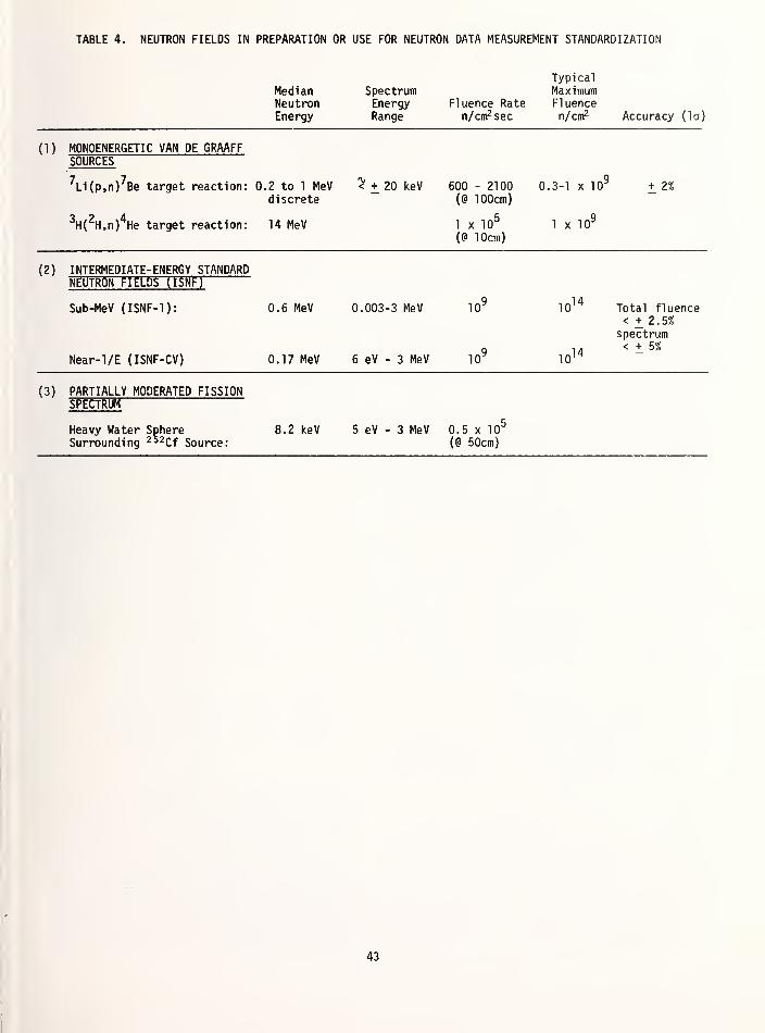
TABLE 4. NEUTRON FIELDS IN PREPARATION OR USE FOR NEUTRON DATA MEASUREMENT STANDARDIZATION
MedianNeutronEnergy
SpectrumEnergyRange
Fluence Raten/cirr'sec
TypicalMaximumFluencen/cm2 Accuracy (la)
(1) MONOENERGETIC VAN DE GRAAFFSOURCES
7Li(p,n)
7Be target reaction: 0.2 to 1 MeV < + 20 keV
discrete
3H(
2H,n)
4He target reaction: 14 MeV
600 - 2100
(@ 100cm)
1 x 10⁵
(@ 10cm)
0.3-1 x 10"
1 x 10⁹
+ 2%
(2) INTERMEDIATE-ENERGY STANDARDNEUTRON FIELDS (ISNF)
Sub-MeV (ISNF-1):
Near-l/E (ISNF-CV)
0.6 MeV 0.003-3 MeV
0.17 MeV 6 eV - 3 MeV
10"
10"
1014
1014
Total fluence< + 2.5%spectrum< + 5%
(3) PARTIALLY MODERATED FISSIONSPECTRUM
Heavy Water Sphere 8.2 keV 5 eV - 3 MeV 0.5 x 10
Surrounding 2 ' 2Cf Source: (@ 50cm)
43


NBS SERVICES FOR IONIZING RADIATION MEASUREMENTS
H.T. Heaton, II
Center for Radiation ResearchNational Bureau of Standards
Washington, D.C. 20234
The NBS measurement support services relevant to establishing traceability to the
national standards for ionizing radiation are described. These services can be
grouped into four categories: calibrations, standard reference materials, mea-surement quality assurance services, and special services. Within each category,the services for photon and electron dosimetry, radioactivity measurements, andneutron measurements are summarized.
(calibration, ionizing radiation, national standards, measurement, quality as-
surance, standard reference material, traceability)
Introduction
The first three papers £1-3] in this publi-cation describe various concepts of traceabilityto national standards for ionizing radiation andthe kinds of mechanisms, including institutional,by which this traceability can be established.The next three papers 1.4-6] describe the nationalstandards for photon and electron dosimetry,radioactivity measurements, and neutron measure-ments to which measurements can be traceable.
To make maximum use of NBS resources thereshould be some kind of intermediate laboratorybetween NBS and the ultimate user. This meansthat measurements can still be traceable to NBSthrough the intermediate laboratory without a
direct interaction with NBS. For those caseswhere a direct interaction with NBS is necessary,this paper will summarize those services whichNBS offers which are useful in establishingtraceability for ionizing radiation measurements.Additional information about these services maybe found in other papers in this publication.
For ionizing radiation measurements, the NBS
services can be grouped into four categories:
°Calibrations"Standard Reference Materials (SRM)
"Measurement Assurance Program (MAP) orMeasurement Quality Assurance CMQA)
Services°Special Services
The first two categories are relevant for estab-lishing what Eisenhower £1] called "artifacttraceability". This is the traditional conceptof traceability. The calibration services thatNBS offers are described in NBS SP 250 £7J. Sim-
ilarly, currently available SRMs are listed in
NBS SP 260 [8]. Both ot tnese publications areregularly updated with the latest editions beingrespectively 1980 and 1979-80. Both publicationshave appendices which contain the latest priceinformation. In addition to NBS SP 250 and SP
260, the Radioactivity Group also distributestwo documents which list the currently available
radioactivity SRMs £9a] and radioactivity cali-bration services £9b]. The former also includesa schedule of when standards containing short-lived radionuclides will be issued.
The third category is relevant to whatEisenhower £1] called "measurement traceability".The programs and services in this category can beused to test the participant's entire measurementsystem. In order to be listed as an "officiallyrecognized" NBS Measurement Assurance Programservice (I.e. to be listed as offering a MAP ser-vice in NBS SP 250) it historically has beennecessary for the Statistical Engineering Divi-sion of NBS to have evaluated the participatingcompany's quality control procedure to ensurethat the process can be maintained in statisticalcontrol. Measurement Quality Assurance services,as used in this paper, are conceptually the sameas a MAP service with the exception that a par-ticipating company's quality control program neednot be evaluated by NBS. Only the term MQA ser-
vice will be used throughout the remainder ofthis paper since, in the area of ionizing radia-tion, there is no NBS evaluation of the partici-pant's quality control program. Participantsshould, however, still have a quality controlprogram to make effective use of an MQA service.
The last is a broad category and the non-routine services listed could, for example, in-clude a short or long term interagency agreement,an internal project which will result in a newcalibration service, or a standard calibration ofan instrument using non-standard techniques.
Calibration Services
The various calibration services that NBS
offers provide one way of achieving "artifacttraceability". In all of these services, someartifact (radioactive source, dosimeter, etc.) is
sent to NBS and the response of that artifact is
determined under specified conditions. NBS willcalibrate certain instruments used in photon andelectron dosimetry and in neutron measurements,and will measure the radioactivity of samples
45

Dosimetry
which meet certain physical and chemical criteria.Before any of the artifacts are sent to NBS forcalibration, arrangements should be made in
advance.
Loevinger [10] has previously discussed thecalibration services offered by the DosimetryGroup. These are summarized in Table 1* and are
Table 1
Summary of Dosimetry Services
Service Items Calibrated/Readout
EnergyRange*(MeV)
Exposure orAbsorbed Dose
Range Comments
Exposure (Rate)calibrations
1) Reference class instrumentswhich serve as user's "in-house"standards
0.01-1.25 10" 6- 10° R/s Not all intensities
are available at all
energies
2) Instruments suitable forcalibrating therapy units
0.01-1 .25 10" 6- 10° R/s
3) TLD's (both personneland environmental) for cali-brating user's readout unit
0.01-1 .25 10'6- 10° R/s This service is in-
tended to providea known exposure whichcan be used to char-acterize the user'sreadout systems and it
is not intended to be
a large scale commer-cial TLD irradiationservice.
Absorbed dosecal ibrations
1) Reference class instrumentswhich serve as user's "in-house"standards
1.25 1 -2 rad/s Calibrations in termsof absorbed dose towater
2) Instruments suitable forcalibrating therapy units
1 .25 1 -2 rad/s
3) Radiochromic dyedosimeters (film and liquid)
1.25 0.1-60 Mrad
4) Beta-particle sources •20-200 rad/s Surface absorbed doserate to graphite,plastic , or water.Mainly tor ar- Y
•ophthalmic (beta-ray)appl icators
LApUbUl C l aleat 1 metercal ibrations
LilCapSU 1 aUcU SOUPCGS OT137Cs, 60 Co, 192
Ir
i /inn mD /hi -huu mK/n Radium is calibrated in
terms of equivalentradium mass
Spectrophotometric
readout of customerirrauiatcu dosi-meters
1) Ferrous sulfate (Fricke)solution
5-50 5-8 krad This is part of an
MQA service to checkconsistency of highenergy electron beams.
2) Radiochromic dyedosimeters
0.1-60 Mrad Can readout opticaldensity at several
wavelengths
Other 1) Determine temperature de-pendence of radiochromic dyedosimeter in range -78°C to 100°C
2) Calibration of penetrameter(Ardran -Crookes-type cassette)
*See Table 16 for conversion of special units to SI units.
46

presented in more detail in Tables 2-5. Table 2
lists the exposure and exposure rate services for
ionization chambers and passive dosimeters. Their
response is compared with that of a free air
ionization chamber for x rays or determined in
standardized beams for gamma rays [11]. Before an
instrument is calibrated, the ionization chamber
is tested for leakage, radiation induced leakage,
stabilization time, short term stability, re-
combination loss, communication to the atmos-
phere, and guard electrode insulation (if appli-
cable). The ionization chamber must have suf-
ficient wall thickness to provide electron equi-
librium for the highest energy photons selected
for calibration. If the ionization chamber is
submitted with an associated electrometer, a
dimensionless correction factor is provided for
Table
scales marked in terms of exposure or exposure
rate. Otherwise, the ionization chamber is
calibrated in terms of exposure per unit charge.
The calibrations can be made with polarizing
potentials of either polarity or with both polar-
ities. Values of the ionization current at half
and full polarizing potentials are available. In
Table 2, the homogeneity coefficient is the ratio
of the first half-value layer (HVL) of Al to the
second HVL of Al . For monoenergetic beams this
coefficient is unity, hence the smaller the
coefficient, the poorer the approximation that
the filtered x-ray beam can be represented by a
monoenergetic photon beam. In many applications,
it is useful to think in terms of an "equivalent
energy"* of the filtered x-ray beam. Table 3
Exposure (Rate) Calibration Services
Beam Constant Added Filter Half-Value Homogeneity Equi va 1 ent Exposure Rate
Potential (mm ) Layer (mm) Coefficient Energy*(kV) Pb Sn Cu ft
1
Cu Al IKev
;
min max(R/s) (R/s)
Lightly Filtered X Ray d)
L-B 10 0 0 029 0 79 7.2 io-6
1 .7
L-C 15 0 0.O50 0 74 9.1 10- 6 4.2
L-D 20 0 0.071 n 7fi 9.8 io-6 3.3
L-E 20 0.5 0 23 0 78 13.6 in- 6 n i?
L-G 30 0.5 0.36 0 64 16.8 io- 6 0.3L-I 50 1.0 1.02 o 66 24.4 io- 6 0.4L-K 75 1 .5 1.86 0 63 31.9 IO
-60.4
L-M 100 2.0 2 78 o 59 38.3 io- 6 0.4
Moderately Filtered X Rays'
MFB 60 0 0 1 62 0 68 28.5 7xl0- 3 0.12MFC 60 0 2.50 0.090 2 79 0 .79 34.2 7xl0" 3 0.04MFE 75 0 2.51 0.116 3 39 0 74 38.7 7xl0- 3 0.07MFG 100 0 3.50 0.20 5 03 0 .73 48.5
1 .5xl0"2 0.10
MFI 150 0.25 3.49 0.66 10 25 0 89 76.91 .5xl0- 2 0.13
MFK 200 0.50 3.49 1 .24 13 20 0 .92 101 3.0xl0-2 0.22
MFM 250 1 .01 3.50 2.23 15 80 0 .92 131 4.0xl0- 2 0.28MFO 250 3.20 3.47 3.25 18 30 0 .98 153 2.0xl0- 2 0.15
Heavily Filtered X Rays U)1
HFC 50 0.10 0 0 2.50 0.14 4 19 38 3x10"" 1 .5xl0" 3
HFE 100 0.50 0 0 2.50 0.74 11 .20 70 8x10 4xl0- 3
HFG 150 0 1
.
51 4.00 2.50 2.45 16.96 117 7x10-" 4xl0- 3
HFI 200 0.77 4. 16 0.60 2.47 4.09 19 60 167 SxlO-" 4xl0- 3
HFK 250 2.72 1. 04 0.60 2.50 5.25 21 .55 210 5x10-" 4xl0- 3
Gamma Rays
Cs-137 10. 8^ } 662 1 .5xl0- 3 0.1
Co-60 14.9^ ) 1250 1 .5xl0" 3 2.5
(*) The inherent filtration is approximately 1.0 mm Be
(
2) The inherent filtration is approximately 1.5 mm Al
(
3) Calculated
*For lightly and moderately filtered x-ray
beam, the "equivalent energy" is the mean
energy for the exposure spectra as reported in
Seelentag et al [12]. For heavily filtered x-
rays, the "equivalent energy" is the "effective
energy" listed in the "Report of Calibration"
for the NBS Dosimetry Group and it is based on
the initial slope of good geometry copper ab-
sorption data. For gamma-rays, the "equivalent
energy" is the mean energy of the gamma-rays
occuring in the radioactive decay.
47

lists the absorbed dose calibrations available:
calibration in a water phantom in a standardized60 Co beam [13], calibration of radiochromic dye
dosimeters in a standardized60 Co beam in an
irradiation pool [14, 15] and calibration of
beta-particle sources in terms of surface ab-
sorbed dose rate. Table 4 lists the sources
which can be calibrated in terms of exposure rate
at one meter:60
Co,i37
Cs £16] and ia2Ir [17].
Radjum sources are calibrated in terms of equiva-
lent radium mass. Table 5 lists the dosimeterswhich can be irradiated by the user and sent to
NBS for spectrophotometry readout to determinethe dose delivered to the dosimeter. Servicesare available for reading ferrous sulfate CFricke)
solution dosimeters [18-20] irradiated accordingto a prescribed protocol [21], and for spectro-
photometrical ly reading irradiated radiochromic
dye dosimeters at specified wavelengths. [14,
15].
Table 3
Absorbed Dose Calibrations
Radiation Cal i brat ionMethod
ItemsCal i bra ted
Absorbed DoseRange Comments
60Co Standardized
beam and waterphantom
1) Ionizationchambers
2) Passivedosimeters
1-2 rad/s Calibration is done in a waterphantom at a depth of 5 g/cm 2
in a 10 cm x 10 cm field
60Co Standardized
beam in anirradiatorpool
Radiochromicdye dosimeters
0.1-60 Mrad Dosimeters are placed knowndistances from a
60 Co sourceat the bottom of an irradia-tion pool
.
Betaparticles
Extrapolationchamber
B-particle sources 20-200 rad/s Source calibrated for surfaceabsorbed dose rates.
Table 4
Exposure Rate at one Meter
Source Encapsulation Nominal Range Comments
mR/h at lm mCi
60Co 0.4-400 0.3-300
137Cs 0.4-400 1-1000
192lr 0.1 mm platinumor
0.2 mm stainlesssteel
0.4-400 0.8-800
Radium Corrections aremade for the encap-sulation if it is
specified
(0.5-250 mgof radium
)
Calibration in terms of equivalent
mass of radium content measuredrelative to the National RadiumStandard through comparison of
gamma radiation.
Radioactivity
In addition to providing SRMs with known •
activities, NBS will also measure the radioactivityof y-ray, ^-particle and a-particle emittingsamples subject to certain conditions. Contact
the Radioactivity Group beTure sending any samples
to NBS to ensure that all physical and chemical
requirements of the sample are met, that resources
will be available to calibrate the sample when
it arrives, and that all possession and shipping
regulations are being followed. Tables 6-9 are
48

Table 5
Spectrophotometric Readout of Customer Irradiated Dosimeter
Dosimeter Application
AbsorbedDoseRange
Wavelength (s) of
ReadoutContainers for
Dosimeters Comments
Ferrous sulfate(Fricke) solution
high energyelectron beams
5-8 krad 304 nm Radiation resistantsil ica-glass
spectrophotometrici*ci i , puiysLyrenemailing containersto be irradiated in
polystyrene phantom
Normally threecells are shipped,one as a controlanrl twn fnv i v—
radiation, Theirradiation shouldbe performed ac-cording to a
prescribed pro-tocol (jReference
21)
Radiochromic dye commercialirradiators
0.1-60Mrad
ultraviolet andvisible, depends onparticular type ofdosimeter andamount of absorbeddose
These dosimetersare used to mea-sure radiation in
processes such as
sterilizing medicalproducts, curingplastics, etc.
Table 6
Calibration of Radioactive Samples
Y-ray a-particle 6-particle
CalibrationInstrument
"4n"f ionizationchamber
2lla proportionalcounter
0.8na defined-sol id-angle
Liquid Scint-illator
4110 proportionalcounter
ActivityRange
10-1500 uCi 0.04-300 nCi 5-300 nCi 0.5-50 mCi/L 0.5-50 mCi/L
Nominal
Uncertainty0.8-3.4% 1 .5% 1.0% 1.5-2% 2-3%
PhysicalForm
solution sol id sol id solution solution
SampleContainer
Flame sealedglass ampoule! 1
)
Such that neitherthe container norpackaging materialcontacts theactive surface
same flame sealedglass ampoule! 1
)
flame sealedglass ampoule! 1
)
Sample
Dimensions5 or 50 mL diameter: 10 cm max
thickness; suchthat 99.5% of thect-particles areemitted with energygreater than 400keV.
diameter: 1 .6 cmthickness: same
5 mL 5 mL
Radiation
Quantityactivity!
2) Alpha-particle
emission rate into2n steradians
activity activi ty activity
i1) appropriate borosi 1 icate-glass ampoules are available from NBS
(2) calibrations for 65 Zn and 109 Cd - 109mAg are in terms of emission rate rather than activity.
49

based on information found in RadioactivityCalibration Services of the National Bureau of
Standards 19b], This reference contains addi-tional information on suggested chemical forms
for the carrier and solution of the radionuclidesand information on the borosilicate glass am-
poules used for radioactivity calibrations. For
samples emitting y-rays, a-particles or 3-
particles, Table 6 summarizes the type of instru-ment used for calibrating the sample, the nominal
activity range, nominal uncertainty, physicalform of the sample, sample container, limitationson sample sizes and what radiation quantity is
determined. The actual uncertainty depends on
the activity level, source geometry and chemicalform. It is the linear sum of the random uncer-tainty at the 99% confidence level plus theestimated maximum limits for all conceivablesources of systematic uncertainty. Table 7
Table 7
Gamma-Ray Emitting Solution Samples
Radionucl ide Nominal Uncertainty (%)
22Na 1 .6
21,Na 0.8
* 2K 2.0
"Sc 0.851 Cr 1 .05"Mn 1 .2
"Co 0.859pe 1 .460
Co 0.865Zn(0 1 .767Ga 1 .4
75Se 2.4
85 Sr 2.088y 0.7"Mo-"mTc 1.6"mjc 1.5109 Cd_109mAg (l)
1 .7iiomAg_noAg 0.9J11
In . 1.3113
Sn- 113 mi n 2.712
3l 1.5131!
1 .3133Ba 1.513 "Cs 1 .0137
Cs- 137mBa 1.5139
Ce 1 .0
3.4lkl
Ce 2.0i52
Eu 1 .615^ Eu 0.8155
Eu 1.5169 Yb 2.5195Au 2.3197
Hg 2.4198Au 1.3201
T1 1 .920 3 Hg 1 .42 0 3pb 1 .7226
Ra 1.1
lists 39 Y-ray-emitting radionuclides with thenominal calibration uncertainty. Table 8 pro-vides similar information for the 8 3-particle-emitting radionuclides together with whichinstrument is used for calibrating that radio-nuclide. Table 9 lists the 9 a-particle-emitting radionuclides calibrated at NBS. In
addition to the calibration services listed in
Tables 6-9, some gaseous radionuclides can be
calibrated by internal gas-counting measurementsand gamma-ray point sources and solution sourcesmay be assayed with calibrated Ge(Li) spectrom-eters.
Table 8
Beta-Particle Emission Solution Samples
Radionucl ide Counting System^ 1) Nominal
Uncertainty(%)
3H L.S. 1.5
mc L.S. 2.5
32p 4116 (PC) 2.036
C1 L.S. 2.089 Sr 4113 (PC) 3.090 Sr_90 Y L.S. 2.5
^Pm 4113 (PC) 3.020*
J-] L.S. 2.0
C) L.S. is Liquid Scintillation counter.4113 (PC) is 4113 proportional counter.
Table 9
Alpha-Particle Emitting Solid Source Samples
Radionucl ideNominal Uncertainty (%)
2lTa proportionalcounter
~ 0.8Jla defined-sol id-angle
11,8Gd 1.5 1 .0
210po 1.5 1 .02 3 0 Th 1.5 1 .02 38 Pu 1.5 1 .02 3 9 Pu 1.5 1 .0241 Am 1.5 1 .02 " 2 Pu 1.5 1 .021t3Am 1 .5 1 .0
U 1.5 1 .0
01 in terms of gamma-ray-emission rate rather
than activity
50

Neutrons
Traditionally, the services NBS offered for
neutron measurements included neutron sourcestrength determinations I22-23J and foil irradia-
tions in a thermal neutron flux density £24-25].These services are described in Table 10. With-
in the past several years, NBS has developed a setof standardized neutron fields [26, 27] which canbe used to calibrate instruments and dosimeters orcan be used to evaluate their performance. Thesefields are summarized in Table 11. The energy,
Table
fluence rate, and uncertainty in the fluence rate
Cat the 67% confidence level) are listed. Theuncertainty does not include any components due to
gamma rays which may be present in the neutronbeam. The gamma-ray component has been measuredfor the filtered beams 1 27] and the gamma-rayspectrum per unit mass of " 2
Cf is listed in ICRU26 128] . In addition to the fields listed in
Table 11, a 14 MeV facility using a d,T reactionat the Van de Graaff will soon be available forcalibration purposes.
10
Neutron Calibrations
Service Method Range Comments
Neutron source manganous 105-TO^n.s- 1 Measure the saturated 56 Mn
emission rate sulfate activity produced by neutron(into 411) bath capture in the bath. Source
composition and encapsulationshould be specified. Sourcelength must be less than1.2 cm.
, Thermal neutron neutron standard 4000 n.cm - 2.s~
1 Dosimeters (gold foils) maydosimeter thermal neutron be irradiated both with andirradiation fl uence without cadmium covers.
Response to gamma rays in
the thermal beam is notprovided.
Table 11
Standard Neutron Fields
Field Energy(MeV)
Fluence rate(n. cm- 2
. s- 1
)
Uncertainty (%)^ •
252Cf 2.1 2xl0 7
<2>
2
Van de Graaff 0.1-1.5 103
2
Cavity (Reactor)
235,
(3
)
ISNFv ;
1 .6
0.6
2 x 10¹⁰
109
5
3
Tnermal 2.5 x 10~8 1011
2.5
Filtered Beams
105 <*>
4xl04 {h)
4xl04 WSi 1 icon
Iron
0.144
0.026
10
10
Scandium 0.002 5
External Thermal 2.5 x 10"8 2 x 10⁷
5
Thermal flux density std. 2.5 x 10"8 4 x 10³
1 .5
t2
i
(
2)
(
3)
n
Uncertainty at the 67% confidence levelany y's present in the beam
5 cm from the source
ISNF is Intermediate-energy Standard Neutron Field
225 cm from the reactor
51
It does not include the uncertainty components due to

Standard Reference Materials
Standard Reference Materials (SRMs) arematerials which have been certified by NBS forspecific chemical composition, chemical propertyor physical property. Currently, the only SRMsdeveloped at the Center for Radiation Researchare produced by the Radioactivity Group. In this
case the activity or emission rate is certified.Many of the SRMs have a short half-life and,
hence, are not always available. One can be put
on a mailing list, maintained by the Radioactivi-ty Group, to be notified when a particular SRM
will be (re)issued. Information on orderingthese SRMs is given in NBS SP 260 [8] or may be
obtained from the Radioactivity Group [9a].
Table 12 summarizes the radionuclides andthe classification in which they have beenissued as SRMs. A numerical entry in the Tablegives the nominal value (or range) of the ac-tivity or activity concentration of the SRM. In
a few cases a symbol appears in the parenthesesafter the value. This indicates that the certi-fication is for the emission rate of that par-ticle in the same units as the heading, i.e. for239 Pu, 6 alpha particles s"
1 g" 1. For the K
x rays, the emission rate is per steradian. An"*" in a column means that the SRM was originallyissued in that form but is temporarily out ofstock. The overall uncertainty (see section onCalibration Services) for most of the SRMs is 1
to 2%.
In addition to the SRMs listed in Table 12the following SRMs are available in the specialform indicated:
Oxalic acid (for11>
e dating)226
Ra solution (0.1 to 100 pg)226
Ra for radon analysis (blank, 10" 8
10- 9,10-" g)
River sediment (12 certified radio-nuclides, an additional 18 values,are listed but not certified)
Point-source and solution standard oflong-lived mixed radionuclide
(
12?Sb, "»Eu, 155
Eu)
Table 12
SRM Nominal Activity at Time of Calibration
RaHinnurl idp Classification of Standard
Solution Point faas-
eous-(adiopharm-
aceuticalr l i \
1 ,10,10(s- 1
) (s-1
) (s-1 g- 1
)3H
1 <+
Q 1 U , 1 U22
Na 1026
A1 3932p
1 U36
C1 101*
37Ar3 9n r 1 n't
10
10^ (Kx)1
0
5ltMnin i 10
r c 10 (Kx) 10 1^x2
"Co * 1Q5
59Fe in 51 u
60 Co 1 (J 1 u63 Ni 1 U67 Ga
l n 81 0
75Se in 61 u
8 5|(r1 a 5 1 a710- 1 0
1 A6 i r\l10 ,io 7
85Sr88y 1 A 5
10
1 u
89Sr *9 0g r_9 0y 10 3
91»Mh l A3109 9m„ 9 9mTr1*10- 1,1
1 Cin 6I u
9 9im-rT a910
1 ^Cd- 1 09mAg 105
(y) 10 3(y)
1 1 1 Inl nin 6I u
1 1 3c n_l 1 3IDT nOil 111in 5
112 3j
in 71 u
125j
in 51 u
127 Xei a61
0
129J *
131j 1 0
1 3 3v p J;Q , 1
0
1
0
1
3
3 RaDa * *
1 3tr,
137 r<- 137mR 3LS- D3 10 1
0
1* ,10
s
1 39 Cei a5
mi i n 31 U
1 ^^(lA1 U - 1 u
152 Eu in 51 u 1 u
169¥b 10 6
195Au 10s
198Au 10 6
zoi T1 10 6
2 0 3 Hg 10 6
2 0 3pb 106
2 0 7Bi 10"
22eRa C
1) 1 u — 1 u
228j h 10*23 8pu 10
2 -10*23 9p u 6 (a)2.,op
u 18 (a)21,1Am lO^lO 6
2l,2Pu 27 (a)
2 - 3Am *
(
:
) mass of radium (g)
52

Measurement Quality Assurance Services
Currently there are measurement qualityassurance services in the areas of photon andelectron dosimetry and radioactivity measurements.The advantage of an MQA service is that it teststhe participant's entire measurement system so
that variation due to different personnel, "in
house" standards, systematic procedures, etc., canbecome apparent. In principle, the MQA servicesshould be a true blind test of the participant'smeasurement capability but in practice the trans-port standard is often of significantly differentform so that special non-routine measurementprocedures must be used. Hence, one might arguethat this does not properly test the measurementsystem. It does, however, demonstrate how well
the user's sytem is performing under a specificset of conditions at the time the MQA service is
carried out. To make effective use of this typeof program, the participant must be making a
conscious effort to maintain his own qualitycontrol program. using "in-house" standards so
that trends and abrupt changes in the measurementprocess can be detected. If the participant'smeasurement system properly characterizes thetransport standard, then there is demonstrableevidence that the participant is able to maintaincalibration of his sytem and can use it to makecorrect measurements. This assurance is furtherbuilt up with each successful participation in
the MQA service, particularly if the transportstandard can be designed so that it will test theuser's system under different conditions. Thelong-term use of an MQA service, together withthe user's own quality control program, signifi-cantly reduces the chance that the correct valuesof the transport standard was obtained as theresult of a "lucky" measurement.
The MQA services for ionizing radiationoperate in the following modes:
°NBS sends a known but undisclosedtransport standard to be characterizedby the user.
°The user selects and characterizes a
suitable item to serve as a transportstandard and sends it to NBS foranalysis.
°NBS sends a transport standard to begiven a predetermined irradiation bythe user and then returned to NBS foranalysis.
Conceptually these programs are very similarto the types of programs in which NBS participateswith the National Standards Laboratories of othercountries to ensure that there is a common basisfor measurements on the international level
.
Tables 13 and 14 respectively summarize theDosimetry and Radioactivity MQA services. Thefirst columns in these tables identify the pro-gram and the participants in the NBS MQA services.The second half of these tables gives the detailsof the various programs including information onthe transport standards and results. The resultsare expressed in slightly different form through-
out the tables although all are in terms of Awhere
..-.^ Participant va lue , ,„»A- 100PS value ~ -1
(% )
Since there were so few participants and so fewresults in the first two programs of Table 13,the actual values of A are specified. Many moreresults have been obtained for the last programlisted in Table 13 and for all the programslisted in Table 14. For these cases, the per-centage of participants' results for variousranges of A are specified, (e.g. for the elec-tron beam dosimetry uniformity study in the years1967-1975, 59% of the participants' values werewithin ±5% of the NBS value, A< 5).
53

Table 13
Dosimetry MQA Services
ProgramDesignation
Participantswith NBS Comments
AAPM RCL £29,30] The three RCL'saccredited bythe AAPM
The RCL laboratories calibrateinstruments used for standardizingtherapy beams.
Federal Agency(BRH) £31]
Bureau of Radio-logical Heal th Cal i-
bration Laboratory
This laboratory calibrates instrumentsfor FDA compliance inspections of x rayunits and for state agencies for theircompliance and contract inspections.
State RCL£32] An RCL is being es-
tablished in the Stateof Illinois
This laboratory will calibrate instru-ments used in their radiological healthprograms and similar instruments for g
other state agencies.
Electron BeamDosimetryUniformitystudy £18-20]
Actual users ofhigh energyelectron beamtherapy units
ProgramDesignation
/ear(s)
AAPM RCL
Federal Agency(BRH)
State RCL
(Illinois)
Electron BeamDosimetryUniformity Study
Numberof
Partici-
pants
1976
1977
19781979
1980
1967-1975
1976-1979
59
124
Transport Standardbetween NBS and Participant
Shonka 3 cm 3 ionization chamberVictoreen 41 5B chamberNEL Dosemeter and Farmer chamberPTW 1 era
3 30-349 chamber
MDH-1015
Ferrous sulfate (Fricke)
solution in sealedspectrophotometry cells
A-mn 1Participant value , I mA " 100
[ NBS Value1
|
U)
A for mediumfiltration x rays
-0.7 to 0.2-0.3 to 0.1
-0.4 to 0.3-0.6 to 0.2
A for 60 Co
gamma -rays
-0.3 to 0.1
-0.1 to 0.30.0 to 0.2-0.4 to 0.2
For 5 lightly filtered x ray
techniques, A less than 1.
For one medium filtered x ray
technique A=l
Still under development
Percentage of measurements with-
in various ranges of A*
A<»5 5<A$10 A>10
58 23 19
73 19 18
*These values of A are averaged over the time interval
participants in the specified range of A.
The numerical values are the percentage of
54

Table 14
Radioactivity MQA Services
ProgramDesignation
Participantswith NBS Comments
EPA NationalQuality AssuranceProgram [33]
EPA Las VegasLaboratory
This laboratory provides bothstandard samples and samplesto be used in QA programs.
NRC ConfirmatoryMeasurement [34]
DOE Laboratory atIdaho Falls
The DOE lab 1) provides radioactivestandards to the NRC for its use and7\ at NRP rlirprtinn ^pnrl<; tp^t ^anrnlp^
to NRC licensees.
AIF [35-37] Radiochemical andradiopharmaceuticalmanufacturers
Typically 7 companies plus FDAparticipate in monthly distributionof high and low level SRMs
CAP "Q" Program[35-37]
Hospital andnuclear pharmacies
Typically 30 to 50 laboratories reportback results. Up to 1977 participantswere asked to identify and quantifythe SRMs but after 1977 only to quantify.
ProgramDesignation Year(s)
Number ofdifferent
test transportstandards
Transport Standard
between NBSand participant
Percentage of samplemeasurements for various
ranges of A where
A=10olreported va1uP
-i 1* IUU
|NBS value1
1
(%)
EPA NationalQuality AssuranceProgram
1976-Present38 NBS SRHs and specially'
calibrated sources.As2 2<A$5 A>555 37 8
NRC ConfirmatoryMeasurement Program
1974-Present 87 NBS SRMs and speciallycalibrated sources.
A^2 2<A<5 A>554 38 8
AIF 1975-1980 44 5 mL solutions in standard NBSborosilicate glass ampoulesHighlevel range: 1-300 mCiLow level range: 0.050-5 mCi24 different radionuclides.Each participant can submitone calibrated sample per yearfor measurement by NBS
A<5 5<A^10 A>1077.4 16.1 6.5
CAP "Q" Program 1972-1979 16 5 mL solutions in standard NBSborosilicate glass ampoulesTypically in range: 0.05-5 mCi
A<10 A>1055 45
1972* 1 50 mCi of 51 Cr with serumbottle
A<20 A>2081 19
*This was a one time test in which the participants were asked to inject a known amount of 51 Cr intoa serum bottle, return it, the syringe and needle to NBS.
55

the services requested, the NBS measurements in-volved, and results obtained are listed. Thetype of traceability resulting from cooperativestudies which use some NBS facilities or mea-surement systems (e.g. characterizing instrumentswith the filtered beams of the rector) is some-
where between "artifact" and "measurement" in
that several facets of the user's measurementsystem are involved but not .necessarily his wholesystem in its normal environment.
i
Table 15
Examples of Special Services
Source ofsupport
Project NBSMeasurements
Percentage of measurement withinvarious ranges of A where
= 100[measured value J
{%)(delivered valueJ
\'
BRH L38.39] Voluntary survey of60
Co teletherapyunits.
Evaluate dose delivered to
CaF2:Mn TLD shipped in
a polystyrene block
A$5 5<A^10 A>10
83 13 4
NCI £10, 40] Calibration of beamsu^pd "frir thpranv in aU ^ VJ 1 Ul bllCl U UJr III d
hospital setting.
Measurement of photonl/cuiiid ud i iiy UIIC INL>*J
portable graphitecalorimeter and an NBScalibrated ionizationchamber.
NRC [41-44] Test of a draft ANSIstandard containinga protocol forestablishing a test-ing laboratory todeliver known dosesto personnelmonitors whichwould then be re-turned to companiesproviding thisdosimeter service.
Supply calibrated sourcesand correction factorsto the pilot testlaboratory.
Percentage of personnel dosimeterreadings within 50% of the dosedelivered by the pilot test lab-oratory
A<50%
80
LLL £27, 45] Remmeter and albedodosimeter responseto low energy mono^energetic neutrons.
Joint NBS-LLL measurementusing the 2, 24, and 144 keVfilter beams at the NBSreactor.
Information at 2 keV is new.Good agreement in region whereprevious measurements exist.
Special Services
NBS will perform many measurements or cali-
brations which are not part of the regularly
offered services. Often these services are re-
quests for calibrations beyond the range NBS
normally offers Ce.g. calibrate neutron sources
with greater source strengths, determine the
radioactivity in samples in non-standard con-
figurations, etc.L Other examples of special
services result when some agency wants to develop
a joint program to test the measurement capa-bility of a particular measurement community.
Four examples of this type of special service are
summarized in Table 15. Who requested the service,
Units
This paper is intended to provide the readerwith information on the wide range of radiationmeasurement services offered by NBS. It was feltthat this could best be accomplished by usingspecial units for the radiation quantities ratherthan SI units. Table 16 provides the conversionfactors between SI units and the special unitsused in this paper.
Table 16
Conversion Factor for Special to SI units
1 R/s 25.8 mA/kg"1 mR/h 71.7 pA/kg
1 rad/s 0.01 Gy/s I
1 Ci 37 GBq 1
1 mCi/L 37 GBq/m 3
10-" n.m-^s- 1
1 n. cm-2, s-
1
56

References
[ 1] Eisenhower, E.H., This publication
[ 2] Kathren, R.L., This publication
[ 3] Jennings, W.A., This publication
[ 4] Loevinger, R., This publication
[ 5] Cavallo, L.M., This publication
[ 6] Grundl , J. A., This publication
[ 7] Calibration and Related Measurement Serviceof the National Bureau of Standards, 1980Edition (Ed. B.C. Belanger) NBS SP 250
[ 8] NBS Standard Reference Material Catalog 1979-
1980 Edition, NBS SP 260
[ 9] References 9a and 9b are available from:
National Bureau of StandardsRadioactivity Group, Bldg. 245Washington, D.C. 20234
[9a] NBS Radioactivity Standards for Science,Industry, Environment and Health.
[9b] Radioactivity Calibration Services of theNational Bureau of Standards
[10] Loevinger, R. Medical Dosimetry StandardsProgramme of the National Bureau of Stan-dards, National and International Standardsfor Radiation Dosimetry, IAEA-SM222 Inter-national Atomic Energy Agency, Vienna, (1978)Vol I, 159
[11] Loftus, T.P., and Weaver. J.T. Standardi-zation of the 6a Co and l57
Cs Gamma-RayBeams in Terms of Exposure, Journal of Re-search of the National Bureau of Standards,Part A 78A (1974) 465
[12] Seelentag, W.W., Panzer, W., Drexler, G.,
Platz, L., and Santner, F., A Catalogue ofSpectra for the Calibration of Dosimeters,GSF Bericht 560, Gesellschaft fur Strahlen-und Umweltforschung mbH, Munchen (19791
II 3] Loevinger, R., National Measurement Standardsfor Radiation Dosimetry, Lecture prepared forthe AAPM 1976 Summer School at Trinity Col-
lege, Burlington, Vermont, July 1976
[14] McLaughlin, W.L., This publication
[15] McLaughlin, W.L., Radiation Sterilization ofPlastic Medical Devices, Radiat. Phys. Chem.
11 (1980) 9
[16] Loftus, T.P., Standardization of Cesium-137Gamma-Ray Sources in Terms of Exposure Units(Roentgens), Journal of Research of theNational Bureau of Standards, Part A, 74A(1970) 1
[17] Loftus, T.P., Standardization of Iridium-192Gamma-Ray Sources in Terms of Exposure.Journal of Research of the National Bureau of
Standards, 85 (1980) 19
[18] Soares, C.G., and Ehrlich, M., This publi-cation
£19] Ehrlich, Margarete and Lamperti, P.J., Uni-
formity of High-Energy Electron-Beam Cali-brations, Phys. Med. Biol U (1969) 305
[20] Ehrlich, M. and Lamperti, P.J., ElectronTherapy Dosimetry, Measurements forthe Safe Use of Radiation, (Ed. S.P.
Fivozinsky) NBS Special Publication 454(1976) 365
£21] Protocol for Dosimetry of High-EnergyElectrons Physics in Medicine andBiology, H (1966) 505
£22] Spiegel, V. Neutron Source Calibrations at
NBS for Calibration Checks of Neutron Ra-
diation Instruments, Measurements for the
Safe Use of Radiation, (Ed. S.P. Fivozinsky)NBS Special Publication 456 (1976) 87
£23] Noyce, R.H., Mosburg, E.R. Jr., Garfinkel,S.B., and Caswell, R.S., Absolute Cali-bration of the National Bureau of StandardsPhotoneutrons Source: III. Absorption in
a Heavy Water Solution of Manganous Sul-
fate. J. Nucl. Eng. 17_ (1963) 313
£24] De Juren, J. A. and Rosenwasser, H. AbsoluteCalibration of the NBS Standard ThermalNeutron Density. J. Res. Nat. Bur. Stand.
CDSI 52 0 954 ) 93
125] Mosburg, E.R. Jr., and Murphy, W.M., ARecalibration of the NBS Standard ThermalNeutron Flux, Reactor Science and TechnologyCJ.N.E. Parts A/B) 14. (1961) 25
126] Wasson, O.A. NBS Facilities for Standar-dization of Neutron Dosimetry from 0.001 to
14 MeV, Neutron Standards and ApplicationsCEds. CD. Bowman, A<D. Carlson, H.O.
Ltskien, and L, Stewart 1, NBS Special Pub-
lication 493 09771 111
I27J Schwartz, R.B., and Grundl, J. A., NBSStandard Reference Neutron Fields forPersonnel Dosimetry Calibration, National
and International Standards for RadiationDosimetry, Proceeding of a Symposium,Atlanta 5-9 December 1977, IAEA-SM-222,International Atomic Energy Agency, ViennaVol. I 0978)
£28] Neutron Dosimetry for Biology and Medicine,ICRD Report 26, International Commission on
Radiation Units and Measurements, Washington,DC 0977)
I29J Shalek, R.J., Humphries, L.J., andHansonW.F., This publication

£30] Shalek, R.J., Kennedy, P., Stovall , M.
,
Andiff, J.H., Gagnon, W.F., Frant, W.III,Hanson, W.F., Quality Assurance for Mea-surements in Therapy, Measurements for theSafe Use of Radiation, (Ed S.P. Fivozinsky)NBS Special Publication 456 (1976) 111
[31] Ohlhaber, T.R. This publication.
[32] Neuweg, M., This publication
[33] Inn, K. G.W., This publication
[34] Cohen, L.K., This publication
[35] Colle R., AIF-NBS Radioactivity Measure-ments Assurance Program for the Radio-pharmaceutical Industry, Measurements forthe Safe Use of Radiation, (Ed S.P.
Fivozinsky) NBS Special Publication 456(1976) 71
£36] Golas, D.B., This publication
[37] Cavallo, L, Ehrlich, M, Hutchinson, J.M.R.,Traceability in Ionizing Radiation Mea-surement Systems, National and InternationalStandards for Radiation Dosimetry, Pro-ceedings of a Symposium, Atlanta, 5-9
December 1979, IAEA-SM-222, InternationalAtomic Energy Agency, Vienna Vol 1, 0978)65
£38] Soares, C.G., and Ehrlich, M., NationalSurvey of Cobalt-60 TeletherapyDosimetry, NBS Technical Note 978 (1978)
£39] Thompson, D.L., Kearly, F.E., Wyckoff, H.O.,Gitlin, J.N., Reffit, E.B., and Shangold,E.J., National Survey of Cobalt-60 Tele-therapy, Final Report, HHS Publication (FDA)80-8130 (1980)
£40] Loevinger, R., private communication (1980)
[41] Plato, This publication
[42] Plato, P. and Hudson, G., Performance Test-ing of Personnel Dosimetry Services, Final
Report of a Two- Year Pilot Study October1977- September 1979, NUREG/CR-1064, U.S.Nuclear Regulatory Commission 0980)
[43] Plato, P., and Hudson, G., PerformanceTesting of Personnel Dosimetry Services,Supplementary Report of a Two-Year PilotStudy, October 1977-September 1979, NUREG/CR-1304, U.S. Nuclear Regulatory Commission(1980)
[44] Plato, Phillip and Hudson, Glenn, Perfor-mance Testing of Personnel Dosimetry Ser-
vices: Procedures Manual, NUREG/CR-1063,U.S. Nuclear Regulatory Commission (1980).
£45] Hankins, D.E., Energy Dependence Measure-ments of Remmeters, and Albedo Dosimeters atNeutron Energies of Thermal, and Between 2
keV and 5.67 MeV, Proceeding InternationalRadiation Protection Association, IV thInternational Congress, Paris (1977) p. 533(also preprint-UCRL-78307) (1977)
58
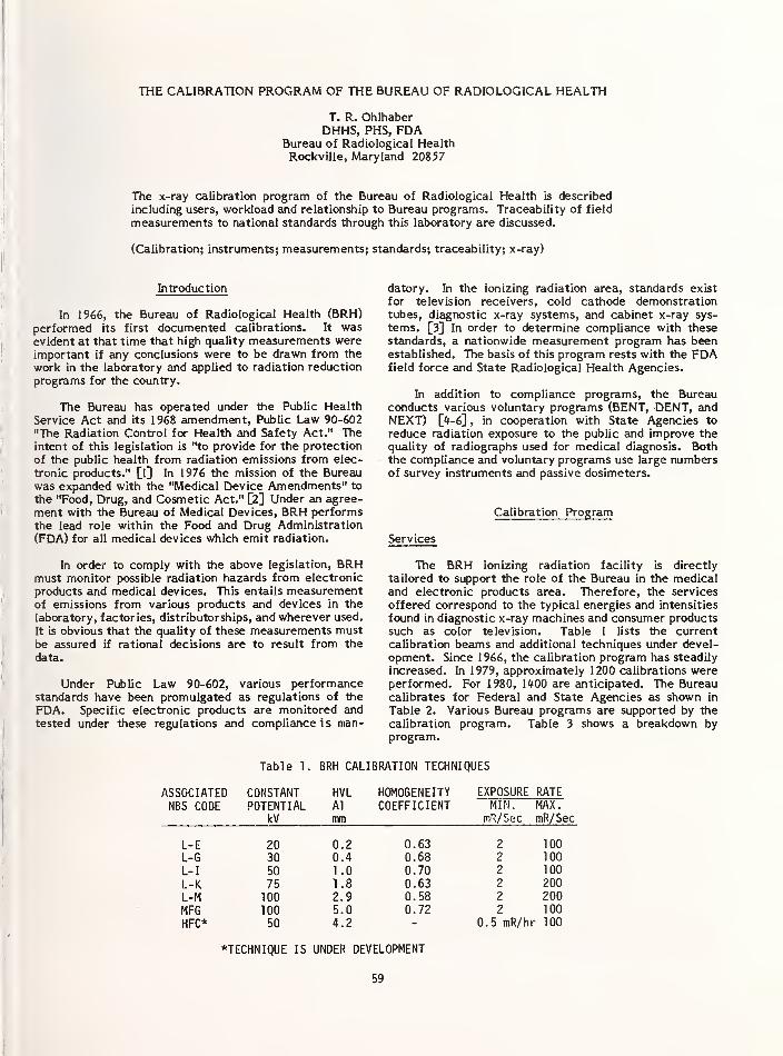
THE CALIBRATION PROGRAM OF THE BUREAU OF RADIOLOGICAL HEALTH
T. R. OhlhaberDHHS, PHS, FDA
Bureau of Radiological HealthRockville, Maryland 20857
The x-ray calibration program of the Bureau of Radiological Health is described
including users, workload and relationship to Bureau programs. Traceability of field
measurements to national standards through this laboratory are discussed.
(Calibration; instruments; measurements; standards; traceability; x-ray)
Introduction
In 1966, the Bureau of Radiological Health (BRH)performed its first documented calibrations. It wasevident at that time that high quality measurements wereimportant if any conclusions were to be drawn from the
work in the laboratory and applied to radiation reduction
programs for the country.
The Bureau has operated under the Public Health
Service Act and its 1968 amendment, Public Law 90-602
"The Radiation Control for Health and Safety Act." Theintent of this legislation is "to provide for the protection
of the public health from radiation emissions from elec-
tronic products." [l] In 1976 the mission of the Bureauwas expanded with the "Medical Device Amendments" to
the "Food, Drug, and Cosmetic Act." [2] Under an agree-
ment with the Bureau of Medical Devices, BRH performs
the lead role within the Food and Drug Administration
(FDA) for all medical devices which emit radiation.
In order to comply with the above legislation, BRHmust monitor possible radiation hazards from electronic
products and medical devices. This entails measurementof emissions from various products and devices in the
laboratory, factories, distributorships, and wherever used.
It is obvious that the quality of these measurements mustbe assured if rational decisions are to result from the
data.
Under Public Law 90-602, various performancestandards have been promulgated as regulations of the
FDA. Specific electronic products are monitored and
tested under these regulations and compliance i s man-
datory. In the ionizing radiation area, standards exist
for television receivers, cold cathode demonstrationtubes, diagnostic x-ray systems, and cabinet x-ray sys-
tems. [3] In order to determine compliance with thesestandards, a nationwide measurement program has beenestablished. The basis of this program rests with the FDAfield force and State Radiological Health Agencies.
In addition to compliance programs, the Bureauconducts various voluntary programs (BENT, DENT, andNEXT) [4-6] , in cooperation with State Agencies to
reduce radiation exposure to the public and improve the
quality of radiographs used for medical diagnosis. Boththe compliance and voluntary programs use large numbersof survey instruments and passive dosimeters.
Calibration Program
Services
The BRH ionizing radiation facility is directly
tailored to support the role of the Bureau in the medicaland electronic products area. Therefore, the services
offered correspond to the typical energies and intensities
found in diagnostic x-ray machines and consumer productssuch as color television. Table 1 lists the currentcalibration beams and additional techniques under devel-
opment. Since 1966, the calibration program has steadily
increased. In 1979, approximately 1200 calibrations wereperformed. For 1980, 1400 are anticipated. The Bureaucalibrates for Federal and State Agencies as shown in
Table 2. Various Bureau programs are supported by the
calibration program. Table 3 shows a breakdown byprogram.
Table 1. BRH CALIBRATION TECHNIQUES
ASSOCIATEDNBS CODE
CONSTANTPOTENTIAL
kV
HVLAl
mm
HOMOGENEITYCOEFFICIENT
EXPOSURE RATEMIN. MAX
.
mR/Sec mR/Sec
L-EL-G
L-I
L-KL-MMFGHFC*
2030
50
7510010050
0.20.41 .0
1.82.95.04.2
0.630.680.700.630.580.72
100100100
200200100
0.5 mR/hr 100
"TECHNIQUE IS UNDER DEVELOPMENT
59

Table 2. CALIBRATIONS LISTED BY AGENCIES Radiation Calibration
AGENCY NUMBER PERCENT
BRH 457 37
FDA Field 466 37Army •J D
-3
0
Air Force 13 1
Navy 14 1
States 263 21
1248 100
Table 3. CALIBRATIONS LISTtD BY PROGRAM
Upon successful completion of the above tests, theinstrument is set up on the x-ray calibration facility. Thetechnique used for calibration consists of a comparisonbetween the response of the laboratory standard and theinstrument under test in a known radiation field.
The radiation field is produced by an industrial x-raytube powered by a specially designed high voltage gen-erator. The output of this system is gated by a pneumaticshutter. Filters are inserted into the x-ray beam appro-priate for each technique. Multiple collimators are usedto control beam size and reduce scatter (Figure 1).
AGENCY NUMBER PERCENT
Compl iance 437 35
BENT 245 20
NEXT 325 26
DENT 29 2
BRH Lab 212 17
1248 100
Instruments Calibrated
Any reasonable quality instrument which is con-
sistent with the calibration techniques listed above is
accepted for calibration. Examples of these are
electrometer and ion chamber sets such as MDH Model1015, Victoreen Model 666, Keithley Model 35020 etc.;
Condensor-R sets and pocket dosimeters such as
Victoreen Model 570, DCA Model 002, Capintec ModelSEQ6 etc.; passive dosimeters such as TLD and film; andother instruments such as G-M and scintillation detectors.
All active instruments are checked for properoperation upon receipt. These checks depend on the
ability to separate functions such as electrical response
and radiation response. Usually, manufacturers suggestedchecks and adjustments are performed.
For instruments with separable ionization chambersand electrometers, electrical calibration of the elec-trometer may be performed. This is routine on all MDHModel 1015 and Victoreen Model 666 instruments. This
calibration determines proper electrical operation on all
modes and scales of measurement and adjusts all elec-
trometers for equal response to charge and current.
The equipment used for electrical calibration is aKeithley Model 261 Picoampere Source and a BRH con-structed charge source. The Picoampere Source is used
to provide precise currents simulating the current froman ionization chamber being used for an exposure rate
measurement. The charge source provides a knownamount of charge to test the integrated exposurefunction.
For instruments which are prone to chamber or high
impedance cable leakage, a charge leakage test is per-
formed by exposing the instrument to radiation and thenmonitoring the leakage of charge in the integrate mode.The leakage rate is compared to the manufacturer speci-
fication to determine whether the chamber, cable or
integrate capacitor is faulty.
If an instrument exhibits erratic readings or does notfunction and minor repairs are indicated, these will beperformed in-house. For major repairs, the symptoms are
noted and the instrument is returned.
X-Ray Tube Shutter
Filter
WheelMain Ion
Collimator Chambers
n-I tli-
i i
i i
[•I
_
Control and Readout Equipment
Figure 1. Radiation Calibration Range
The standard is composed of a high quality ionization
chamber and a readout system. Most commonly used is a
low energy secondary standard such as a Victoreen Model415-A. The laboratory also maintains Models 415-B, 415-
D and Exradin Models A5 and A6 chambers. These cham-bers provide complete coverage of energies employed in
diagnostic x-ray machines.
The readout system is composed of a Keithley Model616 electrometer with a General Radio Model 1403Standard Air Capacitor inserted in the feedback loop.
This configuration provides an integrating electrometerwith a low leakage and precise capacitance (Figure 2).
G RModal 1403
lhChamber
Keithley
Model 616
Figure 2. Charge Collection System
Because the measurement is a comparison of the
response of two devices, a positioner is used at the
calibration site which allows precise positioning of the
standard and device under test, with standard mounts to
hold the most commonly calibrated instruments
(Figure 3). Temperature and pressure are recorded
60

because a correction for air density must be performedfor all the standards and most instruments containingvented ionization chambers.
Cstp ^ calculated from T (ambient temperature in
°C) and P (ambient pressure in mm of mercury) as
follows:
Figure 3. Positioner With Two Chambers and
TLD Holder Mounted
Associated Calculations
All phases of calibration involve the production or
measurement of a physical or electrical property and,
therefore, errors are inherent in each phase of calibra-
tion. The calculations used in radiation calibration arestraightforward.
CF =
Where:
(1)
CF is the correction factor for theinstrument under test;
X5 is the response of the radiation standardin Roentgens per second;
Xj is the response of the instrument in
Roentgens per second.
X$ is calculated at STP by;
q cStpXS = (RCCF) (2)
Where: Q is the integrated charge in Coulomb
RCCF is the NBS conversion factor for the
standard chamber in R/coulomb
C5TP 's tne correction factor for air
density at standard temperature andpressure and;
t is the exposure time in seconds.
For the equipment used in this laboratory, Q is
measured as the product of voltage (V) andcapacitance (C).
CV (3)
'STP
/273.15 + T\ /760 \
\ 273.15 / \ P /
Combining equation (2), (3), and (4) and applying to
the standard chamber (S):
CV /273.15 + Tc\ /760\XS = (RCCF)— ( ]( (5)
*s\273 15 Av
For a typical instrument which measures directly in
Roentgens the term CV (RCCF) reduces to the
instrument reading in Roentgens (rj). Thus:
I
'273.15 + T T\ /760
273.15(6)
If the instrument has a sealed chamber, the termscontaining T and P are dropped indicating no correctionfor air density.
There are basic assumptions in the above equations.
The most important assumption is that both the standardand the instrument under calibration are exposed to iden-
tical radiation, both in energy spectrum and intensity.
Also, it is assumed that effects from other variables suchas charge leakage, relative humidity, air composition(pollutants) and electromagnetic fields are negligible.
The parameters in equations (5) and (6) must bemeasured with reasonable accuracy to maintain an overall
accuracy sufficient for the calibration of field instru-
ments and dosimeters. Table <f lists the equipment used
to measure the parameters. Table 5 provides the speci-
fications of the radiation source.
The instruments are typically used indoors at roomtemperature. Therefore, all correction factors are
recalculated for 22 °C.
CF22° = CF273.15 + 22
273.15(7)
Table 4. RADIATION CALIBRATION MEASUREMENTEQUIPMENT
PARAMETER MEASURED EQUIPMENT
V (Voltage) Keithley Model 616Electrometer
C (Capacitance) General Radio Model1403 Capacitor
t (Time)
P (Pressure)
ERC Model 2612-33Timer, Operating withBRH ConstructedShutter Controller
Sensotec Model Z
Transducer and ERCModel 3501 Readout
T (Temperature) ERC Model 9300-CThermometer
61

Table 5. SPECIFICATIONS OF RADIATION SOURCE
Generator Model
ManufacturerOutput D.C.
RegulationStabilityMeteringEmission CurrentEmission ControlRegulation
Stabil ityMetering
Tube Model
ManufacturerContinuous RatingInherentFiltration
BRE-150-20-DHEW1Universal Voltronics10-150 kV
0.1%0.1 kV/hr+0.5%0.01 - 30 mAActive Feedback Loop+5% 0.01 - 0.299 mA+1% 0.30 - 30.0 mA+1%+2% or +0.01 mA{Whichever is Less)
MG-150Phillips3000 Watts
3 mm Be
On the intermediate level, various approaches can beused. Traceability can be achieved for each individual
component of the measurement system. This usuallyresults in a long and torturous chain to the nationalstandard. An example of this can be shown for themeasurement of charge in this laboratory. This mea-surement is a product of capacitance and voltage. Theair capacitor is calibrated directly by NBS. The voltagemeasured by the Keithley Model 616 electrometer is
traceable through a Fluke Model 335D voltage calibrator
and Fluke Calibration Center standards. This is also
verified at BRH by directly measuring a set of saturatedstandard cells (Eppley Model 121) which are calibrated byNBS. The combination of the capacitor and electrometer
is also checked by a Keithley Model 261 picoamperesource and a BRH constructed charge source. TheKeithley picoampere source is traceable through Keithleyto NBS. Figure k outlines the relationship of measure-ment of charge at BRH to NBS. It is obvious that errorsor equipment failure could occur at any point in this
complicated system. Although redundancy is present, asystematic error could be present and undetected.
Traceability NBS
National Standard
The above measurements with associated internal
quality control provide a consistent measure of "expo-sure." If BRH were the only facility performing these
measurements, this would be sufficient. However,"exposure" is measured at a multitude of facilities andcalibrations must relate to a single standard if meaningfulmeasurements are to be performed. In this country, the
National Bureau of Standards is the only facility
empowered to maintain the national standard of "expo-sure." All measurements and calibrations must be trace-
able to this standard within the necessary accuracy of the
measurement.
Reasons for Traceability
BRH is responsible for enforcing performancestandards which involve radiation measurements. In order
to determine compliance with these standards numerousfield and laboratory measurements are performed across
the nation. These measurements must provide data whichcan be defended. In other words, the data must relate to
the national standard and provide evidence "beyond
reasonable doubt" that the product does not comply with
the performance standard. These measurements have to
be made with the thought that they may have to belegally defensible.
In addition to measurements made to determinecompliance with Federal performance standards, the
States use these instruments to determine compliancewith State laws protecting the public health and safety.
Again, the measurements must relate to the national
standard and might have to be legally defensible.
Traceability Mechanisms
Various approaches can be used to achieve agreementbetween field measurements and the national standard.
The most direct would be to compare each instrument to
the standard. This is obviously impossible since thousands
or tens of thousands of instruments are involved. This
indicates the need for intermediate laboratories to
provide reliable calibration services.
Fluke Cat. Center
I
77
Keithley Cal. Center
Fluke 335D
Eppley 121 Keithley 616 Keithley 261General Radio
1403
BRHCharge Sourceuree \
*~
Primary traceability
Secondary check
Figure 4. Traceability of Measurementof Charge
The final output of this process yields a measurementsystem for charge which documents that the instruments
used in this system are traceable to a national standard.
It does not ensure that the use of these instruments will
yield an accurate measurement of charge.
Extensive quality control systems can be imple-
mented for each instrument involved in the measurement.However, it is still possible for the final product to
deviate from the national standard.
A far better program to determine agreement with
the national standard is to test the total operation of the
calibration laboratory. Not only are the calibration
instrument errors detected but also human, calculational
and systematic errors. All of these contribute to the
total disagreement from the national standard.
Since the final output of this laboratory is the
calibration of survey meters and passive dosimeters at
diagnostic x-ray energies, the test for determination of
agreement with the national standard should involve the
calibration of an instrument at both BRH (using the
62

normal laboratory protocol) and at NBS. Disagreement
between these calibrations will indicate the typical
performance of the laboratory as related to the national
standard. This should be an on-going program continually
documenting the performance.
In addition, cross calibrations between intermediate
laboratories serve a useful purpose. Measurements show-
ing agreement between two or more laboratories would
indicate that the national measurement system is operat-
ing properly at the intermediate level. If the cross
calibrations disagree, a need for improvement is
indicated.
Tests of Agreement
Since 1976 a specific Condensor-R electrometer andchamber have been used to monitor the output of the
BRH facility. This instrument has been calibrated at both
NBS and BRH. Figure 5 contains both sets of data for the
instrument. Variations in the BRH data result fromseveral sources:
1. Standards in the laboratory are interchanged and
returned for recalibration on 7- to 8-monthschedules. The disagreement between the standards
amounts to 2% or less.
BRH View of Traceability
The instruments calibrated by this facility are used
to enforce Federal and State laws for the protection of
the public and, therefore, the measurements made with
these instruments must be accurate and defensible. It is
the intention of BRH to provide calibrations of sufficient
accuracy so that the field instruments can be used to
their full potential with confidence in the measurements.At present this can be interpreted as meaning the calibra-
tions must exhibit less than 5% error. This number is
based on the accuracy of present field instruments and on
the reported needs of the States. [7]
2. Various operators have performed these calibra-
tions. Since the display for this instrument is an
analog system, variability has occurred in their
readings. This can amount to differences as much as
2%.
3. The basic errors in the set-up, measurement andgeneration of the beams can amount to approxi-
mately 1%.
In spite of these errors most BRH points fall within 3% of
the NBS points.
The goal of the laboratory is to maintain an overall
error of 3% or less. This provides a comfortable margin
of safety for unexpected errors. In order to maintain
such a limit, an active quality assurance program mustexist. To be most effective, NBS should be an integral
part of this program. The program should include testing
of the BRH facility by checking instruments calibrated in
the normal manner at BRH against the national standard
and providing a report documenting the degree of agree-
ment. This should be performed on a regular basis, pref-
erably twice a year. As of this date, such a comparison
has been performed.
An MDH Model 1015 instrument was calibrated at
BRH following the normal laboratory protocol. Theinstrument and associated BRH calibration report weresent to NBS for comparison to the National Standard.
The results of this test are present in Table 6. Excellent
agreement was obtained, verifying a reasonable transfer
of the National Standard to the intermediate level.
This program does not replace any in-house quality
assurance program nor does it alleviate the need for
calibration of the individual components of the cali-
bration system. The program is an independent measureof the total system.
1.20r-
Figure 5. Calibration of VictoreenCondensor-R Chamber Model 70-5
Table 6. BLIND COMPARISON OF MDH MODEL 1015
INSTRUMENT CALIBRATED AT BRH TO
NATIONAL STANDARD
TECHNIQUE BRH VALUE NBS VALUEPERCENT
DISAGREEMENT
To eliminate some of the inherent errors in the abovetest, an independent Keithley electrometer system andstandard chamber were compared to the laboratory
system. The results of these tests verify the sources of
errors in routine calibration.
L-E 1 n 1 11*
L-G 1 05 1 05 * The two systems were compared at five different
L-I 0 99 0 99 * techniques. Then the chambers were interchanged and
L-K 0 98 0 98 * the comparisons were rerun. Two general assumptions
L-M 0 99 0 99 * were made, namely that the radiation delivered to each
MFG 1 01 1 .00 U system was identical and that the spectrum of energies
was a reasonable approximation to the NBS techniques.
*N0 APPARANT DISAGREEMENT WITHIN ACCURACY OF Both of these assumptions have been shown to be
TEST INSTRUMENT reasonable from other tests.
63

Calculations were then performed to determine the
deviation in readout systems and the deviation in chamberresponse from the NBS calibration of each chamber.Table 7 summarizes the results of these comparisons.
Table 7. PERCENT DISAGREEMENT OF TWO MEASURINGSYSTEMS LISTED BY CALIBRATION TECHNIQUE
CHARGE CHAMBERTECHNIQUE COLLECTION RESPONSE
L-E 0 28% 2 21%L-G 0 29% 1 13%L-I 0 33% 1 20%L-K 0 13% 1 20%L-M 0 32% 2 07%
As can be seen, the difference between the twocharge collection systems amounts to approximately0.3%. The amount of difference between the two cham-bers seems excessive. The worst point was repeated withboth chambers used on the same charge collection
system. Again, the difference in response, using the NBScalibration factors was 2.2%.
It appears that the greatest error in the BRH calibra-
tion facility can be traced to the transfer chambers. It is
believed that this error may be attributed to changes in
the volume of the chambers because of small movementsof the thin window.
This effect has been noted by changes in the NBSreports for these chambers. It appears that the dis-
agreement shown in this analysis represents the maximumchamber error. Of the chambers used by BRH, the twochosen for this test represent the two extremes of changein NBS reports. Any other combination of chamberschosen for this test should result in a smallerdisagreement.
Because of realization of this effect, more extensive
tests will be performed to determine if these changesoccur while the chamber is in use or only while it is beingtransported and exposed to varying environmentalconditions.
Field Measurement Traceability
The traceability of intermediate laboratories is only
one step in the establishment of field measurementswhich are traceable to the national standard. Aftercalibration by an intermediate lab, the instrument mustbe transported properly, set up properly and usedproperly. BRH has attempted to solve these problems bysupplying simple to use instruments coupled with training
and written test procedures. All programs the Bureauinitiates or cooperates in have a manual which documentsthe needed measurements and equipment.
The step from the intermediate laboratory to the
final field measurement is the most difficult portion of
the traceability. Usually, direct control is lost and eventhough procedures exist, these may be ignored at the timeof the measurement.
Instruments purchased from or repaired at themanufacturer may be assumed to be calibrated when, in
fact, they may not be traceable to a reliable standard.Such calibrations should be verified and repeated if
necessary.
Conclusion
In order to achieve traceability for field
measurements, all facilities in the chain of calibration
must be traceable to the national standard. There mustbe an active measurement assurance program to docu-ment continued agreement to the national standard.
Also, a mechanism should be developed to extend mea-surement assurance to the field level. This may beaccomplished by a more general revision or compilationof existing procedures.
BRH is an active participant in diagnostic x-raymeasurements for the public health and safety. Since1966, BRH has served as an intermediate laboratory for
diagnostic x-ray energies resulting in over 5000 docu-mented calibrations. It is anticipated that this programwill continue with increasing demand for services andwith more emphasis on total traceability of field
measurements.
References
[1] Radiation Control for Health and Safety Act of
1968, Public Law 90-602, H2 U.S.C., (1968)
[2] Medical Device Amendments of 1976, Public Law 9*-
295, 21 U.S.C., (1976)
[3] Regulations for the Administration and Enforcementof the Radiation Control for Health and Safety Actof 1968, HEW Publication (FDA 79-8035), (1978)
M Reduced Dose Mammography - Results of a Nation-
wide Study, R.G. Tans and T.R. Ohlhaber;
Proceedings of the Second Reduced - Dose Mam-mography Meeting, Roswell Park Institute, Buffalo,
New York, (1978)
W Dental Exposure Normalization Technique (DENT)Instruction Manual, HEW Publication (FDA 76-
80*2), (1976)
[6] Nationwide Evaluation of X-Ray Trends: OrganDose Index System, HEW Publication (FDA 77-
8006), (1977)
[7] Ionizing Radiation Measurement Criteria for
Regulatory Purposes, Conference of Radiation
Control Program Directors, Inc., NBS Publication
(GCR 79-174), (1979)
The mention of commercial products, their sources,
or their use in connection with material reported herein is
not to be construed as either an actual or implied
endorsement of such products by the Department of
Health and Human Services (HHS).
64

The EPA National Quality Assurance Program
A. N. JarvisOffice of Quality Assurance-RadiationNational Environmental Research CenterU.S. Environmental Protection Agency
Las Vegas, NV 89114
The speaker submitted neither an abstract nor written version
of his talk for inclusion in the proceedings of this seminar.
For further information, contact the speaker directly.
65


THE LLL CALIBRATION AND STANDARDS FACILITY*
George W. CampbellJack H. Elliott
Hazards Control DepartmentLawrence Livermore Laboratory
University of CaliforniaP.O. Box 5505 Livermore, California 94550
The capabilities of Lawrence Livermore Laboratory's Calibration andStandards Facility are delineated. We describe the facility's ability toprovide radiation fields and measurements for a variety of radiation safetyapplications and the available radiation measurement equipment. The need fornational laboratory calibration labs to maintain traceability to a national
standard are discussed as well as the areas where improved standards and
standardization techniques are needed.
(Standards; calibrations; traceability; calibration instruments; calibrationtechniques.)
Introduction
The Lawrence Livermore Laboratory Calibrationand Standards Laboratory is operated by the
Dosimetry Group of the Hazards Control Depart-ment's Radiation Safety Division. The purpose of
the facility is to maintain radiation standardsfor LLL and to offer radioactive sources that
provide x- and gamma rays, neutrons and betaparticles so that all instruments at LLL may be
standardized [1].
The functions of this facility include:
• Providing accurate measurements and calibra-tion of radioactive gamma (>1 mCi) and
neutron sources, and providing in situ mea-surements of photon fields produced by
x-ray machines.• Providing accurate irradiations using
fields of gamma rays, x-rays, beta and
neutrons over a wide range of energy and
i ntensity.• Performing routine calibrations for the
Personnel Dosimetry program.
t Performing high-level (>10^ rad)
irradiations for radiation damage and
dosimetry development programs.
• Maintaining radiation instrumentationstandards and neutron source standards foraccurate comparisons with other radiationinstruments and neutrons sources within theLaboratory.
• Evaluating new and old radiation detectioninstruments.
• Maintaining portable radiation survey in-struments.
Facility Description
The facility is composed of a low scattercell (Cell A), an x-ray cell (Cell B), a source
storage cell (Cell C), a control room, a dosimetrylaboratory, and a portable instrument calibrationlaboratory as shown in Fig. 1. An elevation of
cells A, B and C is shown in Fig. 2.
Neutron and gamma sources are pneumaticallyfired from Cell C to Cell A. Table 1 lists the
sources available in the pneumatic transfer system.Cell A has an aluminum grating floor that is 3 mabove the solid concrete floor and 5 m below theconcrete ceiling. The locations of the neutronand gamma irradiation heads in Cell A are shown in
Figs. 3 and 4. The heads are positioned 1 m abovethe aluminum-grating which is as far from the ceil-ing and walls as possible to reduce the effects of
scattering. Boggs [2D has shown that the aluminum-grating contributes little to neutron scatteringand that the major contribution to scattering is
from the ceiling and walls. To keep the scatteringto 1% or less the source should be less than 140cm from the detector, greater than 50 cm from the
false floor, and greater than 200 cm from thewalls.
Blockhousewith boreholes
Office
Cell A183 A
Control paneland consoles
Instrument'
calibration shop
Dosimetry laboratoryand counting room
Chemical hood
Cell C183 C
Offices
North
FIG. 1. Sketch of Hazards Control Standards and
Cal'bration Laboratory in bldg. 255 (not to
scale).
This work was performed under the auspices of the U.S. Department of Energyby the Lawrence Livermore Laboratory under contract number W-7405-ENG-48.
67

FIG. 2. Cross section of cells A, B, and C.
TABLE 1. Available source choices in the gamma and neutron pneumatic source-transfersystems.
Gamma system Neutron system
Source3Dose rate at
1 m (mR/min) DHalf life
(yr) SourceDose rate at
1 m (n/s)Half life
(yr)
60co 136 5.263 252Cf 1.316 x 10⁹b
2.646
60Co 29.2 5.263 238PuBe 7.8 x 10?c
86.4
137Cs 406 30 238p U Be 1.6 x 10⁸ 86.4
137Cs 12.9 30 Photoneutron Shortsource storage
a Isotopes.bDose rate as of 1 June 1978.cDose rate as of 28 February 1973.
0.61 m-9 m-
FIG. 3. Locations of pneumatic source-transfer heads and neutron generatorin Cell A. See the heads, generator,and aluminum-grating floor in Fig. 4.
Gammahead
68
FIG. 4. Pneumatic source-transferheads and neutron generator shown in
place in Cell A.

Note that Cell A also contains a neutron gen-
erator suspended below the aluminum-grating flooras shown in Fig. 5. This neutron generator can
produce 14.6 MeV neutrons through the T(d,n)^Hereaction and 2.8 MeV neutrons through the D(d,n)3Hereaction. More detailed information can be foundin the operation manual developed by Elliott. [3D.The exposure rate from the gamma sources is mea-sured with Shonka-type ionization chambers cali-
brated by the NBS, [4], The pneumatic 252Cf
source was calibrated by NBS and the ANISN codehas been used to characterize the neutron fields
in Cell A. The neutron flux in Cell A can also be
measured using a dePangher modified precision long
counter. The long counter (Fig. 6) has been cali-brated from 2 keV to 19 MeV by Slaughter. [5]
Cell A also contains a television camera and
remote screwdriver to calibrate high range surveyinstruments as shown in Fig. 7.
Cell B contains three x-ray systems, a manga-nese sulfate bath for neutron source calibrations,and a beta exposure range.
One x-ray system is a 150 kV, 10-mA x-rayunit used to produce filtered x-ray spectra. Theother two systems are transmission anode x-raytubes (TRAX) [6]. These TRAX tubes produce x rays
characteristic of the anode material giving a
fairly discrete or narrow band of energy dependingon the anode materials. We presently have tubeswith copper, silver, neodymium, tungsten anduranium targets with principal energies of 8, 22,38, 60 and 107 keV, respectively.
FIG. 5. Neutron-generator acceleratorsuspended below aluminum-gratingfloor of Cell A.
FIG. 6. Top target portion of neutrongenerator shown with de Pangherprecision long counter and shadowshield.
FIG. 7. The kiloroentgen/hour scales on portablesurvey instruments are calibrated withpneumatically transferred sources, a remotescrewdriver, and a television monitor (inset).
69

The manganese sulfate bath is used to cali-brate neutron sources using a NBS calibratedneutron source as a reference (see Table 2) [7].Table 3 lists the beta sources that are available.These beta sources are used to calibrate portablesurvey instruments and TLD's. We need some typeof NBS calibration for these sources.
Cell C is used to store the sources listed in
Tables 1 and 5; however, the most intense sourceis located at the bottom of the 60Co pool. Theirradiation pool (Fig. 8) is about 2 m in diameterand 6 m deep. The source consists of 72 pencil
-
shaped, encapsulated G^Co rods arranged verti-cally in a wire basket so they form a circleapproximately 25 cm in diameter. Table 4 liststhe dose rate at different positions in the pool.The pool water is kept pure by continuous recircu-lation of the water through a resin deionizer andfilters. These filters are continuously monitoredfor radioactivity as a leak test mechanism.
FIG. 8. A pneumatic sample capsule transferssamples to the source at the bottom of the6-m-deep 60r,o irradiation pool in Cell C.
The blue glow is produced by high-intensitygamma rays causing Cerenkov radiation.
TABLE 2. Calibration of neutron sources.
Uses Method Reference Standard Standard Calibration
All low level neutronsources used for- dosimeter exposure- detector & spectro-meter development
Intensity (n/s) by
activation comparison
Mn SO4 Bath
Estimated error-countingstatistics +1% max.
combined with sourceerror +2%
238Pu-Be (a, n)
#300094NBSEmission rate, n/s1.7% standard error
TABLE 3. Beta-source choices in the standards and calibrations laboratory beta-source range.
E E
(keV)
Calibration Dose rate
Isotope (keV) (mCi) Date Wi ndow Y (R/h) a
147 Pm 70 224 2.62 0.39 + 0.4/sr4.9 + 0.5
9/75 Aluminum 514 keV (0.4%) 0.075
85Kr 249 672 10.76 -13 9/75 0.002-in.-stainless
thicksteel
None,samarium x rays
2.2
90 Sr/90 Y 200/931 546/2270 28 21 + 10% 10/75 0.002-in.-titanium
•thick Significantbremsstrahlung
18.2
aDose rate of 25 February 1977, using JUNO at -25 cm with all shields open.
70

The portable survey instrument calibrationlaboratory mai ntai ns the radioactive-source block-house [8] shown in Fig. 9. The two main sourcesused are l"Cs and 252r,f t This source rangeis calibrated using IAEA transfer standard tech-niques and the Cell A sources (see Table 5) [9].
Typical Calibration Fields and Uses
The accuracy required in most of our uses is
+5%. In some cases we can do better than thisvalue, but we strive not to exceed it.
Table 6 lists some uses and calibration tech-niques for the 252cf and PuBe neutron sources.We can moderate these sources with Al, polyethel-ene, D2O and water to provide a variety ofspectral distributions (Fig. 10). Our 252Cfsource was calibrated by NBS. Our largest PuBesource is calibrated by the activation comparisonmethod and is traceable to NBS.
Table 7 lists albedo dosimeters, neutronremmeters, spectrometers and neutron activationdetectors as typical uses for the neutron gen-erator. The neutron generator was calibratedusing the dePangher long counter.
Table 8 lists possible uses for the beta-source fields including dosimeter exposures andinstrument response checks. Note that we need tobe able to calibrate these sources and we hope NBSwill provide this much needed service in the nearfuture.
FIG. 9. Radioactive-source blockhousefor calibrating portable surveyinstruments. Sources are stored at
the bottom of vertical holes 4 mbelow the top surface.
Table 9 lists some typical uses for gammafields. The calibration instruments are Shonkachambers with air equivalent walls that have beencalibrated by NBS.
Table 10 lists the type of x-ray fields wecan produce. The exposure rate can be measuredusing Victoreen Radocon probes, free-airionization chambers, or Shonka chambers.
TABLE 4. Sample dose rates at three. 60Cosource positions as of May 1980.
Position Dose Rate (rads/s)
A Center
B Pneumatic
C Outer ring
1710 + 171
1664 + 166
278 + 39
TABLE 5. Portable survey instruments calibration range.
Uses Method Calibration Fields Calibrated
All portable surveyinstruments gammaand neutron
IAEA transfer-standard method
Placement of transferstandard in knownradiation fields(gamma or neutron)
Estimated errors 2.5%if pulses integrated (y)
Gamma source fieldsdetermined by NBScalibrated ShonkaChamber
71

FIG. 10. A variety of neutron source moderatorsare available to simulate the variety of spectraworkers might be exposed to. Moderator materialsavailable are polyethylene, water, D2O, and
solid aluminum. A hydraulic jack positions thespheres about the source head.
TABLE 6. Neutron fields.
Uses Source Dose Rate Calibration
Albedo TLD BadgeCalibration &
Development
Remmeter Calibration
(& Transfer Std. for
Cal. Range)
As Above
Moderators Available
Cf-252
PuBe #300084
Based on Decay Programby Fabricator ORNL for
emission rate
and
ANISN code or similarcode for lowscatter-cellto give rem/neutron,
Emission rate & ANISN(or similar) Code
Uses Code
NBS
Emission Rate n/s
1.6% standard error
Activation comparisonmethod traceable to NBS
TABLE 7. Neutron generator fields.
Uses Sources Calibration Instrument Calibration
Albedo Dosimeters D(d,n) 3 He 2.8 MeV
Neutron Remmeters T(d,n) 4He 14.6 MeV
Spectrometers
dePangher precisionlong counter
Neutron ActivationDetectors
Slaughter & Rueppel
Nuc. Instr. & Meth.145 (1977) 315-320relative to Std.
differential reactioncross sections, exceptat 2 keV, where the
scandium filtered beamat the NBS reactor wasused. (Rate based on
calibrated BF3counter.
)
Efficiency relativeto a calibrated238Pu-Be (a, n)
source.
72

TABLE 8. Beta-source fields.
Uses Fields From Instrument Cal i brati on
Dosimeter
Exposures
147 Pm
85 Kr
Beta Extrapolation Not AvailableChamber
InstrumentResponse checks
90 Sr/ 90 Y
TABLE 9. Y 'fields.
Uses Location Calibration Instrument Calibration
Calibrated doses to
TLD's
High Range Calibrationof Portable SurveyInstrument
Calibrate TransferStandards for SurveyInstrument CalibrationRange
Low Scatter Cell
fields from137 Cs, 60Co sources
Shonka Chambers ionizationchambers with air equivalent
plastic wall
Error Estimates
Electrometer readings +1%
Distance measurements +0.5%NBS calibration +2%Combined, +2.3%
NBS
137 Cs ,60Co
accuracy within 2%
TABLE 10. X-Ray fields.
Instrument Cal i brati on
Low Energy Fields produced by
Transmission AnodeX-ray Tubes 8, 22
& 38 keV
Radocon 10LA keV+3.8%
Victoreen Corpfields
Traceability to
NBS
Above
5-40 keV range
or
Free-air ionizationchamberwe estimate +1.4%optimum
Victoreen claims+0.6% based on
NBS HB 64
no traceability
High Energy Fields over40 keV
Shonka Chamberest. +2.3% combined
NBSG> 37 keV & 115 keV
effectiveaccuracy within 2%
Above40-250 keV range
or
Free-air ionizationchamberEst. +1.4%
Victoreen claims+0.54%.Cross check withShonka chamber.
no traceability
73

TABLE 11. 60Co irradiation pool.
Uses Calibration Methods NBS
High dose ratedosimeter studies
Radiation Damage- Light pipes- epoxy plates- batteries- granite
TLD'sChemical dosimetryNylon film
Current valueTLD's +10% est.
Offers calibrationservice for Nylon film
Table 11 lists some uses and calibrationmethods for the ^Co pool. The uses are usuallyhigh dose rate dosimeter studies or radiationdamage studies. The pool has been calibratedusing TLD's, chemical dosimeters and Nylon film.Nylon film can be calibrated by NBS, and we plan
to use their service.
Traceabi nty
As we have shown in Tables 6-11 many of our
source calibrations are directly traceable to
NBS. That is, either the emission rate from the
source or the calibration instrument must have
been calibrated by NBS. Experience has shown us
that this level of traceability is necessary, be-
cause we have found that instruments calibrated by
someone other than NBS may be calibrated incor-rectly. In such a case, a well equipped facilitysuch as ours will usually discover an incorrectlycalibrated instrument and return it to the manu-facturer for recalibration. However, many smalllaboratories cannot afford the number of over-lapping instruments that we maintain. It is,
therefore, imperative that NBS provide an in-
strument and source calibration service for all
types of radiation, or at a minimum certifyseveral laboratories to provide secondarycalibrations.
Do national labs need to be traceable tonational standards? Since national labs are re-
quired to meet essentially the same standards as
other users of radioactive sources, we feel it is
a necessity for all national labs standards to be
related to NBS standards. For example, the newANSI standard for personnel dosimetry performancetesting is being implemented by the NRC, and DOE
intends to use the same testing lab and standards.In order to pass this standard each national lab
will need sources and instruments calibrated by
NBS to properly calibrate their personnel dosim-eters and to relate to the NBS calibrated sourcesthat the testing lab will use.
NBS Calibration Services
should provide standard filter packs that are
equivalent to those used at NBS. They should also
provide a source of monoenergetic x-rays for cali-
bration of instruments at specific energies. For
example, the filtered x-ray calibration offered by
NBS is not useful for instruments used to calibrateour TRAX systems. That is, we need a correctionfactor for a specific energy, not a range of
energies.
The other area where we Teel a calibrationservice is needed is for beta sources. This ser-vice could be either calibrating the users' sourceor providing NBS calibrated sources. At a minimumwe need calibrated beta sources for personnel do-simetry and portable survey instrument exposure and
energy response tests. In short, this troublesomearea needs immediate help.
Summary
We have described the LLL Standards and Cali-bration facility. It is composed of a low scatter
cell, an x-ray cell, a source storage cell, and a
portable survey instrument calibration facility.
Several typical uses for the facility were de-
scribed as well as the typical calibration in-
strumentation and techniques that are used. Wediscussed the traceability of our radioactive
sources. Finally we stated that national labs do
need to maintain a traceability to the NBS and that
national standards are needed for x-ray and beta
sources.
References
CI] Elliott, Jack H., "Tour of the Standards &
Calibrations Laboratory," LLL, UCRL-52537(1978).
C2J" Boggs, J. V., "Neutron Scattering in the
Hazards Control Low Scatter Cell," Hazards
Control Progress Report No. 34 , LLL,
UCRL-50007-69-2 (1969).
Elliott, Jack H., "Operation of the HazardsControl Calibration Facility Neutron Gen-erator," LLL, UCID-17215 (1976).
We feel that the NBS needs to increase or im- [3]
prove their services in two areas. One is the area
of x-ray calibration. For filtered x-rays NBS
74

Elliott, Jack H., "Shonka Chamber Calibra-tions Procedures," LLL, UCID-17788 (1978).
Slaughter, D. R. and Rueppel, D. W., "Calibra-tion of a dePangher Long Counter from 2 keV to19 MeV," Nucl. Instr. and Meth. , 145, 315
(1977).
Cate, J. L., "Transmission Anode X-ray TubeDevelopment," Hazards Control Progress ReportN o. 53 , LLL, UCRL-50007-76-2 (1976).
[7J" Elliott, Jack H., "Neutron Source CalibrationProcedure by Activation Comparison," LLL,UCID-17216 (1976).
[8] Boggs, J. V., "The Hazards Control InstrumentCalibration Facility," LLL, UCRL-51049 (1971).
[9] "Handbook on Calibration of Radiation Pro-tection Monitoring Instruments," IAEA,Vienna, 1971.
75


STATE OF ILLINOIS REGIONAL CALIBRATION LABORATORY
Maury NeuwegDivision of Radiation Protection
Illinois Department of Public HealthSpringfield, Illinois 62761
The State of Illinois, Department of Public Health, is engaged in a pilot project withthe National Bureau of Standards to establish a regional calibration facility. Theobjective of this project is to provide calibration services for state radiationcontrol programs for radiation measurement instruments utilized in the diagnostic x-rayenergy range. Rationale for the pilot project and the design and implementationphases of the calibration laboratory facility are discussed.
(Facility design, future plans, implementation, objectives, purpose)
Introduction
One of the most fundamental requirements in
the conduct of state radiation control programswhich protect the public from the hazards of ex-cessive and unnecessary exposure to radiation is
the capability to make measurements of radiationfields with adequate accuracy and reliability.This requires the use of measuring instruments withcalibration traceable to the national measurementstandards maintained by the National Bureau ofStandards (NBS). The calibration chain whichprovides traceability to NBS standards for stateradiation control programs should be short anddirect because of the major impact which measure-ments made in state programs have on public healthand safety.
Ideally, radiation measuring instruments usedin state radiation programs should have no morethan 2 calibration steps between them and the NBSstandards. The first step is represented by an
instrument calibration against NBS standard. Thisinstrument plays the role of a transfer standard,and serves as a secondary reference standard in a
regional standards laboratory. The second step is
to calibrate field instruments against the secon-dary reference standard, some of which could serveas tertiary standards.
To complete the chain of traceability in a
satisfactory manner, the calibration system must be
tested periodically to verify that all calibrationsare being performed satisfactorily with adequateaccuracy. This measurement assurance function is a
necessary part of a satisfactory calibration andmeasurement system. Unfortunately, a system whichwill provide the needed calibration traceability to
NBS standards does not exist at this time. As a
result, many measurements are made in state ra-diation control programs with unknown and unspeci-fied accuracy. In many cases, such measurementsare made with instruments that have no verifiedtraceability to NBS standards.
Purpose
Realizing this very important void in ourradiation control program, we agreed to enter into
an agreement with NBS to design and implementa regional calibration laboratory as a pilot pro-ject. The laboratory is designed to serve thecalibration needs for the Illinois Radiation Con-trol Program, specifically relating to measure-ments of x-ray meachines unker 150 kVp. It will
also provide calibration services for other stateradiation control programs, especially, for thestates surrounding Illinois and in the Midwestregion who desire to take advantage of this ser-vice. It is clearly indicated that one of themost serious applications of radiation, in termsof significant exposure of a relatively large per-centage of the public, is the practice of diag-nostic radiology. Therefore, the laboratory willconcentrate on the range of x-ray energies and in-tensities utilized for that purpose. However,this range also covers many additional appli-cations of x-rays in other medical and industrialapplications. Once the procedures and techniquesare established for calibrating instruments withinthe diagnostic x-ray range, it is proposed that anexpansion of the laboratory will be necessary tocalibrate instruments measuring energies and in-tensities above the 150 kVp range.
Objectives
In cooperation with NBS, this project willtest the concept of having a state radiationcontrol program serve as a regional calibrationlaboratory. The laboratory will also serve as a
model facility which could be duplicated in otherstates or regions in an attempt to provide crucialtraceability standards for radiation measuringinstruments. It is not the intent of our Depart-ment either to duplicate or interfere with com-mercial companies or other organizations or pri-vate entities regarding calibration of radiationinstruments. But rather, to provide a supplementto the existing calibration services availableeither locally in Illinois or throughout thenation. The Department of Public Health is plac-ing major emphasis on this project, since it wasthe only new initiative approved by the Bureau ofthe Budget for an appropriation to fund the pro-ject during FY 80 within the Department. TheDirector of the Department has been personallyinvolved in project negotiations, and the Governor
77

is also aware of the project and supports this newinitiative.
Implementation of the Project
Administrators with NBS and the State HealthDepartment formulated the ideal of initiating a
regional calibration laboratory in 1978. Depart-ment administrative staff was extremely supportivein promoting the project, since the need for suchservice has been demonstrated numerous timesthrough diagnostic x-ray inspection and enforce-ment activities. In 1973, the Department initi-ated a rather innovative approach to reduce un-
necessary radiation exposure to patients fromdiagnostic x-ray procedures. This approach re-
lates to the concept of placing a limit on theexposure per radiographic film for certain diag-nostic x-ray examinations. Illinois was the firststate to initiate this method to reduce unneces-sary patient exposure by limiting exposures for
dental bitewing examinations. In 1975, Illinoisbecame the first state to establish limits on 4
specific medical radiologic examinations. Com-
pliance with these limits is determined by makingactual measurements at medical and dental faci-lities throughout the State with appropriateradiation measuring instruments. It is easilyrecognized that accuracy and reliability of the
instrument readings are paramount to regulate and
enforce the exposure limit standards properly. If
radiation measuring instruments are not calibratedand traceable to a national standard, enforcementaction could be challenged and subject to possiblelegal proceedings. This was the Department'sprime reason for initiating the calibrationlaboratory within the State of Illinois.
Other states, and the Federal EnvironmentalProtection Agency, have since either establishedpatient exposure limits or recommendations utiliz-
ing the rationale developed within the Illinois
State Health Department. The Conference of Ra-
diation Control Program Directors, Inc., and the
Food and Drug Administration, Bureau of Radio-logical Health, are currently interested in the
development of patient exposure guidelines as a
method of reducing unnecessary patient exposurethroughout the nation. Measurement results, how-
ever, are only as good as the reliability and
accuracy of the measuring instrument. Therefore,
calibration within the diagnostic x-ray range is
critical in properly assessing exposure to pa-
tients and accurately determining compliancethrough regulatory activities. Since it is
neither possible nor practical for MBS to cali-brate all instruments used in field application,especially if other states implement this concept,it is appropriate to establish regional calibra-tion centers for the convenience of the statesdesiring these services. Thus, the Illinois pilotproject is especially important because it will
test the viability of this concept. If it is
successful, it will then serve as a model forsimilar facilities in other regions of the
country.
FACILITY DESIGN AND OPERATION
The agreement to develop the calibrationlaboratory with NBS specified that the Department
of Public Health would be responsible for pro-viding the necessary space for and components of
the structure, including construction of a
shielded room, adequate electricity and watersupply, and of course, appropriate temperature,humidity and ventilation control. The Departmentwould also provide the operating staff to performthe calibrations and handle the accountability andrecord keeping procedures.
NBS would provide all equipment necessary to
implement the laboratory, including a 150 kVp, 20
mA constant potential industrial x-ray unit andall auxiliary equipment such as electrometers,standard ion chambers, power supplies, laser sys-
tem, visual monitoring system, etc. The Bureauwould also provide training for the operatingstaff, conduct periodic comparisons of the
Illinois standard with the national standard forexposure measurement, and conduct periodic testingof performance of the laboratory to maintainqual ity control
.
The laboratory is located within the Depart-ment of Public Health office complex at 525 WestJefferson, Springfield, Illinois, on the groundfloor level. Two existing walls of the outsidestructure of the building provide excellent en-
vironmental shielding since one side wall is solid
concrete, approximately 18 inches thick at the
bottom, and tapers to approximately 10 inches at
the ceiling of the shielded room. The other wall
has approximately 15 feet of compacted earth, sand
and concrete which provides excellent shielding.The shielded room was constructed so that the
direct beam of the radiation source would be aimed
toward this end wall. To reduce radiation scat-ter, we also constructed a 7' x 7' sheet of one-quarter-tnch. lead on the inside of the end wall
whtch was then covered with plaster board. Theinterior walls of the shielded room consist of
one-quarter-inch thickness of lead sheeting im-
pregnated onto sheet rock which extends to the
ceiling. All openings cut in the lead shieldingfor electrical outlets, and all nail and screw
holes to support the shielding, were individuallycovered with additional lead to provide necessary
exposure reduction and radiation protection. Thefloor above the shielded room within the structureconsists of a 6-inch thickness of concrete. An
oversized door to the shielded room is steel
constructed and leads into a maze to furtherreduce environmental exposure. The entire lab-
oratory consists of approximately 800 square feet.
The shielded room is approximately 250 square
feet. The remaining area of the laboratory con-
tains an office, x-ray control area, and work area
for instrument maintenance and repair, and suf-
ficient space for radiation survey instrument
shipments
.
The x-ray unit was installed in January,
1980. However, the optical bench and auxiliary
supporting equipment have not yet been received
from NBS. We expect to receive the additional
equipment within the next month so we can begin
operation by June or July. Once all the quipment
is installed, a thorough, detailed environmental
monitoring of the shielded room and the laboratory
will be conducted, utilizing thermoluminescent
dosimeters (TLD), to verify integrity of the
78

shielding and conformance to state and nationalradiation protection standards.
FUTURE PLANS AND EXPECTATIONS
Calibration procedures and methodology will
be formatted into standard operating procedureswith assistance from NBS staff. We plan to per-fect the system utilizing our own radiationmeasuring instruments prior to initiating cali-bration services for other state radiation controlprograms. Once the procedures and techniques havebeen developed, tested and approved by the Nat-ional Bureau of Standards, we will then contactstate radiation control program directors ad-vising them of the services available. We expectto assess nominal fees to other state programs tooffset operating expenses the Department will in-
cur through personal services, overhead expensesand transportation costs. The fee structure has
not as yet been determined.
The Bureau has expressed interest in ob-taining a Cesium-137 source of approximately 3-5
curies to provide calibration services for in-struments of higher energy ranges. It is an-
ticipated this will be the second phase of the
project to provide a broader range of calibrationcapabilities on a regional basis.
There will be routine evaluations of theoperating procedures by the Department and NBS to
assure quality control of the calibration system.Operating staff of the facility will be providedwith the best training available through NBS.
Continuing education will also be stressed to
assure that the calibration system will be con-ducted with high quality standards in the ever-increasing complexity and technological advance-ment in the radiation protection field, especiallyas it relates to radiation measuring instrumen-tation utilized by state radiation control pro-grams.
79


THE AMERICAN ASSOCIATION OF PHYSICISTS IN MEDICINE'SREGIONAL CALIBRATION LABORATORY SYSTEM
Robert J. Shalek, Leroy J. Humphries and William F. Hanson
Physics DepartmentThe University of Texas System Cancer Center
M. D. Anderson Hospital and Tumor InstituteHouston, Texas
Three Regional Calibration Laboratories have been establishedprimarily for the dissemination of national radiation standardsfor radiation therapy. The National Bureau of Standards togetherwith the regional laboratories have a calibration capacity in
rough equilibrium with the demand. However, if all instrumentusers had field instruments calibrated regularly the demand mightexceed present calibration capacity. Various data are adduced to
demonstrate that commercially available field instruments can
maintain calibrations for periods longer than the generallyrecommended 2 year interval.
Introduction
It is estimated that there are 1322 radi-
ation therapy facilities in the United Statesand that a minimum of 1057 field instrumentsrequire calibration in order to service these
facilities [1]. At present the National
Bureau of Standards calibrates less than 100
field instruments per year. In order to close
the gap between need and calibration capacity,it was suggested that secondary radiationstandardizing laboratories be established justas secondary laboratories exist for the dis-semination of electrical and other standards.Robert Loevinger of the National Bureau ofStandards recommended that the AmericanAssociation of Physicists in Medicine (AAPM)
become the accrediting agency for the estab-lishment of Regional Calibration Laboratories(RCL) [2]. The AAPM accepted the suggestionin 1970 and appointed Task Group #3 of the
Radiation Therapy Committee to establishcriteria for the initiation and operation of
the laboratories, to review applications forlaboratory accreditation, to select labora-tories and to continue in the supervision ofthe laboratories.
To date, three Regional CalibrationLaboratories have been accredited by the AAPM.These facilities are located at Memorial Sloan-Kettering Cancer Center (MSK) in New York,The University of Texas System Cancer CenterM. D. Anderson Hospital and Tumor Institute(MDA) in Houston, and Victoreen InstrumentDivision (VIC) in Cleveland. It has been re-commended that at least one additional RCLbe established at a distance from the otherlaboratories [1].
In the discussion here, some of the re-
quirements and capabilities of the regional
laboratories will be considered together with
an indication of the quality assurance pro-
cedures between the National Bureau of Stan-dards and the regional laboratories. Thedistribution of work load between the labora-tories and the types of instruments now usedas field instruments will be discussed. In
addition, the frequency of calibration offield instruments used for the calibrationof radiation therapy machines will be con-sidered from the view of what is occurringand what may be required for the satisfactoryuse of the instruments.
The information derives from Task Group#3 reports, from a Report of the Committee on
Radiation Calibration Needs in Therapy of the
American Association of Physicists in Medicine(L. Lanzl , Chairman) [1], from the operatingexperience of the M. D. Anderson RCL, and fromdata collected by the Radiological PhysicsCenter (RPC). The latter organization reviewsradiation measurements and calculations re-
lating to radiation therapy at institutionsparticipating in interinstitutional clincialtrials and thus has the opportunity for ob-serving the operation of field instruments by
the user.
Requirements For and Operation of
Regional Calibration Laboratories
The specific requirements for operationof an RCL are presently being reviewed by a
subcommittee of Task Group #3 [3] . It is
likely that the RCLs will be required to pro-
vide instrument calibrations that agree with
the national standards to within the limitsspecified in Table I. These overall require-ments will replace present specific require-ments upon various steps in the calibrationprocess. In this paper only instruments for
the calibration of therapy machines will be
considered.
81

Table I Table III
Proposed Criteria for Calibration Agreement Radiation Beam Qualities AvailableBetween at NBS and the RCLs (1980)
an RCL and NBS _____________
a Co X ray __ 6 ° Co X Ray (HVL/kV) *Fi1t.
Reference-class instrumentssuitable for calibration of otherinstruments to a precision of 0.1%
Field-class instrumentssuitable for therapy beamcal ibration
Field-class instruments suitablefor diagnostic x-ray calibration
Field-class instruments suitablefor health physics surveymeasurements
±0.5% ±1.0%
±1.0% ±2.0%
±5.0% ±5.0%
±10% ±10%
NBS Yes
MDA Yes
MSK Yes
VIC Yes
0.03-2. 78mm Al/10-100 kVcp L
1 6mm Al-3.2mm Cu/60-250 kVcp M
4 2mm Al-5.2mm Cu/50-150 kVcp H
0.07-2. 4mm Al/20-100 kVp L
2 0mm Al-3.0mm Cu/75-250 kVp M
0.03- 1.95mm Al/10- 60 kVp L
3 0mm Al-2.1mm Cu/60-250 kVcp M
0.9- 1.6mm Al/50- 75 kVp L
2 8mm Al-3.2mm Cu/60-250 kVcp M
* Filtration: Light, L; Moderate, M; Heavy, H
NBS also calibrates at 137 Cs energy
Table II
Secondary Standard Instrumentationat the MDA RCL
Exposure Standards: (NBS calibration biennially)Shonka-Wyckoff , 3.6cc, 0.25mm AE wallExradin Model A-3, 3.6cc, 2.54mm AE wallVictoreen Model 415A. 2cc, 2mil mylar windowNuclear Enterprises Model 2561 (NPL Secondary
Standard), 0.3cc, 0.5mm graphite wall
Capacitance Standards: (NBS traceable calibra-tion biennially)
General Radio Type 1404-A, 1000 pF
General Radio Type 1404-B, 100 pF
Voltage Standards: (*NBS traceable calibra-tion biennially)
Keithley Model 240A, Regulated HV supply,0 to 1.2kV
*Data Precision Model 3500, Sh digit, DNMData Precision Model 245, 4% digit, DWI
*Eppley Model 100, Standard Cell
Other RCL Instruments:Keithley Model 602 electrometersKeithley Model 261 picoampere sourceTaylor Model 6204M aneroid barometerFisher Model 15-043A thermometer, 1 to 51°C,0.1°C/div.
Alumini zed-mylar transmission monitor chamber
Table IV
RCL Measurement Assurance Tests by NBS
Medium Energy X Ray(b )
Devi a tip 1(a) eo CoYear RCL Mean : 'Max Deviation
(
a )
MDA -1 3 - 4 -3
1976 MSK +2 1 + 4 -1
VIC -7 2 -11 +1
MDA -5 - 5 -1
1977 MSK -3 - 3 +3VIC +2 3 + 8 +2
MDA -4 5 -11 +2
1978 MSK -2 1 - 4 0
VIC +3 2 + 6 +1
MDA -5 2 - 8 +2
1979 MSK + 2 4 + 9 -1
VIC -6 4 -12 -4
(a) Deviation: Parts per thousand[(RCL/NBS)-1] x 1000
(b) 60-250kV; 1.86mm Al to 3.2mm Cu HVLs
(c) One standard deviation
Intercomparison Instrument
1976: Shonka 3cm 3ion chamber
1977: Victoreen 2cm 3 415B chamber1978: NEL Dosemeter and Farmer Chamber1979: PTW 1cm 3 30-349 chamber
82

In Table II, the equipment employed at
the MDA RCL is listed. This equipment is
commercially available and for the most part
capable of performing with a reproducibility
of 0.1%. The range of beam qualities avail-
able for calibaration at NBS and at each RCL
are shown in Table III.
The ionization chambers maintained as
secondary standards by an RCL are calibratedat NBS at least biennially for each calibration
energy offered by an RCL. Other instrumentssuch as standard capacitor, standard voltagecell, barometer, thermomether and voltmeterhave calibrations documented as traceable to
NBS. In addition NBS circulates a chamber ordosimeter system with undisclosed calibrationannually to each RCL for calibration. The re-
sults from four years of these measurementassurance tests are shown in Table IV. In eachyear the calibration at cobalt-60 and the meanof the calibrations in the x-ray range werewithin the criteria defined in Table I. In two
isoloated x-ray cases, the deviation from the
national standard exceeded the 1% proposed forreference-class instruments, however, the worstcase was only 1.2%.
Table V shows the distribution of instru-ment calibrations among the various laboratories.Data comes from two sources, the questionnariescirculated by the Lanzl committee [1] and fromRCL records. 80% of the responders to the
Lanzl committee questionnaire had calibrationsfrom NBS or an RCL. Although the word Azgionalappears in the name of the secondary laborato-ries, instruments come for calibration to the
RCLs from distant parts of the country and someforeign countries.
Table V
Laboratory of Last Calibrationand RCL Workload
Laboratory Respondents (a) # Instruments
(
b )
% 7/78 - 6/79
NBS 19
MDA RCL 24 102
MSK RCL 21 65
VIC RCL 16 75
Manufactureror other
20
Directly Traceable to NBS
The first definition of dixzcXly tnaczablzappeared in the 1971 protocol of the AAPMScientific Committee on Radiation Dosimetry(SCRAD) [4] as follows, "for the purposes ofthis protocol, an instrument with a calibrationfactor directly traceable to the National
Bureau of Standards has been calibrated eitherat NBS or against a reference instrument whichhas itself been calibrated at NBS." RobertLoevinger of NBS has proposed that the defini-tion of dixzcAly tna.czja.bZz be tightened as
follows [5]. A {iztd initAumznt uiiXk a cali-bnaution {acXoA cUAzctly tAac.za.blz to tkzNational BuAz.au. ofi StandaAdi hot, bzzn caJLL-
bnatzd against tkz national. itandaxd maintainzdat NBS oA again&t a AzcondaAy itandaAd main-tainzd at a Rzgional CaJLibAation LabonatoAy.Implicit in this definition is the recognitionthat a izaondoAy itandand is more than a re-ference-class instrument calibrated at NBS be-cause of the quality assurance requirementsplaced upon an RCL by the AAPM.
The Frequency of Calibrationof Field Instruments
The Nuclear Regulatory Commission requiresthat licencees of cobalt-60 teletherapy unitsperform calibrations with dosimetry systemscalibrated by NBS or an RCL within the pre-vious two years [6] . Some states and otheragencies require annual recal ibration. Atime period of two years between calibrationsof field instruments accords reasonably wellwith current practices as shown in Table VI.
Table VI
Frequency of securing a calibration
From Lanzl Report From MDA RCL Data
Time(years)
(
a )
Frequency%
Time(years)
(
b )
Frequency%
<1 3 0.5 9
1 33 1 292 30 1.5 323 13 2 18
4 7 2.5 4
5 4 3 4
6 4 3.5 3
7 2 4 1
8 2
>8 3
(a) Number of respondents to thisAverage time: 2.5 year 1.5 year
question was 520; number of 3 3 y
radiotherapy centers is Mean time : 1.5 year 1.2 yearapproximately 1,322.[1]
(b) From RCL reportsa) Time since last calibration
b) Time between calibrations byan institution
83
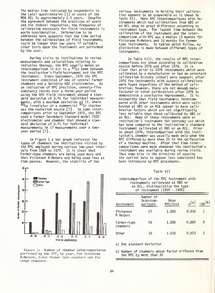
The median time indicated by respondents to
the Lanzl questionnaire [1] or users of theMDA RCL is approximately 1.5 years. Despitethe agreement between the practices of usersand the federal regulation, the frequency ofcalibration necessary for field instruments is
worth consideration. Information to be
addressed here suggests that the time periodbetween the calibrations of field instrumentscould be longer than two years if suitableother tests upon the instrument are performedby the user.
During visits to institutions to reviewmeasurements and calculations relating to
radiation therapy, the RPC usually makes an
intercomparison in air in a °^Co beam betweenthe institution ' s field instrument and the RPCinstrument. Since September, 1970 the RPC
instrument consisted of one of several Farmerchambers and a Keithley 602 electrometer. As
an indication of RPC precision, seventy-fiveconstancy checks over a three-year periodusing the RPC field instrument showed a stan-dard deviation of 0.4% for individual measure-ments, with a maximum deviation of 1%, where°°Co irradiator or a commercial 9 Sr checkerwas the radiation source [7] . In some inter-comparisons prior to September 1970, the RPC
used a Farmer Secondary Standard model 2502electrometer and chamber that showed a stan-dard deviation of 0.7% for individualmeasurements in 17 measurements over a two-
year period [7] .
In Figure 1 a bar graph indicates thetypes of chambers the institutions visited bythe RPC employed during various two-year inter-vals from 1968 to 1979. It is clear thatFarmer-type chambers are being used more andthat Victoreen R-Meters are being used less astime passes. However, the stability of the
various instruments in holding their calibra-tion appears to be comparable as is shown in
Table VII. Here RPC intercomparisons with in-struments which had calibrations from NBS oran RCL show no great difference according toinstrument type. The lapsed time between thecalibration of the instrument and the inter-comparison with RPC was a median 13 months forVictoreen R-Meters and 10 months for Farmertype instruments. In tables whicn follow, nodistinction is made between different types ofinstruments.
In Table VIII, the results of RPC inter-comparisons are shown according to calibrationsource before 1976 and after 1976. It is
clear that prior to 1976 instruments which werecalibrated by a manufacturer or had an uncertaincalibration history (other) were suspect; after1976 few instruments with suspect calibrationswere found regardless of the method of cali-bration; however, there are not enough manu-facturer or other calibrations after 1976 to
demonstrate a conclusive improvement. It is
noteworthy that field instruments intercom-pared with other instruments which were cali-brated at NBS or an RCL appear to have cali-bration factors which are not significantlyless reliable than those calibrated by NBS oran RCL. Many of these instruments were an
institution's instrument for everyday use whichhas been compared to the institution's standardinstrument calibrated at NBS or an RCL. Priorto about 1976, intercomparison with the insti-tution's chamber was usually made only when theRPC differed by more than 2% in the calibrationof a therapy machine. After that time inter-comparisons were made whenever the institution'sinstrument was available during review visits.Thus some bias in the direction of causingthe earlier data to appear less consistent has
been introduced by RPC procedures.
HS Victoreen
Farmer Type
Other
n n I in In70 71 72 73 74 75
YEAR OF COMPARISON
76 77 78 79
Figure 1: Number of chamber intercomparisonsperformed by the RPC, by year, for VictoreenR-Meters, 0.6cc Farmer type chambers and forother chambers
.
Table VII
Intercomparison of the RPC instrument with
instruments calibrated at NBS or
an RCL, distinguishing the type
of instrument (1968 - 1980)
Instrument
VictoreenR Meters
Farmer-typechambers
Other
Number of
Intercom-parisons
57
56
10
MeanRPC/Inst
1.000
1.000
1.016
0.014
0.009 0
0.033
a) One standard deviation
b) Number of chambers whose factor differed fromthe RPC by more than 3%
84

Properly maintained therapy field instru-
ments appear to maintain their calibration
factors over long periods of time. The time
since instrument calibration does not seem to
play a role in the reliability of the chamber
calibration factor as seen in RPC intercom-
parisons in Table IX. These instruments were
calibrated at NBS or an RCL and thus started
with a calibration directly traceable to NBS.
Further data on long term stability of
instruments comes from the MDA RCL. Table X
shows data on 5 chambers which have been cali-
brated by MDA RCL 3 times or more since 1976.
The checks indicate the year of initial cali-
bration and the values are the ratio of the
calibration factor determined in subsequent
calibrations relative to that determined in theoriginal calibration. The maximum deviationseen in the calibrations was 0.3%.
Forty-two other chambers were calibratedtwice by MDA RCL since 1976. The time intervalbetween calibrations varied from one to threeyears. The results are shown in Figure 2. Themean ratio between the new and original cali-
Table IX
Interconparison of the RPC instrument withinstitution's instrument as a function
of the time since instrument was calibratedat NBS or an RCL
Table VIII
Intercomparison of the RPC instrumentwith institution's instruments
calibrated by various laboratories
CalibrationSource
Numberof
Intercom-parisons
MeanRPC/
Inst.,(a)
In&tfum&nti aaLibJuvteA b&{,oi& J 976
NBS
RCL
Compared to
chamber cali-brated at NBSor RCL
Chambermanufacturer
Jnttsuuntrvti aitibAate.d in 1976 on. tat&l
Other
NBS
RCL
Compared to
chamber cali-brated at NBSor RCL
ChamberManufacturer
Other
29
35
20
44
25
1.001
1.003
0.017
0.020
1.005 0.013
1.016
1.009
0.030
0.031
13
6
9
40
24
4
5
1.000
0.999
0.009
0.011
0.998 0.018
1.017
1.005
0.053
0.014
a) One standard deviation.
b) Number of instruments with calibration
factor differing from the RPC by more
than 3%
Time since Number ofcalibration Intercom- Mean
(months) parisons RPC/inst. ,(a)Number>3%
0 - 12 60 1.003 0.018 2
13 - 24 29 0.997 0.010 0
25 - 36 10 0.996 0.008 0
37 - 48 10 1.008 0.016 0
49 - 60 1 0.990 0
>60 3 0.993 0.021 0
a) One standard deviation.
b) Number of instruments with calibrationfactor differing from RPC by more than 3%.
Table X
Repeated Calibrations by MDA RCL(new calibration factor)/
(original calibration factor)
Dosimeter '76 '77 '78 '79 _80
K-F .999 999 .999 1 000
K-F / 1 000 0 999
K-F / 1 000 1 002
F / 0.999 1 002
Vict R 0 999 1 000
K-F - Farmer 0.6 cc graphite chamber withKeithley model 602 or 616 electrometer
F - Farmer 0.6 cc graphite chamber
Vict R - Victoreen model 131 chamber withmodel 570 electrometer
85

bration factors was 1.002 with a standarddeviation of 0.3%. A maximum deviation of 0.7%was seen in three chambers. There was no differ-ence between the results for Victoreen R-Metersand Farmer type instruments.
The MDA RCL data indicate that instrumentsare even more stable and reliable than indicatedby the RPC data above. These differences stemfrom several factors including: the RPC dataare from field intercomaprisons with field in-struments, the institution may be using the in-strument in a different manner from that em-ployed by the calibrating laboratory, or theinstrument may have been modified since cali-bration. Although the data indicate good longterm stability, there are two 0.6cc Farmerchambers (with nylon thimbles), belonging to
the authors, each of which have experiencedunexplained changes in calibration of 1 to 2%.
Discussion of the Time Between
Calibrations of Field Instruments
If NBS and each RCL presently in operation
were to calibrate 85 instruments per year, the
1057 instruments requiring calibration [1]
could on the average be calibrated every 3.1
years. If another RCL was activated the
average time between calibrations could be 2.5
years. However, there are a number of cali-
brations required following repair of instru-
ments or purchase of new instruments. The fact
that the average time between calibrations by
an institution at the MDA RCL is 1.5 years
suggests that some institutions or individuals
may be overly conscientious in calibration of
instruments while others allow longer periods
of time between calibrations of their instru-
ments.
From the instrument user's view, an instru-
ment calibration is essential if he feels uncer-
0 994 — mean = 1 002— a = 003
0 996 n = 42
0 998
1 000
1 002
1 004
1 .006
Frequency
Figure 2: Histogram of the ratio of the
calibration factor assigned by the MDA RCL on
a subsequent calibration, relative to that
assigned when the chamber had been previously-
calibrated by MDA RCL one to three years
earlier.
tain about his current calibration. However,if the user is confident of his instrumentcalibration, a recalibration according to a
time schedule is usually not welcome, sincethere is risk to the instrument in transportand the absence of the instrument may be a seri-
ous inconvenience. In addition, the cost ofcalibration is sometimes a problem.
Techniques Available to AssureReliability of Assigned
Calibration Factors-
Since therapy field instruments appear to
maintain their calibration factors over extend-ed periods of time, the instrument user can
maintain confidence in his instrument calibra-tion through periodic constancy checks. Grant,
et al . [7] discuss the use of a cobalt-60therapy unit or a strontium-90 constancy checksource device to perform routine checks on
the performance of the instrument. Both tech-
niques appear comparable. The 9 Sr data are
reproduced in Figure 3, showing all checks to
be within + 1% of the mean.
Another important constancy check pro-
cure is an intercomparison with instruments
from other institutions that have chambers
calibrated by NBS or an RCL. Table XI shows
the results of intercomparisons carried out in
conjunction with meetings of Southwest, Midwest
and Missouri Valley chapters of the AAPM
[8, 9, 10]. These intercomaprisons uncovered
erroneous factors on two chambers whose fac-
tors were from questionable sources, and
verified suspected problems with two RCL cali-
brated chambers. Periodic intercomparisons of
several chamber electrometer systems (last 5
lines of Table XI) again demonstrate the long
term stability of these dosimetry system.
It is important to remember that any
calibration laboratory can provide an erroneous
calibration factor and that instruments may
2cr = 0.8%
i.oi r
m
% 0 99
S098
100 200 300 400 500 600 TOO
Number of Days (1-18-73, Day I)
Figure 3: Constancy check of an RPC Farmer-
Keithley dosimetry system over a 21 month
period using a 9°Sr constancy check device.
From Grant et al . [7 ]
.
86

undergo change during transport. A physicistshould therefore challenge, in every waypossible, any calibration factor obtainedfrom NBS and an RCL. These challenges can
include; comparing the new factor with the oldfactor, a constancy check on the instrument be-
fore and after calibration, and intercomparisonwith other instruments calibrated at NBS or an
RCL.
Conclusions and Recommendations
The Regional Calibration Laboratoriesappear to be sucessfully filling an importantneed in the radiological community. The usersof therapy field instruments who respond to
Table XI
Intercomparison of Chambers witha Reference Chamber that had
been Recently Calibratedby NBS or an RCL< a )
Time Since Cal ibrationLast Factor
Cal ibration Type of Cal i bra ted Institution/(Months) Dosimeter by Reference
4038
36
34
31
25
21
18
15
7
1
1
?
?
4
14
20
19
33
F-KVict R
Vict R
CapVict R
F-KVict R
F-CapF-KVict R
CapF-KEG&G-KF-K
F-K
F-K
RCLRCL?
RCLRCLRCLRCLRCL
RCLRCLRCL
RCL?
Inter-comparison
Inter-comparison
Inter-comparison
1.0001.0011.0421.001
0.9810.9980.9960.9800.9930.9971.0030.9941.0270.994
0.9980.9981.0000.9940.993
(b)
(c)
(c)
(b)
id)
(d)
F-K, Farmer 0.6cc chamber with Keithleymodel 602 or 616 electrometer
Vict R; Victoreen model 621 or 131
chamber with model 570 electrometerCap; Capintec model 192 chamber with
model 192a electrometerEG&G; EG&G model 586 A chambera) Data from various regional chapters
of the AAPM [7,8,9].b) The chamber factor in use for these two
chambers was of unknown or questionableorigin.
c) Problem with the correction factor wassuspected by the institution.
d) The same institution on several
occasions.
questionnaires and have their instrumentscalibrated regularly have calibrations at amean interval of about 1.5 years. However, froman estimate of potential users and the currentcapacity of NBS and 3 RCLs it is suggested thatonly one calibration every three years would bepossible for each user if all of the instrumentswere calibrated at the same interval.
Data from various sources support theconclusion that commerical field instrumentsare capable of maintaining their calibrationsfor many years. It is suggested here that therebe a reconsideration of the time interval be-tween calibration required by federal or statepolicy. If a user who has a calibration factordirectly traceable to NBS verifies the constancyof this instrument monthly by measurements ona cobalt-60 irradiator or strontium-90 constancychecker and if he verifies the instrument con-stancy at least every two years by an intercom-parison with other instruments with calibrationsdirectly traceable to NBS, it should be possibleto space calibrations at NBS or an RCL to peri-ods of 3 to 5 years. The user would always usethe factor assigned by NBS or an RCL and employthe monthly constancy checks and biennial inter-comparison checks as indications for recalibra-tion of his instrument when consistent discrep-ancies of 2% are found in the checks. Thissuggestion seems warranted by the performancecharacteristics of the available instrumentsif coupled with reliable checks and adequatedocumentation.
[1]
[2]
[3]
[4]
[5]
[6]
References
Lanzl , L. H. (Principal Investigator) Reportof the Committee on Calibration Needs in
Therapy of the American Association ofPhysicists in Medicine, Chicago, Illinois(1979).
Rosenfeld, M. (Chairman), Task Group #3of the American Association of Physicistsin Medicine. It has been recommended that
the regional laboratories be renamed,Accredited Dosimetry Calibration Laboratory(ADCL), but the AAPM has not as yet approv-ed the name change.
McCarthy, W. A., Chairman of Subcommitteeof Task Group #3 of the American Associationof Physicists in Medicine. Report in draft(private communication).
Scientific Committee on Radiation Dosimetry(SCRAD) of the American Association ofPhysicists in Medicine. "Protocol for theDosimetry of X- and Gamma Ray Beams withMaximum Energies between 0.6 and 50 MeV."Phys Med Biol 16 (1971): 379-396.
Loevinger R., NBS, Private Communication.
Federal Register 44, 5, 1722-1725, (Janaury8, 1975).
87

^ Grant III, W. , Cundiff, J., Hanson, W.,
Gagnon, W., and Shalek, R., CalibrationInstrumentation used by the AAPM Radiolog-ical Physics Center. Med Phys 3, p. 353-4,
(1976).
^ Southwest chapter of AAPM (Humphries, L. J.)
unpublished data.
^ Missouri Valley chapter of AAPM (Purdy J. A.,
and Feldman, A.) unpublished data.
^ 10^Midwest chapter of AAPM (Hrejsa, A. F.)
unpublished data.
This work supported in part by DHEW NCI
grant CA 10953.
88

NBS TRACEABILITY PROGRAMS FOR RADIATION THERAPY
Christopher G. Soares and Margarete EhrlichNational Bureau of Standards
Washington, D.C. 20234
Traceability of the calibration of radiation therapy machines to the national
dosimetry standard may be verified by means of a measurement assurance program.Such a program often involves the use of rugged dosimetry systems for estab-lishing a direct link between the user and the primary calibration laboratorywithout personal visits. In this paper, procedures common to this type oftherapy dosimetry survey systems are discussed. Then, to illustrate these pro-
cedures, three of these systems are treated in detail: (1) the ferrous sulfate(Fricke) dosimetry system used at NBS in an ongoing survey of electron-therapydosimetry, (2) a TLD system that was used by NBS in a one-time study ofcobalt-60 teletherapy dosimetry, and (3) a second TLD system proposed for sur-
veying megavoltage bremsstrahlung therapy dosimetry.
(Cobalt-60 gamma radiation; dosimetry; ferrous sulfate dosimetry; high-energybremsstrahlung; high-energy electrons; measurement assurance; radiation therapy;
survey; teletherapy; thermoluminescence dosimetry; traceability)
Introduction
Users of teletherapy equipment rely on a
calibration chain for an assessment of the radi-ation output from their units. The steps in thischain involve calibration of a secondary standardinstrument against a primary standard and then a
measurement of the therapy beam output eitherwith this secondary standard or with a tertiaryinstrument calibrated against the secondary stan-dard. It is the aim of NBS measurement assuranceprograms to test this chain by a direct compari-son between the primary standards laboratory andthe user, with a suitable detector. Such a com-parison may be carried out initially by means ofshipped dosimetry systems sufficiently rugged andcompact to withstand rough handling and variationsin ambient conditions likely to be encounteredduring shipment. Subsequent follow-ups throughpersonal contacts may be required.
All surveys involving shipped dosimetershave certain features in common in their concep-tion and execution. First, a survey objectivemust be stated, defining what is to be measuredand to what accuracy. Then an administrativeprocedure for obtaining participants and report-ing results must be set up. In developing themechanism for the survey, an irradiation protocolmust be decided upon and its feasibility tested.Along with this goes the selection of a suitabledosimeter. Handling and readout procedures forthe dosimeter must be developed and tested, andsome information about the accuracy of dose deter-mination must be gathered. Once these preliminarysteps have been completed, the survey can beperformed.
In actual practice, each round of a typicalsurvey (such as those described here) containsthree distinct phases. They are (a) a dosimetercharacterization phase, in which the relative
response of all dosimeters is determined prior to
shipment; (b) shipment in suitable irradiationholders of the dosimeters required by the survey
participants, and calibration of the remaining
dosimeters in the surveying facility; and (c)
after return of the shipped dosimeters, readoutof all dosimeters in one session and evaluation,from the dosimeter responses, of doses deliveredby the participants. Each of these phases is
discussed in greater detail below.
(a) Dosimeter Characterization Phase
Dosimeters may be characterized by their
response to a known irradiation level. If, in a
given batch, dosimeter identity is maintained,
this response may be used to correct for vari-ations in the response characteristics of indi-
vidual dosimeters during the survey. Thisprocedure may be referred to as individual
dosimeter characterization . If, on the otherhand, dosimeter identity is not maintained, the
batch of dosimeters may be characterized by the
mean and the standard deviation from the mean of
the responses of the members of the batch. This
procedure may be referred to as batch characteri-zation . The way in which dosimeters are charac-terized determines overall uncertainty in doseinterpretation. Batch characterization is suf-
ficient when dosimeters have similar responsecharacteristics. However, when the spread in
response among the dosimeters within the batch is
comparable to or larger than the reproducibilityof the response of individual dosimeters in thebatch, then the increased effort involved in
maintaining dosimeter identity and using indi-
vidual characterizations often pays off in
increased accuracy. Examples are discussed in
a later section.
89

(b) Dosimeter Shipping and Calibration Phase
Participants are shipped dosimeters each con-
sisting of a passive radiation measuring device in
a holder of a material with atomic number close to
water (and soft tissue). They are also giveninstructions for the irradiation of these dosi-
meters in their therapy beams. A portion of thecharacterized dosimeters remain in the surveyingfacility for calibration during the survey round.This calibration consists of delivering known
absorbed doses to individual dosimeters in a
geometry identical to that to be used by the par-
ticipants. A sufficient number of differentabsorbed-dose levels are used to establish a cali-bration curve over the range of doses likely to
be delivered by the participants. This calibra-tion curve forms the basis for the dose inter-
pretation from the response of the dosimetersirradiated by the participants.
(c) Dosimeter Readout and Dose Evaluation Phase
When dosimeters have been returned to the
surveying facility, they are "read out" along withthe dosimeters that remained for calibration
(i.e., the radiation effect is measured). Readoutof all dosimeters at the same time is importantsince it eliminates corrections for possible day-to-day variations in readout apparatus. Doseinterpretations may then be made from dosimeterresponses via the calibration curve, if neces-sary after appropriate corrections.
This completes a single survey round. If thesurvey consists of several rounds and the same
dosimeters are to be used throughout, recharac-terization of the dosimeters may be requiredbetween consecutive rounds.
To illustrate how these procedures work in
practice, traceability surveys with three typesof mailable dosimeters are discussed in thefollowing sections. First, the NBS ferrous sul-fate (Fricke) dosimetry service of megavoltageelectron therapy dosimetry is discussed in detail
Next, a one-time thermoluminescence dosimetry(TLD) traceability survey of cobalt-60 tele-
therapy dosimetry is discussed and finally, a
second TLD system is described which has been
tested for use in a proposed traceability sur-
vey of megavoltage bremsstrahlung dosimetry.
Megavoltage-Electron Dosimetry Traceability
The ferrous sulfate (Fricke) system is usedin an ongoing NBS service to provide users withassistance with absorbed-dose measurements in
high-energy electron beams. This is a fee ser-
vice, performed twice a year. It is not meantto take the place of a beam calibration, but is
only to provide information on uniformity of dosedelivery throughout the country.
Procedure
Megavoltage electron beam users contact NBSif they wish to receive dosimeters for the nextsurvey round. Fresh dosimeter solution is pre-
pared for each survey round and each dosimeter ischaracterized individually. The desired number ofdosimeters is shipped to the participants alongwith a shipping control and the rest kept at NBSas in-house controls. Most dosimeters arereturned within the next six weeks. All dosi-meters are then read out together and dose inter-pretations are made. Results for all dosimetersshipped and irradiated by the participants in oneround are reported to each participant, with onlyhis own identified.
The sensitive volume of the dosimeter is2.5 cm 3 of Fricke solution. This is contained ina ground-glass stoppered quartz spectrophotometercell, encased securely in a polystyrene block asshown in figure 1. The participants are in-structed to insert this block into an appropriatecutout in a 30 cm x 30 cm x 30 cm polystyrenephantom as prescribed in the Protocol of theTherapy Committee of the American Association ofPhysicists in Medicine II]. The center of theblock is to be at the center of a 10 cm x 10 cmfield, at a depth in the phantom at or slightlybeyond that corresponding to maximum depth dose.(The prescribed depth is 1 cm for electrons ofenergy between 5 and 10 MeV, 1.5 cm for electronsbetween 10 and 25 MeV, and 3.5 cm for electronsbetween 25 and 50 MeV.) The participants arefurther instructed to deliver 50-80 Gy (5000-8000 rad) to water to all but one of the dosi-meter blocks and then to return all blocks toNBS, along with their assessment of dosedelivered. The change in ferric- ion concentra-tion in the returned dosimeter solution isevaluated spectrophotometrical ly and related toabsorbed dose. The report mailed to each parti-cipant includes a record of the G-value used inthe dose interpretation.
Figure 1 Ferrous Sulfate (Fricke) DosimeterAssembly
Principle of Fricke Dosimetry
The radiation-chemical yield, or G-value(defined as the number of stable atoms or ionsformed per 100 eV of absorbed energy), is one ofthe quantities of fundamental importance in theuse of the ferrous sulfate (Fricke) dosimeter.For the ferrous-ferric reaction initiated byirradiation, G(Fe+++ ) = 100 n/D, where n is the
90

number of Fe+++ ions formed in a unit mass and D
is the radiation energy in eV absorbed in thesame unit mass. When expressed in terms ofmolar concentration M (in moles per liter) andabsorbed dose D (in grays), this becomes
G(Fe+++
) = 0.9426 x 10⁷
JJ(1)
when the density of the Fricke solution is setequal to 1.024 g/cm3
. The radiation chemistryof the Fricke system has been studied in detailand the G-value of the reactions leading to theoxidation of the ferrous ions has been deter-mined over a relatively wide range of linearenergy transfers I2J.
Since the change in ferric- ion concentra-tion causes a marked change in the ultravioletabsorption spectrum of the Fricke solution, a
chemical evaluation of this change may bereplaced by a simple spectrophotometricmeasurement of the change in the absorption pro-perties in the main absorption peak (304 nm).
Absorbance, A (which is the transmission densitycorrected for losses through scattering in theoptics of the spectrophotometer), is related tothe molar concentration, M, by Beer's law
A = e M d (2)
where d is the optical path length, and e themolar extinction coefficient.
Combining equations (1) and (2) yields
D = 0.9426 x 10⁷
(3)
Ae G(Fe ) d
where AA is the change in absorbance before andafter irradiation to an absorbed dose D andAe = e(Fe+++ ) - e(Fe++ ). When the measurementis made at the conventional wavelength of304 nm, e(Fe++ ) = 0 and, as a consequence,Ae « e(Fe*++ ).
Rather than to rely on the theoretical valuefor the molar extinction coefficient, it is goodpractice to measure this coefficient for one'sown spectrophotometer, using Fe+++ solutions of *a number of different known molar concentrations.Temperature control during optical densitymeasurements is important since the extinctioncoefficient has a temperature dependence of^.7 percent per °C [3].
Dosimeter Preparation
The Fricke solution used at NBS consists of
0.001 M Fe(NH lt ) 2 (S0 4 ) 2 , dissolved in
0.8 N H 2S0 k , well aerated, and
0.001 N NaCl.
Having recently replaced our spectrophotometerwith a new model, we made this measurement in
our new instrument and obtained a value of2188 M-1 cm-1 at 25.0°C, which agrees well withthe theoretical value of 2197 M_1 cm-1 .
The NaCl is added to desensitize the systemagainst organic impurities. Because the addi-tion of NaCl causes an increase in the ratedependence of the G-value, we recommend that theparticipants do not exceed instantaneous doserates of 103 Gy/s. Irradiation of this solutionproduces free radicals and molecular productswhich cause oxidation of Fe++ to Fe+++ . Spon-taneous oxidation also occurs at room temperatureeven in the absence of organic impurities. Thismust be taken into account when there are delaysof more than two or three days between the ini-tial dosimeter readout during the characteriza-tion phase and the final dosimeter readout, asis usually the case in a mailed survey.
Cleanliness of glassware used in preparingand storing the solution is of great importance.
Organic contaminants cause massive spontaneousoxidation of stored solution rendering it useless
for dosimetry. At NBS the spectrophotometer cellswere initially cleaned with detergent in an ultra-
sonic cleaner and since then have been kept filledwith Fricke solution. Other glassware was ini-
tially cleaned with hot concentrated sulfuric acidand since then has been kept filled with either
Fricke solution or distilled water. No plasticsare ever allowed in contact with the Fricke solu-
tion.
The purity of the water used both in cleaningand making the Fricke solution is crucial to the
performance of the system, freedom from organicimpurities being one of the main requirements.Satisfactory water has been obtained at NBS bypermanganate distillation [4]. Over the years,NBS has also had a number of satisfactory com-mercial sources for water.
Dosimeter Characterization
The cleaned and filled cells are all irra-diated with cobalt-60 gamma radiation to a level
of ^50 Gy to water and read out spectrophoto-metrically. These readings characterize eachindividual dosimeter in the batch and furnish thebase line from which changes in optical densitydue to irradiation are measured, as well as thebase line from which corrections for the spon-
taneous growth of optical density are determined.The procedure also identifies dosimeters withanomalous characteristics, which then are elimi-nated from further use; it also provides for a
rough check on the G-value of the particularFricke batch for cobalt-60 gamma radiation, cal-
culated from the average of the optical densi-ties of the irradiated cells and a knowledge of
the dose delivered. No further calibration is
performed.
Dosimeter Evaluation
The returned dosimeters are read out togetherand the change in optical density is determinedfor each dosimeter. Correction of the readingsof the irradiated dosimeters for spontaneousdensity growth is made by subtracting the averagedensity growth of all unirradiated control dosi-meters (shipped and unshipped). Since growthvaries somewhat with individual dosimeters, thisprocedure adds an additional uncertainty to the
91

dose interpretations, which in our procedureamounts to about 1 percent. Finally, the dosedelivered to the dosimeters is determined fromthe corrected change in optical density by
eq (3) using the molar extinction coefficientmeasured for the spectrophotometer employed, andpublished G-values.*
Uncertainty
We estimate that the total uncertainty indose interpretation in the NBS survey procedure isabout 4 percent. We feel that this uncertaintycould be reduced by using a sealed Fricke dosi-metry system instead of the present open system.We are presently attempting to adapt such a systemto our program.
Results
Overall performance of the participants didnot improve noticeably between 1967, when the ser-vice was initiated, and 1975. Table 1 shows that,through 1975, only 58 percent of the dose inter-pretations were within 5 percent of the doseassigned by participants. In the last four years,this fraction is seen to have risen to 73 percent.This improvement has been accompanied by a largeincrease in the number of dosimeters shipped,which indicates an increased awareness in theradiation-therapy community of the importance ofaccurate dosimetry.
Table 1
Performance Results of All Participantsin Electron Beam Dosimetry Uniformity Study
Calendar Year Number ofDosimeters |&| < 5%
Number of Dosimeters withDifference A of
5% < |A| x< 10% |4| > 10%
1967 50 33 (66%) 14 (28%) 3 (6%)
1968 81 39 (48%) 24 (30%) 18 (22%)
1969 65 25 (45%) 16 (29%) 14 (25%)
147(1 61 34 (56%) 12 (20%) 15 (25%)
1971 58 30 (52%) 13 (22%) 15 (26%)
1972 47 35 (74%) 5 (11%) 7 (15%)
1973 60 38 (63%) 9 (15%) 13 (22%)
1974 49 38 (78%) 6 (12%) 5 (10%)
1975 74 38 (51%) 24 (32%) 12 (16%)
1976 99 76 (77%) 19 (19%) 4 (4%)
1977 109 77 (71%) 21 (19%) 11 (10%)
1978 142 107 (75%) 25 (18%) 10 (7%)
1979 148 103 (70%) 29 (20%) 16 (11%)
Cobalt- 60 Teletherapy Dosimetry Traceability
The major objective of the cobalt-60 tele-therapy survey was to assess the ability of usersto deliver a requested absorbed dose. This wasaccomplished- by a survey of teletherapy dosimetry,conducted by the National Bureau of Standards(NBS), supported in part by the Bureau of Radio-logical Health (BRH). Similar studies have been(and are being) performed, elsewhere I5-8J.
Presently, we are using a G-value of 15.5/100 eVfor both cobalt-60 gamma and high-energy electronirradiations.
Procedure
Names and addresses of licensees were sup-plied to NBS by BRH, and each licensee was sent aninvitation to participate free of charge. If
there was no response, a single follow-up invita-tion was sent. In this way, over 700 or abouttwo- thirds of all licensed users agreed to parti-cipate in the survey.
Because of limited facilities, NBS could onlysurvey about 40 participants at a time, which madedosimeter re-use mandatory. Dosimeters wereshipped every six weeks, being kept at NBS forreadout and re-characterization only one weekbetween mailings. Also shipped with the dosi-meters was a three-page information form, whichasked for calibration details of the unit surveyedand for steps in the calculation of the dose to be
delivered. This information was used by NBS to
check the participants' dose calculations. The
results of this check as well as the dose inter-pretations from the response of the irradiateddosimeters were sent to participants in a reportcovering all dosimeters involved in each mailing.All results were kept confidential; the partici-pant to whom the report was sent had only his own
dosimeters identified. Results and informationfrom returned forms, which were given to BRHwithout participant identification, formed the
data base for a later BRH statistical study £9].
Each participant was sent six dosimeterblocks. Five were to be irradiated in separateexposures, the sixth was to be left unirradiatedas a control. The participants were to place one
block at a time on the shipping container andposition the center of the block at their normal
treatment distance, with a 10 cm x 10 cm fieldsize. They were to calculate the time necessary
to deliver 3 Gy to water at this distance, at a
depth of 1 cm in a water phantom, and then to
irradiate the block in air for the calculatedtime. Setups and irradiations were to be per-
formed by persons routinely involved in patientirradiations.
Choice of Dosimeters
Several considerations went into the choice
of the type of dosimeter for use in this survey.
The necessity for dosimeter re-use with minimalre-calibration, the limited manpower available for
performing the work at NBS, and the need to re-
strict overall uncertainty in dose interpretationto less than 5 percent, all pointed towards the
use of thermoluminescence dosimetry (TLD) for the
survey. CaF2:Mn was chosen as the TL phosphorbecause of the relatively small dependence of its
response on annealing and irradiation history.Also, because all irradiations were to be
performed with cobalt-60 gamma rays, one could
ignore the energy dependence of its response
which is large compared with that of other com-
monly used but otherwise less desirable phosphors
(such as LiF and U2B14O7). Normal handling dif-
ficulties involved in TLD work were overcome by
obtaining the TLD phosphor in a commerciallyavailable configuration in which two pieces of
hot- pressed CaF2:Mn, held in contact with a me-
tallic heating strip, are sealed in a glass bulb
92

containing a neutral atmosphere. Each dosimeter
consisted of the commercial TLD bulb enclosed in
a black polystyrene block. The block protected
the bulb during shipment and participant han-
dling, shielded it from ultraviolet radiation,
and provided electron equilibrium during cobalt-60
gamma irradiation. An exploded view of the dosi-
meter is shown in figure 2.
The TLD readout system consisted of a com-
mercial unit in which the metallic strip of the
TLD bulb was heated resistively, and the resulting
thermoluminescence emission was collected by a
cooled photomultiplier tube (PMT). The current
signal from the PMT was fed to a current integra-
tor, which was gated by a timer to allow cutoff
of integration after readout was complete, but
prior to emission of the thermal signal generated
during subsequent annealing. On completion of
the readout, the integrated signal was punched
on paper tape for off-line analysis.
Figure 2
Principle
Schematic Diagram of Bulb DosimeterAssembly
The crystal lattice of some solids--in par-ticular those containing certain impurity cen-
ters—are capable of storing radiation energy and,upon subsequent heating, releasing it in the formof light or ultraviolet radiation. This phe-nomenon is referred to as thermoluminescence (TL).
In many phosphors, TL output increases monotoni-cally--and over a limited range essentially1 inearily--with the amount of radiation energystored, prior to the onset of saturation effects.This is one of the major prerequisites for theapplication of TL in radiation dosimetry. Inten-
sive research and development over the pastdecades has led to a number of TLD phosphorssuited for the practical dosimetry of electrons,photons, and neutrons over a wide range of radi-
ation energies and irradiation levels, a subjectthat has been extensively treated in the litera-ture £10].
Repeated use of most TL phosphors requiressome form of heat treatment (annealing) afterreadout, particularly at dose levels above a fewhundredths of one gray. Insufficient annealingcauses accumulation of unwanted residual re-sponse in subsequent readouts. This is a prob-lem particularly when a low dose is used in thelaboratory to characterize the dosimeter responseand then a high dose is delivsred in the field.For this survey, in which CaF 2 :Mn was used up
to dose levels of about 3.0 Gy, it was found to
be sufficient to anneal the TLD bulbs in the
reader for a few seconds after readout. Thetemperatures developed during this procedurewere found to reduce residuals sufficiently to
necessitate only minor corrections (discussedbelow)
.
Characterization
Dosimeter identity was maintained throughoutthe entire survey, permitting the characteriza-tion of the response of each individual TLD bulb.Initially, a base-line characterization wasobtained in terms of the average response of eachbulb to identical reference irradiations (3 - 5 R)
and subsequent readouts. This also yielded theinformation on the reproducibility of the TLDsystem required for an estimate of the uncer-tainty in the dose interpretation from the re-sponse to irradiations by the participants. Sincesome residual response had been found to bepresent after irradiation at the 3.0-Gy leveland subsequent readout with annealing, all bulbswere read out twice after each mailing (the secondreadout five days after the first) to establishthe level of the residual response. This proce-dure was followed by two further sets of identicalreference irradiations and readouts. The averagerelative response of the bulbs to these irradi-ations, suitably adjusted for residual response,was used as a correction in the computation ofthe dose interpretations from the response of eachof the dosimeters irradiated in the preceding sur-vey round. Throughout the survey, a record waskept of any change in the bulb characterizationfrom the initial base line.
Mailing and Calibration
All but about 40 of the 300 bulb dosimeterswere mailed to participants for irradiation. Theremainder were used at NBS for establishing thecurrent response-versus-dose relationship, andto monitor fading characteristics of the batch.
Initially, the calibration was done atseveral levels around 3.0 Gy, and a second orderpolynomial was fitted to the individually cor-rected responses. Dose interpretations were thenmade via this curve. In later rounds of the sur-vey, calibration was done only at the 3.0-Gylevel, since in the narrow range in which most ofthe bulbs were irradiated (within ±10% of 3.0 Gy),response was proportional to dose.
In order to be able to correct for fadingbetween irradiation and readout, dosimeters alsowere irradiated at a known level at several dif-ferent times during each survey round, and readout with the other dosimeters at the end of theround. Also, a record was kept of the partici-pants' irradiation dates. With a knowledge ofthese dates and of response as a function of fad-ing time, we were able to correct the dose inter-pretations for fading. The fading functionreproduced well over the entire survey, withtypical corrections for four weeks of fadinghaving been of the order of 5 percent.
93

Readout and Evaluation
After readout, corrections were applied for
variations in individual response and for fadingof the response between irradiation and readout.
Because of changes in PMT response during the two
to three hours required for readout of the 300
dosimeter bulbs (probably caused by insufficient
PMT cooling), a further correction, amounting to
up to 2 percent, was necessary.
Dose interpretations were made from the cor-
rected readings via the results of the similarly
corrected calibration data (response- versus-NBSdelivered dose relationship). Establishing a new
calibration for each survey round made it possible
to eliminate the influence of reader variations
and changes in dosimeter response.
Uncertainty
Sources of uncertainty in the dose interpre-tation are shown in table 2. The systematicuncertainties shown are estimated upper bounds.The random uncertainties are taken as three timesthe relative standard deviation of the mean ofdosimeter readings after repeated irradiations andreadouts. This table is discussed in detail in
the comprehensive report on this survey publishedelsewhere 111]. We feel that the quoted overalluncertainty of 4 percent is probably conserva-tively high.
Uncertainties in NBS Method of DeterminingAbsorbed Dose from Dosimeter Response
Systematic Uncertainty
NBS exposure calibration of Co-60 gamma-ray source 0.7%
Uncertainty in dosimeter calibration 0.7%
Uncertainty in dosimeter fading correction 1.0%
*Total (summed linearly) 2.4%
Total (summed in quadrature) 1.4%
Random Uncertainty
Reproducibility of individual dosimeter response .... 2.4%
Correction for sensitivity variation between dosimeters 2.4%
Total for corrected individual dosimeter response 3.4%
Total for average corrected response of five
dosimeters (summed in quadrature) 1 .5%
Total uncertainty in dose interpretation from average of
five dosimeters (summed linearly) ^.0%
(summed in quadrature) 2.8%
Chosen for NBS evaluation
Results
The overall results of the survey are shown
in figure 3. Plotted are percent differencesbetween individual dose interpretations and the
dose to be delivered (3.0 Gy). Eighty- threepercent of the dose interpretations were within
-20 -10 0 10 20
PERCENT DIFFERENCE FROM DOSE TO BE DELIVERED
Figure 3 Performance of Participants Involvedin the Cobalt-60 Teletherapy Survey.Shown is the difference, in percent,between the dose to be delivered bythe participants and the NBS dose in-
terpretation from the average of theresponses of the five irradiateddosimeters. Total number of partici-pants: 812; total number of sets:
906.
5 percent of the requested dose, with only 4 per-cent differing by more than 10 percent. From the
figure it is apparent that there is a positivebias in the data, the average deviation for all
dosimeters shown being +0.7 percent. This couldbe significant, and has been explained by the factthat most participants used the conversion factorfrom exposure to absorbed dose to soft tissue
(0.957) rather than that to water (0.965), whichwas used in the NBS dosimeter calibrations.
Follow-up
Two follow-up studies were performed as sta-
tistical checks on the results of the initialstudy. The first of these studies involved resur-veying a random sample (about one-fifth) of theoriginal participants. The second involved a sur-
vey of a random sample (about one-tenth) of theinitial non-participants. The results of thesefollow-up studies, while of limited statisticalvalidity, tended to confirm the results of the
initial study.
Preparations for a Survey of High-EnergyBremsstrahlung Therapy Dosimetry
There has long been interest in extending thesurvey of therapy dosimetry to include megavoltagebremsstrahlung. Because of the much wider vari-ation in spectral quality of these bremsstrahlung
sources as compared to cobalt-60 gamma-raysources, energy dependence of the dosimeter
response becomes an important consideration.Therefore it was felt that a different systemthan that used in the cobalt-60 teletherapy-dosimetry survey would have to be developed.
94

Procedure, Choice of Dosimeters and Irradiation
Protocol
This study will be carried out by BRH.
While the administrative procedure for this
survey has yet to be worked out by BRH, an
irradiation protocol has been developed and its
feasibility tested by NBS at some length I12J.At this time, it is envisioned that participants
will be sent a cubic polymethyl methacrylate(PMMA) phantom with sides 20 cm in length,
loaded at several depths with hot- pressed LiFsamples. The participants will be asked to
deliver a certain dose (1.0 Gy) to water at a
10- cm depth, treating the phantom for dose
calculation as if it were water. This procedurewill provide information on accuracy of dose
delivery and may also yield some informationobtained with the aid of TLD response at the
different depths.
The response of LiF has a relatively low
energy dependence; this makes LiF desirable for
a survey involving wide spectral variations.
Advances in reader technology have overcomedifficulties once encountered with this phos-
phor, such as spurious readings. For use in the
medical dose range (> 0.1 Gy), furnace annealingwas required with the chosen reader. We inves-
tigated this system using the conventional
annealing cycle of one hour at 400°C, coolingfor one-half hour, followed by one hour at
100°C. In addition, all samples were given a
post-irradiation anneal at 100°C for 10 minutesprior to readout. They were never exposed todirect sunlight or other sources of illuminationcontaining a large ultraviolet component. A
vacuum pickup was used for all sample mani-
pulations. For readout, an automated reader wasemployed, in which the samples are heated by hot
nitrogen and which allows the readout of 50
samples in rapid sequence. The readout signalswere fed directly into a microcomputer systemfor storage and later retrieval for off-lineanalysis.
Several investigations were carried out toassess the feasibility of such a system usingthe protocol described. Fading under laboratoryconditions was found to be almost negligible,with only about 2 percent being evident over a
period of three weeks. Also investigated wasthe influence of phantom dimensions upon dosi-meter response at the depth of interest. Sev-eral phantom sizes and shapes from 15 cm 3 to 20cm3 were investigated, and no significant effectwas measured. The influence on the response ofsamples at a 10-cm depth in the presence ofsamples located on the axis above and below thisdepth was investigated as a function of phantomsize and beam energy. The results of theseinvestigations are shown in table 3. Responseof dosimeters at a depth of 10 cm in the pre-sence or absence of dosimeters at other depthsis compared. There is a trend towards slightlyreduced responses in the presence of otherdosimeters, however its significance is question-able. In view of these results it was concludedthat it was feasible to irradiate dosimeters atmore than one depth simultaneously.
BRH plans to have the first phase of thesurvey include sources of up to 10 MeV in
photon energy. We therefore made measurementsof the response of LiF as a function of absorbeddose with bremsstrahlung produced at excitingpotentials of 4, 6, and 10 MV as well as withcobalt-60 gamma radiation. Dose-versus-responsedata from this determination are shown in figure4. The samples show the same degree of supra-linearity, regardless of energy. Of particularinterest is a comparison of response for dif-
Table 3. Influence on Dosimeter Response of the Presence of Dosimeters 1n Other Depths
AVERAGE DOSIMETER RESPONSE FOR DOSIMETERS AT A 10-cm DEPTH IN
TYPEOF
RADIATION
Cube, 15 cm sides, with dosimeters at Cube, 20 cm sides with dosimeters at Paral leleplped,15 cm x 15 cm x
with dosimeters20 cm deepat
10-cm depth only 2.5-, 5- and 10-cmdepths
10-cm depth only 2.5-. 5-. 10- and15-cm depths
10-cm depthonly
2.5-, 5-, 10-
and 15-cmdepths
Cobalt-60
gamna rad.
0.581 ± 0.002 0.578 t 0.004 0.589 ± 0.003 0.588 t 0.004
4 MV bremsstr. 0.607 0.003 0.601 t 0.004
6 MV bremsstr. 0.552 i 0.003 0.552 t 0.003
10 MV bremsstr. 0.681 ± 0.003 0.680 i 0.004 0.685 i 0.004 0.683 * 0.005 0.683 ± 0.004 0.685 i 0.003
95

200ABSORBED DOSE . rod
Figure 4 LiF Response in PMMA as a Function of
Absorbed Dose. Dashed line - linear
relationship between response and ab-
sorbed dose.
ferent beam energies at one particular dose
level. The level used was 1 Gy, chosen because
higher levels induce residual TL signal which is
difficult to remove with conventional annealing
techniques. Table 4 shows measured values ofthe ratio of responses to 1 Gy irradiations ofhigh-energy bremsstrahlung and cobalt-60 gammaradiation. As is seen from the table, the ratio
is unity within the uncertainty of the determi-nation. Therefore, no correction for beam
energy (at least up to 10 MeV) will be required
in the survey. In addition, it will be possible
to perform calibrations during the mailing round
with cobalt-60 gamma rays, without any furthercorrections.
Finally, exposures were made to assess the
feasibility of measuring depth-dose profilesusing the planned irradiation geometry. Results
of these measurements are shown in figure 5.
Data were normalized to those at the 10-cm
depth, and are seen to be adequate—at least in
Table 4
Ratio of Dosimeter Response in PMMA to Megavoltage Bremsstrahlungand Dosimeter Response in PMMA to Cobalt-60 Gamma Rays,
for 1 Gy Absorbed Dose to Water
Radiation Source Nominal Peak Enerqy Ratio
Varian Clinac-4 4 MeV 0.991
Siemens Mevatron VI 6 MeV 1.001
Varian Clinac-18 10 MeV 0.979
Siemens Mevatron XII 10 MeV 1.000
principle--for distinguishing between the ener-gies employed.
Expected Uncertainty
The number of dosimeters to be included permeasurement point greatly influences the overalluncertainty in dose interpretation. Of impor-tance also is whether the dosimeters are cali-brated individually or as a batch. We havedetermined that associated with the response ofindividually calibrated dosimeters is a standarddeviation of about 1 percent, as compared witha practical lower limit of 1.5 percent asso-ciated with batch-calibrated dosimeters. Sincethe survey will be performed by BRH personnelusing large numbers of dosimeters, batch cali-bration probably will be used. In this case,nine dosimeters per measurement point lead to acombined random and systematic uncertainty ofabout 4 percent in dose interpretation £12].Individual calibration would lower this value byabout 1 percent.
Plans for Extension of Current Programs
Our future plans in therapy dosimetrytraceability include extensions of the proposedhigh-energy survey to bremsstrahlung energies upto 50 MeV. This will involve further phantom-size and energy-dependence studies.
We are presently involved in preliminarywork on devising a TLD system for use in a high-energy electron dosimetry survey. As a firststep, we are trying to determine whether a
system similar to that employed for the high-energy bremsstrahlung survey would be satis-factory or whether charge-up effects will makeit necessary to switch from a plastic to a waterphantom.
DEPTH , cm
Figure 5 Absorbed Dose to Water as a Functionof Depth in the PMMA Phantom, Computedfrom Dosimeter Response. The absorbeddose data were normalized to those ob-tained at a depth of 10 cm in PMMA(arrows)
.
96

References
[1]
[2]
[3]
[4]
[5]
[6]
The Subcommittee on Radiation Dosimetry ofthe AAPM (SCRAD), "Protocol for the Dosimetryof High Energy Electrons", Physics in Medicineand Biology 11_, 505 (1966).
See e.g., Fricke, H., and Hart, E.J., "Chemical
Dosimetry" in Radiation Dosimetry, Vol. II,
Attix, F.H., Roesch, W.C., editors, AcademicPress, New York (1966) or SCRAD Protocol(ref. 1) or "Radiation Dosimetry: Electronswith Initial Energies Between 1 and 50 MeV",I.C.R.U. Report 21, International Commissionon Radiation Units and Measurements, Washington,D.C. (1972).
Scharf, K., and Lee, R.M., "Investigations of
the Spectrophotometry Method of Measuringthe Ferric Ion Yield in the Ferrous SulfateDosimeter", Radiation Research 1J5, 115 (1962).
Chesler, S.N., Gump, B.H., Hertz, H.S.,
et al . , "Trace Hydrocarbon Analysis", p. 49,
Appendix A, NBS 889, U.S. Department ofCommerce, National Bureau of Standards (1976).
Shalek, R.J., Kennedy, P., et al., "QualityAssurance for Measurements in Therapy", Pro-ceedings of the Symposium on Measurements for
the Safe Use of Radiation, NBS SP 456, 111-118,U.S. Department of Commerce, National Bureauof Standards (1976).
Sundara Rao, I.S., Naik, S.B., et al., "Evalu-ation of Dosimetry Accuracy and Uniformityfor 60Co Radiation Therapy", Proceedings ofthe International Symposium on National and
International Standardization of RadiationDosimetry, Atlanta, Ga. (1977).
[7]
C8J
[9]
DO]
[11]
[12]
Eisenlohr, H.H., and Jayaraman, J., "IAEA-WHOCobalt-60 Teletherapy Dosimetry Service UsingMarked Dosimeters. A Survey of ResultsObtained during 1970-75", Phys. Med. Biol. 22,
18-28 (1977).
Dicey, B.B., Moe, H.J., and Tongue, T.M.,
"Nationwide Evaluation of 60Co TeletherapyCalibrations", Medical Physics 5, 434 (1978).
Thompson, D., Kearly, F., Wyckoff, H., and
GUI in, J., "Nationwide Survey of 60Co Tele-
therapy: Final Report", to be published as a
Bureau of Radiological Health Technical
Report.
See, e.g., Fowler, J.F., and Attix, F.H.,
"Solid State Integrating Dosimeters", in Radi-ation Dosimetry, Vol. II, Attix, F.H.,
Roesch, W.C., editors, Academic Press,New York Q966).
Soares, C.G., and Ehrlich, M., "Nationwide
Survey of Cobalt-60 Teletherapy Dosimetry",NBS TN 978, U.S. Department of Commerce,
National Bureau of Standards (1978).
Ehrlich, M., and Soares, C.G., "A Thermolumi-nescence Dosimetry System for Use in a Survey
of High-Energy Bremsstrahlung Dosimetry",NBS TN 1119, U.S. Department of Commerce,
National Bureau of Standards (1980).
97


TRACEABI L I TY PROGRAMS FOR NUCLEAR MEDICINE
D. B. GolasAtomic Industrial Forum, Inc.
Washington, D.C. 20014and
National Bureau of StandardsWashington, D.C. 20234
The National Bureau of Standards (NBS) supervises and administers two measurementsassurance programs: one on behalf of the Atomic Industrial Forum (AIF), re-
presenting several manufacturers of radiopharmaceuticals; and the other with the
College of American Pathologists (CAP), representing hospitals and final users of
radiopharmaceuticals. Each program is described and the results of measurementsof samples of known, but undisclosed, activity are presented.
(Assurance; measurements; radioactivity; radiopharmaceutical; standards; traceability)
Introduction
The National Bureau of Standards (NBS) currentlysupervises and administers two programs for measure-
ments assurance in the field of nuclear medicine.
The research-associate program of the AtomicIndustrial Forum (AIF) involves several of the majorbulk suppliers of radiochemicals and producers
of radiopharmaceuticals; the College of AmericanPathologists (CAP) quality assurance "Q" pro-
gram involves the hospitals and nuclear pharmacies
which comprise the users of radiopharmaceuticals.Together, these two programs encompass the radio-pharmaceutical spectrum from manufacture to use.
The programs are a help in satisfying the increasing
regulatory requirements to demonstrate traceability
to NBS, through the distribution of samples
(Standard Reference Materials) of known, but un-
disclosed, activity ("blinds") which are measuredby the participants. The comparison of the partici-pant's measured activity to that certified by NBS
is a measure of the competence of the participantto quantify an unknown amount of radioactivematerial accurately. In the case of the AIF research-
associate program, a Report of Measurement is thenissued which states the difference between the
participant's reported value and the NBS certi-
fied value, thereby establishing traceability towithin that limit, for that particular radionuclide,at that time. In the CAP program, a Report of
Calibration giving the NBS certified activity valueis sent to each participant upon return of theirresults, and when all values are in, a report is
issued which gives the results for the entire group
of participants. If a participant has a problemmeasuring the unknown, the activity value is usuallygiven by telephone, in advance of sending a certifi-
cate, so that the participant can make use of the
NBS reference material to derive a calibration factorfor his dose calibrator or other measuring system.
The AIF-NBS research-associate program is of
great value to the manufacturers of radiopharmaceu-ticals because it helps to minimize measurementuncertainty and demonstrate traceability to NBS.
This in turn reduces some of the problemsthey have in satisfying application require-ments when filing New Drug Applicationswith the Food and Drug Administration (FDA),
as well as saving time and paperwork whencomplying with requirements of the NuclearRegulatory Commission (NRC) and other Federal and
State agencies. Participation in the program alsohelps the participants when questions arise be-
tween the companies and their customers. For ex-
ample, when the quantity of radioactive material
measured by the customer does not agree with that
of the supplier, the supplier often uses resultsof measurement tests to defend its value.
The CAP "Q" program is valuable to the usersof radiopharmaceuticals because it enables themto determine if the calibration of their dose cali-brator or other measuring system is correct foreach radionuclide that they receive. In additionthey can obtain help if they have problems in themeasurement of these radioactive materials. The CAP
program is limited, however, by the number of par-ticipants who receive the samples for measurement.This will become more apparent later, when thisprogram is described in detail.
AIF-NBS Standards Program for the Radio-Pharmaceutical Industry
The AIF-NBS radioactivity measurements-assur-ance program evolved in response to a number ofproblems facing the commercial suppliers of radio-nuclides. In 1973, Seidel and Brantley [1] de-scribed some of these problems: lack of standardreference materials for about 75 percent of themore than 100 radionuclides commercially producedat that time, the sometimes inconvenient physical
form, and the insufficient activity levels of someof the standards that were available. Anotherreason, important economically, was that one
company's activity differed from that of anotherdue to the use of different decay-scheme para-meters. After several pilot distributions begun in
1972, and at the request of two AIF committees,
99

namely the Committee on Radioisotope Production
and Distribution and the Committee on Radiopharma-
ceuticals, the Atomic Industrial Forum entered into
an agreement with the National Bureau of Standards
in November 1974. The agreement established a re-
search-associate program to help satisfy the needs
of the radiopharmaceutical industry and solve the
problems described above. Past and present industry
participants are listed in Table 1. Con-
currently, the FDA is provided with similar
services through an interagency agreement.
TABLE I
PARTICIPANTS IN THE AIF-NBS STANDARDSPROGRAM FOR THE RADIOPHARMACEUTICAL INDUSTRY
Food and Drug AdministrationBureau of DrugsDivision of Drug ChemistryWashington, D. C.
Atomic Industrial Forum Participants
Atomic Energy of Canada, Ltd.
Ottawa, Canada
General Electric Company 3
Pleasanton, California
Mallinckrodt NuclearSt. Louis, Missouri
Medi-Physics, Inc.
Emeryville, California
New England NuclearNorth Billerica, Massachusetts
E. R. Squibb & Sons, Inc.
New Brunswick, New Jersey
Union Carbide CorporationTuxedo, New York
Amersham/Searle Corporation'3
Arlington Heights, Illinois
Currently a partial member
''Participation terminated November 1975
The major objectives of the AIF-NBS research-
associate program are to: 1) provide a monthlydistribution of both high-level (multi-millicurie)
and low-level (multi-microcurie) Standard ReferenceMaterials (SRMs); 2) provide current decay-scheme
data through the Evaluated Nuclear Structure DataFile at the Oak Ridge National Laboratory; and 3)
assist participants with any difficulties or
problems in the measurement of these SRMs.
The SRMs consist of approximately 5 milli-
liters of solution in standard NBS borosi 1 icate-
glass ampoules, except for xenon-133 which is
distributed as an uncompressed gas in a pyrexampoule having a volume of approximately 5 milli-
liters. The activity ranges are from 1 to 300
mi Hi curies for the high levels and from approx-imately 50 microcuries to 5 millicuries for the
low levels depending on the radionuclide and its
half life. A steering committee composed of
one representative from each participating company
and NBS, and the AIF-NBS research associateselects the radionuclides to be distributed eachyear. Several radionuclides currently more im-
portant in nuclear medicine, such as molybdenum-99
,
technetium-99m, iodine-125, iodine-131, and xenon-133
are distributed yearly and others of lesser im-
portance are supplied every other year. Table 2 list
those radionuclides which have been issued by NBS
through April 1980.
TABLE 2
STANDARD REFERENCE MATERIALS PREPARED FORTHE AIF-NBS STANDARDS PROGRAM
FOR THE RADIOPHARMACEUTICAL INDUSTRYFROM APRIL 1975 TO APRIL 1930
SRM NO. RADIONUCLIDE
4400-C* 51 Cr
4401 -F 131J
4402-B 113Sn-U3m In
4403-B 85 Sr
4404-C 201 T1
4405-B 198 Au
4406-D 32p
4407-E 125j
4408-B 57 Co
4409-C 7 5Se
4410-E 9 9mjc
4411 -B 59 Fe
4412-E "Mo
4413 197 Hg
4414-B 123J
4415-D 133 Xe
4416 67 Ga
4417 ni In
4418 203 H g
4419 169y5
4420 203pb
4421 195Au
4422 36 C1
*The letter after the SRM number indicates
the number of times the radionuclide has
been distributed since the beginning of
the program. (B means it has been
distributed twice; C, three times; etc.)
100

The SRMs are usually dispatched as "knowns"
the first time, and as "blinds" subsequently. A
questionnaire is included with each blind in order
to check the measuring procedures used by each
participant. If the reported activity value is
greatly different from the NBS value, it is often
possible to ascertain where an error occurred or
what caused the discrepancy, by examining the
questionnaire. As previously stated, the
"blinds" are used to demonstrate traceability to
NBS within stated limits prescribed by the U.S.
Pharmacopeia. Although the particpants have the
option of not receiving the SRMs as blind sources
if they do not produce or market the particular
assessment. Participants have usually submitted a
radionuclide that they have had difficultymeasuring in the past; one whose activity value
has been claimed to be incorrect by a customer or
another producer; or one that they market but
which has not been distributed by NBS for some
time.
Figure 1 shows how the participants'reported values compared with the NBS-measured ac-
tivity values for both the high-level and low-level
samples distributed since the beginning of the
program. Twenty-eight of the 429 values used in
the histogram are beyond the 10-percent
AIF High and Low Lsvel Rocults for Round* I Through XLIVAll Values Reported As Of 4/23/80
Vcluas
Not Shown
1.1361.1511.1561.1611.241
1.2441.2541.2811.2971.985
10.119
.880 .890 .900 .910 .920 .930 .940 .950 .960 .970 .960 .990 1.000 1.010 1.020 1.030 1.040 1.050 1.060 1.070 1.080 1.090 1.100
TnbsX/NBS
radionuclide, many companies elect to receive them
as blinds to test their instrument response or
measuring procedures. The first radionuclidedistributed as a part of this program waschromium-51 issued in April 1975. A different SRM
has been distributed almost every month since then,
usually as a blind. The results of the blind dis-
tributions, with the exception of those from the
FDA and Amersham/Searl e Corporation, are
summarized in Tables 3, 4, and 5 and in Figures 1,
2, and 3. The results are not given in the same
order as the listing of companies in Table 1.
Beginning in 1979, two distributions per yearwere replaced by two "open" months to allowparticipants greater flexibility in their choiceas to what radionuclide they would like to measure.
During the open months, each participant submits a
calibrated sample of their choice giving the
activity, solution composition, and impurity
limit (5 percent for iodine-125) imposed by theU.S. Pharmacopeia for radiopharmaceuticals. This
is 6.5 percent of the values, a higher percentagethan would be expected if the differences werestrictly random; however, the trend has been to-ward a reduction in the number of outliers. Forexample: in 1975 and 1976, there were 6 valuesoutside the 10-percent limits; in 1977, there were
7; in 1978, 5; in 1979, 4; so far in 1980, none.
Some of these outliers occurred when the partici-pants asked for the SRMs as blinds during thefirst distribution of that particular radionuclide,so that the values reported were not based on
any previous NBS standard. The negatively skeweddistribution indicates that there is a bias in the
results and that the participants tend to measureless activity in the SRM than is certified by NBS.
This bias can be seen even more clearly in
Figure 2, where the average results are pre-sented chronologically.
101

In Figure 2 the results are averages present-ed for the group of AIF participants as a whole,for each radionuclide distributed each month. Ex-
cept in a few cases, the results are lower than theNBS certified value; one or two large outlierswhich are not representative of the group as a
whole are usually responsible for results greaterthan those of NBS. For example, the differencebetween the high-level and low-level results fortin-113-indium-113m (SRM 4402B) is caused by onelow-level outlier which was almost 100 percentgreater than the NBS value. Figure 2 shows thatthere is little difference between the results for
the high-level and the low-level blinds; thistends to indicate that the differences are due tocalibration errors or source-preparation techniquesrather than to problems in making dilutions.
Figure 3 is similar to Figure 2 except thatthe direction of the deviation from the NBS valueis eliminated by taking the absolute value of thedifference before averaging the participants'values. The results show that the average absolutedeviation from the NBS value has not noticeablyimproved with time, and is generally within fivepercent. Table 4 shows, however, that there are
FIGURE 2
Average x/NBS by SRM Distribution
All Values Received as of 3/3/80
Note: one low level value in
March, 1979 (441 2D) omitted(high by a factor of 10)
BD 0 CDn s n «s t- n r r^toOOOOt-t-OOOajcomcoocoooocococDOOoaOC40>C0i-<T^<0OTCMI0Nt-C0Ot-OOOOOOt-t-Ot-t-OO
omoocaoooouiiuujot>»inooT-c>oi(WTr*-h-o<Oi-
SRM Number
102

FIGURE 3
Average Deviation from NBS by SRM Distribution
All Values Received as of 3/3/80
Note: one low level value In
March, 1979 (4412D) omitted
(high by a factor of 10)
0.0 I I I I I I I I I I II I I I I I I I
CDN S O IO r (O t-O O O O T- -7- © O QQD CO CQ CO 00 coocoooocacocooQ
©OOOOi-t-Ot-i-OC33333333333?SRM Number
CO Q CO Q O QUOCO U
3f333§33333333
103

cases where the results have improved with time.The sharp peaks in certain areas of Figure 3 are
again usually caused by one or two large outliersand are not representative of the group as a whole.
Figure 3 shows that the participants usually do
slightly better with the high-level blinds.
This could be due to the fact that the high-level
blinds are closer to the usual activity levels
measured by most participants. Table 3 illustratesthis trend more clearly.
TABLE 3
AVERAGE DEVIATION FROM NBS VALUE
FOR ROUNDS I THROUGH XLI
(Results received as of February 28, 1980)
PARTICIPANT HIGH LEVELi C\i i i r
-\ # I— iLOW LEVEL
ALL 3.892% 4.616%
(215) (191
)
A 3.58% 2.81%
(48) (41)
R 3 34% 3 79%
09) 07)
c 7.45% 6.20%
(43) (40)
D 2.91% 3.96%
(32) (32)
E 2.36% 2.53%
(37) (34)
F 1.68% 1.66%
(19) (16)
G 4.06% 19.52%
(17) (ID
*Number of values in average.
The overall deviation for the participants is
approximately 4 percent for the high-level blindsand 4.6 percent for the low-level blinds. The re-
sults for individual participants listed by letterin Table 3 show that some participants do a betterjob than others. The order of the participantsin this table is not the same as that in Table 1.
The high value for the low-level results of partic-ipant G is due to one or two outliers, and to thesmall number of results reported to NBS by theparticipant. However, these numbers do not showthat the participant's performance has improvedwith time, and that the average is still largelyaffected by some earlier bad results. Currently,more time is being expended to find and suggestchanges in each participant's measuring procedurethat could give better results. In most cases,however, suggestions would not be implemented un-less the cost or time spent in making the measure-ment is similar to that presently being used.
Substantial changes in the amount of training re-quired by the personnel making the measurementswould also hinder any changes from taking place.
Tables 4 and 5 give the ratios of each parti-cipant's value to that of NBS for individualradionuclides and show how they have changed withrepeated distributions. Only molybdenum-99 andiodine-131 are tabulated as examples. When morethan one value is shown for a particular companyfor a single distribution, it indicates that theparticipant reported the activity measured in twodifferent ways.
The values in Table 4 show that there hasbeen some improvement with time for molybdenum-99,and the deviation has leveled off in the past twoyears so that it is less than 1.5 percent differ-ent from the NBS value for the group as a whole.
There is no guarantee however that the results in
subsequent years will remain as good. The ratiosfor iodine-131 in Table 5 illustrate this; theaverage for the first year is better than thosefor the next two years. From this, one could con-clude that any new improvement would have to be
the result of a change in the method or techniqueused to perform the measurements. For example,most of the participants determine the activityby counting sources which are made from a dilution
of the solution in the ampoule. The dilutions in
most cases are made by volume using pipets whichare quite often uncalibrated. Improvements couldbe made by calibrating the pipets using solutionswhich are the same density as the solutions in theSRMs, by applying volume corrections for changesin temperature and pressure, or better yet, bymaking the dilutions by mass. Most participants,however, cannot justify the changes that NBS wouldsuggest, because some of these improvements mighttake more time than the methods currently employed.If they are already within the requirements imposedby the regulatory agencies, there is no economic in-
centive to improve. This is one reason why it is unlikely that there will be any significant change in
the future unless the regulatory agencies demand an
improvement. Secondly, companies that haveemployees who belong to certain unions must seethat the radiation exposure is divided equallyamong the personnel performing the measurements.This results in many different people making themeasurements, which means that relatively simpleprocedures must be used. This must not be inter-preted, however, to mean that only a minimum oftraining is necessary. Unfortunately, training is
frequently inadequate.
104
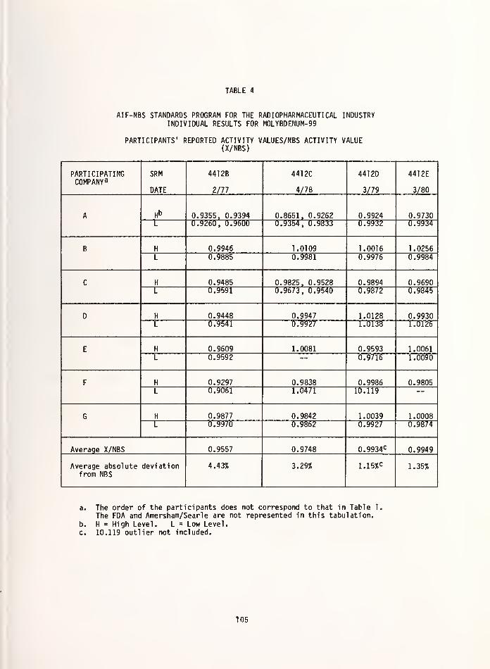
TABLE 4
AIF-NBS STANDARDS PROGRAM FOR THE RADIOPHARMACEUTICAL INDUSTRYINDIVIDUAL RESULTS FOR MOLYBDENUM-99
PARTICIPANTS' REPORTED ACTIVITY VALUES/NBS ACTIVITY VALUE(X/NBS)
PARTICIPATINGCOMPANY 3
SRM
DATE
441 2B
2/77
441 2C
4/78
441 2D
3/79
441 2E
3/80
A H° 0.9355, 0.9394 0.8651, 0.9262 0.9924 0.9730L 0.9260, 0.9600 0.9354, 0.9833 0.9932 0.9934
B H 0.9946 1.0109 1.0016 1.0256L 0.9885 0.9981 0.9976 0.9984
C H 0.9485 0.9825, 0.9528 0.9894 0.9690L 0.9591 0.9673, 0.9540 0.9872 0.9845
D H 0.9448 0.9947 1.0128 0.9930L 0.9541 0.9927 1.0138 1.0126
E H 0.9609 1.0081 0.9593 1.0061L 0.9592 0.9716 1.0090
F H 0.9297 0.9838 0.9986 0.9805L 0.9061 1.0471 10.119
G H 0.9877 0.9842 1.0039 1.0008L 0.9970 0.9862 0.9927 0.9874
Average X/NBS 0.9557 0.9748 0.9934c 0.9949
Average absolute deviationfrom NBS
4.43% 3.29% 1.1 5%c 1.35%
a. The order of the participants does not correspond to that in Table 1.
The FDA and Amersham/Searle are not represented in this tabulation.
b. H = High Level. L = Low Level.c. 10.119 outlier not included.
105

TABLE 5
AIF-NBS STANDARDS PROGRAM FOR THE RADIOPHARMACEUTICAL INDUSTRYINDIVIDUAL RESULTS FOR IODINE-131
PARTICIPANTS' REPORTED ACTIVITY VALUES/NBS ACTIVITY VALUE(X/NBS)
PARTICIPATINGCOMPANY 3
SRM
DATE
440 IB
5/76
440 1C
5/77
4401D
5/78
4401
E
7/79
A H»> 0.9866, 0.9599 0.9798 1.0439 0.9785L 0.9859, 0.9908 1.0100 0.962b 1.0006
B H 1.0036 0.9586 1.0137 1.0138L 1.0012 0.9538 0.9964 1.0081
C H 0.9923 1.0290 1.0083 1.0258L 1.0280 0.9937 1.0081
D H 1.0067 1.0166 1.0094 1.0289L 1.0145 1.0239 1.0108 1.0297
E H 0.9603, 0.9919 0.9888 1.0319, 0.9337 0.9602L 0.9760, 0.9637 0.9917 1.0219, 0.9621 0.9836
F H 0.9742 0.9078 1.0013
L 0.5534 0.8767 1.0024
Average X/NBS 0.9872 0.9590
(0.99591c0.9838 1.0034
Average absolute deviationfrom NBS
1.68% 5.89%(2.37%)c
3.62% 1.64%
a. The order of the participants does not correspond to that in Table 1.
The FDA and Amersham/Searle are not represented in this tabulation.b. H = High Level. L = Low Level.
c. 0.5534 outlier not included.
106

College of American Pathologists QualityAssurance "Q" Program
The College of American Pathologists quality-
assurance program was developed as a result of a
survey taken in 1970 by the Nuclear Medicine Sub-
committee of the College. Out of 1300 laboratories
responding to a questionnaire, 560 users of radio-
active materials were identified, and an interest
in quality assurance was seen.
In the fall of 1970 a pilot study was con-
ducted with 25 participants who responded to the
questionnaire. NBS was asked to prepare and dis-
tribute solution standards of iron-59 and partici-
pants were asked to identify and quantify the ra-
dionuclide. Fourteen laboratories identified the
material correctly, six incorrectly, two said that
they were too busy to participate, one had no in-
terest, one was unable to identify the peaks and
one did not respond. No one reported a cobalt-60impurity in the sample. Nine of the fourteencorrect identifications were within five percent
of the NBS value. The results of this exercise
showed that identification of the radionuclidepresented a larger problem than the assay of theactivity.
In 1972, a new pilot study was performed to
determine the accuracy with which a measured quan-tity of radioactivity could be administered to a
patient. The purpose of this exercise was todetermine how good the participant's laboratoryperformance was on a routine basis. Seventy-sixpercent of the participants that completed this
study indicated that the procedure used in thetest was indeed routine.
Participating laboratories were asked to in-
ject a known activity of approximately 50 micro-curies of chromium-51 into a serum bottle (the
"patient") and return the bottle, syringe, and
needle to NBS. Data were received from 33 out of
46 participants. Reported activities were basedeither on dose-calibrator measurements and, or,
the value supplied on the vial by the manufacturer.Eighty-one percent of the reported values were
TABLE 6
OVERVIEW OF THE CAP QUALITY ASSURANCE "Q" PROGRAM
YEAR RADIONUCLIDE SAMPLESUi orM 1 UntU
PARTICIPANTSREPORTINGpre 1 II TC
CORRECTIDENTIFI-TATTHMC
VALUESWITHIN 10%
Ur NtSo VALUt
-
% OF REPORTEDVALUES WITHIN
1 Cio/ nr mdclU/o Ur NBb
1972131
j 50 28 25 20 71%
125J 56 3R 1
1
i i
197357 Co 50 24 23 12 50%
203 Hg 51 27 17 10 37%
197475 Se 48 25 21 12 48%
59 Fe 45 22 21 14 64%
197560 Co 117 39 27 16 41%
85 Sr 110 38 32 17 45%
197675 Se 123 48 46 26 54%
125j 120 43 41 15 35%
1977133 Xe 83 42 20 48%
201 T1 83 55 28 51%
197867 Ga 80 40 30 75%
169 Yb 82 43 24 56%
1979!11 In
131j
63
68
38
42
31
40
82%
95%
107

within twenty percent of the NBS-measured values.
Noticeable differences from NBS were seen amongparticipants who used the same type of dose cali-
brator, and consistently low values were reportedfrom participants that purchased their material
from one particular supplier. The results ranged
from 0.60 to 1.36 of the NBS-measured values with
one extreme of 3.68. Careless arithmetic and re-porting of results or incorrect decay corrections
were found in one-third of the reported results.
Eighty-two percent stated that they never checked
for radionuclide impurities and six percent never
checked the suppliers' values.
In 1972, as a result of these two studies, the
CAP quality-assurance "Q" program was begun, and
continues in much the same form today. Two cali-brated radioactivity samples are provided by NBS
per year to each subscriber. For the first tendistributions (5 years), the participants wereasked to identify and quantify the unknown radio-nuclide, but beginning with xenon-133 (distributedin saline solution) in the spring of 1977, the
participants were asked only to quantify the amount
of radioactive material present. A summary of
these distributions is presented in Table 6.
The data in the table show that a large num-ber of participants do not report results. Some of
the explanations for not completing the exerciseafter receipt of the material range from "notenough time to measure the sample", to "no settingon the dose calibrator for the particular radio-nuclide", to "the ampoule was too big to fit in
the Nal(Tl) well crystal". The results in the last
three columns indicate that there is much room forimprovement in both identification and quantifica-tion of an unknown radionuclide. It is importantto know that the patient receive the correctmaterial for a specific study, and that the patientbe administered only the amount necessary for that
study. Better training of the personnel, better
equipment, and more careful computation and re-porting skills would all help to improve theresults.
TABLE 7
COLLEGE OF AMERICAN PATHOLOGISTS1979 RADIONUCLIDE STUDY
SERIES Q-B
I0DINE-131
SUMMARY OF ALL PARTICIPANTSmiimrfd nrnUHDLK Ur
PARTICIPANTS
Number of Participants 43
Participants suspectingradionucl idic impurities* 7
Selenium-75 3
Cobalt-57 2
Iodine-125 2
Cobalt-60 1
Indium-113 1
No photon-emitting impurities were found byNBS.
*Two participants noted the presence ofxenon-131m which is, however, a decayproduct of iodine-131.
TABLE a
!: June 1972
Reported Activity as % Deviation from NBS Valus
Overall Performance
<-20-20
to
15.1
•15
to
-10.1
-10
to
-5.1
•5
to
0
0to
+ 5
+ 5.1
to
+ 10
+ 10.1
to
+ 15
+ 15.1
to
+ 20> + 20
No. of SamplesDispatched
No. of Participants
Reporting
50 30*
R R r-i
"1 identified sample as Cr133
1 identified sample as Ba
42.86% of results reported were within 5% of NBS value.
71.43% of results reported were within 10% of NBS value.
108

Table 7 shows some of the results of radio-nuclidlc-impurity identification for the iodine-131
samples distributed in 1979. Little improvement has
occurred in the identification of impurities sincethe first pilot study in 1970. In fact, in 1979,
sixteen percent found radionucl idic impurities in
the iodine-131 when there were none.
Tables 8 and 9 give a comparison between re-
sults for iodine-131 distributed in 1972 and again
in 1979. The overall performance seems to have
improved in the past seven years but this could be
a coincidence as the participants reporting their"esults in 1979 may not be the same as those re-
Dorting in 1972. In the past seven years, however,
;he equipment has most likely improved, and as the)ld equipment is replaced by the new, results should
improve as well. Whether or not the people whonade the measurements were better trained in 1979
is a matter of speculation. The results obtainedvith dose calibrator S would tend to indicate that
:he equipment and not the personnel, is in
question, but the results of the impurity assess-lent would suggest just the opposite. In any case,
improved training of personnel and calibration of:he dose calibrators would substantially improve
the results. It is probable that the participantsin this program are more aware of the need formaking accurate measurements than the average userof radiopharmaceuticals due to their interest inparticipation in the program. Even so, the resultsshow much room for improvement and one can onlyguess as to how well the other 97 percent ofthe 3200 [2] or more hospitals with diagnosticradioisotope facilities can measure a given amount
of radioactive material.
Conclusion
The AIF-NBS Research Associate Program and theCAP Quality Assurance "Q" Program are beneficialfor those associated with the practice of nuclearmedicine because they provide both hospitals and
radiopharmaceutical suppliers with SRMs for thecalibration of their measuring systems, and at thesame time, help them to satisfy the increasing re-
gulatory requirements for traceability to theNational Bureau of Standards. However, 85 percentof the diagnostic procedures performed utilizetechnetium-99m-labeled compounds and the measureddose is usually determined in the hospital'snuclear-medicine department or nuclear pharmacy.
TABLE 9
I: November 1979
Reported Activity as % Deviation from NBS Value
Overall Performance <-2020to
•15.1
•15
to•10.1
•10
to•5.1
•5
to
o
0to
+ 5
+ 5.1
to
+ 10
+ 10.1
to
+ 15
+ 15.1
to
+ 20> + 20
Dose Number of
Calibrator Participants
R 30
r—i R mA
R RD 5
H r—
i
S 3
H%ofParticipants
2% 14% 62% 19% 2%
76.19% of results reported were within 5% of NBS value.
95.24% of results reported were within 10% of NBS value.
109

The AIF program is limited in this area becausetechnetium-99m is not sold in its final preparedform due to its six-hour half life, but rathermilked from a molybdenum-99-technetium-99m generatorin a hospital laboratory. The CAP "Q" program is
limited due to the fact that less than 100
hospitals out of the approximately 3200 hospitalswith diagnostic radioisotope facilities participate
in the program. Also, the radionuclide which is
presently of greatest importance in diagnosticnuclear medicine, tech net ium-99m, has not beendistributed to the CAP participants due to thecost and the great effort required to supply it toeach participant in a short enough time for it tobe useful. In spite of the shortcomings, these pro-
grams are important steps toward assuring that thecorrect dose is given to a patient for a diagnosticprocedure. Because of the AIF-NBS research-asso-ciate program, the suppliers of radiopharmaceuti-cals can give greater assurance to their customersthat the products they sell contain the amount of
activity stated on the label, and this helps thehospital pharmacist provide more accurate doses.The participants in the AIF-NBS Research AssociateProgram and the CAP program are helped by beingable to assess their routine measuring techniques
with each blind received from NBS, and are bene-fited by having a standard to calibrate their in-
struments once the activity is disclosed.
From the patient's point of view, to ensurethat the correct dose of a radiopharmaceutical is
given, important steps would be (1) improvetraining of the personnel in the nuclear-medicinedepartments across the country and (2) involve thecompanies that manufacture dose calibrators in oneof these traceability programs administered by theNational Bureau of Standards.
References
C. W. Seidel and J. C. Brantley, "Activitiesof Commercial Radionuclide Producers" in
Activities and Needs Related to RadioactivityStandards for Environmental Measurements,Environmental Protection Agency Rpt. No.
EPA-670/4-75-006, 39 (U.S. Printing Office,Washington, D.C., 1975).
[2] Hospital Statistics, American Hospital Association Hospital Data Center (1979).
no

THE ROLE OF CALIBRATION STANDARDS IN ENVIRONMENTAL THERMOLUMINESCENCE DOSIMETRY
Thomas F. Gesell and Mary Feild JonesThe University of Texas School of Public Health
P.O. Box 20186Houston, Texas 77025
and
Gail de PlanqueU. S. Department of Energy
Environmental Measurements Laboratory376 Hudson Street
New York, N.Y. 10014
The nature of the environmental radiation field is briefly reviewed and its complexityof composition and energy emphasized. The needs and appropriate standards for environ-mental dosimetry are discussed and calibration procedures are examined. The internationalenvironmental dosimeter intercomparison program is reviewed. Data from the intercomparisonprogram are used to show that only a small part of the error associated with environmentalTLD measurements is likely to be due to uncertainty in the calibration standard. Otherproblems of the calibration process are discussed.
(Calibration; dosimetry; environmental; intercomparison; standards; thermoluminescence)
.
Introduction
Penetrating Environmental Radiation
Penetrating environmental radiation arisesfrom several sources, naturally occurring pri-mordial radionuclides and their daughter products,cosmogenic radionuclides generated in the atmos-phere by cosmic radiation, cosmic radiation it-
self, and man-made radionuclides and radiationdevices (1) . The primoridal radionuclides andtheir daughter products give rise to a complexpenetrating component of the environmental ra-
diation field consisting of gamma rays, x-raysand beta particles. These radiations arise notonly in the rocks and soils but also in the atmos-phere because there is transport of naturallyoccurring radon isotopes from the soil to the
atmosphere. Another major component of penetra-ting environmental radiation arises from cosmicrays. Although primary cosmic radiation consistsalmost entirely of protons, few of these reachground level due to attenuation in the atmos-phere. Instead nuclear reactions in the atmos-phere produce high energy muons and electronswhich reach ground level. The ground level air
ionization produced by these muons and electronsis roughly equivalent to that produced bytypical soil concentrations of the primordialradionuclides. Cosmogenic radionuclides do not
make a significant contribution to penetratingenvironmental radiation field. In addition to
radiation arising from natural radionuclidesdistributed in a natural fashion, there are man-made contributions. These anthropogenic con-
tributions arise from man-made radioisotopesand devices as well from the re-distribution ofnaturally occurring isotopes (2) . Anthropogenicsources contribute gamma rays , x-rays and betaparticles to the penetrating environmental radi-ation field.
Measurement of penetrating environmentalradiation is required for a number of reasonswhich include basic and applied research, regu-latory compliance and health effects studies.When the requirement is for an integrated measure-ment over a period of time of a few days to a
year or so, passive environmental dosimeters,usually thermoluminescence dosimeters (TLDs)
are often employed. These devices are well de-scribed in the literature (3, 4) and are widelyemployed. While no exact ccunt of the users ofthese devices is available, approximately 100laboratories throughout the world have partici-pated in the series of voluntary environmentaldosimetry intercomparisons conducted over thelast several years by the University of TexasSchool of Public Health and by the U. S. Depart-ment Energy. Environmental TLDs are in universaluse around U.S. nuclear facilities and figuredprominently in the assessment of the populationradiation dose to the residents in the vicinityof Three Mile Island Nuclear Station (5)
.
Standards for Environmental TLD
The complexity of the radiation fields towhich environmental TLDs are exposed as well as
the often harsh environmental conditions in
which they are used create special problems for
111

their calibration and handling. These specialproblems have been addressed in the AmericanNational Standards Institute Standard ANSI N545-1975, "performance, testing, and proceduralspecifications for thermoluminescence dosimetry(environmental applications >
" (6) . This stan-dard has been adopted with minor changes by theUnited States Nuclear Regulatory Commission (7)
and therefore serves as guidance to the Com-mission's licencees. The ANSI standard speci-fies (among other things) that the calibrationexposure given to a TLD shall be known to with-in 5% and that acceptable methods of cali-bration include comparison with calibratedequipment or radioactive sources traceable tothe National Bureau of Standards (U.S. A) or sim-ilar national institutions in other countries.
The purposes of this paper are to examinehow environmental TLDs are calibrated, the de-gree of agreement that exists among users of en-vironmental TLDs, the problems of calibrationand the importance of standards in the overallaccuracy of environmental TLD measurements. Thispaper draws heavily on the several internationalintercomparisons of environmental dosimeters,(8,9,10,11) especially the most recent (11) inaddressing these questions.
Calibration of Environmental TLDs
While TLDs in the environment are subjectto a variety of kinds and energies of chargedparticles and a rather broad spectrum of photonenergies, calibration is usually performed withone or at best a few photon sources. Cesium-137,Cobalt-60 and Radium-226 are specifically men-tioned in the ANSI Standard (6) and reported as
being used by most of the intercomparison parti-cipants. The calibration is usually expressedin exposure units, Roentgens or more recentlyGrays. The environmental measurements on theother hand cannot be strictly expressed in expos-ure units because exposure is strictly definedonly for photon radiation. Thus when an environ-mental measurement is expressed in exposure unitsit is understood that the result is equivalent tothat obtained from a specified exposure from thecalibration source. Theoretical and some experi-ment evidence indicates that TLD phosphors under-respond to cosmic ray muons (12). The packagingof typical environmental dosimeters is suffi-ciently thick to exclude some to all of theenvironmental beta particles. Many users howeverutilize a package of sufficient thickness to ex-clude all beta particles. This approach has theadditional advantage of assuring charged particleequilibrium for gamma rays during calibration.In this case, only the photon and cosmic radi-ations are being measured however.
Another intrinsic problem with TLDs con-cerns energy dependence. While some phosphorssuch as those whose major component is LiF and Li.
B4O7 are nearly energy independent, the moresensitive phosphors such as those based onCaSC>4 and CaF2 exhibit a severe over -response to
photon radiation at low energies. Some userscompensate for this over-response with an energycompensating shield or filter. The followingdiscussion of calibration should be interpreted
with the above limitations in mind.
Basic calibration is effected in one of twoways. In one technique an NBS traceable instrumentis used to measure the radiation exposure rate insome small volume in a radiation field and a cali-bration dosimeter substituted for the instrumentfor an appropriate length of time to achieve thedesired exposure. In another approach an NBStraceable source is arranged with the calibrationdosimeter in an approximation of "free air" geo-metry. The calibration exposure is then calcu-lated using the known source strength, the gammaray constant of the source and the inverse squarelaw. Within this basic frame-work a variety ofcalibration schemes are employed. Some labo-ratories calibrate each dosimeter individually;others select batches of dosimeters with similarresponse and calibrate only a random sample ofthe whole batch; others combine these techniquesand perform batch calibrations but use individualdosimeter correction factors
.
The International Environmental DosimeterIntercomparison Program
Procedures
Much of the information contained in thispaper derives from the series of internationalintercomparisons of environmental dosimeters so
a discussion of them is appropriate. The inter-comparisons originated in 1973 with a highlyinformal pilot intercomparison at Oak RidgeNational Laboratory involving 12 sets cf dosi-
meters from 5 laboratories (13) . The poor re-sults of this informal study were sufficientlyalarming that a more formal study with good controlfor radiation exposure acquired in transit wasconducted in 1974 (8) . Dubbed the "first inter-national intercomparison of integrating environ-mental dosimeters" it has been followed by threeothers using similar protocols. The fifth inter-comparison is to be held in Idaho Falls in 1980.
The recent intercomparisons have typically attract-ed 125 sets of dosimeters from 100 laboratorieslocated in 25 countries. For each set to betested in the intercomparisons, each participantsends several pairs of dosimeters to the test
location. One pair of dosimeters is designatedas "control", one pair is designated as "field"
and the third and sometimes fourth pairs are
designated as "laboratory". Upon receipt at the
test site the dosimeters are stored in a lowbackground radiation shield until the beginningof the field test period. At the beginning of
the field test period the "field" dosimeters are
removed from the storage shield and deployed in
close physical proximity in an environmentalradiation field. Both natural (first, second,
fourth intercomparisons) and artificially en-
hanced (pilot, third intercomparisons) fields havebeen employed. Usually a field test period ofthree months is used but shorter times have occ-
asionally been employed. Except for the pilot
study, high pressure ionization chambers have
been operated at the field site for the entire
duration of the field exposures to give an in-
dependent assessment of the field exposure.
Approximately half way through the field period,
112

the "laboratory" dosimeters are removed and ex-posed to a known but unrevealed quantity of gammaradiation. Cobalt-60, Cesium-137 and Radium-226have been employed in the several intercomparisons
.
In the fourth intercomparison, two laboratorypairs of dosimeters were solicited from the part-icipants . One set was given a "low" exposureon the order of a typical field periodexposure to natural radiation; the other pairwas given a "high" exposure approximately fourtimes the "low" exposure. In all but the pilotstudy, control dosimeters were used to isolatethe actual laboratory and field exposures fromthe exposures acquired in transit and storage
.
The control dosimeters also allowed estimationof the transit exposures. The results of theintercomparisons have been analyzed statisticallyand a number of factors contributing to randomand systematic errors identified.
Selected Results of the Intercomparisons
30
as
^ 20
I 15
• LABORATORY* FIELD
4\
INTERCOMPARISON
_ i y1 HOUSTON 1974
2 NEW YORK 1976
: 2 \ 3 OAK RI06E 1977
— z\ 43
I*** •—
4 HOUSTON 1979
4
i i 1 1 1
3
1 1 1 1 1
10 20 30 40 50 60 70
EXPOSURE (mR)
80 90 100
Figure 2. Relationship between percentstandard deviation and delivered exposurefor all tests in four intercomparisons
.
The general results of the fourth inter-comparison are shown in figure 1. The estimateddelivered laboratory and field exposures areshown for comparison. Two levels of laboratoryexposure were used to help determine if pre-viously observed differences in dispersion ofthe results could be related to exposure level,to differences between laboratory and fieldconditions or to improved performance. Thesedata on dispersion are combined with data fromthe previous intercomparisons, and presentedin figure 2. These results strongly suggestthat the dispersion is related to the exposurelevel. The only point not lying on the smoothcurve is the value for the field exposure duringthe third (Oak Ridge) intercomparison. Thisparticular field exposure involved an artifi-cally enhanced source with a large low energy-
scattered radiation component causing unusualresponse problems.
The Importance of the Calibration SourceIn Environmental TLD Measurements
The importance of the accuracy of the cali-bration source in environmental TLD can be illu-strated using data from the fourth intercompari-son (11) . Figure 3 shows the degradation of esti-mated accuracy from the standard itself to thefield measurement. The uppermost histogram is thehypothetical distribution of accuracies of lab-oratory standards available to participants. Forpurposes of illustration it is assumed that allusers could have a laboratory standard with anaccuracy of 2%. This could be either a cali-brated source or a calibrated instrument. The
next lower histogram is the distribution ofoverall calibration accuracy estimated by partici-pants (participants were asked to estimateaccuracy as two standard deviations) . This dis-tribution is clearly much broader and reflectsadditional uncertainties in the calibration pro-cess beyond the uncertainty of the source. These
113

additional uncertainties are introduced byerrors of positioning of the calibrationdosimeters, timing of the exposure, and, especi-ally with calibrated sources, errors associatedwith scattered radiation. The lower three his-tograms represent the distribution of estimatedaccuracy reported by the participants for the"high" laboratory test, the "low" laboratorytest, and the field test (participants wereagain asked to estimate accuracy as two standarddeviations) . Those distributions are in turnbroader than the distribution of accuracyof calibration. The additional breadth resultsfrom known additional sources of measurementerror such as random variation of dosimeterresponse, energy dependence, directional depend-ence, signal fading, and self irradiation (14)
as well as the additional error introduced bythe requirement for subtracting transit exposures.
> zHYPOTHETICAL DISTRIBUTION OF THE ACCURACY OF
LABORATORY STANDARDS AVAILABLE TO PARTICIPANTS
>
ui3oUJ 20
AC
>-
Oz »
DISTRIBUTION OF THE OVERALL ACCURACY OFCALIBRATION REPORTED BY PARTICIPANTS
DISTRIBUTION OF THE OVERALL ACCURACY OFMEASUREMENT REPORTED BY PARTICIPANTS FOR THE
"HIGH" LABORATORY TEST
D=EL10 2030 4050 60 70 80 90
DISTRIBUTION OF THE OVERALL ACCURACY OFMEASUREMENT REPORTED BY PARTICIPANTS FOR THE
"LOW" LABORATORY TEST
DISTRIBUTION OF THE OVERALL ACCURACY OFMEASUREMENT REPORTED BY PARTICIPANTS
FOR THE FIELD TEST
PERCENT
Figure 3. Frequency distributions showingthe hypothetical distribution of accuracy oflaboratory standards available to environ-mental TLD users, the distribution of report-ed overall calibration accuracies and thedistributions of reported overall accuraciesof measurement for the three tests carriedout in the fourth intercomparison.
It should be stressed that figure 3 dis-cussed above consists of a hypothetical dis-tribution of laboratory standard accuraciesplus distributions of estimated accuracies re-ported by environmental TLD users. At this pointwe can turn to actual performance in the inter-comparison tests. Figure 4 illustrates theabsolute percent difference between participants '
3 20
O
LABORATORY TEST- HIGH"
QZtZL
>-ozui3 »O
,0 2030 4090 00708090
LABORATORY TEST ' LOW"
0=. r~r—r~i m ,—,in fin 7n an on ' * 3m10 20 30 5> so 60 53 so eo
5 ' »ioo
FIELD TEST
f—n lhman an ' * _inn
ABSOLUTE PERCENT DIFFERENCE BETWEENPARTICIPANT S RESULT AND THE DELIVERED EXPOSURE
Figure 4. Frequency distributions showingactual deviations ( in %) of the partici-pants' results from the delivered exposuresfor the three tests carried out in thefourth intercomparison.
results and the estimated delivered exposure forall three tests . Performance is seen to be betterfor a the "high" laboratory test than for eitherthe "low" laboratory of "field" tests. This per-formance is in general consistant with the esti-mated accuracies shown in figure 3.
Figure 5 examines more directly the abilityof users to estimate the error of their labo-ratory and field measurements. The quantitydisplayed on the abcissa is the error esti-mated by the participants ( in %) subtracedfrom the actual difference ( in %) betweenthe participants' results and the estimated de-livered exposure. Positive results occur whenthe actual error exceeds the estimated error.These cases of underestimating of error areshaded for emphasis. Approximately 30 percentof the participants' results differed from thedelivered exposure by more than their estimatederror. The estimated accuracy of the deliveredexposures was 10%.
The uncertainties estimated by environmentalTLD users (figure 3) as well as the deviationsfrom the delivered exposures (figure 4) are muchlarger than the estimated uncertainties ofcurrently available laboratory standards trace-able to the National Bureau of Standards orequivalent standards groups in other countries
114

LABORATORY TEST-"HIGH"
«> -80 -40 -20 0 20 40 80 80
j—|—I LABORATORY TEST "LOW"
: 100 -100 -80 -80 -to X 0 20 40 00 80 100
FIELD TEST
u= 100 -100 -80 -80 -40 -20 0 20 40 BO 80 >100
DIFFERENCE BETWEEN ACTUAL ERROR (%) ANDESTIMATED ERROR (X)
Figure 5. Frequency distributions of the dif-ferences between the errors estimated by theparticipants ( in %) and the actual deviationsof the participants 'results from the deliveredexposures ( in %) . The positive (shaded)
results represent cases in which the devi-ation from the delivered exposure was greaterthan the error estimated by the participant.
Furthermore many users are apparently under-estimating their overall uncertainties (figure
5) . It thus appears that little would be gainedby improving the 1-2% accuracy already availablein the calibration standards.
There are however several problems associ-ated with calibration which have been elucidatedby the intercomparison program, but which are
not necessarily connected directly with the
accuracy of the calibration source. When thedata for the second intercomparison (9) wasanalyzed it was noted that the standard devi-
ation of the results of participants who calcu-lated their calibration exposures from knownsource strengths was larger by a factor of two
than the standard deviation of the results of
participants who measured their calibrationexposures directly. It was believed thatthis additional error may be due to unaccounted-for room scattering, air attenuation and effects
of the source capsule or support. This effect
was somewhat diminished in the subsequent inter-
comparisonsfbut still persisted.
Another calibration problem which has per-
sisted through the four international inter-
comparisons is the systematic difference in re-
sults among uses of the three most commoncalibration isotopes. Users of Cobalfc-60
calibration sources typically exhibit averagelaboratory test results a few percent higherthan those using Cesium--137. Users of Radium-226calibration sources exhibit average laboratorytest results a few percent lower than eitherCobalt-60 or Cesium-137 users. No satisfactoryexplanation has been found for these differences.
Conclusions
At the present time the collective errorsassociated with making environmental TLD measure-ments are much larger than the error associatedwith laboratory standards traceable to theNational Bureau of Standards or equivalent stan-dards groups in other countries . It wouldtherefore seem that the standard sources andstandardized instruments available to the usersare of sufficient accuracy in view of the stateof the art. Use of standard sources ratherthan standardized instruments can lead toadditional calibration errors due to uncertain-ties in scatter, attenuation and source holdereffects . While environmental TLD users willnearly always wish to use a locally availablecalibration facility for routine operations, itmay be desirable to have a service similar tothat provided by the international program avail-
able to users at their convenience rather thanat the fixed and rather infrequent intervalspresently available. This service could con-ceivably be provided by the National Bureau ofStandards, another government agency or a con-tractor. This scheme could allow users to
test the effectiveness of their own calibrationsystems at reasonable expenditure of time andmoney
.
References
(1) National Background Radiation in the UnitedStates, National Council on RadiationProtection and Measurements Report NCRP 45,Washington, D.C. (1975)
.
(2) The Technologically Enhanced Natural Radi-ation Environment, T. F. Gesell andH. M Prichard, Health Physics 28 361-366(1957),
(3) Thermoluminescent Dosimetry , J. R. Cameron,N. Suntharalingam, and G. N. Kenney,The University of Wisconson, Press, Madison,Wisconson (1968) .
(4) Solid State Dosimetry, K. Becker, CRCpress, Cleveland, Ohio (1973).
(5) Staff Reports to the Presidents Commissionon the Accident at Three Mile Island;Reports of the Public Health and SafetyTask Force, ed. Jacob I. Fabricant, Sup.Doc. Washington, D.C. (1979)
.
(6) Performance, testing and procedural speci-fications for thermoluminescence dosimetry(environmental applications), ANSI N 545-1975.
115

American National Standards Institute,1430 Broadway, New York (1975)
.
(7) Performance, testing and procedural speci-fications for thermoluminescence dosi-metry; environmental applications, U.S.Nuclear Regulatory Commission, RegulatoryGuide 4.13, Washington, D.C. (1976).
(8) An International Intercomparison of Environ-mental Dosimeters, Thomas F. Gesell, Gailde Planque Burke and Klaus Becker, HealthPhysics 30, p. 125-133 (1976)
.
(9) Second International Intercomparison ofEnvironmental Dosimeters, Gail de Planqueand Thomas F. Gesell, Health Physics 36 p.221-233 (1979)
.
(10) Third International Intercomparison ofEnvironmental Dosimeters under Field andLaboratory Conditions, T. F. Gesell,R. B. Gammage and G. de Planque, Presentedto the 23rd Annual Meeting of the HealthPhysics Society, Minneapolis, Minnesota,18-23 June, 1978 Abstract: Health Physics35, p. 909-910 (1978)
.
(11) Highlights of the Fourth InternationalIntercomparison of Environmental Dosimetersunder field and laboratory conditions,Thomas F. Gesell and Gail de Planque,Nuclear Instruments and Methods (in press)
.
(12) The Response of LiF ThermoluminescenceDosimeters to Natural EnvironmentalRadiation, Wayne M. Lowder and Gail dePlanque, Energy Research and Develop-ment Agency Report HASL-313 New York, N.Y.(1977)
.
(13) Tenth Dosimetry Intercomparison, H. W.
Dickson, F. F. Haywood and K. Becker,Oak Ridge National Laboratory Report#ORNL-TM-4566, Oak Ridge, Tennessee(1975)
.
(14) Error Analysis of Environmental Radi-ation Measurements made with IntegratingDetectors, Gail de Planque Burke andThomas F. Gesell, Proceedings of theSymposium on measurements for the safeuse of radiation, ed. S.P. Fivozinsky,National Bureau of Standards SpecialPublication 456, p. 187-198 (1976)
.
116

THE NATIONAL BUREAU OF STANDARDSLOW-LEVEL RADIOACTIVITY-MEASUREMENTS PROGRAM
K. G. W. Inn
J. R. NoyceNational Bureau of Standards
Washington, D.C. 20234
The National Bureau of Standards low-level radioactivity measurementsprogram is oriented towards the production of reference materials forenvironmental radioactivity measurements needs. These referencematerials are used 1) for calibration of instruments, and 2) as test
sources for analytical procedure evaluation. These endeavors are
designed to provide the nation with a means of assessing the qualityof environmental radioactivity measurements and relating them tonational and international radioactivity standards. The present status
of these efforts is discussed along with possible future plans.
(Calibration, environment, natural material, radioactivity, radionuclide,standard, traceabil ity)
Introduction
The need for environmental radiological
studies has been and will continue to be of
great importance to the public. The protec-
tion of the puDlic from excessive exposure to
radiation and basic scientific understandingof the environment are the two primary reasons
for these studies. Some of the programs that
are concerned with environmental radiologicalstudies are listed in Table 1. Regulatoryrequirements have been established for public
safety and require radiation monitoring around
nuclear-power plants, uranium mines, nuclear-fuel manufacturing plants, nuclear-waste repos-
itories, as well as the air we breath, the waterwe drink, and the food we eat. Basic scientificenvironmental investigations, on the other hand,
use radioactive tracers as a sensitive means for
studying the environment. Careful radiometricmeasurements have aided in transport studies ofthe atmosphere, oceans, and the lithosphere, dat-
ing studies as well as cosmological and biologi-cal studies. The objective of the low-level ra-
dioactivity-measurements program at the NationalBureau of Standards (NBS) is to produce referencematerials suitable for environmental radioac-tivity-measurements needs. These materials are
used for 1) calibration of instruments and 2)
as test sources for analytical -procedure evalu-ation. In this paper the status and requirementsregarding reference materials and test samplesneeded in traceability programs will be discussed.
Table 1
General categories of low-level radioactivity measurements with examples.
Public Safety :
Routine monitoring:
Radioactive waste studies:
Coal-burning power plants, uranium mines, uraniummills, nuclear-power plants, Clean Water Act, CleanAir Act.
High-level contaminated sites, nuclear-waste reposi-
tories, uranium-mill tailings and slag.
Scientific Knowledge :
Transport studies:
Dating studies:
Cosmological studies:
Meteorology, oceanography, water resources.
Archeology, geology, cosmology.
Lunar samples, polar ice, deep-sea sediments, meteorites.

Radioactive Standard Reference Materials
The selection of radioactive Standard Refer-ence Materials (SRM) to be produced has been, toa large degree, influenced by requests from agen-cies such as the Environmental Protection Agency(EPA) and the Nuclear Regulatory Commission(NRC), reports from knowledgeable groups such as
the International Committee for Radiological Me-trology (ICRM), NBS questionnaires, evaluationof regulations and surveys of the literature.Table 2 lists some of the users of the resultingNBS SRMs.
Presently, approximately seventy radioactiveSRMs of nearly forty radionuclides are availablefrom NBS [1], many of which are useful for envi-ronmentally related work [2]„ .Table 3 includesthe various types of SRMs produced by the Radio-activity Group at NBS. These sources come in var-ious forms namely as liquids, point sources, gasesand solids. Most of these SRMs are used to cali-brate instruments for detection efficiencies whilesome are used to monitor the stability of instru-mental response [3], These SRMs also play an im-portant role in traceability considerations.
Table 2
NBS standards users and examples.
Operating nuclear-power stationsPreoperational nuclear-power stationsResearch reactorsMajor nuclear facilities:
Nevada Test SiteIdaho National Engineering LaboratoryRichland, WashingtonOak Ridge National LaboratorySavannah River PlantRocky Flats PlantMound LaboratoryPaducah, KentuckyCimarron, Oklahoma
Federal Agencies:Environmental Protection AgencyNuclear Regulatory CommissionDepartment of Energy
States with active environmentalsurveillance programs:
New York, Pennsylvania, South Carolina
University based research projects:BerkeleyMiami
Arkansas
Institutions:Woods Hole Oceanographic InstitutionScripps Oceanographic InstitutionBattelle NW
Environmental radiation consulting firms:Radiation Management CorporationNuclear Environmental ServicesUnited States Testing CompanyWestinghouse NES
Cities, counties, other sub-state govern-mental bodies:
New York City
Table 3
Types of National Bureau of Standards radio-activity Standard Reference Materials andexamples.
Source Type
alpha-particle,solution
beta-particle,solution
photon-emitting,solution
Examples
239PUj 242Pu
3H, 14C, 63Ni,
5*Mn, 60Co 109 cd137^.137*1^ 226^ a
alpha-particle, point 148Gd, 238Pu, 241Am
55 Fe 85Kr 133Ba139Ce> 152Eu
beta-particle, photon- 3H, 3 '7Ar. 3^Ar.emitting, gas 85Kr, 13lmXe, * 33Xe
photon-emitting,point
sol id River Sediment
Measurements Traceability
In environmental measurements, one is inter-ested in establishing the ability to make consis-tently accurate assays. That is to say, the goal
is to establish a consistently accurate analyt-ical scheme which begins with the collection ofsamples and continues until the data are finallyreported. Measurements-traceabi 1 ity programs forenvironmental radioactivity provide a basis by
which laboratory measurements can be related tonational radioactivity standards. Through a trace-
ability program, data quality can be assessed,and a firm foundation for policy decision and sci-
entific discussion can be established. In manycases traceability may be recommended or requiredunder regulations, agreements, regulatory guides,licensing, or recommended practices. One can
visualize a three-phase traceability scheme whichwould test:
118

1) Instrument calibration
2) Radiochemical procedures
3) Sampling, preparation, and
storage methods.
The first phase of traceabil ity is concerned
with the accuracy of instrumental response.
The second phase of traceabil ity evaluatesradiochemical procedures for significant
chemical biases. And finally, the third
phase provides some assurance that a labora-tory is able to collect and prepare samples
for assay, and store them without affectingtheir integrity.
Calibrations of Instruments
The first phase, instrumental trace-ability, is propagated through the Trace-
ability System [4,5,6,7,8,9] shown in Figure1. NBS maintains traceability internationallythrough interaction with the International
Bureau of Weights and Measures, the Inter-national Atomic Energy Agency and other na-
tional laboratories. Domestically, NBS estab-
lishes instrumental traceability to QualityAssurance (QA) laboratories through Measure-ments-Assurance Programs [10,11,12,13]. Some
of the SRMs produced by the RadioactivityGroup at NBS are used in these programs as
test samples, of undisclosed value, to estab-lish the traceability link between NBS and
QA organizations.
The Environmental Protection Agency (EPA)
is responsible for radiological monitoring of
the environment outside nuclear-fuel-cycle
facilities. To assist in the accomplishment of
EPA's mission, the EPA-NBS traceability programconsists of both implicit and explicit [14] trace-ability measurements for alpha- and beta-particleand gamma-ray-emitting nuclides. Tests on twenty-eight radionuclides have been made so far, and
EPA's performance demonstrates its instrumentaltraceability to NBS for these radionuclides (Fig-
ure 2). Because it has been able to assay a va-
riety of radionuclides accurately, it has devel-oped a reputation for consistent and competentactivity-concentration measurements. Nuclideswhich may be added to its list of traceable nu-
clides by the end of 1980 are 46 Sc, 57 Co, and125 Sb .
In addition to EPA's traceability program,a Radiological Pollutant Quality Assurance Pro-gram was established in 1975 to provide NBS ref-
erence materials for radionuclides released tothe environment by coal-burning and nuclear powerplants. The sources, produced in quantity for
EPA's distribution as calibrated materials [15]or as test samples in their Environmental Radio-activity Laboratory Intercomparison Studies Pro-gram (cross-check program) [16], are listed in
Table 4. When used in EPA's cross-check program,
these materials provide traceability to the userlevel for nuclides that have not been included in
the formal traceability program between NBS and
EPA. Several of the calibrated radioactivitysources in this list are environmental matrixmaterials. A more complete discussion on thenatural material sources follows in the nextsection.
INTERNATIONAL AND NATIONAL RADIOACTIVITYMEASUREMENTS "TRACEABILITY TREE"
BIPMIAEA
DOE NRC EPA
I 1 i
HHS(fda'.brh)
*
DOD AIF CAP
1 I
ETC
1
STATES, UNIVERSITIES, HOSPITALS,
GOVERNMENT AGENCIES, INDUSTRIAL GROUPS AND OTHERS
INTERNATIONAL
ETC NATIONALLABORATORIES
QUALITY CONTROL ANDREGULATORY BODIES
USERS
Figure 1
119

Table 4
Radioactivity-calibrated materials pre-
pared by the National Bureau of Standardsfor the Environmental Protection Agencyunder the Radiological Pollutant QualityAssurance Program (1976-1980).
Solutions:210Po232Th239Pu241Pu
Mixed Radionuclide Solutions:Mixed gamma-ray emitting ("Cr.
Natural uranium (234U, 235U, 238U)
and ?38iU)
Solids:Mancos Shale (
226Ra and 228Ra)
Pttery Clay («7n 88Y> 113cn13mIn> 137Cs.137mBa> and 139cCe)
Fly Ash from coal combustion
(22gRa and 228Ra)
The responsibility of the NRC is to moni-
tor nuclear-fuel -cycle facilities, and its
traceability program with NBS is implementedthrough the Radiological and EnvironmentalSciences Laboratory (RESL) at Idaho Falls.
Since the program was established in 1974, cal-
ibrated sources of forty-six radionuclides havebeen commonly measured by NBS and RESL and theresults of the measurements are shown in Figure3. RESL has demonstrated throughout the programa high level of instrumental reproducibility andstability, and operator competence for a broadrange of alpha-, beta-particle, and photon-emit-ting nuclides, some of the radionuclides beingassayed more than once. Scandium-46, l 33Xe,228Tn.208Tlj and 240Pu are i nc i uded in the RESLtraceability program for 1980.
Another program in the national traceabilityeffort was established by agreement between EPAand NRC. The NRC Regulatory Guide 4.15 [17]requires the nuclear-power plants in the UnitedStates to participate in interlaboratory compar-ison programs, such as the EPA cross-check programfor environmental samples [16], to establishlinks to the national traceability program [18].To evaluate the level of analytical performanceof the power plants, EPA has agreed to developa number of test samples for the NRC. Calibratedsamples of radionuclides such as ,1, naturaluranium, 210Pb, 210Po, 226Ra, and 230Th in air,
food and water are desired. NBS may prepare someof these standards to help implement the EPA-NRCagreement.
The College of American Pathologists (CAP)
and the Atomic Industrial Forum (AIF) also havetraceability programs with NBS. These programshave previously been discussed by Golas [19], and
will not be addressed here.
0.90 0.92 0.94 0.96 0.9S 1.00 1.02 1.04
tPA VAlUtNBS VALUE
1.06 1.08 1.10 1.12
Figure 2
Results of the EPA-NBS Radioactivity-Measurements Traceability Program from its
inception through March, 1980.
120

Sr- Ni-si) c*3
IIOm 9©Sr-
Am-241
iX'g.
2©C
Am-241
Am243
Zn- Co-os -IS
1 1
1.06 1.08 1.10 1.12 1.140.90 0.92 0.94 0.96 0.98 1.00 1.02 1.04
RES1 VALUENBS VALUE
Figure 3
Results of the RESL-NBS Radioactivity Measurements Traceability Program from its
inception through March, 1980.
NBS provides two additional services thatare designed to provide implicit instrumentaltraceability to interested parties. First, SRMscan be obtained by customers, for a small extrafee, as "blind" test sources. These "blinds"are issued without disclosure of their certi-
fied emission-rate or activity-concentrationvalues. The purchaser measures one or other of
these quantities and reports his value to NBS,which then issues a Report of Measurementgiving the certified value, the purchaser'svalue, and the percentage difference from the
certified value. By using the "blinds" the
purchaser can test the performance of his in-
strumentation, but not necessarily his radio-analytical techniques.
NBS also provides traceability servicesfor a large number of radionuclides submittedby the customer. Sources must be submitted in
forms which meet certain criteria for chemical
composition, geometry, and activity. The cus-tomer provides his measured value for the cal-
ibration of the emission rate or activity con-
centration. After NBS completes the calibra-tion of the source, the supplier receives a
Report of Calibration which states the certi-fied emission rate or activity concentrationof the source, the customer's value, the per-
centage difference, the uncertainties in the
NBS assay, and the methods and nuclear param-eters used.
In addition, NBS provides an explicit trace-ability mechanism to other laboratories, thatproduce and distribute radioactivity standards,through their submission of a few samples of eachbatch to NBS for corroborative measurement. Inthe past NBS produced SRMs which contained a mix-ture of nine photon-emitting radionuclides:"Co, 60Co ,
85Sr ,88Y> 109 Cd> 113Sn> 137 Cs>
l-^Ce, an(j 203^. jn -j s mixture was provided inthe forms of point sources and as solutions in
5-, 50-, and 450-ml containers. These SRMs havefound wide application in calibrating detectorsfor gamma-ray spectrometry [20,21], Recently,similar standards or reference sources have beendistributed by the Amersham Corporation and Ana-lytics, Incorporated. Whenever these companieshave produced a set of such standards, they havesent several randomly selected samples from theset to NBS for confirmation of emission rates pergram at 10 or 11 gamma-ray energies. The explic-it traceability mechanism, therefore, providesfor the continual availability of mixed gamma-ray-emitting reference sources that are traceableto NBS.
NBS is presently working on another mixedgamma-ray-emitting reference source consisting of
the relatively long-lived radionuclides l^Sb(t 1/2
= 2.77 Y*), l%u (t 1/2 = 8.6 Y), and
* One mean tropical year equals 365.2422 days.
121

1"eu (ti/2 ~ 4.69 Y). The new mixture will
provide more gamma-ray photopeaks in the lower-
energy region than the earlier mixture and a
longer usable life.
Tests of Radiochemical Procedures
The second phase of environmental tracea-bility is implemented through calibrated test
samples containing specific radioanalyticalproblems. These test samples fall into twogeneral catagories: 1) SRM solutions with par-
ticular chemical challenges and 2) Natural-Matrix Standards (NMSs) which present peculiarmatrix problems. Several test samples withchemical and other interferences have been dis-tributed in the past by NBS and are listed in
Table 5.
Table 5
Test sources with interferences.
losses of material during dry ashing. Lossesof material may be the result of selectivevolatilization, co-precipitation, or even diffu-sion into the container wall. Hamilton et al
.
[27] observed selective volatilization of As in
spiked serum. When the serum was spiked i n vitro ,
28% of the As volatilized during ashing, but whenthe serum was spiked in vivo , as much as 86% ofthe As volatilized. This showed that metabolizedAs was considerably more volatile than As addedas a yield monitor. Thus, if a tracer is addedin vitro as a radiochemical yield monitor for As
determination in serum, chemical equilibrationbetween the sample and the tracer would not beachieved during ashing, thereby resulting in un-
reliable data.
Accordingly, reference materials closer in
composition to environmental samples should pro-vide more rigorous tests of analytical systems.Natural-Matrix Standards (NMSs) serve as testsamples for environmental radiochemical assays.An NMS has been defined by Noyce [28] as
Assayedradionucl ides
89 Sr, solution
90Sr.90Y> solution
232jh, solution
Natural uranium,solution
Mixed photon-emittingspiked pottery clay
Interferences
90Sr, Ca2+
133Ba, Ca2+
230-rh
234y> 235y 238u
(interfere witheach other)
Matrix
Although these test sources with interfer-ences present considerable challenges to theanalyst's skill, they are relatively "clean"samples. Environmental samples, on the otherhand, are very complex materials and contain an
abundant store of insidious difficulties. Someof the obstacles facing the analyst are: in-
terfering ions [22], chelating ligands [22],grain size of the host matrix, organic decompo-sition [23], mineralogical variability, radio-
nuclide volatility [23,24], contamination of
the samples [22,25], density variability, vary-ing chemical species and valence states of thenuclides [e.g., 26], and the variability of theradionuclide distribution in the matrix.
Particularly important is the attainmentof equilibrium between the radionuclides in thematrix and the tracers and carriers being used
as radiochemical yield monitors. Without this
condition, quantitative assays of the radionu-clides will be forfeited before the analyst has
had the opportunity to work the sample. Gorsuch
[23], for example, warned against selective
... a solid, liquid, or gas found in orclosely derived from nature. It is
homogeneous and contains one or moreradionuclides, present from environ-mental processes or by addition in thelaboratory, whose concentrations havebeen rigorously assayed and certified...
For those materials in which the radionuclideswere introduced into the matrix by environmentalprocesses we further designate here as Environ-mentally Quasi-equilibrated Materials (EQMs)
while those materials in which the radionuclideswere introduced by delibrate addition in the lab-
oratory we call Spiked Materials (SMs). The NMSscan be used to develop new wet-chemical proce-dures, to evaluate chemical procedures already in
use, calibrate instruments, act as materials forinterlaboratory comparisons, test the competence of
technicians to do chemical assays, and demonstratethat data outputs are reliable [28].
To date, NBS has produced four NMSs: theRiver Sediment, Mancos Shale, Pottery Clay, and
Fly Ash from coal combustion (from Tables 3 and
4). SRM 4350, the River Sediment, is an exampleof an EQM. The radionuclides certified by NBS
include the alpha-particle emitters 239p., p] us2^0p U) the pure beta-particle emitters ^Sr and
9j?Y, and^the ganma-ray^ emittersJ^Jk,54Mn, 60Co,_ gamma-ray £_...
137 r , r52 E(Jj 154 E u, and 228Ac [29].Zn, 1J/ Cs,
The Mancos Shale and Fly Ash are also EQMs,
and both are certified for 226p a ancj228p a rac(i 0_
activity concentrations.
An example of a calibrated Spiked Material is
the Pottery Clay mixed-gamma-ray emission-rate stan-
dard. In this case, the material was quantitative-ly spiked with calibrated solutions of five radio-
nuclides (65 Zn, 88Y, 113Sn, 13 7r,s, and l39ce).
122

There has been some discussion about which
type of NMS is preferable for presenting ra-
dioanalytical problems. Some of the factorsaffecting the suitability of EQMs and SMs will
now be addressed.
When using NMSs, it is important to keep
in mind the mechanism of nuclide addition tothe material [29,30,31,32,33]. For EQMs, it is
presumed that if the radionuclides have been in
the environment for some time, natural pro-
cesses would have brought them into chemicalequilibrium. Strontium-90 and cesium-137, for
example, require only a relatively short timeto reach an equilibrium state in the environ-ment. Many radionuclides, however, requirelong periods of exposure to the environment to
attain chemical equilibrium. Plutonium dioxide,for example, is highly resistant to weatheringand is likely to require extremely long expo-
sure times before it could be considered equil-ibrated with the environment.
Other problems concerned with the produc-
tion of EQMs are that the desired matrix mate-rial may be limited in quantity, the activitylevels may not be suitable, there is no priorknowledge of the concentration of the radio-nuclides, and because of the low radioactivity-concentrations the possibility of confirmationby independent methods is limited.
The SMs, in principle, have considerablygreater flexibility than EQMs. There is con-
trol over the concentration and composition of
the radionuclides being added (particularlyuseful for short-lived radionuclides), known
analytical problems can be "built into" thematerial, and the cost may be lower because the
calibration and characterization of the mate-
rial may require less effort.
Does the chemical form of the radionu-
clides in an environmental sample significantlyaffect the assay? Herein lies a presumed limi-
tation of SMs as test samples which are to be
subjected to destructive analysis. In most
cases it is probable that spiking results in
chemical species which do not correspond to
those found in the environment. Furthermore,since environmental speciation of the radionu-clides are often not well known or character-ized, duplication of the chemical forms of the
radionuclides in environmental samples by
spiking may not be possible. Thus, the spikedradionuclides may not behave in the same wayduring radiochemical analysis as those nuclideswhich were incorporated by natural processes.
For some purposes, chemical equivalence is
of no consequence. For example, if the mate-
rial is to be assayed by Nal(Tl)- or Ge(Li)-detector spectrometry, the chemical speciationof the radionuclides does not significantly af-
fect the quality of the assay. However, if se-
lective chemical leaching is the method of choice,
it is important that the radionuclide of interestbe as close to its environmental state as pos-sible to justify the validity of the assay. Evenwith these limitations on EQMs and SMs, we feel
that NMSs will still serve as valid test samplesfor many environmental -radioassay methods.
The calibrated River Sediment, Fly Ash,Mancos Shale, and Pottery Clay, of course, cannotcover all the existing needs for environmental-radioactivity-reference materials. Other NMSsare also needed. The Low-Level Techniques Work-ing Group of the ICRM is comprised of representa-tives from a number of national and internationalmetrology and standards laboratories. The Work-ing Group held an international symposium in
Paris, in 1976, to identify problems in low-levelradioactivity measurements [34,35], 11977, an-
other conference was convened at Woods Hole Ocean-ographic Institution (WHOI). The needs for NMSsand assignment of priorities for their productionwere the topics of this meeting. The list of high-priority materials as human organs, foods, water,sediments, soils, and air particulates. Thesematerials are to be calibrated for activation and
fission products as well as a number of natural
radionuclides, and alpha-particle emitters whenfound to be present.
One of the more important considerations wasthat these materials provide a long-term compar-ison base for measurement quality-assurance pro-grams. Consequently, quantities of materials of
the order of several-hundred kilograms are needed.
The production of such large quantities of cali-brated materials by individual QA laboratorieswould have been nearly impossible not only be-
cause the requirements for manpower, time, and
calibration equipment would be prohibitive, but
also specialized materials-handling equipmentand expertise would also be needed. NBS, there-fore, has undertaken the responsibility for pro-ducing some of the requested NMSs with the coop-eration of other domestic and national labora-tories.
From the initial list of requested materialsin Table 6, seven materials were selected to be
produced first. These materials are listed in
Table 7, along with their production progress [36].The Human Lung and Liver are plutonium-contami-nated tissue. The Rocky Flats Soils - East andWest - are low-calcium soils with moderate levelsof plutonium. The Columbia River Sediment is a
fresh water, low-calcium river sediment contain-ing activation and fission products and alpha-particle emitters at low concentrations. Gyttjais a freshwater-lake sediment of high-organiccontent that contains moderate levels of activa-tion and fission products. And, the PeruvianSoil will represent a background "blank" becauseit is expected to be nearly free of falloutradionuclides. All of the collecting, milling,bottling, and homogeneity measurements
123

Table 6
Calibrated materials needed for environmentalradioactivity measurements.
Matrix
Soil:High Ca
Low Ca
Sediments:High Ca
Low Ca
Milltailings
Water:
Biological
:
LungLiverBoneFoodMilk
Sea clamSea hareSeaweed
Air:Filters
Radio-nucl ides
alpha-particleemitters
90sr, i 37cs,2l0p b
alpha- and beta-particle
emitters, photon-emitters
natural radio-nuclides,alpha-particle
JSfRu. ^Cs!
alpha-particleemitters, 3H,14C, fissionproducts,activationproducts
natural radio-
nuclides
Ten-yearrequirements
5,000al iquants
(1-kgsamples)
1,600al iquants(100-gsamples)
Severalthousandal iquants
(50- to100-ml
samples)
Several
hundredaliquants
Tests of Sampling, Preparation, and Storage Pro -
cedures
The third phase of the traceability schemehas not yet been implemented and will be left forfuture discussion.
Future Plans
Future efforts by the low-level radioactiv-ity measurements group at NBS will include con-tinuing traceability programs with RESL and EPA,particularly for those radionuclides thatthey distribute but are not as yet traceable toNBS. We hope to develop new solution SRMs of99Tc ,
208Po or 209Po> 210Pb> 227ACj and 232u#There will also be continued development of NMSswhich may include matrices such as animal bone,vegetation, air filters, and uranium-mill tail-ings. It is also anticipated that referencesources of noble gases for the calibration ofthermoluminescent dosimeters (TLDs) will be de-veloped. Charcoal traps containing 85>Kr, 133x 6)
and l-"Xe W1 n be produced in addition to thepresent gaseous SRMs. And lastly, methods are tobe developed for exposing TLDs to ^Kr an(j 133j( e>
Acknowl edgments
The authors thank Dr. J.M.R. Hutchinson, whois the coordinator of the Low-Level Measurement-Technique Group, ICRM, and Dr. W. B. Mann for
their comments on the manuscript.
References
[1]L.M. Cavallo, National Standards for Radio-activity Measurements, Traceability for Ioniz-
ing Radiation Measurements, May 8-9, 1980,National Bureau of Standards, U.S. Departmentof Commerce, these proceedings.
have been completed for these materials.Assays of the various radionuclides is just be-
ginning and will be a fairly lengthy process.Confirmatory and additional assays will be
carried out by other domestic and national lab-oratories such as Battelle NW, EnvironmentalMonitoring Laboratory, Los Alamos ScientificLaboratory, RESL, Service Central de ProtectionContre les Rayonnements Ionisants, and WHOI. Weare grateful for the efforts of these moral and
financial support of the EPA, NRC, and the U.S.Department of Energy.
B.M. Coursey, J.M.R. Hutchinson, L.L. Lucas,W.B. Mann, T. Matsumura, and J.R. Noyce, Radio-activity Standards for Environmental Monitor-ing, J. Radioanal. Chem. , 43, 451, (1978).
J.M.R. Hutchinson, W.B. Mann, and R.W. Perkins,
Low-Level Radioactivity Measurements, Nucl
.
Inst. Methods, JQ2, 305 (1973).
124

TABLE 7
Status of Calibrated Environmental Material
Rocky FlatsSoil -West
Rocky FlatsSoil -East
PeruvianSoil
Columbia RiverSediments Gyttja
HumanLiver
HumanLung Remarks
Collected / J / / J / Several hundred kilograms
Dried/ J /
FreezeDried
FreezeDried
FreezeDried
FreezeDried
Air dried or freeze dried at<38 C shelf temperature
Milled J* *
/* *
/*
/*+
/**
•Average Particle Diameter i5u,milled by pancake air Jet millwith Internal classification."Wiled by cryogenic hanmermill> 80% -200 mesh
61 ended /
109 kg
/
132 kg/
50 kg 190 kg 59 kg
/34 kg
/10 kg
"V" blender used w/intensifierbar, blended for 30 m1n.
HaTHomogeneityDetermination
/ / / / J N/A N/A Inhomogeneity < 0.31 (3s)
Prel 1m1 naryAssay
/ / / N/A N/A Ge(L1) spectroscopy S
radlochemistry
Bottled / / J / /
Semi-QuantitativeElemental
Determlniation/ / / / N/A N/A
Measurements by emissionspectroscopy
Assay
[4]L.M. Cavallo, M. Ehrlich, and J.M.R.Hutchinson, Traceability in Ionizing Radi-ation Measurements Systems, Proceedings of
"IAEA International Symposium on Nationaland International Standardization of Radi-
ation Dosimetry," Atlanta, Georgia, December5-9, 1977, IAEA-SM-222/18, Vienna (1978).
[5]W.B. Mann, Radionuclide Metrology and QualityAssurance, Environmental Monitoring Series,
EPA-670/4-75-006 (June, 1975), Proceedingsof "Activities and Needs Related to Radio-activity Standards for Environmental Measure-ments", U.S. Environmental Protection Agency,Washington, D.C., August 21, 1973.
[6]L.M. Cavallo, B.M. Coursey, S.B. Garfinkel,J.M.R. Hutchinson, and W.B. Mann, Needs forRadioactivity Standards and Measurements in
Different Fields, Nucl. Inst. Methods,112, 5 (1973).
[7]W.B. Mann, and J. P. Cali, Traceability and
Standard Reference Materials, Proceedings of
"Standardization, Performance and QualityControl in Nuclear Medicine", June 12-14,
1975, National Bureau of Standards, Washington,D.C., The C.V. Mosby Company, Saint Louis,Missouri, (1975).
[8]W.B. Mann, Reliability and Traceability in
Radioactivity Measurements, Proceedings of"Southeastern Workshop on the Utilizationand Interpretation of Environmental RadiationData", Orlando, Florida, March 1-3, 1976.
[9]W.B. Mann, The Radioactivity Standards Pro-gram of the National Bureau of Standards,Proceedings of "IAEA International Symposiumon National and International Standardizationof Radiation Dosimetry," Atlanta, Georgia,December 5-9, 1977, IAEA-SM-222/1 1 , Vienna(1978).
[10]B.M. Coursey, J.R. Noyce, and J.M.R.Hutchinson, Interlaboratory Intercomparisonsof Radioactivity Measurements using NationalBureau of Standards Mixed Radionuclide TestSolutions, National Bureau of StandardsTechnical Note 875, U.S. Department ofCommerce, Washington, D.C. (1975).
[11]H.L. Volchok and M. Feiner, A Radioanalyti-cal Laboratory Intercomparison Exercise,EML-366, Environmental Measurements Labora-tory, U.S. Department of Energy, New York,New York (October, 1979).
125

[12]A.N. Jarvis, The EPA National QualityAssurance Program, Traceability for Ion-izing Radiation Measurements, May 8-9, 1980,National Bureau of Standards, U.S. Depart-ment of Commerce, these proceedings.
[13]L.K. Cohen, NRC Traceability Concerns in
its Inspection and Enforcement Program,Traceability for Ionizing Radiation Measure-ments, May 8-9, 1980, National Bureau of
Standards, U.S. Department of Commerce,these proceedings.
[14]National Council on Radiation Protectionand Measurements, A Handbook of Radioactiv-ity Meaurements Procedures, NRCP Report No.
58, Chapter 8, Natl. Council Radiat. Protec-tion Measurements, Washington, D.C.
(1978).
[15]L.H. Ziegler, Radioactivity Standards Dis-tribution Program 1978-1979, EPA-600/4-78-033, U.S. Environmental Protection Agency,Environmental Monitoring and Support Labor-atory, Las Vegas, Nevada (1978).
[16]Quality Assurance Branch, EnvironmentalRadioactivity Laboratory IntercomparisonStudies Program 1978-1979, EPA-600/4-78-032,U.S. Environmental Protection Agency, Envi-
ronmental Monitoring and Support Laboratory,Las Vegas, Nevada (1978).
[17]U.S. Nuclear Regulatory Commission, QualityAssurance for Radiological Monitoring Pro-grams (Normal Operations) - EffluentStreams and the Environment, RegulatoryGuide 4.15, Office of Standards Development,U.S. Nuclear Regulatory Commission, Wash-ington, D.C. (February, 1979).
[18]L.K. Cohen, Quality Assurance for Effluentand Environmental Monitoring - A NuclearRegulatory Commission Overview, ASTM Spe-cial Technical Publication 698, J.J. Kelly,ed., Amer. Soc. Testing Materials, Phila-delphia, Pennsylvania, 282 (1980).
[19]D. Golas, Traceability Programs for NuclearMedicine, Traceability for Ionizing RadiationMeasurements, May 8-9, 1980, National Bureauof Standards, U.S. Department of Commerce,these proceedings.
[20]B.M. Coursey, J.M.R. Hutchinson, and M.P.Unterweger, Calibration of Ge(Li) Gamma-RaySpectrometers for the Measurement of Radio-active Noble Gases, Int. J. Appl. Rad.
Isotopes, 28, 551 (1977).
[21]B. M. Coursey, Use of NBS Mixed-Radionucl ideGamma-Ray Standards for Calibration of Ge(Li)Detectors Used in the Assay of EnvironmentalRadioactivity, Proceedings of "Symposiumfor the Safe Use of Radiation", NationalBureau of Standards Special Publication 456(November, 1976), U.S. Department of Commerce,173, March 1-4, 1976.
[22]C. W. Sill, Problems in Sample Treatment in
Trace Analysis, Accuracy in Trace Analysis:Sampling, Sample Handling, Analysis, NBSSpecial Publication 422, P.D. LaFleur, ed.,U.S. Department of Commerce, Washington,D.C, Vol. 1 , 463 (1976).
[23]T.T. Gorsuch, Dissolution of Organic Mate-rials, Accuracy in Trace Analysis: Sampling,Sample Handling, Analysis, NBS Special Publi-cation 422, P.D. LaFleur, ed., U.S. Departmentof Commerce, Washington, D.C, Vol. 1, 491
(1976).
[24]International Atomic Energy Agency, ReferenceMethods for Marine Radioactivity Studies,Technical Reports Series No. 118, Vienna(1970).
[25]T.J. Murphy, The Role of the Analytical Blankin Accurate Trace Analysis, Accuracy in TraceAnalysis: Sampling, Sample Handl ing, Analy-sis, NBS Special Publication 422, P.D.
LaFleur, ed. , U.S. Department of Commerce,Washington, D.C, Vol. 1 , 509 (1976).
[26]K.M. Wong, T.A. Jokela, and V.E. Noshkin,Problems Associated with Transuranium Deter-mination of Suspended Solids in SeawaterSamples, Radioelement Analysis Progress andProblems, Proceedings of "Twenty-ThirdConference on Analytical Chemistry in EnergyTechnology", W.S. Lyon, ed., Ann Arbor SciencePublishers Inc., Ann Arbor, Michigan, 207
(1967).
126

[27]E.I. Hamilton, M.J. Minski, and J.J. Cleary,The Loss of Elements During Decompositionof Biological Materials, with Special Ref-
erence to Arsenic, Sodium, Strontium and
Zinc, Analyst, 92, 257 (1967).
[28]J.R. Noyce, Standards for the Assay of
Radionuclides in Solid Environmental Sam-
ples, Effluent and Environmental RadiationSurveillance, ASTM Special Technical Pub-
lication 698, J.J. Kelly, ed., Amer. Soc.
Testing Materials, Philadelphia, Pennsyl-vania, 309 (1980).
[29]J.R. Noyce, J.M.R. Hutchinson, W.B. Mann,
and P. A. Mullen, Development of a NationalBureau of Standards Environmental Radio-activity Standard: River Sediment, Pro-ceedings of "International Conference on
Environmental Sensing and Assessment", LasVegas, Nevada, Sept. 15-19, 1975, IEEE,
Inc., Annals No. 75CH1004-I 19-5.
[30]V.T. Bowen, Natural Matrix Standards, Envi-ronment International, 1_, 35 (1978).
[31]C. W. Sill, The Case Against NaturalMatrix Standards, Twenty-Fifth Annual Con-
ference on Bioassay, Environmental, and
Analytical Chemistry, Las Vegas, Nevada,October 31 - November 1, 1979.
[32]V.T. Bowen and H.L. Volchok, Spiked SampleStandards: Their Uses and Disadvantages in
Analytical Quality Control, EnvironmentalInternational, in press (1980).
[33]D. G. Olson, Synthesized Standards in Nat-ural Matrices, Environment International,in press (1980).
[34]J.M.R. Hutchinson and W.B. Mann, ed., MetrologyNeeds in the Measurement of EnvironmentalRadioactivity, Environment International , 2,I (1978).
[35]J.M.R. Hutchinson, Possible Areas of Effortby the International Committee on Radio-nuclide Metrology in the Field of Low-LevelRadioactivity, Environment International, 1,
II (1978).
[36]H.L. Volchok, M. Feiner, K.G.W. Inn, and J.F.Mclnroy, Development of Some Natural MatrixStandards - Progress Report, EnvironmentInternational, in press (1980).
127


NRC TRACEABILITY CONCERNS IN ITS INSPECTION AND ENFORCEMENT PROGRAM
Lawrence K. CohenU. S. Nuclear Regulatory Commission
Washington, D.C. 20555
This paper discusses NRC's traceability requirements in the licensing process and in its
inspection programs. It describes the approach and direction NRC has taken to achievetraceability for its own program and to provide a means for the licensee as well.
(Enforcement; inspections; NRC; radiation measurements; regulations; regulatory guides;traceability)
Introduction
In the area of radiation measurements, the
U.S. Nuclear Regulatory Commission (NRC) has
imposed upon their licensees technical specifi-
cations and license conditions to protect the
radiation worker and general public from ex-
cessive radiation exposure from facilities.
Among these requirements, it is stated that
radiation standards and measurements systems be
"traceable." This requirement of traceability,
however, is not limited to only NRC licensees.
NRC has also invoked similar requirements on its
own radiation measurements programs being con-
ducted by the NRC Office of Inspection and
Enforcement (OIE).
"Traceability" is a term that often
triggers a spectrum of responses, especially
from licensees, ranging from confusion and
perplexity on the one hand to frustration on the
other. We all know that traceability is perhaps
a noble, idealistic goal for which one should
strive and achieve, but many people are unsure
what needs to be done, how to do it, or what
traceability really means. The concept of
traceability is mostly undefined, vague, often
generating misunderstanding. There is an
abundance of discussions, definitions, and
papers covering the subject, with no apparent
consensus of opinion.
Traceabi 1 ity
Traceability Requirements in the RegulatoryProcess
When writing regulations, technical specifi-
cations, and regulatory guides, regulators feel
compelled to include, for example, some ambig-
uous statement about traceability to the National
Bureau of Standards Radiation Measurement System.
Figure 1 provides a sampling of some of the
statements that have been found in earlier regu-
latory guides and technical specifications.
Regulatory Guide 1.21 (on measuring effluents from power reactors), P. 5, Section 1 1C:
"Calibrations of measuring equipment should be performed using reference standards certified by *he National Bureauof Standards or.standards that have been calibrated against standards certified by the National Bureau of Standards."
Regulatory Guide 4.14 (on measuring effluents from uranium mills), P. 4, Section 4.3:
"To the extent possible, calibrations of measuring equipment should be performed by using radioactive sources that
have been calibrated by a measurement system traceable to the National Bureau of Standards' radiation measurementssystem. . . .Functional tests, i.e., routine checks performed to demonstrate that a given instrument is in working con-
dition, may be performed using sources that are not calibrated by a system traceable to the National Bureau of
Standards."
Regulatory Guide 4.15 (on quality assurance for radiological effluent and environmental monitoring), P. 4, Section 6.1:
"Radionuclide standards that have been certified by the NBS, or standards that have been standardized using a measure-
ment system that is traceable to that of the NBS, should be used when such standards are available. Otherwise standards
should be obtained from other reputable suppliers."
Figure 1. Statements concerning calibrations, traceability, and NBS in NRC Regulatory Guides and Technical
Specifications.
129

Regulatory Guide 4.15 (on quality control for continuous effluent monitoring systems), P. 7, Section 7:
"Initial calibration of each measuring system should be performed using one or more of the reference standards thai
are certified by the National Bureau of Standards or that are calibrated by a measurement system that is traceable to
that of the National Bureau of Standards."
10 CFR 50, Appendix I, Technical Specifications for PWRs, Table 4.3-1 1, Radioactive Liquid Effluent Monitoring
Instrumentation Surveillance Requirements, P. 3/4 3-53:
"The CHANNEL CALIBRATION shall include the use of a known (traceable to the National Bureau of Standards
radiation measurement system) liquid radioactive source positioned in a reproducible geometry with respect to the
sensor and emitting beta and gamma radiation with fluences and energies in the ranges measured by the channel
during normal operation." (A similar statement is made regarding gaseous effluent monitoring.)
Example of a type of statement no longer being used by NRC:
"All liquid effluent radiation monitors shall be calibrated at least quarterly by means of a radioactive source which
has been calibrated to a National Bureau of Standards source."
Figure 1 (continued)
For those who are responsible for theinspection and enforcement of these requirementsand ensuring that the licensee is complying withthem, namely the NRC inspectors, these require-ments present a very difficult burden. Therehave been many attempts to solve this problem.One solution was to replace the word "traceable"with "relatable;" i.e., "Standards that arerelatable to the NBS, etc." As one would expect,this was no solution. It merely produced addi-tional confusion.
In February 1979, the revision to RegulatoryGuide 4.15, "Quality Assurance for Radiological
Monitoring Programs (Normal Operations) — Ef-fluent Streams and the Environment," was issuedto ensure that radiation reference standards usedby the licensee were indeed traced back to NBS.We believe that this is an important aspect of a
good quality assurance program. To prevent con-fusion, we deleted the term "traceable" in
reference to standards and replaced it with a
paragraph that, although more wordy, was moremeaningful, practical, and useful. The paragraphspelled out exactly what had to be done. Thisparagraph is shown in Figure 2. Similar phrasingwas used, incidentally, in the Standard EffluentTechnical Specifications shown in Figure 3.
U.S. NUCLEAR REGULATORY COMMISSIONRavlilon 1
Fsbruiry 1979
REGULATORY GUIDEOFFICE OF STANDARDS DEVELOPMENT
REGULATORY GUIDE 4.16
QUALITY ASSURANCE FOR RADIOLOGICAL MONITORING PROGRAMS(NORMAL OPERATIONS) - EFFLUENT STREAMS AND THE ENVIRONMENT
" RADIONUCLIDE STANDARDS THAT HAVE BEEN CERTIFIED BY NBS OR STANDARDS THAT HAVE BEEN
OBTAINED FROM SUPPLIERS WHO PARTICIPATE IN IfASUREMENT ASSURANCE ACTIVITIES WITH NBS"
A FOOT NOTE FOLLOWING THIS PHRASE DESCRIBES THE PeSUREMENT ASSURANCE PROGRAM (MAP) :
(1) THE SUPPLIER SUBMITS A CALIBRATED RADIOACTIVITY SOURCE TO NBS FOR CONFIRMATION
(2) NBS PROVIDES CALIBRATED RADIOACTIVITY SOURCES OF UNDISCLOSED ACTIVITY TO THE
SUPPLIER.
Figure 2. Standard statement from Regulatory Guide 4.15.
130

(3) The initial CHANNEL CALIBRATION shall he performed using one or more of ihe reference standards certified
by the National Bureau of Standards or using standards that have been obtained from suppliers that participate in
measurement assurance activities with NBS. These standards shall permit calibrating the system over its intended
range of energy and measurement range. For subsequent CHANNEL CALIBRATION, sources that have been
related to the initial calibration shall be used. (Operating plants may substitute previously established calibration
procedures for this requirement.)
Figure 3. Standard statement from Standard Effluent Technical Specifications.
In subsequent discussions with suppliers ofradioactive standards, they appeared to under-stand procedures and mechanisms. However, theydid complain about the cost of the service.
Several speakers have already discussed theMeasurement Assurance Program (MAP) to whichthis paragraph refers, so I do not see any needfor a further elaboration. I would like tothank NBS for their assistance in writing thissection of the guide.
Traceability in the NRC Measurement Program
It is very important that radiation measure-ments made by NRC in the course of an inspection,investigation, or in response to emergencies beaccurate and reproducible. We must be able to
demonstrate that our values are correct and willwithstand a rigorous technical and judiciousreview. We must be able to establish a level ofcredibility with the public. Those considera-tions are becoming more and more important as
NRC expands its Independent Measurements Program(IMP) in the Office of Inspection and Enforce-ment. Increasing emphasis is being placed onindependent measurements to complement thetraditional inspection techniques of records andprocedures review, evaluation, discussion, anddirect observation. Independent measurementsprovide convincing direct evidence of thelicensee's performance and are congruent withthe other techniques. Independent measurementsare being included in all routine inspections at
all NRC- licensed facilities. They cover reactors,fuel facilities, byproduct material processorsand users, and medical users. At these facili-ties, inspectors or NRC contractors take andanalyze inplant samples, such as effluents, or
collect environmental media samples in theenvirons. Similarly, they also take directradiation measurements in the plant and environs.
The RESL Connection
Since the beginning of a quasi -formal
measurements program in 1972, the Radio-
logical and Environmental Sciences Laboratory(RESL) in Idaho Falls (formerly HSL) acted as
the NRC reference laboratory and performed the
radiological analyses. At the present time,
RESL performs over 2000 analyses of over 800
samples a year submitted by the regional
inspectors. It was realized at the beginning of
the program that some assurance was needed to
demonstrate that the analytical results were
accurate.
In January 1973, NRC entered into a contractwith NBS to develop the traceability of the NRC
reference laboratory (RESL) to the NBS system[National Radioactivity Measurements System(NRMS)]. Here we are talking about "directtraceability." The mechanism to achieve this
was by means of a predetermined program oftests. This program required the NRC referencelaboratory to annually assay 8 to 12 preparedNBS solutions of preselected radionuclides ofunknown activity. Included in the selection werealpha emitters, beta emitters, and singlegamma- ray emitters. Under the agreement betweenRESL and NBS, RESL will report its measurementsto NBS. NBS will then issue a report of thetest presenting the ratio of the RESL-to-NBSradioactivities concentration values. If the
ratio lies within the range of 5 percent, the
report will state that RESL has demonstratedtraceability to the NBS to within 5 percent.Figure 4 shows a histogram of the results of
past tests since the inception of the program.The graph shows that the RESL measurements haveconsistently clustered within 1 percent of the
NBS value.As part of the agreement with the NRC,. NBS
measures randomly selected samples from batchesof standards provided by RESL to regional officesand NRC contractors (i.e., States). Periodi-cally, NBS also distributes to RESL, NRC con-
tractors, and regional offices special standardssuch as Kr-85, Xe-127 and Xe-133 gas samples.However, all of these types of samples sent to
RESL are blind samples that are used in calibra-tion and testing.
The NRC Indirect Traceability Connection
In the last two years, NRC has been develop-ing its own capability to perform radiationmeasurements. We have provided each of the fiveregions with mobile laboratories and propose to
equip each regional office with additionallaboratory instrumentation. RESL will play an
important role in a rigorous quality assuranceprogram, as well as provide the radiochemicalcapability that is required.
Interrelationship Between NRC, NBS, RESL andOther Laboratories
Figure 5 shows the interrelationship thatexists between the various laboratories. Althoughthe intercomparisons and other efforts do notconstitute traceability, they help to improvethe quality of the measurements performed.
131
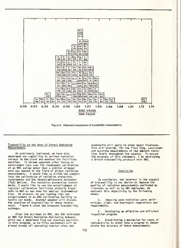
i1 1 1
r
Pu-242
H-3
U-234
Am-241
X-131
Pu-238
Sr-89
Sr-90
Co-139
Co-60
«o-226
Y-68
P-32
Sr-89
Mo-99
Co-57
Y-88
Cf.
137Co-58
U-238
P-
32C-14
Cr-51
Sn-113
U-235
Y-88
Sr-89
Nl63
Co-139
Pb-203
Au-198
Bo-140
Ci-
137Pu-239
CI36
Am-243
Co141
Y-88
Co-60
Cd-109
H-3 U-236
Pu-242
Cr-51
Pm-147
Cr-51
Co-139
I-
131H-3 Am-
w«Zn-65
Od-148
Pm-147
Co-139
No-ll
Po-210
Zn-65
Cl-137
Cr-51
Po-239
I-
125
Sr-90
Ag-110m
Sr-
90H-3 Cd-
109Hg-203
Co-144
Mn-54
Sr-85
Zn-65
Sr. Ni-90 63
C-14
C»-137
Se-75
Mn-54
Ct-137
Ci-134
Sn-113
Mn-54
Co-60
Sr-90
Y-88
Zn-65
Co-45
Pu-241
1 1
0.90 0.92 0.94 0.96 0.98 1.00 1.0? 1.04 1.06 1.08 1.10 1.12 1.14
RESL VALUENBS VALUE
Figure 4. Historical comparison of traceability measurements.
Traceability in the Area of Direct RadiationMeasurements
As previously indicated, we have alsodeveloped our capability to perform radiationsurveys in the plant and monitor the facilitiesenvirons. It became apparent after losing anenforcement case over the inadequate calibrationof an NRC survey meter that a similar arrange-ment was needed in the field of direct radiationmeasurements. I would like to divide the subjectinto the calibration of radiation protectioninstruments and the thermoluminescent dosimeter(TLD) devices. For radiation protection instru-ments, I would like to see the establishment ofregional calibration facilities directly trace-able to NBS as was done for medical instrumenta-tion. At present, we are looking into theestablishment of an NRC calibration facility tohandle our needs. Another speaker will discussthe question of traceability of these instru-ments. Figure 6 shows the proposed traceabilitypathways.
After the accident at TMI, the OIE initiatedan NRC TLD Direct Radiation Monitoring Network,which was a departure from our previous position.In this program, up to fifty dosimeters will beplaced around all operating reactor sites and
1
eventually will apply to other major licensees.This will provide, for the first time, consistentand accurate measurements of the ambient radia-tion levels throughout the country. To ensurethe accuracy of this statement, I am developinga direct traceability protocol with NBS.
Conclusion
In conclusion, our interest in the subjectof traceability is our desire to improve thequality of radiation measurements performed bylicensees as well as by NRC employees. Weapproach this objectivity by the followingmeans:
1. Imposing upon radiation users well-written, clear, and meaningful regulations andrequirements.
2. Developing an effective and efficientinspection program.
3. Establishing a mechanism for users of
radioactivity to enter into a program to demon-
strate the accuracy of these measurements.


RADON AND RADON DAUGHTER FIELD MEASUREMENTS
Andreas C. George
Environmental Measurements Laboratory
U. S. Department of Energy
New York, NY 10014
Practical methods for measuring the concentration of radon
and radon daughters in air are reviewed, and procedures
and instruments are recommended for reliable field
measurements
.
(environmental measurements; radon; radon daughters)
Introduction
Radon and its daughters is causing increasing
concern to many investigators involved in research
and situations where diagnostic measurements for
source identification and quantification are need-
ed.
While radon-222 and its daughters contribute
the highest fraction of the natural radiation dose
to man, we have been more concerned by certain
special cases of exposure. These include the occu-
pational exposure of uranium miners and uranium
mill workers, the general public in and around
areas of enhanced radiation, and more recently
inside houses built with materials with high
radium-226
.
The concentration of radon and its daughters
and their contribution to human dose cannot be
adequately measured and assessed unless all compo-
nents of measurement systems are accurately
calibrated. Little has been published describing
the different calibration methods of all the equip-
ment presently used for radon and radon daughter
measurements. The American National Standards
Institute (ANSI) issued a standard [1] with speci-
fic application in radiation protection in uranium
mines. The ANSI procedures do not specify any
accuracy requirements. A more comprehensive
publication dealing with calibration procedures for
radon and radon daughter measurement equipment was
issued by the Department of the Interior. [2] The
report stresses the necessity for the proper
calibration of the radon and radon daughter
measurement instrumentation to assure accurate
evaluation of the radiation hazard. Although the
publication was intended for uranium mining it is
very useful for other environments.
The instrumentation developed for measurements
in uranium mines has evolved with respect to
sensitivity and convenience. The widespread need
of these instruments in other environments with
much lower concentrations necessitated further
improvement
.
Knowledge of the various kinds of errors
encountered in physical measurements is necessary
for reliable data interpretation and comparison.
In this report I will describe some methods and
instruments employed in the determination of radon
and radon daughters as well as their applications
and limitations so one may be able to choose one
method over another for a particular application.
Lmportance of Radon and Radon Daughter Measurements
The main reason for the high interest in
radon and its daughters is their effect on human
health. An important stimulus for this interest
is the radon releases from the nuclear fuel cycle.
Although studies of radon and radon daughters
provide us with natural radiation data which can
be used as a standard to evaluate health effects •
to human populations from man-made radionuclides,
recently there have been extensive measurement
programs in all sources of radon in the environ-
ment. Some of the areas of interest are:
Nuclear Energy Industry
Uranium and its decay products are found in
all industrial activities associated with uranium
mining and milling operations. Although the
biological hazard data from the uranium mine popu-
lation were investigated extensively, the evalua-
tion of possible radiological hazards from the
waste products of uranium mill tailings is just
beginning. Radon measurements are important for
determining the adequacy of reclamation programs
at uranium tailings
.
Phosphate Mining and Processing
The concentration of natural uranium in
135

phosphate ores ranges from 10 to 400 ppm. [3] The
assessment of the radiological impact of phosphate
mining, processing and use is being investigated
and appropriate standards and guides will be
established. In Florida more than 25,000 acres of
mined lands have been reclaimed for residential
development and the potential higher levels of
airborne radiation warrant additional studies to
define the scope and extent of this problem.
Radon in Natural Gas
Radon is being considered as another source
of exposure of inhabitants of buildings as a
result of combustion of natural gas in unvented
appliances. The concentration of radon in natural
gas depends on the well head concentration and
transmission time to consumption point. Concentra-
tions of radon ranging from 1 to 1,500 pCi/A have
been reported. [4]
Radon In Indoor Environments
Radon diffuses out of building materials(brick, concrete, stone and interior walls) and to
a greater extent from the soil under the floor andfrom the domestic water supply. [10] In regions
with large deposits of radioactive materials,indoor levels become elevated. In recent years,
the construction of energy-efficient homes re-sulted in elevated concentrations of radon andother pollutants, many times over that found
outdoors. In the late 1970's, active solar heatingsystems were installed in residential and commer-cial structures for space heating. To make the
system more efficient, the heat is stored in rockbins until needed. Since the natural radioactivityof rocks in different geographical areas differs,the impact of these rocks on the concentration ofindoor radon levels must be investigated.
Radon in Natural Caves
Every year in the United States an excess of
1 million persons visit some of the large caves.
Usually exposure to tourists will not be large but
measurements show that the radiation dose to
regular cave workers is likely to reach or exceed
the maximum permissible dose. [5]
Radon and Geo thermal Resources Application
High radon concentrations in the waste
streams of geothermal electric power plants were
measured. It is suspected that elevated expo-
sures to radon and its daughters would occur at
the plant and in the surrounding vicinity. Non-
electrical applications of geothermal resources
are widespread especially in the western United
States [6] for space heating, domestic hot water
sources and for recreational purposes . Their
radiological health implications should be
investigated by measuring radon concentrations
inside structures which use geothermal fluids.
Instruments and Methods for Radon and Radon
Daughter Measurements
Measurements of the airborne concentrations ofradon and radon daughters are usually categorizedby application. Technology is sufficiently devel-oped to meet most demands encountered in field
measurements. Choice of the instrument and methoddepends on the levels to be measured, the accuracyrequired, equipment availability and convenience.
There is an abundance of available instruments for
routine laboratory and field applications andrecently complex instruments have been introducedfor research purposes
.
There are methods for prompt or instantaneous
or grab sampling, continuous, and time-integratingthat yield average concentrations for an extended
time period usually for a week or more. Tables 1
and 2 list the most commonly used instruments andmethods for radon and radon daughter measurements.
Detailed procedures of each method are described
in the listed references.
Earthquake Prediction
Radon measurements in sub-surface waters are
being investigated in earthquake prediction. It
is suggested that the tectonic strain of the rock
formations may increase the rate of release of
radon to the ground wa ter . [ 7
]
Radon in Atmospheric Tracer Studies
Since the half-life of radon is sufficiently
long to allow transport over thousands of miles,
it is used to trace continental air masses over
the oceans for as long as two weeks . It is also
used to study air currents, diffusion and cloud
formation and behavior .[8,9]
How Well Can Radon and Radon Daughter Measurements
be Made in the Field ?
The errors of most monitoring techniques are
acceptably small, when instruments are calibrated
and operated properly. The basic errors encoun-
tered in environmental measurements are:
Personal errors due to human failure. This
can be traced to deviation from prescribed proce-
dures. In the field, shortcuts in operating pro-
cedures usually result in errors which can be
eliminated through experience.
Statistical errors due to the random nature
of radioactivity. The resulting random errors
cannot be prevented but they can be reduced and be
accounted for by the application of the proper
136

TABLE 1 . INSTRUMENTS AND METHODS FOR MEASURING RADON
Instrument
and Method Application Principle of Operation Sensitivity Reference
Scintillation flask
Two filter
Track etch
Passive
Plastic bag
Passive monitor
Grab or continuous
sampling
Grab or continuous
sampling
Pulse ionization Grab (laboratory only)
Continuous
Continuous
Time integrating
Time integrating
Scintillation alpha count
Decay of radon and collectionof daughter products on secondfilter; alpha count
Sample transferred Into Ion
chamber; pulse ion count
Alpha sensitive films registertracks when etched in NaOH
Radon diffusion into sensitivevolume. Po-218 collected onscintillation counter
electrostatically
Collection of ambient air
in bag. Transfer In scintilla-tion flask; alpha count
Radon diffusion into sensitivevolume. Po-218 collection onTLD electrostatically
< 0.1 pCi/i
0.01 - 5 pCi/i
< 0.05 pCl/i
0.2 pCi - month/i
0.5 pCi/i
< 0.1 pCi/i
0.03 pCi/A
11, 12
13, 14
15
16, 17
18
19
20
TABLE 2 . INSTRUMENTS AND METHODS FOR MEASURING RADON DAUGHTERS
Instrument
and Method Application Principle of Operation Sensitivity Reference
Kusnetz and Rolle Grab sample for
working level only
Collect sample on filter;
alpha count
0.0005 WL* 21, 22
Tsivoglou and
modifications
Grab sample for
individual radon
daughters and working
level
Collect sample on filter
alpha count
0.1 pCi/i each
of RaA, RaB and
RaC - 0.O005 WL
23, 24, 25,
and 26
Alpha spectrometry Grab sample for indi-
vidual radon daughters
and working level
Collect sample on filter,
count in alpha
spectrometer
0.5 pCl/l each
of RaA, RaB and
RaC - 0.002 WL
27, 28
Instant working
level monitor
Grab sample for indi-
vidual radon daughters
and working levels
Automatic sample collection,
alpha or alpha and beta count
1 pCi/i each of
RaA, RaB and RaC
0.01 WL
29
Working level
monitor
Time-Integra ting radon
daughter concentration
Collect sample on filter
(1-2 weeks). Detect with
thermoluminescent material
0.0005 WL in a
week30, 31, 32
*1 WL (working level) is the concentration of radon daughters in 1 £ of air that will release
1.3 x 10s
MeV of alpha energy upon complete decay through Po-214.
137

statistical methods. In measuring environmental
levels of radioactivity, the primary goal is to
accumulate statistically meaningful counts withina reasonable period of time. By using the bestcombination of sensitive volume, pumping rate and
counting times we can obtain the required preci-
sion. Measurement precision can be determined
experimentally by comparing the results of a
series of replicate measurements. Usually,
measurement precision between 10% and 20% is
satisfactory.
Systematic errors usually result from mal-functioning instruments and from improper calibra-tion of equipment. The accuracy of a method is
measured by calibration against a standard method
or by a reliable method traceable to NBS as near
as possible to the actual deployment use in the
field. Test calibrations should be conducted in
large chambers in which the ambient conditions of
temperature, relative humidity and dust loading
can be simulated for different times of exposure.
Our experience at the Environmental Measurements
Laboratory (EML) is not to accept the calibration
of an instrument as received from a supplier.
Although instruments are usually constructed well,
we found that they are not necessarily calibrated
properly
.
Radon Measurements
Scintillation Flask
For grab samples, the scintillation flask
method is one of the oldest, most reliable and
widely used both in the laboratory and in the
field. Basic equipment consists of a scintilla-
tion flask, a vacuum system or pump and a
photomultiplier tube counter. Measurement errors
with this method may arise due to the following.
Improper flask calibration . In intercalibra-
tion exercises in which several agencies and
universities participated, we found that the
disparity of some of the data was the result of
improper calibration. In one exercise in which 12
groups took part, the reported values of four
participants were low by 20 to 35% and in another
two cases were 20$ higher than the expected value.
Leaking flasks . Scintillation flasks from
the same production batch that deviate substan-
tially from the ideal calibration are associated
with leakage. This is more common with the
evacuated type. It is essential that flasks
should be leak-tested before calibration and that
they be recounted for several days after calibra-
tion to observe any deviation from the expected
value
.
Alpha counting equipment . A radon scintilla-
tion flask should be calibrated with the counting
equipment intended for the field application.Flasks counted on different counters can differsubstantially because of different operatingvoltage plateaus and their accompanying noiselevels. This can be very troublesome whenmeasuring environmental levels of radon.
Two-Filter Method for Radon
Although this method is not used as much as
the scintillation flask it can be designed for a
variety of specific applications. The two-filtersensitive volume may range from .05 I to 1000 I
depending on the required sensitivity. By varyingthe sampling flow rate, tube volume, and samplingtime, radon concentrations as low as .01 pCi/# canbe determined.
The common errors encountered are: any
leakage around the front filter will tend to in-
crease the radioactivity on the exit filter and
overestimate the radon concentration. To avoid
this, it is prudent to push rather than draw air
through the two-filter device; in this manner the
leaks are outwards from the device. The front
filter should have essentially 100$ collectionefficiency for radon daughter products and the
exit filter should have good surface character-
istics for the collection of Po-218.
The counting equipment should be standardized
with an alpha standard that has the same geometric
configuration as the exit filter and approximately
the same alpha energy emission. Calibration under
different conditions of flow rate, collection time
and concentration should be conducted to test the
linearity of the system before it is deployed in
the field.
Continuous Measurement of Radon
Continuous reading radon monitors have been
found useful for measuring varying concentrations
of radon over a long period of time. These types
of measurements are more meaningful than grab
samples in estimating average exposures. Several
kinds of continuously reading radon monitors have
been developed to serve this purpose. However,
this extra information is derived at a consider-
able increase in instrument size, complexity and
additional cost. The most commonly used contin-
uous radon monitors are:
Radon flask monitor . This instrument is
based on the counting of alpha disintegrations
produced from radon circulated through a scintil-
lation flask mounted on a PM tube. Previous
monitors neglected to take into consideration
deposition of radon daughters in the scintilla-
tion flask and this resulted in questionable
measurements. To avoid this discrepancy, the
monitor must be calibrated taking into considera-
tion the total number of counts obtained in
138

successive equal time intervals, the detection
volume of the scintillation flask, counting
efficiency, and correction for the previously
deposited radon daughters .[ 14,33] When this pro-
cedure is applied, the radon flask monitor is
capable of measuring varying radon concentrations
accurately for an indefinite length of time.
Two-filter monitor . The instrument can be
designed to measure environmental levels of radon
(as low as 0.01 pCi/£) . Like the scintillationflask monitor, it must be calibrated in the same
manner as intended for field measurements.
Corrections for the radioactivity from the pre-
vious samples must be made for accurate radon
determination. A source of error is that whicharises from the contribution of thoron activity on
the fixed exit filter. This can be eliminated by
passing the ambient air containing radon and thoron
through a delay chamber upstream from the two-
filter sensitive volume, which it will allow thoron
(Tj5 = 55 seconds) to decay but will have no effect
on the radon.
A modification [34] of the two-filter contin-
uous radon monitor uses an automatic drive that
changes the exit filter every hour and transports
it into a scintillation counter, thus eliminating
the accumulation of thoron daughter products and
the need for corrections from the previous hour-
long sample
.
Passive electrostatic monitor . In principle
the monitor is continuously detecting the ambient
radon concentration. But as in the case of the
scintillation flask and the two-filter monitors,
the changes in ambient radon concentration are
masked by the previously deposited radon daughters.
So far a procedure for correction for the activity
associated with radon daughters deposited in
previous counting intervals has not been incorpo-
rated in the calibration of this instrument.
Another deficiency in this instrument that may
result in error is the dependence of the instru-
ment on humidity. Tests at EML with similar
monitors showed a humidity dependence, namely a 6f>
decrease in sensitivity for a 10% increase in
relative humidity .[35]
Time-Integrating Radon Monitor
Another type of instrument that measures
radon concentration over long periods of time is
the time-integrating monitor which obtains a
single number representing the average concentra-
tion during the period of observation.
Plastic bag method . Air is sampled contin-
uously for 48 hours by pumping ambient air into a
40 & bag at a rate of 10 m£/min.[19] This method
requires additional analytical steps by trans-
ferring the radon from the bag into a scintilla-
tion flask. In addition to errors encountered by
the flask method, correction for the decay ofradon during the course of sampling are somewhatdifficult to make since it is not known exactlywhen the radon was accumulated In the bag.
Passive environmental monitor . Its principleof measurement [20] is similar to the passive-electrostatic monitor in that it samples bymolecular diffusion. Air diffuses through a
desiccant into the sensitive volume thus elimi-nating the effect of humidity on the instrument'sperformance
.
The alpha activity that accumulates on the
electrode is detected continuously during exposure
by a thin thermoluminescence detector (TLD) . Afterexposure the TLD chip is read in a thermolumines-cence reader and its reading is proportional to
the time-Integra ted radon concentration. Calibra-
tion of the monitor under different conditionssimulating field atmospheres is necessary.
The response of the monitor lags about 5
hours, which is the diffusion period through the
desiccant, but over long monitoring periods(usually one week or more) the average concentra-tion in the sensitive volume will equal the
average ambient concentration even in varyingradon atmospheres.
Radon Daughter Measurements
All measurement methods for radon daughters
are based on collecting a known volume of air
through a filter in a known time and by counting
the activity on the filter during or after
sampling. A number of different sampling-
counting regimes may be used and the choice
depends on the amount of information one seeks.
The simplest methods involve a single alpha count
and yield a result in WL only. The more sophis-
ticated methods involve several counts and yield
the individual air concentrations of the three
daughter products, including the WL.
The methods listed in Table 2 for measuring
radon daughter concentrations by grab sampling
are well established. Details of each method are
given in the references
.
Errors in determining individual radon
daughter and WL concentrations result from:
1. measurement of sample volume,
2. filter media characteristics,
3. measurement of collected radioactivity
directly on a filter or indirectly on a
detector close to the filter.
All three are subject to several sources of errors.
139

Measurement of Sample Volume
Inaccuracies in measurements of air sample
volume results from improper calibration of flow-
meters, unstable air samplers, filter holder
integrity and incorrect timing period.
Air pump flowmeters should be calibrated for
each application. Their calibration is density
dependent and care must be taken when used at
different altitudes. The pump-flowmeter- train
assembly should be calibrated at the same condi-
tions of elevation and at the same resistance
caused by the filter and the other component parts
in the sampling train. During field sampling an
open face filter or filter holder assembly suit-
able for particulates should be used to prevent
radon daughter losses due to plate out. Plate-out
losses may be significant in atmospheres with low
concentrations of particles (less than 5,000
particles per cm3). Some instruments tested by
EML were found to be unsuitable for radon daughter
sampling. Plate out was high either because the
filter was situated at the wrong place during
sampling or because of plate out on surfaces
upstream from the filter.
Sample timing is very important in the
usually short sampling periods used for grab
sampling. Errors may be significant if an opera-
tor relies on his wristwatch and on his memory.
A one-minute mistake in timing causes a 20% error
in air volume alone for a nominal five-minute
sample
.
The sensitivity of the different grab
sampling methods depend on sampling rate, the
delay between sampling and counting, and the
counting interval. For low concentrations of
radon daughters, such as those encountered out-
doors, the precision of the measurement can be
improved considerably by sampling a larger volume
of air. This can be accomplished by increasing
the flowrate and the size of the collection
surface. Sample flowrates from 10 Z/m±n to 300
JL/m±n can be achieved with available commercial
air samplers, and filters ranging in size from 4
cm3 to 80 cm3 can be accommodated with existing
samplers and alpha counters. Buildup of filter
resistance from dust loading is unimportant for
the short sampling periods of 5 to 10 min.
If alpha spectrometry is used for counting,
the volume of air is limited because solid state
detectors are very small and can handle small
filters only. Better sensitivity can be achieved
when counting total alpha as in alpha scintilla-
tion detectors which are not limited to sample
volume. A word of caution in using high volume
samplers indoors - if one wants to measure the
ambient air, care should be taken not to disturb
it during sampling. A high volume sampler,
operating at 300 i./min in a small room, will
introduce particulates from its exhaust air. Thiswill disturb the state of equilibrium and attach-ment of the radon daughters, although it will notaffect the radon concentration. However, with the
proper positioning, high volume samplers can beused inside large rooms and outdoors.
Filter Media Characteristics
Filters for radon daughter sampling Shouldhave high collection efficiency and good surface
deposition characteristics. Membrane filters,
< 0.8 urn pore size, were found to be suitable.
Tests done at EML with both membrane, 0.8 um pore
size, and glass fiber filters showed collectionefficiencies of virtually 100$ for radon daughters.
Any other type of filter should be investigated
similarly before deployment in the field.
Measurement of Collected Radioactivity
Errors in counting radon daughter samples
result from incorrect calibration of the counting
equipment and from counting errors.
Several types of laboratory and field
counters are commercially available; some have
more desirable features than others. Scintillation
type detectors are the most popular. Alpha
spectrometry is used in special research applica-
tions with limited use in the field.
The counting efficiency of a detector is a
function of geometry and energy level. The
geometric configuration of the counter depends on
the distance of the detector from the sample and
the relative size and shape of the detector and
sample. It is essential that alpha counters be
calibrated with an alpha standard having the same
size and shape as the sample to be counted.
Usually, Po-218 and Po-214 sampled on a membrane
filter offer the most suitable alpha source.
Instruments with thick windows were found to be
energy dependent and their detection efficiency
with a monoenergetic alpha calibration source of
5 MeV to be as low as half of that for radon
daughters from Po-218 and Po-214. Alpha counters
with windows need to be calibrated with radon
daughters against a windowless counting system.
Once the counting efficiency of a counter is
determined with radon daughters collected on a
membrane filter, any alpha standard may be used as
a reference check source to verify the instru-
ment's counting efficiency in the field.
Alpha self-absorption in membrane filters
counted with alpha scintillation counters was
found to be nil. Comparative measurements made by
EML on glass fiber and membrane filters show self-
absorption in glass fiber filters to be < 5% if
the linear velocity across the filter is main-
tained below 100 cm/s . If any other filter is
used, the alpha energy attenuation in the filter
140

should be investigated by making comparative
measurements with thin membrane filters or by
using the procedure described in the ANSI standard.
[1]
Counting errors result because of the random
nature of radioactive decay and the larger the
number of counts detected the smaller the uncer-
tainty of the measurement. In most of the methods
listed on Tables 1 and 2, there is room for
flexibility to reduce counting errors . This can
be accomplished by sampling a larger volume of air
on a larger filter, by using a larger or more
sensitive detector, and by counting during and
after sampling.
Radon and Radon Daughter Measurements with
Thermoluminescent Detectors
Thermoluminescence dosimetry (TLD) is gaining
wide acceptance in environmental measurements.
There is an abundance of scientific papers in the
literature that cover dosimetry using TLDs and an
ANSI standard [36] was issued which considers the
performance of TLD systems when used to measure x-
and gamma radiation. To our knowledge, there are
no recommended procedures for TLD systems used for
measurement of radon and radon daughter radiation
exposures. However, the same performance specifi-
cations and testing procedures used in x- and
gamma dosimetry will apply equally well in alpha-
dosimetry
.
In alpha dosimetry the phosphors that have
been widely used are LiF, CaF2 and CaS04 . These
materials in combination with manganese or
dysprosium as activators have adequate sensitivity
for monitoring radon and radon daughters
.
The short range of alpha rays in matter
insures total deposition of the incident a-ray
energy in the TLD material. Energetic beta and
gamma rays deposit only a portion of their energy
and this prejudices the registered signal in favor
of a-ray energy deposition - a desirable charac-
teristic .
At EML, alpha TLD work began in the late
1960 's during testing and evaluation of personal
dosimeters for uranium miners. We selected LiF
because it has adequate sensitivity and found it
to be less troublesome in environmental measure-
ments. CaFs and CaS04 have better sensitivities
but require energy response and fading correc-
tions - both undesirable characteristics. Since
TLD respond to beta and gamma radiation, it is
desirable to minimize this response by using a
thin dosimeter chip. Our tests indicate that
LiF-700 (| x f X .015 in.) minimized response to
beta and gamma radiation, and in field measure-
ments the gamma radiation is readily corrected for
by a second control TLD chip which is not exposed
to the alpha radiation.
Besides the practical reasons for choosing a
TLD system, such as cost and system flexibility, a
system with adequate sensitivity over the antici-
pated range of exposures should be selected. The
ANSI standard [36] recommends testing and calibra-
tion procedures which are invaluable in selecting
the appropriate TLD system. The key to proper
testing is the simulation of the environmental
conditions under which the system will be used.
The EML Procedures Manual [15] devotes a
whole section to thermoluminescence dosimetry
procedures which will be of particular help to
those who plan to incorporate TLD dosimetry in
their programs. One of the most critical
parameters that can affect the measurements of
radon and radon daughters is uniformity of TLD
response among dosimeters. At EML we found that
LiF-700 chips from the same supplier but from
different production lots can vary by as much as a
factor of two. Response of TLD chips from the same
lot is usually very good (standard deviation ±5$>) .
The uniformity is usually measured by exposing
TLD chips to alpha radiation for the same length
of time. From our experience, we found it less
troublesome to purchase a large quantity of chips
from the same production lot and use them in our
entire program.
Both of the integrating monitors designed by
EML for measuring radon and radon daughters, using
LiF-700 chips (f x | X .015 in.) as the sensing
devices, are calibrated in the exact configuration
in which they are used in the field. Calibrations
are performed in a large chamber (20 m3 ) in which
radon and radon daughter exposure conditions can
be simulated. By varying the concentration over
periods of one week or more and the normal length
of the field exposure, the sensitivity of the
system over a range of exposures can be achieved.
Traceability of Measurements
Radon Measurements
The common methods for measuring radon con-
centration are usually calibrated against a
secondary standard traceable to a primary NBS
standard; this is usually done in large labora-
tories. At EML, the pulse ionization chamber is
the standard against which all other methods are
compared. The 2 I pulse ionization chamber is
standardized several times a year with radon from
an NBS SRM Ra-226 solution. The solution is
diluted (by weight), split into aliquots and
placed in radon bubblers from which the radon
standard is transferred to the pulse ionization
by emanation. The chamber has an overall counting
efficiency of 85$.
141

Radon Daughter Measurements
Standard electrodeposited alpha sources of
the same size as the filters are usually used to
obtain the counting efficiency of the alpha
detector. At EML, the detection efficiency of 2lT
proportional counters is determined by measuring
an NBS certified U3 08 standard source. The
activity strength of other sources prepared at EML
or procured commercially is calculated based on
the detector efficiency determined with the NBS
standard source. The counting efficiency of radon
daughter detectors is readily determined bycounting Rac' (Po-214) collected on a filter
alternately in a windowless counter and in the
detector to be tested.
References
[10]
[1]
[2]
[3]
[4]
[5]
[6]
[7]
[8]
[9]
Radiation Protection in Uranium Mines, American
National Standards Institute, ANSI N13.8 (1973).
Calibration Procedures for Radon and Radon
Daughter Measurement Equipment, R. T. Beckman,
Mining Enforcement Safety Administration
Report MESA I.R. 1005 (1975).
Radiation Exposures in the Florida Phosphate
Industry, W. A. Mills, R. J. Guimond and S. T.
Windham, Proceedings IV International Congress,
IRPA, Paris, April (1977).
Assessment of Potential Radiological Health
Effects from Radon in Natural Gas, G. W.
Johnson, D. E. Bernhardt, D. E. Nelson and
H. W. Calley, U. S. Environmental Protection
Agency Report EPA 520/1-75-004 (1973)
.
Measurements of Seasonal and Daily Radon
Daughter Concentration Fluctuations in
National Park Service Caves, K. A. Yarborough,
Radon Workshop, ed. A. J. Breslin, U. S. Energy
Research and Development Administration Report
HASL-325, New York (1977).
Radioactivity Associated with Geothermal Waters
in the Western United States, M. F. O'Connell
and G. A. Gilgan, U. S. Environmental Protec-
tion Agency Report ORP/LV-75-8B, April (1978)
.
Investigation of Radon-222 in Subsurface Waters
as an Earthquake Predictor, R. A. Smith, H. R.
Bowman and D. F. Mosier, JEFE Transaction on
Nuclear Science, NS-23, 694-698 (1976).
The Vertical Distribution of Radon-222, Radon-
220 and Their Decay Products in the Atmosphere,
W. Jacob i and K. Andre, J. Geophys . Res., 68,
3799 (1963).
Radon-222 Concentrations in the Convective
Patterns of a Mountain Environment, M. H.
[11]
[12]
[13]
[14]
[15]
[16]
[17]
[18]
[19]
[20]
[21]
Wilkening, J. Geophys. Res., 75, 1733 (1970).
The Distribution of Ambient Radon and RadonDaughters in Residential Buildings in the NewJersey-New York Area, A. C. George and A. J.
Breslin, Presented at the D0E/UT Symposium onthe Natural Radiation Environment III, Houston,
Texas, April 23-28 (1978).
Improved Low-Level Alpha Scintillation -.(Counter
for Radon, H. F. Lucas, Review Sci. Instrum.,
28, 680 (1957).
Scintillation Flasks for the Determination of
Low Level Concentrations of Radon, A. C.
George, Proceedings of Ninth Midyear Health
Physics Symposium, Denver, Colorado, Feb.
(1976) .
A Study of the Two-Filter Method for Radon-222,
J. W. Thomas and P. C. LeClare, Health Phys.
,
18, 113 (1970).
Development and Operation of Continuous Radon
Monitors 1974-77, J. W. Thomas, U. S. Depart-
ment of Energy, Environmental MeasurementsLaboratory, unpublished report (1977).
EML Procedures Manual, ed. John H. Harley,
U. S. Department of Energy Report HASL-300,
updated annually (1972).
Dosimetry of Environmental Radon. Methods and
Theory for Low-Dose Integrated Measurements,
R. L. Fleischer, General Electric Research and
Development Center, Schenectady, NY, unpub-
lished report (1980)
.
Improved Type Track Etch Detector Calibration
Results, H. W. Alter, Terradex Corp., Walnut
Creek, CA, unpublished report (1980).
Design and Application of a Continuous,
Digital-Output Environmental Radon Measuring
Instrument, H. Spitz and M. W. Wrenn, Radon
Workshop, ed . A. J. Breslin, U. S. Energy
Research and Development Administration Report
HASL-325, New York (1977).
An Integrating Air Sampler for Determination
of Radon-222, C. W. Sill, Health Phys., 16,
371 (1969).
Measurement of Environmental Radon with
Integrating Instruments, A. C. George and
A. J. Breslin, Workshop of Methods for
Measuring Radiation in and Around Uranium
Mills, ed. E. D. Harward, Atomic Industrial
Forum, Inc., Program Report, Vol. 3 (1977).
Radon Daughters in Mine Atmospheres - A Field
Method for Determining Concentrations, H. L.
Kusnetz, Am. Ind. Hyg. Assoc. J., 17,85(1956).
142

[22]
[23]
[24]
[25]
[26]
[27]
[28]
[29]
[30]
[31]
[32]
[33]
[34]
Rapid Working Level Monitoring, R. Rolle,
Health Phys. , 22, 233 (1972).
Occurence of Nonequilibrium Atomospheric
Mixtures of Radon and Its Daughters, E. C.
Tsivoglou, H. E. Ayer and D. A. Holaday,
Nucleonics, 1, 40 (1953).
Measurement of Radon Daughters in Air, J. W.
Thomas, Health Physics, 23, 783 (1972).
A Radon Daughter Monitor for Use in Mines,
A. C. James and J. C. Strong, Proceedings 3rd
International Congress, IRPA, Washington, D.C.,
USAEC CONF-730907, p. 932 (1973).
Analysis of the Activity of Radon Daughter
Samples by Weighted Least Squares, 0. G. Raabe
and M. E. Wrenn, Health Phys., 17, 593(1969).
Analysis of Atmospheric Concentrations of RaA,
RaB and RaC by Alpha Spectroscopy, D. E. Martz,
D. F. Holleman, D. E. McCurdy and K. J.
Schiager, Health Phys., 17, 131 (1969).
The Measurement of Low-Concentrations of the
Short-Lived Radon-22 Daughters in the Air by
Alpha Spectroscopy, N. Jonassen and E. I.
Hayes, Health Phys., 26, 104 (1974).
A Microprocessor-Assisted Calibration for a
Remote Working Level Monitor, W. B. McDowell,
D. J. Keefe, P. G. Groer and R. T. Witek,
IEEE Trans. Nucl. Sci., NS-24:1, Feb. (1977).
Integrating Radon Progeny Air Sampler, K. J.
Schiager, Am. Ind. Hyg. Assoc. J., 35, 165
(1974) .
A Working Level Dosimeter for Uranium Miners,
A. J. Breslin, S. F. Guggenheim, A. C. George
and R. T. Graveson, U. S. Department of Energy
Report EML-333, New York (1977).
A Time -Integra ting Environmental Radon
Daughter, S. F. Guggenheim, A. C. George,
R. T. Graveson and A. J. Breslin, Health Phys.,
36, 452 (1979) .
Interpretation of the Response of Continuous
Radon Monitors to Transient Radon Concentra-
tions, A. Busigin, A. W. Van Der Vooren and
C. R. Phillips, Health Phys., 37, 659 (1979).
A Two-Filter Environmental Monitor with an
Automatic Drive that Changes the Exit Filter,
V. C. Negro, U. S. Department of Energy
Report EML-367, p. 244 (1979).
[35]
[36]
FUNGI - A Radon Measuring Instrument with FastResponse, V. C. Negro and S. Watnick, IEEE
Trans. Nucl. Sci., NS-25, p. 757 (1978).
Performance, Testing and Procedural Specifica-tions for Thermoluminescence Dosimetry(Environmental Applications), AmericanNational Standards Institute, ANSI N545
(1975).
143

p
t
a
o
c
tl
a
ti
PI
VI
Ij
01
Hi
31
Oi
a
a
pe
Hi
Co
th
ne
pr
tit
tei
SU]
ai
usi
rei
ita
Sta
(US
::
sin
bt
the

PERFORMANCE TESTING OF PERSONNEL DOSIMETRY SERVICES
Phillip A. PlatoC. Glenn Hudson
The University of MichiganAnn Arbor, MI 48109
From 1977 to 1979, The University of Michigan conducted a pilot study of a dosimetryperformance testing standard that the Nuclear Regulatory Commission is consideringas the basis of a mandatory testing program for dosimetry processors that servicetheir licensees. This paper discusses the traceability of the radiation sources usedin the pilot study to the National Bureau of Standards and summarizes the results of
the pilot study.
(dosimeters, NRC, pilot study, sources, standard, traceability)
Introduction
There have been many attempts during the pasttwenty years to test the performance of personneldosimetry processors in the United States. Cus-tomers and competitors of commercial dosimetryprocessors continuously design tests to examinethe competence of a given processor. Unfortun-ately, the competence of the testing group hasoften been worse than the competence of the pro-cessor being tested, which created more problemsthan were solved. The National Sanitation Found-ation [1] (NSF) has operated an annual dosimetrytesting program since 1966. However, partici-pation in the NSF testing program is on avoluntary basis and, as a result, attracts a
maximum of only a half dozen commercial processorson a regular basis. In 1972, the AmericanNational Standards Institute published a stand-ard [2] that could be used to test the performanceof film badge processors. Due to a variety of
criticisms [3], the standard was never used.Thus, in reviewing the past efforts to test theperformance of dosimetry processors, one commonobservation is apparent; none was successful.
In 1975, the Health Physics Society Standards
Committee (HPSSC) formed Working Group 1.4,
chaired by Dr. Margarette Ehrlich, to prepare a
new standard that could be used to test dosimetryprocessors. There was one primary reason to hopethat this standard would succeed as a useful docu-ment whereas other similar dosimetry standards hadreceived either modest support nationally or no
support at all. That reason was cooperation amonga variety of regulatory agencies that would makeuse of the HPSSC Standard once it had passed peer-review processes
.
The impetus for the development of a newstandard came initially from the Conference of
State Radiation Program Directors. The idea wasendorsed by the US Nuclear Regulatory Commission(NRC) which expressed an interest in amending10 CFR 20 to require performance testing of do-
simetry processors that serve NRC licensees. AnInteragency Policy Committee was formed to monitorthe progress of Working Group 1.4 and to coordin-
ate the efforts of the various regulatory agenciesconcerning future mandatory testing of processors.The Interagency Policy Committee included mem-bers of the NRC, the Department of Energy (DOE),
the Department of Defense, the National Bureau ofStandards, the Bureau of Radiological Health, anda representative from the States. Although no
regulatory agency could commit itself in 1975 to
the adoption of the standard that would be pro-duced by Working Group 1.4, it was the hope ofmany people that the standard would someday beadopted by all the regulatory agencies involvedas the basis of a uniform, nationally-recognized,mandatory testing program for all personnel do-simetry processors in the United States.
By late 1976, the first draft of the HPSSCStandard [4] was available for public comment.In a public meeting held at the end of 1976, con-cern was expressed by a number of people thatregulatory agencies might adopt the Standardwithout first seeing how it would work in a testsituation. Thus, the NRC sponsored a two-yearpilot study of the Standard beginning in October,1977. The contract to conduct the pilot studywas awarded to The University of Michigan. Anyorganization in the United States that processedpersonnel dosimeters used for primary doserecords was permitted to participate in the pilotstudy on a voluntary basis at no charge. A total
of 59 organizations chose to participate. Theseincluded large and small commercial processors,most of the National Laboratories, a number of
prime DOE contractors, many nuclear power plants,the military, and a few medical facilities and
universities
.
The purpose of this paper is to discuss the
traceability of the radiation sources used in the
pilot study to the National Bureau of Standards(NBS), and to summarize the results of the pilot
s tudy
.
145

Radiation Sources
Table 1 is a summary of the radiation sourcesused during the two-year pilot study and the pro-cedures used to determine if a processor passedor failed any radiation category (type of radia-tion) within the Standard. A detailed descriptionof calibration and irradiation procedures has beenpublished [5] . Four types of radiation are re-
quired for the Standard as shown in Table 1:
gamma-rays (cobalt-60), standard NBS X-ray tech-niques (specific combinations of voltage and
filtration), beta particles (strontium-90) , and
neutrons (californium-252) . When the NRC contract'was awarded to The University of Michigan, wehad seven months to obtain the required sources,calibrate the sources, and develop the operationaland administrative procedures required to test
each processor according to the Standard. At thesame time the NRC awarded the contract to TheUniversity of Michigan, they awarded a secondcontract to NBS to provide calibrations and othertechnical services to The University of Michiganto insure that all irradiations done for the pilotstudy would be accurate to within ±5% as specifiedin the Standard.
Two cobalt-60 sources, 5 Ci and 2700 Ci, wereused for the pilot study. Two Shonka-Wyckof
f
ionization chambers, 3 cm3 and 100 cm^, were cal-
ibrated to cobalt-60 by NBS. These chambers werethen used to calibrate the exposure rate fromthe two University of Michigan sources. Half-lifecorrections were made on a daily basis after eachsource was calibrated.
The same two ionization chambers were alsocalibrated by NBS to several standard NBS X-raytechniques . The chambers were used to calibratean X-ray beam before and after dosimeters wereirradiated on a given day. A beam monitor con-
nected to a strip chart recorder was used to
determine if the exposure rate of the beam changedduring the working day.
A 40 mCi strontium-90 beta-particle sourcewas calibrated by both NBS and The University of
Michigan using extrapolation chambers. Half-lifecorrections were made on a monthly basis aftercalibration.
The californium-252 neutron source was cal-
ibrated by NBS with their manganese sulphatebath calibrator. The neutron emission rate de-
termined by NBS was combined with a dose con-
version factor given in the Standard to calculatea dose equivalent rate at a given distance fromthe source.
Results
each depth of each interval (dose range) shownin Table 1. Thus, to pass Category IV, a pro-cessor had to pass only two statistical tests.However, to pass Category II, a processor had to
pass seven statistical tests. The statisticalcriteria are summarized on the bottom of Table 1
and are discussed in detail in the Final Re-port [6] of the pilot study.
The results of the pilot study showed thatonly about one-third of the categories testedwere passed. The passing rate for the intervalstested was considerably better, although a pro-cessor passes a category only if all the doseintervals within the category are passed.
As part of an additional analysis of the
results of the pilot study, the performance of
each individual dosimeter irradiated during thepilot study was examined. This analysis, whichis discussed in detail in a Supplementary Re-port [7] following the completion of the pilotstudy, is not part of the statistical requirementsof the Standard. However, this analysis permitsan observation of the percent of dosimeters that
had a reported dose within ±10% of the actualdelivered dose, ±30%, ±50%, etc. The results of
this analysis showed that approximately 80% of
the 23,000 dosimeters irradiated during the two-year pilot study had a reported dose that waswithin ±50% of the delivered dose.
Conclusion
The NRC and the other relevant regulatoryagencies are currently evaluating the results of
the pilot study to determine if a mandatorytesting program is necessary and feasible for
all dosimetry processors in the United States.
Operationally, a mandatory testing program ap-
pears to be feasible. The radiation sourcesrequired by the Standard can be calibrated and
used to provide delivered doses within ±5% re-
quirement of the Standard. The cost of a manda-
tory testing program does not appear to beprohibitive, probably around $3,000 for a com-
plete test of a processor. Administratively,the problems are immense. Answers are currentlybeing sought to questions such as;
How many tests should a processor be re-
quired to pass within a given timeperiod?
What should be the qualifications of a
testing laboratory?
How many testing laboratories should bepermitted?
How should a testing laboratory be monitored
Each processor was permitted to be tested technically to insure credability?twice during the pilot study. In each test, a
processor could choose to be tested in any or Who should mediate a dispute between a
all of the radiation categories shown in Table 1. testing laboratory and a processor?
To pass each category, a processor had to pass
146

Should a processor that fails a test begiven a probationary period to correctproblems while still being permitted to
provide dosimeters to radiation workers?
The relatively easy work of the pilot studyhas baen completed. The difficult task of im-
plementing the Standard is now at hand.
[1]
[2]
References
National Sanitation Foundation Standard No. 16
Relating to Dosimetry Services. The NationalSanitation Foundation, P.O. Box 1468, AnnArbor, MI, 48106 (1966)
.
American National Standards Institute, inc.,American National Standard Criteria for Film .t"
Badge Performance, ANSI N13.7 - 1972. 14303roadway, New York, NY (1972).
[3]
[4]
[5]
[6]
[7]
Plato, P. Evaluation of "Criteria for FilmBadge Performance" ANSI N13.7 - 1972. Am .
Ind. Hygiene Assoc. Journal , 38:41-45 (1977).
Criteria for testing personnel dosimetry per-formance. Proposed standard prepared by the
Health Physics Society Standards Committee,4720 Montgomery Lane, Suite 506, Bethesda,MD 20014 (November 30, 1977). This Standardis also published by the American NationalStandards Institute as Draft ANSI N13.ll.
Plato, P. and Hudson, G. Procedures manualfor performance testing of personnel dosimetryservices, NUREG/CR-1063, National TechnicalInformation Service, Springfield, Virginia22161 (January, 1980).
Plato, P. and Hudson, G. Final report for
performance testing of personnel dosimetryservices, NUREG/CR-1064, National TechnicalInformation Service, Springfield, Virginia22161 (January, 1980).
Plato, P. and Hudson, G. Supplementary re-
port for performance testing of personneldosimetry services, NUREG/CR-1304, NationalTechnical Information Service, Springfield,Virginia 22161 (April, 1980).
147

TabLe 1. Summary of the HPSSC Standard used in the pilot study.
Tolerance Level (!)
Number ofDosimeters
(see f o: tnote s)
RadiationShallow De - r
Ca t ego r
v
Interval Test Range Per Test ( 7 ms? / ctq^ ") (1000 -z/c-.~ 1
I. Gatoa 1 Accident: 10-SQ0 rad 10 no test a
(Co-60) 2 Protection: 30-100 mrem 10 no test b
3 101-300 10 no test b
4 301-10 000 mrem 10 no test b
II
.
X Ray 1 Accident: 10-800 rad 10 no test a
(30-300 keV) 2 Protection: 30—100 mrem 10 c c
3 101-300 mrem 10 c c
4 301-10,000 mrem 10 c c
III. X Ray Accident: no test(15-30 keV) 1 Protection - 150—300 mrem 10 c c
2 701 -in ODDJul 1U)UUU 10 c c
IV. Beta Accident: no test
(Sr-90) 1 Prnfprfinn' 1 5H— TOD mrem 10 c no test
2 Jul J.v )UUU mrem 10 c no test
V. Man r rAn
c
Accident: no test
(Cf-252) 1 Protection: 100-300 mrem 10 no test c
2 301-5,000 mrem 10 no test c
VI. Photon Mixtures Accident: no test(Cat. I & II) 1 Protection: 50-100 mrem 10 c c
2 101-300 mrem 10 c c
3 301-10,000 mrem 10 c c
VII. Photon and Beta Accident: no testMixtures 1 Protection: 200-300 mrem 10 c c
(Cat. I or II&IV) 2 301-10,000 mrem 10 c c
VIII. Photon and Neutron Accident: no testMixtures 1 Protection: 150-300 mrem 10 no test c
(Cat. I & V) 2 301-5,000 mrem 10 no test c
For each dosimeter, a performance index is calculated by:
H' - HP -
Hwhere: H = delivered quantity
h' = reported quantity
For each depth of each interval, an average performance index, P, and its standarddeviation, S, are calculated.
A processor passes a category if, for each depth of each interval:
|P| + 2S 1 L
where:a: L = 0.3b- L = 0.3 or 6//rf whichever is larger
c: L 0.5 or 15/ /lT whichever is larger
148

OCCUPATIONAL EXPOSURE MEASUREMENTS IN MRC REGULATORY GUIDES*
Allen BrodskyOccupational Health Standards Branch
Office of Standards DevelopmentU.S. Nuclear Regulatory Commission
Washington, D.C. 20555
Since the formation of the Nuclear Regulatory Commission (NRC), a series of guideson occupational radiation protection standards have been developed. These guidesinclude information on acceptable accuracy and quality control of most types ofradiation survey measurements for internal and external exposure assessment. How-ever, more complete specifications of precision, accuracy, and traceabilityrequirements are under development, and programs are underway to establish measure-ment systems for monitoring and certifying licensee compliance with quality controland accuracy standards. Many fundamental measurement principles and radiationprotection concepts are involved in these developments, and they must be betterunderstood and applied to properly establish these systems.
(Accuracy, bioassay performance, occupational radiation protection standards, performance
criteria, quality control, radiation instrument performance, radiation measurements,
ragulatory standards)
I. Introduction
In recent years, a fairly extensive body ofNRC regulatory guides [1-31] has been published to
assist the NRC licensee in establishing acceptableways of meeting regulatory standards for radiationprotection and the measurements and surveysrequired to ensure compliance with the exposurestandards [32]. However, the specific accuracyand quality control performance criteria for the
radiation or radioactivity measurements to be madefor occupational health protection still requirefurther development, although considerable progresshas already been made — particularly in regard to
the development of personnel dosimetry performancecriteria. Preceding papers have described some ofthis development, but some more recent progress in
developing bioassay performance criteria will be
summarized here. NRC programs for implementingperformance testing of personnel dosimetry arealready underway [33-37], and similar programs forimplementing the performance testing of surveymeter calibrations and radiobioassay services areplanned. Many of the agencies and scientistsparticipating in this meeting have been very help-
ful to NRC in the development of these programsand standards.
In developing its guidance, the NRC has
encouraged public and licensee participation, and
has followed the government policies of supportingthe development of national consensus standardsthrough the American National Standards Institute(ANSI) wherever possible [38,39]. A number ofthese standards [40-73], in addition to the recom-
mendations of professional and scientific organi-zations [74-80], are now available to guide the
establishment of good radiation measurement and
survey practices. Where appropriate for regulatorypurposes, some of the provisions of the ANSI havebeen incorporated by reference into NRC guides.The NRC staff is supporting and participating in
the development of further ANSI standards that areexpected to be used in regulatory guidance and rulemaking on measurement accuracy and performance.The participation of all government agencies in thedevelopment and use of consensus standards, in
order to expedite the development of reasonable andeffective regulatory requirements without unneces-sary duplication of effort by the Federal agencies,has been further encouraged by a recent Office ofManagement and Budget circular [81], Consideringthe complexities of scientific methods, measure-ment principles, radiation protection philosophies,government-industry employee-public relations, andradiation protection management principles, whichall interact in the development of adequate per-formance testing systems, it is essential thatparticipation of all concerned and expert partiesbe well coordinated during the implementation ofthese systems. Thus, this is a subject worthy ofconsiderable further discussion. Only a fewcurrent developments can be mentioned here. Thereare also many technical and policy questions thatmust be answered before the complete implementationof a comprehensive national system of performancetesting can be accomplished, which will ensure the
reliability and accuracy of measurements used forradiation protection purposes. Hopefully, the talksand discussions at this conference, and theirpublication for further study, will stimulateprogress in answering these questions.
Presented at the Seminar on Traceability for Ionizing Radiation Measurements, National Bureau of
Standards, Washington, D.C. 20234, May 8-9, 1980, to be published. This paper was prepared by an
employee of the U.S. Nuclear Regulatory Commission. It presents information that does not necessarily
currently represent an agreed-upon staff position, but the author believes it to be consistent with
current NRC plans and policies. NRC has neither approved nor disapproved its technical content.
149
*

II . Types of Occupational Exposure MeasurementsRequired for Employee Health Protection
The types of radiation exposure measurementsrequired by NRC regulations [32] to ensure compli-ance with regulatory limits of exposure may be
divided into the following categories: personnel
dosimetry for external exposure monitoring; bioas-
say measurements for estimating internal exposures
(including in vivo or whole body counting); air
monitoring Tmeasurements of concentrations ofradioactivity in air in work areas); and surveys
of external radiation levels and surface contamina-
tion. The regulatory guides related to occupa-tional protection and license application require-
ments [1-31] now provide rather comprehensiveinformation and references that identify acceptableradiation protection and survey practices for manydifferent types of installations, although the
series is not complete in all respects. Most ofthe guidance is procedural so far, but some
information on accuracy requirements over necessary
ranges of measurement have been developed based on
recommendations of professional consensus standards
and regulatory experience. The present status of
NRC efforts to define, and subsequently monitorcompliance with, accuracy requirements for occupa-tional exposure measurements will be reviewed.However, the NRC programs to improve measurementaccuracies will either depend upon or will be
assisted by, the current national and international
efforts to define and improve both "artifacttraceabil ity" and "measurement traceabil ity" as
described by Eisenhower [111], or equivalently"direct" and "indirect" traceabil ity (including
documentation) as defined by Kathren [112]. Thus,
some remarks will also be made about the NRC 1
s
interest in the subject of traceabil ity, and its
relationship to the overall quality control ofradiation protection measurements of various types.
A. Personnel Monitoring
The development of standards of performance for
personnel monitoring services, and the completionof tests of the feasibility of establishing a
laboratory to certify compliance with such
standards, represents in my opinion a major advance
in recent years toward national systems to assurethe best state-of-the-art accuracy in -Field
measurements for radiation protection purposes.Dr. Plato has ably described the progress of this
program in the preceding paper of this seminar,and in his reports [34-36]. He and Dr. MargareteEhrlich, who chaired the Health Physics Society WGthat produced the recent draft performance stand-
ard [37], deserve commendation and gratitude fortheir scientific and professional leadership in
these projects.
Also, much credit is due R. E. Alexander and R. B.
Minogue who recognized the need for NRC initiativein providing the funding and technical directionto implement this important program. Despite so
many years and so many previous scientific effortsto develop performance criteria [82-86], the
implementation of a nationwide program to certifypersonnel dosimeter processors had foundered until
now. Hopefully, the forthcoming public meeting
[33] on personnel dosimetry will help resolve the
remaining technical and operational questions, and
a national system of quality assurance for
personnel dosimetry will be established and operat-ing within the next few years. This system maythen serve as a model for establishing nationalquality control over the other measurements madefor radiation protection: bioassay measurementsfor internal exposure assessments; measurement ofair concentrations of radioactivity to evaluateand control sources of internal radiation exposurein the work environment; and surveys with fieldinstruments to measure ambient external radiationexposure levels or surface contamination in workareas
.
B . Bioassay
Although a formal system of certifying the accuracyand quality control of bioassay services has not
yet been implemented, there has been considerableprogress in establishing a consensus of good prac-ice in the form of draft or final ANSI standardsfor the important nuclides encountered in industryand medicine. These ANSI standards have been pre-
pared by working groups of the Health PhysicsSociety Standards Committee (HPSSC).
Information in one of the earlier drafts of the
uranium bioassay standard was used in preparingNRC Regulatory Guide 8.11 [11], published togetherwith an NRC NUREG report [126], which providesanalytical methods for evaluating internal radia-tion exposures from uranium bioassay data. Addi-tional experimental work is underway at the
University of Rochester to provide data that will
allow the extension of these analytical methods in
cases of exposure to UFg or its hydrolysis products.
One of the earlier working groups, composed ofhealth physicists involved in radiochemical bio-
assay and whole body counting from various types ofreactor installations, industry users, commercialanalytical laboratories, and the NRC, completeddevelopment of an ANSI standard on bioassay offission products- and activation products [43].
This standard provides conditions requiring bio-
assay, advice on selection of personnel to be
bioassayed, frequencies of bioassay, and actionlevels and actions to be taken, for various radio-nuclides — both for radiochemical procedures and
in vivo counting. It also provides, in appendices,
data and information useful for quantitativelyconverting some types of bioassay data into esti-mates of internal organ doses. This ANSI standardwas well received by NRC technical staff, and was
incorporated into a proposed Regulatory Guide,published for comment in 1979 with only minorinterpretive additions. Comments received indi-
cate that the parts of the standard dealing withestablishing, operating, and quality control offission product/activation product bioassay serv-ices are acceptable, but requests have been madeto update information on methods of dose evalua-tion. Publication of the regulatory guide in
final form as Regulatory Guide 8.26 is expected in
1980, with relatively minor revisions and addi-
tional references to more recent literature on
internal dose calculations and their relationshipsto excretion analysis.
Since many detailed refinements in internal dosim-
etry modeling and calculation methods are underway[104-106], in particular a complete revision ofthe ICPP 10 series that provides methods of
150

relating bioassay data to internal doses [107], the
user of the guide will be reminded to examine
current literature for new information when examin-
ing individual cases with appreciable internal
exposure. After all, in bioassay data evaluation,
each case of significant human exposure requires
more than a single measurement, and is usually a
research effort worthy of publication. Although
for fission and activation products, in vivo detec-
tion limits are usually far below the activitiesthat would deliver maximum permissible internal
organ doses, even for equilibrium situations wherethe internal burdens are continuously maintained(see Table 1 and Reference 43), interpretation ofthe actual burden of each organ and projected dosecommitments still require considerable skill ofmeasurement and analysis. Usually, a number ofmeasurements by several independent methods overtime, selection of the proper mathematical models
of organ retention and body distribution vs. time,
and experienced judgment in pooling results to
obtain the best dose commitment estimates, are
required. This, combined with the inherent complex-
ity and variability in assessing biological risk
factors per unit dose, makes the statement of
accuracy and quality control requirements for bio-
assay of numerous and/or mixed radionuclidesextremely difficult. The specification in advance
of a single mathematical model for utilizing bio-
assay data to evaluate internal exposures in indi-
vidual human cases even with varying parameters for
each nuclide and form -- is impossible at the
present time.
ANSI standards for bioassay of two other nuclides,
plutonium and tritium, have been completed in draft
form by Health Physics Society working groups.
Again, both of these standards provide recommendedmethods and programs for: managing bioassayservices; deciding which employees are to be bio-
assayed, under what working conditions, levels ofexposure to air concentrations, or quantities ofmaterial handled in unsealed form; what frequenciesof bioassay are appropriate; and what actionsshould be taken when bioassay measurements exceed
selected action levels. In both documents, mathe-
matical models and calculation methods for evaluat-
ing internal radiation exposures based on the
bioassay measurements are presented only as exam-
ples of state-of-the-art methods. References are
also given to provide an introduction to important
published data and methods that may be used in
individual human cases to obtain initial and follow
up estimates of internal radiation doses and dose
commitments. Criteria for evaluating measurementaccuracy, and defining and calculating statistical
limits of detection are provided in each document.
These criteria are based in each case on a judgment
of state-of-the-art measurement capabilities, as
well as on radiation protection requirements for
optimum detection and measurement of internal
burdens of H-3 or Pu-239 (and Am-241 ) under the
specified programs and frequencies of sampling.
Although both the H-3 and Pu-239 standards have
been approved by the Health Physics Society Stand-
ards Committee for over a year, neither standard
has yet been approved by the ANSI Ml 3 Committee
and submitted for ANSI board approval. However,
in 1977 the NRC staff utilized some of the earlier
work on the H-3 draft standard to develop a concise
staff position, which is utilized by the Material
Licensing Branch of NRC, and available from thatBranch. This staff position provides criteria forjudginq when it is appropriate to require bioassayfor tritium, and provides methods acceptable to NPC
staff for selecting: employees to be assayed,frequencies of bioassay, action levels in terms ofmeasured urine concentrations of tritium, and
actions to be taken when specified concentrationsare exceeded. The draft plutonium standard has
also been used informally by NRC licensinq stafffor guidance in evaluating bioassay programs in fuel
cycle facilities.
While there are many important differences in the
measurement and radioanalytic techniques of bioassayfor the many different radionuclides, and their
varied physico-chemical forms, there are also manycommon aspects of bioassay proqram management:quality control; statistical definitions accuracy,
precision, bias and lower limit of detection:record keeping; and types of actions to be taken in
following up exposed employees whose bioassaymeasurements have exceeded action levels. Thus, in
order to establish standards of bioassay performanceupon which a uniform national program of performancetesting can be based, which will enable NRC to ensurethat any radionuclide bioassays required of NRClicensees are sufficiently reliable and accurate for
internal exposure monitoring purposes, the Office
of Standards Development requested the Health Phys-
ics Society to establish another working group. In
1979, Working Group 2.5, "Criteria for TestingRadiobioassay Performance," was established underthe chairmanship of Kenneth Heid. Excellent prog-
ress has been made and a first complete draft will
be examined for coherence and edited by the full
Working Group at the 19B0 annual meeting of the
Health Physics Society. The purpose and scope ofthis standard, as currently agreed to and tenta-tively drafted for the Working Group, is as follows:
"1. PURPOSE AND SCOPE
1 .1 Purpose
The purpose of this standard is to provide:quantitative performance criteria for the accuracyof measurements ('radiobioassay') of radioactivityin humans occupational ly exposed to the intake ofradioactive materials and biological matricessampled from these humans; procedures for testingradiobioassay service laboratories to determinethat their analyses conform adequately to theseperformance criteria, for a selection of importantand representative radionuclides; and selectedquality control criteria and procedures of a non-
quantitative nature that are necessary to ensurecontinued reliability of both the radiobioassaysource laboratories and the laboratories conductingthe testing programs.
"1 .2 Scope
This standard provides quantitative per-
formance criteria for the accuracy and precision
of radiobioassays of selected radionuclides in the
bodies of, or in biological samples from, personsoccupationally exposed to the intake of radio-active materials. It also provides standard qualitycontrol procedures for the internal quality assur-ance programs of radiobioassay laboratories, and
procedures to be used by testing laboratories for
151

testing the conformance of radiobioassay servicelaboratories to both the quantitative performancecriteria for accuracy and precision and the stand-ard quality control procedures.
"Specifications are given for:
1. Accuracy and precision of both direct ( in vivo )
and indirect measurements of concentrations and
quantities of selected important radionuclidesin humans and biological samples.
2. Acceptable detection limits for both routineand emergency analyses, in terms of standarddefinitions of acceptable 'minimum detectableamounts (MDA)
.
'
3. Ranges of concentration and amounts to be
measured
.
4. Acceptable time limits for reporting analyticalresul ts
.
5. Standard methods of reporting analytical
resul ts
.
6. Standard procedures for internal quality control
in radiobioassay laboratories, including proce-dures for:
a. obtaining and handling samples
b. preliminary sample preparation and monitor-ing for external contamination
c. showering, clothing, and monitoring personsprior to vn vivo counting
d. quality control and calibration of radio-activity counting equipment
e. providing suitable 'blank' and 'control'
samples of measurement,
f. maintenance of records of all data and pro-
cedures used in radiochemical and radiometricanalyses
7. Standard procedures for preparation and distri-bution of test samples and/or phantoms by the
testing laboratories, for both 'blind' and 'non-
blind' test programs.
8. Standard procedures for reporting test evalua-
tions to the testing laboratories.
9. Standard procedures for evaluating and reportingof test results by the testing laboratories.
"Criteria and procedures pertaining to direct
( in vivo ) radiobioassay are given in separate sec-
tions of this standard from criteria and proceduresfor indirect radiobioassay, since different testinglaboratories may be concerned with the differenttypes of radiobioassay. In addition, examples to
clarify concepts and methods described in this
standard, and information that may be useful in
implementing this standard, are presented in appen-
dices to this standard. The appendices areillustrative and are not a part of the standard.The scope of this standard does not include:
1. detailed radiochemical methods for extractingradionuclides from biological samples,
2. detailed procedures for radiometric measurementof in^ vivo and vn vitro samples.
3. metabolic data and mathematical models forconverting radiobioassay results into absorbeddose and dose equivalent,
4. radiation protection program management aspectsof radiobioassay sampling and services describedin standards for specific nuclides.
"Analytical methods are not currentlystandardized, but are available in the literatureand are provided in summaries and referencesappended to this standard and to standards forspecific nuclides. Standard methods for convertingradiobioassay results into dose and risk estimatesare provided in publications of the InternationalCommission on Radiological Protection (ICRP), the
National Council on Radiation Protection andMeasurements (NCRP), and the International Commis-sion on Radiological Units and Measurements (ICRU).
Recommendations of the ICRP, NCRP, and ICRU, and
experience with the practical application of theserecommendations to the conduct of radiobioassayservices and the interpretation and use of bioassayresults in radiation protection programs, have been
considered in the development of this standard.
Appendices to other standards on the provision and
management of bioassay programs for specific radio-nuclides include information useful for interpret-ing and using bioassay results for radiation pro-
tection purposes. The purpose of the presentstandard is primarily to ensure the accuracy and
reliability of the analytical results."
The purpose and scope alone illustrate the complex-
ity of determining the content of a broad perform-ance standard covering the area of bioassaymeasurements. Anyone wanting to maintain liaisonwith this working group, or contribute experienceor ideas toward its goals, should contact the
Chairman [113].
In addition to progress in improving and standard-izing bioassay performance through participation in
ANSI activities, the NRC develops its own criteriato meet priority needs. Regulatory Guide 8.20 [18]
was developed by NRC scientific staff to meet an
urgent need for guidance on when 1-131 and 1-125
bioassay services should be provided to employees,who should be monitored, and what action levels and
actions are appropriate when positive indicationsof internal 1-131 or 1-125 radioactivity areobtained. Since many of the compounds of iodinenuclides used in medicine, industry and research
tend to be more volatile and/or dispersible than
compounds of other nuclides, and upon inhalation or
ingestion iodine tends to be absorbed into the body
and concentrated in the thyroid, the radioactiveiodine compounds have been involved in numerousquestions regarding the need for, and interpretation
of, bioassay measurements in NRC-licensed establish-ments. Thus, the revision of Regulatory Guide 8.20
required not only a consideration of the many com-
ments on the draft version, but visits to manyhospitals and industrial establishments to obtain
specific information on the likelihood of employee
exposure in different situations, and on practicable
152

methods of carrying out bioassay programs.
During these visits, it was apparent that the
guidance should not include specific measuringequipment, nor radioanalytic or radiochemical pro-
cedures, but only some selected references for
persons establishing new bioassay measuring systems
for 1-131 and 1-125. Many different systems werefound to be in use and adequate for detection and
measurements of 1-131 and/or 1-125, depending in
some cases on what equipment or funds were avail-
able and what I-containing materials were involved
in the exposures. Also, it was evident that a
scientist experienced in radiochemical or iji vivo
measurements would need to be employed by a
licensee to at least set up the equipment and pro-
cedures for bioassay of radioiodines . This conclu-
sion is similar to those of the ANSI committees,which have each concluded that specific radioanaly-tic and measurement techniques should not be a part
of the standard. General guidance on instrumenta-tion and radioactivity measurements is availablein References 78 and 79.
When the development of basic written criteria for
accuracy and performance testing of radiobioassayservices is complete, the implementation of perform-
ance testing will still require answers to manyquestions, including:
(1) What additional procedures will need to be
developed by a testing laboratory to
provide "blind" and/or "double blind" tests
by sending radiochemical ly spiked samplesor phantoms to laboratories around the
country?
(2) What additional radiochemical and physical
requirements need to be imposed on samples
to be prepared for shipment?
(3) What type of laboratory and/or laboratoryfacilities would be appropriate for assuming
the role of the testing laboratory?
(4) How will the performance of the testing
laboratory itself be monitored, and how
will its own measurements be made "trace-
able to the National Bureau of Standards"?
(5) What initial trial program of testing will
be necessary to ascertain both that the
established laboratory is ready to carry out
a formal testing and certification program,
and that the basic standard of performanceis indeed sufficient and appropriate as a
basis for testing the variety of laboratories
offering bioassay measurement services?
(6) What agencies will participate in the fund-
ing and supervision of the implementationof this program, and how will the funding
be provided for the several stages of imple-
mentation?
Some guidance in answering these questions will
come from the professional community of chemists,
physicists, and health physicists involved in
radiobioassay, some will come from the early exper-
ience in NRC's program for performance testing of
personnel dosimetry services [34-37], and some will
come from programs for testing performance of
radioanalytical services in measurinq environmentalsamples [96-103, 114]. However, some additionalapplied research in preparation of properlysimulating biological samples containing known quan-
tities of radionuclides to be assayed will probablybe needed. Also, a pilot program that actuallysets up and implements a testing program for a trial
period of three years will be needed to solve, and
weave into a workable system, all of the management,sample preparation, measurement, statistical, and
legal questions involved in an on-going radiobioas-say performance testing and certification program.
C. Instrumentation, Surveys, and Air Monitoring
Regulatory guidance does not so far providedetailed criteria for the accuracy and performanceof instruments used in surveys and air monitoring,other than some general statements of accuracy in
licensing and survey guides [4, 14, 19, 21, 22, 24-
31]. Some of these statements are under revisionto include suggestions for improvement containedin recent public comments, and can be expected to
be more uniform in future guides. However, they do
not contain the rigorous statistical definitionsof accuracy and performance nor the proceduralspecifications for instrument usage that would en-
sure adequate survey measurements.
Calibration frequencies and some limited specifica-tion of ranges of calibration required for instru-ments used to monitor external radiation are con-tained in these guides. The Occupational HealthStandards Branch plans to recommend a rule and guidespecifying in more detail NRC's calibrationrequirements and acceptable ways of calibratingradiation survey instruments. Several acceptablemethods of calibration have been drafted, with the
advice of National Bureau of Standards staff, and
are presented in Appendix A for illustration only.
The draft in Appendix A takes into account the facts
as explained by Elmer Eisenhower [111] at this
conference, that the National Bureau of Standardsmaintains the standards but does not define methodsfor making measurements by others "traceable to
NBS"; it is each agency's responsibility to define"traceable" for each measurement according to its
requirements. Also, as pointed out by Ron Colle'
[115], one can not define "traceable" withoutactually stating "what you do" to make a measure-ment traceable; and when "what you do" is spelled
out, the word "traceable" may no longer be needed--unless it is useful for repetitive reference.Some of the examples in Appendix A may suffice to
show how the specification of "acceptable methods"of calibration may be used, in lieu of a vaguerequirement to make measurements (or sources)traceable to NBS. The goal is to define what is
to be done to ensure good practice in the calibra-tion of radiation survey instruments.
153

The types of procedures in Appendix A for "accept-able calibrations," if carried out regularly by
the licensee or company responsible for monitoringits employees, would themselves provide considera-ble confidence that monitoring instruments used
for surveys were operable and sufficiently accuratefor radiation hazard assessment. However, anindependent testing program might still be neces-sary for testing independent companies or agenciesperforming calibration services for NRC licensees,and perhaps for testing a licensee's own capabili-ties as appropriate. Recently another workinggroup has been formed under the Health PhysicsSociety Standards Committee to develop an ANSI
standard on the testing of radiation survey instru-
ment performance. Also, the NRC Office of StandardsDevelopment is planning to implement a pilot programfor testing the performance of survey instrumentsagainst the draft ANSI standard when it becomesavail a bl e.
General guidance for many aspects of these programsmay be obtained from some of the regulatory guides[100-103] and the standards and recommendations[74-80] already available. Specifications andperformance standards in some of the current ANSI
standards [41, 42, 44, 45, 46, 53, 54, 55, 57, 59-
62] may also be adaptable for use in implementinga national testing program. The experience in theNRC pilot program for testing personnel dosimetryservices [33-37], and the British experience andspecifications developed for radiation survey meterperformance testing [116, 127-130] are likely to
be invaluable in implementing a radiation survey(and monitoring) instrument performance testingprogram in the United States. Developments in the
NRC Inspection and Enforcement programs for qualitycontrol of surveys made by NRC inspectors [117]may also be invaluable to implementing certainaspects of quality control programs for licensees.
III. NRC's Interest in "Traceabil ity" of Radia -
tion Sources and Radiation Measurements to
NBS
agencies who supply instruments and/orservices related to the licensee's radia-tion protection program. These areinternal quality control procedures.
(3) Procedures and requirements to be followedby licensees and/or their subcontractorsto participate in a national performancetesting and certification program thatindependently monitors overall performanceand accuracy of radiation surveys, and to
provide any data and information necessaryto the continued improvement of radiationmonitoring and surveys for protection pur-poses. These are the external qualitycontrol programs that have yet to be imple-
mented .
Is is my impression, from the privilege ofparticipating in some of these developments at NRCduring the past 5 years, that major progress has
been made in developing the consensus standardsand guides necessary for (1) and (2) above. I
believe that sufficient information, knowledge,and experience is now at hand within theprofessional health physics and nuclear sciencecommunity — representing government, industry,medicine, and research establishments — to com-plete tasks related to (1) and (2) within thenext 3-5 years.
However, tasks related to implementation phases
of (3) above will, in my opinion, require con-siderable further technical assistance, appliedresearch, and systems development. This researchand development may — and probably should -- be
carried out in parallel with pilot performancetesting programs of national scope. These pro-
grams should involve all of the managerial and
technical aspects -- administrative, measurementscience, statistical evaluation, record systemsand legal -- that would comprise the ongoingnational performance testing and certificationprograms. When tasks (l)-(3) are accomplished to
provide the necessary ongoing quality control ofradiation orotection measurements for NRC
regulatory programs, then these aspects of Minogue's
goals [38] for the cooperative "Regulatory-Industry"development of standards for safety will have been
accompl ished
.
IV. Some Basic Problems and ConsiderationsRequiring Attention in ImplementingPerformance Testing Programs
It should be obvious to this audience that onecannot deal in a single article with all the con-siderations of testing performance of the variousradiation measurements made for protection pur-
poses. Many books could be written on this
subject. The standards and guides already refer-
enced could fill many volumes, and those that
will be written in the next few years would
probably fill many more volumes. The publication
of this Conference itself will fill a largevolume, and this Conference has only begun to
approach many of the problems that need to be
solved. The IAEA handbook [76] describing a
laboratory for testing and calibrating radiationsurvey instruments is a good example of the kind
of detail that must be specified just to begin
setting up a calibration laboratory. Thus, only a
As implied by the foregoing discussion, the NRC'sinterest in "traceabil i ty" may be broadly trans-lated into an interest in establishing all of the
procedures licensees, and those firms who carryout calibrations or measurements for them, shouldfollow to ensure the sufficient accuracy and
reliability of radiation measurements made forpurposes of protecting employees and the publicfrom radiation exposure, as required by the regu-lations in Title 10 [32]. These "things thatlicensees and/or their subcontractors should do"
may be outlined as follows:
(1) Procedures carried out by the licensee'sown staff for instrument selection,maintenance, calibration, qual ity controland usage, in order to optimize accuracyand reliability of the licensee'ssurveys for purposes of radiation protec-tion of employees [1 9, 21 , 22, 68] andthe public [100-103], as required in
general terms by the regulations 10 CFR
Part 20 [32].
(2) Procedures for quality control, calibra-tion, and/or repair carried out in houseby commercial companies or independent
154

few questions will be discussed to stimulatethought on some matters that require further study.
A. Rational Definition of Accuracy Requirements,Limits of Detection
Statements of the accuracy requirements for radia-tion survey measurements , as made in current guidesand standards, appear to have been arbitrarilyderived based on the judgments of the authors ofthese reports regarding practical feasibility andthe state of the art. A more substantial effortto arrive at a rational basis for stating requiredaccuracies and documenting this basis is needed,both for guiding further development of perform-ance requirements, and for explaining the reasonsfor acceptability of errors or uncertainties to
administrators and beneficiaries of radiationprotection programs. Stating an "acceptable" levelof accuracy implies the acceptance of a certainrange of error.
This need for rational derivation of acceptableerrors can perhaps be illustrated by posing somecogent questions:
1. What accuracy is needed and justified bythe accuracy in assessing biological riskswhen the exposure is known?
Recently, Warren Sinclair [118] reviewedthe estimated ranges of uncertainty in
assessing carcinogenic effects of radiationalone, placing "error bars" on the estimat-ed risk (or an estimated confidence level)of a factor of 2 to 10 just for the effectsof lowering dose or dose rate in reducingthe estimated (average) risk factorsobtained from the "linear hypothesis"(which themselves contain uncertaintiesoften given as a factor of 2-3 when basedon linear interpolations from high doserate [119]). Thus, let us say for purposesof illustration that the 95 percent confi-dence interval for our best estimate of a
risk factor, R, for a particular radiationcategory in the range of doses to be
measured (which also needs rational defini-tion) is R 1 10 (R times or divided by 10;
i.e., R x 10 or R/10). This would implythat radiation protection standards (expo-sure limits) should be derived with atleast a factor of 10 safety included whenbased on "best" risk estimates, and thatprotection measures to maintain exposureswithin limits as well as ALARA should per-haps generally strive for additionalfactors of safety of 10-100 below the expo-sure limits. (This author believes thateffective radiation protection practice has
sometimes deliberately (and sometimesinadvertently) already converged to thisdegree of conservatism (purposeful over-estimation of risk) over the past eightdecades [120].)
Then, a factor of 2 uncertainty in monitor-ing radiation exposure would seem small on
a logarithmic scale compared to the orderof magnitude uncertainties of risk estimatesand safety factors. Indeed, although NCRP
Report 57 [78] calls for an "accuracy" of + 30%at doses approaching maximum permissiblelevels (MPD) and + 20% at higher doses, itmentions a factor of 2 uncertainty (+ 100%, -50%)as acceptable in the lower range (below 1/4MPD) (see pp 63-64, Ref. 78). (This factorof 2 statement implies a recognition thatmonitoring error distributions tend to be log-normal, as indicated below.) However, NCRPReport 57 calls for a precision of + 10% in
personnel monitoring to improve comparisonsof trends between persons and time periods.
Even if risk estimates were known withcertainty, "biological variations" in responsesof different animals from a single strain mayvary within a factor of 2 or more even for so-called "non-stochastic" effects. For example,the standard geometric deviation of the 30-daymortality curve for gamma irradiation of micein Fig. 17, Ref. 90, can be seen to be about
Sg = * 1.2. The 95 percent range of variabil-
ity would be Sg = f 1.44; i.e., 95 percent of
animals would die at doses between 725 * 1.44
rad, or 503 to 1044 rads. This is about a
factor of 2 variation to cover the 95 percentrange.
The stochastic (probabilistic) effects ofradiation at high and low dose levels also showa variability of response between animals whichmay be partly due to inherent biological vari-ations. However, much of the range over whichindividual animals may respond -- as character-ized by the dose-response curve for givenexperimental conditions -- may in fact be
attributable to the stochastic (chance) natureof the cancer induction process [91, 92]. Aswith chemical agents such as cigarette tars,some individuals may be more resistant (orluckier) and absorb larger. doses over longertime periods before succumbing to cancer.Some may die in old age of other causes withoutcontracting cancer at all — even at thelargest doses. The 95% ranges of radiationdose for lethality for mammals by cancers ofvarious types generally include doses varyingby more than a factor of 2 [91, 92]. Carcino-genesis by internal emitters generally exhibitsdose-response curves covering a broader range.However, the majority of scientific opinionembraces the belief that the probability ofinducing cancer decreases but remains finitedown to the lowest doses, without threshold[118, 119]. At whole-body doses of 1 rem to
younger individuals, probabilities of about2 x 10" 1
* per rem have been estimated by linearextrapolation throuqh the origin from data athigh doses and dose rates; for low LET radia-tion, and for doses below 5 rem/year [118, 119],this probability is believed to be reducedanother factor of 2 to 10.
Thus, the dose at which any given individualwill respond to "non-stochastic" effects canvary by a factor of 2 or more 95% of the time.The same is true for "stochastic effects," butthe probabil ity of an effect is of interestdown to the lowest dose levels because of thenon-threshold nature of the effect. Yet, thisprobability can be estimated only to within
155

about an order of magnitude.
Thus, a dilemma is created in rationallyspecifying "acceptable" accuracy. Obviously,uncertainties by as much as a factor of 2 in
measuring a dose will not influence very muchthe order of magnitude of risk estimates. This
is particularly true if the dose measurementsare made, interpreted and recorded in unbiasedfashion, so that the random errors of impreci-sion (or uncontrolled variation) are partlycancelled according to the statistical laws oflarge numbers in estimating a cumulative (e.g.,
annual) dose from many measurements [87], Yet,
our intuitive ideas of "good practice" wouldoften cause us to reject a factor of 2 uncer-tainty as "unacceptable." We do not conscious-ly realize that in the fields of radiationmeasurement and protection we are usuallyoperating on a logarithmic scale [121 ,122, 130],and a factor of two does not represent a largenumerical uncertainty range.
Perhaps, looking toward the future for moreprecise definition of dose-response and meas-urement phenomena, we should in the meantimesatisfy our taste for precision by startingwith measurements in the radiation dose rangewhere "non-stochastic" effects are likely,
setting the acceptable 95% confidence band ofa measurement at one-tenth the relative ranqeof variation of the 30-day gamma lethalitycurve for pure-bred mice (Figure 17, Reference90). This would establish an accuracy goal
for measurements in the "non-stochastic" rangeof ? 1.05, which is just about equivalent to
+ 5% since such a narrow distribution may be
approximated by either the log-normal or normal
shape over the 95% range [121, 122]. Thisaccuracy goal is consistent with that for
calibration of radiation beams used in radia-tion therapy [123].
It would be difficult to establish the limits
of accuracy of measurements for protectionagainst stochastic effects on a more rational
basis before the ranges of uncertainty of risk
estimates are more firmly established and
understood
.
The ICRP (Publication 12, 1968) (see Reference
76, p 54) states "The uncertainties acceptablein routine individual monitoring should be
somewhat less than the investigation level and
can best be expressed in relation to the
annual dose. The uncertainty in assessing the
upper limits to the annual dose equivalent to
the whole body or to the organs of the bodyshould not exceed 50%. Wherever these doses
are less than 2 rem, an uncertainty of 1 rem
is acceptable." However, these errors will
include variations in field measurements dueto variations in spectral energy, directionsensitivity, environmental conditions, instru-
ment stability, dose interpretations, and manyother factors [76, 78]. For the moment at
least, this author will defer to the judgmentsin the more recent NCPP Report 57 [78]. Per-
haps a more rational approach will be
discovered during the development and imple-
mentation of the performance testing programsdescribed above.
2. What are the legal requirements ^oraccuracy?
There was considerable discussion about thelegal requirements for radiation measure-ments and record keeping at the Medical
Radiation Information for LitigationConference [90], and some recognition by
the lawyers present of the difficulties ofproviding exact numbers to "prove" or "dis-
prove" the causation of diseases by radia-tion. The proof of causation "beyondreasonable doubt" becomes impossible whenthe same diseases may also be caused by
other agents, when the causation by radia-tion can only be expressed as a probabilitythat depends upon dose and many otherconditions, and when even down to the low-
est dose levels there is reason to believethe probability remains small by finite
[91, 92]. I do not believe that a
complete legal basis has yet been devisedfor selecting "acceptable" accuracies ofradiation measurements or assessments. TheNRC regulations [32] do not allow for
uncertainties of measurement, and anyrecorded exposures that exceed limitsallowed under 10 CFR Part 20 are deemed to be
evidence of the violation of regulations.Perhaps the definition of acceptable accur-
acy is a fertile topic for discussionbetween scientists and lawyers concernedwith radiation protection.
3. How should accuracy (precision and bias) be
expressed in rigorous statistical terms?
A brief summary o-f the considerations in
defining detection limits, sometimes bettercalled "minimum detectable amounts or
quantities," is given in section 7 of NCPP
Report No. 58 [79]. Further reference to
the literature cited in this report will
show that there are many ways of definingdetection limits, and lack of standardpractice in many areas o* radiationmeasurement has often led to confusion in
understanding the limitations of given
types of measurement. In the field of
radioactivity and environmental measurements,
however, the practice has been increasing
of utilizing formulations of minimumdetectable activity, or lower limit ofdetection, such as given by the following
formula [102, 125]:
l=E - V- 2.22 Y • exp(-XAt)
where
LLD is the smallest concentration of radio-active material in a sample that willyield a net count (above system background)that will be detected with 95% probabilitywith only 5% probability of falsely con-cluding that a blank observation repre-sents a "real " signal
.
156

s is the observed standard deviation of the
background counting rate or of the counting
rate of a blank sample, as appropriate (as
counts per minute)
E is the counting efficiency (as counts per
disintegration)
V is the sample size (in units of mass or
volume)
2.22 is the number of disintegrations per min-
ute per picocurie
Y is the fractional radiochemical yeild
(when applicable)
X is the radioactive decay constant for the
particular
At is the elapsed time between sample coir
lection, or end of the sample collection
period, and time of counting
This formulation is somewhat different from that
adapted in the NRC Report No. 58 [79] from the work
of Currie [128]. Currie defines several levels ofdetection: the decision limit, Lq, above which
the higher count would produce the decision that it
was more probable than not that activity abovebackground had been detected; the detection limit,
Lq, at or above which level a true signal is likely
to be detected with 95% probability (i.e., the
probability of non-detection at level Ln is
approximately 5%); and a higher level above which
a measurement may be made with a given degree ofprecision. These definitions take into accountstatistics only and are formulated by the following
equations
:
Lc
= 2.327T (2)
LD
= 2.71 + 4.65/F (3)
As pointed out in NCRP Report No. 58 (pp 276-277),
the probability of false detection at the chosen
level of Lc
is approximately 5% and the probability
of non-detection at a level L n is approximately 5%.
These formulas are derived under the assumptionthat the counts of background and total counts are
paired observations and no allowance is made for
experimental variations due to such factors as
variations in back scatter or absorption of some
background radiation by the sample. As pointed
out in the Report, the procedure calls for a deci-
sion of no detection if the net number of counts is
less than Lc , and asks "should the signal level
corresponding to Lg be called the 'minimum detect-
able activity'?" As pointed out, at this level the
flipping of a coin would give the same results in
the long run as the measurements. This condition
is unsatisfactory because by minimum detectable
activity is meant the activity level that could be
detected most of the time, not just occasionally.
Yet, one will often find laboratories quoting
values calculated by equations similar to that of
(2) to be their minimum detectable activity while
other more conservative laboratories will use a
formula similar to that of (3) or (1).
Thus it is important that definitions of minimumdetectable activity or other quantities be definedin standardized ways and be Drooerly understoodbefore requirements are made for detection capa-bilities. There is also a relationship betweenthese definitions and accuracy requirements,because it must be realized that in most radiationmeasurements one must usually be well above theminimum detectable amounts (MDA) before confidenceintervals on the measurements become relativelystabl e.
In Equation (1), the constant 4.66 is derived underthe assumption that when you have an MDA quantitythe overlap of the frequency distributions in totalcounts and backqround counts will be such thatthere will be exactly a probabil ity 6 = 0.05 thatyou will not detect that MDA quantity and have whatis called a "Type ?" error. This is also dependenton the previous acceptance of a probability of ct =
0.05 that this fluctuation of a background countwill not be called a positive measurement. Thus,one can see that any definition of MDA has arbi-trary assumptions, and there is no sharp dividingline below which probability of making an erroneousdecision is zero. This must be emphasized becausethe word "minimum" in the term MDA, or "limit" inthe term LLD, makes the term sound rather absolute.Any definition of MDA or LLD is an arbitrary state-ment of detection capability under given conditionsand counting times (or observation times in thecase of the fluctuating needle on a survey meter).However, the adoption of uniform definitions ofstatistical terms will be very important to theimplementation of performance testing programs.
B. Probabilities in Evaluating Measurement ErrorDistributions
Another area that deserves attention is the studyof the characteristic distributions of error in
measurements, where they are made in the samemanner that they will need to be made for participa-tion in performance testing programs. This will
be necessary in order to properly establish theprobabilities of any given set of measurementsfalling outside of defined ranges. Often, erroranalysis has been carried out under the assumptionthat errors follow a Normal distribution. Perhapsstatisticians should adopt the term "Gaussian"distribution as used by physicists since theelementary statistics courses give the impressionthat the Gaussian distribution of error, whencalled "Normal," is the one to assume for mostmeasurements. This has not been found to be the
case in radiation measurements; when distributionshave been wide enough they have most often shownthemselves to be more closely approximated by thelog-normal function [121, 122].
Figure 1 shows a plot [90] on log-probabilitypaper of the cumulative distributions of ratiosY-j/Xj, of reported divided by delivered doses,
for those film badges of each radiation categorythat were next to farthest away from perfectperformance, for each of 26 companies tested by
the National Sanitation Foundation (NSF) in 1965
[83]. These distributions were plotted in orderto study the nature of the overall errors in film
157
dosimetry. When these same points were plotted on
a linear-probability paper, they lay on a curverather than a straight line, showing that a log-normal frequency distribution would be a betterdescription of the data. Figure 1 shows the fre-quency distribution of error factors for the datapooled for all categories in order to obtain a
sufficient sample size for a gross picture of thedistribution of errors, without considering anyparticular weighting of different radiation cate-gories. This approximate fit to a log-normaldistribution of errors lends a posteriori supportto the fact that NSF selected error bands that wereequal distances on a logarithmic scale above andbelow the 45-degree line of perfect accuracy (i.e.,
error limits obtained by multiplying and dividingthe median (true) dose value by the same errorfactor). When error data follow the log-normaldistribution, another advantage of this kind ofplot is the easy observation of trends in perform-ance. As the performance of the companies orparticipants improves, the slope of the line in
Figure 1 should increase while the median movescloser to 1
.
In Figure 1, the median is 0.88 (half the reportedcategories included Y-j/X-j values above 88% of thetrue dose and half reported below). The geometricstandard deviation (
Y
1-/X
iat 50% divided by Y
1/X
1
-
at 16%) is sQ
= 1.72, meaning that 68 percent ofthe Y.-/X,- values lie between (88 x 1.72)% and
(88/1.72)% of the true dose; and about 95% of thedeviations lie between 88x(1.72) 2
% and 88/(1. 72)2%
of the true dose; i.e., within a "factor of 3" ofthe true dose. It was interesting to note in this
Conference that Dr. Plato's data [124] on errordistributions in personnel dosimetry performancetests as it appeared on a linear plot also generally
seemed to be skewed in the manner of log-normaldistributions and the overall results seem to havea margin of error about the same magnitude as thatin the more limited studies of the National Sani-tation Foundation [83], It would be interestingto examine the more recent data to determine the
nature of the error distributions in each testcategory as well as a pooled overview of the per-formance in general
.
It is also interesting that urinary output of a
patient [129] under chelation therapy for several
years varied daily according to a log-normaldistribution with an S
q= 1.4, similar in width to
the distribution of personnel dosimetry testerrors of Figure 1. Thus, the fundamental singlesample measurements of both internal and externaldosimetry may have similar inherent error distri-butions .
C. Practical Limits to Accuracy of Field
Measurements
References 34-37, 76, 78, 79, 83, 84, 94, and 95
review many of the sources of error in calibrationsand field measurements of external radiation withvarious types of instruments. References 104-107provide some further insight on sources of errorin interpreting bioassay measurements in terms ofinternal dose. However, in performance testingprograms with specific instruments, specificstandardized radiation fields or sources, and
specific experimental procedures, the quantitativecontribution and frequency distribution of each
source of error will need to be determined foreach type of instrument and radiation category.This is necessary before the results of perform-ance tests can be completely interpreted, andmeasures to improve quality control and accuracycan be taken.
D. Effects of Environmental Conditions on ErrorDistributions
The need to test instrument operations and theaccuracy of their calibrations under environmentalconditions of use has been adequately discussedin a general way in current international andnational guides [76, 78, 79]. However, theeffects of environmental variables such as temper-ature pressure, humidity, and ambient radio-frequency electromagnetic radiation under testconditions, must be understood so that conditionscan be specified for implementing performancetests for the desired instruments.
In some cases, the time interval of use of dosim-eters may influence the degree to which environ-mental conditions influence the accuracy of expo-sure determinations. For example, consider thestudies of Ron Kathren et. al designed to separateout the effects of the variables temperature,humidity, dose level and wearing interval on the
accuracy of film determinations of radiationexposure [87-89]. As it turned out (even for
unprotected film packets under high humidityconditions, when they were readable) for weeklyexchange intervals, cumulative 12-week exposuresin the range of most personnel monitoring resultswere found to be reliable under all environmentalconditions studied. However, for exchange inter-vals greater than 6 weeks, film fogginq underhigh humidity conditions exceeded latent imagefading and produced high erratic dose interpreta-tions .
The effects of temperature and humidity on indi-
vidual interpretations was examined for badges
exposed weekly to 10 mr from a radium-gammasource, for environmental conditions includingsome of the more extreme environments encounteredin the field. The powerful effect of the
statistical law of large numbers was experimentallyevidenced, showing that when even small and
variable measurements are recorded as obtained to
within appropriate significant digits, the randomvariations will tend to cancel over a 12-weekperiod, for each of the environmental conditions,
to give a total dose within 10% of the true total
120 mr dose. Similar results were obtained at
other dose levels. Studies with optical densityamplification [88] showed that the sensitivityand precision of films may be limited primarilyby fluctuations of only a few percent in film
emulsion thickness or composition, if the effects
of changing environmental conditions can be
removed or accounted for. However, when exposure
intervals increased beyond 4-6 weeks, high
humidities and temperatures tended to produce a
large fogging effect that overcompensated the
fading of the latent images with time, resulting
in large overestimates of exposure [89].
Similar studies that orthogonal ize and separate
the influence of important environmental variables
on other dosimeters and instruments used for
158

occupational health protection will probably needto be incorporated in pilot studies of performancetesting programs.
(4)
E. Problems in Shipping "Standard" or "Unknown"Samples, Sources, Transfer Chambers orInstruments
Problems and recommendations for preparing radio-chemical test samples for shipment for analysishave been addressed in previous analytical perform-ance testing programs [96-99]. Recommendationsfor shipping and handling sensitive instrumentsand detectors have been provided by the MCRP [78,
79]. However, studies and tests to validate theconditions for shipping appropriate tests or
simulated samples or instruments will need to be
an integral part of any specific pilot performancetesting program.
F. Selection of Categories of Radiation andRadioactivity Measurements for Testing
As in the case of the personnel dosimetry testingprogram, types of measurements or assays to be
tested will need to be grouped into categoriestaking into consideration that some laboratoriesmay specialize in services for particular sectorsof radiation users. Also, types of instruments,types of assays, various qualities and energiesof radiation,, and other factors may naturally fall
into convenient groups for purposes of operatingperformance testing programs. The selection ofcategories for testing thus involves the considera-tion of a complex of many factors -- scientific,statistical, and operational. Thus, the categoriesto be selected will need to be subjected to pilottesting to optimize the effectiveness of anytesting program.
G. Development of Standard Procedures forStatistical Evaluation and Presentation ofProgram Results and Criteria for Certifica-tion
When all other details of performance testingprograms are worked out, a standard design for
evaluation and presentation of program results,incorporating certification decisions, must be
worked out. This is not a trivial consideration,and requires careful and rigorous evaluation ofthe probabilities of all outcomes, as well as
the degree of assurance desired that accuracygoals have been met before certification for a
category is made for the appropriate period oftime. A simple example may suffice to indicatethe importance of these considerations.
Suppose that it has been decided that a +10%error, at a 95% confidence interval, representsgood practice and is quite acceptable for radio-bioassay samples of a given nuclide. Since each
analysis is conducted separately in the laboratory,and since the error may be considered a randomvariable composed of the sum of a random bias,
plus a random uncontrolled variation over time
(such as chemical yield), the probability Pjq
that none out of 10 assays of unknowns provided by
the testing laboratory will be outside of the +10% range even for a laboratory that meets the
accuracy criteria would be:
which for all P. = .95 becomesi
P = (.95)10
= 0.5987 (5)
Thus, unless the random nature of errors is con-sidered in establishing certification criteria,a 10-sample testing in a given category wouldproduce a 40% chance that even an excellentlaboratory would fail the tests for the givenradionuclide. Now, consider that 10 differentradionuclide categories are being tested, and weassume for simplicity that all P^ = .95. Thechance that no sample would be outside the + 10%range would become
P]00
= (0.95)100
= 0.00592 (6)
In other words, there would be only a .6% chancethat an excellent laboratory would receive certi-fication if perfect adherence to the 95% errorrange were required, and the true random natureof errors were not considered in certificationcriteria. Since the determination of reasonableaccuracy requirements is much more complex anddepends upon the type of radiation measurement,the level of radiation or radioactivity and manyother factors in any given category, one can seethat even experienced judgment will not sufficeto arrive at a suitable set of test criteriawithout actually subjecting a performance testingprogram to complete pilot testing, includinq mockruns of certification criteria, and cooperativeexaminations with the laboratory tested of final
results in order to eliminate those sources oferror that are correctable.
V. Summary
The author hopes that this summary of consid-erations in providing programs to improve occupa-tional radiation exposure measurements will be
supportive of further efforts toward this end.
The progress already made in the personnel dosim-etry testing program [124] and in the Britishperformance testing and calibration programs [116]lends hope for future progress toward theestablishment of complete performance testing of
all of the important types o f measurements madefor radiation protection purposes in the UnitedStates.
As pointed out earlier in this Conference, in
order to define "traceabil ity" to the National
Bureau of Standards, one must first state:
"traceabil ity to what degree of accuracy?" In
order to ascertain accuracy, ultimately the inde-
pendent performance testing proqrams are required.Thus, the links between "traceabil ity" and "per-
formance testing" are inseparable.
159

Appendix A*
Illustrative Examples of "Acceptability of Radia-
tion Survey Instrument Cal i brations" (4th Draft)
Special Definition for Purposes of NRC Regulationsand Guides (DraftT
"Acceptable Calibration" - the calibration of a
survey instrument used for surveys to comply withthe requirements of 10 CFR Part 20, section 20.201
(b), 1s defined for purposes of these regulationsto be an acceptable calibration 1f one (or more)of the following conditions 1s met:
(a) The survey Instrument is calibrated by exposureto a standard radiation field under the follow-ing conditions:
(1) Exposure is made in a radiation field
emitted by a source of radioactive materialthat has been certified by the supplierto have: a specified radiation exposurerate at unit distance (e.q., one meter)under specified scattering conditions (for
calculation of exposure rates over a rangeof distances); or specified exoosure rates
at various distances under specifiedscattering and exposure conditions. Thecertified exposure rates in either caseshall be evidenced by a certificate 1 from
the supplier including all appropriateinformation needed for converting Instru-ment readings to the particular exposureor dose units to be used for demonstratingcompliance with exposure limits of 10 CFRPart 20;
(11) The supplier's certificate states that thespecified exposure rates are within + 15%
(or some smaller uncertainty) of the truevalues;
(11i) The source supplier has determined thevalue(s) of the licensee's calibrationsource by comparing it with a standardsource of radiation maintained in thesupplier's laboratory. At least threereplicate comparisons with identicalequipment-geometry setups of the radia-tion measurement system shall be made,in order to avoid errors that might result
'Certificates shall contain any pertinent data on
source purity that may over time affect calibra-tion values, as specified in ICRU Report No. 12,
"Certification of Standardized RadioactiveSources," International Commission on RadiationUnits and Measurements," September 15, 1968.
*This appendix is under further revision for
possible use In regulations or regulatory guid-
ance. It is presented here only to provide a
more concrete illustration of the detailsrequired to specify how "traceable" or acceptablecalibrations might be performed for radiationsurvey instruments.
r*In all calibration procedures, the radiationfield 1n which the survey instrument 1s to be
calibrated shall be of a type and energy appro-priate for the instrument and its intended use.
from operator mistakes, instrument drift,or instrument malfunction. The value ofthe supplier's standard source shall havebeen certified by the National Bureau ofStandards for exposure rate at a fixeddistance (e.g., one meter) according to oneof its standard calibration services. Thechanges in value or intensity of thesupplier's radiation measurement system arechecked on at least a monthly frequencyand verified to remain within + 3% of thevalue calculated by correcting the initial
National Bureau of Standards certifiedvalue for radioactive decay. Records ofall source certificates, calibrationmethods, measured values, and all calcula-tions used by the supplier to certify his
sources shall be maintained permanently in
the supplier's records and be available forInspection by the NRC.
(1v) The instrument has been calibrated on each
ranqe that will be used to comply withrequirements of 10 CFR 20 or license condi-tions. These ranges shall be calibratedby exposure to a field of the appropriatetype and energy of radiation, in field
intensities that will produce at least two
instrument readings on each scale, onewithin 20-30% of the scale range and the
other within 70-80% of the ranqe (in lineardistance along the scale, for log or linearscales). Other scales of the instrumentshall be checked for oneration, but marked"not of Verified Accuracy" for purposes ofcompliance with NRC requirements.
(v) Source intensities or values certified by
the supplier have been corrected by the
licensee for radioactive decay as necessary
to maintain calibrations within an accuracy
of + 20%, which includes the maximum allow-
able + 15% uncertainty in the specified
exposure rates for the source (in paragraph(ii) above; and
(vi) The licensee has maintained records avail-
able for inspection on source certifications,
calibration methods, calibration measure-ments, and calculations including decaycorrections as necessary to compare instru-
ment readings versus administered calibra-tion exposures in units as specified in
10 CFR 20 for the particular type ofradiation involved.
(b) The survey instrument is calibrated by exposure
to a standard source of radioactivity under the
following conditions:
(1) Exposure is made to a source that is certi-
fied by the supplier to have a given amount
of radioactivity, known radionucl idic
purity, and a sufficiently known radioactive
decay scheme and half-life, so that the
necessary field intensities as specified
in (a)(i) above may be calculated by the
licensee from established scientific
information. In this case, all calculations
of exposure or dose rates from radioactivity
units and references used in these calcula-
tions shall be maintained for inspection

with other calibration records.
(ii) The supplier's certificate 1 states that thespecified radioactivity of the source usedfor calibration is within + 15% (or somesmaller uncertainty) of the true values;and
(iii) Conditions (a)(iii) through (a)(vi) aboveare also applicable, except that in (a)
(iii) the supplier's standard source shall
have been certified for radioactivity,rather than the exposure rate at fixeddistance, by the National Bureau ofStandards
.
(c) The survey instrument is calibrated in a radia-tion field standardized with a secondarystandard instrument under the following condi-tions:
(i) The source used for survey meter calibra-tions has been provided with an associatedset of exposure or dose rates at specifieddistances, and these values have been
provided and certified by a qualifiedperson using a secondary standard instru-ment that has been calibrated directly by
exposure to standard sources at theNational Bureau of Standards, or at oneof the Regional Calibration Laboratoriesaccredited by the American Association ofPhysicists in Medicine with the coopera-tion of the National Bureau of Standards.
(ii) Conditions (a)(iv) through (a)(vi) alsoare appl icable.
(d) The survey instrument is calibrated by compari-son with a secondary standard instrument underthe following conditions:
(i) The radiation field used for survey metercalibrations is of appropriate type,
energy, geometry, and intensity, andremains stable during the period when
calibrations are performed. The surveymeter is calibrated by comparison witha secondary standard instrument at a
fixed point within the radiation field.
At each selected point, a techniqueinvolving simultaneous exposure or sub-
stitution is used to compare valuesindicated by the secondary standard instru-ment and the instrument under calibration.The secondary standard instrument shall
have been calibrated by the National
Bureau of Standards, or by one of the
Regional Calibration Laboratories accred-ited by the American Association of
Physicists in Medicine with the cooperationof the National Bureau of Standards.
(ii) The secondary standard instrument is
certified to have been calibrated so thatits indicated values (after application ofany necessary calibration factors) arewithin + 103! (or some smaller uncertainty)of the true values.
(iii) Conditions (a)(iv) and (a)(v1) also areappl Icable.
(iv) Calibrations of ttie survey instrument shall
be made to within a maximum uncertainty of+ 20% (or less) of the true value. Thisuncertainty includes the maximum allowable+10% uncertainty in the values Indicatedby the secondary standard instrument,which shall be taken into account in deter-
mining survey instrument accuracy.
*Qualified persons include persons offering radia-tion dosimetry and calibration services who arecertified by either: The American College ofRadiology in one of the areas of radiologicalphysics; the American Board of Health Physics; or
the American Board of Industrial Hygiene in
radiological aspects.
161

Table 1
SENSITIVITIES OF UNIVERSITY OF PITTSBURGH PROCEDURES
FOR SEVERAL NUCLIDES (1968)*
Radionucl ide Lower (97. 5% CL)
Limit of Detec-tion in Lung for40 Minutes withStandard ChairTechnique
Maximum Per-
missible BodyBurden ('
)
Fractionof MPBBDetectable
Fission products:
Cs-137Zr-95-Nb-951-131
Ba- 140- La- 140
Ce-144-Pr-144
C0-6O /,»
Uranium-238u;
Uranium-235 .
Thorium- Natural
(
z '
Plutonium-239(3)Americium-241 (3)
Natural Potassium
Total Gamma Activit
2x1
0
_1* nCi
9x10-53x1 0"7 |iCi
9xI0_I
* uCl
2x10⁻³ u,Ci
4x1 0"{* uCi
4x1 0~2 UCilxl0"£ uXi
6x10 uCi0. 03 uCi
4xl0_i* |iCi
Measurable within +
.y (Equivalent) 6x10
30 uCi
20 uCI
0. 7uCl
4 uCI
5 UCi
10 uCI
5x10⁻³ uCI0.03 uCI
0. 04 uCi
0.04 |iCi
0.05 uCi
3% for adult male:
J* (Cs-137 equival<
6.6x10~*4. 5xl0
-5
4. 3x1 0"{*
2. 2x10"^4.0x10-**
4.0x10-50. 080. 0030.0150. 750. 008*
jnt)
(1) As given in ICRP Committee II Report, Health Physics 3_» I960, for
the total body burden when the most critical organ is receiving the
maximum permissible occupational exposure rate.
(2) Evaluated by a procedure similar to that given by L M. Scott,Health Physics ]Z, 101-102, January, 1966.
(3) Counted with a thin-window, 1 mm thick x 2"D Na| crystal againstchest for 40 minutes, to detect low energy photons, as in Reference 84.
0.0033 uCi for 10 minute count on 8x4 behind back, assuming +25%fluctuation for uncertainty of K-40 background.
*From A. Brodsky, Reference 90, with permission.
162

_95
— 90
MEDIAN = 0.88 (8858 OF TRUE DOSE)
sg
- 1-72
tegory, 7b"% were r
Log Normall Fit of Er-or Distribution (Y;/X;) for NSFFilm Badge Tests. Trie plot shows that the median reportei
Yj is aboi t 88% of the true delivered dose (hal f of the—reported \alues are lower, and half higher than this)
For the next - to-worst ratios, Yj/Xj, in each radiationcaof the trdereportedcategory)graph would indicate
ported less than 52% (or 88%* 1.72)dose. Note that the distribution of al
1
ijeadings (rather than the next-to-worst in eachwould be narrower (more precise) than this
Median = 0.88
50%
30
20
10
0.5 1 2 3
Y,/Xj - DOSE REPORTED/DOSE GIVEN (FOR NEXT-TO-WORST READING)
Figure 1
163

References
[1]USNRC Regulatory Guide 8.1, "Radiation Symbol,"
2/2/73.
[2]USNRC Regulatory Guide 8.2, "Guide for Admini-strative Practices in Radiation Monitoring,"2/2/73.
[3]USNRC Regulatory Guide 8.3, "Film Badge
Performance Criteria," 2/2/73.
[4]USNRC Regulatory Guide 8.4, "Direct-Reading
and Indirect-Reading Pocket Dosimeters,"2/26/73.
[5]USNRC Regulatory Guide 8.5, "Immediate Evacua-
tion Signal ," 2/16/73.
[6]USNRC Regulatory Guide 8.6, "Standard TestProcedure for Geiger-Mliller Counters," 5/73.
[7]USNRC Regulatory Guide 8.7, "Occupational Radi-
ation Exposure Records Systems," 5/73.
[8]USNRC Regulatory Guide 8.8, "Information Rele-
vant to Ensuring that Occupational RadiationExposures at Nuclear Power Stations Will Be As
Low As Is Reasonably Achievable," Revision 3,
6/78.
[9]USNRC Regulatory Guide 8.9, "Acceptable Con-
cepts, Models, Equations, and Assumptions for
A Bioassay Program," 9/73.
[10]USNRC Regulatory Guide 8.10, "OperatingPhilosophy for Maintaining Occupational Radia-
tion Exposures As Low As Is Reasonably Achiev-
able," Revision 1-R, 9/75.
[11]USNRC Regulatory Guide 8.11, "Applications ofBioassay for Uranium," 6/74.
[12]USNRC Regulatory Guide 8.12, "Criticality Acci-
dent Alarm Systems," 12/74.
[13]USNRC Regulatory Guide 8.13, "InstructionConcerning Prenatal Radiation Exposure,"Revision 1 , 11/75.
[14]USNRC Regulatory Guide 8.14, "Personnel
Neutron Dosimeters," Revision 1, 8/77.
[15]USNRC Regulatory Guide 8.15, "Acceptable Pro-
grams for Respiratory Protection," 10/76.
[16]USNRC Regulatory Guide 8.18, "InformationRelevant to Ensuring that Occupational Radia-tion Exposures at Medical Institutions Will Pe
As Low As Reasonably Achievable," 12/77.
[17]USNRC Regulatory Guide 8.19, "OccupationalRadiation Dose Assessment in Light-WaterReactor Power Plants Design Stage Man-RemEstimates," Revision 1, 6/79.
[18]USNRC Regulatory Guide 8.20, "Applications ofBioassay for 1-125 and 1-131," Revision 1,
9/79.
[19]USNRC Regulatory Guide 8.21, "Health PhysicsSurveys for Byproduct Material at NRC-LicensedProcessing and Manufacturing Plants," Revision
1, 10/79.
[20]USNRC Regulatory Guide 8.22, "Bioassay at
Uranium Mills," 7/78.
[21]USNRC Regulatory Guide 8.23, "Radiation SafetySurveys at Medical Institutions," 2/79.
[22]USNRC Regulatory Guide 8.24, "Health Physics
Surveys During Enriched Uranium-235 Processingand Fuel Fabrication," Revision 1, 10/79.
USNRC Regulatory Guide 10.1, "Compilation ofReporting Requirements for Persons Subject to
NRC Regulations," Revision 3, 5/77.
[24]USNRC Regulatory Guide 10.2, "Guidance to
Academic Institutions Applying for Specific
Byproduct Material Licenses of Limited
Scope," Revision 1, 12/76.
[25]USNRC Regulatory Guide 10.3, "Guide for the
Preparation of Applications for Special
Nuclear Material Licenses of Less Than Critical
Mass Ouantities," Revision 1, 4/77.
[26]
USNRC Regulatory Guide 10.4, "Guide for the
Preparation of Applications for Licenses to
Process Source Material," Revision 1, 3/77.
[27]USNRC Regulatory Guide 10.5, "Guide for the
Preparation of Applications for Type A
Licenses of Broad Scope for Byproduct Material,"
9/76.
[28]USNRC Regulatory Guide 10.6, "Guide for the
Preparation of Applications for Use of SealedSources and Devices for the Performance ofIndustrial Radiography," 9/76.
164

[29]USNRC Regulatory Guide 10.7, "Guide for thePreparation of Applications for Licenses forLaboratory and Industrial Use of SmallQuantities of Byproduct Material," Revision 1,
8/79.
[30]USNRC Regulatory Guide 10.8, "Guide for thePreparation of Applications for MedicalPrograms," 1/79.
[31]USNRC Regulatory Guide 10.9, "Guide for thePreparation of Applications for Licenses forthe Use of Gamma Irradiators," 4/80.
[32]Title 10, Code of Federal Regulations, Part20, "Standards for Protection Against Radia-tion," U.S. Government Printing Office,Washington, D.C., 1980.
[33]Notice to Licensees, Personnel DosimetryProcessors and Other Interested Persons,U.S. Nuclear Regulatory Commission,Washington, D.C. 20555, April 17, 1980.
[34]Phillip Plato and Glenn Hudson, PerformanceTesting of Personnel Dosimetry Services:Procedures Manual , NUREG/CR-1063, preparedfor U.S. Nuclear Regulatory Commission byUniversity of Michigan, January 1980.
[35]
P. Plato and G. Hudson, Performance Testingof Personnel Dosimetry Services, Final Reportof a Two-Year Pilot Study October 1977-
September 1979 , NUREG/CR-1064, prepared forU.S. Nuclear Regulatory Commission by Univers-ity of Michigan, January 1980.
[36]P. Plato and G. Hudson, Performance Testingof Personnel Dosimetry Services, SupplementaryReport of a Two-Year Pilot Study October1977-December 1979 , NUREG/CR-1 304, preparedfor U.S. Nuclear Regulatory Commission by
University of Michigan, April 1980.
[37]"Draft American National Standard Criteriafor Testing Personnel Dosimetry Performance,"N13.ll, American National Standards Insti-tute, Inc., 1430 Broadway, New York, N.Y.
10018, July 1978.
[38]Robert B. Minogue, "The Regulatory- IndustryInterface in Standards Development,"presented at the Atomic Industrial ForumWorkshop on Reactor Licensing and Safety,
San Diego, California, December 11, 1974.
[39]Allen Brodsky, R. E. Alexander, and R. J.
Mattson, "NRC's Radiation Protection Regula-tions," published in the proceedings of theHealth Physics Society Midyear TopicalSymposium, Occupational Health Physics ,
edited by P. L. Carson, W. R. Hendee, andD. C. Hunt, Feb. 9-12, 1976 (available fromCentral Rocky Mountain Chapter, Health PhysicsSociety, P. 0. Box 3229, Boulder, CO 80303).
[40]Calculation of Absorbed Dose from GammaRadiation, Practice For, ANSI/ASTM D2568-70.
[41]Dosimetry, Definitions of Terms Relating to,
ANSI/ASTM El 70-76.
[42]Gamma or X Radiation, Test for Calculationof Absorbed Dose from, ANSI/ASTM E666-78.
[43]Internal Dosimetry for Mixed Fission andActivation Products, ANSI N343-1978.
[44]Neutron and Gamma-Ray Flux-to-Dose-RateFactors, AMSI/ANS 6.1.1-1977.
[45]Performance, Testing, and ProceduralSpecifications for ThermoluminescenceDosimetry: Environmental Applications,ANSI N545-1975.
[46]Fast-Neutron Flux Measurements by Track-EtchTechnique, Method for, ANSI/ASTM E418-73.
[47]Cobalt-60 and Cesium-137 TeletherapyEquipment, Guidelines for Maintaining, ANSIN449-1974.
[48]Integrity and Test Specifications forSelected Brachytherapy Sources, ANSI N44.1-1973.
[49]Leak Testing Radioactive BrachytherapySources, ANSI N44.2-1979.
[50]Teletherapy Equipment, Procedures forPeriodic Inspection of Cobalt-60 and Cesium-137, ANSI N449. 1-1978.
[51]Thyroid Rad1oiod1ne Uptake Measurements Usinga Neck Phantom, ANSI N44. 3-1973.
[52]"Dose Calibrator" Ionization Chambers for
the Assay of Radionuclides, Calibration and
Usage of, ANSI N42. 13-1978.
165
[53]Calibration of Germanium Detectors for Measure-ment of Gamma-Ray Emission Rates of Radionu-clides, Method of, ANSI/ASTM E522-78.
[54]Direct Reading and Indirect Reading PocketDosimeters for X- and Gamma Radiation, Per-
formance, Specifications for, ANSI N1 3. 5-1972.
[55]Geiger-Muller Counters, Test Procedure for,
ANSI/IEEE 309-1970.
[56]Germanium Detectors for Measurement of GammaRay Emission of Radionuclides, Calibrationand Usage of, ANSI N42. 14-1978.
[57]Germanium Gamma-Ray Detectors, Test Proce-dures for, ANSI/IEEE 325-1971.
[58]Germanium Semiconductor Detector Gamma RayEfficiency Determination Using a StandardMarinelli (Reentrant) Beaker Geometry, ANSI/TEEE 680-1978.
[59]Portable X- or Gamma Radiation SurveyInstruments, Specification of, ANSI N13.4-1971 (Rl 977)
.
[60]Radiation Protection Instrumentation Test and
Calibration, ANSI N323-1978.
[61]Semiconductor Radiation Detectors, Test Pro-
cedures for, ANSI/IEEE 300-1969.
[62]Administrative Practices in Radiation Monitor-ing (A Guide for Management), ANSI N13.2-1969.
[63]Dosimetry for Critical ity Accidents, ANSIN13. 3-1969.
[64]Film Badge Performance, Criteria for, ANSI
Nl 3.7-1 972
.
[65]Glossary of Terms Used in Radiation Shield-ing and Dosimetry, Draft Standard, ANSI/ANS6.5
[66]Immediate Evacuation Signal for Use in
Industrial Installations Where RadiationExposure May Occur, ANSI N2. 3-1 967.
[67]Occupational Radiation Exposure Records
Systems, Practice for, ANSI Nl 3.6-1 966
(R1 972).
[68]Sampling Airborne Radioactive Materials in
Nuclear Facilities, Guide to, ANSI Nl 3.1 -1969.
[69]Installations Using Non-Medical X-Ray andSealed Gamma-Ray Sources, Energies Up To 10
MeV, General Safety Standard for, ANSI/NRS114.
[70]Packages for Shipment of Radioactive Mate-rials, Leakage Tests On, ANSI N14. 5-1977.
[71]Evaluating Films for Monitoring X-Rays and
Gamma Rays Having Energies Up To 3 MillionElectron Volts, Method for, ANSI PH2.10-1965 (R1979).
[72]Sensitometry of Industrial X-Ray Films forEnergies Up to 3 Million Electron Volts,Method for, ANSI PH2.8-1975.
[73]Sensitometry of Medical and Dental X-RayFilms, Methods for the, ANSI PH2.9-1974.
[74]NRCP Report No. 10, "Radiological MonitoringMethods and Instruments," April 7, 1952.*
[75]International Atomic Energy Agency (IAEA)
Technical Report Series No. 120, "Monitoring
of Radioactive Contamination on Surfaces,"1970.*
[76]IAEA Technical Report Series No. 133, "Hand-
book on Calibration of Radiation ProtectionMonitoring Instruments," 1971.*
[77]International Commission on Radiation Units
and Measurements (ICRU) Report No. 12,
"Certification of Standardized RadioactiveSources," September 15, 1968.*
[78]NCRP Report No. 57, "Instrumentation andMonitoring Methods for Radiation Protection,"1978.*
[79]NCRP Report No. 58, "A Handbook of Radio-activity Measurement Procedures," 1978.*
*IAEA reports may be obtained from UNIPUB, Inc.,
P.O. Box 433, New York, N.Y. 10016.
ICRP reports may be obtained from Pergamon Press,
Maxwell House, Fairview Park, Elmsford, N.Y. 10523.
ICRU reports may be obtained from the Interna-
tional Commission on Radiation Units and Measure-ments, P.O. Box 30165, Washington, D.C. 20014.
NCRP reports may be obtained from NCRP Publica-
tions, P. 0. Box 30175, Washington, D.C. 20014.
166

[80]International Atomic Energy Commission"Advances in Radiation Protection Monitoring"(ISP494), 1979, 788 pp.
[81]Office of Management and Budget, Office ofFederal Procurement Policy, "Federal Partici-pation in the Development and Use of VoluntaryStandards; Final Issuance," 0MB Circular No.
A-119, Federal Register, Vol. 45, No. 14,
Monday, January 21, 1980.
[82]"Notice Regarding Need for Establishment ofFilm Dosimetry Calibration Laboratory," U.S.Atomic Energy Commission, Federal Register,Document 63-9411, September 4, 1963.
[83]
D. E. Barber, "Report on the National Sani-tation Foundation Film Radge Performance TestProgram," The National Sanitation Foundation,Ann Arbor, Michigan, June 30, 1965; also,Radiological Health Data and Reports, pp 623-
626, Nov. 1966.
[84]C. M. Unruh, H. V. Larson, T. M. Beetle, andA. R. Keene, "The Establishment and Utiliza-tion of Film Dosimeter Performance Criteria,"
BNWL-542, Battelle-Northwest, Richland, WA,
1967.
[85]First Topical Symposium on Personnel Radia-tion Dosimetry , Health Physics Society,Chicago, Illinois, Jan. 30, 31, Feb. 1, 1967(reported in Health Physics, 1968).
[86]"Employee Radiation Hazards and Workmen'sCompensation," Hearings before the JointCommittee on Atomic Energy, U.S. GovernmentPrinting Office, Washington, D.C., 1959.
[87]A. Brodsky, "Accuracy and Sensitivity ofFilm Measurements of Gamma-Radiation, PartII, Limits of Sensitivity and Precision,"Health Physics 9, 463-471, 1963.
[88]A. Brodsky, "An Optical Device for Extendingthe Range of Film Measurements of Gamma
Radiation," Health Physics 9, 656-663, 1963.
[89]R. L. Kathren and A. Brodsky, Health
Physics 9, 769, 1963.
[90]"Characteristics of Radiation MonitoringInstrumentation and Methods," by Allen
Brodsky, in Medical Radiation Information
for Litigation , edited by S. C. Bushong,
J. S. Cox, V. P. Collins, J. B. Neibel,
and G. B. Murphy, pp 5-59, U.S. DepartmentHealth, Education, and Welfare, Document
No. DMRE 69-3, July 1969.
1
[91]Allen Brodsky, "A Stochastic Model ofCarcinogenesis Incorporating Certain Observa-tions from Chemical and Radiation Dose-Response Data," Health Physics 35, 421-428,1978.
[92]Allen Brodsky, "Time and Dose Factors in
Carcinogenesis," Letter to the Editor,Health Physics 36, 468-471, 1979.
[93]Allen Brodsky, "ALARA -- Radiation Risks andthe Need to Keep Exposures 'As Low As
Reasonably Achievable'," presented at theEleventh National Conference on RadiationControl, Sheraton Century Center, OklahomaCity, Oklahoma, May 7, 1979, sponsored bythe Conference of Radiation Control ProgramDirectors, to be published by the Bureau ofRadiological Health, DHEW, Washington, D.C.
[941
R. L. Kathren, "Instruments in the Field Use,Abuse, and Misuse," Health Physics OperationalMonitoring , Vol. 2, C. A. Willis and J. S.
Handloser, Eds., Gordon and Breach, New York,1972, p. 811.
[951
W. P. Howell and R. L. Kathren, "Calibrationand Field Use of Ionization Chamber SurveyInstruments," Health Physics OperationalMonitoring , Vol. 2, C. A. Willis and J. S.
Handloser, Eds., Gordon and Breach, New York,1972, p. 925.
[96]Herbert L. Volchok and Melvin Feiner, "A
Radioanalytical Laboratory Intercompari sonExercise," EML-366, Environmental Measure-ments Laboratory, Department of Energy, NewYork, New York, October 2, 1979.
[97]"Environmental Radioactivity LaboratoryIntercomparison Studies Program 1978-1979,EPA-600/4-78-032, Ouality Assurance Branch,Monitoring Systems Research and DevelopmentDivision, Environmental Monitoring andSupport Laboratory, U.S. Environmental Pro-tection Agency, Las Vegas, NV 89114, June1978.
[98]Lee H. Ziegler, "Radioactivity StandardsDistribution Program 1978-1979," EPA-600/4-78-033, Monitoring Systems Research andDevelopment Division, EnvironmentalMonitoring and Support Laboratory, U.S.Environmental Protection Agency, Las Vegas,NV 89114, June 1978.
[99]"Manual for the Interim Certification ofLaboratories Involved in Analyzing PublicDrinking Water Supplies, Criteria and Pro-cedures," prepared by the Water SupplyOuality Assurance Work Group, U.S. Environ-mental Protection Agency, Wash, D.C. 20460,Sept. 1977.

[TOO]
USNRC Regulatory Guide 4.13, "Performance,Testing, and Procedural Specifications forThermol uminescence Dosimetry: EnvironmentalApplications," Revision 1, 7/77.
[101]USNRC Regulatory Guide 4.14, "Measuring,Evaluating, and Reporting Radioactivity in
Releases of Radioactive Materials in Liquidand Airborne Effluents from Uranium Mills
(For Comment)," 6/77.
[102]USNRC Regulatory Guide 4.15, "Quality Assur-ance for Radiological Monitoring Programs(Normal Operations)--Effl uent Streams andthe Environment," Revision 1, 2/79.
[103]USNRC Regulatory Guide 4.16, "Measuring,Evaluating, and Reporting Radioactivity in
Releases of Radioactive Materials in
Liquid and Airborne Effluents from NuclearFuel Processing and Fabrication Plants (For
Comment)," 3/78.
[104]M. R. Ford, S. R. Bernard, L. T. Dillman,
and S. B. Watson, Internal Dosimetry and
Methods of ICRP - Part I , ORNL/NUREG/TM-
315, Oak Ridge National Laboratory, Oak
Ridge, Tennessee 37830, June 1979.
[105]K. W. Skrable, "Internal Dosimetry and
Action Levels Applicable to In Vivo Count-ing and Other Bioassay Procedures,"unpublished, October 1979 (available fromDr. Kenneth W. Skrable, University ofLowell, One University Avenue, Lowell,Massachusetts 01854).
[106]L. T. Dillman, "EDISTR -- A ComputerProgram to Obtain a Nuclear Decay Data
Base for Radiation Dosimetry," ORNL/TM-6689, Oak Ridge National Laboratory,Oak Ridge, Tennessee 37830, January 1980
(available from the National TechnicalInformation Service, Springfield, VA 22161).
[107]The ICRP 10 series of reports describingmethods of calculating internal dose frombioassay data is under revision andupdating. Information on published ICRP
reports may be obtained from PergamonPress, Inc., Maxwell House, Elms ford, N.Y.
10523.
[108]USNRC Regulatory Guide 5.58, "Considera-
tions for Establishing Traceability ofSpecial Nuclear Material Accounting Measure-ments," Revision 1, 2/80.
[1091
R. J. Brouns, F. P. Roberts, and J. A.
Merrill, "Monitoring the Random Errors ofNuclear Material Measurements," NUREG/CR-0830, Pacific Northwest Laboratory, Richland,Washington 99352, April 1979.
[110]R. J. Brouns, F. P. Roberts, J. A. Merrill,and W. B. Brown, "A Measurement Control Pro-
gram for Nuclear Material Accounting,"NUREG/CR-0829, Pacific Northwest Laboratoryand Office of Standards Development, U.S.Nuclear Regulatory Commission, Wash. D.C.
20555, September 1979.
[Ill]
E. H. Eisenhower, "Traceability - A View fromthe CRR," National Bureau of Standards, thisconference, 1980.
[112]R. L. Kathren, "Traceability - A User's View,"
Battelle-Morthwest, Richland, Washington,this conference, 1980.
[113]K. R. Heid, Chairman, Working Group 2.5,Health Physics Society Standards Committee,""Criteria for Testing Performance of Radio-bioassay Services" (draft), Rattelle North-west Laboratory, P. 0. Pox 999, Richland,Washington 99352, 1980.
[114]A. N. Jarvis, "The EPA National QualityAssurance Program," this conference, 1980.
[115]Ron Colle, informal remarks, first session,this conference, 1980.
[116]W. A. Jennings, "Radiation MeasurementTraceability in the U.K.," National Physical
Laboratory, England, this conference, 1980.
[117]L. K. Cohen, "NRC Traceability Concerns in
its Inspection and Enforcement Proqram,"this conference, 1980.
[118]Warren K. Sinclair, "The Scientific Basis
for Risk Quantification," to be published in
the Proceedings of the Annual Meeting of the
National Council on Radiation Protectionand Measurements, April 2-3, 1980.
[119]NCRP Report No. 64, "The Influence of Doseand Its Distribution in Time on Dose EffectRelationships for Low LET Radiation,"National Council on Radiation Protection and
Measurements, 1980.
168

[120]A. Brodsky, "Radiation Risks: An HistoricalPerspective," invited talk presented at theRadiation and Health Conference, Hershey,PA, September 1979, available from author.
[121]J. Shubert, A. Brodsky, and S. Tyler, "The
Log-Normal Function As A Stochastic Modelof the Distribution of Sr-90 and OtherFission Products in Humans," Health Phys.
13, 1187-1204, 1967.
[122]A. Brodsky, R. P. Specht, P. Brooks, andW. S. Cool, "Log Normal Distributions ofOccupational Exposure in Medicine andIndustry," in the proceedings of the HealthPhysics Society Midyear Topical Symposium,Occupational Health Physics (available fromCentral Rocky Mountain Chapter, P.O. Box3229, Boulder, CO 80303, 1976.
[123]R. Loevinger, NBS Standards for RadiationDosimetry," this conference, 1980.
[124]P. Plato, "Performance Testing of PersonnelDosimetry Services," this conference, 1980.
[125]E. Conti , J. S. Bland, J. D. Buchanan, P. J.
Magno, W. L. Britz, L. K. Cohen, B. H. Weiss,and E. G. Wright, "Radiological Environ-mental Monitoring by NRC Licensees forRoutine Operations of Nuclear Facilities,"NUREG-0475, 1978.
[126]R. E. Alexander, "Applications of Rioassayfor Uranium," WASH-1251, Superintendent ofDocuments, U.S. Government Printing Office,Washington, D.C. 20402, 1974.
[127]The British Calibration Service, Documents:0021, November 1977; Document 0802, Jan. 1977
(General Criteria for Laboratory Approval,Provision of Personal Dosimetry Services);Document 0811, Jan. 1977 (SupplementaryCriteria for Laboratory Approval, Calibra-tion of Radiological Protection LevelInstruments: X-, Gamma- and Beta-Rays);Document 0812, Jan. 1977 (SupplementaryCriteria for Laboratory Approval, Calibra-tion of Radiological Therapy Level Instru-ments; X- and Gamma Rays); Document 0813,Sept. 1977 (Supplementary Criteria for Lab-oratory Approval, Calibration of RadiologicalProtection Level Instruments: Neutrons);Document 0821, Oct. 1977 (SupplementaryCriteria for Laboratory Approval, Provisionof Personal Dosimetry Services Using FilmDosimeters for Beta, Gamma, X- and ThermalNeutron Radiations); Document 0822, Oct.
1977 (Supplementary Criteria for LaboratoryApproval, Provision of Personal DosimetryServices Using Nuclear Emulsion, Film Dosim-eters for Neutron Radiations); Document0823, Oct. 1977 (Supplementary Criteria for
Laboratory Approval, Provision of PersonalDosimetry Services Using ThermoluminescentDosimeters for Beta, Gamma, X- and NeutronRadiations); Document 6601, Jan. 1977(Calibration of Radiological Instruments atProtection and Therapy Levels), BritishCalibration Service National PhysicalLaboratory, Teddington, Middlesex TW 11 0LW,England.
[128]L. A. Currie, "Limits for Oualitative Detec-tion and Ouantitative DeterminationApplication to Radiochemi stry ,
" Anal. Chem.40, 586-93 (1968).
[129]A. Brodsky and I. F. Horm, "Removal of 21,1
Amfrom Humans with DTPA," Progress Report,Bureau of Radioloqical Health Grant 2801EC 00122-03, University of Pittsburgh, 1971.
[1301
A. Brodsky, "Determining Industrial HygieneRequirements for Installations Using Radio-active Materials, Am. Ind. Hyg. Assn. J. 26,294-310, 1965.
169


DOSIMETRY FOR INDUSTRIAL RADIATION PROCESSING
William L. McLaughlin, Jimmy C. Humphreys, and Arne Miller*
Center for Radiation ResearchNational Bureau of Standards
Washington, D.C. 20234
ABSTRACT
In the dosimetry related to sterilization of goods by ionizing photons and elec-trons, and in other industrial radiation applications, i.e., modification of plas-
tic and other materials, food preservation, and treatment of waste products, it
is important to have traceability to standard absorbed dose measurements. The
preferred primary methods of dosimetry for large radiation doses (>10 Gy) are:
(1 ) Calorimetry, which is suitable for both electron and photon radiations; (2)
Standard chemical dosimetry, in particular, ferrous sulfate dosimetry, which,because of its relatively narrow response range (40 - 400 Gy) and rate dependenceat dose rates >10 7 Gys , is mainly suited to x- and gamma radiation. Using
these techniques as primary reference methods, it is possible to calibrate the
response characteristics of routine dosimeters, such as plastics, dyed plastics,
and solid-state sensors in terms of a reproducible signal versus known values of
absorbed dose. Dose levels and dose gradients within a sizable irradiated
volume, e.g., product packages, are determined within specified values of un-
certainty, which may be set in terms of statistical error and precision in makingpractical interpretation of dose and dose limits.
(Calorimetry; dosimeter calibration; dosimetry; electron beams; gamma radiation; quality controlraidation measurement; radiation processing; radiation sterilization; traceability.)
I. Introduction
The radiation processing of industrial goods and
the use of radiation in food preservation, wastetreatment, and energy research involve large-scaleproduct handling in intense fields of electronsand photons having energies ranging mainly from a
few hundred keV to MO MeV D,3J. Examples ofcommercially successful or potentially viable ra-
diation processes are listed in Table I.
TABLE 1
COMMERCIAL RADIATION PROCESSES
Sterilization of medical supplies
Recycling of municipal and industrial wastesTreatment of gaseous effluents and smoke
Water purificationProduction of electrical, thermal, and sound in-
sulationProduction of shrinkable films, tape, and tubing
Production of dry lubricants and pressure-sensitive
adhesi ves
Food shelf-life extensionTire and elastomer manufactureCuring of inks and paints, plastics, and coil coat-
ings
Manufacture of electronics components and batteryseparators
Production of improved textilesFusion researchNon-destructive testingRadiation effects studies
Insect population control
Radiation absorbed doses in such applications are
generally large, exceeding 10 Gy; and in some cases
reach values of 10 6Gy. Standardization of dosim-
etry for such applications, on both national and
international levels, has generally been lacking.
In radiation processing that affects public healthand safety, it is especially important to stand-ardize the measurement of radiation quantities.Applications in this category include the fol-lowing: The sterilization of medical supplies,pharmaceuticals, cosmetics; disinfestation andpreservation of food supplies; treatment ofgaseous, liquid and solid wastes; quality assuranceand safety of many commodities. In limiting thecosts of radiation processing, the improvement ofmeasurement assurance increases quality control,energy saving, and waste and pollution abatement.
This paper is intended to outline means of stan-dardizing large dose radiation measurement,techniques for reducing error and increasing pre-cision in routine dosimetry, and ways of applyingcertain special dosimetry methods for the mappingof absorbed dose profiles in typical irradiatedproducts and in dosimeter probes and their contain-ers .
II. Primary Methods of Dose Measurement
A. Calorimetry
In radiation processing by intense radiationfields, calorimetry is one of the best primarystandard means of measuring absorbed dose [4,6]
.
At verv large dose rates, ionization methods arenot satisfactory because of saturation effects
I 7 , 8J . The first question that arises in calori-metric dosimetry is how complicated one must be in
measuring thermal energy imparted to an irradiated
*Visiting scientist from Accelerator Department,Rispr National Laboratory, Roskilde, Denmark.

substance, that is, whether or not the calorimetermust be adiabatic and contain reference calori-metric bodies with calibration heat sources.
III. Establishing Traceability for Absorbed Dose
A. Calibration Services
Relatively simple heat sensors that lose heat to
their surroundings exponentially with time canbe used successfully, if the decay factors aredetermined accurately and are extrapolated to zerotime, that is, the time of the beginning of theirradiation [5,9]. In the case of pulsed orcontinuous electron beams, useful designs for cali-brating dosimeter response factors include thinfoil calorimeters, in which other dosimeter systemsare positioned at the location of the displacedcalorimetric body [9-11]. Liquid calorimetry is
also a useful approach, in which water or organicsolvents or solutions can be placed in an insula-ted Petri dish or larger container with thermo-couples or thermistors for measurement of energydeposited locally in the irradiated volume [5,6,12,13].
Most cal ibrations of dosimeters at NBS for
radiation processing users involve 60 Co gammaradiation in a cylindrical^ isotropic source ofsome tens of kilocuries in activity [14]. Fortraceability to absorbed dose in graphite, all
measurements or calibrations with this source arebased on calorimetry with a spherical graphitecalorimetric body surrounded by spherical graphiteshells thick enough to approximate electron equil-ibrum conditions [15]. The dose rate can also be
checked using' a graphite ionization chamber of thesame dimensions or with ferrous sulfate solutiondosimeters (in terms of absorbed dose in water)of similar dimensions [16]. Knowing the approximatephoton spectrum in the gamma-ray field, it is pos-sible to estimate within approximately ± 2 percentabsorbed dose in other dosimeters, by applyingratios of mass energy absorption coefficients ofdifferent dosimetry materials, weighted over theapproximate spectrum [17-19].
B. Aqueous Chemical Dosimetry
For absorbed doses in the range 40-400 Gy, a
convenient standard method of dosimetry involvesacidic aqueous solutions of ferrous sulfate orferrous ammonium sulfate, the so-called "Frickedosimeter" [19-22]. This may be considered a pri-mary method, since values of chemical yield offerric ion (G-value) and molar extinction coef-ficient (cr 3+) at 305 nm optical wavelength arewell documented, and measureable with high pre-cision (within ± 1 percent) using quality ultra-violet spectrophotometers. The main limitationsare the requirements of ultra pure ingredients,triply distilled water devoid of organic impur-ities, and extremely clear glass containers.
It is possible to measure larger doses than400 Gy using other types of aqueous chemicalsolutions, such as ferrous-cupric sulfate [20,23],or ceric-cerous sulfate [20,24], or "super Fricke"solutions, involving oxygen-saturation and great-er concentrations of ferrous ions and NaCl [22].In such systems, although G-values and molar ex-tinction coefficients are known, impurities maycause even greater problems than with the ferroussulfate dosimeter.
1
Calibration services were instituted atNBS in 1977 for compliance with needs of radiationprocessing and radiation testing users of high-power electron accelerators and large radionuclidesources of gamma radiation [25]. The aim of theseservices, as specified in NBS Special Publication250, is to allow routine dosimetry practitionersin industrial plants and national laboratories toestablish traceability to primary standard methodsof dose determination based on calorimetry. Thefollowing services are featured.
1. Administer to the user's dosimeters knownknown absorbed doses (range: 0.1-600 kGy) ofelectrons or photons of energy range (0.1 MeV).
2. Make dose interpretations in the user'sirradiatior (e.g. during processing), by meansof transfer radiochromic dye films calibratedat NBS.
3. Intercompare routine dosimeter performance be-tween laboratories.
4. Make spectrophotometry analysis of varioushigh-dose chemical and plastic dosimeters in
the ultraviolet and visible spectral region.
5. Determine dose-rate dependence, temperaturedependence, and humidity dependence of responseof routine dosimeters.
6. Carry out special measurement at the user'sfacility (e.g. dose mapping or processcommissioning)
.
Results of these services are supplied to the userin the form of an NBS calibration test report.
Statistical evaluation of the ability of theuser to meet product specifications may also beincluded, as illustrated in Figure 1 [25].
BO, min
Figure 1 Frequency distribution of absorbeddose in typical product assortmenttreated in a radiation process, show-ing variations in minimum and maximumdose due mainly to differences in pro-duct bulk density (BD), as measuredat positions where minimum and maxi-mum dose have been determined to occur.

Here are illustrated typical Gaussian-shapedfrequency distributions of absorbed dose read-ings at the minimum dose (Dm -j n
) and maximum dose
CWx) Positions in irradiated product of givenaverage bulk density (BD). Such dose interpreta-tions are made by placing in a large sampling ofproduct boxes pairs of calibrated dosimeters ofknown limits of uncertainty considerably smallerthan the values of two standard deviations of dosedue to variation in bulk density. C2apn m^ n
and2o
BD raax^'Practical dose limits may thin De set
according to specifications of one-sided tolerancefactors, k - and k , which determine the factor
6 of product boxes irradiated below or above thelimits at a specified probability level P, as
based on an adequate number of measurement sam-
ples, N. The tolerance factor can be calculatedfrom Student's t- value tables of N versus 6 forspecified values of P. Thus, traceable dosimetrydata in an industrial production application canbe used to determine whether or not a given radi-ation process meets specifications of the unifor-mity ratio U = Dmax/ Dmin> say> in terms of a cer-tain value of limiting uniformity ratio U^:
U < u s °max+ k
max °BD,max
*~ ^min " ^minCT
BD,min
The determination of detailed absorbed dosedistribution in the 60 Co irradiated chamber atNBS was necessary in order to assure that dosegradients over the volume of dosimeters beingcalibrated did not exceed ±2 percent. Thechamber is generally a cylindrical air-filledcavity 30 cm long and 9 cm in inner diameter,consisting of a water-tight stainless steel can-ister lowered manually to a 3 meter depth in
water, so that it is surrounded by a cylindricalarray of twelve 14 cm long 60 Co rods (see eleva-tion view in Figure 2). Nitrogen flow to the
dosimeter is also possible, as indicated. In mostcalibrations the dosimeter is held between layersof polystyrene, aluminum, silicon, etc. (depend-
ing on the material of interest) having thick-nesses sufficient to approximate conditionsof electron equilibrium. The absorbed dose rateis known at this position within approximate un-certainly limits of ±1 percent £15J.
Measurements were made using longer strips ofradiochromic dye film dosimeters held in poly-styrene layers, in order to map absorbed dosedistributions and isodose contours within theirradiation volume of the cannister 1273 - Figures3 and 4 show the results of this mapping study,and reveal that within approximately 2 cm of thecalibration position, namely 6.5 cm above the
inner bottom surface along the cylindrical axis,the absorbed dose rate is uniform to within ±2
percent.
B. Means of Achieving Traceability
The routes to traceability through the NBS
high-dose calibration service for intense fields
of electrons and photons are illustrated in
Figure 5. The approximate uncertainty of each
measurement level is given in the left. At NBSprimary standardization is provided by calorimetry,
and in the case of gamma ray fields, the absorbed
Figure 2 Elevation view of cylindrical stain-less steel cannister positioned fordosimeter calibration in cylindricalarray of twelve 60 Co source rods atbottom of 3-meter deep pool of water.Then thin dosimeters are calibratedeither in air or in nitrogen, whileheld between layers of a medium(plastic, metal, etc.) simulating con-ditions of electron equilibrium.
dose rate, Dc , is checked periodically withstandard graphite ionization chambers matching the
dimensions of the graphite calorimeter [15]. In
the case of electron beams, the absorbed dose, D,
in either graphite or metal is measured by meansof a thin calorimetric body. Multiplication by
ratios of photon energy absorption coefficientsover the approximate radiation spectrum makes it
possible to determine dose, D . , or dose rate, D-j
,
in other materials of interest, such as water,plastic, silicon, biological substances, etc.
Industrial users generally characterize radiation
of standard chemical dosimetry over the absorbeddose ranges indicated. Electron beam users maydepend on calorimetry intercompared with that of a
national standards laboratory, or they may use
transfer dosimeters calibrated against primarystandards. The latter is made possible by the
calibration service described earlier.
IV. Routine Methods of Dose Determination
In radiation processing dosimetry, routine pro-cedures require large numbers of commercially
173

Figure 3 Isodose curves in a vertical plane bisecting the
bottom portion of the volume inside the cannistershown in figure 2, according to measurements by
means of strips of calibrated radiochromic dye
films.
available measurement systems that must have the
following characteristics [28]:
1. Be similar to products cf interest in terms
of radiation ebsorption properties.
2. Have linear response in terms of radiationeffect yields, or give reproducible charac-teristics response curves when calibrated in
terms Of effect-vs.-dose.
3. Be easy to prepare or available in largereproducible commercial batches.
4. Have sufficient response range and precisionat dose levels of interest.
5. Show sufficiently small systematic error dueto effects of extremes of dose rate and
environmental factors during irradiation.
6. Be rugged for production-line use.
7. Be easy to calibrate and analyze for radia-tion effects of interest.
8. Be readily mailed and have long shelf life.
9. Be stable over time of irradiation and stor-age before analysis for dose interpretation.
10. Be inexpensive for routine use.
The most widely used and successful methods in
industrial applications, for doses in the kilograyand tens of kilogray dose regions are plasticdosimeters, such as red acrylic cylinders (a),
red or amber Perspex (b), Perspex HX (c), radio-chromic dye film (d), or cellulose triacetate film(e), [18,25,19]. Of these, radiochromic dye filmswere selected by NBS as a transfer measurementsystem capable of supplying traceability to the
primary standard of absorbed dose in water, gra-
phite, etc. The film consists of a colorlessleucocyanide dye derivative dissolved in a clearplastic matrix, and may be supplied in thicknessranging from 8 urn to 700 urn, in order to covera wide range of absorbed doses ( 1 0-1
0
6 Gy). Be-
sides this advantage, these films have the fol-
lowing favorable properties:
1 . Long shelf life. *
2. Dose rate independence [32].af) Supplied by AECL, Ottawa, Canada
b) Supplied by AERE, Harwell, UK(c) Supplied by UK Panel on Electron and Gamma Ray
Irradiation, UK(d) Supplied by Far West Technology, Inc., Goleta,
CA, USA(e) Supplied by CAPRI-Saclay, France(f) A psuedo low-intensity rate dependence occurs
with some types of radiochromic dye films,
when irradiated to doses exceeding ^ 1 kGy at
rates < 5 Gys" 1 and relative humidities <50%
[30,31].
174
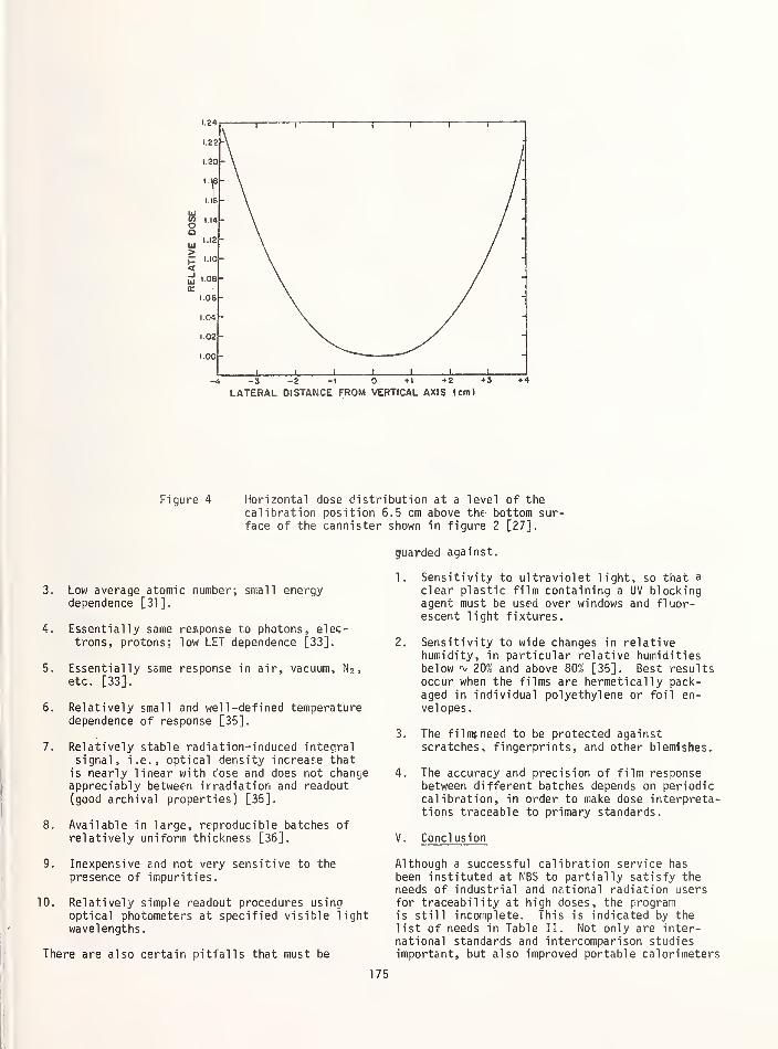
LATERAL DISTANCE FROM VERTICAL AXIS (cm)
Figure 4 Horizontal dose distribution at a level of thecalibration position 6.5 cm above the bottom sur-face of the cannister shown in figure 2 [27].
3. Low average atomic number; small energydependence [31].
4. Essentially same response to photons, elec-trons, protons; low LET dependence [33].
5. Essentially same response in air, vacuum, N 2 ,
etc. [33].
6. Relatively small and well -defined temperaturedependence of response [35].
7. Relatively stable radiation-induced integralsignal, i.e., optical density increase that
is nearly linear with dose and does not changeappreciably between irradiation and readout(good archival properties) [35].
8. Available in large, reproducible batches ofrelatively uniform thickness [36].
9. Inexpensive end not very sensitive to the
presence of impurities.
10. Relatively simple readout procedures usingoptical photometers at specified visible lightwavelengths.
There are also certain pitfalls that must be
guarded against.
1. Sensitivity to ultraviolet light, so that a
clear plastic film containing a UV blockingagent must be used over windows and fluor-escent light fixtures.
2. Sensitivity to wide changes in relativehumidity, in particular relative humiditiesbelow 20% and above 80% [35]. Best resultsoccur when the films are hermetically pack-aged in individual polyethylene or foil en-velopes.
3. The films need to be protected againstscratches, fingerprints, and other blemishes.
4. The accuracy and precision of film responsebetween different batches depends on periodiccalibration, in order to make dose interpreta-tions traceable to primary standards.
V. Cone! usion
Although a successful calibration service has
been instituted at NBS to partially satisfy theneeds of industrial and national radiation usersfor traceability at high doses, the programis still incomplete. This is indicated by thelist of needs in Table II. Not only are inter-national standards and intercomparison studiesimportant, but also improved portable calorimeters
175

Approx.
Uncertainty
± I %
±3
± 5 %
± 10% I
Figure 5 Traceabil ity chart, according to high-dose calibrationservices at NBS designed for users of intense radiationsources.
based on water vs. tissue-equivalent plastics,better energy dependence data, dosimeter qualitycontrol, and continued development of improvedmeasurement systems.
TABLE II
NEEDS FOR SP'-VING PROBLEMS OF TRACEABILITY
1. International standards2. Systematic international intercomparisons3. Transfer calorimeters to reduce number of
levels4. Development of improved water calorimeter5. Knowledge of radiation spectra in both
calibration and application6. Better quality control of transfer dosimeters7. Development of improved routine dosimeters.
176

REFERENCES
[1]
[2]
[3]
[4]
[5]
[6]
[7]
Radiation Processing , Vols. 1 and 2,
Silverman, J. and van Dyken, A.R., eds.,
Pergamon Press, Ltd., Oxford; Radiat.Phys. Chem. 9 (1977)
Advances in Radiation Processing , Vols. 1 and
2, Silverman, J., ed., Pergemon Press, Ltd.,Oxford; Radiat. Phys. Chem. 14 (1979)
Advances in Radiation Processing, Vols. 3 and
4, ed., Silverman, J., Pergamon Press, Ltd.,Oxford; Radiat. Phys. Chem. (1981) (in press)
Laughlin, J. S., Genna, S., Calorimetry,Chapt. 16 in Radiation Dosimetry , Vol. 2,
2nd Ed., Attix, F. H., Roesch, W.C., eds.,Academic Press, New York (1966)
Radak, B.B., Markovic, V.M., Calorimetry,Chapt. 3 in Manual on Radiation Dosimetry ,
Holm, N.W., Berry, R.J., eds., Marcel Dekker,New York (1970)
Domen, S.R., Absorbed Dose Water Calorimeter,Med. Phys. 7 , 157 (1980)
Boag, J.W., Ionization Chambers, Chapt. 1 in
Radiation Dosimeter , Vol. 2, 2nd ed.,eds.Attix. F.H., Roesch, W.C.
Press, New York (1966)
Academic
[8]
[9]
Loevinger, R., Ionization chamber recombinationloss in high intensity radiation fields"Selected Topics in Radiation Dosimetry" ,
Proc. Int. Sympos., Vienna, 1960, InternationalAtomic Energy Agency, Vienna 173 (1961)
Chappell , S.C., Humphreys, J.C., The doserate response of a dye- polycnlorostyrene filmdosimeter, IEEE Trans, on Nucl . Sci. NS-19 ,
175 (1972)
Proc. Int. Sympos., Vienna, 1975, InternationalAtomic Energy Agency, Vienna, 663 (1975)
[14]Rabin, H., Price, W.E., Mapping radiationfields with silver activated phosphate glass,Nucleonics 13 (3) 33 (1955)
[15] Petree, B., Lamperti, P., A comparison ofabsorbed dose determinations in graphite bycavity ionization chamber and by calorimetry,NBS J. Res. 71C, 19 (1967)
[16]McLaughlin, W.L., A National Standardizationprogramme for high-dose measurement, High-Dose Measurements in Industrial RadiationProcessing , IAEA Technical Reports Series,International Atomic Energy Agency (1980)(in press)
[17]
t 10^0swald, R.B., Jr., Eisen, H.A., Conrad, E.E.,
Pulsed electron beam dosimetry, IEEE Trans, on
Nuclear Science., NS-13 , 229 (1966]
[^Miller, G.H., Lockwood, G.J., Halbleib, J. A.,Improved Calorimeter method for energy depositionmeasurement, IEEE Trans, on N ucl. Sci., NS-21 ,
359, (1974)
[12]Holm, N.W., Jarrett, R.D., An evaluation of
dosimetry procedures for use in foodirradiation, Nat. Acad. Sci., - Nat. Res.
Council Publ. 1273 , NAS-NRC, Washington, D.C.,
(1965)
[13]Radak, B.B., Kosanic, M.M., Sesic, M.B.,
McLaughlin, W.L., A calorimetric approach to
the calibration of liquid dose meters in high-intensity electron beams, Biomedical Dosimetry
Hubbell, J.H., Photon mass attenuation andenergy absorption coefficients for 1 keV to
20 MeV , Trends in Radiation Dosimetry,McLaughlin, W.L., ed., Pergamon Press, Oxford,(1981) (in press)
[18]McLaughlin, W.L., Solid-phase chemicaldosimeters, Sterilization by Ionizing Radiation ,
Gaughran, E.R.L., Goudie, A.J., eds.,Multiscience, Montreal, 219 (1974)
[19]Chadwick, K.A. , Ehlermann, D.A.E.,McLaughlin, W.L., Manual on Food IrradiationDosimetry , IAEA Technical Reports Series No.
178, International Atomic Energy Agency,Vienna (1977)
[20]Fricke, H. Hart, E. J., Chemical dosimetry,
Chapt. 12 in Radiation Dosimetry , Vol. 2,2nd ed., Attix, F.H., Roesch, W.C, eds.,Academic Press, New York (1966)
[21]Ehrlich, M. Soares, C.G., Measurement assur-
ance studies of high-energy electron andphoton dosimetry in radiation theraphyapplications; Intercomparison Procedures in
the Dosimetry of High-Energy Electrons andX-rays , IAEA Technical Reports Series,International Atomic Energy Agency, Vienna
(1980) (in press)
[22]Sehested, K. , The Fricke dosimeter, Manual on
Radiation Dosimetry , Holm, N.W., Berry, R.J.,eds., Marcel Dekker, New York, 313 (1970)
[23] Bjergbakke, E., Sehested, K., Lang Rassmussen,
0., The reaction mechanism+and rate constants in
the radiolysis of Fe2+-Cu 2 Solutions, Radiat.Res., 66, 433 (1976)
[24] Bjergbakke, E., Ceric-cerous sulfate dosimetry,Trends in Radiation Dosimetry , McLaughlin, W.L.,
ed., Pergamon Press, Oxford (1981 ) (in press)
177
[25]McLaughlin, W.L., Dosimetry standards for
industrial radiation processing, National andInternational Standardization of RadiationDosimetry , Vol. T, Prcc. Int. Sympos.,Atlanta, 1977, International Atomic EnergyAgency, Vienna, 89 (1978)
ed., Pergamon Press, Ltd., Oxford; Radiat .
Phys. Chem. 14 , 551 (1980)
[36]
[26]Vas, K., Beck, E.R.A., McLaughlin, W.L.,
Ehlermann, Chadwick, K.H., Dose limitsversus dose range, Acta Alimentaria 7 (2)
343 (1978)
Kantz, A.D., Humpherys, K.C., Qualityassurance for radiation processing, Advancesin Radiation Processing , Vol. 2,
Silverman, J., ed., Pergamon Press, Ltd.,Oxford; Radiat. Phys. Chem. 14 , 575 (1980)
[27]Humphreys, J.C., McLaughlin, W.L., Dye film
dosimetry for radiation processing,Application of Accelerators in Research and
Industry , Proc. of 6th Conf . , North TexasState University, 1980, U.S. Department ofEnergy (1981) (in press)
[28]McLaughlin, W.L., Radiation measurement andquality control, Radiat. Phys. Chem. 9 , 147
(1977)
[29]Barrett, J.H., Sharpe, P.H.G., Stuart, I. P.,
Dosimetry with dyed and indyed acrylic plastic,Trends in Radiation Dosimetry , McLaughlin,W.L., ed., Pergamon Press, Ltd.,
Oxford (1981) (in press)
[30]Gehringer, P., Eschweiler, H., Proksch, E.,
Dose-rate and humidity effects upon the gamma-radiation response of nylon-based radiochromicfilm dosimeters, Int . J. Appl . Radiat.Isotopes 31_ 595 (1980]
[31]McLaughlin, W.L., Humphreys, J.C., Levine,H., Miller, A., Radak, B.B., Rativanich, N.
,
The gamma-ray response of radiochromic dyes at
different absorbed dose rates, Advances in
Radiation Processing , Vol
Pergamon Press, Ltd
(1981) (in press)
4, Silverman, J. , ed.
,
Oxford; Radiat. Phys. Chem .
[32]McLaughlin, W.L., Humphreys, J.C., Radak,B.B., Miller, A., Oleinik, J. A., The responseof plastic dosimeters to gamma rays and elec-trons at high absorbed dose rates, Advancesin Radiation Dosimetry , Vol. 2, Silverman, J.,
ed., Pergamon Press Ltd., Oxford, Radiat. Phys.Chem. 14, 535 (1980)
[33]McLaughlin, W.L., Rosenstein, M., Levine, H.,
Bone-and muscle-equivalent, solid chemical dosemeters for photon and electron doses above onekilorad, Biomedical Dosimetry , Proc. Int.
Sympos., Vienna, 1975, International AtomicEnergy Agency, Vienna, 267 (1975)
[34]Hansen, J., Ris# National Laboratory, Roskilde,Denmark, private communicotion, (1980)
[35]Levine, H., McLaughlin, W.L., Miller, A.,
Temperature and humidity effects on thegamma-ray response and stability of plasticand dyed plastic dosimeters, Advances in
Radiation Processing , Vol. ?., Silverman, J.,178

SEMINAR ON TRACEABILITY FOR IONIZING RADIATION MEASUREMENTS
National Bureau of StandardsGaithersburg, MDMay 8-9, 1980
List of Attendees
John ArrasArmed Forces Radiobiology Research InstituteBethesda, MD 20014
Allen BrodskyU.S. Nuclear Regulatory CommissionOffice of Standards DevelopmentWashington, DC 20555
Doris BrunnerPenn. Dept. of Environmental ResourcesBureau of Radiation ProtectionP.O. Box 1467Harrisburg, PA 17120
Lily Buja-BijunasNational Research Council of CanadaBldg M-35Montreal RoadOttawa, Ont. K1A 0R6 CANADA
George CampbellLawrence Livermore National LaboratoryHazards Control DepartmentLivermore, CA 94550
Arthur CarlsonIllinois Department of Public HealthDivision of Radiation Protection535 West Jefferson St.
Springfield, IL 62761
Randall S. CaswellNational Bureau of StandardsCenter for Radiation ResearchWashington, DC 20234
Lucy CavalloNational Bureau of StandardsCenter for Radiation ResearchWashington, DC 20234
Lawrence K. CohenU.S. Nuclear Regulatory CommissionOffice of Inspection & EnforcementWashington, DC 20555
R. ColleNational Bureau of StandardsCenter for Radiation ResearchWashington, DC 20234
Dave DieterEastman Kodak Co.
Kodak Part B6 MC5Rochester, NY 1465Q
Dave DieterlyNew England NuclearMedical Diagnostic Division601 Treble Cove Rd
North Bill erica, MA 01862
Margarete EhrlichNational Bureau of StandardsCenter for Radiation ResearchWashington,
Elmer H. EisenhowerNational Bureau of StandardsCenter for Radiation ResearchWashington, DC 20234
Robert R. Eng
Armed Forces Radiobiology Research InstituteBldg 42 NNMCBethesda, MD 20014
Roger W. FerrisAmersham Corporation2636 Clearbrook Dr.
Arlington Heights, IL 60005
Leo FitzpatrickBiomedics Corp. (Mail Stop TBC)CIF Bldg Rm 398
Kennedy Space Center, FL 32899
D.M. FlemingBattel le, Pacific Northwest Labs.Battel le BlvdRichland, WA 99352
Ralph D. FlintBattel le Memorial Institute505 King Ave.
Columbus, OH 43201
Claude FlorgArmed Forces Radiobiology Research InstituteBethesda, MD, 20014
Andreas GeorgeU.S. Department of EnergyEnvironmental Measurement Laboratory376 Hudson St.
New York, NY 10014
Thomas F. Gesell
University of Texas School of Public HealthP.O. Box 20106Houston, TX 77025
Robert GoldenWalter Reed Army Medical CenterDiagnostic Radiology ServicesDepartment of RadiologyWashington, DC 20012
179

Michael GrissonArmed Forces Radiobiology Research InstituteBldg 42, NNMCBethesda, MD 20014
Ken GrovesNavy Nuclear Power UnitCode 40Port Hueneme, CA 93043
James A. GrundlNational Bureau of StandardsCenter for Radiation ResearchWashington, DC 20234
H.T. Heaton, II
National Bureau of StandardsCenter for Radiation ResearchWashington, DC 20234
Gene HendrixNaval Facilities Engineering CommandAttn: 111N200 Stovall St.
Alexandria, VA 22332
Phil HesseNaval Surface Weapons CenterSilver Spring, MD 20910
J.M.R. HutchinsonNational Bureau of StandardsCenter for Radiation ResearchWashington, DC 20234
Jeffrey N. IadiserniaKeithley Instruments31300 Bainbridge Rd.
Solon, OH 44129
Kenneth Inn
National Bureau of StandardsCenter for Radiation ResearchWashington, DC 20234
Richard JaquishBattel le, Pacific Northwest Labs.Box 999Richland, WA 99352
Arthur N. JarvisU.S. Environmental Protection AgencyOffice of Quality Assurance-RadiationNational Environmental Research CenterP.O. Box 15027Las Vegas, NV 89114
W.A. JenningsNational Physical LaboratoryDivision of Radiation Science and AcousticsTeddington, Middlesex, TW 11 0LWUK
M. JimenezDuke Power Co.
Steam Production Dept.P.O. Box 33189Charlotte, NC
Don JordanUSAF0E HL/RZEBrooks Air Force Base, TX 78235
Ronald L. KathrenBattel le, Pacific Northwest Labs.Battelle BlvdRichland, WA 99352
Bergene Kawin
Food and Drug Administration5600 Fishers Lane, HFX-150Rockville, MD 20857
Frank KearlyBureau of Radiological Health, HFX-705600 Fishers LaneRockville, MD 20857
Kirk J. King
Naval Research Labs, Code 6073Washington, DC 20375
George KomadaBureau of Radiological Health, HFX-2605600 Fishers LaneRockville, MD 20857
Chris E. KuyattNational Bureau of StandardsCenter for Radiation ResearchWashington, DC 20234
George T. LalosNaval Surface Weapons CenterSilver Spring, MD 20910
John J. LanzaNaval Surface Weapons CenterSilver Spring, MD 20910
Robert LoevingerNational Bureau of StandardsCenter for Radiation ResearchWashington, DC 20234
Ronald B. LuersenNaval Research Labs, Code 6073Washington, DC 20375
William McLaughlinNational Bureau of StandardsCenter for Radiation ResearchWashington, DC 20234
Robert MillsBrookhaven National LaboratoryBldg 535 AUpton, NY 11973
Robert MortonBureau of Radiological Health, HFX-705600 Fishers Lane
Rockville, MD 20857
Robert J. MurrayPA Power & Light
2 North Ninth St
Allentown, PA 18101
Harold W. NassUnion CarbideBox 324Tuxedo, NY 10987

Richard E. Needham
Dept. Health and Human ServicesFood and Drug AuthorityEngineering & Analytical Center109 Hoi ton St.
Winchester, MA 01890
Maury NeuwegIllinois Dept. of Public HealthDivision of Radiation Protection535 West Jefferson St.
Springfield, IL 62761
Thomas R. OhlhaberBureau of Radiological Health
5600 Fishers LaneRockville, MD 20857
Dale OlsonU.S. Dept. of Energy550 2nd St.
Idaho Falls, ID 83401
Phillip PlatoUniv. of MichiganSchool of Public HealthAnn Arbor, MI 48109
Adelbert PotterNew York State Dept. of Health
Bureau of Radiological HealthRm 359 Tower Bldg
E.S.P.Albany, NY 12237
Federick PrevoBureau of Radiological Health, HFX-2605600 Fishers LaneRockville, MD 20857
Lawrence A. ProudThe Boeing Co.
P.O. Box 3707 M/S 2T-04Seattle, WA 98124
Nongnooch RatinavichOffice of Atomic Energy for Peace
Bancock, THAILAND
Dennis RileyDosimeter Corp. of AmericaP.O. Box 42377Cincinnati, OH 45242
Genevieve RoesslerUniv. of Florida237 Nuclear Science CenterGainesville, FL 32611
Daniel Sam
Naval Surface Weapons CenterSilver Spring, MD 20910
Robert J. ShalekM.D. Anderson HospitalPhysics Dept.Houston, TX 77030
Donovan SmithU.S. Nuclear Regulatory CommissionWashington, DC 20555
C. SoaresNational Bureau of StandardsCenter for Radiation ResearchWashington, DC 20234
Paul B. SundyRADCAL Corp.
426 W. Duarte Rd.
Monrovia, CA 91016
Kathy TeasdaleReynolds Electrical & Engineering CoP.O. Box 14400
Las Vegas, NV 89114
Bruce ThomadsenUniv. of WisconsinK4/B100 Clinical Science Center600 Highland AvenueMadison, WI 53792
Anthony TseU.S. Nuclear Regulatory CommissionWashington, DC 20555
Paul TyreeNew England NuclearNS Division601 Treble Cove Rd
North Billercia, MA 01862
Ivan VajcovecAtomic Energy of Canada, LimitedCommercial ProductsBox 6300, Station J
Ottawa K2A 3W3 CANADA
Lorraine VekensNew England Nuclear Corp.601 Treble Cove Rd.
North Bill erica, MA 01862
Stephen S. VorisBell Laboratories600 Mountain Ave.Murray Hill, NJ 07974
Graham V. WalfordTechnology for Energy Corp.975 West Outer DriveOak Ridge, TN 37830
R.C. YoderBattele, Pacific Northwest Labs.
P.O. Box 999Richland, WA 99352
Robert ZappBattelle Memorial Institute505 King Ave.Columbus, OH 43201
Joseph ZelenskiE.R. Squibb and Sons, Inc.
Rt. 1, Box 89
Stockton, NJ 08559
Garry ZemanNational Naval Medical CenterBethesda, MD 20014
181

NBS-114A (REV, 2-8C)
U.S. DEPT. OF COMM.
BIBLIOGRAPHIC DATASHEET (See instructions)
1. PUBLICATION ORREPORT NO.
MBS SP 609
2. Performing Organ. Report N04 3. Publication Date
FEBRUARY 198?
4. TITLE AND SUBTITLE
Proceedings of a Meeting on Traceability for Ionizing Radiation Measurementsheld at the National Bureau of Standards, Gaithersburg , MD, on May 8-9, 1980.
EDITOR:
H. Thompson Heaton, II
6. PERFORMING ORGANIZATION (If joint or other than NBS, see instructions)
NATIONAL BUREAU OF STANDARDSDEPARTMENT OF COMMERCEWASHINGTON, D C 20234
7. Contract/Grant No.
8. Type of Report <L Period Covered
Final9. SPONSORING ORGANIZATION NAME AND COMPLETE ADDRESS (Street. City. State, ZIP)
Same as no. 6
10. SUPPLEMENTARY NOTES
Library of Congress Catalog Card Number: 81-600197
I |
Document describes a computer program; SF-185, FlPS Software Summary, is attached.
11. ABSTRACT (A 200-word or less factual summary of most significant information. If document includes a significantbibliography or literature survey, mention it here)
These proceedings are the compilation of 21 papers presented at a seminar on
Traceability for Ionizing Radiation Measurements held at the National Bureau
of Standards, Gaithersburg, MD, on May 8-9, 1980. General concepts of trace-
ability were presented from several perspectives. The national standards for
radiation dosimetry, radioactivity measurements, and neutron measurements were
described. Specific programs for achieving traceability to the national stan-
dards for radiation measurements in medical, occupational, and environmental
applications were summarized.
12. KEY WORDS (Six to twelve entries; alphabetical order; capitalize only proper names; and separate key words by semicolons)
Calibrations, ionizing radiation, measurements, national standards, quality
assurance, secondary standard laboratory, traceability.
13. AVAILABILITY
[yi Unlimited
| |For Official Distribution. Do Not Release to NTIS
|"~~| Order From Superintendent of Documents, U.S. Government Printing Office, Washington, D C20402.
Order From National Technical Information Service (NTIS), Springfield, VA 22161
14. NO. OFPRINTED PAGES
175
15. Price
!^U.S. GOVERNMENT PRINTING OFF
USCOMM-DC eOO-PBO
CE: 1982-360-997/2012


NBS TECHNICAL PUBLICATIONS
PERIODICALS
JOURNAL OF RESEARCH—The Journal of Research of the
National Bureau of Standards reports NBS research and develop-
ment in those disciplines of the physical and engineering sciences in
which the Bureau is active. These include physics, chemistry,
engineering, mathematics, and computer sciences. Papers cover a
broad range of subjects, with major emphasis on measurement
methodology and the basic technology underlying standardization.
Also included from time to time are survey articles on topics
closely related to the Bureau's technical and scientific programs.
As a special service to subscribers each issue contains complete
citations to all recent Bureau publications in both NBS and non-NBS media. Issued six times a year. Annual subscription; domes-
tic $18; foreign S22.50. Single copy S4.25 domestic: S5.35 foreign.
NOTE: The Journal was formerly published in two sections: Sec-
tion A "Physics and Chemistry" and Section B "Mathematical
Sciences."
DIMENSIONS/NBS—This monthly magazine is published to in-
form scientists, engineers, business and industry leaders, teachers,
students, and consumers of the latest advances in science and
technology, with primary emphasis on work at NBS. The magazine
highlights and reviews such issues as energy research, fire protec-
tion, building technology, metric conversion, pollution abatement,
health and safety, and consumer product performance. In addi-
tion, it reports the results of Bureau programs in measurementstandards and techniques, properties of matter and materials,
engineering standards and services, instrumentation, and
automatic data processing. Annual subscription: domestic $11;
foreign $13.75.
NONPERIODICALS
Monographs—Major contributions to the technical literature on
various subjects related to the Bureau's scientific and technical ac-
tivities.
Handbooks—Recommended codes of engineering and industrial
practice (including safety codes) developed in cooperation with in-
terested industries, professional organizations, and regulatory
bodies.
Special Publications—Include proceedings of conferences spon-
sored by NBS, NBS annual reports, and other special publications
appropriate to this grouping such as wall charts, pocket cards, and
bibliographies.
Applied Mathematics Series—Mathematical tables, manuals, and
studies of special interest to physicists, engineers, chemists,
biologists, mathematicians, computer programmers, and others
engaged in scientific and technical work.
National Standard Reference Data Series—Provides quantitative
data on the physical and chemical properties of materials, com-piled from the world's literature and critically evaluated.
Developed under a worldwide program coordinated by NBS under
the authority of the National Standard Data Act (Public Law90-396).
NOTE: The principal publication outlet for the foregoing data is
the Journal of Physical and Chemical Reference Data (JPCRD)published quarterly for NBS by the American Chemical Society
(ACS) and the American Institute of Physics (AIP). Subscriptions,
reprints, and supplements available from ACS, 1 155 Sixteenth St.,
NW, Washington, DC 20056.
Building Science Series—Disseminates technical information
developed at the Bureau on building materials, components,
systems, and whole structures. The series presents research results,
test methods, and performance criteria related to the structural andenvironmental functions and the durability and safety charac-
teristics of building elements and systems.
Technical Notes—Studies or reports which are complete in them-
selves but restrictive in their treatment of a subject. Analogous to
monographs but not so comprehensive in scope or definitive in
treatment of the subject area. Often serve as a vehicle for final
reports of work performed at NBS under the sponsorship of other
government agencies.
Voluntary Product Standards—Developed under procedures
published by the Department of Commerce in Part 10, Title 15, of
the Code of Federal Regulations. The standards establish
nationally recognized requirements for products, and provide all
concerned interests with a basis for common understanding of the
characteristics of the products. NBS administers this program as a
supplement to the activities of the private sector standardizing
organizations.
Consumer Information Series— Practical information, based onNBS research and experience, covering areas of interest to the con-
sumer. Easily understandable language and illustrations provide
useful background knowledge for shopping in today's tech-
nological marketplace.
Order the above NBS publications from: Superintendent of Docu-ments. Government Printing Office, Washington, DC 20402.
Order the following NBS publications—FIPS and NBSIR's—fromthe National Technical Information Services. Springfield, VA 22161
.
Federal Information Processing Standards Publications (FIPSPUB)—Publications in this series collectively constitute the
Federal Information Processing Standards Register. The Register
serves as the official source of information in the Federal Govern-
ment regarding standards issued by NBS pursuant to the Federal
Property and Administrative Services Act of 1949 as amended.
Public Law 89-306 (79 Stat. 1127), and as implemented by Ex-
ecutive Order 11717 (38 FR 12315. dated May 11, 1973) and Part 6
of Title 15 CFR (Code of Federal Regulations).
NBS Interagency Reports (NBSIR)—A special series of interim or
final reports on work performed by NBS for outside sponsors
(both government and non-government). In general, initial dis-
tribution is handled by the sponsor; public distribution is by the
National Technical Information Services. Springfield, VA 22161,
in paper copy or microfiche form.

U.S. DEPARTMENT OF COMMERCENational Bureau of StandardsWashington. DC 20234
OFFICIAL BUSINESS
Penalty for Private Use, $300
POSTAGE AND FEES PAIDU S DEPARTMENT OF COMMERCE
COM-215
THIRD CLASS