Présentation PowerPoint - SFERA-III
58
THIS PROJECT HAS RECEIVED FUNDING FROM THE EUROPEAN UNION’S HORIZON 2020 RESEARCH AND INNOVATION PROGRAMME UNDER GRANT AGREEMENT NO 823802 NETWORKING SFERA-III Solar Facilities for the European Research Area 1st Summer School “Thermal energy storage systems, solar fields and new cycles for future CSP plants” WP1 Capacity building and training activities Odeillo, France, September 9 th -11 th 2019 “Raytracing software and design tools for heliostats fields” Shahab Rohani, Fraunhofer Institute for Solar Energy Systems ISE
-
Upload
khangminh22 -
Category
Documents
-
view
4 -
download
0
Transcript of Présentation PowerPoint - SFERA-III

THIS PROJECT HAS RECEIVED FUNDING FROM THE EUROPEAN UNION’S HORIZON 2020 RESEARCH AND INNOVATION PROGRAMME UNDER GRANT AGREEMENT NO 823802
NETWORKING
SFERA-III
Solar Facilities for the European Research Area
1st Summer School “Thermal energy storage systems, solar fields and new cycles for future CSP plants”
WP1 Capacity building and training activities
Odeillo, France, September 9th-11th 2019
“Raytracing software and design
tools for heliostats fields”Shahab Rohani, Fraunhofer Institute for Solar Energy Systems ISE

©Fraunhofer ISE/Foto: Guido Kirsch
© Fraunhofer ISE
FHG-SK: ISE-INTERNAL
RAYTRACING SOFTWARE AND DESIGN
TOOLS FOR HELIOSTATS FIELDS
Shahab Rohani, Peter Schöttl
Fraunhofer Institute for Solar Energy Systems ISE
SFERA III Summer School
Odeillo, Sep. 9-11 2019
www.ise.fraunhofer.de

© Fraunhofer ISE
2
FHG-SK: ISE-INTERNAL
AGENDA
Raytrace3D
Basics
Simulation acceleration
Angle-dependent reflectance for soiling modeling
Individual heliostat assessment
Sky discretization for fast annual assessment
Coupling to dynamic receiver simulation
Heliostat field design/optimization
Heliostat field layout algorithms
Heliostat selection based on polygon optimization
© Fraunhofer ISE
3
FHG-SK: ISE-INTERNAL
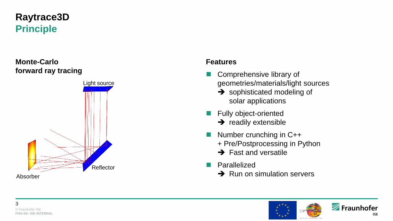
Raytrace3D
Principle
Features
Comprehensive library of
geometries/materials/light sources
sophisticated modeling of
solar applications
Fully object-oriented
readily extensible
Number crunching in C++
+ Pre/Postprocessing in Python
Fast and versatile
Parallelized
Run on simulation servers
Monte-Carlo
forward ray tracing
Light source
Reflector
Absorber

© Fraunhofer ISE
4
FHG-SK: ISE-INTERNAL
Raytrace3D
Heliostat field losses
Monte-Carlo ray tracing:
Fraunhofer ISE tool Raytrace3D
Cosine losses
Shading
Absorption on heliostats
Blocking
Atmospheric attenuation
Spillage
Reflection from receiver
Flux distribution
on receiver surfaces [1] Θ
[1] P. Schöttl, G. Bern, D. W. van Rooyen, J. Flesch, T. Fluri, and P. Nitz, “Efficient modeling of variable solar flux distribution on Solar Tower receivers by
interpolation of few discrete representations,” Solar Energy, vol. 160, pp. 43–55, 2018.

© Fraunhofer ISE
5
FHG-SK: ISE-INTERNAL
Raytrace3D
Graphical postprocessing
Gemasolar system
Fluxmaps depicted on receiver surfaces

© Fraunhofer ISE
6
FHG-SK: ISE-INTERNAL
Ivanpah
Raytrace3D
Simulation of solar towers
Gemasolar
Khi Solar One
Solar Two
PS10

© Fraunhofer ISE
7
FHG-SK: ISE-INTERNAL
Raytrace3D concepts
Angle-dependent reflectance for soiling modeling
Clean mirrors weak incidence angle
dependency of reflectance
Soiled mirrors strong incidence angle
dependency of reflectance
Raytrace3D: incidence angle dependent
reduction of reflectance
Reduction of solar yield
Improved yield prediction
Optimization of cleaning cycles
[2] A. Heimsath, P. Nitz, The effect of soiling on the reflectance of solar reflector materials - Model for prediction of incidence angle
dependent reflectance and attenuation due to dust deposition, Solar Energy Materials and Solar Cells, vol. 195,pp 258-268, , 2019
[2]
[2]

© Fraunhofer ISE
8
FHG-SK: ISE-INTERNAL
Spillage
Raytrace3D concepts
Individual heliostat assessment
Built-in routine for evaluating ray history
Per-unit assessment of primary aperture
(heliostats)
Evaluation of different loss mechanisms (cosine,
shading, …)
(Optional) integration of secondary concentrator
Full insight in heliostat field loss mechanisms
Input for field design
Cosine losses
Absorbed on receiver

© Fraunhofer ISE
9
FHG-SK: ISE-INTERNAL
Raytrace3D concepts
Sky discretization for fast annual assessment [2,3]
Uniform discretization of the sky hemisphere
[3] P. Schöttl, G. Bern, D. W. van Rooyen, J. Flesch, T. Fluri, and P. Nitz, “Efficient modeling of variable solar flux distribution on Solar Tower
receivers by interpolation of few discrete representations,” Solar Energy, vol. 160, pp. 43–55, 2018.
[4] P. Schöttl, K. Ordóñez Moreno, F. C. D. van Rooyen, G. Bern, and P. Nitz, “Novel sky discretization method for optical annual
assessment of solar tower plants,” Solar Energy, vol. 138, pp. 36–46, 2016.
© Fraunhofer ISE
10
FHG-SK: ISE-INTERNAL
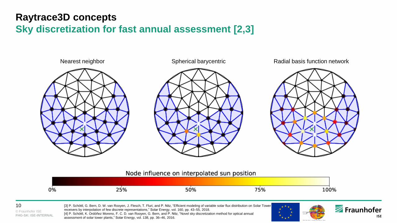
Raytrace3D concepts
Sky discretization for fast annual assessment [2,3]
Nearest neighbor Spherical barycentric Radial basis function network
[3] P. Schöttl, G. Bern, D. W. van Rooyen, J. Flesch, T. Fluri, and P. Nitz, “Efficient modeling of variable solar flux distribution on Solar Tower
receivers by interpolation of few discrete representations,” Solar Energy, vol. 160, pp. 43–55, 2018.
[4] P. Schöttl, K. Ordóñez Moreno, F. C. D. van Rooyen, G. Bern, and P. Nitz, “Novel sky discretization method for optical annual
assessment of solar tower plants,” Solar Energy, vol. 138, pp. 36–46, 2016.
© Fraunhofer ISE
12
FHG-SK: ISE-INTERNAL
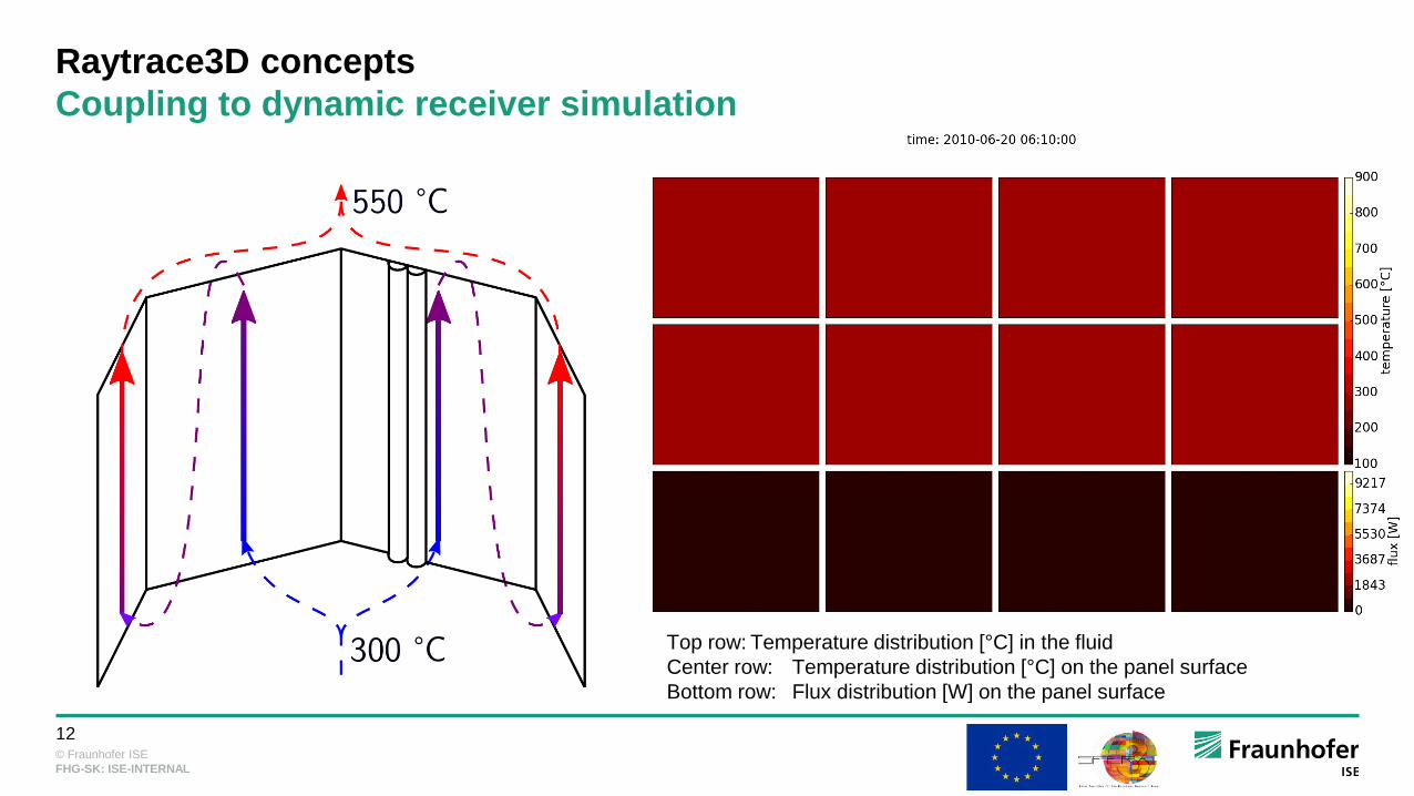
Raytrace3D concepts
Coupling to dynamic receiver simulation
Top row: Temperature distribution [°C] in the fluid
Center row: Temperature distribution [°C] on the panel surface
Bottom row: Flux distribution [W] on the panel surface

© Fraunhofer ISE
13
FHG-SK: ISE-INTERNAL
AGENDA
Raytrace3D
Basics
Simulation acceleration
Angle-dependent reflectance for soiling modeling
Individual heliostat assessment
Sky discretization for fast annual assessment
Coupling to dynamic receiver simulation
Heliostat field design/optimization
Heliostat field layout algorithms
Heliostat selection based on polygon optimization

© Fraunhofer ISE
14
FHG-SK: ISE-INTERNAL
Heliostat field design/optimization
Patterns-based algorithms
Layout algorithms based on underlying pattern
Base cases: radially staggered vs. cornfield
Several free parameters
Advantages:
Fast creation of large fields
Construction and maintenance easier in a regular layout
Disadvantage:
Difficult to adapt to uneven terrain

© Fraunhofer ISE
15
FHG-SK: ISE-INTERNAL
Part of Ivanpah field (source: Google Maps)
Greedy-like method
Cornfield pattern

© Fraunhofer ISE
16
FHG-SK: ISE-INTERNAL
Heliostat field design/optimization
MUEEN layout
Aim: no blocking
Radially staggered
Re-grouping for denser field
Original algorithm [6] extended by Fraunhofer
ISE [5]
Re-modeling of Ivanpah heliostat field with Fraunhofer ISE MUEEN
algorithm and field boundaries
[5] F.M.F. Siala and M.E. Elayeb, “Mathematical formulation of a graphical method for a no-blocking heliostat field layout,” Renewable
Energy, vol. 23, no. 1, pp. 77–92, http://linkinghub.elsevier.com/retrieve/pii/S0960148100001592, 2001.
[6] E. Leonardi, L. Pisani, I. Les, A. Mutuberria, S. Rohani, and P. Schöttl, “Techno-Economic Heliostat Field Optimization: Comparative
Analysis of Different Layouts,” Solar Energy, vol. 180, pp. 601–607, 2019.

© Fraunhofer ISE
17
FHG-SK: ISE-INTERNAL
Heliostat field design/optimization
CAMPO layout [7]
Radially staggered
Creation of densest possible field
Azimuthal and radial stretching (local!) to reduce
shading and blocking
Field generated with CAMPO algorithm (plot from [7])
[7] F. J. Collado and J. Guallar, “Campo: Generation of regular heliostat fields,” Renewable Energy, vol. 46, no. 0, pp. 49–59,
http://www.sciencedirect.com/science/article/pii/S096014811200198X, 2012.

© Fraunhofer ISE
18
FHG-SK: ISE-INTERNAL
Heliostat field design/optimization
Biomimetic layout [8]
Biomimetic phylotaxis disc pattern
sunflower
Angular distribution is related to the golden ratio
(1 + 5)/2
Optimization of free parameter
Field generated with biomimetic algorithm (plot from [8])
[8] C. J. Noone, M. Torrilhon, and A. Mitsos, “Heliostat field optimization: A new computationally efficient model and biomimetic layout,” Sol
Energy, vol. 86, no. 2, pp. 792–803, http://www.sciencedirect.com/science/article/pii/S0038092X11004373, 2012.

© Fraunhofer ISE
19
FHG-SK: ISE-INTERNAL
Heliostat field design/optimization
Pattern-free algorithms
No underlying pattern
Heliostat placement based on some heuristic
Advantages:
Easily applicable to uneven terrain
Disadvantage:
Field creation very complicated and
computationally intensive

© Fraunhofer ISE
20
FHG-SK: ISE-INTERNAL
Heliostat field design/optimization
Genetic algorithm [9]
Random generation of initial heliostat base
points
Genetic algorithm (cross-over, mutation,
selection) to optimize field
Field optimization with genetic algorithm (plot from presentation
related to [9])
[9] P. Richter, M. Frank, and E. Abraham, “Multi-objective optimization of solar tower heliostat fields,” in Proceedings of European Conference on
Mathematics for Industry (ECMI 2014), 2014.
© Fraunhofer ISE
21
FHG-SK: ISE-INTERNAL
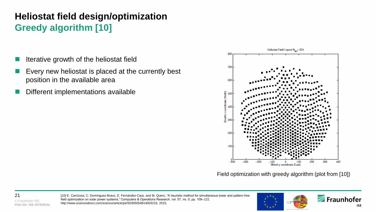
Heliostat field design/optimization
Greedy algorithm [10]
Iterative growth of the heliostat field
Every new heliostat is placed at the currently best
position in the available area
Different implementations available
Field optimization with greedy algorithm (plot from [10])
[10] E. Carrizosa, C. Domínguez-Bravo, E. Fernández-Cara, and M. Quero, “A heuristic method for simultaneous tower and pattern-free
field optimization on solar power systems,” Computers & Operations Research, vol. 57, no. 0, pp. 109–122,
http://www.sciencedirect.com/science/article/pii/S0305054814003219, 2015.

© Fraunhofer ISE
22
FHG-SK: ISE-INTERNAL
HELIOSTAT SELECTION BASED ON POLYGON
OPTIMIZATION
Motivation
Problem Description
Methodology
Application
Summary & Outlook

© Fraunhofer ISE
23
FHG-SK: ISE-INTERNAL
Motivation
Heliostat field represents about 40% of CAPEX of entire plant [1]
Typical loss composition for a 600 MWth Solar Tower plant [3]
Field design for high annual efficiency and low cost is crucial
[1] IRENA, “Renewable energy technologies: Cost Analysis Series - Concentrating Solar Power,” 2012.
[3] Schöttl et al., “Performance Assessment of a Secondary Concentrator for Solar Tower External Receivers,” submitted to 24th
SolarPACES Conference, 2 – 5 October 2018, Casablanca, Morocco.

© Fraunhofer ISE
24
FHG-SK: ISE-INTERNAL
Heliostat selection based on polygon optimization
Problem description: Heliostat Selection from Oversized Field
Respect area boundaries
Meet flux requirements
Optimize for given objective function
Coherent field, feasible w.r.t.
construction and maintenance

© Fraunhofer ISE
25
FHG-SK: ISE-INTERNAL
HELIOSTAT SELECTION BASED ON POLYGON
OPTIMIZATION
Problem Description
Methodology
Oversized Field
Polygon-Based Selection
Area Boundaries
Evolutionary Optimization Algorithm
Application
Summary & Outlook

© Fraunhofer ISE
26
FHG-SK: ISE-INTERNAL
Methodology
Oversized Field
Generation with extended MUEEN algorithm [4]
Assessment with Raytrace3D [5
[4] Siala and Elayeb, “Mathematical formulation of a graphical method for a no-blocking heliostat field layout,” 2001.
[5] Branke and Heimsath, “Raytrace3D-Power Tower - A Novel Optical Model For Central Receiver Systems,” 2010.
Approx. 35k heliostats
in oversized field

© Fraunhofer ISE
27
FHG-SK: ISE-INTERNAL
Methodology
Polygon-Based Selection
Equi-angular vertices
Centered around tower base
Only vertex radii as free parameters in
optimization
Coherent field boundaries
Evaluation of objective function
on entire field
For polar field, limit
angular range
© Fraunhofer ISE
28
FHG-SK: ISE-INTERNAL
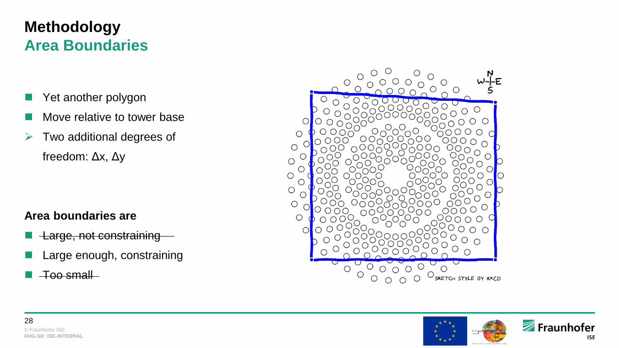
Methodology
Area Boundaries
Yet another polygon
Move relative to tower base
Two additional degrees of
freedom: Δx, Δy
Area boundaries are
Large, not constraining
Large enough, constraining
Too small
© Fraunhofer ISE
29
FHG-SK: ISE-INTERNAL
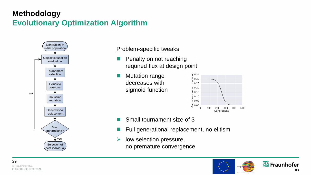
Methodology
Evolutionary Optimization Algorithm
Problem-specific tweaks
Penalty on not reaching
required flux at design point
Mutation range
decreases with
sigmoid function
Small tournament size of 3
Full generational replacement, no elitism
low selection pressure,
no premature convergence

© Fraunhofer ISE
30
FHG-SK: ISE-INTERNAL
HELIOSTAT SELECTION BASED ON POLYGON
OPTIMIZATION
Problem Description
Methodology
Application
Base Scenario
Objective Function
Examples
Summary & Outlook

© Fraunhofer ISE
31
FHG-SK: ISE-INTERNAL
Application
Base Scenario
[6] Leonardi et al., “Techno-Economic Heliostat Field Optimization: Comparative Analysis of Different Layouts,” Submitted to Solar Energy Journal, 2018.
Parameter Value [6]
Site Seville, Spain
Absorbed power at design point 55.27 MW
Tower height 100.5 m
External receiver diameter 14 m
External receiver height 12 m
Number of heliostats in oversized field 35000
Heliostat area (square) 8 m²
Minimum radial heliostat distance to tower 80 m
Design point Winter solstice
Design DNI 850 W/m²

© Fraunhofer ISE
32
FHG-SK: ISE-INTERNAL
Application
Objective function
Objective function maximizes yield per cost [6]:
𝑂𝐹 =𝜂𝑎𝑛 ⋅ 𝐴𝐻𝑆𝐹 ⋅ 𝐷𝑁𝐼𝑎𝑛
𝑘𝑔𝑟𝑜𝑢𝑛𝑑 ⋅ 𝐴𝑔𝑟𝑜𝑢𝑛𝑑 +𝑘𝐻𝑆𝐹 ⋅ 𝐴𝐻𝑆𝐹
𝑂𝐹 =𝜂𝑎𝑛
𝑘 ⋅𝐴𝑔𝑟𝑜𝑢𝑛𝑑𝐴𝐻𝑆𝐹
+ 1
⋅𝐷𝑁𝐼𝑎𝑛𝑘𝐻𝑆𝐹
annual optical efficiency 𝜂𝑎𝑛 of the entire field
ground area 𝐴𝑔𝑟𝑜𝑢𝑛𝑑 being the convex hull of all heliostats
cumulative mirror area 𝐴𝐻𝑆𝐹 of all heliostats
cost ratio 𝑘 =𝑘𝑔𝑟𝑜𝑢𝑛𝑑
𝑘𝐻𝑆𝐹of ground area to mirror area
Cumulative annual direct normal irradiance 𝐷𝑁𝐼𝑎𝑛
[6] Leonardi et al., “Techno-Economic Heliostat Field Optimization: Comparative Analysis of Different Layouts,” Submitted to Solar Energy Journal, 2018.

© Fraunhofer ISE
33
FHG-SK: ISE-INTERNAL
Application
No Area Boundaries, Cost Ratio k=0%
Animations showing best
candidate every ten
generations
𝑂𝐹 =𝜂𝑎𝑛
𝑘 ⋅𝐴𝑔𝑟𝑜𝑢𝑛𝑑𝐴𝐻𝑆𝐹
+ 1
= 𝜂𝑎𝑛

© Fraunhofer ISE
34
FHG-SK: ISE-INTERNAL
Application
No Area Boundaries, Cost Ratio k=0%
𝑂𝐹 = 𝜂𝑎𝑛
© Fraunhofer ISE
35
FHG-SK: ISE-INTERNAL
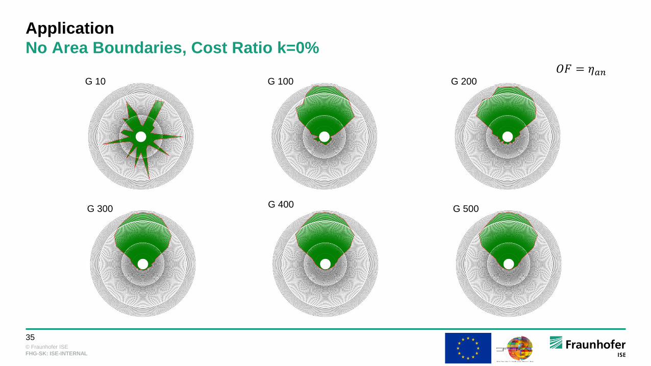
Application
No Area Boundaries, Cost Ratio k=0%
𝑂𝐹 = 𝜂𝑎𝑛G 10 G 100 G 200
G 300 G 400 G 500

© Fraunhofer ISE
36
FHG-SK: ISE-INTERNAL
Application
No Area Boundaries, Cost Ratio k=4% 𝑂𝐹 =𝜂𝑎𝑛
𝑘 ⋅𝐴𝑔𝑟𝑜𝑢𝑛𝑑𝐴𝐻𝑆𝐹
+ 1
G 10 G 100 G 200
G 300 G 400 G 500

© Fraunhofer ISE
37
FHG-SK: ISE-INTERNAL
Application
Complex Area Constraints, Cost Ratio k=0%
𝑂𝐹 =𝜂𝑎𝑛
𝑘 ⋅𝐴𝑔𝑟𝑜𝑢𝑛𝑑𝐴𝐻𝑆𝐹
+ 1
= 𝜂𝑎𝑛

© Fraunhofer ISE
38
FHG-SK: ISE-INTERNAL
Application
Complex Area Constraints, Cost Ratio k=0%
𝑂𝐹 = 𝜂𝑎𝑛
© Fraunhofer ISE
39
FHG-SK: ISE-INTERNAL
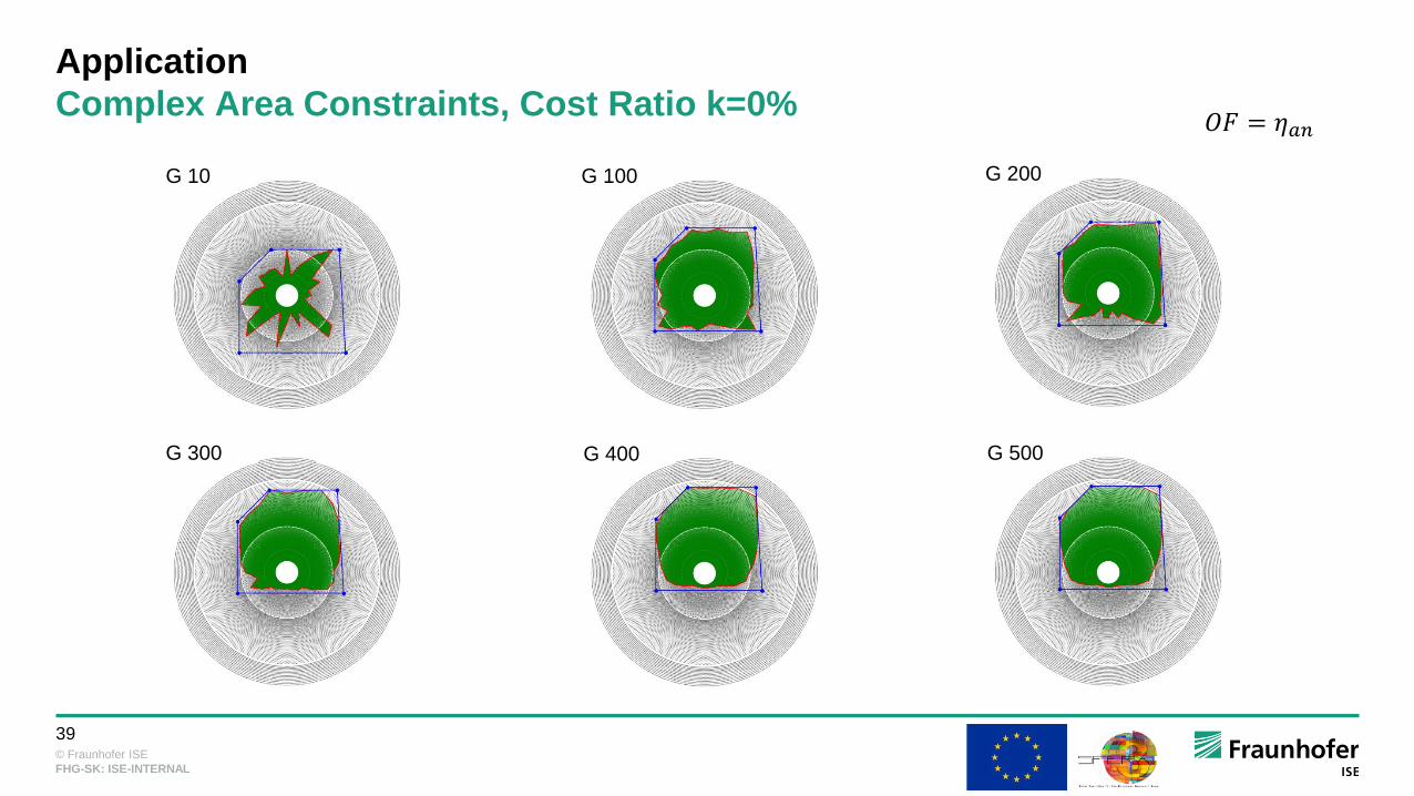
Application
Complex Area Constraints, Cost Ratio k=0%𝑂𝐹 = 𝜂𝑎𝑛
G 10 G 100 G 200
G 300 G 400 G 500

© Fraunhofer ISE
40
FHG-SK: ISE-INTERNAL
Summary & Outlook
Method: solar field heliostat selection based on
polygon optimization and boundaries
Coherent fields
Area boundaries
Flexible objective function
Quantitative comparison to other approaches
Allowable flux limits in objective function
Area boundaries with undercuts, holes and hilly
terrain
Ashalim Power Station, BrightSource Industries Israel (source:
https://inhabitat.com/)

© Fraunhofer ISE
41
FHG-SK: ISE-INTERNAL
Thank you for your Attention!
Fraunhofer Institute for Solar Energy Systems ISE
Shahab Rohani, Peter Schöttl
www.ise.fraunhofer.de

© Fraunhofer ISE
42
FHG-SK: ISE-INTERNAL
CASE STUDY
surrounding versus north fields
Heliostats fields, understanding the influence of latitude
© Fraunhofer ISE
43
FHG-SK: ISE-INTERNAL
AGENDA
Interactive
Summer/winter solstice sun position
Calculation of cosine losses
Latitude effects on surround/polar heliostat fields
Reference scenarios
Methodology recap
Result discussion

© Fraunhofer ISE
44
FHG-SK: ISE-INTERNAL
Summer/winter solstice sun position
Location: Odeillo, France
www.suncalc.org
Summer (S) solstice: solar zenith 𝜃𝑠,𝑆 = 19.1°, solar elevation 𝛼𝑠,𝑆 = 70.9°
Winter (W) solstice: solar zenith 𝜃𝑠,𝑊 = 65.9°, solar elevation 𝛼𝑠,𝑆 = 24.1°
© Fraunhofer ISE
45
FHG-SK: ISE-INTERNAL
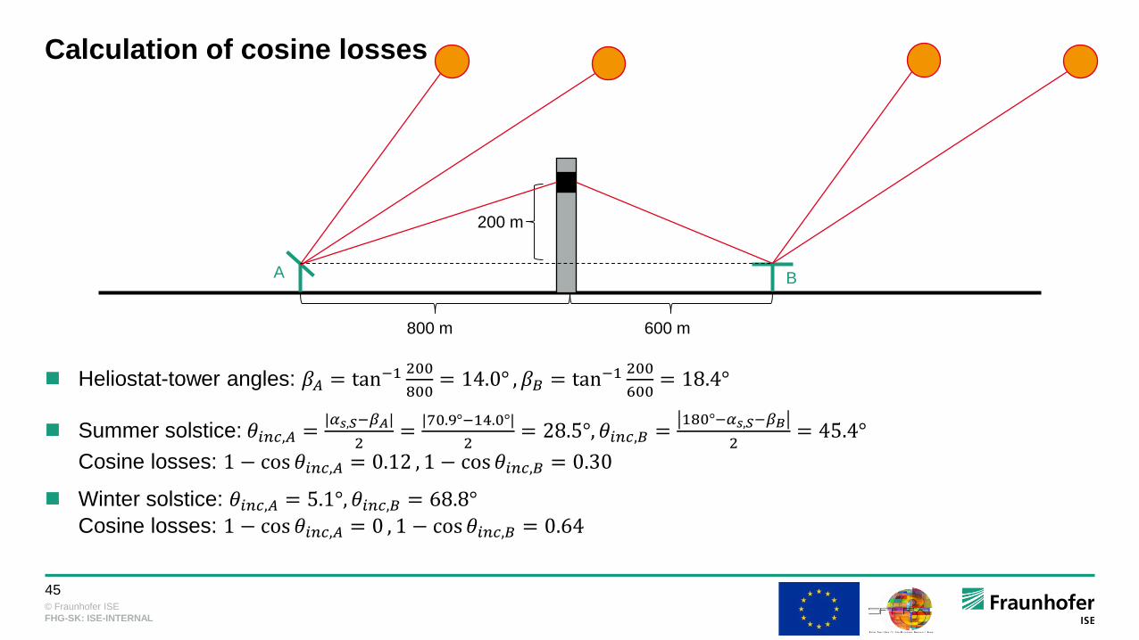
Calculation of cosine losses
Heliostat-tower angles: 𝛽𝐴 = tan−1200
800= 14.0° , 𝛽𝐵 = tan−1
200
600= 18.4°
Summer solstice: 𝜃𝑖𝑛𝑐,𝐴 =|𝛼𝑠,𝑆−𝛽𝐴|
2=
|70.9°−14.0°|
2= 28.5°, 𝜃𝑖𝑛𝑐,𝐵 =
180°−𝛼𝑠,𝑆−𝛽𝐵
2= 45.4°
Cosine losses: 1 − cos 𝜃𝑖𝑛𝑐,𝐴 = 0.12 , 1 − cos 𝜃𝑖𝑛𝑐,𝐵 = 0.30
Winter solstice: 𝜃𝑖𝑛𝑐,𝐴 = 5.1°, 𝜃𝑖𝑛𝑐,𝐵 = 68.8°
Cosine losses: 1 − cos 𝜃𝑖𝑛𝑐,𝐴 = 0 , 1 − cos 𝜃𝑖𝑛𝑐,𝐵 = 0.64
A B
200 m
800 m 600 m
© Fraunhofer ISE
46
FHG-SK: ISE-INTERNAL
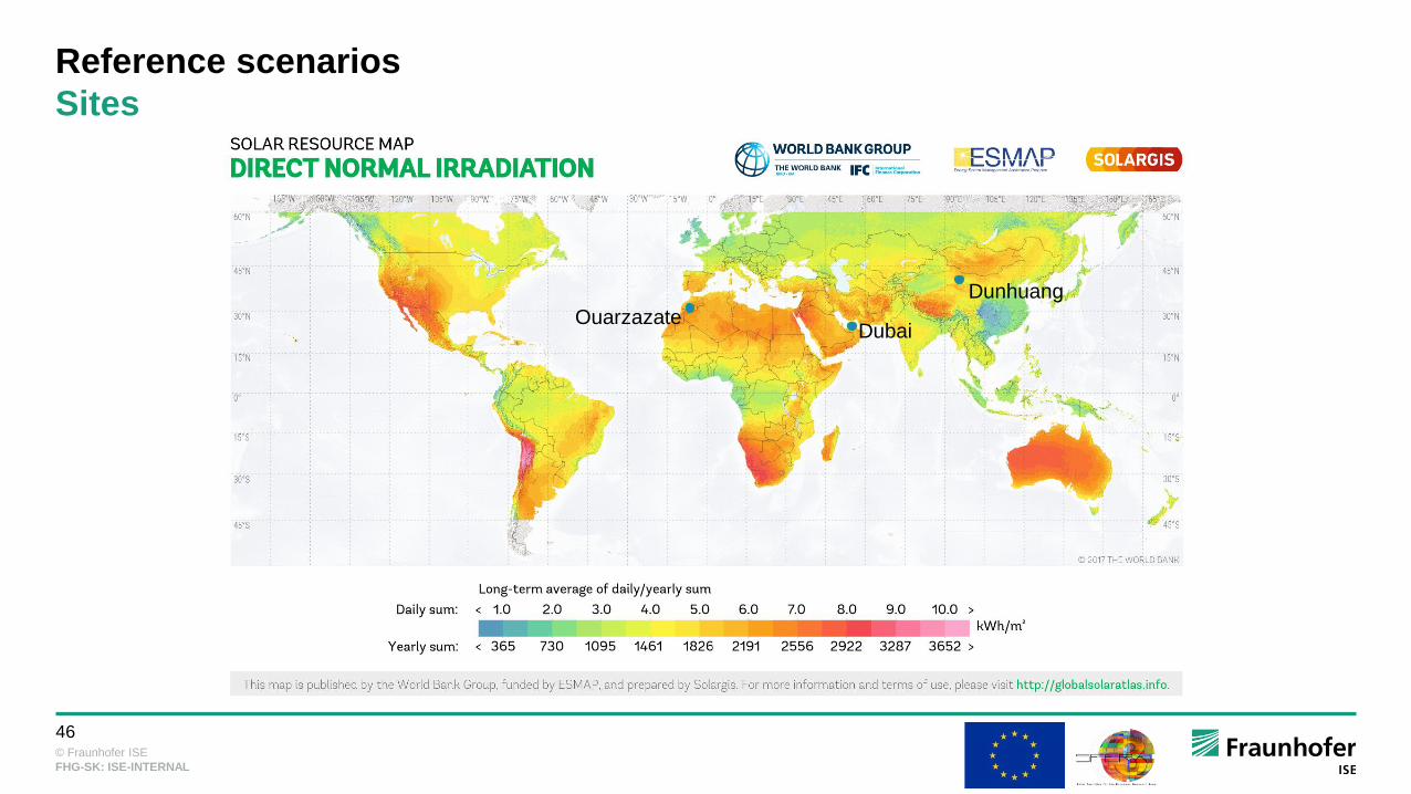
Reference scenarios
Sites
Dubai
Dunhuang
Ouarzazate

© Fraunhofer ISE
47
FHG-SK: ISE-INTERNAL
Reference scenarios
Parameters
Dubai Ouarzazate Dunhuang
Location 24.8 °N, 55.4 °E 31.0 °N, 6.9 °W 39.8 °, 92.7 °E
Annual DNI 2.15 MWh/m²a 2.92 MWh/m²a 2.13 MWh/m²a
Design point DNI 800 W/m² at summer solstice
Tower height 140 m
Receiver design power 120 MWth
Receiver absorber area 521.5 m² (cavity), 260.8 m² (external)
Heliostat mirror area 115.7 m²
Heliostat beam quality 3 mrad
Heliostat reflectance 93%
© Fraunhofer ISE
48
FHG-SK: ISE-INTERNAL
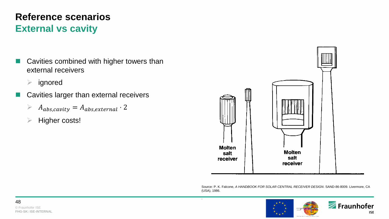
Reference scenarios
External vs cavity
Cavities combined with higher towers than
external receivers
ignored
Cavities larger than external receivers
𝐴𝑎𝑏𝑠,𝑐𝑎𝑣𝑖𝑡𝑦 = 𝐴𝑎𝑏𝑠,𝑒𝑥𝑡𝑒𝑟𝑛𝑎𝑙 ⋅ 2
Higher costs!
Source: P. K. Falcone, A HANDBOOK FOR SOLAR CENTRAL RECEIVER DESIGN. SAND-86-8009. Livermore, CA
(USA), 1986.
.

© Fraunhofer ISE
49
FHG-SK: ISE-INTERNAL
Methodology recap
1. Create oversized MUEEN field
2. Assess heliostat annual efficiencies with Raytrace3D
3. Assess heliostat design point efficiencies with Raytrace3D
4. Select best-performing heliostats with polygon-based approach

© Fraunhofer ISE
50
FHG-SK: ISE-INTERNAL
Result discussion
Dubai: selected fields
Cavity External

© Fraunhofer ISE
51
FHG-SK: ISE-INTERNAL
Result discussion
Ouarzazate: selected fields
Cavity External

© Fraunhofer ISE
52
FHG-SK: ISE-INTERNAL
Result discussion
Dunhuang: selected fields
Cavity External

© Fraunhofer ISE
53
FHG-SK: ISE-INTERNAL
Result discussion
Dubai: optical losses
Cavity External

© Fraunhofer ISE
54
FHG-SK: ISE-INTERNAL
Result discussion
Ouarzazate: optical losses
Cavity External
© Fraunhofer ISE
55
FHG-SK: ISE-INTERNAL
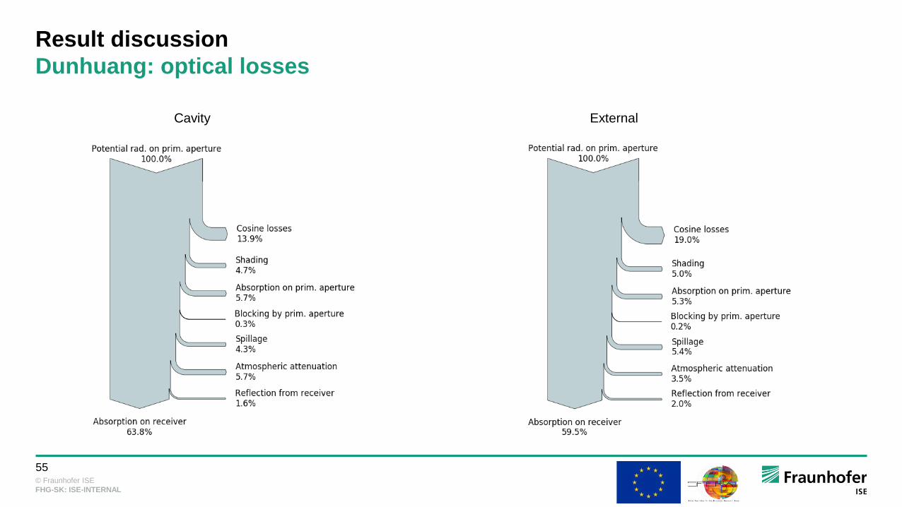
Result discussion
Dunhuang: optical losses
Cavity External

© Fraunhofer ISE
56
FHG-SK: ISE-INTERNAL
Result discussion
Summer/winter solstice
Dubai Ouarzazate Dunhuang
Cavity
Exte
rnal

© Fraunhofer ISE
57
FHG-SK: ISE-INTERNAL
Result discussion
Annual optical efficiency
Source: R. Buck and P. Schwarzbözl, “4.17 Solar Tower Systems,” in Comprehensive Energy Systems: Elsevier, 2018, pp.
692–732.

© Fraunhofer ISE
58
FHG-SK: ISE-INTERNAL
Thank you for your Attention!
Fraunhofer Institute for Solar Energy Systems ISE
Shahab Rohani, Peter Schöttl
www.ise.fraunhofer.de