PREPARATION OF SOIL MONOLITH
32
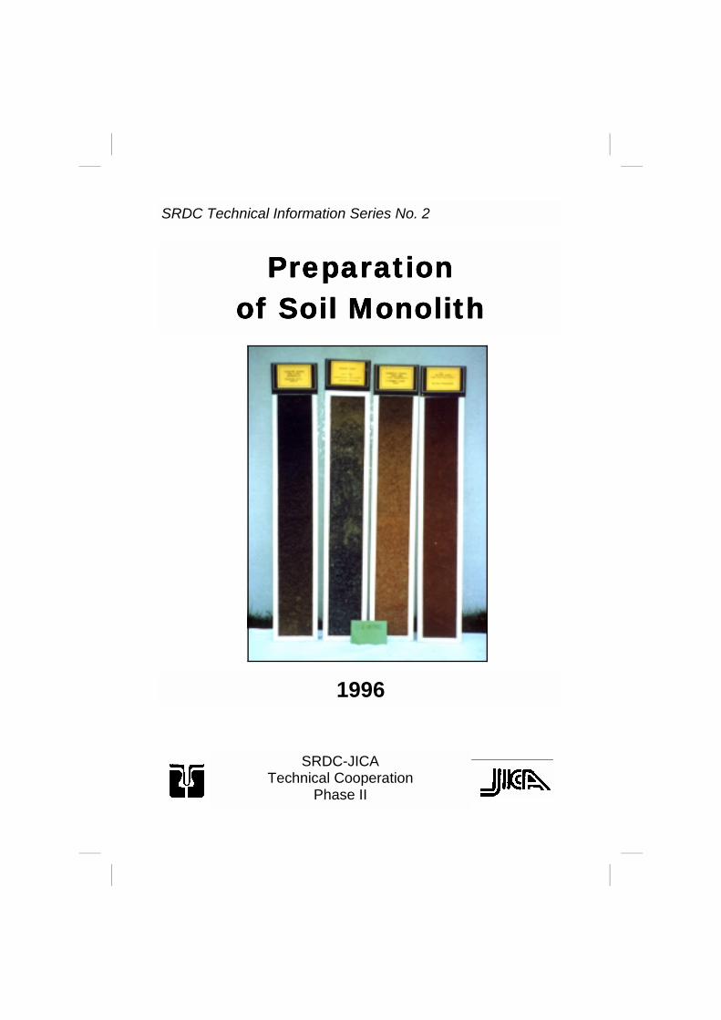
SRDC Technical Information Series No. 2 Preparation Preparation Preparation Preparation of Soil Monolith of Soil Monolith of Soil Monolith of Soil Monolith 1996 SRDC-JICA Technical Cooperation Phase II
-
Upload
independent -
Category
Documents
-
view
0 -
download
0
Transcript of PREPARATION OF SOIL MONOLITH
SRDC Technical Information Series No. 2
Preparation Preparation Preparation Preparation of Soil Monolithof Soil Monolithof Soil Monolithof Soil Monolith
1996
SRDC-JICA Technical Cooperation
Phase II


Preparation of Soil Monolith
Edited and updated from the final reports of Dr. Tadao Hama-zaki, JICA Short-term Expert, and Dr. Shoichi Tokudome, JICA Expert on Soil Survey and Classification under the SRDC-JICA Technical Coopera-tion, Phase I, Revised 1992.
Editors Dr. Toshiaki Ohkura
Rodelio Carating
SRDC Technical Information Series No. 2
Soils Research and Development Center Elliptical Road, Diliman, Quezon City
1996
Preparation of Soil Monolith Soil Productivity Capability Classification Soils Research and Development Center Elliptical Road, Diliman, Quezon City
SRDC Technical Information Series is released to dis-seminate agricultural technologies, publish soil manuals, and compile available technical materials, reports, and other soil information. The mention of brand names in this manual does not mean endorsement of specific products.
Cover: Some of the soil monoliths at the Soil Museum, Soils Research and Development Center, Bureau of Soils and Water Management. From left to right: Mollisol (Tagaytay Series), Vertisol (Candaba Series), Ultisol (Antipolo Series), and Alfisol (Bolinao Se-ries).

5
Contents
Chapter 1: Introduction 7 Chapter 2: Taking a soil column monolith in the field 8 Chapter 3: Preparation of soil peel monolith 14 Chapter 4: Direct preparation of soil peel monolith 20 References


7
Chapter 1: Introduction Soil monoliths give very useful aids for teaching and exten-sion works, for demonstration purposes, or for comparative studies in soil science. Soil profiles may be taken from the field and pre-served as soil columns or as soil peels which are more realistic than color photographs, drawings, or paintings. Soil monoliths were first collected in Russia during the last decades of the 19th century. Soil profiles from Russia were dis-played at the Columbian Exhibition in Chicago in 1893 - 1894, on the occasion of the international exhibition. Eighteen large mono-liths from Latovia were on display at the First International Con-gress of Soil Science, Washington D.C., 1927. These soil profiles were collected in iron or wooden boxes. Preservation of soil profiles with an adhesive was intro-duced by K. Schlacht in 1928. After that, although various newly developed chemicals were applied for the impregnation of soil ma-terial, nitrocellulose lacquers, vinyl light (vinyl acetate vinyl chloride copolymer) resin and polyvinyl acetate emulsion are now univer-sally used. On the other hand, the Buried Cultural Properties Center, National Nara Cultural Properties Institute in Japan developed Tomack NR-51 (special epoxy resin) and Tomack NS10 (special urethane resin) for the profile transcription of the buried ruins. Epoxy resin is characterized by strong adhesive ability, low contractability, and absence of organic solvent. Urethane resin is characterized by hardening with water and high plasticity. This manual includes the procedures for the preparation of soil column monoliths using wooden boxes and soil peel monoliths using epoxy resin or urethane resin, and polyvinyl acetate emul-sion.

8
Chapter 2: Taking soil column monolith A. Tools and Materials 1. Tools for digging and exposing soil profiles Shovel Crowbar Hatchet or bolo Pruning shears Hand shovel Folding meter scale Kitchen knife 2. Tools and materials for taking a soil column monolith (in addition to the above tools) wooden monolith box (as shown) with lids screwed screw driver Figure 1. A wooden monolith box with double frame.
9
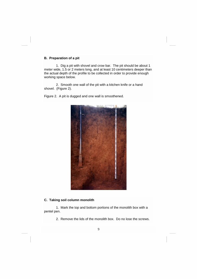
B. Preparation of a pit 1. Dig a pit with shovel and crow bar. The pit should be about 1 meter wide, 1.5 or 2 meters long, and at least 10 centimeters deeper than the actual depth of the profile to be collected in order to provide enough working space below. 2. Smooth one wall of the pit with a kitchen knife or a hand shovel. (Figure 2). Figure 2. A pit is dugged and one wall is smoothened.
C. Taking soil column monolith 1. Mark the top and bottom portions of the monolith box with a pentel pen. 2. Remove the lids of the monolith box. Do no lose the screws.

10
3. Mark the internal dimensions of the monolith box on the wall of the pit with a kitchen knife. (Figure 3)
Figure 3. Marking the internal dimensions of the box into the soil profile

11
4. Cut the soil column at least 3 centimeter thicker than the thick-ness of the monolith box on the wall of the pit with a kitchen knife. 5. Carefully cut the soil column following the exact internal di-mensions of the monolith box. (Figure 4).
Figure 4. Soil column with exact dimensions as the monolith. box.

12
6. Push the monolith box over the soil column, properly placing the top and bottom portions. (Figure 5)
Figure 5. Pushing over the box to fit into the soil column.

13
7. Remove the excess soil materials on the surface of the monolith box by smoothing the profile. 8. Screw the first lid on the frame of the monolith box. 9. Remove the soil materials on both sides of the box by a kitchen knife. Cut exposed roots using pruning shears. (Figure 6)
Figure 6. Excess soil materials are removed.
14
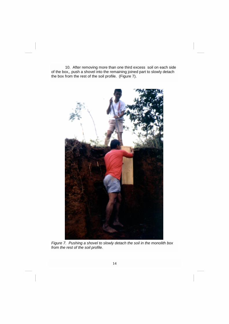
10. After removing more than one third excess soil on each side of the box,, push a shovel into the remaining joined part to slowly detach the box from the rest of the soil profile. (Figure 7).
Figure 7. Pushing a shovel to slowly detach the soil in the monolith box from the rest of the soil profile.

15
11. At the same time, be careful not to deform the soil column by cutting the roots with pruning shears. (Figure 8).
Figure 8. Maintaining the structural form of the soil within the monolith box by cutting the roots with pruning shears before totally de-taching the fresh monolith from the rest of the soil profile..

16
12. Remove excess soil using a kitchen knife to level with the box boundaries. (Figure 9). Cover by screwing the second lid into the frame of the monolith box. 13. Pack the monolith box and transport to the laboratory for chemical treatment.
Figure 9. Removing excess soils to level and fit the soil column into the monolith box.

17
A. Tools and Materials 1. Tools for cutting off a soil peel kitchen knife knife pruning shears brush screwdriver saw cutter plywood, 5 mm thick, with dimensions a littler larger than that of the soil column monolith tweezers 2. Tools for applying, pouring, and spraying resins can (2 - 4 li) with handle spray (5 ml) plastic vessel (1 li) with cap pipette (10 ml) aspirator stirring wooden rod wooden trowel 3. Resins and reagents Tomack NR-51 (Epoxy synthetic resin) Tomack NR-51-w (Hardener with plastic material for Tomack NR-51) Bond CH18 for wood (Polyvinyl acetate emulsion) Vinylight VYHH (UCC Co., US) or Esleck C (Sekisui Chem. Industry Co.) (Vinyl acetate-Vinylchlo- ride copolymer) Thinner for Vinylight VYHH or Esleck C (mixture of acetone:metylosobutylketone (MIBK) 1) 4. Materials cloth made of chemical synthetic fibers such as mosquitoe net mounting board (Figure 10).
Chapter 3: Preparation of a soil peel monolith

18
B. Procedures Pre-treatment 1. Place the soil column monolith collected from the field on a working stand. Remove the lid of the thinner frame of the monolith box. 2. Smoothen the profile with a kitchen knife. If the profile is very wet, dry it first for several days and smoothen again. (Figure 11).
Figure 11. Smoothening the soil profile.
Figure 10. A mounting board with frames.

19
Applying the Tomack Resin 3. Put a piece of cloth 10 cm wider than the profile and pin it on the monolith box. 4. Mix in a can 350 grams of Tomack NR-51 and 140 grams of hardener (Tomack NR-51-w) per 1500 cm2 (20 x 75 cm) of the profile. Stir well. 5. Uniformly apply the mixed Tomack resin with a wooden trowel on the cloth, remove the pins, and turn up the cloth following the exact di-mensions of the profile. 6. Apply the mixed Tomack resin again on the cloth and leave it overnight (or for at least 4 hours) to harden. (Figure 12)
Figure 12. Applying the Tomack resin on the cloth.
20
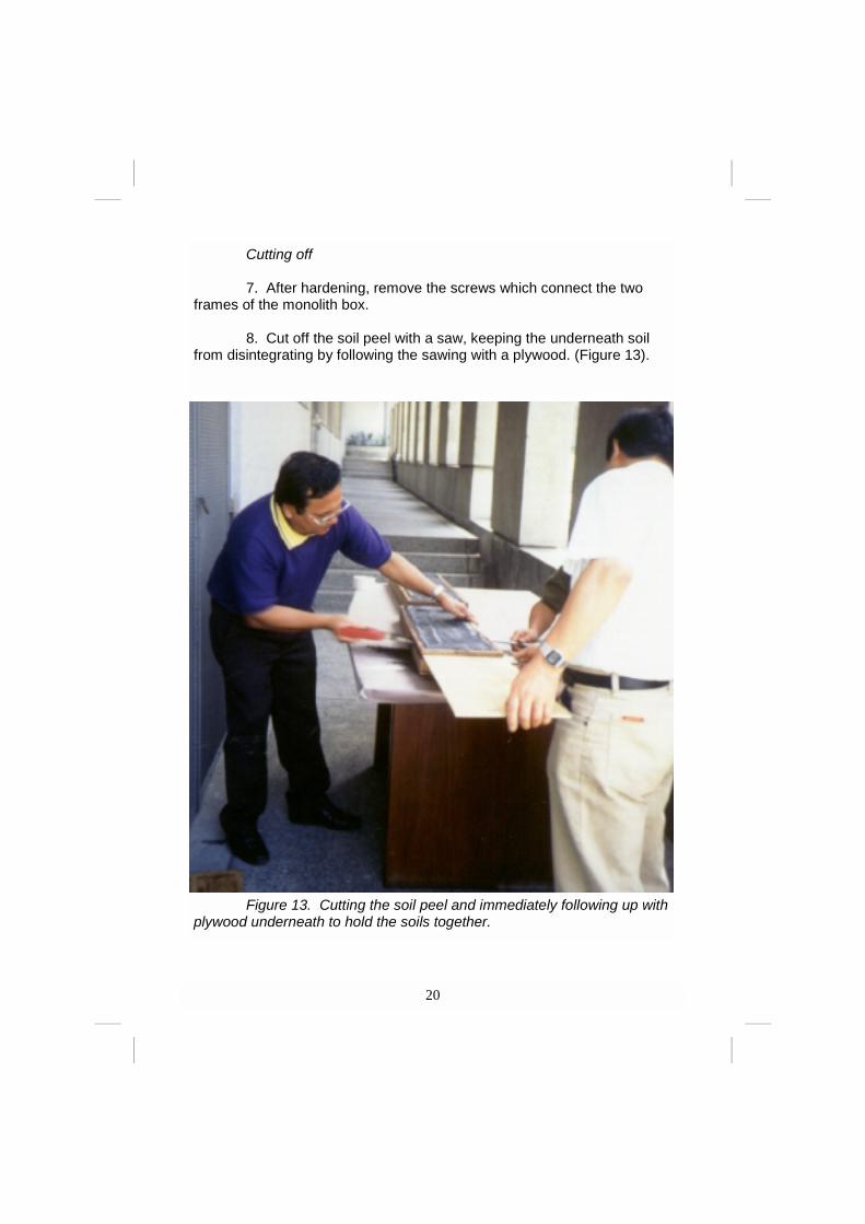
Figure 13. Cutting the soil peel and immediately following up with plywood underneath to hold the soils together.
Cutting off 7. After hardening, remove the screws which connect the two frames of the monolith box. 8. Cut off the soil peel with a saw, keeping the underneath soil from disintegrating by following the sawing with a plywood. (Figure 13).

21
9. Put the soil peel between two plywoods and turn over. 10. Remove the upper plywood. Separate the frame that sticked with the resin from the soil peel using a cutter. (Figure 14).
Figure 14. Separating the sticked frame from the soil peel.

22
Mounting 11. Cut the soil peel to the exact dimensions as those of the in-ternal dimensions of the mounting board. 12. Mix in a can 75 grams of Tomack NR-51 and 30 grams of hardener (Tomack NR-51-w) per 1500 cm2 (20 x 75 cm) of the mounting board. Stir it and uniformly apply on the mounting board with a wooden trowel. 13. Slip the soil peel into the mounting board. 14. Roughly loosen the surface of the soil peel with a knife. Should there be any damage, repair it with excess soil materials of the same horizon. 15. Put the plywoods and the weights on the soil peel. Leave it overnight (or at least 4 hours) fixed on the mounting board. Finishing 16. Carefully poke and loosen the surface of the soil peel with a knife to reveal the structure. (Figure 15)
Figure 15. Poking and loosening the soil peel to reveal the structure.

23
17. Dilute 100 grams of Bond CH18 for wood and about 2 ml of synthetic neutral detergent with 500 ml water in a 1 li vessel and stir well. 18. Uniformly add drop-wise the diluted Bond CH18 on the soil surface using a 10 ml pipette twice or three times and leave it until the soil peel dries. (It will take from overnight to two days.) (Figure 16). Figure 16. Adding drop-wise Bond CH18 emulsion using a pipette.
19. After drying, if the soil surface cracks, press both sides of the crack with a knife or a tweezer to disperse the same soil material on the cracks. Again, add drop-wise diluted Bond CH18 on the soil surface, this time only once, and leave it overnight. 20. Repeat Step 19 from once to three times until the soil materi-als are completely fixed on the mounting board. 21. Dissolve 25 grams of Esleck C in 500 ml thinner and stir the solution well. Spray the diluted Esleck C on the soil surface twice or three times if the soil surface does not appear moistened.

24
Chapter 4: Direct preparation of a soil peel monolith
A. Tools and Materials 1. Tools for digging and exposing soil profiles shovel crowbar hatchet or bolo pruning shears hand shovel folding meter scale kitchen knife 2. Tools and materials for cutting off a soil peel (in addition to the above tools) brush cutter plywood (5 mm thick) with the dimensions a little larger than that of the soil peel to take wooden trowel (plywood 0.5 cm thick, 10 cm long, and 20 cm wide) cloth made of chemical synthetic fibers such as mosquito net can (2 - 4 ml) with a handle ( for the Tomack NR-51 resin) stirring wooden rod (for the Tomack NR-51 resin) spray, 500 ml (for the Tomack NR-51 resin) 3. Resin and solvents Tomack NR-51 (Epoxy synthetic resin) Tomack NR-51-w (Hardener with plastic material for Tomack NR-51) or Tomack NS10 (Urethane synthetic resin) water (Hardener for Tomack NS10) acetone (dilution solvent for Tomack NS10)

25
B. Preparation of a pit 1. Dig a pit with shovel and crowbar. The pit should be about 1 meter wide, 1.5 to 2.0 meters long, and at least 10 centimeters deeper than the actual depth of the profile to be collected in order to provide enough working space below. 2. Smoothen one wall of the pit with a kitchen knife. C. Procedures 1. Provide a piece of cloth 10 centimeters wider and 20 centime-ters longer than the soil peel monolith to be taken. 2. Lay over the cloth on the wall of the pit and fix it well. (Figure 17).
Figure 17. Plac-ing the cloth made of syn-thetic fiber such as mos-quito net over the pit wall where the soil peel mono-lith is to be taken.
26
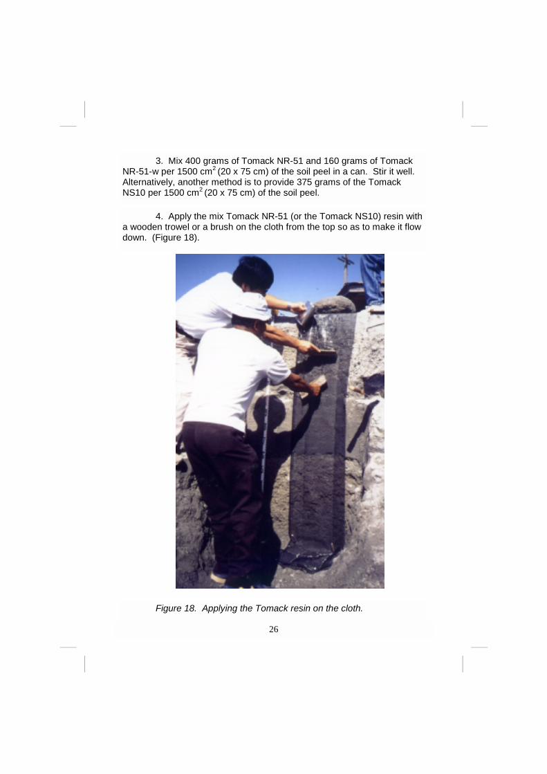
4. Apply the mix Tomack NR-51 (or the Tomack NS10) resin with a wooden trowel or a brush on the cloth from the top so as to make it flow down. (Figure 18).
Figure 18. Applying the Tomack resin on the cloth.
3. Mix 400 grams of Tomack NR-51 and 160 grams of Tomack NR-51-w per 1500 cm2 (20 x 75 cm) of the soil peel in a can. Stir it well. Alternatively, another method is to provide 375 grams of the Tomack NS10 per 1500 cm2 (20 x 75 cm) of the soil peel.

27
Figure 19. Spraying enough water for the hardening of Tomack NS10.
5. Uniformly apply the remainder of the Tomack resin and leave it for about 4 hours (for Tomack NR51). Or when using Tomack NS10, spray enough water and leave it for about an hour until the Tomack resin hardens. (Figure 19).

28
6. After drying, mark with a pentel pen the dimensions of the soil peel on the cloth which has hardened. 7. Cut about 10 centimeters thick of soil column following the ex-act width of the soil peel. Don’t cut the top and the bottom of the soil col-umn and the cloth. (Figure 20). Keep the excess soil peel which was cut off for repairing the soil peel monolith later.
8. Maintaining the form of the soil peel with a plywood, slowly detach the soil peel from the rest of the soil profile by removing the soil materials be-hind and on both sides of the soil column using a kitchen knife or a hand shovel, keeping at least 3 centimeters thick soil peel. Cut exposed roots using pruning shears.
Figure 20. Cutting about 10 centimeter thick soil column.

29
9. Slowly pull away the soil peel from the wall of the pit, keeping it intact with a plywood. (Figure 21)
Figure 21. Removing the soil peel from the pit, keeping it intact with a plywood underneath.

30
10. Lay it down and gently remove excess soil materials of the soil peel using a kitchen knife. 11. Pack the soil peel with the plywood underneath (Figure 22) and transport it to the laboratory for treatment. 12. Proceed to Chapter 3 for the sequence of laboratory treat-ments.
Figure 22. Packing the soil peel for laboratory treatments.
31
REFERENCES
van Baren, J.H. W., and W. Bomer. 1979. Procedures for
the collection and preservation of soil profiles. Technical Paper 1, International Soil Museum, Wageningan, The Netherlands.
Hamazaki, T., and M. Mitsuchi. 1983. Methods for the
preparation of soil monoliths. The Miscellaneous Publica-tions of the National Institute of Agricultural Sciences, Se-ries B, No. 18. Tsukuba, Japan.

Soils Research and Development Center Elliptical Road, Diliman Quezon City
Dr. Rogelio N. Concepcion
Executive Director
Alejandrino R. Baloloy Deputy Executive Director
Alejandro G. Micosa
Project Manager
Dr. Tamaki Yasuda JICA Team Leader
SOIL PRODUCTIVITY CAPABILITY CLASSIFICATION
Dr. Nora B. Inciong Chairman
Dr. Jose D. Rondal
Vice-Chairman
Dr. Toshiaki Ohkura JICA Expert for SPCC
Core Group Members:
Dr. Wilfredo Cabezon
Nestor Ticzon Edna Samar
Igmidio Lapis Rodelio Carating
Subject Matter Specialists:
Magdalena Favis Mario Vinluan Bertolio Arellano Virgilio Castaneda Nestor Merjilla Cristy Perlado Leo Retamar Cleotilde Nicolas Julieta Espineli Oscar Costelo Emiliano Sibolboro Josefina Diloy Querubin Navero Natividad Salonga Cecille Orlanes
An SPCC Production Bureau of Soils and Water Management