Preparation and properties as positive electrodes of PANI–LiNi0.8Co0.2O2 nanocomposites
7
Journal of Solid State Chemistry 179 (2006) 308–314 Preparation and characterization of LiNi 0.8 Co 0.2 O 2 /PANI microcomposite electrode materials under assisted ultrasonic irradiation Y. Mosqueda a , E. Pe´rez-Cappe a , J. Arana b , E. Longo b , A. Ries b , M. Cilense b , P.A.P. Nascente c , P. Aranda d , E. Ruiz-Hitzky d, a Laboratory of Chemistry of Materials-IMRE, Havana University, Havana, Cuba b Chemistry Department, UNESP, Ararquara, Brazil c CCDM-Universidade de Sao Carlos, Brazil d Instituto de Ciencia de Materiales de Madrid, CSIC, Cantoblanco E-28049, Madrid, Spain Received 25 April 2005; received in revised form 12 September 2005; accepted 17 September 2005 Available online 2 November 2005 Abstract A preparation method for a new electrode material based on the LiNi 0.8 Co 0.2 O 2 /polyaniline (PANI) composite is reported. This material is prepared by in situ polymerization of aniline in the presence of LiNi 0.8 Co 0.2 O 2 assisted by ultrasonic irradiation. The materials are characterized by XRD, TG-DTA, FTIR, XPS, SEM-EDX, AFM, nitrogen adsorption (BET surface area) and electrical conductivity measurements. PANI in the emeraldine salt form interacts with metal-oxide particles to assure good connectivity. The dc electrical conductivity measurements at room temperature indicate that conductivity values are one order of magnitude higher in the composite than in the oxide alone. This behavior determines better reversibility for Li-insertion in charge–discharge cycles compared to the pristine mixed oxide when used as electrode of lithium batteries. r 2005 Elsevier Inc. All rights reserved. Keywords: PANI; Ni–Co mixed oxides; Organic–inorganic composites; Electrode materials; Lithium batteries 1. Introduction The Ni-rich oxides of the Li–Ni–Co system present characteristics such as high cell voltage, high and variable oxidation states, high electronic conductivity at room temperature, making them interesting for applications as electrode in rechargeable lithium batteries [1–4]. However, their commercialization is currently limited due to struc- tural impediments associated with the cationic disorder in the octahedral layer occupation [5–7]. Among different synthetic strategies proposed as alternatives to overcome such limitations, we have recently proposed a chemical method for preparation of a Ni-rich mixed oxide phase with structural cationic ordering that enhances its behavior as lithium battery positive electrode [8]. On the other hand, it is known that Ni–Co mixed oxides present a close packed crystalline structure in which octahedral sites are occupied by lithium ions. As the structural features of these materials negatively influence lithium diffusion, their use as battery cathodes imposes one to work at low current (typically 30–50 mA). In addition, these oxides have high relative density and very poor mechanical properties making them less attractive for practical purposes. To overcome the above problems we aim to contribute preparing hybrid materials of the LiNi 0.8 Co 0.2 O 2 nickel- rich phase combined with a classic conducting polymer such as polyaniline (PANI). Doped PANIs are conducting materials of interest for use in secondary batteries [9,10] that have been also satisfactorily combined with inorganic redox oxides, giving systems suitable for electrochemical Li intercalation. The first PANI-based nanocomposite was reported by Kanatzidis and co-workers [11]. These authors described the intercalative polymerization of ani- line in V 2 O 5 xerogel giving PANI-nanocomposites of good electrical conductivity. Later on Nazar and co-workers demonstrated the feasibility of these materials for rever- sible electrochemical lithium insertion and therefore their ARTICLE IN PRESS www.elsevier.com/locate/jssc 0022-4596/$ - see front matter r 2005 Elsevier Inc. All rights reserved. doi:10.1016/j.jssc.2005.09.030 Corresponding author. Fax: +34 91 372 06 23. E-mail address: [email protected] (E. Ruiz-Hitzky).
-
Upload
independent -
Category
Documents
-
view
0 -
download
0
Transcript of Preparation and properties as positive electrodes of PANI–LiNi0.8Co0.2O2 nanocomposites

ARTICLE IN PRESS
0022-4596/$ - se
doi:10.1016/j.jss
�CorrespondE-mail addr
Journal of Solid State Chemistry 179 (2006) 308–314
www.elsevier.com/locate/jssc
Preparation and characterization of LiNi0.8Co0.2O2/PANImicrocomposite electrode materials under assisted ultrasonic irradiation
Y. Mosquedaa, E. Perez-Cappea, J. Aranab, E. Longob, A. Riesb, M. Cilenseb,P.A.P. Nascentec, P. Arandad, E. Ruiz-Hitzkyd,�
aLaboratory of Chemistry of Materials-IMRE, Havana University, Havana, CubabChemistry Department, UNESP, Ararquara, Brazil
cCCDM-Universidade de Sao Carlos, BrazildInstituto de Ciencia de Materiales de Madrid, CSIC, Cantoblanco E-28049, Madrid, Spain
Received 25 April 2005; received in revised form 12 September 2005; accepted 17 September 2005
Available online 2 November 2005
Abstract
A preparation method for a new electrode material based on the LiNi0.8Co0.2O2/polyaniline (PANI) composite is reported. This
material is prepared by in situ polymerization of aniline in the presence of LiNi0.8Co0.2O2 assisted by ultrasonic irradiation. The materials
are characterized by XRD, TG-DTA, FTIR, XPS, SEM-EDX, AFM, nitrogen adsorption (BET surface area) and electrical conductivity
measurements. PANI in the emeraldine salt form interacts with metal-oxide particles to assure good connectivity. The dc electrical
conductivity measurements at room temperature indicate that conductivity values are one order of magnitude higher in the composite
than in the oxide alone. This behavior determines better reversibility for Li-insertion in charge–discharge cycles compared to the pristine
mixed oxide when used as electrode of lithium batteries.
r 2005 Elsevier Inc. All rights reserved.
Keywords: PANI; Ni–Co mixed oxides; Organic–inorganic composites; Electrode materials; Lithium batteries
1. Introduction
The Ni-rich oxides of the Li–Ni–Co system presentcharacteristics such as high cell voltage, high and variableoxidation states, high electronic conductivity at roomtemperature, making them interesting for applications aselectrode in rechargeable lithium batteries [1–4]. However,their commercialization is currently limited due to struc-tural impediments associated with the cationic disorder inthe octahedral layer occupation [5–7]. Among differentsynthetic strategies proposed as alternatives to overcomesuch limitations, we have recently proposed a chemicalmethod for preparation of a Ni-rich mixed oxide phasewith structural cationic ordering that enhances its behavioras lithium battery positive electrode [8]. On the other hand,it is known that Ni–Co mixed oxides present a close packedcrystalline structure in which octahedral sites are occupied
e front matter r 2005 Elsevier Inc. All rights reserved.
c.2005.09.030
ing author. Fax: +34 91 372 06 23.
ess: [email protected] (E. Ruiz-Hitzky).
by lithium ions. As the structural features of thesematerials negatively influence lithium diffusion, their useas battery cathodes imposes one to work at low current(typically 30–50 mA). In addition, these oxides have highrelative density and very poor mechanical propertiesmaking them less attractive for practical purposes.To overcome the above problems we aim to contribute
preparing hybrid materials of the LiNi0.8Co0.2O2 nickel-rich phase combined with a classic conducting polymersuch as polyaniline (PANI). Doped PANIs are conductingmaterials of interest for use in secondary batteries [9,10]that have been also satisfactorily combined with inorganicredox oxides, giving systems suitable for electrochemicalLi intercalation. The first PANI-based nanocompositewas reported by Kanatzidis and co-workers [11]. Theseauthors described the intercalative polymerization of ani-line in V2O5 xerogel giving PANI-nanocomposites of goodelectrical conductivity. Later on Nazar and co-workersdemonstrated the feasibility of these materials for rever-sible electrochemical lithium insertion and therefore their

ARTICLE IN PRESSY. Mosqueda et al. / Journal of Solid State Chemistry 179 (2006) 308–314 309
applicability as electrodes for rechargeable lithium bat-teries [12,13]. The lithium chemical diffusion coefficient ishigher for the nanocomposite than for the oxide alone byone order of magnitude, this effect being particularlyremarkable for high cycling rates [13]. On the basis of thisapproach, the development of conducting nanocompositesreceived significant attention, deserving new studies usingother polymers combined at the molecular (nanometer)level with different inorganic solids [14–17]. Many of thesesystems involve inorganic hosts exhibiting a layeredstructure susceptible to be exfoliated by the guest polymerintercalation. Non-intercalable and three-dimensionalstructured metal oxides could be also combined withconducting polymers such as PANI or polypyrrole (PPy)giving rise to the so-called microcomposites, i.e. materialscombined at the micrometer scale, or even nanocompositestaking into account the micrometer or nanometer scale sizeof the involved oxide particles [18–22]. The resulting solidscan exhibit better electrical, electrochemical, mechanical,morphological and thermal properties than the formercomponents (inorganic solid and guest polymeric species)and some of them have been also tested in rechargeablelithium batteries applications [23–25]. Concerning Ni andCo dioxides/PANI systems, Ramachandran and co-work-ers [26] have reported PANI intercalation by previoustreatment of the host solids with ammonium peroxodisul-fate. As discussed below, the same method applied toLixNi0.8Co0.2O2 phases does not produce intercalationcompounds.
As sonochemistry appears as a powerful tool forpreparation of a great variety of materials [27] this strategyhas been applied here to prepare PANI/LiNi0.8Co0.2O2
composites by polymerization of PANI in the presence ofLiNi0.8Co0.2O2 as a microparticulated solid assisted byultrasound irradiation. This type of approach has beenrecently applied to the preparation of comparable materi-als, for instance, PANI/TiO2 composites providing com-pounds of enhanced conductivity, e.g. s ¼ 0:72 S cm�1 atroom temperature [28]. The final objective of the presentwork is to prepare electroactive PANI/LiNi0.8Co0.2O2
microcomposites showing enhanced electrical conductivityand preserving their reversible electrochemical Li-insertionbehavior, which make them improved electrode materialsfor Li-rechargeable batteries.
2. Experimental section
2.1. Synthesis
LiNi0.8Co0.2O2 is synthesized by a procedure previouslydescribed following a Li–Ni–Co mixed citrate route forthe preparation of the Li0.7Ni0.8Co0.2O2 phase [8] that hasbeen modified in the present case to reach the desiredstoichiometry. In this way, the thermal decomposition ofthe citrate precursor has been carried out here in sealedAu crucibles adding 0.3mole/formula of LiOH �H2O toprocure additional Li. The LiNi0.8Co0.2O2/PANI compo-
site (1:1 oxide/polymer intended ratio) was prepared from200mg of the mixed oxide, 100mg of anilinium chloride,220mg of ammonium peroxodisulfate (1:1 monomer/oxidant molar ratio) and, 1.5 g of sodium lauryl sulfate(surfactant). The starting reagents were dispersed in 200mlof 1.5M HCl and the mixture sonicated 1 h using a Sonicsultrasonic liquid processor (600W) with a probe workingat 240KHz. The experiments were carried out at roomtemperature in air atmosphere. The resulting colloidaldispersion was flocculated with absolute ethanol and firstwashed three times with 100mL of 0.2M HCl to removeresidual monomer, oxidant, and its decomposition pro-ducts, and then with acetone to eliminate low-molecular-weight organic intermediates and oligomers. The ultrafinepowder composite was vacuum dried at 60 1C. Forcomparative purposes, bulk PANI was synthesized follow-ing the same procedure.
2.2. Characterization
X-ray diffraction patterns (XRD) were registered with aRigaku ultra-X 18BV2, (CuKa radiation, 42 kV, 120mA) ata step scan rate of 0.021/s in the 10–1201 2y range. X-rayphotoelectron spectroscopy (XPS) was carried out using aXSAMHS surface spectramicroscopy with an Al Ka
X-ray source at 1486.6 eV energy and 140W power. Thebinding energy of the core level C1s was set at 284.8 eV.Deconvolution of peaks into their components was carriedout with software provided by the furnisher consisting of aGaussian line shape Lorentzian function on a Shirleybackground. The surface elemental compositions weredetermined from the ratio of the peak areas correctedwith the empiric sensitivity factors. The TG curves wereobtained in static air atmosphere using a Netszch-Thermische analyzer equipped with a PU1.851.01 unitpower and a TASC 414/2 controller, using as reference a-Al2O3 and a Pt/Pt–Rh 10% thermocouple. The IR spectrawere registered with a Perkin Elmer 567 model spectro-photometer, in the 400–4500 cm�1 wave number range; thesolid samples were diluted in KBr pellets. The SEM-EDXand the atomic force microscopy (AFM) micrographs werecarried out on a Princeton Gamma-Tech.Inc equipment,SM300 model provided by TOPCON and a MultimodeTM Scanning probe microscope MMAFM-2 model ofDigital Instruments, respectively. Samples (powders) wereAu sputtered for the SEM study. The four-point con-ductivity measurements at room temperature were carriedout using a homemade apparatus described elsewhere [29],the samples being in the form of pellets (0.33 cm2 area,0.05 cm thickness) pressed at 7 ton/cm2.Electrochemical measurements were conducted in
Li/LiClO4 (PC:EC)/(LiNi0.8Co0.2O2/PANI) and Li/LiClO4
(PC:EC)/[LiNi0.8Co0.2O2/carbon black (10%)] cells. Thepositive electrode was prepared as pellets of 0.13 cmdiameter using 0.5 g of either the microcomposite orthe pristine oxide (with 10% carbon black) pressed at3 ton/cm2 and heated at 100 1C for 4 h. The cells, assembled

ARTICLE IN PRESSY. Mosqueda et al. / Journal of Solid State Chemistry 179 (2006) 308–314310
into an argon-filled dry box, were galvanostatically cycledunder 100 and 30 mA, respectively, of direct current in the3–3.8V voltage range.
3. Results and discussion
In a first set of experiments we have applied theprocedure reported by Ramachandran et al. [26] trying toprepare PANI/LiNi0.8Co0.2O2 composites with the aim toobtain nanocomposites based on the in situ intercalativepolymerization of PANI within the mixed oxide layers. Itshould be remarked that although this last procedure wasapparently successfully applied to obtain intercalationcompounds of related solids, such as LiNiO2 and LiCoO2
[26], in our case the resulting compounds consisted of amixture of scarce homogeneity formed by PANI and thestarting mixed oxide without intercalation.
We have instead tested alternative strategies with theobjective to prepare composites without exfoliation of themixed oxide but in which the LiNi0.8Co0.2O2 was present as amicroparticulated solid. In this way, PANI/LiNi0.8Co0.2O2
microcomposites have been prepared by treatment of amixture of LiNi0.8Co0.2O2 synthesized from the citrateroute [8] and anilinium chloride under ultrasound irradia-tion. To assure the formation of PANI in its emeraldinesalt form the treatment was carried out in the presence of(NH4)2S2O8 in acid media (aq. HCl). The resulting materialconsists of a polymer/mixed oxide microcomposite with analmost 1:1 (w/w) ratio as deduced from the TG analyses(polymer loss of about 50% in weight) (Fig. 1). The weightloss up to about 600 1C observed in the TG curve of themicrocomposite shows a similar trend than that observedfor bulk PANI. The first weight loss between 50 and 100 1Cis associated with the removal of physically adsorbed watermolecules. This weight loss represents 0.3% and 10% oftotal weight for the composite and PANI, respectively. Thewater content is related to the hygroscopic character of the
Fig. 1. TG curves of bulk PANI (a) and PANI/LiNi0.8Co0.2O2 micro-
composite (b).
conducting polymer and must be borne in mind for lithiumbattery applications. It should be noted that alternativemethods to combine the polymer and the oxide, e.g.magnetic stirring instead sonication, give materials show-ing lower homogeneity with almost similar conductivityvalues than the pristine oxide alone.The XRD patterns of LiNi0.8Co0.2O2 pristine oxide,
oxide/PANI microcomposite and bulk PANI are shown inFig. 2. The diagram of the microcomposite shows thecoexistence of reflections related to both LiNi0.8Co0.2O2
and PANI, although the low crystallinity of the polymerproduces high scattering that may hide some characteristicdiffraction peaks of the mixed oxide. The preservation ofLiNi0.8Co0.2O2 crystallinity is verified by TEM showingnanometric oxide particles embedded in the polymermatrix. Enlargement of XRD peaks of the oxide can beexplained by the diminution of its particle size asconsequence of the ultrasound irradiation. The threecharacteristic diffraction peaks centered at 0.54, 0.44 and0.35 nm (16.5, 20.1 and 25.1 2y1) corresponding to PANI inits emeraldine salt form [28,30,31], are present in the bulkPANI and the PANI/LiNi0.8Co0.2O2 microcomposite bothprepared by sonication. The peak at 0.44 nm attributed tothe (100) reflection is slightly more intense than that at0.35 nm corresponding to the (110) reflection. According toPouget and co-workers [30] the relative intensities of bothreflections are very sensitive to the ring tilt angle and to theCl–N distance indicating a similar structure of bulk PANIand PANI/LiNi0.8Co0.2O2 microcomposite. This behavioris different from the PANI/TiO2 composites prepared bysonication by Xia and Wang [28], probably being related toa lower doping level of the emeraldine salt in the presentcase as the synthesis has been carried out in a lessconcentrated HCl medium.
Fig. 2. XRD patterns of pristine LiNi0.8Co0.2O2 oxide (a), bulk PANI
(b) and PANI/LiNi0.8Co0.2O2 microcomposite (c).

ARTICLE IN PRESSY. Mosqueda et al. / Journal of Solid State Chemistry 179 (2006) 308–314 311
Fig. 3 shows the IR spectra (400–2000 cm�1) of both thebulk PANI and the PANI/LiNi0.8Co0.2O2 microcomposite.In bulk PANI, the bands assigned to benzoid (B) andquinoid (Q) ring deformations appear at 1467 and1549 cm�1, respectively. Both bands shift to higher wavenumber (1492 and 1575 cm�1, respectively) in the micro-composite reversing their relative intensities. This observa-tion indicates that Q rings predominate in the polymerformed in the microcomposite compared to bulk PANI,suggesting a higher oxidation degree in the polymerbackbone of the former due to its interaction with thesurface of the mixed oxide. The wave number shift is alsoconsistent with a lower degree of PANI protonation in themicrocomposite, which is confirmed by a similar shift effectobserved for the bands in the 1400–1100 cm�1 region [32].The bands around 800 and 1010–1170 cm�1 are assigned toC–H out-of-plane and in-plain bending modes, respec-tively, characteristic of p-di-substitution in benzene rings.The band corresponding to the CH out-of-plane bendingvibration mode of mono-substituted benzene ring isnot observed, indicating that the degree of polymerizationis large. This interpretation is also supported by theobservation in both materials of a band around 1300 cm�1,
Fig. 3. IR spectra in the 400–2000 cm�1 range of bulk PANI (a) and
PANI/LiNi0.8Co0.2O2 microcomposite (b). B and Q represent the benzoid
and quinoid rings of PANI.
which is usually associated with C–N stretching vibrationsof secondary aromatic amine groups [33].The band at 1232 cm�1 can be assigned to C–N
stretching vibrations of benzenoid species. Some authorshave interpreted it as originating from a bipolaronstructure, which could be related to the conducting formof PANI [34,35]. The 1135 cm�1 band observed in themicrocomposite, which is considered as an ‘‘electronicband’’ associated with conduction in doped PANI[33,35,36], can be assigned to a vibration mode of–NH+Q (semiquinone radical cation, IP�+) structures[31,37]. It should be expected that the oxide surfacestrongly interacts with the conjugate structure of PANI,especially through the quinoid ring (semiquinone radicalcation), as it has been reported in other systems [28,38].The observed low slope in the IR spectrum above2000 cm�1 is indicative of a low protonation degree whichis directly related to the experimental conditions adopted inthis work as above indicated. Finally, IR absorption bandsappearing in the 3000–3500 cm�1 range are mainly assignedto stretching N–H vibrations in different environments.By comparing the XPS spectra (Fig. 4) of pristine mixed
oxide and PANI/oxide microcomposite a slight shift ofbinding energies for all the detected elements is observed,indicating a change of environment that affects all theinvolved atoms. It is noteworthy that both Ni and Coatoms located at the surface of the oxide particles in themicrocomposite preserve their +3 oxidation state.Using a fitting procedure that assumes Gaussian func-
tions for describing N(1s) and C(1s) photoelectron lines asseparate components in the XPS spectrum of the PANI/oxide microcomposite, the quantitative analysis summar-ized in Table 1 is proposed [36,39,40]. The existence of N+
species and the lower peak area of NH+ and/or NH2+
groups in relation to NH groups agree with the resultsobtained by IR and XRD techniques, meaning that apoorly doped emeraldine salt is formed in the presence ofthe mixed oxide. The high N+ binding energy observed inthe spectrum of the microcomposite is related not only tothe interaction between this group and protons introduced
Fig. 4. XPS spectra of the pristine mixed oxide (a) and PANI/
LiNi0.8Co0.2O2 microcomposite (b).
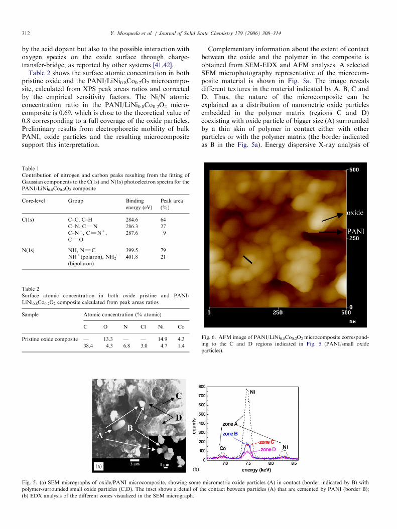
ARTICLE IN PRESSY. Mosqueda et al. / Journal of Solid State Chemistry 179 (2006) 308–314312
by the acid dopant but also to the possible interaction withoxygen species on the oxide surface through charge-transfer-bridge, as reported by other systems [41,42].
Table 2 shows the surface atomic concentration in bothpristine oxide and the PANI/LiNi0.8Co0.2O2 microcompo-site, calculated from XPS peak areas ratios and correctedby the empirical sensitivity factors. The Ni/N atomicconcentration ratio in the PANI/LiNi0.8Co0.2O2 micro-composite is 0.69, which is close to the theoretical value of0.8 corresponding to a full coverage of the oxide particles.Preliminary results from electrophoretic mobility of bulkPANI, oxide particles and the resulting microcompositesupport this interpretation.
Table 1
Contribution of nitrogen and carbon peaks resulting from the fitting of
Gaussian components to the C(1s) and N(1s) photoelectron spectra for the
PANI/LiNi0.8Co0.2O2 composite
Core-level Group Binding
energy (eV)
Peak area
(%)
C(1s) C–C, C–H 284.6 64
C–N, CQN 286.3 27
C–N+, CQN+,
CQO
287.6 9
N(1s) NH, NQC 399.5 79
NH+(polaron), NH2+
(bipolaron)
401.8 21
Table 2
Surface atomic concentration in both oxide pristine and PANI/
LiNi0.8Co0.2O2 composite calculated from peak areas ratios
Sample Atomic concentration (% atomic)
C O N Cl Ni Co
Pristine oxide composite — 13.3 — — 14.9 4.3
38.4 4.3 6.8 3.0 4.7 1.4
Fig. 5. (a) SEM micrographs of oxide/PANI microcomposite, showing some
polymer-surrounded small oxide particles (C,D). The inset shows a detail of t
(b) EDX analysis of the different zones visualized in the SEM micrograph.
Complementary information about the extent of contactbetween the oxide and the polymer in the composite isobtained from SEM-EDX and AFM analyses. A selectedSEM microphotography representative of the microcom-posite material is shown in Fig. 5a. The image revealsdifferent textures in the material indicated by A, B, C andD. Thus, the nature of the microcomposite can beexplained as a distribution of nanometric oxide particlesembedded in the polymer matrix (regions C and D)coexisting with oxide particle of bigger size (A) surroundedby a thin skin of polymer in contact either with otherparticles or with the polymer matrix (the border indicatedas B in the Fig. 5a). Energy dispersive X-ray analysis of
micrometric oxide particles (A) in contact (border indicated by B) with
he contact between particles (A) that are cemented by PANI (border B);
Fig. 6. AFM image of PANI/LiNi0.8Co0.2O2 microcomposite correspond-
ing to the C and D regions indicated in Fig. 5 (PANI/small oxide
particles).

ARTICLE IN PRESS
4.0
3.8
3.6
3.4
3.2
3.0
volta
ge (
V)
1.0 0.9 0.8 0.7 0.6 0.5 0.4lithium content
4.0
3.8
3.6
3.4
3.2
3.0
2.8
volta
ge (
V)
1.0 0.9 0.8 0.7 0.6 0.5 0.4lithium content
charge dischargecharge discharge
(a) (b)
Fig. 7. Fourth and first charge–discharge cycles of Li/LiClO4 (PC:EC)/(LiNi0.8Co0.2O2/carbon black) (a) and Li/LiClO4 (PC:EC)/(LiNi0.8Co0.2O2/PANI)
(b) electrochemical cells applying a current of 30 and 100mA, respectively.
Y. Mosqueda et al. / Journal of Solid State Chemistry 179 (2006) 308–314 313
these different zones indicates different abundance of metaloxide (Fig. 5b) in each of the regions. The fact that theconcentration of oxide nanoparticles in the polymer wasvariable in the different regions of the whole material canbe a consequence of the existence of oxide particles ofdifferent size that submitted to the ultrasound treatmentwere non-homogenously dispersed in the bulk of theformed polymer. AFM (Fig. 6) shows oxide particles(E 30 nm diameter) and PANI intimately combined. Thisimage corroborates the connectivity among oxide particlesprovided by the polymer, which is of great significance inview of the electrical and electrochemical behavior of themicrocomposite.
From dc conductivity measurements at room temperaturedetermined by the Van der Paw’s four-point method isdeduced a value of 10�1 S cm�1 for the PANI/LiNi0.8Co0.2O2
microcomposite. This conductivity is two orders ofmagnitude higher than that of the pristine LiNi0.8Co0.2O2
alone or related oxide phases with lower content in lithiumsuch as Li0.7Ni0.8Co0.2O2 [8]. The electrochemical behaviorof the microcomposite when tested as electrode in aLi/LiClO4 (PC:EC)/(LiNi0.8Co0.2O2/PANI) cell is shownin Fig. 7a, in which is represented the fourth and firstcharge–discharge cycles in the 3–3.8V voltage range usinga direct current of 100 mA. The electrochemical behavior ofthe Li/LiClO4 (PC:EC)/(LiNi0.8Co0.2O2/carbon black) cellusing a direct current of 30 mA is presented for comparisonin Fig. 7b. It appears that the microcomposite works betteras an electrode for lithium insertion–deinsertion comparedto the pristine mixed oxide as it is possible to cycle thesystems at higher current. This is agreement with the highdiffusion coefficient (10�7 cm2/s) of lithium determined byGITT measurements [43] and also with data alreadyreported showing that conductive polymers enhancelithium diffusivity [13]. Moreover, recent investigations[33] indicate that lithium salt-doped PANI directlyfabricated from solutions containing PANI and lithiumsalts, are more effectively doped than samples prepared bychemical treatment with protonic acid doping agents. Itcould be proposed that in a certain way the method usedfor preparing the composite may operate in an analogousway and may favor the increase of the amount of unpairedelectrons (polarons) enhancing the conductivity of the
system. This hypothesis is consistent with the existence ofoxide–polymer interactions in the microcomposite.
4. Concluding remarks
Concerning the preparation of the LiNi0.8Co0.2O2/PANIcomposites, the ultrasound treatment appears to be moreeffective than conventional methods, such as magneticstirring, to produce more homogeneous materials contain-ing a large amount of the metal oxide particles of smallsize. The composites prepared under these conditions canbe regarded as microcomposites instead of nanocompositesin view of the size of most part of the oxide particles andthe lack of intercalation/exfoliation of the metal oxide.PANI constitutes a matrix in which small particles of theoxide are embedded procuring connectivity in the system.The good contact between polymer and oxide particlesdetermines the observed increase in the electrical conduc-tivity of the microcomposite compared to the pristineoxide. The microcomposite maintains the Li-insertionability of the oxide counterpart showing improvedbehavior as electrode for rechargeable lithium batteries asit is possible to perform the cycling at higher current valuescompared to the oxide with added carbon.
Acknowledgments
Financial support from the CSIC and the HavanaUniversity (CITMA) through a Spanish–Cuban coopera-tion (reference 2001CU0007), the CICYT (Spain,MAT2003-06003-C02-01 project) and the UNESP-MEScooperation are gratefully acknowledged.
References
[1] I. Saadoune, M. Menetrier, C. Delmas, J. Mater. Chem. 12 (1997)
2505–2511.
[2] D.-W. Kim, Y.-K. Sun, Solid State Ionics 111 (1998) 243–252.
[3] C. Julien, L. El-Farh, S. Rangan, M. Massot, J. Sol–Gel Sci. Technol.
15 (1999) 63–72.
[4] J. Molenda, P. Wilk, J. Marzec, Solid State Ionics 119 (1999) 19–22.
[5] A. Rougier, I. Saadoune, P. Gravereau, P. Willman, C. Delmas, Solid
State Ionics 90 (1996) 83–90.
[6] E. Zhecheva, R. Stoyanova, Solid State Ionics 66 (1993) 143–149.

ARTICLE IN PRESSY. Mosqueda et al. / Journal of Solid State Chemistry 179 (2006) 308–314314
[7] J. Morales, C. Perez, J.L. Tirado, Mater. Res. Bull. 25 (1990)
623–625.
[8] Y. Mosqueda, E. Perez-Cappe, P. Aranda, E. Ruiz-Hitzky, Eur.
J. Inorg. Chem. (2005) 2698–2705.
[9] P. Nova, K. Muller, K. Santhanam, O. Haas, Chem. Rev. 97 (1997)
207–281.
[10] E. Genies, A. Syed, C. Tsintavis, Mol. Cryst. Liq. Cryst. 121 (1985)
181–186.
[11] M.G. Kanatzidis, C.-G. Wu, H.O. Marcy, C.R. Kannewurf, J. Am.
Chem. Soc. 111 (1989) 4139–4141.
[12] F. Leroux, B.E. Koene, L.F. Nazar, J. Electrochem. Soc. 143 (1996)
L181–L183.
[13] F. Leroux, G. Goward, W.P. Power, L.F. Nazar, J. Electrochem.
Soc. 144 (1997) 3886–3895.
[14] E. Ruiz-Hitzky, Adv. Mater. 5 (1993) 334–340.
[15] E. Ruiz-Hitzky, P. Aranda, An. Quim. Int. Ed. 93 (1997) 197–212.
[16] P. Gomez-Romero, Adv. Mater. 13 (2001) 163–174.
[17] E. Ruiz-Hitzky, P. Aranda, in: T.J. Pinnavaia, G.W. Beall (Eds.),
Polymer–Clay Nanocomposites, Wiley, West Sussex, 2000, pp. 19–46.
[18] S. Maeda, S.P. Armes, J. Coll. Interface Sci. 159 (1993) 257–259.
[19] R.F. de Farias, J.M. de Souza, J.V. de Melo, C. Airoldi, J. Coll.
Interface Sci. 212 (1999) 123–129.
[20] B.Z. Tang, Y. Geng, J.W.Y. Lam, B. Li, X. Jing, X. Wang, F. Wang,
A.B. Pakhomov, X.X. Zhang, Chem. Mater. 11 (1999) 1581–1589.
[21] H. Yoneyama, N. Takahashi, S. Kuwabata, J. Chem. Soc. Chem.
Commun. (1992) 716–717.
[22] H. Yoneyama, A. Kishimoto, S. Kuwabata, J. Chem. Soc. Chem.
Commun. (1991) 986–987.
[23] S. Kuwabata, A. Kisimito, T. Tanaka, H. Yoneyama, J. Electrochem.
Soc. 141 (1994) 10–14.
[24] S. Kuwabata, T. Idzu, C.R. Martin, H. Yoneyama, J. Electrochem.
Soc. 145 (1998) 2707–2712.
[25] S. Kuwabata, S. Masui, H. Tomiyori, H. Yoneyama, Electrochim.
Acta 46 (2000) 91–97.
[26] K. Ramachandran, O. Christopher, M. Lerner, Mater. Res. Bull. 31
(1996) 767–772.
[27] D. Peters, J. Mater. Chem. 6 (1996) 1605–1618.
[28] H. Xia, Q. Wang, Chem. Mater. 14 (2002) 2158–2165.
[29] E. Perez-Cappe, A. Villanueva, J.C. Galvan, G. Perez-Urrutia,
E. Ruiz-Hitzky, Abstracts VI Reunion Nacional de Materiales, San
Sebastian, Spain, 1999.
[30] J. Pouget, M. Josefowiez, A. Epstein, X. Tang, A.G. MacDiarmid,
Macromolecules 24 (1991) 779–789.
[31] Y. Furukawa, T. Hara, Y. Hyodo, I. Harada, Synth. Met. 16 (1986)
189–198.
[32] S.-A. Chen, H.-T. Lee, Synth. Met. 47 (1992) 233–238.
[33] S.K. Ryu, B.W. Moon, J. Joo, S.H. Chang, Polymer 42 (2001)
9355–9360.
[34] J. Stejskal, I. Sapurina, M. Trchova, J. Prokes, I. Krivka,
E. Tobolkova, Macromolecules 31 (1998) 2218–2222.
[35] S. Quillard, G. Louarn, S. Lefrant, A.G. MacDiarmid, Phys. Rev. B
50 (1994) 12496–12508.
[36] K.G. Neoh, E.T. Kang, K.L. Tan, J. Polym. Sci. Part B. Polym. Phys.
31 (1993) 395–401.
[37] Y. Furukawa, F. Ueda, Y. Hyodo, I. Harada, T. Nakajima,
T. Kawagoe, Macromolecules 21 (1988) 1297–1305.
[38] J. Chen, Y. Zhang, D. Wang, H. Dai, J. Am. Chem. Soc. 123 (2001)
3838–3839.
[39] M.G. Han, S.S. Im, Polymer 41 (2000) 3253–3262.
[40] A.P. Monkmam, G.C. Steevens, D. Bloor, J. Phys. D: Appl. Phys. 24
(1991) 738–749.
[41] E.T. Kang, G.K. Neoh, K.L. Tang, Synth. Met. 68 (1995)
141–144.
[42] M. Cochet, W.K. Maser, A.M. Benito, M.A. Callejas, M.T.
Martinez, J.M. Benoit, J. Schreiber, O. Chauvet, Chem. Commun.
(2001) 1450–1451.
[43] Y. Mosqueda, Y. Rodrıguez, E. Perez-Cappe, J. Arana, E. Souza,
Phys. Stat. Sol. C 2 (2005) 3774–3777.