Preliminary Site Characterization Plan
460
Naval Facilities Engineering Systems Command Hawaii Preliminary Site Characterization Plan November 2021 Release, U.S. Navy Well 2254-01 JBPHH, O‘ahu, Hawai‘i January 2022
-
Upload
khangminh22 -
Category
Documents
-
view
1 -
download
0
Transcript of Preliminary Site Characterization Plan

Naval Facilities Engineering Systems Command Hawaii
Preliminary Site Characterization Plan November 2021 Release, U.S. Navy Well 2254-01 JBPHH, O‘ahu, Hawai‘i January 2022

This page intentionally left blank

Preliminary Site Characterization Plan November 2021 Release, U.S. Navy Well 2254-01 JBPHH, O‘ahu, Hawai‘i January 2022
Prepared for NAVFAC Hawaii by
AECOM Technical Services Inc 1001 Bishop Street Suite 1600 Honolulu HI 96813-3698 N62742-17-D-1800 CTO N6274222F0106

This page intentionally left blank

Preliminary Site Characterization Plan November 2021 Release, U.S. Navy Well 2254-01 January 2022
iii
Table of Contents Table of Contents ........................................................................................................................... iii Acronyms and Abbreviations ..........................................................................................................v 1.0 Introduction and Purpose .....................................................................................................1 2.0 Background ..........................................................................................................................1 3.0 Regulatory Framework ........................................................................................................7
3.1 HEER Office Technical Guidance Manual ......................................................................7 3.2 Site Specific Conceptual Site Model for LNAPL ............................................................7 3.3 Evaluation of Environmental Hazards at Sites with Contaminated Soil and
Groundwater (Volume 2) .................................................................................................8 4.0 Phased Site Characterization Plan .....................................................................................10
4.1 In-Tunnel Characterization .............................................................................................10 4.1.1 Geophysical Characterization of Shallow and Deep Subsurface Features ..............10 4.1.2 Additional Surface SVMP Installation and Sampling .............................................19 4.1.3 Near-Surface Intrusive Assessment .........................................................................24 4.1.4 Shallow, Intermediate, and Deep Subsurface SVMPs .............................................25
4.2 External Characterization ...............................................................................................30 4.2.1 OWDF Leach Field Subsurface Characterization ...................................................31
5.0 Sample Details ...................................................................................................................36 5.1 Sample Custody Requirements .......................................................................................36
5.1.1 CoC Sample Identification Number ........................................................................37 5.1.2 Descriptive Identification Number ..........................................................................37 5.1.3 Handling, Shipping, and Custody ............................................................................39
5.2 Laboratory QC Samples .................................................................................................39 6.0 References ..........................................................................................................................39
Appendices
A Project Schedule B Analytical Data Package Requirements for Chemical Analyses C Standard Operating Procedures
Figures
1 In-Tunnel Site Features Map ..............................................................................................3 2 Exterior Site Features Map ..................................................................................................5 3 Example 2D GPR Profile for a Lithology Mapping Survey Along a River Channel
Using a 100-MHz Antenna (m = meters). .........................................................................11 4 Example Combined 3D Grid of Data from Individual 2D Profiles ...................................12 5 GPR pulseEKKO PRO System, with 50-MHz Antennae Frequency ................................13 6 Electrical Resistivity Imaging from a Fuel Tanker Spill ...................................................15 7 Supersting R8 Multichannel Resistivity System, Survey Equipment, and Features .........16

Preliminary Site Characterization Plan November 2021 Release, U.S. Navy Well 2254-01 January 2022
iv
8 Electrical Resistivity Acquisition Inside a Tunnel .............................................................17 9 Geophysical Survey Design ............................................... Error! Bookmark not defined. 10 General Layout of Characterization Activities in the Tunnel .......... Error! Bookmark not
defined. 11 Schematic of Single and Nested SVMPs ...........................................................................27 12 Illustration of Connection between SVMP and Summa Canister ......................................29 13 Exterior Subsurface Soil Boring (Direct-Push) Sampling Layout .....................................33
Tables
3-1 Target Analytes for Middle-Distillate Contaminated Media ...............................................9 3-2 DOH Environmental Action Levels.....................................................................................9 5-1 Area Identifiers ..................................................................................................................38 5-2 Sample Type and Matrix Identifiers ..................................................................................38 5-3 Field QC Sample Type Identifiers .....................................................................................38

Preliminary Site Characterization Plan November 2021 Release, U.S. Navy Well 2254-01 January 2022
v
Acronyms and Abbreviations C degrees Celsius µg/L micrograms per liter µg/m3 micrograms per cubic meter
2D two-dimensional 3D three-dimensional bgs below ground surface BTEX benzene, toluene, ethylbenzene, and xylenes CoC chain of custody CTO contract task order DOH Hawai‘i Department of Health DQO data quality objective DU decision unit EAL Environmental Action Level ER electrical resistivity ft foot/feet GPR ground-penetrating radar HEER Hazard Evaluation and Emergency Response HRS Hawai‘i Revised Statutes Hg mercury I current ID identification IP induced polarization JBPHH Joint Base Pearl Harbor-Hickam JP-5 Jet Fuel Propellant 5 LCSM conceptual site model for light nonaqueous-phase liquid LEL lower explosive limit LIF laser-induced fluorescence LNAPL light nonaqueous-phase liquid MHz megahertz MIP membrane-interface probe MIS multi-increment sampling mg/kg milligrams per kilogram mL milliliter msl mean sea level NAVFAC Naval Facilities Engineering Systems Command NSZD natural source-zone depletion OWDF Oily Waste Disposal Facility PAH polynuclear aromatic hydrocarbon PID photoionization detector ppmv parts per million by volume

Preliminary Site Characterization Plan November 2021 Release, U.S. Navy Well 2254-01 January 2022
vi
PVC polyvinyl chloride QC quality control QSM Quality Systems Manual RCRA Resource Conservation and Recovery Act RPD relative percent difference SOP standard operating procedure SVMP soil vapor monitoring point TBD to be determined TGM Technical Guidance Manual TPH total petroleum hydrocarbons TPH-d total petroleum hydrocarbons – diesel range organics TPH-g total petroleum hydrocarbons – gasoline range organics TPH-o total petroleum hydrocarbons – residual range organics (i.e., TPH-oil) U.S. United States V voltage VAC volts alternating current VOA volatile organic analyte VOC volatile organic compound

Preliminary Site Characterization Plan November 2021 Release, U.S. Navy Well 2254-01 January 2022
1
1.0 Introduction and Purpose This Site Characterization Plan is provided to document the scope of work proposed to characterize the nature and extent of petroleum hydrocarbon that is impacting U.S. Navy Well 2254-01 (also known as Red Hill Shaft).
Areas of concern that will be characterized in this investigation are:
• Areas underground within the Facility tunnels, Figure 1, including:
– The U.S. Navy Well 2254-01 water development tunnel
– The U.S. Navy Well 2254-01 pump station
– The impacted areas of the Adit 3 tunnel
– The impacted areas of the Pearl Harbor tunnel (Adit 1 tunnel)
• Areas external to the underground workings, Figure 2, including:
– The sump drain underground holding tank
– The sump drain underground leach tank
– The associated leach field
This Characterization Plan is prepared under Contract N62742-17-D-1800, Contract Task Order (CTO) N6274222F0106.
The purpose of this Site Characterization Plan is to develop logistics, operating procedures, and methodologies to conduct a comprehensive phased investigation of immediate soil/rock vapor, soil, and rock that is and may in the future be impacted by light nonaqueous-phase liquid (LNAPL) from the November 20, 2021 release of JP-5 that occurred in the Adit 3 tunnel in proximity to the U.S. Navy Well 2254-01 water development tunnel and pump station.
This plan includes the following appendices:
• Appendix A - Project Schedule
• Appendix B - Analytical Data Package Requirements for Chemical Analyses
• Appendix C - Standard Operating Procedures
2.0 Background On November 20, 2021, a release of JP-5 jet fuel occurred in the Adit 3 tunnel of the Red Hill Bulk Fuel Storage Facility (Facility). Approximately 19,000 gallons of JP-5 was released from an overhead 14-inch PVC pipe at a location approximately 400 feet (ft) east of the Adit 3 Pump Station and approximately 200 ft east of the upper Pearl Harbor tunnel. The location of the release point was in close proximity to the underlying U.S. Navy Well 2254-01 water development tunnel that extends greater than 1,200 ft northeast of the pump station at an elevation of approximately

Preliminary Site Characterization Plan November 2021 Release, U.S. Navy Well 2254-01 January 2022
2
0–20 ft above mean sea level (msl) (see Figure 1). Subsequently, Navy divers entered the water development tunnel and swam approximately 300 ft east of the pump station; they reported observing fuel dripping into the water tunnel. Skimmers and floating absorbent booms are currently being used to remove the LNAPL fuel from the surface of the water development tunnel and to prevent it from floating into the production well chamber.
Fuel ran along the tunnel floor, westward likely in the low point between the centrally located rail lines, past the Pearl Harbor tunnel and the Pump Station, which also directly overlay the water development tunnel. Fuel was disposed of in a sump, approximately 750 ft west of the release point.
Fuel that was disposed of in the sump likely migrated into the environment directly at this point, and also likely was distributed along the Hume pipe drainage system that runs between the rails in Adit 3 throughout the study area:
Fuel likely traveled eastward and westward in the subfloor Hume drain:
• Eastward, fuel was observed in the US Navy Well 2254-01 water development tunnel, following the observance of fuel odors and impacts to residents that were served by the well later in the week of November 21, 2021.
• Westward, fuel had the potential to migrate within the sump drainage system via a sump pump to approximately 150 ft from the entrance of Adit 3, and another 225 ft under the Adit 3 loading area to reach the sump drain holding tank and connected sump drain leach tank located at the northwest perimeter of the Facility, adjacent to South Hālawa Stream.
Upon the first indications that there was a fuel-like odor in drinking water in homes served by the Red Hill source, the U.S. Navy Well 2254-01 was turned off on November 28, 2021.
Between December 15 and 17, 2021, 47 subslab soil vapor monitoring points (SVMPs) were installed into petroleum-impacted segments of the Adit 3 and Pearl Harbor tunnels. Results from hand-held organic vapor detectors (photoionization detectors [PIDs]) that sampled these SVMPs between December 17 and 24, 2021 indicated elevated petroleum vapors under the concrete tunnel floors. Organic vapor maxima, or hotspots, were noted directly over the water development tunnel in the vicinity of the release area, and at just below the merge of the Adit 3 tunnel and the Pearl Harbor tunnel. Organic vapors were also elevated throughout the lower portion of the Adit 3 tunnel, highest surrounding the sump.

Preliminary Site Characterization Plan November 2021 Release, U.S. Navy Well 2254-01 January 2022
3
Figure 1: In-Tunnel Site Features Map
November 20, 2021 Release Location

Preliminary Site Characterization Plan November 2021 Release, U.S. Navy Well 2254-01 January 2022
4
This page intentionally left blank

Preliminary Site Characterization Plan November 2021 Release, U.S. Navy Well 2254-01 January 2022
5
Figure 2: Exterior Site Features Map

Preliminary Site Characterization Plan November 2021 Release, U.S. Navy Well 2254-01 January 2022
6
This page intentionally left blank

Preliminary Site Characterization Plan November 2021 Release, U.S. Navy Well 2254-01 January 2022
7
3.0 Regulatory Framework This site characterization will be conducted in accordance with the Resource Conservation and Recovery Act (RCRA), Hawaii Revised Statutes (HRS) Chapter 342L, “Underground Storage Tanks”, HRS Chapter 128D, the “Hawaii Environmental Response Law”, and their implementing rules and regulations.
3.1 HEER Office Technical Guidance Manual The Hawai‘i Department of Health (DOH) Hazard Evaluation and Emergency Response (HEER) Office Technical Guidance Manual (TGM) for the Implementation of the Hawaii State Contingency Plan.is a living document that is updated periodically (DOH 2021). This Site Characterization Plan was developed in consultation with DOH and utilizes guidance from the TGM to prepare sample collection strategies. General strategies include the use of both multi-increment sampling (MIS) methodology and discrete sampling for soil:
• MIS sampling will be used to characterize the surficial extent of contamination in soil.
• For the current phase, targeted discrete samples in boreholes will be used to preliminarily assess the lateral and vertical extent of subsurface contamination (see TGM Section 3.4.4).
Discrete samples will be collected at biased “hotspot” locations based on headspace readings and professional judgment within soil borings to develop a conservative estimate for the extent of JP-5 during this initial phase of the characterization. Results will be used for preliminary delineation purposes such as screening sites for the presence of large subsurface release areas to identify the extent and to help select decision unit (DU) boundaries for collection of more detailed MIS samples, if necessary.
3.2 Site Specific Conceptual Site Model for LNAPL In 2017, the DOH HEER Office published a LNAPL/Petroleum Guide (DOH 2018), which provides a tiered guidance on developing a Conceptual Site Model for Light Nonaqueous-Phase Liquid (LCSM). This guidance is the basis for tasks presented in this Plan. The objectives of this Plan include:
1) A phased approach to data collection, where early data collection phases inform later phases.
2) Develop a Site-specific Conceptual Site Model for LNAPL including soil, soil vapor, unsaturated fractured rock, and groundwater.
3) Data collection technology that will allow temporal changes in media conditions, including soil vapor, temperature, geophysical attributes, etc.
4) Identify migration pathways, including drain corridors, pipelines, and stratigraphic preferential pathways to receptors and vulnerable resources.

Preliminary Site Characterization Plan November 2021 Release, U.S. Navy Well 2254-01 January 2022
8
5) Expedite interim removal actions to mitigate immediate unacceptable threats.
3.3 Evaluation of Environmental Hazards at Sites with Contaminated Soil and Groundwater (Volume 2)
DOH’s technical perspective and regulatory guidance on the characterization of petroleum-impacted soil and groundwater are described in Section 6 (Soil, Soil Vapor and Groundwater Action Levels for TPH) of this guidance (DOH 2017) as follows:
• Petroleum is a complex mixture that degrades into potentially toxic metabolites.
• Non-specific aliphatic and aromatic compounds and related degradation compounds compose the overwhelming majority of the mass collectively referred to as total petroleum hydrocarbons (TPH) (refer to Volume 1, Section 2.6.1; DOH 2017); (DOH 2017).
• Risk to human health and the environmental posed by petroleum releases is evaluated in terms of both TPH and individual “indicator” compounds such as benzene, toluene, ethylbenzene, and xylenes (BTEX) as well as naphthalene, 1-methylnaphthalene, and 2-methylnaphthalene and other targeted polyaromatic hydrocarbons (PAHs). The latter compose only a small percentage of the total mass in fuels and in vapors but can pose a significant risk due to their higher toxicity.
• Concentrations of individually targeted compounds such as BTEX and PAHs should be subtracted from the reported concentration of TPH. This includes soil, vapor, and water samples but is most important for the latter, since dissolved-phase hydrocarbons are anticipated to be dominated by more soluble aromatics. This can only be reliably done, however, if the same analytical method is used for both TPH and individual compounds.
• For risk evaluation, samples should also be evaluated for additives known or suspected to have been pre-blended into the fuel stored in the Red Hill tanks, as well as cleaning agents that might have been used to clean the tunnel after the initial May 2021 release. Additives, including anti-oxidants, biocides, and fuel system ice inhibitors, are normally pre-blended into stored jet fuel or added during fueling of a plane.
Appendix A, Section 4.1.6 (LNAPL Plume Delineation) of the referenced guidance (DOH 2017) identifies soil borings as parts of the LNAPL characterization process, including the following delineation methods for soil:
• If the depth of the source of a release is known, then the approximate upper extent of that release can be inferred.
• Head space measurements for volatile organics will typically show an increase in concentration within the LNAPL zones. Plotting these on a simple chart of depth against concentration will typically show the inferred bulk LNAPL zone (mobile or residual).
• Visual and olfactory comments are typically logged as well, giving another indication of the presence of LNAPL.

Preliminary Site Characterization Plan November 2021 Release, U.S. Navy Well 2254-01 January 2022
9
• Soil samples are often collected and analyzed chemically, which will give another set of clear LNAPL indications. In general, TPH analytic results (for the appropriate fuel carbon range) greater than 250 mg/kg are indicative of residual LNAPL (because soil has a limited sorbance capacity).
Target petroleum-related analytes identified in the above guidance are listed in Table 3-1, and relevant DOH Environmental Action Levels (EALs) are listed in Table 3-2Table 3-2.
Table 3-1: Target Analytes for Middle-Distillate Contaminated Media
Petroleum Product Media Recommended Target Analytes Middle Distillates: diesel, kerosene, Stoddard solvents, heating fuels, jet fuels, etc..
Soil TPH, BTEX, naphthalene, and methylnaphthalenes (1- and 2-)
Soil Vapor TPH, BTEX, naphthalene, and methane Groundwater TPH, BTEX, naphthalene, and
methylnaphthalenes (1- and 2-) Source: (DOH 2017 Vol. 2, Table 6-1)
Table 3-2: DOH Environmental Action Levels
Environmental Action Levels (EALs)
Analytical Method Analyte
Soil (mg/kg) a
Groundwater (µg/L) b
Soil Vapor (µg/m3) c
SW-8260 TPH-g 100 / 450 / 700 500 / 300 4.9 ×10⁶ Benzene 500 / 1.2 / 0.3 170 / 5 6,300 Toluene 500 / 820 / 0.78 40 / 1,000 1.8 ×10⁷ Ethylbenzene 480 / 62 / 0.9 30 / 700 2 ×10⁵ Xylenes 260 / 130 / 1.4 20 / 10,000 3.5 ×10⁵
SW-8270 Naphthalene 500 / 28 / 3.1 21 / 17 1.1 ×10⁴ 1-Methylnaphthalene 500 / 170 / 0.89 10 / 27 9.8 ×10⁵ 2-Methylnaphthalene 500 / 39 / 1.9 10 / 24 5.6 ×10⁴
SW-8015 TPH-d 500 / 220 / 940 500 / 400 2.2 ×10⁶ Notes: Source: (DOH 2017) Hawai‘i Department of Health Environmental Action Level Surfer (Fall 2017) a Soil EALs = (Gross Contamination) / (Direct Exposure) / (Leaching to Groundwater) in milligrams per
kilogram (mg/kg) b Groundwater EALs = (Odor Taste Threshold) / (Drinking Water Toxicity) in micrograms per liter
(µg/L) c Soil Vapor EALs = (Commercial/Industrial Shallow Soil Vapor Action Levels) (Table C) in micrograms
per cubic meter (µg/m3)

Preliminary Site Characterization Plan November 2021 Release, U.S. Navy Well 2254-01 January 2022
10
4.0 Phased Site Characterization Plan This Site Characterization Plan uses a phased approach, including activities within the Adit 3 tunnel and the Pearl Harbor tunnel (in-tunnel characterization) as well as activities external to the tunnels. It is expected that in-tunnel characterization and external characterization will occur concurrently.
It is anticipated that additional phases will be added to this Site Characterization Plan once these initial data gathering events are completed and the data have been evaluated by the Navy and regulatory agencies.
4.1 In-Tunnel Characterization In-tunnel characterization includes but is not limited to the following activities.
4.1.1 Geophysical Characterization of Shallow and Deep Subsurface Features Ground-penetrating radar (GPR) will be used to clear the subsurface for utilities prior to ground disturbance activities. GPR and surface electrical resistivity (ER)/induced polarization (IP) will be used to locate the drainage system, identify subsurface fractures (which may facilitate LNAPL downward migration and inform the location of the deeper soil vapor locations), and potentially identify pooled LNAPL in the vadose zone.
The data quality objectives (DQOs) for the geophysical surveys are:
1. Provide continuous data describing conditions in the fractured and heterogeneous basalt between the Adit 3 and Pearl Harbor tunnel surfaces and the underlying water table
a. Resolution should approach 10–15% of the mapping depth.
b. Additional resolution is anticipated for bore hole ER/IP imaging for boreholes closer than 50 ft from each other.
c. Use of multiple assessment tools (GPR, ER, IP) along with soil vapor and continuous coring will provide multiple lines of evidence to identify structural and material differences of importance through-out the mapped subsurface.
d. Material to be mapped include, but not limited to LNAPL, dense rock, porous rock, void spaces, water-filled vs fuel-filled pores and fractures.
2. Surface geophysics will be conducted over a period of weeks and will provide a snapshot in time of the subsurface conditions:
a. Stable conditions, such as rock characteristics (density, porosity) will not change over time, and single measurements will fulfill requirements.
b. Changing conditions (such as LNAPL migration and moisture content) will vary over time and synoptic measurements will not identify these temporal trends.

Preliminary Site Characterization Plan November 2021 Release, U.S. Navy Well 2254-01 January 2022
11
3. Optional uses of ER/IP to include evaluation of changing conditions would include the option of leaving the electrodes in-place over a period of time and would include periodic data gathering, at significant points in time. These could include:
a. Semi-permanent surface ER/IP array (s) whose construction and capabilities would be similar to the ER/IP array described in Section 4.1.1.2.
b. Semi-permanent downhole arrays that could be installed in tunnel borings that would allow two-dimensional (2D) mapping of properties at depth with resolution similar to that of the surface ER/IP.
GPR and ER/IP are geophysical methods that can potentially identify specific properties of the fuel that are different from the host rock:
• The GPR method maps changes in the dielectric permittivity of the subsurface. Dielectric materials include polarizable molecules such as water, ethanol, and other hydrocarbons.
• The ER/IP method maps the bulk resistivity of the subsurface including the rock, pore space, and materials that fill the pore space, such as water and fuel. When combined with the IP method, materials that can store electrical charge can be identified. Some organic compounds can store charge and be mapped in space to potentially allow us to discern where the fuel may be traveling through the subsurface.
4.1.1.1 GROUND-PENETRATING RADAR
GPR uses high-frequency radio waves, typically in the range of 10–2,000 megahertz (MHz), to image subsurface structures and features. A transmitter-antennae emits electromagnetic energy into the subsurface. When this energy encounters an interface between materials with differing permittivity, part of the energy is reflected back to the surface. A receiving-antennae records the variations in the return signal. The signals are plotted in real-time as distance versus travel time allowing an assessment of the results as the survey progresses. If the site allows, 2D profiles (Figure 3) will be combined into a three-dimensional (3D) grid of data to assess the structure, geology, or fuel location in plan-view as depth slices (Figure 4). Figure 4 shows example subsurface linear anomalies representing transfer pipelines with warmer shades (yellow to red) indicating leaking fuel (LNAPL).
Figure 3: Example 2D GPR Profile for a Lithology Mapping Survey Along a River Channel
Using a 100-MHz Antenna (m = meters).

Preliminary Site Characterization Plan November 2021 Release, U.S. Navy Well 2254-01 January 2022
12
Figure 4: Example Combined 3D Grid of Data from Individual 2D Profiles
Subsequent office-based analysis will be conducted to allow for complex data filtering and processing techniques that are not readily accomplished under field conditions. All GPR data processing will be performed using the Ekko Project software (Sensors and Software, Mississauga, ON, Canada), which allows for a variety of enhancement filters to reduce noise within the data while drawing out GPR targets.
Signals from GPR can also be analyzed for frequency content to determine dispersion. Some materials may preferentially absorb specific frequency bands, potentially leaving behind a unique footprint to help determine the presence or absence of the fuel or its degradation products.

Preliminary Site Characterization Plan November 2021 Release, U.S. Navy Well 2254-01 January 2022
13
An example GPR system is illustrated on Figure 5.
Figure 5: GPR pulseEKKO PRO System, with 50-MHz Antennae Frequency
GPR Logistics and Limitations:
• The electrical conductivity of the subsurface and the transmitter frequency are the primary controls on the penetration depth of the GPR signal. Hence the penetration depth of the GPR signal can be limited at project sites depending on the underlying surficial and geological materials and moisture content, which control the electrical properties of the subsurface. Lower transmitter frequencies have been chosen to improve the penetration depth; however, conductive subsurface materials such as fine-grained sediments in the thin surficial cover or high moisture contents can severely reduce the GPR signal and reduce imaging depths.
• Survey locations must be clear of obstructions and allow free movement of the GPR equipment within the survey area; therefore, areas covered by structures, aboveground pipelines, materials, etc. will not be surveyed.
• It is assumed that GPR data gathering lines will be conducted between the rails and beside the rails in the tunnel to provide two profiles for each frequency.

Preliminary Site Characterization Plan November 2021 Release, U.S. Navy Well 2254-01 January 2022
14
GPR Survey Design:
The GPR survey will be conducted using two data collection survey lines paralleling each other inside the tunnel: one between the rails and one outside the rails. GPR data will be collected in a step-wise procedure along the approximately 1,000-ft length of the two survey lines. Each survey line will be collected using the 50-, 100-, and 200-MHz antenna frequencies, producing a total of six profiles. Use of variable low to high frequency signals allows for:
• Low frequencies provide lower resolution information at greater depths bgs.
• High frequencies provide higher resolution information at lesser depths bgs.
Actual depths are site-specific but anticipated to range between 4 ft bgs and 30 ft bgs.
4.1.1.2 ELECTRICAL RESISTIVITY AND INDUCED POLARITY
In general, ER and IP is the science of measuring the electrical properties of the subsurface, with the goal of using those properties to help characterize structure and properties of rocks and sediments and their pore fluids. ER and chargeability (IP) are volumetric properties that describe the resistance of electrical current flow within a medium and the ability of a material to hold an electrical charge, respectively. Direct electrical current is propagated in rocks and minerals by electronic or electrolytic means. Electronic conduction occurs in minerals where free electrons are available, such as the electrical current flow through metal. Electrolytic conduction relies on the dissociation of ionic species within a pore space. With electrolytic conduction, the movement of electrons varies with the mobility, concentration, and the degree of dissociation of the ions. Mechanistically, the resistivity method uses electric current (I) that is transmitted into the earth through one pair of electrodes (transmitting dipole) in contact with the soil. The resultant voltage potential (V) is then measured across another pair of electrodes (receiving dipole). When the electrical current is turned off, the voltage decays slowly, which is a measure of chargeability.
ER and IP surveys are most reliable as a first-order target recognition tool. In this mode, sufficient background data are required to distinguish the entirety of the target and confirm the extent of its edges. A target cannot be identified if the variations in properties of the background material are similar in contrast and scale to those associated with the target. Assuming the target can be identified, the next order of interpretation is the relative degree of target size and intensity of the signal (Figure 6).

Preliminary Site Characterization Plan November 2021 Release, U.S. Navy Well 2254-01 January 2022
15
Figure 6: Electrical Resistivity Imaging from a Fuel Tanker Spill

Preliminary Site Characterization Plan November 2021 Release, U.S. Navy Well 2254-01 January 2022
16
Data Collection Equipment
Data will be acquired using a Supersting R8 multichannel ER system (Advanced Geosciences, Inc. [AGI], Texas). The Supersting is commonly used in surface geophysical projects and has proven reliable for long-term, continuous acquisition. The meter is powered by an external 12V battery with a maximum rated output current and power of 2 amps and 200 Watts, respectively. The electrodes consist of 24-inch-long steel rods, which are typically installed 12–18 inches into the ground using a small sledgehammer. Multi-electrode systems such as the Supersting allow for automatic switching through pre-programmed combinations of four electrode measurements. Figure 7 shows illustrations of example ER and IP equipment and setup.
Figure 7: Supersting R8 Multichannel Resistivity System, Survey Equipment, and Features
ER and IP Data Analysis & Visualization
Measurements of subsurface ER with ER systems inevitably contain errors from a variety of sources, including poor electrode contact, random device errors, and external effects. HGI, the selected geophysical subcontractor for the project, has a vast array of experience collecting

Preliminary Site Characterization Plan November 2021 Release, U.S. Navy Well 2254-01 January 2022
17
resistivity data in challenging environments and has developed a number of data quality assurance database templates to assist in assessing and editing these errors. Their process of data editing identifies and eliminates erroneous data points, but no data modification (rounding, averaging, smoothing, or splining) is performed.
The recorded raw resistivity data are downloaded each day for analysis, and a number of important diagnostic data parameters are used to eliminate poor quality data. These include repeat errors on the stacking performed during data collection, voltage/current (V/I, or transfer resistance, in ohms), voltage (volts), and electrical current (amps) output. The goal is to find and remove spurious points that do not conform to the data population or points that violate potential theory. The aim is to remove data outside of the statistical population, such as measurements with negative or very low V/I, low voltage, low current, or high apparent resistivity or geometrical factor are removed from the data set.
The edited data set is subsequently inverted using 2D inversion software, RES2DINV (Geotomo Software). RES2DINV is considered an industry standard for modeling ER data, and there are many examples in the literature that show results from the code.
Data quality will be assessed in the field prior to demobilization from the site, and final 2D inversions will be performed after positional information has been incorporated. The resulting inversion output data will then be gridded and contoured using 2D visualization software (Surfer or Geosoft).
Figure 8 shows an example of collecting resistivity inside a concrete-lined tunnel, where low resistivity values were associated with seepage into the tunnel.
Figure 8: Electrical Resistivity Acquisition Inside a Tunnel

Preliminary Site Characterization Plan November 2021 Release, U.S. Navy Well 2254-01 January 2022
18
Electrical Resistivity and Induced Polarity: Logistics and Limitations
• Poor electrical contact (high contact resistance) between the electrodes and the ground can affect the data quality in ER surveys. High contact resistance on electrodes is typically caused by low moisture content (dry) of near-surface soils and materials and can be remedied by watering the electrodes to reduce the resistance.
• The installation of electrodes will require access holes to be drilled through the concrete lining of the tunnel floor and into the surrounding bedrock. The access holes should be 1 inch in diameter and penetrate 4–6 inches into the bedrock to ensure good electrical contact with the natural formation.
• If present, metallic infrastructure in the subsurface, such as metal well casings or pipelines, can cause interference in the ER measurements. Knowing the location of such infrastructure in advance can often enable the survey lines to be positioned to avoid this interference or be designed to minimize the effect on the measurements.
• It is assumed that the survey lines will be accessible along their length using a wheeled cart, as shown on Figure 8. If the tunnel does not allow for cart access or if the cart is prohibited, this will likely reduce production rates if the equipment is required to be hand-carried in from the closest road access.
Electrical Resistivity and Induced Polarity Survey Design
The survey resolution is controlled by the electrode spacing and electrode geometry (or electrode configuration/electrode array). Based on the objectives of the survey, electrode spacing will be approximately 10 ft (3 meters). While the horizontal resolution tends to decrease with imaging depth (due to the required increasing electrode separation for deeper imaging of the technique), this would ensure that the horizontal resolution would be of the order of 3–5 ft in the upper section of the model results.
In addition, a modified Wenner electrode configuration will be utilized to increase resolution and provide high signal-to-noise ratio. The vertical resolution, as with all surface-based geophysics, will diminish with increasing depth and result in an anticipated vertical resolution on the order of 10% of the depth (e.g., at a depth of 30 ft, the maximum resolution would be on the order of 3 ft).
The imaging depth of a resistivity line is a function of the total length of the cable(s) deployed during a single data collection event. This depth can be influenced by topographic changes along the resistivity line, poor electrode contact, and extremely conductive or resistive subsurface materials within the area of concern, but in similar surveys, the typical depth has been a maximum of 20–30% of the line length. The proposed survey line lengths are approximately 1,000 ft in length, which will be designed to produce an imaging depth of approximately 200–250 ft below the tunnel surface.

Preliminary Site Characterization Plan November 2021 Release, U.S. Navy Well 2254-01 January 2022
19
Utility Clearance: Implementing the ER/IP survey will require approximately 150 1-inch-diameter drill holes to be completed through the Adit 3 and Pearl Harbor tunnel concrete floors, located at 10-ft intervals at locations identified on Figure 9. Prior to drilling these holes, the drill areas will be cleared for underground utilities and rebar/wire mesh in the concrete using high-resolution GPR. Locations cleared for drilling will be marked on the tunnel floor with red construction crayon.
Drill through Concrete Slab: A hammer drill with a 24-inch extension 1-inch-diameter drill bit will be used to drill through the concrete tunnel floor at the 120 cleared locations, which will be preferentially located between the rails of the railroad track. Drill holes will pass through the tunnel floor (between 8 and 16 inches thick) and approximately 4–6 inches into the underlying substrate, but preferably into the native basalt. Drill holes will be sealed following their completion to prevent fluids from passing through. As discussed in the DQO section, this will allow a resolution of approximately 10% of the depth imaged:
• At 10-ft depth below the tunnel floor, approximately 1-ft resolution is expected.
• At 80-ft depth below the tunnel floor (the basal water table), approximately 8-ft resolution is expected.
Installing Electrodes: Metal electrodes will be hammered into the substrate with a stickup of less than 1 inch above the concrete floor of the tunnel and will be connected with cabling, as shown on Figure 7.
Data Gathering: Data gathering will be completed over 24–72 hours.
Drill Hole Abandonment: All drill holes will be filled with Portland cement concrete and finished flush to the initial tunnel floor surface. Final drill hole abandonments will be completed so that no liquid will pass through them into the native environment.
4.1.2 Additional Surface SVMP Installation and Sampling Figure 10 provides a conceptual presentation of the expected location of tunnel activities that will occur following the geophysical surveys, including the additional SVMP locations.

Preliminary Site Characterization Plan November 2021 Release, U.S. Navy Well 2254-01 January 2022
20
Note: Due to extreme activity in the pump station associated with preparing the Navy Well 2254-01 for operation to discharge, work associated with the pump station will occur when practical.
Figure 9: Geophysical Survey Design

Preliminary Site Characterization Plan November 2021 Release, U.S. Navy Well 2254-01 January 2022
21
Note: Due to extreme activity in the pump station associated with preparing the Navy Well 2254-01 for operation to discharge, work associated with the pump station will occur when practical.
Figure 10: General Layout of Characterization Activities in the Tunnel

Preliminary Site Characterization Plan November 2021 Release, U.S. Navy Well 2254-01 January 2022
22
4.1.2.1 DATA QUALITY OBJECTIVES AND REGULATORY DRIVERS
The DQOs for the SVMP surveys are:
1. Provide a semi-quantitative and quantitative first-phase evaluation tool to identify areas of the shallow bedrock subsurface and utility corridors that have been impacted by JP-5:
a. In addition to the 47 SVMPs installed in December 2021, five additional SVMPs will be installed at the end of the impacted areas to identify the extent of the release using semi-quantitative hand-held continuous read-out detectors. Calibrated hand-held organic vapor detectors, such as PIDs, will be used to provide timely measurements of relative concentrations, although calibration gas (isobutylene) will not accurately provide exact petroleum hydrocarbon concentrations.
b. SVMPs will be sampled for laboratory analysis to provide information about the constituents within the complex JP-5 mixture to inform the degree of saturation and degradation within the subsurface.
2. Provide a longer-term trend evaluation tool. SVMPs can be monitored over time to evaluate changes in conditions at each location, which can support assessment of LNAPL migration and degradation over time (contaminant fate and transport), which in turn can be used for modeling.
Regulatory drivers for the SVMP surveys are presented in the DOH TGM and LNAPL Guide in Section 3.0.
SVMP Locations and Naming Convention
Two additional subslab SVMPs will be installed at the eastern end of the existing Adit 3 SVMP locations, which currently end at A3-400, located approximately 900 ft from the entrance to Adit 3. Two SVMPs will extend at 50-ft intervals using the following naming system:
• SVMP A3-450 will be located 50 ft east of A3-400 between the rails on the northern edge.
• SVMP A3-500 will be located 100 ft east of A3-400 between the rails on the northern edge.
Two additional subslab SVMPs will be installed at the southern end of the existing Pearl Harbor tunnel SVMP locations, which currently end at S2-225, located approximately 225 ft from the Adit 3 tunnel merge with the Pearl Harbor tunnel. Two SVMPs will extend at 50-ft intervals using the following naming system:
• SVMP S2-275 will be located 50 ft east of S2-225 between the rails on the eastern edge.
• SVMP S2-325 will be located 100 ft east of S2-225 between the rails on the eastern edge.

Preliminary Site Characterization Plan November 2021 Release, U.S. Navy Well 2254-01 January 2022
23
If necessary, one additional SVMP is scoped to be installed at either the east end of the Adit 3 array or the southern end of the Pearl Harbor tunnel array, based on the concentrations measured at the final SVMP locations. If necessary, additional SVMPs will be installed in later phases.
Due to intense activity associated with ongoing cleanup of the U.S. Navy Well 2254-01 water development tunnel, some important areas associated with the Pump House may not be available for subslab soil vapor assessment at this time. These assessments will be considered for future phases.
SVMP Installation and Sampling Procedures
6) SVMP locations will be identified using GPR to identify the thickness of the concrete and avoid utilities and rebar. At each SVMP location, the SVMP will be installed through the tunnel floor approximately 1 ft from the tunnel wall or any tunnel wall obstruction.
7) Concrete drilling will be conducted at each location (6-inch depth or greater anticipated):
– Concrete drilling will be conducted using a concrete hammer drill using 120-volt alternating current (VAC) power source.
– The drill hole will be moistened with small amounts of water to mitigate sparking and will be continuously removed with a high-powered vacuum during drilling.
– The drilling area will be monitored using a lower explosive limit (LEL) meter to ensure that conditions never exceed the LEL during drilling.
– Drill holes will be monitored during drilling to ensure the integrity of the concrete slab. Any cracks in the slab will be repaired to Navy specifications.
– Any drill holes that are not used for any reason will be abandoned per Item 6 below before mobilizing off site.
8) Up to five new SVMPs will be inserted into the concrete core holes per the attached Standard Operating Procedures (SOPs) (Appendix C):
– SVMPs will be flush-installed as to not create a tripping hazard and will be located along the edge of the access tunnel to avoid traffic.
– SVMPs will be sealed with a water-tight stainless steel cap to ensure that no liquids can migrate into the subsurface through the SVMP. The SVMP will also be capped to ensure that no migration through the pin is possible when they are not being used.
9) The new SVMPs will be sampled weekly with the existing SVMP network with Tedlar bags and hand-held direct readout instruments (PIDs) in accordance with the attached SOPs (Appendix C).
10) An additional quality assurance procedure will be conducted on 10% of the samples:
o Two separate samples be collected in Tedlar bags

Preliminary Site Characterization Plan November 2021 Release, U.S. Navy Well 2254-01 January 2022
24
o Three subsamples drawn from each bag will be analyzed by the project PID with a 20% relative percent difference (RPD).
11) Three to five SVMPs will be sampled via Summa canisters monthly, to be analyzed by the contract laboratory. Laboratory samples will be analyzed for total volatile organic compounds (VOCs) by TO-3, individual VOC constituents by TO-15, and methane.
12) SVMPs will be properly abandoned when the U.S. Navy determines that they are no longer useful. The drill holes will be filled with traffic-rated cement with sand aggregate to tunnel surface and finished to the specifications of the original concrete floor.
Activity inside the Adit 3 and Pearl Harbor tunnels may encounter organic vapors. These vapors are likely associated with jet fuel released during the November 20, 2021 release. During all activities, the breathing zone will be monitored for organic vapors using a PID.
4.1.3 Near-Surface Intrusive Assessment
4.1.3.1 DATA QUALITY OBJECTIVES AND REGULATORY DRIVERS
The DQOs for the near-surface intrusive assessments are:
1. Provide a semi-quantitative and quantitative first-phase evaluation tool to identify areas of the shallow bedrock subsurface and utility corridors that have been impacted by JP-5:
a. In hotspot areas, identified by earlier data gathering, including multi-frequency GPR, ER/IP, and subslab SVMP results, the tunnel floor will be removed to verify the existence and construction of the Hume drain and associated utility corridor using semi-quantitative hand-held continuous read-out detectors. Calibrated hand-held organic vapor detectors, such as PIDs, will be used to provide timely measurements of relative concentrations, although calibration gas (isobutylene) will not accurately provide exact petroleum hydrocarbon concentrations.
b. The Hume drain will be assessed and if practical, a drain video will be run through the portion of the pipe that is accessible at each opening.
c. Samples will be collected of the surface soil (0.0–0.5 ft) within each cutout using MIS methodology to provide a MIS result for each cutout as a DU. In one cut-out, MIS sampling will consist of three replicate samples. Each MIS sample will consist of 30 subsamples. MIS samples will be analyzed for:
i. BTEX and TPH-gasoline (-g) by SW-846 Method 8260
ii. Naphthalene, 1-methylnaphthalene, and 2-methylnaphthalene by SW-846 Method 8270
iii. TPH-d and TPH-oil and residuals (-o) by SW-846 Method 8015 Modified

Preliminary Site Characterization Plan November 2021 Release, U.S. Navy Well 2254-01 January 2022
25
Action levels will be associated with potential leaching to drinking water, as described in Table 3-2.
Figure 10 presents the anticipated locations of the near-surface intrusive assessments. Two to three 2-ft × 2-ft concrete squares will be cut within the middle of the Hume line in close proximity to the point of release at the end of the SVMP locations within Adit 3, near the sump, and the Adit 1 hot spot (near Adit 1 and 3 intersection). The purpose of this effort is to have a better understanding of the drainage system and observe the presence of LNAPL pooling and/or seeping into the subsurface.
Surface soils (0.0–0.5 ft below surface) will be visually documented (e.g., level of soil staining), and a MIS sample will be collected for total VOC analysis using a PID.
4.1.4 Shallow, Intermediate, and Deep Subsurface SVMPs Three shallow subsurface SVMPs locations and one Intermediate and deep nested SVMP will be installed during this phase of the characterization in hotspot areas, identified by earlier data gathering, including multi-frequency GPR, ER/IP, subslab SVMP results, and near surface assessment cutouts.
4.1.4.1 SHALLOW SVMPS
Three shallow-subsurface SVMPs will be installed up to 5 ft bgs at the following locations:
• Near the sump (if logistics allow)
• At the point of release
• At the hot spot location within Pearl Harbor Tunnel (overlying the water development tunnel)
The purposes of these subsurface SVMPs are to:
• Validate whether concentrations are higher at depth.
• Track weathering and degradation of the LNAPL.
• Assess LNAPL saturation within the subsurface matrix.
These shallow subsurface SVMPs may be installed in locations identified in the concrete cut-outs described in the near-surface intrusive assessment presented in Section 4.1.3 or may be installed as separate 0.5-inch drill holes in the vicinity of these hotspot cutouts, depending on conditions encountered in the field. Each SVMP will include a temperature probe in the vicinity of the SVMP influent (screen).
To measure natural source-zone depletion (NSZD) rates within the subsurface formation, thermal couple temperature probes will be installed adjacent to the SVMPs to measure the heat signatures

Preliminary Site Characterization Plan November 2021 Release, U.S. Navy Well 2254-01 January 2022
26
within the subsurface. These heat readings can be directly converted to biodegradation rates. This will support degradation information from the laboratory soil vapor results, quantify LNAPL degradation (i.e., gallons per day), and inform selection of future remediation. Measuring temperature at a variety of depths below the tunnel floor will be used to provide qualitative evidence of NSZD.
The purposes of installing shallow subsurface SVMPs and temperature probes are to characterize petroleum impacts within the shallow basalt below the base of the tunnel subfloor infrastructure and to evaluate biological source-zone depletion, which involves exothermic reactions that generate heat. The shallow subsurface SVMPs and temperature probes should be installed at a depth of at least 1 ft into the basalt. Generally, the shallow SVMPs and temperature probes will be installed at a depth of 5 ft below the tunnel floor; however, this depth may be adjusted if additional information is obtained regarding the thickness of the subfloor infrastructure.
Boreholes for the shallow subsurface SVMPs and temperature probes may be installed using either a hammer drill, jack hammer with extension, or a coring instrument. The choice of equipment may depend on the availability and the importance of obtaining a sample core to evaluate shallow geology. The construction of these shallow subsurface SVMPs and temperature probes is presented on Figure 11.
4.1.4.2 ONE SET OF NESTED INTERMEDIATE AND DEEP SVMPS
As the final activity of the current characterization within the tunnels, intermediate and deep SVMPs and temperature probes will be installed in a single boring location, anticipated to correspond with hotspots identified by prior phases (i.e., geophysics, subslab SVMP measurements, and near-surface intrusive assessments, as well as an evaluation of the core for stratigraphic fractures, clinker zones, and observable petroleum contamination). The construction of these nested SVMPs and temperature probes is presented on Figure 11. Actual depths of the filter packs and associated SVMPs and temperature probes will be determined based on the data acquired from previous assessments.
This boring will terminate above the basal water table and will be sealed to ensure that the boring does not become a conduit for petroleum migration to the water table.
These deeper subsurface SVMPs will require an electric coring rig, such as the Hagby ONRAM 1000 or similar.

Preliminary Site Characterization Plan November 2021 Release, U.S. Navy Well 2254-01 January 2022
27
Figure 11: Schematic of Single and Nested SVMPs
Materials
• SVMPs:
– 1-inch stainless steel soil vapor implant (available from EPS, https://www.shop-esp.com/All-Implants-C355.aspx)
– 1/8-inch tubing. Copper or steel tubing is recommended for consistency with the below-tank SVMPs.
– ¼-inch ball valve with 3/16-inch hose barb
– Swagelok hardware for connection of SVMP tubing to ball valve and hose barb
– Sand (US Mesh 20-40)
– Bentonite
• Temperature Probe:
– Physitemp temperature probe with 0.1 degree Celsius (°C) accuracy (e.g., PT-6-6 ft) (www.physitemp.com)
– Note – it may be possible for Physitemp to make custom probes that are more cost-effective than the IT-18-10 ft)
– The temperature probes can be read with a BAT12 thermometer. AECOM has a BAT12 thermometer that was purchased from the 2017/2019 NSZD study.

Preliminary Site Characterization Plan November 2021 Release, U.S. Navy Well 2254-01 January 2022
28
SVMP Completion
The SVMPs should be completed as shown on Figure 11.
SVMP Sampling
SVMPs will be sampled weekly with Tedlar bags and hand-held direct readout instruments (PID) in accordance with the attached SOPs (Appendix C).
Three to five subsurface SVMP/temperature probes will be sampled via Summa canister monthly, to be analyzed by the contract laboratory. Laboratory samples will be analyzed for total VOCs by TO-3 and for individual VOC constituents by TO-15, as well as oxygen, carbon dioxide, and methane.
• Field Equipment:
– RAE System ppbRAE Plus PID (instrument currently used for monitoring program), or equivalent instrument
– RAE System Multi-RAE, or equivalent instrument capable of measuring oxygen, and carbon dioxide.
• Sampling Materials:
– Summa canisters for sample collection plus spare canisters, all batch or individually certified clean
– 200 milliliter (mL)/minute flow controllers
– Hardware and materials to connect the Summa canisters to the SVMPs (see Figure 12).

Preliminary Site Characterization Plan November 2021 Release, U.S. Navy Well 2254-01 January 2022
29
Figure 12: Illustration of Connection between SVMP and Summa Canister
SVMP Sampling Procedures
Field Screening: All SVMPs will be testing using the field instruments (PID and landfill gas meter):
• Total VOC Concentration: Use the PID to measure concentrations of total VOCs concentration in accordance with the attached SOPs (Appendix C). The minimum purge volume prior to sample collection should be 1 liter.
• Oxygen and Carbon Dioxide: Following completion of PID measurements, use the Multi-RAE (or equivalent meter) to measure oxygen and carbon dioxide concentrations in accordance with the instrument operating manual. Ensure that a new charcoal filter cartridge is installed in the sample line between the water filter and the instrument. A new (i.e., previously unused) filter should be suitable for one round of sampling (all sample points and all tanks).
• The Multi-RAE gas meter reading can be collected from the same Tedlar bag used for the PID reading. The landfill gas meter requires approximately 400–600 mL of sample for purge and reading. The Tedlar bag may need to be refilled if sufficient volume is not available after the PID measurement.

Preliminary Site Characterization Plan November 2021 Release, U.S. Navy Well 2254-01 January 2022
30
• Differential Pressure: After collection of the PID sample, use Multi-RAE Meter (or equivalent meter) to measure differential pressure between each SVMP and the tunnel. Connect the meter to the SVMP in accordance with the instrument operating manual. Open the ball valve on the SVMP. Take the pressure reading in accordance with the instrument operating manual.
Sample Collection: A Summa canister (with 200 mL/min flow controller) sample can be collected from select SVMPs based on PID readings. The sampling could be completed as follows:
• Selection of SVMPs: Review the PID readings and select an SVMP from each area of high PID readings indicative of a potential hot spot. Select additional SVMPs in areas of lower PID readings to characterize areas with potentially lesser impacts.
• Summa Canister Sample: If the ball valve on the SVMP has remained closed since filling the Tedlar bag, then the point should not require any additional purging. Connect the Summa canister to the SVMP (e.g., as shown on Figure 12). Open the ball valve on the SVMP and then open the valve on the Summa canister. Leave the valves open until the canister vacuum falls to less than 5 inches mercury (Hg) or for a maximum of 15 minutes to allow the Summa canister to fill. Close the Summa canister and ball valve and disconnect the Summa canister.
Laboratory Analysis
The Summa canister samples should be shipped at ambient temperature under chain of custody (CoC) control to the selected laboratory. For consistency with prior Summa canister sampling at the Facility, it is recommended to use either Alpha Analytical, Westborough, MA, used for a 2017 Red Hill natural source-zone depletion (NSZD) study (DON 2019) and 2021 baseline sampling conducted for the Red Hill Continuous Soil Vapor Monitoring Pilot System (DON 2021a); or Enthalpy Analytical, Orange, CA, used for Notice of Interest monitoring for the May 6, 2021 pipeline breach (DON 2021b).
Samples should be analyzed for:
• Volatile petroleum hydrocarbons by USEPA Method TO-15 (Enthalpy) or TO-15 PIANO (Alpha)
• Fixed gases (oxygen, carbon dioxide, methane, and nitrogen) by ASTM Method D-1946 or EPA Method 3C
• Total petroleum hydrocarbons (TPH) by Method TO-3 or Method 8015
4.2 External Characterization Site characterization external to the tunnels includes but is not limited to the following activities.

Preliminary Site Characterization Plan November 2021 Release, U.S. Navy Well 2254-01 January 2022
31
4.2.1 OWDF Leach Field Subsurface Characterization Based on historical drawings, it is possible that JP5-impacted fluid from the Adit 3 sump may have been transported via the Hume drain system to an external leach field, including first a holding tank and then a leach tank located adjacent to the concreted portion of South Hālawa Stream.
4.2.1.1 BACKGROUND
On December 18, 2021, a buried holding tank and connected leach tank was identified. The purpose of these tanks is to discharge storm water collected from the sump pump located at the entrance of Adit 3. Both cylindrical tanks are 8 ft tall and 7 ft in diameter. Upon inspection of the holding tank, approximately 1,500 gallons of fuel/water mixture was identified. This fuel/water mixture was pumped out of the tank and measured to contain approximately 253 gallons of free product and roughly 1,250 gallons of water. The leach tank was empty and completely dry; however, noticeable petroleum odors were observed. At this time, it is unknown whether these petroleum odors are a result of volatized fuel vapors that traveled from the holding tank or fuel that may have entered the leach tank. This proposed approach seeks to address this uncertainty and support decision-making regarding a remedial action, if needed. The location of the holding tank, leach tank, and sampling locations is illustrated on Figure 13.
The DQOs for the leach field subsurface characterization are:
• Determine whether petroleum and/or petroleum-impacted water was/is entering the holding tank and leach tank from the Adit 3 drain line.
• Determine whether petroleum and/or petroleum-impacted water was/is passing through the holding tank and leach tank from the Adit 3 drain line and into environmental media (subsurface soil, groundwater) in the vicinity of these features.
• If petroleum impacts have entered the environment adjacent to these features, determine the nature and extent of the contamination.
4.2.1.2 PRE-INTRUSIVE WORK REQUIREMENTS
Prior to advancing soil borings:
• The Navy will be provided with completed dig permits for each potential intrusive activity, as described in the SOPs (Appendix C).
• A proper opening in the security fence along the property perimeter must be installed and monitored while open to potential trespassers.
• Each potential boring location must be cleared by utility-clearing methods, or hand or air-knife excavated to 5 ft bgs before direct-push coring can commence, as described in the SOPs (Appendix C).

Preliminary Site Characterization Plan November 2021 Release, U.S. Navy Well 2254-01 January 2022
32
4.2.1.3 SUBSURFACE SOIL SAMPLING STEP-OUT STRATEGY
A direct-push drill rig will be used to collect soil cores from surface to 15 ft bgs initially at four locations surrounding the perimeter of the holding tank (HT) and leach tank (LT). These locations will be 5 ft from the edge of the tank along the modified north, south, east, and west directions to focus on the topographic gradient and impact to South Hālawa Stream.(see Figure 13). If petroleum-contaminated soil is observed at 15 ft bgs, borings will continue until contaminants are not observed or until conditions (boulders, bedrock) make direct-push sampling unfeasible (refusal or groundwater encountered).
If evidence of petroleum is observed in a borehole:
• The boring will be advanced and continuously cored until there is no longer evidence of petroleum, or until refusal.
• The soil core will be screened via headspace analysis using the PID, and visual and olfactory-based professional judgement.
• A discrete soil sample will be collected of the most contaminated portion of the cores as determined by associated headspace analysis and professional judgment and will be analyzed for middle-distillate petroleum constituents as described in Table 3-1.
• A discrete sample will be collected from the total depth of each core hole and analyzed for middle-distillate petroleum constituents.
• When sampling is completed in each borehole, that borehole will be abandoned as specified in the SOPs (Appendix C).
• Once a contaminated boring is completed, the sampler will step-out 15 ft in the associated ordinal direction (north, south, east, west) and begin sampling in the location identified.
If evidence of petroleum is not observed in a borehole:
• If the sampled borehole location is directly adjacent to the holding tank, the sampling team will move to the next initial ordinal direction sampling location (located 5 ft from the holding tank).
• If the sampled borehole location is 15, 30, or 45 ft from the holding tank, the sampling team will step-back 7.5 ft to the next sampling location.
– The next boring will be advanced and sampled following the strategy described above.
• If the sampled borehole location is 7.5, 22.5 ft, or 37.5 ft from the holding tank, the sampling team will move to the next ordinal sampling direction and continue with this strategy until headspace indicates contamination has been delineated in each ordinal direction.

Preliminary Site Characterization Plan November 2021 Release, US Navy Well 2254-01 January 2022
33
Figure 13: Exterior Subsurface Soil Boring (Direct-Push) Sampling Layout

Preliminary Site Characterization Plan November 2021 Release, US Navy Well 2254-01 January 2022
34
This page intentionally left blank

Preliminary Site Characterization Plan November 2021 Release, U.S. Navy Well 2254-01 January 2022
35
Subsurface soil samples will be screened for petroleum constituents in accordance with the SOPs for soil head space screening (Appendix C). If soil headspace is greater than 1 part per million by volume (ppmv) and less than 5 ppmv (above ambient readings) and there is evidence of soil contamination, or the PID reading is greater than 5 ppmv above ambient conditions, the soil will be considered petroleum impacted and sampling will continue in that bore hole.
If contamination is not detected, one discrete sample will be collected at the total depth of the boring.
Samples will be packed and shipped to the contract laboratory to be analyzed for:
• Benzene, toluene, ethylbenzene, xylenes (BTEX) and TPH-g by SW-846 Method 8260
• Naphthalene, 1-methylnaphthalene, and 2-methylnaphthalene by SW-846 Method 8270
• TPH-d and TPH-oil and residuals (-o) by SW-846 Method 8015 Modified
4.2.1.4 HOLDING TANK INVESTIGATION SUBSURFACE SOIL
A direct-push drill rig will be used to collect soil cores from surface to 15 ft bgs at four locations surrounding the perimeter of the holding tank:
• 5 ft north of the edge of the holding tank along the centerline at location HT-N-5
• 5 ft south of the edge of the holding tank along the centerline at location HT-S-5
• 5 ft east of the edge of the holding tank along the centerline at location HT-E-5
• 5 ft west of the edge of the holding tank along the centerline at location HT-W-5
Subsurface soil sampling will continue following the step-out strategy described in Section 4.2.1.3.
4.2.1.5 LEACH TANK INVESTIGATION
The leach tank is located to the west of the Facility security fence and intrusive sampling using mobile direct-push instruments will require access through the security fence, including the temporary removal of fencing. This activity must be completed in accordance with Navy requirements. The security fence must be operable during periods that are not monitored by AECOM employees.
The leach tank investigation has two sequential parts: sediment sampling within the leach tank and direct-push samples around the leach tank using the same step-out strategy defined in Section 4.2.1.3.
Currently, vegetation trimming (not removal) is proposed surrounding the leach tank to clear vegetation for the proposed Large-Volume Treatment Plant. Since vegetation will be trimmed only and not removed due to permitting requirements, the direct-push rig may not be able to collect

Preliminary Site Characterization Plan November 2021 Release, U.S. Navy Well 2254-01 January 2022
36
samples beyond the leach tank. If necessary, samples will be collected using hand augers in the event the drilling rig cannot access sampling locations to due vegetation.
Leach Tank Sediment Sampling
To verify whether fuels may have entered the leach tank, one composited sediment sample will be collected from sediments observed in the bottom of the leach tank and analyzed with a PID for total VOCs. The composited sediment sample will be collected instead of the MIS sample due to the limited sediments anticipated to be available in the tank and the difficult access to these sediments. The composited sample will be packed and shipped to the contract laboratory following SOPs (Appendix C) to be analyzed for:
• BTEX and TPH-g by SW-846 Method 8260
• Naphthalene, 1-methylnaphthalene, and 2-methylnaphthalene by SW-846 Method 8270
• TPH-d and TPH-o by SW-846 Method 8015 Modified
Subsurface Soil Sampling in the vicinity of the Leach Tank
A similar step-out strategy will be used at the leach tank as described for the holding tank :
• 5 ft north of the edge of the leach tank along the centerline at location LT-N-5
• 5 ft south of the edge of the leach tank along the centerline at location LT-S-5
• 5 ft east of the edge of the leach tank along the centerline at location LT-E-5
• 5 ft west of the edge of the leach tank along the centerline at location LT-W-5
Subsurface soil sampling will continue following the step-out strategy described in Section 4.2.1.3.
5.0 Sample Details Details of subsurface unconsolidated material samples are presented in Appendix B.
5.1 Sample Custody Requirements Each sample will be assigned a CoC sample identification (ID) number and a descriptive ID number in accordance with NAVFAC Pacific Environmental Restoration Program Procedure I-A-8, Sample Naming (DON 2015). All sample ID numbers will be recorded in the field logbook in accordance with Procedure III-D, Logbooks (DON 2015). The CoC sample ID number (the only ID number submitted to the analytical laboratory) is used to facilitate data tracking and storage. The CoC sample ID number allows all samples to be submitted to the laboratory without providing information on the sample type or source. The descriptive ID number is linked to the CoC sample ID number, which provides information regarding sample type, origin, and source.

Preliminary Site Characterization Plan November 2021 Release, U.S. Navy Well 2254-01 January 2022
37
5.1.1 CoC Sample Identification Number A CoC sample ID number will be assigned to each sample as follows, to facilitate data tracking and storage:
ERHxxx
Where:
ERH = Designates the samples for the Red Hill Bulk Fuel Storage Facility Groundwater Long-Term Monitoring program
xxx = Chronological number, starting with next consecutive number (will be determined prior to field work and is dependent on the last number used in the most recent sampling event)
QC samples will be included in the chronological sequence.
5.1.2 Descriptive Identification Number A descriptive ID number (for internal use only) will identify the sampling location, type, sequence, matrix, and depth. The descriptive ID number is used to provide sample-specific information (e.g., location, sequence, and matrix). The descriptive identifier is not revealed to the analytical laboratory. The descriptive ID number for all samples is assigned as follows:
Aaaaaa-bbcc-dee-Dff.f
Where:
Aaaaaa = Site area (Table 5-1) bb = Sample type and matrix (Table 5-2) cc = Location number (e.g., borehole 01, 02, 03) d = Field QC sample type (Table 5-3) ee = Chronological sample number from a particular sampling location (e.g., 01,
02) D = The letter “D” denoting depth ff.f = Depth of sample in ft bgs (measured to the tenth of a foot). For water matrix
samples, the depth field will contain the month, day, and year of collection (e.g., 021518 for February 15, 2018).
For example, the sample number RHMW11-BS01-S01-D20.0 would indicate that the sample is the first sample collected from the first subsurface unconsolidated material location, encountered at 20 ft bgs, from the borehole advanced for monitoring well RHMW11. The duplicate sample

Preliminary Site Characterization Plan November 2021 Release, U.S. Navy Well 2254-01 January 2022
38
would be designated as RHMW11-BS01-D01-D20.0. These characters will establish a unique descriptive identifier that will be used during data evaluation.
Table 5-1: Area Identifiers
Identifier Site Area
LF01 Leach Field
LT01 Leach Tank
HT01 Holding Tank
RA01 Release Area 1
PH01 Pearl Harbor Tunnel hotspot 1
AS01 ADIT 3 Sump 01
Table 5-2: Sample Type and Matrix Identifiers
Identifier Sample Type Matrix BS Subsurface Unconsolidated
Material Unconsolidated Material
WQ Water Blanks Water PW Potable Water Water CO Rock Core Core PR Jet Fuel Product
Table 5-3: Field QC Sample Type Identifiers
Identifier Field or QC Sample Type Description S Primary Sample All field samples, except QC
samples D Duplicate Co-located for unconsolidated
material E Equipment Blank Water B Field Blank Water T Trip Blank Water A Ambient Blank Water

Preliminary Site Characterization Plan November 2021 Release, U.S. Navy Well 2254-01 January 2022
39
5.1.3 Handling, Shipping, and Custody All samples collected for analysis will be recorded in the field logbook in accordance with Procedure III-D, Logbooks (DON 2015). All samples will be labeled and recorded on CoC forms in accordance with Procedure III-E, Record Keeping, Sample Labeling, and Chain-of-Custody (DON 2015). Samples will be handled, stored, and shipped in accordance with Procedure III-F, Sample Handling, Storage, and Shipping (DON 2015). All samples collected on this project will be shipped to the analytical laboratory via overnight airfreight.
All samples received at the analytical laboratory will be managed in accordance with laboratory SOPs for receiving samples, archiving data, and sample disposal and waste collection, as well as storage and disposal per Section 5.8, “Handling of Samples” of the Department of Defense Quality Systems Manual (QSM) v. 5.4 (DoD and DOE 2021).
5.2 Laboratory QC Samples Laboratory QC samples will be prepared and analyzed in accordance with the methods and procedures listed in Appendix B.
6.0 References Department of Defense and Department of Energy, United States (DoD and DOE). 2018.
Department of Defense (DoD) and Department of Energy (DOE) Consolidated Quality Systems Manual (QSM) for Environmental Laboratories. DoD QSM Ver. 5.1.1. Prepared by DoD Environmental Data Quality Workgroup and DOE Consolidated Audit Program Operations Team.
———. 2021. Department of Defense (DoD) and Department of Energy (DOE) Consolidated Quality Systems Manual (QSM) for Environmental Laboratories. DoD/DOE QSM Ver. 5.4. Prepared by DoD Environmental Data Quality Workgroup and DOE Consolidated Audit Program Operations Team.
Department of Defense, United States (DoD). 2005. Uniform Federal Policy for Quality Assurance Project Plans, Part 1: UFP-QAPP Manual. Final Version 1. DoD: DTIC ADA 427785, EPA-505-B-04-900A. In conjunction with the U.S. Environmental Protection Agency and the Department of Energy. Washington, DC: Intergovernmental Data Quality Task Force. March.
Department of Health, State of Hawaii (DOH). 2017. Evaluation of Environmental Hazards at Sites with Contaminated Soil and Groundwater, Hawai‘i Edition. Hazard Evaluation and Emergency Response. Revised 2017. Fall.
———. 2018. Draft TGM Update, Section 9.3: LNAPL / Petroleum Guide. https://health.hawaii.gov/heer/2018/07/01/draft-tgm-update-section-9-3-lnapl-petroleum-guide/.
———. 2021. Technical Guidance Manual for the Implementation of the Hawaii State Contingency Plan. Interim Final. Honolulu, HI: Hazard Evaluation and Emergency Response Office. November 12, 2008. Latest Update: July 2021.

Preliminary Site Characterization Plan November 2021 Release, U.S. Navy Well 2254-01 January 2022
40
Department of the Navy (DON). 2015. Final Project Procedures Manual, U.S. Navy Environmental Restoration Program, NAVFAC Pacific. JBPHH HI: Naval Facilities Engineering Command, Pacific. May.
———. 2019. Conceptual Site Model, Investigation and Remediation of Releases and Groundwater Protection and Evaluation, Red Hill Bulk Fuel Storage Facility, Joint Base Pearl Harbor-Hickam, O‘ahu, Hawai‘i; June 30, 2019, Revision 01. Prepared by AECOM Technical Services, Inc., Honolulu, HI. Prepared for Defense Logistics Agency Energy, Fort Belvoir, VA, under Naval Facilities Engineering Command, Hawaii, JBPHH HI.
———. 2021a. Draft Work Plan, Continuous Soil Vapor Monitoring Pilot Test, Red Hill Bulk Fuel Storage Facility Joint Base Pearl Harbor-Hickam, O‘ahu, Hawai‘i. Prepared by AECOM Technical Services, Inc., Honolulu, HI. Prepared for Defense Logistics Agency Energy, Fort Belvoir, VA, under Naval Facilities Engineering Systems Command, Hawaii, JBPHH HI.
———. 2021b. Initial Release Response Report, Pipeline Breach in Tunnel Red Hill Bulk Fuel Storage Facility JBPHH O‘ahu Hawai‘i. Prepared by AECOM Technical Services, Inc. JBPHH HI: Naval Facilities Engineering Systems Command, Hawaii. September.

Preliminary Site Characterization Plan November 2021 Release, U.S. Navy Well 2254-01 January 2022
Appendix A - Project Schedule

Preliminary Site Characterization Plan November 2021 Release, U.S. Navy Well 2254-01 January 2022
This page intentionally left blank

Last Updated: 1/12/2022 6:21 PM
November 20, 2021 Site Characterization Type Task Name Start Date Finish Date
Holding Tank and Leach Tank Subsurface Soil CharacterizationPreparation
Subtask Subcontracting Monday, January 3, 2022 Tuesday, January 10, 1900Laboratory Monday, January 3, 2022 Thursday, January 6, 2022Utility Survey/Toning Monday, January 3, 2022 Thursday, January 6, 2022Direct Push Sampling Rig Monday, January 3, 2022 Thursday, January 6, 2022
Subtask Ground Truth Locations Monday, January 3, 2022 Thursday, January 6, 2022Subtask Dig Permit Monday, January 3, 2022 Tuesday, January 10, 1900Subtask Utility Survey/Toning/One call Monday, January 3, 2022 Friday, January 7, 2022Subtask One Call Monday, January 3, 2022 Friday, January 7, 2022Subtask Utility Survey/Toning Monday, January 3, 2022 Friday, January 7, 2022
Field Work Tuesday, January 10, 1900 Monday, January 16, 1900Task Site Preparation/Mobilization Tuesday, January 10, 1900 Thursday, January 12, 1900
Subtask Vegetation Clearing Tuesday, January 10, 1900 Wednesday, January 11, 1900Subtask Road/Drill Pad Construction Tuesday, January 10, 1900 Wednesday, January 11, 1900Subtask Fence removal and Gate Install Tuesday, January 10, 1900 Tuesday, January 10, 1900Subtask Direct Push Mobilization Tuesday, January 10, 1900 Tuesday, January 10, 1900
Task Soil Boring Sampling and abandonment Friday, January 13, 1900 Saturday, January 21, 1900Subtask Sampling Tuesday, January 10, 1900 Monday, January 16, 1900Subtask Abandonement Monday, January 16, 1900 Monday, January 16, 1900Subtask Site Demobilization Monday, January 16, 1900 Monday, January 16, 1900
Task Analysis and Reporting Monday, January 16, 1900 Thursday, February 23, 1900Subtask Analyze Samples Monday, January 16, 1900 Monday, January 30, 1900Subtask Report Results Monday, January 16, 1900 Thursday, February 23, 1900
Soil Vapor Monitoing Point InstallationTask Preparation Monday, January 3, 2022 Thursday, January 6, 2022
Subtask Subcontracting Monday, January 3, 2022 Thursday, January 6, 2022Laboratory Monday, January 3, 2022 Thursday, January 6, 2022Utility Survey/Toning/SVMP Installation Monday, January 3, 2022 Thursday, January 6, 2022
Subtask Ground Truth Locations Thursday, January 6, 2022 Thursday, January 6, 2022
Task Field Work Monday, January 10, 2022 Wednesday, January 12, 2022Subtask Utility Survey/Toning Monday, January 10, 2022 Monday, January 10, 2022Subtask Install SVMPs Monday, January 10, 2022 Monday, January 10, 2022Subtask Sample SVMPs Wednesday, January 12, 2022 Wednesday, January 12, 2022
Task Analysis and Reporting Wednesday, January 12, 2022 ONGOING weeklySubtask Analyze Samples Wednesday, January 12, 2022 WeeklySubtask Report Results Wednesday, January 12, 2022 Weekly
Geophysical Characterization of Shallow and Deep Subsurface FeaturesTask Subcontracting Monday, January 3, 2022 Thursday, January 6, 2022
Subtask Laboratory Monday, January 3, 2022 Thursday, January 6, 2022Subtask Utility Survey/Toning Monday, January 3, 2022 Thursday, January 6, 2022Subtask Geophysics Subcontractor Monday, January 3, 2022 Thursday, January 6, 2022
Task Site Preparation/Mobilization Monday, January 10, 2022 Monday, January 31, 2022Subtask Utility Survey/Toning (150 locations) Monday, January 10, 2022 Monday, January 24, 2022Subtask Hammer drill (150 locations) Tuesday, January 11, 2022 Wednesday, January 26, 2022Subtask Install Electrodes (150 locations) Friday, January 14, 2022 Monday, January 31, 2022
Interim Schedule

Last Updated: 1/12/2022 6:21 PM
November 20, 2021 Site Characterization Type Task Name Start Date Finish Date
Interim Schedule
Task Conduct Ground Penetrating Radar Survey Monday, January 31, 2022 Saturday, February 12, 2022Subtask Conduct GPR Survey Monday, January 31, 2022 Friday, February 4, 2022Subtask Conduct ER/IP Survey Saturday, February 5, 2022 Thursday, February 10, 2022Subtask Demobilize Thursday, February 10, 2022 Saturday, February 12, 2022
Task Analysis and Reporting Saturday, February 12, 2022 Monday, March 7, 2022Subtask Analyze Surveys Saturday, February 12, 2022 Monday, February 28, 2022Subtask Report Results Monday, February 14, 2022 Monday, March 7, 2022
Near Surface Intrusive AssessmentPreparation Monday, January 3, 2022 Friday, January 7, 2022
Subtask Subcontracting Monday, January 3, 2022 Friday, January 7, 2022Intrusive Excavatiuon Subcontrator Monday, January 3, 2022 Friday, January 7, 2022Utility Survey/Toning Monday, January 3, 2022 Friday, January 7, 2022
Subtask Ground Truth Locations Friday, January 7, 2022 Friday, January 7, 2022
Task Field Work Monday, January 10, 2022 Thursday, February 10, 2022Subtask Utility Survey/Toning Monday, January 10, 2022 Friday, January 14, 2022Subtask Excavate/cutouts Monday, January 17, 2022 Friday, January 21, 2022Subtask Collect MIS Sample Wednesday, January 19, 2022 Monday, January 24, 2022Subtask Install near surface SVMPs Wednesday, January 26, 2022 Saturday, January 29, 2022Subtask Sample near surface SVMPs Monday, January 31, 2022 Thursday, February 3, 2022Subtask Evaluate Hume Pipe/utility corridor Friday, January 21, 2022 Thursday, February 3, 2022Subtask Replace concrete cut-out/with surface mounted SVMPsThursday, February 3, 2022 Thursday, February 10, 2022
Task Analysis and Reporting Thursday, February 10, 2022 Saturday, March 5, 2022Subtask Analysis Thursday, February 10, 2022 Saturday, February 26, 2022Subtask Report Results Saturday, February 12, 2022 Saturday, March 5, 2022
NotesSchedule is based on Assumption that Navy Work Permit can be obtained by January 10, 2022Schedule is based on Subcontactor availability

Preliminary Site Characterization Plan November 2021 Release, U.S. Navy Well 2254-01 January 2022 Appendix B
Appendix B - Analytical Data Package Requirements for Chemical Analyses

Preliminary Site Characterization Plan November 2021 Release, U.S. Navy Well 2254-01 January 2022 Appendix B
This page intentionally left blank

Preliminary Site Characterization Plan November 2021 Release, U.S. Navy Well 2254-01 January 2022 Appendix B
B-1
GC-FID Stage 4 Deliverables
Item No. Deliverable 1 Chain of Custody 2 Sample results with analysis and extraction/preparation dates 3 Summary of MS/MSD/Duplicate recoveries and control limits (listing or link with associated
samples) 4 Summary of LCS/LCSD recoveries and control limits (listing or link with associated
samples) 5 Method blanks (listing or link with associated samples) 6 Summary of surrogate recoveries 7 Summary of initial calibration data (RF and %RSD, or r if applicable) 8 Summary of continuing calibration (%D) 9 Injection logs 10 Extraction/preparation logs 11 Case narrative to discuss anomalies 12 Raw data associated with the summary forms listed above 13 Raw data for item #2 which includes chromatograms, logbooks, quantitation reports, and
spectra Note: The data deliverable package must have a table of contents and be paginated. %D percent difference %RSD percent relative standard deviation GC-FID gas chromatography-flame ionization detector MS matrix spike MSD matrix spike duplicate LCS laboratory control sample LCSD laboratory control sample duplicate RF response factor

Preliminary Site Characterization Plan November 2021 Release, U.S. Navy Well 2254-01 January 2022 Appendix B
B-2
GC-MS Stage 4 Deliverables
Item No. Deliverable 1 Chain of Custody
2 Sample results with analysis and extraction/preparation dates
3 Summary of MS/MSD/Duplicate recoveries and control limits (listing or link with associated samples)
4 Summary of LCS/LCSD recoveries and control limits (listing or link with associated samples)
5 Method blanks (listing or link with associated samples)
6 Summary of instrument blanks - metals only (listing or link with associated samples) 7 Summary of surrogate recoveries 8 Summary of initial calibration data (RRF and %RSD, or r if applicable) 9 Summary of continuing calibration (%D and RRF) 10 Summary of internal standards (area response and retention time)

Preliminary Site Characterization Plan November 2021 Release, U.S. Navy Well 2254-01 January 2022 Appendix B
B-3
Item No. Deliverable 11 Summary of instrument tuning (listing or link with associated samples, must show 12-hour
clock) 12 Injection logs 13 Extraction/preparation logs 14 Case narrative to discuss anomalies 15 Raw data associated with the summary forms listed above 16 Raw data for item #2 which includes chromatograms, logbooks, quantitation reports, and
spectra Note: The data deliverable package must have a table of contents and be paginated. GC-MS gas chromatography-mass spectrometry RRF relative response factor General Chemistry Stage 4 Deliverables
Item No. Deliverable 1 Chain of custody 2 Sample results with analysis and extraction/preparation dates 3 Summary of MS/MSD/Duplicate recoveries and control limits (listing or link with associated
samples) 4 Summary of LCS/LCSD recoveries and control limits (listing or link with associated
samples) 5 Method blanks (listing or link with associated samples) 6 Summary of initial calibration data (correlation coefficient, r) 7 Summary of continuing calibration (%D or % recovery), if applicable 8 Injection logs 9 Extraction/preparation logs, if applicable 10 Case narrative to discuss anomalies 11 Raw data associated with the summary forms listed above 12 Raw data for item #2, which includes logbooks, quantitation reports, and spectra
Note: The data deliverable package must contain a table of contents and be paginated.

Preliminary Site Characterization Plan November 2021 Release, U.S. Navy Well 2254-01 January 2022 Appendix B
B-4
HARD COPY DATA DELIVERABLES COMPACT DISK REQUIREMENTS
The compact disk (CD) shall contain exactly the same information as the hard copy data deliverables (HDD) including amended and additional pages requested during data review and validation. Upon completion of data review and validation by AECOM Technical Services, Inc. or third-party, the laboratory shall be required to provide the CD with the following:
• The images shall be clear and legible.
• The images shall be right side up.
• The images shall be straight.
• The images shall be in the same order as the HDD.
• Images may be submitted in PDF, TIFF, or other equivalent imaging format. Files shall be burned for each page and each CD shall be indexed. The laboratory shall log in samples based on project number, project name and sample delivery group (also known as batch or work order).
• If the images are not clear, legible, right side up, straight or in order, then the laboratory shall resubmit the CD.
• The CD label shall contain the following information: – Navy contract number – Contract task order name and number – Sample delivery group number – Matrices and methods – Date of submittal

Preliminary Site Characterization Plan November 2021 Release, U.S. Navy Well 2254-01 January 2022 Appendix B
B-5
Appendix B.2: Field Sampling, Analytical, and Quality Management Reference Tables
• Table B-1: Location-Specific Sampling Methods/SOP Requirements
• Table B-2: Analyte List and Reference Limits
• Table B-3: Preparation and Analytical Requirements for Field and QC Samples
• Table B-4: Analytical Services
• Table B-5: Analytical SOP References
• Table B-6: Laboratory QC Samples
• Table B-7: Analytical Instrument and Equipment Maintenance, Testing, and Inspection
• Table B-8: Analytical Instrument Calibration
• Table B-9: Data Verification and Validation (Steps I and IIa/IIb) Process


Preliminary Site Characterization Plan November 2021 Release, U.S. Navy Well 2254-01 January 2022 Appendix B
B-7
APPENDIX B.2 – ACRONYMS AND ABBREVIATIONS
%D percent difference APPL Agriculture & Priority Pollutants Laboratories, Inc. BFB 4-bromofluorobenzene CA corrective action CAS Chemical Abstracts Service CCB continuing calibration blank CCV continued calibration verification D difference DFTPP decafluorotriphenylphosphine DoD Department of Defense DQI data quality indicator DQO data quality objective EICP extracted ion current profile EPA Environmental Protection Agency, United States g gram GC gas chromatography GC-FID gas chromatography-flame ionization detector GC-MS gas chromatography-mass spectrometry H2SO4 sulfuric acid HCl hydrogen chloride HNO3 nitric acid ICAL initial calibration ICP-AES inductively coupled plasma-atomic emission spectroscopy ICV initial calibration verification IS internal standard L liter LCS laboratory control sample LDC Laboratory Data Consultants LOD limit of detection LOQ limit of quantitation MB method blank mg/kg milligram per kilogram mL milliliter MPC measurement performance criteria MS matrix spike MSD matrix spike duplicate N/A not applicable NaHSO4 sodium bisulfate NAPL non-aqueous-phase liquid NIST National Institute of Standards and Technology oz ounce PFTBA perfluorotributylamine QA quality assurance QC quality control QSM Quality Systems Manual RPD relative percent difference

Preliminary Site Characterization Plan November 2021 Release, U.S. Navy Well 2254-01 January 2022 Appendix B
B-8
RRT relative retention time RSD relative standard deviation RT retention time SOP standard operating procedure TBD to be determined

Preliminary Site Characterization Plan November 2021 Release, U.S. Navy Well 2254-01 January 2022 Appendix B
B-9
Table B-1: Location-Specific Sampling Methods/SOP Requirements
Sampling Location/ID Number Matrix
Depth
(ft bgs) Analytical Group Number of Samples Sampling SOP Reference LFSB01, LFSB02, LFSB03, LFSB04 plus potential 10 additional step-out borings
Unconsolidated Material approx. 200
Chemical Analyses: VOCs, PAHs, TPH-d
At each soil boring: 1 composite subsurface soil sample of the entire petroleum-impacted soil core; 1 discrete subsurface soil sample at the total depth of the boring;
1 duplicate per 10 subsurface soil samples;
1 MS/MSD pair per 20 subsurface soil samples
1 trip blank per cooler containing VOCs.
Procedure I-B-1 Soil Sampling
HTSB01, HTSB02, HTSB03, HTSB04 plus potential 10 additional step-out borings
Unconsolidated Material approx. 200
Chemical Analyses: VOCs, PAHs, TPH-d
At each soil boring: 1 composite subsurface soil sample of the entire petroleum-impacted soil core; 1 discrete subsurface soil sample at the total depth of the boring;
1 duplicate per 10 subsurface soil samples;
1 MS/MSD pair per 20 subsurface soil samples
1 trip blank per cooler containing VOCs.
Procedure I-B-1 Soil Sampling
Notes: Procedures are from the Project Procedures Manual (DON 2015). Actual number of unconsolidated material samples will be dependent on field observations during coring. Volumes for field duplicate, and MS/MSD samples will only be collected if sufficient unconsolidated material is present at each sampling interval. If limited
volume is present, collecting volume for VOCs, PAHs, and TPH will take priority.

Preliminary Site Characterization Plan November 2021 Release, U.S. Navy Well 2254-01 January 2022 Appendix B
B-10
One trip blank will be collected during each unconsolidated material sampling event. TPH with silica gel cleanup will only be analyzed for sample with detections of TPH-d and TPH-o from the non-silica gel cleaned extract.

Preliminary Site Characterization Plan November 2021 Release, U.S. Navy Well 2254-01 January 2022 Appendix B
B-11
Table B-2: Location-Specific Sampling Methods/SOP Requirements

Preliminary Site Characterization Plan November 2021 Release, U.S. Navy Well 2254-01 January 2022 Appendix B
B-12
Matrix Unconsolidated Material
Laboratory-Specific Limits (mg/kg)
Analyte CAS Number
Screening Criterion a
(mg/kg) Project LOQ Goal
(mg/kg) Project LOD Goal
(mg/kg) LOQ LOD DL TPH TPH-g (C5–C11) -3547 100 33 10 TBD TBD TBD TPH-d (C10–C24) -3527 220 73 22 TBD TBD TBD VOCs Benzene 71-43-2 0.30 0.10 0.030 TBD TBD TBD Ethylbenzene 100-41-4 3.7 1.2 0.37 TBD TBD TBD Toluene 108-88-3 3.2 1.1 0.32 TBD TBD TBD Total Xylenes 1330-20-7 2.1 0.70 0.21 TBD TBD TBD PAHs 1-Methylnaphthalene 90-12-0 4.2 1.4 0.42 TBD TBD TBD 2-Methylnaphthalene 91-57-6 4.1 1.4 0.41 TBD TBD TBD Naphthalene 91-20-3 4.4 1.5 0.44 TBD TBD TBD
Notes: mg/kg milligrams per kilogram a DOH Tier 1 EALs (Summer 2016, updated January 2017),

Preliminary Site Characterization Plan November 2021 Release, U.S. Navy Well 2254-01 January 2022 Appendix B
B-13
Table B-3: Preparation and Analytical Requirements for Field and QC Samples
Matrix Analytical Group Preparation Reference/Method SOP Analytical Reference/Method SOP Containers
Sample Volume
Preservation Requirement
Maximum Holding Time (preparation/analysis)
Unconsolidated Material
TPH-g, VOCs Preparation Method: EPA 5035C Preparation SOP: ANA8260 Analysis Method: EPA 8260C Analysis SOP: ANA8260
2 × 10mL water-preserved; 1 × 5mL methanol-preserved; Teflon-lined septum caps
40 mL Cool to ≤6°C 7 days (water-preserved); 14 days (methanol-preserved)
TPH-d, TPH-o Preparation Method: EPA 3550C Preparation SOP: SON004 Analysis Method: EPA 8015C Analysis SOP: ANA8015
1 × 8-oz glass jar, Teflon-lined lid
30 g Cool to ≤6°C Samples extracted within 14 days and analyzed within 40 days following extraction.
TPH-d, TPH-o with Silica Gel Cleanup
Preparation Method: EPA 3550C/EPA 3630 Preparation SOP: SON004/CLN004 Analysis Method: EPA 8015C Analysis SOP: ANA8015
30 g Cool to ≤6°C Samples extracted within 14 days and analyzed within 40 days following extraction.
PAHs Preparation Method: EPA 3550C Preparation SOP: SON009 Analysis Method: EPA 8270D SIM Analysis SOP: ANA8270SIM
30 g Cool to ≤6°C Samples extracted within 14 days and analyzed within 40 days following extraction.
Notes: g gram H2SO4 sulfuric acid HCl hydrogen chloride L liter mL milliliter NaHSO4 sodium bisulfate oz ounce

Preliminary Site Characterization Plan November 2021 Release, U.S. Navy Well 2254-01 January 2022 Appendix B
B-14
Table B-4: Analytical Services
Matrix Analytical Group Sampling Locations/ ID Numbers Analytical SOP
Data Package Turnaround Time
Laboratory/Organization (name and address)
Unconsolidated Material
VOCs (BTEX) TPH-g, TPH-d, PAHs (1-methylnaphthalene, 2-methylnaphthalene, naphthalene)
LFSB01, LFSB02, LFSB03, LFSB04 plus potential 10 additional step-out borings; HTSB01, HTSB02, HTSB03, HTSB04 plus potential 10 additional step-out borings
ANA8260, ANA8015, ANA8270SIM
14 days after samples are received at laboratory
TBD
a Laboratory meets DOD ELAP or AASHTO accreditation requirements, as applicable, to support project needs.

Preliminary Site Characterization Plan November 2021 Release, U.S. Navy Well 2254-01 January 2022 Appendix B
B-15
Table B-5: Analytical SOP References Laboratory: TBD Point of Contact: TBD Point of Contact Phone Number: TBD
Lab SOP Number Title, Revision Date, and/or Number Definitive or Screening Data
Matrix and Analytical Group Instrument
Variance to QSM (Yes/No)
Modified for Project Work? (Yes/No)
Preparatory Methods
ANA8260 Analysis Of Water/Soil/Sludge By EPA Method 8260, Rev 22, 4/4/18
Definitive VOCs, TPH-g (Unconsolidated Material, Water)
Preparation No No
SON001 Sonication Extraction of Soil, Sludge, and Solid (EPA Method 3550C), Rev 5, 0907/18
Definitive TPH-d, TPH-o, PAHs (Unconsolidated Material)
Preparation No No
CLN004 3630C Silica Gel Cleanup, Rev 2, 12/22/16
Definitive TPH-d, TPH-o Silica Gel Cleanup (Unconsolidated Material)
Preparation No No
Analytical Methods
ANA8260 Analysis Of Water/Soil/Sludge By EPA Method 8260, Rev 22, 4/4/18
Definitive VOCs, TPH-g (Unconsolidated Material, Water)
GC-MS No No
ANA8015 Determination Of Total Extractable Petroleum Hydrocarbons (TPH) In Water, Sludges And Soils By GC-FID, Rev 11, 4/4/18
Definitive TPH-d, TPH-o (Unconsolidated Material, Water)
GC-FID No No
ANA8270SIM PAH By SIM By EPA Method 8270, Rev 8, 12/26/17
Definitive PAHs (Unconsolidated Material, Water)
GC-MS No No
Note: The laboratory SOPs listed in the table are the most current revisions at the time of publication of this MWIWP Addendum 03. The Navy consultant will review the laboratory SOPs immediately prior to sample submittal to ensure that the laboratory uses SOPs that are in compliance with the DoD QSM annual review requirement.
GC-FID gas chromatography-flame ionization detector

Preliminary Site Characterization Plan November 2021 Release, U.S. Navy Well 2254-01 January 2022 Appendix B
B-16
GC-MS gas chromatography-mass spectrometry ICP-AES inductively coupled plasma-atomic emission spectroscopy

Preliminary Site Characterization Plan November 2021 Release, U.S. Navy Well 2254-01 January 2022 Appendix B
B-17
Table B-6: Laboratory QC Samples for Chemistry Analyses Matrix Unconsolidated Material Analytical Group VOCs, TPH-g Analytical Method/SOP Reference Analytical Method: SW-846 8260C
Preparation Method: EPA 5035A, EPA 5030B Laboratory SOPs: ANA8260
Analytical Organization TBD
QC Sample Frequency & Number Method/SOP QC Acceptance Limits Corrective Action
Personnel Responsible for Corrective Action DQI
Measurement Performance Criteria
LOD determination and verification
At initial set-up and verified quarterly. If a laboratory uses multiple instruments for a given method, the LOD must be verified on each.
The apparent signal to noise ratio must be at least 3 and the results must meet all method requirements for analyte identification.
If the LOD verification fails, the laboratory must: 1) Repeat the detection limit determination and LOD verification at a higher concentration; or 2) Perform and pass two consecutive LOD verifications at a higher concentration. The LOD is set at the higher concentration.
Analyst Lab QA Officer Project Chemist
Bias/ Representative-ness
QC acceptance criteria as specified by Lab SOP ANA8260.

Preliminary Site Characterization Plan November 2021 Release, U.S. Navy Well 2254-01 January 2022 Appendix B
B-18
QC Sample Frequency & Number Method/SOP QC Acceptance Limits Corrective Action
Personnel Responsible for Corrective Action DQI
Measurement Performance Criteria
LOQ establishment and verification
At initial setup: 1) Verify LOQ; and 2) Determine precision and bias at the LOQ. Subsequently, verify LOQ quarterly. If a laboratory uses multiple instruments for a given method, the LOQ must be verified on each.
1) The LOQ and associated precision and bias must meet client requirements and must be reported; or 2) In the absence of client requirements, must meet control limits of the LCS. 3) If the method is modified, precision and bias at the new LOQ must be demonstrated and reported. See Volume 1, Module 4, Section 1.5.2 of the DoD QSM 5.4 (DoD and DOE 2021).
If the LOQ verification fails, the laboratory must either establish a higher LOQ or modify method to meet the client-required precision and bias.
Analyst Lab QA Officer Project Chemist
Sensitivity/Bias QC acceptance criteria as specified by Lab SOP ANA8260 and at least as stringent as specified by DoD QSM 5.4 (DoD and DOE 2021).
Tune check Prior to the ICAL and prior to each 12-hour period of sample analysis.
Specific ion abundance criteria of BFB or DFTPP from method.
Retune instrument and verify. Analyst Lab QA Officer Project Chemist
Sensitivity/Bias No samples may be analyzed without a passing tune.

Preliminary Site Characterization Plan November 2021 Release, U.S. Navy Well 2254-01 January 2022 Appendix B
B-19
QC Sample Frequency & Number Method/SOP QC Acceptance Limits Corrective Action
Personnel Responsible for Corrective Action DQI
Measurement Performance Criteria
CCV Before sample analysis, after every 10 field samples, after every 12 hours of analysis time, and at the end of the analysis sequence.
All reported analytes and surrogates within established RT windows. All reported analytes and surrogates within ±20% of true value. All reported analytes and surrogates within ±50% for the end of the analytical batch CCV.
Immediately analyze two additional consecutive CCVs. If both pass, samples may be reported without reanalysis. If either fails, take corrective action(s) and re-calibrate; then reanalyze all affected samples since the last acceptable CCV.
Analyst Lab QA Officer Project Chemist
Accuracy/ Precision
Results may not be reported without a valid CCV. If reanalysis cannot be performed, data must be qualified and explained in the case narrative. If the specific version of a method requires additional evaluation (e.g., average response factors) these additional requirements must also be met.
MB Each time analytical batch.
No analytes detected >1/2 LOQ or >1/10 the amount measured in any sample or 1/10 the regulatory limit, whichever is higher. For common lab contaminants, no analytes detected >LOQ.
Correct problem. If required, re-prep and reanalyze MB and all samples processed with the contaminated blank.
Analyst Lab QA Officer Project Chemist
Bias No analytes detected >1/2 LOQ or >1/10 the amount measured in any sample or 1/10 the regulatory limit, whichever is higher. For common laboratory contaminants, no analytes detected >LOQ.
LCS One per batch of at most 20 samples analyzed of similar matrix per analytical method.
Per DoD QSM Appendix C Limits, Method SW-846 8260C and Lab SOP ANA8260.
Correct problem. If required, re-prep and reanalyze the LCS and all samples processed in the associated preparatory batch for the failed analytes. Results may not be reported without a valid LCS.
Analyst Lab QA Officer Project Chemist
Accuracy QC acceptance criteria at least as stringent as specified by DoD QSM 5.4 (DoD and DOE 2021).

Preliminary Site Characterization Plan November 2021 Release, U.S. Navy Well 2254-01 January 2022 Appendix B
B-20
QC Sample Frequency & Number Method/SOP QC Acceptance Limits Corrective Action
Personnel Responsible for Corrective Action DQI
Measurement Performance Criteria
MS/MSD pair One per analytical method for each batch of at most 20 samples.
Per DoD QSM Appendix C Limits, Method SW-846 8260C and Lab SOP ANA8260. MSD or Matrix Duplicate: RPD of all analytes ≤20%.
Examine the PQOs. Notify Lab QA officer and project chemist about additional measures to be taken.
Analyst Lab QA Officer Project Chemist
Accuracy/ Precision
For matrix evaluation, use QC acceptance criteria at least as stringent as specified by DoD QSM 5.4 (DoD and DOE 2021).
Internal standards verification
Every field sample, standard, and QC sample.
Retention time ±10 seconds from retention time of the midpoint standard in the ICAL; EICP area within -50% to +100% of ICAL midpoint standard.
Inspect mass spectrometer and GC for malfunctions. Reanalysis of samples analyzed while system was malfunctioning is mandatory.
Analyst Lab QA Officer Project Chemist
Accuracy/ Precision/ Representative-ness
Laboratory in-house method manual to be followed for acceptance criteria.
Surrogate spike All field and QC samples.
Per DoD QSM Appendix C Limits, Method SW-846 8260C and Lab SOP ANA8260.
For QC and field samples, correct problem then re-prep and reanalyze all failed samples for failed surrogates in the associated preparatory batch, if sufficient sample material is available. If obvious chromatographic interference with surrogate is present, reanalysis may not be necessary.
Analyst Lab QA Officer Project Chemist
Accuracy/ Precision/ Representative-ness
QC acceptance criteria at least as stringent as specified by DoD QSM 5.4 (DoD and DOE 2021).
Trip blank 1 per cooler. Target analytes ≤1/2 LOQ.
Reanalyze for confirmation through a second analysis of the trip blank. Examine the PQOs.
Analyst Lab QA Officer Project Chemist
Accuracy/Bias, Representative-ness/Contamination
Target analytes ≤1/2 LOQ.

Preliminary Site Characterization Plan November 2021 Release, U.S. Navy Well 2254-01 January 2022 Appendix B
B-21
Matrix Unconsolidated Material Analytical Group TPH-d, TPH-o with and without Silica Gel Cleanup Analytical Method/SOP Reference Analytical Method: EPA Method 8015C
Preparation Method: EPA 3550C/3630C, EPA 3510C/3630C Laboratory SOPs: SON001, CLN004, SEP11, ANA8015
Analytical Organization TBD
QC Sample Frequency & Number Method/SOP QC Acceptance Limits Corrective Action
Personnel Responsible for Corrective Action DQI
Measurement Performance Criteria
LOD determination and verification
At initial set-up and verified quarterly. If a laboratory uses multiple instruments for a given method, the LOD must be verified on each.
The apparent signal to noise ratio must be at least 3 and the results must meet all method requirements for analyte identification.
If the LOD verification fails, the laboratory must: 1) Repeat the detection limit determination and LOD verification at a higher concentration; or 2) Perform and pass two consecutive LOD verifications at a higher concentration. The LOD is set at the higher concentration.
Analyst Lab QA Officer Project Chemist
Bias/ Representative-ness
QC acceptance criteria as specified by Lab SOP ANA8015.

Preliminary Site Characterization Plan November 2021 Release, U.S. Navy Well 2254-01 January 2022 Appendix B
B-22
QC Sample Frequency & Number Method/SOP QC Acceptance Limits Corrective Action
Personnel Responsible for Corrective Action DQI
Measurement Performance Criteria
LOQ establishment and verification
At initial setup: 1) Verify LOQ; and 2) Determine precision and bias at the LOQ. Subsequently, verify LOQ quarterly. If a laboratory uses multiple instruments for a given method, the LOQ must be verified on each.
1) The LOQ and associated precision and bias must meet client requirements and must be reported; or 2) In the absence of client requirements, must meet control limits of the LCS. 3) If the method is modified, precision and bias at the new LOQ must be demonstrated and reported. See Volume 1, Module 4, Section 1.5.2 of the DoD QSM 5.4 (DoD and DOE 2021).
If the LOQ verification fails, the laboratory must either establish a higher LOQ or modify method to meet the client-required precision and bias.
Analyst Lab QA Officer Project Chemist
Sensitivity/Bias QC acceptance criteria as specified by Lab SOP ANA8015, and at least as stringent as specified by DoD QSM 5.4 (DoD and DOE 2021).
CCV Before sample analysis, after every 10 field samples, and at the end of the analysis sequence.
All reported analytes and surrogates within established RT windows. All reported analytes and surrogates within ±20% of true value.
Immediately analyze two additional consecutive CCVs. If both pass, samples may be reported without reanalysis. If either fails, take corrective action(s) and re-calibrate; then reanalyze all affected samples since the last acceptable CCV.
Analyst Lab QA Officer Project Chemist
Accuracy/ Precision
Results may not be reported without a valid CCV. If reanalysis cannot be performed, data must be qualified and explained in the case narrative.

Preliminary Site Characterization Plan November 2021 Release, U.S. Navy Well 2254-01 January 2022 Appendix B
B-23
QC Sample Frequency & Number Method/SOP QC Acceptance Limits Corrective Action
Personnel Responsible for Corrective Action DQI
Measurement Performance Criteria
MB Each time samples are extracted and one per matrix per analytical method for each batch of at most 20 samples.
No analytes detected >1/2 LOQ or >1/10 the amount measured in any sample or 1/10 the regulatory limit, whichever is higher. For common lab contaminants, no analytes detected >LOQ.
Correct problem. If required, re-prep and reanalyze MB and all samples processed with the contaminated blank.
Analyst Lab QA Officer Project Chemist
Sensitivity/Bias No analytes detected >1/2 LOQ or >1/10 the amount measured in any sample or 1/10 the regulatory limit, whichever is higher. For common laboratory contaminants, no analytes detected >LOQ.
LCS One per batch of at most 20 samples analyzed of similar matrix per analytical method.
Per DoD QSM Appendix C Limits, Method 8015C and Lab SOP ANA8015.
Correct problem. If required, re-prep and reanalyze the LCS and all samples processed in the associated preparatory batch for the failed analytes.
Analyst Lab QA Officer Project Chemist
Accuracy QC acceptance criteria at least as stringent as specified by DoD QSM 5.4 (DoD and DOE 2021).
Internal standards verification
Every field sample, standard, and QC sample.
Retention time ±30 seconds from retention time of the midpoint standard in the ICAL; EICP area within -50% to +100% of ICAL midpoint standard.
Inspect mass spectrometer and GC for malfunctions. Reanalysis of samples analyzed while system was malfunctioning is mandatory.
Analyst Lab QA Officer Project Chemist
Accuracy/ Precision/ Representative-ness
Laboratory in-house method manual to be followed for acceptance criteria.

Preliminary Site Characterization Plan November 2021 Release, U.S. Navy Well 2254-01 January 2022 Appendix B
B-24
QC Sample Frequency & Number Method/SOP QC Acceptance Limits Corrective Action
Personnel Responsible for Corrective Action DQI
Measurement Performance Criteria
Surrogate spike All field and QC samples.
Per DoD QSM Appendix C Limits, Method 8015C and Lab SOP ANA8015.
For QC and field samples, correct problem then re-prep and reanalyze all failed samples for failed surrogates in the associated preparatory batch, if sufficient sample material is available. If obvious chromatographic interference with surrogate is present, reanalysis may not be necessary.
Analyst Lab QA Officer Project Chemist
Accuracy/ Precision/ Representative-ness
QC acceptance criteria at least as stringent as specified by DoD QSM 5.4 (DoD and DOE 2021).
Surrogate spike for silica gel cleanup procedure
All field and QC samples.
Acceptable recovery range of 0 to 1% of spiked amount of polar hydrocarbon surrogate.
For QC and field samples, if sufficient sample extract is available, re-run extracts through silica gel cleanup procedure and reanalyze all failed samples for failed surrogates in the associated preparatory batch. Otherwise, re-extract samples and re-run silica gel cleanup on re-extract prior to re-analysis, if sufficient sample material is available.
Analyst Lab QA Officer Project Chemist
Accuracy/ Precision/ Representative-ness
Polar hydrocarbon surrogate recovered at ≤1% of spiked amount.
MS/MSD pair One per analytical method for each batch of at most 20 samples.
Per DoD QSM Appendix C Limits, Method 8015C and Lab SOP ANA8015. MSD or Matrix Duplicate: RPD of all analytes ≤30%.
Examine the PQOs. Notify Lab QA officer and project chemist about additional measures to be taken.
Analyst Lab QA Officer Project Chemist
Accuracy/ Precision
For matrix evaluation, use QC acceptance criteria at least as stringent as specified by DoD QSM 5.4 (DoD and DOE 2021).

Preliminary Site Characterization Plan November 2021 Release, U.S. Navy Well 2254-01 January 2022 Appendix B
B-25
Matrix Unconsolidated Material Analytical Group PAHs Analytical Method/SOP Reference Analytical Method: EPA Method 8270D SIM
Preparation Method: EPA 3550C, EPA 3510C Laboratory SOPs: SON001, SEP004, ANA8270SIM
Analytical Organization TBD
QC Sample Frequency & Number Method/SOP QC Acceptance Limits Corrective Action
Personnel Responsible for Corrective Action DQI
Measurement Performance Criteria
LOD determination and verification
At initial set-up and verified quarterly. If a laboratory uses multiple instruments for a given method, the LOD must be verified on each.
The apparent signal to noise ratio must be at least 3 and the results must meet all method requirements for analyte identification.
If the LOD verification fails, the laboratory must: 1) Repeat the detection limit determination and LOD verification at a higher concentration; or 2) Perform and pass two consecutive LOD verifications at a higher concentration. The LOD is set at the higher concentration.
Analyst Lab QA Officer Project Chemist
Bias/ Representative-ness
QC acceptance criteria as specified by Lab SOP ANA8270SIM.

Preliminary Site Characterization Plan November 2021 Release, U.S. Navy Well 2254-01 January 2022 Appendix B
B-26
QC Sample Frequency & Number Method/SOP QC Acceptance Limits Corrective Action
Personnel Responsible for Corrective Action DQI
Measurement Performance Criteria
LOQ establishment and verification
At initial setup: 1) Verify LOQ; and 2) Determine precision and bias at the LOQ. Subsequently, verify LOQ quarterly. If a laboratory uses multiple instruments for a given method, the LOQ must be verified on each.
1) The LOQ and associated precision and bias must meet client requirements and must be reported; or 2) In the absence of client requirements, must meet control limits of the LCS. 3) If the method is modified, precision and bias at the new LOQ must be demonstrated and reported. See Volume 1, Module 4, Section 1.5.2 of the DoD QSM 5.4 (DoD and DOE 2021).
If the LOQ verification fails, the laboratory must either establish a higher LOQ or modify method to meet the client-required precision and bias.
Analyst Lab QA Officer Project Chemist
Sensitivity/Bias QC acceptance criteria as specified by Lab SOP ANA8270SIM, and at least as stringent as specified by DoD QSM 5.4 (DoD and DOE 2021).
Performance check
Before ICAL and sample analysis, and at the beginning of each 12-hour shift.
Degradation of DDT must be ≤20%. Benzidine and pentachlorophenol will be present at their normal responses and will not exceed a tailing factor of 2.
Correct problem, then repeat performance checks.
Analyst Lab QA Officer Project Chemist
Sensitivity/Bias Degradation of DDT must be ≤20%; and benzidine and pentachlorophenol must be present at normal responses and tailing factor is ≤2. No samples must be analyzed until performance check is within criteria.

Preliminary Site Characterization Plan November 2021 Release, U.S. Navy Well 2254-01 January 2022 Appendix B
B-27
QC Sample Frequency & Number Method/SOP QC Acceptance Limits Corrective Action
Personnel Responsible for Corrective Action DQI
Measurement Performance Criteria
Tune Check Prior to the ICAL and prior to each 12-hour period of sample analysis.
Specific ion abundance criteria of BFB or DFTPP from method.
Retune instrument and verify Analyst Lab QA Officer Project Chemist
Sensitivity/Bias No samples may be analyzed without a passing tune.
CCV Before sample analysis, after every 10 field samples, after every 12 hours of analysis time, and at the end of the analysis sequence.
All reported analytes and surrogates within established RT windows. All reported analytes and surrogates within ±20% of true value.
Immediately analyze two additional consecutive CCVs. If both pass, samples may be reported without reanalysis. If either fails, take corrective action(s) and re-calibrate; then reanalyze all affected samples since the last acceptable CCV.
Analyst Lab QA Officer Project Chemist
Accuracy/ Precision
Results may not be reported without a valid CCV. If reanalysis cannot be performed, data must be qualified and explained in the case narrative.
MB Each time samples are extracted and one per matrix per analytical method for each batch of at most 20 samples.
No analytes detected >1/2 LOQ or >1/10 the amount measured in any sample or 1/10 the regulatory limit, whichever is higher. For common lab contaminants, no analytes detected >LOQ.
Correct problem. If required, re-prep and reanalyze MB and all samples processed with the contaminated blank.
Analyst Lab QA Officer Project Chemist
Sensitivity/Bias No analytes detected >1/2 LOQ or >1/10 the amount measured in any sample or 1/10 the regulatory limit, whichever is higher. For common laboratory contaminants, no analytes detected >LOQ.
LCS One per batch of at most 20 samples analyzed of similar matrix per analytical method.
Per DoD QSM Appendix C Limits, Method 8270D SIM and Lab SOP ANA8270SIM.
Correct problem. If required, re-prep and reanalyze the LCS and all samples processed in the associated preparatory batch for the failed analytes.
Analyst Lab QA Officer Project Chemist
Accuracy QC acceptance criteria at least as stringent as specified by DoD QSM 5.4 (DoD and DOE 2021).

Preliminary Site Characterization Plan November 2021 Release, U.S. Navy Well 2254-01 January 2022 Appendix B
B-28
QC Sample Frequency & Number Method/SOP QC Acceptance Limits Corrective Action
Personnel Responsible for Corrective Action DQI
Measurement Performance Criteria
Internal standards verification
Every field sample, standard, and QC sample.
Retention time ±10 seconds from retention time of the midpoint standard in the ICAL; EICP area within -50% to +100% of ICAL midpoint standard.
Inspect mass spectrometer and GC for malfunctions. Reanalysis of samples analyzed while system was malfunctioning is mandatory.
Analyst Lab QA Officer Project Chemist
Accuracy/ Precision/ Representative-ness
Laboratory in-house method manual to be followed for acceptance criteria.
Surrogate spike All field and QC samples.
Per DoD QSM Appendix C Limits, Method 8270D SIM and Lab SOP ANA8270SIM.
For QC and field samples, correct problem then re-prep and reanalyze all failed samples for failed surrogates in the associated preparatory batch, if sufficient sample material is available. If obvious chromatographic interference with surrogate is present, reanalysis may not be necessary.
Analyst Lab QA Officer Project Chemist
Accuracy/ Precision/ Representative-ness
QC acceptance criteria at least as stringent as specified by DoD QSM 5.4 (DoD and DOE 2021).
MS/MSD pair One per analytical method for each batch of at most 20 samples.
Per DoD QSM Appendix C Limits, Method 8270D SIM and Lab SOP ANA8270SIM. MSD or Matrix Duplicate: RPD of all analytes ≤20%.
Examine the PQOs. Notify Lab QA Officer and project chemist about additional measures to be taken.
Analyst Lab QA Officer Project Chemist
Accuracy/ Precision
For matrix evaluation, use QC acceptance criteria at least as stringent as specified by DoD QSM 5.4 (DoD and DOE 2021).

Preliminary Site Characterization Plan November 2021 Release, U.S. Navy Well 2254-01 January 2022 Appendix B
B-29
QC Sample Frequency & Number Method/SOP QC Acceptance Limits Corrective Action
Personnel Responsible for Corrective Action DQI
Measurement Performance Criteria
LOD determination and verification
At initial set-up and verified quarterly. If a laboratory uses multiple instruments for a given method, the LOD must be verified on each.
The apparent signal to noise ratio must be at least 3 and the results must meet all method requirements for analyte identification.
If the LOD verification fails, the laboratory must: 1) Repeat the detection limit determination and LOD verification at a higher concentration; or 2) Perform and pass two consecutive LOD verifications at a higher concentration. The LOD is set at the higher concentration.
Analyst Lab QA Officer Project Chemist
Bias/ Representative-ness
QC acceptance criteria as specified by Lab SOP TBD.
LOQ establishment and verification
At initial setup: 1) Verify LOQ; and 2) Determine precision and bias at the LOQ. Subsequently, verify LOQ quarterly. If a laboratory uses multiple instruments for a given method, the LOQ must be verified on each.
1) The LOQ and associated precision and bias must meet client requirements and must be reported; or 2) In the absence of client requirements, must meet control limits of the LCS. 3) If the method is modified, precision and bias at the new LOQ must be demonstrated and reported. See Volume 1, Module 4, Section 1.5.2 of the DoD QSM 5.4 (DoD and DOE 2021).
If the LOQ verification fails, the laboratory must either establish a higher LOQ or modify method to meet the client-required precision and bias.
Analyst Lab QA Officer Project Chemist
Sensitivity/Bias QC acceptance criteria as specified by Lab SOP TBD, and at least as stringent as specified by DoD QSM 5.4 (DoD and DOE 2021).

Preliminary Site Characterization Plan November 2021 Release, U.S. Navy Well 2254-01 January 2022 Appendix B
B-30
QC Sample Frequency & Number Method/SOP QC Acceptance Limits Corrective Action
Personnel Responsible for Corrective Action DQI
Measurement Performance Criteria
MB Each time samples are extracted and one per matrix per analytical method for each batch of at most 20 samples.
No analytes detected >1/2 LOQ or >1/10 the amount measured in any sample or 1/10 the regulatory limit, whichever is higher. For common lab contaminants, no analytes detected >LOQ.
Correct problem. If required, re-prep and reanalyze MB and all samples processed with the contaminated blank.
Analyst Lab QA Officer Project Chemist
Sensitivity/Bias No analytes detected >1/2 LOQ or >1/10 the amount measured in any sample or 1/10 the regulatory limit, whichever is higher. For common laboratory contaminants, no analytes detected >LOQ.
LCS One per batch of at most 20 samples analyzed of similar matrix per analytical method.
Per DoD QSM Appendix C Limits, Method TBD and Lab SOP TBD.
Correct problem. If required, re-prep and reanalyze the LCS and all samples processed in the associated preparatory batch for the failed analytes.
Analyst Lab QA Officer Project Chemist
Accuracy QC acceptance criteria at least as stringent as specified by DoD QSM 5.4 (DoD and DOE 2021).
Note: No laboratory QC samples are generated for geotechnical and petrographic analyses.

Preliminary Site Characterization Plan November 2021 Release, U.S. Navy Well 2254-01 January 2022 Appendix B
B-31
Table B-7: Analytical Instrument and Equipment Maintenance, Testing, and Inspection
Instrument/ Equipment
Maintenance Activity
Testing Activity
Inspection Activity Frequency
Acceptance Criteria
Corrective Action Responsible Person SOP Reference a
GC-FID and GC-MS
Change gas purifier.
N/A Visually inspect if traps are changing color.
Every 6–12 months
No moisture Replace indicating traps.
Analyst or certified instrument technician
ANA8015, ANA8270SIM, ANA8270
Change syringes/syringe needles.
N/A Visually inspect for wear or damage.
Every 3 months N/A Replace syringe if dirt is noticeable in the syringe.
Analyst or certified instrument technician
Change inlet liner, liner O-rings, and inlet septum.
N/A Visually inspect for dirt or deterioration.
Weekly for liner Monthly for O-rings Daily for septum
N/A Replace and check often.
Analyst or certified instrument technician
Change front-end column.
N/A Check peak tailing, decreased sensitivity, retention time changes, etc.
Weekly, monthly, or when needed
N/A Remove 1/2 to 1 meter from the front of the column when experiencing problems.
Analyst or certified instrument technician
Clean injector ports.
N/A N/A As needed N/A N/A Analyst
Replace trap on purge-and-trap systems.
N/A N/A Bi-monthly or as needed
N/A N/A Analyst
Replace columns. N/A N/A If chromatograms indicate possible contamination
N/A N/A Analyst

Preliminary Site Characterization Plan November 2021 Release, U.S. Navy Well 2254-01 January 2022 Appendix B
B-32
Instrument/ Equipment
Maintenance Activity
Testing Activity
Inspection Activity Frequency
Acceptance Criteria
Corrective Action Responsible Person SOP Reference a
GC-FID Replace detector jets.
N/A N/A As needed N/A N/A Analyst ANA8015
Replace hydrocarbon traps and oxygen traps on helium and hydrogen gas lines.
N/A N/A Every 4–6 months
N/A N/A Analyst
Replace chemical trap.
N/A N/A Yearly or as needed
N/A N/A Analyst
Replace converter tube in gas purifier system.
N/A N/A Yearly or as needed
N/A N/A Analyst

Preliminary Site Characterization Plan November 2021 Release, U.S. Navy Well 2254-01 January 2022 Appendix B
B-33
Instrument/ Equipment
Maintenance Activity
Testing Activity
Inspection Activity Frequency
Acceptance Criteria
Corrective Action Responsible Person SOP Reference a
GC-MS Change tune MSD, check the calibration vial, and replace the foreline pump oil.
N/A Visually inspect and monitor the fluid becoming discolored.
As needed or every 6 months
In accordance with manufacturer’s recommendation or lab SOP
Keep plenty of PFTBA; refill the vial and check the fluid; change when the fluid becomes discolored.
Analyst or certified instrument technician
ANA8270SIM, ANA8270
Run tuning program to determine if source is functioning properly.
N/A N/A Daily N/A Cool system, vent, disassemble, and clean.
Analyst ANA8270SIM, ANA8270
N/A Tune instrument.
N/A Daily or every 12 hours
Per method Liner and septa are replaced; tune file used is manually adjusted.
Analyst
Vacuum rough pump oil level is checked.
N/A N/A Every 4–6 weeks
N/A Add oil if needed.
Analyst
Replace/refill carrier gas line oxygen and moisture traps.
N/A N/A Yearly or as needed
N/A N/A Analyst
Water Bath (Precision Microprocessor controlled)
Check instrument connections, water level, and thermometer.
Measure water temperature against a calibrated thermometer.
Visually inspect for wear or damage and indicator from computer controls.
Daily and annual maintenance from manufacturer
Refer to manufacturer’s recommendation
Return to manufacturer for recalibration or call for maintenance service.
Analyst or certified instrument technician
INS001

Preliminary Site Characterization Plan November 2021 Release, U.S. Navy Well 2254-01 January 2022 Appendix B
B-34
Instrument/ Equipment
Maintenance Activity
Testing Activity
Inspection Activity Frequency
Acceptance Criteria
Corrective Action Responsible Person SOP Reference a
Drying Oven Thermometer indicator.
Measure oven temperature against a calibrated thermometer.
Visually inspect for wear or damage and indicator from computer controls.
Daily and annual maintenance from manufacturer
Refer to manufacturer’s recommendation
Return to manufacturer for recalibration or call for maintenance service.
Analyst or certified instrument technician
INO003
Analytical Balance
Check digital LCD display and ensure a flat base for the Instrument.
Calibrate against verified (NIST) mass.
Visually inspect for wear or damage and indicator from computer controls.
Daily and annual maintenance from manufacturer
Refer to manufacturer’s recommendation
Return to manufacturer for recalibration or call for maintenance service.
Analyst or certified instrument technician
INO011
pH Meter Check LCD display and pH probe.
3 point calibration using known standards.
Visually inspect for wear or damage and indicator from computer controls.
Daily and annual maintenance from manufacturer
±0.05 units Return to manufacturer for recalibration or call for maintenance service.
Analyst or certified manufacture instrument technician
INO038
Note: No instrument and equipment maintenance, testing, and inspection criteria for geotechnical and petrographic analyses. N/A not applicable NIST National Institute of Standards and Technology PFTBA perfluorotributylamine a See Analytical SOP References table (Table F-5).

Preliminary Site Characterization Plan November 2021 Release, U.S. Navy Well 2254-01 January 2022 Appendix B
B-35
Table B-8: Analytical Instrument Calibration
Instrument Calibration Procedure Frequency of Calibration Acceptance Criteria Corrective Action
Person Responsible for Corrective Action
SOP Reference a
GC-MS EPA Methods 8260C, 8720D SIM
Tuning Prior to ICAL and at the beginning of each 12-hour period
Refer to method for specific ion criteria.
Retune instrument and verify. Rerun affected samples.
Lab Manager/Analyst or certified instrument technician
ANA8270SIM, ANA8270
Breakdown check (DDT-Method 8270 only)
At the beginning of each 12-hour period, prior to analysis of samples
Degradation ≤20% for DDT. Benzidine and pentachlorophenol should be present at their normal responses and should not exceed a tailing factor of 2.
Correct problem, then repeat breakdown checks.
Lab Manager/Analyst or certified instrument technician
Minimum 5-point ICAL for linear calibration Minimum 6-point ICAL for quadratic calibration
Prior to sample analysis
RSD for each analyte ≤15% or least square regression ≥0.995. Non-linear least squares regression (quadratic) for each analyte ≤0.995.
Correct problem then repeat ICAL.
Lab Manager/Analyst or certified instrument technician
Second source calibration verification
After ICAL All analytes within ±20% of expected value.
Correct problem and verify second source standard; rerun second source verification. If fails, correct problem and repeat ICAL.
Lab Manager/Analyst or certified instrument technician
RT window position for each analyte and surrogate
Once per ICAL Position will be set using the midpoint standard for the ICAL.
N/A Lab Manager/Analyst or certified instrument technician

Preliminary Site Characterization Plan November 2021 Release, U.S. Navy Well 2254-01 January 2022 Appendix B
B-36
Instrument Calibration Procedure Frequency of Calibration Acceptance Criteria Corrective Action
Person Responsible for Corrective Action
SOP Reference a
RRT With each sample RRT of each target analyte in each calibration standard within ±0.06 RRT units of ICAL.
Correct problem, then reanalyze all samples analyzed since the last RT check. If fails, then rerun ICAL and samples.
Lab Manager/Analyst or certified instrument technician
CCV Daily, before sample analysis, unless ICAL performed same day and after every 10 samples and at the end of the analysis sequence
All analytes within ±20% of expected value (%D). All reported analytes and surrogates within ±50% for end of analytical batch CCV.
Immediately analyze two additional consecutive CCVs. If both pass, samples may be reported without reanalysis. If either fails, take corrective action(s) and re-calibrate; then reanalyze all affected samples since the last acceptable CCV.
Lab Manager/Analyst or certified instrument technician
IS Each CCV and sample RT ±10 seconds from RT of the ICAL mid-point standard. EICP area within -50% to +100% of area from IS in ICAL mid-point standard.
Inspect mass spectrometer and GC for malfunctions. Reanalysis of samples analyzed during failure is mandatory.
Lab Manager/Analyst or certified instrument technician

Preliminary Site Characterization Plan November 2021 Release, U.S. Navy Well 2254-01 January 2022 Appendix B
B-37
Instrument Calibration Procedure Frequency of Calibration Acceptance Criteria Corrective Action
Person Responsible for Corrective Action
SOP Reference a
GC-FID EPA Method 8015C
Minimum 5-point ICAL for linear calibration Minimum 6-point ICAL for quadratic calibration
Prior to sample analysis
RSD for each analyte ≤20% or least square regression ≥0.995. Non-linear least squares regression (quadratic) for each analyte ≤0.995.
Correct problem then repeat ICAL.
Lab Manager/Analyst or certified instrument technician
ANA8015
Second source calibration verification
Once after each ICAL Analytes within ±20% of expected value (initial source), and within established RT windows.
Correct problem and verify second source standard. Rerun second source verification. If fails, correct problem and repeat ICAL.
Lab Manager/Analyst or certified instrument technician
RT window width At method set-up and after major maintenance
RT width is ±3 times standard deviation for each analyte RT from 72-hour study. For TPH-d: calculate RT based on C12 and C25 alkanes.
N/A Lab Manager/Analyst or certified instrument technician
Establishment and verification of the RT window for each analyte and surrogate
Once per ICAL and at the beginning of the analytical shift for establishment of RT; and with each CCV for verification of RT
Using the midpoint standard or the CCV at the beginning of the analytical shift for RT establishment; and analyte must fall within established window during RT verification.
N/A Lab Manager/Analyst or certified instrument technician
Run second source calibration verification (ICV)
ICV: Daily, before sample analysis, unless ICAL performed same day
All analytes within ±20% of expected value (%D).
Correct problem and rerun ICV. If fails, repeat ICAL.
Lab Manager/Analyst or certified instrument technician

Preliminary Site Characterization Plan November 2021 Release, U.S. Navy Well 2254-01 January 2022 Appendix B
B-38
Instrument Calibration Procedure Frequency of Calibration Acceptance Criteria Corrective Action
Person Responsible for Corrective Action
SOP Reference a
CCV Daily, before sample analysis, unless ICAL performed same day and after every 10 samples and at the end of the analysis sequence
All analytes within ±20% of expected value (%D).
Immediately analyze two additional consecutive CCVs. If both pass, samples may be reported without reanalysis. If either fails, take corrective action(s) and re-calibrate; then reanalyze all affected samples since the last acceptable CCV.
Lab Manager/Analyst or certified instrument technician
Water Bath Measure water temperature against a calibrated thermometer
Annually In accordance with unit model and manufacturer’s recommendation or laboratory SOP.
Terminate analysis, recalibrate, and verify before sample analysis.
Lab Manager/Analyst or certified instrument technician
INS001
Drying Oven Measure oven temperature against a calibrated thermometer
Annually In accordance with unit model and manufacturer’s recommendation or laboratory SOP.
Terminate analysis, recalibrate, and verify before sample analysis.
Lab Manager/Analyst or certified instrument technician
INO003
Analytical Balance
Calibrate against verified (NIST) mass
Daily or prior to analyzing samples
In accordance with unit model and manufacturer’s recommendation or laboratory SOP.
Terminate analysis, recalibrate, and verify before sample analysis.
Lab Manager/Analyst or certified instrument technician
INO011
pH Meter Run a minimum 3-point calibration; run CCV
Daily or prior to analyzing samples; one CCV for every 10 samples
±0.05 unit. Terminate analysis, recalibrate, and verify before sample analysis.
Lab Manager/Analyst or certified instrument technician
INO038
Note: No instrument calibration procedures for geotechnical and petrographic analyses.

Preliminary Site Characterization Plan November 2021 Release, U.S. Navy Well 2254-01 January 2022 Appendix B
B-39
%D percent difference CA corrective action CCV continued calibration verification D difference DDT dichlorodiphenyltrichloroethane ICAL initial calibration ICV initial calibration verification IS internal standard RRT relative retention time RSD relative standard deviation RT retention time a See Analytical SOP References table (Table F-5).

Preliminary Site Characterization Plan November 2021 Release, U.S. Navy Well 2254-01 January 2022 Appendix B
B-40
Table B-9: Data Verification and Validation (Steps I and IIa/IIb) Process
Data Review Input Description
Responsible for Verification (name, organization) Step I/IIa/IIb a Internal/External
Laboratory system audits Determine whether the laboratory holds a current DoD ELAP certification for all analyses to be performed for the project.
Project Chemist (Navy consultant)
Step I Internal
Field procedures Determine whether field procedures are performed in accordance with this SAP and prescribed procedures.
QA Program Manager (Navy consultant)
Step I Internal
Field logbook and notes Review the field logbook and any field notes on a weekly basis and place them in the project file. Copies of the field logbook and field notes will be provided to the Navy consultant CTO manager and included in the Field Audit Report.
Field Manager (Navy consultant)
Step I Internal
Instrument calibration sheets Determine whether instruments are calibrated and used in accordance with manufacturer’s’ requirements.
Project Chemist (Navy consultant) & Data Validator (LDC)
Step I Internal & External
CoC forms Review CoC completed forms and verify them against the corresponding packed sample coolers. A copy of each CoC will be placed in the project file. The original CoC will be taped inside the cooler for shipment to the analytical laboratory.
Project Chemist (Navy consultant)
Step I Internal
Sampling analytical data package
Verify all analytical data packages for completeness prior to submittal of the data to the data validator.
Laboratory Project Manager (APPL)
Step I External
Analytes Determine whether all analytes specified in Table F-2 were analyzed and reported on by the laboratory.
Project Chemist (Navy consultant)
Step IIa Internal

Preliminary Site Characterization Plan November 2021 Release, U.S. Navy Well 2254-01 January 2022 Appendix B
B-41
Data Review Input Description
Responsible for Verification (name, organization) Step I/IIa/IIb a Internal/External
CoC and field QC logbook Examine data traceability from sample collection to project data generation.
Project Chemist (Navy consultant)
Step IIa Internal
Laboratory data and SAP requirements
Assess and document the performance of the analytical process. A summary of all QC samples and results will be verified for measurement performance criteria and completeness. Full Validation will be performed on 10% of the data and Standard Validation will be performed on 90% of the data. A report will be prepared within 21 days of receipt.
Data Validator (LDC) & Project Chemist (Navy consultant)
Steps IIa & IIb Internal & External
VOCs Complete Procedure II-B, Level C and Level D Data Validation Procedure for GC/MS Volatile Organics by SW-846 8260B (DON 2015).
Data Validator (LDC)
Step IIa External
PAHs and SVOCs Complete Procedure II-C, Level C and Level D data Validation Procedure for GC/MS Semivolatile Organics by SW-846 8270C (Full Scan and SIM) (DON 2015).
Data Validator (LDC)
Step IIa External
TPH Complete Procedure II-H, Level C and Level D Data Validation Procedure for Extractable Total Petroleum Hydrocarbons by SW-846 8015B (DON 2015).
Data Validator (LDC)
Step IIa External
Sampling plan Determine whether the number and type of samples specified in Table F-1 were collected and analyzed.
Project Chemist (Navy consultant) & Field Manager (Navy consultant)
Step IIb Internal
Field QC samples Establish that the number of QC samples specified in Table F-1 were collected and analyzed.
Project Chemist (Navy consultant)
Step IIb Internal

Preliminary Site Characterization Plan November 2021 Release, U.S. Navy Well 2254-01 January 2022 Appendix B
B-42
Data Review Input Description
Responsible for Verification (name, organization) Step I/IIa/IIb a Internal/External
Project quantitation limits and data qualifiers
Establish that sample results met the project quantitation limits and qualify the data in accordance with Procedure II-A, Data Validation Procedure (DON 2015).
Data Validator (LDC) & Project Chemist (Navy consultant)
Step IIb Internal & External
Validation report Summarize outcome of data comparison to MPC in the SAP. Include qualified data and an explanation of all data qualifiers.
Data Validator (LDC)
Step IIa External
MPC measurement performance criteria a IIa Compliance with methods, procedures, and contracts. See Table 10, page 117, UFP-QAPP manual, V.1 (DoD 2005). IIb Comparison with measurement performance criteria in the SAP. See Table 11, page 118, UFP-QAPP manual, V.1 (DoD 2005).

Preliminary Site Characterization Plan November 2021 Release, U.S. Navy Well 2254-01 January 2022 Appendix C
Appendix C - Standard Operating Procedures (DON 2015)

Preliminary Site Characterization Plan November 2021 Release, U.S. Navy Well 2254-01 January 2022 Appendix C
This page intentionally left blank

I. Field Procedures Procedure I-A Planning
Procedure I-A-1 Development of Project Quality Objectives Procedure I-A-5 Utility Clearance Procedure I-A-6 Investigation-Derived Waste Management Procedure I-A-8 Sample Naming
Procedure I-B Sampling
Procedure I-B-1 Soil Sampling Procedure I-B-2 Geophysical Testing Procedure I-B-5 Surface Water Sampling
Procedure I-C Well Construction and Well Development Procedure I-C-1 Monitoring Well Installation and Abandonment Procedure I-C-2 Monitoring Well Development
Procedure I-D Miscellaneous Sampling
Procedure I-D-1 Drum Sampling
Procedure I-E Soil and Rock Classification
Procedure I-F Equipment Decontamination
Procedure I-I Land Surveying
II. Data Validation Procedures Procedure II-A Data Validation
III. QC Procedures Procedure III-A Laboratory QC Samples (Water, Soil)
Procedure III-B Field QC Samples (Water, Soil)
Procedure III-D Logbooks
Procedure III-E Record Keeping, Sample Labeling, and Chain-of-Custody
Procedure III-F Sample Handling, Storage, and Shipping

This page intentionally left blank

NAVFAC Pacific ER Program Procedure Number: I-A-1 Development of Project Quality Objectives Revision Date: May 2015 Page: 1 of 17
Development of Project Quality Objectives
1. Purpose This standard operating procedure establishes standard guidelines for the United States (U.S.) Navy Environmental Restoration (ER) Program, Naval Facilities Engineering Command (NAVFAC), Pacific personnel for the development of project quality objectives (PQOs) for a contract task order (CTO). These procedures will help ensure that CTOs meet the purpose and objectives of the task order, as well as the necessary documentation of the environmental decisions that need to be made and the level of data quality needed to ensure that those decisions are based on sound scientific data. The PQOs will be used to develop the work plan (WP), which provides the detailed project-specific objectives, specifications, and procedures needed to conduct a successful data collection activity. Data will be collected according to specifications set forth in the WP, and a data quality assessment will be performed to determine whether PQOs have been satisfied.
2. Scope This procedure applies to all Navy ER projects performed in the NAVFAC Pacific Area of Responsibility.
This procedure shall serve as management-approved professional guidance for the ER Program. As professional guidance for specific activities, this procedure is not intended to obviate the need for professional judgment during unforeseen circumstances. Deviations from this procedure while planning or executing planned activities must be approved and documented by the following prime contractor representatives: the CTO Manager and the Quality Assurance (QA) Manager or Technical Director. A Navy project representative (i.e., Remedial Project Manager or QA Manager) shall also concur with any deviations.
3. Definitions 3.1 APPLICABLE OR RELEVANT AND APPROPRIATE REQUIREMENTS (ARARS) ARARs include cleanup or control standards, regulatory requirements, or limitations promulgated under federal or state environmental laws that specifically address a hazardous substance, pollutant, contaminant, remedial action, location, or other circumstance that applies to a particular CTO.
3.2 ANALYTES Analytes are contaminants that might be present at a site as well as other chemical and physical properties for which the laboratory will analyze samples.
3.3 ANALYTICAL METHODS Analytical methods are standardized procedures used to identify and quantify analytes in environmental samples.
3.4 PQOS PQOs are qualitative and quantitative statements derived from a systematic planning process (e.g., U.S. Environmental Protection Agency [EPA] Guidance on Systematic Planning Using the Data

NAVFAC Pacific ER Program Procedure Number: I-A-1 Development of Project Quality Objectives Revision Date: May 2015 Page: 2 of 17
Quality Objectives Process (EPA 2006) that clarify study objectives, define the appropriate type of data, and specify tolerable levels of potential decision errors. PQOs will be used as the basis for establishing the quality and quantity of data needed to support decisions.
3.5 PQO PROCESS The PQO process is a systematic planning tool based on the scientific method for establishing criteria for data quality and for developing a data collection design.
3.6 ACTION LEVEL Action levels (ALs) are analyte concentrations that if exceeded in site media, indicate that some action is needed to address hazards associated with onsite contamination.
4. Responsibilities The prime contractor CTO Manager is responsible for ensuring that development of PQOs is performed in compliance with this procedure and for identifying instances of noncompliance. The CTO Manager is responsible for ensuring that all personnel involved in sampling and/or testing shall have the appropriate education, experience, and training to perform their assigned tasks as specified in Chief of Naval Operations Instruction 5090.1, under Specific Training Requirements (DON 2014).
The prime contractor QA Manager or Technical Director is responsible for ensuring overall compliance with this procedure.
5. Procedures PQOs shall be developed following performance of the site reconnaissance and prior to development of the WP for all CTOs. When critical environmental decisions need to be made,(e.g., final decision-making or compliance with a standard), the project team should follow a formal systematic planning process such as the data quality objectives (DQO) process described in the Guidance on Systematic Planning Using the Data Quality Objectives Process, EPA QA/G-4 (EPA 2006). The formal DQO process as described in EPA QA/G-4 requires statistical expertise to define the amount of error acceptable when making an environmental decision and includes the following seven steps:
1. State the problem.
2. Identify the goals of the study.
3. Identify information inputs.
4. Define the study boundaries.
5. Develop the analytic approach.
6. Specify performance or acceptance criteria.
7. Develop the plan for obtaining data.
Graded Approach
For data collection activities that are either exploratory or small in nature, or where specific decisions cannot be identified, the formal process is not necessary. For these projects, the project

NAVFAC Pacific ER Program Procedure Number: I-A-1 Development of Project Quality Objectives Revision Date: May 2015 Page: 3 of 17
team should use an abbreviated systematic planning process (e.g., Steps 1-4) to help identify the PQOs and action limits, and to select appropriate sampling, analytical and assessment activities.
Incremental Sampling Approach
Incremental sampling methodology (ISM) is such an integral part of environmental investigations in Hawaii, and therefore, a discussion of ISM PQOs is necessary. The State Department of Health strongly encourages the use of incremental sampling (IS) to enhance the sample representativeness during environmental investigations when appropriate (DOH 2009). IS is a structured sampling protocol that enhances sample representativeness and reduces data variability in the investigation of contaminated soil. The objective of IS is to obtain a single sample for analysis that has an analyte concentration representative of a decision unit within the error limitations required for the project. IS improves the reliability and defensibility of sampling data by reducing variability when compared to conventional discrete sampling strategies. An IS approach requires site-specific information to be considered during the planning process. Therefore, the steps necessary to complete the DQO process as they apply to investigations where IS is used is detailed in Attachment I-A-1-1.
5.1 STEP 1: STATE THE PROBLEM The first step of the PQO process is to state the problem. Clearly define the problem once it has been identified. Assemble a planning team to completely assess the problem. Designate one member of the planning team as the primary decision maker. The planning team shall compile and evaluate available information to develop a concise description of the problem and a conceptual site model (CSM). The CSM describes exposure pathways and exposure scenarios, facilitates identification of decisions that must be made, and identifies deficiencies in the existing information. Prepare a brief summary of the problem once these have been identified.
5.1.1 Identify Members of the Planning Team
The members of the planning team shall be appropriate for the size and complexity of the problem. PQO development requires that the data users be involved in the planning of CTO activities. Because of the interdisciplinary nature of activities, it is important to obtain the appropriate technical expertise in developing PQOs. Data users normally consist of the primary decision maker, and primary and secondary data users.
Primary data users generally consist of those individuals involved in the ongoing CTO activities. The CTO Manager must identify those technical staff needed for the project and involve them in the planning process. For example, if groundwater contamination is a concern, hydrogeologists must be involved. Persons with expertise in analytical chemistry must be involved to specify the type of analyses that may be used and the limitations of these analyses. Toxicologists or others familiar with risk assessment must also be involved to ensure that migration and exposure pathways, potential receptors, and contaminants and levels of concern are considered.
Secondary data users are those that use data to support their activities. These include Navy personnel, and state and federal regulatory enforcement agencies. The roles and responsibilities shall be determined for each member of the planning team. The objectives of the team are to develop a concise description of the problem, specify resources that are available, and determine deadlines for the study.

NAVFAC Pacific ER Program Procedure Number: I-A-1 Development of Project Quality Objectives Revision Date: May 2015 Page: 4 of 17
5.1.2 Identify the Primary Decision Makers
Identify the primary decision makers for the planning team. These individuals have the ultimate authority for making final decisions based on recommendations from the planning team. Examples of primary decision makers are the Navy personnel who must determine what the site will ultimately be used for and the project manager who determines how the investigation should be conducted to meet the investigation objectives.
5.1.3 Develop a Concise Description of the Problem
The planning team shall prepare a brief summary that concisely describes the problem and the conditions or circumstances that are causing the problem. This summary should be based on a site reconnaissance, and a review of site history and potential sources of contamination. Procedure Number I-A-4, Site Reconnaissance provides the procedures for conducting a site reconnaissance. Review literature and studies to ensure that the problem is correctly defined and has not been previously solved. Information regarding site history and potential sources of contamination can be obtained from previous studies and investigations.
The CSM may be helpful in developing a description of the problem. The Department of the Navy Environmental Restoration Program manual (DON 2006) and Guidance for Conducting Remedial Investigations and Feasibility Studies under CERCLA (EPA 1988) provide a general discussion about the development and use of the CSM. Additional CSM tools are available through the navy’s Environmental Restoration Technology Transfer Tool (DON 2010). If a CSM already exists, it may need to be refined. A CSM describes the site and its surroundings, potentially complete and complete exposure pathways for the particular media for both human and ecological receptors, and exposure pathways. It also presents hypotheses regarding the contaminants present, their routes of migration, and their potential site impact. The hypotheses are tested, refined, and modified through the WP activities, which shall be referenced by the CSM.
The areas to be assessed during development of the CSM include the following:
Population, environmental, and welfare concerns
Potential exposure routes and contaminant transport pathways
Nature and extent of contamination at the site
Extent to which the contamination has been defined and can be defined in the future
Potential for migration from the site (if known)
Extent to which site contamination levels have exceeded ARARs or other related environmental or public health standards or criteria (if known)
A complex problem may require division into separate studies.
5.1.4 Specify Available Resources and Relevant Study Deadlines
Specify the budget, personnel, and projected deadline in the summary. Discuss time constraints, such as base closures, if appropriate.

NAVFAC Pacific ER Program Procedure Number: I-A-1 Development of Project Quality Objectives Revision Date: May 2015 Page: 5 of 17
5.2 STEP 2: IDENTIFY THE GOALS OF THE STUDY The second step of the PQO process is to identify the goals of the study. Identify relationships between this decision and any other current or subsequent decisions.
5.2.1 Identify the Principal Study Question
Identify a principal study question based on the problem. The principal study question focuses on pertinent information that is necessary to resolve the problem. State the principal study question as specifically as possible. In general, the question is whether the site poses a threat to human health and/or the environment. Specific examples are as follows:
Does the contaminant concentration in groundwater exceed acceptable levels?
Does the pollutant concentration exceed the National Ambient Air Quality Standard?
Does a contaminant pose a human health or ecological risk?
Is the contaminant concentration significantly above background levels (suggesting a release)?
5.2.2 Define Alternative Actions that Could Result from Resolution of the Principal Study Question
Possible answers to the study question could result in one or more alternative actions including no action. The following example illustrates how alternative actions are defined based on possible answers to the principal study question: “Does a contaminant pose a human health or ecological risk?” If the answer is yes, alternative actions could be site remediation through removal of contaminated soil, contaminant removal through a soil vapor extraction system, or bioremediation. A quarterly groundwater program may also be implemented to monitor the effect of the site contamination on groundwater. If the answer is no, then the site investigation will go to No Further Response Action Planned.
5.2.3 Combine the Principal Study Question and Alternative Actions into a Decision Statement
Create a decision statement by combining the principal study question with alternative actions. The format may be as follows: “Determine whether or not [unknown environmental conditions/issues/criteria from the principal study question] require (or support) [taking alternative actions].” Using the example above, the decision statement could be “Determine whether or not volatile organic constituent contamination from the site poses a risk to groundwater and requires quarterly groundwater sampling. If the answer is no, then no further action is required.”
5.2.4 Organize Multiple Decisions
If multiple decision statements are necessary to resolve the problem, they should be organized and prioritized. Describe the decision-making process, taking into account how the data from a previous phase will affect the following phase. Implement a phased approach to sampling if relationships exist between this decision and other current or subsequent decisions. A flowchart or diagram may be helpful.

NAVFAC Pacific ER Program Procedure Number: I-A-1 Development of Project Quality Objectives Revision Date: May 2015 Page: 6 of 17
5.3 STEP 3: IDENTIFY INFORMATION INPUTS The third step of the PQO process is to identify the information needed and sources for each information input. Determine contaminant-specific ALs, sampling techniques, and analytical methods during this step.
5.3.1 Identify the Information Required To Resolve the Decision Statement
Collect various types of information in order to resolve the decision statement. Information types include data uses and types of data. Data uses can be described in terms of general categories, which include the following:
Identification of the presence or absence of contamination at a site
Site characterization (delineation of the nature and extent of contamination)
Assessment of immediate public health or worker health and safety concerns for site investigation activities
Completion of a risk assessment
Evaluation and design of remedial action alternatives
Acquire information using either a monitoring or modeling approach, or a combination of both. Use this information with existing site information and the CSM to determine what type of data is required to meet the CTO objective. Data types generally consist of types of samples that need to be collected (soil, groundwater, aquifer hydraulic conductivity, and geotechnical), as well as sample analytes. Refer to Procedure Number I-A-2, Selection of Analytes, for procedures on selection of sample analytes.
5.3.2 Determine Sources for Each Informational Input
Identify and qualitatively evaluate for appropriateness the sources for each informational input. Information input sources include previous investigative results, historical records, regulatory guidance, professional judgment, or scientific literature. List those inputs that are obtained through environmental measurements.
5.3.3 Determine the Necessary Information for Establishing Action Levels
Determine the basis for establishing contaminant-specific ALs. The AL is the threshold value that provides the criterion for selecting an alternative action. Derive contaminant-specific action levels from regulatory thresholds or standards, technology based limits, or exposure assessment analysis.
ALs directly affect data quality requirements, in that the analytical methods chosen must have reporting limits that are well below the AL. Reporting limits depend upon the parameter and analytical method being considered.
5.3.4 Identify Potential Sampling Techniques and Appropriate Analytical Methods
Identify potential sampling techniques and appropriate analytical methods for environmental measurements that were previously listed. Use the Project Procedures Manual as the protocol for sampling, and identify significant deviations. Determine the detection limit, limit of detection, and limit of quantitation for each analytical method.

NAVFAC Pacific ER Program Procedure Number: I-A-1 Development of Project Quality Objectives Revision Date: May 2015 Page: 7 of 17
5.4 STEP 4: DEFINE THE STUDY BOUNDARIES The fourth step of the PQO process is to define the spatial boundaries of the study and the temporal boundaries of the decision. The boundaries ensure that the data collection design incorporates the time periods during which the study shall be implemented, populations and geographic areas that shall be sampled, and the applicable time period. The study area may be stratified into subpopulations in order to reduce the complexity of the problem. The spatial boundaries or geographical region of the general study area may expand or contract with each phase of sampling and may include focused areas of sampling or hot spots. Define practical constraints on data collection during this step.
5.4.1 Specify the Characteristics that Define the Population of Interest
Specify the characteristics that define the population of interest. For example, Aroclor-1260 is more specific than polychlorinated biphenyls (PCBs), and adult construction worker receptor is more specific than human receptor.
5.4.2 Define the Geographic Area Applicable to the Decision(s)
Define the geographic area that is applicable to the decision. The property boundary, depth below ground surface, or natural habitat range for a particular animal species may define a specific geographic area.
5.4.3 Divide the Population into Strata with Relatively Homogeneous Characteristics
The population of the study area may be stratified into subpopulations with relatively homogeneous characteristics in order to reduce the complexity of the problem. Examples of characteristics include specific contaminants, age, and species type.
5.4.4 Determine the Decision Timeframe
Determine the timeframe to which the decision applies. Define time frames for the overall population and for any subpopulation of interest; then address discrepancies that may arise from the short time frame of data collection relative to the long time periods for implementing decisions.
5.4.5 Determine When to Collect Data
Determine the data collection time based upon the most favorable conditions. These conditions include weather, temperature, humidity, wind, or amount of sunlight. For example, a quarterly groundwater monitoring program could be implemented because seasonal changes could affect groundwater concentrations.
5.4.6 Determine the Scale of Decision Making
Determine the most appropriate scale of decision-making based on the spatial or temporal boundaries. For example, in a study where the decision statement is, “Determine whether volatile organic constituent contamination from the site is a risk to groundwater and requires quarterly groundwater monitoring,” the geographic area is the site boundary, and the population is benzene, toluene, ethyl benzene, and xylene (BTEX). The scale of decision-making could be set to a particular chemical that is associated with BTEX, such as benzene, which is a known carcinogen. A scale of decision-making based on temporal boundaries could specify the time between groundwater sampling events.
NAVFAC Pacific ER Program Procedure Number: I-A-1 Development of Project Quality Objectives Revision Date: May 2015 Page: 8 of 17
5.4.7 Identify Practical Constraints on Data Collection
Identify practical constraints that could potentially interfere with data collection, such as seasonal or meteorological conditions, access to property or buildings, time, or unavailable personnel.
5.5 STEP 5: DEVELOP THE ANALYTIC APPROACH The fifth step of the PQO process is to develop the analytic approach. This procedure involves identifying the statistical parameter that characterizes the population of interest, specifying the ALs for the decision, and combining the outputs from the previous PQO steps in order to develop decision rules.
5.5.1 Specify the Statistical Parameter of the Population of Interest
Specify statistical parameters that characterize the population or parameter of interest. The parameter may be the mean, median, or percentile that will be used by the decision maker. Statistical parameters may be specified by the regulatory agency or the risk assessment analysis.
Using the mean as the statistical parameter is useful when the AL is based on long-term, average health effects, when the population is uniform, and generally requires fewer samples than the other statistical parameters. However, this may not be a representative measure for highly skewed populations or populations that contain a large number of nondetect measurements.
Using the median as the statistical parameter is useful when the AL is based on long-term, average health effects, is more representative than the mean when the population is skewed or contains a large number of nondetect measurements, and relies on few statistical assumptions. However, this approach may be impacted by extreme values and is still not a representative measure for highly skewed populations.
Using the upper proportion or percentile statistical parameter is useful for protection against extreme health effects, provides the best control of extreme values for highly variable populations, is useful for skewed distributions, may be appropriate for populations that contain a large number of nondetect measurements (provided the detection limit is less than the AL), and relies on few statistical assumptions. However, this approach requires larger sample sizes than the mean statistical parameter.
5.5.2 Specify the Action Level for the Study
The decision maker shall specify the AL for the study. For example, if the trichloroethene (TCE) concentration in groundwater samples exceeds the drinking water criteria of 5 micrograms per liter (µg/L), a particular action may be specified. If TCE is detectable at levels below 5 µg/L, another action may be specified. Specify the procedure for establishing background levels in this step.
5.5.3 Combine Outputs from the Previous PQO Steps into a Decision Rule
Incorporate the parameter of interest and action levels into a decision rule or an “if…then…” statement. If a parameter of interest exceeds a specified AL, then an alternative action will result. For example, if the concentration of TCE in groundwater samples exceeds 5 µg/L, then the production well that distributes this groundwater to the population for consumption will be shut off. If the production well is shut off due to elevated TCE concentrations, then remediation of groundwater may be necessary using a water treatment system.

NAVFAC Pacific ER Program Procedure Number: I-A-1 Development of Project Quality Objectives Revision Date: May 2015 Page: 9 of 17
5.6 STEP 6: SPECIFY PERFORMANCE OR ACCEPTANCE CRITERIA When required by the project objectives, the sixth step is to specify performance or acceptance criteria. This step involves determining the possible range of the parameter of interest, defining the potential consequences of both types of decision errors, specifying a range of minor consequences for decision errors, assigning probability values to reflect the acceptable probability for decision errors to occur, and ensuring that decision errors accurately reflect consequences.
5.6.1 Determine the Possible Range of the Parameter of Interest
Determine the possible range of the parameter of interest by establishing upper and lower boundaries or control limits. Historical data may be used to establish the range of the parameter of interest. For example, the mean concentration of TCE may be between 0.5 and 10 µg/L based on quarterly groundwater sampling results. Only the range of parameters that are expected to drive risk is defined. In some instances, this will not be known and should be so stated.
5.6.2 Define the Potential Consequences of Decision Errors
Environmental sample data has inherent uncertainty associated with it. The uncertainty can be described in terms of sampling design error and measurement error. Sample design error is associated with both random and systematic errors at different stages of the sample acquisition.
Sampling design error arises when sampling plans don’t allow for complete variability of the site, thus not allowing an appropriate decision to be made for the site. This type of error can result in data variability or imprecision (random error) and bias data (systematic error).
Measurement error is variability resulting from imperfections in the measurement and analysis system. This type of error is introduced during sample collection, handling, preparation, and analysis. Other contributors to measurement error include data reduction, transmission, and storage.
Sampling design error together with measurement error is defined as “total study error” or “total variability.” It is necessary to manage the total study error by rigorous evaluation of the sample design and measurement systems to control decision errors to acceptable levels.
Perform the management of decision error through the use of hypothesis testing. Hypothesis testing requires that a baseline condition (i.e., contaminants are below the AL) and an alternative condition (i.e., contaminants exceed the AL) be defined. This test can be used to show that there is insufficient evidence to indicate that the baseline condition is false (acceptance that the baseline condition is true), or that the baseline condition is probably false (acceptance that the alternative condition is true). This process places the burden of proof on rejecting the baseline condition unless there is substantial evidence that the baseline condition is not true.
The two types of decision errors are false rejection errors and false acceptance errors. A false rejection error occurs when the limited amount of sample data leads to the belief that the baseline condition is probably false when it is really true. A false acceptance error occurs when the data leads to the belief that the baseline condition is true when it is really false. Define the false rejection and false acceptance errors for each decision rule and describe the potential consequences of each. For example, the baseline condition could be that a particular site has PCB contamination below AL; a false rejection error (of the baseline condition) could occur when PCB concentrations are determined to be above the AL, when the true PCB concentrations are below the AL. A false acceptance error

NAVFAC Pacific ER Program Procedure Number: I-A-1 Development of Project Quality Objectives Revision Date: May 2015 Page: 10 of 17
(of the baseline condition) could occur when the PCB concentrations are determined to be below the AL when the true PCB concentrations are above the AL. Define and evaluate the potential consequences of each of these in terms such as human health and ecological risks, economic and social costs, and political and legal ramifications.
Decision errors can never be completely eliminated from environmental investigations but they can be managed. Careful evaluation of the sampling design and measurement methods will help ensure an adequate number of samples are collected utilizing the appropriate protocol and analyzing with the appropriate technique.
A comprehensive discussion of decision errors can be found in Section 6 Specify Tolerable Limits on Decision Errors in Guidance on Systematic Planning Using the Data Quality Objectives Process. EPA QA/G-4. (EPA 2006).
5.6.3 Specify a Range of Minor Consequences for Decision Errors
Specify a broad range of minor consequences or a gray region for decision errors when statistical sampling is used. The gray region is a range of possible parameter values where the consequences of false rejection or acceptance decision errors are relatively minor.
5.6.4 Assign Limits to Reflect the Acceptable Probability for Decision Errors to Occur
For statistical sampling, assign probability values to points above and below the gray region that reflect the decision maker’s tolerable limits for making an incorrect decision. At a minimum, the decision maker shall specify a false rejection decision error limit at the AL and a false acceptance decision error limit at the lower end of the gray range. Aggressive identification of reasonably high levels of error is recommended because the risk assessment procedures are relatively conservative.
5.6.5 Ensure that Decision Errors Accurately Reflect Consequences
For statistical sampling programs, check the limits on decision errors to ensure that they accurately reflect the relative consequences for each type of decision error.
5.7 STEP 7: DEVELOP THE PLAN FOR OBTAINING DATA When required by the project objectives, the seventh step of the PQO process is to develop the plan for obtaining data. This procedure involves reviewing the PQO outputs and existing environmental data, developing general sampling and analysis design alternatives, verifying that PQOs are achieved for each design, selecting the most resource-effective design that satisfies all of the PQOs, and documenting the details and assumptions in the sampling and analysis plan.
5.7.1 Review PQO Outputs and Existing Environmental Data
Review the PQO outputs from the previous steps for internal consistency. Also review existing data and identify data significant to the design.
5.7.2 Develop General Sampling and Analysis Design Alternatives
Develop general sampling and analysis design alternatives based on the PQO outputs and other relevant information. These alternatives shall be cost effective and balance the sample size and measurement performance with the sample collection techniques and analytical methods available. Factors to be considered in this step include the phase, media, sample type, number of samples,

NAVFAC Pacific ER Program Procedure Number: I-A-1 Development of Project Quality Objectives Revision Date: May 2015 Page: 11 of 17
sampling locations, analytical methods, and QA/quality control requirements. Also develop a schedule for all sampling activities. The output of this process is a well-defined WP.
For nonstatistical sampling programs, present a justification for using purposive sampling, as well as identification and rationale for using a phased approach and other sampling strategies that are somewhat unusual. Discuss alternative analytical and field sampling strategies and provide rationales for using them. Develop and describe several different sampling scenarios for statistically based plans.
5.7.3 Verify that PQOs Are Achieved for Each Design
Briefly show that the sampling design will achieve the PQOs. For statistically based plans, define a method for testing the hypothesis and a corresponding sample size formula (e.g., T-test), develop a statistical model that describes the relationship between the measured value and the true value, and develop a cost function that relates the number of samples to the total cost of sampling and analysis.
5.7.4 Select the Most Resource-Effective Design that Satisfies all of the PQOs
Evaluate each design option in order to select the most resource-effective and/or cost-effective design that satisfies all of the PQOs.
5.7.5 Document Details and Assumptions in the Work Plan
Document the operational details and theoretical assumptions of the selected design in the WP.
6. Records None.
7. References Department of Defense, United States (DoD). 2005. Uniform Federal Policy for Quality Assurance
Project Plans, Part 1: UFP-QAPP Manual. Final Version 1. DoD: DTIC ADA 427785, EPA-505-B-04-900A. In conjunction with the U. S. Environmental Protection Agency and the Department of Energy. Washington: Intergovernmental Data Quality Task Force. March. On-line updates available at: http://www.epa.gov/fedfac/pdf/ufp_qapp_v1_0305.pdf.
Department of the Navy (DON). 2006. Department of the Navy Environmental Restoration Program Manual. Alexandria, VA: Naval Facilities Engineering Command. August.
——— 2014. Environmental Readiness Program Manual. OPNAV Instruction 5090.1D. 10 January.
Environmental Protection Agency, United States (EPA). 1988. Guidance for Conducting Remedial Investigations and Feasibility Studies Under CERCLA. Interim Final. EPA/540/G-89/004. Office of Emergency and Remedial Response. October.
——— 2006. Guidance on Systematic Planning Using the Data Quality Objectives Process. EPA QA/G-4. EPA/240/B-06/001. Office of Environmental Information. February.
Naval Facilities Engineering Command (NAVFAC). 2010. NAVFAC Technology Transfer (T2) Program.

NAVFAC Pacific ER Program Procedure Number: I-A-1 Development of Project Quality Objectives Revision Date: May 2015 Page: 12 of 17
Procedure I-A-2, Selection of Analytes.
Procedure I-A-4, Site Reconnaissance.
8. Attachments Attachment I-A-1-1: DQO Process Using IS Approach

Attachment I-A-1-1 DQO Process Using IS Approach

This page intentionally left blank

NAVFAC Pacific ER Program Procedure Number: I-A-1 Development of Project Quality Objectives Revision Date: May 2015 Page: 15 of 17
The State of Hawaii, Department of Health, Hazard Evaluation and Emergency Response Office strongly encourages the use of incremental sampling (IS) to enhance sample representativeness in the investigation of contaminated soil (DOH 2009). IS is a structured composite sampling and processing protocol that reduces data variability and provides a reasonably unbiased estimate of mean contaminant concentrations in a volume of soil targeted for sampling. IS provides representative samples of specific soil volumes defined as decision units (DUs) by collecting numerous increments of soil (typically 30–100 increments) that are combined, processed, and subsampled according to specific protocols (DOH 2009 and ITRC 2012).
Similar to other sampling designs, systematic planning must be conducted and used to develop the scope of the investigation. The following subsections detail the steps needed to complete the data quality objective (DQO) process (EPA 2006) as they apply to IS investigations.
1. Define the problem that is prompting the investigation. This step should include:
– A description of the problem
– Development of a conceptual site model for the issue being investigated
– Identification of the types of data needed along with alternative approaches
– Identification of planning team members
– A schedule, including constraints and deadlines, for the project
2. Identify the goals of the investigation. This step should include identification of the principle study questions (PSQs) and alternative outcomes for each PSQ. Decision statements can then be written based on the PSQs and various outcomes.
3. Identify what information is needed to address the problem statement and associated PSQs. This should include the environmental parameters or characteristics (i.e., data) that will be needed to answer the questions being asked at a site. The data could be historical or it could be that new, better, or additional data is needed. This should be identified in the sampling plan. Details of the specific data may include, but are not limited to the following:
– Chemical parameters
– Physical parameters
– How many DUs
– What size DUs are needed
– How many replicate samples are needed
– How many increments per sample are necessary (Anything less than 30 increments should have a full justification)
Also included in this section is the type of data needed to meet the performance criteria for the site. The number and location of DUs proposed for field replicate sampling and the number of replicates for those DUs must be included. In addition to the field replicates, it must be determined whether laboratory replicates should be collected on the project. Laboratory replicates are used to determine the source of sampling error (i.e., field or laboratory) once your data is received from the laboratory.

NAVFAC Pacific ER Program Procedure Number: I-A-1 Development of Project Quality Objectives Revision Date: May 2015 Page: 16 of 17
4. Define the boundaries of the investigation. There is typically a spatial and temporal boundary for the investigation. This is where the target population of interest is identified which informs the size and thickness of the DUs, which is identified here. Also included in this section is the smallest unit on which decisions will be made. This is normally equal to the size of your DUs. Lastly, factors or site features that restrict the ability to collect all the data specified in step three above, should be identified here. These are usually access limitations, either physical or legal.
5. This section should introduce the decision rules for the investigation. These are comprised of a series of “if…then” statements. These if/then statements will be generated using the action level or screening criteria selected for the project and identified in your Uniform Federal Policy for Quality Assurance Project Plans Sampling and Analysis Plan (SAP).
6. This step should specify the acceptance criteria for the study. Acceptance criteria will typically be based on an evaluation of the total study error, which includes the field sampling error and the total laboratory error. The total study error is measured using the relative standard deviation (RSD) of the field replicates. The acceptance criterion should be an RSD less than or equal to 35 percent RSD. If the data do not meet this criterion, they will have to be evaluated further by the project stakeholders to decide whether the DQOs have been met. One factor for evaluating the data is whether the result is within an order of magnitude of the screening level. Data more than an order of magnitude from the screening level are unlikely to be affected sufficiently to prevent a good decision from being made. Another method to assist stakeholders with data that don’t meet the acceptance criterion is to calculate a 95 percent upper confidence limit (UCL). Use of the 95 percent UCL rather than the laboratory reported value will give an additional level of confidence to decision makers that the reported values are protective of the receptors. In addition to the acceptance criterion, the detection limit, limit of detection, and limit of quantitation for the various analytes needed to achieve the performance objectives for the project should be provided in Worksheet #15 of the SAP.
7. The last step must include a compilation of all the information generated in the first six steps. This information should then be used to identify alternative sampling and analysis designs that meet the project objectives. This section should lay out how the samples will be collected, the size, shape, and depth of the DUs, reference to the sampling procedures that will be followed, the sampling instruments that will be used as well as the laboratory containers that will be used to send samples to the laboratory for analysis. Also, reference to the laboratory processing and sub-sampling procedures should be documented in this section. If the soil type at the site is unknown, it is recommended that at least one backup type of sampling tool be kept available in case the primary tool proves unusable for some reason. For instance, if the SAP called for a hand tool (e.g., slide hammer driven soil corer) and the soil turns out to be very hard, the project team should have a backup method to collect the increments such as some kind of power tool or direct push rig.
DU size, depth, and location will determine whether the data is able to satisfy your project objectives. It is imperative that your DUs are suitable for achieving these project objectives.
Things to consider when deciding DU size:

NAVFAC Pacific ER Program Procedure Number: I-A-1 Development of Project Quality Objectives Revision Date: May 2015 Page: 17 of 17
If you need to make a decision about whether unrestricted use is appropriate for a site, then the DUs should be no larger than 5,000 square feet (default residential lot in Hawaii) unless regulators and Navy agree it can be larger.
If commercial/industrial use is intended, then DUs can be larger than 5,000 square feet. The size of DUs should be agreed upon by project stakeholders upfront in the planning phase (e.g., SAP or work plan). Also, any land use other than unrestricted use will require LUCs on the property.
Depending on the needs or goals of the investigation, DUs can be reduced in size to whatever is needed (e.g. DUs for remediation or confirmation sampling).
Involve a risk assessor if risk assessment is planned with the data. You will need to determine what receptors and pathways will be evaluated in the risk assessment and the data must be able to satisfy those objectives. Risk assessment needs will often impact the size, location, and depth of your DUs.
Things to consider when deciding where to place DUs (Many of these same criteria should also be used to determine which DUs should have replicate samples collected, when less than 100 percent of the DUs will have replicate samples collected):
Evaluate historical land use.
Evaluate site features such as geology to identify different soil types or possible transport mechanisms.
Identify potential source areas (current and past).
Evaluate fate and transport properties of the chemicals of potential concern.
Evaluate existing sampling data from the site.
Consult a risk assessor if the data will be used in a risk assessment. Again, receptors and pathways must be evaluated to ensure the DUs will provide data to meet the risk assessment and project objectives. Risk assessors can also provide input on which DUs and how many should have replicate samples collected.
Evaluate site access restrictions due to current site use that could affect where DUs are placed.
References
Department of Health, State of Hawaii (DOH). 2009. Technical Guidance Manual for the Implementation of the Hawaii State Contingency Plan. Interim Final. Honolulu: Office of Hazard Evaluation and Emergency Response. 21 June. http://www.hawaiidoh.org/tgm.aspx.
Environmental Protection Agency, United States (EPA). 2006. Guidance on Systematic Planning Using the Data Quality Objectives Process. EPA QA/G-4. EPA/240/B-06/001. Office of Environmental Information. February.
Interstate Technology and Regulatory Council (ITRC). 2012. Incremental Sampling Methodology. February.

This page intentionally left blank

NAVFAC Pacific ER Program Procedure Number: I-A-5 Utility Clearance Revision Date: May 2015 Page: 1 of 5
Utility Clearance
1. Purpose This standard operating procedure describes the process for determining the presence of subsurface utilities and other cultural features at locations where planned site activities involve the physical disturbance of subsurface materials. The procedure applies to the following activities: soil gas surveying, excavating, trenching, drilling of borings and installation of monitoring and extraction wells, use of soil recovery or slide-hammer hand augers, and all other intrusive sampling activities. The primary purpose of the procedure is to minimize the potential for damage to underground utilities and other subsurface features, which could result in physical injury, disruption of utility service, or disturbance of other subsurface cultural features.
2. Scope This procedure applies to all United States Navy Environmental Restoration (ER) Program projects performed in the Naval Facilities Engineering Command, Pacific Area of Responsibility.
This procedure shall serve as management-approved professional guidance for the ER Program and is consistent with protocol in the Uniform Federal Policy-Quality Assurance Project Plan (DoD 2005). As professional guidance for specific activities, this procedure is not intended to obviate the need for professional judgment during unforeseen circumstances. Deviations from this procedure while planning or executing planned activities must be approved and documented by the following prime contractor representatives: the CTO Manager and the Quality Assurance (QA) Manager or Technical Director. A Navy project representative (i.e., Remedial Project Manager or QA Manager) shall also concur with any deviations.
3. Definitions 3.1 UTILITY For this procedure, a utility is defined as a manmade underground line or conduit, cable, pipe, vault or tank that is, or was, used for the transmission of material or energy (e.g., gas, electrical, telephone, steam, water or sewage, product transfer lines, or underground storage tanks).
3.2 AS-BUILT PLANS As-built plans are plans or blueprints depicting the locations of structures and associated utilities on a property.
3.3 ONE-CALL The Utility Notification Center is the one-call agency for Oregon, Washington, Montana, and Hawaii. The Utility Notification Center is open 24 hours a day, and accepts calls from anyone planning to dig in. The phone number for the Hawaii One Call Center is 1-866-423-7287 (or 811). Additional information can be found at http://www.callbeforeyoudig.org/hawaii/index.asp.
Calling before you dig ensures that any publicly owned underground lines will be marked, so that you can dig around them safely. Having the utility lines marked not only prevents accidental damage to the lines, but prevents property damage and personal injuries that could result in breaking a line.

NAVFAC Pacific ER Program Procedure Number: I-A-5 Utility Clearance Revision Date: May 2015 Page: 2 of 5
The following information will need to be provided when a request is placed to One-Call:
• Your name, phone number, company name (if applicable), and mailing address.
• What type or work is being done. This should be a description of the specific reason for the work, not the method used.
• Who the work is being done for.
• The county and city the work is taking place in.
• The address or the street where the work is taking place.
Marking instructions, (specific instructions as to where the work is taking place).
Under normal circumstances it takes between 2 days to 5 days from the time you call (not counting weekends or holidays) to have the underground lines marked. Because these laws vary from state to state, exactly how long it will take depends on where your worksite is located. You will be given an exact start time and date when your locate request is completed, which will comply with the laws in your area.
In the event of an emergency (any situation causing damage to life or property, or a service outage), lines can be marked sooner than the original given time if requested, but must be handled via voice contact with One-Call.
3.4 TONING Toning is the process of surveying an area utilizing one or more surface geophysical methods to determine the presence or absence of underground utilities. Typically, toning is conducted after identifying the general location of utilities and carefully examining all available site utility plans. Each location is marked according to the type of utility being identified. In addition, areas cleared by toning are flagged or staked to indicate that all identified utilities in a given area have been toned.
4. Responsibilities The prime contractor CTO Manager is responsible for verifying that these utility locating procedures are performed prior to the initiation of active subsurface exploration. The CTO Manager is responsible for ensuring that all personnel involved in sampling and/or testing shall have the appropriate education, experience, and training to perform their assigned tasks as specified in Chief of Naval Operations Instruction 5090.1, under Specific Training Requirements (DON 2014).
The prime contractor QA Manager or Technical Director is responsible for ensuring overall compliance with this procedure.
The onsite Field Manager (FM) and Site Safety and Health Officer (SSHO) are responsible for planning utility clearance and for locating and marking underground utilities according to this procedure.
Field personnel are responsible for the implementation of this procedure.

NAVFAC Pacific ER Program Procedure Number: I-A-5 Utility Clearance Revision Date: May 2015 Page: 3 of 5
5. Procedures Follow the following steps at all sites where subsurface exploration will include excavations, drilling, or any other subsurface investigative method that could damage utilities at a site. In addition to the steps outlined below, always exercise caution while conducting subsurface exploratory work.
5.1 PREPARE PRELIMINARY SITE PLAN Prepare a preliminary, scaled site plan depicting the proposed exploratory locations as part of the work plan. Include as many of the cultural and natural features as practical in this plan.
5.2 REVIEW BACKGROUND INFORMATION Search existing plan files to review the as-built plans and available geographic information system databases to identify the known location of utilities at the site. In addition, the contractor should contact the Navy RPM to obtain the most updated GIS layers. Plot the locations of utilities identified onto a preliminary, scaled site plan. Inform the CTO Manager if utilities lie within close proximity to a proposed exploration or excavation location. The CTO Manager will determine if it is necessary to relocate proposed sampling or excavation locations.
Include the utility location information gathered during investigation (e.g., remedial investigation or remedial site evaluation) work in the project design documents for removal or remedial actions. In this manner, information regarding utility locations collected during implementation of a CTO can be shared with the other contractors during implementation of a particular task order. In many instances, this will help to reduce the amount of additional geophysical surveying work the other contractor may have to perform.
Conduct interviews with onsite and facility personnel familiar with the site to obtain additional information regarding the known and suspected locations of underground utilities. In addition, if appropriate, contact shall be made with local utility companies to request their help in locating underground lines. Pencil in the dimensions, orientation, and depth of utilities, other than those identified on the as-built plans, at their approximate locations on the preliminary plans. Enter the type of utility, the personnel who provided the information, and the date the information was provided into the field log.
During the pre-fieldwork interviewing process, the interviewer will determine which site personnel should be notified in the event of an incident involving damage to existing utilities. Record this information in the field logbook with the corresponding telephone numbers and addresses.
5.3 DIG PERMIT Prior to all activities requiring excavation work that may disrupt utility services, vehicular or aircraft traffic flow, protection provided by fire and intrusion alarm systems, or routine activities at Navy bases (including Joint Base Pearl Harbor-Hickam and Naval Base Guam), as well as intrusive work at Marine Corps Base Hawaii, current procedures shall be followed. The dig permit process tries to identify, as much as practical, any known, potentially hazardous work condition related to excavation activities and is intended to prevent accidents. It also informs key Navy personnel of the digging work and coordinates the required work with these activities to minimize inconveniences (JBPHH 2013).

NAVFAC Pacific ER Program Procedure Number: I-A-5 Utility Clearance Revision Date: May 2015 Page: 4 of 5
5.4 SITE VISIT – LOCATE UTILITIES – TONING Prior to the initiation of field activities, the field task manager or similarly qualified staff personnel shall visit the site and note existing structures and evidence of associated utilities, such as fire hydrants, irrigation systems, manhole and vault box covers, standpipes, telephone switch boxes, free-standing light poles, gas or electric meters, pavement cuts, and linear depression. Compare notes of the actual site configuration to the preliminary site plan. Note deviations in the field logbook and on the preliminary site plan. Accurately locate or survey and clearly mark with stakes, pins, flags, paint, or other suitable devices all areas where subsurface exploration is proposed. These areas shall correspond with the locations drawn on the preliminary site plan.
Following the initial site visit by the FM, a trained utility locator will locate, identify, and tone all utilities depicted on the preliminary site plan. The locator should use appropriate sensing equipment to attempt to locate utilities that might not have appeared on the as-built plans. This may involve the use of surface geophysical methods (Procedure I-B-2, Geophysical Testing). At a minimum, use a utility locator, metal detector, and/or magnetometer; however, it is important to consider the possibility that non-metallic utilities or tanks might be present at the site. Use other appropriate surface geophysical methods, such as Ground Penetrating Radar, if non-metallic cultural features are likely to be present at the site. Clear proposed exploration areas of all utilities in the immediate area where subsurface exploration is proposed. Clearly tone all anomalous areas. Clearly identify all toned areas on the preliminary site plan. After toning the site and plotting all known or suspected buried utilities on the preliminary site plan, the utility locator shall provide the FM with a copy of the completed preliminary site plan. Alternatively, the FM or designee shall document the results of the survey on the preliminary site plan.
Report to the FM anomalous areas detected and toned that are in close proximity to the exploration or excavation areas. The FM shall determine the safe distance to maintain from the known or suspected utility. It may be necessary to relocate proposed exploration or excavation areas. If this is required, the FM or a similarly qualified individual shall relocate them and clearly mark them using the methods described above. Completely remove the markings at the prior location. Plot the new locations on the site plan and delete the prior locations from the plan. In some instances, such as in areas extremely congested with subsurface utilities, it may be necessary to dig by hand to determine the location of the utilities.
5.5 PREPARE SITE PLAN Prior to the initiation of field activities, draft a final site plan that indicates the location of subsurface exploration areas and all known or suspected utilities present at the site. Provide copies of this site plan to the Contracting Officer’s Representative (COR), the CTO Manager, and the subcontractor who is to conduct the subsurface exploration/excavation work. Review the site plan with the COR to verify its accuracy prior to initiating subsurface sampling activities.
6. Records Keep a bound field logbook detailing all activities conducted during the utility locating procedure. The logbook will describe any changes and modifications made to the original exploration plan. The trained utility locator shall prepare a report and keep it in the project file. Also keep a copy of the final site plan on file.

NAVFAC Pacific ER Program Procedure Number: I-A-5 Utility Clearance Revision Date: May 2015 Page: 5 of 5
7. Health and Safety Field personnel shall perform work in accordance with the current (or as contractually obligated) United States Army Corps of Engineers Safety and Health Requirements Manual EM-385-1-1 (USACE 2008) and site-specific health and safety plan.
8. References Department of Defense, United States (DoD). 2005. Uniform Federal Policy for Quality Assurance
Project Plans, Part 1: UFP-QAPP Manual. Final Version 1. DoD: DTIC ADA 427785, EPA-505-B-04-900A. In conjunction with the U. S. Environmental Protection Agency and the Department of Energy. Washington: Intergovernmental Data Quality Task Force. March. On-line updates available at: http://www.epa.gov/fedfac/pdf/ufp_qapp_v1_0305.pdf.
Department of the Navy (DON). 2014. Environmental Readiness Program Manual. OPNAV Instruction 5090.1D. 10 January.
Joint Base Pearl Harbor-Hickam (JBPHH). 2013. Dig Permit Requests. JBPHH Instruction 11013.1. 15 March 2013.
United States Army Corps of Engineers (USACE). 2008. Consolidated Safety and Health Requirements Manual. EM-385-1-1. Includes Changes 1–7. 13 July 2012.
Procedure I-B-2, Geophysical Testing.
9. Attachments None.

This page intentionally left blank

NAVFAC Pacific ER Program Procedure Number: I-A-6 IDW Management Revision Date: May 2015 Page: 1 of 35
Investigation-Derived Waste Management
1. Purpose This standard operating procedure describes the activities and responsibilities of the United States (U.S.) Navy Environmental Restoration (ER) Program, Naval Facilities Engineering Command (NAVFAC), Pacific with regard to management of investigation-derived waste (IDW). The purpose of this procedure is to provide guidance for the minimization, handling, labeling, temporary storage, inventory, classification, and disposal of IDW generated under the ER Program. This procedure will also apply to personal protective equipment (PPE), sampling equipment, decontamination fluids, non-IDW trash, non-indigenous IDW, and hazardous waste generated during implementation of removal or remedial actions. The information presented will be used to prepare and implement work plans (WPs) for IDW-related field activities. The results from implementation of WPs will then be used to develop and implement final IDW disposal plans.
2. Scope This procedure applies to all Navy ER projects performed in the NAVFAC Pacific Area of Responsibility.
This procedure shall serve as management-approved professional guidance for the ER Program and is consistent with protocol in the Uniform Federal Policy-Quality Assurance Project Plan (DoD 2005). As professional guidance for specific activities, this procedure is not intended to obviate the need for professional judgment during unforeseen circumstances. Deviations from this procedure while planning or executing planned activities must be approved and documented by the following prime contractor representatives: the CTO Manager and the Quality Assurance (QA) Manager or Technical Director. A Navy project representative (i.e., Remedial Project Manager or QA Manager) shall also concur with any deviations.
This procedure focuses on the requirements for minimizing, segregating, handling, labeling, storing, and inventorying IDW in the field. Certain drum inventory requirements related to the screening, sampling, classification, and disposal of IDW are also noted in this procedure.
3. Definitions 3.1 IDW IDW consists of all materials generated during site investigations that might be contaminated with chemicals of concern. IDW might consist of many types of potentially contaminated materials, including but not limited to, PPE, disposable sampling and decontamination equipment, investigation-derived soil, sludge, and sediment, well development and purge water, and decontamination fluids.
3.2 PPE PPE, as defined in this procedure, refers to all disposable materials used to protect personnel from contact with potentially contaminated site media, such as inner and outer gloves, Tyvek suits and overboots, and disposable respirator cartridges. Non-consumable items, such as steel-toe boots, respirators, and hard hats are not included in this procedure.

NAVFAC Pacific ER Program Procedure Number: I-A-6 IDW Management Revision Date: May 2015 Page: 2 of 35
3.3 DISPOSABLE SAMPLING EQUIPMENT Disposable sampling equipment consists of all single-use equipment that might have come in contact with potentially contaminated site media, including sample bailers, Draeger air monitoring tubes, used soil sampling trowels and spatulas, plastic drop cloths, plastic bags and bucket liners, and sample containers from field analytical test kits.
3.4 INVESTIGATION-DERIVED SOIL, SLUDGE, AND SEDIMENT Investigation-derived soil consists of all potentially contaminated soil that is disturbed as part of site investigation activities. The most commonly encountered form of IDW soil is drill cuttings brought to the ground surface by drilling. Other forms of disturbed soil, including trenching spoils and excess soil remaining from surface sampling, should not be stored as IDW. Excavated soil should be returned to its source if site conditions permit.
Investigation-derived sludge consists of all potentially contaminated sludge materials generated or disturbed during site investigation activities. Generated sludge might consist of drilling mud used or created during intrusive activities. Other sludge might include solvents or petroleum-based materials encountered at the bottom of storage tanks and grease traps.
Investigation-derived sediment consists of all potentially contaminated sediments that are generated or disturbed during site investigation activities. Generated sediments might include solids that settle out of suspension from well development, purge, or decontamination water (see Definitions 3.5 and 3.6) while stored in 55-gallon drums or during sample filtration. Disturbed sediments might also consist of catch basin sediments or excess sediment from surface water activities.
3.5 WELL DEVELOPMENT AND PURGE WATER Development water consists of groundwater withdrawn from newly installed monitoring wells in preparation for well purging or pump testing. Monitoring well development methods are discussed in Procedure I-C-2, Monitoring Well Development.
Purge water consists of groundwater that is removed from monitoring wells immediately prior to sampling. Well purging methods are discussed in Procedure I-C-3, Monitoring Well Sampling. Groundwater derived during aquifer testing shall be addressed on a site-specific basis. Procedures for handling groundwater generated during aquifer testing shall be included in the WP or equivalent document for the CTO.
3.6 DECONTAMINATION FLUIDS Decontamination fluids consist of all fluids used in decontamination procedures conducted during site investigation activities. These fluids consist of wash water, rinse water, and solvents used for the decontamination of non-consumable PPE, sampling equipment, and drilling equipment. Decontamination procedures are discussed in Procedure I-F, Equipment Decontamination.
3.7 NON-IDW TRASH Non-IDW trash is all waste materials, such as waste paper, drink containers, food, and packaging, generated in the support zone that have not come in contact with potentially contaminated site media.

NAVFAC Pacific ER Program Procedure Number: I-A-6 IDW Management Revision Date: May 2015 Page: 3 of 35
3.8 NON-INDIGENOUS IDW Non-indigenous IDW consists of all waste materials from offsite sources that are generated in the transition or contamination reduction zones and have not come in contact with potentially contaminated site media. Non-indigenous IDW includes materials, such as PPE from “clean” field activities (e.g., field blank generation, water sampling events) and refuse from monitoring well installation (e.g., unused sections of well casing, used bentonite buckets, sand bags, and cement bags).
Non-indigenous waste does not include material/waste that is abandoned at the ER site (including the IDW waste storage area) by other parties not associated with the ER work. Disposal of abandoned material/waste in the vicinity of IDW is the responsibility of the property owner (e.g., Navy Region Hawaii) or party responsible for abandoning the material/waste. The ER contractor shall notify the Contracting Officer’s Representative (COR) of the situation as soon as possible so that recovery actions can be coordinated by the Government.
3.9 RESOURCE CONSERVATION AND RECOVERY ACT (RCRA) HAZARDOUS WASTE Under the RCRA, a solid waste that is not excluded from regulation is defined as hazardous if it:
Is “listed” as a hazardous waste in Chapter 40, Code of Federal Regulations (CFR), Parts 261.31 through 261.33
Exhibits any of four hazardous “characteristics”—ignitability, corrosivity, reactivity, or toxicity (as determined using the Toxicity Characteristic Leachate Procedure [TCLP]) (40 CFR 261.20-24)
Is subject to certain “mixture” or “derived-from” rules (40 CFR 261.3).
Under certain circumstances, petroleum- or polychlorinated biphenyl (PCB)-contaminated wastes are not considered RCRA hazardous when they only exhibit toxicity characteristic (40 CFR 261.4(b)(10) and 261.8). If IDW is determined to be RCRA hazardous waste, then RCRA storage, transport, and disposal requirements shall apply unless exempt.
3.10 RCRA LAND DISPOSAL RESTRICTIONS (LDR) Land disposal, as defined in RCRA, is any placement of RCRA hazardous waste on the land in a waste pile, landfill, impoundment, well, land treatment area, etc. LDRs are regulatory restrictions placed on land disposal, including pre-treatment standards, engineered containment, capacity constraints, and reporting and permitting requirements.
3.11 AREA OF CONTAMINATION (AOC) The U.S. Environmental Protection Agency (EPA) considers the RCRA AOC to be a single land-based disposal unit, usually a “landfill,” and includes non-discrete land areas in which there is generally dispersed contamination. Storing IDW in a container (i.e., portable storage devices, such as drums and tanks) within the AOC and returning it to its source, whether RCRA hazardous or not, does not trigger RCRA LDRs. In addition, sampling and direct replacement of wastes within an AOC do not constitute land disposal.

NAVFAC Pacific ER Program Procedure Number: I-A-6 IDW Management Revision Date: May 2015 Page: 4 of 35
3.12 CERCLA HAZARDOUS SUBSTANCES The Comprehensive Environmental Response, Compensation, and Liability Act (CERCLA) hazardous substances are listed in 40 CFR Table 302.4 and include substances regulated by the RCRA Subtitle C, Clean Water Act (CWA), Clean Air Act (CAA), and Toxic Substances Control Act (TSCA). The CFR is updated annually; therefore, the most recent CFR should be referenced for the CERCLA hazardous waste list.
CERCLA hazardous substances are defined independent of their concentration level (i.e., any detection of a listed CERCLA constituent is considered a “CERCLA hazardous substance”). “Reportable quantities” identified for chemicals in 40 CFR Table 302.4 concern only CERCLA and RCRA requirements for notification to EPA when a release has occurred; they do not dictate whether a chemical is a hazardous substance.
The definition of CERCLA hazardous substances excludes “petroleum, including crude oil or any fraction thereof;” natural gas; natural gas liquids; liquefied natural gas; and synthetic gas usable for fuel, unless specifically listed or designated under the act. Excluded fractions of crude oil contain hazardous substances, such as benzene, that are indigenous in those petroleum substances or that are normally mixed with or added to petroleum during the refining process. However, hazardous substances that are (1) added to petroleum after the refining process, (2) increase in concentration as a result of contamination of the petroleum during use, or (3) commingled with petroleum after a release to the environment, are not considered part of the petroleum exclusion provision, and therefore, are regulated under CERCLA. In addition, some waste oils are regulated under CERCLA because they are specifically listed.
The scope of CERCLA hazardous substances includes the smaller subsets of RCRA hazardous wastes, PCB Aroclors, and other constituents. Therefore, a RCRA hazardous waste is always considered a CERCLA hazardous substance for a CERCLA-driven response action; however, a CERCLA hazardous substance is not always a RCRA hazardous waste.
CERCLA only regulates releases or threats of releases of hazardous substances into the environment. If there is no evidence that (1) a release has occurred (based on site history, visual observations, background metals evaluation), (2) there is a threat of release (as from abandoned, discarded, or non-maintained chemical receptacles), or (3) the release has entered the environment (as defined below), then CERCLA does not regulate the constituent even though it is identified on the CERCLA hazardous substance list.
3.12.1 CERCLA Hazardous Substances: TSCA/PCBs
PCBs are a CERCLA hazardous substance. PCBs belong to a broad family of man-made organic chemicals known as chlorinated hydrocarbons. PCBs were domestically manufactured from 1929 until their manufacture was banned in 1979. They have a range of toxicity and vary in consistency from thin, light-colored liquids to yellow or black waxy solids. Due to their non-flammability, chemical stability, high boiling point, and electrical insulating properties, PCBs were used in hundreds of industrial and commercial applications including electrical, heat transfer, and hydraulic equipment; as plasticizers in paints, plastics, and rubber products; in pigments, dyes, and carbonless copy paper; and many other industrial applications. Although no longer commercially produced in the United States, PCBs may be present in products and materials produced before the 1979 PCB ban.

NAVFAC Pacific ER Program Procedure Number: I-A-6 IDW Management Revision Date: May 2015 Page: 5 of 35
If PCBs are detected at concentrations equal to or greater than 50 parts per million (ppm), the sample is considered TSCA-regulated. Current PCB regulations can be found in the CFR at 40 761. The EPA Q and A Manual (EPA 2009), referring to CFR 761.61 explains PCB remediation waste must be managed and disposed of based on the concentration at which the PCBs are found. It is unacceptable to dilute the as-found concentration of the contaminated soil by mixing it with clean soil during excavation or other IDW management activities.
3.13 ENVIRONMENT Environment means navigable waters, ocean waters, surface water, groundwater, drinking water supply, land surface or subsurface strata, and ambient air, within the U.S. or under federal jurisdiction (see Section 101(8) of CERCLA or 40 CFR 300.5 for complete definition).
3.14 ONSITE AREA The CERCLA onsite area is defined in 40 CFR 300.400(e)(1) as an area that includes:
AOC
All suitable areas in very close proximity to the contamination that are necessary for the implementation of the response action
The delineation of the onsite area is further discussed in Volume 55 Federal Register (FR) Page 8688 and EPA guidance.
Neither CERCLA, the National Oil and Hazardous Substances Pollution Contingency Plan, nor RCRA define the terms “area of contamination” or “contamination.” However, the area of contamination is interpreted as containing “varying types and concentrations of contaminants” (55 FR 8760) that may or may not pose a risk to human health or the environment.
The onsite area may also include several noncontiguous aerial extents of contaminations if they share a common nexus (55 FR 8690).
3.15 OFFSITE AREA The offsite area consists of all areas outside the onsite area.
3.16 CERCLA OFFSITE RULE The CERCLA offsite rule (400 CFR 300.440) states that IDW containing CERCLA hazardous substances (at any concentration) must be stored, treated, or disposed of offsite only at facilities having current EPA approval to accept such CERCLA wastes. RCRA-permitted facilities (Subtitle C and D) must also have specific EPA approval to accept waste generated at a CERCLA site (even if the waste is RCRA hazardous).
With some restrictions, the offsite rule does not apply to the following:
Wastes generated during non-CERCLA actions
Treatability study samples

NAVFAC Pacific ER Program Procedure Number: I-A-6 IDW Management Revision Date: May 2015 Page: 6 of 35
Wastes generated during emergency response actions
Laboratory samples
CERCLA allows IDW to be managed, stored, and disposed of onsite within or near the AOC without the need for EPA approval (i.e., CERCLA facility approval) or RCRA permits. If IDW is to be stored or disposed of on site, the onsite area (and the AOC) should be delineated on a figure in the project field book and revised, based on best professional judgment, as site data become available.
4. Responsibilities The prime contractor CTO Manager is responsible for preparing WPs and IDW disposal plans and reports in compliance with this procedure, and is responsible for documenting instances of noncompliance. The CTO Manager is responsible for ensuring that all personnel involved in sampling and/or testing shall have the appropriate education, experience, and training to perform their assigned tasks as specified in Chief of Naval Operations Instruction 5090.1, under Specific Training Requirements (DON 2014).
The prime contractor QA Manager or Technical Director is responsible for ensuring overall compliance with this procedure.
The Field Manager is responsible for implementing this IDW procedure and ensuring that all project field staff follow these procedures.
Field personnel are responsible for the implementation of this procedure.
5. IDW Management Procedures The procedures for IDW management in the field are described below.
5.1 PLANNING FOR IDW MANAGEMENT The project team should begin planning for IDW issues early in the site investigation planning stage. The proper management of IDW involves all of the following tasks:
Obtain Navy approval for a designated IDW storage area prior to commencement of field work
– Complete Navy form, including IDW Tracking Sheet and provide to remedial project manager (RPM) for processing
Waste generation and minimization
Chemical screening and characterization of the waste
Waste handling, storage, and associated maintenance in compliance with all regulations (prepare an IDW drum inventory, ensure storage areas are compliant with type of waste [double containment, TSCA requirements, etc.] maintain condition of drum and labeling, maintain safety and assess controls, comply with permit requirements [for offsite storage])
Waste transport and disposal within required holding times
Waste tracking, documentation, record keeping, and reporting

NAVFAC Pacific ER Program Procedure Number: I-A-6 IDW Management Revision Date: May 2015 Page: 7 of 35
As part of IDW planning, the CTO Manager should consult with the COR and environmental regulatory agencies to clearly identify the primary federal or state regulatory authority that is driving the site investigation. This authority may be CERCLA, RCRA (Subtitle C), RCRA (subtitle I), TSCA, CWA, or an equivalent state program. The primary investigation authority and regulations promulgated under this authority set forth requirements for IDW management. These requirements may differ under the various response authorities. For CERCLA-driven actions, IDW storage and disposal should comply with all applicable or relevant and appropriate requirements (ARARs) and to-be-considered (TBC) criteria to the extent practicable.
Lastly, the CTO Manager should consider the disposal criteria of the anticipated disposal facility when developing the sampling and analysis plan (SAP). Some offsite facilities do not accept waste that is characterized by association with samples collected from the investigation site or they may require analytical data for chemicals that are not of potential concern at the site. Facility disposal criteria may dictate laboratory reporting limits.
If unknown waste is observed onsite, notify the project RPM and COR for further instructions.
5.2 IDW MINIMIZATION Field managers (FMs) and their designates shall minimize the generation of onsite IDW to reduce the need for special storage or disposal requirements that might result in substantial additional costs and provide little or no reduction in site risks (EPA 1992b). Reduce the volume of IDW by applying minimization practices throughout the course of site investigation activities. These minimization strategies include substitution of biodegradable raw materials; using low-volume IDW-generating drilling techniques; where possible, returning excess material to the source location; using disposable sampling equipment versus generating more decontamination fluids from reusable sampling equipment; using bucket and drum liners; and separating trash from IDW.
Material substitution consists of selecting materials that degrade readily or have reduced potential for chemical impacts to the site and the environment. An example of this practice is the use of biodegradable detergents (e.g., Alconox or non-phosphate detergents) for decontamination of non-consumable PPE and sampling equipment. In addition, field equipment decontamination can be conducted using isopropyl alcohol rather than hexane or other solvents (for most analytes of concern) to reduce the potential onsite chemical impacts of the decontamination solvent. Select decontamination solvents carefully so that the solvents, and their known decomposition products, are not potentially RCRA hazardous waste, unless absolutely necessary.
Give priority to drilling methods that minimize potential IDW generation. Select hollow-stem auger and air rotary methods, where feasible, over mud rotary methods. Mud rotary drilling produces waste drilling mud, while hollow stem and air rotary drilling methods produce relatively low volumes of soil waste. Use small-diameter borings and cores when soil is the only matrix to be sampled at the boring location; however, the installation of monitoring wells requires the use of larger-diameter borings.
If possible, return soil, sludge, or sediment removed from borings, containment areas, and shallow test trenches to the source immediately after sampling and/or geological logging of the soils (EPA 1991, 1992b). Immediate replacement of solid waste in the source location during investigation activities avoids RCRA LDRs, which permit movement of IDW within the same AOC without considering land disposal to have occurred, even if the IDW is later determined to contain RCRA

NAVFAC Pacific ER Program Procedure Number: I-A-6 IDW Management Revision Date: May 2015 Page: 8 of 35
hazardous material (EPA 1991). Place soil IDW from borings and trenches on polyethylene sheeting (e.g., Visqueen) during excavation and segregate it by approximate depth and any apparent contamination (i.e., visible staining). Following excavation, replace the soil IDW from above the saturated layer into the boring or trench and compact it, if possible. Efforts should be made to return the waste to the approximate depth from which it was generated. Soil and sludge IDW generated at or below the saturated layer of a boring or trench should be placed in drums and not returned to the source area. Suspected contaminated soil and sludge IDW generated above the saturated layer of a boring or trench should not be returned below the saturated layer.”
Often monitoring wells are constructed outside the area of concern for soil contamination to sample for potential groundwater contamination or collect characteristic background data. At these locations, soil cuttings generated from above the saturation zone may be immediately disposed of near the wellhead in a shallow pit covered with natural topsoil from the site, and compacted. Contain soil and sludge IDW generated at or below the saturated layer in drums.
Reduce the quantity of decontamination rinse water generated by using dedicated and disposable sampling equipment, such as plastic bailers, trowels, and drum thieves that do not require decontamination. In general, decontamination fluids, and well development and purge water should not be minimized because the integrity of the associated analytical data might be affected.
Minimize the storage of visibly soiled PPE and disposable sampling equipment IDW by implementing decontamination procedures. If, based upon the best professional judgment of the FM, the PPE and disposable sampling equipment can be rendered non-contaminated after decontamination, then double-bag the PPE and disposable sampling equipment and dispose of it off site at a (RCRA Subtitle D) municipal solid waste disposal facility at the end of each work day (EPA 1991, 1992b). Since the decontaminated waste does not contain CERCLA hazardous substances, it need not be disposed of at a CERCLA-approved disposal facility in accordance with the CERCLA offsite rule.
Bucket liners can be used in the decontamination program to reduce the volume of solid IDW generated, and reduce costs on larger projects. The plastic bucket liners can be crushed into a smaller volume than the buckets, and only a small number of plastic decontamination buckets are required for the entire project. The larger, heavy-duty, 55-gallon drum liners can be used for heavily contaminated IDW to provide secondary containment, and reduce the costs of disposal and drum recycling. Drum liners may extend the containment life of the drums in severe climates and will reduce the costs of cleaning out the drums prior to recycling.
All waste materials generated in the support zone are considered non-IDW trash. To minimize the total volume of IDW, separate all trash from IDW, seal it in garbage bags, and properly dispose of it off site as municipal waste at the end of each work day.
Keep excess cement, sand, and bentonite grout prepared for monitoring well construction to a minimum. FMs shall observe well construction to ensure that a sufficient, but not excessive, volume of grout is prepared. Some excess grout may be produced. Unused grout (that should not come in contact with potentially contaminated soil or groundwater) shall be considered non-hazardous trash, and the drilling subcontractor shall dispose of it off site. Surplus materials from monitoring well installation, such as scrap plastic sections, used bentonite buckets, and cement/sand bags that do not

NAVFAC Pacific ER Program Procedure Number: I-A-6 IDW Management Revision Date: May 2015 Page: 9 of 35
come in contact with potentially contaminated soil, shall be considered non-IDW trash, the drilling subcontractor shall dispose of it off site.
Following proper segregation procedures, as discussed in the next section, can minimize the quantity of contaminated IDW generated.
5.3 SEGREGATION OF IDW BY MATRIX AND LOCATION It is necessary to properly segregate IDW in order to:
Avoid commingling contaminated waste with clean waste, thereby creating a larger volume of waste that must be treated as contaminated
Facilitate the sampling, screening, classification, and disposal of waste that may require different management methods
Take efforts to segregate IDW even when these activities will increase storage container and storage space requirements. These efforts will drastically reduce the sampling and documentation required for characterizing the waste and their associated costs.
In general, segregate IDW by matrix and source location and depth at the time it is generated. IDW from only one matrix shall be stored in a single drum (e.g., soil, sediment, water or PPE shall not be mixed in one drum). Groundwater and decontamination water should not be commingled; however, development and purge water from the same well may be stored together.
In general, IDW from separate sources should not be combined in a single drum or stockpile. Take efforts to segregate waste by increments of depth below ground surface. Most importantly, segregate soil IDW generated at or from below the saturated zone from soil generated above this zone (soil below this zone might be impacted by contaminated groundwater, whereas soil above the zone may be “clean”). Similarly, segregate soil above and below an underground storage tank (UST). Label each drum of soil to indicate the approximate depth range from which it was generated; this task may require cuttings to be segregated on plastic sheeting as they are generated or drums to be filled during the trenching or boring operation if this can be done in a safe manner.
It is possible that monitoring well development and purge water will contain suspended solids, which will settle to the bottom of the storage drum as sediment. Include significant observations on the turbidity or sediment load of the development or purge water in the logbook see Procedure III-D, Logbooks and Section 5.5). To avoid mixed matrices in a single drum (i.e., sediment and water), it may be necessary to decant the liquids into a separate drum after the sediments have settled out. This segregation may be accomplished during subsequent IDW sampling activities or during consolidation in a holding tank prior to disposal.
Place potentially contaminated well construction materials in a separate drum. No soil, sediment, sludge, or liquid IDW shall be placed in drums with potentially contaminated waste well construction materials. In addition, potentially contaminated well construction materials from separate monitoring wells shall not be commingled.
Store potentially contaminated PPE and disposable sampling equipment in drums separate from other IDW. Segregate PPE from generally clean field activities, such as water sampling, from visibly

NAVFAC Pacific ER Program Procedure Number: I-A-6 IDW Management Revision Date: May 2015 Page: 10 of 35
soiled PPE, double-bag it, and dispose of it off site as municipal waste. Disposable sampling equipment from activities, such as soil, sediment, and sludge sampling, includes plastic sheeting used as liner material in containment areas around drilling rigs and waste storage areas, disposable sampling equipment, and soiled decontamination equipment. If, according to the Field Manager’s best professional judgment, the visibly soiled PPE can be decontaminated and rendered non-hazardous, then double-bag the decontaminated PPE and disposed of it off site as municipal waste (EPA 1991, 1992b). PPE and disposable sampling equipment generated on separate days in the field may be combined in a single drum, provided clean and visibly soiled IDW are segregated as discussed above.
IDW generated from the use of field analytical test kits consists of those parts of the kit that have come into contact with potentially contaminated site media, and used or excess extracting solvents and other reagents. Contain potentially contaminated solid test kit IDW in plastic bags and store it with contaminated PPE or disposable sampling equipment IDW from the same source area as soil material used for the analyses. Segregate the small volumes of waste solvents, reagents, and water samples used in field test kits, and dispose of it accordingly (based upon the characteristics of the solvents as described in this procedure). Most other test kit materials should be considered non-IDW trash, and be disposed of as municipal waste.
Store decontamination fluids in drums separate from groundwater and other IDW. If practical, decontamination fluids generated from different sources should not be stored in the same drum. If decontamination fluids generated over several days or from different sources are stored in a single drum, record information about the dates and IDW sources represented in the drum. Note this information in the field notebook, on the drum label (Section 5.4.3), and in the drum inventory (Section 5.5).
The FM and designated personnel should separate the liquid and sediment portions of the equipment decontamination fluid present in the containment unit used by the drilling or excavation field crew. The contents of this unit normally consist of turbid decontamination fluid above a layer of predominantly coarse-grained sediment. When the contents of the containment unit are to be removed for storage in IDW drums, the FM shall instruct the field crew to place as much of the liquid into drums as possible and transfer the remaining solids into separate drums. Note observations of the turbidity and sediment load of the liquid IDW in the field notebook, on the drum label (Section 5.4.3), and in attachments to the drum inventory (Section 5.5). It is likely that decontamination fluids will contain minor amounts of suspended solids that will settle out of suspension to become sediment at the bottom of IDW storage drums. As noted above, it may be necessary to segregate the drummed water from sediment during subsequent IDW sampling or disposal activities.
Documentation for waste storage containers should include IDW source and segregation information and be maintained as follows:
1. Field logbook should be updated, at least weekly, with all IDW drum additions – update storage area location map to include new drum position and drum number.
2. External drum log (hard copy and electronic copy) should be updated with each IDW drum addition (drum numbers, source, and generation date) and closure of drum (fill date).

NAVFAC Pacific ER Program Procedure Number: I-A-6 IDW Management Revision Date: May 2015 Page: 11 of 35
5.4 DRUM FILLING, HANDLING, AND LABELING, AND INVENTORYING Drum handling consists of those actions necessary to prepare an IDW drum for labeling. Drum labeling consists of those actions required to legibly and permanently identify the contents of an IDW drum.
5.4.1 Drum Filling
Each drum of solid IDW shall be completely filled, when possible. For liquid IDW, drums should be left with headspace of approximately 5 percent by volume to allow for expansion of the liquid and potential volatile contaminants.
5.4.2 Drum Handling
IDW shall be containerized using U.S. Department of Transportation-(DOT) approved drums. The drums shall be made of steel or plastic, have a 55-gallon capacity, be completely painted or opaque, and have removable lids (i.e., United Nations Code 1A2 or 1H2). Drums having removable lids with bung holes are preferred to facilitate verification of drum contents. Typically 55-gallon drums are used, however small drums may be used depending on the amount of waste generated. New steel drums are preferred over recycled drums. Recycled drums should not be used for hazardous waste, PCBs or other regulated shipments. For short-term storage of liquid IDW prior to discharge, double-walled bulk steel or plastic storage tanks may be used. For this scenario, consider the scheduling and cost-effectiveness of this type of bulk storage, treatment, and discharge system versus longer-term drum storage.
The Guam Environmental Protection Agency may require double-walled drums or other secondary containment for the storage of liquid IDW. For long-term IDW storage at other project locations, the DOT-approved drums with removable lids are recommended. Verify the integrity of the foam or rubber sealing ring located on the underside of some drum lids prior to sealing drums containing IDW liquids. If the ring is only partially attached to the drum lid, or if a portion of the ring is missing, select another drum lid with a sealing ring that is in sound condition.
To prepare IDW drums for labeling, wipe clean the outer wall surfaces and drum lids of all material that might prevent legible and permanent labeling. If potentially contaminated material adheres to the outer surface of a drum, wipe that material from the drum, and segregate the paper towel or rag used to remove the material with visibly soiled PPE and disposable sampling equipment. Label all IDW drums and place them on appropriate pallets prior to storage.
5.4.3 Drum Labeling
Proper labeling of IDW drums is essential to the success and cost-effectiveness of subsequent waste screening and disposal activities (see Attachment I-A-6-1 and Attachment I-A-6-2). Labels shall be permanent and descriptive to facilitate correlation of field analytical data with the contents of individual IDW drums. Label all IDW drums using the three distinct labeling methods described below to ensure durability of the information. These three methods are completing and affixing preprinted NAVFAC Pacific ER Program labels; marking information on drum surfaces with paint; and, affixing aluminum tags to the drum. Use of the preprinted labels, painted labeling, and aluminum tags is mandatory. These methods are described below.

NAVFAC Pacific ER Program Procedure Number: I-A-6 IDW Management Revision Date: May 2015 Page: 12 of 35
5.4.3.1 PREPRINTED LABELS
Complete two preprinted NAVFAC Pacific ER Program drum labels as described below and presented in Attachment I-A-6-1. Seal both labels in separate heavy-duty, clear plastic bags, or use permanent markers on weatherproof stickers, to prevent moisture damage.
1. Place one label on the outside of the drum with the label data facing outward. Affix the bag/sticker to the drum at the midpoint of the drum height using a sufficient quantity of adhesive tape (e.g., duct tape, packing/strapping tape) so the bag will remain on the drum as long as possible during storage.
2. Affix the second label (sealed as mentioned above) to the underside of the drum lid, sealing it inside the drum when the lid is replaced.
The use of two or more preprinted labels for outer IDW drum identification purposes should be considered as a short-term backup to the information on the aluminum tags discussed below.
Print the requested information legibly on the drum labels in black, indelible ink. Instructions for entering the required drum-specific information for each label field are presented below:
CTO: Enter the four-digit number of the CTO for the project during which the IDW was generated. Include any initial zeroes in the CTO number (e.g., CTO 0047).
Activity-Site: Enter the name of the Navy activity responsible for the project site (e.g., Naval Supply Center, Naval Facilities Engineering Command Hawaii) and the name of the site where the project is taking place (e.g., Orote, Landfill, Building [Bldg.] 18).
Drum#: Enter the drum identification number according to the convention described below.
(xxxx-AA-DMzzz);
Where:
xxxx represents the four-digit CTO number
AA represents the unique site identifier assigned by the CTO Manager for multiple site CTOs (e.g., for CTO 0047, OW denotes Old Westpac, OR denotes Orote)
DM represents a drum identification number
zzz the sequential drum number for the site, beginning with 001
Date Collected: Enter the date the IDW was generated and placed in the drum. If IDW was generated over a number of days, enter the start and end dates for the period.
Contents: Record the source identification number on the label. Enter a “√” in the box corresponding to the type of IDW placed in the drum. For “Soil” and “Water,” use the line provided to record observations on the condition of the drum contents (e.g., diesel odor, high turbidity, specific liquid IDW type). Check “Solid Waste” for PPE and indicate that PPE is present in the drum. Check

NAVFAC Pacific ER Program Procedure Number: I-A-6 IDW Management Revision Date: May 2015 Page: 13 of 35
“Other” for disposable sampling equipment and potentially contaminated monitoring well construction materials, and indicate the type of waste on the line provided.
Project Type: Enter a “√” in the box corresponding to the type of investigation. Choices are Remedial Investigation, RCRA Facility Inspection, UST, and Other. If “Other” is specified, indicate the type of project in the “Comments” area, as described below.
Comments: Enter any additional information regarding the drum contents that will assist individuals who will characterize and dispose of the contents of the drum. “Other” project types include Site Inspection, Feasibility Study, Removal/Remedial Action, and Emergency Response activity. In addition, use this space on the label to complete any descriptions that were too large to fit in preceding label fields, such as the turbidity of decontamination water or the site activities from which the PPE was generated.
For Information Contact: Enter the project COR activity / code, address, and phone number.
It is essential that all relevant information recorded on individual drum labels be repeated in the field notebook for later development of the drum inventory database (see Section 5.5 and Procedure III-D, Logbooks).
5.4.3.2 PAINTED LABELS
The second method for labeling drums is to paint label information directly on the outer surface of the drum. At a minimum, the information placed on the drum shall include the CTO number, the drum number (following the numbering convention given above), the source identification number and type, the generation date(s), and the telephone number provided at the bottom of the preprinted label appropriate for the project location. The drum surface shall be dry and free of material that could prevent legible labeling. Confine label information to the upper two-thirds of the total drum height. The top surface of the drum lid may be used as an additional labeling area, but this area should only be used in addition to the upper two-thirds of the sides of the drum. The printing on the drum shall be large enough to be easily legible. Yellow, white, black, or red paint markers (oil-based enamel paint) that are non-photodegradable are recommended to provide maximum durability and contrast with the drum surface.
5.4.3.3 ALUMINUM TAGS
The third method for labeling drums is to affix an aluminum tag to the drum with neatly printed information that shall consist of the CTO number, the drum identification number, the type of contents, the generation date(s), the source identification number and type, and the telephone number provided at the bottom of the appropriate preprinted label. Attachment I-A-6-2 to this procedure presents an example of the aluminum tag, which shall measure approximately 1 inch by 3 inches, or larger. When a ballpoint pen is used to fill out the aluminum tag, the information is permanently recorded as indentations on the tag. A fine ballpoint pen shall be used, and block-printed lettering is required for legibility. Indentations on the tag shall be sufficiently deep to be legible after the label has been exposed to weathering for an extended period.
Complete aluminum tags after the drum has been sealed. Affix the tags to the drum using a wire, which passes through predrilled holes in the label and shall be wrapped around the bolt used to seal the drum lid. The wire is the most likely part of the aluminum tag to decay during exposure. Use of

NAVFAC Pacific ER Program Procedure Number: I-A-6 IDW Management Revision Date: May 2015 Page: 14 of 35
plastic insulated, copper-core electrical wire of appropriate diameter is recommended if long-term exposure to severe weathering is anticipated.
5.4.3.4 WASTE LABELS
Standard green and white non-hazardous and/or other hazardous waste stickers may be used in conjunction with, but not in lieu of, the above labeling procedures.
5.5 DRUM INVENTORY Accurate preparation of an IDW drum inventory is essential to all subsequent activities associated with IDW drum tracking and disposal. Prepare an inventory for each project in which IDW is generated, stored, and disposed of. This information provided in the inventory report constitutes the results of preparing and implementing an IDW sampling, screening, characterization, and disposal program for each site.
The drum inventory information shall include 10 elements that identify drum contents and indicate their outcome. These elements are discussed in Sections 5.5.1 through 5.5.10.
5.5.1 Navy Activity (Generator)/Site Name
Inventory data shall include the Navy activity and the site name where the IDW was generated (e.g., Fleet Industrial Supply Center Pearl/Red Hill, Naval Magazine Headquarters/USTs).
5.5.2 CTO Number
Inventory data shall include the four-digit CTO number associated with each drum (e.g., 0089) and contract number as necessary.
5.5.3 Drum Number
Include the drum number assigned to each drum in the inventory database. Drum numbers shall adhere to the numbering convention presented in Section 5.4.3.1 (e.g., 0091-LF-DM006).
5.5.4 Storage Location Prior to Disposal
Include the storage location of each drum prior to disposal in the inventory database (e.g., Bldg. 394 Battery Disassembly Area, or Adjacent to West end of Bldg. 54). As part of the weekly inventory, a site visit to the IDW storage location shall be performed to observe the condition of the drums and covers. Drums and covers are considered acceptable when the integrity of the drums and covers are structurally intact, drum identification is legible, and the location of the drum storage is secure. An unacceptable classification will require recommendations to remedy the unacceptable classification.
5.5.5 Origin of Contents
Specify the source identification of the contents of each IDW drum in the inventory database (e.g., soil boring number, monitoring well number, sediment sampling location, or the multiple sources for PPE- or rinse water-generating activities).

NAVFAC Pacific ER Program Procedure Number: I-A-6 IDW Management Revision Date: May 2015 Page: 15 of 35
5.5.6 IDW Type
Inventory data shall include the type of IDW in each drum (e.g., soil, PPE, disposable sampling equipment, sludge, sediment, development water, steam cleaning water, decontamination rinse water).
5.5.7 Waste Volume
Specify the amount of waste in each drum in the inventory database as a percentage of the total drum volume or an estimated percentage-filled level (e.g., 95 percent maximum for liquid IDW).
5.5.8 Generation Date
Inventory data shall include the date IDW was placed in each drum. If a drum contains IDW generated over more than one day, the start date for the period shall be specified in dd-mmm-yy format. This date is not to be confused with a RCRA hazardous waste accumulation date (40 CFR 262).
5.5.9 Expected Disposal Date
Specify the date each drum is expected to be disposed of as part of the inventory in mmm-yy format. This date is for the Navy’s information only and shall not be considered contractually binding.
5.5.10 Actual Disposal Date
The actual drum disposal date occurs at the time of onsite disposal, or acceptance by the offsite treatment or disposal facility. Enter this date in the drum inventory data base only when such a date is available in dd-mmm-yy format.
Information required to complete all 10 of the inventory elements for the monthly inventory report described above and summarized in Attachment I-A-6-3, will be located on the IDW labels or provided by the CTO Manager.
Actual disposition of the IDW drum contents will be provided to the Navy.
5.6 IDW CLASSIFICATION In general, the CTO Manager should follow IDW classification guidance contained in the Generic IDW Disposal Plans for Hawaii and Guam (Ogden 1994, 1995) and EPA guidance (EPA 1991, 1992a). The IDW classification process consists of chemical screening and characterization of the waste.
Various federal and state laws and guidance contain requirements for IDW management (handling, storage, transport, disposal, and recordkeeping) based on the type(s) and concentrations of chemicals present in the waste. To ensure that IDW is managed in compliance with these requirements and to evaluate disposal options, the CTO Manager should
Directly sample and analyze the IDW or associate it with historical data, observed site conditions, and/or samples collected on site at the source of the waste
Screen the waste to identify the maximum concentrations of individual chemicals in, or associated with, the waste

NAVFAC Pacific ER Program Procedure Number: I-A-6 IDW Management Revision Date: May 2015 Page: 16 of 35
Screen waste constituents against chemical background data, if available
Characterize the waste based on regulated groups of chemical constituents present in the waste
Screen waste constituents against risk-based health criteria, ARARs, and TBC criteria for onsite disposal, or disposal facility criteria for offsite disposal
Each of the above steps is distinct and should be performed separately to avoid potential mistakes in the IDW classification process. The following subsections discuss these steps in greater detail.
5.6.1 IDW Sampling and Chemical Screening
IDW should be screened to identify chemicals present in the waste and their maximum concentrations. Screening may be facilitated by (1) directly sampling the waste, (2) associating the waste with analytical results from samples collected at the source of the IDW (e.g., a well boring), (3) visual observation of the waste, (4) historical activity data from the site, or (5) a combination of these methods (e.g., association with limited sampling). Composite sampling may be required if the unit volume of IDW is non-homogeneous. Data from samples collected directly from the IDW should take precedence over associated site sample data when making waste management decisions. Procedure I-D-1, Drum Sampling discusses methods for drum sampling.
Typically, IDW is screened for chemicals of potential concern at the site and against background data if available. If IDW is generated from outside the suspected AOC (e.g., soil cuttings from the installation of a background monitoring well), assume it is clean, and dispose of it accordingly.
The CTO Manager should consider the disposal criteria of any offsite disposal facility anticipated to be used when developing the SAP. Some offsite facilities do not accept waste that is characterized by association with samples collected from the investigation site or they may require analytical data for chemicals that are not of potential concern at the site. Direct sampling and analysis of the waste may be required for these other constituents. Some disposal facilities prefer to collect and analyze the samples themselves. In addition, disposal facility criteria may dictate laboratory reporting limits. When possible, the CTO Manager should coordinate sampling and data requirements with the disposal subcontractor and anticipated disposal facility. Such efforts may allow IDW sampling to be conducted while the field team is mobilized for the site investigation, rather than conducting a separate IDW sampling event later.
5.6.2 IDW Characterization
Various federal and state laws and guidance contain requirements for IDW management (handling, storage, transport, disposal, and recordkeeping) based on the particular constituent or group(s) of chemical constituents present in the waste. Therefore, to ensure that IDW is managed in compliance with these requirements, characterize IDW based on the chemical screening results to determine whether any of the following regulated constituents are present in the waste:
Petroleum hydrocarbons (regulated by RCRA Subtitle I when released from a UST; see 40 CFR Part 280)
Hazardous wastes (regulated by RCRA Subtitle C; see 40 CFR 261-299)
Non-hazardous, solid wastes (regulated by RCRA Subtitle D; see 40 CFR 257-258)

NAVFAC Pacific ER Program Procedure Number: I-A-6 IDW Management Revision Date: May 2015 Page: 17 of 35
Hazardous substances and commingled petroleum (regulated by CERCLA; see 40 CFR 300.400 and 302.4)
PCBs (regulated by TSCA; see 40 CFR 700)
Asbestos (regulated by CAA for disposal; see 40 CFR 61, Subpart M)
Radioactive wastes (regulated by the Nuclear Regulatory Commission; see 10 CFR [various parts], 40 CFR, Subchapter F, and other applicable laws)
EPA regulations and guidance do not require IDW to be tested to properly characterize it. Instead waste may be characterized based on historical site data, site observations, analytical data from the source of the IDW, and professional judgment (EPA 1991). Specifically, the EPA has indicated that IDW may be assumed not to be “listed” wastes under RCRA unless available information about the site suggests otherwise (53 FR 51444). Similarly, RCRA procedures for determining whether waste exhibits RCRA hazardous characteristics do not require testing if the decision can be made by “applying knowledge of the hazard characteristic in light of the materials or process used” (40 CFR 262.11(c); EPA 1991). If applicable, the disposal plans and reports should state, “there is no evidence based on site data and observations that the IDW contains listed RCRA wastes or exhibits RCRA characteristics.”
For soil IDW, the potential for exhibiting toxicity may be determined by comparing constituent concentrations in the waste against screening values that are 20 times the TCLP criteria as specified in Section 1.2 of EPA Method Solid Waste-846 1311 Toxicity Characteristic Leaching Procedure (EPA 2007). Otherwise, samples associated with the soil can be tested using the TCLP.
5.7 IDW STORAGE In general, the CTO Manager should follow IDW storage guidance contained in the Generic IDW Disposal Plans for Hawaii and Guam (Ogden 1994, 1995) and EPA guidance (EPA 1990, 1991, 1992a).
Always store IDW in a manner that is secure, protected from weather, and protective of human health and the environment. It is preferable to store IDW within the AOC(s) or on site; however, the Navy may assign a specific IDW storage area away from the project site.
If the IDW is determined to be RCRA hazardous, then RCRA storage, transport, and disposal requirements may apply, including a limited 90-day storage permit exemption period prior to required disposal. If onsite disposal is an option, store RCRA waste within the AOC so that RCRA LDRs will not apply in the future. LDRs may be triggered if the waste is stored within the onsite area, but outside of the AOC or if the waste is removed from and later returned to the AOC for disposal. The AOC concept does not affect the approach for managing IDW that did not come from the AOC, such as PPE, decontamination equipment and fluids, and groundwater. If RCRA hazardous, these wastes must be managed under RCRA and drummed and disposed of off site (EPA 1991).
RCRA waste should not be stored within the AOC prior to disposal when professional judgment suggests the IDW might pose an immediate or permanent public endangerment (EPA 1991b).
Offsite storage of CERCLA waste must comply with the CERCLA offsite rule (40 CFR 300.440).

NAVFAC Pacific ER Program Procedure Number: I-A-6 IDW Management Revision Date: May 2015 Page: 18 of 35
If the IDW is determined to be TSCA-regulated, then TSCA storage requirements as described in CFR 764.65, transport, and disposal requirements apply, including a limited 30-day storage period prior to required disposal. Storage requirements are as follows:
1. Storage facilities must provide an adequate roof and walls to prevent rain water from reaching the stored PCBs.
2. Storage facilities must provide an adequate floor that has continuous curbing with a minimum 6-inch-high curb.
3. Storage facilities must contain no drain valves, floor drains, expansion joints, sewer lines, or other openings that would permit liquids to flow from the curbed area.
4. Storage facilities must provide floors and curbing constructed of continuous smooth and impervious materials to minimize penetration of PCBs.
5. Storage facilities must not be located at a site that is below the 100-year flood water elevation.
6. PCBs in concentrations of 50 ppm or greater must be disposed of within 1 year after being placed in storage.
PCB waste can also be stored in a RCRA-approved waste storage area for 30 days from date of generation.
NAVFAC Pacific requires that all CERCLA, RCRA, and other types of waste be removed from JBPHH areas within 90 days of its generation, particularly within the shipyard area, and 30 days of generation for TSCA waste. Efforts should also be made to dispose of IDW within the 30- and 90-day periods at other Navy installations, unless the IDW will be managed with remediation waste to be generated during a cleanup action in the near future. The Navy may approve extensions of the storage time limit for wastes that are non-hazardous on a project-specific basis.
5.7.1 Drum Storage
Implement drum storage procedures to minimize potential human contact with the stored IDW and prevent extreme weathering of the stored drums. Place all IDW drums upright on pallets before the drums are stored. RCRA storage requirements include the following: containers shall be in good condition and closed during storage; wastes shall be compatible with containers; storage areas shall have a containment system; and spills or leaks shall be removed as necessary.
Place all IDW drums generated during field activities at a single AOC or designated IDW storage area together in a secure, fenced onsite area to prevent access to the drums by unauthorized personnel. When a secure area is not available, place drums in an area of the site with the least volume of human traffic. At a minimum, place plastic sheeting (or individual drum covers) around the stored drums. Post signage at the IDW storage area stating that drums should not be removed from the area without first contacting the Navy COR.
Liquid IDW drums must be stored under secondary containment (either secondary containment pallets or handmade plastic sheeting/polyvinyl chloride frame containment) and all IDW drums (soil

NAVFAC Pacific ER Program Procedure Number: I-A-6 IDW Management Revision Date: May 2015 Page: 19 of 35
and water) must utilize secondary containment when stored within 15 feet of a surface water body or storm drain inlet.
Drums from projects involving multiple AOCs shall remain at the respective source areas where the IDW was generated. IDW should not be transferred off site for storage elsewhere, except under rare circumstances, such as the lack of a secure onsite storage area.
Implement proper drum storage practices to minimize damage to the drums from weathering and possible human exposure to the environment. When possible, store drums in dry, shaded areas and cover them with impervious plastic sheeting or tarpaulin material. Make every effort to protect the preprinted drum labels from direct exposure to sunlight, which causes ink on the labels to fade. In addition, store drums in areas that are not prone to flooding. Secure the impervious drum covers appropriately to prevent dislodging by the wind. It may be possible to obtain impervious plastic covers designed to fit over individual drums; nonetheless, repeat the labeling information on the outside of these opaque covers.
Drums in storage shall be placed with sufficient space between rows of drum pallets and shall not be stacked, such that authorized personnel may access all drums for inspection. Proper placement will also render subsequent IDW screening, sampling, and disposal more efficient when individual drum removal is necessary. It is recommended that IDW drums be segregated in separate rows/areas by matrix (i.e., soil, liquid or PPE/other).
If repeated visits are made to the project site, inspect the IDW drums to clear encroaching vegetation, check the condition and integrity of each drum, secondary containment if applicable, check and replace aluminum tags as necessary, and replace or restore the tarpaulin covers.
5.7.2 IDW Stockpiles
Consider IDW stockpiling only when a very large quantity of IDW will be generated. Segregate stockpiled IDW, and inventory it by source location and depth to the extent practicable. Stockpiling and media mixing should not be used as methods to dilute chemical concentrations in the waste. Line stockpiles on the bottom, cover it with sturdy plastic, and locate it in areas where weather elements (e.g., wind, rainfall runoff) will not cause migration of the waste. Never dispose of liquid IDW on a stockpile; drum or store liquid waste in other appropriate containers. Follow applicable regulation and guidance when sampling stockpiled waste for characterization purposes.
5.8 IDW DISPOSAL Various methods and requirements for onsite and offsite disposal of IDW are discussed in the Generic IDW Disposal Plans for Hawaii and Guam (Ogden 1994, 1995) and EPA guidance (EPA 1990, 1991, 1992b). This section explains the disposal evaluation process and highlights some of the more important requirements for onsite and offsite IDW disposal options.
IDW sampling, characterization, and disposal analysis, particularly for onsite disposal, can be unexpectedly complex and require compliance with many different laws (that act as ARARs for IDW management and disposal). Before preparing the IDW disposal plan, compare estimated costs for onsite vs. offsite disposal. Offsite disposal may be more cost effective than devising and documenting the justification for onsite disposal when the quantity of IDW is small (less than 10 drums) and/or the waste fails the initial conservative screening against conservative risk-based

NAVFAC Pacific ER Program Procedure Number: I-A-6 IDW Management Revision Date: May 2015 Page: 20 of 35
criteria. Also weigh cost savings against the policy preference of the EPA and State of Hawaii Department of Health to manage and dispose of IDW on site, when possible.
5.8.1 Onsite Disposal
In general, the EPA preference is to dispose of IDW on site when the disposal action:
Does not pose an unacceptable long-term risk to human health and the environment
Is in accordance with chemical-, location- and action-specific ARARs “to the extent practicable” (40 CFR 300.415(i); 55 FR 8756)
Does not introduce contaminants into clean soil or other site media
Does not mobilize or significantly increase concentrations of any hazardous constituents already present in the environment
Is consistent with the final remedy planned for the site
Takes into account any community concerns regarding waste storage and the disposal method
Base onsite disposal options on best professional judgment and available site-specific data. For some projects, it may be prudent to store the waste temporarily until additional site data become available (e.g., sample analytical data, preliminary risk-assessment results, AOC delineation, and establishment of background values). Factors to consider include, but are not limited to the following:
The detected or suspected contaminants, their concentrations, and total volume of IDW
Media potentially affected (e.g., groundwater drinking source)
Background metals data for site media
Site access, conditions, and potential receptors
Current and future land use
Public perceptions (especially if drum storage and/or disposal takes place in open view)
Time limits for IDW storage
Potential requirements to treat waste before disposing of it on site
Lack of unpaved areas to disposed of waste on site
Potential wind, erosion, runoff, or flood conditions that might cause offsite migration of disposed waste
Proximity to the ocean, surface water, or environmentally sensitive habitats
Natural attenuation processes
Need for additional utility survey before excavating to backfill waste
Need for land use controls required to limit exposure pathways (e.g., backfill waste, provide permanent security around site, replant site to prevent erosion)

NAVFAC Pacific ER Program Procedure Number: I-A-6 IDW Management Revision Date: May 2015 Page: 21 of 35
Protection of human health can be evaluated by comparing chemical concentrations in the waste to the more conservative of EPA residential regional screening levels), environmental action levels, and chemical-specific ARARs and TBC criteria. Ecological receptors can be protected by screening the IDW against EPA ecological soil screening levels. Onsite disposal of surface and groundwater IDW can be evaluated by initially screening against EPA tap-water PRGs, State Safe Drinking Water Standards (maximum contaminant levels and non-zero maximum contaminant level goals), and/or State Surface Water Quality Standards. These criteria are not always ARARs for the disposal method or site conditions; however, they may be useful to affirmatively show that the disposal is protective. Alternatively, the IDW may be associated with human-health and eco-risk assessment results for the site if the onsite placement of IDW is consistent with exposure pathway assumptions made during the risk assessment (e.g., contaminated soil might not present an unacceptable health risk at depth, but could pose such a risk if disposed of at the ground surface).
In general, return IDW consisting of environmental media to or near its source, and return waste generated from depth to its original depth, if possible and approved by NAVFAC in advance. Bury all contaminated soil and water IDW to be disposed of on site below grade at a depth of at least 3 feet and cover it with clean soil to reduce the potential for future exposure to human and ecological receptors.
Dispose of non-indigenous IDW and contaminated decontamination fluids off site. The cleaning detergent Alconox, often used in the decontamination process, is itself non-hazardous and biodegradable. Small quantities of clean decontamination water containing Alconox may be disposed of to clean areas on site. If onsite disposal is appropriate for RCRA IDW, this waste should be disposed of within the AOC to avoid the need to comply with LDRs.
IDW from several non-contiguous onsite areas may be consolidated and disposed of at one of the areas, provided a nexus exists between the wastes generated and response projects (55 FR 8690-8691).
IDW may also be temporarily disposed of back to the AOC without detailed analysis or documentation if the waste will be addressed with other site contamination during a future response action and will not present a significant short-term threat to human health and the environment.
5.8.2 Offsite Disposal
If onsite disposal is not a viable option, dispose of the IDW at an appropriate offsite treatment and/or disposal facility. Offsite transport and disposal of IDW must comply with all applicable laws and criteria specific to the chosen disposal facility. These requirements may include, but are not limited to the following:
RCRA LDRs
RCRA waste storage permits and time limits
National Pollutant Discharge Elimination System and sewer disposal criteria
CERCLA offsite rule
TSCA treatment requirements
DOT hazardous material transport packaging, manifesting, and security provisions

NAVFAC Pacific ER Program Procedure Number: I-A-6 IDW Management Revision Date: May 2015 Page: 22 of 35
International Maritime Organization ocean transport rules
Certifications and training for waste transport contractors
State notification requirements when importing certain types of waste
The CERCLA offsite rule (40 CFR 300.440) requires that CERCLA waste be disposed of only at facilities specifically approved by the EPA to receive such waste for treatment, storage, or disposal. The acceptability status of a disposal facility can change quickly (e.g., if there is a release at the facility); therefore, the CTO Manager should contact the EPA Region 9 CERCLA Offsite Rule Coordinator no more than 60 days prior to disposal of the IDW to verify the facility’s approval status. The offsite rule applies to any CERCLA-driven remedial or removal action involving the offsite transfer of waste containing hazardous substances regardless of the concentrations present.
RCRA hazardous waste manifests must always be signed by authorized Navy personnel. In some cases, the Navy may authorize contractors to sign non-hazardous manifests. Navy authorization to allow contractor signature of non-hazardous manifests shall be based upon a Navy review of the contractor’s RCRA and DOT training records. In addition, the Navy shall always be allowed the opportunity to review/approve non-hazardous manifests and waste profiles prior to waste disposal efforts.
Disposal of liquid IDW into the Navy sanitary sewer shall occur only if first approved by the Navy. Requests for disposal to Navy facilities should be coordinated through the COR. Discharge to the public sewer system is discouraged and should occur only if approved by state and local government agencies.
5.9 RECORDS The CTO Manager is responsible for completing and updating the site-specific IDW drum inventory spreadsheet and submitting it as needed, and reviewing the IDW disposal plan (IDW disposal paperwork).
FMs and designates are responsible for documenting all IDW-related field activities in the field notebook including most elements of the IDW drum inventory spreadsheet. The correct methods for developing and maintaining a field notebook are presented in Procedure III-D, Logbooks.
Guidance related to preparing an IDW disposal plan (if required) is presented in the Generic IDW Disposal Plans for Hawaii and Guam (Ogden 1994, 1995).
5.9.1 IDW Disposal Documentation
Upon receipt of analytical data from the investigation or from IDW-specific analytical data, the generator information request form will be completed and provided to the IDW subcontractor to begin IDW characterization. Completed IDW disposal paperwork received from the IDW subcontractor should be reviewed for accuracy prior to submitting for Navy review.
The CTO Manager is responsible for submitting backup documentation (actual site or drum sampling results) along with the IDW disposal paperwork to the Navy.
Navy-approved contractor personnel may sign non-hazardous waste IDW documentation. Hazardous waste IDW documentation must be signed by an authorized Navy Environmental Coordinator.

NAVFAC Pacific ER Program Procedure Number: I-A-6 IDW Management Revision Date: May 2015 Page: 23 of 35
All manifests (non-hazardous and hazardous) must be tracked, and if completed manifests (signed by disposal facility) are not received within 30 days of initial transportation, then contractor must notify the RPM weekly of the shipping status (e-mail is acceptable). Hazardous waste must be disposed of within 45 days of initial transportation. If not, specific IDW transportation details must be supplied to the Navy in order to prepare and file an exception report.
TSCA-regulated waste must be physically destroyed and or buried within 1 year of generation (date placed in IDW drum). Disposal certificates should be provided by the waste facility to the IDW subcontractor and Navy contractor.
Following disposal of IDW, the CTO Manager should prepare a short IDW disposal report summarizing the disposal operation and appending any associated records (e.g., final drum log, waste profiles, transport manifests, bills of lading, disposal facility certifications). Minimal topics to include in the report:
IDW inventory and storage
IDW chemical screening and characterization
IDW transport and disposal
Manifests
Drum storage photographs
Site figure
6. Health and Safety Field Personnel shall perform work in accordance with the current (or as contractually obligated) United States Army Corps of Engineers Safety and Health Requirements Manual EM-385-1-1 (USACE 2008) and site-specific health and safety plan.
7. References Department of Defense, United States (DoD). 2005. Uniform Federal Policy for Quality Assurance
Project Plans, Part 1: UFP-QAPP Manual. Final Version 1. DoD: DTIC ADA 427785, EPA-505-B-04-900A. In conjunction with the U. S. Environmental Protection Agency and the Department of Energy. Washington: Intergovernmental Data Quality Task Force. March. On-line updates available at: http://www.epa.gov/fedfac/pdf/ufp_qapp_v1_0305.pdf.
Department of the Navy (DON). 2014. Environmental Readiness Program Manual. OPNAV Instruction 5090.1D. 10 January.
Environmental Protection Agency, United States (EPA). 1990. Guidance on Remedial Actions for Superfund Sites with PCB Contamination. EPA/540/G-90-007. OSWER 9355.4-01. Office of Solid Waste and Emergency Response. August.
———. 1991. Management of Investigation-Derived Wastes During Site Inspections. EPA-540-G-91-009. Office of Emergency and Remedial Response. May.

NAVFAC Pacific ER Program Procedure Number: I-A-6 IDW Management Revision Date: May 2015 Page: 24 of 35
———. 1992a. Guidance for Performing Site Inspections under CERCLA. EPA/540/R-92/021. Office of Emergency and Remedial Response. September.
———. 1992b. Guide to Management of Investigation-Derived Wastes. Quick reference fact sheet. OSWER Dir. 9345.3-03FS. Office of Solid Waste and Emergency Response. January.
———. 2007. Test Methods for Evaluating Solid Waste, Physical/Chemical Methods, SW-846. 3rd ed., Revision 6. Office of Solid Waste. November. On-line updates at: http://www.epa.gov/epawaste/hazard/testmethods/sw846/online/index.htm.
———. 2009. Revisions to the PCB Q and A Manual. January.
Ogden Environmental and Energy Services Company, Inc. (Ogden). 1994. Final Generic IDW Screening, Sampling, Analysis, and Disposal Plan for Various Guam Naval Installations. Pearl Harbor, HI: Pacific Division, Naval Facilities Engineering Command. September.
———. 1995. Generic IDW Screening, Sampling, Analysis, and Disposal Plan for Various Hawaii Naval Installations. Pearl Harbor, HI: Pacific Division, Naval Facilities Engineering Command. April.
United States Army Corps of Engineers (USACE). 2008. Consolidated Safety and Health Requirements Manual. EM-385-1-1. Includes Changes 1–7. 13 July 2012.
Procedure I-C-2, Monitoring Well Development.
Procedure I-C-3, Monitoring Well Sampling.
Procedure I-D-1, Drum Sampling.
Procedure I-F, Equipment Decontamination.
Procedure III-D, Logbooks.
8. Attachments Attachment I-A-6-1: IDW Drum Label
Attachment I-A-6-2: Drum Label – Aluminum Tag
Attachment I-A-6-3: Monthly IDW Drum Inventory Updates

Attachment I-A-6-1 IDW Drum Label

This page intentionally left blank

NAVFAC Pacific ER Program Procedure Number: I-A-6 IDW Management Revision Date: May 2015 Page: 27 of 35
IDW Drum Label
Contract #:
CTO #:
ACTIVITY SITE:
(_ _ _ _ - _ _ - D M _ _ _) DRUM # DATE COLLECTED
CONTENTS: (please and explain)
Soil
Water
Solid Waste
Other
PROJECT TYPE
RI RFI UST Other
COMMENTS:
FOR INFORMATION CONTACT:
COR Activity/ Code:
Address:
Telephone:

This page intentionally left blank

Attachment I-A-6-2 Drum Label - Aluminum Tag

This page intentionally left blank

NAVFAC Pacific ER Program Procedure Number: I-A-6 IDW Management Revision Date: May 2015 Page: 31 of 35
Drum Label - Aluminum Tag
SB-2CTO 910091-03-002
SOIL
2/29/93 Call (808) 471-0701

This page intentionally left blank

Attachment I-A-6-3 Monthly IDW Drum Inventory Updates

This page intentionally left blank

NAVFAC Pacific ER Program Procedure Number: I-A-6 IDW Management Revision Date: May 2015 Page: 35 of 35 Table I-A-6-1: Monthly IDW Drum Inventory Updates
Navy Activity / Site Origin of Waste Generation Expected Actual Disposal Name CTO Number Drum Number Drum Storage Contents (Source Waste Volume Date Disposal Date Date
(Generator Site) (0bbb) (xxxx-AA-DMzzz) Location ID #) IDW Type (Fill level %) (dd-Mon-yy) (Mon-yy) (dd-Mon-yy)
Inspector:
Date of Inspection:
NSC Pearl Harbor/ 0068 0068-LF-DM001 NSC, Bldg 7 SB-1 Soil Cuttings 100 16-Dec-92 Dec-93 N/A Landfill 0068-LF-DM002 N/A MW-1 Purge Water 75 20-Dec-92 Jul 93 26-Jul-93
MW-2 MW-3
0068-LF-DM003 N/A MW-1 Decon. Water 95 20-Dec-92 Jul-93 26-Jul-93
MW-2 MW-3
0068-LF-DM004 NSC, Bldg.16 SB-1 PPE 50 16-Dec-92 Oct-93 N/A
SB-2 SB-3 SB-4 MW-1 MW-2 MW-3
NAVSTA Guam/ 0047 0047-DS-DM001 Hazmat Storage SB-1 Soil Cuttings 100 18-Feb-93 Sep-93 N/A Drum Storage Area SB-2
N/A Not Applicable

This page intentionally left blank

NAVFAC Pacific ER Program Procedure Number: I-A-8 Sample Naming Revision Date: May 2015 Page: 1 of 5
Sample Naming
1. Purpose This standard operating procedure describes the naming convention for samples collected and analyzed, and whose resulting data will be stored in the database for the United States Navy Environmental Restoration (ER) Program, Naval Facilities Engineering Command (NAVFAC), Pacific projects. Unique sample names are used to facilitate tracking by laboratory personnel and project personnel, and for purposes of storing, sorting, and querying data in the database.
2. Scope This procedure applies to all Navy ER projects performed in the NAVFAC Pacific Area of Responsibility.
This procedure shall serve as management-approved professional guidance for the ER Program and is consistent with protocol in the Uniform Federal Policy-Quality Assurance Project Plan (DoD 2005). As professional guidance for specific activities, this procedure is not intended to obviate the need for professional judgment during unforeseen circumstances. Deviations from this procedure while planning or executing planned activities must be approved and documented by the following prime contractor representatives: the CTO Manager and the Quality Assurance (QA) Manager or Technical Director. A Navy project representative (i.e., Remedial Project Manager or QA Manager) shall also concur with any deviations.
3. Definitions 3.1 CHAIN OF CUSTODY SAMPLE NUMBER The chain of custody (COC) sample number is a five-character identification number that is used by the laboratory and project personnel for tracking purposes. A unique COC sample number must be used for each sample collected from a particular location at a particular time. It is useful for the first two characters to be letters unique to a particular site or project, while the remaining three characters may be digits from 001 to 999 (e.g., AA001). The COC sample number is the only identifier that should be presented to the laboratory.
3.2 SAMPLE IDENTIFICATION NUMBER The sample identification number is a unique multi-alpha, multi-numeric identifier that is used by the field team to associate sampling results to the particular sampling location, sample type, number of times the location has been sampled, and depth. To avoid potential bias in sample analysis, the sample identifier is not provided to the laboratory. The sample identification number shall be recorded in the field logbook concurrently with the COC sample number.
4. Responsibilities The prime contractor CTO Manager shall ensure that a proper sample naming convention is identified in the field sampling plan. The Field Quality Control (QC) Supervisor or other field-sampling leader shall ensure that the sample naming convention is implemented. The laboratory coordinator, CTO Manager, and/or other designated personnel shall ensure on a daily basis that unique, appropriate COC sample numbers and sample identifiers have been assigned. The prime

NAVFAC Pacific ER Program Procedure Number: I-A-8 Sample Naming Revision Date: May 2015 Page: 2 of 5
contractor QA Manager or Technical Director is responsible for ensuring overall compliance with this procedure.
The prime contractor Technical Director will designate one person in each office (e.g., the laboratory coordinator) to track site designations used in the COC sample number.
5. Procedures A COC sample number and sample identifier shall be assigned as described below. It is critical that each sample name have a unique COC sample number and sample identifier; otherwise, data cannot be properly stored and tracked in the database.
5.1 COC SAMPLE NUMBER Use the following format for the COC sample number:
abccc
Where:
a = A letter indicating the office managing the CTO
b = A letter indicating the project or site, for example
A = first site
B = second site
C = third site, etc.
ccc = Chronological number, for example
001 = first sample from the site
002 = second sample from the site
105 = 105th sample from the site
Field QC samples should be included in this chronological sequence
For example, the 23rd sample from the Carpentry Shop Dip Tank site (assigned project “A” for b above; the office will be assigned “D”) being investigated would be referred to as “DA023.” This might be a soil sample, water sample, trip blank, equipment blank, field duplicate, or other sample type. Using this COC sample number, the samples will be submitted to the laboratory “blind,” that is, the laboratory should not know whether each sample received is a site or field QC sample.
If a sample is lost during shipping, the replacement sample must be assigned a new COC sample number. If different containers for the same sample are shipped on different days, a new COC sample number must be assigned.
When numbering reaches the letter Z, the 26th site, it may begin with a new first letter “a,” which must be coordinated with the prime contractor QA Manager or Technical Director and Coordinator or designee to ensure that it has not been used by another CTO.

NAVFAC Pacific ER Program Procedure Number: I-A-8 Sample Naming Revision Date: May 2015 Page: 3 of 5
Alternatively, the “ab” designators can serve to identify a unique project field, such as “RH” for the Red Hill site.
5.2 SAMPLE IDENTIFICATION NUMBER The following format is provided as a suggested guidance. Individual site objectives may necessitate variations to the suggested guidance. Coordinate with the prime contractor QA Manager or Technical Director when considering deviating from this guidance.
AA-bbcc-dee-Dff.f
Where:
AA = Designates the site identification
bb = Sample type and matrix (see Table I-A-8-1)
cc = Location number (e.g., 01, 02, 03)
d = Field QC sample type (see Table I-A-8-2)
ee = Chronological sample number from a particular sampling location (e.g., 01, 02, 03)
D = The letter “D” denoting depth
ff.f = Depth of sample in feet bgs (to the measured decimal place). For field blanks, trip blanks and equipment blanks, the depth field will contain the month and date of collection.
For example, the first subsurface soil sample collected from the Foundry Building (FB) borehole location four at a depth of 10 feet would be designated “FB-BS04-S01-D10.0.” These characters will establish a unique sample identifier that can be used when evaluating data.
Table I-A-8-1 presents the character identifiers to be used in the sample and matrix portion of the sample identification number. In all cases, the second letter indicates the sample matrix. Note grab, composite, and undisturbed sample designations in the field logbook.
Table I-A-8-1: Sample Type and Matrix Identifiers
Identifier Sample Type Matrix
SS Surface Soil Soil IS Surface Soil (ISM) Soil IB Subsurface Soil (ISM) Soil BS Subsurface Soil Soil BG Subsurface Soil (Geotechnical) Soil SD Sediment Sediment GW Groundwater Water SW Surface Water Water FP Free Product Oil WQ Water Blanks Water SG Soil Gas Soil gas CC Concrete Chips Concrete

NAVFAC Pacific ER Program Procedure Number: I-A-8 Sample Naming Revision Date: May 2015 Page: 4 of 5
Identifier Sample Type Matrix
WS Waste (IDW) Soil WW Waste (IDW) Water IDW investigation-derived waste ISM incremental sampling methodology Table I-A-8-2 describes the field QC designator types. These field QC designators clarify the type of sample collected.
Table I-A-8-2: Field QC Sample Type Identifiers
Identifier QC Sample Type Description
S Normal (Primary) Sample All non-field QC samples D Duplicate Collocate (adjacent liners) R Triplicate Replicate E Equipment Rinsate Water B Field Blank Water T Trip Blank Analytical-laboratory-prepared sample -Water M Trip Blank Analytical-laboratory-prepared sample – Methanol L Batch Test Sample Batch Test Leaching Model Sample P Blind Spike Performance testing sample
6. Records Sample identifiers (and COC sample numbers, if appropriate) shall be identified in advance if the exact numbers of samples to be collected are known; these numbers may be listed on a spreadsheet along with requested analyses to be used as a reference by field sampling personnel.
The COC/analytical request form must be used to track all sample names. Copies of each COC form shall be sent daily to the CTO Laboratory Coordinator and with the samples to the analytical laboratory. An example of a COC form is included as Attachment III-E-2 of Procedure III-E, Record Keeping, Sample Labeling, and Chain-of-Custody.
In the field, personnel shall record in the field logbook the COC sample number of each sample collected, as well as additional information, such as the sampling, date, time, and pertinent comments.
7. Health and Safety Not applicable.
8. References Department of Defense, United States (DoD). 2005. Uniform Federal Policy for Quality Assurance
Project Plans, Part 1: UFP-QAPP Manual. Final Version 1. DoD: DTIC ADA 427785, EPA-505-B-04-900A. In conjunction with the U. S. Environmental Protection Agency and the Department of Energy. Washington: Intergovernmental Data Quality Task Force. March. On-line updates available at: http://www.epa.gov/fedfac/pdf/ufp_qapp_v1_0305.pdf.

NAVFAC Pacific ER Program Procedure Number: I-A-8 Sample Naming Revision Date: May 2015 Page: 5 of 5
Procedure III-E, Record Keeping, Sample Labeling, and Chain-of-Custody.
9. Attachments None.

This page intentionally left blank
NAVFAC Pacific ER Program Procedure Number: I-B-1 Soil Sampling Revision Date: May 2015 Page: 1 of 34
Soil Sampling
1. Purpose This section sets forth the standard operating procedure for soil sampling (surface samples, trench samples, and boring samples) to be used by United States (U.S.) Navy Environmental Restoration (ER) Program, Naval Facilities Engineering Command (NAVFAC), Pacific personnel.
2. Scope This procedure applies to all Navy ER projects performed in the NAVFAC Pacific Area of Responsibility.
This procedure shall serve as management-approved professional guidance for the ER Program and is consistent with protocol in the most recent version of the Uniform Federal Policy-Quality Assurance Project Plan (UFP QAPP) Part 1 (DoD 2005a), 2A (DoD 2012), and 2B (2005b), as well as the DoD Quality Systems Manual (DoD 2013). As professional guidance for specific activities, this procedure is not intended to obviate the need for professional judgment during unforeseen circumstances. Deviations from this procedure while planning or executing planned activities must be approved and documented by the following prime contractor representatives: the CTO Manager and the Quality Assurance (QA) Manager or Technical Director. A Navy project representative (i.e., Remedial Project Manager or QA Manager) shall also concur with any deviations.
3. Definitions None.
4. Responsibilities The prime contractor CTO Manager is responsible for ensuring that these standard soil sampling procedures are followed during projects conducted under the NAVFAC Pacific ER Program, and that they are conducted or supervised by a qualified individual. A qualified individual for subsurface sampling is defined as a person with a degree in geology, hydrogeology, or geotechnical/civil engineering with at least 1 year of experience in the supervision of soil boring construction. A qualified individual for trenching, excavation (e.g., pit), or surface sampling supervision is one who has sufficient training and experience to accomplish the objectives of the sampling program. The CTO Manager shall also ensure that a qualified person, as defined in Procedure I-E, Soil and Rock Classification, conducts soil classification during all types of soil sampling. The CTO Manager is responsible for ensuring that all personnel involved in sampling and/or testing shall have the appropriate education, experience, and training to perform their assigned tasks as specified in Chief of Naval Operations Instruction 5090.1, under Specific Training Requirements (DON 2014).
The prime contractor QA Manager or Technical Director is responsible for ensuring overall compliance with this procedure.

NAVFAC Pacific ER Program Procedure Number: I-B-1 Soil Sampling Revision Date: May 2015 Page: 2 of 34
The Field Manager is responsible for ensuring that all project field staff follow these procedures.
Field sampling personnel are responsible for the implementation of this procedure.
5. Procedures 5.1 CONSIDERATIONS FOR MUNITIONS AND EXPLOSIVES OF CONCERN
Potential Munitions and Explosives of Concern (MEC) hazards may be encountered in any area formerly or currently occupied or used by the Department of Defense (DoD). MEC hazards may occur on the ground surface, in the subsurface, and within bodies of water, and may not always be readily observable, or identifiable. As a result, whether or not munitions-related activities ever occurred on the specific work area or within waters in which Navy operations/activities will take place, special care should always be taken when conducting field operations, especially intrusive activities, in the event that MEC may be encountered.
If the site is currently recognized as belonging in the Military Munitions Response Program and has a current, Naval Ordnance Safety and Security-accepted, site-specific Explosives Safety Submission (ESS) (per DON 2010), then field activities, especially intrusive activities, shall adhere to the safety procedures outlined within the ESS.
If suspected MEC is encountered on an active DoD installation, immediately notify your supervisor, DoD Point of Contact, and installation Point of Contact, who will contact and facilitate military Explosive Ordnance Disposal response.
5.2 SUBSURFACE SOIL SAMPLING
The purpose of subsurface soil sampling is to acquire accurate, representative information about subsurface materials penetrated during drilling or trenching. This is accomplished by logging lithologic information, classifying lithologic materials, and collecting lithologic samples for analysis using geotechnical or chemical methods.
5.2.1 Inspection of Equipment
The collection of reliable samples of subsurface materials depends partly on the types of samples that can be collected when using various subsurface exploration techniques. These procedures are described in Section 5.2. In all cases, the equipment shall be inspected prior to commencement of drilling for signs of fluid leakage, which could introduce contaminants into the soil. If, at any time during subsurface exploration, fluid is observed leaking from the rig, operations shall cease and the leak shall be immediately repaired or contained. All soil and other materials affected by the leak will be collected, containerized, and labeled for proper disposal (Procedure I-A-6, Investigation-Derived Waste Management).
5.2.2 Preparation of Site
Proper preparation of the site prior to the commencement of subsurface exploration is essential for smooth drilling operations. It is required to protect the health and safety of site personnel. First, the

NAVFAC Pacific ER Program Procedure Number: I-B-1 Soil Sampling Revision Date: May 2015 Page: 3 of 34
site shall be inspected to ensure that there are no overhead hazards that could affect subsurface exploration. Then, all subsurface sampling locations shall be assessed using geophysical methods to identify subsurface utilities or hazards. If possible, the area shall be excavated by hand to a depth of 2 to 3 feet before beginning drilling. If surface or shallow samples are required, it is suggested that the hand excavation be done as close to the actual subsurface exploration as possible. The drill rig must have a means to guard against employee contact with the auger (e.g., guard around the auger; barricade around the perimeter of the auger; electronic brake activated by a presence-sensing device). All members of the field crew shall know the location of the kill switch, which must be readily accessible, for the equipment.
The equipment shall be situated upwind or side-wind of the borehole. The area surrounding, and in the vicinity of, the borehole shall be covered with plastic, including the area where cuttings are placed into 55-gallon drums and the equipment decontamination area. The required exclusion zones shall be established by using plastic tape or cones to designate the various areas.
5.2.3 Equipment Decontamination
To avoid cross-contamination, all sampling equipment utilized for borehole drilling and soil sampling that may potentially come into contact with environmental samples shall be thoroughly decontaminated as described in Procedure I-F, Equipment Decontamination. All sampling tools shall be decontaminated between each sampling event and between each borehole or trench. At a minimum, all equipment shall be steam-cleaned or undergo the wash-and-rinse process. All wash-and-rinse water shall be collected, containerized, and labeled for proper disposal. Clean equipment (e.g., augers and samplers) shall be protected from contact with contaminated soils or other contaminated materials prior to sample collection. Equipment shall be kept on plastic or protected in another suitable fashion. After a borehole is completed, all augers and contaminated downhole equipment shall be stored on plastic sheeting.
5.2.4 Handling of Drill Cuttings
All soil cuttings from borehole drilling shall be placed into 55-gallon U.S. Department of Transportation (DOT)-approved drums or other appropriate containers, such as a roll-off bin. The containerized cuttings shall be stored in a centralized area pending sample analysis to determine their final disposition. The procedure on investigation-derived waste (IDW) (see Procedure I-A-6, Investigation-Derived Waste Management) details drum handling and labeling procedures.
5.3 SUBSURFACE SOIL SAMPLE COLLECTION METHODS
Table I-B-1-1 describes the characteristics of the sampling methods for the drilling techniques frequently used for soil borings and monitoring well installation, as described in Procedure I-C-1, Monitoring Well Installation and Abandonment. The split-spoon sampling method is the most commonly used soil sampling technique. However, in certain circumstances, other methods may have to be used to obtain optimal soil sampling results.

NAVFAC Pacific ER Program Procedure Number: I-B-1 Soil Sampling Revision Date: May 2015 Page: 4 of 34
Sampling and handling procedures for samples submitted for volatile organic compound (VOC) analyses are provided in Attachment I-B-1-1. Considerations when using incremental sampling (IS) methods are provided in Attachment I-B-1-1.
Table I-B-1-1: Characteristics of Common Subsurface Formation-Sampling Methods
Type of Formation
Sample Collection Method
Sample Quality
Potential for Continuous Sample Collection?
Samples Suitable for Analytical Testing?
Discrete Zones Identifiable?
Unconsolidated Bulk Sampling (Cuttings)
Poor No No No
Thin Wall Good Yes Yes Yes
Split Spoon Good Yes Yes Yes
Trench Good No Yes Yes
Core Barrels Good Yes Yes Yes
Consolidated Cuttings (direct rotary)
Poor No No No
Core Barrels Good Yes Yes Yes
The following text describes the primary soil sampling methods used for the NAVFAC Pacific ER Program.
5.3.1 Split-Spoon Samples
Split-spoon sampling is usually used in conjunction with the hollow-stem or solid-stem auger drilling method and can be used for sampling most unconsolidated and semi-consolidated sediments. It is used less frequently for air and mud rotary, and casing drive methods. It cannot normally be used to sample bedrock, such as basalt, limestone, or granite. The method can be used for highly unconsolidated sands and gravels if a stainless-steel sand catcher is placed in the lower end of the sampler.
The split-spoon sampler consists of a hardened metal barrel, 2 to 3 inches in diameter (2 to 2.5 inches inner diameter) with a threaded, removable fitting on the top end for connection to the drill rods and a threaded, removable “shoe” on the lower end that is used to penetrate the formation. The barrel can be split along its length to allow removal of the sample.
The following steps are required to obtain a representative soil sample using a split-spoon sampler:
• Advance the borehole by augering until the top of the desired sampling interval is reached. Then withdraw the drill bit from the hollow-stem augers.
• Equip the sampler with interior liners that are composed of materials compatible with the suspected contaminants if samples are to be retained for laboratory analytical analysis. Generally, these liners consist of brass or stainless steel and are slightly smaller than the inner diameter of the sampler. It is recommended to use stainless-steel liners rather than

NAVFAC Pacific ER Program Procedure Number: I-B-1 Soil Sampling Revision Date: May 2015 Page: 5 of 34
brass if samples are to be analyzed for metals. Always evaluate the composition of the liners with respect to the types of contaminants that are suspected.
• Attach the properly decontaminated split-spoon sampler (equipped with liners) either to the drill rods or to a cable system and lower it to the bottom of the borehole through the augers.
• Drive the sampler into the formation by either a manual or automatic hammer (usually a 140-pound weight dropped through a 30-inch interval). Record the number of blows required to drive the sampler at 6-inch intervals in the boring log since blow counts provide an indication of the density/compaction of the soils being sampled. The field geologist, hydrogeologist, or geotechnical engineer shall carefully observe the internal measuring technique of the driller and keep track of sampling materials to ensure the accurate location of samples. Continuous samples can be collected with the split-spoon method by augering or drilling to the bottom of the previously sampled interval and repeating the operation. Whether continuous or intermittent, this collection method disturbs samples and cannot be used for certain geotechnical tests that require undisturbed samples.
• Bring the split-spoon sampler to ground surface and remove it from the drill rods or cable system following sample acquisition. Loosen the upper and lower fittings and take the sampler to the sample handling area. At the sample handling area, remove the fittings, split the barrel of the sampler, and remove one side of the sampler. At this time, it is important to observe and record the percentage of sample recovery.
Liners—Sampler liners can be used to collect and store samples for shipment to laboratories, for field index testing of samples, and for removing samples from solid barrel type samplers. Liners are available in plastic, Teflon, brass, and stainless steel. Other materials can be used as testing needs dictate. Liners are available in lengths from 6 inches (152.4 millimeters) to 5.0 feet (1.53 meters). Liner material selection often is based on the chemical composition of liner/soil to minimize sample reaction with liner. Most liner use is short-term as samples are subsampled and preserved immediately on site. Teflon may be required for mixed wastes and for long-term storage. Liners generally are split in the field for subsampling. Individually split liners are available in some sizes for field use. The liner should have a slightly larger inside diameter than the soil specimen to reduce soil friction and enhance recovery. When a slightly oversized liner is used, the potential for air space exists around the sample. Certain chemical samples may be affected by the enclosed air. Liners with less tolerance may be required and a shortened sample interval used to reduce friction in the liner. Metal liners can be reused after proper cleaning and decontamination. Plastic liners should be disposed of properly after use (ASTM 2005).
Immediately remove the liners containing the soil samples from the sampler. Generally, the lowermost liner is considered the least disturbed and shall be retained as the analytical laboratory sample. However, in certain circumstances (such as with the use of a sand catcher), other liners may be more appropriate for retention as the laboratory sample. If liners containing the sample material are to be submitted to the laboratory, then cover the ends of the sample liner to be retained as the analytical laboratory sample with Teflon film and sealed with plastic caps. While currently not

NAVFAC Pacific ER Program Procedure Number: I-B-1 Soil Sampling Revision Date: May 2015 Page: 6 of 34
preferred by the State of Hawaii, if liners are submitted, the laboratories should be instructed to prepare the soil from the liner as an incremental sample to prevent biasing the results that can occur when discretely collecting the analytical volume. The site geologist, hydrogeologist, or geotechnical engineer shall observe the ends of the liner destined for analytical sampling and describe the physical nature of the sample (e.g., soil or rock type, grain size, color, moisture, as indicated in Procedure I-E, Soil and Rock Classification.) Then label the sample according to Procedure III-E, Record Keeping, Sample Labeling, and Chain-of-Custody, and immediately place it on ice in a cooler as described in Procedure III-F, Sample Handling, Storage, and Shipping.
• Collect split-spoon soil samples submitted for VOC analysis using the procedure found in Attachment I-B-1-1.
• Collect split-spoon soil samples submitted for non-VOC analysis using the IS procedure found in Attachment I-B-1-1
• Any remaining liners collected from the sample can then be used for other purposes, such as providing a duplicate sample for field quality control or material for lithologic logging. These samples can also be used for headspace analysis as described in Section 5.4.
• Conduct lithologic logging of each sample in accordance with Procedure I-E, Soil and Rock Classification, and enter each sample into the boring log presented in Figure I-B-1-1. In most instances, an additional liner full of material is available for this purpose. Check to ensure that all liners contain similar material. If an extra liner full of material is not available, then log by collecting the extra material present in the end of the sampler shoe. Make a comparison to the material visible at the end of the sample liner destined for laboratory analysis to ensure that the entire sample consists of similar material. If not, then describe the different material to the extent possible by relating it to similar material that was encountered previously.
• If VOCs are suspected to be present, screen the sample with an organic vapor monitor (OVM) or equivalent, and collect headspace samples according to Section 5.4.
• Decontaminate all sampling equipment prior to each use according to Procedure I-F, Equipment Decontamination.
5.3.2 Thin-Wall Samples
The thin-wall or Shelby tube sampler is usually used in conjunction with the hollow-stem and solid-stem auger drilling methods and is most useful when sampling clay- and silt-rich sediments. It can also be used with air and mud rotary and casing drive drilling techniques. It is amenable only to lithologies that are relatively soft and, in some cases, is not capable of penetrating hard clays or compacted sands. In addition, samples of unconsolidated sands cannot normally be acquired because they cannot be retained within the sampler, although a sand catcher can be utilized, in some cases, with moderate success.

NAVFAC Pacific ER Program Procedure Number: I-B-1 Soil Sampling Revision Date: May 2015 Page: 7 of 34
The thin-wall sampler often consists of a single thin tube that is 3 to 4 inches in outer diameter and 1 to 3 feet in length. The upper end of the sampler has a solid metal section with a fitting for drill rods. There is no fitting for the lower end of the sampler, and it is usually open to allow sample acquisition; however, when sampling in poorly consolidated materials, a sand catcher may be placed in the lower end to ensure retention of the sample.
The following steps are required to obtain a representative soil sample using a thin-wall sampler:
• Advance the borehole by augering or drilling until the top of the desired sampling interval is reached. Then withdraw the drill bit from the hollow-stem augers.
• Place the sampler on the end of the drill rods and lower it to the bottom of the borehole.
• Instead of driving the sampler, use the hydraulic apparatus associated with the kelly bar on the drilling rig to press the sampler into the undisturbed formation. The thin-wall sampler may lack sufficient structural strength to penetrate the materials, in which case another sampling technique may be required. The samples obtained using this method cannot be used for certain geotechnical tests where undisturbed samples are required.
• Thin-wall samples submitted for VOC analysis must be collected using the procedure found in Attachment I-B-1-1.
• Following sample acquisition, bring the thin-wall sampler to the ground surface, remove it from the drill rods, and take it to the sample handling area.
• Immediately cover the ends of the sample with Teflon film and sealed with plastic caps if the sample is to be retained as a laboratory sample. Then label the sample according to Procedure III-E, Record Keeping Sample Labeling, and Chain of Custody and immediately place it on ice in a cooler. Extrude the sample from the sampler and inspect it if the sample is to be used only for lithologic logging.
• Conduct lithologic logging of each sample in accordance with Procedure I-E, Soil and Rock Classification and enter each sample into the boring log presented in Figure I-B-1-1. If the sample is contained in a sleeve, observe the ends of the sample in the sleeve to assess lithologic and stratigraphic characteristics.
• If VOCs are suspected to be present, screen the sample with an OVM or equivalent, and collect headspace samples according to Section 5.4.
• Decontaminate all sampling equipment prior to each use according to Procedure I-F, Equipment Decontamination.
5.3.3 Cores
A core barrel is often used to obtain core samples from harder lithologic materials, such as basalt, granite, and limestone, in instances where undisturbed samples are required for geotechnical testing, and in cases where completely continuous sampling is required. Complete recovery of samples during coring is often difficult when sampling unconsolidated and semi-consolidated lithologies, such as clays, silts, and sands.

NAVFAC Pacific ER Program Procedure Number: I-B-1 Soil Sampling Revision Date: May 2015 Page: 8 of 34
Field Log of Boring BORING NUMBER
SHEET ____ OF _____
PROJECT NAME PROJECT NUMBER ELEVATION AND DATUM LOCATION
DRILLING COMPANY DRILLER DATE AND TIME STARTED DATE AND TIME COMPLETED
DRILLING EQUIPMENT DRILLING METHOD COMPLETION DEPTH TOTAL NO. OF SAMPLES
SIZE AND TYPE OF BIT HOLE DIAMETER NO. OF BULK SS DRIVE PITCHER SAMPLES
DRILLING FLUID DRILLING ANGLE WATER FIRST AFTER _______ HOURS LEVEL
SAMPLE HAMMER HYDROGEOLOGIST/DATE CHECKED BY/DATE
TYPE DRIVING WT. DROP
ESTIMATED PERCENT OF
R S E B C
A C L O M O P V O U DEPTH L E W N USCS
LITHOLOGY (FEET) E R T DESCRIPTION SYMBOL GR SA FI COMMENTS S Y
Figure I-B-1-1: Field Log of Boring

NAVFAC Pacific ER Program Procedure Number: I-B-1 Soil Sampling Revision Date: May 2015 Page: 9 of 34
ASTM International (ASTM) has standardized rock coring methods (D-2113) (ASTM 2006). Several standardized core sizes for bits, shells, and casings have been established (e.g., RX, NX, SW). Table I-B-1-2 summarizes the various size standards for core barrels and bits.
Table I-B-1-2: Standard Core Barrel Sizes (in inches)
Description RX or RW
EX or EW
AX or AW
BX or BW
NX or NW
HX or HW
PX or PW
SX or SW
UX or UW
ZX or ZW
Bit Set Normal I.D. 0.750 0.845 1.185 1.655 2.155 3.000 — — — —
Bit Set Normal and Thin-wall O.D.
1.160 1.470 1.875 2.345 2.965 3.890 — — — —
Bit Set Thin-wall. I.D 0.735 0.905 1.281 1.750 2.313 3.187 — — — —
Shell Set Normal and Thin-wall O.D.
1.175 1.485 1.890 2.360 2.980 3.907 — — — —
Casing Bit Set I.D. 1.000 1.405 1.780 2.215 2.840 3.777 4.632 5.632 6.755 7.755
Casing Bit Set and Shoe O.D.
1.485 1.875 2.345 2.965 3.615 4.625 5.650 6.780 7.800 8.810
I.D. Inner Diameter O.D. Outer Diameter
The selection of the most practical core barrel for the anticipated bedrock conditions is important. The selection of the correct drill bit is also essential to good recovery and drilling production. Although the final responsibility of bit selection usually rests with the drilling contractor, there is a tendency in the trade to use “whatever happens to be at hand.” The selection of the diamond size, bit crown contour, and number of water ports depends upon the characteristics of the rock mass. The use of an incorrect bit can be detrimental to the overall core recovery. Generally, fewer and larger diamonds are used to core soft formations, and more numerous, smaller diamonds, which are mounted on the more commonly used semi-round bit crowns, are used in hard formations. Special impregnated diamond core bits have been developed recently for use in severely weathered and fractured formations where bit abrasion can be very high.
Core barrels are manufactured in three basic types: single tube, double tube, and triple tube. These basic units all operate on the same principle of pumping drilling fluid through the drill rods and core barrel. This is done to cool the diamond bit during drilling and to carry the borehole cuttings to the surface. A variety of coring bits, core retainers, and liners are used in various combinations to maximize the recovery and penetration rate of the selected core barrel.
The simplest type of rotary core barrel is the single tube, which consists of a case hardened, hollow steel tube with a diamond drilling bit attached at the bottom. The diamond bit cuts an annular groove, or kerf, in the formation to allow passage of the drilling fluid and cuttings up the outside of the core barrel. The single tube core barrel cannot be employed in formations that are subject to erosion, slaking, or excessive swelling, as the drilling fluid passes over the recovered sample during drilling.

NAVFAC Pacific ER Program Procedure Number: I-B-1 Soil Sampling Revision Date: May 2015 Page: 10 of 34
The most popular and widely used rotary core barrel is the double tube, which is basically a single tube barrel with a separate and additional inner liner that is available in either a rigid or swivel type of construction. In the rigid types, the inner liner is fixed to the outer core barrel so that it rotates with the outer tube. In contrast, the swivel type of inner liner is supported on a ball-bearing carrier, which allows the inner tube to remain stationary, or nearly so, during rotation of the outer barrel. The sample, or core, is cut by rotation of the diamond bit. The bit is in constant contact with the drilling fluid as it flushes out the borehole cuttings. The addition of bottom discharge bits and fluid control valves to the core barrel system minimizes the amount of drilling fluid and its contact with the sample, which further decreases sample disturbance.
The third and most recent advancement in rotary core barrel design is the triple tube core barrel, which adds another separate, non-rotating liner to the double tube core barrel. This liner, which retains the sample, consists of a clear plastic solid tube or a split, thin metal liner. Each type of liner has its distinct advantages and disadvantages; however, they are both capable of obtaining increased sample recovery in poor quality rock or semi-cemented soils, with the additional advantage of minimizing sample handling and disturbance during removal from the core barrel.
The rotary core barrels that are available range from 1 to 10 inches in diameter, and the majority may be used with water, drilling mud, or air for recovering soil samples. Of the three basic types of core barrels, the double tube core barrel is most frequently used in rock core sampling for geotechnical engineering applications. The triple tube core barrel is used in zones of highly variable hardness and consistency. The single tube is rarely used because of its sample recovery and disturbance problems.
Coring to obtain analytical samples requires only filtered air as the drilling fluid. The core barrel operates by rotating the outer barrel to allow the bit to penetrate the formation. The sample is retained in the inner liner, which in most samplers does not rotate with the outer barrel. As the outer barrel is advanced, the sample rises in the inner liner. In general, a secondary liner consisting of plastic or metal is present within the inner liner to ensure the integrity of acquired samples.
Obtain soil or rock core samples with a core barrel or a 5-foot split-spoon core barrel using the following procedure:
• Drill the core barrel to the appropriate sampling depth. It is important to use only clean, filtered air (i.e., particulate- and petroleum-free) as drilling fluid while coring to obtain samples for laboratory analysis. If necessary, distilled water may be added through the delivery system of the coring device by the driller, provided that the drilling returns cannot be brought to the surface by air alone.
• Retrieve the core barrel from the hole. Use care to ensure that the contents of the core barrel do not fall out of the bottom during withdrawal and handling.
• Open the core barrel by removing both the top and bottom fittings. Then remove the sample within the inner liner from the core barrel and take it to the sample handling area.

NAVFAC Pacific ER Program Procedure Number: I-B-1 Soil Sampling Revision Date: May 2015 Page: 11 of 34
• Conduct lithologic logging of each sample in accordance with Procedure I-E, Soil and Rock Classification, and enter each sample into the boring log presented in Figure I-B-1-1.
• If VOCs are suspected to be present, screen the sample with an OVM or equivalent, and collect headspace samples according to Section 5.4.
Collect core samples submitted for VOC analysis using the procedure found in Attachment I-B-1-1.
• If rock core samples are to be recovered for analytical laboratory or geotechnical analyses, the core barrel will either be lined with a sample container (e.g. stainless steel or acrylic liner), or the samples will be transferred to an appropriate sample container (e.g. stainless steel / acrylic liner, glass jar). Samples collected or placed in stainless steel or acrylic liners shall have the ends of the liners covered with Teflon film and sealed with plastic end caps. The sample containers shall be labeled in accordance with Procedure III-E, Record Keeping, Sample Labeling, and Chain-of-Custody, and Procedure III-F, Sample Handling, Storage, and Shipping, and immediately placed on ice in a cooler.
• Place the samples in core boxes if samples are to be catalogued and stored. Affix the CTO number; site name; borehole number; start depth; end depth; date; and name of the geologist, hydrogeologist, or geotechnical engineer to the core box. Store the samples in a clean, dry area on site during the duration of field sampling; samples shall not be brought back to the office or equipment storage area. Document proper disposal at the completion of field sampling.
• Decontaminate all sampling equipment prior to each use according to Procedure I-F, Equipment Decontamination.
5.3.4 Bulk Samples
The term “bulk sample” represents a sample collected from borehole cuttings either from the hollow-stem auger flights or the discharge of any of the rotary or cable tool drilling techniques. This type of sample is useful for describing soils or consolidated materials, where no undisturbed samples representative of a specific depth are being collected. It should be noted that this type of sample is generally considered to be the least acceptable of the types of samples previously described in this section and shall be used only when detailed lithologic data are not needed.
Handling and lithologic logging of bulk samples should be performed in a manner consistent with that used for split-spoon samples. An estimate of the depth (or range of depths) from which the sample was obtained, and date and time of collection should be recorded on the boring log. Samples are usually collected every 5 feet, preferably at several different times during a 5-foot drilling run so that lithologic variations occurring over the drilling interval can be noted. Rock fragments commonly range in size from 1/16 to 1/2 inch, with many fragments larger than 1/4 inch. Larger fragments can often be obtained with reverse circulation rotary drilling. Rotary-tool samples usually contain some caved materials from above and, when drilling with mud or water rotary, the cuttings may contain soil and rock recirculated by the mud/water pump; therefore, care must be exercised when interpreting lithologic logs completed using data from this type of sample.

NAVFAC Pacific ER Program Procedure Number: I-B-1 Soil Sampling Revision Date: May 2015 Page: 12 of 34
Because the collection of samples at the surface lags behind the actual drilling of a given lithologic bed at depth, the samples usually represent a depth less than that of the current depth of the drill bit. The amount of lag may be significant in deeper boreholes, but can be eliminated by collecting samples after circulating for a period of time sufficient to permit the most recently drilled materials to reach the surface.
5.3.5 Borehole Abandonment
Following completion of soil sampling, the borehole shall be properly abandoned unless a monitoring well is to be installed. Abandonment shall occur immediately following acquisition of the final sample in the boring and shall consist of the placement of a bentonite-cement grout from the bottom of the boring to within 2 feet of ground surface. The grout mixture shall consist of a mix of 7 to 9 gallons of water per 94-pound bag of Portland Type I or II cement with 3 to 5 percent by weight of powdered bentonite. Other commercial products such as Volclay are also acceptable with approval of the CTO Manager and QA Manager or Technical Director. The bentonite-cement grout shall be placed in one continuous pour from the bottom of the boring to within at least 0.5 foot to 2 feet of ground surface through a tremie pipe or hollow-stem augers. Additional grout may need to be placed if significant settlement occurs. The remaining portion of the boring can be filled with topsoil.
5.3.6 Trenching and Pit Sampling
Trenching is used in situations where the depth of investigation generally does not exceed 10 to 15 feet and is most suitable for assessing surface and near-surface contamination and geologic characteristics. In addition, trenching allows detailed observation of shallow subsurface features and exposes a wider area of the subsurface than is exposed in borings. Pit sampling is typically conducted in conjunction with a removal or remedial action.
A backhoe is usually used to excavate shallow trenches to a depth of no greater than 15 feet. Front-end loaders or bulldozers are used when it is not possible to use a backhoe; for example, when materials lack cohesion or are too stiff, or the terrain is too steep for a backhoe. Larger excavations (i.e., pits) may require additional equipment as described in the CTO work plan (WP) or equivalent document.
Typically, trenches have widths of one to two backhoe buckets and range in length from 5 to 20 feet, although larger trenches can be dug depending on the objectives of the study. Pits will vary in size depending upon the scope of the removal/remedial action. Soils removed from the trench/pit shall be carefully placed on plastic sheeting or other appropriate materials in the order of removal from the trench or excavation. The shallow excavated materials can be placed on one side of the trench/excavation and deeper materials on the other side to allow better segregation of shallow and deep materials.
Soil sampling locations within each trench or pit shall be chosen on the basis of visual inspection and any VOC screening results. Samples shall be collected from either the sidewalls or the bottom of the trenches/excavations. Soil sampling should be conducted outside the trench/excavation, and

NAVFAC Pacific ER Program Procedure Number: I-B-1 Soil Sampling Revision Date: May 2015 Page: 13 of 34
personnel generally should not enter a trench or pit if there is any other means (e.g., backhoe buckets, hand augers, shovels, or equivalent) to perform the work. If entry is unavoidable, then a competent person shall first determine acceptable entry conditions including sloping, shoring, and air monitoring requirements, personal protective equipment (PPE), and inspections. In addition, the site-specific health and safety plan must be amended to include applicable requirements of 29 Code of Federal Regulations (CFR) 1910.146.
Equipment used for trench/pit sampling may include hand augers, core samplers (slide hammer), liners inserted manually into the soil, or hand trowels. In addition, samples may be obtained directly from the trench or from the backhoe bucket. All samples shall be properly sealed and labeled according to Procedure III-E, Record Keeping, Sample Labeling, and Chain-of-Custody, and immediately placed on ice in a cooler as indicated in Procedure III-F, Sample Handling, Storage, and Shipping. Sample locations and descriptions shall be described and recorded on the field trench/pit log.
Trench or pit samples submitted for VOC analysis must be collected using the procedure found in Attachment I-B-1-1.
The exposed materials shall be observed for lithologic and contaminant characteristics following completion of the excavation activities. Detailed mapping of the exposed walls of the trench shall be conducted, although in no instance shall personnel enter a trench without first determining acceptable entry conditions including sloping, shoring, and air monitoring requirements, PPE, and inspections as defined in 29 CFR 1910.146. A useful mapping technique for extremely long trenches or large pits is to examine the vertical profile of the excavation at horizontal intervals of 5 to 10 feet, in a manner similar to the method typically used for preparation of a geologic cross-section using soil borings. Field observations shall be noted in the field logbook and described in detail on a trench/pit log. An example of a field trench/pit log is presented in Figure I-B-1-2. The lithologic description shall include all soil classification information listed in Procedure I-E, Soil and Rock Classification. A cross-section of the trench or pit should also be included on the field trench/pit log. Photographs of the trench/pit are also an excellent way to document important subsurface features.
During backfilling of the excavation, the materials excavated from the greatest depth should be placed back into the excavation first. Lithologic materials should be replaced in 2- to 4-foot lifts and recompacted by tamping with the backhoe bucket. For certain land uses or site restoration, more appropriate compaction methods may be required. These methods shall be described in the CTO WP and design documents. The backfilled trench/pit shall be capped with the original surface soil. If materials are encountered that cannot be placed back in the excavation, they should be placed either in DOT-approved open-top drums or placed on and covered with visqueen or equivalent material and treated as IDW in accordance with Procedure I-A-6, Investigation-Derived Waste Management.
5.4 SURFACE SOIL SAMPLING
All surface soil samples shall be accurately located on field maps in accordance with Procedure I-I, Land Surveying. Detailed soil classification descriptions shall be completed in accordance with

NAVFAC Pacific ER Program Procedure Number: I-B-1 Soil Sampling Revision Date: May 2015 Page: 14 of 34
Procedure I-E, Soil and Rock Classification and recorded on the surface and shallow soil sample log (Figure I-B-1-3).
In general, surface soil samples are not to be analyzed for VOCs unless there is sufficient evidence to suggest the presence of such compounds.
Methods commonly used for collection of surface soil samples are described below. Considerations when using IS methods are provided in Attachment I-B-1-1.
5.4.1 Hand Trowel
A stainless-steel or disposable hand trowel may be used for sampling surface soil in instances where samples are not to be analyzed for volatile organics. The hand trowel is initially used to remove the uppermost 2 inches of soil and is then used to acquire a representative sample of deeper materials to a depth of 6 inches. Generally, only samples within the upper 6 inches of soil should be sampled using these methods. The depth of the sample shall be recorded in the surface and shallow soil sample log (Figure I-B-1-3). The soil classification shall include all the information outlined in Procedure I-E, Soil and Rock Classification.
Soil samples collected using a hand trowel are usually placed into pre-cleaned, wide-mouth glass jars. The jar is then sealed with a tight-fitting cap, labeled according to Procedure III-E, Record Keeping, Sample Labeling, and Chain-of-Custody, and placed on ice in a cooler in accordance with Procedure III-F, Sample Handling, Storage, and Shipping. All sampling equipment must be decontaminated prior to each use according to the methods presented in Procedure I-F, Equipment Decontamination.
5.4.2 Hand Auger
A soil recovery hand auger consisting of a metal rod, handle, detachable stainless-steel core barrel, and inner sleeves can be used to obtain both surface soil and trench samples. Multiple extensions can be connected to the sampler to facilitate the collection of samples at depths up to 15 feet below the existing ground surface.
Pre-cleaned sample liners are loaded into the core barrel prior to sampling. In general, these liners are used not only to collect samples, but also to serve as the sample container. Alternatively, in instances where VOCs are not to be analyzed or where not enough samples can be collected to completely fill a liner, samples can be transferred to wide-mouth glass jars. In either case, the sample shall be labeled according to Procedure III-E, Record Keeping, Sample Labeling, and Chain-of-Custody and immediately placed on ice in a cooler as indicated in Procedure III-F, Sample Handling, Storage, and Shipping. To minimize possible cross-contamination, the soil recovery hand auger and sample liners shall be decontaminated prior to each use according to the procedures described in Procedure I-F, Equipment Decontamination.

NAVFAC Pacific ER Program Procedure Number: I-B-1 Soil Sampling Revision Date: May 2015 Page: 15 of 34
5.4.3 Slide Hammer Sampling
In instances where the soil type precludes the collection of soil samples using the soil recovery hand auger, a manually operated slide hammer can be used to collect relatively undisturbed soil samples from excavations and surface soils. The slide hammer consists of a 6- to 12-inch core barrel that is connected to the slide hammer portion of the device using detachable extensions.
The core sampler is typically loaded with two to four sample liners, depending on the liner length, which are not only used to acquire the samples, but also serve as the sample container. Immediately following acquisition, samples shall be labeled according to Procedure III-E, Record Keeping, Sample Labeling, and Chain-of-Custody and immediately placed on ice in a cooler as indicated in Procedure III-F, Sample Handling, Storage, and Shipping.
All of the sampling equipment that comes into contact with the sample medium shall be decontaminated in accordance with Procedure I-F, Equipment Decontamination. Split-barrel slide hammer core samplers, which have recently become available, are much easier to decontaminate than the older, single-piece core barrel, and should be used in place of the older core barrels where possible.

This page intentionally left blank

NAVFAC Pacific ER Program Procedure Number: I-B-1 Soil Sampling Revision Date: May 2015 Page: 17 of 34
FIELD LOG OF TRENCH/PIT
Project Name
Trench Number Project Number Elevation and Datum Location
Equipment Supplier Operator Date and Time Started Date and Time Completed
Equipment Type Trench Orientation Total Depth Total Number of Samples
Bucket Width Trench Length Trench Width No. Of Bulk Ss Drive Hand Auger Samples
Geologist or Hydrogeologist/Date Check by/Date
SOIL DESCRIPTION
Est. % of
DEPTH USCS
LITHOLOGY (FEET) DESCRIPTION SYMBOL G S F COMMENTS
Description taken _______ feet
from ______ end of trench.
Figure I-B-1-2: Field Log of Trench/Pit

This page intentionally left blank

NAVFAC Pacific ER Program Procedure Number: I-B-1 Soil Sampling Revision Date: May 2015 Page: 19 of 34
SURFACE AND SHALLOW SOIL SAMPLE LOG
Project Number Project Name Date Time
Sample Identification Number and Time Checked by
Sampled by Recorded by
Method of Collection
Surface Description
Notes
Soil Sample Data
Location
Coordinates Elevation
Est. % of
DEPTH USCS
LITHOLOGY (FEET) DESCRIPTION SYMBOL G S F COMMENTS
Figure I-B-1-3: Surface and Shallow Soil Sample Log

This page intentionally left blank

NAVFAC Pacific ER Program Procedure Number: I-B-1 Soil Sampling Revision Date: May 2015 Page: 21 of 34
5.4.4 Hand Sampling Using Sample Liners
Surface soil samples can sometimes be collected by hand using just the sample liners. This method can be used in cases where the surface soils are soft or where it is advantageous to minimize the disturbance of the sample (such as when sampling for volatiles). Obtaining surface soil samples with this method consists merely of pushing or driving the sample tube into the ground by hand.
The sample liner (with the collected sample inside) is then removed from the ground and capped with Teflon film and plastic end caps. The sample is labeled according to Procedure III-E, Record Keeping, Sampling Labeling, and Chain-Of-Custody and immediately placed on ice in a cooler. All liners shall be decontaminated prior to use in accordance with Procedure I-F, Equipment Decontamination. Since the only pieces of equipment used are the sample liners, this method helps to minimize the required amount of equipment decontamination.
5.5 VOLATILE ORGANICS SCREENING AND HEADSPACE ANALYSIS
Volatile organics screening and headspace analysis is performed to preliminarily assess if the sample contains VOCs. Volatile organics screening and headspace analysis of samples shall be performed using a portable organic vapor analyzer (OVA), a portable photoionization detector (PID), or other similar instrument.
Volatile organics screening and headspace analysis is intended as a field screen for the presence of VOCs. The method measures the presence or absence of VOCs in the headspace (air) above a soil sample. Various factors affect the level of VOCs volatilizing from soils, such as concentration in the soil, temperature of the soil and air, organic carbon content of the soil, equilibration time, moisture content of the soil, and the chemical and physical characteristics of the VOCs. Therefore, headspace readings can only be regarded as qualitative assessments of volatiles, and caution should be exercised if using this technique to select samples for analytical testing. OVA and PID readings can vary because the two instruments have different sensitivities to the various VOCs and are usually calibrated relative to different gas standards (i.e., methane for the OVA and isobutylene for the PID).
In order to screen samples for VOCs, the instrument probe shall be inserted into the top of the sample liner immediately after the sampler is opened. The instrument response (normally in parts per million) is then recorded in the field notebook and/or the field log.
For headspace analysis, a portion of the sample is transferred into a zipper storage bag or pre-cleaned glass jar, which is then sealed and agitated. The VOCs are allowed to volatilize into the headspace and equilibrate for 15 to 30 minutes. Next, the instrument probe is then inserted into the container to sample the headspace, and the instrument response is recorded in the field notebook and/or the field log.
6. Records Soil classification information collected during soil sampling should be documented in borehole, trench, and surface soil log forms. All log entries shall be made in indelible ink. Information

NAVFAC Pacific ER Program Procedure Number: I-B-1 Soil Sampling Revision Date: May 2015 Page: 22 of 34
concerning sampling activities shall be recorded on sample log forms or in the field logbook. The CTO Manager or designee shall review all field logs on at least a monthly basis. Procedures for these activities are contained in this manual. Copies of this information should be sent to the CTO Manager and to the project files.
7. Health and Safety Field Personnel shall perform work in accordance with the current (or as contractually obligated) United States Army Corps of Engineers Safety and Health Requirements Manual EM-385-1-1 (USACE 2008) and site-specific health and safety plan.
8. References ASTM International (ASTM). 2005. Standard Guide for Direct Push Soil Sampling for
Environmental Site Characterizations. ASTM D6282-98. West Conshohocken, PA.
———. 2006. Standard Practice for Rock Core Drilling and Sampling of Rock for Site Investigation. D2113-06. West Conshohocken, PA.
Department of Defense, United States (DoD). 2005a. Uniform Federal Policy for Quality Assurance Project Plans, Part 1: UFP-QAPP Manual. Final Version 1. DoD: DTIC ADA 427785, EPA-505-B-04-900A. In conjunction with the U. S. Environmental Protection Agency and the Department of Energy. Washington: Intergovernmental Data Quality Task Force. March. On-line updates available at: http://www.epa.gov/fedfac/pdf/ufp_qapp_v1_0305.pdf.
———. 2005b. Uniform Federal Policy for Quality Assurance Project Plans, Part 2B: Quality Assurance/quality Control Compendium: Minimum QA/QC Activities. Final Version 1. DoD: DTIC ADA 426957, EPA-505-B-04-900B. In conjunction with the U. S. Environmental Protection Agency and the Department of Energy. Washington: Intergovernmental Data Quality Task Force. March. On-line updates available at: http://www2.epa.gov/sites/production/files/documents/qaqc_v1_0305.pdf.
———. 2012. Uniform Federal Policy for Quality Assurance Project Plans, Part 2A: Optimized UFP-QAPP Worksheets. Revision 1. March.
Department of the Navy (DON). 2007. Environmental and Natural Resources Program Manual. OPNAV Instruction 5090.1C. 30 October.
———. 2010. Ammunition and Explosives Safety Ashore. NAVSEA OP 5 Volume 1, 7th Revision, Change 11. 0640-LP-108-5790. Commander, Naval Sea Systems Command. July 1.United States Army Corps of Engineers (USACE). 2008. Consolidated Safety and Health Requirements Manual. EM-385-1-1. Includes Changes 1–7. 13 July 2012.
Procedure I-A-6, Investigation-Derived Waste Management.
Procedure I-C-1, Monitoring Well Installation and Abandonment.
NAVFAC Pacific ER Program Procedure Number: I-B-1 Soil Sampling Revision Date: May 2015 Page: 23 of 34
Procedure I-E, Soil and Rock Classification.
Procedure I-F, Equipment Decontamination.
Procedure I-I, Land Surveying.
Procedure III-E, Record Keeping, Sample Labeling, and Chain-of-Custody.
Procedure III-F, Sample Handling, Storage, and Shipping.
9. Attachment Attachment I-B-1-1: Sampling and Handling Procedure: Analysis of Soil for Volatile Organic Compounds

This page intentionally left blank

Attachment I-B-1-1 Sampling and Handling Procedure:
Analysis of Soil for Volatile Organic Compounds

This page intentionally left blank

NAVFAC Pacific ER Program Procedure Number: I-B-1 Soil Sampling Revision Date: May 2015 Page: 27 of 34
1. Laboratory Requirements The laboratory must be capable of performing (1) United States (U.S.) Environmental Protection Agency (EPA) Solid Waste (SW)-846 Method 5035 and (2) Method 8260, 8021, or 8015 (purgeable hydrocarbons), depending on the project objectives (EPA 2007). The laboratory must have method performance data to verify this capability.
Sampling and handling procedures for the analysis of soil for volatile organic compounds (VOCs) will depend on the project objectives and the sampling approach. The laboratory is responsible for providing the necessary sample containers with preservatives (if applicable) that meet consumable certification requirements. The following section describes the consumable options for VOC soil sampling. In addition, sample containers must have a sample label and be weighed prior to shipment to the field for use. The laboratory is responsible for recording the weight of each container before and after sampling. Alternately, EnCore-type samplers may be employed.
The laboratory must provide a minimum of three prepared containers, or EnCore-type samplers, for each soil sample analyzed for VOCs.
2. Supplies • Disposable coring devices (hereafter referred to as coring devices): either vendor-calibrated
sample coring devices, or EnCore-type samplers. One coring device sampler per sampling location, plus additional coring devices (5 percent) in case of breakage.
• The number and type of laboratory prepared sample containers will depend upon the sampling scheme employed.
• For discrete soil VOCs, two 40 milliliter (mL) volatile organic analyte (VOA) vials with 5 mL of ASTM International (ASTM) Type II water, single-use magnetic stir bar with Teflon lined septa cap, one VOA vial with 5 mLs of methanol with a Teflon lined septa cap, and sample label, or three EnCore-type samplers.
• For incremental soil VOC samples, the total number of sample containers will depend upon the number of increments collected. The laboratory shall provide containers which contain a maximum of 30 mL of methanol (or as dictated by Federal Laws for transporting Exempted Limited Quantities of Dangerous Goods (49 CFR 100-185) with a Teflon lined septa cap, and sample label.
• Reagent/trip blanks: laboratory-prepared in identical fashion to sample vials.
• Temperature blanks: laboratory-prepared.
• 2-ounce glass jars with Teflon-lined lid: for dilution purposes and percent moisture determination.
• Nitrile or equivalent gloves.

NAVFAC Pacific ER Program Procedure Number: I-B-1 Soil Sampling Revision Date: May 2015 Page: 28 of 34
3. Field Sampling The following directions apply to all sampling techniques for soil coring devices: For reasons stated in section 3.4of this attachment and explained in detail in Sections 8.2.1.8 and A7.2 of EPA Method 5035, core-type (i.e., Terra Core, EnCore, etc.) samplers are recommended for sample collection, not sample collection and transport (EPA 2007).
• Always wear clean gloves while handling sample containers to help prevent soil and other debris from adding to the weight of the vial. Always don a new pair of gloves and use a new core sampler for each sampling location.
• Whenever possible, collect the soil samples for VOC analysis in place. If this is not possible, practical, or safe, collect the sample from a sample liner, or if absolutely necessary, from a backhoe bucket. Avoid having particles of soil adhering to the grooves of the screw cap or the container threads.
• Collect VOA samples as quickly as possible to avoid unnecessary VOC losses. EPA Region 9 recommends total exposure of the soil sample to ambient conditions should not exceed 10 seconds.
• Once the soil has been transferred to the sample container, screw the cap back on and mark the sample ID on the label with a ballpoint pen. Do not use a pen that has high solvent concentrations in the ink such as a Sharpie.
• Place the VOA vial inside a cooler containing either wet ice in sealed bags or gel ice.
• Collect the number of sample containers as describe in Section 2 of this standard operating procedure at each sampling location. The same core sampler may be used to prepare all containers. Duplicate samples require collecting additional sample containers. For percent moisture purposes, soil must also be collected in 2-ounce or greater glass jars with Teflon-lined lids at each sampling location. If other analyses are being conducted for the sampling location, then the percent moisture may be obtained from other sample containers. The 2-ounce jar will be completely filled with zero headspace. If other analyses are not being conducted at the sampling location, then an additional sample must be collected in another 2-ounce glass jar for percent moisture.
• When incrementally collecting samples from a liner for non-VOC analysis, a core sampler may be used to obtain equal incremental sample volumes. The liner will have been sliced open prior to incremental sample collection for access to the entire length of the sample.
• Depending on the 1) pre-selected volume to be collected per sample, 2) the sample/liner length available for incremental sampling, and 3) the size of the core tool, collect as many cores from the entire soil sample/liner section that will total to the required sample volume. For example, if 30 grams is the volume to be collected per sample location, the sample/liner length is 6 inches, and a 5 gram core tool is used, then 6 incremental samples, located throughout the sample length to provide adequate, representative coverage of the entire

NAVFAC Pacific ER Program Procedure Number: I-B-1 Soil Sampling Revision Date: May 2015 Page: 29 of 34
6 inches of sample, would be collected (i.e., 6 incremental samples could be taken at equally spaced locations across the sample length, totaling 30 grams of sample).
• Collect one equipment blank per laboratory or vendor shipment of Terra Core, as described in Procedure III-B, Field QC Samples (Water, Soil), unless the syringes are certified clean (e.g., certificate of analysis or equivalent documentation) by the vendor.
• Place samples in bubble wrap or other protective covering. Place custody seals on the covering. Custody seals or tape must not be placed directly on the sample vials, as this will interfere with the analytical instrumentation, final weight of the sample, and ultimate sample VOC concentration.
The following additional directions for VOC soil sample collection are taken from EPA SW-846 Method 5035A Appendix A7.0 (EPA 2002).
Collection of Samples for Analysis
After a fresh surface of the solid material is exposed to the atmosphere, the subsample collection process should be completed in the least amount of time to minimize the loss of VOCs due to volatilization. Removing a subsample from a material should be done with the least amount of disruption (disaggregation) as possible. Additionally, rough trimming of the sampling location’s surface layers should be considered if the material may have already lost VOCs (been exposed for more than a couple of minutes) or if it might be contaminated by other waste, different soil strata, or vegetation. Removal of surface layers can be accomplished by scraping the surface using a clean spatula, scoop, knife, or shovel (ASTM 2005, Hewitt et al. 1999).
Subsampling of Cohesive Granular but Uncemented Materials Using Devices Designed to Obtain a Sample Appropriate Analysis
Collect subsamples of the appropriate size for analysis using a metal or rigid plastic coring tool. For example, coring tools for the purpose of transferring a subsample can be made from disposable plastic syringes by cutting off the tapered front end and removing the rubber cap from the plunger or can be purchased as either plastic or stainless-steel coring devices. These smaller coring devices help to maintain the sample structure during collection and transfer to the VOA vials, as do their larger counterparts used to retrieve subsurface materials. When inserting a clean coring tool into a fresh surface for sample collection, air should not be trapped behind the sample. If air is trapped, it could either pass through the sampled material causing VOCs to be lost or push the sample prematurely from the coring tool.
The commercially available EasyDraw Syringe, Powerstop Handle, and Terra Core sampler coring devices are designed to prevent headspace air above the sample contents. For greater ease in pushing into the solid matrix, sharpen the front edge of these tools. The optimum diameter of the coring tool depends on the following:

NAVFAC Pacific ER Program Procedure Number: I-B-1 Soil Sampling Revision Date: May 2015 Page: 30 of 34
• Size of the opening on the collection vial or bottle (tool should fit inside mouth)
• Dimensions of the original sample, particle size of the solid materials (e.g., gravel-size particles would require larger samplers)
• Volume of sample required for analysis
For example, when a 5-gram (g) subsample of soil is specified, only a single 3-cubic-centimeter (cm3) volume of soil has to be collected (assuming the soil has density of 1.7 g/cm3). Larger subsample masses or more subsample increments are preferred as the heterogeneity of the material increases. After an undisturbed sample has been obtained by pushing the barrel of the coring tool into a freshly exposed surface and then removing the filled corer, quickly wipe the exterior of the barrel with a clean disposable towel.
The next step varies depending on whether the coring device is used for sample storage and transfer or solely for transfer. If the coring tool is used as a storage container, cap the open end after ensuring that the sealing surfaces are cleaned. If the device is to be solely used for collection and not for storage, immediately extrude the sample into a VOA vial or bottle by gently pushing the plunger while tilting the VOA vial at an angle (to avoid splashing any deionized water or methanol). The volume of material collected should not cause excessive stress on the coring tool during intrusion into the material, or be so large that the sample easily falls apart during extrusion. Obtain and transfer samples rapidly (<10 seconds) to reduce volatilization losses. If the vial or bottle contains ASTM reagent Type II water, hold it at an angle when extruding the sample into the container to minimize splashing. Just before capping, visually inspect the lip and threads of the sample vessel, and remove any foreign debris with a clean towel, allowing an airtight seal to form.
Devices that Can Be Used for Subsampling a Cemented Material
The material requiring sampling may be so hard that even metal coring tools cannot penetrate it. Subsamples of such materials can be collected by fragmenting a larger portion of the material using a clean chisel to generate aggregate(s) of a size that can be placed into a VOA vial or bottle. When transferring the aggregate(s), precautions must be taken to prevent compromising the sealing surfaces and threads of the container. Losses of VOCs by using this procedure are dependent on the location of the contaminant relative to the surface of the material being sampled. Therefore, take caution in the interpretation of the data obtained from materials that fit this description. As a last resort, when this task cannot be performed on site, a large sample can be collected in a vapor-tight container and transported to the laboratory for subsampling. Collect, fragment, and add the sample to a container as quickly as possible.
Devices that Can Be Used for Subsampling a Non-cohesive Granular Material
As a last resort, gravel, or a mixture of gravel and fines that cannot be easily obtained or transferred using coring tools, can be quickly sampled using a stainless-steel spatula or

NAVFAC Pacific ER Program Procedure Number: I-B-1 Soil Sampling Revision Date: May 2015 Page: 31 of 34
scoop. If the collection vial or bottle contains ASTM reagent Type II water, transfer samples with minimal splashing and without the spatula or scoop contacting the liquid contents. For some solids, a wide-bottom funnel or similar channeling device may be necessary to facilitate transfer to the container and prevent compromising the sealing surfaces of the container. Take caution when interpreting the data obtained from materials that fit this description. Loss of VOCs is likely due to the nature of the sampling method and the non-cohesive nature of the material, which exposes more surface area to the atmosphere than other types of samples. During the sampling process, non-cohesive materials also allow coarser materials to separate from fines, which can skew the concentration data if the different particle sizes, which have different surface areas, are not properly represented in the sample.
Use of the EnCore Sampler (or Equivalent) for Sample Transport and Storage
The EnCore sampler is a sampling device that can be used as both a simultaneous coring tool for cohesive soils and a transport device to a support laboratory (field or off site). The EnCore sampler is intended to be a combined sampler-storage device for soils until a receiving laboratory can initiate either immediate VOC analysis, or preserve extruded soil aliquots for later VOC analysis. It is meant to be disposed of after use. The commercially available device is constructed of an inert composite polymer. It uses a coring/storage chamber to collect either a 5-gram or 25-gram sample of cohesive soils. It has a press-on cap with hermetically a vapor-tight seal and locking arm mechanism. It also has a vapor-tight plunger for the non-disruptive extrusion of the sample into an appropriate container for VOC analysis of soil.
An individual disposable EnCore sampler (or equivalent) is needed for each soil aliquot collected for vapor partitioning or ASTM reagent Type II water sample preparation. Upon soil sample collection, store the EnCore sampler is at 4 ±2 degrees centigrade (°C) until laboratory receipt within 48 hours. Upon laboratory receipt, soil aliquots are extruded to appropriate tared and prepared VOA vials.
Validation data have been provided to support use of the EnCore sampler for VOC concentrations in soil between 5 and 10 parts per million, for two sandy soils, with a 2-day holding time at 4 ±2°C. Preliminary data (Soroni et al. 2001) demonstrate an effective 2-day (48-hour) holding time at 4 ±2°C for three sandy soil types with VOC concentrations at 100 parts per billion (ppb) (benzene and toluene at 300 ppb), as well as an effective 1- or 2-week holding time at <-7°C (freezing temperature). Recent published work (EPA 2001) neither definitively supports nor shows the EnCore device to be ineffective for sample storage at these preservation temperatures. Soils stored in the EnCore device for 2 calendar days at 4 ± 2°C are subject to loss of benzene, toluene, ethylbenzene, and xylene (BTEX) compounds by biodegradation if the soil is an aerated, biologically active soil (e.g., garden soil) (Soroni et al. 1999), but this BTEX loss is eliminated for up to 48 hours under freezing conditions (Hewitt 1999).

NAVFAC Pacific ER Program Procedure Number: I-B-1 Soil Sampling Revision Date: May 2015 Page: 32 of 34
Further details on the EnCore sampler can be found in ASTM D4547-09 (ASTM 2009) or other publications.
Since Naval Facilities Engineering Command, Pacific action levels for VOCs in soil are typically associated with EPA Region 9 preliminary remediation goals for residential exposure scenarios, it is recommended that if EnCore samplers are used, they be frozen on site prior to shipment to the laboratory or extruded into a 40-mL VOA vial before shipment.
4. Sample Shipping and Holding Times Samples preserved with water may be shipped either at 4 ±2°C or frozen at –7°C. The primary difference between the two shipping temperatures is the allowable holding time of the sample between sample collection and sample analysis. Samples shipped at 4 ±2°C must either be received and analyzed by the laboratory within 48 hours of sample collection or be received by the laboratory within 48 hours, frozen upon receipt, and analyzed within 14 days of sample collection. Samples shipped at –7°C and received/maintained by the laboratory in a frozen state must be analyzed within 14 days of sample collection.
If soil samples are to be field frozen, place the frozen samples in a cooler containing fresh, frozen gel packs or an ice and rock salt mixture, and ship the cooler using an overnight carrier. Dry ice may be used as a refrigerant for sample shipment, but must be coordinated with the overnight carrier in advance. The sample vials and caps must never be placed in direct contact with the dry ice since cracking may occur.
Soil or sediment samples contained in methanol and 2-ounce glass jars may be shipped in standard coolers using conventional shipping protocols described in Procedure III-F, Sample Handling, Storage, and Shipping, if the sample appears to have a moisture content that might cause the sample to expand and the glass jar to break due to freezing. If soil samples contained in 2-ounce glass jars are shipped in this manner, then trip blanks must accompany them during shipment.
Reagent/trip blanks that contain the same volume of ASTM Type II water and sample label used in the sample VOA vials must be included in each shipment. The reagent/trip blanks will be packaged, shipped, and analyzed in the same manner as field samples. Reagent/trip blanks will be analyzed to evaluate cross-contamination during shipment and to identify potential reagent contamination issues.
5. Laboratory Receipt Upon receipt by the analytical laboratory, the sample temperature must be measured and recorded. The laboratory should note whether the samples are frozen. The samples must be logged in and assigned an analysis date to ensure that samples are analyzed within the 14-day holding time.
Once the samples have been logged in, they are placed in a freezer at 0°C or colder until they are analyzed. Samples arriving in a non-frozen state (greater than 0°C) are to be frozen upon receipt or

NAVFAC Pacific ER Program Procedure Number: I-B-1 Soil Sampling Revision Date: May 2015 Page: 33 of 34
analyzed within 48 hours of sample collection. If the duration of sample shipment exceeds 48 hours, the non-frozen samples should be analyzed on the day of laboratory receipt.
The laboratory will prepare the samples for analysis as dictated by laboratory standard operating procedures and SW-846 Method 5035, and analyzed by Method 8260, 8021, or 8015 (purgeable hydrocarbons), depending on the project objectives.
6. References 49 Code of Federal Regulations (CFR) 100-185. Hazardous Materials and Oil Transportation.
ASTM International (ASTM). 2005. Standard Guide for Direct Push Soil Sampling for Environmental Site Characterizations. ASTM D6282-98. West Conshohocken, PA.
———. 2009. Standard Guide for Sampling Waste and Soils for Volatile Organic Compounds. D4547-09. West Conshohocken, PA.
Department of the Navy (DON). 2014. Environmental Readiness Program Manual. OPNAV Instruction 5090.1D. 10 January.
Environmental Protection Agency, United States (EPA). 2002. Method 5035A Closed System Purge and Trap and Extraction for Volatile Organics in Soil and Waste Samples, Draft Revision 1. Office of Solid Waste. July.
———. 2007. Test Methods for Evaluating Solid Waste, Physical/Chemical Methods, SW-846. 3rd ed., Revision 6. Office of Solid Waste. November. On-line updates at: http://www.epa.gov/epawaste/hazard/testmethods/sw846/online/index.htm.
Hewitt, Alan. D. 1999. Frozen Storage of Soil Samples for VOC Analysis. Environmental Testing & Analysis, 8 (5), pp. 18–25, 46.
Hewitt, Alan. D. and K. F. Myers. 1999. Sampling and On-Site Analytical Methods for Volatiles in Soil and Groundwater—Field Guidance Manual; Special Report 99-16. Hanover, NH: U.S. Army Cold Regions Research and Engineering Laboratory. November.
Soroni, S. S. and J. F. Schaborn. 1999. Performance of the Disposable EnCore Sampler for Storing Soil for Volatile Organic Analysis. Proceedings of the 15th Annual Waste Testing and QA Symposium, EPA. Washington. pp. 129-134.
Soroni, S. S., J. F. Schaborn and J. F. Rovani. 2001. Validation of a New Soil VOC Sampler: Performance of the En Core Sampler for Storage of Low VOC Concentrations and EPA Method 1311 Volatile Organic Analytes. Topical Report WRI-01-R005; Laramie, WY: Western Research Institute.
Procedure III-B, Field QC Samples (Water, Soil).

NAVFAC Pacific ER Program Procedure Number: I-B-1 Soil Sampling Revision Date: May 2015 Page: 34 of 34
Procedure III-F, Sample Handling, Storage, and Shipping.

NAVFAC Pacific ER Program Procedure Number: I-B-2 Geophysical Testing Revision Date: May 2015 Page: 1 of 17
Geophysical Testing
1. Purpose This section sets forth the standard operating procedure for acquiring surface geophysical data to facilitate the collection of geologic, hydrogeologic, and geotechnical data related to hazardous waste site characterization. This procedure is for use by personnel working on the United States Navy Environmental Restoration (ER) Program, Naval Facilities Engineering Command (NAVFAC), Pacific.
2. Scope This procedure applies to all Navy ER projects performed in the NAVFAC Pacific Area of Responsibility.
This procedure shall serve as management-approved professional guidance for the ER Program and is consistent with protocol in the Uniform Federal Policy-Quality Assurance Project Plan (DoD 2005). As professional guidance for specific activities, this procedure is not intended to obviate the need for professional judgment during unforeseen circumstances. Deviations from this procedure while planning or executing planned activities must be approved and documented by the following prime contractor representatives: the CTO Manager and the Quality Assurance (QA) Manager or Technical Director. A Navy project representative (i.e., Remedial Project Manager or QA Manager) shall also concur with any deviations.
This procedure has been developed to help personnel: (1) determine whether surface geophysics should be used at a site; (2) choose the most applicable methods for a particular objective; and (3) implement proper field procedures. The specific supporting information explaining how various geophysical techniques will be applied shall be defined in the project-specific work plan (WP).
3. Definitions For a more complete set of terms and definitions, refer to R. E. Sheriff (1991).
3.1 COUPLING Coupling is the interaction between systems, and includes the following:
• A device for fastening together, as the plugs for connecting electrical cables.
• Aspects, which affect energy transfer. Thus the “coupling of a geophone to the ground” involves the quality of the plant (how firmly the two are in contact) and also considerations of the geophone's weight and base area because the geophone-ground coupling system has natural resonances and introduces a filtering action.
• The type of mutual electrical relationship between two closely related circuits. As coupling would exclude dc voltages by employing a series capacitive element. Direct coupling may exclude higher frequency signals by using a capacitive element across the inputs or may allow all components to pass.

NAVFAC Pacific ER Program Procedure Number: I-B-2 Geophysical Testing Revision Date: May 2015 Page: 2 of 17
• Capacitive coupling may occur because of mutual capacitive impedance, as between the wires in induced polarization (IP) circuits (see Section 3.6) or between a wire and ground.
• Inductive coupling occurs because of mutual inductive impedance, such as between grounded IP transmitter and receiver circuits, especially at higher frequencies, greater distances, or lower earth resistivity. This may give rise to false IP anomalies. Also called electromagnetic (EM) coupling.
• Resistive coupling in IP surveying is due to leakage between wires, between a wire and ground, or through the resistance of the ground itself between two grounded circuits.
3.2 ELECTRICAL LOG • A generic term that encompasses all electrical borehole logs (spontaneous potential [SP],
normal, lateral, laterologs, induction, microresistivity logs).
• Also used for records of surface resistivity surveying; to compare electrical survey.
• Electrolog, a borehole log, which usually consists of SP and two or more resistivity logs, such as short and long normal and long lateral resistivity logs. Electrolog is a Dresser Atlas trade name.
3.3 ELECTRICAL SOUNDING Electrical sounding is an IP, resistivity method, or electromagnetic method in which electrode or antenna spacing is increased to obtain information from successively greater depths at a given surface location. Electromagnetic sounding can also be done with a fixed spacing by varying the frequency (time-domain technique). Electrical sounding is intended to detect changes in resistivity of the earth with depth at this location (assuming horizontal layering).
Electrical Survey:
• Measurements at or near the earth’s surface of natural or induced electrical fields to map mineral concentrations or for geological or basement mapping. (See electrical profiling, electrical sounding, electromagnetic method, resistivity method, self-potential method, induced-polarization method, telluric method, and magnetotelluric method).
• Electrical logs run in a borehole.
3.4 ELECTROMAGNETIC METHODS A method in which the magnetic or electrical fields associated with artificially generated subsurface currents are measured. In general, EM methods are those in which the electric and magnetic fields in the earth satisfy the diffusion equation (which ignores displacement currents) but not Laplace’s equation (which ignores induction effects) nor the wave equation (which includes displacement currents). One normally excludes methods that use microwave or higher frequencies (and that consequently have little effective penetration) and methods that use direct coupling or very low frequencies in which induction effects are not important (resistivity and IP methods). Some methods that employ natural energy as the source, such as Afmag, are usually classified as EM methods, whereas other methods using natural energy, such as the magnetotelluric method, are not.

NAVFAC Pacific ER Program Procedure Number: I-B-2 Geophysical Testing Revision Date: May 2015 Page: 3 of 17
3.5 GEOPHYSICS • The study of the earth by quantitative physical methods, especially by seismic reflection and
refraction, gravity, magnetic, electrical, and radiation methods.
• The application of physical principles to study the earth. Includes the branches of: (a) seismology (earthquakes and elastic waves); (b) geothermometry (heating of the earth, heat flow, and volcanology and hot springs); (c) hydrology (ground and surface water and sometimes including glaciology); (d) oceanography; (e) meteorology; (f) gravity and geodesy (the earth’s gravitational field and the size and form of the earth); (g) atmospheric electricity and terrestrial magnetism (including ionosphere, Van Allen belts, telluric currents); (h) tectonophysics (geological processes in the earth); and (i) exploration and engineering geophysics. Geochronology (the dating of earth history) and geocosmogony (the origin of the earth). These are sometimes added to the foregoing list. Enthusiasts in particular branches are inclined to appropriate the word “geophysics” to their own branch exclusively, whether that branch be ionospheric studies or exploration for oil.
• Exploration geophysics is the use of seismic, gravity, magnetic, electrical, EM, etc., methods in the search for oil, gas, minerals, water, etc., for economic exploitation.
3.6 INDUCED POLARIZATION • IP is an exploration method involving measurement of the slow decay of voltage in the
ground following the cessation of an excitation current pulse (time-domain method) or low frequency (below 100 Hertz) variations of earth impedance (frequency-domain method). Also known as the overvoltage method. Refers particularly to electrode polarization (overvoltage) and membrane polarization of the earth. Also called induced potential, overvoltage, or interfacial polarization. Various electrode configurations are used.
• The production of a double layer of charge at mineral interfaces or of changes in such double layers as a result of applied electric or magnetic fluids.
3.7 LOW-VELOCITY LAYER • Weathering; a near-surface belt of very low-velocity material.
• A layer of velocity lower than that of shallower refractors (i.e., blind zones).
• The B-layer in the upper mantle from 60 to 250 kilometers deep, where velocities are about 6 percent lower than in the outermost mantle.
• The region just inside the earth's core.
3.8 RESISTANCE Resistance is the opposition to the flow of a direct current.
3.9 RESISTIVITY Resistivity is the property of a material that resists the flow of electrical current. Also called specific resistance. The ratio of electric-field intensity to current density. The reciprocal of resistivity is conductivity. In nonisotropic material, the resistivity is a tensor.

NAVFAC Pacific ER Program Procedure Number: I-B-2 Geophysical Testing Revision Date: May 2015 Page: 4 of 17
3.10 RESISTIVITY LOGS • Well logs that depend on electrical resistivity, normal, lateral, laterolog, and induction log.
Most resistivity logs derive their readings from 10 to 100 cubic feet of material about the sonde. Microresistivity logs, however, derive their readings from a few cubic inches of material near the borehole wall.
• Records of surface resistivity methods.
3.11 RESISTIVITY METHOD • Observation of electric fields caused by current introduced into the ground as a means for
studying earth resistivity in geophysical exploration. The term is normally restricted to those methods in which a very low frequency or direct current is used to measure the apparent resistivity. Includes electrical profiling and electrical sounding. Various array types are used.
• Sometimes includes IP and EM survey methods also.
3.12 SEISMIC SURVEY Seismic survey is a program for mapping geologic structure by creating seismic waves and observing the arrival time of the waves reflected from acoustic-impedance contrasts or refracted through high-velocity members. A reflection survey is usually implied unless refraction survey is specifically mentioned. The energy source for creating the waves is usually impulsive (i.e., energy is delivered to the earth for a very short period of time) although energy is introduced for considerable time with the Vibroseis method. The energy is detected by arrays of geophones or hydrophones connected to amplifiers, and the information is amplified and recorded for interpretation. The data often are processed to enhance the wanted information (signal) and displayed in record-section form. Signal is recognized as a coherent event, although noise often is coherent also. Events considered to be reflections from acoustic-impedance contrasts (reflectors) are used to locate the reflectors, it being assumed that their attitudes are that of the geologic structure. Events attributed to be head waves are used to locate the refractors of which they are characteristic, it being assumed that the attitudes of these refractors are those of the geologic structure. Velocity analysis is also done on reflection data where the offset varies.
3.13 SELF-POTENTIAL/SPONTANEOUS POTENTIAL • The direct coupling or slowly varying natural ground voltage observed between nearby
non-polarizing electrodes in field surveying. In many mineralized areas, this is caused by electrochemical reaction at an electrically conducting sulfide body.
• A well log of the difference between the potential of a movable electrode in the borehole and a fixed reference electrode at the surface. The SP results from electrochemical SP and electrokinetic potentials, which are present at the interface between permeable beds adjacent to shale. In impermeable shales, the SP is fairly constant at the shale base-line value. In permeable formations, the deflection depends on the contrast between the ion content of the formation water and the drilling fluid, the clay content, the bed thickness, invasion, and bed-boundary effects, etc. In thick, permeable, clean non-shale formations, the SP has the fairly constant sand line value, which will change if the salinity of the formation water changes. In sands containing disseminated clay (shale), the SP will not reach the sand line and a pseudostatic SP value will be recorded. The SP is positive with respect to the shale base line in sands filled with fluids fresher than the borehole fluid.

NAVFAC Pacific ER Program Procedure Number: I-B-2 Geophysical Testing Revision Date: May 2015 Page: 5 of 17
3.14 TELLURIC Telluric means of the earth, and often refers specifically to telluric currents.
3.15 TELLURIC CURRENT Telluric current is a natural electrical earth current of very low frequency that extends over large regions and may vary cyclically in that direction. Telluric currents are widespread, originating in variations of the earth's magnetic field.
4. Responsibilities CTO Managers are responsible for determining whether surface geophysical methods should be used on a project and if so, which methods should be used. This information should be included in the project-specific WP. The objectives of the geophysical investigation shall be stated explicitly in the subcontract WP. Further, deliverables by the subcontractor shall be clearly identified in the WP so the prime contractor knows what to expect from the subcontractor. The CTO Manager is responsible for ensuring that all personnel involved in sampling and/or testing shall have the appropriate education, experience, and training to perform their assigned tasks as specified in Chief of Naval Operations Instruction 5090.1, under Specific Training Requirements (DON 2014).
The prime contractor QA Manager or Technical Director is responsible for ensuring overall compliance with this procedure.
The Field Manager (FM) is responsible for ensuring that the appropriate selected procedures are conducted according to the instructions in this manual and the project specific sampling plan. In many cases, subcontractors will conduct these procedures. In these situations, the FM is responsible for overseeing and directing the activities of the subcontractor. The need to establish site-specific quality control procedures is particularly important.
Field personnel are responsible for the implementation of this procedure.
5. Procedures 5.1 METHOD SUMMARY A wide variety of surface-based geophysical methods exist that may apply to contamination delineation, geologic, hydrogeologic, or other site characterization/investigation requirements. In general, geophysical exploration methods provide for a non-invasive mapping of subsurface features through the measurement of the physical properties of a subsurface. Typically, an active signal (e.g., acoustic or electrical) propagates into the earth and the interaction of the signal with the subsurface materials is measured at the surface. Interpretation of the data provides a map or image of the subsurface. For example, electrical conductivity of soil governs the propagation of an electrical signal through the subsurface. The geologic/hydrologic/waste characteristics are then inferred from an interpretation of the data or correlated with borehole data.
For a geophysical survey to be successful, the method of choice must be capable of resolving a particular physical characteristic that relates to the goals of the investigation. For example, if a zone of contaminated groundwater is being investigated by an electrical method, the electrical conductivity of the contaminated portion of the aquifer should be sufficiently different from the uncontaminated portion to allow for identification of the ‘plume’. If the target (i.e., the

NAVFAC Pacific ER Program Procedure Number: I-B-2 Geophysical Testing Revision Date: May 2015 Page: 6 of 17
high-conductivity plume in this example) does not contrast sufficiently with the uncontaminated portion, then the geophysical survey will not be successful. Often, preliminary calculations or a trial survey can be performed to evaluate a particular method.
For purposes of this procedure, the geophysical methods discussed herein are classified as follows:
• Seismic Methods: These include seismic refraction and reflection methods and are typically applied to investigate depths to water or geologic structures (stratigraphic horizons or depth to bedrock).
• Electrical Methods: A wide variety of these exist including Direct Current (DC) Resistivity, Low-Frequency EM Induction (i.e., loop-loop methods), Very Low Frequency EM, Ground Penetrating Radar (GPR), Complex Resistivity/IP, metal detection equipment, and SP profiling. These respond to variations in the electrical properties of a site, specifically the electrical conductivity and (for GPR) the dielectric/permittivity constant. Applications include general geologic/hydrologic mapping, identification of solute ‘plumes,’ and the detection of conductive metallic debris/objects.
• Potential Field Methods: Some methods do not require an active signal source and instead measure naturally occurring potential fields of the earth. These include measurements of the earth’s magnetic or gravitational fields. Magnetic methods are often used to detect the response of the earth's magnetic field to metallic objects and can be very effective in locating buried metallic materials. Gravity methods respond to subtle density variations and are typically used to map the depth/thickness of alluvial basins or to detect cavities within consolidated sediments (e.g., Karst sinkholes).
While a number of geophysical methods may be applied at hazardous waste sites, the scope of this procedure is limited to the following commonly applied methods:
Seismic: Refraction
Electrical: DC Resistivity
EM Induction (Loop-Loop)
GPR
Metal Detection
IP
SP Profiling
Potential Field: Magnetics
Often, geophysical contractors specialize in a particular survey method. The following references may be useful to provide additional information:
Dobrin, M. B. and C. H. Savit. 1988. Introduction to Geophysical Prospecting. McGraw-Hill.
Journals: Geophysics (Society of Exploration Geophysics); Geophysical Exploration European Association of Exploration Geophysicists; occasionally - Groundwater, Groundwater Monitoring Review (National Water Well Association).

NAVFAC Pacific ER Program Procedure Number: I-B-2 Geophysical Testing Revision Date: May 2015 Page: 7 of 17
Sheriff, R. E. 1991. Encyclopedic Dictionary of Exploration Geophysics. Society of Exploration Geophysics.
Telford, W. M., L. P. Geldart, R. E. Sheriff, D.A. Keys. 1998. Applied Geophysics. Cambridge University Press.
5.2 METHOD LIMITATIONS/INTERFERENCES AND POTENTIAL PROBLEMS Each of the geophysical methods discussed herein are typically designed and implemented on a site-specific basis. Exercise care to ensure that a particular method is applicable and that an identifiable target is likely to exist. A determination must be made that the exploration target can be resolved versus the background signal/site conditions and that cultural or other ‘noise’ problems will not interfere. ‘Cultural Noise’ is defined as near-surface or surficial features (e.g., power lines or traffic vibrations) that can potentially mask or overwhelm the signal produced by the subsurface target.
All of the survey methods require field instrumentation and electronics that might be impacted by extreme climactic variations. Check the equipment regularly (daily, at a minimum) to ensure internal calibration. Review the manufacturers’ guidelines and specifications prior to field application.
5.2.1 Seismic Method Limitations and Potential Problems
5.2.1.1 REFRACTION SURVEYS
Care should be exercised in avoiding the following potential problems:
• Poorly emplaced geophones (e.g., in loose soil)
• Poor couplings of induced signal (e.g. strike plate) with ground
• Intermittent electrical shorts in geophone cable (never drag geophone cables)
• Wet geophone connections
• Vibration due to wind and traffic-induced noise
• Improper gain/filter settings
• Insufficient signal strength
• Topographic irregularities (an accurate topographic survey is often required prior to field operations)
5.2.2 Electrical Method Limitations and Potential Problems
5.2.2.1 DC RESISTIVITY
Measurement of electrical resistivity represents a bulk average of subsurface material resistivity. In some instances, the resistivity of the target material may not contrast sufficiently with ‘background’ material to be observed with this method, especially as the target material gets thinner and/or deeper. If highly conductive soil/rock are present at shallow depths, electrical current may not penetrate to depths beyond this layer. An electrical current always follows the path of least resistance.

NAVFAC Pacific ER Program Procedure Number: I-B-2 Geophysical Testing Revision Date: May 2015 Page: 8 of 17
Care should be exercised in avoiding the following potential problems:
• Poorly coupled electrodes (insufficient grounding)
• Unshielded wires causing intermittent shorts
• Background electrical noise, such as natural currents (SP or telluric effects)
• EM coupling with power lines, causing the introduction of induced electrical currents into the receiver wire
• Grounded fence lines and power lines interfering with the survey
• Inadequate signal power (increase current levels to produce sufficient signal to noise ratios)
• Very low resistivity layer at the surface preventing the electrical field from penetrating deeper layers
• Very high resistivity layer at the surface (e.g. dry sandy gravel) preventing the electrical field from penetrating the surface layer
5.2.2.2 EM METHOD
A variety of EM methods may be applied; however, in practice, the Geonics EM31-MK2 and EM34-3 Loop-Loop instruments are usually used in hazardous waste surveys. The EM methods are similar to DC methods in application and are sensitive to conductive materials, except for the basic distinction that they are not electrically grounded. Complications may arise in the EM method in developed sites because aboveground, metallic objects or electrical fields may interfere. Power lines, automobiles, train tracks, water tanks, and other objects may completely dominate data results and render the method useless.
5.2.2.3 GPR METHODS
GPR methods are seldom useful where highly conductive conditions or clay is present at shallow depths. The high-frequency signal propagates as a function of both electrical conductivity and dielectric constant (permittivity). The selection of transmission frequency is important because high frequencies are rapidly attenuated and the signal may not penetrate. Often, a choice of frequencies is available and it is suggested to perform site-specific field tests over known, observable targets to determine whether GPR is appropriate for use.
Care should be exercised in avoiding the following potential problems:
• Improperly adjusted/configured equipment (e.g., antenna gain, filter slopes or gain thresholds)
• Insufficient signal and/or poor transmission qualities of the materials found at a site (e.g. clay, saline water conditions)
• The influence of reflected signals outside of the immediate zone of investigation upon the radar record (e.g., fences, power poles, buildings)
5.2.2.4 METAL DETECTION
Metal objects that are not survey targets, including those worn or carried by the operator, might interfere with measurements.

NAVFAC Pacific ER Program Procedure Number: I-B-2 Geophysical Testing Revision Date: May 2015 Page: 9 of 17
5.2.3 Potential Field Method Limitations and Problems
5.2.3.1 MAGNETICS
The signal measured by a magnetometer varies with time and is subject to variations induced by solar storms. Care should be exercised in avoiding the following potential problems:
• Metal objects that are not survey targets, such as those worn or carried by the operator and surficial metallic objects, interfering with measurements
• Lack of base station control to measure background field fluctuations
• Failure to maintain a constant sensor height with respect to ground elevation
5.3 SURVEY DESIGN/PRE-FIELD PREPARATION 5.3.1 Survey Design
Prior to performing a field investigation, it is often possible to estimate the effectiveness of a surface geophysical survey by using data interpretation software relevant to the survey or by other calculation methods. A sensitivity analysis is usually performed to determine if a geophysical target possesses sufficient contrast with background conditions to be detected using surface geophysics. In some instances, available site data or prior geophysical investigations may be available to obtain estimates of the geophysical characteristics of the site.
5.3.2 Field Preparation
• Verify that the required geophysical equipment is pre-calibrated and operational.
• Establish grid locations or set up traverses for location of sampling stations.
• Survey the station locations and record them on a scaled site plan.
• Test and calibrate geophysical equipment.
5.4 FIELD PROCEDURES The following procedures apply to geophysical surveys conducted at a hazardous waste site. Procedures may vary since equipment capabilities and methodologies are rapidly evolving. In general, survey field locations, accurately record them, and ensure that the equipment is functional and calibrated. Typically, a control or base station location will be established to check the equipment response over the duration of the field investigation. In addition, ensure a high signal to noise ratio can be maintained to obtain a geophysical response representative of the target/zone of interest.
5.4.1 Seismic Refraction Methods
Use seismic refraction techniques to determine the structure of a site based upon the travel time or velocity of seismic waves within layers. Interpretation of the travel time variation along a traverse of geophones can yield information regarding the thickness and depth of buried strata. Seismic methods are often used to determine depths to specific horizons of contrasting seismic velocities, such as bedrock, clay layers, or other lithologic contrasts, and the water table (under unconfined conditions).

NAVFAC Pacific ER Program Procedure Number: I-B-2 Geophysical Testing Revision Date: May 2015 Page: 10 of 17
Procedures
• Check the seismic signal and noise conditions on the instrument to verify the proper functioning of geophones and cables and to check the instrument settings.
• When the seismic field equipment does not produce hard copies of seismic records, immediately plot the arrival time selected from the electronic display on a time/distance graph in the field. Produce a hard copy of the data, and keep it in the record file. Problems with improper picks are often discovered by early inspection of these plots.
• Background or offsite data may be required for correlation to site conditions. Correlation of the seismic data with electrical method results, if obtained, or with borehole or outcrop data, may be a useful means of assigning thickness or seismic velocities.
• If possible, analyze boring logs or other data to determine if low velocity (inverse layers) or thin beds may be present that might not be detected otherwise.
• Run the seismic system at a known standard base station for periodic checks of instrument operation.
• Properly store the data in digital form for subsequent processing and data evaluation.
5.4.2 Electrical Methods
5.4.2.1 DC RESISTIVITY
The resistivity method provides a measurement of the bulk electrical resistivity of subsurface materials. Application of the method requires that a known electrical current be induced into the ground through a pair of surface electrodes. Measure the resulting potential field (voltage) between a second pair of surface electrodes. Evaluate the subsurface electrical properties based on the current, voltage, and electrode position (array configuration).
Given the length of the wire cables, their connections to the electrodes, and the coupling of the electrodes with the ground, there are a number of potential problems for obtaining reliable data (e.g., poor electrical contact, short and open circuits). These conditions can be minimized by careful observation of instrument readings and trends.
Procedures
• Calculate and plot apparent resistivities during field acquisition as a means of quality control. If vertical electrical sounding is performed, the data plots (curves) should be smooth, and discontinuous jumps in the data should not occur. Profiling data should also show a general trend in the data from one station to the next; however, abrupt changes may occur in both sounding and profiling data due to “noise” from near-surface inhomogeneities or electrode contact problems.
• The resistivity instrument can be calibrated using standard resistors or by using the internal calibration circuits often contained within the equipment. Calibration is particularly important if the data are to be compared to resistivity measurements from other instruments or other parameters, such as specific conductance of water samples.

NAVFAC Pacific ER Program Procedure Number: I-B-2 Geophysical Testing Revision Date: May 2015 Page: 11 of 17
5.4.2.2 EM METHODS
EM methods provide a means of measuring the electrical conductivity of subsurface soil, rock, and groundwater. Electrical conductivity (the inverse of electrical resistivity) is a function of the type of soil, porosity, permeability, and the conductivity of fluids in the pore spaces. The EM method can be used to map natural subsurface conditions and conductive contaminant plumes. Additionally, trench boundaries, buried conductive wastes, such as steel drums, metallic utility lines, and steel underground storage tanks, might potentially be located using EM techniques.
Following factory calibration, the instruments will normally retain their accuracy for long periods; however, the user should establish a secondary standard area at the field site for periodic recalibration. This will provide a reference base station to check “drift” in the instrument’s performance and to permit correlation between instruments.
While precision can be easily checked by comparing subsequent measurements with the instrument at a standard site, accuracy is much more difficult to establish and maintain.
EM instruments are often used to obtain relative measurements. For these applications, it is not critical to maintain absolute accuracy; however, the precision of the instrument can be important. For example, in the initial mapping of the spatial extent of a contaminant plume, a moderate level of precision is necessary. If the same site is to be resurveyed annually to detect small changes in plume migration and movement, a very high level of precision is necessary.
If the objective of the survey is to obtain quantitative results from the EM data for correlation to other measurable parameters (e.g., specific conditions), proper steps should be taken to ensure good instrument calibration. This is particularly important when performing surveys in areas of low conductivity, where measurement errors can be significant.
The dynamic range of EM instruments varies from 1 to 1,000 millimhos/meter (mmho/m). At the lower conductivities, near 1 mmho/m and less, it is difficult to induce sufficient current in the ground to produce a detectable response; hence, readings may become unreliable. At conductivity values greater than about 100 mmho/m, the received signal is no longer linearly proportional to subsurface conductivities, and corrections must be applied to the data, if it is to be used for quantitative purposes.
Procedures
• Maintain or verify calibration records from the equipment supplier or manufacturer. Calibrate the EM system regularly.
• Prior to conducting a survey, select a temporary site on location for daily calibration checks. Conduct calibration checks twice daily, before and after conducting daily survey operations. Readings shall repeat to +/-5 percent. Originals of all calibration records shall remain on site during field activities, and copies shall be submitted to the records file. The original calibration records shall be transferred to the project files upon completion of the fieldwork.
Note: Conduct calibration checks outside the influence of power lines, buried utilities, buried metal objects, fences, etc. on a relatively flat surface.

NAVFAC Pacific ER Program Procedure Number: I-B-2 Geophysical Testing Revision Date: May 2015 Page: 12 of 17
• The field operating party shall check instrument stability when there is local or distant thunderstorm activity. EM radiation from thunderstorms can generate noise in the EM system. It may be necessary to postpone operations during rainstorms and resume them when they have passed.
• Exercise technical judgment such that conductivity readings recorded in the field are reasonable with respect to existing site conditions.
• Record instrument sensitivity settings in the field notebook as readings are taken. Submit the notebook to the records file.
5.4.2.3 GPR
GPR uses high frequency radio waves to acquire subsurface information. Energy is radiated downward into the subsurface through a small antenna, which is moved slowly across the surface of the ground. Energy is reflected back to the receiving antenna, where variations in the return signal are continuously recorded. This data produces a continuous cross sectional “picture” or profile of shallow subsurface conditions. These responses are caused by radar wave reflections from interfaces of materials having different electrical properties. Such reflections are often associated with natural hydrogeologic conditions, such as bedding, cementation, moisture content, clay content, voids, fractures, and intrusions, as well as manmade objects. The radar method has been used at numerous hazardous waste sites to evaluate natural soil and rock conditions, as well as to detect buried wastes and buried metallic objects.
The radar system measures two-way travel time from the transmitter antenna to a reflecting surface and back to the receiver antenna. Calibration of the radar system and data requires a two-step process:
• First, accurately determine the total time window (range) set by the operator.
• Second, determine the EM velocity (travel time) of the local soil-rock condition.
After completing these two steps, the radar data may then be calibrated for depths of particular features.
Calibrate the time window (range) that has been picked for the survey by using a pulse generator in the field. This generator is used to produce a series of time marks on the graphic display, measured in nanoseconds. These pulses are counted to determine the total time range of the radar. A calibration curve can be made up for each radar system.
In order to precisely relate travel time to actual depth units, determine the velocity (or two-way travel time per unit distance) for the particular soil or rock found at the site.
Various levels of accuracy in determining travel time can be used. These may range from first order estimates to precisely measured onsite values.
Using the depth of a known target (trenches, road cuts or buried pipes/road culverts can provide a radar target of known depth), a radar record taken over the known target, and a time scale provided by the pulse generator will provide basic calibration record. From these data, a two-way travel time can be accurately determined at the given target location. Because this approach may give accurate

NAVFAC Pacific ER Program Procedure Number: I-B-2 Geophysical Testing Revision Date: May 2015 Page: 13 of 17
calibration at the specific site, it must be assumed that conditions in other areas to be surveyed are the same as in the calibration areas. If they are not, errors will occur in determining depths.
If significant changes in soil type or moisture content occur with depth, travel time will not be the same throughout the vertical radar profile, and the vertical radar depth scale may be non-linear. Such a condition is common, and occurs whenever an unsaturated zone exists over a saturated zone.
Procedures
• Check the time scale of the GPR unit regularly for accuracy. This can be done either on or off the site by placing the GPR unit at a known distance from the ground, a wall, etc., and measuring the two-way travel time to that reflecting surface in the air. The velocity of electromagnetic waves in air is 1 foot per nanosecond (3 × 10⁸ meters per second). The following equation shall be used:
t = 2d/c
Where:
t = two-way travel time from antenna to the surface (nanoseconds)
d = distance of antenna to the surface (feet)
c = velocity of light in air, (1 foot/nanosecond)
• Prior to conducting a survey, conduct a GPR traverse over a buried object of known depth (if available). From the two-way travel time and the measured burial depth of the object, the average electromagnetic wave velocity in soil can be calculated from the following equation:
V = 2d/t
The average dielectric constant of the soil is then calculated using:
Er = c2/v2 Where:
Er = average relative dielectric constant of soil (unitless)
c = velocity of light in air (1 foot/nanosecond)
v = average electromagnetic wave velocity of the soil (feet/nanosecond)
Note: The equation above assumes a soil with a relative magnetic permeability of 1. Exercise technical judgment such that soil velocity and relative dielectric constant values are reasonable with respect to existing site conditions.
• A short GPR traverse shall be repeated twice daily over a known feature prior to and after conducting daily operations. Exercise technical judgment to ensure that variations between repeat readings are due to changing soil conditions rather than the electronics.

NAVFAC Pacific ER Program Procedure Number: I-B-2 Geophysical Testing Revision Date: May 2015 Page: 14 of 17
5.4.2.4 METAL DETECTION - MAGNETOMETERS
Magnetometers are designed to provide measurements of the earth’s magnetic field. In hazardous waste site investigations, magnetometers are invaluable for detecting buried drums and for delineating the boundaries of areas containing ferrous metallic debris.
Procedures
• Check the proposed date of the magnetic survey for solar flares to ensure that anticipated background conditions do not occlude data collection (Bureau of Standards, Boulder, CO, Goldendale, WA).
• Obtain a daily background reading in the immediate vicinity of the site to be surveyed. This reading should be outside the influence of all sources of cultural magnetic fields (e.g., power lines, pipeline). Exercise technical judgment such that the background reading is reasonable with regard to published data for the total magnetic field intensity at the site latitude and longitude. This daily background reading should repeat to within reasonable diurnal variations in the earth's magnetic field.
• Take sequential readings twice daily, before and after normal magnetic surveying operations. Take these readings (within 10 seconds of each other) at any location on site, distant from cultural magnetic fields, and record them in the field notebook. Two or three sequential readings should be sufficient. In the absence of magnetic storms (sudden and violent variations in the earth’s magnetic field), the readings should compare within 0.1 to a few tenths of a gamma. Variations during magnetic storms may approach 1 gamma.
• Take base station readings so that the efforts of diurnal variation in the earth's magnetic field may be removed from the data. Magnetic storms can be detected if the base station sampling frequency is high enough. It may be necessary to postpone operations during magnetic storms and resume them when they have passed. Identification of such periods of rapid synoptic variation may be documented at a permanent base stations set up on site where continuous readings are automatically recorded every 10 to 15 minutes. Alternatively, readings may be manually recorded at base stations during the survey every 45 to 60 minutes.
• Use of automatic recording magnetometers requires recording the magnetometer readings for the first and last station of each traverse in a field notebook. At the end of the day, compare the data recorded in the field notebook with data from the automatic recording device. Data recorded in the field notebook should be within 1 gamma of the values derived from the recording device. It is recommended to transfer the data onto hard copies from the recording device on a daily basis.
Total field measurements may be corrected for these time variations by employing a reference base station magnetometer; changes in the earth's field are removed by subtracting fixed base station readings from the moving survey data. Gradiometers do not require the use of a base station, as they inherently eliminate time variation in the data.
5.4.2.5 SP PROFILING
This method is different from other electrical techniques in that no artificial current source is used to inject a signal into the ground; only the naturally occurring voltage potentials are measured between

NAVFAC Pacific ER Program Procedure Number: I-B-2 Geophysical Testing Revision Date: May 2015 Page: 15 of 17
surface stakes. These natural voltages are produced by chemical oxidation reactions between groundwater and different soil and mineral types.
SP equipment consists of a digital, high-impedance volt meter; two porous pot electrodes; and cables. SP equipment should have a resolution of at least ±2 millivolts (mv) and accuracy within ±10 mv.
Procedures
• Calibrate equipment per the manufacturer’s specifications. At a minimum, calibrate the equipment twice daily, once prior to beginning operations and once at the end of daily operations. Record calibration results in the field log.
• Each SP station shall be identified with a unique number and located on a site layout drawing. Record profiling results for each station using a field data form that includes the time of each measurement. Annotate the form to show any natural or cultural features near or between the SP stations.
• Establish a base station for the purpose of measuring instrument drift during the SP profiling activities. Take the instrument to the base station routinely during the day, and obtain readings from one location at the base station. Obtain base station readings at the beginning and end of each day and at interim intervals not exceeding 4 hours in duration.
• Reduce data by adjusting measurements obtained for instrument drift. Base station readings are plotted as a separate curve from profiling station measurements. The drift is interpolated (straight line) between base station readings as a function of time and the appropriate drift correction is subtracted from each profiling station measurement. Reduced data are used for interpretation.
• Interpret data by plotting reduced data (either for linear cross-sections of the study area or as surface contours over the study area surface). Anomalies are identified from these plots, and inferences regarding their sources are developed.
5.4.3 Post-Operations
Geophysical personnel working at a site should follow standard hazardous waste site protocols. In many cases, the geophysical survey may precede services that may result in personnel contact with hazardous waste/materials. Geophysical personnel at all sites should follow standard hazardous waste site decontamination procedures.
5.5 DATA REDUCTION/DATA INTERPRETATION Geophysical surveys typically require significant data reduction and processing. The exact methodology depends upon the purpose, scope, and type of survey.
Data interpretation and presentation reports should include the following:
• Data reduction technique
• Data processing steps
• Technical basis for data processing

NAVFAC Pacific ER Program Procedure Number: I-B-2 Geophysical Testing Revision Date: May 2015 Page: 16 of 17
• Survey location data
• Site base map showing survey location or transects
• Dates and times of survey
• Interpretation results
• Theoretical assumptions for the interpretation
• Equipment used
• Data format (digital format, ASCII, SEG B.,)
5.6 QUALITY ASSURANCE/QUALITY CONTROL The following QA procedures apply to all geophysical instrumentation and their use during data acquisition.
• Document all data transmittals on standard forms supplied by the geophysical subcontractor. Copies of these forms will be maintained with the field files on site.
• Operate geophysical instrumentation in accordance with operating instructions supplied by the manufacturer, unless otherwise specified in the work plan.
• Monitor battery voltage levels for all instruments each day throughout the survey. Charge or replace battery packs when voltage levels fall below the recommended level specified by geophysical equipment manufacturers.
6. Records The FM is responsible for documenting all field activities in the field notebook. The FM should also oversee all subcontractor activities and ensure that their documentation is complete. The specific procedures used in the field shall be documented in the site characterization report or similar deliverable.
7. Health and Safety Field Personnel shall perform work in accordance with the current (or as contractually obligated) United States Army Corps of Engineers Safety and Health Requirements Manual EM-385-1-1 (USACE 2008) and site-specific health and safety plan.
8. References Department of Defense, United States (DoD). 2005. Uniform Federal Policy for Quality Assurance
Project Plans, Part 1: UFP-QAPP Manual. Final Version 1. DoD: DTIC ADA 427785, EPA-505-B-04-900A. In conjunction with the U. S. Environmental Protection Agency and the Department of Energy. Washington: Intergovernmental Data Quality Task Force. March. On-line updates available at: http://www.epa.gov/fedfac/pdf/ufp_qapp_v1_0305.pdf.
Department of the Navy (DON). 2014. Environmental Readiness Program Manual. OPNAV Instruction 5090.1D. 10 January.
Dobrin, M. B. and C. H. Savitt. 1988. Introduction to Geophysical Prospecting. McGraw-Hill.

NAVFAC Pacific ER Program Procedure Number: I-B-2 Geophysical Testing Revision Date: May 2015 Page: 17 of 17
Sheriff, R. E. 1991. Encyclopedic Dictionary of Exploration Geophysics. Tulsa, OK: Society of Exploration Geophysics.
Telford, W. M., L. P. Geldart, R. E. Sheriff, D. A. Keys. 1998. Applied Geophysics. Cambridge University Press.
United States Army Corps of Engineers (USACE). 2008. Consolidated Safety and Health Requirements Manual. EM-385-1-1. Includes Changes 1–7. 13 July 2012.
9. Attachments None.

This page intentionally left blank

NAVFAC Pacific ER Program Procedure Number: I-B-5 Surface Water Sampling Revision: May 2015 Page: 1 of 7
Surface Water Sampling
1. Purpose The purpose of this standard operating procedure is to establish standard protocols for use in sampling surface water by all United States Navy Environmental Restoration (ER) Program, Naval Facilities Engineering Command (NAVFAC), Pacific personnel.
2. Scope This procedure applies to all Navy ER projects performed in the NAVFAC Pacific Area of Responsibility.
This procedure shall serve as management-approved professional guidance for the ER Program and is consistent with protocol in the most current version of the Uniform Federal Policy-Quality Assurance Project Plan (DoD 2005). As professional guidance for specific activities, this procedure is not intended to obviate the need for professional judgment during unforeseen circumstances. Deviations from this procedure while planning or executing planned activities must be approved and documented by the following prime contractor representatives: the CTO Manager and the Quality Assurance (QA) Manager or Technical Director. A Navy project representative (i.e. Remedial Project Manager or QA manager) shall also concur with any deviations.
3. Definitions
None.
4. Responsibilities The prime contractor CTO Manager is responsible for ensuring that all project field personnel follow these procedures when sampling surface water. The CTO Manager is responsible for ensuring that all personnel involved in sampling and/or testing shall have the appropriate education, experience, and training to perform their assigned tasks as specified in Chief of Naval Operations Instruction 5090.1, under Specific Training Requirements (DON 2014).
The prime contractor QA Manager or Technical Director is responsible for ensuring overall compliance with this procedure.
The Field Manager is responsible for ensuring that all project field staff follow these procedures.
Field sampling personnel are responsible for the implementation of this procedure.
5. Procedures Surface water bodies that could be affected by a release from an investigation site may be selected for sampling. This procedure describes sample collection methods for a surface water sampling program.

NAVFAC Pacific ER Program Procedure Number: I-B-5 Surface Water Sampling Revision: May 2015 Page: 2 of 7
5.1 SELECTION OF SAMPLING TECHNIQUES Proper selection of sampling points and collection methodology are essential to meeting the objectives of a surface water sampling program. The data quality objectives and the conceptual site model should be used to determine all sampling methods and parameters. Sampling points should be selected for collection of surface water samples on the basis of characteristics of the surface water body to be monitored, the location of the body of surface water, and its hydrologic boundaries with respect to the site. Other considerations include the contaminants of concern, logistical considerations, such as access to the surface water body, the direction of flow, and determination of a background location.
Methods of collecting surface water samples vary from hand sampling procedures at a single point to sophisticated, multipoint sampling techniques. The number and type of samples to be collected depends on the characteristics of the body of water, the amount of suspended sediment that a moving body carries, the size of the discharge area at the site, and other factors. Multipoint sampling techniques apply to larger bodies of water; the samples are composited to provide a more representative sample.
Whenever possible, the sampling device, either disposable or constructed of a nonreactive material, should hold at least 500 milliliters to minimize the number of times the liquid must be disturbed, thus reducing agitation of any sediment layers. A 1-liter polypropylene or stainless steel beaker with a pour spout and handle works well. Any sampling device might contribute contaminants to a sample. The correct sampling device will not compromise the integrity of the sample and will give the desired analytical results.
5.1.1 Shallow Water Body Surface Water Sample Collection
A dip or grab sample is appropriate for a small body of water, or for collecting near-surface samples in a larger surface water body. The sampling method involves filling a sample container by submerging it either just below the surface, or by lowering the container to a desired depth by using a weighted holder. For shallow bodies of surface water, hold the sample container carefully just beneath the water surface to avoid disturbing the streambed and stirring the sediment. Position the container’s mouth so that it faces upstream, while the sampling personnel are standing downstream. Any preservative added to the sample should be added after sample collection to avoid loss of preservative. Alternatively, a transfer device may be dipped into the water, and then the contents transferred to the appropriate container containing the preservative. For near-surface sample collection in a large surface water body, a pond sampler may be used if an extended reach is required to collect a representative sample. A pond sampler consists of a single use sample container attached to a telescoping, heavy-duty, aluminum pole via an adjustable clamp attached to the end. The collection technique for shallow surface water samples can be used for near-surface samples in a large surface water body.
5.1.2 Deep Surface Water Sample Collection
For deeper surface water bodies, either sample containers or transfer devices may be used to collect a sample. A weighted holder that allows either a sample transfer device or a sample container to be lowered, opened for filling, closed, and returned to the surface is suggested for sampling deeper surface water bodies. This is because concentrations of constituents near the surface of a deeper body of surface water might differ from the total concentration distributed throughout the water column cross section and thus a surface sample would not be representative of the water body. An open

NAVFAC Pacific ER Program Procedure Number: I-B-5 Surface Water Sampling Revision: May 2015 Page: 3 of 7
container that is lowered and raised to the surface at a uniform rate so that the bottle is just filled on reaching the surface is appropriate for deeper stagnant water bodies, however this method does not collect a truly representative sample in deeper flowing surface water bodies.
Kemmerer Samplers. Collect samples near the shore unless sampling from a boat is feasible and permitted. If a boat is used, the body of water should be cross-sectioned, and samples should be collected at various depths across the water in accordance with the specified work plan. For this type of sampling, use a weighted-bottle sampler to collect samples at any predetermined depth. The sampler consists of a glass bottle, a weighted sinker, a bottle stopper, and a line that is used to open the bottle and to lower and raise the sampler during sampling. The sampler can be either fabricated or purchased. The general procedure for using the sampler is as follows:
1. Assemble the weighted bottle sampler.
2. Gently lower the sampler to the desired depth so as not to remove the stopper prematurely.
3. Pull out the stopper with a sharp jerk of the sampler line.
4. Allow the bottle to fill completely, as evidenced by the cessation of air bubbles.
5. Raise the sampler and cap the bottle.
6. Wipe the bottle clean. The bottle can also be used as the sample container.
Teflon Bailers: Teflon bailers have also been used to collect samples in deep bodies of water. When the use of Teflon bailers is deemed appropriate for sampling water from a specific depth, the bailers shall be equipped with a check valve that closes during sample retrieval.
Peristaltic Pump: Another method of extending the reach of sampling efforts is to use a small peristaltic pump. In this method, the sample is drawn through heavy-wall Teflon tubing and pumped directly into the sample container. This system allows the operator to reach into the liquid body, sample from depth, or sweep the width of narrow streams. However, use of the peristaltic pump is restricted to a maximum depth of 20 to 24 feet due to the physical constraints associated with vacuum pumps.
If medical-grade silicon tubing is used in the peristaltic pump, the system is suitable for sampling almost any analyte, including most organics. Some volatile stripping may occur; due to the relatively high flow rate of the pump. Therefore, avoid pumping methods for sampling volatile organics. Battery-operated peristaltic pumps are available and can be easily carried by hand or with a shoulder sling, as needed. It is necessary in most situations to change both the Teflon suction line and the silicon pump tubing between sampling locations to avoid cross contamination. This action requires maintaining a sufficiently large stock of material to avoid having to clean the tubing in the field.
Peristaltic pumps work especially well for sampling large bodies of water when a near-surface sample will not sufficiently characterize the body as a whole. It is capable of lifting water from depths in excess (but not much in excess) of 21 feet. This lift ability decreases somewhat with higher-density fluids and with increased wear on the silicone pump tubing. Similarly, increases in altitude will decrease the pump’s ability to lift from depth. When sampling a liquid stream that exhibits a considerable flow rate, it may be necessary to weight the bottom of the suction line.

NAVFAC Pacific ER Program Procedure Number: I-B-5 Surface Water Sampling Revision: May 2015 Page: 4 of 7
Use the following procedures for collecting samples using peristaltic pumps:
1. Install clean, medical-grade silicone tubing in the pump head, per the manufacturer’s instructions. Allow sufficient tubing on the discharge side to facilitate convenient dispensation of liquid into sample bottles but only enough on the suction end for attachment to the intake line. This practice will minimize sample contact with the silicone pump tubing. (Some types of thinner Teflon tubing may be used.)
2. Select the length of suction intake tubing necessary to reach the required sample depth and attach it to the tubing on the intake side of the pump. If necessary, a small weight composed of relatively inert material, which will not react with anticipated chemicals, may be used to weight the intake tubing. Heavy-wall Teflon of a diameter equal to the required pump tubing will suit most applications. (A heavier wall will allow for a slightly greater lateral reach.)
3. If possible, allow several liters of sample to pass through the system before actual sample collection. Collect this purge volume, and then return it to the source (i.e., surface water) after the sample aliquot has been collected.
4. Fill necessary sample bottles by allowing pump discharge to flow gently down the side of bottle with minimal entry turbulence. Cap each bottle as it is filled.
5. Preserve the sample, if necessary, following guidelines in the work plan. In most cases, place preservatives in sample containers before sample collection to avoid overexposure of samples and overfilling of bottles during collection.
6. Check that a Teflon liner is present in the cap, if required. Secure the cap tightly. Tape the cap to the bottle, and then date and initial the tape. The tape will serve as a custody seal.
7. Label the sample bottle with an appropriate tag using a solvent-free marker. Be sure to label the tag carefully and clearly, addressing all the categories or parameters. Record the information in the field logbook, and complete the chain-of-custody documents.
8. Place the properly labeled sample bottle in an appropriate carrying container.
9. Allow the system to drain thoroughly, and then disassemble and decontaminate it.
5.2 TRANSFER DEVICES Samples from various locations and depths can be composited if project quality objectives indicate that it is appropriate; otherwise, collect separate samples. Identify approximate sampling points on a sketch of the water body. Use the following procedures for collecting samples using transfer devices:
1. Submerge a stainless steel dipper or other suitable device, causing minimal disturbance to the surface of the water. Note the approximate depth and location of the sample source (e.g., 1 foot up from bottom or just below the surface).
2. Allow the device to fill slowly and continuously.
3. Retrieve the dipper or device from the surface water with minimal disturbance.
4. Remove the cap from the sample bottle and slightly tilt the mouth of the bottle below the dipper or device edge.
5. Empty the dipper or device slowly, allowing the sample stream to flow gently down the side of the bottle with minimal entry turbulence.

NAVFAC Pacific ER Program Procedure Number: I-B-5 Surface Water Sampling Revision: May 2015 Page: 5 of 7
6. Continue delivery of the sample until the bottle is almost filled. Check all procedures for recommended headspace for expansion.
7. If necessary, preserve the sample according to guidelines in the work plan. In most cases, place preservatives in sample containers before sample collection to avoid overexposure of samples and overfilling of bottles during collection.
8. Check that a Teflon liner is present in the cap, if required. Secure the cap tightly. Tape the cap to the bottle using solvent-free tape, and then date and initial the tape. The tape will serve as a custody seal.
9. Label the sample bottle with an appropriate sample tag using a solvent-free marker. Be sure to label the tag carefully and clearly, addressing all the categories or parameters. Record the information in the field logbook, and complete the chain-of-custody form.
7. Dismantle the sampler, wipe the parts with terry towels or rags, and store them in plastic bags for subsequent disposal. Follow all instructions for proper decontamination of equipment and personnel.
Use the following procedures for collecting samples using peristaltic pumps:
1. Install clean, medical-grade silicone tubing in the pump head, per the manufacturer’s instructions. Allow sufficient tubing on the discharge side to facilitate convenient dispensation of liquid into sample bottles but only enough on the suction end for attachment to the intake line. This practice will minimize sample contact with the silicone pump tubing. (Some types of thinner Teflon tubing may be used.)
2. Select the length of suction intake tubing necessary to reach the required sample depth and attach it to the tubing on the intake side of the pump. If necessary, a small weight composed of relatively inert material, which will not react with anticipated chemicals, may be used to weight the intake tubing. Heavy-wall Teflon of a diameter equal to the required pump tubing will suit most applications. (A heavier wall will allow for a slightly greater lateral reach.)
3. If possible, allow several liters of sample to pass through the system before actual sample collection. Collect this purge volume, and then return it to the source (i.e., surface water) after the sample aliquot has been collected.
4. Fill necessary sample bottles by allowing pump discharge to flow gently down the side of bottle with minimal entry turbulence. Cap each bottle as it is filled.
5. Preserve the sample, if necessary, following guidelines in the work plan. In most cases, place preservatives in sample containers before sample collection to avoid overexposure of samples and overfilling of bottles during collection.
6. Check that a Teflon liner is present in the cap, if required. Secure the cap tightly. Tape the cap to the bottle, and then date and initial the tape. The tape will serve as a custody seal.
7. Label the sample bottle with an appropriate tag using a solvent-free marker. Be sure to label the tag carefully and clearly, addressing all the categories or parameters. Record the information in the field logbook, and complete the chain-of-custody documents.
8. Place the properly labeled sample bottle in an appropriate carrying container.
9. Allow the system to drain thoroughly, and then disassemble and decontaminate it.

NAVFAC Pacific ER Program Procedure Number: I-B-5 Surface Water Sampling Revision: May 2015 Page: 6 of 7
Multipoint sampling techniques that represent both dissolved and suspended constituents and both vertical and horizontal distributions are applicable to larger bodies of water. Subsequent to sample collection, multipoint sampling techniques may require a compositing and sub-sampling process to homogenize all the individual samples into the number of subsamples required to perform the analyses of interest. Homogenizing samples is discouraged for samples collected for volatile organic analysis, because aeration causes a loss of volatile compounds. If collection of composite samples is required, then include the procedure for compositing in the project-specific work plan.
The sampling devices selected must not compromise sample integrity. Collect samples with either disposable devices, or devices constructed of a nonreactive material, such as glass, stainless steel, or Teflon. The device must have adequate capacity to minimize the number of times the liquid must be disturbed, reducing agitation of any sediment layers. Further, the device must be able to transfer the water sample into the sample container without loss of volatile compounds. A single- or double-check valve or stainless steel bailer made of Teflon equipped with a bottom discharging device may be used.
All equipment used for sample collection must be decontaminated before and after use in accordance with Procedure I-F, Equipment Decontamination.
5.3 TYPICAL FIELD SAMPLING SUPPLIES AND EQUIPMENT/APPARATUS Sampling supplies
• Work Plan
• Maps/Plot plan
• Tape measure
• Survey stakes, flags, or buoys
• Camera
• Stainless steel, plastic, or other appropriate composition (e.g., Teflon) bucket
• Laboratory supplied sampling containers
• Ziploc plastic bags for samples, and sample jars
• Logbook
• Labels
• Chain of Custody forms
• Site description forms
• Cooler(s)
• Ice
Equipment/Apparatus
• Decontamination supplies/equipment
• Spade or shovel

NAVFAC Pacific ER Program Procedure Number: I-B-5 Surface Water Sampling Revision: May 2015 Page: 7 of 7
• Spatula
• Scoop
• Trowel
• Task-specific surface water sampling equipment
6. Records During the completion of sampling activities, fill out the sample logbook and transmit forms to the CTO Manager for storage in project files.
7. Health and Safety Field Personnel shall perform work in accordance with the current (or as contractually obligated) United States Army Corps of Engineers Safety and Health Requirements Manual EM-385-1-1 (USACE 2008) and site-specific health and safety plan.
8. References Department of Defense, United States (DoD). 2005. Uniform Federal Policy for Quality Assurance
Project Plans, Part 1: UFP-QAPP Manual. Final Version 1. DoD: DTIC ADA 427785, EPA-505-B-04-900A. In conjunction with the U. S. Environmental Protection Agency and the Department of Energy. Washington: Intergovernmental Data Quality Task Force. March. On-line updates available at: http://www.epa.gov/fedfac/pdf/ufp_qapp_v1_0305.pdf.
Department of the Navy (DON). 2014. Environmental Readiness Program Manual. OPNAV Instruction 5090.1D. 10 January.
United States Army Corps of Engineers (USACE). 2008. Consolidated Safety and Health Requirements Manual. EM-385-1-1. Includes Changes 1–7. 13 July 2012.
Procedure I-F, Equipment Decontamination.
9. Attachments None.

This page intentionally left blank

NAVFAC Pacific ER Program Procedure Number: I-C-1 Monitoring Well Installation and Abandonment Revision Date: May 2015 Page: 1 of 44
Monitoring Well Installation and Abandonment
1. Purpose This standard operating procedure describes the methods to be used by the United States (U.S.) Navy Environmental Restoration (ER) Program, Naval Facilities Engineering Command (NAVFAC), Pacific personnel during the installation of groundwater monitoring wells. It describes the components of monitoring well design and installation and sets forth the rationale for use of various well installation techniques in specific situations.
2. Scope This procedure applies to all Navy ER projects performed in the NAVFAC Pacific Area of Responsibility.
This procedure shall serve as management-approved professional guidance for the ER Program and is consistent with protocol in the Uniform Federal Policy-Quality Assurance Project Plan (DoD 2005). As professional guidance for specific activities, this procedure is not intended to obviate the need for professional judgment during unforeseen circumstances. Deviations from this procedure while planning or executing planned activities must be approved and documented by the following prime contractor representatives: the CTO Manager and the Quality Assurance (QA) Manager or Technical Director. A Navy project representative (i.e., Remedial Project Manager or QA Manager) shall also concur with any deviations.
3. Definitions 3.1 FILTER PACK Filter pack is sand or gravel that is smooth, uniform, clean, well-rounded, and siliceous. It is placed in the annulus of the well between the borehole wall and the well screen to prevent formation materials from entering the well and to stabilize the adjacent formation.
3.2 ANNULUS The annulus is the downhole space between the borehole wall and the well casing and screen.
3.3 BRIDGE An obstruction in the drill hole or annulus. A bridge is usually formed by caving of the wall of the well bore, by the intrusion of a large boulder, or by filter pack materials during well completion. Bridging can also occur in the formation during well development.
3.4 GROUT Grout is a fluid mixture of cement and water that can be forced through a pipe and emplaced in the annular space between the borehole and casing to form an impermeable seal. Various additives, such as sand, bentonite, and polymers, may be included in the mixture to meet certain requirements.

NAVFAC Pacific ER Program Procedure Number: I-C-1 Monitoring Well Installation and Abandonment Revision Date: May 2015 Page: 2 of 44
3.5 SIEVE ANALYSIS Sieve analysis is the evaluation of the particle-size distribution of a soil, sediment, or rock by measuring the percentage of the particles that will pass through standard sieves of various sizes.
4. Responsibilities CTO Managers are responsible for issuing WPs that reflect the procedures and specifications presented in this procedure. Individual municipalities, county agencies, and, possibly, state regulatory agencies enforce regulations that may include well construction and installation requirements. The CTO Manager shall be familiar with current local and state regulations, and ensure that these regulations are followed. Regulations are subject to constant revision. Every effort should be made to stay informed of these changes through contact with the agencies that oversee work in specific project areas, prior to initiation of field activities. The CTO Manager or designee shall review all well construction logs on a minimum monthly basis. The CTO Manager is responsible for ensuring that all personnel involved in monitoring well installation and abandonment have the appropriate education, experience, and training to perform their assigned tasks as specified in Chief of Naval Operations Instruction 5090.1, under Specific Training Requirements (DON 2014).
The prime contractor QA Manager or Technical Director is responsible for ensuring overall compliance with this procedure.
The Field Manager (FM) is responsible for direct supervision of the installation of monitoring wells and ensuring that procedures and specifications are implemented in the field. The qualifications for the FM include a degree in geology, hydrogeology, civil/geotechnical/environmental engineering, or equivalent with at least 2 years of field experience in the installation of monitoring wells.
Field sampling personnel are responsible for the implementation of this procedure.
The onsite geologist/hydrogeologist/engineer is expected to obtain a description of the lithologic samples obtained during the excavation and construction of a monitoring well. These data are often required to provide guidance regarding the installation of specific components of the monitoring well. Guidance for lithologic sample collection and sample description is contained within Procedure I-B-1, Soil Sampling.
5. Procedures 5.1 CONSIDERATIONS FOR MUNITIONS AND EXPLOSIVES OF CONCERN Potential Munitions and Explosives of Concern (MEC) hazards may be encountered in any area formerly or currently occupied or used by the Department of Defense (DoD). MEC hazards may occur on the ground surface, in the subsurface, and within bodies of water, and may not always be readily observable, or identifiable. As a result, whether or not munitions-related activities ever occurred on the specific work area or within waters in which Navy operations/activities will take place, special care should always be taken when conducting field operations, especially intrusive activities, in the event that MEC may be encountered.
If the site is currently recognized as belonging in the Military Munitions Response Program and has a current, Naval Ordnance Safety and Security-accepted, site-specific Explosives Safety Submission

NAVFAC Pacific ER Program Procedure Number: I-C-1 Monitoring Well Installation and Abandonment Revision Date: May 2015 Page: 3 of 44
(ESS) (per DON 2010), then field activities, especially intrusive activities, shall adhere to the safety procedures outlined within the ESS.
If suspected MEC is encountered on an active DoD installation, immediately notify your supervisor, DoD Point of Contact, and installation Point of Contact, who will contact and facilitate military Explosive Ordnance Disposal response.
5.2 BACKGROUND INFORMATION The primary objectives of installing a monitoring well at a site are: to observe groundwater levels and flow conditions; to obtain samples for determining groundwater quality; and to evaluate the hydraulic properties of water-bearing strata. To achieve these objectives, it is necessary to satisfy the following criteria:
• Construct the well with minimum disturbance to the formation.
• Construct the well with materials that are compatible with the anticipated geochemical environment.
• Properly complete the well in the desired zone.
• Adequately seal the well with materials that will not interfere with the collection of representative water samples.
• Sufficiently develop the well to remove drilling fluids or other additives or conditions associated with drilling, and provide unobstructed flow to the well.
The proper design and construction of monitoring wells requires an understanding of site geology and hydrogeology, and knowledge of contaminant transport in subsurface materials.
A significant difference between monitoring wells and production or “water” wells is that the intake section of monitoring wells is often purposely completed in a zone of poor water quality and/or poor yield. The quality of water entering a monitoring well can vary from drinking water to a hazardous waste or leachate. In contrast, production wells are normally designed to efficiently obtain water from highly productive zones containing good quality water. The screen of a monitoring well often extends only a short length (typically 10 feet or less) to monitor hydraulic conditions within, and obtain water samples from, selected water-bearing intervals. In contrast, water wells are often designed to obtain economic quantities of water from multiple zones of water-bearing strata.
5.3 MONITORING WELL DESIGN CONSIDERATIONS The following information was compiled from a number of technical references. For additional information related to monitoring well installation, consult the references listed in Section 8.
5.3.1 Well Placement
Select the location of a monitoring well according to the purpose of the monitoring program, which will vary among different sites and may include detection of contaminants in groundwater, verification of contaminant migration predictions, the monitoring of leachate at a landfill site, or remediation of a contaminated site. Each of these purposes will require a specialized array of monitoring locations and completion intervals, and a specific sampling program. Therefore, design the monitoring well network to satisfy the needs of the particular situation.

NAVFAC Pacific ER Program Procedure Number: I-C-1 Monitoring Well Installation and Abandonment Revision Date: May 2015 Page: 4 of 44
Determine the position of a monitoring well in a contaminant flow path for a monitoring effort based on the interpretation of preliminary data. These data shall be sufficient to facilitate identification of potential contaminant sources. Also consider site history, topography, climate, surface hydrology, and the location of nearby pumping wells.
Design the layout of the groundwater monitoring network following preliminary evaluation of the approximate direction of groundwater flow. A minimum of three wells is necessary to estimate local hydraulic gradients. Ideally, at least one well will be located hydraulically upgradient, and two or more wells strategically located hydraulically downgradient of each potential contaminant source. Determination of the horizontal and vertical extent of a contaminant plume is often an iterative process requiring the installation and sampling of wells in several phases.
Install monitoring wells hydraulically downgradient and as close as physically possible to the areas of suspected contamination in order to immediately detect releases from a hazardous waste site. Locate additional monitoring wells based on the interception of potential groundwater flow paths and direction of contaminant migration.
The placement of groundwater monitoring wells shall also consider the three-dimensional nature of groundwater flow. Significant vertical gradients and heterogeneous and/or anisotropic hydraulic conditions may exist at a site. Thus, the direction of groundwater flow may not necessarily coincide with the apparent horizontal gradient observed by the triangulation provided by three monitoring wells. Determine the completion intervals of existing wells prior to the calculation of groundwater gradient directions. Consider temporal/seasonal groundwater flow conditions if the monitoring well network is located near existing active well fields, near tidal zones, or near ephemeral surface water (e.g., canals, dry river beds).
5.3.2 Well Depth and Screened Interval
A detailed understanding of the site stratigraphy, including both horizontal and vertical extent of geologic formations, is necessary to identify zones of different permeabilities, and discontinuities, such as bedding planes, fractures, or solution channels. Groundwater flow and/or contaminant transport beneath the site preferentially occur in the more permeable zones. Equally important is the identification of relatively low permeability zones that may impede migration of contaminants. The occurrence and movement of groundwater in the subsurface is closely related to lithology. Thus, geologic conditions will influence the location, design, and methods used to locate and install monitoring wells.
The depth of a monitoring well is determined by the depth of one or more water-bearing zones that are to be monitored. For example, if preliminary soil borings indicate that multiple water-bearing zones are present at a site, and it is believed that zones other than the uppermost zone may be impacted by surface contamination, a well should be completed in each individual water-bearing zone encountered. Where two or more saturated zones occur beneath a site, and the intent of the monitoring program is to monitor water quality in the lower zone, the monitoring well will generally require surface casing to isolate the upper water-bearing zone from the deeper zone prior to drilling into the deeper zone.
In multiple aquifer systems, highly variable conditions may occur. For example, an overlying unconfined aquifer may be contaminated, whereas the underlying confined aquifer may not contain contaminants. Exercise extreme care to ensure that the installation/completion of monitoring wells

NAVFAC Pacific ER Program Procedure Number: I-C-1 Monitoring Well Installation and Abandonment Revision Date: May 2015 Page: 5 of 44
does not cause cross-contamination of the aquifers. In these cases, it may be preferable to install surface casing through the contaminated aquifer to minimize the possibility of cross-contamination to the lower aquifer system.
Characteristics of lithologic materials encountered at the site, such as the degree of consolidation and grain size, also influence the type of well completion. In unconsolidated alluvial deposits, screened well intakes are typically used. An emplaced filter pack, consisting of well-sorted, clean, inert silica sand with a grain size and well screen slot size appropriate for the formation, typically is used to filter out fine-grained materials present within formations encountered in the borehole. Where permeable, consolidated formations are present, casing may be extended through overlying unconsolidated deposits and the well may be completed with a section of open borehole in the consolidated water-bearing zone. Even in these cases, however, fine-grained materials may enter the well through fractures, and if severe enough, an artificial filter pack and screened intake may be required. Also, many regulatory agencies require a screened interval installed with filter pack for all well completions.
Placement of the screened interval depends primarily on two factors: the interval to be monitored and the type of contaminants. The desired interval to be monitored shall dictate the interval to be screened. Determine which stratigraphic horizons represent potential pathways for contaminant migration by the site characterization. Short screened sections provide more specific data on the vertical distribution of contaminants and hydraulic head, while long screen intervals can result in a cumulative dilution of contamination in one zone with uncontaminated groundwater in another zone, as well as less specific information on hydraulic head. In addition, a long screened interval could potentially create vertical conduits that might result in cross-contamination.
Consider the type of contaminants involved prior to well installation. Contaminants that have a density less than water migrate differently than contaminants with a density equal to or greater than water. For example, if the contaminant in an unconfined aquifer has a density lower than water, such as diesel or gasoline, it is important to ensure that the screened interval of the well extends above the maximum seasonal elevation of the water table. Doing so facilitates an accurate determination of apparent thickness of free product in a monitoring well. In general, the screen shall extend 3 to 5 feet above the highest anticipated level of the water table when monitoring the upper portions of an unconfined aquifer.
Conversely, if the contaminant of concern has a density higher than water, such as trichloroethene (TCE), the screened interval of one or more monitoring wells should be installed just above the lower confining bed of a potentially impacted aquifer. TCE may be transported at high concentrations as a dense, nonaqueous phase liquid (DNAPL) near the source area, and migrate along the top of a confining bed at the base of an impacted aquifer.
Give special attention to interpretation of site stratigraphy when assessing DNAPL, particularly with respect to dipping beds, as it is possible for DNAPLs to effectively move hydraulically upgradient if low permeability perching horizons dip in a direction opposite the hydraulic gradient. This type of situation is important to consider when selecting monitoring well locations.
If time and budget allow, correlate conventional borehole geophysical methods and continuous cores of soil samples to yield a more complete stratigraphic characterization. A continuous profile of borehole conditions is compared to field observations and is used to select screened intervals.

NAVFAC Pacific ER Program Procedure Number: I-C-1 Monitoring Well Installation and Abandonment Revision Date: May 2015 Page: 6 of 44
5.3.3 Well Permitting
All wells shall be permitted in accordance with the regulations of the jurisdiction where well installation is occurring, if this is Navy policy for the region of activity. Contact local authorities prior to establishing well construction requirements for the project.
The permit procedure may require permit fees, site inspections, and an application signed by a registered professional geologist or engineer. Permit requirements may impact field schedules and budgets. The driller may also be required by law to be licensed and bonded. Provide documentation that all legal requirements have been met to the appropriate agencies prior to the installation of a monitoring well.
5.4 SELECTION OF DRILLING METHOD Monitoring well installation at hazardous waste sites may involve drilling through or near hazardous materials, in areas where the extent of contamination is unknown, or through more than one geologic material or aquifer. Use of any drilling method at a hazardous waste site involves an element of risk related to the potential spread of contamination or creation of a pathway through which contaminants can migrate. Selection of a method most appropriate for site-specific conditions is essential to minimize these risks. Table I-C-1-1 provides an interpretation of how geologic conditions may influence the selection of a particular drilling method.
Most drill rigs use gasoline or diesel fuel, as well as hydraulic fluid during operation. Because these fluids are all potential contaminants, it is important to protect the drill hole and immediate area from these substances. Whenever leaking fluid from the drill rig is detected, drilling operations shall cease as soon as practical following stabilization of the drill stem, and the rig shall be moved to a safe area to be repaired.
Table I-C-1-1: Relative Performance of Different Drilling Methods in Various Types of Geologic Formations; Commonly Utilized Drilling Methods
Type of Formation
Auger-Hollow Stem
Rotary Bucket Auger*
Rotary with
Fluids (foam, mud)*
Air Rotary
Air Rotary with
Casing Hammer
Down the Hole Air Hammer
Dual Tube/
Casing Hammer Coring
Reverse Rotary
with Fluids*
Reverse Rotary
with Dual Tube
Direct Push
**
Loose sand and gravel
G P P-G NR E NR E NR P-E E E
Loose boulders in alluvium
P P-G G NR E NR P NR P G NR
Clay, silt E G E NR E NR E P-G E E G
Shale P NR E P E NR NR E E E NR
Sandstone P NR G E NR NR NR E G E P
Limestone with chert
NR NR G E NR E NR E G G NR
Limestone with and without fractures
NR NR G-E E NR E NR E P-E E P
Limestone, cavernous
NR NR P-G P-G NR E NR E NR E NR

NAVFAC Pacific ER Program Procedure Number: I-C-1 Monitoring Well Installation and Abandonment Revision Date: May 2015 Page: 7 of 44
Type of Formation
Auger-Hollow Stem
Rotary Bucket Auger*
Rotary with
Fluids (foam, mud)*
Air Rotary
Air Rotary with
Casing Hammer
Down the Hole Air Hammer
Dual Tube/
Casing Hammer Coring
Reverse Rotary
with Fluids*
Reverse Rotary
with Dual Tube
Direct Push
**
Dolomite NR NR E E NR E NR E E E NR
Basalts-thin layers in sedimentary rocks
P NR G E NR NR NR E G E P
Tuff P NR G E NR E NR E G G NR
Basalts-thick layers
NR NR P G NR E NR E G G NR
Basalts-highly fractured
NR NR NR P NR G NR E NR G NR
Metamorphic rocks
NR NR NR-P G NR E NR E G G NR
Granite NR NR NR-P E NR E NR E G G NR E Excellent G Good NR Not Recommended P Poor * Cannot be used for analytical soil sampling ** Procedure I-H, Direct-Push Sampling Techniques discusses protocol associated with direct push applications.
The following sections discuss commonly used drilling methods and their applicability to installation of monitoring wells. Regardless of the drilling method selected, decontaminate all drilling equipment using Procedure I-F, Equipment Decontamination. Follow these procedures before use and between borehole locations to prevent cross-contamination. In addition to selecting the proper drilling technique, take other precautions to prevent distribution of any existing contaminants throughout the borehole.
5.4.1 Hollow-stem Continuous-flight Auger
Hollow-stem continuous-flight auger (HSA) is the most frequently employed method used in the environmental industry for the drilling and installation of shallow monitoring wells in unconsolidated materials. Drilling with HSA is possible in loose sand and gravel, loose boulders in alluvium, clay, silt, shale, and sandstone. HSA drilling is usually limited to unconsolidated materials and depths of approximately 150 to 200 feet. HSA drill rigs are mobile, relatively inexpensive to operate, generally cause minimal disturbance to the subsurface materials, and have the additional advantage of not introducing drilling fluids (e.g., air, mud, or foam) to the formation.
Another advantage of the HSA method is that undisturbed samples are obtained by driving a split-spoon sampler below the lead auger. Soil samples can usually be easily collected in this manner with a minimum of tripping sampling tools into and out of the hole.
Moreover, in the HSA drilling method, the well is constructed inside the HSAs as the augers are gradually removed from the ground. This method decreases the possibility of the borehole collapsing before the well is installed. HSAs shall have a nominal outside auger-flight diameter of 10 to 12 inches and a minimum inside diameter of 8 inches. Larger inside diameter auger flights are sometimes available. Well casing diameter is usually limited to 4 inches or less when using the HSA

NAVFAC Pacific ER Program Procedure Number: I-C-1 Monitoring Well Installation and Abandonment Revision Date: May 2015 Page: 8 of 44
method. The difference between the inner diameter (I.D.) of the auger and the outer diameter (O.D.) of the well casing shall be at least 4 inches (i.e., a minimum 2-inch annular space) to permit effective placement of filter pack, bentonite seal, and grout without bridging.
5.4.2 Rotary Bucket Auger
Rotary bucket auger drilling, or bucket auger drilling (BAD), utilizes a large-diameter bucket auger to excavate earth materials. Excavated material is collected in a cylindrical bucket that has auger-type cutting blades on the bottom of the bucket. The bucket is attached to the lower end of a kelly bar that passes through, and is rotated by, a large ring gear that serves as a rotary table.
The kelly bar is square in cross-section and consists of two or more lengths of square steel tubing, with each successive length of tubing telescoped inside the previous length. This design permits boring to a depth several times the collapsed length of the kelly bar before having to add a length of drill rod between the kelly and the bucket. In drilling with the telescoping kelly, the bucket is typically lifted and dumped without disconnecting, thereby speeding up the process when drilling deep holes. Depths of 75 to 100 feet are achievable with most telescoping kellys. It is possible to construct wells more than 250 feet deep by this method, although depths of 50 to 150 feet are more typical.
The BAD technique is most effective in semi-consolidated or clayey formations that stand open without caving. Drilling through unconsolidated materials within the saturated zone is difficult, but not impossible if the hole is kept full of water or mud (see direct rotary methods with foam or mud). Drilling mud may be necessary, particularly in loose formations consisting of unconsolidated fine- to medium-grained sands and silts. In the right conditions, a bucket auger bit will remove a cylinder of material 12 to 24 inches deep with each run. Therefore, samples obtained by the BAD method are representative of the formation being drilled, unless sloughing or caving of the borehole walls occurs.
Boreholes drilled with the BAD technique generally range from 18 to 48 inches in diameter. Because of the large diameter of the borehole drilled with this technique, and the common need to add either water or mud to maintain the borehole in unconsolidated, near-surface deposits, it is recommended to use this method only for the installation of surface casing through the first water-bearing unit at a hazardous waste site.
5.4.3 Direct Rotary with Foam or Mud
Direct rotary drilling (DRD) techniques involve the use of various types of drilling fluids, which typically include air, foam, and mud. In each of the DRD methods, drilling fluids are circulated down through the inside of the drilling pipe into the borehole, and then up through the annulus between the drilling pipe and the borehole wall to carry drill cuttings up to the surface. The drilling fluids may also be used for stabilizing the borehole wall, which may be especially useful in unconsolidated, caving formations. In this section, the DRD method and its use with either foam or mud are discussed.
A variety of bit types may be used with each of these drilling fluids, depending on the type of formational material encountered; however, typically, the tri-cone or roller bit is used. The drilling bit is attached directly to a heavy section of drill pipe called a drill collar, which is attached to help keep the borehole straight. The drill collar is in turn attached to the drill pipe and the kelly.

NAVFAC Pacific ER Program Procedure Number: I-C-1 Monitoring Well Installation and Abandonment Revision Date: May 2015 Page: 9 of 44
General types of drilling fluids available for use with the DRD method include water with clay additives, water with polymeric additives, water with clay and polymeric additives, and foams (comprised of air or water, surfactants, and occasionally clays or polymers). The drilling fluid density may be adjusted during drilling to improve or resume circulation within the borehole, or to attempt to stabilize the borehole wall. A major problem with the addition of these fluids is that it is almost impossible to estimate the amount introduced into the formation through the saturated and unsaturated zones. Additionally, it is also very difficult to estimate the magnitude and duration of the impact to groundwater quality by the use of these fluids.
The drilling fluids and associated cuttings shall not be allowed to flow over the site unrestricted. A downhole circulation system, or fluid diversion system shall be used to keep the fluids and cuttings contained in a reasonable manner, yet still allow the collection of grab samples for lithologic identification.
While in some geologic situations DRD may be the most efficient method of drilling a borehole, potential problems associated with the drilling fluids usually make DRD a last-resort drilling technique for environmental purposes; one that should be avoided whenever possible.
Potential Problems of DRD with Foam or Mud
• The chemistry of the drilling fluid could adversely affect the chemistry of groundwater samples, soil samples, or the efficiency of the well (when using mud).
• Bentonite mud reduces the effective porosity of the formation around the well, thereby compromising the estimates of well recovery. Bentonite may also affect groundwater pH. Additives to adjust viscosity and density may introduce contaminants to the system or force irrecoverable quantities of mud into the formation.
• Some organic polymers and compounds provide an environment for bacterial growth, which in turn, reduces the reliability of sampling results.
• Uncontained drilling foam and/or mud may create unsafe working conditions at the surface around the rig.
Solutions
• DRD should only be utilized as a last resort.
• The hydrogeologist should ensure that the fluids used will not affect the chemistry of the soil samples and groundwater samples. One possibility is to collect samples of the drilling fluid for laboratory analysis.
• The hydrogeologist shall keep track of the amount of water and fluids introduced to the borehole in order to purge this quantity during well development.
• Provisions to contain drilling mud and foam shall be discussed in the drilling contractor scope of work.
5.4.4 Air Rotary and Air Rotary with Casing Hammer
Air rotary drilling (ARD) and air rotary with casing hammer (ARCH) force air down the drill pipe and back up the borehole and remove drill cuttings in the same manner as DRD with foam or mud. Without a casing hammer, the use of ARD techniques is best suited to hard-rock formations where

NAVFAC Pacific ER Program Procedure Number: I-C-1 Monitoring Well Installation and Abandonment Revision Date: May 2015 Page: 10 of 44
the borehole will stand open on its own and circulation loss is not a major concern. ARCH is most useful in unconsolidated sediments of all types due to the use of a hardened steel casing that is driven behind the bit with a pneumatic casing hammer to keep the hole open. A combination of these two drilling techniques is very useful where unconsolidated overburden overlies consolidated rock. In this case, the casing hammer attachment would be used to set the surface casing at the top of the consolidated formation while continuing with ARD. As a well is being installed or the hole is being abandoned, the casing can be retrieved for use on another hole, or left in place to serve as surface casing.
Air from the compressor shall be filtered to ensure that oil or hydraulic fluid is not introduced into the soils and/or groundwater system to be monitored. In addition, foam or hydrocarbon-based lubricating joint compounds for the drill rods shall not be used with any rotary drilling method due to the potential for introduction of contaminants into the native materials and/or groundwater. Teflon-based joint lubricating compounds that are typically mixed with vegetable oil are available for this purpose.
Potential Problems of ARD and ARCH
• In the case of sampling with a split-spoon sampler to collect soil samples for laboratory analysis, the high-pressure air from inside the drill pipe can cause volatilization of contaminants from the soils beneath the bit in unconsolidated sediments. If installing deep wells or boreholes, this problem may not be avoidable.
• Fine-grained saturated materials that may cause surging and heaving problems are common in many coastal areas. Heaving sediments may cause problems during sampling and well installation when drilling with ARD.
• Rocks and other drill cuttings may be ejected from the borehole at high velocities, creating a secondary hazard around the rig.
Solutions
• ARD and ARCH should not be used for soil sampling in shallow, unconsolidated situations where a HSA rig could be used as effectively.
• One method to compensate for heaving and surging aquifer materials is to over drill the borehole by 5 or 10 feet to provide space for heaving sediments to fill in while well completion is being performed.
• Another method to control heaving sands is to add clean water to a level above the water table to create a downward pressure on the heaving materials. This additional volume of water should also be extracted during well development.
• Drill rigs shall be equipped with cyclones or equivalent devices designed to contain formation projectiles.
5.4.5 Dual Tube Casing Hammer with Reverse Air Circulation
Dual tube casing hammer with reverse air circulation (DTCH) is useful in unconsolidated sediments, but is most effective as a method for drilling through thick sequences of materials, such as coarse-grained sands and gravels. The DTCH system operates by simultaneously driving a pair of heavy gauge steel pipes into the ground while using high pressure reverse air circulation to blow air down

NAVFAC Pacific ER Program Procedure Number: I-C-1 Monitoring Well Installation and Abandonment Revision Date: May 2015 Page: 11 of 44
the annulus of the two pipes and bring air and unconsolidated lithologic materials out through the inside of the inner pipe. The method does not employ a typical bit in that the formational materials are not ground up, sliced, nor cut into pieces. Instead, the bit consists of a special shoe that is used to funnel materials either into, or away from, the inner pipe, depending on whether the formational material is fine- or coarse-grained, respectively.
Typically, the method can drill through 200 feet of gravel in a day with relative ease. The inside diameter of the inner pipe is about 6 inches, with the borehole diameter being about 10 inches. Cobbles with long axes of up to 6 inches come up through the inner pipe easily. Larger conglomerate clasts must be either pushed aside or broken up using the pneumatic hammer to drive the heavy shoe down onto the clast.
Conversely, the method works poorly in clay-rich materials. The shoe acts as a large cookie cutter, forcing a plug of clay into the inner pipe, which then must be forced to the surface and physically removed from the diverter/shoe assembly with the hammer. This method should probably be avoided where large thicknesses of clay are expected to be encountered in the subsurface.
Typically, the DTCH method can drill to approximately 200 feet with standard equipment. Deeper holes will likely require a larger air volume for circulation via an additional compressor hooked up to the drilling rig. Additionally, a variation of the DTCH called “triple tube” can be used to install larger-diameter wells to depths of about 200 feet depending upon the site. This method can also be used to supply a temporary surface casing to avoid cross-contamination of deeper zones while extending the boring to greater depths.
Potential Problems of DTCH
• In the case of soil sampling with a split-spoon sampler to collect samples for laboratory analysis, the high-pressure air from inside the drill pipe can cause volatilization of contaminants from the soils beneath the bit in unconsolidated sediments. If installing deep wells or boreholes, this problem may not be avoidable.
Solutions
• DTCH should not be used for sampling soil in shallow, unconsolidated situations where a HSA rig could be used as effectively.
5.5 MONITORING WELL DESIGN PROCEDURES The designs of typical groundwater monitoring wells are depicted in Figure I-C-1-1 and Figure I-C-1-2. A discussion of the design of the individual components of a typical monitoring well is given in the following subsections.
5.5.1 Pre-installation Design Drawing
Develop a pre-installation design drawing after the borehole for the well has been completed and well-specific lithologic and hydrologic information are available. The pre-design drawing shall identify the anticipated depth of the well, the locations of the top and bottom of the screened interval, the anticipated top of the filter pack, the anticipated top of the bentonite seal, and the locations of centralizers (if applicable). In addition, calculate the volumes of sand, bentonite, and grout

NAVFAC Pacific ER Program Procedure Number: I-C-1 Monitoring Well Installation and Abandonment Revision Date: May 2015
Page: 12 of 44
anticipated to be placed in the annular space of the well. Maintain the drawing as documentation of the well design.
5.5.2 Casing Selection
The cased section of a monitoring well is a pipe without slots or openings, which is installed to prevent the well from directly accessing formations above the screened interval. The casing isolates the screened interval.
The selection of appropriate casing materials must take into account several site-specific factors, such as: (1) geology, (2) geochemistry, (3) well depth, (4) size and type of equipment to be used in the well, and (5) the types and concentrations of suspected contaminants. In addition, consider several other logistical factors, including drilling method, cost, and availability. Typical casing materials comprise polyvinyl chloride (PVC), chlorinated PVC, fiberglass reinforced plastic, Teflon, galvanized steel, carbon steel, Type 304 stainless steel, and Type 316 stainless steel. Casing materials must be compatible with the environment into which they will be placed. Metallic casings are most subject to corrosion, while thermoplastic casings are most subject to chemical degradation. Some thermoplastic materials are susceptible to sorption and desorption of chemicals. The extent to which these processes occur is related to water quality, the concentration of contaminants, and the type of casing materials. Choose casing material with knowledge of the existing or anticipated groundwater chemistry. If non-aqueous phase liquids (light non-aqueous-phase liquid or DNAPL) are potentially present at a site, careful consideration of the concentrations and types of chemicals that may come into contact with the casing must be made to insure the casing will not degrade over time. Table I-C-1-2 presents the relative compatibilities of some typical casing materials.Table I-C-1-2: Relative Chemical Compatibility of Rigid Well-Casing Material
PVC a 1 Galvanized
Steel Carbon Steel
Low-Carbon Steel
Stainless b Steel 304
Stainless b
Steel 316 Teflon c
Buffered weak acid 100 56 51 59 97 100 100
Weak acid 98 59 43 47 96 100 100
Mineral acid/high solids
100 48 57 60 80 82 100
Aqueous/organic mixtures
64 69 73 73 98 100 100
Percent overall rating d 91 58 56 59 93 96 100 a PVC casing shall not be installed in a groundwater environment containing chlorinated solvent or other destructive
contaminants where the concentration of organics is greater than 1 part per million, and where the desired detection limit is less than 25 part per billion.
b Type 316 stainless steel screen and/or casing shall be used rather than type 304 when conditions are unknown and the lifespan of the monitoring well is to be greater than 5 years, or where the pH (indicates the hydrogen ion concentration – acidity or basicity) is less than 4.5, or where chloride concentration is greater than 1,000 part per million.
c Trademark of E.I. DuPont de Nemours d Overall rating based on scale of 0 to 100 with 0 being the least compatible and 100 being the most compatible.
Besides chemical compatibility, a second consideration for specification of casing materials is the depth of the monitoring well. Well installations greater than 150 feet deep require casing materials of greater structural strength. In the case of PVC casing, Schedule 80 PVC rather than Schedule 40 may be required to prevent over-stressing of the casing couplings. The build-up of heat during grout setup might adversely affect some thermo-plastic materials.

NAVFAC Pacific ER Program Procedure Number: I-C-1 Monitoring Well Installation and Abandonment Revision Date: May 2015 Page: 13 of 44
Regardless of the type of casing materials, use only flush-threaded couplings. Flush-threaded couplings ensure that no screws, mechanical adapters, glues, or solvents are necessary to join individual sections. Steel conductor casing shall be welded at the joints, and the joint shall be at least as thick as the thickness of the casing wall. The weld shall be fully penetrating and shall meet the standards of the American Welding Society. Outside steel collars may be used to increase the strength of the welded joint. Do not use Teflon tape on PVC or stainless steel casing joints because it reduces the tensile strength of the joints.
The selection of an appropriate casing diameter is also important. The I.D. shall be 4 inches or greater to allow better access to the well and more rigorous well development than is commonly possible with smaller-diameter wells. Wells with casing smaller than 4-inch I.D. shall only be installed with the approval of the QA Manager or Technical Director. Wells greater than 150 feet in depth may require diameters larger than 4 inches to ensure that development and sampling equipment can be moved easily through the well. In addition, wells designed for groundwater extraction shall have a casing diameter large enough to accommodate a pump capable of achieving the appropriate pumping rate. The borehole in which the well is to be installed shall be a minimum of 4 inches larger in diameter than the O.D. of the well casing.

NAVFAC Pacific ER Program Procedure Number: I-C-1 Monitoring Well Installation and Abandonment Revision Date: May 2015 Page: 14 of 44
Figure I-C-1-1: General Cross Section of Monitoring Well, Unconfined Water Bearing Zone

NAVFAC Pacific ER Program Procedure Number: I-C-1 Monitoring Well Installation and Abandonment Revision Date: May 2015 Page: 15 of 44
Figure I-C-1-2: General Cross Section of Monitoring Well, Confined Water Bearing Zone

NAVFAC Pacific ER Program Procedure Number: I-C-1 Monitoring Well Installation and Abandonment Revision Date: May 2015 Page: 16 of 44
5.5.3 Well Screen Selection
The screened section of the monitoring well allows groundwater to flow freely into the well, while retarding movement of fine-grained lithologic materials into the well. When designing a well screen, consider important factors, such as type of well screen material, length of the screened section, location of the screened section, the intake opening (slot) size, the type of intake opening, and size of filter pack to be utilized.
Five factors directly affect the performance of the monitoring well and are evaluated in the selection of an appropriate screen: (1) chemical resistance/interference, (2) screen length, (3) screen placement, (4) intended use of well (e.g., long-term groundwater extracted); and (5) intake opening size.
Selection of a screen material that provides chemical resistance and minimizes interference follows the same basic procedures as the selection of an appropriate casing material (see Table I-C-1-2). Some typical screen materials consist of PVC, Teflon, Type 304 stainless steel, and Type 316 stainless steel. Again, use only flush-threaded couplings. Screen sections constructed of different metals in the same well may cause electrochemical reactions that could rapidly degrade the casing or screen; therefore, do not use this type of composite well construction. In addition, construct wells intended for long-term groundwater extraction with well screen rather than slotted casing for facilitating redevelopment.
Selection of the screen length depends on its primary use(s). Most monitoring wells function as both groundwater sampling points and piezometers. Shorter-screened sections provide more specific data on vertically distributed contaminants, hydraulic head, and flow, and are generally preferred to longer-screened lengths. Saturated sections in groundwater monitoring wells shall be limited to between 5 and 10 feet in length; however, longer intervals may be justified in certain circumstances with approval of the QA Manager or Technical Director.
Placement of the screened interval within a groundwater monitoring well depends primarily upon two factors: the discrete interval and the type of contaminants to be monitored. The location of the discrete interval to be monitored will dictate the location of the screened interval within a monitoring well; however, also consider the characteristics of the contaminants to be monitored (i.e., light, non-aqueous phase liquid; dense, non-aqueous phase liquid) when choosing placement of the screened interval.
An additional consideration in the design of the screened section of the well is the hydraulic characteristics of the water-bearing zone that is to be monitored (i.e., confined or unconfined). If an unconfined zone is being monitored for contaminants that are less dense than water (e.g., gasoline, diesel, waste oil), place 3 to 5 feet of screened interval above the highest level of the water table to allow for evaluation of fluctuations in water level and to ensure that contaminant phases less dense than water can be observed. Conversely, if an unconfined zone is being monitored for contaminants that are denser than water (e.g., chlorinated solvents), place approximately 5 feet of screened interval (maximum) just above the confining unit at the base of the water-bearing zone to facilitate detection of the dense-phase contaminants. In the case of a confined water-bearing zone, use a maximum-screened interval of approximately 5 feet.
Selection of an appropriate intake opening size is critical to the performance of the monitoring well and to the integrity of groundwater samples obtained from the well. The size of the intake openings

NAVFAC Pacific ER Program Procedure Number: I-C-1 Monitoring Well Installation and Abandonment Revision Date: May 2015 Page: 17 of 44
can only be determined following the selection of an appropriate filter pack, which itself is selected based upon the grain-size of the formation. An intake size is generally designed to hold back between 85 to 100 percent of the filter pack material. Figure I-C-1-3 can be used to select appropriate intake opening sizes. The screen slots shall be factory-made (or formed).
5.5.4 Filter Pack Design
Filter pack material shall be clean and chemically stable within the monitoring well environment to minimize addition to, or sorption from, the groundwater. Filter pack shall meet the following minimum specifications:
• Filter pack material shall be at least 95 percent silica, consisting of hard, durable grains that have been washed until free of dust and contamination, and graded.
• Filter pack material shall not be angular and non-uniform such that it will bridge in the annular space, leaving a void or poorly packed materials that can consolidate or settle after construction.
• Select filter pack to meet the grading specification determined from sieve analysis of the geologic formation to be screened, if available.
• Filter pack material shall be commercially packaged in bags that prevent the entrance of contaminants, and allow proper handling, delivery, and storage at the monitoring well site. Do not use material delivered in broken bags for monitoring well construction.
In investigations where there are limited data on site conditions prior to monitoring well installation, select the filter pack size prior to field activities based on available lithologic data. Use finer filter pack sizes if fine-grained formations are anticipated to be present, and use coarser-grained filter packs in coarser lithologies and consolidated formations.
In investigations where sieve analysis data exist for a site prior to field activities, base selection of a proper filter pack upon the grain size of the formation materials to be monitored. Use the sieve data for the finest lithology identified in the interval to be monitored for establishing filter pack size. The U.S. Environmental Protection Agency recommends that filter pack grain size be selected by multiplying the 70 percent retained grain size of the formation materials by a factor between 4 and 6. Use a factor of 4 if the formation materials are fine-grained and uniform, and use a factor of 6 if the formation materials are coarse-grained and non-uniform. In any case, the actual filter pack used should fall within the area defined by these two curves. An example of this technique is presented in Figure I-C-1-4.
5.5.5 Annular Seal
The annular seal is placed directly above the filter pack in the annulus between the borehole and the well casing. The annular space must be sealed to prevent the migration of water and contaminants through the annulus. The annular seal is also intended to hydraulically and chemically isolate discrete water-bearing zones.

NAVFAC Pacific ER Program Procedure Number: I-C-1 Monitoring Well Installation and Abandonment Revision Date: May 2015 Page: 18 of 44
Figure I-C-1-3: Selecting Well Intake Slot Size Based on Filter Pack Grain Size

NAVFAC Pacific ER Program Procedure Number: I-C-1 Monitoring Well Installation and Abandonment Revision Date: May 2015 Page: 19 of 44
Figure I-C-1-4: Filter Pack Design Criteria

NAVFAC Pacific ER Program Procedure Number: I-C-1 Monitoring Well Installation and Abandonment Revision Date: May 2015 Page: 20 of 44
Typically, annular seals consist of two discrete sections. The first section, known as the bentonite seal, consists of a pure sodium bentonite seal. To be effective, the bentonite seal should be emplaced directly over the top of the filter pack and extend approximately 3 to 5 feet (no less than 3 feet thick). Typical materials for the seal consist of granular sodium bentonite, or sodium bentonite pellets or chips.
The second section of the annular seal typically contains grout slurry, which completely fills the remaining annular space from the bentonite seal to just below the ground surface. Grout consists of either sodium bentonite and Portland cement slurry or neat cement slurry. Give special consideration to the selection of annular seal material for wells installed in coastal areas where groundwater may contain elevated concentrations of sulfates. In this situation, use a sulfate resistant grout to prolong the usefulness of the well.
5.5.6 Surface Completion
The surface of the well shall be completed using either an above-grade (monument) style, or a flush-to-grade (traffic box) style. In either case, the protection of the wellhead at land surface is accomplished by means of a surface seal of concrete and a metal completion box surrounding the well casing. The surface seal serves to prevent infiltration of surface water and unauthorized entry, and where necessary, to provide protection from vehicular traffic.
5.6 MONITORING WELL INSTALLATION TECHNIQUES The following general procedures describe the installation of groundwater monitoring wells.
5.6.1 General Casing and Screen Installation Techniques
Following completion of the borehole, the FM or designate will first measure the total depth of the hole to ensure that the desired depth has been attained. The lengths of casing and screen shall also be measured. These measurements shall be made with an accuracy of 0.01 feet using either a fiberglass or steel tape measure.
Installation of the casing and screen is normally accomplished by emplacing them into the well as an integral unit. Prior to installation, decontaminate individual lengths of the well casing and screen according to Procedure I-F, Equipment Decontamination, unless the casing and screen were certified by the manufacturer to have been properly pre-cleaned at the factory and sealed in plastic. Following decontamination, inspect each length to ensure that damaged or otherwise unsuitable sections are not used.
To ensure even distribution of filter pack, bentonite seal, and grout materials around the well within the borehole, suspend the casing and screen with a threaded hoisting plug and do not allow them to rest on the bottom of the boring unless the installation is less than 30 feet deep.
5.6.2 Centralizers
Install centralizers at the top and bottom of screened sections when using the air or mud rotary techniques for well installation. Also place centralizers at 20- to 40-foot intervals on blank casing; the FM will determine the spacing according to the depth of the well. Align the centralizers from top to bottom of the casing so that they do not interfere with the insertion and removal of the tremie pipe. All devices used to affix centralizers to the casing shall not puncture the casing or contaminate the groundwater with which they come in contact. Centralizers shall be constructed of stainless steel.

NAVFAC Pacific ER Program Procedure Number: I-C-1 Monitoring Well Installation and Abandonment Revision Date: May 2015 Page: 21 of 44
5.6.3 Filter Pack Installation
Prior to the addition of any filter pack material, cover the top of the well casing to prevent filter pack material from entering it.
The filter pack is usually installed through HSAs, conductor casing, or a tremie pipe depending on the drilling technique used; however, if the depth to the bottom of the screened interval is less than 10 feet, and lithologic materials are sufficiently consolidated to preclude the possibility of hole collapse, the filter pack may be poured into the annular space of the well from the ground surface. This procedure applies to any drilling method.
During installation, measure the level of the top of the filter pack periodically to ensure that no bridging has occurred, and to determine the depth to the top of the filter pack. Be sure that the filter pack encloses the entire length of the screened section. For wells less than 100 feet in total depth, the filter pack shall generally extend to 2 feet above the top of the screened section of the well. For wells greater than 100 feet in total depth, an additional 1 foot of filter pack may be emplaced above the screen for each 100 feet of well depth.
An alternative to conventional monitoring well construction and installation is through the use of small diameter pre-fabricated monitoring wells, commonly referred to as “pre-pack” wells. Pre-pack wells typically consist of a well screen (slotted PVC) surrounded by sand (filter-pack) held in place by a stainless steel or polyethylene mesh. The pre-pack well assembly is commonly used in conjunction with direct-push drilling methodologies, which allows a relatively quick installation of these small diameter wells. Having the filter pack around the slotted PVC before the well screen is installed ensures that the filter pack is located directly around the well screen and minimizes the effort required for the filter pack installation.
The filter pack is normally an inert (e.g., siliceous) granular material that has a grain-size distribution chosen to retain formation materials. A sleeved screen consists of a slotted pipe base over which a sleeve of stainless steel mesh filled with selected filter media is installed. Pre-packed or sleeved screens may be used for any formation conditions, but they are most often used where heaving, running or blowing sands make placement of conventional well screens and filter packs difficult, or where predominantly fine-grained formation materials are encountered (ASTM 2010). During installation, the boring is advanced using hollow drive rods with an expendable drive point. Upon reaching the desired monitoring well installation depth, the entire well assembly (i.e., pre-pack well) is lowered to the desired depth within the hollow drive rods. At the desired depth, the hollow drive rods are retracted to a point above the screen. At this step a barrier is placed directly above the screen to prevent grout or material from entering the screened interval as the hollow drive rods are extracted from the boring. This barrier can be created either by natural formation collapse (occurring during the initial rod retraction), by gravity installation of fine-grade sand through the rod annulus, or as part of the pre-pack monitoring well components (e.g. expanding foam bridge). With the barrier in place, granular bentonite or bentonite slurry is then installed in the annulus to form a well seal. When installing pre-pack screens additional sand must be used to fill in the annular space between the pre-pack and the edge of the borehole. Furthermore, filter sand should be installed to at least 2 feet above the top of the pre-packed well screen.
Vendors offer pre-pack monitoring well components with varying outer diameters, which is typically based on the inner diameter of the hollow drill rods. These types of wells may be sampled by several

NAVFAC Pacific ER Program Procedure Number: I-C-1 Monitoring Well Installation and Abandonment Revision Date: May 2015 Page: 22 of 44
methods including peristaltic pump, mini-bailer, or bladder pump to yield data of similar quality to that of conventional monitoring wells.
Following the installation of the filter pack, a surge block or large bailer shall be placed into and removed from the casing for approximately 10 minutes to set and compact the filter pack and to begin well development. Then, check the level of the filter pack again. Add more filter pack material according to the procedures described above if any settling of the filter pack has occurred. After emplacement, note the volume of filter pack material placed in the well, record it in the well completion record (Figure I-C-1-5), and compare it to the calculated volume of filter pack that was expected to have been used.
5.6.4 Annular Seal Installation
The sodium bentonite seal shall have a minimum thickness of 3 feet. Generally, to be effective the bentonite seal should extend above the filter pack approximately 3 to 5 feet. It may be constructed of powdered, granular, or pelletized bentonite, and may be emplaced as a dry solid, powder, or slurry. Use only sodium bentonite manufactured specifically for use in the drilling and construction of water wells. Typically, granular or pelletized bentonite is emplaced dry. Powdered bentonite is usually mixed with potable water to produce a slurry. Depending on the type of installation method, the bentonite may be emplaced through the HSAs, conductor casing, or tremie pipe.
In dry form, place the bentonite directly on the top of the filter pack. After emplacing each 1-foot-thick layer of dry bentonite in the well, add approximately 5 gallons of water of known chemical quality to hydrate the bentonite. Allow a minimum of 15 minutes for hydration of the bentonite seal once it is completely installed.
When emplacing the bentonite in slurry form, take care to ensure that the bentonite is thoroughly mixed, with no visible lumps to ensure the proper consistency. Then place a 1-foot layer of fine-grained silica sand over the top of the filter pack. This fine-grained sand layer will prevent infiltration of the filter pack by the bentonite slurry.
Emplace the remaining annular seal following the installation of the bentonite seal. The annular seal shall be a slurry consisting of 7 to 9 gallons of water per 94-pound bag of Portland cement Type I or II and a minimum of 3 to 5 percent bentonite (1/4 to 1/2 bags of bentonite powder per five bags of Portland cement). The slurry may be emplaced through a HSA, conductor casing, or tremie pipe, depending on the method of installation. Thoroughly mix the grout to ensure the proper consistency with no visible lumps of dehydrated powder. The rates at which the augers or pipe are withdrawn and the slurry added will be such that the level of the grout within the well annulus is just below the lowermost auger or pipe.
If a tremie pipe is used, emplace the annular grout seal by pumping through a pipe with a minimum 1-inch I.D., in one continuous pour, from the top of the transition seal to the ground surface. Place the bottom of the tremie pipe about 5 to 10 feet above the transition seal, depending on the stability of the hole and impact velocity of the grout.
A tremie pipe is not required for annular seals less than 10 feet from the ground surface to the top of the transition seal or for grouting within dual wall drill strings or HSAs. Measure the volume of grout seal material placed in the well, record it in the well construction log, and compare it with the

NAVFAC Pacific ER Program Procedure Number: I-C-1 Monitoring Well Installation and Abandonment Revision Date: May 2015 Page: 23 of 44
calculated volume. The slurry shall extend from the top of the bentonite seal to a depth of approximately 2 feet below ground surface (bgs).
5.6.5 Annular Seal “Set Time” and Setting
Let the annular grout seal set at least 12 hours before disturbing the casing or well so that separations or breaks do not occur between the seal and the casing, or between the seal and the borehole. Development of the well is prohibited until the grout seal has set. Likewise, the concrete slab, traffic box, and/or casing riser of the surface completion shall not be poured and constructed until the grout seal has set. Top off any settlement of the grout seal as soon as possible after it sets. Record all pertinent data on the well construction log.
5.6.6 Surface Completion
The surface of a groundwater monitoring well shall be either an above-ground completion or as a flush-to-ground completion. Regardless of the method, each monitoring well shall have, at a minimum, a casing cap, concrete slab and annular seal, and a locking protective casing or locking vault. Although wellheads vary in size, effort should be made to use a consistent size wellhead or similar completion per site.
In an above-ground completion, the protective casing or monument is installed around the top of the well casing within a cement surface seal. A 2-foot-long by 2-foot-wide cement pad with a minimum thickness of 3 inches is constructed around the protective casing. Type 1 Portland cement, which meets the requirements of CLASS A standards, is used for the surface seal. Inspect the monument prior to installation to ensure that no oils, coatings, or chemicals are present. Once installed, maintain the monument in a plumb position with 2 to 3 inches of clearance between the top of the well casing and the lid of the monument. The monument shall extend at least 18 inches above grade and at least 12 inches below grade. Construct a minimum of three concrete-filled posts around the well to protect it from vehicular damage.
Inside the monument, cut or scribe two permanent survey marks, approximately 0.25 inches apart, into the top of the well casing, and also permanently mark the well with its identification number. Permanent marks may include painting, marking, or engraving on the protective casing or surface completion. An alternate option may be to attach a non-corroding, imprinted metal tag to part of the well. Cover the top of the well casing with a slip cap or locking cap to prevent debris from entering the well. Fit the monument with a casehardened lock to prevent unauthorized entry.
In a flush-to-ground completion, the protective casing or traffic box is installed around the top of the well casing, which has been cut off slightly below grade. The traffic box has a lid that is held firmly in place by bolts and has a flexible O-ring or rubber gasket to prevent water from entering the box. Whenever possible, wells with flush completions should not be placed in low spots where surface water can accumulate. If this is unavoidable, consider an aboveground completion. The traffic box is set within a cement surface seal slightly above grade to deflect surface water flow away from the well. The surface seal must form an apron at ground surface that is at least 2 feet wide and 4 inches thick. The concrete apron must slope away from the well (a minimum of 1 percent) to prevent surface water leakage into the well head (DOH 2009). An effort should be made to standardize the appearance of the well completions at a particular site. Type 1 Portland cement, which meets the requirements of CLASS A standard, is used for the surface seal. Where monitoring well protection must be installed flush with the ground, an internal cap should be fitted on top of the riser within the

NAVFAC Pacific ER Program Procedure Number: I-C-1 Monitoring Well Installation and Abandonment Revision Date: May 2015 Page: 24 of 44
manhole or vault. This cap should be leak-proof so that if the vault or manhole fills with water, the water will not enter the well casing. The cap should also be able to lock to prevent unwanted access or tampering with the well. Ideally, the manhole cover cap should also be leak-proof (ASTM 2010). Inspect the traffic box prior to installation to ensure that no oils, coatings, or chemicals are present. Once installed, maintain the traffic box in a level position that leaves 2 to 3 inches of clearance between the top of the well casing and the lid of the traffic box. Regular maintenance may be necessary to maintain the integrity of the seals and pads protecting the wells.
Cut two permanent survey marks into the top of the well casing, approximately 0.25 inches apart, and also permanently mark the well with its identification number. Cover the top of the well casing with a lockable cap to prevent debris from entering the well. Also fit the lockable cap with a casehardened lock to prevent unauthorized entry.
In areas where there is a high probability of damaging the well (high traffic, heavy equipment, poor visibility), it may be necessary to enhance the normal protection of the monitoring well through the use of posts, markers, signs, or other means. The level of protection should meet the damage threat posed by the location of the well (ASTM 2010).
5.6.7 Installation of Surface Casing
The use of surface casing may be required to minimize the potential for cross-contamination of different hydrogeologic zones within the subsurface of a site. The depth of placement of the surface casing shall be based on site-specific geologic knowledge obtained from lithologic samples collected in situ during the drilling of the well boring.
If a surface casing is to be installed permanently along with the well, grout it in place. The borehole shall be of sufficient diameter that a tremie or grout pipe can be easily placed between the borehole wall and the outside of the surface casing. After the desired placement depth is reached and the drilling tools are removed from the borehole, lower the casing into the borehole and center it. The bottom of the surface casing may be plugged or driven into the sediment at the base of the borehole to keep grout from entering the casing, if necessary.
Install grout through the tremie pipe and pump it from the bottom of the casing to ground surface. As the grout is being placed, raise the tremie pipe slowly to avoid excessive backpressure and potential clogging of the tremie pipe. After the grout has been allowed to set for at least 24 hours, drilling and subsequent well installation can continue. The required time for grout to set before drilling can continue depends on the volume of grout emplaced; the more grout used, the longer the delay time.

NAVFAC Pacific ER Program Procedure Number: I-C-1 Monitoring Well Installation and Abandonment Revision Date: May 2015 Page: 25 of 44
Figure I-C-1-5: Well Completion Record

NAVFAC Pacific ER Program Procedure Number: I-C-1 Monitoring Well Installation and Abandonment Revision Date: May 2015 Page: 26 of 44
5.6.8 Shallow Well Completion
Due to the occurrence of shallow groundwater in some areas, there are instances when the top of the screened interval must be placed at a depth so shallow that it is impossible to install the well using the typical design for annular materials (i.e., 2 feet above the screen for filter pack followed by a 3-foot thickness of bentonite seal). In cases where the top of the screen must be placed between 4 and 6 feet bgs, use the following design alteration:
• Place the filter pack 1 foot above the top of the screened interval.
• Place a minimum of 3 feet of bentonite seal above the filter pack.
• Fill the remainder of annular space with a 3 percent to 5 percent bentonite-cement grout.
In no case shall the top of the screen be brought higher than 4 feet bgs because it is difficult to install a reliable annular seal at these shallow depths.
5.6.9 Method-specific Well Installation Techniques
The following sections describe well installation techniques for groundwater monitoring at hazardous waste sites. Sections on troubleshooting common problems encountered when using each technique and potential solutions to the problems are included.
5.6.9.1 HSA
General methods of well installation using the HSA technique are listed below:
• Complete a pre-installation design drawing in accordance with Section 5.4.1.
• Prior to well installation, properly decontaminate and measure the well screen, cap, and casing to ensure accurate placement of well casing and screen. Mark the well casing near the ground surface to signal to the drillers where the casing should be placed.
• Remember that wells are constructed within the augers as the augers are removed from the ground.
• The diameter of the well casing constructed within an HSA is limited to 4 inches. Note: The difference between the I.D. of the HSA and O.D. of the well casing must be at least 4 inches to permit effective placement of filter pack, bentonite seal, and grout.
• Remove the inner rod and hammer quickly, measure the depth of the borehole, and place the well screen and casing quickly into the auger to the desired depth. Note: the well screen and casing shall be suspended in hole by the use of a hoisting bail in order to ensure proper depth and plumb construction. This may not be necessary for wells less than 30 feet in depth.
• Prior to adding filter pack, cover the top of the well casing to prevent filter pack material from entering it.
• The HSA acts as tremie pipe for placement of filter pack, bentonite, and grout.
• Slowly pour filter pack between the inside of the auger and the outside of the well casing.
• While the filter pack material is being poured, incrementally withdraw the auger. The rate of auger withdrawal and filter pack placement shall allow for the top of the filter pack level to be just below the lead auger. In general, the augers should be withdrawn in increments of

NAVFAC Pacific ER Program Procedure Number: I-C-1 Monitoring Well Installation and Abandonment Revision Date: May 2015 Page: 27 of 44
2 to 3 feet. Note: The level of the top of the filter pack shall be constantly tagged with a measuring tape during emplacement of the filter pack.
• Surge the well to consolidate the filter pack; add more if settlement occurs.
• Emplace bentonite pellets or chips through the HSA. Tag the level of the bentonite periodically to ensure accurate placement. For each foot of bentonite seal installed in an unsaturated completion, pour 5 gallons of water of known chemical quality into the well to hydrate the bentonite. If the bentonite seal is less than 10 feet bgs and the borehole is stable, the bentonite may be emplaced directly from the top of the borehole rather than through the HSA.
• After allowing 15 minutes for the bentonite seal to hydrate, emplace a grout seal through the HSA from the top of the bentonite seal to within 2 feet of ground surface. The grout shall be emplaced from bottom to top in one continuous pour. If the top of the bentonite seal is less than 10 feet bgs and the borehole is not subject to collapse, the grout may be emplaced directly from the top of the borehole. If the top of the bentonite seal is greater than 10 feet bgs, a tremie tube shall be used to emplace the grout. The composition of the grout is detailed in Section 5.4.5.
• Construct an above- or below-ground wellhead.
Potential Problems and Solutions
Bridging Filter Pack or Bentonite Seal
Bridging filter pack or bentonite can create unwanted void spaces or lock the well casing within the HSA.
Avoidance of Locked Well Casing
• Carefully tag the filter pack level and keep it just below the lead auger while the auger is inched up and sand is slowly added.
• Use an auger with a larger I.D.
• Use filter pack materials with a larger grain size.
• Add water of known chemical quality while pouring the sand filter pack. Try this only in cases where the filter pack is very fine.
Solutions for Unlocking Well Casing from Augers
• Gently hold the casing in place while lifting and twisting the auger (do not force).
• Insert the surge block into the casing and gently surge the water column if bridge is below water table.
• Add water between the well and auger if the sand bridge is above the water table.
• Attach an air compressor to a tremie pipe, and then gently blow the bridge away.
• Completely remove the casing and screen, and reinstall the well.
• Never drive the casing out of the auger with a hammer because this will break the casing.

NAVFAC Pacific ER Program Procedure Number: I-C-1 Monitoring Well Installation and Abandonment Revision Date: May 2015 Page: 28 of 44
Heaving, Surging Materials
Fine-grained saturated materials that might cause surging problems are common in coastal areas. Heaving sediments might cause problems when drilling with HSA.
Solutions for Heaving Sediments
• Over-drill the borehole by 5 or 10 feet to provide space for heaving sediments to fill in while well installation begins. Begin placement of filter pack as soon possible. Add it quickly until over-drilled space is filled.
• Add clean water to a level above the water table to create a downward pressure on the heaving materials. The volume of water added shall be recorded on the well installation log and extracted during well development.
• Drill an initial pilot borehole and sample with a 6-inch-diameter auger. The 6-inch auger may be fitted with plastic or metal core catcher on the lead auger, which will allow for soil sampling and prevent sediments from entering augers. After the total sampling depth is reached, the 6-inch auger is removed and 10-inch-diameter augers are substituted to ream out the borehole. Fit the lead auger with a tapered stainless steel plug. At a depth below the desired total depth of the well, use the sampling hammer and center rod to knock out the stainless steel plug. Then complete well installation.
5.6.9.2 DIRECT ROTARY WITH FOAM OR MUD
General well installation techniques using direct rotary with foam or mud are listed below:
• Complete a pre-installation design drawing in accordance with Section 5.4.1.
• Prior to well installation, measure the well screen, cap, and casing to ensure accurate placement of well casing and screen. Place mark on the portion of the well casing near ground surface to identify to the drillers where the casing should be placed. Place centralizers on the well casing and screen as discussed in Section 5.5.2.
• With DRD techniques, wells are constructed in the borehole after the bit and drill pipe are removed from the hole. For mud rotary drilling, first thin the mud sufficiently prior to removing the bit and drill pipe from the hole. Thinning the mud allows faster and more accurate placement of the annular materials within the borehole, which balances the density of the borehole fluids so they more closely match the density of the fluids used to install the filter pack and bentonite seal. It also reduces the potential for annular materials to be washed out of the borehole through the tremie.
• After the bit and drill pipe are retrieved from the hole as smoothly and quickly as possible, measure the total depth of the hole to verify its depth and to check its stability.
• Suspend the well screen and casing in the hole by the use of hoisting bail in order to ensure proper depth and a plumb construction. This may be unnecessary for wells less than 30 feet in depth. Place the casing and screen in the hole as fast as is safely possible to minimize the time that the borehole stays open.
• Prior to the addition of filter pack, cover the top of the well casing to prevent filter pack material from entering the well casing.

NAVFAC Pacific ER Program Procedure Number: I-C-1 Monitoring Well Installation and Abandonment Revision Date: May 2015 Page: 29 of 44
• Use a tremie pipe for placement of filter pack, bentonite, and grout. Also emplace the filter pack and bentonite seal as soon as possible to avoid potential collapse of the hole.
• Slowly pour the filter pack into the tremie pipe to avoid bridging within the tremie pipe at the water table. The level of the top of the filter pack shall be constantly tagged with measuring tape as the filter pack is being emplaced.
• Make the bentonite seal at least 3 feet thick. It should consist of bentonite pellets or chips emplaced through the tremie pipe. Tag the level of the bentonite periodically to ensure accurate placement. If the bentonite seal is less than 10 feet bgs and the borehole is stable, the bentonite may be placed directly from the top of the borehole rather than through the tremie pipe.
• After allowing 15 minutes for the bentonite seal to hydrate, emplace a grout seal through the tremie pipe from the top of the bentonite seal to within 2 feet of ground surface. The grout shall be placed from bottom to top in one continuous pour. If the top of the bentonite seal is less than 10 feet bgs, and the borehole is not subject to collapse and is not filled with drilling fluid, the grout may be placed directly from the top of the borehole. The composition of the grout is detailed in Section 5.4.5.
• Construct an above- or below-ground wellhead.
Potential Problems and Solutions
Bridging Filter Pack or Bentonite Seal
Bridging filter pack or bentonite can create unwanted void spaces that might collapse in the future.
Solution
Controlled pouring of the annular materials is the best solution for bridging. In the case of mud rotary, however, it may be necessary to perform emplacement of the filter pack and bentonite chips or pellets through the borehole without the aid of a tremie pipe. For wells greater than 10 feet deep, obtain the approval of the QA Manager or Technical Director.
5.6.9.3 AIR ROTARY AND AIR ROTARY WITH CASING HAMMER
General well installation techniques using ARD or ARCH are listed below:
• Prepare a pre-installation design drawing in accordance with Section 5.4.1.
• Prior to well installation, properly decontaminate and measure the well screen, cap, and casing to ensure the accurate placement of well casing and screen.
• Remember that with ARD techniques, wells are constructed in the borehole after the bit and drill pipe are removed from the hole. With ARCH, the driven casing remains in the ground and is slowly withdrawn as well installation proceeds.
• After the bit and drill pipe are retrieved from the hole as smoothly and quickly as possible, measure the total depth of the hole to verify its depth and to check its borehole stability.
• To ensure proper depth and a plumb construction, suspend the well screen and casing in the hole using a hoisting bail. Place the casing and screen in the borehole as fast as is safely possible to minimize the time that the hole stays open, particularly for ARD.

NAVFAC Pacific ER Program Procedure Number: I-C-1 Monitoring Well Installation and Abandonment Revision Date: May 2015 Page: 30 of 44
• Before adding filter pack, cover the top of the well casing to prevent filter pack material from entering it.
• For ARD, use a tremie pipe for placement of filter pack, bentonite, and grout. Emplace the filter pack and bentonite seal as soon as possible to avoid potential collapse of the hole. For ARCH, the annular materials can in most cases be placed directly between the driven casing and the well casing. A tremie pipe is advisable if exacting placement is required.
• For ARD, place the tremie pipe within 2 feet of the interval where the filter pack is to be placed. Slowly pour the filter pack into the tremie pipe to avoid bridging within the tremie pipe at the water table. The tremie pipe shall be slowly withdrawn during placement.
• Periodically tag the level of the top of the filter pack with measuring tape while the filter pack is being emplaced. Install bentonite in a similar manner.
• For ARCH, pour the filter pack slowly between the well casing and driven casing. The driven casing shall be withdrawn periodically while the filter pack is being emplaced. Withdraw the driven casing in increments no greater than 2 to 3 feet.
• For ARD, emplace bentonite pellets or chips through the tremie pipe to a minimum thickness of 3 feet. Tag the level of the bentonite periodically to ensure accurate placement. For each foot of bentonite seal installed in an unsaturated completion, add 5 gallons of water of known chemical quality into the well to hydrate the bentonite. If the bentonite seal is less than 10 feet bgs and the borehole is stable, the bentonite may be emplaced directly from the top of the borehole rather than through the tremie pipe. For ARCH, emplace the bentonite between the well casing and the driven casing while the driven casing is being withdrawn.
• Emplace a grout seal through the tremie pipe for the ARD method or through the driven casing for the ARCH method. Emplace the grout from the top of the bentonite seal to within 2 feet of ground surface. The driven casing or tremie pipe shall be withdrawn as the grout is placed. Emplace the grout from bottom to top in one continuous pour following placement of the bentonite seal. If the top of the bentonite seal is less than 10 feet bgs and the borehole is not subject to collapse, emplace the grout directly from the top of the borehole. The composition of the grout is detailed in Section 5.4.5.
• Construct an above- or below-ground wellhead.
Potential Drilling Problems
Bridging Filter Pack or Bentonite Seal
Bridging filter pack or bentonite can create unwanted void spaces that might collapse in the future.
Solutions
Controlled pouring of the annular materials is the best solution against bridging.
Heaving Sediment
Fine-grained saturated materials that might cause heaving problems are common in coastal areas. Difficulties caused by heaving sediments might create problems when drilling with ARCH. Heaving sediments cannot be drilled using ARD techniques.

NAVFAC Pacific ER Program Procedure Number: I-C-1 Monitoring Well Installation and Abandonment Revision Date: May 2015 Page: 31 of 44
Solutions for Heaving Sediments
• Over-drill the borehole by 5 or 10 feet to provide space for heaving sediments to fill in while well completion is begun.
• Add clean water to a level above the water table to create a downward pressure on the heaving materials. The volume of water added should be extracted during well development.
• Heaving sands may also be controlled by first removing the drill pipe from the hole, and then constructing an airlift line made from the tremie pipe. If there is sufficient water above the heaving sands, an air line connected approximately 10 feet from the bottom of the tremie pipe can be used to air lift out the fine-grained sediments at the base of the casing.
• Begin placement of filter pack as soon as possible and add it quickly until the over-drilled space is filled.
5.6.9.4 DTCH
General well installation techniques using DTCH are listed below:
• Prepare a pre-installation design drawing in accordance with Section 5.4.1.
• Prior to well installation, measure the well screen, cap, and casing to ensure accurate depth placement of well casing and screen. Place a mark near the top of the casing to identify to the drillers the proper position to place the casing and screen.
• Like HSA drilling techniques, wells are constructed within the dual tube pipe as the pipe is removed from the ground.
• Prior to setting the casing and screen in the hole, verify total depth of the hole by measuring it and check for surging materials. Suspend the well screen and casing in the hole using a hoisting bail in order to ensure proper depth and plumb construction.
• Prior to addition of filter pack, cover the top of the well casing to prevent filter pack material from entering the well casing.
• The inner pipe of the dual tube assembly shall act as tremie pipe for placement of filter pack, bentonite, and grout.
• Slowly pour the filter pack between the inside of the augers and the outside of the well casing to avoid potential bridging of the annular materials. While the filter pack material is being poured, the dual tube pipe shall be incrementally withdrawn. The rate of pipe withdrawal and filter pack emplacement shall allow for the top of the filter pack level to be just below the shoe of the dual tube assembly. The level of the top of the filter pack shall be constantly tagged with measuring tape.
• Use bentonite pellets or chips to construct the well seal, which shall be a minimum of 3-feet thick, and shall also be emplaced through the dual tube assembly. For each foot of bentonite seal installed in an unsaturated completion, 5 gallons of water of known chemical quality shall be poured into the well to hydrate the bentonite. Tag the level of the bentonite periodically to ensure accurate emplacement. If the bentonite seal is less than 10 feet bgs and the borehole is stable, the bentonite may be emplaced directly from the top of the borehole rather than through the tremie pipe.

NAVFAC Pacific ER Program Procedure Number: I-C-1 Monitoring Well Installation and Abandonment Revision Date: May 2015 Page: 32 of 44
• Emplace a grout seal through the dual tube assembly from the top of the bentonite seal to within 2 feet of ground surface. Emplace the grout from bottom to top in one continuous pour immediately following emplacement of the bentonite seal. If the top of the bentonite seal is less than 10 feet bgs, the grout may be emplaced directly from the top of the borehole. The composition of the grout is detailed in Section 5.4.5.
• Construct an above- or below-ground wellhead.
Potential Problems and Solutions
Bridging Filter Pack or Bentonite Seal
Bridging filter pack or bentonite can create unwanted void spaces or lock the well casing and dual tube pipe together.
Avoidance of Locked Well Casing
• Tag carefully and always keep the filter pack just below the shoe while inching the dual tube assembly up and slowly adding sand.
• Use a smaller-diameter well casing.
• Use a filter pack with a larger grain size.
• Add water while pouring the sand filter pack. Avoid this unless absolutely necessary.
Solutions for Unlocking Well Casing from Dual Tube Pipe
• Insert a surge block into casing and gently surge the water column if the bridge is below water table.
• Add water between the well and piping if the sand bridge is above the water table.
• Attach an air compressor to a tremie pipe, and gently blow the bridge away.
Heaving, Surging Materials
Fine-grained saturated materials that might cause surging problems are common in coastal areas. Heaving sediments might cause problems when drilling with DTCH.
Solutions for Heaving Sediments
• Over-drill the borehole by 5 or 10 feet to provide space for heaving sediments to fill in while well completion begins.
• Add clean water to a level above the water table to create a downward pressure on the heaving materials. The volume of water added should be extracted during well development.
• Remove the drill pipe from the hole, and then construct an airlift line made from the tremie pipe. If there is sufficient water above the heaving sands, an air line connected approximately 10 feet from the bottom of the tremie pipe can be used to air lift out the fine-grained sediments at the base of the casing.
• Begin emplacement of the filter pack as soon as possible, and add it quickly until the over-drilled space is filled.

NAVFAC Pacific ER Program Procedure Number: I-C-1 Monitoring Well Installation and Abandonment Revision Date: May 2015 Page: 33 of 44
5.6.10 Well Construction Record Keeping Procedures
A written well completion record (Figure I-C-1-5) detailing the timing, amount of materials, and methods of installation/construction for each step of monitoring well construction shall be prepared during construction of each monitoring well by the FM or designate. Construction records shall be kept in a hard-bound field notebook dedicated to the CTO. An “as-built” drawing illustrating the placement location and amounts of all materials used in construction of each monitoring well shall be prepared in the field at the time of construction. The well construction record shall be filled out with indelible ink. Construction records shall include the date/time and quantities of materials used at each of the following stages of monitoring well construction, including:
• Drilling
− Drill rig type
− Drilling method/coring method
− Drill bit/core barrel diameter (hole diameter)
− Drill company, driller, helper(s)
− Field geologist, supervising geologist
− Dates/times start and finish drilling hole, interval drilling rates
− Total depth of hole
− Drilling location, surveyed ground elevation
− Inclination of hole from horizontal
• Borehole abandonment – type, volume, and surface seal
• Casing material – type
• Casing decontamination – document process and equipment used
• Casing diameter – nominal I.D. of casing
• Screen material
− Type
− Top and bottom of section as actually installed
− Length
− Slot type, size, shape
− Type of bottom plug and/or cap used
• Filter pack material
− Composition and size gradation
− Manufacturer
− Actual volume and depth of top and bottom of filter pack
− Calculated volume versus actual volume used and explanation of discrepancies
• Transition seal

NAVFAC Pacific ER Program Procedure Number: I-C-1 Monitoring Well Installation and Abandonment Revision Date: May 2015 Page: 34 of 44
− Composition and depth of top and bottom of seal
− Size (or gradation) or material used (e.g., pellets, granulated, or powdered)
− Time allowed for hydration prior to emplacement of annular grout slurry seal
• Annular slurry seal
− Date and time of beginning and completion of annular seal
− Type and actual volume of seal
− Calculated volume versus actual volume and explanation of discrepancies
− Set time allowed prior to commencement of additional work
• Surface completion
− Type of construction
− Nature of materials used for surface completion
− Date/time of completion
5.6.11 Well Location
A registered land surveyor shall survey each monitoring well location for exact horizontal location to the nearest 0.5 foot, and exact vertical location to the nearest 0.01 foot, referenced to mean sea level or mean low low water. The vertical elevation shall be surveyed between the two notches cut in the top of the well casing, which is the point from which all water level measurements shall be made. The elevation of the ground or top of the concrete slab adjacent to the monitoring well shall also be surveyed, to the nearest 0.01 foot.
5.7 WELL ABANDONMENT/DESTRUCTION Once a monitoring well is no longer needed as part of an investigation, or has been damaged to the extent that it cannot be repaired, it is essential that it be properly abandoned. The proper abandonment of a monitoring well ensures that the underlying groundwater supply is protected and preserved. In addition, proper well abandonment eliminates a potential physical hazard and liability. An additional permit and/or inspection may be required for abandonment, depending on state or local regulations.
The standard procedures for the abandonment of a groundwater monitoring well apply to the HSA drilling method. This type of installation was chosen because it is the primary method of abandoning groundwater monitoring wells. For wells abandoned on Guam, the current Guam Environmental Protection Agency Well Abandonment Procedures shall be followed (Attachment I-C-1-1).
The first step in abandoning a groundwater monitoring well is to remove the surface completion from around the top of the well casing. This is normally accomplished using a jackhammer to break the surface cement seal, and then removing the monument or traffic box. When the surface seal and the wellhead cover have been removed, over-drill the well to its total depth using HSAs. Once the total depth of the well has been reached, remove the casing and screen from the borehole. Then completely backfill the borehole with a grout seal. Typically, the grout seal is emplaced as slurry of Portland cement grout, which contains a minimum of 3 to 5 percent bentonite as described in

NAVFAC Pacific ER Program Procedure Number: I-C-1 Monitoring Well Installation and Abandonment Revision Date: May 2015 Page: 35 of 44
Section 5.4.5. When mixing the slurry, take care that the bentonite is mixed according to the manufacturer’s specifications to ensure the proper consistency.
Emplace the slurry through the HSAs. The rates at which the augers are withdrawn and the slurry is added shall be such that the level of the slurry within the borehole is just below the lead auger. The borehole seal shall extend from the total depth of the borehole to a depth of approximately 1 foot bgs. Then repair the surface to prior conditions and grade.
If the monitoring well casing cannot be pulled or drilled out, perforate the well casing adjacent to the saturated zones so that the annular space and any nearby voids can be filled with sealing material. Fill the perforated well or borehole from the bottom up with an appropriate sealing material, such as neat cement. Inject the neat cement under pressure to force it into the annular space, nearby voids, and filter pack. Apply pressure for a sufficient time to allow the cementing mixture to set. After the cement has hardened, excavate a hole around the well (use a backhoe if necessary) to the depth specified in the Monitoring Well Abandonment Work Plan (WP) and ensure the excavation depth is in accordance with local regulatory agency guidelines (Attachment 1 for Guam Monitoring Well Abandonment Procedure) (GEPA 2006). Remove the uppermost portion of the casing, (if still in place), and pour a cement cap on top of the abandoned well, and backfill the remaining portion of the excavation with sealing material. Note, if personnel are required to enter the excavation to remove the upper portion of the casing, then proper sloping and shoring are required as per Section 25, Excavations of The Safety and Health Requirements Manual EM 385-1-1 (USACE 2008).
The State of Hawaii Department of Health Hazard Evaluation and Emergency Response must be notified at least 1 week prior to any well abandonment activities conducted in Hawaii (DOH 2009, Section 6.2.5.1). Additionally, an Abandonment of Monitoring Well Summary Report should be prepared using the form presented in Attachment 1-C-1-2. The record should include the following information:
• Well construction information:
− Date of installation
− Drilling company
− Total depth
− Casing material/length
− Screen material/length
− Annular material
• General abandonment information:
− Drilling firm (contact, mailing address, and phone number).
− Consulting firm (contact, mailing address, and phone number).
• Well abandonment information
− Date of abandonment
− Reason for abandonment

NAVFAC Pacific ER Program Procedure Number: I-C-1 Monitoring Well Installation and Abandonment Revision Date: May 2015 Page: 36 of 44
− Details of how the casing/screen was removed drilled out or perforated.
− Sealing material (weight/volume/bags/mix ratio)
5.8 VAPOR EXTRACTION/MONITORING WELLS Vapor extraction/monitoring wells have most of the same design and installation considerations and procedures as groundwater-monitoring wells, with the exception that they are screened in the unsaturated zone. Vapor extraction/monitoring wells generally shall not be screened over an interval greater than 20 feet and shall not be screened over two or more lithologies that have air permeabilities that differ by more than one order of magnitude. Vapor extraction/monitoring wells shall be installed using drilling techniques that do not require drilling fluids other than filtered air. Vapor monitoring wells may have casing I.D.s of 2 inches or less while extraction wells shall generally have casing I.D.s of at least 4 inches. The design of vapor extraction/monitoring wells is dependent upon many site-specific factors, such as the depth of contamination, soil conditions, geology, and depth to groundwater. As a result, specifics related to the design of these wells shall be included in the CTO WP, field sampling plan, or plans and specifications.
5.9 DRIVE POINTS An alternative to conventional monitoring well construction is, under limited conditions, the use of drive points. These consist of slotted steel pipe that is pushed, hammered, or hydraulically jetted into the ground. A filter pack is not constructed around the screen, so the width of the screen openings must be sufficiently small to prevent the passage of significant quantities of sediment into the well during the withdrawal of water for sampling. In some instances, the drive points are used only as piezometers.
Drive points are commonly used in hazardous waste investigations to sample ambient soil gases in the vadose zone. It is often possible to extend the drive point below the water table to collect water samples. In some instances, permits may be required because the drive points are considered in some jurisdictions to be equivalent to a temporary monitoring well.
5.10 DISCRETE DEPTH GROUNDWATER SAMPLING Another alternative to conventional monitoring well construction is the use of a discrete groundwater sampling device such as a Hydropunch. The Hydropunch tool can be used in conjunction with a standard drill rig, a cone penetrometer rig, or possibly a vehicle capable of driving vapor probes to sample groundwater and non-aqueous phase liquid in unconsolidated formations. The Hydropunch tool is constructed of a stainless steel drive point, a perforated section of Teflon pipe for a sample intake, and a stainless steel sample chamber. The tool is 55.5 inches long, 2 inches in O.D., and weighs approximately 24 pounds.
Ideally, a standard HSA drilling rig is used to drill a pilot hole to a depth just above the desired sampling depth. The Hydropunch tool is then hydraulically pushed or driven 4 to 5 feet through the saturated zone at each sampling location. As the tool is advanced, the sample intake screen remains pristine within the watertight stainless steel chamber. When the desired sampling interval is reached, the steel sampling chamber is unscrewed and withdrawn 1 foot to several feet, depending on how long a sampling interval is needed. This exposes the intake screen to the groundwater. Under hydrostatic pressure, groundwater flows through the intake screen and fills the sample chamber,

NAVFAC Pacific ER Program Procedure Number: I-C-1 Monitoring Well Installation and Abandonment Revision Date: May 2015 Page: 37 of 44
without aeration or agitation occurring. The drive cone, which is attached to the base of the screen, will remain in place by soil friction.
The pointed shape of the sampler and its smooth exterior surface prevent downward transport of surrounding soil and groundwater as the tool is advanced. Once in place, the intake screen will be sealed from groundwater above and below the interval being sampled, because the exterior of the Hydropunch tool is flush against the surrounding soil wall. Additionally, as the tool is advanced, the sample intake screen is retained within the steel watertight sample chamber.
A stainless steel or Teflon bailer with a bottom check valve is lowered into the sample chamber to collect the groundwater sample. Groundwater is then decanted at ground surface from the bailer into the appropriate sample containers.
6. Records Monitoring well location, design, and construction shall be recorded in the field notebook for the CTO and on a well completion record form (Figure I-C-1-5). The field operations manager should provide a copy of this form to the CTO Manager for the project files.
7. Health and Safety Field personnel shall perform work in accordance with the current (or as contractually obligated) United States Army Corps of Engineers Safety and Health Requirements Manual EM-385-1-1 (USACE 2008) and site-specific health and safety plan.
8. References ASTM International (ASTM) 2010. Standard Practice for Design and Installation of Ground Water
Monitoring Wells. D5092-04e1(Reapproved 2010). West Conshohocken, PA.
Department of Defense, United States (DoD). 2005. Uniform Federal Policy for Quality Assurance Project Plans, Part 1: UFP-QAPP Manual. Final Version 1. DoD: DTIC ADA 427785, EPA-505-B-04-900A. In conjunction with the U. S. Environmental Protection Agency and the Department of Energy. Washington: Intergovernmental Data Quality Task Force. March. On-line updates available at: http://www.epa.gov/fedfac/pdf/ufp_qapp_v1_0305.pdf.
Department of Health, State of Hawaii (DOH). 2009. Technical Guidance Manual for the Implementation of the Hawaii State Contingency Plan. Interim Final. Honolulu: Office of Hazard Evaluation and Emergency Response. 21 June.
Department of the Navy (DON). 2010. Ammunition and Explosives Safety Ashore. NAVSEA OP 5 Volume 1, 7th Revision, Change 11. 0640-LP-108-5790. Commander, Naval Sea Systems Command. July 1.
———.2014. Environmental Readiness Program Manual. OPNAV Instruction 5090.1D. 10 January.
Guam Environmental Protection Agency (GEPA). 2006. Well Abandonment Procedure. Water Resources Management Program.
NAVFAC Pacific ER Program Procedure Number: I-C-1 Monitoring Well Installation and Abandonment Revision Date: May 2015 Page: 38 of 44
United States Army Corps of Engineers (USACE). 2008. Consolidated Safety and Health Requirements Manual. EM-385-1-1. Includes Changes 1–7. 13 July 2012.
Procedure I-A-5, Utility Clearance.
Procedure I-B-1, Soil Sampling.
Procedure I-B-5, Surface Water Sampling.
Procedure I-F, Equipment Decontamination.
9. Attachments Attachment I-C-1-1, Guam Monitoring Well Abandonment Procedure
Attachment I-C-1-2, DOH Abandonment of Monitoring Well Summary Report Form

Attachment I-C-1-1 Guam Well Abandonment Procedure

This page intentionally left blank

NAVFAC Pacific ER Program Procedure Number: I-C-1 Monitoring Well Installation and Abandonment Revision Date: May 2015 Page: 41 of 44

NAVFAC Pacific ER Program Procedure Number: I-C-1 Monitoring Well Installation and Abandonment Revision Date: May 2015 Page: 42 of 44

Attachment I-C-1-2 DOH Abandonment of Monitoring Well Summary Report Form

This page intentionally left blank

Abandonment of Monitoring Well Summary Report
___________________ (Monitoring Well ID)
Submit form within 30 days of well abandonment or within 90 days if included in a site closure, monitoring, or investigation report. In addition, submit copies of the original boring log and well construction diagram for the monitoring well, a site map showing the location of the abandoned monitoring well, and the disposal documentation for wastes generated during the abandonment process. Submit all documentation to: Hawaii Department of Health, Hazard Evaluation and Emergency Response Office, Attention: SDAR, 919 Ala Moana Blvd, Rm. 206, Honolulu Hawaii 96814.
Location Information Owner Information
Facility Name: Well Owner:
Facility Address: Contact Person:
Mailing Address:
Latitude:
Longitude: Phone Number: Fax Number:
TMK: Land Owner:
Location Description: Contact Person:
Mailing Address:
Monitoring Well Location Map Attached: Y N Phone Number: Fax Number: Well Construction Information
Date of Installation: Casing Material: Casing Diameter:
Drilling Company: Casing Length: Casing Depth:
Total Depth: Screen Material: Slot Size:
Depth to Water: Screen Length: Screen Depth:
Was the Well Set in an Aquifer that is a Current or Potential Annular Material: Depth:
Drinking Water Source: Y N Annular Material: Depth:
Boring Log/Well Construction Diagram Attached: Y N Annular Material: Depth:General Abandonment Information
Drilling Firm: Consulting Firm:
Contact Person: Contact Person:
Mailing Address: Mailing Address:
Phone Number: Fax Number: Phone Number: Fax Number: Well Abandonment Information
Date of Abandonment: Sealing Material: Depth:
Reason for Abandonment: Volume/Weight/Bags Mixing Ratio:
Casing/Screen Removed: Y N Sealing Material: Depth:
If Yes, was annular material removed?: Y N Volume/Weight/Bags Mixing Ratio:
If No, was casing cut off below the surface?: Y N Method of Sealing Material Placement:
Comments:
Driller's Signature: Date:
Consultant's Signature: Date:
Version: September 2005

This page intentionally left blank

NAVFAC Pacific ER Program Procedure Number: I-C-2 Monitoring Well Development Revision: May 2015 Page: 1 of 13
Monitoring Well Development
1. Purpose This section describes the standard operating procedures for monitoring well development to be used by United States Navy Environmental Restoration (ER) Program, Naval Facilities Engineering Command (NAVFAC), Pacific personnel.
2. Scope This procedure applies to all Navy ER projects performed in the NAVFAC Pacific Area of Responsibility.
This procedure shall serve as management-approved professional guidance for the ER Program and is consistent with protocol in the Uniform Federal Policy-Quality Assurance Project Plan (DoD 2005). As professional guidance for specific activities, this procedure is not intended to obviate the need for professional judgment during unforeseen circumstances. Deviations from this procedure while planning or executing planned activities must be approved and documented by the following prime contractor representatives: the CTO Manager and the Quality Assurance (QA) Manager or Technical Director. A Navy project representative (i.e., Remedial Project Manager or QA Manager) shall also concur with any deviations.
3. Definitions None.
4. Responsibilities The prime contractor CTO Manager is responsible for ensuring that these monitoring well development procedures are followed during projects conducted under the NAVFAC Pacific ER Program. The CTO Manager is responsible for ensuring that all personnel involved in monitoring well development shall have the appropriate education, experience, and training to perform their assigned tasks as specified in Chief of Naval Operations Instruction 5090.1, under Specific Training Requirements (DON 2014).
The prime contractor QA Manager or Technical Director is responsible for ensuring overall compliance with this procedure.
The Field Manager is responsible for ensuring that all project field staff follow these procedures.
Field personnel are responsible for the implementation of this procedure.
5. Procedure 5.1 INTRODUCTION Well development procedures are crucial in preparing a well for sampling. They enhance the flow of groundwater from the formation into the well and remove the clay, silt, and other fines from the formation so that produced water will not be turbid or contain suspended matter that can interfere with chemical analyses. A monitoring well should be a “transparent” window into the aquifer from

NAVFAC Pacific ER Program Procedure Number: I-C-2 Monitoring Well Development Revision: May 2015 Page: 2 of 13
which samples can be collected that are truly representative of the quality of water that is moving through the formation.
The goal of well development is to restore the area adjacent to a well to its natural condition by correcting damage to the formation during the drilling process. Well development shall accomplish the following tasks:
• Remove a filter cake or any drilling fluid within the borehole that invades the formation.
• Remove fine-grained material from the filter pack.
• Increase the porosity and permeability of the native formation immediately adjacent to the filter pack.
Well development shall not occur until 24 hours after the completion of well installation to allow the annular seal to fully set up.
5.2 FACTORS AFFECTING MONITORING WELL DEVELOPMENT 5.2.1 Type of Geologic Materials
Different types of geologic materials are developed more effectively by using certain development methods. Where permeability is greater, water moves more easily into and out of the formation and development is accomplished more quickly. Highly stratified deposits are effectively developed by methods that concentrate on distinct portions of the formation. If development is performed unevenly, a groundwater sample will likely be more representative of the permeable zones. In uniform deposits, development methods that apply powerful surging forces over the entire screened interval will produce satisfactory results.
5.2.2 Design and Completion of the Well
Because the filter pack reduces the amount of energy reaching the borehole wall, it must be as thin as possible if the development procedures are to be effective in removing fine particulate material from the interface between the filter pack and natural formation. Conversely, the filter pack must be thick enough to ensure a good distribution of the filter pack material during emplacement. The general rule is that filter pack material must be at least 2 inches thick.
The screen slot size must be appropriate for the geologic material and filter pack material in order for development to be effective. If slot size is too large, the removal of too much sediment may cause settlement of overlying materials and sediment accumulation in the casing. When screen openings are too small, full development may not be possible and well yield will be below the potential of the formation. Additionally, incomplete development coupled with a narrow slot size can lead to blockage of the screen openings.
5.2.3 Drilling Method
The drilling method influences development procedure. Typical problems associated with specific drilling methods include the following:
• If a mud rotary method is used, mud cake builds up on the borehole wall and must be removed during the development process.

NAVFAC Pacific ER Program Procedure Number: I-C-2 Monitoring Well Development Revision: May 2015 Page: 3 of 13
• If drilling fluid additives have been used, the development process must include an attempt to remove all fluids that have infiltrated into the native formation.
• If driven casing or hollow-stem auger methods have been used, the interface between the casing or auger flights and the natural formation may have been smeared with fine particulate matter that must be removed during the development process.
• If an air rotary method has been used in rock formations, fine particulate matter is likely to build up on the borehole walls and may plug pore spaces, bedding planes, and other permeable zones. These openings must be restored during the development process.
5.3 PREPARATION In preparing for monitoring well development, development logs for any other monitoring wells in the vicinity should be reviewed to determine the general permeability of the water-bearing formation and the appropriate development method.
Depth to groundwater and information from the well construction log should be used in calculating the required quantity of water to be removed. The distance between the equilibrated water level and the bottom of the screen is the saturated section. The saturated section (feet) multiplied by the unit well volume per foot (gallons/linear foot) equals the gallons required to remove one total well volume of water. The unit well volume is the sum of the casing volume and the filter pack pore volume, both of which depend upon casing and borehole diameter and the porosity of the filter pack material. Well volume can be calculated using Table I-C-2-1, Table I-C-2-2, or Table 1-C-2-3.
Table I-C-2-1: Casing Volume*
Casing Diameter (inches) Volume (gallon/linear foot)
2 0.16
4 0.65
6 1.47
Table I-C-2-2: Filter Pack Pore Volume
Casing Diameter (inches) Borehole Diameter (inches) Volume a (gallon/linear foot)
2 6 0.52
2 8 0.98
4 10 1.37
4 12 2.09
6 12 1.76 * The above two volumes must be added together to obtain one unit well volume. a Assumes a porosity of 40% for filter pack.

NAVFAC Pacific ER Program Procedure Number: I-C-2 Monitoring Well Development Revision: May 2015 Page: 4 of 13
Table I-C-2-3: Well Volume Calculation HOLE DIAMETER dh = WELL CASING dwID = INSIDE DIAMETER OUTSIDE DIAMETER dwOD = _____ DEPTH TO: H = WATER LEVEL S = _____ BASE OF SEAL BASE OF WELL TD = EST. FILTER PACK POROSITY P = _____
WELL VOLUME CALCULATION :
d ID 2
2
CASING VOLUME = Vc = Pw
(TD - H) = 3.14 ( - ) = 2 2
d 2
d OD 2
FILTER PACK PORE VOLUME = Vf = Ph
- w
(TD - (S or H *)(P) = 2 2
(* if S > H, use S; if S < H, use H)
2
2 = 3.14 - ( - )( ) =
2 2
TOTAL WELL VOLUME = VT = Vc + Vf = + = ft.3 x 7.48 = gal.
dw
}SCREENEDINTERVAL
H
S
GROUNDSURFACE
dh
TD

NAVFAC Pacific ER Program Procedure Number: I-C-2 Monitoring Well Development Revision: May 2015 Page: 5 of 13
5.4 DECONTAMINATION The purpose of decontamination of development equipment is to prevent cross-contamination between monitoring wells. Use disposable equipment where appropriate. Use a steam-cleaner, if available, to decontaminate development equipment. Clean the equipment away from the monitoring well in such a fashion that decontamination effluent can be intercepted and drummed.
A triple rinse decontamination procedure is acceptable for equipment, such as bailers, or if access to a steam cleaner is not possible (Procedure I-F, Equipment Decontamination).
During well development, place visqueen around the well to prevent contamination at ground surface. Properly dispose of this sheeting after each use.
5.5 WELL DEVELOPMENT MONITORING Throughout the well development process, maintain a development record using the form presented in Attachment I-C-2-1. The record should include the following information:
• General:
- Project name and number
- Well name/number and location
- Date, time, and weather conditions
- Names of personnel involved
• Development volume:
- Initial and final water level
- Casing total depth and diameter
- Borehole diameter
- Casing volume, filter pack pore volume, total well volume
- Volume of water to be evacuated
- Method and rate of removal
- Appearance of water before and after development
• Monitoring data for each sample point:
- Date, time, elapsed time
- Cumulative gallons removed, removal method, removal rate
- Temperature, pH (indicates the hydrogen ion concentration – acidity or basicity), specific conductivity, turbidity, dissolved oxygen, redox potential, and salinity
Part of the well development procedure shall consist of acquisition and analysis of water samples at appropriate intervals considering the total quantity of water to be removed. Measure conductivity, pH, temperature, dissolved oxygen, redox potential, turbidity, and salinity in each sample using a multi-parameter meter and flow-through cell. Collect readings on a periodic basis (approximately every 3 to 5 minutes) during development and obtain at least one reading after removal of each well

NAVFAC Pacific ER Program Procedure Number: I-C-2 Monitoring Well Development Revision: May 2015 Page: 6 of 13
volume. At the time each sample is analyzed, record the cumulative water removed, the time, the time elapsed during development, and calculated flow rate. Continue development until at least 3 borehole volumes have been removed, turbidity stabilizes at or below 5 nephelometric turbidity units, and three successive readings of the parameters have stabilized (values within 10 percent of each other). If stabilization has not been attained, if turbidity remains high, or if the well does not readily yield water, allow the water level in the well to recover, conduct an additional 15 minutes of mechanical surging and/or bailing, then continue development until stabilization can be achieved or for a reasonable time.
Section 5.7 describes well development in special situations, such as low yield formations and 2-inch wells.
5.6 METHODS OF MONITORING WELL DEVELOPMENT The methods available for the development of monitoring wells have been inherited from production well practices. Methods include: (1) mechanical surging with a surge block or swab, and (2) surge pumping. Development methods using air or jetting of water into the well are generally inappropriate for development of monitoring wells due to the potential for affecting water quality.
Containerize and appropriately label all development water (unless it is permissible to discharge it on site). All development efforts must utilize mechanical surging or surge pumping, followed by bailing or groundwater removal with a pump. More detailed descriptions of appropriate development methods are presented below.
5.6.1 Mechanical Surging and Bailing
For mechanical surging and bailing, a surge block or swab is operated either manually or by a drill rig. The surge block or swab should be vented and be of sufficient weight to free-fall through the water in the well and create a vigorous outward surge. The equipment lifting the tool must be strong enough to extract it rapidly. A bailer is then used to remove fine-grained sediment and groundwater from the well.
Procedures:
1. Properly decontaminate all equipment entering the well.
2. Record the static water level and the total well depth.
3. Lower the surge block or swab to the top of the screened interval.
4. Operate in a pumping action with a typical stroke of approximately 3 feet.
5. Gradually work the surging downward through the screened interval during each cycle.
6. Surge for approximately 10 to 15 minutes per cycle.
7. Remove the surge block and attach the bailer in its place.
8. Bail to remove fines loosened by surging until the water appears clear.

NAVFAC Pacific ER Program Procedure Number: I-C-2 Monitoring Well Development Revision: May 2015 Page: 7 of 13
9. Repeat the cycle of surging and bailing at least three times or until turbidity is reduced and stabilization of water quality parameters occurs.
10. The surging shall initially be gentle and the energy of the action should gradually increase during the development process.
The advantages (+) and disadvantages (–) of this method are listed below:
+ Reversing the direction of flow reduces bridging between large particles, and the inflow then moves the fine material into the well for withdrawal.
+ It affects the entire screened interval.
+ It effectively removes fines from the formation and the filter pack.
– It might cause upward movement of water in the filter pack that could disrupt the seal.
– Potential exists for damaging a screen with a tight-fitting surge block or with long surge strokes.
5.6.2 Surge Pumping
Procedures:
1. Properly decontaminate all equipment entering the well.
2. Record the static water level and the total well depth.
3. Lower a submersible pump or airlift pump without a check valve to a depth within 1 to 2 feet of the bottom of the screened section.
4. Start pumping and increase discharge rate to maximum capacity (overpumping), causing rapid drawdown of water in the well.
5. Periodically stop and start the pump, allowing the water in the drop pipe to fall back into the well and surge the formation (backwashing), thus loosening particulates.
6. The pump intake shall be moved up the screened interval in increments appropriate to the total screen length.
7. At each pump position, the well shall be pumped, overpumped, and backwashed alternately until satisfactory development has been attained as demonstrated by reduction in turbidity and stabilization of water quality parameters.
The advantages (+) and disadvantages (–) of this method are listed below:
+ Reversing the direction of flow reduces bridging between large particles, and the inflow then moves the fine material into the well for withdrawal.
+ It effectively removes fines from the formation and filter pack.
– The pump position or suction line must be changed to cover the entire screen length.

NAVFAC Pacific ER Program Procedure Number: I-C-2 Monitoring Well Development Revision: May 2015 Page: 8 of 13
– Submersible pumps suitable to perform these operations may not be available for small diameter (1 inch or less) monitoring wells.
– It is not possible to remove sediment from the well unless particle size is small enough to move through the pump.
For additional information on well development, consult the references included in Section 8 of this procedure.
5.7 SPECIAL SITUATIONS 5.7.1 Development of Low Yield Wells
Development procedures for monitoring wells in low-yield (<0.25 gallons per minute), water-bearing zones are somewhat limited. Due to the low hydraulic conductivity of the materials, surging of water in and out of the well casing is difficult. Also, the entry rate of water is inadequate to remove fines from the well bore and the gravel pack when the well is pumped. Additionally, the process may be lengthy because the well can be easily pumped dry and the water level is very slow to recover.
Follow the procedures for mechanical surging and bailing for low yield wells. During surging and bailing, wells in low yield formations should be drawn down to total depth twice, if possible. Development can be terminated, however, if the well does not exhibit 80 percent recovery after 3 hours.
5.7.2 Development of 2-inch Wells
It is easier to develop monitoring wells that are large in diameter than small diameter wells. Mechanical surging or bailing techniques that are effective in large diameter wells are much less effective when used in wells 2 inches or less in diameter. Mechanical surge blocks and bailers have a high potential for damaging a small diameter well. As a result, the CTO Manager shall obtain approval from the QA Manager or Technical Director prior to installing groundwater monitoring wells with inside diameters of 2 inches or less.
Develop two-inch or smaller diameter wells by surging with a specially designed, hand-operated surge block or by pumping with a bladder or airlift pump. Information related to development of wells 2 inches or less in diameter shall be included in the CTO work plan.
6. Records Well development information should be documented in indelible ink on well development monitoring forms (Attachment I-C-2-1). Copies of this information shall be sent to the CTO Manager and to the project files. The CTO Manager shall review all well development logs on a minimum monthly basis.
7. Health and Safety Field personnel shall perform work in accordance with the current (or as contractually obligated) United States Army Corps of Engineers Safety and Health Requirements Manual EM-385-1-1 (USACE 2008) and site-specific health and safety plan.

NAVFAC Pacific ER Program Procedure Number: I-C-2 Monitoring Well Development Revision: May 2015 Page: 9 of 13
8. References Department of Defense, United States (DoD). 2005. Uniform Federal Policy for Quality Assurance
Project Plans, Part 1: UFP-QAPP Manual. Final Version 1. DoD: DTIC ADA 427785, EPA-505-B-04-900A. In conjunction with the U. S. Environmental Protection Agency and the Department of Energy. Washington: Intergovernmental Data Quality Task Force. March. On-line updates available at: http://www.epa.gov/fedfac/pdf/ufp_qapp_v1_0305.pdf.
Department of the Navy (DON). 2014. Environmental Readiness Program Manual. OPNAV Instruction 5090.1D. 10 January.
United States Army Corps of Engineers (USACE). 2008. Consolidated Safety and Health Requirements Manual. EM-385-1-1. Includes Changes 1–7. 13 July 2012.
Procedure I-F, Equipment Decontamination.
9. Attachments Attachment I-C-2-1: Well Development Record

This page intentionally left blank

Attachment I-C-2-1 Well Development Record

This page intentionally left blank

NAVFAC Pacific ER Program Procedure Number: I-C-2 Monitoring Well Development Revision: May 2015 Page: 13 of 13
WELL DEVELOPMENT LOG
PROJECT WELL ID SITE PREPARED BY
METHOD REMARKS: OVERPUMPAGE INITIAL WATER LEVEL: INITIAL TOTAL DEPTH: BAILER
FINAL WATER LEVEL: FINAL TOTAL DEPTH:
SURGE *CAPACITY OF *VOLUME BETWEEN CASING AND HOLE BLOCK CASING (GALLONS/LINEAR FOOT) (GALLONS/LINEA (ASSUMING 40% POROSITY) AIR LIFT R FOOT)
1” CASING AND 2” HOLE - 0.013 2” CASING AND 6” HOLE - 0.52 OTHER 1” - 0.012 2” CASING AND 8” HOLE - 0.98 __________ 2” - 0.16 4” CASING AND 10” HOLE - 1.37 4” - 0.65 4” CASING AND 12” HOLE - 2.09 6” - 0.1.47 *The two volumes for the saturated portion of the well must be added together to obtain one unit well volume.
DEVELOPMENT LOG: CUMULATIVE WATER WATER QUALITY
REMOVED COMMENTS
FLOW ELAPSED RATE TEMP SP. COND DO ORP TURBIDITY SALINITY
ATE TIME METHOD TIME (gpm) GALLONS pH (°C) (mS/cm) (mg/L) (mV) (ntu) (ppt)
D
DO dissolved oxygen ORP oxidation-reduction potential

This page intentionally left blank

NAVFAC Pacific ER Program Procedure Number: I-D-1 Drum Sampling Revision: May 2015 Page: 1 of 13
Drum Sampling
1. Purpose This standard operating procedure describes the methods by which United States Navy Environmental Restoration (ER) Program, Naval Facilities Engineering Command (NAVFAC), Pacific personnel will sample drum(s) at hazardous waste and non-hazardous waste sites. Prior to disturbing and handling drums of unknown origin and/or with unknown contents, approval from the Navy will be required.
2. Scope This procedure applies to all Navy ER projects performed in the NAVFAC Pacific Area of Responsibility.
This procedure shall serve as management-approved professional guidance for the ER Program. As professional guidance for specific activities, this procedure is not intended to obviate the need for professional judgment during unforeseen circumstances. Deviations from this procedure while planning or executing planned activities must be approved and documented by the following prime contractor representatives: the CTO Manager and the Quality Assurance (QA) Manager or Technical Director. A Navy project representative (i.e., Remedial Project Manager or QA Manager) shall also concur with any deviations
3. Definitions None.
4. Responsibilities The prime contractor CTO Manager is responsible for ensuring that drums of concern are handled and sampled according to this procedure. The CTO Manager is responsible for ensuring that all personnel involved in drum sampling have the appropriate education, experience, and training to perform their assigned tasks as specified in Chief of Naval Operations Instruction 5090.1, under Specific Training Requirements (DON 2014).
The prime contractor QA Manager or Technical Director is responsible for ensuring overall compliance with this procedure.
The Field Manager is responsible for ensuring that these procedures and the work plan (WP) are followed when drums are sampled.
Field sampling personnel are responsible for the implementation of this procedure.
5. Procedures 5.1 METHOD SUMMARY Prior to sampling, drums should be inventoried, staged, and opened. Inventorying entails recording the visible qualities of each drum and any characteristics pertinent to classification of the contents. Staging involves the organization, and sometimes consolidation, of drums containing similar wastes

NAVFAC Pacific ER Program Procedure Number: I-D-1 Drum Sampling Revision: May 2015 Page: 2 of 13
or that share characteristics. Closed drums may be opened manually or remotely. In the interest of worker safety, it is required to open drums remotely unless the drum contents are known not to present any potential physical or chemical threat to workers. Analytical results from associated field samples may be used to evaluate potential threats. The most widely used method of sampling a drum containing liquids involves the use of a glass thief. This method is quick, simple, relatively inexpensive, and does not require decontamination. Additional information related to drum sampling is available in Section 8, References.
5.2 INTERFERENCE AND POTENTIAL PROBLEMS The practice of tapping drums to determine their contents is neither safe nor effective and should not be used. Any necessary air monitoring should be conducted when working near over-pressurized drums.
Do not move drums that are over-pressurized to the extent that the head is swollen several inches above the level of the chime (the protruding rings at the top and bottom of the drum). A number of devices have been developed for venting critically swollen drums. One method that has proven to be effective is a tube and spear device. A light aluminum tube (3 meters long) is positioned at the vapor space of the drum. A rigid, hooking device attached to the tube goes over the chime and holds the tube securely in place. The spear is inserted in the tube and positioned against the drum wall. A sharp blow on the end of the spear drives the sharpened tip through the drum, and the gas vents along the grooves. The venting should be done remotely (e.g., using a backhoe bucket) from behind a wall or barricade. Once the pressure has been relieved, the bung can be removed and the drum sampled. It is necessary that personnel experienced in sampling of over-pressurized or unknown drum contents, or known hazardous waste contents, perform this task. If project team personnel are not experienced in this type of sampling, it is recommended that a subcontractor experienced in this type of sampling implement this portion of the sampling.
5.3 EQUIPMENT/APPARATUS The following are standard materials and equipment required for sampling:
• An approved site-specific sampling plan and health and safety plan (HSP)
• Personal protection equipment
• Sample containers appropriate for the matrix being sampled
• Uniquely numbered sample identification labels
• One-gallon covered cans half-filled with absorbent packing material, to be used as necessary to hold waste
• Chain-of-custody sheets
• Decontamination equipment (Procedure I-F, Equipment Decontamination.)
• Glass thieving tubes, composite liquid waste sampler (COLIWASA), or equivalent
• Drum-opening devices
• Monitoring equipment for the detection of toxic and explosive environments, whenever the contents are not known

NAVFAC Pacific ER Program Procedure Number: I-D-1 Drum Sampling Revision: May 2015 Page: 3 of 13
5.3.1 Drum-Opening Devices
5.3.1.1 BUNG WRENCH
A common method for opening drums manually is using a universal bung wrench. The fittings on a bung wrench are made to remove nearly all commonly encountered bungs. They are usually constructed of cast iron, brass, or a bronze-beryllium, non-sparking alloy. The use of a non-sparking wrench does not eliminate the possibility of producing a spark.
5.3.1.2 DRUM DEHEADER
One means by which a drum can be opened manually when a bung is not removable with a bung wrench is by using a drum deheader. This tool is constructed of forged steel with an alloy steel blade and is designed to partially or completely cut off the lid of a drum by means of scissors-like cutting action. A limitation of this device is that it can be attached only to closed head drums. Drums with removable heads or over-pressurized drums should be opened by other means.
5.3.1.3 BACKHOE SPIKE
The most common means of opening drums remotely for sampling is the use of a metal spike attached or welded to a backhoe bucket. In addition to being very efficient, this method can greatly reduce the likelihood of personnel exposure.
5.3.1.4 HYDRAULIC DRUM OPENER
Hydraulic drum openers use hydraulic pressure to pierce the drum. It consists of a manually operated pump that pressurizes oil through a length of hydraulic line attached to a metal point that pierces the side or head of the drum.
5.3.1.5 PNEUMATIC DEVICES
A pneumatic bung remover consists of a compressed air supply that is controlled by a heavy-duty, two-stage regulator. A high-pressure air line of desired length delivers compressed air to a pneumatic drill, which is adapted to turn a bung fitting selected to fit the bung to be removed. An adjustable bracketing system positions and aligns the pneumatic drill over the bung. The bracketing system must be attached to the drum before the drill can be operated. Once the bung has been loosened, the bracketing system must be removed before the drum can be sampled. The pneumatic bung opener does not permit the slow venting of the container, and therefore, appropriate precautions must be taken. The pneumatic bung opener also requires the container to be upright and relatively level. This device cannot remove bungs that are rusted shut.
5.4 SAMPLING PROCEDURE 5.4.1 Drum Staging
Prior to sampling, stage the drums (if not already staged) for easy access. Ideally, the staging area should be located just far enough from the drum opening area to prevent a chain reaction if one drum with unknown contents or visibly over-pressurized should explode or catch fire when opened.
During staging, physically separate the drums into the following categories: those containing liquids; those containing solids; lab packs; gas cylinders; and those that are empty. The strategy for sampling and handling drum/containers in each of these categories will be different. Categories are determined by:

NAVFAC Pacific ER Program Procedure Number: I-D-1 Drum Sampling Revision: May 2015 Page: 4 of 13
• Visual inspection of the drum and its labels, codes, etc. Solids and sludges are typically disposed of in open top drums. Closed head drums with a bung opening generally contain liquid.
• Visual inspection of the contents of the drum during sampling, followed by restaging, if needed.
For discovered drums that require excavation, eliminate immediate hazards by over packing or transferring the drum’s contents to another suitable container, affixing with a numbered tag, and transferring to a staging area. Use color-coded tags, labels, or bands to mark similar waste types. Record a description of each drum, its condition, any unusual markings, and the location where it was buried or stored on a drum data sheet (see Attachment I-D-1-1.) This data sheet becomes the principal record-keeping tool for tracking the drum on site.
Where space allows, physically separate the unknown or suspected hazardous waste-containing or over-pressurized drum opening area from the drum removal and drum staging operations. Move drums from the staging area to the drum opening area one at a time using forklift trucks equipped with drum grabbers or a barrel grappler. In a large-scale drum handling operation, drums may be conveyed to the drum opening area using a roller conveyor.
5.4.2 Drum Opening
There are three techniques for opening drums at suspected or known hazardous waste sites:
• Manual opening with non-sparking bung wrenches
• Drum deheading
• Remote drum puncturing and bung removal
The choice of drum opening technique and accessories depends on the number of drums to be opened, their waste contents, and their physical condition. Remote drum opening equipment should always be considered to protect worker safety. Under Occupational Safety and Health Administration 1910.120 (OSHA 1998), manual drum opening with bung wrenches or deheaders should be performed only on structurally sound drums whose waste contents are known not to be shock sensitive, reactive, explosive, or flammable.
5.4.2.1 MANUAL DRUM OPENING
Bung Wrench
Do not perform manual drum opening with bung wrenches unless the drums are structurally sound (no evidence of bulging or deformation) and their contents are known to be non-explosive. If opening the drum with bung wrenches is deemed reasonably cost-effective and safe, then certain procedures should be implemented to minimize the hazard:
• Field personnel should be fully outfitted with protective gear.
• Continually monitor atmospheres for toxicity, explosivity, and if applicable, radioactivity.

NAVFAC Pacific ER Program Procedure Number: I-D-1 Drum Sampling Revision: May 2015 Page: 5 of 13
• Position drums upright with the bung up, or, for drums with bungs on the side, laid on their sides with the bung plugs up.
• The wrenching motion should be a slow, steady pull across the drum. If the length of the bung wrench handle provides inadequate leverage for unscrewing the plug, attach a “cheater bar” to the handle to improve leverage.
5.4.2.2 DRUM DEHEADING
Do not perform drum deheading unless the drums are structurally sound (no evidence of bulging or deformation) and their contents are known to be non-explosive. Drums are opened with a drum deheader by first positioning the cutting edge just inside the top chime and then tightening the adjustment screw so that the deheader is held against the side of the drum. Moving the handle of the deheader up and down while sliding the deheader along the chime will enable the entire top to be rapidly cut off, if desired. If the top chime of a drum has been damaged or badly dented, it may not be possible to cut the entire top off. Because there is always the possibility that a drum may be under pressure, make the initial cut very slowly to allow for the gradual release of any built-up pressure. A safer technique would be to employ a remote method prior to using the deheader.
Self-propelled drum openers, which are either electrically or pneumatically driven, are available and can be used for quicker and more efficient deheading.
5.4.2.3 REMOTE OPENING
Remotely operated drum opening tools are the safest available means of opening a drum. Remote drum opening is slow, but provides a high degree of safety compared to manual methods of opening.
Backhoe Spike
“Stage” or place drums in rows with adequate aisle space to allow ease in backhoe maneuvering. Once staged, punching a hole in the drumhead or lid with the spike can quickly open the drums.
Decontaminate the spike after each drum is opened to prevent cross contamination. Even though some splash or spray may occur when this method is used, mounting a large shatter-resistant shield in front of the operator’s cage can protect the operator of the backhoe. When combined with the normal personal protection gear, this practice should protect the operator. Providing the operator with an on-board air line system affords additional respiratory protection.
Hydraulic Devices
Hydraulic devices consist of a piercing device with a metal point that is attached to the end of a hydraulic line and is pushed into the drum by hydraulic pressure. The piercing device can be attached so that a hole for sampling can be made in either the side or the head of the drum. Some of the metal piercing devices are hollow or tube-like so that they can be left in place, if desired, to serve as a permanent tap or sampling port. The piercing device is designed to establish a tight seal after penetrating the container.
Pneumatic Devices
Pneumatically operated devices using compressed air have been designed to remove drum bungs remotely.

NAVFAC Pacific ER Program Procedure Number: I-D-1 Drum Sampling Revision: May 2015 Page: 6 of 13
5.4.3 Drum Sampling
Immediately after the drum has been opened, sample the headspace gases within the drum using an explosimeter, organic vapor analyzer, and/or a photoionization detector, and record the data on the Drum Data Sheet (see Attachment I-D-1-1) as necessary. The CTO WP shall reference procedures listed in the site HSP.
In most cases, it is impossible to observe the contents of these sealed or partially sealed drums. Because some layering or stratification is likely in any solution left undisturbed over time, take a sample that represents the entire depth of the vessel. In addition, a sample of solid material collected from a drum should include the entire depth to be most representative of the drum contents.
When sampling a previously sealed drum, check for the presence of bottom sludge. This is easily accomplished by measuring the depth to apparent bottom, and then comparing it to the known interior depth.
5.4.3.1 GLASS THIEF SAMPLER
The most widely used implement for sampling liquids in a drum is a glass tube (glass thief, 6 millimeters inner diameter × 30.47 centimeters [cm] [48 inches] length). This tool is simple, cost effective, quick, and collects a sample without having to decontaminate.
Specific Sampling Procedure Using a Glass Thief
1. Remove the cover from the sample container.
2. Slowly insert the glass tubing almost to the bottom of the drum or until a solid layer is encountered. About 1 foot of tubing should extend above the drum.
3. Allow the waste in the drum to reach its natural level in the tube.
4. Cap the top of the sampling tube with a tapered stopper or thumb, ensuring liquid does not come into contact with the stopper.
5. Carefully remove the capped tube from the drum, and insert the uncapped end into the sample container. Do not spill liquid on the outside of the sample container.
6. Release the stopper, and allow the glass thief to drain completely into the sample container. Fill the container to about 2/3 of capacity.
7. Remove the tube from the sample container, carefully break it into pieces, and place the pieces in the drum.
8. Cap the sample container tightly, and place the pre-labeled sample container in a carrier.
9. Replace the bung or place plastic over the drum.
10. Transport the sample to the decontamination zone to be prepared for transport to the analytical laboratory.
In many instances, a drum containing waste material will have a sludge layer on the bottom. Slow insertion of the sampling tube down into this layer and then a gradual withdrawal will allow the sludge to act as a bottom plug to maintain the fluid in the tube. The plug can be gently removed and placed into the sample container by the use of a stainless steel lab spoon.

NAVFAC Pacific ER Program Procedure Number: I-D-1 Drum Sampling Revision: May 2015 Page: 7 of 13
In some instances, disposal of the tube by breaking it into the drum might interfere with eventual plans for the removal of its contents. Clear this technique with NAVFAC Pacific personnel or evaluate other disposal techniques.
5.4.3.2 COLIWASA SAMPLER
The COLIWASA is a much-cited sampler designed to permit representative sampling of multiphase wastes from drums and other containerized wastes. It collects a sample from the full depth of a drum and maintains it in the transfer tube until delivery to the sample bottle. One configuration consists of a 152 cm by 4 cm-inner diameter section of tubing with a neoprene stopper at one end attached by a rod running the length of the tube to a locking mechanism at the other end. Manipulation of the locking mechanism opens and closes the sampler by raising and lowering the neoprene stopper.
The major drawbacks associated with using a COLIWASA include decontamination and cost. The sampler is difficult (if not impossible) to decontaminate in the field, and its high cost relative to alternative procedures (glass tubes) make it an impractical throwaway item. However, disposable, high-density, inert polyethylene COLIWASAs are available at a nominal cost. Although the applications of a disposable COLIWASA are limited, it is especially effective in instances where a true representation of a multiphase waste is absolutely necessary.
Procedures for Use
1. Open the sampler by placing the stopper rod handle in the T-position and pushing the rod down until the handle sits against the sampler’s locking block.
2. Slowly lower the sampler into the liquid waste. Lower the sampler at a rate that permits the levels of the liquid inside and outside the sampler tube to be about the same. If the level of the liquid in the sample tube is lower than that outside the sampler, the sampling rate is too fast and will result in a non-representative sample.
3. When the sampler stopper hits the bottom of the waste container, push the sampler tube downward against the stopper to close the sampler. Lock the sampler in the closed position by turning the T-handle until it is upright and one end rests tightly on the locking block.
4. Slowly withdraw the sampler from the waste container with one hand while wiping the sampler tube with a disposable cloth or rag with the other hand.
5. Carefully discharge the sample into a suitable sample container by slowly pulling the lower end of the T-handle away from the locking block while the lower end of the sampler is positioned in a sample container.
6. Cap the sample container with a Teflon-lined cap, attach a label and seal, and record it on the sample data sheet.
7. Unscrew the T-handle of the sampler, and disengage the locking block.
8. Clean the sampler.
5.5 DRUM CLOSING Upon completion of sampling activities, close the drums, and then store them in a secure area as described in Procedure I-A-6, Investigation-Derived Waste Management. If the bung opening and the bung are still intact, then close the drum by replacing the bung. In addition, open top drums that

NAVFAC Pacific ER Program Procedure Number: I-D-1 Drum Sampling Revision: May 2015 Page: 8 of 13
are still in good condition can be closed by replacing the top and securing the drum ring with the attached bolt.
If a drum cannot be closed in the manner discussed above, then secure it by placing it in an approved 85-gallon overpack drum (type UN 1A2/Y43/S). Fill the void spaces between the outer portion of the inner drum and the inside of the overpack drum with vermiculite to secure the drum contents to the extent possible.
5.6 EQUIPMENT DECONTAMINATION Decontamination of sampling equipment should follow Procedure I-F, Equipment Decontamination.
5.7 SAMPLE PRESERVATION, CONTAINERS, HANDLING, AND STORAGE 1. Do not add preservatives to the sample unless specifically required by the analytical method
or WP.
2. Place the labeled sample container in two re-sealable plastic bags.
3. If the contents of the investigation-derived waste drum are unknown, or known to contain hazardous waste, place each bagged sample container in a 1-gallon covered can containing absorbent packing material. Place the lid on the can.
4. Mark the sample identification number on the outside of the can.
5. Place the samples in a cooler, and fill the remaining space with absorbent packing material.
6. Fill out the chain-of-custody record for each cooler, place it in a re-sealable plastic bag, and affix it to the inside lid of the cooler.
7. Secure the lid of the cooler, and affix the custody seal.
9. Arrange for the appropriate transport mode consistent with the type of waste involved (hazardous or non-hazardous).
6. Records Keep records of all sampling activities in the field notebook and on the Drum Data Sheets. Document sample custody on the chain-of-custody form. The CTO Manager shall review these documents at the completion of field activities, and, at least on a monthly basis for long-term projects.
7. Health and Safety Field Personnel shall perform work in accordance with the current (or as contractually obligated) United States Army Corps of Engineers Safety and Health Requirements Manual EM-385-1-1 (USACE 2008) and site-specific health and safety plan.
8. References Department of the Navy (DON). 2014. Environmental Readiness Program Manual. OPNAV
Instruction 5090.1D. 10 January.

NAVFAC Pacific ER Program Procedure Number: I-D-1 Drum Sampling Revision: May 2015 Page: 9 of 13
Occupational Safety and Health Administration (OSHA). 1998. Occupational Safety and Health Standards (29 CFR 1910); with special attention to Section 1910.120, Hazardous Waste Operations and Emergency Response (HAZWOPER). Washington, DC: United States Department of Labor.
United States Army Corps of Engineers (USACE). 2008. Consolidated Safety and Health Requirements Manual. EM-385-1-1. Includes Changes 1–7. 13 July 2012.
Procedure I-A-6, Investigation-Derived Waste Management.
Procedure I-F, Equipment Decontamination.
9. Attachments Attachment I-D-1-1: Drum Data Sheet

This page intentionally left blank

Attachment I-D-1-1 Drum Data Sheet

This page intentionally left blank

NAVFAC Pacific ER Program Procedure Number: I-D-1 Drum Sampling Revision: May 2015 Page: 13 of 13
DRUM DATA SHEET
CTO/DO #: Date Sampled:
Drum I.D.#: Time:
Estimated Liquid Quantity:
Original Drum Location:
Staging Location:
Sampler's Name:
Drum Condition:
Physical Appearance of the Drum/Bulk Contents:
Headspace Gas Concentration:
Odor: Color:
pH: % Liquid:
Laboratory Date of Analysis:
Analytical Data:
Compatibility:
Hazard:
Waste I.D.:
Treatment Disposal Recommendations:

This page intentionally left blank

NAVFAC Pacific ER Program Procedure Number: I-E Soil and Rock Classification Revision: May 2015 Page: 1 of 19
Soil and Rock Classification
1. Purpose This section sets forth standard operating procedures for soil and rock classification for use by United States Navy Environmental Restoration (ER) Program, Naval Facilities Engineering Command (NAVFAC), Pacific personnel.
2. Scope This procedure applies to all Navy ER projects performed in the NAVFAC Pacific Area of Responsibility.
This procedure shall serve as management-approved professional guidance for the ER Program and is consistent with protocol in the Uniform Federal Policy-Quality Assurance Project Plan (DoD 2005). As professional guidance for specific activities, this procedure is not intended to obviate the need for professional judgment during unforeseen circumstances. Deviations from this procedure while planning or executing planned activities must be approved and documented by the following prime contractor representatives: the CTO Manager and the Quality Assurance (QA) Manager or Technical Director. A Navy project representative (i.e., Remedial Project Manager or QA Manager) shall also concur with any deviations.
3. Definitions None.
4. Responsibilities The prime contractor CTO Manager is responsible for ensuring that these standard soil and rock classification procedures are followed during projects conducted under the ER Program and that a qualified individual conducts or supervises the projects. A qualified individual is defined as a person with a degree in geology, hydrogeology, soil science, or geotechnical/civil engineering with at least 1 year of experience classifying soil. Supervision is defined as onsite and continuous monitoring of the individual conducting soil classification. The CTO Manager is responsible for ensuring that all personnel involved in soil and rock classification have the appropriate education, experience, and training to perform their assigned tasks as specified in Chief of Naval Operations Instruction 5090.1, under Specific Training Requirements (DON 2014).
The CTO Manager is responsible for reviewing copies of the field boring log forms on a monthly basis at a minimum. However, it is recommended that initially boring logs are reviewed daily to ensure accuracy.
The prime contractor QA Manager or Technical Director is responsible for ensuring overall compliance with this procedure.
The Field Manager is responsible for field oversight to ensure that all project field staff follow these procedures.
Field personnel are responsible for the implementation of this procedure.

NAVFAC Pacific ER Program Procedure Number: I-E Soil and Rock Classification Revision: May 2015 Page: 2 of 19
5. Procedures 5.1 SOIL CLASSIFICATION The basic purpose of the classification of soil is to thoroughly describe the physical characteristics of the sample and to classify it according to an appropriate soil classification system for the NAVFAC Pacific ER Program. The Unified Soil Classification System (USCS) was developed so that soils could be described on a common basis by different investigators and serve as a "shorthand" description of soil. A classification of a soil in accordance with the USCS includes not only a group symbol and name, but also a complete word description.
Describing soil on a common basis is essential so that soil described by different site qualified personnel is comparable. Site individuals describing soil as part of site activities must use the classification system described herein to provide the most useful geologic database for all present and future subsurface investigations and remedial activities at NAVFAC Pacific ER Program sites.
The site geologist or other qualified individual shall describe the soil and record the description in a boring log or logbook. The essential items in any written soil description are as follows:
• Classification group name (e.g., silty sand)
• Color, moisture, and odor
• Range of particle sizes
• Approximate percentage of boulders, cobbles, gravel, sand, and fines
• Plasticity characteristics of the fines
• In-place conditions, such as density/consistency, compaction, amount of induration/cementation or weathering, retention of the parent rock fabric, and structure
• USCS classification symbol
The USCS serves as “shorthand” for classifying soil into 15 basic groups:
GW1 Well graded (poorly sorted) gravel (>50 percent gravel, <5percent fines)
GP1 Poorly graded (well sorted) gravel (>50percent gravel, <5percent fines)
GM1 Silty gravel (>50 percent gravel, >15 percent silt)
GC1 Clayey gravel (>50 percent gravel, >15 percent clay)
SW1 Well graded (poorly sorted) sand (>50 percent sand, <5 percent fines)
SP1 Poorly graded (well sorted) sand (>50 percent sand, <5 percent fines)
SM1 Silty sand (>50 percent sand, >15 percent silt)
SC1 Clayey sand (>50 percent sand, >15 percent clay)
1 If percentage of fine is 5 percent to 15 percent, a dual identification shall be given (e.g., a soil with more than 50 percent poorly sorted gravel and 10 percent clay is designated GW-GC.

NAVFAC Pacific ER Program Procedure Number: I-E Soil and Rock Classification Revision: May 2015 Page: 3 of 19
ML2 Inorganic, low plasticity silt (slow to rapid dilatancy, low toughness, and plasticity)
CL2 Inorganic, low plasticity (lean) clay (no or slow dilatancy, medium toughness and plasticity)
MH2 Inorganic elastic silt (no to slow dilatancy, low to medium toughness and plasticity)
CH2 Inorganic, high plasticity (fat) clay (no dilatancy, high toughness, and plasticity)
OL Organic low plasticity silt or organic silty clay
OH Organic high plasticity clay or silt
PT Peat and other highly organic soil
Figure I-E-1 defines the terminology of the USCS. Flow charts presented in Figure I-E-2 and Figure I-E-3 indicate the process for describing soil. The particle size distribution and the plasticity of the fines are the two properties of soil used for classification. In some cases, it may be appropriate to use a borderline classification (e.g., SC/CL) if the soil has been identified as having properties that do not distinctly place the soil into one group.
5.1.1 Estimation of Particle Size Distribution
One of the most important factors in classifying a soil is the estimated percentage of soil constituents in each particle size range. Being proficient in estimating this factor requires extensive practice and frequent checking. The steps involved in determining particle size distribution are listed below:
1. Select a representative sample (approximately 1/2 of a 6-inch long by 2.5-inch diameter sample liner).
2. Remove all particles larger than 3 inches from the sample. Estimate and record the percent by volume of these particles. Only the fraction of the sample smaller than 3 inches is classified.
3. Estimate and record the percentage of dry mass of gravel (less than 3 inches and greater than 1/4 inch).
4. Considering the rest of the sample, estimate, and record the percentage of dry mass of sand particles (about the smallest particle visible to the unaided eye).
5. Estimate and record the percentage of dry mass of fines in the sample (do not attempt to separate silts from clays).
6. Estimate percentages to the nearest 5 percent. If one of the components is present in a quantity considered less than 5 percent, indicate its presence by the term “trace.”
7. The percentages of gravel, sand, and fines must add up to 100 percent. “Trace” is not included in the 100 percent total.
2 If the soil is estimated to have 15 percent to 25 percent sand or gravel, or both, the words “with sand” or “with gravel” (whichever predominates) shall be added to the group name (e.g., clay with sand, CL; or silt with gravel, ML). If the soil is estimated to have 30 percent or more sand or gravel, or both, the words “sandy” or “gravely” (whichever predominates) shall be added to the group name (e.g., sandy clay, CL). If the percentage of sand is equal to the percent gravel, use “sandy.”

NAVFAC Pacific ER Program Procedure Number: I-E Soil and Rock Classification Revision: May 2015 Page: 4 of 19
5.1.2 Soil Dilatancy, Toughness, and Plasticity
5.1.2.1 DILATANCY
To evaluate dilatancy, follow these procedures:
1. From the specimen, select enough material to mold into a ball about 1/2 inch (12 millimeters [mm]) in diameter. Mold the material, adding water if necessary, until it has a soft, but not sticky, consistency.
2. Smooth the soil ball in the palm of one hand with the blade of a knife or small spatula. Shake horizontally, striking the side of the hand vigorously against the other hand several times. Note the reaction of water appearing on the surface of the soil. Squeeze the sample by closing the hand or pinching the soil between the fingers, and note the reaction as none, slow, or rapid in accordance with the criteria in Table I-E-1. The reaction is the speed with which water appears while shaking, and disappears while squeezing.
Table I-E-1: Criteria for Describing Dilatancy Description Criteria
None No visible change in specimen.
Slow Water appears slowly on the surface of the specimen during shaking and does not disappear or disappears slowly upon squeezing.
Rapid Water appears quickly on the surface of the specimen during shaking and disappears quickly upon squeezing.
5.1.2.2 TOUGHNESS
Following the completion of the dilatancy test, shape the test specimen into an elongated pat and roll it by hand on a smooth surface or between the palms into a thread about 1/8 inch (3 mm) in diameter. (If the sample is too wet to roll easily, spread it into a thin layer and allow it to lose some water by evaporation.) Fold the sample threads and re-roll repeatedly until the thread crumbles at a diameter of about 1/8 inch. The thread will crumble at a diameter of 1/8 inch when the soil is near the plastic limit. Note the pressure required to roll the thread near the plastic limit. Also, note the strength of the thread. After the thread crumbles, lump the pieces together and knead it until the lump crumbles. Note the toughness of the material during kneading. Describe the toughness of the thread and lump as low, medium, or high in accordance with the criteria in Table I-E-2.
Table I-E-2: Criteria for Describing Toughness Description Criteria
Low Only slight pressure is required to roll the thread near the plastic limit. The thread and the lump are weak and soft.
Medium Medium pressure is required to roll the thread near the plastic limit. The thread and the lump have medium stiffness.
High Considerable pressure is required to roll the thread near the plastic limit. The thread and the lump have very high stiffness.

NAVFAC Pacific ER Program Procedure Number: I-E Soil and Rock Classification Revision: May 2015 Page: 5 of 19
Figure I-E-1: Unclassified Soil Classification System (USCS)

This page intentionally left blank

NAVFAC Pacific ER Program Procedure Number: I-E Soil and Rock Classification Revision: May 2015 Page: 7 of 19
Figure I-E-2: Flow Chart for Fine Grain Soil Classification
CL
CHML
MH
<30%
plu
s N
o. 2
00<1
5% p
lus
No.
200
<15%
gra
vel
<15%
san
d
15.2
5% p
lus
No.
200
Lean
cla
y
San
dy le
an c
lay
San
dy le
an c
lay
w/ g
rave
lG
rave
lly le
an c
lay
Gra
velly
lean
cla
y w
/ san
d
Lean
cla
y w
/ san
dLe
an c
lay
w/ g
rave
l
GR
OU
P SY
MB
OL
GR
OU
P N
AM
E
% s
and
<% o
f gra
vel
>30%
plu
s N
o. 2
00%
san
d >%
of g
rave
l
% s
and
>% o
f gra
vel
% s
and
<% o
f gra
vel
>15%
gra
vel
>15%
san
d
<30%
plu
s N
o. 2
00
>30%
plu
s N
o. 2
00
<30%
plu
s N
o. 2
00
>30%
plu
s N
o. 2
00
<30%
plu
s N
o. 2
00
>30%
plu
s N
o. 2
00
<15%
plu
s N
o. 2
0015
.25%
plu
s N
o. 2
00
% s
and
<% o
f gra
vel
% s
and
>% o
f gra
vel
<15%
gra
vel
<15%
san
d
% s
and
>% o
f gra
vel
% s
and
<% o
f gra
vel
>15%
gra
vel
>15%
san
d
<15%
plu
s N
o. 2
0015
.25%
plu
s N
o. 2
00
% s
and
<% o
f gra
vel
% s
and
>% o
f gra
vel
<15%
gra
vel
<15%
san
d
% s
and
>% o
f gra
vel
% s
and
<% o
f gra
vel
>15%
gra
vel
>15%
san
d
<15%
plu
s N
o. 2
0015
.25%
plu
s N
o. 2
00
% s
and
<% o
f gra
vel
% s
and
>% o
f gra
vel
<15%
gra
vel
<15%
san
d
% s
and
>% o
f gra
vel
% s
and
<% o
f gra
vel
>15%
gra
vel
>15%
san
d
Silt San
dy s
iltS
andy
silt
w/ g
rave
lG
rave
lly s
iltG
rave
lly s
ilt w
/ san
d
Silt
w/ s
and
Silt
w/ g
rave
l
Fat c
lay
San
dy fa
t cla
yS
andy
fat c
lay
w/ g
rave
lG
rave
lly fa
t cla
yG
rave
lly fa
t cla
y w
/ san
d
Fat c
lay
w/ s
and
Fat c
lay
w/ g
rave
l
Ela
stic
silt
San
dy e
last
ic s
iltS
andy
ela
stic
silt
w/ g
rave
lG
rave
lly e
last
ic s
iltG
rave
lly e
last
ic s
ilt w
/ san
d
Ela
stic
silt
w/ s
and
Ela
stic
silt
w/ g
rave
l

This page intentionally left blank
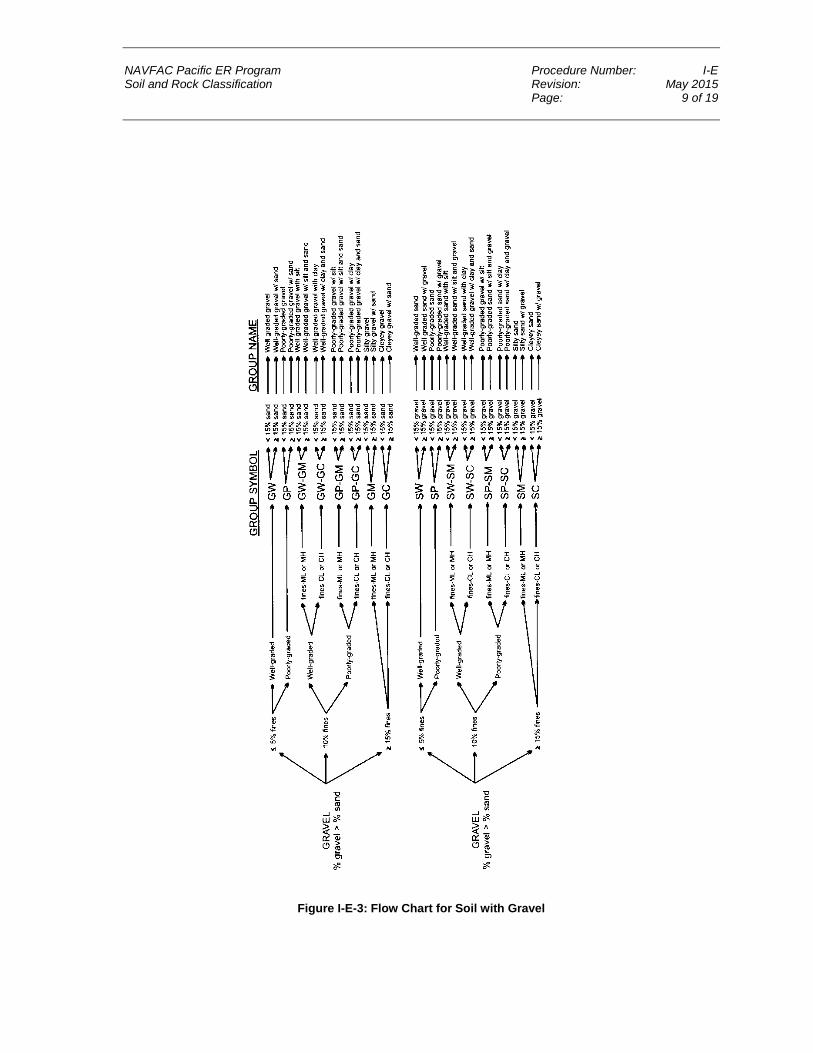
NAVFAC Pacific ER Program Procedure Number: I-E Soil and Rock Classification Revision: May 2015 Page: 9 of 19
Figure I-E-3: Flow Chart for Soil with Gravel

This page intentionally left blank

NAVFAC Pacific ER Program Procedure Number: I-E Soil and Rock Classification Revision: May 2015 Page: 11 of 19
5.1.2.3 PLASTICITY
The plasticity of a soil is defined by the ability of the soil to deform without cracking, the range of moisture content over which the soil remains in a plastic state, and the degree of cohesiveness at the plastic limit. The plasticity characteristic of clays and other cohesive materials is defined by the liquid limit and plastic limit. The liquid limit is defined as the soil moisture content at which soil passes from the liquid to the plastic state as moisture is removed. The test for the liquid limit is a laboratory, not a field, analysis.
The plastic limit is the soil moisture content at which a soil passes from the plastic to the semi-solid state as moisture is removed. The plastic limit test can be performed in the field and is indicated by the ability to roll a 1/8-inch (0.125-inch) diameter thread of fines, the time required to roll the thread, and the number of times the thread can be re-rolled when approaching the plastic limit.
The plasticity tests are not based on natural soil moisture content, but on soil that has been thoroughly mixed with water. If a soil sample is too dry in the field, add water prior to performing classification. If a soil sample is too sticky, spread the sample thin and allow it to lose some soil moisture.
Table I-E-3 presents the criteria for describing plasticity in the field using the rolled thread method.
Table I-E-3: Criteria for Describing Plasticity Description Criteria
Non-Plastic A 1/8-inch thread cannot be rolled.
Low Plasticity The thread can barely be rolled.
Medium Plasticity The thread is easy to roll and not much time is required to reach the plastic limit.
High Plasticity It takes considerable time rolling the thread to reach the plastic limit.
5.1.3 Angularity
The following criteria describe the angularity of the coarse sand and gravel particles:
• Rounded particles have smoothly-curved sides and no edges.
• Subrounded particles have nearly plane sides, but have well-rounded corners and edges.
• Subangular particles are similar to angular, but have somewhat rounded or smooth edgesand.
• Angular particles have sharp edges and relatively plane sides with unpolished surfaces. Freshly broken or crushed rock would be described as angular.
5.1.4 Color, Moisture, and Odor
The natural moisture content of soil is very important. Table I-E-4 shows the terms for describing the moisture condition and the criteria for each.
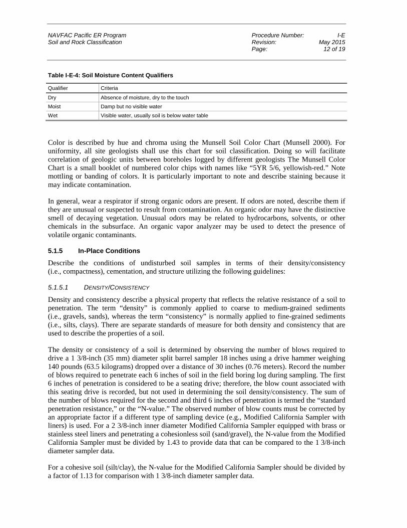
NAVFAC Pacific ER Program Procedure Number: I-E Soil and Rock Classification Revision: May 2015 Page: 12 of 19
Table I-E-4: Soil Moisture Content Qualifiers Qualifier Criteria
Dry Absence of moisture, dry to the touch
Moist Damp but no visible water
Wet Visible water, usually soil is below water table
Color is described by hue and chroma using the Munsell Soil Color Chart (Munsell 2000). For uniformity, all site geologists shall use this chart for soil classification. Doing so will facilitate correlation of geologic units between boreholes logged by different geologists The Munsell Color Chart is a small booklet of numbered color chips with names like “5YR 5/6, yellowish-red.” Note mottling or banding of colors. It is particularly important to note and describe staining because it may indicate contamination.
In general, wear a respirator if strong organic odors are present. If odors are noted, describe them if they are unusual or suspected to result from contamination. An organic odor may have the distinctive smell of decaying vegetation. Unusual odors may be related to hydrocarbons, solvents, or other chemicals in the subsurface. An organic vapor analyzer may be used to detect the presence of volatile organic contaminants.
5.1.5 In-Place Conditions
Describe the conditions of undisturbed soil samples in terms of their density/consistency (i.e., compactness), cementation, and structure utilizing the following guidelines:
5.1.5.1 DENSITY/CONSISTENCY
Density and consistency describe a physical property that reflects the relative resistance of a soil to penetration. The term “density” is commonly applied to coarse to medium-grained sediments (i.e., gravels, sands), whereas the term “consistency” is normally applied to fine-grained sediments (i.e., silts, clays). There are separate standards of measure for both density and consistency that are used to describe the properties of a soil.
The density or consistency of a soil is determined by observing the number of blows required to drive a 1 3/8-inch (35 mm) diameter split barrel sampler 18 inches using a drive hammer weighing 140 pounds (63.5 kilograms) dropped over a distance of 30 inches (0.76 meters). Record the number of blows required to penetrate each 6 inches of soil in the field boring log during sampling. The first 6 inches of penetration is considered to be a seating drive; therefore, the blow count associated with this seating drive is recorded, but not used in determining the soil density/consistency. The sum of the number of blows required for the second and third 6 inches of penetration is termed the “standard penetration resistance,” or the “N-value.” The observed number of blow counts must be corrected by an appropriate factor if a different type of sampling device (e.g., Modified California Sampler with liners) is used. For a 2 3/8-inch inner diameter Modified California Sampler equipped with brass or stainless steel liners and penetrating a cohesionless soil (sand/gravel), the N-value from the Modified California Sampler must be divided by 1.43 to provide data that can be compared to the 1 3/8-inch diameter sampler data.
For a cohesive soil (silt/clay), the N-value for the Modified California Sampler should be divided by a factor of 1.13 for comparison with 1 3/8-inch diameter sampler data.

NAVFAC Pacific ER Program Procedure Number: I-E Soil and Rock Classification Revision: May 2015 Page: 13 of 19
Drive the sampler and record blow counts for each 6-inch increment of penetration until one of the following occurs:
• A total of 50 blows have been applied during any one of the three 6-inch increments; a 50-blow count occurrence shall be termed “refusal” and noted as such on the boring log.
• A total of 150 blows have been applied.
• The sampler is advanced the complete 18 inches without the limiting blow counts occurring, as described above.
If the sampler is driven less than 18 inches, record the number of blows per partial increment on the boring log. If refusal occurs during the first 6 inches of penetration, the number of blows will represent the N-value for this sampling interval. Table I-E-5 and Table I-E-6 present representative descriptions of soil density/consistency vs. N-values.
Table I-E-5: Measuring Soil Density with a California Sample – Relative Density (Sands, Gravels)
Description
Field Criteria (N-Value)
1 3/8 in. ID Sampler 2 in. ID Sampler using 1.43 factor
Very Loose 0–4 0–6
Loose 4–10 6–14
Medium Dense 10–30 14–43
Dense 30–50 43–71
Very Dense >50 >71
Table I-E-6: Measuring Soil Density with a California Sampler – Fine Grained Cohesive Soil
Description
Field Criteria (N-Value)
1 3/8 in. ID Sampler 2 in. ID Sampler using 1.13 factor
Very Soft 0–2 0–2
Soft 2–4 2–4
Medium Stiff 4–8 4–9
Stiff 8–16 9–18
Very Stiff 16–32 18–36
Hard >32 >36
For undisturbed fine-grained soil samples, it is also possible to measure consistency with a hand-held penetrometer. The measurement is made by placing the tip of the penetrometer against the surface of the soil contained within the sampling liner or shelby tube, pushing the penetrometer into the soil a distance specified by the penetrometer manufacturer, and recording the pressure resistance reading in pounds per square foot. The values are as follows (Table I-E-7):

NAVFAC Pacific ER Program Procedure Number: I-E Soil and Rock Classification Revision: May 2015 Page: 14 of 19
Table I-E-7: Measuring Soil Consistency with a Hand-Held Penetrometer Description Pocket Penetrometer Reading (psf)
Very Soft 0–250
Soft 250–500
Medium Stiff 500–1,000
Stiff 1,000–2,000
Very Stiff 2,000–4,000
Hard >4,000
Consistency can also be estimated using thumb pressure using Table I-E-8.
Table I-E-8: Measuring Soil Consistency Using Thumb Pressure
Description Criteria
Very Soft Thumb will penetrate soil more than 1 inch (25 mm)
Soft Thumb will penetrate soil about 1 inch (25 mm)
Firm Thumb will penetrate soil about 1/4 inch (6 mm)
Hard Thumb will not indent soil but readily indented with thumbnail
Very Hard Thumbnail will not indent soil
5.1.5.2 CEMENTATION
Cementation is used to describe the friability of a soil. Cements are chemical precipitates that provide important information as to conditions that prevailed at the time of deposition, or conversely, diagenetic effects that occurred following deposition. Seven types of chemical cements are recognized by Folk (1980). They are as follows:
1. Quartz – siliceous
2. Chert – chert-cemented or chalcedonic
3. Opal – opaline
4. Carbonate – calcitic, dolomitic, sideritic (if in doubt, calcareous should be used)
5. Iron oxides – hematitic, limonitic (if in doubt, ferruginous should be used)
6. Clay minerals – if the clay minerals are detrital or have formed by recrystallization of a previous clay matrix, they are not considered to be a cement. Only if they are chemical precipitates, filling previous pore space (usually in the form of accordion-like stacks or fringing radial crusts) should they be included as “kaolin-cemented,” “chlorite-cemented,” etc.
7. Miscellaneous minerals – pyritic, collophane-cemented, glauconite-cemented, gypsiferous, anhydrite-cemented, baritic, feldspar-cemented, etc.
The degree of cementation of a soil is determined qualitatively by utilizing finger pressure on the soil in one of the sample liners to disrupt the gross soil fabric. The three cementation descriptors are as follows:

NAVFAC Pacific ER Program Procedure Number: I-E Soil and Rock Classification Revision: May 2015 Page: 15 of 19
1. Weak – friable; crumbles or breaks with handling or slight finger pressure
2. Moderate – friable; crumbles or breaks with considerable finger pressure
3. Strong – not friable; will not crumble or break with finger pressure
5.1.5.3 STRUCTURE
This variable is used to qualitatively describe physical characteristics of soil that are important to incorporate into hydrogeological and/or geotechnical descriptions of soil at a site. Appropriate soil structure descriptors are as follows:
• Granular: Spherically shaped aggregates with faces that do not accommodate adjoining faces
• Stratified: Alternating layers of varying material or color with layers at least 6 mm (1/4 inch) thick; note thickness
• Laminated: Alternating layers of varying material or color with layers less than 6 mm (1/4 inch) thick; note thickness
• Blocky: Cohesive soil that can be broken down into small angular or subangular lumps that resist further breakdown
• Lensed: Inclusion of a small pocket of different soil, such as small lenses of sand, should be described as homogeneous if it is not stratified, laminated, fissured, or blocky. If lenses of different soil are present, the soil being described can be termed homogeneous if the description of the lenses is included
• Prismatic or Columnar: Particles arranged about a vertical line, ped is bounded by planar, vertical faces that accommodate adjoining faces; prismatic has a flat top; columnar has a rounded top
• Platy: Particles are arranged about a horizontal plane
5.1.5.4 OTHER FEATURES
• Mottled: Soil that appears to consist of material of two or more colors in blotchy distribution
• Fissured: Breaks along definite planes of fracture with little resistance to fracturing (determined by applying moderate pressure to sample using thumb and index finger)
• Slickensided: Fracture planes appear polished or glossy, sometimes striated (parallel grooves or scratches)
5.1.6 Development of Soil Description
Develop standard soil descriptions according to the following examples. There are three principal categories under which all soil can be classified. They are described below.
5.1.6.1 COARSE-GRAINED SOIL
Coarse-grained soil is divided into sands and gravels. A soil is classified as a sand if over 50 percent of the coarse fraction is “sand-sized.” It is classified as a gravel if over 50 percent of the coarse fraction is composed of “gravel-sized” particles.

NAVFAC Pacific ER Program Procedure Number: I-E Soil and Rock Classification Revision: May 2015 Page: 16 of 19
The written description of a coarse-grained soil shall contain, in order of appearance: Typical name including the second highest percentage constituent as an adjective, if applicable (underlined); grain size of coarse fraction; Munsell color and color number; moisture content; relative density; sorting; angularity; other features, such as stratification (sedimentary structures) and cementation, possible formational name, primary USCS classification, secondary USCS classification (when necessary), and approximate percentages of minor constituents (i.e., sand, gravel, shell fragments, rip-up clasts) in parentheses.
Example: POORLY SORTED SAND WITH SILT, medium- to coarse-grained, light olive gray, 5Y 6/2, saturated, loose, poorly sorted, subrounded clasts, SW/SM (minor silt with approximately 20 percent coarse-grained sand-sized shell fragments, and 80 percent medium-grained quartz sand, and 5 percent to 15 percent ML).
5.1.6.2 FINE-GRAINED SOIL
Fine-grained soil is further subdivided into clays and silts according to its plasticity. Clays are rather plastic, while silts have little or no plasticity.
The written description of a fine-grained soil should contain, in order of appearance: Typical name including the second highest percentage constituent as an adjective, if applicable (underlined); Munsell color; moisture content; consistency; plasticity; other features, such as stratification, possible formation name, primary USCS classification, secondary USCS classification (when necessary), and the percentage of minor constituents in parentheses.
Example: SANDY LEAN CLAY, dusky red, 2.5 YR 3/2, moist, firm, moderately plastic, thinly laminated, CL (70 percent fines, 30 percent sand, with minor amounts of disarticulated bivalves [about 5 percent]).
5.1.6.3 ORGANIC SOIL
For highly organic soil, describe the types of organic materials present as well as the type of soil constituents present using the methods described above. Identify the soil as an organic soil, OL/OH, if the soil contains enough organic particles to influence the soil properties. Organic soil usually has a dark brown to black color and may have an organic odor. Often, organic soils will change color, (e.g., from black to brown) when exposed to air. Some organic soils will lighten in color significantly when air-dried. Organic soils normally will not have a high toughness or plasticity. The thread for the toughness test will be spongy.
Example: ORGANIC CLAY, black, 2.5Y, 2.5/1, wet, soft, low plasticity, organic odor, OL (100 percent fines), weak reaction to HCl.
5.2 ROCK CLASSIFICATION The purpose of rock classification is to thoroughly describe the physical and mineralogical characteristics of a specimen and to classify it according to an established system. The generalized rock classification system described below was developed for the NAVFAC Pacific ER Program because, unlike the USCS for soils, there is no universally accepted rock classification system. In some instances, a more detailed and thorough rock classification system may be appropriate. Any modifications to this classification system, or the use of an alternate classification system should be considered during preparation of the site work plan. Both the CTO Manager and the QA Manager or

NAVFAC Pacific ER Program Procedure Number: I-E Soil and Rock Classification Revision: May 2015 Page: 17 of 19
Technical Director must approve any modifications to this classification system, or the use of another classification system.
Describing rock specimens on a common basis is essential so that rocks described by different site geologists are comparable. Site geologists describing rock specimens as a part of investigative activities must use the classification system described herein, or if necessary, another more detailed classification system. Use of a common classification system provides the most useful geologic database for all present and future subsurface investigations and remedial activities at NAVFAC Pacific ER Program sites.
A rock classification template has been designated as shown in Figure I-E-4 to provide a more consistent rock classification between geologists. The template includes the classification of rocks by origin and mineralogical composition. When classifying rocks, all site geologists shall use this template.
The site geologist shall describe the rock specimen and record the description in a borehole log or logbook. The items essential for classification include:
• Classification Name (i.e., schist)
• Color
• Mineralogical composition and percent
• Texture/Grain size (i.e., fine-grained, pegmatitic, aphanitic, glassy)
• Structure (i.e., foliated, fractured, lenticular)
• Rock Quality Designation (sum of all core pieces greater than two times the diameter of the core divided by the total length of the core run, expressed as a percentage)
• Classification symbol (i.e., MF)
Example: Metamorphic foliated schist: Olive gray, 5Y, 3/2, Garnet 25 percent, Quartz 45 percent, Chlorite 15 percent, Tourmaline 15 percent, Fine-grained with Pegmatite garnet, highly foliated, slightly wavy, MF.
6. Records Document soil classification information collected during soil sampling onto the field boring logs, field trench logs, and into the field notebook. Procedure I-B-1, Soil Sampling presents copies of the field boring log form. Copies of this information shall be placed in the project files.
7. Health and Safety Field Personnel shall perform work in accordance with the current (or as contractually obligated) United States Army Corps of Engineers Safety and Health Requirements Manual EM-385-1-1 (USACE 2008) and site-specific health and safety plan.
NAVFAC Pacific ER Program Procedure Number: I-E Soil and Rock Classification Revision: May 2015 Page: 18 of 19
8. References Department of Defense, United States (DoD). 2005. Uniform Federal Policy for Quality Assurance
Project Plans, Part 1: UFP-QAPP Manual. Final Version 1. DoD: DTIC ADA 427785, EPA-505-B-04-900A. In conjunction with the U. S. Environmental Protection Agency and the Department of Energy. Washington: Intergovernmental Data Quality Task Force. March. On-line updates available at: http://www.epa.gov/fedfac/pdf/ufp_qapp_v1_0305.pdf.
Department of the Navy (DON). 2014. Environmental Readiness Program Manual. OPNAV Instruction 5090.1D. 10 January.
Folk, Robert L. 1980. Petrology of Sedimentary Rocks. Austin, TX: Hemphill Publishing Company.
Munsell Color Company (Munsell). 2009. Munsell Soil Color Chart, (Revised). Baltimore.
United States Army Corps of Engineers (USACE). 2008. Consolidated Safety and Health Requirements Manual. EM-385-1-1. Includes Changes 1–7. 13 July 2012.
Procedure I-B-1, Soil Sampling.
9. Attachments None.

NAVFAC Pacific ER Program Procedure Number: I-E Soil and Rock Classification Revision: May 2015 Page: 19 of 19
Figure I-E-4: Rock Classification System

This page intentionally left blank

NAVFAC Pacific ER Program Procedure Number: I-F Equipment Decontamination Revision: May 2015 Page: 1 of 5
Equipment Decontamination
1. Purpose This standard operating procedure describes methods of equipment decontamination for use during site activities by United States (U.S.) Navy Environmental Restoration (ER) Program, Naval Facilities Engineering Command (NAVFAC), Pacific personnel.
2. Scope This procedure applies to all Navy ER projects performed in the NAVFAC Pacific Area of Responsibility.
This procedure shall serve as management-approved professional guidance for the ER Program and is consistent with protocol in the Uniform Federal Policy-Quality Assurance Project Plan (DoD 2005). As professional guidance for specific activities, this procedure is not intended to obviate the need for professional judgment during unforeseen circumstances. Deviations from this procedure while planning or executing planned activities must be approved and documented by the following prime contractor representatives: the CTO Manager and the Quality Assurance (QA) Manager or Technical Director. A Navy project representative (i.e., Remedial Project Manager or QA Manager) shall also concur with any deviations.
3. Definitions None.
4. Responsibilities The prime contractor CTO Manager is responsible for identifying instances of non-compliance with this procedure and ensuring that decontamination activities comply with this procedure. The CTO Manager is responsible for ensuring that all personnel involved in equipment decontamination have the appropriate education, experience, and training to perform their assigned tasks as specified in Chief of Naval Operations Instruction 5090.1, under Specific Training Requirements (DON 2014).
The prime contractor QA Manager or Technical Director is responsible for ensuring overall compliance with this procedure.
The Field Manager is responsible for field oversight to ensure that all project field staff follow these procedures.
Field personnel are responsible for the implementation of this procedure.
5. Procedures Decontamination of equipment used in sampling of various media, groundwater monitoring, and well drilling and development is necessary to prevent cross-contamination and to maintain the highest integrity possible in collected samples. Planning a decontamination program requires consideration of the following factors:

NAVFAC Pacific ER Program Procedure Number: I-F Equipment Decontamination Revision: May 2015 Page: 2 of 5
• The location where the decontamination procedures will be conducted
• The types of equipment requiring decontamination
• The frequency of equipment decontamination
• The cleaning technique and types of cleaning solutions appropriate for the contaminants of concern
• The method for containing the residual contaminants and wash water from the decontamination process
• The use of a quality control measure to determine the effectiveness of the decontamination procedure
The following subsection describes standards for decontamination, including the frequency of decontamination, cleaning solutions and techniques, containment of residual contaminants and cleaning solutions, and effectiveness.
5.1 DECONTAMINATION AREA Select an appropriate location for the decontamination area at a site based on the ability to control access to the area, the ability to control residual material removed from equipment, the need to store clean equipment, and the ability to restrict access to the area being investigated. Locate the decontamination area an adequate distance away and upwind from potential contaminant sources to avoid contamination of clean equipment.
It is the responsibility of the site safety and health officer (SSHO) to set up the site zones (i.e., exclusion, transition, and clean) and decontamination areas. Generally, the decontamination area is located within the transition zone, upwind of intrusive activities, and serves as the washing area for both personnel and equipment to minimize the spread of contamination into the clean zone. For equipment, a series of buckets are set up on a visqueen-lined bermed area. Separate spray bottles containing laboratory-grade isopropyl alcohol (or alternative cleaning solvent as described in the CTO work plan [WP]) and distilled water are used for final rinsing of equipment. Depending on the nature of the hazards and the site location, decontamination of heavy equipment, such as augers, pump drop pipe, and vehicles, may be accomplished using a variety of techniques.
5.2 TYPES OF EQUIPMENT Drilling equipment that must be decontaminated includes drill bits, auger sections, drill-string tools, drill rods, split barrel samplers, tremie pipes, clamps, hand tools, and steel cable. Decontamination of monitoring well development and groundwater sampling equipment includes submersible pumps, bailers, interface probes, water level meters, bladder pumps, airlift pumps, peristaltic pumps, and lysimeters. Other sampling equipment that requires decontamination includes, but is not limited to, hand trowels, hand augers, slide hammer samplers, shovels, stainless-steel spoons and bowls, soil sample liners and caps, wipe sampling templates, composite liquid waste samplers, and dippers. However, equipment that is shipped pre-packaged from the vendor should not have to be decontaminated prior to first use. Equipment with a porous surface, such as rope, cloth hoses, and wooden blocks, cannot be thoroughly decontaminated and shall be properly disposed of after one use.

NAVFAC Pacific ER Program Procedure Number: I-F Equipment Decontamination Revision: May 2015 Page: 3 of 5
5.3 FREQUENCY OF EQUIPMENT DECONTAMINATION Decontaminate down-hole drilling equipment and equipment used in monitoring well development and purging prior to initial use and between each borehole or well. Down-hole drilling equipment, however, may require more frequent cleaning to prevent cross-contamination between vertical zones within a single borehole. When drilling through a shallow contaminated zone and installing a surface casing to seal off the contaminated zone, decontaminate the drilling tools prior to drilling deeper. Initiate groundwater sampling by sampling groundwater from the monitoring well where the least contamination is suspected. Decontaminate groundwater, surface water, and soil sampling devices prior to initial use and between collection of each sample to prevent the possible introduction of contaminants into successive samples.
5.4 CLEANING SOLUTIONS AND TECHNIQUES Decontamination can be accomplished using a variety of techniques and fluids. The preferred method of decontaminating major equipment, such as drill bits, augers, drill string, and pump drop-pipe, is steam cleaning. To steam clean, use a portable, high-pressure steam cleaner equipped with a pressure hose and fittings. For this method, thoroughly steam wash equipment, and rinse it with potable tap water to remove particulates and contaminants.
Where appropriate, disposable materials are recommended. A rinse decontamination procedure is acceptable for equipment, such as bailers, water level meters, new and re-used soil sample liners, and hand tools. The decontamination procedure shall consist of the following: (1) wash with a non-phosphate detergent (alconox, liquinox, or other suitable detergent) and potable water solution; (2) rinse in a bath with potable water; (3) spray with laboratory-grade isopropyl alcohol; (4) rinse in a bath with deionized or distilled water; and (5) spray with deionized or distilled water. If possible, disassemble equipment prior to cleaning. Add a second wash at the beginning of the process if equipment is very soiled.
Decontaminating submersible pumps requires additional effort because internal surfaces become contaminated during usage. Decontaminate these pumps by washing and rinsing the outside surfaces using the procedure described for small equipment or by steam cleaning. Decontaminate the internal surfaces by recirculating fluids through the pump while it is operating. This recirculation may be done using a relatively long (typically 4 feet) large-diameter pipe (4-inch or greater) equipped with a bottom cap. Fill the pipe with the decontamination fluids, place the pump within the capped pipe, and operate the pump while recirculating the fluids back into the pipe. The decontamination sequence shall include: (1) detergent and potable water; (2) potable water rinse; (3) potable water rinse; and (4) deionized water rinse. Change the decontamination fluids after each decontamination cycle.
Solvents other than isopropyl alcohol may be used, depending upon the contaminants involved. For example, if polychlorinated biphenyls or chlorinated pesticides are contaminants of concern, hexane may be used as the decontamination solvent. However, if samples are also to be analyzed for volatile organics, hexane shall not be used. In addition, some decontamination solvents have health effects that must be considered. Decontamination water shall consist of distilled or deionized water. Steam-distilled water shall not be used in the decontamination process as this type of water usually contains elevated concentrations of metals. Decontamination solvents to be used during field activities will be specified in CTO WP and site-specific health and safety plan.

NAVFAC Pacific ER Program Procedure Number: I-F Equipment Decontamination Revision: May 2015 Page: 4 of 5
Rinse equipment used for measuring field parameters, such as pH, temperature, specific conductivity, and turbidity with deionized or distilled water after each measurement. Also wash new, unused soil sample liners and caps with a fresh detergent solution and rinse them with potable water followed by distilled or deionized water to remove any dirt or cutting oils that might be on them prior to use.
5.5 CONTAINMENT OF RESIDUAL CONTAMINANTS AND CLEANING SOLUTIONS A decontamination program for equipment exposed to potentially hazardous materials requires a provision for catchment and disposal of the contaminated material, cleaning solution, and wash water.
When contaminated material and cleaning fluids must be contained from heavy equipment, such as drilling rigs and support vehicles, the area must be properly floored, preferably with a concrete pad that slopes toward a sump pit. If a concrete pad is impractical, planking can be used to construct solid flooring that is then covered by a nonporous surface and sloped toward a collection sump. If the decontamination area lacks a collection sump, use plastic sheeting and blocks or other objects to create a bermed area for collection of equipment decontamination water. Situate items, such as auger flights, which can be placed on metal stands or other similar equipment, on this equipment during decontamination to prevent contact with fluids generated by previous equipment decontamination. Store clean equipment in a separate location to prevent recontamination. Collect decontamination fluids contained within the bermed area and store them in secured containers as described below.
Use wash buckets or tubs to catch fluids from the decontamination of lighter-weight drilling equipment and hand-held sampling devices. Collect the decontamination fluids and store them on site in secured containers, such as U.S. Department of Transportation-approved drums, until their disposition is determined by laboratory analytical results. Label containers in accordance with Procedure I-A-6, Investigation-Derived Waste Management.
5.6 EFFECTIVENESS OF DECONTAMINATION PROCEDURES A decontamination program must incorporate quality control measures to determine the effectiveness of cleaning methods. Quality control measures typically include collection of equipment blank samples or wipe testing. Equipment blanks consist of analyte-free water that has been poured over or through the sample collection equipment after its final decontamination rinse. Wipe testing is performed by wiping a cloth over the surface of the equipment after cleaning. Procedure III-B, Field QC Samples (Water, Soil) provides further descriptions of these samples and their required frequency of collection. These quality control measures provide "after-the fact" information that may be useful in determining whether or not cleaning methods were effective in removing the contaminants of concern.
6. Records Describe the decontamination process in the field logbook.
7. Health and Safety Field Personnel shall perform work in accordance with the current (or as contractually obligated) United States Army Corps of Engineers Safety and Health Requirements Manual EM-385-1-1 (USACE 2008) and site-specific health and safety plan.
NAVFAC Pacific ER Program Procedure Number: I-F Equipment Decontamination Revision: May 2015 Page: 5 of 5
8. References Department of Defense, United States (DoD). 2005. Uniform Federal Policy for Quality Assurance
Project Plans, Part 1: UFP-QAPP Manual. Final Version 1. DoD: DTIC ADA 427785, EPA-505-B-04-900A. In conjunction with the U. S. Environmental Protection Agency and the Department of Energy. Washington: Intergovernmental Data Quality Task Force. March. On-line updates available at: http://www.epa.gov/fedfac/pdf/ufp_qapp_v1_0305.pdf.
Department of the Navy (DON). 2014. Environmental Readiness Program Manual. OPNAV Instruction 5090.1D. 10 January.
United States Army Corps of Engineers (USACE). 2008. Consolidated Safety and Health Requirements Manual. EM-385-1-1. Includes Changes 1–7. 13 July 2012.
Procedure I-A-6, Investigation-Derived Waste Management.
Procedure III-B, Field QC Samples (Water, Soil).
9. Attachments None.

This page intentionally left blank

NAVFAC Pacific ER Program Procedure Number: I-I Land Surveying Revision: May 2015 Page: 1 of 5
Land Surveying
1. Purpose This standard operating procedure sets forth protocols for acquiring land surveying data to facilitate the location and mapping of geologic, hydrologic, geotechnical data, and analytical sampling points and to establish topographic control over project sites for use by United States (U.S.) Navy Environmental Restoration (ER) Program, Naval Facilities Engineering Command (NAVFAC), Pacific personnel.
2. Scope This procedure applies to all Navy ER projects performed in the NAVFAC Pacific Area of Responsibility.
This procedure shall serve as management-approved professional guidance for the ER Program and is consistent with protocol in the Uniform Federal Policy-Quality Assurance Project Plan (DoD 2005). As professional guidance for specific activities, this procedure is not intended to obviate the need for professional judgment during unforeseen circumstances. Deviations from this procedure while planning or executing planned activities must be approved and documented by the following prime contractor representatives: the CTO Manager and the Quality Assurance (QA) Manager or Technical Director. A Navy project representative (i.e., Remedial Project Manager or QA Manager) shall also concur with any deviations.
3. Definitions 3.1 BOUNDARY SURVEY Boundary surveys are conducted by Certified Land Surveyors in order to delineate a legal property line for a site or section of a site.
3.2 GLOBAL POSITIONING SYSTEM (GPS) A GPS is a system of satellites, computers, and receivers that is able to determine the latitude and longitude of a receiver on Earth by calculating the time difference for signals from different satellites to reach the receiver.
3.3 WAYPOINT A waypoint is a reference point or set of coordinates that precisely identify a location.
4. Responsibilities The prime contractor CTO Manager is responsible for determining the appropriate land surveying protocols for the project and ensuring this procedure is properly implemented. The CTO Manager is responsible for ensuring that all personnel involved in land surveying shall have the appropriate education, experience, and training to perform their assigned tasks as specified in Chief of Naval Operations Instruction 5090.1, under Specific Training Requirements (DON 2014).

NAVFAC Pacific ER Program Procedure Number: I-I Land Surveying Revision: May 2015 Page: 2 of 5
The prime contractor QA Manager or Technical Director is responsible for ensuring overall compliance with this procedure.
The Field Manager (FM) is responsible for ensuring that the appropriate protocols are conducted according to this procedure and the project-specific sampling plan. In virtually all cases, subcontractors will conduct these procedures. The FM is responsible for overseeing the activities of the subcontractor and ensuring that sampling points and topographic features are properly surveyed.
Field personnel are responsible for the implementation of this procedure.
5. Procedures 5.1 THEODOLITE/ELECTRONIC DISTANCE MEASUREMENT (EDM) Follow the procedures listed below during theodolite/EDM land surveying conducted under the NAVFAC Pacific ER Program:
• A land surveyor registered in the state or territory in which the work is being performed shall directly supervise all surveying work.
• An authorized manufacturer’s representative shall inspect and calibrate survey instruments in accordance with the manufacturer's specifications regarding procedures and frequencies. At a minimum, instruments shall be calibrated no more than 6 months prior to the start of the survey work.
• Standards for all survey work shall be in accordance with National Oceanic and Atmospheric Administration standards and, at a minimum, with accuracy standards set forth below. The horizontal accuracy for the location of all grid intersection and planimetric features shall be (±) 0.1 feet. The horizontal accuracy for boundary surveys shall be 1 in 10,000 feet (1:10,000). The vertical accuracy for ground surface elevations shall be (±) 0.1 feet. Benchmark elevation accuracy and elevation of other permanent features, including monitoring wellheads, shall be (±) 0.01 feet.
• Reference surveys to the local established coordinate systems, and base all elevations and benchmarks established on U.S. Geological Survey datum, 1929 general adjustment.
• Reference surveyed points to mean sea level (lower low water level).
• Jointly determine appropriate horizontal and vertical control points prior to the start of survey activities. If discrepancies in the survey (e.g., anomalous water level elevations) are observed, the surveyor may be required to verify the survey by comparison to a known survey mark. If necessary, a verification survey may be conducted by a qualified third party.
• All field notes, sketches, and drawings shall clearly identify the horizontal and vertical control points by number designation, description, coordinates, and elevations. Map all surveyed locations using a base map or other site mapping, as specified by the CTO Manager.
• Begin and end all surveys at the designated horizontal and vertical control points to determine the degree of accuracy of the surveys.

NAVFAC Pacific ER Program Procedure Number: I-I Land Surveying Revision: May 2015 Page: 3 of 5
• Iron pins used to mark control points shall be made of reinforcement steel or an equivalent material and shall be 18 inches long with a minimum diameter of 5/8 inch. Drive pins to a depth of 18 inches into the soil.
• Stakes used to mark survey lines and points shall be made from 3-foot lengths of 2-inch by 2-inch lumber and pointed at one end. Clearly mark them with brightly colored weatherproof flagging and biodegradable paint.
• Clearly mark the point on a monitoring well casing that is surveyed by filing grooves into the casing on either side of the surveyed point.
5.2 GLOBAL POSITIONING SYSTEM (GPS) TO CONDUCT LAND SURVEY Follow the procedures listed below during GPS land surveying conducted under the NAVFAC Pacific ER Program:
• A land surveyor registered in the state or territory in which the work is being performed shall directly supervise all surveying work.
• An authorized manufacturer’s representative shall inspect and calibrate survey instruments in accordance with the manufacturer's specifications regarding procedures and frequencies. At a minimum, instruments shall be calibrated no more than 6 months prior to the start of the survey work.
• Standards for all survey work shall be in accordance with National Oceanic and Atmospheric Administration standards and, at a minimum, with accuracy standards set forth below. The horizontal accuracy for the location of all grid intersection and planimetric features shall be (±) 0.1 feet. The horizontal accuracy for boundary surveys shall be 1 in 10,000 feet (1:10,000). The vertical accuracy for ground surface elevations shall be (±) 0.1 feet. Benchmark elevation accuracy and elevation of other permanent features, including monitoring wellheads, shall be (±) 0.01 feet. Accuracy requirements shall be specified in the project work plan (WP).
• Reference surveys to the local established coordinate systems, and base all elevations and benchmarks established on U.S. Geological Survey datum, 1929 general adjustment.
• All field notes, sketches, and drawings shall clearly identify the horizontal and vertical control points by number designation, description, coordinates, and elevations. Map all surveyed locations using a base map or other site mapping, as specified in the project WP.
• Begin and end all surveys at the designated horizontal and vertical control points (as applicable) to determine the degree of accuracy of the surveys.
• Iron pins used to mark control points shall be made of reinforcement steel or an equivalent material and shall be 18 inches long with a minimum diameter of 5/8 inch. Drive pins to a depth of 18 inches into the soil.
• Stakes used to mark survey lines and points shall be made from 3-foot lengths of 2-inch by 2-inch lumber and pointed at one end. Clearly mark them with brightly colored weatherproof flagging and biodegradable paint.
• Clearly mark the point on a monitoring well casing that is surveyed by filing grooves into the casing on either side of the surveyed point.

NAVFAC Pacific ER Program Procedure Number: I-I Land Surveying Revision: May 2015 Page: 4 of 5
5.3 GLOBAL POSITIONING SYSTEM (GPS) TO POSITION SAMPLE LOCATIONS OR LOCATE SITE FEATURES
Experienced field personnel may use a GPS system unit to position sample locations (e.g. grid positioned samples) at a site. The decision to use field personnel or a licensed land surveyor will depend on the objectives of the survey (e.g. vertical elevation is not required) and the levels of precision required. Typically when a level of precision greater than (±) 3 to 5 meters is required, a licensed surveyor will be required. When a level of precision of (±) 3 to 5 meters is sufficient to meet project requirements (i.e., when laying sampling grids, identifying significant site features, or locating features identified in geographic information system [GIS] figures) experienced field personnel may use commercially available, consumer-grade GPS units. Follow the procedures listed below to locate samples or site features using GPS:
• A commercially available GPS unit with wide angle averaging system (WAAS), topographic map display, and waypoint storage capabilities should be used.
• If waypoints are to be imported into a GIS database, the same grid projection system should be used. For Guam this is typically WGS84, Zone 55N. For Hawaii this will either be NAD83 Zone 3 and 4 or WGS84 Zone 5N.
• If a permanent reference point near the site is available, it is recommended that the reference point is surveyed each day the GPS unit is used.
• When laying out a sampling grid from a GIS map, upload the coordinates from GIS to the GPS unit, including coordinates for an easily identified, permanent, nearby feature (i.e., building corner, roadway intersection, or USGS benchmark).
• If during the initial site walk, the permanent feature identified does not overlay within (±) 5 meters as identified in the GPS unit, field corrections of the waypoints should be made.
• Field corrections can be made by adding/subtracting the difference in x,y coordinates between the field measurement of the permanent site feature and the anticipated x,y coordinates. This correction should then be applied to the x,y coordinates for each sampling location to be marked. Corrected x,y coordinates can then be uploaded into the GPS unit.
• Sampling points and site features can then be located in the field using the GPS units “Go To” function. When the distance to the sampling point or feature remains close to zero, the location can be marked.
• If no field corrections to the sampling location need to be made, or if sampling locations are to be surveyed by a licensed surveyor at a later date, no additional waypoints need to be taken. If significant changes to the sampling location are made, GPS coordinates at the corrected location shall be stored and labeled.
• It is recommended that GPS coordinates be uploaded to a storage device such as a personal computer at the end of each day.
• Field logs shall indicate manufacturer and model number for GPS unit used, map datum and projection used, and any field corrections made. If the GPS unit cannot lock onto a WAAS system at the site, this should also be noted.

NAVFAC Pacific ER Program Procedure Number: I-I Land Surveying Revision: May 2015 Page: 5 of 5
6. Records The surveyor shall record field notes daily using generally accepted practices. The data shall be neat, legible, and easily reproducible. Copies of the surveyor's field notes and calculation forms generated during the work shall be obtained and placed in the project files.
Surveyor's field notes shall, at a minimum, clearly indicate:
• The date of the survey
• General weather conditions
• The name of the surveying firm
• The names and job titles of personnel performing the survey work
• Equipment used, including serial numbers
• Field book designations, including page numbers
A land surveyor registered in the state or territory in which the work was done shall sign, seal, and certify the drawings and calculations submitted by the surveyor.
Dated records of land surveying equipment calibration shall be provided by the surveyor and placed in the project files. Equipment serial numbers shall be provided in the calibration records.
7. Health and Safety Field personnel shall perform work in accordance with the current (or as contractually obligated) United States Army Corps of Engineers Safety and Health Requirements Manual EM-385-1-1 (USACE 2008) and site-specific health and safety plan.
8. References Department of Defense, United States (DoD). 2005. Uniform Federal Policy for Quality Assurance
Project Plans, Part 1: UFP-QAPP Manual. Final Version 1. DoD: DTIC ADA 427785, EPA-505-B-04-900A. In conjunction with the U. S. Environmental Protection Agency and the Department of Energy. Washington: Intergovernmental Data Quality Task Force. March. On-line updates available at: http://www.epa.gov/fedfac/pdf/ufp_qapp_v1_0305.pdf.
Department of the Navy (DON). 2014. Environmental Readiness Program Manual. OPNAV Instruction 5090.1D. 10 January.
United States Army Corps of Engineers (USACE). 2008. Consolidated Safety and Health Requirements Manual. EM-385-1-1. Includes Changes 1–7. 13 July 2012.
9. Attachments None.

This page intentionally left blank

NAVFAC Pacific ER Program Procedure Number: II-A Data Validation Revision: May 2015 Page: 1 of 39
Data Validation
1. Purpose This procedure describes the presentation format and information provided in the data validation reports under the United States (U.S.) Navy Environmental Restoration (ER) Program for Naval Facilities Engineering Command (NAVFAC), Pacific. The objective of data validation is to provide data of known quality to the end user. This procedure also establishes the method by which a Contract Task Order (CTO) Manager selects and confirms the content of data validation reports and is consistent with protocol in the Department of Defense Quality Systems Manual (QSM) for Environmental Laboratories (DoD QSM) (DoD 2013).
2. Scope This procedure applies to all Navy ER projects performed in the NAVFAC Pacific Area of Responsibility.
This procedure shall serve as management-approved professional guidance for the ER Program and is consistent with protocol in the most recent version of the Uniform Federal Policy-Quality Assurance Project Plan (UFP QAPP) Part 1 (DoD 2005a), 2A (DoD 2012) and 2B (2005b) as well as the DoD Quality Systems Manual (DoD 2013). As professional guidance for specific activities, this procedure is not intended to obviate the need for professional judgment during unforeseen circumstances. Deviations from this procedure while planning or executing planned activities must be approved and documented by the following prime contractor representatives: the CTO Manager and the Quality Assurance (QA) Manager or Technical Director. A Navy project representative (i.e., Remedial Project Manager or QA manager) shall also concur with any deviations.
3. Definitions Acronyms and abbreviations used in all data validation procedures and reports are defined in Attachment II-A-1. Commonly used terms are defined in Attachment II-A-2.
4. Responsibilities The CTO Manager, the QA Manager or Technical Director, and the CTO QA Coordinator are responsible for ensuring that this procedure is implemented by data validation personnel.
Data validation personnel are responsible for implementing this procedure for all data validation reports.
5. Procedure 5.1 INTRODUCTION This procedure addresses the validation of data obtained under the NAVFAC Pacific ER Program using primarily U.S. Environmental Protection Agency (EPA) Solid Waste (SW)-846 methods (EPA 2007). Based on the data validation requirements identified in the CTO project planning documents, the analytical data may undergo “Level B,” “Level C,” or “Level D” data validation or

NAVFAC Pacific ER Program Procedure Number: II-A Data Validation Revision: May 2015 Page: 2 of 39
some combination of these validation levels. This procedure establishes the required format and content of the various validation reports.
5.1.1 Confirmation of Data Validation Reports
Prior to shipment of all completed data validation reports to the CTO Manager, a single draft report for one sample delivery group (SDG) should be submitted. The CTO Manager shall review the draft report to confirm that the report contains the requested information, and respond to the Data Validation Project Manager in a timely manner. Once the requested contents are confirmed, the complete data validation packages should be delivered to the CTO Manager.
5.2 CONTENT AND FORMAT OF THE DATA VALIDATION REPORT
The data validation report will consist of the following four major components:
1. Cover letter
2. Data validation reference package comprising:
a. Cover page
b. Acronyms and abbreviations list
c. Data qualifier reference table
d. Qualification code reference table
3. Individual data validation reports by SDG:
e. Cover page
f. Introduction
g. Data validation findings
h. Appendix of laboratory reports with applied data qualifiers
A discussion of the contents and format of these components is provided in the following sections.
5.2.1 Cover Letter
The cover letter will contain the generation date of the cover letter, the address of the CTO office, the CTO number, and the CTO Manager’s name or designee. The cover letter will list the specific reports being sent under that cover letter. A senior data reviewer must review the report and sign the cover letter to denote approval. Attachment II-A-3 is an example of the cover letter.
5.2.2 Data Validation Reference Package
One data validation reference package shall be provided per CTO and shall contain the reference information needed for interpretation of the individual data validation reports. The following sections shall be included:
5.2.2.1 COVER PAGE
The cover page shall indicate the CTO title and number to which the reference package applies.

NAVFAC Pacific ER Program Procedure Number: II-A Data Validation Revision: May 2015 Page: 3 of 39
5.2.2.2 ACRONYMS AND ABBREVIATIONS LIST
This list shall present all acronyms and abbreviations used in the individual data validation reports. Attachment II-A-1 is an example of the acronyms and abbreviations list.
5.2.2.3 DATA QUALIFIER REFERENCE TABLE
Data qualifiers are applied in cases where the data do not meet the required quality control (QC) criteria or where special consideration by the data user is required.
The data qualifier reference table lists the data qualifiers used in the validation of the analytical data. Attachment II-A-4 is an example of this table.
5.2.2.4 QUALIFICATION CODE REFERENCE TABLE
Qualification codes explain why data qualifiers have been applied and identify possible limitations of data use. Attachment II-A-5 provides the qualification codes used by the NAVFAC Pacific ER Program. Qualification codes are to be provided by data validation personnel on the annotated laboratory reports discussed in Section 5.2.3.4.
5.2.3 Individual Data Validation Reports by SDG
For all analyses, each SDG shall have a unique data validation report. The procedures used to generate the reports are discussed in the following sub-sections.
5.2.3.1 COVER PAGE
The cover page shall indicate the CTO title and number, analysis type, and the SDG(s), which the report addresses.
5.2.3.2 INTRODUCTION
This section will contain a brief description of the CTO information that is pertinent to data validation. This information includes the CTO title and number, CTO Manager, the sample matrices and analyses performed on the samples, the data validation level for the project, and a brief discussion of the methodologies used for data validation. This section will also contain a Sample Identification Table which lists the identification of each sample identification number cross referenced with its associated internal laboratory identification number and COC sample number. Each sample will be listed under every analytical method for which data was validated. Attachment II-A-6 is an example of the sample identification table.
5.2.3.3 DATA VALIDATION FINDINGS
This section shall present the data validation findings of the data reviewer for the CTO data package. The findings shall be determined on the basis of validation criteria established for each analytical method1 in the DoD QSM (DoD 2013) or the CTO planning document and Procedure II-B through Procedure II-X. For all data validation levels, the data validation findings are divided into the following analytical categories:
• II-B GC/MS Volatile Organics by SW-846 Method 8260 1 Other methods may be included with approval of the CTO and Data Validation Managers.

NAVFAC Pacific ER Program Procedure Number: II-A Data Validation Revision: May 2015 Page: 4 of 39
• II-C GC/MS Semivolatile Organics by SW-846 8270 (full scan and SIM)
• II-D HRGC/HRMS Polychlorinated Dibenzodioxins (PCDDs) and Polychlorinated Dibenzofurans (PCDFs) by SW-846 8290
• II-E Organochlorine Pesticides by SW-846 8081
• II-F Polychlorinated Biphenyls as Aroclors by SW-846 8082
• II-G Polychlorinated Biphenyls as Congeners by SW-846 8082
• II-H Total Petroleum Hydrocarbons by SW-846 8015
• II-I Chlorinated Herbicides by SW-846 8151
• II-J Organophosphorus Pesticides by SW-846 8141
• II-K Halogenated and Aromatic Volatiles by SW-846 8021
• II-L Phenols by SW-846 8041
• II-M Ethylene Dibromide/Dibromochloropropane by SW-846 8011
• II-N Polynuclear Aromatic Hydrocarbons by SW-846 8310
• II-O Explosives by SW-846 8330
• II-P Carbamate and Urea Pesticides by EPA Method 632
• II-Q Metals by EPA Method SW-846 6000/7000
• II-R Wet Chemistry Analyses
• II-S Data Quality Assessment Report
• II-T HRGC/HRMS Polychlorinated Biphenyls as Congeners by EPA Method 1668
• II-U Carbamate and Urea Pesticides by SW-846 8321
• II-V Perchlorate by SW-846 6850
• II-W GC/FID/ECD Volatile Organics and Fixed Gases in Soil Gas/Vapor by EPA Method TO-3 and ASTM D1946
• II-X GC/MS Volatile Organics and Fixed Gases in Soil Gas/Vapor by EPA Method TO-14, TO-15, and TO-17
GC/MS gas chromatography/mass spectrometry ECD electron capture detector FID flame ionization detector HRGC/HRMS high resolution gas chromatograph/high resolution mass spectrometer SIM selective ion monitoring
Level C and Level D Data Validation
Data obtained using any analytical methods in the above categories will be validated in terms of meeting criteria for specific QA/QC factors such as holding times, instrument calibration, and blank analyses. A separate discussion of each QA/QC factor under each analytical method will be

NAVFAC Pacific ER Program Procedure Number: II-A Data Validation Revision: May 2015 Page: 5 of 39
presented in the CTO data validation report. The QA/QC factors used to validate data for Level C and Level D validation are presented below for each analytical category.
Volatile Organics by Gas Chromatography/Mass Spectrometry (GC/MS)
1. Sample management (sample preservation, handling, and transport, chain-of-custody, and holding times)
2. GC/MS instrument performance check
3. Calibration (initial calibration, initial calibration verification, and continuing calibration)
4. Method blanks
5. Blank spikes and laboratory control samples (LCSs)
6. Surrogate recovery
7. Matrix spike/matrix spike duplicate (MS/MSD)
8. Field QC samples (trip blanks, equipment blanks, field blanks, field duplicates, and field triplicates)
9. Internal standards performance
10. Target compound identification (Level D only*)
11. Compound quantitation and reporting limits (RLs) (Level D only*)
12. Tentatively identified compounds (Level D only*)
13. System performance (Level D only*)
Semivolatile Organics by Full Scan and SIM GC/MS
1. Sample management (sample preservation, handling, and transport; chain-of-custody; holding times)
2. GC/MS instrument performance check (full scan)
3. Calibration (initial calibration, initial calibration verification, and continuing calibration)
4. Method blanks
5. Blank spikes and LCSs
6. Surrogate recovery
7. MS/MSD
8. Field QC samples (equipment blanks, field blanks, and field duplicates)
9. Internal standards performance
10. Target Compound identification (Level D only*)
11. Compound quantitation and RLs (Level D only*)
12. Tentatively identified compounds (Level D only*)

NAVFAC Pacific ER Program Procedure Number: II-A Data Validation Revision: May 2015 Page: 6 of 39
13. System performance (Level D only*)
Dioxins/Dibenzofurans by HRGC/HRMS
1. Sample management (sample preservation, handling, and transport; chain-of-custody; holding times)
2. HRGC/HRMS instrument performance check
3. Calibration (initial calibration, initial calibration verification, and continuing calibration)
4. Method blanks
5. Blank spikes and LCSs
6. MS/MSD
7. Field QC samples (equipment blanks, field blanks, field duplicates, and field triplicates)
8. Internal standards performance
9. Target compound identification (Level D only*)
10. Compound quantitation and RLs (Level D only*)
11. System performance (Level D only*)
Organochlorine Pesticides by GC
1. Sample management (sample preservation, handling, and transport; chain-of-custody; holding times)
2. Pesticides instrument performance (retention time evaluation, 4,4'-DDT/Endrin breakdown evaluation)
3. Calibration (analytical sequence, initial calibration, initial calibration verification, continuing calibration)
4. Method blanks
5. Blank spikes and LCSs
6. Surrogate recovery
7. MS/MSD
8. Sample cleanup performance
9. Field QC samples (equipment blanks, field blanks, field duplicates, and field triplicates)
10. Target compound identification (Level D only*)
11. Compound quantitation and RLs (Level D only*)
Organic Analyses by GC (QA/QC factors may vary depending on analysis type)
1. Sample management (sample preservation, handling, and transport; chain-of-custody; holding times)

NAVFAC Pacific ER Program Procedure Number: II-A Data Validation Revision: May 2015 Page: 7 of 39
2. Instrument performance
3. Calibration (initial calibration, initial calibration verification and continuing calibration)
4. Method blanks
5. Blank spikes and LCS
6. Surrogate recovery
7. MS/MSD
8. Field QC samples (trip blanks [volatile organic compounds], equipment blanks, field blanks, field duplicates, and field triplicates)
9. Target compound identification (Level D only*)
10. Compound quantitation and RLs (Level D only*)
Organic Analyses by High-Performance Liquid Chromatography (QA/QC factors may vary depending on analysis type)
1. Sample management (sample preservation, handling, and transport; chain-of-custody; holding times)
2. Instrument performance
3. Calibration (initial calibration, initial calibration verification and continuing calibration)
4. Method blanks
5. Blank spikes and LCSs
6. Surrogate recovery
7. MS/MSD
8. Field QC samples (equipment blanks, field blanks, field duplicates, and field triplicates)
9. Target compound identification (Level D only*)
10. Compound quantitation and reporting limits (RLs) (Level D only*)
Organic Analyses by Liquid Chromatography–Mass Spectrometry (QA/QC factors may vary depending on analysis type)
1. Sample management (sample preservation, handling, and transport; chain-of-custody; holding times)
2. Instrument performance
3. Calibration (initial calibration, initial calibration verification, and continuing calibration)
4. Method blanks
5. Blank spikes and LCSs
6. MS/MSD
7. Field QC samples (equipment blanks, field blanks, field duplicates, and field triplicates)

NAVFAC Pacific ER Program Procedure Number: II-A Data Validation Revision: May 2015 Page: 8 of 39
8. Internal standards performance
9. Target compound identification (Level D only*)
10. Compound quantitation and RLs (Level D only*)
Metals
1. Sample management (sample preservation, handling, and transport; chain-of-custody; holding times)
2. Calibration (initial and continuing)
3. Blanks (Calibration blanks and Method [preparation] blanks)
4. Inductively coupled (argon) plasma (spectroscopy) (ICP) interference check sample
5. Blank spikes and LCSs
6. MS/MSD and Matrix duplicates
7. Furnace atomic absorption QC
8. Internal standards performance (MS methods only)
9. ICP serial dilution
10. Sample result verification (Level D only*)
11. Field QC samples (equipment blanks, field blanks, field duplicates, and field triplicates)
Inorganic Analyses by Wet Chemical Methods, (QA/QC factors may vary depending on analysis type)
1. Sample management (sample preservation, handling, and transport; chain-of-custody; and holding times)
2. Calibration (initial and continuing)
3. Method blanks
4. Blank spikes and LCSs
5. MS/MSD and Matrix duplicates
6. Sample result verification (Level D only*)
7. Field QC samples (equipment blanks, field blanks, field duplicates, and field triplicates)
* Sections applicable to Level D validation only will also appear in Level C validation reports with the notation “not applicable for Level C validation.”
Level B Data Validation
Data obtained using any analytical methods in the Level B Validation analytical categories will be validated in terms of meeting criteria for specific QA/QC factors such as holding times, blank spike

NAVFAC Pacific ER Program Procedure Number: II-A Data Validation Revision: May 2015 Page: 9 of 39
analyses, and blank analyses. A separate discussion of each QA/QC factor under each analytical method will be presented in the CTO data validation report. The QA/QC factors used to validate data for QA/QC “Level B Validation” are presented below for each analytical category.
Organic Analyses
1. Sample management (sample preservation, handling, and transport; chain-of-custody; and holding times)
2. Method blanks
3. Blank spikes and laboratory control samples
4. Field QC samples (trip blanks (volatile organic compounds), equipment blanks, field blanks, field duplicates, and field triplicates)
5. Surrogate recovery
6. MS/MSD
Inorganic Analyses
1. Sample management (sample preservation, handling, and transport; chain-of-custody; and holding times)
2. Blanks (Calibration and Method blanks)
3. Blank spikes and LCSs
4. Field QC samples (equipment blanks, field blanks, field duplicates, and field triplicates)
5. MS/MSD and Laboratory Duplicates
6. ICP serial dilution
5.2.3.4 LABORATORY REPORTS
Annotated laboratory reports with the appropriate data qualifiers and qualification codes as specified in the NAVFAC Pacific ER Program data validation procedures will be submitted as an appendix to the data validation report. An example is provided as Attachment II-A-7. Records
Copies of all documents generated by data validation personnel will be stored for no less than 10 years. The original validated laboratory data shall be archived to the Federal Records Center at project completion.
6. References Department of Defense, United States (DoD). 2005a. Uniform Federal Policy for Quality Assurance
Project Plans, Part 1: UFP-QAPP Manual. Final Version 1. DoD: DTIC ADA 427785, EPA-505-B-04-900A. In conjunction with the U. S. Environmental Protection Agency and the Department of Energy. Washington: Intergovernmental Data Quality Task Force. March. On-line updates available at: http://www.epa.gov/fedfac/pdf/ufp_qapp_v1_0305.pdf.

NAVFAC Pacific ER Program Procedure Number: II-A Data Validation Revision: May 2015 Page: 10 of 39
———. 2005b. Uniform Federal Policy for Quality Assurance Project Plans, Part 2B: Quality Assurance/quality Control Compendium: Minimum QA/QC Activities. Final Version 1. DoD: DTIC ADA 426957, EPA-505-B-04-900B. In conjunction with the U. S. Environmental Protection Agency and the Department of Energy. Washington: Intergovernmental Data Quality Task Force. March. On-line updates available at: http://www.epa.gov/swerffrr/pdf/-qaqc_v1_0305.pdf.
———. 2012. Uniform Federal Policy for Quality Assurance Project Plans, Part 2A: Optimized UFP-QAPP Worksheets. Revision 1. March.
———. 2013. Department of Defense Quality Systems Manual for Environmental Laboratories. Version 5.0. Draft Final. Prepared by DoD Environmental Data Quality Workgroup and Department of Energy Consolidated Audit Program Operations Team. July.
Environmental Protection Agency, United States (EPA). 2007. Test Methods for Evaluating Solid Waste, Physical/Chemical Methods, SW-846. 3rd ed., Final Update IV. Office of Solid Waste. On-line updates at: www.epa.gov/epaoswer/hazwaste/test/new-meth.htm.
7. Attachments Attachment II-A-1: Acronyms and Abbreviations
Attachment II-A-2: Definition of Terms
Attachment II-A-3: Sample Cover Letter
Attachment II-A-4: Data Qualifier Reference Table
Attachment II-A-5: Qualification Code Reference Table
Attachment II-A-6: Sample Identification Table
Attachment II-A-7: Example Annotated Laboratory Report Volatile Organics Analysis Data Sheet

Attachment II-A-1 Acronyms and Abbreviations

This page intentionally left blank

NAVFAC Pacific ER Program Procedure Number: II-A Data Validation Revision: May 2015 Page: 13 of 39
ACRONYMS AND ABBREVIATIONS
Following is a list of acronyms and abbreviations that may be used in NAVFAC Pacific ER Program data validation reports and the data quality assessment reports.
%D percent difference %R percent recovery µg/kg microgram per kilogram µg/L microgram per liter 4,4'-DDD 4,4'-dichlorodiphenyldichloroethane 4,4'-DDE 4,4'-dichlorodiphenyldichloroethylene 4,4'-DDT 4,4'-dichlorodiphenyltrichloroethane AA atomic absorption ARRF average relative response factor BFB bromofluorobenzene BNA base/neutral/acid CCB continuing calibration blank CCC calibration check compound CCV continuing calibration verification CF calibration factor CLP Contract Laboratory Program COC chain-of-custody COD chemical oxygen demand CTO contract task order CVAA cold vapor atomic absorption DBCP Dibromochloropropane DCB decachlorobiphenyl DFTPP decafluorotriphenylphosphine DL detection limit DoD Department of Defense DOE Department of Energy DQAR data quality assessment report DUP laboratory duplicate DVP data validation procedure EB equipment blank EDB ethylene dibromide EDL estimated detection limit EICP extracted ion current profile EPA Environmental Protection Agency, United States FB field blank GC gas chromatography GC/ECD gas chromatography/electron capture detector GC/ELCD gas chromatography/electrolytic conductivity detector (Hall detector) GC/FPD gas chromatography/flame photometric detector GC/MS gas chromatography/mass spectrometry

NAVFAC Pacific ER Program Procedure Number: II-A Data Validation Revision: May 2015 Page: 14 of 39
GC/PID gas chromatography/photoionization detector GFAA graphite furnace atomic absorption GPC gel permeation chromatography Hg mercury HPLC high-performance liquid chromatography HRGC/HRMS high resolution gas chromatography/high resolution mass spectrometry HT holding time ICB initial calibration blank ICP inductively coupled plasma ICS interference check sample ICV initial calibration verification IDL instrument detection limit IR infrared spectroscopy IRP installation restoration program IS internal standards LCS laboratory control sample LOD limit of detection LOQ limit of quantitation m/z mass to charge ratio MBAS methyl blue active substance mg/kg milligram per kilogram mg/L milligram per liter MS matrix spike MSA method of standard addition MSD matrix spike duplicate NFESC Naval Facilities Engineering Services Center ng/kg nanogram per kilogram OP organophosphorus PAH polynuclear aromatic hydrocarbon PARCC precision, accuracy, representativeness, comparability, completeness PCB polychlorinated biphenyl PCDD polychlorinated dibenzodioxin PCDF polychlorinated dibenzofuran PE performance evaluation PEM performance evaluation mixture PFK perfluorokerosene pg/g picogram per gram pg/L picogram per liter PQO project quality objective QA quality assurance QAC quality assurance coordinator QAPP quality assurance project plan QC quality control QSM quality system manual

NAVFAC Pacific ER Program Procedure Number: II-A Data Validation Revision: May 2015 Page: 15 of 39
r correlation coefficient r2 coefficient of determination RF response factor RIC reconstructed ion chromatogram RL reporting limit RPD relative percent difference RRF relative response factor RRT relative retention time RSD relative standard deviation RT retention time s/n signal to noise ratio SDG sample delivery group SICP selected ion current profiles SOP standard operating procedure SOW statement of work SPCC system performance check compound SRM standard reference material SVOC semivolatile organic compound TB trip blank TCDD tetrachlorodibenzodioxin TCX tetrachloro-m-xylene TDS total dissolved solids TIC tentatively identified compound TOC total organic carbon TOX total organic halides TPHE total petroleum hydrocarbons as extractables UV/VIS ultraviolet/visible VOA volatile organic analysis VOC volatile organic compound VTSR validated time of sample receipt WDM window defining mixture

This page intentionally left blank

Attachment II-A-2 Definition of Terms

This page intentionally left blank

NAVFAC Pacific ER Program Procedure Number: II-A Data Validation Revision: May 2015 Page: 19 of 39
DEFINITION OF TERMS
Calibration – A plot of response versus concentration of standards. Curve CCB – Continuing Calibration Blank – a deionized water sample run every 10
samples designed to detect any carryover contamination. CCV – Continuing Calibration Verification – a standard run every 10 samples to
test instrument performance. EDL – Estimated Detection Limit – The sample specific EDL is the concentration
of a given analyte required to produce a signal with a peak height of at least 2.5 times the background signal level.
Field Blank – Field blanks are intended to identify contaminants that may have been introduced in the field through source water.
Field Duplicate – A duplicate sample generated in the field, not in the laboratory. Findings – Any out-of-control, unacceptable, or out of criteria event which may impact
the quality of the data or require corrective action. GPC – Gel Permeation Chromatography – A sample clean-up technique that
separates compounds by size and molecular weight. Generally used to remove oily materials from sample extracts.
Holding Time – The time from sample collection to sample analysis. ICB – Initial Calibration Blank – the first blank standard run to confirm the
calibration curve. ICV – Initial Calibration Verification – the first standard run to confirm the
calibration curve. Initial – The establishment of a calibration curve with the appropriate number of Calibration standards and concentration range. The calibration curve plots instrument
response versus concentration of standards. IR – Infrared Spectroscopy. IS – Internal Standards – compounds added to every VOA and BNA standard,
blank, matrix spike duplicate, and sample extract at a known concentration, prior to instrumental analysis. Internal standards are used as the basis for quantitation of the target compounds.
Laboratory – A duplicate sample generated in the laboratory. Duplicate MDL – Method Detection Limit – minimum concentration of a substance that can
be measured and reported with 99% confidence that the analyte concentration is greater than zero.
MS – Matrix Spike – introduction of a known concentration of analyte into a sample to provide information about the effect of the sample matrix on the extraction or digestion and measurement methodology.
m/z – The ratio of mass (m) to charge (z) of ions measured by GC/MS.

NAVFAC Pacific ER Program Procedure Number: II-A Data Validation Revision: May 2015 Page: 20 of 39
Post Digestion – The addition of a known amount of standard after digestion. (Also Spike identified as analytical spike or spike for furnace analysis). Primary Analysis – One of two types of pesticide/PCB analysis by GC/EC techniques, the other
being confirmation analysis. The primary analysis is used to establish the tentative identification of any pesticides/PCBs detected. The identification is confirmed in the confirmation analysis. If the two analyses are done simultaneously, either may be considered the primary analysis. Either may be used for quantitation if contract criteria are met.
QA – Quality Assurance – total program for assuring the reliability of data QC – Quality Control – routine application of procedures for controlling the
monitoring process. RL – Reporting Limit – value specified by the client based on sensitivity
requirements from project-specific action levels. RPD – Relative Percent Difference (between matrix spike and matrix spike
duplicate, duplicate laboratory control samples, or blank spikes) Serial Dilution – A sample run at a specific dilution to determine whether any significant
chemical or physical interferences exist due to sample matrix effects (ICP only).
SDG – Sample Delivery Group – defined by one of the following, whichever occurs first:
Case of field samples Each 20 field samples within a case Each 14-day calendar period during which field samples in a case are
received, beginning with receipt of the first sample in the SDG
Level B – Data validation is performed using sample results and QA/QC summaries Validation (i.e., method blanks, LCS, MS/MSDs, surrogates, and serial dilutions).
This level of data validation was previously identified as “Standard.” Level C Data – Data validation is performed using sample results and QA/QC summaries Validation (including instrument performance, calibration, and internal standard data).
This level of data validation was previously identified as “Cursory.” Level D Data – Data validation is performed using sample results, QA/QC summaries Validation (including instrument performance, calibration, and internal standard data)
and raw data associated to the sample results and QA/QC summaries. This level of data validation was previously identified as “Full.”

Attachment II-A-3 Sample Cover Letter

This page intentionally left blank

NAVFAC Pacific ER Program Procedure Number II-A Data Validation Revision May 2015 Page 23 of 39
SAMPLE COVER LETTER
(Date)
(CTO Manager or designee) (company address) Dear ( ): Enclosed is Revision __ of the data
validation reports for CTO (number) as follows: Semi-volatiles SDG S0221 SDG S0350
Pesticides/PCBs SDG S0201 Metals SDG S0221 SDG S0201 The specific sample
identifications are listed in the Sample Identification Table(s). The data packages were reviewed
according to the data validation procedures referenced in the introduction to each report.
Sincerely,
(Signature)
Data Validation Project Manager

This page intentionally left blank

Attachment II-A-4 Data Qualifier Reference Table

This page intentionally left blank

NAVFAC Pacific ER Program Procedure Number II-A Data Validation Revision May 2015 Page 27 of 39
Table II-A-4-1: Data Qualifier Reference Table
Qualifier Organics Inorganics
U The analyte was analyzed for, but was not detected above the method detection limit.
The analyte was analyzed for, but was not detected above the method detection limit.
J The analyte was positively identified; the associated numerical value is the approximate concentration of the analyte in the sample.
The result is an estimated quantity. The associated numerical value is the approximate concentration of the analyte in the sample.
N The analysis indicates the presence of an analyte for which there is presumptive evidence to make a "tentative identification."
Not applicable.
NJ The analysis indicates the presence of an analyte that has been "tentatively identified" and the associated numerical value represents its approximate concentration.
Not applicable.
UJ The analyte was not detected above the method detection limit. However, the associated value is approximate and may or may not represent the actual limit of quantitation necessary to accurately and precisely measure the analyte in the sample.
The analyte was analyzed for, but was not detected. The associated value is an estimate and may be inaccurate or imprecise.
R The sample results are rejected due to serious deficiencies in the ability to analyze the sample and to meet quality control criteria. The presence or absence of the analyte cannot be verified.
The data are unusable. The sample results are rejected due to serious deficiencies in meeting the Quality Control (QC) criteria. The analyte may or may not be present in the sample.

This page intentionally left blank

Attachment II-A-5 Qualification Code Reference Table

This page intentionally left blank

NAVFAC Pacific ER Program Procedure Number II-A Data Validation Revision May 2015 Page 31 of 39
Table II-A-5-1: Qualification Code Reference Table
Qualifier Organics Inorganics
H Holding times were exceeded. Holding times were exceeded.
S Surrogate recovery was outside QC limits. The sequence or number calibration was incorrect.
of standards used for the
C 2Calibration %RSD, r, r or %D were noncompliant Correlation coefficient is <0.995.
R Calibration RRF was <0.05. %R for calibration is not within control limits
B Presumed contamination from preparation (method blank)
Presumed contamination from preparation (method) blank or calibration blank
L Laboratory Control Sample/Laboratory Control Sample Duplicate %R or RPD was not within control limits
Laboratory Control Sample/Laboratory Control Sample Duplicate %R or RPD was not within control limits
Q MS/MSD recovery was poor MS/MSD recovery was poor.
E MS/MSD or Duplicate RPD was high. MS/MSD or Duplicate RPD or difference was high.
I Internal standard performance was unsatisfactory ICP ICS results were unsatisfactory.
A Not applicable. ICP Serial Dilution %D were not within control limits
M Instrument Performance Check noncompliant
(BFB or DFTPP) was Not applicable.
T Presumed contamination from trip blank. Not applicable.
F Presumed contamination from FB or ER. Presumed contamination from FB or ER.
D The analysis with this flag should not be used because another more technically sound analysis is available.
The analysis with this flag should not be used because another more technically sound analysis is available.
P Instrument performance for pesticides was poor Post Digestion Spike recovery was not control limits
within
V Unusual problems found with the data that have been described in the validation report where a description of the problem can be found.
Unusual problems found with the data that have been described in where a description of the problem can be found.

This page intentionally left blank

Attachment II-A-6 Sample Identification Table

This page intentionally left blank

NAVFAC Pacific ER Program Procedure Number II-A Data Validation Revision May 2015 Page 35 of 39
Table II-A-6-1: Sample Identification Table
EPA Identification Sample Identification Lab Identification Number COC Sample Number Matrix
FB001 FB-BS04-E01-D10.0 2720-1 DA001 water
FB002 FB-BS04-B01-D10.0 2720-2 DA002 water
FB003 FB-BS04-B02-D10.0 2720-3 DA003 water
FB004 FB-SS01-S01-D0.5 2720-4 DA004 soil
FB005 FB-BS01-S01-D10.0 2720-5 DA005 soil
FB006 FB-SS02-S01-D0.5 2720-6 DA006 soil
FB007 FB-BS02-S01-D10.0 2720-7 DA007 soil
FB008 FB-BS02-D01-D10.0 2720-8 DA008 soil
FB009 FB-SS03-S01-D0.5 2720-9 DA009 soil
FB010 FB-BS03-S01-D10.0 2720-10 DA010 soil

This page intentionally left blank

Attachment II-A-7 Example Annotated Laboratory Report Volatile Organics Analysis Data Sheet

This page intentionally left blank

NAVFAC Pacific ER Program Procedure Number II-A Data Validation Revision May 2015 Page 39 of 39
EXAMPLE ANNOTATED LABORATORY REPORT VOLATILE ORGANICS ANALYSIS DATA SHEET

This page intentionally left blank

NAVFAC Pacific ER Program Procedure Number: III-A Laboratory QC Samples (Water, Soil) Revision: May 2015 Page: 1 of 5
Laboratory QC Samples (Water, Soil)
1. Purpose This section sets forth the standard operating procedure for identifying the number and type of laboratory quality control (QC) samples that will be analyzed during each contract task order (CTO) associated with the United States Navy Environmental Restoration (ER) Program, Naval Facilities Engineering Command (NAVFAC), Pacific. Laboratory QC analyses serve as a check on the precision and accuracy of analytical methods and instrumentation, and the potential contamination that might occur during laboratory sample preparation and analyses. Laboratory QC analyses include blank, surrogate, blank spike, laboratory control sample (LCS), and matrix spike (MS)/matrix spike duplicate (MSD) analyses. These laboratory QC analyses are discussed in general below.
2. Scope This procedure applies to all Navy ER projects performed in the NAVFAC Pacific Area of Responsibility.
This procedure shall serve as management-approved professional guidance for the ER Program and is consistent with protocol in the most recent version of the Uniform Federal Policy-Quality Assurance Project Plan (UFP QAPP) Part 1 (DoD 2005a), 2A (DoD 2012), and 2B (2005b), as well as the DoD Quality Systems Manual (DoD 2013). As professional guidance for specific activities, this procedure is not intended to obviate the need for professional judgment during unforeseen circumstances. Deviations from this procedure while planning or executing planned activities must be approved and documented by the following prime contractor representatives: the CTO Manager and the Quality Assurance (QA) Manager or Technical Director. A Navy project representative (i.e., Remedial Project Manager or QA Manager) shall also concur with any deviations.
3. Definitions 3.1 PRECISION Precision is the degree to which a set of observations or measurements of the same property, obtained under similar conditions, conform to themselves. Precision is usually expressed as a standard deviation, variance, or range, in either absolute or relative terms. Examples of QC measures for precision include laboratory duplicates, laboratory triplicates, and matrix spike/matrix spike duplicates.
3.2 ACCURACY Accuracy is the degree of agreement between an observed value and an accepted reference value. Accuracy includes a combination of random error (precision) and systematic error (bias), components which are due to sampling and analytical operations. Examples of QC measures for accuracy include performance evaluation samples, matrix spikes, LCSs, and equipment blanks.
3.3 MATRIX A specific type of medium (e.g., surface water, drinking water), in which the analyte of interest may be contained. Medium is a substance (e.g., air, water, soil), which serves as a carrier of the analytes of interest (EPA 2010).

NAVFAC Pacific ER Program Procedure Number: III-A Laboratory QC Samples (Water, Soil) Revision: May 2015 Page: 2 of 5
3.4 METHOD BLANK An analyte-free matrix (water, soil, etc.) subjected to the entire analytical process to demonstrate that the analytical system itself does not introduce contamination.
3.5 MATRIX SPIKE A sample prepared by adding a known concentration of a target analyte to an aliquot of a specific homogenized environmental sample for which an independent estimate of the target analyte concentration is available. The MS is accompanied by an independent analysis of the unspiked aliquot of the environmental sample. Spiked samples are used to determine the effect of the matrix on a method’s recovery efficiency.
3.6 LABORATORY CONTROL SAMPLES AND BLANK SPIKES A sample of known composition prepared using reagent-free water or an inert solid that is spiked with analytes of interest at the midpoint of the calibration curve or at the level of concern. It is analyzed using the sample preparation, reagents, and analytical methods employed for regular samples.
3.7 SURROGATES A pure substance with properties that mimic the analyte of interest (organics only). Surrogates are typically brominated, fluorinated, or isotopically labeled compounds unlikely to be found in environmental samples. These analytes are added to samples to evaluate analytical efficiency by measuring recovery.
3.8 INTERNAL STANDARDS A pure substance added to both samples and laboratory standards at a known concentration with the purpose of providing a basis of comparison in the quantitation of analytes of interest. Internal standards are primarily used to increase the accuracy and precision of analytical methods where the primary source of variability is in sample preparation or sample injection on instrument.
4. Responsibilities The prime contractor’s QA Manager or Technical Director, as well as QC coordinators are responsible for ensuring that sample analytical activities during all CTOs are in compliance with this procedure.
The CTO QC Coordinators and the Laboratory Manager are responsible for identifying instances of non-compliance with this procedure and ensuring that future laboratory analytical activities are in compliance with it.
5. Procedures Laboratory QC checks include all types of samples specified in the requested analytical methods, such as the analysis of laboratory blank, duplicate, and MS samples. QC requirements are specified in each analytical method and in Appendix B, Quality Control Requirements, and Appendix C, Laboratory Control Sample (LCS) Control Limits and Requirements, of the Department of Defense Quality Systems Manual for Environmental Laboratories Version 5.0 (or most current version)

NAVFAC Pacific ER Program Procedure Number: III-A Laboratory QC Samples (Water, Soil) Revision: May 2015 Page: 3 of 5
(DoD QSM). Types of QC samples are discussed in general below. Detailed discussion and minimum QA/QC requirements are presented in the DoD QSM (DoD 2013).
A comprehensive discussion of the minimum number of laboratory QC samples can be found in the Uniform Federal Policy for Quality Assurance Project Plans, Part 2B, Quality Assurance/Quality Control Compendium: Minimum QA/QC Activities (DoD 2005b). However, additional QA/QC samples may be necessary based on the project quality objectives. Information pertaining to laboratory QC samples shall be documented in Worksheet 28 Laboratory QC Samples Table of the project UFP QAPP-style planning document.
5.1 LABORATORY BLANKS Laboratory blank samples are analyzed to assess the degree to which laboratory contamination by reagent or method preparation may have affected sample analytical results. At a minimum, one laboratory blank will be analyzed per matrix per analytical method for each batch of at most 20 samples. In evaluating the blank results, all blank data are reviewed to identify any compounds detected in the blanks. The laboratory shall be contacted to discuss detection of analytes in blank samples only in the event of unusual contamination, but not for common laboratory contaminants at low levels. The following compounds are considered to be common laboratory contaminants: acetone, methylene chloride, 2-butanone, and common phthalate esters. The data for samples analyzed during the same time period as the blank are then evaluated to identify the presence of any contaminants found in the blanks. The presence of the blank contaminants found in associated samples is then evaluated to avoid potential misinterpretation of actual sample constituents. Briefly, as discussed in the data validation procedures, any analyte detected above the LOQ in both the sample and the associated blank is qualified as not detected if the sample concentration is less than five times the blank concentration (5× rule). For common laboratory contaminants (methylene chloride, acetone, 2-butanone, and common phthalate esters), a 10× rule applies.
5.2 LABORATORY REPLICATES (DUPLICATES AND TRIPLICATES) Replicates are analyzed to evaluate the reproducibility, or precision, of the analytical procedures for a given sample. A replicate is two (duplicates) or three (triplicates) representative portions taken from one homogeneous sample by the laboratory and analyzed in the same laboratory (DoD 2005a). One duplicate sample is analyzed for each batch of twenty samples analyzed in a given matrix. Lab triplicates are assigned by the field team and identified on the chain of custody. The identification of a sample for lab triplicate analysis is typically selected from one of the field triplicates to allow for the evaluation of total study error of the sampling and analysis process. Duplicate analyses are normally performed on sample portions analyzed for inorganic constituents. For organic analyses, duplicate analyses are performed on MS samples (Section 5.5 of this procedure).
5.3 SURROGATES Surrogate compounds must be added to all samples, standards, and blanks for all organic chromatography methods except when the matrix precludes its use or when a surrogate is not available. Poor surrogate recovery may indicate a problem with the sample composition and shall be reported to the client whose sample produced the poor recovery. Surrogate compounds to be included for organic analysis are specified in each analytical method.

NAVFAC Pacific ER Program Procedure Number: III-A Laboratory QC Samples (Water, Soil) Revision: May 2015 Page: 4 of 5
5.4 LABORATORY CONTROL SAMPLES AND BLANK SPIKES LCSs are used to demonstrate that the laboratory process for sample preparation and analysis is under control.
Analytes selected for spiking of LCSs are usually the same compounds used to spike MS/MSD samples and are representative target compounds. Control limits for LCS recoveries are provided in Appendix C of DoD QSM. If no control limits for LCS recoveries are listed in Appendix C of the DoD QSM for a given analyte, the laboratory’s in-house derived control limits should be used.
For wet chemistry methods, a single spike of an appropriate control for each method may be used for LCS analyses (i.e., cyanide, a control standard of sodium cyanide from a source other than that used for calibration may be spiked into water samples and analyzed with the water samples). LCSs should be analyzed at a frequency of one per batch of at most twenty samples analyzed of similar matrix.
5.5 MATRIX SPIKES/MATRIX SPIKE DUPLICATES MS analyses are conducted by the laboratory to assess the accuracy of specific analytical methods and to provide information on the effect of the sample matrix on the analytical methodology. Spike analyses are performed by adding compounds of known concentration to a sample, an unspiked portion of which has previously been analyzed or is concurrently analyzed. The spiked analytes are representative target compounds for each analytical method performed. The spiked sample results are evaluated with the original sample results to evaluate any effects the matrix has on the analysis. One MS is analyzed for each batch of at most 20 samples of similar matrix. Since MS samples only provide information about the specific sample matrix used for the spike, MS analyses should be performed for each type of matrix collected.
For the MSD, a separate aliquot of the sample is separately spiked and analyzed. As discussed in Section 5.2, results of MSD analyses are expressed as a relative percent difference, which is calculated by dividing the difference in concentration between the MSD and the MS sample analyses by the arithmetic mean of their concentrations. One MSD analysis is required for at most each 20 samples of similar matrix.
Acceptance criteria for both the MS and the MSD are based on historic laboratory performance and are laboratory-specific. As a general rule, the acceptance criteria should be no more stringent than the LCS acceptance criteria.
It is important to note that the UFP QAPP Part 2B, QA/QC Compendium: Minimum QA/QC Activities (DoD 2005b) states that for organic analysis, MS and MSDs are not considered a minimum QC activity as long as surrogate spikes properly mimic the analytes of concern and can identify matrix effects. Project quality objectives should be evaluated to determine if organic MS/MSDs are useful for individual projects.
6. Records Records of QC samples analyzed during ER Program CTO activities will be maintained on laboratory bench sheets, raw data sheets, in the laboratory computerized data system, and on QC summary forms, as requested. Analytical laboratories maintain records in accordance with their quality assurance manual (QAM) as part of performing environmental analytical work under DoD.

NAVFAC Pacific ER Program Procedure Number: III-A Laboratory QC Samples (Water, Soil) Revision: May 2015 Page: 5 of 5
Records shall be maintained in accordance with the analytical laboratory subcontract agreement specifications or the laboratory-specific QAM, whichever is more stringent.
7. Health and Safety Applicable to laboratory personnel only.
8. References Department of Defense, United States (DoD). 2005a. Uniform Federal Policy for Quality Assurance
Project Plans, Part 1: UFP-QAPP Manual. Final Version 1. DoD: DTIC ADA 427785, EPA-505-B-04-900A. In conjunction with the U. S. Environmental Protection Agency and the Department of Energy. Washington: Intergovernmental Data Quality Task Force. March. On-line updates available at: http://www.epa.gov/fedfac/pdf/ufp_qapp_v1_0305.pdf.
———. 2005b. Uniform Federal Policy for Quality Assurance Project Plans, Part 2B: Quality Assurance/quality Control Compendium: Minimum QA/QC Activities. Final Version 1. DoD: DTIC ADA 426957, EPA-505-B-04-900B. In conjunction with the U. S. Environmental Protection Agency and the Department of Energy. Washington: Intergovernmental Data Quality Task Force. March. On-line updates available at: http://www.epa.gov/swerffrr/pdf/-qaqc_v1_0305.pdf.
———. 2012. Uniform Federal Policy for Quality Assurance Project Plans, Part 2A: Optimized UFP-QAPP Worksheets. Revision 1. March.
———. 2013. Department of Defense Quality Systems Manual for Environmental Laboratories. Version 5.0. Final. Prepared by DoD Environmental Data Quality Workgroup and Department of Energy Consolidated Audit Program Operations Team. July.
Environmental Protection Agency, United States (EPA). 2010. Environmental Monitoring and Assessment Program: QA Glossary. November 8. On-line updates available at: http://www.epa.gov/emfjulte/html/pubs/docs/resdocs/qa_terms.html#mm. Accessed 2015.
Procedure I-A-7, Analytical Data Validation Planning and Coordination.
9. Attachments None.

This page intentionally left blank

NAVFAC Pacific ER Program Procedure Number: III-B Field QC Samples (Water, Soil) Revision: May 2015 Page: 1 of 6
Field QC Samples (Water, Soil)
1. Purpose This standard operating procedure describes the number and types of field quality control (QC) samples that will be collected during United States Navy Environmental Restoration (ER) Program, Naval Facilities Engineering Command (NAVFAC), Pacific site field work.
2. Scope This procedure applies to all Navy ER projects performed in the NAVFAC Pacific Area of Responsibility.
This procedure shall serve as management-approved professional guidance for the ER Program and is consistent with protocol in the most recent version of the Uniform Federal Policy-Quality Assurance Project Plan Part 1 (DoD 2005a), 2A (DoD 2012), and 2B (2005b), as well as the DoD Quality Systems Manual (DoD 2013). As professional guidance for specific activities, this procedure is not intended to obviate the need for professional judgment during unforeseen circumstances. Deviations from this procedure while planning or executing planned activities must be approved and documented by the following prime contractor representatives: the Contract Task Order (CTO) Manager and the Quality Assurance (QA) Manager or Technical Director, as well as QC coordinators responsible for compliance with the procedure. A Navy project representative (i.e., Remedial Project Manager or QA Manager) shall also concur with any deviations.
3. Definitions 3.1 TRIP BLANK Trip blanks are samples that originate from organic-free water (e.g., ASTM Type II water, high performance liquid chromatography grade water, etc.) prepared by the laboratory, shipped to the sampling site, and returned to the laboratory with samples to be analyzed for volatile organic compounds (VOCs). Trip blanks are analyzed to assess whether contamination was introduced during sample shipment (DoD 2005a). Trip blanks are prepared using the same sample container (typically a 40 ml VOA vial) as that used to collect field samples.
3.2 EQUIPMENT BLANK SAMPLES An equipment blank (i.e., “decontamination rinsate,” or “equipment rinsate”) sample consists of a sample of water free of measurable contaminants poured over or through decontaminated field sampling equipment that is considered ready to collect or process an additional sample. Equipment blanks are to be collected from non-dedicated sampling equipment to assess the adequacy of the decontamination process.
3.3 FIELD BLANKS A blank used to provide information about contaminants that may be introduced during sample collection, storage, and transport. It can also be a clean sample carried to the sampling site, exposed to sampling conditions, transported to the laboratory, and treated as an environmental sample.

NAVFAC Pacific ER Program Procedure Number: III-B Field QC Samples (Water, Soil) Revision: May 2015 Page: 2 of 6
3.4 FIELD DUPLICATE A generic term for two field samples taken at the same time in approximately the same location is referred to as a field duplicate. The location of the duplicate (distance and direction from primary sample) should be specified in the project planning documents. They are intended to represent the same population and are taken through all steps of the analytical procedure in an identical manner and provide precision information for the data collection activity. There are two categories of field duplicate samples defined by the collection method: co-located field duplicates and subsample field duplicates. Co-located field duplicates are two or more independent samples collected from side-by-side locations at the same point in time and space so as to be considered identical. Co-located samples are collected from adjacent locations or liners (e.g., laterally or vertically, in separate containers), or water samples collected from the same well at the same time that have not been homogenized. Subsample field duplicates samples are obtained from one sample collection at one sample location.
3.5 FIELD REPLICATES Two or more field replicates are used with incremental sampling approaches to statistically evaluate the sampling precision or error for each decision unit (DU). The location of the replicates (distance and direction from primary sample) and the number of DUs with replicates should be specified in the project planning documents. Increments for replicate samples are collected from completely separate locations (i.e., separate systematic random or stratified random grid). Triplicate samples (i.e., primary incremental sample plus two replicates) are required for incremental sampling and are more useful than just duplicates for statistical evaluation. The replicate samples are collected, prepared, and analyzed in the same manner as carried out for the primary sample.
3.6 TEMPERATURE INDICATORS (BLANKS) A temperature indicator sample is often referred to as a temperature blank, but it is not analyzed nor does it measure introduced contamination. It may be a small sample bottle or VOA vial filled with distilled water that is placed in each shipping container to evaluate if samples were adequately cooled during sample shipment.
3.7 SOURCE WATER Source water is water free from measurable contaminants that is used as the final decontamination rinse water.
4. Responsibilities The prime contractor CTO Manager and QA Manager or Technical Director are responsible for ensuring that field QC samples are collected and analyzed according to this procedure. The CTO Manager is responsible for ensuring that all personnel involved in sampling or testing shall have the appropriate education, experience, and training to perform their assigned tasks as specified in Chief of Naval Operations Instruction 5090.1, under Specific Training Requirements (DON 2014).
The prime contractor QC Coordinator is responsible for determining the QC sample requirements.
The Laboratory Manager is responsible for ensuring that field QC samples are analyzed according to the specifications of the project statement of work and the analytical methods used.

NAVFAC Pacific ER Program Procedure Number: III-B Field QC Samples (Water, Soil) Revision: May 2015 Page: 3 of 6
The Field Manager is responsible for ensuring that all project field staff follow these procedures.
Field sampling personnel are responsible for the implementation of this procedure.
5. Procedures Field QC checks may include submission of trip blank, equipment blank, field blank, duplicate, triplicate, and temperature indicator (blank) samples to the laboratory. Types of field QC samples are discussed in general below. Table III-B-1 identifies the minimum frequency at which field QC samples should be collected, with the actual frequency to be determined by the individual project needs. For additional information on field QC frequency, see the State of Hawaii Department of Health 2009 Technical Guidance Manual for the Implementation of the Hawaii State Contingency Plan.
A comprehensive discussion of the minimum types and numbers of field QC samples can be found in the Uniform Federal Policy for Quality Assurance Project Plans, Part 2B, Quality Assurance/Quality Control Compendium: Minimum QA/QC Activities (DoD 2005).
Table III-B-1: Field QC Samples per Sampling Event
Type of Sample
Minimum QC Sample Frequency
Metals Organic
Trip blank (for volatiles only) N/A 1/analytical method/cooler
Equipment blank 5% 5%
Field blank 1/decontamination water source/event a/for all analytes bField replicates
Temperature Indicator (blank)
10% 10%
1/shipping container % percent N/A not applicable a A sampling event is considered to be from the time sampling personnel arrive at a site until they leave for more than a week.
The use of controlled-lot source water makes one sample per lot, rather than per event, an option. b To the extent practical, field replicates should be collected from the same locations as the samples designated for a
laboratory matrix spike/matrix spike duplicate (organic analysis) where applicable, or from the sample used as a laboratory duplicate (inorganic analysis).
5.1 TRIP BLANKS The laboratory prepares trip blanks using organic-free water, and then sends them to the field. The laboratory shall place trip blanks in sample coolers prior to transport to the site so that they accompany the samples throughout the sample collection/handling/transport process. Once prepared, trip blanks should not be opened until they reach the laboratory. One set of two 40-milliliter vials per volatile analysis forms a trip blank and accompanies each cooler containing samples to be analyzed for volatiles. Trip blanks are only analyzed for volatiles. Results of trip blank analyses are used to assess whether samples have been contaminated by volatiles during sample handling and transport to the laboratory.
Trip blanks are not typically associated with tissue samples; however, project-specific quality objectives shall determine if trip blanks for tissue samples are required.

NAVFAC Pacific ER Program Procedure Number: III-B Field QC Samples (Water, Soil) Revision: May 2015 Page: 4 of 6
5.2 EQUIPMENT BLANK SAMPLES Collect equipment blank samples by pumping the source water over and/or through the decontaminated sampling equipment. Collect this runoff water into the sample containers directly or with the use of a funnel, if necessary. The source water may be pumped or poured by tipping the jug of water upside down over the equipment. Results of equipment blank samples are used to evaluate whether equipment decontamination was effective.
At a minimum, equipment blank samples should be collected at a rate of 5 percent of the total samples planned for collection for each sampling technique used. This rate may be adjusted depending on the nature of the investigation (site inspection, remedial investigation, remedial site evaluation, long-term monitoring) and the associated project quality objectives (PQOs). Equipment blank samples will be analyzed for the same parameters as the samples collected with that particular equipment. If analytes pertinent to the project are found in the equipment blanks, the frequency of equipment blank samples may be increased after decontamination procedures have been modified to further evaluate the effectiveness of the decontamination procedure.
When disposable or dedicated sampling equipment is used, equipment blank samples do not need to be collected.
Sampling devices (e.g., gloved hands, dip nets, or traps) used for collection of tissue samples are generally non-intrusive into the organisms collected, so equipment blank samples will not be collected as long as the devices have been properly cleaned following Procedure I-F, Equipment Decontamination, and appear clean.
5.3 FIELD BLANKS Field blanks, consisting of samples of the source water used as the final decontamination rinse water, will be collected on site by field personnel by pouring the source water into sample containers and then analyzed to assess whether contaminants may have been introduced during sample collection, storage, and transport.
The final decontamination rinse water source (the field blank source water) and equipment blank source water should all be from the same purified water source. Tap water used for steam cleaning augers or used in the initial decontamination buckets need not be collected and analyzed as a field blank since augers typically do not touch the actual samples and the final decontamination rinse water should be from a purified source.
Field blanks should be collected at a minimum frequency of one per sampling event per each source of water. A sampling event is considered to be from the time sampling personnel arrive at a site until they leave for more than a week. Field blanks will be analyzed for the same parameters as the samples collected during the period that the water sources are being used for decontamination. Additional field blanks may be required based on PQOs.
5.4 FIELD DUPLICATES Field duplicates consist of either co-located or subsampled samples. Field duplicates for ground water and surface water samples are generally considered to be co-located samples. Soil duplicate samples may be homogenized and subsampled in the field (or at the laboratory) to form an original

NAVFAC Pacific ER Program Procedure Number: III-B Field QC Samples (Water, Soil) Revision: May 2015 Page: 5 of 6
and duplicate sample, or may be an additional volume of sample collected in a separate sample container to form a co-located sample.
The interpretation of co-located duplicate data may be more complex than subsample duplicate data because of the number of variables associated with the results of this type of duplicate sample. Duplicate soil samples for VOC analysis shall always be co-located (i.e., not homogenized or otherwise processed or subsampled). Duplicates will be analyzed for the same analytical parameters as their associated original sample. Collection of both co-located and subsampled versions of the same sample may be performed to aid in approximating sampling and analysis error.
Field duplicates for biological tissue samples will consist of subsamples of the original sample. Twice the required volume of organisms for one sample will be collected and placed into one food-grade, self-sealing bag. The sample will later be homogenized in the laboratory and subsampled, producing an original and a duplicate sample. Tissue duplicate samples will be analyzed for the same analytical parameters as their associated original samples.
5.5 FIELD REPLICATES Field replicates are completely separate incremental replicate samples (collected from a set of systematic random or stratified random locations within the DU that are different from those used for the primary incremental samples). A different random starting location is determined for each replicate collected in the selected DU. Field replicates are typically collected in sets of three (the primary sample and two replicate samples) to produce a triplicate.
Replicate sample increments are collected from the same sampling grid established through the DU for the primary incremental sample, though at different systematic random locations than initially used. The replicate increments should not be collected from the same points or co-located with those used for the primary incremental sample. Replicate samples are sent to the laboratory as “blind” samples, meaning the laboratory does not know they represent replicate samples of the primary incremental sample.
5.6 TEMPERATURE INDICATORS (BLANKS) Temperature indicators (blanks) may be prepared in the lab or field by filling a small sample bottle or VOA vial with distilled water and sealing the container. One temperature indicator sample should be placed in each sample cooler or shipping container. Upon arrival at the laboratory, the temperature of the bottle is measured to determine if samples were adequately cooled during the shipment.
6. Records Records of QC samples analyzed during ER Program CTO activities will be maintained on laboratory bench sheets, raw data sheets, in the laboratory computerized data system, and on QC summary forms, as requested. Analytical laboratories maintain records in accordance with their quality assurance manual (QAM) as part of performing environmental analytical work under DoD. Records shall be maintained in accordance with the analytical laboratory subcontract agreement specifications or the laboratory-specific QAM, whichever is more stringent.

NAVFAC Pacific ER Program Procedure Number: III-B Field QC Samples (Water, Soil) Revision: May 2015 Page: 6 of 6
7. Health and Safety Field personnel shall perform work in accordance with the current (or as contractually obligated) United States Army Corps of Engineers Safety and Health Requirements Manual EM-385-1-1 (USACE 2008) and site-specific health and safety plan.
8. References Department of Defense, United States (DoD). 2005a. Uniform Federal Policy for Quality Assurance
Project Plans, Part 1: UFP-QAPP Manual. Final Version 1. DoD: DTIC ADA 427785, EPA-505-B-04-900A. In conjunction with the U. S. Environmental Protection Agency and the Department of Energy. Washington: Intergovernmental Data Quality Task Force. March. On-line updates available at: http://www.epa.gov/fedfac/pdf/ufp_qapp_v1_0305.pdf.
———. 2005b. Uniform Federal Policy for Quality Assurance Project Plans, Part 2B: Quality Assurance/quality Control Compendium: Minimum QA/QC Activities. Final Version 1. DoD: DTIC ADA 426957, EPA-505-B-04-900B. In conjunction with the U. S. Environmental Protection Agency and the Department of Energy. Washington: Intergovernmental Data Quality Task Force. March. On-line updates available at: http://www.epa.gov/swerffrr/pdf/-qaqc_v1_0305.pdf.
———. 2012. Uniform Federal Policy for Quality Assurance Project Plans, Part 2A: Optimized UFP-QAPP Worksheets. Revision 1. March.
———. 2013. Department of Defense Quality Systems Manual for Environmental Laboratories. Version 5.0. Draft Final. Prepared by DoD Environmental Data Quality Workgroup and Department of Energy Consolidated Audit Program Operations Team. July.
Department of the Navy (DON). 2014. Environmental Readiness Program Manual. OPNAV Instruction 5090.1D. 10 January.
United States Army Corps of Engineers (USACE). 2008. Consolidated Safety and Health Requirements Manual. EM-385-1-1. Includes Changes 1–7. 13 July 2012.
Procedure I-F, Equipment Decontamination.
Procedure III-E, Record Keeping, Sample Labeling, and Chain-of-Custody.
9. Attachments None.

NAVFAC Pacific ER Program Procedure Number: III-D Logbooks Revision: May 2015 Page: 1 of 7
Logbooks
1. Purpose This standard operating procedure describes the activities and responsibilities pertaining to the identification, use, and control of logbooks and associated field data records for use by United States Navy Environmental Restoration (ER) Program, Naval Facilities Engineering Command (NAVFAC), Pacific personnel.
2. Scope This procedure applies to all Navy ER projects performed in the NAVFAC Pacific Area of Responsibility.
This procedure shall serve as management approved professional guidance for the ER Program and is consistent with protocol in the most recent version of the Uniform Federal Policy-Quality Assurance Project Plan Appendix A. Section 1.4 Field Documentation SOPs (DoD 2005). As professional guidance for specific activities, this procedure is not intended to obviate the need for professional judgment during unforeseen circumstances. Deviations from this procedure while planning or executing planned activities must be approved and documented by the following prime contractor representatives: the Contract Task Order (CTO) Manager and the Quality Assurance Manager or Technical Director. A Navy project representative (i.e., Remedial Project Manager or QA Manager) shall also concur with any deviations.
3. Definitions 3.1 LOGBOOK A logbook is a bound field notebook with consecutively numbered, water-repellent pages that is clearly identified with the name of the relevant activity, the person assigned responsibility for maintenance of the logbook, and the beginning and ending dates of the entries.
3.2 DATA FORM A data form is a predetermined format used for recording field data that may become, by reference, a part of the logbook (e.g., soil boring logs, trenching logs, surface soil sampling logs, groundwater sample logs, and well construction logs are data forms).
4. Responsibilities The prime contractor CTO Manager or delegate is responsible for determining which team members shall record information in field logbooks and for obtaining and maintaining control of the required logbooks. The CTO Manager shall review the field logbook on at least a monthly basis. The CTO Manager or designee is responsible for reviewing logbook entries to determine compliance with this procedure and to ensure that the entries meet the project requirements.
A knowledgeable individual such as the Field Manager, CTO Manager, or quality control (QC) Supervisor shall perform a technical review of each logbook at a frequency commensurate with the level of activity (weekly is suggested, or, at a minimum, monthly). Document these reviews by the

NAVFAC Pacific ER Program Procedure Number: III-D Logbooks Revision: May 2015 Page: 2 of 7
dated signature of the reviewer on the last page or page immediately following the material reviewed.
The Field Manager is responsible for ensuring that all project field staff follow these procedures and that the logbook is completed properly and daily. The Field Manager is also responsible for submitting copies to the CTO Manager, who is responsible for filing them and submitting a copy to the Navy (if required by the CTO Statement of Work).
The logbook user is responsible for recording pertinent data into the logbook to satisfy project requirements and for attesting to the accuracy of the entries by dated signature. The logbook user is also responsible for safeguarding the logbook while having custody of it.
Field personnel are responsible for the implementation of this procedure.
All NAVFAC Pacific ER Program field personnel are responsible for complying with Chief of Naval Operations Instruction 5090.1, under Specific Training Requirements (DON 2014).
5. Procedure The field logbook serves as the primary record of field activities. Make entries chronologically and in sufficient detail to allow the writer or a knowledgeable reviewer to reconstruct the applicable events. Store the logbook in a clean location and use it only when outer gloves used for personal protective equipment (PPE) have been removed.
Individual data forms may be generated to provide systematic data collection documentation. Entries on these forms shall meet the same requirements as entries in the logbook and shall be referenced in the applicable logbook entry. Individual data forms shall reference the applicable logbook and page number. At a minimum, include names of all samples collected in the logbook even if they are recorded elsewhere.
Enter field descriptions and observations into the logbook, as described in Attachment III-D-1, using indelible black ink.
Typical information to be entered includes the following:
• Dates (month/day/year) and times (military) of all onsite activities and entries made in logbooks/forms
• Site name, and description
• Site location by longitude and latitude, if known
• Weather conditions, including estimated temperature and relative humidity
• Fieldwork documentation, including site entry and exit times
• Descriptions of, and rationale for, approved deviations from the work plan or field sampling plan
• Field instrumentation readings
• Names, job functions, and organizational affiliations of personnel on-site

NAVFAC Pacific ER Program Procedure Number: III-D Logbooks Revision: May 2015 Page: 3 of 7
• Photograph references
• Site sketches and diagrams made on-site
• Identification and description of sample morphology, collection locations and sample numbers as described in Procedure I-A-8, Sample Naming
• Sample collection information, including dates (month/day/year) and times (military) of sample collections, sample collection methods and devices, station location numbers, sample collection depths/heights, sample preservation information, sample pH (if applicable), analysis requested (analytical groups), etc., as well as chain-of-custody (COC) information such as sample identification numbers cross-referenced to COC sample numbers
• Sample naming convention
• Field QC sample information
• Site observations, field descriptions, equipment used, and field activities accomplished to reconstruct field operations
• Meeting information
• Important times and dates of telephone conversations, correspondence, or deliverables
• Field calculations
• PPE level
• Calibration records
• Contractor and subcontractor information (address, names of personnel, job functions, organizational affiliations, contract number, contract name, and work assignment number)
• Equipment decontamination procedures and effectiveness
• Laboratories receiving samples and shipping information, such as carrier, shipment time, number of sample containers shipped, and analyses requested
• User signatures
The logbook shall reference data maintained in other logs, forms, etc. Correct entry errors by drawing a single line through the incorrect entry, then initialing and dating this change. Enter an explanation for the correction if the correction is more than for a mistake.
At least at the end of each day, the person making the entry shall sign or initial each entry or group of entries.
Enter logbook page numbers on each page to facilitate identification of photocopies.
If a person’s initials are used for identification, or if uncommon acronyms are used, identify these on a page at the beginning of the logbook.
At least weekly and preferably daily, the preparer shall photocopy (or scan) and retain the pages completed during that session for backup. This will prevent loss of a large amount of information if the logbook is lost.

NAVFAC Pacific ER Program Procedure Number: III-D Logbooks Revision: May 2015 Page: 4 of 7
6. Records Retain the field logbook as a permanent project record. If a particular CTO requires submittal of photocopies of logbooks, perform this as required.
7. Health and Safety Store the logbook in a clean location to keep it clean and use it only when outer gloves used for PPE have been removed.
8. References Department of Defense, United States (DoD). 2005a. Uniform Federal Policy for Quality Assurance
Project Plans, Part 1: UFP-QAPP Manual. Final Version 1. DoD: DTIC ADA 427785, EPA-505-B-04-900A. In conjunction with the U. S. Environmental Protection Agency and the Department of Energy. Washington: Intergovernmental Data Quality Task Force. March. On-line updates available at: http://www.epa.gov/fedfac/pdf/ufp_qapp_v1_0305.pdf.
Department of the Navy (DON). 2014. Environmental Readiness Program Manual. OPNAV Instruction 5090.1D. 10 January.
Procedure I-A-8, Sample Naming.
9. Attachments
Attachment III-D-1: Description of Logbook Entries

Attachment III-D-1 Description of Logbook Entries

This page intentionally left blank

NAVFAC Pacific ER Program Procedure Number: III-D Logbooks Revision: May 2015 Page: 7 of 7
Logbook entries shall be consistent with Section A.1.4 Field Documentation SOPs of the UFP-QAPP Manual (DoD 2005) and contain the following information, as applicable, for each activity recorded. Some of these details may be entered on data forms, as described previously.
Name of Activity For example, Asbestos Bulk Sampling, Charcoal Canister Sampling, Aquifer Testing.
Task Team Members and Equipment
Name all members on the field team involved in the specified activity. List equipment used by serial number or other unique identification, including calibration information.
Activity Location Indicate plan.
location of sampling area as indicated in the field sampling
Weather Indicate general weather and precipitation conditions. Level of PPE Record the level of PPE (e.g., Level D). Methods Indicate method or procedure number employed for the activity. Sample Numbers Indicate the unique numbers associated
Identify QC samples. with the physical samples.
Sample Type and Volume
Indicate the medium, container each sample.
type, preservative, and the volume for
Time and Date Record the time and date when the activity was performed (e.g., 0830/08/OCT/89). Use the 24-hour clock for recording the time and two digits for recording the day of the month and the year.
Analyses Indicate the appropriate code for sample, as specified in the WP.
analyses to be performed on each
Field Measurements Indicate measurements and field instrument readings taken during the activity.
Chain of Custody and Distribution
Indicate chain-of-custody for each sample collected whom the samples are transferred and the destination.
and indicate to
References If appropriate, indicate references to other logs or forms, drawings, or photographs employed in the activity.
Narrative (including time and location)
Create a factual, chronological record of the team’s activities throughout the day including the time and location of each activity. Include descriptions of general problems encountered and their resolution. Provide the names and affiliations of non-field team personnel who visit the site, request changes in activity, impact the work schedule, request information, or observe team activities. Record any visual or other observations relevant to the activity, the contamination source, or the sample itself. It should be emphasized that logbook entries are for recording data and chronologies of events. The logbook author must include observations and descriptive notations, taking care to be objective and recording no opinions or subjective comments unless appropriate.
Recorded by Include the signature of the individual responsiblecontained in the logbook and referenced forms.
for the entries
Checked by Include the signature of the individual who performs the review of the completed entries.

This page intentionally left blank

NAVFAC Pacific ER Program Procedure Number: III-E Record Keeping, Sample Labeling, Revision Date: May 2015 and Chain-of-Custody Procedures Page: 1 of 26
Record Keeping, Sample Labeling, and Chain-Of-Custody
1. Purpose The purpose of this standard operating procedure is to establish standard protocols for all United States (U.S.) Navy Environmental Restoration (ER) Program, Naval Facilities Engineering Command (NAVFAC), Pacific field personnel for use in maintaining field and sampling activity records, writing sample logs, labeling samples, ensuring that proper sample custody procedures are used, and completing chain-of-custody/analytical request forms.
2. Scope This procedure applies to all Navy ER projects performed in the NAVFAC Pacific Area of Responsibility.
This procedure shall serve as management-approved professional guidance for the ER Program and is consistent with protocol in the most recent version of the Uniform Federal Policy-Quality Assurance Project Plan (UFP QAPP) Part 1 (DoD 2005a), 2A (DoD 2012), and 2B (2005b), as well as the DoD Quality Systems Manual (DoD 2013). As professional guidance for specific activities, this procedure is not intended to obviate the need for professional judgment during unforeseen circumstances. Deviations from this procedure while planning or executing planned activities must be approved and documented by the following prime contractor representatives: the CTO Manager and the Quality Assurance (QA) Manager or Technical Director. A Navy project representative (i.e., Remedial Project Manager or QA Manager) shall also concur with any deviations.
3. Definitions 3.1 LOGBOOK A logbook is a bound field notebook with consecutively numbered, water-repellent pages that is clearly identified with the name of the relevant activity, the person responsible for maintenance of the logbook, and the beginning and ending dates of the entries.
3.2 CHAIN-OF-CUSTODY Chain-of-custody (COC) is documentation of the process of custody control. Custody control includes possession of a sample from the time of its collection in the field to its receipt by the analytical laboratory, and through analysis and storage prior to disposal.
4. Responsibilities The prime contractor CTO Manager is responsible for determining which team members shall record information in the field logbook and for checking sample logbooks and COC forms to ensure compliance with these procedures. The CTO Manager shall review COC forms on a monthly basis at a minimum.
The prime contractor CTO Manager and QA Manager or Technical Director are responsible for evaluating project compliance with the Project Procedures Manual. The QA Manager or Technical Director is responsible for ensuring overall compliance with this procedure.

NAVFAC Pacific ER Program Procedure Number: III-E Record Keeping, Sample Labeling, Revision Date: May 2015 and Chain-of-Custody Procedures Page: 2 of 26
The Laboratory Project Manager or Sample Control Department Manager is responsible for reporting any sample documentation or COC problems to the CTO Manager or CTO Laboratory Coordinator within 24 hours of sample receipt.
The Field Manager is responsible for ensuring that all field personnel follow these procedures. The CTO Laboratory Coordinator is responsible for verifying that the COC/analytical request forms have been completed properly and match the sampling and analytical plan. The CTO Manager or CTO Laboratory Coordinator is responsible for notifying the laboratory, data managers, and data validators in writing if analytical request changes are required as a corrective action. These small changes are different from change orders, which involve changes to the scope of the subcontract with the laboratory and must be made in accordance with a respective contract (e.g., Comprehensive Long-Term Environmental Action Navy, remedial action contract).
NAVFAC Pacific ER Program field personnel are responsible for following these procedures while conducting sampling activities. Field personnel are responsible for recording pertinent data into the logbook to satisfy project requirements and for attesting to the accuracy of the entries by dated signature. All NAVFAC Pacific ER Program field personnel are responsible for complying with Chief of Naval Operations Instruction 5090.1, under Specific Training Requirements (DON 2014).
5. Procedures This procedure provides standards for documenting field activities, labeling the samples, documenting sample custody, and completing COC/analytical request forms. The standards presented in this section shall be followed to ensure that samples collected are maintained for their intended purpose and that the conditions encountered during field activities are documented.
5.1 RECORD KEEPING The field logbook serves as the primary record of field activities. Make entries chronologically and in sufficient detail to allow the writer or a knowledgeable reviewer to reconstruct each day’s events. Field logs such as soil boring logs and groundwater sampling logs will also be used. These procedures are described in Procedure III-D, Logbooks.
5.2 SAMPLE LABELING Affix a sample label with adhesive backing to each individual sample container with the exception of pre-tared containers. Record the following information with a waterproof marker (ballpoint pen for containers for volatile analyses) on each label:
• Project name or number (optional)
• COC sample number
• Date and time of collection
• Sampler's initials
• Matrix (optional)
• Sample preservatives (if applicable)

NAVFAC Pacific ER Program Procedure Number: III-E Record Keeping, Sample Labeling, Revision Date: May 2015 and Chain-of-Custody Procedures Page: 3 of 26
• Analysis to be performed on sample (This shall be identified by the method number or name identified in the subcontract with the laboratory)
• Indicate if sample is to be used as the matrix spike (MS)/matrix spike duplicate (MSD) or laboratory triplicate sample
With the exception of sample containers with pre-tared labels, place clear tape over each label (preferably prior to sampling) to prevent the labels from tearing off, falling off, or being smeared, and to prevent loss of information on the label.
These labels may be obtained from the analytical laboratory or printed from a computer file onto adhesive labels.
For volatile soil organic analyses (VOA), labels are not to be affixed to vials that are pre-tared by the laboratory. Instead, on each of the VOA vials in the sample set (typically three per sample), mark the sample COC Sample identification (ID) on the vial in ballpoint pen. Then wrap the vials together in bubble wrap and place one sample label on the bubble wrap and cover with tape. It is imperative that the COC Sample ID be clearly marked on each vial as this will help prevent laboratory error if the vials are inadvertently separated after removal from the bubble wrap.
5.3 CUSTODY PROCEDURES For samples intended for chemical analysis, sample custody procedures shall be followed through collection, transfer, analysis, and disposal to ensure that the integrity of the samples is maintained. Maintain custody of samples in accordance with the U.S. Environmental Protection Agency (EPA) COC guidelines prescribed in U.S. Environmental Protection Agency (EPA) NEIC Policies and Procedures, National Enforcement Investigations Center, Denver, Colorado, revised August 1991 (EPA 1978); EPA RCRA Ground Water Monitoring Technical Enforcement Guidance Document (TEGD), Guidance for Conducting Remedial Investigations and Feasibility Studies Under CERCLA (EPA OSWER Directive 9355 3-01) (EPA 1988, Appendix 2 of the Technical Guidance Manual for Solid Waste Water Quality Assessment Test (SWAT) Proposals and Reports (Cal/EPA 1988), and Test Methods for Evaluating Solid Waste (EPA 2007). A description of sample custody procedures is provided below.
5.3.1 Sample Collection Custody Procedures
According to the EPA guidelines, a sample is considered to be in custody if one of the following conditions is met:
• It is in one’s actual physical possession or view
• It is in one’s physical possession and has not been tampered with (i.e., it is under lock or official seal)
• It is retained in a secured area with restricted access
• It is placed in a container and secured with an official seal such that the sample cannot be reached without breaking the seal
Place custody seals on sample containers (on bubble wrap for pre-tared containers) immediately after sample collection and on shipping coolers if the cooler is to be removed from the sampler's custody.

NAVFAC Pacific ER Program Procedure Number: III-E Record Keeping, Sample Labeling, Revision Date: May 2015 and Chain-of-Custody Procedures Page: 4 of 26
Place custody seals in such a manner that they must be broken to open the containers or coolers. Label the custody seals with the following information:
• Sampler's name or initials
• Date and time that the sample/cooler was sealed
These seals are designed to enable detection of sample tampering. An example of a custody seal is shown in Attachment III-E-1.
Field personnel shall also log individual samples onto COC forms (carbon copy or computer generated) when a sample is collected or just prior to shipping. These forms may also serve as the request for analyses. Procedures for completing these forms are discussed in Section 5.4, indicating sample identification number, matrix, date and time of collection, number of containers, analytical methods to be performed on the sample, and preservatives added (if any). The samplers will also sign the COC form signifying that they were the personnel who collected the samples. The COC form shall accompany the samples from the field to the laboratory. When a cooler is ready for shipment to the analytical laboratory, the person delivering the samples for transport will sign and indicate the date and time on the accompanying COC form. One copy of the COC form will be retained by the sampler and the remaining copies of the COC form shall be placed inside a self-sealing bag and taped to the inside of the cooler. Each cooler must be associated with a unique COC form. Whenever a transfer of custody takes place, both parties shall sign and date the accompanying carbon copy COC forms, and the individual relinquishing the samples shall retain a copy of each form. One exception is when the samples are shipped; the delivery service personnel will not sign or receive a copy because they do not open the coolers. The laboratory shall attach copies of the completed COC forms to the reports containing the results of the analytical tests. An example COC form is provided in Attachment III-E-2.
5.3.2 Laboratory Custody Procedures
The following custody procedures are to be followed by an independent laboratory receiving samples for chemical analysis; the procedures in their Naval Facilities Engineering and Expeditionary Warfare Center-evaluated Laboratory Quality Assurance Plan must follow these same procedures. A designated sample custodian shall take custody of all samples upon their arrival at the analytical laboratory. The custodian shall inspect all sample labels and COC forms to ensure that the information is consistent, and that each is properly completed. The custodian will also measure the temperature of the temperature blank in the coolers upon arrival using either a National Institute for Standards and Technology calibrated thermometer or an infra-red temperature gun. The custodian shall note the condition of the samples including:
• If the samples show signs of damage or tampering
• If the containers are broken or leaking
• If headspace is present in sample vials
• Proper preservation of samples (made by pH measurement, except volatile organic compounds (VOCs) and purgeable total petroleum hydrocarbons (TPH) and temperature). The pH of VOC and purgeable TPH samples will be checked by the laboratory analyst after the sample aliquot has been removed from the vial for analysis.

NAVFAC Pacific ER Program Procedure Number: III-E Record Keeping, Sample Labeling, Revision Date: May 2015 and Chain-of-Custody Procedures Page: 5 of 26
• If any sample holding times have been exceeded
All of the above information shall be documented on a sample receipt sheet by the custodian.
Discrepancies or improper preservation shall be noted by the laboratory as an out-of-control event and shall be documented on an out-of-control form with corrective action taken. The out-of-control form shall be signed and dated by the sample control custodian and any other persons responsible for corrective action. An example of an out-of-control form is included as Attachment III-E-4.
The custodian shall then assign a unique laboratory number to each sample and distribute the samples to secured storage areas maintained at 4 degrees Celsius (soil samples for VOC analysis are to be stored in a frozen state until analysis). The unique laboratory number for each sample, the COC sample number, the client name, date and time received, analysis due date, and storage shall also be manually logged onto a sample receipt record and later entered into the laboratory's computerized data management system. The custodian shall sign the shipping bill and maintain a copy.
Laboratory personnel shall be responsible for the care and custody of samples from the time of their receipt at the laboratory through their exhaustion or disposal. Samples should be logged in and out on internal laboratory COC forms each time they are removed from storage for extraction or analysis.
5.4 COMPLETING COC/ANALYTICAL REQUEST FORMS COC form/analytical request form completion procedures are crucial in properly transferring the custody and responsibility of samples from field personnel to the laboratory. This form is important for accurately and concisely requesting analyses for each sample; it is essentially a release order from the analysis subcontract.
Attachment III-E-2 is an example of a generic COC/analytical request form that may be used by field personnel. Multiple copies may be tailored to each project so that much of the information described below need not be handwritten each time. Attachment III-E-3 is an example of a completed site-specific COC/analytical request form, with box numbers identified and discussed in text below.
Box 1 Project Manager: This name shall be the name that will appear on the report. Do not write the name of the Project Coordinator or point of contact for the project instead of the CTO manager.
Project Name: Write the project name as it is to appear on the report.
Project Number: Write the project number as it is to appear on the report. It shall include the project number and task number. Also include the laboratory subcontract number.
Box 2 Bill to: List the name and address of the person/company to bill only if it is not in the subcontract with the laboratory.
Box 3 Sample Disposal Instructions: These instructions will be stated in the Master Service Agreement or each CTO statement of work with each laboratory.

NAVFAC Pacific ER Program Procedure Number: III-E Record Keeping, Sample Labeling, Revision Date: May 2015 and Chain-of-Custody Procedures Page: 6 of 26
Shipment Method: State the method of shipment (e.g., hand carry; air courier via FED EX, AIR BORNE, or DHL).
Comment: This area shall be used by the field team to communicate observations, potential hazards, or limitations that may have occurred in the field or additional information regarding analysis (e.g., a specific metals list, samples expected to contain high analyte concentrations).
Box 4 Cooler Number: This will be written on the inside or outside of the cooler and shall be included on the COC. Some laboratories attach this number to the trip blank identification, which helps track volatile organic analysis samples. If a number is not on the cooler, field personnel shall assign a number, write it on the cooler, and write it on the COC.
QC Level: Enter the reporting/QC requirements (e.g., Full Data Package, Summary Data Package).
Turn around time (TAT): TAT will be determined by a sample delivery group (SDG), which may be formed over a 14-day period, not to exceed 20 samples. Once the SDG has been completed, standard TAT is 21 calendar days from receipt of the last sample in the SDG. Entering NORMAL or STANDARD in this field will be acceptable. If quicker TAT is required, it shall be in the subcontract with the laboratory and reiterated on each COC to remind the laboratory.
Box 5 Type of containers: Write the type of container used (e.g., 1 liter glass amber, for a given parameter in that column).
Preservatives: Field personnel must indicate on the COC the correct preservative used for the analysis requested. Indicate the pH of the sample (if tested) in case there are buffering conditions found in the sample matrix.
Box 6 COC sample number: This is typically a five-character alpha-numeric identifier used by the contractor to identify samples. The use of this identifier is important since the labs are restricted to the number of characters they are able to use. See Procedure I-A-8, Sample Naming.
Description (sample identification): This name will be determined by the location and description of the sample, as described in Procedure I-A-8, Sample Naming. This sample identification should not be submitted to the laboratory, but should be left blank. If a computer COC version is used, the sample identification can be input, but printed with this block black. A cross-referenced list of COC Sample Number and sample identification must be maintained separately.
Identify if sample requires laboratory subsampling.
Date Collected: Record the collection date to track the holding time of the sample. Note: For trip blanks, record the date it was placed in company with samples.

NAVFAC Pacific ER Program Procedure Number: III-E Record Keeping, Sample Labeling, Revision Date: May 2015 and Chain-of-Custody Procedures Page: 7 of 26
Time Collected: When collecting samples, record the time the sample is first collected. Use of the 24-hour military clock will avoid a.m. or p.m. designations (e.g., 1815 instead of 6:15 p.m.). Record local time; the laboratory is responsible for calculating holding times to local time.
Lab Identification: This is for laboratory use only.
Box 7 Matrix and QC: Identify the matrix (e.g., water, soil, air, tissue, fresh water sediment, marine sediment, or product). If a sample is expected to contain high analyte concentrations (e.g., a tank bottom sludge or distinct product layer), notify the laboratory in the comment section. Mark an “X” for the sample(s) that have extra volume for laboratory QC matrix spike/matrix spike duplicate (MS/MSD) or laboratory triplicate purposes. The sample provided for MS/MSD purposes is usually a field duplicate.
Box 8 Analytical Parameters: Enter the parameter by descriptor and the method number desired (e.g. benzene, toluene, ethylbenzene, and xylenes 8260B, polynuclear aromatic hydrocarbons 8270C, etc.). Whenever practicable, list the parameters as they appear in the laboratory subcontract to maintain consistency and avoid confusion.
If the COC does not have a specific box for number of sample containers, use the boxes below the analytical parameter, to indicate the number of containers collected for each parameter.
Box 9 Sampler’s Signature: The person who collected samples must sign here.
Relinquished By: The person who turned over the custody of the samples to a second party other than an express mail carrier, such as FEDEX, must sign here.
Received By: Typically, a representative of the receiving laboratory signs here. Or, a field crew member who delivered the samples in person from the field to the laboratory might sign here. A courier, such as Federal Express, does not sign here because they do not open the coolers. It must also be used by the prime contracting laboratory when samples are to be sent to a subcontractor.
Relinquished By: In the case of subcontracting, the primary laboratory will sign the Relinquished By space and fill out an additional COC to accompany the samples being subcontracted.
Received By (Laboratory): This space is for the final destination (e.g., at a subcontracted laboratory).
Box 10 Lab Number and Questions: This box is to be filled in by the laboratory only.

NAVFAC Pacific ER Program Procedure Number: III-E Record Keeping, Sample Labeling, Revision Date: May 2015 and Chain-of-Custody Procedures Page: 8 of 26
Box 11 Control Number: This number is the “COC” followed by the first contractor identification number in that cooler, or contained on that COC. This control number must be unique (i.e., never used twice). Record the date the COC is completed. It should be the same date the samples are collected.
Box 12 Total No. of Containers/row: Sum the number of containers in that row.
Box 13 Total No. of Containers/column: Sum the number of containers in that column. Because COC forms contain different formats depending on who produced the form, not all of the information listed in items 1 to 13 may be recorded; however, as much of this information as possible shall be included.
COC forms tailored to each CTO can be drafted and printed onto multi-ply forms. This eliminates the need to rewrite the analytical methods column headers each time. It also eliminates the need to write the project manager, name, and number; QC Level; TAT; and the same general comments each time.
Complete one COC form per cooler. Whenever possible, place all volatile organic analyte vials into one cooler in order to reduce the number of trip blanks. Complete all sections and be sure to sign and date the COC form. One copy of the COC form must remain with the field personnel.
6. Records The COC/analytical request form shall be faxed or e-mailed to the CTO Laboratory Coordinator for verification of accuracy. Following the completion of sampling activities, the sample logbook and COC forms will be transmitted to the CTO Manager for storage in project files. The data validators shall receive a copy also. The original COC/analytical request form shall be submitted by the laboratory along with the data delivered. Any changes to the analytical requests that are required shall be made in writing to the laboratory. A copy of this written change shall be sent to the data validators and placed in the project files. The reason for the change shall be included in the project files so that recurring problems can be easily identified.
7. Health and Safety Not applicable.
8. References California Environmental Protection Agency (Cal/EPA). 1988. Technical Guidance Manual, Solid
Waste Water Quality Assessment Test (SWAT) Proposals and Reports. Solid Waste Disposal Program, Hydrogeology Section, Land Disposal Branch, Division of Water Quality, State Water Resources Control Board. August.
Department of Defense, United States (DoD). 2005a. Uniform Federal Policy for Quality Assurance Project Plans, Part 1: UFP-QAPP Manual. Final Version 1. DoD: DTIC ADA 427785, EPA-505-B-04-900A. In conjunction with the U. S. Environmental Protection Agency and the Department of Energy. Washington: Intergovernmental Data Quality Task Force. March. On-line updates available at: http://www.epa.gov/fedfac/pdf/ufp_qapp_v1_0305.pdf.

NAVFAC Pacific ER Program Procedure Number: III-E Record Keeping, Sample Labeling, Revision Date: May 2015 and Chain-of-Custody Procedures Page: 9 of 26
———. 2005b. Uniform Federal Policy for Quality Assurance Project Plans, Part 2B: Quality Assurance/quality Control Compendium: Minimum QA/QC Activities. Final Version 1. DoD: DTIC ADA 426957, EPA-505-B-04-900B. In conjunction with the U. S. Environmental Protection Agency and the Department of Energy. Washington: Intergovernmental Data Quality Task Force. March. On-line updates available at: http://www.epa.gov/swerffrr/pdf/-qaqc_v1_0305.pdf.
———. 2012. Uniform Federal Policy for Quality Assurance Project Plans, Part 2A: Optimized UFP-QAPP Worksheets. Revision 1. March.
———. 2013. Department of Defense Quality Systems Manual for Environmental Laboratories. Version 5.0. Draft Final. Prepared by DoD Environmental Data Quality Workgroup and Department of Energy Consolidated Audit Program Operations Team. July.
Department of the Navy (DON). 2014. Environmental Readiness Program Manual. OPNAV Instruction 5090.1D. 10 January.
Environmental Protection Agency, United States (EPA). 1978. NEIC Policies and Procedures. EPA-330/9-78-001-R. Revised August 1991. National Enforcement Investigation Center. Denver. May.
———. 1988. Guidance for Conducting Remedial Investigations and Feasibility Studies Under CERCLA. Interim Final. EPA/540/G-89/004. Office of Emergency and Remedial Response. October.
———. 2007. Test Methods for Evaluating Solid Waste, Physical/Chemical Methods, SW-846. 3rd ed., Revision 6. Office of Solid Waste. November. On-line updates at: http://www.epa.gov/epawaste/hazard/testmethods/sw846/online/index.htm.
Procedure I-A-8, Sample Naming.
Procedure III-D, Logbooks.
9. Attachments Attachment III-E-1, Chain-of-Custody Seal Attachment III-E-2, Generic Chain-of-Custody/Analytical Request Form Attachment III-E-3, Sample Completed Chain-of-Custody Attachment III-E-4, Sample Out-of-Control Form

This page intentionally left blank

Attachment III-E-1 Chain-of-Custody Seal

This page intentionally left blank

NAVFAC Pacific ER Program Procedure Number: III-E Record Keeping, Sample Labeling, Revision Date: May 2015 and Chain-of-Custody Procedures Page: 13 of 26
CHAIN-OF-CUSTODY SEAL
CUSTODY SEAL
Company Name (808) XXX-XXXX
Sampler’s Name/Initials:___________________ Date: _____________ Time: _____________

This page intentionally left blank

Attachment III-E-2 Generic Chain-of-Custody/Analytical Request Form

This page intentionally left blank

NAVFAC Pacific ER Program Procedure Number: III-E Record Keeping, Sample Labeling, Revision Date: May 2015 and Chain-of-Custody Procedures Page: 17 of 26
Generic Chain-of-Custody/Analytical Request Form

This page intentionally left blank

Attachment III-E-3 Sample Completed Chain-of-Custody

This page intentionally left blank

NAVFAC Pacific ER Program Procedure Number: III-E Record Keeping, Sample Labeling, Revision Date: May 2015 and Chain-of-Custody Procedures Page: 21 of 26
Sample Completed Chain-of-Custody

This page intentionally left blank

Attachment III-E-4 Sample Out-of-Control Form

This page intentionally left blank

NAVFAC Pacific ER Program Procedure Number: III-E Record Keeping, Sample Labeling, Revision Date: May 2015 and Chain-of-Custody Procedures Page: 25 of 26
Status Date Initial
Noted OOC
Submit for CA*
Resubmit for CA*
Completed
Date Recognized: By: Samples Affected
Dated Occurred: Matrix (List by Accession
Parameter (Test Code): Method: AND Sample No.)
Analyst: Supervisor:
1. Type of Event 2. Corrective Action (CA)*
(Check all that apply) (Check all that apply)
Calibration Corr. Coefficient <0.995 Repeat calibration
%RSD>20% Made new standards
Blank >MDL Reran analysis
Does not meet criteria: Sample(s) redigested and rerun
Spike Sample(s) reextracted and rerun
Duplicate Recalculated
LCS Cleaned system
Calibration Verification Ran standard additions
Standard Additions Notified
MS/MSD Other (please explain)
BS/BSD
Surrogate Recovery
Calculations Error
OUT OF CONTROL FORM

NAVFAC Pacific ER Program Procedure Number: III-E Record Keeping, Sample Labeling, Revision Date: May 2015 and Chain-of-Custody Procedures Page: 26 of 26
Holding Times Missed
Other (Please explain Comments:
3. Results of Corrective Action
Return to Control (indicated with)
Corrective Actions Not Successful - DATA IS TO BE FLAGGED with _____________.
Analyst: Date:
Supervisor: Date:
QA Department: Date:

NAVFAC Pacific ER Program Procedure Number: III-F Sample Handling, Storage, and Shipping Revision: May 2015 Page: 1 of 41
Sample Handling, Storage, and Shipping
1. Purpose This standard operating procedure sets forth the methods for use by the United States (U.S.) Navy Environmental Restoration (ER) Program, Naval Facilities Engineering Command (NAVFAC), Pacific personnel engaged in handling, storing, and transporting samples.
2. Scope This procedure applies to all Navy ER projects performed in the NAVFAC Pacific Area of Responsibility.
This procedure shall serve as management-approved professional guidance for the ER Program and is consistent with protocol in the most recent version of the Uniform Federal Policy-Quality Assurance Project Plan (UFP QAPP) Part 1 (DoD 2005a), 2A (DoD 2012), and 2B (2005b), as well as the DoD Quality Systems Manual (DoD 2013). As professional guidance for specific activities, this procedure is not intended to obviate the need for professional judgment during unforeseen circumstances. Deviations from this procedure while planning or executing planned activities must be approved and documented by the following prime contractor representatives: the CTO Manager and the Quality Assurance (QA) Manager or Technical Director. A Navy project representative (i.e., Remedial Project Manager or QA Manager) shall also concur with any deviations.
3. Definitions None.
4. Responsibilities The prime contractor CTO Manager and the Laboratory Project Manager are responsible for identifying instances of non-compliance with this procedure and ensuring that future sample transport activities are in compliance with this procedure.
The Field Manager is responsible for ensuring that all samples are shipped according to this procedure.
Field personnel are responsible for the implementation of this procedure.
The QA Manager or Technical Director is responsible for ensuring that sample handling, storage, and transport activities conducted during all CTOs are in compliance with this procedure.
All field personnel are responsible for complying with Chief of Naval Operations Instruction 5090.1, under Specific Training Requirements (DON 2014).
5. Procedures 5.1 HANDLING AND STORAGE Immediately following collection, label all samples according to Procedure III-E, Record Keeping, Sample Labeling, and Chain-of-Custody. In addition, when more than one volatile organic analyte

NAVFAC Pacific ER Program Procedure Number: III-F Sample Handling, Storage, and Shipping Revision: May 2015 Page: 2 of 41
(VOA) vial is used to collect one sample, the chain-of-custody (COC) identification (ID) will be written on the VOA vials (even pre-tared vials) with a ball point pen for that sample. The lids of the containers shall not be sealed with duct tape, but should be covered with custody seals (except pre-tared containers which should have the custody seal placed on the outside of the protective bubble wrap). Wrap glass sample containers on the sides, tops, and bottoms with bubble wrap or other appropriate padding to prevent breakage during transport. When collecting three VOA vials per sample, it is acceptable to wrap all three vials together and store in one plastic bag. Store all glass containers for water samples in an upright position, never stacked or placed on their sides. Samples will be maintained as close to 4 degrees Celsius (°C) as possible from the time of collection through transport to the analytical laboratory, using refrigerators and/or freezers when appropriate. Place all containers into self-sealing bags and into an insulated cooler with wet ice while still in the field. Samples should occupy the lower portion of the cooler, while the ice should occupy the upper portion. Place an absorbent material (e.g., proper absorbent cloth material) on the bottom of the cooler to contain liquids in case of spillage. Ship samples as soon after collection as possible to allow the laboratory to meet holding times for analyses. Check with the laboratory for operating/sample receipt hours prior to all traditional and non-traditional holidays to ensure sample shipment will be received. When not shipping samples directly upon field collection, store samples in a refrigerator or freezer (never freeze water samples) until shipped to the laboratory.
5.2 PACKING Each cooler must contain a temperature blank (small plastic bottle with sterile water) to confirm cooler temperature upon receipt at the laboratory. Water samples can be used as such, but it is best to include a designated temperature blank bottle, typically supplied by the laboratory with the coolers.
One trip blank must be included in each cooler containing samples for volatile analysis (e.g., volatile organic compounds, total petroleum hydrocarbons-gasoline range organics.
Cooler must be lined completely in ice at the bottom and all four sides. After confirming all project samples are accounted for and labeled correctly, place samples in cooler. Record sample IDs on cooler-specific COC(s). Pack glass containers for water samples in an upright position, never stacked or placed on their sides. Fill all empty space between sample containers with bubble wrap or other appropriate material (not Styrofoam). Place a layer of ice on top of samples and fill all empty space between ice and cooler lid with bubble wrap or other appropriate material.
Place laboratory copies of completed COC(s), and soil permit if applicable, into resealable bag and tape to underside of cooler lid.
5.3 SHIPPING Follow all appropriate U.S. Department of Transportation regulations (e.g., 49 Code of Federal Regulations [CFR], Parts 171-179) for shipment of air, soil, water, and other samples. Elements of these procedures are summarized below.
5.3.1 Hazardous Materials Shipment
Field personnel must state whether any sample is suspected to be a hazardous material. A sample should be assumed to be hazardous unless enough evidence exists to indicate it is non-hazardous. If not suspected to be hazardous, shipments may be made as described in the Section 5.3.3 for non-hazardous materials. If hazardous, follow the procedures summarized below.

NAVFAC Pacific ER Program Procedure Number: III-F Sample Handling, Storage, and Shipping Revision: May 2015 Page: 3 of 41
Any substance or material that is capable of posing an unreasonable risk to life, health, or property when transported is classified as hazardous. Perform hazardous materials identification by checking the list of dangerous goods for that particular mode of transportation. If not on that list, materials can be classified by checking the Hazardous Materials Table (49 CFR 172.102 including Appendix A) or by determining if the material meets the definition of any hazard class or division (49 CFR Part 173), as listed in Attachment III-F-2.
All persons shipping hazardous materials must be properly trained in the appropriate regulations, as required by HM-126F, Training for Safe Transportation of Hazardous Materials (49 CFR HM-126F Subpart H). The training covers loading, unloading, handling, storing, and transporting of hazardous materials, as well as emergency preparedness in the case of accidents. Carriers, such as commercial couriers, must also be trained. Modes of shipment include air, highway, rail, and water.
When shipping hazardous materials, including bulk chemicals or samples suspected of being hazardous, the proper shipping papers (49 CFR 172 Subpart C), package marking (49 CFR 172 Subpart D), labeling (49 CFR 172 Subpart E), placarding (49 CFR 172 Subpart F, generally for carriers), and packaging must be used. Attachment III-F-1 shows an example of proper package markings. Refer to a copy of 49 CFR each time hazardous materials/potentially hazardous samples are shipped.
According to Section 2.7 of the International Air Transport Association Dangerous Goods Regulations publication, very small quantities of certain dangerous goods may be transported without certain marking and documentation requirements as described in 49 CFR Part 172. However, other labeling and packing requirements must still be followed. Attachment III-F-2 shows the volume or weight for different classes of substances. A “Dangerous Goods in Excepted Quantities” label must be completed and attached to the associated shipping cooler (Attachment III-F-3). Certain dangerous goods are not allowed on certain airlines in any quantity.
As stated in item 4 of Attachment III-F-4, the Hazardous Materials Regulations do not apply to hydrochloric acid (HCl), nitric acid (HNO3), sulfuric acid (H2SO4), and sodium hydroxide (NaOH) added to water samples if their pH or percentage by weight criteria are met. Hazardous Materials Regulations also do not apply to methanol (MeOH) for soil samples if the percentage by weight criterion is met. These samples may be shipped as non-hazardous materials as discussed below.
5.3.2 Non-hazardous Materials Shipment
If the samples are suspected to be non-hazardous based on previous site sample results, field screening results, or visual observations, if applicable, then samples may be shipped as non-hazardous.
If preservatives (HCl, HNO3, H2SO4, NaOH, or MeOH) are used, ensure their individual pH or percentage by weight criteria, as shown in item 4 of Attachment III-F-4, are met to continue shipping as non-hazardous samples.
When a cooler is ready for shipment to the laboratory, place the receiving laboratory address on the top of the cooler, place chain-of-custody seals on the coolers as discussed in Procedure III-E, Record Keeping, Sample Labeling, and Chain-of-Custody, place soil permit labels on top if applicable, and seal the cooler with waterproof tape.

NAVFAC Pacific ER Program Procedure Number: III-F Sample Handling, Storage, and Shipping Revision: May 2015 Page: 4 of 41
5.3.3 Shipments from Outside the Continental United States
Shipment of sample coolers to the continental U.S. from locations outside the continental U.S. is controlled by the U.S. Department of Agriculture (USDA) and is subject to their inspection and regulation. A “USDA Soil Import Permit” is required to prove that the receiving analytical laboratory is certified by the USDA to receive and properly dispose of soil. In addition, all sample coolers must be inspected by a USDA representative, affixed with a label indicating that the coolers contain environmental samples, and accompanied by shipping forms stamped by the USDA inspector prior to shipment. In addition, the U.S. Customs Service must clear samples shipped from U.S. territorial possessions or foreign countries upon entry into the U.S. As long as the commercial invoice is properly completed (see below), shipments typically pass through U.S. Customs Service without the need to open coolers for inspection.
In Hawaii, soil sample shipments are typically brought to the courier at the airport where the courier contacts a USDA representative to make an inspection. Alternatively, the contractor may enter into an agreement with the USDA to ship soil samples. In this way, the USDA does not need to inspect each soil sample shipment. If the contractor maintains a Domestic Soil Permit, place the permit label and the soil origination label (Attachment III-F-9) on the top of the cooler. Place a copy of the receiving laboratory’s soil permit with the COC inside the cooler. Confirm custody seals were placed on each container (Section 5.1) to ensure proper chain-of-custody control in the event coolers are opened for inspection.
In Guam, shipments can be dropped off directly to the Federal Express branch or to the courier at the airport. Alternatively, the courier can pick up shipments at each site provided that arrangements have been made regarding pickup time and location. USDA inspections occur outside of Guam. The laboratory’s soil permit shall be placed with the COC inside the cooler, and the soil origination label (see Attachment III-F-9) should be placed on top of the cooler.
The USDA does not need to inspect water sample shipments.
Completion and use of proper paperwork will, in most cases, minimize or eliminate the need for the USDA and U.S. Customs Service to inspect the contents. Attachment III-F-5 shows an example of how paperwork may be placed on the outside of coolers for non-hazardous materials. For hazardous materials, refer to Section 5.3.1.
In summary, tape the paperwork listed below to the outside of the coolers to assist sample shipments. If a shipment is made up of multiple pieces (e.g., more than one cooler), the paperwork need only be attached to one cooler, provided that the courier agrees. All other coolers in the shipment need only be taped and have address and COC seals affixed.
1. Courier Shipping Form & Commercial Invoice. See Attachment III-F-6, and Attachment III-F-7 for examples of the information to be included on the commercial invoice for soil and water. Place the courier shipping form and commercial invoice inside a clear, plastic, adhesive-backed pouch that adheres to the package (typically supplied by the courier) and place it on the cooler lid as shown in Attachment III-F-5.
2. Soil Import Permit (soil only). See Attachment III-F-8 and Attachment III-F-9 for examples of the soil import permit and soil samples restricted entry labels. The laboratory shall supply these documents prior to mobilization. The USDA in Hawaii often does stop

NAVFAC Pacific ER Program Procedure Number: III-F Sample Handling, Storage, and Shipping Revision: May 2015 Page: 5 of 41
shipments of soil without these documents. Staple together the 2 inch × 2 inch USDA label (described below), and soil import permit, and place them inside a clear plastic pouch. The courier typically supplies the clear, plastic, adhesive-backed pouches that adhere to the package.
Placing one restricted entry label as shown in Attachment III-F-5 (covered with clear packing tape) and one stapled to the actual permit is suggested.
The USDA does not control water samples, so the requirements for soil listed above do not apply.
3. Chain-of-Custody Seals. The laboratory should supply the seals. CTO personnel must sign and date these. At least two seals should be placed in such a manner that they stick to both the cooler lid and body. Placing the seals over the tape (as shown in Attachment III-F-5), then covering it with clear packing tape is suggested. This prevents the seal from coming loose and enables detection of tampering.
4. Address Label. Affix a label stating the destination (laboratory address) of each cooler.
5. Special Requirements for Hazardous Materials. See Section 5.3.1.
Upon receipt of sample coolers at the laboratory, the sample custodian shall inspect the sample containers as discussed in Procedure III-E, Record Keeping, Sample Labeling, and Chain-of-Custody. The samples shall then be either immediately extracted and/or analyzed, or stored in a refrigerated storage area until they are removed for extraction and/or analysis. Whenever the samples are not being extracted or analyzed, they shall be returned to refrigerated storage.
6. Records Maintain records as required by implementing these procedures.
7. Health and Safety Personnel shall perform work in accordance with the current (or as contractually obligated) United States Army Corps of Engineers Safety and Health Requirements Manual EM-385-1-1 (USACE 2012) and site-specific health and safety plan.
8. References Department of Defense, United States (DoD). 2005a. Uniform Federal Policy for Quality Assurance
Project Plans, Part 1: UFP-QAPP Manual. Final Version 1. DoD: DTIC ADA 427785, EPA-505-B-04-900A. In conjunction with the U. S. Environmental Protection Agency and the Department of Energy. Washington: Intergovernmental Data Quality Task Force. March. On-line updates available at: http://www.epa.gov/fedfac/pdf/ufp_qapp_v1_0305.pdf.
———. 2005b. Uniform Federal Policy for Quality Assurance Project Plans, Part 2B: Quality Assurance/quality Control Compendium: Minimum QA/QC Activities. Final Version 1. DoD: DTIC ADA 426957, EPA-505-B-04-900B. In conjunction with the U. S. Environmental Protection Agency and the Department of Energy. Washington: Intergovernmental Data Quality Task Force. March. On-line updates available at: http://www.epa.gov/swerffrr/pdf/-qaqc_v1_0305.pdf.

NAVFAC Pacific ER Program Procedure Number: III-F Sample Handling, Storage, and Shipping Revision: May 2015 Page: 6 of 41
———. 2012. Uniform Federal Policy for Quality Assurance Project Plans, Part 2A: Optimized UFP-QAPP Worksheets. Revision 1. March.
———. 2013. Department of Defense Quality Systems Manual for Environmental Laboratories. Version 5.0. Draft Final. Prepared by DoD Environmental Data Quality Workgroup and Department of Energy Consolidated Audit Program Operations Team. July.
Department of the Navy (DON). 2014. Environmental Readiness Program Manual. OPNAV Instruction 5090.1D. 10 January.
United States Army Corps of Engineers (USACE). 2008. Consolidated Safety and Health Requirements Manual. EM-385-1-1. Includes Changes 1–7. 13 July 2012.
Procedure III-E, Record Keeping, Sample Labeling, and Chain-of-Custody.
9. Attachments Attachment III-F-1: Example Hazardous Materials Package Marking
Attachment III-F-2: Packing Groups
Attachment III-F-3: Label for Dangerous Goods in Excepted Quantities
Attachment III-F-4: SW-846 Preservative Exception
Attachment III-F-5: Non-Hazardous Material Cooler Marking Figure for Shipment From Outside The Continental United States
Attachment III-F-6: Commercial Invoice – Soil
Attachment III-F-7: Commercial Invoice – Water
Attachment III-F-8: Soil Import Permit
Attachment III-F-9: Soil Samples Restricted Entry Labels

Attachment III-F-1 Example Hazardous Material Package Marking

This page intentionally left blank

NAVFAC Pacific ER Program Procedure Number: III-F Sample Handling, Storage, and Shipping Revision: May 2015 Page: 9 of 41
55
1
4
2
6
3
AIR BILL/COMMERCIAL INVOICE
USDA PERMIT (Letter to Laboratory from USDA)
CUSTODY SEAL
USDA 2" X 2" SOIL IMPORT PERMIT
WATERPROOF STRAPPING TAPE
DIRECTION ARROWS STICKER - TWO REQUIRED
Shipper Consignee
THIS SIDE UP
THIS SIDE UP
7
HAZARDLABEL
UN
9
8
PROPER SHIPPING NAMECLASSUN NUMBERPACKAGING INSTRUCTIONS, PACKING GROUPNET QUANTITYE.R.G. GUIDE NUMBER
HG/Y40/5/93 (for example)USA/D.G.C.-M4554 (for example)
1
2
6
3
7
8
4
105
9
THIS SIDE UP STICKERS
HAZARD LABEL
HAZARDOUS MATERIAL INFORMATION
PACKAGE SPECIFICATIONS

This page intentionally left blank

Attachment III-F-2 Packing Groups

This page intentionally left blank

NAVFAC Pacific ER Program Procedure Number: III-F Sample Handling, Storage, and Shipping Revision: May 2015 Page: 13 of 41
Note A: Packing groups are not used for this class or division. Note B: For inner packagings, the quantity contained in receptacle with a water capacity of 30 mL. For outer packagings, the
sum of the water capacities of all the inner packagings contained must not exceed 1 L. Note C: Applies only to Organic Peroxides when contained in a chemical kit, first aid kit or polyester resin kit. Note D: See 6.1.4.1, 6.1.4.2 and 6.2.1.1 through 6.2.1.7, radioactive material in excepted packages. Note E: For substances in Class 9 for which no packing group is indicated in the List of Dangerous Goods, Packing Group II
quantities must be used.
PACKING GROUP OF THE SUBSTANCE PACKING GROUP 1 PACKING GROUP II PACKING GROUP III
CLASS or DIVISION of PRIMARY or Packagings Packagings Packagings SUBSIDIARY RISK
Inner Outer Inner Outer Inner Outer
1: Explosives ----------------------------- Forbidden (Note A) ----------------------------------
2.1: Flammable Gas ----------------------------- Forbidden (Note B) ----------------------------------
2.2: Non-Flammable, non-toxic gas ----------------------------- See Notes A and B ----------------------------------
2.3: Toxic gas ----------------------------- Forbidden (Note A) ----------------------------------
3. Flammable liquid 30 mL 300 mL 30 mL 500 mL 30 mL 1 L
4.1 Self-reactive substances Forbidden Forbidden Forbidden
4.1: Other flammable solids Forbidden 30 g 500 g 30 g 1 kg
4.2: Pyrophoric substances Forbidden Not Applicable Not Applicable
4.2 Spontaneously combustible substances Not Applicable 30 g 500 g 30 g 1 kg
4.3: Water reactive substances Forbidden 30 g or 500 g or 30 g or 1 kg or 30 mL 500 mL 30 mL 1 L
5.1: Oxidizers Forbidden 30 g or 500 g or 30 g or 1 kg or 30 mL 500 mL 30 mL 1 L
5.2: Organic peroxides (Note C) See Note A 30 g or 500 g or Not Applicable 30 mL 250 mL
6.1: Poisons - Inhalation toxicity Forbidden 1 g or 1 500 g or 30 g or 1 kg or mL 500 mL 30 mL 1 L
6.1: Poisons - oral toxicity 1 g or 1 300 g or 1 g or 1 500 g or 30 g or 1 kg or mL 300 mL mL 500 mL 30 mL 1 L
6.1: Poisons - dermal toxicity 1 g or 1 300 g or 1 g or 1 500 g or 30 g or 1 kg or mL 300 mL mL 500 mL 30 mL 1 L
6.2: Infectious substances ----------------------------- Forbidden (Note A) ----------------------------------
7: Radioactive material (Note D) ----------------------------- Forbidden (Note A) ----------------------------------
8: Corrosive materials Forbidden 30 g or 500 g or 30 g or 1 kg or 30 mL 500 mL 30 mL 1 L
9: Magnetized materials ----------------------------- Forbidden (Note A) ----------------------------------
9: Other miscellaneous materials (Note E) Forbidden 30 g or 500 g or 30 g or 1 kg or 30 mL 500 mL 30 mL 1 L

This page intentionally left blank

Attachment III-F-3 Label for Dangerous Goods in Excepted Quantities

This page intentionally left blank

NAVFAC Pacific ER Program Procedure Number: III-F Sample Handling, Storage, and Shipping Revision: May 2015
Page: 17 of 41
DANGEROUS GOODS IN EXCEPTED QUANTITIES
This package contains dangerous goods in excepted small quantities and is in all respects in compliance with the applicable international and national government regulations and the IATA Dangerous Goods Regulations.
_____________________________________ Signature of Shipper
______________________ ____________________ Title Date
_________________________________________________
_________________________________________________ Name and address of Shipper
This package contains substance(s) in Class(es) (check applicable box(es))
Class: 2 3 4 5 6 8 9
ο ο ο ο ο ο ο
and the applicable UN Numbers are:

This page intentionally left blank

Attachment III-F-4 SW-846 Preservative Exception

This page intentionally left blank

NAVFAC Pacific ER Program Procedure Number: III-F Sample Handling, Storage, and Shipping Revision: May 2015 Page: 21 of 41
Measurement Vol. Req. (mL)
Container2 Preservative 3,4 Holding Time5
MBAS 250 P,G Cool, 4ºC 48 Hours
NTA 50 P,G Cool, 4ºC 24 Hours
1. More specific instructions for preservation and sampling are found with each procedure as detailed in this manual. A general discussion on sampling water and industrial wastewater may be found in ASTM, Part 31, p. 72-82 (1976) Method D-3370.
2. Plastic (P) or Glass (G). For metals, polyethylene with a polypropylene cap (no liner) is preferred.
3. Sample preservation should be performed immediately upon sample collection. For composite samples each aliquot should be preserved at the time of collection. When use of an automated sampler makes it impossible to preserve each aliquot, then samples may be preserved by maintaining at 4ºC until compositing and sample splitting is completed.
4. When any sample is to be shipped by common carrier or sent through the United States Mail, it must comply with the Department of Transportation Hazardous Materials Regulations (49 CFR Part 172). The person offering such material for transportation is responsible for ensuring such compliance. for the preservation requirements of Table 1, the Office of Hazardous Materials, Materials Transportation Bureau, Department of Transportation has determined that the Hazardous Materials regulations do not apply to the following materials: Hydrochloric acid (HCl) in water solutions at concentration of 0.04% by weight or less (pH about 1.96 or greater); Nitric acid (HNO3) in water solutions at concentrations of 0.15% by weight or less (pH about 1.62 or greater); Sulfuric acid (H2SO4) in water solutions at concentrations of 0.35% by weight or less (pH about 1.15 or greater); Sodium hydroxide (NaOH) in water solutions at concentrations of 0.080% by weight or less (pH about 12.30 or less).
5. Samples should be analyzed as soon as possible after collection. The times listed are the maximum times that samples may be held before analysis and still considered valid. Samples may be held for longer periods only if the permittee, or monitoring laboratory, has data on file to show that the specific types of sample under study are stable for the longer time, and has received a variance from the Regional Administrator. Some samples may not be stable for the maximum time period given in the table. A permittee, or monitoring laboratory, is obligated to hold the sample for a shorter time if knowledge exists to show this is necessary to maintain sample stability.
6. Should only be used in the presence of residual chlorine.

This page intentionally left blank

Attachment III-F-5 Non-Hazardous Material Cooler Marking Figure for Shipment from
outside the Continental United States

This page intentionally left blank

NAVFAC Pacific ER Program Procedure Number: III-F Sample Handling, Storage, and Shipping Revision: May 2015 Page: 25 of 41
55
1
4
2
6
3
1
6
5
4
3
2
AIR BILL/COMMERCIAL INVOICEUSDA PERMIT (Letter to Laboratory from USDA)CUSTODY SEALUSDA 2" X 2" SOIL IMPORT PERMITWATERPROOF STRAPPING TAPEDIRECTION ARROWS STICKER - TWO REQUIRED

This page intentionally left blank

Attachment III-F-6 Commercial Invoice – Soil

This page intentionally left blank

NAVFAC Pacific ER Program Procedure Number: III-F Sample Handling, Storage, and Shipping Revision: May 2015 Page: 29 of 41
THESE COMMODITIES ARE LICENSED FOR THE ULTIMATE DESTINATION SHOWN.
DIVERSION CONTRARY TO UNITED STATES LAW IS PROHIBITED.
I DECLARE ALL THE INFORMATION CONTAINED IN THIS INVOICE TO BE TRUE AND CORRECT
SIGNATURE OF SHIPPER/EXPORTER (Type name and title and sign)
Joe Smith, Ogden Joe Smith 1/1/94
Name/Title Signature Date
DATE OF EXPORTATION EXPORT REFERENCES (i.e., order no., invoice no., etc.) 1/1/94 <CTO #>
SHIPPER/EXPORTER (complete name and address) CONSIGNEE Joe Smith Sample Receipt Ogden <Lab Name> c/o <hotel name> <Lab Address> <hotel address>
COUNTRY OF EXPORT IMPORTER - IF OTHER THAN CONSIGNEE Guam, USA
COUNTRY OF ORIGIN OF GOODS Guam, USA
COUNTRY OF ULTIMATE DESTINATION USA
INTERNATIONAL (NOTE: All shipments must be AIR WAYBILL NO. accompanied by a Federal Express
International Air Waybill)
MARKS/NOS NO. OF TYPE OF FULL DESCRIPTION OF GOODS QT UNIT OF WEIGHT UNIT TOTAL PKGS PACKAGING Y MEASURE VALUE VALUE
3 coolers Soil samples for labora $1.00 $3.00 analysis only
TOTAL TOTAL TOTAL NO. OF WEIGHT INVOICE PKGS. VALUE
3 $3.00 Check one
F.O.B. C&F C.I.F.

This page intentionally left blank

Attachment III-F-7 Commercial Invoice – Water

This page intentionally left blank

NAVFAC Pacific ER Program Procedure Number: III-F Sample Handling, Storage, and Shipping Revision: May 2015 Page: 33 of 41
THESE COMMODITIES ARE LICENSED FOR THE ULTIMATE DESTINATION SHOWN.
DIVERSION CONTRARY TO UNITED STATES LAW IS PROHIBITED.
I DECLARE ALL THE INFORMATION CONTAINED IN THIS INVOICE TO BE TRUE AND CORRECT
SIGNATURE OF SHIPPER/EXPORTER (Type name and title and sign)
Joe Smith, Ogden Joe Smith 1/1/94
Name/Title Signature Date
DATE OF EXPORTATION EXPORT REFERENCES (i.e., order no., invoice no., etc.) 1/1/94 <CTO #>
SHIPPER/EXPORTER (complete name and address) CONSIGNEE Joe Smith Sample Rece Ogden <Lab Name> c/o <hotel name> <Lab Address> <hotel address>
COUNTRY OF EXPORT IMPORTER - IF OTHER THAN CONSIGNEE Guam, USA
COUNTRY OF ORIGIN OF GOODS Guam, USA
COUNTRY OF ULTIMATE DESTINATION USA
INTERNATIONAL (NOTE: All shipments must be AIR WAYBILL NO. accompanied by a Federal Express
International Air Waybill)
MARKS/NOS NO. OF TYPE OF FULL DESCRIPTION OF GOODS QT UNIT OF WEIGHT UNIT TOTAL PKGS PACKAGING Y MEASURE VALUE VALUE
3 coolers Water samples for labo $1.00 $3.00 analysis only
TOTAL TOTAL TOTAL NO. OF WEIGHT INVOICE PKGS. VALUE
3 $3.00
Check one F.O.B. C&F C.I.F.

This page intentionally left blank

Attachment III-F-8 Soil Import Permit

This page intentionally left blank

NAVFAC Pacific ER Program Procedure Number: III-F Sample Handling, Storage, and Shipping Revision: May 2015 Page: 37 of 41

This page intentionally left blank

Attachment III-F-9 Soil Samples Restricted Entry Label and Soil Origin Label

This page intentionally left blank

NAVFAC Pacific ER Program Procedure Number: III-F Sample Handling, Storage, and Shipping Revision: May 2015 Page: 41 of 41
U.S. DEPARTMENT OF AGRICULTURE
ANIMAL AND PLANT HEALTH INSPECTION SERVICE
PLANT PROTECTION AND QUARANTINE
HYATTSVILLE, MARYLAND 20782
SOIL SAMPLES
RESTRICTED ENTRY
The material contained in this package is imported under authority of the Federal Plant Pest Act of May 23, 1957.
For release without treatment if addressee is currently listed as approved by Plant Protection and Quarantine.
PPQ FORM 550 Edition of 12/77 may be used
(JAN 83)
Soil Samples Restricted Entry Label
SOIL ENCLOSED
_________ Origin of Soil _________________
Soil Origin Label

This page intentionally left blank