Predictive control architecture for real-time image moments based servoing of robot manipulators
10
J Intell Manuf DOI 10.1007/s10845-013-0743-0 Predictive control architecture for real-time image moments based servoing of robot manipulators Adrian Burlacu · Cosmin Copot · Corneliu Lazar Received: 17 October 2012 / Accepted: 15 February 2013 © Springer Science+Business Media New York 2013 Abstract This paper presents a real-time architecture for visual servoing of robot manipulators using nonlinear based predictive control. In order to increase the robustness of the control algorithm, image moments were chosen to be the visual features which describe the objects from the image. A visual predictive architecture is designed to solve tasks addressed to robot manipulators with an eye-in-hand config- uration. An implementation of the proposed architecture is done so that the capabilities of a 6 d.o.f robot manipulator are extended. The results of different experiments conducted with two types of image moments based controllers (propor- tional and predictive with reference trajectory) are presented and discussed. Keywords Predictive control · Robot vision · Industrial robots Introduction Increased flexibility, accuracy and robustness using informa- tion from images is one of the main research theme in intelli- gent manufacturing (Megahed and Camelio 2012; Museros et al. 2012; Chokkalingham et al. 2012; Paniagua et al. 2010; A. Burlacu · C. Lazar (B ) Department of Automatic Control and Applied Informatics, Technical University of Iasi, Iasi, Romania e-mail: [email protected] A. Burlacu e-mail: [email protected] C. Copot Department of Electrical Energy, Systems and Automation, Ghent University, Ghent, Belgium e-mail: [email protected] Ramachandram and Rajeswari 2004). Adding visual mea- surements to a manipulation system lead to performance improvement in multiple manufacturing areas. Visual ser- voing has been studied in various forms for more than three decades starting from simple pick and place tasks to todays advanced manipulation of objects. The main goal of visual servoing systems is to control the end-effector of a robot arm such as a set of image features reaches a desired configuration (Hutchinson et al. 1996; Chaumette and Hutchinson 2006). Visual servoing architectures can be divided in: image based (IBVS), position based (PBVS) and hybrid (HBS). Visibil- ity constraints, robotic system constraints and convergence when dealing with large displacements are problems which can appear when an IBVS architecture is used. In order to solve these problems, advanced techniques from control the- ory (Rawlings and Mayne 2009) have been adapted to visual servoing systems (Sim et al. 2002), the new approach became known as Visual Predictive Control (VPC). Most of the VPC laws were developed using Nonlinear Model Predictive Con- trol (NMPC) (Sauvee et al. 2006, 2008; Allibert et al. 2010), approach which will be used also in this paper. Image based control laws can be designed using dif- ferent types of visual features which often are divided in: point features (centroids or corners), line or ellipse fea- tures and generic descriptors (image moments) (Marchand and Chaumette 2005). As known, point features based con- trol laws have different stability problems (Chaumette 1998) when particular configurations are considered. Also cross- ing between various number of point features can generate discontinuities (Mansard et al. 2009) which can lead to the end of the control process. Aiming to design robust, sta- ble and decoupled image based control laws, a new type of visual features was proposed for servoing applications: image moments (Chaumette 2004). Image moments repre- sent generic visual features that can be computed easily from 123
-
Upload
independent -
Category
Documents
-
view
0 -
download
0
Transcript of Predictive control architecture for real-time image moments based servoing of robot manipulators

J Intell ManufDOI 10.1007/s10845-013-0743-0
Predictive control architecture for real-time image moments basedservoing of robot manipulators
Adrian Burlacu · Cosmin Copot · Corneliu Lazar
Received: 17 October 2012 / Accepted: 15 February 2013© Springer Science+Business Media New York 2013
Abstract This paper presents a real-time architecture forvisual servoing of robot manipulators using nonlinear basedpredictive control. In order to increase the robustness of thecontrol algorithm, image moments were chosen to be thevisual features which describe the objects from the image.A visual predictive architecture is designed to solve tasksaddressed to robot manipulators with an eye-in-hand config-uration. An implementation of the proposed architecture isdone so that the capabilities of a 6 d.o.f robot manipulatorare extended. The results of different experiments conductedwith two types of image moments based controllers (propor-tional and predictive with reference trajectory) are presentedand discussed.
Keywords Predictive control · Robot vision · Industrialrobots
Introduction
Increased flexibility, accuracy and robustness using informa-tion from images is one of the main research theme in intelli-gent manufacturing (Megahed and Camelio 2012; Museros etal. 2012; Chokkalingham et al. 2012; Paniagua et al. 2010;
A. Burlacu · C. Lazar (B)Department of Automatic Control and Applied Informatics,Technical University of Iasi, Iasi, Romaniae-mail: [email protected]
A. Burlacue-mail: [email protected]
C. CopotDepartment of Electrical Energy, Systems and Automation,Ghent University, Ghent, Belgiume-mail: [email protected]
Ramachandram and Rajeswari 2004). Adding visual mea-surements to a manipulation system lead to performanceimprovement in multiple manufacturing areas. Visual ser-voing has been studied in various forms for more than threedecades starting from simple pick and place tasks to todaysadvanced manipulation of objects. The main goal of visualservoing systems is to control the end-effector of a robot armsuch as a set of image features reaches a desired configuration(Hutchinson et al. 1996; Chaumette and Hutchinson 2006).Visual servoing architectures can be divided in: image based(IBVS), position based (PBVS) and hybrid (HBS). Visibil-ity constraints, robotic system constraints and convergencewhen dealing with large displacements are problems whichcan appear when an IBVS architecture is used. In order tosolve these problems, advanced techniques from control the-ory (Rawlings and Mayne 2009) have been adapted to visualservoing systems (Sim et al. 2002), the new approach becameknown as Visual Predictive Control (VPC). Most of the VPClaws were developed using Nonlinear Model Predictive Con-trol (NMPC) (Sauvee et al. 2006, 2008; Allibert et al. 2010),approach which will be used also in this paper.
Image based control laws can be designed using dif-ferent types of visual features which often are divided in:point features (centroids or corners), line or ellipse fea-tures and generic descriptors (image moments) (Marchandand Chaumette 2005). As known, point features based con-trol laws have different stability problems (Chaumette 1998)when particular configurations are considered. Also cross-ing between various number of point features can generatediscontinuities (Mansard et al. 2009) which can lead to theend of the control process. Aiming to design robust, sta-ble and decoupled image based control laws, a new typeof visual features was proposed for servoing applications:image moments (Chaumette 2004). Image moments repre-sent generic visual features that can be computed easily from
123
J Intell Manuf
a binary or a segmented image, or from a set of point features(Chaumette 1998). Computing image moments in a framesequence is a more stable and robust process then detectingpoint features, due to the fact that only a high level globalmatching stage of the object is needed and not an accuratematching of each point. This type of descriptors can be usedto characterize different geometrical entities whatever theobject shape complexity. Another problem when point fea-tures or lines are considered for visual servoing applicationsis the high coupled state of the interaction matrix. Usingimage moments, the interaction matrix has a maximal decou-pled structure, without any singularity. Thus, the robustnessand the numerical stability of the visual servoing system arehigh. This was proved first for the case of objects parallelto projection plane (Chaumette 2004; Tahri and Chaumette2005) and later for the general case (Collewet and Chaumette2007).
In this paper a VPC architecture based on image momentsis designed and its performance is analyzed via real-timeexperiments. VPC is an advanced technique for control-ling nonlinear and coupled servoing systems that was devel-oped in order to improve the performance of classical IBVSapproaches. A first advantage of VPC is the possibility ofsolving singularity cases that frequently appear in visual ser-voing applications. Also, embedding visibility and mechani-cal constraints in an optimization problem for any type ofvisual features is another advantage of VPC in compar-ison with IBVS. Because image moments showed betterperformances in comparison with point features when ser-voing applications are considered, the paper is focused onthe design of an mage moments based VPC architecture. Theconstruction of the VPC architecture is build on a local modelpredictors proposed by the authors in Lazar et al. (2011),Copot et al. (2011), a reference trajectory based cost func-tion and a minimization technique.
Until now these performances were analyzed mainlythrough simulation (Allibert et al. 2010; Lazar and Burlacu2009) and, in the few cases when real implementationswere considered, only point features were used (Ferreiraand Pinto 2006). The real-time execution of the proposedimage moments based VPC architecture is a very challeng-ing task. In order to have a robust and stable control lawthe image based controller must be designed taking intoaccount the dynamic constraints of the robot manipulator andthe workspace configuration. A direct implementation of thevisual feedback scheme is very difficult to obtain, mainlybecause the low level components (ex: joint motors) that arepart of the robot can not be accessed. Due to this impedi-ment, a method for extending the capabilities of the robots’controller was created. The extension is designed so that allthe existing time periods (induced by data transfer, imageprocessing and control law computation) are included andthe system works in real-time. An image moments based
predictive control is developed and a real-time implementa-tion is done using an eye-in-hand configuration of a FANUC6 d.o.f robot manipulator. The performance of both classicalapproach and nonlinear predictive approach are analyzed viatwo experiments.
The present paper is organized as follows: section “Visualfeatures for servoing applications” presents two types ofvisual features used in servoing applications. Section “Non-linear image moments based predictive control” reveals themain principles of design for nonlinear model based predic-tive strategies using image moments. Section “Visual pre-dictive control architecture implementation” is dedicated toVisual predictive control architecture implementation whilein section “Experimental results” are revealed and discussedthe real-time experimental results. Section “Conclusion” isdedicated to conclusions and future work.
Visual features for servoing applications
Point features
A variety of operators have been proposed to detect point fea-tures. For our application the Harris detector (Ma et al. 2003)was chosen. This algorithm defines a point feature as typi-cally being a location in the image where the local autocor-relation function has a distinct peak. Given an monochromeimage, let V denote its intensity function. An autocorrelationmatrix can be computed from
A =∑
x
∑
y
H(x, y)
[V 2
x Vx Vy
Vx Vy V 2y
](1)
where H is a Gaussian kernel and Vx , Vy are the gradientson the x and y directions. The main idea for detecting pointfeatures is to analyze the function:
C(A) = det(A)− δtrace2(A), (2)
where δ ∈ R is a tunable sensitivity parameter. In order toestablish the influence of δ let the two eigenvalues (whichin this particular case are also the singular values) of A beσ1, σ2. Then:
C(A) = σ1σ2 − δ(σ1 + σ2)2, (3)
and for δ being small, both eigenvalues need to be big enoughto make C(A) pass a threshold, thus only point features aredetected. The algorithm proved to be robust due to its highreliability in finding L-junctions and its good temporal sta-bility making it an attractive point feature detector for visualservoing applications (Ma et al. 2003).
123

J Intell Manuf
Image moments
Image moments are statistical descriptors of objects in imageplane. Assuming that an object in the image is described bya set of n point features or edges of coordinates (x, y) withV (x, y) = 1, then image moments mi j of order (i + j) aredefined as
mi j =n∑
k=1
xik y j
k , (4)
while the centered moments μi j of order (i + j) are givenby:
μi j =n∑
k=1
(xk − xg
)i (yk − yg
) j. (5)
The xg = m10m00, yg = m01
m00represent the coordinates of the
gravity center, and m00 = a = n is the object area.In visual servoing applications, one of the most important
stages is to ensure the correct correspondence of visual fea-tures between two successive image. When using point fea-tures, a low-level matching algorithm is employed. In orderto avoid this time consuming stage, a set of image momentsfm = [xn, yn, an, τ, ξ, α]T can be used to design the image-based predictive control law. Let the velocity of the camerabe denoted vc = [v,ω]T , where v = [vx , vy, vz]T are thelinear and ω = [ωx , ωy, ωz]T the angular components. Thelinear camera velocities are controlled using the first threecomponents of fm (Tahri and Chaumette 2005):
xn = an xg, yn = an yg, an = Z∗√
a∗a. (6)
In (6), Z∗ represents the desired depth between the desiredobject position and the camera, and a∗ is the desired objectarea. The area a represents the number of point features thatcharacterize the object and it can not be used as visual featureand thus, in Tahri and Chaumette (2005) it was propose toreplace it with:
a = μ20 + μ02. (7)
The angular camera velocities are controlled using the lastthree components of fm . For τ and ξ the following imagemoments were proposed in (Tahri and Chaumette 2005)
τ = In1
In3, ξ = In2
In3, (8)
where:
In1 = (μ50 + 2μ32 + μ14)2 + (μ05 + 2μ23 + μ41)
2
In2 = (μ50 − 2μ32 − 3μ14)2 + (μ05 − 2μ23 − 3μ41)
2 (9)
In3 = (μ50 − 10μ32 + 5μ14)2 + (μ05 − 10μ23 + 5μ41)
2 .
As in (Chaumette 2004), the orientation angle of an object αis computed using the centered moments of order two
α = 1
2arctan
(2μ11
μ20 − μ02
)(10)
and it is used to control the angular velocity ω∗z .
Nonlinear image moments based predictive control
The main goal of any IBVS architecture is to drive a robotusing information acquired by a visual sensor (Chaumetteand Hutchinson 2006). For that, a trajectory for the videocamera must be designed. The trajectory is given by theintegration of the camera velocity obtained from the IBVSarchitecture while minimizing the error between the currentvisual feature vector configuration and the desired one. Ifimage moments are considered as visual features, then thetime dependent error function needed to be minimized is:
e(t) = fm(t)− f∗m . (11)
In (11), fm(t) are the image moments computed at time t ,while f∗
m denotes the image moments computed from thedesired image. Even if the classical proportional approachto IBVS has a straightforward implementation it has its ownmajor drawbacks (Chaumette and Hutchinson 2006). Thislead to the development of advanced control techniques forvisual servoing systems like VPC.
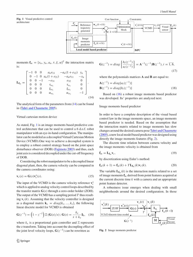
From control theory it is known that any predictive strat-egy is composed from the followings: a model based predic-tor of future behavior of the process output when differentcontrol scenarios are considered, a reference trajectory, a costfunction and a minimization technique Rawlings and Mayne(2009). Taking into account the previous rules an VPC archi-tecture was designed (Fig. 1). Next all the components of theVPC architecture from (Fig. 1) are discussed.
Image moments interaction matrix
The analytical form of the interaction matrix for the generalcase is given in (Chaumette 2004). For the discrete case thetime derivative of μi j is obtained from differentiation of (5):
μi j =n∑
k=1
i(xk − xg)i−1(yk − yg)
j (xk − xg)
+ j (xk − xg)i (yk − yg)
j−1(yk − yg). (12)
Using (12) the interaction matrix of the centered momentsμi j is computed by:
Lμi j = [μvx ; μvy ; μvz ; μωx ; μωy ; μωz
]. (13)
The detailed structure of the parameters from (13) can befound in (Tahri and Chaumette 2005). For the set of image
123
J Intell Manuf
Fig. 1 Visual predictive controlarchitecture
Reference trajectory generator
mf
VCMDOptimizationblock
Visual sensor
Image momentspredictor
* ( | )c k kv ( )c kv ( )m kf
IbPC
Constraints
+_
( )m kf
Local model based predictor
* ( | )c k i kv
Cost function
( | )m k i kf
( | )k i ke
( | )m k i kw
moments fm = [xn, yn, an, τ, ξ, α]T the interaction matrixis:
Lfm =
⎡
⎢⎢⎢⎢⎢⎢⎣
−1 0 0 ane11 −an(1 + e12) yn
0 −1 0 an(1 + e21) −ane11 −xn
0 0 −1 −e31 e32 00 0 0 τωx τωy 00 0 0 ξωx ξωy 00 0 0 αωx αωy −1
⎤
⎥⎥⎥⎥⎥⎥⎦.
(14)
The analytical form of the parameters from (14) can be foundin (Tahri and Chaumette 2005).
Virtual cartesian motion device
As stated, Fig. 1 is an image moments based predictive con-trol architecture that can be used to control a 6 d.o.f. robotmanipulator with an eye-in-hand configuration. The manipu-lator can be modeled as a decoupled Virtual Cartesian MotionDevice (VCMD).One way to achieve a decoupled system isto employ a robust control strategy based on the joint spacedisturbance observer (DOB) (Fujimoto 2003) and thus, eachjoint axis is considered decoupled under the cut-off frequencyof DOB.
Considering the robot manipulator to be a decoupled lineardiagonal plant, then, the camera velocity can be computed inthe camera coordinates using:
vc(s) = G(s)v∗c (s). (15)
The input of the VCMD is the camera velocity reference v∗c
which is applied to analog velocity control loops described bythe transfer matrix G(s) through a zero-order holder (ZOH).The output of the VCMD has a sampling period T thus result-ing vc(k). Assuming that the velocity controller is designedas a diagonal matrix kv = diag{kv, ..., kv}, the followinglinear discrete model for VCMD is obtained
G(z−1) =(
1 − z−1)
Z (G(s)/s) ; G(s) = kvs + kv
I6, (16)
where kv is a proportional gain controller and Z representsthe z transform. Taking into account the decoupling effect ofthe joint level velocity loops, G(z−1) can be rewritten as
G(z−1) = diag
{bi (z−1)
ai (z−1)
}= A−1(z−1)B(z−1), i = 1, 6,
(17)
where the polynomials matrices A and B are equal to:
A(z−1) = diag{ai (z−1)}
B(z−1) = diag{bi (z−1)} (18)
Based on (16) a robust image moments based predictorwas developed. Its’ properties are analyzed next.
Image moments based predictor
In order to have a complete description of the visual basedcontrol law in the image moments space, an image momentsbased predictor is needed. Based on the assumption thatthe interaction matrix related to image moments has slowchanges around the desired camera pose Tahri and Chaumette(2005), a new local model based predictor was designed usingdirectly the image moments features (Fig. 2).
The discrete time relation between camera velocity andthe image moments velocity is obtained from
fm = Lfm vc, (19)
by discretization using Euler’s method:
fm(k + 1) = fm(k)+ T Lfm (k)vc(k). (20)
The variable Lfm (k) is the interaction matrix related to a setof image moments fm derived from point features acquired atthe current discrete time k with a camera and an appropriatepoint feature detector.
A robustness issue emerges when dealing with smallneighborhoods around the desired configuration. In those
Fig. 2 Image moments predictor
123
J Intell Manuf
neighborhoods there is the possibility of reaching a so calledsingularity, where the generated camera velocity is 0 but thedesired configuration is not reached. Let u = (rx , ry, rz) =θu be the (3×1) vector containing the axis of rotation u andthe angle of rotation 0 ≤ θ < 2π . Combining the translationvector t with vector u results γ = (t,u), a (6 × 1) vectorwhich contains the pose of a reference frame expressed in anopen subset S ⊂ R × SO(3), where SO(3) Siciliano et al.(2009) is the special orthogonal group of 3 × 3 matrices. Letγ c ∈ S and γ o ∈ S be the camera pose and the object pose.Based on the camera pose dependence of the visual features,the Eq. (19) can be written as:
fm(γ c) = ∂fm
∂γ c. (21)
From the assumption fm(γ c) �= f∗m results that the Taylor
expansion of fm(γ c) around a neighborhood of γ ∗c is:
fm(γ c) = fm(γ∗c)+ ∂fm
∂γ c(γ ∗
c)(γ c − γ ∗
c
). (22)
The time differentiation of (22) gives
fm = Lf∗m
vc, (23)
which combined with (19) leeds to:
fm = 1
2(Lfm + Lf∗
m)vc. (24)
Taking in to account performance analysis conducteduntil now, the interaction matrix Lfm used by the imagemoments predictive controller will be replaced with Lfm =1/2
(Lf∗
m+ Lfm (k)
), where Lf∗
mis the interaction matrix
related to f∗m . The one-step ahead prediction of the image
moments evolution, when the plant model is considered, canbe computed using (20) and the discrete model (17) of theVCMD, resulting:
fm(k + 1|k) = fm(k)+ T Lfm (k)A−1(z−1)B(z−1)v∗
c (k|k).(25)
Shifting the one-step ahead prediction model (25) by recur-sion and having the hypothesis that the interaction matrix Lfm
is constant over the prediction horizon h p, the next predictorsover prediction horizon h p are obtained:
fm(k + i |k) = fm(k)+ T Lfm (k)A−1(z−1)B(z−1)
h p∑
i=1
v∗c (k + i − 1|k). (26)
The prediction is initiated with the image moments fm(k)derived from point features or edges extracted at discretetime k.
This predictor is used to construct a reference trajectorybased cost function, which is the input in the optimizationblock (Fig. 1).
Reference trajectory based cost function
The aim of the optimization block from Fig. 1 is to generatesystem inputs so that the controlled outputs converge to adesired set point. For that, we define a cost function J as aquadratic function of predicted control errors and inputs. Thecost function is
J = 1
2
h p∑
i=1
eT (k + i |k)Qe(k+i |k)
+hu−1∑
i=0
v∗Tc (k + i |k)Wv∗
c (k + i |k), (27)
where Q and W denote positive definite, symmetric weight-ing matrices, h p is the prediction horizon and hu is the controlhorizon.
The error is defined by
e(k + i |k) = fm(k + i |k)− wm(k + i |k), i = 1, h p, (28)
where wm(k + i |k) is an image moments reference trajectoryrelated to the current step k.
A reference trajectory design directly in the imagemoments space is presented next. Let q = q(σ ) be amonotonic function of the non dimensional time σ = i/h p,which starts from q(0) for i = kT and ends at q(1) fori = (k + h p)T . This function can be approximated by aquintic-polynomial
q(σ ) = a5σ5 + a4σ
4 + a3σ3 + a2σ
2 + a1σ1 + a0, (29)
which emerges from the initial and final conditions:{
q(0) = 0; q(0) = ψ; q(0) = 0q(1) = 1; q(1) = 0; q(1) = 0
(30)
Tuning the ψ parameter will generate different behaviors ofthe time function q. The geometrical interpretation ofψ is thetangent of the angle under which the time function q starts.Thus if the value of ψ is increased then a faster responsefor q is obtained, this implies that ψ is a parameter that willinfluence the dynamic of the resulting path which is definedby
wm(k + i |k) = fm(k)+ q
(i
h p
)�, i = 1, h p, (31)
where � = f∗ − fm(k).In order to completly define the cost function J constraints
must be added to (27). The main constraints are associated tothe limits of the image. These are called visibility constraintsand are used to ensure that all the features remain visiblethroughout the entire servoing task:(x j (k), y j (k)
) ∈ [(xmin, ymin) , (xmax, ymax)] , j = 1, n.
(32)
123

J Intell Manuf
Also, a visual servoing system may be subject to torque con-straints or joints boundaries.
Visual predictive control architecture implementation
In order to analyze the performance of the VPC strategydescribed in section “Nonlinear image moments based pre-dictive control” a real-time visual servoing architecture for aFANUC 6 d.o.f robot manipulator was developed. The pro-posed servoing architecture (Fig. 3) is composed from threedifferent modules: Image Based Control Strategy, RobotCommunication Interface (RCI) and Robot Controller, eachone having a different execution time. The following nota-tions are considered: Tap the execution time for the ImageBased Control module, Tc the RCI module execution timeand T the execution time for Robot Controller module. Thesample period (Ts) of the entire architecture is obtained from:
Ts = Tap + Tc + T . (33)
This architecture is an event driven one, the acquisition of animage being the event that triggers the controller to generatenew information.
Image based control strategy module
The Image Based Control Strategy module is composedfrom the following blocks: Features Extraction, Image BasedPredictive Controller, Depth Extraction, Image Acquisition,Direct Kinematic Model (DKM) and Inverse KinematicModel (IKM). The Features Extraction block embeds thepoint features detection method presented in 2.1 and the
image moments computation method described in 2.2. TheImage based Predictive Controller block was build usingthe visual predictive strategy proposed in section “Nonlin-ear image moments based predictive control”. It allows theused of both point features and image moments and generatesthe reference velocities for the video camera.
The aim of direct kinematics is to compute the pose of thecamera frame, attached to the last link, as a function of thejoint variables. In this paper the considered robot is an openchain that has 6 revolute joints and thus the direct kinematicequation will be:
0T6(q) =0 A1(q1)1A2(q2) . . .
5 A6(q6), (34)
where i−1Ai(qi), i = 1, 6 are homogeneous transformationmatrices, each of which is a function of a single joint vari-able. In order to compute (34) the Denavit–Hartenberg (D-H)convention (Siciliano et al. 2009) was used.
The inverse kinematics problem consists of the determi-nation of the joint variables corresponding to a given cameraframe pose (Siciliano et al. 2009). The existence of solutionsis guaranteed only if the given camera frame pose belong tothe manipulator dexterous workspace. An unique solution tothe inverse kinematic problem is almost impossible to obtain.One can use either analytical approaches or numerical meth-ods (Siciliano et al. 2009).
Robot communication interface
In order to have a direct communication between the ImageBased Control Strategy module, which is implemented inMatlab, and the R-J3iB controller a Robot CommunicationInterface (RCI) is used. The RCI module has three blocks:
IMAGE MOMENT BASED PREDICTIVE CONTROL STRATEGY
( )m
f k
mfFeatures
Extraction
Image
Acquisition
Features
Extraction
( )kcv ( )kcx Velocity
Controller
Image
Based
Predictive
Controller
Integrator TCP/IP
Depth
Extraction
( )z k
Desired
Image
apT c
T T
( )tqDKM
(0)q
Data
File
User
Interface
Homogeneus
Matrix
( )kq
c
bT
IKM
ROBOT COMMUNICATION
INTERFACE
c
bT
ROBOT CONTROLLER
( )b
cT k
Fig. 3 Visual servoing structure
123
J Intell Manuf
I/O, User Interface and TCP/IP. The RCI incorporates theUser Interface block which ensures the communication withthe robot controller. This one allows external interactionthrough the TCP/IP via Ethernet network and the effectivecommunication is carried out using Robot Server from PCDeveloper’s Kit. The role of RCI in the visual servoing archi-tecture is to analyze the MATLAB output, transfer the properdata to the robots controller and read the new configurationof the joints via the standard RS-232-C port.
Robot controller
The data flow of the proposed architecture is the follow-ing: first the image based predictive controller generates thecamera reference velocity v∗
c using the method describedin sections “Visual Features for Servoing applications” and“Nonlinear image moments based predictive control”. Nextan integral action is applied and the desired pose x∗
c (t) isobtained and further transformed into a homogeneous matrix�cT ∗
b that represents the difference between the current posecTb(t) of the camera frame and the desired one. The productof �cT ∗
b with cTb(t) generates cT ∗b that is the input of the
IKM. The solution of IKM, denoted by q∗, is the new currentconfiguration of the joints. This information is written in adata file which is read by the User Interface and sent to therobot controller.
Robot Controller is a module which ensures the correctmotion of the robot tool center point (TCP) in order to reacha desired pose. Because the eye-in-hand configuration wasconsidered, the pose of the TCP will be transfered throughlinear transformation to the camera pose. The RJ3i Matecontrol unit can control up to eight axes, divided into upto three operation groups (multiple motion function). Theoperation groups are independent of one another, but can besynchronized to operate the robot simultaneously. When amotion instruction is used, the motion of the robot dependson the position data, motion format, positioning path, travel-ing speed, and feed rate override specified in the instruction.For the proposed architecture the motion format selected tooperate the robot is Joint. In subsection “Virtual cartesianmotion device” the VCMD model was introduced for themanipulator robot. Using Joint motion format, the modelgiven by (16) was adjusted for the Fanuc robot, resultingkv = 160.
Experimental results
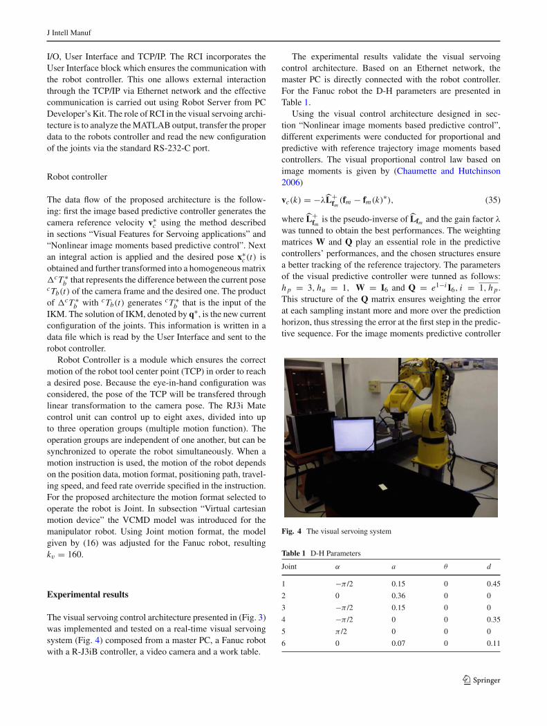
The visual servoing control architecture presented in (Fig. 3)was implemented and tested on a real-time visual servoingsystem (Fig. 4) composed from a master PC, a Fanuc robotwith a R-J3iB controller, a video camera and a work table.
The experimental results validate the visual servoingcontrol architecture. Based on an Ethernet network, themaster PC is directly connected with the robot controller.For the Fanuc robot the D-H parameters are presented inTable 1.
Using the visual control architecture designed in sec-tion “Nonlinear image moments based predictive control”,different experiments were conducted for proportional andpredictive with reference trajectory image moments basedcontrollers. The visual proportional control law based onimage moments is given by (Chaumette and Hutchinson2006)
vc(k) = −λL+fm(fm − fm(k)
∗), (35)
where L+fm
is the pseudo-inverse of Lfm and the gain factor λwas tunned to obtain the best performances. The weightingmatrices W and Q play an essential role in the predictivecontrollers’ performances, and the chosen structures ensurea better tracking of the reference trajectory. The parametersof the visual predictive controller were tunned as follows:h p = 3, hu = 1, W = I6 and Q = e1−i I6, i = 1, h p.This structure of the Q matrix ensures weighting the errorat each sampling instant more and more over the predictionhorizon, thus stressing the error at the first step in the predic-tive sequence. For the image moments predictive controller
Fig. 4 The visual servoing system
Table 1 D-H Parameters
Joint α a θ d
1 −π /2 0.15 0 0.45
2 0 0.36 0 0
3 −π /2 0.15 0 0
4 −π /2 0 0 0.35
5 π /2 0 0 0
6 0 0.07 0 0.11
123

J Intell Manuf
the minimization of the cost function was done using thefmincon function from Matlab. The fmincon parameters wereset to keep the camera velocity between [−0.5; 0.5]m
s and
[−11.25; 11.25] degs .
In the first experiment an object which can be described bya small set of point features was chosen. The point featureswere extracted via Harris algorithm presented in subsection“Point features”.
Images were acquired using a Foculus FO124TC videocamera. This type of industrial camera is based on a ser-ial communication interface IEEE-1394a (FireWire), whichallows a transfer rate of 400 Mbit/s and uses a 6-pin connec-tor. For the acquisition process the image was chosen to bemonochrome, while the resolution was set on 640 × 480.A calibration stage was conducted using the CalibrationToolbox for Matlab and the intrinsic parameters matrix wasrevealed to be equal to:
K =⎡
⎣838.85 0 302.7
0 837.79 272.490 0 1
⎤
⎦ (36)
The desired depth is Z∗ = 0.3 m while the time para-meters were set as follows: T = 0.1s, Tc = 0.25s andTap = 2.12s. In Fig. 5a is presented the initial configura-tion while the desired one is depicted in Fig. 5b. The linearand angular camera velocities obtained for the proportionalapproach are presented in Fig. 6a, while for the predictivemethod the results are depicted in Fig. 6b. The experimen-tal results showed that all the considered constraints werefulfilled by both controllers and a 10 % improvement in thenumber of iterations needed to reach the zero steady statewas achieved by the predictive controller.
For the second experimental setup a symmetric object isconsidered. The object is described by its entire region andso the image moments computation becomes a highly timeconsuming stage. In order to improve this aspect, a SonyXCD-V60CR visual sensor was used. The link between thistype of industrial camera and the master PC is realized by anIEEE-1394b serial bus interface which allows a transfer rateof 800 Mbit/s and uses a 9-pin connector. The image acquiredwas chosen to be monochrome with 320×240 resolution. Thecalibration stage gave the following intrinsic parameters:
(a) (b)
Fig. 5 Point features configuration for general object: a Initial; b Desired
1 5 10 15 20 25 30 35 40 45 50−0.01
0
0.01
0.02
Samples
Line
ar v
eloc
ity(m
/sec
)
1 5 10 15 20 25 30 35 40 45 50−2
0
2
4
Samples
Ang
ular
vel
ocity
(deg
/sec
)
1 5 10 15 20 25 30 35 40−0.1
−0.05
0
0.05
0.1
Samples
Line
ar v
eloc
ity(m
/sec
)
1 5 10 15 20 25 30 35 40−5
0
5
10
Samples
Ang
ular
vel
ocity
(deg
/sec
)
(a) (b)
Fig. 6 The linear and angular camera velocity for a general object: a image moments—Proportional law; b image moments—Predictive controller
123

J Intell Manuf
(a) (b)
Fig. 7 The initial and desired images
1 10 20 30 40 50 60 70 78−0.01
−0.005
0
0.005
0.01
0.015
0.02
Samples
Line
ar v
eloc
ities
(m/s
)
1 10 20 30 40 50 57−0.005
0
0.005
0.01
0.015
0.02
0.025
Samples
Line
ar v
eloc
ities
(m/s
)
1 10 20 30 40 50 60 70 78−0.5
0
0.5
1
1.5
2
2.5
Samples
Ang
ular
vel
ociti
es(d
eg/s
)
1 10 20 30 40 50 57−1
0
1
2
3
4
5
Samples
Ang
ular
vel
ociti
es(d
eg/s
)
(a) (b)
(c) (d)
Fig. 8 The linear and angular camera velocity for: a, c image moments based proportional control law; b, d image moments based predictivecontrol law with reference trajectory
K =⎡
⎣319.33 0 162.67
0 317.87 121.880 0 1
⎤
⎦ . (37)
An initial image Fig. 7a and a desired one Fig. 7b, are theinputs of the experiment. Both desired and starting camerapose are parallel with the object plane, the desired depthis Z∗ = 0.19 m and based on the time parameters T =0.12s, Tc = 0.24s , Tap = 1.27s the sample period was seton Ts = 1.65s. The time evolution of the camera velocitiesis presented in (Fig. 8). The proportional image momentsbased controller offers the results from Fig. 8a and c, whilein Fig. 8b and d are the results of the image moments basedpredictive controller.
Both experiments were successful and in each case con-vergence was achieved. The linear velocities generated bythe proportional controller are comparable with the onesgenerated by the predictive controller. The number of itera-tions needed by the predictive controller to reach the desired
configuration is 15 % lower then the proportional approach.Another interesting aspect emerges when the angular veloc-ities of the proportional controller are compared with theones of the predictive controller. During the experiments theangular velocities for proportional controller presented someoscillations which can generate execution problems to therobot manipulator.
Thus taking into account the lower number of iterationsneeded to complete the servoing task and the smoothnessof the generated camera velocities, we conclude that the bestperformances were obtained using the image moments basedvisual predictive controller with reference trajectory.
Conclusion
In this paper the design of visual predictive control architec-tures was discussed. Using image moments as visual fea-tures, a VPC law was designed using a nonlinear modelbased predictor and a reference trajectory. The advantage
123

J Intell Manuf
of using image moments as visual features comes from theirincreased stability and robustness in comparison with othertypes of visual features used in servoing applications. Theimage moments based predictive controller was evaluatedin a real-time servoing architecture. A comparison with aclassical proportional image moments based controlled wasconducted. The results of two experiments, with regular andsymmetric objects, showed that the best performances areobtained by the image moments based predictive controller,which reduces the number of iterations needed to achievezero steady state by 15 %.
As future work the aim of the authors is to develop a visualservoing framework that can be used for any type of industrialrobots with 6 d.o.f.
Acknowledgments This paper was supported by the Project PER-FORM-ERA Postdoctoral Performance for Integration in the EuropeanResearch Area (ID-57649), financed by the European Social Fund andthe Romanian Government.
References
Allibert, G., Courtial, E., & Chaumette, F. (2010). Visual servoing viaAdvan. Numer. Methods, chapter visual servoing via nonlinear pre-dictive control. pp. 375–393, Springer.
Chaumette, F. (1998). Potential problems of stability and convergence inimage-based and position-based visual servoing. In The confluenceof cision and control, (pp. 66–78).
Chaumette, F. (2004). Image moments: A general and useful set offeatures for visual servoing. IEEE Transaction on Robotics, 20(4),713–723.
Chaumette, F., & Hutchinson, S. (2006). Visual servo control, part I:Basic approaches. IEEE Robotics and Automation Magazine, 13(4),82–90.
Chokkalingham, S., Chandrasekhar, N., & Vasudevan, M. (2012). Pre-dicting the depth of penetration and weld bead width from the infrared thermal image of the weld pool using artificial neural networkmodeling. Journal of Intelligent Manufacturing, 23(5), 1995–2001.
Collewet, C. & Chaumette, F. (2007). Visual servoing on nonplanarobjects from active vision. In Proceedings of IEEE internationalconference on Robotics and automation, pp. 2446–1451. Roma.
Copot, C., Burlacu, A., & Lazar, C. (2011). Visual predictive controlarchitecture based on image moments for manipulator robots. InProceedings of the 20th IEEE international symposium on industrialelectronics, pp. 963–968. Gdansk.
Ferreira, P. & Pinto, J. (2006). Visual based predictive control for asix degree of freedom robot, In Proceedings of IEEE conference onemerging technologies and factory automation, pp. 846–853, Prague.
Fujimoto, H. (2003). Visual servoing of 6 DOF manipulator by multiratecontrol with depth identification. In Proceedings of the 42nd IEEEconference on decision and control, pp. 5408–5413.
Hutchinson, S., Hagerand, C., & Corke, P. (1996). A tutorial on visualservo control. IEEE Transactions on Robotics and Automation,12(5), 651–670.
Lazar, C. & Burlacu, A. (2009). Visual servoing of robot manipula-tors using model-based predictive control. In Proceedings of 7thIEEE international conference on industrial informatics, pp. 690–695, Cardiff.
Lazar, C., Burlacu, A., & Copot, C. (2011). Predictive control architec-ture for visual servoing of robot manipulators, In Proceedings of the18th IFAC World Congress, pp. 9464–9469. Milano.
Ma, Y., Soatto, S., Kosecka, J., & Sastry, S. (2003). An invitation to -Dvision. London: Springer.
Mansard, N., Remazeilles, A., & Chaumette, F. (2009). Continuity ofvarying-feature-set control laws. IEEE Transactions on AutomaticControl, 54(11), 2493–2505.
Marchand, E., & Chaumette, F. (2005). Feature tracking for visual ser-voing purposes. Robotics and Autonomous Systems, 52(1), 53–70.
Megahed, F. M., & Camelio, J. A. (2012). Real-time fault detectionin manufacturing environments using face recognition techniques.Journal of Intelligent Manufacturing, 23(3), 393–408.
Museros, L., Falomir, Z., & Velasco, F. (2012). 2D qualitative shapematching applied to ceramic mosaic assembly. Journal of IntelligentManufacturing, 23(5), 1973–1983.
Paniagua, B., Vega-Rodriguez, M. A., Gomez-Pulido, J. A., & Sanchez-Perez, J. M. (2010). Improving the industrial classification of corkstoppers by using image processing and Neuro-Fuzzy computing.Journal of Intelligent Manufacturing, 21(6), 745–760.
Ramachandram, D., & Rajeswari, M. (2004). Neural network-basedrobot visual positioning for intelligent assembly. Journal of Intelli-gent Manufacturing, 15(2), 219–231.
Rawlings, J., & Mayne, D (2009). Model predictive control: Theory anddesign. Nob Hill Pub Press.
Sauvee, M., Poignet, P., & Dombre, E. (2008). Ultrasound image-basedvisual servoing of a surgical instrument through nonlinear modelpredictive control. The International Journal of Robotics Research,27(1), 25–40.
Sauvee, M., Poignet, P., Dombre, E., & Courtial, E. (2006). Imagebased visual servoing through nonlinear model predictive control.In Proceedings of the 4th IEEE conference on decision and control,pp. 1776–1781, San Diego.
Siciliano, B., Sciavicco, L., Villani, L., & Oriolo, G. (2009). Roboticsmodelling, planning and control. London: Springer.
Sim, T., Hong, G., & Lim, K. (2002). Multirate predictor control schemefor visual servo control. IEEE Proceedings-Control Theory andApplications, 149(2), 117–124.
Tahri, O., & Chaumette, F. (2005). Point-based and region based imagemoments for visual servoing of planar objects. IEEE Transaction onRobotics, 21(6), 1116–1127.
123