
Prediction and cooperation in gaze control
10
Biol. Cybern. 63, 61-70 (1990) Biological Cybemetics Springer-Verlag1990 Prediction and Cooperation in Gaze Control C. Brown Computer Science Department, University of Rochester, Rochester, NY 14627, USA Received: July 20, 1989 Accepted in revised form: November29, 1989 Abstract. Multiple gaze control capabilities are coordi- nated using predictive methods. Internal models of state allow smooth interaction of multivariable, multirate controls. The problem of rapid gaze shift in a simulated robotic system illustrates several styles of control inter- action. 1 Cooperating Controls in Animate Vision The work reported here investigates predictive mecha- nisms to solve problems of cooperation and delay. "Subsumption" architectures (Brooks 1986; Connell 1987) find these problems troublesome since internal state representations are minimized, control interaction is usually limited to pre-emption, and actions are syn- chronized only through the outside world. Our previous work investigates the interaction of five simple camera (or eye) and head controls, and shows that predictive techniques can overcome the catastrophic effects of delays and interactions (Brown 1990). It makes comparisons with primate gaze controls and with an open-loop approach to delay. The earlier work is here extended in three ways. Tracking, gaze shifts, and vergence controls use three dimensional, not retinal, coordinates. Optimal estimation techniques are used to estimate and predict the dynamic properties of the target. More camera and head controls are added, and their interaction is more sophisticated than in the earlier model, which only had two modes, tracking and fast gaze shift. The control algorithms are run in a simulation that is meant to be general and flexible, but especially to capture the relevant aspects of an existing robotic sys- tem (Brown and Rimey 1988). Recent work with the Rochester Robot produced several implementations of potential basic components of a real-time gaze-control system (Ballard 1989; Brown 1988; Ballard and Ozcan- darli 1988; Olson and Potter 1989). These components included basic capabilities of target tracking, rapid gaze shifts, gaze stabilization against head motion, verging the cameras, binocular stereo, optic flow and kinetic depth calculations. These separate capabilities do not yet cooperate to accomplish tasks. The work reported here is partly motivated by the need to integrate several capabilities smoothly for a range of tasks useful for perception, navigation, manipulation, and in general "survival". 2 The Gaze Controls There are four main coordinate systems of interest in this work: LAB, HEAD, and (left and right) camera and retinal. The LAB, HEAD, and camera systems are three-dimensional, right-handed and orthogonal. The retinal system is two-dimensional and orthogonal. LAB is rigidly attached to the environment in which the animate system and objects move. HEAD is rigidly attached to the head, and (for this work) has three rotational and three translational degrees of freedom. The camera systems are rigidly attached to the cameras and have independent pan and a shared tilt degree of freedom. The retinal systems represent image coordi- nates resulting from perspective projection of the visible world. The cameras are supported on a kinematic chain so that their principal points do not in general lie on any head rotation, pan, or tilt axis. The simulated system controls are summarized in Table 1. Our purpose is to investigate, with some flexibility, the interactions of various forms of basic camera and head controls. The controls are not meant to model those of any biological system. Rather the goal is to build a system with sufficient functionality to exhibit many control interactions. The interaction of a subset of these controls on target tracking and acqui- sition tasks (the "smooth pursuit" and "saccadic" sys- tems) is reported in (Brown 1990), which also illustrates the effects of different control algorithms for coping with delays. We assume a different delay is possible for
Transcript of Prediction and cooperation in gaze control
Biol. Cybern. 63, 61-70 (1990) Biological Cybemetics �9 Springer-Verlag 1990
Prediction and Cooperation in Gaze Control C. Brown
Computer Science Department, University of Rochester, Rochester, NY 14627, USA
Received: July 20, 1989 Accepted in revised form: November 29, 1989
Abstract. Multiple gaze control capabilities are coordi- nated using predictive methods. Internal models of state allow smooth interaction of multivariable, multirate controls. The problem of rapid gaze shift in a simulated robotic system illustrates several styles of control inter- action.
1 Cooperating Controls in Animate Vision
The work reported here investigates predictive mecha- nisms to solve problems of cooperation and delay. "Subsumption" architectures (Brooks 1986; Connell 1987) find these problems troublesome since internal state representations are minimized, control interaction is usually limited to pre-emption, and actions are syn- chronized only through the outside world.
Our previous work investigates the interaction of five simple camera (or eye) and head controls, and shows that predictive techniques can overcome the catastrophic effects of delays and interactions (Brown 1990). It makes comparisons with primate gaze controls and with an open-loop approach to delay. The earlier work is here extended in three ways. Tracking, gaze shifts, and vergence controls use three dimensional, not retinal, coordinates. Optimal estimation techniques are used to estimate and predict the dynamic properties of the target. More camera and head controls are added, and their interaction is more sophisticated than in the earlier model, which only had two modes, tracking and fast gaze shift.
The control algorithms are run in a simulation that is meant to be general and flexible, but especially to capture the relevant aspects of an existing robotic sys- tem (Brown and Rimey 1988). Recent work with the Rochester Robot produced several implementations of potential basic components of a real-time gaze-control system (Ballard 1989; Brown 1988; Ballard and Ozcan- darli 1988; Olson and Potter 1989). These components included basic capabilities of target tracking, rapid gaze
shifts, gaze stabilization against head motion, verging the cameras, binocular stereo, optic flow and kinetic depth calculations. These separate capabilities do not yet cooperate to accomplish tasks. The work reported here is partly motivated by the need to integrate several capabilities smoothly for a range of tasks useful for perception, navigation, manipulation, and in general "survival".
2 The Gaze Controls
There are four main coordinate systems of interest in this work: LAB, HEAD, and (left and right) camera and retinal. The LAB, HEAD, and camera systems are three-dimensional, right-handed and orthogonal. The retinal system is two-dimensional and orthogonal. LAB is rigidly attached to the environment in which the animate system and objects move. HEAD is rigidly attached to the head, and (for this work) has three rotational and three translational degrees of freedom. The camera systems are rigidly attached to the cameras and have independent pan and a shared tilt degree of freedom. The retinal systems represent image coordi- nates resulting from perspective projection of the visible world. The cameras are supported on a kinematic chain so that their principal points do not in general lie on any head rotation, pan, or tilt axis.
The simulated system controls are summarized in Table 1. Our purpose is to investigate, with some flexibility, the interactions of various forms of basic camera and head controls. The controls are not meant to model those of any biological system. Rather the goal is to build a system with sufficient functionality to exhibit many control interactions. The interaction of a subset of these controls on target tracking and acqui- sition tasks (the "smooth pursuit" and "saccadic" sys- tems) is reported in (Brown 1990), which also illustrates the effects of different control algorithms for coping with delays. We assume a different delay is possible for
62
TARGET POSIT. AND VELOCITY ~ CALCULATE CONST. PAN,
(3.tt~.. TARGET T~T VELS
IN'I'ERCF~lwr/ON AND DURATION
CURRENT GAZE
DIKEUFION (a) RAPID GAZE SHIFT
LEFT X ~ DISPARITY
RIGHT X = L~X - R_X
m PROPORTIONAL LEF3" X.Y INTEGRAL
OR DERIVATIVE
X_VEL,Y_VEL
LEFT PAN_VEL ~ - - ~
LEFT TILT VEL
(b) TRACKING
PROPORTIONAL
~ R A L
DERIVATIVE
(e) VERGENCE
ERROR
R~Ry,Rz ~ APPROXIMATE
TARGET KINEMATICS
DISTANCE
~ ' - - ~ [ - - ~ TflLTL&R~PAN' ~
(d) GAZ~ STABILIZATION
pAN AND TILT C O ~ T P GAIN
ANGLES FUNCTION
(r HEAD COMPENSATION
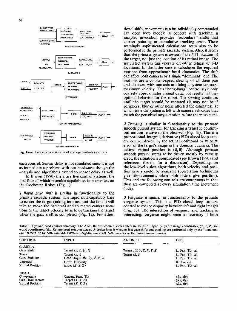
Fig. l a - e . Five representative head and eye controls (see text)
each control. Sensor delay is not simulated since it is not as immediate a problem with our hardware, though the analysis and algorithms extend to sensor delay as well.
In Brown (1990) there are five control systems, the first four of which resemble capabilities implemented on the Rochester Robot (Fig. 1).
1 Rapid gaze shift is similar in functionality to the primate saccadic system. The rapid shift capability tries to center the target (taking into account the time it will take to move the cameras) and to match camera rota- tions to the target velocity so as to be tracking the target when the gaze shift is completed (Fig. la). For atten-
tional shifts, movements can be individually commanded (an open loop mode): in concert with tracking, a sampled invocation provides "secondary" shifts that correct pointing or cumulative tracking error. These seemingly sophisticated calculations seem also to be performed in the primate saccadic system. Also, it seems that the primate system is aware of the 3-D location of the target, not just the location of its retinal image. The simulated system can operate on either retinal or 3-D locations. In the latter case it calculates the required motions from approximate head kinematics. The shift can affect both cameras or a single "dominant" one. The motions are a constant-speed slewing of all three pan and tilt axes, with one axis attaining a system constant maximum velocity. This "bang-bang" control style only coarsely approximates animal data, but results in time- optimal behavior for the robot. The slewing continues until the target should be centered (it may not be if peripheral blur or other noise affected the estimates), at which time the system is left with camera velocities that match the perceived target motion before the movement.
2 Tracking is similar in functionality to the primate smooth pursuit system, for tracking a target in continu- ous motion relative to the observer (Fig. lb). This is a proportional, integral, derivative (PID) closed loop cam- era control driven by the retinal positional or velocity error of the target's image in the dominant camera. The desired retinal position is (0,0). Although p r i m a t e smooth pursuit seems to be driven mostly by velocity error, the situation is compficated (see Brown (1990) and references therein for a discussion). Depending on the low-level vision algorithms, both velocity and posi- tion errors could be available (correlation techniques give displacements, while blob-finders give position). This and the following controls are continuous in that they are computed at every simulation time increment (tick).
3 Vergence is similar in functionality to the primate vergence system. This is a PID closed loop camera control to reduce disparity between left and right images (Fig. lc). The interaction of vergence and tracking is interesting: vergence might seem unnecessary if both
Table 1. Eye and head control summary. The ALT. INPUT column shows alternate forms of input. (x, y) are image coordinates, (.t, Y, Z) are world coordinates, (Rx, Ry) are head rotation angles. A design issue is whether fast gaze shifts and tracking are performed only by the "dominant eye" camera or by both cameras. Likewise vergence can affect both cameras or the non-dominant camera
CONTROL INPUT ALT.INPUT OUT
CAMERA Gaze Shift Target (x, y), (~, 3~) Track Target (x,y) Gaze Stabilize Head Origin Rx, Ry, ~, ~', 2 Vergence Horiz. Disparity Virtual Position target (.t, Y, Z)
HEAD Compensate Camera Pans, Tilt Fast Head Rotate Target (.I, Y, Z) Virtual Position Target (.t, Y, Z)
Target. ,I, Y, Z, ~, I~, 2 Target (~,))
L. Pan, Tilt vel. L. Pan, Tilt vel. L. Pan, Tilt vel. R. Pan vel. L. Pan, Tilt vel.
(~x, ~y) (~x,/~y) (/~x, ~y)
cameras track the target. In the laboratory, specific hardware is devoted to implementation of tracking and vergence- it may be cheaper in hardware to do tracking with both cameras with no vergence control. Vergence, however, makes cameras less likely to wander off and pursue separate targets.
4 Gaze stabilization is similar in functionality to the primate vestibulo-ocular and otolith-ocular reflexes (VOR, OOR) (Fig. ld). This is a proportional-gain closed loop camera control to oppose head rotation and translation with contrary camera rotation. It is similar to the primate system in that it uses information about target range. Its current implementation differs in that its input is not sensory (say from accelerometers), but is an "efferent copy" of the head control signals. This avoids its interference with tracking when head compensation (below) is active but means unexpected physical distur- bances are not compensated. Compensation for head rotations around X and Y axes assumes the head is small with respect to target distance. For translation, a target at distance D undergoing a motion of (dx, dy) is taken to induce angular motion (dx/D, dx/D).
5 Head compensation is a proportional-gain head- control system driven by head-relative camera position that rotates the head in the direction of camera rotation to limit excursion of camera angles (Fig. le). Since camera position affects head position, it is an open loop system. The "comfort function" is 0/((0-0max)2), where 0 is the average pan angle (to control head "yaw" movements) or the tilt angle (to control head "pitch" movements). In either case 0max is the mechanically imposed limit of the system. This capability may not mirror any named biological one, but it does reflect a widespread primate tendency to move the head, if al- lowed, during pursuit and eye saccades.
The new controls are the following. The first two are added explicitly to test whether "local feedback" theo- ries could provide effective guidance on the cooperation of head and cameras for fast gaze shift. The last was added to achieve time-optimal cooperation of head and camera gaze shifts.
6 and 7 Virtual position head and camera controls are closed loop PID position controls that drive the head or cameras to point at a commanded location in space. For camera control the location may be given in HEAD or LAB coordinates, for head control in LAB coordinates.
8 Fast head motion is an open loop control to rotate the head axes at constant maximum angular velocity to point the head at a commanded position in LAB coordinates.
3 Control with Delays
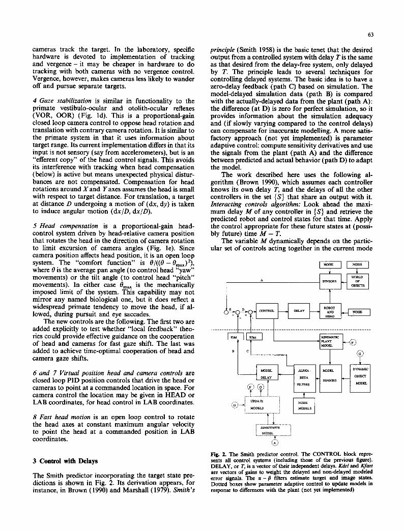
The Smith predictor incorporating the target state pre- dictions is shown in Fig. 2. Its derivation appears, for instance, in Brown (1990) and Marshall (1979). Smith's
63
principle (Smith 1958) is the basic tenet that the desired output from a controlled system with delay T is the same as that desired from the delay-free system, only delayed by T. The principle leads to several techniques for controlling delayed systems. The basic idea is to have a zero-delay feedback (path C) based on simulation. The model-delayed simulation data (path B) is compared with the actually-delayed data from the plant (path A): the difference (at D) is zero for perfect simulation, so it provides information about the simulation adequacy and (if slowly varying compared to the control delays) can compensate for inaccurate modelling. A more satis- factory approach (not yet implemented) is parameter adaptive control: compute sensitivity derivatives and use the signals from the plant (path A) and the difference between predicted and actual behavior (path D) to adapt the model.
The work described here uses the following al- gorithm (Brown 1990), which assumes each controller knows its own delay T, and the delays of all the other controllers in the set {S} that share an output with it. Interacting controls algorithm: Look ahead the maxi- mum delay M of any controller in {S} and retrieve the predicted robot and control states for that time. Apply the control appropriate for these future states at (possi- bly future) time M - T.
The variable M dynamically depends on the partic- ular set of controls acting together in the current mode
~:]}).. i ' z ....... ~.....~ .........
. . . . . . . . . : . . . ~ . . . . . . . . . . . . . �9
S E N S I T I V I T Y i
M O D E L i . . . . . . . . . . . . . . . . A. . . . . . . . . . . . . :
Fig. 2. The Smith predictor control. The CONTROL block repre- sents all control systems (including those of the previous figure). DELAY, or T, is a vector of their independent delays. Kdel and Kfast are vectors of gains to weight the delayed and non-delayed modeled error signals. The � 9 p filters estimate target and image states. Dotted boxes show parameter adaptive control to update models in response to differences with the plant (not yet implemented)
64
of operation. The stability of the resulting system is dependent on the accuracy of the estimates of plant states and delays. Sensitivity analysis can be used to determine when the system is most vulnerable, and adaptative techniques will likely be necessary to main- tain predictive accuracy.
In contrast with the explicit kinematic simulation used to predict the system state, standard optimal (i.e. variance-minimizing) filtering techniques are used to predict the position and velocity of the world object. The simulation has been run with extended Kalman filters, (linear) Kalman filters, and time-invariant filters as predictors. It is standard practice with optimal filtering to use statistical techniques to see if the current dynamic model fits the data, and if not to substitute another model (Bar-Shalom and Fortmann 1988). This "variable dimension" approach is the predictive filtering equiva- lent of choosing the object motion model in a signal synthesis adaptive control scheme (Bahill and McDon- ald 1981; McDonald and Bahill 1983), and the block diagrams of the two systems are basically the same. For the work reported here a simple, time-invariant ~t - f l filter is used with a constant-velocity model (Bar-Shalom and Fortmann 1988). Varying the process noise in the model allows the filter to accommodate targets with more or less variable velocities.
4 The Simulation
The simulator demonstrates results and is a basic part of the predictive control system. It can model a large class of kinematic, imaging, and control systems. It incorpo- rates head geometry and models angular velocity con- trols acting with delays.
4.1 The Robot
The simulated robot has a HEAD (a coordinate system) that can be translated and rotated under velocity con- trol. The modeled cameras are at the ends of kinematic chains attached to the HEAD origin, with their individ- ual pan and common tilt velocities controllable. The target is modeled as a single point in three dimensions, and its image under perspective projection as a retinal point. This idealized percept ignores many of the phe- nomena that cause problems for low-level computer vision but also provide information to both artificial and biological systems (e.g. motion blur, optic flow or retinal slip, and moving edges). The robot state also includes the position of the target's image in both cameras, its incremental motion since the last simulated instant (its instantaneous optic flow), and three-dimen- sional target position information (say from kinetic depth, binocular stereo, a sonar sensor, or an internal world representation).
The geometric configuration, speeds, delays, and time constants of the simulation can be altered to conform with a variety of robotic or biological spe- cifications. The simulation of eye movements by pan and tilt (not allowing rotations about the optic axis) seems reasonable for primate modeling. The kinematic (i.e.
non-dynamic) robot model is satisfactory at a certain level of abstraction, while biological models even of the eyeball can be complex. The Rochester Robot's existing controllers deal with robot dynamics on a per-joint basis, keeping motion slow enough to hide dynamic interactions. Their computations are not available to applications software. The abstraction of the six-link robot arm to the model HEAD coordinate system is in fact supported by software in the robot controller, which provides commands that allow motions of the end of the arm (bearing the head) in the HEAD coordinate system. A single origin of head coordinates does not do justice to the primate head and neck joints, but is a reasonable approximation and would make dynamics easy to com- pute. The discrete-time nature of the simulation is not traditional but allows unlimited freedom in control law design.
For this paper the simulator was geometrically configured like the Rochester Robot, and other para- meters were set to illustrate the phenomena of interest. The main task studied in this paper in quick gaze shifts to static or slowly moving target.
4.2 Delays and Controls
The data structure implementing control is a pipeline (ring buffer) of [robot state, target state vector, com- mand vector] triples, indexed by time, running from present into future. Robot state is a HEAD coordinate system, three head translational and three head angular velocities, two camera coordinate systems with two camera pan and one camera tilt angular velocities, two "images" (image (x, y) positions and (dx, dy) velocities of the target). Target state vector is the target's dynam- ical description, (here 3-D position and velocity). Con- trol vector is six velocity settings for the head and three for the cameras.
Control delay is simulated by inserting controls into the pipeline to take place at the appropriate future instant. Time is discretized to some level, called a tick. A larger delay results in entry of the corresponding command further in the future. Control saturation is simulated by thresholding, and the explicit pipeline permits the technique of dividing the commanded change between as many ticks as necessary to achieve the desired effect at maximum control ouput. Saturated control is important since time-optimal control is often achieved by a saturated, "bang-bang" scheme.
A cycle of control activity involves the application of a control action for the current time, the computa- tion of new controls, the updating (by overwriting or addition) of the control action in the pipeline corre- sponding to the correct delay, and the simulated appli- cation of all controls in the pipeline to the system to update the pipeline of simulated future states.
4.3 Simulation Parameters
The simulation is controlled by a number of compile- time decisions that specify the control inputs and out- puts (tracking by position or velocity, one- or two-camera fast gaze shifts, etc.), the geometry of the
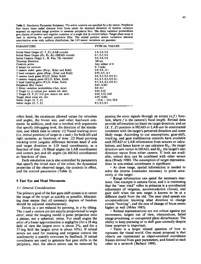
Table 2. Simulation Parameter Summary. The active controls are specified by a bit vector. Peripheral blur factor times radial distance from fovea yields the standard deviation of random variation imposed on reported image position to simulate peripheral blur. The delay variation probabilities give chance of positive and negative variation of a single tick in control delays. Target plant noise is used in deriving the optimal predictive filter. The retinal position sensor variations simulate quantization noise with uniform distribution, the 3-D sensor variations are gaussian
PARAMETERS TYPICAL VALUES
Initial Head Origin (X, I;', ~.) (LAB coords) Initial Head Origin (kx, Ry,/~z) (HEAD coords) Initial Camera Origin L., R. Pan, Tilt velocities Timestep Duration Controls active 8 delays for controls 3 camera stabil, gains (Prop., Kfast and Kdel) 3 head compens, gains (Prop., Kfast and Kdel) 5 camera track gains (P,I,D, Kfast, Kdel) 5 camera verging gains (P,I,D, Kfast, Kdel) 5 head tracking gains (P,I,D, Kfast, Kdel) Peripheral Blur Factor 2 Delay variation probabilities (fast, slow) 2 Target (x, y) retinal pos. sensor std. devs. 3 Target (X, Y, Z) 3-D pos. sensor std. devs. Target plant noise std. dev. Initial target (X, Y, Z) Initial target Q/', 1>, 2 )
1.0, 2.0, 3.0 0.1, 0.2, 0.0 0.0, 0.0, 0.0 I00 ms Any sfibset of 8 0-5 ticks 0.9, 0.9., 0.1 0.95, 0.9., 0.1 0.8, 0.5, 0.2, 0.9, 0.1 0.4, 0.3, 0.2, 0.9, 0.I 0.7, 0.4, 0.2, 0.9, 0.1 0.05-0.001 0.0-0.1 0.01, 0.02 0.01, 0.02, 0.05 0.05-0.001 --25.0, - 10.0, 50.0 0.5, 0.5, 0.5
65
robot head, the maximum allowed values for velocities and angles, the foveal size, and other hardware con- stants. In addition, each run is invoked with arguments that specify debugging level, the duration of the simula- tion, and which data to create: (I) Visual tracking error (i.e. retinal position) of target in x and y for both left and fight cameras, as functions of time. (2) Head pointing tracking error (angular difference between head Z axis and target direction in 3-D head coordinates), as a function of time. (3) Head angles (in LAB coordinates) and camera pan and tilt angles (in HEAD coordinates) as functions of time.
Each simulation run is also controlled by parameters that specify the initial state of the robot, the dynamical properties of the observed target, the controls in effect, and the control parameters (Table 2).
5 Fast Eye and Head Movements
5.1 General Considerations
The primary goal of the fast gaze-shift system is to center the image of the target as quickly as possible. Minimiz- ing time means that all necessary degrees of freedom should be adjusted simultaneously.
Errors in x are reduced by panning, in y by tilting. The x and y vectors are not exactly proportional to angle error, since the imaging model is point projection onto a planar, not a spherical, retina. For small angles the error of a linear approximation is negligible (for a 28 deg field of view the largest error is about 2%, and for a 57 deg field the largest error is about 10%). If retinal errors are used for tracking and vergence control the nonlinearity is quickly overcome by feedback. If retinal coordinates are used to generate fast gaze shifts to the periphery, then the above errors can be removed by
passing the error signals through an arctan (x/ f) func- tion, where f is the camera's focal length. Retinal data provide information (at least) on target direction, and an (X, Y, Z ) position in HEAD or LAB can be constructed consistent with the target's perceived direction and some likely range. According to our assumptions, gaze-shift, tracking, and gaze stabilization controls have available such HEAD or LAB information from sensors or calcu- lations, and hence know or can calculate Ox, the target direction unit vector in HEAD, and Oe, the target's unit direction vector from either camera. If both are avail- able, retinal data can be combined with other sensor data (Brady 1988). The assumption of target representa- tions in non-retinal coordinates is significant.
�9 At close range, spatial information is needed to solve the inverse kinematics necessary to point accu- rately at the target.
�9 Range information can speed the necessary reac- tions. One example is camera focus, and it is interesting that the "near triad" reflex in primates is a coordinated adjustment of vergence, accommodation (focus), and gaze shift when the new target is known to be at a different depth from the old. The near triad speeds eye accommodation: knowing what direction to change avoids "hunting", and the rate of change of focus seems higher as well (Miles 1985).
�9 Retinal representations are not robust against eye movements, targets out of view, obscurations, failed image processing, or unexpected plant disturbances. The ability to keep pursuing or to shift gaze correctly despite these surprises is important.
�9 There is a larger related question of how to represent the visual world. One recent proposal is that objects are represented as object-centered coordinate frames derived from gaze parameters, and linked to each other in a network (Ballard 1989).
66
5.2 Eye Movements
Eye movements are performed by the independent pans and a common tilt. The assumption is that tilt affects the pan axis but not vice-versa. Let k n and ke be the unit vectors along HEAD and camera Z axes. We desire the pan and tilt angles that will point ke in the direction OE = (x, y, z) r in camera coordinates. The pan and tilt may be approximated by zero if the head is pointing at the target, or may be calculated from the image or even from an internal representation of target position and the plant state.
True pans and tilts are derived from an approximate inverse kinematic calculation based on head geometry. For a target distant with respect to the link lengths, approximate camera tilt angle is
Oct = - a rc tan(y /z) . (1)
The camera pan angle is
O ep = arcsin(x / R) , (2)
where R = (x 2 + y 2 + z2)l/Z.
The maximum angular velocity attainable by the camera motors may be simultaneously commanded to pan and tilt for the two required times, or the equivalent number of discrete angular steps commanded. Alterna- tively the velocities may be sealed so that the pan and tilt are completed at the same time, with the smaller motion performed more slowly. The latter method is used in the simulations. The independence of the tilt axis from the pan motion is all that is needed to allow both motions to proceed simultaneously or in either order with no interference: the situation is different for head movements.
5.3 Head Movements
The semantics of HEAD is that of a coordinate system. Even if its axes initially correspond to actual rotation axes, as they can if the origin of HEAD is taken to be the center of a robotic wrist, the situation is not the same as with camera movements. The control commands for HEAD orientation are to rotate HEAD about one of its axes: such rotation changes both other axes. Since 3-D rotations in general do not commute, the simultaneous rotations we desire will interact with one another. Thus pan and tilt angles computed as for fast camera gaze shifts would only work correctly if the movements are carried out sequentially in the correct order.
Since simultaneous rotations are needed for speed, we must compute the continuous rotation velocities about HEAD Y and Y axes needed to accomplish a head movement, and the time interval to activate them. For discrete simulation or implementation as a set of individ- ual commands, we need to approximate the motion by a number N of small rotations. Depending on the accuracy needed, a number of these small rotations may be composed to correspond to what happens in one simulation instant. Luckily, small rotations are the key of the non-commutativity problem, and the error in the approximation can be made to fall off as N -2.
Consider a smooth rotation taking kn to On = (x, y, z) r directly (along a great circle route on the HEAD-centered Gaussian sphere) and at a constant speed. The angular distance to be covered is
0to t = arccos(kn �9 O n ) = arccos(z). (3)
Projecting the Gaussian sphere onto the (X, Y) plane projects the great circle along which On moves onto a straight line from the origin to (x, y). Thus the instanta- neous direction of the head motion is constant, and at any time the ratio of distance rotated around x and y axes is x / ( - y ) . If the total angular distance to be covered is divided into N steps, each step consists of small head rotations On,, and Ony, where Ore, = (x / ( -y )Ony . A Euclidean approximation yielding the desired distance 0tot is that
Onx = (x(Otot/N))/r ( 4 )
and
Oily = - - y ( 0 t o t / N ) ) / r , ( 5 )
where r = ( x 2 "[- y2) U2. The error increases as the spher- ical triangle differs from the planar. If 0m,x is the maximum rotational velocity of the head motors, the continuous time to complete the entire head movement is
t = (max(x, y)(Otot ) ) / (rOmax) , (6)
with the velocities in the ratio x/y, so assigned that the X and Y rotations complete at the same time and the greater velocity is 0max. The approximation of the con- tinuous motion by a sequence of small rotations works because infinitesimal rotations about coordinate axes, as the generators of the Lie group of rotations, commute (Altmann 1986). The resulting cumulative angular error decreases reliably as 1/N, independent o f z or x/y (except that the error is zero if either of x or y is zero). I f the desired direction is (x, y, z)r, the result for the worst case, N = 1, is obtained by applying the tilt and pan given by (4) and (5) to the vector (0, 0, 1) r. The resulting vector is
0 = [cos(Ony)sin(Om,), sin(0ny), Cos(Otty)COs(Onx)] r. (7)
The difference between the desired vector and the result (I[O- On II or arccos(IS �9 On)) may be sealed by 1/N to predict the corresponding error in the cumulative motion. If the simulation or discrete command se- quence uses alternating [xrot, yrot] and [yrot, xrot] ac- tions in the sequence of small motions, the error decreases as 1/N 2.
6 Cooperating Eye and Head Motion
There are two main reasons for head motions during gaze shifts: First, to keep the eyes centered in the head, maximizing the mechanical freedom for later eye move- ments. Second, to increase the velocity of eye rotation in LAB, leading to a more rapid visual acquisition of the desired target.

This section describes four versions of cooperating camera-head motions. In each, the goal of the fast head movement system is position matching: When the head movement finishes the head is pointing at the (instanta- neous) current target position and head rotation veloc- ity commands are zero. The goal of the camera fast movement system is position and velocity matching. (It would be just as easy to produce position and velocity matching in both systems, to move the head by only the minimum amount that allows acquisition, or other variations.)
The aim is not to reproduce the complex findings on primate systems and their interaction, but to establish that a usable range of capabilities is possible. Although certain primate capabilities (such as coping with distur- bances) have inspired features of some of the versions, the goal has simply been to produce fast, stable, and robust camera-head gaze shifts. The first two schemes have the virtue of simplicity, but are handicapped by control interactions and use no prediction. The third scheme has no feedback and optimal speed, but no robustness. The last and most successful scheme uses explicit predictive simulation to generate gaze shifts, and the loop is closed by re-triggering the calculation when a disturbance is sensed.
A first example of simultaneous, cooperating cam- era and head motions is provided by simply running the
0s (a)
0.2
0.1.
0.0 , _ _ g
(b)
0 0.5 Tim e (sec)
1'0 l's
Fig. 3. a Linear summation. Robot gaze (butterflies), camera (fight squares), and head (dark squares) angles (radians) showing linear summation effect arising from reflex interaction. Here the camera gaze shift control is active together with head-compensation and gaze stab'flization reflexes. The combination of camera saccades with head compensation and gaze stabilization forces the gaze velocity to be the velocity of the camera movement acting by itself. Time units are arbitrary and chosen to illustrate the behavior, b Human gaze (G), eye (E), and head (H) movements during 80 deg gaze shift. A has no head motion, B has 80 deg head movement, and gaze shift is com- pleted twice as fast
67
fast camera gaze shift as defined in Sect. 2 simulta- neously with the VOR-like gaze stabilization and head- compensation reflexes (Brown 1990; Sect. 2). Figure 3 shows the result, which is similar to that which once was claimed (under the "linear summation hypothesis") to hold in primates, viz. that their camera rotational veloc- ity measured in LAB is kept constant (camera rotational velocity is decreased by head rotational velocity) (Morasso et al. 1973). However, in primates the linear summation hypothesis has been contradicted by findings indicating eye-head gaze shifts outperform eye saccades alone (Robinson and Zee 1981) (see Fig. 3b). Certainly in a robotic context a speed improvement is attainable, and the following three versions are intended to out- perform the first one.
The gaze feedback version is inspired by local feed- back theories, and is based on continuous head and camera internal position-feedback controls. A head gaze-shift is then simply implemented as a re-positioning operation, and cooperating camera-head gaze-shifts are simultaneous head and camera re-positioning. The sam- pled optimal version is a closed-form sampled (or open loop) solution for full-speed camera and head move- ments. The simulated optimal version uses the pipeline of predicted future states to maintain optimal speed and add the ability to deal with arbitrary velocity profiles and disturbances.
6.1 Gaze Feedback
This version of camera and head movements is just the simultaneous action of virtual position control feedback loops in both camera and head. This literal and straight- forward interpretation of "local feedback" affords some illuminating comparisons.
In one obvious local feedback scheme the camera pursues its desired position with respect to the head. This means that its final position in HEAD is entirely deter- mined by distance to the target and head geometry. Given that the system knows the range R of the target and the horizontal and vertical offsets (h and v) of the cameras from the head origin, the camera position when kA (the head) is pointed at the target is (pan, tilt)= (arctan(h/R), - arctan(v/R)). Being at this position only centers the target when the head is correctly pointed, so this scheme is no faster than head movement alone, regardless of camera movement velocity.
Another alternative is to have camera and head both track the target position (in LAB or retinal coordinates). This scheme would seem capable of faster performance, but in practice is disappointing.
Letting both controls run with the gaze stabilization is not effective. Gaze stabilization slows the camera rotation by the amount of head rotation, and thus the behavior of the gaze angle is the same as if the camera system were acting alone. Just as in the linear summation gaze shift above, gaze stabilization defeats cooperative speed-up.
However, if the camera-head movement is made without gaze stabilization, the head pursues the target as a second order system, carrying the camera with it.

68
The camera control is also second order, but is being forced by the head's motions. The effect is that of a fourth order system, and the case of gaze shift to a motionless target corresponds to a step input. The root locus behavior of fourth order systems makes them prone to instability as gain increases. Their perfor- mance is also at issue. Optimal coefficients for n-order systems under the several performance criteria (such as the integral of time multiplied by absolute error) may be derived, and step responses for the optimal systems of various orders plotted (Dorf 1986). Two points emerge: (1) under three common performance criteria, optimal fourth-order rise times are slower than opti- mal second order, and convergence to the desired value is no faster. (2) the cascaded second-order sys- tems give a restricted form of the general fourth order system that does not in general produce the optimal higher-order system, and certainly does not if the lower order systems are themselves optimal.
These observations are a demonstration that sim- ply cascading two second order position control sys- tems will not outperform either acting alone if it is correctly designed. Since head-camera rise time will be faster than either system acting alone (unless they ro- tate in opposite directions), the resulting system is guaranteed to be sub-optimal by point (1) above, and even the optimal fourth-order system could perform no better than either system acting alone.
To summarize: Straightforward implementations of gaze feedback models have performance limitations. If the commanded camera position is in HEAD the gaze shift of a head-camera movement cannot be faster than the head movement by definition. If a VOR-like gaze stabilization is in effect, a head-camera movement cannot be faster than the camera movement by defini- tion. Last, without head compensation the combined gaze motion obeys a higher-order form of control whose performance may well be theoretically worse than either camera or head acting alone, and cannot be better than a tailored version of either control. This prediction is borne out by experimentation. The psy- chophysical data indicate that the primate system ex- ceeds the speed of either head or eye saccades without oscillations. Thus gaze feedback seems to have techni- cal problems that make it unsatisfactory for use with PID control and perhaps unpromising as a model for primate abilities as well. The next versions incorporate time-optimal ("bang bang") control.
6.2 Sampled Optimal
Time optimality demands that the camera and head both move at maximum velocity to acquire the (possi- bly moving) target. For generality we assume arbitrary head and camera initial positions H0, and Eo, along with the initial target position To. We assume a con- trol delay An for head rotations, and a control delay Ae for camera rotations. (Maximum) head velocity is vH, (maximum) camera velocity is vr, target angular velocity in HEAD is yr.
The commands for head and camera motions are
assumed to be computed instantaneously and issued at time 0. (Thus they begin at times AA and AE). The system is called sampled since commands are not re- calculated until the motion has completed or some latency expired. The directions for the motions are easily computed in each dimension. The problem is to compute the durations of the motions, or equiva- lently the times the velocity commands should cease, t z and te.
The algorithm computes the head movement first, since it affects camera position and not vice-versa. At tH the target position and the head position are to be equal, so (in one dimension)
To + tnVr = Ho + (tt~ -- Ax)VH �9 (8)
Thus To - H 0 + AHvH
t , - (9) V H - - V T
Computing te is more complicated. There are six cases, depending on the overlap between the periods of head and camera motion. The cases can be easily distinguished by simple tests based on the delays, veloc- ities, and tH. For example, the computation for the case in which the camera departs after the head and also reaches its final position after the head does,
To + teVr = Eo + (AE - A.)vH + (tH -- AE)(VH + re)
+ (te -- t , ) v z (10)
and so
To -- Eo + A e v e + vH(tH -- An) t E = (11)
V E - - V T
The expression for tn and the six expressions for te all have the form
T o - Xo + C l tx =f(To, vr, Xo; ct, c2) - , (12)
C2--VT
where X stands for E or H, and cl and c2 depend on the case but are simple combinations of the (presumably unchanging) camera and head delays and maximum velocities. The expressions for tx become linear when the target is stationary (VT = 0).
This version gives optimal performance if the vari- ous assumptions are met. Implementing it with simula- tion and recalculating when necessary yields the next method, which is more robust.
6.3 Simulated Optimal
This version is an extension of the last method using the predictive simulation techniques of the main gaze con- trol system. The control simulation uses the pipeline of future system states. The important quantities are the angular position and velocity for the target (in HEAD coordinates) head (in LAB), and camera (in HEAD), indexed by time: O(k), O(k), H(k), l~l(k), E(k), l~(k). ,
The simulation algorithm first computes a head movement by determining, for the x and y dimensions, the direction to rotate and then driving at maximum velocity, stopping after there is a zero-crossing in pre-
69
Eye x Y Position
-20
2 0
-20
20 40
Head, Eye Velocity
.26 I ~ ~ " 20
_io b
J o=o" R=IO ~
I" ,:~, �9 . .
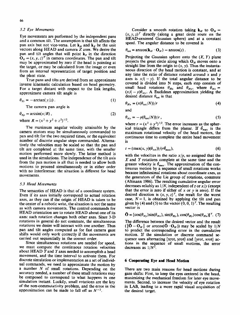
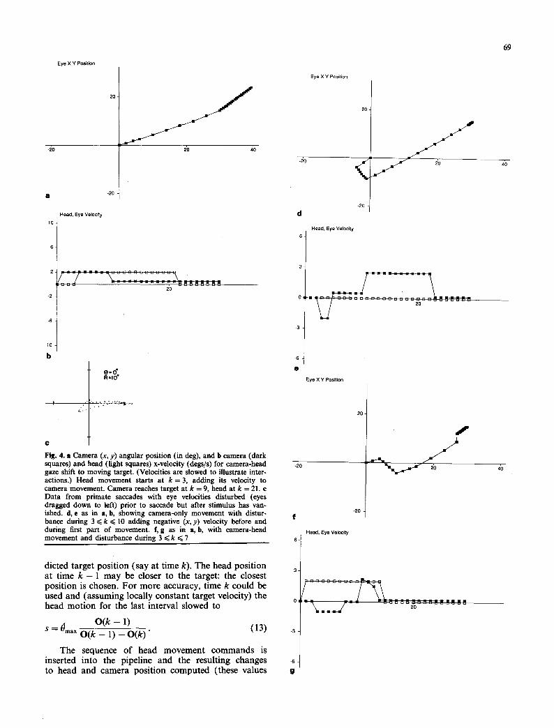
C Fig. 4. a Camera (x, y) angular position (in deg), and b camera (dark squares) and head (light squares) x-velocity (degs/s) for camera-bead gaze shift to moving target. (Velocities are slowed to illustrate inter- actions.) Head movement starts at k = 3, adding its velocity to camera movement. Camera reaches target at k = 9, head at k = 21. e Data from primate saccades with eye velocities disturbed (eyes dragged down to left) prior to saccade but after stimulus has van- ished, d, e as in a, b, showing camera-only movement with distur- bance during 3 <~ k ~< 10 adding negative (x, y) velocity before and during first part of movement, f, g as in a, b, with camera-bead movement and disturbance during 3 ~< k ~< 7
dieted target posi t ion (say at time k). The head posi t ion at t ime k - 1 may be closer to the target: the closest posi t ion is chosen. Fo r more accuracy, t ime k could be used and (assuming locally cons tan t target velocity) the head mo t ion for the last interval slowed to
O ( k - ] ) ( 1 3 ) $ -~- Omax O ( k - - 1) - - O ( k ) "
The sequence of head movemen t c o m m a n d s is inserted into the pipeline and the result ing changes to head and camera posi t ion computed (these values
Eye X Y Position
-i:~o
d -20
Head, Eye Velocity 6
e
Eye X Y Position
20.
-20 f
_ /
Head, Eye Velocity
i l i - I . . . . - . . . . . . " . . . . . . . .
g
4'0
40
70
overwrite existing values, as the fast gaze shift is taken to replace previous control). Then the camera move- ment is computed exactly like the head movement, except camera position is computed by adding the head-relative camera velocity to the head velocity.
So far, this version of fast gaze shift control is sampled, and in simple cases the solution obtained is the same as the optimal solution above. However the simulation solution copes uniformly with head and camera movement interactions, and handles arbitrary head or camera velocity profiles (velocity ramp-ups and ramp-downs, for instance) as well as arbitrary (pre- dictable) target motion. To cope with disturbances, and to implement successive ("catch up") movements, the simulation is placed in a loop that runs until the movement is successfully completed, checking if at any time a new calculation must be performed. In the simulation, a disturbance to the velocity or position of the cameras is taken to signal the need for a recalcula- tion. This gives the robustness of a continuous system only computed on demand. In a robotic implemen- tation, sensors like accelerometers are needed to detect any unexpected disturbance. Figure 4 shows some results from this control scheme. After reaching the target, the camera continues moving at the target's velocity, (due to tracking control or velocity matching by the camera gaze shift mechanism), and gaze stabi- lization compensates for any continuing head motion.
When macaque monkeys have their eye velocities electrically disturbed after the target stimulus has van- ished, they successfully correct the movement (Fig. 4c). The "recalculation" can sometimes be done during the latency period of the original saccade, so the correction does not delay saccade onset (Mays and Sparks 1981). One possible explanation is that the initial calculation simply sets spring constants in the eye muscles, so that the equilibrium position is the desired direction. Fixing these constants during the latency period would render the system robust against all disturbances at zero "com- putational cost". In the simulated system the computa- tional cost and control delay is unavoidable, but correction does occur (Fig. 4d-g).
7 Discussion
Prediction is one key to stability of interacting closed- loop multi-rate control systems with time delays, as are found in artificial and natural animate systems. This work demonstrates kinematic and stochastic models for prediction in a simulated system with multiple interact- ing gaze controls. Gaze control is one of several central capabilities needed by a behaving sensorimotor system to support higher-level activities. In non-reduced situa- tions, eye movements may resemble reflexes less than skills deployed for practical purposes. Control theory is evolving ever more sophisticated methods for incorpo- rating adaptive techniques leading to synthesis of opti- mal performance applicable to motor learning in general and hence gaze control (Bahill and McDonald 1981; Flasher et al. 1989). Gaze control skills lie somewhere
between purely reflexive (innate) and skilled (learned or practiced) behavior, and thus provide a promising domain for the investigation of control theory, al- gorithms and neural mechanisms underlying the acquisi- tion and performance of general sensorimotor skills.
Acknowledgements. This work is funded by the DARPA U.S. Army Engineering Topographic Laboratories Grant DACA76-85-C-0001 and the Air Force Systems Command (RADC, Griffiss AFB, NY) and Air Force OSR Contract F30602-85-C-0008, which supports the Northeast Artificial Intelligence Consortium. Thanks to Prof. J. Michael Brady, Dr. Hugh Durrant-Whyte, Dr. Ron Daniel, and the research and administrative staff of the Robotics Research Group in the Dept. of Engineering Sciences, Oxford University. The referees made several valuable suggestions.
References
Altmann SL (1986) Rotations, quaternions, and double groups. Clarendon Press, Oxford
Bahill AT, McDonald JD (1981) Adaptive control models for sac- cadic and smooth pursuit eye movements. In: Fuchs AF, Becker W (eds) Progress in oculomotor research. Elsevier, Amsterdam
Ballard D (1989) Animate vision. In: International Joint Conference on Artificial Intelligence 1989, pp 1635-1641
Ballard DH, Ozcandarli A (1988) Real-time kinetic depth. In: Second International Conference on Computer Vision, November 1988
Bar-Shalom Y, Fortmann TE (1988) Tracking and data association. Academic Press, New York
Brady JM (1988) Special issue on sensor data fusion. Int J Robot Res 7:1-205
Brooks RA (1986) A robust layered control system for a mobile robot. IEEE J Robot Automat RAo2:14-23
Brown CM (1988) The rochester robot. Technical Report 257, Uni- versity of Rochester, September 1988
Brown CM (1990) Gaze controls with interactions and delays. IEEE Trans Syst Man Cybern IEEE-TSMC20(2), March 1990
Brown CM, Rimey R (1988) Kinematics, coordinate systems and conversions for the rochester robot. Technical Report 255, Uni- versity of Rochester, September 1988
Connell JH (1987) Creature design with the subsumption architec- ture. In: Int Joint Conference on AI, 1124-1126, Milano, Italy
Doff RC (1986) Modern control systems. Addison Wesley, Reading, Mass
Flashner H, Beuter A, Boettger C (1989) Parameter optimization model of learning in stepping motion. Biol Cybern 60:277-284
Marshall JE (1979) Control of time-delay systems. Peregrinus, London Mays L, Sparks D (1981) The localization of saccade targets using a
combination of retinal and eye position information. In: Fuchs AF, Becker W (eds) Progress in oculomotor research. Elsevier, Amsterdam
McDonald JD, Bahill AT (1983) Zero-latency tracking of predictable targets by time-delay systems. Int J Control 38:881-893
Miles FA (1985) Adaptive regulation in the vergence and accommo- dation control systems. In: Berthoz A, Melvill Jones G (eds) Adaptive mechanisms in gaze control. Elsevier, Amsterdam
Morasso P, Bizzi E, Dichgans J (1973) Adjustment of saccade charac- teristics during head movements. Exp Brain Res 16:492-500
Olson T, Potter R (1989) Real-time vergence control. Proc. Comput Vision Pattern Recognition Conf. 1989:201-209
Robinson DA, Zee DS (1981) Theoretical considerations of the function and circuitry of various rapid eye movements. In: Fuchs AF, Becker W (eds) Progress in oculomotor research. Elsevier, Amsterdam
Smith OJM (1958) Feedback control systems. McGraw-Hill, New York
Dr. Christopher Brown Computer Science Department University of Rochester Rochester, NY 14627 USA