Controls on the emission of plant volatiles through stomata: A sensitivity analysis
Upload
senavirtualCategory
view
3download
0
Journal of Chromatography, 300 (1984) 127-162 Chromatographic Reviews Elsevier Science Publishers B.V., Amsterdam - Printed in The Netherlands
CHREV. 173
PRE-CONCENTRATION OF HEADSPACE VOLATILES FOR TRACE OR- GANIC ANALYSIS BY GAS CHROMATOGRAPHY
ALBERT0 J. NUAEZ* and LUIS F. GONZALEZ
National Centre For Scientific Research, Apdo. 6990, Havana City (Cuba)
and
JAROSLAV JANAK
Institute of Analytical Chemistry, Czechoslovak Academy of Sciences, Leninova 82, 611 42 Brno (Czecho- slovakia)
(Received July 5th, 1983)
CONTENTS
l.Introduction ...................................................................... ..12 7 2. Theoretical and practical aspects of headspace analysis ................................... 129
2.1.General ...................................................................... ..12 9 2.2. Theoretical principles of headspace gas chromatography .............................. 130
2.2.1. Static (equilibrium) headspace analysis ....................................... 130 2.2.2. Dyunamic (non-stationary) headspace analysis ................................ 133
2.3. Thechnical development of practical headspace analysis in trace organic analysis ........ 136 2.3.1. Sampling methods ......................................................... 136
(a)DirectsampIing ...................................................... ..13 6 (b) Indirect sampling ....................................................... 137 (c)Closedcircuit ........................................................ ..14 0
2.3.2. Desorption methods of headspace volatiles trapped on solid adsorbents .......... 142 (a)Liquiddesorption.. ................................................... ..14 2 (b) Thermal desorption ..................................................... 143
3. Solid adsorbents applied to the trapping of headspace volatiles ............................ 147 3.1. Activated carbon and graphitized sorbents .......................................... 147 3.2.Porouspolymers.. ............................................................. ..14 8
3.2.1. Porapakseries ............................................................. 151 3.2.2. Chromosorbseries ......................................................... 151 3.2.3. Tenax GC [poly- (2,6-diphenyl-p-phenylene oxide)] ............................ 152 3.2.4. Amberlite XAD resins ..................................................... 153 3.2.5. Other types of porous polymeric adsorbents .................................. 155
4.Conclusions.. ..................................................................... ..15 6 5.Summary ......................................................................... ..15 7
References ......................................................................... 157
1. INTRODUCTION
Solvent extraction’-5, steam distillation”8 or distillation under vacuumsL12 are
common methods of sample enrichment or pre-concentration of components to be ana-
lysed when they are present at such low concentrations that preliminary steps are re- quired. However, these traditional enrichment techniques suffer from inherent draw- backs, which are more pronounced in the trace organic analysis of volatile compounds.
0378-4355/84/$10.80 0 1984 Elsevier Science Publishers B.V.

128 A. J. NUNEZ, L. F. GONZALEZ, J. JANAK
When the concentrations of the analytes are too low, that is micrograms or nanograms per litre, these processes of pre-concentration may introduce uncertainty, not only in the complete quantitative isolation of the compounds but also in the qualitative analy- sis, as other substances in this concentration range can be present in the solvent or enter into the sample from the surroundings.
By analysing not the medium under study, but a phase in thermodynamic equi- librium with it, generally the gaseous phase, one can eliminate many drawbacks present in the usual methods of pre-concentration, although the sensitivity depends on several experimental parameters which must be well controlled. However, this arrangement is the best choice when non-fluidic or solid samples are to be analysed for the deter- mination of trace organic volatiles, where the nature of the matrix impedes direct in- jection into the gas chromatograph. This principle can be applied to the determination of trace organic volatiles in the gaseous phase above the matrix sample and has been called “headspace analysis” (HSA).
The advantages of HSA compared with the conventional manipulation of sam- ples requiring extensive preliminary procedures result from the fact that no overloading or contamination of the chromatographic column with water and high-boiling com- pounds or non-volatile materials occurs. The choice of an adequate pre-concentration procedure depends on various factors, the most important being the analytical effect of the matrix on the results of the gas chromatographic analysis and the concentration of the analytes to be detected in the original sample, that is, if they are in present sufficient amount to be detected in the concentrate obtained, according to the chro- matographic system employed.
Gas chromatography (GC) is a sensitive technique, but it may be inadequate when the direct analysis of trace organics is desired. Some detection systems, overall specific detectors such as flame photometric detectors or mass spectrometers, have re- duced the detection limit (see Table l), but in many instances it is necessary to employ special techniques of sample enrichment of the components to be analysed. Many re- views covering this aspect of trace organic analysis have compared different techniques of sample enrichment 13-15, but special emphasis has not been placed on headspace tech- niques until recent years’““.
TABLE 1
DETECTION LIMITS OF SOME DETECTORS EMPLOYED IN GAS CHROMATOGRAPHY AND
RELATED TECHNIQUES
Detection system Type* Detection limit
Thermal conductivity detector (TCD) Rame photometric detector (FPD) in sulphur mode GC-MS with total ion monitoring (TIM) Flame-ionization detector (FID) Flame photometric detector (FPD) in phosphorus mode Nitrogen-phosphorus selective detector (NPD) in nitrogen mode GC-MS with selected ion monitoring (SIM) Nitrogen-phosphorus selective detector (NPD) in phosphorus mode Electron-capture detector (ECD)
50 ng/ml 1 ngkec 1 ngkec 10 pg/sec 10 pg/sec 1 pgkec 1 pg/sec 0.1 pgkec 0.1 pgkec
l C = Concentration-sensitive detector: M = mass-sensitive detector.

PRE-CONCENTRATION OF HEADSPACE VOLATILES 129
Several technical procedures for the trace organic analysis of headspace volatiles have been developed with two variants, either by direct injection of the vapour sample in equilibrium with the original sample into the gas chromatograph or by injection of a concentrate obtained from the original sample by gas extraction. The common pres- ence of large amounts of water in headspace samples and the higher detection limit of direct injection methods make this sampling procedure generally inapplicable to trace organic analysis, although in some instances detection limits of the order of 0.1-10 &l have been reported20321. Direct injection procedures are also unsuitable for constituents of mixtures with low vapour pressures.
Many pre-concentration methods for headspace volatiles have been explored in order to trap the analytes in a suitable medium with subsequent elution and injection into the gas chromatograph, eliminating the disadvantages of direct injection. Cold traps, freezing of the concentrate in an empty tube or directly in an open-tubular col- umn, chemisorption approaches, in which the analytes react towards a suitable sensitive medium, and physical sorption of the analytes on activated carbon, carbonaceous ma- terials, molecular sieves and porous polymers have demonstrated their advantages in the trace organic analysis of headspace volatiles and are the most promising.
The physico-chemical basis of these procedures, their advantages and limitations and their potential as analytical tools in trace organic analysis must be well understood by everyone working in this field and, therefore, thorough discussions are presented here on the theoretical principles, practical procedures and historical development of the technique.
2. THEORETICAL AND PRACTICAL ASPECTS OF HEADSPACE ANALYSIS
2.1. General
The techniques of gas chromatographic headspace analysis, according to the me- thod of extraction of volatiles, can be divided into three groups:
(a) The sample for chromatographic analysis is taken from a closed vessel where the material under study comes into equilibrium with its vapour at a pre-determinated temperature. This “static” headspace analysis requires rigid control of the sample tem- perature, sample withdrawal and other parameters22-24. The concentrations of the ana- lytes in the phases do not change with time after the system has reached equilibrium. However, this state of equilibrium is disturbed temporarily upon sampling. Therefore, the method of withdrawal and the volume of the sample must be carefully chosen.
(b) The sample is taken from the gaseous effluent stripped “through” the ma- terial under study. Generally, this gaseous effluent is passed through a suitable trapping medium, inert to the stripping gas, where the volatiles are trapped and subsequently eluted, thermally or with a solvent, into the gas chromatograph. This strip-trap or pur- ge technique can be applied in two ways: in an open system, where the stripping gas passes through the sample and the trap, and is vented to the atmosphere, or in a closed circuit, where the gaseous phase is recycled through the sample and the trap. The latter procedure has two variants depending on whether the process is performed until the least sorbed component in the trap does not break through (conservation procedure) or the most sorbed component in the trap comes into equilibrium with the gaseous phase (equilibration procedure)25. The concentration of the analytes in open systems

130 A. J. NljhEZ, L. F. GONZALEZ, J. JANAK
decreases continuously with time in both phases and approaches zero asymptotically. The deviation from equilibrium is more or less pronounced, although it may be assumed that even under these non-stationary conditions the gas in the bubbles leaving the con- densed phase is practically equilibrated with the latter.
(c) The sample is taken from the gaseous effluent passed “over” the material under study. This “dynamic” HSA is similar to the strip-trap procedure, but the equi- librium between the condensed and gaseous phases depends on the flow of the stripping gas and may not be well attained. The surface contact is smaller compared than in the strip-trap-through method and either it may take longer time for the analysis or the concentrate obtained may have not contain sufficient amounts of the analytes to be detected. However, the technique is suitable for the HSA on solids, which cannot be solubilized26,27, or for samples that produce considerable foaming, especially biological fluids2s,29.
Numerous procedures of HSA by gas chromatography have been reported, in- cluding automated sampling procedures30,31, multiple headspace extractions3z-36, and ancillary devices 37-41 which make this technique more sophisticated.
2.2. Theoretical principles of headspace gas chromatography
2.2.1. Static (equilibrium) headspace analysis The samples to be analysed by static headspace techniques can be homogeneous
liquid solutions, homogeneous solid solutions or non-homogeneous materials, either fluidic or non-fluidic. When the sample is a homogeneous liquid solution with two or more components it is convenient to define the distribution constant of the analytes, taking into account either the variables of state of the system or the mass balance of the analytes between the condensed and gaseous phases.
The thermodynamic expression for the distribution constant (KY) can be derived from the expression of the Henry’s law (Pyi = kr+rJ as:
K; = $ql I
(1)
where Xi and yi are the molar fractions of the analyte i distributed between the con- densed and gaseous phases, respectively, at overall pressure P. The distribution con- stant defined in this manner (KY) is the inverse of the Henry’s law constant (kn).
Considering the non-ideality of the system, it is necessary to know the variations of the above terms, taking into account the activity (n) and fugacity (vi) coefficients for the analyte i in the system at a given temperature T and overall pressure P (ref. 42):
where (vi)p is the fugacity coefficient of the analyte i in the headspace gas at pressure P, (u~jpplis the fugacity coefficient of pure substance i at its saturation vapour pressure
pp, (J$‘)~ is the saturation vapour pressure of substance i at the overall external pressure

PRE-CONCENTRATION OF HEADSPACE VOLATILES 131
P and -yi is the Raoult-law activity coefficient of analyte i. By combining eqns. 1 and 2 we obtain
For the quantity (py)p it holds43:
where pp is the saturation vapour pressure of analyte i at its own pressure, V” is the molar volume of pure liquid substance i and R is the ideal gas constant. Substituting eqn. 3 in eqn. 2a we obtain
K; _ (“i)p . exp[ -L( Vk/RT)dP]
(v&J Y&c (4)
Eqn. 4 provides an exact interpretation of the equilibrium distribution between the considered phases in terms of the thermodynamic properties of the system.
The distribution constant (Ki), defined in terms of the equilibrium mass/volume concentrations in the condensed and gaseous phases, can be expressed asr9
where CiL and Cio are the concentration of analyte i, WtL and wio are the masses of analyte i, and VL and VG are the volumes of the condensed and gaseous phases in the system, respectively. Eqn. 5 can be written by employing known thermodynamic defi- nitions and neglecting the non-ideality of the gaseous phase and the compressibility of the condensed phase effects as
RTdL Ki= -
Y&ML
where dL and ML are the density and the molar mass of the condensed phase, respec- tively.
The distribution constant is not invariant with changes in temperature (Z’), ex- ternal pressure (P) and the composition of the system. The dependence of the distri- bution constant with T, P and xi can be defined in differential form as

132 A. J. Not&Z, L. F. GONZALEZ, J. JANAK
where each partial differential can be defined following well established physico-chem- ical principles44, neglecting the effects of thermal expansion and compressibility of the condensed phase:
AH:-- A HF =
RT’ (7)
where AH; is the molar enthalpy of vaporization of pure substance i,A@ is the partial molar excess enthalpy of analyte i and T is the absolute temperature of the system
where L$ is the partial molar volume of analyte i in the condensed phase,
=- (9)
where 21, it4j and xj are the partial molar density, molar mass and molar fraction of the analyte j affecting the value of the distribution constant.
The HSA of a defined system at constant temperature, pressure and molar com- position thus leads to the determination of the concentration of the analyte i in the condensed phase, knowing the distribution constant and the concentration of analyte i in the gaseous phase. Commonly, to avoid the determination of the distribution con- stants, model reference systems are examined, which are prepared with exact amounts of the solutes to be analysed. The applicability of this procedure is limited to systems with very simple condensed matrices and, unfortunately, very often it is impossible to simulate the composition of the matrix.
Other approaches, which include “continuous”3S34 or “repetitive”35y36 gas ex- tractions of the headspace samples, have been achieved successfully, where the head- space volatiles would be almost completely removed from the sample and the sum of the weights of the analyte i in the gaseous phase (Wio) determined in the individual extracts will be approximately equal to the total amount of the analyte i in the original sample (Wi). These procedures give good results overall when solid samples are to be analysed . 36q45 However the standard additions method has proved to be the best choice when the distribution constant is unknown or it is impossible to prepare model refer- ence systems16J3*24. The procedure is based on the assumption that the addition of a small amount of an analyte that is already present in the system will not alter signifi- cantly the thermodynamic properties of the phases, which means that the value of Ki before and after the addition of the standard will be practically the same. The value of Wi can be calculated from the gas phase concentrations of the analyte in the original and enriched systems, provided both determinations have been performed under the same conditions.
The static or equilibrium headspace technique fails when trace components or components with very low vapour pressures are analysed. In these instances, the con-

PRE-CONCENTRATION OF HEADSPACE VOLATILES 133
centration of the analytes in the gaseous phase can be increased by: (a) raising the temperature, which increases the saturated vapour pressure (@‘) of the pure trace com- ponent. This increase in the temperature of the system can be effected in such a way that the value of Ki might be approximately zero and thus it is not necessary to know it; (b) increasing the value of the activity coefficients by adding an electrolyte or a non- electrolyte (“salting-out” effect). Other ways, e.g., variation of the pH of the solution, could increase the values of these coefficients.
2.2.2. Dynamic (non-stationary) headspace analysis In spite of the advantages of static HSA, several drawbacks limit its application
to trace organic analysis: (a) Solutes with very low concentrations cannot be detected owing to the sen-
sitivity of the detection system employed. Also, solutes with low vapour pressures can- not be detected if their concentrations in the gaseous phase are below the detection limit.
(b) Complex mixtures of volatiles, e.g., flavours, need to be analysed with high- resolution capillary columns, which have a low sample capacity and the sample volume injected into the GC column must be small or split, which affects the detection limit. Although the sample capacity can be increased, e.g., with SCOT columns, or the in- jection system adapted for analysis with capillary columns, e.g., using splitless or on- column procedures, not much work has been performed on the trace analysis of head- space extracts and this drawback still remains to some extent.
For these rsasons, dynamic procedures for the pre-concentration of headspace volatiles before the GC analysis have been developed in recent years. These procedures can be performed by trapping the volatiles, extracted from above the sample or through the sample with a stripping gas, on a suitable medium, e.g., cold traps, solid adsorbents or solid supports coated with a liquid stationary phase or a specific reactant towards a given class or classes of compounds. In this way, the trace components can be enriched to reach the detection limit of the chromatographic system employed in the analysis.
The physico-chemical principles of adsorption, either physical or chemical, must be applied when these procedures are going to be performed. Nevertheless, physical sorption on to polymeric or natural sorbents is the most commonly used procedure for trapping headspace volatiles, covering many of applications in air and water pollution analysis4650, biological fluidsz2,“, flavours in foods and beverages”2-56, determination of residues in polymers32,36,57, etc., and thus the physical adsorption phenomena must be emphasized. The concentration mechanisms in gas-liquid systems have been exten- sively studied by Novak and co-workersssYs9 and in gas-solid systems by Kolb and co- worker8’.
A tube packed with a solid sorbent for trapping headspace volatiles can be con- sidered as a chromatographic column operated with a constant concentration mixture, to a first approximation. When the volume of inert gas passed through the column becomes equal to the retention volume of the analyte i at temperature T, it breaks through and elutes from the column. In the first instance, a knowledge of these breakth- rough volumes for each analyte is necessary in order to establish when the complete trapping of the analytes within the trap tube has occurred. The value of the break- through volume depends on different parameters: (a) the form and size of the trap tube; (b) the porosity, specific surface area, amount used and inertness toward the analytes

134 A. J. NtifiEZ, L. F. GONZALEZ, J. JANAK
of the adsorbent; (c) the flow-rate of the stripping inert gas, connected with its purity and temperature; and (d) the original concentration and chemical structure of the analytes in the sample and the complexity of the mixture.
The maximum sample volume (V’) that can be passed through the trap tube without breakthrough is 60a*60bV61
v = vn (1 - 2/tij (10)
where N is the number of theoretical plates of the trap tube and Vn is the retention volume of the analyte i. Therefore, the determination of retention volumes in a chro- matographic column packed with the sorbent, which will be used as a trapping medium, must be carried out in order to determine the breakthrough volumes on the trap tube.
Many reports have been published on the determination of breakthrough volu- mes using different solid adsorbents. Bertsch et al. 62 determined the breakthrough vo- lumes for various organic volatiles in water using Tenax GC as the trapping medium, to establish the extent to which the method would become quantitative, and found that the rate of stripping, temperature, particle size of the adsorbent, length of the trap tube and sample size play significant roles in the retention of a given substance on Tenax GC. More recently, Kawata et ~1.~~ determined the breakthrough volumes for 90 com- pounds dissolved in water on Tenax GC (60-80 mesh), which they grouped into eleven classes according to their chemical structure, and in many groups the logarithm of the breakthrough volume showed good linear correlations with the boiling points, mole- cular weights and carbon numbers, indicating the possibility of using these correlations for determining the breakthrough volumes of other compounds having similar struc- tures. Murray64 compared the breakthrough volumes of some aqueous volatiles on Chromosorb 102, 105 and 106 and Tenax GC using two trap tubes in series. Tenax GC had low breakthrough volumes for some compounds of medium volatility and, there- fore, they passed from the first to the second trap and were not quantitatively recov- ered, while either Chromosorb 105 or 106 showed no breakthrough with the same kind of compounds. Similar studies with other polymeric adsorbents, in order to de- termine their retention behaviour, have been performed on Porapak series65, Chro- mosorb series55 and Tenax GC”.
The rate of stripping, expressed as the change of the mass of the analyte i in the time (dW,ldf) can be expressed as l9
dW. I= wi.
F
dt VG + KiVL (11)
where F is the volumetric flow-rate of the stripping inert gas, Wi is the instantaneous total mass of the analyte i in the system, and VG and V,_ are the volumes of gaseous and condensed phases, respectively.
Integrating eqn. 11 for t=O and Wi=K as initial conditions and calculating the time necesary to strip out of the system 95% of the analyte, we obtain
T 0.05 = g (VG + KY3 (12)

PRE-CONCENTRATION OF HEADSPACE VOLATILES 135
The capacity factor, k’, (mass of the analyte sorbed on to the adsorbent divided by the mass of solute present in the void volume of the trap tube) of the traps should be measured to adjust the ratios between the adsorbent and the sample for the maximal adsorption of the solute of interest@.
Krost et al.” have discussed the influence of adsorbent packing diameter, trap length, sampling rate and particle mesh range of the adsorbent on the collection of volatiles on Tenax GC. They calculated the pressure drop (AP) curves for each mesh size allowing for selecting the practical attainable flow-rate for each mesh size and trap packing dimensions (see Fig. 1). The data obtained indicate that trap tube diameters of 0.5 cm and a mesh range above 35-70 should be avoided, as they require high flow- rates and hence high pressure drops occur.
NUMBERS Flow rotefmllm~nl
670
.WO
18
15
\
9
1 0.5 1.0
I I
12
4 9
\
5
\
I b 0.5 10
I I /
1.5
I t
05 1.0 5
TRAP-TUBE l.D.(cml
Fig. 1. Effect of particle mesh range on pressure differential and relationship to’trap tube diameter. Trap tube length 6 cm. (A) BPL carbon (12-30 mesh); (B) Tenax GC (35-60 mesh); (C) Tenax GC (60-80 mesh). (From ref. 27.)
A suitable choice of the adsorbent, depending on the objectives of the analysis and the characteristics of the sample under study, is essential for a successful result. Generally, before the analysis proper, the evaluation of several types of adsorbents using model systems as references is recommended50y67. Nevertheless, no adsorbent has universal properties considered satisfactory for all analytical purposes, which led us to consider each one separately in Section 3, discussing their physical and chemical prop- erties for use as trapping media for the collection of headspace volatiles.
Each procedure for the analysis of headspace volatiles, either static or dynamic, has its own characteristics and fields of application. Whenever the concentrations of the analytes in the headspace gas are sufficient and the amount of water in the sample is very low, static HSA is the best choice for the characterization of a system. Dynamic

136 A. J. NfJjlllEZ, L. F. GONidLEZ, J. JANAK
and strip-trap procedures include not only the determination of volatiles that can be analysed by the static procedure, but also other analytes of lower volatility or concen- tration. The necessity for sample enrichment for the trace organic analysis of headspace volatiles by gas chromatography makes the dynamic and strip-trap procedures the best choices for the high-resolution glass capillary headspace gas chromatographic analysis of trace volatiles.
2.3. Technical development of practical headspace analysis in trace organic analysis
2.3.1. Sampling methods Determination of trace organic volatiles in vapours requires a representative
sample to be obtained by means of a well defined procedure. The sampling procedure must be reproducible and give an enrichment factor that permits the detection limit of the gas chromatographic system to be reached.
The importance of sampling errors in trace organic analysis lies in its significance for research into improved analytical methods. The overall precision of the methods used is more a function of the concentration of analytes than of the method of analysisa, and thus obtaining a representative sample is essential for the efficient performance of the whole procedure of sampling and GC analysis. The high chemical reactivity of sev- eral types of trace components implies that chemical composition at trace levels is not static, but rather dynamic. Unstable trace compounds can decompose, polymerize, etc., or interact with other compounds in sample handling, which will falsify the results sys- tematically. KaiseF9 discussed the sources of these systematic errors in trace analysis and divided them into six groups:
(1) Sample source: homogeneity of the source, sample flow-rate, time and du- ration of sample extraction.
(2) Sample handling: method of sample withdrawal, sample drawing duct, size of the vessel, temperature and pressure of intermediate systems, temperature, pressure and duration of storage, walls of the vessel.
(3) Sample preparation: chemical reactions (in chemisorptive approaches), en- richment, non-representative secondary sampling out of the sample vessel.
(4) Separation process: incomplete desorption, undesirable chemisorption, in- complete separation (overlapping), incomplete elution from the connecting ducts.
(5) Detection: non-linearity in the trace range, interference by a third substance during separation, wrong calibration, inadmissible extrapolation of the dynamic range.
(6) Evaluation: wrong assumptions regarding qualitative and quantitative sepa- ration and detection (systematic calibration error), calculation errors (less frequent).
The effect of these sources of errors will increase with increasing reactivity and decreasing concentration of the traces compounds.
In several methods of sampling it is necessary to calculate the distribution con- stant of the analytes from gas chromatographic data prior to sampling7’ if the procedure is to be performed until equilibrium has been reached. The theoretical implications of the sampling procedure have been extensively studied by many workers33,58,71-74 and thus a survey of practical arrangements for sampling methods is presented below.
(a) Direct sampling. The use of normal or modified syringes for direct sampling of the headspace volatiles is always associated with the static or equilibrium method, although some apparatus has been designed for specific applications where syringe is

PRE-CONCENTRATION OF HEADSPACE VOLATILES 137
needed and direct connection between the headspace vessel and the chromatographic column is used.
By taking some precautions, it is possible to perform reproducible analyses with the use of syringes: (a) the syringe must be at a higher temperature than the sample and be grease-free; (b) the back-pressure in the GC injection port should be lower than the pressure of the gas sample; (c) the syringe must be carefully cleaned after each injection by vacuum or high temperature.
Nevertheless, the quantitative results obtained are often unsatisfactory and this method is commonly employed for empirical or preliminary experiments. The use of gas-tight syringes with good quantitative results 23 has been reported. Grob and Renn- bards” reported recently some aspects of the evaluation of syringe handling techniques which should be taken into account.
Direct sampling systems with syringes have been designed to avoid errors due to pressure differences, either by equilibrating the pressures between the sample and the GC injector76, reducing the pressure in the whole sampling system77 or increasing the pressure in the headspace sample 7s81 Thd latter procedure has been completely . automated82 where the amount of headspace gas taken from the samples is always the same, eliminating errors of manual handling. The arrangement, shown schematically in Fig. 2, has three essential steps, as follows. (I) The samples are placed in glass vials (1) closed with a PTFE- or aluminium-lined septum and thermostated to the desired temperature, mounted on a cylindrical magazine in front of the injection system for headspace sampling. (II) Each glass vial is raised to the sampling needle (2), mounted on a movable cylinder (3), and punctures the septum while the solenoid valve (4) is open, passing a flow of carrier gas into the glass vial until the pressure within it equals that at the head of the column. (III) The solenoid valve is closed for a few seconds and the volatiles are expanded through the needle and transferred into the GC column (5) and detector (6).
Direct sampling procedures have recently contributed to great developments in high-resolution glass capillary gas chromatography with the improvement of splitless samplinggM8 and on-column sampling8’91 in open-tubular columns, which increase the sensitivity of GC techniques for trace organic analysis. However, their major use has been achieved with liquid samples and the necessity for prior enrichment steps for pre- concentration of headspace volatiles in trace organic analysis is still present. Some workers22,30 have obtained good results in qualitative analysis with headspace sampling on open-tubular columns without any additional pre-concentration step, depending on the detection limit to be reached.
(b) Indirect sampling. In this sampling method a known volume of gaseous ef- fluent is removed from the sample using a syringe or a flow of stripping inert gas and passed through a trapping medium where the headspace volatiles are enriched and sub- sequently injected into the gas chromatograph.
The general procedure of indirect sampling by means of a syringe is illustrated in Fig. 3. A defined volume of headspace gas is taken from the thermostated sample by means of a gas-tight syringe and the organic volatiles are then trapped on a cryogenic trap (or solid adsorbent trap). The trapped volatiles are eluted into the GC column by rapid heating of the trap at a suitable temperature or with a temperature programme. The small volumes of gas-tight syringes, even of 100 ml, do not permit a great enrich- ment of trace organics and therefore the method is seldom used in this field.

138 A. J. NtifiEZ, L. F. GONZALEZ, J. JANAK
Fig. 2. Schematic representation of automated direct sampling for headspace analysis by increasing the pres- sure in the headspace sample. I, Normal position; II, pressurization; III, sampling. 1, Glass vial; 2, sampling needle; 3, movable cylinder; 4, solenoid valve; 5, GC column; 6, GC detector. (From ref. 36.)
THERMOSTAT
Fig. 3. Diagram of indirect sampling procedure by means of a gas-tight syringe from the headspace volume using a cryogenic trap (or trap tube) for enrichment of organic volatiles. (From H. Hachenberg and A. P.
Schmidt, Gas Chromatographic Headspace Analysis, Heyden, London, 1917, p. 24.)

PRE-CONCENTRATION OF HEADSPACE VOLATILES 139
The second approach involves the use of a stripping inert gas passed through or over the sample, and is commonly used for trace organic analysis owing to its high enrichment factors. Two types of stripping apparatus are shown in Fig. 4 (where the stripping inert gas is passed through the sample) and Fig. 5 (where the stripping inert gas is passed over the sample).
t t
6
PURGE GAS
/
FUiGE GAS- 5
Fig. 4. Stripping apparatus for trapping headspace volatiles on solid adsorbents. 1, Sampler body; 2, condenser; 3. 4. trap tubes; 5, tube holder; 6, glass frit; 7, reducer. (From ref. 62.)
Fig. 5. Dynamic headspace gas stripping apparatus for trapping headspace volatiles on solid adsorbents. I. Trap tuhc. 2. PTFE muon; 3. rcduccr; 4, sampler (IOO-ml round-bottomed flask); 5, magnetic stirring bar; 6. thermometer: 7. thermometer adapter. (From ref. 26.).
The sampling arrangement used by Bertsch et aLe2 (Fig. 4) was applied to the trace organic analysis of volatiles in water. The sampler body (1) was made by joining 70 mm O.D. glass tubing of length 30-75 cm to a 150-ml fritted-glass btichner funnel which can accommodate a sample of 1.5-2 1. A condenser (2) was inserted between the sampler body and the trap tubes (3 and 4) to avoid the passage of water into them. The purge gases (helium or nitrogen), purified with cryogenic traps, were bubbled at flow-rates of 4S-80 ml/min, measured with a soap flow meter directly at the sampling tubes. By using a two-, three- or more-way tube holder (5) one can connect several traps containing the same or different solid adsorbents in order to perform comparisons of retention behaviour on materials used as trapping media.

140 A. J. NtifiEZ, L. F. GONZALEZ, J. JANAK
Depending on the sample being analysed, foaming phenomena often occur, which can lead to contamination of the trap-tubes. Some anti-foaming agents have been proposed28,29 but the introduction of additional compounds into the sample, although non-volatiles, alters the thermodynamic properties of the system.
Michael et al.26 used a dynamic gas-stripping apparatus (Fig. 5) for the deter- mination of volatile environmental pollutants in biological matrices such as blood and urine. As the samples produce considerable foaming on stripping through with gas, they sampled the volatiles by stripping over the matrices with gas. Although the liquid-gas interfacial area is significantly smaller with this procedure and hence the efficiency of pre-concentration is diminished, several parameters (temperature, stirring, flow-rate of the stripping gas, etc.) can be adjusted to optimize the sampling procedure in order to attain equilibrium between the condensed and gaseous phases and to avoid foaming.
For indirect sampling procedures more preparatory work is needed, each run of sample analysis is too time consuming and more parameters than in other procedures must be well controlled. However, these methods have been widely used in the trace organic analysis of headspace volatiles owing to their high efficiency, which permit the detection of very small amounts of organics, not possible with any other method today.
(c) Closed circuit. The strip-trap method in a closed circuit for sampling head- space volatiles, described originally by Grob and co-workers74,92-94, has received con- siderable attention in recent reports 25*47*67,95-99,99a. In this method the gaseous phase of a gas-liquid or gas-solid system is recycled through the sample and a trap tube with a solid adsorbent, by means of a pump, and the trapped analytes are subsequent analy- sed by gas chromatography.
Nawar and Fagersonioo reported earlier a circulation methpd, but the entrapping of volatiles was performed using a cold trap, which is disadvantageous. Vitenberg et aL6’ also reported a closed system for the determination of atmospheric pollutants using a liquid stationary phase impregnated on the walls of a glass tube as trapping medium.
Grob and co-workers’ method can be performed in two ways: conservation trap- ping or equilibrium trapping. In the former, the volume of gas pumped is such that it does not cause the frontal zone of the least sorbed analyte to leave the trap. In the latter, the volume pumped is large enough (several multiples of the retention volume of the most sorbed analyte in the trap tube) to bring the whole system into equilibrium. Thus, the amounts of volatiles trapped with this method depend on the procedure used.
Novak et al.25 have related the amount of analyte i accumulated in the trap (W,) with the initial amount of the analyte i in the system (Wi) for both methods, conser- vation and equilibrium, which is necessary for quantitative analysis:
Ft ’
VG + )I KLGVL
Eqn. 13 is valid for both open and closed systems, and describes the mass balance of the stripping and trapping process under non-steady-state conditions.
wit = K [(vG~~~sJ(& + +$f + ‘)I-’ (14)

PRE-CONCENTRATION OF HEADSPACE VOLATILES 141
Eqn. 14, where VG, is the void volume of the trap tube, Vs is the volume of sorbent in the trap tube and Kso is the distribution constant, that is, the ratio of equi- librium concentrations of the analyte in the sorbent and in the stripping gas at the temperature of the trap tube, is valid only for the closed circuit, where alone the equi- librium can be obtained. With appropriate choice of the solid adsorbent, the method gives a high selectivity of analysis, especially when it is performed in the equilibrium mode.
Grob et al.92 compared the method with solvent extraction and found that: (a) the detection limit with the strip-trap method in a closed circuit is ten times lower for more volatile substances, whereas solvent extraction is more sensitive for heavy ma- terials, (b) the quantitative reproducibility is better in a closed circuit as it can be stan- dardized to a higher degree than solvent extraction, (c) there was no essential difference between the methods in sensitivity depending on the polarity of the analyte.
The standard addition method for quantitation of headspace volatiles in a closed circuit has been studied25,95 and with appropriate choice of the experimental conditions it gives fairly reliable results. More recently, Drozd and Novak96 have introduced the principle of quantitation with the double-sampling method”’ combined with the closed circuit for the determination of trace hydrophobic volatiles in aqueous media. The pro- cedure was performed by connecting successively two trap tubes filled with Tenax GC to a home-made equipment, shown schematically in Fig. 6, and then the peak areas were measured for the first (Aio) and second (Air) runs. If equal volumes of the head- space gas are sampled and analysed under constant conditions, the ratio &/Al0 is equal to the ratio WiG1IWim, where Wi, and WiGl are the masses of the analyte i in the gaseous phase of the closed system in the first and second runs, respectively. The fol-
Fig. 6. Diagram of the closed system for stripping and trapping headspace volatiles on solid adsorbents. 1, Stainless-steel bellows pump; 2, motor; 3, drop-ball valve; 4, sampler; 5, trap tube; 6,8, connection details; 7, silicone rubber or PTFE ring; 9, quartz-wool plug; 10, sample or standard inlet. (From ref. 96.)

142 A. J. NtifiEZ, L. F. GONZALEZ, J. JANAK
lowing equation holds for the determination of the total initial mass of analyte i in the system (WJ:
where fl is the calibration factor for the analyte i. The errors of the method were related to the competitive adsorption of higher
hydrocarbons (for benzene) and with the irreversible adsorption (for n-dodecane), al- though mutual interference of the analytes as a source of error was not discarded. Di- rect analysis of headspace samples in the model reference systems employed gave no results owing to the low concentrations of the analytes.
The home-made arrangement of the closed circuit used by Drozd and Novak (Fig. 6) has a drop-ball valve/stainless-steel bellows pomp (1) actuated with a cam driven by a motor (2) as the main component. The liquid sample is placed in a lOO-ml glass vessel (4) provided with a sintered-glass frit at the bottom. The gaseous phase is recycled by the valve (3), vessel (4) and the traptube (5) filled with Tenax GC (30-60 mesh). Compared with other arrangements for working in a closed circuit, this equip- ment does not use a membrane or peristaltic pump, where the connecting lines and internal parts have a higher surface area in contact with the gaseous sample and more possibilities to have smaller systematic errors are present. Nevertheless, the equipment is limited to small samples connected with the capacity of the drop-ball valve/stainless- steel bellows pump.
McGuire er alsw have reported the use of the closed circuit for solving taste and odour problems in drinking waters by stripping-trapping of headspace volatiles. Westendo@ has described an automated device that has been developed for concen- trating trace organics in a closed circuit (Tekmar CLS-l), but its applicability has not yet been well demonstrated.
2.3.2. Desorption methods of headspace volatiles trapped on solid adsorbents Methods and devices for the desorption of headspace volatiles trapped on solid
adsorbents in trap tubes and subsequent injection into the gas chromatograph include liquid desorption and thermal desorption.
(a) Liquid desorption. Liquid desorption procedures are performed with small volumes of organic solvents where the partition coefficients are shifted in favour of the eluent. Commonly methanolun, isopropanol’03, acetonelw and different types of low- molecular-weight ketones”’ are used as eluents. A knowledge of adsorption principles from liquid-solid chromatography must be applied, as well as the application of the system of eluotropic series for the selection of a suitable organic solvent for the elution of trapped volatiles.
The methods of carbon-chloroform-extract1w and carbon-disulphide-extract*m are well known because of their wide application since the beginning of trapping tech- niques for volatiles and injection into the gas chromatograph.
The direct trace analysis of an organic aliquot is not possible in all instances and it is often necessary to evaporate part of the solvent in order to enrich the analytes by a suitable factor. This enrichment by means of evaporation has the following draw- backs:
PFWCONCENTRATION OF HEADSPACE VOLATILES 143
(a) The introduction of artifacts into eluted samples from sources such as solvent, glassware and storage vials, which can produce significant contamination in the solvent extract and lead to erroneous conclusions regarding sample composition. Therefore, solvents of extremely high purity with no complex blanks must be employed and the glassware used must be decontaminated before the experimental work.
(b) The solvent peak in the chromatogram of the eluted extract can produce masking of the volatiles, which does not permit either qualitative or quantitative de- terminations.
(c) The method is time consuming with uncertain efficiency when the solvent is evaporated, owing to losses of volatiles. Also, the sample handling must be carried out carefully.
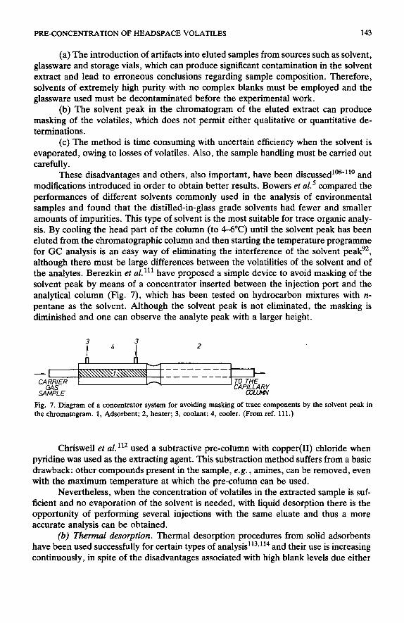
These disadvantages and others, also important, have been discussed’oS”O and modifications introduced in order to obtain better results. Bowers et al.’ compared the performances of different solvents commonly used in the analysis of environmental samples and found that the distilled-in-glass grade solvents had fewer and smaller amounts of impurities. This type of solvent is the most suitable for trace organic analy- sis. By cooling the head part of the column (to 44°C) until the solvent peak has been eluted from the chromatographic column and then starting the temperature programme for GC analysis is an easy way of eliminating the interference of the solvent peak9*, although there must be large differences between the volatilities of the solvent and of the analytes. Berezkin et al. ‘I1 have proposed a simple device to avoid masking of the solvent peak by means of a concentrator inserted between the injection port and the analytical column (Fig. 7), which has been tested on hydrocarbon mixtures with it- pentane as the solvent. Although the solvent peak is not eliminated, the masking is diminished and one can observe the analyte peak with a larger height.
Fig. 7. Diagram of a concentrator system for avoiding masking of trace components by the solvent peak in the

144 A. J. NirI%Z, L. F. GONZALEZ, J. JANAK
to thermal decomposition or to solvent or impurities procedure.
A schematic diagram of the general thermal procedure commonly used with trace organics is shown in Fig. 8. The valve, lines and trap tube should be heated to an elevated temperature, whose value is a to avoid condensation of volatiles in the circuit and back-flushing
5
Fig. 8. Schematic diagram of general thermal desorption procedure for injection of volatiles trapped on solid adsorbents into the gas chromatograph. 1, Inert gas recipient; 2, filter-trap; 3, Bow controller; 4,4-way valve; 5, stainless-steel tubing; 6, heating jacket for inert gas; 7, trap tube; 8, movable heatcontrolled oven; 9, carrier gas line; 10, GC injector; 11, GC column; 12, GC oven; 13, GC detector.
In simple approaches to thermal desorption techniques, the trap tube has been inserted before the GC column in many ways. In some reportsi” the oxygen is purged with a suitable flow of carrier gas and then the injector is quickly heated to the desired temperature. Owing to slow heat transfer from the injector to the trap tube, sometimes it is necessary to use a short column packed with sorbent between the injector and the GC column62~1’6, or a cold trap117 or the cooled head of the capillary column, if one is used”8,119.
Thermal desorption devices situated before the GC injector or designed specially for injection of analytes in trap tubes include the rapid heating of the trap tube sometimes in a few milliseconds) from room or low temperature to an elevated temperature (206300°C). Resistively heated wire and tape120, ovens which slide along the trap tubei2’ and electric circuit arrangements with a high heating efficien-
cy 122, proposed originally for heating of cold traps, can be used for this purpose. Eaton’23 developed a gradient desorption technique with Tenax GC trap tubes
for use in GC-mass spectrometry (GC-MS) systems which decreases the vapour pressure

PRE-CONCENTRATION OF HEADSPACE VOLATILES 145
from the high-concentration analytes of the sample exceeding the normal operatingvac- uum pressure of the MS system. More recently, Pankow and co-workers’ 24*1 z 5 used the thermal desorption method for the determination of hydrocarbons and methyl esters of fatty acids using Tenax GC as the solid adsorbent. The results obtained with their thermal desorption apparatus indicate that Tenax GC is the most suitable solid adsor- bent when thermal desorption is used, owing to its thermal stability.
The apparatus shown in Fig. 9, where the heat is provided by a movable oven (l), includes lines for purging oxygen from the trap tube (24) and necessary ferrule- type fittings for making positive seals between the trap tube and the analytical column (5) and between the brass of the desorption apparatus and the injector (6). All gas lines were made of stainless steel and silver-soldered to the brass (7).
Fig. 9. Thermal desorption apparatus. 1, Movable oven; 2-4, stainless-steel carrier gas lines; 5,6, ferrule type fittings; 7, brass; 8, brass stopper. (Simplified from ref. 124.)
The major drawback of all these procedures is the expensive, and in some in- stances complex, hardware required to desorb the analytes thermally from a solid ad- sorbent trap tube into the GC column, requiring heated switching valves, heating de- sorption devices and heating sample transfer lines. For these reasons, introduction of the trap tube directly into the GC injection port is widely used by many workers38Y’26*‘27. The injector design for thermal desorption of a trap tube proposed by Peterson et aL3*

146 A. J. Nti&EZ, L. F. GONZALEZ, J. JANAK
is shown in Fig. 10, which has the advantage of accepting larger trap tubes (7.6 cm x
0.6 cm O.D. X 0.48 cm I.D.) made of stainless steel. The body of the attachment to the injector (Fig. 10a) was fabricated from a 5.0 cm O.D. 4020 aluminium rod and the heat sink, machined from the same stock, was attached to the body by a 20/40 threaded couple. Attachment to the plunger rod was made with a 1.9-cm piece of 6132 screw stock silver-soldered into the end of the trap tube, which permitted its insertion and removal intact.
a) injector body
ALUMINUM ROD
COUPLE
b] Trap tube
TA DSORBEN T -
AT TO
/ FERRULE TYPE FITTING
Fig. 10. Injector design for thermal desorption procedure by direct insertion of the trap tube. (a) Injector body; (b) trap tube design. (From ref. 38.)
The designed injector, originally attached to a Varian Model 2400 injection port, can be attached to different models with little modification. Its sealing prevents back- flushing or venting of the analytes and was successfully applied to the analysis of beer vapour using Tenax GC as solid adsorbent38.
The characteristics of desorption procedures for trace organic analysis can be summarized as follows:
(a) When the solid adsorbent has sufficient thermal stability, e.g., Tenax GC, and a low background level, thermal desorption is the best choice. However, some adsorbents of high specific surface area, e.g., Amberlite XAD resins, .give their best results with liquid desorption.
(b) Efficient devices for rapid heat transfer, good linkage and no possibility of entry of oxygen into the system must be designed or correctly selected from the avai- lable literature. Nevertheless, the use of the GC injection port or its use with little modification is a simple, inexpensive and effective means of thermal desorption. The simplicity and lower cost of the equipment required for liquid desorption is advanta- geous compared with thermal desorption.
(c) Several chromatograms can be obtained by GC analysis when liquid desorp- tion is performed, whereas only one chromatogram is obtained with thermal desorp- tion. Mistakes in sample handling with thermal desorption necessitate the repetition of the whole procedure with adverse economic and time consequences.

PRE-CONCENTRATION OF HEADSPACE VOLATILES 147
3. SOLID ADSORBENTS APPLIED TO THE TRAPPING OF HEADSPACE VOLATILES
3.1. Activated carbon and graphitized sorbents
The first reports on trapping headspace volatiles and subsequent GC analysis, by means of aqueous stripping with an inert gas, used activated carbon as the trapping medium 93~128*129 because its high specific surface area and resistance to heat up to 700°C without significant changes in structure. These properties of activated carbon permit a very wide range of organic compounds to be adsorbed from a gas stream as has been demonstrated in air pollution studies and other applications’303131. However, the use of activated carbon or graphitized sorbents in the general application of the strip-trap technique has many limitations, which must be taken into account when this procedure is going to be performed:
(a) These adsorbents have a strong affinity for water, which is often encountered in headspace samples in large amounts and affects their adsorption properties.
(b) The excessive surface activity (for activated carbon) or the presence of a large number of active sites for polar compounds (for graphitized sorbents) make their use fairly limited because of irreversible adsorption and decomposition problems.
(c) The temperature required for desorption, when the thermal desorption method is performed, is so high that many substances decompose.
Colenutt and Thorburn have studied various factors that affect the efficiency of the method of trapping headspace volatiles with activated carbon and found that it fails for samples containing organic volatiles in the parts per billion range. The activated carbon trap tube was made from a piece of 0.5 cm O.D. glass tube, which was drawn to a fine jet at one end and had an overall length of 8 cm. The adsorbent (between 5 and 25 mg) was held in the trap tube by two pieces of glass-wool and the trapped volatiles were eluted with 50 ~1-1 ml of carbon disulphide. Good recoveries were ob- tained in the parts per million range with hydrocarbons, oxygenated compounds and chlorinated pesticides, but at lower concentration levels problems of low recovery and formation of artifacts appeared.
Graphitized sorbents (or carbon blacks) are among the most homogeneous ad- sorbents available and many studies have been carried out to show the large influence of graphitization on the linearity of the adsorption process133V134. The differences ob- served in the chromatographic behaviour of carbon blacks are attributed to differences in the specific surface area, these being mainly responsible for the variation in retention volumes, particularly for saturated aliphatic hydrocarbons, which have non-specific in- teractions with the carbon surface. When polar compounds are eluted, the chromato- graphic properties of these sorbents depends on the specific interactions between the analyte and the chemical impurities, which act as specific active sites. The elution of polar compounds from graphitized sorbents thus depends on its quality, determined by the production process and the manufacturer. Hydrogen treatment of graphitized sor- bents has been proposed 135~136 for eliminating the presence of active site.
Methods for obtaining graphitized sorbents have included the pyrolysis of ben- zene, n-hexane and n-decanol on the surface of silicage1137J38, which has been inves- tigated for chromatographic purposes. DiCorcia et a1.‘3g have analysed phenols in drinking waters by means of acid-washed graphitized carbon black modified with trimesic acid and PEG 20M and concluded that it is superior to Tenax GC for this

148 A. J. NilfiEZ, L. F. GONZALEZ, J. JANAK
analysis, owing to severe chemisorption of some kinds of phenols and tailing for other phenols at low concentrations.
Holzer et aZ.lM have demonstrated the applicability of Carbopack B HT and Ambersorb XE-340 as alternatives to Tenax GC for the measurement of trace volatiles in rural and urban areas. Ambersorb XE-340 showed good adsorption properties for low-molecular-weight compounds in preliminary tests and it was found that many ther- mally labile compounds adsorbed on such material were not altered when stored over long periods of time.
Hunt and Pangaro 14r observed that the graphitized resins Ambersorb XE-340 and -348 showed lower blanks in desorption procedures than Amberlite XAD resins, which led to their recommendation as solid sorbents for pre-concentration purposes.
Applications of activated carbon and graphitized sorbents for the pre-concen- tration of trace organics have been reported for the analysis of organic pollutants in water’4z-‘44, although it is not always advantageous in this field, and in air’4S’47. Klimes and Lamparsky 148 have determined 0.1 ppb of volatile flavour compounds in vanilla beans using two activated carbon trap tubes in series. Streif’49 has proposed a simplified method for rapid GC determinations of aroma volatiles using activated carbon as solid adsorbent. For a general view, some of the graphitized sorbents reported and used so far are given in Table 2.
Activated carbon or graphitized sorbents may be used when porous polymers have insufficient sampling capacity, and liquid desorption for very high-boiling com- pounds, which are not readily thermally desorbed. Liquid desorption can also be em- ployed for analyses with an electron-capture detector, where the increased sensitivity of this detection system over flame-ionization detection balances the dilution effect of liquid extraction.
TABLE 2
PHYSICAL PROPERTIES OF SOME GRAPHITIZED CARBON BLACK SORBENTS USED FOR PRE- CONCENTRATION OF HEADSPACE VOLATILES
Sorbent Specific surface Mean pore area (m’lg) diameter (A)
Carbosieve B Carbosieve G Carbopack B Carbopack B HT Carbopack C Carbopack C HT Ambersorb XE-340 Ambersorb XE-348 Sterling FT Carbosphere Carbochrome K-5 Carbosil
- - 3ooo -
2c00 -
300 300
1500 1200 3500
DO 40-60
3.2. Porous polymers
The use of organic polymeric sorbents as trapping media for headspace volatiles has been extended in recent years because it eliminates many of the disadvantages that

PRE-CONCENTRATION OF HEADSPACE VOLATILES 149
type of occur when activated carbon or graphitized sorbents are employed. Several of these polymeric sorbents exhibit a characteristically low capacity for water and do not show irreversible adsorption or decomposition phenomena in some instances.
Their uses include the analysis of pesticides132p1 5o,1 5 l, air and water pollution studies140,152, flood flavour quality studies153,154, disease diagnosis155,156 and the investigation of medical disorders’ 5 ‘9 l 5 8.
There are three major types of porous polymers used for chromatographic purposes’59:
(a) Cross-linked linear polymers, such as the Sephadex type, which are‘ com- monly used in gel permeation chromatography.
(b) Homogeneous cross-linked polymers synthesized from the pure monomers. A monovinyl compound is copolymerized with a fixed amound of cross-linker which results in a cross-linked copolymer with a certain porosity. Their use could be either in gas or liquid chromatography.
(c) Heterogeneous cross-linked polymers, synthesized starting from a mixture of monomers in the presence of an inert and soluble solvent. A wide variety of monomeric materials can be used and are the most used in the pre-concentration of trace organics for gas chromatographic applications.
The effect of the method of synthesis on the chromatographic behaviour of the polymer is due primarily to its physical structure. The various chemical structures in commercial polymers are not always known, but examination of the material by infra- red spectroscopy gives a good quick indication’60.
Modifications of porous polymers to effect changes in the adsorption-elution pat- tern, or retention characteristics in gas chromatographic uses, have followed two ap- proaches: (a) applying a liquid phase in much the same manner used to prepare packing for gas-liquid chromatography, and (b) chemically treating of the porous polymer by silalizing it to remove active sites; either method could be performed, depending on the sample being analysed.
Porapak and Chromosorb series porous polymeric materials such as Amberlite XAD resins, Tenax GC, Spheron, Synachrom and Cekachrom are commonly used for the pre-concentration of trace organics in general and for headspace volatiles in par- ticular. In experimental work with any of these polymeric materials general rules must be observed in order to avoid various detrimental effects on the performance of the porous polymer:
(a) Oxidizing atmospheres should be avoided while working at elevated tem- peratures.
(b) Heavy organic molecules deposited on the surface of the polymeric sorbent tend to modify either its chemical structure or its adsorptive properties. Similar effects could occur with salts dissolved or present in aqueous samples.
(c) The polymer must not be heated to a temperature higher than the maximum permitted and generally specified by the manufacturer, or thermal degradation will oc- cur to some extent.
Developments in the manufacture of porous polymeric adsorbents has led to a wide range of possibilities for the selection of a suitable trapping medium for a given determination of headspace volatiles, and thus the study of its properties and charac- teristics becomes necessary for anyone working in this field. Hollisi6’, Dave16i, Sa- kodvnskii et a1.162 and more recently Dressler 163 have reviewed the methods of pre-

150 A. J. NljfiEZ, L. F. GONZALEZ, J. JANAK
TABLE 3
PHYSICAL PROPERTIES OF POROUS POLYMERIC ADSORBENTS COMMONLY USED FOR PRE- CONCENTRATION OF TRACE ORGANIC VOLATILES
Sorbent Composition* Specific @ace Mean pore Temperature area (m2ig) diameter (A) limit CC)
Tenax GC
Chromosorb 101 102 103 104 105
106 107
108 Porapak N
P
Q QS PS R S T
Amberlite XAD-2
XAD-4 XAD-7 XAD-8 XAD-1
Ostion SP-1 Synachrom
Spheron MD 30/70
SE
Cekachrom 1
2
3
Polysorbimide
Poly(Z,ddiphenyl-p- phenylene oxide) S-DVB copolymer S-DVB copolymer Cross-linked poly-S ACN-DVB copolymer Polyaromatic type
Poly-s Poly-AE Cross-linked AE Polyvinylpyrrolidone S-DVB copolymer EVB-DVB copolymer Silanized Q Silanized P Polyvinylpyrrolidone Polyvinylpyridine
EGDMA S-DVB copolymer S-DVB copolymer S-DVB copolymer Poly-MTC resin Polymethyl-MTC resin
S-DVB copolymer S-DVB-EVB copolymer Methyl-MTC-DVB copolymer S-ethylenedi-MTC copolymer Ethyl-S-DVB copolymer Ethyl-S-DVB copolymer
Ethyl-S-DVB copolymer PMDA-DADPE copolymer
19-30
50 3oo-400
15-25
100-200 600-700 700-800 400-500
100-200 225-300 100-200
630-840
550-700 76 250 450-600 76 300 300-450 91 200 290-300 85-90 200 750 50 200 450 80 150 140 250 150 100 200 150 350 86 200 520-620 75 340
320 3800 230
70
520
300
120
70
720 450
3500 90
3500 700
500 50 80
250
75
300 250 250 250 200 250 250 200 200
250 250
3800 280
170 250
650 250
780 250
3500 300
l S = styrene; DVB = divinylbenzene; ACN = acrylonitrile; AE = acrylic ester; MTC = methacrylate; EVB = ethylvinylbenzene; EGDMA = ethylene glycol dimethyl adipate; PMDA = pyromellitic dianhydride; DADPE = 4,4’-diaminodiphenyl ether.
concentration for trace organics in different media using porous polymers and pointed out the advantages of the procedure when it is compared with other methods of pre- concentration or other trapping media. In Table 3 are listed the organic porous poly- mers adsorbents, that have been mainly reported for the pre-concentration of trace organics, for comparison of their compositions and principal physical characteristics.

PRE-CONCENTRATION OF HEADSPACE VOLATILES 151
3.2.1. Porapak series The specific surface area of Porapak porous polymers are in the range from
100-200 (Porapak P) to 630-840 m2/g (Porapak Q) and their mean pore diameters are 75-91 AIM. The maximum temperature should not exceed 20&3OO”C, depending on the polymer type.
The first applications were wide ranging 160*165,166, but their most significant use has been in the separation of smaller molecules, particularly those polar molecules which exhibit gross tailing due to adsorption in many GC systemsr6’. The analysis of water in a wide range of samples and of alcohol in biological systems has been particularly successfu1168*‘6g.
The pre-concentration effect of some of these polymeric adsorbents has been investigated for solutions of hydrocarbons and halocarbons in water”‘, mainly using Porapak Q, which has the highest specific surface area in the Porapak series. Enrich- ment factors of the order of lo4 - lo6 have been reportedr’r and in some instances the recovery was substantially greater than with Amberlite XAD resins, e.g., for halocarbons”*. However, the Porapak series have a major limitation in their appli- cation to and effectiveness for the analysis of trace organic volatiles: the maximum temperature should not exceed 200°C during thermal desorption, which is insufficient when analytes of medium volatility have to be analysed. Oxidative degradation begins at ca. 200°C with the production of carboxylic compounds on the polymer surface and subsequent depolymerization and oxidation 173. These characteristics limit the use of thermal desorption for trace organic volatiles trapped within it.
Caste110 and D’Amato’7”176 have studied the polarity of the Porapak series for the analysis of gaseous mixtures, taking Porapak Q as a “less polar” reference material, by determination of the retention indices of ethylene, acetylene and carbon dioxide with respect to the first member of the alkane series. The order of increasing polarity encountered was Porapak Q<P<S<N,R<T, which permits a qualitative classification of the Porapak series for the pre-concentration of gaseous mixtures.
Wainwright et al. I” have determined the linearity of the relationships between retention data and carbon number for homologous series of oxygen-containing com- pounds for the Porapak series. The results demonstrate the possibility of using Pora- paks for the pre-concentration of alcohols, aldehydes, acetates and methyl ketones, although the lower members of the series showed deviations from linearity. Rakshieva et al. 65 demonstrated the variation of specific retention volumes (V,) using Porapaks modified with a liquid stationary phase, which led to an increase in Vs with respect to the uncoated polymer on increasing the flow velocity. Also, the determination of eth- ylene in large air volumes at the fractional ppb level using Porapak trap tubes has been reported”‘.
3.2.2. Chromosorb series Eight types of Chromosorb porous polymers are commercially available, namely
Chromosorb 101-108. The limited specific surface area of Chromosorb 101, 103, 104 and 108 reduces their use for pre-concentration purposes, but Chromosorb 102, 105, 106 and 107 have adequate specific surface areas (300-800 m*/g) and mean pore diam- eters between 50 and 1500 A, which permits their use for the purposes considered here. Nevertheless, any Chromosorb can be used as a trapping medium, depending on the specific application.

152 A. J. NfJflEZ, L. F. GONZALEZ, J. JANAK
Tanaka61 calculated the adsorption capacity and retention volumes for Chro- mosorb 101,102 and 103 with halogenated hydrocarbons in air, demonstrating the pos- sibility of using any of these three types as adsorbents for trace organic vapour pollu- tants. Mieure and Dietrich’79 applied Chromosorb 102 to the pre-concentration of model compounds and determined the recoveries of a widely different organic classes. Murray@ reported insignificant backgrounds with Chromosorb 105 and 106 and described a suit- able method for conditioning of the polymeric trap tube. The stainless-steel trap tube (90 mm x 3.2 mm O.D. X 2.4 mm I.D.) was filled with 100 mg of Chromosorb 105 (50-60 mesh), held between plugs of rolled-up stainless-steel gauze and silanized glass pads. Initial conditioning was performed at 225°C for 12-24 h in a stream of oxygen- free nitrogen at 10 ml/min. After each use the trap tubes were conditioned overnight in oxygen-free nitrogen at 150-170°C.
Barnes et ~1.~’ compared Chromosorb 101, 102, 103 and 105 and Tenax GC, considering their efficiency as adsorbents for volatile odorous compounds using simple model systems, and found that when desorption was accomplished by liquid elution with acetone, Chromosorb 103 gave the best recoveries (90-95%). The efficiencies of Chromosorb 102 and 107 were greater than that of Tenax GC in the trapping of phos- phineinairatambienttemperature 180.TheuseofChromosorb105forpre-concentration purposes was reported by Murray 64 for the examination of the airborne and aqueous volatiles by GC and GC-MS and also by Simpson s5 for wine headspace analysis, study- ing the influence of the gas volume sampled on the polymeric trap tube.
3.2.3. Tenax GC [Poly(2,6-diphenyl-p-phenylene oxide)] Tenax GC is the most widely used organic polymeric adsorbent for the pre-con-
centration of trace organic volatiles in different media because of its high thermal sta- bility (up to 45o”C), in spite of its limited specific surface area (W-30 m*/g). The con- ditioning of Tenax GC for chromatographic or pre-concentration purposes is very simple, by passing a stream of oxygen-free inert gas (helium or nitrogen) at 350°C for 1 h and subsequent heating at 200°C overnight I81 Up to 350°C there is no loss of organic com- . pounds, at 430°C the weight losses are very small (0.3% per hour) and at 450°C they are large (3% per hour)“*.
Sakodynskii et a1.16* studied some properties of Tenax GC, such as structure and chromatographic behaviour. They found that, unlike Porapak Q, the retention of un- saturated compounds on its surface depends on the presence and the number of double bonds in the molecule rather than on the boiling point and resembles Porapak T in its retention behaviour towards unsaturated and aromatic hydrocarbons. Also, the sep- aration of polar molecules on Tenax GC depends on the dipole moment of the com- ponents.
The ability of Tenax GC to elute hydroxylated compounds such as water, lower aliphatic alcohols and aliphatic carboxylic acids permits these types of compounds to be eluted before other non-polar and/or lower boiling compounds, which is advanta- geous for pre-concentration procedures. This fact demonstrates that the ability of these hydroxylated compounds to form hydrogen bonds is not fully realized. The importance of this behaviour for Tenax GC in the pre-concentration of trace volatiles is obvious, owing to the larger contents of water in headspace samples.
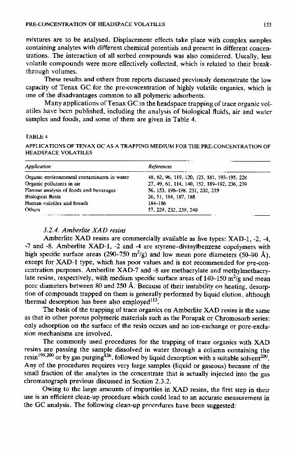
Novotny et al. lg3 studied some analytical aspects of the headspace trapping of volatiles using Tenax GC and the factors that have a major influence when complex
PRE-CONCENTRATION OF HEADSPACE VOLATILES 153
mixtures are to be analysed. Displacement effects take place with complex samples containing analytes with different chemical potentials and present in different concen- trations. The interaction of all sorbed compounds was also considered. Usually, less volatile compounds were more effectively collected, which is related to their break- through volumes.
These results and others from reports discussed previously demonstrate the low capacity of Tenax GC for the pre-concentration of highly volatile organics, which is one of the disadvantages common to all polymeric adsorbents.
Many applications of Tenax GC in the headspace trapping of trace organic vol- atiles have been published, including the analysis of biological fluids, air and water samples and foods, and some of them are given in Table 4.
I-ABLE 4
APPLICATIONS OF TENAX GC AS A TRAPPING MEDIUM FOR THE PRE-CONCENTRATION OF
HEADSPACE VOLATILES
Application References
Organic environmental contaminants in water 48, 62, 96, 119, 120, 125, 181, 193-195, 228
Organic pollutants in air 27, 49, 61, 114, 140, 152, 189-192, 236, 239
Flavour analysis of foods and beverages 56, 153, 196198, 231, 232, 233
Biological fluids 26, 51, 184, 187, 188
Human volatiles and breath 184-186
Others 57, 229, 232, 239, 240
3.2.4. Amberlite XAD resins Amberlite XAD resins are commercially available as five types: XAD-1, -2, -4,
-7 and -8. Amberlite XAD-1, -2 and -4 are styrene-divinylbenzene copolymers with high specific surface areas (290-750 m*/g) and low mean pore diameters (50-90 A), except for XAD-1 type, which has poor values and is not recommended for pre-con- centration purposes. Amberlite XAD-7 and -8 are methacrylate and methylmethacry- late resins, respectively, with medium specific surface areas of 14CL150 m*/g and mean pore diameters between 80 and 250 A. Because of their instability on heating, desorp- tion of compounds trapped on them is generally performed by liquid elution, although thermal desorption has been also employed’r3.
The basis of the trapping of trace organics on Amberlite XAD resins is the same as that in other porous polymeric materials such as the Porapak or Chromosorb series: only adsorption on the surface of the resin occurs and no ion-exchange or pore-exclu- sion mechanisms are involved.
The commonly used procedures for the trapping of trace organics with XAD resins are passing the sample dissolved in water through a column containing the resin’99,200 or by gas purging 126 followed by liquid desorption with a suitable solvent200. Any of the procedures require: very large samples (liquid or gaseous) because of the small fraction of the analytes in the concentrate that is actually injected into the gas chromatograph previous discussed in Section 2.3.2.
Owing to the large amounts of impurities in XAD resins, the first step in their use is an efficient clean-up procedure which could lead to an accurate measurement in the GC analysis. The following clean-up procedures have been suggested:

TA
BL
E
5 .
RE
CO
VE
RIE
S O
BT
AIN
ED
W
ITH
T
HE
APP
LIC
AT
ION
O
F A
MB
ER
LIT
E
XA
D-2
A
ND
-4
RE
SIN
S IN
TH
E
RA
NG
E
20 p
pt-1
0 pp
b.
Com
poun
ds
test
ed
XA
D-2
X
AD
-4
Min
imum
C
ompo
und
Max
imum
C
ompo
und
Min
imum
C
ompo
und
Max
imum
C
ompo
und
reco
very
re
cove
ry
reco
very
re
cove
ry
(%)
(%)
(%)
(%I
Poly
nucl
ear
arom
atic
s 60
T
etra
hydr
onap
htha
lene
10
0 B
iphe
nyl
80
Nap
htha
lene
87
B
iphe
nyl
Alk
ylbe
nzen
es
80
Eth
ylbe
nzen
e 95
C
umen
e 65
B
enze
ne
80
p-C
ymen
e H
aloh
ydro
carb
ons
70
2,C
Dic
hlor
otol
uene
95
1,
2-D
ichl
orot
olue
ne
85
Chl
orob
enze
ne
95
Ben
zyl
chlo
ride
E
ther
s 75
D
ihex
yl e
ther
95
2-
Met
hoxy
- na
phth
alen
e A
lcoh
ols
85
Cin
nam
yl
alco
hol
100
n-O
ctan
ol
93
Cin
nam
yl
alco
hol
100
n-O
ctan
ol
Ald
ehyd
es
and
keto
nes
88
2-U
ndec
anon
e 10
0 Sa
licyl
alde
hyde
92
B
enza
ldeh
yde
100
2-U
ndec
anon
e E
ster
s 70
M
ethy
l pa
lmita
te
100
Ben
zyl
acet
ate
35
Met
hyl
palm
itate
99
B
enzy
l ac
etat
e Ph
enol
s 84
o-
Cre
sol
100
2-N
apht
hol
Nitr
ogen
co
mpo
unds
80
o-
Nitr
otol
uene
10
0 B
enzo
thia
zole
Pe
stic
ides
45
A
ldri
n 95
D
DT

PRE-CONCENTRATION OF HEADSPACE VOLATILES 155
(a) Vacuum degassing and gas stream desorption, both elevated temperature procedures2ca.
(b) Several tandems of Soxhlet extractions, 24 h each, with water, methanol and methylene chloridei4i.
(c) The resin is washed several times with water in a beaker and the fines are discarded by decanting. Several washes with methanol are then required. The resin is dried by filtration and sieved to collect different fractions (3M5 and 45-60 mesh). Each fraction is finally washed with diethyl ether in a Sohxlet apparatus (2 x 12 h) and then dried in aigol.
(d) The resin (100 g) is washed successively with 1.5 1 of acetone, methanol and methylene chloride or chloroform. A portion of the last wash is then evaporated (15O:l) and checked for interferences by GC. If necessary, the chloroform washing is repeated until the blank chromatogram shows no interferences*‘*.
The clean-up procedure proposed by the manufacture?03 proved to be unsatis- factory for pre-concentration methods, because the manufacturing process leaves a con- siderable amount of monomeric material trapped interstitially in the porous structure. The alternative, including a sequential solvent rinsing technique for long periods, gave better results141, but it is too time consuming. The effectiveness of clean-up procedure (d) was demonstrated finally by GC analysis and does not take an excessive time.
Recoveries of some solutes from Amberlite XAD-2 and -5 resins are given in Table 5. These recoveries are associated with the ability of the adsorbent to trap the organic compounds from solutions and to release them during the desorption process. Factors such as partial dissociation of organic molecules, e.g. phenols, the pH of the solution, e.g., in organic acids, or the aromaticity of the molecules have a strong in- fluence on the adsorption capacity of the resin. Partially dissociated organic molecules are weakly adsorbed200, while strongly ionic organic compounds are not adsorbediss. XAD resins have a lower concentration effect for low-molecular-weight aliphatic than for aromatic compounds. The increase in molecular weight across the homologous se- ries increases the trapping efficiency.
Amberlite XAD-2 and -4 have similar adsorption propertieslo and they can therefore be interchanged. Amberlite XAD-7 has been shown to be an ideal medium for the pre-concentration of polyethoxylated compounds204 and Amberlite XAD-8 has been used effectively for the determination of several humic and fulvic acids205. Van Rossum and Webb202 have measured the recovery efficiencies of organic pol- lutants using resin mixtures of XAD-4/-8 and XAD-2/-8 and found that they were effective using tap water.
Various applications of Amberlite XAD resins to the pre-concentration of trace organics, mainly dissolved in water, are given in Table 6.
3.2.5. Other types of porous polymeric adsorbents Although Tenax GC, Chromosorb, Porapak series and Amberlite XAD resins
are the most commonly used solid adsorbents as packings for pre-concentrating trap tubes, there are a wide variety of other suitable polymeric adsorbents whose charac- teristics will be briefly discussed (see Table 3).
Ostion SP-1, Synachrom and Spheron types are copolymers of styrene-divinylbenzene, styrene-divinylbenzene-ethylvinylbenzene and derivatives of methacrylate-styrene or divinylbenzene, respectively. Ostion SP-1 has similar prop-

156 A. J. NUNEZ, L. F. GONZALEZ, J. JANAK
TABLE 6
APPLICATIONS OF AMBERLITE XAD RESINS IN TRACE ORGANIC ANALYSIS
Resin
XAD-2
XAD-4
XAD-7
KAD-8
Resin mixture
Compounds tested References
Halohydrocarbons 206, 211, 172 Pesticides 151, 207-209
Herbicides 104 FIavour compounds 211 Nucleotides 212 Halohydrocarbons 213 Herbicide derivatives 214 Organic phosphates 215 Polyethoxylated compounds 204 Phenols 199, 216, 217 Hormones 202 Humic and fulvic acids 66, 205 Light organic solutes 218 Complex mixtures 201
erties to those of Amberlite XAD-2 and has been used in the determination of phenols219 and detergents220 in water. The application of Synachrom to the pre-con- centration of phenols and hydrocarbons in water showed that its adsorptive properties are inversely proportional to the solubility of the compounds in wate?21.222. In this sense, its sorption mechanism is similar to that of activated carbon’m.
Spheron MD 30/70 and SE were used in the determination of phenols and hy- drocarbons in watepYm, showing similar adsorption capacities to the Synachrom type.
Porous polymeric adsorbents of the Cekachrom series have been developed by Wennrich et al.2z and gave a good performance as adsorbents for trace organic analy- sis. Their properties and characteristics have been studied by Hoffman et a1.226, who demonstrated their ability to trap headspace volatiles.
Ioffe et a1.15* applied polysorbimide**’ for the pre-concentration of trace organic volatiles in urban atmospheres. The results agreed well with those obtained with Tenax GClg9.
It must be noted that most of the applications of some of the polymeric materials described in Sections 3.2.4 and 3.2.5 have been to trace organics dissolved in water and not headspace volatiles, which should be clearly differentiated in Tables 5 and 6. How- ever, the possibility exists of their use in trapping of headspace volatiles, and this should be demonstrated experimentally.
4. CONCLUSIONS
The importance of and necessity for trace organic analysis in many fields has led to great developments in gas chromatography, from both the theoretical and the tech- nical points of view, leading to special considerations in qualitative and quantitative chromatographic analyses.
The trace organic analysis of headspace volatiles requires prior steps for the en- richment of the analytes, as static procedures do not always provide good results re- garding the amount of water in the sample and/or a sufficient amount of the analytes to be detected by the chromatographic system, so indirect sampling procedures are needed.

PRE-CONCENTRATION OF HEADSPACE VOLATILES 157
Indirect sampling of headspace volatiles on solid adsorbent% solid supports coat- ed with a liquid stationary phase or cold traps is an important tool for the analyst concerned with the trace organic analysis of volatiles. The selection of the sampling procedure and the subsequent introduction of the analytes into the gas chromatograph depends on various factors, such as the physico-chemical characteristics of the trapping medium, the thermal lability of the analytes and the volatility of the analytes, a knowl- edge of which leads to successful analyses.
Adsorption on polymeric adsorbents, including the Chromosorb and Porapak series, has been widely applied. However, Tenax GC is the most widely used owing to its thermal stability, in spite of its lower specific surface area. The use and design of polymeric trap tubes filled with a sufficient amount of Tenax GC of the highest mesh commercially available (60-80), operating under optimal experimental conditions, has given good analytical results, although analytes of the highest volatility are not well retained.
For accurate results in the trace organic analysis of volatiles by dynamic methods it is necessary to take into account all the physico-chemical parameters that determine the distribution of the analytes between the liquid or solid phase (original sample) and the gaseous phase (headspace sample), and between the latter and the selected adsor- bent, if quantitative analysis is to be performed.
5. SUMMARY
Methods for the pre-concentration of headspace volatiles for trace organic analy- sis by gas chromatography are reviewed, emphasizing the dynamic methods of head- space gas analysis.
The theoretical basis of static and dynamic procedures in headspace gas analysis is discussed, demonstrating the necessity for the latter procedures in trace organic analysis.
Experimental arrangements for the enrichment of volatiles by means of dynamic procedures on solid adsorbents are discussed with respect to their efficiency. A com- parison is made of liquid and thermal desorption for the trapped analytes on solid ad- sorbents, for their introduction into the GC column, leading to a greater analytical potential of thermal desorption when it is feasible.
The applications and physico-chemical properties of a wide range of graphitized and polymeric adsorbents are presented.
REFERENCES
1 M. Ahnhoff and B. Josefsson, Anal. 46 (1974) 6.58. M. A. Scheiman, R. Saunders and F. Saulfeld, Biomed. 4 (1974) 209. A. Zlatkis K. Kim, (1976) 475. W. Averill J. E. Chromatogr. 7 13.
5 D. Bowers, L. Parsons, R. Clement, G. A. and W. Karasek, J. Chromatogr., 206 (1981) 279. E. A. and D. Lillard, J. Dairy Sci., (1960) 585. E. Kaminski, Wascwicz and R. Aliment. Pal., 7 59.
8 P. Sandra and Verzele, J. (1981) 325. D. A. V. M. and H. Ramshaw, J. Food Chem., 15 1104.
10 A. Singleton H. E. in (Editor), Analysis of Foods Head space Press, New York, 1978, 359.

158 A. J. NUNEZ, L. F. GONZALEZ, J. JANAK
11 M. Rosli and B. Marek, Mitt. Geb. Lebensmirrelunrers. Hyg., 88 (1977) 440. 12 B.-M. Gawell, B. Larsson and E. Ch. Sandberg, Vdr Fiida, 31 (1979) 155. 13 H. S. Hertz, W. E. May, S. A. Wise and S. N. Chesler, Anal. Chem., 50 (1978) 428A. 14 F. W. Karasek, R. E. Clement and J. A. Sweetman, Anal. Chem., 53 (1981) 105OA. 15 T. H. Risby, L. R. Field, F. J. Yang and S. P. Cram, Anal. Chem., 54 (1982) 410R. 16 J. Novak, Advan. Gas Chromarogr., 21 (1982) 303. 17 J. Novak, Quantitative Analysis by Gas Chromatography, Marcel Dekker, New York, 1975. 18 J. Janak, in E. Heftmann (Editor), Chromatography, Van Nostrand Reinhold, New York, 1975,3rd ed.,
Ch. 28, p. 895. 19 J. Drozd and J. Novak, J. Chromarogr., 165 (1979) 141. 20 T. Fujii, J. Chromarogr., 139 (1977) 297.
21 J. Teply and M. Dressler, J. Chromatogr., 191 (1980) 221. 22 L. S. Ettre, J. E. Purcell, J. Widowski, B. Kolb and P. Pospisil, J. Chromatogr. Sci., 18 (1980) 116. 23 J. Drozd and J. Novak, 1. Chromatogr., 152 (1978) 55. 24 J. Drozd and J. Novak, J. Chromarogr., 136 (1977) 37. 25 J. Novak, J. Janak and J. Golias, in Proceedings of the 9th Materials Research Symposium, April 10-13,
1978, held at NBS, Gaithersburg, MD, NBS Special Publication, No 519, National Bureau of Standards,
Washington, DC, 1979, p. 739. 26 L. C. Michael, M. D. Erickson, S. P. Parks and E. D. Pellizari, Anal. Chem., 52 (1980) 1836. 27 K. J. Krost, E. D. Pellizari, S. G. Walburn and S. A. Hubbard, Anal. Chem., 54 (1982) 810. 28 M. E. Rose and B. N. Colby, Anal. Chem., 51 (1979) 2176. 29 M. D. Erickson, M. K. Alsup and D. A. Hyldburg, Anal. Chem., 53 (1981) 1265. 30 B. Kolb, P. Pospisil, T. Borath and M. Auer, J. High Resolut. Chromatogr. Chromatogr. Commun., 2
(1979) 283. 31 J. Widowski and W. Thompson, J. Chromafogr. Newsl., 7 (1979) 31. 32 B. Kolb and P. Pospisil, Chromatogruphia, 10 (1977) 705. 33 B. V. Ioffe and A. G. Vitenberg, Chromatographia, 11 (1978) 282. 32 A. G. Vitenberg and M. I. Kostkina, Vestn. Leningr. Univ. Fir. Khim., (1980) 110. 35 C. McAuliffe, Chem. Tech., 1 (1971) 46. 36 B. Kolb, M. Auer and P. Pospisil, Angew. Chromarogr. (Perkin-Elmer), No. 35-E (1981). 37 D. P. Beggs, Amer. Lnb., 19 (1978) 81. 38 H. Peterson, G. A. Eiceman, L. R. Field and R. E. Sievers, Anal. Chem., 50 (1978) 2152. 39 M. W. Dietrich, L. M. Chapman and J. P. Mieure, Amer. Ind. Hyg. Ass. J., 39 (1978) 385. 40 A. G. Gargus and C. R. Waterson, Amer. Lab., 12 (1980) 133. 41 S. N. Chesler, F. R. Guenther and R. G. Christensen, J. High Resolut. Chromatogr. Chromatogr. Com-
mun., 3 (1980) 351. 43 E. Hala, J. Pick, V. Fried and 0. Vilim, Vapour-Liquid Equilibrium, Pergamon Press, Oxford, 1967,
2nd ed., p. 117. 43 W. J. Moore, Physical Chemistry, Longmans, London, 1972, 5th ed., p. 261. 44 K. G. Denbigh, The Principles of Chemical Equilibrium, Cambridge University Press, Cambridge, 1957. 45 M. Suzuki, S. Tsuge and T. Takeuchi, Anal. Chem., 42 (1970) 1705. 46 R. H. Brown and C. J. Purnell, J. Chromatogr., 178 (1979) 79. 47 R. S. Narang and B. Bush, Anal. Chem., 52 (1980) 2076. 48 J. Brass, Inr. Lab., 10 (1980) 17. 49 W. N. Billings and T. E. Bidleman, Environ. Sci. Technol., 14 (1980) 679. 50 P. D. Barnes, L. M. Law and A. J. Ma&sod, Analyst (London), 106 (1981) 412. 51 M. P. Shiaris, T. W. Sherritt and G. S. Sayler, Appl. Environ. Microbial., 39 (1980) 165. 52. G. Charalambous (Editor), Analysis of Foods and Beverages. Headspace Techniques, Academic Press,
New York, 1978. 53 W. G. Jennings and M. Filsoof, J. Agr. Food Chem., 25 (1977) 440. 54 P. J. Williams and C. R. Strauss, J. Inst. Brew., 83 (1977) 213. 55 R. F. Simpson, Chromatographia, 12 (1979) 733. 56 R. A. Cole, J. Sci. Food Agr., 31 (1980) 1242. 57 R. P. Lattimer and J. P. Bausch, Znr. Lab., 10 (1980) 51. 58 J. Novak, V. VaSak and J. Janak, Anal. Chem., 37 (1965) 260. 59 J. GelbiEovl-RutiEkova, J. Novak and J. Jan&k, J. Chromatogr., 64 (1972) 15. 60 B. Kolb (Editor), Applied Headspace Gas Chromatography, Heyden, London, 1980.

PRE-CONCENTRATION OF HEADSPACE VOLATILES 159
60a A. Raymond and G. Guiochon, Analusb, 2 (1973) 357. 60b A. Raymond and G. Guiochon, J. Chromatogr. Sci., 13 (1975) 173. 61 T. Tanaka, J. Chromafogr., 153 (1978) 7. 62 W. Bertsch, E. Anderson and G. Holzer, J. Chromatogr., 112 (1975) 701. 63 K. Kawata, T. Uemura, I. Kifune, Y. Tomikaga and K. Oikawa, Bun&i Kagaku (Jap. Anal.), 8 (1982)
453. 64 K. E. Murray, .I. Chromatogr., 13.5 (1977) 49. 65 N. R. Rakshieva, S. WiEar, J. Novak and J. Jan&k, J. Chromatogr., 91 (1974) 59. 66 E. M. Thurman, R. L. Malcolm and G. R. Aiken, Anal. Chem., 50 (1978) 775. 67 A. G. Vitenberg, B. V. Ioffe and V. N. Borisov, Chromatographia, 7 (1974) 610. 68 W. Horwitz and J. Howard, in Proceedings of the 9th Materials Research Symposium, April 10 30
1978, held at NBS, Gaithersburg, MD, NBS Special Publication, No. 519, National Bureau of Stan dards, Washington, DC, 1979, p. 235.
69 R. Kaiser, J. Chromatogr. Sci., 9 (1971) 227. 70 B. V. Ioffe, A. G. Vitenberg, K. N. Borisov and M. A. Kuznetsov, J. Chromatogr., 112 (1975) 311. 71 J. Janak, J. RutiEkova and J. Novak, J. Chromatogr., 90 (1974) 689. 72 M. Waldmand and M. Vantcek, Collect. Czech. Chem. Commun., 43 (1978) 2905. 73 A. G. Vitenberg, B. V. Ioffe, 2. St. Dimitrova and T. P. Strukova, J. Chromatogr., 126 (1976) 205. 74 K. Grob and F. Ziircher, J. Chromatogr., 117 (1976) 285. 75 K. Grob, Jr. and S. Rennhard, _r. High Resolut. Chromatogr. Chromatogr. Commun., 3 (1980) 627. 76 P. Ronkainen, Kern. Teoll., 26 (1969) 215. 77 H. Zenz and H. Klaushofer, Mitt. Vers. Anst. Gdr. Gew., 22 (1968) 175. 78 G. Gdke, Chromatographia, 5 (1972) 622. 79 H. Pauschmann, Chromatographia, 3 (1970) 376. 80 J. D. Green, J. Chromatogr., 210 (1981) 25. 81 M. A. Baylis, J. D. Green and S. R. Massey, Chem. Ind. (London), (1979) 353. 82 B. Kolb, 1. Chromatogr., 112 (1975) 287. 83 K. Grob and G. Grob, J. Chromatogr. Sci., 7 (1969) 584. 84 K. Grob and K. Grob, Jr., J. Chromatogr., 94 (1974) 53. 85 K. Grob and K. Grob, Jr., J. High Resolut. Chromatogr. Chromatogr. Commun., 1 (1978) 57.
86 J. A. Rijks, J. Drozd and J. Novak, J. Chromatogr., 186 (1979) 167. 87 G. Schomburg, H. Behlau, R. Dielmann, F. Weeke and H. Husmann, J. Chromatogr., 142 (1977) 87. 88 F. J. Yang, A. C. Brown, III and S. P. Cram, J. Chromatogr., 158 (1978) 91. 89 K. Grob and K. Grob, Jr., J. Chromatogr., 151 (1978) 311. 90 K. Grob, Jr. and H. P. Neukom, J. Chromatogr., 189 (1980) 109. 91 R. Hiltunen, I. Laakso, S. Hovinen and J. Derome, J. Chromatogr., 237 (1982) 41. 92 K. Grob, K. Grob, Jr. and G. Grob, J. Chromatogr., 106 (1975) 299. 93 K. Grob, .I. Chromatogr., 84 (1973) 255. 94 K. Grob and G. Grob, J. Chromatogr., 90 (1974) 303. 95 J. Novak, J. GolilS and J. Drozd, 1. Chromatogr., 204 (1981) 421. % J. Drozd and J. Novak, ht. J. Environ. Anal. Chem., 11 (1982) 241. 97 M. J. McGuire, S. W. Krasner et al., J. Amer. Water Works Ass., 73 (1981) 530. 98 R. F. Westendorf, Int. Lab., 12 (1982) 32. 99 B. V. Ioffe, V. A. Isidorov and I. G. Zenkevich, J. Chromatogr., 142 (1977) 787. 99a H. BorCn, A. Grimvall and R. Savenhed, J. Chromatogr., 252 (1982) 139.
100 W. W. Nawar and I. S. Fagerson, Food Technol., 16 (1962) 107. 101 J. Novak, Quantitative Analysis by Gas Chromatography, Marcel Dekker, New York, 1975, p. 130. 102 I. Viden, V. Kubelka and J. Mostecky, 2. Anal. Chem., 280 (1976) 369. 103 D. C. Kennedy, Environ. Sci. Technol., 7 (1973) 138. 104 V. Niederschulte and K. Ballschmitter, Z. Anal. Chem., 269 (1974) 360. 105 R. M. Cassidy, M. T. Burteau, J. D. Misian and R. W. Ashley, J. Chromatogr. Sci., 14 (1976) 444. 106 H. Braus, F. M. Middleton and G. Walton, Anal. Chem., 23 (1951) 1160. 107 L. Ch. Fraust and E. R. Hermann, Amer. Znd. Hyg. Ass. J., 27 (1966) 68. 108 G. A. Junk, C. D. Chriswell, R. C. Chang, L. D. Kissinger, J. J. Richards, J. S. Fritz and J. H. Svec,
Z. Anal. Chem., 282 (1976) 331. 109 A. A. Deetman and P. Demeulemeester, Anal. Chim. Acta, 82 (1976) 1. 110 L. A. Shadoff, R. A. Hummel, L. Lamparski and J. H. Davidson, Bull. Environ. Contam. Toxicol., 18
(1977) 478.

160 A. J. NljfiEZ, L. F. GONZALEZ, J. JANAK
111 V. G. Berezkin, M. N. Budantseva and E. Dows, J. Chromarogr., 191 (1980) 309. 112 C. D. Chriswell, L. D. Kissinger and J. S. Fritz, Anal. Chem., 48 (1976) 1123. 113 J. P. Ryan and J. S. Fritz, J. Chromarogr. Sci., 18 (1978) 488. 114 R. G. Melcher and V. J. C. Caldecourt, Anal. Chem., 52 (1980) 875. 115 V. Palo and J. Hrivfiak, 5th International Symposium on Progress and Applications of Chromatography,
Bratislava, Czechoslovakia, April 26-28, 1977. 116 R. D. Cox and R. F. Earp, Anal. Chem., 54 (1982) 2265. 117 D. Kalman, R. Dills, C. Perera and F. DeWalle, Anal. Chem., 52 (1980) 1993. 118 W. G. Jennings, R. Wohleb and M. J. Lewis, .I. Food Sci., 37 (1972) 69. 119 T. A. Bellar and J. J. Lichtenberg, J. Amer. Water Works Ass., 66 (1974) 739. 120 P. P. K. Kuo, E. S. K. Chian, F. B. DeWalle and J. H. Kim, Anal. Chem., 49 (1977) 1023. 121 W. E. May, S. N. Chesler, S. P. Cram, B. H. Gump, H. S. Hertz, D. P. Enagorio and S. M. Dyszel, J.
Chromatogr. Sci., 13 (1975) 535. 122 J. A. Settlage and W. G. Jennings, 1. High Resolur. Chromarogr. Chromarogr. Commun., 3 (1980) 146. 123 H. G. Eaton, J. Chromarogr. Sci., 18 (1980) 580. 124 J. F. Pankow and L. M. Isabelle, J. Chromatogr., 237 (1982) 25. 125 J. Pankow, L. M. Isabelle and T. J. Kristensen, Anal. Chem., 54 (1982) 1815. 126 B. J. Dowty, L. E. Green and J. L. Laseter, Anal. Chem., 48 (1976) 946. 127 A. A. Michelson, 0. Merosz and B. Lenyk, Anal. Chem., 49 (1977) 816. 128 R. D. Kleopfer and B. J. Fairless, Environ. Sci. Technol., 6 (1972) 1036. 129 J. W. Swinnerton and V. J. Linnenbom, J. Gas Chromatogr., 5 (1967) 570. 130 F. K. Mueller and J. A. Miller, Amer. Lab., 6 (1974) 49. 131 B. A. Colenutt and D. N. Davies, Inr. J. Environ. Anal. Chem., 7 (1980) 223. 132 B. A. Colenutt and S. Tborburn, Znr. J. Environ. Anal. Chem., 7 (1980) 231. 133 F. Bruner, G. Bertoni and P. Ciccioli, .I. Chromarogr., 120 (1976) 307. 134 A. V. Kiselev and I. Yashin, Gas Adsorption Chromarogruphy, Plenum, New York, 1969. 135 A. DiCorcia and F. Bruner, Anal. Chem., 42 (1970) 1500. 136 A. DiCorcia and R. Samperi, J. Phys. Chem., 77 (1973) 1301. 137 R. Leboda, Pal. J. Chem., 54 (1980) 2805. 138 R. Leboda, Chromatographia, 13 (1980) 549. 139 A. DiCorcia, R. Samperi, E. Sebastiani and C. Severini, Chromatographia, 14 (1981) 86. 140 G. Holzer, H. Shanfield, A. Uatkis, W. Bertsch, P. Juarez, H. Mayfield and H. M. Liebich, J. Chro-
matogr., 142 (1977) 755. 141 G. Hunt and N. Pangaro, Anal. Chem., 54 (1982) 369. 142 A. A. Rosen and E. M. Middleton, Anal. Chem., 31 (1959) 1729. 143 J. W. Eichelberg and J. J. Lichtenberg, J. Amer. Water Works Ass., 63 (1971) 25. 144 C. D. Chriswell, R. C. Chang and J. S. Fritz, Anal. Chem., 47 (1975) 1325. 145 A. Turk, S. M. Edmonds and H. L. Mark, Environ. Sci. Technol., 2 (1968) 44. 146 L. A. Niemeyer and R. A. McCormick, J. Air Pollut. Control Ass., 18 (1968) 403. 147 A. Ketrup, H. Stenner, J. Hevel and W. Lorek, in B. Kolb (Editor), Applied Headspace Gus Chromo-
togruphy, Heyden, London, 1980, p. 23. 148 J. Klimes and D. Lamparsky, in G. Charalambous (Editor), Analysis of Foods and Beverages. Headspace
Techniques, Academic Press, New York, 1978, p. 95. 149 J. Streif, Garlenbauwissenschaft, 46 (1981) 72. 150 J. J. Lichtenberg, IEEE Trans. Nucl. Sci., NS-22 (1975) 874. 151 J. J. Richard and J. S. Fritz, Tulunra, 21 (1974) 91. 152 B. V. Ioffe, V. A. Isidorov and I. G. Zenkevich, J. Chromatogr., 142 (1977) 787. 153 T. H. Parliment and R. Scarpellino, J. Agr. Food Chem., 25 (1977) 92. 154 P. J. Dirinck, L. Schreyen and N. M. Schamp, J. Agr. Food Chem., 25 (1977) 759. 155 H. M. Liebich and J. Wall, J. Chromatogr., 142 (1977) 505. 156 A. B. Robinson, D. Partridge, M. Turner, R. Teranisbi and L. Pauling, J. Chromatogr., 85 (1973) 19. 157 H. Dirren, A. B. Robinson and L. Pauling, Clin. Chem., 21 (1975) 70. 158 T. Kitagawa, B. A. Smith and E. S. Brown, Clin. Chem., 21 (1975) 735. 159 0. Dufka, J. Malinsky, J. Churacek and K. Kamarek, J. Chromatogr., 54 (1970) 111. 160 D. L. Hollis, J. Chromatogr. Sci., 11 (1973) 335. 161 S. B. Dave, J. Chromatogr. Sci., 7 (1969) 389. 162 K. Sakodynskii, L. Panina and N. Klinskaya, Chromatographia, 7 (1974) 339.

PRE-CONCENTRATION OF HEADSPACE VOLATILES 161
163 M. Dressier, 1. Chromarogr., 165 (1979) 167. 164 J. F. Johnson and E. M. Barrall, I, J. Chromatogr., 31 (1967) 547. 165 F. OnuSka, 3. Jan&k, S. DuraS and M. Krcmlrova, J. Chromnrogr., 40 (1969) 209. 166 M. Dressler, 0. K. Guha and J. Janak, J. Chromarogr., 65 (1972) 261. 167 F. M. Zado and J. Fabecic, J. Chromarogr., 51 (1970) 37. 168 D. L. Hollis and V. W. Hayes, J. Gas Chromatogr., 4 (1966) 235. 169 J. R. Lindsay Smith and D. J. Waddlington, .I. Chromarogr., 36 (1968) 145. 170 F. W. Williams and M. E. Umstead, Anal. Chem., 40 (1968) 2232. 171 M. KrejEi, M. Roudni and Z. Vayrouch, J. Chromatogr., 91 (1974) 549. 172 W. H. Glaze, G. R. Peyton and R. Rawley, Environ. Sci. Technol., 11 (1977) 685. 173 P. H. Krumpennan, J. Agr. Food Chem., 20 (1972) 909. 174 G. Caste110 and G. D’Amato, J. Chromarogr., 243 (1982) 25. 175 G. Caste110 and G. D’Amato, J. Chromarogr., 196 (1980) 245. 176 G. Caste110 and G. D’Amato, J. Chromarogr., 212 (1981) 261. 177 M. S. Wainwright, J. K. Haken and D. Srisukh, J. Chromarogr., 236 (1982) 1. 178 J. DeGreef, M. DeProft and F. DeWinter, Anal. Chem., 48 (1976) 38. 179 J. P. Mieure and M. W. Dietrich, J. Chromarogr. Sci., 11 (1973) 559. 180 T. Dumas and E. J. Bond, J. Chromarogr., 206 (1981) 384. 181 B. Versino, H. Kn0ppe1, M. de Groot, A. Peil, J. Poelman, H. Schavenburg, H. Vissers and F. Geis, J.
Chromnrogr., 142 (1977) 755. 182 R. van Wijk, Chimia, 24 (1970) 254. 183 M. Novotny, M. L. Lee and K. D. Bartle, Chromarographia, 7 (1974) 333. 184 A. Zlatkis, H. A. Lichtenstein and A. Tishbee, Chromatographia, 6 (1973) 67. 185 B. Krotoszynski, G. Gabriel, H. O’Neil and M. P. A. Claudio, J. Chromarogr. Sci., 15 (1977) 239. 186 S. D. Sastry, K. T. Buck, J. Jan&k, M. Dressier and G. Pretti, in G. R. Wailer and 0. C. Dermer
(Editors), Biochemical Applicurions of Mass Specrromerry, Wiley, New York, 1980, Ch. 34, p. 1085. 187 A. Zlatkis, W. Bertsch, H. A. Lichtenstein, H. M. Shunbo, A. DiCorcia and N. Fleischer, Anal. Chem.,
45 (1973) 763.
188 K. Kaneko, T. Imai and 0. Katayama, Nippon Shokunin Kogyo Gakkaishi, 27 (1980) 407. 189 W. Bertsch, R. C. Chang and A. Zlatkis, J. Chromarogr. Sci., 12 (1974) 175. 190 E. D. Pellizari, B. H. Carpenter, J. E. Bunch and E. Sawicki, Environ. Sci. Technol., 9 (1975) 557. 191 K. Grob and G. Grob, J. Chromarogr., 62 (1971) 1. 192 A. Raymond and G. Guiochon, Environ. Sci. ‘fechnol., 8 (1974) 143. 193 R. E. Sievers, R. M. Barkley, G. A. Eiceman, R. H. Shapiro, H. F. Walton, K. J. Kolonko and L. R.
Field, J. Chromarogr., 142 (1977) 745. 194 V. Leoni, G. Pucceti and A. Grella, J. Chromarogr., 106 (1975) 119. 195 H. C. Hu and P. H. Weiner, J. Chromatogr. Sci., 18 (1980) 333. 196 G. Holzer, J. Or6 and W. Bertsch, J. Chromarogr., 126 (1976) 771. 197 R. J. Mickkets and R. R. Lindsay, Tech. Q. Master Brew. Ass. Amer., 11 (1974) 19. 198 A. A. Williams, H. V. May and 0. G. Tucknott, J. Sci. Food Agr. , 29 (1978) 1041. 199 A. K. Burnham, G. V. Calder, G. A. Junk, H. J. Svec and R. Willis, Anal. Chem., 44 (1972) 139. 200 G. A. Junk, J. J. Richard, M. D. Greser, D. Witiak, J. L. Witiak, M. D. Arguello, R. Vick, H. J. Svec,
J. S. Fritz and G. V. Calder, J. Chromarogr., 99 (1974) 745. 201 B. Andersson and K. Andersson, J. Chromarogr., 242 (1982) 353. 202 P. van Rossum and R. G. Webb, J. Chromarogr., 150 (1978) 381. 203 Technical Bullerins, Amberlite XAD Resins, Rohm &.Haas, Philadelphia, PA, 1978. 204 P. Jones and G. Nickless, J. Chromarogr., 156 (1978) 87. 205 R. L. Malcolm, E. M. Thurman and G. R. Aiken, Proceedings of the 11th Annual Conference on Truce
Substances in Environmental Health, Columbia, MO, 1977, p. 307. 206 G. R. Harvey, W. G. Steinhauer and J. M. Ted], Science, 180 (1973) 643. 207 E. E. McNeil, R. Otson, W. F. Wiles and F. J. M. Rajabalee, J. Chromarogr., 132 (1977) 277. 208 C. Osterroht, J. Chromatogr., 101 (1974) 289. 209 G. A. Junk, J. J. Richard, H. J. Svec and J. S. Fritz, J. Amer. Water Works Ass. 68 (1976) 218. 210 W. H. Glaze, J. E. Henderson, J. E. Bell and A. van Wheeler, J. Chromatogr. Sci., 11 (1973) 580. 211 L. Zaika, J. Agr. Food Chem., 17 (1969) 893. 212 R. H. Niemann, D. L. Pap and R. A. Clark, J. Chromatogr., 161 (1978) 137. 213 P. R. Musty and G. Nickless, J. Chromatogr., 89 (1974) 185.

162 A. J. NUNEZ, L. F. GONZALEZ, J. JANAK
214 S. Mierzwa and S. Witek, J. Chromafogr., 136 (1977) 105. 215 C. G. Daughton, D. G. Crosby, R. L. Garnas and D. P. H. Hsiek, J. Agr. Food Chem., 24 (1976) 236.
216 J. S. Fritz and R. B. Willis, J. Chromarogr., 79 (1973) 107. 217 S. F. Stepan and J. F. Smith, Waler Res., 11 (1977) 339.
218 E. M. Thurman, G. R. Aiken and R. L. Malcolm, Proceedings of the 4th Conference of the Sensing of Environmental Pollutants, New Orleans, 1977, p. 630.
219 J. Seidl and F. KrSka, Chem. Prum., 25 (1975) 597.
220 J. Seidl, Chem. Prum., 26 (1976) 74. 221 V. Kubelka, J. Mitera, J. Novak and J. Mustecky, Collect. Tech. Univ. Chem. Technol. Prague, F-20
(1976) 85. 222 I. Viden, Thesis, Faculty of Fuel and Water Technology, Technical University of Chemical Technology,
Prague, 1975. 223 E. Bfizova, M. Pop1 and J. Coupek, Chem. Prum., 27 (1977) 352. 224 E. Bfizova, M. Pop1 and J. coupek, J. Chromatogr., 139 (1977) 15. 225 L. Wennrich, W. Engewald, T. Welsch and B. Wenzel, Chem. Tech. (Leipzig), 33 (1981) 203. 226 H. Hoffmann, M. Henke, H. Haupke and G. Schwachula, Pluste Kautsch., 8 (1978) 453. 227 K. I. Sakodynskii, N. S. Khnskaya and L. I. Panina, in A. Uatkis (Editor), Advances in Chromatography
1973, 1973, p. 109. 228 N. E. Spingam, D. J. Horthington and T. Pressley, J. Chromatogr. Sci., 20 (1982) 286. 229 M. Novotny and M. L. Lee, Experientia, 29 (1973) 1038. 230 M. Novotny, M. L. McConnell and M. L. Lee, J. Agr. Food Chem., 22 (1974) 765. 231 B. W. Christensen, A. Kjaer and J. Bgaard Madsen, J. Amer. Oil Chem. Sot., 58 (1981) 1053. 232 T. Ramstad and T. J. Nestrick, Bull. Environ. Conram. Toxicol., 26 (1981) 440. 233 B. A. Colenutt and S. Thombum, Chromatographia, 12 (1979) 519. 234 H.-J. Neu, W. Mea and H. Panzel, 1. High Resolut. Chromutogr. Chromatogr. Commun., 5 (1982) 382.
235 P. J. Dirinck, H. L. DePooter, G. A. Willaert and N. M. Schamp, .I. Agr. Food Chem., 29 (1981) 316. 236 Y. Hoshika and G. Muto, Bunseki Kagaku (Jup. Anal.), 29 (1980) TlO. 237 J. F. Pankow, L. M. Isabelle and T. J. Kristensen, J. Chromatogr., 245 (1982) 31. 238 G. Bertoni, F. Bruner, A. Liberti and C. Perrino, J. Chromarogr., 203 (1981) 263. 239 S. G. Zeldes and A. D. Horton, Anal. Chem., 50 (1978) 779. 240 L. Torres, M. Frikha, J. Mathieu, M. L. Riba and J. Namiesnik, Int. J. Environ. Anal. Chem., 13 (1983)
155.
Copyright © 2022 FDOKUMEN