Practical masonry, bricklaying and plastering, both plain and ...
374
4 mBs M ^
-
Upload
khangminh22 -
Category
Documents
-
view
2 -
download
0
Transcript of Practical masonry, bricklaying and plastering, both plain and ...
4
mBs
M
^
UCSB LVBRKRV
P.ng^on SlwLby
///ff/ff/f/ //
yr;>rA'^,M//^J^y 4" < yf^-'^^j;y^M^'^"^>-^^^- >^. V-/v^7.
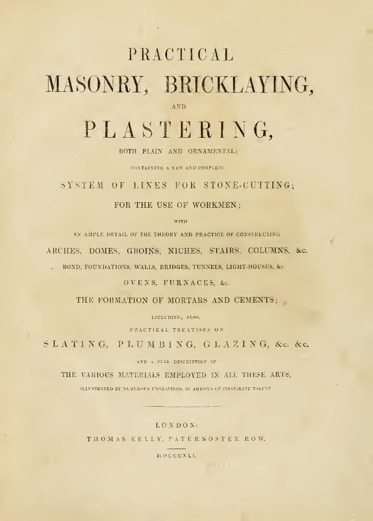
PRACTICAL
MASONRY, BRICKLAYING,AND
PLASTERING,BOTH PLAIN AND ORNAMENTAL;
CONTAINING A NEW AND COMPLETE
SYSTEM OF LINES FOK STONE-CUTTING;
FOR THE USE OF WORKMEN
;
WITH
A.V AMPLE DETAIL OF THE THEORY AND PRACTICE OF CONSTRUCTING
ARCHES. DOMES. GROINS, NICHES, STAIRS, COLUMNS, &c.
. BOND, FOUXDATIOXS, WALLS, BRIDGES, TUNNELS, LIGHT-HOUSES, &c.
OVENS, FURNACES, &c.
THE FORMATION OF MORTARS AND CEMENTS;
IXCLUDINO, ALSO,
P K A C T I C A L TREATISES ON
SLATING, PLUMBING, GLAZING, &c. &c.
AND A I'LLL DESCRIPTION OF
THE VARIOUS MATERIALS EMPLOYED IN ALL THESE ARTS,
ILIUSTKATED BY NLMKRIH^i F.NGli WINGS. UY AKTIST^ OF HR'^T-RATE TALENT.
LONDON:
THOMAS K E L L ^'. P .\ T E R N S T E R R O W.
MDCCCXLI.
London: J. Rider. Priater, 14, Bartholomew Close.
PREFACE.
IN submitting the present Volume to the Public, we have to offer our grateful
acknowledgments for the very favourable reception which the previous work on
Carpentry and Joinery* has met with, and we feel much gratified in having been,
in an eminent degree, successful in our endeavours to unfold and elucidate the
scientific Principles and Practical Application of those Arts which have the object
of employing Wood in the construction of Buildings : we now proceed to deve-
lope, in a similar manner, the scientific Frinciples and Practice of the Arts of Con-
struction, using other materials, and particularly the important Arts of Masonry
and Bricklaying, and also the Ornamental Art of Plastering.
Our plan consists in separately treating the Arts of Construction, and elucidat-
ing them by grouping together those principal branches which have a natural
relation to each other, and which require similar operations, and in which a work-
man in the one always has an advantage in knowing the principles of the others ;
and we are the more powerfully encouraged to proceed in it, by the knowledge
that this plan is as new as it will be found useful, and we trust the Work itself
will bear the palm, as well for originality and beauty, as for its practical utility.
The nature of our Work will be more fully understood from the following
short sketch of its plan. First, we begin with a Treatise on Masonry, in which
is given a complete System of Lines for Stone Cutting, in all its branches
;
as for instance. Arches, Niches, Domes, Plain and Gothic Groins, Mouldings, &c.
Next we treat of the qualities of Building Stones, the nature and composition of
* The PRACTICAL CARPENTRY, JOINERY, and CABINET MAKING ; being a new and com-
plete System of Lines, for the Use of Workmen; founded on accurate Geometrical and Mechanical Prin-
ciples, with their application in Carpentry,—to Roots, Domes, Centring, &c. ; in Joinery,—to Stairs,
Hand-rails, Soffits, Niches, &c. ; and in Cabinet-Making, to Furniture, both Plain and Ornamental, fully
and clearly explained.
This useful and scientific Work is completed in Thirty Numbers, Quarto, Price One Shilling each, or in
Six Parts at Five Shillings each, containing Ninety Plates, and upwards of Two Hundred Di.igrams, exe-
cuted by Artists of the first-rate Talent. Printed for T. Kelly, price only 30s. in boards.
IV PREFACE.
Mortars and Cements, and the principles of constructing Foundations, Walls,
Bridges, Domes, Tunnels, Light-houses, &c.
Secondly, a Treatise on Bricklaying is introduced, showing the nature
and qualities of Bricks, Tiles, &c. The Theory of Brick-bond and the construc-
tion of Arches, Groins, &c. ; also the best methods of building Ovens, Furnaces,
and Fire-places in general, &c.
Thirdly, a Treatise on Plastering, describing the composition of the mate-
rials, and their application in both Plain and Ornamental work, with specimens
of Ornaments, in the various styles that have been adopted in that department at
various periods.
Fourthly, of Slating, in which the various qualities of Slates are fully ex-
plained, and also the most perfect method of applying them as a covering for
buildings.
Fifthly, of Plumbing, Painting, and Glazing, with a full description of the
qualities of the materials, and the most approved methods of applying them :
the whole forming a valuable mass of practical information peculiarly calculated
to direct and assist the workmen in all these branches of the Building Art.
A Glossary of the peculiar Technical Terms applicable to each Department,
is placed at the close of each division, in which an explanation is given of those
objects which require it, and references to where they are treated of in the body
of the work, by which means a greater facility will be obtained in consulting the
AVork.
The examples in the Plates are engraved in the best style, and are chiefly
selected from the most approved works, already executed by the following dis-
tinguished Architects and Civil Engineers, viz. Messrs. Wyattville, Soane, Rennie,
Telford, Brunei, Perronet, &c. &c., as we are persuaded that such designs will be
found superior to any of our own. Our sole object and endeavours in the pro-
secution of these Works, have been to combine Theory with actual Practice, and
to render both familiar and easy.
CONTENTS.
BOOK I.—MASONRY.PAGE
Intkoduction.—Masonry practically considered. The application of the Art in ancient times, compared
with the modern use I
Chapter I.—Of the Description of Arches. Parabolic Arch ; Elliptical Arch ; method of drawing the
joints ; to draw a tangent to a semi-elliptic Arch, the axis major being horizontal. Of
the Cyclograph S
Chapter IL—Stone Cutting. To form a plane surface, 4. Winding Surfaces, 5. Angles formed by
plane surfaces, 5. Of the construction of semi-circular right arch, 6. Of the forms pro-
duced by the intersection of Arches, 6. Elliptical Arch, with splayed jambs, 7. To
find the joints of an oblique Arch, 7. To find the joints of an oblique circular Arch, 8.
Oblique Arch, 9. A semi-circular arched Passage, between two semi-circular arched
Vaults, 10. An Archway revealed and splayed, &c -. 11
Of spherical Vaults, or Domes and Niches 12
Of ribbed Groined Vaults. Raking Mouldings 13
Of the Materials employed in Masonry 14
Of Mortars and Cements 21
Chapter III.—Of the Construction of Foundations 30
Chapter IV.—Of the Construction of Walls 33
Of Wharf, Dock, and Revetment Walls 35
Chapter V.—Of the Construction of Bridges, &c 38
Theory of Bridges 42
Illustration of the Principles of Bridges 47
Chapter VI.—Of the Construction of Domes, Groins, and Spires 31
Theory of Domes 54
Of Groined Vaulting 55
Of the Construction of Spires 58
Chapter VII.—Of the Construction of Light-houses 59
The Eddystone Light-house 60
The Bell Rock Light-house 61
Chapter VIII.—Ornamental Masonry 63
Appendix to Ornamental Masonry 77
Description of Plates 77
Chapter IX.—Valuation of Masons' Work 82
Explanation of Terms, and Description of Tools used in Masonry 83
BOOK II.—BRICKLAYING.
Introduction.—Nature and Properties of various kinds of Bricks 88
Chapter I.—On the Nature and Properties of Brick-bond >96
On English and Flemish Bond 96
Chapter II.—On the Construction of Walls 100
Choice of Materials for the Foundations of Walls 101
Prison Walls 103
Chapter III. — On the Construction of Arches for Cylindrical Vaults 104
Chapter IV.—On the Construction of Vaults for Warehouses and Cellars 108
Introductory Principles and Observations 108
The Principles of Brick Vaulting, as in common Groins Ill
The Principles of Brick Vaulting, as in the London Docks 112
The Principles of Brick Vaulting, as in St. Catherine's Docks 113
b
VI CONTENTS.PACE
Chapter IV.—The Principles of Brick Vaulting, as under the Hall of Christ's Hospital 116
Principles of Brick Vaulting, similar to that described by Mr. Tappen 119
Chapter V.—On the Construction of Brick Niches 120
On the Construction of Tunnels and Drains 121
Description of the Tunnel at the Regent's Canal 123
Tunnel under the Thames from Rotherhithe to Wapping 125
Various other Designs for the sections of Tunnels, Sewers, Culverts, and Drains .. 129
Chapter VII.—On the Construction of Ovens, Boiler Fire-places, and of the setting of Coppers .
.
131
Of Boiler Fire-places 133
On the Method of fixing a Copper Boiler for Brewing 136
Chapter VIII.—Setting Retorts, as particularly applicable to Gas Works 137
Method of setting a Bench of five Retorts 139
On Fire Bricks, &c 1 •! 1
Coke Oven Plan 141
Improved Method of setting five Retors in an Oven 142
Safety Plugs 144
Retort Furnaces 145
Chimnies for Gas Works 147
Chapter IX.—On Furnaces for the Fusion of Metal 149
On the Proportions of Air Furnaces . . . , 156
On the Nature and Properties of Reverberating Furnaces 158
On the Method of Constructing a Watch Dial Plate and Enameler's Furnace 159
On the Properties and Construction of Blast Furnaces 160
On the Construction of Fire-places for Warming Rooms in Dwelling Houses 163
Chapter X.—An Explanation of the Terms and Description of Tools used in Bricklaying 166
BOOK III.—PLASTERING.
Introduction 171
Chapter I.—Of the Gothic style of Ornament 174
Of the Elizabethan style of Ornament 175
Of the old English style of Ornament 175
Of the Roman style of Ornament 176
Of the Grecian style of Ornament 176
Of the French style of Ornament , 177
Chapter II.—Of the Materials and Compositions used in Internal Finishing 178
Manner of forming Columns or Pilasters in Scagliola 183
Chapter III.—Of External Compositions 184
Roman Cement 184
Terra Cotta, and various Methods of using it 185
Mastic ; manner of using it for various purposes 187
Chapter IV.—Operations and Modes of performing them -' 189
Plain and Ornamental Cornices 192
Plain Straight Cornices 1 92
Circular and Ellintical Cornices 193• *
Mouldings belonging to Groined Ceilings, commonly called Ribs 194
Intersections which terminate either on Corbels, or on the Capitals of Columns .... 1 95
Enriched or Ornamented Cornices 196
Grecian Cornices 196
Roman Cornices 196
Gothic Cornices • • 197
CONTENTS. Vll
PACBChapter IV.—French Cornices 197
Working Ornament by hand 197
Modelling 198
Moulding Ornaments 199
Moulding in Plaster 20t)
Casting in Plaster ~00
Fixing Ornaments 200
Chapter V.—Description of the Plates of Ornament belonging to Plastering 201
Chapter VI.—An Explanation of the Terms and Description of the Tools used in Plastering 203
BOOK IV.—SLATING.
Description of Slates and their Qualities 205
Description of the various parts of Slates 206
Various Methods of combining them considered 207
The best Method of fastening and laying them 208
Explanation of the Principles and Practice of Slating 212
The kind of Slates to be used 214.
Comparison in weight of the sundry Coverings employed on Roofs 216
The Slaters' Tools 217
Valuation of Slaters' Work 217
Explanation of the Terms used in Slating 218
BOOK v.—PLUMBING, PAINTING, AND GLAZING.
Chapter I.—Plumbery or Plumbing 219
On the Properties of Lead 219
On casting Sheet Lead 219
On casting Lead Pipes 220
Laying of Sheet Lead 221
On various Pumps 222
Terms used in Plumbing, and Description of Tools 223
CHAriER II.—House Painting 224
The economical application of Paint 224
Nature and Properties of White Lead 224
Of Linseed Oil and Spirits of Turpentine 225
Of various Dryers < 235
Putty 226
The best Modes of executing Painting 226
Of Painting Stucco 227
On the Colours used in Painting 228
On Painting in Distemper 228
Graining 2?9
Chapter III.— Glazikg.
On the Antiquity of Glass 229
The nature of Modern Glazing ^ ••
.
229
Glazing in Lead Work 230
On the various kinds of Glass used in Glazing 230
On valuing Glaziers' Work * 231
On the Instruments for Cutting Glass 2 J
1
Charges for Cleaning Windows 232
On the mode of Measuring Glaziers' Work 232
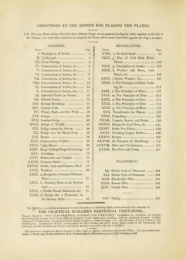
DIRECTIONS TO THE BINDER FOR PLACING THE PLATES.
N B. The same Plates being referred to from different Pages, we recommend placing the whole together at the end of
the Volume ; but where this method is not adopted, the Plates will be most convenient opposite the Pages, as below.
MASONRY.Plates Page
I. Description of Arches ~
II. Cyclograph 3
III. Stone-Cutting 4
IV. Construction of Arches, &c 6
V. Construction of Arches, &c 7
VI. Construction of Arches, S;c 7
VII. Construction of Arches, &c 8
VIII. Construction of Arches, &c. .... 10
rX. Construction of Arches, &c 10
X. Construction of Arches, &c 11
XI. Spherical Vaults or Domes .... 12
XII. Ribbed Groins 13
XIII. Raking Mouldings 14
XIV. Antient Walls 33
XV. Wharf, Dock, and Sea Walls .
.
36
XVI. Bridges 41
XVII. London Bridge 51
XVIII. Bridge of NeuiUy 48
XIX. Bridge across the Severn 49
XX. Bridge over the Menai Strait .
.
50
XXI. Domes 51
XXII. Construction of Spires 58
XXIII. Light-House 60
XXIV. King's College Chapel,Cambridge 57
XXV. Mouldings 76
XXVI. Balustrades and Parapet 77
XXVII. Chimney Shafts 78
XXVIII. Gothic Arch and Chimney Shaft 79
XXIX. Windows 80
XXIX. a. Design for a Grecian Chimney-
Piece 81
XXIX. 6, Chimney Piece in the Grecian
style 81
XXIX. c, Gothic Mural Monument, &c. 81
XXIX. d, Design for a Monument in
the Grecian Style 82
BRICKLAYING.Plates Page
XXIX. e. On Brick-bond 96
XXIX. /, Plan of Cold Bath Fields
Prison 103
XXIX. g, Description of Arches 105
XXIX. h, Window and Door, with
Details, &c 107
XXIX. i, Gothic Window, &c 107
XXIX. i, The Principles of Brick Vault-
ing, &c Ill
XXIX. /, The Principles of Ditto 112
XXIX. ffi. The Principles of Ditto .... 113
XXIX. n. The Principles of Ditto 114
XXIX, 0, The Principles of Ditto .... 116
XXIX. p, The Principles of Ditto 119
XXX. Tunnel under the Thames .... 129
XXXI. Tunnelling 129
XXXII. Tunnels, Sewers, and Drains .. 129
XXXIII. Design for Coal Oven, &c 131
XXXIV. Boiler Fire Places 133
XXXV. On fi.King Copper Boilers 136
XXXVI. Retorts 139
XXXVII. Air Furnaces for Metallurgy .. 154
XXXVIIL Blast and Air Furnaces 159
XXXIX. Fire Place and Pump 165
PLASTERING.
XL. Gothic Style of Ornament .... 201
XLI. Gothic Style of Ornament 201
XLII. Elizabethan Ditto 201
XLIII. Roman Ditto 201
XLIV. French Ditto 202
XLV. Slating 212
The Publisher respectfully recommends to each Subscriber the following highly useful and necessary Addenda :—
THE PRACTICAL BUILDER'S PERPETUAL PRICE-BOOK ;
Being a Sequel to " THE NEW PRACTICAL M.A50NRY AND CARPENTRY," elucidating the Principles of correctly
ascertaining the average Value of the differeut Artificer's Works employed in Building ; with the particular Customs of Mea.
suring and Valuing in the various parts of the United Kingdom ; comprehending, also, the Substance of every Clause in thithe
Building Act. Intended as a Key to, or Illustration of, these Works, and will be found highly useful to the Gentleman, the
Surveyor, and the Architect, as well as to all Persons anywise concerned in the Art of Building.
The Addenda is completed in Eleven Numbers or Two Parts, in Quarto, illustrated with suitable Plates. It is also printed sefa-
rtuly, in Octaoo size,/or the convenience qftlte Practical Builder, Surveyor, Ifc, price Eight Shillings, sewed.
PRACTICAL
MASONRY, BRICKLAYING, &c,
BOOK I.
31 AS O N R Y.
INTRODUCTION.
Art. 1. lYxASONRY, practically considered, is the art of shaping and uniting Stones for
the various purposes of Building. It, therefore, includes the cutting or hewing of stones into
the particular forms required, and the union of them by level and perpendicular joints, con-
nected by the aid of cement, or by iron cramps and lead. The operations of Masonry require
much practical dexterity, with some skill in Geometry and Mechanics.
In treating on this subject, it will be necessary to divide it into several branches ; but first,
we may notice that, though necessity was its parent, nevertheless the fluctuations of this Art
have marked the rise and fall of the Empires.
2. In Egypt, Greece, and Italy, among the greater works of masonry, are included some
of almost incredible magnitude, formed of materials of the most imperishable nature. These
countries seem to have been favoured with every thing which could contribute to their beinc
eternized ; for they abounded in the finest granites, porphyries, and marbles, which rendered their
structures magnificent, independently of their size, or of peculiar contrivance in arrangement.
3. The older specimens of masonry of Britain, in point of geometrical skill and mechanical
arrangement, are inferior to none : the magnificent structure at Cambridge, called King's
College Chapel, is the most celebrated, and was justly styled by Lord Orford, " a work that
alone will be sufficient to ennoble any age ;" and it has, from time to time, received the homage
of those who are best qualified to appreciate its merits. It is to be regretted, however, that in
it, as in most of the old works in this country, too little regard was given to the selection of
durable materials.
Modern masonry is chiefly directed to somewhat different objects ; Bridges, Docks, Light-
houses, &c., works requiring an equal degree of skill, and if not productive of equal magni-
ficence are infinitely superior in utility.
S PRACTICAL MASONRY.
CHAPTER I.
OF THE DESCRIPTION OF ARCHES.
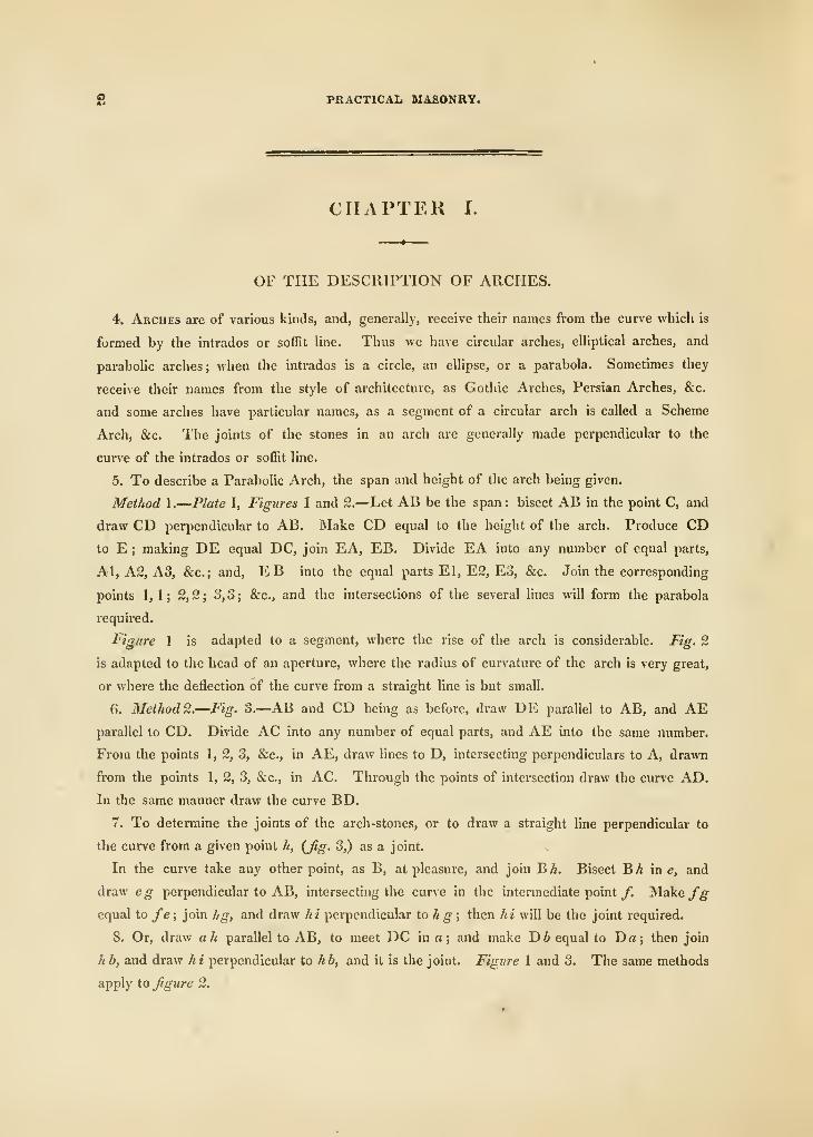
4. Arcues are of various kinds, and, generally, receive their names from the curve which is
formed by the intrados or soffit line. Thus we have circular arches, eUiptical arches, and
parabolic arches ; when the intrados is a circle, an ellipse, or a parabola. Sometunes they
receive their names from the style of architecture, as Gothic Arches, Persian Arches, &c.
and some arches have particular names, as a segment of a circular arch is called a Scheme
Arch, &c. The joints of the stones in an arch are generally made perpendicular to the
curve of the intrados or soffit line.
5. To describe a Parabolic Arch, the span and height of the arch being given.
Method 1.
—
Plate I, Figures 1 and 2.—Let AB be the span: bisect AB in the point C, and
draw CD perpendicular to AB. Make CD equal to the height of the arch. Produce CDto E ; making DE equal DC, join EA, EB. Divide EA into any number of equal parts,
Al, A2, A3, &c. ; and, EB into the equal parts El, E2, E3, &c. Join the corresponding
points 1,1; 2, 2 ; 3, 3 ; &c., and the intersections of the several lines will form the parabola
required.
Figure 1 is adapted to a segment, where the rise of the arch is considerable. Fig. 2
is adapted to the head of an aperture, where the radius of curvature of the arch is very great,
or where the deflection of the curve from a straight line is but small.
6. Method 2.—Fig. 3.—AB and CD being as before, draw DE parallel to AB, and AEparallel to CD. Divide AC into any number of equal parts, and AE into the same number.
From the points 1, 2, 3, &c., in AE, draw lines to D, intersecting perpendiculars to A, drawn
from the points 1, 2, 3, &c., in AC. Through the points of intersection draw the curve AD.
In the same manner draw the curve BD.
7. To determine the joints of the arch-stones, or to draw a straight line perpendicular to
the curve from a given point h, (fig. 3,) as a joint.
In the curve take any other point, as B, at pleasure, and join BA. Bisect Bh in e, and
draw eg perpendicular to AB, intersecting the curve in the intermediate point /. Make fgequal to fe; join hg, and draw hi perpendicular to hg; then hi will be the joint required.
8. Or, draw ah parallel to AB, to meet DC in a; and make D6 equal to Da; then join
h b, and draw hi perpendicular to hb, and it is the joint. Figure 1 and 3. The same methods
apply to figure 2.
ARCHES, &C. 3
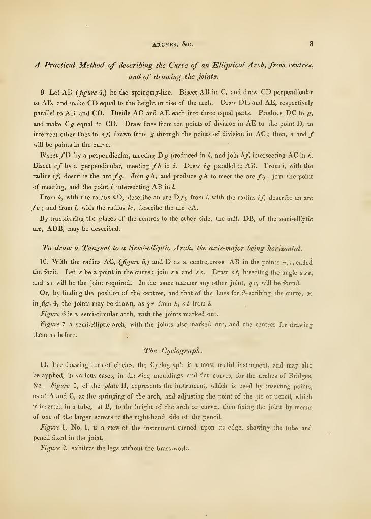
A Practical Method of describing the Curve of an Elliptical Arch, from centres,
and of drawing the joints.
9. Let AB {figure 4,) be the springing-line. Bisect AB in C, and draw CD perpendicular
to AB, and make CD equal to the height or rise of the arch. Draw DE and AE, respectively
parallel to AB and CD. Divide AC and AE each into three equal parts. Produce DC to g,
and make Cg equal to CD. Draw lines from the points of division in AE to the point D, to
intersect other lines in ef, drawn from g through the points of division in AC ; then, e and /will be points in the curve.
Bisect/D by a perpendicular, meeting D^- produced in h, and join hf, intersecting AC in k.
Bisect ef by a perpendicular, meeting fh in i. Draw i q parallel to AB. From i, with the
radius if, describe the axe fq. Join qA, and produce g'A to meet the asc fq : join the point
of meeting, and the point i intersecting AB in I.
From h, with the radius hT>, describe an arc T)f; from i, with the radius if, describe an arc
fe ; and from I, with the radius le, describe the arc eA.
By transferring the places of the centres to the other side, the half, DB, of the semi-elliptic
arc, ADB, may be described.
To draw a Tangent to a Semi-elliptic Arch, the axis-major being horizontal.
10. With the radius AC, (figure 5,) and D as a centre, cross AB in the points u, v, called
the focii. Let * be a point in the curve: join su and sv. Draw si, bisecting the angle usv,
and st will be the joint required. In the same manner any other joint, qr, wiU be found.
Or, by finding the position of the centres, and that of the lines for describing the curve, as
in jig. 4, the joints may be drawn, as g'r from li, st from i.
Figure 6 is a semi-circular arch, with the joints marked out.
Figure 7 a semi-elliptic arch, with the joints also marked out, and the centres for drawing
them as before.,
The Cyclograph.
11. For drawing arcs of circles, the Cyclograph is a most useful instrument, and may also
be applied, in various cases, in drawing mouldings and flat curves, for the arches of Bridges,
&c. Figure 1, of the plate II, represents the instrument, which is used by inserting points,
as at A and C, at the springing of the arch, and adjusting the point of the pin or pencil, which
is inserted in a tube, at B, to the height of the arch or curve, then fixing the joint by means
of one of the larger screws to the right-hand side of the pencil.
Figure 1, No. 1, is a view of the instrument turned upon its edge, showing the tube and
pencil fixed in the joint.
Figure 2, exhibits the legs without the brass-work.
4i PRACTICAL MASONRY.
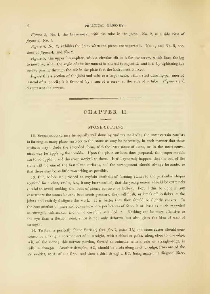
Figure 3, No. 1, the biass-work, with the tube in the joint. No. 2, is a side view of
figure 3, No. 1.
Figure 4, No. 2, exhibits the joint when the pieces are separated. No. 1, and No. 3, sec-
tions oi figure 4, and No. 2.
Figure 5, the upper brass-plate, with a circular slit in it for the screw, which fixes the leg
to move in, when the angle of the instrument is altered to adjust it, and it is by tightening the
screws passing through the slit in the plate that the instrument is fixed.
Figure 6 is a section of the joint and tube to a larger scale, with a steel drawing-pen inserted
instead of a pencil ; it is fastened by means of a screw at the side of a tube. Figure 7 and
8 represent the screws.
CHAPTER II.
STONE-CUTTING.
12. Stone-cutting may be equally well done by various methods ; the most certain consists
in formino- as many plane surfaces to the stone as may be necessary, in such manner that these
surfaces may include the intended form, with the least waste of stone, or in the most conve-
nient way for applying the moulds. Upon the plane surfaces thus prepared, the proper moulds
are to be applied, and the stone worked to them. It will generally happen, that the bed of the
stone will be one of the first plane surfaces, and the arrangement should always be made, so
that there may be as little re-working as possible.
13. But, before we proceed to explain methods of forming stones to the particular shapes
required for arches, vaults, &c., it may be remarked, that the young mason should be extremely
careful to avoid making the beds of stones concave or hollow. For, if this be done in any
case where the stones have to bear much pressure, they will flush, or break off in flakes at the
joints and entirely disfigure the work. It is better that they should be slightly convex. In
the construction of piers and columns, where perfectness of form is at least as much regarded
as strength, this maxim should be carefully attended to. Nothing can be more offensive to
the eye than a flushed joint, since it not only deforms, but also gives the idea of want of
strength.
14. To form a perfectly Plane Surface, (see fig. 1, plate III,) the stone-cutter should com-
mence by making a narrow part of it straight, with a chisel or point, along close to one edge,
AB, of the stone; this narrow portion, formed to coincide with a rule or straight-edge, is
called a draught. Another draught, AC, should be made along another edge, from one of the
extremities, as A, of the first ; and then a third draught, BC, being made in a diagonal direc-
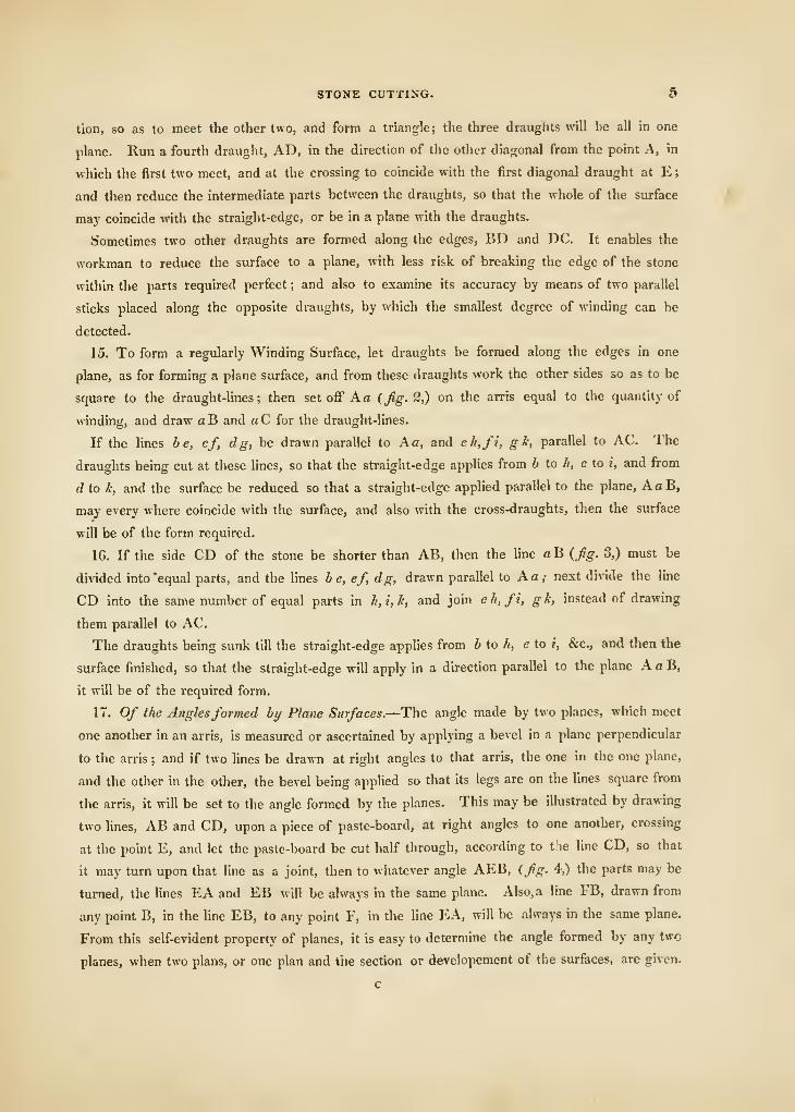
STONE CUTTING. 5
tion, so as to meet the other two, and form a triangle; the three draughts will be all in one
plane. Run a fourth draught, AD, in the direction of the other diagonal from the point A, in
which the first two meet, and at the crossing to coincide with the first diagonal draught at E
;
and then reduce the intermediate parts between the draughts, so that the whole of the surface /5
may coincide with the straight-edge, or be in a plane with the draughts.
Sometimes two other draughts are formed along the edges, BD and DC. It enables the
workman to reduce the surface to a plane, with less risk of breaking the edge of the stone
within the parts required perfect ; and also to examine its accuracy by means of two parallel
sticks placed along the opposite draughts, by which the smallest degree of wmding can be
detected.
15. To form a regidarly Winding Surface, let draughts be formed along the edges in one
plane, as for forming a plane surface, and from these draughts work the other sides so as to be
square to the draught-lines; then set off A a (Jig. 2,) on the arris equal to the quantity of
winding, and draw aB and a C for the draught-lines.
If the lines be, cf, dg, be drawn parallel to Aa, and eh,fi, g k, parallel to AC. The
draughts being cut at these lines, so that the straight-edge applies from b to h, c to i, and from
d to k, and the surface be reduced so that a straight-edge applied parallel to the plane, AaB,
may every where coincide with the surface, and also with the cross-draughts, then the surface
will be of the form required.
16. If the side CD of the stone be shorter than AB, then the line aB {fig. 3,) must be
divided into 'equal parts, and the lines be, ef, dg, drawn parallel to Ao; next divide the line
CD into the same number of equal parts in h,i,k, and join eh,fi, gh, instead of drawing
them parallel to AC.
The draughts being sunk till the straight-edge applies from b to //, e to i, &c., and then the
surface finished, so that the straight-edge will apply in a direction parallel to the plane AaB,
it will be of the required form.
n. Of t/ie Anglesformed by Plane Surfaces.—The angle made by two planes, which meet
one another in an arris, is measured or ascertained by applying a bevel in a plane perpendicular
to the arris ; and if two lines be drawn at right angles to that arris, the one in the one plane,
and the other in the other, the bevel being applied so that its legs are on the hues square from
the arris, it will be set to the angle formed by the planes. This may be illustrated by drawing
two lines, AB and CD, upon a piece of paste-board, at right angles to one another, crossing
at the point E, and let the paste-board be cut half through, according to t'.ie line CD, so that
it may turn upon that line as a joint, then to whatever angle AEB, (fig. 4,) the parts may be
turned, the lines EA and EB will be always in the same plane. Also, a line FB, drawn from
any point B, in the Une EB, to any point F, in the line EA, will be always in the same plane.
From this self-evident property of planes, it is easy to determine the angle formed by any two
planes, when two plans, or one plan and the section or developement of the surfaces, are given.
c
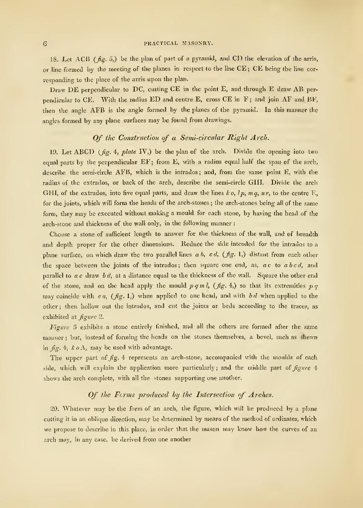
6 PRACTICAL MASONRY.
18. Let ACB {fig. 5,) be the plan of part of a pvramitl, and CD the elevation of the arris,
or line formed by the meeting of the planes in respect to the line CE ; CE being the hne cor-
responding to the place of the arris upon the plan.
Draw DE perpendicular to DC, cutting CE in the point E, and through E draw AB per-
pendicular to CE. With the radius ED and centre E, cross CE in F ; and join AF and BF,
then the angle AFB is the angle formed by the planes of the pyramid. In this manner the
angles formed by any plane surfaces may be found from drawings.
Of the Construction of a Se??ii-circular Right Arch.
19. Let ABCD {Jig. 4, plate IV,) be the plan of the arch. Divide the opening into two
equal parts by the perpendicular EF ; from E, with a radius equal half the span of the arch,
describe the semi-circle AFB, which is the intrados ; and, from the same point E, with tlie
radius of the extrados, or back of the arch, describe the semi-circle GHI. Divide the arch
GHI, of the extrados, into five equal parts, and draw the lines k o, Ip, mq, nr, to the centre E,
for the joints, which will form the heads of the arch-stones ; the arch-stones being all of the same
form, they may be executed without making a mould for each stone, by having the head of the
arch-stone and thickness of the wall only, in the following manner
:
Choose a stone of sufficient length to answer for the thickness of the wall, and of breadth
and depth proper for the other dimensions. Reduce the side intended for the intrados to a
plane surface, on which draw the two parallel hnes ab, cd, {fig. 1,) distant from each other
the space between the joints of the intrados; then square one end, as, ac to abed, and
parallel to a c draw bd, at a distance equal to the thickness of the wall. Squai'e the other end
of the stone, and on the head apply the mould p q m 1, {fig. 4,) so that its extremities p q
may coincide with c a, (fig. 1,) when a])plied to one head, and with bd when applied to the
other ; then hollow out the intrados, and cut the joints or beds according to the traces, as
exhibited at figure 2.
Figure 3 exhibits a stone entirely finished, and all the others are formed after the same
manner ; but, instead of forming the heads on the stones themselves, a bevel, such as Shewn
in fig. 4, koA, may be used with advantage.
The upper part of fig. 4 represents an arch-stone, accompanied with the moulds of each
side, which will explain the application more particularly ; and the middle part of figure 4
shows the arch complete, with all the stones supporting one another.
Of the Forms produced by the Intersection of Arches.
20. Whatever may be the form of an arch, the figure, which will be produced by a plane
cutting it in an oblique direction, may be determined by means of the method of ordinates, which
we propose to describe in this place, in order that the mason may know how the curves of an
arch may, in any case, be derived from one another
CONSTRUCTION OF ARCHES, &C 7
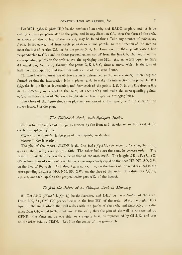
Let MFL {fig. G, j^lute III,) be the section of an arch, and BADC its plan, and let it be
cut by a plane perpendicular to the plan, and in any direction CA, then the form of the arch,
as shown on the surface of the section, may be found thus : Take any number of points, as,
/, e, d, in the curve, and from each point draw a line parallel to the direction of the arch to
meet the line of section CA, as in the points 6, 5, 4. From each of these points raise a line
perpendicular to CA ; and on these perpendiculars set ofF from the line CA, the height of the
corresponding points in the arch above the springing-line ML. As, make EG equal to NF;
^k equal g d, &c. ; and, through the points G,K,?, A, C, draw a curve, which is the form of
half the arch required, and the other half will be of the same figure.
21. The line of intersection of two arches is detennined in the same manner, when they are
formed so that the intersection is in a plane : and, to make the intersection in a plane, let BD
{fig. 6,) be the line of intersection, and from each of the points 1, 2, 3, in this line draw a line
in the direction, or parallel to the sides, of each arch ; and make the corresponding points,
a, b, c, in these arches of the same height above their respective springing-lines.
The whole of the figure shows the plan and sections of a plain groin, with the joints of the
stones inserted in the plan.
T/ie Elliptical Arch, with Splayed Jambs.
22. To find the angles of the joints formed by the front and intrados of an Elliptical Arch,
erected on splayed jambs.
Figure 1, on plate V, is the plan of the Imposts, or Jambs.
Figure 2, the Elevation.
The plan of the impost ABCDE is the first bed; /^/«JA, the second; Imnop, the third.
qrstu, the fourth ; vwxijx, the fifth : The other beds are the same in reverse order. The
breadth of all these beds is the same as that of the arch itself. The lengths hK, wP, sV, xZ,
of tile front lines of the moulds of the beds are respectively equal to the lines HF, NL, SQ, XV,
on the face of the arch. And also, hg, nm, sr, xw, on the fronts of the moulds equal to the
corresponding distances HG, NM, SR, XW, on the face of the arch. The distances kf, p I,
u q, a V, are each equal to the perpendicular part AE, of the impost.
To find the Joints of an Oblique Arch in Masonry.
23. Let ABC {Plate VI, fig. 1,) be the intrados, and DEF be the extrados, of the arch.
Draw DK, AL, CM, FN, perpendicular to the base DF, of the arch. Make the angle DFG
equal to the angle which the wall makes with the jambs of the arch, and draw KN, at a dis-
tance from GF, equal to the thickness of the wall ; then the plan of the wall is represented by
GFNK ; the abutment on one side, or springing base, is represented by GHLK, and that
on the other side by FIMN. Let J be the centre of the given arch.
8 PRACTICAL MASONRY.
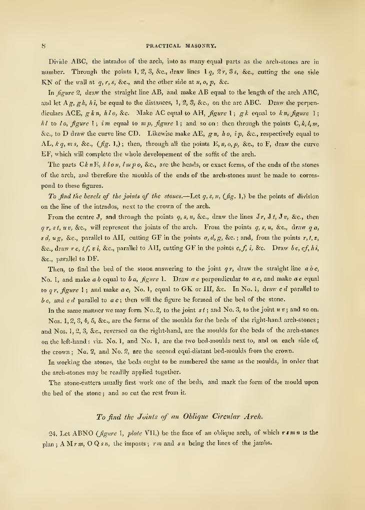
Divide ABC, the intrados of the arch, into as many equal parts as the arch-stones are in
number. Through the points 1, 2, 3, &c., draw hnes \ q, 2r,3s, Sec, cutting the one side
KN of the wall at q, r, s, Sec, and the other side at n, o, p, &c.
In figure 2, draw the straight line AB, and make AB equal to the length of the arch ABC,
and let hg, gh, hi, be equal to the distances, 1, 2, 3, &c., on the arc ABC. Draw the perpen-
diculars ACE, gin, hlo, &c. Make AC equal to AH, figure \; gk equal to k n, figure 1
;
hi to lo, figure \; im equal to mp, figure 1 ; and so on : then through the points C,k,l,m,
&c., to D draw the curve line CD. Likewise make AE, g n, h o, ip, &c., respectively equal to
K\j,kq,ms, &c., {fig- 1,); then, through all the points ^,n,o,p, &c., to F, draw the curve
EF, which will complete the whole developement of the soffit of the arch.
The parts CA «E, klon, Impo, &c., are the heads, or exact forms, of the ends of the stones
of the arch, and therefore the moulds of the ends of the arch-stones must be made to corres-
pond to these figures.
To find the bevels of the joints of the stones.—Let q,s, u, {fig. 1,) be the points of division
on the line of the intrados, next to the crown of the arch.
From the centre J, and through the points q, s, u, &c., draw the lines Jr, J t, J v, &c., then
qr, st,uv, &c., will represent the joints of the arch. From the points q, s, u, &c., draw q a,
sd, ug, &c., parallel to AH, cutting GF in the points a,d,g, &c. ; and, from the points r,t,v,
&c., draw re, tf, vi, &c., parallel to AH, cutting GF in the points c,f, i, &c. Draw be, ef hi,
&c., parallel to DF.
Then, to find the bed of the stone answering to the joint q r, draw the straight line abc.
No. 1, and make ab equal to ba, figure 1. Draw ae perpendicular to ac, and make ae equal
to qr, figure 1 ; and make ac, No. 1, equal to GK or HI, &c. In No. 1, draw cd parallel to
b e, and e d parallel to a c ; then will the figure be formed of the bed of the stone.
In the same manner we may form No. 2, to the joint s t ; and No. 3, to the joint u v ; and so on.
Nos. 1, 2, 3, 4, 5, &c., are the forms of the moulds for the beds of the right-hand arch-stones
;
and Nos. 1, 2, 3, &c., reversed on the right-hand, are the moulds for the beds of the arch-stones
on the left-hand: viz. No. 1, and No. 1, are the two bed-moulds next to, and on each side of,
the crown ; No. 2, and No. 2, are the second equi-distant bed-moulds from the crown.
In working the stones, the beds ought to be numbered the same as the moulds, in order that
the arch-stones may be readily applied together.
The stone-cutters usually first work one of the beds, and mark the form of the mould upon
the bed of the stone ; and so cut the rest from it.
To find the Joints of an Oblique Circular Arch.
24. Let ABNO {figure 1, plate VII,) be the face of an oblique arch, of which rtmn is the
plan ; AMrn», OQsn, the imposts ; rm and sn being the lines of the jambs.
OBLIQUE ARCHES. 9
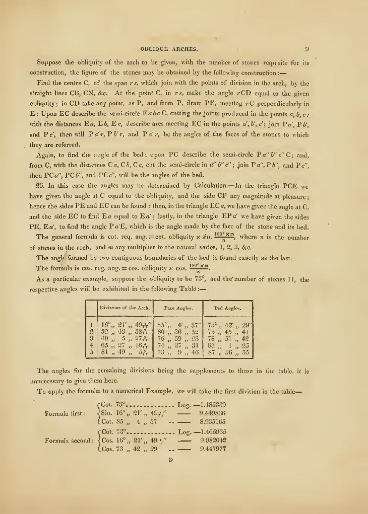
Suppose the obliquity of the arch to be given, with the number of stones requisite for its
construction, the figure of the stones may be obtained by the following construction :
—
Find the centre C, of the span rs, which join with the points of division in the arch, by the
straight hnes CB, CN, &c. At the point C, in rs, make the angle rCD equal to the given
obliquity; in CD take any point, as P, and from P, draw PE, meeting rC perpendicularly in
E : Upon EC describe the semi-circle Ea6cC, cutting the joints produced in the points a, b,c:
with the distances Ea, E6, Ec, describe arcs meeting EC in the points a',b', c'; join Pa', Fb',
and Pc', then will Par, V b' r, and Per, be the angles of the faces of the stones to which
they are referred.
Again, to find the angle of the bed: upon PC describe the semi-cu-cle Pa"b" c"C; and,
from C, with the distances Ca,Cb,Cc, cut the semi-circle in a" b" c"; join Fa",Pb", and Pc",
then PC a", PC b", and PC c", will be the angles of the bed.
25. In this case the angles may be determined by Calculation.—In the triangle PCE we
have given the angle at C equal to the obliquity, and the side CP any magnitude at pleasure
;
hence the sides PE and EC can be found : then, in the triangle ECc, we have given the angle at C,
and the side EC to find Ea equal to Eo' ; lastly, in the triangle EPa' we have given the sides
PE, Ea', to find the angle Pa'E, which is the angle made by the face of the stone and its bed.
The general formula is cot. req. ang. =:cot. obliquity x sin.180°Xn>
', where w is the number
of stones in the arch, and ?w any multiplier in the natural series, 1, 2, 3, &c.
The angl/ formed by two contiguous boundaries of the bed is found exactly as the last.
The formula is cos. reg. ang. = cos. obliquity x cos. ^.
As a particular example, suppose the obliquity to be 73°, and the' number of stones 11, the
respective angles will be exhibited in the following Tabid :
—
10 PRACTICAL MASONRY.
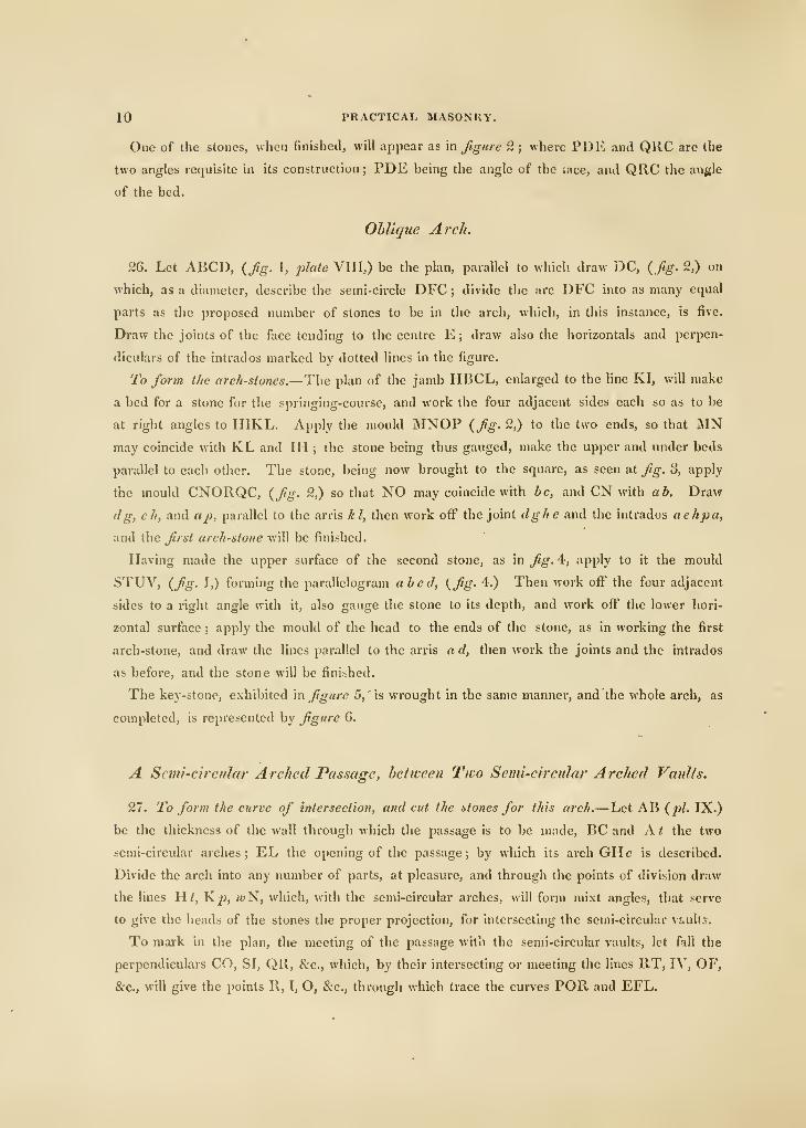
One of the stones, when finished, will appear as in figure 2 ; where PDE and QRC are the
two angles requisite in its construction ; PDE being the angle of the iace, and QRC the an{{le
of the bed.
Oblique Arch.
26. Let ABCD, (fig. 1, plate VIII,) be the plan, parallel to which draw DC, (fig. 2,) on
which, as a diameter, describe the semi-circle DFC ; divide the arc DFC into as many equal
parts as the proposed number of stones to be in the arch, which, in this instance, is five.
Draw the joints of the face tending to the centre E ; draw also the horizontals and perpen-
diculars of the intrados marked by dotted lines in the figure.
To form the arch-stones.—The plan of the jamb HBCL, enlarged to the line KI, will make
a bed for a stone for the springing-course, and work the four adjacent sides each so as to be
at right angles to IIIKL. Apply the mould MNOP (fig. 2,) to the two ends, so that MNmay coincide with KL and IH ; the stone being thus gauged, make the upper and under beds
parallel to each other. The stone, being now brought to the square, as seen at fig. o, apply
the mould CNORQC, (fig. 2,) so that NO may coincide with be, and CN with ab. Draw
dg, eh, and ap, parallel to the arris hi, then work off the joint dghe and the intrados aehpa,
and the fiirst arch-stone will be finished.
Having made the upper surface of the second stone, as in fig. 4, apply to it the mould
STUV, (fig. 1,) forming the parallelogram abed, (fig. 4.) Then work off the four adjacent
sides to a right angle with it, also gauge the stone to its depth, and work off the lower hori-
zontal surface ; apply the mould of the head to the ends of the stone, as in working the first
arch-stone, and draw the lines parallel to the arris a d, then work the joints and the intrados
as before, and the stone will be finished.
The key-stone, exhibited m figure 5, 'is wrought in the same manner, and the whole arch, as
completed, is represented by figure 6.
A Semi-circular Arched Pas.mge, hehveen Tivo Semi-circtilar Arched Vmdls.
21. To form the curve of intersection, and cut the itones for this arch.—Let AB (pi. IX.)
be the thickness of the wall through which the passage is to be made, BC and A t the two
semi-circular arches ; EL the opening of the passage ; by which its arch GHc is described.
Divide the arch into any number of parts, at pleasure, and through the points of division draw
the lines Ut, K^, wN, which, with the semi-circular arches, will form mixt angles, that serve
to give the heads of the stones the proper projection, for intersecting the semi-circular vaults.
To mark in the plan, the meeting of the passage with the semi-circular vaults, let fall the
perpendiculars CO, SI, QR, &c., which, by their intersecting or meeting the lines RT, IV, OF,
&c., will give the points R, I, O, &c., through which trace the curves POR and EFL.
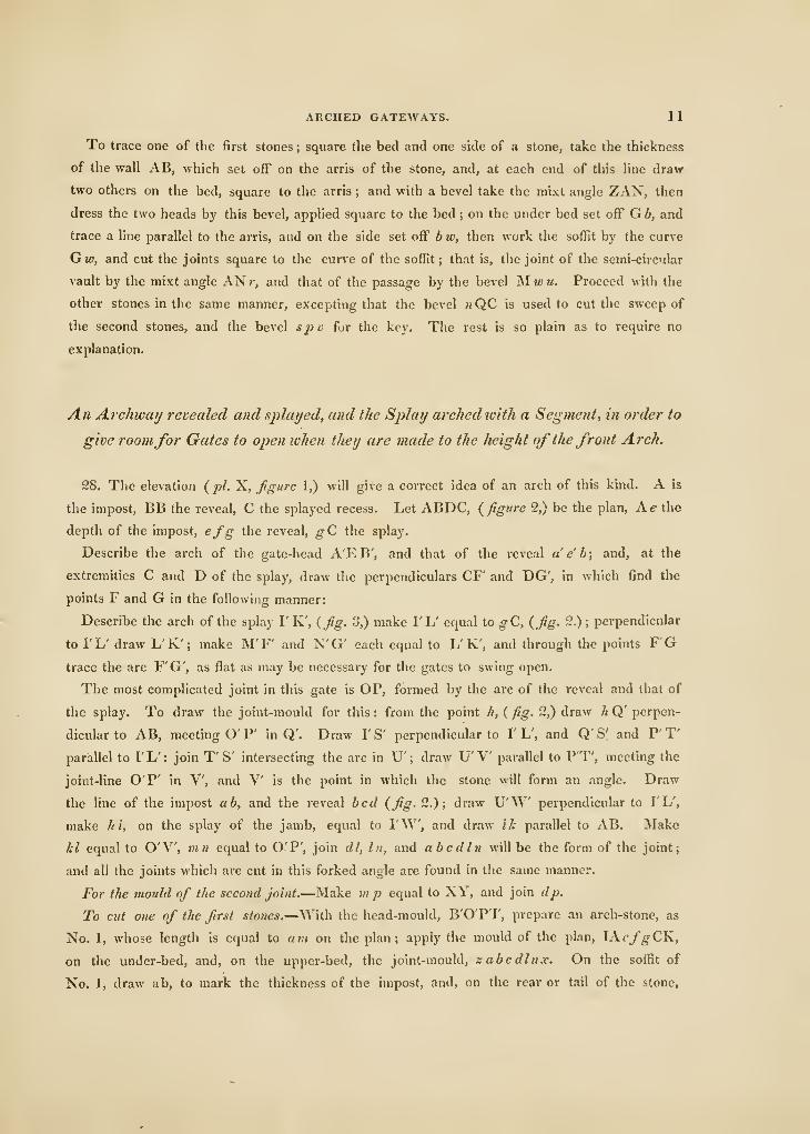
ARCHED GATEWAYS. 11
To trace one of the first stones; square the bed and one side of a stone, take the thickness
of the wall AB, wliich set off on the arris of the stone, and, at each end of this line draw
two others on the bed, square to the arris ; and with a bevel take the mixt angle ZAN, then
dress the two heads by this bevel, applied square to the bed ; on the under bed set off G b, and
trace a line parallel to the arris, and on the side set off bw, then work the soffit by the curve
Gw, and cut the joints square to the curve of the sofiSt ; that is, the joint of the semi-circular
vault by the mixt angle ANr, and that of the passage by the bevel Mm)m. Proceed with the
other stones in the same manner, excepting that the bevel wQC is used to cut the sweep of
the second stones, and the bevel sj} v for the key. The rest is so plain as to require no
explanation.
An Archway revealed and splayed, and the Splay arched with a Segment, in order to
give roomfor Gates to ojien when they are made to the height of the front Arch.
28. The elevation {pi. X, figure 1,) will give a correct idea of an arch of this kind. A is
the impost, BB the reveal, C the splayed recess. Let ABDC, {figure 2,) be the plan, h.e the
depth of the impost, efg the reveal, ^C the splay.
Describe the arch of the gate-head A'E B', and that of the reveal a e' b; and, at the
extremities C and D of the splay, draw the perpendiculars CF' and DG', in which find the
points F and G in the following manner:
Describe the arch of the splay I'K', {fig. 3,) make I'L' equal to gC, {fig. 2.) ;perpendicular
to I'L' draw L'K'; make M'F' and N'G' each equal to L' K', and through the points FGtrace the arc F'G', as flat as may be necessary for the gates to swing open.
The most complicated joint in this gate is OP, formed by the arc of the reveal and that of
the splay. To draw the joint-mould for this: from the point //, ( /?^. 2,) draw A Q' perpen-
dicular to AB, meeting O' P' in Q'. Draw I'S' perpendicular to I' L', and Q' S' and P' T'
parallel to 1' L' : join T' S' intersecting the arc in U' ; draw U'V parallel to P'T', meeting the
joint-line O'P' in V, and V is the point in which the stone will form an angle. Draw
the line of the impost ah, and the reveal bed {fig- 2.); draw U'W perpendicular to I'L',
make hi, on the splay of the jamb, equal to I'W, and draw ik parallel to AB. Make
kl equal to O'V, mn equal to O'P', join dl, In, and abcdln will be the form of the joint;
and all the joints which are cut in this forked angle are found in the same manner.
For the mould of the second joint.—Make m p equal to XY, and join dp.
To cut one of the first stones.—With the head-mould, B'O'P T, prepare an arch-stone, as
No. 1, whose length is equal to am on the plan; apply the mould of the plan, lAefgCK,
on the under-bed, and, on the upper-bed, the joint-mould, s abcdlnx. On the soffit of
No. 1, draw ab, to mark the thickness of the impost, and, on the rear or tail of the stone.
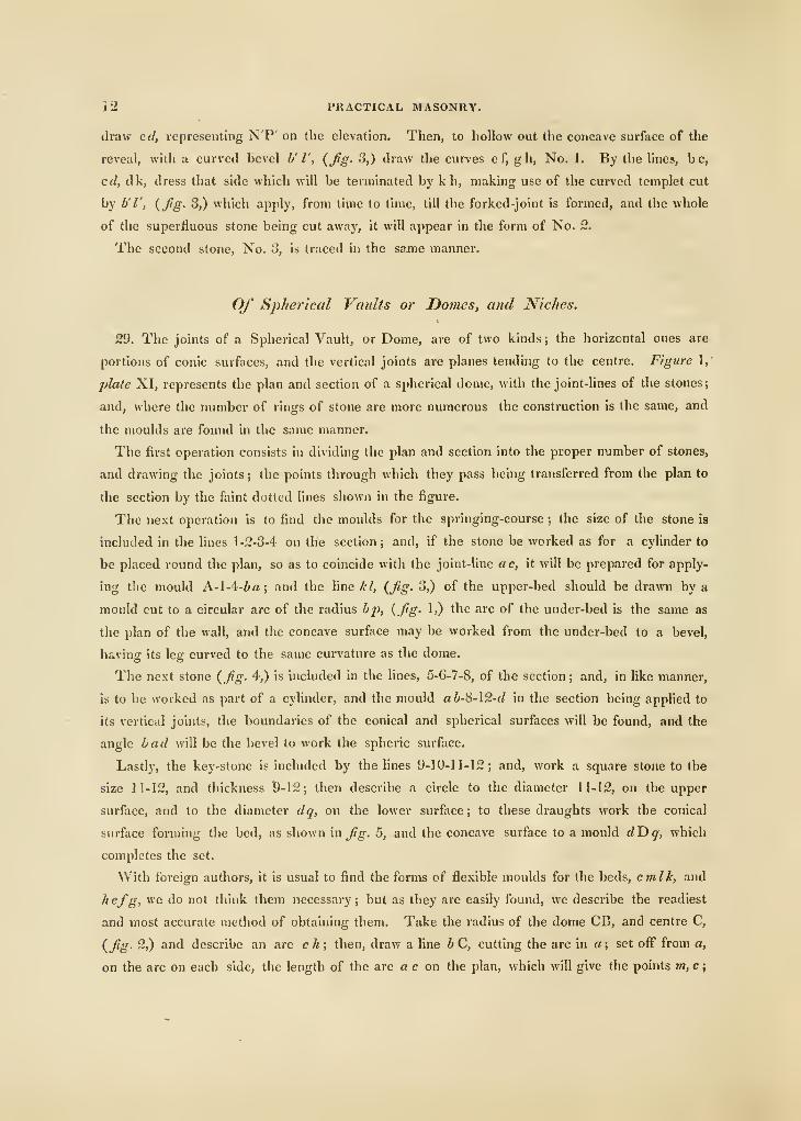
J 2 PUACTICAL MASONRY.
draw erf, representing N'P' on the elevation. Then, to hollow out the concave surface of the
reveal, witli a curved bevel h' I', {fig. 3,) draw the curves e f, gh. No. 1. By the lines, be,
cd, dk, dress that side which will be terminated by k h, making use of the curved templet cut
by b'l', {fig. 3,) which apply, from time to time, till the forked-joint is formed, and the whole
of the superfluous stone being cut away, it will appear in the form of No. 2,
The second stone. No. 3, is traced in the same manner.
Of Spherical Vaults or Domes, and Niches.
29. The joints of a Spherical Vault, or Dome, are of two kinds ; the horizontal ones are
portions of conic surfaces, and the vertical joints are planes tending to the centre. Figure 1,
plate XI, represents the plan and section of a spherical dome, with the joint-lines of the stones;
and, where the number of rings of stone are more numerous the construction is the same, and
the moulds are found in the same manner.
The first operation consists in dividing the plan and section into the proper number of stones,
and drawing the joints; the points through which they pass being transferred from the plan to
the section by the faint dotted lines shown in the figure.
The next operation is to find the moulds for the springing-course ; the size of the stone is
included in the lines 1-2-3-4 on the section; and, if the stone be worked as for a cylinder to
be placed round the plan, so as to coincide with the joint-line ac, it will be prepared for apply-
ing tlie mould A.-\A-ba; and the line Z;^, {fig. 3,) of the upper-bed should be drawn by a
mould cut to a circular arc of the radius bp, {fig. 1,) the arc of the under-bed is the same as
the plan of the wall, and the concave surface may be worked from the under-bed to a bevel,
having its leg curved to the same curvature as the dome.
The next stone {fig. 4,) is included in the lines, 5-6-7-8, of the section; and, in like manner,
is to be svorked as part of a cylinder, and the mould ab-\i-\2-d in the section being applied to
its vertical joints, the boundaries of the conical and spherical surfaces will be found, and the
angle bad will be the bevel to work the spheric surface.
Lastly, the key-stone is included by the lines 9-10-11-12; and, work a square stone to the
size 11-12, and thickness 9-12; then describe a circle to the diameter 11-12, on the upper
surface, and to the diameter dq, on the lower surface; to these draughts work the conical
surface forming the bed, as shown in fig. 5, and the concave surface to a mould dUq, which
completes the set.
With foreign authors, it is usual to find the forms of flexible moulds for the beds, cmlk, and
hefg, we do not think them necessary; but as they are easily found, we describe the readiest
and most accurate method of obtaining them. Take the radius of the dome CB, and centre C,
{fig. 2,) and describe an arc ch; then, draw a fine bC, cutting the arc in a; set off from a,
on the arc on each side, the length of the arc a c on the plan, which will give the points m, c;
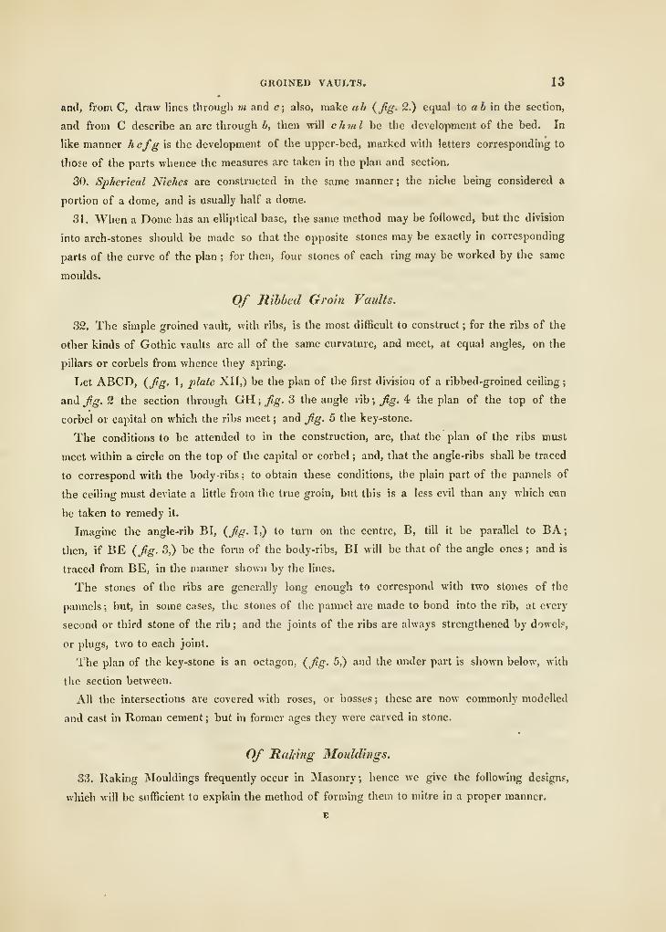
GROINED VAULTS. 13
and, from C, draw lines through m and c; also, make ab {Jig. 2.) equal to a Zi in the section,
and from C describe an arc through b, then will chml be the development of the bed. In
like manner h efg is the development of the upper-bed, marked with letters corresponding to
those of the parts whence the measures are taken in the plan and section.
30. Spherical Niches are constructed in the same manner; the niche being considered a
portion of a dome, and is usually half a dome.
31. When a Dome has an elliptical base, the same method may be followed, but the division
into arch-stones should be made so that the opposite stones may be exactly in corresponding
parts of the curve of the plan ; for then, four stones of each ring may be worked by the same
moulds.
Of Ribbed Groin Vaults.
32. The simple groined vault, with ribs, is the most difficult to construct ; for the ribs of the
other kinds of Gothic vaults are all of the same curvature, and meet, at equal angles, on the
pillars or corbels from whence they spring.
Let ABCD, {fig. 1, plate XII,) be the plan of the first division of a ribbed-groined ceiling
;
and fig. 2 the section through GH ; fig. 3 the angle rib; fig. 4 the plan of the top of the
corbel or capital on which the ribs meet ; and fig. 5 the key-stone.
The conditions to be attended to in the construction, are, that the plan of the ribs must
meet within a circle on the top of the capital or corbel ; and, that the angle-ribs shall be traced
to correspond with the body -ribs ; to obtain these conditions, the plain part of the pannels of
the ceiling must deviate a little from the true groin, but this is a less evil than any which can
be taken to remedy it.
Imagine the angle-rib BI, (fig. 1,) to turn on the centre, B, till it be parallel to BA;
then, if BE (fig. 3,) be the form of the body-ribs, BI will be that of the angle ones ; and is
traced from BE, in the manner shown by the lines.
The stones of the ribs are generally long enough to correspond with two stones of the
pannels ; but, in some cases, the stones of the pannel are made to bond into the rib, at every
second or third stone of the rib ; and the joints of the ribs are always strengthened by dowel?,
or plugs, two to each joint.
The plan of the key-stone is an octagon, (fig. 5,) and the under part is shown below, with
the section between.
All the intersections are covered with roses, or bosses ; these are now commonly modelled
and cast in Roman cement ; but in former ages they were carved in stone.
Of Raking Mouldings.
33. Raking Mouldings frequently occur in Masonry; hence we give the following designs,
which will be sufficient to explain the method of forming them to mitre in a proper manner.
E
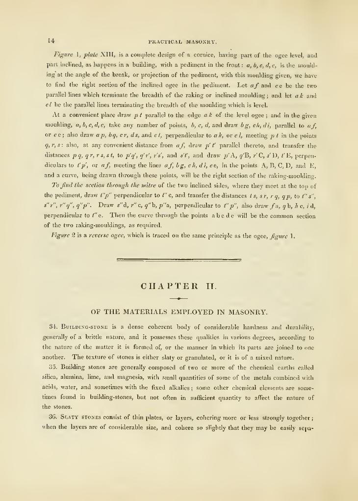
l-t PRACTICAL MASONRY.
Figure 1, plate XIII, is a complete design of a cornice, having part of the ogee level, and
part inclined, as happens in a building, with a pediment in the front : a, b, c, d, e, is the mould-
ing at the angle of the break, or projection of the pediment, with this moulding given, we have
to find the right section of the inclined ogee in the pediment. Let af and e e be the two
parallel lines which terminate the breadth of the raking or inclined moulding ; and let a k and
el he the parallel lines tenninating the breadth of the moulding which is level.
At a convenient place draw 2> t parallel to the edge a h of the level ogee ; and in the given
moulding, a,b,c,d,e, take any number of points, b, c, d, and draw bg, c/i, di, parallel to af,
or ee; also draw ap, bq, cr, ds, and ct, perpendicular to ak, or el, meeting pt m the points
q, r, s : also, at any convenient distance from af, draw p' t' parallel thereto, and transfer the
distances p q, qr, rs,st, to p'q', q'r', r's', and s'i', and draw p'A, q'B, r'C, s'D, fE, perpen-
diculars to t'p', or af, meeting the lines af, bg, ch, di, ee, in the points A, B, C, D, and E,
and a curve, being drawn through these points, will be the right section of the raking-moulding.
To find the section through the mitre of the two inclined sides, where they meet at the top of
the pediment, draw t"p" perpendicular to t" e, and transfer the distances ts, sr, rq, qp, to t" s",
s"r", r"q", q"p". Draw «"d, r" c, q"h, 2)"a; perpendicular to f'j}", also draw /a, qh, he, id,
perpendicular to t" e. Then the curve through the points abode will be the common section
of the two raking-mouldings, as required.
Figure 2 is a reverse ogee, which is traced on the same principle as the ogee, figure 1.
CHAPTER II.
OF THE MATERIALS EMPLOYED IN MASONRY.
Si. BuiLDiNG-STONE is a dense coherent body of considerable hardness and durability,
generally of a brittle nature, and it possesses these qualities in various degrees, according to
the nature of the matter it is formed of, or the manner in which its parts are joined to one
another. The texture of stones is either slaty or granulated, or it is of a mixed nature.
35. Building stones are generally composed of two or more of the chemical earths called
siHca, alumina, hme, and magnesia, with small quantities of some of the metals combined with
acids, water, and sometimes with the fixed alkalies ; some other chemical elements are some-
times found in building-stones, but not often in sufficient quantity to affect the nature of
the stones.
36. Slaty stones consist of thin plates, or layers, cohering more or less strongly together
;
when the layers are of considerable size, and cohere so slightly that they may be easily sepa*
MATERIALS. 15
rated, the stones are called Slates. The layers are always nearly parallel to the quarry-beds of
the stone, and they should always be horizontal, or as nearly so as possible, in a building,-
otherwise the action of the weather will cause them to separate, and fall off in flakes. Sand-
stones generally have a slaty texture, and the direction of the layers may often be discovered
by their different shades of colour, when they will not readily separate ; in others, the layers
may be distinguished by the position of minute scales of shining mica, which always lie parallel
to them. In most stones, the direction of the layers may be ascertained by the facility with
which the stone yields to the tool in that direction, but a considerable degree of practice is
necessary to acquire so nice a discrimination of resistance, and good workmen only attain it.
37. Among slaty stones those are the most durable in which the slaty structure is least
distinct, and the texture uniform. When the parts do not perfectly cohere, they are soon
injured by frost, and they are wholly unfit for places alternately wet and dry.
38. Granulated stones consist of distinct concretions resembling grains, either all of the
same, or of different minerals, cohering together. When the texture is uniform, and the
grains or concretions are small, stones of this kind are always strong and durable, if the con-
cretions themselves be so. Granulated stones are sometimes open and porous, but when they
are uniformly so, they seldom suffer materially by frost, because their uniform porosity allows
the expansive force of the congealing-water to be distributed in every direction.
39. Stones of a compound structure, that is, partly laminated and ])artly granular, have,
more or less, of the characters of the two classes before described ; for it may be observed, in
coarse-grained granite, that the laminated structure of some of its parts, render it very liable
to shiver away by the effect of the weather.
40. All the kinds of stone, in the quarry, are found divided by vertical or inclined seams, cr
joints, which are sometimes so close that they cannot be distinguished till the stones be wrought,
but they often separate under the tool at such seams ; and it is not safe to employ stone to resist
any considerable cross-strains, on account of the difficulty of knowing where those seams are.
41. The qualities requisite for building-stones for bridges, or water-works, are, hardness,
tenacity, and compactness, with the property of resisting the decomposing effects of water, and
of the atmosphere. Besides, the strength necessary to support the weight in such buildings,
they must also often have to resist the impetus of floating bodies, and particularly of large
masses of ice. Those stones which are the hardest, are not precisely those which have the
most tenacity or toughness, of this we have a familiar illustration in comparing common lime-
stone and glass ; the latter, though much harder, is far more easily broken than the former.
42. The causes that accelerate the decay and destruction of stone in buildings are nearly
the same with those which occasion the destruction or wear of rocks on the surface of the
globe ; they may be classed into two kinds : those of decomposition, and those of disunion of
parts. In the former, a chemical change is effected in the stone itself; in the latter, a mecha-
nical division and separation of its parts.
IG PRACTICAL MASONRY.
43. Decomposition takes place, when the stone contains parts that are, more or less, soluble
in water, or which enter into combination with the oxygen of the air or acids in water. Iron,
in different states of oxydation, and in different proportions, enters into the composition of
almost all stones, and is frequently an important agent in their decomposition. When stones
contain pure iron, it rusts or oxydates, and expands so as to burst the parts asunder. The
iron absorbing oxygen and carbonic acid from the air, the presence of moistures accelerates
this kind of decomposition and it is always still further hastened by increase of temperature.
According to the observations of Kirwan, stones, containing iron, which does not contain its
full doze of oxygen, are of a black, a brown, or a bluish colour ; arid, in some instances, when
united with clay and magnesian earth, they are of a gray or greenish gray ; the former, as the
iron draws oxygen from the air, changes to purple, red, orange, and, finally, pale yellow ; the
latter kind becomes, at first, blue, then purple, then red, &c. But stones, containing iron,
combined with its full doze of oxygen, are generally very durable : such are red porphyry,
jaspers, &c. Stones, containing manganese, lime, alumina, carbon, or bitumen, in particular
states, are subject of decomposition, from the affinities of one or other of these bodies ; but
nothing very decisive is, or perhaps can be, known, respecting such changes, unless the com-
ponent parts be determined with some certainty.
44. Disintegration is the separation of the parts of stones by mechanical action , the chief
cause is, the congelation of water in the minute pores and fissures of stones, which bursts them
open, or separates small parts according as the structure is slaty, or irregularly granulated.
The south sides of buildings, in northern climates, are most subject to fail from this cause;
for the surface is often thawed, and filled with wet, in the sunny part of the day, and frozen
again at night. This repeated operation of freezing is also very injurious to sea-walls, the
piers of bridges, and other works exposed alternately to water and frost.
45. Granite is a compound sihceous rock, which varies much in the proportion of its
constituent parts, and its degrees of hardness ; compared with most other rocks, granite may
be considered as a durable building-stone ; but those granites that contain much white felspar,
and only a small portion of quartz, like the greater part of tlie granites of Cornwall and De-
vonshire, are liable to decomposition and disintegration much sooner than many of the Scotch
granites, in which the quartz is more abundantly, and more equally disseminated, and the grain
finer. In the selection of gi-anite, in Cornwall and Devonshire, the preference is given to that
which can be procured in the largest blocks, and worked with the greatest ease, and for
common purposes, it may answer very well ; but, for the piers and arches of bridges, the
harder granite will be found much more durable, such as the Aberdeen now using for London
Bridge. In Cornwall, many of the granite rocks are in a state of rapid disintegration and
decay, the felspar in that granite contains a portion of potass, and to this its more rapid de-
composition may be principally ascribed, hence the stones should be carefully selected. The
Naval Hospital of Plymouth is built of Cornish or Devonshire granite, which appears to liave
MATERIALS. 17
been selected with care, for it has been erected about seventy years, and exhibits no symptoms
of decay, except some slight ones in the columns forming the colonnade in front of each
building. Cornish granite was used for the Waterloo Bridge, and shows some tendency to
fret away in the piers ; the new Londoa Bridge is of Aberdeen granite.
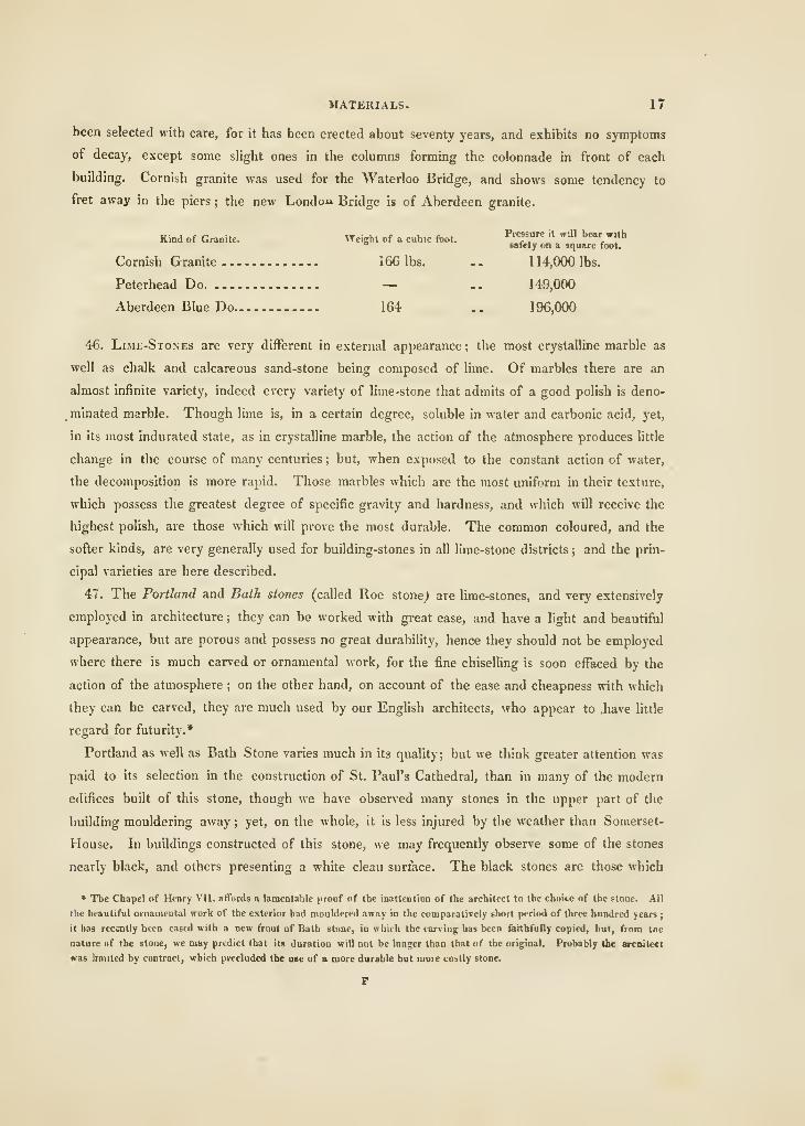
Kind of Granite. Weight of a cubic foot. ^'^7" '» "*' bear with" safety on a square foot.
Cornish Granite 166 lbs. .. 114,000 lbs.
Peterhead Do — .. 149,000
Aberdeen Blue Do 164 .. 196,000
46. Lime-Stones are very different in external appearance ; the most crystalline marble as
well as chalk and calcareous sand-stone being composed of lime. Of marbles there are an
almost infinite variety, indeed every variety of lime-stone that admits of a good polish is deno-
minated marble. Though lime is, in a certain degree, soluble in water and carbonic acid, yet,
in its most indurated state, as in crystalline marble, the action of the atmosphere produces little
change in the course of many centuries ; but, when exposed to the constant action of water,
the decomposition is more rapid. Those marbles which are the most uniform in their texture,
which possess the greatest degree of specific gravity and hardness, and which will receive the
highest polish, are those which will prove the most durable. The common coloured, and the
softer kinds, are very generally used for building-stones in all lime-stone districts ; and the prin-
cipal varieties are here described.
47. The Portland and Bath stones (called Roe stone^ are lime-stones, and very extensively
employed in architecture ; they can be worked with great ease, and have a light and beautiful
appearance, but are porous and possess no great durability, hence they should not be employed
where there is much carved or ornamental work, for the fine chiselling is soon effaced by the
action of the atmosphere ; on the other hand, on account of the ease and cheapness with which
they can be carved, they are much used by our Enghsh architects, who appear to .have little
regard for futurity.*
Portland as well as Bath Stone varies much in its quahty; but we think greater attention was
paid to its selection in the construction of St. Paul's Cathedral, than in many of the modern
edifices built of this stone, though we have observed many stones in the upper part of the
building mouldering away; yet, on the whole, it is less injured by the weather than Somerset-
House. In buildings constructed of this stone, we may frequently observe some of the stones
nearly black, and others presenting a white clean surface. The black stones are those which
» The Chapel of Henry Vll. afTords a lamentable proof of the inattention of the architect to the choice of the stone. All
the beautiful ornameotal work of the exterior had mouldered away in the comparatively short period of three hundred years;
it has recently been cased with a new front of Bath stone, in which the larviiig has been farthfully copied, but, fiom Ine
nature of the stone, we may predict that its duration will not be longer than that of the original. Probably the arcnitect
was bunted by contract, which precluded the use of a more durable bat more costly stone.
P
18 PRACTICAL MASONRY.
are most compact and durable, and preserve their coating of smoke; the wliite stones are
decomposing and constantly presenting a fresh surface, as if they had been recently scraped.
This effect is strikingly exhibited in the columns of Somerset-House.
4-8. Bath Stone, Ketton Stone, and Painswick Stone, are all varieties of the same kind of
stone, procured at those different places, as well as from several others in their neighbourhood.
The stone is so much softer than that from Portland, that it may be cut with a carpenter's saw,
and it may be moulded and carved more in the manner of wood than of stone, nevertheless it
is quite as durable as Portland stone, and fitted for similar works, excepting where strength or
wear is required. The Painswick variety is perhaps the closest and best for London use, as it
works with very little waste; the Ketton seems to be the most durable, but none of theso
varieties are hard enough for steps, stairs, or other works liable to wear, or requiring strength
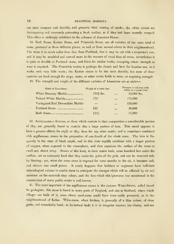
49. The strength and weight of the different varieties of Limestone are as under
—
Kinds of Lime-Stone. Weight of a cubic foot. ^"f"''^ " «'" bear with
° safely ou ;i square foot.
White Statuary Marble 172^ lbs. .
.
83,000 lbs.
Veined White Marble 170 .
.
1 74.000
Variegated Red Devonshire Marble — .. 129,000
Portland Stone 132 .. 30,000
Bath Stone 1231 .. 17,000
50. Argillaceous Stones, or those which contain in their composition a considerable portion
of clay, are generally found to contain also a large portion of iron. This metal appears to
have a greater affinity for argil, or clay, than for any other earth ; and is sometimes combined
with argillaceous stones in the proportion of one-fourth of the whole mass. The iron is fre-
quently in the state of black ox^de, and in this state rapidly combines with a larger portion
of oxygen, when exposed to the atmosphere, and thus occasions the surface of the stone to
swell and shiver away. Stones of this kind, in their native beds, some hundred feet under the
surface, are so extremely hard that they resist the point of the pick, and can be removed only
by blasting; yet, when the same stone is exposed for some months to the air, it becomes soft,
and shivers into small pieces. It rarely happens that builders or engineers have sufficient
mineralogical science to enable them to anticipate the changes which will be effected by air and
moisture on the materials they select ; and the loss which this ignorance has occasioned in the
construction of many public works is well known.
51. The most important of the argillaceous stones is the common Whin-Stone, called basalt
bv geologists; this stone is found in many parts of England, and also in Scotland, where whole
villages are built of it, even where sand-stone could have been easily procured, as in the
neighbourhood of Kelso. "Whin-stone, when broken, is generally of a blue colour, of close
grain, and remarkably hard ; in its natural beds it is in irregular masses ; too clumsy, and too
MATERIALS. 19
hard for the finer works of masonry ; the best for architectural purposes is found in loose blocks
in the beds of rivers, and places of a like nature, where it has been long exposed to the wea-
ther, for some varieties of whin-stone decompose by exposure in the manner of other argil-
laceous stones, (art. 50.) and are said to become rotten. By exposure, a thin coatin'^ forms on
the surface of whin-stone ; and it is said to be more durable when the coat is frequenfly cleaned
off. The more hard and durable kinds are valuable for road materials. Whin-stone and
indeed all argillaceous stones, attract moisture, and in consequence assume a darker colour in
damp weather ; when the atmosphere is damp, walls of this stone condense the vapour till it
runs down in streams, hence it is not generally adapted for houses.
The weight of a cubic foot of whin-stone varies from 170 to 192 lbs. ; and, according to
experiment, it appears that 280,000 lbs. may be supported by a superficial foot with safety.
52. Of Sand-stones there are two kinds, which are very common, viz. the siliceous and the
argillaceous
;
—of these the siUceous is the best, and perhaps the most abundant.
Sand-stone is common to most counties of England, as well as Scotland. The quarries of
siUceous sand-stone about the cities of Glasgow and Edinburgh afford very superior kinds,
which contribute in no small degree to the elegance of the buildings in these places ; the supe-
riority, however, is in material only, as the taste with which some towns built of brick have been
laid out and executed, is not inferior to that displayed by the architects of the north.
In the parish of Sproustone, near Kelso, is a sand-stone quarry, belonging to the Dowager
Duchess of Roxburgh, of immense value. The stone is of a beautiful silver grey, which,
when exposed to the weather, soon becomes of a smokey hue. It is remarkably fine grained,
indeed, so fine, that it is unfit for the purpose of whetting an edged instrument. Most part of
Kelso is built of it, as well as the whole of the bridges in its vicinity. Although not a haul
stone, it is very durable, and the seam is so deep and long that stones of large dimensions can
be procured from it.
There are also many other excellent beds of sand-stone in the course of the Tweed, but that
which we have just mentioned is perhaps the best. A little farther up, on the lands of Dry-
burgh, the property of the Earl of Buchan, there is plenty of sand-stone ; it is of a deep red
colour, and much indented by cross scars and seams ; it is not, therefore, so generally
useful as some other at no great distance from it. In the body of this stone there are many
small pieces of a softer texture, and a deeper red, that do much injury to it as a durable mate-
rial. The celebrated statue of Sir William Wallace, the defender of Scottish liberty, is cut
out of a mass of this stone ; but the sculptor, Mr. John Smith, of Damick, has shown his
skill m selecting the piece which he has used, as it appears too hard to vield to the ravages of
time and of weather.
On the banks of the Tiviot, in the parish of Roxburgh, there is a bed of sand-stone, of
excellent quality, fit for almost any purpose to which it may be applied. This has been used to
a great extent, by the proprietor, Sir George Douglas, of Springwood Park, but has not been
20 PRACTICAL MASONRY.
biou'^lit into general use. It is of a white yellow colour, and rises from the bed in masses
sufficiently large for every purpose of masonry. In the old buildings, in the neighbourhood,
there is a species of sand-stone of a beautiful yellow and uncommonly soft ; but where the
I)uilders found it cannot now be ascertained, as no vestige of a seam remains wherein the stone
is of such a deep and beautiful colour. Should such be discovered, it will be of immense
value to the proprietor, from its beauty, which would bring plenty of purchasers : but we
conclude that it is of a nature not adapted to resist the weather, and that, in process of time,
by being exposed to wetness and drought, it becomes of that soft state we find it in among
the ruins of old buildings. A little farther up, on the precipitous banks of the Tiviot, there
are extensive beds of yellow sand-stone ; but, from their situation, they cannot be wrought with
success.
In Dumfriesshire are great quarries of sand-stone, both of a red and white colour, exceed-
ingly good ; the towns of Dumfries and Maxwelton are built chiefly of the red kind. The
masses here are very small, and prevent the masons exhibiting their skill, to any great extent,
in cutting figures, and other architectural ornaments.
If we mistake not, there are numerous and excellent beds of this stone about the town of
Kirkcudbright, and the surrounding country : but that which is found abundantly in Ayrshire,
on account of its white colour and durable nature, is to be preferred to any that we have yet
mentioned, Sproustone only excepted.
The quarries in the other parts of Scotland, being nearly of the same nature with those
already described, and this remark applying also to the quarries of sand-stone in England, we
need not enter into farther notice of it ; since its utility, as a building material, is very gene-
rally known.
A kind of argillaceous sand-stone is much used in London, for rough pavhig and steps,
under the name of Yorkshire Stone; it is a very strong and durable stone, and wears well;
but there is an objection to its use for internal work, owing to its absorbing damp rapidly, which
renders it cold and uncomfortable for flooring.
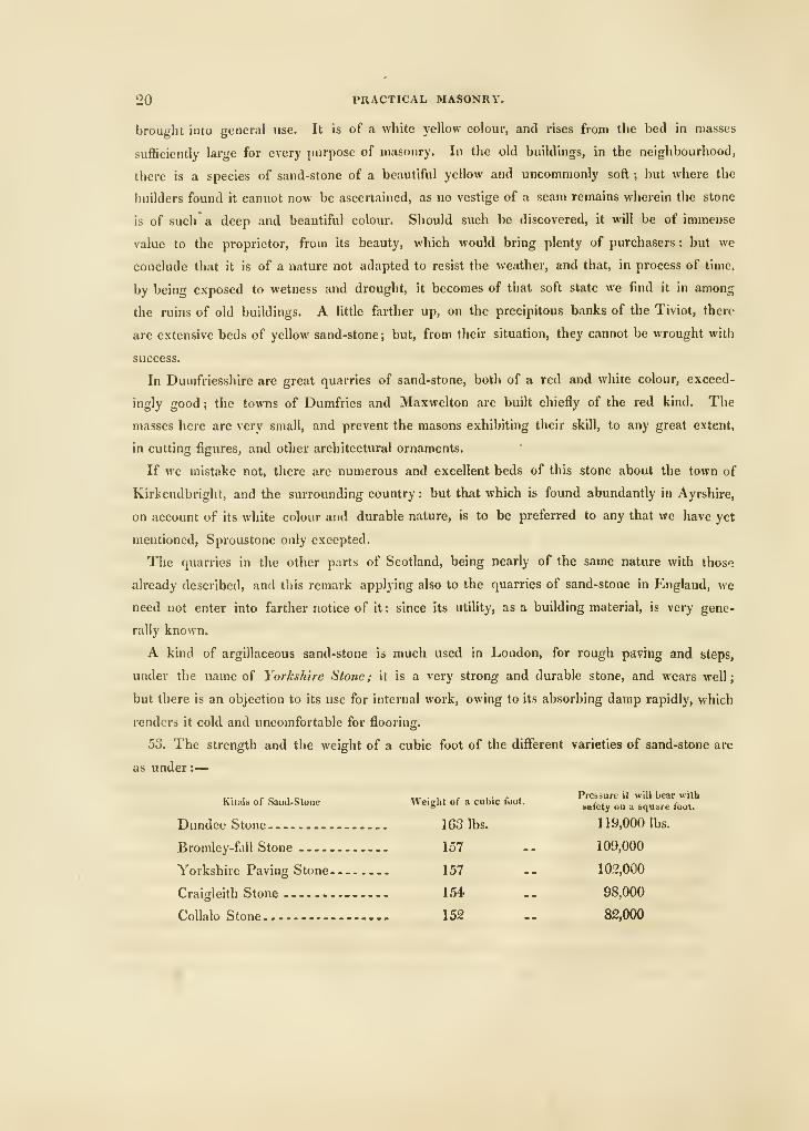
53. The strength and the weight of a cubic foot of the diflerent varieties of sand-stone are
as under :
—
„...„, -^ ,,,.,,, , e .Pressure it will bear with
Kmds of Saud-Stone Weight of a cubic foot.^^^^j^ ^^ ^ ^^^^^.^ ^^^
Dundee Stone 163 lbs. 119,000 lbs.
Bromley-fall Stone 1 57 . . 1 09,000
Yorkshire Paving Stone 157 .. 102,000
Craigleith Stone 1 54 .
.
98,000
Collalo Stone 152 .. 82,000
MORTARS AND CEMENTS. 21
OF MORTARS AND CEMENTS,
54. In the construction of works in Masonry, we generally employ some kind of cementitious
matter for connecting the stones together, and rendering them firm and compact. "SVhen the
works are to be exposed to the action of v/ater immediately after being built, this cementitious
matter must be of such a nature, that it will harden under water. Hence it is, that we have
occasion for two kinds of mortar, one that will set and harden under water, called by Smeaton
a water-mortar, or cement ; and common mortar for ordinary buildings.
oo. Common Mortar, it is almost superfluous to say, is a preparation of lime and sand,
mixed with water, which serves to unite the stones, in the building of walls, &c., and on the
proper or improper manner in which such mortar is prepared and used, depends the durability
and security of buildings ; we shall, therefore, here introduce many particulars on this head,
discovered by Smeaton, Dr. Higgins, &c., but which, not being generally known, have never
been introduced into general practice.
56. Limestone, marble, chalk, or shells, may be used to burn for lime for common mortar,
all these substances being composed chiefly of lime and carbonic acid ; and if a piece of one
of them be slowly burnt or calcined, so as to expel the whole, or nearly the whole, of its
carbonic acid, it loses about 44 per cent, of its weight ; and when a small quantity of water
is added to the calcined matter, it swells, gives out heat, and falls into a finely-divided powder,
called slacked lime. The bulk of the powder is about double that of the limestone. If this
powder be rapidly formed into a stiflf paste with water, it sets or solidifies as a hydrate oi
lime, and ultimately hardens by the absorption of carbonic acid from the air. This constitutes
common building-mortar. Hydrate of lime consists of 100 parts of lime, and 31 parts of
water. Common limestone consists of carbonate of lime, with very little of any other substance;
it produces a white lime, which slacks freely when well burnt ; it dissolves in diluted muriatic
acid, with only a small portion of residue, and never contains more than a trace of iron. It
diflfers much in external characters, as chalk, marble, common compact limestone, &c.
These limestones do not form cements to set in water, without the addition of other kinds
of cementing matter; hence they are usually employed only for common mortar. The hardest
marble and the softest chalk make equally good lime when well burnt ; but chalk-lime will
slack when not perfectly burnt, and, therefore, seldom has a sufficient quantity of fire ; whereas
stone-lime must have sufficient to make it slack. It was also observed by Dr. Higgins, that
stone-lime does not re-absorb carbonic acid so rapidly as chalk-lime
Lime, made from common limestones, sustains very little injury from being kept after it has
been formed into mortar, provided the air be effectually excluded ; indeed, Alberti mentions
G
22 PRACTICAL MASONRY.
an instance of some which had been covered up in a ditch for a very long time, and yet was
found to be of an excellent quality.
57. Sand.—To employ lime alone in the composition of mortar would render it expensive,
besides, it would be of inferior quality. The material commonly used to mix with lime is sand,
and this sand should be of a hard nature, not very fine, but angular, and having a consider-
able degree of affinity for lime, also the more irregular it is in size the better. It should be
free from any mixture of soft or earthy matter, if it can be procured without. The reason is
obvious; for mortar, composed of soft sand, cannot be harder than that sand. Sea-sand makes
good mortar, particularly water-mortar. Very hard-burnt brick, or tile, reduced to a coarse
powder, also makes an excellent substance to mix with lime, for many purposes.
The best proportion of sand, for common mortar, is easily ascertained by trial ; enough
should be added to render the mortar rather short than tough under the trowel. The propor-
tion varies from 4 parts of sand to 1 of lime, to 1j parts of sand to 1 of lime, by measure, the
proportion differing according to the coarseness of the sand, the nature of the limestone, and
the precautions used in burning it ; all set proportions being universally adhered to only by
those who are utterly ignorant of the subject. In many situations, it is impossible to procure
good sand, except at an enormous expense.
.58. Making Mortar.—The instructions given by Dr. Iliggins for making stucco-mortar,
apply only when a very superior kind is wanted ; but the same general principles ought to
be followed even with the commonest kinds of mortar. We will, therefore, insert them in this
place.
Of Sand, the following kinds are to be preferred ; first, drift-sand, or pit-sand, which con-
sists chiefly of hard quartose flat-faced grains, with sharp angles ; secondly, that which is the
freest, or may be most easily freed by washing, from clay, salts, and calcareous, gypseous, or
other grains less hard and durable than quartz ; thirdly, that which contains the smallest quan-
tity of pyrites, or heavy metallic-matter, inseparable by washing ; and fnurthly, that which
suffers the smallest diminution of its bulk in washing. Where a coarse and fine sand of this
kind, and corresponding in the size of their grains with the coarse and fine sands hereafter
described, cannot be easily procured, let such sand of the foregoing quality be chosen as may
be sorted and cleansed in the following manner :
—
Let the sand be sifted in streaming clear water, through a sieve which shall give passage to
all such grains as do not exceed one-sixteenth of an inch in diameter ; and let the stream of
water, and the sifting, be regulated so that all the sand which is much finer than the Lynn-sand,
commonly used in the London glass-houses, together with clay, and every other matter sneci-
fically lighter than sand, may be washed away with the stream ; whilst the purer and coarser
sand, which passes through the sieve, subsides in a convenient receptacle, and the coarse
rubbish and rubble remain on the sieve to be rejected.
MORTARS AND CEMENTS. 23
Let the sand, which thus subsides in the receptacle, be washed in clean streaming water
through a finer sieve, so as to be further cleansed, and sorted into two parcels ; a coarser,
which will remain in the sieve, which is to give passage to such grains of sand only as are less
than one-thirtieth of an inch in diameter, and which is to be saved apart under the name of
coarse sand; and a finer, which will pass through the sieve and subside in the water, and
which is to be saved apart under the name oi fine sand. Let the coarse and the fine sand be
dried separately, either in the sun, or on a clean iron plate, set on a convenient surface, in the
manner of a sand-hea'v.
Let stone-lime be chosen, which heats the most in slaking, and slakes the quickest when
duly watered ; that which is the freshest made and closest kept ; that which dissolves in
distilled vinegar with the least effervescence, and leaves the smallest residue insoluble, and in
the residue the smallest quantity of clay, gypsum, or martial matter. Let the lime, chosen
according to these rules, be put in a brass-wired sieve, to the quantity of fourteen pounds.
Let the sieve be finer than either of the foregoing ; the finer the better it will be : let the hme
be slaked, by plunging it into a butt filled with soft-water, and raising it out quickly, and
suffering it to heat and fume ; and, by repeating this plunging and raising alternately, and
agitating the lime until it be made to pass through the sieve into the water ; and let the part
of the lime which does not easily pass through the sieve be rejected : and let fresh portions of
the lime be thus used, until as many ounces of lime have passed through the sieve as there
are quarts of water in the butt.
Let the water, thus impregnated, stand in the butt closely covered until it becomes clear,
and through wooden cocks, placed at different heights in the butt, let the clear liquor be
drawn off, as fast and as low as the lime subsides, for use. This clear liquor is called lime-
tcater. The freer the water is from saline matter, the better will be the cementing liquor made
with it.
Let fifty-six pounds of the aforesaid chosen lime be slaked, by gradually sprinkhng the
lime-water on it, and especially on the unslaked pieces, in a close clean place. Let the slaked
part be immediately sifted through the last mentioned fine brass-wired sieve : let the lime
which passes be used instantly, or kept in air-tight vessels ; and let the part of the lime which
does not pass through the seive be rejected. This finer and richer part of the lime, which
passes through the sieve, may be called purified lime.
Let bone-ash be prepared in the usual manner, by grinding the whitest burnt bones ; but
let it be sifted, so as to be much finer than the bone-ash commonly sold for making cupels.
The best materials for making the cement being thus prepared, take fifly-six pounds of the
coarse sand, and forty-two pounds of the fine sand ; mix them on a large plank of hard wood
placed horizontally ; then spread the sand so that it may stand to the height of six inches, with
a flat surface on the plank, wet it with the lime-water, and let any superfluous quantity of the
liquor, which the sand in the condition described cannot retain, flow away off the plank. To
24 PRACTICAL MASONRY.
the wetted sand add fourteen pounds of the purified lime, in several successive portions:
mixino- and beating tliem up together, in the mean time, with the instruments generally used in
making fine mortar : then add fourteen pounds of the bone-ash, in successive portions, mixing
and beating all together.
Tlie ouicker and the more perfectly these materials are mixed and beaten together, and the
sooner the cement thus formed is used, the better it will be. This may be called coarse-grained
cement, which is to be applied in building, pointing, plastering, stuccoing, or other work, as
mortar and stucco generally are ; with this difference chiefly, that, as this cement is shorter
than mortar, or common stucco, and dries sooner, it ought to be worked expeditiously in all
cases; and, in stuccoing, it ought to be laid on by sliding the trowel upwards on it. The
materials used along with this cement in building, or the ground on which it is to be laid
in stuccoing, ought to be well wetted with the lime-water in the instant of laying on the cement.
The lime-water is also to be used when it is necessary to moisten the cement, or when a liquid
is required to facilitate the floating of the cement.
When such cement is required to be of a still finer texture, take ninety-eight pounds of the
fine sand, wet it with the lime-water, and mix it with the purified lime and the bone-ash, in the
juantities and in the manner above described ; with this difference only, that fifteen pounds
jf lime, or thereabouts, are to be used instead of fourteen pounds, if the greater part of
-he sand be as fine as Lynn sand. This may be called fine-grained cement. It is used in
living the last coating, or the finish, to any work intended to imitate the finer-grained stones
or stucco. But it may be applied to all the uses of the coarse-grained cement, and in the
same manner.
When, for any of the foregoing purposes of pointing, building, &c., a cement is required
much cheaper and coarse-grained than either of the foregoing, then much coarser clean sand
than the foregoing coarse sand, or well-washed fine rubble, is to be provided. Of this coarse
iand, or rubble, take fifty-six pounds, of the foregoing coarse sand twenty-eight pounds,
and of the fine sand fourteen pounds ; and, after mixing these, and wetting them with the
cementing-liquor, in the foregoing manner, add fourteen pounds, or somewhat less, of the
purified lime, and then fourteen pounds, or somewhat less, of the bone-ash, mixing them toge-
ther in the manner already described. When the cement is required to be white, white sand,
white lime, and the whitest bone-ash, are to be chosen. Gray sand, and gray bone-ash formed
of half-burnt bones, are to be chosen to make cement gray ; and any other colour of the
cement is obtained, either by choosing coloured sand, or by the admixture of the necessary
quantity of coloured talc in powder, or of coloured, vitreous, or metallic, powders or other
durable colouring ingredients, commonly used in paint.
This cement, whether the coarse or fine-grained, is applicable in forming artificial stone, by
making alternate layers of the cement and of flint, hard stone, or bricks, in moulds of the
!igure of the intended stone, and by exposing the masses so formed to the open air, to hardeti.
MORTARS AND CEMENTS. 25
When such cement is required for water-fences, two-thirds of the prescribed quantity of
bone-ashes are to be omitted ; and, in the place thereof, an equal measure of powdered terras
is to be used ; and, if the sand employed be not of the coarsest sort, more terras must be
added, so that the terras shall be one-sixth part of the weight of the sand.
When such a cement is required of the finest grain, or in a fluid form, so that it may be
applied with a brush, flint-powder, or the powder of any quartzose or hard earthy substance,
may be used in the place of sand ; but in a quantity smaller, in proportion as the flint or other
powder is finer ; so that the flint-powder, or other such powder, shall not be more than six
times the weight of the lime, nor less than four times its weight. The greater the quantity of
lime within these limits, the more will the cement be liable to crack by quick drying, and, vice
versa.
Where the above described sand cannot be conveniently procured, or where the sand cannot
be conveniently washed and sorted, that sand which most resembles the mixture of coarse and
fine sand above prescribed, may be used as directed, provided due attention be paid to the
quantity of the lime, which is to be greater as the quality is finer, and, vice versd.
Where sand cannot be easily procured, any durable stony body, or baked earth, grossly
powdered, and sorted nearly to the sizes above prescribed for sand, may be used in the place
of sand, measure for measure, but not weight for weight, unless such gross powder be speci-
fically as heavy as sand.
Sand may be cleansed from every softer, lighter, and less durable, matter, and from that
part of the sand which is too fine, by various methods preferable in certain circumstances, to
that which has been already described.
Water may be found naturally free from fixable gas, selenite, or clay ; such water may, with-
out any great inconvenience, be used in the place of the lime-water ; and water approaching
this state will not require so much lime as above prescribed to make the lime-water ; and a
Hme-water sufficiently useful may be made by various methods of mixing lime and water in the
described proportions, or nearly so.
When stone-lime cannot be procured, chalk-lime, or shell-lime, which best resembles stone-
lime, in the foregoing characters of lime, may be used in the manner described, excepting that
fourteen pounds and a half of chalk-lime will be required in the place of fourteen pounds of
stone-lime. The proportion of lime, as prescribed above, may be increased without incon-
venience, when the cement or stucco is to be applied where it is not liable to dry quickly ; and,
in the contrary case, this proportion may be diminished. The defect of lime, in quantity or
quality, may be very advantageously supplied, by causing a considerable quantity of lime-water
to soak into the work, in successive portions, and at distant intervals of time ; so that the
calcareous matter of the lime-water, and the matter attracted from the open air, may fill and
strengthen the work.
H
26 PRACtlCAL MASONRY.
The powder of almost every well-dried or burnt animal substance may be used instead of
bone-ash ; and several earthy powders, especially the micaceous and the metallic ; and the
elixated ashes of divers vegetables, whose earth will not burn to lime, as well as the ashes of
mineral fuel, which are of the calcareous kind, but will not burn to lime, will answer the ends
of bone-ash in some degree.
The quantity of bone-ash described may be lessened without injuring the cement ; in those
circumstances especially which admit the quantity of lime to be lessened, and in those wherein
the cement is not liable to dry quickly. The art of remedying the defects of lime may be
advantageously practised to supply the deficiency of bone-ash, especially in building, and in
making artificial stone with this cement.
As the preceding method of making mortar differs, in many particulars, from the common
process, it may be useful to inquire into the causes on which this difference is founded.
When the sand contains much clay, the workmen find that the best mortar they can make
must contain about one-half lime ; and hence they lay it down as certain, that the best mortar
is made by the composition of half sand and half lime.
But with sand requiring so great a proportion of lime as this, it will be impossible to make
good cement ; for it is universally allowed that the hardness of mortar depends on the crystal-
lization of the litne round the other materials which are mixed with it ; and thus uniting the
whole mass into one solid substance. But, if a portion of the materials used be clay, or any
other friable substar.ce, it must be evident that, as these friable substances are not changed in
one single particular, by the process of being mixed up with lime and water, the mortar, of
which they form a proportion, will consequently be, more or less, of a friable nature, in pro-
portion to the quantity of friable substances used in the composition of the mortar. On the
other hand, if mortar be composed of lime and good sand only, as the sand is a stony sub-
stance, and not in the least friable, and as the lime, by perfect crystallization, becomes likewise
of a stony nature, it must follow, that a mass of mortar, composed of these two stony sub-
stances, will itself be a hard, solid, unfriable, substance. This may account for one of the
essential variations in the preceding method from that in common use, and point out the neces-
sity of never using, in the place of sand, which is a durable stony body, the scrapings of roads,
old mortar, and other rubbish, from antient buildings, which are frequently made use of, as all
of them consist, move or less, of muddy, soft, and minutely divided particles.
Another essential point is the nature and quality of the lime. Now, experience proves that,
when lime has been long kept in heaps, or untight casks, it is reduced to the state of chalk,
and becomes every day less capable of being made into good mortar ; because, as the goodness
or durability of the mortar depends on the crystallization of the lime, and, as experiments have
proved, that lime, when reduced to this chalk-like state, is always incapable of perfect crystal-
lization, it must follow that, as lime in this state never becomes crystallized, the mortar of
MOUTARS AND CEMENTS. 27
which it forms the most indispensable part, will necessarily be veiy imperfect ; that is to say, it
will never become a solid stony substance ; a circumstance absolutely required in the formation
of good durable mortar. These are the two principal ingredients in the formation of mortar;
but, as water is also necessary, it may be useful to point out that which is the fittest for this
purpose ; the best is rain-water^ river-water the second, land-water next, and spring-water last.
The ruins of the antient Roman buildings are found to cohere so strongly, as to have caused
an opinion that their constructors were acquainted with some kind of mortar, which, in com-
parison with ours, might justly be called cement: and that, to our want of knowledge of the
materials they used, is owing the great inferiority of modern buildings in their durability. But
a proper attention to the above particulars would soon sHow that the durability of the antient
edifices depended on the manner of preparing their mortar more than on the nature of the
materials used. The following observations will, we think, prove this beyond a possibility
of doubt
:
Lime, which has been slaked and mixed with sand, becomes hard and consistent when dry,
by a process similar to that which produces natural stalactites in caverns. These are always
formed by water dropping from the I'oof. But, when the small drop of water comes to be
exposed to the air, the calcareous matter contained in it begins to attract carbonic acid
from the atmosphere. In proportion as it does so, it also begins to separate from the water,
and to re-assume its native form of lime-stone or marble. When the calcareous matter is
perfectly crystallized in this manner, it is to all intents and purposes hme-stone or marble of
the same consistence as before. If lime, in a caustic state, be mixed with water, part of the
lime will be dissolved, and will also begin to crystallize. The water which parted with the
crystallized lime will then begin to act upon the remainder, which it could not dissolve before
;
and thus the process will continue, either till the lime be all reduced to an effete, or crystalline
state, or something hinders the action of the water upon it. It is this crystallization which is
observed by the workmen when a heap of lime is mixed with water, and left for some time to
macerate. A hard crust is formed upon the surface, which is ignorantly called froslling,
though it takes place in summer as well as in winter. If, therefore, the hardness of the lime,
or its becoming a cement, depends entirely on the formation of its crystals, it is evident that
the perfection of the cement must depend on the perfection of the crystals, and the hardness
of the matters which are entangled among them. The additional substances used in making
of mortar, such as sand, brick-dust, or the like, serve only for a purpose similar to what is
answered by sticks put into a vessel full of any saline solution ; namely, to afford the crystals
an opportunity of fastening themselves upon it. If, therefore, the matter interposed between
the crystals of the lime is of a friable brittle nature, such as brick-dust or chalk, the mortar
will be of a weak and imperfect kind ; but, when the particles are hard, angular, and very
difficult to be broken, such as those of river or pit-sand, the mortar turns out exceedingly good
and strong. That the crystallization may be the more perfect, a large quantity of water sboiud
28 PRACTICAL MASONRY.
be used, the ingredients be perfectly mixed together, and the drying be as slow as possible.
An attention to these particulars, and to the quality of bricks and stones, would make the
buildings of the moderns equally durable with those of the antients. In the old Roman works,
the great thickness of the walls necessarily required a vast length of time to dry. The middle
of them was composed of pebbles thrown in at random, and which, evidently, had thin mortar
poured in among them. Thus a great quantity of the lime would be dissolved, and the crystal-
lization performed in the most perfect manner. The indefatigable pains and perseverance, for
which the Romans were so remarkable in all their undertakings, leave no room to doubt that
they would take care to have the ingredients mixed together as well as possible. The conse-
quence of all this is, that the buildings formed in this manner are all as firm as if cut out of a
solid rock ; the mortar being equally hard, if not more so, than the stones themselves.
59. Water-Mortars or Cements.—The cementing materials are either found ready com-
bined in certain kinds of stone, as in the case of Roman cement ; or the effect is produced by
mixture, as when we mix the lime of poor lime-stones with Dutch terras. The natural com-
bination is, however, by far the best ; and it is only in cases where the other can be obtained
at a much less expense, that we advise it to be resorted to ; but, for such cases, we propose to
describe the best compositions now known.
GO. Roman Cement is made from the kind of stones called clay-balls.* The best stone
contains about 60 per cent, of carbonate of lime, and 8 or 10 per cent, of protoxide of
iron, the rest being silex and alumine nearly in equal parts. The inferior stones contain
peroxide of iron, and often soluble earthy and alkaline salts. Stone of the best kind is pro-
cured on the coast of the Isle of Sheppy, and from the alum-shale on the coast of Yorkshire,
near Whitby. Stone of an inferior quality is procured near Harwich, and other places on the
coast of England, and at Boulogne, in France. The stone is, after being broken to a proper
size, slowly calcined in kilns or ovens, and then it is ground to a fine powder, of a light snufF-
colour, when the stone is good ; and of a deeper, approaching to a burnt-umber brown, when
the quality is inferior. The powder should be kept perfectly dry till it is to be used ; and, in
order to use it, mix it with not less than an equal portion, by measure, of dry, clean, and sharp,
river-sand ; then add as much clear water as will form it into a stiff paste, but not more ; and
the whole that is so mixed must be used before it begins to set, which, with good cement,
happens in about fifteen minutes from the time of adding the water ; but, in cements very fit for
building, the setting may not be commenced in less than half or three-quarters of an hour.
When the setting begins, all the moisture on the surface disappears, and the cement feels dry
and warm to the touch, and hardens ; the hardening continues for some months, and is increased
by frequent wetting the work, in cases where it has not to be exposed to water immediately on
its being set. A coat of this cement is impervious to water, and it is therefore most extensively
used for lining cisterns, tanks, reservoirs, &c.
• They arc by some called teptaria, from being generally divided by thin eepta of carbonate of lime ; and by other,
tudns helinnnfii
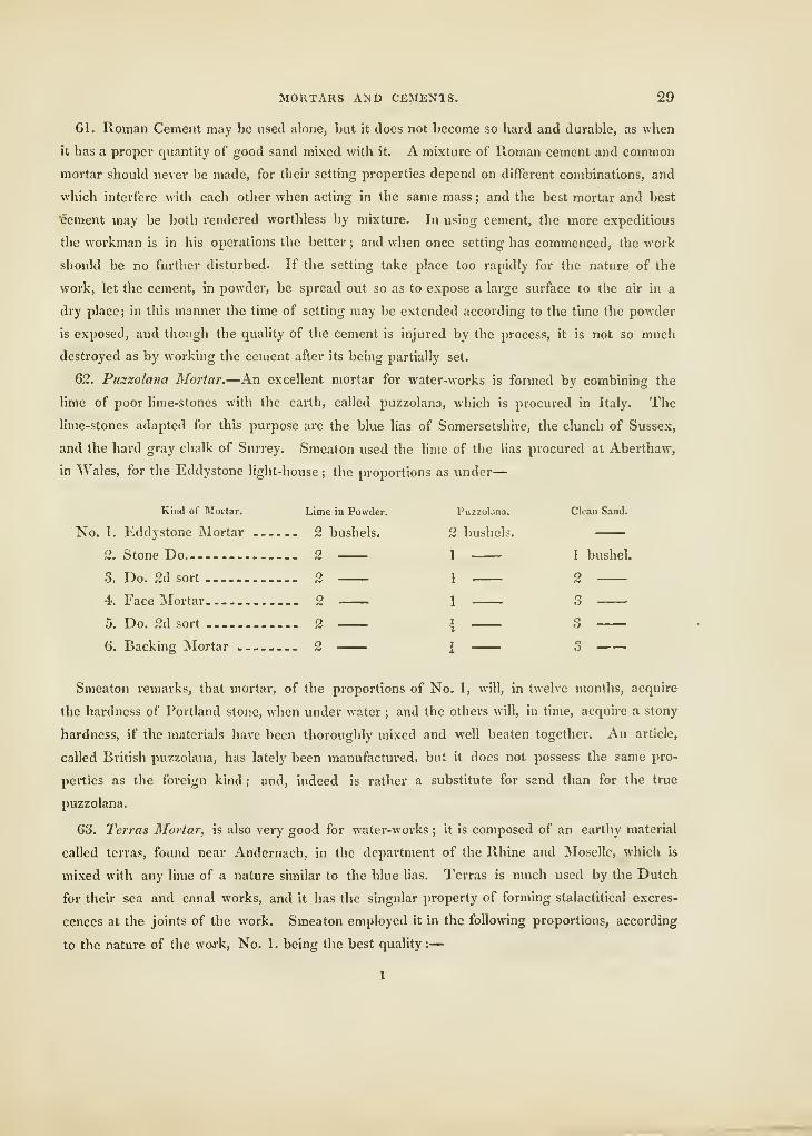
MORTARS AND CEMENIS. 29
61. Roman Cement may be used alone, but it does not become so hard and durable, as when
it has a proper quantity of good sand mixed with it. A mixture of Roman cement and common
mortar should never be made, for their setting properties depend on different combinations, and
which interfere with each other when acting in the same mass ; and the best mortar and best
Icement may be both rendered worthless by mixture. In using cement, the more expeditious
the workman is in his operations the better ; and when once setting has commenced, the work
should be no further disturbed. If the setting take place too rapidly for the nature of the
work, let the cement, in powder, be spread out so as to expose a large surface to the air in a
dry place; in this manner the time of setting may be extended according to the time the powder
is exposed, and though the quality of the cement is injured by the process, it is not so much
destroyed as by working the cement after its being partially set.
62. Puszolana Mortar.—An excellent mortar for water-works is formed by combining the
lime of poor lime-stones with the earth, called puzzolana, which is procured in Italy. The
lime-stones adapted for this purpose are the blue lias of Somersetshire, the clunch of Sussex,
and the hard gray chalk of Surrey. Smeaton used the lime of the lias procured at Aberthaw,
in Wales, for the Eddystone light-house ; the proportions as under
—
Kind of Mortar. Lime in Powder. Puzzolana. CIcaD Sand.
No. I. Eddystone Mortar 2 bushels. 2 bushels.
2. Stone Do. 2 1 I bushel.
3. Do. 2d sort 2 1 2
4. Face Mortar 2 1 3
5. Do. 2d sort 2 \ 3
6. Backing Mortar 2 i 3 —
—
Smeaton remarks, that mortar, of the proportions of No. 1, will, in twelve months, acquire
the hardness of Portland stone, when under water ; and the others will, in time, acquire a stony
hardness, if the materials have been thoroughly mixed and well beaten together. An article,
called British puzzolana, has lately been manufactm-ed, but it does not possess the same pro-
perties as the foreign kind ; and, indeed is rather a substitute for sand than for the true
puzzolana.
63. Terras Mortar, is also very good for water-works ; it is composed of an earthy material
called terras, found near Andernach, in the department of the Rhine and Moselle, which is
mixed with any lime of a nature similar to the blue lias. Terras is much used by the Dutch
for their sea and canal works, and it has the singular property of forming stalactitical excres-
cences at the joints of the work. Smeaton employed it in the following proportions, according
to the nature of the work, No. 1 . being the best quahty :
—
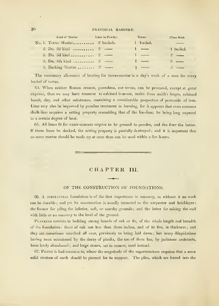
30 PRACTICAL MASONRY.
Kind of Mortar. Lime in Powder. Terras. Ciran Sand.
No. 1. Terras JNIortar ...... 2 bushels. 1 bushel.
ii. Do. 2cl kind 2 1 1 bushel.
3. Do. Sdkind 2 1 2
4. Do. 4th kind 2 1 .S
5. Backing INIortar 2 | ;3
The customary allowance of beating for terras-mortar is a day's work of a man for every
bushel of terras.
64. When neither Roman cement, puzzolana, nor terras, can be procured, except at great
expense, then we may have recourse to calcined iron-ore, scales from smith's forges, calcined
basalt, clay, and other substances, containing a considerable proportion of protoxide of iron.
Lime may also be improved by peculiar treatment in burning, for it appears that even common
chalk-lime acquires a setting property resembling that of the lias-lime, bv being long exposed
to a certain degree of heat.
G5. All limes fit for water-cements require to be ground to powder, and the finer the better.
If these limes be slacked, the setting property is partially destroyed ; and it is important that
no more mortar should be made up at once than can be used within a few hours.
CHAPTER III.
OF THE CONSTRUCTION OF FOUNDATIONS.
66. A SUBSTANTIAL foundation is of the first importance in masonry, as without it no work
can be durable ; and yet its construction is usually intrusted to the carpenter and bricklayer
:
the former for piling the inferior, soft, or marshy grounds ; and the latter for raising the wall
with little or no masonry to the level of the ground.
Planking consists in bedding strong boards of oak or fir, of the whole length and breadth
of the foundation : those of oak not less than three inches, and of fir five, in thickness ; and
they are sometimes scorched all over, previously to being laid down; but many dilapidationii
having been occasioned by the decay of planks, the use of them has, by judicious architects,
been lately abandoned ; and large stones, set in cement, used instead.
67. Piling is had recourse to, where the magnitude of the superstructure requires that a more
solid stratum of earth should be pierced for its support. The piles, which are forced into the
CONSTRUCTION OF FOUNDATIONS. 31
earth, are made of fir, oak, &c., usually about nine or ten inches square. Their length is
ascertained by boring the ground the ends of the piles are cased or shoed with pointed iron,
and the tops surrounded with a hoop of the same metal. The machine for driving these piles
consists of a frame of wood, braced by strong pieces of timber, and secured by ledgers and
feet; with a cast-iron wheel at the top, about eighteen inqhes in diameter, and fluted on the
outside for a rope, or chain, to move in. This rope, or chain, is attached to the axis of a
heavy iron beater, called the ram, which, for general use, weighs about five or seven hundred
weight. This ram slides sometimes in grooves, in the upright frame, and often on the frame
of the upright. A ladder is attached for adjusting the chain, and oiling the machine. It is
worked by twenty or more men, each taking hold of a rope for that purpose, and thus raising
the beater up and down in the frame. When many piles are to be driven, double sets of men
to work the beater alternately will be necessary. The piles are driven as near together as may
be considered proper to support the building, and the tops sawn off level, and the intervals
filled up, by the Romans with charred substances, and by us with chalk, stone, and rubble
;
and the tops planked over to receive the stone-work.
In works exposed to water, the base is encircled by plank-piling ; these piles are all grooved
on their opposite sides ; and, when driven close to each other, a tongue is forced between to
bind the whole together, so as to produce a close chain of wooden piling, from one end of the
foundation to the other.
68. Some architects have not deemed either planking or piling eligible for foundations,
within infirm or swampy grounds ; and have, therefore, had recourse to a cradle of oak, or fir,
in quartering, strongly framed and braced together in bays, and in lengths of from five to ten
feet, and of widths proportionate to the weight of the superstructure : these frames are again
covered over by cross-pieces, or joists, and the whole bedded firmly on the ground, and filled
up flush with brick or stone, bedded in water-cement. (See art. 59, &c.) The foundation of
brick or stone walls, laid on this, has been found safer than planking ; because, if the quarters of
the cradle should decay, the connected work between would still remain united, and conse-
quently the sinking of the building would be regular, though not altogether prevented.
69. The foundations of Bridges are generally laid dry at the piers, by the water's being,
for a time, turned into a new course, or by erecting a cofler-dam. A coffer-dam consists of a
double chain of piles, driven into the ground, at a sufficient distance from the intended pier, to
admit the work's being conveniently proceeded in ; when the piles ai-e all firmly fixed in the
earth, strong horizontal beams are framed and bolted to them with braces to stiffen tjie inter-
mediate parts ; they are then finally planked inside and out, so as to form a complete case.
The void between each casing is then filled with loam or clay, so that very little water can
percolate, and what does get in is removed by pumping. A more ingenious method has, how-
ever been practised. It consists of forming a strong grating of timber, covered with planks,
32 PRACTICAL MASONUY.
which at once forms a floating-raft, and the floor upon which the stone pier is to be erected
the pier built on the raft is composed of stones, amply secured, and rendered, by cement,
water-tight ; and the whole is so arranged as to float upon the water till it has advanced in
height ; so that, if sunk, it should be above low-water mark, or higher, as found expedient.
This levity is obtained either by attaching the raft by ropes to vessels, or by the pier's being
worked with vacuities sufficient to render it specifically lighter than an equal bulk of water.
The pier is sunk either by letting the water into the vacuities, or by loosening the ropes ; but
the bed of the river should be previously prepared for its reception, by drcdging-machines.
Should the bottom of the ground prove not to be level, the pier must be raised by pumping
the water out, or by means of the machines in the vessels, and the ground then satisfactorily
levelled.
In the erection of Westminster Bridge, M. Labelye erected the piers in caissons, or water-
tight boxes ; the bulk of the box, though loaded with the pier, producing a mass specifically
lighter than an equal bulk of water : after each pier had been erected, the sides of the box
served again for boxes of other piers ; the pier was sunk, and raised as above. Similar caissons
were likewise used in erecting Blackfriars' Bridge.
Till of late years the foundation of bridges was erected in the following manner : The piles
were driven into the bottom of the river, in the site of the intended pier, and then cut oflT a
little below lov.'-water mark ; the interstices being filled with stone and strong cement ; on these
piles a grafing of timber was laid, boarded with thick boarding, and thus was formed the floor
for the intended pier. The work was then continued, at low-water This is a very simple
method, requiring no machine beyond a pile-driving engine.
The foundations of the piers of London Bridge, as appeared from that which was removed,
when the two small arches were converted into one, was composed of a quadruple row of piles,
driven in close together on the exterior site of the pier, and forming a case to receive the stone
and cement. So soon as the exterior piles were taken away, the force of the water cleared
away the remainder, so that it could not be ascertained whether there were piles in the heart
of the pier. To protect the piers of this bridge, sterlings were constructed round them. Asterling consists of an enclosure of piles driven close together into the bed of the river, and
secured by horizontal pieces of timber, bolted by iron to the tops of the piles ; and the void
within, to the piling of the pier, filled with chalk, gravel, stone, &c., so as to form a complete
defence to the internal piling, upon which the stone piers are erected.
CONSTRUCTION OF WALLS. 33
CHAPTER IV
OF THE CONSTRUCTION OF AVALLS.
TO. The antients used several modes of constructing Walls, in which more or less masonry
was always introduced. They had their recticular or reticulated walls, and also the inceriain :
of these, the recticuiative kind {plate XIV, fig. 2,) was esteemed the most handsome ; but the
joints are so ordered, that, in all parts, the courses have a regular position ; whereas, in the
incertain, (Jig. 1,) the materials rest irregularly one upon another; and are interwoven together,
so that they are much stronger than the reticulated, though not so handsome. In the kind of
wall represented in Jig. 1, the courses are neither level, nor the upright joints ranged regu-
larly or perpendicularly to each other in the alternate courses, nor in any other respect corres-
pondently, but uncertainly, according to the size of the stone employed. Stones are so arranged
in ordinary rubble walls, in which all that is regarded is, that the upright joints, in two ad-
joining courses, do not coincide. Walls, of both sorts, were formed of very small pieces, with
a sufficient quantity of good mortar, which added greatly to their solidity.
To saturate, or fill up, a wall with mortar, is a practice which ought to be had recourse to
in most cases, where small stones, or bricks, admit of it. It consists in mixing fresh Hme with
water, and pouring it, while hot, among the masonry in the body of the wall.
The walls called by the Greeks Isodomum, {fig. 4,) are those in which all the courses are of
an equal thickness ; and Pseudo-isodomtim, {fig. 3,) those when they are unequal. Both these
walls are firm, in proportion to the compactness of the mass, and the solid nature of the stones,
so that they do not absorb the moistness of the mortar too rapidly ; and, being situated in
regular and level courses, the mortar is prevented from falling, and thus the whole thickness of
the wall is united.
71. In the kind of wall called emplection by the Greeks, {fig. 6,) the faces were built with
dressed stones, with the other sides left as they came from the quarry ; and the two faces were
secured by occasional bond-stones. This kind of building admits of great expedition, as the
artificer can easily raise a case, or shell, for the two faces of the work, and fill the intermediate
space with rubble-work and mortar. Walls of this kind, consequently, consist of three parts,
with very imperfect connection ; two being the faces, and the other a rubble core in the middle
:
but the great works of the Greeks were not thus built, for, in them, the whole intermediate
space between the two faces was constructed in the same manner as the faces themselves
(fig. 5) ; and they, besides, occasionally introduced diatonos, or single pieces. A, A, extending
K
34 PRACTICAL MASONRY.
from one face to the other, to strengthen and bind the wall. These different methods of uniting
the several parts of the masonry of a wall, should be well considered by all persons who are
intrusted with works requiring great strength and durability.
The existing examples of Roman emplection, with partial cores of rubble-work, or brick,
sufficiently prove its durability when united by excellent mortar ; of the Greek method, wliich
was worked throughout the whole thickness of the wall, in the same manner as the facings or
fronts, their temples, now existing, testify the solidity.
72. The stone in the walls of modern buildings is sometimes used for ornament, or covering
of the brick-work, but is generally combined with solidity. In London, the thickness of walls
is regulated by a specific Act of Parliament ; but, to prevent dilapidation, it is often necessary
to strengthen the walls beyond what the law requires, as this law was framed only as a pro-
tection from fire, and was only for brick-walls. The thicknesses of walls should be regulated
according to the nature of the materials, and the magnitude of the edifice. Walls entirely
of hewn stone may be made one-fifth thinner than those of brick ; and brick-walls, in the base-
ment and ground-stories of buildings of the first-rate, should have the facing-stones rusticated,
to prevent their splitting ; a circumstance which has been too much disregarded by our present
builders.
73. A wall should be reduced in thickness as it rises, for the same reason that a column is
diminished ; and if the wall be a part of a house, it should be reduced in a still greater degree,
since the load, wliich is to be supported by it at different parts of its height, is usually much
varied, by the weight of the floors, and of the contents of the apartments; such walls are
reduced by internal offsets, the external face of the wall having only a slight inclination, called
battering, of about an inch in a height of 10 feet. The obliquity of the external surface of a
wall may, however, become objectionable, by promoting the growth of moss and weeds. In
building a wall, the first precaution that is required, is to dig deep enough to ascertain the
nature of the ground ; tile next, to lay a sufficiently extensive and firm foundation ; and it
has been very properly recommended that where walls are wanted, the ground should be well
examined before the foundations of a house be laid, in order to ascertain the qualities of the
different strata which are to support them.
74. The disposition of the stones, or bricks, is of much importance ; the strength of a
wall or to\^er is obviously greatest when all the surfaces are either horizontal or vertical ; for
if they be oblique, they must have a tendency to slide away laterally, and the wall must be
very liable to crack : hence the reticulated walls, sometimes employed by the antients, of which
all the joints were oblique, possessed but little durability {art. 70). If the materials be put
together without regular joints, the parts in contact tend to separate the walls by their action
on each other; occasionally, as in the case of piers, or quays, this circumstance may be of
some advantage in opposing external pressure, and uncoursed or rubble-work may be used
;
but no wall, composed of different kinds of masonry, is so strong as when wholly of one kind.
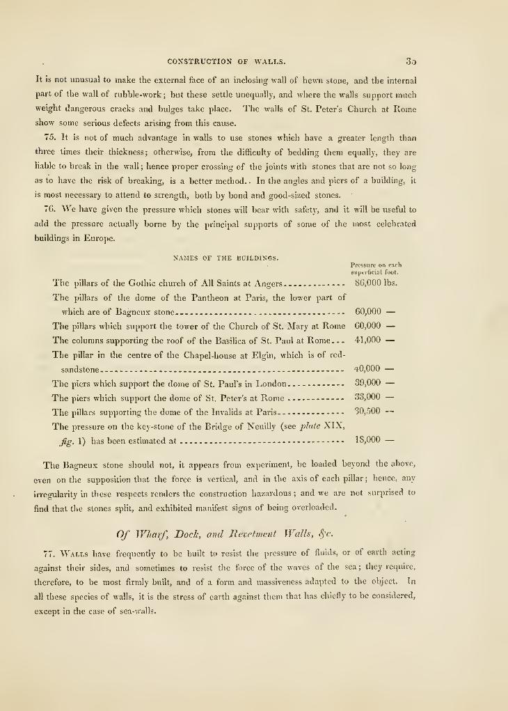
CONSTRUCTION OF WALLS. 3o
It is not unusual to make the external face of an inclosing wall of hewn stone, and the internal
part of the wall of rubble-work ; but these settle unequally, and where the walls support much
weight dangerous cracks and bulges take place. The walls of St. Peter's Church at Rome
show some serious defects arising from this cause.
75. It is not of much advantage in walls to use stones which have a greater length than
three times their thickness; otherwise, from the difficulty of bedding them equally, they are
liable to break in the wall ; hence proper crossing of the joints with stones that are not so long
as to have the risk of breaking, is a better method. . In the angles and piers of a building, it
is most necessary to attend to strength, both by bond and good-sized stones.
76. We have given the pressure which stones will bear with safety, and it will be useful to
add the pressure actually borne by the principal supports of some of the most celebrated
buildings in Europe.
NAMES OF THE BUILDINGS.Pressure on each
superficial foot.
The pillars of the Gothic church of All Saints at Angers 86,000 lbs.
The pillars of the dome of the Pantheon at Paris, the lower part of
which are of Bagneux stone- - - 60,000 —The pillars which support the tower of the Church of St. Mary at Rome 60,000 —The columns supporting the roof of the Basilica of St. Paul at Rome
—
41,000 —The pillar in the centre of the Chapel-house at Elgin, which is of red-
sandstone *0,000 —The piers which support the dome of St. Paul's in London . 39,000 —The piers which support the dome of St, Peter's at Rome 33,000 —The pillars supporting the dome of the Invalids at Paris 30,500 —The pressure on the key-stone of the Bridge of Neuilly (see jilate XIX,
fig. 1) has been estimated at 1 8,000 —
The Bagneux stone should not, it appears from experiment, be loaded beyond the above,
even on the supposition that the force is vertical, and in the axis of each pillar ; hence, any
irregularity in these respects renders the construction hazardous ; and we are not surprised to
find that the stones split, and exhibited manifest signs of being overloaded.
Of Wharf, Dock, and Revetment Walls, S^'c.
11. Walls have frequently to be built to resist the pressure of fluids, or of earth acting
against their sides, and sometimes to resist the force of the waves of the sea ; they require,
therefore, to be most firmly built, and of a form and massiveness adapted to the object. In
all these species of walls, it is the stress of earth against them that has chiefly to be considered,
except in the case of sea-walls.
36 PRACTICAL. MASONRY.
78. Tlie most simple kind of wall is a rectangular one {fig. 1, plate W .) ; but an equ,.l
degree of strength, with less material, is obtained by giving it an exterior slope, as fig. 2.
For fortification, ^'auban used to make this exterior slope r of the height, but the joints
perish, and mosses grow on and destroy walls having so much slope, hence later engineers make
it less, i of the height is commonly used, but -f or -vs is, in our opinion, quite sufficient. To
gain an equivalent in strength, we would adopt the countersloping form. Jig. 3, or its equi-
valent, Jig. 4. In some instances, the bulk of the wall has been increased, by leaving spaces in
the work to be filled in with rubble, gravel, &c., as in Jig. 5 ; and in others, sloping walls have
been built as in Jg. G ; and the latest change is to make the walls curved, as in Jig. 7. The
latter are very appropriate for docks and basins, but are not so fit for dry works.
79. The strength of any of these walls is materially increased by adding counterforts on the
side next the earth, of a breadth about equal to the mean thickness of the wall, and about
three times that thickness apart, (Jg. 8,) and their thickness about three-quarters of their
breadth. The strength of the wall should be such, that, were it deprived of counterforts, it
would be sufficient to resist the pressure of the earth.
SO. In order to consider the strength of walls to support earth, &c., it should be understood
that the bank of earth itself may be sloped so that it will stand, and let this slope be ac
(.Af?- Ij plate XV.) ; it is called the natural slope of the earth; and the angle it forms with the
horizon is called the angle of repose. Now it is evident, that the triangular prism of earth
sustained is abc; but, within that triangle, there will be found another, dab, which, though
it be less in weight, has more force to overturn the wall, because it is a more acute wedge ; the
line da then is the line of fracture, and it has been shown' by Mr. Tredgold, that, when the
forces are found in a horizontal direction, the pressure on a foot in length, tending to overturn
the wall, is—A'S „ , . „ PSc--^ c'-\ and, Its enect, —— •
Where h is the height of the wall in feet, s the weight ot a cubic foot of the earth, and c' the
square of the cotangent of half the angle of repose of the earth.
81. In treating of the resistance of walls, we shall omit the effect of the coherence of the
mortar, and of the earth, because a wall generally has the whole stress upon it before the
mortar be set, or the earth has become compact ; and, also, when a wall oversets, it cannot be
sustained by a mere arris, but the angle would crush and shorten the leverage the weight of
the wall acts with, the amount of this shortening mav be estimated at -5: of the leverage of
the wall at the base.
Now, in all walls, the height h in feet, multiplied by t, the mean thickness in feet, and by
MI, the weight of a cubic foot of the masonry, will give the weight of a foot in length ; that
is, /(/(<; = the weight; and the leverage is equal to the distance nt therefore, ——^ = the
resistance of the wall, and making it equal to the pressure of the earth, or -^^— = -^- ;
we have t — he ^ /_£_.\/ 6 urn
CONSTRUCTION OF WALLS. 37
82. For rectangular stone walls, {fig. 1,) to support common earth, n = |;w=I30;*=96 lbs.,
and c'=-'5Q\ therefore, tzz'Sh, or the thickness of the wall in feet should be three-tenths
of its height in feet.
83. For sloping walls, (fig. 2,) with a slope of ^ih , then n = .6043, and t being the mean
thickness, the conditions being in other respects the same as the last, t = "ST h.
84. If the wall have ofiFsets at the back, (fig. 4,) it will be proper to make the weight of the
mass, a b ef, of equal weight to a rectangular wall, found by art. 82 ; but a sloping back has
much more stress upon it.
85. In a sloping wall, (fig. G,) if the slope ge he m times the mean thickness of the wall,
then n = "*";and t = he \ / ;—r-Ts ; and, when the slope is equal to the mean thickness,
2 \' 5 «c (nt + 1
)
for common earth and stone walls, we have < = '215 A, or the thickness of the wall, measured
horizontally, should be "215 times its height.
86. A wall ought to be so constructed that the resultant of the pressures should every where
fall within the thickness of the wall ; and a careful investigation of this problem will show that
a curved wall of a particular form is the best possible. If a plain wall be not of sufficient
thickness to admit the curve to be drawn within it, there will be a tendency to bulge at one-third
of the height from the base ; hence, for all sloping walls, we should give the preference to the
curved forms. (See fig. 7, 9, and 10.)
87. Where walls have to resist the pressure of water, or other fluid matter not materially
heavier, the general rule becomes t — h */ "':= ^'V/
'~~~'
For a common stone rectangular wall, (fig. 1,) w = 130 lbs., and « = i, therefore t — "44 //
;
or the height of the wall multiplied by "44, is equal to the proper thickness.
88. If the wall has a slope of one-sixth, (as fig. 2,) then the mean thickness should be four-
tenths of the height.
89. The preceding rules are so easily applied, that we have not added tables ; but, in prefer-
ence, describe some of the most important works of this kind that have been executed. In
revetment walls, for fortification, the celebrated Vauban always used an exterior slope of \, and
made the wall 5t feet at the top, and the back vertical. He made diminished counterforts at
from 15 to IS feet apart; for a wall ten feet high the counterfort had a length of 4 feet, and
a breadth of 3 feet at the root and 2 feet at the tail ; and for every additional foot in height
he added 3"6 inches to the length, and '8 in. to the breadth of the counterforts. The exterior
slope is less in later works.
90. Of Dock-walls, there are many examples, chiefly of the curved form, which was first used
by Jessop, for the West-India Docks. The height of the walls of which are 29 feet ; the face-
curve is described by a radius of 72 feet, from a centre level with the top of the wall, (see
fig. 9,) the thickness of the wall is 6 feet, and uniform, and the counterforts 3 ft. by 3 ft., and
I.
38 PRACTICAL MASONRY.
18 feet apart. As the slope is, in this case, very nearly the same as the thickness of the vail.
the rule {art. 85) ought to apply, which gives G*2 feet for the mean thickness.
Where less than the mean thickness is sufficient for resisting the wear and tear at the top of
the wall, there will be considerable advantage in increasing the thickness of the base, as has
been done by Mr. Walker, at the entrance-basin of the East-India Docks (see fig. 10) ; the
wall of which is 22 feet high, 1\ feet at the base, and 3| feet at the top ; the counterfortt^
2} feet wide, H feet at the top, and 1\ feet at the bottom, the backs of them being vertical.
91. As an example of a sea-wall, we have given the section of one built at Liverpool in
1806 {fig. 11); the height is 30 feet; the base 15 feet, and top 1\ feet, with a front slope of
one in 12 ; the counterforts are 15 feet wide, and 36 feet from centre to centre. But, for a wall
to defend any place from the force of the ocean, a long slope, in form resembling the sea-
beach, only rising more rapidly, should be made. The section of the celebrated Breakwater,
at Plymouth, is shown, {fig. 12, plate XV,) but it is a straight-lined figure, and wants a
connected surface next the Channel, to render it an effective means of resisting the force of the
waves. It is formed by dropping large masses of stone, H to 2 tons in weight, in such a
manner as to obtain the figure shown in the section. There was 4,233 feet in length finished
in 1825.
92. In order to secure walls, by completely uniting the masses of stone together, dove-tailing,
dowels of hard stone, or of cast-iron, cramps run in with lead, and various other methods are
used; of these, the best is locking the stones by dovetail-joints, {plate XWW, fig. Z,) and
fiUing them with cement (see urt. 60).
CHAPTER V.
OF THE CONSTRUCTION OF BRIDGES, &c.
93. The construction of Bridges is an art of immense importance ; as it largely contributes
towards the improvement of that system of internal communication which diffuses the benefits
of industry and trade throughout the British Empire.
In the theory of the construction of bridges, mathematical science, in all its dignity, is exer-
cised, and to the enlightened mechanical mind, it has, therefore, always been a favourite sub-
ject. To him especially who delights in ranging the delightful truths of geometry, and in
employing the higher powers of analysis, and who feels, as he contemplates them, that enthu-
siastic emotion which poets and philosophers alone can know. There are few operations of art
to which the man of science can apply his speculative principles more successfully than to the
CONSTRUCTION OF BRIDGES, &C. 39
building of bridges ; theory, however, did not at one period keep pace with practice, but now,
through recent improvements, science will have a potent influence in directing the operations of
the mechanic, and the carpenter and builder will lean, with full confidence, on the deductions
of the mathematician.
The construction of bridges is a subject in itself highly interesting; from the difficulty
attending their erection, and the ingenuity displayed, both have much power over a contempla-
tive mind, and in common ones excite astonishment. ^Vhat, indeed, can be more striking than
to see a huge mass of ponderous stones, suspended, by the mutual balance of its parts, over
the mightiest river in the world ? and, so far has the intrepidity of the engineer carried him,
that bridges are thrown over arms of the soa ; and here, also, has success been complete. The
boldness of form and grandeur of effect is not a greater source of astonishment than the neat-
ness and elegance of the structures. Holding at nought the danger attending their labour, the
workmen must show their skill in preparing, placing, and embellishing, their materials, as if
ornament, more than utility, were the object of their wishes: but, generally, it will be found
that, while ornament is obtained, utility is the main object of the design, and that the stones
are so artfully constructed and laid together, that, in combination, they may give mutual sup-
port, and the heaviest load may pass over in perfect safety.
The construction of a perfect bridge is, however, a very complex operation; it could not be
accomplished by a rude and unintelligent people ; and we find, in the history of bridges, that
the erection of arches did not always correspond with the progress of other arts, even where an
advantageous intercourse subsisted-
94. The SIMPLEST bridge is obviously that which is composed of a single tree, thrown across
a small stream, whose width is not too great for the length of the tree ; but, when this is the
case, a higher effort of inventive power is necessarj', and this is also soon supplied by stretching
another tree from the opposite side, and fastening them together in the middle, by some means
or other, such as twisting the branches. This sort of bridge must frequently occur by chance.
Mr. Park found such in the interior of Africa.
95. The next step is not much more complex ; for the process of twining ropes of fibrous
bark or leathern thongs is very simple ; and we have only to connect together and stretch as
many as may be necessary, from one tree to another, on the opposite banks of the stream, and
cover them so as to answer the purpose required. Bridges of this kind have been constructed
in South-America and in India, and the principle has been improved upon in Britain by using
chains of iron instead of rope or leather ; the first bridge of the kind was thrown across the
Tees at Winston, and the most splendid is that which has been erected, by Telford, over the
Straits of Menai for the mail-road to Holyhead, the span of the bridge being .'560 feet; and the
abutments and towers for fixing the chains are fine specimens of masonry. (See plate XX.)
A suspension bridge of this kind has just been completed over the Thames at Hammer-
smith. The suspension towers are 400 feet apart, built of hewn stone, and designed as archways
40 PRACTICAL MASONRY.
of the Tuscan order, the towers are 22 feet thick, and of the breadth of the bridge, and rise
48 feet above the roadway ; they have the singular and evident defect of having no passage for
foot passengers. The retaining piers on the shores are built of brick and stone firmly cemented
together, with tunnels for the chains to pass through.
96. The next mode of forming bridges is to construct piers of stone, at such a distance from
each other, as to admit a beam of timber, or a long single stone, to stretch over the width of
the stream. This, if the water be shallow, is a very simple operation ; for the piers may be
built of rough stone without mortar, and such a process would soon present itself to a rude
people.
But, if the stream be at all times rapid and deep, and the piers built of hewn stone laid with
mortar, we may infer that the people who formed such a structure were well acquainted
with the useful arts ; for it is clear that the stones must previously have been quarried and
hewn, and before a proper foundation for the pier could be had, the union and experience of
various arts were required : hence, then, we conclude that the society in which a work of this
sort, of any considerable magnitude, is accomplished, is far advanced in civilization, and has
the command of much well-regulated labour.
97. With respect to the mode, now commonly adopted, of constructing arches between piers
of stone, the Chinese pretend that they erected bridges in this manner many centuries before
arches were known in Europe, or to the inhabitants of any part of the western world : but,
when we consider the many specious claims that this empire has held forth for the high anti-
quity of its improvements and inventions, we may perhaps feel but little disposed to credit the
assertion.
In Egypt and in India, countries of the highest antiquity, and which have produced many
useful inventions, both in science and in art, the construction of the arch appears not to have
been known ; for the temples of the one, and the tombs of the other, were produced by cutting
matter away in the manner of sculpture : and further, in the antient works of Persia and Phoe-
nicia no trace of an arch can be found. The Greeks created a school of architecture and
sculpture, and carried their knowledge very far in these departments, yet even they have but
an obscure claim to the knowledge of the arch. It is, at least, certain that they never used it
externally in their temples, much less in the construction of bridges.
It is to the Romans, then, that we are indebted for this useful application of a great prin-
ciple in architecture ; but there is no certainty as to the time when it was first practised. It is
asserted, by some, that the Romans derived their knowledge of the arch from the Etruscans
;
but, if this were admitted, the first knowledge of the art is at least very intimately connected
with Greece, for we believe it is not disputed that the Etruscans were a colony of Dorians.
But, however doubtful may be the claim to the invention of the arch, we know, from history,
that the Romans were the first to apply it to useful purposes ; the oldest known example being
the Cloacas jNIaxima of Rome, and it was soon afterwards used in forming aqueducts for convev-
CONSTRUCTION OF BRIDGES, &C. 41
ing water to cities, erecting bridges over rivers, vaulting temples, and the like, and in erecting
monuments to record the exploits of their heroes.
98. Having thus described the rude bridges of uncivilized nations, and shown that the
Romans were the first to perfect and bring the arch into common use, we shall pass over the
description of most of the massy structures of this kind that have been reared in other coun-
tries, and confine ourselves chiefly to those which are conspicuous in our own kingdom, be-
ginning with the old bridge of London.
This bridge was originally begun in the year 1176, by a priest, called Peter, curate of St. Mary
Colechurch, a celebrated architect of those times, and occupied thirty-three years in building :
but this period will not appear surprising, when it is considered that it was built over a river in
which the tide rises, twice every day, from 13 to 18 feet. The bridge at first consisted of
twenty aixhes, and houses were erected on each side of the roadway ; but, in 1758, the middle
pier was taken down, and the two adjacent arches were converted into one, the span of which
was seventy-two feet ; its breadth forty-five feet, and the houses along each side of it were
removed. The remaining arches were very narrow, and the piers inconveniently large, being
from fifteen to twenty-five feet in thickness. The passage over the bridge was very commo-
dious, but in other respects there was nothing to recommend it, and the fall of water under it,
from the obstruction of the piers and sterlings, with the difficulty of preserving the bases of the
piers from failure, rendered it necessary to build a new bridge.
99. The foundation-stone of Westminster Bridge was laid on the 24th of January, 1739,
by the Earl of Pembroke (a nobleman distinguished by his taste in architecture), ^^'estminste^
Bridge is 1220 feet in length, and 44 feet in width, having a commodious foot-path, seven feet
broad, on each side. It consists of thirteen large, and two small arches, fourteen intermediate
piers, and two abutments. (See plate XVI.) The length of each abutment is 76 feet ; the
opening of the smaller arches is 25 feet each ; the span of the first of the larger arches, at
each end, is 52 feet ; of the next, oQ feet ; and so on progressively, increasing four feet at a
time, to the centre arch, of which the span is 76 feet. The piers of the middle arch are each
17 feet thick, containing 3000 cubic feet, or nearly 200 tons of solid stone. The others decrease
equally one foot on each side; every pier terminating with a saliant right-angle against the
stream. The arches are semi-circular, and spring from about the height of two feet above
low-water mark, leaving a free water-way of 870 feet. The size and disposition of the mate-
rials are such, that there is no false bearing, nor a false joint in the whole structure, but they
are not of a durable kind. The foundations were laid by means of caissons, (see art. 68,) and
one of the piers sunk, owing to being undermined by removing sand out of the river. The
bridge was opened for passengers in 1750, and cost ^^2 18,800. The engineer was M. I,a-
belye, and Mr. James King directed the execution.
100. About ten years after Westminster Bridge was completed, another was begun, at
a mile lower down the river, known by the name of Blackfriars' Bridge ; designed by
M
42 PRACTICAL MASONRY
Mr. Robert Mylne : it consists of nine arches, of an elliptical form, of which the middle one is
one hundred feet in span, and the breadth across the bridge is forty-three feet six inches. (See
plate XVI.) The whole length of the bridge, from shore to shore, is 995 feet, the breadth of
the carriage-way is 28 feet, and that of the foot-path, seven feet, on each side. The centre arch
is 100 feet span, and the four arches on either side decrease gradually towards the shore, being
98, 2Z, 83, and 70 feet respectively, leaving a water-way of 788 feet. The upper surface of
the bridge forms the segment of a very large circle, guarded on each side by an elegant open
stone balustrade. Over each pier \& an open recess, or balcony, supported by two Ionic
columns, with pilasters, which rest on a circular projection from the pier above the high-water
mark. Each extremity of the bridge is rounded off to the right and left in the form of the
quadrant of a circle, which renders the access commodious and agreeable. The arches being
elliptical, and of wider span than those of Westminster, the bridge, of course, has a lighter
appearance, but the Ionic columns are not in good taste ; nevertheless it is a work of very great
merit, and will stand a comparison with any other constructed in the same age. It was finished
in \0\ years, and cost ^£152,840.
It will be an advantage, before we proceed further with the description of bridges, to give
the most important points of the theory of the art, in order that the reader may see its applica-
tion more clearly.
Tlieory of Bridges.
101. In the Theory of Bridges we have first to examine the nature of equilibrium and sta-
bility; as, by a proper knowledge of, and attention to, this important subject, the beauty and
strength of bridges are to be secured.
The celebrated Dr. Hook proposed, as a proper form for an arch, the curve into which a
rope or chain would arrange itself, if suspended at the two extremities by pins or nails fixed in
a wall; this curve is commonly called the catenarian curve, the properties of which have been
investigated by different mathematicians.
102. If a chain, or string of beads, equal in size and weight, be suspended at its extremities
by two pins or nails, it will form itself into the curve line called the catenary. Suppose that
this curve could be turned steadily round, without change of form, till it obtained a position in
which the lowest point became the highest in the same plane ; then all the beads in the arch
would, by gravity and equal pressure, retain the same position ; and, consequently, the arch
formed will be the catenary. This arch, however, would support no weight, a mere breath
being sufficient to destroy the equipoise.
103. But, if we suppose the beads, in place of being small globes or spheres, to become
pieces of a cubical form, equal in height to the diameter of the globes, and retaining the same
position, the stability of the arch would be considerable, hence we see that depth of arch gives
stability. The arch is now formed of a mass of truncated wedges, arranged so that the cate-
THEORY OF BRIDGES. 43
iiarian curve passes through their centres, and it is for this case the proper curve of equilibrium
;
therefore, when the stones are all of the same weight and size, this cur^e is the only one proper
for arches ; but, arches not being in any case in practice of this equable form and weight, but
must have their haunches filled up, a level or slightly inclined roadway, and parapets, we must
investigate the effect of other dispositions of the weight.
104. Suppose it be required to determine the form of an arco, of a given span and height,
proper to carry a road-way of a given fonii.
Let the proposed span be marked horizontally, on a vertical plane of any substance that may
answer the purpose ; bisect the span by a perpendicular directed downwards, and equal to the
given height of the centre of the arch-stones ; from the extremities of the span suspend a rope
or chain, so that its middle pouit may be a Uttle below the point marking the intended height of
the arch ; divide the span into any number of equal parts, and at the points of division raise
perpendiculars cutting the suspended chain in particular points; from these points suspend
pieces of chain, so adjusted that their ends may meet the Hne of road-way : and it may be
observed that, as those which hang near the haunch bring it down, the crown will rise to its
proper position. If the sum of the small chains has, to the large one suspended from the
extremities of the span, the same ratio that the material to be filled into the haunches has to
the whole weight of the arch-stones, this will be the exact form of the middle of the arch
required to support the given road-way ; and, by setting off the depth of the arch equally on
each side of this line, it gives the curve of the under side of the arch.
105. The curve of equilibrium is, therefore, an imaginary line, and ought to pass through
the centre of the arch-stones, and not form the soffit, as the early authors on this subject have
stated ; for if the curve of equilibrium touches the intrados of an arch of any kind, the com-
pression at the surface must be at least four times as great as if it remained in the middle of the
arch-stones, and still greater than this, if it pass ever so little out of the ring of the arch-stones
in any part of the arch, for then the arch cannot stand, except by the cohesion of the mortar,
which ought not to be depended on.
The passage of the curve of equilibrium through the middle of each block is all that is neces-
sary to insure the stability of a bridge of moderate dimensions and of sound materials, and the
strength of an arch is not increased, like that of a frame of carpentry, or of a beam to support
a weight by an increase of its depth in preference to any other of its dimensions ; but a greater
depth gives it a power of effectually resisting a greater extraneous force from the presence of
any occasional load on any part of the structure, but the magnitude of such a load is seldom
very considerable, in proportion to the weight of the bridge ; the breadth of the arch increases
with its weight, and must be arranged for convenience of passage, and the depth will be sufB-
cient when the stress on each square foot cannot possibly exceed one-eighth part of the pressure
which would crush the material used for the arch-stones, or that load the material bears with
safety. (See art. 45, 48, and o5.)
44 PRACTICAL MASONRY.
lOG. The pressure increases from the crown towards the abutments, and may be found for
any point by drawing a line parallel to a tangent to the curve of equilibrium at that point in
this manner. On a vertical line, {fig. 3, plate XIX,) take any length c 6 by a scale of equal
parts, and from c draw a line parallel to the tangent to the arch at the springing, and from b
draw a horizontal line, these will meet in the point a, then as ab-.ad:: pressure at the crown
:
the pressure at the point where the tangent is drawn.
Also if ac be parallel to the tangent at the abutment, then cb : ab:: weight of the semi-
arch : pressure on the arch-stones at the crown.
107. The joints ought to be perpendicular to the curve of equilibrium, for if the pressure at
each joint be not exactly perpendicular to the joints of the arch-stones, it cannot be resisted
without friction, and the parts may slide on each other if they be oblique to the curve : this,
however, is an event not likely to occur in practice. But when the curve, representing the
general pressure on any joint, passes beyond the limits of the arch-stones, the joints will open
at their opposite ends, unless they be held by a very firm cement, and the structure may wholly
fall, and if it continue to stand it will be in another form.
108. Having given these principles for the form, stability, and strength of an arch, it only
remains to consider the effect of the arch on piers, or abutments. A pier must be considered
as an increase in the weight of an arch of sufficient magnitude to cause the curve of equilibrium
to fall within its base. Let the centre of the abutting joint be b, (fig. 6. pi. XIX,) and draw
be a tangent to the curve of equilibrium at that point, and ba, a horizontal line, and ad a
vertical line from a point d as far within the base of the pier as half the depth of the arch-
stones ; then as ac : cd : : weight of semi-arch : weight of the pier, and this condition is essen-
tial to the stability of the arch.
lO'J. If it be an abutment, the joints should be perpendicular to the line bd, in order that
they may have no tendency to slide ; and the resistance of abutments is generally much in-
creased by prolonging the side walls (called wing-walls).
1 10. The practical application is rendered much easier by means of algebraic formulae.
Let IV — the weight of a foot in breadth of the arch
;
h — tlie whole height of the abutments or pier from its base
;
= the mean thickness of the abutment or pier, the thickness at the base should be
greater by half the depth of the avch-stones;
X — the height from the base to the springing
;
a = the angle the tangent of the curve forms with the horizon at the springing
;
s — the weight of a cubic foot of the stone-work of the pier.
Then Ids zz the weight of the abutment or pier, and txian a =. ae\ (pi. X.IX, fig. 6;)
hence txtan a:x - txtan a:: io:hts - '"^"""'^'"""^ consequently <= \ / JEl 4-txtana V ltsy,lan a
—-; and, sufficiently accurate for practice, Z^^/ —
^
_1_
ian a
THEORY OF BRIDGES. 45
111. Also ify = the pressure a square foot of stone bears with safety (art. 45-53), or one-
eighth of the force which will crush the stone ; d its depth in feet ; and w the whole weight of
the semi-arch one foot in thickness, then, j^^ — df; or fj^^ = ti = the depth of the arch at
the crown, and f-r-^ ^z. d — the depth at the abutment; when the arch is of the proper
figure. In the description of the plates we will show the application of these equations ; and
now proceed to give a brief view of the fall of water under the arches of a bridge, it beino-
necessary to pay some attention to this, in designing the edifice.
112. It is known that, if the same quantity of water, that flows in an open extended channel,
have to pass through a space any way contracted, it rises above the general level ; and, conse-
quently, has the velocity of its current increased. The piers of a bridge form obstacles in the
way of running waters, and in proportion as they contract the channel, the water will rise above
the usual level, and the rapidity of the current be increased ; but the investigation of the law of
increase, agreeing to a given contraction, would occupy too much room for our present purpose,
and would, also, be too refined a speculation for this work ; we shall, therefore, present two
tables which may be of considerable use to men of practice, as the effect of different contrac-
tions is brought at once under his view.
We do not pretend to say, that the tables are complete, yet they will be found to answer
many useful purposes ; and, in order that they might be as perfect as possible, we have given
one for the velocity, and the other for the rise the obstruction will produce in the level of
the river's surface, for a space equal to the breadth of the bridge. The depth has to be
attended to, in discovering the velocity ; but we will not enter into these delicate circumstances,
as the data cannot always be obtained with similar exactness.
113. We shall now give an example to show the use of the tables.
Suppose it were required to build a bridge over a river, 100 feet wide, and velocity three
feet per second ; but the abutments and piers together reduce the water-way to 75 feet, that
is, diminishing the original width by one-fourth.
Look in the upper table, opposite to 3 feet, and under the obstruction J, and 135 will
be the head found; this is about 1*6 inch, and therefore is not objectionable ; and, by the
lower table, the velocity under the arch will be 4*2 feet per second ; which the bottom should
be capable of bearing.
The effects of accidents to which rivers are liable may be discovered by the second table.
—
By inspection, it will be seen that, when the velocity is 10 feet per second, or above it, the
power of the inundation is sufficient to carry away every thing before it, except the hardest
primitive rocks, while firmly united in their natural beds. The numbers in the latter part of
the table therefore show that, in fact, such contractions are impracticable.
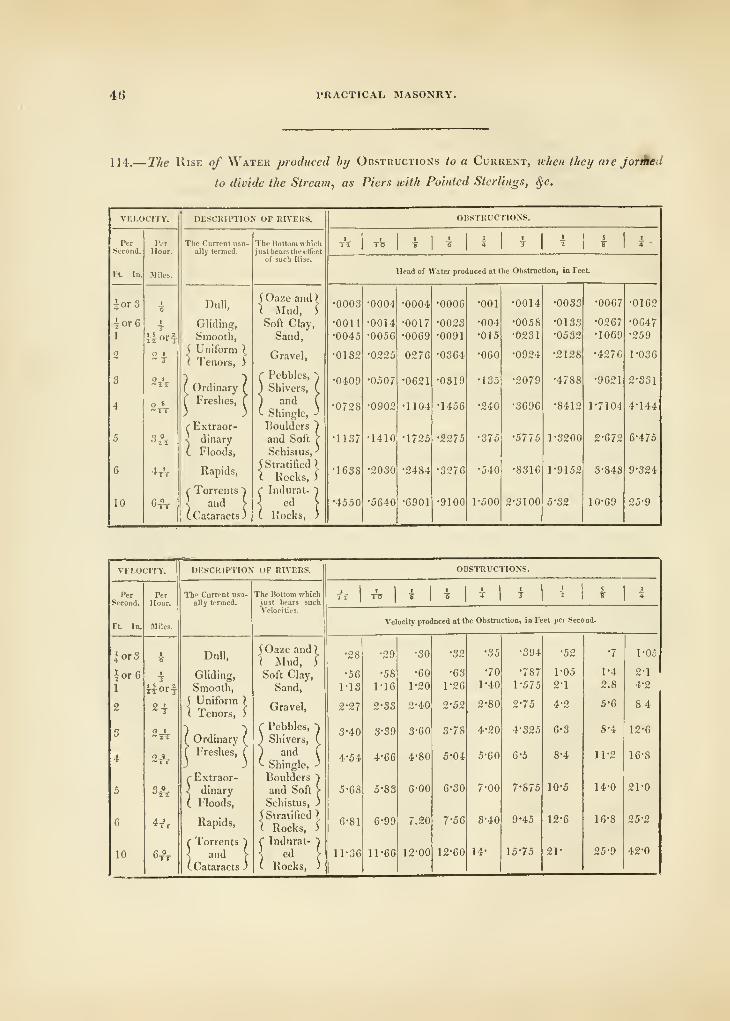
46 PRACTICAL MASONRY.
114..
—
The Rise of Water produced bij Obstructions to a Current, when they are jorMed
to divide the Stream, as Piers with Pointed Sterlings, ^c.
VELOCITY.
PRINCIPLES OF BRIDGES. 47
115. The next subject which claims our attention is the Water-breakers, or, what the work-
men call Sterlings, being the extremities of the piers which meet and divide the water in its
course. The preceding table supposes them to be rounded, or pointed, but if they be square
and abrupt, the conti-action produces a greater velocity by one-eighth, and the head is about
If times the head for rounded piers, and, consequently, very objectionable in navigable rivers.
The opinions of engineers respecting the proper form of this part of a bridge are various,
some contending for one form, and some for another ; but, it is obvious that, the form which
divides the water with least resistance, and least contracts the water-way, must be the best ; if,
at the same time that these advantages are attained, it retains suflScient strength to support
the structure.
The right-angled isosceles triangle was formerly employed by some bridge-builders as a form
the most suitable ; this opinion arises from the consideration of the right-angle being the
strongest of all others ; that is, if two bodies meet each other at right-angles, tliey will overcome
a greater resistance than they would do at any other inclination. Others contend for a form
composed of two arcs, containing each 60°, described from the two angles of the pier, and
meeting each other in the line dividing the water: sometimes a semi-ellipse, described on a
conjugate equal to the width of the pier, is used; and, not unfrequently, others of the conic
sections, or some whimsical figure that pleases the fancy of the architect.
Those who adopt the right-angle, erroneously contend that it divides the stream best ; those
who use the semi-circle and semi-ellipse, consider that they are the best calculated to resist the
shock of a loaded barge, or other floating body, that may come upon them, and that the
Gothic arches combine the advantages of both : we have already observed, that the form must
be adapted for dividing the stream, and allowing the water to pass most freely ; and it obvi-
ously should not be pointed so as to be dangerous to navigation.
Illustration of the Principles of Bridges.
116. We commence our illustration of the principles of Bridges with the magnificent edifice
which bears the triumphant appellation of Waterloo Bridge ; a work not less pre-eminent
among the bridges of all ages and countries than the event which it commemorates is unrivalled
in the pages of ancient or modern history.
It consists of nine elliptical arches, each of 120 feet span, and 35 feet rise, (see plate XVI,)
the piers are 20 feet thick; and the water-way is 1080 feet. The road-way is 28 feet wide,
with a foot-pavement of granite, of 7 feet width on each side. The arches and piers are built
of large blocks of Cornish granite, with short reversed arches in each pier for the principal
ones to abut against. The spandrils over the haunches are filled in with longitudinal walls of
brick, with spaces between them, which are covered over with strong pieces of sand-stone to
form the road-way upon. These hollow spaces lighten the stress on the bridge considerably
;
and are provided with proper outlets to prevent water collecting in them. The arch-stones
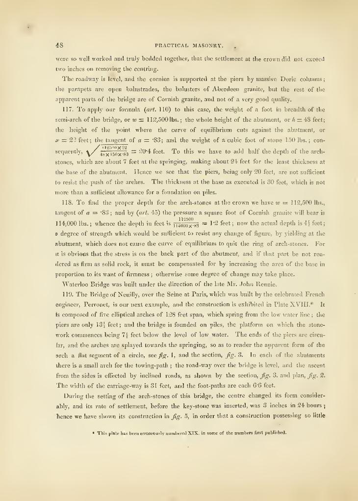
48 PRACTICAL MASONRY.
were so well worked and truly bedded together, that tlic settlement at the crown did not exceed
two inches on removing the centring.
The roadway is level, and the cornice is supported at the piers by massive Doric columns
;
ihe parapets arc open balustrades, the balusters of Aberdeen granite, but the rest of the
apparent parts of the bridge are of Cornish granite, and not of a very good quality.
117. To apply our formula (art. 110) to this case, the weight of a foot in breadth of the
semi-arch of the bridge, or w — 11 2,500 lbs. ; the whole height of the abutment, or h — 48 feet
;
the height of the point where the curve of equilibrium cuts against the abutment, or
ic = 2.2 feet; the tangent of a = 'SS; and the weight of a cubic foot of stone 150 lbs. ; con-
sequently, \/ 4Mxi5nx-83 "~ ~^'^ ^^^^' "^^ *'''^ ^® ^s.\e to add half the depth of the arch-
stones, which are about 7 feet at the springing, making about 21 feet for the least thickness at
the base of the abutment. Hence we see that the piers, being only 20 feet, are not sufficient
to resist the push of the arches. The thickness at the base as executed is 30 feet, which is not
more than a sufficient allowance for a foundation on piles.
118. To find the proper depth for the arch-stones at the crown we have jc «= 112,500 lbs.,
tangent of a = "So ; and by (art. 45) the pressure a square foot of Cornish granite will bear is
11-2500, - 1 1 . • .1 I !>
114,000 lbs. ; whence the depth in feet is ii4oqox-83 ~ ^'~ '^^^ '"°^^ ^""^ actual depth is 4^ teet;
a degree of strength which would be sufficient to resist any change of figui'e, by yielding at the
abutment, which does not cause the curve of equilibrium to quit the ring of arch-stones. For
it is obvious that the stress is on the back part of the abutment, and if that part be not ren-
dered as firm as solid rock, it must be compensated for by increasing the area of the base in
proportion to its want of firmness ; otherwise some degree of change may take place.
Waterloo Bridge was built under the direction of the late Mr. John Rennie.
119. The Bridge of Neuilly, over the Seine at Paris, which was built by the celebrated French
engineer, Perronet, is our next example, and the construction is exhibited in Plate XVIII.* It
fs composed of five elliptical arches of 128 feet span, which spring from the low water line ; the
piers are only 13i feet ; and the bridge is founded on piles, the platform on which the stone-
work commences being 7^ feet below the level of low water. The ends of the piers are circu-
lar, and the arches are splayed towards the springing, so as to render the apparent form of the
arch a flat segment of a circle, see fig. \, and the section, fig. 3. In each of the abutments
there is a small arch for the towing-path ; the road-way over the bridge is level, and the ascent
from the sides is effi^cted by inclined roads, as shown by the section, fig. 3. and plan, fig. 2.
The width of the carriage-way is 31 feet, and the foot-paths are each (i-Q feet.
During the setting of the arch-stones of this bridge, the centre changed its form consider-
ably, and its rate of settlement, before the key-stone was inserted, was 3 inches in 24 hours;
hence we have shown its construction in fig. 5, in order that a construction possessing so little
• This plate has been erroneously numbered XTX. in some of the numbers first published.
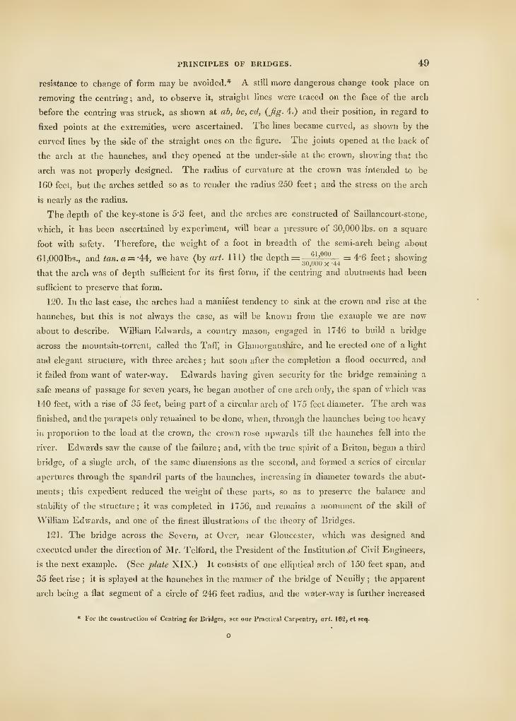
PRINCIPLES OF BRIDGES. 49
resistance to change of form may be avoided.* A still more dangerous change took place on
removing the centring; and, to observe it, sti-aight lines were traced on the face of the arch
before the centring was struck, as shown at ab, be, cd, {jig. 4.) and then: position, in regard to
fixed points at the extremities, were ascertained. The lines became curved, as shown by the
curved lines by the side of the straight ones on the figure. The joints opened at the back of
the arch at the haunches, and they opened at the under-side at the crown, showing that the
arch was not properly designed. The radius of curvature at the crown was intended to be
160 feet, but the arches settled so as to render the radius 250 feet ; and the stress on the arch
is nearly as the radius.
The deptli of the key-stone is 5"3 feet, and the arches are constructed of Saillancourt-stone,
which, it has been ascertained by experiment, will bear a pressure of 30,000 lbs. on a square
foot with safety. Therefore, the weight of a foot in breadth of the semi-arch being about
61,000 lbs., and ton.a = -44, we have (by ari!. ill) the depth = ^^^i^5!L_ = 4-6 feet; showing
that the arch was of depth sufficient for its first form, if the centring and abutments had been
sufficient to preserve that form.
120. In the last case, the arches had a manifest tendency to sink at the crown and rise at the
haunches, but this is not always the case, as will be known from the example we are now
about to describe. William Edwards, a country mason, engaged in 1746 to build a bridge
across the mountain-torrent, called the TafF, in Glamorgansture, and he erected one of a light
and elegant structure, with three arches ; but soon after the completion a flood occurred, and
it failed from want of water-way. Edwards having given security for the bridge remaining a
safe means of passage for seven years, he began another of one arch only, the span of which was
140 feet, with a rise of .35 feet, being part of a circular arch of 175 feet diameter. The arch was
finished, and the parapets only remained to be done, when, through the haunches being too heavy
in proportion to the load at the crown, the crown rose upwards till the haunches fell into the
river. Edwards saw the cause of the failure; and, with the true spirit of a Briton, began a thud
bridge, of a single arch, of the same dimensions as the second, and formed a series of circular
apertures through the spandril parts of the haunches, increasing in diameter towards the abut-
ments ; this expedient reduced the weight of these parts, so as to preserve the balance and
stability of the structure; it was completed in 1756, and remains a monument of the skill of
William Edwards, and one of the finest illustrations of the theory of Bridges.
121. The bridge across the Severn, at Over, near Gloucester, which was designed and
executed under the direction of Mr. Telford, the President of the Institution jof Civil Engineers,
is the next example. (See plate XIX.) It consists of one elliptical arch of 150 feet span, and
35 feet rise ; it is splayed at the haunches in the manner of the bridge of Neuilly ; the apparent
arch being a flat segment of a circle of 246 feet radius, and the water-way is further increased
* For the construction of Centring for Bridges, see our Practical Carpentry, art. 182, et seq.
O
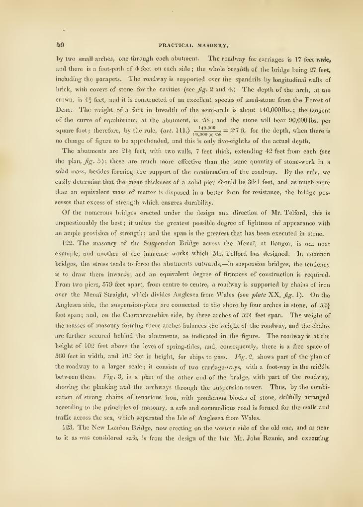
50 PRACTICAL MASONRY.
by two small arches, one through each abutment. The roadway for carriages is 17 feet wnle*
and there is a foot-path of 4 feet on each side ; the whole breadth of the bridge being 27 feet,
including the parapets. The roadway is supported over the spandrils by longitudinal walls of
brick, with covers of stone for the cavities (see fig. 2 and 4.) The depth of the arch, at tJie
crown, is 4| feet, and it is constructed of an excellent species of sand-stone from the Forest of
Dean. The weight of a foot in breadth of the semi-arch is about 140,000 lbs. ; the tangent
of the curve of equilibrium, at the abutment, is "58; and the stone will bear 90,000 lbs. per
square foot; therefore, by the rule, {art. 111.) '-—— = 2'7 ft. for the depth, when there is
no change of figure to be apprehended, and this is only five-eighths of the actual depth.
Tlie abutments are 21f feet, with two walls, 7 feet thick, extending 42 feet from each (see
the plan, ^^. 5); these are much more effective than the same quantity of stone-work in a
solid mass, besides forming the support of the continuation of the roadway. By the rule, wc
easily determine that the mean thickness of a solid pier should be 36" 1 feet, and as much more
than an equivalent mass of matter is disposed in a better form for resistance, the bridge pos-
sesses that excess of strength which ensures durability.
Of the numerous bridges erected under the design anc. direction of Mr. Telford, this is
unquestionably the best ; it unites the greatest possible degree of lightness of appearance with
an ample provision of strength ; and the span is the greatest that has been executed in stone.
122. The masonry of the Suspension Bridge across the Menai, at Bangor, is our next
example, and another of the immense works which Mr. Telford has designed. In common
bridges, the stress tends to force the abutments outwards,—in suspension bridges, the tendency
is to draw them inwards; and an equivalent degree of firmness of construction is required.
From two piers, 579 feet apart, from centre to centre, a roadway is supported by chains of iron
over the Menai Straight, which divides Anglesea from Wales (see plate XX, fig. 1). On the
Anglesea side, the suspension-piers are connected to the shore by four arches in stone, of 52^
feet span ; and, on the Caernarvonshire side, by three arches of 52| feet span. The weight of
the masses of masonry forming these arches balances the weight of the roadway, and the chains
are further secured behind the abutments, as indicated in the figure. The roadway is at the
height of 102 feet above the level of spring-tides, and, consequently, there is a free space of
560 feet in width, and 102 feet in height, for ships to pass. Fig. 2, shows part of the plan of
the roadway to a larger scale ; it consists of two carriage-ways, with a foot-way in the middle
between them. Fig. 3, is a plan of the other end of the bridge, with part of the roadway,
showing the planking and the archways through the suspension-tower. Thus, by the combi-
nation of strong chains of tenacious iron, with ponderous blocks of stone, skilfully arranged
according to the principles of masonry, a safe and commodious road is formed for the mails and
traffic across the sea, which separated the Isle of Anglesea from Wales.
123. The New London Bridge, now erecting on the western side of the old one, and as near
to it as was considered safe, is from the design of the late Mr. John Rennie, and executing
CONSTRUCTION OF DOMES, &C. 51
under the direction of his sons, Messrs. John and George Rennie, with some variations. The
principal parts are of Scotch granite. The bridge consists of five elliptical arches, (see plate
XVII,) the span of the centre one is 150 feet, and the rise 29| feet, above the datum, as the
level of the high-water mark of the Trinity-House is called ; the piers adjoining the centre arch
are 24 feet each ; the span of the arches next the centre one is 140 feet, with a rise of 2S\ feet
above the datum, and piers of 22 feet each. The span of the arches next the abutments
is 130 feet, with a rise of 25 feet above the datum, and abutments of 74 feet each. This makes
the total length of the water-way 690 feet; the length between the abutments 782 feet; and the
total length, including the abutments, 930 feet. The width of the carriage-way is to be 36 feet,
and the width of the bridge, to the outsides of the parapets, is 56 feet.
CHAPTER VI.
OF THE CONSTRUCTION OF DOMES, GROINS, AND SPIRES.
124. The Construction of a Dome is less difficult than that of an arch, because the tendency
which each part has to fall, is not only counteracted by the pressure of the parts below, but
also by the resistance of those on each side ; hence a dome may be erected, without the expen-
sive centring which an arch requires, and it may also be left open at the top, or without any
key-stone. Many of the large domes have nevertheless failed, or cracked, so as to create
alarm, and generally in consequence of the inadequacy of the supporting walls or piers.
The masonry of domes differs from that of arching, in the figure of each voussoir, which
must fit the void in a sphere instead of a cylinder. If a dome rises nearly vertical, with its
form spherical, and of equal thickness, it should be confined by a chain, or hoop, as soon as
the rise reaches to about ^hs of its whole diameter, in order that the lower parts may not
be forced out: but, if the masonry be diminished in thickness as it rises, this precaution will
not be necessary.
125. The dome of the antient Pantheon, at Rome, built by Agrippa, is the oldest and the
finest example. (See plate XXI.) It is the largest vaulted edifice constructed by the antient
Romans ; the plan is circular, the interior diameter 142 feet, and it is cylindrical to the height
of 72J feet, with a wall 23 feet in thickness ; but the wall has so many large niches and deep
recesses, that the mass is not more than equivalent to that of a wall one-third of the thickness
;
while the advantage in disposition is evident. The dome itself is internally a hemisphere, with
an opening at the top 29 feet in diameter ; the thickness is 4 ft. 10 in. where it joins the
platform round the aperture, 5 ft. 2 in. just above the last set-ofF, and 17 feet where it joins
52 PRACTICAL MASONRY.
the circular wall which supports it ; but the mass of the dome is diminished by five ranges
of deep sunk caissons. The ribs between the caissons are of brick, the pannel part of tufa and
pumice stones in small pieces.*
The construction of the cylindrical portion is not less judicious, it is of brick and filled in
with rubble-stone, but at every four feet in height a bond of brick-work is formed of bricks two
inches thick and two feet square ; the discharging arches also consist of two series of these
bricks, and the angles and faces of the wall are built of triangular bricks.
If we attentively examine the nature of this work we find the supporting part to consist of
piers connected by a continued inclosing wall, which gives the greatest degree of strength at the
base, at the place where it is required to resist a tendency to overset. The dome consists of ribs
and pannels ; the depth of the ribs gives stability, and the pannelled spaces are filled in with as
much lightness, both in regard to material and thickness, as was consistent with the proper
degree of strength. In this remarkable structure, every artifice which theory indicates is em-
ployed ; and the most refined works of the Gothic builders, though so difierent in form, are the
same in respect to principles ; the supports in both are piers connected by an inclosing wall ; and
the vaultings of deep ribs filled in between with light pannels. The Pantheon has now existed
nearly nineteen centuries ; and its fine portico has been admired by architects with more or less
of paltry criticism, but the scientific skill necessary to construct such an edifice, in the absence
of an example to imitate, is a rare acquirement, not often possessed by above one in an age.
On the restoration of the arts in Italy, many attempts were made to imitate the dome of the
Pantheon ; but the skill of the architect was, in general, insufiicient to ensure success.
126. Antheniius, a Greek architect, was selected by the Emperor Justinian, for erecting a
dome to the church of St. Sophia, at Constantinople, the church itself was to be in the form of
a cross, and vaulted with stone ; the dome he attempted to raise on the heads of four piers, of
about 115 feet high, and at the same extent from each other, and strengthened by four but-
tresses. The buttresses were solid masses of stone, extending, at least, ninety feet from the
piers to the north and south, so as to form the side walls of the cross. These effectually secured
the piers from the thrust of the two great arches of the nave which supported the dome. But,
when the dome was finished, and had stood a few months, as there was no provision against the
thrust of the great north and south arches, the two eastern piers, with their buttresses, gave
way; and the dome and half-dome fell in. On the death of Anthemius, Isidorus, another
Greek, succeeded to the work, and, having filled up some hollows to strengthen the piers on
the east side, again began to raise the dome ; but, while one part was building, another part fell
in. It was now found that the pillars and walls of the eastern semi-circular end were too much
• It is said, that when the wails were I'aiseti to the springing of the dome, the interior was filled with earth to turn the
dome upon; and that to induce the people to remove the earth money was strewed among it, a uiound being still pointed
out by the commun people of Rome as tlie place to wluie the eartli was removed; but the story is improbable, for tlie sci-
entific skill so well developed in the design of the edifice could not have had a difficulty in contriving a centre, and one of
earth would have settled so as to he useless.
CONSTRUCTION OF DOMES, &C. 53
shattered to give any resistance to the push which was directed against them ; and therefore
several clumsy buttresses were erected on the eastern wall of the square which surrounded the
Greek cross. These were roofed in, so as to form a kind of cloister, and lean against the
piers of the dome, and thus oppose the thrust of the great north and south arches. The dome
was now turned for the third time ; and though it was extremely flat, and, except the ribs, roofed
with pumice-stone, it was soon found necessary to fill the whole, from top to bottom, with
arcades, in three stories, to prevent the dome falling a third time. Thus a dome, which was
intended to be a beautiful specimen of architecture, was rendered a mis-shapen mass of de-
formity and an example of ignorance, which should warn the architect not rashly to undertake
what he has not sufficient science, in a proper manner, to perform.
127. Since that time, domes have been erected in various parts of Europe, and some that
display every requisite of beauty and strength, peculiar to this species of building. St. Peter's,
at Rome, an elliptical dome, 139 feet in diameter, is a superb specimen, but not without defects,
which have shown that its architects knew better how to distribute its supports for grandeur of
effect, than for firmness and durability, the dome having many cracks from the unequal settle-
ment of its supports.
128. The inner dome of St. Paul's, at London, is also elliptical, and open in the centre ; it is
112 feet in diameter, and still continues perfect. The lantern is supported by a conical vault of
brick-work, a figure admirably adapted for supporting an immense load on its summit ; but the
outer dome is formed by wooden framing.*
129. The dome of the church of St. Genevieve, including the peristyle on which it rests, is a
beautiful specimen as to form and composition. The peristyle is formed by fifty-two columns of
the Corinthian order, each about fifty feet high, completely insulated, and standing on a circular
pedestal. Above the cornice of the peristyle, the dome arises in a beautiful curved line to the
top, on which is formed a pedestal and gauery. But, when the dome was raised, the columns
composing the interior began to sink with the weight ; and some of the shafts of the columns
decorating the interior, which consisted of four naves, with the lantern and dome over them,
began to fracture at the joinings ; this defect was removed by walling up the inter-columniation
at the four quarters of the screen, which thus preserved from dilapidation one of the boldest
monuments of genius.
130. The following table gives the interior diameter, the height of the top of the dome from
the floor of the edifice, and the date of construction, when known, for some of the most cele-
brated works of the kind in Europe.
• The church of St. Genevieve has three vaults, all in stone, but then it is only 67 feet in diameter, with the vaulU ofsuch improper forms that they will not sustain the weight it was intended to place on them.
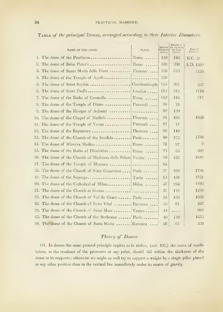
54 PRACTICAL MASONRY.
Table of the principal Domes, arranged according to their Interior Diameters.
NAME OF THE DOME.
1. The dome of the Pantheon
2. The dome of Saint Peter's
3. The dome of Santa Maria delle Fiore
4. The dome of the Temple of Apollo—5. The dome of Saint Sophia -.—G. The dome of Saint Paul's .---—7. The dome of the Baths of Caracalla
8. The dome of the Temple of Diana
9. The dome of the Mosque of Achmet
10. The dome of the Chapel of Medicis —1 1
.
The dome of the Temple of Venus
12. The dome of the Baptistery
13. The dome of the Church of the Invalids
14. The dome of Minena INIedica
15. The dome of the Baths of Diocletian
16. The dome of the Church of Madonna della Salute
17. The dome of the Temple of Mercury
18. The dome of the Church of Saint Genevieve ...
19. The dome of the Superga
20. The dome of the Cathedral of Milan
21
.
The dome of the Church at Sienna
22. The dome of the Church of Val de Grace
23. The dome of the Church of Saint Vital
24. The dome of the Church of Saint Marc ,
25. The dome of the Church of the Sorbonne
26. Thg^ttome of the Church of Saint Maria
PLACE.
Rome
Rome
Florence .
Constantinople
London
Rome
Puzzuoli
Florence .
.
Puzzuoli ..
Florence .,
Paris
Rome
Rome . . .
;
Venice —
Paris ,
Ravenna
Venice
Paris
Ravenna
Interior
diameterin feet.
GROINED VAULTING 65
132. When tlie weight of the dome is equally distributed over the area, then the curve of
equilibrium is a cubic parabola ; and if one-sixth part of the weight supported be multiplied
by the diameter, and the result divided by the rise, the quotient is the horizontal thnist tending
to separate and overset the supporting wall.
133. When the weight increases from the centre to the circumference in proportion to the
distance from the centre, then the curve is a biquadratic parabola, and one-eighth part of the
weight should be taken instead of one-sixth part.
134. It also may be proved, that the horizontal thrust of the dome will be wholly counter-
acted by a resistance to tension in the circle, equivalent every where to one-sixth of the horizontal
thrust ; and, when this strain is amply provided for, either by the bond and substance of the
walls at the springing, or by chains of iron, the dome will be secure at whatever height from
the ground it may spring, if the vertical walls or pillars be sufficiently so to resist the weight
upon them.
135. The plan of a dome is usually a circle, and this is the most perfect figure for the pur-
pose ; but any regular polygon may form the base of a dome, whether octagon, decagon, &c-
they do not, however, possess the same property of resisting change of figure which belongs
to the circular base.
136. If the lateral or horizontal thrust is to be resisted by the weight of the supporting wail
or piers, so as to be sufficiently strong without the connection obtained by binding the parts
together in a continued circle, then, the rule Cin art. 110) applies to this case, as well as to
arches, where the whole weight of the dome divided by the circumference of the supporting
wall, or the sum of the breadth of the piers, in feet, is inserted for w, in finding the thickness.
137. In Uke manner, by finding the weight w on each foot of circumference, the depth of
the dome may be found, which renders it of sufficient strength, either at the abutments or at the
crown, (by art. 106 and 111,) for when the connection of the parts is left out of the calculation,
as a proper reserve of strength for duration, the arch and dome are dependent on the same
principles.
Of Groined Vaulting.
138. A long rectangular space may be covered with a continued arch, called a vault, but so
heavy a covering, destitute of variety, had little chance to please the taste of men, who, having
seen the finest works of antiquity, were desirous of excelhng them, if possible, particularly in
the construction of the peculiar form that had been selected for Christian churches. The plan
being a cross, the object was to find a graceful and varied form of covering, in which the pro-
found science displayed in the Roman Pantheon should, at least, be equalled : for that work
was evidently considered the master-piece of the age.
139. A vault, or continued arch, consisting of deep ribs, with thin pannels between, might
first suggest itself; and such a construction has been employed in both vaults and bridges, the
56 PRACTICAL, MASONRY.
old Gothic hr'uUe at Durham, called Framwell-gate Bridge, now being altered and widened
under the direction of Mr. Bonomi, architect to the county of Durham, is one of the finest
examples of the kind. On this subject we have only to remark that, in a bridge, deep ribs expose
a much greater surface of stone to decay, and the experience of many ages has shown that a
plain soffit is better ; but we see no difficulty in obtaining the advantage which the Gothic
brido-e has in real lightness and stability, without exposing more surface to the weather than the
common method. When applied as a vault, the continued arch required continued thick walls
for abutments, and these were too heavy, expensive, and tasteless for the spirit of the age.
140. Vaults, supported by piers or pillars, were sometimes executed by the antient Romans;
but there is a degree of formal clumsy heaviness about them, which is universally felt, and
often censured ; the Gothic vault, on the contrary, commences at the base of the pillars which
support it, and these being carried perpendicularly to a proper height, bend over and spread
to form the ribs of the vaulting ; no interrupting entablature breaks the connection between the
pillars and the ribs of the vault ; hence that lightness of effect, with apparent as well as real
strength and fitness, which characterize the stone roofs of our cathedrals ; and show that these
works were the production of men having a knowledge of what is most profound in the science
and practice of building, and a boldness in execution of which classic antiquity furnishes no
example ; neither has it descended to our times ; the art has fled, but left for our instruction,
—
'* Her pemlant roof, her windows* brancliy grace,
Pillars of clustcr'd reeils, ami tracery of lace."
141. In a dome, if the part supported be divided into triangular portions, the base of each
triande is at the supporting wall;—in a groined vault divided into triangles, the vertex of each
ti-iangle is at one of the supporting piers ;—in an arch, instead of triangles, we have parallelo-.
grams. But, notwithstanding this diversity in the distribution of the load to be supported,
the same general principles apply, for they are but different cases of the same mechanical
problem.
142. When the weight of a groined vault is equally distributed over the area it covers, the
curve of equilibrium is a semi-cubical parabola ; and the horizontal tln-ust of a part compre-
hended between two angle-ribs, is one-third of its weight multiplied by the span of the arch, and
the result, divided by its rise, gives the thrust tending to overset the pillar or oier in the direc-
tion of the body-rib of the compartment.
143. If the weight be distributed so as to increase in proportion as it approaches the support,
then the curve of equilibrium will be a common parabola, and one-fourth of the weight of a
compartment should be taken instead of one-third, but in other resoects the horizontal thrust
is to be found as in the last article.
144. The parts of the groin which are on opposite sides of the pier balance each other,
and it is usual to make the piers only of sufficient magnitude to support the load ; but the piers
are so connected, by the side-walls between them, that a failure from a pier being deprived of
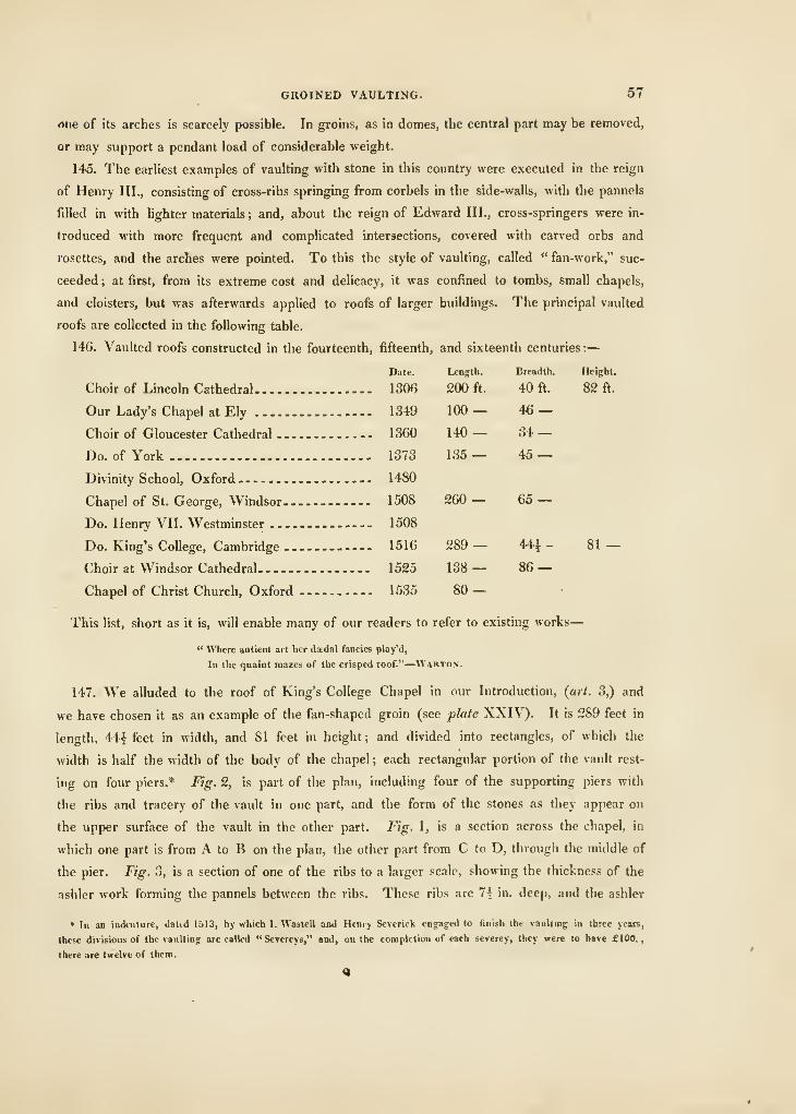
GROINED VAULTING. 57
due of its arches is scarcely possible. In groins, as in domes, the central part may be removed,
or may support a pendant load of considerable weight.
145. The earliest examples of vaulting with stone in this country were executed in the reign
of Henry III., consisting of cross-ribs springing from corbels in the side-walls, with the pannels
filled in with lighter materials ; and, about the reign of Edward III., cross-springers were in-
troduced with more frequent and comphcated intersections, covered with carved orbs and
rosettes, and the arches were pointed. To this the style of vaulting, called " fan-work," suc-
ceeded ; at first, from its extreme cost and deUcacy, it was confined to tombs, small chapels,
and cloisters, but was afterwards applied to roofs of larger buildings. The principal vaulted
roofs are collected in the following table.
146. Vaulted roofs constructed in the fourteenth, fifteenth, and sixteenth centuries:
—
Date. LeDg:th. Breadth. Height.
Choir of Lincoln Cathedral 1306 200 ft. 40 ft. 82 ft.
Our Lady's Chapel at Ely 1349 100— 46 —Choir of Gloucester Cathedral 1360 140 — 34 —Do.ofYork 1373 135— 45 —Divinity School, Oxford 1480
Chapel of St. George, Windsor 1508 260 — 65 —Do. Henry VII. Westminster 1508
Do. King's CoUege, Cambridge 1516 289— 44i - 81 —Choir at Windsor Cathedral 1525 138— 86 —Chapel of Christ Church, Oxford 1535 SO —
This hst, short as it is, will enable many of our readers to refer to existing works
—
" Where antient art her daedal fancies play'd,
Iq the quaint mazes of the crisped roof."—Warton.
147. We alluded to the roof of King's College Chapel in our Introduction, (art. 3,) and
we have chosen it as an example of the fan-shaped groin (see plate XXIV). It is 289 feet in
length, 44y feet in width, and 81 feet in height ; and divided into rectangles, of which the
width is half the width of the body of the chapel ; each rectangular portion of the vault rest-
ing on four piers.* Fig. 2, is part of the plan, including four of the supporting piers with
the ribs and tracery of the vault in one part, and the form of the stones as they appear on
the upper surface of the vault in the other part. Fig. 1, is a section across the chapel, in
which one part is from A to B on the plan, the other part from C to D, through the middle of
the pier. Fig. 3, is a section of one of the ribs to a larger scale, showing the thickness of the
ashler work forming the pannels between the ribs. These ribs are 7' in. deep, and the ashler
• In an indenture, tlatid 1513, by which I. Wastell and Henry Severick engaged to finish the raulliog in three yean,
these divisions of the vaulting are called "Sctereys," and, on the completion of each severey, they were to hare £100.,
there are twelve of them.
58 PRACTICAL MASONRY.
v'ork of the pannels 4^ in. thick. Great as the merit of the designer is, his n;inie is unknown;
but its successful execution merits an equal degree of praise, and the names of John Woolrich,
Henry Severick, and John Wastell, may be handed down to posterity as the most skilful master-
masons of their age and nation.
Of the Construction of Spires.
148. The spires of churches are pyramidal vaults either straight or convex, and generally a
little convex ; they vary from 6 to 9 inches in thickness, according to the quality of the stone,
or the size of the spire. The base is sometimes square, but most frequently octagon ; and
they are raised from either square or octagon towers.
49. When a spire springs from a square tower, the walls of the tower are gradually in-
creased in thickness towards the point from whence the spire rises, and are formed to the shape
of its base ; the bond of the work being rendered as perfect as possible, by employing large
stones, crossing the joints, and connecting them by cramps run in with lead ; sometimes the
ring of stones on which the base of the spire rests is further secured by a chain of iron, bedded
in the stone, and run in with lead. The bed-joints of the spire itself must be perpendicular to
its slant surfaces, and the vertical joints directed to the centre.
In order to illustrate these remarks by examples, we have selected two of the most esteemed
spires in England.
150. The spire of Salisbury Cathedral (see plate XXI.) is octagonal, and rises from the
centre of the' square tower, four of its sides resting on the walls of the tower, and the other
four on arches across at the angles, at the top of the tower ; the wall is five feet in thickness,
two of which are occupied by the base of the spire, two by a passage to go round it, and one
by the parapet. The wall of the spire gradually diminishes in thickness to about twenty feet
above the tower, where it is reduced to nine inches, and is continued of that thickness to the
summit. The figure in the plate is one half section, showing the timber-framing within, which
is ingeniously contrived, the other half elevation. Externally, the spire is ornamented with ribs
up the angles, each of which has two rows of knobs attached to it, and the spire is divided
into four nearly equal portions, by bands of tracery, pannels, &c. At the base tliere are four
decorated door-ways to the parapet of the tower. The two uppermost divisions, or stories of
the tower, and the whole of the spire, are evidently of later erection than the church, or of
the lower story of the tower; the stile of architecture is enriched; and in the forms and orna-
ments of the pediments, pinnacles, and open parapets, resemble the much-admired crosses
raised by King Edward I., and other works erected at the end of the thirteenth century. It
seems that the architect of this spire was ambitious to carry its apex higher than any similar
building of stone in England ; from the ground to the highest point is 404 feet ; and though it
is not of equal altitude to that of St. Stephen's Church at Vienna, which is 4(J5 feet, nor that
LIGHT-HOUSES. b9
of Strasburgh, which is 4-56 feet, yet its vast height has rendered it an object of popular
wonder, as well as of great curiosity and interest to the architect. To the old tower 387 feet
of new foundation was added on the erection of the spire, and several windows were filled uj),
and ties of iron inserted. A settlement has taken place on the western side; and it appears
that, at the cap-stone of the spire, the decHnation is 24j inches to the south, and IGJ to the
west. The date of its erection is the end of the thirteenth century.
151. The spire of Litchfield Cathedral is represented on the same plate, and in a similar
manner, one half being a section, the other half elevation. It was finished in the middle of
the fifteenth century, and it is a good example of an ornamented spire, but we do not think the
insertion of windows appropriate, nor that horizontal bands and mouldings improve a spire
;
they seem to owe their effect to fine proportions rising unbroken from the base to the summit
;
nevertheless some degree of ornament improves a spire ; and the effect of one perfectly plain,
ending in a needle-point, may be seen at the church Mr. Nash built in Langham Place.
152. When a spire is an exact pyramid, its arrises, though straiglit, appear concave to the
eye; hence, in construction, they should be slightly convex ; and further, it may be proved that
where there is not a perfect coherence of the parts, the figure should be convex to be of equal
strength in all its parts. We have treated this subject at greater length than we had intended,
because, in our eyes, the beautiful spires of some parts of England add much to the interest
and effect of the country.
CHAPTER VII
OF THE CONSTRUCTION OF LIGHT-HOUSES.
153. A LIGHT-HOUSE is a tower of considerable height, with the means of producing li.Tht in
the top part, )r lantern, so as to render it visible to a great distance at sea, to serve as a guide
to seamen in steering their vessels in the night-time.
154. Those light-houses which are constructed on the sea-coasts, or on the piers of harbours,
present very little difficulty ; a round or octagon tower, with a winding stair, and small rooms
for the accommodation of the keeper, being the only essential parts of the masonry. In some
instances, it is difficult to procure a solid foundation, and the usual methods of piling, grating,
and planking, are resorted to. (See Chap. III.)
155. But the protection of the commerce of Great Britain required that light-houses should
be erected on isolated rocks of the ocean; noble works, which no man can regard with indiffer-
ence, rearing their heads amidst the tumultuous waves, while the dwellers within trim their
lamps in safety, to guide their endangered fellow-creatures through the peril? of the storm. (See
60 PRACTICAL MASONRY.
plale XXIII.) To raise a permanent light-house on a rock covered by the sea at high-water,
was first attempted at the Eddystone ; two were erected chiefly of timber and destroyed, the
one bv a storm, and the other by fire. Mr. Smeaton designed another to be executed in stone,
it was erected, and still remains a proud monument of the skill of that celebrated engineer.
The Edihjstone Light-house.
156. Mr. Snieaton's first journey to Plymouth, upon the business of the Eddystone light-
house, as will be seen from his excellent narrative of the work, was in the month of March.
1756; and, on the 5th of April, the following month, he landed, for the first time, on Eddy-
stone-rock. In the course of the ensuing winter, and following spring, arrangements were
made for proceeding with the building operations. A large stock of materials had been pro-
vided, and various experiments were made by Mr. Smeaton with lime-stone from different
parts of the coast, which enabled him to conclude, that a mixture of lime from Aberthaw, in
the Bristol channel, and puzzolano earth from Italy, was the proper mortar for this building.
(See art. 62.) A stock of oak trenails was provided for fixing the newly-laid stones to the
rock, or to the course below, which, with the system of dove-tailing and joggling, (see plate
XXIII, fig. 3,) prevented them from being carried away before the mortar took bond, or while
the respective courses were in an unfinished stale. Things ^being thus in preparation for the
second year's operations, the attending-vessel was moored in her place, near the rock, and the
foundation-stone of the building was laid on the 12th of June, 1757 ; and, by much perse-
verance, the ninth course, or third entire course above the top of the rock, was completed by
the last day of September, with which the season's work was successfully closed. Owing to
several disappointments, the commencement of the work at the rock did not take place till the
2d day of July, 1758, when part of the 10th course was landed ; and, by the 8th of August, the
14th course, or solid part of the building, was completed, which brought the work to the
entrance-door, or to the height of 12 feet above the top of the rock; and, by the latter end
of September, the 24th course, forming the top of the staircase and floor of the first apart-
ment, or store-room, was laid. Tlie work being continued till the beginning of the month of
October, the outward circle of the 29th course, or the arciied roof of the store-room, was laid.
It was not till the latter end of March following, that a favourable opportunity was afforded to
Mr. Jessop, the assistant-engineer, for landing at the rock, when he found every thing nearly
in the same state in which it had been left in the month of October, excepting one stone of the
upper or unfinished course, which the workmen were in the act of laying, when they were
oblio^ed hastilv to leave the rock. This stone had been carried away from its having, perhaps,
been left too near the outer verge of the building. But it deserves notice, that the wooden
centering, for carrying the arch or dome over the store-room, was found in its place, after all
the gales of winter, together with a set of wooden triangles, which had been left on the top of
LIGHT-HOUSES. 61
the building, and were found, on landing in the spring, to be in good condition, together with
a stone which was ready to be laid, and was still found suspended by the tackle. By the
middle of the month of June, 1759, in the fourth and last year of the work, the whole of the
stones were hewn early in the season, and were ready to ship from the work-yard to the rock.
The work commenced this season on the 5th of July, and by the 17th of August following, the
balcony and upper course of the cornice was laid, which completed the masonry of the Eddy-
stone light-house.
The exterior parts of the building which are exposed to the action of the sea are of granite,
the interior of Portland stone. Fig. 5, shows the continued chain which is inserted to assist
the tendency to spread from the thrust of the floors ; and fig. 4, the cramps and dowels in the
other courses.
The Bell Rock Light-house.
157. The Bell Rock light-house is nearly of the same form as the Eddystone, with some
improvements in the mode of constructing the upper parts of the work. Fig. 1, plate XXIII,
is an elevation ; and fig. 2, a section of the Bell Rock light-house. The Bell Rock itself is a
sunken reef of sand-stone, the highest part only being uncovered at ordinary ebb-tides. The
nearest land to the Bell Rock is the town of Arbroath, from which it lies in a south-eastern
direction, about 1 1 miles distant. The dimensions of the part of the rock which become dry
in spring-tides are, about 400 feet in length, and 250 in breadth ; at flood-tides, the whole
rock is from 10 to 12 feet under water, and it presents a very rugged surface. In regard to
the depth of the sea near the Bell Rock, it appears that, at the distance of about 100 yards, in
a low state of the tide, the water varies from two to three fathoms in depth. Between the rock
and the opposite shore of Fife the greatest depth is 23 fathoms ; but on the south-east, or sea-
ward side, it increases suddenly to 23 fathoms. The observations made upon the currents at
the rock are curious. Although a mere spot on the surface of the ocean, it produces all the
remarkable phenomena of in-shore and ofi'-shore tides, which are noticeable on the projecting
coasts of the mainland, or among the Scottish islands.
Mr. Stevenson first landed on the rock in the summer of 1800 ; and became satisfied of the
practicability of erecting a stone light-house on this fatal reef, upon principles similar to those
employed by Smeaton in the construction of the Eddystone one, and reported to that effect to
the Commissioners of Northern Light-houses, who also consulted Mr. Rennie on the subject;
and the work was commenced in 1807.
From the insidated and distant situation of this rock, the first object was to moor the tender
for the exhibition of a temporary light, and for the convenient residence of the artificers. A
vessel was also provided for carrying workmen between the shore and the rock. Quarries were
opened near Aberdeen for supplying granite for the outward courses of the building, and at
Kingoodie, near Dundee, for supplying sand-stone for the interior. The principal establish-
R
62 PRACTICAL MASONRY.
ment on shore was Hxed at Arbroath, where a large enclosure was procured for the preparation
of the stones, connected with barracks for the accommodation of the artificers. By strenuous
and unremitting exertions the beacon-house was erected, and the foundations of the building
prepared by the middle of the month of July, in the second season of the work. The foun-
dation had the appearance of a great circular platform of compact red sand-stone, measuring
42 feet in diameter, surrounded by an irregular margin of rock, rising from 18 inches to 5 feet.
In the work-yard at Arbroath, where the materials were prepared, the first and second courses
of the light-house now lay ready for being shipped for the rock. Each stone was accurately
marked, so that its relative position in the building on the rock could at once be recognised.
The stones were cut of a dove-tail form, on a plan similar to those of the Eddystone light-
house. The foundation-stone at the Bell Rock was laid by Mr. Stevenson with masonic
ceremony, on the 10th of July, 1808; and, by the latter end of September, the works were
brought to a conclusion for the season. The building, being now on a level with the highest
part of the margin of the foundation-pit, or about 5 feet 6 inches above the lower bed of the
foundation-stone, is computed at 388 tons of stone, consisting of 400 blocks, connected by
738 oaken trenails, and 1215 pairs of oaken wedges. The number of hours of low-water work
upon the rock this season was 265, of which number only 80 were employed in building.
In the spring of the year 1809, the operations re-commenced. Every thing was found to
have withstood the eftects of the winter's storms, all the courses which had been laid, and the
beacon itself, now in the third year from its erection, remaining quite entire; and with that
season was completed the 24th course, reckoning above the first entire one, and the 26th above
the rock. This finished the solid part of the building, and terminated the height of the out-
ward casing of granite, which is 31 feet 6 inches above the rock, or site of the foundation-
stone, and about 17 feet above high-water, at spring-tides. The first circumstance attended
to in commencing the building operations of 1810 was to fix upon the proper position of the
entrance-door of the light-house. In this Mr. Stevenson was assisted by carefully observing
the range of the sea upon the solid part of the building, and by tracing the growth of fuci
and confervas on the walls. The heaviest sea being in this manner determined to be from the
north-east, the door was consequently laid off towards the south-west. This and other preli-
minary steps having been taken, the first cargo of stones was brought to the rock about the
middle of May ; and, from the very complete and systematic arrangement of the works, the
building operations were brought to a close during the month of August, without any material
obstacle having been experienced. This greatly increased facility in building, was ascribed partly
to the experience acquired by practice in former seasons, in landing and raising the materials.
Plate XXIII, contains an elevation and section of the light-house, to which we refer our readers.
Having already noticed the manner of attaching the lower courses of the stones, which was
similar to that resorted to at the Eddystone, we shall now advert to the plan followed for the
upper or habitable part. At the stone staircase, leading from the door to the first floor, the
ORNAMENTAL MASONRY. 63
wall is of the medium thickness of about 7 feet, and gradually diminishes upwards, till,
under the cornice of the building, it is only 18 inches. The stones of the walls of the several
apartments are connected at the ends with dove-tail joints instead of square joggles, as in the
solid and in the stair-case ; while the bed-joints are fairly imbedded in each other by means of
a girth raised upon the one stone, and sunk into the other. The floors are also constructed in
a manner which adds much to the bond or union of the fabric. Instead of being arched,
which would give a tendency or pressure outwards on the walls, the floors are formed of long
stones, radiating from the centre of the respective apartments, and at the same time forming a
course of the outward walls of the building. These floor-stones are also joggled sideways, and,
upon the whole, form a complete girth at each story. In this manner, the pressure of the
floors is rendered perpendicular, while the side-joggles resemble the groove and feather in
carpentry. In the strangers'-room, or library, the roof takes an arched form, but the curve is
cut only upon the interior ends of the stones of the cornice, the several courses of which it is
composed being all laid upon level beds.
On the 2d of February, 1811, it was lighted for the first time. The light is clear and power-
ful, and may be seen, when the sky is clear, very distinctly at eight leagues distance. The
light is alternately red and white.
" Far in the bosom of the deep,
O'er the wide shelves my watch I keep
—
A ruddy gem of changeful light,
Bound on the dusky brow of night;
The seaman scuds, my lustre hails.
And seems to sti'ike his timorous sails."
—
Sir \V. Scott.
CHAPTER VIII.
ORNAMENTAL MASONRY.
158. Ornamental Masonry includes the construction of columns and the parts connected
with them, stairs, chimney-pieces, and monuments.
159. Of columns.—These comprise, generally, a conoidal shaft, with a diminution
towards their upper diameter, which is, generally, about one-sixth less than the lower diameter.
The proportions of columns, among the Egyptians, varied but little ; the columns of this people,
in their large temples, were only about four and a half diameters in height. Those of Greece
vary considerably ; the Doric from 4|- to t>J- diameters ; those of the Parthenon, at Athens,
are little more than five. In the best Roman examples, the proportion of the Doric was
increased to seven diameters. The columns of all the Grecian remains are fluted. The Doric
(34 PRACTICAL MASONRY.
shafts liave for their flutes very flat segments of circles, finished to an arris : but someiinies
flutings of the semi-elliptical shape were adopted. The genius of an architect is generally
displayed in the application of columns. The Greeks surrounded their public walks with them
;
and in their porticos carried this kind of splendour to its highest pitch. To construct a temple,
in the Greek manner, required the greatest taste and judgment, combined with a perfect know-
led<re of architecture. The Parthenon, at Athens, was, without exception, the most elaborate
piece of masonry in the world.
The comparatively perfect state in which the monuments of Greece remain, is a proof of the
perfection with which they were constructed. The famous Temple of Minerva would have
been entire to this day, if it had not been destroyed by a bomb. The Propylea, which was
used as a magazine for powder, was struck by lightning and blown up. The Temple of
Theseus, having escaped accidental destruction, is almost as entire as when first erected. The
little chora"-ic monument of Thrasybulus, as well as that of Lysicrates, are also entire. These
instances should impress on modern architects the utility of employing large blocks, of uniting
them with the greatest accuracy, and giving the highest degree of finish to the whole.
160. The joining of columns in free-stone, has been found more difficult than in marble ; and
the practice used by the French masons, to avoid the failure of the two arrises of the joint,
might be used with success for constructing columns of some of our softer kinds of free-stone.
It consists in taking away the edge of the joints, by which means a groove is formed at everj
one throughout the whole column. This method is employed only in plain shafts. It appears
to have been occasionally used by the antients, though for a different purpose ; vh. to admit the
shaft to be adorned with flowers, and other insignia, on the occasion of their shows and games.
In the French capital, they affix rows of lamps on their columns, making use of these grooves to
adjust them regularly, which produces a very good effect.
IGl. The shafts of colunms, in large works, intended to be adorned by flutes, are some-
times put up plain, and the flutings chiselled out afterwards. The Greeks commonly formed
the two extreme ends of the fluting previously, as may be seen in the remaining columns of the
Temple of Apollo, in the Island of Delos ; a practice admitting great accuracy and neatness.
The finishing the detail of both sculpture and masonry on the building itself, was a very
common practice among the antients : they raised their columns first in rough blocks, on them
they placed the architraves and friezes, and surmounted the whole by the cornice ; finishing
down only such parts as could not be got at in the building ; hence, perhaps, in some measure,
arose that striking proportion of parts, together with the beautiful curvature and finish given
to all the profiles in Grecian buildings. In modern works, a greater command of the me-
chanical powers, and more accurate methods of ai-ranging the parts of large works, causes the
more scientific practice of executing them in parts to be preferred.
When a plumb-rule is applied to try if the axis of the column be exactly vertical, the rule
should be so held that its plane surface, if produced, would pass every where through the axis.
ORNAMENTAL MASONRY. G5
162. With regard to the practice of the ancients, in diminishing the shafts of their columns,
nothing can be learned from the writings of Vitruvius, since his text is so very obscurely
expressed as not to be understood. It has been always supposed by modern writers on archi-
tecture, that the contour of the columns was that of a convex curve, called by Vitruvius the
entasis. Some writers have supposed that the greatest diameter of the shaft was not at the
extremities, but at some intermediate section of its height ; and the practice of modern archi-
tects of the last century was to make the shaft cylindrical to one-third part of the height, and
thence to lessen the diameter continually, so that the sides might form a convex curve.
163. Sir William Chambers I'ecommends the trammel, which Nicomedes used for the descrip-
tion of his first conchoid, as being best adapted for this purpose, as this instrument gives at
one sweep both the entasis and diminution. We must, however, observe, that the instrument
of Nicomedes is not only cumbersome, but inconvenient to use, on account of its requiring so
much room, in order to place it and to describe the curve. He moreover says, that it is
universally allowed to be the most perfect practice hitherto discovered ; and that the columns
of the Pantheon, accounted the most beautiful among the antiques, are traced in this manner,
as appears by the exact measures of one of them to be found in Desgotez's Antiquities
of Rome.
164. How columns could be executed with such exactness, or how the dimensions, after
standing so many hundred years, could be taken with such accuracy as to ascertain that the
curve-Une of their sides was that of the conchoid, we are at a loss to know, since the curvature
of all curves, at the vertex, is very nearly equal when the radius of curvature is equal ; so that
many curves of different properties, as the circle, the ellipse of any given eccentricity, the
parabola, the conchoid, &c., may be all drawn through three given points, without its being
possible to discover any deviation. And thus it will appear, that the dimensions given of the
shafts of the columns of the Pantheon prove nothing; so that, in point of fact, when the
curvature differs but little from a right line, the entasis formed by any known geometrical curve
must be equally agreeable to the eye, whether we use a portion of one curve, or a portion of
another. It will, however, be most convenient to employ such a curve as can be the most easily
described, and, at the same time, will require the least space to perform the operation.
165. It is singular that Stewart, the celebrated author of the Antiquities of Athens, has not
favoured us with the measures of the contours of the columns, taken upon sections through the
axes of the shafts of the columns of any Grecian edifice.
Mr. Reveley, an ingenious traveller, in his Defence of Grecian Architecture, in answer to tlie
attacks of Sir William Chambers, says, that the contours of the columns of Grecian temples were
executed in the most graceful sweeping lines, but does not confirm this assertion by any example.
" The entasis of columns has not till lately formed a part of the critical study and observation
of the student of Grecian architecture, and had escaped even the exact and minute attention of
s
G6 PRACTICAl MASONRY.
Stewart and Revett ; yet, of its importance, no one will doubt, who considere but for a moment
how much of beauty depends upon the nicely-executed contour of the shaft of the column."
The entasis, in every instance, (here given,*) are produced from the bottom of the column,
but none have the entasis perceptible to the eye, and scarcely to the rule, so slight is it ; from
which we cannot but infer, that it never was the intention of Grecian architects to produce
any other effect to the eye of the beholder than that of a straight line ; nor are we aware that
there is an example now remaining, but the columns of the Pscudodipteral temple at Paestuni.
These conclusions are corroborated by the observations of Mr. Wilkins, in his excellent
translation of Vitruvius, where he says, if the fillet between the flutings of the Ionic columns
be the measure of the entasis of Vitruvius, tiie deviation from a straight line will be scarcely
perceptible in the outline of a column.
166. These facts seem at variance with the ideas of modern architects and authors, wlio
assert, that columns which have their shafts in the figure of the frustum of a cone appear
concave to the eye. This concavity, however, is a delusion of the senses, generated by con-
stantly seeing the shafts of columns diminished in a convex curve. We will venture to affirm,
that had they been accustomed always to view conic or cylindric shafts instead of conoidal
shafts, the notion of their being concave would never have been so generally impressed.
167. Some columns are fluted round the shaft to the number of twenty-four, with as many
fillets, one between every two flutes, as in the Ionic, Corinthian, and Composite orders ; and
some columns are fluted without fillets, as in the Doric order, the profiles of the flutes being
generally a segment of a circle less than a semi-circle. Semi-circular flutings are generally used
in Roman architecture, the proportion between a fillet and a flute being as one to three, or as
one to four ; and, in the columns of Grecian architecture, the profile of the flutes in the Ionic
and Corinthian orders is a semi-ellipse surbased, the proportion of a fillet and a flute is from
one to five to from one to seven.
IGS. OF PILASTERS. — Pilasters are rectangular trunks of stone, employed in Roman
architecture in place of columns, and may belong to any of the five orders.
In Roman architecture, when detached columns are employed, pilasters are always ranged
behind the columns ; and if such columns are placed within a recess, besides the pilasters behind
the columns, a pilaster is attached to each of the flank-walls, so as to range with the columns
and to support the ends of the entablature over them; in this case, a quarter pilaster must be
placed in each interior angle of the recess, so as to range with the pilasters behind the columns
* Sec Stewart's Antiquities of Athens, published by Priestly and Wealc, Volume IV., parts Sixth and Seventh, by Mr.
William Jenkins, Jun. Plate 4, belonging to the same parts, exhibits the sections of the shafts through the axis of the
Portico and North wing of the Propylea, the temple of Theseus, the temple of Minerva, and the Choragic monument at
Athens ; and Plate 5 exhibits the sections througli the axes of the shafts of the columns of tlic north and east porticos of
the triple temple, called the Erectheum, at Athens; and those of tlie portico and pronaos of the temple of Jupiter Panhei-
lenius, at £giDa.
ORNAMENTAL MASONRY. 67
and with the two pilasters in the range of the columns, as also to support the extremities of the
entablature over the pilasters behind the columns and the extremities of the two entablatures
over the pilasters upon the flanks of the recess ; but, if a range of insulated columns are
placed partly within a recess and partly without, the two extreme pilasters in the range of the
columns must then exhibit two complete faces, one parallel to the front of the building, and
one parallel to each of the flank-walls.
169. In Roman architecture, pilasters aiTanged behind ought to diminish, and to have an
entasis in an equal degree to those of the columns, so that the bases and capitals may not only
range in a horizontal line, but also that the capitals may preserve the same proportion in their
outline as those of the columns. Ancient examples, in which this is particularly observed, may
be seen in the Temple of Mars the Avenger, in the Frontispiece of Nero, in the Portico of
Septimus Severus, and in the Arch of Constantine at Rome ; but, if they are arranged upon a
wall, without columns, their faces and returning edges ought to be rectangular parallelograms.
170. Engaged pilasters are employed in Churches, Galleries, Halls, Sec, in order to save
room ; for they seldom project beyond the naked of the walls more than one-quarter of their
breadth, and do not occupy near so much space as engaged columns. They are sometimes
employed in exterior decorations instead of columns, and sometimes alone, on account of their
being less expensive, as at the Duke of Queensberry's house in Burlington-Gardens, General
Wade's house in the same place, and in many other buildings in London. Examples where
they accompany columns, being placed behind them, may be seen in the portico of the Pantheon
at Rome, and in the portico of St. Martin-in-the-Fields ; and examples in which they range
with, and flank the columns, may be seen in the portico of Septimus Severus at Rome, and in
the church of St. Lawrence Jewry, London. The projection of pilasters behind columns need
not be so great as when they are alone.
171. The trunks of pilasters are sometimes adorned with flutings, in the same manner as the
columns of the same order. The profile of the flutes ought never to exceed a semi-circle, and
in order that they may be of the same dimensions as in columns of the same magnitude and
specie, the breadth of the front ought to contain seven flutes, making each interval equal to
a third or a fourth part of the breadth of each flute ; and when the pilaster is within the
reach of accidents, and thereby liable to be broken, the angle must be taken away by an astragal,
leaving a fillet between the moulding and the adjacent flute. The flutes, as in columns, may be
filled with cablings to one-third of their height, and the returning sides of pilasters ought to
be of such breadth as to terminate upon the naked of the wall in a fillet.
172. The capitals of Tuscan and Doric pilasters are profiled in the same manner as those of
the respective columns ; but, in the capitals of the other orders, there is some trifling difierence
to be observed. In the antique Ionic capital, the extraordinary projection of the ovolo makes
it necessary either to bend it inwardly, at the extremities, that it may pass behind the volutes,
or, instead of keeping the volutes flat on the front, as they commonly are in the antique, to
(38 PRACTICAL MASONRY.
twist them till they give room for the passage of the ovolo. The same difficulty exists with
retrard to the passage of the ovolo behind the angular volutes. However, in order that the
faces of the volutes may be in a vertical plane, and to afford room for the ovolo behind them,
the plane which contains their projecting lines, must project in a much greater degree before
the face of the pilaster than those which belong to columns of the same kind. This idea has
been recommended by Scamozzi, and has been practised by Inigo Jones, in the Banqueting-
house at Whitehall. What has been said in respect of the Ionic capital, will, in a certain de-
cree, apply to the capitals of the Composite and Corinthian orders.
173. The employment of half, or other parts of pilasters, of which their vertical planes inter-
sect in re-entrant and salient angles, should be avoided as much as possible, since it generally
occasions irregularities in the entablatures, and sometimes also in the capitals. Particular care
must be taken never to introduce more than one of these breaks in the same place, for more
can never be necessary.
174. OF ANTjE.—Antae are a species of pilasters employed in Grecian architecture, either
behind each extreme column of a range of columns, or in the range of the columns themselves,
when there are only two intermediate ones ; and, though there are no instances in which antas
are placed behind intermediate columns in a range, yet the monument of Philopapus affords an
example in which pilasters are used in Greek architecture, in a range projecting from, and
attached to, the wall, half the breadth of their fronts. As the word antcB signifies before,
the Greeks called all those square pillars which stood before, and were attached to, the
ends of walls, by the name of antae. We cannot, therefore, give this name to a series of
rectangular pillars attached to the face of a wall; besides, the bases and capitals of antae
differ entirely in their compositions from those of the columns which they accompany ; but, in
pilasters, they were always of the same specific order ; and in tlie example of the monument of
Philopapus, just alluded to, the capitals and bases are of the genuine Grecian Corinthian order:
so that pilasters, though used profusely in Roman architecture, are not entirely confined to it ; for
though they do not abound, are yet to be found in the magnificent ruins of Grecian edifices.
175. This much we have said, as some writers on architecture confound antce with pilasters;
and no author, that we are aware of, has pointed out their specific applications, though they
inform us, generally, that the capitals of antae differ in their form and proportion from the
capitals of the columns with which they are associated.
176. Antae are not always diminished, and when they are, the diminution is very small, and
not generally equal to that of the columns with which they are placed. In Greek architecture,
as the architrave generally projected some considerable distance over the tops of the shafts of
the columns, and as the flanks of the antae never projected beyond the vertical face of the
architrave adjacent to the capitals of the columns, these limits allowed very great latitude for
the breadth of the upper extremities of the antae : and thus we find that such liberties were
taken by Grecian architects, as is confirmed by the remains of ancient edifices ; for the breadths
ORNAMENTAL MASONRY. 69
of the tops of the pillars of the antae, and the upper diameters of the shafts of their respective
columns, did not always bear the same proportion to one another, but, in different edifices, had
most frequently different proportions.
177. ON PARASTAT^.—Parastatae are square isolated pillars, with bases, capitals, and
entablatures, according to any of the Greek orders of architecture, or to any fanciful compo-
sition in the manner of an order ; the bases and capitals may be similar to those of anta, and
the entablature may be that of any of the five orders. The monument of Trasyllus, at Athens,
affords an example where one parastatae is employed between two antcB, in the same manner as
two columns are placed between the antae of a temple in antes.
178. ON ATTICS.—An attic is a kind of dwarf order, with pilasters instead of columns.
Attics are sometimes employed instead of a second order, to crown the first by an ornamental
piece of masonry. The height of an attic should never exceed one-third of the height of the
order on which it is placed, nor ever be less than one-quarter. The base, die, and cornice of
which they are composed, may have the same proportions to each other as the corresponding
parts of pedestals to which they resemble. Sometimes these attics are continued without any
breaks ; and, at other times, they project and form pilasters which may be said to be stunted,
as they are not so elongated as those which belong to a regular order, but at the same time are
generally higher than pedestals. Pilasters, thus formed, are called attic-pilasters, and the
pilasters and entablature are together called the attic order.
179. The breadths of these pilasters ought to be equal to the upper diameter of the columns
or pilasters under them, and their projectures may be any distance between one-quarter and
one-fifth part of the breadth of their fronts. The fronts are most frequently plain ; they are
sometimes, however, adorned with panels which are surrounded with mouldings.
180. PARAPETS.—Parapets are very ornamental to the upper part of an edifice. They
were used by the Greeks and Romans, and are composed of three parts ; viz. the plinth, which
is the blocking-course to the cornice ; the base, which is the part immediately above the plinth
;
and the die, surmounted by a cornice, which projects in its moulding, sufficiently to carry off the
rain-water from the die and plinth. Architects have devised the parapet with reference to the
roof of the building which it is intended to obscure.
181. ASHLARING.— Ashlaring is a term used by masons to designate the plain stone-work
of the front of a building, in which all that is regarded is getting the stone to a smooth face,
called its plain work. The courses should not be too high, and the joints should be. crossed
regularly, which will improve its appearance, and add to its solidity.
182. CILLS.—These belong to the apertures of the doors and windows, at the bottom of
which they are fixed ; their thickness varies, but is commonly about one inch and a half; they
are also fluted on their under edges, and sunk on their upper sides, projecting about two inches,
in general, beyond the ashlaring.
70 PRACTICAL MASONRY.
183. CORNICE.—This forms the crown to the ashlaring, at the summit of a building ; it is
frequently the part which is marked particularly by the architect, to designate the particular
order of his work ; hence Doric, Ionic, and Corinthian, cornices are employed, when, perhaps,
no column of either is used in the work; so that the cornice alone designates the particular style
of the building. In working the cornice, the top or upper side should be splayed away towards
its front edge, that it may more readily carry off the water. At the joint of each of the stones
of the cornice, throughout the whole length of the building, that part of each stone which
comes nearest at the joints, should be left projecting upwards a small way ; a process by work-
men called saddling the joints ; this is done to keep the rain-water from entering them, and
washing out the cement. These joints should be chased or indented, and such chases filled
with lead, and even when dowels of iron are employed, they should be fixed by melted
lead, or, which is more preferable, filled with Roman cement.
184. RUSTICATING, in architecture and masonry, consists in forming horizontal sinkings,
or grooves, in the stone ashlaring of an elevation, intersected by vertical or cross ones; perhaps
invented to break the plainness of the wall, and denote more obviously the bond of the stones.
It is often formed by splaying away the edge of the stone only ; in this style, the groove forms
the elbow of a geometrical square. Many architects omit the vertical grooves in rustics, so that
their walls present an uniform series of horizontal sinkings. There are many examples, both
antient and modern, of each kind.
185. BASEMENTS.—Instead of employing several orders, one above the other, in a com-
position, the wall of the ground-floor is sometimes made in the form of a continued base, called
a Basement, on which the order that decorates the principal story is placed. The proportion
of these basements is not fixed. It depends upon various circumstances ; but chiefly upon the
nature of the apartments composing the ground-floor, without having any relative proportion to
the order above. It will not, however, on any occasion, be advisable to make the basement
higher than the order it has to support, nor should it be lower than half the order, if it has
to contain apartments.
186. The usual manner of decorating basements is with rustics of different kinds. The
heights of the rustics, including the joints, should never be less, nor much more, than one
module of the superior order; and the figure of a full rustic may be that of a triple square.
The joints between them may either be rectangular, with one face parallel to the plane of the
rustic, and the two receding sides perpendicular to the plane of the face of the said rustic ; or
the joints of the rustics may exhibit two planes of equal breadth, forming with each other a
right angle. Those which have three sides, ought not to be wider than one-eighth part of the
height of the rustic nor narrower than one-tenth part, and the depth about one-half of their
breadth. Those rustics which exhibit two sides are called champhered rustics, and those which
exhibit three sides are called square rustics. The whole recess is called a joint.
ORNAMENTAL MASONRY. 71
187. It is a very general practice in France, to form the joints of rustics in a variety of dif-
ferent figures ; and very frequently to execute them with horizontal joints only.
188. Rustics with horizontal joints are very frequently practised in Great Britain, and through-
out the British dominions. The ancient Romans formed their rustics both with horizontal and
perpendicular joints, and in this they have been followed by the modern Italian architects.
189 Rusticated Basements which are high are sometimes finished with a cornice, as in the
Strand-front of Somerset-Place ; but the usual practice is only to crown it with a plat-band, of
which the height should not exceed that of the rustics, including the joint, nor lower than a
rustic, exclusive of the joint. The plinth, at the foot of the basement, must be at least equal
to the height of the plat-band.
190. Whenever there are arches in the basement, the plat-band which supplies the impost
must be of the same height as one of the rustics, exclusive of the joint ; and where a cornice
is introduced to finish the basement, a regular moulded base to the same must be introduced.
To the height of the cornice may be given one-eighteenth part of the whole basement, and to
that of the base about twice as much ; which, being divided into six equal parts, the lower five
parts may form the plinth, and the upper sixth part the moulded cornice.
-191. ARCHITRAVES adorn the apertures of a building, projecting somewhat from the
face of the ashlaring ; they have their faces sunk with mouldings, and also their outside edges.
When they surround the curve formed in the face of an arch by the intrados, they are called
archivolts. Archivolts give beauty to the exterior of a building, and the best examples of them
are to be found among the Roman buildings, since it is doubtful whether ever the Greeks were
acquainted with the use of the arch.
192. ORNAMENTS OF APERTURES.— The ornaments of apertures are of several
varieties : the most simple method of adorning doors and windows is with an architrave, sur-
rounding the two vertical sides and the head. ^Mien the aperture is remarkably high, with respect
to the width, it becomes necessary to enlarge the breadth of the ornaments on the sides, either
with pilasters or consoles, and sometimes with both, in order to give the whole composition an
agreeable proportion.
193. When an edifice consists of several floors, the principal story may have its windows
decorated with a fi-ieze and cornice, surmounting an architrave bordering the aperture, and
sometimes, instead of the architrave, frieze, and cornice, the simple architrave is surrounded
with columns on the flanks, and a regular entablature surmounting the columns ; but the windows
of the other stories ought either to have no ornaments, or a plain architrave bordering the
aperture only. When the ground-stoi^ is rusticated, the rustics ought not to return upon the
reveals of the windows, but either upon the flanks of an architrave or pilaster, or upon a plain
margin surrounding the aperture. Sometimes this margin is made so broad as to admit of an
architrave.
194. In the application of architraves to doors and windows, the breadth of the architrave
72 PRACTICAL MASONRY.
should never be less than one-sixth part of the breadth of the aperture ; but in some respects
considerably more, when other dressings are introduced on the flanks, as in the entrance-door
ways of the new church of St. Pancras.
195. In the most admired works of architecture, we find the same object generally continued
throughout the same level ; but the dressings of windows in any two stories may differ from
each other. Sometimes, however, when the front of the building is broken into three or more
plane faces, the centre, and sometimes the extreme breaks, may be adorned with Venetian, and
sometimes with Scamozzian, windows.
196. It has been supposed that the practice of diminishing the upper part of the aper-
tures of doors and windows was derived by the Greeks from Egypt ; but, in reality, the
apertures of Egyptian monuments are found to be of equal dimensions at the top as at the
bottom, though the ornaments round them (which may have misled the eye) have a consider-
able diminution.
197. PEDIMENTS.—A Pediment is an ornament formed with a horizontal cornice, and
two equally-inclined straight cornices rising from the extremities of the horizontal cornice, and
meeting each other in a vertical plane bisecting the length of the horizontal cornice, so that
the three cornices may comprise a triangular space called the tympanum. Sometimes, instead
of two equally-inclined cornices, one circular cornice is used, which, with the horizontal cornice,
forms a tympanum in the figure of a segment of a circle.
198. Pediments, with straight inclined cornices, are called triangular pediments, and those
which have a circular cornice are called circular pediments. Circular pediments are never so
proper as triangular pediments ; they are sometimes used, however, over the apertures of doors
and windows, alternately with triangular pediments, in order to give variety to the general
faQade. Circular pediments ought never to be employed upon the gable ends of buildings, or
to surmount the cornice of an order, as they are neither so elegant, nor so useful in discharging
the rain-water from the upper surface.
199. Triangular pediments only were used among the Greeks ; but the Romans employed
not only triangular but circular pediments also over the apertures of doors and windows ; but
never upon the gable ends of buildings, as is done by the modern Italians.
200. Some writers object to pediments used in interior decorations, because, when the whole
is covered (they say) there can be no occasion for a covering to shelter each particular pai"t.
Beauty and fitness, however, have frequently but little connection with each other, and in archi-
tecture they are sometimes incompatible ; and there are many things, which, though beautiful
in the highest degree, yet carry with them, in their application, an evident absurdity. One
instance which is in the Corinthian capital : a form composed of a slight basket, surrounded with
leaves and flowers ; can any thing be more unfit to support an entablature, consisting of a heavy
mass of materials ? yet the Corinthian capital has been approved of and admired for some
thousand years, and will probably still continue to be approved of for ages to come.
ORNAMENTAL MASONRY. 73
201. There are some improprieties in the use of pediments, which ought never to be admitted
in exterior decorations : such as the arched head of a door or window to break the horizontal
cornice ; as this application at once destroys the tie which connects the inclined cornices : nor
should any interval be left between the inclined cornices, since the pediment represents the end
of a roof, for such a mutilation would represent an imperfect and unprotected house.
202. Vitruvius observes, that the Greeks never employed modillions or dentils in their pedi-
ments, both of them representing the parts in the construction of a roof which only appear in
the flanks of the building. However, be this as it will, there are very few Grecian buildings in
which dentils and modillions are not employed in the horizontal cornices of pediments, as well as
in flanks of the building, though there are scarcely any instances in which modillions or dentils
can be found in the inclined cornices of pediments, as was the practice of Roman architects.
208. It is to be observed, that the uppermost mouldings in the profiles which form the extre-
mities of the horizontal cornice, are not extended along the horizontal cornice, being only
applied as a covering to the pediment.
204. The proportions of pediments depend upon their size ; for the same proportions which
have a good effect in a wide aperture, will not succeed in one which is narrower. When the
base of the pediment is short, but placed at a great height, its height must be increased ; and
when the base of the pediment is very long, compared to its height above the horizon, the
height of the pediment must be diminished ; for, when the length of the level cornice is small,
as the inclined cornice is proportioned to the height of the order, they would leave no room
between them and the horizontal cornice, and, consequently, would not have any tympanum. In
short, the height of the pediment must be regulated by the height of the aperture, or by the
height of the order, accordingly as it accompanies an aperture or order.
205. The face of the tympanum is always placed in the same plane which contains the frieze
of the entablature, and is frequently adorned with sculpture; and the pediment is often sur-
mounted with square blocks of stone, called acroteries, which, according to Vitruvius, are equal
in height to the tympanum.
206. BLOCKING COURSE.—This is a course of stone, extending along the top of the
cornice upon which it is fixed ; it is commonly, in its height, equal to the projection of the cor-
nice, and is of great utility in giving support to the latter by its weight, and, besides, it adds grace
and dignity to the entire composition of the facade. At the same time, it admits of gutters behind
it to convey the superfluous water from the covering of the building. The joints should always
cross those of the cornice, and should be plugged with lead, or cramped on their upper edges
with iron. The Romans often dove-tailed such courses of stone.
207. BALUSTRADE.—A Balustrade is a row of small pillars supporting a continued string,
in the same manner as a series of columns of any order support their entablature ; the pillars
are called balusters, and the string is called the rail. The use of the balustrade is to perform
the office of a parapet, by a more light and aerial construction.
V
74 PRACTICAL MASONRY.
208. Balusters are sometimes of real use in a building, and at other times they are merely
ornamental. Such as are intended for use, as when they are employed on steps, or stairs, or
before windows, or to enclose a terrace, or other elevated place of resort, must always be
nearly of the same height, which ought to be between three feet and three feet six inches ; so
that a person of ordinary size may lean over them with ease, and without being in danger of
foiling. But those which are principally designed for ornament, as when they finish a building,
or even for use and ornament, as when they enclose a passage over a large bridge, ought to
be proportioned to the architecture they accompany, and their height, without the plinth, ought
never to exceed four-fifths, nor be less than two-thirds, of the height of the entablature, on
which they are sometimes placed. The height of the pUnth must be suflicient to leave the
whole balustrade exposed to view when seen from a proper point.
209. A good proportion for a balustrade ^vith single-bellied balusters is to divide the given
height into thirteen equal parts, to make the height of the base three of these parts, the balus-
ters eight, and the height of the rail equal to the remaining two ; or, when the balustrade
stands very high, the whole height may be divided into fourteen equal parts, giving four for the
height of the base, eight for the balusters, and two for the rail.
210. The double-bellied balusters being the lightest, are the most proper to accompany
windows, or other compositions, in which the parts are small and the profiles delicate. The
bases of these balusters may have the same profile as that of the single-bellied ones ; but they
must not be quite so large. In these, the height must be divided into fourteen equal parts, of
which the height of the base may contain three, the baluster nine, and the rail two. The side
of the square plinth is generally equal to the diameter of the greatest circle of belly. In balus-
trades, the distance between two balusters should not exceed the half, nor be less than one-third,
of the diameter of the baluster or the side of the square plinth.
211. The pedestals which support the rail should be at such a distance from each other as
to contain eight or nine balusters, besides the two half-ones engaged on the fianks of the
pedestals. But the disposition of the pedestals depend on the situation of the piers,
pilasters, or columns, in the front, it being always deemed necessary to place a pedestal directly
over the middle of each of these. By attending to this circumstance, it frequently happens
that the intervals are suflScient to contain sixteen or even eighteen balusters : in this case, the
pedestals may be flanked with half-dies, and each range may be divided into two, or which is
better, into three intervals, by placing one or two dies in the range, the dies being, in all cases,
flanked with two half-balusters. The breadth of these dies being from two-thirds to three-
quarters of the breadth of the dies of the pedestals. As these intermediate dies are intro-
duced to strengthen the rail and to break the long ranges, the rail and the base should be con-
tinued in a straight line between the dies of the pedestals, otherwise they would predominate
and destroy the appearance of those placed over the central lines of the piers, or over the
central lines of the columns.
ORNAMENTAL MASONRY. 75
21ii. When an order is surmounted by a balustrade, the breadth of the dies over the columns
or pilasters should never exceed, nor even be much narrower, than the superior diameter of
the shaft of the column, or the superior breadth of the front of the pilasters ; and when there
are neither columns nor pilasters in the composition, the die should never be much broader than
its height, and very seldom narrower.
213. The use of balusters was unknown among the ancients: there is no trace of them among
any of their works ; they were introduced into architecture by the modern architects of Italy,
in whose productions the most ancient balusters are to be found. The most elegant forms are
those exhibited in the works of Palladio.
214. FASCIA is a plain course of stone, generally about one foot in height, projecting about
an inch before the face of the ashlaring, or in a line with the plinth of the building : it is fluted
or throated on its under edge, to prevent the water from running over the ashlaring ; its upper
edge is sloped downwards for the same purpose. It is commonly inserted above the windows of
the ground-stories ; viz. between them and those of the principal story.
215. A PLINTH, in masonry, is the first stone or rows of stones inserted above the ground:
it is in one or more pieces, according to its situation, projecting beyond the walls above it about
an inch, with its projecting edge sloped downwards, or moulded, to carry off the water that may
fall on it.
216. IMPOSTS.—These are projections of stone, under each springing of an arch, with their
front faces generally moulded ; when left plain, they are prepared in a similar manner to the
facias. They form the spring-stones to the arches in the apertures of a building.
217. CHIMNEY SHAFTS.—A Chimney shaft is a turret projecting upwards above the roof of
a house, in order to conduct the funnels, and to discharge the smoke above the top of the building.
218. The shafts of chimney-funnels should be regularly disposed on the roofs of buildings,
and all of them be made of the same height : moreover, when they stand in the same range,
they ought to be of the same breadth. The most handsome are those constructed of a rect-
angular figure, and finished with a light cornice, surmounted by a blocking-course. Scamozzi
recommends obelisks and vases ; Serlio has given designs for decorating the tops of funnels,
which are in the form of towers ; and Sir John Vanbrugh frequently converted his into castles,
as may be seen at Blenheim, Castle Howard, and others of his numerous stately works. Neither
the Italians, nor the Englishman above cited, have been very successful in theu- desit^ns; but
upon the same ideas, good ones might be composed, and may be made to terminate a structure
with elegance and propriety.
219. The construction of chimney-shafts, as regards the operation of discharging the smoke
to the best advantage, will have very great influence on their general appearance. For, as the
smoke ascends in the funnel, it will become more and more cool, and will therefore loose its
buoyancy;or that the degree of heat which the smoke contains, as it passes equal sections of
the funnel, will be continually diminished, and hence, in order to preserve an equal decree of
76 PRACTICAL MASONRY.
velocity in every point of its ascent, the funnel must be continually contracted as it rises. Hence
the use of chimney-pots, in order to contract the upper part of the flue, and thus to give the
current of hot air a greater degree of velocity, and thereby to prevent the rush of the cold air
from descending into the funnel. But, as chimney-pots disfigure the appearance of a building,
the general effect will be greatly improved by making a separate shaft for every funnel. These
shafts may be constructed in the same style of architecture as the building, and be made
ornamental in the highest degree.
220. CHIMNEY-PIECES.—A Chimney-piece is an ornament in one side of a room sur-
rounding the aperture for containing the fire ; the front of this aperture is generally rectangular,
and is therefore susceptible of every species of decoration which may be used upon walls around
their apertures ; but, as interior decorations are always near and immediately under (lie range
of the eye, they may be made of a lighter construction than those which are used on the exte-
rior, which require to be bold, in order to be seen with advantage at a proper distance.
221. Chimnies are of modern introduction, and therefore we have no precedents in the
remains of ancient architecture, in order to direct our taste in the decoration of this construction.
The ornaments of chimnies has been but Uttle cultivated on the Continent ; the celebrated Inigo
Jones may be justly considered as the first in England who has introduced a good taste for this
species of architectural decoration. Since his time, architects have wrought upon his original
ideas, and have greatly improved the ornaments of chimney-pieces. It is generally allowed at
the present time, that the inhabitants of the British empire far excel those of other nations in
such compositions.
222. GRECIAN MOULDINGS.—Grecian mouldings are those of which the profiles are
formed by the curves of conic sections, particularly those of the ellipse and hyperbola. In
every moulding there is to be considered the two extremities, the curvature is always regulated
by a tangent at one extremity, and a tangent at some intermediate point.
223. A Grecian ovolo, when used in any part of the entablature, is generally the curve of an
ellipse ; but, when used' in the capitals of Doric columns, the curve of the moulding is that of
an hyperbola.
224. To describe a Grecian ovolo as a jwrtion of an ellipse, given two tangents equal and
parallel to two conjugate diameters, the jioints of contact being the extremities of the diameters,
one of them at the lower extremity of the moulding, and the other at its greatest projection.—In the ovolo, figures 1, 2, 3, jilote XXV, the two tangents BC, CD," respectively to two conjugate
diameters are given, B and D being the points of contact, the point B being the lower extre-
mity, and D the point on which the moulding has its greatest projection. Draw BA and DArespectively parallel to CD and CB, meeting each other in the centre A. Prolong BA to E,
making AE equal to AB, and divide AD and CD each into a like number of equal parts.
Draw right lines from E, through the divisions of AD, intersecting right lines drawn from B to
the corresponding divisions in CD, m the points a, b, c, &c., and these are points in the curve.
APPENDIX TO ORNAMENTAL MASONRY. 77
225. To describe the Grecian elliptic ovolo, figures 4 and 5; having given two tangents, CBand Cp, the point B being the lower extremity of the curve, and the extremity of a semi-axis
of the ellipse, and p being the 2ioint of the greatest projection of the curve.—Draw B b per-
pendicular to BC, and join B/;. Bisect Byj in ^, and drawC^. Prolong CI to meet Biin the point A, and through A draw Aq parallel to BC. From the point p, with the distance
AB, cut the right line A^ in r; draw pr and prolong pr, to meet Bi m s. Make Aq equal
to ps; then, with the semi-axis A 9^ and AB, describe the curve l&kpqG, which will be the
ovolo required.
226. Grecian mouldings may also be described by the ordinates of the arcs of circles perpen-
dicular to their chord, and transferring them, on the contrary side, upon ordinates which are
parallel to the fillets, as in figures 6 and 7 ; in which a bare inspection of the figures will makethis process sufficiently plain. These may be applied in capitals, bases, cornices, &c. Themost elegant forms of mouldings are those where the point of contact at the lower extremity of
the curve is the extremity of the semi-axis minor, as in figures 4 and 5,
APPENDIX TO ORNAMENTAL MASONRY,WITH A DESCRIPTION OF ILLUSTRATIVE PLATES TO THE PRECEDING CHAPTER.
227. Plate XXVI. fig. 1, exhibits the form of a Balustrade and Parapet. The compartment,
on tlie right hand, is filled with balusters in the usual manner (art. ISO). As there are various
modes of decorating parapets, by way of variety we have here shown two other designs in
the same range : the middle compartment is panelled ; but as this mode of decoration exhibits
too much the appearance of joiners' work, the plain surface may be left without sinkino-, as
was generally the practice of the ancients. The compartment, on the right hand, is ornamented
with arches, perforating the thickness of the naked surface. This manner of decoration pro-
duces a very beautiful aerial effect on the eye, and very proper for the termination of a wall.
A rectilineal termination has, however, at all times, been thought too abrupt, and it has been
generally desirable to break the right line which terminated the walls of an ornamented building,
in order that it might associate gradually, and become insensibly aerial. Hence, in Greek
architecture, the antifisa, which was at first used as an ornament, in order to cover the ends of
the joints of the tiles, was, firom the good eflect it produced, afterwards used as terminations in
other situations, where the ends of the tiles could not come : in Roman architecture, the tops
of buildings were frequently decorated with pedestrian and equestrian statues, and sometimes
with an ornament similar to the Greek antifixa ; and, in Gothic architecture, the tops of walls
were generally decorated with pinnacles, which were afterwards surmounted by finials. At the
restoration of architecture in Italy, the ItaUan architects invented the balustrade. The dis-
X
V7S PRACTICAL MASONRY.
position of the architects of the present clay, with regard to the termination of their buildings,
seems to be that of imitating the style of the ancients, and of Gothic architecture, each in its
native purity.
228. Figures 2, 3, 4, 5, and 6.—Balusters to a large scale of several forms and proportions,
in order to exhibit the parts distinctly. Fig. 2, exhibits a baluster with the profiles of the rail
and plinth. The proportions of the heights of the members are as in art. 209 ; the thickness
of the belly and breadth of the plinth are each one-third of the entire height of the baluster
itself ; and Jig. 3, is the same baluster seen in front.
229. Figure 4, exhibits two balusters of somewhat lighter proportion than figures 2 and 3,
the proportion of the parts in the height being the same ; but the diameter of its greatest circle,
and the side of the plinth, are each to the entire height of the baluster, as 2 to 7. These two
balusters have an interval between their greatest circles, or thickest parts, equal to one-third of
the side of the plinth of each base. The slightest proportion of single-bellied balusters may be
that in which the diameter of the greatest circle of the belly is to the entire height, as 1 to 4.
230. Figure 5, exhibits two double-bellied balusters, recommended by Sir William Chambers
for windows, terraces, and fences. In these, tlie thickness of the belly at the thickest part is
one-fifth of the entire height of the baluster, and the interval between them is one-half of the
diameter of the thickest part. All these balusters are of the Paladian form.
231. As balusters are not found in classic architecture, and as they are yet susceptible
of various improvements in their contour, some attempts have lately been made to intro-
duce small columns in their place, in various buildings of the metropolis. The desirable
object of improving their form does not yet seem to be effected ; the attempt is, however,
laudable, and there is no doubt but future efforts will accomplish the desideratum required.
Fig. 6, is a design for a fancy baluster, the shaft is surrounded with a series of reeds, which
rise from the thickest part of the belly, and terminate below the annular sinkings under the
capital.
232. Figures 7, 8, and 9, exhibit various forms of rustics, by means of a section and eleva-
tion to each kind. Figures 7 and 8 are those described art. 184. Fig. 7, exhibits part of the
faces of two rustics, with a square joint between them ; and fig. 8, exhibits a part of each face
of two rustics, with a bevel joint between them. Fig. 9, exhibits another form for the joint
between two rustics, in which the arris is rounded. These forms of rustics were taken from a
building in Paris, near the Rue de Pinon, of which the elevation is fig. 10.
233. Plate XXVII. exhibits various designs for chimney-shafts, by means of a plan and
elevation to each design, see art. 218. The design, fig. 1, is formed by a series of stunted
columns isolated from each other, but all connected together by an intermediate part between
the abacus of any one and that of the next adjacent one; these columns stand upon a plinth
which is supported upon a pedestal, the plinths are not separated, but have a small recess
between every two of them, in order to mark each distinctly. The plan is a horizontal section,
APPENDIX TO ORNAMENTAL MASONRY. 70
immediately under the shaft, or in the plane of the tops of the plinths. The series of columns
may be continued to any number, which, being greater, the effect will be the more imposincr.
234. Fig. 2, a design for a chimney-shaft in the form of an attic, which is decorated with a
series of pilasters, and the intervals have chamfered recesses between them, in order to
increase the contrast of light and shade. The elevation is shown at No. 1, and the plan
at No. 2.
235. Fig, 3, is another design, in which arches splayed from the fronts are introduced, in
order to lighten the appearance of the construction. The elevation is shown at No. 1, and the
plan at No. 2, which is taken in the horizontal plane at the bottom of the arches. The funnels
have each a separate head, and the angles are cut away by splays, so as to form in the middle
of the first neck a complete octagon, and all the horizontal sections above into recular figures
of eight sides each.
236. Fig. 4, exhibits the design for the termination of a stack of chimneys in the Gothic style
of architecture. Our domestic buildings, in the Gothic style, exhibit many beautiful forms and
ideas for the designs of chimney-shafts.
237. Plate XXVIII. fg. 1, exhibits another design in one single shaft; No. I shows the
elevation, No. 2, the plan, and No. 3, a profile or section of the same. Fig. 2, is a profile of
the upper mouldings of the chimney-shaft, Jig. 4, in the preceding plate (being pkife XXVII).
238. To describe the eyes and points of a Gothic arch, /g-. 3, let the arcs ab and cd, de-
scribed from the centre g, be the two edges of the cavetto next to the glass upon one side of
an.aperture or compartment. Then, whatever be the number of points the side of the arch
will admit of, we must find such a distance ce, in the straight line gh, as will divide the arc ef,
described also from the centre g, with the distance ge, (intercepted between the horizontal line
hg, and the perpendicular line kb, bisecting the aperture, J into twice as many equal parts as
the points are in number, and this must be done in such a manner as will leave the points of
sufficient substance. Thus let it be required to have three eyes and three points, we must
describe the arc ef at such a distance as ce from the arc cd, that ce may divide the arc
ef into six equal parts, beginning at the point/ in the perpendicular k b, and making the lower
extremity of the sixth part to terminate in the given straight line kg. The first centre is the
point /, by which opposite parts of the first eye is described ; the second centre is the point 2,
by which the second eye is described ; and thus the first point completed, the third centre is the
point 4, by which the third eye is described, and the second point is completed ; and the last
centre is the point e, by which the half-eye or hollow, and the side of the third point, is formed.
From the same centres f, 2, 4, e, are described the arcs sr, rqn, nml, and la. In the execution
the arcs sr, rqn, nml, and la, are very frequently in a plane parallel to the plane of the fillet of
which the edge is ab, but the plane which contains the arcs sr, rqn, nml, and la, recedes at a
small distance from the plane of the same fillet of which the edge is ba. The curve lines, sr
vq, qu, urn, mt, and ta. are the sunk edges. These edges continually recede from the points s, >
80 PRACTICAL MASONRY.
ffi. a, to the points c, u, t, in which they recede the most. The triangular parts xvr, qrv, qnu,
mnu, mlt, alt, are portions of a convex surface. The spaces between the concentric arcs re
present concave surfaces.
239. Fig. 4, a Gothic window in three compartments. In this the muUions of the head-work
intersect each other. To form such a window, the extreme breadth over the fillets is divided
into three equal parts, and vertical lines are drawn through the points of division ; these vertical
lines are the bisecting lines of the breadths of the fillets, and are prolonged until they meet the
base line of the large arch which springs from the jambs of the window.
Then whatever be the radius of the two side-arches springing from the jambs, the same
radius must be used for the corresponding parts of the arches which terminate the upper extre-
mities of the compartments ; hence, whatever be the form of the extreme side-arches, the rami-
fications of the muUions will have arches of the same form : all the corresponding parts of
these arches may therefore be wrought by the same moulds. 1 he two middle ramifications
intersect each other, and form symmetrical quadrilaterals with the adjacent ramifications,
formintr the heads of the extreme compartments. In each of these quadrilaterals, the opposite
eyes and i)oints are all symmetrical with regard to the vertical lines bisecting the breadth of
the fillets.
Each of the three arches over each compartment is described in the same manner as shown
for fig. 3 The eyes and points in each of the quadrilaterals must be formed by the eye. In
all these the straight line which bisects each of the points, must always be in a direction of the
radius of curvature of the various arcs described. The moulding over the head, which returns
upon the face of the wall, is termed the hood or label-moulding. Fig. 5, is a section of the
label to a larger scale. Fig. G, is an enlarged section through one of the munnions. In this
the curves, both within and without, are equal and similar, and both sides are symmetrical, as
regards their lines of symmetry, which are vertical.
The two notches, one upon each side, are taken out, in order to receive the glass-frame,
which being inserted, the frame is fixed with cement, by which the complete surface of the
hollow and the straight part perpendicular to the glass is symmetrically formed to the same
section, as the part on the outside of the glass-frame. The transome of this window is plain,
but it may be ornamented in the same manner as the heads of the three vertical compartments;
but with this difference, that each head ought to be similar to the arches which spring from the
jambs, and not to those which spring from the munnions.
When the ornaments of any head consist of three eyes, the head is called a trefoil-head
;
and when it consists of five eyes, it is called a cinquefoil-head ; figures 7 and 8 are profiles of
different forms for labels.
240. Plate XXIX containing Grecian and Roman windows {art. 192). Fig. I, the elevation
of a window, with an architrave and sill surrounding the aperture. The architrave has a break
upon each side immediately under the lintel, as was frequently done in Greek and Roman archi-
APPENDIX TO ORNAMENTAL MASONRY. 81
tecture. The sill of the window is something broader than the architrave. The sills of ancient
buildings have no relation to those of common buildings, which are generally of one thickness
in tlieir height, and usually about 2j inches, when the aperture is without an architrave, or
without any other ornament on the three remaining sides. Windows of this description are
appropriate to buildings of one story, slightly decorated in the other parts. The elevation of
the window here given is in imitation of that in the temple of Erectheus, at Athens.
241. Fig. 2, the elevation of a window, surrounded with an architrave on the two vertical
sides and over the head ; the two vertical sides of the architrave are flanked with plain pilasters,
and the horizontal part of the architrave is surmounted by a frieze and cornice, of which each
extremity is supported by a console. The breadth of the sill is equal to that of the architrave.
The profile of the ornaments, which shows the end elevation of the cornice and the side of
the console, is exhibited at Jig. 3. Such forms of windows may be apphed to the principal
stories of buildings.
242. Fig. 4, elevation, consisting of the dressings of a window, of which the upper part is a
regular entablature, surmounted with a pediment. The architrave round the three sides, and
the sill, being very nearly similar to those in fig. 1, as well as the aperture, which is wider at
the bottom than at the top. These trapezoidal apertures were used both by the Greeks and
Romans ; but not in imitation of those which are to be found among the Egyptians : for, as it has
already been observed that, in the remaining antiquities of Egypt, the jambs of all apertures are
vertical, and are therefore parallel to each other ; and consequently, because the sills and soffits
are level, the apertures of Egyptian buildings are rectangular. The simple ornament, however,
which forms a kind of architrave, is wider at the bottom than at the top.
243. Fig. 5, exhibits the dressings of an arched window, the ornaments consist of pilasters,
one on each side of the aperture, supporting an archivolt, concentric with the semi-circular
head of the window. Though the ornaments of this window are Roman, the combination is
Gothic.
244. Plates XXIX. a, XXIX. i.—Decorations for chimney-pieces. In these ornaments, for
want of original precedents, we are under the necessity of applying such ornaments to the aper-
tures of fire-places, as we might suppose that the ancients would have done, had they used such
recesses in their walls for the warming of rooms.
245. Plates XXIX. c, XXIX. d.—Designs for monuments. Plate XXIX. c, is a design for a
monument in the florid style of Gothic architecture. In the Grecian style of architecture, the
fillets and faces of architraves are, in ancient and modern works, parallel to the face of the
building ; but, in Gothic architecture, the architrave is neither parallel nor perpendicular to the
face, but at an angle generally inclined at lo5 degrees. In the design before us, though truly
Gothic, may be traced the features of genuine Greek architecture, with the exception of the
architrave, and the ornaments which surround the arch. The sill, instead of being plain, is
decorated with Gothic mouldings, and support pilasters, which, instead of being plain, are oma-
Y
82 PRACTICAL MASONRY.
merited with panels, terminating with eyes and points, as usual in this species of architecture.
The pilasters support a frieze and cornice. The frieze is decorated with square pateras of various
forms. It must, however, be observed here, that the pilasters have no apparent break at the
top, but are joined together by a part extending over the head of the architrave in the same
plane with the styles and heads.
The cornice on the top is surmounted with a tablet filled with diagonal panels, and the panels
are surrounded with points and eyes. The cornice which terminates this tablet has a sharp-
pointed pediment in the centre.
One peculiarity in Gothic architrave mouldings is, that the outer mouldings are frequently
carried perpendicularly, and mitre with a corresponding horizontal part, and thus forming three
sides of a rectangle ; and the adjacent mouldings in the middle parts of the architrave are carried
from the spring round upon each jamb, and meet together over the centre of the aperture, and
thus form a Gothic arch. The mouldings of the architrave, which form the three sides of a
rectangle, and the Gothic curves, contain triangular spaces called spandrils, which are generally
filled with quatrefoil-arcs and small panels upon each side. The under side of the arch is often
decorated with cusp-panels. In this example, besides the cusp-panels, the inner margin termi-
nates in eyes and points.
Plate XXIX. (/, is a design of a monument in the Grecian style of architecture, which, from
a dcree of neatness and plainness, exhibits a striking contrast when compared with the Gothic.
CHAPTER IX.
VALUATION OF MASONS' WORK.
246. To all the distinct parts of Masons' work, a certain value is assigned for the labour and
expense of erection and execution.
Masons' work is generally measured with two rods, about five feet long, each divided into
feet, halves and quarters of feet, and sometimes inches; but the common rule is generally
applied to measure the smaller fractions. Stone-work, exceeding two inches in thickness, is
valued by cubic feet ; if less than two inches, it is valued as slabs, by the superficial feet. All
kinds of ornamental work, as groovings, flutings, joints, rebats, throatings, copings, &c., are
valued by the running foot. The dimensions are put down in a book. It often happens that
there are several pieces of the same size, and these are marked down, as well as the nature ot
the stone, and the species of labour required for working it.
VALUATION OF MASONS* WORK. 83
Thus every portion of material and labour is accurately ascertained. After thb has been
done, a loose sheet of paper is ruled into as many columns as there are species of work, which
is written over the head of each ; as, begiming with cube of Portland-stone, is placed in the
column under that head ; and the same for piain-work, sunk-work, moulded-work, and each
species of running-work, separately. They are cast up at the bottom of each column, and
from them made out into bills, beginning with cubes, then superficies ; and, lastly, ornamental-
work. For measuring, cubing, squaring, valuing, and finishing the account, surveyors are
allowed two and a half per cent, on the gross amount.
247. Plain-work consists merely in the cleaning up of its surface, and all is measured which
is seen.
248. Sunlc-work is that which has been partly chiselled away, as the tops of window-cills, &c.
249. Moulded-work is that which is formed into various forms on the edges, as cornices,
architraves, &c. The dimensions of moulded-work are ascertained by girting the whole round
with a piece of tape, over and into all its several parts ; the length of the tape will give the
width of the moulded-work, and then taking its length, and squaring them together, the super-
ficial quantity of moulded-work will be given. A distinct valuation is attached to each kind of
labour ; and, as this varies in different places, it would be of little use to insert any here. In
London, however, the prices are uniform for each separate kind.
CHAPTER X.
AN EXPLANATION OF TERMS, AND DESCRIPTION OF TOOLS, USEDIN MASONRY.
Abutment.—A term used in masonry, which implies one of the props at the springing of an
arch, which is supported by an abutment at each end. The abutments of a bridge mean the
walls adjoining to the land, which support the ends of the extreme arches or roadway.
Aperture.—An opening through a wall, &c. which has, generally, four straight sides, form-
ing a rectangle ; of these four sides, two are perpendicular to the horizon, and the other two
parallel to it ; the vertical stones are called jambs. The lower horizontal stone is called the cill,
and the upper one the head or lintel. Sometimes, instead of a lintel, an arch is introduced, in
order to support the incumbent wall. If the head be an arch, the aperture is called an arcade.
Apertures may be entirely cylindrical ; but these are not very frequent.
Arch.—Part of a building suspended over a hollow, between abutments at the extremities,
and concave towards the area, over which the arch is suspended.
84 PRACTICAL MASOXRY.
Archivolt, is the architrave round an arch, formed into mouldings concentric with the in-
trados upon the upper sides of the arch-stones in the face of the work ; by the archivolt is also
understood the whole set of arch-stones that appear in the face of the work.
Ashlar.—A term applied to common or fiee-stones, as they come out of the quarry. By
ashlar is also meant the facing of squared stones on the front of a building. If the work be so
smoothed as to take out the marks of the tools by which the stones were first cut, it is called
plane-ashlar : if figured, it may be tooled ashlar, or random tooled, or chiselled, or boasted, oi
pointed. If the stones project from the joints, it is said to be rusticated.
Banker.—The stone bench on which work is cut and squared.
Banquet.—The raised foot-way adjoining to the parapet on the sides of a bridge.
Battardeau.—See Coffer-dam.
Batter.—The leaning part of the upper part of the face of a wall, which so inclines as to
make the plumb-line fall within the solid.
Beds of a Stone.—The parallel surfaces which intersect the face of the woik in lines parallel
to the horizon, and meet two and two in every pair of adjacent stones.
In arching, the beds were formerly called sumtnerings ; but now, with more propriety, radio-
tions or radiated joints.
Bond.—That regular connexion, in lapping the stones upon one another, when carrying up
the work, which forms an inseparable mass of building.
Butment.—See Jbutment.
Caisson.—A chest of strong timber in which the piers of a bridge are built, by sinking it, as
the work advances, till it comes in contact with the bed of the river, and then the sides are dis-
engaged, being constructed for that purpose.
Centres.—The frame of timber-work for supporting arches during their erection.
Coffer-dam, or Battardeau.—A case of piling, without a bottom, constructed for inclosing
and building the piers of a bridge. A cofter-dam may be either single or double, the epace
between being filled with clay or chalk, closely rammed.
Drag.—A thin plate of steel indented on the edge, like the teeth of a saw, and used in
working soft stone, which has no grit, for finishing the surface.
Drift.—The horizontal force of an arch, by which it tends to overset the piers.
Extrados of an Arch.—The exterior or convex curve, or the top of the arch-stones. This
term is opposed to the Intrados, or concave side.
Extrados of a Bridge.—The curve of the road-way.
Fence-Wall.—A wall used to prevent the encroachment of men or animals.
Footings.—Projecting courses of stone, without the naked superincumbent part, and which
are laid in order to rest a wall firmly on its base.
Headers.—Stones disposed with their length horizontally, in the thickness of the wall
Jettee. The border made around the stilts under a pier.
EXPLANATION OF TERMS, &C. USED IN MASONRY. 85
Impost or Springing.—The upper part or parts of a wall employed for springing an arch.
Intrados.—The concave surface, or soffit, of an arch.
Joggled Joints.—The method of indenting the stones, so as to prevent the one from being
pushed away from the other by lateral force.
Key-Stones.—A term frequently used for bond-stones.
Key-Stone.—The middle voussoir of an arch, over the centre.
Key-Stone of an Arch.—The stone at the summit of the arch, put in last for wedging and
closing the arch.
Level.—Horizontal, or parallel to the horizon; or, a straight line perpendicular to a plumb-line.
Naked, of a Wall.—The vertical or battering surface, whence all projectures arise.
Off-set.—The upper surface of a lower part of a wall, left by reducing the thickness of the
superincumbent part upon one side or the other, or both.
Parapets.—The breast-walls erected on the sides of the extrados of the bridge, for prevent-
ing passengers from falling over.
Paving.—A floor, or surface of stone, for walking upon.
Piers in Houses.—The walls between apertures, or between an aperture and the corner.
PiEKS of a Bridge.—The insulated parts between the apertures, for supporting the arches
and road-way.
Piles.—Timbers driven into the bed of a river, or the fuundation of a building for support-
ing a structure.
Pitch of an Arch.—The height from the summit of the arch to the chord extended be-
tween the springing-points.
Push of an Arch.—The same as Drift ; which see.
Quarry.—The place whence stones are raised.
Random Courses, in Paving.—Unequal courses, without any regard to the arrangement of
the joints.
Shoot of an Arch.—The same as Drift ; which see.
Span.—The span of an arch is the extension between the two springings.
Sterlings.—A case made about a pier of stilts, or piles, in order to secure it. See the
following article.
Stilts.—A set of piles driven into the bed of a river, at small distances, with a surrounding
case of piling driven closely together, and the interstices filled with stones, in order to form a
foundation for building the pier upon.
Stretchers.—Those stones which have their length disposed horizontally in the length ol
the wall.
Through Stones.—A term employed, in some countries, for bond-stones.
Thrust.—The same as Drift ; which see.
z
86 PRACTICAL MASONRY.
Tools used by Masons.—Tlie masons Level, Plumb-Rule, Square, Bevel, Trowel, Hod, and
Compasses.
The Saw used by masons is without teeth, and stretched in a frame nearly resembling the
joiner's saw-frame. It is made from four to six feet, or more, in length, according to the size
of the slabs which arc intended to be cut by it. To facilitate the process of cutting slabs
into slips and scantlings, a portion of sharp silicious sand is placed upon an inclined plane, with
a small barrel of water at the top, furnished with a spigot, which is left sufficiently loose to
allow the water to exude drop by drop ; and thus, by running over the sand, carries with it a
portion of sand into the kerf of the stone. The workman sits at one side of the stone, and
draws the saw to and fro, horizontally, taking a range of about twelve inches each time before
he returns. By this means, calcareous stones of the hardest kinds may be cut into slabs of any
thickness, with scarcely any loss of substance. But, as this method of sawing stone is slow
and expensive, mills have been erected in various parts of Great Britain, by which the same
process is performed at a much cheaper rate, and in some of these mills every species of mould-
ing upon stone is produced.
Masons make use of many chisels, of different sizes, but all resembling, or nearly resem-
bling, each other in form. They are usually made of iron and steel welded together ; but,
when made entirely of steel, which is more elastic than iron, they will naturally produce a
greater effect with any given impulse. The form of masons' chisels is that of a wedge, the
cutting-edge being the extremity of the vertical angle. They are made about eight or nine
inches long. When the cutting-edge is broader than the portion held in the hand, the lower part
is expanded in the form of a dove-tail. When the cutting-edge is smaller than the handle, the
lower end is sloped down in the form of a pyramid. In finishing off stone, smooth and neat,
great care should be taken that the arris is not splintered, which would certainly occur, if the
edge of the chisel were directed outwards in making the blow : but, if it be directed inwards,
so as to overhang a little, and form an angle of about forty-five degrees, there is little danger
of splintering the arris in chipping.
Of the two kinds of chisels which are the most frequently made use of, the tool is the
largest ; that is to say, in the breadth of its cutting-edge ; it is used for working the surface of
stone into narrow furrows, or channels, at regular distances ; this operation is called tooling, and
the surface is said to be tooled.
The Point is the smallest kind of chisel used by masons, being never more than a quarter
of an inch broad on its cutting-edge. It is used for reducing the irregularity of the surface of
any rough stone.
The Straight-Edge is similar to the instrument among carpenters of the same name ; it
being a thin board, planed straight upon one edge, to point out cross-windings and other
mequalities of surface, and thus direct the workmen in the use of the chisel.
EXPLANATION OF TERMS, &C. TSED IN MASONRY. 87
The Mallet used by the mason differs from that of any other artisan. It is similar to a dome
in contour, excepting a portion of the broadest part, which is rather cyhndrical. The handle
is rather short, being only just long enough to be firmly grasped in the hand. It is employed
for giving percussive force to chisels, by striking them with any part of the cylindrical surface
of the mallet.
The Hammer used by masons is generally furnished with a point or an edge like a chisel.
Both kinds are used for dividing stones, and likewise for producing those narrow marks or fur-
rows left upon hewn-stone work which is not ground on the face.
Vault.—A mass of stones so combined as to support each other over a hollow.
Under Bed of a Stone.—The lower surface, generally placed horizontally.
Upper Bed of a Stone.—The upper surface, generally placed horizontally.
VoussoiRs.—The arch-stones in the face or faces of an arch ; the middle one is called the
ket/stone.
Wall.—An erection of stone, generally perpendicular to the horizon ; but sometimes batter-
ing, in order to give stability.
Walls are of various descriptions, and, on some occasions, they are denominated from the
nature of the plan, whatever may be the form of the profile ; and thus, generally speaking, a
wall may either be straight or curved. A straight wall is that in which the two edges of its plan
(supposed to be horizontal) is a straight line ; and a curved wall is that of which the two edges
of its plan (supposing these edges contained in a horizontal plane) are curves. Walls are also
denominated from the form of their surface. A plan^ wall is a straight wall, in which the sides
of the vertical section are straight lines, either perpendicular to the horizon or battering. A
cylindrical wall is a wall of which the plan is a curve, and of which the vertical sections are
right lines perpendicular to the horizon. However, in order that a wall may be called a cylin-
drical wall, it is only necessary that one side may be a cylindrical surface. A conical wall is
that of which the plan is a curve, and the rising line of the profile a battering right-line.
88 PRACTICAL BRICKLAYING.
BOOK II
BRICKLAYING
INTRODUCTION.
250. JcSrICKLAYING is the art of Building with Brick, or of uniting them, by cement
or mortar, into various forms for particular purposes.
251. Before we enter into the descriptive and technical explanations of this useful art, it will
be advantageous to investigate the nature and properties of the various kinds of bricks that
have been made, not only in this counti7, but also in those countries where the genial tempe-
rature of the climate permitted the use of bricks manufactured in a more simple manner than
can possibly be adopted in this country, where alternate frost and thaw are prevalent.
Bricks may not improperly be considered as a kind of artificial stone : but, before we enter
into a description of the various kinds that are produced by the process of burning, or partial
vitrification, it will be proper to notice the nature of those that, in warm cHmates, are made
sufficiently durable by being dried in the %un.
As clay is the material that has at all times been used for making bricks, some of its peculiar
properties require to be noticed in this place, in order to show the propriety of certain operations
that are necessary in the manufacture of that most necessary article.
Alumina is one of the primitive earths, and constitutes the plastic principle of all clays,
loams, and boles, on account of its being obtained in the greatest degree of purity from alum.
It has obtained the name of Alumina; and it should be here understood, that the various proper-
ties which we find in clays, cannot arise from any variation in the quaUty of the Alumina which
constitutes the base of all clays, but from the admixture of silicia, iron, lime, mica, feltspar, &c.,
which, being combined or mixed with them in various proportions, renders them peculiarly
valuable for certain purposes, when tliev are properly selected and prepared by the processes
peculiar to certain manufactures.
If we carefully observe the various strata of clay, as they lie in their natural beds, we shall
find that all of them permit water to percolate through them with great facility, both ascending
and descending, and hence springs are by no means uncommon where clay abounds : but if
clay of that plastic kind, suitable for the manufacture of bricks and various kinds of pottery,
be dug from its native bed, and exposed to the action of the atmosphere, and also to the degree
of temperature producing frost, it will be disintegrated in a considerable degree, and rendered, by
INTRODUCTION. 89
such minute division of its substance, more fit for the operation of mixing with other sub-
stances or materials necessary in certain cases, and which will be hereafter described.
When clay has been treated in the manner above described, it must be moistened sufficiently
with water, and be well beaten or wrought together without any admixture of other materials
;
and if it be also well compressed together, it will attain such a degree of solidity by compression
as will render it capable of resisting the passage of water through it in a considerable degree
:
its filtering or percolating properties being by these means very nearly destroyed. It is in this
state that it should be used as a covering to arches forming the vaults in front of houses, to
prevent the water from passing through the brick-work, and thereby destroying any articles
usually deposited therein.
If clay be tempered in this manner, and when it has obtained a certain degree of dryness,
and it be firmly compressed in a mould either by absolute weight or percussion, and if it be
afterwards well dried in the air, with the addition of the heat of the sun, bricks so made will
be found sufficiently hard to resist the effects of great pressure ; hence walls may be constructed
in warm climates that will be found very durable. It is stated by ancient authors upon this
subject, that such bricks were seldom used until they had been submitted to the process of
drying for two years at least.
Vitruvius, in describing the nature and properties of semi-dried bricks, states that such
could not be used by the Romans within the city, for the laws did not permit any walls in public
places to be made thicker than one foot and a half; whereas sun-dried bricks of that thickness
would not support more than one story.
When Augustus boasted that he found Rome of brick, and left it of marble, it is evident
that he must have meant sun-dried bricks ; for it is well known that the temple of Peace,
the Pantheon, and many other buildings, were constructed of bricks, hardened by the process
of burning.
Tlie use of bricks is of the greatest antiquity; the cement used in the earliest periods being a
kind of bitumen. In this manner the city of Nineveh was built by Nimrod, and the justly
celebrated walls of Babylon, estimated by the Greeks as worthy to be numbered among the
wonders of the world, were erected of the same materials.
The method of making unburnt bricks, by the Egyptians of modern times, appears to be the
same that was adopted in the oldest time ; namely, that of mixing straw with tempered clay, in
order to prevent the mass from cracking. This is proved by examining the remains of a
pyramid formed of these bricks, the name of which is stated by Pocoke to be " Klouber-el
menshich." The remains of this immense structure were found to be 150 feet hish.
252. Having so far explained the nature of sun-dried bricks, we shall now call the attention
of our readers to that of kind of bricks that are hardened by the action of fire. In most cases,
fine pure clay is found to make the most durable bricks, provided proper care be taken to
temper the clay well, and also that they be well dried and sufficiently burned. Many of the
£a
90 PRACTICAL BRICKLAYING.
bricks or tiles made by the Romans while in this country arc still in existence : a portion or
fragment of an arch may be seen at Leicester, composed of Roman tiles, which retain their
original hardness ; and those appear to be made of clay, containing a large portion of the oxyde
of iron, the colour being red. They have evidently been burned, and most hkely with wood as
fuel, coal being most probably either unknown, or very little used at that period. This red kind
of brick is very generally known over England, as most of our clays are, more or less, combined
or impre"nated with oxyde of iron ; that being the material that imparts the red colour to earths
when burned.
Bricks of this description are usually burned in kilns, in which case the fire completely sur-
rounds them, and the equality of heat that can be obtained by these means produces a greater
equality in the articles so burned, than can be obtained by burning in clumps, which is the
method that is most frequently adopted around London.
253. The bricks of the antients were of various forms and sizes, and their triangular bricks
were peculiarly adapted to certain figures, but modern bricks, of English make, are commonly
of one form, 9 inches long, by 4| broad, and 2\ deep.
254'. Bricks, near the metropolis, are made of a species of clay or loamy earth, either pure or
with various mixtures ; they are shaped in a mould, and, after some drying in the sun or air,
are burnt to an uncertain degree of hardness. The more pure the earth of which they are
formed, the harder and firmer the bricks will be. The bricks generally known to our modern
builders are of several sorts : that is to say. Marls, of two qualities, Gray-StocJcs, and Place-
Bricks, besides two or three foreign kinds, occasionally imported. Bricks vary in quality,
according to the quality of the material of which they are composed, the manner in which the
clay is tempered, and the diffusion of the heat while burning.
The finest kind of Marls, called Firsts, are those usually selected for arches over doors and
windows : those less fine, called Seconds, are commonly used for the fronts of buildings. The
Gray-Stocks are of the next quahty, and are generally of good earth, well-wrought, with little
mixture, sound, and durable. Place-Bricks are too frequently poor and brittle, badly burnt,
and of very irregular colour. Burrs or Clinkers are such as are so much overburnt as to vitrify,
and run too or three together.
Red Stocks and the Red Bricks, called also, from their use. Cutting Bricks, owe their colour
to the nature of the clay of which they are made, containing much oxyde of iron ;this is always
used tolerably pure, and the bricks of the better kind are called by some Claij Bricks, because
they are supposed to be made of nothing else.
255. Many of the clays near London are so largely mixed with gravel, that it is found neces-
sary to have recourse to the process of washing, and for this pui-pose, clay-mills are used, in
which the clay when dug is placed, and plenty of water being poured upon it, the mass is
agitated and separated in a circular trough, and when the gravel has subsided to the bottom,
the fluid is permitted to run off into pits where the superfluous water drains from it; and when
INTRODUCTION. 91
it has obtained sufficient consistency, the materials necessary to be mixed with it are then laid
upon the surface, and mixed with it by the manual operation of tempering.
In many parts of tlie country, clay mixed in certain proportions with cow-dung, small coals,
saw-dust, and other combustible materials, is used as fuel, when made up into balls and dried in
the sun or air ; and when masses of these are laid together and kindled, they are found to
consume, and offer a very convenient mode of using the refuse of coal and other materials.
The principle of making bricks near the metropolis is so analogous to this method of preparing
fuel, that we have thought it right to call the attention of our readers to the subject, in order
that the circumstances of burning bricks in clamps may be better understood. The very great
consumption of coals in London, and its environs, produces an immense quantity of cinders
and ashes, which are collected, and when sifted to separate the cinders or breeze (as they are
technically called) from the ashes or soil, they are sold to the brick-makers to mix with their
clay, and also to burn their bricks with. About one-fourth or one-sixth, as the case may be,
of the soil or ashes, is usually mixed with the clay for making the common gray-stock, and also
the j)lace-bricks, and the mixture is in such a plastic state as to enable the workman to fill his
mould, by merely letting it fall with some degree of force into it, and the superfluous part is
removed with a wooden straight-edge, and so little is it compressed that it will readily drop out
of the mould, upon either hand-board used to remove it upon. In this state it is laid upon
others, that have attained some degree of dryness, and thus rendered fit to be placed in the
clamp to be burned.
A little consideration will shew that bricks so made are very similar to the clay-balls above
named; that is to say, they are combined with materials calculated to burn themselves, in a
great degree, when properly kindled : for if the ashes or soil, as it is technically called, be
carefully examined, it will be found to contain a large portion of the small coals that have fallen
through the grates, and which has never been submitted to the action of combustion at all, aiul
also a large portion of very minute cinders, quite capable of supporting combustion, and thereby
assisting to burn, or partially vitrify, the mass of which they form so large a part.
256. While treating of this department of brick-making, it may be well to call attention to
the imperfect mode of moulding them, which is owing entirely to the very wet state in wliich
the clay is used ; for, in consequence of this circumstance, a shrinking takes place to such an
extent, as to render it almost certain, that if the mass be bound in the least degree as it lays to
dry, it will materially separate, and become cracked befoi'e it is carried to the clamp ; whereas
if the mass, when properly mixed, was used much drier, and forced into the mould by mecha-
nical means, the bricks so formed would be much more solid and ponderous, and when burned,
would be found to be without cracks, and, consequently, more durable and valuable in every
respect.
In packing bricks so made into the clamp, it is found necessary to lay a course of bricks
already burned at the bottom, in a very open manner, so that the spaces between may form flues
92 PRACTICAL BUICKLAYING.
or passages for the air ; ami then upon these the first layer or course of unburned bricts are
laid, having on them a layer of breeze, four or five inches thick ; other courses are laid on these,
diminishing the quantity of breeze, or cinders, until a very thin sprinkling is laid between the
upper courses, which is generally found sufficient for the purpose.
When a clamp of bricks are burned in this way, it will be found that, for want of sufficient
means to regulate the draught, some of them are completely vitrifyed, while others have received
so small a degree of heat, tliat tlicy are very little harder than dried clay; while those wliich
have received a due degree of heat will be found generally of a clean, sound, and good shape.
Those that are fairly burned, are selected and sold under the name of Graij-stocks ; while those
that are very slightly burned are selected for Place-bricks, being very frequently and improperly
used on the inside part of walls.
Place-bricks are usually redder than stocks, and much more soft and crumbly. Those that
are partially vitrifyed lose their shape, and are sold under the name of Burrs. This sort of
bricks lose their colour, and become, in many instances, little better than a mass of scoria : for
in some cases, owing to particular circumstances, large portions of the clamp will be so com-
pletely vitrifyed that it is impossible to separate the bricks from each other, and hence very
considerable loss is experienced by the manufacturer.
257. The Gray Stocks, being made of a good earth, well wrought, and soundly burned, are com-
monly used in the fronts of common buildings, for in the best brick-work the best marls are used;
the Place Bricks, for the reasons given above, are therefore weaker and more brittle, and are
introduced where they cannot be seen, and where little stress is laid upon them: the Red Bricks,
of both kinds, are made of a particular earth, well wrought, and little injured by mixtures ; and
they are used in fine work, in ornaments over windows, and in paving. These are frequently
cut or ground down to a perfect evenness, and sometimes set in putty instead of mortar ; and
thus set they make a very beautiful appearance.
These are the kinds of bricks commonly used by us in building, and their difference is owing
to variety in the materials. The Place Bricks and Gray Stocks are made in the neighbourhood
of London, wherever there is a brick-work ; the two kinds of red brick, depending upon a par-
ticular kind of earth, can be made only where that is to be had ; they are furnished from several
places within fifteen or twenty miles of London.
258. We have already observed, that tliere are two or three other kinds of brick to be
named, which are imported from other countries ; and there is also one of the red sort of cut-
ting brick that is of our own manufacture, which, for its excellence, deserves to be particularly
mentioned ; this is the Hedgerly Brick : it is made at a village of that name, of the famous earth
called Hedgerly loam, well-known to the glass-makers and chymists. The loam is of a yellow-
reddish colour, and very harsh to the touch, containing a great quantity of sand ; its particular
excellence is, that it will bear the greatest violence of fire without injury : the chymists coat and
lute their furnaces with this, and the ovens at glass-houses are also repaired or lined with it.
INTRODLCTION. 93
where it stands all the fury of their heat without damage. It is brought into London for this
purpose, under the name of Windsor loam, the village being near Windsor, and is sold at a
high price. The bricks made of this are of the finest red that can be imagined. They are
called Fire- Bricks, because of their enduring the fire ; and are used about furnaces and ovens
in the same way as the earth.
The foreign bricks above mentioned are the Dutch and Flemish Bricks and Clinkers : these
are all nearly of a kind, and are often confounded together ; they are very hard, and of a dirty
brimstone colour ; some of them not much unlike our Gray Stocks, others yellower. The
Dutch are generally the best baked, and Flemish the yellowest. A§ to the Clinkers, they are
the most baked of all, and are generally warped by the heat. These bricks are used for pecu-
liar purposes ; the Dutch and Flemish for paving yards, stables, and the like ; and the clinkers
for ovens.
The fine red cutting English Bricks are twice, or more than twice, the price of the best Gray
Stocks ; the Red Stocks half as dear again as the gray; and the Place Bricks, as they are much
worse, so they are much cheaper, than any of the others.
The Gray Stocks and Place Bricks are employed in the better and worse kinds of plain work
;
the red stocks, as well as the gray, are used sometimes in this business, and sometimes for
arches, and other more ornamental pieces : the fine red cutting bricks are used for ruled and
gauged work, and sometimes for paving ; but the red stones are more frequently employed when
a red kind is required for this purpose.
259. As the colour of bricks is an object of considerable importance, some being greatly
preferable to others, we shall here observe, that in London and its environs, the gray stock
for external is preferred, except for very superior buildings, and there the best Marls are
always used. The gray colour of the stock brick is partly produced by an external coating of
a peculiar kind of sand obtained in the river Thames, about and below Blackwall. This is
brought up the river in barges, and carted to the different brick-works, where it is spread out
in the air to dry. Previous to the mass of tempered clay being dropped into the mould, it is
well rolled about in a quantity of this sand which forms an external coating, and when the mass
leaves the mould, it is laid upon a board covered with the sand, and the upper surface is also
covered with it by a sieve. In this way two purposes are effected ; namely, colour is given to
the external surface of the brick, and, by being covered with sand, which becomes imbedded,
it is in a better state to be handled or moved to the place where it is to be dried.
It must be admitted, that much of the London clay is very impure, and from an admLsture
with gravel, is very unfit for the purpose of making good sound bricks ; but it is also evident,
that the present mode of making them in so moist a state, is bad in principle and highly pre-
judicial in the practice. It has been suggested to make bricks with tempered clay and ashes in
a much drier state, and l)y great compression force the materials into the mould, by which
means they would obtain greater solidity and compactness previous to being dried.
94 PRACTICAL BRICKLAIING.
Several patents have been obtained for applying machinery to this purpose, but, in using a
plastic material, like tempered clay, so much difficulty was experienced in feeding the moulds,
and separating the superfluous quantity of clay from the surface of the mould, so as to leave a
well-formed mass therein, that they have all been given up and abandoned. Much difficulty
was also experienced in protruding or delivering the compressed clay from the mould ; for this
could only be effected by a piston that exactly fitted the mould internally, and when so adjusted,
it was found to continue in that state but a very short time, having to act continually against
sand, gravel, and pebbles of all shapes and forms, which very soon destroyed those parts of
the machinery where considerable accuracy was most requisite.
We must, in justice to the inventors of the various machines, declare that a more legitimate
object for improvement does not offer itself to the attention of the mechanist or engineer than
the one under consideration, and it is much to be lamented that success did not crown the efforts
of those who made the attempt ; for, having seen some of the bricks burned that were so com-
pressed, we have no hesitation in saying, they were by far the best, both for shape, soundness,
and hardness, that we had ever seen.
~G0. The Red Cutting Brick, or fine red, is the finest of all bricks. In some places they
are not at all acquainted with this ; in others, they confound it with the red stock, and use that
for it ; though, where the fine red brick is to be had pure and perfectly made, the difference is
five to three in the sale price between that and the red stock.
The Red and Gray Stock are frequently put in gauged arches, and one as well as the other
set in putty instead of mortar : this is an expensive work, but it answers in beauty for the regu-
larity of the disposition and fineness of the joints, and has a very pleasing eflfect.
The fine Red Brick is used in arches ruled and set in putty in the same manner ; and, as it
is much more beautiful, is somewhat more costly. This kind is also the most beautiful of all in
cornices, ruled in the same manner, and set in putty.
The Gray Stocks of an inferior kind are also used in brick walls,
261. The Place Bricks are used in paving dry, or laid in mortar, and they are put down flat
or edgeways. If they are laid flat, thirty-two of them pave a square yard ; but, if they are
placed edgeways, it takes twice that number : in the front work of walls the Place Bricks should
never be admitted, even in the meanest building. That consideration, therefore, only takes
place in the other kinds : and the fine Cutting Bricks come so very dear this way, that few
people will be brought to think of them ; so that it lies, in a great measure, between the Gray
Stocks and Red Stocks. Of these the gray are most used ; and this not only because they
are cheaper, but, in most cases where judgment is preferred to fancy, they will have the pre-
ference.
We see many very beautiful pieces of workmanship in Red Brick ; but this should not tempt
the judicious architect to admit them into the front walls of buildings. In the first place, the colour
itself is fiery and disagreeable to the eye ; and, in summer, it has an appearance of heat that is
INTRODUCTION. 95
very disagreeable ; for this reason it is most improper in the country, though the oftenest used
there, from the difficulty of getting gray. But a farther consideration is, tliat, in the fronts of
most important buildings, there is more or less stone-work ; now, as there should be as much
conformity as can be attained between the general nakedness of the wall and those several
ornaments which project from it, the nearer they are of a colour, the better they always range
together; and if we cast our eyes upon two houses, the one of red and the other of gray brick,
where there is a little stone-work, we shall not be a moment in doubt which to prefer. There is
something harsh in the transition from the red brick to stone, and it seems altogether unnatural
;
in the other, the Gray Stocks come so near the colour of stone, that the change is less violent,
and they sort better together. Hence, also, the Gray Stocks are to be considered as best
coloured when they have least of the yellow cast ; for the nearer they come to the colour of
stone, when they are to be used together with it, it is certainly the better. Where there is no
stone-work, there generally is wood ; and this, being painted white, as is commonly the prac-
tice, has yet a more violent contrast with red brick than the stone-work : the transition is more
sudden in this than in the other ; but, on the other hand, in the mixture of gray bricks and white
paint, the colour of the brick being soft, there is no violent change.
The Gray Stocks are now made, of prime quality, in the neighbourhood of London. The
late Duke of Norfolk had the bricks brought from his estate, in that county, for building the
front of his house, in St. James's-square ; but the event shews that his Grace might have been
better supplied near at hand, as to colour, with equal hardness.
The greatest advantage that a Gray Stock, which is the standard brick, can have, is in its
sound body and pale colour ; so that the pruicipal thing the brick-maker ought to have in view,
for the improvement of his profession, is the seeking for earth that will burn pale, and that will
have a good body, and to see it has sufficient working. The judicious builder will always
examine his bricks in this light, and be ready to pay that price which is merited by their
goodness.
The utility and common practice of building all our edifices of brick, both in London and
the country, arises from motives too obvious to need a definition; since it is generally considered
to be much the cheapest, as well as the most eligible substance that can be invented for the
purpose, both in point of beauty and duration, and inferior to nothing but wrought stone.
96 PKACTICAL BRICKLWING.
CHAPTER I.
ON THE NATURE AND PROPERTIES OF BRICK BOND.
262, Bricks are laid in a varied, but regular, form of connection, or Bond, as exhibited in
Plate XXIX, c. The mode of laying them for a 9-inch walling, shown m fgurc 1, being
denominated English Bond; and figure 2, Flemish Bond, Figure u is English Bond, in a
brick and a half, or 14-inch walling ; and figure 4, Flemish Bond, in the same. Figure 5
represents another method of disposing Flemish Bond in a 14-inch wall. Figure G, English
Bond, in an IS-inch, or two brick thick, wall; and figure 7, English Bond, in a two and half
brick thick wall.
Figures 8, 9, 10, 11, represent courses, in square pairs, of Flemish Bond. In each pair, if
one be the lower course, the other will be the upper course.
The bricks, having their lengths in the thickness of the wall, are termed Headers, and those
which have their lengths in the length of the wall are Stretchers, By a Course, in walling, is
meant the bricks contained between two planes parallel to the horizon, and terminated by the
faces of the wall. The thickness is that of one brick with mortar. The mass formed by bricks
laid in a radiated position, for arches or vaults, is also denominated a Course.
The disposition of bricks in a wall, of which every alternate course consists of headers, and
of which every course between every two nearest courses of headers consist of stretchers, con-
stitutes English Bond.
The disposition of bricks in a wall, (except at the quoins,) of which every alternate brick in
the same course is a header, and of which every brick between every two nearest headers is a
stretcher, constitutes Flemish Bond.
265. It is, therefore, to be understood that English Bond is a continuation of one kind
throughout, in the same course or horizontal layer, and consists of alternate courses of headers
and stretchers, as shown in the plate ; the headers serving to bind the wall together, in a lon-
gitudinal direction, or lengthwise, and the stretchers to prevent the wall splitting crossways, or
in a transverse direction. Of these evils the first is of the worst kind, and therefore the most
to be feared.
A respectable writer on this subject has said, that the old English mode of brick-work affords
the best security against such accidents ; as work of this kind, wheresoever it is so much under-
mined as to cause a fracture, is not subject to such accidents, but separates, if at all, by break-
ing through the solid brick, just as if the wall were composed of one piece.
NATURE AND PROPERTIES OF BRICK BOND. "07
The antient brick-wovk of the Romans was of this kind of bond, but the existing specimens
of it are very thick, and have three, or sometimes more, courses of brick, laid at certain inter-
vals of the height, stretchers on stretchers, and headers on headers, opposite the return wall,
and sometimes at certain distances in the length, forming piers, that bind the wall together in
a transverse direction ; the intervals between these piers were filled up, and formed panels of
rubble or reticulated work (articles 70 and 71); consequently, great substance, with strength,
were economically obtained.
264. It will, also, be understood that Flemish Bond consists in placing, in the same court-e,
alternate headers and stretchers, a disposition considered as decidedly inferior in every thir.cr
but appearance, and even in this the difference is trifling; yet, to obtain it, strength is sacri-
ficed, and bricks of two qualities are fabricated for the purpose ; a firm brick often rubbed
and laid in what the workmen term a putty-joint for the exterior, and an inferior brick for the
interior, substance of the wall ; but, as these did not correspond in thickness, the exterior and
interior surface of the wall would not be otherwise connected together than by an outside
heading-brick, here and there continued of its wliole length ; but, as the work does not admit
of this at all times, from the want of agreement in the exterior and interior courses, these
headers can be introduced only where such a correspondence takes place, which, sometimes,
may not occur for a considerable space.
Walls of this kind consist of two faces of four-inch work, with very little to connect them
together, and what is still worse the interior face often consists of bad brick, little better than
rubbish. The practice of Flemish Bond has, notwithstanding, continued from the time of
William and ]Mary, when it was introduced, with many other Dutch fashions, and our workmen
are so infatuated with it, that there is now scarcely an instance of the old English Bond to
be seen.
The frequent splitting of walls into two thicknesses has been attributed to the Flemish Bond
alone, and various methods have been adopted for its prevention. Some have laid laths or slips
of hoop-iron, occasionally, in the horizontal joints between the two courses; others have laid
diagonal courses of bricks at certain heights from each other ; but the effect of the last method
is questionable, as, in the diagonal course, by their not being continued to the outside, the
bricks are much broken where the strength is required.
Other methods of uniting complete Bond with Flemish facings have been described, but
they have been found equally unsuccessful. In fgures 2 and 4, {Plate LXXXV,) the interior
bricks are represented as disposed with intention to unite these two particulars ; the Flemish
facings being on one side of the wall only ; but this, at least, falls short of the strength ob-
tained by English Bond. Another evil attending this disposition of the bricks is, the difficulty
of its execution, as the adjustment of the bricks in one course must depend on the course
beneath, which must be seen or recollected by the workman ; the first is difficult from the joints
of the under-course being covered with mortnr, to bed the bricks of the succeeding course;
2c
9S PRACTICAL PRICKLAi'ING.
and, for the workman to carry in his mind the arrangement of the preceding course can hardly
be expected from him;yet, unless it be attended to, the joints will be frequently brought to
correspond, dividing the wall into several thicknesses, and thus rendering it subject to splitting,
or separation. But, in the English Bond, the outside of the last course points out how the
next is to be laid, so that the workman cannot mistake.
The outer appearance is all that can be urged in favoui* of Flemish Bond, and many are of
opinion that, were the English mode executed with the same attention and neatness that is
bestowed on the Flemish, it would be considered as equally handsome ; and its adoption, in
preference, has been strenuously recommended.
In forming English Bond, the following rules are to be observed
:
1st, Each course is to be formed of headers and stretchers alternately.
2d, Every brick in the same course must be laid in the same direction : but, in no instance,
is a brick to be placed with its whole length along the side of another, so that their extremities
may coincide two and two ; but to be so situated that the end of one may reach to the middle
of the others which lie contiguous to it, excepting the outside of the stretching-course, where
three-quarter bricks necessarily occur at the ends, to prevent a continued upright-joint in the
face-work.
3d, A wall, which crosses at a right-angle with another, will have all the bricks of the same
level course in the same parallel direction, which completely bonds the angles, as shown bv
figures 1, 3, and 6.
265. The great principle in the practice of brick-work lies in the proclivity or certain
motion of absolute gravity, caused by a quantity or multiplicity of substance being added or
fixed in resistible matter, and which, therefore, naturally tends downwards, according to the
weight and power impressed. In bricklaying, this prochvity, chiefly by the yielding mixture of
the matter of which mortar is composed, and cannot be exactly calculated, because the weight
of a brick, or any other substance, laid in mortar, will naturally decline according to its sub-
stance or quality; particular care should, therefore, be taken, that the material be of one
regular and equal quality all through the building ; and, likewise, that the same force should be
used to one brick as another ; that is to say, the stroke of the trowel : a thing or point in prac-
tice of much more consequence than is generally imagined ; for, if a brick be actuated by a
blow, this will be a much greater pressure upon it than the weight of twenty bricks. It is, also,
especially to be remarked, that the many bad effects arising from mortar not being of a proper
quality should make masters very cautious in the preparation of it, as well as the certain quan-
tity of materials of which it is composed, so that the whole structure may be of equal density,
as nearly as can be effected.
Here we may notice a particular which often causes a bulging in large flank-walls, especially
when they are not properly set off on both sides ; that is, the irregular method of laying bricks
too high on the front edge : this, and building the walls too high on one side, without continuing
NATUUE AND PROPERTIES OF BRICK BOND. 99
the other, often causes the defects. >Jot\vithstanding, of the two evils, this is the least; and
bricks should incline rather to the middle of the wall, that one half of the wall may act as a
«hore to the other. But even this method, carried too far, will be more injurious than beneficial,
because the full width of the wall, in this case, does not take its absolute weight, and the gravity
«s removed from its first line of direction, which, in all walls, should be perpendicular and
united ; and it is farther to be considered that, as the walls will have a superincumbent weight
to bear, adequate to their full strength, a disjunctive digression is made from the right line of
direction; the conjunctive strength becomes divided; and, instead of a whole or united support
from the wall, its strength is separated in the middle, and takes two lateral bearings of gravity;
each insufficient for the purpose ; therefore, like a man overloaded either upon his head or
shoulders, naturally bends and stoops to the force impressed ; in which mutable state the
grievances above noticed usually occur.
2GG. Another great defect is frequently seen in the fronts of houses, in some of the principal
ornaments of Brick-work, as, arches over windows, &c., and which is too often caused by a
want of experience in rubbing the bricks ; which is the most difficult part of the branch, and
ought to be very well considered : the faults alluded to, are the bulging or convexity in which
the faces of arches are often found, after the houses are finished, and sometimes loose in the
key or centre bond. The first of these defects, which appears to be caused by too much
weight, is, in reality, no more than a fault in the practice of rubbing the bricks too much off on
the insides ; for it should be a standing maxim (if you expect them to appear straight under
their proper weight) to make them the exact gauge on the inside, that they bear upon the front
edges ; by which means their geometrical bearings are united, and all tend to one centre of
gravity.
The latter observation, of camber arches not being skewed enough, is an egregious fault
;
because it takes greatly from the beauty of the arch, as well as its significancy. The proper
method of skewing all camber arches should be one-third of their height. For instance, if an
arch is nine inches high, it should skew three inches ; one of twelve inches, four ; one of fifteen
inches, five; and so of all the numbers between those. Observe, in dividing the arch, that the
quantity consists of an odd number : by so doing, you will have proper bond ; and the key-bond
in the middle of the arches ; in which state it must always be, both for strength and beauty.
Likewise observe, that arches are all drawn from one centre ; the real point of camber arches
's got from the above proportion. First, divide the height of the arch in three parts ; one is
the dimensions for the skewing ; a line drawn from that through the point at the bottom, to the
perpendicular of the middle arch, gives the centre to which all the rest must be drawn.
200 PKACTICAL BUlCr.LAYlNG.
CHAPTER IT.
ON THE CONSTRUCTION OF WALLS.
^67. FOUNDATIONS.— If a projected building is to have celiarj), or under-ground kitchens,
there will commonly be found a sufficient bottom, without any extra process, for a good solid
foundation. When this is not the case, the remedies are to dig deeper, or to drive in large
stones with the rammer, or by laying in thick pieces of oak, crossing the direction of the wall,
and planks of the same timber, wider than the intended wall, and running in the same direction
with it. The last are to be spiked firmly to the cross-pieces, to prevent their sliding, the ground
having been previously well rammed under them.
The mode of ascertaining if the ground be solid is by the rammer ; if, by striking the ground
with this tool, it shake, it must be pierced with a borer, such as is used by well-diggers ; and,
havinff found how deep the firm ground is below the surface, you must proceed to remove the
loose or soft part, taking care to leave it in the form of steps, if it be tapering, that the stones
may have a solid bearing, and not be subject to slide, which would be likely to happen if the
ground were dug in the form of an 'Inclined plane.
If the ground prove variable, and be hard and soft at different places, the best way is to (m-n
inverted arches from one hard bearing to another, by bringing up the piers, which carry llie
principal weight of the building, to the intended height and thickness, and then turning the
arches, as shown in figure 18, {Plate XXIX, e.) In this case, it is clear that the piers cannot
sink without carrying the arches, and consequently the ground on which they he, with them.
This practice is excellent, and has been very successful in such cases, and should, therefore, be
general, wherever required.
When the hard ground is to be found under apertures only, build your piers on these places,
and turn arches from one to the other. In the construction of the arches, some attention must
be paid to the breadth of the insisting pier, whether it will cover the arch or not; for, suppose
the middle of the piers to rest over the middle of the summit of the arches, then the narrower
the piers, the more curvature the supporting arch ought to have at the apex. When arches of
suspension are used, the intrados ought to be clear, so that the arch may have the full effect:
but, as already noticed, it will also be requisite here that the ground on which the piers are
erected be uniformly hard ; for it is better that it should be uniform, though not so hard as
might be wished, than to have it unequally so : because, in the first case, the piers would de-
scend uniformly, and the building remain uninjured ; but, in the second, a vertical fracture would
take place, and endanger the whole structure.
CONSTRUCTION OF WALLS. 101
368. WALLS, &c.—The foundation being properly prepared, the choice of materials is to
be considered. In places much exposed to the weather, the hardest and best bricks must be
used, and the softer reserved for in-door work, or for situations less exposed. In slaking lime,
use as much water only as will reduce it to a powder, and only about a bushel of lime at a time,
covering it over with sand, in order to prevent the gas from escaping. This is a better mode
than slaking the whole at one time, there being less surface exposed to the air:
for, in thus suf-
fering the gas to escape, we lose that virtue of the hme which constitutes its hardening quaHty.
Before the mortar is used, it should be beaten three or four times over, so as to incorporate
the lime and sand, and to reduce all knobs or knots of lime that may have passed the sieve.
This very much improves the smoothness of the lime, and, by admitting air into its pores, will
make the mortar stronger : as little water is to be used in this process as possible. Whenever
mortar is suffered to stand any time before used, it should be beaten again, so as to give it
tenacity, and prevent labour to the bricklayer. In dry hot summer-weather use your mortar
soft ; in winter, rather stiff.
In laying bricks in dry weather, by wetting the bricks, or by causing water to be thrown over
them before they are used, will greatly add to the strength and durability of the work. Few
workmen are sufficiently aware of the advantage of wetting bricks before they are used;but
experience has shown that works in which this practice has been followed have been much more
durable than others wherein it has been neglected. It is particularly serviceable where work is
carried up thin, and in putting in grates, furnaces, &c.
In the winter season, as soon as frosty weather sets in, cover your wall with straw or boards
;
the first is best, if well secured ; as it protects the top of the wall, in some measure, from frost,
which is very prejudicial, particularly when it succeeds much rain ; for the rain penetrates to the
heart of the wall, and the frost, by converting the water into ice, expands it, and causes the
mortar to assume a short and crumbly nature, and altogether destroys its tenacity, before it has
acquired a sufficient hardness to resist it.
In working up a wall, it is proper not to work more than four or five feet at a time ; for, as
all walls shrink immediately after building, the part which is first brought up will remain com-
paratively stationary ; and, when the adjoining part is raised to the same height, a shrinkmg m
the latter will take place in a much greater degree than in the former, which will separate from
the latter, causing a crack, which will become more evident as the work proceeds. In carrying
up any particular part, each side should be sloped off, to receive the bond of the adjoining
work on the right and left. Nothing but absolute necessity can justify carrying the work higher,
in any particular part, than one scaffold ; for, wherever it is so done, the workman should bo
answerable for all the evil that may arise from it.
269. The distinctions of Bond have already been shown, and we shall now detail them more
particularly ; again referring to Plate XXIX, e, in which the arrangement of bricks, in depths
of different thicknesses, so to form English Bond, is shown in figures 1, 3, 6, and 7.
3d
702 PRACTICAL BRICKLAYING.
The bond of a ivall of nine inches is represented by fig. 1 . In order to prevent two upright
or vertical joints from running over each other, at the end of the first stretcher from the corner,
place the return corner-stretcher, which is a header, in the face of the wall in which the stretcher
is in below, and occupies half its length ; a quarter-brick is placed on its side, forming together
6J inches, and leave a lap of 2J inches for the next header, which lies with its middle upon the
middle of the header below, and forms a continuation of the bond. The three-quarter brick,
or brick-bat, is called a closer.
Another way of effecting this is, by laying a three-quarter bat at the corner of the stretching-
course ; for, when the corner-header conies to be laid over it, a lap of 2J inches will be left at
the end of the stretchers below for the next header ; which, when laid, its middle will come over
the joint below the stretcher, and in this manner form the bond.
In a fourteen-inch or brick-and-half wall, (fig. 3,) the stretching-course upon one side, is so
laid that the middle of the breadth of the bricks, upon the opposite side, falls alternately upon
the middle of the stretchers and upon the joints between the stretchers.
In a two-brick wall, (Jig. G,) every alternate header, in the heading-course, is only half a
brick thick on both sides, which breaks the joints in the core of the wall.
In a two-brick and a half wall, (Jig. 7,) the bricks are laid as shown in figure 6.
Flemish Bond, for a nine-inch wall, is represented m figure 2, wherein two stretchers lie
between two headers, the length of the headers and the breadth of the stretchers extending
the whole thickness of the wall.
In brick-and-half Flemish bond, (fig. 4,) one side being laid as in figure 2, and the opposite
side, with a half-header, opposite to the middle of the stretcher, and the middle of the stretcher
opposite the middle of the end of the header.
Figure 5 exhibits another arrangement of Flemish Bond, wherein the bricks are disposed
alike on both sides of the wall, the tail of the headers being placed contiguous to each other,
so as to form square spaces in the core of the wall for half-bricks.
The Face of an upright-wall, English Bond, is represented by figure 19, and that of
I'lemish Bond, by figure 20.
270. Brick-nogging is a mode of constructing a wall with a row of posts or quarters, dis-
posed at from eighteen inches to three feet apart, with brick-work filling up the intervals. In
this mode the wall is, generally, either of the thickness or breadth of a brick, and the wood-
work projects on both sides with the faces of the brick-work about three-quarter's of an inch, in
order to make a proper allowance for the irregularity of the splitting of the lath. Thin pieces
of timber, called nogging-pieces, laid horizotaliy from post to post, are so disposed as to form
brick-work between every two posts or quarters, into several compartments in the height of the
story ; each piece being inserted between two courses of brick, with its edges flush with the wall.
271. Cornices.—In respect of brick cornices, many pleasing combinations may be made;
thus, fig. 21 shows the rudiments of a Doric entablature ; and fig. 22, that of a dentil cornice.
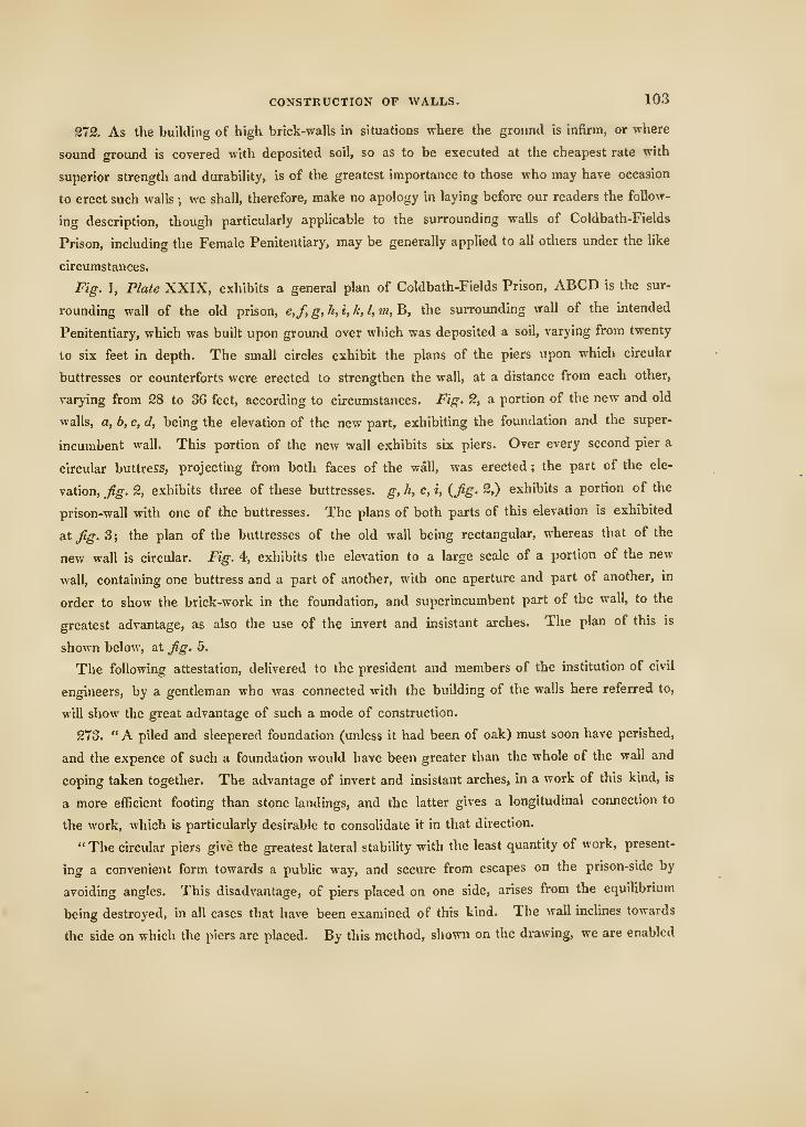
CONSTRUCTION OF WALLS. 103
272. As the building of high brick-walls in situations where the ground is infirm, or where
sound ground is covered with deposited soil, so as to be executed at the cheapest rate with
superior strength and durability, is of the greatest importance to those who may have occasion
to erect such walls ; we shall, therefore, make no apology in laying before our readers the follow-
ing description, though particularly applicable to the surrounding walls of Coldbath-Fields
Prison, including the Female Penitentiary, may be generally applied to all others under the like
circumstances.
Fig. 1, Plate XXIX, exhibits a general plan of Coldbath-Fields Prison, ABCD is the sur-
rounding wall of the old prison, e,f,g,h,i,k,l,m,'&, the surrounding wall of the intended
Penitentiary, which was built upon ground over which was deposited a soil, varying from twenty
to six feet in depth. The small circles exhibit the plans of the piers upon which circular
buttresses or counterforts were erected to strengthen the wall, at a distance from each other,
varying from 28 to 36 feet, according to circumstances. Fig. 2, a portion of the new and old
walls, a, b, c, d, being the elevation of the new part, exhibiting the foundation and the super-
incumbent wall. This portion of the new wall exhibits six piers. Over every second pier a
circular buttress, projecting from both faces of the wall, was erected ; the part of the ele-
vation, fig. 2, exhibits three of these buttresses, g, h, c, i, (Jig. 2.) exhibits a portion of the
prison-wall with one of the buttresses. The plans of both parts of this elevation is exhibited
at/g. 3; the plan of the buttresses of the old wall being rectangular, whereas that of the
new wall is circular. Fig. 4, exhibits the elevation to a large scale of a portion of the new
wall, containing one buttress and a part of another, with one aperture and part of another, in
order to show the brick-work in the foundation, and superincumbent part of the wall, to the
greatest advantage, as also the use of the invert and insistant arches. The plan of this is
shown below, at Jig. 5.
The following attestation, delivered to the president and members of the institution of civil
engineers, by a gentleman who was cormected with the building of the walls here referred to,
will show the great advantage of such a mode of construction.
273. " A piled and sleepered foundation (unless it had been of oak) must soon have perished,
and the expence of such a foundation would have been greater than the whole of the wall and
coping taken together. The advantage of invert and insistant arches, in a work of this kind, is
a more efficient footing than stone landings, and the latter gives a longitudinal connection to
the work, which is particularly desirable to consolidate it in that direction.
" The circular piers give the greatest lateral stability with the least quantity of work, present-
ing a convenient form towards a public way, and secure from escapes on the prison-side by
avoiding angles. This disadvantage, of piers placed on one side, arises from the equilibrium
being destroyed, in all cases that have been examined of this kind. The wall inclines towards
the side on which the piers are placed. By this method, shown on the drawing, we are enabled
101 PRACTICAL BRICKLAYING.
to lay foundations at considerable depths, without adding much additional weight, and thereby
a permanent foundation by using only imperishable materials. Another advantage obtained by
this method arose from having occasion to raise the ground in some places fourteen feet ; with
these large apertures the ground settles uniformly, without pressing unequally against either side
of the wall, and thereby preserving its vertical position.
" The motives which directed this plan were two : viz. the failui'e of piles and sleepers in
some foundations that had been taken up, about three years since, within the prison-walls ; and
secondly, economy : for, if pile and sleeper foundations had been adopted, the expense would
liave been increased at least one-third. It would be superfluous to go into the detail of exe-
cution ; suffice it to say, that, with good materials and workmanship, a work upon this prin-
ciple would possess a durability equal to the most expensive mode of execution."
CHAPTER III.
*
ON THE CONSTRUCTION OF ARCHES FOR CYLINDRICAL VAULTS.
274. An Arch, in brick-work, is a mass of bricks so arranged, that, in the profile, or right
section, the under line or intrados is generally a curve, which is always concave towards the
aperture, and the joints between the bricks radiate towards a centre, in such a manner that each
joint ought always to be perpendicular to the curve. In order to form a rectangular aperture,
the under-Iine, which terminates the head of the right section, is a straight line. In such a case,
the joints must still radiate to a centre in the middle of the breadth of the aperture; but these
joints cannot be perpendicular to the soffit, as was the case when the intrados or soffit was a
curved surface. An arch does not always imply a mass of bricks or stones supported at the
extremities, and terminating upon a concave surface over a hollow. The principle of a brick
or stone arch arises from the radiating directions of the joints, which, in fact, divides the arch
or vault into separate bricks, in the form of the frustum of a wedge, of which the lesser ends
form the intrados of the arch. It is easy to see that none of these bricks, thus separated by
the radiating joints, can descend, for the aperture through which any brick has to pass being
narrower at tlie bottom than at the top, will not admit of the wide end of the wedge to pass
through it, nor even to descend to any distance, however small. Hence a mass of bricks or
stones, connected by radiating surfaces, will support each other, even though the intrados may
be a plane surface ; what is called the curve of equilibrium being within the solid mass. Arches
are therefore of several kinds, when the profiles are circular, as straight arches, semi-circular
arches, and segmental arches ; which are also called scheme arches.
ARCHES FOR CYLINDRICAL VAULTS. 105
The springings of a semi-civcular arch are in a plane parallel to the horizon ; the springings
of a scheme arch are in two planes, each being at right-angles to the tangent plane to the in-
trados at the commencement of the curve.
The springings which are neither parallel nor perpendicular to the horizon, are called, in
the technical language of the bricklayer, skew-backs. Straight arches must have skew-backs,
as well as scheme-arches.
275. Fig. 1.', exhibits the right section or profile of an arch for the head of an aperture,
which forms the intrados of a straight arch ; the manner in which these joints are drawn will be
shown in the following description (see Jig. 17). Upon the width, AB, of the aperture as a base,
describe an equilateral triangle, and from the vertex, C, with a radius equal to the thickness of
a brick, describe a small circle. Draw DE, the extrados of the arch, at such a distance from
the intrados as is equal to the breadth of the arch, which, in this example, is equal to the height
of four courses of bricks in the face of the wall, and draw the skew-backs, AB and DE, one
at each extremity of the arch. Draw a line parallel to one of the skew-backs, (which ought to
be a tangent to the small circle,) cutting the intrados in F, and draw the straight Une CF. Find
the point G in the same manner, and draw GC, and so on to the middle, when the operation
will be complete.
Fig. 14, is the profile of the head of an aperture with a part of each jamb, the head being
a scheme-arch. It is contained between two concentric circles and the springing-lines, which
are portions of the radii of these circles. Fig. 15, is a semi-circular arch.
276. Fig. 16, a semi-elliptic arch, struck from two centres, A and B, having the longer axis
in a position parallel to the horizon. The method of describing elliptic arches is as follows (see
Plate XXIX. g.) Let AB be the span of the arch, and CD its height, from the middle of AB,
and perpendicular thereto. Draw A a- and Da: respectively parallel to CD and CA, and divide
Ax and AC each into three equal parts, by the two intermediate points, 1, 2. Make Cz equal
to CD, and from the points 1, 2, in Ax, draw straight lines to the point D, intersecting straight
lines drawn from the points 1, 2, in AC, in the points y and n. Make the angle Dtih equal to
the angle wDC, and prolong DC to meet nh in h. Join yn, or suppose yn to be joined, and
bisect 1/nhy a. perpendicular meeting nh in i. Join yi, intersecting AB in k, and let nh inter-
sect AB in /. In CB, make C r equal to C I, and from h, through r, draw h u. In k r, make
liq equal to hi, and in CB, make Cs equal to Ck. Join qs, and prolong qs to t. From
the centre h, with the radius AD, describe the arc nu, and from the centres i and q, describe
the arcs ny and tit, and from the centres k and s describe the arcs y A and <B. Then will
Ay?)D«<B be the intrados of the arch. Prolong the lines iy and in, qu and qt, as also
CA, CB, to E, o,p, w, V, F, and make DG equal to the breadth of the arch ; then, by the same
centres, h, i, q, k, s, describe the extrados F.opGwvF, which will complete the right section
of the arch. The joints of the bricks are drawn through the same centres, observing that
tiie extrados must be divided into parts, each equal to the thickness of a brick.
2e
f
106 PRACTICAL BRICKLAYING.
277. Gothic Arches.—Let AG be the span of the arch, (see figures 2 and 3,*) DC the
perpendicular height from D, the middle of the spanning line AG, and let CB be a tangent to
the arch at the summit C, and AB perpendicular to AG, a tangent at the springing point A.
278. To describe the Gothic Arch, fig. 2, by finding any number of points in the curve.—Prolong CD to /, and in D/ make DE equal to the difference between the two perpendiculars,
AB and DC. Join AE, and divide AE and AB each into the same number of equal parts, as
in this example each of these lines is dirided into six equal parts. Through the points, 1, 2, 3,
&c., in AB, draw straight lines to the point C, and from the point/, through the points I, 2, 3»
&c., in AE, draw right lines, to intersect the former right lines, (concurring in C,) in the points
a, ft, c, &c. Through these points draw the curve AabcdeC, and thus we have constructed
one half of the section of the intrados of the arch. In the same manner, the other half of the
section of the intrados may be constructed. The extrados Hnes, HJ and IJ, are found by
drawing them at an equal distance from the intrados lines AC and GC.
279. To describe a Gothic Arch by centres.—In fig. 3, draw Cm perpendicular to CB, and
in the span AG, make Ak equal to AB. In Cm, make C^ equal to A A; or AB, and join kl.
Bisect kl by a perpendicular, meeting C»» in m, and join mk. Prolong 7h k to n. From the
point m, as a centre, with the distance m C, as radius, describe the arc C n, and from the centre
k, with the distance kn, describe the arc « A. Then Am C will be half of the curve of the sec-
tion of the intrados. Prolong AG, the spanning from each extremity, to H and I, and prolong
kn to o. Make AH equal to the breadth of the course which forms the head of the arch ; then
again from the centre k, with the radius k H, describe the arc H o, and from the centre tn, with
the radius ni o, describe the arc o J, meeting the summit in the point J. In the same manner
may be found the extrados and intrados of the other half of the right section of the arch. But
the centres may be found more readily by the following construction, by observing that the
centres must be in a symmetrical position on each side of the right line CD, which divides the
right section into two symmetrical parts. Make D^j equal to D k, and prolong CD to q. Draw
mr parallel to the spanning line GA, intersecting CD prolonged in q, and make qr equal to
q m. Join rj}, and prolong rp to s. Join r C ; then, from the centre r, with the distance r C,
describe the arc C *, and from the centre p, with the radiiis p s, describe the arc s G. Again,
making GI equal to AH}^ from the centre p, with the radius p I, describe the arc 1 1, meeting
p s prolonged in the point f ; and from the centre r, with the radius r t, describe the arc t J ; and
tlnis we have described the whole of the right section of the arch.
280. One observation which the bricklayer must attend to, in dividing the section of his arch
into bricks, by drawing the joints, is, that he must divide the extrados, or outside curve, into
equal parts, and not the inside curve, as this would occasion the bricks to be of a greater size
than they are made.
• These constructions, exhibited in figures 2 and 3, are tlic invention of Mr. Peter Nicholson, to whom the art of build-
ing is greatly indebted ; and it is important to remark, in the construction, Jti/. 2, that when AB is greater than the half of
DC, the curve AC is elliptic ; when equal to the half of BC, it is parabolic ; and when less, it is of the hyperbolic kind.
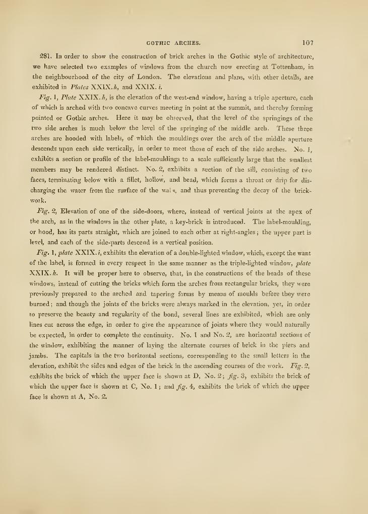
GOTHIC ARCHES. 107
281. In order to show the construction of brick arches in the Gothic style of architecture,
we have selected two examples of windows from the church now erecting at Tottenham, in
the neighbourhood of the city of London. The elevations and plans, with other details, are
exhibited in Plates XXIX. A, and XXIX. i.
Fig. 1, Plate XXIX. //, is the elevation of the west-end window, having a triple aperture, each
of which is arched with two concave curves meeting in point at the summit, and thereby forming
pointed or Gothic arches. Here it may be observed, that the level of the springings of the
two side arches is much below the level of the springing of the middle arch. These three
arches are hooded with labels, of which the mouldings over the arch of the middle aperture
descends upon each side vertically, in order to meet those of each of the side arches. No. ],
exhibits a section or profile of the label-mouldings to a scale sufficiently large that the smallest
members may be rendered distinct. No. 2, exhibits a section of the sill, consisting of two
faces, terminating below with a fillet, hollow, and bead, which forms a throat or drip for dis-
charging the water from the surface of the wai s, and thus preventing the decay of the brick-
work.
Fig. 2, Elevation of one of the side-doors, where, instead of vertical joints at the apex of
the arch, as in the windows in the other plate, a key-brick is introduced. The label-moulding,
or hood, has its parts straight, which are joined to each other at right-angles ; the upper part is
level, and each of the side-parts descend in a vertical position.
Fig. 1, plate XXIX. i, exhibits the elevation of a double-hghted window, which, except the want
of the label, is formed in every respect in the same manner as the triple-lighted window, plate
XXIX. h. It will be proper here to observe, that, in the constructions of the heads of these
windows, instead of cutting the bricks which form the arches from rectangidar bricks, they were
previously prepared to the arched and tapering forms by means of moulds before they were
burned; and though the joints of the bricks were always marked in the elevation, yet, in order
to preserve the beauty and regularity of the bond, several lines are exhibited, which are only
lines cut across the edge, in order to give the appearance of joints where they would naturally
be expected, in order to complete the continuity. No. 1 and No. 2, are horizontal sections of
the window, exhibiting the manner of laying the alternate courses of brick in the piers and
jambs. The capitals in the two horizontal sections, corresponding to the small letters in the
elevation, exhibit the sides and edges of the brick in the ascending courses of the work. Fig. 2,
exhibits the brick of which the upper face is shown at D, No. 2 ; Jig. 3, exhibits the brick of
which the upper face is shown at C, No. 1 ; and Jig. 4, exhibits the brick of which the upper
face is shown at A, No. 2.
108 PRACTICAL BRICKLAYING
CHAPTER JV.
ON THE CONSTRUCTION OF VAULTS FOR WAREHOUSES AND CELLARS.
Introductory JPriiici^jles and Observations.
282. A simple vault is a mass of bricks, or stones, forming a concavity over a hollow, and
extending between two opposite walls, which are generally parallel, or otherwise supported upon
a circular wall. The concave surface towards the hollow is called the intrados, which is gene-
rally a portion of a cylindrical surface, or that of a spherical surface, never greater than the
half of the solid. Tlie surface from which the vault rises is called its springing. If the vault
be the surface of a semi-cylinder, or that of a hemisphere, the two springings are both con-
tained in one plane ; if the right section of the intrados of the vault be a segment of a circle,
the springings are generally inclined planes, as they ought to be, and if the intrados be a portion
of a hemispheric concave surface, the springing surfaces will be in the surface of a right cone,
that is, the springing surface will be the surface of a conic zone. In lime and brick kilns,
vaults are formed of conic surfaces, having their axes vertical. The wooden dome of St. Paul's
Cathedral, London, is supported upon a conical vault of brick-work, having the axis of the
conic surface in a vertical position. Conic surfaces, of which their axes are in vertical positions,
are very seldom used in private buildings, except in walls over the apertures of doors and
windows where the jambs are splayed, in order to admit a greater quantity of light into the
interior of the building. All vaults of which the axis of the intrados has a horizontal position
are called horizontal vaults ; and such as have their intrados portions of the surfaces of cones
and cylinders with their axes horizontal, are also called horizontal vaults.
283. A groin-vault is that of which the intrados is formed by the intersections of two or more
cylindric surfaces, of which their axes are in a horizontal position, intersecting eacli other in one
common point, so that no part of the surface of one cylinder may be contained between the
concavity of another. In cylindrical groined vaults, the convex surface of either cyhnder may
extend without the convex side of the other. In general, the summits of the cylindrical surfaces
are right lines intersecting each other, and are in the same horizontal plane. When the sec-
tions of the cylindrical surfaces are circles, and the diameters unequal, the groined vault is that
which is called by workmen a Welsh groin. When a groined vault consists of two cylindric
surfaces, the axes are generally at right angles to each other, and as they terminate upon walls
at right-angles to their axes, the sides are constructed upon a rectangular plan.
VAULTS FOR WAREHOUSES, &C. 109
SSi. It has been long experienced and universally acknowledged, that rectangular-groined
vaults are necessarily of a weak and imperfect construction, and the figure of the piers is in-
commodious for warehouses or other buildings. It is manifest to every one who will take the
trouble to examine them, that a very great part of the substance of the bricks which con-
stitute the ground angle is cut away, in order to form the intended surface upon each side
of the line in which the two cylindrical surfaces meet each other, so that the lengths of the
bricks thus forming the angle may be parallel to the axis of a cylindrical surface, and so placed
alternately in each cylindrical surface; and thus the joints of the bricks will be preserved in
right hnes parallel to the axis. The slanting or oblique direction in which it is necessary to
cut the bricks at the groin-angles render them extremely liable to be thrust out of their situa-
tions by any sudden impulse operating upon the crown of the arch, and thus instead of pre-
senting the greatest resistance, are the most feeble that can be conceived, and were it not for
the adjacent arches they would be incapable of supporting themselves. Hence, when such a
construction has been loaded with stones, the superincumbent weight has been found to act
chiefly in the direction of the groins, although they are least capable of resisting it. Therefore,
it follows, that the stronger these parts are made, the better the whole arch will counteract the
tendency to fracture. Instead of square piers, so commonly used, octagonal ones will be found
much more convenient and more susceptible of admitting the necessary improvements ; and
since the right angles are taken away, there will be more room for goods, and for the turning of
casks, without endangering the breaking of the angles. The improvements in the construction
of vaults, consists in carrying a cylindrical arch, in breadth equal to the length of a brick, a
brick-and-half, or two bricks, instead of the angle or groin from pier to pier, depending on the
extension of the interval between the piers.
As the diagonal of a square is longer than either of its sides, the girt of the elliptic cross-
ribs must be greater than the girt of the semi-circular arch ; on this account, in such a con-
struction, it is not possible to keep the joints of the brick-work of the filling-in arches upon the
same level as the joints of the brick-work constituting the ribs. In order to save expense in
the cutting of the bricks, and to prevent the irregularity at the junctions, it will be found
necessary to cut off all communication between the cross and the filling-in arches, by making
the cross-arches project from the filling-in arches at the surface where they join each other.
By setting back the filling-in arches affords a most excellent opportunity of binding the work.
This improvement upon groins was first suggested by Mr. George Tappen, architect.
285. Another mode of vaulting has been introduced in St. Catherine's Docks, of which the
pendent parts, resting upon the piers, are solids of revolution, being concave in their vertical
sections, and convex in their horizontal sections, which are the arcs of circles. This form
possesses some advantages, as the courses may be so arranged that their joints will be in conic
surfaces. The principle is the same as was applied in the stone roof of the Chapel of King
Henry VII., Westminster, and at the Chapel of King's College, Cambridge, and will show a
2f
110 PRACTICAL BRICKLAYING.
very considerable variation in the mode of execution. If the axes of the piers are raised from
the angles of a square, and if the vertical section through the axis of the diagonal piers be a
given semi-circle, the vertical sections of the side arches will be of the Gothic form ; and if
the vertical sections of the side arches be given semi-circles, a quadrilateral space will be formed
in the centre of the groined severy,* and will have its four sides contained in a plane, which will
be a tangent to the curved surface of revolution. It is obvious that the exterior form of the
surface of each pendent of the groined severy is that of the exterior form of a trumpet, which
is a surface of revolution. When the sides are semi-circles, and all the four pendents complete,
the curved surface of the intrados may be made to touch a plane surface, which will be a
tangent at every point to the surface of revolution ; but, as the space enclosed by the sides of
the quadrilateral must be filled in before the arch is completed, it is evident that the mass
included will not partake of the principle of an arch, because the joints are all in the surfaces
of prisms, and not in radiating surfaces, as is the case with the four pendents rising from the
piers : this defect may be rectified by making the side arches pointed, instead of one con-
tinued curve from pier to pier. For by this means, the plane which contains the quadrilateral
will not touch the points of the curved surface of the pendent parts ; but will form an aperture
of less dimensions at the bottom than at the top, and consequently will allow a sufficient spread
for the radiations of the joints. It is obvious that the joints of the pendents are partly in
conical surfaces, and partly in vertical planes, and that the conical surfaces intersect the intrados
in the arcs of circles which have their centres in the axes of the four piers ; that is, in the axis
of each surface of revolution forming the intrados of each pendent over each of the piers.
286. Another mode of vaulting with brick, which has been found to answer the purpose
extremely well, will easily be understood from the following description:—Imagine a quadrant
of an ellipse comprised between two semi-axes and the portion of the curve between them to
revolve round the semi-axis minor, the surface of revolution will be the half of a probate
spheroid, terminated by a circle generated by the semi-axis major. The spheroidal surface
generated by the quadrantal arc of the ellipse is well adapted for a vault suspended by a circular
wall, or a wall upon a circular plan ; but, in order to vault over an area raised from a square
plan, let us suppose that we have such a hemispheroid, and that the diameter of its great circle
is equal to the diagonal of the square plan. Upon the plane of the great circle of this spheroid,
suppose two diameters are to be drawn at right-angles to each other, and the extremities of
these diameters to be joined by straight lines, so as to form a square inscribed in the circum-
ference. Let this hemispheroid be cut by four planes, each passing along one of the sides of
the square perpendicularly to the plane of the circle, the portion of the hemispheroidal surface
will be the exact centre for such a vaidt, and, consequently, the concave surface, coinciding with
* Savery, or severy, is the proper name for every compartmeDt of vaulting. The word may be seen in turning over the
pages of our ancient records, where the description of the ceilings of old buildings are registered. It is nol, however, to be
found in Johnson's Dictionary, not even in the late editions which contain the numerous insertions of the Rev, H. J. Todd.
Sec Bretton's Architectural Antiquities of Great Britain.
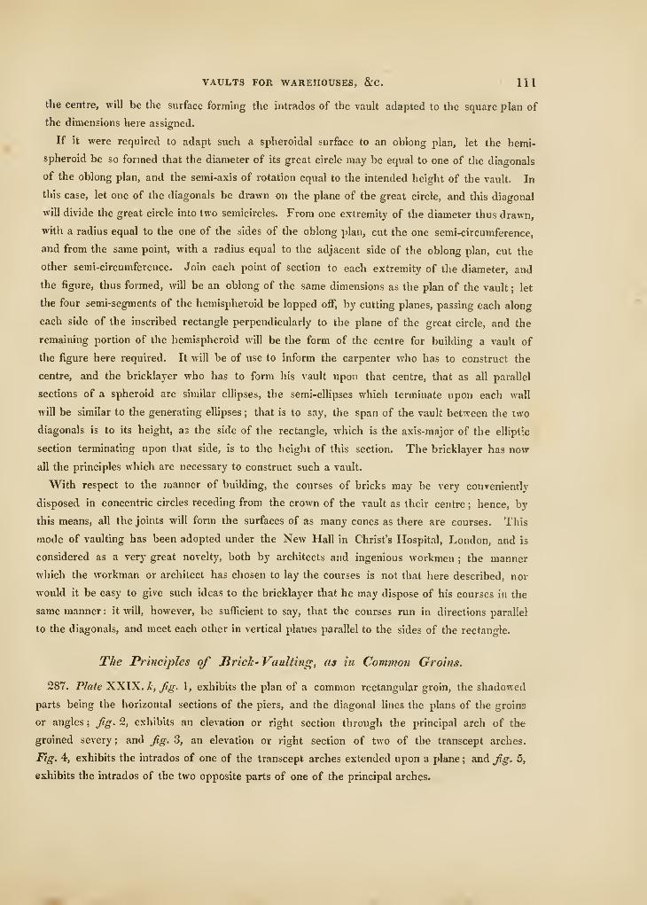
VAULTS FOR WAREHOUSES, &C. Ill
the centre, will be the surface forming the intrados of the vault adapted to the square plan of
the dimensions here assigned.
If it were required to adapt such a spheroidal surface to an oblong plan, let the hemi-
spheroid be so formed that the diameter of its great circle may be equal to one of the diagonals
of the oblong plan, and the semi-axis of rotation equal to the intended height of the vault. In
this case, let one of the diagonals be drawn on the plane of the great circle, and this diagonal
will divide the great circle into two semicircles. From one extremity of the diameter thus drawn,
with a radius equal to the one of the sides of the oblong plan, cut the one semi-circumference,
and from the same point, with a radius equal to the adjacent side of the oblong plan, cut the
other semi-circumference. Join each point of section to each extremity of the diameter, and
the figure, thus formed, will be an oblong of the same dimensions as the plan of the vault ; let
the four semi-segments of the hemispheroid be lopped oflF, by cutting planes, passing each along
each side of the inscribed rectangle perpendicularly to the plane of the great cu-cle, and the
remaining portion of the hemispheroid will be the form of the centre for building a vault of
the figure here required. It will be of use to inform the carpenter who has to construct the
centre, and the bricklayer who has to form his vault upon that centre, that as all parallel
sections of a spheroid are similar ellipses, the semi-ellipses which terminate upon each wall
will be similar to the generating ellipses ; that is to say, the span of the vault between the two
diagonals is to its height, as the side of the rectangle, which is the axis-major of the elliptic
section terminating upon that side, is to the height of this section. The bricklayer has now
all the principles which are necessary to construct such a vault.
With respect to the manner of building, the courses of bricks may be very conveniently
disposed in concentric circles receding from the crown of the vault as their centre ; hence, by
this means, all the joints will form the surfaces of as many cones as there are courses. This
mode of vaulting has been adopted under the New Hall in Christ's Hospital, London, and is
considered as a very great novelty, both by architects and ingenious workmen ; the manner
which the workman or architect has chosen to lay the courses is not that here described, nor
would it be easy to give such ideas to the bricklayer that he may dispose of his courses in the
same manner : it will, however, be sufficient to say, that the courses run in directions parallel
to the diagonals, and meet each other in vertical planes parallel to the sides of the rectangle.
The Principles of JBi'ick- Vaulting, as in Covimon Groins.
287. Plate XXIX. h, fig. 1, exhibits the plan of a common rectangular groin, the shadowed
parts being the horizontal sections of the piers, and the diagonal lines the plans of the groins
or angles; fig. 2, exhibits an elevation or right section through the principal arch of the
groined severy; and fig. 3, an elevation or right section of two of the transcept arches.
Fig. 4, exhibits the intrados of one of the transcept arches extended upon a plane ; and fig. 5,
exhibits the intrados of the two opposite parts of one of the principal arches.
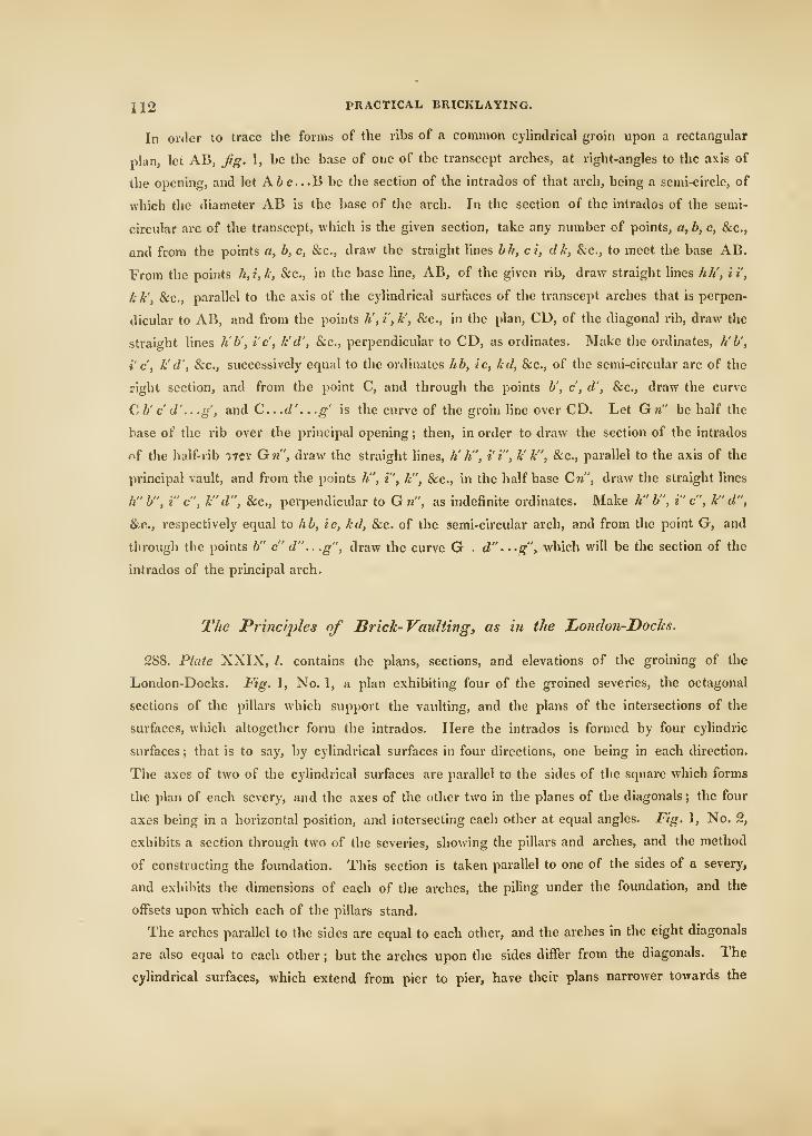
112 PRACTICAL BRICKLAYING.
In order to trace the forms of the ribs of a common cyHndrical groin upon a rectangular
plan, let AB, fig. 1, be the base of one of the transcept arches, at right-angles to the axis of
the opening, and let A6c...B be the section of the intrados of that arch, being a semi-circle, of
which the diameter AB is the base of the arch. In the section of the intrados of the semi-
circular arc of the transcept, which is the given section, take any number of points, a, b, c, &c.,
and from the points a, b, c, &c., draw the straight lines bh, ct, dk, &c., to meet the base AB.
From the points h,i,h, &c., in the base line, AB, of the given rib, draw straight hnes hh', it,
k k', &c., parallel to the axis of the cylindrical surfaces of the transcept arches that is perpen-
dicular to AB, and from the points //, i', k', &c., in the plan, CD, of the diagonal rib, draw the
straight lines lib', i'c, k'd', &c., perpendicular to CD, as ordinates. Make the ordinates, h'b',
i' c'. It d', &c., successively equal to the ordinates hb, ic, kd, &c., of the semi-circular arc of the
right section, and from the point C, and through the points b', c, d', &c., draw the curve
C b' c d' .. .g, and C.d' . . .g' is the curve of the groin line over CD. Let G n" be half the
base of the rib over the principal opening ; then, in order to draw the section of the intrados
of the half- rib iTcr Gw", draw the straight lines, h' h", i'i", k' k", &c., parallel to the axis of the
principal vault, and from the points /*", i", k", &c., in the half base Cw", draw the straight lines
h" b", i" c", k"d", &c., perpendicular to Gn", as indefinite ordinates. Make h" b", i"c", k'd",
&c.., respectively equal to hb, ic, kd, &c. of the semi-circular arch, and from the point G, and
through the points b" c" d" ., .g", draw the curve G . d" •••g", which will be the section of the
intrados of the principal arch.
The Princ'qyles of Brick- Vaulting, as in the London-DocJes.
288. Plate XXIX, I. contains the plans, sections, and elevations of the groining of the
London-Docks. Fig. 1, No. 1, a plan exhibiting four of the groined severies, the octagonal
sections of the pillars which support the vaulting, and the plans of the intersections of the
surfaces, which altogether form the intrados. Here the intrados is formed by four cylindric
surfaces ; that is to say, by cylindrical surfaces in four directions, one being in each direction.
The axes of two of the cylindrical surfaces are parallel to the sides of the square which forms
the plan of each severy, and the axes of the other two in the planes of the diagonals ; the four
axes being in a horizontal position, and intersecting each other at equal angles. Fig. 1, No. 2,
exhibits a section through two of the severies, showing the pillars and arches, and the method
of constructing the foundation. This section is taken parallel to one of the sides of a severy,
and exhibits the dimensions of each of the arches, the piling under the foundation, and the
offsets upon which each of the pillars stand.
The arches parallel to the sides are equal to each other, and the arches in the eight diagonals
are also equal to each other ; but the arches upon the sides differ from the diagonals. The
cylindrical surfaces, which extend from pier to pier, have their plans narrower towards the
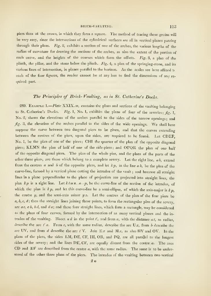
BRICK-VAULTING. 113
piers than at the crown, in which they form a square. The method of tracing these groins will
be very easy, since the intersections of the cyhndrical surfaces are all in vertical planes passino-
through their plans. Fig. 2, exhibits a section of one of the arches, the various len"ths of the
radius of curvature for drawing the sections of the arches, as also the extent of the portion of
each curve, and the heights of the courses which form the offsets. Fig. 3, a plan of the
plinth, the pillar, and the stone below the plinth. Fig. 4, a plan of the springing-stone, and its
various lines of intersection, in planes parallel to the hoi-izon. As the scales are here affixed tt
each of the four figures, the reader cannot be at any loss to find the dimensions of any re-
quired part.
The Principles of Brick- Vaulting, as in St. Catherine's Doclcs.
289. Example 1.
—
Plate XXIX. »«, contains the plans and sections of the vaulting belonging
to St. Catherine's Docks. Fig. 1, No. 1, exhibits the plans of four of the severies; fiT. 1,
No. 2, shows the elevations of the arches parallel to the sides of the narrow openings; and
fig. 3, the elevation of the arches parallel to the sides of the wide openings. We shall here
suppose tlie curve between two diagonal piers to be given, and that the curves extending
between the centres of the piers, upon the sides, are required to be found. Let CDEFNo. 1, be the plan of one of the piers; CHI the quarter of the plan of the opposite diagonal
piers; KLMN the plan of half of one of the side-piers; and OPQR the plan of one half
of the opposite diagonal piers. The plan of the whole pier, and the plans of the parts of the
other three piers, are those which belong to a complete severy. Let the riglit line, ab extend
from the centres a and b of the opposite piers, and let Icp, in the line a b, be the plan of the
curve-line, formed by a vertical plane cutting the intrados of the vault ; and because all straight
lines in a plane perpendicular to the plane of projection are projected into straight lines, the
plan 1:2} is a right line. Let Iclmn o- p,\)e the curve-line of the section of the intrados of
which the plan is Icp, and let this curve-hne be a semi-ellipse, of which the axis-major is kp,
the centre y, and the semi-axis minor y z. Let the centres of the plan of the four piers be
a, b, c, d; then the straight lines joining these points, to form the rectangular plan of the sever}-,
are ac, c b, bd, and da; and these four straight lines, which form a rectangle, may be considered
as the plans of four curves, formed by the intersection of as many vertical planes and the in-
trados of the vaulting. Bisect ad m the point t', and from a, with the distance a t, as radius,
describe the arc t' x. From c, with the same radius, describe the arc Ux, from b describe the
arc UV, and from d describe the arc ^V. Join TLx and Mx, as also HV and OV. In the
plans of the piers, the sides LM, DE, CF, HI, OR, and PQ, are all parallel to the longest
sides of the severy ; and the lines DE, CF, are equally distant from the centre a. The arcs
CD and EF are described from the centre a, with the same radius. The same is to be under-
stood of the other three plans of the piers. The intrados of the vaulting between two vertical
2a
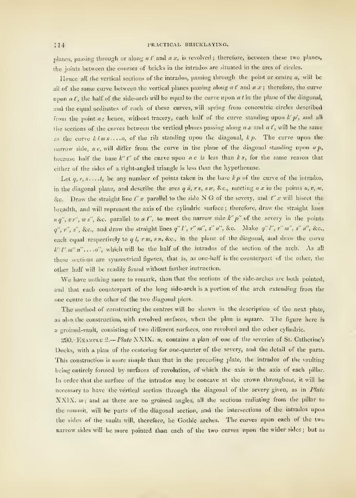
114 PRACTICAL BRICKLAYINO.
planes, passing tlirough or along a t' and a x, is revolved ; therefore, between these two planes,
the joints between the courses of bricks in the intrados are situated in the arcs of circles.
Hence all the vertical sections of the intrados, passing through the point or centre a, will be
all of the same curve between the vertical planes passing along a t' and a x ; therefore, the curve
upon a t', the half of the side-arch will be equal to the curve upon a tin the plane of the diagonal,
and the equal ordinates of each of these curves, will spring from concentric circles described
from the pohit a; hence, without tracery, each half of the curve standing upon /:'//, and all
tlie sections of the curves between the vertical planes passing along a x and a t', will be the same
as the curve klmn o, of the rib standing upon the diagonal, k j^. The curve upon the
narrow side, a c, will differ from the curve in the plane of the diagonal standing upon ap,
because half the base k" t" of the curve upon a c is less than k x, for the same reason that
either of the sides of a right-angled triangle is less than the hypothenuse.
Let q, r, s t, be any number of points taken in the base kp of the curve of the intrados,
in the diagonal plane, and describe the arcs qu, rv, sw, &c., meeting ax'm the points u, v, w,
8pc. Draw the straight line t" x parallel to the side N G of the severy, and t" x will bisect the
breadth, and will represent the axis of the cylindric surface ; therefore, draw the straight lines
u q'\ V r", w s", &c. parallel to x t", to meet the narrow side k"p" of the severy in the points
q", r", s", &c., and draw the straight lines q" I", r" m", s" n", &c. Make q" I", r" m" , s" n", &c.,
each equal respectively to ql, rni, sn, &c., in the plane of the diagonal, and draw the curve
k" I" m" n" o", which will be the half of the intrados of the section of the arch. As all
these sections are symmetrical figures, that is, as one-half is the counterpart of the other, the
other half will be readily found without farther instruction.
We have nothing more to remark, than that the sections of the side-arches are both pointed,
and that each counterpart of the long side-aixh is a portion of the arch extending from the
one centre to the other of the two diagonal piers.
The method of constructing the centres will be shown in the description of the next plate,
as also the construction, with revolved surfaces, when the plan is square. The figure here is
a groined-vault, consisting of two different surfaces, one revolved and the other cylindric.
290.- Example 2.
—
Plate XXIX. w, contains a plan of one of the severies of St. Catherine's
Docks, with a plan of the centering for one-quarter of the severy, and the detail of the parts.
This construction is more simple than that in the preceding plate, the intrados of the vaulting
being entirely formed by surfaces of revolution, of which the axis is the axis of each pillar.
In order that the surface of the intrados may be concave at the crown throughout, it will be
necessary to have the vertical section through the diagonal of the severy given, as in Plate
XXIX. m; and as there are no groined angles, all the sections radiating from the pillar to
the summit, will be parts of the diagonal section, and the intersections of the intrados upon
the sides of the vaults will, therefore, be Gothic arches. The curves upon each of the two
nariow sides will be more pointed than each of the two curves upon the wider sides ; but as
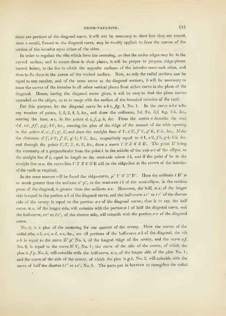
BRICK-VAULTING. 115
these are portions of the diagonal curve, it will not be necessary to show how they are traced,
since a mould, formed to the diagonal curve, may be readily applied to draw the curves of the
section of the intrados upon either of the sides.
In order to regulate the ribs which form the centering, so that the under edges may be in the
curved surface, and to secure them in their places, it will be proper to prepare ridge-pieces
curved below, to the line in which the opposite surfaces of the intrados meet each other, and
then to fix them in the crown of the vaulted surface. Now, as only the radial sections can be
equal to one another, and of the same curve as the diagonal sections, it will be necessary to
trace the curves of the intrados in all other vertical planes from either curve in the plane of the
diagonal. Hence, having the diagonal curve given, it will be easy to find the plane curves
extended on the ridges, so as to range with the surface of the intended intrados of the vault.
For this purpose, let the diagonal curve be abc,fig. 1, No. 1. In the curve oic take
any number of points, 1, 2, 3, 4, 5, &c., and draw the ordinates, \d, 2e, 3/, 4^, b h, &c.,
meeting the base, a c, in the points d, e, f, g, h, &c. From the centre a describe the arcs
dd', ee',ff', gg, hli, &c., meeting the plan of the ridge of the summit of the wide opening
in the points d', e, /', g' , li , and draw the straight lines d' \\ e 2',f 3', g' 4', K 5', &c., IMake
the distances </' 1', e' 2', /' 3', £•' 4', /«' 5', &c., respectively equal to d\, e2, fo, gi, h5, &c.
and through the points 1', 2', 3\ A', 5', &c., draw a curve 1' 2' 3' 4' 5' B'. The point B' being
the extremity of a perpendicular from the point i in the middle of the axis a c of the ellipse, to
the straight line d' i, equal in length to the semi-axis minor i b, and if the point d' be in the
straight line m n, the curve-line 1' 2' 3' 4' 5' B will be the ridge-line at the crown of the intrados
of the vault as required.
In the same manner will be found the ridge-curve, p" 1" 3" 5" B". Here the ordinate * B" is
as much greater than the ordinate o" p", as the semi-axis i 6 of the semi-ellipse, in the vertical
plane of the diagonal, is greater than the ordinate u v. INIoreover, the half, w x, of the longer
side is equal to the portion a 1 of the diagonal curve, and the half-curve * r" or t r" of the shorter
side of the severy is equal to the portion a » of the diagonal curve ; that is to say, the half
curve, w x, of the longer side, will coincide with the portion;rt 1 of half the diagonal curve, and
the half-curve, sr' or tr", of the shorter side, will coincide with the portion « » of the diagonal
curve.
No. 2, is a plan of the centering for one quarter of the severy. Here the curves of the
radial ribs, ab,ac,a d, a e, &c., are all portions of the half-curve a b of the diagonal, the rib
ah is equal to the curve W p" No. 1, of the longest ridge of the severy, and the curve a/,
No. 2, is equal to the curve B' 1', No. 1 ; the curve of the side of the centre, of which the
plan is fg. No. 2, will coincide with the half-curve, w x, of the longer side of the plan No. 1 ;
and the curve of the side of the centre, of which the plan is g h. No. 2, will coincide with the
curve of half the shorter tr" ox sr", No. 1. The parts put in between to strengthen the radi&l
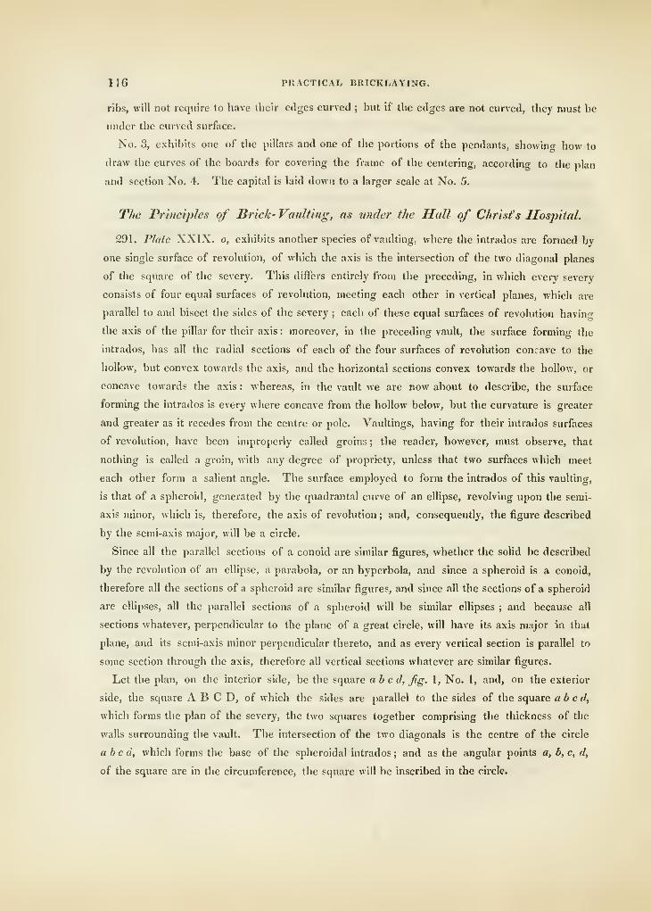
116 PRACTICAL BRICKLAYING.
ribs, will not require to have their edges curved ; but if the edges are not curved, they must be
under the curved surface.
No. 3, exhibits one of the pillars and one of the portions of the pendants, showin" how to
draw the curves of the boards for covering the frame of the centering, according to the plan
and section No. 4. The capital is laid down to a larger scale at No. 5.
The Principles of Brick- Vaulting, as under the Hall of Christ's Hospital.
291. Plate XXIX. o, exhibits another species of vaulting, where the intrados are formed by
one single surface of revolution, of which the axis is the intei'section of the two diagonal planes
of the square of the severy. This differs entirely from the preceding, in wliich evei-y severy
consists of four equal surfaces of revolution, meeting each other in vertical planes, which are
parallel to and bisect the sides of the severy ; each of these equal surfaces of revolution havin^
the axis of the pillar for their axis : moreover, in the preceding vault, the surface forming the
intrados, has all the radial sections of each of the four surfaces of revolution concave to the
hollow, but convex towards the axis, and the horizontal sections convex towards the hollow, or
concave towards the axis : whereas, in the vault we are now about to describe, the surface
forming the intrados is every where concave from the hollow below, but the curvature is greater
and greater as it recedes from the centre or pole. Vaultings, having for their intrados surfaces
of revolution, have been improperly called groins ; the reader, however, must observe, that
nothing is called a groin, with any degree of propriety, unless that two surfaces which meet
each other form a salient angle. The surface employed to form the intrados of this vaulting,
is that of a spheroid, generated by the quadrantal curve of an ellipse, revolving upon the semi-
axis minor, which is, therefore, the axis of revolution ; and, consequently, the figure described
by the semi-axis majoi", will be a circle.
Since all the parallel sections of a conoid are similar figures, whether the solid be described
by the revolution of an ellipse, a parabola, or an hyperbola, and since a spheroid is a conoid,
therefore all the sections of a spheroid are similar figures, and since all the sections of a spheroid
are ellipses, all the parallel sections of a spheroid will be similar ellipses ; and because all
sections whatever, perpendicular to the plane of a great circle, will have its axis major in that
plane, and its semi-axis minor perpendicular thereto, and as every vertical section is parallel to
some section through the axis, therefore all vertical sections whatever are similar figures.
Let the plan, on the interior side, be the square ab c d, Jig. 1, No. 1, and, on the exterior
side, the square A B C D, of which the sides are parallel to the sides of the square abed,
which forms the plan of the severy, the two squares together comprising the thickness of the
walls surrounding the vault. The intersection of the two diagonals is the centre of the circle
abed, which forms the base of the spheroidal intrados ; and as the angular points a, b, c, d,
of the square are in the circumference, the square will be inscribed in the circle.
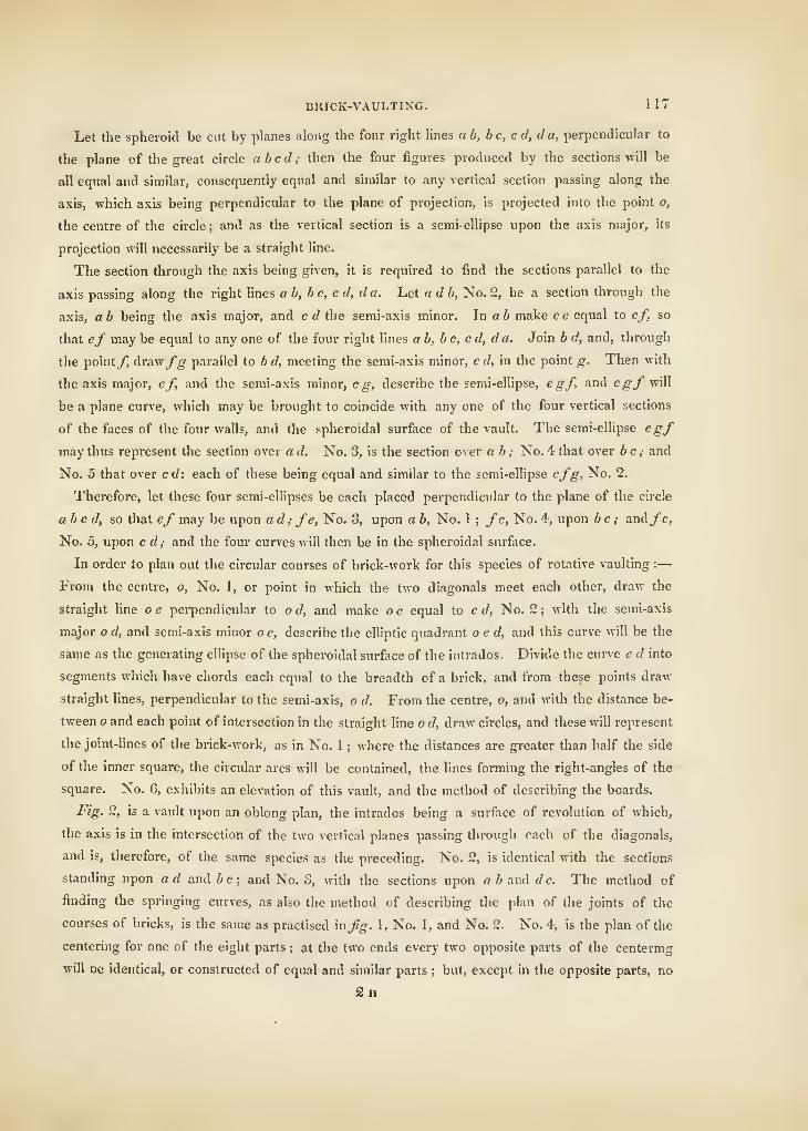
BRICK-VAULTIXG. 117
Let the spheroid be cut by planes along the four right lines ab, be, cJ, da, perpendicular to
the plane of the great circle abed; then the four figures produced by the sections will be
all equal and similar, consequently equal and similar to any vertical section passing along the
axis, which axis being perpendicular to the plane of projection, is projected into the point o,
the centre of the circle; and as the vertical section is a semi-ellipse upon the axis major, its
projection will necessarily be a straight line.
The section through the axis being given, it is required to find the sections parallel to the
axis passing along the right lines a b, b e, c d, d a. Let a d b. No. 2, be a section through the
axis, a b being the axis major, and e d the semi-axis minor. In a 6 make e e equal to ef, so
that ef may be equal to any one of the four right lines ab, be, ed, da. Join b d, and, through
the pointy, Axavifg parallel to b d, meeting the semi-axis minor, c d, in the point g. Then with
the axis major, ef, and the semi-axis minor, eg, describe the semi-ellipse, egf, and egf will
be a plane curve, which may be brought to coincide with any one of the four vertical sections
of the faces of the four walls, and the spheroidal surface of the vault. The semi-ellipse egf
may thus represent the section over a d. No. 3, is the section over ab ; No. 4 that over 6 c,- and
No. 5 that over c d: each of these being equal and similar to the semi-ellipse efg. No. 2.
Therefore, let these four semi-ellipses be each placed perpendicular to the plane of the circle
abed, so that ef may be upon ad; fe, No. 3, upon a b. No. 1; fe. No. 4, upon be ; and/c.
No. 5, upon c d; and the four curves will then be in the spheroidal surface.
In order to plan out the circular courses of brick-work for this species of rotative vaulting :
—
From the centre, o. No. 1, or point in which the two diagonals meet each other, draw the
straight line o e pei-pendicular to o d, and make o e equal to e d. No. 2 ; with the semi-axis
major o d, and semi-axis minor o e, describe the elliptic quadrant o e d, and this curve will be the
same as the generating ellipse of the spheroidal surface of the intrados. Divide the cune e d into
segments which have chords each equal to the breadth of a brick, and from these points draw
straight lines, perpendicular to the semi-axis, o d. From the centre, o, and with the distance be-
tween o and each point of intersection in the straight line o d, draw circles, and these will represent
the joint-lines of the brick-work, as in No. 1 ; where the distances are greater than half the side
of the inner square, the circular arcs will be contained, the lines forming the right-angles of the
square. No. 6, exhibits an elevation of this vault, and the method of describing the boards.
Fig. 2, is a vault upon an oblong plan, the intrados being a surface of revolution of which,
the axis is in the intersection of the two vertical planes passing through each of the diagonals,
and is, therefore, of the same species as the preceding. No. 2, is identical with the sections
standing upon ad and 6c; and No. 3, with the sections upon abanddc. The method of
finding the springing curves, as also the method of describing the plan of the joints of the
courses of bricks, is the same as practised in^"-. 1, No. 1, and No. 2. No. 4, is the plan of the
centering for one of the eight parts ; at the two ends every two opposite parts of the centermg
will De identical, or constructed of equal and similar parts ; but, except in the opposite parts, no
2h
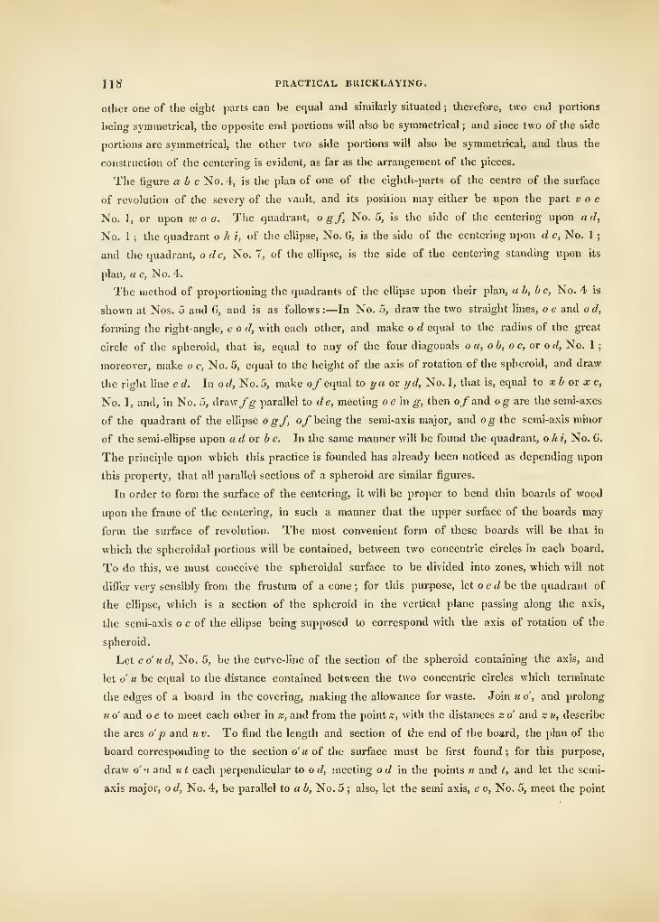
lis PKACTICAL BRICKLAYING.
other one of the eight parts can be equal and similarly situated ; therefore, two end portions
being symmetrical, the opposite end portions will also be symmetrical ; and since two of the side
portions are symmetrical, the other two side portions will also be symmetrical, and thus the
construction of the centering is evident, as far as the arrangement of the pieces.
The figure a b c No. 4, is the plan of one of the eighth-parts of the centre of the surface
of revolution of the severy of the vault, and its position may either be upon the part v o c
No. 1, or upon w o a. The quadrant, o gf, No. 5, is the side of the centering upon ad,
No. 1 ; the quadrant o h i, of the ellipse. No. G, is the side of the centering upon d c, No. 1 ;
and the quadrant, o dc, No. 7, of the ellipse, is the side of the centering standing upon its
plan, a c, No. 4.
The method of proportioning the quadrants of the ellipse upon their plan, ab, be, No. 4 is
shown at Nos. 5 and 6, and is as follows :—In No. 5, draw the two straight lines, o e and o d,
forming the right-angle, e o d, with each other, and make o d equal to the radius of the great
circle of the spheroid, that is, equal to any of the four diagonals oa, ob, oc, or o d, No. 1 ;
moreover, make o e, No. 5, equal to the height of the axis of rotation of the spheroid, and draw
the right line ed. In od, No. 5, make o/ equal io ya or yd, No. 1, that is, equal to xb ov x c,
No. 1, and, in No. 5, draw/^ parallel to de, meeting oe in ^, then o/and og are the semi-axes
of the quadrant of the eUipse o gf, oy being the semi-axis major, and og the semi-axis minor
of the semi-ellipse upon ad ov be. In the same manner will be found the quadrant, o h i. No. 6.
The principle upon which this practice is founded has already been noticed as depending upon
this property, that all parallel sections of a spheroid are similar figures.
In order to form the surface of the centering, it will be proper to bend thin boards of wood
upon the frame of the centering, in such a manner that the upper surface of the boards may
form the surface of revolution. The most convenient form of these boards will be that in
which the spheroidal portions will be contained, between two concentric circles in each board.
To do this, we must conceive the spheroidal surface to be divided into zones, which will not
differ very sensibly from the frustum of a cone; for this purpose, let oedhe the quadrant of
the ellipse, which is a section of the spheroid in the vertical plane passing along the axis,
the semi-axis o e of the ellipse being supposed to correspond with the axis of rotation of the
spheroid.
Let e o' u d, No. 5, be the curve-line of the section oi the spheroid containing the axis, and
let o u be equal to the distance contained between the two concentric circles which terminate
the edges of a board in the covering, making the allowance for waste. Join u o, and prolong
u o' and o e to meet each other in z, and from the point z, with the distances s; o and z ii, describe
the arcs o j) and tiv. To find the length and section of the end of the board, the plan of the
board corresponding to the section o'« of the surface must be first found; for this purpose,
draw o''i and ut each perpendicular to o d, meeting o d m the points n and t, and let the semi-
axis major, o d, No. 4, be parallel to a b, No. 5 ; also, let the semi axis, e o. No. 5, meet the point
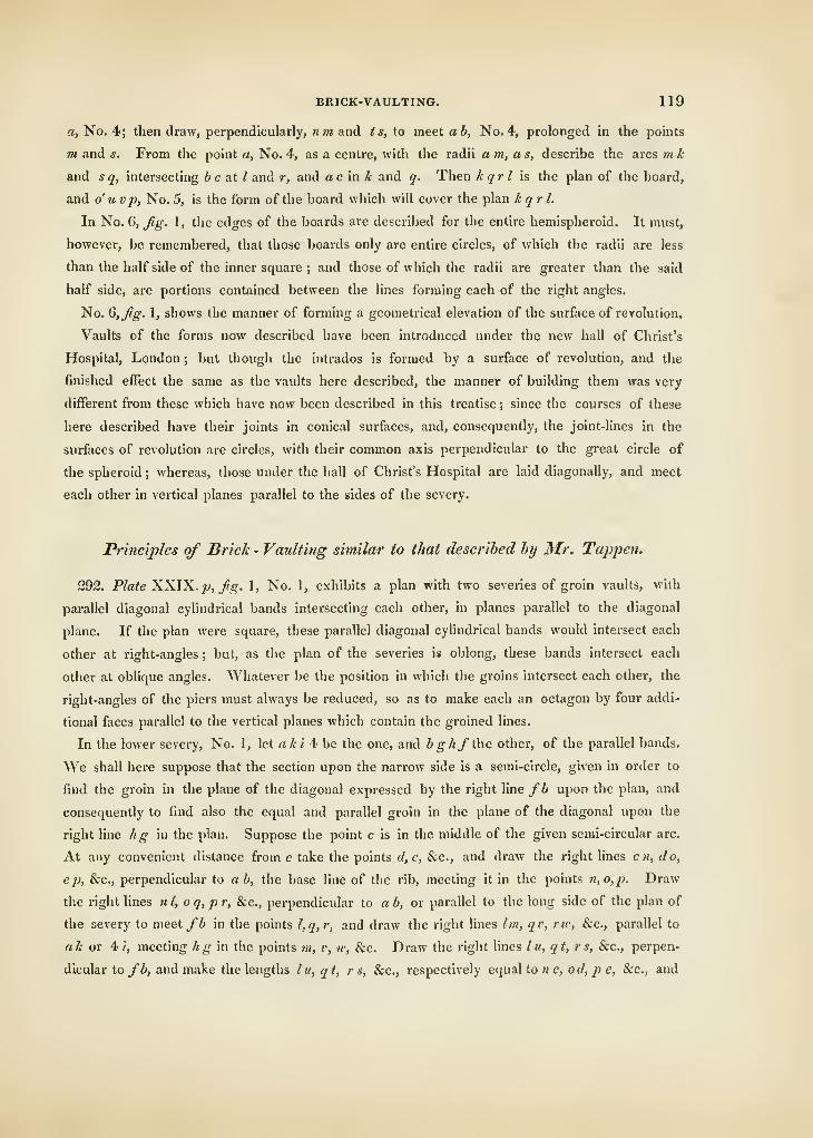
BRICK-VAULTING. 119
a, No. 4; then draw, perpendicularly, nm and ts, to meet ab, No. 4, prolonged in the points
m and s. From the point a, No. 4, as a centre, with the radii am, as, describe the arcs m k
and sq, intersecting be a.tl and r, and acmk and y. Then kqrl is the plan of the board,
and o u vp, No. 5, is the form of the board which will cover the plan kqrl.
In No. 6, ^g. 1, the edges of the boards are described for the entire hemispheroid. It must,
however, be remembered, that those boards only are entire circles, of which the radii are less
than the half side of the inner square ; and those of which the radii are greater than the said
half side, are portions contained between the lines forming each of the right angles.
No. G,Jig. 1, shows the manner of forming a geometrical elevation of the surface of revolution.
Vaults of the forms now described have been introduced under the new hall of Christ's
Hospital, London ; but though the intrados is formed by a surface of revolution, and the
finished effect the same as the vaults here described, the manner of building them was very
different from these which have now been described in this treatise ; since the courses of these
here described have their joints in conical surfaces, and, consequently, the joint-lines in the
surfaces of revolution are circles, with their common axis perpendicular to the great circle of
the spheroid ; whereas, those under the hall of Christ's Hospital are laid diagonally, and meet
each other in vertical planes parallel to the sides of the severy.
Principles of Brick - Vaulti?ig similar to that described by Mr. Tappen.
292. Plate XXJX. p, fg. 1, No. 1, exhibits a plan with two severies of groin vaults, with
parallel diagonal cylindrical bands intersecting each other, in planes parallel to the diagonal
plane. If the plan were square, these parallel diagonal cylindrical bands would intersect each
other at right-angles ; but, as the plan of the severies is oblong, these bands intersect each
other at oblique angles. Whatever be the position in which the groins intersect each other, the
right-angles of the piers must always be reduced, so as to make each an octagon by four addi-
tional faces parallel to the vertical planes which contain the groined lines.
In the lower severy, No. 1, let aki 4; be the one, and bghf the other, of the parallel bands.
We shall here suppose that the section upon the narrow side is a semi-circle, given in order to
find the groin in the plane of the diagonal expressed by the right line fb upon the plan, and
consequently to find also the equal and parallel groin in the plane of the diagonal upon the
right line hg in the plan. Suppose the point c is in the middle of the given semi-circular arc.
At any convenient distance from c take the points cl,e, &c., and draw the right lines en, do,
ep, &c., perpendicular to ab, the base line of the rib, meeting it in the points n,o,p. Draw
the right lines nl, oq,p r, Sec, perpendicular to a b, or parallel to the long side of the plan of
the severy to meet fb in the points l,q,r, and draw the right lines Im, qv, no, &c., parallel to
ah or 4/, meeting hg in the points m, v, w, &c. Draw the right lines lit, qt, r s, &c., perpen-
dicular to fb, and make the lengths I u, qt, rs, &c., respectively equal to » c, o d, p e, &c., and
120 PRACTICAL BRICKLAYING.
through the points thus found draw the elliptic curve uts b, which will be the groin stand-
in" upon lb or mg. Let leg be the right line upon which a vertical section is to stand. Draw
the right lines, fn x, v y, w z, &c., perpendicular to g h, or parallel to the narrow side of the
severy, meeting kg in the points x, y, x, &c., and draw the right lines x\, y2, %2>, &c., per-
pendicular to kg, and make the lengths of the right lines, x \,y%z 3, &c., equal to the lengths
nc, od,pe, &c., and through the points 1, 2,o....g, draw the curve 1, 2, 3..../T, which will
be the section required.
Fig. 1, No. 2, is an elevation corresponding to the narrow side of a severy.
CHAPTER V.
ON THE CONSTRUCTION OF BRICK NICHES.
293. A Niche is a recess in a wall, either for ornament, or for the purpose of containmg a
sJatue.
The surfaces of niches are generally concave. The most elegant are those which are formed
1'y cylindrical and spherical surfaces, the back being formed by the cylindrical surface, and the
canopy, or head, by the spherical surface. The portion used of the cylindric surface is either
that which would be terminated by a diametrical plane, or which would be a less portion of the
surface terminated by a plane parallel to the axis, the terminating plane being the face of the
wall. The axis of the cylindric back is vertical, and the centre of the sphere is in the upper
extremity of the axis of the cylinder, and the spherical and cylindrical surfaces meet each other
in a great circle of the sphere contained in a plane perpendicular to the axis of the cylinder.
The bottom of the niche is generally horizontal, sometimes in the plane of the floor, but more
commonly raised above the plane of the floor.
The niche, figure 2, plate XXIX. ^, is taken from that in the front of the green-house, Ken-
sington-Gardens, which is one of the best-executed pieces of brick-work in this country.
Numbers 2 and 3 exhibit the bond of the courses laid according to the Flemish manner ; No. 4
exhibits a vertical section through the centre of the spherical surface, and perpendicular to
the face of the wall.
sot. The practice of constructing a niche in brick-work is the most difiicult part of the
profession, on account of the very thin size which the bricks are obliged to be reduced down
to the inner circle, as they cannot extend beyond the thickness of one brick in the arch sur-
rounding the crown, it being usual, as well as much the neatest method, to make all the courses
radiate.
TUNNELS AND DRAINS. 121
The most familiar way to reduce this method to practice, is to draw the front, back, &c., and
make a templet of paste-board. After the arch has been divided into the number of bricks,
observe that one templet for every radiating course will answer the front, and one for the side of
the brick. At the top of the straight part, from which the niche takes its spring, make a circle, 8
or 9 inches diameter, and cut this, as well as the former, out of pasteboard, and divide it into the
same number of parts as the outward circle terminating in the front of the wall. From this will
be found the width of the front-templet at the bottom. The reason of introducing this inner
circle is to cut off the thin ends at their conjunction, as they would otherwise require to ter-
minate in straight hnes in the centre of the niche, and therefore the bricks would be formed into
such very acute angles, that they would be liable to break off in working them ; it being impos-
sible to make the thin ends stand at a thickness less than half an inch.
Within the inner circle, the bricks must be laid so that their longest dimensions may be
horizontal and parallel to the plane of the front from which the niche recedes. It will be neces-
sary to have one templet made convex, in order to try the faces of the bricks, as well as to set
them after being properly shaped. The stone upon which the faces of the bricks are rubbed,
must be cut at one end in the exact form of the niche, or otherwise it will be impossible
to face them as they ought to be. The level of the flat sides of the bricks will be obtained by
dividing the back into an equal number of equal parts as in the front, and the radiating lines
must be all struck from the centre. From the circle of the front and the face of the niche set
a bevel, which will answer to the sides of the whole, always taking care that the bricks hold
their full gauge at the back ; for if this circumstance is neglected, much trouble will attend the
execution. Works of this nature require a good price, in proportion to the great skill and
attention required in the execution.
The portion of brick-work, which shows a semi-circle in the front, is called by the name of
Trompilion ; this is made up of several courses, of which the fronts of the bricks must be all
curved, so that, when placed and fixed, they must form the true spherical surface in which it
was intended that the niche should form.
CHAPTER Vr.
ON THE CONSTRUCTION OF TUNNELS AND DRAINS.
General Observations.
295. A Tunnel is an excavation made under ground, terminating at each extremity in the
surface of the earth, for the purpose of giving passage for some moveable thing or things.
2i
122 PRACTICAL BRICKLAYING.
Such a communfcation would either be found convenient or necessary, where some intervening
object would render the conveyance dangerous or extremely expensive, or even, in some cases,
impossible. By means of a tunnel, a stream of water may be conducted from a given entrance
on one side of a hill to a given outlet on the other ; or a passage of communication between
the opposite shores of a deep river, without interrupting its navigation, may be effected.
If the object of the tunnel be to conduct vessels by means of water, it is evident that the
bed of the fluid must be nearly in a horizontal plane, and if it be required to effect the passage
in the least time, its direction ought to be in a right line. This mode of communication would
also be found necessary in conducting a roadway through a hill, which would otherwise be
found insurmountable.
The figure of the section of such an aperture will depend greatly upon the soil through which
it is cut ; but whatever be the form of the right section through any particular point, the same
figure must invariably continue, unless the quality of the substance is found to vary. In this
case, the figure of the section must be such as will meet every contingency. The sides of the
aperture ought always to be lined with brick or stone, and the top ought to be arched. If the
soil be sand, a tunnel cannot be constructed so as to support the superincumbent mass ; and
therefore, in this case, such a conveyance, though ever so desirable, ought never to be at-
tempted. If the soil be clay or solid earth, the figure of the right section of the tunnel must
be of such a form all round that the mutual pressure upon the parts may balance one another ;
or by making allowance for the convenience of practical operations, the figure ought to be as
near as possible to the curve of equilibrium for the support of such a surrounding mass. If the
substance be rock through which a tunnel is to be cut, it will not be necessary to form an arch
all round, the bottom may be paved in the usual manner, and the sides which form walls may
be built upon the solid rock.
In executing a tunnel, it is evident that no more of the ground should be cut away than is
absolutely necessary to effect a part of sufficient length for the operation of walling and arching,
and thus the building and the excavation must be carried on alternately at regular intervals.
The lengths excavated at a time before the brick-work is built must depend upon the nature of
the ground, and may be from 3 or 4, to 7 or 8, feet, in the fine of direction of the tunnel,
observing the quality of the ground with the utmost circumspection, so as not to endanger its
falling by taking away too much at a time.
Instead of making one continued arch all round the tunnel, and in order to save the mate-
rials, the bottoms are most frequently constructed in the figure of an inverted arch, being a
segment considerably less than a semi-circle. The sides and top, however, ought to be carried
round from one extremity of the pavement, or inverted arch, to the other extremity, in such a
curve as will be most suitable to the surrounding pressure of the earth, observing to form a
commodious aperture for passage. With regard to the supporting of the earth at the crown in
the most sufficient manner, it will depend upon the nature of the soil, and upon the circum-
TUNNELS AND DRAINS. 123
stances attending the execution of the work. This will be best understood by a reference to
particular examples : in general, however, this may be done by horizontal bars placed in the
direction of the tunnel, having their remote ends inserted a foot or more in the solid earth,
and their other ends supported by the portion of the arch last constructed, or by means of
upright shores from the pavement.
In these constructions, it is necessary that the joints should be as close as possible;there-
fore, in order to effect this with brick materials, as all the opposite faces of a brick are in
parallel planes, the joints cannot radiate as they ought to do ; hence the opposite sides of
any number of courses built with bricks closely-jointed, would also be comprised between
parallel planes, and consequently such a position of bricks could never form an arch. In order,
however, to render the use of common bricks practicable, the arch would require to have a
very great radius of curvature, and only a few courses (their number depending upon that cur-
vature) built at a time between two courses of wedged-bricks made for the purpose;these
wedged-bricks must be so constructed as to have their sides, which comprise the intenals for
the common bricks, in parallel planes. The figure of the arch would thus become a polygon of
a great number of sides, the general effect of the intrados could not therefore be distinguished
from a curved surface. The skew-backs at the extremities of the pavement may be made of
hard stone, so as to answer to the radiations of the brick-work upon each side.
Description of the Tunnel at the Regent's Canal.
296. Plate XXlX.g, figures 4 and 5, exhibits a section of this tunnel, from a drawing by Mr.
Provis, who received a premium of one hundred guineas from the company appointed to direct
the work. By inspecting/^. 4, it will be perceived that the curvature of the bottom, top, and
sides, are struck from four centres ; the thickness of the bottom is 1 \ bricks in length, and all
the other parts two bricks. The bricks are of the common sort, with the exception of one
course in eight in the bottom and sides, and one course in six in the arch at the top. These
bricks which separate the common bricks radiate in such a manner, as to leave the sides of the
intervals between every two of them in parallel planes, so that each interval may contain the
number of common bricks between the parallel plane surfaces of the radiating ones:these radi-
ating bricks were all made for the express purpose. As common bricks have their sides in
parallel planes, and as it is of the greatest consequence that the joints of mortar should be as
thin as possible, particularly on the lower part adjacent to the convex surface, forming the ceil-
ing or soffit of the arch, which has to sustain the greatest pressure, these radiating bricks are
absolutely necessary to prevent the joints from departing too much from the radiating lines.
In executing a tunnel, it is essential that no more of the ground should be cut away than is
absolutely necessary; having excavated the first length, the leading frames must be already pre-
124 PRACTICAL BRICKLAYING.
pared similar to those sliown m Jig. 5; they may be made of li-inch deal; then having correctly
obtained the level of the bottom of the tunnel, and the central range or line of direction which
is intended to pass from one extremity of the tunnel to the other, lay the first course of brick-
work at the bottom by means of this line, with two or three courses on each side of it, in order
to give it a firm support as at I, Jig. 5. Upon these courses set up the leading frame at each
end, the centre of the under-curve of which must coincide with the line of direction on tlie top
of the middle course of bricks. Having placed the leading frames in their proper positions,
secure them to their places as exhibited in Jig. 5 ; then execute the brick-work of the bottom
on each side of the central or directing courses, making the joints between the bricks with as
tliin a substance of mortar as possible, not forgetting to put in the courses of wedged or ra-
diating bricks at their proper distances from each other; and upon the margins at E, E,
^g. 4, lay the skew-backs, which may be made either of bricks or stones, and upon the
skew-backs carry up the curved sides or walls as high as the tops of the leading frames, ob-
serving, as before, to insert the wedged course of bricks in their proper places, and if any
space should remain between the natural ground and the brick-work, fill the vacuity up with
solid earth, well condensed by ramming it, or otherwise the space must be wrought up with
solid brick-work.
In the course of these operations, the next thing to be done is to set the centre for the arch
at the top. It must consist of two single ribs without any attached covering, and may be of
any common construction, so as to be of the proper curve and sufficiently strong. As the brick-
layers must stand below the arch, in order to turn it, instead of being above it, the covering of
the centre must consist of single straight pieces of wood, about three inches square, and must be
laid loose on the circular ribs by one at a time as the courses proceed, till the work arrives as
high as the supporting bars F, F, &c., which must be taken out one at a time, as the brick-
work approaches them, taking care all the way to stop up firmly every vacuity that may be
between the top of the brick-wovk of the arch and the soil immediately above it. The arch is
at last keyed in with wedged-bricks, which must be driven upwards very tight.
When the first length is completed, the leading frames and centre are moved out of the way,
m order that the miners may proceed to excavate the next length, which, when done, the
bricklayers proceed again as before, with this difference, that only one leading frame is required
for the next and each succeeding length ; as the brick-work, already executed, will answer all
the purposes of a second leading frame.
Fig. 4, shows the arch as completely finished ; and Jig. 5, exhibits a section of the hollow as
excavated for one of the single lengths, at one interval of time, before the brick-work is built
;
the length thus excavated at once must depend upon the nature of the ground, and may be
from three to eight feet, being careful not to endanger the falling in of the ground by taking
too great length at a time. The horizontal bars, to support the superincumbent earth during
the excavation and building of the brick-work, are exhibited at F, F, F, &c. The leading frames,
TUNNELS AND DRAINS. 125
which direct the shape or figure of the section of the tunnel is exhibited at A, B, C, D, fig. 5.
This is the main guide by which the bricklayers are enabled to conduct their work in the process
of building : the plumb-line, which directs the position of the leading frames, is exhibited at GH;
at I, is shown the courses of brick, in order to support the middle of the leading frames, and
on which the line of direction for setting them is drawn ; the supports for the two extremities of
the leading frame are shown at J, J. These are to be taken away when the bottom is so far
laid as to give sufficient stability for the leading frames. The bars F, F, &c., are fixed by in-
serting one end a foot or more into the solid earth, and the other end is supported by the
arch last turned, or may be supported by upright shores from the bottom.
In fi^. 4, which shows the arch as complete, the radiating bricks are shown at a, b, c, &c.
for the inverted arch; at d, e,f, &c. and g, h, i, &c., for the sides ; and at k, I, m, &c. and «, o,j),
&c. for the arch at the top. The centre for describing the inverted arch is shown at L ; the
centres for describing the side-arches n o, n o, are shown at m, m ; and lastly, that for describing
the arch at the top is shown at p. It is obvious that this point must be in the intersection of
the two right-lines, mn, mn, in order that the two curves may meet each other without making
angles at the points «, n, which would not only destroy but weaken the figure of the tunnel. The
beauty and regular gradation of the curve tends greatly to promote the strength and durability
of the work.
In the construction of tunnels, the whole of the mortar employed should be made of the
best water-cement, otherwise it will very soon be brought to a state of decay, and would require
to be often repaired; and therefore eventually would become very expensive, a disagreeable cir-
cumstance which may be avoided by anticipating it in the outset, and thus providing against it
in the execution.
Tunnel under the Thames, from Rotherhithe to Wapjring.
S97. This bold design, to effect a communication of the opposite shores of this very deep
and navigable river, was undertaken by Mr. Brunei, an engineer of eminence, who, undismayed
by the failure of some attempts which had been made to accomplish the same end, completed a
design for the execution of a tunnel beneath the river Thames.
This enterprising design, from the rational hope of remuneration, did not continue long without
patronage. A bill to incorporate a company for the execution of the proposition under Mr.
Brunei's superintendance received the royal assent, on the 24th June, 1824. Tlie examination
of the bed of the river, the selection of the most eligible position, the purchase of property,
the preparation of the novel machinery, &c. &c. occupied the rest of the year.
The soundings taken along the proposed line across the river, gave 12 feet water at the lowest
tides, and 36 at the highest, in the deepest parts. The bed was found to be a stratum of sand,
about 3 feet 8 inches thick, laying upon a stratum composed of sand and clay ; thence the top
of the excavation was a bed of tenacious clay. The descending order of the strata at the
2k
126 PRACTICAI> BRICKLAYING.
lower part of this bed in which the tunnel is executed was as follows :—A bed of stiff blue clay,
about 2 feet in thickness ; a bed of silt, 7 feet ; silt mixed with shells, 7 feet ; indurated clay,
3 feei ; silt and gravel-stones, 3 feet.
The tunnel was begun early in the year 1825; and the design consists of a square mass of
brick-work, 37 feet by 22, comprising the arched passages, each of the width of 16 feet 4
inches. Each carriage-road is 13 feet G inches wide, and the height of each aperture above the
road-way 15 feet 6 inches. The extreme sides are 3 feet in thickness, and the arches 2 feet
3 inches. The arched passages are divided by a wall of great strength ; and this division-wall
is perforated by a range of arcades, of which a certain number of them, placed at regular
intervals, are so wide that vehicles may pass from one carriage-way to the other. The central
wall was built solid for the greater security of the work, and afterwards perforated. Under
each passage is turned an inverted arch, 2 feet 3 inches in thickness ; the external wall rests
upon one extremity of this arch, and half of the middle wall upon the other. Over the invert
rests the Macadamized roads, terminating with commodious foot-paths on the sides: all the
joints between the bricks are laid with cement.
The foundations were all laid upon very strong beech-planks, which seem to have answered the
purpose extremely well, since there has been no instance of any sinking or settlement of any kind.
It was intended that the foot-passengers should enter the tunnel from either side of the river,
by means of a winding-stair placed in a circular shaft. The distance of the two shafts for the
passengers was intended to be 1300 feet, the width of the river being 1000 feet, from wharf to
wharf; and that the descents for the carriages should be circular. Before the tunnel could be
begun, it was necessary to get down to the depth at which the level of the bottom of the en-
trance was to commence. For this purpose a cylindrical wall, 40 feet in height, 3 feet in thick-
ness, and 50 feet in diameter, was constructed, so that, when sunk, to become the lining of the
shaft. This circular wall rested upon a wooden curb shod with cast-iron base, of which the
lower edges was formed into an acute angle in the manner of a chisel, and the top was secured
by another wooden cuib, which was joined to the bottom one by means of iron rods. The
brick-work was built with the utmost care on the surface of the ground immediately over the
place which was intended for the shaft.
In the upper part of the shaft, a steam-engine of 36-horse power was constructed, with a
boiler, fire-place, &c., for the purpose of freeing the bottom of water, and lifting the exca-
vated soil.
The first brick of the tower was laid on the 2d of March, 1825, by Wm. Smith, Esq., M. P.
for Norwich, and on the 1st of April following, the excavation commenced within its enclosure.
As they proceeded, this immense structure, with its engine, &c., continued to descend vertically,
without accident, for twenty days, through successive strata of gravel, &c., and when it had
descended 37 feet from the surface, it rested upon a solid bed of clay. It was there permitted
to remain ; but the excavation was continued, and the cylindric-wall under-built to the depth of
TUNNELS AND DRAINS. 127
24 feet. At this level the diameter was reduced to 25 feet, and another cylindric-wall inserted,
sunK 20 feet more.
This lower part was intended as a tank, or receptacle for the drainage-water, into which were
carried the suction-pipes of the engine-pump, for the purpose of carrying it off.
The total height of the brick-work of this shaft was therefore 40-f- 24 + 20 = 84 feet, 64 of
which are of 50 feet diameter, and 20 of 25 feet. It consumed about 260,000 bricks, and 1200
barrels of cement. The weight of this construction is about 900 tons. The cylindrical cavity is
intended eventually as the stair-case for persons on foot. Near it, a little to the southward, will
be built the cylindrical shaft of 160 feet diameter, by which carriages are to ascend and descend,
so as not to exceed in any part a greater declivity than that of Waterloo-Place, Pali-Mall.
Though the principle of sinking this shaft was familiar to every well-digger, and to every
miner, yet, from its vast diameter and proportional dimensions, it is considered as the greatest
work of the kind ever yet attempted, as it demanded a more than ordinary degree of skill and
intrepidity on the part of the engineer, in order to secure the success of the work.
At the bottom of this shaft a lateral excavation was made for commencing the tunnel ; and
from thence the constant protection and support of the soil, and the great weight of water upon it,
was effected by means of a strong iron frame, consisting of several moveable vertical parts, the
whole of which was called by Mr. Brunei by the name of a shield, weighing 120 tons, being
37 feet in width, 22 in height, and 8 feet in depth, and containing thirty-six workmen. It
consisted of twelve compartments, which were advanced alternately and independently of each
other, having each three cells, of which the floors serve constantly as a scaffold for the miners
and bricklayers.
The front of the shield is placed against the face of the soil to be excavated ; and, by means of
moveable boards placed upon it, the workman can, by taking away the board, remove any part of
the earth behind at his discretion, and when done, he places the board against the new vertical
surface now exposed, and the board by this means becomes in advance of the box, and is kept
in its place by props, which have their supports by the face of the brick-work in the rear.
When he has thus proceeded with all the boards, it will be evident that an excavation will have
been made equal to the area of the front of the shield, and of a certain depth, and that the
boards will all be in advance equal to this depth. The box, by means of screws, is forced
forward to the boards, and the operation of excavation recommences, and so on, observing that
at every time the excavation is made, the brick-work is immediately executed all round close
to the shield, and thus the security of the work is preserved.
The work proceeded for several months, at the rate of about two feet in twenty-four hours,
displacing from 90 to about 100 tons of earth, which were lifted to the surface by the engine.
In each foot in length of the tunnel 5,500 bricks were used. On the 2d of Rlarch it had ad-
vanced 4T0 feet, w])ich is about one-third of the whole length. About 11,000 bricks, laid in
cement, were used every day, and the labour of one hundred men was constantly kept up.
128 PRACTICAL BHICKLAYING.
A main from the gas-works is laid along the floor, and conveys the gas to columns placed in the
connecting arches as they are formed ; and from these branches both the road-ways are illumi-
nated, which produce in the eyes of the spectator, at his entrance, a most extraordinary and
beautiful gradation in the perspective succession. The total freedom from water is preserved
by drains underneath, which empty themselves into the tank under the engine at the bottom
of the shaft.
^98. Though Mr. Brunei has conducted this work with very great ability, by numerous expe-
dients to facilitate the progress, and to anticipate the difficulties of this extraordinary undertaking,
these qualities were destined to a very severe trial. On the 18th of May, 1827, at a distance of
544 feet from the commencement of the tunnel, in the cyhndric wall of the shaft, the water of
the river found its way through a portion of loose earth, and entered the tunnel through tne
shield, with a velocity and volume which filled the hollow and the shaft in fifteen minutes.
This happened while the workmen were at their duties, but no lives were lost. In this eruption
about 1,000 tons of loose soil and rubbish descended into the tunnel. This breach was exa-
mined by means of a diving-bell, and repaired by depositing about 15,000 cubic yards of clay,
in bags, so as to fill up the cavity complete. The water was then pumped out, and the brick-
work surrounding each aperture was found very slightly injured. In the latter part of September
the works recommenced ; but, after the length had been extended 52 feet farther, and the dan-
gerous part passed, on the 12th of January, 1828, the water of the I'iver broke in and passed
through the shield a second time ; the tunnel was filled in less than ten minutes, and the rush of
water brought in with it a current of air that put out all the lights : six of the workmen, being
unable to extricate themselves, were drowned, the rest escaped. The point at which this eruption
happened occurred at the distance of GOO feet from the shaft. This unfortunate eruption has also
been perfectly stopped ; and, though the tunnel descends 3 feet in 100, into the excavation, in
one part, towards the middle of the river, had approached within 10 feet of the water above it.
These events, though much as it must be deplored, as tending to check the progress of the
work, yet prove in a manner highly satisfactory, that no event of this nature can offer any
impediment which cannot be surmounted.
The sympathy which these misfortunes have so justly excited, together with the increased
admiration which the overcoming of such difficulties has prodijced, induces a hope that the
progress in future will be a national concern, and that the subscribers will be relieved from
farther outlay by the munificent hand of government.
The whole cost of the tunnel was originally calculated by Mr. Brunei to be ^^160,000 ; but the
work has been attended with so many contingencies, independently of the expense incurred
by the last accident, the expenditure before was ^157,000., of which about ^38,000. has been
laid out in the purchase of premises and machinery, and .^118,500. in the works. The
directors state that about j€75,000. will be necessary to complete the tunnel to the north
,em))ankment.
TUNNELS AND DRAINS. 129
Plate XXX. fig. 1, exhibits a transverse section of the river Thames, passing longitudinally
along the tunnel, and through the substance between the bed of the river and the excavation,
with the sections of the shafts for the descending and ascending of carriages and foot-passengers.
The plan of the shafts and tunnel are exhibited in fig. 2.
Fig. 3, exhibits an elevation of the shield in which three men are represented at work in one
of the compartments ; and fig. 4 is an elevation of the side of the shield, and in the longitudinal
direction of the tunnel. The whole weight of this shield was 1^0 tons.
Fig. 5, a transverse section through the two apertures of the tunnel, and through the summit
of one of the arches of the division-wall, showing the representations of a loaded carriage and
foot-passengers to and fro.
Plate XXXI. fig. 1, exhibits a view of a part of the cylindrical brick-wall, the other part
being taken down, in order to show how the curbs which secure the extremities of the brick-
work are connected to each other by means of rods made of iron and wood alternately, placed
and fixed to the curbs by means of screws. This, as has been explained, was sunk by con-
tinually taking away the earth from beneath, and rested at intervals, so that the axis of the
cylinder might be perpendicular at each descent. During the time of making any one descent,
when a certain portion of the ground was taken away from under the wall, this portion was
supported in the middle by blocks and wedged tight to the under side of the curb ; after this
was done, another portion of the soil was dug away, and the under side was again supported
by %vedges in the same manner, and so on all round, till the excavation was completed ; and
then, when the wedges were slackened, and the blocks removed, the mass descended through
one step, and this operation was done in every step.
Fig. 2, shows a portion of a section of the bed of the river containing a transverse section
of the excavation of the tunnel, and elevation of the six compartments of the shield. This sec-
tion shows also a profile of the cavity formed by the irruption of the water, the manner in
which it was filled by the clay-bags, and how the tarpauling above the clay-bags was kept
down, by means of cast-iron kentledge, and, above all, the covering of gravel for securing
the whole.
Fig. 3 exhibits a section, as in fig. 2, but without the cavity being filled with the clay-bags,
in order to show the state of the bed of the river after the irruption more clearly than fig. 2.
Various other Designsfor the Sections of Tunnels, S~ ucrs. Culverts, and Drains.
299. Fig. 7, plate XXXII, the section of a Tunnel, in which the road-way is sufficiently
broad as to admit of carriages to pass each other with ease and without danger. The breadth
of the road-way is 2S feet, and that of each of the foot-paths 7 feet, the whole breadth being
42 feet. The entire height between the middle of the head-arch and that of the inverted arch
is 21 feet, and the height between the summit of the pavement in the carriage-way and the
2l
130 PRACTICAL BRICKLAYING.
summit oi me arcii is 18 feet. Fig. 8, is a design for another tunnel, containing carriage and
foot-ways, the whole width at the widest part being 21' feet. Fig. 7, is adapted to those
situations in which the surface of the ground is not at a rery great distance from the hollow
of the tunnel ; and jig. 8, is adapted to a situation where the pressure by the weight above is
very great.
Fig. 2, is adapted to a culvert for passing a large body of water, as a mill-dam, or the like.
Fig. 1 , section of the brick-work of a common or main sewer. Figures 3 and 5, are the sec
tions of smaller sewers or drains. Fig. 4, exhibits the section of a small barrel-drain ; and
Jig. 6, shows the section of one of the smallest drains in use.
All these designs, excepting ^^. 8, may either be constructed of brick or stone, according as
the one or the other is most easily procured. In all cases, the planes of the joints should be
perpendicular to the visible surface of the tunnel, whether the material used be brick or stone;
by this means the work will not only be easier to execute, but at the same time it will require
fewer materials and will be much stronger, and, consequently, much less expensive than when
the joints are placed obliquely to the visible surface of the brick-work adjacent to the aptn-ture
or void of the tunnel.
Though a uniform figure for the form of the right section of a tunnel is both stronger and
more elegant than one that is compounded of the arcs of circles;
yet, if the variation is not
very sudden in any place, to execute the whole of an arch of variable curvature, in several or
in many portions of circular arcs, having their radii varying gradually from each other, will be
very convenient, as such an approximation will not be perceptible in the whole design. It must,
however, be observed, that the arcs on each side of every point of junction must have their
centres in the same straight line, and that this straight line must pass through the point of junc-
tion ; that is to say, the three points, viz. the centres of the two arcs, and the point of junction
of the arcs, must be all in the same straight line. If this circumstance is not attended to, the
beauty and strength of the work will be greatly deteriorated, as the curvature of the section of
the arch will be deficient in point of continuity, and this will produce a very unsightly effect on
the eye in the general appearance of the work, by crippling it in sudden gradations. This
unpleasant effect must therefore be carefully guarded against, so that nothing but beauty and
harmony may result from the execution of the design; and this \\\\\ not only give satisfaction to
the workman who executes, and to his employer, but also to the public, who are ultimately to
judge of the general effect of the design.
CONSTRUCTION OF OVENS, &C. 131
CHAPTER VII.
ON THE CONSTRUCTION OF OVENS, BOILER FIRE-PLACES, AND OF THESETTING OF COPPERS.
300. The section of the roof of the oven, on the old principle, for the use of bakers, was
usually of an oval figure, being arched over at top in the figure of an ellipsoid ; the sides and
bottom of brick, tiles, and lime, with a door in front ; and at the upper part, an inclosed closet,
with an iron gratinif, for the tins to stand on, called the Proving Oven. To heat such ovens,
fagots are introduced and burnt to ashes, which are then removed, and the bottom cleaned out.
This operation requires some time, during which much of the heat escapes. A still further
length of time is required for putting in the bread, and unless much more fuel is expended than
is really necessary, in heating an oven upon this principle, it becomes chilled before the loaves
are all set in, and they are, therefore, by this means, very much injured.
To remedy this inconvenience, many ovens have latterly been built upon a pavement supported
upon solid brick-work, with a door of iron, furnished with a damper to carry off the steam as
it rises, and heated with fossil coal. On one side is a fire-place or furnace, with grating, ash-
hole, and iron-door, similar to that for supporting a copper, with a partition to separate it from
the oven, and open at one end. Over this is a middling-sized copper, or boiler, with a cock at
the bottom, and on one side of it is placed the proving oven ; the whole being faced with brick
and plaster.
When this oven is required to be heated, the boiler is filled with water, and the fire being
kindled, the flame spreads around the oven, in a circular direction, all over its concavity, and
renders it as hot as if heated with wood, without causing dirt or ill smell, while the smoke
escapes through an aperture, which may pass into the kitchen-chimney. When the coal is
burnt to a cinder, there is no necessity for removing it, as it prevents the oven from cooling while
the bread is setting in, and keeps up a regular heat till the door is closed. The advantages of
an oven built upon this principle, are too obvious to requii'e comment.
Plate XXXIII. exhibits, in detail, the improved plan of an oven, on the new construction.
It has been communicated by Mr. Elsam, the Architect, inider whose directions it has been
constructed in various public buildings in different parts of the United Kingdom.
Figure 1 is the plan of the oven. The fire is put into the furnace, A, and is supported upon
wrought-iron bars, which are fixed an inch and a half below the level of the oven, to prevent
the cinders from entering it. The outside of the furnace is shut with two cast-iron doors CI, 2,
m plan). The ashes fall into the ash-pit beneath, B, (Jig. 2,) the door of which is marked 3,
in the elevation (Jig. 3).
132 PRACTICAL BRICKLAYING.
While tlie coals are burning, the mouth of the oven is inclosed only by the curved cast-iron
door, or blower, B, shown in the section of the oven, {fig. 4,) and elevation, {fig- 10,) and
which is so shaped in order to make a proper passage for the smoke to the flue, C. This door,
or blowei', is not hung, but is put up and taken away by hand, as may be required.
When the oven is sufficiently hot, a man, placed at its mouth, with the iron bar, E, {jig. 5,)
slides the cast-iron stopper, D, {fig- 1 and 6,) to the angle, F, where it stops, as shown by the
dotted lines ; then going to the mouth of the furnace, he hooks the crooked part, G, of the same
iron bar, {Jig. 5,) mto the circular hole of the stopper, H, {fig. 7,) and pulls the fillet, I III I,
{fig. 8,) into the frame of the furnace, upon which it fits. This stopper is made to slide, but
not in a groove, as the cinders might sometimes prevent its being shut.
Figure 8, represents an iron frame, to be fixed round the mouth of tlie inside of the furnace.
The opening of the mouth should be one foot two inches wide, and one foot high, and to be
made to receive the fillets of the stopper. III.
The door, K, {fig. 4,) is fastened to an iron chain, and is raised or let down, at pleasure, by
turning the lever, L, {figures 4, 10.) In order to prevent the heat from escaping while the
bread is putting in, the mouth of the oven must be made as small as possible. To the handle
of the lever is hung an iron pin, with a chain, and over it is a semi-circular iron plate, fastened'
to the wall, with five holes drilled in it to receive the pin, which, by this mean, will regulate the
height of the door, K, at pleasure.
When bread is baking, the curved door, B, not being then wanted, is taken away ; and the
two doors of the oven, with the two doors of the furnace, are shut up.
At the top of the furnace, M, {fig. 4,) is a small flue, about three inches square, commu-
nicating with the flue of the oven. The use of this small flue is to leave a passage for tlie
sulphur that may remain in the ashes, and might injure the bread while baking. The connnu-
nication of this small flue of the oven is opened or shut by means of an iron slider, N, {fig. 10.)
Over the furnace is a niche, {fig. 3,) with a boiler of hot water.
It has been observed that, in ovens on this construction, whatever be the dimensions of the
fire-place, it is always proper to set the bars eight or ten inches in from the door, by this means
a supply of coals will be kept warming before they are pushed forward into the fire. The im-
portance of this preparation is known to those who have attended to the effect of every fresh
supply of coals to the boilers of steam-engines, as it instantly stops the boiling, unless this pre-
caution is attended to. It also prevents, in a great measure, the cold air getting in between the
door and frame of the fire-place, which frequently happens, from the difficulty of fitting iron
doors to iron frames.
Ovens, on the improved construction, will hold, according to their size, as follows :
—
Eight feet wide, and seven feet deep, eight bushels of bread.
Nine feet wide, and seven and a half feet deep, ten bushels.
Ten feet wide, and eight and a half feet deep, twelve bushels.
BOILER FIRE-PLACES. 133
If required to hold less than eight bushels, or more than twelve, the proportions, of course,
must vary accordingly.
The oven represented in the plate is eight feet wide and seven deep ; and, therefore, as stated
above, it is adapted for eight bushels of bread. The fire-hole, or furnace, exhibited in fi^. I,
enters the oven in a diagonal direction with the farthest corner ; the sides of the oven are
carried nearly straight, and turned as sharp as possible at the haunch and shoulder, this iorm
being supposed better calculated to retain the heat than any other : the flue is immediately over
the entrance, as shown in figures 1 and 4. Welsh lumps, or fire-bricks, are used for the fiir-
nace. In works of this nature, it is usual to introduce a considerable quantity of old iron hoops,
more especiallj' around and over the oven, in order to keep the work together. This pre-
caution is advisable on all occasions where great heat is required.
In building the oven, one end of the crown is turned with bricks, as shown in the section,
jig. 4 ; and the centering, for building the brick-work upon, is formed by filling the void with
sand, clay, or rubbish, which must be well trodden down, and formed to the shape or figure of
the crown. When the upper work is finished, the sand, clay, or rubbish, which formed the
centering, must be dug out by the mouth of the oven.
Other particulars will be found in the explanation of the terms used by Bricklayers and
Plasterers.
Of Boiler Fire-Places.
301. Plate XXXIV. shows the method of constructing a series of kitchen fire-places, for
heating boilers, stew-pans, and other culinary apparatus.
Fig. 1 represents a section, and fig. 2, a plan of a double-boiler fire-place ; the vertical
section is taken through the centre of the grate, as shewn by the dotted line, a, a.
In this construction, one boiler is placed immediately over the grate, and the other is placed
over the space seen at b ; the space b is made sufficiently capacious to admit a large portion of
the heated current of air, the direction of which is shewn by darts, the flue being so con-
structed, as to completely envelope the external surface of the two boilers. If the flues were
made all the way along their course of equal capacity with the space contained around the
grate, it is very clear that when the air became rarified by the combustion of the fuel, it would
move in every part with an equal velocity, and the greatest portion of the heat would escape,
without being imparted to the vessel and its contents intended to be heated. In order to
prevent this, the area of the flue is contracted at c, by which means the heated air is detained
much longer under the bottom of the boiler, and impinging upon the surface of the vessel,
tends to heat it in the most advantageous manner, it being a well-known fact, that heat is best
communicated by ascent ; therefore it will, at all times, be advantageous to detain the heated
current as long as possible, while it is covered by the under surface of the boiler. These
2m
134; PRACTICAL BRICKLAYING.
reasons, if duly attended to, will, in every case, suggest to the practical bricklayer the most
advantageous situation to construct the check or diminished area of the passage for the heated
current.
In cases where very great economy is requisite, as in steam-engine boilers, &c., the advan-
tage of the ascending property of heat is so well understood by engineers, that they make the
sides of their boilers project so as to form the upper surface of the enveloping flue, by which
means they not only avail themselves of the lateral heat of the current, but also of that most
important one before stated, namely, the ascending property.
The sides around the grate, shewn at d, d, d, d, d, should rise in a sloping direction, so as to
accommodate the space to the rarified state of the air, after it has been heated by the com-
bustion of the fuel ; and as these sides will have to sustain the greatest action of the heat, they
being many times covered with the ignited fuel, it is absolutely requisite that they should be
formed of the best fire-bricks, and set in Stourbridge clay, or fire-loam, mixed with ground-
clinkers from smiths' forges, which, when heated, will form a semi-vitrified mass that will bind
and unite the whole mass firmly together. In all cases, where it can be admitted, the approach
to the narrowed passage of the current should be made to slope gradually upwards, which will
assist to contract the current, like a funnel, at the same time that such an effect is greatly assisted
by changing the direction of the heated medium.
In the construction of every kind of fire-place, where it is intended that the heated air should
be made to strike or impinge against any vessel, in order to raise the temperature of its contents,
it will be of the greatest importance to have all the brick-work done in the most solid manner
possible, as nothing can be more injurious than cracks or openings, which, by being connected
with the flues, admit cold air into the heated current, and thereby destroy, in a great mea-
sure, the effect intended. To the practical man who is aiming at eminence in his profession,
we cannot too much enforce these observations, as they have been practically proved to be of
the greatest importance.
Before concluding these obsei"vations upon the construction of this class of fire-place, we
wish most strenuously to impress upon our practical readers the mistaken and false economy of
making fire-grates too small, a practice that most completely defeats the principal object in
view, namely, that of saving fuel.
A very little reflection will clearly show that where the space for fuel is too small, the want
of room to spread the fuel will cause it to lay in such a compact and solid state, that the
gaseous parts will be distilled and pass along the flue without being ignited, and by such means,
instead of imparting heat by entering into combustion, a precisely contrary effect will be pro-
duced. And if, on the other hand, very small portions of fuel are frequently supplied, the
opening of the door of the fire-place so repeatedly will permit so much cold air to enter as to
essentially diminish the heating of the vessel, and its contents, independently of the great loss
of time that will be required to keep up a steady heat.
BOILER FIRE-PLACES. 135
There is also another circumstance of great importance, which must be admitted into the
consideration of this subject, namely, that where fire-places are made sufficiently large, fuel of
a much coarser description can be used, and a very equable and economical heat may be pro-
duced; for, in such cases, the cinders and ashes from the common fire-grates, when mixed with
a due proportion of small coals, will be not only sufficient for creating a proper heat, but will
not require half the attendance that pure coals with a pinched fire-place will do.
We have been induced to impress these observations, from a perfect conviction of their prac-
tical utility, having frequently observed the great loss that accrues, and serious inconvenience
that is sustained by many families who have employed persons to set the ordinary kitchen-
copper, which is too frequently executed upon such bad principles, that a great portion of the
advantages and convenience of that very useful apparatus is lost to the public. The length of
the bars, in most cases, should be about three-fourths of the diameter of the bottom of the
boiler, and if they are loose bars, they will be much better than a frame cast with all the bars
entire, the space between each bar should be about half an inch. And it should be remem-
bered that the flues of these kind of fire-places are as likely as others to be clogged with soot,
and therefore it will be very requisite to have loose bricks, or stoppers, placed in proper situa-
tions, as shewn at c, Jig. 2, which will give great facility in cleansing such flues, and frequently
prevent danger firom fire in buildings where they may be erected.
It may be necessary to state, that the same precautions and directions ought to be observed
in figures 3,. 4, and 5, as in figures 1 and 2. Figures 3 and 4 represent a section and plan
of a hot-plate, which is most generally of cast-iron, resting about an inch on the brick-work all
round, and a rim of wrought-iron should be fixed round the external brick-work, to protect it
from being broken or otherwise damaged. The bridge of fire-brick ought to be built to within
three-quarters of an inch of the plate, leaving that distance between the bridge and the under-
part of the plate, for the smoke and heat to pass on the way to the chimney.
The dotted lines, in fig. 3, shows the position of the flue and the chimney; fig. 5 is the plan
of the copper-boiler, with the bottom part contracted round the grate. The smoke rises at
the opening in the back, passes round the bottom, and then enters the chimney.
Fig. 6, is the representation of a charcoal-stove, which is composed of soHd brick-work,
except it should so happen that a very large one should be wanted, then the wall may be built
hollow and filled up with rubble. The grates are constructed of cast-iron, and placed four
inches deep, with a vacuity under to the floor for the ashes to drop, and thence they may be
drawn out through the cavity left in the front.
Stoves of this description are used for stew-pans, chafing-dishes, &c. A rim of wrought-iron
should also be fixed round the brick-work at the top, about 3f inches deep.. The grates are
of diflerent sizes, according to the magnitude of the building.
186 PRACTICAL BRICKLAYING.
On the Method of fixing a Copper-Boiler for Brewing,
302. Fig. 1, plate XXXV. is a section through the upper vertical line in the middle of
the copper; fig. 2, a horizontal section of the copper taken under the bottom, and may be
considered as the plan of the brick-work immediately above the grate. This method offers the
least obstruction for the flame to play on both sides of the grate, where it meets on the oppo-
site side of the prop at A, and thence rises in a sloping direction towards the back, which is
shown by another section, fig. 3; the part at A, being the partition, as shown on the plan,
fig. 2. Above the partition. A, the whole of the smoke rushes into a chimney or tube, ascending
up the back of the brick-work, and is discharged into the atmosphere at the top. This
chimney is shown in the section, fig. 3, which is taken at right-angles to fig. 2, as exhibited by
the plan, fig. 4, which is the plan of the section, fig. 3.
Fig. 5, is a vertical section taken through the axis of the boiler, and through the discharging
cock, B and C, shown on the plans. Figures 2 and 4 are two other props, besides the par-
tition A, which is also used as a prop. The plan or horizontal section, fig. 2, is that of fig. 1,
and the plan or horizontal section, fig. 4, is that of the vertical section, fig. 3; fig. 4, being
the same as fig. 2, only differing in its position, which is fig. 2, turned at right-angles.
Fig. 6, is an elevation of the front, showing the fire-place, and the manner of suspending the
door by means of pullics, which is balanced by a weight depending from the remote pulley.
The top of the brick-casing round the copper is entirely closed round the circumference, as
shown on the three sections at cm, aa, &c. There is a similar ring of brick-work which encom-
passes the circumference of the copper, and is also shown on these sections, at bh, bb, &c.
This construction is that recommended by Mr. David Booth, a gentleman well known by his
numerous publications, and his scientific acquirements on practical and useful subjects.
We cannot conclude this department of instructions without again enforcing upon our scien-
tific friends the absolute necessity of making the atmospheric air pass through the ignited fuel,
and also to take especial care that their work may be made so close and sound as to prevent a
circulation of that which is very properly called the pabulum of life and flame ; for one fact
should never be lost sight of for an instant, namely, that whatever air is admitted, without being
decomposed or used up by the fuel, must of course tend to impart its own temperature to the
surrounding objects, and, consequently, rather retard than accelerate the object in view. Weare well aware, that however well fire-places of this kind may be constructed, much evil is fre-
quently produced by having to join the flue, or carry it into one already formed. In such case,
it will generally be well to continue the flue belonging to the boiler fire-place to as great an
extent as possible, before it enters the flue already formed, which will assist, in some degree, to
obviate a portion of the difficulty ; and where only one of the fire-places is used at the same
time, that portion of the flue that leads from the one not in use, should be stopped, to prevent
the entrance of air through it at such part.
SETTING RETORTS. 137
CHAPTER VIII.
SETTING RETORTS, AS PARTICULARLY APPLICABLE TO GAS-WORKS.
303. As Gas, for the purpose of aiFording light, has now become an article of general utility,
it may be necessary to give some account of the brick-work, particularly of that very essential
part of it, which applies to the setting of the retorts.-
Notwithstanding the numerous experiments made, at the principal gas-stations, as to the best
shape, and the most economical method of setting retorts, for the purpose of carbonizing coal,
yet very little improvement, generally speaking, has been made, in either of these most important
points, since the first introduction of gas-Hght.
Retorts made of cast-iron ; lumps or tiles, made of fire-clay, have been tried ; and ovens
built entirely of fire-bricks, have also been used, with greater or less success. Of these mate-
rials, we may merely notice generally, that metal, being an absorbent of heat, and clay a non-
absorbent, it hence follows, reasoning a priori, that the former would appear to be decidedly
the preferable material for retorts. The practice at the principal gas-works sanctions this
opinion. Indeed, metal retorts are now almost universally used.
Retorts have been tried of various shapes : cylindrical, oval, semi-circular (or D shaped),
parallelopipedal, &c. The form now most generally adopted is cylindrical, 7 feet 6 inches long,
and 12 inches internal diameter. But whether that shape be the most profitable to the
gas-manufacturer, can only be ascertained by actual experience; the results of experiments
being so various, as regards gas matters, in different hands, no certain conclusion can with
safety be drawn from them. The only sure criterion therefore to judge by is from making
a fair trial.
The modes of setting retorts are as multifarious as their shapes. They were first set on
what is termed the flue-plan : sometimes one, two, three, and four retorts were set to one fire,
which was placed either in front or at the back of the retorts, as room permitted, or as the
fancy of the engineer directed. Sometimes two fires were used to heat a bench of three or
four retorts. These flues were carried over and under the retorts repeatedly ; and were cer-
tainly well calculated to produce an equal distribution of heat throughout the retorts. Mr.
Peckston states, that two retorts, set on the flue-plan, to one fire, carbonized at 20 per cent, for
fuel only. He does not, however, state directly the quantity of gas produced by this plan, from
a chaldron of coals ; but, from the results given by him, of the produce of different kinds of
retorts, in a Table, p. 141 of his book on Gas Lighting, we conclude it to have been 10,000
cubic feet, per chaldron, of Bewick and Craster's Walls-end coals.
138 PRACTICAL BRICKLAYING.
Retorts, for the destructive distillation of coal, were next set on what is designated the
oven-plan. This was the design of Mr. A. Rackhouse. His first experiment was made at
one of the gas-works in London, by heating one retort in an oven. It was reported to heat
very uniformly, and at little expence. He next set two in one oven, then three, afterwards
five, and, lastly, seven. It is proper to observe, that cylindrical metal retorts, set in benches of
five retorts each, on the oven-plan, to one fire, is still, by far, the most general mode adopted
at the best conducted gas-light establishments.
Mr. Stone, engineer to the Ratcliffe Gas Company, took out a patent some years ago for
heating retorts by means of a coke-oven. This is still used at Ratcliffe works ; and answers
the purpose admirably. There it has th§ peculiar advantage of being managed under his own
immediate inspection. It has failed in other liands, but from what cause is not at present
very clearly understood. At Ratclifie it has proved successful; and, having examined it
carefully, we are far from experiencing any degree of surprise that it should be so. The coke
made by this oven is excellently adapted for the blast-furnaces of founderies ; and sells for from
30*. to 32s. per chaldron. One oven heats seven square or parallelopipedal retorts, 6 feet 6
inches long, (they purpose making them a foot longer, which will be a decided improvement,)
by two feet broad, and one foot deep, internal diameter. The oven is charged every thirty
hours ; and the retorts every four hours.
The grand object in view, in setting retorts, and in choosing the best configuration of them,
is to be enabled thereby to make the greatest quantity of the best carburetted hydrogen-gas,
at the smallest expence, and in the shortest space of time.
In order to be able to accomplish this, there are four cardinal points which demand parti-
cular attention: 1st, To use as little fuel as possible, in bringing the retorts to a proper
deoree of heat, and in keeping it up ; 2d, To distribute and equalize that heat throughout the
whole body of the retorts ; 3dly, To protect the retorts from the immediate action of the fire,
without prejudice to the economizing of fuel; and 4thly, To dispose of the coal, within the
retorts, so as to produce an abundance of good coke and carburetted hydrogen gas, of a suffi-
cient specific gravity and illuminating power.
It may, perhaps, be sufficient for all practical purposes, to give, in the first place, a descrip-
tion of the mode, as presently practised at the principal gas-works, of setting cylindrical metal
retorts, in benches of five retorts, to one fire, on the oven-plan ; next a description of Mr.
Stone's coke-oven, which is capable of heating seven parallelopipedal retorts, as now in action
at the Ratcliffe gas-works ; and, lastly, an improved method of setting fire retorts, in one oven,
to one fire. By attending to these several modes, any number of retorts may be set on the
same principles.
Before entermg on this, it may be proper, however, to explain why five retorts in a bench are
preferred to seven. The fact is, the heat is much more easily distributed amongst five than seven
retorts. It is no saving offuel to use seven retorts in an oven, heated by one fire. The con-
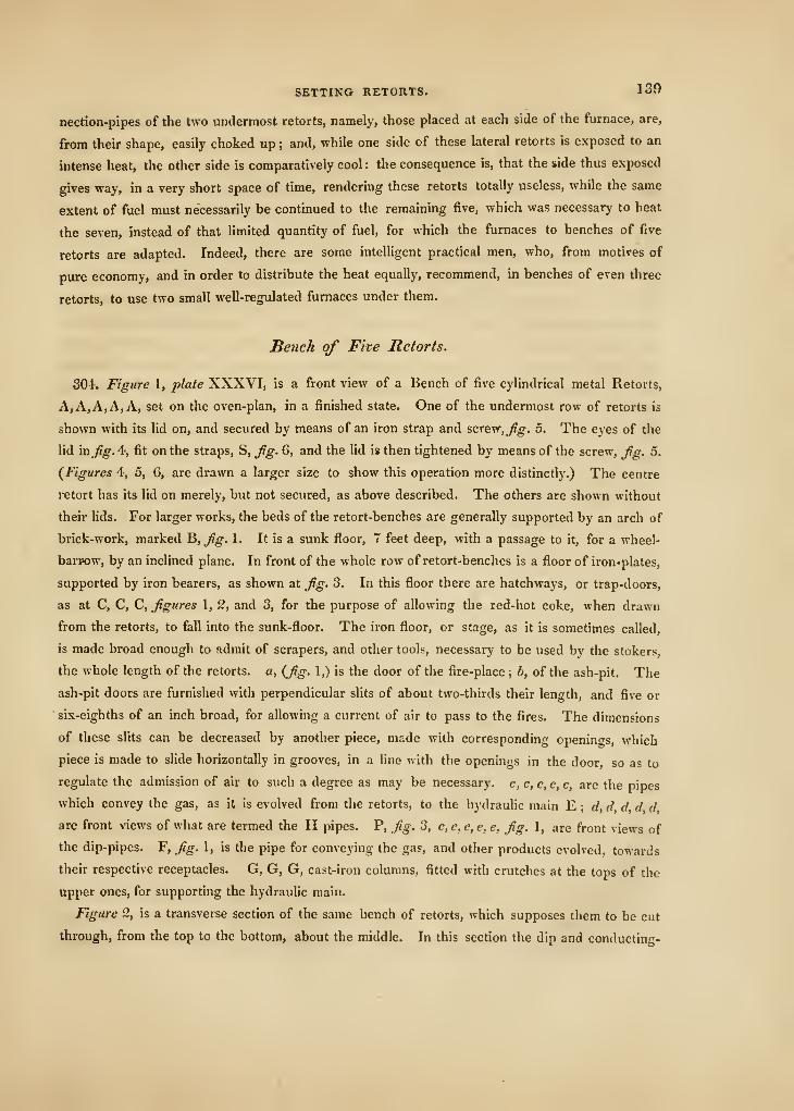
SETTING RETORTS. 139
nection-pipes of the two undermost retorts, namely, those placed at each side of the furnace, are,
from their shape, easily choked up ; and, while one side of these lateral retorts is exposed to an
intense heat, the other side is comparatively cool : the consequence is, that the side thus exposed
gives way, in a very short space of time, rendering these retorts totally useless, while the same
extent of fuel must necessarily be continued to the remaining five, which was necessary to heat
the seven, instead of that limited quantity of fuel, for which the furnaces to benches of five
retorts are adapted. Indeed, there are some intelligent practical men, who, from motives of
pure economy, and in order to distribute the heat equally, recommend, in benches of even three
retorts, to use two small well-reg\ilated furnaces under them.
Bench of Five Retorts.
304. Figure I, plate XXXVI, is a front view of a Bench of five cylindrical metal Retorts,
A, A, A, A, A, set on the oven-plan, in a finished state. One of the undermost row of retorts is
shown with its lid on, and secured by means of an iron strap and scTe\r,fig. 5. The eyes of the
lid in fig. 4, fit on the straps, S, Jig. 6, and the lid is then tightened by means of the screw, Jig. 5.
(Figures 4, 5, 6, are drawn a larger size to show this operation more distinctly.) The centre
retort has its lid on merely, but not secured, as above described. The others are shown without
their lids. For larger works, the beds of the retort-benches are generally supported by an arch of
brick-work, marked ^, Jig. 1. It is a sunk floor, 7 feet deep, with a passage to it, for a wheel-
barrow, by an inclined plane. In front of the whole row of retort-benches is a floor of iron-plates,
supported by iron bearers, as shown at Jig. 3. In this floor there are hatchways, or trap-doors,
as at C, C, C, figures 1, 2, and 3, for the purpose of allowing the red-hot coke, when drawn
from the retorts, to fall into the sunk-floor. The iron floor, or stage, as it is sometimes called,
is made broad enough to admit of scrapers, and other tools, necessary to be used by the stokers,
the whole length of the retorts, a, (Jig. 1,) is the door of the fire-place; b, of the ash-pit. The
ash-pit doors are furnished with perpendicular slits of about two-thirds their length, and five or
six-eighths of an inch broad, for allowing a current of air to pass to the fires. The dimensions
of these slits can be decreased by another piece, made with corresponding openin<Ts, which
piece is made to slide horizontally in grooves, in a line with the openings in the door, so as to
regulate the admission of air to such a degree as may be necessary, c, c, c, c, c, are the pipes
which convey the gas, as it is evolved from the retorts, to the hydraulic main E ; d, d, d d dare front views of what are termed the H pipes. P, Jig. 3, e, e, e, e, e, Jig. 1, are front views of
the dip-pipes. F, Jig. i, is the pipe for conveying the gas, and other products evolved, towards
their respective receptacles. G, G, G, cast-iron columns, fitted with crutches at the tops of the
upper ones, for supporting the hydraulic main.
Figure 2, is a transverse section of the same bench of retorts, which supposes them to be cut
through, from the top to the bottom, about the middle. In this section the dip and conducting-
140 PRACTICAL BRICKLAYING.
pipes are not shown. A, A, A, A, A, the retorts ; a, a, a, a, a, a, such parts of the arch of the
oven and furnace as are constructed of the best Stourbridge fire-bricks, set in good grey-
coloured Stourbridge fire-clay. In the next course, or that which is immediately contiguous to
this, sometimes good Welsh or Windsor, or Newcastle, fire-bricks are used, set in Windsor
fire-clay. The fire-bricks in the roof of the oven to be wedge-shaped, conformably to the
radius of the circle, of which the oven is a segment. In order to keep the heat as close to
the retorts as possible, the crown of the oven is flattened, by means of wedge-shaped Stour-
bridge fire-tiles, as shown at b. At the extreme end of the oven are two openings, which lead
into the two small flues, c, c. These flues pass above the top of the oven towards the front of the
retorts, and then each of them turn towards the centre flue, d, through which the smoke passes to
the vertical flue, e ; and from it into the main flue, H. f,fig- 2, is the fire-place, and g the ash-pit.
It, h, h, are fire-lumps placed below the lowermost retorts, to protect them from the immediate
or too intense action of the fire. The two upper retorts were formerly supported near their
middle by wrought-iron belts, which were brought through the upper part of the oven, and
passing through a cast-iron bearing-bar, placed above it, were secured by means of nuts in the
situation wanted. From the great expansion of the iron straps, by the influence of the heat,
&c., fire-bricks and fire-tiles, supported (as represented in fig. 2,) on the undermost course of
fire-guai"ds, with occasional openings between them, are now most generally adopted;
When the oven-plan was first introduced, the retorts were supported by cast-iron props,
bedded in the brick-work, crutch-shaped at top, and rising to a proper height to receive them.
They are now universally abandoned, in works that are conducted on any thing approaching to
scientific principles, and therefore not shown in the plate.
Figure S, is a longitudinal section of the same retorts. A, A, are the retorts, the mouth-
piece of the lower one being secured by the lid, fig. 4, and cross-piece, fig. 5. The upper
one is shown without the lid; _/, is the fire-place, with the position of the grate-bars. These
ai"e made deep in the centre, and chamfered oflT, so as to admit the air freely, g, is the
ash-pit ; o, o, o, o, are the openings, or, as they are termed, the pigeon-holes, from the
furnace to the retort oven. S, the fire-lumps: these are made generally 16 or 18 inches
long, and sufficiently broad to cover the fire-place ; they are from 2^ to 3 inches thick,
of the best Stourbridge fire-clay. W, W, the fire-guards ; /i is the conducting pipe which
conveys the gaseous and other products from the retorts to the H pipe, i, and that carries them
into the dip-pipe, k, which enters into the hydraulic main, E. C is the opening, or trap-door, in
the iron floor, for allowing the red-hot coke, as drawn from the retorts, to fall into the sunk
floor, X. In fig. 1, R represents a cast-iron binder, to prevent the brick-work from being dis-
turbed by means of the great heat in the ovens. To these binders flat straps of wrought-iron
are attached ; they pass considerably into the brick-work, so as to take a sufficient hold of it.
It is not considered necessary for the binders to extend to the sunk floor, as here represented :
it is sufficient, generally, that they commence four inches from the plate-iron floor, and reach
SETTING RETORTS. 141
to within four inches of the top of the benches. Two of them are placed at the extreme ends
of the row of benches, with a flat piece of wrought-iron between them ; and one binder is
placed between each bench of retorts. Sometimes these binders serve to secure a large cast-
iron plate, (with holes in it for the retorts to pass through,) used for the purpose of preventing
the walls of the retort-benches from protruding, by means of the excessive heat. It is an
excellent plan, though somewhat expensive at starting. These plates are placed on both sides
of the benches, where the mouths of the retorts are at one side of the benches, and the furnace-
doors at the other : an arrangement which certainly requires a capacious retort-house ; but, by
which, the health and comfort of the stokers are considerably benefited.
Firc'-Bricks, ^'c.
305. Fire-bricks, fire-guards, tiles, lumps, &c., are made of fire-clay, or, what is termed by
brick-makers, from its property of infusibility, " refractonj clay." It consists of alumine, (the
basis of all clays,) and silica, in variable proportions : or of alumine and lime. Either of these,
in any proportions whatever, are infusible, by the strongest heat that can be raised in our
furnaces : hence they are used for making fire-bricks, crucibles, and glass-house pots, &c
But it must be particularly remarked, that a mixture of alumine, lime, and silica, is very
fusible ; and the fusion is most readily effected when two parts of silica to one of lime is em-
ployed. Oxide of iron also renders clay fusible : but not unless its proportion be much greater
than is ever likely to occur in any clay used for the manufacture of bricks. Those clays that
contain much feldspar, as is generally the case in most clays that are used for making common
bricks, are likewise easily fused. Fire-clay most commonly forms a portion of that class of
stratified depositions called by Geologists the " coal formation" It is often much blackened
by coaly matter, in which case it is to be considered as rather of an inferior quality. The
best is, therefore, of a light bluish grey colour, such as is to be found at Stourbridge. This
is certainly the best fire-clay in England. In making fire-bricks, &c., the clay is mixed up
with powdered crucibles, or old fire-bricks, or glass-house pots, in place of the sand generally
used in the manufiicture of common bricks. It does not communicate the tendency to fusion,
when in contact with various fluxes, that is communicated by silicious sand. The clay is first
ground, and then any pieces of iron-stone, &c., that may be still remaining in it, must be sepa-
rated by sifting it.
Coke Oven Plan.
306. Figure 7, plate XXXVI, is a transverse section of one of Mr. Stone's coke-ovens, as used
At RatclifTe Gas-works, for heating seven coal-gas retorts, of the dimensions already described.
O is the oven, 11 feet long, 2| feet deep, and in breadth, according to the length of the retorts
to be heated. At present, it is only 6 feet 6 inches broad. A, A, A, A, A, A, A, are the seven
2o
142 PRACTICAL, BRICKLAYING.
retorts; four in the umlermost row, and three in the upper row. each of these rest on two of
the under row; g an arcli, of a very flat elliptical form, above the oven, which is made of the
best Stourbridge ground-edged fire-bricks. It is brought to a level at the top, that the retorts
may all lie in one horizontal line; p,p, are the flues from the oven to the retorts. There are
six of them, three on each side ; a, a, is an arch, formed of the best fire-bricks, above the re-
torts ; and b is the flattened crown of it, to keep the heat as near the retorts as possible.
The flame, as in fig. 2, passes through the two small flues, c, c. These, passing above the
top of the arch, towards the back of the retorts, (not the front, as in fig. 2,) each of them
turns towards the centre flue d, through which the smoke passes to the vertical flue, e, and
lastly, into the main flue, H. s, s, s, s, s, are the fire-tiles in the bottom and sides of the
oven, &c.
Figure 8 is a longitudinal section of the same seven parallelopipedal retorts. The same
letters denote the same parts as in fig. 7. P, P, P, is the ground line, F is the sunk floor, at
the side where the mouth, D, of the oven is placed. The mouth-pieces of the retorts are at
the opposite side ; L, L, represent the cast-iron binders, described with the bench of five re-
torts, to prevent the walls from bursting by the excess of heat. O is the coke-oven; g the
flat arch roof; p,p,p, three of the six flues; s,s,s,s,s, the fire-tiles; «, the roof of fire-
bricks above the retorts ; A, A, the retorts ; c, d, e, H, the flues already fully described ; Jt, is
the connection-pipe, leading from the mouth-pieces of the retorts to the hydraulic main,
already fully shown in fig. 3. The other parts will be suflSciently understood by a reference
to figures 1, 2, and 3.
Improved Method of setting Five Retorts iti an Oven.
307. Figure 9, plate XXXVI, is a transverse section of an improved method of setting five
coal-gas retorts, A, A, A, A, A, in an oven, to one fire. The retort immediately over the
fire is set precisely in the same manner as represented in fig. 2: but the two side retorts,
and the two upper ones, are placed on what is called saddles (fire-tiles of the shape represented
in fig. 10). These saddles, for the upper retorts, are 15 inches wide, from a to b, 14 inches
from b to e; and from 2| to 3 inches thick, of the best Stourbridge fire-clay. From b to c, is
4 1 inches ; from c to d, 5 inches. The versed sine of this segment is 2 inches. From (/ to e is
4j inches. They are rebated or checked, so as to overlap each other at their joinings, at the
ends, (I, b, and k, e. From h tofi is 11 inches. The openings in the saddles are, of course,
meant to correspond with the side-flues and interstices below them. Throughout the whole
length of the oven, the openings s, s, fig. 9, under the centre part of these saddles, traverse
the piers that divide the side-flues, or, as they are generally termed, the pigeon-holes : (those
openings that run from each side of the furnace to the outer sides of the lateral retorts.) This
admits of a full and free circulation of the heat, which is indeed the great object in view
SETTING UETORTS. 143
throughout the whole of the plan. The saddles placed under the two upper retorts are cham-
fered off at the edges, so as to fit the shape of the undermost retorts. Above the saddles, the
usual fire-guards are placed, care being at all times taken that these guards join, or break joint,
either on b, c, of the saddles, or on d, e.
Instead of the flues, c, c, as in fig. 2, entering only at the back end, and thereby causing
a draught to that point,—highly injurious to the retorts,—there are two rows of several open-
ings into the flues d, Jig. 9, throughout the whole length of the oven ; and, in place of
uniting in one flue, d, as in fig. 2, and going to the back part of the oven above the flues
c, c, the flame from c,c, descends in d, until it arrives at e,e, (half-way nearly down the
sides of the oven,) through which it passes to the vertical flues H, H, and thence into the
main flue K, keeping the heat all the while as near to the body of the retorts as possible;
and counteracting, at the same time, any injurious draught to one part of the oven more
than to another. The heat, by this means, is kept nearly as much towards the front of the
oven as towards the back of it. Indeed, so much has this been the case, that the engineer,
not anticipating a result so very successful, found that, notwithstanding the great precautions
he had taken, to brace the front wall with binders, &c., they were totally inadequate to
resist the very great expansion of the brick-work, in front, caused of course by the quantity
of heat now brought so much towards the front of the retorts. When these retorts are once
brought to their proper degree of heat, very little fuel is afterwards required to keep them at
work. But the saving in fuel does not stop here. In three benches, set on this plan, the
centre bench has consumed the whole of the smoke of the other two benches, while they,
at the same time, were kept up to a proper degree of working heat. Suppose figure 9,
to be one of three-benches of retorts, placed on one side of the centre bench, _^^. 11. (If
there be a series of them, every three benches must have an independent flue, so as to open
occasionally either into the main flue, or under the grate of a centre bench (by means of
dampers) through a flue similar to «, o.) Passing in a thin stratum, of 18 or 20 inches by 3 deep,
under the furnace-bars of the centre bench,^^. 11, the smoke is thereby kept hot, which is essen-
tial to be attended to ; and, in the ash-pit oi Jig. 11, receives as much of the oxygen of the air as
renders it again combustible. In this state it passes upwards at P, P, through the interstices of
the bars, and is consumed by the fire of the centre furnace : answering every purpose, in fact, of
so much fresh coal. Fuel is thus not only saved, but a great nuisance to the neighbourhood very
much diminished. The method of shutting off" communications, by means of dampers, is an
operation of such extreme simpUcity, that it must be unnecessary to describe this part of the
process. In Jig. 9, the ash-pit is sunk a little below the floor, R. This enables the stokers to
charge and draw the upper tier of retorts more easily ; and is not attended with any obstruction
whatever to the free draught of air to the furnaces.
Of the saddles, Jig. 10, five are required for each circular retort : the retort being 7 feet
6 inches long, by 14$ inches external diameter.
J 44 PRACTICAL BRICKLAYING.
The saddles for the under retorts are of the following dimensions :—From a to h, \1i
inches ; from h to/, 7| inches, and the versed sine of the segment c, d, 5 inches. The other
parts, in all respects, arc similar to those for the upper row of retorts, as already described.
Fifrurc 12 is a transverse section of the fire-guards, And Jig. 13 a plan of them. Five pairs,
or 10 pieces, are required for each circular retort of the above dimensions. They are rebated
in the under ends, to ovcr-laji. At a, fg. VZ, the edge is 1 i inch thick: at b it is only three-
quarters of an inch thick. From a to c the tile is 9| inches broad : from d to 6 it is 8 inches
:
from c to /is 14 inches. The space from c io d may be made to suit any diameter by being
filled up with fire-clay. Flere the tile tapers down to one inch in thickness. At least half an
inch of space should be left for the retorts to expand. On account of the expansion of the
metal of the retorts, these guards are much better in two pieces than in one. These, fig. 12
and 13, and saddles, fig. 10, are, it will be seen, drawn to a much larger scale than the other
figures in this plate.
Safety Plugs, S^c.
oOS. There is a circumstance, intimately connected with coal-gas retorts, which we may here
notice, as it cannot be considered altogether irrelevant to our present subject. The retorts, when
heated, expand of course in all directions, and contract in cooling. Those set five in a bench,
as we have described under the head of " Improved Method of setting Five Retorts in an Oven,"
have been observed to expand towards the front of the bench, where the mouth-pieces and con-
nections are placed, protruding as much as five-eighths of an inch beyond the brick-work of
the bench. Now, according to th.c present mode of jointing the connection-pipes, which con-
nect the retorts with the hydraulic main, these connection-pipes must be fractured and injured
by this protrusion, if they do not yield to it ; and it is well known that neither cast-iron, nor the
joints commonly made on it, with rust cement and bolts, can yield by any means, with safety, to
this extent. It is true that, if all the retorts joined to the hydraulic main were in action, at the
same time, and the expansion affecting them equally, their united expanding force might, in
such a case, have the effect perhaps of turning the hydraidtc main outwards, were it at all
moveable on its supports ; and thereby preventing any fracture in the connection-pipes or their
joints, by thus yielding to their thrust. But when it is considered that, from various causes, which
need not be here enumerated, there is at all times on an average, in gas works of any magnitude,
at least one bench of retorts in six out of action, and attached to the same main, it will be
evident that the remedy we have alluded to camtot, at all times, he relied on. In the generality
of oil-gas works, however, this expansion of the retorts is provided for, by a very simple and
effectual contrivance :—On the vertical connection-pipe, not very far distant from the retort, an
hydrauhc joint is formed, which is filled with fusible metal instead of water. This metal is
composed of eight parts of bismuth, three of tin, and five of lead, with a very small portion of
mercury (about an ounce to a pound of the whole of the other materials). This composition
RETORT FURNACES. 145
(which is well known by the name of Sir Isaac Newton's metal) melts at the temperature of
197° of Fahrenheit, without any sensible evaporation, effectually sealing the hydraulic joint, as
the heat arrives towards the point just mentioned ; and allowing a sufficiency of play to permit
the retort either to expand or to contract. Indeed, where no safety-plug is used, it also acts as
a safety-valve, in case of any obstruction happening, as is often the case, between the retorts
and the hydraulic main. But, in the most approved modern works, safety-plugs are generally
used. They not only serve the purpose of affording safety to the works, but they enable the
gas-maker to discharge the crude and watery vapours from the coal, which are evolved in great
abundance on its first exposure to the heat of the retorts ; and, towards the latter end of the
charge, (should it not be convenient to draw the retorts at the proper time,) they likewise
enable the stoker to discharge the sulphurated hydrogen, azotic gas, hydrogen gas, &c., evolved
by the coal, if allowed to remain, beyond the proper period, in the retorts; and which impu-
rities, but for these plugs, or other contrivances of a similar description, find their way (under
the circumstances just stated), to a certain extent, into the gasometer, and deteriorate the gas
accordingly. They also very unnecessarily and injuriously saturate the purifying mixture, ren-
dering it too soon inefBcient. By lifting these plugs, during the operation of charging or
drawing the retorts, another important advantage is obtained : much of that intolerable heat
and smoke, issuing from the mouth of the retorts, and to which the stoker was exposed, is
now very considerably diminished, by their thus allowing the flame and smoke to ascend
through the vertical connection-pipes, instead of issuing out, as heretofore, in suffocating
volumes dii-ectly in his face.
In the case, too, of any choking up of the connection-pipes, the stoker has merely to lift the
safety-plugs, and clear out the pipes, by introducing a rod of iron into them, without any of
that delay whatever which must have taken place to unscrew and remove the glans, that were
formerly used, at the upper extremities of the connection-pipes. During the tedious operation
of unscrewing and taking off those caps and glans, frequent burstings and explosions have
taken place in gas works, as might have been expected, from the excessive concentration or
compression of the obstructed gas. A compression of gas, exceeding the weight of the plug,
will lift it up, allowing the compressed gas to escape ; and this escape will, consequently, be
more or less as the compressed gas has the eflfect of raising the plug. It is on precisely the
same principle as the safety-valve of a steam-boiler.
Retort Furnaces.
309. We may remark that, by keeping the heat much more towards the front of the retorts, than
it is kept by the common method we have described of setting retorts, and which causes a partial
and injurious draft to the back part of the furnace only, the furnace-doors are much more, of course,
exposed to injury than formerly. This is to be guarded against, 1st, by fixing fire-tiles, wedged
2p
146 PRACTICAL BRICKLAYING.
with chips and fire-clay on the inside of the doors ; and, secondly, by having a few spare
doors at hand to substitute for any that may be over-heated, as will be the case, notwithstand-
ing the precaution of lining them with fire-tiles. In order to be able to do this with facility,
however, the doors should be so hung as to be readily lifted off and on. A spare door for
each furnace is by no means necessary : one to three or four furnaces will be sufficient. The
first taken off will be gradually cooled, so as to be put on again in five or six minutes thereafter.
Between the furnace-door and the grate-bars, a plate of cast metal is placed, to prevent the
brick-work from being injured by the action of the rake, or shovel, &c. It is about half an inch
thick of metal, and from 10 to 12 inches broad. The grate-bars rest easily on cross-bars of
cast-iron, 4 inches square, placed at each end of the furnace in the usual way. These cross-bars
have a rabbet in them, to receive the ends of the grate-bars, so as to allow both of their upper
sides to be flush with each other. The grate-bars should be much deeper at the centre
than at the ends, (say 4^ inches at the centre, and 2\ at the ends,) and chamfered off, so as to
admit the air freely. Their distance from each other should not be less than six or seven-tenths
of an inch. As they heat, this opening will diminish by their expansion. Their average length,
for gas retort-furnaces, is about 42 inches.
Three large fire-lumps are generally used in each furnace. They are placed at the extreme
back ; one is laid transversely, at the end, and the others join it longitudinally, one at each
side. This is to oppose the excessive action of the fire at that part of the furnace. Their
dimensions are : for the two side lumps, 2 feet long by 9 inches deep, and 6 inches thick ; and
for that at the back, 18 inches long by 9 inches deep, and 6 inches thick. They are cut off at
the upper sides, to a certain extent, so as to communicate readily and correspond with the side-
flues, or pigeon-holes, as they are termed by the workmen. The lumps are rabbeted together,
and joined by fire-clay in the usual manner. The rest of the furnace is built of fire-bricks, and
corballed at the upper part, for 3 or 4 inches of projection, at each side. Twelve inches broad
by 14 inches deep, is a very general size for a gas-work furnace, to heat five retorts set on the
oven-plan. If the retorts be 7 feet 6 inches long, the horizontal line from the front of the fur-
nace or door will be 66 inches. This includes the plate already mentioned, 12 inches ; the
length of the grate-bars 42 inches, and 12 inches more, of horizontal space. After this, the
back of the furnace should rise in a gradual sloping direction, terminating within 10 or 11 inches
of the end of the retorts. This affords considerable protection to the ends of the retorts ; and,
if they are skilfully set, no apprehension whatever need be entertained of that part of the retort
not being sufficiently heated. From the grate-bars, to its junction with the retorts, the bottom
of the furnace must be laid with Stourbridge fire-tiles, of from 2| to 3 inches thick. It will
be seen, by examining the saddles, fg. 10, plate XXXVI, that the side-flues in the furnace are
placed 9 inches apart, and are 5 inches wide. The practical advantages of such an arrangement,
an experienced bricklayer will be at no loss to appreciate.
CHIMNIES FOR GAS-WORKS. 147
Chim7iey.
310. In erecting the chimney, or stack, to the furnaces, the first point to be attended to is
the foundation.
For the other purposes of a gas work, it so happens that a shaft or well will be required to
be sunk. This will afford the means also of ascertaining the substrata. Chimnies for gas wOrks
are made generally much higher than is absolutely requisite to afford the necessary draught.
That is commonly done for the purpose of carrying off the smoke more effectually from the
neighbourhood ; otherwise, a chimney of from 40 to 50 feet high, is all that would be required
for the mere purpose of draught. For an air-furnace, a chimney of 40 feet, for example, in an
open situation, is considered abundantly sufficient. The area of the flue must of course be
in proportion to the volume of smoke that would issue through it, were the whole benches con-
nected with it, in action at one and the same time
If the foundation be of a firm and rocky nature, all that is required, of course will be to
bring it to a proper level. Two scarcements only, of 4 inches each, will be quite sufficient to
commence the chimney. If of compact gravel or chalk, 2 feet below the surface may be dug
to found on, and the breadth of the foundation should be as three is to two of the wall. If of
clay, the breadth of the foundation, in proportion to the upper walls, should be about double,
and sunk at least 4 feet. This depth is particularly necessary, if the substratum be of clay
:
for in clayey ground the effect of shrinkage, by heat, is often sensible at that depth below the
surface. In boggy earths, or infirm sand, or alluvial deposit, piling and frame-work may be
necessary. No mortar should, however, be used with the piles, as it rots the wood. On this
account, to cramp the under courses with cast-iron, and only compact clay used instead of lime,
has been recommended. If the foundation be dry sand, it will require to be double the breadth
of the chimney, as in a clayey soil ; but only 2 feet of depth will be required, being a suflf!-
cient protection against the effects of frost, which has seldom been known in this country to
exceed that depth of dry loose sand. But the extent to which all these precautions require
to be carried, will depend on the height to which it may be thought necessary to carry the
chimney, as well as on the nature of the inferior strata. The foundation-walls should diminish
on each side gradually from the bottom towards the surface of the ground. These diminutions
are termed scarcements. If large flat stones can be readily got, they form by far the best foun-
dations. Every course, whether of brick or of stone, should be well grouted with hot mortar
;
and great care should be taken, in the case of stones being used, not to roll them on the courses
already laid, as is sometimes done by careless workmen, but to deposit them at once in tneir
proper beds, by means of a triangle, or other means, and they ought not to be aftenvards
shifted : or, if shifting should be unavoidable, the same precautions must be used in doing so,
and also in replacing them.
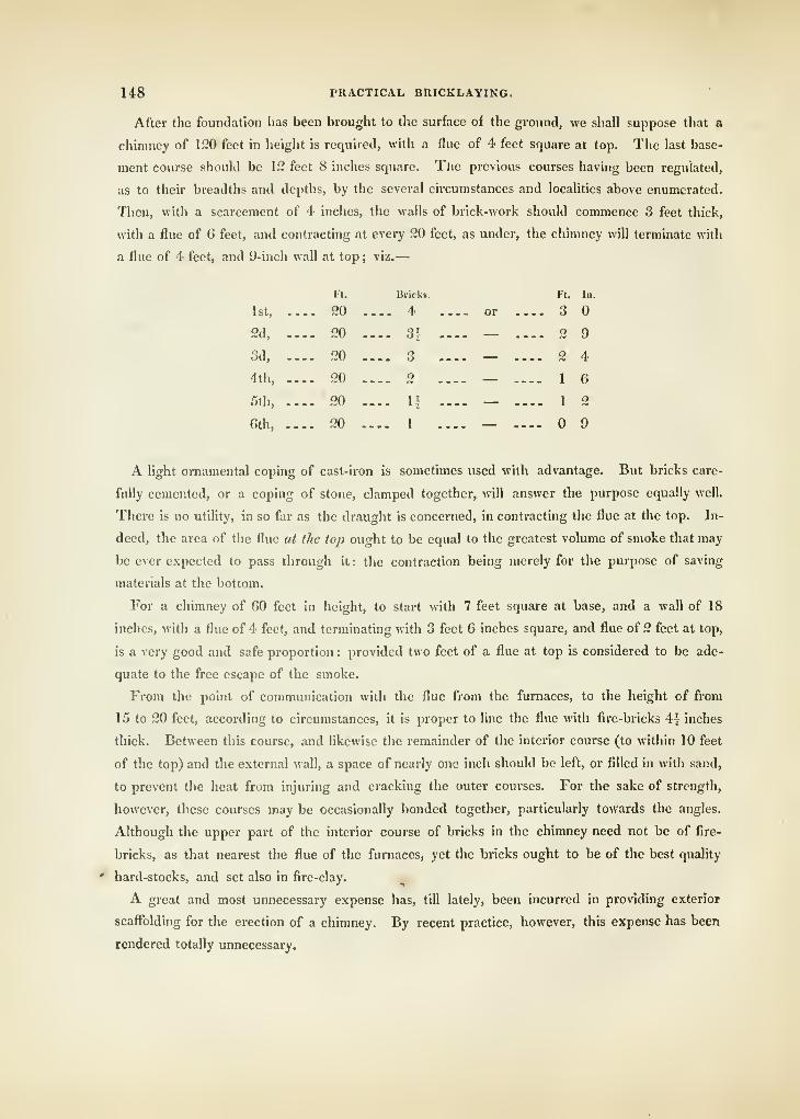
148 PKACTICAL BRICKLAYING.
After the foundation has been brought to the surface of the ground, we shall suppose that a
chimney of 120 feet in height is required, with ;i flue of 4 feet square at top. The last base-
ment course should be 12 feet 8 inches square. The previous courses having been regulated,
as to their breadths and depths, by the several circumstances and localities above enumerated.
Then, with a scarcement of 4 inches, the walls of brick-work should commence 3 feet thick,
with a flue of 6 feet, and contracting at every 20 feet, as under, the chimney will terminate with
a flue of 4 feet, and 9-inch wall at top; viz.
—
FURNACES FOR THE FUSION OF METAL, &C. ]49
Spars are let into the interior course of the chimney, at the proper distances, for the men to
mount up by, like the steps of a common ladder. The bricks and mortar are hoisted by a
projecting beam and pulley at the end of it, to the top, where the bricklayers are at work ; and
when the work is finished, the spars, being merely wedged into their places with loose brick,
are afterwards very easily disengaged. The spaces, in which they were fixed, are then care-
fully filled up with bricks and cement. By this simple method, a saving is effected of from
j£20. to rfSO. on the former method of outside scaffolding, in the erection of a chimney of only
50 or 60 feet high. It is quite safe and practicable for chimnies of any height.
It has been recommended, for the sake of accuracy, that only one bevelled plummet-rod
should be used by all the bricklayers, in case of any discrepancies in the others, by which
means one side might be run up in one direction, while the others are built in a different angle.
Brick chimnies are sometimes very sensibly to the eye off" the true vertical line (perpendicular
to the horizon), and yet stand safely in all weathers. There are some in Glasgow and Paisley of
this description, that are at least 120 feet high. They have stood so for several years, notwith-
standing the great rocking to which the upper part of brick chimnies are liable in high
winds : the sines of their angles of inclination falling sufficiently within their bases, to preserve
their equilibrium. They are still, by several degrees, more vertical than the celebrated Tower
of Pisa.
CHAPTER IX.
ON FURNACES FOR THE FUSION OF METAL, &c.
311. The term Furnace is commonly applied either to vessels, or constructions, calculated
by their form, and also the nature of their materials, to endure heats of very high temperature,
and of long continuance. They are of first-rate importance in chemistry, metallurgy, and other
branches of science connected therewith. They will be considered in this work under two
distinct heads, namely, air or wind furnaces, and those usually called blast-furnaces. The air or
wind furnace depends entirely for its supply of atmospheric air upon the draught produced by
rarifying the column of air contained in the flues or chimnies of such structures ; but in the
blast-furnace, the supply of air is entirely produced by bellows of various kinds, or rather
mechanical contrivances, which are used to force into the ignited fuel any requisite quantity of
air that the various operations may demand.
It is much to be lamented, that in no work are those dimensions or proportions of the various
parts of furnaces given that should enable us to determine the exact size that will be necessary
for any given operation ; but this will cease to be a subject of surprise, when it is considered
that the various processes in chemistry, metallurgy, and other branches of science and art,
2q
l/iO PRACTICAL BRICKLAYING.
render it necessary that various proportions should be adopted, each of which may be appli-
cable only to the purpose for which it is intended.
In cases of this description, we conceive the better plan is to give such general rules and
directions as may lead a practical man to inquire, first, the nature of the effects intended to be
produced ; and, secondly, to make choice of and adopt such proportions as are best suited to
the case required.
There is one well-established fact to which we particularly wish to call the attention of the
reader, namely, that the heat generated by combustion must be greatest when the largest quan-
tity of fuel is consumed in the smallest time; and also that, where fuel is supplied in sufficient
quantity, and its quality good, the heat generated will likewise be in proportion to the oxygen
consumed in its passage through the ignited fuel in a given time.
It should, at all times, be carefully ascertained what kind of fuel is intended to be used in a
furnace previously to its construction, because some fuel contains properties that greatly assist
in the process of combustion, while other sorts require the greatest aid from artificial and
mechanical means to effect combustion in such a manner as to obtain a due degree of heat.
All sorts of pit-coal contain a large proportion of gaseous matter, which is very readily decom-
posed with a comparatively shght degree of heat, and owing to its levity, it very rapidly ascends,
and assists greatly in creating a draught, in which case atmospheric air will enter the grate, and
passing through the fuel will, by its decomposition, assist the process of combustion ; hence it
will be seen that the gaseous parts of coal and other fuel, containing such products in large
proportion, perform a very important part in the process of combustion. It is, however, found
that pit-coal is a very inconvenient material for producing high degrees of temperature ; for, as
the gaseous parts ascend with great rapidity when heat is applied, they cause so quick a draught
as to make a large portion of the atmospheric air pass through the furnace without coming in
absolute contact with the coal, and hence, instead of heating the objects placed in the fire, they
have a contrary tendency, by the introduction of such superfluous quantities of cold air. These
remarks, it should be observed, apply exclusively to air or wind furnaces.
To avoid these inconveniences, and to obtain the most intense and lasting degrees of heat,
when compared with the bulk of the fuel used, coke has been universally adopted, and this
must ever be the case while pit-coal remains the principal fuel of this country.
On comparing the combustion of coal and coke, we shall find this manifest difference between
the two. When coals are laid together in a furnace, or fire of any kind, a large quantity of tar
or pitchy matter is liberated, which, running in between the interstices of the mass, has the
effect of closing up a large portion of the passages through which it is necessary that air should
pass and if, in this state, the mass be not broken or stirred, as it is commonly termed, the
ignition of the whole will be very soon extinct, or combustion will go on in a very languid
manner ; but where coke is used, there being no tar and very little gaseous product to separate,
the mass being nearly all pure carbon, the only visible change that takes place is a gradual
FURNACES FOR THE FUSION OF METAL, &C. 151
wasting of each piece exposed to the current of air necessary for its combustion, the ashes fall-
ing through the grate in very fine powder. There is, however, a property in coke that must
not be lost sight of, and that is, the want of levity in any of the gaseous products that are de-
composed or driven off from fuel of this description while in an ignited state.
The principal gaseous matters that escape during the combustion of coke are sulphurous
and carbonic gases, which, mixed together, are specifically heavier than atmospheric air, and in
order to make them ascend, and thereby create a draught, it is absolutely requisite that whatever
air enters the furnace, should be made to pass completely through the fuel, where, after part-
ing with its oxygen, it will be so rarified as to create such a draught by its rapid ascent, as to
cause a continual supply of fresh air to the coke, and thereby obtain the greatest degree of
heat that such fuel is capable of giving out.
As these principles are founded on facts, long established by practical experience, we cannot
too much impress them upon the attention of our readers, because upon these principles de-
pends the necessity of peculiar forms and constructions of various furnaces for particular pur-
poses ; for, upon the slightest reflection, it will easily be conceived, that if a furnace were con-
structed of a small area and considerable depth, where coal is to be the fuel, it would be
quite impossible to carry on combustion advantageously, on account of the adhesive property of
coal, when heated in the manner above described ; but where coke, or even charcoal, is used,
a much greater depth may be dispensed with, the fuel being of such a nature as to retain the
interstices between each piece through which the air may pass freely, and thereby produce the
beneficial effects above described.
It is entirely owing to these observations that the fire-grates or stoves for burning pit-coal
have of late been so completely altered in form, the very deep fire-place being now completely
rejected, and those of greater area and smaller depth being preferred ; a practice perfectly con-
sistent with reason, provided it be not carried to excess.
In regard to the velocity with which heated air ascends, it is as the difference of specific
gravity between the atmosphere and the heated air. The principles upon which the motion
arising from a change of a specific gravity depends, may be referred to the case of two weights
hanging over a pulley. If they be of equal weight, no motion is produced, but if one be in-
creased, or the other diminished, the heavy one will descend, and the light one ascend, with a ve-
locity proportionate to their difference.
312. A very material part of every air or wind furnace is the flue or chimney, which, from con-
siderable experience, we are enabled to say, should never be less than eighteen feet above the
top of the fuel ; but if thirty feet can be obtained, it will be much better, provided the area of
such chimney be not too large. In general, it will be found advantageous to make the area of
it equal, at least, to one-half of the furnace.
The height of the fire-place must be governed by the nature of the operations to be per-
formed therein. If, for instance, it is to be used for melting metals of a very refractory kind,
J50 PRACTICAL BRICKLAYING.
the height must be such as to allow the fuel to lay about half the width of the furnace above
the melting-pot, which should always be elevated upon either the fuel, or a suitable stand, at
least one-fourth the breadth of the furnace above the fire-bars or grate, in order that it may be
completely enveloped in the fuel ; but where metals of more fusible qualities are to be melted,
it will be sufficient to have the melting-pot imbedded in the fuel, without covering it to such a
depth as is necessary in the case before mentioned.
The deeper the ash-pit or opening under the fire-grate of all sorts of wind or air furnaces
can be, the better will they be supplied with atmospheric air ; for it should be observed, that
air is best supplied to the fuel when it enters perpendicularly, therefore, the greater the height
can be, the more perfect will be the effect produced. It is for this reason that the most valuable
and best constructed furnaces are supphed with air from a vault or cellar beneath, from which
an ample supply of cool, and consequently condensed air, is always attainable. It is, indeed,
owing to this circumstance, in a great degree, that the majority of the melting-furnaces, erected
in vaults or cellars, are found to answer so well when compared with those which are placed in
more elevated places.
313. A false economy has suggested the propriety of casting the bars of air-furnaces in one en-
tire piece, forming a fixed and immoveable grate, but experience has proved that this is a bad
method ; for when the process of melting is completed, the whole of the ignited fuel must be
lifted with tongs out of the furnace, which is attended with much difficulty ; or, if this be not
done, it must be suffered to burn out, which would be a very great waste of fuel, and also a
very considerable loss. Another great inconvenience arises from the grate becoming in time
covered with adhering clinkers or coal-slag, which can only be removed at the risk of breaking
the bars in pieces, and, consequently, destroying the whole grate ; but if wrought-iron bars of a
proper kind be used, the whole may be removed in a very short time, by which means the fuel
will be saved, and the bars may be cleaned without the least risk or injury. The precise form
of some very improved bars we shall describe in another place.
Having extended our general observations on the principles necessary to be observed in the
construction of air-furnaces, we shall now examine the nature of the materials necessary to
resist the extreme degrees of heat that must be produced, in order to effect the objects required
by the chemist, metallurgist, and philosophical experimentalist.
The materials of which the foundation or under part of furnaces is constructed may be of
any kind that will bear the necessary weight ; the principal attention of the builder should be
directed to the quality of those that are to form the internal part or lining, where the greatest
heat prevails, and also to the quality of the materials that are used, as cement, to unite the
linings, and likewise the nature of the substances that are placed in immediate contact with the
linings.
The best materials for lining the internal parts of furnaces are bricks or lumps formed of
two-thu-ds of Stourbridge clay, beaten up and well tempered with one-third of the same mate-
FURNACES FOR THE FUSION OF METAL, &C. 153
rial, which has been submitted to a very great degree of heat, and by such means has become
partially vitrified ; or, in lieu of this, broken crucibles, after they have been used and rejected,
will answer equally well. This compound must be used with as little water as possible, in which
state it should be forced by great pressure into strong moulds that are capable of resisting the
necessary compression of the materials, and in this state they should remain until, in drying,
they shrink sufficiently to leave the mould without any force. They may then be laid out to
dry very slowly, by which means they will be prevented from cracking, before they are submitted
to the fire. When thoroughly dry, they should be burnt in any convenient kiln, when they will
be ready for use. Lumps made in this way will be very nearly the same size when dry and
burned as when they were in the mould, a circumstance that greatly ensures their soundness
and durability.
Where Stourbridge clay cannot be obtained conveniently, or the lumps cannot be manu-
factured in the way above described, the common Welch lumps must then be used, but they
cannot be so well depended upon in very high degrees of heat. The best material in which to
set them, is a mixture of equal parts of Stourbridge clay and glass-grinders' slush. The slush
is composed of fine sand, mixed with small particles of flint-glass, which is ground off from the
various articles, during the process commonly called glass-cutting. These articles form an
excellent cement, which is sufficiently tenacious to hold the parts together, and when great heat
is applied, they partially vitrify, and thereby unite all the parts near the body of the fuel very
firmly. Where slush cannot be obtained, fine sharp sand, free from any metallic oxyde, may
be substituted, or what is better than either, where the expence can be afforded, namely, fluits
heated to whiteness, and then quenched in water, which process renders them so brittle, that
they may be pounded in a mortar of iron, and passed through a coarse sieve ; and if, when so
prepared, they be mixed with Stourbridge clay, a cement will be formed that will resist ahnost
any degree of temperature. Although this process may appear very troublesome, yet expe-
rience has proved that it will amply repay by its durability; and it must be remembered that it
is only the lumps that fonn the lining near the body of the fire that need be united, or set with
this cement, the parts behind, or in contact with these, may be sufficiently secured with good
lime and sand.
It is an object of the gi-eatest importance, in all works of this kind, to retain the heat, which
is at all times generated at a considerable expence ; for this purpose, therefore, it will be neces-
sary to place in immediate contact with the internal lining, materials that are known to be non-
conductors of heat; few substances will answer this purpose better than common place-bricks
that are tolerably well burnt; in this state they answer the purpose exceedingly well, and more
particularly, if the clay of which they are made be mixed with a considerable portion of
charcoal, or coke-dust, the charcoal being a most perfect non-conductor of heat, and when
enveloped in the clay, it will retain its properties for any length of time, provided the air be
excluded. It will soon be found that a considerable saving in fuel will be effected, if these pre-
2a
154 PRACTICAL BRICKLAYING.
cautions be carefully attended to, and most of the operations will be more speedily performed
from the same cause.
Where very intense heat is required to be kept up for a great length of time, some persons
have adopted the method of forming the parts or lumps used for the lining so perfect, that they
may be fitted into their places without any cement, or other material, to fix them together ; by
this means they may be more easily removed when destroyed by the action of the fire, and re-
placed without the aid of a bricklayer, or any part that is partially exposed to the greatest heat
may be renewed without pulling down the principal part of the furnace. These will, by some
persons, be considered advantages, but they are unfortunately attended by corresponding dis-
advantages, which will be found to arise purely from the joints being open, each of which will
become a small flue, through which air will be passing instead of going through the fuel, and
thus the want of solidity will be a very great evil, and, in some cases, will more than counter-
balance any convenience or gain that may be anticipated.
There is no part of a furnace that requires more attention than the bars which form the
fire-grate, for upon the proper shape and construction of these much of the success will depend,
and as their preservation from decay is of considerable importance to every person that has to
use them extensively, we shall now describe some as they are usually made, and then show
how they may be constructed, so as to be much more durable, and equally if not more
effective.
The usual cast-iron furnace-bars are of the shape shown in section at ^g. 1, plate XXXYII
;
a side-view or elevation is shewn at Jig. 2. These bars are made broad above, and tapering to
their lower edge, having square blocks formed at each end of them to lodge upon bearing-bars.
These blocks serve, when placed in close contact with each other, to keep the bars a proper
distance asunder, and allow the air to pass freely between them to feed the fire.
The principal defects of these furnace-bars are, that they choke up, on account of the clinkers
that form upon them, and that they very soon become burnt away in the middle, and bent so
as to be totally useless; and, in some cases, they actually melt and separate in the centre
An ingenious manufacturing chemist in Dublin, some time since, constructed some furnace-
bars that have properties so superior to any that we have ever seen, that we are tempted to
give a perfect description of them for the benefit of our readers, more particularly as they have
been used for a considerable time by Mr. George Manwaring, engineer, of Marsh-place, Lam-
beth, whose report upon their advantages has completely confirmed our opinion of their great
value ; we therefore feel no necessity for apology in laying them before our practical readers,
who will, at all times, be better pleased with one practical fact proved by experience than twenty
ingenious suggestions, the value of which is at best problematical.
Figure 3, shews a section of one of these improved cast-iron furnace-bars ; fig. 4, a side-view
;
and ^g. 5, a top or bird's-eye view, drawn to the same scale ; and ^g. 6, is a representation of
several of them lodged upon a bearing-bar in the fire-place, as they are placed when in use.
FURNACES FOR THE FUSION OF METAL, SiC. 155
It will be seen from the foregoing figures, that there is a semi-cylindrical hohow, or furrow
made all along the middle of the top of each bar, and that each side is thinned away below
very considerably to the web or fin which forms the central and supporting part of each bar in
the middle of it. And it is yet doubtful whether the great durability of these bars be owing to
the lodgment of ashes from the fuel in the hollow top of each bar, and which, acting as an im-
perfect conductor of heat, prevents the immediate action of the fire upon it, and the consequent
formation of clinkers, or whether it be owing to the rush of air from below, which has the effect
of cooling the bars in its passage to the fire, or, which is most likely, the joint action of both these
causes ; however this may be, the effect is, that these bars endure the action of the fire for a
great length of time without receiving any injury, or being, in the least degree, altered in shape
or form. Bars of this form are also lighter than the common ones, which is another recom-
mendation, where large engine fire-places, or coppers, are to be erected. We would also
recommend the bearing-bars to be cast with a furrow underneath, as shewn by the section
in Jig. 7 ; this will have the double advantage of keeping the bars cool, and also save a con-
siderable quantity of iron.
In the construction of the flues or chimnies of furnaces, and all sorts of fire-places, it will
be desirable to have the sides as smooth as possible, and for this purpose those bricks that have
the best surfaces should be chosen, or, if they be rough, they should have one side made
smooth by rubbing, and that side should be placed internally ; by these means, the air will
have less friction, and, consequently, the draught will be increased in proportion.
Another very important circumstance ought to be carefully attended to in the construction of
chimnies, viz. the air, which is heated in passing through the fire, should retain its heat, if
possible, till it clear the top of the chimney. Although this cannot be efFectually accomplished,
it may be effected as far as the non-conducting power of the materials of the chimney will
admit.
Common place-bricks, as has before been stated, are non-conductors, and many fire-bricks of
of loose aggregation, are still better calculated to retain the heat.
The very best method, however, of making perfect chimnies, is first to build one of very
close smooth bricks, making the internal surface as above directed. This should be surrounded
with a second chimney, leaving a cavity between the two about the breadth of a brick. This
cavity should be filled with powdered coke, or, what is much better, powdered charcoal. The
heated air would retain its original temperature much longer in such a chimney, which would
also admit of its being carried up higher, and thereby obtain an increased draught.
Being satisfied that if these directions be duly attended to with a proper attention to propor-
tions, success must be certain ; but in order that nothing may be wanted to complete the object
on which we have been treating, we will present our readers with a description of some fm-naces,
the proportions of which have been approved by persons long used to operations of tiiat kind,
.nnd consequently capable of pronouncing a sound judgment.
156 PRACTICAL BRICKLAYING.
On the Proportions of Air-Fnrnaces.
314. Although, strictly speaking, all furnaces are air-furnaces, yet, as we have already no-
ticed, they are usually distinguished into those, where the air is forced through the lire by
bellows, and'those, where the air enters by means of what is called the draught of the chimney.
These are again denominated either from their construction, or the peculiar uses to which
they are applied. Generally speaking, the furnaces used in chemical operations, and for melt-
ing and refining metals are of the latter kind, or air-furnace, of which we shall now proceed to
describe the parts and particular uses.
A vertical section of an air-furiiace, calculated to produce veiy intense heat, and particularly
adapted for a melting-furnace of the fixed kind, and possessing all the requisite advantages, is
represented in Jig. 8, plate XXXVII. A, is the ash-pit of the furnace, B the grate, C the fire-
place, D the cover. The cover is formed of a cast-iron frame, with cavities to contain fire-
brick, which is fixed in firmly by cement. The cover slides sideways, either to the right or
left hand, to open the mouth of the furnace, some of these cover-frames have an opening in the
centre, into which a plug or stopper of fire-brick is closely fitted, and which may be drawn out
to enable the operator to examine the state of the fire without shifting the cover. G, F, is in
place of the common flue, which here lorms a part of the chimney, H. The part E, F, G, might
be made solid to where the dotted line, EF, is seen, without injury to the furnace, or the recess
may be used for many useful purposes, such as roasting ores, or any other substances, setting
crucibles upon it to anneal before they be placed in the furnace, or a cupel may be placed there
for an assay, by drawing out the plug in the door to admit a sufficient supply of air. This
furnace will be found much more powerful in not having a contracted flue, and at the same time
making an obtuse angle with the side of the furnace. The high ash-pit will greatly assist the
action of this excellent furnace ; the chimney also being made double, and the cavity filled with
powdered coke or charcoal, as shewn at /, i, will assist in preserving the increased temperature
of the air until it reach the top of the chimney and escapes.
Figure 9, represents a vertical section of an air-lurnace designed by M. Chevenix. The
sides, instead of being vertical, or perpendicular to the horizontal plane, are inverted, so that
the hollow or inclosed space is pyramidical, the bottom opening, for the bars of the fire-grate, is
13 inches square, and at the top it is but 8 inches; the height being 17 inches. This peculiar
form possesses the following advantages, 1st, a great surface of fuel is exposed to the air by the
comparatively increased size of the fire-grate, giving great facility to the entrance of the air,
which rushes through the fuel with great rapidity. 2d, The inclined sides act in some degree
as reverberating surfaces, and, by narrowing the dimensions of the fire-place at the upper part,
detain the air until it be completely decomposed by the fuel. 3d, This shape is pecul.arly
favourable by permitting the fuel to fall as it decreases, by wh-ch means it keeps enveloping the
PROPORTIONS OF AIR-FURNACES. 157
crucible without the assistance of the operator. In these kind of furnaces, the greatest heat
prevails at about three inches above the grate, therefore the bottom of a crucible, or melting-
pot, should never be permitted to approach nearer to the bars than the given distance. It being
found both dangerous and inconvenient to stir the fire frequently when a crucible is in it, and
under a high degree of temperature, this kind of furnace will completely preclude the necessity
of so doing, the fuel being found, at all times, to descend freely, and thereby render the ope-
ration of stirring quite unnecessary.
a, is a grate composed of bars ; c, c, are two bricks or lumps which may be let in at pleasure
to diminish the internal capacity of the fire-place ; b, is another grate, which can be placed
upon the bricks c, c, for smaller purposes : d, d, are bricks or lumps, which can be placed upon
the grate b, to diminish the upper capacity, so that, in fact, there are four different sizes in the
same furnace. The bricks or lumps should all be formed, either by moulding or grinding, to
the slope or inclination of the sides of the furnace, and fit in with accuracy. They are then
totally independent of the pyramidical form of the furnace.
Such a structure as this is admirably adapted for an experimental chemist, as the smallest
size may be obtained, and which will be found to act as well in proportion as when the largest
means are used.
Another air-furnace of great power, and very convenient for many operations, has been con-
structed by Mr. Mushet, in his numerous and valuable experiments on iron. Fig. 10, is a ver-
tical section of an assay, or melting and annealing and also a reverberatory furnace, for fusing
in very high heats with pit-coal. A, is the assay-furnace, B the reverberatory-furnace, and C
the annealing or cementing furnace.
T'he assay-furnace is cased in cast-iron, with a flanch projecting inward the breadth of a jbrick
and about half an inch more, which serves instead of bearers for the fire-bars, see a, a, figures
10 and 11. Upon this flanch the brick-work is reared, which should be of good fire-bricks on
the bed. The furnace is nine inches square, and the total height is 9,1 inches, from the top of
the flanch to the bottom of the flue. The interval is 18 inches, the flue is four inches high, the
height above is five inches; flue seven inches long, and keeps opening into the chimney, as may
be seen at b, fig. 12. If the chimney be under 25 feet in height, a larger flue is requisite
;
and if beyond 35 feet, a smaller flue will throw the heat more regularly through the furnace.
It should, however, be observed, that more harm ensues in a flue too small than in one too
large, a small flue having the effect of wire-drawing the current of air in such a manner as
to check the draught very considerably, c, c, is the ground or floor line, which also represents
the edge of a gi'ate that covers the ash-pit, which will be better seen in the plan, fig, 12, at d.
This grate is nine inches from the fire-bars, and covers a small vault beneath, giving ample room
for air to enter and advance to the fire, and forming a bearing for the operator to stand upon.
e, e, in figures 10 and 11, is the ash-pit. In fig. 12, which is a ground-plan of the chimney
2s
158 PRACTICAL BRICKLAYING.
and furnaces, C, is the annealing or cementing furnace in which crucibles are baked to a bright
red heat, before they be introduced along with the matter to be operated upon into the assay-
furnace. It also serves instead of a cementing-furnace, being easily made to produce a heat of
100° of Wedgewood. It may also be made of any size, from 9 to 14 inches square, a nine-
inch chimney being sufficiently wide to the extent of an 18-inch furnace.
The chimney to each furnace is carried up five feet perpendicularly, they then gradually
inchne to the centre openings, which they enter about 12 feet above the flues ; d, d, d, are
dampers : from the grates of this assay-furnace to the top of the chimney is 33 feet.
This furnace has melted 400 grains of maleable iron in ten minutes, and half a pound from
lumps in forty minutes. If the materials to be operated upon be prepared with judgment, any
experiment to the extent of half a pound of matter may be performed in half an hour, and less
((uantities in much less time. When approaching to its highest degree of temperature, a Stour-
bridge clay crucible (which usually drops at about 16S° of Wedgewood) will disappear in fifteen
minutes from the time of its being put in. The first five minutes brings it to 140° of Wedge-
wood, at which cast-iron boils. Steel boils in it at 16~°, and maleable iron boils at 170° to
172° of Wedgewood. It is, however, probable, that the advantages of this furnace do not result
from the height of the chimney, (which is certainly not great,) nor from the size of its openings;
it is more likely that it depends upon the flue, the opening of the grate-bars, the size of the
fuel, and the care that is taken in feeding it.
On the Nature and Properties of Reverberating Furnaces.
315. In many of the processes of metallurgy, it is found necessary to divest the dross of
metal of certain substances, which become volatile under a considerable degree of heat, con-
tinued for a greater or less period of time, according to circumstances. This process is tech-
nically called roasting, and it is most frequently done in a reverberatory furnace. This kind of
furnace differs from the air-furnaces, previously described, in the following particular; namely,
that, instead of the heated air being allowed to escape freely up the chimney, it is made to
strike or impinge on the ore as it lays upon a hearth, and when the impure materials contained
in the metal are rendered volatile by the heat, they are carried by the rarified current up
the chimney and dissipated in the atmosphere. One of these furnaces is represented in plate
XXXVIII, figures 1 and 2. a, fig. 1, is the ash-pit, ^nd b, the fire-grate; c, is a bridge over
which the flame and heated current passes, and is directed upon the hearth d, by the dome or
arched covering, e. f, is the chimney, and g, is a door closing the opening where the metal is
introduced, and also withdrawn when necessary. All the parts near the fire should be con-
structed of the best materials for resisting the effects of heat, particularly the bridge, as the
upper part will be exposed to the greatest effort of the flame, for in this kind of furnace pit-
coal is most generally used.
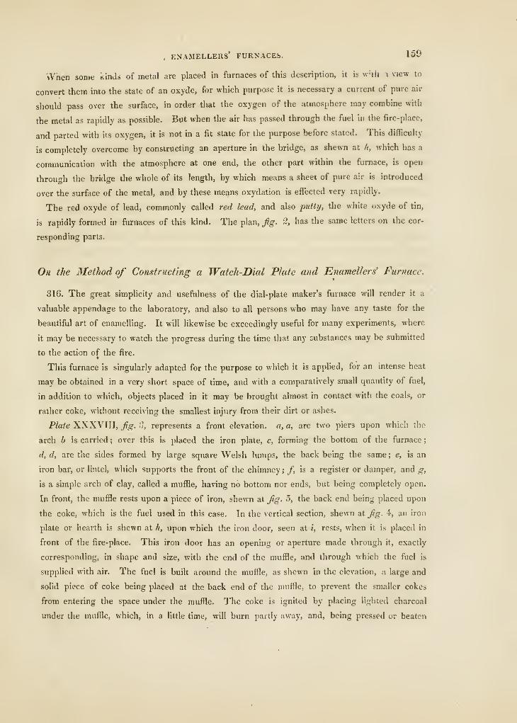
. ENAMELLERS' FURNACES. 150
vVnen some Kinds of metal are placed in furnaces of this description, it is w-ih i view to
convert them into the state of an oxyde, for which purpose it is necessary a current of pure air
should pass over the surface, in order that the oxygen of the atmosphere may combine with
the metal as rapidly as possible. But when the air has passed through the fuel in the fire-place,
and parted with its oxygen, it is not in a fit state for the purpose before stated. This difficulty
is completely overcome by constructing an aperture in the bridge, as shewn at h, which has a
communication with the atmosphere at one end, the other part within the furnace, is open
throu<rh the bridge the whole of its length, by which means a sheet of pure air is introduced
over the surface of the metal, and by these means oxydation is effected very rapidly.
The red oxyde of lead, commonly called red lead, and also putty, the white oxyde of tin,
is rapidly formed in furnaces of this kind. The plan, fig. 2, has the same letters on the cor-
responding parts.
On the Method of Constructing a Watch-Dial Plate and Enamellers' Furnace.
316. The great simplicity and usefulness of the dial-plate maker's furnace will render it a
valuable appendage to the laboratory, and also to all persons who may have any taste for the
beautiful art of enamelling. It will likewise be exceedingly useful for many experiments, where
it may be necessary to watch the progress during the time that any oubstances may be submitted
to the action of the fire.f
This furnace is singularly adapted for the purpose to which it is applied, for an intense heat
may be obtained in a very short space of time, and with a comparatively small quantity of fuel,
in addition to which, objects placed in it may be brought almost in contact with the coals, or
rather coke, without receiving the smallest injury from their dirt or ashes.
P/a/e XXXVIII, /?^. ;J, represents a front elevation, a, a, are two piers upon which th.e
arch b is carried ; over this is placed the iron plate, c, forming the bottom of the furnace
;
d, d, are the sides formed by large square Welsh lumps, the back being the same ; e, is an
iron bar, or lintel, which supports the front of the chimney; /, is a register or damper, and g,
is a simple arch of clay, called a muffle, having no bottom nor ends, but being completely open.
In front, the muffle rests upon a piece of iron, shewn at fig. 5, the back end being placed upon
the coke, which is the fuel used in this case. In the vertical section, shewn at fig. 4, an iron
plate or hearth is shewn at h, upon which the iron door, seen at i, rests, when it is placed in
front of the fire-place. This iron door has an opening or aperture made through it, exactly
corresponding, in shape and size, with the end of the muffle, and through which the fuel is
supplied with air. The fuel is built around the muffle, as shewn in the elevation, a large and
solid piece of coke being placed at the back end of the muffle, to prevent the smaller cokes
from entering the space under the muffle. The coke is ignited by placing lighted charcoal
under the muffle, which, in a Httle time, will burn partly away, and, being pressed or beaten
IGO PRACTICAL BUICKLAYING.
down, will t'orm a clear bed on which to place the work. This very simple furnace is knovru
only amongst the enamellers of watch dial-plates, with whom it is found extremely convenient,
and for many other purposes it would be found exceedingly convenient, were it more generally
known. There is one great advantage attending this peculiar construction, which is, that
a very moderate height of chimney will be sufficient, for in most cases, these furnaces are built
in the attic story of the houses where they are used ; the majority of persons employed in the
art being in the habit of carrying on their business at the top of their houses. We have known
an addition made to this furnace that was sometimes very useful, which was as follows :—The
iron plate forming the bottom was placed so that it could be taken out, and under it was placed
a set of bars, the part under the bars being open, so as to permit a supply of air in that direc-
tion, the door was placed before it as usual, and the aperture being stopped, the whole acted
as a wind or air-furnace to melt any substance that might be required ; in this case, iron bars or
lintels were adopted instead of the arch, by which means a greater depth was obtained to hold
the fuel when it was used as an air-furnace.
Having given an account of the principles, and described some of the varieties of air or
draught furnaces, we shall now describe one of those furnaces which are supplied with air by
mechanical means, and which are called blast-furnaces.
On the Properties and Construction of Blast-Furnaces.
317. The term blast is used at iron-foundries to denote the column of air forced into the
furnace for the combustion of the fuel, and consequent reduction of the metal from the ore.
Its velocity is occasioned solely by the power of the blowing machine forcing the whole contents
of the air-pump through apertures which enter near the bottom of the furnace, called nose-
pipes ; and, according to the absolute power of the engine, air of various degrees of density may
be produced ; whereas, in air or wind furnaces, a power equal to the density of the atmosphere
is all, at the most, that can be produced.
Combustion, in the blast-furnace, consists chiefly in the rapid reduction of a given quantity of
solid fuel, and its accompanying portion of ore, in the shortest possible time. That furnace and
that blast which can, in a given time, reduce the greatest quantity of fuel, all things else being
alike, will always manufacture the greatest quantity of iron. Some idea may be formed of the
enormous quantity of atmospheric air which is necessary to supply a blast-furnace, when we
state, that to manufacture thirty tons of iron per week, it will be necessary to blow into the fur-
nace 3000 cubic feet of air per minute. This circumstance will show, in a very striking degree,
the difference between the air and blast furnace.
Some blast-furnaces are constructed externally of a quadrangular form, and sand-stone is the
material most commonly used for the outside or body of the building ; they are sometimes coni-
cal, and formed of good bricks on the outside, the insides of all being lined with the most
BLAST FURNACES. 161
refractory materials that can be obtained. In almost every case, and in whatever way they may
be constructed, the most prominent cause of their destruction is the great expansion of the
materials that takes place from the immense heats that are generated in them. Iron binders of
various kinds have been adopted, and the most approved mode of uniting the several parts have
been practised ; but in almost every case, such has been the effect of heat, that rents and cracks
have been made, defying the ingenuity of the most experienced workmen to remedy or prevent.
In some instances, excavations have been made in the soHd rock, with the hope that the soliditv
of the materials would resist the effects of heat, but in vain ; for when the temperature of the
furnace was raised to its necessary height, the solid rocks were rent asunder in the same manner
as the labours of the most ingenious workman. Some iron-masters, seeing how hopeless it was
to make a solid and lasting structure, formed an external shell, and also an internal one like-
wise, leaving a space between the two, which was loosely filled with sand-stone of various sizes,
hoping that, when the internal shell or lining expanded, the stones between the two would yield
by becoming wedged, and by these means, although the inner shell or lining was split, yet the
external one would remain entire ; in some cases, the outside part was preserved, but when the
internal part gave way, it opened a passage for a current of air through the loosely arranged
and broken stone, which was found very injurious to the process of smelting, and ultimately that
plan was relinquished.
There is one circumstance that we fear is productive of much mischief, and which ou<iht to
be guarded against with all possible care : we mean the great quantity of water that sand-stone
holds in its pores, more especially if it be used immediately that it be brought from the quarry.
We may also add the quantity of water used with the mortar, which, with that in the stone, will
constitute a weight of many tons. To evaporate this by very gentle means would be a work of
much time, far more we are inclined to believe than is ever bestowed upon it ; therefore, when
the blast is applied, and the heat raised, the expansion, both by heat and also the effect of
steam, generated from the imbibed water, is such, that no structure we are acquainted with can
ever withstand it. The only mode then seems to be, that of repairing the breaches, from time
to time, in the best manner possible.
In order to assist the evaporation as much as possible by artificial means, cylindrical cavities
round the body of the building should be formed, having outlets at as many places as may be
convenient, say not more than four or five inches apart, by which means the water may be made
to escape from the more solid part of the structure, in a manner that would reduce in a consi-
derable degree the time that must otherwise be employed for the same purpose ; and as all
furnaces are more or less subject to similar circumstances, the same precautions should be
observed, in order to ensure success.
As there are various opinions concerning the exact form of a blast-furnace, many of which
are merely hypothetical, we shall give a vertical section of one that has been long adopted,
2t
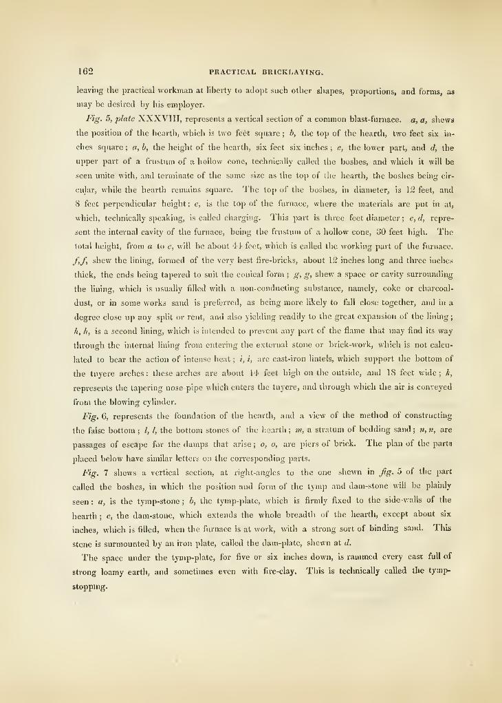
162 PRACTICAL BRICKLAYING.
leaving the practical workman at liberty to adopt such other shapes, proportions, and forms, as
may be desired by his employer.
Fig. 5, plate XXXVIII, represents a vertical section of a common blast-furnace, a, a, shews
the position of the hearth, which is two feet square ; b, the top of the hearth, two feet six in-
ches square ; a, b, the heiglit of the hearth, six feet six inches ; c, the lower part, and (/, the
upper part of a frustum of a hollow cone, technically called the boshes, and which it will be
seen unite with, and terminate of the same size as the top of the hearth, the boshes being cir-
cular, while the hearth remains square. The top of the boshes, in diameter, is 12 feet, and
8 feet perpendicular height; e, is the top of the furnace, where the materials are j)ut in at,
which, technically speaking, is called charging. This part is three feet diameter ; e, d, repre-
sent the internal cavity of the furnace, being the frustum of a hollow cone, 30 feet high. The
total height, from a to e, will be about 'It feet, which is called the working part of the furnace.
f,f, shew the lining, formed of the very best fire-bricks, about 12 inches long and three inches
thick, the ends being tapered to suit the conical form; g, g, shew a space or cavity surrounding
the lining, which is usually filled with a non-conducting substance, namely, coke or charcoal-
dust, or in some works sand is preferred, as being more likely to fall close together, and in a
degree close up any split or rent, and also yielding readily to the great expansion of the lining
;
h, h, is a second lining, which is intended to prevent any part of the flame that may find its way
through the internal lining from entering the external stone or brick-work, which is not calcu-
lated to bear the action of intense heat ; i, i, are cast-iron lintels, which support the bottom of
the tuyere arches: these arches are about 14 feet high on the outside, and 18 feet wide; k,
represents the tapei-ing nose-pipe which enters the tuyere, and through which the air is conveyed
from the blowing cylinder.
Fig. 6, represents the foundation of the hearth, and a view of the method of constructing
the false bottom ; I, I, the bottom stones of the lieaitli ; »«, a stratum of bedding sand ; n, n, are
passages of escape for the damps that arise ; o, o, are piers of brick. The plan of the partu
placed below have similar letters on the corresponding parts.
Fig. 7 shews a vertical section, at right-angles to the one shewn in Jig. 5 of the part
called the boshes, in which the position and form of the tymp and dam-stone will be plainly
seen : a, is the tymp-stone ; b, the tymp-plate, which is firmly fixed to the side-walls of the
hearth ; c, the dam-stone, which extends the whole breadth of the hearth, except about six
inches, which is filled, when the furnace is at work, with a strong sort of binding sand. This
stcne is surmounted by an iron plate, called the dam-plate, shewn at d.
The space under the tymp-plate, for five or six inches down, is rammed every cast full of
strong loamy earth, and sometimes even with fire-clay. Thb is technically called the tymp-
stoppmg.
FIRE-PLACES IN DWELLING-HOUSES. 163
On the Constructioti of Fire-Places for warming Hooms in DwelUng-Houses.
318. Having concluded our observations on the methods of constructing a variety of furnaces,
and fire-places for heating vessels, and performing various other important operations, we shall
close this department of the work with some observations on the principles that should be ob-
served in fixing stoves for the purpose of warming rooms or apartments in houses.
It should be remembered, that, in the foregoing subjects, each and every one of them are
either used to communicate the heat generated to vessels containing some liquid or material to
be heated, or else they are used to liquify metallic or other substances placed in actual contact
with the ignited fuel, the whole of which is completely inclosed within walls composed of earthy
materials. But, in the class of fire-places now to be considered, the ignited fuel is always open,
and fully exposed to view, the effect of heating being produced entirely by radiation.
There are few departments of the art that call for more skill, than that of setting fire-places
for our ordinary apartmetits, for if they be not executed in a proper manner, every comfort in a
room may be destroyed.
In order to produce the gi'eatest degree of heat in an apartment, many persons are desirous
of having their stoves set as forward as possible, in which case there is certainly something
gained in point of heat, but it is generally at the expence of having every thing in the room
covered with the ashes that fall from the fuel, and hence that accumulation of dust on the fur-
niture, in some apartments, which is almost unbearable. In other cases, where it has been
attempted to avoid this evil, stoves have been placed so far back in the fire-place, that the
greatest portion of the radiant heat is carried up the chimney, acting in no other way than to
create and increase draught, without augmenting the temperature in proportion to the consump-
tion of fuel.
Count Rumford, who investigated the nature and properties of fire-places, and the econo-
mical use of fuel in general, observes, that our fire-places are mostly too large, or rather it is
the throat of the chimney, or the lower part of its open canal near the mantle, and immediately
over the fire, that is too capacious. We must, however, admit, that while chimnies are swept,
as at present, by the barbarous practice of climbing-boys, a great part of this inconvenience mthe construction must remain ; this may, however, still be remedied by proper appendages to
stoves, which will be presently explained ; but, as the immoderate size of the throats of chim-
nies is the great fault of their construction, it is this fault which ought always to be attended to
in every attempt that is made to improve them.
As the smoke and vapour which ascend from burning fuel, rise in consequence of their being
rarified by heat, and made lighter than the air of the surrounding atmosphere, it is clear the
nearer the throat of a chimney is to the fire, the stronger or more rapid will be its drauf^ht, and,
consequently, the less danger will there be of its smoking; the only thing to be apprehended is.
that the fuel will be too rapidly consumed.
164. PRACTICAL BRICKLAYING.
It is very clear that the greatest part of the heat of fuel consumed in open fire-places, i«
projected into the space to be warmed by radiation; but, by proper contrivances, much may
also be obtained by reflection, from suitable materials placed in the most beneficial position for
that purpose.
The best form for the vertical sides of the chamber of a fire-place, or what are usually called
the covings, is that of an upright plane, making an angle with the plane of the back of the fire-
place, of about 130 degrees, which will reflect the heat in such a direction from each plane, that
various intersections will take place, and, consequently, a general dispersion of the rays will
ensue. But, where the covings are placed so as to stand at right-angles with the plane of the
back, the reflected rays will never enter the space of the apartment, tlie whole of their bene-
ficial influence being entirely lost.
It is a well-established fact, that all bodies that absorb radiant heat, are necessarily heated in
consequence of that absorption. It is therefore very desirable that we should be well acquainted
with the nature and properties of the materials used, in order to prevent a failure from an im-
proper choice of them. The method of ascertaining the absorbent and reflecting properties of
materials is very easy, namely, by exposing them to the direct rays of a clear fire, when those
that are last heated in a given time will evidently have absorbed the least caloric, and are there-
fore to be chosen as the best reflectors. Fire-stone, fire-bricks, and most of the earthy cements,
are slow conductors of heat, and consequently good reflectors, the worst material being metal of
any description ; but from its neat appearance and durability, when combined with its cheap-
ness, it is most likely to exclude from general use those materials whose properties are for this
purpose so much more valuable.
When bricks or any earthy material is used for forming the covings or sides of fire-places,
they should be covered with a coat of plaster, or what would be much better, Dutch tiles. The
whole interior of the throat, or covings, should be kept white, instead of the dingy black and
sombre tint now universally adopted ; for it is a well known fact, that white, as a colour, reflects
heat, while black, on the contrary, absorbs and retains it.
Where the throat, or lower chamber of a fire-place, is of necessity obliged to be of dimen-
sions inconveniently capacious, the best stove for such a fire-place is that known by the name
of register stove; for by the peculiar construction of this kind of stove, the throat will, in effect,
be narrowed, while suflTicient room will be obtained for the passage of a climbing-boy. Wehave no doubt that many chimnies where register-stoves arc used are liable to a return of
smoke in some instances, but as the open space behind the register forms a chamber to receive
it, it rarely or never enters the room, and therefore is no evil. A simple method of producing
the same effect, and at a very small expense, was some years since invented by Mr. Edmund
Turrell, Engraver, and as it proved very successful, we shall give a brief description, for the
benefit of our practical readers, more particularly, as it is calculated to benefit many of those
who follow sedentary pursuits.
FIRE-PLACES IN DWELLING-HOUSES. 165
There are, perhaps, no evils attendant upon sedentary pursuits greater than those whicli
arise from the want of attention to proper ventilation of the apartments where persons so
engaged follow their daily avocations. It is no uncommon circumstance, on entering the attic
workshop of a watch-maker, to find him enveloped in a highly-rarified atmosphere, the tem-
perature of which will seldom be less than from 75° to 80°. This is, in most cases, produced
by a German stove, which is supplied with air from the lower part of the apartment, and which
is indeed the only part that receives any fresh supply. But the upper part of the room is con-
tinually heated, and there being no means of escape for the air so heated, the unhappy victim
is under the necessity of breathing the same atmosphere over and over again repeatedly, until,
at last, there is scarcely any oxygen remaining in it to supply the blood with, and for want of
this, the liver becomes enlarged or diseased, and the inhabitant of such a place assumes the
appearance of those persons who live in hot climates.
There is no doubt that a large proportion of these evils arise from inattention and ignorance,
but much is endured from real necessity, for in almost all cases, persons of this class feel it
absolutely necessary to occupy the attic rooms, on account of the superior light they obtain
there, and as the chimnies of such rooms are always short, the natural consequence is that they
smoke insufferably if an open fire-place is used. This inconvenience has occasioned the neces-
sity of using German stoves, the pipes of which being carried some distance up the chimney,
has the effect of preventing the smoke from returning into the room.
Upon investigating the cause of this circumstance, it was found that when the iron-pipe was
carried some considerable distance up the chimney, or was made to enter it near the ceiling,
there was a space formed around the pipe in one case, and beneath it, in the other, to receive
the smoke when it made a momentary return, and this it was which prevented the entrance of it
into the room ; and, in addition to this circumstance, the iron pipe being a good conductor of
heat, the air in the chimney was kept so much rarified, that the return of the smoke was ren-
dered much more difficult. Seeing, from long experience, the great advantages of this method
of preventing smoke returning, it was conceived that the same advantages might be obtained by
applying it to an open fire-place, which proved highly beneficial, when arranged in the following
manner :
—
319. Plate XXXIX, Jig. 1, represents an open fire-place, with a common pantheon-stove fixed
in the usual manner. A, represents the section of an iron pipe which terminates at the bottom
in the funnel-shaped portion, B, which is made to fit the covings very closely. C, C, represents
the space or chamber that is formed to receive the returning smoke; and in order to show the
whole to greater advantage, the chimney is shown in section as low as the breast D, D, the funnel
is fixed to the covings by pins of iron, or screws, which can easily be withdrawn when it is re-
quisite to remove it, and the pipe should be made in short lengths, the joints being fitted very
loosely, a provision that will render it easy to be removed when the chimney wants sweeping.
This invention contains in part the advantage of the narrowed throat, without the disadvantage
2c
166 PRACTICAL BRICKLAYING.
of excessive draught. It may also be made to answer as a register, if a damper, moving on a
centre, be fixed at tlie bottom of the pipe near B ; but its greatest advantages arise from its pro-
perty of rarifying the air in the chimney, and the formation of a chamber to receive the smoke
at any time that it makes a return in the chimney.
Almost any chimney may be cured of smoking, if the mantle is sufficiently lowered so as to
limit the opening for the passage of the atmosphere ; but in that case it is well known that the
fire-place is converted into a species of air-furnace, in which state it will communicate scarcely
any heat by radiation, while the consumption of fuel will be enormous in proportion to the
effect produced. The skill of the practical workman is, in such cases, much required.
In many instances, chimnies continue to smoke as long as the door of a room is closed,
proving thereby that a constant supply of air is requisite. In such cases, a complete cure niiiy
be effected by conveying air from without by means of a pipe, which should be made to enter
beneath the grate, and by this means the unpleasant necessity of remaining in an apartment
with the door always open will be avoided, and the fuel abundantly supplied with fresh air to
carry on the combustion.
We are well aware that many local circumstances will frequently tend to make the cure of
smokey chimneys a desideratum ; but the practical bricklayer will do well to make himself ac-
quainted with the general principles herein given, by the careful application of which he may
hope to overcome many of the difficulties hitherto considered unattainable.
CHAPTER X.
320.—AN EXPLANATION OF THE TERMS, AND DESCRIPTION OF TOOLS,
USED IN BRICKLAYING.
Many of the technical Terms applicable to this Art are alio used in Masonry, therefore those that have been described in
the Terms of Masonry, page 83, will b* omitteil here to avoid useless repetition.
Alumina, is the plastic principle of all clays. It is one of the primitive earths, and when
pure is perfectly white ; all colour in clays being produced by some metallic oxyde, or some
other substances mixed with them.
Bed.—The under-surface of bricks when laid in any kind of work.
Bedding.—The art of laying bricks in such a manner, that they may bear their weight
equally on every part of their beds or under-surface. Work is well-bedded when no rocking
motion can be nroduced. by bearing partially upon the upper-surface at either end. The
EXPLANATION OF TERMS, &C. USED IN BRICKLAYING. 167
plastic and pliant state of mortar makes this operation an easy task, therefore it is Irequently
laid even upon the earth in sufficient quantities to bed bricks in, as in the case of pavmg.
Bedding-Stone.—A plane surface of marble used to try the beds or rubbed sides of bricks,
and thereby detect any winding in the surface.
Bond or Bonding.—A technical term used both in bricklaying and masonry : it means such
an arrangement, or combination of bricks when laid upon each other, that the perpendicular
joint formed by any two adjacent bricks may, at all times, be covered by the centre (or nearly
so) of one laid immediately over the joint, by which means the nearest approximation to
solidity will be attained that such materials are capable of producing. For a further description
of this essential quality, see page 96.
Bond Timber.—Square pieces of timber laid in walls, on the inside of buildings, at intervals
above each other, to prevent the separation of brick-work in a perpendicular direction.
Brick Axe.—An instrument used to cut oiF portins of bricks before they are rubbed upon
the rubbing-stone ; by a dexterous use of this tool large portions of those bricks intended
for arches may be cut away, so as to save a great deal of time in rubbing.
Brick Trowel.— This is the principal tool of the bricklayer; it is used to lay and
spread the mortar, also to cut even the hardest bricks. When really good, they ought to do this
without gapping or notching ; they used to be made of iron, edged with steel, but the trade
are indebted to Mr. George Walby, for the invention of making trowels entirely of steel. The
valuable properties of his trowels may perhaps be equalled, but will, we think, never be exceeded.
Bricks, are a species of artificial stone ; for an accurate description of the various kinds, see
page 88 ; and of Roman bricks, see page 90.
Burrs.—Bricks that are completely vitrified, and on that account frequently adhere together
in large masses, when they can be separated, they are the best to place in foundations.
Buttress.—A projecting mass of brick-work attached and combined to walls to assist in
supporting them, see plate XXIX.
Cambered.—Any kind of work that partakes of the properties of an arch.
Camber Slip, is a piece of board, of any length or breadth, made convex on one or both
edges, and generally something less than an inch in thickness ; it is made use of as a rule.
When only one side or edge is cambered, it rises about one inch in six feet, and is employed
in drawing the soffit-lines of straight arches ; when the other edge is curved, it rises only about
half that quantity, and is used for drawing the upper side of the arch, so as to prevent its
becoming hollow by the settling of the arch. But some persons prefer having the upper side
of the arches straight, in which case the upper edge of the arch is not cambered. The camber
slip should be sufficiently long to meet any case that may present itself.
Clamp.—A term used to denote a large mass of bricks, laid in a certain order, to be burned
in the open air. The new or unburned bricks are usually protected by an external covering ot
bricks already burned.
168 PRACTICAL BRICKLAYING.
Clay.—The earth always used to make bricks with. When pure and unadulterated, it is
white after being burned, as is the case with pipe-clay, which is nearly pure, but not quite, there
being a considerable portion of silex combined with it, which is also white when burned, with-
out being vitrified ; for a description of this valuable material, see page 88.
Clay Mill.—This is used to separate stones and coarse gravel from impure clays; for a
description, see page 90.
Coal-Ashes.—These are used, when sifted very fine, to mix with lime ; those produced by
smiths in their forges, they being partially vitrified, are the best. The composition, called coal-
ash mortar, is used to point or fill up the interstices or joints of brick-work, and to receive upon
its surface the white lines of tuck-pointing.
Float-Stone.—This is used for taking out the marks of the axe, and smoothing the surfaces
of curved-work, such for instance, as the cylindrical backs and spherical heads of niches.
But, for this purpose, the float-stone must itself be curved in the reverse form, though of a
radius equal to that intended for the brick, so that it may coincide with it.
Foundation.—The surface upon which the first layer of bricks of any wall or building are
laid ; see page 100.
Groining.—Groined arches are those whose lines of continuation meet each other at any
angle and form a junction, producing thereby various intersections; see page 111.
Grout.—Mortar, or any other cement, reduced to a liquid state with water. It is usually
poured over each layer or course of bricks, by which means the work is made solid, the liquid
grout completely filling up the interstices.
Hammer.—One end of this tool is formed like the common hammer, and the other is shaped
like an axe, the cutting edge of which is not more than an inch and a half long. By the pro-
jecting length at the cutting end, it is well adapted for making holes in walls, by being used as
a chopper.
Headers, are those bricks that show only their ends on the outside or inside of a wall or
building, their whole length being laid perpendicular to the face of the wall, and crossing those
called stretchers, at right angles.
Inverts, are those arches usually resting on the foundation of earth being turned upside
down, in which position they are well adapted to resist pressure, the piers of buildings being
usually made to rest upon the springings. For an example of the application of such arches,
see the Plate of the Wall of Coldbath-Fields Prison, page 103.
Jointer.—A steel tool, nearly in the form of the letter S ; it is used to mark lines or in-
dentations in the joints of brick-work, where tuck-pointing is omitted.
Lines and Pins.—The line, when strained over each course of the quoins by the pins,
enables the workman to keep all the rows or courses of work parallel.
Marls.—Bricks made of clay, nearly pure, their colour being a fine yellowish gray; the
best coloured ones are called ^^r*/*, and those not equal in noint of colour are called seconds
;
EXPLANATION OF TERMS, &C. USED I.V BRICKLAYING. 169
see page 90 : the softest of the firsts are used in the construction of arches, as they are easily
cut and rubbed into any given shape or form, which is performed, first, by cutting with an
edged tool called an axe, and then rubbing them upon a sharp grit-stone with dry sand.
Mould.—This is used for forming the face and back of the brick to its proper taper; and for
this purpose one edge of the mould is brought close to the bed of the brick previously squared.
The mould has a notch for every course of the arch.
Niche, is a recess in a wall, the principal object of which is to relieve a large plain surface, and
also to hold a figure or any other ornamental device. They are semi-circular, semi-eliptical, having
a hemispherical canopy or head. They are sometimes made simply hemispherical.—See page 120.
Oven. An arched cavity, having a floor made of tiles, the roof or arch is made of the same
materials. It is used for baking food and other purposes.—For a description, see page 131.
Pargeting.—A mixture of good mortar and a certain portion of cow-dung, it is used to
plaister the internal surfaces of chimnies with, making the surfaces smooth, and filling up any
interstices in the brick-work. It also contributes to prevent accidents by fire.
Paving-Bricks.—Red stock-bricks, well burned, are the best kind for this purpose ; where
very good work is required, they must be chosen quite free from curvature, which sometimes
happens in burning them.
Place-Bricks.—These are made of the same materials as stocks, but they are always soft,
being very slightly burned ; they may, on that account, be more easily cut ; and being non-
conductors of heat, are fit for many purposes where that quality is indispensable.
Pointing Tools.—Small trowels used to lay on the pure lime used in tuck-pointing. \
Quoins.—All those bricks that are used to form the corners or solid angles of any wall or
building.
Red Rubbers.—These are bricks made of the natural clay without any mixture, they are
therefore red when burned, and very equal in their texture.—See page 90.
Rubbing Stone, is a rough-grained grit-stone about twenty inches diameter ; it is usually
laid in a bed of mortar on one end of a strong bench, called a banJcer; upon this stone the
bricks that have been cut witli the axe are to be rubbed until they are brought to the proper
shape, and sufficiently smooth on their surfaces.
Saw.—This is made of a piece of flat tin. It is used to cut lines about the eighth of an
inch deep in those bricks that are to be cut by the axe. By this method rough jagged edges will
be prevented, which would be the case if the axe was used without such a manipulation.
Sewer.—An excavation under ground used as a water-course, the bottom and sides are
formed of brick-work, the top is fonned by an insisting arch, the bottom being an inverted arch.
—See page 129.
Shaft.—A hollow tower of brick-work, which is sunk like a well under ground ; it is used
as a passage to descend to mines or tunnels, placed at a great depth below the surface of tbe
earth.—See page 126.
2x
270 PRACTICAL BRICKLAYING.
Skewback, is the sloping plane upon which the springings of a straight or scheme aixh rest
on each extreme.
Skewing.—A technical term for sloping or inclining.
Sleepers, are thick planks of timber, laid down on a foundation of earth, upon which brick
foundations are laid, in order to prevent partial sinkings or settlements in the walls of buildings.
Springings, are the bricks on each side of an arch that rest upon the piers or abutments,
the plane of their bases being parallel to the horizon.
Stocks. These are bricks formed mostly of impure clay and coal-ashes, the gray colour on
their surfaces being produced by Thames sand, which is imbedded in them, while the clay is
wet and adhesive. These are considered next in quality to marl seconds.
Stretchers, are bricks laid in the direction of the length of a wall ; they form bond by laying
across the joints of headers.
Throat.—The contracted part of any open fire-place, through which the rarefied air passes
with an increased velocity proportionate to its internal area. The nearer it is to the fire, the
greater, generally speaking, will be the draught.
Tunnel.—An excavated line under ground, each end opening upon the surface of the
earth. It is used to form a passage through hills, parts of mountains and rocks; also to form
a roadway under a river where a bridge would be impracticable.—See page 121.
Vaulting.—A method of covering excavated spaces under ground, which are used to keep
various stores in. When the arched roofs of vaults run in various directions, and intersect each
other, they are called Groined Vaulting or Arches.—See page 108.
PLASTERING, PLAIN AND ORNAMENTAL. JTl
t
BOOK III.
PLASTERING,PLAIN AND ORNAMENTAL.
INTRODUCTION.
321. X HE exact period when the art of Plain Plastering was invented, cannot, owing to the
want of sufficient data, be positively determined ; but it must readily occur to the mind of every
thinking man, that necessity must have been the inventor, and time its great improver.
On referring to the huts of the primitive inhabitants of the universe, more particularly
those of the northern parts of Europe, we find that the interstices, which occurred between the
timbers or wicker-work, were filled up by means of clay or mud, in order to protect the inmates
from the severity of the weather, and whicli is indeed practised at the present day by the
peasantry of this country.
In process of time, when civilization had rendered man more susceptible of elegance and
convenience, the surfaces of the walls were made smooth and straight, being, in some instances
painted, in a style much practised by the Romans, and known to the moderns by the name of
fresco, as many examples discovered in the excavations of Pompeii and Herculaneum will prove.
That the Romans, at a very early period, practised the art of plain plastering, is sufficiently
evident by the portions which remain attached to the walls of some of their most ancient build-
ings, the antiquity of which must be considered as proved, when we look at the manner in
which the carbonic acid contained in the atmosphere has acted upon the lime and sand, it
having reduced the various particles into a solid and compact substance resembling stone, and
which, indeed, is a carbonate of lime, defying the most dexterous applications of the hammer
and chisel to separate it from the walls without bringing off pieces of the stone attached to it.
Connected with this art, and indeed belonging to it, is one of the most elegant branches of
decoration, formerly called stucco-working, but now known by the more comprehensive title of
Ornamental Plastering, including modelling, casting, and working in stucco.
The invention of stucco-working has been attributed to Margaritoni, an Italian, who died
in L317.
The materials used by him were sifted lime and white marble pounded, which were kneaded
together to the consistency of potter's clay, pure water alone being used in their amalgamation.
172 PLASTERING, PLAIN AND ORNAMENTAL.
The method practised by Margaritoni, in the working of stucco, was the laying a body of
tlie material on a ground prepared to receive it, which, while in a plastic state, was made to
assume the form required. The tools used for this purpose were of a very simple construction,
being merely a piece of steel, about 12 inches long, formed at one end like a small trowel, and
the other end round, which is now technically called a boasting tool, from its being used in
giving the first shape to the work ; several smaller ones, of similar construction, were used for
the finishing.
Vittoria (a pupil of Giocomo Tatti, a celebrated sculptor of Venice, contemporary with
Michael Angelo) has the credit of perfecting the working in stucco. He unquestionably intro-
duced a diftcrent method of working, which difference consisted in pressing the plastic stucco
into moulds of wood, lead, or baked clay, previously dusted with finely-sifted lime. By this
means, the face-work and outline were produced ; the part so formed was separated from the
mass, bent by the fingers to the necessary shape, and afterwards attached to the ground by a
little soft stucco, which served as a cement for the connection of the different parts of the
ornament.
This manner of working has been called patted and pressed work, but how far it was a per-
fecting of the original mode is problematical, when we recollect that the execution must of neces-
sity have been limited to the production of such designs as it was possible to make moulds for
;
whereas, in the former method, the general effect, as well as the most simple details, depended
entirely on the judgment and ability of the artist, who required an intimate knowledge of nature
in her animal and vegetable kingdoms.
The manner of patted and pressed work has been entirely superseded by the improve-
ments which have been made by the moderns on the method, the first principles of which were
invented by Margaritoni, together with the casting of plaster ornaments in wax-moulds, which
was invented by one of our own countrymen.
In the year 1703, during the time that Rose was employed in the ornamental work at old
Buckinorham-house, a dis])ute arose between him and his Italian stucco-workers, respecting the
remuneration for tlieir labour. He being unwilling to accede to their (what he considered) un-
reasonable demands, set his ingenuity to work, and was successful in inventing the casting of
ornaments, by pouring plaster of Paris, in a liquid state, into moulds composed of a mixture
of rosin and bees'-wax, so that the major part of the embellishments, which had hitherto been
executed in stucco, were cast, and fixed in their proper situations with plaster mixed with water
until it had attained the consistency of paste.
3;22. Before entering into a further description of the different methods of working in stucco,
it will be necessary to trace the origin of ornament and its introduction into architectural deco-
ration. For this purpose, we must revert to Egypt, the cradle of the arts and sciences. The great
progress which the Egyptians had, at a very early period of history, made towards civilization,
naturally attracts the attention to their country as the place where ornament had its origin.
INTRODUCTION. 173
At the annual overflowings of the Nile, the hollows of the earth which remained filled
with water (after the retiring of the main body) were seen covered with numerous aquatic
plants, the most beautiful of which was the lotus or water-lily. This plant, no doubt, at once
presented itself to the luisophisticated minds of the Egyptians as the most appropriate emblem
of the annual inundations upon which the fertility of their country so much depended, and
hence its introduction into architecture.
Thus we find the earliest examples of the Egyptian column made to represent a bundle of
lotus plants bandaged together, the flowers forming the capital, the stems the shaft, and the
roots the base.
Owing to the proximity of Greece and Egypt, and the commercial intercourse which ex-
isted between the two countries, the Grecians were led to copy, and afterwards to improve,
upon the Egyptian style of decoration, by combining the honeysuckle, and other productions of
nature, with the water-lily, as may be observed in the most ancient of the Grecian temples.
We are informed by history that all the ideas of the Romans, in the art of decoration,
were taken from the models of the Grecians, which will be found sufficiently evident by com-
paring the two styles.
The principal fault in the Grecian foliage was the uniformity of its raffleing, the flatness of its
emboss or projection from the ground-work, and a want of energy and freedom in its face-work.
The form of the Grecian raffle was pointed, and in no case was there a second raffle introduced
between the burstings of the leaves, as invariably occurs in nature. These deficiencies, by a
more correct imitation of nature, were considerably improved by the Romans.
In the fifth century, architecture, and, in fact, all the arts and sciences gradually began to
decline in Europe, which decline was facilitated by the blind policy of the northern hordes, who
at this period, subverted the Roman empire, overran one half of Europe, and almost totally
annihilated those glorious buildings which had been the work of ages, and intended to per-
petuate the memory of a race of men, to whom mankind are indebted for the ground-work of
most of the ideas they now possess.
We should stop here, and rest contented with what we have already said upon ornament,
were it not that we prefer giving the reader a practical description of the different styles to
referring him to a voluminous list of books on Architecture, many of which may be in a lan-
guage not understood by the practical man, and all of an expensive description. We, there-
fore, now proceed to explain the different styles of ornament, in the order in which they were
introduced into England, shewing the degree of connection subsisting between them up to the
present time, and specifying some of the most celebrated workers in each particular style.
2y
17J, PLASTERING, PLAIN AND ORNAMENTAL.
CHAPTER I.
Of the Gothic Style of Ornament.
323. For the space of four or five centuries after the fall of the Roman empire, a dark age
seemed to reign throughout Europe ; but the dawn of refinement at length made its appear-
ance, and materially affected the building art, by the invention of Gothic architecture.
In this style nature seems to have afforded an inexhaustible source from which to draw,
as we frequently observe the leaves of the oak, the maple, the thistle, and the cabbage, intro-
duced in the capitals and running ornaments, and also the human figure, with representations of
monkeys, owls, squirrels, mice, &c. &c. But embellishments in Gothic, more particularly belong
to what is termed the florid style, as enrichments rarely occur in the early Norman examples to
be seen at Durham, Dunfermhne, and Lindisferne, except the partial introduction of barbarous
looking heads, and the zigzag moulding, which cannot strictly be called an ornament, as it is, in
many cases, formed by the intersections of mouldings. Its greatest characteristics are grandeur
of design, astonishing effect, on account of the magnitude of its proportions, an expressive
depth of shadow, and the boldness of the profiles of its mouldings. There are some beautiful
specimens of this style on the Continent, in the cathedrals of Milan, Strasburgh, and Rouen ; in
England, at York, Lincoln, Ely, Salisbury, &c. The enrichments in the cathedral at Salisbury
are of a very peculiar description, as will be seen by a reference to plate XL.
The organ-screen at York is, perhaps, the most exquisite piece of Gothic workmanship now
in existence.*
There are very early traces of the application of plain plastering to Gothic buildings to
be met with in Great Britain ; one very old example may be seen at the Manor Shore, York, in
the remains of St. Mary's Abbey, where it occurs that the plain panels of the groined roof
have been covered with a coat of plaster ; but England is indebted to the enterprising genius of
Mr. Francis Bernasconi for the application of Gothic ornamental plastering to buildings of
every description. He, under the auspices of the justly-celebrated James Wyatt, Esq. (the
reviver of florid Gothic architecture in England,) Elliot, Porden, Atkinson, &c. has executed
several works of great magnitude, among which may be particularly enumerated, Fonthill Abbey,
the grand staircase at Windsor Castle, finished in 1801 ; Eaton Hall, the seat of Earl Grosvenor
;
and Taymouth Castle, the seat of the Earl of Breadalbane.f
• ll was repaired with plaster, by Mr. Bernasconi, in the year 1804.
f The staircase at Taymouth Castle is the most luagniricent Gothic staircase in Great Britain, it bcin^ 40 feel squa.*,
and 80 feet high; it was designed by Elliot.
ELIZABETHAN AND OLD ENGLISH STYLES OF ORNAMENT 175
As Joseph Bernasconi, the greatest Gothic modeller that ever lived, formed his taste from
a shrewd observance of the embellishments of York Cathedral, we would most strongly enforce
an acquamtance with the examples of York, as well as those of Ely, to future aspirants in this
peculiar department in preference to any others in England.
As the cathedral at York will only be accessible to a few, Halfpenny's folio book of ornaments
will be found of essential service.
We would also most particularly recommend to modellers, the study of the heads by
Mr. Francis Bernasconi, finishing under the labels of doors and windows, and likewise those in
other situations.
Of the Elizabethan Style of Ornament.
324. About the year 1560, a style of finishing of a very peculiar character, uniting many
absurdities of design with great beauty of workmanship, and frequently astonishing ingenuity
in some of its combinations, came into general use. The name of the original inventor of this
style remains in mystery, but, on comparison, a strong resemblance between its outline and the
Gothic of Salisbury Cathedral is observable, although there is a great difference in the projec-
tion and manner of finishing. It is obvious, from the numerous examples extant, that it arrived
at its greatest perfection during the reign of Elizabeth, and was also generally practised in
those of James and Charles the First.
Its parts consist of the interlacing of numerous small fillets in every imaginable form, with the
frequent introduction of grotesque heads and small rosettes.
The finest specimens of this style may be seen at Longleate-House, near Salisbury, the
seat of the Marquis of Bath ; in Lord Holland's house at Kensington ; in some of the halls mthe Temple, London ; and also on the exterior of Northumberland-House ; but, perhaps, the
best specimen is Queen Elizabeth's gallery in Windsor Castle, executed during her reign, the
ceiling of which is literally covered with ornament. The chimney-piece in this gallery, together
with several chairs composed of ebony, which were formerly removed to Hampton-Court, but,
subsequently, placed in the corridor at Windsor, are complete chef-d'oeuvres of this beautiful,
though peculiar, style of embellishment.
Of the Old English Style of Ornament.
325. About the year 1630, under the auspices and from the designs of the celebrated Inigo
Jones, the old English, or, as it is generally called, strap foliage, was introduced and much
practised.
This style is of a very rich flowing character, abounding with splendid festoons composed
of fruit and flowers, and also foliage springing from elaborately worked trophies and shields.
It has been by some said to be a modification of the old ItaUan ornament, and indeed a great
176 PLASTERING, PLAIN AND ORNAMENTAL.
similarity in design may be traced, by comparing its ornaments with those in the Architectura di
Sebastian Serho.
Albin's House, m Essex, the seat of Rutherford Abdy, Esq. which was executed from
the drawings of Inigo Jones, is a very fine specimen.*
Of tlie Roman Style of Ornament.
326. The Old English manner of finishing, after some years, was superseded by one which
participated a great deal more of the Roman character. It was brought to its greatest perfec-
tion in England, at old Buckingham-House, in 1703, which was at that time executed by Rose
from the designs of the learned and accomplished John Sheffield Duke of Buckingham.
Many of the works of Sir Christopher Wren, and other eminent architects, are finished in
this style.
The finest ancient specimens now extant are to be found in the three columns of the
Campo Vaccino, the baths of Dioclesian, the frontispiece of Nero, and the pantheon, at
Rome. The best examples in England may be seen in St. Paul's Cathedral and other churches
in the metropolis, and also at Uxbridge-House, in Burlington Street, the residence of the Mar-
quis of Anglesea.
The parallel of ancient and modern architecture by Monsieur Ronald Freart, Sieur de
Chambray, which was translated into English by John Evelyn, in 1707, may be consulted with
great advantage, as it contains many designs from ancient Rome, executed with a precision and
beauty truly astonishing.
Amongst the moderns, who have most eminently contributed to the advancement and
improvement of the Roman ornament, Bulliphant, Watling, Ash, Papworth, Finney, and
Rothwood, may be enumerated. The Roman foliage of Bulliphant, for gracefulness of out-
line and delicacy of finish, has, perhaps, never been equalled ; but the works of any of the
above modellers may be profitably consulted by the aspirant to perfection in this manner of
embellishment.
Of the Grecian Style of Ornartient.
327. The Grecian style of decoration (which having been, as we before stated) greatly im-
proved from the models of the Egyptians, began to arrive at perfection under the fostering care
of Pericles, which period, including the reign of Alexander, must be considered as the climax
of grace, elegance, and beauty, in Greece.
The enterprise of men of genius, amongst whom Stuart, Revett, and Cotterill, stand
most conspicuous, who have travelled through Greece, and published the results of their re-
searches, illustrated by copious drawings of buildings, with details of their various parts or
* The library is the best sjiecimeo, and ib ninety-seveD feet long.
FRENCH STYLE OF ORNAMENT. 17/
ornaments, has accelerated an admiration of those magnificent d.splays of antiquity, and con-
sequently the adaptation of Grecian architecture, both to ecclesiastical and domestic purposes.
Its most striking characteristics are great simplicity, chasteness, and purity of design,
without that grandeur of effect so peculiarly belonging to the Gothic, and at the same time not
admitting of so much diversity.
The prevailing ornaments adopted by the Greeks were the lotus and honey-suckle, which
are most frequently applied to their friezes, but they are also often introduced in other
situations. Their iriez;es are also charged with bas-reliefs, representing subjects from the
heathen mythology and triumplial processions.
Besides the ornaments above alluded to, we have Greek ovolos, ogees, &c. ; the former, being
an imitation of an egg encircled by a band, is by some workmen called an egg-mould.
The finest examples of Grecian ornament in this country are the Elgin marbles, which
were brought over by the Earl of Elgin, and whose name they have since taken. Stuart and
Rivett's Atnens may also be consulted on this subject with equal advantage.
Of the French Style of Ornament.
Q28. In the reign of Louis XIV, a peculiar and fantastic style of ornament came into ge-
neral use for the decoration of the interior? of buildings. It consists of a great profiasion of
foliage twisting round mouldings, and emanating from heads, animals, shells, shields, trophies,
&c. ; the line of the foliage throughout being invariably maintained with an exquisite degree of
freedom and spirit.
The Italian stucco-workers, Catezi, Philip Danielli, and Franconi, being no doubt on their
route through France to this country, struck with the beauty of this style, were the first
workers of it to any extent in England, although, prior to their time, seme small portions had
been executed, as may be seen in the churches of St. Giles and St. INIartin-in-the-Fields,
London.*
Beautiful specimens of the works of the above mentioned stucco-workers are lo be found
in the county of Durham, in the banqueting-room and temple at Hardwick, and also in the
castles of Bishop's Auckland, Lumley, and Hilton, executed about the year 1760.
This style for the last half century has been disuse^' in England, but is now m a great
measure revived through the instrumentality of those eminent architects, Sir GeofFry Wyattville
and Benjamin Wyatt, Esq. ; the former having applied it to the decorating of the drawing-
room, library, and reading-rooms, at the royal residence at Windsor, and likewise to the
ball-room, which is now in progress. The ball-room, when finished, will present the most
splendid display of this style to be met with in Great Britain. The latter architect has m-
« The oruamcntal work in St. Martin's cnurch was executed by Artezi, about the year 172».
2z
178 PLASTERING, PLAIN AND ORNAMENTAL.
troduced it with great effect in the mansion which was built for the late Duke of York. The
staircase in this building cannot be too greatly admired, not only for the workmansliip, but also
for its ample dimensions, it being 56 feet by 4G feet, and 73 feet high. The ornamental work
is completely free from those absurdities so frequently complained of in a majority of the old
examples, all its parts corresponding with each other, thereby not having the appearance of
being lop-sided.*
We would most particularly call the attention of the ingenious to an examination of the
specimens noticed above, as a careful investigation of their different merits will assist the stu-
dent in the formation of his taste.
We would also recommend a reference to the folio work of La Porte, published in Paris at
the period when French ornament was in the meridian of its splendour ; the original sketches
of La Fosse ; the work by Swan ; and last, but not least, the elaborately-finished prints by
the justly-celebrated Gribelin, originally published by Bowles, in St. Paul's Church-Yard, but
now only to be had in loose engravings, the work itself being now extinct. The plates by
Gribelin are as useful to chasers in gold and silver, as they are to the ornamental plasterer, and
are in themselves complete gems of art.
Havin<T thus, we trust, given the young artist a clear and intelligible description of the
different styles of ornament, we will next endeavour to give an account of the materials and
compositions made use of for internal and external finishing, and also an explanation of the
various operations and modes of performing them.
CHAPTER ir.
Of the Materials and Compositions used in Internal Finishing.
329. Laths, which in general form the ground-work of all kinds of plastering, consist of thin
slips of wood, which are nailed to ceilings and partitions of rooms, with a verv narrow opening
between each, for the purpose of receiving the coarse stuff or pricking-up coat. They are made
of oak or fir, and are of various lengths, as three-foots, three-and-half, four-foots, and four-and-
half, and are sometimes made of many other lenghts to suit particular purposes.
They may either be purchased by the foot, bundle, or load. They are also of different
degrees of thickness, as single-laths, lath-and-half, and double-laths. Single laths are the
cheapest and thinnest lath-and-half denotes one-third, and double laths twice the thickness of
single laths.
• The interior of Apslcy-House is also finished in this style.
INTERNAL FINISHING. 179
The laths generally used in London are made of fir imported from Norway, the Baltic,
and America, in pieces called staves. Most of the London timber-merchants are dealers in
them, and there are many persons who confine themselves exclusively to this branch of trade,
under the title of lath-renders.
330, Lime, which forms a most essential ingredient in all the operations of plastering, is pre-
pared from two substances, viz. lime-stone and chalk, which are broken into small pieces, and
piled in convenient layers, with coal, furze, or other fuel, in proper kilns, where they are kept for
a considerable time in a white heat.
Bishop Watson found, by experiment, that, upon an average, every ton of lime-stone pro-
duced 11 cwt. 1 qr. 4 lbs. of quick-lime, weighed before it was cold; and that when exposed to
the air, it increased in weight daily, at the rate of a hundred weight per ton, for the first five
or six days after it was drawn from the kiln, owing to its gradual absorption of carbonic acid.
Great precaution ought always to be exercised in the choice of lime, particularly avoid-
ing the stone of a hard nature, for if great care be not taken in the slacking, owing to the
quantity of magnesia it contains, which being almost insoluble in water, it will eventually spoil
the work, however great the pains which may have been taken in the finishing, by breaking out
in ugly protuberances, called by the plasterer, blisters. The lime of Breedon, in Leicester-
shire, is found to contain half its weight of magnesia.
The principal portion of lime used in London and its vicinity is prepared from chalk,
and the greater part of it is brought from Purfleet, in Essex ; but for stuccoing and external
finishing, in which strength and durability are required, the lime manufactured at Dorking is
preferred. This useful article is sold at the wharfs about London, in bags, containing each one
hundred pecks.
331. Sand, which is so material for the making of good mortar, ought always to be chosen of
the sharpest description, of a consistency approaching to fine gravel, free from all particles of
earth or clay, for on the purity and quality of the sand, the strength and durability of the
mortar entirely depends.
Z"o2. Lime and Hair, or coarse stuff, is prepared in different ways, which must be deter-
mined by the quality of the materials.
When prepared from chalk or lime-stone of a weak nature, it is screened and prepared
in the usual way, similar to common mortar, with the addition of hair from the tan-yards, and
may be used a few days after its preparation ; but when tlie lime-stone is of a hot or hard
quality, it is not advisable to adopt this method, for if the stuff be used soon after its prepa-
ration, it will inevitably cause blisters in the work. The safest mode of preparing lime and
hair, when the stone is of a strong nature, is by forming a pan or binn of a convenient size,
perfectly water-tight, and about 18 inches in depth. A large tub must then be procured into
which the lime, after having been well slacked must be put and mixed with a proper propor-
180 PLASTERING, PLAIN AND ORNAMENTAL.
tion of waier, and run through a sieve with apertures not exceeding a quarter of an inch, until
the pan is filled, when the hair and sand must be added, the whole being well incorporated with
a drag or three-pronged rake. There must then be a small hole made at a suitable height in
the side of the pan, to allow the water to escape. After thus remaining until it be sufficiently
set, it may be taken out of the pan and made fit for use by the labourers.
This composition is used for the first or pricking-up coat, and for the floating of ceilings
and walls. It is also used for mouldings and cornices which require much stuff, in which case
it is mixed with plaster of Paris.
3o3. Fine Stuff is commonly used for giving the last coat to the plain surfaces of floated
work. It consists of pure lime slacked with a sufficient quantity of water, and well saturated.
It is afterwards run through a fine sieve, and put into tubs in a semi-fluid state, where it is
allowed to settle and the water to evaporate, when a small portion of white hair may be added,
which will very much improve its quality.
334. Stucco, for inside walls, called trowelled or bastard stucco, is composed of fine stuff,
above described, (omitting the hair,) and very fine washed sand well incorporated with it, in the
proportion of one of the latter to three of the former. All walls intended to be painted or
papered should be finished with this stucco ; but for what is termed rough stucco, commonly
applied to staircases, passages, and entrance-halls, a larger portion of sand ought to be used,
and that of a much coarser quality.
335. Plasterers' Putty is prepared from unslacked lime, the process being performed by
immersing the lime in water where it remains until it be completely dissolved ; the liquid being
then strained through a very fine sieve must be left in this state until set, when it is considered
fit for use.
Putty is used in all the finer branches of plastering, as for the setting or last coats of
soffits, and for the running of mouldings and cornices. When it is used for mouldings, it is
mixjJ with plaster of Paris, which induces it to set quickly and become more dense.
336. Stucco, which was used by the old ornament-workers, is prepared in a very peculiai
manner. It has, since the invention of casting ornaments in moulds, almost entirely fallen into
disuse ; however, it is but proper here to notice it for the benefit of the curious.
A sufficient quantity of fine putty being procured to complete the portion of work con-
templated, some marble-dust, made very fine, or pounded alabaster, (and in some cases very fine
silver-sand,) must be added. This mixture must be well chafed and spread over a brick-wall,
in order to assist the co-operation of the water. After it becomes stifl", it must be taken from
the wall, and well chafed with a wooden beater until it becomes tough ; it must then be spread
over the wall a second time, and the same process repeated, viz. chafing it well with the beater
until it becomes plastic, when it is fit for use, and may be apphed to the ornamental work after
it has been first boasted with lime and hair.
INTERNAL FINISHINGc 181
This kind of stucco is sometimes mixed with a small portion of burnt plaster of Paris,
prepared in the manner of lime, instead of being, according to the usual mode, baked in an
oven, which prevents it from setting within twenty-four hours.
Many specimens of ornament worked with this composition by Durham, who was a pupil
of Catezi's, may be seen in many parts of the north of England.
Stucco, used at the present day for the working of Gothic ornaments, such as bosses,
spandrels, and corbels, is merely a simple mixture of putty, with silver or very fine house-sand.
337. Plaster of Paris, as it is commonly called, is the composition on which the plasterer
materially depends for giving the precise form and finish to the decorative part of his work ; by
its aid he executes all the ornaments applied to ceilings and cornices, besides sometimes mixing
it with his lime used in the finishing coat of the walls and ceilings of rooms, in cases of emer-
gency, when time is of material consequence.
This composition is known amongst chemists, by the several names of sulphate of lime,
selenite, and gypsum.
The property which plaster possesses, of setting into a compact mass when mixed with
water, was, according to Herodotus, the Greek historian, well known to the ancients. Accord-
ing to his account, the inhabitants of Ethiopia had a peculiar method by which they preserved
the remembrance of their deceased relatives. After having dried the body in the sun, they
enveloped it in a paste of gypsum, and afterwards painted the likeness of the real figure on the
encrustation with which it was covered.
The sulphate of lime is found in immense quantities in the hill named Mont Martre, in
the vicinity of Paris, and hence its name, plaster of Paris. The stone from this place is, in its
appeai'ance, similar to common freestone, excepting its being replete with small specular crystals.
The French mode of manufacture is by breaking the stone into small fragments, about the size
of an egg, then burning it in kilns with billets of wood, until the crystals lose their brilliancy;
it is afterwards ground with stones to different degrees of fineness, according to the different
purposes for which it is intended. This kind of specular gypsum is found in great abundance
in Russia, where it is said to be used in the windows of their cottages, as a substitute for glass.
The specific gravity of gypsum, or plaster of Paris, varies from 1.872 to 2.311., and, ac-
cording to Bergman, contains 32 parts of lime, and 68 of acid and water, requiring 500 parts
of cold, and 450 of heat, to dissolve it. In the process of burning, or calcination, it decre-
pitates, becomes very friable and white, and heats a little with water.
The plaster commonly used in the metropolis is prepared from a suiphate of lime, pro-
duced in Derbyshire, and called alabaster. It is brought to London in a crude state, calcined,
and afterwards ground in a mill, when it is ready for use, bi ing usually sold in brown paper
bags, each containing about half a peck.
At Chelaston, near Derby, 800 tons are annually raised. It is also found in most of the
cliffs in the Severn, especially at the Old Passage, near Bristol. There are also excellent
3 A
182 PLASTERING, PLAIN AND ORNAMENTAL.
quarries near Rippon and Hull, in Yorkshire, great quantities being annually shipped from
the latter place.
This mineral is much used in Derbyshire, for laying the flooirs of cheese-rooms, granaries,
&c. After preparing it in the usual way, they mix it with water, and spread it on the floors
about 2j inches thick, which, when dry, forms a smooth surface and durable flooruig, the whole
expence not exceeding 1*. 6d. per square yard.
338. Paste Composition is a most excellent substitute for carving in wood, at much less ex-
pence, and may be very successfully applied to picture-frames, window-cornices, trusses, and
brackets, or, indeed, to any ornamental work, which is afterwards to be painted or gilded, it
being frequently used for the execution of the cornices and capitals of shop-fronts.
It is composed of—7 parts glue, 2 do. linseed-oil, 7 do. rosin.
The glue and linseed-oil must be first well boiled together, the rosin being bruised must be
then added, and the whole stirred until they be completely incorporated. This mixture is
poured into a small dam, formed of whiting, with which it is thickened until it comes to the
consistency of baker's dough, it is then rolled out into flat cakes, and forced into moulds by
means of a screw and lever-press.
The moulds used are either of wood, sulphur, or brass. Wood moulds are made by
sinking the reverse of the ornament intended to be produced, in a piece of Turkey box, which
process requires the greatest care and much practice to produce any thing perfect, but indeed
wood-moulds are only suitable for the finest and smallest parts of embellishments.
Sulphur moulds, which are most commonly used, are formed from the clay model, by
pouring liquid sulphur over it, having previously placed a fence of clay round the model, and
oiled it with sweet oil. The sulphur-mould, thus formed, is trimmed and fixed in a block of
wood or cast-iron. When the wood is adopted, a space is cut in the block sufficiently large
to admit the mould, the interstices being filled up with liquid sulphur, thus keeping it securely
in its place, for were it not for this precaution, the mould would be crushed to atoms by the
action of the press the first time that an attempt was made to squeeze the composition into it.
Brass moulds are made by moulding the model with plaster of Paris, which inverse
mould is sent to the brass-founder and by him moulded in brass, after which it is chased or
riffled. It is necessary that brass moulds be bedded in wooden blocks, to protect them from
injury.
339. ScAGLiOLA has, of late years, begun to be much practised in the interiors of the mansions
of our nobility, and may be applied not only to columns and their capitals and bases, but also
to the paneling of walls, &c.*
The formation of columns, &c., in scagliola, is a distinct branch of plastering. It was
first invented in Italy, thence carried to France, and afterwards to England. For its intro-
duction into this country we are indebted to Henry Holland, Esq., who was, for many years,
* A beautiful specimen of this style of paneling may be seen at the Marquis of Stafford's new bouse in St. James's Park.
COLUMNS OR PILASTERS IN SCAGLIOLA. 183
the favourite architect of his late Majesty George III. He procured artists from Paris to
perform works with this composition at Carhon Palace, some of whom finding a considerable
demand for their productions, remained amongst us, from whom our British workmen learnt the
art, and hrve since brought it to the greatest perfection.
Scagliola is a composition of plaster of Paris and eartny colours, or any colours which will
withstand the action of an alkali. In its manufacture, the ground or predominating colour is
first mixed to the desired tint, and the other colours intended to be introduced must be mixed
separately with a portion of clear size, and a little spirits of turpentine, to facilitate the drying.
If, in the marble intended to be imitated, the colours blend gradually into each other, as
in sienna and the others generally executed, the imitation must be formed while the colours
are in a soft state, by putting the ground mixture into a large trough, and adding the different
colours in a proportion and a taste which can alone be acquired by experience.
If, on the contrary, the distinction between the colours is strongly marked, the secondary
colours must be allowed to set nearly hard, broken into small pieces, and added to the ground
mixture, which must be kept in the trough in a soft state, as before mentioned.
Manner offorming Columns or Pilasters in Scagliola.
340. When the architect has furnished the drawing exhibiting the diameter of the shaft, a
cradle is made of wood about 2\ inches less in diameter than the projected column. The cir-
cumference of this cradle being lathed with double laths, as in common plastering, must be
covered with a pricking-up coat of plaster, gauged with very thin size, in order to harden it.
The pricking-up coat, after being completely set, must be well soaked with water. The
composition must be then taken from the trough, flattened into cakes about eight inches square,
applied to the column, and well beat on with a wooden beater and small gauging trowel. In
this state it must remain until perfectly dry, when the protuberances may be taken off with a
plane. The column must then be put in the lathe and turned to the size required. This
operation being finished, it will have a porous appearance, which must be obviated by the apph-
cation of a thick wash, and scraping, it with steel scrapers, until it assumes the surface of real
marble, when it will be fit for pohshing, which must be effected by first using pumice-stone,
at the same time cleansing it with a wet sponge, and afterwards with Tripoli powder and char-
coal. After going over the whole with a piece of white glove-leather, dipped in a mixture of
Tripoli powder and oil of olives, the process must be finished by the application of pure oil.
White Scagliola is simply a mixture of plaster of Paris and mineral green, the manner of
using it being the same as above described.
184 PLASTERING, PLAIN AND ORNAMENTAL.
CHAPTER III.
Of External Compositions.
341. Within the last fifty years, considerable improvements have been made in the art of
Plastering, by the invention of various compositions for the covering of the exteriors of build-
ings, such as Roman Cement, Terra Cotta, Mastic, and Bailey's Composition.
These compositions are susceptible of being applied both to the finishing a plain face, to
be jointed to imitate stone, and also in the formation of ornaments of every description.
Before the period alluded to, the application of cements to the exteriors of buildings
was unknown; but the facility of their adaptation, on account of their cheapness, has tended
greatly to foster the art of design, and produce a diversity of architectural display v/hich here-
tofore was never dreamt of, as an inspection of Regent Street, and the terraces in the Regent's
Park, will fully substantiate.
The careful study of the antique examples of architecture, both in Greece and ancient
Rome, has also acted as a powerful stimulus to the promotion of the art of design, as well as
ornamental plastering, more particularly in the getting up of Greek and Roman capitals, the
former of which were, until within the last few years, scarcely known in this country, and the
latter have been most amazingly improved by means of a reference to the casts procured from
the originals now extant. ^Tlie invention of compositions has, no doubt, been facilitated by the great scarcity of
good stone in the southern parts of Great Britain, a misfortune which appears very evi-
dent in comparing the streets and public buildings of the metropolis with those of the Scottish
capital.
342. Roman Cement, which is by plasterers, for the sake of brevity, called Compo, was first
introduced to public notice by the late James Wyatt, Esq. It was originally known as Parker's
Patent Cement, and sold by Messrs. Charles Wyatt and Co., Bankside, London ; but there is
now a much superior article prepared from a stone discovered by William Atkinson, Esq., on
the estate of the Earl of Mujgrave, at Sandsend, near Whitby, in Yorkshire, and which is now
universally known by the appellation of Atkinson's Cement. The latter is certainly, in the first
instance, a httle higher in price, but it will bear a great deal more sand than the former ; is of
a more delicate stone colour, and for situations constantly exposed to the action of water, not to
be surpassed by any cement now in existence.
Roman cement is prepared from the kind of stone, called clay-balls, or septaria, by being,
after the manner of manufacturing plaster, first broken into pieces of a convenient size, slowly
EXTERNAL COMPOSITIONS. 185
calcined in kilns or ovens, and afterwards ground to a fine powder, and put into proper casks,
great care being taken to preserve it from damp.
Two parts of this composition, with three parts of clean grit-sand, will form a very
durable substitute for stone. In selecting the sand, great care must be taken to procure it pos-
sessing quahties of a sharp and binding nature, and free from clay or mud ; if it cannot be
procured free from these, it must be washed until perfectly clean.
After the walls intended to be covered have been well soaked with water, the cement
must be prepared by the hawke-boy on a stuff-board made for the purpose, adding as much
water as brings it to the consistency of paste, but no more must be mixed than can be used in
ten minutes. It must be laid on with the greatest possible expedition, in one coat of three-
quarters of an inch in thickness, and, after being well-adjusted with the floating-rule, the hand-
float must be incessantly used to bring it to a firm and solid surface before it sets, which takes
place within fifteen minutes, if the cement be good.
When the work is all finished in the stuccoing, viz. after it has been drawn and jointed
to imitate well-bonded masonry, it may be coloured with washes composed of five ounces of
copperas to every gallon of water, mixed with a sufficient quantity of fresh lime and cement,
adding the colours necessary to produce an exact imitation of any particular stone which may be
required. When this mode of colouring is executed with judgment, and finished with taste, so
as to produce a picturesque effect, by touching the divisions with rich tints of ochre, umber, &c.,
it is with difficulty distinguished from real stone.
It has been attempted, and in some cases very successfully, to produce ancient Gothic ruins
in cement, and although to consummate the deception, great skill and judgment ai'e required,
yet we have no doubt that, by paying proper attention to the style of architecture, as well as the
manner of colouring, imitations of this kind might be carried to great perfection.
343, Terra Cotta, or Artificial Stone, is an excellent as well as durable composition made
use of at the present day very advantageously for all kinds of exterior decoration. It is a com-
pound of pipe-clay, stone-bottles, glass, and flint, well pounded together, and sifted through a
very fine sieve, a small portion of silver-sand being afterwards added. The above ingre-
dients must first be well mixed in a dry state, and then water added to reduce them to the
pliability of modellers' clay. The mixture, thus formed, having remained in this state for two
or three days, must be beat or tempered in a similar manner to modelling clay, after which it is
fit for use.
Marnier of working Terra Cotta as applied to Capitals.—The bell, or core, must be pre-
pared not more than two inches and a half thick, the stuff" of which it is composed bein« of
a coarser nature than that used for its embellishments. After the ornaments, as the leaves,
volutes, &c. have been modelled, they must be moulded in plaster, and squeezes of artificial
stone taken from the moulds, well cleaned up with appropriate tools, and fixed to the bell.
It is necessary, when the ornaments are fitted, to bore two or three holes, three-quarters of an
3b
186 PLASTERING, PLAIN AND ORNAMENTAL.
inch in diameter, on those parts of the bell where the enrichments are to be placed, in order to
let the damp air escape in the process of burning.
To fix the ornaments, procure some of the dry composition, and let it remain in water
about one day, then take out the portion that remains at the bottom, which being well chafed
on a hawke, composes the stuff for fixing.
After the bell and the back of the enrichments have been well roughed, a little soft stuff is
rubbed on each, and the ornament attached to the bell in the usual way.
The capital being then in a fit state for drying, must be left in the open air for that purpose,
and, when thoroughly dried, placed in the kiln, which is composed of the same materials as a
common oven, but of a somewhat different construction, as the flue must extend entirely over
the coved ceiling of the kiln, and be perfectly clear of the ornament.
In the burning of Terra Cotta, it is necessary to commence with a very slow fire, gra-
dually increasing it for the first week, after which a brisk fire must be kept up for three days
and nights without intermission. The front of the kiln must then be closed with an iron plate
to prevent the ingress of the atmospheric air. Having remained three days in this situation, it
is considered sufficiently burnt, and the kiln must be gradually opened, as the sudden admission
of the air will cause the ornaments to crack or splinter.
Method of Moulding Terra Cotta.—The models being executed in clay, as is usual in
modelling plaster-ornaments, they must be moulded in the same manner as figures and busts,
with this difference, that the clay must not be oiled, nor the joints of the plaster-pieces which
compose the mould. Instead of oiling the model, it is washed all over with pure water, when
the moulder may commence his operations. The various joints of the plaster-pieces in the
mould must be touched with a small brush containing a little liquid clay (instead of oil, which
is the general method,) great care being taken in the formation of the different joints, as the
pieces cannot be taken from the model to be cut and fitted, but must all be brought to their
particular shapes while they remain on it. When the sufficient number of pieces are made, so
as to completely envelop the model, a case of plaster must be put over the whole. In taking
the pieces from the model, it is requisite to soak the whole in water, in order that they may
leave the more readily, which being done, the mould must be well washed and put into the
case, and gradually dried in the air, when it will be fit for use without the process of season-
ing in oil, as is customary in casting in plaster from a plaster-mould.
Manner of procuring Impressions from the Mould in Terra Cotta, commonly called Squeez-
ing.—The mould being thoroughly dry, the workman must take a little of the finer stuff in
his hands, and press a thin coat over the whole of the face of the mould, adding on the back,
that of a coarser quality, rubbing in small portions at a time, so that the ornament may be firm
and sohd. Immediately after squeezing, the ornament must be taken from the mould, cleaned
up, and fixed in its place. When the mould has been used two or three times, it is liable to
become damp, which prevents the impressions from leaving expeditiously; in this case, for
EXTERNAL COMPOSITIONS. 187
the purpose of destroying its adhesiveness, dust a little very finely sifted flint-powder into the
mould.
These methods of moulding and casting may be judiciously applied not only to capitals, but
also to all kinds of work in this composition, such as coats of arms, vases, fountains, figures,
and busts, always taking the precaution never to allow the substance of artificial stone to exceed
two inches and a half, for any greater thickness will be liable to injury in the burning.
344. Mastic, is an external composition possessing peculiar properties, which, in some cases,
render it superior to Roman cement, having the power of resisting heat and adhering to iron,
copper, and even glass, with equal tenacity.
It is genei-ally applied to the exteriors of mansions, but it may also be very beneficially used
for laying the floors of halls, kitchens, &c.*
This composition was first introduced into England from France by Hamlin, but is now sold
by the sole manufacturers, Messrs. Fi'ancis and White, at Nine Elms, near Vauxhall Bridge.
It is composed of pounded stone, silver sand, litharge, and red-lead, and when manufactured
has the appearance of very fine sand. The manner of working Mastic is entirely different
from that of Roman Cement.
To one cwt. of mastic add one gallon of linseed-oil, and let them be well incorporated by the
labourer, which must be effected by treading them together with the feet until the amalgamation
is complete, which may be easily ascertained by smoothing a portion of the mixture with the
shovel, should any bright spots be observable, the treading must be again and again repeated
until they completely disappear, when it is considered fit for use.
Manner of using Mastic.—The joints of the brick-work being well cleaned out, the work
must be correctly plumbed up by means of flat-headed nails, and screeds for the guidance of
the floating-rule formed with Roman cement, and kept about one inch in breadth. This being
done, the bricks must be well saturated with boiled linseed-oil of the best quality, and the
mastic laid on with the hands, assisted occasionally by the laying-trowel, until the space be-
tween the screeds be covered to the thickness required. The floating-rule is then passed
carefully over the work, and when the space between the screeds is suiflciently filled up, it
must be floated with a hand-float, composed of sycamore or beech, until it assumes the same
appearance as highly polished stone. Thus a space of large dimensions must be followed up
until the whole be completed, when the screeds must be cut out, their places filled with
mastic, and compactly hand-floated into the rest of the work.
These directions will be found suitable for large surfaces, but where windows frequently
occur, it will be necessary to attach rules, about three-eighths of an inch in thickness, to the
sides of the windows, the reveals being formed by applying a set square to the window-frame
and rules. The rules being eventually taken down, the nail-holes must be filled up and adjusted
with the hand-float.
• The best specimen of mastic-work in London is the hoase of the Duke of Clarence, in St. James's.
Xgg PLASTERING, PLAIN AND ORNAMENTAL.
In order to run mouldings with mastic, a mould of wood must be cut, in every way three-
eighths of an inch less than the intended moulding. The moulding, being dubbed up with
broken tiles, must be first run out with Roman cement, and afterwards with mastic, the mastic-
mould being cut to the exact size, and bevelled, the edge being mounted with brass or iron.
All ornaments executed in mastic must be cast in plaster-moulds, similar to those used in figure-
castino, only that they must not be seasoned with oil, but used in their dry state, especial care
beinfT taken to preserve them from all moisture or particles of mastic. The ornaments must
always be taken out before the mastic is set, and a perfectly dry polish kept on the face of the
moulds by frequently rubbing them with tow or linen rag.
Manner affixing Modillions, %c. on 5o^/«.—Dovetail a hole rather smaller than the size
of the modillion, penetrating as far as the brick-work ; having marked the size of the aper
ture on the top of the modillion which goes next the soffit, fill it with nails, then gauge
some Roman cement, with which fill the hole. While the cement is in a soft state, fix the
modillion in its place with the nails in it. All small enrichments may be easily fixed with white
lead.
Manner of laying Floors ivith Mastic.—The ground-work being completely dry, the space
to be covered with mastic must be laid by the bricklayer with bricks edge-ways upwards, and
completely level. The brick-work being entirely dry, it must be well cleaned and saturated
with boiled hnseed-oil. Screeds must then be formed with Roman cement at the places most
convenient for the working of the floating-rule, levelhng from the slab that goes round the
room. These screeds must be one inch in breadth, and a sufficient thickness to allow a coat
of three-eighths or half an inch of mastic. All the screeds being formed, the space between
them must be covered with mastic, and the superfluous stuff taken off with the floating-rule,
which must be frequently wiped with a cloth to prevent it from sticking to the work. It must
afterwards be floated, the screeds cut out, and their places filled up in the usual way.
345. Bailey's Composition is a most valuable invention, of recent date, and may be used
with great advantage in various situations, without being at all injured by the severest winter.
The exteriors of many of the public buildings in the metropolis are covered with this composition,
amongst which is the Colosseum in the Regent's Park.
It is simply a mixture of lime and sand, the strength of the lime being preserved by the pecu-
liar manner in which it is prepared. In its manufacture, chalk should never be used; it ought
always to be made from lime-stone or carbonate of lime.
The lime, being taken before being slacked and ground to a fine powder, must be placed in
iron-bound casks to prevent the admission of air or damp. When used, it must be mixed with
one-third its quantity of sharp river sand, the manner of working it being the same as that of
Roman cement.
OPERATIONS IN PLASTERING 189
CHAPTER IV.
Operations, and Modes of performing them.
346. Lathing, which is the method of preparing walls for the reception of plastering, con-
sists in nailing thin slips of wood, of divers lengths, on ceilings and walls. The nails used in
lathing are of two sorts, viz. wrought and cast-iron : the wrought-iron nails are much to be
preferred. The cast-iron ones may be employed for common purposes, but cannot be used with
any degree of safety, when the joists of the building are composed of oak. For stoothed walls
or partitions, the lightest or single laths may be used, but to ceilings, or any description of work
requiring strength, double laths ought always to be applied.
After having determined the size of the ceiling, or walls, the laths whose lengths best suit
the spaces between the joists must be chosen, and the nailing so managed, that the joints be as
much broken as possible, as paying attention to this will strengthen the plastering laid thereon
by giving it a firmer key or tie.
347. Pricking-up, or first coating, is performed by spreading a single coat of lime and hair
upon a ceiling, or partition of an equal thickness in evei^ part ; this being completed, the sur-
face is well scratched with the end of a lath, in order to give a key or tie to the floated coat
which is to follow.
348. Laying, which is the cheapest manner of plastering, consists in laying on a single coat
of coarse stuff entirely over a wall or ceiling, taking care to keep it even and perfectly smooth
throughout.
349. Two-coAT WORK, is also another cheap manner of plastering, principally practised in the
North of England, in performing which the pricking-up coat must only be slightly scratched
with a small broom prepared for the purpose, and then a thin coat of finer hme and hair spread
over, which must be made regular with the derby, and afterwards smoothed with the setting-
trowel.
350 Floating, is the laying on of the coat of piastering (on all work intended to be well
finished) immediately following the pricking-up coat. In floating ceilings the following direc-
tions must be observed :
—
The pricking-up coat being sufficiently dry, and the projection of the cornice ascertained
from the drawings, and marked on the ceiling, a screed must be formed about eight inches wide
at this projection, perfectly straight and level. This is effected by driving in a nail at the
projection of the cornice, allowing it to protrude sufficiently from the pricking-up coat to allow
the usual thickness of floating, which is generally about half an inch, a convenient level being
3c
190 PLASTERING, PLAIN AND ORNAMENTAL.
then procured, another nail is put in at its extremity and adjusted until it exactly coincides
with the first nail. This process being followed up all round the ceiling, other nails are put in
directly opposite to those already mentioned, and about seven or eight inches from them, being
at right-angles from the walls, and made exactly level with the former ones, by the assistance of
a small triangle. A portion of coarse stuff must then be applied between the nails, and with a
short float bearing on the two nails made perfectly straight, which forms what the plasterer
terms a dot. These dots are formed at each length of the level, which is commonly 10 or 12
feet. When the dots are sufficiently set, the spaces between them are filled up flush with
coarse stuff, and finished with the floating-rule, which must be about two feet longer than the
level, so that it may bear well on each of the dots. This being finished, it forms a perfect
screed round the whole of the ceiling, and serves for a guide in the floating of the inner part of
it. This screed being dry, others are formed about eight feet apart, parallel to the ends of
the room, which being set, the spaces between them are filled up flush, and made even with the
face of the screeds.
The floating is thus finished, by applying the floating-rule on the screeds, and moving it back-
wards and forwards until the whole of the floating is completely level with them. The ceiling
is then gone over with the hand-float, making good any deficiencies that may appear in the
floating, by adding a little soft stuff, until the whole is a perfectly smooth and compact mass.
The same methods apply to the floating of walls, with this difference, that the screeds must be
plumbed from the wood-grounds at the bottom of the room, instead of being levelled as is the
case in ceilings.
351. Setting.—After the floating has remained until it be quite firm and solid, which
requires it ^o be nearly half dry, it is covered with a thin coat of putty, (mixed with a little
fine sand, and sometimes a little white hair,) called setting. In cases of emergency, the putty
is gauged in small quantities at a time, by adding to it about one-third of plaster of Paris, which
causes it to set more quickly. The floated work must not be allowed to get too dry before the
setting is applied to it, otherwise there is a probabihty of its cracking and eventually peeling off,
thus giving the ceiling an unsightly appeararxe. Bat cracks in ceilings may arise from the laths
being too weak, or from too much plaster being laid on, or from strong laths and too little
plastering. Floated work, executed by a judicious workman, the materials being good, and the
lathing properly attended to, no fears need be entertained of its cracking without the shrinking
of the timbers.
352. Trowelled Stucco is a very neat mode of finishing, much used in drawing-rooms,
dining-rooms, libraries, &c. Trowelled stucco is worked on a floated ground, the floating
being nearly dry before the stucco is laid on. When the stucco has been prepared in the
manner we have described under the head of Materials, it is beaten and tempered with clean
water, until it is about the consistency of thin paste, when it is considered fit for use. The
stucco being thus tempered, must be spread upon tlie ground prepared for its reception, about
OPERATIONS IN PLASTERING. 191
one-sixteenth of an inch thick, by the aid of the largest trowel, as even as possible, and
afterwards adjusted with the hand-float, which is a piece of deal, half an inch in thickness,
about nine inches long, and three inches and a half wide, planed smooth, with a handle attached
to the upper side to enable the workman to move it with facility. When a convenient portion
of the work has been so spread, the plasterer, with a brush which he holds in his left hand,
sprinkles a small portion of the stucco with water, and follows this operation by rubbing it
with the hand-float, alternately sprinkling it with water and applying the hand-float, until the
whole is reduced to a compact surface. In order to make it more complete, the same ope-
ration is again repeated ; after which it is sprinkled with water, and smoothed with the setting-
trowel, and, finally, brushed repeatedly in various directions with a dry stock-brush until it
becomes quite smooth. The water has the effect of hardening the face of the stucco, so that,
after being well hand-floated and finished with the setting-trowel and stock-brush, it feels to
the touch as smooth as glass.
Walls intended to be painted or coloured are always finished with this kind of stucco.
353. Stucco for Paper, is prepared with a less portion of sand than the trowelled stucco,
and is merely skimmed on the floated work, and polished by the assistance of water and the
setting-trowel.
354. Rough Stucco, is generally applied to staircases, passages, and entrance-halls, and is
worked in a different manner from the two preceding. It must be mixed with a much larger
portion of' sand, (even as much as the putty will bear), and that of a coarser quality than that
used for trowelled stucco.
It is also worked on a floated ground, which should be taken in a half-dry state, and a thin
coat of stucco spread over it with the setting-trowel, and subsequently gone over with the hand-
float, adding stuff" to fill up any defects which may occur. This stucco is also sometimes
floated on with the derby, and afterwards with the hand-float, which is the best method, as it
renders the surface of the work more regular. It is then hand-floated in the manner described
for the trowelled stucco ; but, in order to raise the grit of the sand more effectually, the hand-
float must be covered with a piece of felt. It must be carefully hand-floated three times over,
and instead of being smoothed, must be left rough from the hand-float, which gives the entire
surface of the work the appearance of stone. When great care has been taken in the finishing
of this peculiar stucco, it has a very beautiful appearance, and may be jointed to imitate well-
bonded masonry.
355. Rough-Casting, is an outside finishing, which is performed by first giving the wall in-
tended to be rough-casted a pricking-up coat of lime and hair, upon which, when tolerably dry,
a second of the same material must be laid. As quick as the second coat is finished, a second
workman follows the other with a pail of rough-cast, which he throws on the new plastering, in
small portions at once, by means of a trowel prepared for the purpose, composed of a thin piece
of sheet-iron, about seven inches long and five inches wide, with a wooden handle attached to
192 PLASTERING, PLAIN AND ORNAMENTAL.
it. The materials used for rough-casting are fine gravel well washed, until completely free from
all particles of earth or clay, mixed with pure Ume and water, until the whole is in a semi-
fluid state.
Plain and Ornamental Cornices.
356. In describing Plain Cornices, and the manner of their formation, it will be necessary,
for the sake of perspicuity, to divide them into two distinct heads, viz. straight and circular
:
the latter requiring a different process, and more labour in the execution of it.
Plain Straight Cornices.
357. Previously to commencing the operation of forming the cornice, it should invariably
be the practice of the plasterer to examine the drawings, even before the preparation is made
for the pricking-up coat, as, when it happens that the projection of the cornice exceeds seven or
eight inches, it is necessary to take a preliminary step, called bracketing, which consists of fixing
pieces of wood, about an inch thick and a foot apart, all round the angle of the room where the
cornice is to be formed.
The form of the bracket is obtained from the section of the cornice on the drawing, taking
the precaution to allow an inch back from the line of the cornice for necessary stuff required in
the formation of the members. On these brackets laths are fastened, and the whole covered
with a coat of coarse stuff, which must remain until it be perfectly dry before the operator
commences the formation of the cornice upon it. When the cornice has been so far forwarded,
a mould must be made from the drawing to the profile or section of the cornice, exactly repre-
senting all its members. These moulds are either made of wood, copper, or iron. When wood
is used, sycamore is found best adapted for the purpose, but beech, and other hard woods, are
sometimes used. Wooden moulds are generally employed when there is only a small quantity
of cornice to be done, but when there are many rooms to be embellished with the same
pattern, copper or iron moulds are most preferred, they being more durable than wood, and
the plasterer is enabled to make better work with them, as they tend to make the arrises, in
particular, more sharp and clean.
3.58. In the making of iron or copper moulds, it is necessary to cut the profile of the cornice
in a piece of pasteboard, which must be attached to a piece of the metal of sufficient size, and
after the superfluous iron or copper has been removed with a pair of large shears, the members
must be all exactly formed by the assistance of files of various degrees of fineness. This being
completed, the profile, so cut, must be inserted in a piece of deal about half an inch thick,
leaving about a quarter of an inch of the metal protruding from the wood, which must be level-
ed away, so as not to clog the mould during the process of running.
Another mould is also sometimes used, called the coarse stuff mould, which is employed in
forming the cornice in coarse stuff previously to its being finished with putty and plaster of
OPERATIONS IN PLASTERING. 193
Paris. This mould is traced from the other by keeping the line one-eighth of an inch within
the other, so as to allow the necessary thickness for the fine stuff. The coarse stuff mould may
be formed entirely of wood, and must be screwed to the side of the fine mould, and used in
that manner until the cornice be formed in the coarse stuff; it is then taken off, and the cornice
finished with the iron or copper mould.
The cutting of the moulds being completed, preparations are made for (as it is technically
called) running the cornice.
The ceiling and walls having been antecedently floated, in the manner before described,
the projection of the cornice must be marked on the ceiling, and also its encroachment on the
wall. At each line of projection, on the ceiling, narrow screeds must be made with a very thin
coat of strong gauged fine stuff, and made perfectly smooth with the floating-rule. In the
making of these screeds, much care must be taken, as the correctness of the cornice in a
great measure depends upon the precaution used in their formation. These preliminaries
being gone through, the mould is applied to the angle, and its encroachment marked upon the
wall, and a straight line drawn all round the room, which serves as a guide for fixing the run-
ning rules, which consist of pieces of wood about three inches wide, and half an inch thick,
nailed upon the line (which has been drawn round the room) for the purpose of directing
the mould in forming the cornice. This being done, the cornice is considered ready for
running, which process requires two workmen,—one to lay on the stuff, and the other to work
the mould.
The hawke-boy commences gauging the coarse stuff, which, at first, must be gauged very
strong, gradually making it weaker until the cornice is full. The stuff being properly gauged,
one of the workmen takes a portion of it on his hawke, and plasters a part of it on the place
where the cornice is to be ; the other workman then begins, by moving the mould backwards and
forwards, holding it firmly to the ceiling and wall, thus removing the superfluous stuff. This
operation is continued until the cornice is as perfectly formed as it is possible with the coarse
stuff. This being done, the putty and plaster are then gauged, and the same process gone
through as in the coarse stuff, using the fine mould, and adding gauged stuff until the exact
contour of the cornice is formed.
When the projection of the cornice is very great, it is requisite to have small moulds to run
the lower parts of the cornice, as the large mould will run no further than the square of its
projection.
The mitres, internal and external, as well as breaks, or small returns, are afterwards worked
in by hand with small tools for the purpose.
Circular and Elliptical Cornices.
359. Circular and elliptical mouldings require a great deal more labour than straight ones,
but the principle on which they are executed is in every way similar, excepting that when th^y
3d
194 PLASTERING, PLAIN AND ORNAMENTAI ^
are circular, they must be run from a centre, by means of what is termed a gig-stick,* to which
the mould is attached ; a hole being bored in it exactly to the radius, which fits to a pin placed
exactly in the centre of the circular moulding.
When the mouldings are to describe an ellipsis, the most correct method is to run them from
a trammel, such as is used by the carpenter.
Mouldings belonging to Groin CeiVmgs, commonly called Ribs.
360. The most approved method of forming the ribs on groined ceilings, now in practice, is,
in the first place, to level the springings of the mouldings at the intersections, and then procure
what is called an intersection-board, which must be fixed exactly at the termination of the
mouldings on the wall, and perfectly level. Tlie intersection-board must have the plan of the
mouldings marked on it, and apertures pierced in it, coinciding exactly with the centre of each
of the mouldings, for the reception of what is termed the horse, which serves for the mould to
run on.
The horse consists of a stout piece of wood one inch and a half in thickness, got out exactly
to the curve of the moulding intended to be run, sufficient allowance being made for the mould
to move between the upper part of the horse and the ceiling, so that, when finished, the mould-
ing may stand completely clear of the horse. After the horse has been properly fixed at the
bottom, in the aperture made in the intersection-board, and at the top, at the crown of the arch,
by means of an apparatus of a rectangular shape, of sufficient capacity to receive the end of the
horse. This apparatus is generally composed of iron, of sufficient strength, with a screw in-
serted in the upper end of it, by which it is screwed into the ceiling to the height required.
This beinw effected, there must be a hole pierced in each side of the apparatus, through which
screws must be put, that come in contact with the horse, which serve to steady it when it has
been fixed in its proper place in the apparatus and in the intersection board at the bottom.
The mould being cut in the usual way, must have two pieces of board attached to the
bottom of it, at right-angles to each other, so that they may fit the horse in the process of
running ; the upper piece, attached to the mould which goes on the horse, may be three inches
wide, and the lower one six inches, and of equal lengths, viz. about eight inches, or longer or
shorter, in proportion to the size of the moulding.
The operation of running the moulding then commences, and is performed in every way
similar to that described for cornices, except that the finishing coat must be fine stucco, (putty
mixed with fine sand,) which must also be gauged and well incorporated with plaster of Paris,
which gives to Gothic mouldings more the appearance of stone, which the plasterer frequently
endeavours to imitate in this peculiar style of architecture. This kind of stucco possesses
another signal advantage, as it has the property of making the mouldings much stronger than
• The gig-stick, io some of the northern counties of England is called a trainer.
OPERATIONS IN PLASTERING. 195
if they were done with putty without sand. It is here worthy of remark, that the mould for
running the ribs must be contrived so that it leave on each side of the upper part of it, at the
extreme termination of the moulding, about one inch and a half of additional stuff, which will form
a ground for floating in the plain spaces which compose the panels between the ribs. These
spaces, after the ground is formed on each side of the moulding, are floated in with coarse
stuff, by the assistance of floating rules of such lengths as may suit the dimensions of the panels,
and finally finished with the hand-float,*
Intersections which terminate either on Corbels, or on the Capitals of Columns.
361. In the formation of intersections terminating either on corbels or capitals of columns,
some difficulties are to be encountered, particularly when the room is of an oblong shape, as
the arches then become of various spans, consequently altering their curves, and preventing
the different members of the moulding from forming a regular mitre at the intersection ; but,
where circumstances will admit, these difficulties may be easily obviated, by having the intersec-
tion-board of a circular plan, and so contriving the curves of the arches, that they may be all of
the same shape until they come directly over the intersection-board, gradually easing them off
as they approach the extremity at the top.
In ceilings where the ribs are very numerous, and of various curves, the two following me-
thods may be advantageously put in requisition for forming the intersections. First, as the
moulding, as it approaches the intersection-board, is consequently curtailed, the large mould will
not run it down to its extremity, it then becomes necessary to procure a smaller mould, in which
the most prominent part of the moulding, or what is technically called the nosing of the mould-
ing, is only formed. With this small mould, the most prominent member of the rib is continued
down to the intersection-board at each corbel or capital, the joinings to which, and to the mould-
ing at the place where the larger mould left off running, is made good by hand.
The second method is by procuring what the plasterer calls a cylinder, formed of wood, and
the concave surface of which must exactly coincide with the back-ground of that portion of the
moulding which occupies the space from the top of the intersection to the intersection-board,
and also of sufficient width to allow the nosing of the moulding to be run upon it. The face of
the cylinder thus forms the ground-work of the intersection, and being well oiled with sweet oil,
a sufficient number of lengths of the nosing is run on it to complete the intersection. The
cylinder being well oiled, the pieces are easily taken from it, and fixed in their proper situations
with a portion of pure lime mixed with a small quantity of hair and sand, and well gauged with
plaster of Paris, the intersection-board serving- as a guide at the bottom, and the larger part of
the moulding at the top, after which the joints ai-e finished by hand.
• It is perhaps necessary to observe to the inexperienced, that the panels between the ribs of groined.work are inva-
riably stmigbt lines, excepting when the wori( is on a circulai- plan.
196 PLASTERING, PLAIN AND ORNAMENTAL.
Tne mitres of the mouldings which occur at the crown of the arches or centres of the ceil-
ings are executed with the assistance of joint or mitre rules, but, in most cases, they do not
require so much nicety, being either covered with bosses, or flowers of various sorts of foliage.
Enriched or Ornamented Cornices.
362. Enriched cornices are executed in the same manner as plain ones, excepting that the
mould must be so constructed, that, in running the plain parts, it leave indents or sinkings for
the reception of the ornaments.
The formation of ornamented cornices presents a grand field for displaying the taste of the
plasterer ; and in the selection of ornament for this purpose strict regard ought always to be
paid not only to the style, but also to the order of architecture to which it is applied, as
nothing can appear more absurd than the loading a cornice indiscriminately with ornaments,
which in no way coincide with the finishing of the other parts of the room.
The enriched cornices most generally executed at the present day may be divided into the
four distinct heads of Grecian, Roman, Gothic, and French.
Grecian Cornices.
363. Grecian cornices are commonly decorated with friezes of various description ;, together
with ovolos, ogees, beads, frets, &c. What is technically called the honeysuckle frieze, from
the supposition that the ancient Greeks had the first idea of its form from nature, is most fre-
quently employed. For the sake of diversity, the honeysuckle and lotus are sometimes alter-
nately executed on the same ground.
These friezes are modelled to various sizes, according to the magnitude of the buildings for
which they are intended. The most convenient sizes for internal practice are from 6 to 15
inches in width.
Roman Cornices. ;
364. As we have before observed, there can be no doubt that the primitive ideas of Roman
Cornices were copied from the Grecian buildings, and afterwards much improved by the addi-
tion of a great variety of embellishments of a flowing and elaborate description.
The Roman Doric cornice, when executed complete, has its characteristic ornaments,
such as the guttse or drops in the soffit of the corona, and also the triglyphs and metopes,
generally charged with trophies of war, the skulls of oxen, &c.
Ionic cornices have frequently blocks or modillions, introduced into them, similar to
those of the Corinthian, but of a plainer description.
The Roman Ionic frieze is sometimes embellished with festoons of flowers, supported
by figures of children, as is the case in the frieze of the Temple of Fortuna Virilis, at Rome.
OPERATIONS IN PLASTERING. 197
The Corinthian cornice is considered the most beautiful and delicate in its enrichments,
as may be seen in our plate of Roman ornament. It consists of richly moulded reversas, ogees,
modillions, &c., with their attendant coffers and roses. Sometimes (but that very rarely) the
frieze is filled with rich winding foliage, a beautiful example of which may be seen by a refer-
ence to a work on ornament, published by Mr. Tatham, in which is a frieze from the Villa
Aldobrandini, near Rome, where it is executed in white marble in high relief.
Of the Composite cornice, it is unnecessary to give a detail, as it is almost in every respect
the same as the Corinthian, the entablature being the same, and the only difference between
the two orders being in the volutes of the capital.
Gothic Cornices.
365. The forming of Gothic cornices in decorative stucco has, within the last half century,
been carried to great perfection, but when we consider the vast source from which embellish-
ments may be derived, we are led to conceive that by closely studying the old examples, many
improvements may yet be made in their execution.
The principal features of Gothic cornices are very deep hollows, which are generally filled
with spaced ornaments, that is, enrichments placed at a short distance from each other, having
a plain space between them, or by continued and running ornaments composed of the acorns
and leaves of the oak, the grapes and leaves of the vine, the leaves of the hop, thistle, &c.
with the introduction of apes, squirrels, &c. peeping through the foliage.
French Cornices.
366. During the reign of Louis XIV. what are now called French cornices were executed
to a great extent in France, and partially in England, but they have of late years been revived,
and, when designed in strict accordance with this peculiar style, have a splendid and most mag-
nificent effect.
These cornices, in general, consist of a large cove, with fully-enriched ovolos at its upper
and lower extremity ; the cove being always charged with luxuriant foliage emanating from a
grotesque head, a part of the human figure, a large shell, or a beautifully-ornamented shield,
with scrolls combining themselves with its outer edges.
An embellishment adapted for a cove may be seen by consulting fig. 1 . in our plate of French
Ornament. Fig. 6, also displays the angle of the upper part of a cornice in this taste.
Working Ornament hij Hand.
367. The forming of ornaments of every description in their proper places, by means of suit-
able tools, commonly called " Hand Ornament working," is at the present day but partially
practised, having been, in a great measure, superseded by the invention of cast-work; but, not-
withstanding, we think it necessary to advert to it.
3e
198 PLASTERING, PLAIN AND ORNAMENTAL.
In working ornament, according to the method practised by the old Italian stucco-workers, it is
necessary, in the first place, to draw the design of the ornaments, either in the cove or what-
ever situation they are intended to fill ; the foliage, shields, trophies, fruit, flowers, or whatever it
may be, must then be boasted, or got out in the rough, with gauged fine stuff, which is afterwards
followed up by a thin coat of the kind of stucco, which we have described in our account of
materials, under the head of " Ornament Stucco," which must be worked into the proper shape,
and finally finished with the assistance of small steel tools of various sizes and patterns.
When the ornaments are intended to have a gi'eat emboss or projection from the ground,
long nails, with tarred twine twisted round them, for the purpose of making the stuff adhere
more closely, must be driven into the timbers ; and in the formation of festoons of flowers,
&c., which are to hang completely cleai-, it will be necessary to attach copper wire of sufficient
length to the plain surface of tlie work, which must be bent to the particular shape, and placed
in positions that will not interfere with the design of the work when viewed from the floor.
The manner of giving the embellishments a boldness proportionate to the height of the
rooms in which they are executed, can be attained by practice and shrewd observation alone
;
but a knowledge of drawing, and a facility in sketching, will be found of great assistance in the
acquirement of this department of ornamental plastering.
Enriched mouldings in cornices, prior to the invention of cast-work, were also worked in
their situations by filling the spaces left for them with soft stucco, on which was pressed a
reverse leaden mould, which left the impression of the ornament, this impression being after-
wards cleaned up with steel tools.
The method of stucco-working practised at the present day, and which is commonly ipplied
to Gothic work, is also first roughed out with gauged fine stuffs, and followed up by a coat of
stucco, composed of putty and fine sand, which also must be gauged. The ornaments being
first worked into eir proper shape, must be cleaned off with small steel instruments called
scratch-tools, which being on their edges similar to a fine saw, leave on the work a matted sur-
face which greatly adds to its effect at a proper distance.
Modelling.
S68. The whole of the ornaments cast in plaster of Paris are previously modelled in clay,,
which method, as we have before stated, has of late years almost entirely supplanted the process
of working the ornaments in their places by hand.
Having, in our explanation of the different styles of ornament, pointed out to the young artist
what we conceive the best examples to study from in forming a correct taste for modelling, it
will be quite unnecessary to revert to the subject again in this place.
Large works, such as angle-pieces, and fuliage for ceilings, require more judgment than
enriched mouldings, such as ogees or ovolos, as the eye of the modeller in the former case being
his sole guide, whereas, in the mouldings, the compasses are found of essential service.
OPERATIONS IN PLASTERING. 199
For example.—In the modelling of an ogee similar to fig. 3, in our Greek plate, No. 1,
only one of the divisions is requisite to be modelled in clay, which may be effected by procuring
a templet exactly corresponding with the profile of the moulding, and running a small portion
of the moulding out with it in clay, in a small case of wood adapted to the purpose. The
design of the ornament is then marked on the clay, and modified to its peculiar form by the use
of tools made of ebony and box, and finally polished with brass tools. When finished in the
modelling, it is moulded in wax, and a sufficient number cast and fixed together to a length
varying from eight inches to one foot, and afterwards cleaned up and corrected with steel and
brass tools. This piece of ornament, after being properly corrected, is called an original, as
an unlimited number of moulds may be taken from it.
In modelling an angle-piece, similiar to fig. 5 in our French plate, it is necessary to run out
a sufficient quantity of the plain moulding in putty and plaster to the exact form of the angle.
The embellishments are then modelled on the mouldings, and also moulded thereon, the mould-
ings forming a ground for the ornaments, so that, after being cast, they will exactly fit the
mouldings when fixed in their proper situations on the ceilings.
In modelling friezes, a ground of clay must be floated out to the length and width required,
on which the design must be marked and finished in the usual way.
Moulding Ornaments.
369. There are two methods of moulding practised by plasterers, viz. moulding in wax, and
moulding in plaster. The former is applied to all kinds of cornice enrichments, as friezes,
soffits, ogees, ovolos, &c., and also to centre flowers and angle pieces. The latter is generally
employed for works of large dimensions, which, from the manner in which they are under-cut,
are not easUy cast in wax moulds, as coats of arms, trophies, and plain capitals attached to
trusses ; it may also be applied to works in Roman cement, such as balustrades, heads, &c.
In moulding in wax, the clay model must in the first place be well oiled with sweet oil, and a
fence of clay put round it to prevent the liquid wax from escaping, after which a sufficient
quantity of wax and rosin must be dissolved together, which, when lukewarm, must be poured
over the model until it is completely covered. When the wax is sufficiently set, the whole must
be immersed in water, which will cause the wax to leave more readily, after which the clay being
all washed out of the mould, it will be fit for casting in. This method will be found sufficient
where a face-mould only is required, but when what is termed a back andfront is wanted, as is
the case in all leaves for centre flowers, it is requisite to cut the front plaster-cast back, so that
the raffling shews distinct, and afterwards to soak it in water. The leaf must then be backed
up all round within one-sixteenth of an inch of the edge with a substance of clay an inch wide,
in which rivets must be inserted. The leaf being freed from all particles of water which may
200 PLASTERING, PLAIN AND ORNAMENTAL.
remain on the surface, the clay must be well oiled. A fence of clay is then put round the whole,
and the wax poured on, which, after remaining until quite hard, must be turned upside down,
and the clay all removed from it, when the wax must be oiled, or the whole brushed over with a
little liquid clay. Another quantity of wax must be prepared, and, when almost cold, poured
over the first, which will form the back mould ; a fence of clay being previously put round to
prevent the wax from escaping. When this mass is sufficiently set, the two parts may be dis-
united, and the plaster-leaf removed, thus forming two moulds, the one for casting the back,
and the other the front of the leaf. This manner of moulding is also used for all kinds of
foliage, which needs much relief
Moulding in Plaster.
370. In moulding in plaster, the same as in wax, the clay-model must be oiled with sweet
oil, but the plaster must be laid on (not too soft) by one piece at a time, forming the joints,
and fitting them to each other in such situations as the skill of the workman may suggest.
After having completely covered the model with pieces, the whole must be removed, and when
perfectly dry, soaked in boiled linseed-oil. The various parts of the mould being well satu-
rated with oil, and quite chy, are fit for use, and may be oiled, ready for casting, with sweet-oil,
in the same manner as wax-moulds.
Casting in Plaster.
37 1
.
The moulds being prepared and properly cleansed, are oiled in the way above-men-
tioned. A sufficient quantity of plaster of Paris, being mixed with water to a semi-fluid state,
is well dubbed into the mould with a small brush, which, after remaining a short time, is floated
off flush with the rim of the mould. The plaster being set, the impression is taken from the
mould by means of pressing the wax gently with the hands all round, the heat of the plaster
causing the mould to yield. The ornaments, after being taken from the mould, are cleaned up
and cut with the trimming-knife to the proper joints, ready for the workmen to fix in the places
intended for their reception.
Friezes and basso-relievos should always be cast with a half-inch ground at their backs, which
serves to strengthen and secure their proportions.
Fixing Ornaments.
372. "VMien the enrichments about to be fixed are small in size, they may be fixed in the
grooves or indents prepared for them, with putty well gauged with plaster; but when the
ornaments ai'e of a weighty description, it becomes necessary to use fine stuff", and to cut away
the plain surface of the work as far as the lathing. The place, so cut away, is then filled with
DESCRIPTION OF THE PLATES. 201
gauged fine stuff, and the cast being well scratched on the back in the form of a dove-tail, must
also have a portion of fine stuff laid on it when it is placed in its proper position, and pressed
to the work, so that they may both incorporate.
When the ornaments are extremely heavy, such as coats of arms and shields, in addition to
the above mode, it is indispensably necessary to have recourse to large screws, which must pass
through the cast-work into the timbers.
CHAPTER V.
DESCRIPTION OF THE PLATES OF ORNAMENT BELONGING TO PLASTERING.
373. Plate XL. Gothic Ornament.—Fig. 1, is an enrichment suitable for a hollow, taken
from Ely Cathedral. Figures 2 and 3, are square flowers adapted for the filling of panels,
which may be enlarged or diminished by the modeller, according to circumstances. Fig. 3,
being from the remains of Sefton Church, near Liverpool. Fig. 4, a spaced ornament, after
the manner of the celebrated Mr. Joseph Bernasconi. Fig. 5, is a spandril from Westminster
Abbey, in which the portcullis is introduced. Fig. 6, represents another spandril taken from
St. Catherine's Church (which was situated on Tower-hill) before its demolition, which of
course renders it more valuable. Figures 7 and 8, are bosses, from the Cathedral Church of
York. Fig. 9, shews the peculiarities of the style in which the ornaments in York Cathedral
are executed ; and Jig. 10, from Salisbury Cathedral, contrasted with it, exhibits, at one view,
the great difference in the decoration of the two cathedi-als.
Plate XLI. Gothic Ornament.—Pig. 1, a finial from Sefton Church, Lancashire. Fig. 2,
is an oblong panel from the west front of Wells Cathedral. Fig. 3, an ornament from the
screen, at York, joining the choir. Fig. 4, a pendant belonging to one of the canopies in the
Chapter-house, York. Fig. 5, is a pinnacle from the north-east front of Salisbury Cathedral.
Fig. 6, a grotesque head attached to one of the stalls in the Chapter-house, York. Fig. 7, a
battlement from Ely Cathedral. Fig. 8, finial from Westminster Abbey. Fig. 9, a panel from
Wells Cathedral. Fig. 10, is from a design by Mr. W. Brown.
374. Plate XLIL Elizabethian Ornament.—Fig. 1, represents a running ornament, from
the seat of the Marquis of Bath, at Longleate, in Wiltshire. Fig. 2, is an oblong panel from the
hall of the Middle Temple, London. Fig. 3, is from the back of the ebony chairs formerly at
Hampton Court, but now placed in the magnificent corridor in Windsor Castle. Figures 4 and
5, are the pilasters of Ann of Cleve's monument in Westminster Abbey. Fig. 6, displays the
front and profile of a bracket executed in the reign of Charles the First.
375. Plate XLIII. Roman Ornament.—Fig. 1, exhibits the entablature of the Temple of
Jupiter Stator, the most beautiful example of the Corinthian order now extant. Fig. 2, shews
3 F
202 PLASTERING, PLAIN AND ORNAMENTAL.
llie soffit of the corona. Fig. 3, is a piodiilion of a peculiar shape, from the splendid example
of the trontispiece of Nero, at Rome. Fig. 4, is an ovolo from Vignola. Fig. 5, ogee and
dentils, from the same celebrated architect. Fig. 6, shews the exact form of the Roman bead.
376. Plate XUV. French Ornament.—Fig. 1, represents an elaborate frieze running from
a centre, which might be judiciously introduced into a cornice. Fig. 2, is an enriclied cynia
recta, with an appropriate bead attached to it. Fig. 3, shews the profile of a large bracket
suitable for the reception of a bust or figure ; it might also be adopted for tiie support of a
moulding at the springing of an arch. Fig. 4, exemplifies the variety of this style when applied
to the decoration of ceilings by a complete angle-piece, with the frame-moulding attached, and
fully enriched with the shell and festoons of flowers. Fig. 5, is an enrichment applied ro a
hollow, or cavetto, which would produce a pretty effect in a small cornice.
CHAPTER VI.
377.— AN EXPLANATION OF THE TERMS, AND DESCRIPTION OF TOOLS.USED IN PLASTERING.
Alabaster; plaster of Paris in its unprepared state.
Antique Ornaments, are those which were employed by the Greeks and Romans. Antique
architectural ornaments, such as capitals and friezes, are at the present day held in IuctIi esti-
mation, as they serve as examples to copy from in the embellishing of edifices in the Greek oi-
Roman style of architecture.
Bass-Relief, or Basso-Relievo ; a model, or cast, in which the figures do not project from
the ground, with their full proportion. M. Felibien enumerates three kinds of basso-relievos
;
in the first, the front figures appear almost with their full projection or relief; in the second,
they stand but one-half; and in the third, much less, as in coins and vases.
Beaters, are used for making the coarse stuflF fit for laying on. There are two forms of
beaters; one being similar in shape to a common shovel, and nearly the same size at the lower
end, and made out of a piece of deal one inch and a half thick, tapeVed up towards the handle
so that it may be conveniently used. The other is formed from a piece of w ood about five feet
in length, and one inch and a half thick, leaving the end which comes in contact with the mortar
in the process of beating the necessary size; rounding and thinning it down towards the end
which is held by the labourer.
BiNN ; a sort of dam of any convenient size, formed with bricks, and made perfectly water-
tight, for the purpose of containing putty, stucco, &c.
Blister ; a protuberance on the surface of plastering, caused by the bursting of a small
portion of the lime.
EXPLANATION OF TERMS, &C. USED IN PLASTERING. 203
Boasting Tool ; that which is used for giving the primitive form to ornaments which are
worked by hand.
Boss; a Gothic ornament, which covers the intersections of the mouldings on a groined ceiling.
Cast ; any form produced from a mould ; but, in plastering, more particularly applied to
ornaments composed of plaster of Paris or Roman cement, produced from wax, plaster, or
sulphur moulds; ornaments formed in this way being entirely distinct from those made in terra
cotta, or mastic, which are pressed.
Coat ; a stratum or thickness of plastering done at one time.
Corbel ; a Gothic termination of one or more groins. Corbels are, in some cases, composed
of mouldings alone, and in others, enriched with leafage, heads, &c. An example of one filled
with leafage may be seen by referring to ^;/a/e XLI. fig. 10.
Core, or Bell ; the ground-work on which the volutes and leaves of a Corinthian capital
are placed.
Crocket ; an ornament which creeps up the pinnacles in Gothic architecture, an example of
which is furnished in plate XLI. fig. 5.
Cylinder, in plastering, is technically applied to the apparatus used in forming the portions
of mouldings for a Gothic intersection, which terminates on a corbel or capital.
Derby ; a two-handed float, composed of a piece of wood, three feet six inches long, four
inches and a half wide, and three-quarters of an inch thick.
Dots ; the guides for the floating-rule to work on in forming a screed.
Drag ; a three-pronged rake, used in incorporating the hair and sand with the lime in pre-
paring coarse stuff.
Egg-Mould; the ovolo enriched in a peculiar manner, somewhat reeembling an egg encircled
by bands.
Emboss ; the projection of ornaments from their ground.
Fine Stuff ; the kind of stuff used for giving the finishing coat to the work.
Finial ; the ornament which forms the extreme termination of a Gothic pinnacle, examples
of which may be seen in plate XLI. figures 1 and 8.
Floating Rules, are composed of a piece of deal about an inch and a half thick, and are
used for bringing coarse stuff to a straight surface, and also for forming screeds.
Frieze, in arjbhitecture, is the portion between the architrave and the cornice in an entabla-
ture ; in plastering, it has seldom more than a small moulding under it.
Gauging-Trowels, are used in the laying on stuff for mouldings, &c., and are generally made
of a thin piece of plate-steel, about eight inches long, and two inches and a half wide, at the
handle-end, and tapered off to a point at the other. A smaller one is also sometimes used, about
six inches long, and of a proportionate width. The handles of these trowels are made of wood.
Hand-float, is composed of a piece of wood, 10 inches long, four inches and a half wide,
and five-eighths of an inch thick, with a handle of the same material attached to it, and is used
in finishing trowelled and rough stucco.
204 PLASTERING, PLAIN AND ORNAMENTAL.
Hawke, is used by the plasterer for the purpose of holding stuff on, and is generally made
of a piece of deal, 1 1 inches square, and three-quarters of an inch thick, thinned off to the edge,
with a handle four inches long affixed to the under side, for the purpose of holding it.
Honeysuckle ; an ornament from nature, first introduced into architecture by the Greeks.
See page 173.
Lop-sided ; a piece of ornament is said to be lop-sided, when both the sides which spring
from a centre, do not correspond with each other.
Lotus, or Water-Lily; an aquatic plant, the representation of which was first used in
decoration by the Egyptians.
Model, in plastering, signifies a piece of ornament finished in clay ; it is also applied to a
building in miniature, executed in plaster.
Pan. See Binn.
Patted and Pressed Work; a method of working in stucco, invented by Vittoria, a pupil
of Giocomo Tatti. See page 172.
Planceer. See Soffit.
Pricking-up; the first coat. See page 189.
Raffling ; the notched edges of foliage.
Rose ; the term rose is applied to the ornament which is inserted in the coffer of the Corinthian
sofiit.—Rose also signifies any plaster-ornament which bears any resemblance to the rose of nature.
Scratch-Tools, are made of pieces of steel, varying from 9 to 11 inches in length, flattened
out towards the ends, which are notched in a similar manner to a fine saw, and are used for the
cleaning up of ornaments.
Screed, in plastering, signifies a border about eight inches wide, formed on a ceiling or wall,
for the purpose of running a moulding on.
Setting; the quality that any composition possesses of getting hard in a short time. This
term is also used for a thin coat of putty. See page 190.
Sieves, are of various degree of fineness, being used for the purpose of straining liquid-lime
through in the preparation of putty, &c.
Soffit, from the Italian word Soffito, means the under part of the corona, and is also ap-
plied to the under parts of the heads of doors and windows.
Spaced Ornaments ; are those fixed in Gothic cornices, with a plain space between them.
Spandrils; spaces, either plain or ornamented, between an arch and the square formed round it.
Templet, in modelling, a thin piece of wood, in which is cut the profile of an enrichment,
for the purpose of running it out in clay previously to its being modelled.
Trimming-Knives, are from three to five inches in length, tapered off to a sharp point ; they
are used for cutting or trimming ornaments.
Tripoli ; called also alana ; a kind of chalk or soft stone of a yellowish grey colour, used in
polishing of scagliola.
Truss ; an ornamental support.
SLATING. 205
BOOK IV.
SLA TING.
378. Slate, a laminated species of stone, which is generally of a bluish colour, and which
may be split into parts, or slices, so very exactly, that their substances will be very nearly com-
prised each between two parallel planes.
Slate is extracted from the quarries in the same manner as other stony substances. The
strength of slate to that of Portland stone has been computed to be in the ratio of five to one.
The thickness of slates is very variable ; fine slate is so very thin, that six of them may be com-
prised within an inch, which will be the average thickness of only three of the coarser kind
The average thickness of slates, in general, will scarcely exceed a quarter of an inch.
Slates, used in the covering of buildings, vary in their dimensions, from one to three feet in
length, and from six to twenty-four inches in breadth. Their thinness renders them extremely
light ; and since they are, at the same time, both strong and durable, they are well adapted
to the covering of buildings. Wales and Westmoreland are the sources from which our slate is
generally procured. The Welsh slates are generally considered as the best, and are, in colour,
approaching to sky blue. The Westmoreland incline to the colour of a dull light green.
379. Slates may be so arranged upon the surface of a timber boarding, as to prevent the drift-
ing of snow or rain by the most heavy winds ; but to prevent this, it is necessary to lay them in
courses, or rows, to incline the plane surface of the boarding to the horizon at a sufficient
angle, to make the joints between any two slates of every course as close as they can be conve-
niently made, and to make them fall each upon the central line of a slate in the course below
them. By this means, the roof may be rendered comfortable and secure from the penetration of
moisture or wet.
It is evident, that close joints between every two slates, and an equality of length throughout
every course, will greatly contribute to the perfection of the work, as well as to its regularity.
To make close joints between every two slates which join, two edges of every slate must be made
straight and parallel to each other; and to preserve regularity and beauty in the work, the edge
intended to be the lowest part of the slate must also be made straight and perpendicular to the
other two, in order that the lower extremities of every course may be arranged in a straight line.
Such a covering, however, as slate, being subjected to the force of heavy winds, could never
be permanent without some ligature to connect the slates with the boarding, they are, there-
fore, generally secured by means of one or more iron nails driven through their thickness
into the boarding. For the purpose of letting them pass freely, the slater makes one or
3g
206 SLATING.
more holes throu;;h each slate, sufficient to admit the thickest part of the shank of a nail, but
not the head.
Small fine slates have generally their edges straight, and at right-angles to each other. Wehave already mentioned that, for the security and regularity, as well as for the beauty of the
work, it is necessary that every slate have three straight edges, the bottom end being at right-
angles to the other two, the upper end of the slate is therefore either straight or rough ; but
when it is rough, a small portion in the middle of the breadth ought to be straight, and no
part ought to be indented, but rather convex.
When very small slates are employed, one nail to fasten each of them will be sufficient; there-
fore, in every course of such slates throughout, the holes ought to be at an equal distance from
the lower edge of the course, for reasons which will afterwards make this evident, and each
hole should be as near to the middle of the breadth of the slate as it can be conveniently made ;
but when large slates are employed, two holes will, at least, be found necessary; and, in order to
place them to the best advantage, they ought to be as close to the edges which are intended to
join, as is consistent with the strength of the slate, and situated in the part of the surface in-
tended to be concealed ; but here it is not absolutely necessary, with a boarding underneath,
that these holes should be at an equal distance from the lower end of the slate, as the shape of
the slate often requires them in various positions ; however, regularity in this respect will also
contribute to the strength of the work.
If, in every course of large slate, the nail-holes were all equi-distant from the lower edge of
each slate, and if the courses succeed each other in equal breadths, or in their succession to-
wards the top of tlie covering by a regular diminution, all the nail-holes of any and every
course of slating would be in a straight line, and all the straight lines would be parallel to each
other ; therefore, the timber used for the immediate fastening of the slates would only be re-
quired to extend along these lines, and to be of sufficient breadth and thickness to support the
courses, and to resist splitting when the nails are driven home to their places This circum-
stance has given occasion to the introduction of narrow pieces of timber, called battens, with
large intervals between them, to be used instead of boards set closely together.
380. The two parallel surfaces of every slate are called its faces, and the narrow surfaces
comprised between these faces are called the edges ; the end of the slate, which is perpendicular
to the other two, is called the tail of the slate ; the face of the slate, which is intended to be
the upper one, is called the back. The shortest dimension of slates, in the first courses, to a
certain distance, is always placed in the work between the joints. As slates vary in all grada-
tions of length, after having prepared three edges of each, they are then cut to the different
lengths, and placed in heaps of various sizes, in regular gradations ; but those which belong to
any one of these heaps are all of an equal length. The different sizes are called gauges. The
best face of every slate ought to be that which is intended for the back.
In every course of slating, the straight Une formed by the lower end of the slates, is called
the apparent edge of the course. The continued surface formed by the backs of the slates vs
SLATING. 207
called the back of the course ; moreover, the part of the back of every course which is exposed
to the eye is called the margin of that course.
From what has been said, it is evident that a slated covering, constructed according to the
foregoing principles, will exhibit, alternately, external and internal angles, having the arrises of the
external angles parallel to one another, as well as those of the internal angles ; that the external
angles are formed by the margin and tail of each slate, and that the internal angles are formed
by the margin of one course and the tails of the slates in the course immediately above.
381. We shall now endeavour to ascertain how much the slates ought to be lapped upon one
another, in order that the covering may be secure from rain or snow. Suppose that the slates
in a roof were all of equal length, and so laid that every slate in an upper course would just
cover half the length of the backs of the slates in the next lower course ; then, in every three
adjacent courses of slating, a wire, or right-line, perpendicular to the plane of the margin of
the middle course, and in the upper extremity of the joint between two slates, will fall upon the
upper edge of the course below, and upon the lower edge of the course above ; and, conse-
quently, if the slates cover each other less than half their length, there will be an aperture at
the upper end of every joint between two adjacent slates. It is therefore necessary, in order
to close every opening, that one course may cover the adjacent lower course more than half the
length of the slate.
In every three adjacent courses of slate, laid according to the principles here pointed out, if
the nails are placed in the edges of the slates, the distance between the top of the slate of the
lowermost course, and the lower end of the slates in the uppermost course, is called the bond
of the covering ; or, if the slates have a nail in the middle of the head of each, the distance
which that nail in the lowermost course is above the lower ends of the uppermost course in the
sloping or inclined direction of the boarding, is called the bond or lap of that course. Opposite
to the bond of every course, the slates are in three thicknesses, but in all other places they are
in two thicknesses only.
When the courses are all of equal breadth, the part which is covered of every course is
equal to the half sum of the length of a slate and the breadth of the bond, the breadth of the
margin or visible part of a course is equal to half the difference between the length of a slate
and the breadth of the bond. Moreover, the breadth of those parts in which the slates are in
two thicknesses, is equal to the difference between the length of a slate and three times the
breadth of the bond.*
III order to make it convenient for computation, it will be useful to express these rules in formula. For this purpose,
let I represent the length of a slate, and b the breadth of the bond ; then will,
'+ ''—-—= the breadth ol the part which is lapped or covered of a course;
1—b—-—=: the breadth ot the margin or visible part ot a course;
= breadth of those parts which are in two thicknesses
208 SLATING.
It is, however, more convenient in the practice of slating, and equally agreeable to the eye, to
make the courses decrease in breadth in a regular progression upwards ; therefore, when the
breadth of the bond is one-third of the length of the slate, the breadth of those parts in which
the slates are only two plus in thickness is nothing, or, in other words, the slates in this case
are every where in three thicknesses, except in one point only. There are some architects who
observe, as a general rule, to make the bond equal to one-third of the length of the slate ; but,
in the two extreme cases, this rule would give the breadth of the bond in the one extreme too
little, and in the other too much ; therefore, in the one extreme, the covering would not be
secure, and in the other, there would be a vast waste of material. This rule is therefore
false in principle, and will be more evident when we come to consider the different inclinations
which arise from different elevations of roofs; it is therefore justly condemned by all experi-
enced workmen.
In fastening the slates, it is of great importance to have the nails of a proper material, or to
have them prepared in order to resist decomposition, as iron nails, in their natural state, would
speedily decay. To prevent this, it will be proper to use copper or zinc nails ; but as the
expense of these is considerable, iron nails, plated with tin, have been lately introduced. An-
other expedient, in the use of iron nails, is to immerse them in a vessel of white-lead well
saturated with oil, or indeed with hnseed-oil only, and let them soak till the paint or oil
completely adhere to their surface, they are then taken out, and when thoroughly dried, are
fit for use.
It is the business of the slater to regulate and fix the boarding agreeable to the several gauges
of the courses, and agreeable to the proper bond of the slating ; and here, in order to save
material, it will be useful to observe, that the boards may have open spaces between their
edges ; battens now, therefore, are more generally eipployed. It is a rule with slaters to use
smaller battens when small slates are used, and larger battens when larger slates are used ; thus,
for instance, in the use of small slates, battens two inches and a half in breadth, and three-quar-
ters of an inch thick, are generally employed, and in the use of large slates, battens three inches
in width, and one inch in thickness, are employed ; this will, however, depend upon the weight
of the slates. By employing battens, instead of boards, an expence of twenty shillings in the
sqifare will l)e saved, speaking in a general way ; because, in some cases, the breadth of battens
are not more than one-fifth part of the breadth of boards, and hence the adoption of boards
will necessarily be attended with an enormous waste of timber.
Regularity in the breadth of the courses is of the greatest importance ; if the slates are not
of equal lengths, they ought to diminish in a regular progression, and at the same time the
slater should be careful to select them of such thickness, as to be proportional to the breadth of
the margin? of the courses which they are in. The thickest slates should therefore be those
in the lowest or first course, and the thinnest those in the highest course.
SLATING. 209
Unless that these gradations and proportions are attended to in the execution of the work,
the slates can never be made to lie upon boards or battens arranged in a plane surface;or
otherwise, if the tops of the slates are brought close to the boarding or battening, the beds
cannot be made to coincide ; in such a case, the greatest bond would not be able to prevent
the penetration of winds, nor the drifting of rain or snow, and, in the act of repairing the roof,
the slates, from their surfaces only partially coinciding, and generally open, would be liable to
break in being trod upon.
If all the courses of slates were of one and the same thickness, the surface of the boarding
would require to be curved with a small incurvation at the bottom of the roof; but continually
increasing towards the top, where it is the greatest, provided the slate have a continual dimi-
nution, for if the breadths of the slates are equal, the line which their edges preserve will be a
straight line. Moreover, if the slates were to diminish in the breadth of the courses, as they
succeed each other, without diminishing in thickness, the weight of the same quantity of sur-
face nearer to the top of the covering would be greater than that nearer to the bottom, and this
inequality would occasion a very considerable waste of materials, and an unnecessary burden on
the timbers of the roof.
Another observation, which is of no less importance, is, that care should be taken, in selecting
the slates, to make them all of one breadth throughout the covering ; that is, the distance mea-
sured in a horizontal direction between every two adjacent joints should be the same every
where. Any irregularity in this respect would weaken the bond, and would greatly contribute
to lessen the good effect of the regular gradations of the margins. Nothing short of the whole
combination of these circumstances, and the choice of slates of the best quality, will make a
comfortable and secure covering from inclement weather. Though a small deviation may be
occasionally admitted, in order to accommodate certain sizes of slate, and though this may be
of little consequence, every departure from these regulations will deteriorate from the quality
of the work.
382. The ratio which exists between the distance which a roof stretches from wall to wall, and
the height of the roof, is called the pitch of that roof, and thus the pitch of a roof may be de-
termined also by the angle which the sloping sides make with a plane parallel to the horizon.
The most approved pitch of a roof, which is also very agreeable, may be comprised between
the angles which are formed by making the height of the roof one-fourth and one-third of
the breadth of the building. In these extremes, one-third is the ratio of 3 to 1, and one-
fourth the ratio of 4 to 1 ; but we shall here recommend a pitch half-way between these,
namely, that of a right-angled triangle, which is the half of an equilateral triangle ; therefore
the angle at the base will be 30°, and half the vertical angle of the roof will be 60°. The
ancles at the bases of the three roofs will be as follow :
—
When the height of the roof is one-fourth of the breadth of the building,
its inclination is.. 26 24
3h
210 SLATING.
When the length of the rafter is the side of an equilateral triangle, and the
base the perpendicular, its inclination is— . 30° 0'
When the height of the roof is one-third of the breadth of the building, its
inclination is ............. .......... .... . 33 41
The roof in which the angles at the base are 30°, is very convenient in the mensuration of
slater's-work, since we require no effort to get at the breadth of the sloping sides ; for then
the breadth of both sides, or twice the length of the rafter, will be equal to four times the height
of the roof.
Agreeably to these extremes, it has been found, by long experience, that the breadth of a
suitable bond for the slates ought to be from about two and a half to three inches, observing,
however, that, in either case, the slates thus employed ought to be of the best quality, and of
the largest size. The bond of the slates, in order to make a water-tight roof, depends not
only upon the pitch of the roof, but upon the length and thickness of the slates. As a roof
requires to be repaired, the slates ought to be of such thickness as to be sufficient to resist
fracture in being trod upon. A low pitched roof will require the slates to have more bond than
one that is higher.
If the lengths of the slates which form the breadths of the courses in their consecutive order
are given, whether in arithmetical progression, or in any irregular numbers, it is plain, from
the nature of the bond depending always upon the third course, that the position of the slates
in the first, third, fifth, seventh, &c. odd courses are altogether independent of the slates
which constitute the series of the even courses. Upon this consideration, the practice of lay-
ing the slates of a roof depend upon the following principles :
—
1st. The difference between the length of a slate in any course, and the breadth of the bond,
is equal to the sum of the margin of that course and the margin of the course next above.
2d. The diflference of the lengths of the slates in two adjacent courses is equal to the dif-
ference of the margins of the slates in the lower course, and the slates in the course next
above these two courses.
These principles will be true, whether the slates in the courses as they rise are in a regular
or irregular order ; but, if the slates of the courses follow in equal length, or in any decreasing
arithmetical progression, as they usually do, we shall, by means of these two principles, arrive at
the sum and difference of two margins in any two consecutive courses, and thus determine the
breadths of these margins, and, consequently, the breadths of the whole series of margins from
the eave to the ridge.
In the case in which the length of the slates of the consecutive courses form a decreasing
arithmetical progression, the difference between any two adjacent margins is equal to half the
difference between the lengths of the slates in any two adjacent courses.
Example.—Let there be given the following decreasing arithmetical series, expressing the
lengths of the slates in inches, of the consecutive courses, and let the breadth of the bond be
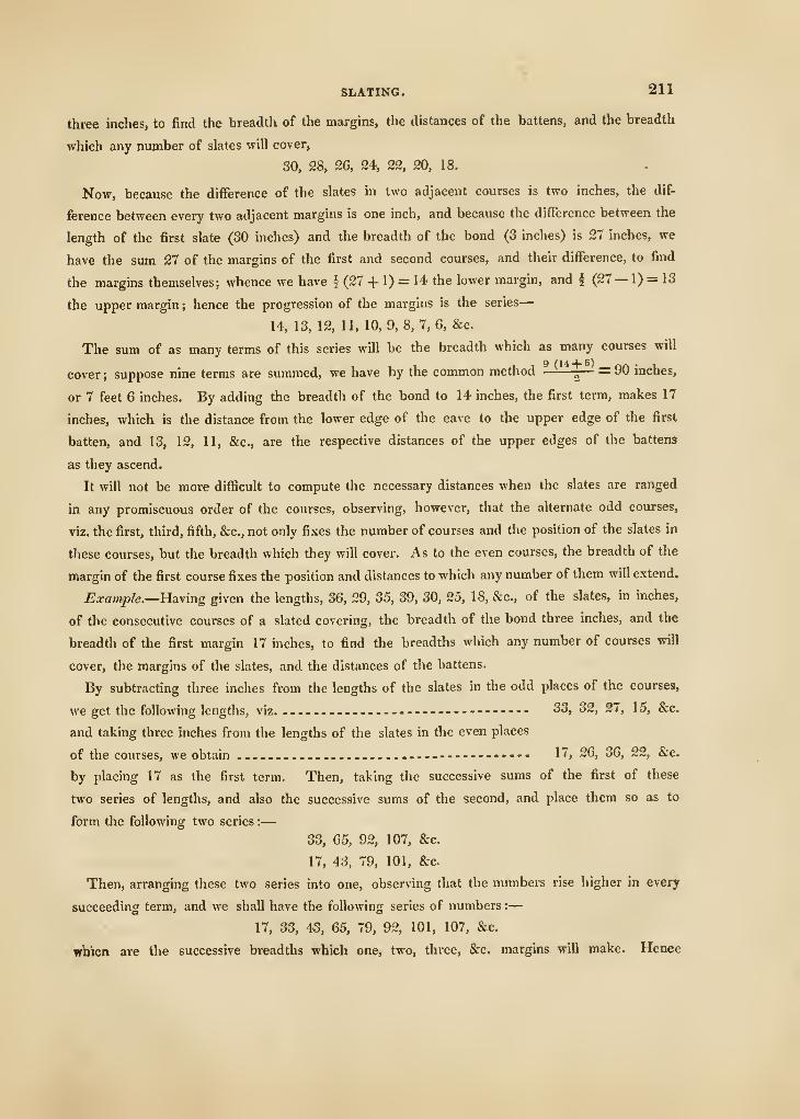
SLATING. 211
three inches, to find the breadth of the margins, the distances of the battens, and the breadth
which any number of slates will cover,
30, 28, 26, 24, 22, 20, 18.
Now, because the difference of the slates in two adjacent courses is two inches, the dif-
ference between every two adjacent margins is one inch, and because the difference between the
length of the first slate (30 inches) and the breadth of the bond (3 inches) is 27 inches, we
have the sum 27 of the margins of the first and second courses, and their difference, to find
the margins themselves; whence we have f (27 + 1) = 14 the lower margin, and | (27— 1) = 13
the upper margin ; hence the progression of the margins is the series
—
14, 13, 12, 11, 10,9,8,7,6, &c.
The sum of as many terms of this series will be the breadth which as many courses will
cover ; suppose nine terms are summed, we have by the common method — = 90 inches,
or 7 feet 6 inches. By adding the breadth of the bond to 14 inches, the first term, makes 17
inches, which is the distance from the lower edge of the eave to the upper edge of the first
batten, and 13, 12, 11, &c., are the respective distances of the upper edges of the battens
as they ascend.
It will not be more difficult to compute the necessary distances when the slates are ranged
in any promiscuous order of the courses, observing, however, that the alternate odd courses,
viz, the first, third, fifth, &c., not only fixes the number of courses and the position of the slates in
these courses, but the breadth which they will cover. As to the even courses, the breadth of the
margin of the first course fixes the position and distances to which any number of them will extend.
Exa7}iple.—Haying given the lengths, 36, 29, 35, 39, 30, 25, 18, &c., of the slates, in inches,
of the consecutive courses of a slated covering, the breadth of the bond three inches, and the
breadth of the first margin 17 inches, to find the breadths which any number of courses will
cover, the margins of the slates, and the distances of the battens.
By subtracting three inches from the lengths of the slates in the odd places of the courses,
we get the following lengths, viz. . ....... 33, 32, 27, 15, &c.
and taking three inches from the lengths of the slates in the even places
of the courses, we obtain ..... 17, 26, 36, 22, &c.
by placing 17 as the first term. Then, taking the successive sums of the first of these
two series of lengths, and also the successive sums of the second, and place them so as to
form the following two series :
—
33, 65, 92, 107, &c.
17, 43, 79, 101, &c.
Then, arranging these two series into one, observing that the numbers rise higher in every
succeeding term, and we shall have the following series of numbers :
—
17, 33, 43, 65, 79, 92, 101, 107, &e.
wb'icn are the successive breadths which one, two, three, &c. margins will make. Hence
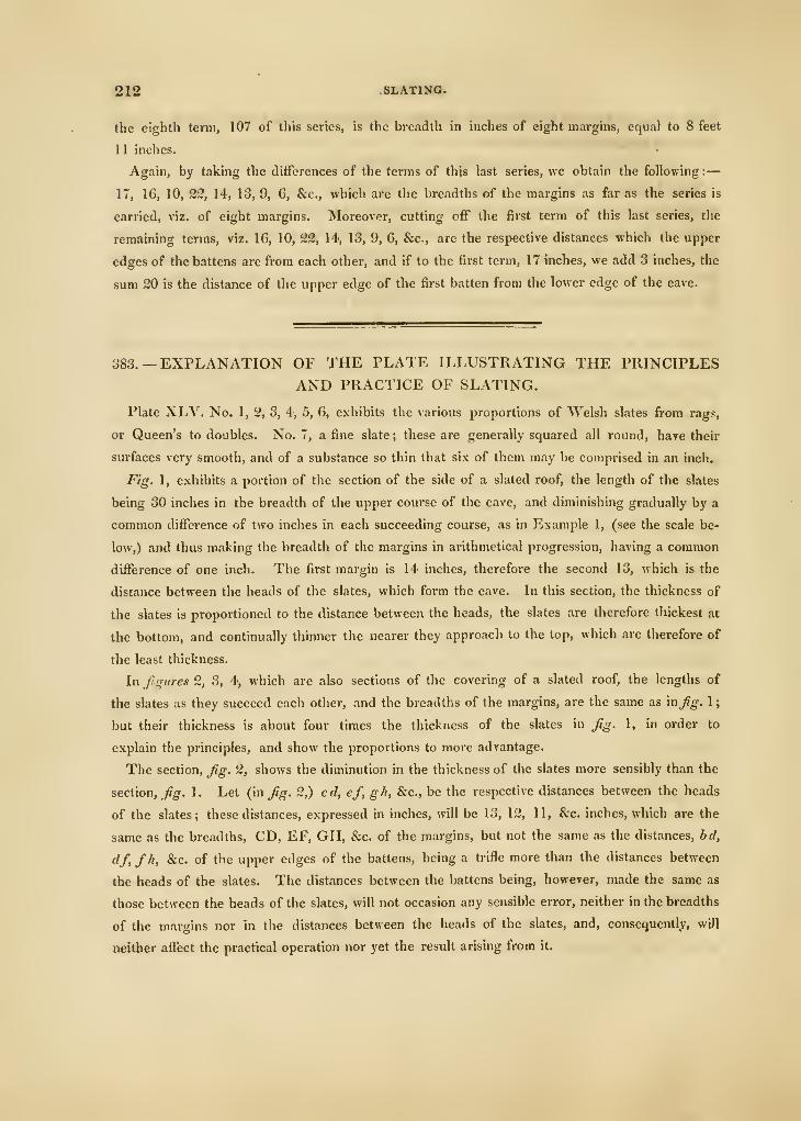
212 SLATING.
the eighth term, 107 of this series, is the breadth in inches of eight margins, equal to 8 feet
1 1 inches.
Again, by taking the differences of the terms of this last series, we obtain the following :
—
17, 16, 10, 22, 14, 13, 9, 6, &c., which are the breadths of the margins as far as the series is
carried, viz. of eight margins. Moreover, cutting off the first term of this last series, the
remaining terms, viz. 16, 10, 22, 14, 13, 9, 6, &c., are the respective distances which the upper
edges of the battens are from each other, and if to the first term, 17 inches, we add 3 inches, the
sum 20 is the distance of the upper edge of the first batten from the lower edge of the eave.
383. — EXPLANATION OF THE PLATE ILLUSTRATING THE PRINCIPLES
AND PRACTICE OF SLATING.
Plate XLV. No. 1, 2, 3, 4, 5, 6, exhibits the various proportions of Welsh slates from rags,
or Queen's to doubles. No. 7, a fine slate ; these are generally squared all round, have their
surfaces very smooth, and of a substance so thin that six of them may be comprised in an inch.
Fig. 1, exhibits a portion of the section of the side of a slated roof, the length of the slates
being 30 inches in the breadth of the upper course of the eave, and diminishing gradually by a
common difl^erence of two inches in each succeeding course, as in Example 1, (see the scale be-
low,) and thus making the breadth of the margins in arithmetical progression, having a common
difference of one inch. The first margin is 14 inches, therefore the second 13, which is the
distance between the heads of the slates, which form the eave. In this section, the thickness of
the slates is proportioned to the distance between the heads, the slates are therefore thickest ai
the bottom, and continually thinner the nearer they approach to the top, which are therefore of
the least thickness.
In ftqiire.1 2, 3, 4, which are also sections of the covering of a slated roof, the lengths of
the slates as they succeed each other, and the breadths of the margins, are the same as inJig. 1
;
but their thickness is about four times the tliickness of the slates in Jig. 1, in order to
explain the principles, and show the proportions to more advantage.
The section, Jtg. 2, shows the diminution in the thickness of the slates more sensibly than the
section. Jig. 1. Let (in Jig. 2,) cd, ej, gh, &c., be the respective distances between the heads
of the slates; these distances, expressed in inches, will be 13, 12, 11, &c. inches, which are the
same as the breadths, CD, EF, GH, &c. of the margins, but not the same as the distances, bd,
df, fh, &c. of the upper edges of the battens, being a tiifle more than the distances between
the heads of the slates. The distances between the battens being, however, made the same as
those between the heads of the slates, will not occasion any sensible error, neither in the breadths
of the margins nor in the distances between the heads of the slates, and, consequently, will
neither affect the practical operation nor yet the result arising from it.
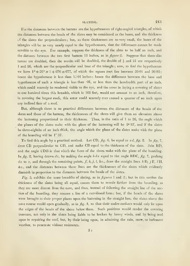
SLATING. 213
For the distances between the battens are the hypothenuses of right-angled triangles, of which
the distances between the heads of the slates may be considered as the bases, and the thickness
cf the slates the perpendiculars ; but, as these thicknesses are so very small, the bases of the
triangles will be so very nearly equal to the hypothenuses, that the differences cannot be made
sensible to the eye. For example, suppose the thickness of the slate to be half an inch, and
the distance between the two first battens 13 inches, as m figure 2. Suppose that these dis-
tances are doubled, then the results will be doubled, the double of \ and 13 are respectively
1 and 26, which are the perpendicular ana base of the triangle ; now, to find the hypothenuse
we have P-f-262= 1 -f 076 = 677, of which the square root lies between 26-01 and 2602
;
hence the hypothenuse is less than IS'Ol inches ; hence the difference between the base and
hypothenuse of such a triangle is less than '01, or less than the hundredth part of an inch,
which could scarcely be rendered visible to the eye, and the error in laying a covering of slates
to one hundred times this breadth, which is 108 feet, would not amount to an inch, therefore,
in covering the largest roofs, this error could scarcely ever exceed a quarter of an inch upon
any inclined face of a roof.
But, although there is no practical differences between the distances of the heads of the
slates and those of the battens, the thicknesses of the slates will give them an elevation above
the battening proportional to their thickness. Thus, in the ratio of 1 to 26, the angle which
the planes of the slates make with the plane of the battening will be 2° 12', and if the slates
be three-eighths of an inch thick, the angle which the plane of the slates make with the plane
of the boarding will be 1° 33'.
To find this angle by a practical method. Let CD, fig. 6, be equal to cd, fig. 2. In fig. 7,
draw CB perpendicular to CD, and make CB equal to the thickness of the slate. Join BD,
and the angle CDB is that which the faces of the slates make with the plane of the boarding.
In fig, 2, having drawn dc, by making the angle bdc equal to the angle BDC, fig. 7, prolong
dc to V, and through the remaining points, /, h,j, I, &c., draw the straight lines // D, ^' F, /H,
&c., and the distances between these lines are the thicknesses of the slates which evidently
diminish in proportion to the distances between the heads of the slates.
Fig. 3, exhibits the same breadths of slating, as in figures 1 and 2 ; but in this section the
thickness of the slates being all equal, causes them to recede farther from tiie boarding, as
they are more distant from the eave, and thus, instead of following the straight line of the sec-
tion of the boarding, they assume a line of a curvilineal form ; but, if the heads of the slates
were brought to their proper places upon the battening in the straight line, the slates above the
eave course would open gradually, as in fig. 4-, so that their under-surfaces would only lie upon
the edges of the heads of the slates below them. Such positions would render the covering
insecure, not only in the slates being liable to be broken by heavy winds, and by being trod
upon in repairing the roof, but, by their being open, in admitting the rain, snow, or inclement
weather, to penetrate without resistance.
3i
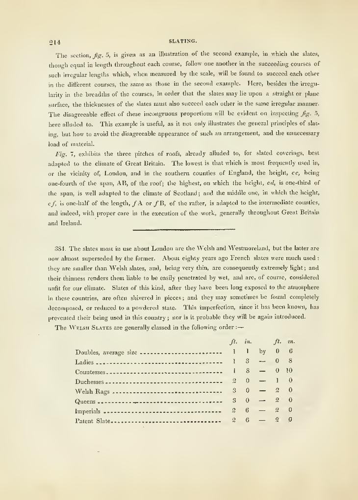
214 SLATING.
The section, fig. 5, is given as an illustration of the second example, in which the slates,
thou^^h equal in length throughout each course, follow one another in the succeeding courses of
such irrei^ular lengths which, when measured by the scale, will be found to succeed each other
in the different courses, the same as those in the second example. Here, besides the irregu-
larity in the breadths of the courses, in order that the slates may lie upon a straight or plane
surface, the thicknesses of the slates must also succeed each other in the same irregular manner.
The disagreeable effect of these incongruous proportions will be evident on inspecting fg. 5,
here alluded to. This example is useful, as it not only illustrates the general principles of slat-
ing, but how to avoid the disagreeable appearance of such an arrangement, and the unnecessary
load of material.
Fig. 7, exhibits the three pitches of roofs, already alluded to, for slated coverings, best
adapted to the climate of Great Britain. The lowest is that which is most frequently used in,
or the vicinity of, London, and in the southern counties of England, the height, ce, being
one-fourth of the span, AB, of the roof; the highest, on which the height, cd, is one-third of
the span, is well adapted to the climate of Scotland ; and the middle one, in which the height,
cf, is one-half of the length, /A or /B, of the rafter, is adapted to the intermediate counties,
and indeed, with proper care in the execution of the work, generally throughout Great Britain
and Ireland.
384. The slates most in use about London are the Welsh and Westmoreland, but the latter are
now almost superseded by the former. About eighty years ago French slates were much used :
they are smaller than Welsh slates, and, being very thin, are consequently extremely light ; and
their thinness renders them liable to be easily penetrated by wet, and are, of course, considered
unfit for our cUmate. Slates of this kind, after they have been long exposed to the atmosphere
in these countries, are often shivered in pieces ; and they may sometimes be found completely
decomposed, or reduced to a powdered state. This imperfection, since it has been known, has
prevented their being used in this country ; nor is it probable they will be again introduced.
The Welsh Slates are generally classed in the following order :
—
ft. in. ft. tn.
Doubles, average size .-.-. 1 1 hy 6
Ladies 13-08Countesses -- 18 — 10
Duchesses 2 — 10Welsh Rags 3 — 20Queens ^ 3 — 20Imperials 2 6 — 20Patent Slate 2 6 — 2 .0
SLATING. 215
The Doubles are so called from their small size. These are made from the fragments of the
larger qualities, as they are sorted, respectively.
The Ladies are made up from fragments, as above, in pieces that will square up to the size
of such a description of slate.
Countesses are in size the next gradation above ladles; and Duchesses still larger.
385. The Imperial Slating, for roofs, is particularly neat, and is known by having its
lower edge sawn ; whereas all the other slates, used for covering, are only chipped square on
their edges.
386. Patent Slating is so called, among the slaters, from the peculiar mode of laying it on
roofs, but we are not aware of any patent for it being ever obtained. It was first brought into
notice by the late James Wyatt, Esq. the architect of our late revered king, George the Third.
Patent slating may be laid on rafters of much less elevation than any other kind of slating ; it is
considerably lighter ; because the breadths of the laps are much less than the slates adopted for
the common sort of slating. Patent slating was originally composed of slates called the Welsh
Rags, but at the present time it is composed of the Inqjerials, which are lighter, and much
neater in appearance. Neither battens nor boarding is required for these slates; but the
common rafters should be left loose on the purlins, so that a rafter may be fixed under each of
the meeting-joints of the rows of slates. The work of covering is then performed, as already
described, except that no bond is required, the slates being laid uniformly, and screwed down
by two or three strong one-and-a-half inch screws at each end into the rafters beneath.
Filleting is now commenced, which consists in covering the meeting-joints with fillets of
slates, bedded in putty, and screwing them down through the whole into the rafters. These
fillets are then neatly pointed up with more putty, and then painted, to resemble the slates.
The hips and ridges of roofs are sometimes filleted, but lead is preferable. The Patent Slating
may thus be laid, perfectly water-tight, with a rise of two inches in one foot of a rafter.
These are the general modes of laying slates ; and for peculiar neatness they are sometimes
laid in a lozenge form, but as, in this form, only one nail can be used to each slate, thus laid
they soon become dilapidated.
387. On the Westmoreland Slate, some experiments were made by Dr. Watson, the late
Bishop of LlandafF, whence it appears that there is very little difference in the natural compo-
sition of this kind of slate and that of Wales. The bishop's comparison of their absolute
weight, as compared with the weight of other materials made use of as a covering to buildings,
may be of great utility, inasmuch as it may tend towards forming a datum for adding to, or
diminishing from, the quantity of timber employed in roofs of different spans and elevations.
" That sort of slate," says his lordship, " other circumstances being the same, is esteemed the
best, which imbibes the least water ; for the imbibed water not only increases the weight of the
covering, but, in frosty weather, being converted into ice, it swells and shivers the slate. This
eflect of the frost is very sensible in tiled houses, but it is scarcely felt in slated ones ; for good
216 SLATING.
slate imbibes but little water ; and, when tiles are well glazed they are rendered, in some measure,
with respect to this point, similar to slate." He adds, " I took a piece of Westmoreland
slate and a piece of common tile, and weighed each of thera carefully ; the surface of each was
about thirty square inches ; both the pieces were immersed in water for ten minutes, and then
taken out and weighed as soon as they had ceased to drip, and it was found that the tile had
imbibed about one-seventh part of its weight of water, and the slate had not imbibed a two-
hundredth part of its weight. Indeed the wetting of the slate was merely superficial, while the
tile, in some measure, became saturated with the water. I then placed both the wet pieces
before the fire ; in a quarter of an hour's time the slate was become quite dry, and of the same
weight it had before it was put into the water ; but the tile had lost only about twelve grains of
the water it had imbibed, which was, as near as could be expected, the same quantity that had
been spread on its surface ; for it was this quantity only which had been imbibed by the slate,
the surfiice of which was equal to that of the tile. The tile was left to dry in a room heated
to 60° of Fahrenheit, and it did not lose all the water imbibed in less than six days." He adds,
further, " that the finest sort of Westmoreland slate is sold at Kendal at 3s. 6d. per load, which
will amount to 1/. I5s. per ton, the load weighing two hundred weight. The coarser sort may
be had at '2s. id. a load, or 1/. Ss. id. per ton. Thirteen loads of the finest sort will cover
forty-two square yards of roofing, and eighteen loads of the coarsest will cover the same quan-
tity ; so that there is half a ton less weight put upon forty-two square yards of roofs, when the
finest sort of slate is used, than if it was covered with the coarsest kind, and the difference of
expense only three shillings and sixpence." It must be remarked, that this slate owes its light-
ness, not so much to any diversity in the component parts of the stone from which it is split, as
to the thinness to which the workmen reduce it, and it is not so well calculated to resist violent
winds as that which is heavier.
COMPARISON IN WEIGHT OF THE SUNDRY COVERINGS EMPLOYEDON ROOFS.
388. A Common Plain Tile weighs thirty-seven ounces, and they are used, at a medium, seven
hundred to cover a single square of roof of one hundred superficial feet.
A Pan-tile weighs seventy-six ounces, or four pounds and three-quarters, and one hundred
and eighty are required to lay on a single square of roof.
Both the plain and pan tiles are commonly bedded in mortar ; indeed the former cannot be well
laid on a roof without it. The mortar used may be about one-fourth of the weight of the tiles.
Common Lead or Copper, for covering roofs, generally requires seven pounds of the former,
and seven ounces of the latter, for each superficial foot. A square of one hundred feet covered
with the above materials stand relatively thus :
—
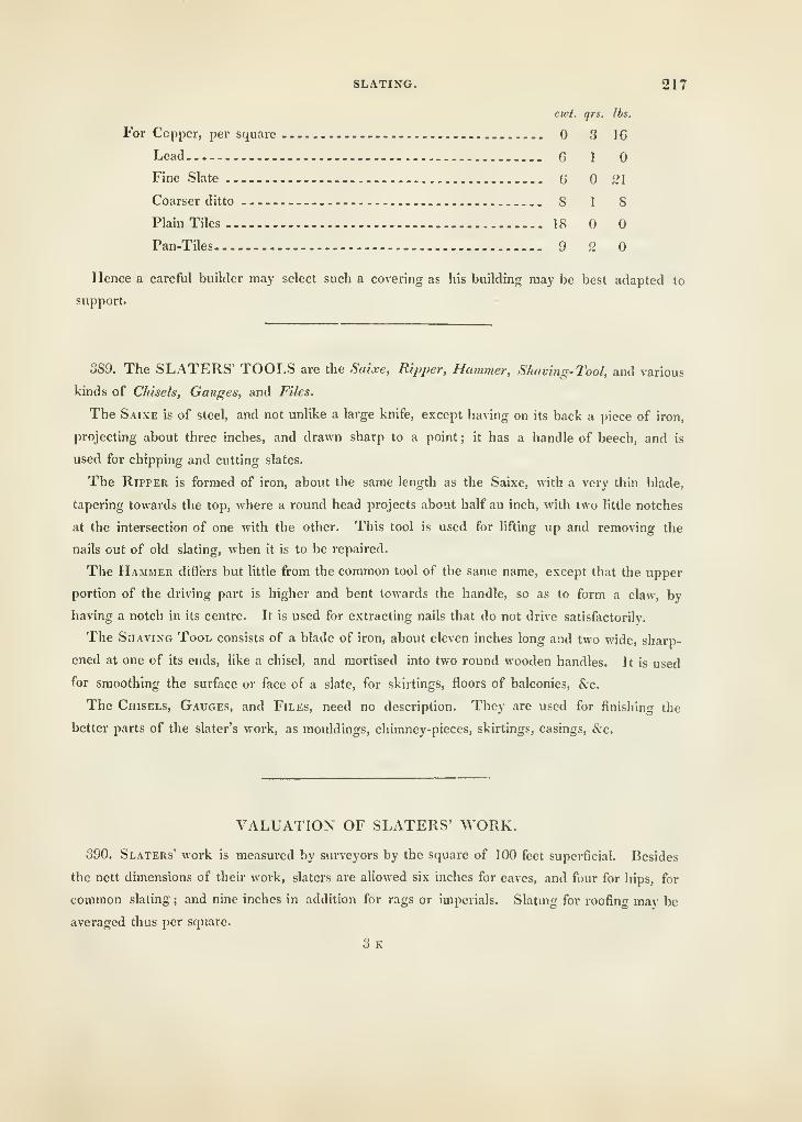
SLATING. 217
cwt. qrs. lbs.
For Copper, per square 3 16
Lead G 1
Fine Slate G 21
Coarser ditto 8 1 8
Plain Tiles 18
Pan-Tiles 9 2
Hence a careful builder may select such a covering as his building may be best adapted to
support.
389. The SLATERS' TOOLS are the Saixe, Ripper, Hammer, Shaving-Tool, and various
kinds of Chisels, Gauges, and Files.
The Saixe is of steel, and not unlike a large knife, except having on its back a piece of iron,
projecting about three inches, and drawn sharp to a point ; it has a handle of beech, and is
used for chipping and cutting slates.
The Ripper is formed of iron, about the same length as the Saixe, with a very thin blade,
tapering towards the top, where a round head projects about half an inch, with two little notches
at the intersection of one with the other. This tool is used for lifting up and removing the
nails out of old slating, when it is to be repaired.
The Hammer differs but little from the common tool of the same name, except that the upper
portion of the driving part is higher and bent towards the handle, so as to form a claw, by
having a notch in its centre. It is used for extracting nails that do not drive satisfactorily.
The Shaving Tool consists of a blade of iron, about eleven inches long and two wide, sharp-
ened at one of its ends, like a chisel, and mortised into two round wooden handles. It is used
for smoothing the surface or face of a slate, for skirtings, floors of balconies, &c.
The Chisels, Gauges, and Files, need no description. They are used for finishing the
better p.arts of the slater's work, as mouldings, chimney-pieces, skirtings, casings, &c.
VALUATION OF SLATERS' WORK.
390. Slaters' work is measured by surveyors by the square of 100 feet superficial. Besides
the nett dimensions of their work, slaters are allowed six inches for eaves, and four for hips, for
common slating ; and nine inches in addition for rags or imperials. Slating for roofing may be
averaged thus per square.
3k
218 SLATING.
£. 4. d.
Doubles 2 2
Countesses 2 12 6
Welsh Rags and Imperials- -- 3 13 6
Westmoreland — --- - ^ ^^ (>
Slaters' work, for galleries, varies, according to the mouldings, from 4s. 6f/. to 5i. 6(/. per
foot superficial; skirtings and facings from \s.M. to 2*. per foot. Chimney-pieces, &c. are
sold at so much per piece.
391.—EXPLANATION OF THE TERMS USED IN SLATING.
Back of a Slate.—The upper side of it.
Backer.—A narrow slate put on the back of a broad square-headed slate when the slates
begin to get narrow.
Bed of a Slate.—The lower side of it.
Bond or Lap of a Slate.—The distance between the nail of the under slate, and the lower
end of the upper slate.
Eave.—The skirt or lower part of the slating hanging over the naked of the wall.
Holing.—The piercing of slates for the admission of nails.
Margin of a Course.—Those parts of the backs of the slates exposed to the weather.
Nails.—Pointed iron, or copper, or zinc, of a pyramidal form, for fastening the slates to the
laths or boarding. They are commonly of the description or shape of clout-nails.
Patent Slates.—Those which are used without boarding, and screwed to the rafters, with
slips of slates, bedded in putty, to cover the joints.
Scantle.—A gauge by which slates are regulated to their proper length.
Sorting.—Regulating slates to their proper length by means of the scantle.
Squaring.—Cutting or paring the sides and bottom of the slates.
Tail.—The bottom or lower end of the slate.
Trimming.—Cutting or paring the side and bottom edges of a slate, the head of the slate
never being cut.
PLUMBlNti. - 21U
BOOK V.
PLUMBING, PAINTING, AND GLAZING.
CHAPTER I.
PLUMBERY OR TLUMBING.
392. Plumbery comprehends tlic practice of casting and laying sheets of lead, also making
and forming pumps, cisterns, reservoirs, water-closets, &c. The ductility of lead enables the
plumber to effect his operations by means of tools, few in number, and simple in construction.
393. Lead, the metal in which the plumber chiefly works, is distinguished for durability and
malleability. It is a white metal of a considerable blue tinge, very soft and flexible, not very
tenacious, and consequently incapable of being drawn into very fine wire, though it is easily
extended into thin plates under the hammer. Its specific gravity is 11'35. ; it melts at G12°, in
a strong heat it boils and emits noxious fumes. Lead is brittle at the time of congelation. In
this state it may be broken into fragments with a hammer.
Lead is not much altered by exposure to air or water, though the brightness of its surface,
when cut or scraped, very soon goes off. It is probable, that a thin stratum of oxyde is
formed on the surface which defends the rest of the metal from corrosion.
Every kind of metal becomes more difficult of corrosion or oxydation when its specific gra-
vity is increased by condensation, this may be effected either by the hammer or passing it
through rollers. Sheet-lead is used in two distinct states by plumbers, the first is that in which
it is cast, and in this state it is applied as a covering to the flat-roofs, gutters, and other parts of
buildings, also for lining cisterns or reservoirs where water is kept. In architecture, it is tech-
nically divided into 5, 5\, 6, 6§, 7, 1\, 8, 87 lbs. cast-lead, by which it is understood that every
foot superficial of such cast-sheet lead is to contain one or other of these weights.
394. Large sheets of lead are cast in the following manner :—The lead destined for this use is
melted in a large cauldron or furnace, formed mostly of free-stone. At the bottom, a place is
sunk lower than the rest in which is placed an iron pot or pan to receive what may remain of
the metal after the sheet is run. The furnace is so raised above the area of the floor, as that
220 PLUMBING.
tlie iron pot just rests upon it. In using tlie furnace, they heat it with wood, whicli is placed
within it and ignited, and then the lead is thrown in at random with the burning fuel to melt.
Near the furnace is the table or mould on which the lead is to be cast. This is formed of
large pieces of wood well jointed, and bound with bars of iron at the ends. Around it runs a
frame or ledge of wood three inches thick, and about two inches high from the table, technically
culled the sharps. The ordinary width of the tables is from three to four feet, and their length
from eighteen to twenty feet.
This table is covered with a stratum of fine sand slightly moistened with water, taking care
to use no more than will just make it bind together when closely pressed. The sand in this
state is closely compressed by beating it with a mallet, the surface being reduced to a plane by
a straight edge of brass or wood.
Over the table is a strike or rake of wood which bears and plays on the edges of the frame,
by means of a notch cut in either end of it, and is so placed as that, between it and the sand,
is a space proportionable to the intended tliickness of the sheet of metal to be cast. Tliis
strike is used to drive the metal, while yet liquid, to the extremity of the mould.
At the top of the table is a triangular peel or shovel, bearing before on the edge of the table
itself, and behind on a kind of tressel, somewhat lower than the table ; its use is in conveying
the metal into the mould, and the design of its oblique disposition is, that it may by that means
be able to retain the metal, and keep it from running off at the fore-side, where it has no ledge,
some of these peels are large enough to hold fifteen hundred weight.
^^^len the apparatus is thus disposed, with a large iron ladle they take the melted lead, coals,
and all out of the furnace, and with this, mixed as it is, they fill the iron peel. When full,
they take out the coals, and clean the lead with another iron spoon, pierced after the manner of
a scummer ; they then hoist up the lower part of the peel by its handle, upon which the liquid
matter running off, and spreading itself upon the mould, the plumber conducts and drives it to
the extremity of the table by means of the strike, which he passes along the ledges, and thus
renders the sheet of an equal thickness. The sheets thus cast, there remains nothing to do,
but to planish the edges on both sides, in order to render them smooth and straight.
Where it is desirable to increase the durability of lead, as in the cases of being very much
exposed to sun or wet, it is now usually rolled between the rollers of a flatting mill. The lami-
nation increases the specific gravity of the metal, and makes it resist oxydation much longer.
This process is performed most commonly at the furnaces where the ore is reduced, the rollers
being of immense dimensions, and requiring great power to drive them.
395. Lead Pipes are universally employed for small watex'-pipes, chiefly from the facility of
bending them in any direction, and also the capability of soldering their joints. Although some
kinds of water corrode the metal by degrees, this will not produce so much harm as iron under the
same circumstances, but would be a most dangerous poison if it was used in sufficient quantities
to have any effect at all.
PLUMBING. 221
Tlie method now very generally adopted in the manufacture of leaden pipes, is to cast the lead
in an iron mould, upon a cylindrical iron rod of the size for the bore of the intended pipe, the
lead being three or four times the thickness of the intended pipe ; and in short lengths, which
are then drawn through holes in pieces of steel, in the manner of wire drawing, till the pipe is
reduced to the intended thickness, and drawn out to the proper length. Another method is to
reduce the pipe by repeatedly passing it through the two rollers of a flatting mill, in each of
which a number of semi-circular notches or grooves are formed all round, so that the two rollers
when put together, have a number of circular cavities between them, which gradually diminish
in diameter from one end of the rollers to the other.
The pipe is first rolled between the largest of these cavities, then in a smaller one, and so on
to the last, which extends the pipe to its proper length, and diminishes its substance to the proper
thickness, at the same time, by condensing the metal, hardens it, and makes a very strong tube
with very little metal. Mr. John Wilkinson, of Broseley, obtained a patent, in 1790, for the last
named method, which he practised on a very extensive scale. Since the expiration of this
patent, many manufactories of this article have been established, some employing rollers, and
others the draw-bench for extending the pipes.
396. Solder is used for uniting the joints of leaden work, and it should more readily acquire
a state of fusion than the metal intended to be soldered thereby, and be of the same colour. The
solder generally made use of by the plumber, is called soft solder, and is made of tin and lead,
in equal parts, fused together, and run into moulds like a common gridiron ; in this state it is
purchased of the manufacturer by the plumber at so much per pound, according to the price of
the market.
397. Laying of Sheet Lead. The ground for sheet lead, whether it be of plaster or boards,
should be perfectly even, otherwise the work will be bad, unsightly, and liable to crack. The
sheets not being more than six feet in width, make it necessary that they should sometimes be
joined ; this is performed either by seams or rolls. The seams are formed by bending the two
edges of the lead up, and over each other, and then dressing them down close. The rolls are
formed by fastening a piece of wood about two inches square under the joints of the lead, and
dressing one of the edges of the lead over the roll on the inside, and the other edge over both
of them on the outside, and then fastening them down by hammering. Soldering is sometimes
used for joining two sheets; but this mode should be rejected on account of its liability to crack
when exposed to alternate expansion and contraction, occasioned by heat and cold. All sheet
lead should be laid with a current to keep it as dry as possible ; and for this purpose the boarding
or ground upon which it is laid, should have a fall of about one quarter of an inch to every foot
upon which the lead is laid.
398. Drips on Flats or Gutters are formed also in the preceding manner, and by dressing
the joints of the lead as described for rolls. This is used to avoid solder, and keep the work dry.
399. Flashings are pieces of milled lead about eight or nine inches vide, and are fixed round
22'2 PLUMBINCi.
the extreme edf^e of a flat or gutter in which lead has been used. One edge is dressed over the
lead of the flat or gutter, and the other fastened, either by passing it into the joints of brick work,
or fixing it by means of wall-hooks.
The pipes used by plumbers vary, in the diameter of their bores, from half an inch to two
inches. Socket pipes are those which are used for conveying superfluous water from roofs, Sec,
and are usually from three to five inches diameter. These are made of milled lead, in lengths of
eight or ten feet, dressed on a cylindrical core of wood, and fastened at the vertical joinings with
solder ; the horizontal joints are formed by an astragal moulding in a separate piece of lead, about
three inches wide, which laps completely over it, both above and below the joint, and hence it is
called a lap-joint. Two broad pieces of lead, called tachs, are attached to tlie back lap joints,
and spread out right and left for fastening the pipes to a wall by means of wall hooks. The
cistern head, which is fixed to the upper end of rain-water pipes, is either made of sheet lead,
or cast in a mould, and fastened by tacks as above described.
400. Pumps. Those supplied to the public by plumbers are usually made by engineers, who have
suitable apparatus for boring the barrels, they being made of brass, or metal very similar in its
nature. They may be divided into three distinct kinds, namely. Sucking, Lifting, and Forcing
Pumps. Forcing pumps are now but little used ; the lifting and sucking pumps being proved by
experience to be the best for most domestic purposes. The sucking pump consists of two pipes,
the barrel and suction pipe, the latter being smaller in diameter. These are joined by flanches,
having leather placed between them to make the joints water-tight. The flanches are united by
screw-bolts in the usual manner. The lower end of the suction pipe is spread out, or made funnel-
shaped to facilitate the entry of the water, and it frequently has a grating to keep out filth and
o-ravel. The working barrel is cylindrical, and as evenly bored as practicable, to give the piston
the least possible friction.
The Pixion is generally made of wood in the form of a truncated cone, the small end being
cut off at the sides so as to form a kind of an arch, by which it is fastened to the iron rod or
spindle ; the two ends of the conical part may be hooped with brass, and the larger end of the
cone uniformly surrounded with leather to some distance below its base. This leather band
should be sufliciently large to render the piston uir tight, without causing unnecessary friction.
The Lifting Pump consists, as in the former, of a working barrel, which is closed at both
ends. The piston is usually solid, and its rod passes through a collar of leather, or a stuffing
box, in the plate, which closes the upper end of the working barrel. The barrel communicates
laterally with the suction pipe, and above with the rising main. This pump differs from the pre-
ceding only in having two valves, the lower one moveable, and the upper one fixed.
In Plate XXXIX. fig. 2, represents an elevation, and figure 3, a vertical section, of a very
perfect lifting pump, as now made by Messrs. Bramahs, the celebrated engineers, at Pimlico ; the
construction of the various parts as explained by the section, will show the extent of water-%^..y
that has been here obtained by the excellent construction and disposition of the valves, and also

PLUMBING. 223
the superior means applied in tlie upper part for keeping the piston rod lubricated with oil. Tlie
excellent proportions of all the parts, and the judicious combination of the whole, induced us to
give the two figures before-named for the benefit of our practical readers, who will here have an
opportunity of examining the internal construction engraved from a working drawing, very kindly
furnished us by Messrs. Bramah and Sons, for this work.
The Forcing Pump consists of a working barrel, a suction pipe, and serving main, or raising
pipe. The last is usually in three parts ; the first consisting of one piece, and making part of
the working barrel ; the second is joined to it by flanches, forming an elbow with it; and the
third is the beginning of tlie main, and is continued to where the water is delivered, where it
is furnished with two moveable valves. The perfection of the barrel and piston of this pump is
so great as to require neither wadding nor leather ; it is only used where it is found requisite to
force water to a considerable height.
There are a considerable variety of pumps besides those above described, but none of them
are so applicable to domestic purposes or general use, as those we have enumerated.
The materials of these pumps are manufactured to almost every required purpose, and thus
sold to the plumber, who only puts them together so as to make them produce their desired effects.
The different parts of water-closets are made in a similar way, and sold to the plumber, who
places the basin, apparatus, traps, socket pipe, cistern, and forcing or lifting pump together, so as
to put them in action.
Sheet lead is charged by the hundred weight, according to prices arranged at intervals by
the Warden and Court of Assistants of the Plumbers' Company. Milled lead is usually charged
two shillings per hundred weight more than cast lead. The best method of preserving lead when
exposed to the action of the atmosphere and water, is to place iron in close contact with it ; the
galvanic effect produced causes the iron to be oxydized, the lead being preserved almost entire
while there is iron in contact with it.
401. The tools of the plumber are few in number, and simple in construction. The following
enumeration will be deemed sufficient :
—
Centre Bits, of various sizes.
Chalk Line, used in the same manner as a carpenter's.
Compasses, are used for striking out circular portions of lead.
Cutting Knives, of various sizes ; these are used for dividing sheet lead at the mark left by
the chalk line.
Dressing and Flatting Tool.—This is made of beech, about eighteen inches long, and two
and a half square;planed smooth on one side, and rounded into an arch on the other. It is
used for stretching out and flattening the sheet lead, or dressing it into any required shape.
Files, of various sizes.
Glasing or Heating Irons, of various sizes ; about twelve inches long, and tapering at both
224 HOUSE PAINTING.
ends, the handle end being turned quite round, that it may be held firmly in the hand. The
opposite end is spindle shaped. These are used red hot in soldering.
Hammer, made of iron, which is rather heavier than those in general use.
Ladles, made of iron ; these are of various sizes, and are used for melting solder in.
Mallets, similar to the carpenter's, of various sizes.
Jack and Trying Plane for finishing the edges of sheet lead.
CHAPTER ir.
HOUSE PAINTING.
402. House Painting is that economical application of artificial colours, compounded either
with oils or water, which is employed in preserving or embellishing houses, ships, furniture, &c.
The term economical painting may with propriety be applied to the property which oil and var-
nishes possess of preventing the injurious effects of the atmosphere upon wood, iron, and stucco,
by interposing an artificial surface or covering composed of materials, which, by the peculiar che-
mical changes effected in them, are rendered capable of resisting the decomposing and destroying
qualities of the atmosphere, and thereby of preserving various substances from premature decay.
It is here intended to use the term more generally, in allusion to the decorative part, as applied
to buildings, as well as to its more essential ones, and as it is employed by the architect through-
out every part of his work, both externally and internally.
The chemical properties of the materials, and the mode of applying them is the same, either
in churches, theatres, or any other public or private buildings, or with such slight variations, as
will be readily suggested by a judicious workman. We shall now describe the principal pigment
used as a base in all house painting, and also the vehicles most commonly used to mix and dilute
the colours with.
403. White Lead is the principal ingredient used in house painting, forming the basis of most
of the neutral colours. It is obtained by rolling thin sheets of lead into coils, leaving their surfaces
about half an inch apart from each other, and then placing them vertically in earthen pots, with
a portion of good vinegar at the bottom, in such a way, that when set in a moderate heat, the
vapor of the acid oxydates the lead, producing a carbonate of lead, which may be taken off" in
white flakes when the sheets of metal are uncoiled. These flakes are then ground in linseed
oil, in which state it is sold in the market by the name of white lead. The materials so combined
are much better for being kept, and where the best and purest whites are required to be pro-
duced, it should be kept in the levigated state for at least two years. The Nottingham white
HOUSE PAINTING. 225
lead is most esteemed for whites, without gloss, commonly or technically called flatting or dead
white.
404. Linseed Oil is expressed from the seed of flax, by those who manufacture it, in large
quantities. It is the principal oil used in house painting. The worst defect of this otI is its
natural brown colour, and a tardiness in drying. The goodness of linseed oil, therefore, consists
in its near approach to a colourless state, and in its drying soon. It may, however, be used in
its simple state, by simply mixing with it some substance which will increase its drying proper-
ties. But keeping it for some considerable time, will be found to improve its quahties both for
colour and also drying. These effects will be greatly promoted by exposing it to the action of
the atmosphere and light, both of which tend to bleach and improve it. This oil may be ren-
dered much more capable of drying, by boiling it with certain substances, such as red lead, white
vitriol, sugar of lead, umber, and many other substances ; but all of these have a tendency to
increase its natural colour, and if carried to a considerable extent, render it very nearly black,
owing, in a great degree, to particles of the oil being completely carbonized.
405. Boiled Oil may be prepared by adding to each gallon of linseed oil one pound of
litharge, one pound of white vitriol, half a pound of sugar of lead, and a quarter of a pound of
umber ; boil them so long as the discolouring the oil will permit, for the oil must not be boiled so
long as to produce blackness. When the oil is taken off the fire, it may while hot be strained
through flannel, after any indissoluble portion of the ingredients have settled.
406. Oil of Turpentine is an essential oil, distilled fiom crude turpentine, and is techni-
cally called by the painters Turps ; it quickly exhales or evaporates in the air, and if mixed with
Hnseed, nut, or poppy oils, in flying off, carries with it the more volatile parts of such oils, and
causes them to dry much sooner than they otherwise would do. On this account it is very gene-
rally used as a dryer to mix with the other oils, for which "purpose it has greatly the advantage
over drying oil with regard to colour, as it is perfectly transparent and pellucid.
It is used without any other preparation than mixing it, either alone or together with drying
oil, along with the other oils and colours ; and it is not subject to any adulteration, except the
dissolving crude turpentine or resin in it, which do not greatly injure it for the purposes we are
describing. It should, however, be observed, that for all the purposes of painting it will be the
better for age ; its valuable quality for drying being greatly increased by that circumstance.
407. Litharge is an oxyde of lead, prepared in the process of refining gold and silver. It is
used in making drying oil, in the manner above described.
408. Sugar of Lead is a chemical preparation of lead, made by dissolving it in vinegar, and
reducing the salt to a crystalline state. It has a quality of making oils dry w hen mixed with them,
and on that account is very frequently used, as well in the manufacture of drying oil, as in the
common use of the oils, where it is ground up with them, together with the colours. It is also
kept ready ground with oil, and sold in a state ready to mix with colours at any time.
409. White Vitriol, or sulphate of zinc, is commonly used as a dryer. It is found as a
3 M
226 HOUSE PAINTING.
mineral substance in various parts of Europe, and may be made artificially by a peculiar appli-
cation of sulphuric acid to zinc. It is much used in making drying oils, and also when ground
with oil, and mixed with colours, to render the oil drying.
410. Putty is a compound of whiting and linseed oil, but the best is that made with drying oil
that has been very much boiled, by the use of which a composition may be formed, that will become
sufficiently hard, but will yet be tough, without being so brittle as that which is made of common
linseed oil without boiling. In all cases, the oil should be thoroughly mixed with the whiting,
and the more it is worked together the better it will be ; and for this purpose, some manufacturers
have used a kind of mill to facilitate the operation.
411. The first coatings or layers, if on wood or iron, ought always to be of white lead, the very
best that can be obtained, great care being taken to procure that which is thoroughly ground;
but previous to laying the first coat upon fir or deal of any sort, it will be requisite to destroy the
effects of the knots. These are, in general, so thoroughly saturated with pure turpentine, as to
render it one of the most difficult parts of the house painter's art to conquer ; indeed it may be
truly said, to remain at the present time a desideratum. The usual method is to dab them over
with a mixture of white lead ground in water, having a portion of red lead mixed therewith,
the liquid vehicle being parchment size ; when this is dry, they should be separately painted
over with white lead ground in oil, to which some powerful drier has been added, as red lead or
litharge, about one-fourth of either being the usual quantity. These preparations should be
smoothly finished with the brush, in the direction of the grain of the wood. When the two
coats are dry, the parts so treated should be rubbed over with pumice stone to make them
equally smooth with the other parts, and then the first coat of paint should be laid on, the colour
being rendered sufficiently liquid with linseed oil. The first coat being dry, all the nail-holes
and other imperfections should be filled up or stopped with putty, the surface being left per-
fectly smooth. The work may then receive a second coat of white lead and oil, somewhat diluted
with the essential oil of turpentine, and this should be repeated twice at least, forming three
coats in all, but in very fine works a fourth is sometimes added. Where it is intended the work
when finished should not be of a perfect white, the last coat should have a small quantity of
ivory or lamp black added, to reduce the whiteness in a slight degree, which will produce a
very pleasing effect, and will be found very serviceable in preventing the change of colour
which frequently takes place from the oil not being of sufficient age. The usual proportion
of turpentine to oil is about one-fourth of the former to three of the latter, which will
produce a glossy or shining surface ; but where the surface is required to be without gloss,
as in all the better sorts of work, and which is technically called flatted, then the colour,
whether it be pure white or any compound tint, must be made sufficiently thin with turpentine,
and when used in that state, it will dry without any gloss upon the surface, and consequently
reflect to the eye of the beholder one uniform flat tint. It may be requisite to obser\e
here, that as the colour mixed with a large proportion of oil dries much slower than where
HOUSE PAINTING.
a large proportion of turpentine is used, little difficulty is experienced in laying it on large sur-
faces perfectly even, the one part blending into the other very easily, but, in flatted work, con-
siderable management is requisite, as well as considerable activity, on account of the rapid drying
of the colour ; and for this purpose, where the sides of very lofty apartments are to be covered
in that manner, it is frequently necessary to have two persons employed at the same time, upon
nearly the same part. The best mode of proceeding is to begin at the top of the right hand
side of the compartment to be flatted, taking care not to cover a larger stripe or portion than
can be completely effected before the upper part becomes dry ; and if this be properly accom-
plished, the joinings will not be visible ; but where the sides of a room are too lofty for one
person to effect the object in time, then two must be employed to ensure success, it being almost
impossible to produce a flat tint, where a new portion is joined upon a part already dry, or
nearly so. It must also be observed, that two coats in oil, and then two in turpentine, are neces-
sary for all new work that is to be well executed. Flatted work, owing to its want of gloss, is
more likely to soil by being touched, than work executed in oil ; but its superior delicacy, and
also the property it has of retaining its colour, renders it indispensable for all situations where
delicacy and durability of colour are necessary. It should, however, be observed, that as a very
small portion of oil is used, namely, that only that is necessary to grind the colour with, it is
inapplicable to parts that are exposed to the weather, preservation being in that case the prin-
cipal object.
What has been here stated may suffice as to painting on wood, either on outside or inside works;
the former being seldom executed otherwise than in oil, three or four coats being generally quite
sufficient. But as the painting of stuccoed walls (not previously painted) require considerable
care, we shall now offer such observations and directions as, if attended to, will render that
department easy and certain of attainment.
412. In order to succeed in painting stucco, not only the plastered surface should be tho-
roughly dry, but the brick-work upon which it is laid should also be completely free from damp
or moisture, which can only be the case where the walls have been erected a sufficient time to
permit the mass to attain perfect dryness. Indeed, the greatest part of the mystery of painting
stucco, so as to answer the intended purpose of standing and wearing well, consists in attending
most scrupulously to these observations, for whoever has observed the expansive power of water,
not only in congelation, but also in evaporation, must be well aware, that when it meets with any
foreign body obstructing its escape, as oil-painting for instance, it immediately resists it, forming
a number of vesicles or particles, containing an acrid lime-water, which forces off the layers of
plaster, and frequently causes large defective patches, extremely difficult to be repaired. In
those works where persons have an interest in the durability, two years is certainly not too \ona
a time to thoroughly dry both the walls and plaster ; but in speculative works, even a few weeks
are scarcely allowed, and hence the bad appearance of such works in such a very short period of
time after they are executed.
228 HOUSE PAINTING.
If these precautions be duly attended to, tlicrc can be no better mode adopted for priming or
l.iviii<^ on the first coat on stucco, than by using boiled linseed oil, prepared as above-desciibed,
takin" care to lay it on very evenly, so as to leave the surface very smooth, and not more than
tlie stucco will absorb. It should then be covered with at least three coats of white lead and
oil. takincf care to let two or three days intervene between each coat.
If the stucco be intended to be finished of any given tint, as grey, light green, apricot, &c., it
u ill then be proper about the third coat of painting, to prepare the ground for the desired tint
by a slight advance towards it.
Grey is made with white lead, Prussian blue, ivory black, and lake. Sage green, pea and sea
"reens, with white, Prussian blue, and fine chrome yellow. Apricot and peach, with lake, white,
Chinese vermilion and chrome yellow. Fawn colour, with burnt terra sienna or umber and white.
Olive greens, with fine Prussian blue and Oxfordshire ochre.
In some cases it may be absolutely necessary to inhabit buildings before the walls are suffi-
ciently dry to receive a coating of oil paint ; the colouring in distemper must then be resorted to,
which being a covering of water-colour fixed by size, may be washed oft' and completely
removed at any time when the walls are considered to be perfectly dry and fit to receive the oil
colour.
413. DisTEMPUK. In this kind of painting, the white colour or base most commonly used is the
finest whitintT, which is prepared in large quantities by various manufacturers. The colours most
commonly mixed with it for producing the various tints are as follows :—Straw colour, may be made
with white and masticot or Dutch pink ; fine greys, with white and refiner's verditer ; an inferior
grey may be compounded with blue black or bone black, and damp blue or indigo;pea greens,
with French green, Olympian green ; and fawn colour, with burnt terra sienna or burnt umber and
white, and so of any intermediate tint. All the colours used in distemper, should either be
ground very fine, or washed over so as to ensure the most minute division of their particles. In
general, the size made of common glue is used with a proper quantity of water to render the
colour liquid, but where the work will afford it, parchment size will be found greatly superior.
It will not require less than two coats of any of the foregoing colours, in order to cover the
plaster, and bear out with an uniform appearance.
When old iilastering has become discoloured by stains, and it be desired to have it painted in
distemper, it is then advisable to give the old plaster, when properly cleaned off and prepared,
one coat at least of white lead ground in oil, and used with spirits of turpentine, which will
generally cover all old stains, and when quite dry will take the water colours very kindly.
The above process will also apply to old wainscotings, in cases where temporary painting is only
required ; but of course such a method cannot be recommended for durability.
In every kind of painting, but particularly in oil-painting, the greatest degree of cleanliness
should be rigidly enforced. The brushes and all the utensils should be freed from the portions
of paint that will dry upon them from time to time, by scraping and washing, which may be done
GLAZING. 229
with a blunt knife and strong soap and water, for if this be not done, the colours will soon become
very foul, and the work will in such cases be very inferior.
414. Graining. This is a kind of ornamental painting, lately used to a considerable extent in
the decoration of houses. It consists of imitating, by means of painting, various kinds of rare
woods, as satin-wood, mahogany, rose-wood, &c., and likewise various species of marble. For
this kind of work the painter is furnished with several camels' hair pencils, and with one or more
flat hogs' hair brushes. An even ground is first laid of a mixture of white lead, and the colour
required, diluted with oil of turpentine. This is left for a day or two to get thoroughly dry. The
painter then prepares his palette-board with small quantities of the colour required, and having
some boiled oil and turpentine mixed together, tries the effect of the tint by spreading it over a
panel, and if it suits, perseveres by doing a single panel at a time. The shades and graining is
then produced by dipping the flat hogs' hair brushes in the mixture of oil and turpentine, and
drawing it down the newly-laid colours. The other particular appearance required, is produced
by means of the camels' hair pencil. When all is fixed and dry, the whole is covered with one
or two coats of good oil varnish. This kind of painting is not much dearer than good work in
the common way, but it will last ten times as long by being occasionally varnished, without losing
any of its freshness.
CHAPTER in.
GLAZING.
415. On glass very little has been communicated in the works of the ancients. It, indeed,
appears, from the ruins of several Grecian buildings, that they had apertures or windows ; and
it would seem, from the nature of their construction, they were adapted to receive a frame filled
with some transparent substance. In some of the apertures discovered at Pompeii and Hercula-
neum, squares of amber were found ; yet, though many of the Roman authors mention glass, it
was so rare as to be employed only in the mansions of the opulent.
Bede is the first who mentions glass as applied to glazing windows. He likewise informs us
that Abbot Benedict was the first who introduced the art of making glass into this kingdom,
about the year 609 ; and, from the specimens that now remain, it is evident that not only the
making of glass, but the art of staining it, made rapid strides towards perfection in a very short
time after.
Glazing, as now practised, embraces the cutting of glass, and fixing it into sashes of wood or
casements of lead and likewise the ornamenting of windows with stained glass.
3 N
230 GLAZING.
Plain coloured glass may frequently be used with a very pleasing effect, and is very little more
expensive than good common glass. Coloui'ed glass is charged by the pound ; Claude Lorraine,
green, red, &c., at about six or seven shillings, and blues somewhat more.
Glazing in lead-work is of the most antient description ; sashes being of modern date. These
sashes are formed with a groove or rebate, on the back of their cross and vertical bars, for the
reception of the glass, which the glazier cuts to its proper size, and beds in the composition
called putty.
Putty is made of pounded whiting, beat up, with linseed oil, into a tough tenacious cement.
When used for mahogany frames, a little red-ochre is mixed with it to suit the colour of the
wood.
The beauty of glazing depends principally on the colour of the glass. Glaziers now use chiefly
what is called croivn glass, which is divided into three kinds, called firsts, seconds, and thirds,
according to their qualities, on which its value depends. The glass is bought by the crate, which
consists of twelve tables of the best, fifteen of the seconds, and eighteen of the thirds. These
tables are each about three feet in diameter. A crate of the best glass is vfilued at about four
guineas ; of the seconds, about three ; and the third.s, two guineas. The crown glass manufac-
tured at Newcastle and its neighbourhood is esteemed the best : the prices of glass are various.
Green-Glass is another sort, much used for common purposes, being not more than half the
price of the crown-glass. From many old windows, it appears that this kind of glass was the
most antient made use of.
Waved Plate-Glass is very thick and strong, presenting an uneven surface, as if indented
all over with wires, so as to leave the intermediate spaces in the form of lozenges ; it was for-
merly nmch used in counting-houses, &c. to prevent the inconvenience of being overlooked ; but
thou'^h it has lately been superseded by ground-glass, it is still to be obtained in London.
Ground or Rough Glass is used for the same purpose as the above, and is no other than the
common crown-glass, rendered opaque by having its polish taken off", and rubbing it witli sand
and water or emery.
Plate-Glass is the most beautiful glass made use of, being nearly colourless, and sufficiently
thick to admit being polished in the highest degree. The tables of this glass will admit of pieces
being taken out of them much lai'ger than can be obtained from any other kind of glass. The
British Plate-Glass Company, in Albion-Place, London, is the most celebrated depot for this
species. There it is sold by the inch, in proportion to its size, the value increasing accordingly.
Though the expense of this glass, by far, exceeds that of any other, yet is now so much pre-
ferred, as to be used in many shop-windows in the leading streets.^
German Sheet is another species of glass much esteemed, and would be superior to the pre-
ceding, had it not a disagreeable appearance, from being very wavy or uneven.
Bohemian Plate-Glass is similar to the above, only possessing a red tint ; and though much
used about thirty years ago, it is now quite rejected.
GLAZING. 231
416. Glaziers value their work by feet, inches, and parts, according to the size of the panes,
or squares, employed. The charges are regulated by the Master, Wardens, and Court-Assistants
of the Company of Glaziers, and at present run thus :
—
s. d.
Best crown, not exceeding 3 feet, per square 3 10
Ditto, ditto 2 ft. 6 in., ditto 3 4
Ditto, ditto 2 ft. ditto 3 2
Ditto, under 2 ft. ditto 3
Seconds of the same dimensions are about ten per cent, cheaper ; and
Thirds, of similar dimensions, are 10 per cent, cheaper than the seconds.
Green glass is the cheapest, never exceeding eighteen pence per foot.
The price of all kinds of bent glass, for circular and other windows, varies accordin'^ to the
size, the trouble of obtaining it, and fitting it in.
Cottage and some kinds of church windows are glazed in squares, or other figures, in leaden
rebates, which are cast and drawn for the purpose, and soldered together at the interstices. This
leaden work is of various sizes, according to the strengtii required, and is used instead of the
cross bars of sashes. The grooves left in it for the glass have their cheeks sufficiently soft to be
pressed down all round to admit the glass, and again raised up, when the glass has been put in,
to keep it firm. Sucli windows are strengthened by vertical and cross b.irs of iron, with.bands,
which, having been soldered to the lead, are twisted round the iron. In cottage windows the
bars, instead of being of iron, are often of wood.
417. Glaziers formerly cut their glass out with an instrument called & grozhig-iron ; but this pro-
cess was not only tedious but difficult, and has therefore been entirely superseded by the introduc-
tion of the diamond, which is as complete a tool for the purpose as can possibly be required. This
instrument consists of a diamond spark, in its natural uwpolished state, fixed in lead, and fastened
to a handle of some hard wood by means of a brass ferrule. The handle is about the size of a
moderate drawing pencil. The diamond is the principal working tool of the glazier. His other
tools are a rule and several small straight edges. The former is divided into thirty-six parts, or
inches, and is used for dividing the tables of glass into any required size. The straight edges
are merely thin pieces of some hard wood, about two inches wide, and one quarter of an inch
thick, and are used for the diamond to work against. Glaziers are likewise furnished with stop-
ping knives, which resemble dinner knives, with the blade reduced to about three inches in lenTtii,
and ground away on each side of its edges to an apex. They are used for bedding the glass in
the rebates, and for spreading and smoothing the putty.
A Hacking-out Tool is an old broken knife, ground sharp on its edge, and used for removing
old putty out of the rebates, which are to be filled with new squares of glass.
The glazier s luimmer is similar to the smaller kinds used by otlier ariifirers.
232 GLAZING.
Glaziers are also furnished with a pair of compasses, which has one of its legs formed with a
socket to receive the handle of the diamond, for drawing and cutting out any peculiar shapes of
glass for fan-lights, &c.
Good glazing requires that the glass be cut full into the rebates ; for,'when too small or too
large, it is liable to be broken by the least pressure within, or even the wind from without : more-
over, the putty should never project beyond the line of wood in the inside, and large squares
should be further secured by small sprigs being driven into the rebates of the sash, and covered
over with another coat of putty.
The business of a glazier includes the cleaning of windows, and this forms no inconsiderable
portion of the trade in London; some masters keeping one or two men constantly employed
therein. The charge is regulated b'y the number of windows cleaned, and the number of squares
in each frame. Windows, exceeding twelve squares, are charged from 6d. to 8d. per dozen, the
large squares of French sashes being raised about one-third more. The master-glazier takes
upon himself the risk of windows being broken by his men, when employed in cleaning them.
In many parts of the United Kingdom it is the custom to measure all the wood-work apper-
taining to the sashes, for the quantities of glass contained in the respective squares ; also, the
lead-work. And such is the prejudice in favour of the practice in some places, that if any intel-
ligent person was to attempt to reason them out of it, he would be considered a most inequitable
valuator, and unworthy of being countenanced. Time and concurring circumstances, it is pre-
sumed, may, at some period or other, equalize our customs, weights, and measures ; but until that
period arrives, the system of valuation must be dependent upon local customs. The net quan-
tities of glass, should, in all cases, be measured, except in circular fan-lights and similar works,
where the glass should be measured in the widest part ; and because the pieces cut off to make
the glass fit the apertures can be considered only as waste glass, the price or allowance for whicii
is not embraced in the value charged by the glazier for his glass so consumed.
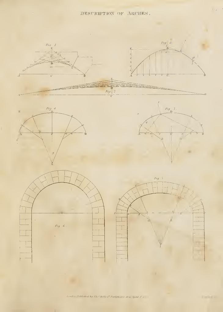
JrL
DESCRIPTION or ^VRC'IIES
fiy 6
fit, . 1
londim./liMufin/ /ly T/u'' Ar//r 17 I'ulrrnntlri- Kin; tf.ni / /, • f:Tiirrt'H.Jf
.
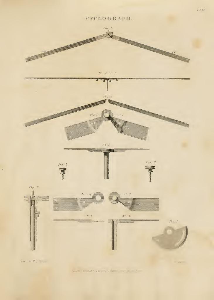
PT^ITj
CYCI^OOMAFJi.
/;,/. /.
/></. y y J
.\y 2.
I'iq. a.
\i
.r" J .v: :1.
f*ra\vn h^' M J Xicht^Iscti
.
£rufravrJ
/.m./m. AiMshtd A riu'IuT}^ 11 fakm^vi. i-Rc»Jiu\A I'^lgM
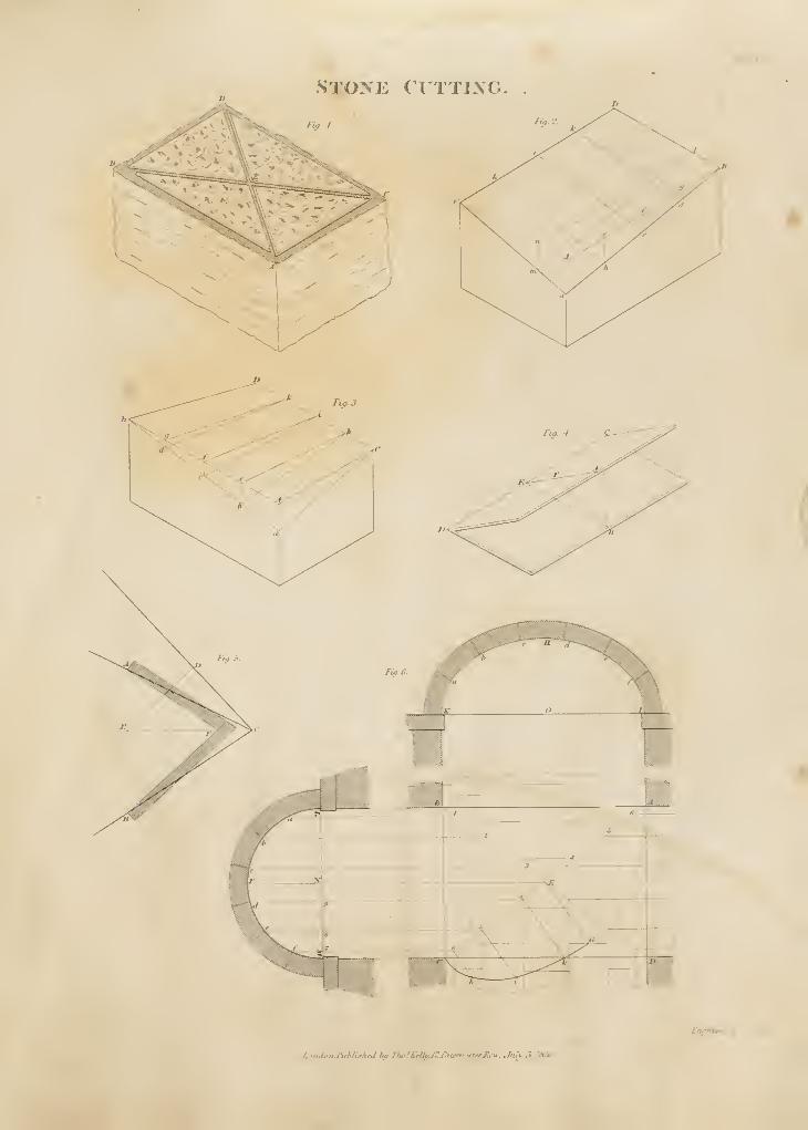
^' li:
STOXE ( UTTIXG.
Crwrinni <*
r.-n.i.'nJ'ui-fi.'hrti hu Ifi^fA'eHuJr./)n^m,^erji^>u . Juh S /rfJr
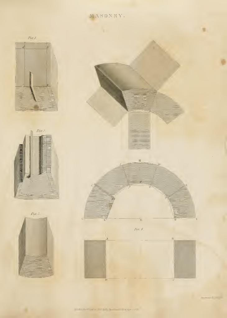
A sosax
tu/.I.
fit/.i.
le*tJ,'n.hthb'.diei Hf 7hi*fA}iffif. /kt^tu\ffrr/ttir.Stpe, i. i,i35.
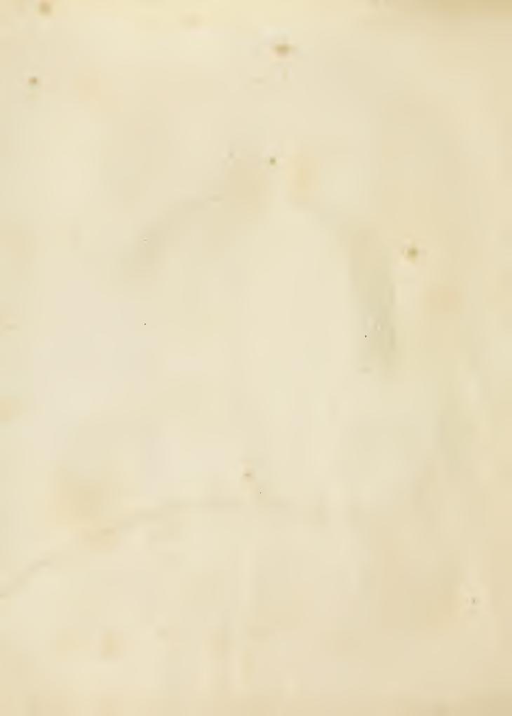
J|fASO>'KTPir
S F /// n Vi t;
£/Ufniir,/ A' /i/ifir
L ii,L : ni.luk^.1 ririiriiei Jii'if
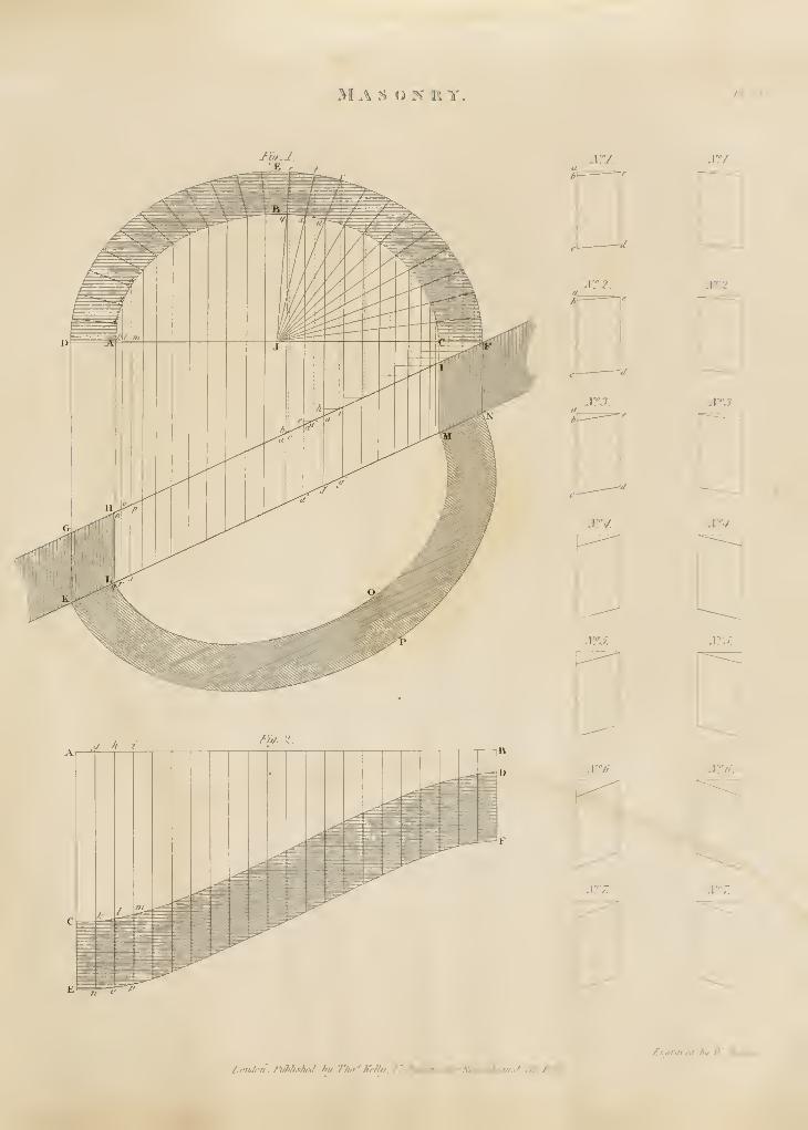
MAS ON RY. TJ. n
2rrj. Jtrrj.
_if h vTi^.2
if
Nf2.
J\rf3.
]\r!'4.
JSTfJ.
]S'.'6.
JTfZ
2r2.
Jff3.
2^4.
2iyj.
Iff6.
X'T.
^n^ravei bu V Svmfi
J.oTiJon. J^Mshfti hy ThnfXfliif. 27 /^^Oerrws^rJidyw. Jji^ust M7d'35.
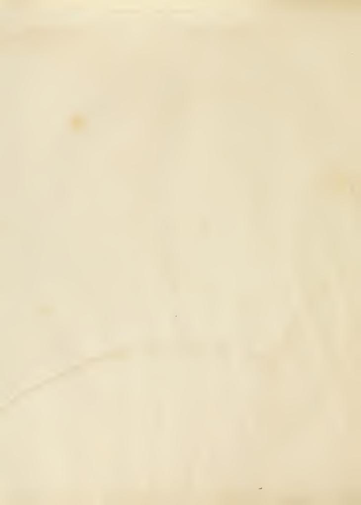
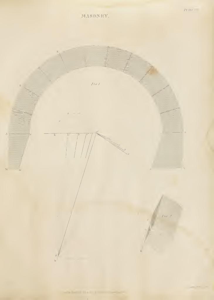
J'UTK n:
nx^o^iw
/^WuVm /IwV/.r^. '^'AW/t /'Miiint4*t/rt /,','»
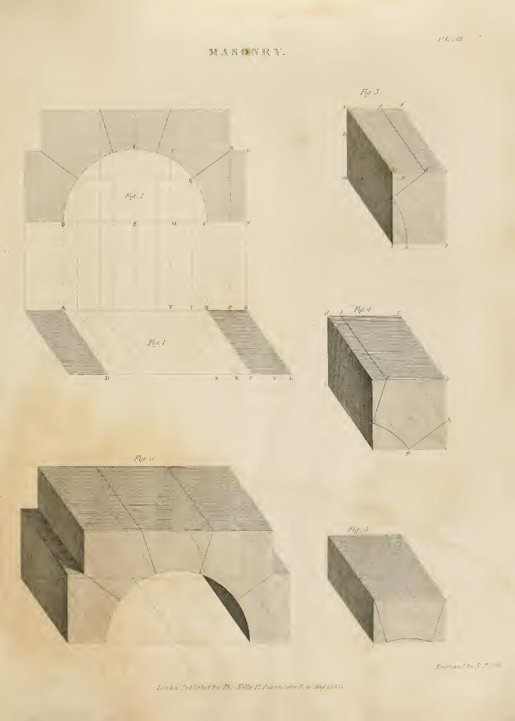
MAS <>-?>' K V/'/, rni
Fia.3
.
'-\,\,
\iJ-hr- 2
iniiiiisilniamiiii )^' ...II iiiji;]Lirliiiii]:i
\ v\ d IFw.4
2^,1.
K C T X
J^i/y o.
2^iii. S
£nar.n-fti f>vJi Ti^'f^'f
/.ondcn.I^J'Ufhfd Iru ni'^AWfi'J~.^afrrrif-f/f/t,m:Ju/lJ'<1-'i
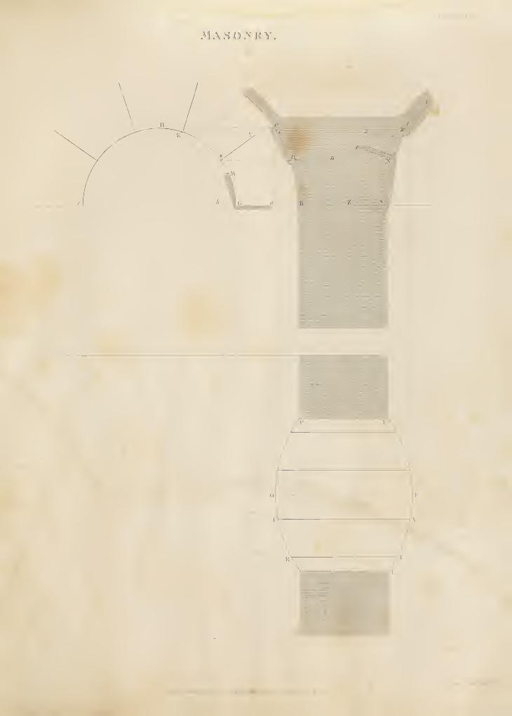
.MASOMiV
\- /
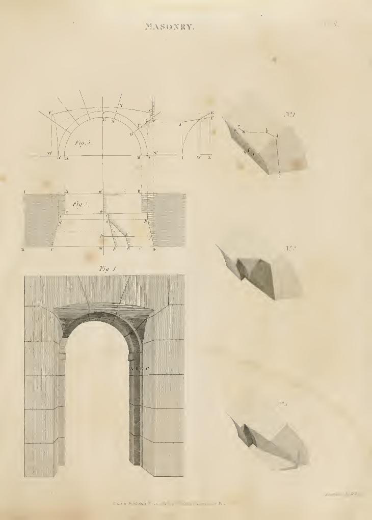
>JASO>'KY I': A'.
Ztt.iniieJ huhJtfli.
l.,ii,hm fuMitheiycv.li.l/tSi hilT/le'Jx.n/ti I'iitfr>i,:flrrlt,'ir
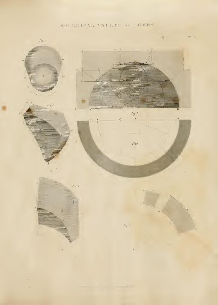
Srill J', li 3 r Al. VATLTS ov. DOMKS
Fill j.
PI. XI
1<
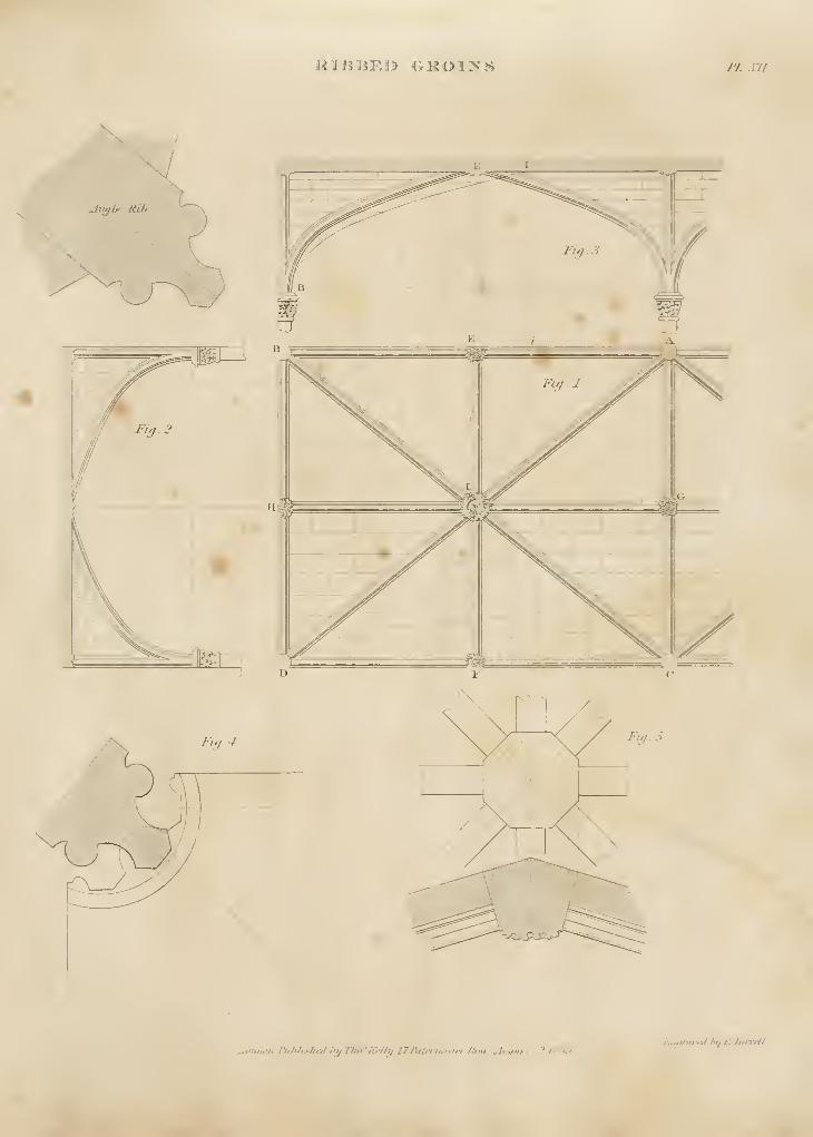
RIBBED GROIIVS F£.zn.
Lotulon.Publu-hed I'l/ThofEdbiJyFata-nosta-.Jiim: ^lufnsl ? /Ki.'Eupnif'tyi ht/£-Titi'iH/

>iASO>RV.
P f.ri t t > r g p
/. ,ulc/U'„hl,..i,.,l ,•),; JoS !,u nufiCdU ruta-nesta-Jii'i,.
£naraffil tu JtA^tfSr.
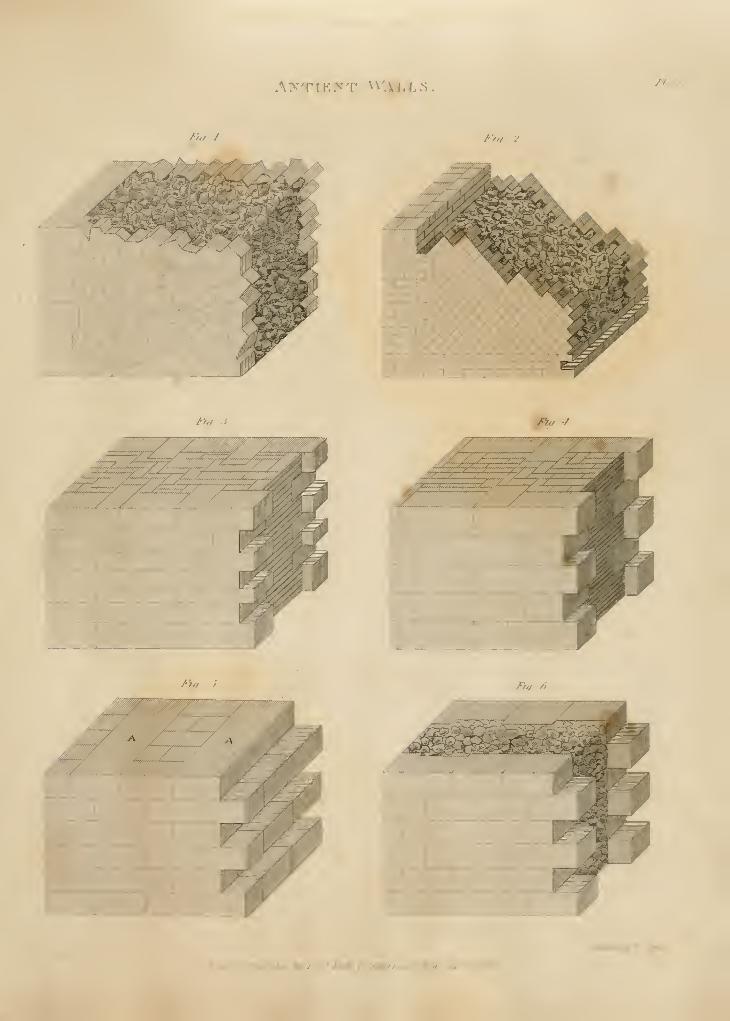
AXTIENT W:iiLL5, fi :•/,
/>,/ / /'ill 2
T>n :i J^,/ •/
.^^?^mf:..":,:. iC.. - ;
""'
,- i-'-;-{-f'
J^l^ J 7^/f fi
A'fsjfmrd Mf *' S^Mwu
/.rm/^n. /*f/MjArf/ dv '/fir " AWAr, 17, ta^rarji/ty Aftf. jiy?V /'''.<^.
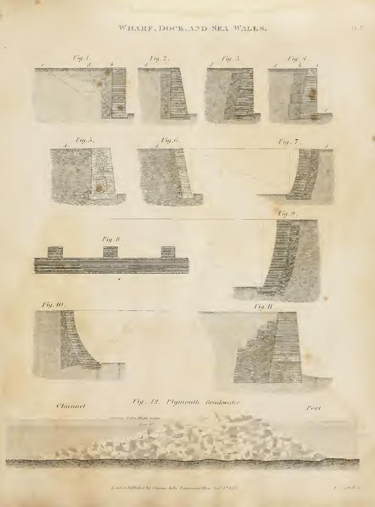
^^HAKF,]>OCli,A?fI}» SEA WALLS. PL.r'.
Fiy.L. liq. 2 Fit/. :i. Fiq .'1
.
Fig.5 Ti^.6. Fig. 7
.
Fig.<)
Fiq.8
Fiy.LO. Ii<l II
<'/l(l ti/ic/Fi(/. I J, /'/i/moiif/i Bn-dk-ti-ti/rr
Fort
ypHna Tides Hit/h Jl'it/rr-
^^A^"
London Puhiidttd hit T/wtna* Af//i/ f'titrrtiiK*fr/- /^'u- Xor'' f* />"i.'>f E. TurrrlLsi-
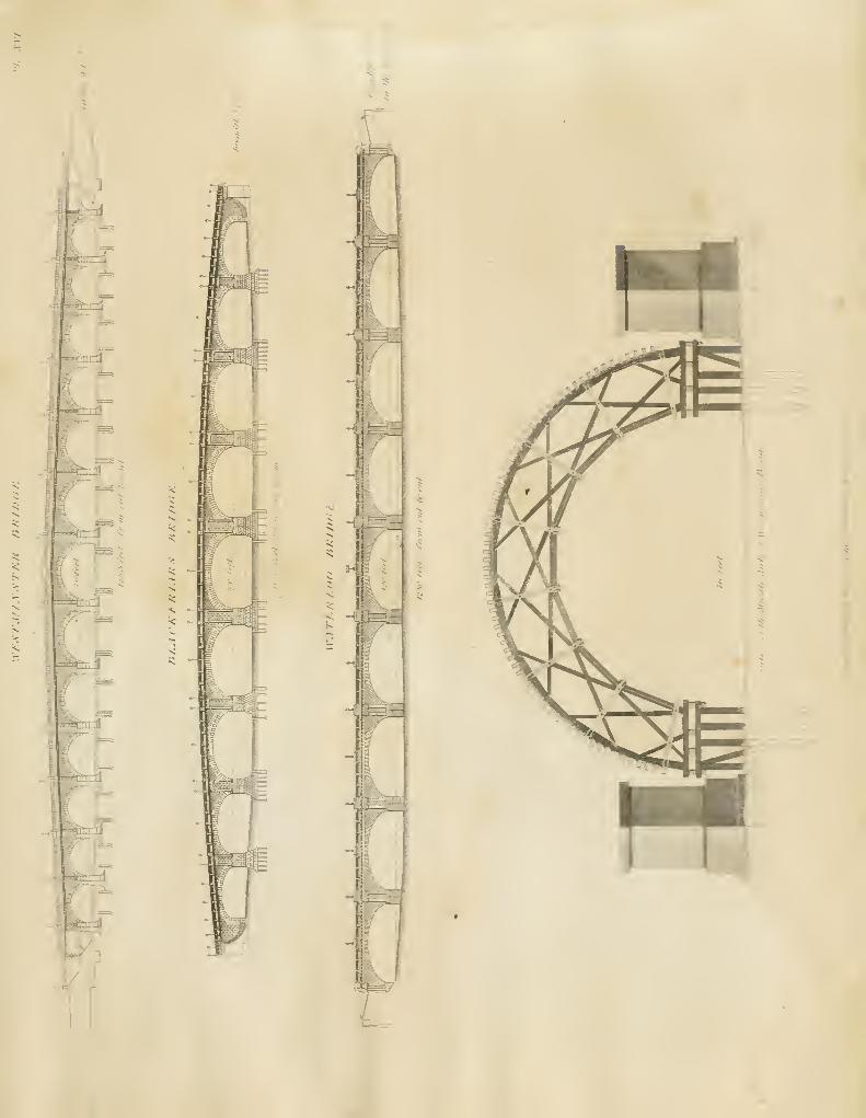
5 3=
ft;
a;
p>^L
s-
-i
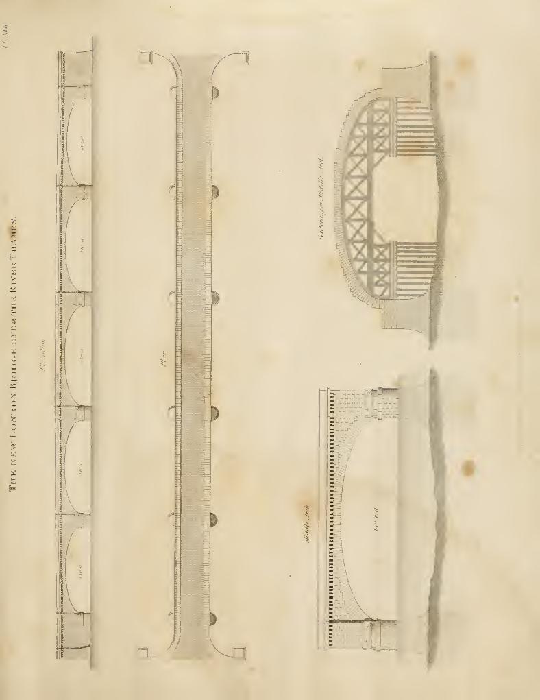
s =
n
p
5
5:
i
3-/
I
S
f
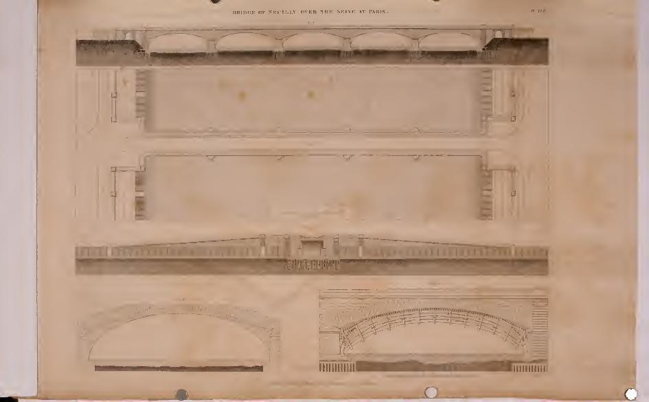
l>UII><iK OK NKIIl-LV OVKH TliU SKINK \T r.VllIS.
1
m ^C kmt
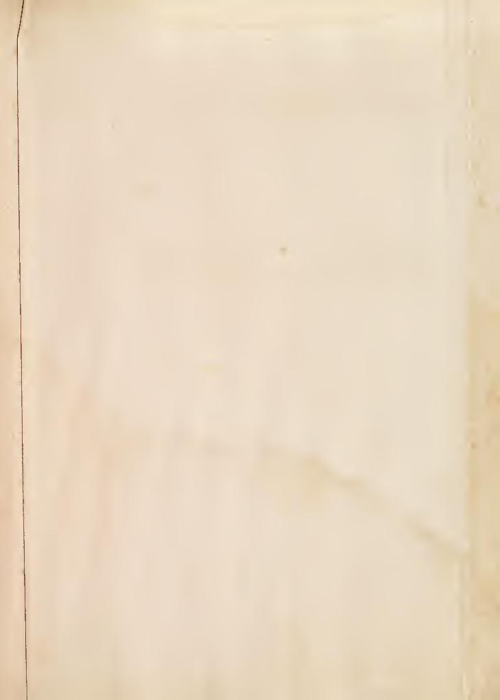
UlUiiiili XVliUSS THE .SKVEU>- AEAU HL-Ori'liSTIiU.
Oli,1 ^"M'"''i :iil!l.!,ii:i, ':;.:.•,. .:., l!!l.;;'in!ir
rtan ef !/•• tlendniiy
-^
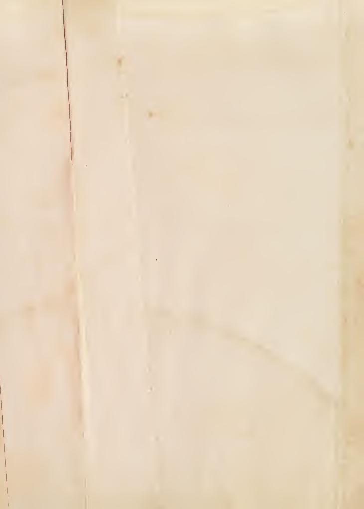
illE NrSl"K.>'Sl01S" BRUJCIK <»VKK TlIK MK.VAH STK.IIT.iMuannl mill •m-uini l>i, T/w'T^//""/ £si/'/-' II S /. <l- £
^iy^i:££S£A
Pt -VX I
' \KHXli<tt>X.\-f/Ht0
CMfi-vfv/^r/.di
/i/ri^ tj/'/Zlf /'/ti/t of't/i^ Sfifti/unif .r/,riri>i// t/,r ^//^uiArwitf
l^A ,^^ . _ ga ^i^
~^^ Si ^-=^^-
/i/// ,-/'f/ir /'fail of't/f Mott^lwtn/.
•r /liL»*w.u»r/Ti'» -fi-v'/^l/IM
Q.( .. f
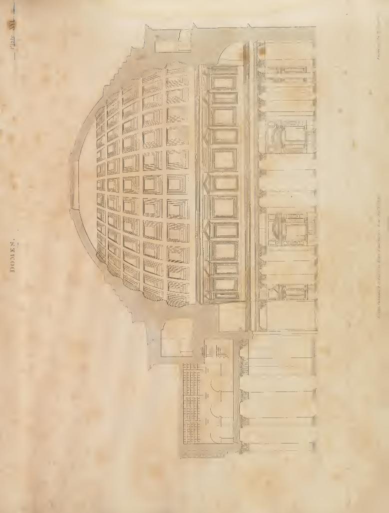
i
Sk>
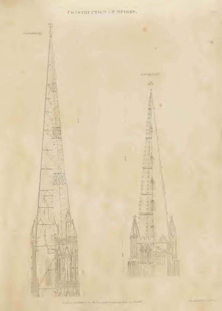
rO-^STRFC'TIOX OF SPIKES. ,'. .\X!i
S'// //s/i/i?y/.
ii ZU'^'u-M
.
J-m
^\-'~.T\\.
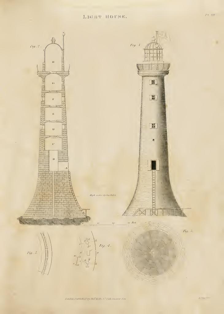
hUvirr \iov^r.. rI.. XXI1
1
J hi I
//,/../.
/>'/ ^•
/,m,luH.riilili.'/ir,l /•! r/„i.Af//\. 17 l4it, in.al^/- /.'.iir..Ti"i-<ll
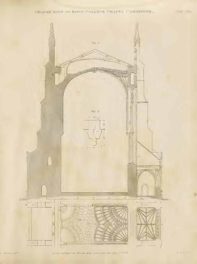
f'.KUl>Kl> KiM^K 0¥ Myr.yt f"i)LLKr.E VUAVKi. ( ".OmKlJ^i'.E riate XKIV
r. M,i.l:-i,:ir.M! LtriilittiriiHulin/ I'll T/iinuu- Ar/tu /"il/rr/wjirr /\rw Mm/ /'^ IHiiS t . Tumi/. .
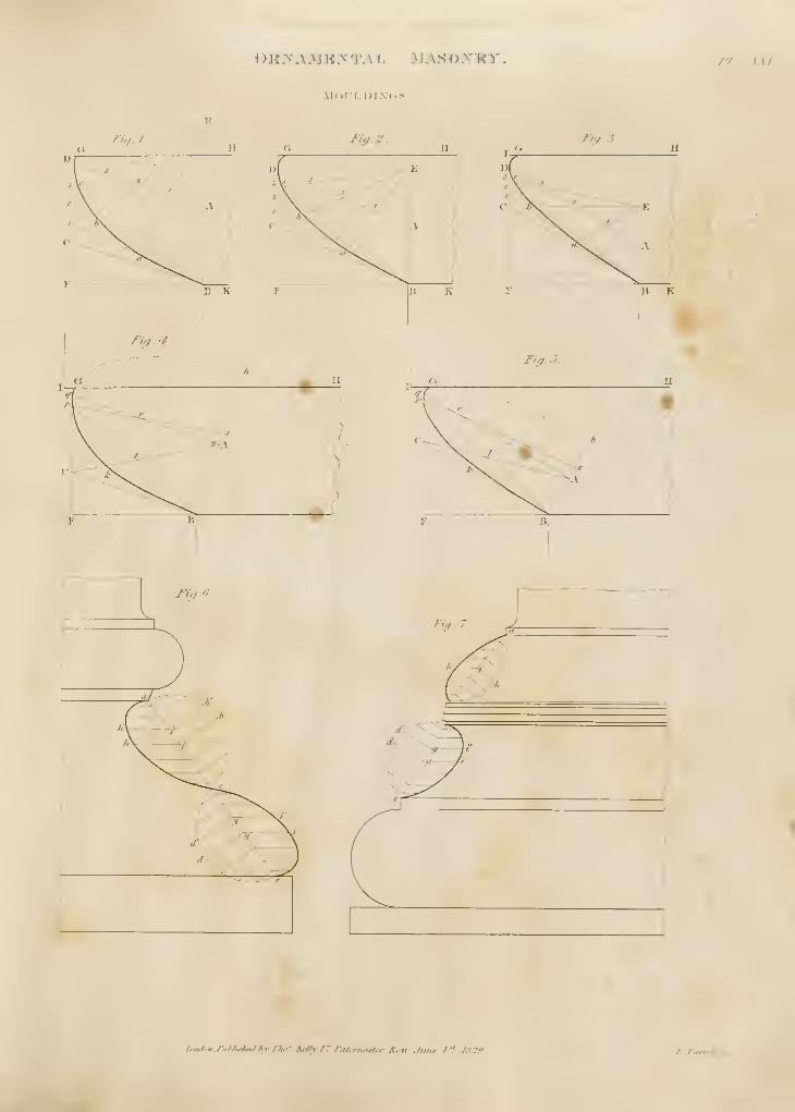
OKXAMK>-T.\L MASO.VKTT. P/ . Ill"/-
mc)i:luin'<;>< .
[.•n-/-ii J'HNir/irtl />v rhf'. KrI/v 17 rnt(nu'stcr Kim ,/iilu- / ''. /.V.;'.". K. Turrrit j.
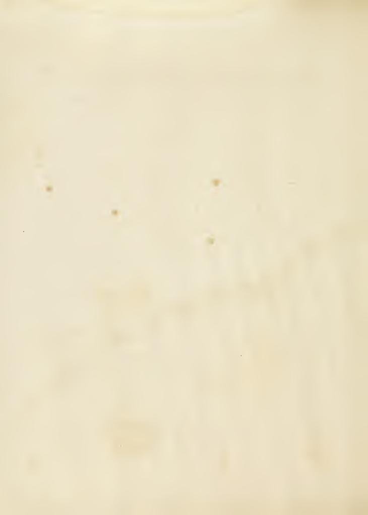
OKXAMKXTAH. .^lANOXR^". i'LATE XXi'Ia
p""n r^fi^f.J.
\ T
\'V\l\iiMl. DQOUUflC
I'uif. -'. Ji^. 3
.
Tii/.-f. Fiff. fu/.O.
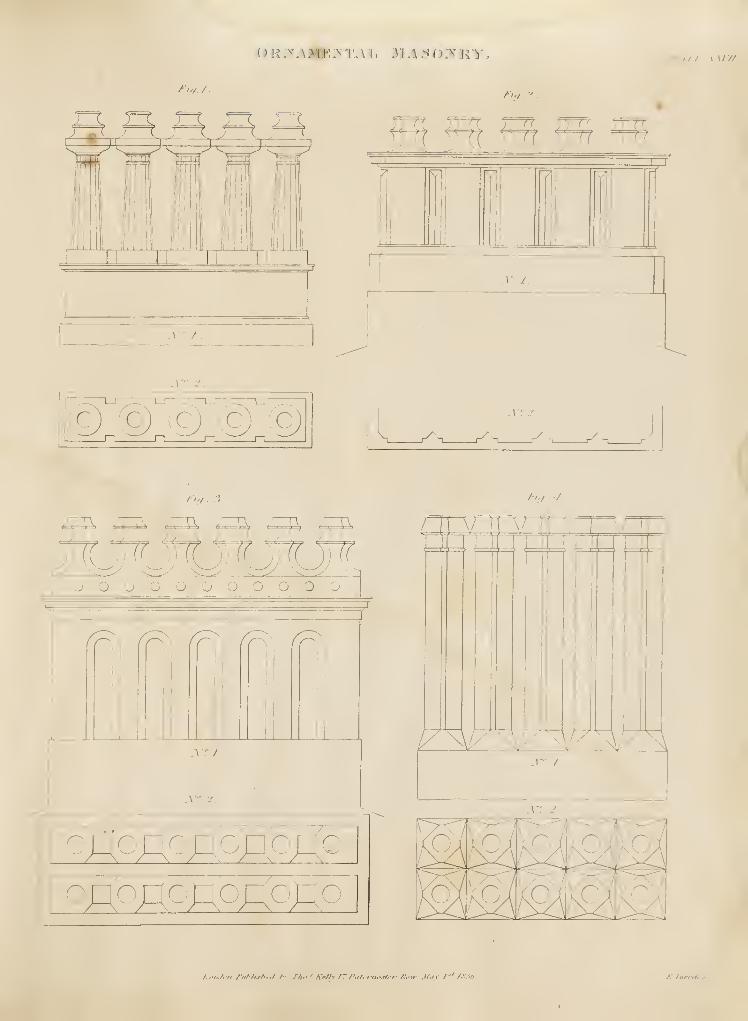
<JR.TAlliE:vT.\ L 311A S O.XKT. /'J^I7f: AAIV/
/Vv. /
.
O G C Q. ^
.i'." /.
i;x
/is,.
ffiff+t ^ TfT?
M IV M
A'r/.
F7I
znj
.vr -^
.
.v; -.!
\ ^ n r^ - r^ n r^ -^
''</ ' N;,.-/
^M.&,&.^&. gDnr^r(n"
nh-nn^MMMMMMooooooooooo^""^
>
XT I.
\'*' '*
oSo»o:^o^ogoononononono
? ' I I ? I i; I ? 1^ o
^^^KM/7^/7^F^
y\rf ^
.
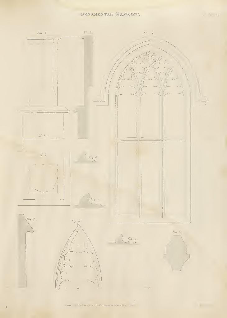
)RXA3lE]VTArj MaSO-VHY. J / _\. .\ III
J'iy.I y. 3 Fi't. I
.'ii,-,t ^•\ t hi:'Aril \ i i. f ,Htrn.ttfn- a'.ii' MiVf 1'"^ h'li.i
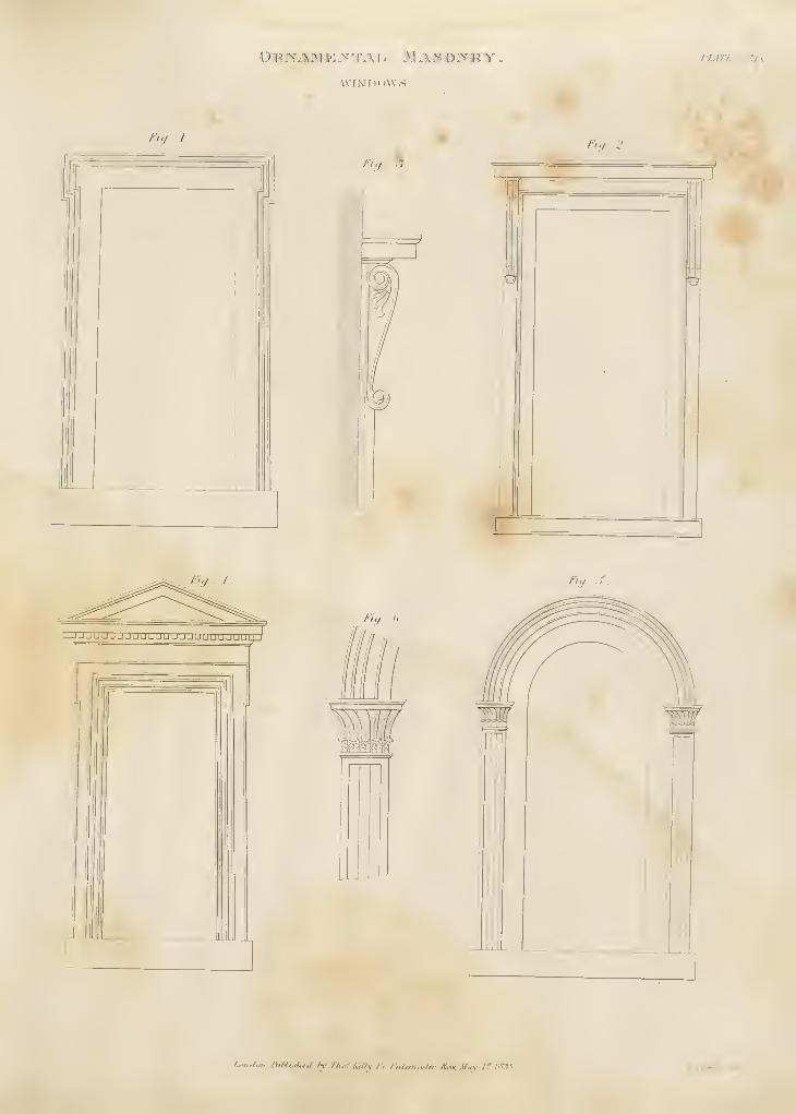
ORJVAi^I JO >"TJU A MaS OiVM^Tr"
.
VVI>J1>()VV,S .
I'/M'£ XXA-
/V- Z. *.
/•Vy . 5.%.
/•'</ 2 .
: 7
/'y / /5y X
/></ . a,
l.oi„i.m,l\,ML<f,t,l /y fhor A'ttlv /l l'„/tnu^<lH- *n. .l/./v /' /.CT1 EJ'umll .•!
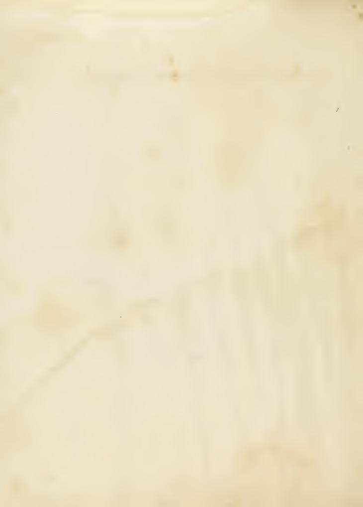
^^ ?
'X ^
X
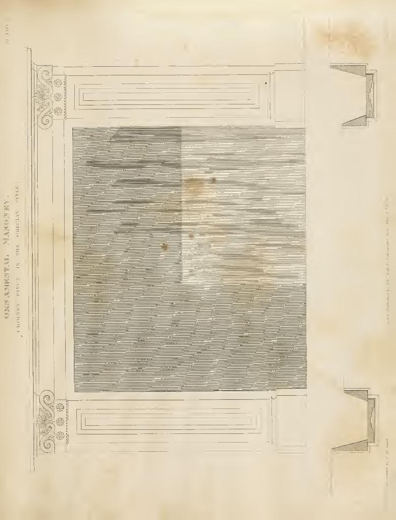
«V" r.-
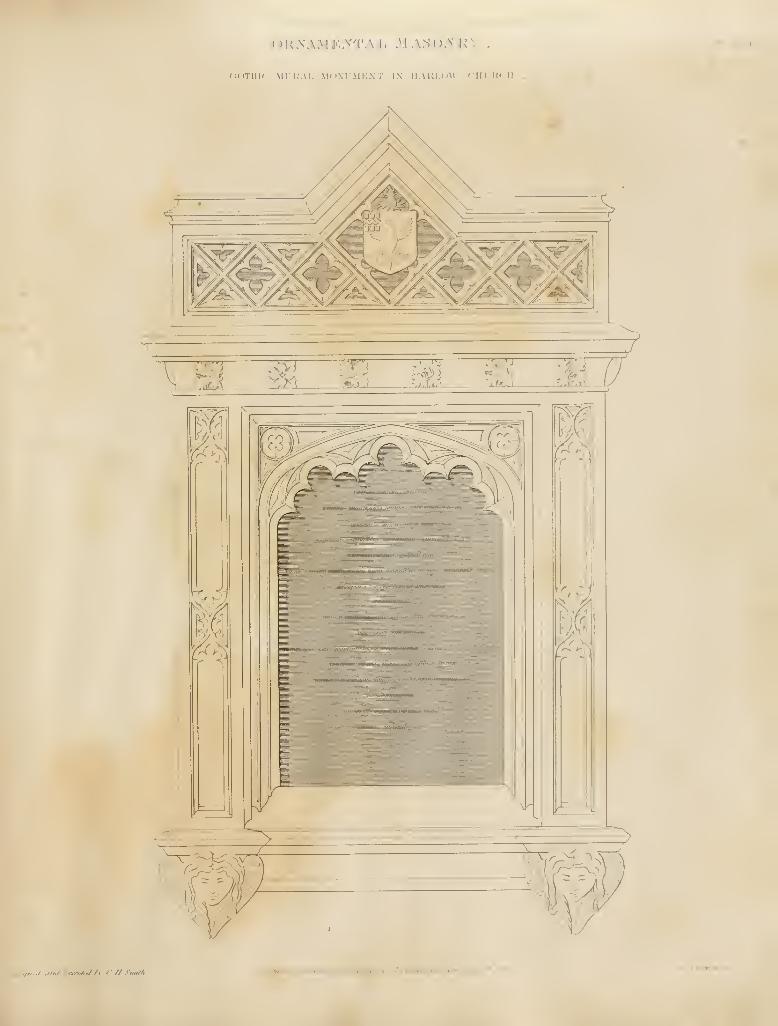
r)R>'.\;\i K y'T.\ 1 . M AS():\ :u' /y .T.\/.r
(ioTllli MI i;\l, M'>.\rMi;\r i\ IHIU-UW CIII'KCII
,-,/ ,itij iwwtilej /fV t'.//.Snu//t
.
/.4'»t^'fl,/1*f'/A</tr-i /T /'H/ertt<^<f<'f fiiuv .yky,/" /A,:" f:.riim//.j»-.
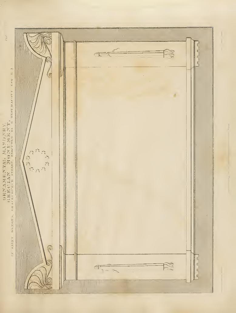
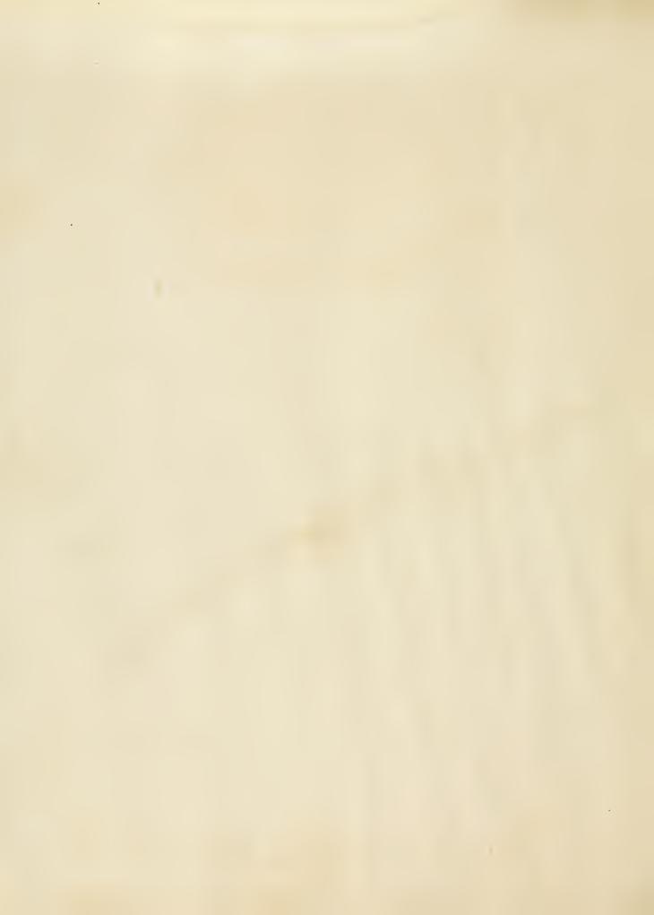
BR 1(C K:]LAYIN (GPlati:
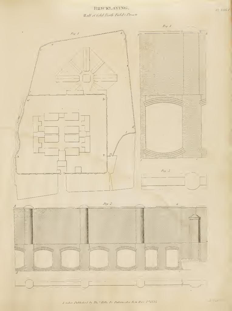
n jQzv 7'
j-i^.^
o __^J.,.n./.v, JWMj/if/ M n.' Kf/ty //. r.i/fni.-.'tfr /{,it J/,1 X i''/<tJS.
/•. ?'
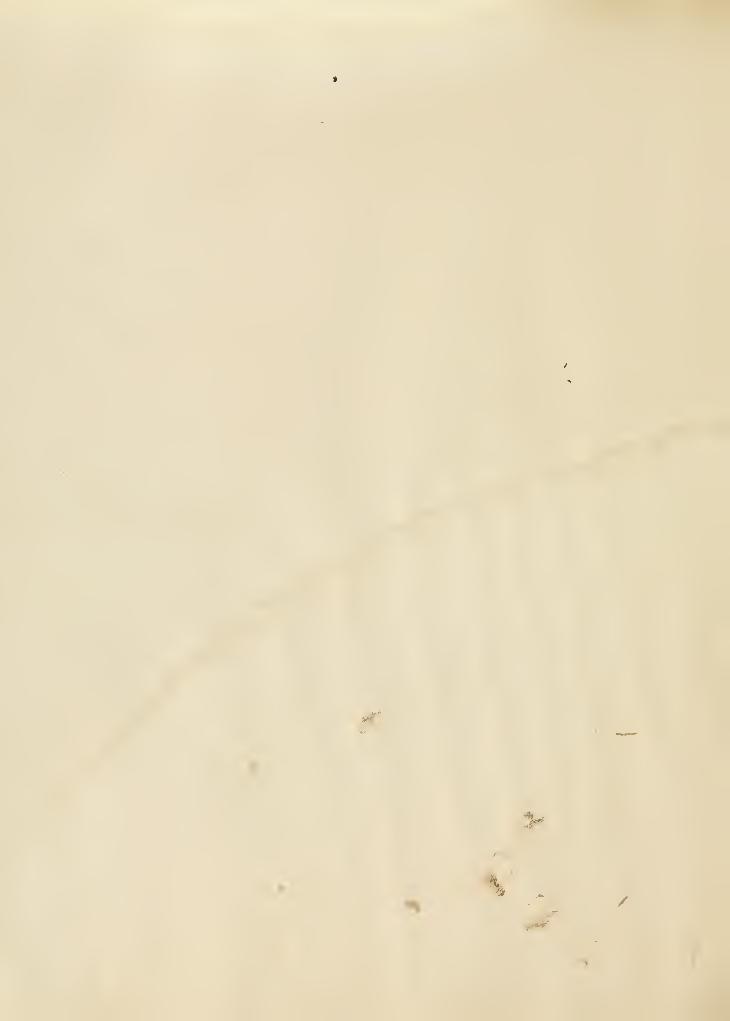
>
/*'**'
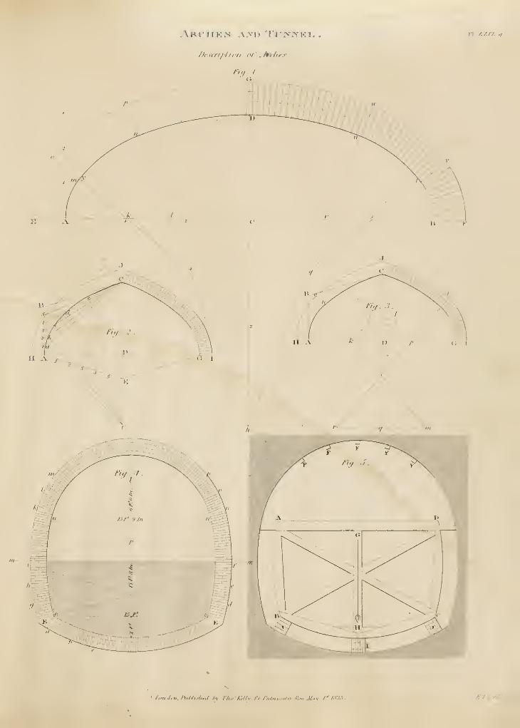
J)i:\ill/'l I n/i I'/' .hdliy
/..•;i,/,./.. /ti/./.,./!.-./ Av r/u<:A;//v ri./',ilni,.^<t^ A^-,, JLiy /"l.rjs. JC. Vnnr/r
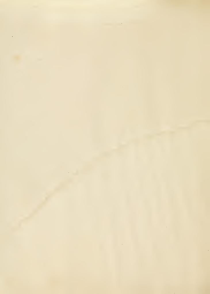
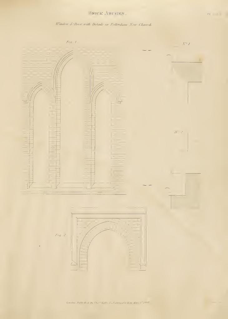
Bkh'k ,VK<nK.s
JlifiaC"!!- t(-/J,'fv: ii/'/A Ditiii/.s- in 7'cU/frJiMii .Yeiv (7ti//i/i
hi,i . I Xl.
("
aV: 2.
^
/Vy, .
/-.!.,/,«, . riiHi.^,,1 hi //i,.' AW/v. /•/. /'nirru.vlfr K'mv. M.iv.lfl'tSff
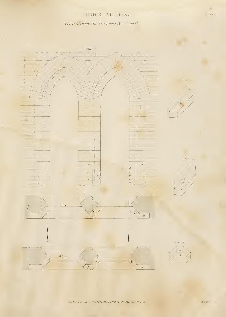
r. U 11' K' .\ K I
•il il !•; .s .
(}i'l/iir Hy////i'ir ill '/'iil/i'ii/iiiiii .\ r^v (7iiiit/i .
/'/ ////
/>>/ / .
M
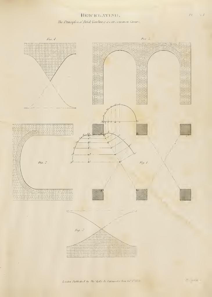
I 'I. '\ A-
/'././.
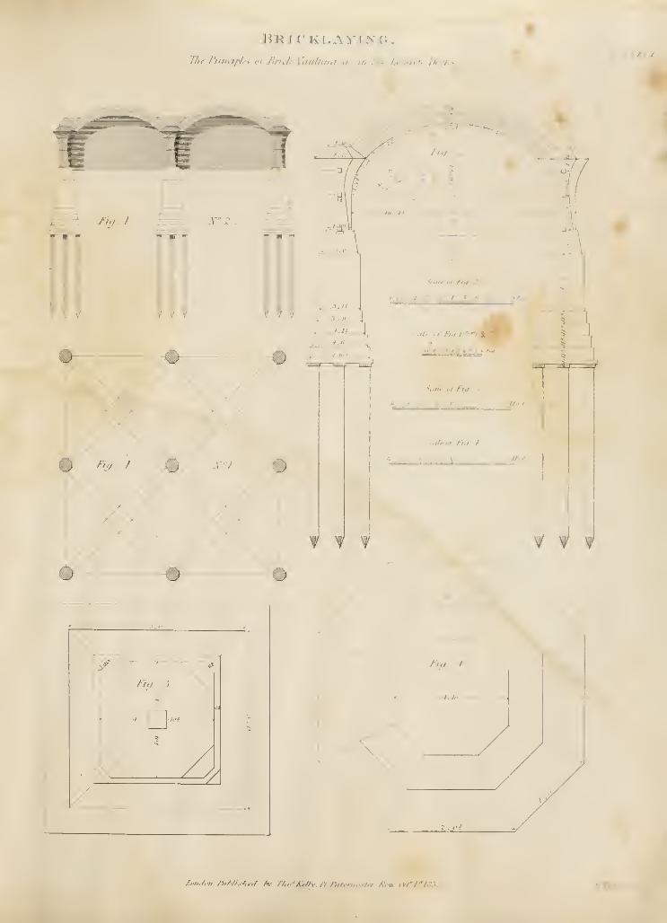
Tlif PniHipli:^ ot'Brick Vitiilliini ,i<in iJiy ^.w./'-, /a./v
rici . 1
.
*=ir
N^Z.
FT f=r
ill
/,;/,
'^iS- / ? ^ / -f ? ? ^^ " ^'"
4Scfi/r ofFt^ . .j .
a o K 3
SctiU or'fUt /
" ^ " » <*
i i
jf.f.'t
_£IM
f Y Y
/.,m,/,n nMtshe,/ /k TAo-^Kfllv /'/ r,i/r,yu:-/er Mow (V/VA'. V,
,
.- Tar
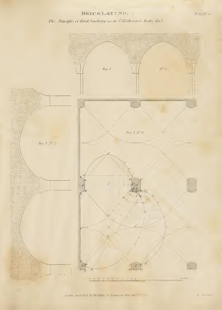
T/ii: frhiii/i/i< el'Bn<k \'iui//tiit/ ii.s in S'Kufh)!rifii-'s l)ocks.£ud..
flJiXIX
M-nJoiL fulJi-t/iiJ Av Tho'Sdls n /:ittn,...ifr K.„ .Ymrj* Ml'." e riirtrll ...
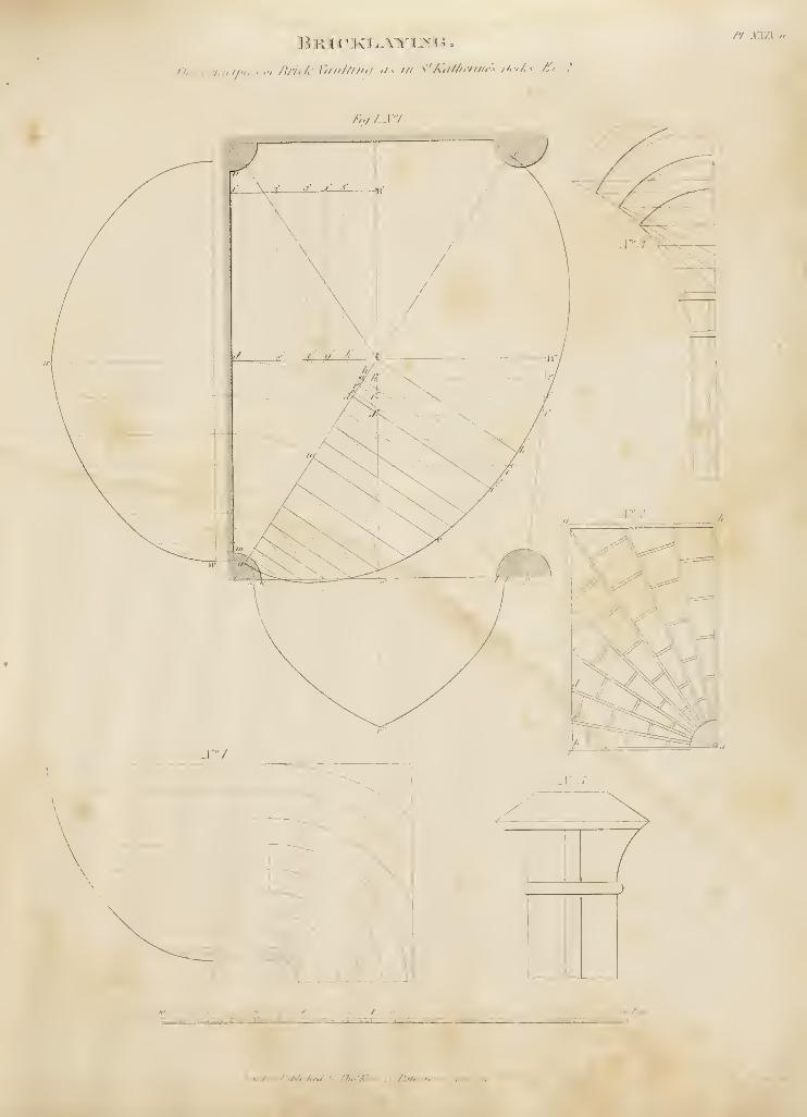
The PnnctplcLV of^iiik Ttiti/tnit/ ,t-^ i/i S'k,i//ienii,:< Av/a K, Z.
/'/ XX/X II
/;,//.! '7.
7.,'>„/A-n AMisia/ /yJTu.
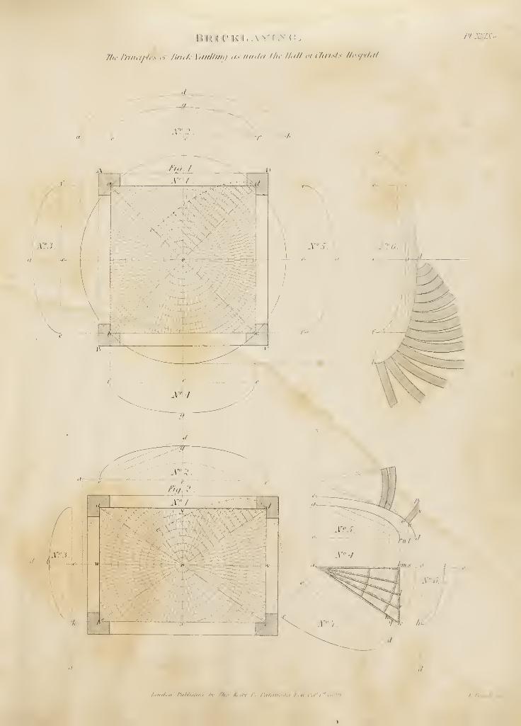
///-• /riii.iph's ,<i/lri,k V,iii//i/hi ,i.< nil./,/ ///-• //-/// ei l'/iri.<l.< ll,'<fil,il
.n Xvzv'o
/A<i„/fii niNis/trii fv n,.' K,/<\ /> /',il,/i„.,,v ,„ir i<,-t''/'f liS''.'!.
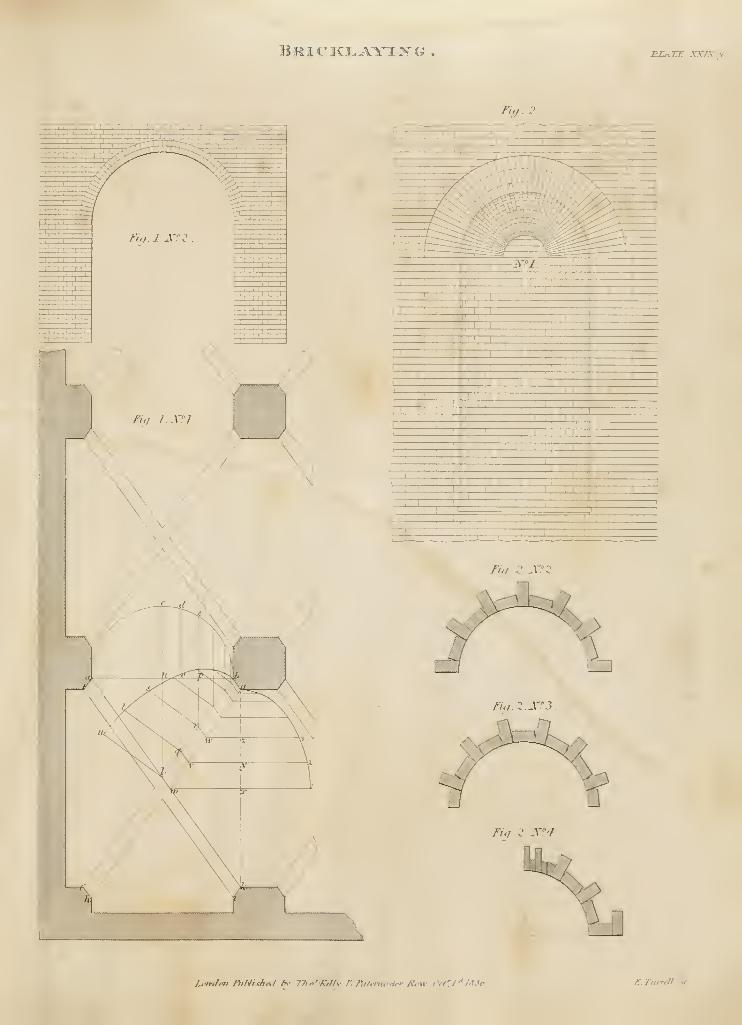
15riciclayi:s^g . vr.ATT: xxix/i
Fig. 2.
11 AXT
• #
rrrll
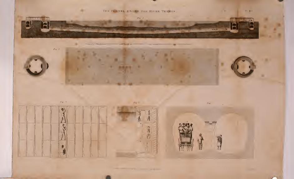
TlIK TfAA'KI, V>'I>^ THE KIVKK THANKS n ^x
o•
^.,.3.
1
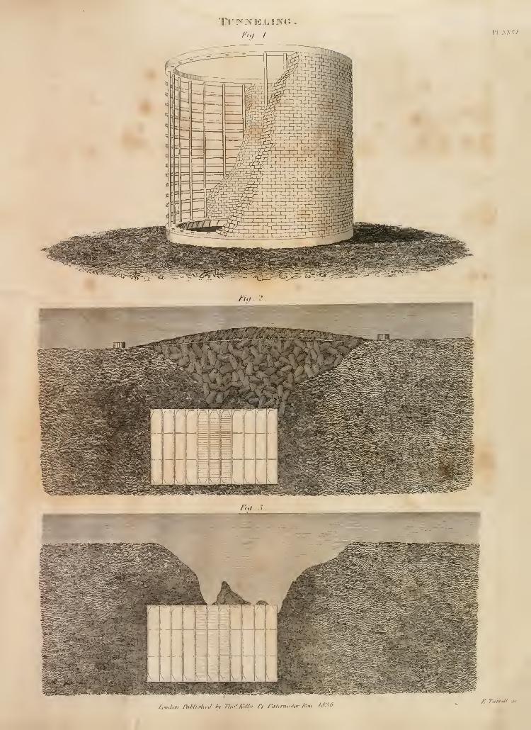
Fiff. 2.
J.,mJ,ii l)ihli.tlu:l h- 77u<k'My /V r.i/.m.^'/.r K.M. IS-iO/: 7amil..'f
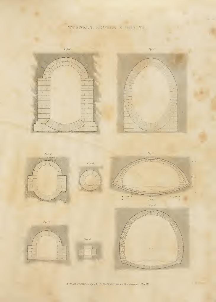
TTv-vT'l,'^ vMrw-T-isK y. D.1L\1I«'S.
Fiq:
^^v.-^:^^>Cs^^i^\(M^v«^^^W^^\\^^v>^>;J^\«4.^^^sssf^iM :v, \,: •-;;,;-a!r^^^
-!
Fill J. f,^ 7.
Loiulon J'iiNi.r/ifJ /ii/ ITu^iKellu J7 ftittrniKftrr Bfltrjynvmltfr 1S.IS3S.
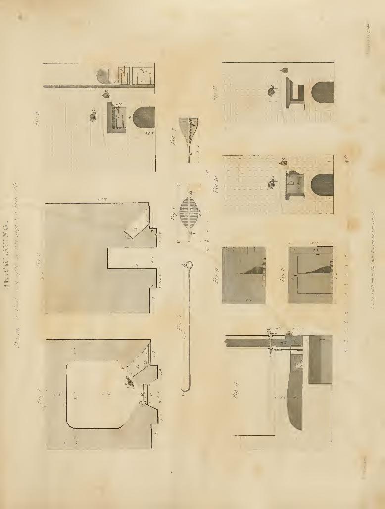
'•:^^
s
\X
lilhi-Hi
I^
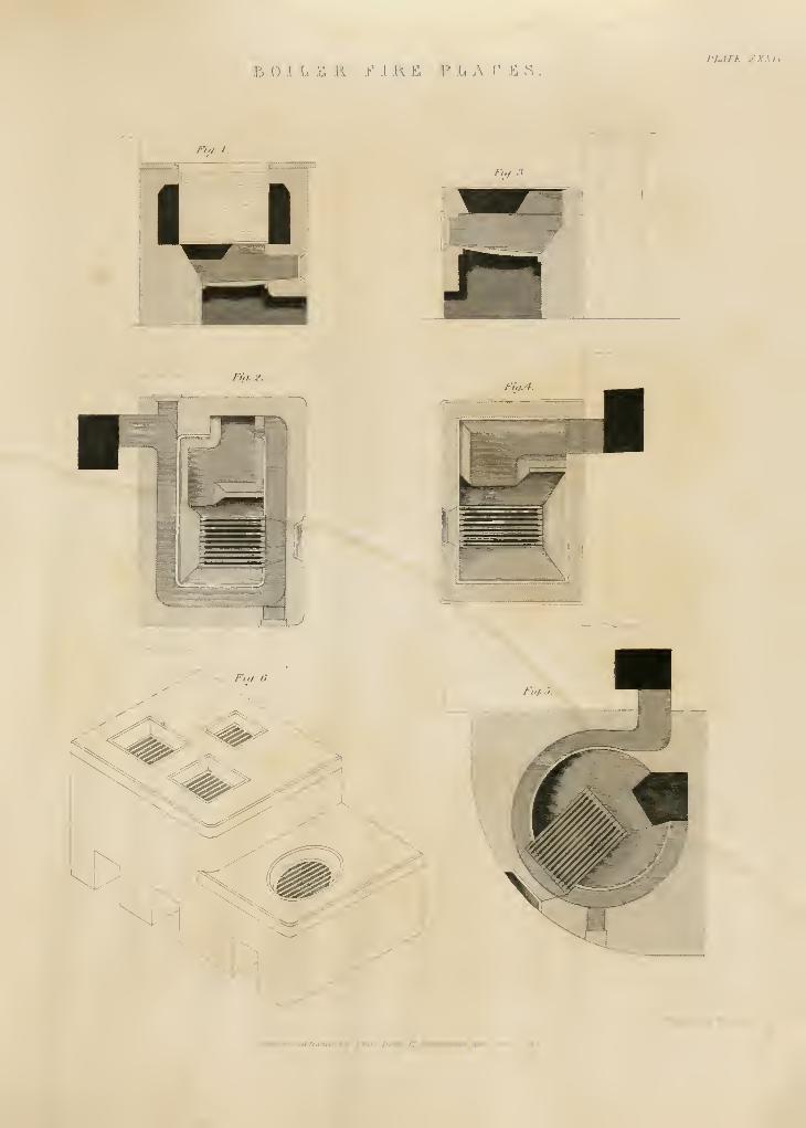
:k o .1 .L, .K ii r 1 R. & ? h A V .!: .s
,
pj^m zxxiv
'1 no. J
J-'u/.'i.
Fit). 2.
Fiti.4.
(T' I
k^<X
holuhmVul'li.thi,! I'll Thi^' li<Hll,l7.J':U(rnp.ili-r/:.
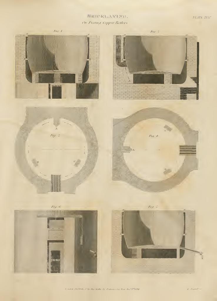
/->-/ /
I! [<((' K'i,.\ ^-r >'(i. PLATI XXSV
J-'iti II riff r>
/..li.l.l, IIiI'IkI,.,! Iv n.-Krllv n /-.ilrrii.-.l.-l K.w /l,,'/''l/136 /:. riinri/
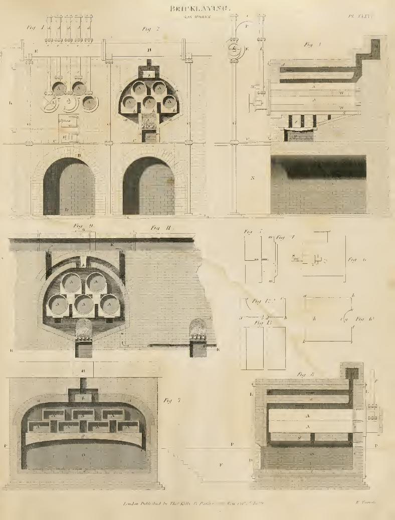
m^^T^
GAS n-OHKS '^^^•—--- ^T"
/iy . 2 .
e e f e
frf-
't
m^
H-n
"Tn^
_L J,
1 M[[ L^_l L.,..L
^^TT^-r'-iLbP
Off
;^
XT=ri;
In. ;;.
_ZL
PSFIP ^
rrr
/>V ^•J*/./ //
i****
|).
j'f. -ixnv
V.
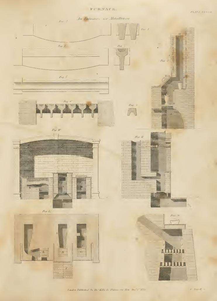
/7-/ ;•
FI^IirS'ACK.PL-tTl: XXATU.
/>./.#:
'D,/•III .>'
/>v A'
il^irzi '-
n.i. I
ri., '.
\'
f.,tiJ,i< hiNi..l„.l 'v Th.'-KRv n r.i/^in.:.t,r /\".w r>,;'l~'l"lf
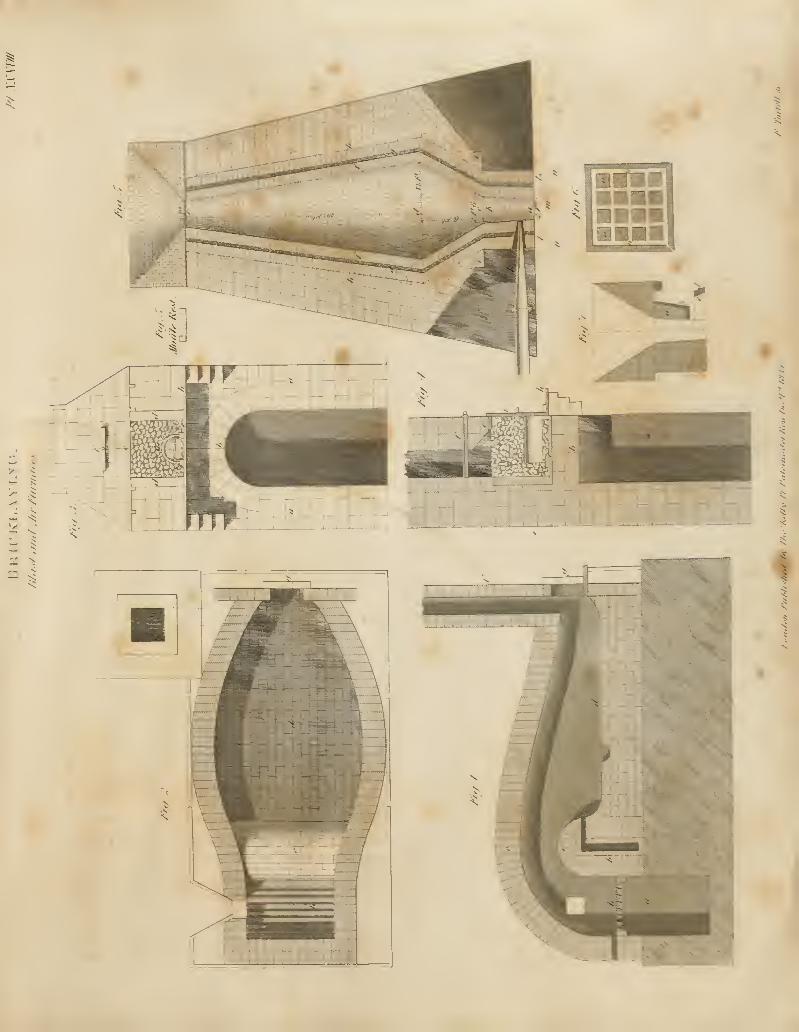
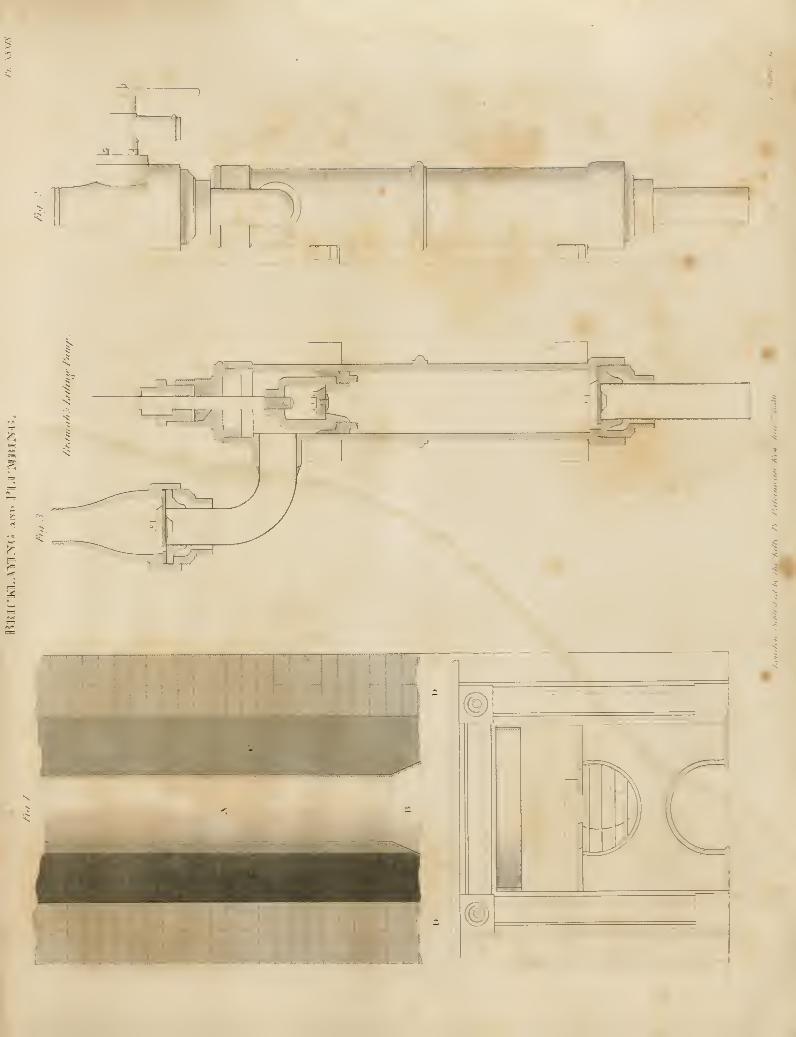
^-w
ui I
1J-v _£racsa
.-''\_
So
5^
-J
«
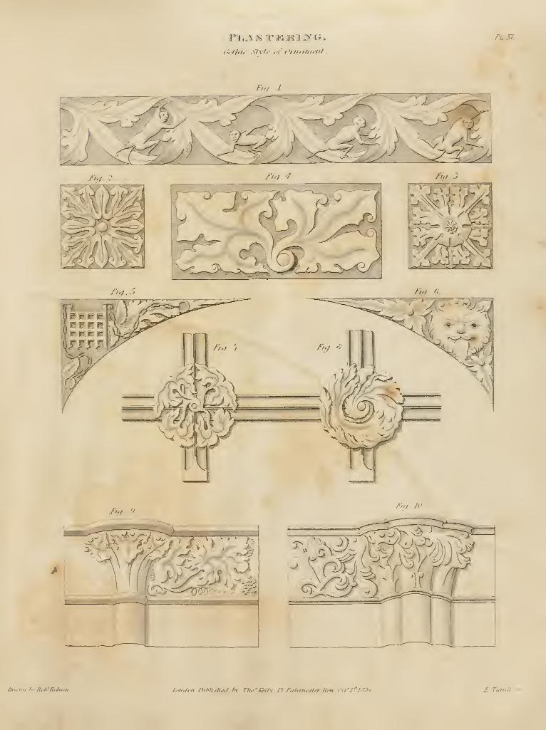
h'i't/ii<- S'tvh- I'f Crntimi'iit
.
PLSL
Jiq 1
//./ Tui '
Iig..9.fiV/ JO
5^^ 5
/^>t»n M' Jltf^*_£olxgtVi h'ndon DiNis/i^,/ A' n..' Kriiv n PaUnwst/rJim t\t'l'^]fi3-t. £. Tamil sr
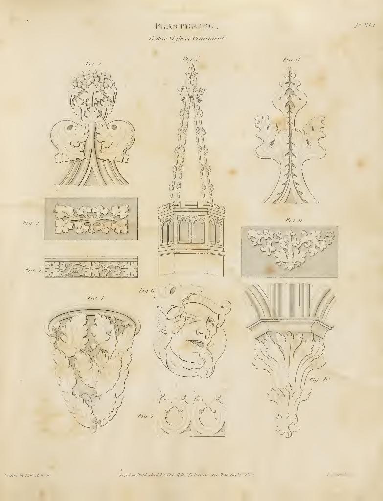
(•i'//ilr \/\'/i' el' I'/// If//III//
TIX/J
/•„/
/'/I/ .'-}
/j/turti f'V Atf^M/f.^Kfii/i /,«./.« /•iiMi.,Af./ />v r/i.^KfUv'J/ fiii.m.-.s/.-r A'-ir /J^.'y'M-i /: T/irtr/f '
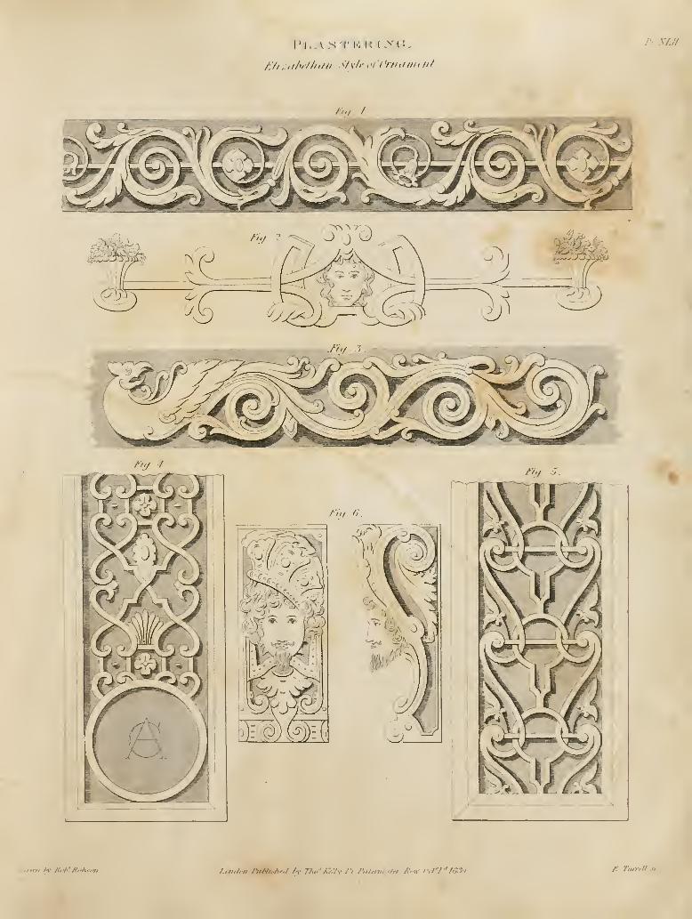
I' I, AN 'I' !•; U (>'(',
A'//;:,//"/////// <l\li' i'i'i'rii,iiu,/i/
n sfji
Jiff, J.
7u/-fFtty . -J.
I'llI. fi
^
n„ A- A'.'/'' //.</'.<;;, /..ii.l.n riMi.</,r.l l-Y nw'fMv /'/ /'<//«7«w/« /".n- '•,/'/"/'?.« /r rmrrll jc
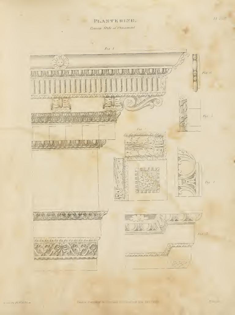
f','in,in .S/v/»' c/'Oniiimfnl
fL.SJM
n./.J
/>'/ '>
/>-/
/•;-/ /
/></ . J
Mnuni /t /'i h'K.^K'tii Lmii'it I'aUKihtJ .. frt'r/aX'i
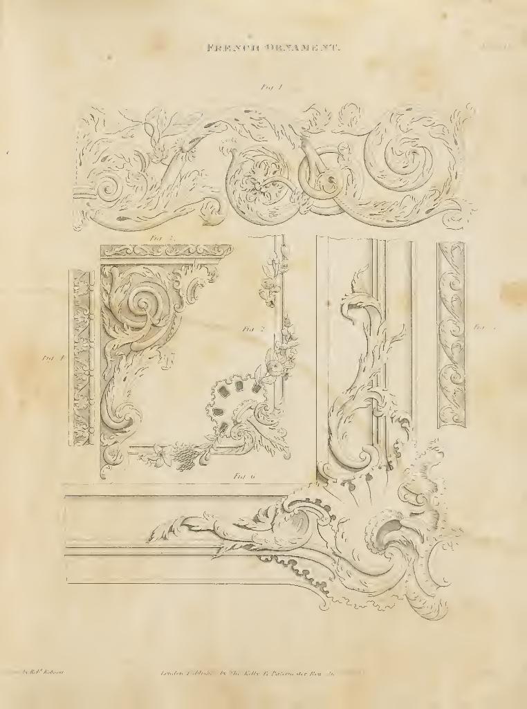
J''K J-^.>' 1 •
I •( <") K TA >.i !•: "^"r'.
/>-/ /
/>./ /
/•>',
/Jfiiim M-AW'' A',:/-.. /<•/»./.•// /'ii/'/ish,./ M- 7/».''/7//c. ///</.V/7i,..7,r A. 11 />.
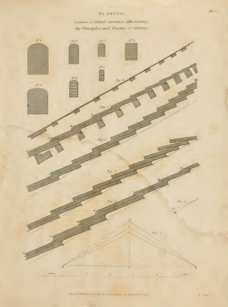
S i , .vv I -x 1 ;
.
.Kiu/tr/is ,ir-^7fi/<'</ i'<'\y//Hf/<. r////-///////rf7.
///, /'///i.f/'/i.-; ,///,/ /Yi/r/u-e o/S/i///n(/.
/7...\/.r
J)r2 jury.
I i 1 I 1 I i I I I I 1 J_ f ritt
/..»/././, /iM,.,/,r,/ Ay /•/„. A./Zy/; /'„/„„,../,, /,',.„ /•,/•/'/.!.; A JTitrtY
''<;
NFAV AND \^\LUABLE PUBLICATIONS, PRINTED FOR T. KELLY, PATERNOSTER ROW, LONT)ON,
IN FOLIO, AND EMBELLISHED WITH ELEGANT ENGRAVINGS.
The London Folio Edition of the Bev. JOHN BROWN'SSELF-INTERPRETING FAMILY BIBLE, embeUished with
elegant Steel Engravings ; completed in 87 double Numbers,
price 6d. each Number, or in 29 Parts at 3s. each, printed with a
large clear type, on fine demy paper ; and may be also had in
Quarto.
These Editions, being correctly printed from the Original, and
the Marginal Notes placed according to the Author's own arrange-
ment, are published with the approbation and recommendation
of the sons of the much-esteemed Author— the Rev. John Brown,
Whitburn, Scothnul, the Rev. Ebenezer Brown, Incerheithing,
Scotland, and also by numerous eminent divines.
A valuable Concokdance, by the Rev. T. Smith, to accompany
this Work, is completed in 35 Nos. at 6rf. each.
MATTHEW HENRY'S FAMILY BIBLE; with Notes andAnnotations, abridged : and a complete Concordance, by the
Rev. T. Smith. 16S Nos. at Grf. and in Parts at 3»\
^° The Books of the Apocrypha, with Engravings suitable to
bind up with any of the Folio Bibles, in 22 Nos.. or, sewed in OnePart, price I U-.
BROWN'S SELF-EXPLANATORY HISTORY ANDLIFE OF CHRIST: containing a copious Display of parallel
'J'e.xts of Scripture, fully illustrating the Incarnation, Sufferings,
Death, Resurrection, and Ascension of the Saviour of the World60 Nos. at &d. each.
BURKITT'S EXPOSITORY NOTES WITH PRACTICALOBSERVATIONS ON THE NEW TESTAMEN 1'
: designedto encourage the Reading of the Holy Scriptures in Private Families,
and to render the Perusal of them profitable and delightful. 90Nos. at 6r/., or 15 Parts at 'is.
FOX'S BOOK OF MARTYRS, or the Acts and Monumentsof the Christian Church; being a complete History of Martyr-dom, from the Commencement of Christianity to the present Time.Edited by the Rev. J. Malham. 100 Nos. at 8d.
IN quarto, each work EMBELLISHED WITH KNGRAVI \GS.
THE EXPLANATORY FAMILY BIBLE; containing the
Sacred Text of the Old and New Testaments, with Practical
Observations on every Chapter, and Marginal References, selected
from the Writings of Matthew Henry, Brown, Doddridge, Clarice,
Scott, and other eminent Divines ; with the Apocrypha at large.
Illustrated by elegant Engravings, from Paintings of the mostcniinptit .-Artists. Completed in 42 Parts, price Is.
A NEW AND COMPLETE CONCORDANCE TO THEHOLY SCRIPTURES; the most correct Edition ever published.
By the Rev. T. Smith. 9 Parts at 2s., or 36 Nos. at Qd., or iu
boards, 18s.
BROWN'S DICTION.\RY OF THE HOLY BIBLE; form-
ing a complete Compendium of Scripture History, Chronology,
and Divinity ; an entirely New and corrected Edition, by the Rer.r. Smith. "54 Nos. at 6rf., or 9 Parts at 3s,
The valuable Concordance to accompany this Worli is com-pleted in 30 Nos., or 5 Parts.
BL'RKITT ON THE NEW TESTAMENT, printed in
Roijal Q.:.arto, each Book ornan\ented with an elegant Wood-cutInitial Letter. 83 Nos. at 6J., and also iu Parts at 2s.
BROWNS SELF-INTERPRETING BIBLE. 140 Nos. at
6(/., or in Parts at 2s. (For particulars, see the Folio Edition, top
of this Page.)
gg' The Books of the Apocrypha, with Engravings, suitable to
bind up with the above, or any oi" the Quarto Bibles, in 12 Nos. at
6rf., or 3 Parts at 2s.
DR. FLEETWOODS LIFE OF CHRIST, Gena^ Edition,
containing an accurate and universal History of our Glorious Re-deemer, from his Birth to his -Ascension into Heaven, the Lives of
the Apostles and ^•^angtli^ts, witli Bishop Porteus's Evidence of
the Christian Religion, Dr. Doddiidgc's Defence of Christianity, &c.
52 Nos. at 6(/., or 13 Parts at 2s., in 4to., with elegant Engravings.
^g° 'J his Work is also published in the W elsu Language, in
10 Parts at 2* , or in Nos. at Gd. each.
THE EVANGELICAL LIFE OF CHRIST, published under
the express sanction of the Rt. Rev. Dr. Bramston, V.A., London;
the Rt. Rev. Dr. Murray, Archbishop of Dublin: the Rt. Rev. Dr.
Paterson, V.A. ; the Rt Rev. Dr. Penswick ; the Rev. G. J. Crooke;
and patronised by most of the other Bishops and Catholic Clergy in
the United Kingdoms. The Life. Doctrine, and Sufferings of our
Lord Jesus Christ, as recorded by the Four Evangelists , with
Explanatory Notes, &c., by the Rev. H. Ruttbe. 11 Parts at 2».,
or 44 Nos . at 6rf.
HUME'S STANDARD HISTORY OF ENGLAND, from
the earliest Period of authentic Record, to the Revolution in 1688;
with a Continuation to the Reign of William IV. By HewbonClark, Esq. Hume is completed in 100 Nos. at 6rf., or 20 Parts
at 2s. ad. ; and the Continuation in 82 Nos. or 16 i Parts.
An Improved Edition of
KELLY'SNEW SYSTEM OF UNIVERSAL GEOGRAPHY.Edited by Tho.mas Bartlett, Esq., comprehending an authentic,
History and Entertaining Description of the WORLD AND ITSINH.\BITANTS, with an account of the Empires, Kingdoms,
Republics, Colonies, &c. &e., of the four ancient divisions of
the world, as well as of that new general Dinsion which includes
AUSTRAL-ASIA and POLYNESIA, under the modern De-
signation of OCE.-\NIC A, forminga Complete System of Usiversajl
Geography ; embodying the Discoveries that have been made by
the most celebrated Navigators and Travellers, from Columbus to
the present time, including those of ROSS, PARRY, FRANKLIN,BACK, CLAPPERTON, DKMIAM, DAVIDSON, and others.
With an Introductory Cuaptei: on Astronomy. The numerous
Plates are engraved on Steel, and a set of Maps correctly drawn
by Alexander, Findlay, M.G.S. Completed iu 42 Parts at 2s.,
in 4to., and in Nos. at 6c?. each.
KELLY'S MODERN AND COMPLETE GENERALATLAS, including the most recent Boundaries and Divisions of
every known, Country iu the World : with the New Partitions of
Continental Europe and South America, the latest discoveries in
the Arctic Sea, Central Africa, Austral-Asia, &c. &c., in 40 Maps,constructed, drawn, and engraved on steel, by Alexasdeh,Findlay, member of the R.G.S. In 8 Parts, at 2s. 6(/, or bound
in cloth, 22s.
THE OXFORD ENCYCLOP.EDIA ; or a Dictionary of
Arts, Sciences, and General Literature. By J. A. Stewart, M.A.
and C. BurLER, Esq. This comprehensive Encyclopaedia is neatly
printed in 4to., in a handsome new T^pe, and published in 83
Parts at 3s. each, also in Nos. at 6rf., containing 224 Engravings,
including numerous Diagrams, &c. The whole forming 7 large 4to.
vols., each volume containing more than double the quantity of
matter than in any former work.
BARCLAY'S COMPLETE AND UNIVERSAL DIC-TION.ARY', enlarged and Improved; including a Pronouncing
Dictionary; an Epitome of History, Geography, the Population
according to the last Census, &c. Embellished with views of
Cities, Maps of the Universe, &c. In 36 Parts at Is. each.
LAWRENCE'S CO.MPLETE FARRIER AND BRITISHSPORTSM.AN ; containing a systematic Inquiry into the Structure
and Animal Economy of that noble animal the Horse, and every
Disease to which he is liable , with an Account of the most cele-
brated Horses and Dogs ; the last Game Act, &c. 12 Parts at 2t.,
or 48 Nos. at 6(/. ; or in boards. 25s.
DR. DICKSON'S LIVE-STOCK AND CATTLE-KEEPER'S GUIDE, or Improved System of Livc-Stock and
Cattle Management ; with the latest practical Improvements, in
raising all sorts of Live-Stock and Domestic Animals. In 84 Nos.
at %d., or in 21 Parts at 2s. ; also in Parts, with the Plates coloured
from nature, at 2.v. Gd. each.
BUFFON'S NATURAL HISTORY, general and Particular;
a New Edition, corrected and improved; containing the recent
Discoveries of eminent Naturalists. 98 Nos. at %d.. or 16 Parts
at 4s., with coloured plates ; also with the plates plain, at 6d. each
No., or 3s. each Part.
CULPEPER'S HERBAL; to which are added, his ENGLISHPHYSICI.AN ENLARGED ; also Fifly choice Receipts from the
Author's last Legacy to his Wife ; a List of Diseases, »;c. With
coloured plates. 10 Parts at 2s., or 40 Nos. at 6(/. ; or in
boai'ds, 21s.
NEW AND VALUABLE PUBLICATIONS, PRINTED FOR T. KELLY, PATERNOSTER ROW, LONDON,
KELLY'S BATTLE OF WATERLOO ; with DioRraphicalSketches of the most distinguished VVateiloo Heroes. Compiledfrom Official Documents. 42 Nos. at 6d., or in 7 Parts at 3s., orin boards, 21«.
KELLY'S HISTORY OF THE FRENCH REVOLUTION,and the WARS produced by that Event, to the Deportation ofBuonaparte to St. Helena ; concluding with an Account of his
Illncae Death and Funeral. 20 Paits at 3s., or 120 Nos. at M.
THE HISTORICAL GALLERY OF CELEBRA lEDMEN OF EVERY AGE AND NATION; containing AuthenticPortraits, by eminent Artists, with the Autograph of tlie Individualaffi.xed to each Portrait. Each Number contains Two Portraits.
Price \s., India Proofs, 2s.
THE PUBLIC AND PRIVATE LIFE OF KINGGEORGE 111., our late most Gracious Sovereign. By RobertHiisu, Esq. 1 1 Parts at 3s., or (iG Nos. at (id.
ROBER rSON'S HISTORY OF AMERICA ; including theHistory of Virginia and New England : with a CONTINUATION,comprising the History of the Colonies, from 1652 to the presentTime. By Davip M'Intosh, LL.D. 50 Nos. at GU., or Parts at 3s.
THE NEW AND IMPROVED PRACTICAL BUILDER,and WorliUian's Companion ; exhibiting a full Display of the mostrecent and skilful methods pursued by Architects and Artificers,
in all the various Departments of Building. In 3 Volumes.— Vol.
1, contains Geometry, Carpentry, Joinery, and Cabinet-Making.
—
Vol. 2, iMasom-y, Bricklaying, Plastering, Slating, Painting, Glazing,and Plumbing.—Vol. 3, Theory and Practice of the Five Orders,Gothic Architecture, Perspective, Projection, Fractions, Decimal i
Arithmetic, 6tc., comprehending a Summary of the Art of Building; |
Descriptive Accounts of Building Materials, Strength of Timber,I
Cements, &c., and a Glossary of the Teclmical Terms [wculiar toj
each department. Illustrated by numerous Diagrams and SteelPlates, engraved by the most eminent Artists. In 35 Parts, at 3s. '
eacii ; and in Nos. at Is. each.
PRACTICAL CARPENTRY, JOINERY, AND CABINET-MAKING ; being a New and Complete SYSTEM OF LINES,for the Use of Workmen ; founded on Geometrical and MechanicalPrinciples. 30 Nos. at \s., or (i Parts at 5i., or in boards, 30s. ;
containing 90 Plates, and numerous Diagrams.
This and Uie two following Works are published separately from the above, " PracticalBuittier^" in order to accomodate the Workmen ai\d Student in their various depart-ments of Ituilding ; and the Buitder'i Perpetual Price- Huok" may be added to either,at the option 01 the Subscribers, making 11 additional Nos. or 2 I'arts.
PRACTICAL MASONRY, BRICKLAYING, ANDPLASTERING, both Plain and Ornamental ; containing a Newand Complete System of LINES for Stone-Cutting, for the Useof Workmen ; with tlie Formation of Mortars and Cements, &c.
;
and a Description of the various Materials employed. In 30 Nos.at \s., or G Parts at 5s., or in boards, 30s. ; containing 60 Plates
and numerous Diagrams.
A Theoretical and Practical Treatise on
THE FIVE ORDERS OF ARCHITECTURE; containing
the Uiost plain and simple Rules for Drawing and Executing themin the purest style; including an Historical Description of (JOTHICARCHPiECtURE. In 35 Nos. at Is., or 7 Parts at 5s., il-
lustrated by upwards of 100 steel Engravings, executed by Artists
of the first-rate talent, including numerous Diagrams, &c. Or in
boards, 35s.
DESIGNS FOR COTTAGE AND VILLA ARCHITEC-TURE : containing Plans, Elevations, Sections, Perspective Viewsand Details, for the Erection of Cottages and Villas. By S. H.Beooks, Esq., Architect. Each Number contains One Designexemplified with Plans, Perspective Views and Details, beautifully
engraved on Three Steel Plates, with Directions for Building, anathe estimated cost of each Building. 37 Nos. at Is., or 12 Parts at
3s. each, or in 1 vol. cloth, 39s.
DESIGNS FOR PUBLIC BUILDINGS, consisting of Plans,
Elevations, Sections, Perspective Views, and Details, of Churches,Chapels, Schools, Alms-houses. Gas Works, Markets, and otherbuildings erected for public purposes. By S. II. Bkooks, Esq.,
Architect, Author of " Designs for Cottage and Villa Architecture."Each Number contains a Design, exemplified with Plan.s, PerspectiveViews, and Details, beautifully engraved on Three Steel Plates.
10 Parts at 3s., and in Nos. at Is. each. Cloth boards 32s.
THE HOUSE DECORATOR AND PAINTF^R'S GUIDE;containing a Series of Designs for Decorating Apartments, suited
to the various styles of Architecture. By 11. W. and \. Akrow-SMiTH, House Decorators to Her Majesty. 10 Parts 3s., in Nos.at Is. each, and in cloth boards. 32s.
THE HOUSE PAINTER, OR DECORATOR'S COM-PANION ; containing a complete Treatise on the Art of HousePainting, Graining, and Marbling ; to which is added, a His-
tory of the Art in all ages. By W. M. Higgins, Es(]. In 10 Parts
at 3s., and in Nos. at Is. Each Number is accompanied by anactuai, specimen of uand-brush graining, oe marbling. Incloth boards, 32s.
IN OCT.'iVO, EACH WORK EMBELLISHED WITH ENGRAVINGS.
KELLY'S PRACTICAL BUILDER'S PERPE'l'UAL PRICEBOOK. 8 Parts royal 8vo., at l.v. each, or sewed, 8s.; illustrated
by Eight explanatory Engravings.
A Reprint of that useful and popular Work,
THE ENGINEER'S AND MECHANICS ENCYCLO-P.^DI.\, comprehending Practical Illustrations of the Machineryand Processes employed in every Description of Manufacture. Withupwards of 2000 Wood Engravings. By LuKii llK.iimT, Civil
Engineer ; Editor of the History and Progress of the Steam Engine,
&c., and Journal of Patent Inventions. In 18 Parts, price 2v. each.
The Wood-cuts are interspersed with the dcscrijitive Letter-press.
Forming Two Octavo Volumes, beautifully printed, cloth bds. 36s.
GALLOWAY AND IIEBERTS HISTORY OF THESTE.AM ENGINE; containing Descriptions of the various ira-
pro\ed Boilers, the Machinery used iu Steam Navigation, the
jnew Plans for Steam Carnages ; with an Experimental Dissertation
on the Nature of Steam and other Elastic Vapours, the Strength' and Weight of jNIaterials, &c. ; illustrated by upwards of 300
I
wood-cuts. 9 Parts at 2j., or 36 Nos. at 6d.; or 18s. boards.
A PRACTICAL TREATISE ON RAIL-ROADS ANDLOCO.AJOTIVE ENGINES; including an Explanation of every
Patent that has hitherto been granted in England for improvementsin the Mechanism of Locomotion. Illustrated by nearly 250 wood-cuts. By Luke Hebert, Editor of the Engineer's and Mechanic'sEncyclopaedia, &c. Price 4». 6rf.
A New and Improved Edition of
THE PRACTICAL GARDENER AND MODERNHORTICULTURIST ; exhibiting the latest and most approvedManagement of Kitchen, Fruit, and Flower Gardens, Hot House,Conservatory, Sic, for every Month in the Year. By Ciias.
M'Intosh, C.M.C.H.S., late Head Gardener to the King ofthe Belgians at Claremont, and now Head Gardener to the Dukeof Bucclcuch at Dalkeith. The Work is just completed iu 10parts, at 2s. each, forming one handsome Octavo Volume, illustrated
by numerous Wood-cuts of Designs for laying out and arranging
Gardens, Parterres, Trees, Walls, Jet's-d'caux, Hot Houses, Con-servatories, &c. A superior Edition is published, with ColouredPlates of choice Flowers, drawn and coloured from nature, price
2s. 6rf. each part. Or in cloth boards, plain, 21.?, ; coloured, 26j.
A NEW AND COMPREHENSIVE GAZETTEER; beinga Delineation of the present State of the World, fiom the mostrecent Authorities, arranged in Alphabetical Order, and con-stituting a systematic Dictionary of Geogi-aphy. By the Rev.(J. N. Weight, M.A., P.A.R. Illustrated by Maps, and apj)ro~
priate Views, engraved from the latest Observations and Drawingsof Modern Travellers. In Parts, each embellished with a 4to.
Map, engraved on steel, and a View of some metropolitan Cityor 'remarkable Place. Price 2s. with plain Maps; or, with theJIaps coloured, 2s. Qd. Completed in 41 Parts, or in 82 Nos. atIs. each, forming four handsome Volumes, royal Svo. A Sup-plementary Volume is added, consisting of 8 Parts, at 2s. each.
BUCHAN'S DOMESTIC MEDICINE ; or a Treatise on thePrcv-^ntion and Cure of Diseases, by Regimen and Simple Medi-cines. Including the Author's Advice to Mothers, &c. &c. Towhich is appended, the Life of CORNARO, {ichich may he hadseparufe, prwe Is. vith a Portrait,) in 33 Nos. at 6rf.
WALKER'S CRITICAL PRONOUNCING DICTIONARY,and EXPOSI'l'OR of the English Language, in which the mean-ing of every W ord is clearly explained, and the sound of everySyllable distinctly shown; to which are prefixed, the Principles ofEnglish Pronunciation, Ike. 24 Nos. at 6ri.
NEW AND VALUABLE PUBLICATIONS, PRINTED FOR T. KELLY, PATERNOSTER ROW, LONDON,
THE YOUNG WOMAN'S COMPANION ; or New FemaleInstructor and Guide to Domestic Happiness. 28 Nos. at 6d., or
16«. 6rf. bound.
HENDERSON'S DOMESTIC COOKERY, and House-keeper's Instructor. 19 Nos. at 6rf. or I'Js. bound.
YOUNG MAN'S BEST COMPANION; and Book of
General Knowledge. By Thos. Babtlett. -32 Nos. at Gd., or
in Parts at 2.«. each; 1 vol. boards, 16s.
FLOWERS OF LITERATURE; or ELEGANT EX-TRACTS, selected from the most celebrated Writers of all Ages,
in Prose and Verse. Embellished with Portraits and Autographsof the most eminent Literary Characters. 10 Parts at 2s., or 40Nos. at 6d. each.
VOYAGES AND TRAVELS, selected from the most enter-
prising Navigators and Travellers, from the Days of Columbus to
the late Voyages of Captains Parry, Ross, Back, and others, their
Progress and Discoveries in all parts of the World. By C. Kelly,Esq. 36 Nos. at 6d., or 9 Parts at 2s.
THE HISTORY OF THE MISSIONARY SOCIETIES,containing Accounts of the Voyages, Travels, Labours, andGlorious Results of the various Missionaries in dilfcrent parts ofthe habitable Globe. By the Rev. Thos. Smith. To which is
added, an interesting Narrative of the great success attending that
zealous and persevering Missionaiy, the late Rev. J. Williams,who was cruelly murdered by the natives of Erromanga. 50 Nos.at 6d., or 12 Parts at 2s.
THE LIFE OF NAPOLEON BUONAPARTE, and His-tory of the Wars of Europe ; including an Account of his Mode of
Life at St. Helena, his Illness, Death, Funeral, and final Intertoent
in Paris. In 35 Parts, at Is.
MExMOIRS OF GEORGE IV., descriptive of the most in-
teresting Scenes of his Private and Public Life. By RobertHoisH, Esq. 12 Parts at 2s., or 48 Nos. at 6d., or 2 vols. bds. 24s.
MEMOIRS OF THE LATE QUEEN CAROLINE, fromher Infancy to her Death, Funeral, &c. By Robert Huish, Esq.1 1 Parts at 3s , or 66 Nos. at 6(/., making two octavo volumes.
THE TRIAL OF QUEEN CAROLINE, printed verbatimfrom the Official Journals of the House of Peers. 10 Parts, or
60 Nos., also in two volumes.
MEMOIRS OF HER LATE ROYAL HIGHNESSPRINCESS CHARLOTTE ; including a variety of interesting
Anecdotes, 5 Parts at Ss., or 30 Nos. at 6f/.
MRS. ROWE'S LETTERS ON FRIENDSHIP INDEATH ; with jLctters, Moral and Entertaining, &c. 22 Nos.at 6d.
THE PEARL OF GREAT PRICE : including the famousTitles of Jesus Christ ; also, the Believer's Golden Chain, andCabinet of Jewels. By the Rev. W. Dvek. To which is added,
THE CHRISTIAN SOLDIER, or Heaven taken by Storm.By the Rev. T. Watson. 24 Nos. at 6d.
HOURS OF DEVOTION; OR THE CIIRISITAN'SCLOSET COxMPANION; being a Series of Meditations onthe Holy Scriptures. Intended for the Spiritual Edification andImprovement of the Members of the Christian Church. Translatedfrom the German of the Rev. John Frederick Tiede, D.D. 6 Partsat 2s., or 24 Nos. at Gd., or in boards, 12s.
DR. BLAIR'S SERMONS. 32 Nos. at 6(/., the whole com-prised in one large handsome volume, royal octavo.
RUSSELL'S SEVEN SERMONS, on the Unpardonable Sinagainst the Holy Ghost, &c. &c. 26 Nos. Gd.
DR. WATTS'S WORLD TO COME ; or Discourses on the
Joys and Sorrows of Departed Souls at Death. 18 Nos. at Gd.
WATTS'S IMPROVEMENT OF THE MIND. 19 Nos.
at 6(/.
DR. WATTS'S PSALMS, HYMNS, AND SPIIUTUALSONGS, very large Print. 18 Nos, at 6i^. •
BAXTER'S SAINTS EVERLASTING REST; or a Treatise
on the Blessed State of the Saints in their Enjoyment of God in
Heaven : to which are added, " A Call to the Unconverted,"and " Now or Nevek," with his Dying Thoughts, &c. 27 Nos.at 6rf.
THE CHRISTIAN'S PATTERN ; or a Treatise on the
Imitation of Christ. Translated from the Latin of Thomas a
Kempis, by Geobge Stanhope, D.D. 22 Nos. at Gd.
A NEW MANUAL OF DEVOTION, consisting of Prayers
and Offices of Devotion, for Families and Private Persons, suitable
upon most Occasions ; to which is now first added. The great
Importance of a Religious Life. By W. Melmoth, Esq. 26 Nos.
at Gd., with the Life of the Author. ^THE MESSI.\II ; a Sacred Poem. Translated from the Ger-
man of F. Klopstock. 24 Nos. at Gd.
HERVEYS MEDITATIONS AND CONTEMPLATIONS;with the Life of the Author, and his Funeral Sermon, by the Rev.
W. RoMAiNE, A.M. 18 Nos. at Gd.
HERVEY'S DIALOGUES AND LETTERS; or TaEBo."«
AND AspAsio ; being a Series of Dialogues and Letters on the
most important Subjects of the Gospel 40 Nos. at Gd.
RIVERS' ROMAN CATHOLIC .MANUAL ;or Pastoral
Instructions upon the Creed, Commandments, Sacraments, Lord's
Prayer, &c. 23 Nos. at Gd., or 1 Is. Gd. boards.
THE GOLDEN TREASURY FOR THE CHILDREN OFGOD, containing a jNIeditation for every Morning, and a Medita-
tion for every Evening throughout the Year. By C. U. V.
Bogatzkt. A new Edition, revised and corrected from the
Original. 31 Nos. at Gd.
BUNYAN'S PILGRIM'S PROGRESS, with Notes and
Evangelical Reflections, by Mason and other eminent authors. Anew and improved Edition, with the Life of the Author. In
24 Nos. at Gd. To which are added, BUNYAN'S DIVINEEMBLEMS and VISIONS, in 6 Nos., which may be had separa-
tely or together, at the option of Purchasers.
'/ Also may be had, BUNYAN'S HOLY WAR, in 14 Nos.
at Gd.
BUNYAN'S SELECT WORKS, \iz.—Heart\i Ease in Heart
Trouble— 2'Ae Heaoenly Footman—Solomon's Temple Spiritualized
— The Water of Life—Barren Fig Tree—Come and Welcome to
Jesus— Grace Abounding, Sf-c. 32 Nos. at Gd., uniform with the
foregoing.
LECTURES ON THE PILGRIM'S PROGRESS, designed
as a Companion to that universally-admired Book ; By the Rev.
W. Guenev, M.A., Rector of St Clement Danes. 18 Nos. at Gd.
THE DEATH OF ABEL, in Five Books ; to which are
added. The Death of Cain, the Life of Jose))h, and Death, a
Vision. 20 Nos. at Gd.
MACGOWAN'S DIALOGUES OF DEVILS, on the manyVices which abound in the World, &c. 28 Nos. at Gd.
RELIGIOUS COURTSHIP; being Historical Discourses onthe Importance of the Marriage State. 10 Nos. at Gd.
THE RUIN OF ROME, or Exposition upon the whole
Revelation ; showing the Popish Religion shall decay, and be
utterly destroyed before the End of the World. 14 Nos. at 6'/.
DRELINCOURT'S CHRISTIANS DEFENCE AGAINSTTHE FEARS OF DEATH, with seasonable Directions how to
die well. 24 Nos. at Gd. ; including an Account of the Apparition
of Mrs. A eal.
JENKS'S FAMILY DEVOTIONS; or, Prayecs and Offices
of Devotion for Families. To which are added, Meditations onDeath, Judgment, Heaven, &c. ; also, the Great Importance of aReligious Life, by W. Melmoth, Esq., with the Life of that ex-
cellent Author. 24 Nos at Gd.
STURM'S REFLECTIONS on the Works of God, in Natureand Providence, for every Day in the Year. 34 Nos. at Gd.
BROWN'S CHRISTIAN JOURNAL ; being his Meditationson a Spring, Summer, Harvest, Winter, and the Sabbath- Day.17 Nos. at Gd.
BROWN'S PSALMS OF DAVID, in Metre, aUowed by theKirk of Scotland to be sung in Congregations and Families ; withNotes and Paraphrases on several Passages of Scripture. In a
large type. 14 Nos. at Gd.
DODDRIDGE'S RISE AND PROGRESS OF RELIGIONIN THE SOUL; with the Life of Colonel Gardiner. 21Nos.at6</
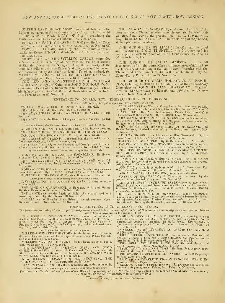
NF.W AM) VALUABLE PUBLICATIONS, PRIXII'.D FOR T. Kl.I LV, PATERNOSTEK ROW, LONDON.
SMITH'S I,AST GUKAT ASSIZE, or Crand Jubilee, in Six
Discourses, iiuliiiliii!:; the "shei-iikru's tbnt," &c. 28 Nos. at 6d.
Tilt; NKW WIIOLK DUTY OF MAN; containing the
Faith as well as Practice of a Christian. 23 Nos. at 6d.
BURKITT'S FAMIIiY PRAYER BOOK ; or. Book of Com-mon Praver ; in a large clear type, with Motes, 4cc. 26 Nos. at Gd.
COWPER'S POEMS, edited by the Rev. John Newton,A..M., late Rector of St. Mary Woolnoth. In 2 vols and published
in .'SO Nos. at (>(/.
SHIPWRECK OF THE STIRLING CASTLE, containing
a Narrative of the Sutferings of the Crew, and the cruel Murder
of Captain Eraser by the Savages. Also, the Barbarity of the
Cannibals inHictcd upon the Captain's Widow, as stated by herself,
and corroborated by the other survivors. To which is added, the
NARRATIVE of the WKECK of the CHARLES EATON, in
the same latitude. By J. Cuktis. In 16 Nos. at Gd.
THE LIFE AND ADVENTURES OF SIR WILLIAMCOURTNEY. Knight of -Malta, alias .lOHN NICHOLS TOM;containing a Detail of the Incidents of his Extraordinary Life from
THE NEWGATE CALENDER, containing the Lives of the
I
most notorious Characters who have violated the Laws of their
I
Country, from 1700 to the present time. By G. T. Wilkinson,
I
Esq. In about l.OO Nos. at (id. The whole or part may be had,' at the option of subscribers.
' THE MURDER OF WILLIAM WEARE ; and the Trial
!and Execution of JOHN THURTELL, the Murderer, and his
;Accomplices ; with the whole of Hunt's Confessions. 22 Nos. at
Grf., or in boards, 1 is.
THE MURDER OF MARIA MARTEN; with a full
development of all the extraordinary Circumstances which led to
the Discovery of her Body in the Rkd Barn. Together with the
TRIAL and Execution of WILLIAM CORDER, at Bury St.
Edmund's. 6 Parts at 2.t., or 24 Nos. at G(/.
THE MURDER OF CELIA HOLLOVVAY, AT BRIGH-TON, including the TRIAL for the Murder, and the extraordinary
Confessions of .lOHN WILLIAM HOLLOWAY. Together
with his LIFE, written by himself, and published by his owndesire. In 16 Nos. at 6d.
his Infancy to the Dreadful Battle at Bossenden Wood, in KentIn 5 Parts at 2s., or 20 Nos. at 6d.
ENTERTAINING NOVELS, EOT., EMBELLISHED WITH ENGR.WINGSBeing a Collection of the follouimj uniirrsally approved Novels.
VICAR OF WAKEFIKLI). By Oliver Goldsmith, M.B.
TIIK OLIJ BNULlsH BAUON. By Claka Keeve.
THK ADVENTURES OF SIR LANCLLOl GREAVES. By De.
Smollett.IHE SISTERS, or the History of Lucy and Carolioe SaDSom. BjDb.
DoDD.The above forming Otte handsome Volume, containiog: 18 No3. at (iJ. each.
AL.MOKAN AND HAM ET, an Oriental lale. By Ur. Hawkesworth.
THb AUVENlUKES OF SIGNOR GAUDLNllU Ul LUCCA.ZAUIG, OR IHE BOOK OF FA I E. By M. De Voltaire.
THE CASILE OF OTRAN 10, translated from the original Italian of
ONUI'nBIO MORALTO, hy \V. MARSHALL, Esq.
lARI'ARlAN I ALES, or One 1 housand and One Quarters of Hours;
written lu French by M. Gueulette, and translated by 1 . Fllovd, Esq.
The above forming a Second Volume, contaiuin^ 17 Nos. at 6d. each.
THE HISTOKY OF TOM JONEs, A FOUNDLING. By HenryFielding, E>q. 6 and a iulf parts, al 25.. oi 26 Nos. at 6d.
THE ADVENTURES OF TELEMACHUs, THE SON OFULYSSES, translated by Dr. Hawkbswoktu. 3 Pans at 2s., or 12
Nos. at 6d.
ROBlN^ON CRU'^OF, with an Account of his Travels through various
Parts of the VVorld. By D. Defoe. 4 Parts at 2s., or 16 Nos at Gii.
ROMANCE OF THE FOREST. By Mrs. Haocliffe. 24N'os.at6rf.
An Original Novel, printed uniformly with the W'averly Novels.
FITZALLEN. OR THE VOTARY OF LOVF. 7 Parts al 2s., or
28 Nos. at 6d.
THE ROSE OK CLAREMONT. or DauRhter, Wife, and Molhtr.
By Mrs. Catharine G. Ward. 30 Nos. at 6d.
THE BHOTHERS, or the Castle of Niolo. An original and very
interesting Novel. By Mr. Hoish. 34 Nns. at 6d.
CECILIA, or ilip Memoirs of an Heiress. Amuch-esteemed Novel.By Miss Bdrney. New Edition. 26 Nos. at 6d.
FATHERLESS FANNY, or a Young Ladys First Entrance into Life;being the Mtmoirs of a Little .Mendicant and her Beneiactors. 22 Nos. at 6d.
FATHERLESS ROSA, oi the Dangers of Femdie Life. Intended asa Companion to the preceding. By K. HuiSH, Esq. 22 Nos. at 6rf.
ARABIAN NIGHTS' ENTERTAINMENTS, or the Thousand andOne Nights; Accu ateiy describing ihe Manners, Custo.Tis, Laws, andReligiun ot the Eastern Nations, 24 Nos. at 6rf.
TH^ HISTORY OF HENRY EARL OF MORELAND. ByHenry Brooke, Revised and edited by the Uev. John V\ esley, M.A.24 Nos. at tid.
GRETNA GREEN, or the Elopement of Miss D with a GallantSon of .Mars. F'oanded on recent Facts. 29 Nos. at 6rf.
TALES OF THE CASTLE. By M. De. GtNLis. 31 Nos. at 6rf.
PAMELA, OR VIRTUE REWARDED; in a Series of Letters fr. ma Young Damsel to her Parent,. By S. If ichardson. 25 Nos. at tid.
THE HLSTORY OK SIR CHARLES GRANDISON AND THEHON. MISS BYRON; in a Series of Letters. By S. Richardson.40 Nos. at6d.
CLARISSA H.\RLOWE, or history of a Young Lady; in a Series
of Letters. By ihe Author of, and being a Compaiiiun to the two pie-
ceding Works. 58 Nos. at 6rf.
DON JUAN ; a highly entertaining WorV. liy A. Thornton, Esq.With coloured Engravings. 30 Nos. at 6d.. or 5 Parts at 3s,
DON JUAN'S LIFE IN LONDON; uniform wiih the above.
CASTLE OF INCHVALLY ; A Tale, alas ! too true. By the
Author of the Haunted Priory, &c. 22 Nos, at 6d.
GRANDVILLES ILLUSTRATED FABLES, from the most eminent
British. French, German, and Spanish Authors, illustrated with upwards of
fifty beautiful Wood-cuts, by Giandville. in 12 Paris at Is, each ; forming
a handsome volume, royal 8vo.
KELLY'S RUDIMENTS OF DRAWING; for the Inslruclinn of
Youth ; containing progressive Lessons for Drawing in Perspective, includ-
ing Sketches, Landscapes, Marine Views, Animals, Birds, &c., with
Directions for Drawing the Human Figure cnrrec ly. 30 Nos at 6d.
POCKET EDITIONS, WITH ELEGANT ENGRAVINGS.The following interesting Works are particularly recovimended to the attention of Parents and Guardians, as eminently suited to cultivate tirtuou*
and religious priciples in the minds of Youth.
THE BOOK OF COM.MON PRAYER: wherein ihe Service of i
the Church of England is illustrated by 3000 Proofs from the Holy Scrip-|
lures. By Ihe late Rev. John Vbneer. With the New Version ofI
Psalms, 16 Nvs. iBmo. at 6(f., with 14 Engravings; and in embossed bind-
ing, 10s.; without plates, 7s. Gd.
.\n Original Edition, enlarged and improved.
MILLER'S SCRIPTURE HISTORY, fur the Impiovementof Y'outh,
illustrated bv upwards of 240 Engravings, 30 Nos. 16ino. at Gd., and maybe bad in 2 vols, cloth, or bound.
MILLER'S NATURAL HISTORY; for the Improvement of Youth,
with 300 Engravings. 25 Nos. al Gd.
THE AFFECTIONATE PARENTS GIFT, AND GOODCHILD'S REW.VRD; a Scries of Poems and Essays, on Natural,
Moral, and Relinious Subjects. Uniform with the preceding Work.2tl Nos. at Gd.. with upwards of 114 Engravings.
NEW WEEK'S PREPARATION FOR RECEIVING THELORD'S SUPPER. In Two Parts, price 3s. 6(<, bound.
WATT'S PSALMS AND HYMNS. Bound incalf,3s.6d., or shcep,3s.
A liberal Allowance to those who puchase 25 copies or upwards, to give away
MODERN GEOGRAPHY. FOR YOUTH; comprising a clearand tnierlaining Account of all the Empires. Kingdoms. .States, &c. in
l-urope, Asia, Africa, an ' .America. By H. M. Jones. Embellished with120 Views o( the principal Cities, Costumes of Nations, and -Maps. 25Nos. al Gd. each.
A SELECTION OF INTERE.STING ANECDOTES, both Moraland Religious. 72mo. Gd.
THE hCRITURE INSTRUCTOR! for the use of Families andSchools in general ; being the Christian Doctrine and Practice, as set
forth in the Words of Scripture, price Gd,, or in neat cloih, 9d,
THE BELIEVER'S POCKET COMPANION, with devout anduseful Sayings By John Mason, .\.M. price Gd.
TIME AND THE END OF TIME. By John Fox, Author, of the" Look of Martyrs.'! Price 3s, bound.THOMP.->ON'-< COMPLETE BIRD FANCIER. With 12 Engravings
of Song-Birds, price Is.
THOMH|M}N'» COMPLETE PIGEON FANCIER. With 12 En-gravings ofxhoice Pigeons, price Is.
KELLY'S vrEKEOlYPED READY RECKONER; large Figures,
and containing many useful Tables, &.c. Price Is. €d. bound.
TAe Parts and Numbers of most of the above Works being already printed the uhole or any portion of them may be had at once, at the opti.m ofPurchasers ; or complete in Boards, or in various Bindings.
Primrote Street, Bixkopigate.

KCSB UBRARY
?f!

w
H'-'."",-%VW.;,
.^^^-
.,,.,•, •K-v'filv
^
ff