Practical Electronics - feb 2004.pdf
65
-
Upload
khangminh22 -
Category
Documents
-
view
1 -
download
0
Transcript of Practical Electronics - feb 2004.pdf

Copyright 2004, Wimborne Publishing Ltd (408 Wimborne Road East, Ferndown, Dorset, BH22 9ND, UK)
and TechBites Interactive Inc.,
(PO Box 857, Madison, Alabama 35758, USA)
All rights reserved.
WARNING! The materials and works contained within EPE Online — which are made available by Wimborne Publishing Ltd and TechBites Interactive Inc — are copyrighted. You are permitted to make a backup copy of the downloaded file and one (1) hard copy of such materials and works for your personal use. International copyright laws, however, prohibit any further copying or reproduction of such materials and works, or any republication of any kind. TechBites Interactive Inc and Wimborne Publishing Ltd have used their best efforts in preparing these materials and works. However, TechBites Interactive Inc and Wimborne Publishing Ltd make no warranties of any kind, expressed or implied, with regard to the documentation or data contained herein, and specifically disclaim, without limitation, any implied warranties of merchantability and fitness for a particular purpose. Because of possible variances in the quality and condition of materials and workmanship used by readers, EPE Online, its publishers and agents disclaim any responsibility for the safe and proper functioning of reader-constructed projects based on or from information published in these materials and works. In no event shall TechBites Interactive Inc or Wimborne Publishing Ltd be responsible or liable for any loss of profit or any other commercial damages, including but not limited to special, incidental, consequential, or any other damages in connection with or arising out of furnishing, performance, or use of these materials and works.
ISSN 0262 3617PROJECTS . . . THEORY . . . NEWS . . .COMMENTS . . . POPULAR FEATURES . . .
VOL. 33. No. 2 FEBRUARY 2004Cover illustration by jgr22
Everyday Practical Electronics, February 2004 81
© Wimborne Publishing Ltd 2004. Copyright in alldrawings, photographs and articles published inEVERYDAY PRACTICAL ELECTRONICS is fullyprotected, and reproduction or imitations in whole orin part are expressly forbidden.
Our March 2004 issue will be published onThursday, 12 February 2004. See page 83 for details Readers Services Editorial and Advertisement Departments 91
www.epemag.wimborne.co.ukEPE Online: www.epemag.com
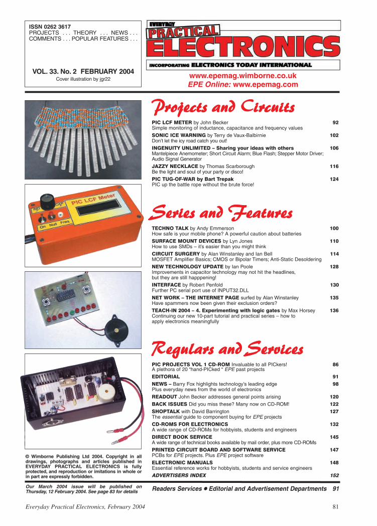
PPrroojjeeccttss aanndd CCiirrccuuiittssPIC LCF METER by John Becker 92Simple monitoring of inductance, capacitance and frequency values
SONIC ICE WARNING by Terry de Vaux-Balbirnie 102Don’t let the icy road catch you out!
INGENUITY UNLIMITED – Sharing your ideas with others 106Mantelpiece Anemometer; Short Circuit Alarm; Blue Flash; Stepper Motor Driver;Audio Signal Generator
JAZZY NECKLACE by Thomas Scarborough 116Be the light and soul of your party or disco!
PIC TUG-OF-WAR by Bart Trepak 124PIC up the battle rope without the brute force!
SSeerriieess aanndd FFeeaattuurreessTECHNO TALK by Andy Emmerson 100How safe is your mobile phone? A powerful caution about batteries
SURFACE MOUNT DEVICES by Lyn Jones 110How to use SMDs – it’s easier than you might think
CIRCUIT SURGERY by Alan Winstanley and Ian Bell 114MOSFET Amplifier Basics; CMOS or Bipolar Timers; Anti-Static Desoldering
NEW TECHNOLOGY UPDATE by Ian Poole 128Improvements in capacitor technology may not hit the headlines,but they are still happpening!
INTERFACE by Robert Penfold 130Further PC serial port use of INPUT32.DLL
NET WORK – THE INTERNET PAGE surfed by Alan Winstanley 135Have spammers now been given their exclusion orders?
TEACH-IN 2004 – 4. Experimenting with logic gates by Max Horsey 136Continuing our new 10-part tutorial and practical series – how toapply electronics meaningfully
RReegguullaarrss aanndd SSeerrvviicceessPIC PROJECTS VOL 1 CD-ROM Invaluable to all PICkers! 86A plethora of 20 “hand-PICked “ EPE past projects
EDITORIAL 91NEWS – Barry Fox highlights technology’s leading edge 98Plus everyday news from the world of electronics
READOUT John Becker addresses general points arising 120BACK ISSUES Did you miss these? Many now on CD-ROM! 122SHOPTALK with David Barrington 127The essential guide to component buying for EPE projects
CD-ROMS FOR ELECTRONICS 132A wide range of CD-ROMs for hobbyists, students and engineers
DIRECT BOOK SERVICE 145A wide range of technical books available by mail order, plus more CD-ROMs
PRINTED CIRCUIT BOARD AND SOFTWARE SERVICE 147PCBs for EPE projects. Plus EPE project software
ELECTRONIC MANUALS 148Essential reference works for hobbyists, students and service engineers
ADVERTISERS INDEX 152

NO ONE DOES IT BETTERDON'T MISS AN
ISSUE – PLACE YOURORDER NOW!
Demand is bound to be high
MARCH 2004 ISSUE ON SALE THURSDAY, FEBRUARY 12
Everyday Practical Electronics, February 2004 83
NEXT MONTH
MIDI HOME STUDIOHEALTH-CHECKA MIDI code transmitter and receiver that will enableyou to check out a range of MIDI (Musical InstrumentDigital Interface) based instruments/modules/computers. When originally using a new MIDI set-up,the system will often not function correctly the firsttime and it is usually difficult to decide if something isfaulty, devices are connected wrongly or if particularsettings are incorrect. This easy-to-build PIC-basedsystem transmits and detects single MIDI messagesin a way that clearly demonstrates the presence orabsence of meaningful code signals using an l.c.d.readout.Invaluable for those who need to set up a homerecording studio etc.
BAT-BANDCONVERTERA Bat-Band Converter that not only detectsbats but converts their sounds to frequenciesthat fall within the range of human hearing. Itdoes this using just a single quad op.amp i.c.and a handful of components to deliversurprisingly good performance.A bat will emit rapid bursts of ultrasound –typically 10 to 200 times a second – increasingrapidly as it nears its prey. These bursts are inthe region of 12kHz to 150kHz depending onthe species. This unit will “hear” the soundsover the range of 13·6kHz to 180kHzdepending on the transducer used.The converter has a number of other uses,such as a puncture finder, for checking otherultrasonic devices and, with slight modification,as a v.l.f. receiver or a digital voice transmitter.
STANDBY LIGHT – BE PREPARED FOR POWER CUTSTEACH-IN 2004 – PART 5 LOGIC GATES AS SWITCHESPLUS
RC MIXERFOR DELTAOR V-TAIL PLANESThis simple mixer cross-mixes two radio controlchannels for delta or V-tail model airplanes. Insuch a configuration one servo must respond toboth aileron and elevator commands; this mixertakes the signals as they come from thereceiver, does the maths, and generates therequired servo signal to move the controlsurfaces correctly. It’s all done with a score ofcomponents and a PIC, and provides resolutionof one microsecond, giving one thousand stepsover the servo’s range.

Quasar Electronics LimitedPO Box 6935, Bishops Stortford,CM23 4WPTel: 0870 246 1826Fax: 0870 460 1045E-mail: [email protected]
Add £2.00 P&P to all UK orders. 1st Class Recorded – £4.Next day (insured £250) – £7. Europe – £5. Rest of World – £10.We accept all major credit/debit cards. Make cheques/POspayable to Quasar Electronics Limited.Prices include 17.5% VAT. MAIL ORDER ONLY.Call now for our FREE CATALOGUE with details of over 300high quality kits, projects, modules and publications.
Helping you make the right connections!
PIC & ATMEL ProgrammersWe have a wide range of low cost PIC andATMEL Programmers. Complete range anddocumentation available from our web site.
Programmer Accessories:40-pin Wide ZIF socket (ZIF40W) £15.0018VDC Power supply (PSU201) £5.95Leads: Parallel (LEAD108) £4.95 / Serial(LEAD76) £4.95 / USB (LEADUAA) £2.95
NEW! USB ‘All-Flash’ PIC ProgrammerUSB PIC programmer for all‘Flash’ devices. No externalpower supply making it trulyportable. Supplied with boxand Windows Software. ZIFSocket and USB Plug A-A leadnot incl.Kit Order Code: 3128KT – £29.95Assembled Order Code: AS3128 – £39.95
Enhanced “PICALL” ISP PIC ProgrammerWill program virtually ALL 8to 40 pin PICs plus certainATMEL AVR, SCENIX SXand EEPROM 24C devices.Also supports In SystemProgramming (ISP) for PIC
and ATMEL AVRs. Free software. Blank chipauto detect for super fast bulk programming.Requires a 40-pin wide ZIF socket (notincluded)Kit Order Code: 3144KT – £54.95Assembled Order Code: AS3144 – £59.95
ATMEL 89xxx ProgrammerUses serial port and anystandard terminal commsprogram. 4 LEDs displaythe status. ZIF socketsnot included. Supply:16VDC.Kit Order Code: 3123KT – £29.95Assembled Order Code: AS3123 – £34.95
NEW! USB & Serial Port PIC ProgrammerUSB/Serial connection.Header cable for ICSP. FreeWindows software. See web-site for PICs supported. ZIFSocket and USB Plug A-Alead extra. 18VDC.
Kit Order Code: 3149KT – £29.95Assembled Order Code: AS3149 – £44.95
Introduction to PIC ProgrammingGo from a complete PICbeginner to burning yourfirst PIC and writing yourown code in no time!Includes a 49-page step-by-step Tutorial Manual,Programming Hardware (with LED benchtesting section), Win 3.11–XP ProgrammingSoftware (will Program, Read, Verify &Erase), and a rewritable PIC16F84A thatyou can use with different code (4 detailedexamples provided for you to learn from).Connects to PC parallel port.Kit Order Code: 3081KT – £14.95Assembled Order Code: AS3081 – £24.95
008877008877 1111 CREDIT CARDSALES 717 7168717 7168
ABC Mini Microcontroller BoardCurrently learning aboutmicrocontrollers? Needto do more than flash aLED or sound a buzzer?The ABC Mini StarterKit is based on ATMEL’sAVR 8535 RISC tech-nology and will interestboth the beginner andexpert alike.Beginners will find thatthey can write and test a simple program,using the BASIC programming language,within an hour or two of connecting it up.Experts will like the power and flexibility ofthe ATMEL microcontroller, as well as theease with which the board can be“designed-in” to a project.The ABC Mini STARTER PACK includeseverything you need to get up and experi-menting right away. On the hardware side,there’s a pre-assembled ABC Mini Boardwith parallel and serial cables for connectionto your PC. Windows software included onCD-ROM features an Assembled, BASICcompiler and in-system programmer.Order Code ABCMINISP – £49.95The ABC Mini boards only can also bepurchased separately at £29.95 each.
Rolling Code 4-Channel UHF RemoteState-of-the-Art. High security.4 channels. Momentary orlatching relay output. Rangeup to 40m. Up to 15 TXs canbe learned by one Rx (kitincludes one Tx but moreavailable separately).4 indicator LEDs.Rx: PCB 77x85mm, 12VDC/6mA (standby).Two & Ten Channel versions also available.Kit Order Code: 3180KIT – £41.95Assembled Order Code: AS3180 – £49.95
Computer Temperature Data LoggerSerial port 4-channel tem-perature logger. °C or °F.Continuously logs up to 4separate sensors located200m+ from board. Widerange of free software appli-cations for storing/using data.PCB just 38x38mm. Powered
by PC. Includes one DS1820 sensor andfour header cables.Kit Order Code: 3145KT – £22.95Assembled Order Code: AS3145 – £29.95Additional DS1820 Sensors – £3.95 each
NEW! DTMF Telephone Relay SwitcherCall your phone numberusing a DTMF phone fromanywhere in the worldand remotely turn on/offany of the 4 relays asdesired. User settableSecurity Password, Anti-Tamper, Rings toAnswer, Auto Hang-up and Lockout.Includes plastic case. 130 x 110 x 30mm.Power: 12VDC.Kit Order Code: 3140KT – £39.95Assembled Order Code: AS3140 – £59.95
Serial Port Isolated I/O ModuleComputer controlled8-channel relayboard. 5A mainsrated relay outputsand 4 opto-isolateddigital inputs (formonitoring switch
states, etc). Useful in a variety of controland sensing applications. Programmed viaserial port (use our new Windows interface,terminal emulator or batch files). Serialcable can be up to 35m long. Includesplastic case 130 x 100 x 30mm. Power:12VDC/500mA.Kit Order Code: 3108KT – £54.95Assembled Order Code: AS3108 – £64.95
Infra-red RC 12-Channel Relay BoardControl 12 on-board relayswith included infra-redremote control unit. Toggleor momentary. 15m+ range.112 x 122mm.Supply: 12VDC/0·5A.
Kit Order Code: 3142KT – £41.95Assembled Order Code: AS3142 – £59.95
PC Data Acquisition & Control UnitMonitor and log amixture of analogueand digital inputsand control externaldevices via the ana-logue and digitaloutputs. Monitorpressure, tempera-ture, light intensity, weight, switch state,movement, relays, etc. with the apropriatesensors (not supplied). Data can beprocessed, stored and the results used tocontrol devices such as motors, sirens,relays, servo motors (up to 11) and twostepper motors.
Features 11 Analogue Inputs – 0·5V, 10 bit (5mV/step) 16 Digital Inputs – 20V max. Protection 1K in
series, 5·1V Zener 1 Analogue Output – 0-2·5V or 0-10V. 8 bit
(20mV/step) 8 Digital Outputs – Open collector, 500mA, 33V
max Custom box (140 x 110 x 35mm) with printed
front & rear panels Windows software utilities (3·1 to XP) and
programming examples Supply: 12V DC (Order Code PSU203)
Kit Order Code: 3093KT – £69.95Assembled Order Code: AS3093 – £99.95
Controllers & LoggersHere are just a few of the controller and dataacquisition and control units we have.See website for full details. Suitable PSU forall units: Order Code PSU203 – £9.95
Most items are available in kit form (KT suffix)or pre-assembled and ready for use (AS prefix).

Cool New Kits This Winter!Here are a few of the most recent kitsadded to our range. See website or join ouremail Newsletter for all the latest news.
FM Bugs & TransmittersOur extensive range goes from discreetsurveillance bugs to powerful FM broadcasttransmitters. Here are a few examples. Allcan be received on a standard FM radioand have adjustable transmitting frequency.
Helping you make the right connections!
CREDITCREDITCARDCARDSALESSALES08710871717717
71687168
NEW! EPE Ultrasonic Wind Speed MeterSolid-state designwind speed meter(anemometer) thatuses ultrasonictechniques and hasno moving partsand does not need
calibrating. It is intended for sports-typeactivities, such as track events, sailing,hang-gliding, kites and model aircraft flying,to name but a few. It can even be used tomonitor conditions in your garden. The probeis pointed in the direction from which thewind is blowing and the speed is displayedon an LCD display.
SpecificationsUnits of display: metres per second, feet per
second, kilometres per hour and miles per hourResolution: Nearest tenth of a metreRange: Zero to 50mph approx.
Based on the project published in EverydayPractical Electronics, Jan 2003. We havemade a few minor design changes (see website for full details). Power: 9VDC (PP3 bat-tery or Order Code PSU203).Main PCB: 50 x 83mm.Kit Order Code: 3168KT – £34.95
NEW! Audio DTMF Decoder and DisplayDetects DTMFtones via anon-board electretmicrophone ordirect from thephone lines throughan audio trans-former. The
numbers are displayed on a 16-character,single line display as they are received. Upto 32 numbers can be displayed by scrollingthe display left and right. There is also aserial output for sending the detected tonesto a PC via the serial port. The unit will notdetect numbers dialled using pulse dialling.Circuit is microcontroller based.Supply: 9-12V DC (Order Code PSU203).Main PCB: 55 x 95mm.Kit Order Code: 3153KT – £17.95Assembled Order Code: AS3153 – £29.95
NEW! EPE PIC Controlled LED FlasherThis versatilePIC-based LEDor filament bulbflasher can beused to flashfrom 1 to 160
LEDs. The user arranges the LEDs in anypattern they wish. The kit comes with 8superbright red LEDs and 8 green LEDs.Based on the Versatile PIC Flasher by SteveChallinor, EPE Magazine Dec ’02. See web-site for full details. Board Supply: 9-12V DC.LED supply: 9-45V DC (depending onnumber of LED used). PCB: 43 x 54mm.Kit Order Code: 3169KT – £10.95
NNoo..11KITS
FOR Secure Online Ordering Facilities Full Product Listing, Descriptions & Photos Kit Documentation & Software Downloads
www.quasarelectronics.com
Most items are available in kit form (KT suffix)or assembled and ready for use (AS prefix)
MMTX’ Micro-Miniature 9V FM Room BugOur best selling bug! Goodperformance. Just 25 x 15mm.Sold to detective agenciesworldwide. Small enough tohide just about anywhere.Operates at the ‘less busy’ top
end of the commercial FM waveband andalso up into the more private Air band.Range: 500m. Supply: PP3 battery.Kit Order Code: 3051KT – £8.95Assembled Order Code: AS3051 – £14.95
HPTX’ High Power FM Room BugOur most power-ful room bug.Very Impressiveperformance. Clear and stable output signalthanks to the extra circuitry employed.Range: 1000m @ 9V. Supply: 6-12V DC (9VPP3 battery clip suppied). 70 x 15mm.Kit Order Code: 3032KT – £9.95Assembled Order Code: AS3032 – £17.95
MTTX’ Miniature Telephone TransmitterAttach anywherealong phone line.Tune a radio into thesignal and hear
exactly what both parties are saying.Transmits only when phone is used. Clear,stable signal. Powered from phone line socompletely maintenance free once installed.Requires no aerial wire – uses phone line asantenna. Suitable for any phone systemworldwide. Range: 300m. 20 x 45mm.Kit Order Code: 3016KT – £7.95Assembled Order Code: AS3016 – £13.95
4 Watt FM TransmitterSmall, powerful FMtransmitter. Audiopreamp stage andthree RF stagesdeliver 4 watts of RFpower. Can be usedwith the electret
microphone supplied or any line level audiosource (e.g. CD or tape OUT, mixer, soundcard, etc). Aerial can be an open dipole orGround Plane. Ideal project for the novicewishing to get started in the fascinatingworld of FM broadcasting. 45 x 145mm.Kit Order Code: 1028KT – £22.95Assembled Order Code: AS1028 – £34.95
25 Watt FM TransmitterFour transistor based stages with a PhilipsBLY89 (or equivalent) in the final stage.Delivers a mighty 25 Watts of RF power.Accepts any line level audio source (inputsensitivity is adjustable). Antenna can be anopen dipole, ground plane, 5/8, J, or YAGIconfiguration. Supply 12-14V DC, 5A.Supplied fully assembled and aligned – justconnect the aerial, power and audio input.70 x 220mm.Order Code: 1031M – £124.95
Electronic Project LabsGreat introduction to the world of electron-ics. Ideal gift for budding electronics expert!
200-in-1 Electronic Project LabA great way tolearn 200 excitingelectronic experi-ments safely.Everything youneed to start afascinating hobbyin basic electron-ics! Learn abouttransistors, transformers, diodes, capacitors,oscillators, basic electronic circuits andschematic symbols. Easy-to-read 110-pageA5 illustrated lab style manual takes youthrough each electronic experiment step-by-step and includes schematics diagrams andcircuit explanations.Order Code EPL200 – £47.9530, 130-300 and 500-in-1 project labs alsoavailable – see website for details.
1046KT – 25W Stereo Car Booster £26.953087KT – 1W Stereo Amplifier £4.953105KT – 18W BTL mono Amplifier £9.953106KT – 50W Mono Hi-fi Amplifier £19.953143KT – 10W Stereo Amplifier £9.951011KT – Motorbike Alarm £11.951019KT – Car Alarm System £10.951048KT – Electronic Thermostat £9.951080KT – Liquid Level Sensor £5.953005KT – LED Dice with Box £7.953006KT – LED Roulette Wheel £8.953074KT – 8-Ch PC Relay Board £29.953082KT – 2-Ch UHF Relay £26.953126KT – Sound-Activated Relay £7.953063KT – One Chip AM Radio £10.953102KT – 4-Ch Servo Motor Driver £15.953160KT – PIC16F62x Experimenter £8.951096KT – 3-30V, 5A Stabilised PSU £30.953029KT – Combination Lock £6.953049KT – Ultrasonic Detector £13.953130KT – Infra-red Security Beam £12.95SG01MKT – Train Sounds £6.95SG10 MKT – Animal Sounds £5.951131KT – Robot Voice Effect £8.953007KT – 3V FM Room Bug £6.953028KT – Voice-Activated FM Bug £12.953033KT – Telephone Recording Adpt £9.953112KT – PC Data Logger/Sampler £18.953118KT – 12-bit Data Acquisition Unit £52.953101KT – 20MHz Function Generator £69.95
Number 1 for Kits!With over 300 projects in our range we arethe UK’s number 1 electronic kit specialist.Here are a few other kits from our range.

PIC-Based Ultrasonic Tape MeasureYou’ve got it taped if you PIC this ultrasonic distance measuringcalculatorEPE Mind PICklerWant seven ways to relax? Try our PIC-controlled mind machine!PIC MIDI Sustain PedalAdd sustain and glissando to your MIDI line-up with thisinexpensive PIC-controlled effects unitPIC-based MIDI HandbellsRing out thy bells with merry tolling – plus a MIDI PIC-up, ofcourse!EPE Mood PICkerOh for a good night’s sleep! Insomniacs rejoice – your wakefulnights could soon be over with this mini-micro under the pillow!PIC Micro-ProbeA hardware tool to help debug your PIC softwarePIC Video CleanerImproving video viewing on poorly maintained TVs and VCRsPIC Graphics LCD ScopeA PIC and graphics LCD signal monitor for your workshopPIC to Printer InterfaceHow to use dot-matrix printers as data loggers with PICmicrocontrollersPIC PolywhatsitA novel compendium of musical effects to delight the creativemusicianPIC Magick MusickConjure music from thin air at the mere untouching gesture of afingertipPIC Mini-EnigmaShare encrypted messages with your friends — true spymasterentertainmentPIC Virus ZapperCan disease be cured electronically? Investigate thiscontroversial subject for yourselfPIC Controlled Intruder AlarmA sophisticated multi-zone intruder detection system that offers avariety of monitoring facilitiesPIC Big-Digit DisplayControl the giant ex-British Rail platform clock 7-segment digitsthat are now available on the surplus marketPIC Freezer AlarmHow to prevent your food from defrosting unexpectedlyPIC World ClockGraphically displays world map, calendar, clock and globaltime-zone dataPICAXE ProjectsA 3-part series using PICAXE devices – PIC microcontrollersthat do not need specialist knowledge or programmingequipmentPIC-based Tuning Fork and MetronomeThrill everyone by at long last getting your instrument properlytuned!Versatile PIC FlasherAn attractive display to enhance your Christmas decorations oryour child’s ceiling
Please send me ........ (quantity) EPE PIC PROJECTS VOL 1 CD-ROM
Price £14.45 each – includes postage to anywhere in the world.
Name . . . . . . . . . . . . . . . . . . . . . . . . . . . . . . . . . . . . . . . . . . . .
Address . . . . . . . . . . . . . . . . . . . . . . . . . . . . . . . . . . . . . . . . . .
. . . . . . . . . . . . . . . . . . . . . . . . . . . . . . . . . . . . . . . . . . . . . . . .
. . . . . . . . . . . . . . . . . . . . . . . . . . . . . . . . . . . . . . . . . . . . . . . .
. . . . . . . . . . . . . . . . . . . . . . . . . . Post Code . . . . . . . . . . . . .
I enclose cheque/P.O./bank draft to the value of £ . . . . . . . . .
Please charge my Visa/Mastercard/Amex/Diners Club/Switch
£ . . . . . . . . . . . . . . . . . . . . . . . . . . . . . . . . . . . . . . . . . . . . . . .
Card No. . . . . . . . . . . . . . . . . . . . . . . . . . . . . . . . . . . . . . . . . .
Card Security Code . . . . . . . . . . (The last 3 digits on or just under the signature strip)
Expiry Date . . . . . . . . . . . . . . . . . . Switch Issue No. . . . . . . .
SEND TO: Everyday Practical Electronics,Wimborne Publishing Ltd.,
408 Wimborne Road East, Ferndown, Dorset BH22 9ND.Tel: 01202 873872. Fax: 01202 874562.Email: [email protected]
Payments must be by card or in £ Sterling – cheque or bank draftdrawn on a UK bank.
Normally supplied within seven days of receipt of order.Send a copy of this form, or order by letter if you do not wish to cut your issue.
Order on-line fromwww.epemag.wimborne.co.uk/shopdoor.htm
or www.epemag.com (USA $ prices)or by Phone, Fax, Email or Post.
EPE PIC PROJECTSVOLUME 1
MINI CD-ROMA plethora of 20 “hand-PICked” PICProjects from selected past issues of EPETogether with the PIC programming software for each project plus bonus articlesThe projects are:
NOTE: The PDF files on this CD-ROM are suitable to use on any PC with aCD-ROM drive. They require Adobe Acrobat Reader.
ONLY££1144..4455
INCLUDINGVAT and P&P
86 Everyday Practical Electronics, February 2004
NNEEWW
EPE PIC PROJECTS CD-ROMORDER FORM
BECOME A PIC PROJECT BUILDER WITH THE HELP OF EPE!

PIC Training & Development SystemThe best place to start learning about microcontrollers is the PIC16F84. This iseasy to understand and very popular with construction projects. Then continue onusing the more sophisticated PIC16F877 family.
The heart of our system is two real books which lie open on your desk whileyou use your computer to type in the programme and control the hardware. Startwith four very simple programmes. Run the simulator to see how they work. Testthem with real hardware. Follow on with a little theory.....
Our complete PIC training and development system consists of our universalmid range PIC programmer, a 306 page book covering the PIC16F84, a 262 pagebook introducing the PIC16F877 family, and a suite of programmes to run on aPC. The module is an advanced design using a 28 pin PIC16F870 to handle thetiming, programming and voltage switching requirements. The module has twoZIF sockets and an 8 pin socket which between them allow most mid range 8, 18,28 and 40 pin PICs to be programmed.The plugboard is wired with a 5 volt supply.The software is an integrated system comprising a text editor, assemblerdisassembler, simulator and programming software. The programming isperformed at 5 volts, verified with 2 volts or 3 volts applied and verified again with5.5 volts applied to ensure that the PIC is programmed correctly over its fulloperating voltage. DC version for UK, battery version for overseas. UK ordersinclude a plugtop power supply.
Universal mid range PIC programmer module+ Book Experimenting with PIC Microcontrollers+ Book Experimenting with the PIC16F877 (2nd edition)+ Universal mid range PIC software suite+ PIC16F84 and PIC16F870 test PICs. . . . . . . £159.00
(Postage & insurance UK £10, Europe £15, Rest of world £25)
Experimenting with PIC MicrocontrollersThis book introduces the PIC16F84 and PIC16C711, and is the easy wayto get started for anyone who is new to PIC programming. We begin withfour simple experiments, the first of which is explained over ten and halfa pages assuming no starting knowledge except the ability to operate aPC. Then having gained some practical experience we study the basicprinciples of PIC programming, learn about the 8 bit timer, how to drivethe liquid crystal display, create a real time clock, experiment with thewatchdog timer, sleep mode, beeps and music, including a rendition ofBeethoven’s Für Elise. Finally there are two projects to work through,using the PIC16F84 to create a sinewave generator and investigating thepower taken by domestic appliances. In the space of 24 experiments, twoprojects and 56 exercises the book works through from absolutebeginner to experienced engineer level.
Hardware & Ordering InformationOur latest programmer module connects to the serial port of your PIC(COM1 or COM2), which enables our PIC software to operate directlywithin Windows 98, XP, NT, 2000 etc.
Telephone with Visa, Mastercard or Switch, or send cheque/PO forimmediate despatch. All prices include VAT if applicable.
Web site:- www.brunningsoftware.co.uk
138 The Street, Little Clacton, Clacton-on-sea,Essex, CO16 9LS. Tel 01255 862308
Mail order address:
Learn About Microcontrollers NEW 32 bit PC AssemblerExperimenting with PC Computers with its kit is theeasiest way ever to learn assembly languageprogramming. If you have enough intelligence tounderstand the English language and you can operatea PC computer then you have all the necessarybackground knowledge. Flashing LEDs, digital toanalogue converters, simple oscilloscope, chargingcurves, temperature graphs and audio digitising.
Kit now supplied with our 32 bit assembler with 84page supplement detailing the new features andincluding 7 experiments PC to PIC communication.Flashing LEDs, writing to LCD and two way data using3 wires from PC’s parallel port to PIC16F84.
Book + made up kit 1a + software........ £73.50Book + unmade kit 1u + software......... £66.50(PP UK £4, Europe £10, Rest of world £14)
C & C++ for the PCExperimenting with C & C++ Programmes teaches us toprogramme by using C to drive the simple hardwarecircuits built using the materials supplied in the kit. Thecircuits build up to a storage oscilloscope usingrelatively simple C techniques to construct aprogramme that is by no means simple. Whenapproached in this way C is only marginally moredifficult than BASIC and infinitely more powerful. Cprogrammers are always in demand. Ideal for absolutebeginners and experienced programmers.
Book + made up kit 2a + software ..... £57.50Book + unmade kit 2u + software ...... £51.50Book + top up kit 2t + software .......... £37.98(PP UK £4, Europe £10, Rest of world £14)
The KitsThe assembler and C & C++ kits contain the prototypingboard, lead assemblies, components and programmingsoftware to do all the experiments. The ‘made up’ kitsare supplied ready to start. The ‘top up’ kit is for readerswho have already purchased kit 1a or 1u.
Assembler and C & C++Click on ‘Special Offers’ on our website for details ofhow to save by buying a combined kit for assembler andC & C++.
Experimenting with the PIC16F877The second PIC book starts with the simplest of experiments togive us a basic understanding of the PIC16F877 family. Then welook at the 16 bit timer, efficient storage and display of textmessages, simple frequency counter, use a keypad for numbers,letters and security codes, and examine the 10 bit A/D converter.
The PIC16F627 is then introduced as a low cost PIC16F84. Weuse the PIC16F627 as a step up switching regulator, and tocontrol the speed of a DC motor with maximum torque stillavailable.We study how to use a PIC to switch mains power usingan optoisolated triac driving a high current triac. Finally we studyhow to use the PICs USART for serial communication to a PC.
Everyday Practical Electronics, February 2004 87
MICRO PEsTSCAREROur latest design – The ultimatescarer for the garden. Usesspecial microchip to give randomdelay and pulse time. Easy tobuild reliable circuit. Keeps pets/pests away from newly sown areas,play areas, etc. uses power sourcefrom 9 to 24 volts.RANDOM PULSESHIGH POWER DUAL OPTION Plug-in power supply £4.99
KIT 867. . . . . . . . . . . . . . . . . . . . . . . . . . . . .£19.99KIT + SLAVE UNIT. . . . . . . . . . . . . . . . . . . .£32.50
WINDICATORA novel wind speed indicator with LED readout. Kit comescomplete with sensor cups, and weatherproof sensing head.Mains power unit £5.99 extra.
KIT 856. . . . . . . . . . . . . . . . . . . . . . . . . . . . .£28.00
135 Hunter Street, Burton-on-Trent, Staffs. DE14 2STTel 01283 565435 Fax 546932http://www.magenta2000.co.ukE-mail: [email protected] Prices include V.A.T. ADD £3.00 PER ORDER P&P. £6.99 next day
MAIL ORDER ONLY CALLERS BY APPOINTMENT
EPE MICROCONTROLLERP.I. TREASURE HUNTER
The latest MAGENTA DESIGN – highlystable & sensitive – with I.C. control of alltiming functions and advanced pulseseparation techniques. High stability
drift cancelling Easy to build
& use No ground
effect, worksin seawater
Detects gold,silver, ferrous &non-ferrousmetals
Efficient quartz controlledmicrocontroller pulse generation.
Full kit with headphones & allhardware
KIT 847 . . . . . . . . .£63.95
Stepping Motors
MD100..Std 100 step..£9.99
MD200...200 step...£12.99
MD24...Large 200 step...£22.95
MOSFET MkII VARIABLE BENCHPOWER SUPPLY 0-25V 2·5ABased on our Mk1 design andpreserving all the features, butnow with switching pre-regulator for much higher effi-ciency. Panel meters indicateVolts and Amps. Fully variabledown to zero. Toroidal mainstransformer. Kit includespunched and printed case andall parts. As featured in April1994 EPE. An essential pieceof equipment.
Kit No. 845 . . . . . . . .£64.95
EE258
PIC PIPE DESCALERSIMPLE TO BUILD SWEPTHIGH POWER OUTPUT FREQUENCYAUDIO & VISUAL MONITORINGAn affordable circuit which sweepsthe incoming water supply withvariable frequency electromagneticsignals. May reduce scale formation,dissolve existing scale and improvelathering ability by altering the waysalts in the water behave.Kit includes case, P.C.B., coupling coil and all components.High coil current ensures maximumeffect. L.E.D. monitor.
KIT 868 ....... £22.95 POWER UNIT......£3.99
DUAL OUTPUT TENS UNITAs featured in March ’97 issue.Magenta have prepared a FULL KIT for this.excellent new project. All components, PCB, hardware and electrodes are included.Designed for simple assembly and testing andproviding high level dual output drive.
KIT 866. . Full kit including four electrodes £32.90
Set of4 spare
electrodes£6.50
1000V & 500V INSULATIONTESTER
Superb new design. Regulatedoutput, efficient circuit. Dual-scalemeter, compact case. Reads up to200 Megohms.Kit includes wound coil, cut-outcase, meter scale, PCB & ALLcomponents.KIT 848. . . . . . . . . . . . £32.95
SIMPLE PICPROGRAMMER
KIT 857... £12.99
Includes PIC16F84 chipdisk, lead, plug, p.c.b.,
all components andinstructions
Extra 16F84 chips £3.84Power Supply £3.99
EEPPEETTEEAACCHH--IINN22000000Full set of top quality NEWcomponents for this educa-tional series. All parts asspecified by EPE. Kit includesbreadboard, wire, croc clips,pins and all components forexperiments, as listed inintroduction to Part 1.*Batteries and tools not included.
TEACH-IN 2000 -
KIT 879 £44.95MULTIMETER £14.45
SPACEWRITERAn innovative and exciting project.Wave the wand through the air andyour message appears. Programmableto hold any message up to 16 digits long.Comes pre-loaded with “MERRY XMAS”. Kitincludes PCB, all components & tube plusinstructions for message loading.
KIT 849 . . . . . . . . . . . .£16.99
SUPER BATDETECTOR
1 WATT O/P, BUILT INSPEAKER, COMPACT CASE
20kHz-140kHzNEW DESIGN WITH 40kHz MIC.
A new circuit using a ‘full-bridge’ audioamplifier i.c., internalspeaker, andheadphone/tape socket.The latest sensitivetransducer, and ‘doublebalanced mixer’ give astable, high perfor-mance superheterodyne design.
KIT 861 . . . . . . . . . . .£27.99ALSO AVAILABLE Built & Tested. . . £42.99
12V EPROM ERASERA safe low cost eraser for up to 4 EPROMS at atime in less than 20 minutes. Operates from a12V supply (400mA). Used extensively for mobilework - updating equipment in the field etc. Also ineducational situations where mains supplies arenot allowed. Safety interlock prevents contactwith UV.
KIT 790 . . . . . . . . . . . .£29.90
Keep pets/pests away from newlysown areas, fruit, vegetable andflower beds, children’s play areas,patios etc. This project producesintense pulses of ultrasound whichdeter visiting animals.
ULTRASONIC PEsT SCARER
UP TO 4 METRES RANGE
LOW CURRENT DRAIN
KIT INCLUDES ALL COMPONENTS, PCB & CASE
EFFICIENT 100V TRANSDUCER OUTPUT
COMPLETELY INAUDIBLE TO HUMANS
KIT 812. . . . . . . . . . . . . . . . . . . . . . . . . . . . . . £15.00
TENS UNIT
NOW
WITH PIC16C84
EEPPROM
CHIP & SOFTW
ARE DISK
68000 DEVELOPMENTTRAINING KIT
KIT 621£99.95
ON BOARD 5V REGULATOR
PSU £6.99 SERIAL LEAD £3.99
NEW PCB DESIGN 8MHz 68000 16-BIT BUS MANUAL AND SOFTWARE 2 SERIAL PORTS PIT AND I/O PORT OPTIONS 12C PORT OPTIONS
EPE PROJECT PICSProgrammed PICs for *EPE Projects
12C508/9 – £3.90; 16F627/8 – £4.9016C84/16F84/16C71 – £5.90
16F876/877 – £10.00All inc. VAT and Postage
(*Some projects are copyright)
88 Everyday Practical Electronics, February 2004

PIC 16F84 LCD DISPLAY DRIVER
MAGENTA BRAINIBOT I & II
INCLUDES 1-PIC16F84 WITH DEMOPROGRAM SOFTWARE DISK, PCB,INSTRUCTIONS AND 16-CHARAC-TER 2-LINE
LCD DISPLAY
Kit 860 ££1199..9999Power Supply £3.99
FULL PROGRAM SOURCE CODESUPPLIED – DEVELOP
YOUR OWN APPLICATION!
Another super PIC project from Magenta. Supplied with PCB, industry standard 2-LINE ×16-character display, data, all components, and software to include in your own programs.Ideal development base for meters, terminals, calculators, counters, timers – Just waitingfor your application!
PIC 16F84 MAINS POWER 4-CHANNELCONTROLLER & LIGHT CHASER
ZERO VOLT SWITCHING HARD-FIRED TRIACS OPTO ISOLATED 5 Amp WITH SOURCE CODE 12 KEYPAD CONTROL SPEED & DIMMING POT.
EASILY PROGRAMMED
Kit 855 ££3399..9955
Tel: 01283 565435 Fax: 01283 546932 E-mail: [email protected]
All prices include VAT. Add £3.00 p&p. Next day £6.99
EEPPEE PPIICC TTuuttoorriiaall VV22EPE APR/MAY/JUNE ’03 and PIC RESOURCES CD
THE LATEST TOOLKIT BOARD – 8, 18, 28 AND 40-PIN CHIPSMAGENTA DESIGNED P.C.B. WITH COMPONENT LAYOUT
AND EXTRASL.C.D. BREADBOARD AND PIC CHIP INCLUDEDALL TOP QUALITY COMPONENTS AND SOFTWARE SUPPLIED
KIT 880 . . . £34.99WITH 16F84
PIC TUTOR BOARD KITIncludes: PIC16F84 Chip, TOP Quality PCB printed withComponent Layout and all components* (*not ZIF Socket orDisplays). Included with the Magenta Kit is a disk with Testand Demonstration routines.KIT 870 .... £27.95, Built & Tested .... £42.95Optional: Power Supply – £3.99, ZIF Socket – £9.99LCD Display ........... £7.99 LED Display ............ £6.99Reprints Mar/Apr/May 98 – £3.00 set 3
SUPER PIC PROGRAMMER READS, PROGRAMS, AND VERIFIES WINDOWS SOFTWARE PIC16C AND 16F – 6X, 7X, AND 8X USES ANY PC PARALLEL PORT USES STANDARD MICROCHIP HEX FILES DISASSEMBLER SOFTWARE PCB, LEAD, ALL COMPONENTS, TURNED-PIN
SOCKETS FOR 18, 28, AND 40 PIN ICs
SEND FOR DETAILEDINFORMATION – ASUPERB PRODUCT ATAN UNBEATABLE LOWPRICE.
Kit 862 ££2299..9999Power Supply £3.99
PIC STEPPING MOTOR DRIVER
8-CHANNEL DATA LOGGER
INCLUDES PCB,PIC16F84 WITH DEMO PROGRAM,SOFTWARE DISC,INSTRUCTIONSAND MOTOR.
Kit 863 ££1188..9999FULL SOURCE CODE SUPPLIEDALSO USE FOR DRIVING OTHERPOWER DEVICES e.g. SOLENOIDS
Another Magenta PIC project. Drives any 4-phase unipolar motor – up to24V and 1A. Kit includes all components and 48 step motor. Chip is pre-programmed with demo software, then write your own, and re-programthe same chip! Circuit accepts inputs from switches etc and drives motor inresponse. Also runs standard demo sequence from memory.
As featured in Aug./Sept. ’99 EPE. Full kit with Magenta redesigned PCB – LCD fits directly on board. Use as Data Logger or as a test bed for many other 16F877 projects. Kit includes programmed chip, 8 EEPROMs, PCB, case and all components.
KIT 877 £49.95 inc. 8 × 256K EEPROMS
NEW!
PIC Real TimeIn-Circuit Emulator
Icebreaker uses PIC16F877 in circuit debugger Links to Standard PC Serial Port (lead supplied) Windows
TM(95+) Software included
Works with MPASM and MPLAB Microchip software 16 x 2 L.C.D., Breadboard, Relay, I/O devices and patch leads supplied
As featured in March ’00 EPE. Ideal for beginners AND advanced users.Programs can be written, assembled, downloaded into the microcontroller and run at fullspeed (up to 20MHz), or one step at a time.Full emulation means that all I/O ports respond exactly and immediately, reading anddriving external hardware.Features include: Reset; Halt on external pulse; Set Breakpoint; Examine and Changeregisters, EEPROM and program memory; Load program, Single Step with display ofStatus, W register, Program counter, and user selected ‘Watch Window’ registers.
KIT 900 . . . £34.99POWER SUPPLY £3.99 STEPPING MOTOR 100 STEP £9.99
THE LATEST SERIES – STARTED NOV ’03ALL PARTS INCLUDING PROTOTYPE BREADBOARD AND WIRE– AS LISTED ON p752 NOV. ISSUE (EXCL MISC.)“A BRILLIANT NEW ELECTRONICS COURSE”
KIT 920 . . . £29.99ADDITIONAL PARTS – AS LISTED UNDER MISCELLANEOUS – BUTLESS RADIO MODULES, SOLENOID LOCK AND MOTOR/GEARBOX.
KIT 921 . . . £12.99
EPE TEACH-IN 2004 Full kit with ALL hardware
and electronics As featured in EPE Feb ’03 –
KIT 910 Seeks light, beeps, avoids
obstacles Spins and reverses when
‘cornered’ Uses 8-pin PIC ALSO KIT 911 – As 910
PLUS programmable from PCserial port – leads and soft-ware CD provided
KIT 910 £16.99 KIT 911 £24.99
Everyday Practical Electronics, February 2004 89
NEW
FOLLOW THIS SERIES WITH EPE PIC TOOLKIT 3
PIC TUTOR 1 MARCH - APRIL - MAY ’98EPE SERIES 16F84

90 Everyday Practical Electronics, February 2004

Editorial Offices:EVERYDAY PRACTICAL ELECTRONICS EDITORIALWIMBORNE PUBLISHING LTD., 408 WIMBORNE ROAD EAST,FERNDOWN, DORSET BH22 9NDPhone: (01202) 873872. Fax: (01202) 874562.Email: [email protected] Site: www.epemag.wimborne.co.ukEPE Online (downloadable version of EPE): www.epemag.comEPE Online Shop: www.epemag.wimborne.co.uk/shopdoor.htmSee notes on Readers’Technical Enquiries below – we regretlengthy technical enquiries cannot be answered over the tele-phone.Advertisement Offices:EVERYDAY PRACTICAL ELECTRONICS ADVERTISEMENTSMILL LODGE, MILL LANE, THORPE-LE-SOKEN, ESSEX CO16 0ED Phone/Fax: (01255) 861161 Email: [email protected]
Editor: MIKE KENWARDDeputy Editor: DAVID BARRINGTONTechnical Editor: JOHN BECKERBusiness Manager: DAVID J. LEAVERSubscriptions: MARILYN GOLDBERGAdministration: FAY KENWARDEditorial/Admin: (01202) 873872Advertisement Manager:PETER J. MEW, (01255) 861161Advertisement Copy Controller:PETER SHERIDAN, (01202) 873872On-Line Editor: ALAN WINSTANLEYEPE Online (Internet version) Editors:CLIVE (MAX) MAXFIELD and ALVIN BROWN
READERS’TECHNICAL ENQUIRIESE-mail: [email protected] are unable to offer any advice on the use,purchase, repair or modification of commercialequipment or the incorporation or modificationof designs published in the magazine. Weregret that we cannot provide data or answerqueries on articles or projects that are morethan five years old. Letters requiring a personalreply must be accompanied by a stampedself-addressed envelope or a self-addressed envelope and international replycoupons.
PROJECTS AND CIRCUITSAll reasonable precautions are taken to ensurethat the advice and data given to readers isreliable. We cannot, however, guarantee it andwe cannot accept legal responsibility for it.A number of projects and circuits published inEPE employ voltages than can be lethal. Youshould not build, test, modify or renovateany item of mains powered equipmentunless you fully understand the safetyaspects involved and you use an RCDadaptor.
COMPONENT SUPPLIESWe do not supply electronic components orkits for building the projects featured, thesecan be supplied by advertisers (see Shoptalk).We advise readers to check that all partsare still available before commencing anyproject in a back-dated issue.
ADVERTISEMENTSAlthough the proprietors and staff ofEVERYDAY PRACTICAL ELECTRONICS takereasonable precautions to protect the interestsof readers by ensuring as far as practicablethat advertisements are bona fide, the maga-zine and its Publishers cannot give any under-takings in respect of statements or claimsmade by advertisers, whether these advertise-ments are printed as part of the magazine, orin inserts.The Publishers regret that under no circum-stances will the magazine accept liability fornon-receipt of goods ordered, or for latedelivery, or for faults in manufacture.
TRANSMITTERS/BUGS/TELEPHONEEQUIPMENTWe advise readers that certain items of radiotransmitting and telephone equipment whichmay be advertised in our pages cannot belegally used in the UK. Readers should checkthe law before buying any transmitting ortelephone equipment as a fine, confiscation ofequipment and/or imprisonment can resultfrom illegal use or ownership. The laws varyfrom country to country; readers should checklocal laws.
AVAILABILITYCopies of EPE are available on subscription anywherein the world (see opposite), from all UK newsagents(distributed by COMAG) and from the followingelectronic component retailers: Omni Electronics andYebo Electronics (S. Africa). EPE can also be pur-chased from retail magazine outlets around the world.An Internet on-line version can be purchased anddownloaded for just $10.99US (approx £7) per yearavailable from www.epemag.com
SUBSCRIPTIONSSubscriptions for delivery direct to any address in theUK: 6 months £16.50, 12 months £31, two years £57;Overseas: 6 months £19.50 standard air service or£28.50 express airmail, 12 months £37 standard air ser-vice or £55 express airmail, 24 months £69 standard airservice or £105 express airmail. To subscribe from theUSA or Canada see the last magazine page.Online subscriptions, for downloading the magazine viathe Internet, $10.99US (approx £7) for one year avail-able from www.epemag.com.Cheques or bank drafts (in £ sterling only) payable toEveryday Practical Electronics and sent to EPE Subs.Dept., Wimborne Publishing Ltd. 408 Wimborne RoadEast, Ferndown, Dorset BH22 9ND. Tel: 01202 873872.Fax: 01202 874562. Email: [email protected] via the Web at: http://www.epemag.wimborne.co.uk.Subscriptions start with the next available issue. We acceptMasterCard, Amex, Diners Club, Switch or Visa. (For pastissues see the Back Issues page.)BINDERSBinders to hold one volume (12 issues) are availablefrom the above address. These are finished in bluep.v.c., printed with the magazine logo in gold on thespine. Price £6.95 plus £3.50 p&p (for overseas readersthe postage is £6.00 to everywhere except Australiaand Papua New Guinea which cost £10.50). Normallysent within seven days but please allow 28 days fordelivery – more for overseas.Payment in £ sterling only please. Visa, Amex, DinersClub, Switch and MasterCard accepted. Send, fax orphone your card number, card expiry date and cardsecurity code (the last 3 digits on or just under the sig-nature strip), with your name, address etc. Or order onour secure server via our UK web site. Overseas cus-tomers – your credit card will be charged by the cardprovider in your local currency at the existingexchange rate.
Everyday Practical Electronics, February 2004 91
VOL. 33 No. 2 FEBRUARY 2004
COMMERCIALI often wonder if some of the projects we publish will make it as commercial products. Over
the years we have seen a number of projects eventually emulated as commercial designs. One Iremember well from many years past was a meter to monitor electricity use that was featured onTomorrow’s World. They demonstrated it by showing the cost of electricity used to cook a casse-role in a conventional oven and in a microwave oven. The day I spent at the BBC was fascinat-ing – they also had a motorised rollerskate on the same programme and watching the presenterstry it out was quite fun, but that is another story – one thing that I remember well was how fastthe crew devoured the two casseroles once the programme had finished! We have published otherelectricity monitors since, the last one being John Becker’s PIC Electric Meter back in 1996, and,of course, these are now available as commercial products.
On a totally different subject, the Jazzy Necklace design by Thomas Scarborough in this issuesurely deserves to be turned into a commercial product. The display is fascinating and, with someminiaturisation of the electronics and development of the style, it would make a truly beautifulpiece of unusual and relatively inexpensive jewellery. It will be interesting to see if anything onsimilar lines becomes available. Or if indeed anything is already available – if you are aware ofany jewellery of this type please let us know. In the meantime you can stand out from the crowdwith your own “unique” necklace.
POINTLESS?Of course, many of our projects are already widely available. Take, for instance, the Sonic Ice
Warning in this issue. Plenty of cars now have outside temperature monitors that will tell youwhen it is freezing outside, but, of course, there are still large numbers of models that do not havethis feature, hence our worthwhile design.
There are also a number of projects that we publish that, on the face of it, seem a little point-less because it is easier and cheaper to buy the commercial equivalent. The recent series ofPractical Radio Circuits falls into this category, but what is more satisfying than building yourown receiver and tuning in to programmes and amateur transmissions from around the world?
The whole point of a hobby is doing it because you enjoy doing it. No matter that you can buya radio off the shelf, where is the satisfaction in that? We engage in electronics because we arefascinated by it, because we enjoy it and because of the satisfaction gained from designing ormaking something unusual that works. It works for us!
One technique for using an inductor in aCMOS oscillator circuit is that shown inFig.1. Here the oscillation frequency isdetermined by the formula:
F = 12 × × (L × C)
where:
F = frequency
C = C1 × C2C1 + C2
L = inductance = 22/7
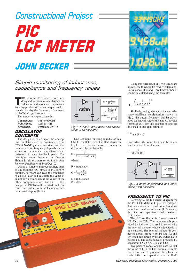
THIS simple PIC-based unit wasdesigned to measure and display thevalues of inductors and capacitors.
As a by-product of the technique used, itcan also display the frequency of an exter-nal 0V/+5V signal source.
The ranges are approximately:
Capacitance: 1pF to 6500FInductance: 1H to 10HFrequency: 0·05Hz to 5MHz
The design is based upon the conceptthat oscillators can be constructed fromCMOS NAND gates or inverters, and thattheir oscillation frequency depends on thevalues of inductance, capacitance andresistance in their feedback paths. Theprinciples were discussed by GeorgeHylton in his two-part series Logic GateInverter Oscillators of Sept/Oct ’02.
Using a suitable microcontroller, suchas one from the PIC16F62x or PIC16F87xfamilies, software can read the frequencyof an oscillator and calculate the value ofan unknown component if the values of theother components are known. In thisdesign, a PIC16F628 is used and theresults are output to an alphanumeric liq-uid crystal display (l.c.d.).
Using this formula, if any two values areknown, the third can be readily calculated.For instance, if C and F are known, then Lcan be calculated using the formula:
1 2
L = ( 2 × × F)
C
Similarly, using the capacitance-resis-tance oscillator configuration shown inFig.2, the output frequency can be calcu-lated for known values of R and C. Severalformulae exist for this calculation and theone used in this application is:
F = 1 × R × C
from which the value for C can be calcu-lated if R and F are known:
C = 1 × R × F
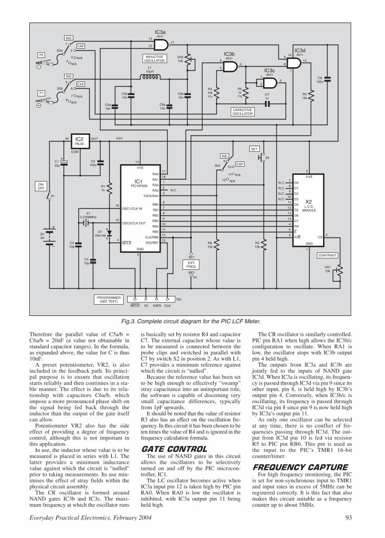
Referring to the full circuit diagram for
the PIC LCF Meter in Fig.3, two indepen-dent oscillators are used, one based oninductance and capacitance (LC) values,the other on capacitance and resistance(CR) values.
The LC oscillator is formed aroundNAND gate IC3a. The inductance is pro-vided by inductor L1, used in series withthe external inductor whose value needs tobe measured. The external inductor is con-nected across probe clips P1 and P2 andswitched into circuit by rotary switch S2 inposition 1. The capacitance is provided bycapacitors C5a, C5b, C6a and C6b.
Two pairs of capacitors are used so thatthe value of C in the LC formula is simplefor the software to process. The values foreach of the four capacitors is set at 10nF.
Fig.1. A basic inductance and capaci-tance (LC) oscillator.
Fig.2. A basic capacitance and resis-tance (CR) oscillator.
92 Everyday Practical Electronics, February 2004
Therefore the parallel value of C5a/b =C6a/b = 20nF (a value not obtainable instandard capacitor ranges). In the formula,as expanded above, the value for C is thus10nF.
A preset potentiometer, VR2, is alsoincluded in the feedback path. Its princi-pal purpose is to ensure that oscillationstarts reliably and then continues in a sta-ble manner. The effect is due to its rela-tionship with capacitors C6a/b, whichimpose a more pronounced phase shift onthe signal being fed back through theinductor than the output of the gate itselfcan allow.
Potentiometer VR2 also has the sideeffect of providing a degree of frequencycontrol, although this is not important inthis application.
In use, the inductor whose value is to bemeasured is placed in series with L1. Thelatter provides a minimum inductancevalue against which the circuit is “nulled”prior to taking measurements. Its use min-imises the effect of stray fields within thephysical circuit assembly.
The CR oscillator is formed aroundNAND gates IC3b and IC3c. The maxi-mum frequency at which the oscillator runs
is basically set by resistor R4 and capacitorC7. The external capacitor whose value isto be measured is connected between theprobe clips and switched in parallel withC7 by switch S2 in position 2. As with L1,C7 provides a minimum reference againstwhich the circuit is “nulled”.
Because the reference value has been setto be high enough to effectively “swamp”stray capacitance into an unimportant role,the software is capable of discerning verysmall capacitance differences, typicallyfrom 1pF upwards.
It should be noted that the value of resistorR3 also has an effect on the oscillation fre-quency. In this circuit it has been chosen to beten times the value of R4 and is ignored in thefrequency calculation formula.
The use of NAND gates in this circuit
allows the oscillators to be selectivelyturned on and off by the PIC microcon-troller, IC1.
The LC oscillator becomes active whenIC3a input pin 12 is taken high by PIC pinRA0. When RA0 is low the oscillator isinhibited, with IC3a output pin 11 beingheld high.
The CR oscillator is similarly controlled.PIC pin RA1 when high allows the IC3b/cconfiguration to oscillate. When RA1 islow, the oscillator stops with IC3b outputpin 4 held high.
The outputs from IC3a and IC3b arejointly fed to the inputs of NAND gateIC3d. When IC3a is oscillating, its frequen-cy is passed through IC3d via pin 9 since itsother input, pin 8, is held high by IC3b’soutput pin 4. Conversely, when IC3b/c isoscillating, its frequency is passed throughIC3d via pin 8 since pin 9 is now held highby IC3a’s output pin 11.
As only one oscillator can be selectedat any time, there is no conflict of fre-quencies passing through IC3d. The out-put from IC3d pin 10 is fed via resistorR5 to PIC pin RB6. This pin is used asthe input to the PIC’s TMR1 16-bitcounter/timer.
For high frequency monitoring, the PIC
is set for non-synchronous input to TMR1and input rates in excess of 5MHz can beregistered correctly. It is this fact that alsomakes this circuit suitable as a frequencycounter up to about 5MHz.
Everyday Practical Electronics, February 2004 93
Fig.3. Complete circuit diagram for the PIC LCF Meter.

For external frequency counting the sig-nal is input directly to PIC pin RB6 viasocket SK1, with resistor R5 providing abuffer between the signal and the output ofIC3d. The resistor also provides a bufferwhen the PIC is programmed in-circuitfrom a system such as PIC Toolkit TK3(Oct-Nov ’01) – see later.
The frequency output from IC3d can beconnected via R5 and socket SK1 to anexternal frequency counter suited to accept-ing normal logic-level signals.
As stated earlier, the function of switch
S2 is two-fold. The component to be mea-sured, either inductor or capacitor, is con-nect via crocodile clipped leads (P1 andP2) to the poles of S2a and S2b. The switchis set so that the component is connected toits appropriate oscillator circuit. There is nodanger of component or circuit damage ifthe wrong switch setting is selected. It willbe obvious from the measured results if thewrong path has been chosen!
The second function of switch S2 is toinform the PIC which type of component itis to measure. This is controlled by S2c.When in position 1, S2c connects the +5Vline to PIC pin RA4. In position 2, RA4 isheld at 0V via resistor R6. Softwaremonitors the logic on RA4 and reactsaccordingly.
Switch S3 is a push-to-make type and isused to “null” the circuit prior to takingmeasurements. It is monitored by PIC pinRA2, which is biased low by resistor R2when S3 is not pressed.
Switches S2 and S3 are also used to set“corrective” factors should any be foundnecessary, as discussed later.
The results of component value calcula-
tions are output to the 2-line by 16 charac-ters per line l.c.d., X2. Preset VR1 sets thel.c.d.’s screen contrast.
The system is operated at 3·2768MHz,as set by crystal X1 in conjunction withcapacitors C3 and C4. It can be powered atbetween +7V and +12V d.c., at about 9mAfor a 9V supply.
Regulator IC2 reduces the input supplyvoltage to +5V, to suit the PIC and the l.c.d.Capacitors C1, C2 and C8 help to ensureadditional power line stability.
Connector TB2 is in the author’s stan-dard configuration for programming PICsin-situ should readers wish to modify thesoftware. Brand new PICs should not beprogrammed via this option due to the con-figuration settings installed during manu-facture (adverse LVP setting). Such PICsshould only be programmed on the boardof a dedicated PIC programmer.
Diode D1 and resistor R1 prevent theprogramming and unit supply voltagesfrom interacting. (They must be retainedeven if on-board programming is notrequired.)
Component position and track layout
details for the PIC LCF Meter’s printed cir-cuit board are shown in Fig.4. This board isavailable from the EPE PCB Service, code434.
In order to obtain the best potential accu-racy from this unit, components C5a, C5b,C6a, C6b, R3 and R4 should have the best
tolerance that you can obtain. Ideally allshould be 1% devices, although capacitorshaving such close tolerance are not widelyavailable and you may have to accept 2% or5% for them. The software has an offsetcompensation facility should you need tocorrect displayed values upwards or down-wards in the light of experience.
Assemble in your own preferred order –that preferred by the author is wire links,i.c. sockets, and then in ascending order ofcomponent size. Ensure that electrolyticcapacitors and the semiconductors areinserted the correct way round, but do notinsert IC1 and IC3, or connect the l.c.d.(whose p.c.b. connections are in theauthor’s standard order, also see Fig.4),until the correctness of the power supplyhas been checked. The latter should only bedone once you are sure that everything elseis correctly positioned and soldered.
Note that inductor L1 is mounted verti-cally on the board, with its other leadtrimmed to serve as a terminal pin. In theprototype it was originally mounted flat onthe board but it was found that this causedinstability in the oscillation frequency dueto the proximity of a signal-carrying p.c.b.track running in parallel with the inductor.
The switches and socket SK1 need onlybe temporarily connected at this stage,wiring them permanently once the case hasbeen prepared and assembled. Adjust S2’slugged washer so that only positions 1 and2 can be selected.
In the test model, extra-flexible wire wasused for the probe leads, about 15cms long,terminated in miniature crocodile clipswith different coloured insulating coversindicating their polarised identities.
For the prototype, a plastic case (theauthor’s “orange box” again!) measuring150mm × 80mm × 50mm was used, havingbeen suitably drilled for the panel-mountedcomponents (see photograph). Note that theauthor did not use 0V socket SK2 (seelater).
When initial checks have been made,
connect the l.c.d., insert IC3 and the pre-programmed PIC microcontroller.
Switch on power and recheck that the+5V supply voltage is still correct. Thenadjust preset VR1 until the l.c.d. screencontrast is satisfactory. Switch off powerand then go through the following maincheck routine:
Set switch S1 to position 2 (capacitance).Leave the probe clips unconnected (opencircuit). Switch on the power. The screenwill first briefly display an opening mes-sage on line 1, EPE LCF METER, followedby CAPACITOR, with WAITING TIMINGon line 2.
The software then assesses the frequencygenerated by the CR oscillator in relation tocapacitor C7 and any stray capacitance pre-sent around the assembled unit.
Sampling is done at approximately one-second intervals, so that the frequencymonitoring is in Hertz (cycles per second).After each sampling period, the frequencyis displayed on screen line 1. Below it is
shown the interpretation of that frequencyin terms of capacitance. It will be wrong atthis time, until the circuit has been nulled.With the prototype, the frequency at thisstage is typically about 247000Hz with adisplayed capacitance value of 1227pF.
This is the value which results from theexact value of capacitor C7 and any straycapacitance in relation to the values ofresistors R3 and R4. When taking activemeasurements of a capacitor connected
94 Everyday Practical Electronics, February 2004
ResistorsR1 1kR2, R5, R6 10k (3 off)R3 10k 1%R4 1k 1%
All 0·25W 5%, except where stated
PotentiometersVR1, VR2 10k min. preset, round
(2 off)
CapacitorsC1 22 radial elect. 16VC2, C8 100n ceramic disc,
5mm pitch (2 off)C3, C4 10p ceramic disc,
5mm pitch (2 off)C5a, C5b,
C6a, C6b 10n ceramic disc, or plate, ideally 1%(see text), 5mm pitch(4 off)
C7 1000p (1n), ceramicdisc, 5mm pitch
SemiconductorsD1 1N4148 signal diodeIC1 PIC16F628
microcontroller,pre-programmed(see text)
IC2 78L05 +5V voltageregulator
IC3 4011 CMOS quadNAND gate
MiscellaneousL1 10H axial inductorS1 min. s.p.s.t. toggle
switchS2 3-pole 4-way rotary
switch, panel mountingS3 s.p. push-to-make
switchSK1, SK2 socket, size as
preferred, one each red and greensuggested
X1 3·2768MHz crystalX2 2-line 16-character (per
line) alphanumericl.c.d. module
Printed circuit board, available fromthe EPE PCB Service, code 434; plasticcase, 150mm x 80mm x 50mm; 14-pind.i.l. socket; 18-pin d.i.l. socket; knob forS2; 1mm terminal pins; cable ties; p.c.b.mounting supports, self-adhesive (4off); min. crocodile clips, with insulatingcovers, one each red and green sug-gested; extra-flexible wire; connectingwire; solder, etc.
SeeSSHHOOPPTTAALLKKppaaggee
Approx. CostGuidance Only ££2255
EPE Online
Note that the circuit boards used in EPE Online projects are available from the EPE Online Store at www.epemag.com (also note that the codes for the boards in the online store are prefixed with 7000, so a board with a code of say 256 will appear as 7000256 in the online store).
EPE Online
Note that you can purchase pre-programmed PIC microcontrollers for our PIC projects (see the “ShopTalk” page in the associated issue of the Magazine for more details). Alternatively, if you wish to program the PIC yourself, you can find the code files by bouncing over to the EPE Online Library (visit www.epemag.com, click in the “Library” link in the top navigation, then on the “Project Code Files” link).
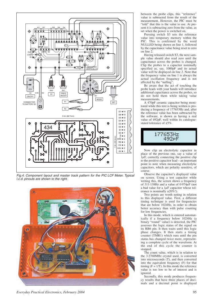
between the probe clips, this “reference”value is subtracted from the result of themeasurement. However, the PIC must be“told” that this is the value to use. At pre-sent it is subtracting zero from the value, asset when the power is switched on.
Pressing switch S3 sets the referencevalue into temporary memory within thePIC. This is confirmed by the wordNULLED being shown on line 1, followedby the capacitance value being reset to zeroon line 2.
Having released switch S3, the next sam-ple value should also read zero until thecapacitance across the probes is changed.Clip the probes to a capacitor nominallyspecified as, say, 1000pF and its actualvalue will be displayed on line 2. Note thatthe frequency value on line 1 is always theactual oscillation frequency and is notaffected by the “nulling”.
Be aware that the act of touching theprobe leads with your hands will introduceadditional capacitance across the probes, sodo not hold them while taking valuemeasurements.
A 470pF ceramic capacitor being moni-tored while this text is being written is pro-ducing a frequency of 177653Hz and, afterthe reference value has been subtracted bythe software, is shown as having a realvalue of 492pF, well within its catalogue-stated tolerance of ±5%.
Now clip an electrolytic capacitor inplace of the previous one, say a value of1F, correctly connecting the positive clipto the positive capacitor lead – an importantpoint to note when measuring electrolyticcapacitors, which are polarity sensitive, ofcourse.
Observe the capacitor’s displayed valueon screen. Using a test capacitor whilewriting this, the screen shows a frequencyof 311·138Hz and a value of 0·974F (nota bad value for a 1F capacitor whose tol-erance is nominally ±20%!).
Two points are worth noting in relationto this displayed value. First, a differenttiming technique is used for frequenciesthat are below 1024Hz, in order to obtainbetter accuracy than with pulse countingfor low frequencies.
In this mode, which is entered automat-ically if a frequency below 1024Hz (abinary “round” value) is detected, the PICassesses the logic status of the signal onits RB6 pin. It then waits until this logicphase changes. It then starts a timingcounter (TMR1) which runs until the pinstatus has changed twice more, represent-ing a complete cycle of the waveform. Atthe end of this cycle the counter isstopped.
The count value, which is in relation tothe 3·2768MHz crystal used, is convertedinto microseconds (T), and then convertedinto the equivalent frequency (F) for thattiming (F = 1/T). In this mode the referencevalue is too low to be of interest and isignored.
Secondly, this mode produces frequen-cy results that have three places of deci-mals and a decimal point is displayed
Everyday Practical Electronics, February 2004 95
Fig.4. Component layout and master track pattern for the PIC LCF Meter. Typicall.c.d. pinouts are shown to the right.

accordingly. Additionally the value is nowexpressed in microfarads (F – but shownas “uF”).
Now, if you have a capacitor to hand of,say, 220nF (0·22F), clip it to the probesand examine the result. Taking one at ran-dom, the prototype displayed a frequencyof 1305Hz, representing a value of231·210nF. Note the “nF” suffix – the soft-ware, when registering a calculated valueof less than 10000 (but which has not beenobtained by the “uF” route), gives an “nF”suffix, but otherwise shows “pF”.
Note that with larger values of elec-trolytic capacitor, you need to be patientwhile the values are assessed, since up tothree logic half cycles may need to beprocessed – the initial logic level change,followed by one complete cycle. Forinstance, a random test with an electrolyticmonitored as 5055F had a full cycle peri-od of 0·060Hz.
To test the LC oscillator, switch S2 to
position 1 (inductance) and clip the probesto each other (as a short circuit). In thisconfiguration inductor L1 completes thefeedback circuit for IC3a, which oscillatesaccordingly.
Adjust preset VR2 until the oscillationrate appears stable, as indicated by the fre-quency value shown on screen line 1. Thesetting will be obvious if an oscilloscope isused. If a scope is not available, try VR2 atvarious wiper settings and chose the best –it is not critical. In the prototype the authorset the wiper for approximately three-quar-ters clockwise rotation (about 7k5).
Again the frequency and calculatedresults are shown on the upper and lowerlines of the screen. In the prototype typicalun-nulled values are 468608Hz and11.492H. Pressing “null” switch S3 theinductance value should read 0·000uH
Now clip an inductor of, say, 10Hbetween the probes. A typical displaymight then be 342348Hz, 9·969uH. In thiscase showing that the external inductor ispretty close to its marked value.
As with the capacitance mode, the pulsewidth assessment technique is used whenthe monitored frequency is below a certainvalue, 16384Hz for inductors. Again thefrequency value is shown with three deci-mal places.
On the normal frequency counting range,values less than 100H are displayed witha “uH” suffix, otherwise they are shown inmillihenries (mH), i.e. 100.801H wouldbe displayed as 0·100801mH.
Values obtained using the pulse widthtechnique are displayed in henries, with asuffix of “H”, for example 7.305H.
Be patient when monitoring higher val-ues of inductance, for the same reason asfor larger values of capacitance.
To monitor an external frequency, whichmust conform to normal logic levels(swinging between 0V and +5V), connectthe signal source to socket SK1. Switch S2may be in either position.
Resistor R5 prevents the signal frombeing adversely affected by the running ofeither internal oscillator.
Frequencies from about 0·05Hz togreater than 5MHz can be monitored.
Because switch S2 does not cause theinternal oscillators to be inhibited duringexternal frequency input, the displayed fre-quency will always be accompanied by aninductance or capacitance value on line 2.
Socket SK1 may also be used to feed theinternal oscillator frequencies to an exter-nal frequency counter.
Note that if the LCF Meter is not pow-ered by the same power supply source asthe external signal source or frequencycounter, then a common 0V (ground) con-nection between them must be provided viasocket SK2.
In the prototype SK2 was omitted as theauthor always uses a common workshoppower supply for all circuits.
In the event that the component values
used with the oscillators are not exactlythose for which the software has been writ-ten, compensation is possible through aroutine selectable when the LCF Meter isfirst switched on.
With power switched off, set switch S2for the capacitance or inductance mode youwant to modify. Press switch S3 and hold itpressed while the power is switched on. Onrecognising the pressed status of S3 duringits initialisation routine, the PIC’s softwarejumps to the appropriate correction routineselected by S2.
This will be confirmed by a screen mes-sage on line 1 stating which correctionmode has been accessed, for example CAPCORRECTION. On line two the existingcorrection value will be displayed. Thedefault is 100.
In normal running mode the calculatedcapacitance and inductance values are mul-tiplied by the correction value and thendivided by 100. For instance, if the correc-tion value is 100, then there is no correctionapplied, since multiplying by 100 and thendividing by 100 is the same as multiplyingby 1, so leaving the value unchanged.
If the correction value is 101, however,the effect is to multiply the value by 1·01 (a1% increase). Conversely, if the correctionis 99, then the effect is a multiplication by0·99 (a 1% decrease). The range of correc-tion values is 1 to 199, i.e. a multiplicationrange of 0·01 to 1·99.
When the screen shows that correctionmode has been entered, release S3. Waitbriefly for the software to exit a switchdebounce routine (about 0·5 seconds). Thecorrection value can now be changed usingboth S2 and S3.
If S2 is in position 2 (capacitor) theneach press of S3 causes the correction valueto be incremented. On the other hand, if S2is in position 1 (inductance) then each pressof S3 causes the correction value to bedecremented.
Each press of S3 causes the new value tobe stored to the PIC’s internal non-volatile(EEPROM) memory, where it remains evenafter power has been switched off. (The“nulling” factors referred to earlier are notstored beyond switch-off.)
Each time the unit is switched on, thecorrection values for the two oscillatormodes are recalled from memory andapplied to each value calculation.
It would have required an extra switch toallow the software to be told to exit correc-tion mode and the only way out of it is toswitch off and then switch on again, leav-ing a suitable pause before doing so toallow the circuit’s power line capacitors todischarge.
Correction for the other oscillator’s rou-tine is entered in the same way, first settingswitch S1 to the opposite position prior topower-up.
A point to appreciate is that this simple
unit has no temperature compensationcircuitry. The oscillator frequencies canand will drift with temperature changes.For higher capacitance and inductancevalues, especially those in the “F” and“H” ranges, the drift is insignificant. Forlower component values (i.e. higheroscillation rates), though, you shouldalways “null” the meter prior to taking ameasurement.
For capacitance nulling the probes mustbe open; for inductance nulling they shouldbe closed (shorted).
Finally, never try to measure the valuesof components that are “in-circuit”. At best,the existence of other components withinthat circuit is likely to result in incorrectreadings. At worst, if the other circuit ispowered, it and the PIC LCF Meter couldbe damaged.
The software for the PIC LCF Meter is
available from the EPE PCB Service on3.5in disk (for which a nominal handlingcharge applies). It is also available for freedownload from the EPE website, accessi-ble via the Downloads click-link on ourhome page at www.epemag.wimborne.co.uk (path PICs/LCFmeter).
Read this month’s Shoptalk page forinformation on component buying for thePIC LCF Meter.
The author gratefully thanks Peter
Hemsley for his excellent maths routineswhich have been used extensively in thePIC software, and without which thisdesign would have been extremely difficultto achieve.
A selection of Peter’s routines is in the PICTricks folder on our Downloads site.
96 Everyday Practical Electronics, February 2004

NNeewwss .. .. .. A roundup of the latest EverydayNews from the world of
electronics
98 Everyday Practical Electronics, February 2004
NCT on Coursefor 2004
SINCE joining forces with OakCADTraining, the National College ofTechnology has been focusing on the needsof the electronics sector. Its range of dis-tance learning courses is suitable for begin-ners and those with more experience whoneed to update their skills.
The programme of courses offeredthrough the college is being adjusted aspart of the continuous developmentprocess and further new courses are cur-rently being prepared for launch during2004. These courses can lead to a BTECqualification or taken as individual mod-ules. Tutor support is available to help indi-viduals through each part of a course.
Anyone interested to register can contactNCT on 08456 345 445 or view the cours-es on www.oakcad.co.uk/nct.aspx.
ALTHOUGH less than four years old,British mobile phone maker Sendo is
not afraid to tangle with the big boys. Lastyear Sendo pulled out of a deal withMicrosoft to make Windows-powered pic-ture phones for use on the Orange network.Sendo is still in dispute with Microsoft andis now trying to stop Orange sellingWindows picture phones made in Taiwan.The Orange Smartphone, claims Sendo,infringes Sendo’s patent on integrated cir-cuits and printed circuit boards.
Last year Microsoft and Orange joinedforces to launch a Smartphone service,offering SPV (Sound, Pictures and Video)on the move for 40 million Orange sub-scribers in 21 countries. The SPV phonesuse Microsoft Windows and InternetExplorer to access the Internet, and theGPRS (general packet radio service) sys-tem to squeeze higher transmission speedsfrom existing GSM networks.
At the London launch Orange andMicrosoft announced support from Sendo,and Sendo called its Windows-powered
Z100 “the world’s smartest phone”. Amonth later Sendo backed out, and adoptedthe rival Symbian system from Nokia.
Now Sendo has started legal proceedingsin the British High Court, using recentlygranted British Patent 2 377 080 to try andstop Orange selling the Orange SPVphone. Sendo also wants damages forphones already sold.
“We have tried to solve the matter in anamicable way”, says Hugh Brogan,Sendo’s CEO, “Now we have to take legalsteps”.
The patent tells how to keep the manyconnections to an integrated circuit shortand separate from each other, by arrangingthem in rings like a square darts board. Thepower supply contacts are in the outerrings, the earth or ground contacts in thecentre and data contacts in between.
So far Sendo only has a British patent.So the company cannot try to stop manu-facture in Taiwan. But the UK patent haslegal force as soon as the phones areimported into Britain for sale and use.
MOBILISING PICTUREPHONE PATENTS
Sendo challenges Orange under Patents law,as Barry Fox reports.
MULTILOGGING DATA NICON Designs have introduced a low cost analogue data acquisition modulethat offers 4-channel 12-bit logging on demand, and with timed measurementcapabilities. The Multilog ML4-12 module provides true differential and unipo-
lar inputs with 12 programmablevoltage/current ranges and inde-pendent sensor supplies for eachchannel.
When fitted with the optional MMCmemory card, the unit is capable ofstoring up to two million time-stamped data sets. Setup and datatransfer is via a standard RS232interface. The simple interfaceenables straightforward connectionto off-the-shelf GPRS and LPRSmodules.
Multilog is supplied with a weath-erproof enclosure and Windows-based control and display software.
For more information contactNicon Designs Ltd, Dept EPE, 13The Buntings, Bradwell, NorfolkNR31 8PE. Tel: 01493 442350. Fax:01493 667689.
Web: www.nicon-designs.co.uk.
Schmart Boards
A NEW product for developing elec-tronic circuits and known asSchmartboard has been introduced.It is described as providing “electron-ic circuit blocks for engineers, stu-dents and hobbyists”.
Schmartboard allows prototypeelectronic circuits to be assembled ina modular fashion, allowing subse-quent modifications to be made withminimal changes to the overallassembly. The system uses pre-tracked printed circuit boards that areconnectable like building blocks.They allow circuits to be assembledblock by block, connecting the blockstogether to form a functional board.Because the boards are pre-tracked,the need for wire jumpers is min-imised. The boards are available inseveral style configurations.
For more information browsewww.schmart.com and www.engineeringlab.com.
Everyday Practical Electronics, February 2004 99
SQUIRES2004 CAT
SQUIRES are renowned for their compre-hensive range of miniature hand and powertools and their extensive range of electron-ic components. Their 2004 catalogue hasrecently been received at HQ. It seemseven more massive than their previous one.It is impossible on this page to give fullcredit to the enormous variety of items thatare listed and illustrated in 600-odd pages,but it seems fair to say that there can sure-ly be nothing of the craft tools nature thathas been omitted.
Squires have also purchased GoughBrothers fine art materials shop and TheNimble Needle needle craft shop, both inBognor Regis, where Squires themselvesare based. So whatever your art and craftrequirements, Squires should be more thancapable of helping you.
For more information contact SquiresModel and Craft Tools, 100 London Road,Bognor Regis, W. Sussex PO21 1DD. Tel:01243 842424. Fax: 01243 842525.
Email: [email protected]: www.squirestools.com.
STRONGL.C.D.S
HAVE you ever had the misfortune tobreak the glass screen of an l.c.d., or dam-aged one by dropping it, or exposing it toadverse weather conditions? It seems thatthese are quite common occurrences, forSharp have now introduced new “StrongL.C.D.s”. These have been designedspecifically for use under difficult condi-tions. You may not only touch and shakethese new displays, but even expose themto temperatures as low as –10°C and ashigh as 65°C.
Enhanced integration and a more com-pact mechanical design make these l.c.d.smuch less susceptible to vibration, surfacepressure and shock. Sharp have alsoincreased the brightness by a new long-lifebacklight, providing for excellent visibilityeven with bright sunlight or from greaterdistance.
Initially, the size available is 10·4 inches(26·4cm) with 640 × 480 pixels resolution,but Sharp say that 12·1in (53·3cm) with800 × 600 pixel resolution will soonbecome available.
BOOSTEDDVD+RW/+RDVD recording capacity is
increased again.Barry Fox reports
THE DVD+RW/+R recordable format,developed by Philips, has received
three significant boosts. Pioneer, the driv-ing force behind the rival DVD-RW/-Rformat has built DVD+ support into its newgeneration of PC burners. These are nowon sale. Apple, previously committed toDVD-R, has now added DVD+RW/+Rsupport to the latest version of its Macoperating system.
Hot on the heels of announcing 8×recording speeds for DVD+R blanks at theIFA show in Berlin, Philips andMitsubishi/Verbatim have increasedDVD+R capacity from 4·7GB per side to8·5GB. This extends recording time to fourhours of DVD-quality video or 16 hours ofVHS-quality video, without the need toturn over the disc.
The new DVD+R blanks use a dual-layercoating. During recording the laser focusesfirst on one organic dye film, and then dur-ing a second pass on the other. Althoughthe new blanks will only work on newrecorders, the dual-layer recordings willplay back on existing players – becauseDVD drives are already designed to playdual-layer pressed discs.
The trick is to use a highly reflectivelower layer and sandwich a thin layer ofsemi-reflective silver-alloy in the upperlayer. The upper layer passes 50% of thelaser light through to the lower layer forrecording and playback, while reflectingat least 18% for readout of the upperlayer.
All eyes are now on Pioneer and theDVD-RW/-R camp to see if they can comeup with a dual-layer DVD-R blank.
MICROMOUSE 2004THE micro-robotics competition knownas Micromouse 2004 is to be hosted bythe Technology Innovation Centre atBirmingham’s Millennium Point onSaturday 19 June 2004. It is the latestevent in the world’s longest runningrobotics competition. Originated in theUK by the Institution of ElectricalEngineers (IEE), it has run for more than20 years.
The event consists of races against theclock between microprocessor controlledrobotic “mice” programmed to search andsolve complex mazes. There are severaltechnical standards in the competition,with senior and junior categories. Thisenables individuals and organisations atdifferent levels of technical skill to enter.Individuals, clubs, schools, colleges anduniversities have all competed in past com-petitions.
Anyone interested in learning moreabout Micromouse 2004 should contact theEvent Administrator, Rita Kerry, on 0121331 5400 or [email protected].
Also browse: http://micromouse.cs.rhul.ac.uk/events.
MINITOOL
THE new Minitool range of high quality precision tools from Shesto is designed and madein Germany to exacting standards. The manufacturers, Boehler, have over 30 years expe-rience in producing 12V tools which answer the specific needs of anyone interested inminiature precision work. They enjoy a high reputation in Europe as well as in the USA andCanada.
The functions offered by the Minitool include sword saw, detail sander, 3D contoursander, high speed rotary tool, jigsaw/scrollsaw, planer, screwdriver/rotary tool, rotary cut-ting tool, engraving pen, 4-in-1 cutting tool.
For more details of the Minitool and its stockists, contact Shesto Ltd., Unit 2, SapcoteTrading Centre, Dept EPE, 374 High Road, Willesden, London NW10 2DH. Tel: 020 84516188. Fax: 020 8451 5450. Email: [email protected]. Also browse www.minitool.co.uk.
THE pronouncement “Woman burnedby exploding cellphone” was one ofseveral similar headlines last year. It
wasn’t booby-trapped and it won’t be thelast to cause injury. So exactly what hap-pened and why?
Figuratively, mobile phones can burn ahole in your pocket, but the last thing youexpect them to do is to burn up in yourhand. Yet over the past 12 months or sothere has been a spate of occurrences ofthis kind.
According to news reports on the Web,the first victim was an Indonesian man,who suffered severe burns on his facewhen his cellphone ignited a fire at a gasstation in 1999. Closer to home was 15-year-old Niklas Eivik in Norway, whoseNokia 3310 cellphone exploded duringNovember 2002. A report states that thephone first vibrated, then started beepingwhile smoke erupted, and finally the phoneexploded leaving marks on the floor, theceiling and people in the room.
Ten months later in Amsterdam anotherphone, again reported to be a Nokia prod-uct, exploded in a woman’s face while shewas out shopping. The blast caused burnsto her face and neck. Apparently the phoneswitched itself off when its 33-year-oldowner dropped it. When she switched itback on again, the phone exploded.
Reading all this you might think that
Nokia phones were at worst lethally dan-gerous or at best hopelessly unreliable.That’s not the case, however, and othermakers’ kit has been struck as well. Whenan Ealing-based electrician’s phone com-busted spontaneously, it was a Sharp, not aNokia.
Steve Wing said that after recharging hisGX10 (in a proper Sharp charger) it startedhissing, glowed red and then shot the backoff the phone in a cloud of smoke. Reportson the Internet indicate that GPS receivershave also self-destructed and in all casesthe linking factor is the use (or possiblymisuse) of lithium batteries.
The actual mechanism causing theexplosions is simple – overheating causedby a short-circuit.
Investigation into the incidents shows
that in most cases the explosions werecaused by non-original (but perfectly legal)replacement batteries. Nokia, concernedthat these explosions were giving itsmobiles an undeserved bad name, held apress conference the day before this articlewas written at which the company took aimat unsafe, low-quality counterfeit batteries.
“I want to stress that consumer safety isour top concern,” said Janne Jormalainen,Vice President, Mobile Enhancements,Nokia Mobile Phones. “We believe con-sumers are unknowingly being fooled intobuying unsafe, low-quality batteries andwe are actively taking measures to combatthe illegal counterfeit operation at the rootof this problem.”
He revealed that tens of thousands ofcounterfeit products had been seized inrecent raids in Belgium, the UnitedKingdom, and other countries in the EU,bringing the total global number of seizedand destroyed products in 2003 to morethan five million. As a result of these raids,authorities gained valuable leads on acounterfeit network, enabling them tobegin immediate actions against thoseinvolved.
Counterfeit batteries had also misled
consumer groups, he said. Test-Aankoop, aBelgian consumer group, acknowledgedtheir recent test results that had led them toannounce Nokia batteries were unsafewere “most probably unreliable” due to theinclusion of counterfeit batteries in theirtest sample. Test-Aankoop has agreed to anew, independent test of batteries, usingonly Nokia original batteries.
If consumer protection groups can befooled by sophisticated counterfeits, it’slittle wonder that users are taken in,although retailers should know full wellwhen they buy through other than normalchannels. For this reason Nokia will nowadopt “aggressive, regional anti-counter-feit measures” to thwart the sale of prod-ucts that to the average consumer appear tobe Nokia original accessories.
Retailers sell counterfeit batteries forone reason only: because they are cheaper.And the reason why these replacements arecheaper is because they lack essential safe-ty features. “Official” replacement lithium-ion battery packs cost more than genericequivalents because they include extraelectronics to guarantee reliable (and safe)performance.
A small printed circuit board, shrink-wrapped inside the pack, performs a num-ber of vital functions. While charging, thecircuit balances the voltage of the cells,ensuring that both cells are properlycharged as well as preventing the cellsfrom being overcharged, which could leadto rupture.
During discharge, the circuit preventsthe cells from being shorted by automati-cally shutting down the pack if too muchcurrent is drawn. This prevents the batter-ies from exploding if something shorts out
the pack. To ensure long battery life thecircuitry also shuts down the battery packautomatically before the individual cellvoltages reach 3V.
Needless to say, the statistical risk of
being injured by an exploding mobiledevice is minimal; you have more chanceof winning the national lottery. But youneed to be aware of the risks of misusinglithium-ion cells, regardless of their envi-ronment or application.
You may have spotted that lately somesellers have been offering surplus cell-phone batteries on eBay for use in microradio-controlled aircraft and other elec-tronic projects. One typical battery packcontains two lithium-ion cells that canprovide 8·4V at 830mAh. They are ratedfor discharge rates up to 1·66A. Weighingonly 2oz (56g), they are seemingly perfectfor most applications. In addition, withonly a little bit of work, the single cells inthe packs can provide 4·2V for smallermodels.
So why are these cells not sold morewidely? The main reason why lithium-ionbatteries are not more widely sold forhobby use is the limitations in their safeuse. It’s a fact that lithium-ion batteries canexplode if shorted out or (and this is cru-cial) if the cells are charged improperly.Unless you have a charger designed forcharging lithium-ion cells and tailored tothe specific type of cell you are using, youshould not attempt to charge them at all.Fortunately, the more responsible vendorssell suitable chargers as well as the batterypacks.
To avoid being scarred by your mobile:
Buy only original batteries from yourphone’s manufacturer; products fromthird-party suppliers may have differentcharacteristics even though dimensional-ly compatible.
Even if the battery bears your cellphonemaker’s name, check that it looks“right”. Crummy packaging is an obvi-ous give-away.
Buy from recognised dealers and keepthe receipt; you’ll have a job claimingagainst boot sale or street market traders.
Avoid leaving batteries charging unat-tended in case they overheat and catchfire.
After this article was written, Nokia
announced that a new study by the Belgianconsumer organisation confirmed the safe-ty of genuine Nokia batteries.
100 Everyday Practical Electronics, February 2004
TTEECCHHNNOO--TALK ANDY EMMERSON
Handset HazardsHow safe is your mobile phone? Andy Emmerson explains how to
avoid becoming the next victim.
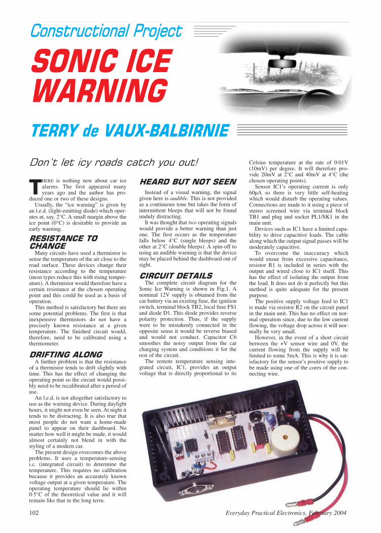
Instead of a visual warning, the signalgiven here is audible. This is not providedas a continuous tone but takes the form ofintermittent bleeps that will not be foundunduly distracting.
It was thought that two operating signalswould provide a better warning than justone. The first occurs as the temperaturefalls below 4°C (single bleeps) and theother at 2°C (double bleeps). A spin-off tousing an audible warning is that the devicemay be placed behind the dashboard out ofsight.
The complete circuit diagram for the
Sonic Ice Warning is shown in Fig.1. Anominal 12V supply is obtained from thecar battery via an existing fuse, the ignitionswitch, terminal block TB2, local fuse FS1and diode D1. This diode provides reversepolarity protection. Thus, if the supplywere to be mistakenly connected in theopposite sense it would be reverse biasedand would not conduct. Capacitor C6smoothes the noisy output from the carcharging system and conditions it for therest of the circuit.
The remote temperature sensing inte-grated circuit, IC1, provides an outputvoltage that is directly proportional to its
THERE is nothing new about car icealarms. The first appeared manyyears ago and the author has pro-
duced one or two of these designs.Usually, the “ice warning” is given by
an l.e.d. (light-emitting diode) which oper-ates at, say, 2°C. A small margin above theice point (0°C) is desirable to provide anearly warning.
Many circuits have used a thermistor to
sense the temperature of the air close to theroad surface. These devices change theirresistance according to the temperature(most types reduce this with rising temper-ature). A thermistor would therefore have acertain resistance at the chosen operatingpoint and this could be used as a basis ofoperation.
This method is satisfactory but there aresome potential problems. The first is thatinexpensive thermistors do not have aprecisely known resistance at a giventemperature. The finished circuit would,therefore, need to be calibrated using athermometer.
A further problem is that the resistance
of a thermistor tends to drift slightly withtime. This has the effect of changing theoperating point so the circuit would possi-bly need to be recalibrated after a period ofuse.
An l.e.d. is not altogether satisfactory touse as the warning device. During daylighthours, it might not even be seen. At night ittends to be distracting. It is also true thatmost people do not want a home-madepanel to appear on their dashboard. Nomatter how well it might be made, it wouldalmost certainly not blend in with thestyling of a modern car.
The present design overcomes the aboveproblems. It uses a temperature-sensingi.c. (integrated circuit) to determine thetemperature. This requires no calibrationbecause it provides an accurately knownvoltage output at a given temperature. Theoperating temperature should lie within0·5°C of the theoretical value and it willremain like that in the long term.
Celsius temperature at the rate of 0·01V(10mV) per degree. It will therefore pro-vide 20mV at 2°C and 40mV at 4°C (thechosen operating points).
Sensor IC1’s operating current is only60µA so there is very little self-heatingwhich would disturb the operating values.Connections are made to it using a piece ofstereo screened wire via terminal blockTB1 and plug and socket PL1/SK1 in themain unit.
Devices such as IC1 have a limited capa-bility to drive capacitive loads. The cablealong which the output signal passes will bemoderately capacitive.
To overcome the inaccuracy whichwould ensue from excessive capacitance,resistor R1 is included in series with theoutput and wired close to IC1 itself. Thishas the effect of isolating the output fromthe load. It does not do it perfectly but thismethod is quite adequate for the presentpurpose.
The positive supply voltage feed to IC1is made via resistor R2 on the circuit panelin the main unit. This has no effect on nor-mal operation since, due to the low currentflowing, the voltage drop across it will nor-mally be very small.
However, in the event of a short circuitbetween the +V sensor wire and 0V, thecurrent flowing from the supply will belimited to some 5mA. This is why it is sat-isfactory for the sensor’s positive supply tobe made using one of the cores of the con-necting wire.
102 Everyday Practical Electronics, February 2004

Everyday Practical Electronics, February 2004 103
ResistorsR1 2k2R2 2k2 1%R3 27k 1%R4 2201R5 220R6 2M2R7 47kR8, R9 2M2 (2 off)R10 4M7
All resistors 0·25W 5% carbon film, except where stated
PotentiometerVR1 2M2 min. enclosed carbon preset, vertical
CapacitorsC1, C4 100n ceramic (2 off)C2, C3, C5 47n ceramic (3 off)C6 100µ radial elect. 25V
SemiconductorsD1 1N4001 50V 1A rect. diodeIC1 LM35 temperature sensorIC2 AD680 2·5V referenceIC3 TS932IN micropower dual op.ampIC4 4017 decade counterIC5 4011 quad 2-input NAND gateIC6 7556 dual CMOS timer
MiscellaneousWD1 solid-state buzzer, 3V to 24V d.c. operation,
10mA maximumFS1 200mA 20mm fuse and p.c.b. mounting
fuseholderTB1 3-way p.c.b. terminal block, 5mm spacingTB2 2-way p.c.b. terminal block, 5mm spacingPL1/SK1 3-pin DIN line plug and chassis socket
Printed circuit board available from the EPE PCB Service,code 433; plastic case, size 130mm x 68mm x 46 mm (exter-nal); 8-pin d.i.l. socket; 14-pin d.i.l. socket (2 off); 16-pin d.i.l.socket; light-duty auto-type wire; bullet-type connectors; smallnylon fixings; plastic stand off insulators (2 off); solder etc.;stereo screened cable; sleeving; plastic tube and silicone adhe-sive/sealant to make sensor (see text).
SeeSSHHOOPPTTAALLKKppaaggee
Approx. CostGuidance Only ££1166
excl. case
Ω Ω
µ
Voltage reference device IC2 has three pins: supply positive (pin3), 0V (pin 1) and output (pin 2). The output is an accurate 2·5Vover a wide range of input voltages. Capacitor C1, connecteddirectly across the supply pins, is necessary for stable operation.
The output from sensor IC1 is applied to both inverting inputs
(pin 2 and pin 6) of IC3, a dual low-power operational amplifier(op.amp). Resistor R6 prevents the inverting inputs from “float-ing” (being left unconnected) if the sensor were to be disconnect-ed while a supply voltage was present.
The 2·5V reference voltage, from pin 2 of IC2, is connected tothe “ladder network” comprising resistors R3, R4 and R5 con-nected in series. These provide a potential divider “chain” withconnections made to two points along it. The upper point is con-nected to IC3a non-inverting input (pin 3) while the lower one isconnected to IC3b non-inverting input (pin 5).
With the resistor values used, the voltage at IC3b pin 5 will bevery close to 0·02V (20mV) and at IC3a pin 3, 0·04V (40mV).These voltages have been chosen because they are equal to thoseat the corresponding inverting inputs at sensor temperatures of 4°Cand 2°C respectively. Any small discrepancy is not important sinceprecise operating values are not required.
Imagine the temperature of IC1 is greater than 4°C. The volt-age at both op.amp inverting (–) inputs will exceed those at thecorresponding non-inverting (+) ones. Both outputs of IC3a
Fig.1. Complete circuit diagram for the Sonic Ice Warning.
EPE Online
Note that the circuit boards used in EPE Online projects are available from the EPE Online Store at www.epemag.com (also note that the codes for the boards in the online store are prefixed with 7000, so a board with a code of say 256 will appear as 7000256 in the online store).
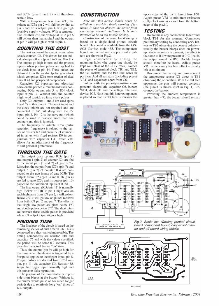
and IC3b (pins 1 and 7) will thereforeremain low.
With a temperature less than 4°C, thevoltage at IC3a pin 2 will fall below that atpin 3 and IC3a output, pin 1, will go high(positive supply voltage). With a tempera-ture less than 2°C, the voltage at IC3b pin 6will be less than that at pin 5 and the outputat pin 7 will go high as well as pin 1.
The next section of the circuit is centred on
decade counter IC4. This device has ten indi-vidual outputs 0 to 9 (pins 1 to 7 and 9 to 11).The outputs go high in turn and the processrepeats when positive pulses are applied tothe clock input at pin 14. These pulses areobtained from the astable (pulse generator),which comprises IC6a (one section of dualtimer IC6) and peripheral components.
Capacitor C2 bypasses any electricalnoise on the printed circuit board track con-necting IC6a output pin 5 to IC4 clockinput at pin 14. Without this, the countermight tend to pick up false clock pulses.
Only IC4 outputs 1 and 3 are used (pins2 and 7) in this circuit. The reset input andthe clock inhibit are not required and areconnected to 0V rail along with the 0Vinput, pin 8. Pin 12 is the carry out (whichcould be used to cascade more than onecounter) and this is ignored.
The frequency of astable IC6a (pulserepetition frequency) is related to the val-ues of resistor R7 and preset VR1 connect-ed in series with fixed resistor R9 in con-junction with capacitor C4. Preset VR1allows for an adjustment of the frequencyto suit personal preference.
The output from op.amp IC3a (pin 1)
and output 1 (pin 2) of counter IC4 are fedto the input pins (1 and 2) of gate IC5a.Likewise, the output from IC3b (pin 7) andoutput 3 (pin 7) of counter IC4 are con-nected to the two inputs of gate IC5b. Theoutputs from IC5a (pin 3) and IC5b (pin 4)are fed to gate IC5c and its output (pin 10)passed to the combined inputs of IC5d.
The final output (IC5d pin 11) is normallyhigh. Below 4°C (IC3a pin 1 high) and oneach high pulse from IC4 pin 2, it will go low.Below 2°C it will go low on pulses receivedfrom both IC4 pin 2 and pin 7. The effect isthat single low pulses are given below 4°Cand double pulses below 2°C. The short inter-val between these double pulses is providedwhen IC4 output 2 (pin 4) goes high.
The final part of the circuit is based on the
remaining section of dual timer IC6b. This isconnected as a short-period monostable. Thetiming components are resistor R10 andcapacitor C5 and with the values specified,the period will be some 0·2 seconds. Thisprovides the actual buzzer “on” time.
Thus, the output (pin 9) will go high forthis time when the device is triggered by alow pulse applied to the trigger input, pin 8.Trigger pulses are derived from IC5d out-put, pin 11, via capacitor C3. Resistor R8keeps the trigger input normally high andthis prevents false operation.
The purpose of the monostable is to pro-vide short bleeps at the buzzer. Without it,the buzzer would pulse on for much longerperiods due to relatively long “on” times ofIC4 outputs.
Note that this device should never berelied on to provide a timely warning of icyroads. It does not absolve the driver fromexercising normal vigilance. It is onlyintended to be an aid to safe driving.
Construction of the Sonic Ice Warning isbased on a single-sided printed circuitboard. This board is available from the EPEPCB Service, code 433. The componentlayout and actual size copper master pat-tern are shown in Fig.2.
Begin construction by drilling themounting holes (the upper one should bekept well clear of the +12V track). Solderthe pieces of terminal block TB1 and TB2,the i.c. sockets and the two link wires inposition. Add all resistors (including presetVR1) and capacitors apart from C6.
Follow with the polarity-sensitive com-ponents: electrolytic capacitor C6, buzzerWD1, diode D1 and the voltage referencedevice, IC2. Note that this latter componentis placed so that its flat face is towards the
upper edge of the p.c.b. Insert fuse FS1.Adjust preset VR1 to minimum resistance(fully clockwise as viewed from the bottomedge of the p.c.b.).
Do not make any connections to terminal
block TB1 for the moment. Commencepreliminary testing by connecting a 9V bat-tery to TB2 observing the correct polarity –usually the buzzer bleeps once on power-up. Since no sensor is present, the effect isthe same as if it were present at 0°C (that is,the output would be 0V). Double bleepsshould therefore be heard. Adjust presetVR1 as necessary for best effect – usuallyleft at minimum.
Disconnect the battery and now connectthe temperature sensor IC1 direct to TB1observing the orientation. With the flat faceuppermost the pins will connect correctly(the pinout is shown inset in Fig. 1). Re-connect the battery.
Providing the ambient temperature isgreater than 4°C, the buzzer should remain
104 Everyday Practical Electronics, February 2004
Fig.2. Sonic Ice Warning printed circuitboard component layout, copper foil mas-ter and off-board wiring details.

silent. Hold digital voltmeter probesbetween TB1 terminals 2 and 3 (that is, IC1output). The reading in millivolts dividedby ten should correspond to the ambienttemperature.
Wrap an ice cube in cling film and holdit on IC1 (this method ensures that no watercan reach the connections). You shouldhear single bleeps when the temperaturereaches 4°C and this should change to dou-ble bleeps when 2°C is reached (withapproximately 40mV and 20mV respec-tively being indicted)
If all is well, the p.c.b. may be mounted in
its case and a permanent sensor constructed.Use a small plastic box that will accommo-date the circuit panel and a 3-pin DIN sock-et that will be used to connect the sensor.
Mark through the p.c.b. fixing holes anddrill these through. Make holes for the DINsocket fixing and a further small hole forthe power supply wires to pass through.Attach the p.c.b. on short stand-off insula-tors and nylon fixings. This will preventany possibility of a bolt head assuming bat-tery positive potential and causing a shortcircuit with a metallic part of the car.
You may need to drill a hole in the lid ofthe box later to allow the sound from thebuzzer to pass through. However, depend-ing on the type of buzzer used, it might beloud enough without this.
Referring to Fig.3. Attach the DIN socket
and connect it to terminal block TB1 usingshort pieces of stranded connecting wire.
As a departure from normal practice, themetal part of the DIN socket should notmake contact with 0V. The reason for this isbecause, if the supply were to be connectedincorrectly (in the opposite sense), thesocket body would assume battery positivevoltage. It would then be possible for it totouch a metal part of the car body and causea short circuit to the supply resulting in aremote fuse blowing.
Connect short pieces of red and blackautomotive type stranded wire to terminalblock TB2/1 (+V) and TB2/2 (0V) respec-tively. Pass the wires through the holedrilled in the case for them. Leave a littleslack inside the case and apply a strainrelief (a tight cable tie) so that they cannotbe accidentally pulled out of the terminals.Connect the free ends of the wires to insu-lated “bullet” type plugs (not sockets).
The sensor “head” unit should now be
made. The method used in the prototype isshown in Fig.3. Remembering that the sen-sor will be sited outside the car, it is impor-tant this is completely waterproof.
Decide on suitable positions for the sen-sor and main unit. A good place for the sen-sor would be behind the front bumperwhere it would respond to the temperatureof the air close to the road. Of course, itmust not be placed near any source of heatsuch as the exhaust system.
Find the best way for the connectingwire to pass between the two units.Measure the length of stereo screened wirerequired and cut this off. The sensorprovides a very low voltage output andordinary (unscreened) wire would pick up
electrical noise that could result in falseoperation.
The prototype sensor was housed in afuseholder boot. It is important that thescreening of the interconnecting wire shouldbe used for IC1’s 0V connection and theinner conductors for its output and +V feed,keep a note of which is which. Use a piece ofsleeving to insulate the end of the screening.
Solder resistor R1 in series with the sen-sor output pin inside the housing as shown.It is acceptable to solder the connections toIC1’s end leads but this must be donequickly to avoid damage. Make certain allconnections are properly insulated and can-not short circuit with one another.
Now fill the tube using non-conductingsilicone adhesive/sealant. This should beforced into the open end of the tube until itis completely full and emerges from theother end. In this way, IC1, resistor R1 andthe soldered joints will be totally water-proofed, insulated and held securely. Waitfor the material to completely hardenbefore proceeding.
Secure the sensor in position on the vehi-cle. Apply some strain relief to the wiresusing, say, a small clip to prevent thempulling free. Route the wire to the main unitposition remembering that wherever it mustpass through a hole drilled in metal, a rub-ber grommet must be used. Sleeve thescreening at the end and connect the wiresto the DIN plug terminals that correspondto those made at the socket.
Disconnect the car battery positive termi-nal before proceeding. Make sure you havenoted any code needed for audio equipmentsince this will need to be entered againwhen the supply is re-established.
Using light-duty auto-type cable, make
the +12V connection to a point that is“live” (via an existing fuse) only while theignition is switched on. This ensures thatthe device does not drain the car batteryand sound unnecessarily when the vehicleis left parked. Similarly, make the 0V con-nection to an “earth” (car chassis) point. Itis often convenient to make these connec-tions to the existing radio wiring using“snap-lock” connectors.
Note that car radios usually have two+12V feed wires – one is “live” all thetime and the other “live” only when theignition is switched to the “radio” posi-tion. Terminate both +12V and “earth”wires using bullet-type sockets (notplugs). Connect these to the unit makingsure the polarity is correct and plug in thesensor.
Connect the car battery. Make a checkthat everything is working by switching onthe ignition and applying ice to the sensor(or use freezer spray). If after using the cir-cuit you decide to alter the operatingpoints, change the value of resistor R3.Raising its value will lower the operatingtemperatures and vice versa.
Remember that the sensor has a fairly
large thermal inertia. This means that ittakes several minutes to respond to the tem-perature of its surroundings. It will not“see” sudden, local changes of temperaturewhich can cause patches of ice to form inunexpected places!
Everyday Practical Electronics, February 2004 105
Sensor head (left) plugged into the DIN socket on the side of the case.
Fig.3. Sensor head details and wiring.

INGENUITYUNLIMITEDOur regular round-up of readers' own circuits. We pay between£10 and £50 for all material published, depending on lengthand technical merit. We're looking for novel applications andcircuit designs, not simply mechanical, electrical or softwareideas. Ideas must be the reader's own work and must nothave been published or submitted for publication else-where. The circuits shown have NOT been proven by us.Ingenuity Unlimited is open to ALL abilities, but items forconsideration in this column should be typed or word-processed, with a brief circuit description (between 100 and500 words maximum) and full circuit diagram showing allcomponent values. Please draw all circuit schematics asclearly as possible.Send your circuit ideas to: Ingenuity Unlimited, WimbornePublishing Ltd., 408 Wimborne Road East, Ferndown DorsetBH22 9ND. (We do not accept submissions for IU via E-mail.)Your ideas could earn you some cash and a prize!
WWIINN AA PPIICCOO PPCC BBAASSEEDDOOSSCCIILLLLOOSSCCOOPPEE WWOORRTTHH ££558866
100MS/s Dual Channel Storage Oscilloscope 50MHz Spectrum Analyser Multimeter Frequency MeterSignal GeneratorIf you have a novel circuit idea which would beof use to other readers then a Pico TechnologyPC based oscilloscope could be yours.Every 12 months, Pico Technology will beawarding an ADC200-100 digital storageoscilloscope for the best IU submission. Inaddition, a DrDAQ Data Logger/Scope worth£69 will be presented to the runner up.
106 Everyday Practical Electronics, February 2004
MANTELPIECE ANEMOMETER –WWIINNDDYY RREEPPEEAATTSS
THE domestic variety of anemometer usually employs an externalanemometer spinning in the wind, with a digital or linear display
indoors to indicate wind speed. The anemometer itself, however, isseldom seen. This usually stands in the garden, or is attached to theroof.
The circuit of Fig.1 is a domestic anemometer with a difference.When the wind blows, a miniature anemometer spins on the mantel-piece indoors. All that is required to achieve this is a simple currentamplifier, namely power transistor TR1. This amplifies the currentgenerated by outside anemometer M1, so as to spin miniatureanemometer M2 on the mantelpiece.
Both of these motors need to spin freely at various speeds, therefore“solar” motors (those designed to be powered by solar cells) are rec-ommended. As shown, both motors will spin clockwise. Since weneed to overcome the base-emitter voltage drop of TR1, a higher volt-age solar motor (6V to 12V) is recommended for M1. A lower voltagemotor here would require higher wind speeds to start to move M2. M2on the other hand is any solar motor powered at between 3V and 12V,preferably geared.
If wind speed is moderate to high, an ungeared M2 will spin at greatspeed, therefore a geared motor will give a more realistic representa-tion of the wind speed outside. Supply voltage should match the volt-age of M2, alternatively use a suitable series resistor with M2. Themotor outside is connected to the circuit inside through a length of
narrow “twin-flex” wire. Resistor R1 serves to limit current throughthe base-emitter junction of TR1 (since this would not normally risevery high, the value of R1 may be low). Preset resistor VR1 adjusts thesensitivity of motor M2 – that is, its readiness to spin.
A mains operated d.c. power supply is recommended for the circuit,since it may draw significant current over long periods. Since mostsmall motors will not draw more than about 0·5A, and since TR1 israted as 1·5A 12·5W, there should be no overheating of TR1, even if a12V supply is used. However, if M2 at full speed draws more thanabout 1A, use a suitable series resistor to limit current.
If a more powerful external motor and larger anemometer cups wereto be used for M1, this could in fact drive M2 directly.
Thomas Scarborough, South Africa
Fig.1. Circuit diagram for the Mantelpiece Anemometer.
BEING prone to accidentally shorting out my home-made 2V to 25Vpower supply, I decided to incorporate the alarm circuit shown in
Fig.2 to warn me when it happens. Its operation is as follows:As long as the power supply output voltage is above 1V or so, the
current flowing through resistor R1 will be sufficient to keep transis-tor TR1 saturated, ensuring that transistor TR2 is held off. If the powersupply output is short circuited, the current flowing through resistorR1 will fall to zero, and transistor TR1 will be cut off. This allowstransistor TR2 to conduct due to the base current via R2, saturating thetransistor. This turns on the piezo sounder WD1.
Resistor R3 reduces the unregulated voltage of the power supply tothat required by the piezo sounder and should be selected to suit. Theoptional l.e.d. D1 can be included in series with the sounder to give avisual indication if required. The circuit should work well on anypower supply with an output voltage greater than about 1V, so long asthe unregulated voltage is sufficient to drive the sounder.
If the unregulated voltage is around 12V then R1 and R2 should be47k, and above 20V they should be 100k – the general rule beingthat R2 should be low enough to saturate TR2 when TR1 is cut off, andR1 should be low enough to saturate TR1 at the lowest output voltageof the power supply.
The power supply cable feeding the unit should be substantialenough to prevent significant voltage drop across it, which would pre-vent the unit from working.
SHORT CIRCUIT ALARM – DDEESSIIGGNNEERR SSHHOORRTTSS??
This circuit, although useful, is no substitute for a current limiting cir-cuit, and is intended to complement such a circuit rather than replace it.
P. A. Tomlinson, Hull
Fig.2. Circuit diagram for a Short Circuit Alarm.

Everyday Practical Electronics, February 2004 107
ASUPPLY of more than 3V is normallyrequired to light a blue l.e.d. The circuit
diagram shown in Fig.3a will repeatedly flasha blue l.e.d. from a 1·5V D-cell.
Transistors TR1 and TR2 are configured asa complementary astable with a cycle ofapproximately 1 to 2 seconds, adjustable bypotentiometer VR1. In this type of oscillatorboth transistors are either on or off together.
While TR1 and TR2 are off, which is thecase for most of the timing cycle, capacitorC3 charges close to the supply voltage
through resistors R3 and R7 and similarly C4charges through R6 and R5. When C2charges sufficiently so that it can no longerdivert the current through VR1, R1 and R2from entering the base of TR1 the astableswitches and both transistors are driven intosaturation.
The collector of TR1 now falls close to 0Vtaking the negative side of C3 well below zerovolts, similarly the positive side of C4 is forcedabove the voltage of the battery as the collec-tor of TR2 rises. Capacitor C4, the battery and
C3 are now effectively connected in seriesacross the l.e.d. (see Fig.3b) and there is suffi-cient voltage to cause the l.e.d. D1 to light.
Transistors TR1 and TR2 only remain onfor a short time while sufficient base currentto TR1 can be supplied by C2. Once TR1starts to come out of saturation the astableswitches and the the next cycle begins.
If the cycle rate is too quick the flashbrightness will dim because C3 and C4 do notget enough time to recharge between flashes.Capacitor C1 helps to maintain the flashbrightness as the battery ages.
B. L. Page, Bracknell
µ
Fig.4. Circuit diagram for a simple Stepper Motor Driver.
THE simple circuit shown in Fig.4 willoperate a unipolar stepper motor (6V to
15V) in wave mode, using just a handful ofcommon components. Such motors are nowwidely available from discarded floppy diskdrives, printers and scanners in particular. Asshown, the circuit is wired up for manual con-trol, with switch S1 determining the motor’sdirection (clockwise/anticlockwise), and S2advancing the motor one step at a time. If S1,S2, R1 and C1 are removed, then IC1 pins 10and 15 may be controlled by digital inputs.
IC1 is wired as a 4-bit binary up-downcounter. The state of the up-down input at pin10 (through S1) causes the motor to reversedirection. Depending on the state of pin 10,the count is either increased or decreased asdigital pulses are received at clock input pin15, thus turning the motor either clockwise oranticlockwise.
IC1’s outputs Q1 to Q4 produce a four-bitbinary number, which is converted to deci-mal, one to four, to sequence the four phasesof the unipolar stepper motor. The two centredigits of IC1’s binary sequence repeat everyfour steps, therefore outputs Q2 and Q3 areselected to clock two-to-four line decoderIC2.
Four IRF510 power MOSFETs (or similar)are used to drive the stepper motor. Thesehave the advantage of being able to carry aheavy current, while introducing a minimalvoltage drop across the motor. Since steppermotors work up quite a heat (they are fre-quently rated at more than 100°C), a suitablyrated resistor may be inserted in the motor’scommon line to avoid excessive heating if fullpower is not required. A suitably rated powersupply is also required – typically 500mA.
Further possibilities would be to use thecircuit (with suitable ballast resistors) to
µ
µ
µ
Fig.3b. When TR1 and TR2 conductC4, B1 and C3 are connected in seriesacross D1.Fig.3a. Circuit diagram for a Blue L.E.D. Flasher.
sequence lights or l.e.d.s, or to use switchesS1 and S2 to carry out sequential tasks withbutton-presses or even a light beam. If eightsignal diodes are added, as demonstrated withthe Manual Stepper Motor Controller (see
EPE May 2001), and if a 47k pull-downresistor is employed at the gate of eachMOSFET, the circuit will operate a unipolarstepper motor in full-step mode. thus greatlyincreasing torque.
Thomas Scarborough, South Africa
STEPPER MOTOR DRIVER – WWAAVVYY PPAACCEEDD
BLUE FLASH – AA VVOOLLTT FFRROOMM TTHHEE BBLLUUEE
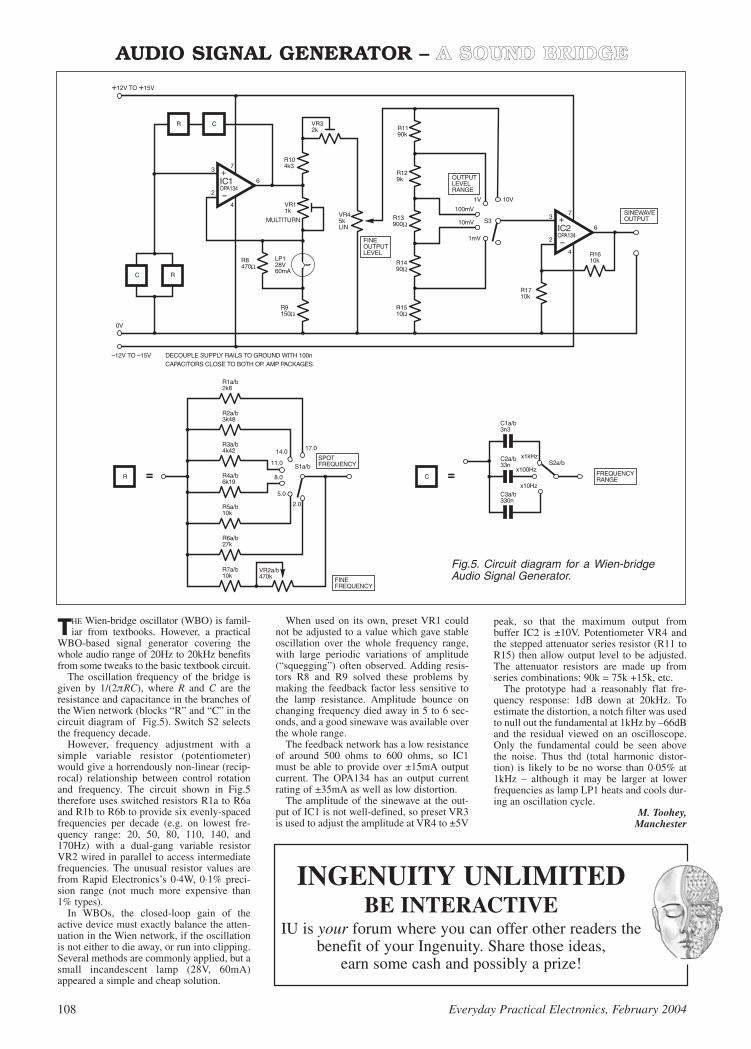
108 Everyday Practical Electronics, February 2004
THE Wien-bridge oscillator (WBO) is famil-iar from textbooks. However, a practical
WBO-based signal generator covering thewhole audio range of 20Hz to 20kHz benefitsfrom some tweaks to the basic textbook circuit.
The oscillation frequency of the bridge isgiven by 1/(2RC), where R and C are theresistance and capacitance in the branches ofthe Wien network (blocks “R” and “C” in thecircuit diagram of Fig.5). Switch S2 selectsthe frequency decade.
However, frequency adjustment with asimple variable resistor (potentiometer)would give a horrendously non-linear (recip-rocal) relationship between control rotationand frequency. The circuit shown in Fig.5therefore uses switched resistors R1a to R6aand R1b to R6b to provide six evenly-spacedfrequencies per decade (e.g. on lowest fre-quency range: 20, 50, 80, 110, 140, and170Hz) with a dual-gang variable resistorVR2 wired in parallel to access intermediatefrequencies. The unusual resistor values arefrom Rapid Electronics’s 0·4W, 0·1% preci-sion range (not much more expensive than1% types).
In WBOs, the closed-loop gain of theactive device must exactly balance the atten-uation in the Wien network, if the oscillationis not either to die away, or run into clipping.Several methods are commonly applied, but asmall incandescent lamp (28V, 60mA)appeared a simple and cheap solution.
When used on its own, preset VR1 couldnot be adjusted to a value which gave stableoscillation over the whole frequency range,with large periodic variations of amplitude(“squegging”) often observed. Adding resis-tors R8 and R9 solved these problems bymaking the feedback factor less sensitive tothe lamp resistance. Amplitude bounce onchanging frequency died away in 5 to 6 sec-onds, and a good sinewave was available overthe whole range.
The feedback network has a low resistanceof around 500 ohms to 600 ohms, so IC1must be able to provide over ±15mA outputcurrent. The OPA134 has an output currentrating of ±35mA as well as low distortion.
The amplitude of the sinewave at the out-put of IC1 is not well-defined, so preset VR3is used to adjust the amplitude at VR4 to ±5V
peak, so that the maximum output frombuffer IC2 is ±10V. Potentiometer VR4 andthe stepped attenuator series resistor (R11 toR15) then allow output level to be adjusted.The attenuator resistors are made up fromseries combinations: 90k = 75k +15k, etc.
The prototype had a reasonably flat fre-quency response: 1dB down at 20kHz. Toestimate the distortion, a notch filter was usedto null out the fundamental at 1kHz by –66dBand the residual viewed on an oscilloscope.Only the fundamental could be seen abovethe noise. Thus thd (total harmonic distor-tion) is likely to be no worse than 0·05% at1kHz – although it may be larger at lowerfrequencies as lamp LP1 heats and cools dur-ing an oscillation cycle.
M. Toohey,Manchester
AUDIO SIGNAL GENERATOR – AA SSOOUUNNDD BBRRIIDDGGEE
Ω
Ω
ΩΩ
Ω
INGENUITY UNLIMITEDBE INTERACTIVE
IU is your forum where you can offer other readers thebenefit of your Ingenuity. Share those ideas,
earn some cash and possibly a prize!
Fig.5. Circuit diagram for a Wien-bridgeAudio Signal Generator.
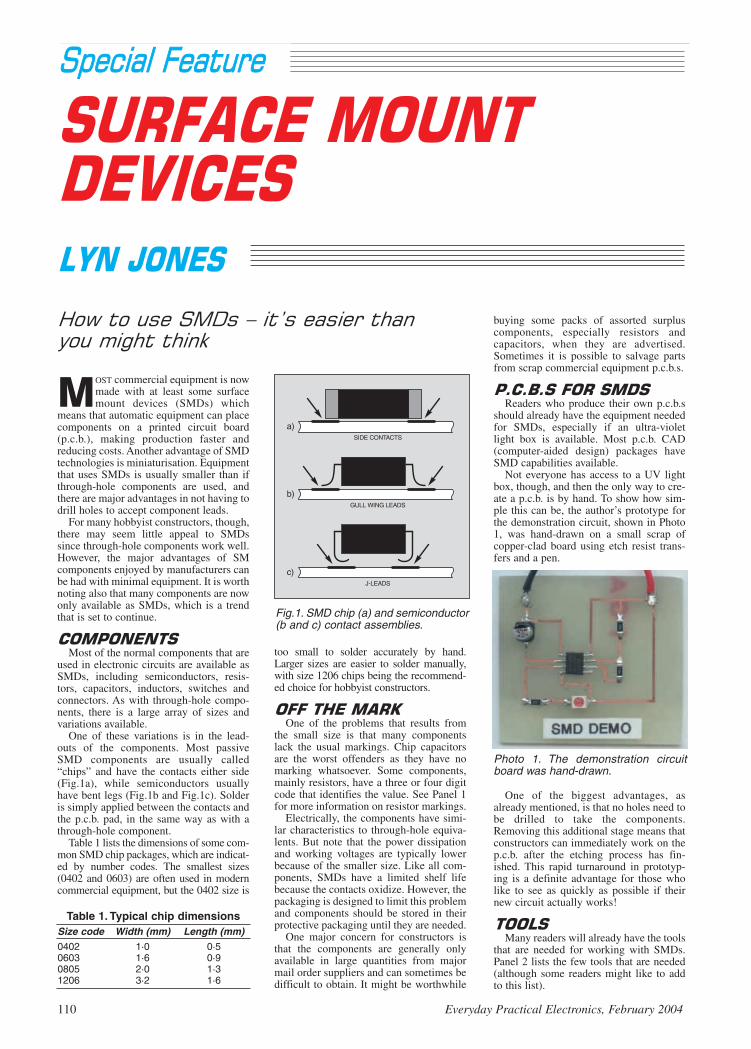
too small to solder accurately by hand.Larger sizes are easier to solder manually,with size 1206 chips being the recommend-ed choice for hobbyist constructors.
One of the problems that results from
the small size is that many componentslack the usual markings. Chip capacitorsare the worst offenders as they have nomarking whatsoever. Some components,mainly resistors, have a three or four digitcode that identifies the value. See Panel 1for more information on resistor markings.
Electrically, the components have simi-lar characteristics to through-hole equiva-lents. But note that the power dissipationand working voltages are typically lowerbecause of the smaller size. Like all com-ponents, SMDs have a limited shelf lifebecause the contacts oxidize. However, thepackaging is designed to limit this problemand components should be stored in theirprotective packaging until they are needed.
One major concern for constructors isthat the components are generally onlyavailable in large quantities from majormail order suppliers and can sometimes bedifficult to obtain. It might be worthwhile
MOST commercial equipment is nowmade with at least some surfacemount devices (SMDs) which
means that automatic equipment can placecomponents on a printed circuit board(p.c.b.), making production faster andreducing costs. Another advantage of SMDtechnologies is miniaturisation. Equipmentthat uses SMDs is usually smaller than ifthrough-hole components are used, andthere are major advantages in not having todrill holes to accept component leads.
For many hobbyist constructors, though,there may seem little appeal to SMDssince through-hole components work well.However, the major advantages of SMcomponents enjoyed by manufacturers canbe had with minimal equipment. It is worthnoting also that many components are nowonly available as SMDs, which is a trendthat is set to continue.
Most of the normal components that are
used in electronic circuits are available asSMDs, including semiconductors, resis-tors, capacitors, inductors, switches andconnectors. As with through-hole compo-nents, there is a large array of sizes andvariations available.
One of these variations is in the lead-outs of the components. Most passiveSMD components are usually called“chips” and have the contacts either side(Fig.1a), while semiconductors usuallyhave bent legs (Fig.1b and Fig.1c). Solderis simply applied between the contacts andthe p.c.b. pad, in the same way as with athrough-hole component.
Table 1 lists the dimensions of some com-mon SMD chip packages, which are indicat-ed by number codes. The smallest sizes(0402 and 0603) are often used in moderncommercial equipment, but the 0402 size is
buying some packs of assorted surpluscomponents, especially resistors andcapacitors, when they are advertised.Sometimes it is possible to salvage partsfrom scrap commercial equipment p.c.b.s.
Readers who produce their own p.c.b.s
should already have the equipment neededfor SMDs, especially if an ultra-violetlight box is available. Most p.c.b. CAD(computer-aided design) packages haveSMD capabilities available.
Not everyone has access to a UV lightbox, though, and then the only way to cre-ate a p.c.b. is by hand. To show how sim-ple this can be, the author’s prototype forthe demonstration circuit, shown in Photo1, was hand-drawn on a small scrap ofcopper-clad board using etch resist trans-fers and a pen.
One of the biggest advantages, asalready mentioned, is that no holes need tobe drilled to take the components.Removing this additional stage means thatconstructors can immediately work on thep.c.b. after the etching process has fin-ished. This rapid turnaround in prototyp-ing is a definite advantage for those wholike to see as quickly as possible if theirnew circuit actually works!
Many readers will already have the tools
that are needed for working with SMDs.Panel 2 lists the few tools that are needed(although some readers might like to addto this list).
110 Everyday Practical Electronics, February 2004
Fig.1. SMD chip (a) and semiconductor(b and c) contact assemblies.
Table 1. Typical chip dimensionsSize code Width (mm) Length (mm)0402 1·0 0·50603 1·6 0·90805 2·0 1·31206 3·2 1·6
Photo 1. The demonstration circuitboard was hand-drawn.

The most important tool is the solderingiron, which should have a pointed tip so asto accurately supply heat to the compo-nents. Most low power soldering irons areadequate, but a soldering iron station ismore useful because the temperature of thesoldering iron can be altered depending onthe component that is being soldered. Setthe iron to the lowest setting that melts thesolder and gives a good joint.
Some manufacturers produce solderingiron handles that resemble tweezers withtwo tips either side of a handle, as shown inPhoto 2. These are used to heat both sidesof an SMD chip simultaneously, which canbe especially useful when removing a com-ponent. It is also possible to get specialtwo-pin soldering iron tips that can be usedon standard soldering irons, but theserestrict the user to one component size at atime.
A source of hot air can be useful to meltthe solder on more than one pin of a com-ponent. In industry, special hot air guns andsoldering pencils are used, some needingcompressed air. The unit shown in Photo 4has adjustable airflow and temperature con-trols, and the nozzles can be changeddepending on the component dimensions.For occasional use, a small butane poweredblowtorch is useful, providing it has a suit-able “hot air” adaptor which does not pro-duce any flames that would damage theboard.
A fine grade solder, for example 0·4mmor 0·7mm, is preferred because it is easierto dispense just the right amount of solderonto the joint. Both traditional solders andlead free equivalents can be used, but a
“no-clean” flux provides a cleaner andmore satisfactory result than “rosin” flux.
Because of the small size of components,a well-lit workstation is necessary. Somereaders will find a magnifying lens a neces-sary aid, in which case a bench mountedmagnifier and lamp unit is ideal.
Soldering SMDs onto a p.c.b. is straight-
forward. Following the steps outlinedbelow, and with a little practice, readerswho are competent in through-hole assem-bly will become proficient in solderingSMDs. Fig.2 shows the most importantstages graphically:
1. Prepare the p.c.b. using a p.c.b. clean-er block or an abrasive pen to make surethat the copper is clean and will accept thesolder.
2. Place a small quantity of solder ontoone of the pads for the component, asshown in Fig.2a.
3. Offer the component onto the p.c.b.using tweezers and flow the solder tosecure the component in place as shown inFig.2b. Make sure that the component isflush and square with the p.c.b., checkingfor short circuits between pads.
4. Solder other pin(s) or pad(s) on thedevice. For chips, as shown in Fig.2c, sim-ply solder the other side. For i.c.s, continue
Everyday Practical Electronics, February 2004 111
For SMD soldering you will need: Soldering iron with small pointed bit
and fine solder Flux pen and (optional) flux cleaner P.C.B. cleaner block and/or
abrasive pen Tweezers with fine points
(e.g. size AA) Magnifying lens
Additional tools for rework are: Hot air gun Desoldering braid and solder sucker
Recommended: Bench mounted lamp unit with
magnifier
The three main numbering systems
used on SMD resistor chips. With types aand b, the codes are simply made fromthe first significant figures with the lastdigit indicating the number of zeros. Inthese two examples, both resistors are47k ohms.
Another code is often found on lowvalue resistors in which an R is used toshow the value in ohms. If this appears
with numbers either side it acts as thedecimal point, so in example c, the valueis 4·7 ohms.
Fig.2. Recommended steps when sol-dering SMD components.
Photo 2. Soldering station with both stan-dard and tweezer-type soldering irons.Courtesy www.paceworldwide.com
Photo 4. Hot air station for SMDrework. Courtesy www. leister.com.
Photo 3. The Antex 690SD tempera-ture control solder station with aselection of surface mount bits.Courtesy www.antex.co.uk.

with the lead that is diagonally opposite tothe first pin then continue in any order.
5. If needed, reheat the joints with flux(from a flux pen) and melt the solder so thatall connections are good and “wet” as inFig.2d.
6. Inspect the whole component andcheck for dry joints etc. Should you need toremove excess solder shorting out i.c. pins,first apply some flux and re-flow the solderusing the soldering iron.
7. Repeat for any other components.8. Clean off any flux residue on the
board as this could lead to reliabilityproblems.
A solder resist layer is usually present oncommercial boards to prevent solder shortsand to stop the solder flowing along thetracks. Home-made p.c.b.s usually do nothave the benefit of this layer, so a littleadditional care is needed when the compo-nents are soldered onto the p.c.b.Sometimes a small piece of heat resistantKapton tape can be used as a solder resist,or as protection for other parts on theboard.
Care is also needed not to overheat thecomponents because their small size makesthem more susceptible to heat damage. Aswhen soldering through-hole components,the soldering iron should be used for theshortest time possible for the solder to meltand flow to make a good joint.
Although soldering components onto a
p.c.b. is a relatively easy operation, some-times components need to be removed torework a p.c.b. The most important consid-eration when removing SMDs is to makesure that the pads do not lift off from thep.c.b. Extra care is needed because the heatrequired to melt the solder also loosens theadhesive that bonds the copper pads andtracks to the board.
For many components, the whole devicemust be heated so that all soldered jointsmelt simultaneously. However, care isneeded because some components, likeelectrolytic capacitors and l.e.d.s, are madefrom plastic housings that melt with theheat.
On some commercial p.c.b.s a small spotof adhesive is used to hold the componentsin place so that they do not fall off in thesoldering machinery. If boards using thistechnique are encountered, take extra carenot to damage the pads because more forceis needed to remove the components.
There are three methods that can be usedto remove SMDs from a board, as shown inFig.3.
Small chips can be removed simply byheating the whole component with the sol-dering iron tip, as shown in Fig.3a.Sometimes, a little solder might need to beadded to cover the whole component tomake it easier to remove. A solder suckercan be used to “vacuum up” the component.
Medium sized components, like largerchip resistors and i.c.s, can be removed byhot air, as shown in Fig.3b. Take extra carenot to dislodge nearby parts when heatingup the p.c.b. (the use of Kapton tape isadvisable). Lift the component straight upusing tweezers.
Large components (especially electrolyt-ic capacitors) may be gently prised off oneside at a time, which is shown in Fig.3c.
Gently lever the component when the sol-der is fully molten, taking extreme care notto lift off the pad. Some components mightneed tweezers to be used underneath toprise the part off the p.c.b.
The pads should then be cleaned offusing desoldering braid before a new com-ponent is soldered onto the board.
The example circuit presented in Fig.4
can be used to demonstrate the solderingtechniques for a number of common andlow cost SMD components. It is a simple555 timer plus l.e.d. flasher circuit that can
be constructed with minimal cost. This cir-cuit should be familiar to most readers,which is why it has been chosen and nofunctional description is offered here.
The p.c.b. layout shown in Fig.5 hasbeen designed with space to help readerswho are new to SMDs to solder the compo-nents. This board is intended for creation asdescribed earlier. It is not available for pur-chase. Throughout construction, refer tothe soldering guide given earlier.
Start by soldering the resistors on thep.c.b. as these are the smallest components.The i.c. should then be fitted, checking theorientation, which is usually shown by asmall dot, indent or the manufacturer’s logonear pin 1. First solder pin 5 of the i.c., thensolder all the remaining pins in any order.
Finally, solder the capacitor and thel.e.d., making sure that they are both in thecorrect orientation. Electrolytic capacitorsusually have a mark showing the negativeside, but note that with tantalum capacitorsthe mark shows the positive side. L.E.D.susually have a dot or mark on the cathode,but it is advisable to test this first using amultimeter.
The circuit can be powered from any 9Vor 12V d.c. power supply, and can be incor-porated into many different projects. Thel.e.d. should flash for about half a secondevery one and a half seconds, but this canbe altered by changing the resistor andcapacitor values.
With SMDs being used increasingly in
equipment, an appreciation of how to usethem is important for constructors and stu-dents. It is clear that we will all encountermore of these components as the industrymakes ever smaller products. Additionally,many readers will appreciate the speed withwhich designs can be made into workingcircuit boards when they use SMDs, withthe space saving an additional benefit.
112 Everyday Practical Electronics, February 2004
Fig.3. Removal of SMD componentsfrom a circuit board.
Fig.5. Component and track layout forthe suggested demonstration p.c.b.
µ
Fig.4. Circuit diagram for the SMDassembly demonstration board inPhoto 1 and Fig.5.

in the saturation region the drain-sourcecurrent was controlled by the gate-sourcevoltage, more or less independently of thedrain-source voltage. This region of opera-tion is exploited in linear amplifiers.
The first step in designing such a circuitinvolves finding a suitable operating pointat which to bias the transistor. Usually thiswill be well into the saturation region toallow the device to amplify a relativelywide range of signal levels without distor-tion (see Fig.1).
Amplifier CircuitThe amplifier circuit is shown in Fig.2.
This circuit will look familiar to manyreaders as the same circuit arrangementcan be used with BJTs (bipolar junctiontransistors) and JFETs (junction field-effect transistors). In this circuit resistorsR1 and R2 set the bias voltage at the gate,the output voltage is developed across R3and R4 provides negative feedback to sta-bilise the bias.
The voltage at the gate VG is given by thestandard potential divider equation VG =VDD × R2/(R1+R2) and controls the gate-source voltage along with R4. This deter-mines the quiescent drain current, IDS, animportant element in the bias conditions.
Resistors R1 and R2 can be large valuesto keep the input impedance high; valuesaround 1M are practicable. Similar circuitsusing BJTs cannot usually employ suchhigh values due to the need to supply basecurrent without loading the potentialdivider.
The quiescent drain-source current isusually chosen by the designer rather thancalculated. A value which gives best per-formance can be selected using the datasheet, but other considerations such aspower consumption may come into play.
If we know the required value of IDS wecan find the corresponding value of VGSusing the equation VGS=VT+(IDS/K) orusing a suitable graph from the data sheet.To use the equation we also need to knowthe threshold voltage VT and the transistorgain parameter K.
Regular Clinic
114 Everyday Practical Electronics, February 2004
MOSFET Amplifier Basics
LAST month we looked at the basicphysics of how MOSFETs can con-
duct in a linear circuit. Many readersprobably think of power switching whenMOSFETs are mentioned, as this is aparticularly popular application.Furthermore, a look at a catalogue suchas Farnell will reveal a lot of switchingMOSFETs and few or no devices obvi-ously aimed at linear applications.
However, MOSFETs can be used in lin-ear amplifier circuits, and are commonlyused this way inside i.c.s. Discrete devicesoptimised for linear rather than switchinguse do exist, for example the ADL1101matched n-channel MOSFET pair fromAdvanced Linear Devices Inc., which istargeted at precision analogue circuitdesigns.
Another area where linear discrete MOS-FET circuits are used is in RF amplifiers, inparticular dual-gate MOSFETs (semicon-ductor tetrodes) such as the BF996S fromPhilips. Dual-gate MOSFETs are used tobuild cascode amplifiers, which have betterperformance than single transistor ampli-fiers. MOSFETs are also used in the outputstages of audio power amplifiers.
This month we will look at the design ofa single transistor MOSFET voltage ampli-fier. Previously, after a request to discusslinear MOSFET circuits, we described thebehaviour of a MOSFET and showed that
For example if we have a MOSFET forwhich VT= 0·7V and K=2·5mA/V2 and wechoose a quiescent drain-source current of10mA we require a gate source voltage of0·7+(10/2·5) = 2·7V.
Unfortunately K is a fundamental MOS-FET parameter that you may not find onthe data sheet. It is related to the transcon-ductance (gm), which is often quoted, bygm=2(KIDS), or K=gm
2/(4IDS). Note thattransconductance varies with the drain-source bias current. The above examplehas a transconductance of about 3·2mA/Vat IDS=1mA.
Resistor R4 helps stabilise the bias pointagainst variations between individualdevices (in different copies of our circuit)or variations for an individual device withfactors such as age and temperature. Eachdevice will have slightly different values ofK and VT and hence different values of IDwill result from a fixed VGS. Similarly IDwill vary with temperature for a fixed VGS.If R4 was not present these variationswould upset the bias conditions.
The negative feedback operates as fol-lows. Imagine we have set up the circuitwith a particular drain-source current, butdue to (say) a change in temperature thedrain-source current increases. Thisresults in a larger voltage drop across R4,which decreases the gate-source voltage,which in turn reduces the drain-source
Following on from last month’s column, the basic design of a single MOSFET amplifierstage is outlined, anti-static soldering precautions are described and we look at the
differences between CMOS and bipolar timers.
Fig.1. Idealised output characteristicsfor a MOSFET transistor.
Fig.2. Single MOSFET amplifier circuitdiagram.
from one rail to the other (nearer to +Vand 0V), where a bipolar timer outputtends to swing to say a volt or two belowthe maximum, or above the minimum. ACMOS timer operates typically down to+3V (bipolar: +5V).
Also, the CMOS device has a loweroperating current than the bipolar timer,which can improve a circuit’s current con-sumption, especially when twin timers areused. The inherently high impedance ofthe CMOS timer enables it to use highervalue resistors and smaller capacitorscompared with the bipolar 555/556.
In practice I have usually found no prob-lems with swapping one timer for theother, but one area to check is the outputcharacteristic: if output currents are impor-tant, then a bipolar type is higher (200mA)than a CMOS (100mA). The CMOS outputfalls noticeably when source current (seelast month) increases. Using a voltmeter,some tests with both types driving a simpleload (e.g. a 150 ohm resistor) will soonhighlight any differences, or you can try tounravel the graphs in a data sheet down-loaded from the web. A.R.W
Anti-Static DesolderingIn an effort to find some information on
soldering and desoldering techniques Ifound your web pages and photos(www.epemag.wimborne.co.uk then theResources link on the home page). In mycase I need to take care of ESD (electro-static discharge), and wondered what is thebest mode of soldering and desoldering,and where can I buy an ESD proof desol-dering pump? Thanks from Dr Sumi Dharby email.
For the hobbyist, CMOS damage causedby static is far less of a worry than it usedto be, and it isn’t necessary for ESD-proofequipment to be needed to assemble typi-cal projects. However, nylon carpets andPVC carpet protectors are notorious forcreating enormous static voltages that canbe dealt with using an anti-static wriststrap– and it is wise to do this when handlinge.g. computer memory chips or expensivemotherboards.
current, and tends to cancel out the origi-nal increase.
If we choose 500 ohms for R4 we get0·5V at the source from the 1mA bias cur-rent. This means the R1/R2 potentialdivider must give 0·5+2·7 = 3·2V, so wecould use R1=900 kilohms and R2=330kilohms.
The value of R3 influences the voltagegain and output swing. The drain voltageshould not fall below the gate voltage bymore than VT (0·7V in our example), so theminimum drain voltage is 2·5V. The maxi-mum drain voltage is the supply voltage(12V), so we have a maximum swing of9·5V or ±4·75V centred on 7·25V. For adrain voltage of 7·25V with no signal weneed R3=(12–7·25)/1mA=4·75 kilohms.
The voltage gain of the circuit is given by–gmR3 / (1+gmR4).
In our example the gain is about 5·8. Thestabilising resistor reduces the gain, butthis can be overcome by bypassing it witha capacitor. I.M.B.
CMOS or Bipolar TimersI am about to build the Super Motion
Sensor from the May 2003 edition (BackIssues available by visiting our Online Shopwww.epemag.wimborne.co.uk – ARW).One component is listed as a 7556 CMOSdual timer. I have been offered an alterna-tive NE556 dual timer instead. Is there a dif-ference between the two types? Thanks fromNeil, posted in the EPE Chat Zone.
We looked at some basic differencesbetween the two families in last month’sCircuit Surgery. The NE556 is the originaldual 555 timer and is classed as a bipolardevice, i.e. one that is made from n-p semi-conductor material.
Ordinary silicon transistors such as theBC548 also belong to the same bipolarfamily. Then along came the CMOS(Complementary Metal-Oxide Semicon-ductor) timer which in theory is pin-for-pincompatible with the old bipolar chip whilstoffering all the advantages of CMOStechnology.
The main differences are that the outputof the CMOS type is better able to switch
In manufacturing applications, wherestatic sensitive components or boards arebeing soldered or repaired, then problemscan arise due to static electricity discharg-ing into semiconductors, possibly destroy-ing them. For example, a search on theInternet soon unearthed (no pun intended)the web site of Assurance TechnologyCorporation who posted some interestingimages of an ESD failure in an op.amp.See http://www.assurtech.com/FA1.asp.
ESD-safe tools are made from partiallyconductive materials that will not generateany damaging static nor allow staticcharges to be carried to components beingsoldered. The bit of an ESD soldering ironis usually grounded (possibly through aresistor) to prevent static accumulating onit, so that you can’t transfer a charge to asemiconductor. They may be listed as “sta-tic dissipative” tools.
An ESD-safe desoldering pump is alsostatic-conductive, this time so that it willbe automatically discharged to earth whenyou take hold of it: wrist or ankle strapscan be worn which are grounded through aresistor. ESD benchtop mats can be boughtthat also connect to ground through a spe-cial mains adaptor that has plastic live andneutral pins and a metal ground pin. Thesecan also allow a wriststrap to be connectedand earthed.
Manufacturers of ESD safe solderingirons include Antex (www.antex.co.uk) –see their advert in this issue, and pumps aremade by Edsyn (Soldapult brand) or Abecoto name but two. Major suppliers includeFarnell (www. farnellinone.co.uk) and RSComponents (www.rswww.com).
If using a wriststrap, then the fact thatyou are grounded, and that the tools areESD safe as well, means that there isnowhere for static charges to gather, sothere is no possibility of “zapping”components being soldered or desol-dered. It’s rather like the way the equip-ment and buildings in a power stationare completely grounded throughout,using heavy copper busbars, to make iteasy for “escaping” high voltages tofind their way to earth and blow a tripswitch. A.R.W.
Everyday Practical Electronics, February 2004 115
TAKE A LOOK,A FREE ISSUEIS AVAILABLE
A one year subscription(12 issues)
costs just $10.99 (US)(approx. £7)
www.epemag.com
Get your magazine “instantly”anywhere in the world –
buy and downloadfrom the web.

Clear cast acrylic rods are superbtransmitters of light. They are also goodreflectors of light, when their surfaces aresuitably abraded. If a 45-degree arc isroughened at the back of such a rod, 315degrees remain for the transmission oflight down the length of the rod.
Any light that is caught by the abrasionsat the back is cast forward through themagnifying curve of the rods. Thus if anultrabright l.e.d. is shone down the lengthof the rod, there is no apparent loss ofbrightness down tens of centimetres ofrod.
The Jazzy Necklace randomly flashes
sixteen l.e.d.s using just two commonCMOS i.c.s. The full circuit diagram forthe “necklace” is shown in Fig.1.
ACHIC appearance and a strikingpiece of jewellery can emphasisethe beauty of the wearer, as well as
adding a sense of lightness to life. An item of jewellery that lends itself
particularly well to electronic enhance-ment is a traditional African necklacewhich comprises an array of vertical rods,artistically arranged, suspended from astring around the neck. These rods may bemade of various traditional materials,including wood, ivory, tortoiseshell, orstone.
This article unveils a 21st-Century ver-sion of this necklace which, instead ofusing rods of wood or other customarymaterials, employs sixteen sparkling clearcast acrylic rods. These are accompaniedby a compact circuit which darts allcolours of light down the length of therods, at random.
This is not a pseudo-random display,as may be created (as an example) withshift registers, but comes close to atruly random display by using threeoscillators, IC1a to IC1c, each of whichoscillates independently of the other two.These create a constantly changing three-digit binary “select” number, which isdecoded to eight switch positions of aCMOS 4051 eight-channel analoguemultiplexer (IC2).
This multiplexer i.c. is similar to a sin-gle-pole, eight-position switch, with theimportant difference that it allows randomaccess to each of the eight switch posi-tions. This means that it does not need tosequence through each of the eight posi-tions as a normal switch would do, but hasthe ability to jump randomly from oneposition to the next.
It has, of course, only eight switchpositions, and in order to independentlyflash sixteen l.e.d.s, the number of switchpositions is effectively multiplied by twoby creating two alternating 0V rails. A
116 Everyday Practical Electronics, February 2004
Fig.1. Complete circuit diagram for the sixteen l.e.d. Jazzy Necklace.

fourth oscillator (IC1d) is employed forthis purpose, again oscillating indepen-dently of the other three, to effect themultiplication. Two buffers (IC1e andIC1f) prevent excessive loading of theoscillator. This creates a random displayof sixteen l.e.d.s., using less than onecomponent per l.e.d.
Pin 3 of IC2 is the centre or commonpole of the “switch”, which is connected toany given output position (numbered 0 to7). The three-bit binary value which is pre-sented at the three “select” terminals A, Band C (pins 9 to 11) are decoded to theeight separate outputs.
Since only one three-digit value can beentered at a time, only one of the outputterminals can go “high” at any time. Thus,a practically random three-digit binaryvalue is generated, with fleeting patternsemerging.
Since the common pole (IC2 pin 3) inthis circuit is connected to the positive sup-ply rail, through ballast resistor R5, each ofthe switch positions goes “high” when con-nected, therefore the cathodes of the l.e.d.sare connected to the alternating 0V rail.
An important feature of this design isthat when a switch position is disconnectedfrom the common pole, the correspondingl.e.d. is disconnected from the power sup-ply. This is in contrast with the 4028CMOS i.c., which may serve a similarfunction in digital circuits.
However, the output terminals of the4028 i.c. will only go “high” or “low” (it isthus a bi-state device). Therefore, if the4028 had been used in this design, thereverse voltage across the l.e.d.s wouldhave been close to 12V, which exceeds therating of the typical l.e.d.
While the supply voltage could havebeen reduced to overcome this, the designcould not then have accommodated allcolour l.e.d.s. Therefore the 4051 8-chan-nel analogue multiplexer i.c. is used.
The four oscillators (IC1a to IC1d) are
each based on a single Schmitt inverter (orNOT) gate, and are thus very simple, requir-ing only one resistor and one capacitoreach. For the purpose of preventing “fre-quency lock” (the tendency of oscillators to“lock on” to one another in close proximi-ty), the values of capacitors C2 to C4 andC6 are, therefore, relatively large (10F).
For a less jazzy (that is, more sedate) dis-play, increase the values of the capacitors,
and vice versa. A supply decoupling capac-itor C1 is included for “good practice”,although it is not strictly necessary.
Due to the relatively high supply voltage(12V), and since only one l.e.d. is everflashed at a time, a single ballast resistor(R5 – connected to IC2 common pin 3) canbe used for all sixteen l.e.d.s combined,thus simplifying and compressing thecircuit. While it would be possible to useseveral ballast resistors, thus perfectlymatching them to each colour l.e.d., inpractice this is not necessary, and wouldconsiderably increase the componentcount. The result is a very compact circuit.
Do note, however, that when selectingl.e.d.s, their luminous intensity should beapproximately the same – alternatively, testthem first with 12V and a one kilohm (1k)ballast resistor.
Besides the “circuit proper”, three fur-
ther components are employed, so as to dis-able the Jazzy Necklace when the wearer isno longer moving (for instance, when hav-ing moved off the dance floor to enjoy arefreshment).
To accomplish this, the inhibit pin (pin6) of IC2 is wired to a non-mercury tiltswitch, S1. As long as this switch is occa-sionally closed, pin 6 is held “low” throughcapacitor C5, and the circuit continues toflash jazzily. But when pin 6 is taken“high” through the gradual discharging ofC5 through resistor R4, all switch positionsare disabled, and the Necklace, after a fewseconds, “goes to sleep”.
Note, however, that it does not switch off,but continues to draw about 2mA current.If a tilt switch is not available this compo-nent may simply be omitted from the p.c.b.
A miniature 12V battery is used (a 23Aor MN21 or similar), and diode D17 isemployed on the printed circuit board(p.c.b.) for supply reverse polarity protec-tion. The circuit is switched off simply byremoving the battery – or a suitable con-nector may be inserted in one lead. Thecircuit draws about 10mA, and shouldtherefore run for about three hours continu-ous off the specified battery.
Finally, a question which is commonlyasked about the 4051 i.c. is what purpose pin7 (VEE) serves. When this terminal is tiedlow, the i.c. will handle signals between 0Vand +Ve, as it does in the present circuit.
When, on the other hand, analogue sig-nals need to be routed through the i.c., thispin would normally be connected to thelowest voltage level in the circuit. Forinstance, pins 16 and 7 could be connectedto +6V and –6V respectively, while pin 8could be connected to ground (0V). In thisway, analogue voltages of up to ±6V couldbe handled with 6V digital control signals.
Construction of the Jazzy Necklace is on
a single-sided printed circuit board (p.c.b.)measuring 128mm × 28mm, which is fur-ther cut and filed to shape as shown inFig.2. The topside component layout andfull-size copper foil master pattern is illus-trated in Fig.2. This board is available fromthe EPE PCB Service, code 432.
Everyday Practical Electronics, February 2004 117
Front-on view of the “necklace” circuit board. Note the l.e.d.s bent at an angle just above the components.
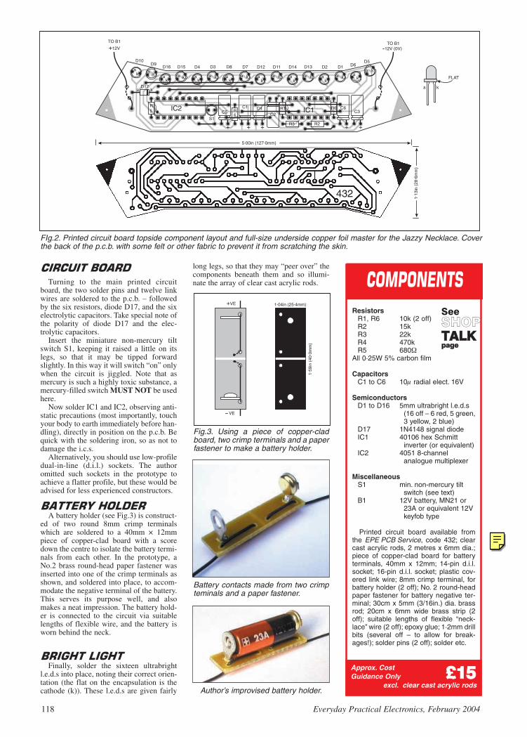
Turning to the main printed circuitboard, the two solder pins and twelve linkwires are soldered to the p.c.b. – followedby the six resistors, diode D17, and the sixelectrolytic capacitors. Take special note ofthe polarity of diode D17 and the elec-trolytic capacitors.
Insert the miniature non-mercury tiltswitch S1, keeping it raised a little on itslegs, so that it may be tipped forwardslightly. In this way it will switch “on” onlywhen the circuit is jiggled. Note that asmercury is such a highly toxic substance, amercury-filled switch MUST NOT be usedhere.
Now solder IC1 and IC2, observing anti-static precautions (most importantly, touchyour body to earth immediately before han-dling), directly in position on the p.c.b. Bequick with the soldering iron, so as not todamage the i.c.s.
Alternatively, you should use low-profiledual-in-line (d.i.l.) sockets. The authoromitted such sockets in the prototype toachieve a flatter profile, but these would beadvised for less experienced constructors.
A battery holder (see Fig.3) is construct-
ed of two round 8mm crimp terminalswhich are soldered to a 40mm × 12mmpiece of copper-clad board with a scoredown the centre to isolate the battery termi-nals from each other. In the prototype, aNo.2 brass round-head paper fastener wasinserted into one of the crimp terminals asshown, and soldered into place, to accom-modate the negative terminal of the battery.This serves its purpose well, and alsomakes a neat impression. The battery hold-er is connected to the circuit via suitablelengths of flexible wire, and the battery isworn behind the neck.
Finally, solder the sixteen ultrabright
l.e.d.s into place, noting their correct orien-tation (the flat on the encapsulation is thecathode (k)). These l.e.d.s are given fairly
long legs, so that they may “peer over” thecomponents beneath them and so illumi-nate the array of clear cast acrylic rods.
118 Everyday Practical Electronics, February 2004
ResistorsR1, R6 10k (2 off)R2 15kR3 22kR4 470kR5 680
All 0·25W 5% carbon film
CapacitorsC1 to C6 10 radial elect. 16V
SemiconductorsD1 to D16 5mm ultrabright l.e.d.s
(16 off – 6 red, 5 green,3 yellow, 2 blue)
D17 1N4148 signal diodeIC1 40106 hex Schmitt
inverter (or equivalent)IC2 4051 8-channel
analogue multiplexer
MiscellaneousS1 min. non-mercury tilt
switch (see text)B1 12V battery, MN21 or
23A or equivalent 12Vkeyfob type
Printed circuit board available fromthe EPE PCB Service, code 432; clearcast acrylic rods, 2 metres x 6mm dia.;piece of copper-clad board for batteryterminals, 40mm x 12mm; 14-pin d.i.l.socket; 16-pin d.i.l. socket; plastic cov-ered link wire; 8mm crimp terminal, forbattery holder (2 off); No. 2 round-headpaper fastener for battery negative ter-minal; 30cm x 5mm (3/16in.) dia. brassrod; 20cm x 6mm wide brass strip (2off); suitable lengths of flexible “neck-lace” wire (2 off); epoxy glue; 1·2mm drillbits (several off – to allow for break-ages!); solder pins (2 off); solder etc.
SeeSSHHOOPPTTAALLKKppaaggee
Approx. CostGuidance Only ££1155
excl. clear cast acrylic rods
FIg.2. Printed circuit board topside component layout and full-size underside copper foil master for the Jazzy Necklace. Coverthe back of the p.c.b. with some felt or other fabric to prevent it from scratching the skin.
Fig.3. Using a piece of copper-cladboard, two crimp terminals and a paperfastener to make a battery holder.
Battery contacts made from two crimpteminals and a paper fastener.
Author’s improvised battery holder.
EPE Online
Note that the circuit boards used in EPE Online projects are available from the EPE Online Store at www.epemag.com (also note that the codes for the boards in the online store are prefixed with 7000, so a board with a code of say 256 will appear as 7000256 in the online store).
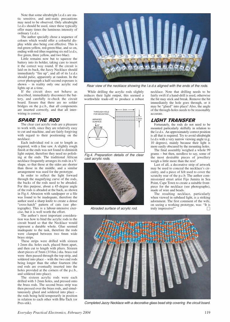
Note that some ultrabright l.e.d.s are sta-tic sensitive, and anti-static precautionsmay need to be observed. Only ultrabrightl.e.d.s should be used, since these typicallyoffer many times the luminous intensity ofordinary l.e.d.s.
The author specially chose a sequence ofcolours which would offer a colourful dis-play while also being cost effective. This isred-green-yellow, red-green-blue, and so on,ending with red (thus requiring six red l.e.d.s,five green, three yellow, and two blue).
Little remains now but to squeeze thebattery into its holder, taking care to insertit the correct way round. If the circuit islaid on its back, the Jazzy Necklace shouldimmediately “fire up”, and all of its l.e.d.sshould pulse, apparently at random. In thecover photograph a half-second exposure isshown – in reality only one acrylic rodlights up at a time.
If the circuit does not behave asdescribed, immediately disconnect the bat-tery, and carefully re-check the circuitboard. Ensure that there are no solderbridges on the p.c.b., that all componentsare inserted correctly, and that all inter-wiring is correct.
The clear cast acrylic rods are a pleasure
to work with, since they are relatively easyto cut and machine, and are fairly forgivingwith regard to their positioning on thenecklace.
Each individual rod is cut to length asrequired, with a fine saw. A slightly roughfinish at the ends was not found to diminishlight output, therefore they need no polish-ing at the ends. The traditional Africannecklace frequently arranges its rods in a V-shape, so that those at the sides are shorterthan those in the middle, and a similararrangement was used for the prototype.
In order to reflect the light forwardthrough the magnifying curve of the rods,the backs of the rods need to be abraded.For this purpose, about a 45-degree angleof the rods is abraded at the back, as shownin Fig.4. Abrasion with sandpaper or a filewas found to be inadequate, therefore theauthor used a sharp knife to create a dense“cross-hatch” pattern of cuts (see pho-tographs). This is a labour-intensive exer-cise, but it is well worth the effort.
The author’s most important considera-tion was how to bind the acrylic rods to thecircuit board so that the Necklace wouldrepresent a durable whole. Glue seemedinadequate to the task, therefore the rodswere clamped between two 6mm widebrass strips.
These strips were drilled with sixteen1·2mm dia. holes each, placed 8mm apart,and then cut to length with pliers. Sixteenshort pieces of 5mm (3/16in.) dia. brass rodwere then passed through the top strip, andsoldered into place – with the two end rodsbeing longer than the other fourteen (theend rods are eventually inserted into theholes provided at the corners of the p.c.b.,and soldered into place).
The sixteen acrylic rods were eachdrilled with 1·2mm holes, and pressed ontothe brass rods. The second brass strip wasthen pressed over the brass rods, and simul-taneously glued and soldered into place –the rods being held temporarily in positionin relation to each other with Blu-Tack (orPres-stik).
While drilling the acrylic rods slightlyreduces their light output, this seemed aworthwhile trade-off to produce a robust
necklace. Note that drilling needs to befairly swift if a hand-drill is used, otherwisethe bit may stick and break. Remove the bitimmediately the hole goes through, or itmay be “glued” into place! Also, the angleof the through-holes needs to be reasonablyaccurate.
Fortunately, the rods do not need to be
mounted particularly skilfully in relation tothe l.e.d.s. An approximately correct positionis all that is required. Try to avoid ultrabrightl.e.d.s with a very narrow viewing angle (e.g.10 degrees), mainly because their light ismore easily obscured by the mounting holes.
The final assembly weighed a whole 99grams – but then, needless to say, some ofthe most desirable pieces of jewelleryweigh a little more than the rest!
Last of all, a decorative strip of artworkmay be used to conceal the necklace’s cir-cuitry, and a piece of felt used to cover thescratchy rear of the p.c.b. The author com-missioned street artist Fijo Jumira in SeaPoint, Cape Town to create a suitable front-piece for the necklace (see photographs),made of wire and beads.
The resulting necklace, particularlywhen viewed in subdued light, is a strikingadornment. The first comment of the wife,on seeing a working prototype, was: “It istruly impressive!”
Everyday Practical Electronics, February 2004 119
Rear view of the necklace showing the l.e.d.s aligned with the ends of the rods.
Fig.4. Preparation details of the clearcast acrylic rods.
Abraded surface of acrylic rod.
Completed Jazzy Necklace with a decorative glass bead strip covering the circuit board.
based on EPE articles. The links give some infoon other applications, such as R/C aircraft etc.
Thanks for an excellent magazine.David Forrest, via email
Thanks David, that’s an interesting siteyou’ve got – and even covers model subs! Alsosee page 83 of this issue.
TEACH-IN DIODESDear EPE,I am avidly reading your Teach-In 2004 arti-
cles and although I have a little electronics expe-rience and understanding, there are occasionswhere I cannot get my head around certain dia-gram configurations.
In your December issue on page 828 there isone such arrangement. In Fig.2.7 there is a diodeand it is inserted to prevent back-e.m.f. from themotor damaging the transistor. Yes I can under-stand back-e.m.f. and I do know that current canpass one way through a diode but not the other.What I cannot understand is why it is in parallel.Surely it should be in series? In that drawingthere is a clear path between the motor and thetransistor and I just cannot see how the diode islikely to protect the motor. Can you explain?
Stephen Eyre, via email
Max Horsey, author of our Teach-In 2004series replies:
Parallel diodes often provoke questions likethis. The main thing to appreciate is that elec-tricity always takes the easiest route. So a diodein parallel with the motor will provide an easypath for the current caused by back-e.m.f. Innormal circumstances the maximum voltageacross a silicon diode in the forward direction isaround 0·7V. So the voltage at the collector ofthe transistor cannot rise much above P + 0·7,where P is the power supply voltage. Hence theback-e.m.f. which may otherwise rise to 100Vor more, is held at P + 0·7V.
It’s rather like a lavatory pan. If you pour abucket of water (the back-e.m.f.) into the toilet,the water level rises a little, but quickly returns tonormal, as the water flows though the U-pipe (thediode). The analogy isn’t perfect, as the U-pipewould allow flow both ways, unlike the diodewhich allows the flow in only one direction.
A series diode wouldn’t work. If the diode point-ed downwards, the back-e.m.f. would damage thetransistor. If the diode pointed upwards, it wouldprevent the normal flow of current via the motor.
Max Horsey
CAR COMPUTERWith our US friends always in his mind, our
Online Editor Alan Winstanley asked whetherMike Hibbert’s PIC Car Computer (Jan ’04)could display miles per US gallon (which is0·83268 British gallons). Mike replied:
The simple answer is yes. The reason for thisis that the combinations ltr/km, ltr/mile, gal-lons/km, gallons/mile are nothing more than textlabels. The calculation is simply distance trav-elled/fuel used, The program doesn’t care whatthe units of measurement are expressed as. Thisis why you have to clear the memory when youchange from one unit type to another.
Mike Hibbett, via email
LETTER OF THE MONTH LIFE OF BRYON?
Dear EPE,Just a thought about your mag! I’ve been a
subscriber now for many years and really appre-ciate the trouble you guys must go to in findingnew projects and articles each month. I am alsoa professional electronics engineer havingworked in various fields, from my early days indomestic radio and TV, through main framecomputers, then industrial computers, CNCmachines and PLCs, with some interface mod-ule design and manufacture thrown in, an inter-esting life? Yes – well paid, no.
My other great love is aviation, I hold a pri-vate pilots’ license and subscribe to Pilot maga-zine. One of their regular features, I learntabout flying from that, is a column written byreaders about interesting or scary moments thathave happened to them while flying. Couldn’tyou run a similar column for electronics relatedsubjects? Nearly everyone interested in elec-tronics must have a story of how they solved anunusual problem. Somewhere betweenIngenuity Unlimited, Readout and CircuitSurgery. Just to give you a bare bones example:
The mystery of the blowing 12V fuse: afterretrofitting a PC in place of a Tape Reader to aCNC system, the 12V fuse would blow atswitch on, exhaustive tests found no shorts butthe vital clue was that during the retrofit aninterface module powered by 12V was removedas not required. The culprit was a transducermodule with catching diodes (connected to the12V line) on a level changer circuit that
stopped the transducer input from goingabove 12V.
The power supply was fitted with a crowbarcircuit and though capable of sourcing 10Ahad no sink capability, so the catching diodeswere pulling the 12V above the crowbar volt-age limit and thus blowing fuses. The removedinterface module was acting as current sink.Loading the p.s.u. with a suitable resistor fixedthe problem.
This story is a practical demonstration ofthe use of catching diodes, crowbar circuitsand the often-overlooked fact that most p.s.u.scannot sink current
Some years ago I remember a series, sort of“week in the life of a radio and TV repairshop”. This was a “fictional” story about anOld Bob figure in charge of the workshop andhis keen-to-learn apprentice struggling with aproblem. Old Bob explains, with the aid of cir-cuits and drawings, how to fix it. Sorry but Ican’t remember which publication it was in, orknow of anyone who could write it. Maybe itwouldn’t work today anyway, just an idea.
Bryon Epps, via email
Yes, Bryon, I half remember a column ofthat nature, but I’m also not sure that it wouldwork today. You may recall that we used to doa column Ohm Sweet Ohm by Max Fidling.From his workshop, and helped by his catPiddles, Max looked at life’s electronic oddi-ties and their possible solutions, but that waseventually dropped as it was hard to sustain.
120 Everyday Practical Electronics, February 2004
RREEAADDOOUUTTJJoohhnn BBeecckkeerr aaddddrreesssseess ssoommeeooff tthhee ggeenneerraall ppooiinnttss rreeaaddeerrss
hhaavvee rraaiisseedd.. HHaavvee yyoouu aannyytthhiinnggiinntteerreessttiinngg ttoo ssaayy??
DDrroopp uuss aa lliinnee!!
WIN AN ATLAS LCR ANALYSERWORTH £79
An Atlas LCR Passive ComponentAnalyser, kindly donated by Peak ElectronicDesign Ltd., will be awarded to the authorof the Letter Of The Month each month.
The Atlas LCR automatically measuresinductance from 1H to 10H, capacitancefrom 1pF to 10,000F and resistance from1 to 2M with a basic accuracy of 1%.
Email: [email protected]
All letters quoted here have previously been replied to directly.
ZAPPER AND BLOWN BULBSDear EPE,I’ve just been perusing Andy Flind’s PIC
Virus Zapper MkII (Dec ’03). I can see that he’screating a square wave that sweeps between<2kHz to >22kHz. But what is the frequency ofthe sweep, and does it pause at each end, orcome straight back?
Also, regarding Blown Bulbs (Readout Dec’03) – a company did a Bulb Failure Detectionpresentation to us at Jaguar in ’86. They usedexactly the system that David Palmer describes,i.e. reed switches. It was so simple and reliable.Unfortunately, Jaguar decided not to try this sys-tem (internal politics I think) on the XJ40 andstuck with another one using in-line resistors –just some crude coils of wire on formers.
Because they were doing high-side detection,the op.amps that were monitoring the voltagedrop across the coils had to have a supply railgreater than that of the vehicle. To achieve this,they used a simple 555 oscillator driving acharge pump. Now – each corner of the car hada Bulb Control/Failure Detection module, sothere were four of these units in all.
This seemed to be doing the business until mymate tried to do his radio reception sign-off test.He was getting all sorts of interference – whichwas ultimately traced to these 555s merrily oscil-lating away and bunging out r.f. harmonics intothe car wiring harnesses! A few carefully placedcapacitors managed to smooth off the edges.
The design for the Dim/Dip Headlamp con-troller was even more hilarious – as a dealer was
launching the new model to some enthusiasticpotential customers, smoke was pouring out thefront corner of the car behind him as the MOS-FET controlling the 60W bulb drifted uncontrol-lably into the linear region! And boy did it stink!
Sorry to digress – I’ve got pages ofAutomotive Electrical horror stories! Perhaps Iought to make it into a regular column?
Steve Dellow, via email
Thanks, Steve, for the interesting “bulb” com-ments! I regret we can’t offer you an X-ratedcolumn but they do make interesting Readout –also see above.
Andy replies to your question:
In the article a few lines under the heading“Mk2 Circuit” it says, “a simple oscillator witha period of about sixteen seconds, or eight sec-onds in each phase direction, as set by capacitorC8 and resistor R9”. There’s not supposed to beany “dwell” at either end, though componenttolerances may mean that it “bottoms” and givesa brief period. I seem to recall struggling a bit tominimise that during the design stage.
PICS FOR RADIO CONTROLDear EPE,I was interested to see the discussions on ser-
vos etc., in recent Readout columns. PICs andservos do make a very good combination.
You asked for information, so please havea look at my website: www.rdforrest.freeserve.co.uk. This gives some of my ideasfor radio control applications – many of them

BBAACCKK IISSSSUUEESSOCT ’02 Photocopies only
PROJECTS EPE Bounty Treasure Hunter ICTester Headset Communicator PIC-PocketBattleships.FEATURES Circuit Surgery New TechnologyUpdate Logic Gate Inverter Oscillators – 2 Interface Network – The Internet Page UsingTK3 With Windows XP and 2000.
NOV ’02 Photocopies only PROJECTS EPE Hybrid Computer – 1 TuningFork and Metronome Transient Tracker PICAXEProjects–1 (Egg Timer – Dice Machine – QuizGame Monitor).FEATURES Practically Speaking IngenuityUnlimited Circuit Surgery New TechnologyUpdate Net Work – The Internet Page.
DEC ’02PROJECTS Versatile PIC Flasher EPE HybridComputer – 2 Door Defender PICAXE Projects– 2 (Temperature Sensor – Voltage Sensor – VUIndicator).FEATURES Electronic Paper Alternative Usesfor Transistors Interface Circuit Surgery NewTechnology Update Ingenuity Unlimited NetWork – The Internet Page 2002 Annual Index.
JAN ’03PROJECTS EPE Minder F.M. Frequency Surfer Wind Speed Meter PICAXE Projects–3 (ChaserLights).FEATURES Who Really Invented The Transistor TechnoTalk Circuit Surgery PracticallySpeaking New Technology Update ComputerGOTOs Ingenuity Unlimited Net Work – TheInternet Page.
FEB ’03PROJECTS Wind Tunnel Brainibot Buggy Back To Basics–1 (Hearing Aid, Audio PowerAmplifier) Tesla High Voltage Transformer.FEATURES In The Bag Techno Talk CircuitSurgery New Technology Update Interface Ingenuity Unlimited Net Work – The Internet Page.
MAR ’03PROJECTS Wind-Up Torch Mk II 200kHzFunction Generator Driver Alert Back-To-Basics–2 (Metal Detector, Simple Timer).FEATURES Ingenuity Unlimited PracticallySpeaking Techno Talk New Technology Update Circuit Surgery Peak LCR Component AnalyserReview Net Work – The Internet Page.
APR ’03PROJECTS Atmospherics Monitor IntelligentGarden Lights Controller Back-To-Basics–3(Touch Light, Plant Watering Reminder) EarthResistivity Logger–Part 1.FEATURES Ingenuity Unlimited Techno Talk New Technology Update Circuit Surgery Interface Network – The Internet Page SPECIALSUPPLEMENT – EPE PIC Tutorial V2–Part 1.
MAY ’03PROJECTS Super Motion Sensor EarthResistivity Logger – Part 2 Door Chime Back-To-Basics–4 (Live Wire Detector, Medium Wave Radio).FEATURES Ingenuity Unlimited Techno Talk Practically Speaking Circuit Surgery Net Work– The Internet Page SPECIAL SUPPLEMENT –EPE PIC Tutorial V2 – Part 2.
JUNE ’03PROJECTS Fido Pedometer PICronos L.E.D.Wall Clock–Part 1 Back-To-Basics–5 (MiniTheremin, Twilight Switch) Radio Circuits–1 (CrystalSet, MK484 TRF Receiver, Headphone Amplifier).FEATURES Ingenuity Unlimited Techno Talk Interface Circuit Surgery New TechnologyUpdate Net Work – The Internet Page SPECIALSUPPLEMENT – EPE PIC Tutorial V2 – Part 3.
JULY ’03PROJECTS EPE Mini Metal Detector LowRange Ohmmeter Adaptor Mk2 Radio Circuits–2(Q-Multiplier, MW Reflex Radio, Speaker Amplifier)Ultimate Egg Timer PICronos L.E.D. Wall Clock– Part 2.FEATURES Ingenuity Unlimited Circuit Surgery Techno Talk Practically Speaking Flowlog LiteReview Net Work–The Internet Page.
AUG ’03PROJECTS EPE PIC Met Office–1 AlarmSystem Fault Finder Master/Slave Intercom Electronic Two-Up Radio Circuits–3 (RegenerativeReceivers).FEATURES Digital Command Control for ModelTrains Ingenuity Unlimited Circuit Surgery Interface Techno Talk New Technology UpdateNet Work – The Internet Page.
SEPT ’03PROJECTS PIC-A-Colour Vibration Alarm Priority Referee EPE PIC Met Office–2 RadioCircuits–4 (Tuning Systems).FEATURES Using the PIC’s “High” Operator Practically Speaking Ingenuity Unlimited Techno Talk Circuit Surgery Net Work – TheInternet Page.
OCT ’03PROJECTS RC Car Wars Serial Interface forPICs and VB6 Practical Radio Circuits–5 (SuperRegen. Receiver) Spooky Bug.FEATURES PIC Breakpoint Ingenuity Unlimited Interface Techno-Talk New Technology Update Net Work – The Internet Page.
NOV ’03PROJECTS PIC Random L.E.D. Flasher Cardboard Clock Practical Radio Circuits–6(S.S.B. and Direct Conversion Receiver) AnyoneAt Home?FEATURES Teach-In 2004 – Part 1 IngenuityUnlimited Practically Speaking Techno Talk Circuit Surgery New Technology Update NetWork – The Internet Page.
DEC ’03PROJECTS PIC Nim Machine Practical RadioCircuits–7 (Superhet Tuner) PIC Virus Zapper Mk2 Christmas Cheeks.FEATURES Teach-In 2004 – Part 2 Electrotherapy Circuit Surgery IngenuityUnlimited Techno Talk High-Speed Decimal ToBinary For PICs Interface Network – The InternetPage.
JAN ’04PROJECTS Car Computer Practical RadioCircuits–8 (Dual-Conversion SW Receiver) Bedside Nightlight PIC Watering Timer.FEATURES GPS to PIC and PC Interface Practically Speaking Teach-In 2004 – Part 3 Ingenuity Unlimited Techno Talk CircuitSurgery New Technology Update Net Work –The Internet Page.
We can supply back issues of EPE by post, most issues from the past three years are available. An EPE index for the last five years is also available atwww.epemag.wimborne.co.uk or see order form below. Alternatively, indexes are published in the December issue for that year. Where we are unable toprovide a back issue a photocopy of any one article (or one part of a series) can be purchased for the same price. Issues from Nov. 98 are available on CD-ROM – see next page – and issues from the last six months are also available to download from www.epemag.com. Please make sure all components arestill available before commencing any project from a back-dated issue.
BACK ISSUES ONLY £3.50 each inc. UK p&p.Overseas prices £4 each surface mail, £5.50 each airmail.
We can also supply issues from earlier years: 1999 (except Feb., May, Aug., Sept., Dec.), 2000 (exceptFeb.), 2001 (except May, Sept., Oct., Nov.), 2002 (except June, Aug. to Nov.) Where we do not have anissue a photocopy of any one article or one part of a series can be provided at the same price.
OORRDDEERR FFOORRMM – BACK ISSUES – PHOTOCOPIES– INDEXES
Send back issues dated . . . . . . . . . . . . . . . . . . . . . . . . . . . . . . . . . . . . . . . . . . . . . . . . . . . . . . . . . . . . . . . . . . .
Send photocopies of (article title and issue date) . . . . . . . . . . . . . . . . . . . . . . . . . . . . . . . . . . . . . . . . . . . . . . . . .
Send copies of last five years indexes (£3.50 for five inc. p&p – Overseas £4 surface, £5.50 airmail)
Name . . . . . . . . . . . . . . . . . . . . . . . . . . . . . . . . . . . . . . . . . . . . . . . . . . . . . . . . . . . . . . . . . . . . . . . . . . . . . . . . . . . .
Address . . . . . . . . . . . . . . . . . . . . . . . . . . . . . . . . . . . . . . . . . . . . . . . . . . . . . . . . . . . . . . . . . . . . . . . . . . . . . . . . . .
. . . . . . . . . . . . . . . . . . . . . . . . . . . . . . . . . . . . . . . . . . . . . . . . . . . . . . . .Tel: . . . . . . . . . . . . . . . . . . . . . . . . . . . . .
I enclose cheque/P.O./bank draft to the value of £ . . . . . . . . . . . . . . . . . . . . . . . . . . . . . . . . . . . . . . . . . . . . . . . .
Please charge my Visa/Mastercard/Amex/Diners Club/Switch £ . . . . . . . . Switch Issue No. . . . . . . . . .
Card No. . . . . . . . . . . . . . . . . . . . . . . . . . . . . . . . . . . . . . . . . . . . . . . . . . . . . . . . . . . . . . . . . . . . . . . . . . . . . . . . . . .
Card Expiry Date . . . . . . . . . . . . Card Security Code . . . . . . . . . . (The last 3 digits on or just under the signature strip)
SEND TO: Everyday Practical Electronics, Wimborne Publishing Ltd., 408 Wimborne Road East, Ferndown, Dorset BH22 9ND.Tel: 01202 873872. Fax: 01202 874562.
E-mail: [email protected] On-line Shop: www.epemag.wimborne.co.uk/shopdoor.htmPayments must be in £ sterling – cheque or bank draft drawn on a UK bank. Normally supplied within seven days of receipt of order.
Send a copy of this form, or order by letter if you do not wish to cut your issue. M02/04
122 Everyday Practical Electronics, February 2004
DDIIDD YYOOUU MMIISSSS TTHHEESSEE??

SSTTOORREE YYOOUURR BBAACCKK IISSSSUUEESS OONN MMIINNII CCDD--RROOMMSS
A great way to buy EPE Back Issues – our mini CD-ROMs containback issues from our EPE Online website plus bonus articles, all therelevant PIC software and web links. Note: no free gifts are included.
All this for just £14.45 each including postage and packing.
VOL 1: BACK ISSUES – November 1998 to June 1999
VOL 2: BACK ISSUES – July 1999 to December 1999
VOL 3: BACK ISSUES – January 2000 to June 2000
VOL 4: BACK ISSUES – July 2000 to December 2000
VOL 5: BACK ISSUES – January 2001 to June 2001
VOL 6: BACK ISSUES – July 2001 to December 2001
VOL 7: BACK ISSUES – January 2002 to June 2002
VOL 8: BACK ISSUES – July 2002 to December 2002
VOL 9: BACK ISSUES – January 2003 to June 2003
NOTE: These mini CD-ROMs are suitable for use on any PC with aCD-ROM drive. They require Adobe Acrobat Reader (available free
from the Internet – www.adobe.com/acrobat)
WHAT IS INCLUDEDAll volumes include the editorial content of every listed issue, plusall the available PIC Project Codes for the PIC projects publishedin those issues.
Note: Some supplements etc. can be downloaded free from theLibrary on the EPE Online website at www.epemag.com.No advertisements are included in Volumes 1 and 2; from Volume 5onwards the available relevant software for Interface articles isalso included.
EXTRA ARTICLES – ON ALL VOLUMESBASIC SOLDERING GUIDE – Alan Winstanley’s internationallyacclaimed fully illustrated guide. UNDERSTANDING PASSIVE COMPO-NENTS – Introduction to the basic principles of passive components.HOW TO USE INTELLIGENT L.C.Ds, by Julyan Ilett – An utterly practi-cal guide to interfacing and programming intelligent liquid crystal displaymodules. PhyzzyB COMPUTERS BONUS ARTICLE 1 – Signed andUnsigned Binary Numbers. By Clive “Max” Maxfield and Alvin Brown.PhyzzyB COMPUTERS BONUS ARTICLE 2 – Creating an EventCounter. By Clive “Max” Maxfield and Alvin Brown. INTERGRAPHCOMPUTER SYSTEMS 3D GRAPHICS – A chapter from Intergraph’sbook that explains computer graphics technology. FROM RUSSIA WITHLOVE, by Barry Fox – Russian rockets launching American Satellites.PC ENGINES, by Ernest Flint – The evolution of Intel’s microprocessors.THE END TO ALL DISEASE, by Aubrey Scoon – The original work ofRife. COLLECTING AND RESTORING VINTAGE RADIOS, by PaulStenning. THE LIFE & WORKS OF KONRAD ZUSE – a brilliant pioneerin the evolution of computers. A bonus article on his life and work writtenby his eldest son, including many previously unpublished photographs.
Note: Some of the EXTRA ARTICLES require WinZip to unzip them.
BACK ISSUES MINI CD-ROM ORDER FORM
Please send me ........ (quantity) BACK ISSUES CD-ROM VOL 1Please send me ........ (quantity) BACK ISSUES CD-ROM VOL 2Please send me ........ (quantity) BACK ISSUES CD-ROM VOL 3Please send me ........ (quantity) BACK ISSUES CD-ROM VOL 4Please send me ........ (quantity) BACK ISSUES CD-ROM VOL 5Please send me ........ (quantity) BACK ISSUES CD-ROM VOL 6Please send me ........ (quantity) BACK ISSUES CD-ROM VOL 7Please send me ........ (quantity) BACK ISSUES CD-ROM VOL 8Please send me ........ (quantity) BACK ISSUES CD-ROM VOL 9
Price £14.45 each – includes postage to anywhere in the world.
Name . . . . . . . . . . . . . . . . . . . . . . . . . . . . . . . . . . . . . . . . . . . .
Address . . . . . . . . . . . . . . . . . . . . . . . . . . . . . . . . . . . . . . . . . .
. . . . . . . . . . . . . . . . . . . . . . . . . . . . . . . . . . . . . . . . . . . . . . . .
. . . . . . . . . . . . . . . . . . . . . . . . . . Post Code . . . . . . . . . . . . .
I enclose cheque/P.O./bank draft to the value of £ . . . . . . . . .
Please charge my Visa/Mastercard/Amex/Diners Club/Switch
£ . . . . . . . . . . . . . . . . . . . . . . . . . . . . . . . . . . . . . . . . . . . . . . .
Card No. . . . . . . . . . . . . . . . . . . . . . . . . . . . . . . . . . . . . . . . . .
Card Security Code . . . . . . . . . . (The last 3 digits on or just under the signature strip)
Expiry Date . . . . . . . . . . . . . . . . . . Switch Issue No. . . . . . . .
SEND TO: Everyday Practical Electronics,Wimborne Publishing Ltd.,
408 Wimborne Road East, Ferndown, Dorset BH22 9ND.Tel: 01202 873872. Fax: 01202 874562.E-mail: [email protected]
Payments must be by card or in £ Sterling – cheque or bankdraft drawn on a UK bank.
Normally supplied within seven days of receipt of order.Send a copy of this form, or order by letter if you do not wish to cut your issue.
Everyday Practical Electronics, February 2004 123
Order on-line fromwww.epemag.wimborne.co.uk/
shopdoor.htmor www.epemag.com (USA $ prices)
or by phone, Fax, E-mail or Post
ONLY££1144..4455 each
including VATand p&p
VVOOLL 99NNOOWW AAVVAAIILLAABBLLEE

need for any “physical” interaction eitherduring or after the game!
Instead, speed of reaction is importantand the two players are equipped withpushbuttons which they must press asquickly as possible after a light emittingdiode (l.e.d.) is lit to “pull” their opponentover the line. The software program iswritten to ensure that the delay before thel.e.d. lights is random, so the players can-not accurately predict when it will light.
To make the game last longer (just like
the real Tug-of-War game does not rely onone sharp tug to determine the winningteam) the winner must beat his opponentfive clear times before the game is decided.
The state of play is displayed on a rowof nine l.e.d.s and the game begins with thecentre one lit. Each time a player beats his
MANY electronic handheld gamesare intended for only one playerwho pits his wits against the com-
puter, thus giving the player little opportu-nity for social interaction and producingwhat many psychologists fear couldbecome a generation of social misfits!
This simple Tug-of-War game, althoughit is built around a PIC microcontroller,must be played by two people (in theiranoraks if they wish), providing, as theysay, “fun for all the family”.
Unlike the real game, however, it does
not require a rope or a large space such asa field or village green, or large quantitiesof beer(?). Nor does it rely on brutestrength so that a large number of rugbytypes are also superfluous and, as the win-ner is clearly indicated, there should be no
opponent, the l.e.d. to the left or the right ofthe centre will light, depending on whichplayer was successful. At the end of thegame, the l.e.d. on one or other end of therow remains lit to indicate the winner. Themicrocontroller then plays a tune in thewinner’s honour!
To prevent any cheating, a player whoanticipates the Pull l.e.d. lighting and press-es his (or her – it’s a non-sexist game) but-ton before this l.e.d. has lit is penalised bythe cancellation of one of his earlier suc-cessful attempts. Thus if he has beaten hisopponent four times and requires only onemore successful attempt to win the gamebut presses his button too early, he will haveone of his earlier attempts cancelled. Hewill then require a further two successfulturns to win, assuming his opponent contin-ues to be slower.
The complete circuit diagram for the PIC
Tug-of-War is shown in Fig.1.Being based on a microcontroller, all of
the logic is performed by software so that
124 Everyday Practical Electronics, February 2004
Ω
Ω
Ω
µ
Fig.1. Complete circuit diagram for the PIC Tug-of-War game.
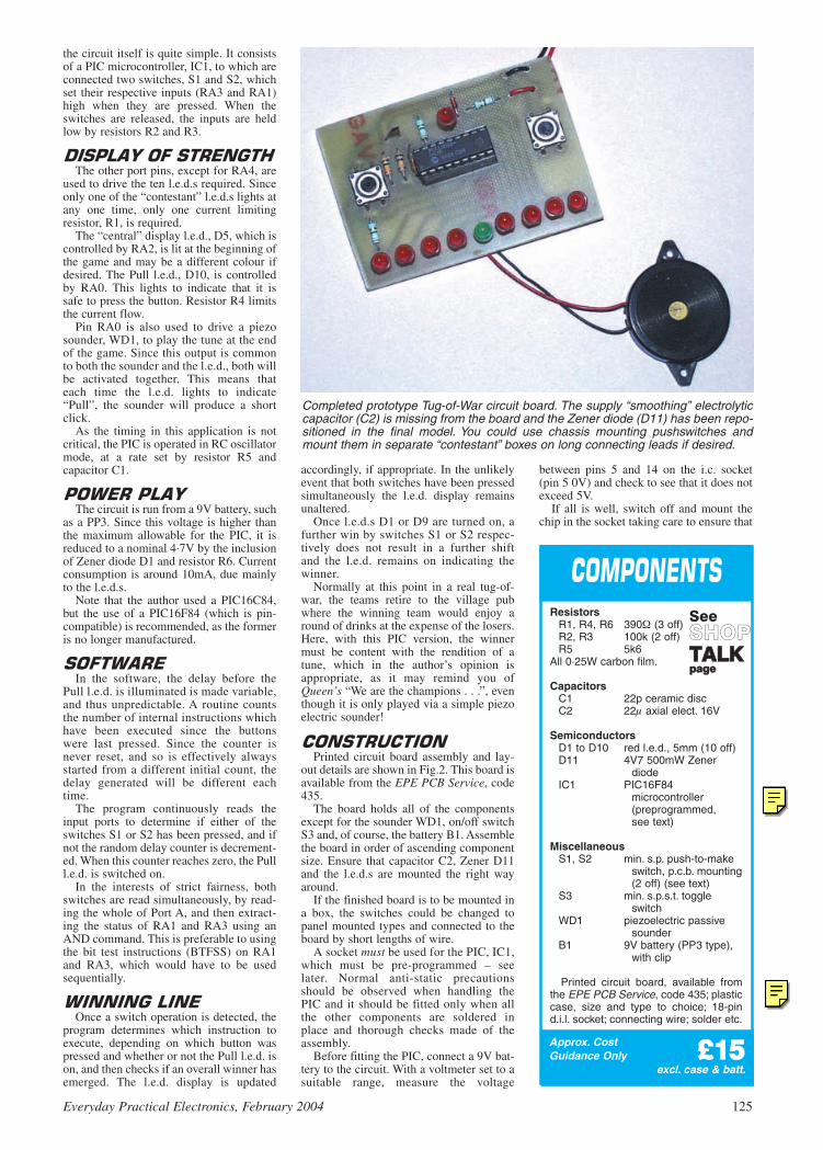
the circuit itself is quite simple. It consistsof a PIC microcontroller, IC1, to which areconnected two switches, S1 and S2, whichset their respective inputs (RA3 and RA1)high when they are pressed. When theswitches are released, the inputs are heldlow by resistors R2 and R3.
The other port pins, except for RA4, are
used to drive the ten l.e.d.s required. Sinceonly one of the “contestant” l.e.d.s lights atany one time, only one current limitingresistor, R1, is required.
The “central” display l.e.d., D5, which iscontrolled by RA2, is lit at the beginning ofthe game and may be a different colour ifdesired. The Pull l.e.d., D10, is controlledby RA0. This lights to indicate that it issafe to press the button. Resistor R4 limitsthe current flow.
Pin RA0 is also used to drive a piezosounder, WD1, to play the tune at the endof the game. Since this output is commonto both the sounder and the l.e.d., both willbe activated together. This means thateach time the l.e.d. lights to indicate“Pull”, the sounder will produce a shortclick.
As the timing in this application is notcritical, the PIC is operated in RC oscillatormode, at a rate set by resistor R5 andcapacitor C1.
The circuit is run from a 9V battery, such
as a PP3. Since this voltage is higher thanthe maximum allowable for the PIC, it isreduced to a nominal 4·7V by the inclusionof Zener diode D1 and resistor R6. Currentconsumption is around 10mA, due mainlyto the l.e.d.s.
Note that the author used a PIC16C84,but the use of a PIC16F84 (which is pin-compatible) is recommended, as the formeris no longer manufactured.
In the software, the delay before the
Pull l.e.d. is illuminated is made variable,and thus unpredictable. A routine countsthe number of internal instructions whichhave been executed since the buttonswere last pressed. Since the counter isnever reset, and so is effectively alwaysstarted from a different initial count, thedelay generated will be different eachtime.
The program continuously reads theinput ports to determine if either of theswitches S1 or S2 has been pressed, and ifnot the random delay counter is decrement-ed. When this counter reaches zero, the Pulll.e.d. is switched on.
In the interests of strict fairness, bothswitches are read simultaneously, by read-ing the whole of Port A, and then extract-ing the status of RA1 and RA3 using anAND command. This is preferable to usingthe bit test instructions (BTFSS) on RA1and RA3, which would have to be usedsequentially.
Once a switch operation is detected, the
program determines which instruction toexecute, depending on which button waspressed and whether or not the Pull l.e.d. ison, and then checks if an overall winner hasemerged. The l.e.d. display is updated
accordingly, if appropriate. In the unlikelyevent that both switches have been pressedsimultaneously the l.e.d. display remainsunaltered.
Once l.e.d.s D1 or D9 are turned on, afurther win by switches S1 or S2 respec-tively does not result in a further shiftand the l.e.d. remains on indicating thewinner.
Normally at this point in a real tug-of-war, the teams retire to the village pubwhere the winning team would enjoy around of drinks at the expense of the losers.Here, with this PIC version, the winnermust be content with the rendition of atune, which in the author’s opinion isappropriate, as it may remind you ofQueen’s “We are the champions . . .”, eventhough it is only played via a simple piezoelectric sounder!
Printed circuit board assembly and lay-
out details are shown in Fig.2. This board isavailable from the EPE PCB Service, code435.
The board holds all of the componentsexcept for the sounder WD1, on/off switchS3 and, of course, the battery B1. Assemblethe board in order of ascending componentsize. Ensure that capacitor C2, Zener D11and the l.e.d.s are mounted the right wayaround.
If the finished board is to be mounted ina box, the switches could be changed topanel mounted types and connected to theboard by short lengths of wire.
A socket must be used for the PIC, IC1,which must be pre-programmed – seelater. Normal anti-static precautionsshould be observed when handling thePIC and it should be fitted only when allthe other components are soldered inplace and thorough checks made of theassembly.
Before fitting the PIC, connect a 9V bat-tery to the circuit. With a voltmeter set to asuitable range, measure the voltage
between pins 5 and 14 on the i.c. socket(pin 5 0V) and check to see that it does notexceed 5V.
If all is well, switch off and mount thechip in the socket taking care to ensure that
Everyday Practical Electronics, February 2004 125
Completed prototype Tug-of-War circuit board. The supply “smoothing” electrolyticcapacitor (C2) is missing from the board and the Zener diode (D11) has been repo-sitioned in the final model. You could use chassis mounting pushswitches andmount them in separate “contestant” boxes on long connecting leads if desired.
ResistorsR1, R4, R6 390 (3 off)R2, R3 100k (2 off)R5 5k6
All 0·25W carbon film.
CapacitorsC1 22p ceramic discC2 22 axial elect. 16V
SemiconductorsD1 to D10 red l.e.d., 5mm (10 off)D11 4V7 500mW Zener
diodeIC1 PIC16F84
microcontroller (preprogrammed, see text)
MiscellaneousS1, S2 min. s.p. push-to-make
switch, p.c.b. mounting(2 off) (see text)
S3 min. s.p.s.t. toggle switch
WD1 piezoelectric passivesounder
B1 9V battery (PP3 type),with clip
Printed circuit board, available fromthe EPE PCB Service, code 435; plasticcase, size and type to choice; 18-pind.i.l. socket; connecting wire; solder etc.
SeeSSHHOOPPTTAALLKKppaaggee
Approx. CostGuidance Only ££1155
excl. case & batt.
EPE Online
Note that the circuit boards used in EPE Online projects are available from the EPE Online Store at www.epemag.com (also note that the codes for the boards in the online store are prefixed with 7000, so a board with a code of say 256 will appear as 7000256 in the online store).
EPE Online
Note that you can purchase pre-programmed PIC microcontrollers for our PIC projects (see the “ShopTalk” page in the associated issue of the Magazine for more details). Alternatively, if you wish to program the PIC yourself, you can find the code files by bouncing over to the EPE Online Library (visit www.epemag.com, click in the “Library” link in the top navigation, then on the “Project Code Files” link).

it is fitted the correct way around. Furthertesting or setting up is not required and pro-vided no wiring mistakes have been made,the circuit should function correctly.
Having played the game a few times, the
author realised that if the Pull l.e.d. wasdisabled, an even more interesting versionof the game would result. Since therewould now be no indication of whether ornot it was “safe” for a player to press hisbutton, the whole nature of the game wouldchange from one based simply on the speedof reaction to one of brinkmanship.
It would obviously be in a player’s inter-est to hang back for as long as possible toensure that it was safe to press his button,but on the other hand delaying too longcould result in his opponent pressing hisbutton first and winning the round.
This change can be implemented at thetime that the unit is first switched on priorto any gaming session.
If switch S2 is held pressed prior topower being applied, the circuit simplyprograms pin RA0 as an input and in this(high impedance) mode it is unable tolight the Pull l.e.d. so that it remains offthroughout the game. At the end of thegame, when the unit plays its tune, portRA0 is redefined as an output so that thetune plays normally.
The PIC programming software for this
design is available from the EPE PCBService on 3·5-inch disk, for which a nom-inal handling charge applies. It is alsoavailable for free download via our websiteat www.epemag. wimborne.co.uk. It is infolder PICs/Tug of War. Read this month’sShoptalk page for details about purchasingpreprogrammed PICs and other compo-nents for this project.
126 Everyday Practical Electronics, February 2004
Fig.2. Printed circuit board component layout, full-size copper foil master and wiringdetails for the PIC Tug-of-War.
Name ..................................................................................................
Address ...............................................................................................
Post code ......................... Tel. ...........................................................
SUBSCRIPTION ORDER FORM
I enclose payment of £ ............. (cheque/PO in £ sterling only),
payable to Everyday Practical Electronics
My card number is: .......................................................................Please print clearly, and check that you have the number correct
Signature .........................................................................................
Card Security Code .................. (The last 3 digits on or just under the signature strip)
Card Ex. Date ......................................... Switch Issue No. .............
Subscriptions can only start with the next available issue.For back numbers see the Back Issues page.
RC MIXER FOR DELTA OR V-TAIL PLANES BAT-BAND CONVERTER
EMERGENCY STANDBY LIGHTTEACH-IN 2004 Part 5
Annual subscription rates:6 Months: UK £15.50, Overseas £18.50 (standard air service),
£27.50 (express airmail)1 Year: UK £29.50, Overseas £35.50 (standard air service)
£53 (express airmail)2 Years: UK £54.00, Overseas £66.00 (standard air service)
£101 (express airmail)To: Everyday Practical Electronics,
Wimborne Publishing Ltd., 408 Wimborne Road East, Ferndown, Dorset BH22 9NDTel: 01202 873872 Fax: 01202 874562
E-mail: [email protected] from our online shop at:
www.epemag.wimborne.co.uk/shopdoor.htm
WE ARE FLYING HIGH NEXT MONTHORDER YOUR COPY NOW!
TAKE ADVANTAGE NOW!
If you do not wish to cut your issue, send a letter or copy of this form.
PLUS

Sonic Ice WarningSome readers may have difficulties in tracking down a local source for
two of the semiconductor devices used in the Sonic Ice Warning project.The rest of the components seem to be “off-the-shelf” items. Certainly,the LM35DZ temperature i.c. is stocked by most of our componentsadvertisers.
The TS932IN dual, rail-to-rail, micropower op.amp is currently stockedby Farnell ( 0870 1200 200 or www.farnellinone.co.uk), code 332-9392.They also supplied the Analog Devices AD680 2·5V reference volt-age chip, code 411-218. Expect to pay a handling charge.
The author suggests that other low-power dual op.amps that are pin-for-pin compatible and suitable for a single supply could be used here.The same applies to the reference voltage i.c.
The printed circuit board is available from the EPE PCB Service, code433 (see page 147).
Finally, note that it is most important that the metal body of the DINsocket must not make contact with the 0V line. The light-duty auto-wireand “bullet” connectors should be available from motor spares shops.
PIC LCF MeterJust a few minor points came to light when checking out parts for the
PIC LCF Meter project. As a 2-way 3-pole combination rotary switchappears to be non-existent, you will need to order a 4-way 3-pole typewith an adjustable rotation end-stop and set it for 2-way operation. Quitea number of our advertisers now stock 2-line 16-characters per linealphanumeric l.c.d. modules and sourcing should not be a problem.
The 10H axial inductor used in the prototype is the type that resem-bles a resistor and should be widely available. It can usually be found incatalogues listed as an r.f. choke.
Ideally, the LC oscillator capacitors, C5a/b and C6a/b, should be 1%types but these are not generally available and you may have to accept5% tolerance types. We have only seen “close tolerance” polystyrenefilm and silvered mica types boasting a 1% tolerance – at a price, ofcourse.
A pre-programmed PIC16F628 microcontroller can be purchasedfrom Magenta Electronics ( 01283 565435 or www.magenta2000.co.uk) for the inclusive price of £4.90 each (overseas add £1 p&p). Thesoftware is available on a 3·5in. PC-compatible disk (Disk 7) from the
EPE Editorial Office for the sum of £3 each (UK), to cover admin costs(for overseas charges see page 147). It is also available Free via theDownloads click-link option on the EPE home page when you enter ourmain web site at www.epemag.wimborne.co.uk, then enter the PICMicrocontroller source codes folder and select PIC LCF Meter.
The printed circuit board is available from the EPE PCB Service, code434 (see page 147).
Tug-of-WarNo likely problems to report concerning components for the Tug-of-
War game project.For those readers unable to program their own PICs, a ready-pro-
grammed PIC microcontroller can be purchased directly from the authorfor the sum of £5.50 inclusive (add £1 for overseas). Although the authorused a PIC16C84 in the model, which is no longer manufactured, andthe PIC16F84 is its pin-compatible replacement, we understand theauthor will be supplying the PIC16C54.
Orders should be sent to Bart Trepak, 20 The Avenue, London, W138PH. Payments should be made out to B. Trepak, and only in £ sterlingand drawn on a British bank, UK postal orders are also accepted.
The software is available on a 3·5in. PC-compatible disk (Disk 7) fromthe EPE Editorial Office for the sum of £3 each (UK), to cover admincosts (for overseas charges see page 147). It is also available Free viathe Downloads click-link option on the home page when you enter ourmain web site at www.epemag.wimborne.co.uk, then enter the PICMicrocontroller source codes folder and select PIC Tug-of-War.
The printed circuit board is available from the EPE PCB Service, code435 (see page 147).
Jazzy NecklaceThe only source we have located for the 6mm clear cast acrylic rods
used in the Jazzy Necklace project has been RS Components, code824-531 (five per lot). They can be ordered through any bona-fide RSstockist, including some of our advertisers. You can order direct (creditcard only) from RS on 01536 444079 or rswww.com). A post andpacking charge will be made.
We most strongly recommend that readers only use a non-mercury tiltswitch in this project. If any readers have problems finding one, it is cur-rently listed in the new Squires ( 01243 842424 orwww.squirestools.com) catalogue, code TSW760.
The ultrabright l.e.d.s and other semiconductors are fairly commondevices and should be easy to find locally. The “necklace” printed circuitboard, together with the small battery p.c.b., are obtainable from theEPE PCB Service, code 432 (see page 147). For the glass beads wecan only suggest you try needlecraft shops.
Everyday Practical Electronics, February 2004 127
!" #$ %% #
"&'( ) )*%"!+ ,%!#
-'&./( &0+.&++% %% +###
. ' 1-2#
3.&456 )0)))#
'7'8 ) )+9
!"#$%"&" '(()
9:;<:<=>?=><#-09:;<:<=>@AB<#2)9+++#)##,+++#)#
&*
&$ '$( C #################D?#A:
E>: F
+,- EF9 . (
86/ 764/'& D;G#>A D?>#A:
'-8'$ E&F D<<#:: D@<#::
'-.2'/ E&F D<>#:: DA<#::
(+, /' C(4'6
(+,,) 9
'EBF +E;<F
H$'HC,/ D########
)2)$)
$)IH&H+H0H/
&)9
9 ##############+69 ####
&#########################################
&#########################################
##################################################
$H5############## #####################
###########################################
+ ! "/0!1//0"0""" " 2
/,
! 3))) 4+"5
&6+7
+ #
EPE Online
Note that the circuit boards used in EPE Online projects are available from the EPE Online Store at www.epemag.com (also note that the codes for the boards in the online store are prefixed with 7000, so a board with a code of say 256 will appear as 7000256 in the online store).
EPE Online
Note that you can purchase pre-programmed PIC microcontrollers for our PIC projects as described on this “Shop Talk” page. Alternatively, if you wish to program the PIC yourself, you can find the code files by bouncing over to the EPE Online Library (visit www.epemag.com, click in the “Library” link in the top navigation, then on the “Project Code Files” link).

MANY of the recent improvements incapacitor technology are being taken
for granted. These days capacitors are farsmaller, and offer far greater levels of per-formance and reliability than those pro-duced a few years back.
As many of the improvements havetaken place without all the fanfare of thesemiconductor developments they areoften overlooked. Nevertheless, there aremany revolutionary ideas that are beingworked upon even now.
Increasing the capacitance density isone major focus for activity. The possi-bility of having very large capacitancesin a small volume is of particular inter-est. With much greater values of capaci-tance density very large figures forcapacitance are available in manageablepackages.
The developments are opening up newapplications for these components. Manyof these are in the higher current areas,including some electrical applications.
New ResearchResearchers at Cambridge University
are developing new electrode materialsfor very high performance super-capaci-tors. The focus of this research has beendirected towards merging the propertiesof nano-tubes and conducting polymerfilms. Carbon nano-tubes provide a veryhigh surface area and good electricalconductivity that enable them to achievevery fast response times, making themparticularly good for many electronicapplications.
The other element to the research hasbeen into developing the conducting poly-mers. These polymers can be reversiblyoxidised and reduced, and their conductiv-ity approaches that of copper. This makesthem ideal for use in capacitors where highlevels of charge storage are required.However, they offer comparatively slowresponse times.
It was the aim of this research to be ableto provide the best from both technologiesto enable high value super-capacitors, withfast response times, to be produced. In thisway super-capacitors will be able to beutilised in a number of new applicationsthat were not previously possible. Usingthe new technology capacitance levels ofup to 2F/cm3 have been attained – levelswhich only a few years ago would not havebeen thought possible.
The research has focussed upon mergingthe two technologies by utilising carbonfilms and conducting polymers in compos-ite films of the two materials.
128 Everyday Practical Electronics, February 2004
store power electric vehicles could begiven a new lease of life.
In addition to this the capacitors couldfind many uses within the much lower cur-rent electronics area. Here they could pro-vide very high levels of capacitance forsmall circuits. They may even provide ahold-up-battery function, charging upwhen the power supply is available, andthen supplying the circuit when the poweris removed.
Now that the technology has beenproved, the university is looking forinvestors to help in commercialising thetechnology.
Other DevelopmentsThere are many other capacitor devel-
opments that are being undertaken. AVX,a major manufacturer of capacitors hasmoved forward tantalum capacitor tech-nology to provide capacitors with anextended temperature operating range,allowing operation at temperatures up to170°C. Although these temperatures areunlikely to be experienced in normaldomestic electronics, automotive andespecially many “on-engine” applica-tions as well as many applications in theindustrial sector experience extreme tem-peratures. Here the ability to use compo-nents that are operating well within theirlimits ensures that reliability is kept tothe highest levels.
To achieve this the maximum operatingtemperature of the materials was investigatedto prove their long-term stability at elevatedtemperatures.
Further developments of other areas havealso been made. The tantalum anode itselfis particularly important. Applying similarrules to those used for the general materialdevelopment, the tantalum powder usedfor the anode has been optimised. Evensmall changes in characteristics such as thegranularity, porosity, and purity make sig-nificant differences.
Again the encapsulation of the finishedcapacitor is important. This needs to beable to reduce the stresses arising fromthermal and mechanical shocks as well aspreventing moisture ingress. To achievethis new moulding compounds have beendeveloped.
This work has resulted in componentsthat are able to run continuously in an envi-ronment at 150°C with reliability levelstwice that of existing components at lowertemperatures.
Further information about electronicstechnology can be seen at www.radio-elecronics.com.
Growing FilmsIn order to be able to grow the compos-
ite films, very close control of the condi-tions is required. Only in this way is it pos-sible to effectively combine the redoxcharge storage mechanism of the conduct-ing polymers with high surface area of thecarbon nano-tubes. It has been found thatthe alignment, concentration, production,dimensions and the chemical treatment ofthe nano-tubes all varied the overall per-formance of the resulting material. Thishas resulted in nano-tubes coated in a verythin layer of a conductive polymer knownas polypyrrole.
It has also been found that introducing anegatively charged functional groupimproves the production process. Thegroup is attached to the nano-tube surfaceduring production using an acid treatmentprocess.
This enables excellent interactionbetween the nano-tube surface and theconducting polymer film to be achieved. Italso indicates that theories developed forthe interaction of small molecules withconducting polymers is equally applicablein many respects for the interaction ofmuch larger carbon nano-tubes with thesepolymers.
The technology works using an electro-chemical reduction and oxidation process.Charge is stored on the polypyrrole mole-cules that are strictly known as pseudo-capacitors. It is then possible to optimisethe capacitor using different levels of filmthickness, different polymers and differentproduction techniques. In this way theoptimum performance can be provided fora given application.
ResultsThe research team managed to success-
fully produce composites of carbon nano-tubes with conducting polymers and togain some remarkable results. They wereable to achieve capacitance levels in excessof 200F/g and 2·6F/cm2. These levels arequite remarkable and are more than twicethe figures seen when the technologies areused on their own.
These levels of capacitance open the wayfor the use of these capacitors in electricvehicles. Currently one of the major prob-lems limiting the use of electric vehicles isthat the batteries used are typically leadacid types that are exceedingly heavy. Thisweight significantly limits the use of thesevehicles with most of the weight oftenbeing contributed by the batteries them-selves. By using these new capacitors to
New TechnologyUpdate

IN the previous Interface article thesubject of directly controlling the PC
serial ports was considered with specialreference to the new version ofinpout32.dll. By writing the appropriatevalues to the registers of a serial port it ispossible to set the required baud rate andword format.
Writing bytes of data can be equallystraightforward, and in its most basic it isjust a matter of writing the data to thedata register of the UART. Receiving isalso fairly straightforward. The UARTsused in PCs, in common with most UARTchips, do not provide individual controlof the sending and receiving baud rate orword format. The methods of setting thebaud rate and word format described inthe previous Interface article thereforeapply equally to receiving data.
Multiple ReadingsWhen sending data it is necessary to
ensure that bytes are not written to thetransmission register at an excessive rate.There can be a similar problem whenreceiving data, in that it is possible to takereadings at a higher rate than data isreceived. This is not necessarily of impor-tance, and it depends on how thereceived data will be used. In a very sim-ple application it would probably be of noimportance.
Suppose that the serial port is receivingreadings from a temperature interfaceand displaying the readings on the screenvia a digital readout. Suppose also thatthe interface is monitoring the air temper-ature, which would change only quiteslowly. The interface could be designed toprovide (say) a new reading once per sec-ond. This would be more than adequateto accurately track slow temperaturechanges.
The software could be designed toupdate the display at a somewhat fasterrate of perhaps ten times per second. Thiswould ensure that any change in the datafrom the interface would quickly be readand the new reading would be displayedalmost at once.
Sampling RatesWith this system each byte of data
would be read from the UART about tentimes. While this is admittedly a bit ineffi-cient, it is unlikely to be of any practicalimportance. Although there are multiplereadings of each byte of data, the valuesbeing displayed are the latest readingsand are accurate. The situation would bedifferent if readings were being taken atregular intervals and plotted on a graph.Readings would have to be taken at onesecond intervals in order to match therate of the interface.
This could be done using separatetimers in the interface and the softwarerunning on the PC, but this type of thingcannot be guaranteed to maintain propersynchronisation. With a low sampling
rate it might actually work quite well, butat higher rates the two parts of the systemwould inevitably suffer from a lack ofaccurate synchronisation. Some bytes ofdata would be missed and others wouldbe read twice.
On the face of it, with a serial interfaceit is possible to transfer bytes of data,which is of little use where it is necessaryto transfer 16 or 32 bits of data. Also, a ser-ial interface seems to be unsuitable whereit is necessary to read several sensors witheach one producing a byte of data.
In practice serial ports are often usedwith sophisticated pieces of hardwarethat require something more than an 8-bitinterface. The trick is to send groups ofbytes. With five sensors for example,groups of five bytes would be sent.
This is another example where it isessential for the PC receiving thedata to be properly synchronisedto the sending device. Thereceiving computer knows thatthe first, second, third, etc., bytesof data in each group correspondto the first, second, third, etc.sensors. This method clearlyrelies on the computer detectingeach new byte of data so that itsgroup, and position in the group,can be determined using a sim-ple counting system. With ran-dom reading there is no way ofknowing which sensor has pro-duced each byte of data.
PollingIn both cases the way around
this problem is to have the soft-ware detect and immediately read eachfresh byte of data. With this system therate at which readings are taken is con-trolled solely by the timer in the interface,and synchronisation will not be lost pro-vided the program in the PC can keep upwith the flow of data.
This should not be a problem becausean ordinary serial interface is not par-ticularly fast even when used at highbaud rates. Some other form of inter-face is required if you need to transferdata at more than about 10 kilobytesper second.
Of course, things are effectively sloweddown still further when sending data inthe form of groups of bytes. With a singlesensor producing single bytes of data it ispossible to take readings at about 10,000per second when using the highest nor-mal baud rate of 115 kilobaud.
Using five sensors would still give anoverall rate of 10,000 per second, but just2,000 per sensor. Using a single sensor butwith (say) four bytes per reading, themaximum number of readings per secondwould be reduced to 2,500. Clearly theserates are still high enough to accommo-date many applications, but serial inter-facing is not suitable for the moredemanding tasks.
Basic ReadingIn order to read data from a serial port
it is just a matter of reading from the dataregister, which is at the base address ofthe port. This will usually be &H3F8 forport one (COM1) and &H2F8 for port two(COM2), but these port addresses can bechecked using the Windows DeviceManager program if you are in any doubt.
Reading from the ports using VisualBASIC is now very straightforwardregardless of which version of Windowsis in use. Using the new version ofinpout32.dll it is possible to add the Inpand Out commands, even with a PC run-ning under Windows NT, 2000, or XP. Inthe simple examples provided here it isassumed that Visual BASIC is equippedwith the new inpout32.dll.
In order to display readings from a ser-ial port it is merely necessary to add alabel and a timer to the form and add aline of code. Make the label quite largeand give it a suitably large text size usingthe Font panel of the Properties Inspector.
Set the timer’s Interval value at (say)50 milliseconds using the PropertiesInspector, which will give twenty read-ings per second. Use this routine for thetimer component:
Private Sub Timer1_Timer()Label1.Caption = Inp(&H3F8)End Sub
The Inp function reads the data registerof the serial port and writes that value tothe caption property of the label so that itis displayed on the screen. The addressused here is correct for serial port one,and should be changed to &H2F8 in orderto read serial port two.
The easiest way to test the reception ofserial data is to get the port to send datato itself. This requires a link between thetransmit and receive pins on the serialport. A nine or 25-way female D connec-tor is needed to make connections to a PCserial port, and with both types therequired link is between pins 2 and 3. The
130 Everyday Practical Electronics, February 2004
INTERFFAACCEERobert Penfold
FURTHER PC SERIAL PORT USE OF INPOUT32.DLL
Fig.1. Incorrect value at the halfway slider settingwhen the slider’s maximum value is set to 255.
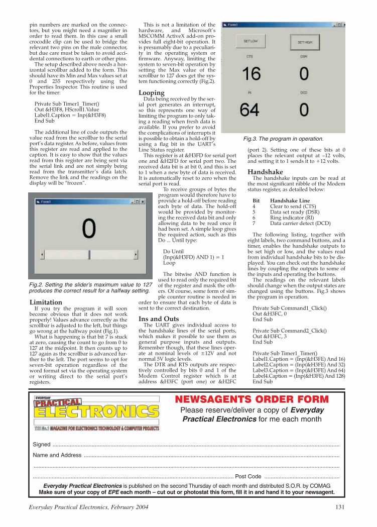
pin numbers are marked on the connec-tors, but you might need a magnifier inorder to read them. In this case a smallcrocodile clip can be used to bridge therelevant two pins on the male connector,but due care must be taken to avoid acci-dental connections to earth or other pins.
The setup described above needs a hor-izontal scrollbar added to the form. Thisshould have its Min and Max values set at0 and 255 respectively using theProperties Inspector. This routine is usedfor the timer:
Private Sub Timer1_Timer()Out &H3F8, HScroll1.ValueLabel1.Caption = Inp(&H3F8)End Sub
The additional line of code outputs thevalue read from the scrollbar to the serialport’s data register. As before, values fromthis register are read and applied to thecaption. It is easy to show that the valuesread from this register are being sent viathe serial link and are not simply beingread from the transmitter’s data latch.Remove the link and the readings on thedisplay will be “frozen”.
LimitationIf you try the program it will soon
become obvious that it does not workproperly! Values advance correctly as thescrollbar is adjusted to the left, but thingsgo wrong at the halfway point (Fig.1).
What is happening is that bit 7 is stuckat zero, causing the count to go from 0 to127 at the midpoint. It then counts up to127 again as the scrollbar is advanced fur-ther to the left. The port seems to opt forseven-bit operation regardless of theword format set via the operating systemor writing direct to the serial port’sregisters.
This is not a limitation of thehardware, and Microsoft’sMSCOMM ActiveX add-on pro-vides full eight-bit operation. Itis presumably due to a peculiari-ty in the operating system orfirmware. Anyway, limiting thesystem to seven-bit operation bysetting the Max value of thescrollbar to 127 does get the sys-tem functioning correctly (Fig.2).
LoopingData being received by the ser-
ial port generates an interrupt,so this represents one way oflimiting the program to only tak-ing a reading when fresh data isavailable. If you prefer to avoidthe complications of interrupts itis possible to obtain a hold-off byusing a flag bit in the UART’sLine Status register.
This register is at &H3FD for serial portone and &H2FD for serial port two. Thereceived data bit is at bit 0, and this is setto 1 when a new byte of data is received.It is automatically reset to zero when theserial port is read.
To receive groups of bytes theprogram would therefore have toprovide a hold-off before readingeach byte of data. The hold-offwould be provided by monitor-ing the received data bit and onlyallowing data to be read once ithad been set. A simple loop givesthe required action, such as thisDo ... Until type:
Do Until(Inp(&H3FD) AND 1) = 1Loop
The bitwise AND function isused to read only the required bitof the register and mask the oth-ers. Of course, some form of sim-ple counter routine is needed in
order to ensure that each byte of data issent to the correct destination.
Ins and OutsThe UART gives individual access to
the handshake lines of the serial ports,which makes it possible to use them asgeneral purpose inputs and outputs.Remember though, that these lines oper-ate at nominal levels of ±12V and notnormal 5V logic levels.
The DTR and RTS outputs are respec-tively controlled by bits 0 and 1 of theModem Control register which is ataddress &H3FC (port one) or &H2FC
(port 2). Setting one of these bits at 0places the relevant output at –12 volts,and setting it to 1 sends it to +12 volts.
HandshakeThe handshake inputs can be read at
the most significant nibble of the Modemstatus register, as detailed below:
Bit Handshake Line4 Clear to send (CTS)5 Data set ready (DSR)6 Ring indicator (RI)7 Data carrier detect (DCD)
The following listing, together witheight labels, two command buttons, and atimer, enables the handshake outputs tobe set high or low, and the values readfrom individual handshake bits to be dis-played. You can check out the handshakelines by coupling the outputs to some ofthe inputs and operating the buttons.
The readings on the relevant labelsshould change when the output states arechanged using the buttons. Fig.3 showsthe program in operation.
Private Sub Command1_Click()Out &H3FC, 0End Sub
Private Sub Command2_Click()Out &H3FC, 3End Sub
Private Sub Timer1_Timer()Label1.Caption = (Inp(&H3FE) And 16)Label2.Caption = (Inp(&H3FE) And 32)Label3.Caption = (Inp(&H3FE) And 64)Label4.Caption = (Inp(&H3FE) And 128)End Sub
Everyday Practical Electronics, February 2004 131
Fig.2. Setting the slider’s maximum value to 127produces the correct result for a halfway setting.
Fig.3. The program in operation.
Everyday Practical Electronics is published on the second Thursday of each month and distributed S.O.R. by COMAGMake sure of your copy of EPE each month – cut out or photostat this form, fill it in and hand it to your newsagent.
NEWSAGENTS ORDER FORMPlease reserve/deliver a copy of EverydayPractical Electronics for me each month
Signed .......................................................................................................................................................................................
Name and Address ...................................................................................................................................................................
...................................................................................................................................................................................................
................................................................................................................................ Post Code ................................................

Prices for each of the CD-ROMs above are:(Order form on third page)
Hobbyist/Student ...................................................£45 inc VATInstitutional (Schools/HE/FE/Industry)..............£99 plus VATInstitutional 10 user (Network Licence) ..........£199 plus VATSite Licence........................................................£499 plus VAT
Complimentary output stage
Virtual laboratory – Traffic Lights
Digital Electronics builds on the knowledge of logic gates covered in ElectronicCircuits & Components (opposite), and takes users through the subject of digitalelectronics up to the operation and architecture of microprocessors. The virtuallaboratories allow users to operate many circuits on screen.Covers binary and hexadecimal numbering systems, ASCII, basic logic gates,monostable action and circuits, and bistables – including JK and D-type flip-flops.Multiple gate circuits, equivalent logic functions and specialised logic functions.Introduces sequential logic including clocks and clock circuitry, counters, binarycoded decimal and shift registers. A/D and D/A converters, traffic light controllers,memories and microprocessors – architecture, bus systems and their arithmetic logicunits. Sections on Boolean Logic and Venndiagrams, displays and chip types havebeen expanded inVersion 2 and new sections include shift registers, digital faultfinding, programmable logic controllers, and microcontrollers and microprocessors.The Institutional versions now also include several types of assessment forsupervisors, including worksheets, multiple choice tests, fault finding exercises andexamination questions.
(UK and EU customers add VAT at 17.5% to “plus VAT’’ prices)
Analogue Electronics is a complete learning resource for this most difficultbranch of electronics. The CD-ROM includes a host of virtual laboratories,animations, diagrams, photographs and text as well as a SPICE electronic circuitsimulator with over 50 pre-designed circuits.Sections on the CD-ROM include: Fundamentals – Analogue Signals (5sections),Transistors (4 sections), Waveshaping Circuits (6 sections). Op.Amps– 17 sections covering everything from Symbols and Signal Connections toDifferentiators. Amplifiers – Single Stage Amplifiers (8 sections), Multi-stageAmplifiers (3 sections). Filters – Passive Filters (10 sections), Phase ShiftingNetworks (4 sections), Active Filters (6 sections). Oscillators – 6 sections fromPositive Feedback to Crystal Oscillators. Systems – 12 sections from AudioPre-Amplifiers to 8-Bit ADC plus a gallery showing representative p.c.b. photos.
Filters is a complete course in designing active and passive filters that makesuse of highly interactive virtual laboratories and simulations to explain how filtersare designed. It is split into five chapters: Revision which provides underpinningknowledge required for those who need to design filters. Filter Basics which is acourse in terminology and filter characterization, important classes of filter, filterorder, filter impedance and impedance matching, and effects of different filtertypes. Advanced Theory which covers the use of filter tables, mathematicsbehind filter design, and an explanation of the design of active filters. PassiveFilter Design which includes an expert system and filter synthesis tool for thedesign of low-pass, high-pass, band-pass, and band-stop Bessel, Butterworthand Chebyshev ladder filters. Active Filter Design which includes an expertsystem and filter synthesis tool for the design of low-pass, high-pass, band-pass,and band-stop Bessel, Butterworth and Chebyshev op.amp filters.Filter synthesis
FILTERS
ANALOGUE ELECTRONICS
Logic Probe testing
ELECTRONICS PROJECTS
DIGITAL ELECTRONICS V2.0
PRICES
Electronic Projects is split into two main sections: Building Electronic Projectscontains comprehensive information about the components, tools and techniquesused in developing projects from initial concept through to final circuit boardproduction. Extensive use is made of video presentations showing soldering andconstruction techniques. The second section contains a set of ten projects forstudents to build, ranging from simple sensor circuits through to power amplifiers. Ashareware version of Matrix’s CADPACK schematic capture, circuit simulation andp.c.b. design software is included.The projects on the CD-ROM are: Logic Probe; Light, Heat and Moisture Sensor;NE555 Timer; Egg Timer; Dice Machine; Bike Alarm; Stereo Mixer; PowerAmplifier; Sound Activated Switch; Reaction Tester. Full parts lists, schematicsand p.c.b. layouts are included on the CD-ROM.
ELECTRONICSCAD PACK
Electronics CADPACK allows users todesign complex circuit schematics, to viewcircuit animations using a unique SPICE-based simulation tool, and to designprinted circuit boards. CADPACK is madeup of three separate software modules.(These are restricted versions of the fullLabcenter software.) ISIS Lite whichprovides full schematic drawing featuresincluding full control of drawingappearance, automatic wire routing, andover 6,000 parts. PROSPICE Lite(integrated into ISIS Lite) which usesunique animation to show the operation ofany circuit with mouse-operated switches,pots. etc. The animation is compiled usinga full mixed mode SPICE simulator. ARESLite PCB layout software allowsprofessional quality PCBs to be designedand includes advanced features such as16-layer boards, SMT components, andan autorouter operating on user generatedNet Lists.
PCB Layout
VERSION 2
ELECTRONIC CIRCUITS & COMPONENTS V2.0Provides an introduction to the principles and application of the most common types ofelectronic components and shows how they are used to form complete circuits. Thevirtual laboratories, worked examples and pre-designed circuits allow students tolearn, experiment and check their understanding. Version 2 has been considerablyexpanded in almost every area following a review of major syllabuses (GCSE, GNVQ,A level and HNC). It also contains both European and American circuit symbols.Sections include: Fundamentals: units & multiples, electricity, electric circuits,alternating circuits. Passive Components: resistors, capacitors, inductors,transformers. Semiconductors: diodes, transistors, op.amps, logic gates. PassiveCircuits. Active Circuits. The Parts Gallery will help students to recognise commonelectronic components and their corresponding symbols in circuit diagrams.Included in the Institutional Versions are multiple choice questions, exam stylequestions, fault finding virtual laboratories and investigations/worksheets.Circuit simulation screen
VERSION 2
ROBOTICS &MECHATRONICS
Robotics and Mechatronics is designed toenable hobbyists/students with littleprevious experience of electronics todesign and build electromechanicalsystems. The CD-ROM deals with allaspects of robotics from the controlsystems used, the transducers available,motors/actuators and the circuits to drivethem. Case study material (including theNASA Mars Rover, the Milford Spider andthe Furby) is used to show how practicalrobotic systems are designed. The resultis a highly stimulating resource that willmake learning, and building robotics andmechatronic systems easier. TheInstitutional versions have additionalworksheets and multiple choice questions.Interactive Virtual LaboratoriesLittle previous knowledge requiredMathematics is kept to a minimum and
all calculations are explainedClear circuit simulations
Case study of the MilfordInstruments Spider
132 Everyday Practical Electronics, February 2004

Prices for each of the CD-ROMs above are:(Order form on next page)
Hobbyist/Student £45 inc VATInstitutional (Schools/HE/FE/Industry) £99 plus VAT
Flowcode Institutional £70 plus VATInstitutional 10 user (Network Licence) £249 plus VATSite Licence £599 plus VAT
(UK and EU customers add VAT at 17.5% to “plus VAT’’ prices)
PRICES
VERSION 2 PICmicro MCUDEVELOPMENT BOARD
Suitable for use with the three software packageslisted below.
This flexible development board allows students to learnboth how to program PICmicro microcontrollers as well asprogram a range of 8, 18, 28 and 40-pin devices. Forexperienced programmers all programming software isincluded in the PPP utility that comes with the developmentboard. For those who want to learn, choose one or all of thepackages below to use with the Development Board. Makes it easier to develop PICmicro projects Supports low cost Flash-programmable PICmicro
devices Fully featured integrated displays – 13 individual l.e.d.s,
quad 7-segment display and alphanumeric l.c.d. display Supports PICmicro microcontrollers with A/D converters Fully protected expansion bus for project work All inputs and outputs available on screw terminal
connectors for easy connection
ASSEMBLY FOR PICmicro V2(Formerly PICtutor)
Assembly for PICmicro microcontrollers V2.0(previously known as PICtutor) by JohnBecker contains a complete course inprogramming the PIC16F84 PICmicromicrocontroller from Arizona Microchip. Itstarts with fundamental concepts andextends up to complex programs includingwatchdog timers, interrupts and sleep modes.The CD makes use of the latest simulationtechniques which provide a superb tool forlearning: the Virtual PICmicro micro-controller. This is a simulation tool thatallows users to write and execute MPASMassembler code for the PIC16F84microcontroller on-screen. Using this youcan actually see what happens inside thePICmicro MCU as each instruction isexecuted which enhances understanding. Comprehensive instruction through 39tutorial sections Includes Vlab, a VirtualPICmicro microcontroller: a fully functioningsimulator Tests, exercises and projectscovering a wide range of PICmicro MCUapplications Includes MPLAB assembler Visual representation of a PICmicroshowing architecture and functions
Expert system for code entry helps first timeusers Shows data flow and fetch executecycle and has challenges (washingmachine, lift, crossroads etc.) ImportsMPASM files.
‘C’ FOR PICmicroVERSION 2
The C for PICmicro microcontrollers CD-ROM is designed for students andprofessionals who need to learn how toprogram embedded microcontrollers in C.The CD contains a course as well as all thesoftware tools needed to create Hex codefor a wide range of PICmicro devices –including a full C compiler for a wide rangeof PICmicro devices.Although the course focuses on the use ofthe PICmicro microcontrollers, this CD-ROM will provide a good grounding in Cprogramming for any microcontroller. Complete course in C as well as Cprogramming for PICmicro microcontrollers Highly interactive course Virtual CPICmicro improves understanding
Includes a C compiler for a wide range ofPICmicro devices Includes full IntegratedDevelopment Environment IncludesMPLAB software Compatible with mostPICmicro programmers Includes acompiler for all the PICmicro devices.
FLOWCODE FOR PICmicroFlowcode is a very high level languageprogramming system for PICmicromicrocontrollers based on flowcharts.Flowcode allows you to design and simulatecomplex robotics and control systems in amatter of minutes.Flowcode is a powerful language that usesmacros to facilitate the control of complexdevices like 7-segment displays, motorcontrollers and l.c.d. displays. The use ofmacros allows you to control theseelectronic devices without getting boggeddown in understanding the programminginvolved.Flowcode produces MPASM code which iscompatible with virtually all PICmicroprogrammers. When used in conjunctionwith the Version 2 development board thisprovides a seamless solution that allowsyou to program chips in minutes.Requires no programming experience Allows complex PICmicro applications to bedesigned quickly Uses internationalstandard flow chart symbols (ISO5807) Full on-screen simulation allows debuggingand speeds up the development process Facilitates learning via a full suite ofdemonstration tutorials Produces ASMcode for a range of 8, 18, 28 and 40-pindevices Institutional versions includevirtual systems (burglar alarms, car parksetc.).
HARDWARE
£145 including VAT and postage
12V 500mA plug-top PSU (UK plug) £725-way ‘D’ type connecting cable £5
Minimum system requirements for theseitems: Pentium PC running Windows 98,
NT, 2000, ME, XP; CD-ROM drive;64MB RAM; 10MB hard disk space.
Virtual PICmicro Burglar Alarm Simulation
SOFTWARESuitable for use with the Development Board shown above.
Everyday Practical Electronics, February 2004 133

TEACH-IN 2000 – LEARN ELECTRONICS WITH EPEEPE’s own Teach-In CD-ROM, containsthe full 12-part Teach-In series by JohnBecker in PDF form plus the Teach-Ininteractive software covering all aspectsof the series. We have also added AlanWinstanley’s highly acclaimed BasicSoldering Guide which is fully illustratedand which also includes Desoldering.The Teach-In series covers: ColourCodes and Resistors, Capacitors,Potentiometers, Sensor Resistors, Ohm’sLaw, Diodes and L.E.D.s, Waveforms,Frequency and Time, Logic Gates,Binary and Hex Logic, Op.amps,Comparators, Mixers, Audio and SensorAmplifiers, Transistors, Transformers andRectifiers, Voltage Regulation, Integration, Differentiation, 7-segment Displays, L.C.D.s,Digital-to-Analogue.Each part has an associated practical section and the series includes a simple PCinterface so you can use your PC as a basic oscilloscope with the various circuits.A hands-on approach to electronics with numerous breadboard circuits to try out.
£12.45 including VAT and postage. Requires Adobe Acrobat (available free fromthe Internet – www.adobe.com/acrobat).FREE WITH EACH TEACH-IN CD-ROM – Electronics Hobbyist Compendium 80-pagebook by Robert Penfold. Covers Tools For The Job; Component Testing; OscilloscopeBasics.
MODULAR CIRCUIT DESIGN Contains a range of tried and tested analogue and digital circuit modules, together with theknowledge to use and interface them. Thus allowing anyone with a basic understanding of circuit symbols todesign and build their own projects. Version 3 includes data and circuit modules for a range of popular PICs; includesPICAXE circuits, the system which enables a PIC to be programmed without a programmer, and without removing itfrom the circuit. Shows where to obtain free software downloads to enable BASIC programming.Essential information for anyone undertaking GCSE or “A’’ level electronics or technology and for hobbyists who wantto get to grips with project design. Over seventy different Input, Processor and Output modules are illustrated and fullydescribed, together with detailed information on construction, fault finding and components, including circuit symbols,pinouts, power supplies, decoupling etc.
Single User £19.95 inc. VAT. Multiple User £34 plus VAT(UK and EU customers add VAT at 17.5% to “plus VAT’’ prices)
Minimum system requirements for these CD-ROMs: Pentium PC, CD-ROM drive, 32MB RAM, 10MB hard disk space. Windows 95/98/NT/2000/ME/XP, mouse, sound card, web browser.
CD-ROM ORDER FORMElectronic ProjectsElectronic Circuits & Components V2.0Analogue Electronics Version required:Digital Electronics V2.0 Hobbyist/StudentFilters InstitutionalElectronics CAD Pack Institutional 10 userRobotics & Mechatronics Site licenceAssembler for PICmicro‘C’ for PICmicroFlowcode for PICmicroDigital Works 3.0
PICmicro Development Board (hardware)Development Board UK plugtop power supplyDevelopment Board 25-way connecting lead
Teach-In 2000 + FREE BOOKElectronic Components PhotosElectronics In Control – Single UserElectronics In Control – Multiple UserModular Circuit Design – Single UserModular Circuit Design – Multiple User
Full name: . . . . . . . . . . . . . . . . . . . . . . . . . . . . . . . . . . . . . . . . . . . . . . . . . . . . . . . . . . . . . . . . . . . . . .
Address: . . . . . . . . . . . . . . . . . . . . . . . . . . . . . . . . . . . . . . . . . . . . . . . . . . . . . . . . . . . . . . . . . . . . . . . .
. . . . . . . . . . . . . . . . . . . . . . . . . . . . . . . . . . . . . . . . . . . . . . . . . . . . . . . . . . . . . . . . . . . . . . . . . . . . . .
. . . . . . . . . . . . . . . . . . . . . . . . . . . .Post code: . . . . . . . . . . . . . . . .Tel. No: . . . . . . . . . . . . . . . . . . . .
Signature: . . . . . . . . . . . . . . . . . . . . . . . . . . . . . . . . . . . . . . . . . . . . . . . . . . . . . . . . . . . . . . . . . . . . . . .
I enclose cheque/PO in £ sterling payable to WIMBORNE PUBLISHING LTD for £ . . . . . . . . . . . . . . Please charge my Visa/Mastercard/Amex/Diners Club/Switch: £ . . . . . . .Card expiry date: . . . . . . .
Card No: . . . . . . . . . . . . . . . . . . . . . . . . . . . . . . . . . . . . . . . . . . . . . . . . . . . Switch Issue No. . . . . . . . . .
Card Security Code . . . . . . . . . . (The last 3 digits on or just under the signature strip)
ORDERINGALL PRICES INCLUDE UK
POSTAGE
Student/Single User/Standard Versionprice includes postage to most
countries in the worldEU residents outside the UK add £5 for
airmail postage per order
Institutional, Multiple User and DeluxeVersions – overseas readers add £5 to thebasic price of each order for airmail postage(do not add VAT unless you live in an EU(European Union) country, then add 17½%VAT or provide your official VAT registrationnumber).
Send your order to:Direct Book Service
Wimborne Publishing Ltd408 Wimborne Road East
Ferndown, Dorset BH22 9NDTo order by phone ring
01202 873872. Fax: 01202 874562Goods are normally sent within seven days
E-mail: [email protected]
Online shop:www.epemag.wimborne.co.uk/shopdoor.htm
Note: The software on each version isthe same, only the licence for use varies.
ELECTRONICCOMPONENTS PHOTOS
A high quality selection of over 200 JPGimages of electroniccomponents. Thisselection of highresolution photos can beused to enhanceprojects andpresentations or to helpwith training andeducational material.They are royalty free foruse in commercial orpersonal printed projects, and can also beused royalty free in books, catalogues,magazine articles as well as worldwide webpages (subject to restrictions – see licence forfull details).Also contains a FREE 30-day evaluation ofPaint Shop Pro 6 – Paint Shop Pro imageediting tips and on-line help included!
Price £19.95 inc. VAT
Please send me:
VERSION 3
ELECTRONICS IN CONTROLTwo colourful animated courses for students on one CD-ROM. These cover Key Stage 3 and GCSE syllabuses. KeyStage 3: A pictorial look at the Electronics section featuring animations and video clips. Provides an ideal introductionor revision guide, including multi-choice questions with feedback. GCSE: Aimed at the Electronics in many Design &Technology courses, it covers many sections of GCSE Electronics. Provides an ideal revision guide with HomeworkQuestions on each chapter. Worked answers with an access code are provided on a special website.
Single User £29 inc. VAT. Multiple User £39 plus VATStudent copies (available only with a multiple user copy) £6 plus VAT
(UK and EU customers add VAT at 17.5% to “plus VAT’’ prices)
Sine wave relationship values
FREE BOOK
WITH TEACH-IN
2000 CD-ROM
Digital Works Version 3.0 is a graphicaldesign tool that enables you to constructdigital logic circuits and analyze theirbehaviour. It is so simple to use that it willtake you less than 10 minutes to make yourfirst digital design. It is so powerful that youwill never outgrow its capability Softwarefor simulating digital logic circuits Createyour own macros – highly scalable Createyour own circuits, components, and i.c.s Easy-to-use digital interface Animationbrings circuits to life Vast library of logicmacros and 74 series i.c.s with data sheetsPowerful tool for designing and learning.Hobbyist/Student £45 inc. VAT.Institutional £99 plus VAT.Institutional 10 user £199 plus VAT.Site Licence £499 plus VAT.
Counterproject
DIGITAL WORKS 3.0
134 Everyday Practical Electronics, February 2004

THIS month we examine what effect the latest legislation will haveon the deluge of spam that affects almost every Internet user.
Major Internet service providers intercept millions of spamemails every day, yet a vast number of uninvited spam mails stillfind their way through to unsuspecting recipients. Fraudulent anddeceitful spammers are using increasingly desperate and dirty tricksto confuse spam filters, including stripping in random characters toavoid being trapped by filter systems.
Ironically, many spammers are becoming ever more self-defeat-ing this way, because the mails are so full of random ASCII as tomake them virtually unreadable anyway. Other tricks include usingan enticing Subject in the message, such as “About our meetingtomorrow” or “I called you last night but you were out”, or Subjectlines may be left blank altogether. The unrecognised sender’s nameis usually the giveaway.
Spammers have an atrocious habit of forging senders’ emailaddresses, by mixing usernames with legitimate domain names. Forexample, at the time of writing I am receiving numerous reject mes-sages to e.g. [email protected] from irate peo-ple who think I am a big cheese in the latest “Weight Loss Patch100% Guarantee” sales drive. It was my Usenet posts from the mid1990’s that yielded my email address to spammers, and I now receivemany thousands of spams every year as a consequence. Emailaddresses are also vacuumed up from web sites for use by spammers,either to target mail or to forge them as senders’ addresses.
There are some commercial solutions to help overcome the prob-
lems of spam. In the case of EPE’s mail, when the volumes of highlyunsavoury spam reached industrial quantities, genuine incomingemails were in danger of being overlooked or buried as our mailbox-es filled up with hundreds of unwanted messages every day. A twoweek trial with the Enterprise version of Email Filtering (www.emailfiltering.co.uk) revealed these statistics: out of 5,843 emails received,89% of them (5,200 or 371 per day) were either spam or virus-laden.The few hundred pounds a year that is now being spent on EMF’scommercial filtering seems like money well spent: for just five usersthe service starts at £137 per year plus VAT, for which the vast major-ity of spam, virus and porn emails are filtered out. But of course, thispushes the cost of dealing with spam onto the recipient whilst thesenders can send spam for next to no cost.
The EMF commercial system requires alterations to the MX(mail exchange) records of the domain name, so that all incomingemail actually arrives at EMF’s servers where the junk is thensieved out. The remainder is forwarded to the ISP’s mail serverawaiting customer collection. It must be said that on a couple ofoccasions, delays in delivery have resulted in our mail backing up,but alarm bells do ring when the email suddenly dries up so weknow something is wrong somewhere. A good tip is to use a POP3mail client such as Popcorn (www.ultrafunk.com price $20) or therecommended JBMail (http://jbmail.pc-tools.net $35) to track thelive contents of mailboxes, so you can see for yourself what’s hap-pening on the mail servers.
A cheaper filtering system operated by EMF is classed as the“home” service. Their server fetches all mail from your POP3 mail-box and filters out most of the spam and virus mail, leaving theclient to fetch the remainder from an EMF mailbox or through web-mail. This system is less configurable and has been problematic ona small number of occasions, but overall the cost is negligible andthe ardent home email user will definitely consider it as money wellspent (£3.75 per month). My epemag.demon.co.uk mail is filteredthis way and EMF has intercepted at least 10,000 emails over theyear. Home users face other restrictions, notably the 15MB mailboxsize.
Looking at more robust and high-end options, MessageLabs(www.messagelabs.co.uk) is one of the best known filtering ser-vices around and is used by many large commercial andGovernmental sectors, including, they claim, our military intelli-gence services. Their service requires customers to install a dedi-cated mail server at the ISP, so it’s not possible to hook into yourISP’s shared mail server. The cost is more substantial therefore, butthey do still offer to cater for small to medium enterprises.
For readers in the UK, I have some fantastic news – spam email
is now illegal! Yes, that’s right: under the Privacy & ElectronicCommunications Regulations, UK marketers cannot transmit unso-licited marketing material by electronic mail to individual sub-scribers, unless they have previously advised that they consent (i.e.they opt-in) to receive it “for the time being”.
The catch – sorry to dash your hopes so cruelly – is that there isan immediate exception to this rule that cow-tows to UK-basedmarketers, known as the “soft opt-in”. It’s still OK for them to spamindividuals if they have previously obtained your contact detailsfrom previous sales or negotiations, provided that (i) the products orservices now being spammed are similar to anything transacted pre-viously, and (ii) the recipient had been given a means of refusingthe use of his details for marketing purposes when his details werefirst collected, and (iii) where recipients did not refuse the use ofhis details, he is offered a chance to refuse their use at the time ofeach subsequent communication (from that marketer). Corporateusers will enjoy none of the anti-spam protection afforded to indi-vidual subscribers (that’s residential users, sole traders and partner-ships) under these regulations.
These UK anti-spam rules became law on 11 December ’03 butthe realisation soon dawned that, actually, it will have littleimmediate impact on UK users’ mailboxes, a view echoed by thehighly respected UK anti-spam group Spamhaus (www.spamhaus.org). The main problem is of course that the majority of spam is ofAmerican origin. A new US law (Controlling the Assault of Non-Solicited Pornography and Marketing Act of 2003, or “CAN-SPAM”) effective Jan 1st 2004 actually makes it entirely legal tospam recipients provided they get an opportunity to be removedfrom subsequent mailings.
However, misleading Subject lines, the harvesting of emailaddresses from web sites, the hijacking of open relays (i.e. usingsomeone else’s mail server to send it) and the forging of ReturnAddresses are all outlawed. Spammers must also provide a validRemove-me link for at least 30 days (i.e. links of the sort that we’vebecome conditioned to never using, because it often confirms yourvalid address to the spammer.)
This means that the UK/European Directive and the new USlaw will be at odds with each other, with UK marketers needing a(soft) opt-in from recipients before mails can be sent, whilst USspam will arrive in torrents, requiring only a subsequent Opt-Outfrom recipients. In fact, Spamhaus reckons that as a result of thenew US anti-spam laws being implemented, the volume of spamseen by European users will more than double in 2004.
My own view is that although spam volumes may certainlyrise as a result of the US CAN-SPAM law, the new rules do atleast address a number of major aspects that will help users toidentify spam more easily, avoid users being deceived by falsi-fied Subjects and avoid having one’s personal address forged asthe sender. In two to three years time we should also be able tofilter out spam ruthlessly because it will also be a requirementthat US spam Subjects are labelled with “ADV” (advert) to per-mit ruthless filtering. It remains to be seen whether spammerswill follow the rules!
You can email me at [email protected].
SURFING THE INTERNET
Everyday Practical Electronics, February 2004 135

OPERATIONAL amplifiers (op.amps),as discussed in Part 3, deal withanalogue signals, i.e. voltages
which can vary continuously between theupper and lower power supply voltages. Adigital signal has only two voltage states,generally zero and positive.
Analogue systems have – unfairly –
gained a reputation for being less accuratethan digital systems. The word digitalseems to have become synonymous withexcellent and perfect. Advertisers frequent-ly use the word digital even in systemswhich are inherently analogue, digitalheadphones, for example.
As another example, digital television issold as the ultimate in picture quality, butthe rather low bit-rate allowed in the digitalsignal for some programmes, sometimesproduces a picture inferior to the analoguealternative.
In principle, an analogue system can beperfect. But it is rarely perfect in practice,and it is difficult to copy an analogue signalperfectly. Analogue systems can sufferfrom external interference, e.g. the wiresand components can be affected by mag-netic and electrostatic fields. Once interfer-ence is added to a signal, it is very difficultto remove.
A digital system can be virtuallyimmune from interference, and a digitalsignal can be copied with great, even per-fect, accuracy. We will return to the prob-lems of digitising an analogue sound signallater in the series, but for now we will con-centrate on digital signals – examininglogic gates and logic systems.
Logic systems, from the humble logic
gate to the mightiest Pentium chip, work ontwo logic levels, logic 0 (generally 0V) andlogic 1 (generally the power supply volt-age). The power supply voltage used to be5V for most systems, but some types ofCMOS logic gates can operate at up to 16V,(making them very useful for hobbyist
project work), and the latest computerchips operate on 3V or less. The lower thevoltage, the closer you can pack the com-ponents in the chip, and the faster theyoperate.
If, for now, we assume a 5V power sup-ply, then we can generalise by saying thatany signal of less than 2·5V will be inter-preted by the chip as logic 0, and any signalabove 2·5V will be interpreted as logic 1,although there are exceptions to this rule.The point is, though, that within the voltageranges called logic 0 and logic 1, our signalsdo not need accurate voltage levels.
To understand why logic gates are use-
ful, consider the problem of a simple coffeevending machine. To obtain coffee, the cus-tomer must insert a coin, and press a but-ton. The coffee will only be dispensed if acup is in place, and the machine is notshaken. We can sum this up as follows:
Coffee dispensed if:
coin-sensor AND coffee-button AND -cup-sensor AND NOT shake-sensor
You could probably devise a circuitusing switches. For example, an AND cir-cuit could simply be two switches connect-ed in series as shown in Fig.4.1. Whenswitches A or B are pressed separately,nothing happens, but if switch A ANDswitch B are pressed at the same time, lampLP1 is turned on.
However, a hard-wired system is inflexi-ble, and becomes very complicated if moreoptions are added, e.g. milk and sugar! Sowe resort to electronic logic gates.
Our shake sensor switch produces a pos-
itive output (logic 1) whenever the machineis shaken. So we will need a NOT gatesince shaking must prevent the coffee beingdispensed.
A NOT gate is simply a circuit in whichthe output always has the opposite logiclevel to that at the input. It is also known asan inverter gate, a term we shall use here(and you are unlikely to find the term NOTgate used in catalogues).
An example using a transistor is shown inFig.4.2. If you connect a voltmeter acrossthe output points it will show a reading ofthe same voltage as the power suply, in thiscase the battery. This is because no currentis flowing through the transistor, and sothere will be no voltage drop across resistorR2 (as explained in Part 2). Since the topend of R2 is connected to positive, the lowerend will therefore also be positive.
Now connect the input to R1 directly tothe positive power line. The transistor willswitch on, and the voltage at the output willfall to zero. Hence the output is always atthe opposite logic level to the input. Wehave an inverter gate.
A transistorised inverter gate may beappropriate when only a single inverter
136 Everyday Practical Electronics, February 2004
EPE Tutorial Series
TEACH-IN 2004Part Four – Experimenting with Logic Gates
How to apply electronics meaningfully – the aim of this 10-part series is to show, experimentally,how electronic components function as part of circuits and systems, demonstrating how each part
of a circuit can be understood and tested, and offering advice about choosing components
MAX HORSEY
Fig.4.1. Example of an AND functionusing switches.
Fig.4.2. A transistor-based invertercircuit.

is required, but in logic systems weoften require large numbers of gates,and so symbols are used to representthem. The symbol for an inverter gate isshown in Fig.4.3. When the input is atlogic 0, the output will be at logic 1, andvice-versa.
It is essential to realise that the gate hasaccess to a power supply, even thoughpower supply pins are often not shown.
The inversion principle is illustrated inFig 4.4. Note that the switch within theinverter symbol is imaginary – the truestory is more like that illustrated by thetransistor gate in Fig.4.2.
The circuit in Fig.4.4a shows an imagi-nary lamp, LP1, which is lit when theinverter input is at logic 0. When the inputis at logic 1, the imaginary switch changesover, and the situation is as shown inFig.4.4b.
(In practice the outputs of most logicgates cannot control a lamp directly, due tothe limited current that is available,although some gates can manage to light anl.e.d.)
Our coffee machine also requires an
AND gate function. The symbol for anAND gate is shown in Fig.4.5.
The function of the AND gate is summedup as follows:
both inputs logic 0 = output logic 0either input logic 1 = output logic 0both inputs logic 1 = output logic 1
We will see later how this information isexpressed as a “truth table” and how logicgates are used in practice, but for now wewill wire-up our coffee machine.
As said, coffee is dispensed if:
coin-sensor AND coffee-button ANDcup-sensor AND NOT shake-sensor
We will begin by reducing the word-count as follows:
coffee = coin AND button AND cup ANDNOT shaken
When we devise an electronic circuit, theoutput (coffee) will be on the right, and theinputs on the left. The complete system isshown in Fig.4.6, comprising three ANDgates and one inverter.
If the coin is inserted (logic 1) AND thebutton is pressed (logic 1), then gate A out-puts a logic 1. If the cup is also in place(logic 1), then gate B outputs a logic 1. Ifthe machine is NOT shaken (logic 0) thenthe inverter (NOT) gate outputs a logic 1,and so gate C outputs a logic 1 and the cof-fee is delivered.
So, only if all inputs to all three ANDgates are at logic 1 will coffee be delivered.If any of the AND gate inputs is at logic 0,then coffee will not bedelivered.
There are a numberof “families” of gatesavailable, but for nowwe will consider theCMOS 4000 series.These are ideal forproject work, sincethey can be poweredfrom a supply ofaround 3V to 15V. Inthis Teach-In we shalluse a 9V supply.
In the CMOS 4000series, four 2-inputAND gates are includ-ed in one package.This device has thetype number of 4081.Because it has fourgates it is known as aquad 2-input ANDgate. Its outline andpinouts are shown inFig.4.7.
Positive power isdelivered to the gatesvia pin 14, which maybe notated as VDD or+VE. The 0V supplyis fed to pin 7, whichmay be notated as 0V,or GND (ground) orVSS.
Note the notch at the top of the i.c. out-line. With the real i.c. package, pin 1 isalways to the left of this notch, althoughsome i.c.s have a dot indicating pin 1, andsome have both the notch and a dot.
The CMOS 4000 series has a device,type 4069, with six inverter gates in it,hence its name of hex inverter gate. Itspinouts are also shown in Fig.4.7.
Since we require only one inverter forour coffee machine circuit, we might actu-ally consider using a transistor inverter asshown in Fig.4.2, but many circuits willrequire several inverter gates, making theuse of an i.c. worthwhile, so we will staywith the type 4069 hex inverter.
Having chosen thei.c.s we need, we cannow amend the circuitin Fig.4.6 to a physicallayout, such as that inFig.4.8. This is notmeant to be a fully fin-ished layout, but showshow the two i.c.s couldbe combined. Thereare also refinements tothis layout which wemust make, as dis-cussed later.
There are several things you need to
understand in order to use CMOS logici.c.s successfully. The first is that the inputpins on each gate are static sensitive, andyou must take “static precautions” in orderto avoid damaging the chip.
When we move about, our bodies andclothes often become charged with staticelectricity. The amount of current involved
Everyday Practical Electronics, February 2004 137
Fig.4.3. Symbol for an inverter gate.
Fig.4.4. Schematic representation ofthe inversion function.
Fig.4.5. Symbol for an AND gate.
Fig.4.6. Symbolic logic for the coffee machine.
Fig.4.7. Pinout diagrams for four logic gate types.
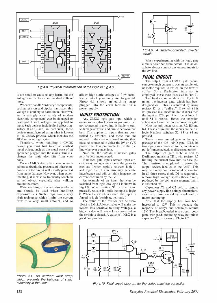
is too small to cause us any harm, but thevoltage can rise to several hundred volts ormore.
When we handle “ordinary” components,such as resistors and bipolar transistors, thisvoltage is unlikely to harm them. However,an increasingly wide variety of modernelectronic components can be damaged ordestroyed if such voltages are appplied tothem. Such devices include field effect tran-sistors (f.e.t.s) and, in particular, thosedevices manufactured using what is knownas the CMOS process, which includes the4000 series of logic gates.
Therefore, when handling a CMOSdevice you must first touch an earthedmetal object, such as the metal case of anappliance plugged into the mains. This dis-charges the static electricity from yourbody.
Once a CMOS device has been connect-ed into a circuit, the presence of other com-ponents in the circuit will usually protect itfrom static damage. However, when exper-imenting, it is wise to frequently touch anearthed object, especially after walkingaround the room.
Wrist earthing straps are also availableand should be used when handlingexpensive i.c.s. Such straps have a veryhigh resistance which limits the currentflow to a very small amount, and so
allows high static voltages to flow harm-lessly out of your body and to ground.Photo 4.1 shows an earthing strapplugged into the earth terminal on apower supply.
Any CMOS logic gate input which is
open-circuit (also known as floating), i.e.not connected to anything, is liable to stat-ic damage at worst, and erratic behaviour atbest. This applies to inputs that are con-trolled by switches, and those that areunused. In the case of unused inputs, theymust be connected to either the 0V or +VEpower line. It is preferable to use the 0Vline wherever convenient.
Note that the outputs of unused gatesmust be left unconnected.
If unused gate inputs remain open-cir-cuit, stray voltages may cause the gates tooscillate (switch rapidly between logic 1and logic 0). This in turn may generateinterference and will certainly increase thecurrent consumed by the i.c.
An example of an input that can beswitched from logic 0 to logic 1 is shown inFig.4.9. When switch S1 is open (notpressed), resistor R1 pulls the input to logic0. When the switch is closed, the input isforced to high (positive), i.e. logic 1.
The value of the resistor can be from10k to 1M. A lower value will make thesystem less sensitive to stray voltages, ahigher value will waste less current whenthe switch is closed. A value of 100k is agood compromise.
When experimenting with the logic gatecircuits described from hereon, it is advis-able to always connect any unused inputs tothe 0V line.
The output from a CMOS gate cannot
source enough current to operate a solenoidor motor required to switch on the flow ofcoffee. So a Darlington transistor isemployed (these were discussed in Part 2).
The final circuit is shown in Fig.4.10,minus the inverter gate, which has beendesigned out! This is achieved by usingresistor R1 as a “pull-up”. If switch S1 isnot pressed (i.e. machine not shaken) thenthe input at IC1c pin 9 will be at logic 1,until S1 is pressed. Hence the inversionaction is achieved without an inverter gate.
Note the pull-down resistors R2, R3 andR4. These ensure that the inputs are held atlogic 0 unless switches S2, S3 or S4 arepressed.
There is one unused gate in the quadpackage of the 4081 AND gate, IC1d. Itstwo inputs are connected to 0V, and its out-put left unconnected, as discussed earlier.
The output of gate IC1c is fed toDarlington transistor TR1, with resistor R5limiting the current flow into its base (b).The transistor is employed to power theoutput device, labelled as the “coil”. Thismay be a relay coil, a solenoid or a motor.In all three cases, diode D1 is required toremove high voltage spikes (back e.m.f.)produced by the coil at the moment that itis switched off.
Capacitors C1 and C2 help to removeany power supply line voltage fluctuations,especially those caused by a solenoid ormotor starting up.
Note that the supply has now beenincreased to 12V. This is because themajority of relays and solenoids require12V. The breadboarded test circuit, com-plete with p.c.b. mounting relay but minuscapacitor C2, is shown in Photo 4.2.
138 Everyday Practical Electronics, February 2004
Fig.4.8. Physical interpretation of the logic in Fig.4.6.
Photo 4.1. An earthed wrist strapwhich prevents the build-up of staticelectricity in the user. Fig.4.10. Final circuit diagram for the coffee machine controller.
FIg.4.9. A switch-controlled invertercircuit.

Having seen the practical use of an AND
gate, we need to consider the full range ofgates available. First, though, you need tobe familiar with the concept of truth tables.These were mentioned earlier in relation tothe behaviour of an AND gate in responseto the logic levels on its inputs.
It is easier to view the effect of gates bymeans of a truth table (see Fig.4.11). Totake the truth table for an AND gate, theinputs are labelled A and B, and the outputQ. Notice how all the possible combina-tions of logic levels for A and B are shown.Output Q remains at logic 0 unless both Aand B are at logic 1.
All the principle logic gate symbols,together with their truth tables, are shownin Fig.4.11.
We have already discussed the use ofAND and inverter gates. Example uses ofother gate types will be given as weprogress, but in brief their functions are:
NAND GATE: a NAND gate combinesan AND gate and an inverter. Its output isthe opposite of an AND gate in response tothe same input logic levels.
OR GATE: with an OR gate, if eitherinput is at logic 1, so too is the output. Bothinputs must be at logic 0 for the output toalso be at logic 0.
NOR GATE: the output of a NOR gateis the opposite of that for an OR gate.
BUFFER GATE: this gate may appearpointless, but remember that the currentrequired at the input is generally very low,under 1A for a CMOS gate, yet the
output current required can be several mil-liamps. A buffer can be used as a “currentamplifier” between the input and outputdevices.
XOR GATE: the output of an exclusive-OR gate (written as XOR or occasionallyEOR) is at logic 1 when input A is at logic 1,OR input B is at logic 1, but not both togeth-er – when the output is always logic 0.
XNOR GATE: the output of this gate isthe opposite of that for an XOR gate.
It is possible to combine some gates to
achieve another function. For example, ifyou follow an AND gate with an invertergate, as shown in Fig.4.12a, the result is aNAND gate.
If you combine a NAND gate with aninverter (Fig.4.12b), then like any
double-negative the negatives cancel, andwe are left with an AND gate.
The combination of a NOR gate with aninverter is shown in Fig.4.12c. Using twoinverters together simply produces a buffergate, as in Fig.4.12d.
We can also make an inverter gate byjoining together the inputs of a NAND gateor a NOR gate, as shown in Fig.4.13. Forexample, if you need an AND gate, aNAND gate and an inverter gate in thesame circuit, instead of buying three i.c.s,you can use a single quad 2-input NANDgate (e.g. CMOS 4011), as shown inFig.4.14.
The NAND gate is simply IC1a. Theinverter is formed by connecting the inputsof IC1b. The AND gate is made combiningIC1c and IC1d.
In fact you canmake any gate out ofNAND gates or NORgates. For instance,the making of an ORgate from threeNAND gates is illus-trated in Fig.4.15.
But how do youknow the system inFig.4.15 will work?Again, a truth tablecomes to the rescue.Begin by labelling theintermediate points, Tand U in our case.Now list all the possi-ble combinations ofthe inputs, R and S:
Everyday Practical Electronics, February 2004 139
Photo 4.2. Breadboard layout for the circuit in Fig.4.10, but minus capacitor C2.
Fig.4.12. The results of following a logic gate by an inverter.
Fig.4.11. Truth tables for a variety of logic gates. other gate types with more inputsexist.
Fig.4.13. Connecting the two inputs ofNAND or NOR gates results in aninverter gate.
Fig.4.14. Using the four gates in aquad NAND package to achieve invert-er, AND and NAND functions.
Fig.4.15. Using three NAND gates toachieve a NOR function.
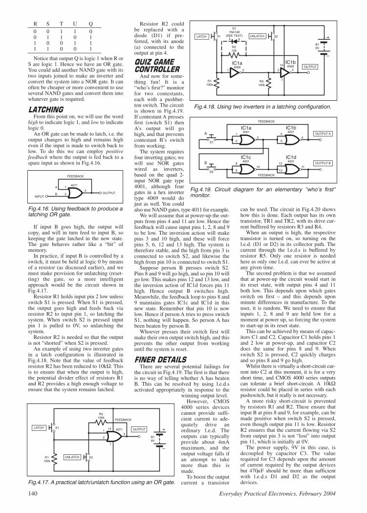
R S T U Q0 0 1 1 00 1 1 0 11 0 0 1 11 1 0 0 1
Notice that output Q is logic 1 when R orS are logic 1. Hence we have an OR gate.You could add another NAND gate with itstwo inputs joined to make an inverter andconvert the system into a NOR gate. It canoften be cheaper or more convenient to useseveral NAND gates and convert them intowhatever gate is required.
From this point on, we will use the word
high to indicate logic 1, and low to indicatelogic 0.
An OR gate can be made to latch, i.e. theoutput changes to high and remains higheven if the input is made to switch back tolow. To do this we can employ positivefeedback where the output is fed back to aspare input as shown in Fig.4.16.
If input B goes high, the output willcopy, and will in turn feed to input B, sokeeping the gate latched in the new state.The gate behaves rather like a “bit” ofmemory.
In practice, if input B is controlled by aswitch, it must be held at logic 0 by meansof a resistor (as discussed earlier), and wemust make provision for unlatching (reset-ting) the gate, so a more intelligentapproach would be the circuit shown inFig.4.17.
Resistor R1 holds input pin 2 low unlessswitch S1 is pressed. When S1 is pressed,the output goes high and feeds back viaresistor R2 to input pin 1, so latching thesystem. When switch S2 is pressed inputpin 1 is pulled to 0V, so unlatching thesystem.
Resistor R2 is needed so that the outputis not “shorted” when S2 is pressed.
An example of using two inverter gatesin a latch configuration is illustrated inFig.4.18. Note that the value of feedbackresistor R2 has been reduced to 10k. Thisis to ensure that when the output is high,the potential divider effect of resistors R1and R2 provides a high enough voltage toensure that the system remains latched.
Resistor R2 couldbe replaced with adiode (D1) if pre-ferred, with its anode(a) connected to theoutput at pin 4.
And now for some-thing fun! It is a“who’s first?” monitorfor two contestants,each with a pushbut-ton switch. The circuitis shown in Fig.4.19.If contestant A pressesfirst (switch S1) thenA’s output will gohigh, and that preventscontestant B’s switchfrom working.
The system requiresfour inverting gates; wewill use NOR gateswired as inverters,based on the quad 2-input NOR gate type4001, although fourgates in a hex invertertype 4069 would dojust as well. You couldalso use NAND gates, type 4011 for example.
We will assume that at power-up the out-puts from pins 4 and 11 are low. Hence thefeedback will cause input pins 1, 2, 8 and 9to be low. The inversion action will makepins 3 and 10 high, and these will forcepins 5, 6, 12 and 13 high. The system istherefore stable, and the high from pin 3 isconnected to switch S2, and likewise thehigh from pin 10 is connected to switch S1.
Suppose person B presses switch S2.Pins 8 and 9 will go high, and so pin 10 willgo low. This makes pins 12 and 13 low, andthe inversion action of IC1d forces pin 11high. Hence output B switches high.Meanwhile, the feedback loop to pins 8 and9 maintains gates IC1c and IC1d in thisnew state. Remember that pin 10 is nowlow. Hence if person A tries to press switchS1, nothing will happen. So person A hasbeen beaten by person B.
Whoever presses their switch first willmake their own output switch high, and thisprevents the other output from workinguntil the system is reset.
There are several potential failings for
the circuit in Fig.4.19. The first is that thereis no way of telling whether A has beatenB. This can be resolved by using l.e.d.sactivated appropriately in response to the
winning output level.However, CMOS
4000 series devicescannot provide suffi-cient current to ade-quately drive anordinary l.e.d. Theoutputs can typicallyprovide about 4mAmaximum, and theoutput voltage falls ifan attempt to takemore than this ismade.
To boost the outputcurrent a transistor
can be used. The circuit in Fig.4.20 showshow this is done. Each output has its owntransistor, TR1 and TR2, with its drive cur-rent buffered by resistors R3 and R4.
When an output is high, the respectivetransistor is turned on, so turning on thel.e.d. (D1 or D2) in its collector path. Thecurrent through the l.e.d.s is buffered byresistor R5. Only one resistor is neededhere as only one l.e.d. can ever be active atany given time.
The second problem is that we assumedthat at power-up the circuit would start inits reset state, with output pins 4 and 11both low. This depends upon which gatesswitch on first – and this depends uponminute differences in manufacture. To theuser, it is random. We need to ensure thatinputs 1, 2, 8 and 9 are held low for amoment at power up, so forcing the systemto start-up in its reset state.
This can be achieved by means of capac-itors C1 and C2. Capacitor C1 holds pins 1and 2 low at power-up, and capacitor C2does the same for pins 8 and 9. Whenswitch S2 is pressed, C2 quickly chargesand so pins 8 and 9 go high.
Whilst there is virtually a short-circuit cur-rent into C2 at this moment, it is for a veryshort time, and CMOS 4000 series outputscan tolerate a brief short-circuit. A 10kresistor could be placed in series with eachpushswitch, but it really is not necessary.
A more risky short-circuit is preventedby resistors R1 and R2. These ensure thatinput B at pins 8 and 9, for example, can bemade positive when switch S2 is pressed,even though output pin 11 is low. ResistorR2 ensures that the current flowing via S2from output pin 3 is not “lost” into outputpin 11, which is initially at 0V.
The power supply, 9V in this case, isdecoupled by capacitor C3. The valuerequired for C3 depends upon the amountof current required by the output devicesbut 470F should be more than sufficientwith l.e.d.s D1 and D2 as the outputdevices.
140 Everyday Practical Electronics, February 2004
Fig.4.16. Using feedback to produce alatching OR gate.
Fig.4.17. A practical latch/unlatch function using an OR gate.
Fig.4.18. Using two inverters in a latching configuration.
Fig.4.19. Circuit diagram for an elementary “who’s first”monitor.

Everyday Practical Electronics, February 2004 141
Remember that the purpose of C3 is to“smooth-out” any sudden dips in the powersupply voltage, which could cause the sys-tem to fail to latch (i.e. fail to stay on aftera switch is pressed). In other applications,if a greater load is used, the value of C3may need increasing.
Toggle switch S3 is used to reset the sys-tem, by switching it off and then on again.You could use a normally-closed push-switch in series with S3 if a pushbuttonreset is preferred.
The prototype test circuit assembly isshown in Photo 4.3.
It is worth noting that the 74HC familyof logic gates can provide an output currentof up to about 25mA, and so could be usedto drive an l.e.d. (via a buffer resistor ofcourse) without transistors.
It must be noted, though, that the 74HCseries can only be powered at a typicalmaximum of about 6V (7V for 74HCdevices from some manufacturers).Secondly, devices in this 74HC familyhave different pinouts to devices of a simi-lar function in the 4000 series.
In the context of electronics, the term
multivibrator simply means a circuitwhich generates a voltage that switchesbetween high and low, either once, ormany times.
Two graphs are illustrated in Fig.4.21,the upper one is a sinewave. This is a
“pure” waveform and it consists of anexact frequency with no overtones orharmonics.
A mechanical tuning fork produces asinewave and so is useful when tuninginstruments. But most musical soundscontain overtones – additional frequen-cies which add “colour” to the sound.
Every musical instrument has a differ-ent set of overtones, and so, for exam-ple, a trumpet sounds different to apiano, even when both are playing thesame note.
A square wave (the bottom graph inFig.4.21) contains an infinite number ofovertones. Most amplifiers can handlesinewaves with ease, but a test of a goodamplifier is to apply a square wave at itsinput and view the shape of thewaveform at the output. You are likely tosee rounded edges and other imperfec-tions, especially at upper and lowerfrequencies.
We will examine three types of multivi-brator, based on logic gates:
Bistable multivibrator – often referredto as a flip-flop or latch
Monostable multivibrator – alsoknown as a one-shot multivibrator and isoften used as a timer
Astable multivibrator – which generatesa continuous stream of waveforms, typi-cally square waves but not necessarily so.
A bistable circuit is stable in two states,
but can be switched between those states.So our quiz circuit was a type of bistablesince each half of the circuit could belatched with its output high or low. Wehave already seen how an OR gate can bemade to latch by means of feedback, butwe will now examine a more sophisticatedbistable, using two NOR gates, as shown inFig.4.22.
We will assume that at power-up IC1boutput pin 4 (marked Q) is low, and thatIC1a output pin 3 (marked Q) is high.Hence IC1a input pin 2 is low and IC1binput pin 5 is high.
At this stage we need to check the truthtable for a NOR gate since this will helpunderstand the action of the circuit.
INPUTS OUTPUT0 0 10 1 01 0 01 1 0
Fig.4.20. A fully working implementation of the circuit in Fig.4.19.
Photo 4.3. Breadboard assembly for the circuit in Fig.4.20.
Fig.4.21. A sinewave (upper graph) contains no harmonics or overtones and is a “pure”waveform. A square wave (lower graph) contains an infinite number of overtones.
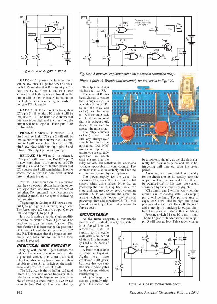
GATE A: At present, IC1a input pin 1will be low since it is pulled down by resis-tor R1. Remember that IC1a input pin 2 isheld low by IC1b pin 4. The truth tableshows that if both inputs are low then theoutput will be high. Hence IC1a output pin3 is high, which is what we agreed earlier –i.e. gate IC1a is stable.
GATE B: If IC1a pin 3 is high, thenIC1b pin 5 will be high. IC1b pin 6 will below, due to R2. The truth table shows thatwith one input high, and the other low, theoutput will be at logic 0. Hence gate IC1bis also stable.
PRESS S1: When S1 is pressed, IC1apin 1 will go high. IC1a pin 2 will still below, so our truth table shows that IC1a out-put pin 3 will now go low. This forces IC1bpin 5 low. Now with both input pins 5 and6 low, IC1b output pin 4 will go high.
RELEASE S1: When S1 is released,IC1a pin 1 will return low. But IC1a pin 2is now high since it is connected to IC1boutput pin 4, and the truth table shows thatIC1a output pin 3 will remain high. In otherwords, the system has now been latchedinto its alternative state.
You will have seen from this sequencethat the two outputs always have the oppo-site logic state, one inverted in respect ofthe other. Conventionally, such outputs arelabelled Q and Q, the bar symbol indicatingthe inversion.
Triggering the Set input (S1) causes out-put Q to go high and output Q to go low.The Reset input (S2) causes output Q to golow and output Q to go high.
It is worth noting that with slight modifi-cation to the circuit, a NAND gate could beused to perform the same function. Themodification is to interchange the positionsof S1 and R1, and also the positions of S2and R2. This means that the inputs are nor-mally held high but go low when theirswitch is pressed.
Staying with the NOR gate bistable, we
will add the necessary components to makea practical circuit, plus a transistor andrelay to control an appliance. You will thenbe able to press S1 to switch on the appli-ance, and press S2 to switch it off.
The full circuit is shown in Fig.4.23 (andPhoto 4.4). We have added transistor TR1,which can be any high-gain npn type capa-ble of driving a small relay, a BC549 forexample (see Part 2). It is controlled by
IC1b output pin 4 (Q)via base resistor R3.
The value of R3 hasbeen chosen to ensurethat enough current isavailable through TR1to suit the relay coil(RLA). As the relaycoil will generate backe.m.f. at the momentthat it is switched off,diode D1 is used toprotect the transistor.
The relay contacts(RLA1) are usedlike any change-overswitch, to control theappliance. DO NOTuse a mains appliance,unless you are suitablyqualified, in whichcase ensure that therelay contacts can withstand the a.c. mainsvoltages applicable in your country. Thecontacts must also be suitably rated for thecurrent (amps) used by the appliance.
The power supply for the circuit isshown as 12V, since this is a more usefulsupply when using relays. Note that atpower-up the circuit may latch in eitherstate, and may need to be reset by pressingswitch S2. If you require the circuit toalways latch into its “output low” state atpower-up, then add capacitor C3. This willprovide a short logic 1 pulse at power-up toforce a reset.
As the name suggests, a monostable
multivibrator is stable in only one state. Ifit is forced into thealternative state itreturns to its stablestate after a set periodof time. It is frequent-ly used as the basis oftiming circuits.
A basic monostableis shown in Fig.4.24.Again we haveemployed NOR gates,but note that you can-not use NAND gatesin this design withoutredesigning it.
At power-up thesystem generally trig-gers. This should not
be a problem, though, as the circuit is nor-mally left permanently on and the initialtriggering will time out after the presetperiod.
Assuming we have waited sufficientlyfor the circuit to enter its standby state, theoutput pin 4 will be low and l.e.d. D1 willbe switched off. In this state, the currentconsumed by the circuit is negligible.
IC1a pins 1 and 2 will be low when thecircuit is in its standby state, IC1a outputpin 3 will be high. The positive side ofcapacitor C1 will also be high due to thepresence of resistor R2. Hence IC1b pins 5and 6 are high, so making its output pin 4low. The system is stable in this condition.
Pressing switch S1 sets IC1a pin 1 high.The NOR gate truth table shows that outputpin 3 will thus go low. This sudden change
142 Everyday Practical Electronics, February 2004
Fig.4.22. A NOR gate bistable.Fig.4.23. A practical implementation for a bistable controlled relay.
Photo 4 (below). Breadboard assembly for the circuit in Fig.4.23.
Fig.4.24. A basic monostable circuit.
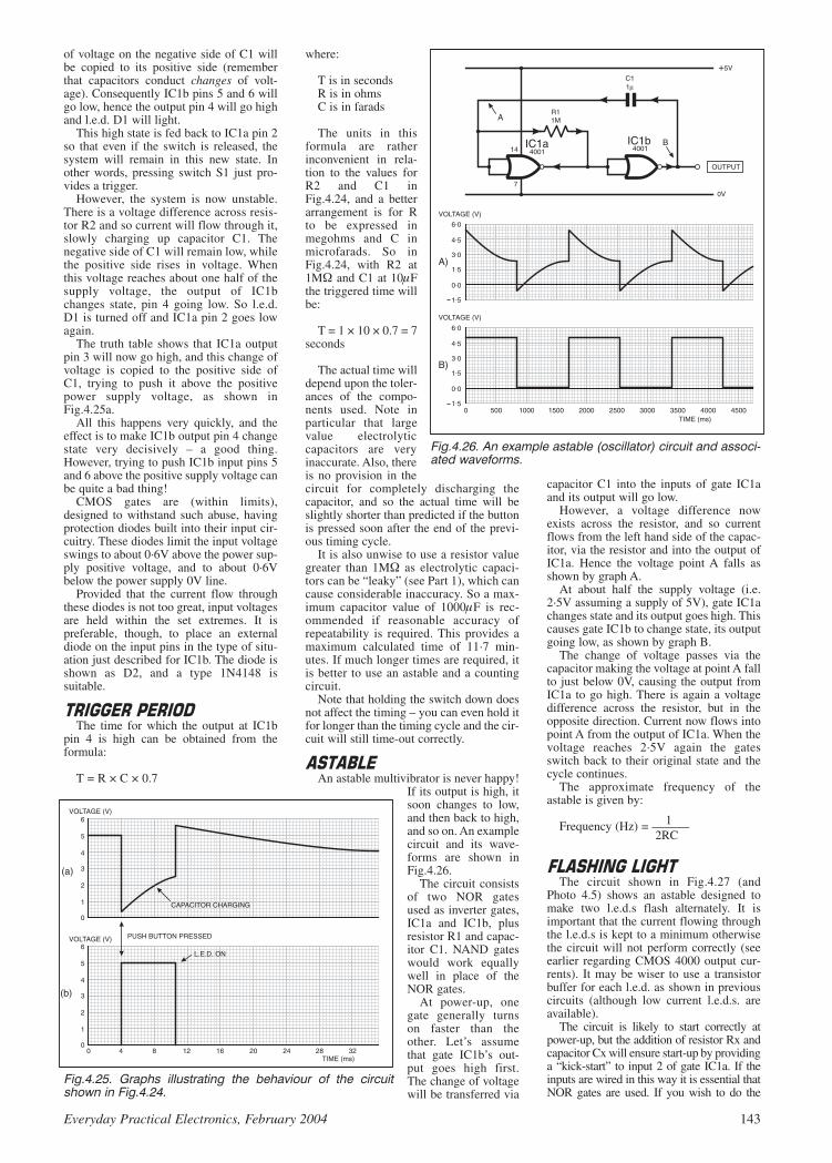
Everyday Practical Electronics, February 2004 143
of voltage on the negative side of C1 willbe copied to its positive side (rememberthat capacitors conduct changes of volt-age). Consequently IC1b pins 5 and 6 willgo low, hence the output pin 4 will go highand l.e.d. D1 will light.
This high state is fed back to IC1a pin 2so that even if the switch is released, thesystem will remain in this new state. Inother words, pressing switch S1 just pro-vides a trigger.
However, the system is now unstable.There is a voltage difference across resis-tor R2 and so current will flow through it,slowly charging up capacitor C1. Thenegative side of C1 will remain low, whilethe positive side rises in voltage. Whenthis voltage reaches about one half of thesupply voltage, the output of IC1bchanges state, pin 4 going low. So l.e.d.D1 is turned off and IC1a pin 2 goes lowagain.
The truth table shows that IC1a outputpin 3 will now go high, and this change ofvoltage is copied to the positive side ofC1, trying to push it above the positivepower supply voltage, as shown inFig.4.25a.
All this happens very quickly, and theeffect is to make IC1b output pin 4 changestate very decisively – a good thing.However, trying to push IC1b input pins 5and 6 above the positive supply voltage canbe quite a bad thing!
CMOS gates are (within limits),designed to withstand such abuse, havingprotection diodes built into their input cir-cuitry. These diodes limit the input voltageswings to about 0·6V above the power sup-ply positive voltage, and to about 0·6Vbelow the power supply 0V line.
Provided that the current flow throughthese diodes is not too great, input voltagesare held within the set extremes. It ispreferable, though, to place an externaldiode on the input pins in the type of situ-ation just described for IC1b. The diode isshown as D2, and a type 1N4148 issuitable.
The time for which the output at IC1b
pin 4 is high can be obtained from theformula:
T = R × C × 0.7
where:
T is in secondsR is in ohmsC is in farads
The units in thisformula are ratherinconvenient in rela-tion to the values forR2 and C1 inFig.4.24, and a betterarrangement is for Rto be expressed inmegohms and C inmicrofarads. So inFig.4.24, with R2 at1M and C1 at 10Fthe triggered time willbe:
T = 1 × 10 × 0.7 = 7seconds
The actual time willdepend upon the toler-ances of the compo-nents used. Note inparticular that largevalue electrolyticcapacitors are veryinaccurate. Also, thereis no provision in thecircuit for completely discharging thecapacitor, and so the actual time will beslightly shorter than predicted if the buttonis pressed soon after the end of the previ-ous timing cycle.
It is also unwise to use a resistor valuegreater than 1M as electrolytic capaci-tors can be “leaky” (see Part 1), which cancause considerable inaccuracy. So a max-imum capacitor value of 1000F is rec-ommended if reasonable accuracy ofrepeatability is required. This provides amaximum calculated time of 11·7 min-utes. If much longer times are required, itis better to use an astable and a countingcircuit.
Note that holding the switch down doesnot affect the timing – you can even hold itfor longer than the timing cycle and the cir-cuit will still time-out correctly.
An astable multivibrator is never happy!
If its output is high, itsoon changes to low,and then back to high,and so on. An examplecircuit and its wave-forms are shown inFig.4.26.
The circuit consistsof two NOR gatesused as inverter gates,IC1a and IC1b, plusresistor R1 and capac-itor C1. NAND gateswould work equallywell in place of theNOR gates.
At power-up, onegate generally turnson faster than theother. Let’s assumethat gate IC1b’s out-put goes high first.The change of voltagewill be transferred via
capacitor C1 into the inputs of gate IC1aand its output will go low.
However, a voltage difference nowexists across the resistor, and so currentflows from the left hand side of the capac-itor, via the resistor and into the output ofIC1a. Hence the voltage point A falls asshown by graph A.
At about half the supply voltage (i.e.2·5V assuming a supply of 5V), gate IC1achanges state and its output goes high. Thiscauses gate IC1b to change state, its outputgoing low, as shown by graph B.
The change of voltage passes via thecapacitor making the voltage at point A fallto just below 0V, causing the output fromIC1a to go high. There is again a voltagedifference across the resistor, but in theopposite direction. Current now flows intopoint A from the output of IC1a. When thevoltage reaches 2·5V again the gatesswitch back to their original state and thecycle continues.
The approximate frequency of theastable is given by:
1Frequency (Hz) = ———2RC
The circuit shown in Fig.4.27 (and
Photo 4.5) shows an astable designed tomake two l.e.d.s flash alternately. It isimportant that the current flowing throughthe l.e.d.s is kept to a minimum otherwisethe circuit will not perform correctly (seeearlier regarding CMOS 4000 output cur-rents). It may be wiser to use a transistorbuffer for each l.e.d. as shown in previouscircuits (although low current l.e.d.s. areavailable).
The circuit is likely to start correctly atpower-up, but the addition of resistor Rx andcapacitor Cx will ensure start-up by providinga “kick-start” to input 2 of gate IC1a. If theinputs are wired in this way it is essential thatNOR gates are used. If you wish to do the
Fig.4.25. Graphs illustrating the behaviour of the circuitshown in Fig.4.24.
Fig.4.26. An example astable (oscillator) circuit and associ-ated waveforms.
(a)
(b)

same trick with NANDgates, then Rx and Cxshould be interchanged.
We have barelyscratched the surfaceof digital electronicsin this part of Teach-In 2004. Each of theelements discussedcan lead to other sys-tems. Logic gates, forinstance, can be made into complex prob-lem solving systems, and bistable latchescan lead to counters and computers.
However, although logic gates and coun-ters, etc., still form the basis of many elec-tronics applications, the use ofmicrocontrollers, such as PICs and othersimilar devices, have largely taken over asa way of squeezing a lot of processingpower into a small, low-cost package.
But while the means of achieving digitalprocessing may be forever changing, withmore complex and faster processors, the
electronic principles employed remain thesame, and it is well worth understandingthem.
In Part 5 next month, we shall examine
logic gates and their use as switches, withspecial reference to audio applications. Wealso introduce PIC microcontrollers toreduce the chip count. We shall look atmore specific applications using digital cir-cuits as and when appropriate in other partsof this series.
144 Everyday Practical Electronics, February 2004
PANEL 4.1. LOGIC FAMILIESThere are two main families of logic i.c.s: TTL, based on ordi-
nary bipolar transistor technology, and CMOS, more akin tofield-effect transistor technology:
TTL (Transistor-Transistor-Logic)The original range of TTL logic devices was known as the
7400 series. This has long since been superseded by other TTLlogic families, such as the 74LS series, for instance. All aredesigned for operation on 5V. This inflexible supply voltage, andrather awkward operating characteristics, make them unsuitablefor the Teach-In 2004 series.
CMOS (Complementary Metal Oxide Semiconductor)The oldest range of CMOS logic devices in common use is the
4000 series. These are ideal for use in this Teach-In as they canoperate on a supply voltage of between about 3V and 15V.
Another range of CMOS logic i.c.s is the 74HC series. Thesehave many advantages, including higher speed than the 4000series, and their outputs can supply a generous amount of current,typically around 25mA, plenty to light a typical l.e.d. for example.
However, because 74HC devices can only operate on supplyvoltages within the range 2V to 6V, they are only suited for usein Teach-In 2004 if the power supply voltage suggested in thecircuit diagrams is reduced to within this lower range. It is essen-tial to note that the 4000 and 74HC series have different pinouts.
Both CMOS families require static precautions, as explainedearlier.
Note that CMOS 4000 series device numbers may have a suf-fix of “B”, standing for Buffered, or “U” or “UB”, which standsfor “Unbuffered”. Buffered outputs are generally better as theyare electrically more robust, but will make little difference in thecircuits in this series.
Fig.4.27. An astable circuit to alternately flash two l.e.d.s.
Photo 4.5. Breadboard assembly ofthe circuit in Fig.4.27.
EEPPEE BBIINNDDEERRSSKEEP YOUR MAGAZINES SAFE – RING US NOW!
This ring binder uses a special system to allow the issues to be easily removed and re-inserted without any damage. A nylon strip slips overeach issue and this passes over the four rings in the binder, thus holding the magazine in place.
The binders are finished in hard-wearing royal blue p.v.c. with the magazine logo in goldon the spine. They will keep your issues neat and tidy but allow you to remove them for useeasily.
The price is £6.95 plus £3.50 post and packing. If you order more than one binder add £1postage for each binder after the initial £3.50 postage charge (overseas readers the postageis £6.00 each to everywhere except Australia and Papua New Guinea which costs £10.50each).
Send your payment in £’s sterling cheque or PO (Overseas readers send £ sterling bankdraft, or cheque drawn on a UK bank or pay by card), to Everyday Practical Electronics,Wimborne Publishing Ltd, 408 Wimborne Road East, Ferndown, Dorset BH22 9ND.Tel:01202 873872. Fax: 01202 874562.
E-mail: [email protected] site: http://www.epemag.wimborne.co.ukOrder on-line from:www.epemag.wimborne.co.uk/shopdoor.htm
We also accept card payments. Mastercard, Visa, Amex, Diners Club or Switch. Send yourcard number and card expiry date plus Switch Issue No. with your order.

IC 555 PROJECTSE. A. ParrEvery so often a device appears that is so useful thatone wonders how life went on before without it. The 555timer is such a device. Included in this book are over 70circuit diagrams and descriptions covering basic andgeneral circuits, motor car and model railway circuits,alarms and noise makers as well as a section on 556,558 and 559 timers. (Note. No construction details aregiven.) A reference book of invaluable use to all thosewho have any interest in electronics, be they profession-al engineers or designers, students or hobbyists.
POWER SUPPLY PROJECTSR. A. PenfoldThis book offers a number of power supply designs,including simple unstabilised types, and variable voltagestabilised designs, the latter being primarily intended foruse as bench power supplies for the electronics work-shop. The designs provided are all low voltage types forsemiconductor circuits. The information in this bookshould also help the reader to design his own powersupplies. Includes cassette PSU, Ni-Cad charger, volt-age step-up circuit and a simple inverter.
HOW TO USE OSCILLOSCOPES AND OTHER TESTEQUIPMENTR. A. PenfoldThis book explains the basic function of an oscilloscope,gives a detailed explanation of all the standard controls,and provides advice on buying. A separate chapterdeals with using an oscilloscope for fault finding onlinear and logic circuits, plenty of example waveformshelp to illustrate the control functions and the effects ofvariouus fault conditions. The function and use of vari-ous other pieces of test equipment are also covered,including signal generators, logic probes, logic pulsersand crystal calibrators.
PRACTICAL REMOTE CONTROL PROJECTSOwen BishopProvides a wealth of circuits and circuit modules foruse in remote control systems of all kinds; ultrasonic,infra-red, optical fibre, cable and radio. There areinstructions for building fourteen novel and practicalremote control projects. But this is not all, as each ofthese projects provides a model for building dozens ofother related circuits by simply modifying parts of thedesign slightly to suit your own requirements. Thisbook tells you how.
Also included are techniques for connecting a PC to aremote control system, the use of a microcontroller inremote control, as exemplified by the BASIC Stamp, andthe application of ready-made type-approved 418MHzradio transmitter and receiver modules to remote controlsystems.
Everyday Practical Electronics, February 2004 145
COMPUTING FOR THE OLDER GENERATAIONJim GatenbyEspecially written for the over 50s, using plain Englishand avoiding technical jargon. Large clear type for easyreading.
Among the many practical and useful ideas for usingyour PC that are covered in this book are: Choosing, set-ting up and understanding your computer and its maincomponents. Writing letters, leaflets, invitations, etc., andother word processing jobs. Keeping track of yourfinances using a spreadsheet. Recording details of holi-days and other ideas using a database. Using the Internetto find useful information, and email to keep in touch withfamily and friends. Making ‘back-up’ copies of your workand checking for viruses. How to use Windows XP to helppeople with impaired vision, hearing or mobility.
Provides the basic knowledge so you can gain enoughconfidence to join the local computer class.
DIRECT BOOKSERVICE
The books listed have been selected by Everyday PracticalElectronics editorial staff as being of special interest to everyoneinvolved in electronics and computing. They are supplied by mailorder direct to your door. Full ordering details are given on the lastbook page.
All prices include UK postage
FOR A FURTHER SELECTION OF BOOKSSEE THE NEXT TWO ISSUES OF EPE.
projectconstruction
160 pages Temporarily out of print
167 pages Temporarily out of print
91 pages £4.99Order code BP76
104 pages £4.99Order code BP267
THE INTERNET FOR THE OLDER GENERATIONJim GatenbyEspecially written for the over 50s. Uses only clear andeasy-to-understand language. Larger type size for easyreading. Provides basic knowledge to give you confidenceto join the local computer class.
This book explains how to use your PC on the Internetand covers amongst other things: Choosing and settingup your computer for the Internet. Getting connected tothe Internet. Sending and receiving emails, photographs,etc., so that you can keep in touch with family and friendsall over the world. Searching for and saving information onany subject. On-line shopping and home banking. Settingup your own simple web site.
SETTING UP AN AMATEUR RADIO STATIONI. D. PooleThe aim of this book is to give guidance on the decisionswhich have to be made when setting up any amateurradio or short wave listening station. Often the experiencewhich is needed is learned by one’s mistakes, however,this can be expensive. To help overcome this, guidance isgiven on many aspects of setting up and running an effi-cient station. It then proceeds to the steps that need to betaken in gaining a full transmitting licence.
Topics covered include: The equipment that is needed;Setting up the shack; Which aerials to use; Methods ofconstruction; Preparing for the licence.
An essential addition to the library of all those takingtheir first steps in amateur radio.
EXPERIMENTAL ANTENNA TOPICSH. C. WrightAlthough nearly a century has passed since Marconi’s firstdemonstration or radio communication, there is stillresearch and experiment to be carried out in the field ofantenna design and behaviour.
The aim of the experimenter will be to make a measure-ment or confirm a principle, and this can be done withrelatively fragile, short-life apparatus. Because of this,devices described in this book make liberal use of card-board, cooking foil, plastic bottles, cat food tins, etc. Thesematerials are, in general, cheap to obtain and easily workedwith simple tools, encouraging the trial-and-error philosophywhich leads to innovation and discovery.
Although primarily a practical book with text closelysupported by diagrams, some formulae which can be usedby straightforward substitution and some simple graphshave also been included.
25 SIMPLE INDOOR AND WINDOW AERIALSE. M. NollMany people live in flats and apartments or other types ofaccommodation where outdoor aerials are prohibited, or alack of garden space etc. prevents aerials from beingerected. This does not mean you have to forgo shortwave-listening, for even a 20-foot length of wire stretched outalong the skirting board of a room can produce acceptableresults. However, with some additional effort and experi-mentation one may well be able to improve performancefurther.
This concise book tells the story, and shows the readerhow to construct and use 25 indoor and window aerials thatthe author has proven to be sure performers. Much infor-mation is also given on shortwave bands, aerial directivity,time zones, dimensions etc.
228 pages £8.99Order code BP600
86 pages £4.45Order code BP300
308 pages £8.99Order code BP601
72 pages £4.00Order code BP278
50 pages £2.25Order code BP136
EEPPEE TTEEAACCHH--IINN22000000 CCDD--RROOMM
The whole of the 12-part Teach-In 2000 series by JohnBecker (published in EPE Nov ’99 to Oct 2000) is nowavailable on CD-ROM in PDF form. Plus the Teach-In2000 interactive software covering all aspects of theseries and Alan Winstanley’s Basic Soldering Guide(including illustrations and Desoldering).
Teach-In 2000 covers all the basic principles of elec-tronics from Ohm’s Law to Displays, including Op.Amps,Logic Gates etc. Each part has its own section on theinteractive software where you can also change compo-nent values in the various on-screen demonstration cir-cuits.
The series gives a hands-on approach to electronicswith numerous breadboard circuits to try out, plus asimple computer interface which allows a PC to beused as a basic oscilloscope. (Win 95, 98, ME ONLY).
ONLY £12.45 including VAT and p&pOrder code Teach-In CD-ROM
ELECTRONIC PROJECT BUILDING FOR BEGINNERS R. A. PenfoldThis book is for complete beginners to electronic projectbuilding. It provides a complete introduction to the practi-cal side of this fascinating hobby, including the followingtopics:
Component identification, and buying the right parts;resistor colour codes, capacitor value markings, etc;advice on buying the right tools for the job; soldering;making easy work of the hard wiring; construction meth-ods, including stripboard, custom printed circuit boards,plain matrix boards, surface mount boards and wire-wrap-ping; finishing off, and adding panel labels; getting “prob-lem’’ projects to work, including simple methods of fault-finding.
In fact everything you need to know in order to get start-ed in this absorbing and creative hobby.
A PRACTICAL INTRODUCTION TO SURFACE MOUNT DEVICESBill MooneyThis book takes you from the simplest possible startingpoint to a high level of competence in handworking withsurface mount devices (SMD’s). The wider subject of SMtechnology is also introduced, so giving a feeling for itsdepth and fascination.
Subjects such as p.c.b. design, chip control, solderingtechniques and specialist tools for SM are fullyexplained and developed as the book progresses. Someuseful constructional projects are also included.
Whilst the book is mainly intended as an introductionit is also an invaluable reference book, and the browsershould find it engrossing.
TEST EQUIPMENT CONSTRUCTIONR. A. PenfoldThis book describes in detail how to construct some simple andinexpensive but extremely useful, pieces of test equipment.Stripboard layouts are provided for all designs, together withwiring diagrams where appropriate, plus notes on constructionand use.
The following designs are included:-AF Generator, Capacitance Meter, Test Bench Amplifier, AF
Frequency Meter, Audio Mullivoltmeter, Analogue Probe, HighResistance Voltmeter, CMOS Probe, Transistor Tester, TTLProbe.The designs are suitable for both newcomers and moreexperienced hobbyists.
104 pages £4.49Order code BP248
FREE Electronics Hobbyist Compendiumbook with Teach-In 2000 CD-ROM
135 pages £5.49
120 pages £5.49Order code BP411
COMPUTING
radioOrder code BP392

AN INTRODUCTION TO PIC MICROCONTROLLERSRobert PenfoldDesigning your own PIC based projects may seem adaunting task, but it is really not too difficult providing youhave some previous experience of electronics.
The PIC processors have plenty of useful features, butthey are still reasonably simple and straightforward touse. This book should contain everything you need toknow.
Topics covered include: the PIC register set; numberingsystems; bitwise operations and rotation; the PIC instruc-tion set; using interrupts; using the analogue to digitalconverter; clock circuits; using the real time clock counter(RTCC); using subroutines; driving seven segmentdisplays.
PRACTICAL OSCILLATOR CIRCUITSA. FlindExtensive coverage is given to circuits using capacitorsand resistors to control frequency. Designs usingCMOS, timer i.c.s and op.amps are all described indetail, with a special chapter on ``waveform generator’’i.c.s. Reliable “white’’ and “pink’’ noise generator circuitsare also included.
Various circuits using inductors and capacitors are cov-ered, with emphasis on stable low frequency generation.Some of these are amazingly simple, but are still veryuseful signal sources.
Crystal oscillators have their own chapter. Many of thecircuits shown are readily available special i.c.s forsimplicity and reliability, and offer several output frequen-cies. Finally, complete constructional details are given foran audio sinewave generator.
PRACTICAL ELECTRONICS HANDBOOK –Fifth Edition. Ian SinclairContains all of the everyday information that anyoneworking in electronics will need.
It provides a practical and comprehensive collection ofcircuits, rules of thumb and design data for professionalengineers, students and enthusaists, and thereforeenough background to allow the understanding anddevelopment of a range of basic circuits.
Contents: Passive components, Active discretecomponents, Circuits, Linear I.C.s, Energy conversioncomponents, Digital I.C.s, Microprocessors and micro-processor systems, Transferring digital data, Digital-analogue conversions, Computer aids in electronics,Hardware components and practical work, Micro-con-trollers and PLCs, Digital broadcasting, Electronicsecurity.
COIL DESIGN AND CONSTRUCTIONAL MANUALB. B. BabaniA complete book for the home constructor on “how tomake’’ RF, IF, audio and power coils, chokes and trans-formers. Practically every possible type is discussed andcalculations necessary are given and explained in detail.Although this book is now twenty years old, with theexception of toroids and pulse transformers little haschanged in coil design since it was written.
OPTOELECTRONICS CIRCUITS MANUALR. M. MarstonA useful single-volume guide to the optoelectronicsdevice user, specifically aimed at the practical designengineer, technician, and the experimenter, as well asthe electronics student and amateur. It deals with thesubject in an easy-to-read, down-to-earth, and non-mathematical yet comprehensive manner, explainingthe basic principles and characteristics of the bestknown devices, and presenting the reader with manypractical applications and over 200 circuits. Most of thei.c.s and other devices used are inexpensive and read-ily available types, with universally recognised typenumbers.
OPERATIONAL AMPLIFIER USER’S HANDBOOKR. A. PenfoldThe first part of this book covers standard operationalamplifer based “building blocks’’ (integrator, precision
rectifier, function generator, amplifiers, etc), and consid-ers the ways in which modern devices can be used to givesuperior performance in each one. The second partdescribes a number of practical circuits that exploit mod-ern operational amplifiers, such as high slew-rate, ultralow noise, and low input offset devices. The projectsinclude: Low noise tape preamplifier, low noise RIAA pre-amplifier, audio power amplifiers, d.c. power controllers,opto-isolator audio link, audio millivolt meter, temperaturemonitor, low distortion audio signal generator, simplevideo fader, and many more.
A BEGINNERS GUIDE TO CMOS DIGITAL ICsR. A. PenfoldGetting started with logic circuits can be difficult, since manyof the fundamental concepts of digital design tend to seemrather abstract, and remote from obviously useful applica-tions. This book covers the basic theory of digital electronicsand the use of CMOS integrated circuits, but does not losesight of the fact that digital electronics has numerous “realworld’’ applications.
The topics covered in this book include: the basicconcepts of logic circuits; the functions of gates, invert-ers and other logic “building blocks’’; CMOS logic i.c.characteristics, and their advantages in practical circuitdesign; oscillators and monostables (timers); flip/flops,binary dividers and binary counters; decade countersand display drivers.
146 Everyday Practical Electronics, February 2004
VALVE & TRANSISTOR AUDIO AMPLIFIERSJohn Linsley HoodThis is John Linsley Hood’s greatest work yet, describ-ing the milestones that have marked the development ofaudio amplifiers since the earliest days to the latest
systems. Including classic amps with valves at theirheart and exciting new designs using the latest compo-nents, this book is the complete world guide to audioamp design.
Contents: Active components; Valves or vacuumtubes; Solid-state devices; Passive components;Inductors and transformers; Capacitors, Resistors,Switches and electrical contacts; Voltage amplifierstages using valves; Valve audio amplifier layouts;Negative feedback; Valve operated power amplifiers;Solid state voltage amplifiers; Early solid-state audioamplifiers; Contemporary power amplifier designs;Preamplifiers; Power supplies (PSUs); Index.
AUDIO AMPLIFIER PROJECTSR. A. PenfoldA wide range of useful audio amplifier projects, eachproject features a circuit diagram, an explanation of thecircuit operation and a stripboard layout diagram. Allconstructional details are provided along with a shop-ping list of components, and none of the designsrequires the use of any test equipment in order to setup properly. All the projects are designed for straight-forward assembly on simple circuit boards.
Circuits include: High impedance mic preamp, Lowimpedance mic preamp, Crystal mic preamp, Guitar andGP preamplifier, Scratch and rumble filter, RIAApreamplifier, Tape preamplifier, Audio limiter, Bass and tre-ble tone controls, Loudness filter, Loudness control,Simple graphic equaliser, Basic audio mixer, Small(300mW) audio power amp, 6 watt audio power amp,20/32 watt power amp and power supply, Dynamic noiselimiter.
A must for audio enthusiasts with more sense thanmoney!
VALVE AMPLIFIERSSecond Edition. Morgan JonesThis book allows those with a limited knowledge of the fieldto understand both the theory and practice of valve audioamplifier design, such that they can analyse and modify cir-cuits, and build or restore an amplifier. Design principles andconstruction techniques are provided so readers can deviseand build from scratch, designs that actually work.
The second edition of this popular book builds on its mainstrength – exploring and illustrating theory with practicalapplications. Numerous new sections include: output trans-former problems; heater regulators; phase splitter analysis;and component technology. In addition to the numerousamplifier and preamplifier circuits, three major new designsare included: a low-noise single-ended LP stage, and a pairof high voltage amplifiers for driving electrostatic transduc-ers directly – one for headphones, one for loudspeakers.
LOUDSPEAKERS FOR MUSICIANSVivan CapelThis book contains all that a working musician needs toknow about loudspeakers; the different types, how theywork, the most suitable for different instruments, forcabaret work, and for vocals. It gives tips on constructingcabinets, wiring up, when and where to use wadding,and when not to, what fittings are available, finishing,how to ensure they travel well, how to connect multi-speaker arrays and much more.
Ten practical enclosure designs with plans andcomments are given in the last chapter, but by the timeyou’ve read that far you should be able to design your own!
circuits and design
audio and music133 pages £5.49Order code BP393
440 pages £17.99Order code NE21
96 pages £4.49Order code BP160
166 pages £6.49Order code BP394
182 pages £20.99Order code NE14
119 pages £5.45Order code BP333
120 pages £5.45Order code BP335
250 pages £25.99Order code NE24
116 pages £10.95 £5.45Order code PC113
288 pages £32.99Order code NE33
164 pages £5.49Order code BP297
BOOK ORDERING DETAILSAll prices include UK postage. For postage to Europe (air) and the rest of the world (surface)please add £2 per book. For the rest of the world airmail add £3 per book. CD-ROM pricesinclude VAT and/or postage to anywhere in the world. Send a PO, cheque, international moneyorder (£ sterling only) made payable to Direct Book Service or card details, Visa, Mastercard,Amex, Diners Club or Switch to: DIRECT BOOK SERVICE, WIMBORNE PUBLISHING LIMIT-ED, 408 WIMBORNE ROAD EAST, FERNDOWN, DORSET BH22 9ND.
Books are normally sent within seven days of receipt of order, but please allow 28 days fordelivery – more for overseas orders. Please check price and availability (see latest issue ofEveryday Practical Electronics) before ordering from old lists.
For a further selection of books see the next two issues of EPE.Tel 01202 873872 Fax 01202 874562. E-mail: [email protected] from our online shop at: www.epemag.wimborne.co.uk/shopdoor.htm
BOOK ORDER FORMFull name: ...............................................................................................................................................
Address: ..................................................................................................................................................
.................................................................................................................................................................
.................................................................................................................................................................
.............................................. Post code: ........................... Telephone No: .............................................
Signature: ................................................................................................................................................
I enclose cheque/PO payable to DIRECT BOOK SERVICE for £ ...................................................
Please charge my card £ ....................................... Card expiry date...............................................
Card Number ........................................................................................... Switch Issue No.....................
Card Security Code ................ (the last three digits on or just below the signature strip)
Please send book order codes: ..............................................................................................................
.................................................................................................................................................................Please continue on separate sheet of paper if necessary

PROJECT TITLE Order Code Cost
PIC Controlled Intruder Alarm APR ’02 339 £6.50PIC Big Digit Display MAY ’02 341 £6.02Washing Ready Indicator 342 £4.75Audio Circuits–1 – LM386N-1 343 £4.28
– TDA7052 344 £4.12– TBA820M 345 £4.44– LM380N 346 £4.44– TDA2003 347 £4.60– Twin TDA2003 348 £4.75
World Lamp JUNE ’02 340 £5.71Simple Audio Circuits–2 – Low, Med and High
Input Impedance Preamplifiers (Single Trans.) 349 £4.60Low-Noise Preamplifier (Dual Trans.) 350 £4.75Tone Control 351 £4.60Bandpass Filter 352 £4.75
Frequency Standard Generator – Receiver 353 £4.12– Digital 354 £6.82
Biopic Heartbeat Monitor 355 £5.71Simple Audio Circuits – 3 JULY ’02
– Dual Output Power Supply 356 £4.60– Crossover/Audio Filter 357 £4.44
Infra-Red Autoswitch 358 £4.91EPE StyloPIC 359 £6.50Rotary Combination Lock – Main Board 360 £5.39
– Interface Board 361 £4.91Using the PIC’s PCLATH Command – Software only – –Big-Ears Buggy AUG ’02 362 £5.71PIC World Clock 363 £5.39Simple Audio Circuits–4 – Low Freq. Oscillator 364 £4.44
– Resonance Detector 365 £4.28Vinyl-To-CD Preamplifier SEPT ’02 366 £5.71Freebird Glider Control 367 £4.91Morse Code Reader 368 £5.23Headset Communicator OCT ’02 369 £4.75EPE Bounty Treasure Hunter 370 £4.77Digital I.C. Tester 371 £7.14PIC-Pocket Battleships – Software only – –Transient Tracker NOV ’02 372 £4.75PICAXE Projects–1: Egg Timer; Dice Machine;
Quiz Game Monitor (Multiboard) 373 £3.00Tuning Fork & Metronome 374 £5.39EPE Hybrid Computer – Main Board double- 375 £18.87
– Atom Board sided 376 £11.57PICAXE Projects–2: Temperature Sensor;D DEC ’02
Voltage Sensor; VU Indicator (Multiboard) 373 £3.00Versatile PIC Flasher 377 £5.07PICAXE Projects–3: Chaser LightsD JAN ’03 373 £3.00
6-Channel Mains Interface 381 £5.08EPE Minder – Transmitter 378 £4.75
– Receiver 379 £5.39Wind Speed Monitor 380 £5.08Tesla Transformer FEB ’03 382 £5.07Brainibot Buggy 383 £3.00Wind Tunnel 384 £6.02200kHz Function Generator MAR ’03 385 £6.34Wind-Up Torch Mk II 386 £4.75Driver Alert 387 £6.35Earth Resistivity Logger APR ’03 388 £6.02Intelligent Garden Lights Controller 389 £3.96PIC Tutorial V2 – Software only – –Door Chime MAY ’03 390 £5.07Super Motion Sensor 391 £5.55Radio Circuits–1 MK484 TRF Receiver JUNE ’03 392 £4.44
Headphone Amp. 393 £4.28Fido Pedometer 394 £4.91PICronos L.E.D. Wall Clock 395 £14.65EPE Mini Metal Detector JULY ’03 396 £4.28Radio Circuits – 2 Q-Multiplier 397 £4.28
MW Reflex Radio 398 £4.60Wave Trap 399 £4.28Speaker Amplifier 400 £4.44
Ohmmeter Adaptor MkII 401 £4.60Ultimate Egg Timer (Top Tenner) 403 £4.91
Everyday Practical Electronics, February 2004 147
EPE PRINTED CIRCUIT BOARD SERVICEOrder Code Project Quantity Price.....................................................................................Name ...........................................................................Address .....................................................................................................................................................
Tel. No. .........................................................................
I enclose payment of £................ (cheque/PO in £ sterling only) to:
Everyday Practical Electronics
MasterCard, Amex, DinersClub, Visa or Switch
Card No. ................................................................................
Card Exp. Date ............................... Switch Issue No ...........
Card Security Code ..............(The last 3 digits on or just under the signature strip)
Signature ..............................................................................
NOTE: You can also order p.c.b.s by phone, Fax, Email or via ourInternet site on a secure server:
http://www.epemag.wimborne.co.uk/shopdoor.htm
PROJECT TITLE Order Code CostEPE PIC Met Office AUG ’03 402 £10.46Alarm System Fault Finder 404 £4.44Radio Circuits–3 Regen. Radio 405 £5.07
Tuning Capacitor Board 406 £4.28Master/Slave Intercom (Top Tenner) 407 £4.75Two-Up (Top Tenner) 408 £4.91Priority Referee (Top Tenner) SEPT ’03 410 £5.07Vibration Alarm (Top Tenner) 411 £5.39Radio Circuits–4 Varicap Tuner 412 £4.44
Coil Pack – General Coverage 413 £5.07Coil Pack – Amateur Bands 414 £4.75
PIC-A-Colour – Software only – –Spooky Bug (Top Tenner) OCT ’03 409 £5.07Radio Circuits–5 Crystal Marker 415 £4.44
Super Regen. Receiver 419 £5.07Buffer Amplifier 420 £4.44
Serial Interface for PICs and VB6 416 £5.23PIC Breakpoint – Software only – –Anyone At Home – Logic Board NOV ’03 421
– Relay Board 422 Pair £6.35
Radio Circuits–6 Direct Conversion SW Receiver 423 £6.02PIC Random L.E.D. Flasher 424 £4.60PIC Virus Zapper Mk2 DEC ’03 425 £5.72Radio Circuits–7 SW Superhet Tuner/Mixer 426 £5.70Christmas Cheeks (double-sided) 427 £4.44PIC Nim Machine – Software only – –Bedside Nightlight (Top Tenner) JAN ’04
Sound Trigger 417 £4.44Timing/Lamp 418 £4.60
Radio Circuits–8 Dual Conversion SW ReceiverI.F. Amp 428 £5.71Signal-Strength Meter 429 £4.45B.F.O./Prod. Detector 430 £4.75
Car Computer (double-sided) 431 £7.61PIC Watering Timer – Software only – –GPS to PIC and PC Interface – Software only – –Jazzy Necklace FEB ’04 432 pair £5.40Sonic Ice Warning 433 £5.39LCF Meter 434 £5.00PIC Tug-of-War 435 £5.00
EEPPEE SSOOFFTTWWAARREE
PPCCBB SSEERRVVIICCEE
Printed circuit boards for most recent EPE constructional projects are available fromthe PCB Service, see list. These are fabricated in glass fibre, and are fully drilled androller tinned. All prices include VAT and postage and packing. Add £1 per board forairmail outside of Europe. Remittances should be sent to The PCB Service,Everyday Practical Electronics,Wimborne Publishing Ltd., 408 Wimborne RoadEast, Ferndown, Dorset BH22 9ND. Tel: 01202 873872; Fax 01202 874562;Email: [email protected]. On-line Shop: www.epemag.wimborne.co.uk/shopdoor.htm. Cheques should be crossed and made payable toEveryday Practical Electronics (Payment in £ sterling only).NOTE: While 95% of our boards are held in stock and are dispatched withinseven days of receipt of order, please allow a maximum of 28 days for delivery– overseas readers allow extra if ordered by surface mail.Back numbers or photostats of articles are available if required – see the BackIssues page for details. We do not supply kits or components for our projects.
Please check price and availability in the latest issue.A large number of older boards are listed on our website.
Boards can only be supplied on a payment with order basis.
Software programs for EPE projects marked with a single asterisk areavailable on 3·5 inch PC-compatible disks or free from our Internet site. Thefollowing disks are available: PIC Tutorial V2 (Apr-June ’03); EPE Disk 3(2000); EPE Disk 4 (2001); EPE Disk 5 (2002); EPE Disk 6 (2003 – excl.Earth Resistivity and Met Office); EPE Disk 7 (Jan 2004 to current coverdate); EPE Earth Resistivity Logger (Apr-May ’03); EPE PIC Met Office(Aug-Sept ’03); EPE Teach-In 2000; EPE Spectrum; EPE Interface Disk 1(October ’00 issue to current cover date). The software for these pro-jects is on its own CD-ROM.The 3·5 inch disks are £3.00 each (UK), the CD-ROMs are £6.95 (UK). Add 50p each for overseas surface mail, and £1 eachfor airmail. All are available from the EPE PCB Service. All files can be down-loaded free from our Internet FTP site, accessible via our home page at:www.epemag.wimborne.co.uk.

WWHHEETTHHEERR EELLEECCTTRROONNIICCSS IISS YYOOUURR HHOOBBBBYYOORR YYOOUURR LLIIVVEELLIIHHOOOODD .. .. ..
YYOOUU NNEEEEDD TTHHEE MMOODDEERRNN EELLEECCTTRROONNIICCSS MMAANNUUAALLaanndd tthhee EELLEECCTTRROONNIICCSS SSEERRVVIICCEE MMAANNUUAALL
TTHHEE MMOODDEERRNN EELLEECCTTRROONNIICCSS MMAANNUUAALL ((CCDD--RROOMM VVEERRSSIIOONN OONNLLYY))
The essential referencework for everyone
studying electronics
EEVVEERRYYTTHHIINNGG YYOOUU NNEEEEDD TTOO GGEETTSSTTAARRTTEEDD AANNDD GGOO FFUURRTTHHEERR IINN EELLEECCTTRROONNIICCSS!!The revised CD-ROM edition of the Modern Electronics BaseManual (MEM) contains practical, easy-to-follow information on thefollowing subjects:
BASIC PRINCIPLES: Electronic Components and theirCharacteristics (16 sections from Resistors and Potentiometers toCrystals, Crystal Modules and Resonators); Circuits Using PassiveComponents (10 sections); Power Supplies; The AmateurElectronics Workshop; The Uses of Semiconductors; DigitalElectronics (6 sections); Operational Amplifiers; Introduction toPhysics, including practical experiments; Semiconductors(5 sections) and Digital Instruments (3 sections).
CIRCUITS TO BUILD: There's nothing to beat the satisfaction ofcreating your own projects. From basic principles, like solderingand making printed circuit boards, to the tools needed forcircuit-building, the Modern Electronics Manual and itsSupplements describe clearly, with appropriate diagrams, how toassemble a radio, loudspeaker circuits, amplifiers, car projects,
a computer interface, measuring instruments, workshopequipment, security systems, medical and musical circuits, etc.The Base Manual describes 12 projects including a Thereminand a Simple TENS Unit.
ESSENTIAL DATA: Extensive tables on diodes, transistors,thyristors and triacs, digital and linear i.c.s.
EXTENSIVE GLOSSARY: Should you come across a technicalword, phrase or abbreviation you're not familiar with, simply lookup the glossary included in the Manual and you'll find acomprehensive definition in plain English.
The Manual also covers Safety and provides web links tocomponent and equipment Manufacturers and Suppliers.The most comprehensive reference work ever produced at a priceyou can afford, the CD-ROM edition of THE MODERNELECTRONICS MANUAL provides you with all the essentialinformation you need.
TTHHEE MMOODDEERRNN EELLEECCTTRROONNIICCSS MMAANNUUAALL (MEM – CD-ROM version only)Revised CD-ROM Edition of Basic Work: Contains over 800 pages of information in Adobe Acrobat format. Edited by John Becker.Supplements: Additional CD-ROMs each containing approximately 500 pages of additional information on specific areas of electronics areavailable for £19.95 each. Information on the availability and content of each Supplement CD-ROM will be sent to you.Presentation: CD-ROM suitable for any modern PC. Requires Adobe Acrobat Reader which is included on the MEM CD-ROM.
Price of the Basic Work: £29.95 POST FREE.
CD-ROM VERSION
OF THE
MODERN ELECTRONICS
MANUAL
AVAILABLE NOW
ONLY
££2299..9955
Over 800 pages
In-depth theory
Projects to build
Detailed assembly instructions
Full components checklists
Extensive data tables
Manufacturers’ web links
Easy-to-use Adobe Acrobat
format
Clear and simple layout
Comprehensive subject range
Professionally written
Supplements
OORRDDEERR BBOOTTHH MMAANNUUAALLSS TTOOGGEETTHHEERR AANNDD SSAAVVEE ££2200AA mmaassss ooff wweellll--oorrggaanniisseedd aanndd cclleeaarrllyy eexxppllaaiinneedd iinnffoorrmmaattiioonn iiss bbrroouugghhtt ttoo yyoouu bbyy eexxppeerrtt eeddiittoorriiaall
tteeaammss wwhhoossee ccoommbbiinneedd eexxppeerriieennccee eennssuurreess tthhee wwiiddeesstt ccoovveerraaggeeSSuupppplleemmeennttss ttoo tthheessee uunniiqquuee ppuubblliiccaattiioonnss,, kkeeeepp yyoouu aabbrreeaasstt ooff tthhee llaatteesstt tteecchhnnoollooggyy aanndd
tteecchhnniiqquueess iiff rreeqquuiirreedd

EELLEECCTTRROONNIICCSS SSEERRVVIICCEE MMAANNUUAALL(PRINTED VERSION ONLY)
EEVVEERRYYTTHHIINNGG YYOOUU NNEEEEDD TTOO KKNNOOWW TTOO GGEETT SSTTAARRTTEEDD IINNRREEPPAAIIRRIINNGG AANNDD SSEERRVVIICCIINNGG EELLEECCTTRROONNIICC EEQQUUIIPPMMEENNTTSAFETY: Be knowledgeable about Safety Regulations, Electrical Safety and First Aid.
UNDERPINNING KNOWLEDGE: Specific sections enable you to Understand Electricaland Electronic Principles, Active and Passive Components, Circuit Diagrams, CircuitMeasurements, Radio, Computers, Valves and Manufacturers' Data, etc.
PRACTICAL SKILLS: Learn how to identify Electronic Components, Avoid StaticHazards, Carry Out Soldering and Wiring, Remove and Replace Components.
TEST EQUIPMENT: How to Choose and Use Test Equipment, Assemble a Toolkit, SetUp a Workshop, and Get the Most from Your Multimeter and Oscilloscope, etc.
SERVICING TECHNIQUES: The regular Supplements include vital guidelines on how toService Audio Amplifiers, Radio Receivers, TV Receivers, Cassette Recorders, VideoRecorders, Personal Computers, etc.
TECHNICAL NOTES: Commencing with the IBM PC, this section and the regularSupplements deal with a very wide range of specific types of equipment – radios, TVs,cassette recorders, amplifiers, video recorders etc..
REFERENCE DATA: Detailing vital parameters for Diodes, Small-Signal Transistors,Power Transistors, Thyristors, Triacs and Field Effect Transistors. Supplements includeOperational Amplifiers, Logic Circuits, Optoelectronic Devices, etc.
The essential work forservicing and repairingelectronic equipmentAround 900 pagesFundamental principlesTroubleshooting techniquesServicing techniquesChoosing and using test
equipmentReference dataEasy-to-use formatClear and simple layoutVital safety precautionsProfessionally writtenRegular SupplementsSturdy gold blocked ring-binder
EELLEECCTTRROONNIICCSS SSEERRVVIICCEE MMAANNUUAALL(ESM – Printed version only)Basic Work: Contains around 900 pages of information. Edited by Mike Tooley BARegular Supplements: Unlike a book or encyclopedia, this Manual is a living work –continuously extended with new material. If requested, Supplements are sent to you onapproval approximately every three months. Each Supplement contains around 160 pages– all for only £23.50+£2.50 p&p.You can, of course, return any Supplement (within tendays) which you feel is superfluous to your needs.You can also purchase a range of pastSupplements to extend your Base Manual on subjects of particular interest to you.Presentation: Durable looseleaf system in large A4 format
Price of the Basic Work: £29.95(to include a recent Supplement FREE).
POSTAGE CHARGES FOR ESMMEM CD-ROM POST FREE TO ALL COUNTRIES(Note we use the VAT portion of the MEM CD-ROM payment
to pay for overseas postage)
Price PER ESM PRINTED MANUALPostal Region Surface Air
Mainland UK FREE –Scottish Highlands,
UK Islands & Eire £7 each –Europe (EU) – £23 eachEurope (Non-EU) £23 each £30 eachUSA & Canada £28 each £39 eachFar East & Australasia £35 each £43 eachRest of World £28 each £52 each
Please allow four working days for UK delivery.NOTE: Surface mail can take over 10 weeks to some parts of
the world. Each ESM weighs about 4kg when packed.
ORDER FORMSimply complete and return the order form with your
payment to the following address:
Wimborne Publishing Ltd, Dept.Y2, 408 Wimborne Road East, Ferndown, Dorset BH22 9ND
We offer a 30 day MONEY BACK GUARANTEEon ESM – see the panel above for details.
mem-cd
PLEASE send me
THE MODERN ELECTRONICS MANUAL (CD-ROM version only)
ELECTRONICS SERVICE MANUAL plus a FREE SUPPLEMENT (Printed version only)I enclose payment of £29.95 (for one Manual) or £39.90 for both Manuals (saving £20 byordering both together) plus postage if applicable.I also require the appropriate ESM Supplements four times a year. These are billedseparately and can be discontinued at any time. (Please delete if not required.)
FULL NAME . . . . . . . . . . . . . . . . . . . . . . . . . . . . . . . . . . . . . . . . . . . . . . . . . . . . . . . . . . . . .
ADDRESS . . . . . . . . . . . . . . . . . . . . . . . . . . . . . . . . . . . . . . . . . . . . . . . . . . . . . . . . . . . . . .
. . . . . . . . . . . . . . . . . . . . . . . . . . . . . . . . . . . . . . . . . . . . . . . . . . . . . . . . . . . . . . . . . . . . . . .
. . . . . . . . . . . . . . . . . . . . . . . . . . . . . . . . . . . . . . . . . . . .POSTCODE . . . . . . . . . . . . . . . . .
SIGNATURE . . . . . . . . . . . . . . . . . . . . . . . . . . . . . . . . . . . . . . . . . . . . . . . . . . . . . . . . . . . . .
I enclose cheque/PO in UK pounds payable to Wimborne Publishing Ltd.
Please charge my Visa/Mastercard/Amex/Diners Club/Switch Switch Issue No . . . . .
Card No . . . . . . . . . . . . . . . . . . . . . . . . . . . . . . . . . . . . . . . . . . . . . . . . . . . . . . . . . . . . . . . .
Card Exp. Date . . . . . . . . . . Card Security Code . . . . . . . . . .(The last 3 digits on or just under the signature strip)
(PLEASE PRINT)
££2200OOFFFFBuy both Manuals and save £20.
DON’T MISSTHIS!
Our 30 day money back guarantee gives you complete peace of mind. If you are not entirely happy with the Electronics ServiceManual, for whatever reason, simply return it to us in good condition within 30 days and we will make a full refund of yourpayment – no small print and no questions asked. All we ask is that you pay the return postage. (Overseas buyers also have topay our overseas postage charge). Sorry, but we can only make exchanges on the Modern Electronics Manual (CD-ROM
version) if the CD-ROM is faulty, we cannot offer a money back guarantee on this product as the content can be printed out.
Wimborne Publishing Ltd., Dept Y2, 408 Wimborne Road East, Ferndown, Dorset BH22 9ND. Tel: 01202 873872. Fax: 01202 874562.Online shop: www.epemag.wimborne.co.uk/shopdoor.htm
Guarantee

ADVERTISERSINDEX
ANTEX . . . . . . . . . . . . . . . . . . . . . . . . . . . . . . . . . . . .113AUDON ELECTRONICS . . . . . . . . . . . . . . . . . . . . . . .113N. R. BARDWELL . . . . . . . . . . . . . . . . . . . . . . . . . . . .151B.K. ELECTRONICS . . . . . . . . . . . . . . . . .Cover (iv)/109BRUNNING SOFTWARE . . . . . . . . . . . . . . . . . . . . . . .87BULL GROUP . . . . . . . . . . . . . . . . . . . . . . . . . .Cover (ii)CRICKLEWOOD ELECTRONICS . . . . . . . . . . . . . . . .151DISPLAY ELECTRONICS . . . . . . . . . . . . . . . . . . . . . . 82ESR ELECTRONIC COMPONENTS . . . . . . . . . . . . . . .90JPG ELECTRONICS . . . . . . . . . . . . . . . . . . . . . . . . .152LABCENTER . . . . . . . . . . . . . . . . . . . . . . . . . . .Cover (iii)MAGENTA ELECTRONICS . . . . . . . . . . . . . . . . . . .88/89MATRIX MULTIMEDIA . . . . . . . . . . . . . . . . . . . . . . . .109MILFORD INSTRUMENTS . . . . . . . . . . . . . . . . . . . . . .97NATIONAL COLLEGE OF TECHNOLOGY . . . . . . . . .151PEAK ELECTRONIC DESIGN . . . . . . . . . . . . . . . . . .121PICO TECHNOLOGY . . . . . . . . . . . . . . . . . . . . . . . . .101QUASAR ELECTRONICS . . . . . . . . . . . . . . . . . . . .84/85RYKEL TECHNOLOGIES . . . . . . . . . . . . . . . . . . . . . .113SHERWOOD ELECTRONICS . . . . . . . . . . . . . . . . . . .152SQUIRES . . . . . . . . . . . . . . . . . . . . . . . . . . . . . . . . . .151STEWART OF READING . . . . . . . . . . . . . . . . . . . . . .129TOTAL ROBOTS . . . . . . . . . . . . . . . . . . . . . . . . . . . . .129
ADVERTISEMENT MANAGER: PETER J. MEWADVERTISEMENT OFFICES:EVERYDAY PRACTICAL ELECTRONICS, ADVERTISEMENTS,MILL LODGE, MILL LANE, THORPE-LE-SOKEN,ESSEX CO16 0ED.Phone/Fax: (01255) 861161For Editorial address and phone numbers see page 91
Published on approximately the second Thursday of each month by Wimborne Publishing Ltd., 408 Wimborne Road East, Ferndown, Dorset BH22 9ND. Printed in England by Apple Web Offset Ltd., Warrington,WA1 4RW. Distributed by COMAG Magazine Marketing, Tavistock Rd., West Drayton, UB7 7QE. Subscriptions INLAND: £16.50 (6 months); £31 (12 months); £57 (2 years). OVERSEAS: Standard air ser-vice, £19.50 (6 months); £37 (12 months); £69 (2 years). Express airmail, £28.50 (6 months); £55 (12 months); £105 (2 years). Payments payable to “Everyday Practical Electronics’’, Subs Dept, WimbornePublishing Ltd. Email: [email protected]. EVERYDAY PRACTICAL ELECTRONICS is sold subject to the following conditions, namely that it shall not, without the written consent of thePublishers first having been given, be lent, resold, hired out or otherwise disposed of by way of Trade at more than the recommended selling price shown on the cover, and that it shall not be lent, resold, hiredout or otherwise disposed of in a mutilated condition or in any unauthorised cover by way of Trade or affixed to or as part of any publication or advertising, literary or pictorial matter whatsoever.
Watch Slides on TV.Make videos of your slides. Digitise your slides(using a video capture card)“Liesgang diatv” automatic slide viewer with built inhigh quality colour TV camera. It has a compositevideo output to a phono plug (SCART & BNC adaptorsare available).They are in very good condition with fewsigns of use. More details see www.diatv.co.uk.£91.91 + VAT = £108.00
Board cameras all with 512 x 582 pixels 8·5mm 1/3 inch sensor and composite videoout. All need to be housed in your own enclosure and have fragile exposed surfacemount parts. They all require a power supply of between 10V and 12V DC 150mA.47MIR size 60 x 36 x 27mm with 6 infra red LEDs (gives the same illumination as asmall torch but is not visible to the human eye) £37.00 + VAT = £43.4830MP size 32 x 32 x 14mm spy camera with a fixed focus pin hole lens for hidingbehind a very small hole £35.00 + VAT = £41.1340MC size 39 x 38 x 27mm camera for ‘C’ mount lens these give a much sharperimage than with the smaller lenses £32.00 + VAT = £37.60Economy C mount lenses all fixed focus & fixed irisVSL1220F 12mm F1.6 12 x 15 degrees viewing angle £15.97 + VAT £18.76VSL4022F 4mm F1·22 63 x 47 degrees viewing angle £17.65 + VAT £20.74VSL6022F 6mm F1·22 42 x 32 degrees viewing angle £19.05 + VAT £22.38VSL8020F 8mm F1·22 32 x 24 degrees viewing angle £19.90 + VAT £23.38
Better quality C Mount lenses VSL1614F 16mm F1·6 30 x 24 degrees viewing angle £26.43 + VAT £31.06VWL813M 8mm F1.3 with iris 56 x 42 degrees viewing angle £77.45 + VAT = £91.001206 surface mount resistors E12 values 10 ohm to 1M ohm
100 of 1 value £1.00 + VAT 1000 of 1 value £5.00 + VAT866 battery pack originally intended to beused with an orbitel mobile telephone it con-tains 10 1·6Ah sub C batteries (42 x 22 dia.the size usually used in cordless screw-drivers etc.) the pack is new and unusedand can be broken open quite easily£7.46 + VAT = £8.77
Please add £1.66 + vat = £1.95 postage & packing per order
JJPPGG EElleeccttrroonniiccssShaws Row, Old Road, Chesterfield, S40 2RB.
Tel 01246 211202 Fax 01246 550959Mastercard/Visa/Switch
Callers welcome 9.30 a.m. to 5.30 p.m. Monday to Saturday
EPE SUBSCRIPTIONSSubscriptions for delivery direct to any address in the UK:6 months £16.50, 12 months £31, two years £57; Overseas:6 months £19.50 standard air service or £28.50 express airmail,12 months £37 standard air service or £55 express airmail,24 months £69 standard air service or £105 express airmail.Cheques or bank drafts (in £ sterling only) payable to EverydayPractical Electronics and sent to EPE Subs. Dept., WimbornePublishing Ltd., 408 Wimborne Road East, Ferndown, DorsetBH22 9ND. Tel: 01202 873872. Fax: 01202 874562. Email:[email protected]. Also via the Web athttp://www.epemag.wimborne.co.uk. Subscriptions start withthe next available issue. We accept MasterCard, Amex, DinersClub, Switch or Visa. (For past issues see the Back Issues page.)
ONLINE SUBSCRIPTIONSOnline subscriptions, for downloading the magazine via theInternet, $10.99US (approx. £7) for one year available fromwww.epemag.com.
USA/CANADA SUBSCRIPTIONSTo subscribe to EPE from the USA or Canada please telephoneExpress Mag toll free on 1877 363-1310 and have your creditcard details ready. Or fax (514) 355 3332 or write to ExpressMag, PO Box 2769, Plattsburgh, NY 12901-0239 or ExpressMag, 8155 Larney Street, Anjou, Quebec, H1J 2L5.Email address: [email protected] site: www.expressmag.com.USA price $60(US) per annum, Canada price $88(Can) perannum – 12 issues per year.
Everyday Practical Electronics, periodicals pending, ISSN 0262 3617 ispublished twelve times a year by Wimborne Publishing Ltd., USA agentUSACAN at 1320 Route 9, Champlain, NY 12919. Subscription price inUS $60(US) per annum. Periodicals postage paid at Champlain NY and atadditional mailing offices. POSTMASTER: Send USA and Canadaaddress changes to Everyday Practical Electronics, c/o Express Mag., POBox 2769, Plattsburgh, NY, USA 12901-0239.
SHERWOOD ELECTRONICS
SP1 15 x 5mm Red LEDsSP2 12 x 5mm Green LEDsSP3 12 x 5mm Yellow LEDsSP5 25 x 5mm 1 part LED clipsSP6 15 x 3mm Red LEDsSP7 12 x 3mm Green LEDsSP8 10 x 3mm Yellow LEDsSP9 25 x 3mm 1 part LED clipsSP10 100 x 1N4148 diodesSP11 30 x 1N4001 diodesSP12 30 x 1N4002 diodesSP18 20 x BC182 transistorsSP20 20 x BC184 transistorsSP23 20 x BC549 transistorsSP24 4 x CMOS 4001SP25 4 x 555 timersSP26 4 x 741 Op.AmpsSP28 4 x CMOS 4011SP29 3 x CMOS 4013SP33 4 x CMOS 4081SP34 20 x 1N914 diodesSP36 25 x 10/25V radial elect. caps.SP37 12 x 100/35V radial elect. caps.SP39 10 x 470/16V radial elect. caps.SP40 15 x BC237 transistorsSP41 20 x Mixed transistorsSP42 200 x Mixed 0·25W C.F. resistorsSP47 5 x Min. PB switchesSP49 4 x 5 metres stranded core wireSP102 20 x 8-pin DIL socketsSP103 15 x 14-pin DIL socketsSP104 15 x 16-pin DIL socketsSP105 4 x 74LS00SP109 15 x BC557 transistorsSP112 4 x CMOS 4093SP115 3 x 10mm Red LEDsSP116 3 x 10mm Green LEDsSP118 2 x CMOS 4047SP124 20 x Assorted ceramic disc capsSP126 6 x Battery clips – 3 ea.
PP3 + PP9SP130 100 x Mixed 0·5W C.F. resistorsSP131 2 x TL071 Op.Amps
SP133 20 x 1N4004 diodesSP134 15 x 1N4007 diodesSP135 6 x Miniature slide switchesSP136 3 x BFY50 transistorsSP137 4 x W005 1·5A bridge rectifiersSP138 20 x 2·2/63V radial elect. caps.SP140 3 x W04 1·5A bridge rectifiersSP142 2 x CMOS 4017SP143 5 Pairs min. crocodile clips
(Red & Black)SP146 10 x 2N3704 transistorsSP147 5 x Stripboard 9 strips x
25 holesSP151 4 x 8mm Red LEDsSP152 4 x 8mm Green LEDsSP153 4 x 8mm Yellow LEDsSP154 15 x BC548 transistorsSP156 3 x Stripboard, 14 strips x
27 holesSP160 10 x 2N3904 transistorsSP161 10 x 2N3906 transistorsSP165 2 x LF351 Op.AmpsSP166 20 x 1N4003 diodesSP167 5 x BC107 transistorsSP168 5 x BC108 transistorsSP172 4 x Standard slide switchesSP173 10 x 220/25V radial elect. capsSP174 20 x 22/25V radial elect. capsSP175 20 x 1/63V radial elect. caps.SP177 10 x 1A 20mm quick blow fusesSP178 10 x 2A 20mm quick blow fusesSP181 5 x Phono plugs – asstd coloursSP182 20 x 4·7/63V radial elect. caps.SP183 20 x BC547 transistorsSP187 15 x BC239 transistorsSP189 4 x 5 metres solid core wireSP192 3 x CMOS 4066SP195 3 x 10mm Yellow LEDsSP197 6 x 20 pin DIL socketsSP198 5 x 24 pin DIL socketsSP199 5 x 2·5mm mono jack plugsSP200 5 x 2·5mm mono jack sockets
22000044 Catalogue now available £1inc. P&P or FFRREEEE with first order.
P&P £1.50 per order. NO VATOrders to:
SShheerrwwoooodd EElleeccttrroonniiccss,,77 WWiilllliiaammssoonn SStt..,, MMaannssffiieelldd,,
NNoottttss.. NNGG1199 66TTDD..
RESISTOR PACKS – C.FilmRP3 5 each value – total 365 0·25W £3.20RP7 10 each value – total 730 0·25W £4.45RP10 1000 popular values 0·25W £6.35RP4 5 each value-total 345 0·5W £4.10RP8 10 each value-total 690 0·5W £6.75RP11 1000 popular values 0·5W £8.60
Buy 10 x £1 Special Packs and choose another one FREE