
Power Quality Enhancement using Fuzzy Controlled Active ...
8
www.ijsetr.com ISSN 2319-8885 Vol.05,Issue.43 November-2016, Pages:8838-8845 Copyright @ 2016 IJSETR. All rights reserved. Power Quality Enhancement using Fuzzy Controlled Active Power Filter with Distributed Generation Integration Feature S. DINESH 1 , D. PRASADA RAO 2 1 PG Scholar, Dept of EEE, Ellenki College of Engineering & Technology, Patelguda, Medak (Dt), TS, India, E-mail: [email protected]. 2 Assistant Professor, Dept of EEE, Ellenki College of Engineering & Technology, Patelguda, Medak (Dt), TS, India, E-mail: [email protected]. Abstract: To improve the THD we are using Fuzzy logic controller recent scenario in the distribution system is harmonics created by nonlinear load and unbalance current. It affects not only the working of adjacent loads but also shorten the life of power equipment by creating excessive losses. In this paper, a fuzzy controlled shunt active power filter is described to maintain the (Total Harmonic Distortion) THD within the allowable limits defined by IEEE Std. 519-1992 and to reduce reactive power and improve power factor. This Filter draws the opposite harmonics containing current from the load so that source current remain sinusoidal and undistorted. Fuzzy logic controller is used to control the shunt active power filter and the performance of the shunt active filter control strategies has been evaluated in terms of harmonic mitigation. Three-phase reference current waveforms generated by proposed scheme are tracked by the three-phase voltage source converter in a hysteresis band control scheme. A fully functional MATLAB based Simulink model of Shunt Active Power Filter for different types of load (nonlinear, unbalance, both) has been designed based on `Instantaneous Power Theory' or `p-q Theory'. The results of simulation comply with all the features described by the theory; justifying employment of Shunt Active Power Filter (SAPF) with fuzzy controller improves power quality compared to conventional Proportional Integral (PI) controller. Keywords: Renewable Energy Sources (RES), Distributed Generation (DG), Multifunctional Grid Connected Inverter (MFGCI), Power Quality, Total Harmonic Distortion (THD). I. INTRODUCTION In recent years Distributed Generation (DG) based on Renewable Energy Sources (RES) has undergone tremendous development globally. Due to the increasing energy demand, reducing fossil fuels and clean energy concepts more and more DG units are connected to the grid at the distribution level [1]. Microgrid which integrates RESs, energy storage devices and local loads are a solution to the present day energy crisis [2].Power quality is a major issue in a conventional distribution system in the presence of increased usage of nonlinear loads and power electronic based equipments. Poor power quality is a big challenge for the stable, effective and economic operation of an inverter dominated microgrid [1, 3, 4, and 8]. In the near future electricity will be a commodity marketed by judging its quality in a competitive environment [8]. A number of active power filtering techniques have been developed to mitigate the traditional distribution system harmonic issues [6]. The basic structure of an active filter is similar to that of a DG inverter and the primary function of these grid interfacing inverters is to inject active power to the grid. The DG inverter may not operate at its full capacity at all the time due to the stochastic nature of the renewable energy sources like solar and wind [7]. If controlled properly the unused capacity of DG inverter scan be effectively used for providing ancillary services like harmonic, reactive power compensation and unbalance mitigation of the power distribution system [2,]. Such an inverter can be called as a multifunctional grid connected inverter (MFGCI). With the recent developments in microgrid technology power quality enhancement using flexible control of MFGCI is an interesting research topic [10]. Use of MFGCI eliminates the necessity of additional compensating devices and results in a cost effective system [7-9]. Voltage Source inverters are used as the interfacing converters in most of the DG systems. Normally these inverters operate in current controlled mode (CCM) during grid connected operation due to its superior harmonic compensation capability when compared to the voltage controlled mode (VCM). Various control strategies and techniques for enhanced power quality in a grid connected system have been reported recently [8-[4]. During harmonic compensation of the nonlinear load current, the fundamental DG current supplied by the interfacing inverter has to be calculated based on the active and reactive power reference. A control technique with power quality improvement features for the integration of DG systems to the grid is discussed in [12]. In this strategy generation of fundamental DG current component assumes a stiff voltage source at the
-
Upload
khangminh22 -
Category
Documents
-
view
5 -
download
0
Transcript of Power Quality Enhancement using Fuzzy Controlled Active ...

www.ijsetr.com
ISSN 2319-8885
Vol.05,Issue.43
November-2016,
Pages:8838-8845
Copyright @ 2016 IJSETR. All rights reserved.
Power Quality Enhancement using Fuzzy Controlled Active Power Filter
with Distributed Generation Integration Feature S. DINESH
1, D. PRASADA RAO
2
1PG Scholar, Dept of EEE, Ellenki College of Engineering & Technology, Patelguda, Medak (Dt), TS, India,
E-mail: [email protected]. 2Assistant Professor, Dept of EEE, Ellenki College of Engineering & Technology, Patelguda, Medak (Dt), TS, India,
E-mail: [email protected].
Abstract: To improve the THD we are using Fuzzy logic controller recent scenario in the distribution system is harmonics
created by nonlinear load and unbalance current. It affects not only the working of adjacent loads but also shorten the life of
power equipment by creating excessive losses. In this paper, a fuzzy controlled shunt active power filter is described to maintain
the (Total Harmonic Distortion) THD within the allowable limits defined by IEEE Std. 519-1992 and to reduce reactive power
and improve power factor. This Filter draws the opposite harmonics containing current from the load so that source current
remain sinusoidal and undistorted. Fuzzy logic controller is used to control the shunt active power filter and the performance of
the shunt active filter control strategies has been evaluated in terms of harmonic mitigation. Three-phase reference current
waveforms generated by proposed scheme are tracked by the three-phase voltage source converter in a hysteresis band control
scheme. A fully functional MATLAB based Simulink model of Shunt Active Power Filter for different types of load (nonlinear,
unbalance, both) has been designed based on `Instantaneous Power Theory' or `p-q Theory'. The results of simulation comply
with all the features described by the theory; justifying employment of Shunt Active Power Filter (SAPF) with fuzzy controller
improves power quality compared to conventional Proportional Integral (PI) controller.
Keywords: Renewable Energy Sources (RES), Distributed Generation (DG), Multifunctional Grid Connected Inverter
(MFGCI), Power Quality, Total Harmonic Distortion (THD).
I. INTRODUCTION
In recent years Distributed Generation (DG) based on
Renewable Energy Sources (RES) has undergone
tremendous development globally. Due to the increasing
energy demand, reducing fossil fuels and clean energy
concepts more and more DG units are connected to the grid
at the distribution level [1]. Microgrid which integrates
RESs, energy storage devices and local loads are a solution
to the present day energy crisis [2].Power quality is a major
issue in a conventional distribution system in the presence of
increased usage of nonlinear loads and power electronic
based equipments. Poor power quality is a big challenge for
the stable, effective and economic operation of an inverter
dominated microgrid [1, 3, 4, and 8]. In the near future
electricity will be a commodity marketed by judging its
quality in a competitive environment [8]. A number of active
power filtering techniques have been developed to mitigate
the traditional distribution system harmonic issues [6]. The
basic structure of an active filter is similar to that of a DG
inverter and the primary function of these grid interfacing
inverters is to inject active power to the grid. The DG
inverter may not operate at its full capacity at all the time due
to the stochastic nature of the renewable energy sources like
solar and wind [7]. If controlled properly the unused capacity
of DG inverter scan be effectively used for providing
ancillary services like harmonic, reactive power
compensation and unbalance mitigation of the power
distribution system [2,].
Such an inverter can be called as a multifunctional grid
connected inverter (MFGCI). With the recent developments
in microgrid technology power quality enhancement using
flexible control of MFGCI is an interesting research topic
[10]. Use of MFGCI eliminates the necessity of additional
compensating devices and results in a cost effective system
[7-9]. Voltage Source inverters are used as the interfacing
converters in most of the DG systems. Normally these
inverters operate in current controlled mode (CCM) during
grid connected operation due to its superior harmonic
compensation capability when compared to the voltage
controlled mode (VCM). Various control strategies and
techniques for enhanced power quality in a grid connected
system have been reported recently [8-[4]. During harmonic
compensation of the nonlinear load current, the fundamental
DG current supplied by the interfacing inverter has to be
calculated based on the active and reactive power reference.
A control technique with power quality improvement
features for the integration of DG systems to the grid is
discussed in [12]. In this strategy generation of fundamental
DG current component assumes a stiff voltage source at the
S. DINESH, D. PRASADA RAO
International Journal of Scientific Engineering and Technology Research
Volume.05, IssueNo.43, November-2016, Pages: 8838-8845
grid side and does not consider non ideal supply conditions.
An open loop power control strategy for optimal power
quality compensation in Microgrid using multifunctional grid
connected inverters is proposed in [13].
An electrical distribution system is subjected to power
fluctuations and uncertainties which causes the voltage at the
point of common coupling (PCC) to be unbalanced. The
interaction between the DG inverter nonlinear current and
distorted PCC voltages may contribute power control errors
in the steady state [14-16].Hence a closed loop power control
strategy is necessary for accurate power tracking in the case
of distorted voltages at the PCC. In [14], a closed loop power
control strategy for single phase inverters with active
harmonic filtering in stationary frame is proposed for
harmonic compensation. The objective of this paper is to
develop a control strategy for harmonic current filtering in a
three phase grid connected DG system without using extra
compensating device. The proposed closed loop control is
able to track the active power reference and improve the
power quality in the presence of unbalanced and distorted
supply voltages. The effectiveness of the control scheme is
validated by elaborate simulation studies for different
operating modes of the DG inverter under ideal and non-
ideal supply conditions.
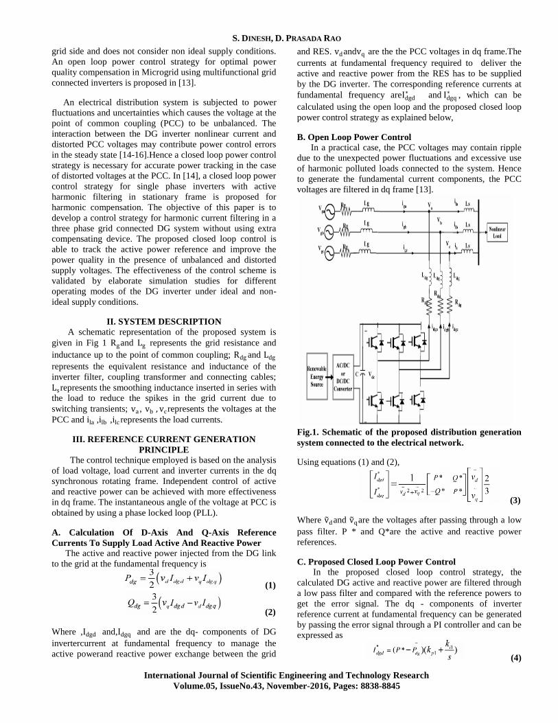
II. SYSTEM DESCRIPTION
A schematic representation of the proposed system is
given in Fig 1 Rgand Lg represents the grid resistance and
inductance up to the point of common coupling; Rdg and Ldg
represents the equivalent resistance and inductance of the
inverter filter, coupling transformer and connecting cables;
Lsrepresents the smoothing inductance inserted in series with
the load to reduce the spikes in the grid current due to
switching transients; va , vb , vcrepresents the voltages at the
PCC and ila ,ilb ,ilc represents the load currents.
III. REFERENCE CURRENT GENERATION
PRINCIPLE
The control technique employed is based on the analysis
of load voltage, load current and inverter currents in the dq
synchronous rotating frame. Independent control of active
and reactive power can be achieved with more effectiveness
in dq frame. The instantaneous angle of the voltage at PCC is
obtained by using a phase locked loop (PLL).
A. Calculation Of D-Axis And Q-Axis Reference
Currents To Supply Load Active And Reactive Power
The active and reactive power injected from the DG link
to the grid at the fundamental frequency is
(1)
(2)
Where ,Idgd and,Idgq and are the dq- components of DG
invertercurrent at fundamental frequency to manage the
active powerand reactive power exchange between the grid
and RES. vdandvq are the the PCC voltages in dq frame.The
currents at fundamental frequency required to deliver the
active and reactive power from the RES has to be supplied
by the DG inverter. The corresponding reference currents at
fundamental frequency areIdgd∗ and Idgq
∗ , which can be
calculated using the open loop and the proposed closed loop
power control strategy as explained below,
B. Open Loop Power Control
In a practical case, the PCC voltages may contain ripple
due to the unexpected power fluctuations and excessive use
of harmonic polluted loads connected to the system. Hence
to generate the fundamental current components, the PCC
voltages are filtered in dq frame [13].
Fig.1. Schematic of the proposed distribution generation
system connected to the electrical network.
Using equations (1) and (2),
(3)
Where v dand v qare the voltages after passing through a low
pass filter. P * and Q*are the active and reactive power
references.
C. Proposed Closed Loop Power Control In the proposed closed loop control strategy, the
calculated DG active and reactive power are filtered through
a low pass filter and compared with the reference powers to
get the error signal. The dq - components of inverter
reference current at fundamental frequency can be generated
by passing the error signal through a PI controller and can be
expressed as
(4)
Power Quality Enhancement using Fuzzy Controlled Active Power Filter with Distributed Generation Integration Feature
International Journal of Scientific Engineering and Technology Research
Volume.05, IssueNo.43, November-2016, Pages: 8838-8845
(5)
Where Pdg andPqg represent the filtered real and reactive
power of the DG inverter, kp1.ki1kp2and ki2are
theproportional and integral gains for minimizing the real
and reactive power control errors, As per IEEE 1547 the
inverters in a distributed generation system are not permitted
to inject reactive power to the grid [5]. As such, the total q-
axis reference current for the inverter is limited to meet only
the reactive power demand of the load so that Idgq∗ = O.
Hence only active power control is done in both open loop
and closed loop control schemes. In rotating synchronous
frame the quadrature component of load current i1q is
perpendicular to the direct component of voltage (ilq vd ).
Accordingly the q-axis reference current of the DO inverter
can be expressed as
(6)
D. Calculation of Total D-Axis Reference Current
The d-axis component of the load current can be
expressed as
(7)
Where ini∎ld is the oscillating component of the load
currentand ild1 is the fundamental component of load
current. In dq frame the fundamental frequency component
of the load current appears as a dc component. The harmonic
components of the load current can be obtained by using a
high pass filter. But due to the excessive phase lag associated
with the high pass filter, a second order low pass filter
having a cut off frequency of 25 Hz is used to extract the
harmonic component of the load current. i ∎ld Can be
expressed as
(8)
(9)
The DO inverter has to supply the d-axis component of
harmonic load current given by equation (8) and the d-axis
component of current at fundamental frequency given by
equation (3) or (4) depending upon the type of the power
control scheme. Hence the total d-axis reference current for
the DO inverter can be expressed as
(10)
E. DC Link Voltage Control
When the power from the RES is equal to zero, the
inverter operates in shunt active filter mode. The DO inverter
draws an active power component of current for maintaining
the dc bus voltage constant and to meet the losses in the
inverter. The DC link voltage error can be expressed as
(11)
The current can be obtained by passing the error
through a PI controller and is given by
(12)
Where kp and k; are the proportional and integral gain
constants.
F. Hysteresis Current Control Scheme
A Hysteresis band current controller is used to generate
the switching pulses for the DO inverter. The reference
currents generated in dq frame are transformed to natural
ABC frame and compared with the inverter currents to
generate the error signals.
If Idga∗ − idga > hb ,then upper switch is switched
ON and lower switch is switched OFF in the
inverter leg of phase 'a'.
If Idga∗ − idga < hb then upper switch is switched
OFF andlower switch is switched ON in the inverter
leg of phase 'a',
Where hb is the assigned hysteresis band? Using the same
principle switching pulses for the other switches in phase
'b'&'c' are produced. The hysteresis band directly controls the
amount of ripples in the current injected into the grid. The
main advantages of hysteresis current controller are ease of
implementation, extremely good dynamic response,
outstanding robustness and independence of load parameter
changes [17]. The switching frequency depends on the width
of hysteresis band, the size of interfacing inductor Ldg to the
grid and the DC voltage. As per [18], the relation between
switching frequency and the filter inductance can be
expressed as
(13)
Wherevdc is the DC link voltage, hb is the hysteresis band
and fbsw max is the maximum switching frequency.
IV. INTRODUCTION TO FUZZY LOGIC
CONTROLLER L. A. Zadeh presented the first paper on fuzzy set theory
in 1965. Since then, a new language was developed to
describe the fuzzy properties of reality, which are very
difficult and sometime even impossible to be described using
conventional methods. Fuzzy set theory has been widely
used in the control area with some application to dc-to-dc
converter system. A simple fuzzy logic control is built up by
a group of rules based on the human knowledge of system
behavior. Matlab/Simulink simulation model is built to study
the dynamic behavior of dc-to-dc converter and performance
of proposed controllers. Furthermore, design of fuzzy logic
controller can provide desirable both small signal and large
signal dynamic performance at same time, which is not
possible with linear control technique. Thus, fuzzy logic

S. DINESH, D. PRASADA RAO
International Journal of Scientific Engineering and Technology Research
Volume.05, IssueNo.43, November-2016, Pages: 8838-8845
controller has been potential ability to improve the
robustness of dc-to-dc converters. The basic scheme of a
fuzzy logic controller is shown in Fig.2 and consists of four
principal components such as: a fuzzification interface,
which converts input data into suitable linguistic values; a
knowledge base, which consists of a data base with the
necessary linguistic definitions and the control rule set; a
decision-making logic which, simulating a human decision
process, infer the fuzzy control action from the knowledge of
the control rules and linguistic variable definitions; a de-
fuzzification interface which yields non fuzzy control action
from an inferred fuzzy control action [10].
Fig.2. General Structure of the fuzzy logic controller on
closed-loop system.
The fuzzy control systems are based on expert
knowledge that converts the human linguistic concepts into
an automatic control strategy without any complicated
mathematical model [10]. Simulation is performed in buck
converter to verify the proposed fuzzy logic controllers as
shown in Fig.3.
Fig.3. Block diagram of the Fuzzy Logic Controller
(FLC) for dc-dc converters.
Fuzzy Logic Membership Functions: The dc-dc converter
is a nonlinear function of the duty cycle because of the small
signal model and its control method was applied to the
control of boost converters. Fuzzy controllers do not require
an exact mathematical model. Instead, they are designed
based on general knowledge of the plant. Fuzzy controllers
are designed to adapt to varying operating points. Fuzzy
Logic Controller is designed to control the output of boost
dc-dc converter using Mamdani style fuzzy inference system.
Two input variables, error (e) and change of error (de) are
used in this fuzzy logic system. The single output variable
(u) is duty cycle of PWM output as shown in Figs.4 to 6.
Fig. 4.The Membership Function plots of error.
Fig.5. The Membership Function plots of change error.
Fig.6. the Membership Function plots of duty ratio.
Fuzzy Logic Rules: The objective of this dissertation is to
control the output voltage of the boost converter. The error
and change of error of the output voltage will be the inputs of
fuzzy logic controller. These 2 inputs are divided into five
groups; NB: Negative Big, NS: Negative Small, ZO: Zero
Area, PS: Positive small and PB: Positive Big and its
parameter [10]. These fuzzy control rules for error and
change of error can be referred in the table that is shown in
Table II as per below:
TABLE II: Table Rules For Error And Change Of Error

Power Quality Enhancement using Fuzzy Controlled Active Power Filter with Distributed Generation Integration Feature
International Journal of Scientific Engineering and Technology Research
Volume.05, IssueNo.43, November-2016, Pages: 8838-8845
V. MATLAB/SIMULINK RESULTS
Simulation results of this paper is as shown in bellow
Figs.7 to 22.
Fig.7. Simulation model for generation of switching
pulses for the DG inverter
Fig.8. Simulation waveform for Grid voltage, Grid
currents and DC link voltage during shunt active filter
mode of the DG inverter.
Fig.9. Simulation waveform for source voltage, source
currents.
Fig.10. Simulation waveform for Grid voltage, Grid
current and DG current in phase a under forward power
flow mode.
Fig.11.Simulation waveform for forward reactive power
Fig.12. Simulation waveform for Grid voltage, Grid
current and DG current in phase a under forward mode.

S. DINESH, D. PRASADA RAO
International Journal of Scientific Engineering and Technology Research
Volume.05, IssueNo.43, November-2016, Pages: 8838-8845
Fig.13. Simulation waveform for reverse reactive power.
Fig.14. Simulation waveform for Grid voltage, Grid
current and DG current in phase a under reverse mode.
Fig.15. Simulation waveform for Grid voltage, Grid
current and DG current in phase a under reverse power
flow mode.
Fig.16.Simulation waveform for DG Real power under
non ideal supply conditions using open loop and closed
loop control.
Fig.17.Simulation waveform for Fundamental current
tracking in Closed loop control.
Fig.18. Simulation waveform for Dynamic performance
of the proposed closed loop power control.
Fig.19. source current THD with PI controller 3.57%.
Power Quality Enhancement using Fuzzy Controlled Active Power Filter with Distributed Generation Integration Feature
International Journal of Scientific Engineering and Technology Research
Volume.05, IssueNo.43, November-2016, Pages: 8838-8845
Fig.20. Fuzzy logic control block diagram for generation
of switching pulses for the DG inverter.
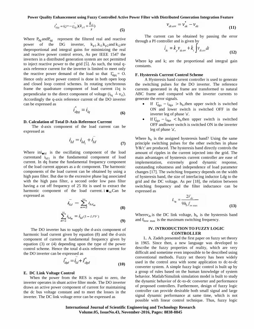
Fig.21. source current THD is 1.02 with fuzzy logic
controller.
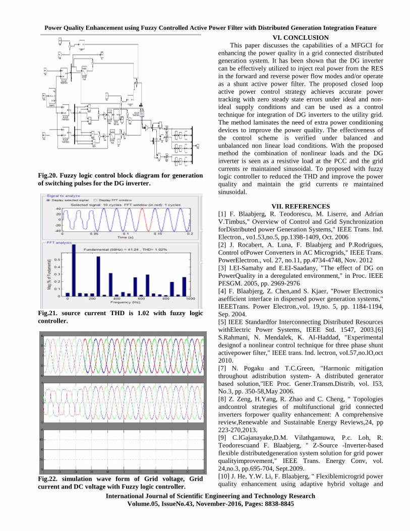
Fig.22. simulation wave form of Grid voltage, Grid
current and DC voltage with Fuzzy logic controller.
VI. CONCLUSION
This paper discusses the capabilities of a MFGCI for
enhancing the power quality in a grid connected distributed
generation system. It has been shown that the DG inverter
can be effectively utilized to inject real power from the RES
in the forward and reverse power flow modes and/or operate
as a shunt active power filter. The proposed closed loop
active power control strategy achieves accurate power
tracking with zero steady state errors under ideal and non-
ideal supply conditions and can be used as a control
technique for integration of DG inverters to the utility grid.
The method laminates the need of extra power conditioning
devices to improve the power quality. The effectiveness of
the control scheme is verified under balanced and
unbalanced non linear load conditions. With the proposed
method the combination of nonlinear loads and the DG
inverter is seen as a resistive load at the PCC and the grid
currents re maintained sinusoidal. To proposed with fuzzy
logic controller to reduced the THD and improve the power
quality and maintain the grid currents re maintained
sinusoidal.
VII. REFERENCES
[1] F. Blaabjerg, R. Teodorescu, M. Liserre, and Adrian
V.Timbus," Overview of Control and Grid Synchronization
forDistributed power Generation Systems," IEEE Trans. Ind.
Electron., vo1.53,no.5, pp.1398-1409, Oct. 2006
[2] J. Rocabert, A. Luna, F. Blaabjerg and P.Rodrigues,
Control ofPower Converters in AC Microgrids," IEEE Trans.
PowerElectron., vol. 27, no.11, pp.4734-4748, Nov. 2012
[3] I.EI-Samahy and E.EI-Saadany, "The effect of DG on
PowerQuality in a deregulated environment," in Proc. IEEE
PESGM. 2005, pp. 2969-2976
[4] F. Blaabjerg, Z. Chen,and S. Kjaer, "Power Electronics
asefficient interface in dispersed power generation systems,"
IEEETrans. Power Electron.,vol. 19,no. 5, pp. 1184-1194,
Sep. 2004.
[5] IEEE Standardfor Interconnecting Distributed Resources
withElectric Power Systems, IEEE Std. 1547, 2003.[6]
S.Rahmani, N. Mendalek, K. AI-Haddad, "Experimental
designof a nonlinear control technique for three phase shunt
activepower filter," IEEE trans. Ind. lectron, voI.57,no.lO,oct
2010.
[7] N. Pogaku and T.C.Green, "Harmonic mitigation
throughout adistribution system- A distributed generator
based solution,"lEE Proc. Gener.Transm.Distrib, vol. I53,
No.3, pp. 350-58,May 2006.
[8] Z. Zeng, H.Yang, R. Zhao and C. Cheng, " Topologies
andcontrol strategies of multifunctional grid connected
inverters forpower quality enhancement: A comprehensive
review,Renewable and Sustainable Energy Reviews,24, pp
223-270,2013.
[9] C.lGajanayake,D.M. Vilathgamuwa, P.c. Loh, R.
Teodorescuand F. Blaabjerg, " Z-Source -Inverter-based
flexible distributedgeneration system solution for grid power
qualityimprovement," IEEE Trans. Energy Conv, vol.
24,no.3, pp.695-704, Sept.2009.
[10] J. He, Y.W. Li, F. Blaabjerg, " Flexiblemicrogrid power
quality enhancement using adaptive hybrid voltage and

S. DINESH, D. PRASADA RAO
International Journal of Scientific Engineering and Technology Research
Volume.05, IssueNo.43, November-2016, Pages: 8838-8845
currentcontroller." IEEE trans. Ind. Electron.. 61. no.6. June
2014.
[11] M. Singh, S. Member, V. Khadkikar, A. Chandra, and
S.Member, "Grid Interconnection of renewable energy
sources atthe distribution level with power-quality
improvement features,"IEEE Trans. Power Delivery vol. 26,
no. I, pp. 307-315, 2011.
[12] E. Pouresmaeil, C. M - Espinar, M. M - Campos,D. M-
Miracleand O. G -Bellmunt, "A Control technique for
integration ofDGunits to the Electrical networks," IEEE
Trans. Power Electron.,vol. 60, no. 7, pp. 2881-2893, July
2013.
[13] Z. Zeng, H Yang, Q Tang, R Zhao, " Objective-oriented
powerquality compensation of multifunctional grid -tied
inverters andits application in Microgrids," IEEE Trans.
Power Electron.,vo1.30, no.3, pp. 1255-1265, March 2015.
[14] 1 He, Y.Wei Li, F,Blaabjerg, X.Wang, "Active
harmonicfiltering using current-controlled grid –connected
DG units withclosed loop power control," IEEE Trans.
Power Electron.,vol.29, no. 2, pp. 642-653, Feb. 2014.
[15] H.Akagi, E.H. Watanabe,andM.Aredes, Instantaneous
Power Theory and Applications to Power Conditioning,
Hoboken, NJ:Wiley-IEEE Press, Feb. 2007.
[16] R. Teodorescu, M. Liserre, and P.Rodriguez, Grid
Convertersfor Photovoltaic and Wind Power Systems, IEEE
Wiley, 2011.