
Power PrunerTM - ECHO-USA.com
32
POWER PRUNER TM OPERATOR'S MANUAL 1 Power Pruner TM Operator's Manual MODEL: PPT-261 Serial Number 002001001 & Up WARNING DANGER X750001210 10/00 X7502094400 Read rules for safe operation and instructions carefully. ECHO provides an Operator's Manual and a Safety Manual. Both must be read and understood for proper and safe operation.
-
Upload
khangminh22 -
Category
Documents
-
view
1 -
download
0
Transcript of Power PrunerTM - ECHO-USA.com

POWER PRUNERTM
OPERATOR'S MANUAL 1
Power Pruner TM
Operator's Manual
MODEL: PPT-261Serial Number 002001001 & Up
WARNING DANGER
X75000121010/00
X7502094400
Read rules for safe operation and instructions carefully. ECHO provides an Operator'sManual and a Safety Manual. Both must be read and understood for proper and safeoperation.

2INTRODUCTION
Welcome to the ECHO family. This ECHO product was designed and manufactured to provide long life and on-the-job-dependability. Read and understand this manual and the SAFETY MANUAL you found in the same package. You willfind both easy to use and full of helpful operating tips and SAFETY messages.
WARNING DANGERRead rules for safe operation and instructions carefully. ECHO provides an Operator's Manual and a Safety Manual.Both must be read and understood for proper and safe operation.
THE OPERATOR'S MANUALcontains specifications and information for operation, starting,stopping, maintenance, storage and assembly specific to this product.
THE SAFETY MANUALexplains possible hazards involved with the use of Power PrunerTM andwhat measures you should take to make their use safer.
TABLE OF CONTENTSIntroduction ............................................................... 2
- The Operator's Manual ........................................ 2- The Safety Manual....................................................2
Manual Safety Symbols and Important Information .. 3Safety ......................................................................... 3
- Decals .................................................................. 3- International Symbols ......................................... 4- Equipment ........................................................... 4- Fuel ...................................................................... 5- Personal Condition and Safety Equipment .......... 6- Safe Operation ..................................................... 7- Kickback .............................................................. 8- Extended Operation/Extreme Conditions ............. 9
Description .............................................................. 10- Contents ............................................................ 10- Emission Control ............................................... 10
Specifications ........................................................... 13Assembly ................................................................. 14
- Shaft Tube / Power Head .................................. 14- Cutting Attachment to Shaft Tube Installation . 14- Throttle Linkage Installation ............................. 15- Saw Chain Tension Adjustment ....................... 16
Pre-Operation ........................................................... 16- Fuel................................................................... 16- Lubricating the Guide Bar and Saw Chain ........ 18- Adjusting Automatic Oiler ................................ 18- Equipment Check .............................................. 19- Determine Operation Area ................................ 19
Operation ................................................................. 20- Starting Cold Engine ......................................... 20- Starting Warm Engine ....................................... 21- Stopping Engine ............................................... 21- Pruning Technics .............................................. 22
Maintenance ............................................................ 22- Skill Levels........................................................ 22- Maintenance Intervals ...................................... 23- Air Filter ............................................................ 24- Fuel Filter .......................................................... 24- Spark Plug ......................................................... 25- Cooling System Cleaning .................................. 25- Exhaust System ................................................. 26- Carburetor Adjustment ..................................... 27- Guide Bar and Saw Chain Replacement ............ 28- Filing Saw Chain ............................................... 29
Troubleshooting ...................................................... 30Storage ..................................................................... 31Servicing Information ............................................... 32
- Parts .................................................................. 32- Service.............................................................. 32- ECHO Consumer Product Support .................... 32- Warranty Card .................................................. 32- Additional or Replacement Manuals ................ 32- Manual Ordering Instructions .......................... 32
CopyRight© 2000 By Echo, IncorporatedAll Rights Reserved.
Specifications, descriptions and illustrative material in thisliterature are as accurate as known at the time of publica-tion, but are subject to change without notice. Illustrationsmay include optional equipment and accessories, and maynot include all standard equipment.

POWER PRUNERTM
OPERATOR'S MANUAL 3
The circle with the slash symbol means whatever isshown within the circle is prohibited.
This symbol accompanied by the words WARNINGand DANGER calls attention to an act or condition thatcan lead to serious personal injury to operator andbystanders.
MANUAL SAFETY SYMBOLS AND IMPORTANT INFORMATION
Throughout this manual and on the product itself, you will find safetyalerts and helpful, information messages preceded by symbols or keywords. The following is an explanation of those symbols and keywords and what they mean to you.
IMPORTANT The enclosed messageprovides information necessary for theprotection of the unit.
SAFETY
DECALS
Locate this safety decal on your unit. The complete unit illustration found in the "DESCRIPTION" section, will help youlocate them. Make sure the decals are legible and that you understand and follow the instructions on them. If a decalcannot be read, a new one can be ordered from your ECHO dealer. See PARTS ORDERING instructions for specificinformation.
Shaft Coupler
IMPORTANT NOTE
NOTE This enclosed message providestips for use, care and maintenance of theunit.
P/N 89016022660

4
Symboldescription/application Symbol form/shape
Symboldescription/applicationSymbol form/shape
HotSurface
Carburetoradjustment- Idle speed
Carburetoradjustment
- High speed mixture
Symboldescription/application Symbol form/shape
Symboldescription/applicationSymbol form/shape
Read andunderstand
Operator's Manual.
Wear eyes, earsand head
protection
Emergency stop
Fuel and oilmixture
Finger Severing
Carburetoradjustment
- Low speed mixture
Safety/Alert
Avoid all powerlines. This unit is
not insulatedagainst electrical
current.
Do not operatecloser than 15 m
(50 ft.) fromelectricalhazards.
Keep bystandersat least 15 m(50 ft.) away.
Plan retreat pathfrom falling
objects.
Wear handprotection. Use
two handed.
DO NOT smokenear fuel.
DO NOT allowflames or sparks
near fuel.
Wear slipresistant foot
wear.
Engine chokecontrol.
IgnitionON/OFF
Chain lubrication
Primer bulb
INTERNATIONAL SYMBOLS
EQUIPMENT
Before operation a complete check of the unit must be performed;• Check unit for loose/missing nuts, bolts and screws. Tighten
and/or replace as needed.• Inspect fuel lines, tank and area around carburetor for fuel leaks.
DO NOT operate unit if leaks are found.• Never adjust the guide bar or saw chain when the engine is operat-
ing.
Guide Bar and Saw Chain
WARNING DANGER• Serious injury may result from the use of non approved guide bar
and saw chain combinations. Read and comply with all safetyinstructions listed in this manual.
• ECHO, INC. will not be responsible for the failure of cuttingdevices or accessories which have not been tested and approvedby ECHO for use with this unit.

POWER PRUNERTM
OPERATOR'S MANUAL 5• Check that the cutting attachment, guide bar and saw chain is firmly
attached and in safe operating condition.
• Only use ECHO approved guide bar and saw chain.
• Only use one ECHO approved extension on the pruner.
• Do not hit rocks, stones, tree stumps and other foreign objects withthe saw chain.
• Do not cut into the ground with the saw chain.
• If cutting attachment end strikes an obstruction, stop engine immedi-ately and inspect saw chain for damage.
• Do not operate with a dull, fractured or discolored saw chain.
• Remove all foreign objects from work area.
• Always cover the guide bar and saw chain with guide bar coverduring transportation and in storage.
FUEL
WARNING DANGERFuel is VERY flammable. Use extreme care when mixing, storing orhandling, or serious personal injury may result.• Use an approved fuel container.• DO NOT smoke near fuel.• DO NOT allow flames or sparks near fuel.• Fuel tanks/cans may be under pressure. Always loosen fuel caps
slowly allowing pressure to equalize.• NEVER refuel a unit when the engine is HOT!• NEVER refuel a unit with the engine running.• DO NOT fill fuel tanks indoors. ALWAYS fill fuel tanks out
doors over bare ground.• Securely tighten fuel cap after refueling.• Inspect for fuel leakage. If fuel leakage is found, do not start or
operate unit until leakage is repaired.
IMPORTANTSpilled fuel is a leading cause of hydrocarbon emissions. Somestates may require the use of automatic fuel shut-off containersto reduce fuel spillage. Contact your ECHO dealer for orderinginformation.
After Refueling;• Wipe any spilled fuel from the unit.• Move at least 3 m (10 ft.) from refueling location before starting.
After Use;• DO NOT store a unit with fuel in its tank. Leaks can occur. Return
unused fuel to an approved fuel storage container.
3 m(10 ft.) MINIMUM

6PERSONAL CONDITION & SAFETY EQUIPMENT
Physical Condition --Your judgment and physical dexterity may not be good:
• if you are tired or sick,• if you are taking medication,• if you have taken alcohol or drugs.
Operate unit only if you are physically and mentally well.
Eye Protection --Wear eye protection that meets ANSI Z87.1 or CE requirements when-ever you operate the Power PrunerTM.
Face & Head Protection --When trimming overhead, always wear head protection meeting ANSIZ89.1 or CE requirements with a full face shield. Head protection withfull face shield will help protect you from falling branches and debris.
Hand Protection --Wear no-slip, heavy duty work gloves to improve your grip on thePower PrunerTM handles. Gloves also reduce the transmission ofmachine vibration to your hands.
Hearing Protection --ECHO recommends wearing hearing protection whenever unit is used.
Proper Clothing --Wear snug fitting, durable protective clothing; chain saw safety pantsor chaps are recommended.• Pants should have long legs, shirts with long sleeves.• DO NOT WEAR SHORTS,• DO NOT WEAR TIES, SCARVES, JEWELRY.
Wear sturdy protective safety shoes or boots with non-skid soles;• DO NOT WEAR OPEN TOED SHOES,• DO NOT OPERATE UNIT BAREFOOTED.
Hot Humid Weather --Heavy protective clothing can increase operator fatigue which may leadto heat stroke. Schedule heavy work for early morning or late afternoonhours when temperatures are cooler.
WARNING DANGERPower PrunerTM users risk injury to themselves and others if the Power PrunerTM is used improperly and or safetyprecautions are not followed. Proper clothing and safety gear must be worn when operating a Power PrunerTM.

POWER PRUNERTM
OPERATOR'S MANUAL 7SAFE OPERATION
WARNING DANGERAll over head electrical conductors and communications wires canhave electricity flow with high voltages. Never touch wires directlyor indirectly when pruning, otherwise serious injury or death mayresult.
Determine Operation Area
• Provide all operators of this equipment with the Operator's Manualand instructions for safe operation.
• Review the area to be trimmed. Look for hazards that could contributeto unsafe conditions. DO NOT operate unit if any wires (power,telephone, cable, etc.) are closer than 15 m (50 ft.) to any part of theoperator or unit.
• Spectators and fellow workers must be warned, and children andanimals prevented from coming nearer than 15 m (50 ft.) while thePower PrunerTM is in use.
• Avoid all power lines. This unit is not insulated against electricalcurrent.
Operation
WARNING DANGERDo not operate this product indoors or in inadequately ventilatedareas. Engine exhaust contains poisonous emissions and can causeserious injury or death.
Use Proper Clothing & Equipment• Before starting the unit, equip yourself and any other person
working within the 15 m (50 ft.) Safety Zone with the requiredProtective Equipment and clothing.
• Always wear head protection with full face shield to help protectagainst falling branches and debris.
Avoid Hot Surfaces• During operation, the complete unit, especially the power head,
muffler cover area and cutting attachment may become very hot, toohot to touch. Avoid contact during and immediately after operation.Always keep exhaust area clear of flammable debris.
15 m(50 ft.)

8Keep A Firm Grip• Grip Power PrunerTM with both hands with thumbs and fingers
encircling the handle, and lower shaft tube.
Keep A Solid Stance• Maintain footing and balance at all times. Do not stand on slippery,
uneven or unstable surfaces. Do not work in odd positions or onladders. Do not overreach.
• Operate the Power PrunerTM only from the ground or out of anapproved bucket lift.
• Always evaluate the branches to be pruned for hazards such as loosedead branches which may fall and strike the operator or helpers.Remove hazards before pruning.
• Cut branches bounce when striking ground.
• Plan retreat path from falling objects.
• Check that shoulder harness is adjusted for safe, comfortableoperation. See picture at right for proper adjustment.
• Turn the Power PrunerTM off when moving from tree to tree.
• Avoid any contact with saw chain.
KICKBACK
WARNING DANGERKickback can lead to dangerous loss of control of the PowerPrunerTM and result in serious injury to the operator or any onestanding close by. Hold the Power PrunerTM firmly with both handswith thumbs and fingers encircling the front and rear handles. Beaware of the down and outward path the pruner will take after thecut is made.
Kickback may occur when the moving saw chain at the nose or tip ofthe guide bar touches an object, or when the wood closes in andpinches the saw chain in the cut. In some cases this may cause alightning-fast reverse action, kicking the guide bar and saw chain upand back or down and back towards the operator. Either of thesereactions may cause the operator to lose control of the Power PrunerTM
which could result in serious personal injury.
With a basic understanding of kickback, you can reduce or eliminate theelement of surprise which contributes to accidents.
Avoid contact of the guide bar tip with any object while the saw chainis moving.
Cut only wood. Avoid striking concrete, metal, wire, or other obstruc-tions which could cause kickback or damage to the saw chain.
If the saw chain does strike a foreign object, immediately stop theengine, inspect and repair the Power PrunerTM if necessary.

POWER PRUNERTM
OPERATOR'S MANUAL 9
EXTENDED OPERATION/EXTREME CONDITIONSVibration and ColdIt is believed that a condition called Raynaud’s Phenomenon, whichaffects the fingers of certain individuals may be brought about byexposure to vibration and cold. Exposure to vibration and cold maycause tingling and burning sensations followed by loss of color andnumbness in the fingers. The following precautions are stronglyrecommended because the minimum exposure which might trigger theailment is unknown.
• Keep your body warm, especially the head, neck, feet, ankles, handsand wrists.
• Maintain good blood circulation by performing vigorous armexercises during frequent work breaks and also by not smoking.
• Limit the hours of operation. Try to fill each day with jobs whereoperating the trimmer or other hand-held power equipment is notrequired.
• If you experience discomfort, redness and swelling of the fingersfollowed by whitening and loss of feeling, consult your physicianbefore further exposing yourself to cold and vibration.
Repetitive Stress InjuriesIt is believed that overusing the muscles and tendons of the fingers,hands, arms and shoulders may cause soreness, swelling, numbness,weakness and extreme pain in those areas. Certain repetitive handactivities may put you at a high risk for developing a Repetitive StressInjury (RSI). An extreme RSI condition is Carpal Tunnel Syndrome(CTS), which could occur when your wrist swells and squeezes a vitalnerve that runs through the area. Some believe that prolonged exposureto vibration may contribute to CTS. CTS can cause severe pain formonths or even years.To reduce the risk of RSI/CTS, do the following:
• Avoid using your wrist in a bent, extended or twisted position.Instead try to maintain a straight wrist position. Also, when grasping,use your whole hand, not just the thumb and index finger.
• Take periodic breaks to minimize repetition and rest your hands.
• Reduce the speed and force with which you do the repetitivemovement.
• Do exercises to strengthen the hand and arm muscles.
• Immediately stop using all power equipment and consult a doctor ifyou feel tingling, numbness or pain in the fingers, hands, wrists orarms. The sooner RSI/CTS is diagnosed, the more likely permanentnerve and muscle damage can be prevented.

10DESCRIPTION
Due to packaging restriction the ECHO product you have purchased requires some assembly.
After opening the carton, check for damage. Immediately notify your retailer or ECHO Dealer of damaged or missingparts. Use the contents list to check for missing parts.
IMPORTANT ENGINE INFORMATIONENGINE FAMILY: YEHXS.0254CA
DISPLACEMENT: 25.4 CC
THIS ENGINE MEETS U.S. EPA PH1 AND 2000 AND
LATER CALIFORNIA EMISSION REGULATIONS FOR
S.O.R.E. REFER TO OWNER'S MANUAL FOR
MAINTENANCE SPECIFICATIONS AND ADJUSTMENTS.
An Emission Control Label is located on the engine.(This is an EXAMPLE ONLY, information on label variesby engine FAMILY).
AIR INDEX TAGThe Air Index Tag indicates, for purposes of con-sumer awareness, how this product's emissionscompare to other products under the standardsenacted by the California Air Resources Board.
PRODUCT EMISSION DURABILITYThe 300 hour emission durability period is the time span selected by the manufacturer certifying the engine emissionsoutput meets applicable California emissions regulations, provided that approved maintenance procedures arefollowed as listed in the Maintenance Section of this manual.
EMISSION CONTROLCalifornia Tier 2The emission control system for these engines areEM (Engine Modification).
CONTENTS__ Power Head__ Shaft Tube Assembly__ Cutting Attachment W/ Guide Bar and Saw Chain__ Plastic Bag__ Operator's Manual__ Safety Manual__ Warranty Registration Card__ Warranty Statement__ Plastic Bag__ T-Wrench (combination screwdriver/spark plug socket)__ 3 mm hex wrench__ 4 mm hex wrench__ 8 x 10 mm Spanner__ Safety Glasses__ 2-Stroke Oil Bottle (2.6 oz.)__ Shoulder Harness__ Guide Bar Cover

POWER PRUNERTM
OPERATOR'S MANUAL 11
1
1211
10
23
9
14
1516
17
18
19
20
2113
87
6
54
22
2324

121. POWER HEAD - Includes the Engine, Clutch, Fuel System, Ignition System and Starter.
2. THROTTLE TRIGGER - Spring loaded to return to idle when released. During acceleration press trigger graduallyfor best operating technique.
3. SHOULDER HARNESS - An adjustable strap that suspends the unit from the operator.
4. CUTTING ATTACHMENT - Sealed, gear ratio is 1.5:1 reduction.
5. CUTTING SHOE - Used to capture and stabilize branch while cutting. Place cutting shoe against branch, accelerateand lower saw chain into branch.
6. GUIDE BAR - 305 mm (12 in.) guide bar w/chain tensioner.
7. SAW CHAIN - 91 VS 9.53 mm (3/8 in.) low profile Oregon® saw chain. Runs approximately 609.6 m/min. (2000 ft/min)at full throttle.
8. AUTOMATIC OILER ASSEMBLY - Self oiling. Use high quality, low viscosity, non detergent bar and chain oil.
9. LOWER SHAFT TUBE - Durable fiberglass mesh housing.
10. STOP SWITCH - Mounted on top of handle assembly. Move switch forward to run, back to stop.
11. THROTTLE TRIGGER LOCKOUT - This lever must be depressed before throttle trigger can be operated.
12. REAR HANDLE ASSEMBLY - Sturdy handle for right hand placement. Includes stop switch and throttle trigger.
13. ARM REST - Provides arm rest during operation and protects arm from hot engine.
14. SPARK ARRESTOR - CATALYTIC MUFFLER / MUFFLER - The muffler or catalytic muffler controls exhaust noiseand emission. The spark arrestor screen prevents hot, glowing particles of carbon from leaving the muffler. Keepexhaust area clear of flammable debris.
15. FUEL TANK - Contains fuel and fuel filter.
16. FUEL TANK CAP - Covers and seals fuel tank opening.
17. PRIMER BULB - Pumping primer bulb before starting engine draws fresh fuel from the fuel tank priming the carbure-tor for starting. Pump primer bulb until fuel is visible and flows freely in the clear fuel tank return line. Pump bulb anadditional 4 or 5 times.
18. RECOIL STARTER - Pull recoil handle slowly until starter engages, then quickly and firmly. When engine startsreturn handle slowly. DO NOT let handle snap back or damage will occur.
19. AIR CLEANER ASSEMBLY - Contains replaceable air filter element.
20. CHOKE - Located on top of air cleaner housing. Move lever to 'Cold Start" position to close choke for cold starting.Move lever to "Run" to open choke.
21. SPARK PLUG - Provides spark to ignite fuel mixture.
22. GUIDE BAR COVER - Used to cover guide bar and saw chain during transport and storage. Remove guide barcover before using unit.
23. OPERATOR'S MANUAL - Read and understand this manual before operation. Keep manual in a safe location forfuture reference, i.e., operation, maintenance, storage and specifications.
24. SAFETY MANUAL - Read before operation and keep in a safe place for future reference to learn proper, safeoperating techniques.

POWER PRUNERTM
OPERATOR'S MANUAL 13
LEDOM 162-TPP
)dradnatS(htgneL ).ni7.0.tf9(m67.2
)dednetxE(htgneL ).ni057.9,.tf21(m09.3
noisnetxe/whtgneL ).tf71(m44.5
htdiW ).ni60.9(m32.
thgieH ).ni8.11(m22.
)yrd(thgieW ).bl7.61(gk06.7
epyTenignE enigneenilosagrednilycelgnis,ekorts-owt,deloocriA
eroB ).ni43.1(mm0.43
ekortS ).ni01.1(mm0.82
tnemecalpsiD ).ni.uc55.1(cc4.52
metsyStsuahxE tsylatac/wrelffuMrotserrAkrapS
roterubraC JYWorblaW
metsySnoitingI )noitingiegrahcsidroticapac(IDC
gulPkrapS ).ni620.0(mm56.0paGY7-MPBKGN
leuF )liOekorts-owTdnaenilosaG(dexiM
oitaRliO/leuF lioenignedeloocriaekorts-owt,ecnamrofrePhgiHOHCE1:05
enilosaG,lohoclalyhtemgniniatnocleufesuTONOD.dedaelnuenatcO98
.EBTM%51rolohoclalyhte%01nahterom
yticapaCknaTleuF ).zo.lfSU6.91(.til85.0
metsySretratS retratSlioceRcitamotuA
hctulC epyTlagufirtneC
epyTtekcorpS hctip)"8/3(mm35.9,rupshtoot6
ylbmessAtfahSnoissimsnarTrewoP noisurtxEmunimulA
oitaResaCraeG 1:5.1
metsySgniliO citamotuA
yticapaCliOniahCwaS ).zo6.7(lm522
eldnaH tuokcoldnareggirtelttorht/wpirgdnahthgiR
ssenraHredluohS dradnatS
)MPR(deepSeldI 0003-0042
)MPR(deepSelttorhTnepOediW 000,11-0059
)SV19(niahCwaSdnaraBediuG hctip)"8/3(mm35.9;).ni21(mm503
SPECIFICATIONS

14
B
A
C
E
D
A
ASSEMBLY
SHAFT TUBE / POWER HEAD
Tools Required:10x19mm (13/32x3/4in) T-wrench, 8x10 mm Wrench,4 mm Hex Wrench
Parts Required: Power Head, Shaft Tube Assembly; Cutting Attach-ment
1. Loosen bolt (A).
2. Match square socket in engine shaft with square power transmis-sion shaft (B) and slide together until engine rests against themachine surface of lower shaft tube housing coupler (C).
3. Rotate lower shaft tube housing to align engine and rear handleassembly in an upright position.
4. Tighten bolt (A) securely so engine will not rotate on lower shafttube.
CUTTING ATTACHMENT TO SHAFT TUBE INSTALLATION
WARNING DANGERSaw Chain is sharp! Always wear gloves when handling assembly,otherwise serious personal injury may result.
1. Loosen the four (4) screws (D) and locator screw (E) on cuttingattachment.

POWER PRUNERTM
OPERATOR'S MANUAL 15
E
D
F
GH
G
HI
J
2. Loosen center clamp knob (F) turning counter clockwise.
3. Pull upper shaft tube (G) out of fiberglass lower shaft tube 127-152mm (5-6 in.), then slide (G) back into fiberglass lower shaft tubeexposing inner power transmission shaft (H). Align and join starshaped drive end of inner power transmission shaft (H) with cuttingattachment shaft (I).
4. Align ridges on upper shaft tube (G) with seams in cutting attach-ment.
5. Slide together aligning locator screw (E) in cutting attachment withlocating hole (J) in upper shaft tube.
6. Tighten locator screw (E). Tighten four (4) cutting attachmentscrews (D).
7. Extend upper shaft tube to desired length. Tighten center clampknob (F) turning clockwise.
THROTTLE LINKAGE AND IGNITION LEADS
1. Close choke and remove air filter cover.
2. Loosen nut (A) and place threaded end of throttle linkage inbracket slot. Finger tighten nut (A).
3. Place inner cable in slot of carburetor swivel (B) and tighten nut(A).
4. Check throttle for freedom of movement and that wide open throttle/ low idle extremes are adjusted properly. If adjustment cannot beachieved with adjusting nuts, consult with your Echo Dealer forcorrect adjustment procedure.
5. Connect ignition stop leads (C) and (D).
6. Bundle and secure ignition leads against engine housing with clip(E).
7. Install air filter and cover.
C
AB
D
E

16
PRE-OPERATION
FUEL
Fuel Requirements
Gasoline - Use 89 Octane [ ] (mid grade or higher) gasoline known tobe good quality. Gasoline may contain up to 15% MTBE (methyltertiary-butyl ether). Gasohol containing methyl (wood) alcohol is NOTapproved.
Two Stroke Oil - A two-stroke engine oil meeting ISO-L-EGD (ISO/CD13738) and J.A.S.O. FC Standards, must be used. Echo brand Premium50:1 oil meets these standards. Engine problems due to inadequatelubrication caused by failure to use an ISO-L-EGD and J.A.S.O. FCcertified oil, such as Echo Premium 50:1 Two-stroke Oil, will void thetwo-stroke engine warranty. (Emission related parts only are coveredfor two years, regardless of two-stroke oil used, per the statement listedin the California Emission Defect Warranty Explanation.)
SAW CHAIN TENSION ADJUSTMENT
Tools Required: 10x19mm (13/32x3/4in.) T-wrench provided
WARNING DANGERAlways disconnect spark plug wire before servicing cuttingattachment. Wear gloves when handling saw chain, otherwiseserious personal injury may result.
To Adjust Saw Chain Tension.
1. Loosen two (2) 10 mm (13/32 in.) guide bar nuts (A) located oncutting attachment.
2. Turn the adjuster slot (B) clockwise until saw chain touches thebottom of guide bar. Turning adjuster slot (B) counter clockwisewill loosen saw chain on guide bar.
3. Tighten guide bar nuts firmly. Move saw chain backwards onguide bar by hand. Saw chain should move freely on guide bar if itis in proper mesh with sprocket.
Keep the saw chain lubricated and properly adjusted and the guide barnuts tightened firmly at all times. If saw chain is difficult to rotate orbinds on guide bar, it is too tight.
R + M2
A B

POWER PRUNERTM
OPERATOR'S MANUAL 17IMPORTANTEcho Premium 2-Stroke Oil may be mixed at 50:1 ratio for applica-tion in all Echo engines sold in the past regardless of ratiospecified in those manuals.
Mixing Instructions1. Fill an approved fuel container with half of the required amount of
gasoline.2. Add 2-stroke oil to gasoline.3. Close container and shake to mix oil with gasoline.4. Add remaining gasoline and remix.5. Install fuel container cap and wipe any spilled fuel from container
and surrounding area.
Handling Fuel
WARNING DANGERFuel is VERY flammable. Use extreme care when mixing, storing orhandling, or serious personal injury may result.• Use an approved fuel container.• DO NOT smoke near fuel.• DO NOT allow flames or sparks near fuel.• Fuel tanks/cans may be under pressure. Always loosen fuel caps
slowly allowing pressure to equalize.• NEVER refuel a unit when the engine is HOT!• NEVER refuel a unit with the engine running.• DO NOT fill fuel tanks indoors. ALWAYS fill fuel tanks out
doors over bare ground.• Securely tighten fuel cap after refueling.• Inspect for fuel leakage. If fuel leakage is found, do not start or
operate unit until leakage is repaired.
IMPORTANTSpilled fuel is a leading cause of hydrocarbon emissions. Somestates may require the use of automatic fuel shut-off containersto reduce fuel spillage. Contact your ECHO dealer for orderinginformation.
After Refueling;• Wipe any spilled fuel from the unit.• Move at least 3 m (10 ft.) from refueling location before starting
the engine.
After use;• DO NOT store a unit with fuel in its tank. Leaks can occur.
Return unused fuel to an approved fuel storage container.
Storage -Fuel storage laws vary by locality. Contact your local government forthe laws affecting your area. As a precaution, store fuel in an approved,air tight container. Store in a well ventilated, unoccupied building, awayfrom sparks and flames. Do not store fuel longer than 30 days.
3 m(10 ft.) MINIMUM

18
Automatic Oiling System
1. Wipe debris from around oil fill cap.
2. Remove oil fill cap and fill reservoir with a quality, low viscosityguide bar and saw chain oil.
NOTEThe discharge volume of the automatic oiler is preset to deliver 3 to4 cc/min. at normal operating RPM. During heavy or dry cuttingconditions the oil discharge volume may be adjusted to assureadequate lubrication. Refill the oil reservoir with each tank of fuel.
IMPORTANTTo prevent plastic deterioration, do not use synthetic or siliconebased oil.
ADJUSTING AUTOMATIC OILER
Tools required: 10x19mm (13/32x3/4) T-Wrench provided
1. Remove two (2) 10 mm guide bar retaining nuts and sprocket cover.
2. From bottom of gear case, turn adjustment screw (A) clockwise todecrease oil volume - counter clockwise to increase oil volume.
NOTEVery little visible oil on the saw chain will provide sufficientlubrication.
A
IMPORTANTStored fuel ages. Do not mix more fuel than you expect to use inthirty (30) days, ninety (90) days when a fuel stabilizer is added.
IMPORTANTStored two-stroke fuel may separate. ALWAYS shake fuelcontainer thoroughly before each use.
LUBRICATING THE GUIDE BAR AND SAW CHAIN
S M T W T F S1 2 3 4 5 6 78 9 10 11 12 13 14
15 16 17 18 19 20 2122 23 24 25 26 27 2829 30 31
POWER PRUNERTM
OPERATOR'S MANUAL 19
15 m(50 ft.)
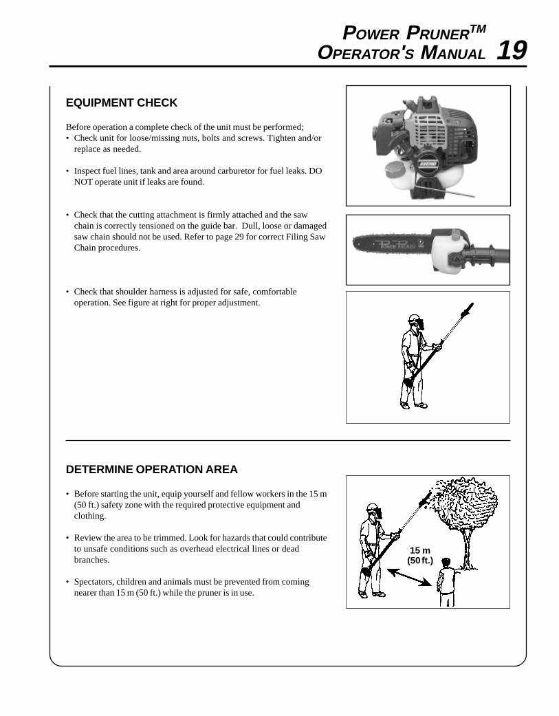
EQUIPMENT CHECK
Before operation a complete check of the unit must be performed;• Check unit for loose/missing nuts, bolts and screws. Tighten and/or
replace as needed.
• Inspect fuel lines, tank and area around carburetor for fuel leaks. DONOT operate unit if leaks are found.
• Check that the cutting attachment is firmly attached and the sawchain is correctly tensioned on the guide bar. Dull, loose or damagedsaw chain should not be used. Refer to page 29 for correct Filing SawChain procedures.
• Check that shoulder harness is adjusted for safe, comfortableoperation. See figure at right for proper adjustment.
DETERMINE OPERATION AREA
• Before starting the unit, equip yourself and fellow workers in the 15 m(50 ft.) safety zone with the required protective equipment andclothing.
• Review the area to be trimmed. Look for hazards that could contributeto unsafe conditions such as overhead electrical lines or deadbranches.
• Spectators, children and animals must be prevented from comingnearer than 15 m (50 ft.) while the pruner is in use.

20OPERATION
WARNING DANGERDo not operate this product indoors or in inadequately ventilatedareas. Engine exhaust contains poisonous emissions which cancause serious injury or death.
• Provide all operators of this equipment with the Operator's Manual,and instructions for safe operation.
• Before starting the unit, equip yourself and any other personworking within the 15 m (50 ft.) Safety Zone with the requiredProtective Equipment and clothing.
• Always evaluate the area being cut for overhead hazards, such asdead branches which may fall and strike the operator or helpers.
• Be aware of branches bouncing when striking the ground.• Larger branches should be removed in sections.• During operation, the complete unit, especially the power head,
muffler cover area and cutting attachment may become very hot, toohot to touch. Avoid contact during and immediately after operation.Always keep exhaust area clear of flammable debris.
STARTING COLD ENGINE
WARNING DANGERThe cutting attachment should not move at idle. If cutting attach-ment moves, readjust carburetor according to "Carburetor Adjust-ment" instructions in this manual or see your ECHO Dealer,otherwise serious personal injury may result.
1. Stop Switch - Start/Run.Move stop switch button (A) forward away from the STOPposition.
2. Choke - Cold Start.Move choke (B) to “Cold Start” Position.
3. Primer Bulb -Purge.Pump primer bulb (C) until fuel is visible and flows freely in theclear fuel tank return line. Pump bulb an additional 4 or 5 times.
WARNING DANGERInspect starting area for hazards such as rocks, glass, debris etc.which could be contacted by the cutting attachment when starting.Keep helpers and bystanders at least 15 m (50 ft.) from starting area,otherwise serious personal injury may result.
4. Lay the pruner on a flat clear area. Firmly grasp right hand grip andpull recoil starter handle/rope (D) until engine fires (or maximum five[5] pulls).
A
B
C
D

POWER PRUNERTM
OPERATOR'S MANUAL 215. Move choke lever to “Run” position and pull recoil starter handle/
rope (D) until engine starts and runs. Allow unit to warm up at idlefor several minutes.
NOTEIf engine does not start with choke in “Run” position after 5 pulls,repeat instructions.
6. After engine warm up, gradually depress throttle trigger to increaseengine RPM to operating speed.
STARTING WARM ENGINE
WARNING DANGERThe cutting attachment should not move at idle. If cutting attach-ment moves, readjust carburetor according to "Carburetor Adjust-ment" instructions in this manual or see your ECHO Dealer,otherwise serious personal injury may result.
1. Stop Switch - Start/Run. Move Stop Switch button (A) forwardaway from the STOP position.
2. Start - Pull Rope. Lay the pruner on a flat clear area and pullthe recoil starter handle (D) until the engine fires.
NOTEIf engine does not start after 5 pulls, use Cold Start Procedure.
STOPPING ENGINE
1. Release Throttle. Allow engine to idle for a minute.
2. Stop Switch - Stop. Move stop switch button (A) backward toSTOP position.
WARNING DANGERIf engine does not stop when stop switch is moved to STOPposition, close choke - COLD START position - to stall engine.Have your ECHO dealer repair stop switch before using pruneragain.
A
A

22
BLADE HITS REAR BRANCH
NOTCORRECT
CORRECT
GUIDE AGAINSTBRANCH
NOTCORRECT
PRUNING TECHNIQUES
The Power PrunerTM is designed for light to medium trimming of limbsand branches up to 203 mm (8 in.) in diameter. Follow these tips forsuccessful operation.
• Plan cut carefully. Check direction branch will fall.
• Plan retreat path from falling branch. Cut branches bounce whenstriking ground.
• Long branches should be removed in several pieces.
• Do not stand directly beneath branch being cut.
• When ready to cut:Hold "cutting shoe" against branch. This will prevent whipping ofthe branch. DO NOT use back and forth sawing action.
• Look out for branch immediately behind the branch being cut. If sawchain hits rear branch damage to saw chain may occur.
• Accelerate to full throttle.
• Apply cutting pressure.
• Ease cutting pressure when nearing end of cut to maintain control.
• When pruning a limb 102 mm (4 in.) diameter or larger cut as follows:1. Under cut 1/4 limb diameter near tree trunk.2. Finish top cut slightly farther out on limb.3. Flush cut stub at trunk.
• DO NOT use for felling or bucking.
NOTERefer to Pole Pruner Safety Manual for proper and safe pruningtechniques.
MAINTENANCEYour ECHO Power PrunerTM is designed to provide many hours of trouble free service. Regular scheduled maintenancewill help your pruner achieve that goal. If you are unsure or are not equipped with the necessary tools, you may want totake your unit to an ECHO Service Dealer for maintenance. To help you decide whether you want to DO-IT-YOURSELFor have the ECHO Dealer do it, each maintenance task has been graded. If the task is not listed see your ECHO Dealerfor repairs.
SKILL LEVELLevel 1 = Easy to do. Most required tools come with unit.Level 2 = Moderate difficulty. Some specialized tools may be required.Level 3 = Experience required. Specialized tools are required. ECHO recommends
that the unit be returned to your ECHO dealer for service.
ECHO offers REPOWERTM Maintenance Kits and Parts to make your maintenance job easier. Just below each taskheading are listed the various part numbers required for that task. See your ECHO dealer for these parts.

POWER PRUNERTM
OPERATOR'S MANUAL 23MAINTENANCE INTERVALS
/TNENOPMOCMETSYS
ECNANETNIAMERUDECORP
D'QERLLIKSLEVEL
ROYLIADEROFEB
ESU
YREVELEUFER
3SHTNOM
09ROSRUOH
6SHTNOM
072ROSRUOH
YLRAEY006
SRUOH
serudecorPecnanetniaMrelaeDohcEdednemmoceR
troPtsuahxErednilyC nobraceD/naelC/tcepsnI 3 C/I
serudecorPecnanetniaMflesruoY-tI-oD
retliFriA ecalpeR/naelC/tcepsnI 1 C/I *I
metsySekohC naelC/tcepsnI 2 C/I
retliFleuF ecalpeR/tcepsnI 1 I *R/I
skael,metsySleuF ecalpeR/tcepsnI 1 *R/I I I
metsySgnilooC naelC/tcepsnI 2 C/I
rotserrAkrapSrelffuM ecalpeR/tcepsnI 2 *R/I
noissimsnarTrewoPtfahS
liO/naelC/tcepsnI 2 )1(I I
raBediuG etacirbuL/naelC/tcepsnI 2 C/I I
niahCwaS /ecalpeR/neprahS/tcepsnIetacirbuL
2 *R/I I
epoRretratSlioceR naelC/tcepsnI 1 *R/I
gulPkrapS naelC/tcepsnI 2 C/I *R
stloB/stuN/swercS ecalpeR/nethgiT/tcepsnI 1 *R/I
SEDOCRETTELERUDECORPECNANETNIAM NAELC=C,ECALPER=R,TCEPSNI=I:-ETONTNATROPMI deriuqerfoycneuqerfehtenimretedlliwecneirepxeruoydnaesulautcA.mumixameranwohsslavretniemiT
.ecnanetniam:SETONERUDECORPECNANETNIAM
* .noitcepsnignirudraewroegamadfognidnifehtnodesaberaecalperotsnoitadnemmocerllA)1( OHCEylppA ® EBUL MT .esufosruoh52yreve

24AIR FILTER
Level 1.
Tools required: 25 or 50 mm (1 or 2 in.) medium bristle paint brushParts required: 90030 REPOWERTM FILTER KIT
1. Close choke (Cold Start Position). This prevents dirt from enteringthe carburetor throat when the air filter is removed. Brush accumu-lated dirt from the air cleaner area.
2. Remove the air cleaner cover. Clean and inspect the element fordamage. If element is fuel soaked and very dirty, replace.
3. If element can be cleaned and reused, be certain it: -properly fits the cavity in the air cleaner cover. -is installed with the original side out.
NOTECarburetor adjustment may be needed after air filter cleaning/replacement. See Carburetor Adjustment Section.
FUEL FILTERLevel 1.
Tools required: 203-254 mm ( 8 - 10 in.) length of wire with one endbent into a hook. Clean rag, funnel, and an approved fuel container
Parts Required: 90030 REPOWERTM FILTER KIT
WARNING DANGERFuel is VERY flammable. Use extreme care when mixing, storing orhandling or serious personal injury may result.
1. Use a clean rag to remove loose dirt from around fuel cap andempty fuel tank.
2. Use the “fuel line hook” to pull the fuel line and filter from the tank.
3. Remove the filter from the line and install the new filter.

POWER PRUNERTM
OPERATOR'S MANUAL 25
WARNING DANGERCatalytic mufflers operate at extremely high temperatures. Mufflerarea must be kept clean. Do not perform maintenance on the muffleruntil engine and muffler are completely cool, otherwise seriouspersonal injury may occur.
SPARK PLUG
Level 2.
Tools required: 10x19mm (13/32x3/4in) T-wrench, Feeler gauge,(preferably a wire gauge), Soft metal brushParts Required: 90065 REPOWERTM KIT
1. Remove spark plug and check for fouling, worn and rounded centerelectrode.
2. Clean the plug or replace with a new one. DO NOT sand blast toclean. Remaining sand will damage engine.
3. Adjust spark plug gap by bending outer electrode.
4. Tighten spark plug to 145-155 kg/cm (125-135 in. lb.).
COOLING SYSTEM CLEANING
Level 2.Tools required: Cross Head Screwdriver, 3 mm Hex wrench, 25 or 50 mm(1 or 2 in.) medium bristle paint brushParts Required: None.
IMPORTANTTo maintain proper engine operating temperatures, cooling air mustpass freely through the cylinder fin area. This flow of air carriescombustion heat away from the engine.
Overheating and engine seizure can occur when:
• Air intakes are blocked, preventing cooling air from reaching thecylinder.
• Dust and grass build up on the outside of the cylinder. This build upinsulates the engine and prevents the heat from leaving.
Removal of cooling passage blockages or cleaning of cooling fins isconsidered “Normal Maintenance”. Any failure attributed to lack ofmaintenance is not warranted.
0.65 mm(0.026 in.)

261. Remove spark plug lead.
2. Remove two (2) muffler cover screws and muffler cover (A).
3. Remove screw and arm rest (B).
4. Remove engine cover (C).
IMPORTANTDO NOT use a metal scraper to remove dirt from the cylinder fins.
5. Use brush to remove dirt from the cylinder fins.
6. Remove grass and leaves from the grid between the recoil starterand fuel tank.
EXHAUST SYSTEM
Level 2.Tools Required: Cross Head Screwdriver, Soft Metal Brush, 4 mm HexWrench
Parts Required: Spark Arrestor Screen P/N 14586251030.
A
B
C

POWER PRUNERTM
OPERATOR'S MANUAL 27Spark Arrestor Screen
1. Remove muffler cover (A).
2. Place piston at Top Dead Center (TDC) to prevent carbon/dirt fromentering cylinder.
3. Remove spark arrestor screen cover (B), gasket (C), gasket (D) andscreen (E) from muffler body.
4. Clean carbon deposits from screen and muffler components.
NOTEWhen cleaning carbon deposit, be careful not to damage thecatalytic body.
5. Replace screen if it is cracked, plugged or has holes burnedthrough.
6. Assemble components in reverse order.
Cylinder Exhaust Port
Level 3.
IMPORTANTThe cylinder exhaust port must be inspected and cleaned of excesscarbon every 3 months or 90 hours of operation in order to maintainthis engine within the emissions durability period. ECHO stronglyrecommends that you return your unit to your ECHO dealer for thisimportant maintenance service.
CARBURETOR ADJUSTMENTEngine Break-InNew engines must be operated a minimum duration of two tanks of fuelbreak-in before carburetor adjustments can be made. During the break-inperiod your engine performance will increase and exhaust emissions willstabilize. Idle speed can be adjusted as required.
High Altitude AdjustmentHigh altitude adjustment is not required for proper operation of thisengine.
Level 2.
Tools required: Screwdriver, Tachometer (ECHO P/N 99051130017).
Parts required: None.
A
B
C
D
E

28
WARNING DANGERWhen carburetor adjustment is completed, the cutting attach-ment should not turn at idle, otherwise serious personal injurymay result.
NOTEEvery unit is run at the factory and the carburetor is set in compli-ance with California Emission Regulations. This carburetor doesnot have acceleration and high speed adjustment needles.
1. Check idle speed and reset if necessary. If a tachometer is avail-able, idle speed screw (A) should be set to the specifications foundon page 13 "Specifications" of this manual. Turn idle screw (A)clockwise to increase idle speed; counter clockwise to decreaseidle speed.
GUIDE BAR AND SAW CHAIN REPLACEMENT
WARNING DANGERNever try to replace or adjust guide bar and saw chain with engine running. Always disconnect spark plug wirebefore servicing guide bar and saw chain. This saw chain is VERY sharp, wear heavy gloves to protect your handswhen handling it. Wear eye protection meeting CE or ANSI specification Z87.1.
A B
A
Guide Bar Replacement / InstallationLevel 2
Tools Required: 10x19mm (13/32x3/4in) T-wrench
• Remove two (2) 10 mm (13/32 in.) guide bar nuts (A) and relieve sawchain tension turning adjuster slot (B) counter clockwise.
• Remove sprocket cover.• Free saw chain from sprocket and remove from guide bar. If guide bar
is okay proceed to saw chain installation.• Slide guide bar forward and remove from cutting attachment. Install
new guide bar sliding it onto the cutting attachment as far as pos-sible.
Saw Chain InstallationLevel 2
• Install new saw chain onto guide bar. Make sure cutting links arefaced towards the nose of the guide bar.
• Engage saw chain with sprocket.• Secure sprocket cover with (2) two guide bar nuts.• Follow instruction for adjusting saw chain tension page 16.
POWER PRUNERTM
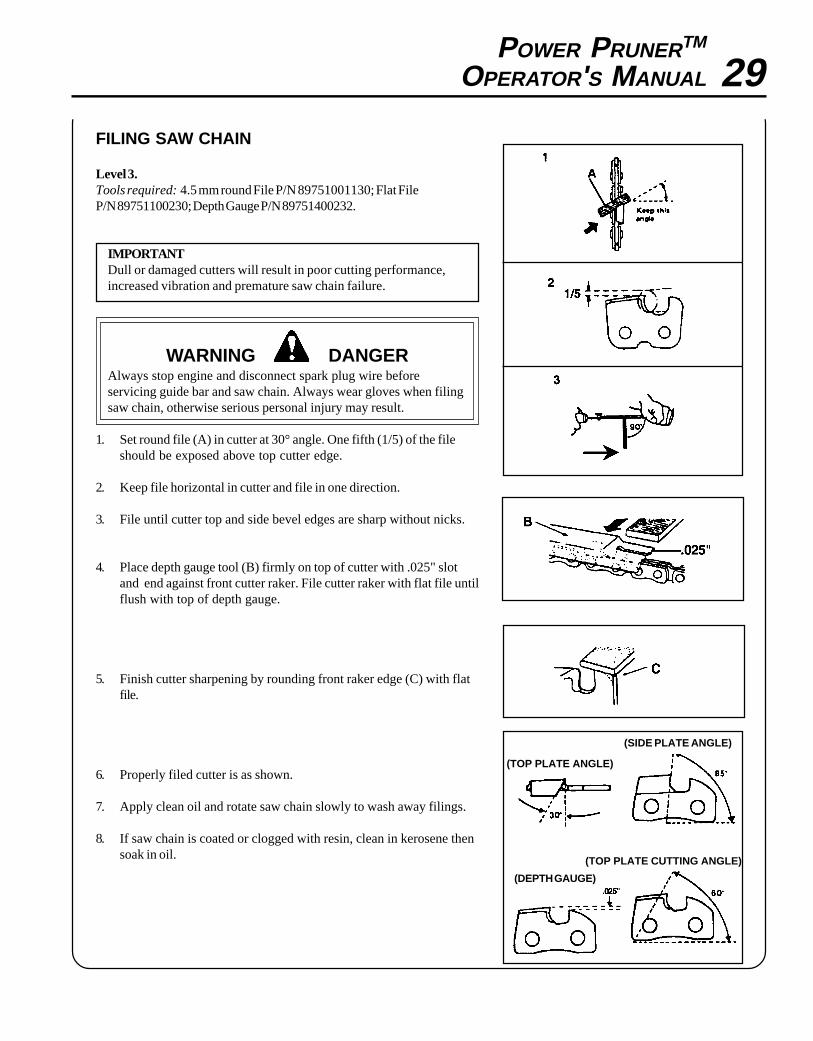
OPERATOR'S MANUAL 29FILING SAW CHAIN
Level 3.Tools required: 4.5 mm round File P/N 89751001130; Flat FileP/N 89751100230; Depth Gauge P/N 89751400232.
IMPORTANTDull or damaged cutters will result in poor cutting performance,increased vibration and premature saw chain failure.
WARNING DANGERAlways stop engine and disconnect spark plug wire beforeservicing guide bar and saw chain. Always wear gloves when filingsaw chain, otherwise serious personal injury may result.
1. Set round file (A) in cutter at 30° angle. One fifth (1/5) of the fileshould be exposed above top cutter edge.
2. Keep file horizontal in cutter and file in one direction.
3. File until cutter top and side bevel edges are sharp without nicks.
4. Place depth gauge tool (B) firmly on top of cutter with .025" slotand end against front cutter raker. File cutter raker with flat file untilflush with top of depth gauge.
5. Finish cutter sharpening by rounding front raker edge (C) with flatfile.
6. Properly filed cutter is as shown.
7. Apply clean oil and rotate saw chain slowly to wash away filings.
8. If saw chain is coated or clogged with resin, clean in kerosene thensoak in oil.
(TOP PLATE ANGLE)
(SIDE PLATE ANGLE)
(DEPTH GAUGE)
(TOP PLATE CUTTING ANGLE)

30
melborP
drahstrats--enignE
tratstonseod--enignE esuaC ydemeR
enignEsknarC
taleuFroterubrac
taleufoNroterubrac
deggolcreniartsleuFdeggolcenilleuF
roterubraC
naelCnaelC
relaedOHCEruoyeeS
taleuFrednilyc
taleufoNrednilyc
roterubraC relaedOHCEruoyeeS
tewrelffuMleufhtiw
hcirootsierutxiMleuF ekohcnepOretlifriaecalper/naelC
roterubractsujdArelaedOHCEruoyeeS
dnetakrapSeriwgulpfo
krapsoNfodnetaeriwgulp
ffohctiwspotSmelborplacirtcelE
hctiwskcolretnI
nohctiwsnruTrelaedOHCEruoyeeSrelaedOHCEruoyeeS
gulptakrapS krapsoNgulpta
tcerrocnipagkrapSnobrachtiwderevoC
leufhtiwdeluoFevitcefedgulpkrapS
).ni620.0(mm56.0tsujdAecalperronaelCecalperronaelC
gulpecalpeR
enignEtonseod
knarc
melborpenignelanretnI relaedOHCEruoyeeS
enignEsnur
ylroopsetareleccaroseiD ytridretlifriAytridretlifleuF
deggulptnevleuFgulpkrapSroterubraC
deggulpmetsysgnilooCneercsrotserrakrapS
deggulp
ecalperronaelCecalpeRecalpeR
ecalper/tsujdadnanaelCtsujdA
naelC
naelC
TROUBLESHOOTING
WARNING DANGERFuel vapors are extremely flammable and may cause fire and/or explosion. Never test for ignition spark near an openspark plug opening, otherwise serious personal injury may result.

POWER PRUNERTM
OPERATOR'S MANUAL 31
Long Term Storage (over 30 days)
Do not store your unit for a prolonged period of time (30 days orlonger) without performing protective storage maintenance whichincludes the following:
1. Store unit in a dry, dust free place, out of the reach of children.
WARNING DANGERDo not store in enclosure where fuel fumes may accumulate orreach an open flame or spark.
2. Place the stop switch (A) in the "STOP" position.
3. Remove accumulation of grease, oil, dirt and debris from exterior ofunit.
4. Perform all periodic lubrication and services that are required.
5. Tighten all the screws and nuts.
6. Drain the fuel tank completely and pull the recoil starter handleseveral times to remove fuel from the carburetor.
7. Remove the spark plug and pour 7 cc (1/4 oz.) (1/2 tablespoon) offresh, clean, two-stroke engine oil into the cylinder through thespark plug hole.
A. Place a clean cloth over the spark plug hole.B. Pull the recoil starter handle 2-3 times to distribute the oil inside
the engine.C. Observe the piston location through the spark plug hole. Pull
the recoil handle slowly until the piston reaches the top of itstravel and leave it there.
8. Install the spark plug (do not connect ignition cable).
9. Install the guide bar cover on guide bar and saw chain.
STORAGE
A
WARNING DANGERDuring operation the muffler or catalytic muffler and surrounding cover become hot. Always keep exhaust area clearof flammable debris during transportation or when storing, otherwise serious property damage or personal injurymay result.

SERVICING INFORMATION
PARTSGenuine ECHO Parts and ECHO REPOWER™ Parts and Assemblies foryour ECHO products are available only from an Authorized ECHODealer. When you do need to buy parts always have the ModelNumber and Serial Number of the unit with you. You can find thesenumbers on the engine housing. For future reference, write them in thespace provided below.
Model No. _____________ SN. ____________
SERVICEService of this product during the warranty period must be performedby an Authorized ECHO Service Dealer. For the name and address ofthe Authorized ECHO Service Dealer nearest you, ask your retailer orcall: 1-800-432-ECHO (3246). Dealer information is also available on ourWeb Site. When presenting your unit for Warranty service/repairs,proof of purchase is required.
ECHO CONSUMER PRODUCT SUPPORTIf you require assistance or have questions concerning the application,operation or maintenance of this product you may call the ECHOConsumer Product Support Department at 1-800-673-1558 from 8:00 amto 5:00 pm (Central Standard Time) Monday through Friday. Beforecalling, please know the model and serial number of your unit to helpyour Consumer Product Support Representative.
WARRANTY REGISTRATIONYou may register your Echo equipment using the warranty registrationcard or register on-line at www.echo-usa.com. Registering provides adirect link between you and ECHO if we find it necessary to contactyou.
ADDITIONAL OR REPLACEMENT MANUALSSafety Manuals in English/Spanish or English/French are available, free of charge, from your ECHO dealer or atwww.echo-usa.com.Operator's and Parts Manuals are available by:• Downloading free from www.echo-usa.com• Purchasing from your Echo Dealer.• Sending a check or money order for $2.00 per Parts Catalog or $1.50 per Operator's Manual made payable to ECHO,
INCORPORATED. State on a sheet of paper the model number and serial number of the ECHO unit you have, partnumber of the manual (if known), your name and address and mail to address above.
Available Parts Catalog
PPT-261 S/N 002001001 & Up99922203168
DEALER?Call
1-800-432-ECHOor
www.echo-usa.com
CONSUMER PRODUCTSUPPORT
1-800-673-15588 - 5 Mon - Fri C.S.T.
ECHO, INCORPORATED400 OAKWOOD ROAD
LAKE ZURICH, IL 60047
www.echo-usa.com