Solution-processed bismuth halide thin film semiconductors ...
Upload
independentCategory
view
0download
0
Ž .Materials Science and Engineering C 11 2000 35–40
www.elsevier.comrlocatermsec
Porous bioactive calcium carbonate implants processed by starch
consolidation
A.F. Lemos, J.M.F. Ferreira)
Department of Ceramics and Glass Engineering, UniÕersity of AÕeiro, UIMC, 3810-193 AÕeiro, Portugal
Accepted 20 September 1999
Abstract
Ž .Macroporous calcium carbonate CaCO materials with porous structures suitable for implantation purposes were prepared in the3
present work. A new ‘‘direct consolidation’’ technique that uses starch granules as consolidator agent and as pore formers, combined with
other larger organic inclusions, enabled us to tailor the porous microstructure for the intended application. Pore sizes as large as several
hundreds of micrometers could be generated without matrix cracking, due to the high solid loading of the starting suspensions.
The macroporous CaCO bodies fabricated exhibit an accentuated bioactivity even for short soaking time periods. The crystalline3
calcium phosphate phases precipitate preferentially in the pores, pore boundaries, or in other strained sites at the surface of the samples.
q 2000 Elsevier Science S.A. All rights reserved.
Keywords: Starch consolidation; Suspensions; Macroporous bioceramics; Calcium carbonate; Bioactivity
1. Introduction
Ž .Calcium carbonate CaCO is a material widely used3
for many applications in different industrial fields such asw x w xPortland cement 1 , metallurgy, 2 and soda–lime glass-
w xware 3 . CaCO can either be employed as a filler in3
paper and plastic industries and in the control of atmo-w xspheric pollution 2 . Recent applications as a bioceramic
material for implantation purposes have been proposed duew xto its biocompatibility and bioresorbability properties 4–6 .
Marine coral with 99% of CaCO and 1% of organic3
w xmaterials has been used as a bone graft substitute 4–10 .
An ideal bone grafting material should be replaceable by
the host bone. Therefore, the implant needs to be bothw xbiodegradable and osteoconductive 4–7 . The three di-
mensional macro-porous framework of coral mimics natu-
ral cancellous bone and facilitates tissue and vascular
invasion into the pore areas after the implantation of thew xcoral 7 . In fact, experimental and clinical data showed
excellent vascular invasion, biocompatibility and osteocon-
ductivity of the coral when used as a bone graft substitute
)
Corresponding author. Tel.: q351-34-370-242; fax: q351-34-425-
300.Ž .E-mail address: [email protected] J.M.F. Ferreira .
and demonstrated that coral can represent an interestingw xalternative to bone auto-, allo- or xenografts 4,5 .
w xOhgushi et al. 6 showed that the bone forming re-
sponse of CaCO was comparable to that of the well-known3
bioactive hydroxyapatite; however, some degradation was
also shown. Degradation was dependent on the pore size
range and the total pore volume area. Larger pores enablew xa faster resorption and faster development of new bone 5 .
Bioactive ceramics show surface changes, including
dissolution and precipitation phenomena, that lead to car-
bonate containing apatite formation on their surface. This
apatite layer can be reproduced on their surfaces even inŽ .an acellular simulated body fluid SBF with chemical
Ž . w xcomposition close to human blood plasma Table 1 11 .
Such apatite layer is not formed on the surfaces of non-w xbioactive materials. Ohgushi 7 demonstrated that marine
coral with 99% of CaCO presents rapid carbonated ap-3
atite formation.
Bioactive materials with open porosity and pore diame-
ters greater than ;100 mm can allow bioactive fixation,
with direct attachment by chemical bonding with the bonew x12–14 . There are different techniques to obtain porous
ceramics such as the polymeric sponge method or foamingw xprocesses 15 , but a general problem is how to control the
processing and the ultimate material properties in terms of
pore structure and component dimensions. Some of the
techniques for the manufacture of porous ceramics are
0928-4931r00r$ - see front matter q 2000 Elsevier Science S.A. All rights reserved.Ž .PII: S0928-4931 00 00134-X
( )A.F. Lemos, J.M.F. FerreirarMaterials Science and Engineering C 11 2000 35–4036
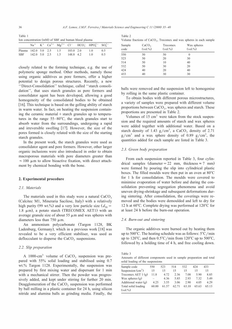
Table 1Ž .Ion concentration mM of SBF and human blood plasma
q q 2q 2q y y 2y 2yNa K Ca Mg Cl HCO HPO SO3 4 4
Plasma 142.0 5.0 2.5 1.5 103.0 2.0 1.0 0.5
SBF 142.0 5.0 2.5 1.5 148.8 4.2 1.0 0.5
closely related to the forming technique, e.g. the use of
polymeric sponge method. Other methods, namely those
using organic additives as pore formers, offer a higher
potential to design porous structures. Recently, a new
‘‘Direct-Consolidation’’ technique, called ‘‘starch consoli-
dation’’, that uses starch granules as pore formers and
consolidator agent has been developed, allowing a good
homogeneity of the consolidated bodies to be obtainedw x16 . This technique is based on the gelling ability of starch
in warm water. In fact, on heating the suspension contain-
ing the ceramic materialqstarch granules up to tempera-
tures in the range 55–808C, the starch granules start to
absorb water from the surroundings, undergoing a rapidw xand irreversible swelling 17 . However, the size of the
pores formed is closely related with the size of the starting
starch granules.
In the present work, the starch granules were used as
consolidator agent and pore formers. However, other larger
organic inclusions were also introduced in order to obtain
macroporous materials with pore diameters greater than
;100 mm to allow bioactive fixation, with direct attach-
ment by chemical bonding with the bone.
2. Experimental procedure
2.1. Materials
The materials used in this study were a natural CaCO3
Ž .Calcitec M1, Mineraria Sacilese, Italy with a relativelyŽ . Žhigh purity 99 wt.% and a very low particle size d s50
. Ž .1.8 mm , a potato starch TRECOMEX AET1 with an
average granule size of about 55 mm and wax spheres with
diameters less than 750 mm.ŽAn ammonium polycarbonate Targon 1128, BK
. w xLadenburg, Germany , which in a previous work 18 was
revealed to be a very efficient stabiliser, was used as
deflocculant to disperse the CaCO suspensions.3
2.2. Slip preparation
A 1000-cm3 volume of CaCO suspension was pre-3
pared with 55% solid loading and stabilised using 0.7
wt.% Targon 1128. Experimentally, the suspension was
prepared by first mixing water and dispersant for 1 min
with a mechanical stirrer. Then the powder was progres-
sively added, and kept under stirring for further 20 min.
Deagglomeration of the CaCO suspension was performed3
by ball milling in a plastic container for 24 h, using silicon
nitride and alumina balls as grinding media. Finally, the
Table 2
Volume fractions of CaCO , Trecomex and wax spheres in each sample3
Sample CaCO Trecomex Wax spheres3
Ž . Ž . Ž .code vol.% vol.% vol.%
550 50 50 0
523 50 20 30
514 50 10 40
532 50 30 20
424 40 20 40
433 40 30 30
balls were removed and the suspension left to homogenise
by rolling in the same plastic container.
To obtain bodies with different porous microstructures,
a variety of samples were prepared with different volume
proportions between CaCO , wax spheres and starch. These3
proportions are presented in Table 2.
Volumes of 15 cm3 were taken from the stock suspen-
sion and the required amounts of starch and wax spheres
were added together with additional water. Based on a
starch density of 1.43 grcm3, a CaCO density of 2.713
grcm3 and a wax sphere density of 0.89 grcm3, the
quantities added for each sample are listed in Table 3.
2.3. Green body preparation
From each suspension reported in Table 3, four cylin-Ž .drical samples diameters22 mm, thicknessf7 mm
were formed by pouring the slip into cylindrical plastic
boxes. The filled moulds were then put in an oven at 808C
for 1 h for consolidation. The moulds were covered to
minimise evaporation of water before and during the con-
solidation preventing segregation phenomena and avoid
uneven drying-shrinkage and subsequent deformations dur-
ing sintering. After consolidation, the coverings were re-
moved and the bodies were demoulded and left to dry for
12 h at 608C. Complete drying was performed at 1208C for
at least 24 h before the burn-out operation.
2.4. Burn-out and sintering
The organic additives were burned out by heating them
up to 5008C. The heating schedule was as follows: 58Crmin
up to 1208C, and then 0.58Crmin from 1208C up to 5008C,
followed by a holding time of 4 h, and free cooling down.
Table 3
Amounts of different components used in sample preparation and total
solid loading of the suspensions
Sample code 550 523 514 532 424 4333Ž .Suspension cm 15 15 15 15 15 15Ž .Trecomex AET 1 g 11.8 4.72 2.36 7.08 5.90 8.85
Ž .Wax spheres g – 4.36 5.85 2.93 7.32 5.49Ž .Additional water g 4.25 3.55 3.06 2.90 4.05 4.29
Total solid loading 60.00 61.57 62.71 63.10 65.63 65.13Ž .vol.%

( )A.F. Lemos, J.M.F. FerreirarMaterials Science and Engineering C 11 2000 35–40 37
During this burn-out operation, air was pumped into the
furnace to promote the oxidation of the organic matter.
The calcined bodies were then sintered at 9008C in a
horizontal tubular furnace, under 1 atm of CO . The2
heating rate was 108C up to 9008C, with 2 h holding time
at this temperature and free cooling down. For tempera-
tures G5008C, a continuous flow of CO along the fur-2
nace of about 40 bubblesrmin was maintained.
2.5. Sintered material eÕaluations
The densities and pore size distributions of sinteredŽbodies were determined by the mercury porosimetry Pore-
.Sizer 9320, Micromeritics, USA . The pore sizes measured
by this technique are not the true sizes of the pores but of
their interconnections.
Microstructural observations of the overall porous struc-
tures left by the starch granules and the wax spheres wereŽperformed on fracture surfaces by using a SEM S-4100,
.HITACHI, Japan .
2.6. Tests of bioactiÕity
The tests of bioactivity were carried out on the 514
samples. Three of these samples were heat-treated at 3008C
in a horizontal tubular furnace to remove all the impurities
eventually present at the surface. After that, each sample
was suspended into a small plastic flask, which was then
filled with the required amounts of SBF solution. The SBF
solution with a pH of 7.34 was previously prepared and
conserved into a refrigerator at about 58C. Considering the
total surface area of the samples, 4 ml of SBF were poured
in the plastic flask for each mm2. During in vitro experi-
ments, the plastic flasks were maintained at 378C and the
SBF renewed every 24 h. The samples were definitely
removed from the SBF after 2, 5 and 10 days, washed
gently with distilled water and put again into the oven at
378C to remove the water.
The surfaces of the tested samples were observed in
SEM to evaluate the deposition of the apatite phases
formed.
3. Results and discussion
3.1. Density and porous microstructures
Although considerable high solid loading suspensions
were used in the present work, the differences in density
Ž . Ž . Ž .Fig. 1. Porous microstructures of the sintered bodies: a segregated region of the sample 514; b homogeneous region of the same sample 514; cŽ .magnification of one of part of b; d general view of the sample 550.

( )A.F. Lemos, J.M.F. FerreirarMaterials Science and Engineering C 11 2000 35–4038
Fig. 2. Size distributions of the interconnection between the pores in theŽ . Ž .samples containing 50 a and 40 vol.% CaCO b .3
among the components would drive the composition to-
wards segregation by sizes andror densities. In fact, the
less dense wax spheres tended to concentrate in the upper
part of the samples. Although this phenomenon would be
undesirable in most cases, it can also be exploited to
design functional gradient ceramics. Otherwise, when un-
desirable, it can be significantly reduced by further increas-
ing the viscosity of the suspension namely by improving
the solid loading. Fig. 1 compares the porous microstruc-Ž . Ž .ture of the samples 514 Fig. 1a–c and 550 Fig. 1d . Fig.
1a shows a segregated region of the sample 514 where the
wax spheres migrate to the top part, while a homogeneous
region of the same sample is displayed in Fig. 1b. It can be
seen that the porous microstructure is composed of smaller
pore sizes corresponding approximately to the average size
of the starch granules, and by larger pore sizes left by the
wax spheres. The pores are interconnected, although the
average diameter of these interconnections is significantly
smaller compared with the average size of the pores. Fig.
1c is a magnification of one of part of Fig. 1b, showing a
region between three larger pores. The comparison be-
tween the micrographs 1c and 1d enable us to conclude
that the starch granules are responsible for the interconnec-
tions among the larger pores and that the extension of the
interconnection depends on the amount of starch added.
Fig. 2a and b reports the pore size distributions of the
sintered samples prepared with 50 and 40 vol.% CaCO ,3
respectively. No significant difference can be detected
among all these samples. This might be partially due to the
segregation phenomenon referred above and the possibility
for the part of the sample used in the porosimetry measure-
ments do not represent the overall composition. This inter-
pretation is also supported by the density and porosity data
reported in Table 4. Moreover, the average pore sizes are
significantly smaller than the pores observed in the micro-
graphs of Fig. 1. This is not surprising since mercury
porosimetry only measures the sizes of the passages be-
tween the pores.
3.2. BioactiÕity
The in vitro experiments revealed that the porous CaCO3
bodies produced in the present work show good bioactiv-
ity. Fig. 3 shows some aspects of the calcium phosphate
phases precipitated at the surface of the 514 samplesŽ .suspended into SBF solutions for 2 days Fig. 3a and b ,
Ž . Ž .for 5 days Fig. 3c and d , and for 10 days Fig. 3e and f .
The crystalline phases shown in micrographs 3a, 3c, and
3e have a crystal habit characteristic of a di-calcium
phosphate di-hydrate, CaHPO P2H O, known as brusite4 2
w x w x19 . It can be formed according to the reaction 19 :
Ca2qqHPO2yq2H OzCaHPO P2H O,4 2 4 2
Kss10y25.2 , at 258C 1Ž . Ž .
The kinetics of this reaction will be higher at the testingŽ .temperature 378C .
Besides brusite, other acicular calcium phosphate phases
appear in the samples soaked in the SBF for all different
time periods. These acicular phases seem to come prefer-Ž .entially from the interior of the pores Fig. 3b . However,
the preference for the pores and pore borders or other more
strained points at the surface of the samples seem to be the
privileged sites for the formation of the calcium phosphateŽ .phases Fig. 3d and f . This can be understood since the
most fine and strained points will dissolve more easily into
the SBF, supersaturating the solution in the close vicinity
in the ionic active species, promoting the formation of the
new phases. It should be noticed that the amount of the
calcium phosphate phases precipitated increase with the
Table 4
Density and porosity data of the green and sintered bodies
Sample code 514 523 424 4333Ž .Green density grcm 1.29 1.19 1.20 1.22
3Ž .Sintered density grcm 1.50 1.31 1.39 1.28Ž .Average pore size mm 12.12 13.42 13.89 12.73
Ž .Porosity % 42.24 48.33 45.61 47.30

( )A.F. Lemos, J.M.F. FerreirarMaterials Science and Engineering C 11 2000 35–40 39
Ž .Fig. 3. Some aspects of the calcium phosphate phases precipitated at the surface of the 514 samples suspended into SBF solutions for: 2 days a and b ; 5Ž . Ž .days c and d ; 10 days e and f .
soaking time. This can be clearly seen from the compari-
son between micrographs 3a, 3c, and 3e.
4. Conclusions
The results presented in this work enable us to draw the
following conclusions:
1. The starch consolidation technique was revealed to be
an interesting method to fabricate porous bioceramic
materials, enabling the transformation of a fluid suspen-
sion into a rigid body without liquid removal.
2. A combination of the gelling properties of the starch
granules to consolidate the suspensions and to generate
interconnecting pores with other organic inclusions of
larger size, to generate the required macropores for
bone ingrowth, offer great potentialities to design porous
microstructures for implantation purposes.
3. The macroporous CaCO bodies fabricated exhibit an3
accentuated bioactivity even for short soaking time
periods.

( )A.F. Lemos, J.M.F. FerreirarMaterials Science and Engineering C 11 2000 35–4040
Acknowledgements
ŽThe authors acknowledge FCT Portuguese Foundation.for Science and Technology for the financial support.
References
w x1 L. Burlamacchi, Capire il Calcestruzzo, Ed. Hoepli, Milano, 1994.w x2 R. Chang, Quımica, 5th edn., McGraw-Hill, Portugal, 1994, p. 258.´w x3 G. Tarı, J.M.F. Ferreira, Colloidal processing of calcium carbonate,`
Ž .Ceram. Int. 24 1998 527–532.w x4 G. Guilllemin, J.-L. Patat, J. Fournie, M. Chetail, The use of coral as
Ž .a bone graft substitute, J. Biomed. Mater. Res. 21 1987 557–567.w x5 G. Guilllemin, A. Meunier, P. Dallant, P. Christel, J.-C. Poouliquen,
L. Sedel, Comparison of coral resorption and bone apposition with
two natural corals of different porosities, J. Biomed. Mater. Res. 23Ž .1989 765–779.
w x6 H. Ohgushi, M. Okumura, T. Yoshikawa, K. Inoue, E.C. Shors,
Bone formation process in porous calcium carbonate and hydroxy-Ž .apatite, J. Biomed. Mater. Res. 26 1992 885–895.
w x7 H. Ohgushi, Coral derived porous framework having different chem-
ical compositions as a scaffold for osteoblastic differentiation, Mater.Ž .Sci. Forum 250 1997 209–220.
w x8 G. Guillemin, M. Launay, A. Meunier, Natural coral as a substrateŽ .for fibroblastic growth in vitro, J. Mater. Sci. Mater. Med. 4 1993
575–581.
w x9 J.C. Fricain, Ch. Baquey, B. Basse-Cathalinat, B. Dupuy, Compari-
son of resorption and bone conduction of two CaCO bone substi-3
Ž .tutes, Bioceramics 10 1997 383–386.w x10 C. Muller-Mai, C. Voigt, S.R. De Almeida Reis, Substitution of
natural coral be cortical bone and bone marrow in the rat femur: Part
II. SEM, TEM, and in situ hybridization, J. Mater. Sci. Mater. Med.Ž .7 1996 479–488.
w x Ž .11 T. Kokubo, Novel bioactive materials, An. Quım. 93 1997 S49–55.´w x12 K. De Groot, C.P.A.T. Klein, J.G. Wolke, J. De Blieck-Hogervorst,
Chemistry of calcium phosphate bioceramics, in: T. Yamamuro,Ž .L.L. Hench, J. Wilson Eds. , Handbook of Bioactive Ceramics Vol.
2 CRC Press, Boca Raton, FL, 1990, pp. 3–16.w x13 E.W. White, J.N. Webber, D.M. Roy, E.L. Owen, R.T. Chiroff,
R.A. White, Replamineform porous biomaterials for hard tissueŽ .implant applications, Biomed. Mater. Symp. 6 1975 23–27.
w x14 S.F. Hulbert, The reaction to three ceramics of porous and non-por-Ž .ous structures, J. Biomed. Mater. Res. 6 1972 347–374.
w x15 J. Saggio-Woyansky, C.E. Scott, W.P. Minnear, Processing of porousŽ .ceramics, Am. Ceram. Soc. Bull. 71 1992 1674–1682.
w x16 O. Lyckfeldt, J.M.F. Ferreira, Processing of porous ceramics byŽ .starch consolidation, J. Eur. Ceram. Soc. 18 1998 131–140.
w x Ž .17 M. Rutenberg, Starch and its modifications, in: R.L. Davidson Ed. ,
Handbook of Water-Soluble Gums and Resins 22 McGraw-Hill,
New York, 1979, pp. 1–83.w x18 G. Tarı, S. Touchal, J.M.F. Ferreira, Dispersion, stabilisation and`
casting of calcium carbonate suspensions, in: D. Bortzmeyer, M.Ž .Boussuge, Th. Chartier, G. Fantozzi, G. Lozes, A. Rousset Eds. ,
Proc. 5th Eur. Ceram. Soc. Vols. 132–136 Trans Tech Publications,
Switzerland, 1997, pp. 289–292.w x19 Lorenzo, L. M. R., ‘‘Sıntesis, Procesado y Proprieades de Ceramicas´ ´
de Fosfato de Calcio con Interes Clınico’’, Ph.D. Thesis, Universi-´ ´dad Complutense de Madrid, 1999.
Copyright © 2022 FDOKUMEN