Polymers in Construction - National Academic Digital Library ...
528
Polymers in Construction Editor: Güneri Akovali
-
Upload
khangminh22 -
Category
Documents
-
view
2 -
download
0
Transcript of Polymers in Construction - National Academic Digital Library ...

Polymers in Construction
Editor: Güneri Akovali


Polymers inConstruction
Editor: Güneri Akovali
Rapra Technology Limited
Shawbury, Shrewsbury, Shropshire, SY4 4NR, United KingdomTelephone: +44 (0)1939 250383 Fax: +44 (0)1939 251118
http://www.rapra.net
TECHNOLOGYrapra

First Published 2005 by
Rapra Technology LimitedShawbury, Shrewsbury, Shropshire, SY4 4NR, UK
©2005, Rapra Technology Limited
All rights reserved. Except as permitted under current legislation no partof this publication may be photocopied, reproduced or distributed in anyform or by any means or stored in a database or retrieval system, without
the prior permission from the copyright holder.
A catalogue record for this book is available from the British Library.
Every effort has been made to contact copyright holders of any materialreproduced within the text and the authors and publishers apologize if
any have been overlooked.
Typeset by Rapra Technology LimitedCover printed by The Printing House Limited, Crewe, UK
Printed and bound by Rapra Technology Limited, Shrewsbury, UK
ISBN: 1-85957-468-8

i
Contents
Preface ................................................................................................................... 1
1. Introduction .................................................................................................... 3
2. The Use of Polymers in Construction: Past and Future Trends ...................... 13
2.1 History of Polymeric Materials ............................................................ 13
2.1.1 Plastics in Building ................................................................... 16
2.2 Use of Plastics and Rubbers in Construction: Current Statusand Trends for the Future .................................................................... 22
3. The Use of Plastics in Building Construction ................................................. 35
3.1 Introduction ......................................................................................... 35
3.2 Structural Applications of Polymers in Building Construction ............. 36
3.2.1 Sandwich Panels (SWP) and Sandwich Panel Applicationsin Housing Construction.......................................................... 38
3.2.2 All-Composites Housing .......................................................... 41
3.3 Secondary Structural and Non-Structural Applications ofPolymers in Housing Construction ...................................................... 42
3.3.1 Piping, Electrical Cables, Wiring and ConduitApplications of Polymers in Housing Construction ................. 42
3.3.2 Cladding and Profile Applications of Polymers inHousing Construction.............................................................. 45
3.3.3 Insulation Applications of Polymers in HousingConstruction ............................................................................ 47
3.3.4 Sealant, Gasket and Adhesive Applications of Polymersin Housing Construction.......................................................... 54
3.3.5 Roofing and Flooring System Applications of Polymersin Housing Construction.......................................................... 57

Polymers in Construction
ii
3.3.6 Glazing, Plastic Lumber, Paint, Wall-Covering, and OtherApplications of Polymers in Housing Construction ................. 59
3.4 Coatings............................................................................................... 64
3.4.1 Polymers Used for Coatings ..................................................... 66
3.4.2 Solvent-Based Coatings ............................................................ 68
3.4.3 Water-Based Coatings .............................................................. 69
3.4.4 Curing Techniques ................................................................... 74
3.4.5 Powder Coatings ...................................................................... 76
3.4.6 Intumescent Coatings ............................................................... 77
3.4.7 Durability of Coatings ............................................................. 77
3.5 EPDM Membrane: Application in the Construction Industryfor Roofing and Waterproofing ........................................................... 78
3.5.1 Introduction ............................................................................. 78
3.5.2 Chemistry of the EPDM Elastomer .......................................... 79
3.5.3 Process of Manufacture of EPDM Membrane ......................... 82
3.5.4 Process of Preparation of Adhesive .......................................... 83
3.5.5 EPDM Polymer Characteristics of Crack Resistance ................ 84
3.5.6 Distinctive Waterproofing Properties of EPDM Membrane ..... 84
3.5.7 Maintenance Free, Temperature Endured Roof Sheathings ...... 85
3.5.8 Installation Engineering of EPDM Membrane ......................... 86
3.5.9 Effluent Treatment Plant Lining ............................................... 87
3.5.10 Ecological and Decorative Gardening Applications ................. 87
4. Systems for Condensation Control ................................................................ 97
4.1 Introduction ......................................................................................... 97
4.2 Standard Condensation Control .......................................................... 97
4.2.1 Standard Assessment Methods ................................................. 97
4.2.2 Standard Condensation Control in Building Practice ............... 99
4.3 Controlling Air Leakage .................................................................... 101
4.3.1 Moisture Accumulation Due to Air Leakage.......................... 101
4.3.2 Thermal Effects of Air Movement ......................................... 103

iii
ContentsContents
4.3.3 Air Barrier Systems and Requirements:The Canadian Example.......................................................... 105
4.3.4 Air Leakage Control in Building Practice ............................... 106
4.4 A Systems Approach to Condensation Control .................................. 107
4.4.1 Warm Roof Designs ............................................................... 107
4.4.2 Condensation Control Systems .............................................. 109
5. Use of Polymers in Civil Engineering Applications ...................................... 115
5.1 Geotechnical Engineering Applications .............................................. 115
5.1.1 General .................................................................................. 115
5.1.2 Geosynthetic Properties and Testing ...................................... 118
5.1.3 Use of Geosynthetics in Roadways, Pavements,Runways and Railways .......................................................... 120
5.1.4 Use of Geosynthetics in Drainage and ErosionControl Systems ..................................................................... 123
5.1.5 Use of Geosynthetics in Soil Reinforcement Applications ...... 124
5.1.6 Use of Geosynthetics in Waste Disposal Facilities .................. 124
5.1.7 Miscellaneous Applications of Geosynthetics......................... 127
5.2 Polymers in Concrete ......................................................................... 128
5.2.1 Polymer Concrete .................................................................. 128
5.2.2 Polymer Portland Cement Concrete ....................................... 132
5.2.3 Polymer Impregnated Concrete .............................................. 134
5.2.4 Polymer Based Admixtures for Concrete ............................... 136
5.2.5 Polymeric Fibres in Fibre Reinforced Concrete ...................... 143
5.3 Use of Polymeric Materials in Repair and Strengthening of Structures ... 144
5.3.1 Types of FRP Composites ...................................................... 144
5.3.2 Methods of Forming FRP Composites ................................... 145
5.3.3 Mechanical Properties of FRP Composites ............................ 147
5.3.4 Bond Strength of FRP-to-Concrete Joints .............................. 150
5.3.5 Bond Strength Models ........................................................... 152
5.3.6 Flexural Strengthening of RC Beams ..................................... 153

Polymers in Construction
iv
5.3.7 Shear Strengthening of RC Beams .......................................... 155
5.3.8 Strengthening of RC Slabs ..................................................... 157
5.3.9 Strengthening of RC Columns ............................................... 159
5.3.10 Strengthening of Masonry Walls and Infills ........................... 161
6. Plastics and Plastics Composites: A Perspective on their Chemistryand Mechanics ............................................................................................ 169
6.1 Chemistry of Plastics .......................................................................... 169
6.1.1 Molecular Weight .................................................................. 169
6.1.2 Synthesis of Polymers ............................................................. 172
6.1.3 Classification ......................................................................... 181
6.1.4 Physical Structure .................................................................. 183
6.1.5 Morphology Changes in Polymers ......................................... 184
6.1.6 Mechanical Properties ............................................................ 187
6.1.7 Mechanical Models ................................................................ 189
6.1.8 Thermal Properties ................................................................ 189
6.1.9 Weathering and Other Properties ........................................... 189
6.2 Additives ............................................................................................ 190
6.2.1 Introduction ........................................................................... 190
6.2.2 Classification and Types of Plastics Additives ........................ 190
6.3 Structure-Property Relationships ....................................................... 199
6.3.1 Control of Tm and Tg .............................................................................................. 199
6.3.2 Effect of Macromolecular Skeleton ........................................ 199
6.3.3 Effect of Different Side Groups .............................................. 201
6.3.4 Some Structure-Property Relations of Polymers asRegards Building and Construction ....................................... 203
6.4 Polymer Composites .......................................................................... 208
6.4.1 Introduction, Definitions and Classifications ......................... 208
6.4.2 Chemical Structure of the Polymer Matrix ............................ 212
6.4.3 Structure of Reinforcing Components .................................... 224
6.4.4 On The Mechanics of PMC ................................................... 231

v
ContentsContents
7. Plastics and Polymer Composites: A Perspective on PropertiesRelated to their use in Construction ............................................................ 237
7.1 Foams ................................................................................................ 237
7.1.1 Foaming (Blowing) Agents ..................................................... 240
7.1.2 Foam Manufacturing Technologies ........................................ 242
7.1.3 Thermoplastic Foams............................................................. 243
7.1.4 Thermosetting Foams ............................................................ 246
7.1.5 Special Foams ........................................................................ 250
7.2 Ageing................................................................................................ 252
7.3 Electrostaticity ................................................................................... 255
7.4 Fire Safety .......................................................................................... 257
7.4.1 Flammability of Polymer Foams ............................................ 264
7.4.2 Flammability of Composites .................................................. 268
7.5 Environmental Hazards ..................................................................... 269
7.6 Recycling ........................................................................................... 270
7.6.1 Recycling of Some Polymers Used in Building........................ 272
7.6.2 Reclaim Plastic Scrap ............................................................. 275
7.6.3 Biodegradable Plastics ............................................................ 275
7.7 Repair and Maintenance .................................................................... 276
7.7.1 Injection Grouting ................................................................. 277
7.7.2 Patching ................................................................................. 277
7.7.3 Coating .................................................................................. 277
7.7.4 Repair with Polymer Concrete ............................................... 278
7.7.5 Metals Maintenance .............................................................. 279
7.7.6 Repair of Plastics and Their Composites ................................ 279
7.8 Smart Materials and Structures .......................................................... 279
7.8.1 Examples of Smart Materials ................................................. 281
8. Sustainable Construction ............................................................................ 303
8.1 Introduction ....................................................................................... 303

Polymers in Construction
vi
8.2 Resource-Efficiency and Sustainable Construction............................. 303
8.2.1 Brief History of Sustainable Construction.............................. 304
8.2.2 Resource-Efficiency as a Key Concept of SustainableConstruction .......................................................................... 304
8.2.3 Resource-Efficiency Economics .............................................. 307
8.3 Ecology as the Basis for Resource Efficient Design ............................ 308
8.3.1 Ecological Concepts ............................................................... 308
8.3.2 Industrial Ecology as a Starting Point .................................... 311
8.3.3 Rules of the Production-Consumption System ....................... 312
8.3.4 The Golden Rules of Eco-Design ........................................... 312
8.3.5 Construction Ecology ............................................................ 313
8.4 Resource Efficiency Strategies for Building Design............................. 314
8.4.1 Materials Selection and Design for Deconstruction ............... 314
8.4.2 Energy Strategies .................................................................... 316
8.4.3 Water, Wastewater and Stormwater ....................................... 318
8.4.4 Land Use ................................................................................ 318
8.4.5 Landscape as a Resource........................................................ 319
8.5 Case Study ......................................................................................... 319
8.5.1 Design and Construction ....................................................... 321
8.5.2 Use and Refurbishment .......................................................... 322
8.5.3 Demolition/End Use ............................................................... 322
8.6 Conclusions ....................................................................................... 323
9. Processing of Individual Plastics Components for House Construction,for Civil and Highway Engineering Applications ........................................ 325
9.1 Processing of Plastics ......................................................................... 325
9.1.1 Extrusion ............................................................................... 325
9.1.2 Moulding ............................................................................... 327
9.2 Processing of Plastics Composites ...................................................... 330
9.2.1 Processing of (Fibre Reinforced) Thermoset Plastic Composites 331
9.2.2 Processing of Fibre Reinforced Thermoplastic Composites .... 344
9.3 On-Site Processing .......................................................................... 345

vii
Contents
10. Lignocellulosic Fibre – Plastic Composites in Construction ........................ 349
10.1 Introduction .................................................................................... 349
10.2 Sources of Lignocellulosic Fibres ..................................................... 350
10.2.1 Bagasse .............................................................................. 350
10.2.2 Cereal Straw...................................................................... 351
10.2.3 Coconut Coir .................................................................... 351
10.2.4 Corn Stalks ....................................................................... 352
10.2.5 Cotton Stalks .................................................................... 352
10.2.6 Jute ................................................................................... 352
10.2.7 Kenaf ................................................................................ 353
10.2.8 Rice Husks ........................................................................ 353
10.2.9 Other Fibre Sources........................................................... 353
10.2.10 Chemical Composition....................................................... 354
10.3 Types of Polymers (Binders) ............................................................ 354
10.3.1 Thermosets ........................................................................ 354
10.3.2 Thermoplastics .................................................................. 356
10.4 Wood-Plastic Composites ................................................................ 363
10.4.1 Additives ........................................................................... 364
10.4.2 Properties .......................................................................... 364
10.4.3 Applications ...................................................................... 365
10.5 Compatibility .................................................................................. 365
10.5.1 Surface Modification of Natural Fibres ............................. 366
10.5.2 Grafting Modifications of Plastics ..................................... 370
10.6 Processing ....................................................................................... 371
10.6.1 Thermosets ........................................................................ 371
10.6.2 Thermoplastics .................................................................. 377
10.7 Testing Methods .............................................................................. 378
10.8 Environmental Effects ..................................................................... 379
10.9 Conclusions..................................................................................... 380

Polymers in Construction
viii
11. Rubber Concrete ......................................................................................... 389
11.1 An Introduction to Rubber Concrete .............................................. 389
11.2 Experience Related to Rubber Concrete Construction .................... 390
11.3 Characterisation of Rubber Concrete .............................................. 392
11.4 Air Content and Compressive Strength ........................................... 396
11.5 Applicability ................................................................................... 401
11.6 Discussions and Conclusion ............................................................ 402
12. Some Possible Health Issues Related to Polymeric ConstructionMaterials and on Indoors Atmosphere ........................................................ 407
12.1 Introduction .................................................................................... 407
12.1.1 Indoor Air Quality (IAQ) and Sick BuildingSyndrome (SBS) ................................................................. 408
12.1.2 What is SBS? ..................................................................... 408
12.1.3 Volatile Organic Compounds (VOC) ................................ 412
12.1.4 Toxic compounds and Toxicology ..................................... 414
12.1.5 Carcinogens ...................................................................... 416
12.1.6 Risk Management ............................................................. 417
12.1.7 Radon Indoors .................................................................. 417
12.1.8 Endocrine Disrupters (ECD) ............................................. 419
12.2 Construction Materials and Health Issues Indoors.......................... 425
12.2.1 Plastics .............................................................................. 425
12.2.2 Rubbers ............................................................................. 440
12.2.3 Wood and Wood Laminates .............................................. 440
12.2.4 Other Hazardous Construction Materials and PossibleHealth Hazards From Some Construction Applications .... 443
13. Glossary and Web Addresses of Interest ...................................................... 455
Abbreviations and Acronyms............................................................................. 485

xi
Contributors
Elsayed M. Abdel-BaryFaculty of Science, Mansoura University, Mansoura, Egypt
Güneri AkovaliDepartments of Chemistry and Polymer Science & Technology, Middle East TechnicalUniversity, 06531 Ankara, Turkey
Leyla ArasDepartments of Chemistry and Polymer Science & Technology, Middle East TechnicalUniversity, 06531 Ankara, Turkey
Bireswar BanerjeeB-12/3 Karunamoyee Estate, Salt Lake, Calcutta 700091, India
Dorel FeldmanDepartment of Building, Civil and Environmental Engineering, Concordia University,1455 de Maisonneuve Boulevard W, Montreal, Quebec, H3G 1M8, Canada
Arnold JanssensDepartment of Architecture and Urban Planning, Jozef Plateaustraat 22, Ghent University,9000 Ghent, Belgium
Charles J. KibertPowell Center for Construction & Environment, University of Florida, Gainesville, Florida32611-5703, USA
Ugur PolatDepartment of Civil Engineering, Middle East Technical University, 06531 Ankara, Turkey
Mustafa TokyayDepartment of Civil Engineering, Middle East Technical University, 06531 Ankara, Turkey
Yildiz WastiDepartment of Civil Engineering, Middle East Technical University, 06531 Ankara, Turkey
Han ZhuCivil Engineering Department, Tian-Jin University, Tian-Jin, China 300072

Polymers in Construction
xii
Commercial rubbers

1
Preface
The construction sector is the second highest user of plastics worldwide, although itsacceptance by this sector is not yet complete. However, signs are very promising for amuch larger share of plastics and rubber in this sector in the very near future. In the EUonly, over 6 million tonnes of plastics per year are consumed in the construction sector,and this figure is predicted to increase to 8 million tonnes by the year 2010.
Plastics are used very effectively for various structural and non-structural applications inconstruction, because they provide long-lasting and the least problematic solutions. Theyare light in weight with perfect durability and toughness. Plastics provide ease of installationand assembly with cost effectiveness and low maintenance. It is now a very common practiceto use plastics and rubber in exterior and interior applications, and in energy conservation.They are used for thermal, as well as for water, acoustic, electrical and retrofit insulations.They are very successfully applied for retrofitting and rehabilitation, in addition to inflooring, piping and conduit applications. Plastics and rubber are very attractive choicesfor window profiles and doors, as well as for seals, gaskets, membranes and claddings,fencing and decking, isolation foams and shock absorbing materials. The list for these andother applications of plastics in construction is long, and grows ever longer.
This book is designed as a handbook to provide some basic, up-to-date information andwhenever possible information on practical issues, for this very promising material andits applications in construction. It is hoped that, it will give enough insight both to thenewcomers to the industry and to the technical personnel already working in constructionsector and that it will help to further promote the use of this material which is neglectedsomewhat because of the unkowns and negligence.
The book has 13 chapters, each prepared by a group of experts from different parts ofthe world. The first chapter, the introduction, provides the basic information. A reviewof the use of plastics in construction looking at its past and the future trends is coveredin detail, in Chapter 2.
The use of plastics specifically in building construction is discussed in five sections inChapter 3, by considering their structural, secondary structural and non-structuralapplications and also their use in polymeric coatings and EPDM membranes. Systemsfor condensation control is the theme of Chapter 4.
The use of plastics in civil engineering, is covered, in general, in Chapter 5. In this chapter,geotechnical engineering applications of plastics and their use in concrete, with theirrepair and strengthening applications, are discussed in depth.
2
Polymers in Construction
To give some insight for this relatively new material, namely plastics, some basicinformation is presented in Chapters 6, 7 and 9. The brief chemistry and mechanics ofplastics materials and composites are discussed in Chapter 6, along with some informationon the additives commonly used, while in Chapter 7, a review is presented of the propertiesrelated to use of plastics and polymer composites in construction. To complete the plasticscircle, processing of plastics and composites are reviewed in Chapter 9.
Chapter 8 concentrates on sustainable construction. Wood-plastic composites are beingused in construction at an increasing rate. Lignocellulosic fibres and plastic compositesare extensively discussed in Chapter 10.
Rubber and rubber concrete is an additional issue that should be considered in the book,because rubber is considered to be a different material, although it is a polymer and usedin the construction sector at large. Thus, rubber concrete is the subject of Chapter 11.
There has been a growing interest in health issues relating to the use of plastic constructionmaterials, for some time, and especially on their effect on indoor atmospheres, causingthe so called ‘sick building syndrome’. PVC is the one plastic that has been most critisised.Some general issues regarding health problems are discussed in Chapter 12.
Chapter 13 presents some definitions related to the subject.
I would like to thank specifically to each of the contributing chapter editors for preparingsuch a fine work so skillfully, for being timely and co-operative at all times.
My special thanks are due to the commissioning editor, Ms. Frances Powers of RapraTechnology Ltd., for her ever-encouraging efforts as well as unceasing support and forbeing so cooperative at all times.
I must also thank Claire Griffiths, the editorial assistant, who has done a lot of thecorrections to the book and Stephen Barnfield, who was responsible for typesetting thebook and designing the cover and Geoffrey Jones who compiled the index. They all dida lot of work to get the book ready for publication, and certainly without them the bookwould not have been completed in time, so nicely and professionally.
As a final note, I enjoyed editing the book a lot, and I hope that the readers will alsoenjoy reading and having the book, and consider it as a valuable source of information.
Professor Guneri Akovali, Editor
August 5, 2004

3
1 Introduction
Güneri Akovali
Plastics are used greatly in various parts of construction. In fact, the construction sectoris the second highest user of plastics (after packaging). In 1999, 18% of total plasticsconsumption was due to this sector which totalled to over 6 million tonnes only in theEU (Table 1.1). There are many reasons for the increasing use of plastics in construction,both for structural and non-structural applications. Firstly, they are light and hence haveexcellent strength to weight ratios, they have perfect durabilities and toughness, propercost effectiveness and low maintenance, and perfect insulating properties, all of whichmake them a very attractive choice as a construction material (Table 1.2). Plastics areused in the construction industry because:
• They provide long-lasting solutions: they are durable, strong, tough and corrosionresistant with perfect insulation properties (water, heat, noise and vibration).
• They are light in weight and their installation and assembly is easy.
• They can be used for creation of stylish, hygienic modern designs, i.e., in kitchensand bathrooms, and for retrofitting and rehabilitation.
• They can be used for the design of the future applications: i.e., as smart materials, toproduce climate walls to regulate internal temperature, in solar energy generationsystems, in activated glazing systems which can become transparent or opaque, andto produce earthquake-proof buildings.
• Special light transmitting plastics with high clarity and shatter resistance are suitablefor use indoors and outdoors.
Plastics in construction are mainly used for insulation (thermal, water, acoustic, electricaland retrofit insulations) as well as for flooring, piping and conduits, and as variousprofiles (in windows and doors), as membranes and cladding, and they are applied asseals and gaskets The use of plastics in the construction sector (currently, 23% of allplastics consumption in UK) is expected to grow even more in the coming years mainlybecause of the increased emphasis on energy efficiency in buildings. Consumption ofplastics by the building and construction sector in Western Europe is predicted to rise by

4
Polymers in Construction
noitcurtsnocehtnisrebburdnascitsalpfosnoitacilppaemoS1.1elbaTrotcesgnidliubdna
epolevnegnidliubehtnI sdraobaicsafsA sehsinravdnastniapnI
slairetamgnifoorsA slenapgniddalcsA sevisehdasA
sa(gnifoorpretawroF)senarbmemdnastaoc
rofsetanimalsAnoitaroceddnakrowmrof
stnalaessA
/lamreht(noitalusninI)/gnifoorpdnuos/lacirtcele
sgnittifroiretnisA rofsmaofelbixelfsAyretslohpu
smlifreirrabsA gniliardnagnikcednI dnastepracrof(serbifsA)scirbaf
srood,semarfwodniwsA ,serutxif,gnibmulpnIeganiarddnasrettug,sepip
smetsys
noitarbiv-itnasAcimsiesdnasgnitnuom
srotalosi
etercnocsAdnanoitangerpmi/evitidda
tnemecrofnier
,sdirgoeg,selitxetoegsAdnasenarbmemoeg
secirtamoeg
gnicnefcitsalpsA
gnizalgnI srepapllawsA dnagnittiforterlarenegnIsgnidliubfonoitatilibaher
dnasgnirevocroolfroFgniroolftneiliser
rebmulcitsalpsA ,segdirbfognittiforterroFdnasyawklawlairea
snoitadnuof
gnidliub,smetsysniard-foor,gnifooR:niylniamerascitsalpfoesuROIRETXE)a(.gnidisdnagniddalc,mirtroiretxe,epolevne
gniliec/llaW:niylniamerascitsalpfosnoitacilppaNOITAVRESNOCYGRENE)b(dnanoitalitnev-taeh,gnihtaehsgnitalusni-larutcurtsdnasreirrabtnaidar,snoitalusni
.)CAVH(smetsysgninoitidnocria
eroc-maof,emarf(srooddnaswodniW:niylniamerascitsalpfoesuROIRETNI)c(retnuoc,gniroolf,serutxifdnasgnittif,gnipip,gnizalg,)stnalaesdnasteksag,sretnec
.steprac,sgnihsinruf,mirtroiretni,stniap,sgnitaoc,spot
:rofylniamdesueraSTCUDORPNOITCURTSNOCsasrebburdnascitsalP)d(llawyrd,smetsysllawdetargetni,stnioj/smaebgniraebdaoldereenigne-erP
nignihtaehsgnitalusni/larutcurts,sllawytraperif/dnuos,seirosseccadnasevitanretladnasdirgoeg,senarbmemoeg,selitxetoegsa,gnikced/gnicnefdna,gnidliubesuoh
,noitcurtsnocegdirb)PRF(citsalpdecrofnier-erbifdnaskcedegdirbni,secirtamoegesion/hsarc,sevitiddatlahpsa,serutcurtsetercnocdlofonoitatilibaher/gnittiforter
.snoitacilppagnireenignelivicni,sreirrab

5
Introduction
noitcurtsnocniylnommocdesuscitsalpehtfoemoS2.1elbaT
)s(noitacilppA desu)srebburdna(scitsalP
gnizalG ciremotsalecilyrcanahtiwAMMP,scilyrcAdecrofnierssalg,)CP(etanobracylop,)tnenopmoc
)foor()PRG(scitsalp
gnifooR enedilynivylop,)EPC(enelyhteylopdetanirolhc,CVPeneid-enelyporp-enelyhte,CP,PRG,)CDVP(edirolhc
)SPE(enerytsylopdednapxe,)MDPE(remonom)SBS(eneryts-eneidatub-enerytsdecrofnier,)teehs(
remylopoc
)gnidis(gniddalC ,)U-CVP(CVPdesicitsalpnudemaof,CVP,PRGasa)SBA(remylopoceneryts-eneidatub-elirtinolyrca
FDVP/cilyrca/SBAfodnelb
sgniliecdednepsuS CP,SP,PRG,cilyrcA
snoititrapllawdnasllaW rocilyrcahtiw(CVP,CVP,)PP(enelyporpylop,PRG)ni-llifdnasteehs(SPE,)CP
srepapllaW CVPyltsoM
srooddnasemarfwodniW -oc(SBA,)etutitsbusdoow(CVPdemaof,CVPsnifeloyloproASAdeifidomlynivhtiwdedurtxe-)NAS(remylopocelirtinolyrcaenerytsdeifidom
etisopmoc,)PRFG(citsalpdecrofniererbif-ssalgytilauqhgihrofslenapdemrofomreht(SBA,desab
)seliforpwodniwdnasrood
dnasteksag,stnalaes,slaeSsevisehda
senocilis,sremotsalecitsalpomreht,yxope,UP
)roiretnidnaroiretxe(stniaP scinocilis,scilyrca,UP
noitalusnilarutcurts-noN)taeh(smaof
enelyhteylopdednapxe,SPE,)digir(UP:fosmaoFetarunaycosiylop,CVP,senaruf,scilonehp,)EPE(
)sroodni()FU(edyhedlamrofaeru,)RIP(
smaofnoitalusnirehtO)tsorf/retaw(
enelyporpylop,)EP(enelyhteylop[snifeloylop,SP,UPCVP,])PP(
cimsiesdnaesion(noitalusnIsmaofronos,)snoitarbiv
,)enerporolhc/larutanyltsom(rebburfosetanimaLllecnepo,smaofFU,OPP(edixoenelynehpylop
SP,RIP,UPfosmaof
noitalusnilacirtcelE)stiudnocdnaselbac,gniriw(
-nondnademaof()PP,EP(snifeloylop,CVPyltsoM)demaof

6
Polymers in Construction
(noitcurtsnocniylnommocdesuscitsalpehtfoemoS2.1elbaT deunitnoC )
)s(noitacilppA desu)srebburdna(scitsalP
gnireenigne-larutcurtSslenaphciwdnas,smaof
)PWS(
,OPPdeifidom,)PP,EP(snifeloylop,)RIP(:fosmaoFdaolrof(UPdehciwdnas,SPtcapmi-hgih,SBA,CP
)snoitacilppagniraeb
gnidliubrofsmlifreirraBepolevne
,sedimaylopcitahpila,CVP,)PP,EP(snifeloyloP)TEP(etalahthperetenelyhteylop
rofgnipip(gnibmulPdnaeganiard,retawtoh/dloc
roolfdnanoitubirtsidsag)smetsysgnitaeh
lairtsudniretemaidegralrof(CVPC,CVPyltsoM,sepytrehtodnaDLdnaDH-EP,CVPOM,)sepip
snifeloylop,lateca,)BP(enelytubylop,PRG,PP,SBA)gnitaehroolfrof()EPX(EPdeknilsorc(
selit,gniroolF UP,yxope,sremylopocs'tidnaCVP
tnemecotevitiddanasAetercnocotrecrofnierdna
etercnocremylop,)CMP(etercnocdeifidomremyloP-erbif,)CIP(etercnocdetangerpmiremylop,)CP(
sraber)PRF(citsalpdecrofnier
tlahpsaotevitiddanasAtnemecdna
setalunargrebbuR
doowdnarebmulcitsalPsetutitsbus
doowhtiwlla,)DL/DH(EP,EPDH,)TEP(etsaW.htiwCVP/SBA(kcotspacdedurtxe-ocdna)serbif
)revocFDVP
,sllecoeg,selitxetoeG,secirtamoeg,senarbmemoeg
sdirgoeg
citehtnys,)tesomreht(sretseylop,CVP,EPDH,PPsrebbur
dnagnikced,gnicnefcitsalPgniliar
CVP
dnaroolf,krow(gnicafruS)secafruselbat
)tesomreht(sretseyloP
dnagnittiforteRnoitatilibaher
ssalg,.e.i(smetsystesomrehtdecrofniererbiF)sretseylop/yxopedecrofniererbifnobrac/erbif
CVPdeifidoM:CVPOMCVPdetanirolhC:CVPC
remylopockcolbelirtinolyrca-eneryts-elirtinolycA:ASAediroulfenedilynivyloP:FDVP

7
Introduction
more than 60%, to almost 8 million tonnes by 2010. Germany is the largest user ofplastics in building and construction so far in Europe (27%), followed by France (18%)and the UK (14%). In the Netherlands, 25% of the country’s total plastics consumptionis in this sector (which is 5% of Europe’s use).
Tables 1.1 and 1.2 present some examples of plastics and rubbery materials used typicallyin building and construction applications.
Additional information about some of these applications as well as their historicalevolution are presented in Chapters 2 to 6 of this book.
In the plastics construction materials list, the biggest share belongs to polyvinyl chloride(PVC) (by 55%), followed by polystyrene (PS) (15%), polyolefins (15%), polyurethanes(PU) (8%), and two others, mainly poly(methylmethacrylate) (PMMA) (7%) [1].
If the various uses of plastics materials in construction is considered, a number of reasonsfor these uses can be postulated:
• Plastics help to conserve energy. Polymeric foam insulation, vinyl siding and vinyl-framed windows all help to cut energy consumption and lower the heating and coolingbills. Polymeric foams are used effectively for insulation of roofs, walls (either as cavitywall, or internal and external walls), heat pipes and floors. The success of theseapplications is certainly due to the positive results obtained as well as to the favourableratio of cost to results. One study shows that more than 60% of all domestic energyconsumption is for space heating [3], and that improvement in thermal insulation,(i.e., by cavity and loft insulation), results in at least a 35% saving. Since cellularplastic materials (both foamed and expanded, with closed cell structures) are the mosteffective heat insulators, with lowest rates of heat transfer values (as characterised byU, being 0.26-0.4 W/m2-K for polymers versus 1.4-3 W/m2-K for brick and concrete),they provide considerable improvements of thermal efficiencies in houses. It is estimatedby the US Department of Energy (DOE) that only the use of polymeric foam insulationin homes and buildings is expected help to save about 60 million barrels of oil per year,worldwide. The extra cost of insulation by the use of cellular plastics is shown to berecovered within a maximum 6 year period [2]. In Europe during the last three decades,use of plastics insulation has increased by more than 1250%. It is also estimated thatthe use of plastics in construction will reduce annual fuel consumption (for a 100 m2
apartment from 2,000 litres to 300 litres), simply by replacing traditional buildingcomponents with their equivalent plastic components, (i.e., by using triple glazed PVCwindow frames and polymeric window coatings, which do not only reduce heat lossfrom the house, but also allow solar gain). In fact, PVC use in window applicationsand floor coverings increased on average by 5,000% and 120%, respectively, worldwide,during the last three decades.
8
Polymers in Construction
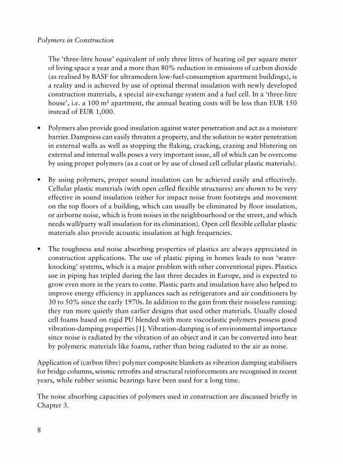
The ‘three-litre house’ equivalent of only three litres of heating oil per square meterof living space a year and a more than 80% reduction in emissions of carbon dioxide(as realised by BASF for ultramodern low-fuel-consumption apartment buildings), isa reality and is achieved by use of optimal thermal insulation with newly developedconstruction materials, a special air-exchange system and a fuel cell. In a ‘three-litrehouse’, i.e. a 100 m2 apartment, the annual heating costs will be less than EUR 150instead of EUR 1,000.
• Polymers also provide good insulation against water penetration and act as a moisturebarrier. Dampness can easily threaten a property, and the solution to water penetrationin external walls as well as stopping the flaking, cracking, crazing and blistering onexternal and internal walls poses a very important issue, all of which can be overcomeby using proper polymers (as a coat or by use of closed cell cellular plastic materials).
• By using polymers, proper sound insulation can be achieved easily and effectively.Cellular plastic materials (with open celled flexible structures) are shown to be veryeffective in sound insulation (either for impact noise from footsteps and movementon the top floors of a building, which can usually be eliminated by floor insulation,or airborne noise, which is from noises in the neighbourhood or the street, and whichneeds wall/party wall insulation for its elimination). Open cell flexible cellular plasticmaterials also provide acoustic insulation at high frequencies.
• The toughness and noise absorbing properties of plastics are always appreciated inconstruction applications. The use of plastic piping in homes leads to non ‘water-knocking’ systems, which is a major problem with other conventional pipes. Plasticsuse in piping has tripled during the last three decades in Europe, and is expected togrow even more in the years to come. Plastic parts and insulation have also helped toimprove energy efficiency in appliances such as refrigerators and air conditioners by30 to 50% since the early 1970s. In addition to the gain from their noiseless running:they run more quietly than earlier designs that used other materials. Usually closedcell foams based on rigid PU blended with more viscoelastic polymers possess goodvibration-damping properties [1]. Vibration-damping is of environmental importancesince noise is radiated by the vibration of an object and it can be converted into heatby polymeric materials like foams, rather than being radiated to the air as noise.
Application of (carbon fibre) polymer composite blankets as vibration damping stabilisersfor bridge columns, seismic retrofits and structural reinforcements are recognised in recentyears, while rubber seismic bearings have been used for a long time.
The noise absorbing capacities of polymers used in construction are discussed briefly inChapter 3.

9
Introduction
As regards the toughness of plastics, the catastrophic Northridge earthquake (6.7 on theRichter Scale) on January 17, 1994 can be mentioned: it was found that within the threepipe materials used (asbestos cement, PVC and steel), PVC outperformed the others. In30 minutes, while hundreds of mains and service lines broke, none of the lines made ofPVC, about half of the city’s total system of approximately 430 km, failed.
It is said that, there would be no electricity in our homes if there were no plastics materialsavailable to coat and insulate the wires. As shown previously in the Tables, plastics arealso used as electrical insulators, i.e., in electrical wires. Hence, in their absence, lifewould not be that easy, because electricity would not be able to be delivered that easily;and so plastics certainly help to improve the quality of life.
Plastics have lower densities than other structural materials. This results in lighter materialsin construction. The roof of the ‘Stade de France’, in Paris, which hosted the FootballWorld Cup, for example, is the world’s largest adaptable Olympic stadium, which ismade of 60,000 m2 of plastic membrane weighing 75 tonnes, in comparison to the 13,000tonnes of the whole roof structure.
Improved concrete structural members such as columns and piles can be manufacturedwith exterior and interior sub-members of fibre-reinforced-plastics (FRP). FRPcomponents impart greater compressive, flexural and shear strengths in addition toductility and durability, to the concrete structural member. Use of a FRP exterior shell tocontrol plastic shrinkage cracking of concrete has been known for a long time. The FRPexterior shell can also serve as a form for casting the concrete during fabrication, andduring use, it prevents, or retards, the intrusion of moisture and any other possibleenvironmental degradation of the concrete, hence prevents, or retards, corrosion of anysteel reinforcement or steel structural member(s) embedded in the concrete. This isparticularly critical in regions where concrete is damaged during freeze/thaw cycles, i.e.,for houses and bridges especially in coastal areas and in earthquake zones. In fact, this isa general universal problem and according to Antonio Nanni, a professor of civilengineering at the University of Missouri-Rolla, almost half of the 575,600 highwaybridges in the US are structurally deficient or functionally obsolete [4], which could beretrofitted easily by a band-aid solution: by applying the exterior carbon fibre reinforcedepoxy system. This composite is eight times stronger than conventional steel bar concrete,and it can be formed into sheets of prepregs and can easily be wallpapered over damagedconcrete foundations and structures.
A number of different applications for the use of polymers with concrete and its variousretrofitting and rehabilitation examples are presented in Chapters 4, 6 and 8 of this book.
Replacement of steel rods (‘rebars’ - short for ‘reinforcing bars’) by polymeric fibres (toproduce FRP Rebars) is a very effective way to eliminate the problem of corrosion of steel

10
Polymers in Construction
rods in concrete, and also to impart improved strength, which has been successfully appliedin many construction applications so far. The use of ultra-high strength polymeric fibresthat are at least six times stronger than steel, some 20% lighter and are non-corrosive,non-magnetic and durable, can also be combined with detecting sensors (intelligent) giving‘smartness’ to the structure and hence remote monitoring of the structure. In these systems,the load-bearing capacity of FRP Rebar lies in the polymeric fibres: they bear the load, andthe actual purpose of concrete is to hold them in place, hence help to reinforce the rods.
FRP composites are considered as a major breakthrough in the construction sector, andone of its applications as ‘FRP Composite Bridges’ is worth mentioning, (i.e., a pedestrianbridge across a railway line for an electric high-speed train in Spain, several compositefootbridges and road bridges in UK, and the bridge between Scandinavia and Denmark).
Although its applications are so versatile and promising [5], plastics as a construction materialand its composites are not as well known as the other conventional construction materials,such as steel and concrete. Very few architects, engineers or structural engineers have extensiveexperience in working with structural or non-structural use of plastics and FRP profiles.
In this context, general information about polymer composites are presented in Chapters5 and 8, while more detailed information for FRP rebars and retrofitting/rehabilitationof concrete as well as several applications are presented in Chapters 2, 4 and 6.
The use of wood plastic composites (WPC) [6] is gaining importance in constructionsector, and is discussed in Chapter 9.
To the existing all-plastic (or most-plastic) ‘concept’ houses, a ‘NanoHouse’ concept hasrecently been realised, which takes us from ‘imagination’ to ‘reality’, as presented brieflyin Chapter 2.
Application of ‘smart material’ concepts is certainly helping to increase the living standardsand comfort, as well as monitoring a building’s health to help to prevent disasters.
The variety of applications of plastics materials in the construction and construction-related areas is almost never-ending, and every day there are several new ones appearingas structural or non-structural applications. One such application is their use as lightcomposite decks in elevated freeways to accommodate private cars hence increasing roadcapacity during peak hours traffic in Netherlands (in Netherlands, roads can only beextended in width and therefore it is logical to look at elevated highways to speed uptraffic flow), while another is the maintenance-free estate fencing composite made ofpolypropylene with glass fibre (which is economical and does not need any painting atall). It is almost impossible to mention and cover all of existing and new applications ofplastics in construction but I believe that we have done our best to in this handbook.

11
Introduction
References
1. A.C.F. Chen and H.L. Williams, Journal of Applied Polymer Science, 1976, 20,12, 3403.
2. V.L. Kefford, Plastics in Thermal and Acoustic Building Insulation, RapraReview Report No. 67, 1993, 6, 7.
3. BRE Report on Energy Consideration and Possible Means of Saving Energy inHousing, 1975, Building Research Establishment, Garston, UK, CP56/75.
4. Composites in Construction: A Reality, Eds., E. Cosenza, G. Manfredi and A.Nanni, 2001, ASCE Publications, Reston, VA, USA.
5. H. Fisch, Plastics, an Innovative Material in Building and Construction,Proceedings of Eurochem Conference, Toulouse, France, 2002.
6. Proceedings of Wood Plastic Composites-Advances in Engineered WoodComposites - New Products, Manufacturing Technologies and Design Methods,University of Maine, Orono, ME, USA, 2004.

12
Polymers in Construction

13
2 The Use of Polymers in Construction:Past and Future Trends
Dorel Feldman and Güneri Akovali
2.1 History of Polymeric Materials
The use of polymeric materials started within the first stages of the evolution of mankind,who had used a wide range of macromolecular products such as: clay, stone, wood,leather, cotton, wool, silk, parchment, papyrus and later on paper. Paper fabricationmarked the beginning of the chemical processing of the natural polymers that over timewere developed more and more. When man protected himself against wind and weatherhe constructed his primitive buildings of wood, bamboo, leaves, leather and fabrics, allof these materials are made of natural polymers.
Natural organic polymers dominated the existence and welfare of all nations, virtuallynothing was known about their composition and structure. In each area: food, clothing,transportation, communication, housing and art, highly sophisticated craftsmanshipdeveloped which was sparked by human intuition, creativity, zeal and patience and ledto accomplishments which deserved the highest admiration of generations that followed.
Nowadays polymers have become an increasingly important part of the general group ofengineering materials. Their range of interesting properties and applications is at least asbroad as that of other major groups of materials, and ease of fabrication frequentlymakes it possible to produce finished items very economically. Important industries suchas those for plastics, fibres, rubbers, adhesives, sealants, coatings and caulking compoundsare based on polymers.
Natural polymers were the first basic substances used, starting in the 19th century, forobtaining the first plastic materials. During the 20th century, chemical processes permittedthe production of a wide range and high volume of synthetic polymers. They are now basicmaterials in construction, automation, transportation, packaging, electronics, etc.
Between 1862 and 1866 in England and the USA, nitrocellulose was produced by treatingcellulose with nitric acid, which in 1872 was plasticised with camphor to become thefirst plastic material known as celluloid [1].
In about 1897, galalith (gala = milk, lithos = stone) was produced in Germany by reactingcasein, a milk protein, with formaldehyde [2].

14
Polymers in Construction
Whereas celluloid was the first plastic material obtained by chemical modification ofcellulose, the phenol-formaldehyde (PF) resin was the first commercially successfulsynthetic plastic. This phenolic plastic was discovered by L.H. Baekeland in Belgiumin 1907, and Bakelite was produced industrially in 1910. Baekeland used the termresole to describe PF resins made with an alkaline catalyst, and those made with anacidic catalyst were called novolac. The ability of formaldehyde to transform someproducts in resinous materials was observed by Butlerov (1859) and Bayer (1872) [3].
It is of interest to note that Eastman used Bakelite for the Kodak camera in 1914 andthat the Hyat Burroughs Billiard Ball Co., replaced celluloid with bakelite for its billiardballs in 1912 [4]. The commercial development of the PF product is considered to bethe beginning of the truly synthetic plastics era, and of the plastics industry, althoughcellulose nitrate had been known and in use for some time. The first synthetic rigidcellular plastic was produced accidentally, also by Baekeland in 1909, but the firstcommercial foam was sponge rubber [5].
The first aminoplast based on urea-formaldehyde (UF) was obtained and patented in1918 by John through the polycondensation of urea with formaldehyde, although thisreaction was first described in 1884 by Tollens [4]. Unlike the phenolics, the UF couldbe moulded into light-coloured articles and they rapidly achieved commercial success.Paper impregnated with UF resin was used as an outer surface layer of decorativelaminate in 1931, and the polycondensation of melamine with formaldehyde led to anew aminoplast resin in 1933 [5].
Unsaturated polyester (uPES) resins based on phthalic anhydride were obtained inthe 1930s and were known as alkyd or glyptal resins. Crosslinked with polystyrene(PS) they were, and are still used, for fibre impregnation to produce plastic composites.uPES is among the four most important thermosetting resins besides PF, UF andepoxy (EP) resins and nowadays they represent about 20% of the total volume ofthermosets [6].
Polyvinyl chloride (PVC) was first observed as long ago as 1838 by Regnault [7] andfirst patented in 1912 when Klatte used sunlight to initiate the photo polymerisationof vinyl chloride (VC). In 1926, Ostromislensky patented flexible film cast from asolution containing the polymer and a plasticiser. The phthalate plasticisers wereintroduced in 1920 and 1922. The first patent on a mouldable plasticised PVC (PVC-P) was granted to BFGoodrich in 1932. Later on the Carbide Company patentedcopolymers of VC with vinyl acetate (VAc) that are still in use today [1].
In the early 1930s, PVC-P was commercialised by companies like DuPont, UnionCarbide, Goodyear, BF Goodrich in USA and IG Farbenindustry in Germany.

15
The Use of Polymers in Construction: Past and Future Trends
Dynamite Nobel AG introduced PVC flooring in Europe in 1934 under the trade nameNipolan. In USA the same product manufactured by Carbide and Chemical Co., wasnamed Vinylite. In England in 1943, ICI and Distillers Co., commenced pilot-plantproduction of PVC, a material then in demand as a rubber substitute for cable insulation.After the war, developments were concerned largely with PVC-P, handled mainly byextrusion, calendering and paste techniques.
In 1931, Fawcett and Gibson obtained polyethylene (PE), a plastic which showed excellentelectrical insulating properties and chemical resistance. Its industrial production startedin 1939 [8]. The first application was as underwater cable insulator.
During the 1930s the styrene monomer was obtained and used first in copolymerswith elastomeric characteristics [7]. In 1938 several tonnes of polystyrene (PS) wereobtained [9].
In the same period polymethyl methacrylate (PMMA) was produced, in 1933 by Rohmand Haas in Germany for aircraft glazing and for a wide variety of applications particularlywhere transparency and/or good weathering resistance is important [2].
The first polyamide (PA) with the trade name Nylon was developed by Carothers as afibre in the mid 1930s, and as a moulding plastic. The first fibre known as Nylon 66was obtained commercially in 1939, and the production of PA plastic started later in1941 [10].
The discovery of fluoropolymers by Plankett, started in 1941 with polytetrafluoroethylene(PTFE). The most important polymers of this group are the homopolymers oftetrafluoroethylene, trifluorochloroethylene, vinyl fluoride and various copolymers basedon these and other monomers [11].
In 1946, Whinfield and Dickson in England discovered saturated polyester (PES).Nowadays polyethylene terephthalate (PET) produced first by ICI in 1955, is used as aplastic and for films and fibres [12].
In 1937, in Germany, IG Farben started the development of polyurethane (PU) and in1947 Bayer published an impressive account of the synthesis of PU and polyureas fromdiisocyanates and dihidroxy or diamino compounds, respectively. Later on in 1961 thePU were found to be useful for the production of plastics, foams, adhesives, fibres andcorrosion resistant coatings [13].
In the 1950s, high density PE (HDPE) was marketed. Shortly afterwards in 1953 Zieglerand Natta independently developed a family of stereospecific transition-metal catalyststhat led to the synthesis and commercialisation of HDPE as well as isotactic polypropylene

16
Polymers in Construction
(iPP) as major commodity plastic. The production of this iPP began in Italy, the FederalRepublic of Germany and USA in 1957. Polyolefins soon became large tonnagethermoplastics [9, 10, 14].
In 1956, Schnell mastered in Germany, the technical process of producing polycarbonate(PC) which had first been synthesised in 1898 by Einhorn [11].
In the same period styrene-acrylonitrile (SAN) copolymer (1954) and polyacetals (1956)were synthesised for the first time.
The next two decades saw the development of new polymers such as: thermoplastic PU(1961), aromatic polyamides, polyimides (1962) polyaminimides (1965), thermoplasticelastomers (styrene-butadiene block copolymers in 1965), ethylene-vinyl acetatecopolymer, ionomers (1964), polysulfone (1965), phenoxy resins, polyphenylene oxide,thermoplastic elastomers based on copolyesters, polybutyl terephthalate (1971) andpolyarylates (1974).
By the early 1970s, PVC was being manufactured in a large number of countries and wascontending with polyethylene (PE) for the title of the world’s number one plastic material,in terms of consumption [9].
PVC is used for a large number of items for the construction industry such as: pipes,fittings, tiles for flooring, window frame profiles, sidings and gutters, etc.
After 1980 continuous growth was recorded with the development of a number of highperformance polymers that could compete with traditional materials such as:polyetheretherketone, polyetherimide (1982), polyamide 4,6 (1987), syndiotactic PS(1989), metallocene polyolefins, polyphthalamide (1991), styrene-ethylene copolymer,syndiotactic PP in 1992 and nanocomposites [15].
In the growth of polymeric materials in the last decades, plastics are the leader followedby fibres and elastomers.
2.1.1 Plastics in Building
Polymers have been used in construction since as long ago as the fourth millennium BC,when the clay brick walls of Babylonia were built using the natural polymer asphalt inthe mortar. The temple of Ur-Nina (King of Lagash), at the site of Kish, had masonryfoundations built with mortar made from 25-35% bitumen (a natural polymer), loam,and chipped straw or reeds. The walls of Jericho were built using bituminous earth inabout 2500-2100 BC. Other historic applications of bituminous mortars in construction

17
The Use of Polymers in Construction: Past and Future Trends
have been identified in the ancient Indus Valley cities of Mohenjo-Daro and Harappaaround 3000 BC, and near the Tigris River in 1300 BC. Many natural polymers havebeen used in ancient mortar including albumen, blood, rice paste and others [16].
The diversity of their properties and the possibility of adapting these properties to the jobat hand, have enabled plastics to gain a real advantage over other building materials.Whilst as early as 1959 the value of plastic materials was a considerable 5% of all buildingmaterials, by 1971 it had surpassed 12% and has reached 20% in 1995 [17]. Contemporaryconstruction industry makes used of a wide variety of plastic materials and composites.
2.1.1.1 Flooring
In the 1850s Walton invented linoleum (linum = flax, oleum = oil) by applying linseed oilonto cloth. The first replacement of asphalt floor tile came only in 1932 in the early formof what was to become the vinyl-asbestos floor tiles. Later on PVC-P and some VCcopolymers proved to be tough and abrasive resistant, essential requirements for goodresilient flooring. Because the plasticiser originally used for PVC tiles has led to strainingproblems, the use of internal plasticisation through the copolymerisation with VAc wasimplemented in the formulation of the tile [18].
Heavy-duty, lightweight PP duck boarding provides a versatile, easily cleaned workplatform, increasing operator comfort and safety. PP flooring is non-corroding andresistant to bacteriological attack [19].
The epoxy polymer (EP) normally used as an adhesive and coating is applied as coveringon a sub-floor, providing a durability of over 25 years.
The growth of seamless floors has had an exciting and profound effect on both the PUand flooring industries [18].
2.1.1.2 Roofing
From the first introduction of plastic materials into the roof membrane in Japan andEurope as the sheet (single-ply membrane) or liquid systems, in the late 1950s, they havereplaced the conventional hot-applied, built-up bituminous membrane. Single-plymembrane was introduced in USA only in the mid 1960s.
West Germany developed a single ply polyisobutylene (PIB) membrane in 1957, a singleply PVC in 1959 and a plasticised PVC sheet for flooring was trailed for areas of lighttraffic in 1962 and has been gradually improved [21].

18
Polymers in Construction
Polymer modified bitumen (Modbit) was developed in Italy around 1960 using atacticPP. The use of such composite systems in USA began during the mid 1970s. These systemsbased on PP or styrene-butadiene-styrene (S-B-S) block copolymer have used, asreinforcement non-woven fibreglass or PET.
Today thermoplastic roofing systems tend to be lighter in colour, which can add value interms of aesthetics. They are especially popular in multitiered roofing that can be seenfrom above the building by occupants or neighbours. The two most common chlorinatedhydrocarbon thermoplastics used for roofing are PVC and chlorinated PE (CPE). CPE, athermoplastic elastomer has rubber-like elasticity, is easy to install (like PVC-P), and ithas a better weatherability than the latter. CPE was first used for roofing in 1967. Themajority of today’s roof membranes are offered in an uncured composition and arereinforced with PES fibres [22]. Some elastomers are also used as roofing materials.
2.1.1.3 Insulating Materials
The history of the science and technology of synthetic foams can be traced from the late1920s with latex foam. The technologies evolved at that time reached the trial stage inthe 1930s. Among rigid foams, low density products were first obtained from specialphenolic resins. Before 1942 PF foams had little commercial value. In the USA, the UnionCarbide Company initiated development work on low density PF foam as early as 1945.
UF foams were developed as early as 1933. UF is one of the oldest of the cellular plastics.Discovered in 1933 it has been commercially available in USA since the 1950s. The primaryuses have been in retrofitting existing walls in residences and within the cavities of newmasonry walls, in both residential and commercial buildings. Because of formaldehyderelease, many countries have banned the use of UF foam for thermal insulation.
The first patents for cellular PS were obtained in 1931 in Sweden and in 1935 in the USA.Only in the early 1940s did PS foam become commercially available. In the UK, PS foamwas made in 1943. In the same year in USA under the trade name of Styrofoam largeextruded logs were obtained [24, 25]. The first extrusion technology for producing PSfoam was developed in the early 1940s through the early 1950s, and became the currentextrusion process for its manufacture. Moulded expanded, extruded PS foam sheet andexpanded PS loose-fill packaging materials were developed in the mid-1950s [25].
The rigid PU foams were developed in Germany during the early 1940s by Bayer [26].During World War II work in the laboratories of Farbenfabriken Bayer, led to thedevelopment of both rigid and flexible PU foams. These products were accepted in theUSA only after the war. The entry in 1957 of PU grade, polyether-polyol brought abouta major change in PU foam technology and markets.

19
The Use of Polymers in Construction: Past and Future Trends
The preparation of rigid polyisocyanurate (PIR) foam was first described in 1961 anddeveloped in Japan in 1966 [13].
These foams are characterised by higher thermal resistance, low smoke density rating,lower thermal conductivity and higher friability than rigid PU foams. More recent chemicalmodification (cyclic imide groups, carbodiimide groups, etc.), of PIR foam providesrelatively low friability and excellent thermal stability.
DuPont in USA disclosed a process for the preparation of expanded PE in 1942, usingnitrogen as a blowing agent. In 1945 carbon dioxide was used instead of nitrogen.Commercial production of expanded PE as an electric cable insulation started in 1950s.In 1958 chlorofluorocarbons (CFC) were introduced, and foamed PE insulation wasbased on high pressure, low density PE (LDPE) [24].
2.1.1.4 Glazing
The basic technique of using domes formed from acrylic sheet as skylights was developedin the 1950s and represented one of the earliest commercial applications of acrylic plastic.
Flat glazing is one of the largest architectural applications for transparent plastics. Theneed for impact resistance is the main reason for turning from glass to plastics in glazing.
The uses of acrylic and polycarbonate (PC) in architecture started in the 1960s. TheWorld Fairs of 1964 and 1967 in New York and Montreal, respectively, provided timelyopportunities to demonstrate on a large scale the earliest examples of plastics as materialsfor enclosures. Today, flat glazing represents one of the largest architectural applicationsfor transparent plastics [27].
2.1.1.5 Window Frames
Germany produced an unreinforced, all vinyl window in 1960 [28]. The PVC windowframe profiles market in West Germany has undergone dynamic growth since 1970 [29].
In 1978 the European market used 10% of the windows made of rigid PVC; in 1988 PVCwindow profiles having an acrylic impact modifier reached 45-50% of this market [9, 30].
2.1.1.6 Sidings
A rigid PVC siding die built in 1957 and believed to be the world’s first, remains ondisplay in Columbus, Ohio. In 1963, three companies commercially introduced solid
20
Polymers in Construction
vinyl siding at nearly the same time (one in Canada and two in USA). After 10 yearsfrom the first production, vinyl siding had become accepted.
The improvements relating mainly to colour resistance and impact retention allowedrapid growth in the vinyl siding industry by the late 1970s. By mid-1982 most majoraluminum siding producers were also manufacturing vinyl sidings [31, 32].
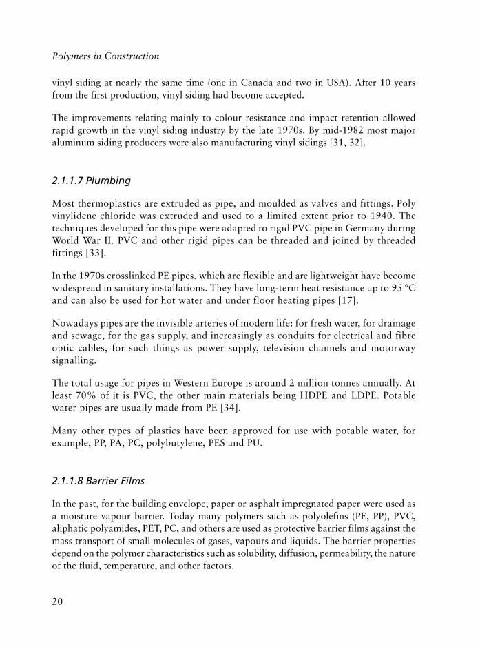
2.1.1.7 Plumbing
Most thermoplastics are extruded as pipe, and moulded as valves and fittings. Polyvinylidene chloride was extruded and used to a limited extent prior to 1940. Thetechniques developed for this pipe were adapted to rigid PVC pipe in Germany duringWorld War II. PVC and other rigid pipes can be threaded and joined by threadedfittings [33].
In the 1970s crosslinked PE pipes, which are flexible and are lightweight have becomewidespread in sanitary installations. They have long-term heat resistance up to 95 °Cand can also be used for hot water and under floor heating pipes [17].
Nowadays pipes are the invisible arteries of modern life: for fresh water, for drainageand sewage, for the gas supply, and increasingly as conduits for electrical and fibreoptic cables, for such things as power supply, television channels and motorwaysignalling.
The total usage for pipes in Western Europe is around 2 million tonnes annually. Atleast 70% of it is PVC, the other main materials being HDPE and LDPE. Potablewater pipes are usually made from PE [34].
Many other types of plastics have been approved for use with potable water, forexample, PP, PA, PC, polybutylene, PES and PU.
2.1.1.8 Barrier Films
In the past, for the building envelope, paper or asphalt impregnated paper were used asa moisture vapour barrier. Today many polymers such as polyolefins (PE, PP), PVC,aliphatic polyamides, PET, PC, and others are used as protective barrier films against themass transport of small molecules of gases, vapours and liquids. The barrier propertiesdepend on the polymer characteristics such as solubility, diffusion, permeability, the natureof the fluid, temperature, and other factors.

21
The Use of Polymers in Construction: Past and Future Trends
2.1.1.9 Composites
The construction industry is using various kinds of composite materials such as: fibrereinforced plastics (FRP), polymer concrete, polymer-asphalt, fibre reinforced polymerconcrete, and so on.
It is considered that the late 1930s and early 1940s marked the beginning of the age ofdesigned materials, taking into account that the production of glass fibres was patentedby Slayter and Thomas only in the 1930s [35, 36].
The main growth in interest and technology of the glass fibre-uPES composites in thebuilding and construction industry was in the 1960s. Two sophisticated glass fibre reinforcedplastic (GFRP) structures have played a major role in the development of these materials inconstruction; these are the dome structure erected in 1968 in Benghazi and the roof structureat Dubai Airport built in 1972. During the 1970s and 1980s GFRP was used for otherprestigious buildings. In the early 1990s, the Neste Corporation (Finland) designed andconstructed an experimental house as a test-bed for polymer-based construction materials.Of the materials used, 75% were manufactured from polymers and composites, showingthat these materials can achieve results that are competitive with traditional materials andare aesthetically, functionally and technically sound [37].
In the period 1980-1990 there were major advancements in the evolution of compositematerials technology. New developments in polymer resin formulations, fibrereinforcements, and processing technology led to increasing use of advanced compositematerials in many areas.
In the early 1990s, FRP was developed in Japan to overcome the corrosion problemsinherent in conventional steel rebar. This new rebar has been used for 10 years in non-structural applications. Structural use, however, has been slow to catch on because of alack of design guidelines.
The earliest indication of the use of polymers in concrete was apparently in 1909, inUSA when a patent for such use was granted to Baekeland and in 1922 in France and in1923 in UK [38]. Polymers can be added by three different methods into normal concrete,leading to: polymer impregnated concrete (PIC), polymer modified cement concrete (PCC)and polymer concrete.
Polymers added in the form of fibres are now replacing the asbestos reinforced Portlandcement that appeared in the mid-1980s. The fibres commonly used today besides steeland glass are PP and PA. A variety of other synthetic fibres can be used including PE,PES, aramid and carbon [39].

22
Polymers in Construction
Polymer modified asphalt originated in Europe in the early 1960s. Atactic PP is still usedtoday in asphalt compositions mainly in Europe, Mexico and Asia. A PP copolymercontaining 2-10% ethylene is more popular in USA. Thermoplastic block copolymerswith styrene end blocks or with a diene midblock like S-B-S and styrene-isoprene-styrene(SIS) and their hydrogenated versions are common modifiers for asphalt [40].
2.2 Use of Plastics and Rubbers in Construction: Current Status andTrends for the Future
The building and construction sector is the second largest user of plastics after packaging(in 1999, 18% of the total plastics consumption was from the construction sector whichtotalled over 6 million tonnes in the EU alone – this figure is above 20% today). Of thetotal amount of plastics used in construction, PVC has the largest share (55%), followedby PS (15%), polyolefins (15%), PU (8%) and others (7%). The use of plastics in thebuilding and construction sector has a wide range of applications, from structural tocosmetic (or protective) and it is expected to grow even more in the years to come duemainly to the increased emphasis on energy efficiency in buildings [41]. The constructionmarket in the EU is worth about 400 billion pounds sterling representing 8.5% of grossdomestic product (GDP) (which is similar for the gross total but a lower share of GDPfor both Japan and USA) [22].
Natural polymers have been used in construction in the form of wood and plant by-productsin the past. The cost of some traditional construction materials, i.e., wood, are increasingsteadily, which means that plastic building products are becoming a lower cost option witheach day that passes. In addition, plastics have excellent strength to weight ratios, (i.e.,expanded polystyrene (EPS) combines extreme lightness with a capability of withstandinghigh loads), their environmental resistances are exceptional, they provide more flexibilityin design as well as huge benefits to builders, to designers and home owners.
Plastics materials over-simplify construction methods, in general, by reducing the amountof work necessary on site and usually less skill is needed for their application. They canbe used successfully in buildings from the top (roof) of the house to the bottom (flooring)and even below (pipes); from exteriors (PVC cladding and exterior paints) to interiorwalls (wall partitions, wallpapers and paints). The first use of plastics in constructionmarket was some 40 years ago, mainly being used as substitutes of some of the traditionalmaterials. However, today, they are also being used in much more sophisticatedapplications in construction.
The use of FRP composite materials directly in bridge applications is gaining importancein recent years. FRP have advantages such as high strength/low weight ratio and corrosion

23
The Use of Polymers in Construction: Past and Future Trends
resistance that makes them good candidates for use in bridge construction and retrofits,in addition to some long-term economic advantages by reduced maintenance and labourcosts. The University of Missouri – Rolla (UMR) designed and built an all-compositesmart plastic bridge that is installed at the UMR campus, which is composed of carbonfibre reinforced pultruded tubes in the matrix of vinyl ester resin. The smart compositebridge has fibre optic sensors built into the structure. This application proved that all-composite bridge decks (made of pultruded glass and carbon tubes) can be a suitablereplacement for bridges made of conventional materials.
FRP applications in structural rehabilitation, such as, column strengthening and seismicretrofitting by using FRP wraps, beam strengthening with bonded FRP wraps and prestressedlaminates, as well as its applications to masonry and other structures are the focus ofrecent innovative work and these applications are expected to increase during the years tocome [42, 43, 44]. The typical way to support cracked piers, columns and supports issimply to wind composite filaments around them. There is also the need for repair andretrofitting/rehabilitation in time as any infrastructure gets older. Nearly half of the 570,000highway bridges in USA (that were built some 40 to 50 years ago) are reported as ‘structurallydeficient or functionally obsolete’ [45], and need trillions of dollars for rehabilitation. Inthe Alberta province of Canada, almost 5,000 bridges were found deficient in shear strength,which could lead to a very dramatic type of failure. Examples like these can be easily foundworldwide. All of these problems can and will be solved through the use of plastics compositematerials, economically and quickly; sometimes by applying paper-thin graphite epoxypatches, a process which requires a minimum amount of demolition work before repairbegins, hence, without rerouting traffic much during the process. Innovative compositebridge deck applications utilising glass or carbon fibres are increasing and will be a veryproductive area in the future. Currently, retrofits to reinforce substandard structures havea huge potential and their use is increasing.
In addition to their applications for repair and rehabilitation of damaged bridge decksin the form of durable and fast curing materials, plastic composites provide non-penetrating non-skid overlays and they are used heavily in a number of public-relatedprojects, such as in the Channel Tunnel (1990s) and in the construction of stadia at thelast Olympics in Australia.
All plastic composite materials are already used in some challenging civil engineeringapplications, such as, in a composite footbridge (Aberfeldy, Scotland, UK; 1992) androad bridges (Stonehouse, Gloucestershire, UK; 1994).
The 40 metre long and 3 metre wide all glass fibre reinforced plastic (GFRP) compositebridge to connect Scandinavia to the mainland Europe has just been completed inDenmark. The bridge weighs only 10 tons, just half the weight of a similar steelconstruction, and is expected to require only cosmetic maintenance throughout its life.

24
Polymers in Construction
Polymers, after their combination with fibres to form special composites produces somematerials with enhanced properties, enabling them to be used as structural members andunits, competing with metals. The use of polymeric fibres in concrete to replace steelframe (as composite rebars) has many advantages which has been in use for a long timewith an ever increasing trend in use, if the material costs involved are decreased in thefuture, as expected. However, proper materials characterisation in addition to developmentof new standard test methods still appear to be the immediate needs to be fulfilled in thenear future.
There is a growing interest in the application of plastic composite structures more andmore in construction, and a pan-European project funded under the Eureka scheme(Eurocomp) has the aim of designing the lacking criteria and specifications in structuraldesign of polymer composites.
A carbon fibre composite blanket was used as a vibration damping stabiliser for bridgecolumns, seismic retrofits and structural reinforcements, while seismic bearings havelong been applied to the base to increase the flexibility of the building (laminates madeof natural and chloroprene rubber or high damping PU elastomer), and are usedsuccessfully for earthquake isolation. Most of the buildings in Japan and in certain partsof USA (California) are already (and in increasing proportions, will be) protected bysuch isolators.
Construction activities with building in recent years are mostly for both new residentialand related repair/maintenance applications for the old, and these are much higher thanfor their civil engineering and non-residential uses, especially in the EU. There is a verybig increasing trend in window and door applications in these countries (and, in addition,especially in China) and for this, PVC is expected to be the dominating plastic. After thefirst applications of smart windows in glazing, it is expected that the demand for thiswill be more towards the use of PC, rather than acrylics.
Insulation, mostly of heat, is expected to centre mostly on EPS in the near future, at leastfor general heat insulation applications. The problems associated with new blowing agents,(i.e., thermal inefficiencies involved for new blowing agents of PU) are expected to causePUF use to decrease in general, except in flooring and roofing applications. Plastic fibreinsulation, preferably produced from plastic wastes, is showing a big potential for theirfuture use as insulators.
For flexible sheeting, as single ply roofing use, PVC and ethylene-propylene-dienemonomer (EPDM) are expected to be the main polymers used. For wall and floor coveringsPVC is still expected to continue to dominate the construction market. PVC will be themain plastic used for pipe and conduit, wire and cable, profiles and flooring applications,while EPS will be mostly used in insulation.

25
The Use of Polymers in Construction: Past and Future Trends
All-plastic (or most-plastic) ‘concept’ houses have been on show for a long time asmentioned in the previous section (such as Monsanto’s ‘House of the Future’, DuPont’s‘Signature Place’ and the four storey GE Plastics’ ‘Living Environments House’, all inthe USA, ‘Futuro’, and ‘Nestehous’ in Finland (the latter from Neste); where a largeproportion of plastics are used with the most up-to-date applications of the time. InNestehous, plastics account for 75% by volume of the materials used, where PP fibresreinforced concrete rebars are applied as the main load bearing units. The Nestehousfeatures see-through ‘a-Si modules’ as window glass and crystal-silicon sun shades onthe south facade to reduce summer cooling loads. The International Institute of PolymerArts and Techniques (IIATP) of France built a plastic demonstration house (Milon House)with self-darkening windows and carbon/glass fibre (GF) composite frames, polyesteramide doors, melamine walls, epoxy seals and transparent floors, with a very lighttriangular shaped textile/GFRP composite roof.
In recent years, better construction methods and products have been developed, althoughrelated technology still mostly depends on traditional labour intensive, on site-basedwork. However, there are also sophisticated technologies applied, such as, intelligent(smart) material applications, as well as, the prefabrication of sub-components such as(light) building frame members and modules. Earlier, in GE Plastics ‘Concept House’,windows were prepared from two layers of PC sheets laminated by using a liquid crystalpolyester film, which can change from clear to translucent via a switch hence naturaldaylight control can be explored easily. In the same house, voice-activated mini-blinds inliving rooms regulates the amount of light as well, and there is a health pad in the bathroomto give readouts of the pulse rate, blood pressure, and weight, with the touch of a finger;and there is a voice activated computer on the top floor. There are also the followingconceptual visions to consider: foam floor tiles are used (that form a grid to define theposition of piping in the house), flexible quick-connect plumbing and a toilet system thatincorporates a mulching unit are designed (to preprocess wastes, allowing much smallerwaste pipes and reducing water volume) and there is the total environment control unitin the house (to combine new ideas in heat exchangers, reverse osmosis water purification,and heat distribution). Today, electronic control and communication systems are providinga basis for intelligent buildings. In fact, BASF developed a smart material that providesshade and overheating from incident solar rays; this will certainly be used for shuttersand blinds as well as classical outdoor functional cladding in houses, panels in greenhousesand conservatories. The same company developed another smart system by using hydrogelsthat has thermotropic properties (changes in properties by heat), that is being used alreadyto cool the company’s exterior solar heating system where excess heat generation insummer is blocked effectively.
‘The MIT Home of the Future Consortium’, in its recent form ‘Open Source BuildingAlliance’, is working on a project (project House-n, the ‘n’ being scientific shorthand for

26
Polymers in Construction
‘variable’) to prefabricate (plastic) smart houses most economically. The heart of thisproject is a chassis with an infill of cheap sensing devices like LED, speakers, displays,automatic lighting, heat sensors, and miniature cameras that can be plugged in at anypoint and upgraded; the network being self-configuring. The floors, the walls and theceilings are all made of plastics in this design. Furnishings and equipment, as well as thehouse itself, are almost 100% synthetic.
A ‘smart brick’ concept was developed recently by scientists at the University of Illinoisat Urbana-Champaign, Center for Nanoscale Science and Technology; that can be usedto monitor a building’s health, and hence can help to prevent disasters. The system,combined sensor fusion, signal processing, wireless technology and basic construction
Figure 2.2 Computer controlled geodesic ‘Dome Home’ of J. Noel Pigout (to achieveenergy efficiency by opening and folding in like a flower, closing up when temperature istoo high or low and turning its back away from or towards the sun) (2001, Paris Fair),
Figure 2.1 Monsanto House (1957-1967) at Disneyland, then at MIT, USA; all plastic;with ultrasonic dishwashers, foam-backed plastic floor coverings, atomic food
preservation and plastic sinks with adjustable heights. Its demolition took a long time(two weeks) with a crew of several men than normal planned duration (one-day).

27
Figure 2.4 ‘Orange at Home’ House (2001), an average Hertfordshire house is turnedinto a remote-controlled show home (UK). The house is powered partly by solar
panels on the roof and is equipped with energy-saving innovations, such as, a hot-airrecovery system that draws warm air from the kitchen and bathroom to heat the
cooler rooms. Security is totally automated, and the front door can be opened with amobile phone, room temperature can be set by yelling at the walls.
Figure 2.3 ‘Futuro’ House (1968/2002) of Matti Suuronen design, fromFRP polyester composite.
material into a multi-modal sensor package that can report building conditions to aremote operator. The prototype has a thermistor, two-axis accelerometer, multiplexer,transmitter, antenna and battery hidden inside a brick, or, inside laminated beams, orother building materials. Built into a wall, the system can monitor a building’s temperature,vibration and movement.
The Use of Polymers in Construction: Past and Future Trends

28
Polymers in Construction
‘NanoHouse Initiative’ is a model house developed by the Commonwealth Scientific& Industrial Research Organisation (CSIRO) and the University of Technology Sydney(UTS) which shows how new materials, products and processes that are emerging fromplastics and nanotechnology research and development might be applied to our livingenvironment. As is known, nanotechnology is the design, fabrication, andcharacterisation of functional objects having dimensions at the nanometer (one billionthof a metre) length scale. The principles upon which NanoHouse is based are energyefficiency, sustainability, and mass customisation. The NanoHouse has a radiativecooling paint as the outer surface of some of the roofing material. A metal roof coatedwith this paint becomes a cooling element in a building rather than a source of unwantedheat gain (new paint additives that mean dark surfaces stay relatively cool, and lightsurfaces can absorb heat). Other features are self-cleaning glass (multifunctionalwindows), cold lighting systems and the dye solar cell – a photovoltaic cell based ontitanium dioxide rather than silicon. Nanotechnology can also be applied to our livingenvironment by embedded, distributed sensing systems that involve implanting tinysensors (temperature, air quality, stress) in building materials. Using such systems wecan get ‘smart spaces’ that use technology that can sense and act, communicate, reason,and interact with us to make our living and working environment more comfortable.The architectural model of the house is the first stage of the concept, with the creatorsplanning a full size version in the future.
In Chapter 6 (Section 6.8, smart materials and structures), additional information isprovided on the subject.
Future trends in the EU for plastics construction materials is increased use of plasticspiping in sewage transport.
PU and PIR rigid foams account most for general and phenolics for indoors applications,this trend is expected to be the same for the future.
The ‘three-litre house’ that consumes an equivalent of only three litres of heating oil persquare meter of living space was realised by BASF and is on the market. If comparedwith the ‘unmodernised’ building with 2,000 litres of oil consumption (costingapproximately 700 EUR) with an estimated 6 tons of carbon dioxide emission for a 100m2 house, the three litre house will need 300 litres (costing 100 EUR) of oil producing0.9 tons of carbon dioxide (both in oil consumption hence cost of heating, and in carbondioxide emissions, there are considerable decreases expected per year) [46].
Processing wood plastic composites (WPC) into profiles by extrusion for building andconstruction applications is one of the most exciting businesses of recent years. Growthobserved is such that WPC applications are already very high (at least 30% a year in

29
Europe), and new applications will continue to be found in the future. This market ismore active in North America, which based largely on the success of WPC deckingapplications and is expected to more than double by the year 2006; however potentialin Europe is also vast and growing quickly. In Europe, wood plastic composite productsare mainly used in a wide range of applications, ranging from basic solid extrusions toengineered profiles in high performance interior applications; including window profiles,garden furniture, fencing, doors, cladding, crates, roofline products, and decking.Shorter cycle times are possible when injection moulding WPC and there areenvironmental benefits to be gained when WPC are produced from waste wood andrecycled plastics, another very attractive consideration for using WPC systems, whichcertainly helps it to compete favourably with other plastics. In Japan, WPC are usedfor a high quality finish for interior applications.
There are studies to develop better and much safer insulating products for the futurehomes, such as aerogels, powder-filled/evacuated/vacuum insulation panels, and phasechange materials.
Aerogels are one of the strongest, lightest and yet transparent (although non-polymeric)building products with 99% of empty volume, typically produced from silicone or carbon;with equivalent thermal insulating efficiency equal to 10-20 glass window panes [47].
Insulation panels use the Dewar’s principle [48] which uses reflective outer layers andencaged stagnant insulating media in between, which is the most effective way of heatinsulation.
Phase change materials, which are non-polymeric as well, can store and release energyby changing phases when used for electronics cooling, etc., by allowing substantial thermalstorage to become part of the building’s structure without effecting the temperature ofthe room envelope, hence daily indoors room temperature fluctuations are smoothed.Another phase change material application was developed recently as a specific atticinsulation which absorbs heat during the daytime and releases it at night, where the atticis hermetically sealed with polymeric foams [49].
The future will certainly see the applications of a wide variety of new and improvedmaterials in construction. There are improvements and tailored properties through processsimulation and modelling for functionally graded materials, layered structures, nano-structured multifunctional materials for ultra-lightweight structures, and ‘smart’ materials.Use of digital technology already led to a number of smart housing innovations: voice-activated appliances, homes that set their own thermostats and recognise their ownersby ‘dog tags’ or badges (used for unlocking doors, turning on lights, etc). Microsoft’s BillGates recently made an alliance with Samsung to develop home technologies to produce
The Use of Polymers in Construction: Past and Future Trends

30
Polymers in Construction
an ‘entire ecosystem of personal computers, digital devices, intelligent home appliances...transform[ing] average households into next-generation digital homes’. In the currentGates estate, there are touch-sensitive pads to control lighting, music, and climate ineach room, and automatic setting of lights and of heating the floors throughout thehouse (and the driveway).
The Smart home approach is the future trend for homes with a lot of home automationand smart concept applications. In all of these, the possibility to create a home andenvironment that is aware of its occupants and activities to provide services to enhancethe quality of life or to help residents to maintain independence as they age. The followingexamples are just a random collection of them.
Several years ago 3M developed a paper-thin, electrically sensitive Privacy Film, basedon patents held by Kent State University and Raychem Corporation. Between two sheetsof this film, a layer of liquid crystal was put and all are held between panes of glass toproduce the Privacy Glass (Electrically switchable ‘smart’ windows). When electricity isapplied to this system, the liquid crystals line up and the foggy material becomes clear,when the current is withdrawn, it becomes opaque again.
Now there are smart windows that sense climatic changes or that go from opaque toclear, on their own.
Mood paint has a thermochromic carbon-based pigment, and fades as the temperaturerises and brightens as it cools (NASA developed this paint as a coating that would warnscientists when a machine was overheating). Mood paint if used as an exterior housepaint would darken and absorb heat from sunlight during cooler seasons. Jürgen MayerHermann, a German artist, created his housewarming installation by using mood paintindoors and showed that when the wall is touched, the colour temporarily fades, leavinga sort of negative shadow. This will probably be the ‘interactive’ wallpaper that can bealtered to suit the mood.
Low-energy interior wall and ceiling paints can be accomplished by use of radiancepaint that reflects radiant heat energy back into a room in the winter and reflectsradiant heat away in the summer (which is applied in space shuttles to let astronautsstay comfortable) with which the estimated energy saving in radiance-painted roomswill be 5 to 15%. Similarly, furniture can be made out of smart materials that canchange colour and/or even conform to shape.
Smart wall and the smart concrete concept was created by Deborah Chung, from theState University of New York at Buffalo, by embedding electronic properties into materialsso that surfaces are able to store electricity and have the intelligence to measure andcontrol climate, as well as to scale the weights above them.

31
For Smart walls, carbon fibres bound by an epoxy matrix are used that act as a structuralmaterial and as a semiconductor. It is less expensive, less fragile, and easier to producethan silicon circuitry, structural electronics will allow walls to store energy and act ascontrol circuitry.
For smart concretes, ordinary concrete reinforced with short carbon fibres are used whichcan conduct electricity and give the surfacing mixture measurable electrical resistivitiesto function as a ‘scale’ that can detect the weight passing over it by following the changein the amount of contacts between the carbon fibres, as it alters, the resistance of the mixis affected. The Smart concrete concept is expected to be used in highway engineering aswell as indoors, (i.e., as smart flooring in bathrooms in place of bathroom scales) [50].
Carbon fibres can also be used to create other types of smart concretes that can senseand report structural damages. Sandia is exploring candidate smart materials that can beattached to or embedded into structural systems to enable the structure to sensedisturbances, process the information and through commands to actuators, and toaccomplish some beneficial reaction such as vibration control.
Recently, the nano concept is included in construction as well and it is applied to a model‘nanohouse’, developed by the CSIRO, Australia and the University of Technology Sydney(UTS); showing how new materials, products and processes that are emerging fromnanotechnology research and development can be applied to our living environment (onenergy efficiency, sustainability, and mass customisation) [57]. The NanoHouse has a radiativecooling paint as the outer surface of some of the roofing material. A metal roof coated withthis paint becomes a cooling element in a building (rather than a source of unwanted heatgain). Other features of the nano house are self-cleaning glasses, cold lighting systems andthe dye solar cell - a photovoltaic cell based on titanium dioxide rather than silicon.
Smart materials and structures are presented in more detail in Chapter 6 (in Section 6.8).
References
1. R.B. Seymour in Pioneers in Polymer Science, Ed., R.B. Seymour, KluwerAcademic Publishers, Dodrecht, The Netherlands, 1989, 81.
2. H-G. Elias, An Introduction to Plastics, VCH, Vienna, Germany, 1993.
3. R.B. Seymour, Journal of Chemical Education, 1988, 65, 4, 327.
4. R.B. Seymour in Applications of Polymers, Eds., R.B. Seymour and H.F. Mark,Plenum Press, New York, NY, USA, 1988, 125.
The Use of Polymers in Construction: Past and Future Trends

32
Polymers in Construction
5. Chemical Engineering News, 1991, April, 36.
6. L.A. Utracki, Polymer Engineering and Science, 1995, 35, 1, 2.
7. C.A. Russell in Chemistry, Society and Environment: A New History of theBritish Chemical Industry, Ed., C.A. Russell, Royal Society of Chemistry, 2000,Cambridge, UK, 245.
8. J.R. Fried, Polymer Science and Technology, Prentice Hall PTR, Upper Saddle,NJ, USA, 1995.
9. J.A. Brydson, Plastics Materials, 5th Edition, Butterworths, Sevenoaks, UK,1995.
10. D. Feldman and A. Barbalata, Synthetic Polymers: Technology, Properties,Applications, Chapman and Hall, London, UK, 1996.
11. J. Hausmann and N. Mustafa in Plastics Waste Management: Disposal, Recyclingand Reuse, Ed., N. Mustafa, Marcel Dekker, New York, NY, USA, 1993, 59.
12. H. Morawetz, Polymers: The Origins and Growth of a Science, J. Wiley & Sons,New York, NY, USA, 1985.
13. K. Ashida in Handbook of Polymeric Foams and Foam Technology, Eds., D.Klempner and K.C. Frisch, Hanser Publishers, Munich, Germany, 1991, 95.
14. S. Moulay, L’actualite Chimique, 1999, 12, 31.
15. F. Rodriguez, C. Cohen, C.K. Ober and L.A. Archer, Principles of PolymerSystems, 5th Edition, Taylor & Francis, New York, NY, USA, 2003.
16. S. Chandra and Y. Ohama, Polymers in Concrete, CRC Press, Boca Raton, FL,USA, 1994.
17. W. Hasemann and R. Weltring, Kunststoffe Plast Europe, 1995, 85, 1, 27.
18. D. Feldman, Polymeric Building Materials, Elsevier Applied Science, London,UK, 1989.
19. Manufacturing Chemist, 1984, 55, 6, 83.
20. O. Baum and B.R. Tutt in Roof and Roofing: New Materials, IndustrialApplications, Uses and Performance, Ed., J.O. May, J. Wiley & Sons, New York,NY, USA, 1988, 40.
33
21. M. Koike in Roof and Roofing, Ed., J.O. May, J. Wiley & Sons, New York, NY,USA, 1988, 7.
22. R. Scharff and T. Kennedy, Roofing Handbook, 2nd Edition, McGraw-Hill, NewYork, NY, USA, 2001.
23. D.R. Croy and D.A. Dougherty, Handbook for Thermal Insulation Applications,Noyes Publications, Park Ridge, NJ, USA, 1984.
24. K.C. Frisch, Journal of Macromolecular Science A, 1981, 15, 6, 1089.
25. K.W. Suh in Handbook of Polymeric Foams and Foam Technology, Eds., D.Klempner and K.C. Frisch, Hanser Publishers, 1991, Munich, Germany, 152.
26. G.K. Backus in Polymeric Foams, Eds., D. Klempner and K.C. Frisch, HanserPublishers, 1991, Munich, Germany, 74.
27. R. Montella, Plastics in Architecture: A Guide to Acrylic and Polycarbonate,Marcel Dekker Inc., New York, NY, USA, 1985.
28. J. Germer, Progressive Builder, 1986, November, 21.
29. T.R. Pfeiffer, Journal of Vinyl Technology, 1983, 5, 3, 136.
30. Caoutchoucs et Plastiques, 1988, 678, 77.
31. J.A. Briggs, Journal of Vinyl Technology, 1983, 5, 2, 41.
32. J.W. Summers, Journal of Vinyl Technology, 1983, 5, 2, 43.
33. R.B. Seymour, Plastics vs. Corrosives, J. Wiley & Sons, New York, NY, USA,1982.
34. J. Maxwell, Plastics, The Layman’s Guide, IOM Communications Ltd., London,UK, 1999.
35. C. Ageorges and L. Ye, Fusion Bonding of Polymer Composites, Springer Verlag,London, UK, 2002.
36. R.B. Seymour, Reinforced Plastics: Properties and Applications, ASMInternational, Materials Park, OH, USA, 1991.
37. L. Hollaway, Polymer Composites for Civil and Structural Engineering, BlackieAcademic & Professional, London, UK, 1993.
The Use of Polymers in Construction: Past and Future Trends

34
Polymers in Construction
38. J.B. Kardon, Journal of Materials in Civil Engineering, 1997, 9, 2, 85.
39. B. Berenberg, Composites Technology, 2001, 7, 4, 44.
40. N. Akmal and A.M. Usmani, Polymer News, 1999, 24, 4, 136.
41. H. Fisch in Proceedings of Eurochem Conference 2002, Toulouse, France, p.31.
42. K.W. Neale, Progress in Structural Engineering and Materials, 2000, 2, 2, 133.
43. R. El-Hacha, R.G. Wight and M.F. Green, Progress in Structural Engineering andMaterials, 2001, 3, 2, 111.
44. T.C. Triantafillou, Progress in Structural Engineering and Materials, 2001, 3, 1,57.
45. Engineering News Record, 1995, 11 September.
46. BASF (the three-litre house), www.3lh.de/www.LUWOGE.dewww.basf.de/en/corporate/innovationen/realisiert/innovationspreis/3_liter_haus.htm
47. Microgravity Science: Aerogel in Your House, the House of the Future?, NASA,USA, http://science.nasa.gov/newhome/help/tutorials/housefuture.htm
48. R.T. Bynum, Insulation Handbook, McGraw Hill, New York, NY, USA, 2001.
49. F. Helmut and S. Corina, CBS Newsletter, 1997, No.6.
50. Orr Robert J. and Abowd D. Gregory ‘The Smart Floor: A Mechanism forNatural User Identification and Tracking’ Proceedings, April 2000 Conference onHuman Factors in Computing Systems (CHI 2000), The Hague, Netherlands.
51. Nanohouse Brings Nanotechnology Home, CSIRO Media Release, Reference2003/198, November 19th 2003.

35
3 The Use of Plastics in Building Construction
Güneri Akovali, Dorel Feldman and Bireswar Banerjee
3.1 Introduction
Building means any structure that is used (or intended to be used) for supportingoccupancy or sheltering. Building construction is currently one of the largest industriesworldwide, i.e., new construction in US was approximately 620 billion US$ [1], andwith renovation, maintenance and repair added, the total volume of construction wasabout 1000 billion US$ (during 1997-1998), corresponding to 12.3% of the GDP. Inthe EU, the construction market was about 400 billion pounds in size (in 1997) whichgrows about 2-3% per year [2].
Within building construction, residential construction has the highest share in general(approximately 40%), followed by commercial institutions (30%), public works (20%)and industrial constructions (10%).
There are a number of different materials involved in the building and constructionsector, beginning with cement (used to produce concrete) and lumber, which are theclassic and common materials. There is also a variety of novel plastics materials beingused in the same sector, which are not that old, and their use is ever increasing andreplacing the conventional ones. ‘Lumber’ and ‘composites of various ligno-cellulosicfibres with plastics’ are being used in large proportions in construction.
Plastics have a wide range of applications in the building industry, and this sector is thesecond largest user of plastics. These applications range from non-structural to structuraluses, inside and outside of the house, because of the fact that plastics materials haveseveral advantages, such as, they are light, economical, durable, have high performancecharacteristics, are easily handled and processed and have aesthetic properties. In thecase of fibre reinforced plastics (FRP), high strengths are combined with low weights. Ifglass, carbon or aramid fibres are bound by polyester, epoxy or vinyl ester resins in aFRP structure (say in the form of a rod with a nominal diameter of 7.5 mm with 60,000fibres developed for use in building construction and as a tensioning element) has at leastthe same longitudinal tensile strength that the best pre-stressed steel has. Since polymercomposites are light, using them can minimise the destruction and damage due to thedeadly falling elements during an earthquake or tornado.

36
Polymers in Construction
Although there is still a rather slow pace of acceptance of plastics and its composites inconstruction mainly due to the general lack of knowledge of the properties and applicabilityof these new materials as well as lack of availability of related building codes and standards,they are being recognised, appreciated and applied more and more every day [3].
Polymer structures are used in construction as either (i) structural or (ii) non-structuralelements, as well as (iii) cosmetic (or protective) and repair elements. Hence a classificationfor their use in construction can be done by using these criteria. Within these, their non-structural use is more common than their use with other applications.
However, it is also possible to make a different classification for use of polymers inconstruction, by considering:
(a) polymers that are used in the building envelope (which includes all buildingcomponents that separate the indoor from the outdoor, such as, exterior walls,foundations, roof, windows and doors – all provide a thermal shell), and
(b) polymers that are used in other applications.
Both of these classifications will be used to some extent, interchangeably, in thefollowing parts.
3.2 Structural Applications of Polymers in Building Construction
Structural applications are such that they require proper mechanical performance(strength, stiffness, vibration damping ability) in the material, which may or may notbear the load in the structure. Structural components should withstand ‘live’ loads (suchas: people, wind, etc.), as well as the ‘dead’ loads (the weight of the structure), which canbe (a) ‘load- bearing’ walls, (b) columns and beams, and (c) bracing: in frame construction,or ‘shear walls’.
Load-bearing structural applications of polymers are mostly FRP or their advanced composites,where there are high strengths and low densities involved. After their development and usemainly for military and aerospace applications during and after 1940s, these materials arebeing used in a number of different structural applications, including load bearing sandwichpanel (SWP) and infill panels [4], rebars, complete stand alone structures where FRP unitsare connected together and the shape provides the rigidity needed.
For primary structural applications, which are load bearing: firstly the strength of thematerial should be able to support at least in-plane loads, with proper stiffnesses(if bending and shear forces are involved), and mechanical property requirements are
37
The Use of Plastics in Building Construction
critical. Since under the design loads, the shape of the structure should not deform,materials with high strengths are usually selected in construction. It should be rememberedthat, the failure of primary structural material can cause the complete collapse of thesystem, which is not replaceable. Beams and columns are known as the main primaryload carrying members in buildings, which are with much larger lengths than their depthor widths, with symmetrical cross sections, designed to bend in this plane of symmetrywhich is also the plane of highest strength and stiffness coinciding with the plane ofapplied loads. Beams (and composite beams) are fabricated beginning from metal,reinforced/prestressed/polymer fibre reinforced concrete (rebars) and FRP materials. Loadbearing wall units and sandwich type beams, surfaced with pultruded FR polyester profilescontaining EPS cores (with reinforcement bars and concrete casting) is applied successfully,i.e., in the Neste model house.
In general, composite skeletal systems manufactured by pultrusion have extremely highaxial and flexural strengths and relatively low transverse strengths, and their hoopstrengths can be improved by incorporating hooped strands along a reinforcement core.Continuous fibre mats are also frequently used to improve the transverse strengths ofpultruded structures. There are different methods used for jointing of skeletal compositestructures [5].
Rebars are polymer fibre reinforced-concrete composites, and they are used as primarystructures. It is estimated that replacement of steel reinforcing bars by non-corrosivepolymer fibres, i.e., by Kevlar or carbon fibres (which gives rise to Kevlar or C-composite bars) for concrete structures produces structures with one-quarter theweight and twice the tensile strength of the steel bar. It is known that, corrosion ofsteel reinforcement from carbonation or chloride attack can lead to loss of thestructural integrity of concrete structures, and such a danger is non-existent for rebars.Thermal expansion coefficient (TEC) values of these fibres are closer to concretethan that of steel, which provides an another advantage; and they have the samesurface deformation patterns as the steel bars. In addition, they can provide moreeconomy than epoxy-coated steel bars.
Composite rebars can be prepared by use of various polymeric fibres, such as, carbonfibre, E-glass fibre and Kevlar/aramid fibre. For high modulus requirements, hybridsof carbon-glass and aramid fibres are applied. C-composite rebars are used preferentiallyin places where non-corroding and non-magnetic structures are needed (in sea walls,hospital MRI room walls, reactor pads, roofs of chemical plants, transmission towers,military structures, in areas where EM neutrality is needed, and applications in othersalt water areas, bridges, etc.). Composite rebars with carbon fibres can also be usedto check the self-diagnosis of the structure, by following the changes of electricalresistance of the structure.

38
Polymers in Construction
Composite rebars are applied either as continuous pultruded rods or as structural profiles.Glass fibres, although they have lower moduli values (some 20% of that of steel), canstill provide high tensile strengths (approximately four times higher than steel). However,it should always be remembered that the modulus and the strength values in polymercomposites are also highly dependent on the volume fraction and orientation of thefibres, hence the orthotropy of the material must be considered in the design andapplication of the composite structures at all times.
In addition, since defining the material’s criteria for design of polymer composites ismore complicated than for other conventional structural materials like steel, concreteand aluminium, and because they depend on factors such as the details of stress-strain-strength behaviour, as well as on the changes in these properties with time-temperature-processing conditions and stress environment, (i.e., creep); it is suggested that the ‘limitstate design principle’ is employed [6], which provides the basic tool for determining thelimits of their application as a structural material.
Nevertheless, FRP fibres are better candidates for the pre-stressing and post-tensioningtendons in concrete structures than steel [7], and more than 15% of glass fibres producedare already being used by the building and construction industry [8, 9].
The secondary structural materials are materials that if the structure fails can only causelocal damage that can be repaired, such as secondary wall panels for a steel framedbuilding in a modular construction. These panels, which are aesthetically pleasing, arelight to handle and are low in maintenance, are SWP with FRP or rigid metallic skins onthe face and have a polymeric foam core, usually of EPS or PU. The load on these panelsis mainly the pressure induced by wind.
The complete 2,200 m2 wall façade of Dubai airport is fabricated from FRP and itcomprises architectural components (single and double arches) and images.
Structural bearings are widely used for bridges and expansion joints. Isolation of buildingsfrom ground or structure-bourne vibrations (as well as protecting the building fromdamage of earthquakes) by use of secondary structural rubber bearings, even rubberblocks, has been used for a long time [10-14].
3.2.1 Sandwich Panels (SWP) and Sandwich Panel Applications in HousingConstruction
SWP [15] are layered structures with thin, two high modulus (metallic, concrete orpolymeric) facings adhered to a lightweight core of foam or honeycomb. They can be

39
The Use of Plastics in Building Construction
transparent (where the core is GRP honeycomb and with layers of transparent rigidpolymers) or non-transparent (as is generally the case).
SWP use in construction dates back to the end of World War II where they were used forfor cold stores and freezers. And in recent decades, it is applied in a number of differentbuilding applications. It offers an alternative to ‘solid construction’ methods with itsfavourable economy, lightness and function; the high modulus facings (usually metallic)and the core, (i.e., PU rigid foam) possess an ideal combination of physical, mechanicaland structural properties. SWP, currently has a share of 12.1% of construction and mostof this is for warehouse construction and industrial buildings. SWP application fordomestic buildings is rather small currently (approximately 5%), and it is increasing.
When use of SWP by the construction element is considered, most of it is applied externally(as external walls and facades, 56%), followed by roof insulation (30%) and for ceilings,internal and partition walls (14%). SWP can also be installed as wall panels with integratedwindows, for various indoors separations, as acoustic roof panels and as constructionaccessories (variable connecting SWP panels to connect individual wall and roof panels)and in prefabricated housing and shelters.
Most of SWP are used with steel or reinforced concrete as supporting structures. In SWPconstruction, there are practically no restrictions on building dimensions.
When used as an external wall element, it is calculated that to provide the same heatinsulation level, a SWP with 80 mm rigid PU core insulation can replace 385 mm ofconventional masonry wall. When conventional 24 cm thick masonry with 2 cm resinplaster wall is compared with 80 mm SWP wall, the latter would need 6 times less heatingoil per m2 of external wall. SWP use effectively lowers heat transmission losses resultingfrom thermal bridges. Although degree of elimination of noise is known to improve withincrease of mass in general, lightweight SWP can still help to eliminate noise effectivelythrough its ‘high acoustic damping factor’.
In SWP, the shearing and tension-resistant components of the thin facing units, alongwith the thick core, creates a new structural material with completely different loadbearing behaviour: the three layer sandwich has a synergy in bending and torsionalresistances; both are much greater than the sum of the individual components. The wholeshear force is completely taken up by the core, and the deformation stiffness is associatedwith the shear rigidity of the rigid PU core. Because of their high stiffness, they are self-supporting and have excellent load bearing properties, despite their light weight. Theyare usually fastened to an open framework as a transverse web to carry shear loading(and are used occasionally as a primary structural member). They can be successfullyused as a building envelope as well as the (secondary) load bearing components (wall

40
Polymers in Construction
and roof components). For these load bearing applications, a minimum density of 36 kg/m3 PU rigid foam is needed in the core. Recently complete SWP panel systems for roofand wall cladding were developed and used. In one of these, on the curved facade, 60mm thick and 900 mm wide, SWP are installed successfully with external triple layercoating (waste disposal plant, ROTEB, in Rotterdam, The Netherlands - this incineratorburns 380.000 tons of domestic waste annually to produce 190 million KWh of electricity).
SWP store little heat (with no heat radiation) and hence they provide excellentthermal comfort.
The main advantages of SWP are summarised, and they mainly provide the followingin construction:
(a) accelerated building erection, and cost savings in construction and in energy,
(b) simplified planning and use of SPW gives a number of different architectural designpossibilities,
(c) SPW provide physical construction quality and a substantial energy saving and spaceclimate
(d) they offer flexible rebuilding and extension possibilities.
Figure 3.1 presents a general type of SPW with its core replaced by a honeycomb structure.
Figure 3.1 A typical SWP (with a honeycomb core)

41
3.2.2 All-Composites Housing
There are several buildings that have already been constructed completely from polymericcomposite materials within the last decade [16]. Faber Maunsel Structural Plastics(Beckenham, UK) is one of the companies who have been involved. They built severalprototype single and two storey buildings in the 1990s with the Advanced CompositeConstruction System (ACCS) [17], consisting of pultruded E-glass/isopolyester multicelledmodules with interlocking joints connected for walls, floor and roof assemblies whichare used to construct complete monocoque buildings without need of additionalframework. This house is claimed to shelter from two to 500 people, is highly durableand easy-to assemble. FRP composite structures are also proposed as a possibleearthquake-proof construction method, with buildings assembled from interlocking FRPpanels held together by adhesives and a mechanical fastening system [18, 19].
A large scale, multi-cellular reinforced plastic (RP) polymeric structure was constructedat Weston, USA, for a multi-purpose facility use of Division of Highways, in 1995 [20],where the entire walls are constructed with RP multi-cellular panels made of E-glassfibres and polyester resin, and are connected with wide flanges.
In 2000, Goldsworthy & Associates, USA, showed that a three bedroom, two bath housecan be assembled completely in four hours with unskilled labour. In the GoldsworthyInnovative Fabrication Technology (GIFT) housing project, pultruded structural insulatedpanels (SIP), of woven 0°/90° E-glass roving with phenolic resin over a proprietarymaterial; along with novel snap-lock joining technology, were used. The modularcomposite house, which received the PATH award (Partnership for Advancing Technologyin Housing), was mainly aimed at emergencies, as well as for housing in the Third Worldand developing countries.
In the same year, the Abersham Technology Group, UK, introduced their recyclable,all composite house, where no timber or steel was used at all, and wall and roof panelsare of structural sandwich panel (SSWP) construction with skin laminates and coreconsisting of a blend of glass chopps or glass beads, respectively, and unsaturatedpolyester (UPE). An interconnected network of pultruded carbon/epoxy cables as solidrods were used through each wall and roof panel (to simulate rebars) and they wereattached to the structural concrete slab foundation, and were additionally extendedvertically from the foundation through the wall panels to the roof, creating a greaterload resistance than the dead load of the concrete to provide greater resistance tohurricane winds and earthquake forces [16].
A new folding-house was also developed by Top Glass SpA, Italy, as a portable emergencyall composite system.
The Use of Plastics in Building Construction

42
Polymers in Construction
Medabil (Brazil), patented all-vinyl houses as ‘Casa Forte’ (meaning strong house) andfirst group of plastics condominium, vinyl houses (the structure is made mostly of vinyland vinyl profiles filled in with concrete and steel support) are being built by them in thecity of Canoas with a total of 131 units each with 72 m2, with a 30 year guarantee. It isfurther planned to have 3,000 houses on the same location soon, and this construction isapproved for funding by CEF (Brazilian Federal Savings Bank) [21].
3.3 Secondary Structural and Non-Structural Applications of Polymersin Housing Construction
These are a number of non-load bearing applications of polymers, and their use is morecommon in housing construction. These non-load bearing secondary structural or non-structural applications can be categorised in four main areas:
(a) piping and conduit,
(b) cladding and profiles,
(c) insulation materials, and
(d) sealants, gaskets and seals.
In addition, there are other special non-structural applications of polymers in housingconstruction, such as, wallpapers, glazing, fencing, paints and coating, and so on.
Of these, pipe and conduit applications (which are mostly of PVC followed by PE) accountsfor the highest use (35%) in building construction, followed by cladding and profile(mostly of PVC, 18%) and insulation (mostly from EPS and PU, 17%), by flooring (ofPVC, 10%), wire and cable (PE and PVC, 8%), and film and sheeting (8%),applications [2, 22].
3.3.1 Piping, Electrical Cables, Wiring and Conduit Applications of Polymersin Housing Construction
3.3.1.1 Piping
Piping, which is defined as the arterial sanitation of houses is an important, functionalpart of buildings, used to deliver clean, potable water (for drinking and for otherpurposes) and gas, as well as to convey waste water away from buildings (for theirtreatment and subsequent reuse).

43
A variety of piping materials have been used in the past, (i.e., asbestos cement and ductileiron), and since the introduction of plastic pipes in the first half of the 20th century (firstin Europe then in the USA), plastics piping materials, mostly of PVC and various gradesof PE predominates the sector. In general, plastic pipe and fittings have temperaturelimitations as a disadvantage and there are also restrictions for their use at rather lowpressures. However, plastic pipes offer higher resistance to environmental conditions(corrosion resistance) and have durability; they provide considerable reductions in weight,ease and economy of fabrication and installation, ease of repair and (relatively) low cost.Plastic pipes have a smoother bore than their metallic counterparts, hence flow rates canbe increased and scale formation is reduced. Plastic pipes of small diameters are availablein continuous lengths of up to 100 m (even up to 250 m in some cases), that help toreduce the number of joints and the number of potential leak points.
Within buildings, the push-fit waste systems have made plumbing much quicker, andalso safer.
In addition, it is shown that, plastic pipes in the house and out (such as underground), allshow good resiliency in the case of earthquakes that beats all other traditional materialsavailable (Valencia Water Company, USA, the California private utility was able tocompare the performance of three pipe materials – asbestos-cement, PVC and steel, duringthe catastrophic Northridge earthquake of January 1994, and found that PVCoutperformed the others). Since the Kobe earthquake, which showed the structuralweakness of traditional pipes, HDPE pipes are preferentially being used as gas pipes [2].
Plastic pipes are available in different lengths, diameters and pressure classes with a fullcomplement of standard fittings, valves and couplings. They are compatible with otherpipe materials and they can be specified for either new construction or for system upgrades.Plastic pipes can be repaired easily if for any reason they are damaged. On the otherhand, traditional metallic and other pipe and tube installations can be sealed and/orrepaired, (i.e., by spray coating of epoxy [2]) by use of polymeric materials.
The Association of Plastic Manufacturers’ in Europe’s (APME) report demonstrates thatplastics’ use in ‘gas, sewage and water piping’ has tripled in the EU between 1970 to1995, rising from approximately 650 K to 1.9 M tonnes.
HDPE, PVC, acrylonitrile-butadine-styrene (ABS), PB and polypropylene (PP) pipes enteredthe market as ‘solid walled, varying thickness’ pipes of ‘small and large diameters’, however,PVC and PE pipes and fittings are more widely accepted and used in construction in waterand gas piping, although they still are facing some competition from metallics, (i.e., copper,cast iron). In general, plastic pipes with diameters up to 30 cm are almost all made of PVC,(specifically, PVC-U). Chlorinated PVC (CPVC) and molecularly oriented PVC (MOPVC)are used for large diameter industrial pipes, where high corrosion resistance is required,
The Use of Plastics in Building Construction

44
Polymers in Construction
and for high pressure pipes, respectively. MOPVC are specially processed where fracturefailures are ductile, and crack paths follow the laminar structure of the pipe circumferentially[2]. The lifetime of vinyl piping and fittings are estimated as 50 years.
For potable water, PE pipes are preferable. HDPE is mainly used for pressure water pipes(approximately 6.3 MPa) with both small and large diameters, while low densitypolyethylene (LDPE) pipes with small diameters are used for low water pressures (4MPa). Use of medium density polyethylene (MDPE) and its blend with HDPE as pipes,for higher water pressures (8-10 MPa) and with better long-term performances in additionto higher flexibilities, are more recent. PE high pressure irrigation pipeline systems arecommonly used. There are cases for the use of linear low density polyethylene (LLDPE)and its blends with MDPE in plastics piping. Usually blue grades of PE are for highpressure water delivery and underground potable water distribution, which enables theburied pipe to be immediately identified, orange/yellow for gas distribution (both withcertain UV stabilisers) and carbon black grade is for (above ground) pressure wastewater and gas pipes. If existing domestic supply pipes are corroded, the replacement(yellow) plastic pipe is threaded through the existing pipe. The plastic pipe placed beneaththe ground surface (the underground pipeline used for transmission of water, gas, oil andother liquids) are sometimes called geopipes [23] and over 95% of natural gas transmissionlines are made of HDPE geopipes.
FRP pipes prepared by use of GF reinforcements are usually the material of choice fortransporting corrosive fluids and when external corrosive conditions exist, hence theyare used mainly in industrial custom and commodity piping applications [24].
For hot water systems, (i.e., in underfloor heating systems and for hot waterdistribution), pipes are mainly polybutylene (PB), which can be used in systems with acontinuous operating temperature of 82 °C and can survive short peak temperaturesof up to about 110 °C, as well as crosslinked polyethylene (XLPE) with improvedcreep resistances, that can withstand operating temperatures for the same range as PB.The heat dispersion is optimised by these plastic piping systems by using the heatstoring capacity of the floor.
3.3.1.2 Electrical Cables, Wiring and Conduits
It is estimated that about 5%t of the total value of a real estate belongs to electricalcables and wiring. Within the polymers used for electrical cables and wiring, PVC electricalproducts are the most durable that provide electrical and fire safety at low cost andcontribute to the life safety in building design. PVC-U is inherently flame retardant, butPVC-P looses this property somewhat (because of the plasticisers used) and are used

45
with certain flame retardants added. New generation electrical wires are available withthe second lining of a double layer of PVC providing higher insulation and higher resistanceto bending, rolling and pressure. A slippery vinyl coating applied on the wire helps theinstalment, (i.e., passage of wires through the conduits, etc.).
For plastic conduit systems, there are PVC-P, PU or Nylon for special flexible ones, andPP or PVC-U in most rigid nonmetallic conduit systems.
There are alternative cable types available with low-smoke, zero halogen (LSOH)characteristics, which are claimed to be safer and are being used in several undergroundrailway systems in Europe and USA.
3.3.2 Cladding and Profile Applications of Polymers in Housing Construction
3.3.2.1 Cladding
In the construction sector, the use of ‘easy-to install’ materials are always preferred, andthe coating of façades and application of sidings were always rather expensive and timeconsuming construction procedures. For this reason, until recently, residential exteriorcladding was considered only as an option, and until the 1980s, aluminium (and wood)were predominant in this application. The recent large acceptance of plastics siding andaccessories as an essential exterior element in housing construction is mainly due to theease of their application and the favourable economy involved, in addition to thetraditional or modern looks they provide, and their energy efficiency. In recent years,cladding and siding is the fastest growing segment in the construction sector and its useis expected to reach to 1.4 million tons by 2005 [22]. Currently, PVC siding has about50% of the market share for exterior cladding products on residential and light commercialbuildings. The popularity of use of PVC-U in cladding and accessories (soffit, fascia,etc.), which are provided in different colours and shades, (including the vertical/horizontalwood grains or in a smooth matte finish) is because of the durability, ease of maintenance,impact resistance, versatility and low installation cost. On new buildings particularly,PVC-U external panels, fascia and soft boards are frequently being used in place oftraditional timber products.
Exterior normal size cladding is often prepared with either solid or foamed PVC-U (doubleskin or foam filled double skin) with the look, feel and workability of wood (they can benailed, machined and cut like wood). However, during fixing of PVC-U cladding products,proper allowance must be made (approximately 2 mm per metre length between sections)for thermal expansion and contraction, to prevent buckling of the sheets due to thepossible heating effect of sunlight, unlike their timber counterparts. With the double
The Use of Plastics in Building Construction
46
Polymers in Construction
skin cellular construction, sink or shrinkage marks are often seen running along the ribs.PVC-U claddings are light in weight, they have good resistances to rot and warp, theyare inherently flame resistant, they are available in a variety of colours and finishes, andthey do not need regular maintenance, (i.e., painting). PVC siding, usually in the form ofa parallel bar coating fixed to profiles, is used for the covering of both residential andcommercial facades and is an easy-to apply material.
PVC siding with parallel bar configuration is a very aesthetic, very easy finishing materialto apply against block, brick, steel or wooden walls that do not require any painting orother maintenance. The bars are installed leaving a certain distance between them whichis determined by the known regional climatic coefficients. It is self-extinguishing, highlyresistant to traction, resistant to UV, air pollution and corrosive sea-air, and can conserveits characteristics up to 70 °C without showing any deformation.
Larger claddings are usually prepared from polyester based GFRP. There is also a trendfor the use of cladding panels made of phenolics as their excellent flame resistances areconsidered, in particular for public structures (like railway - airport terminals, hospitals,and schools).
3.3.2.2 Profiles
Use of plastics materials in profiles in construction, mainly in fenestration applicationssuch as windows and doors, which replaces the use of aluminium, wood or steel, givesrise to better energy efficiency, aesthetics, low maintenance and design flexibility, inaddition to the economy. Introduction of new extrusion techniques in plastics processinghave also helped to promote the use of plastics in profile applications. In the USA, demandfor plastic windows and doors are expected to grow by more than 7% through 2007(currently 2% of all window and door demand in USA in plastic) to give a market shareof 6.2 billion US$ in the USA [25].
PVC-U has been in use for many years for the manufacture of window frames, particularly,for double glazed windows. There are substitutes, such as PP and styrenics (ABS withacrylonitrile-styrene-acrylonitrile (ASA) capstock) and wood composite alternatives,however, PVC is still the strongest and alternatives seem to complement it.
Several advantages of using plastics window frames are:
(a) their lower thermal conductivities compared to equivalent metal frames, which providesmore effective thermal insulation helping to reduce condensation on the frame,
(b) they can be more easily assembled,

47
(c) they do not require regular maintenance, and do not need a wooden surround or asub-frame (only for the larger frames, steel reinforcement is usually added for extrastrength and security).
Plastic frames with low heat conductivities provide energy savings, stable fixation,durability and low service costs for a long time (average estimated usage time of a PVCframe is 40 years).
Extruded PVC prepared with a variety of different formulations and in different forms,including a wood-vinyl composite that is made of sawdust as well as a vinyl cellularfoam that can be extruded into solid shapes, are all used in the production of a variety ofwindow styles (traditional, single-double or triple hung windows, sliding windows etc.)[26]. Being inherently fire resistant, which can be enhanced with flame resistant additiveswhenever needed, and durable, PVC is the preferred and the leading material for framesin construction, since the production of first plastic window profiles in Germany afterWorld War II from extruded frames of PVC. During the period of 1992 to 1998, PVCwindow applications grew by nearly 125%, in residential new construction andremodelling.
Fully reversible and enhanced security casement window systems and doors made bypultruded FRP were first introduced in UK with their low environmental impact, energy-saving abilities and design versatility.
A water tight seal of the frame to concrete and brickwork is usually done by bedding theframe in silicone rubber and by injecting a silicone rubber bead along all joints [27].
3.3.3 Insulation Applications of Polymers in Housing Construction
Insulation applications of polymers in construction, in general, can be one of the followingthree types:
(a) heat insulation,
(b) moisture insulation, and
(c) vibration and sound insulation.
3.3.3.1 Heat Insulation
There is transfer of heat (from hot to cold), whenever there are two areas of differenttemperatures, through either conduction, convection or radiation. In a house, heat
The Use of Plastics in Building Construction

48
Polymers in Construction
conduction occurs through the material it is made of, and convection is realised by currentsof air within the house, attic and wall cavities. Heat energy may also be radiated across theair space and then it can be absorbed by an another body. Heat can also leave the home byair leaking in and out, i.e., through cracks, gaps or existing holes. Heat insulation materialsare used to control the transfer of heat through the home’s envelope. Insulation strength israted in terms of R (the thermal resistance, in m2K/W, indicates the ability of a particularthickness of a material to resist heat flow), the higher the value the better the insulationeffectiveness. The R value depends primarily on structure of the material, as well as on itsdensity, and on how and where the installation is made (whole wall thermal performance[28]). Thermal conductivity, k, with units of W/mK, is an another term used frequently,and it specifies the rate of heat transfer. A value of 1 for k meaning: 1 m3 of material thattransfers heat at a rate of 1 watt for every degree of temperature difference betweenopposite faces, eventually, the lower the value of k, the higher the insulating ability is.Thermal conductivities (k) are usually for heat transfer in any homogeneous material,whereas thermal resistance (R) is for a material or assembly of materials, (i.e., wall of abuilding), in such a way that overall thermal resistance of an assembly of materials canbe found simply by adding individual R values. The reciprocal of R is known as the U(heat transfer coefficient or heat loss factor), with units of W/m2K. U is similar to the kvalue, in that it measures the quantity of heat flowing through a 1 m2 area during onehour when there is a hot-to-cold side temperature difference of 1 K. The lower the valueof U, the better the insulation is. The U value is one of the most important criteria tojudge the wall’s ability to retain heat, and the statutory U value required for new buildingsand extensions/refurbishments is 0.45 W/m2K [29].
Basically there are four different types of heat insulation:
(a) blanket insulation (in batts or rolls),
(b) loose-fill (blown-in) or spray-applied insulation (with rock wool, fibre glass, celluloseor PU foam),
(c) rigid insulation (with extruded/expanded PS foam, PU foam, polyisocyanuratefoam sheets),
(d) reflective systems (foil-faced systems, i.e., foil faced PE bubbles/plastic film etc).
Fibreglass (in batts, loose fill or fibre glass batts in sealed bag forms) and rock wool are twocommon (mineral) insulations that have been used since the 1950s, in addition to cellulose.
Air is known to be a good heat insulator, and when it is trapped (to stay static) in smallchambers, (such as in the case of foams or porous building blocks, where the entrapped airdoes not escape and is stagnant), heat transfer is prevented additionally by convection.

49
Hence, light weight, aerated concrete building blocks or by incorporation of foamed plasticsheeting within the structure would be good strategies in heat insulation. Typical foamedplastics including rigid PU foam and EPS, and various other foamed plastics may be used[30]. Plasterboard can be obtained with a 25 mm foamed polystyrene backing and othercomposite sheet building products are available with PU foam cores. For these, fire retardantfoams are available which meet the appropriate building and fire regulations.
Rigid foam structures of extruded polystyrene (usually coloured), EPS, (usually whitecoloured) and PU in the form of panels (as partial or complete building panels), boardsand SWP are widely used in insulation, for exterior and interiors for energy conservationpurposes. Spray-in place PU foam on the other hand, seals cavities almost completely,thus stopping convection and infiltration [31, 32]. PU foams have the highest R value ofany insulation, although, they are not very cost effective. According to the APME, onekilogram of oil used in the production of EPS can save an equivalent of 75 kilograms ofoil (in 25 years). The spongy, less brittle polyisocyanurate (PIR) foam with a very lowthermal conductivity can even provide better heat insulation, or a given level of insulationcan be obtained by using thinner sections of it. There is also Icynene foam to considerwhich is a modified lightweight urethane foam applied like PU, and water is used as apropellant, which stays soft and billowy when set, hence is expandable/contractible withthe structure. Icynene is also available in spray foams and pour-in formulations.
EPS is a very effective insulating material and it has positive ratio of price to quality withexcellent thermal insulation characteristics (0.040 W/m.K at a density of 15 kg/m3 and0.035 W/M.K at a density of 30 kg/m3). EPS is used for roof insulation, insulation ofwalls and heat pipes, and for floors.
More information of polymeric foams are provided in Chapter 6.
Figure 3.2 presents heat insulation characteristics of different insulation materials withtheir average thicknesses to provide the same level of insulation.
In heating the building, one of the most important factors to consider is glass surfaces (itssurface percentage, its arrangement, type of glazing involved and factors such as protectionagainst the sun, etc.). Glass windows are the weak point in the chain, they offer little resistanceto heat flow, and account for as much as 50% of the cost for heating and cooling in houses.
Conventionally heat insulation is applied (a) on the walls, (b) in the basement (underfloors above unheated spaces, around walls in a heated basement or unventilated crawlspaces, as well as on the edges of slabs-on-grade) and, (c) in the attic (including the atticdoor or hatch cover). These are the main locations of heat loss in houses. It is estimatedthat, only air infiltration through openings in the house envelope can account for the 30-40% of heat loss in a typical home.
The Use of Plastics in Building Construction

50
Polymers in Construction
In addition to the proper heat insulation, a vapour barrier on the inside walls and avapour-permeable house wrap on the outside, should also be provided.
Infiltration is the loss or gain of heat through areas where inside and outside air, throughleaks, meet. Many homes lose up to 30-40% of the energy used for heating and coolingthrough leaks, there are most common at outside doors that do not fit well or poorlyset windows.
Heat insulation of exterior walls of buildings can be done by a variety of methodsand rigid EPS foam is well suited for most of them, i.e., application of reinforcedplaster renderings over EPS board, or use of EPS insulation board and a coating offabric-reinforced plaster. A coating of EPS foam (2 m2 of 10 cm thick) (which isequivalent to 10 litres of petroleum) can help to save 1200 litres of heating oil overa 50 year span.
Figure 3.2 Different materials with their average thicknesses to provide the same levelof heat insulation

51
In the case of cavity walls, either insulating boards are installed into the cavities (rigidinsulation) or cavities are filled with PU foam (or prefoamed EPS particles), both foamedin situ by chemical reaction (foamed in-place) or by steam application (blown-in).
For insulation of floors: in addition to heat insulation, a certain degree of sound insulationmust also be considered, which is usually done by means of a floating floor cover layingover an intermediate layer of elastified foamed boards, covered with a layer of PE film.Underfloor heating in houses, with an insulation layer below the underfloor heating, isusually combined with impact-noise insulations. Over hot (steam transfer) pipes, usuallyXLPE foams are used.
The insulation level of the existing home (retrofitting) can also be improved at any time.
The passive house is the ideal concept to reduce the losses of heat to such small amounts,that a separate heating system is no longer needed, (the EU Cepheus project on CostEfficient Passive Houses [33]).
If the attic space is a part of the living quarters, sloping tile roofs need to be upgraded forfurther heat insulation, which can be done either above the rafters (between the roofframing and the tile covering. EPS with a density of 25 kg/m3 is preferred for thisapplication), or between the rafters (mostly EPS insulating boards are used, which permitsome flexibility and transverse elasticity so that boards can be pressed in between therafters), below the supporting roof structure, or by their combinations. In non-ventilatedflat roofs, insulation with EPS foam (in the form of laminated boards or roll-on insulation)is done with units prelaminated with the roofing felt.
Adequate insulation and inhibition of air leakage in homes certainly means more effectiveconservation of energy and having a more energy efficient structure with big savings. However,it should also be remembered that insulating a house completely can bring severalinconveniences as well, such as sick building syndrome (SBS) and increase of concentrationof some harmful gases that may already be present indoors, such as formaldehyde, radon,etc., (for more information on SBS and harmful gases in houses, please also see Chapter 10).
In addition, thermal comfort is also an important factor in buildings; this is linked to thefollowing four physical factors: the ambient room air temperature, the average temperatureof room-enclosing surfaces, moisture content and movement of air within the room.
3.3.3.2 Moisture Insulation
Water can enter the house through a leaky roof or a poorly-sealed wall (mostly bycapillary action for the latter), as well as through normal living activities in houses
The Use of Plastics in Building Construction

52
Polymers in Construction
(through cooking, bathing, washing, breathing, etc). Water entering the house can beavoided by improving the retrofitting and insulation. On the other hand, moisturegenerated moves from warm to cold areas in the house, through diffusion, and has apositive onwards pressure. Although water vapour can move through ceilings easily, itcannot do so through the (insulated) walls and it is trapped and condensed, affectingthe R value of wall insulation and even causing rotting of some of the structuralmembers. Increased levels of thermal insulation in buildings are also shown to lead tocondensation and increased moisture [24].
Vapour retarders (VR; sometimes called vapour barriers, although this term is not correct)are usually used to retard (or prevent, in the case of barrier; which is not possiblecompletely) moisture migrating the cavities of wall. Plastic films, membranes or coatingsserve as VR, membranes are generally thin or thick flexible materials, in the case of thelatter they are also called structural VR. Kraft paper or foil-faced insulation helps toslow the migration down in general, and for more severe cases, vapour-impermeable PEfilm on all exterior walls (under the drywall) is used. The type and kind of vapour retarderand its place of application depends on such factors as whether moisture is moving intoor out of the house. If moisture moves both ways, even the application of a retarder canbe avoided completely. Most paints and coatings also help to retard water vapour diffusion,this is known as the perm rating (any material with a perm rating of less than 1.0 isconsidered to be a VR). Glossy (acrylic) paints with a high percentage of solids and thickin application are especially effective (more so in colder climates). Polyvinylalcohol (PVA)is suggested as a coat (or its incorporation directly into the building materials) to controlthe moisture flow in and out of porous building materials [34]. Silicones have been usedsuccessfully in structural protection applications for decades, especially in water repellenttreatments for building materials, such as roof tiles, and for protecting concrete and inmasonry paints [35]. Thermoplastic lattices added to concrete and mortar can improveimpermeabilities. Glass fibre reinforced polyester (the Glaswall system) can also be appliedto vertical surfaces of concrete and brick to improve water resistancy of surfaces. However,in any case, in long lasting wall assemblies, one important characteristic of the wall is itsability to dry itself out if it picks up moisture for any reason.
The insulation system for pitched roofs usually provides the advantage of a continuous,homogeneous insulating layer with an economy in construction. Bitumen (asphalt)as well as its different versions modified with various polymers and a number ofdifferent roofing membranes, i.e., preformed or liquid applied sheets of PVC,terpolymer of ethylene-propylene-diene monomer (EPDM), chlorosulfonatedpolyethylene (Hypalon), PU, butyl rubber, polychloroprene (Neoprene) [36], all havebeen used as insulating layers.
More detailed information is provided in Section 3.3.5 and Chapter 5.

53
3.3.3.3 Sound Insulation
Sound and noise within buildings can either be of a general type (that is transmittedthrough walls and floors), or can be a specific noise arising from vibrating machinery(which can be eliminated by using proper vibration mounts). With general airbournenoise, the traditional method was to build very thick and heavy walls and floors withdouble windows, but, as buildings and walls have become lighter, other methods ofsound reduction have become necessary. For ground-bourne or the structure-bournenoise, where vibration is transmitted up from the foundations, a different isolationapproach is used. In principle, sound insulation can be provided by either ‘a simpleand heavy’ or ‘a light and complex’ construction, of which the latter involves the useof rubber and plastics materials.
In many buildings there is a need to prevent external ground-bourne vibrationsentering the building, (i.e., for those buildings that are close to rail and road traffic),which necessitates the incorporation of anti-vibration mounts during the constructionof the building (in UK, laminated elastomeric bearings, and in France and Germany,steel coil springs, are often used). In this context, rubber blocks provide severaladvantages: (a) they are less massive than the equivalent steel springs for any particularapplication, and, (b) their dynamic properties can provide protection over a widerrange of frequencies, particularly at high frequencies. One such big complexesupported solely on rubber blocks with a total mass of 24 K tons against ground-bourne noise is in Westminster, London, UK [10]. The Wellington Hospital in Londonwhich was built directly over underground tunnels and railway tracks was successfullysupported on resilient rubber bearings giving rise to an isolation natural frequencyof about 8 Hz in the building. Rubber vibration isolation bearing systems, althoughknown for many years, have only during the last decades become available after highefficiency compound systems were developed, and it is estimated that their applicationcan increase the cost of construction by up to 10%. With their high damping capacitiesand resiliencies, rubber bearings are unsurpassed materials, also used for theearthquake protection of buildings [10-14]. In Los Angeles, USA, the Law and JusticeCenter building is built to remain functional after an earthquake of 8.3 on the Richterscale, has 98 rubber bearings, each between 0.5-0.75 m in diameter with steellaminations and each weighing 500 kg. In such applications, the building sits on thebearings that isolate it from the ground and during a quake, the bearings intercept,absorb and damp vibrations, by lowering (or detuning) the buildings frequency belowthe earthquake’s so that the structure moves like a rigid body instead of flexing, as aunit. The ultimate in earthquake-proof buildings is further improved in Japan byintroduction of ‘smart structures that can tune to the rhythm of an earthquake’ byadding active computer controls [13], and elsewhere, by using electro-rheologicalfluids [37] and friction pendulum systems [13].
The Use of Plastics in Building Construction

54
Polymers in Construction
For adequate airbourne sound insulation in houses and offices, dry lining and compositewall panels incorporating foamed plastics are often used with walls. There is also thefloating floor construction commonly used, where an air gap is created by placing a resilientmaterial (rubber or foamed plastic) between the timber raft and the concrete floor.
Plastic composites are found to be effective in retrofitting masonry buildings to reduceseismic damage to remove seismic deficiency: the thin layer of reinforcement (fibrereinforced composite sheet) applied to the wall (like wall paper) is shown to increasesubstantially the load carrying capacities of masonry walls [38] as well as of reinforcedconcrete structures, including columns and walls and beam-column joints [39].
3.3.4 Sealant, Gasket and Adhesive Applications of Polymers inHousing Construction
3.3.4.1 Sealants and Gaskets
Sealants are elastomeric substances used to seal (or caulk) an opening orexpansion/contraction joints in building structures against wind and water [40].
Seal joints can be expansion joints in concrete or masonry walls, they can be joints usedbetween glazing materials and it’s frames, or joints between precast concrete wall panels.Within these, polysulfides offer good resistance to chemicals and fuels, silicones provideperformance within a wide range of temperatures [41], and urethanes provide abrasion andchemical resistant seals; all being elastic and flexible. A joint sealant is expected to be animpermeable material, mechanically proper, and durable that resists wear, indentation andchemicals as well as atmospheric conditions (with large changes in temperature cycling,moisture, UV irradiation and wind loads in expansion, compression and vibration [42, 43].The life of a building depends largely on the ability of its external surface, including all jointsand extensions, to withstand these conditions, and sealants are the most important to consider.
In glass-walled buildings, structural glazing high-performance two component sealantsare used, which are usually of silicone and are designed specifically for use with meteringand mixing equipment. In structural glazing, the sealant applied also acts as an adhesiveto fix glass panels to the buildings framework.
Sealants are also known as ‘adhesives with lower strengths’, and they mainly comprisesynthetic elastomeric thermoplastic or thermosetting polymers (pigmented/unpigmented).
(a) Thermoplastic sealants: vinylics (mostly PVC) and acrylics (mostly polymethylmethacrylate, PMMA) are used mainly in buildings for caulking and glazing, providinga maximum extension/compression range of ± 5%.

55
Thermoplastic sealants are, in general, either preformed sealants or hot-appliedpolymeric sealants.
Preformed sealants are pre-moulded from a range of materials (synthetic rubber, PVC) withdifferent shapes (in tape, ribbons, beads, or extruded shapes), and are mainly used for glazing.
Hot-applied polymeric sealants are formulated with a carefully balanced blend of polymerwith certain compounds, like asphalt, plasticisers and inert reinforcing fillers to producea hot-pour point sealant with excellent bonding properties, high resiliency, ductility andresistance to degradation from weathering, to provide a positive seal during expansionand contraction of the joint.
Various grades of PVC sealants are commonly used in PVCu window and door frameapplications and flexible PVC waterstops are mainly used to either keep water in as primarysealing system, (i.e., in pools), or out (in buildings below grade or in earth-retaining walls).
Acrylics, on the other hand, with good weatherabilities are used mostly for curtain wallpanels as a sealant. Water-based (waterbourne) acrylic sealants and adhesives are wellknown. Use of thermoplastic elastomers is also increasing in various sealants applications.
(b) Thermosetting sealants are usually of the chemically curing type, high performancesealants, (i.e., polysulfides, PU, silicones, epoxy-based materials; all with maximumextension/compression ranges of ± 25, ± 25, 100 to -50 and less than 25%, respectively).These sealants are either (i) one- or (ii) two-component, or (iii) solvent release type, allwith very good recovery capacities (>80%).
One-component sealants are mostly premixed sealants with polymer (can be of polysulfide,silicone or urethane-based) and the catalyst, which are paste-like materials kept at rather lowtemperatures (approximately –20 °C) that can be applied directly on site with a caulking gunafter its thawing at room temperature, which cures chemically at ambient temperatures togive rise to sealants with rubberlike properties. One part silicone building sealants can beapplied with an ordinary cartridge gun to porous (calcite-based substrates such as concrete,mortar, limestone, marble) or even non-porous (glass and aluminium) surfaces. These pre-prepared types have the advantage of their availability in a range of hardnesses from thesoftest types (used where there is maximum movement/minimum of strain) and mediumgrades (used if there is vibration movement) to hard types (for high abrasion resistance).
Two-part sealants, such as the chemically curing two-part polysulfide, silicone, epoxyor urethane resilient sealants, are applied on-site by mixing two parts: the polymerbase part and the catalyst together and within the pot-life of hardening, which is usuallyone hour, the sealant is obtained. Chemically curing thermosets have much greaterservice lives than the others, and they usually need adhesion additives in order to achievea proper bond to a surface.
The Use of Plastics in Building Construction

56
Polymers in Construction
Silicone-based thermosetting two-part sealants show high dependencies on environmentalconditions for their cure rate (there is a longer curing period when temperature andhumidities are low). Silicone rubber building sealants, for structural joints as well as formetal-to-glass joints remain flexible from –40 to 200 °C and resist prolonged exposureto harsh weather conditions and have better performances compared to polysulfidesealants, which are shown to loose their elasticities (after several years of sunlight, hotand cold weather cycling).
PU two-part sealants cure to a durable rubber consistency with high elasticity,abrasion/indentation resistance and bonding strength over a wide range of temperatures.
Epoxy resins also known as epoxides, are monomers (or prepolymer epoxies) that furtherreact with curing agents (or hardeners) to yield the desired flexible, semi-rigid or rigidthermosetting plastics of liquid, paste or mortar consistency. The system is usually usedin the semi-cured (non-crosslinked, uncured) state. Epoxies cure on their own underwarm or cold conditions of application, where curing agents can be formulated to providelong or short pot lives, (i.e., slow cure, from 27 to 60 °C; normal cure, from 5 to 60 °Cand rapid cure, from –18 to 60 °C). There are also special formulations for super rapidcure which has a potlife of 30 seconds. Polyurea seals are 100% solids, with highelongation self-levelling elastomers. They are volatile organic compound (VOC) free,used in horizontal saw or preformed joints on concrete or asphalt.
Within solvent release type thermosetting sealants, there are Neoprene, butadiene-styrene,chlorosulfonated polyethylene, EPDM, and silicones. Solvent release types constitute thelargest variety of sealants and are composed of three parts: (1) the liquid portion of thecompound which is the basic non-volatile polymer/elastomeric vehicle, (2) the pigmentcomponent, and a (3) solvent or thinner component used to ease the process and tocontrol the thickness. The sealant is cured and its required viscosity is controlled by theevaporation of solvent.
Gaskets are in the form of thick ribbon (tape) sealants which are widely used with glazingand for precast concrete panels in certain walls. Elastomers are also used as piping gaskets,and in civil engineering for a range of applications, (i.e., as bridge and other structuralbearings, and expansion joints etc).
3.3.4.2 Adhesives
Adhesives, are substances capable of holding two or more surfaces together in a strong,often permanent bond, which may provide a specific function in themselves as well (suchas protection, decoration, etc.) [44, 45]. Adhesives can be classified by their reaction toheat (thermoplastic/thermosetting) and their ability to remain rigid or not (elastomeric

57
adhesives). Large scale modern application of adhesives is essential to the constructionindustry in such materials as plywood, laminated beams (wall partitions in floors andceilings). Polyvinyl acetate (PVAc) can be used between two pieces of wood as an adhesiveto glue the pieces together, and adhesive bonded connections are frequently used inconstruction. In this context, adhesive bonding of FRP composites introduces someproblems. Currently epoxy and acrylic-based toughened adhesives are used frequentlyfor general applications.
Epoxy resin, as an adhesive, is used for many applications in building/construction, (i.e.,it is possible to bond a new rebar to existing steel in concrete instead of welding it, by useof special epoxy adhesives). Epoxy can bond to almost any material (for structural ornon-structural bonding) with high adhesive strength in various environments andtemperatures. In civil engineering applications, epoxy adhesives are used to bond concretein a number of different ways. Epoxy can be used to bond plastic concrete (or wetconcrete) to cured concrete, it can be used to bond cured concrete to cured concrete, orcured concrete to cracked concrete, as well as to bond cured concrete to other materialswith similar or dissimilar thermal expansion coefficients and elastic moduli.
Although the expansion coefficient of epoxy is two-to ten times that of concrete, use offillers in the epoxy helps to adjust it to the level of concrete [46]. For bonding surfaces(such as steel and concrete, but not composite surfaces), an adhesive-compatible primercoat is usually needed. However, recently an adhesive has been developed which doesnot need any activators or primers that can be used to bond composites, metals glass,ceramics, plastics and wood successfully [19, 47].
3.3.5 Roofing and Flooring System Applications of Polymers inHousing Construction
3.3.5.1 Roofing
The ultimate life of a building depends on a reliable roofing system. Water seepage dueto rain or any other sources gradually damages the concrete and cemented roof at firstand then percolates through the walls of the building. This process ultimately causessevere damage to the whole construction, if proper waterproofing measures have notbeen taken care of. The problem is highly acute in the areas where there is a high rate ofrainfall. In all cases, the roof system is expected to withstand wear, tear and atmosphericconditions: while still remaining watertight.
In the traditional waterproofing systems, bitumen (or bituminous felt) was used commonlyin the so-called ‘built-up’ roofs. Since the introduction of plastic films, sheets of mainly
The Use of Plastics in Building Construction
58
Polymers in Construction
PVC and PE have played a major role in the shift of early roof waterproofing technologyand materials. After the introduction of elastomeric and other thermoplastic materials,flexible membranes of polychloroprene (Neoprene) rubber, butyl rubber and Hypalonwere used. Later on, liquid PU, solvent-based liquid acrylate and liquid EPDM systems,in addition to new materials like SBS modified bitumens, were also used in the managementof roofing. All fall into the ‘single-ply’ family of roofing, which offers a much cleaner,safer, energy-efficient and cost-effective alternative to built-up roofs.
In selecting efficient (waterproofing) systems for roofing out of all the materials tested,elastomeric membranes of EPDM rubber has been well known since the mid 1970s asproviding the most effective moisture protection, which is highly cost-effective, hasexcellent weather resistance, is light in weight and easy to install even on the old andused building roofs, is rot proof and has a very long maintenance-free service life as well.In addition to its use in roofing, EPDM membranes can also be effectively used as variousdamp-proof linings to provide excellent moisture barriers in the water management sector(like canal linings, acid and alkali resistant lining in effluent treatment plants, in coveringcar parking decks), and can also be used as geomembranes. In the commercial constructionmarket, use of EPDM single-ply materials has continued to grow in the roofing andwaterproofing sectors at a steep rate in many countries now.
Details of EPDM membrane and its applications in roofing is presented in Section 3.5.
Wired glass and corrugated plastic sheeting (mainly glass fibre reinforced unsaturatedpolyester for the latter) have been used in the past for roofing in conservatories andbuildings, where transparent panels are required and, in recent years double and triplewalled polycarbonate (PC) and PVC sheeting (in clear and bronze colours) have becomeavailable and used to provide diffuse daylight for illumination and heat insulation. PCsheeting are light in weight, have high resistance to breakage (250 times stronger thanglass), can be cut-drilled and machined, can be cold formed (or thermoformed) into anumber of shapes to provide attractive and functional curved surfaces, and rigid enoughto handle. UV stabilised grades of PC are used, in some cases with an additional UVbarrier film incorporated under the outer skins and for its fixing, aluminium or PVCuglazing bars are used.
3.3.5.2 Floors and Flooring
A number of different materials have been used as flooring material, beginning withrubber (1894), cork (1904), asphalt (1920) and linoleum until after World War II, wheneasy-to-maintain and more durable vinyl (resilient) flooring was introduced. Today, useof vinyl flooring is second to wall-to-wall carpet application in floor covering sales in
59
USA. Originally used only in high traffic areas, vinyl flooring (both sheet and tile) is themost popular choice for any hard-surface application, and flexible PVC-P [plasticised bya series of phthalate plasticisers, like di-isononyl phthalate (DINP), di(2-ethylhexyl)phthalate (DEHP), benzylbutyl phthalate (BBP) and di-isoheptyl phthalate (DIHP)] floorsare commonly used in nursing homes and hospitals, in particular in operating theatreswhere proper cleanliness is vital, in addition to their use in houses. Vinyl flooring reducesnoise and provides comfort underfoot, and are resistant to impact (static as well asrolling) loads. Vinyl (resilient) floors accounts for about 10-12% of all floor coveringmaterials and typically contain fillers, plasticisers, stabilisers and pigments, in additionto the basic ingredient of PVC resin (which may change between 10-55%). Producers ofPVC floor coverings have begun to substitute the controversial DEHP phthalate plasticiserwith much safer ones [48].
There are some applications of rubber flooring, and EPDM rubber is recommended bythe Danish Environmental Protection Agency as an alternative to PVC use.
3.3.6 Glazing, Plastic Lumber, Paint, Wall-Covering, and Other Applicationsof Polymers in Housing Construction
3.3.6.1 Glazing
Glazing is one of the external surfaces of the building which causes most of the thermallosses, either by conduction through the glass, around the window frame or by infiltration.Glazes allow penetration of light into houses, provide visual comfort, privacy, and mayhelp to reduce heating and cooling costs. Still, it is estimated that about 20% of the energyused for space heating in houses is being lost through glazing, because windows are notvery effective heat flow inhibitors (both in winter and summer) of the building’s shell.
The thermal performance of glazing is characterised by the U factor (the heat transfercoefficient or heat loss factor); the lower the U value of a glazing the lower the heat loss,and it is important that the U value is given for each type of glazing
Until recently, clear glass was the primary glazing material used. Glass is durable andallows the passage of a high percentage of sunlight, but it also has little resistance to heatflow. However, during the last two decades, glazing technology has changed considerably.The advanced glazing systems include double- and triple-pane windows as well as use ofglass with special coatings (of low emissivity, known as low-e, spectral selective, heatabsorbing –tinted or reflective) and with other applications (gas filled windows), orcombinations of these. Within these, it is estimated that, if all single and double glazing inEU dwellings is replaced with low-e double glazing, there could be more than 1 million gJ
The Use of Plastics in Building Construction
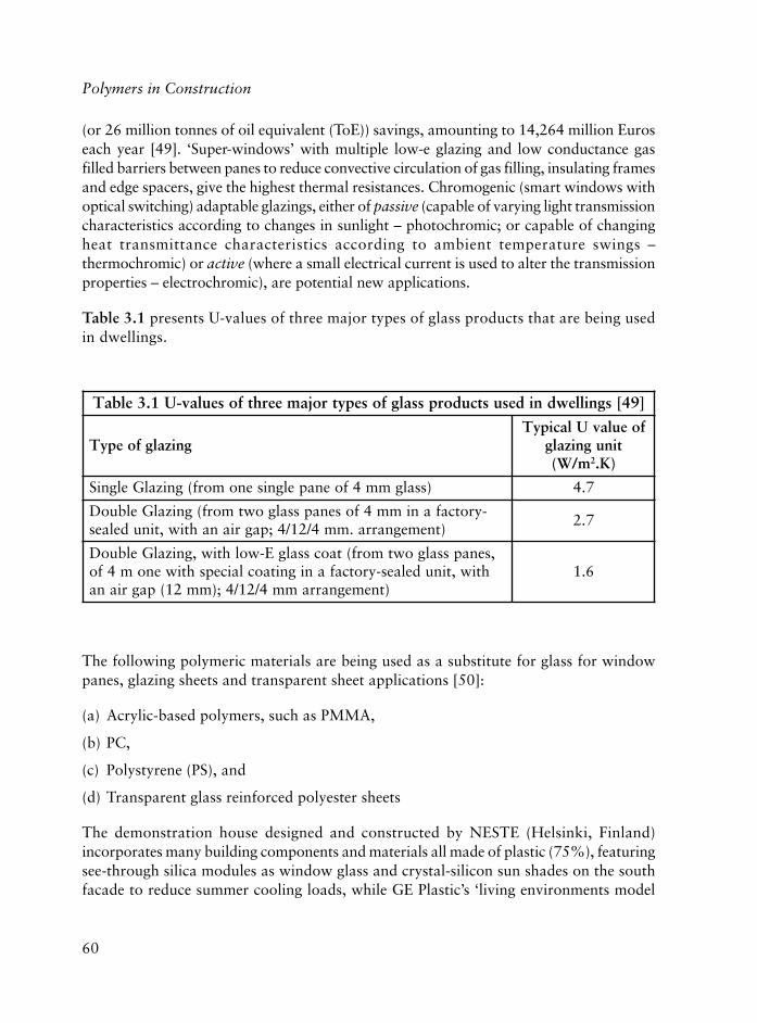
60
Polymers in Construction
(or 26 million tonnes of oil equivalent (ToE)) savings, amounting to 14,264 million Euroseach year [49]. ‘Super-windows’ with multiple low-e glazing and low conductance gasfilled barriers between panes to reduce convective circulation of gas filling, insulating framesand edge spacers, give the highest thermal resistances. Chromogenic (smart windows withoptical switching) adaptable glazings, either of passive (capable of varying light transmissioncharacteristics according to changes in sunlight – photochromic; or capable of changingheat transmittance characteristics according to ambient temperature swings –thermochromic) or active (where a small electrical current is used to alter the transmissionproperties – electrochromic), are potential new applications.
Table 3.1 presents U-values of three major types of glass products that are being usedin dwellings.
]94[sgnillewdnidesustcudorpssalgfosepytrojameerhtfoseulav-U1.3elbaT
gnizalgfoepyTfoeulavUlacipyT
tinugnizalgm/W( 2 )K.
)ssalgmm4foenapelgnisenomorf(gnizalGelgniS 7.4
-yrotcafanimm4fosenapssalgowtmorf(gnizalGelbuoD)tnemegnarra.mm4/21/4;pagrianahtiw,tinudelaes
7.2
,senapssalgowtmorf(taocssalgE-wolhtiw,gnizalGelbuoDhtiw,tinudelaes-yrotcafanignitaoclaicepshtiwenom4fo
)tnemegnarramm4/21/4;)mm21(pagriana6.1
The following polymeric materials are being used as a substitute for glass for windowpanes, glazing sheets and transparent sheet applications [50]:
(a) Acrylic-based polymers, such as PMMA,
(b) PC,
(c) Polystyrene (PS), and
(d) Transparent glass reinforced polyester sheets
The demonstration house designed and constructed by NESTE (Helsinki, Finland)incorporates many building components and materials all made of plastic (75%), featuringsee-through silica modules as window glass and crystal-silicon sun shades on the southfacade to reduce summer cooling loads, while GE Plastic’s ‘living environments model

61
house’ has a characteristic foyer, rich with PC glazing. PC, in addition to its strength andhigh transparency, also provides toughness enough to withstand abuse, and is ideal forroof-glazing. Glass-walled buildings are becoming a feature of most European cities inthe last decade, where structural glazing high-performance sealants are used.
Passive solar heating and cooling is the most cost effective heating/cooling system in houses.Solar energy falling on the roof is generally much more than the total energy consumed inthe house. Solar energy is in the form of heat and light, and about 35-40% of it reaches theearth. When sunlight in the form of short wave radiation strikes a surface, it is ‘reflected,transmitted or absorbed (transformed to heat)’, depending on the nature, colour and clarityof the surface; and heat absorbed is redistributed evenly through the solid mass (conductionof heat). Heat transfer from a solid material to liquid or air occurs by radiation (infrared)and it may be either via natural or forced convection. Gases and plastics are known aspoor (and metals as better) heat conductors. In this context, a good storage material isexpected to absorb heat easily/and give it back when needed; and it must be a good heatconductor. Radiant energy is limited to infrared radiation emitted from a material at ambientconditions, which depends both on the temperature of the material and the characteristicsof its surface, i.e., polished metal surfaces are poor emitters/poor absorbers of thermalenergy, and, glass is less transparent to most thermal radiation (it transmits nearly all solarradiation by letting radiation to move through). Hence, solar energy passing through thewindows can be absorbed by interior materials mostly, and re-radiated into the interiorspace in the form of thermal energy (heat).
In passive solar designs: the windows, walls, floors, and the roof are all used as the heatcollecting, storing, releasing, and distributing system. Firstly there is a transparent material(glass or plastic) with a south facing exposure to allow effective entry of solar energy andsecondly a material inside (normal walls/water wall, floor and ceiling) to absorb andstore the heat (or cool) for later use; where the collection and storage of heat withconvection process is foreseen. In this design, the system (the mechanism of heating andcooling equipment) is integrated into the building elements and materials. Passive solarsystems can also be isolated gain type, which uses a fluid (liquid or air) to collect heat ina flat plate solar-collector attached to the structure, and again by natural convection,heat is transferred through ducts or pipes to a storage area where the collected cooler airor water is displaced and forced back to the collector.
3.3.6.2 Plastic Lumber
Recycled plastic lumber (RPL) was developed as a substitute for treated wood [51]. RPL,being a product of commingled plastics, can contain as much as 100% post-consumer plastics(or a blend of recycled plastic and recycled wood waste), while ‘structural plastic lumber’ is
The Use of Plastics in Building Construction

62
Polymers in Construction
a high-performance construction material consisting of a patented formula of recycled plastic,fibreglass, and selected additives; with improved stiffness and strength. If compared withwood, unreinforced RPL, (RPL-U) has lower stiffness values (modulus of elasticity of RPL-Uis lower by an order of magnitude). RPL is also significantly viscoelastic (it’s mechanicalproperties are time- and temperature-dependent and are subject to permanent deformation(creep or sagging) under sustained loads (the rate of which depends on the magnitude andduration of the stress, and temperature). Dimensional changes due to temperature are alsobigger in RPL than in wood. RPL are machinable like wood and, in fact, hold nails andscrews better than wood. RPL are virtually maintenance free and last for 50 years.
RPL products offer inherent resistance to insects, rot, moisture, chemicals and to theenvironment, and are an excellent alternative to chemically treated wood, because theydo not leach toxic chemicals into the soil. They are available in different colours both forcommercial and residential applications. RPL are applied mainly outdoors (as decks,docks, bulkheads, landscaping, fencing, window and door trim, benches, tables,playground equipment, pallets, and even in foot bridges, etc.), with the possibility ofuses indoors (for shower stalls, counter tops, base boards). Plastic lumber is extremelywell-suited and applied to the walking surfaces of decks and marine docks, as well as forrailings and industrial cribbing/blocking. It is usually not well developed in load-bearingapplications such as joists, beams or studs. However, the added fibre (typically fibreglassor wood) gives additional stiffness and strength to the lumber, improving its performancein structural applications. If RPL-U is used as decking boards, especially if the span istoo big, joist spacings are decreased and/or thicker deck boards are used to avoid creep(under its own weight).
The American Society for Testing Materials (ASTM) established structural and propertystandards for plastic lumber, ASTM D6662, in 2001 [52].
RPL and structural plastic lumber still is not well accepted and used by the constructionindustry, most probably due to processing deficiencies, product inconsistencies, and pricevolatilites; although a number of projects already undertaken have proved its value andimportance in the sector, for example:
(a) Decking boards in a boardwalk at Kelleys Island on Lake Erie, Ohio, USA, where180 m boardwalk in a wetlands area was selected as a demonstration project,
(b) Bridge at Fort Leonard Wood, MO, USA, was developed to demonstrate the structuralcapabilities of plastic lumber. The 7.6 m by 8.1 m plastic lumber bridge sitting on sixsteel girders which is used primarily for pedestrian traffic and to carry vehicularloads. The bridge is expected to last 50 years with no maintenance. For the plasticlumber preparation, 5900 kg of waste plastics (equivalent to approximately 78,000(3.79 litre) HDPE milk jugs and 335,000 (240 ml) PS foam coffee cups) were used.

63
(c) Floating docks for the Op Sail 2000 event in New York, NY, USA. Since chromiumcopper-arsenate-treated wood poses an environmental hazard, RPL use in marine andwaterfront applications, is most suitable. This demonstration project showed the viabilityof RPL for floating docks (seven of them were built) during the Op Sail event with tallships in New York Harbor, and to date, they have all been working successfully.
(d) Elevated platforms at the bob-sled and luge track, Lake Placid, NY, USA. This wasthe first major project where reinforced structural plastic lumber was used (in joists,beams, girders, and decking boards). RPL platforms were designed and installed atlow temperatures of –40 °C in time for the start of the games, and one particularplatform was tested for creep under sustained loading with sandbags with 490 kg/m2
loading for a year.
(e) An arched truss bridge near Albany, NY, USA, which is a 9.1 m span bridge used asa demonstration project to investigate the performance of structural reinforced RPLsin the form of laminated beams.
(f) Plastic lumber railroad cross-ties (supporting 240 ton locomotives that need to bereplaced about every 12 years, in place of chemically treated wood ties), and,
(g) A bridge made primarily from plastic lumber supporting up to 30 tons (Ft LeonardWood in St. Robert, MI, USA), designed to last for 50 years.
3.3.6.3 Paints
Paints are used for cosmetic as well as protective reasons (in the form of coatings). Withinthis group, there are acrylic paints commonly used which contain PMMA in a solvent(which evaporates as the paint dries), which makes the paint surface, hard, tough andshiny. Since PMMA is hydrophobic, to make the acrylic paint waterbourne, poly(vinylalcohol-co-vinyl acetate) copolymer is generally used, where PMMA can stay suspendedin water, (known as PMMA latex and latex paints).
More detailed information on the subject is provided in Section 3.4.
3.3.6.4 Wall-Coverings
Wall-coverings (or wallpapers) are one of the flexible PVC applications in residentialand commercial interiors. PVC wall-coverings contain a number of additives (plasticisers,stabilisers and other additives, such as pigments, mildewicides, fungicides, flame retardants(or smoke suppressors), as well as low levels of biocides) in addition to PVC. They areused both as decorative as well as for protective purposes, they are fairly impermeable
The Use of Plastics in Building Construction

64
Polymers in Construction
for water and can act as a vapour barrier trap (known as concealed condensation), theycan provide energy savings and enhance the durability of the wall. In the case of concealedcondensation, growth of mildew over time can occur, and use of a permeable membraneon the outside wall can help to vent moisture. Certain ‘microvented’ breathable wallpapers are also available.
Most wall-coverings have three layers: (a) the decorative (top) layer, (b) the intermediate(ground) layer, (c) the substrate (or the backing) layer.
Vinyl wall-coverings can be categorised in general as: vinyl coated paper, paper backedvinyl or solid sheet vinyl and/or fabric backed vinyl and rigid vinyl sheet without a backing.
Wallpapers often have coatings made of PVA and other ingredients to make them shiny.
3.3.6.5 Blinds, Fencing, Decking and Railing
Blinds are typical examples of non-structural applications of plastics, used to filter theUV and infrared rays when applied to windows, allowing for diffuse lighting. They arepreferably produced from PVC-P or rigid, translucent or opaque, with a range of flapsizes and colours.
Fencing, decking and railing, are mainly made of reinforced PVC, and are another seriesof non structural application of plastics products for outdoors. The use of vinyl fencing,decking and railing is becoming one of the most cost-competitive outdoor living productsused in place of traditional wood and/or metal, including high-rise apartment balconiesand stadium guardrails and front porches. In fact, plastic fencing is reported as the fastestgrowing segment (with an approximately 30% annual growth rate) and at current growthrates, they could account for 30% of the residential market by 2007 [53].
GFR polypropylene-based composite fence (with 75% glass fibre and the rest beingchemically coupled, heat and light-stabilised PP concentrate), which is fade-resistant andwith the matte finish look of wrought iron, is shown to be 60% stronger and moreflexible than aluminium; it absorbs impacts and becomes more rigid than aluminiumallowing the fence to withstand better, heavier impacts at higher stress loads.
3.4 Coatings
Dorel Feldman
A coating is a material that is applied to a substrate surface and which becomes acontinuous film after drying. The terms coating or surface coating and paint are often

65
used interchangeably. The purpose of their application is aesthetic or protective or both.It has become common practice to use coatings as the broader term and to restrict paintsto the architectural and household coatings.
Emphasising the importance of aesthetic factors is not to overlook the important protectiverole that coatings play against moisture, UV light, chemicals (including pollutants),abrasion and freeze-thawing. The use of metals in construction would be restricted withoutprotective coatings. On an inert surface, coatings will last longer than they do on manycommon building materials. Movement in wood can lead to the flaking of paint;conversely, an impermeable coating contributes to wood decay if moisture is trapped.
For the interior of buildings, the paint has a special effect on illumination; white andpastel colours increase the availability of natural and artificial light and influence moodand feelings.
From the point of view of applications, coatings are grouped into architectural, productcoatings and special purpose coatings.
Architectural coatings include the familiar paints and varnishes (transparent paints) usedto decorate and protect exterior and interior of building, undercoaters, stains, primersand sealers.
Product coatings called also industrial coatings or industrial finishes are applied onautomobiles, machinery, equipment, appliances, wood products, etc. [54, 55].
A coating formulation is based on a film former (the binder), the pigment, a volatilecomponent, and additives. The main component, the binder is an organic film formingpolymer. Most of the coatings contain a finely divided insoluble pigment that providescolour and opacity. For steel, anti-corrosive pigments are used. The coating fluiditynecessary for application is obtained with a volatile liquid (solvent, diluent, extender).While solution viscosity increases with the molecular weight (MW) of the polymer, theviscosity of emulsions or dispersions is independent of the MW. The choice of the solventdepends on the type of polymer used. Stabilisers for long shelf life and flow modifiers(thixotropic agents) are sometimes necessary. Coating products must resist irreversiblechanges such as skinning or coagulation.
To reduce the amount of VOC emissions, an important continuing drive in the coatingdomain is to decrease the amount of organic solvent by replacement with water.Waterbourne coatings are products with aqueous media. Sometimes the term water-reducible coatings is used for waterbourne products, including latices based on hydrophilicresins. Radiation curable and powder coatings don’t contain volatile solvents.
The Use of Plastics in Building Construction

66
Polymers in Construction
Whilst the move to waterbourne systems offers advantages in terms of environmentalpollution, additional disadvantages may be introduced in climates where the evaporationof water is too slow as in cold or high humidity areas.
Complete removal of residual organics from waste water is extremely difficult and costlybut techniques for using supercritical fluids like carbon dioxide for stripping suchcompounds from waste water are already being used [56].
The main requirements for coatings are: durability, opacity, gloss, adhesion to substrate,colour, protection, and specific physical properties. Durability is considered as the degreeto which surface coating systems withstand the destructive effects of the environmentwhich can involve weathering as well as mechanical wear and attack by corrosivesubstances [57, 58].
A typical architectural paint for metals or wood may contain:
(i) a primer to improve adhesion to substrate and undercoat
(ii) an undercoat which has to contribute to the obliteration of the substrate and providesa smooth surface upon which to apply the topcoat
(iii)a topcoat which is not pigmented provides the aesthetic effect [59].
The progresses made in the formulation of coatings, both low temperature application andlow VOC emissions, have proved to be very advantageous for painting. A smarter approachto the mixology of these paints holds great promise for the future. They dry faster thancommon paints, they resist frosting, peeling and blistering because of the cold weather [60].
3.4.1 Polymers Used for Coatings
Some natural products and a lot of synthetic polymers are used in coating production –they can be grouped as:
(a) oils, natural polymers (resins, cellulose, starch, proteins), and modified naturalpolymers, (i.e., nitrocellulose)
(b) polymers obtained through polycondensation or polyaddition (polyesters, alkyds,PU, epoxy polymer (EP), urea formaldehyde(UF), phenol formaldehyde (PF))
(c) polymerisation polymers (vinyl, copolymers, etc.)
More recently, coatings based on synthetic polymers are divided into solvent-based orwater-based.

67
3.4.1.1 Natural Products and Modified Natural Polymers
Vegetable oils and their derived fatty acids play nearly as important a role in surfacecoatings today as they did in the past because of their availability as a renewable resource,their variety and their versatility [61].
Triglyceride oils such as linseed, tall, tung, castor, vernoia and other highly unsaturatedoils are used as the basis for oil-based formulations. They cure by an oxidative mechanism,forming ether bonds between the trygliceride molecules, and through oxidatively initiatedfree radical reactions attacking the double bonds, leading to a three-dimensional polymer.
The following stages can be distinguished during the formation of the film based ondrying oil:
(a) auto-oxidation, where oil reacts with oxygen to form peroxy compounds
(b) peroxy compounds decompose to create covalent bonds between the triglyceridemolecules
(c) the film continues to react by ageing, forming additional crosslinks, some volatileproducts and eventually chalking [62, 63].
Castor oil and vernoia oil are also based on tryglycerides, but they bear different functionalgroups. The first contains hydroxyl and vernoia oil epoxy groups. When one of thesetwo oils reacts with difunctional sebacic acid, a three-dimensional esterification reactionoccurs, forming a network [64, 65].
Metals (Co, Pb, Ca) added as soaps of long chain acids (naphthenates) usually catalyse theauto-oxidative crosslinking of tall oil with a high content in polyunsaturated fatty acids.
Shellac is a natural resin produced by refining an insect (Coccus laca) secretion. It issoluble in alcohol and other organic solvents but resistant to hydrocarbons and widelyused as a wood coating. It has good abrasion resistance and adheres well to metals.
Unlike nitrocellulose, which is still used for lacquers, other cellulose esters (cellulose acetate,cellulose acetate butyrate) have been used in the past as coatings for different materials.
Vegetable and animal proteins, which are often abundantly available as by-products ofthe food processing industry, are among the biopolymers being used or investigated asfeedstocks for the production of films and coatings. In recent years, the scientific literatureworldwide has seen an explosion of published papers, often the product of interdisciplinaryresearch, related to protein-based films [66].
The Use of Plastics in Building Construction

68
Polymers in Construction
3.4.2 Solvent-Based Coatings
Organic solvents are used in coating formulations for their preparation and application.When the organic liquid is not able to dissolve the polymer binder it is preferable to callit the diluent. In case of the water-based coatings, water can act as a solvent for somecomponents, but as a non-solvent for the synthetic polymers.
Solvents can have harmful effects on humans arising from their carcinogenic, mutagenicand reprotoxic properties. In their selection the following criteria have to be considered:evaporation rate, polymer solubility, activity, flash point, density. Evaporation rate canaffect the drying time and film formation. As evaporation proceeds, the coatingcomposition varies, during this change it is important to maintain solvency and to avoidpolymer precipitation. A high flash point is always preferred and a lower density besidesother advantages confers economic benefits since less weight is needed to fill a givenvolume [67]. Flammability also poses a significant hazard regarding the storage, handlingand use of organic solvent-based coatings.
For many applications, the most effective blends have been based on ketones and aromatichydrocarbon solvents currently restricted as hazardous air pollutant (HAP) products.Since new solvent systems will have smaller amounts of HAP, the blend cost is likely torise. Methyl n-amyl ketone (MNAK) and n-butyl propionate (BuProp) are attractivefrom the point of view of the environment and their physical properties [68].
In the first stage of organic solvent evaporation, its rate is independent on the presenceof the polymer. Evaporation rate depends on:
(a) the vapour pressure at a given temperature
(b) the ratio of surface area to the volume of the film
(c) the rate of air flow over the surface.
During evaporation, the viscosity of the system and glass transition temperature (Tg)increase, free volume decreases and the rate of loss of solvent from the film becomesdependent not on how fast the solvent evaporation will take place but rather on howrapidly the solvent molecules will diffuse through the film [54].
More often the solvent-based coatings are made of alkyds, acrylics, PU or EP polymers.Alkyd-based polyols and unsaturated dibasic acids were the first synthetic polymersused in coating technology. It was successful in chemically combining oil or oil derivedfatty acids into a polymer structure, thus enhancing the mechanical properties, dryingspeed and durability over and above those of the oils themselves and the oleoresinsthen available [61].
69
Aromatic acids such as phthalic anhydride of isophthalic acid and maleic anhydridecontribute to the hardness, chemical resistance and durability. Long chain dibasic acidssuch as azelaic are sometimes used to provide flexibility. The used polyols are at leasttrifunctional to permit branching or crosslinking. The oil content may vary from less than40%, up to above 60%. Alkyds with more than 60% drying oils are soluble in aliphaticsolvents and are drying slowly to give soft films with poorer gloss retention and durability.Alkyds with less than 60% oil give less flexible films with good gloss retention and chemicalresistance. Alkyd modification can be done with PU, polyamide (PA), silicone, PF, aminoresins or with vinyl monomers such as styrene, vinyl toluene, methyl methacrylate (MMA)and butyl-methacrylate [69].
Acrylic coatings can be applied as solutions, aqueous emulsions, and powder. Themethacrylates are more resistant to alkalis than the acrylates [70].
The most important types of PU coatings are based on two component systems, an isocyanateprepolymer and a polyol. Coatings based on high MW thermoplastic PU dissolved in asolvent are used, and they are cured by the evaporation of the solvent [71]. Other PUcoatings applied for flooring are formulated for radiation cure or vapour cure. At theinitial stages of the crosslinking reactions, solvent evaporation competes with the PU networkformation and isocyanate consumption changes at various depths from the film/air andfilm/substrate interfaces [72].
For EP coatings, the most common commercially available is the ‘two package’ type coatingused for floor toppings, tank linings and as heavy-duty industrial marine maintenanceproduct [73]. The crosslinking agents reacting with epoxide and hydroxyl groups result inhighly chemical and solvent resistant films because all the bonds are relatively stable [74].
One of the new technologies that have arisen in response to economic pressures, to reduceenergy or the use of petroleum derived solvents and concern with environmental pollutionand occupational health is that of producing high solids coatings [75]. In such products,low MW resins are used to keep a low solution viscosity, and after curing they convert tothree-dimensional networks.
Solvents can be replaced with reactive diluents like some monomers, as is the practice withunsaturated polyesters and with radiation-curing polymers. Polyfunctional monomers likeunsaturated melamine resins are becoming used as diluents for alkyd resins [61].
3.4.3 Water-Based Coatings
The environmental drive for the replacement of solvent bourne coatings with theiraqueous-based counterparts has forced the world coatings industry to develop new
The Use of Plastics in Building Construction

70
Polymers in Construction
polymer technologies to overcome the technical hurdles involved in the production ofthe VOC coating systems. The trend is to move away from solvent bourne coatings withhigher VOC content to high solids/low solvent, waterbourne, or radiation curable liquidand powder coatings [76].
For water emulsions, one of the main parameters is the minimum film formingtemperature, implying the temperature at which the polymer still forms satisfactoryhomogeneous films. Beside others, the Tg of the polymer determines this parameter.
There is a growing interest in water-based coatings for a number of reasons, the mostimportant being the increasing environmental legislation, health aspects and the lack offlammability.
3.4.3.1 Alkyd Coatings
Alkyds are among the first water-based coatings. An alkyd emulsion is a dispersion of analkyd resin in water. Unfortunately, almost all dispersions are unstable from thethermodynamic point of view - droplets will coalesce together in an irreversible wayonce they come too close to each other. In order to assure that all the particles repel eachother strongly enough to withstand all the external influences, the mechanism calledelectrostatic repulsion or the steric (osmotic) repulsion is used. A fundamental study [77]on alkyd emulsion paints has arrived at the following conclusions:
(i) The type of colloidal stabilisation of pigments and resins should be identical to assureoptimum stability, gloss and other properties.
(ii) The rheology of dispersion paints can be improved by using hydrophilic thickeners.
(iii)The use of anti-skinning agents should be avoided, provided that the stability of thealkyd emulsion is satisfactory.
(iv) Excellent properties can be obtained by using alkyd emulsions.
After the application of alkyd coating, the physical film is formed together withcrosslinking (known in coating industry as curing) by means of oxidative drying, identicalto the crosslinking of solvent-based alkyds [78].
The replacement of organic solvent by water poses a number of challenges to both resinand additives, particularly in the areas of film mechanical properties and durability. Thelow photochemical resistance of many polymers limits their use in coatings, mainly thosedesigned for exterior applications such as exposure for long time to sunlight. Where

71
necessary, modifications with PU and acrylics will improve drying characteristics andstability. The latest developments are so called ‘core-shell emulsions’ which are producedfrom alkyds with low acid values and a surplus of hydroxyl groups [79].
Significant improvements have been observed in the properties of alkyd resin aftermodification (grafting) with acrylates. The incorporation of MMA into alkyd at a level of30-40% yields a binder suitable for formulation of high performance exterior paints [80].
3.4.3.2 Acrylic Coatings
One of the most important groups of film forming latexes used in waterbourne coatingsis the group of acrylic resins. These are for the most part, the polymers obtained fromacrylate and methyl acrylate esters of lower alcohols, of which methanol and butanolhave the widest application. Those based on MMA and butyl acrylate (BA) yieldcopolymers with good film properties [81].
The development of associative thickeners during the 1980s saw a significant advance inthe rheological performance of acrylic emulsion paints and has assisted their ingress intohigh performance sectors of the coating market. The new thickeners (polyether-basedPU, hydrophobically modified carboxylated polyacrylates and hydrophobically modifiedcellulose derivatives) offer substantial benefits. Coatings produced with such polymersshow rheology more akin to that obtained with solvent bourne alkyd systems, and as aconsequence offer improved flow and levelling and film build, improved brushingproperties relative to cellulosic-based thickening agents, improved pigment dispersion,and thus excellent gloss in conjunction with the best acrylic latex technology.
Although paint films based on the hydroxy acrylic, grafted acrylic and low Tg acrylicpolymers have in general good properties, the films containing the grafted copolymerexhibit superior flexibility and impact strength. The accelerated weathering of thepigmented films based on the grafted copolymer is intermediate to that of parentpolyacrylic and low Tg polyacrylic films [82, 83].
The prospects for acrylic latex paints in the masonry market are much brighter todaythan in the past due to the many advances in acrylic emulsion chemistry. Besides theunsurpassed exterior durability (tint retention, chalk resistance and water resistance)and good adhesion that acrylic chemistry brings to all exterior coating applications, theacrylic technology, provides features uniquely suited to the masonry market, includingresistance to alkalinity, good holdout, resistance to efflorescence and cracking. Especiallyimportant is the very good alkali resistance provided by acrylic binders. This attributeenables paints formulated with these latexes to be applied over highly alkaline, damp,
The Use of Plastics in Building Construction

72
Polymers in Construction
fresh masonry without difficulties. In contrast, paints formulated with solvent bourneoleoresins binders tend to degrade rapidly when applied to these materials.
A recent study [84] regarding the application to wood of this group of coatings, showsthat the adhesion values of alkyd emulsion paints were much lower than the values ofthe acrylic dispersion paints under dry conditions. The adhesion was much higher forsmall particle dispersion paint, due to the improved penetration of the small acrylicparticles into wood and/or to an increased contact area between this paint and the woodsubstrate due to a more packaging of the particles. Under high moisture conditions theadhesion values of the acrylic dispersion paints decreased to a high extent.
Silicon-acrylic resin systems using the crosslinking technology overcome at least some ofthe defects of conventional waterbourne coatings [85].
Polyaminated dispersants are able to stabilise the fine dispersions with inorganic or organicpigment [86].
In the early 1990s, the drive for higher performance coatings with lower VOC contentled to the commercial introduction of waterbourne acrylic-epoxy coatings. These aretwo component coatings, with one component containing carboxyl functional acryliclatex, and the other component containing an EP emulsion. Upon mixing, cure is believedto proceed via carboxyl-epoxy reaction and/or EP homopolymerisation. It is interestingthat although these reactions usually proceed slowly under ambient conditions, the appliedcoating has attractive properties [54].
3.4.3.3 PU Coatings
These products can be broadly defined as coatings that contain the urethane or ureagroups. To a lesser extent, groups such as allophanate or biuret can be present. They areavailable one or two component systems, able to cure at room or higher temperature.These coatings can be based on linear PU dispersions, or crosslinkable dispersions andthey can also be produced by solvent free processes.
Linear PU dispersions can be obtained by the so called ‘acetone process’. An isocyanate-terminated PU is made in acetone solution from diisocyanate and a diol (or mixture ofdiols). The chain extension is obtained with a substituted diamine. After dilution withwater, acetone is removed by distillation. The crosslinkable PU dispersions can be producedby one-step or by two-step process [71].
A preferred route to stabilise PU dispersions involves the existence of ionic groups in thePU macromolecules in the presence or absence of additional nonionic emulsifier.

73
The weatherability of PU coatings depends on the nature of both main components: theisocyanate and the polyol. From the weatherability point of view, the following orderwas established: polyethers<polyesters<acrylic polyols.
While the latter two provide more UV stability, those based on polyether polyols have abetter hydrolysis stability [87].
Two component PU have been used successfully for several years and are proven energy-efficient systems. Recent developments have yielded higher solids components and theseshould be considered for applications where high performance VOC compliant coatingsare needed. PU coatings are ideal candidates to satisfy the demands of specific segments ofthe architectural and maintenance coating markets [87]. Compared with solvent-based,two component coatings, the water-based one can be expected to have limited pot life [71].
A new dispersion technology is used to make waterbourne PU coating with high solids,high gloss, excellent definition of image and long pot life - performance properties equalto the solvent-based systems, zero VOC and easy application. These performanceadvantages combined with the ability to tailor final coating properties through isocyanateselection, enable this system to be used in a wide variety of applications [88].
Core/shell type products with a polyacrylic component inside and PU shell provideexcellent coating properties [89].
3.4.3.4 EP Coatings
EP resins had begun to displace other polymers from many applications, and the high-end property profiles inherent in this type of binder were considered indispensable iftruly high performance, water-based coatings were to be produced. EP resins are alsoversatile, and lend themselves to the molecular engineering necessary to achieve watersolubility and dispersibility [90].
There have been many adaptations of EP technology for water-based coatings, such as:
(a) Incorporation of emulsifiers in either or both the EP or amine package, permitsaddition of water during mixing.
(b) To use salts of amine functional resins.
(c) To use weakly acidic solvents such as nitro-alkanes able to form salts with amines.Salt groups stabilise EP-amine emulsions and allow the system to be reduced withwater [71].
The Use of Plastics in Building Construction

74
Polymers in Construction
The use of waterbourne two component EP-amine systems is common today for civilengineering or maintenance applications that predominantly require curing at ambienttemperature. These include coatings for concrete, and for metals especially anticorrosionprimers for steel [91, 92].
3.4.3.5 Other Coatings
Poly(vinyl acetate) (PVAc) and vinyl acetate (VAc) copolymer coatings in latex formfor buildings possess good light resistance, a medium stability to chemicals and lowcost. VAc-methacrylate copolymers form good paints for interior and exteriorapplication [54, 93].
Polychloroprene latices relatively new in the field provide a wide range of effective basepolymers and modifiers from which to formulate useful environmentally friendly andcost effective coatings for a wide range of substrates [94, 95].
Fluoropolymers of different types are commercially available as coating resins [96].Methods to fabricate perfluorinated coatings and films to impart the desirable propertiesof perfluorocarbons where they are most needed, without the disadvantages of handlingand applying bulk perfluorinated materials are described in the literature [97].
One of waterbourne coating’s performance drawbacks is that the technology has lowpeel and shear strength, according to the Pacific Northwest Pollution Prevention ResourceCenter (PPRC), a Seattle based non-profit organisation that provides information onpollution prevention. It has the ability to withstand wide temperature ranges, but haspoor resistance to humidity.
Although it is not growing at the advanced rate predicted, use of waterbourne technologiesare still on rise [98].
3.4.4 Curing Techniques
There are two stages in the drying of coating films:
(1) Removal of the solvent
(2) Fusion of polymer particles into a film, or crosslinking (curing), or a combination offusion and crosslinking.
In lacquers, (1) is the only stage in the drying process. Fast air movement is even moreimportant than heat for drying there. In 100% polymerisable coatings, only in stage (2)

75
is heating required - room temperature cure, convected hot air, jet-drying, radio-frequency,infra red, UV, electron beam radiation are used [99].
UV curing is a green technology and it has proven its value as a ‘friend to the environment’in many ways, being VOC free. Running cost of UV in comparison to traditional thermaldrying and curing are usually very favourable, with capital costs typically lower thaninstalling catalytic converters or the emission control devices to existing thermal processes[100, 101].
Due to technical advances and increasing pressure to reduce VOC, use of UV curablewater-based coatings are experiencing rapid growth in the market place especially forwood parts finishing.
Recent developments in the dispersion technology such as the technique of surfactantselection, the optimisation of various parameters in the dispersion process and theenhancement to dispersion stability have made it possible to disperse a variety of curableoligomers such as: acrylated EP, acrylated PU, acrylated polyester resins in water. Filmsbased on the dispersions can have faster UV cure speed, better surface hardness andbetter flexibility compared with films based on undispersed resin systems [102]. UVcuring offers many advantages including 100% solids with no solvents present informulation and polymerisation is instantaneous leading to a large MW polymer [103].
UV curable systems were compared with electron beam (EB) radiation, which producesbetter surface curing and reduces the odour. EB curing is applied as surface technologytoday in various fields including the curing of coatings on panels for outdoor applications,lacquering of panels using the combined UV/EB curing processes, etc. [104].
In consideration of the intrinsic characteristics of the laser emission, these powerful lightsources present many advantages which make them very attractive for curing applications.After absorbing a laser photon, the photoinitiator will split into radicals which will acton the monomer double bond, initiating in a fraction of millisecond the polymerisationthat will develop in three-dimensions [105].
A novel penetrative cure at ambient temperature is based on the process in which, whena wet coating film reaches a thermoplastic state upon evaporation of liquid medium, isdipped in an aqueous solution of a crosslinking agent which penetrates into the film andcures it during the duration of dipping. This curing technology was applied to a cationicelectrodeposition paint and the network formed into the film provided remarkableimprovement in physical properties, water-resistance, solvent-resistance, weatherabilityand corrosion-resistance. The crosslinked surface layer prevented the penetration ofcorrosive material, and the underlying non crosslinked layer maintained sufficient adhesionbetween the film and the adherent [106].
The Use of Plastics in Building Construction

76
Polymers in Construction
Determining when the coating film is completely cured is very important. The standardmethods are generally well accepted, but the data obtained are not always reproducible.A new method called evaporation rate analysis (ERA) is the most objective andreproducible [107].
3.4.5 Powder Coatings
Coatings made entirely from solid components are the result of the necessity to reducesolvent emission and energy consumption. Use of powder coating is undergoing a rapidgrowth especially in Europe and Japan. The general principle is to formulate a coatingfrom solid components, melt mix them, disperse pigments and other insoluble additivesin a polymer matrix, and pulverise the formulation. The powder is applied to a substrate,usually a metal (steel reinforcing bars) and fused to a continuous film by baking. Morethan 90% of the powder coating market is based on thermosetting polymers [54, 108].
Powder coatings present advantages such as: 100% solids, solvent-free, high applicationefficiency and high thickness and good film properties. Thickness of up to 500 μm can beachieved in a single application and the resultant coatings exhibit excellent film properties.But, they need specific automated equipment, colour ranges are difficult, higher temperaturesare needed for flow/cure and they also present a risk of dust explosion [109].
The most used thermosetting resins for powder coatings are: EP (18%), acrylics (2%),unsaturated polyesters (28%), PU (7%), and hybrid systems (45%); and amongthermoplastics, PA, polyolefins, PVC and poly vinyl fluoride are preferred [110, 111].
Through the use of additives, surface quality can be markedly improved and the overallperformance profiles of powder coating systems can be fully optimised [112]. Additionof organic or mineral pigments of various colours and shades affects the UV curingperformance of the powder coating. Photoinitiator type, pigment absorption, and particlesize require careful consideration in formulating an opaque coating [113].
Exterior durable powders are generally used in either architectural applications likealuminium window frames, facades, or general applications like inside and outside coatingof steel pipelines, coating of concrete reinforcing bars, gate, lamp posts, etc. [114].
Among the most used powder coating methods are: fluidised bed, electrostatic spraycoating, electrostatic fluidised bed coating and flame spraying [110].
The disadvantages of this technology include the high capital cost for ovens and newspray equipment, high bake temperature that makes coating of large complex objectsdifficult, limited colour changeability, and no ability to modify formulation or filmthickness during application [115].

77
Producers of medium density fibreboard for the building industry opt for powder coatingsinstead of vinyl and laminate films because of waste savings, the environmental advantageof eliminating VOC-containing lamination adhesives and the possibility of using only aone-step process and not a multi-step one like lamination [116].
3.4.6 Intumescent Coatings
Within fire protection of building materials, intumescent coatings are among the mostwidely used products with some unique features. They require a much lower thicknessand weight than the alternative thermal insulating materials, and they allow simpleapplication in thin films with high performance.
Intumescent means ‘to swell up’ and intumescent coatings contain several activecomponents that react as temperature increases to form a char to evolve gases and expandto more than 100 times its original volume [117, 118].
Although the use of intumescent combinations of a polyhydric organic compound, anacid foaming catalyst and a foaming agent have long been known to form fire protectivecoatings for combustible substrates, the incorporation of one or more of these additivesinto the basic polymer formulation to confer an intumescent property when exposed toflames is only a recent development. The type of polymer determines the necessaryadditives and their amount [119]. Salts of phosphoric acid like ammonium phosphateor ammonium polyphosphate which liberate the acid on which they are based attemperatures above 150 °C are nearly always used. Under the effect of heat,chloroparaffins, melamine and guanidine liberate large quantities of non-combustiblegases such as ammonia, hydrogen chloride or carbon dioxide and ensure the formationof a carbonaceous foam layer over the substrate. The resin binder covers the foam witha skin which prevents the gases escaping.
Intumescent coatings are used for structural steel work or for other substrates such astimber, painted surfaces, and so on.
3.4.7 Durability of Coatings
Protection of materials is the most important role of coatings. The loss of protectioneffect can be produced by the paint degradation due to environmental factors and adhesionloss. The degradation produced by the weather includes the effect of the UV part of solarlight, the penetration of oxygen, water, acidic pollutants from the atmosphere, and leadsto successive deterioration stages such as: the loss of gloss, chalking, decrease of thickness
The Use of Plastics in Building Construction

78
Polymers in Construction
due to contraction, brittleness, crazing, peeling, etc. The final visible effect is crackingand flaking of the film.
The loss of adhesion is produced by the influence of microclimate and the water filmon the adherent surface which leads to swelling, blister formation and cracking [120].
The major difference between geographical sites is the intensity of the environmentalfactors. It is anticipated that intense sunshine will accelerate breakdown of coatings,but the level of humidity (usually expressed in terms of rainfall) will also have asignificant effect. Thus it is usual for sites to be compared in terms of the climaticconditions [96, 116, 121-123].
3.5 EPDM Membrane: Application in the Construction Industry forRoofing and Waterproofing
Bireswar Banerjee
3.5.1 Introduction
The elastomeric sheetings made out of butyl and polychloroprene rubbers were firstintroduced as barriers against water migration. In the early 1960s, EPDM rubbers werecommercially available. Considering the superiority of EPDM-based membrane overother elastomers, its application to construction industry as moisture barrier was firstintroduced in the United States about 30 years ago.
EPDM sheeting has some high level properties which gives it dominance in many diverseapplications [124]. These properties include: excellent weather resistance and almostmaintenance free life expectancy of 20 to 30 years.
Waterproofing materials used in the construction industry must have the followingessential characteristics:
(1) Impermeability to water,
(2) Good resilience,
(3) Resistance to oxidation, sunlight and ozone,
(4) Resistance to chemicals,
(5) Excellent dimensional stability, and
(6) Overall economy.

79
To meet these desirable properties, the appropriate polymer to consider would beethylene – propylene-diene terpolymer (EPDM). In the manufacture of a cost effective,impermeable membrane system, EPDM rubber is the right choice as a discreet materialfor improved waterproofing and protective lining applications in roofing and otheruses in the construction sectors [125].
3.5.2 Chemistry of the EPDM Elastomer
EPM - the saturated copolymer of ethylene and propylene is a non crystalline materialwith rubbery behaviour that gives excellent resistance to degradation, and requiresperoxides for vulcanisation. EPM copolymer has brittle point in the range of �95 °C andit’s Tg is �60 °C (Figure 3.3).
CH2 CH2 CH
CH3
CH2 Nn
Figure 3.3 Structure of EPM
EPDM – is a terpolymer, polymerised from ethylene, propylene and a small percentageof diene (the latter provides unsaturation in the side chain or pendent to give sites forcrosslinking) which can be vulcanised by a conventional process with sulfur and it providesexcellent weather resistant properties to the vulcanisates. Applications are in thetemperature range of 150-175 °C with the properties of very low compression set -peroxide curing may be necessary in place of sulfur. In commercial EPDM usually 4-5%by weight of diene and 30-70% by weight of ethylene are used to get a serviceableproduct. Among the natural and synthetic elastomers available, ethylene/propylene rubberhas the lowest specific gravity [126].
Rubbers with a high proportion of ethylene or propylene offer higher tensile strengthand elongation properties. By increasing the ethylene content the ultimate product showshigher hardness, high modulus, increased tensile strength and also enhanced reboundresilience of the vulcanisate. EPDM rubber shows no degradation in tensile strength upto 125 °C when aged for 1500 hours.
Commercial dienes used for EPDM are 1,4 hexadiene (Figure 3.4), dicyclopentadiene(DCPD) and ethylidene norbornene (ENB) (Figure 3.4).
The Use of Plastics in Building Construction
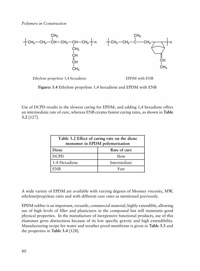
80
Polymers in Construction
A wide variety of EPDM are available with varying degrees of Mooney viscosity, MW,ethylene/propylene ratio and with different cure rates as mentioned previously.
EPDM rubber is an important, versatile, commercial material, highly extendible, allowinguse of high levels of filler and plasticisers in the compound but still maintains goodphysical properties. In the manufacture of inexpensive functional products, use of thiselastomer gives distinctness because of its low specific gravity and high extendibility.Manufacturing recipe for water and weather proof membrane is given in Table 3.3 andthe properties in Table 3.4 [128].
eneidehtnoetargnirucfotceffE2.3elbaTnoitasiremylopMDPEniremonom
eneiD erucfoetaR
DPCD wolS
eneidaxeH4-1 etaidemretnI
BNE tsaF
Use of DCPD results in the slowest curing for EPDM, and adding 1,4 hexadiene offersan intermediate rate of cure, whereas ENB creates fastest curing rates, as shown in Table3.2 [127].
Figures 3.4 Ethylene propylene 1,4 hexadiene and EPDM with ENB
CH2 CH2 CH
CH3
CH2 CH
CH2
CH2 n
CH
CH
CH3
CH2 CH2 C
CH3
CH2 n
CH
CH3
Ethylene propylene 1,4 hexadiene EPDM with ENB

81
)rhp(enarbmemMDPErofsnoitalumrofgnirutcafunaM3.3elbaT
)BNEDEM(MDPE 0.001
edixocniZ 0.5
dicaciraetS 0.1
QMT:tnadixoitnA 5.1
DPTD:tnanozoitnA 5.0
kcalbFEF 0.06
kcalbFRS 0.04
liocinehthpaN 0.57
TBM 0.1
SDTMT 8.0
AenorteT 8.0
rufluS 0.2
enenrobronenedilyhtemuideM:BNEdeMeniloniuqordyhid-2,1-lyhtemirt-4,2,2desiremyloP:QMT
:DPTD N�,N enimaidenelynehparap-lyraid-ecanrufnoisurtxetsaF:FEF
ecanrufgnicrofnier-imeS:FRSelozaihtoznebotpacreM-2:TBM
ediflusidmaruihtlyhtemarteT:SDTMTediflusartetmaruihtenelyhtematnepiD:AenorteT
031tahcrocsyenooMretfaMDPEfoseitreporP4.3elbaT ° setunim21rofC
061taderuC)a( ° setunim01rofC
htgnertselisneT aPM01
kaerbtanoitagnolE %003
ssendraH DHRI06
htgnertsraeT mm/N02
08tadegA)b( ° syad82rofC
STniegnahC %02
kaerbtanoitagnoleniegnahC %04
seergeDssendraHrebbuRlanoitanretnI:DHRIhtgnertselisneT:ST
The Use of Plastics in Building Construction

82
Polymers in Construction
3.5.3 Process of Manufacture of EPDM Membrane
The first step of manufacturing a membrane is to prepare a suitable rubber compoundeither in a Banbury internal mixer or in an open two roll mixing mill by adding differentcompounding ingredients in the proper sequence during the mixing operation to get awell dispersed compound.
Sheeting can be made by calendering or extrusion processes from the compound preparedas in Table 3.3. The viscosity of the rubber compound is required to be checked beforefurther processing.
3.5.3.1 Calendering
To manufacture EPDM sheeting/membrane, pre-warmed, plasticised EPDM compoundat a temperature of 80-100 °C is used for calendering in a 3 roll in-line ‘�’ configurationrubber calender machine or in a 4 bowl ‘Z’ configuration rubber calender machine.
Strips or dollies of EPDM rubber compound of maintained viscosity can be fed to thefirst roll nip of a 3 bowl calendar. The thickness of the sheeting is adjusted by operatingthe motorised roll nip adjustment device fitted on the machine.
The first nip of the calender machine produces the sheet which is then fed round to asecond nip thus precision control of the sheet gauge is obtained. Using the second nipblistering due to air entrapment can also be avoided. Membrane of the desired thicknesscomes out from the machine in a continuous length, and is then wound-up on the oppositeside of the machine at uniform speed. A textile liner can be used to prevent sticking of thesheeting with the help of a let-off roll. A suitable dusting agent like starch powder/talcumpowder may also be dusted on the membrane in place of liner as an anti-sticking agent.
In an inverted L and Z configuration four roll calender machine, two thin layered sheetscan be prepared in the first and third nips. Taking out the two thin sheets and plying upwith two rubber covered rolls pressure device just before the winding operation, a singleply sheet is formed. This system can be adopted for higher thickness sheeting and to helpin eliminating the blistering problem of the membrane. The quality of the sheeting dependson the speed of the machine and proper temperature control of the rolls [129].
3.5.3.2 Extrusion Process
EPDM rubber sheet can also be made using the hot or cold feed rubber extruder machineof 20-30 cm screw diameter. For a hot feed machine the L/D ratio of the screw should be5:1 and for the cold feed extruder 20:1.

83
The technique of producing a sheet by an extruder is to extrude a higher diameter tube.The temperature of the compound needs to be maintained in the range of 95-110 °C toget better extrusion properties.
A sharp cutting tip is fitted at the extruder die head which slits the tubular section of thetube on one side and opens up to form a flat sheet. Extruded sheet is then cooled bypassing it through a cold water tunnel, and after drying and winding onto batch rolls, itis dusted with a dusting agent like starch/talc powder to prevent sticking duringvulcanisation. Curing can be done in an autoclave in batches. The advantage of using theextrusion process is that it reduces the chance of blistering of the sheeting.
3.5.4 Process of Preparation of Adhesive
The rubber is broken down in an open two roll mill for five minutes. Subsequentlymagnesium oxide and antioxidant, and lastly zinc oxide are added to the mix as in theformula given in Table 3.5 [130].
enarbmemMDPErofevisehdatcatnocdesabenerporolhcyloP5.3elbaT)rhp(noitallatsni
)CAenerpoeN(rebburenerporolhcyloP 001
edixomuisengamthgiL 5
edixocniZ 5
tnadixoitnaenimalyhthpan:tnadixoitnA 1
nisercilonehplytubyraitretevitcaer–taeH 03
nisercilonehpenepreT 02
enaxeH 052
enotecA 051
enuloT 002
tnetnocdiloS %62
The milled stock is then cut into small pieces and swelled in solvent for 24 hours. Swollenstock can be fed into a rubber solution churner (a motorised, vertical, rubber solutionmixer), and solutions of resins in solvents are prepared separately and are added graduallyto the feedstock for proper dispersion of the ingredients. Finally the balance blendedsolvent is added in to the churner. The machine is run for a desired period to get a rubbersolution of consistent and desired viscosity.
The Use of Plastics in Building Construction

84
Polymers in Construction
3.5.5 EPDM Polymer Characteristics of Crack Resistance
EPDM is totally resistant to ozone, heat, water and UV radiation. The architects andbuilding contractors in USA and Japan have proved how dependable this material is. A lotof flat roofs (more than 55%) are covered with EPDM sheets in these countries because ofthe superiority of this amazing material over conventional waterproofing substances.
EPDM rubber sheet can be stretched up to 400% – it will not tear, crack or split but returnsto its original position, shows unfailing flexibility. Because of these outstanding propertiesEPDM rubber-based membranes have many applications, which include the following [125]:
(a) waterproofing of roofs
(b) wall and foundation waterproofing
(c) waterproofing of underground constructions
(d) walkway coverings
(e) parking and plaza deck flooring
(f) fluid storage lining
(g) lining for irrigation canals
(h) landscape ponds lining
(i) dams for waterways
(j) lining of effluent treatment tanks
3.5.6 Distinctive Waterproofing Properties of EPDM Membrane
A reliable roof is the most important part of a building and it is this which decides thequality and ultimate life of a building. An efficient roof sheeting should never allow eventraces of water to pass through it at any given point and should maintain this characteristicover a long period of time. It should withstand slight movements of the structure, badweather, chemical degradation and mechanical stresses and strain.
EPDM rubber-based membrane can meet the stringent requirements to prevent water seepageon roof tops, vertical walls, ground and basement walls in construction applications.
Over time it is far more economical than traditional waterproofing systems. A singlelayer membrane of thickness of 1.2 mm made from EPDM rubber provides superiorwaterproofness than multi-layer traditional material systems.
EPDM membrane of 1.2 mm thickness is 22 times more waterproof than asphalt and 59times as waterproof as PVC sheet.

85
3.5.7 Maintenance Free, Temperature Endured Roof Sheathings
EPDM roof sheet is one of the lightest roof membrane materials because of its lowspecific gravity. It is highly suitable for lightweight structures and puts negligible extraload on the roof to be waterproofed. It is serviceable over a wide range of temperatures�50 °C to 150 °C, and the membrane does not embrittle in freezing condition nor softenin hot weather.
In many countries asphalt felt coating is used to protect the building roof from leaking –the life of such a waterproofing system is only two to three years. For exceptional waterand weather resistance the EPDM roof membrane is known to be serviceable for morethan 20 years and virtually no maintenance is required.
Comparative properties of different waterproofing materials are shown in Table 3.6
enarbmemMDPEfoseitreporpevitarapmoC6.3elbaT susrev slairetamrehto
seitreporP MDPE lytuB-yloP-orolhc
enerpCVP UP
deifidoMnemutib
suonimutiBpu-dliubgnifoor
lanoisnemiDytilibats
E G G F F F F
:otecnatsiseR
hgiHerutarepmet
E G F P F P P
enozO E G G G G F F
VU E G G F G F G
gnikcarcdloC E G F F F P P
rehtaeW E G G F F P P
dnasdicAseilakla
E G E G F AN AN
tsoCssenevitceffe
sseLevisnepxe
yreVevisnepxe
yreVevisnepxe
evisnepxEyreV
evisnepxeevisnepxE evisnepxE
tnellecxE:EdooG:G
riaF:FrooP:P
The Use of Plastics in Building Construction

86
Polymers in Construction
3.5.8 Installation Engineering of EPDM Membrane
EPDM membranes can be factory assembled from smaller width sheets by a hot vulcanisingprocess, using suitable rubber-based adhesive or room temperature vulcanisable adhesivesystem, to form a higher width waterproof joint surface. Alternately, the individual sheetscan be welded at site with the help of a proper adhesive system.
As the EPDM membrane is elastic and tear resistant at low temperatures, the sheets canbe manipulated over pipes and curves in any weather and can also be fitted properlyaround projections.
For use on roofs, the surface of the roof or the substrate must be clean, free from debris,chipping or other materials prior to the laying of the built in sheet is necessary. If thesurface is rough or uneven, an appropriate board sheet material can be used to provide asmooth surface.
The following methods can be used for installation engineering of EPDM membrane:
(i) ballasting
(ii) adhesive bonding
(iii)mechanical fixing
3.5.8.1 Ballasting
Ballasting is an economical and quick system to secure an EPDM roof membrane.Waterproofing sheet is simply fitted over the flat roof or to a low slope, and covered withcleanly washed well rounded gravel with a diameter of 40-50 mm. Corners may beballasted with suitable concrete slabs to prevent the sheeting from wind uplift and theperimeter can be fixed with contact adhesive.
3.5.8.2 Adhesive Bonding
Bonding EPDM membrane with a cold adhesive is appropriate when structures are toolight or roofs are steep with curves or sharp corners. Before application of the adhesive,the surface should be made smooth, clean, free from dust, oil, grease or other contaminateswhich may affect the adherence. This method is economical to cover all types of complexstructures even on vertical walls. The sheets can be adhered to smooth surfaces of cementconcrete, wood and metallic surfaces made of steel, aluminium, etc. An adhesive bondingsystem is also suitable for use on rigid insulation and old concrete roofing.

87
The cold bonded rubber-based adhesive is applied to the area to be covered by brushingor spraying on the surface of the floor, roof or wall, and to the contact surface of themembrane before laying for better adherence. Applying pressure with a metallic/rubbercovered roller can help to remove undersurface trapped air and will allow proper contactof the membrane and the surface.
3.5.8.3 Mechanical Fixing
To anchor the sheet mechanically, non-penetrating rivets are used to fix the membrane,particularly on sloped roofs or steep surfaces. Polyamide studs are fixed to the deck withan EPDM rubber cap and metal clip. Spacing of the studs depending on the expectedwind lift, and the covering is then placed over the fixed studs. With the help of properlubricants, caps are secured to the studs with a fastener tool and the perimeters can besecured with adhesive.
3.5.9 Effluent Treatment Plant Lining
The significant characteristics of EPDM sheeting, such as, its resistance to acids andalkalies, resistance to vegetable and animal fat, being unaffected by toxic chemicals, andwith good mechanical properties make its way as an effective lining barrier for effluenttreatment plants.
3.5.10 Ecological and Decorative Gardening Applications
Ecological and functional designed roof tops and terrace gardening become more andmore popular to improve the working and living environment. Because of the uniqueadvantages to prevent plant root penetration, resistance to rot, fungi, algae and micro-organisms, EPDM membrane considered to be the most suitable material as an effectivewaterproof liner for building and landscape decoration.
References
1. Value of Construction Put in Place: May 1998, Current Construction Reports,C30/98-5, US Government Printing Office, Washington, DC, USA, 1998.
2. P. Dufton, Polymers in Building and Construction, Rapra Industry AnalysisReports, Rapra Technology Ltd., Shawbury, Shrewsbury, UK, 1997.
The Use of Plastics in Building Construction
88
Polymers in Construction
3. K. Flaga, Journal of Materials Processing Technology, 2000, 106, 1-3, 173.
4. L. Hollaway, Polymers and Polymer Composites in Construction, ThomasTelford Ltd., London, UK, 1990.
5. L. Hollaway and C.J. Burgoyne in Polymers and Polymer Composites inConstruction, Ed., L.C. Hollaway, Thomas Telford Ltd., London, UK, 1990,Chapter 11.
6. P.R. Head and R.B. Templeman in Polymers and Polymer Composites inConstruction, Ed., L.C. Hollaway, Thomas Telford Ltd., London, UK, 1990,Chapter 4.
7. J.M. Lees, Progress in Structural Engineering Materials, 2001, 3, 2, 122.
8. Reinforced Plastics, 2003, 47, 7, 28.
9. B. Roux, Composites Plastiques Renforces Fibres de Verre Textile, 1992, 32, 2, 24.
10. P. Grootenhuis in Polymers and Polymer Composites in Construction, Ed., L.C.Hollaway, Thomas Telford Ltd., London, UK, 1990, Chapter 9.
11. C.J. Derham, Progress in Rubber and Plastics Technology, 1985, 1, 3, 14.
12. C.J. Derham, J.M. Eidinger, J.M. Kelly and A.G. Thomas, NR Technology, 1977,8, 3, 41.
13. C. Joyce, New Scientist, 1991, 129, No. 1756, 30.
14. L. White, European Rubber Journal, 1990, 172, 5, 51.
15. R. Koschade, Sandwich Panel Construction, Ernst and Sohn, Berlin, Germany, 2002.
16. D. Dawson, Composites Technology, 2001, 7, 2, 28.
17. Composites Technology, 1998, 4, 2, 56.
18. British Plastics and Rubber, 1993, November, 27.
19. G. Valero, Adhesives Age, 2001, 44, 9, 7.
20. H.V.S GangaRao, R. Lopez-Anido, D.L. Williams and T. Winegardner inProceedings of the SPI 51st Annual Conference, Cincinnati, OH, USA, 1996,Paper No. 20-E.
89
21. Mercantil Gazeta, 2002, September 5th, Real Estate Section p.7 (available from<www.institutopvc.org/casapvc1print.htm>)
22. High Performance Plastics, 2000, November, 6.
23. R.M. Koerner, Designing with Geosynthetics, 3rd Edition, Prentice Hall,Englewood Cliffs, NJ, USA, 1986.
24. C.M. Stirling in Proceedings of Utech 96, The Hague, The Netherlands, 1996,Paper No. 65.
25. Reinforced Plastics, 2003, 47, 5, 13.
26. W. Chetanachan, D. Sookkho, W. Sutthitavil, N. Chantasatrasamy and R.Sinsermsuksakul, Journal of Vinyl and Additive Technology, 2001, 7, 3, 134.
27. P.E. Beers and K.F. Yarosh, Journal of Testing and Evaluation, 2000, 28, 2, 131.
28. ASHRAE Standard 90.2, Energy Efficient Design of Low-Rise ResidentialBuilding, 2001.
29. A.L. Swan, Insulation Journal, 1999, August, 16.
30. P. Ashford in Conference Proceedings of the SPI Polyurethane World Congress’97, Amsterdam, The Netherlands, 1997, p.612.
31. M.T. Bomberg and J.W. Lstiburek, Journal of Thermal Insulation, 1998, 21, 526.
32. M.T. Bomberg and J.W Lstiburek, Journal of Thermal Insulation, 1998, 21, 385.
33. F. Wolfgang in Proceedings of the 1st Benelux Passive House Symposium,Europeion, Turnhout, Belgium, 2003, Keynote Lecture.
34. T. Beckenhauer, inventor; no assignee; US 6110270, 2000.
35. R. Krebbs and H. Kober, Paint and Ink International, 1997, 10, 1, 24.
36. D. Feldman, Polymeric Building Materials, Elsevier Applied Science, London,UK, 1989.
37. T. Hao, Advances in Colloid and Interface Science, 2002, 97, 1-3, 1.
38. J Jai, G.S. Springer, L.P. Kollar and H. Krawinkler, Journal of CompositeMaterials, 2000, 34, 18, 1548.
39. T.C. Triantafillou, Structural Engineering and Materials, 2001, 3, 1, 57.
The Use of Plastics in Building Construction

90
Polymers in Construction
40. S. Shah, Adhesives Age, 2000, 43, 11, 35.
41. S.S. Mishra, M.D. Beers and T.M. Feng, Adhesives Age, 2002, 45, 9, 30.
42. J.S. Amstock, Handbook of Adhesives and Sealants in Construction, McGrawHill, New York, NY, USA, 2001.
43. M. Bowtell, Adhesives Age, 1998, 41, 1, 45.
44. A. Kinloch, Adhesion and Adhesives, Grolier Electronic Publishing Inc., Dabury,CT, USA, 1987.
45. R.J. Lohman, Adhesives Age, 2002, 45, 7, 46.
46. R.B. Seymour, Synthetic Resin and Building Materials, American ChemicalSociety Proceedings, ACS, Washington, DC, USA, 1983.
47. Reinforced Plastics, 2003, 47, 8, 20.
48. ENDS Report, 2002, No. 329, 30.
49. Low E-Glass in Buildings: Impact on the Environment and on Energy Savings,Report EU 15, Groupemant Europeen de Producteurs de Verre Plot (GEPVP),Brussels, Belgium.
50. A. Srivastava, R.K. Aggarwal and P. Singh, Popular Plastics and Packaging,2001, 46, 1, 62.
51. T. Buwalda and B. Halpin, Resource Recycling, 1998, October, 22.
52. ASTM D662-93, Standard Test Method for Evaluating Degree of Erosion ofExterior Paints, 2000.
53. J.H. Schut, Plastics Technology, 2000, 46, 7, 53.
54. Z.W. Wicks, Jr., F.N. Jones and S.P. Pappas, Organic Coatings: Science andTechnology, Volume 1, J.Wiley and Sons, 1992, New York, NY, USA.
55. M.S. Reisch, Chemical and Engineering News, 1994, 72, 42, 44.
56. J.N. Hay, Polymer Paint and Coatings, 1998, 188, 4400, 14.
57. N. Falla, Surface Coatings International, 1998, 81, 8, 375.
58. L.F.E. Jacques, Progress in Polymer Science, 2000, 25, 9, 1337.

91
59. R. Lambourne in Paint and Surface Coatings: Theory and Practice, Ed., R.Lambourne, Ellis Horwood Ltd., Chichester, UK, 1987, 23.
60. V. Puccio, Modern Paint and Coatings, 2001, 91, 10, 25.
61. J. Bentley, Modern Paint and Coatings, 2001, 91, 10, 41.
62. L.H. Sperling and C.E. Carraher, Jr., in Polymer Applications of RenewableResource Materials, Eds., C.E. Carraher, Jr., and L.H. Sperling, Plenum Press,New York, NY, USA, 1983, 1.
63. J. Mallegol, L. Gonon, J. Lemaire and J-L. Gardette, Polymer Degradation andStability, 2001, 72, 2, 191.
64. A.M. Fernandez, J.A. Manson and L.H. Sperling in Renewable ResourceMaterials, New Polymer Sources, Eds., C.E. Carraher, Jr., and L.H. Sperling,Plenum Press, New York, NY, USA, 1983, 177.
65. A.M. Fernandez, C.J. Murphy, M.T. DeCosta, J.A. Manson and L.H. Sperling inPolymer Applications of Renewable Resource Materials, Eds., C.E. Carraher, Jr.,and L.H. Sperling, Plenum Press, New York, NY, USA, 1983, 273.
66. J.M. Krochta in Protein-Based Films and Coatings, Ed., A. Gennadios, CRCPress, Boca Raton, FL, USA, 2002, p.1.
67. The Solvents Council, Modern Paint and Coatings, 1996, 86, 4, 22.
68. D.A. Sullivan, Modern Paint and Coatings, 1995, 85, 11, 38.
69. J.M. Charrier, Polymeric Materials and Processing: Plastics, Elastomers andComposites, Hanser Publishers, Munich, Germany, 1991, 172.
70. R.B. Seymour, Plastics vs. Corrosives, John Wiley and Son, New York, NY, USA,1982.
71. R.A. Hickner in Reaction Polymers Chemistry: Polyurethanes, Epoxies,Unsaturated Polyesters, Phenolics, Special Monomers and Additives: Technology,Applications, Markets, Eds., W.F. Gum, W. Riese and H. Ulrich, HanserPublishers, Munich, Germany, 1992, 664.
72. A.M. Kaminski and M.W. Urban, Journal of Coatings Technology, 1997, 69,872, 55.
73. S.J. Shaw and D.A. Tod, Materials World, 1994, 2, 10, 523.
The Use of Plastics in Building Construction
92
Polymers in Construction
74. D. Feldman and A. Barbalata, Synthetic Polymers, Technology, Properties,Applications, Chapman and Hall, London, UK, 1996, 329.
75. R. Parvani and M.C. Shukla, PaintIndia, 1991, 41, 5, 21.
76. M.S. Reisch, Chemical and Engineering News, 1999, 77, 42, 22.
77. Polymers Paint Colour Journal, 1997, 187, No. 4398, 15.
78. H. Warson, Polymers Paint Colour Journal, 1998, 188, No. 4405, 16.
79. P. Manshausen, Polymers Paint Colour Journal, 1998, 188, No. 4402, 15.
80. S. Majumdar, D. Kumar and Y.P.S. Nirvan, Journal of Coatings Technology,1998, 70, 879, 27.
81. A.M. Morrow, N.S. Allen and M. Edge, Journal of Coatings Technology, 1998,70, 880, 65.
82. A.N. Theodore and M.S. Chattha, Journal of Coatings Technology, 1982, 54,No. 693, 77.
83. W.H. Hill, Jr., and J.R. Johnson, Modern Paint and Coatings, 1997, 87, 12, 32.
84. S.L. Bardage and J. Bjurman, Journal of Coatings Technology, 1998, 70, 878, 39.
85. N. Harul and T. Agawa, Journal of Coatings Technology, 1998, 70, 880, 73.
86. S. Creutz, R. Jerome, G.M.P. Kaptijn, A. W. van der Werf and J.M. Akkerman,Journal of Coatings Technology, 1998, 70, 883, 41.
87. T.A. Potter and J.L. Williams, Journal of Coatings Technology, 1987, 59, No.749, 63.
88. W.O. Buckley, Modern Paint and Coatings, 1996, 86, 10, 81.
89. I. Bechara and F. Bonney, Modern Paint and Coatings, 1997, 87, 3, 34.
90. C.H. Hare, Modern Paint and Coatings, 1996, 86, 2, 28.
91. A. Wegmann and T. Vogel, Surface Coatings International, 1998, 81, 7, 342.
92. D.J. Weinmann and C. Smith, Modern Paint and Coatings, 1997, 87, 2, 22.
93. N. Sonoda and J.P. Rioux, Studies in Conservation, 1990, 35, 189.

93
94. W.A. Tandy, Proceedings of the International Rubber Conference, IRC ’96,Manchester, UK, 1996, Paper No. 47.
95. L. Christell, Modern Paint and Coatings, 1997, 87, 10, 60.
96. K. Wood, Makromolecular Symposia, 2002, 187, 469.
97. D.W. Grainger and C.W. Stewart in Fluorinated Surfaces, Coatings and Films,Eds., D.G. Castner and D.W. Grainger, ACS Symposium Series No. 787,American Chemical Society, Washington, DC, USA, 2001, 1.
98. J. Schwartz, Modern Paint and Coatings, 2001, 91, 10, 41.
99. G.P.A. Turner in Paint and Surface Coatings: Theory and Practice, Ed., R.Lambourne, J. Wiley and Sons, New York, NY, USA, 1987, 513.
100. A. Lockwood, Polymers Paint Colour Journal, 1998, 188, No. 4409, 16.
101. R.S. Davidson, Polymers Paint Colour Journal, 1998, 188, No. 4409, 27
102. Z.J. Wan, J.A. Arceneaux and J. Hall, Modern Paint and Coatings, 1996,August, 24.
103. S. Whittle, Polymers Paint Colour Journal, 1998, 188, No. 4409, 22.
104. P. Holl, Polymers Paint Colour Journal, 1998, 188, No. 4401, 25.
105. C. Decker in Radiation Curing of Polymers, Ed., D.R. Randell, Royal Society ofChemistry, Cambridge, UK, 1987, 16.
106. Y. Nakayama, Journal of Coatings Technology, 1997, 69, 875, 33.
107. K. Sharp, G. Mattson and S. Jonsson, Journal of Coatings Technology, 1998,70, 877, 97.
108. A.L. Hendricks in Proceedings of the NACE International Corrosion ’94Conference, Baltimore, MD, USA, 1994, 5.
109. D.A. Ausdell in Paint and Surface Coatings: Theory and Practice, Ed., B.Lambourne, J. Wiley and Sons, New York, NY, USA, 1987, 486.
110. D.S. Richart in Polymer Powder Technology, Eds., M. Narkis and N.Rosenzweig, J. Wiley, New York, NY, USA, 1995, 219.
111. B.W. Johnson, U. Parducci, E. Nascovilli, A. Phillips, R. Lion, Z. Cunliffe andR. Wilkinson, Surface Coatings International, 1999, 82, 3, 134.
The Use of Plastics in Building Construction

94
Polymers in Construction
112. H. Juckel, Polymers Paint Colour Journal, 1998, 188, No. 4408, 18.
113. L. Misev, O. Schmid, S. Udding-Louwrier, E.S. de Jong and R. Bayards, Journalof Coatings Technology, 1999, 71, 891, 37.
114. J.H. Jilek, Journal of Coatings Technology, 1997, 69, 871, 91.
115. K.D. Weiss, Progress in Polymer Science, 1997, 22, 1, 203.
116. A.H. Tullo, Chemical and Engineering News, 2000, 78, 41, 19.
117. C. Pagella, F. Raffaghello and D.M. De Faveri, Polymers Paint Colour Journal,1998, 188, No. 4402, 16.
118. A. Cargill, Polymers Paint Colour Journal, 1998, 188, No. 4402, 19.
119. R.R. Hindersinn in Fire and Polymers: Hazards Identification and Prevention,Ed., G.L. Nelson, ACS Symposium Series No. 425, American Chemical Society,Washington, DC, USA, 1990, 87.
120. E.V. Schmid, Galvano-Organo-Traitements de Surface, 1989, 58, 599, 841.
121. R.R. Blakey, Progress in Organic Coatings, 1985, 13, 5, 279.
122. J.W. Martin, Progress in Organic Coatings, 1993, 23, 1, 49.
123. A. Davis and D. Sims, Weathering of Polymers, Applied Science Publishers,London, UK, 1983.
124. Proceedings of a Rapra Technology Conference on EPDM Supply and Demandinto The Next Decade, Brussels, Belgium, 2000.
125. B. Banerjee, Proceedings of the Indian Rubber Conference, Indian Institute ofTechnology, Kharagpur, West Bengal, India, 2002, Paper No. 13.
126. Rubber Engineering, Ed., Indian Rubber Institute, Tata McGraw, New Delhi,India, 1998.
127. Rubber and Plastics Technology, Eds., R. Chandra and S. Mishra, CBSPublishers, New Delhi, India, 1995, 24-27.
128. Rubber Technology, Second Edition, Ed., Maurice Morton, Van NostrandReinhold, New York, NY, USA, 1973, 225, 226, 242.

95
129. Rubber Technology and Manufacture, Ed., C.M. Blow, Newnes – Butterworths,London, UK, 1971, p.102-106.
130. Handbook of Adhesives, 2nd Edition, Ed., I. Skeist, Van Nostrand Reinhold,New York, NY, USA, 1977.
Other References of Interest
Rubber Products Manufacturing Technology, Eds., A.K. Bhowmick, M.M. Hall,H.A. Benarey, Marcel Dekker, Inc., New York, NY, USA, 1994 p.36, 330-332, 708.
S. Bukowski, Flooring Instant Answers, McGraw-Hill Professional, New York, NY,USA, 2002.
R. Bynum, Insulation Handbook, McGraw-Hill Professional, New York, NY, USA, 2000.
Hertalan EPDM Roof Waterproofing System, Hertelan, WATFORD, UK, 2001, 3.
T. Kennedy, Roofing Instant Answers, McGraw-Hill Professional, New York, NY,USA, 2002.
M. Kubal, Construction Waterproofing Handbook, McGraw-Hill Professional, NewYork, NY, USA, 1999.
H.O. Laaly, The Science and Technology of Traditional and Modern RoofingSystems, Two Volumes, Roofing Materials Science and Technology, Los Angeles,CA, USA, 2002.
S. Levy, Building Envelope and Interior Finishes Databook, McGraw-HillProfessional, New York, NY, USA, 2000.
W. Hofmann, Rubber Technology Handbook, Hanser Publishers, New York, NY,USA, 1989, p.93-100, 162-163.
The Use of Plastics in Building Construction

96
Polymers in Construction

97
4 Systems for Condensation Control
4.1 Introduction
In building components, such as walls and roofs, plastics are most often used in the formof films or sheets. These films contribute to moisture control of the building envelope, byimproving the air tightness, reducing the migration of water vapour from the insideenvironment, or preventing rain penetration. Depending on the control function of theplastic film, it is referred to as the air barrier, the wind barrier, the vapour retarder or theweather-resistive barrier.
This chapter gives a review of the use of plastics for condensation control in buildingcomponents. The evolution of condensation assessment methods and control strategiesdeveloped by building scientists are compared to the condensation control measures andmaterials applied in building regulations and practice. This overview helps in definingperformance criteria for the use of plastic films in building components.
4.2 Standard Condensation Control
4.2.1 Standard Assessment Methods
Conventional condensation control strategies focus on the control of water vapour migratinginto the building envelope by diffusion under vapour pressure differences. Two controlmeasures are common practice. The introduction of a vapour retarder at the warm side ofthe building envelope restricts the entry of water vapour into the construction. Theapplication of a ventilated cavity may facilitate the escape of water vapour to the cold sideof the construction. The conventional moisture performance analysis consists of definingthe proper vapour retarder or the required ventilation area, using analytical calculationtools or rules of thumb. These control measures and calculation methods are the subject ofvarious standards and guidelines in Western Europe [1-4]. Also in North America, vapourretarders and ventilation are an element of almost all building codes [5].
Most of the guidelines and standards on condensation control in Anglo-Saxon countriesgo back to the studies on moisture accumulation in residential woodframe walls and
Arnold Janssens

98
Polymers in Construction
roofs performed by Rowley in the 1930s [6]. In his experiments he demonstrated thegeneral principles for condensation control within insulated constructions: to reduce therate at which water vapour can enter a construction on the side of higher temperature,and to enhance its escape on the side of lower temperature. Rowley developed a qualitativeassessment method for condensation, later called the dew-point method. Hisrecommendations were for the use of vapour retarders and vented air spaces.
The condensation control standards of the European continent are all based on thecalculation method developed during the 1950s by Glaser, generally known as ‘Glaser’smethod’ [7, 8]. The method differs from the dew-point method by its better physical andmathematical basis. It allows quantification of the condensation rates and locations in amulti-layered assembly exposed to a temperature and vapour pressure gradient. It wasoriginally developed to predict condensation in a sandwich construction for cold storagewalls, but later it was applied to all types of building assemblies, mainly as a result of theinfluence of German publications. In the 1970s, the method evolved to a more appropriatecondensation evaluation tool with the introduction of realistic boundary conditions,better assessment criteria and the concepts of equilibrium state and critical moisturecontent [9, 10]. In the 1980s, the method was integrated into computer models with thepossibility of studying the drying of construction moisture. However, the basic assumptionsof all methods were the same:
(1) moisture migration in and out of the envelope is by water vapour diffusion,
(2) the boundary conditions are steady-state, and,
(3) all heat and vapour transport is one-dimensional, i.e., perpendicular to the envelope.
The standards differ in the way the environmental conditions are treated and in the waythe calculation results are assessed. In the most simple case, the condensation rates arecalculated for a 60 day winter period with constant extreme internal and externaltemperature and humidity [2, 4]. The designer is advised to use his practical experienceto assess the calculation results. In the more elaborate guidelines the outdoor climate isdescribed by a moisture reference year with monthly mean values of humidity andtemperature, corrected for solar radiation, clear sky radiation and the non-linearrelationship between temperature and saturation humidity [1, 3]. The indoor conditionsare selected from a set of internal climate classes, to account for the expected buildinguse and vapour production. The envelope moisture performance, predicted by a calculationfor every month of the year, is assessed using two criteria: the annual moisture balanceand the maximum amount of accumulated moisture. The envelope design is rejected ifthere is a net moisture accumulation over the year, which means that the total condensationamount during winter is not balanced by drying in summer. The maximum calculatedmoisture accumulation may be compared to tabulated values in order to judge the designfor the degradation of material durability and thermal resistance.
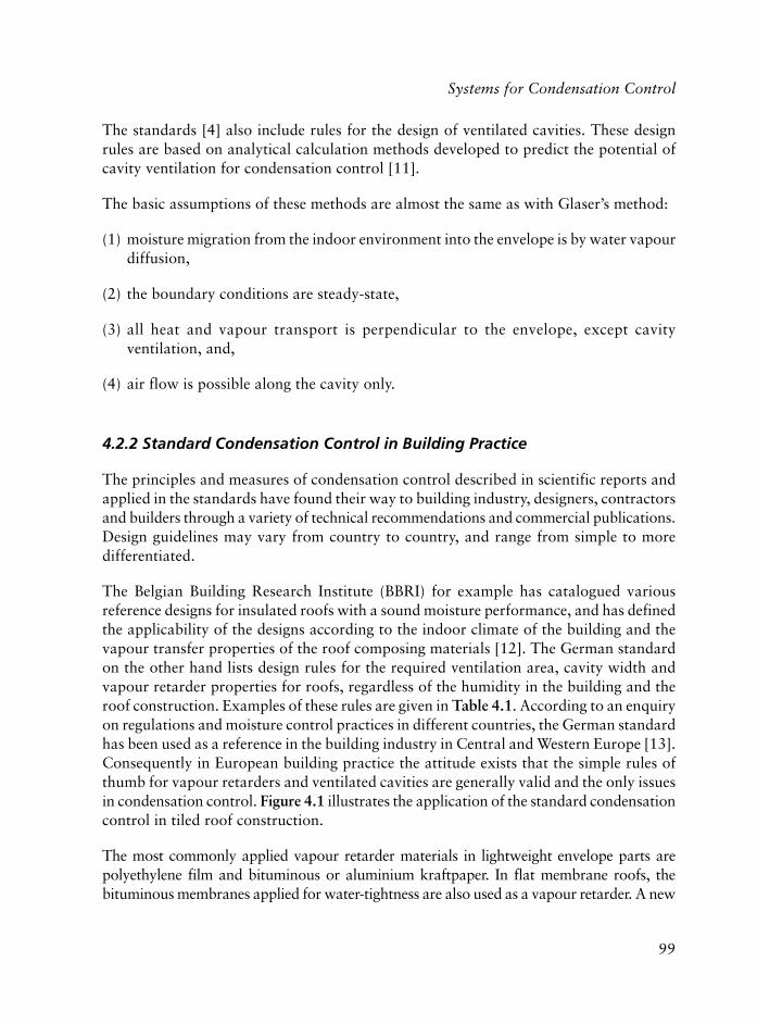
99
The standards [4] also include rules for the design of ventilated cavities. These designrules are based on analytical calculation methods developed to predict the potential ofcavity ventilation for condensation control [11].
The basic assumptions of these methods are almost the same as with Glaser’s method:
(1) moisture migration from the indoor environment into the envelope is by water vapourdiffusion,
(2) the boundary conditions are steady-state,
(3) all heat and vapour transport is perpendicular to the envelope, except cavityventilation, and,
(4) air flow is possible along the cavity only.
4.2.2 Standard Condensation Control in Building Practice
The principles and measures of condensation control described in scientific reports andapplied in the standards have found their way to building industry, designers, contractorsand builders through a variety of technical recommendations and commercial publications.Design guidelines may vary from country to country, and range from simple to moredifferentiated.
The Belgian Building Research Institute (BBRI) for example has catalogued variousreference designs for insulated roofs with a sound moisture performance, and has definedthe applicability of the designs according to the indoor climate of the building and thevapour transfer properties of the roof composing materials [12]. The German standardon the other hand lists design rules for the required ventilation area, cavity width andvapour retarder properties for roofs, regardless of the humidity in the building and theroof construction. Examples of these rules are given in Table 4.1. According to an enquiryon regulations and moisture control practices in different countries, the German standardhas been used as a reference in the building industry in Central and Western Europe [13].Consequently in European building practice the attitude exists that the simple rules ofthumb for vapour retarders and ventilated cavities are generally valid and the only issuesin condensation control. Figure 4.1 illustrates the application of the standard condensationcontrol in tiled roof construction.
The most commonly applied vapour retarder materials in lightweight envelope parts arepolyethylene film and bituminous or aluminium kraftpaper. In flat membrane roofs, thebituminous membranes applied for water-tightness are also used as a vapour retarder. A new
Systems for Condensation Control

100
Polymers in Construction
generation of vapour retarder materials are the so-called moisture-adaptive sheets, developedfor specific applications. One example is the hygro-diode membrane, originally conceived byKorsgaard [14] as a water permeable vapour retarder to be used in flat, cold deck roofs. Themembrane consists of a synthetic felt with good capillary properties, sandwiched betweenstaggered strips of polyethylene. The felt wicks excess (liquid) water from the building envelope,while the plastic strips retard vapour migration into the roof. Another example is the ‘humidity
)]4[retfa(sfoornilortnocnoitasnednocdradnatS1.4elbaT
epolsfooR ytivaCmc,htdiw
aeranoitalitneV fossenkcihtnoisuffiDfoedisnitasreyaleht
m,ytivac
� 01 ° 0 mc0 2 � 001
2 a:evae � mc02 2 *m/mc002muminimhtiw 2 m/
a:egdir � mc01 2 m/
a � :01 � 2a � :51 � 5
:51>a � 01
01< ° 0 mc0 2 � 001
5 a:evae � mc02 2 m/ � 01
a* )m(ecaffoorfohtgnelegdirotsevae=
Figure 4.1 Ridge detail for tiled vented roof design, according to standardcondensation control practice.

101
controlled’ vapour retarder, developed by Künzel [15] for moisture control in historic facadesretrofitted with thermal insulation on the inside. The system consists of a polyamide film,engineered such that the vapour resistance is high when exposed to humidities typical for theindoor environment during winter, and low when exposed to humidities typical for indoorsummer conditions. This way the film prevents moisture accumulation during cold weather,without reducing the drying capacity during summer.
In the Belgian design guides, four vapour retarding classes have been developed, dependingon the resistance to water vapour diffusion of a vapour retarder (expressed as the diffusionthickness or equivalent air layer thickness: μd). Table 4.2 gives the boundaries of the vapourretarding classes, and some examples of materials.
4.3 Controlling Air Leakage
4.3.1 Moisture Accumulation Due to Air Leakage
The importance of air leakage for the moisture performance of building envelopes wasfirst studied and recognised in countries with a building tradition of insulated lightweightconstruction, such as Canada and Scandinavia. The Division of Building Research at theNational Research Council of Canada was probably the first research institute to focus onair leakage as an essential element in moisture control. This notion grew primarily by theobservation of moisture problems exhibited by buildings in the cold Canadian climate. Inthe 1950s, Hutcheon [16] concluded there had to be another mechanism for vapourmigration than the usual one of vapour diffusion, to explain the observed rates of moisture
]21[sessalcredraterruopaV2.4elbaT
ssalC ssenkcihtnoisuffiD slairetaM
1 <m2 μd � m5 mlifenelyhteylop,tlefsuonimutib,repaptfarK)%05<HRta(mlifedimaylop,)mm2.0<d(
2 <m5 μd � m52 edoidorgyh,)mm2.0ed(mlifenelyhteyloP)%05<HRta(enarbmem
3 <m52 μd � m002 )mm3>d(senarbmemsuonimutiB
4 μ m002>d liofcillatemhtiwsenarbmemsuonimutiBsenarbmemreyal-itlum,tnemecrofnier
ytidimuHevitaleR:HRμ ssenkcihtreyalriatnelaviuqe:d
Systems for Condensation Control

102
Polymers in Construction
accumulation in the building envelope. At a symposium in 1965 the Canadian researcherspresented contributions on the effects of air leakage. Wilson and Garden [17] discussed thedriving forces inducing air movement in buildings as the result of building chimney action(thermal stack effect), wind action and imbalance of mechanical supply and exhaustventilation systems. They showed the potential for moisture accumulation due to air leakageto be two or more orders of magnitude higher than that due to diffusion, depending onbuilding and climate. They concluded that moisture problems due to exfiltration of warm,moist air generally increase with increasing building height, decreasing average wintertemperatures and increasing building humidity. Dickens and Hutcheon [18] recommendedairtightness of the internal linings as a first line of defense against moisture problems. Thecommon vapour retarder should block air flow in order to be effective. They achieved thisby sealing the vapour retarder at all joints and at the edges of openings, contrary to Canadianpractice at the time. Finally they advised that cavity ventilation as a condensation controlmeasure should be avoided, in order to minimise air leakage where a good seal at the insideof the envelope was not obtained. They also showed that actual ventilation rates in cavitiesvary widely depending on local pressure patterns around buildings and that the vapourcapacity of cold ventilation air is often too small to control condensation effectively.
After the energy crisis in the 1970s the application of thermal insulation materials in buildingsincreased. As a result, moisture problems in lightweight insulated envelope parts were alsoexperienced and studied in countries with moderate climates. Many of the buildingresearchers in the United States and Western Europe adopted similar conclusions andrecommendations as were recommended earlier for cold climates [19-22].
A typical example of the evolution of the principles of condensation control among buildingscientists is found in the ASHRAE Handbook series. The Handbook of Fundamentals [23]is a basic reference for mechanical and building engineers, with upgraded issues every fouryears. In the 1960s and 1970s the Handbook stressed the use of vapour barriers andventilation of structural cavities as major condensation control measures. The 1981 editionrecognised airbourne vapour movement to be far more powerful in transporting watervapour within the building envelope than water vapour diffusion. In a new paragraph onthe importance of air leakage, airtight construction was called the first defence againstinterstitial condensation. More importantly from a psychological point of view, theterminology for ‘vapour barrier’ was abandoned in favour of the physically more correct‘vapour retarder’. Since the 1993 issue, the Handbook includes a section on air barrierfunctions and properties.
While the identification of air leakage as a source of moisture problems is half a century old,the prediction of its effects is more recent. During the past decade the understanding of themoisture performance of building envelopes has increased with the development of powerfulcomputer models. Hens [24] gave an extensive survey of the state-of-the-art of heat, air and

103
moisture (HAM) models for building components. The early methods to calculate moistureaccumulation due to air leakage were analytical [25] or based on hydraulic network analysis[26]. Most of the recent computer models use numerical finite difference techniques to predictthe transient hygrothermal behaviour of multilayer assemblies in one or two dimensions[27]. The computation results show the complex interaction of the transport and storageprocesses of heat, air and moisture in building components. The moisture accumulation dueto air leakage appears to vary substantially depending on the building design, the indoor andoutdoor climate conditions, the moisture transfer and storage properties of building materialsand the actual air flow patterns through the envelope. Numerical HAM-calculations havebeen applied recently to develop design guidelines for air barriers [28].
4.3.2 Thermal Effects of Air Movement
An additional reason for controlling air movement in the building envelope is the effectof air flows on the energy efficiency of buildings. Many researchers in building andthermal insulation engineering have studied the mechanisms of convection heat transfer.
Figure 4.2 Typical air flow patterns in insulated cavities: (a) air rotation by naturalconvection, (b) air infiltration by natural or forced (wind) convection, (c) wind-
washing around corner, (d) diffuse air leakage, (e) air leakage through gaps and (f)mixed pattern (after Ojanen and Kohonen [29]).
Systems for Condensation Control

104
Polymers in Construction
Air movement influences the thermal performance of building envelopes in variousways: by natural air convection in and around the thermal insulation layer, by airleakage through the envelope or by forced air infiltration in the thermal insulation(so-called wind-washing). Figure 4.2 gives a classification of the various air flowpatterns. Two configurations have been studied in detail by building researchers: acavity filled with an open porous insulation material [30] and an air cavity partlyfilled with a thermal insulation layer [31]. Because of the high possibility ofworkmanship errors in building envelope applications, the sensitivity of the thermalperformance to defects in the insulation layer has often been a topic [32]. FurthermoreTimusk and co-workers [33], and Uvsløkk [34] have made measurements that showedthe significant thermal effects of wind in insulated timber framed constructions,especially at exterior corners.
In general, the studies indicate that air movement may substantially decrease theenergy efficiency of building envelopes, even at small flow rates. The recommendationsto preserve the effectiveness of thermal insulation are for airtight construction,elimination of air gaps at either side of the insulation layer and protection of theinsulation cavity against air infiltration. To achieve this the thermal insulation layershould fill the structural cavity completely and be protected from the wind by a so-called wind barrier. This concept is called the ‘compact’ or ‘sandwich’ envelope designby Hens [21] and Künzel [22]. Air leakage criteria for wind barriers in wood framewalls are given by Ojanen [35] and Uvsløkk [34]. They are based on calculations andexperiments in order to limit the relative increase in heat loss by wind-washing toless than 5%.
Table 4.3 lists examples of wind barrier performance criteria.
]82[srekrow-ocdnaodraneLiDretfaairetircegakaelriA3.4elbaT]43[kkølsvUdna
noitacilppA,egakaelriA
m3 m/ 2 )aP57(h/,ecnaemrepriA
m3 m/ 2 aP/s/
noisuffiDdniwssenkciht
m,reirrab
lairetamreirrabriA 70.0< 3.0< × 01 6- *
metsysreirrabriA 27.0< 7.2< × 01 6- * 52.0<
stnioj+ 81.0< 7.0< × 01 6- * 52.3>
stnioj+reirrabdniW *57.3< 0.41< × 01 6-
.noitalererusserp-wolfraenilnodesabnoitalopartxE*
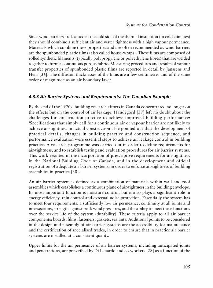
105
Since wind barriers are located at the cold side of the thermal insulation (in cold climates)they should combine a sufficient air and water tightness with a high vapour permeance.Materials which combine these properties and are often recommended as wind barriersare the spunbonded plastic films (also called house-wraps). These films are composed ofrolled synthetic filaments (typically polypropylene or polyethylene fibres) that are weldedtogether to form a continuous porous fabric. Measuring procedures and results of vapourtransfer properties of spunbonded plastic films are reported in detail by Janssens andHens [36]. The diffusion thicknesses of the films are a few centimetres and of the sameorder of magnitude as an air boundary layer.
4.3.3 Air Barrier Systems and Requirements: The Canadian Example
By the end of the 1970s, building research efforts in Canada concentrated no longer onthe effects but on the control of air leakage. Handegord [37] left no doubt about thechallenges for construction practice to achieve improved building performance:‘Specifications that simply call for a continuous air or vapour barrier are not likely toachieve air-tightness in actual construction’. He pointed out that the development ofpractical details, changes in building practice and construction sequence, andperformance evaluation were essential steps to achieve air leakage control in buildingpractice. A research programme was carried out in order to define requirements forair-tightness, and to establish testing and evaluation procedures for air barrier systems.This work resulted in the incorporation of prescriptive requirements for air-tightnessin the National Building Code of Canada, and in the development and officialregistration of adequate air barrier systems, in order to enforce air-tightness of buildingassemblies in practice [38].
An air barrier system is defined as a combination of materials within wall and roofassemblies which establishes a continuous plane of air-tightness in the building envelope.Its most important function is moisture control, but it also plays a significant role inenergy efficiency, rain control and external noise protection. Essentially the system hasto meet four requirements: a sufficiently low air permeance, continuity at all joints andintersections, strength against peak wind pressures, and the ability to meet these functionsover the service life of the system (durability). These criteria apply to all air barriercomponents: boards, films, fasteners, gaskets, sealants. Additional points to be consideredin the design and assembly of air barrier systems are the accessibility for maintenanceand the certification of specialised trades, in order to ensure that in practice air barriersystems are installed at a consistent quality.
Upper limits for the air permeance of air barrier systems, including anticipated jointsand penetrations, are prescribed by Di Lenardo and co-workers [28] as a function of the
Systems for Condensation Control

106
Polymers in Construction
water vapour permeance of the materials at the cold side of the thermal insulation. Theyare based on computer simulations of the moisture accumulation in timber frame walls.The maximum allowable air leakage rates are defined considering both moisture collectionand energy conservation. Even when air leakage does not result in moisture accumulation,the value of 2.7 x 10⁻⁶ m3/m2/s/Pa, is considered to be the maximum allowable airpermeance of the system. This upper limit is necessary to limit the heat loss due to airleakage to 15% of the conductive heat transfer through an insulated wall. Examples ofair barrier requirements are listed in Table 4.3.
4.3.4 Air Leakage Control in Building Practice
Several handbooks and design guidelines on moisture control in North America haveadopted requirements, descriptions and construction details for airtightness [39, 40].Resistance to air leakage can be provided at any location in a building assembly, eachlocation having its pros and cons. Most guidelines however recommend applying theair barrier system at the warm side or inside of the thermal insulation, in order toeliminate all flows of humid air to the colder side of the thermal insulation. The airbarrier system is adapted into conventional building construction by using existingenvelope components and addressing continuity at critical locations. Two approachesare common in residential lightweight construction. Either a plastic vapour retarderfilm, often polyethylene, is used as the air barrier material (then called the air-vapourbarrier), or the internal lining, generally a gypsum board, is designed and assembled toresist air leakage.
Continuity is achieved at construction joints, intersections and penetrations, using tape,gaskets, sealant or glue between the air barrier materials, framing elements and plasticaccessories. Long-term field studies have demonstrated that both approaches are capableof meeting building air-tightness requirements in practice [41].
The implication of the concepts of air flow control for wood frame roof design is illustratedin Figure 4.3.
Recent design guidelines in Western Europe also provide recommendations for airtightconstruction in order to control condensation and heat loss in building components[42]. Air-tightness of the building envelope is considered to be a prerequisite for thevalidity of standard condensation assessment methods. However, contrary to theCanadian guidelines, no performance requirements for air barrier systems areestablished. In addition, for many architects and contractors in Western Europe theconcepts of air-tightness are new and difficult to understand. They have a tradition ofheavyweight construction (masonry walls, concrete floors) for which air-tightness was

107
never a concern. At the moment the expertise and quality of care needed to design andinstall a well-performing air barrier is lacking, despite the existence of design guidelinesand the development of air barrier systems by the industry. As a result lightweightbuilding assemblies remain sensitive to air leakage through the joints, cracks andperforations, common to most existing methods of construction.
4.4 A Systems Approach to Condensation Control
4.4.1 Warm Roof Designs
For some specific envelope designs it is recognised that neither the standard condensationcontrol measures nor the use of an interior air barrier system are reliable measures toprevent moisture problems in practice. After experience of premature failures, the envelopedesign is often changed pragmatically. For example, in Belgium, the use of cavity insulatedwood frame membrane roofs, so called cold deck roofs, was abandoned in favour of thewarm deck roofs with air-vapour barrier, thermal insulation and roofing membrane locatedon top of the roof deck [43]. Also in severe climates new envelope designs and constructionmethods have been introduced. In the Canadian Northwest Territories, a similar designassembly is preferred for wood-frame roofs, walls and floors: the ‘overcoat approach’
Systems for Condensation Control
Figure 4.3 Ridge detail for tiled compact roof design, according to the concepts of airleakage control

108
Polymers in Construction
implying the location of the air-vapour barrier, the insulation and the exterior finishoutside of the structural sheathing and framing. Messer [44] and Ogle and O’Connor[45] proposed a warm roof and wall design to control condensation in non-residentialCanadian construction. The implication of this approach for wood frame roof design isillustrated in Figure 4.4.
There are two major reasons for these changes in envelope design. First continuity ofthe air-vapour barrier is easier to achieve and less susceptible to damage. Due to itslocation on the outside of the structure, interference in continuity by major structuralelements, internal walls and service penetrations is minimised. The continuity ofairtightness is less affected by other trade’s work, such as electricians or plumbers.Because the air barrier is applied to a rigid support, it is easier to install correctly.Moreover, due to the inverse construction sequence, the air barrier has to provide aweatherproof enclosure at an early stage in construction, as a result of which the careof designers and contractors to achieve continuity increases. Secondly, the potentialcondensation planes are shifted to the outside of the structural cavity, so thatcondensation, if occurring, causes less damage. An additional benefit is the eliminatedthermal bridging through the structural framing. Disadvantages are, of course, thehigher initial cost and thickness of the new design and the possible technical difficultiesto connect the insulation and the exterior finish to the structure.
Figure 4.4 Ridge detail for tiled warm roof design

109
4.4.2 Condensation Control Systems
As illustrated by the previous example, other factors than purely physicalconsiderations play an important role in condensation control. The properties of airbarriers or vapour retarders are not the only concerns in preventing condensationproblems. Different condensation control strategies may be combined in order tocreate condensation control systems with a greater probability of effectiveness inbuilding practice.
Ten Wolde and Rose [46] presented two major approaches to moisture control in thebuilding envelope. The first is to design and construct the building envelope for ahigh tolerance for moisture. The second is to limit the moisture load on the envelope.Designing the envelope for a high moisture tolerance implies the use of measures tocontrol the migration of moisture into the construction, to control moistureaccumulation in building materials or to enhance removal of moisture from thebuilding assembly [40]. The limitation of the moisture load often involves controlstrategies on the level of building design and operation, e.g., ventilation,dehumidification or depressurisation.
Table 4.4 categorises potential condensation control measures for thebuilding envelope.
retfaepolevnegnidliubehtrofseigetartslortnocnoitasnednoC4.4elbaT]64[esoRdnaedloWneTdna]04[ydomraCdnakerubitsL
ygetartS miA erusaeM
sseccaerutsiomfolortnoC egakaelriaetanimilE reirrabriA
noisuffidruopavtcirtseR redraterruopaV
erutsiomfolortnoCnoitalumucca
foerutarepmetesiaRecafrusgnisnednoc
foedistuonoitalusnIecafrusgnisnednoc
sselmrahwollAnoitalumucca
tayticapacerutsiomhgiHecafrusgnisnednoc
erutsiomfolavomeR gniyrdetomorP sreyalelbaemrepruopaV
sreyalevitcayrallipaC
noitalitnevytivaC
noitasnednocevomeR eganiarD
daolerutsiomfonoitcudeR noitcurtsnoctimiLerutsiom
slairetamyrdyllaitinI
Systems for Condensation Control

110
Polymers in Construction
Table 4.5 lists measures to restrict the moisture load by proper building design andoperation. The individual measures may be combined to create an effective condensationcontrol system. This way the integral building envelope and even the building may beregarded as a protective system for moisture control.
4.5 References
1. Moisture Performance of Building Components, WTCB-Tijdschrift No.1, BelgianBuilding Research Institute, Brussels, Belgium, 1982. (in Dutch)
2. BS 5250, Code of Practice for Control of Condensation in Buildings, 2002.
3. ISO 13788, Hygrothermal Performance of Building Components and BuildingElements - Internal Surface Temperature to Avoid Critical Surface Humidity ofInterstitial Condensation – Calculation Methods, 2001.
4. DIN 4108-3 Thermal Protection and Energy Economy in Buildings - Part 3:Protection against Moisture Subject to Climate Conditions; Requirements andDirections for Design and Construction, 2002.
5. P.R. Achenbach and H.R. Trechsel in the Proceedings of the second ASHRAE/DOE Conference - Thermal Performance of the Exterior Envelopes of BuildingsII, Las Vegas, NV, USA, 1982, p.1090.
6. F.B. Rowley, A.B. Algren and C.E. Lund, ASH&VE Transactions, 1939, 45, 231.
7. H. Glaser, Kältetechnik, 1958, 10, 11, 358. (in German)
8. H. Glaser, Kältetechnik, 1958, 10, 12, 386. (in German)
retfanoitarepodnangisedgnidliubybdaolerutsiomfonoitcudeR5.4elbaT]64[esoRdnaedloWneTdna]04[ydomraCdnakerubitsL
miA ngiseD noitarepO
riaroiretniniruopavtimiL metsysnoitalitnevlarutaN noitalitnevlacinahceMnoitacifidimuheD
erusserprialortnoCslaitnereffid
snoitarapesroolfthgitriA)thgiehkcatslamrehttimil(
noitasirusserpeD

111
9. E. Tammes and B.H. Vos, Heat and Moisture Transport in Building Components,Kluwer Technische Boeken BV, Deventer-Antwerpen, The Netherlands, 1980.(in Dutch)
10. B.H. Vos, Building Science, 1971, 6, 7.
11. K.W. Liersch, Vented Roofs and Walls, Part 3, Roofs: Fundamentals of Heat andMoisture Control, Bauverlag Wiesbaden, Gütersloh, Germany, 1986. (in German)
12. Hygrothermal Factors In Roof Design, Report No. 134, Belgian BuildingResearch Institute, Brussels, Belgium, 1980. (in Dutch).
13. K. Kiessl, Annex 24, Final Report, Volume 4, Heat, Air And Moisture Transfer InInsulated Envelope Parts (HAMTIE): Experience, Regulations, ExperimentalEvaluation, International Energy Agency, Paris, France, 1996.
14. V. Korsgaard, Proceedings of the Third ASHRAE/DOE/BTECC Conference -Thermal Performance of the Exterior Envelopes of Buildings III, ClearwaterBeach, FL, USA, 1985, 985.
15. H.M. Künzel, ASHRAE Transactions, 1998, 104, 2, 903.
16. N.B. Hutcheon, Control of Water Vapour in Dwellings, Division of BuildingResearch, National Research Council of Canada, Ottawa, Ontario, Canada,Technical paper No.19. NRC No.3343, 1954.
17. A.G. Wilson and G.K. Garden in Proceedings of the RILEM/CIB Symposium onMoisture Problems in Buildings, Helsinki, Finland, 1965, Paper No.2-9.
18. H.B. Dickens and N.B. Hutcheon in Proceedings of the RILEM/CIB Symposiumon Moisture Problems in Buildings, Helsinki, Finland, 1965, Paper No. 7-1.
19. V. Korsgaard, G. Christensen, K. Prebensen and T. Bunch-Nielsen, BuildingResearch and Practice, 1985, 13, 211.
20. G.S. Dutt, Energy and Buildings, 1979, 2, 251.
21. H. Hens, Bauphysik 1992, 14, 6, 161. (in German)
22. H. Künzel, Wärmegedämmmte Satteldächer ohne Belüftung (Insulated PitchedRoofs Without Ventilation), Fraunhofer Institut für Bauphysik, IBP-Mitteilung,1989, 16, 173. (in German)
23. ASHRAE Handbook of Fundamentals, American Society of Heating,Refrigerating and Air-Conditioning Engineers, Inc. Atlanta, GA, USA, 2001.
Systems for Condensation Control

112
Polymers in Construction
24. H. Hens, Annex 24, Modelling – Fianl Report, Volume 1, Part 1, Heat, Air AndMoisture Transport, International Energy Agency, Paris, France, 1996.
25. A. Ten Wolde, ASHRAE Transactions, 1985, 91, 1a, 322
26. A-C. Andersson, Computer Programs For Two-Dimensional Heat, Moisture, Air-Flow, Report No.TVBH-3005, Division of Building Technology, Lund Institute ofTechnology, Lund, Sweden, 1981.
27. Moisture Analysis and Condensation Control in Building Envelopes, Ed., H.R.Trechsel, ASTM Manual 40, American Society for Testing and Materials, WestConshohocken, PA, USA, 2001.
28. B. Di Lenardo, W.C. Brown, W.A. Dalgliesh, M.K. Kumaran and G.F. Poirier, AirBarrier Systems for Exterior Walls of Low-Rise Buildings, CCMC TechnicalGuide Master Format 07195, Canadian Construction Materials Centre, NationalResearch Council Canada, Ottawa, Ontario, Canada, 1995.
29. T. Ojanen, and R. Kohonen in the Proceedings of the fourth ASHRAE/DOE/BETEC Conference - Thermal Performance of the Exterior Envelopes ofBuildings IV, Orlando, FL, USA, 1989, p.234.
30. F. Powell, M. Krarti and A. Tuluca, Journal of Thermal Insulation, 1989, 12, 239.
31. A. Silberstein, C. Langlais and E. Arquis, Journal of Thermal Insulation, 1990,14, 22.
32. H.A. Trethowen, Journal of Thermal Insulation, 1991, 15, 172.
33. J. Timusk, A.L. Seskus and N. Ary, Journal of Thermal Insulation, 1991, 15, 8.
34. S. Uvsløkk, Journal of Thermal Insulation and Building Envelopes, 1996, 20, 40.
35. T. Ojanen in Proceedings of Building Physics 93 – Third Nordic Symposium,Copenhagen, Denmark, Ed., B. Saxhof, 1993, Volume 2, p.643.
36. A. Janssens and H. Hens, Journal of Thermal Insulation and Building Envelopes,1997, 21, 202.
37. G.O. Handegord in Air Leakage, Ventilation and Moisture Control in Buildings.Moisture Migration in Buildings, Eds., M. Leiff and H.R. Trechsel, ASTM STP779, American Society for Testing and Materials, West Conshohocken, PA, USA,1982, p.223-233.

113
38. M. Herschfield, Air Barrier Systems For Walls Of Low-Rise Buildings:Performance And Assessment, NRCC-40635, Canadian Construction MaterialsCentre, National Research Council Canada, Ottawa, Ontario, Canada, 1997.
39. Moisture Problems, CMHC Report No.NHA 6010, Canada Mortgage andHousing Corporation, Ottawa, Ontario, Canada, 1987.
40. J. Lstiburek and J. Carmody, Moisture Control Handbook: Principles andPractices for Residential and Small Commercial Buildings, Van NostrandReinhold, New York, NY, USA, 1993.
41. G. Proskiw and P. Eng, Journal of Thermal Insulation and Building Envelopes,1997, 20, 278.
42. G. Hauser and F. Otto, Holzbau Handbuch, Reihe 1: Entwurf und Konstruktion(Woodframe Handbook, Series 1: Design and Construction),Entwicklungsgemeinschaft Holzbau in der DGfH eV, Münich, Germany, 1995,(in German)
43. The Flat Roof, Report No.183, Belgian Building Research Institute, Brussels,Belgium, 1992. (in Dutch).
44. H.W.E. Messer, Journal of Thermal Insulation and Building Envelopes, 1996,19, 279.
45. R. Ogle and J. O’Connor in Proceedings of the sixth ASHRAE/DOE/BTECCConference - Thermal performance of the Exterior Envelopes of Buildings VI,Clearwater Beach, FL, USA, 1995, p.379.
46. A. Ten Wolde and W.B. Rose, Journal of Thermal Insulation and BuildingEnvelopes, 1996, 19, 206.
Systems for Condensation Control

114
Polymers in Construction

115
5.1 Geotechnical Engineering Applications
Yildiz Wasti
5.1.1 General
The utilisation of polymers in ‘Geotechnical Engineering’ (a sub-discipline within civilengineering which covers broadly all forms of soil or the earth’s crust – related problems)constitutes a major range of applications for these materials. The term ‘geosynthetic’ hasbeen coined to describe the ‘synthetic’ polymers, almost exclusively thermoplastics, usedfor ‘geotechnics’ problems including environmental geotechnology.
The American Society for Testing and Materials (ASTM) has defined geosynthetic inD4439-02 Terminology [1] as follows: ‘a planar product manufactured from polymericmaterial used with soil, rock, earth, or other geotechnical engineering related material asan integral part of a man-made project, structure, or system.’ They are generally used inplace of, or to enhance the function of, natural soil materials. Common geosyntheticpolymers are polyethylene (PE), polypropylene (PP), polyvinylchloride (PVC), polyethyleneterephthalate (PET), polyamide (PA), polystyrene (PS) and chloro-sulfonated polyethylene(CSPE). In all cases additives are used as colorants, ultraviolet (UV) light adsorbers,plasticisers, antioxidants, biocides, flame retardants, thermal stabilisers, lubricants,forming agents or antistatic agents [2]. Carbon black and UV stabilisers are the mostcommon additives for protection from weathering.
The main types of geosynthetics are geotextiles, geomembranes, geogrids, geonets,geocomposites and geosynthetic clay liners. Estimations of the market activity of these productsin North America between 1970 and 1992 given by Koerner [2] show a continued growth,which is probably still very strong. The amount of geosynthetics used in 1992 in NorthAmerica alone is estimated to be about 485 million m2, with geotextiles having the greatestutilisation (~ 325 million m2), followed by geomembranes, geocomposites, geonets, geogridsand the more recently developed geosynthetic clay liners, in decreasing order. On the basis ofcost however, geomembranes have the greatest market share. Globally 1,400 million m2 ofgeotextiles, which comprise 75% of all geosynthetics, are used each year [3]. As of 1998there were more than 600 different products available in North America alone [4].
5 Use of Polymers in Civil EngineeringApplications
Mustafa Tokyay, Yildiz Wasti and Ugur Polat

116
Polymers in Construction
Geotextiles are permeable geosynthetics, which form the oldest and largest group ofgeosynthetics. They are mainly of two types: woven and nonwoven as illustrated inFigure 5.1a. The woven geotextiles are made on conventional textile weaving machineryusing monofilament, multifilament, or fibrillated yarns, or slit films and tapes. There aresubdivisions of nonwoven geotextiles, based upon the way the fibres (or filaments) arebonded together: mechanically bonded or needle-punched in which the fibres are entangledby specially designed needles, heat bonded, in which the fibres are welded together byheat and/or pressure at fibre crossover points, and chemical or resin bonded in whichfibrous web is either sprayed or impregnated with an acrylic resin. Woven geotextilesgenerally have relatively high strength and stiffness (which makes it possible to use themin soil reinforcement applications as well) and, relatively poor filtration/drainagecharacteristics. Nonwoven geotextiles have low to medium strength with high elongationat failure, and good filtration/drainage characteristics. Fabric, engineering fabric or filterfabric is synonymous with the newer term ‘geotextile’. The main polymer material usedin the manufacture of geotextiles is polypropylene but polyester is also used [2].
Geomembranes are very low-permeability geosynthetics used as fluid or vapour barriers.The most widely used geomembranes are thin, flexible sheets mainly of PVC, CSPE,high-density polyethylene (HDPE) and very-low-density polyethylene (VLDPE).Geotextiles impregnated with asphalt or sprayed with polymeric mixes or geotextile –bitumen geocomposites are also used as geomembranes. Polymeric sheet geomembranesare manufactured by extrusion, calendering and spread coating methods. All polyethylenegeomembranes are manufactured by the extrusion method and processes called ‘texturing’are used to obtain a roughened HDPE and VLDPE surface. Details of various methodsused to produce geomembranes, geomembrane seaming methods and seam tests are givenby Koerner [2]. Environmental regulations being enacted all over the world especiallyfor the hazardous waste disposal call for extensive mandatory utilisation of geomembranes.
Geogrids are grid like materials with apertures of sufficient size to interlock with thesurrounding soil and are used for reinforcement. Extruded grids are manufactured byfirst punching a regular pattern of holes into the polymer sheets (polyethylene for uniaxialand polypropylene for biaxial grids) and then stretching the sheet uniaxially or biaxially.A more flexible type of geogrid which may be called a ‘woven’ or ‘strip geogrid’ ismanufactured from two sets of high-tenacity polyester yarns which intersect at 90° andare joined at the crossover points by a knitting or heat welding process, and then coatedwith a polymer usually polyethylene, polyvinyl chloride or bitumen (Figure 5.1b).
Geonets consist of two sets of parallel, roughly round polymer strands usually intersectingat between 60 to 90° and forming a mesh-like appearance. Although they can be used ascomparatively low strength soil reinforcement, their main utilisation is as the core or spacermaterial in composite drainage products for conveyance of liquids or gases. Geonets areusually manufactured from PE, by a continuous extrusion process [2].

117
Use of Polymers in Civil Engineering Applications
Figure 5.1 Examples of various geosynthetics
(a) Geotextiles
(b) Geogrids
(c) Geocomposite sheet drain
(d) Geosynthetic clay liners

118
Polymers in Construction
Geocomposites consist of various combinations of geotextiles, geogrids, geonets,geomembranes, and/or other materials. Most geocomposites have been developed fordrainage applications (Figure 5.1c).
Geosynthetic clay liners are low permeability composites typically consisting of a thinlayer of dry bentonite clay, supported by geotextiles and/or geomembranes which areheld together by needling, stitching, or adhesives (Figure 5.1d).
More information on geosynthetic types, manufacturing processes, properties andconstruction techniques can be found in [2, 5 and 6].
Geosynthetics have six basic functions:
1. Separation: Prevention of the inter-mixing of particles from dissimilar soil layers,commonly a fine-grained soil and a granular drainage soil.
2. Filtration: Use of geotextiles as filters to permit the flow of water across the geotextilewithout significant migration of soil fines into drainage aggregate or pipes.
3. Drainage or fluid transmission: Allowing water (or vapour) to be transmitted in theplane of a thick nonwoven needle-punched geotextile or a drainage geocomposite.
4. Reinforcement: Imparting tensile strength to the soil.
5. Sealing or fluid barrier: Impeding the flow of a liquid (or gas) using geomembranes orgeotextiles which are field sprayed or impregnated with bitumen or polymeric mixes.
6. Protection: Protection of geomembrane against puncture by means of a cushion ofnonwoven geotextile.
Although in many applications it is possible to identify one dominant or primary function,geosynthetics usually perform one or more essential secondary functions.
5.1.2 Geosynthetic Properties and Testing
Geosynthetics have a wide range of physical and mechanical properties because of theenormous number of products available and the new ones being added regularly.Nevertheless, the following list covers the range of important properties required toevaluate the suitability of geosynthetics for most geotechnical applications:
1. General Properties (commonly given in sales brochures)
(a) Geosynthetic type and manufacturing process
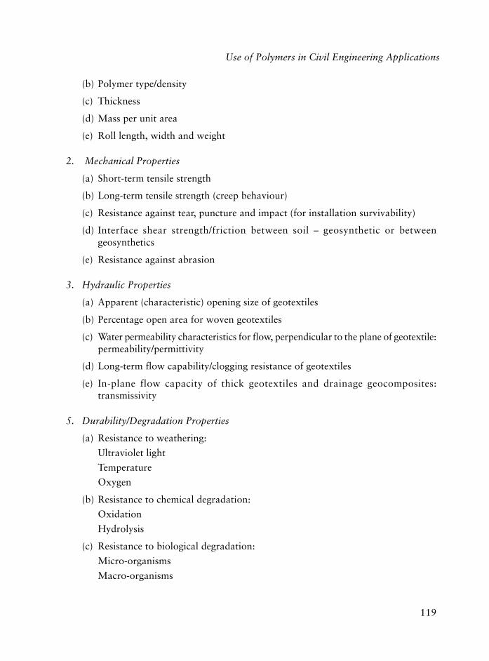
119
Use of Polymers in Civil Engineering Applications
(b) Polymer type/density
(c) Thickness
(d) Mass per unit area
(e) Roll length, width and weight
2. Mechanical Properties
(a) Short-term tensile strength
(b) Long-term tensile strength (creep behaviour)
(c) Resistance against tear, puncture and impact (for installation survivability)
(d) Interface shear strength/friction between soil – geosynthetic or betweengeosynthetics
(e) Resistance against abrasion
3. Hydraulic Properties
(a) Apparent (characteristic) opening size of geotextiles
(b) Percentage open area for woven geotextiles
(c) Water permeability characteristics for flow, perpendicular to the plane of geotextile:permeability/permittivity
(d) Long-term flow capability/clogging resistance of geotextiles
(e) In-plane flow capacity of thick geotextiles and drainage geocomposites:transmissivity
5. Durability/Degradation Properties
(a) Resistance to weathering:
Ultraviolet light
Temperature
Oxygen
(b) Resistance to chemical degradation:
Oxidation
Hydrolysis
(c) Resistance to biological degradation:
Micro-organisms
Macro-organisms

120
Polymers in Construction
5.1.3 Use of Geosynthetics in Roadways, Pavements, Runways and Railways
For geosynthetic design purposes, roads may be broadly classified into two categories: unpavedand paved roads. Unpaved roads are those in which the pavement material is unbound stoneaggregate placed on the subgrade which is the base layer of a road or the natural groundunder the pavement. They are usually of a temporary nature such as haul roads used by largetrucks for transporting mined or other material, access roads, detours and constructionplatforms. Unpaved road performance requirements allow for some rutting to occur. In thecase of weak subgrades, such as soft clays, water bearing silts, intermixing of the aggregateand the subgrade soil with the associated loss in aggregate thickness and structural supporteventually makes the road impassable or in need of constant maintenance. Paved roads aredefined as those where the upper part of the pavement structure is bound – usually by bitumenor concrete - overlying the granular base and sub-base layers. Pavement failure is expressedin terms of decreased serviceability caused by the development of cracks and ruts.
Geosynthetics have been used in new road construction in various ways to minimise thepreviously mentioned problems as well as in the maintenance of existing paved roads(overlays applied to strengthen existing pavements). In this category of application the twoprincipal roles for geosynthetics are separation/filtration, and reinforcement. The use ofgeosynthetics to perform these functions in unpaved and paved roads is discussed inSection 5.1.3.1 and 5.1.3.2.
5.1.3.1 Use of Geosynthetics in Unpaved Roads
Incorporating a geotextile in the road construction as a separator at the interface betweensoft, fine-grained subgrade soil and aggregate (Figure 5.2) was the first application ofgeosynthetics in roads. In this application the geotextile separator must perform a filtrationfunction as well, preventing particles smaller than about 0.06 mm in size called soil finesfrom migrating into the aggregate and avoiding build-up of excess pore water pressures.In addition, the geotextile may provide reinforcement through lateral restraint of thesubgrade soil and additional support to the wheel loads due to the membrane action ofthe geotextile in tension. Geogrid reinforcements applied between the soil and the granularlayer can lock the granular particles together and prevent repeated strains on the soilthat can cause slurry to form and pumping of the slurry up into the granular layer, butideally a geotextile must be used together with the geogrid.
Geogrid reinforcement placed at approximately mid-depth of the granular layer (unless thelayer is very thick), is also suggested for the control of rutting through restriction of permanentstrain development in the granular layer [7]. Stiff extruded geogrids are suitable for thisapplication. Possible locations for geosynthetics in unpaved roads are given in Figure 5.3.

121
Use of Polymers in Civil Engineering Applications
Figure 5.2 Mechanism for geotextile separation in unpaved road
Figure 5.3 Locations for geosynthetics in unpaved roads
(a) Weak subgrade, good aggregate
(b) Stiff subgrade, poor aggregate
(c) Weak subgrade, poor aggregate
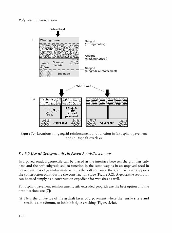
122
Polymers in Construction
5.1.3.2 Use of Geosynthetics in Paved Roads/Pavements
In a paved road, a geotextile can be placed at the interface between the granular sub-base and the soft subgrade soil to function in the same way as in an unpaved road inpreventing loss of granular material into the soft soil since the granular layer supportsthe construction plant during the construction stage (Figure 5.2). A geotextile separatorcan be used simply as a construction expedient for wet sites as well.
For asphalt pavement reinforcement, stiff extruded geogrids are the best option and thebest locations are [7]:
(i) Near the underside of the asphalt layer of a pavement where the tensile stress andstrain is a maximum, to inhibit fatigue cracking (Figure 5.4a).
Figure 5.4 Locations for geogrid reinforcement and function in (a) asphalt pavementand (b) asphalt overlays
(a)
(b)

123
Use of Polymers in Civil Engineering Applications
(ii) Near the upper surface of the asphalt layer to reduce rutting (Figure 5.4a).
(iii) At the interface of the existing pavement and asphalt overlay to reduce thedevelopment of reflection cracking.
Alternatively, in overlays, geotextiles placed on the existing road surface which hasbeen cleaned and sprayed with an asphaltic sealant before the hot mix overlay is installed,help to control subsequent reflection cracking and also provide a waterproofing layerfor controlling surface water infiltration. Use of a geosynthetic in overlays for reflectioncracking control has been the most popular application in asphalt paving. A geogridlocated at mid-depth of the overlay reduces rutting in the overlay (Figure 5.4b).
Use of geosynthetics for taxiways, runways and car parks follows the same principles asfor paved roads.
5.1.3.3 Use of Geosynthetics in Railways
Railways tracks are supported by granular material called ‘ballast’. The application ofgeosynthetics in railways is therefore somewhat similar to unpaved roads and can beconsidered basically in two categories:
(i) A geotextile separator/filter at the interface between the ballast and soft clayey subgrade.
Slurries produced from cohesive subgrades beneath railway ballast can be pumpedinto the ballast under the action of the dynamic train loading to give the conditionknown as ‘erosion pumping’. The load support capability of the ballast is reduced as aresult of the contamination of the ballast, eventually leading to unacceptable movementsof the rails. The problem is addressed by the provision of a sand blanket (filter) on thesubgrade. Geotextile filters can be incorporated in the design to replace the sand blanketor, even better, with a thin layer of sand blanket. There appears to be some agreementbetween North American and European practice on the use of generally thick, nonwovenneedle-punched geotextiles for subgrade separation application in railways [6].
(ii) Ballast strengthening using a stiff geogrid within the ballast to reduce the permanentdeformation of the ballast due to the repetitive vibratory train loads.
5.1.4 Use of Geosynthetics in Drainage and Erosion Control Systems
(a) Use of geotextiles to perform a ‘filtration’ function (in situations where the flow isperpendicular to the plane of the geotextile) as a replacement for or in conjunctionwith conventional granular filters. This is one of the major areas of geotextile use.

124
Polymers in Construction
Examples in drainage systems are: Geotextile filters around drainage aggregate orperforated/slotted pipes in various types of drains for land drainage, highway drainage,structural drainage for retaining walls or buildings (Figure 5.5a), earth dam drainage(chimney and toe drains).
Examples of the use of a geotextile in erosion control measures are: beneath largestones employed in revetments called riprap, armour stone, concrete block, gabionmattress type revetments (which are wire-mesh boxes filled with stones) forrainfall/runoff, coastal/stream bank erosion protection (Figure 5.5b) and in scourprotection for bridge piers and abutments. Geosynthetic erosion control blanketsor mats manufactured from both natural (straw or coconut fibres) and polymermeshes/webbings are also used, to enhance the establishment of a vegetative coveron slopes prone to erosion by rainfall and runoff.
(b) Applications where the in-plane drainage ability of a thick geotextile or mostly ageocomposite drain is utilised. Composite drains have a water conducting spacer coreof extruded and fluted plastic sheets, geonets, waffled plastic sheets, meshes and matswith a geotextile filter on either one or both sides (Figure 5.1c, Figure 5.5a). They maybe prefabricated or fabricated on site. They have been used as highway edge drains,highway shoulder drains, structural drains and band/strip drains as a substitute forvertical sand drains to induce rapid consolidation of soft clays (Figure 5.5c).
5.1.5 Use of Geosynthetics in Soil Reinforcement Applications
Geosynthetics with high tensile strength and stiffness such as geogrids, woven tapes/stripsare used in reinforcement applications. Examples are: reinforced soil walls, reinforcedsteep slopes, slope repair by reinforced soil, basal reinforcement at the base of embankmentson soft ground or embankments over piled foundations, as illustrated in Figure 5.6.
5.1.6 Use of Geosynthetics in Waste Disposal Facilities
Environmental regulations dictate that landfills and surface impoundments for the disposalof hazardous and non-hazardous waste have liners (base, side-slope, and cover liners)and a leachate (contaminated water that emanates from a disposal site) collection andremoval system in order to protect air, water, and land resources. Base and side-slopes ofcontainments are lined with compacted clay or geomembrane (commonly HDPE) orboth. Cover liners generally incorporate a foundation material overlain by a clay and/orgeomembrane (commonly VLDPE which is more flexible than HDPE) liner. Geosyntheticclay liners may be used in place of clay. The leachate collection and removal system is

125
Use of Polymers in Civil Engineering Applications
(a) Use of geotextile filter/drainage geocomposite in trench drains
(b) Slope / Streambank / Coastline erosion control
(c) Vertical drains to accelerate consolidation
Figure 5.5 Examples of filtration, erosion control and drainage applications

126
Polymers in Construction
(d) Piled embankment
Figure 5.6 Examples of reinforcement applications
(c) Embankment on soft foundations
(a) Reinforced earth wall (b) Reinforced steep slopes
essentially a granular drainage layer and perforated leachate collection pipes (commonlyof HDPE) at the base of the waste containment facility. A drainage layer may be placedon the cover liner as well to reduce infiltrating water through the liner.

127
Use of Polymers in Civil Engineering Applications
Other geosynthetics are also used in waste containment systems: geotextiles as filtersand separators protecting drainage layers, geonets as drains in place of granular material,geocomposite drains for removal of surface water and geogrids for slope and subsidencereinforcement (Figure 5.7).
5.1.7 Miscellaneous Applications of Geosynthetics
Other noteworthy examples of geosynthetic applications are:
• Use of geotextiles in silt fences, which consist of geotextiles placed vertically on poststo prevent eroded material from being transported away from the construction siteby runoff water.
• Use of geomembranes in canal, tank and tunnel linings, as impervious cores orupstream blankets in earth dams, as waterproofing rehabilitation in the upstreamface of old concrete or masonry dams and in vertical cut-off walls in earth dams,around waste sites and in encapsulating swelling soils.
Figure 5.7 Geosynthetics in landfill containment

128
Polymers in Construction
• Use of ‘geofoams’, with polystyrene foam having the strongest market share, for thermalinsulation, vibration damping, as lightweight fill material and in the form of acompressible inclusion, i.e., a foam layer placed in contact between a non-yieldingstructural element such as a foundation or wall and the ground.
• Use of ‘geocells’ (a row of geogrid cells typically one metre high, filled with sand orgravel) as foundation mattresses below embankments (Figure 5.6c).
• Use of buried plastic pipes also called ‘geopipes’, for pipeline transmission of water,gas, oil and in drainage systems for buildings, retaining walls, tunnels, highways,railways, slopes, landfills, etc. PVC, HDPE, PP, polybutylene (PB), acrylonitrile butadienestyrene (ABS) and cellulose acetate butyrate (CAB) are the polymer resins in currentuse in the fabrication of these pipes [2].
5.2 Polymers in Concrete
Mustafa Tokyay
Concretes with polymers are generally classified into three categories as polymer concrete (PC),polymer Portland cement concrete (PPCC), which is also known as latex-modified concrete(LMC) and polymer-impregnated concrete (PIC) according to their process technologies.
Polymer concrete is a composite material formed by polymerising a monomer and aggregatemixture. There is no other cementitious material present in it. PPCC (or LMC) is a Portlandcement concrete produced usually by replacing a specified portion of the mixing waterwith a latex (polymer emulsion). It can also be produced by adding a monomer to freshconcrete with subsequent in situ curing and polymerisation. PIC is a hardened Portlandcement concrete with impregnated monomer which is polymerised in situ.
Concretes containing polymers are causing much interest as high performance or multi-functional materials in the construction industry. PPCC was developed in late 1920s, polymerconcrete in 1950s and PIC in late 1960s. Currently, the first two types are being used aspopular construction materials whereas PIC has not yet been used much due to its relativelyhigher processing cost although it performs very well.
A general classification of concrete-polymer composites is given in Figure 5.8 [8].
5.2.1 Polymer Concrete
Binders used for polymer concrete include epoxy resins (EP), unsaturated polymer resin(UP), vinyl ester resin (VE), methyl metacrylate (MMA) and furan resins [9-11].

129
The properties of polymer concrete depend on the characteristics of the polymer and theaggregate used and the formulation [12, 13]. Broadly speaking, the unique properties ofpolymer concrete are [13]:
(i) High strength (tensile, flexural and compressive),(ii) good adhesion to most surfaces,(iii) long-term freeze-thaw durability,(iv) low permeability, and,(v) high chemical resistance.
5.2.1.1 Production
Polymer concrete production uses equipment and methods that are being used forproducing Portland cement concrete. In the design of polymer concrete mixes, the mainobjective is to obtain a suitable particle size distribution of the aggregate so that a goodworkability will be attained with a minimum amount of monomer or resin [9]. Aggregatesshould be dried to at least 3% moisture [11] but moisture contents less than 1% arepreferred as moisture reduces the bond between the binder and the aggregate [14].
Figure 5.8 Classification of concrete-polymer composites [8]
Use of Polymers in Civil Engineering Applications

130
Polymers in Construction
There are numerous formulations of polymer concrete as each one is designed for aspecific application. Epoxy resins with proper curing agents are the most commonlyused polymer concrete binders. The aggregate:resin ratio may range between 1:1 and15:1 by weight, depending on the aggregate gradation.
The initiators for monomers are benzoyl, lauroyl or methyl ethyl ketone peroxides. Thepromoters for monomers are tertiary amines like dimethyl aniline or dimethyl-p-toluidine.Epoxy compounds are usually formulated in two parts as epoxy resin and the hardener [11].
5.2.1.2 Uses
Applications of polymer mortars and polymer concretes include patching of Portlandcement concrete, floor and pavement overlays, anti-corrosive linings, precast products,vaults, panels [8, 11]. These indicate that there is no single polymer concrete that performsall of these tasks. Application and performance of polymer concrete depend on the binderused and the aggregate. Copolymerisation techniques allow the production of a widerange of binders with varying properties [11].
Repair Materials: When polymer concrete is to be used for repair or patching purposes,it is necessary to obtain a strong, sound, dry and clean surface for treatment.Otherwise, a poor bond would occur between the surface and the repair material.All the deteriorated and unsound material should be removed with special care takenfor not damaging the surrounding areas and not impairing the bond of remainingsound concrete with the reinforcement.
Polymer concrete can be placed by either premix, dry pack or prepack methods. Thepremix method is similar to the conventional Portland cement concrete mixing and placing.The binder, fine aggregate and coarse aggregate are added to the mixer in that order andmixing is continued until all aggregate particles are thoroughly wetted. Then the materialis placed where it is required and consolidated. It is usually recommended that the surfaceto be treated is primed with the binder before placement.
The aggregate with specified grading is placed in the area to be repaired and compactedby tamping in the dry pack method. Then the monomer mixture is applied to the aggregate,placed by means of a dispenser until all the aggregate is wetted. Usually, monomers ofviscosities less than 0.1 Pa-s are necessary for this method.
In the prepack method, monomer or resin is fed into the mixer, after adding the fineaggregate, the coarse aggregate is introduced and the entire blend is mixed for a specifiedtime. The composite is then placed where required and consolidated.
131
Overlays: polymer concrete overlays are used to get a durable, almost impervious andwear-resistant surfaces on Portland cement concretes. Suitable surface texture may beobtained for appropriate skid resistance and hydroplaning characteristics. The surfaceson which overlay will be applied must be prepared to ensure good adhesion. The surfacemust be strong, sound, dry and clean. The monomer and aggregate systems used forpolymer concrete overlays are similar to those of polymer concrete repairing materials.
There are four different methods of applying polymer concrete overlays:
(i) thin sand-filled resin overlay,
(ii) polymer seal coat overlay,
(iii) premixed polymer concrete overlay, and,
(iv) prepacked polymer concrete overlay.
For thin sand-filled overlays, a thin layer of initiated and promoted resin is applied to theconcrete surface. Before the resin starts to gel, aggregate is spread over. Upon completionof curing, the excess aggregate is swept off. This cycle is repeated three or four timesuntil a nonpermeable and skid resistant overlay is obtained.
In polymer seal coat application, a 6-7 mm layer of dry sand is placed upon the concretesurface then a strong sandstone is put on the sand and hand rolled to set the aggregate.First, a low viscosity monomer mixture is applied. Then, the viscosity is increased bypolymer addition and spread over the aggregate surface. Usually, surfaces are covered tominimise monomer evaporation.
In premixed polymer concrete overlays, the aggregate and the monomer or resin systemare mixed together in a concrete mixer and then spread over the surface and compacted.Sometimes, additional aggregate may be applied on the surface to increase skid resistance.Most of the time, a primer coat of initiated and promoted resin is applied on the concretesurface on which the overlay is to be placed.
Precast Elements: There are numerous applications of precast polymer concrete such aspanels, pipes, drainage channels, tiles, bricks, linings, manhole structures, stair treads,electric insulators, etc. [11, 15].
The method of producing precast polymer concrete is similar to that of precast Portlandcement concrete. The extremely short hardening period of polymer concrete is an obviousadvantage over Portland cement concrete. Form removal may be as short as 40 seconds,depending on the type of monomer used [11]. The formwork, vibrators and mixers used inproducing polymer concrete precast elements are no different to those used for Portlandcement concrete precast elements. However, it should be noted that the formwork shouldbe durable, smooth surfaced and must be able to withstand the heat developed during theexothermic polymerisation process.
Use of Polymers in Civil Engineering Applications
132
Polymers in Construction
Form vibration is preferable to internal vibration in polymer concretes and low viscositymonomers require low-frequency high-amplitude vibration whereas high viscositymonomers are better consolidated by high-frequency low-amplitude vibration.
5.2.2 Polymer Portland Cement Concrete
PPCC mixtures are Portland cement concrete mixtures to which polymer latexes havebeen added during the mixing process. Hardening of the polymer occurs simultaneouslywith the curing of concrete thus forming a continuous polymer network throughout theconcrete [11, 16].
Although many different polymers were investigated for use in PPCC, latexes are themost widely used binders. The latexes that are in general use are styrene-butadiene rubber(SBR) and chloroprene rubber (CR) which are elastomeric; polyacrylic ester (PAE), ethlene-vinyl acetate (EVA) and poly(styrene-acrylic ester) (SAE) which are thermoplastic. Besideslatexes, epoxy resins, which are thermosetting, are also used in PPCC [11, 17].
The mixing and placing operations of PPCC are similar to those of Portland cementconcrete. Curing, on the other hand, is different. Portland cement concrete requirescomparatively long curing periods under 100% relative humidity whereas PPCC needsone day of moist curing after which polymer membranes surrounding the cement pasteform and retain the water inside for continued cement hydration [17].
After one day of moist curing and at least three days of air curing at 7-30 °C, the PPCCcan be put safely into service [11]. Rewetting may result in re-emulsifying or redispersionof the latex with consequent strength reduction.
The most important feature of PPCC is its excellent bonding characteristics. However,this may sometimes cause problems of form removal unless suitable release agents areplaced on forms [11].
5.2.2.1 Uses
PPCC applications include deck coverings, floors, pavements, precast units, anti-corrosivelinings, adhesives, patching or repairing Portland cement concretes [11, 17].
Deck Coverings: Deterioration of reinforced concrete by the ingress of moisture, oxygenand chlorides resulting in the corrosion of reinforcement and subsequent spalling ofconcrete may cause serious problems especially in bridge decks [11, 18].

133
The dispersed polymer phase throughout the concrete causes considerable reduction inporosity and microcracks in the Portland cement matrix as well as serving as an additionalbinding material [11, 19]. Thus, PPCC is a more durable and weather resistant materialfor deck coverings and parking lot overlays.
Floors and Pavements: The chemical resistance and overall improvement in the physicaland mechanical properties of PPCC makes it a suitable material especially for industrialfloor applications where chemical spills and heavy traffic are the typical problemsencountered.
Precast Units: PPCC is suitable for precast operations due to its good workability andheat-curing characteristics. Since most polymers also have a water reducing effect, it ispossible to obtain PPCC with low water:cement ratios. Although high temperature curingis beneficial, care should be taken to prevent the direct contact of steam with the PPCCunits. Otherwise, moisture may cause strength reduction [19].
Patching and Repair: Very high bond strength of PPCC makes it a suitable material forpatching and repair of portland cement concrete. The deteriorated or unsound concretemust be removed properly before PPCC application.
5.2.2.2 PPCC Mix Proportions
The mix proportions of any PPCC depend on the intended use and the type of polymer. Ingeneral, the solid content of the polymer used ranges between 10-20% (by weight of cementused). The cement content should be sufficiently high (usually, more than 400 kg/m3).Total aggregate constitutes about 70% (by weight) of the whole mix and the coarseaggregate-to-fine aggregate ratio depends on the surface finish required. Typicalwater:cement ratios of PPCC range between 0.25 and 0.40. It must be remembered that,emulsions contain water and that amount should also be included in the total mixingwater when calculating the mix proportions [11]. Suggested guidelines for PPCC mixproportioning may be found in [11].
5.2.2.3 Preparation, Mixing, Placing and Curing Procedures
Before placing the PPCC as an overlay or patch, the concrete surfaces to be covered mustbe prepared appropriately. The surface is to be cleaned within 24 hours of placement. Allunsound concrete and foreign materials including rust and oil must be removed in orderto ensure a strong bond between the existing surface and the PPCC overlay. For the casesthat necessitate complete removal of the existing concrete, forms should be provided fora proper placement of PPCC.
Use of Polymers in Civil Engineering Applications

134
Polymers in Construction
The cleaned surfaces should be wetted thoroughly one hour before placement. However, anystanding water on the surface must be removed by compressed air prior to PPCC application.
The corroded reinforcements should be blast-cleaned. The reinforcing bars that have lostmore than one-quarter of their original diameter should be replaced by new ones. If thebond between the existing concrete and the reinforcement is destroyed or more than halfof the reinforcing steel diameter is exposed, the concrete around the reinforcement shouldbe removed to leave at least 19 mm clearance so that PPCC will bond to the entire reinforcingsteel. Care should be taken to prevent damage to the exposed reinforcement [11].
For overlays, PPCC is mixed on site and brushed onto the exposed surfaces. The PPCCshould be covered with wet burlap (coarse jute fabric) and a layer of polyethylene film ontop of it. After 24 hours of wet curing, the burlap and polyethylene are removed and PPCCis let to dry out for at least 72 hours. Then the traffic may be permitted on the surface.
PPCC is usually placed at temperatures above 7 °C. At lower temperatures curing periodsshould be extended [11].
5.2.3 Polymer Impregnated Concrete
PIC are formed by drying the Portland cement concrete, removing the air in the voids,adding by diffusion a low viscosity (<0.1 Pa-s) monomer by atmospheric or pressuresoaking and polymerising the monomer [11]. Depending on the degree to which the voidvolume of concrete is filled with monomer, PIC are divided into two groups: partiallyimpregnated and fully impregnated. Full impregnation implies that approximately 85%of the void space is filled. If the ratio of the filled voids to the total available void contentis less than that then partial impregnation is attained. Sometimes, partially impregnatedconcrete is also called surface impregnated concrete because it is impregnated to a limiteddepth beneath the surface [11].
After impregnation the monomer in the system is polymerised by either thermal-catalyticor promoted-catalytic or ionising radiation methods. The catalytic methods are morecommonly used than the latter [11].
The thermal-catalytic method involves the use of chemical initiators and heat. Commonlyused initiators include benzoyl peroxide (CFRP), azobis-isobutyronitrile, �-tert-butyl-azoisobutyronitrile, tert-butylperbenzoate, and methylethylketone peroxide (MEKP) [11].
In order to allow polymerisation at low ambient temperatures, the promoted-catalyticmethod may be used. This is achieved by promoters which are reducing agent compounds
135
added to the monomer for the decomposition of the peroxide initiators to produce thefree radicals needed for polymerisation. The promoters that have been successfully usedinclude methyl anilines, dimethyl-p-toluidine, cobalt naphthalene and mercaptans [11].
Another way of achieving polymerisation at low temperatures is by using ionising radiationfrom gamma rays emitted by cobalt-60. The radiation energy absorbed by the monomerresults in the production of free radicals. The radiation method does not require initiatorsor promoters. On the other hand, the cost of radiation source is high and polymerisationrate may be low [11].
The selection of a monomer for PIC depends on its impregnation and polymerisationcharacteristics. Vinyl monomers such as acrylonitrile, methyl methacrylate, styrene and vinylacetate containing an initiator are the most commonly used materials for PIC production.
Various additives and modifiers are frequently used in PIC to produce desired changes inthe properties. Plasticisers like dibutylphtalate (DBP) increase the flexibility in brittlepolymers, whereas crosslinking agents like trimethylolpropane trimethacrylate(TMPTMA) increase the rigidity and the softening temperature of the polymer. Initiatorsact as catalysts and promoters accelerate the polymerisation. Silane coupling agents canbe used to improve the strength of PIC by forming chemical bonds between the polymerand the surrounding inorganic matrix.
5.2.3.1 Partially Impregnated PIC
Partially impregnated concrete, which is also called surface impregnated concrete, isusually accomplished by a simple soaking technique. The main objective of partialimpregnation is to obtain an in-depth protective zone of reduced permeability on thesurface of the concrete. Thus, improvement in durability rather than strength is aimedfor by use of partial impregnation.
The partial impregnation process consists of the following steps:
(1) surface preparation,(2) concrete drying,(3) concrete cooling,(4) monomer soaking,(5) polymerisation, and,(6) cleaning [11].
The application of partially impregnated PIC includes treatment of precast concrete membersand existing concrete structures and restoration of deteriorated concrete structures.
Use of Polymers in Civil Engineering Applications

136
Polymers in Construction
5.2.3.2 Fully Impregnated PIC
Full impregnation is usually achieved by pressure. The principal reason for fullimpregnation is to improve the strength and other mechanical properties of concrete.Durability improvement accompanies this.
The full impregnation process consists essentially of the same steps as the partialimpregnation process. Fully impregnated concrete applications are restricted to precastconcrete members [9].
5.2.4 Polymer Based Admixtures for Concrete
Chemical admixtures are frequently introduced into concrete for improving one or moreof its properties in the fresh or hardened state. They are usually classified according tothe specific function they perform. The American Concrete Institute provides aclassification in terms of air entraining admixtures, accelerating admixtures, waterreducing admixtures, set controlling admixtures, and miscellaneous admixtures [20].More detailed classifications are being used for specific groups of admixtures. For example,ASTM defines the functional properties as Type A: water reducing, Type B: retarding,Type C: accelerating, Type D: water reducing and retarding, Type E: water reducing andaccelerating, Type F: high range water reducing and Type G: high range water reducingand accelerating [21].
Polymeric admixtures used in concrete are mainly for water reduction purposes. Besidesthis primary effect they may also have secondary effects like retardation, acceleration, orair-entrainment, depending on their formulations.
5.2.4.1 General Thoughts About Chemical Admixture-Cement Interactions
The concepts outlined next are focused on retarders, water reducing agents and airentraining agents which are the main groups of organic chemical admixtures used inconcrete. Most of the organic admixtures show an affinity towards the surfaces of thecement particles or hydration products resulting in considerable adsorption. Organicmolecules bearing charged groups or polar functional groups interact with particle surfacesthrough electrostatic forces or hydrogen bonds. Polymeric admixtures containinghydrophobic groups in addition to polar and ionic groups result in adsorption caused bythe cumulative effect of all three groups [22]. The adsorbed compounds change the surfaceproperties of the cement particles and thus their interactions with the solution phase andother cement particles [23]. Polymers and anionic surfactants result in a negative electrical

137
charge on the particle surface, which induces repulsion between the neighbouring cementparticles and increased dispersion. When high molecular weight polymers are used, stericforces lead to additional repulsion [24, 25].
5.2.4.2 Water Reducing Admixtures
The water reducing admixtures are the materials that have the primary function ofproducing concrete of a specified workability at a lower water:cement ratio than that ofthe control concrete without admixture. The effect of water reducing admixtures onvarious properties of fresh and hardened concrete is illustrated in Figure 5.9 [23, 26].
Figure 5.9 Effect of water reducing admixtures on properties of fresh andhardened concrete [23, 26].
W/C: water:cement ratio, WRA: water reducing admixture
Use of Polymers in Civil Engineering Applications
138
Polymers in Construction
Water reducing admixtures (WRA) are grouped into five types:
(i) normal,
(ii) accelerating,
(iii) retarding,
(iv) air-entraining, and,
(v) high-range WRA (superplasticisers) admixtures according to their secondary functions.
The accelerating WRA, besides the water reducing capability of the normal type, givehigher strength earlier, which is advantageous for low temperature concreting or concretework where higher early strength is required.
The retarding WRA, again possess the properties of the normal type but elongate thesetting time of concrete resulting in increased time for transportation, handling, and placing.
The air-entraining WRA, entrain microscopic air bubbles into cement paste besidesreducing the water content of the mix. Air-entrainment results in increased freeze-thawresistance of concrete. However, air-entrainment by itself causes reduction in strengthunless precautions are taken. Air-entraining WRA have the advantage of overcoming thestrength reduction due to induced air bubbles by air-entrainment through reduction inwater:cement ratio.
The high-range water reducing admixtures (HRWRA) which are also calledsuperplasticisers are admixtures that reduce the mixing water requirement of a concretewith a given consistency by more than 12% [20].
There are five chemical material groups that form the basis of all water reducing admixtures.Rixom and Mailvaganam [26] categorise the basic chemicals used in Table 5.1.
Lignosulfonates: The lignosulfonate molecule is a substituted phenyl propane unitwith hydroxyl, carboxyl, methoxy and sulfonic acid groups [26]. The polymer has amolecular weight ranging from a few hundred to 100,000. Commercial lignosulfonatesused for admixtures are usually calcium- or sodium-based. The lignosulfonate byitself and the sugar present in the lignosulfonate materials result in retardation of thehydration reactions of cement. Therefore, to obtain normal or accelerating WRA,accelerating admixtures such as triethanolamine, calcium formate or calcium chlorideare added [23, 26].
Many lignosulfonates, especially the less pure types, entrain a certain volume of air inconcrete. This may be desirable to improve the durability of concrete against freezing and

139
thawing. However, surfactant addition to lignosulfonate is more common for this purpose.In order to reduce the entrained air content, a defoaming agent is usually added [23, 26].
Hydroxycarboxylic Acids: The hydroxycarboxylic acids have hydroxyl (OH) and carboxyl(COOH) groups attached to a carbon chain. Gluconic, citric, tartaric, mucic, malic, salicylic,heptonic, saccharic, and tannic acids can be used as retarding and retarding water reducingadmixtures. For use as normal WRA they are mixed with accelerating admixtures [23].Hydroxycarboxylic acid-based WRA are mostly used as aqueous solutions of sodium salt.However, they may occasionally be found as salts of ammonia or triethanolamine.
Hydroxylated Polymers: Hydroxylated polymers are obtained by the partial hydrolysisof polysaccharides to form polymers of low molecular weight. They have a retardationeffect, by themselves. In order to be used as normal or accelerating WRA, small amountsof calcium chloride or triethanolamine should be added [23, 26].
Salts of Formaldehyde-Naphthalene Sulfonate: Although it was the first WRA referredto in the literature, it has been used in major applications only since the early 1970s. Thematerial is obtained by oleum or sulfur trioxide sulfonation of naphthalene. The reactionof the product results in polymerisation [26]. If the material obtained is of lowpolymerisation, it does not result in air-entrainment. However, if they are of highmolecular weight they do not result in air-entrainment.
gnicuderretawnidesuslacimehccisabfonoitasirogetaC1.5elbaT]52[serutximda
serutximdagnicuderretawfoepyTlamroN gnitareleccA gnidrateR gniniartne-riA sresicitsalprepuS
eruPetanoflusongil
etanoflusongiLlCaC+ 2
ragushgiHetanoflusongil
erupmIetanoflusongil
eruPetanoflusongil
+etanoflusongiLgniniarted-ria
tnega
+etanoflusongiLenimalonahteirt
-yxordyHdicacilyxobrac
etanoflusongiLtnatcafrus+
fotlaS-edyhedlamrof
enelahthpanetanoflus
-yxordyHdicacilyxobrac
)egasodwol(
+etanoflusongiLetamrofmuiclac
detalyxordyHremylop
-yxodyHdicacilyxobrac
tnatcafrus+
fotlaS-edyhedlamrof
enimalemetanoflus
detalyxordyHremylop
)egasodwol(
-yxordyHdicacilyxobrac
lCaC+ 2
Use of Polymers in Civil Engineering Applications

140
Polymers in Construction
They are commonly used to produce high-range WRA because it is possible to add themin large amounts in concrete without causing undesirable retardation or air-entrainmentand resulting in considerable reduction in water:cement ratio [26].
Salts of Formaldehyde-Melamine Sulfonate: The material is prepared by normalresinification techniques through:
(i) addition of formaldehyde to melamine,
(ii) addition of sodium bisulphite to trimethylol melamine, and then,
(iii) polymerisation. The molecular weight of the resulting polymer depends on the lengthof the polymerisation time. A suitable high range WRA should have a molecular weightof about 30,000 [26]. It has no adverse side effects like retardation or air-entrainment.
5.2.4.3 Effects of WRA on Properties of Fresh Concrete
Workability: Workability of concrete can be defined as the ability of concrete to beplaced, compacted and finished without harmful segregation. WRA are used to increaseworkability for a specified water:cement ratio. The increase in workability is dependenton the type and amount of the admixture used as illustrated in Figure 5.10 [26].
Figure 5.10 Effect of type and amount of WRA on slump of concrete: (a) Relationshipbetween the slump of concrete with WRA and slump of control concrete; (b) Effect of
the amount of WRA on slump [26]

141
High range WRA act in a similar manner to WRA. However, because higher dosages canbe used the increase in workability is much more.
Since WRA transform stiff concrete mixes into more plastic mixes at a givenwater:cement ratio, they can also be used to improve the pumpability. Concrete mixeswith WRA were reported to have increased pumpability even with reduced water andcement contents for a specified workability [23].
Workability Loss: Most WRA also have a retardation effect. Therefore, they reduce theworkability loss, which is usually described in terms of slump (measure of concreteconsistency) loss. For normal WRA, a distinction should be made between concrete mixeswith a specified water:cement ratio and a specified slump. At a given water:cement ratiothe slump of concrete with WRA increases considerably. Although the rate of slump lossincreases upon normal WRA use, the higher slump value at the beginning causes laterslump values to be still higher than those of the concrete without WRA. On the otherhand, for the same initial slump, the workability loss is more rapid in normal WRAincorporated concretes than that of control concretes. A similar but more pronouncedeffect of loss of workability is observed in high range WRA incorporated mixes.
Bleeding: Generally speaking, WRA or HRWRA, which do not have an air-entrainmentproperty as a side effect result in increased bleeding. Rate of bleeding increases if theadmixture is used to increase workability of concrete with a specified water:cementratio. On the other hand, if it is used to reduce the water content of the concrete mixthen the amount and rate of bleeding decrease.
Air-entrainment: WRA and HRWRA generally result in approximately 1% additionalair in concrete. Although the amount of air in a concrete mix depends on the type andquantity of the admixture used and the mix proportions, for a normal concrete, theadditional air due to water reducing admixtures may be as high as 5% (air-entrainingWRA) and as low as 0.25% (sodium melamine sulfonate formaldehyde) [26].
Water Reduction: WRA and HRWRA are commonly used to reduce the water content ofa concrete mix with a specified workability. The reduction in water content allows higherstrength and durability characteristics or results in a more economical mix due to decreasedcement content for a specified strength.
Amount of water reduction depends on:
(i) aggregate-cement ratio,
(ii) required workability,
(iii)addition level, and,
(iv) chemical composition of the cement.
Use of Polymers in Civil Engineering Applications

142
Polymers in Construction
Hydroxylated polymers and hydroxycarboxylic acid based WRA are preferred for lowaggregate:cement ratios (rich concretes) whereas lignosulfonate-based WRA are moreeffective for high aggregate:cement ratios (leaner concretes) [26]. The higher workabilityresults in a greater reduction in water:cement ratio upon WRA or HRWRA incorporation.As the amount of admixture used increases, water reduction also increases. Although theeffect of the chemical composition of cement on the water reduction upon WRA use is notyet fully investigated, there is some evidence that water reduction decreases with increasingtricalcium aluminate or alkali content of the cement when lignosulfonate type WRA areused. Other types of WRA are not very much dependent on cement composition [26].
5.2.4.4 Effects of WRA on the Properties of Hardened Concrete
Specific Gravity: WRA and HRWRA increase the specific gravity of concrete providedthat they do not result in air-entrainment. Increases of 0.6-1.2% were recorded [27].
Porosity: The porosity of cement paste decreases with decreasing water:cement ratio. Therefore,concretes with or without WRA have similar porosities at a given water:cement ratio [23]whereas porosity is reduced by WRA or HRWRA incorporation to obtain a specified slump.
Permeability: Due to the reduction in water:cement ratio, the permeability of concrete isreduced by using WRA or HRWRA. Figure 5.11 illustrates that feature for a concretewith a given cement content and slump value when a commercial hydroxylated polymeris incorporated [28].
Figure 5.11 Permeability of concretes at a specified slump with and withouthydroxylated polymer as WRA [28]

143
Strength: The compressive strength of concretes containing WRA or HRWRA followsthe same rule as that of concrete without admixtures and is basically a function ofwater:cement ratio. Therefore, use of these materials for workability increase results insimilar compressive strengths for a specified water:cement ratio. Reduction in watercontent for a specified workability results in higher compressive strength than the controlconcretes without admixtures. The relationship between compressive, tensile and flexuralstrength values does not change by using water reducing agents.
Modulus of Elasticity: There is no significant difference between concretes containingwater reducing admixtures and control concretes without admixture.
Durability Aspects: The ability of concrete to resist external and internal aggressive effectsdepends on many parameters. However, permeability may be considered as an index tothe durability. Since the permeability of concrete is reduced by water reducing admixturesfor a specified workability, it can be stated that these admixtures have positive effects onfreezing-thawing resistance, sulfate resistance, reinforcement corrosion, resistance to acidattack and resistance to expansion caused by alkali-silica reaction by reducing the ingressof aggressive liquids, gases and moisture into concrete.
Shrinkage and Creep: Results of several drying shrinkage tests on concretes with andwithout water reducing admixtures indicated that these admixtures have little or nodetrimental effect [23, 28] although direct addition of water reducing admixtures toincrease the workability increases the shrinkage [26]. A similar discussion holds true forthe creep of concrete, too.
It is generally agreed that the shrinkage and creep of admixture-incorporated concretesfollow the same mechanism, obey the same rules and are affected by the same parametersas the concretes without admixtures.
5.2.5 Polymeric Fibres in Fibre Reinforced Concrete
Concrete containing fibres is called fibre reinforced concrete. Fibres of various shapesand sizes produced from steel, plastic, carbon, glass and natural materials are used [29].Polymeric fibres in fibre reinforced concrete include PA, polyester, PE, PP, polyolefinsand Rayon among which PP is the most widely used. PP fibres are manufactured bydrawing the polymer into thin film sheets, which are then slit to produce fine fibres.They come in three different configurations as monofilaments, collated bundles orcontinuous films. Although monofilaments disperse evenly in concrete, their handling isdifficult. Collated bundles also disperse evenly in concrete and they are easier to handle.Continuous films are placed in forms prior to concrete pouring. The advantage of PP
Use of Polymers in Civil Engineering Applications

144
Polymers in Construction
fibres for use in concrete is due to their unique properties such as stability in alkalineenvironment, relatively higher melting point, and low cost.
Polymeric fibres can be used as primary reinforcement as mesh or fabric up to 10% byvolume. However, they are commonly used in low volumes (<1.5%) as secondaryreinforcement against plastic shrinkage cracking. They do not have a significant effect on thestrength of concrete, but after the matrix has cracked, they provide some residual strengthand resistance to crack propagation by bridging the cracks until they are pulled out or ruptured.
Adding fibres to concrete reduces the workability and the loss of workability isproportional to the volume concentration of the fibres. To compensate for this, WRA orHRWRA may be used [29]. Impact resistance, flexural fatigue resistance, and resistanceto surface deterioration is increased by fibre reinforcement.
5.3 Use of Polymeric Materials in Repair and Strengthening of Structures
Ugur Polat
Historically, civil engineering is known to be a field of engineering which is conservativein the use of technological materials. An important part of the reason for this reliance onthe either natural or close to naturally available traditional materials stems from theneed for widespread availability and low cost for the construction materials to fulfill thevery basic needs of man for shelter. Currently, steel may be considered as the mosttechnological and widely used construction material. Nevertheless, in the past few decades,the civil engineers have been in constant search for alternatives to steel to alleviate thehigh costs of repair and maintenance of structures damaged by corrosion or naturalevents such as earthquakes and upgrading those in need of increased strength for heavieruse. The lightweight, excellent durability and fatigue behaviour, easy handling and thehigh tensile strength of fibre-reinforced plastic (FRP) composites coupled with significantdrop in their prices starting from mid-1990s have attracted the attention of civil engineersworldwide. An extensive review on the use of FRP composites in repair and strengtheningof reinforced concrete (RC) structures can be found in [30].
5.3.1 Types of FRP Composites
FRP composites are a laminate structure such that each lamina contains an arrangementof unidirectional fibres embedded in a thin layer of polymer matrix material. The fibresprovide the strength and stiffness and the matrix binds and protects the fibres and transfersthe stresses between them. Fibres used in FRP composites for civil engineering applicationsare continuous or long fibres, which are approximately 5-20 μm in diameter. Continuous

145
fibres that are appropriate for civil engineering structures are carbon fibres (CF), aromaticpolyamide or simply aramid fibres (AF) and glass fibres (GF).
CF are classified into two types based on the precursor raw material. One type is refinedpetroleum or coal pitch, which is passed through a thin nozzle and stabilised by heating.This type of CF is known as pitch-type fibre. The other type, which is more common, ispolyacrylonitrile (PAN) fibres that are carbonised by burning at elevated temperaturesand commonly known as PAN-type fibres. Both types of CF are a collection of imperfectblack lead micro crystals. The diameter of pitch-type CF is approximately 9-18 μm andthat of PAN-type CF is 5-8 μm. CF are known for their high strength, high modulus,high fatigue performance, and excellent moisture and chemical resistance.
AF used in the construction industry are better known by the trade names Kevlar andTwaron. Each is a family of fibre types rather than a particular one. AF are approximately12 μm in diameter. They have high strength and fatigue performance, intermediatemodulus, good moisture and chemical resistance, and well known for their excellentimpact resistance.
GF are basically classified into two types: electrical or simply E-glass fibres and alkaliresistant AR-glass fibres. E-glass fibres contain high levels of boric acid and aluminate,which lowers their alkali resistance, thus restricting their use in concrete structures. Withthe intention of preventing glass fibres from being eroded by cement system alkalinity,AR-glass fibres are obtained by the addition of zirconium. They are characterised bytheir high strength, low modulus, low moisture and chemical resistance, and low cost. Amajor drawback to their use as a construction material is their high rate of sensitivity tosustained loads under which they fail by creep rupture.
FRP composites are formed by embedding continuous fibres in a resin matrix, which bindsthe fibres together. Depending on the fibres used, FRP composites used in structuralapplications are classified into three basic types: carbon-fibre-reinforced polymer (CFRP)composites, glass-fibre-reinforced polymer (GFRP) composites, and aramid-fibre-reinforcedpolymer (AFRP) composites. Epoxy resins, polyester resins and vinyl ester resins are thecommon resins. However, epoxy resins are preferred and more common for structuralapplications. A general background on the composition of these materials and theirmechanical properties can be found in the State-of-the Art Report of ACI 440R-96 [31]
5.3.2 Methods of Forming FRP Composites
Fibres appropriate for civil engineering applications are available in three major formats:continuous or chopped strands, woven or unwoven fabrics (sheets) and pre-impregnatedforms. Commercially available fibres are produced in the form of spooled strands.
Use of Polymers in Civil Engineering Applications

146
Polymers in Construction
They are later processed into other formats in secondary operations. The size of thefibre tow bundle can range from 1000 filaments (1K) to more than 200K. Generally,commercial-grade fibres appropriate for civil engineering applications have 48K orlarger filament counts.
Two common methods of forming FRP composites are used in structural applications.The first method involves the impregnation of reinforcing fibres by in situ application ofresin to either a woven fabric or a unidirectional tow sheet. This approach, which isreferred to as the wet lay-up method, is the most commonly used scheme due to itsversatility in site applications. The second method is the prefabrication of FRP compositesin various forms (Figure 5.12). In this method FRP plates or other structural shapes withconstant cross-sectional dimensions are obtained through a process known as pultrusion.First, the continuous fibres in roving or mat/roving form are drawn through a resin bathto coat each fibre with resin mixture. The coated fibres are then assembled by a formingguide and then drawn through a heated die. Finally, the resin is cured by heat. Examplesof pultruded FRP components for structural applications range from simple plates tostructural profiles similar to steel sections, round or ribbed rebars, bolts and nuts, pre-stressing tendons, and complex floor deck systems. On a number of occasions, preformedFRP shells have been used to strengthen circular columns. The most appropriatemanufacturing process for FRP cylindrical shells seems to be the filament winding inwhich resin-impregnated fibres are wound around a mandrel or directly on the columnsurface. Although, the wet lay-up method is more versatile on-site applications in termsof bonding to curved surfaces and wrapping around corners, the prefabrication allows
Figure 5.12 Various forms of prefabricated FRP composite structural shapes(Courtesy of Strongwel Inc.)
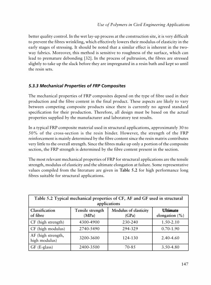
147
better quality control. In the wet lay-up process at the construction site, it is very difficultto prevent the fibres wrinkling, which effectively lowers their modulus of elasticity in theearly stages of stressing. It should be noted that a similar effect is inherent in the two-way fabrics. Moreover, this method is sensitive to roughness of the surface, which canlead to premature debonding [32]. In the process of pultrusion, the fibres are stressedslightly to take up the slack before they are impregnated in a resin bath and kept so untilthe resin sets.
5.3.3 Mechanical Properties of FRP Composites
The mechanical properties of FRP composites depend on the type of fibre used in theirproduction and the fibre content in the final product. These aspects are likely to varybetween competing composite products since there is currently no agreed standardspecification for their production. Therefore, all design must be based on the actualproperties supplied by the manufacturer and laboratory test results.
In a typical FRP composite material used in structural applications, approximately 30 to50% of the cross-section is the resin binder. However, the strength of the FRPreinforcement is mainly determined by the fibre content since the resin matrix contributesvery little to the overall strength. Since the fibres make up only a portion of the compositesection, the FRP strength is determined by the fibre content present in the section.
The most relevant mechanical properties of FRP for structural applications are the tensilestrength, modulus of elasticity and the ultimate elongation at failure. Some representativevalues compiled from the literature are given in Table 5.2 for high performance longfibres suitable for structural applications.
larutcurtsnidesuFGdnaFA,FCfoseitreporplacinahcemlacipyT2.5elbaTsnoitacilppa
noitacifissalCerbiffo
htgnertselisneT)aPM(
yticitsalefosuludoM)aPG(
etamitlU etamitlU etamitlU etamitlU etamitlU)%(noitagnole
)htgnertshgih(FC 0094-0034 042-032 01.2-05.1
)suludomhgih(FC 0945-0472 923-492 09.1-07.0
,htgnertshgih(FA)suludomhgih
0063-0023 031-421 06.4-04.2
)ssalg-E(FG 0053-0042 58-07 08.4-05.3
Use of Polymers in Civil Engineering Applications

148
Polymers in Construction
It should be noted that the fibre properties are based on short sample tests and are notrepresentative of the actual strength or stiffness of the final FRP product. The strength offibre bundles will be lower due to the higher probability of having micro defects in thelong fibres, differential load sharing among fibres, the relatively lower strength of theresin, and inability of fibres to redistribute loads at high stress levels. As a result, thefibre stress in an FRP composite is, on the average, 30 to 40% lower than the constituentfibre strength. The modulus of elasticity of an FRP composite may be approximated bythe rule of mixtures. If VF is the volume fraction (percentage of the cross-section), and EF
is the modulus of elasticity of long fibres used, and ER is the modulus of elasticity of theresin, the modulus of elasticity of FRP composite material, EFRP, can be approximated as:
EFRP = EFVF + ER (1-VF) � EFVF
Regardless of the type of fibres used, FRP materials display similar characteristic stress-strain behaviour: linear elastic up to ultimate strain followed by a brittle failure due torupture, as shown in Figure 5.13.
This brittle behaviour of FRP composites has some important consequences in structuralapplications. First, it may limit the desirable ductile behaviour of RC membersstrengthened with FRP composites. Secondly, the redistribution of stresses is restricteddue to this lack of ductility. Therefore, the design of structures bonded with FRPcomposites cannot follow the existing methods for RC structures by simply considering
Figure 5.13 Typical stress-strain curves for FRP and mild steel

149
FRP as equivalent steel reinforcement. Existing design methods for RC structures needto be modified to take this brittle behaviour into account.
The deformability of FRP composites covers a good portion of the ductile range ofsteel. The concrete or masonry members reinforced with FRP continue to gain strengthuntil rupture or compression failure of the concrete or masonry. However, as the FRPreinforcement ratios increase, the flexural members become progressively more andmore brittle.
Another important property of FRP composites to be considered in the design process istheir behaviour under shear. The shear strength of FRP composites is controlled by thebehaviour and the shear strength of the binding resin, and the shear strength of resinwhich is relatively very low compared to the tensile strength of fibres. The actual strengthof FRP composites is provided by the tensile strength of their constituent high performancefibres. Under shear forces, the high tensile stresses in one layer of fibres cannot be easilytransferred to the adjacent layers as a result of a phenomenon known as shear lag causedby the relatively low shear strength of the binding resin. Consequently, the shear strengthof FRP composites is relatively low compared to their tensile strength. For example, thesteel shear strength is about 45% of its tensile strength while the FRP shear strength isoften less than 10% of its tensile strength. This behaviour of FRP composites undershear must be taken into account in such cases as thick or deep FRP components whenthe stresses are applied on one face parallel to fibre direction or large diameter rods usedas a rebar in RC components in which the axial stress capacity of FRP reinforcementdrops rapidly with the increasing bar diameter [33].
A large number of tests have shown that the creep strength of CFRP is far superior tothat of other fibre composites. In a creep test performed on CFRP rods under alternatingload, no failure was observed in the rods up to a stress level of 70% of their short-termtensile strength after 10,000 hours [34]. In another experimental study, a creep strengthof 79% of their short-term tensile strength is extrapolated for CFRP rods for a period of50 years [35].
CFRP composites also have very high fatigue strength. In tests conducted with maximumstresses of up to 85% of their short-term tensile strength and amplitudes of up to 1,000MPa, more than 4 x 10⁵ load cycles were reached [36]. No fatigue failure and, in thesubsequent tensile tests, no reduction in the tensile strength was observed of CFRP rodsembedded in concrete after 4 x 10⁵ load cycles with an amplitude range of 5-50% oftheir short-term tensile strength and a frequency of 0.5 Hz [37].
All three types of FRP composites used in construction have relatively very low coefficientsof thermal expansion. It is nearly zero for CFRP in the fibre direction and AFRP even has
Use of Polymers in Civil Engineering Applications
150
Polymers in Construction
a negative coefficient of thermal expansion. Both theoretical and experimental studies,however, show that the thermal incompatibility between these FRP composites and theconcrete substrate do not cause any serious damage to the bond between them withinpractical limits of temperature variation [38]. However, a real problem is to be expectedat elevated temperatures approaching the glass transition temperature (Tg) of the epoxyused to bond the FRP composites to concrete surface. Typical Tg for epoxy is around80 °C, above that the bond performance degrades very rapidly and practically disappears.
5.3.4 Bond Strength of FRP-to-Concrete Joints
RC structures are strengthened by externally bonding FRP plates and sheets to its membersusing epoxy resin. For the externally bonded FRP to be effective in increasing the load-carrying capacity of the structure, effective stress transfer between the FRP compositeand the concrete is essential. The bond strength of FRP-to-concrete joints is a majorlimiting factor in exploiting the high strength of FRP composites for structural upgrading.
There is a considerable amount of experimental [39-43] and analytical [44-46] workreported in the literature on the bond strength of FRP-to-concrete joints. Based on theexperimental results and observations made during the experiments on RC beams andslabs strengthened for flexure, the types of bond failures can be broadly classified intotwo main categories: crack-induced interfacial debonding and the end-zone interfacialdebonding. In RC members subjected to bending, formation of flexural cracks is inevitableas the flexural capacity of the member is approached. Once such cracks are formed, theparts of FRP plate under the cracks are highly stressed. These stresses are transferred tothe concrete, which causes a concentration of shear stresses in the interface eventuallyleading to bond failure of the FRP-to-concrete joints under the cracks. This interfacialseparation progresses towards the less stressed regions as shown in Figure 5.14(a, b). Onthe other hand, high interfacial stresses also build up in the end zones of the FRP-to-concrete joints. Since the level of axial stress in the FRP plate is low near the ends, thestresses normal to the interface layer (peeling stresses) cause a premature bond failure byseparation of the FRP plate from the concrete surface (Figure 5.14(c)). The separation ofthe concrete cover is also possible in the end zones, as shown in Figure 5.14(d), in caseswhen the concrete strength is low or when the cover concrete is on the verge of spalling(breaking into chips) as a result of corrosion in the steel rebars. In the literature, this typeof failure is sometimes referred to as concrete cover rip-off failure, concrete coverdelamination, and concrete cover separation. Therefore, some extra measures are necessaryto anchor the externally bonded FRP plates in these end zones.
For FRP plates or sheets bonded to a concrete substrate, there is an effective bond lengthbeyond which any increase in the bonded length cannot increase the total load the bonded
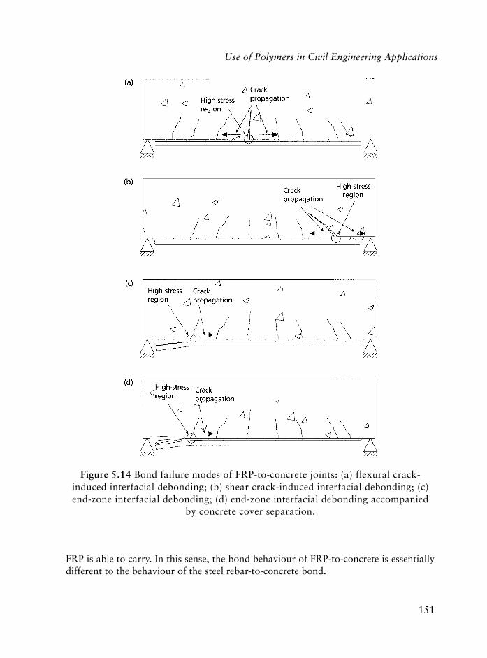
151
FRP is able to carry. In this sense, the bond behaviour of FRP-to-concrete is essentiallydifferent to the behaviour of the steel rebar-to-concrete bond.
Figure 5.14 Bond failure modes of FRP-to-concrete joints: (a) flexural crack-induced interfacial debonding; (b) shear crack-induced interfacial debonding; (c)end-zone interfacial debonding; (d) end-zone interfacial debonding accompanied
by concrete cover separation.
Use of Polymers in Civil Engineering Applications
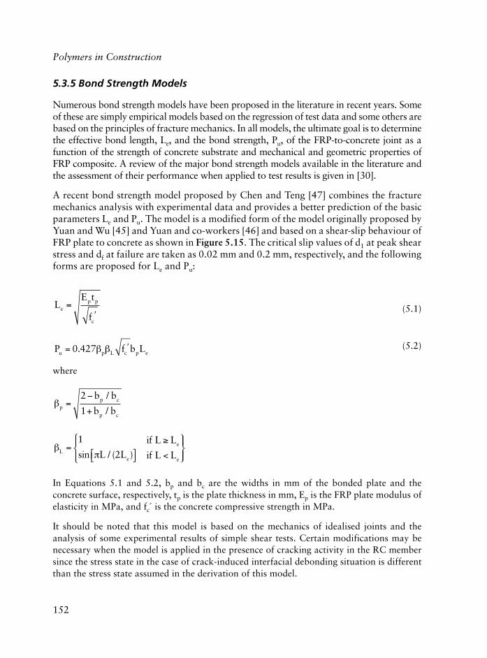
152
Polymers in Construction
5.3.5 Bond Strength Models
Numerous bond strength models have been proposed in the literature in recent years. Someof these are simply empirical models based on the regression of test data and some others arebased on the principles of fracture mechanics. In all models, the ultimate goal is to determinethe effective bond length, Le, and the bond strength, Pu, of the FRP-to-concrete joint as afunction of the strength of concrete substrate and mechanical and geometric properties ofFRP composite. A review of the major bond strength models available in the literature andthe assessment of their performance when applied to test results is given in [30].
A recent bond strength model proposed by Chen and Teng [47] combines the fracturemechanics analysis with experimental data and provides a better prediction of the basicparameters Le and Pu. The model is a modified form of the model originally proposed byYuan and Wu [45] and Yuan and co-workers [46] and based on a shear-slip behaviour ofFRP plate to concrete as shown in Figure 5.15. The critical slip values of d1 at peak shearstress and df at failure are taken as 0.02 mm and 0.2 mm, respectively, and the followingforms are proposed for Le and Pu:
LE t
fe
p p
c
=�
(5.1)
P f b Lu p L c p e= �0 427. (5.2)
where
pp c
p c
b b
b b=
�
+
2
1
/
/
L
e
e
eL L
if L L
if L L=
�� �
���
��
�
<
���
��
1
2sin / ( )
In Equations 5.1 and 5.2, bp and bc are the widths in mm of the bonded plate and theconcrete surface, respectively, tp is the plate thickness in mm, Ep is the FRP plate modulus ofelasticity in MPa, and fc´ is the concrete compressive strength in MPa.
It should be noted that this model is based on the mechanics of idealised joints and theanalysis of some experimental results of simple shear tests. Certain modifications may benecessary when the model is applied in the presence of cracking activity in the RC membersince the stress state in the case of crack-induced interfacial debonding situation is differentthan the stress state assumed in the derivation of this model.
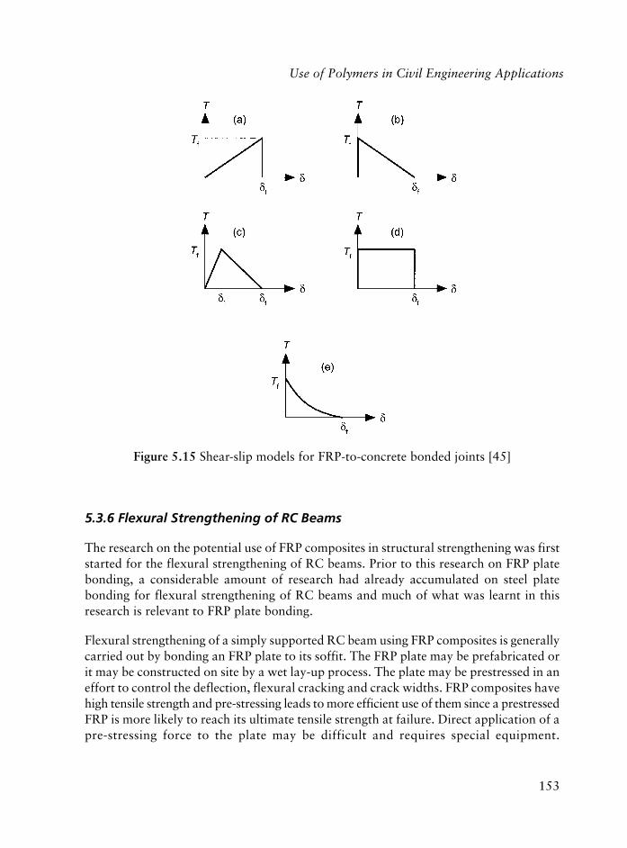
153
5.3.6 Flexural Strengthening of RC Beams
The research on the potential use of FRP composites in structural strengthening was firststarted for the flexural strengthening of RC beams. Prior to this research on FRP platebonding, a considerable amount of research had already accumulated on steel platebonding for flexural strengthening of RC beams and much of what was learnt in thisresearch is relevant to FRP plate bonding.
Flexural strengthening of a simply supported RC beam using FRP composites is generallycarried out by bonding an FRP plate to its soffit. The FRP plate may be prefabricated orit may be constructed on site by a wet lay-up process. The plate may be prestressed in aneffort to control the deflection, flexural cracking and crack widths. FRP composites havehigh tensile strength and pre-stressing leads to more efficient use of them since a prestressedFRP is more likely to reach its ultimate tensile strength at failure. Direct application of apre-stressing force to the plate may be difficult and requires special equipment.
Figure 5.15 Shear-slip models for FRP-to-concrete bonded joints [45]
Use of Polymers in Civil Engineering Applications

154
Polymers in Construction
However, a similar pre-stressing effect can be accomplished by bonding the FRP withoutthe presence of any service loads on the beam or even by negative loading of the RC beambefore the FRP bonding process. A detailed review of existing research on RC beamsstrengthened with prestressed FRP soffit plates is given by Hollaway and Leeming [48].
To prevent the end-zone debonding of the FRP soffit plate, special anchorage schemesare used. Relatively rigid steel plates placed over FRP plate and epoxy bonded to boththe plate and the RC member surface or the use of U-shaped FRP strips formed by a wetlay-up process are the common types of end anchorage (Figure 5.16).
Until very recently, the most pultruded FRP plates on the market were unidirectional(UD). However, a new generation of bi-directional (BD) pultruded FRP plates is nowavailable which make it possible to anchor the FRP soffit plates directly onto the RCmember surface by anchor bolts. A detailed summary of different anchorage schemesand experimental results are given by Hollaway and Mays [49].
In practical applications, mechanical end-zone anchorage of the FRP plate must beconsidered whenever possible. In some practical situations, end-zone anchorage in theform of FRP U strips may not be possible or effective as in the case of wide and/orshallow beams.
Figure 5.16 Anchorage schemes to prevent premature end-zone debonding

155
The risk of debonding can be reduced by a proper preparation of both the concrete andthe FRP surfaces and the use of a better quality adhesive for bonding. It is important tohave a clean and smooth concrete surface to utilise the high strength of the FRP to abetter extent. It is even more so in the case of wet lay-up process of forming a thin layerof FRP since their profile closely follows the uneven concrete surface. Under tension, thisthin and flexible layer of FRP tries to straighten itself. This, in turn, causes interfacialpeeling stresses to develop and eventually leads to premature debonding in the concreteadjacent to the adhesive-to-concrete interface [32]. Another point to observe in the surfacepreparation phase is the treatment of any existing cracks of the RC member. Such crackspromote the crack-induced debonding and must be filled by a proper procedure, forinstance by epoxy injection, before bonding FRP on to the surface. Failure can alsooccur at the FRP-to-adhesive interface with the pultruded FRP plates if the surface of theplate is not properly prepared. The new generation of pultruded FRP plates has a texturedsurface to increase the bond capacity and comes with a clean surface covered with aprotective film. The film is peeled off on the site just before the application.
Strong adhesives are available for FRP plate bonding, and their strengths are, in general,higher than that of concrete. Therefore, failure in the adhesive layer is, normally, not expectedand very rare. However, the use of a substandard adhesive or its improper application mayresult in an unexpected failure within the adhesive layer. Epoxy is the most commonly usedadhesive for bonding FRP to concrete surface. Insufficient mixing of its components and/or mixing incorrect proportions of the raw materials on the construction site is a seriouspotential source for obtaining a substandard adhesive. Special attention must be paid tothis point when a small amount of epoxy is needed while it is available in larger packages.
5.3.7 Shear Strengthening of RC Beams
Fibres running longitudinally along a beam do not make a significant contribution to theshear strength but they are helpful in limiting the shear crack width. Therefore, it isobvious that the longitudinal FRP bonded to the sides of a beam is not effective for shearstrengthening [50, 51]. Various FRP bonding schemes have been used to increase theshear capacity of RC beams. Bonding FRP to the sides only is the easiest but the leasteffective and is more vulnerable to debonding. The fibres may be oriented so as to bettercontrol the shear cracks. Considering the possibility of reversed cyclic loadings, the fibresmay also be oriented in two or even three directions. A better side-bonding alternative isthe use of FRP sheet U jackets (sides + tension face) formed by a wet lay-up process.These are less vulnerable to debonding provided the beam depth is sufficient to providea good bond length. The U jackets may be formed as intermittent strips or it may beformed by continuous sheets as shown in Figure 5.17. Another advantage of U jacketingis that they also act as mechanical anchors for the flexural FRP reinforcement.
Use of Polymers in Civil Engineering Applications
156
Polymers in Construction
Two major modes of failure have been observed in experiments on RC beamsstrengthened for shear with FRP composites. These are the shear failure with or withoutFRP rupture, and premature failure by FRP debonding. Failures with or without FRPrupture are essentially the same and signify the effective use of the FRP strength if thecorners are properly rounded to prevent stress concentrations. Premature failure byend-zone debonding of FRP can be delayed or even prevented by using some sort ofsupplementary anchoring of FRP at the end zones by, for example, steel plates andanchor bolts (Figure 5.18).
The idea in this scheme is to arrest the required anchorage force in the end zone byfirst transferring it to the steel plate glued over the FRP and then anchoring it toconcrete base by anchor bolts and as contact stresses between the plate and theconcrete base.
Figure 5.17 Various schemes for FRP shear strengthening

157
5.3.8 Strengthening of RC Slabs
As a flexural member, the behaviour of one-way slabs is very similar to flexural behaviourof beams and, as far as the FRP reinforcement is concerned, the behaviour of two-wayslabs can be taken as uncoupled bending in two orthogonal directions. It is probably forthis reason that there is much less work reported in the literature on the flexuralstrengthening of RC slabs using FRP composites.
The basic procedure of flexural strengthening of slabs using FRP composites is to bondFRP on the tension face of the slab. This bonding of FRP can be in the form of strips(Figure 5.19) or the entire surface of the slab can be covered with FRP sheets. However,FRP sheets covering the entire surface of the slab makes it difficult to control the bondquality and may increase the risk of bond deterioration by blocking the free movementof moisture out of the bond surface [52]. For a given amount of FRP material to bebonded to the slab surface, applying it in the form of strips rather than covering thewhole surface is more desirable. Similarly, the use of less number of wider strips as
Figure 5.18 End-zone anchoring of FRP by steel plates and anchor bolts
Use of Polymers in Civil Engineering Applications

158
Polymers in Construction
opposed to increased number of narrow strips as the former offers a larger contact areabetween the slab and the FRP and thus reduces the risk of debonding failures.
A recent study by Zhang and co-workers [53] shows that two-way slabs bonded with asteel plate in the central region and subjected to central point loads fails by formation ofyield lines around the perimeter of the bonded plate and along the diagonal lines in theunstrengthened part of the slab. Slabs bonded with an equivalent amount of FRP can beexpected to behave in a similar fashion. This observation suggests the idea of increasingthe span moment capacity of slabs by changing its yield line pattern (failure mechanism)as postulated by the lower bound theorem of plasticity. Therefore, it is possible to increasethe span moment capacity of slabs by strengthening part of it so as to push the yield linepattern away from the strengthened portion.
Strengthening RC slabs near the continuous support regions for negative moment presentsan extra difficulty regarding the anchorage of FRP in these regions. The slabs are usuallysubject to the greatest bending moment over the continuous supports and the FRP stripsor sheets cannot be terminated before ensuring proper anchorage. The difficulty ariseswhen there is a wall over the support, which is often the case, or an upturned edge beam.The simple idea of bending the FRP strips or sheets over the edge surface in a wet lay-upprocess was found to be ineffective in a test in which debonding of FRP from the wall
Figure 5.19 A two-way slab bonded with FRP strips for span moment.
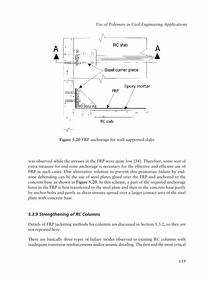
159
was observed while the stresses in the FRP were quite low [54]. Therefore, some sort ofextra measure for end-zone anchorage is necessary for the effective and efficient use ofFRP in such cases. One alternative solution to prevent this premature failure by end-zone debonding can be the use of steel plates glued over the FRP and anchored to theconcrete base as shown in Figure 5.20. In this scheme, a part of the required anchorageforce in the FRP is first transferred to the steel plate and then to the concrete base partlyby anchor bolts and partly as shear stresses spread over a larger contact area of the steelplate with concrete base.
5.3.9 Strengthening of RC Columns
Details of FRP jacketing methods for columns are discussed in Section 5.3.2, so they arenot repeated here.
There are basically three types of failure modes observed in existing RC columns withinadequate transverse reinforcements and/or seismic detailing. The first and the most critical
Figure 5.20 FRP anchorage for wall-supported slabs
Use of Polymers in Civil Engineering Applications

160
Polymers in Construction
failure mode is the shear failure manifested by inclined cracking, cover-concrete spalling,and rupture or opening of the transverse reinforcement eventually leading to brittle failureof the column. The second column failure mode, usually encountered in structures whenthey are subjected to severe seismic forces, is the formation of plastic hinges at the columnends due to high flexural stresses. The high flexural effects at column ends cause crushingand spalling of the cover-concrete and buckling of the longitudinal rebars. This mode offailure is usually caused by the lack of sufficient confinement in these regions. Finally,column failure in the regions of lap splices at the lower ends and rebar cut-off areas due toinsufficient splice length and/or confinement is also a common mode of failure.
Prior to early 1990s, constructing an additional shell around a deficient RC column inthe form of a reinforced concrete cage or a grout-injected steel jacket was a commonrehabilitation technique used by the engineers. In recent years, the use of FRP compositesfor the strengthening of RC columns has become increasingly popular among engineersand researchers [31, 55-57].
It is a well-established fact that lateral confinement of concrete can substantially enhanceits compressive strength and ductility [58-61] and it is beneficial to controlling, delayingand, in some cases, even preventing all three modes of failure mentioned above. Therefore,the most common form of FRP strengthening of columns involves external wrapping ofFRP sheets or straps around them.
Many researchers have studied the stress-strain behaviour of concrete confined withFRP composites. Enhancement in the compressive strength of concrete as a result ofexternal wrapping of FRP was first demonstrated by Fardis and Khalili [62, 63]. Althoughthe mechanical aspects of FRP confinement of concrete leading to an improvement in itsbehaviour is very similar to that of steel, there are some major differences between thetwo: One of the problems with FRP confinement of concrete is that the strength of FRPjacket cannot be fully utilised until the lateral strain in the confined concrete is very high.In some cases, the concrete will crush before the potential strength of FRP jacket is fullymobilised [65-67].
The idea of confining concrete by winding continuous resin-impregnated fibre strands aroundRC columns (filament winding) is another technique used for FRP strengthening of RCcolumns. In this process, an FRP jacket with controlled thickness, fibre direction and volumefraction can be obtained. This procedure is more appropriate for circular columns and usually,special computer-controlled winding machines are used for this purpose.
Existing RC columns can also be strengthened using prefabricated FRP shells. The shellsare prefabricated under controlled conditions using fibre strands or sheets. They can befabricated in half cylindrical or rectangular shells. They can also be fabricated in a closedform with a vertical slit so that they can be opened up and placed around the columns.

161
For the FRP confinement to be effective, a full contact between the column surface and theFRP shell is essential. This can be ensured by either bonding the shell directly on to theconcrete surface using adhesives, or injecting cement grout or mortar into the space betweenthe shell and the column.
Comparing the three approaches to column strengthening by FRP confinement ofconcrete, it is seen that external wrapping is by far the most commonly preferredapproach mainly because of its flexibility in coping with different column shapes andease in site handling.
Level of confinement provided by externally applied FRP shell depends on the shape ofthe column cross-section. Although it is very effective for circular and nearly circularcolumns, it is much less effective for rectangular columns especially if the aspect ratiois high. For rectangular columns, more effective confinement can be achieved bymodifying the column section into a circular or elliptical shape before FRP jacketing[69-70]. Prefabricated and slightly oversized circular or elliptical shells can also beused for this purpose in which the FRP shell also functions as a permanent formworkfor casting the additional concrete.
The confinement provided by externally applied FRP is normally passive in nature, inthat the confining effect cannot be started before a significant axial deformation of thecolumn is realised. However, the confinement provided by FRP can be made active byapplying some pretension to fibres during external wrapping or filament winding processand filling the gap between the RC columns and the slightly oversized FRP jacketaround them with expansive cement grout or pressure injected epoxy resin [68-70].
The rupture strains of FRP measured in recent tests on FRP-confined concrete cylindersare substantially below those from flat coupon tensile tests [71-73]. This discrepancyis attributed mainly to the curvature of the FRP jacket and the non-uniform deformationof concrete.
5.3.10 Strengthening of Masonry Walls and Infills
Unreinforced masonry buildings in which the masonry walls are the main load-bearingcomponents make up a good portion of the existing building stock worldwide. Amongmasonry structures, historic monumental structures are exceptionally important sincetoday’s society looks at these old buildings as a reminder of the past and the interestingarchitectural practices of past generations. Masonry is a strong construction materialunder compression or gravity loads. However, the bond between mortar and the masonryblock is normally quite low and does not provide comparable resistance to tensile, flexure,
Use of Polymers in Civil Engineering Applications
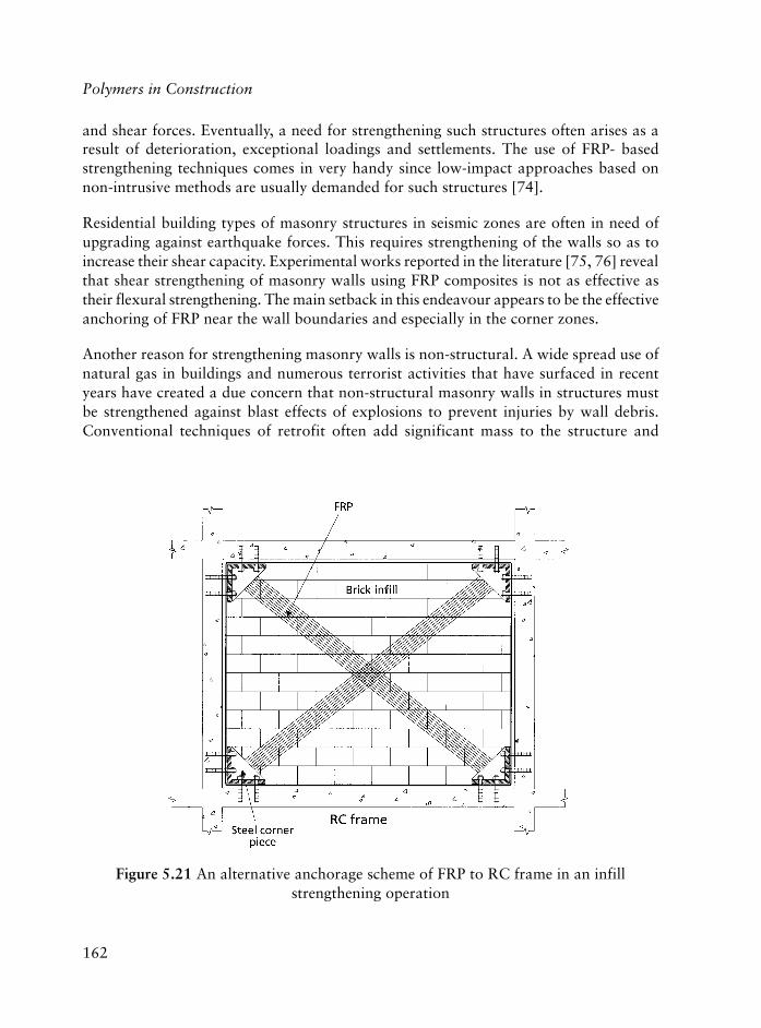
162
Polymers in Construction
and shear forces. Eventually, a need for strengthening such structures often arises as aresult of deterioration, exceptional loadings and settlements. The use of FRP- basedstrengthening techniques comes in very handy since low-impact approaches based onnon-intrusive methods are usually demanded for such structures [74].
Residential building types of masonry structures in seismic zones are often in need ofupgrading against earthquake forces. This requires strengthening of the walls so as toincrease their shear capacity. Experimental works reported in the literature [75, 76] revealthat shear strengthening of masonry walls using FRP composites is not as effective astheir flexural strengthening. The main setback in this endeavour appears to be the effectiveanchoring of FRP near the wall boundaries and especially in the corner zones.
Another reason for strengthening masonry walls is non-structural. A wide spread use ofnatural gas in buildings and numerous terrorist activities that have surfaced in recentyears have created a due concern that non-structural masonry walls in structures mustbe strengthened against blast effects of explosions to prevent injuries by wall debris.Conventional techniques of retrofit often add significant mass to the structure and
Figure 5.21 An alternative anchorage scheme of FRP to RC frame in an infillstrengthening operation

163
adversely affect the aesthetics of the upgraded area besides being costly, disturbing to theoccupants, and time-consuming. These disadvantages may be overcome by using FRPcomposites as reinforcing material [77]. Several investigations have indicated that flexuralstrength and ductility of un-reinforced masonry walls can be enhanced considerably byexternally bonded FRP reinforcement [78, 79].
Masonry walls are normally used as non-structural partition walls in most of the RCframe type of building structures. In seismic zones, observations after earthquakes revealthat these non-structural walls play an important role in resisting the earthquake forces.Probably, the most exciting use of FRP composites for structural strengthening in seismiczones is the potential of strengthening some of these masonry infill walls against sheareffects and, thus, turning them into lateral load-resisting shear walls for seismic upgrading.A major problem in this approach is to find an effective anchorage mechanism to transferlarge forces in the FRP composite to RC frame at the joints. One such alternative isshown in Figure 5.21.
References
1. ASTM D4439-02, Standard Terminology for Geosynthetics, 2002.
2. R.M. Koerner, Designing With Geosynthetics, Prentice Hall, Englewood Cliffs,NJ, USA, 1994.
3. D.I. Cook, Geosynthetics, Rapra Review Report No.158, Volume 14, No.2,Rapra Technology Ltd., Shrewsbury, UK, 2003.
4. R.D. Holtz, B.R. Christopher and R.R. Berg, Geosynthetic Design andConstruction Guidelines, Participant Notebook, US Federal HighwayAdministration, National Highway Institute, Washington, DC, USA, PublicationNo. FHWA HI-95-038, 1998.
5. T.S. Ingold, and K.S. Miller, Geotextiles Handbook, Thomas Telford, London,UK, 1988.
6. N.W.M. John, Geotextiles, Blackie and Son Ltd., Glasgow, UK, 1987.
7. S.F. Brown, Geosynthetics in Asphalt Pavements, International GeosyntheticsSociety, Easley, SC, USA, Mini Lecture Series, 2002.
8. Y. Ohama, Advances in Concrete Technology, Ed., V.M. Malhotra, Energy, Mines& Resources, Ottawa, Canada, 1992, p.775-805.
Use of Polymers in Civil Engineering Applications

164
Polymers in Construction
9. J.T. Dikeou, Progress in Concrete Technology, Ed., V.M. Malhotra, Energy,Mines & Resources, Ottawa, Canada, 1980, p.539-581.
10. Y. Ohama, Advanced Cement Based Materials, 1997, 5, 31.
11. ACI Comm. 548, Guide for Use of Polymers in Concrete, ACI, Farmington Hills,MI, USA, 1986, p.799-829.
12. J.J. Montana and J. Bartholemew in Applications of Polymer Concrete, SP-69,ACI, Farmington Hills, MI, USA, 1981, p.21-30.
13. V.I. Solomatov, Polymer-Cement Concretes and Polymer Concretes, AEC-tr-7147,Moscow, 1970, p.37-50.
14. P.F. Meyer in Applications of Polymer Concrete, SP-69, ACI, Farmington Hills,MI, USA, 1981, p.107-122.
15. R.C. Purisinski in Polymers in Concrete: International Symposium, SP-58, ACI,Farmington Hills, MI, USA, 1978, p.90-101.
16. J.B. Kardon, Journal of Materials in Civil Engineering, 1997, 9, 2, 85.
17. Y. Ohama, Cement and Concrete Composites, 1998, 20, 12-3, 89.
18. S. Marusin, Polymer Modified Concrete, Ed., D.W. Fowler, SP-99, ACI,Farmington Hills, MI, USA, 1987, p.135-150.
19. Y. Ohama, Handbook of Polymer-Modified Mortars and Concrete, NoyesPublications, 1995, Park Ridge, NJ, USA.
20. R. Bennington and P. Emmons, Concrete International, 1981, 3, 4, 24.
21. ASTM C494/C494M-04, Standard Specification for Chemical Admixtures forConcrete, 2004.
22. C. Jolicoeur and M-A. Simard, Cement and Concrete Composites, 1998, 20, 2-3, 87.
23. M. Collepardi, Concrete Admixtures Handbook: Properties, Science andTechnology, Ed., V.S. Ramachandran, Noyes Publications, Park Ridge, NewJersey, USA, 1995, p.116-210.
24. C. Jolicoeur, P-C. Nkinamubanzi, M-A. Simard and M. Piotte, Superplasticisersand Other Chemical Admixtures in Concrete, Ed., V.M. Malhotra, SP-119, ACI,Farmington Hills, MI, USA, 1994, p.63-88.

165
25. H. Uchikawa, S. Hanehara and D. Sawaki, Cement and Concrete Research,1997, 27, 1, 37-50,.
26. M.R. Rixom and N.P. Mailvaganam, Chemical Admixtures for Concrete,2nd Edition, E. & F.N. Spon, London, UK, 1986.
27. C.A. Vollick in Proceedings of an ASTM Symposium on the Effect of Water-Reducing Admixtures and Set-Retarding Admixtures on the Properties of FreshConcrete, San Francisco, CA, USA, 1960, p.180-200.
28. M. Collepardi and L. Massidda, in the Proceedings of Hydraulic Cement Pastes:Their Structure and Properties, Sheffield, UK, 1976, p. 256-267,.
29. P.K. Mehta and P.J.M. Monteiro, Concrete: Structure, Properties and Materials,2nd Edition, Prentice Hall, Paramus, NJ, USA, 1992.
30. J.G. Teng, J.F .Chen, S.T. Smith and L. Lam, FRP Strengthened RC Structures,John Wiley & Sons, Ltd., Chichester, West Sussex, UK, 2002.
31. State-of-the Art Report on Fibre Reinforced Polymer (FRP) Reinforcement forConcrete Structures, Report No. ACI 440R-96, ACI, Farmington Hills, MI,USA, 1996.
32. U. Meier, Construction and Building Materials, 1995, 9, 6, 341.
33. S. Faza and H. GangaRao, Fibre-Reinforced-Plastic (FRP) Reinforcement forConcrete Structures: Properties and Applications, Ed., A. Nanni, Elsevier,Amsterdam, The Netherlands, 1993, p.167-188.
34. C. W. Dolan, B. L. Leu and A. Hundley, Proceedings of the Third InternationalSymposium on Non-Metallic (FRP) Reinforcement for Concrete Structures,Sapporo, Japan, 1997, Session 2, p.187.
35. N. Ando, H. Matsukawa, A. Hattori and M. Mashima, Proceedings of the ThirdInternational Symposium on Non-Metallic (FRP) Reinforcement for ConcreteStructures, Sapporo, Japan, 1997, Session 2, p.203-210.
36. T. Uomoto, T. Nishimura and H. Ohga, Proceedings of the Second International(RILEM) Symposium on Non-Metallic (FRP) Reinforcement for ConcreteStructures, Ghent, Belgium, 1995, p.100-107.
37. R. Adini, H. Rahman, B. Benmokrane and K. Kobayashi in Proceedings of theSecond International Conference on Composites in Infrastructure, ICCI 98,Tucson, AZ, USA, 1998, Session 2, p.203-210.
Use of Polymers in Civil Engineering Applications

166
Polymers in Construction
38. F. S. Rostasy, Assessment of the Suitability of CRP Plates from S&P CRP Systemfor Use as Adhesive-Bonded Reinforcement to Strengthen ConcreteConstructional Elements and Bases of Assessment for Their General Approval bythe Construction Supervisory Authorities, Expert Opinion No.98/0322, S&PReinforcement, Technical University of Braunschweig, Germany, 1998.
39. M.J. Chajes, W.W. Finch, T.F. Januszka and T.A. Thomson, ACI StructuralJournal, 1996, 93, 2, 295.
40. L. Bisindavyi and K.W. Neale, Journal of Composites for Construction, 1999, 3,4, 153.
41. R.N. Swamy, R. Jones and A. Charif in Proceedings of an International RILEMSymposium on Adhesion Between Polymers and Concrete: Bonding, Protectionand Repair, Ed., H.R. Sassed, Chapman and Hall, London, UK, 1986, p.741.
42. T. Maeda, Y. Asano, Y. Sato, T. Ueda and Y. Kakuta in Proceedings of the ThirdInternational Symposium on Non-Metallic (FRP) Reinforcement for ConcreteStructures, Sapporo, Japan, 1997, Session 1, p.279-285.
43. U. Neubauer and F.S. Rostasy in Proceedings of the Seventh InternationalConference on Structural Faults and Repairs, Ed., M. C. Forde, EdinburghUniversity Press, Edinburgh, UK, p.109-118.
44. T.C. Triantafillou and N. Plevris, Materials and Structures, 1992, 25, 201.
45. H. Yuan and Z. Wu, in Proceedings of Symposium of China and Japan, Scienceand Technology of 21st Century, Tokyo, Japan, 1999, p.142.
46. H. Yuan, Z.S. Wu and H. Yoshisawa, Journal of Structural Mechanics andEarthquake Engineering, 2001, 675, I-55, 27.
47. J.F. Chen and J.G. Teng, Journal of Structural Engineering, 2001, 127, 7, 784.
48. L.C. Hollaway and M.B. Leeming in Strengthening of Reinforced ConcreteStructures: Using Externally-Bonded FRP Composites in Structural and CivilEngineering, Ed., L.C. Hollaway and M.B. Leeming, Woodhead Publishing,Cambridge, UK, 1999, Chapter 2.
49. L.C. Hollaway and G.C. Mays, Strengthening of Reinforced Concrete Structures:Using Externally-Bonded FRP Composites in Structural and Civil Engineering,Ed., L.C. Hollaway and M.B. Leeming, Woodhead Publishing, Cambridge, UK,1999, Chapter 4.
50. M.J. Chajes, T.F. Januszka, D.R. Mertz, T.A. Thomson and W.W. Finch, ACIStructural Journal, 1995, 92, 3, 295.
167
51. A. Khalifa, G. Tumialan, A. Nanni and A. Belarbi in Proceedings of the FourthInternational Symposium on Fibre Reinforced Polymer Reinforcement (FRP) forReinforced Concrete Structures, Eds., C.W. Dolan, S.H. Rizkalla and A. Nanni,American Concrete Institute, Farmington Hills, MI, USA, 1999, p.995-1008.
52. V.M. Karbhari, F. Seible, W. Seim and A. Vasquez in Proceedings of the FourthInternational Symposium on Fibre Reinforced Polymer Reinforcement (FRP) forReinforced Concrete Structures, Eds., C.W. Dolan, S.H. Rizkalla and A. Nanni,American Concrete Institute, Farmington Hills, MI, USA, 1999, p.1163-1173
53. J.W. Zhang, J.G. Teng, Y.L. Wong and Z.T. Lu, Journal of StructuralEngineering, 2001, 127, 4, 390.
54. J.G. Teng, L. Lam, W. Chan and J. Wang, Journal of Composites forConstruction, 2000, 4, 2, 75.
55. C. Ballinger, T. Maeda and T. Hoshijiama, Proceedings of Fibre-Reinforced-Plastic Reinforcement for Concrete Structures International Symposium, SP-138,ACI, Farmington Hills, MI, USA, 1993, p.243-248.
56. H. Saadatmanesh, M.R. Ehsani and L. Jin, ACI Structural Journal, 1996, 93, 6, 639.
57. F. Seible, M.J.N. Priestley, G.A. Hegemier and D. Innamorato, Journal ofComposites for Construction, 1997, 1, 2,52.
58. F.E. Richart, A. Brandtzaeg and R.L. Brown, A Study of the Failure of Concreteunder Combined Compressive Stresses, University of Illinois, EngineeringExperimental Station Bulletin, Illinois, USA, 1928.
59. F.E. Richart, A. Brandtzaeg and R.L. Brown, The Failure of Plain and SpirallyReinforced Concrete in Compression, University of Illinois, EngineeringExperimental Station Bulletin, Illinois, USA, 1929.
60. S.H. Ahmad and S.P. Shah, ACI Journal, 1982 79, 6, 448.
61. J.B. Mander, M.J.N. Priestley and R. Park, Journal of Structural Engineering,1988, 114, 8, 1804.
62. M.N. Fardis and H. Khalili, ACI Journal, 1981, 78, 6, 440.
63. M.N. Fardis and H. Khalili, Magazine of Concrete Research, 1982, 34, 121, 191.
64. A. Mirmiran and M. Shahawy, Journal of Structural Engineering, 1997, 123, 5, 583.
Use of Polymers in Civil Engineering Applications

168
Polymers in Construction
65. M. Samaan, A. Mirmiran and M. Shahawy, Journal of Structural Engineering,1998, 124, 9, 1025.
66. M. Saafi, H.A. Toutanji and Z. Li, ACI Materials Journal, 1999, 96, 4, 500.
67. M.R. Spoelstra and G. Monti, Journal of Composites for Construction, 1999, 3, 3, 143.
68. M.J.N. Priestley and F. Seible, Construction and Building Materials, 1995, 9, 6, 365.
69. H. Saadatmanesh, M.R. Ehsani and L. Jin, Earthquake Spectra, 1997, 13, 2, 281.
70. H. Saadatmanesh, M.R. Ehsani and L. Jin, ACI Structural Journal, 1996, 93, 6, 639.
71. M. Shahaway, A. Mirmiran and T. Beitelman, Composites Part B: Engineering,2000, 31, 6-7, 471.
72. S. Pessiki, K.A. Harries, J.T. Kestner, R. Sause and J.M. Ricles, Journal ofComposites for Construction, 2001, 5, 4, 237.
73. L. Lam and J-G. Teng in Proceedings of the Sixth International Symposium onFRP Reinforcement for Concrete Structures, Ed., K. H. Tan, World ScientificPublishers, Hong Konk, 2003, Volume 1, p.601-612.
74. T.C. Triantafillou in Proceedings of the International Conference on FRPComposites in Civil Engineering (CICE), Hong Kong, China, Ed., J-G. Teng,Elsevier, Oxford, UK, 2001, p.959-965.
75. S. Russo, R. Gottardo and D. Codato in Proceedings of the Sixth InternationalSymposium on FRP Reinforcement for Concrete Structures, Ed., K.H. Tan, WorldScientific Publishers, Hong Kong, 2003, Volume 2, p.1239-1248.
76. X.L. Gu, Y. Ouyang, W.P. Zhang and F.F. Ye, Proceedings of the Sixth InternationalSymposium on FRP Reinforcement for Concrete Structures, Ed., K.H. Tan, WorldScientific Publishers, Hong Konk, 2003, Volume 2, p.1259-1268.
77. T.C. Triantafillou, Journal of Composites for Construction, 1998. 2, 2, 96.
78. L.M. Albert, E.E. Alaa and J.J.R. Chang, Journal of Composites forConstruction, 2001, 5, 2, 76.
79. V. Turco, N. Galati, G. Tumialan and A. Nanni in Proceedings of the SixthInternational Symposium on FRP Reinforcement for Concrete Structures, Ed.,K.H. Tan, World Scientific Publishers, Hong Konk, 2003, Volume 2, p.1219-1228.

169
6 Plastics and Plastics Composites: A Perspectiveon their Chemistry and Mechanics
Leyla Aras and Guneri Akovali
6.1 Chemistry of Plastics
It can be considered that the mid 20th century into the 21st century will be known as theage of synthetics; these are plastics, man-made fibres, synthetic rubbers, sealants, caulkingcompounds, composite materials and synthetic adhesives. In general, the properties ofplastics are intermediate between those of fibres and elastomers with many overlappingproperties, so, typical plastics may have cohesive energies higher than those of elastomersbut lower than those of fibres. Thus plastics exhibit some flexibility and hardness withvarying degrees of crystallinity.
Completely synthetic polymers, such as Bakelite, were first produced in 1909. ChemicallyBakelite is phenol formaldehyde resin produced when phenol and the gas formaldehydeare combined in the presence of a catalyst. This product is used today in certain engineeringapplications. Now it is possible to adapt polymers and to create new ones which can bedesigned for specific functions. Polymers, together with metals and ceramics representthe essential engineering materials in the construction of buildings, household articles ofall kinds, vehicles, engines, etc. The main factors responsible for the rapid growth ofthese engineering materials are [1]:
(a) The availability of basic raw materials: the sources of production are coal, oil, wood,agriculture and forest wastes
(b) The ensemble of technical properties specific for polymers: lightweight, chemicalstability, elasticity, etc.
(c) Easy processing using techniques such as extrusion, thermoforming, injectionmoulding, calendering, casting, etc.
6.1.1 Molecular Weight
A polymer is a large molecule, i.e., a macromolecule consisting of a large number ofrepeating small, simple chemical units called monomers covalently bonded to form a
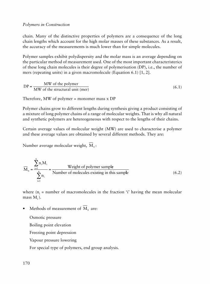
170
Polymers in Construction
chain. Many of the distinctive properties of polymers are a consequence of the longchain lengths which account for the high molar masses of these substances. As a result,the accuracy of the measurements is much lower than for simple molecules.
Polymer samples exhibit polydispersity and the molar mass is an average depending onthe particular method of measurement used. One of the most important characteristericsof these long chain molecules is their degree of polymerisation (DP), i.e., the number ofmers (repeating units) in a given macromolecule (Equation 6.1) [1, 2].
DP =MW of the polymer
MW of the structural unit (mer) (6.1)
Therefore, MW of polymer = monomer mass x DP
Polymer chains grow to different lengths during synthesis giving a product consisting ofa mixture of long polymer chains of a range of molecular weights. That is why all naturaland synthetic polymers are hetereogeneous with respect to the lengths of their chains.
Certain average values of molecular weight (MW) are used to characterise a polymerand these average values are obtained by several different methods. They are:
Number average molecular weight, Mn :
M
n M
nn
i i
i
n
i
i
n= ==
=
�
�1
1
Weight of polymer sampleeNumber of molecules existing in this samplle (6.2)
where (ni = number of macromolecules in the fraction ‘i’ having the mean molecularmass Mi ).
• Methods of measurement of Mn are:
Osmotic pressure
Boiling point elevation
Freezing point depression
Vapour pressure lowering
For special type of polymers, end group analysis.

171
Plastics and Plastics Composites: A Perspective on their Chemistry and Mechanics
• Weight average molecular weight, Mw:
M
n M
n Mw
i i
i
n
i i
i
n= =
=
�
�
2
1
1
(6.3)
Mw is determined experimentally by light scattering, which depends on the size and
the mass of the molecules.
• Z-average molecular weight, Mz:
Mz is expressed mathematically as:
M
n M
n Mz
i i
i
n
i i
i
n= =
=
�
�
3
1
2
1
(6.4)
• Viscosity average molecular weight, Mv:
The Mark-Houwink equation defines the viscosity average molecular mass as:
�[ ] = K Mv
a_(6.5)
where:
[�] = intrinsic viscosity
k and a = constants which depend on the nature of polymer, temperature, and solvent.
��[ ] =
�limc
spc0
(6.6)
� ���
� ��sp rel= = � =�
�10
0
01 (6.7)

172
Polymers in Construction
where:
�sp = specific viscosity�rel = relative viscosity� = the viscosity of the solution�0 = the viscosity of the solventc = the concentration of the polymer in the solution (g/100 cm3)
MM
w
n is used to determine the spread of the molecular weight distribution of the polymerthat is the polydispersity and the ratio is called the heterogeneity index, (HI). HI isclose to one for a narrow polydispersity, and it may increase to 3-10 for a broadmolecular mass distribution.
6.1.2 Synthesis of Polymers
6.1.2.1 Condensation Polymerisation
Carothers in 1929 made the classical subdivision of polymers into two main groups,condensation and addition polymers. Condensation polymers, are characteristicallyformed by reactions involving the elimination of a small molecule, such as water, in eachstep. Polyester formation is a good example of this type of polymerisation. Bifunctionalmonomers react with each other with the elimination of water as shown in Reaction 6.1.
In addition polymers, no loss of small molecules takes place. The most important group ofaddition polymers are synthesised from unsaturated vinyl monomers, see Reaction 6.2.
xHO R OH + xHOCO R� COOH
HO R OCO R� COO H + (2x-1)H2Ox
Reaction 6.1
Reaction 6.2
H2C CH
X
CH2 CH CH2 CH
X X

173
Later in the 1950s, Mark classified polymerisation without considering the loss of asmall molecule or type of inter unit linkage. To avoid confusion, he based hisclassification on the basis of mechanism and used step reaction and chain reactionwhere step-growth and chain-growth polymerisation are also very commonly used.Table 6.1 summarises the main differences between chain and step polymerisationmechanisms [2-4].
Some examples of commercially important step-growth polymerisations together withnon condensation step-growth polymerisations are illustrated in Figure 6.1.
6.1.2.2 Chain (Addition) Polymerisation
In this type of polymerisation an initiating molecule is required so that it can attack amonomer molecule to start the polymerisation. This initiating molecule may be a radical,anion or cation. Chain growth polymerisation is initiated by free-radical, anion or cationproceeded by three steps: initiation, propagation and termination. The chemical natureof the substituent group determines the mechanism.
• Initiation
Initiation in a free radical polymerisation consists of two steps.
smsinahcemnoitasiremylop-petsdna-niahcfoserutaefgnihsiugnitsiD1.6elbaT
noitasiremylopniahC noitasiremyloppetS
gnitaepersddanoitcaerhtworgylnO.niahcehtotemitataenostinu
nactneserpseicepsralucelomowtynA.tcaer
sesaercednoitartnecnocremonoM.noitcaerehttuohguorhtylidaets
ta:noitcaerniylraesraeppasidremonoM.sniamerremonom%1nahtssel,01PDa
remyloP.ecnotademrofsiremylophgiHelttilsegnahcthgiewralucelom
.noitcaerehttuohguorht
ylidaetssesirthgiewralucelomremyloP.noitcaerehttuohguorht
tubsdleiyhgihevigsemitnoitcaergnoL.elttilthgiewralucelomtceffa
otlaitnesseerasemitnoitcaergnoL.sthgiewralucelomhgihniatbo
ylnosniatnocerutximnoitcaeRyrevadna,remylophgih,remonom
.sniahcgniworgfotnuomallams
eraseicepsralucelomllaegatsynatA.noitubirtsidelbaluclacanitneserp
noitasiremylopfoeergeD:PD
Plastics and Plastics Composites: A Perspective on their Chemistry and Mechanics
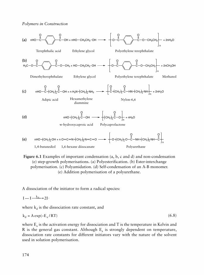
174
Polymers in Construction
A dissociation of the initiator to form a radical species:
I I Ikd— � ��� �2
where kd is the dissociation rate constant, and
k A E RTd a= �exp( / ) (6.8)
where Ea is the activation energy for dissociation and T is the temperature in Kelvin andR is the general gas constant. Although Ea is strongly dependent on temperature,dissociation rate constants for different initiators vary with the nature of the solventused in solution polymerisation.
Figure 6.1 Examples of important condensation (a, b, c and d) and non-condensation(e) step-growth polymerisations. (a) Polyesterification. (b) Ester-interchange
polymerisation. (c) Polyamidation. (d) Self-condensation of an A-B monomer.(e) Addition polymerisation of a polyurethane.
C CnHO
O O
OH + nHO CH2CH2 OH O C C
O
O CH2CH2
O
n
+ 2nH2O
H3C O C
O
C
O
O CH3 + HO CH2CH2 OH O C C
O
O CH2CH2
O
n
+ 2nCH3OH
nHO C
O
CH2 C
O
OH + n H2N CH2 NH24 6C
O
CH2 C
O
HN4 CH2 NH6 n+ 2nH2O
nHO CH2 C
O
OH6
CH2 C
O
O6 n
+ nH2O
nHO CH2 OH + n O4
C N CH2 N C O6
O CH2 O C4
n
O
NH CH2 NH C
O
6
Terephthalic acid Polyethylene terephthalateEthylene glycol
Dimethylterephthalate Ethylene glycol Polyethylene terephthalate Methanol
Adipic acid Hexamethylenediammine
Nylon-6,6
w-hydroxycaproic acid Polycaprolactone
1,4-butanediol 1,6-hexane diisocanate Polyurethane
(a)
(b)
(c)
(d)
(e)

175
Some commonly used initiators for free-radical polymerisations include azo (-N=N-),disulfide (-S-S-) or peroxide (-O-O-) groups, (i.e., dissociation of 2,2�-azobis(isobutyronitrile) which yields nitrogen and two cyanoisopropyl radicals), see Reaction 6.3.
• Association
A monomer molecule (M) is attached to the initiator radical:
I M � + � �� �ka IM
where ka is a rate constant for monomer association, and
CH3 C
C
CH3
N
+ N2C CHka CH3 C
C
CH3
N
CH2 CH
where M is a (styrene) monomer.
• Propagation
In this step, additional monomer units are added to the initiated monomer species:
IM M
M
� + � �� �
� + � �� �
k
Xk
X
p
p
IMM
IM IM M
where kp is propagation rate constant.
H3C C
C
CH3
N
N
N C
C
CH3
N
CH3Heat
2CH3 C
C
CH3
N
+ N2
Reaction 6.3
Plastics and Plastics Composites: A Perspective on their Chemistry and Mechanics
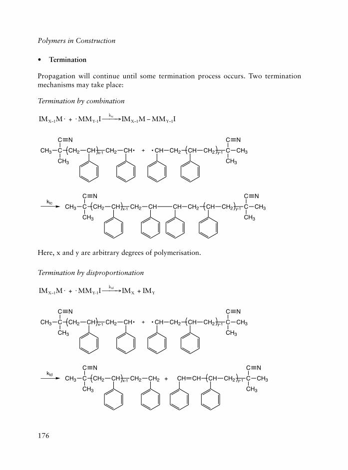
176
Polymers in Construction
• Termination
Propagation will continue until some termination process occurs. Two terminationmechanisms may take place:
Termination by combination
IM M I IM M MM IX
k
X Ytc
� � �� � � �� �1 1 1+ MMY-1
CH3 C
C
CH3
CH2
N
CH CH2 CHx-1 + CH CH2 CH CH2 Cy-1
C
CH3
CH3
N
CH3 C
C
CH3
CH2
N
CH CH2 CHx-1 CH CH2 CH CH2 Cy-1
C
CH3
CH3
Nktc
Here, x and y are arbitrary degrees of polymerisation.
Termination by disproportionation
IM M I IM IMX
k
X Ytd
� � � � ��1 + MM +Y-1
CH3 C
C
CH3
CH2
N
CH CH2 CHx-1 + CH CH2 CH CH2 Cy-1
C
CH3
CH3
N
CH3 C
C
CH3
CH2
N
CH CH2 CH2 +x-1 CH CH CH2 Cy-1
C
CH3
CH3
Nktd
CH

177
Plastics and Plastics Composites: A Perspective on their Chemistry and Mechanics
As seen from the termination reactions, cyanoisopropyl groups cap both ends of thechain in the case of termination by combination, one end of the chain is capped intermination by disproportionation.
In addition to termination by combination and disproportionation, chain transfer reactionalso terminates a growing chain. Chain transfer occurs by hydrogen abstraction from aninitiator, monomer, polymer or solvent molecule [2-4].
IM M S IM SXk
Xtr
� �� � ��� �1 1 + H MH +
6.1.2.3 Anionic Polymerisation
Monomers with an electron withdrawing group can polymerise by an anionic pathway.The initiator in anionic polymerisation may be any strong nucleophile including Grignardreagents and other organometallic compounds like n-butyl (n-C4H9) lithium. Initiationof styrene is given as an example, see Reaction 6.4.
Bu-Li+ + H2C CH Bu CH2 CH- Li+
Carbanion Counter ion
Reaction 6.4
Propagation takes place by insertion of additional styrene monomers between thecarbanion and counterion. Under very pure conditions including the absence of waterand oxygen, propagation can proceed indefinitely or until all the monomer is consumed.For this reason, anionic polymerisation is sometimes called ‘living’ polymerisation. Inanionic polymerisation, termination occurs only by the deliberately added oxygen, carbondioxide, methanol or water into the reaction medium as shown in Reaction 6.5.
Bu CH2 CH CH2 CH- Li+ + HOH Bu CH2 CH CH2 CH2 + Li+OH-x-1 x-1
Reaction 6.5

178
Polymers in Construction
In typical free radical polymerisation, polydispersity is above 2 and as high as 20. Inanionic polymerisation, the absence of termination due to a living polymerisation, maycause very narrow molecular weight distribution with polydispersities as low as 1.06.
6.1.2.4 Cationic Polymerisation
Monomers with an electron donating group follow a cationic pathway. Unlike free radicaland anionic polymerisations, initiation in cationic polymerisation uses a true catalystthat is restored at the end of the polymerisation and thus not incorporated into theterminated polymer-chain. A strong Lewis acid, such as H+, BF3 or AlCl3 can be used asa catalyst. A cocatalyst, e.g., water, is also required to provide the actual proton sourcein some cases. Cationic polymerisation of isobutylene is given in Reaction 6.6.
BF3.H2O + H2C C
CH3
CH3
C+[BF3OH]-CH3
CH3
H3C
Boron trifluoride Isobutylene
Reaction 6.6
Proton addition yields an isobutylenecarbonium ion. BF3OH is the counterion or gegenion. Propagation is as shown in Reaction 6.7.
C+[BF3OH]- + H2C
CH3
CH3
H3C C
CH3
CH3
C
CH3
CH3
H3C CH2 C+[BF3OH]-CH3
CH3
Reaction 6.7
Termination is similar to anionic polymerisation termination and transfer to counter ionis represented in Reaction 6.8.
Polyisobutylene
H3C C
CH3
CH3
(CH2 C)x
CH3
CH3
CH2 C+[BF3OH]-CH3
CH3
H3C C
CH3
CH3
(CH2 C)x
CH3
CH3
CH C + H+[BF3OH]-CH3
CH3
Reaction 6.8
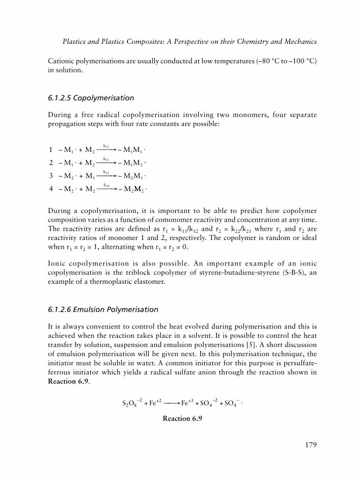
179
Plastics and Plastics Composites: A Perspective on their Chemistry and Mechanics
Cationic polymerisations are usually conducted at low temperatures (–80 °C to –100 °C)in solution.
6.1.2.5 Copolymerisation
During a free radical copolymerisation involving two monomers, four separatepropagation steps with four rate constants are possible:
1
2
~ ~
~ ~
M M M M
M M M M
k
k
1 2 1 1
1 2 1 2
11
12
� + � �� �
� + � �� ��
� + � �� �
� + � ��
3
4
~ ~
~ ~
M M M M
M M M
k
k
2 1 2 1
2 2 2
21
22 MM2 �
During a copolymerisation, it is important to be able to predict how copolymercomposition varies as a function of comonomer reactivity and concentration at any time.The reactivity ratios are defined as r1 = k11/k12 and r2 = k22/k21 where r1 and r2 arereactivity ratios of monomer 1 and 2, respectively. The copolymer is random or idealwhen r1 = r2 = 1, alternating when r1 = r2 = 0.
Ionic copolymerisation is also possible. An important example of an ioniccopolymerisation is the triblock copolymer of styrene-butadiene-styrene (S-B-S), anexample of a thermoplastic elastomer.
6.1.2.6 Emulsion Polymerisation
It is always convenient to control the heat evolved during polymerisation and this isachieved when the reaction takes place in a solvent. It is possible to control the heattransfer by solution, suspension and emulsion polymerisations [5]. A short discussionof emulsion polymerisation will be given next. In this polymerisation technique, theinitiator must be soluble in water. A common initiator for this purpose is persulfate-ferrous initiator which yields a radical sulfate anion through the reaction shown inReaction 6.9.
S O Fe Fe SO SO2 82 2 3
42
4� + + � �+ � �� + + �
Reaction 6.9

180
Polymers in Construction
The essential ingredients for emulsion polymerisation are:
• Monomer
• Emulsifying agent
• Water
• Water soluble initiator
• Surfactant (normally an amphipathic long chain fatty acid salt with a hydrophilic‘head’ and a hydrophobic ‘tail’)
Aggregates or micelles (0.1 to 0.3 μm long) are formed in water consisting of 50 to100 molecules oriented with the tails inwards, creating an interior hydrocarbonenvironment and a hydrophilic surface of heads in contact with water. Theconcentration of micelles must exceed ‘critical micelle concentration’. Radicals diffusethrough the aqueous phase and penetrate both the micelles and the droplets. Thepolymerisation takes place in the micelle interior. Figure 6.2 represents an emulsionpolymerisation system.
Figure 6.2 Schematic representation of a emulsion polymerisation system

181
Plastics and Plastics Composites: A Perspective on their Chemistry and Mechanics
6.1.3 Classification
There are many ways of classifying of polymers because of the diversity of function andstructure found in the field of macromolecules. One way of doing this is shown in Figure6.3 [1, 2].
Synthetic polymers may be classified according to their:
• Monomer type
• Preparative techniques
• Polymer structure
• Physical properties
• Processing techniques
• End uses (associated with specific industries such as fibre, rubber, film, etc).
The thermosetting materials become permanently hard when heated above a criticaltemperature and will not soften again on reheating (crosslinked). The thermoplasticpolymer will soften when heated above its glass transition temperature (Tg) [1] and canbe shaped and keeps its shape when cooled. This process is reversible.
A more comprehensive classification divides polymers into:
• Organic polymers
• Semi-organic polymers
• Mineral polymers (inorganic)
Figure 6.3 General Classification of Polymers

182
Polymers in Construction
Organic polymers consist of carbon (C), hydrogen (H), oxygen (O), nitrogen (N), sulfur(S), halogen atoms, and O, N, or S in some cases can be on the backbone chain. Semi-organic polymer chains contain carbon atoms and heteroatoms. For example,poly(dimethyl siloxane), see Figure 6.4.
Si O
CH3
CH3
Si O
CH3
CH3
Si O
CH3
CH3
Figure 6.4 Poly(dimethyl siloxane)
Inorganic polymers do not contain carbon atoms, all the elements of group IV can formlinear chains analogous to those of polyethylene, see Figure 6.5.
Si Si Si Si Si
H H H H H
HHHHH
Ge
H
H
Ge Ge Ge Ge
H
H
H
H
H
H
H
H
Polysilanes Polygermanes
Figure 6.5 Polysilanes and Polygermanes
Polymers may also be classified according to their geometrical shapes:
• Linear (Figure 6.6) and branched (Figure 6.7) polymers.
A A A A A A A A A A A A A A A A
A
A
A
A
A
Figure 6.7 Branched PolymerFigure 6.6 Linear Polymer
(A being the mer, the unit of the chain)

183
• Bi-dimensional network (i.e., graphite lattice).
• Three-dimensional network polymers, as shown in Figure 6.8.
A A A A A A A A A
A
A
A
A
A
A A A AAAAAA
A
AA
A
Figure 6.8 Crosslinked Polymer
6.1.4 Physical Structure
Chain structures of polymers strongly influence the properties of polymers. A three-dimensional arrangement of monomers along the chain is very important and alters theproperties of the polymer to a certain extent. The following terms are most commonlyused to explain the sequential arrangements of monomers along the chain.
A conformation describes the geometric arrangement of atoms in the polymer chain andconfiguration denotes the stereochemical arrangement of atoms. Conformation of apolymer chain can be altered by rotation of atoms while configuration of a polymerchain cannot be altered without breaking chemical bonds [2, 5, 7].
Tacticity of a polymer is related to its configuration. If R represents a substituent group,it may have several different placements as it repeats along the chain. In one configuration,all the R groups may lie on the same side of the plane formed by the extended-chainbackbone. Such polymers are called isotactic. If the substituent groups regularly alternatefrom one side of the plane to the other, the polymer is syndiotactic. Polymers with randompreferred placement are atactic.
6.1.4.1 Crystalline State
Under suitable conditions, some polymers cooled from the melt can organise into regularcrystalline structures and they have less perfect organisation than crystals of low molecularweight substances.
Plastics and Plastics Composites: A Perspective on their Chemistry and Mechanics

184
Polymers in Construction
The basic units of crystalline polymer morphology are:
• Lamellae
• Tight or regular loop
• Loose (irregular) loop
• Fringed micelle
• Ringed spherulites, etc.
No polymer is completely crystalline and the chemical structure of a polymer determineswhether it will be crystalline or amorphous in the solid state. Tacticity or stereospecificityof the polymer is very important for crystallisation. Atactic poly(vinyl chloride) (PVC) ishighly amorphous, while atactic poly(vinyl alcohol) (PVA) is partly crystalline because ofthe occurrence of specific interchain interactions, (i.e., hydrogen bonding), see Figure 6.9.
CH2 CH
Cl
CH2 CH
OH
PVC PVA
Figure 6.9 Polyvinyl Chloride (PVC) and Polyvinyl Alcohol (PVA)
Isotactic and syndiotactic configurations having specific chain interactions between atomshighly favour the crystal structure.
6.1.5 Morphology Changes in Polymers
No bulk polymer is completely crystalline although single crystals of some polymerssuch as polyethylene can be grown under laboratory conditions. Polymers can beamorphous or semi-crystalline where regular crystalline units are linked by unoriented,random conformation chains that constitute the amorphous regions. Atactic polymerssuch as atactic polystyrene, and atactic polymethyl methacrylate (PMMA) are totallyamorphous. The presence of a crystalline structure have a significant influence on thephysical, thermal and mechanical properties of the polymer. All linear polymers are glassesat sufficiently low temperatures and most long chain, synthetic polymers show acharacteristic sequence of changes as they are heated. During heating a certain point isreached at which the amorphous polymer changes from a glass to a rubber. Thetemperature at which this change occurs is called the glass transition temperature (Tg). Ifheating is continued, amorphous polymers pass successively through leathery or a retarded,
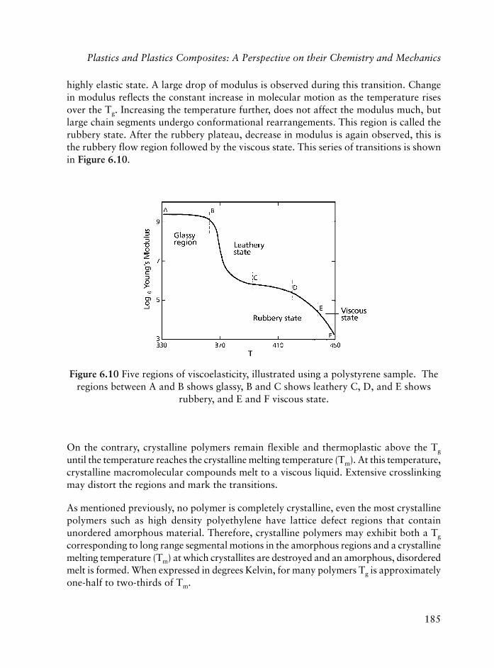
185
highly elastic state. A large drop of modulus is observed during this transition. Changein modulus reflects the constant increase in molecular motion as the temperature risesover the Tg. Increasing the temperature further, does not affect the modulus much, butlarge chain segments undergo conformational rearrangements. This region is called therubbery state. After the rubbery plateau, decrease in modulus is again observed, this isthe rubbery flow region followed by the viscous state. This series of transitions is shownin Figure 6.10.
On the contrary, crystalline polymers remain flexible and thermoplastic above the Tg
until the temperature reaches the crystalline melting temperature (Tm). At this temperature,crystalline macromolecular compounds melt to a viscous liquid. Extensive crosslinkingmay distort the regions and mark the transitions.
As mentioned previously, no polymer is completely crystalline, even the most crystallinepolymers such as high density polyethylene have lattice defect regions that containunordered amorphous material. Therefore, crystalline polymers may exhibit both a Tg
corresponding to long range segmental motions in the amorphous regions and a crystallinemelting temperature (Tm) at which crystallites are destroyed and an amorphous, disorderedmelt is formed. When expressed in degrees Kelvin, for many polymers Tg is approximatelyone-half to two-thirds of Tm.
Figure 6.10 Five regions of viscoelasticity, illustrated using a polystyrene sample. Theregions between A and B shows glassy, B and C shows leathery C, D, and E shows
rubbery, and E and F viscous state.
Plastics and Plastics Composites: A Perspective on their Chemistry and Mechanics

186
Polymers in Construction
epytlarenegehtfosremylopcitcatarofserutarepmetnoitisnartssalG2.6elbaTremylopfoepyT (– HC– 2 –XHC )n– Tg K/ X
enelyhteyloP 881 H–
)PP(enelyporpyloP 352 HC– 3
)ene-1-lytub(yloP 942 C– 2H5
)ene-1-tnep(yloP 332 C– 3H7
)ene-1-xeh(yloP 322 C– 4H9
)ene-1-lyhtem-4(yloP 203 HC– 2 HC(HC– 3)2
)lohoclalyniv(yloP 853 HO–
)edirolhclyniv(yloP 453 lC–
elirtinolyrcayloP 873 NC–
)etatecalyniv(yloP 103
)etalyrcalyhtem(yloP 972
)etalyrcalyhte(yloP 942 COOC– 2H5
)etalyrcalyporp(yloP 522 COOC– 3H7
)etalyrcalytub(yloP 812 COOC– 4H9
enerytsyloP 373
(yloP � )enelahthpanlyniv- 804
)lynehpiblyniv(yloP 814
remylopfoepyT (– HC– 2 HC(C 3 –X) )n–
)etalyrcahtemlyhtem(yloP 873
)etalyrcahtemlyhte(yloP 833
)etalyrcahtemlyporp(yloP 803
elirtinolyrcahtemyloP 393 NC–
(yloP � )enerytslyhtem- 544
OC
O
CH3
C O
O
CH3
C
O
O CH2CH3
C
O
O CH2CH2CH3
C
O
O CH3
187
6.1.5.1 The Glassy State
Thermodynamically, Tm is a first order transition and Tg is a second order transition. Tg
varies with the type of skeletal atoms present, with the type of side groups and even withthe spatial disposition of the side groups. As a result, the practical utility of polymersand their different properties depend strongly on their Tg. The transition from a glass toa rubber-like state is accompanied by marked changes in the specific volume, the heatcapacity, the refractive index and other physical properties of the polymer. Since it is asecond order transition it bears many of the characteristics of a relaxation process andthe precise value of Tg can depend on the method used and the rate of the measurement.
Several phenomenological models have been used to provide an understanding of Tg.One of them is an isoviscous state. As a polymer is cooled from its melt state, the viscosityincreases rapidly to a common maximum value, approximately 1012 Pa-s (1013 poise) atTg for all glassy materials – both low molecular weight and polymeric. Another view isthat the Tg represents a state of iso free volume. Free volume, Vf, is defined as the differencebetween the specific or actual volume V of the polymer at a given temperature and itsequilibrium volume at absolute zero Vo, Vf = V-V0. Each term is temperature dependent[5, 8, 9].
Vf is a measure of the space available for the polymer to undergo rotation and translation,and when the polymer is in the liquid and rubber-like states the amount of free volumewill increase with temperature as the molecular motion increases. If the viscous polymeris cooled this free volume will contract and eventually reach a critical value where thereis insufficient free space to allow large scale segmental motion to take place. Tg is thetemperature at which this critical value is reached. A third view of the Tg is that it representsan isoentropic (same entropy) state.
To transform a polymer into a useful plastic, we have to process it at a temperaturehigher than Tm or Tg depending on its physical structure, i.e., semi-crystalline oramorphous.
6.1.6 Mechanical Properties
Polymers are used as structural materials, therefore their mechanical properties arevery important. Mechanical behaviour of a polymer is its deformation and flowcharacteristics under stress. The generalised stress-strain curve for plastics is representedin Figure 6.11, which serves to define several useful quantities, including modulus orstiffness (the slope of the curve), yield stress, and strength and elongation at break.Polyethylene gives such a curve.
Plastics and Plastics Composites: A Perspective on their Chemistry and Mechanics

188
Polymers in Construction
Different types of tests can be performed to measure the following mechanical propertiesof polymers:
• Tensile strength
• Shear
• Flexure
• Compression
• Torsion
Macro and micro structures of polymers, (i.e., their degree of crystallinity, degree ofcrosslinking, values of Tg and Tm, the molecular mass and polydispersity), affect themechanical behaviour of polymers widely. A high degree of crystallinity (or crosslinks)imparts high elastic moduli, low strength and low Tg to macromolecular compounds.The temperature limits of utility of a high polymer are governed by its crystalline Tmand Tg for amorphous polymers; strength is lost above Tg and Tm.
Brittle and tough high polymers like polystyrene and PMMA have high strength andvery low extensibility and whereas plastics like polyethylene and plasticised PVC haverelatively high extensibility and require much more energy to produce rupture, this energyis represented by the area under the stress-strain curve.
Figure 6.11 Generalised tensile stress-strain curve for plastics

189
6.1.7 Mechanical Models
A perfectly elastic material obeying Hook’s law behaves like a perfect spring, on theother hand, the application of a shear stress to a viscous liquid is relieved by viscousflow, and can be described by Newton’s law. Comparison of the two models shows thatthe spring represents a system storing energy which is recoverable, whereas the dashpotrepresents the dissipation of energy in the form of heat by a viscous material subjected toa deforming force. Because of their chain like structure, polymers are not perfectly elasticbodies and deformation is accompanied by a complex series of long and short rangecooperative molecular rearrangements. As a result, the mechanical behaviour is dominatedby viscoelastic phenomena. Creep, stress-relaxation and dynamic response are the resultof viscoelastic behaviour of amorphous polymers.
6.1.8 Thermal Properties
Whether undesirable or useful, if a polymer is heated to a sufficiently high temperature,reversible and irreversible changes in its structure will take place. Chain cracking,formation of low molecular weight products (degradation), discoloration and someother changes are mostly not desirable. Yet reversible softening of thermoplastics makesit possible to reshape the material several times. The mechanical properties ofthermoplastics are temperature dependent. Thermal expansion and specific heat valuesof polymers are also very useful for studying the structure-property relation as a functionof temperature.
6.1.9 Weathering and Other Properties
Polymers are widely used indoors and outdoors, therefore they are exposed to a chemicalenvironment which may include atmospheric oxygen, acidic fumes, acidic rain, moistureheat and thermal shock, ultra-violet light, high energy radiation, etc. Different polymersare affected differently by these factors even though the amorphous polymers are moresensitive. Ageing is also important and it is defined as the process of deterioration ofengineering materials resulting from the combined effects of atmospheric radiation[10], heat, oxygen, water, micro-organisms and other atmospheric factors. Polymertechnologists regard it a serious problem to be able to predict the weathering andageing behaviour of a polymer over a prolonged period of time, often 20 years ormore. As a matter of fact, PMMA and other acrylic polymers have outdoor lives ofmore than 30 years. PVC used in cladding panels for building has a continuous outdoorlife of more than 20 years.
Plastics and Plastics Composites: A Perspective on their Chemistry and Mechanics

190
Polymers in Construction
From a study done in 1977 on the ageing of about 35 high polymers and organicglasses, it was concluded that ageing occurs in broad temperature ranges below theTg [10], (i.e., for PVC from +70 to –50 °C and for polycarbonate (PC) from +150 to–100 °C).
Permeability, toxicity, flammability are also some of the important properties ofpolymers which must be considered during their structural use.
6.2 Additives
6.2.1 Introduction
The properties of polymers may be improved by the presence of appropriately selectedadditives. Types of additives and their purposes vary and the exact proportions andnature of the additives need some experimentation. Commercial plastics are mixtures ofmore polymers along with a variety of additives such as plasticisers, thermal stabilisers,flame retardants, processing lubricants and fillers. Specific applications or processingrequirements depend on the exact formulation [1, 8].
In some cases, certain properties of a polymer can be enhanced by blending it withanother polymer or by copolymerisation with a suitable monomer pair. Additives maybe mixed with the polymer before processing by a variety of techniques, such as dryblending, extrusion, compounding, and other methods discussed in Chapter 8.
6.2.2 Classification and Types of Plastics Additives
Classification of additives according to a general scheme is extremely difficult because ofthe diversity of chemical structures and compositions, molecular weight, natural form,shape, and so on [11]. One way of doing this is according to the original scheme suggestedby Mascio [11, 12] in which additives may be classified according to their general and/orspecific functions. Table 6.3. gives examples of specific groups of additives used with thespecified general functions. There are numbers of other kinds of additives which will bediscussed when discussing the specific properties of the polymers.
Polymer modification through additives is ultimately related to the affinity of the additiveto the matrix which is controlled by physical and chemical interactions. The selection ofmixing configuration which in turn, depends on the nature of the additive (low viscosityliquid, low molecular weight solid, melt, liquid) also affects the performance of theadditive. Additives forming distinct dispersed morphologies may be deformable or rigid
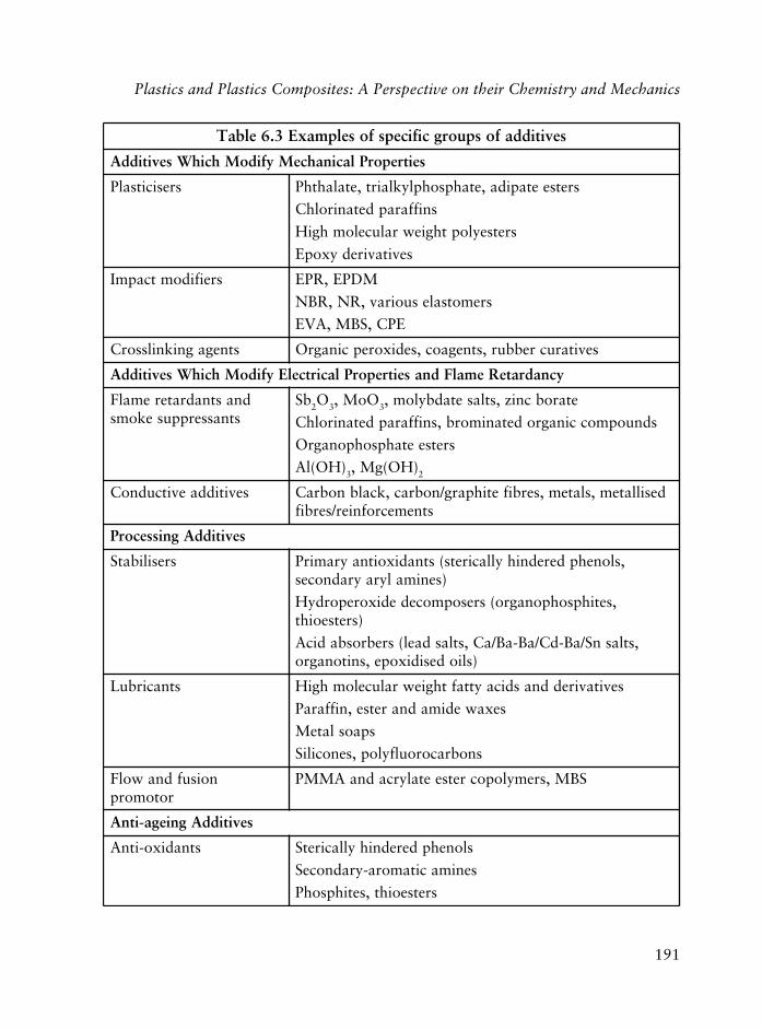
191
sevitiddafospuorgcificepsfoselpmaxE3.6elbaT
seitreporPlacinahceMyfidoMhcihWsevitiddA
sresicitsalP sretseetapida,etahpsohplyklairt,etalahthP
sniffarapdetanirolhC
sretseylopthgiewralucelomhgiH
sevitaviredyxopE
sreifidomtcapmI MDPE,RPE
sremotsalesuoirav,RN,RBN
EPC,SBM,AVE
stnegagniknilssorC sevitarucrebbur,stnegaoc,sedixorepcinagrO
ycnadrateRemalFdnaseitreporPlacirtcelEyfidoMhcihWsevitiddA
dnastnadrateremalFstnasserppusekoms
bS 2O3 OoM, 3 etarobcniz,stlasetadbylom,
sdnuopmoccinagrodetanimorb,sniffarapdetanirolhC
sretseetahpsohponagrO
)HO(lA 3 )HO(gM, 2
sevitiddaevitcudnoC desillatem,slatem,serbifetihparg/nobrac,kcalbnobraCstnemecrofnier/serbif
sevitiddAgnissecorP
sresilibatS ,slonehpderednihyllacirets(stnadixoitnayramirP)senimalyrayradnoces
,setihpsohponagro(sresopmocededixorepordyH)sretseoiht
,stlasnS/aB-dC/aB-aB/aC,stlasdael(srebrosbadicA)sliodesidixope,snitonagro
stnacirbuL sevitavireddnasdicayttafthgiewralucelomhgiH
sexawedimadnaretse,niffaraP
spaoslateM
snobracoroulfylop,senociliS
noisufdnawolFrotomorp
SBM,sremylopocretseetalyrcadnaAMMP
sevitiddAgniega-itnA
stnadixo-itnA slonehpderednihyllaciretS
senimacitamora-yradnoceS
sretseoiht,setihpsohP
Plastics and Plastics Composites: A Perspective on their Chemistry and Mechanics

192
Polymers in Construction
(sevitiddafospuorgcificepsfoselpmaxE3.6elbaT deunitnoc )
sevitiddAgniega-itnA deunitnoC
srotavitcaedlateM ,sedizardyh,sedimaxo,senozardyh(stnegagnitalehC)senihpsohp,setihpsohp
sresilibatsthgiL )sedixonori,kcalbnobrac(stnemgiP)selozairtozneb,senonehpyxordyh(srebrosbaVU
)sexelpmociNcinagro(srehcneuqetatsdeticxE)SLAH,senidirepip(sregnevacslacidar-eerF
stnegAgniwolBdnasreifidoMytreporPlacitpO
stnemgiP ,sediflusbPdnaaB,dC,sedixorCdna,eF,iT:cinagronI,kcalbnobrac:cinagrO.setamorhcdna,setaflus
stnemgipoza,senodircaniuq
seyD senoniuqarhtnAsdnuopmocozasibdnaozA
senisorgiN
stnegagnitaelcuN OiS 2 etaoznebmuidos,clat,
stnegagniwolB OC(sesagtrenI 2 N, 2)snobracolah,snobracordyH
,)edimanobracidoza(stnegagniwolblacimehCsetanobracib
sreifidoMecafruS
s)ci(tatsitnA stlasmuinomayranretauqdnasenimadetalyxohtEretseetahpsohP
sedirecylG
pils,stnegagnikcolbitnAsevitidda
edimaelo,sexawedimA
sreggofitnA srehteyloP
evitiddaraewitnA )EFTP(enelyhteoroulfartetyloP
stnegagnitteW stnatcafruscinoinon,cinoI
srotomorpnoisehdA setanatit,senaliS*sremylopoctfargdnakcolB
gnilpuoc,sresilibitapmoc(sdnelbremylopelbicsimmiroftnatropmiylralucitraP*.)stnegalaicafretni,stnega
enelyhteylopdetanirolhC:EPC resilibatsthgilenimaderedniH:SLAHremonomeneidenelyporpenelyhtE:MDPE enerytseneidatubetalyrcahteM:SBM
rebbureneidatubelirtinolyrcA:RBNrebburenelyporpenelyhtE:RPErebburlarutaN:RNetatecalynivenelyhtE:AVE

193
[11-15]. Whether deformable or rigid, important characteristics controlling the degreeof dispersion, resulting morphology and the final properties are:
• Viscosity and elasticity at processing conditions
• Concentration
• Interfacial tension
• Particle size and shape, size distribution, surface area and volume fraction
• Bulk properties, surface tension and surface reactive sites.
6.2.2.1 Plasticisers
A plasticiser is a material incorporated in a plastic to increase its workability and flexibilityor distensibility. The melt viscosity, elastic modulus and Tg of a plastic are lowered by aplasticiser addition. There are several theories to explain plasticiser effects such as thelubricity, gel, and free volume. Plasticisers are essentially nonvolatile solvents and therefore,polymer and plasticiser compatibility is very important and the solubility parameterdifference (��) should be less than 1.8. When present in small amounts plasticisersgenerally act as antiplasticisers, (i.e., they increase the hardness and decrease the elongationof polymers). Figure 6.12 illustrates the effect of plasticiser on modulus. Increasingconcentration of the plasticiser shifts the transition from the high modulus (glassy) plateauregion to the low, i.e., to occur at lower temperature [9].
Figure 6.12 Effect of increasing plasticiser concentration on the modulus-temperature plot
Plastics and Plastics Composites: A Perspective on their Chemistry and Mechanics

194
Polymers in Construction
A very useful equation relating Tg to the composition of a polymer mixture from knownparameters is given as:
lnln( )
( ),
,
,
,
,
T
T
wT
T
wT
T w
g
g
g
g
g
g
1
22
1
12
12
=+
(6.9)
In the equation, Tg is the glass transition temperature of the mixture, Tg,1, Tg,2 are theglass transition temperatures of components 1 and 2, and w1, w2 are the weight fractionsof components 1 and 2, respectively.
Table 6.4 shows some common plasticisers for PVC. The actual reduction in polymer Tg
per unit weight of plasticiser is called the plasticiser efficiency.
Plasticisation may occur either internally or externally. In some cases, plasticiserfunction can be obtained by copolymerising the polymer with the monomer of a lowTg polymer such as PVA, this process is called internal plasticisation, typical externalplasticisation is addition of dioctyl phthalate, diisooctyl phthalate and di-2 ethylhexyl phthalate to PVC.
Water is a widely utilised plasticiser in nature which permits flexibility. Most plasticfloor tiles become brittle with extended use, mainly due to the leaching out of the plasticiser.This may be overcome through many routes including surface treatment of polymerproduct surface, effecting less porous surface features and, use of branched polymerswhich can act as plasticisers to themselves.
6.2.2.2 Fillers and Reinforcements
Fillers are inert materials and important additives for thermoplastics and thermosets.They reduce the resin cost and improve processibility or dissipate heat in exothermicthermosetting reactions. Some examples of fillers include wood flour, clay, talc, fly ash,sand, mica and glass beads. Graphite, carbon black, aluminum flakes and metal andmetal coated fibres are used to minimise electrostatic charging. Reinforcing fillers areused to improve some mechanical properties such as modulus, tensile or tear strength,abrasion resistance and fatigue strength. Carbon black, silica, woven fabrics and choppedfibres are used for this purpose.

195
6.2.2.3 Antioxidants
Some polymers are not too stable outdoors due to their molecular structure likepolypropylene, which has a readily removable hydrogen atom on the tertiary carbon atoms.In the absence of stabilisers, chain degradation may take place, see Reaction 6.10.
CVProfsresicitsalpnommoC4.6elbaT
ssalcresicitsalP erutcurtslacimehC selpmaxE
etalahthplyklaiD POID,POD
retseidcitahpilA AOD
etahpsohplyklairT PCT
etatillemirtlyklairT MTOT
enotcalorpacyloP
etalahthplytcoid:PODetalahthplytcoosiid:POID
etapidalytcoid:AODetahpsohplysercirt:PCT
etatillemirtlytcoirt:MTOT
C
C
O
OR
OR
O
RO C CH2
O
C
O
ORn
P
O
OR
RO OR
C
O
RO C OR
O
C
O
OR
C CH2
O
O5 n
Plastics and Plastics Composites: A Perspective on their Chemistry and Mechanics

196
Polymers in Construction
C C
H H
C
H
C
H
HHHH
C C
H
C
H
C
H
CH3HCH3H
C C
H
H
H
CH3
C C
H
H
H
CH3
hv
sun light
Polypropylene Macroradical Lower mwpolymer
Lower mwmacroradical
Reaction 6.10
Chain reaction degradation is retarded by the presence of small amounts of antioxidantswhich are derivatives of phenols or hindered phenols, alkyl phosphites or thioesters andcarbon black [8], see Reaction 6.11.
CH2 C
CH3
R
OH
R+ CH2 C
CH3
HR
O
R+
Stable free radical
Reaction 6.11
6.2.2.4 Ultraviolet and Light Stabilisers
Radiation stabilisers absorb radiation prior to molecular bond breakage. The high energyradiation of sun that reaches the earth’s surface is sufficiently strong to cleave covalentbonds and cause yellowing and embrittlement of organic polymers. Phenyl salicylaterearranges in the presence of high energy radiation to form 2,2� dihydroxybenzophenone,so it acts as an energy-transfer agent, see Reaction 6.12.
OH
C
O
Ohv
C
OOH HO
C
OH
O OH
Phenyl salicylate 2,2� dihydroxybenzophenone Quinone + hv
Reaction 6.12

197
6.2.2.5 Heat Stabilisers
Another type of degradation (dehydrohalogenation) also occurs with chlorine containingpolymers such as PVC. PVC may lose hydrogen chloride when heated and form achromophoric conjugated polyene structure. Since the allylic chlorides produced arevery unstable, the degradation continues as an unzipping type of chain reaction, seeReaction 6.13.
C
H
C
H
C
H
C
H
C
H
C
H
C
H
C
H
C
H
C
H
H Cl H Cl H Cl H Cl H Cl
heat
-2HClC
H
C
H
C
H
C
H
C
H Cl H Cl
H
C
H
C C
H
C C
H H H
H Cl
Reaction 6.13
This type of degradation is accelerated in the presence of iron salts, oxygen and hydrogenchloride. There are some HCl scavengers, some of which are toxic and some are lesstoxic such as mixtures of magnesium and calcium stearates, and dioctyl tin salts. Lesstoxic, epoxidised, unsaturated oils such as soy bean oil also act as an HCl scavenger asshown in Reaction 6.14.
O
CH CH + HCl C C
ClO
H H
H
Epoxy group Chlorohydrin derivative
Reaction 6.14
6.2.2.6 Flame Retardants
Many flame retardants are halogen or phosphorus compounds. These may be:
(a) additives,
(b) external retardants such as antimony oxide and organic bromides,
(c) internal retardants, such as tetrabromophthalic anhydride which can become part ofthe polymer. A compound which is not a good fuel may have flame retardant properties
Plastics and Plastics Composites: A Perspective on their Chemistry and Mechanics

198
Polymers in Construction
such as polyfluorocarbons, phosphazenes and some composites. Fillers such as aluminatrihydrate release water when heated and hence reduce the temperature of thecombustion reaction. Char, formed in some combustion process, also shields thereactants from oxygen and retards the outward diffusion of volatile combustibleproducts. Aromatic polymers tend to char, and some phosphorous and boroncompounds catalyse char formation. Antimony trioxide and an organic bromocompound are more effective than single flame retardants because of their synergisticflame retardant properties [8, 9, 11].
6.2.2.7 Curing Agents
Curing is applying heat (and pressure) to change the properties of rubber or thermosettingresins. Vulcanisation of Hevea rubber with sulfur by Charles Goodyear in 1938 is an oldexample of a curing process. Then, in the 1900s, hexamethylene tetraamine was used asa curing agent (crosslinking agent) for A- or B-stage novolacs.
The curing of polyesters, ethylene-propylene copolymers, and for the grafting of styreneonto elastomeric polymer chains, benzoylperoxide is used. High density polyethylene(HDPE) is crosslinked in the presence of 2,5-dimethyl-2,5-di(t-butylperoxy)hexyn-3.Crosslinking is achieved by electrons, �-rays or UV irradiation, and enhanced by thepresence of methyl ether of benzoin.
6.2.2.8 Processing Additives
Lubricants are processing additives, which improve flow during processing by reducingmelt viscosity (internal lubricants) or by reducing adhesion between methalic surfaces ofthe processing equipment and the polymer melt (external lubricants). Important lubricantsare: amides, esters, metallic stearates (often used for PVC), waxes, acids, mineral oils,and low molecular weight polyolefins.
6.2.2.9 Blowing Agents
Many plastics such as polystyrene (PS), expanded polystyrene and polyurethanes arefoamed to provide insulating properties (rigid foam) or flexible properties (flexiblefoam) for seat cushions and other applications. Blowing and foaming agents are usedfor this purpose and examples of physical blowing agents are volatile liquids such asshort chain hydrocarbons, (e.g., pentanes, hexanes, heptanes) and fluorocarbons, (e.g.,trichloromethane, tetrachloromethane and trichlorofluoromethane), and gases such as
199
nitrogen, carbon dioxide and air. In the case of polyurethanes, flexible foams areproduced by the production of carbon dioxide from the reaction of an isocyanate andwater [9].
6.3 Structure-Property Relationships
A fundamental knowledge of structure-property relationships is required as the demandfor the use of synthetic polymers to replace or supplement more traditional materialssuch as wood, metals ceramics and natural fibres is increasing and has stimulated thesearch for even more versatile polymeric structures covering a wide range of properties.After establishing the suitability of a polymer for a particular purpose, i.e., whether it isglass-like, rubber-like or fibre forming, one has to consider the characteristics dependentprimarily on chain flexibility, chain symmetry, intermolecular attractions and of courseenvironmental conditions. These properties, excluding environmental, are reflected invalues for Tm, Tg, modulus and crystallinity [8].
6.3.1 Control of Tm and Tg
As discussed in section 6.1, chain symmetry, flexibility and tacticity can influence theindividual values of both Tm and Tg. As discussed earlier a highly flexible chain has a lowTg which increases as the rigidity of the chain becomes greater. Also, strong intermolecularforces tend to increase Tg and increase crystallinity. Table 6.5 shows the effect of aromaticrings on chain stiffness on Tg and Tm. In the polyamide and polyurethane series hydrogenbonding strengthens the crystallite regions and increases Tm. The effect is strongest whenregular evenly spaced groups exist in the chain. An alternative method of reducing thehydrogen bonding potential and hence Tm, in the polyamides is to increase the length ofthe (CH2-CH2)n sequence between each bonding site [5].
6.3.2 Effect of Macromolecular Skeleton
The environment in which the macromolecule finds itself is important in discussingstructure-property relationships. The environment is solvent molecules when themacromolecule is in solution, it is the other polymer molecules in solid state, and at thesurface, the vapour or the liquid that are in contact with the surface. The skeleton ofthe polymer where the flexibility and stability are highly affected and the types of sidegroups are important in discussing the structure property relationships. The carbon-carbon single bond confirms appreciable flexibility to a polymer chain but, its weaknessis its sensitivity to thermooxidative cleavage. The aliphatic carbon-carbon double bond
Plastics and Plastics Composites: A Perspective on their Chemistry and Mechanics

200
Polymers in Construction
has a barrier to internal rotation which generates chain stiffness and high Tg. However,when the double bonds are alternating, skeletal rigidity is generated along with colourand electrical conductivity.
Aromatic rings in a polymer skeleton confer rigidity and extended chain character and inaromatic polyamides, polyesters or polyarylenes can also show main chain liquidcrystallinity. In Table 6.5, a few examples with their Tg and Tm values are given.
seulavehtybnwohssa,ssenffitsniahcnosgnircitamorafotceffE5.6elbaTTfo m Tdna g
erutcurtS Tg K/ Tm K/
881 004
602 933
- 356tuobA
243 835
023 835
- 316
645536tuobA
)noitisopmoced(
- 377tuobA
CH2 CH2 n
CH2 CH2 nO
CH2 CH2 n
CH2 2 OCO COO
NH(CH2)6NHCO(CH2)4CO
NH NHCO(CH2)4 CO
n
n
NH NHCO CO
NH NHCO CO
n

201
Oxygen atoms in a hydrocarbon chain give torsional mobility and materials flexibility.Nearby skeletal units have to be taken into consideration as ether linkages are generallystable to hydrolysis and to thermooxidation while polyaldehydes depolymerise readilyat moderate temperatures.
The amide linkage makes the chain stiffer because of the partial double bond characterof the N-C bond which causes a possibility for internal and external hydrogen bonding:
N C
OH+
Many commercial polyamides are highly crystalline and have repeating units withineach crystalline region are inaccessible to water or other reagents.
Urethane linkages:
(C) N
H
C
O
O (C)
in polymers should give hydrolytically sensitive sites to the chain and are considered tobe a source of molecular flexibility, and this property enables the use of manypolyurethanes as elastomers.
The silicone-oxygen bond has one of the highest torsional mobilities in any polymerbackbone, e.g., Tg of poly(methyl siloxane) is –130 °C. Polydimethylsiloxane(-[Si(CH3)2O]n-) is more stable to thermooxidative attack than is the aliphatic C–O bondbut is sensitive to certain reagents such as acids and bases.
Even though a double bond, –P=N–, is present in the structure of a phosphazene linkageit gives very high flexibility to the polymer chain. The phosphorus-nitrogen skeleton hasa high chemical, photolytic and thermo oxidative stability and appears to be resistant toozone and a variety of free radical reagents. Also, nitrogen atoms in the phosphazenegroups can complex to metal ions.
6.3.3 Effect of Different Side Groups
The side groups attached to a polymer chain can have a more profound effect on thepolymer properties than the skeleton itself. Side groups are responsible for severalproperties such as protecting the skeleton against chain cleavage reactions, solubilityproperties, steric and polar interactions between side groups on the same chain or differentchains which determine the Tg, crystallinity and surface properties of the material.
Plastics and Plastics Composites: A Perspective on their Chemistry and Mechanics

202
Polymers in Construction
Among the alkyl side groups, methyl side groups are present in many polymers, as shownin Figure 6.13:
C
CH3
H
CH2 , C
CH3
CH3
CH2 , Si
CH3
CH3
O , P
CH3
CH3
N
Figure 6.13 Polypropylene, polyisobutylene, polydimethyl siloxane
They enhance the hydrocarbon character of the skeleton, making them hydrophobicand soluble in organic solvents. In polypropylene, the methyl group determines thetacticity of the polymer – and as a result, isotactic polypropylene is a crystallinethermoplastic. Ethyl-, propyl-, butyl-, or higher alkyl side chains generally increase thehydrocarbon character and the confirmational disorder introduced by these side groupsmay prevent crystallisation yet, longer chain side units undergo crystallisation.
Aryl side groups are hydrophobic and relatively bulky. They impose stiffness and sterichindrance to the main chain as in polystyrene and increase Tg. Aryl side groups are notonly phenyl rings but they may appear as mesogenic side groups as well. Biphenyl,aromatic azo, or cholesteryl units in a side group may generate side chain liquidcrystallinity, see Figure 6.14.
X
N N X
Biphenyl
Aromatic azo
Figure 6.14 Biphenyl and aromatic azo units
It is also possible to have halogen side groups, such as fluorine and chlorine. Polymerswith fluorine in their side groups have extreme hydrophobicity and water insolubility.This raises the thermal and oxidative stability and confers solvent, fuel and oilresistance. Some examples of fluoro polymers are poly(tetrafluoroethylene) (Teflon),

203
poly(vinylidene fluoride) (PVDF) – a variety of fluoro chloro carbon elastomers, fluoroalkyl siloxane elastomers, and fluoro alkyl oxy phosphazene elastomers. Chlorineside groups polymers are relatively resistant to chemical attack. PVC andpoly(vinylidene chloride) are stable polymers that are widely used. One or morechlorine atoms per repeat unit, connected directly to a carbon skeleton increase chainstiffness. Carbon-chlorine bonds are not stable to sunlight. Cyano side groups alsoimpose a special set of properties on the carbon backbone polymers, e.g., acrylonitrile,-CHCN-CH2-, such as reducing solubility in nonpolar solvent and increasing it indimethylformamide, dimethylsulfoxide or dimethylacetamide. Copolymers ofacrylonitrile are used in solvent- and oil-resistant elastomers. The Tg ofpolyacrylonitrile is 85 °C.
Hydroxyl groups in polymer chains impart hydrophilicity and water-solubility to thepolymer. They form strong hydrogen bonds which increase the Tg of the polymers.Ester side group polymers can be polyacrylic acid esters, polymethacrylic acid esters,or esters of poly(vinyl acetate) (PVAc), see Figure 6.15.
O
C
C
H
CH2
OR
,
O
C
C
CH3
CH2
OR
,
O
C
CH3
CH2
C
,
R
O
(a) (b) (c)
Figure 6.15 (a) polyacrylic esters; (b) polymethacrylate acid esters;(c) polyvinyl acetate esters
The Tg of carbon backbone polymers with ester side groups vary widely with the tacticityand the nature of the R groups. Atactic PMMA has a Tg of 105 °C while PVAc has a Tg
of 28-31 °C. They are all nontoxic [6].
6.3.4 Some Structure-Property Relations of Polymers as Regards Buildingand Construction
Plastics materials will not reduce the demand for bricks, mortar and concrete but it isclear that as the construction industry gains confidence in using new materials, theirinfluence is likely to spread. The main uses of plastics materials and their applicationsin building construction can be summarised as in Table 6.6.
Plastics and Plastics Composites: A Perspective on their Chemistry and Mechanics

204
Polymers in Construction
6.3.4.1 Poly(Vinyl Chloride) (PVC)
PVC is used in the construction sector in:
• Pipes and fittings
• Cladding and profiles
• Wall coverings
• Floor covering
• Film/sheet
Lead, barium and cadmium based stabilisers are widely used for rigid PVC [16]. However,calcium and zinc containing materials are preferable as they offer good heat and weatherstability and are used in flexible PVC applications. Foamed PVC can be considered more
noitcurtsnocdnagnidliubnidesuslairetamscitsalplacipyT6.6elbaT
snoitacilppA )s(lairetamciremyloP
gnizalgdnaswodniW )lanretni(SP,CVP,CP,scilyrcA
gnizalgfoordetalusnidnasthgilfooR CVP,CP,PRG,scilyrcA
gnifooR ,CDVP,FDVP,CP,PRG,)eriw(CVP,CVP)srebburMSCdnaMDPE-lytubosla(
sgniliecdednepsuS CP,SP,PRG,cilyrcA
snoititrapdnasllaW CP/CVP,cilyrca/CVP,CVP,PP,PRG
gniddalclanretxE FDVP/cilyrca/SBA,CVP,PRG
noitalusnI FU,SP,enaruf,cilonehp,RIP,RUP
gniriw,elbaC senelyhteylop,CVP
sepiP PP,SBA,senelyhteylop,CVPPRG,enelytubylop
gniroolF yxope,CVP
citsalpdecrofnierssalG:PRG)edirolhcenedilyniv(yloP:CDVP
enelyhteylopdetanoflusorolhC:MSCenerytseneidatubelirtinolyrcA:SBA
enahteruyloP:RUPetarunaycosiyloP:RIP
edyhedlamrofaerU:FU

205
as a wood substitute than the traditional PVC profiles. It is suitable for both interior andexterior applications and unlike wood it does not need any special treatment.
Research in PVC is continued with great enthusiasm by many scientists. In the study ofStoeva and co-workers [17] the effect of a natural, activated and modified microzeolitesare studied individually and in combination with ammonium sulfamate as high-meltingdispersed additives. Their effect on the mechanical properties and as a fire retardantadditive are also discussed. It is reported that the strength-deformation properties ofPVC are improved within the interval of 3-8 wt% of additive.
6.3.4.2 Polyethylene (PE) and its Copolymers
Polyethylene owes its success in pressure piping to a number of factors, mainly to itsflexibility and resulting properties are long coil length, fewer joints, quickerinstallation, low sensitivity to earth movements and good potential for relining. Beingnoncorrosive results in long, maintenance-free service [5, 16]. Production of pipes inlarge diameters for high pressures can lead to wall thickness problems. The newHDPE materials which show bimodal molar mass distribution solved this problem.Based on bimodal polymerisation technology with highly active Ziegler catalysts,the comonomer can be incorporated into the higher molecular mass fraction and sobe dispersed throughout the structure. The ‘tie molecules’ connect the crystallitelamellae and are responsible for enhanced mechanical properties, high resistance tocrack growth, high creep resistance, ductile failure only at high stress and no brittlefracture by chain rupture.
Olefinic polymers are transparent at normal room temperatures but become milky whenexposed to bright sunlight and they are designed to provide shade and prevent overheatingfrom incident solar radiation. Light hitting the polymer is scattered, thus reducing heatbuild up, but still allowing brightness, within rooms. The scattering centres arise whenthe polymer mixtures become incompatible with each other. This is overcome by varyingthe polymer structures to produce a substance, which is miscible at low temperature. Apolymer blend is intended for film or sheet extrusion in applications to cover skylights,greenhouse and conservatory panels. Hydrogel formation is also possible with PE.
Bouma and co-workers studied the foam stability related to low density polyethyleneusing low molecular weight additives such as alkanes (isobutane) as blowing agents andstearyl stearamide as an additive [18]. The results of this work indicate that phaseseparation occurs, resulting in migration of the low molecular weight additive to thesurface. Formation of a more or less structured layer of the additive at the surface explainedthe low isobutane permeability.
Plastics and Plastics Composites: A Perspective on their Chemistry and Mechanics

206
Polymers in Construction
6.3.4.3 Styrenics
The use of PS as expanded PS (EPS) foam gained much importance in civil engineering dueto its good insulating value, excellent moisture resistance, predictable long-term performanceunder real-life conditions, stable and low conductivity value, mildew/corrosion resistance,compressive strength, toughness and durability. Most PS is used as expanded blocks orextruded foam sheet for insulation purposes.
ABS terpolymer is used as a window profile material which is co-extruded with a weatherprotection layer. Impact strength and dimensional stability are claimed to be greaterthan for PVC.
Interesting research on the dynamic mechanical and thermal properties of fire-retardanthigh-impact polystyrene (HIPS) is published by Chang and co-workers [19]. HIPS maybe produced by the free-radical chain polymerisation of styrene in the presence of anunsaturated elastomer. The authors showed that the melting point of the additive inrelation to the processing temperature of the thermoplastics and the compatibility of theadditive with the polymer phases are the two important variables governing the interactionof additive with polymer matrix.
6.3.4.4 Acrylics
PMMA sheets with an added elastomer component offer optical clarity and are resistantto crazing impacts, ageing and weathering. Acrylic sheets are the top surface layer ofbaths and other bathroom wares.
6.3.4.5 Engineering Thermoplastics
Among the several engineering thermoplastics some interesting research on amine curedepoxy resins [20, 21] and bisphenol A polycarbonate [22] will be discussed next. Thereaction product of 4-hydroxyacetanilide and 1,2-epoxy-3-phenoxopropane, whenadded at 19 wt% to a conventional epoxy-resin curing agent mixture, increases thetensile strength of the cured system from 82 MPa to 123 MPa and increases the shearmodulus from 970 MPa to 1560 MPa, but this system fails with appreciable localiseddeformation occurring during fracture. The other study on the structure-propertyrelationships as a tool for the formation of high performance epoxy-amine networks[19], chose an additive miscible in the mixture of monomers, but which gives rise tophase nano-separation along the network construction. The study on the effect ofionic additives on the deformation behaviour of bisphenol A PC [22] reflects that the

207
impact strength of PC markedly decreased as the content of additive increased andbrittle fracture of PC was observed in tensile tests when the concentration of additivewas above 2.5 phr, while critical shear yield stress and critical craze stress appeared toexist in the range of 2.5 to 3.5 phr of additive.
6.3.4.6 Polyurethanes (PU)
PU is manufactured by the condensation polymerisation of polyol (from crude oil)and isocyanate. In civil engineering, PU block foams and the continuous laminatedfoams are used for various applications such as roofing or sealing strips, glass fleece,metal or plastic foils, all used as facing [17]. Rigid PU foam has physical stabilityand excellent thermal insulation qualities and is used extensively in the walls androofs of buildings where a very high standard of insulation is required. When heatedPU decomposes in the temperature range of 400-500 °C, it is less toxic than woodand cork decomposition. In the case of fire, the thermoset PU rigid foam does notmelt and does not form burning droplets.
In the manufacture of flexible foams, carbon dioxide generated from the water-isocyanatereaction has replaced the external blowing agent, yet methylene chloride is still widelyused with acetone and liquid carbon dioxide. Cyclopentane has become the main blowingagent for refrigeration appliances, n-pentane has only been exploited for sandwich panelsand other building insulation.
Use of water-dispersible or water-soluble polyether-urethanes, which optionally containisocyanate groups as additives for inorganic binders in the preparation of buildingmaterials, particularly a high-density or high strength mortar or concrete compositionhas been studied by Laas and co-workers [23]. The building material results from the useof the water-dispersible or water-soluble polyether-urethanes.
6.3.4.7 Bitumen Modification
Styrenics have a significant use as modifiers for asphalts and bitumens. They improvethe flexibility of the base materials, especially at low temperatures and they also reducethe tendency to flow at higher temperatures. Additionally, they are also effective inimproving the softening point, stiffness, ductility, tensile strength and elastic recovery[6]. Generally less than 20% of the thermoplastic elastomer is added to the blend, even3% can make a significant difference to the properties. Applications include road surfacedressings such as chip seals, road crack seals, slurry seals, asphalt concrete, roofingand waterproofing.
Plastics and Plastics Composites: A Perspective on their Chemistry and Mechanics

208
Polymers in Construction
Styrene-butadiene-styrene (S-B-S) block copolymers are used in bitumen roofingformulations because of their suitable dynamic viscoelastic properties.
A study on the bitumen-free binder, especially for building materials such as surfacingfor traffic areas, sports grounds, etc., used in sealing compounds, jointing compounds,insulating paints and surface coating is characterised by Sychra and Steindl [24].
It consists essentially of an oil modified with 0.1 to 40 pbw, preferably 1 to 10 pbw ofsulfur. A building material mixture can include, along with the bitumen-free binder, upto 98 pbw of inorganic additives. The bitumen-free binder can also be used in the formof an aqueous dispersion as insulating paint or surface coating.
6.3.4.8 Polymer Modification of Asphalt
S-B-S rubber polymer (11-15 weight%) or polypropylene (25-30 weight%) based on asphaltis used in roofing. These higher loadings lead to polymer network formation wherein thepolymer becomes the continuous phase and the asphalt becomes the discontinuous phase.Modification of asphalt by mixing with PP or S-B-S is favoured economically. Star-shapedS-B-S will provide high viscosity, high softening point and better low temperature flexibilityto the compound. Linear S-B-S will impart low viscosity, low softening point and bettertoughness. To provide strength and reduce cost, S-B-S as well as PP modified asphalts arefilled with fillers, e.g., calcium carbonate and clays.
Fibrillated PTFE and molybdenum disulfide particles are other bitumen and asphaltmodifiers. The copolymer comprises two incompatible polymers forming a two-phasecopolymer including a thermoplastic and block polymer and an elastomeric mid-blockpolymer. The asphalt modifier is made by mixing together, under high shear, particles ofthermoplastic elastomeric copolymer, and molybdenum disulfide until the PTFE is fibrillatedand combined with the thermoplastic elastomer.
6.4 Polymer Composites
6.4.1 Introduction, Definitions and Classifications
Structural materials can be classified as metals, ceramics or polymers, each with itsown advantages and disadvantages. For example, metals are strong, tough, inexpensive,but are heavy, chemically reactive and limited to service temperatures below 1,000 °C.Ceramics are hard, chemically stable and useful at high temperatures, but they arebrittle and difficult to fabricate. Polymers are light, easy to process, but are relatively

209
weak and they are limited to lower service temperatures below 300 °C. Compositesare the combination of two or more of these materials combined together which offeran excellent balance of properties in one material, by eliminating undesirable propertiesand retaining the desirable ones of the components. ‘Composite’ is an anisotropicmaterial with two or more components differing in form or composition on amacroscale, having two or more distinct phases with recognisable interfaces betweenthem [25, 26]. Polymer composites usually consist of a reinforcing material (constitutingthe first component and phase), embedded in a polymer matrix (called the binder,which is the second component and continuous phase). Since one of the main objectivesin any structural design is to minimise weight, low densities are important, as well ashigh strengths and moduli, all of which can be provided by composite structures witheconomic viabilities.
In general, various material properties of composites, are optimised and are betterthan those of the individual constituents, as a result of the principle of combined action.Frequently, composites offer an excellent opportunity to eliminate some of theundesirable properties while retaining the desirable properties of the constituents. Hence,one can produce a material with better mechanical properties (mainly strength),improved chemical and/or physical properties (such as smaller thermal expansion/andbetter thermal conduction values, improved specific heats, higher softening and meltingpoints, improved electrical conductivities/electrical permittivities, dielectric loss,improved optical and acoustical properties) by shifting to a composite material. Inmost of these, structural weight savings while retaining the reliability and strength areachieved together by using composite materials [27]. There are three main factors thatmay affect the competition between composites and traditional engineering materialswith similar mechanical properties: the cost, the reliability and the degree of complexityinvolved. The cost barrier for composites is usually overcome by the mass productionand the reliability is achieved successfully as explained. However, the degree ofcomplexity is certainly more critical for composites which is due to the unisotropyexisting (at least on microscale) for these structures. It is known that, in composites,thermoelastic properties as well as strength and failure modes have strong directionaldependencies, which may be the only disadvantage of using these materials.
There are already a number of composite materials of natural origin known, i.e., boneis one of them and wood is the other. Also, crushed rock aggregate commonly used inconcrete in civil engineering, is a typical composite structure which improves thecompressive strength of the matrix appreciably. During the last few decades, there hasbeen an ever increasing demand for materials that are stiffer and stronger, yet lighter,in various structural, aeronautical, energy and civil engineering applications, but sofar there is no monolithic engineering material available to satisfy all, which certainlyled to the concept of combining and using different materials in a composite structure.
Plastics and Plastics Composites: A Perspective on their Chemistry and Mechanics

210
Polymers in Construction
6.4.1.1 Matrix Related Classification of Composites
In composites, the matrix can be either polymeric, ceramic or metallic, hence, polymermatrix composites (PMC), ceramic matrix composites (CMC) or metal matrix composites(MMC). Obviously, the latter two structures are used for high temperature applications(>315 °C), where PMC are usually inadequate. In addition, MMC with proper electricaland thermal conductivities are also used in heat dissipation/electronic transmissionapplications. In addition to the general types of composites, some specific compositescan also be of the type ceramic/metal/polymer or carbon matrix (CMC) or even hybridcomposites (HC).
In this chapter, only PMC that are used in construction will be covered in any detail.
In general, the following principle is used in the incorporation of dispersed phase intothe matrix, in the production of a composite: the matrices selected for use are of lowermodulus, while the dispersed reinforcing elements are typically some 50 times strongerand 20-150 times stiffer. One should note, that the properties of the matrix are particularlyimportant in most polymer composite systems - as in such systems, the matrix bears theload and it is distributed between the matrix and reinforcing particles. Each matrix typewith different incorporated phases certainly has a different impact on the processingtechnique to be used.
By embedding natural and near-natural reinforcing fibres (such as flax, cellulose) into abiopolymeric matrix (from cellulose, starch or lactic acid derivatives, thermoplastics aswell as thermosets), a new group of fibre reinforced systems are also created, called as‘biocomposites’ [28].
More in-depth information about the polymer matrices is given in Section 6.2.2.
6.4.1.2 Dispersed Phase Related Classifications of Composites
Dispersed (or reinforcing) phase in composites usually exists with substantial volumefractions (10% or more). The most commonly used reinforcing component is either aparticulate or a fibrous form (continuous/discontinuous chopped fibre), hence thefollowing three common types of composites can be produced, depending on the sizeand/or aspect ratio and volume fraction(s) of reinforcing phase(s):
(a) particle strengthened,
(b) discontinuous (chopped) fibre reinforced,
(c) continuous fibre reinforced composites.

211
Within these, fibre reinforced composites (FRC) are the most commonly used in structuralapplications where the reinforcing component is of utmost importance: fibres bear themain load and the function of the matrix is confined mainly to the load distribution andits transfer to the fibres.
Feldman [1] used a different terminology - if all the dispersed phases are between 10-1000 nm in size with only one continuous phase they are called microcomposites, and ifthere is more than one continuous phase present they are macrocomposites. In addition,if the sizes of the reinforcing components in a microcomposite are in the form of ‘quantumdots’ specifically smaller than 25 nm, a nanocomposite is obtained. The term flexiblecomposite is used to identify composites based on elastomeric polymers where the usablerange of deformation is much larger than conventional thermoplastic or thermosettingcomposites [29].
There are also cases where reinforcing phases are in the form of sheets bonded togetherand they are often impregnated with more than one continuous phase in the system [27],which are known as laminar composites (or simply laminates). Sandwiching a lightweightpolymeric core material (which can be a foam of a thermoplastic or a thermosettingplastic or even a honeycomb web of a nonmetallic, such as aramid or carbon) betweenthe skins of a FRC can significantly help to increase the stiffness of the laminate withoutadding too much to its overall weight, giving better load carrying capabilities to thestructural material [30].
Hybrid composite materials (HCM) represent the newest group of various compositeswhere more than one type of fibre is used to increase cost-performance effectiveness, i.e.,in a composite system reinforced with carbon fibres: the cost can be minimised by reducingits content while maximising the performance by optimal partial replacement with ananother fibre or by changing the orientations. HCM include nanocomposites [31],functionally gradient materials [32], Hymats (hybrid materials) [33], interpenetratingpolymer networks (IPN) [34], and liquid crystal polymers [35].
More in-depth information about the dispersed phases is given in Section 6.2.3.
6.4.1.3 The Interface and Interphases
The interfaces and interphases between different components and phases in the composite,which is the bounding surface with a discontinuity, has a vital importance in determiningfinal structural properties of the composite. The interfaces and interphases (the interactionand adhesion) between the dispersed phases and matrix are expected to be able to distributethe load evenly that can be borne by the composite [36].
Plastics and Plastics Composites: A Perspective on their Chemistry and Mechanics

212
Polymers in Construction
6.4.1.4 Advanced Composites
Advanced composite materials (ACM) were developed during the third quarter of thetwentieth century, once special (advanced) high tensile and/or high modulus (andspecifically continuous) fibres of carbon, boron, silicon carbide and alumina becameavailable. They are used to reinforce high performance polymers, metal or ceramic matrices[27]. They are a specialised group of composites that have high performances applicationsunder extreme mechanical, electrical and environmental conditions in aircraft/aerospace,construction and leisure or sports. Today, the fraction of carbon fibre composites inlarge passenger aircrafts like those made by Airbus, and the Boeing 737 or Tu-204/Il-86has reached 15% of the structure weight and in most military helicopters it exceededhalf of the total structure weight. ACM consist of a high strength reinforcing constituentcombined with a high performance matrix [37].
6.4.2 Chemical Structure of the Polymer Matrix
Matrices are usually about 30-40% of the composite structure, and can have a numberof critical functions: firstly, the matrix helps to bind the reinforcing components togetherand determines the main thermomechanical stability of the composite, protecting andsafeguarding reinforcing components from wear/abrasion and various effects of theenvironment. The matrix also helps to distribute the applied load by acting as a stresstransfer medium. In addition, the matrix provides durability, interlaminar toughnessand strength, (i.e., shear/compressive/transverse strengths), to the system, and helps toachieve the desired fibre orientations and spacings in specific composite structures. Ahigh performance matrix resin is expected to have a modulus of at least 3 GPa for strengthand a sufficiently high shear modulus (to prevent buckling of fibre reinforcementsespecially when under compression, although the matrix is known to play a minor rolein the tensile load-carrying capacity of a composite). The matrix has a major influenceon the interlaminar shear (particularly important for structures under bending loads)and on the in-plane shear (important for structures under torsional loads) properties.Most of the reinforcing components, (i.e., glass, graphite and boron fibres), are all linearelastic and are brittle solids. Whenever they are stressed alone, they show catastrophicfailure as a result of growth of an unstable flaw. And although both reinforcingcomponents and the matrices are brittle, their combination can produce a toughercomposite material, via the synergism achieved.
In PMC the matrices are polymeric. Low densities leading to low weights and low thermalexpansions of these matrices in addition to their high stiffness, strength and fatigueresistances are fulfilled mostly by use of polymeric systems. This gives them properties

213
comparable with metallics, even with aluminium, and PMC are the most well developedcomposite materials group. They can be fabricated into any large complex shape, whichis the biggest advantage PMC provides.
In PMC applications, either thermosetting or thermoplastic polymers can be used asthe matrix component. PMC, also called reinforced plastics (RP) or fibre reinforcedplastics (FRP), in general, are in ‘a synergistic combination of high performance fibresand matrices’. In these systems, the fibre provides high strengths and moduli while thepolymer matrix spreads the load and helps resistance to weathering and to corrosion.Hence, in PMC, strength is almost directly proportional to the basic fibre strength andit can be further improved at the expense of stiffness. Matrix polymers as the rawmaterial usually constitute some 40% of the total cost of the composite, followed by30% for the fabrication costs.
PMC and in particular FRP composites have generated a lot of interest and there arefuture expectations for their use in construction in coming years. They are already beingused to improve the performance and durability of new as well as deteriorated facilities(for repair/rehabilitation or upgrading), as either ‘stand alone’ structural members, asreinforcement for concrete, (i.e., as FRP bars or as externally bonded reinforcements,EBR) [38] or in combination with other structural materials. FRP are especially suitablefor difficult and complex applications both for load bearing (beams, columns, etc.), oron secondary elements (infill, partition walls and so on) [39].
In PMC, the polymer matrix is expected to wet and bond to the second (reinforcing)constituent, and it is expected to flow easily for complete penetration and elimination ofvoids in the system. It must be elastic enough with low shrinkage and low thermalexpansion coefficients (TEC); it must be easily processable, must have proper chemicalresistance, in addition to low and high temperature capabilities, dimensional stabilityand so on.
Table 6.7 presents some advantages and disadvantages of using thermoplastic andthermosetting PMC.
6.4.2.1 Thermoplastic PMC
Thermoplastic PMC usually have limited use temperatures and they soften upon heatingat their Tg which are usually not too high (upwards of 220 °C). However, thermoplasticPMC can be easily and readily processable by use of conventional processing techniques,and they can be reshaped whenever needed. They offer the potential of high toughness
Plastics and Plastics Composites: A Perspective on their Chemistry and Mechanics

214
Polymers in Construction
and low cost, high volume processibility for composite structures. The rather largecoefficient of thermal expansion (CTE) values of thermoplastic PMC (which may leadto a serious mismatch between dispersed phases and the matrix) and their sensitivitiestowards certain environmental effects - mostly hygrothermal, i.e., absorption of moisturecan cause swelling as well as reduction in Tg leading to accumulation of severe internalstresses in the composite structures, are probably the main disadvantages of thesematerials in use.
Most commonly used matrix materials for thermoplastic PMC in construction arepolyolefinics (PE, PP), vinylic polymers (PVC, PTFE), polyamides (Nylons), polyacetals,polyphenylenes [polyphenylene sulfide (PPS)], polysulfone and poly-ether-ether-ketone(PEEK). All of these are discussed in the first part of this chapter and some of theircharacteristic properties are presented in Table 6.8.
–CMPdnasgerperp,secirtamcitsalpomrehtdnatesomrehT7.6elbaTsegatnavdasiddnaegatnavdarieht
deredisnocytreporP xirtamtesomrehT xirtamcitsalpomrehT
xirtaMsA
noitalumroF xelpmoC relpmiS
ytisocsiV)tleM( )gninnigebehtta(woL hgihrehtaR
noitangerpmierbiF reisaE tluciffidyreV
tsocllarevO muidemotwoL hgihotwoL
gerperPsA
epard/ssenikcaT dooG wolylbarapmoC
efilflehS roopyreV dooG
etisopmoCsA
elcycgnissecorP gnolyreV gnolottrohS
erusserpdnaerutarepmetgnissecorP etaredoM hgiH
stcudorpfoeziS egral)yrevebnaC( muidemotllamS
stnevlosotecnatsiseR dooG doogotrooP
ecnarelotegamaD tnellecxeotrooP doogotriaF
peercotecnatsiseR dooG )nwonktoN(
ssenhguoterutcarfranimalretnI woL hgiH
noitacirbaffoesaE evisnetniruobaL evisnetniruobalsseL

215
6.4.2.2 Thermosetting PMC
Thermosetting PMC are the most frequently used matrix materials in compositesproduction. Thermosetting PMC are crosslinked materials and they are shaped duringthe final fabrication step, after which they do not soften by reheating. They are knownto have covalently bonded, insoluble and infusible three-dimensional network structures.In order to promote their processabilities, thermosetting resins are applied in the partiallycured and usually vitrified system below their gel points (B-stage resin), which is a lowmolecular weight telehelic reactive oligomer.
During processing of the composite part, the reinforcement, B-stage resin, curing agent and/or hardener are all mixed, pre-shaped and cured completely. For the use of reinforcements insheet form with approximately 1 mm thicknesses, a special term, ‘prepreg’ is used (short for‘pre-impregnation’) for the mixed, pre-shaped, but as yet uncured system. The stage of theresin in final fully cured and ready-to-use part is called C-stage resin in all cases.
secirtamcitsalpomrehtemosfoseitreporplacipyT8.6elbaT
EPDL EPDH PP CVPedimayloP
6SPP KEEP
mc.g(ytisneD 3- )-98.0
39.0-49.0
89.0-58.0
29.04.1-3.1 51.1 3.1
-62.123.1
suludomcitsalE)aPG(
3.0-1.0 2.1-5.0 5.1-0.1 0.4-5.2 0.3-6.2 3.3 0.4-7.3
htgnertselisneT)aPM(
52-5 04-51 04-52 07-52 87 29 001-07
01(ETC 5- /° )C 81 21 01 5 21 9.9
lamrehTytivitcudnoc
m.W( 1- K. 1- )33.0 36.0 5.0 13.0 52.0
retaWnoitprosba
)%h42(510.0< 10.0< 10.0<
-4.070.0
7.2 2.0 1.0
Tg (° )C 011- 09- 51- 78 06-64 58 341
suounitnoCecivres
(erutarepmet ° )C09 021 051 56 001 062 013
enelyhteylopytisned-woL:EPDL
Plastics and Plastics Composites: A Perspective on their Chemistry and Mechanics

216
Polymers in Construction
Solidification starts either whenever the components are mixed (at ambient temperatures)or when they are heated at elevated cure temperatures usually in an autoclave (or by othermeans of curing, such as radiation), which causes a reaction resulting in a rigid, highlycrosslinked network or a vitrified system. During curing, there are various intermediatestages from liquid to gel and to the vitrified states as characterised by time - temperature -transformation (TTT) isothermal cure diagrams [40]. From TTT diagrams and rheologicalor dynamic mechanical data, curing characteristics of thermosetting can be optimised [27].
Thermosetting PMC, because of their three-dimensional fused structures, have higherheat resistances with no softening points, however, their use temperature ranges are stillsomewhat limited. Thermosetting PMC are also susceptible to environmental degradationto some extent, mainly due to radiation, moisture and even atomic oxygen, (i.e., in space),and they have rather low transverse strengths.
Although the magnitude of environmental degradation, i.e., oxidation, is not as severe asfor thermoplastic PMC, there may still be some mismatch in CTE of reinforcement and thethermoset matrix, which may lead to development of residual stresses in the system.
The most common thermoset PMC used in construction and engineering are, polyesters(unsaturated), epoxies, phenolics and polyimides. Information for these will be givenin some depth in the following section. Polyesters are extensively used with glass fibres,because they are inexpensive, are somewhat resistant to environmental exposures andare lightweight with useful temperatures up to 100 °C. They are ‘low temperaturethermoset matrices’ that set and are used at ambient temperatures. They are the mostwidely used class of thermosetting resins used for automotive, various constructionand in general for most of the non-aerospace applications. Their poor impact and hot/wet mechanical properties, limited shelf life and high curing shrinkages make themunsuitable for high performance applications. Epoxies are more expensive thanpolyesters and have lower shrinkage on curing. They are usually set and usable athigher temperatures: ‘medium temperature thermosets’. Epoxies show good hot/wetstrength, have excellent mechanical properties (especially rigidity) and dimensionalstability, good adhesion to a variety of reinforcements and a better moisture resistance,with a slightly higher maximum use temperature (175 °C). A large number of differenttypes and different formulations are available for epoxies. Most of the high performancePMC have epoxies as matrices. Epoxies have applications in the field of constructioncastings, repair materials, (i.e., to repair and for rehabilitation of damaged bridge decks,expressways and runways), pavements, coatings and structural and non-structuraladhesives as well as in decorative floor applications and chemically resistant foams. Inthese applications, epoxy resins are widely used as polymer concrete or cement inhydraulic construction projects, adhesives, grouting materials, injection glues andsealants. Epoxy resins are used as wall coatings and flooring materials to protect thesubstrate from chemical corrosion abrasion erosion. They have outstanding adhesionproperties and many epoxy systems have been developed to bond to concretes (dry-to-

217
dry ‘old’ or in dry-to-wet ‘new’ concrete). Phenolics are also ‘medium temperaturethermosets’. Polyimides and bis-maleimides are more difficult to fabricate, as theyhave much higher use temperatures (300 °C), and are ‘high temperature thermosets’.
Some of the characteristic properties of thermosetting PMC are presented in the Table 6.9.
Flammability characteristics of composites are outlined in Chapter 6, (Section 6.4.2).
6.4.2.3 Epoxy Resin Chemistry
Low molecular weight organic liquid resins with a number of three membered rings withone oxygen and two carbon atoms (called epoxide groups, Figure 6.16) are the startingmaterials for the epoxy matrix.
C C
O
Figure 6.16 Characteristic group for epoxy resins
Epoxides can be simply difunctional or polyfunctional. The most widely used versionis the difunctional epoxy type: diglycidyl ether of bisphenol A, with (n) from 0.2 to 12(formula 1 in Figure 6.17) which can be used with different types of curing agents,(i.e., various amines). Epoxidised novolaks (formula 2 in Figure 6.17) have multi-
secirtamgnittesomrehtemosfoseitreporplacipyT9.6elbaT
detarutasnU tesomrehT
retseyloP yxopE edimiyloP scilonehP
)aPG(suludomcitsalE 4.4-1.2 2.4-8.2 2.3 8.4-8.2
)aPM(htgnertselisneT 09-51 001-53 021-55 26-53
01(ETC 5- /° )C 01 11-5.4 9-5 4
m.W(ytivitcudnoclamrehT 1- K. 1- ) 3.0-2.0 32.0-71.0 63.0
)%h42(noitprosbaretaW 51.0 1.0 3.0 51.0
Tg (° )C 052-031 073
erutarepmetecivressuounitnoC 021 58-52 003-062 003-002
Plastics and Plastics Composites: A Perspective on their Chemistry and Mechanics

218
Polymers in Construction
epoxy functionalities (where there are at least two or more epoxy groups per molecule).While for higher temperature applications, a special polyfunctional epoxy with aromaticand heterocyclic glycidyl amine groups, i.e., tetraglycidyl methylene dianiline (TGMDA;formula 3 in Figure 6.17) is generally used. New generation aromatic and glycidylamine resins with improved hot/wet temperature characteristics (formulae 4 and 5 inFigure 6.17), as well as a number of special multi-functional epoxides formulated withTGMDA and/or bisphenol A, (formula 1 in Figure 6.17) are also available.
H2C CH
O
CH2O C
CH3
CH3
OCH2
OH
CH2O C
CH3
CH3
OCH2 CH CH2
O
n
H2C CH
O
CH2O
CH2
OCH2 CH CH2
O
CH2
OCH2 CH CH2
O
n
N CH2
CH2CH
CH CH2
H2C
H2C
O
O
N
CH2 CH
CHCH2
CH2
CH2
O
O
N
CH2CH
CH CH2
H2C
H2C
O
O
N
CH2 CH
CHCH2
CH2
CH2
O
O
C
CH3
CH3
C
CH3
CH3
N
CH2CH
CH CH2
H2C
H2C
O
O
N
CH2 CH
CHCH2
CH2
CH2
O
O
C
CH3
CH3
C
CH3
CH3
H3C
H3C
CH3
CH3
Figure 6.17 Diglycidyl ether of bisphenol A (formula 1), an epoxidised novolakformula 2), TGMDA (formula 3) and new generation (aromatic and glycidyl )
amine resins (formulae 4 and 5)
(1)
(2)
(3)
(4)
(5)

219
Curing agents used for epoxides can either be incorporated with the epoxide directly orcan act as a catalyst to promote crosslinking. For the former, they are usually polyfunctionaland basic or acidic. Primary/secondary amines, and polyaminoamides are examples ofpolyfunctional and basic while anhydrides, polyphenols, polymeric thiols are the mostcommon polyfunctional and acidic curing agents used. Depending on the basicity or acidityof curing agent, curing may occur at room or at high temperatures. Curing agents thatpromote crosslinking are also known as ‘catalytic curing agents’, such as tertiary aminesand BF3 complexes and they can accelerate curing both at low or at ambient temperatures).
There is usually a compromise between the use temperature and toughness for finalepoxides produced, i.e., if the use temperature is high (247 °C), the epoxy is brittle.Whereas the use temperature is much lower for the toughened epoxides), and the degreeof polymerisations are also found to affect crosslink densities [40], and henceprocessability. The type of curing agent or accelerator and their molar ratio to theepoxy effects final crosslink densities of the system and they must be optimised (forstructural applications, a special hardener dicy-dicyandiamide is widely used). Thereare a number of different methods and strategies already available [41] and there is aconsiderable amount of research available as regards further improvement of toughness[40, 37], moisture resistance and heat stability of epoxy matrices. These studies led toepoxy composite systems with the desired tensile - compressive moduli and tensilestrength values of 138 GPa and 1930 MPa (3100 MPa and 96 MPa for the neat resin),respectively [31].
Epoxy resins have the added advantage over many other thermosets in that, since novolatiles and condensation products other than the polymer product are produced duringcure, moulding does not require, in principle, high pressure moulding equipment.
By using an epoxy matrix, one can gain a system with following advantages:
(a) a wide variety of properties,
(b) low shrinkage during cure, lowest within other thermosets,
(c) good resistance to most chemicals,
(d) good adhesion to most fibres, fillers,
(e) good resistance to creep and fatigue, and
(f) good electrical properties.
and with following principal disadvantages:
(a) sensitivity to moisture (after moisture absorption (1-6%), there is usually a decreasein the following: heat distortion point, dimensions and physical properties),
Plastics and Plastics Composites: A Perspective on their Chemistry and Mechanics

220
Polymers in Construction
(b) difficulty in combining toughness and high temperature resistances, as explained previously,
(c) high TEC as compared to other thermosets,
(d) susceptibility to UV degradation, and,
(e) cost - epoxies are more expensive than polyesters.
6.4.2.4 Polyester (Unsaturated) Chemistry
Unsaturated polyesters are the most versatile class of thermosetting polymers. They aremacromolecules made up of an unsaturated component, (i.e., maleic anhydride or its transisomer, fumaric acid, which provides the sites for further reaction) and a saturated dibasicacid or anhydride with dihydric alcohols or oxides (typically phthalic anhydride which canbe replaced by aliphatic acid, like adipic acid, for improved flexibility). If blends of phthalicanydride (or isophthalic acid) and maleic anhydride/fumaric acid are used, ‘ortho (or iso)resins’ (Figure 6.18) are obtained. On the other hand, if propoxylated or ethoxylated bisphenolA is used with fumaric acid, ‘bisphenol A fumarates’ are obtained, if a blend of chlorendic
OC
O
CH CH C
O
OCH2CHO
CH3
C
O
C
O
O
CH CH2
+
Prepolymer polyester
Styrene + catalyst (+ heat)
Crosslinked network
Figure 6.18 Production of an (ortho) unsaturated polyester crosslinked matrix
221
anhydride or chlorendic acid and ‘maleic anhydride/fumaric acid’ are used, ‘chlorendics’ areobtained. Within these, biphenol A fumarates are unique for high performance and chlorendicsare for improved flame resistance applications. If the unsaturated resin is prepared by thereaction of a monofunctional unsaturated acid, (i.e., methacrylic or acrylic acid), with abiphenol diepoxide, a new family of polyesters which are called ‘vinyl resins’ with exceptionalmechanical and thermal properties is obtained [36].
The unsaturated polyester matrix is prepared as follows: in most cases, the polymer(polyester) is dissolved in a reactive vinyl monomer, (i.e., styrene) to give a proper (solution)viscosity. The resin is cured by use of a free radical catalyst, decomposition rate of whichdetermines the curing time (and curing times, in general, can be decreased by increasingthe temperature). For a high temperature cure, say at 100 °C, benzoyl peroxide iscommonly used, whereas for room temperature cure, other peroxides with metal saltaccelerators are preferred. A crosslinking reaction occurs between the unsaturated polymerand the unsaturated monomer, converting the low viscosity solution into a highly viscous,and finally to a solid three-dimensional network system. Crosslink densities can change(by direct proportionality) the modulus, the value of Tg and thermal stabilities, and (byinverse proportionality), strain to failure and impact energies. The formation of the finalcrosslinked structure can be accompanied by considerable volume contractions (7-27%).
Polyesters, as matrix materials, have rather good tensile and flexural strength values andtheir sensitivities to brittle fractures can be improved and even can be eliminated, afterapplication of extensive annealing treatment [41]. Because of the high content of aromaticvinyl groups, the crosslinked polyester is easily susceptible to thermooxidativedecomposition, which reduces the long-term use temperature. In general they have goodchemical and corrosion resistance, and also have good outdoor resistances. As in thecase of epoxides, polyesters have the added advantage over many other thermosets that,since no volatiles and condensation products other than the polymer product are producedduring cure, moulding does not require, in principle, high pressure moulding equipment.Table 6.10 shows some characteristics of polyester and epoxy thermosets.
6.4.2.5 Chemistry of Polyimides and Bismaleimides
Polyimides can be thermosets (condensation) or thermoplastics. Thermosetting polyimidesare products of a ‘diamine’ and a ‘dianhydrate of a tetracarboxylic acid’ in polar solvents,which first gives a polyamic acid. The removal of water yields polyimides. The polyimidematrices are mostly used in high performance advanced composite applications. Polyimidescontain (-CO-NR-CO-) groups as linear or heterocyclic units along the polymer backbone.They may be translucent or opaque. A condensation polyimide is shown in Figure 6.19.Their tensile and flexural strengths are commonly around 110 and 200 MPa, respectively.
Plastics and Plastics Composites: A Perspective on their Chemistry and Mechanics

222
Polymers in Construction
ArN N
O O
OO
R
n
Figure 6.19 A condensation polyimide
Aromatic, heterocyclic polyimides (Figure 6.20) have outstanding mechanical properties andthermal-oxidative stabilities. They are mostly used for high performance applications in placeof metals and glass. However, they have one disadvantage: their price is rather high.
O
O
N R
n
R C
O
N C
R
O
n
Figure 6.20 An aromatic, heterocyclic polyimide
stesomrehtretseylopdnayxopefoscitsiretcarahcemoS01.6elbaT
scitsiretcarahC snoitatimiLemoS
’stesomrehterutarepmetmuidem‘:secirtamyxopE
seitreporplacirtceledooG rofserutarepmethgihtagniruCecnamrofrepmumixam
ecnatsiserlacimehcdooG tsochgiH
noisehdadooG ytivitisneserutsioM
shtgnertshgiH CEThgiH
erucnoegaknirhswolyreV
’stesomrehterutarepmetwol‘:secirtamretseylopdetarutasnU
seitreporpdnuora-lladooG noitadargedfoesaE
noitacirbaffoesaE 001otpuserutarepmetlufesU °C
ytilitasrev,tsocwoL efilflehsdetimilseitreporptcapmirooP

223
Bismaleimides (Figure 6.21) can be considered as structurally modified polyimides, or asPMR (polymerisation of monomer reactants) [41], or addition polyimides (obtained byusing end-capped imide oligomers with unsaturated functional groups like olefins,norbornene, acetylene or maleimide. The thermally induced crosslinking reaction occursvia a free radical mechanism across the terminal double bonds, which can react withthemselves or with other co-reactants (such as vinyl, allyl or other functionalities). PMRwere developed as the result of ‘the demanding requirements’ of the aerospace industries,in particular. They are materials with low flammability, high strength and high mechanicaland thermal integrity at high temperatures in aggressive environments for prolongedperiods of time with inherent brittlenesses, which are modified by use of severalthermoplastics to increase its toughness.
CN
C
O
O
CHH
CN
C
O
O
Figure 6.21 A bismalemide
6.2.2.6 Brief Chemistry of Phenolics
The most commonly known phenolic composite group is phenol formaldehyde polymers(phenoplasts). They are produced by polycondensation of a phenol and a mixture of phenols(phenol and phenol derivatives like cresol-resorcinol or para tertiary butyl phenol) with analdehyde, usually formaldehyde and hexamethylene tetramine. Reaction of formaldehydewith phenol (up to 3 moles of formaldehyde can react with one mole of phenol - phenolacts as a three functional monomer) yields methylol groups in the ortho and para positionsof the phenol molecule. In a further reaction, the methylol groups condenses with anothermolecule of phenol to form a methylene bridge. In practice, a prepolymer (usually a powder)is prepared first which is then cured later to the shape of the article in the mould.
There are two types of phenolic:
(a) One stage polymers (resoles) are produced using an alkaline catalyst with phenoland formaldehyde mixed in proper proportions. The polymer is a thermoset andheat reactive which further heating (to complete the reaction) produces an infusible,insoluble, highly crosslinked structure.
Plastics and Plastics Composites: A Perspective on their Chemistry and Mechanics
224
Polymers in Construction
(b) Two stage polymers (novolacs) are produced using an acid catalyst, where only partof the formaldehyde is used in the system. After discharging the fusible thermoplasticresin, more formaldehyde is added and the final infusible insoluble polymer is obtained.
Both one and two stage polymers are used individually or in combination in applications.The final insoluble and infusible phenol-formaldehyde resins are called Bakelite [1]. Phenol-formaldehyde resins are good electrical insulators, they are resistant to heat and chemicalattack. However, they are brittle and their mechanical properties are not too good.
6.4.3 Structure of Reinforcing Components
In composites, there is usually a substantial volume fraction of high strength, highstiffness reinforcing components dispersed in a lower modulus matrix. The propertiesof composites strongly depend on the properties of both constituent phases (reinforcingand matrix), as well as on their relative amounts, and geometry of the reinforcingphase, (i.e., shape of the reinforcing component and size, their distribution andorientation). As mentioned previously, the reinforcing component can be discontinuous(either in the form of dispersions/particles, flakes, whiskers, discontinuous short fibreswith different aspect ratios) or continuous (long fibres and sheets), particulate andfibrous forms being the most common in use. In fact, PMC can simply be classifiedinto three groups, as:
(a) Particle (or particulate) reinforced composites which have a equiaxed (distributed inall directions) reinforcing phase (where particle dimensions are approximately thesame in all directions) with spherical, rod, flake-like and other shapes of reinforcingcomponents with roughly equal axes. Simple filled systems (that are used mostly forcost reduction purposes there is no reinforcement) cannot be considered as particulatereinforced and the same applies for the particles added for nonstructural purposes,i.e., flame retarders and so on.
(b) Fibre reinforced composites, where the dispersed phase is fibrous with a larger length-to-diameter (aspect) ratio, and,
(c) Structural composites [42]. At least two sub-divisions exist, for in each of the firsttwo of these there is always the possibility of change of shape (and even the size) ofparticulates and size of fibres depending on the type of processing used during theprocessing stage, while the third one in this classification can be a combination ofcomposites and homogeneous materials, (i.e., laminates and sandwich panels). Usuallymaterials in fibre form are much stronger and stiffer than any other form and mainlyfor this reason, there is usually an overwhelming attraction for the fibre reinforcements.

225
6.4.3.1 Particulate Reinforced Composite Systems
Particulates have similar length and breadths with aspect ratios (ratio of length to breadth)around ‘1’ with regular shape, such as spheres, as well as those with irregular shapes,that may have extensive convolution and porosity. Particulates (or particles) are themost common and cheapest and can have various effects on the final mechanical propertiesof matrix: if ductile particles are added to a brittle matrix, usually an increase in thetoughness, as cracks have difficulty in passing through them, i.e., rubber modifiedpolystyrene (HIPS) and epoxy systems [43, 44, 45]. However, if the particles added arehard and stiff, (i.e., have high moduli), and are used in a ductile matrix, an increase inthe strength and stiffness values are observed in general, as in the carbon black added torubber, decreasing the fracture toughness of the ductile matrix somewhat. Particulateshelp to produce the most isotropic state for composite structures.
Particle reinforced composite systems can be either ‘large particle’ or ‘dispersion’strengthened. If a composite is reinforced by large particles (larger than 0.1 μm andequiaxed, which are harder and stiffer than the matrix), mechanical properties aredependent on volume fractions of both components and are enhanced by increase ofparticulate content. Concrete is a common large particle strengthened composite whereboth matrix and particulate phases are ceramic materials.
Whereas in dispersion strengthened composites, dispersed particle sizes are smaller (0.01-0.1 μm) and the matrix bears the main load. In such systems, small dispersed particlesobstruct and hinder the motion of dislocations in the matrix. As a result plasticdeformations are restricted. In dispersion strengthened composites both yield and tensilestrengths as well as hardnesses are improved where particle-matrix interactions are onthe molecular, or even on the atomic, level. Elastomers and rubbers are usually reinforcedwith various particulate components, i.e., carbon black consisting of very small (diameters0.02-0.05 μm) essentially spherical particles are efficient reinforcing components forvulcanised rubber, enhancing tensile strength, toughness, tear and abrasion resistances.
6.4.3.2 Fibre Reinforced Composite (FRC) Systems
Fibre, by definition, means a single, continuous material whose length is at least 200 timesits width (or diameter), and filaments are endless or continuous fibres. FRC are widelyused in structural applications because of the high specific moduli (the ratio of elasticitymodulus to specific gravity) and/or high specific strengths (the ratio of tensile strength tospecific gravity) they provide. In FRC, the dispersed fibre phase bears the main load andthe matrix is confined mainly to load distribution (and its transfer to the fibres as well so asto hold the fibres in place). In FRC, the organic matrix phase is also expected to coat the
Plastics and Plastics Composites: A Perspective on their Chemistry and Mechanics

226
Polymers in Construction
fibre surfaces, and the interactions involved at interfaces are physical. Proper adhesionbetween fibres and the matrix is very important as explained previously, to let the matrixcarry the stress. This is of utmost importance if a fibre breaks or its size gets smaller.
Fibres that are used in FRC can be natural (mostly organic fibres from plants, such ascellulosics or inorganic natural fibres such as asbestos, which is no longer used due tothe health hazards involved, and glass fibres) or synthetic (aramids - Kevlar and Nomex,high and ultra-high modulus PE with moduli in the range of 50-100 GPa, about tentimes that of normal textile fibres), PP and carbon fibres, all applied either as woven ornon-woven fabrics, fibres or rovings in either discontinuous or continuous form. Syntheticsare usually more uniform in size and are economical to use.
The global market for advanced composites consumes over 140,000 tonnes/year of fibrereinforcements (of carbon, aramid, high modulus PE, boron, various types of glass fibres).
6.4.3.3 Glass Fibres
Glass is an amorphous material composed of a silica network and it has been knownsince the time of the ancient Egyptians [33]. Commercially there are four main classes ofglass used in fibre form: high alkali, A glass grade (essentially soda-lime-silica), electrical,E glass grade (a calcium alumino-borosilicate with low alkali oxide content), chemicallyresistant, modified E glass grade (with calcium alumino-silicate; ECR glass) and highstrength, S glass grade (with magnesium alumino-silicate and no boron oxide). Withinthese, E glass fibre is the most widely used for reinforcement, although S grade has thehighest tensile strength and elastic modulus (Table 6.11). Glass fibre is spun from themelt and it is obtained after cooling in the final solid condition without letting it crystallise.After their production, fibres are transformed into finished forms (as either continuousor woven rovings, chopped strands or fibreglass mats and preforms) and a proper fibresizing (fibre finishing or application of a coupling agent) is applied to facilitate theinteraction with matrix, to protect them from damage during processing and to aid theprocessing. They can be proper film forming organics and polymers or adhesion promoters(like silane coupling agents) [35].
Table 6.11 presents some mechanical properties of different types of glass fibres.
6.4.3.4 Carbon Fibres
Carbon fibres have been known for more than 100 years, however, only after 1950s, didthey become more common after the increase of interest for high strength and light
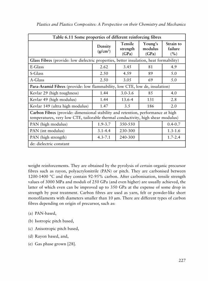
227
weight reinforcements. They are obtained by the pyrolysis of certain organic precursorfibres such as rayon, polyacrylonitrile (PAN) or pitch. They are carbonised between1200-1400 °C and they contain 92-95% carbon. After carbonisation, tensile strengthvalues of 3000 MPa and moduli of 250 GPa (and even higher) are usually achieved, thelatter of which even can be improved up to 350 GPa at the expense of some drop instrength by post treatment. Carbon fibres are used as yarn, felt or powder-like shortmonofilaments with diameters smaller than 10 μm. There are different types of carbonfibres depending on origin of precursor, such as:
(a) PAN-based,
(b) Isotropic pitch based,
(c) Anisotropic pitch based,
(d) Rayon based, and,
(e) Gas phase grown [28].
serbifgnicrofniertnereffidfoseitreporpemoS11.6elbaT
ytisneDmc/g( 3)
elisneThtgnerts)aPG(
s’gnuoYsuludom
)aPG(
otniartSeruliaf
)%(
serbiFssalG )ytilibamroftaeh,noitalusniretteb,seitreporpcirtceleidwol:edivorp(
ssalG-E 26.2 54.3 18 9.4
ssalG-S 05.2 95.4 98 0.5
ssalG-A 05.2 50.3 96 0.5
serbiFdimarA-araP )noitalusni,edwol,ETCwol,ytilibammalfwol:edivorp(
)ssenhguothgih(92ralveK 44.1 6.3-0.3 58 0.4
)suludomhgih(94ralveK 44.1 4-6.31 131 8.2
)suludomhgihartlu(941ralveK 74.1 5.3 681 0.2
serbiFnobraC hgihtaecnamrofrep,noitneterdnaytilibatslanoisnemid:edivorp()suludomraehshgih,ytivitcudnoclamrehtelbaroliat,ETCwolyrev,serutarepmet
)suludomhgih(NAP 7.3-9.1 055-053 7.0-4.0
)suludomtni(NAP 4.4-1.3 003-032 6.1-3.1
)htgnertshgih(NAP 1.7-3.4 003-042 4.2-7.1
tnatsnoccirtceleid:ed
Plastics and Plastics Composites: A Perspective on their Chemistry and Mechanics

228
Polymers in Construction
Depending on their mechanical properties, carbon fibres can be classified into four groups:
(a) PAN-based high modulus (HM), low strain to failure type,
(b) PAN-based high tensile (HT), high strain to failure type,
(c) PAN-based intermediate modulus (IM) type, and
(d) Mesophase (pitch) based.
The third of these belong to the HT type with high tensile strength and improved stiffness.Table 6.11 shows some mechanical properties of different types of carbon fibres.
6.4.3.5 Aramid/Kevlar Fibres
Aramids are aromatic polyamides. The two commonest members of this family are Kevlar(para-phenyleneterephtalamide, PPA) and Nomex (polymetaphenylene, PPD), which wereintroduced in the early 1970s. Kevlar has an aromatic ring structure which contributesto high thermal stability and the para configuration leads to rigid molecules that contributeto high strength and modulus. Kevlar is a liquid crystalline material. When Kevlar isextruded into fibre form, a highly anisotropic structure with a high degree of alignmentof straight polymer chains develops, giving rise to higher strength and modulus inlongitudinal direction of the fibre. In addition, there is fibrillation in the structure whichis believed to have a very strong effect on fibre properties and failure mechanisms. Someadvantages of using Kevlar are: they are tough and have good damage tolerances and donot have a conventional melting point or a Tg (estimated as >375 °C). In turn, Kevlardecomposes (in air) at around 425 °C and they are flame resistant. Para-aramid fibreshave a small but negative longitudinal (and a bigger positive transverse) TEC value.Kevlar fibre can be degraded chemically only by strong acids or bases, in addition to UVradiation. There are different types of Kevlar - Kevlar 29 (with high toughness), Kevlar149 (with ultra high modulus) and Kevlar 49 (with high modulus). In structural compositeproduction, Kevlar 49 is mostly used. Different short fibre forms and yarn counts ofKevlar fibres are also available. For Kevlar fibres, moduli ranges between 85-186 GPawhile tensile strengths are around 3.4-4 GPa, the latter of which is more than twice thestrength of Nylon 66 and 50% greater than that of E-glass.
6.4.3.6 Other Natural and Synthetic Polymeric Reinforcing Fibres
Natural polymeric fibres, mostly cellulosics, have been used since ancient times forreinforcement. Mechanical properties of these are inferior to glass, carbon or aramidfibres. Cellulosics are usually used as a laminating material, in the woven form. Processing
229
wood plastic composites (WPC) into profiles for building and construction applicationsis currently one of the most exciting businesses in extrusion. After the availability ofsynthetics, (i.e., polyamides, acrylics, polyolefins, etc.), and in particular, with ultra-highmodulus fibres later, new generation of synthetic fibres with high moduli (ultra-highmodulus fibres of 50-100 GPa, the value of which is about ten times those of conventionalfibres) are achieved. Recent introduction of polyether imide (PEI) fibres by Akzo (Enka)offer high temperature and good environmental resistances while paraphenylenepolybenzobisoxazole, (PBO) fibres by Dow have a unique combination of high strength,stiffness and environmental resistance, which offers high tensile strength and modulusvalues that are better than Kevlar. There is also the family of polybenzazoles (PBZ),which have good strength and moduli values.
Within these fibres, polypropylene fibres were used successfully to reinforcecement-based materials.
6.4.3.7 Use of Reinforcing Polymeric Fibres in Concrete
There is a considerable interest in use of polymeric fibres as reinforcements in concrete(FRP reinforcement [46]) and as structural shapes for building construction, to improvethe performance of new constructions or deteriorated constructions for repair andrehabilitation. These applications are limited to bars and laminates for the time being.Polymeric fibre reinforced bars are currently being used as the internal reinforcement inconcrete members (when the steel bars may not (desired, e.g., due to corrosion) [47, 48].Strengthening of concrete with externally bonded reinforced (EBR) FRP composites inthe form of laminates or near surface mounted bars (NSM) to repair and strengthenexisting structures is becoming a more established practice worldwide, specifically forrestoration of historical structures mainly due to their ease of application [49]. In eitherapplication, the use of FRP as structural reinforcement is accepted as a viable alternativeto classical types of reinforcement with many potentials offered. The use of FRP in concretestructures started some 25 years ago in Europe, and resulted for example in the firsthighway bridge in the world with FRP post tensioning cables in Germany in 1986 andstructural FRP shapes in the Aberfeldy bridge in Scotland in 1992, where glass fibre andaramid reinforced structural elements were used in the deck and towers bonded withepoxy. And the recent all composite bridge suitable for heavy traffic being built in DenDungen in the Netherlands. The FRP reinforcement market today is much larger andmore developed in North America and Japan. In both, the bulk of FRP applications arerelated to both reinforcing (as a substitute for steel) and for upgrading (retrofitting andrepairing) studies, particularly for strengthening of slabs, beams and columns in buildings.Some design guidelines on the use of FRP rods [49] and sheets are available [50]. Onedisadvantage of FRP bars are their unfavourable economy at the moment. Most glass
Plastics and Plastics Composites: A Perspective on their Chemistry and Mechanics

230
Polymers in Construction
fibre reinforced bar applications are in ‘cosmetic concrete’ or in constituent matricesother than Portland cement. Although they are used as top mat reinforcing for bridgedecks and seismic upgrading of masonry, they are commonly in demand in magneticresonance imaging areas in hospitals due to their magnetic transparency. They are usedin high voltage substations and reactive transformer pads as well as in airports and inradio frequency research labs for their electrical neutrality.
6.4.3.8 Different Reinforcing Fibre Forms
Depending on the final properties to be achieved and the processing method to be used,reinforcing fibres can be utilised in a number of different forms, i.e., as continuous orchopped. In the continuous form, individual filaments are usually available as a collectionof untwisted, parallel, 12 to 120 continuous individual strands (called rovings or tows).Continuous rovings are used in several polymeric composite processes, such as filamentwinding and pultrusion. For the twisted collection of filaments, the term yarn is used[51]. The most familiar forms of continuous fibres are woven rovings and woven yarns.Woven rovings and woven yarns can be either interwoven to produce braids, while knitscan be obtained by interloping chains of rovings and yarns [37]. Filament winding andpultrusion processes are used to produce pipes, tanks and structural composites, whereasrovings are passed through a resin bath and then shaped by winding the resin-impregnatedroving onto a mandrel or by pulling it through a heated die. Chopped strands with shortlengths of between 3 to 50 mm long are used with different sizings to enhance compatibilitywith most plastics. Chopped strands are used in a spray-up process where chopped strandsare sprayed simultaneously with liquid resin to build up reinforced thermoset parts onthe mould [52] or in the injection moulding industry, as well as in sheet and bulk moulding.
Fibres can also be prepared in the form of a mat consisting of randomly oriented shortfibres held loosely together by a chemical binder, sometimes in a carrier fabric, as acontinuous thin flat sheet. Mats are commercially available as blankets of various weights,thickness, and widths, which can be cut and shaped for use as preforms in some closed-mould processes and in hand lay-up, press moulding, bag moulding, autoclave moulding,and in various continuous impregnating processes.
Cut and shaped fibre forms ready for reinforcement are called preforms. During thepreforming process, dimensional materials, (e.g., mats, woven yarns, prepregs, etc.), areconverted into three-dimensional shapes. While prepregs are continuous unidirectionalor woven fibres (mainly aramid, carbon, and glass) pre-coated with a controlled quantityof an uncured catalysed resin matrix material (mostly epoxy, bismaleimide, phenolic, orpolyimide resin) [30], that are supplied in roll or sheet form and ready for immediateuse. The predominant methods of prepreg production are via a hot melt or a solventimpregnation. Prepregs are widely used for high-performance structural applications [15].

231
6.4.4 On The Mechanics of PMC
Mechanical properties of PMC are strongly influenced by the filler (by its size, type,concentration and dispersion) and by the properties of the matrix, as well as the extent ofinterfacial interactions and adhesion between them and their micro-structural configurations.The interrelation of these variables is rather complex. In FRC, the system is anisotropicwhere fibres are usually oriented uniaxially or randomly in a plane during the fabricationof the composite, and properties are dependent on the direction of measurement. Generally,‘the rule of mixture’ equations are used to predict the elastic modulus of a composite withuniaxially oriented (continuous) fibres under iso-strain conditions for the upper bound‘longitudinal modulus in the orientation direction’ (Equation 6.10).
E E V E Vc m m p p= +[ ] [ ] (6.10)
as well as lower bound ‘transverse modulus in the direction perpendicular to orientation’,for iso-stress condition (Equation 6.11) (and by assuming that the strains involved aresmall, deformations for matrix and fibre are both elastic and they both have the samePoisson’s ratio and that there is no de-bonding).
[ ] [ ] [ ]� = +� � �E V E V Ec m m p p1 1 1 (6.11)
where E, E´ and V are tensile, Young’s (longitudinal and transverse) and volume fraction,respectively; whereas subscripts c, m, p represent the composite, the matrix and theparticulate (fibre) components.
More specifically, transverse modulus is given by the modified Halpin-Tsai equation(Equation 6.12):
[ / ] [ ] / [ ]� = + �E E AB V B Vc c p p1 1 � (6.12)
where A is a constant depending on filler geometry and the Poisson’s ratio of the matrix(A is equal to twice the aspect ratio for uniaxially oriented fibres), B is a constant, changingas a function of A and relative moduli of the filler and matrix, and � is a constant thatdepends on maximum packing volume fraction of the filler [53-58].
Large particle reinforced composite systems are utilised with all three types of materials(metals, ceramics and polymers). Concrete is a common large particle strengthenedcomposite where both matrix and particulate phases are ceramic materials.
Composite strength is not as easily modelled as modulus as it depends on a number offactors such as the extent of interaction between matrix and fillers. As interfacial strength
Plastics and Plastics Composites: A Perspective on their Chemistry and Mechanics

232
Polymers in Construction
can be affected and reduced by the presence of water as it is adsorbed on the filler surfaceor by thermal stresses from mismatch between CTE values of the filler and the matrix. Infact there is an order of magnitude difference between CTE values of polymers and glass,formulation of composite strength becomes more difficult and complex. For compositebars, the design tensile strengths that should be used in design equations, is calculated as:
(design tensile strength of product) = (environmental design factor)× (tensile strength of the bar)
Where the environmental design factor is given for different fibre types and exposureconditions, i.e., for glass fibre (GF) for interiors it is 0.85 and for both exterior/aggressiveenvironment, 0.85 [48, 59].
As a final note, the ‘FRP-ConstruNet’ initiative sponsored by EU into the 6th FrameworkProgramme Network must be mentioned, which is created under the construction industryinitiative and it is technological, commercial - scientific and technologically oriented.
References
1. D. Feldman, Polymeric Building Materials, Elsevier Applied Science, London,UK, 1989.
2. F.W. Billmeyer, Jr., Textbook of Polymer Science, Wiley-Interscience, New York,NY, USA, 1984.
3. R.B. Seymour and C. Carraher, Jr., Polymer Chemistry: an Introduction, MarcelDekker, New York, NY, USA, 1992.
4. R.J. Young and P.A. Lovell, Introduction to Polymers, 2nd Edition, Chapmanand Hall, Cambridge, UK, 1991.
5. J.M.G. Cowie, Polymers: Chemistry and Physics of Modern Materials, 2ndEdition, Blackie, Glasgow, UK, 1991.
6. H.R. Allcock and F.W. Lampe, Contemporary Polymer Chemistry, Prentice Hall,Eaglewood Cliffs, NJ, USA, 1990.
7. F. Rodriquez, Principles of Polymer Systems, 2nd Edition, Hemisphere PublishingCo., New York, NY, USA, 1982.
8. R.B. Seymour and C.E. Carraher, Jr., Structure-Property Relationships inPolymers, Plenum Press, New York, NY, USA, 1984.

233
9. J.R. Fried, Polymer Science and Technology, Prentice Hall, Upper Saddle River,NJ, USA, 2003.
10. L.C.E. Struik, Polymer Engineering Science, 1977, 17, 3, 165.
11. L. Mascia and M. Xanthos, Advances in Polymer Technology, 1992, 11, 4, 237.
12. L. Mascia, Thermoplastics Materials Engineering, 2nd Edition, Elsevier AppliedScience, London, UK, 1989.
13. C.D. Han, Multiphase Flow in Polymer Processing, Part I, Academic Press, NewYork, NY, USA, 1981.
14. L.A. Utracki, Polymer Alloys and Blends, Thermodynamics and Rheology, Part 3,Hanser Publishers, Munich, Germany, 1990.
15. R.P. Sheldon, Composite Polymeric Materials, Applied Science Publishers,London, UK, 1982.
16. P. Dufton, Polymers in Building and Construction: Materials in Use andDevelopments in Markets, Rapra Technology Ltd., Shrewsbury, UK, 1997.
17. S. Stoeva, D. Benev and M. Karaivanova, Journal of Applied Polymer Science,1993, 47, 10, 1859.
18. R.H.B. Bouma, W.J. Nauta, J.E.F. Arnauts, T. Van den Boomgaard, J.M. Steutenand H. Strathmann, Journal of Applied Polymer Science, 1997, 65, 13, 279.
19. E.P. Chang, R. Kirsten and E.L. Slagowski, Journal of Applied Polymer Science,1977, 21, 8, 2167.
20. J. Daly, A. Britten, A. Garton and P.D. MacLean, Journal of Applied PolymerScience, 1984, 29, 4, 1403.
21. A. Chateauminois, V. Sauvant and J.L. Halary, Polymer International, 2003, 52,4, 507.
22. S-S. Lee, K. Cho and J. Kim, Journal of Polymer Science Part B: Polymer Physics,2001, 39, 21, 2635.
23. H. Laas, J. Mazanek, D. Knofel, K-G. Bottger and A. Reinschmidt, inventors;Bayer AG, assignee; US6051634, 2000.
24. M. Sychra and H. Steindl, inventors; Krems Chemie AG, assignee; WO9518276A1, 1995.
Plastics and Plastics Composites: A Perspective on their Chemistry and Mechanics

234
Polymers in Construction
25. H.E. Peply in Engineered Materials Handbook, Volume 2, Ed., T.J. Reinhart,ASM International, Metals Park, OH, USA, 1987.
26. C.T. Herakovich in Mechanics of Fibrous Composites, J. Wiley and Sons, Inc.,New York, NY, USA, 1998.
27. L. Hollaway Polymer Composites for Civil and Structural Engineering, BlackieAcademic and Professional, London, UK, 1993.
28. U. Riedel and J. Nickel, Die Angewandte Makromolekulare Chemie, 1999, 272,1, 34.
29. S.Y. Lou and T.W. Chou in Composite Applications: The Role of Matrix, Fibreand Interface, Eds., T.L. Vigo and B.J. Kinzig, VCH Publishers, Inc., New York,NY, USA, 1992, Chapter 2.
30. K. Simpson, Reinforced Plastics, 2003, 47, 4, 28.
31. S. Komameni, Journal of Materials Chemistry, 1992, 2, 12, 1219.
32. J.S. Moya, A.J. Sanchez-Herencia, J. Requena and R. Moreno, Materials Letters,1992, 14, 5/6, 333.
33. W.E. Frazier, M.E. Donnellan, P. Archietto and R. Sands, JOM, 1991, 43, 5, 10.
34. D.R. Clarke, Journal of the American Ceramics Society, 1992, 75, 4, 739.
35. M. Hunt, Machine Design, 1993, 65, 52.
36. L.H. Sharpe in The Interfacial Interactions in Polymeric Composites, Ed., by G.Akovali, NATO ASI Series, E, Volume 230, Kluwer Academic Publishers,Dordrecht, The Netherlands, 1993.
37. Handbook of Composite Fabrication Ed., G. Akovali, Rapra Technology Ltd.,Shrewsbury, UK, 2001.
38. L. Laverne and S. Matthis in Composites in Construction, a Reality, Proceedingsof the International Workshop, Eds., R. Cosenza, G. Manfredi and A. Nanni,2001, ASCE, Reston, VA, USA, p.19.
39. D.W. Halpin and M. Hastak in Composites in Construction, a Reality,Proceedings of the International Workshop, Eds., E. Cosenza, G. Manfredi andA. Nanni, 2001, ASCE, Reston, VA, USA, p.65.

235
40. M.M. Schwartz, Composite Materials, Volume 1: Properties, NondestructiveTesting and Repair, Prentice Hall, Upper Saddle River, NJ, USA, 1997.
41. L.A. Pilato and M.J. Michno, Advanced Composite Materials, Springer Verlag,New York, NY, USA, 1994.
42. W.D. Callister, Jr., Materials Science and Engineering: an Introduction, 2ndEdition, J. Wiley and Sons Inc., New York, NY, USA, 1991.
43. L.T. Manzione, J.K. Gillham and C.A. McPherson, Journal of Applied PolymerScience, 1981, 26, 3, 889.
44. L.T. Manzione, J.K. Gillham and C.A. McPherson, Journal of Applied PolymerScience, 1981, 26, 3, 907.
45. C. Kaynak, E.Sipahi-Salam and G. Akovali, Polymer, 2001, 42, 9, 4393.
46. A. Nanni in Composites in Construction: A Reality, Proceedings of anInternational Workshop, Eds., E. Cosenza, G. Manfredi and A. Nanni 2001,ASCE, Reston, VA, USA, p.9.
47. Guide for the Design and Construction of Concrete Reinforced with FRP Bars,ACI 440.IR-03, ACI, Farmington Hills, MI, USA, 2003.
48. Guide for the Design and Construction of Externally Bonded FRP Systems forStrengthening Concrete Structures, ACI 440.2R-02, ACI, Farmington Hills, MI,USA, 2001.
49. Recommendations for Design and Construction of Concrete Structures usingContinous Fibre Reinforcing Materials, Concrete Engineering Series 23, Ed., A.Machida, Japan Society of Civil Engineers, Tokyo, Japan, 1997.
50. Recommendations for Upgrading of Concrete Structures with Use of ContinuousFibre Sheets, Concrete Engineering Series 41, Japan Society of Civil Engineers,Tokyo, Japan, 2001.
51. M.P. Groover, Fundamentals of Modern Manufacturing: Materials, Processing,and Systems, Prentice Hall, Upper Saddle River, NJ, USA, 1996.
52. M.M. Schwartz, Composite Materials, Volume 2: Processing, Fabrication, andApplications, Prentice-Hall, Upper Saddle River, NJ, USA, 1997.
53. H. Brody and I.M. Ward, Polymer Engineering and Science, 1971, 11, 2, 139.
Plastics and Plastics Composites: A Perspective on their Chemistry and Mechanics

236
Polymers in Construction
54. A.P. Wilczynski, Composites Science and Technology, 1990, 38, 4, 327.
55. P.J. Hine, R.A. Duckett and I.M. Ward, Composites Science and Technology,1993, 49, 1, 13.
56. S.W. Tsai and H.T. Hahn, Introduction to Composite Materials, TechnomicPublishing Co., Westport, CT, USA, 1980.
57. M. Takayanaki, H. Harima and Y. Iwata, Memoirs, Faculty of Engineering,Kyushu University, 1963, 23, 1.
58. J.M. Illston and P.L.J. Domone, Construction Materials: their Nature andBehaviour, 3rd Edition, Spon Press, London, UK, 2001.
59. Anonym, Plastics Handbook, Modern Magazine, McGraw Hill, New York, NY,USA, 1994.

237
7 Plastics and Polymer Composites: APerspective on Properties Related to their usein Construction
Dorel Feldman
7.1 Foams
Polymer foams, also known as cellular polymers or cellular plastics, are multi-phasematerial systems (composites) that consist of a polymer matrix and a fluid phase, oneusually being a gas. Foam is a general term that refers to a material with any degree ofcommunication between its voids. The word cellular is used as a general term wherebythe cells may have any degree of interconnection - expanded polymers are compositeswith closed cells.
The rapid upsurge of interest in lightweight materials during the last few decades hasinevitably brought cellular polymers into prominence. These polymers offer an attractivecombination of properties, often at low cost and the types of material and range ofapplications is increasing rapidly. It is estimated that in 2000 close to 3.5 billion tons ofpolymer foams were produced and consumed in USA. Their annual growth is estimatedat 3-4%, most of which is in the construction, automotive, packaging and consumerproduct market [1].
Polymer foams have entered the construction industry by direct replacement ofconventional thermal insulation materials. Most foam can be made with a large spectrumof properties, densities and shapes to fulfil specifications. Nowadays it is possible tofoam virtually any polymer since a lot of the basic principles governing the foamingtechnology and its operations are applicable to a large number of macromolecularcompounds, but only a small number have been commercially exploited. Polymer foamsare made of thermoplastics or thermosets. While the former can be reprocessed andrecycled, the thermoset foams are intractable since they have a high degree of crosslinking.Even recycled polymers can be used for foam manufacturing [2]. Table 7.1 shows someexamples of thermoplastic and thermosetting foams.
The foams that dominate the market are made of polystyrene (PS), polyurethane (PU)and polyvinyl chloride (PVC). Phenolic foams are also used in a significant volume.These and PVC foam are becoming more interesting because of their low flammabilitycharacteristics. However, over the last few years there has been an increasing utilisation

238
Polymers in Construction
of engineering structural foams for load bearing applications. The polymers used includepolyisocyanurate (PIR), polyolefins, modified polyphenylene oxide, polycarbonate (PC),and acrylonitrile-butadiene-styrene terpolymer (ABS).
Polyimide characterised by thermal and thermal-oxidative stability at elevatedtemperatures, chemical resistance and good mechanical properties is relatively new inthe family of polymer foams [3]. In some cases, depending on the uses, additionalreinforcement can be included. Examples are fibre reinforced foams and syntactic foamswhich are composites containing hollow glass, ceramic or plastic micro-spheres dispersedthroughout the polymer matrix.
Due to their complex nature, polymer foams have been classified following differentcriteria such as:
(a) Composition (which refers to the kind of polymer the matrix is),
(b) Cellular morphology (open cell or closed cell), mechanical behaviour (rigid or flexible),
(c) Density (low density range 10-50 kg/m3, medium density range 50-350 kg/m3, highdensity range 350-900 kg/m3).
The open cell foams have a cellular network and the voids coalesce so that the solid(polymer matrix) and the fluid phases are continuous [4].
smaofgnittesomrehtdnacitsalpomrehtemoS1.7elbaT
remylopfoepyT sisehtnysfoedoM seitreporplacinahceM
CVP noitasiremyloP digirdnaelbixelF
SP noitasiremyloP digiR
UP noitiddayloP digirdnaelbixelF
RIP noitasiremirtolcyC digiR
edimayloP noitasnednocyloP digirdnaelbixelF
edimiyloP noitasnednocyloP digirimeS
)FP(scilonehP noitasnednocyloP digiR
)FU(stsalponimA noitasnednocyloP digiR
aeruyloP noitiddayloP digirdnaelbixelF
)PE(yxopE noitasiremylopgninepo-gniR digiR
edyhedlamrof-aeru:FU

239
Plastics and Polymer Composites: A Perspective on Properties Related to their use
At present, there are at least two approaches to the investigation of the cellular structureof foamed polymers. In the first one, which may be formally called a graphical approach,attempts are made to draw conclusions about the macroscopic properties frommorphological parameters such as geometry and stereometry of cells of various sizes andshapes. The second approach, which may be referred to as physico-chemical, attempts toexplain and predict the morphology from the data of the chemical composition of thematrix and the mechanism of foaming [3].
In practice, the two cellular morphologies can co-exist so that polymer foam is not alwayscompletely open or closed cell. The volume fraction of closed cells has a considerableinfluence on the mechanical properties of these systems so it is an important structuralcharacteristic. Ways to characterise and measure morphology that affects the solid andheat radiative contributions in closed cell foams have been recently developed [4].
Rigid foams can be crystalline, semi-crystalline or amorphous; in the last case, its state(glassy) is below its glass transition temperature (Tg), and the properties depend highlyon the existence of some crystalline domains and the extent of crosslinking. A flexiblecellular polymer is a system in which the matrix is in a state (high elastic) above its Tg.Most polyolefins, PS, phenolics, PC, polyphenylene oxide and some PU foams are rigid,whereas rubber foams, elastomeric PU, certain polyolefins and plasticised PVC are flexible.Intermediate between the two extremes is a class of semi-rigid foams.
The rigid cellular foams can be further subdivided into:
• Non-load bearing (non-structural foams) applications, such as thermal insulation, or
• Load bearing (structural foams) structural materials, which require high stiffness,strength and impact resistance.
Rigid foams are used mainly in building and construction, for insulation, tanks, pipes, etc.
From the structural point of view some foams can be homogeneous with a uniformcellular morphology or they may be structurally anisotropic. They may have an integralsolid polymer skin [5] or they may be multi component in which case the polymer skin isof different composition to that of the polymeric cellular core.
Microcellular polymers produced by gas nucleation, refer to closed cell thermoplastic foamswith a very large number of very small cells (of the order of 10 mm in diameter), typically108 or more cells per cm3. Microcellular thermoplastics have been obtained from a numberof different polymers, ranging in relative density from 0.1 to 1.0 kg/m3, containing 108 to1010 cells per cm3, offering a new range of properties for design [6, 7]. For examplemicrocellular PU foams can be obtained via polymerisation in carbon dioxide [8, 9].

240
Polymers in Construction
Most polymer foams are produced by one of the several known foaming techniqueswhich include, extrusion, compression moulding, injection moulding, reaction injectionmoulding, thermoforming, solid state technique (where pressurised gas is forced into asolid polymer at room temperature followed by depressurisation and heating to abovethe Tg of the polymer), spraying and so on [10, 11].
7.1.1 Foaming (Blowing) Agents
The gas phase in any polymer foam derives from the use of foaming (or blowing) agents inthe foam manufacturing process. In foam production, foaming agents and, in many cases,other auxiliary substances are added to the polymer. These components must be mixedvery thoroughly to prevent defects and irregularities in the foam. As foaming starts, themixture must be able to flow freely. Once the bubbles formed have attained the desired sizethey must be fixed. This is accomplished through the hardening of the polymer. The resultantcellular body is a solid-gas composite consisting of a continuous polymer phase and a gasphase either continuous or discrete created by the foaming agent. Depending on the natureof the cell-forming process, that is, whether it is a physical change of state or a chemicaldecomposition, blowing agents are classified as physical or chemical.
7.1.1.1 Physical Foaming Agents (Gaseous or Liquid)
Nitrogen, air, carbon dioxide, a mixture of air and helium, are examples of gaseous foamingagents used in the production of polymer foams. Nitrogen and air are preferred since theyare inert, nontoxic, non-flammable and have a low diffusivity with respect to the majorityof polymers. An air/helium mixture permits an easy control of the foam density.
Volatile liquids with boiling points less than 110 °C like the aliphatic hydrocarbons (fromC5-C7) are useful physical foaming agents. They undergo a phase change during the foamingprocess. They must be odourless, non-toxic, non-corrosive and non-flammable and have alow vapour thermal stability in the gaseous state and low permeability through the polymerand low global warming potential (GWP). Other requisites include thermal and chemicalstability and in some special cases appropriate solubility [12-14]. Since the efficiency of theliquid foaming agents is directly related to the ratio of specific volume of liquid, productswith high specific gravity combined with low molecular mass are most effective.
Halogenated aliphatic hydrocarbons possess such characteristics including a very lowthermal conductivity, and therefore are ideal physical foaming agents. However, in the mid1980s it became apparent that further increases in chlorofluorocarbon (CFC) concentrationsin the upper atmosphere would lead to long-term damage to the ozone layer. Internationalrecognition by scientists and political leaders culminated in the signing of the MontrealProtocol in 1987. This first international protocol addresses the global impact of CFC andoutlines a timetable for worldwide reduction of CFC consumption [15].

241
Recent measurements of the atmospheric chlorine content indicate that the equivalenteffective chlorine content in the northern troposphere has been decreasing. This demonstratesthat the phaseout of CFC has achieved a very positive environmental impact. In the rigidfoam applications, the alternative foaming agents are hydrochlorofluorocarbons (HCFC)with low ozone depletion potential (ODP), and hydrofluorocarbons (HFC) andhydrocarbons with zero ODP. In the USA, the phaseout of CFC-11 in rigid PU applicationswas made possible with use of HCFC-14b, which offers excellent thermal insulation andfire performances, especially compared to hydrocarbons. In the transitional period followingthe 1995 restrictions of ODP, HCFC-141b and HCFC-142b, compounds with somewhatsimilar insulating potentials might be used. But the international agreements ultimatelyrequire the use of zero-ODP foaming agents in these applications, (e.g., CO2, cyclopentanes,and certain HFC). The development of the next generation (zero ODP) foaming agents hasbeen underway for several years [16-19].
7.1.1.2 Chemical Foaming Agents
These are mineral or organic chemicals, usually solids, able to decompose at certaintemperatures and to liberate large amounts of gas. Most of them in well-defined temperatureintervals liberate in addition to nitrogen, other condensable gases such as CO2, CO andhydrogen. The residue of the decomposition process becomes part of the matrix and shouldnot affect any of the valuable properties of the polymer. Mineral foaming agents, mostlysalts or weak acids can release gas either by thermal dissociation or in the presence ofpromoters by chemical decomposition. The most important of these agents are ammoniumbicarbonate (decomposition temperature 60 °C), which doesn’t leave residue duringdecomposition, sodium bicarbonate (decomposition temperature interval 100-140 °C), andsodium borohydride (NaBH4; decomposition temperature 300 °C). In some case watercan also be used as a foaming agent [20, 21].
Organic chemicals able to release nitrogen as the main component of the liberated gasare the most important, their decomposition usually occurs in narrow temperature ranges,and it is an irreversible exothermic reaction independent of external pressure.
Organic foaming agents have some important advantages such as:
• The reaction which liberates the gas is irreversible.
• Some have the maximum gas liberation temperature close to the flow temperaturerange of the polymer matrix.
• They can be mixed uniformly with the necessary additives.
Plastics and Polymer Composites: A Perspective on Properties Related to their use

242
Polymers in Construction
The disadvantages of organic foaming agents consist of their high cost and in some casesin their toxicity. The non-gaseous products of their thermal decomposition must be takeninto account because they can plasticise the polymer, thus decreasing its stability. Mostof the known organic foaming agents fall into one of the following classes [22, 23]: azoand diazo compounds, N-nitroso compounds, sulfonyl-hydrazides, azides, triazines,triazols and tetrazoles, sulfonyl semicarbazides, urea derivatives, guanidine derivatives,esters. Almost all of these functional organic foaming agents are represented among thecommercial products.
7.1.2 Foam Manufacturing Technologies
The foaming mechanism that causes the development of bubbles and the process offormation of the cellular structure can be classified as mechanical, physical or chemical.In the mechanical foaming, the bubbles are created by using an agitator to stir a gas intothe mixture of matrix components, or by using high pressure to force the gas into themelted polymer. Latex foam rubber is made by mechanically induced frothing of a latexor liquid elastomer, followed by crosslinking of the polymer in the expanded state. In thephysical process, heat produces a low boiling liquid which evaporates, thus forming thebubbles. In chemical foaming, the blowing agent reacts under the influence of heat,releasing gases, which form the voids in the melted polymer beads obtained throughsuspension polymerisation [24].
Foaming processes lead to products with different shape such as: blocks, boards, sheets,slabs, moulded items and extruded profiles. Some polymer foams can be sprayed ontosubstrates to form coatings, foamed in place between walls, (i.e., poured into the emptyspace in liquid form and allowed to foam), or used as a core in more complex structureslike panels for the construction industry. Conventional technologies such as extrusion,injection moulding or simple expansion of polymer beads in moulds in the presence of afoaming agent are frequently used [25, 26]. Once the polymer has been expanded, thecellular structure must be stabilised through physical or chemical stabilisation, otherwise itwould collapse. If the macromolecular compound is a thermoplastic, expansion is carriedout above its Tg or melting point (Tm) and then immediately cooled below the Tm. This isphysical stabilisation. Chemical stabilisation requires expansion cooling process, acrosslinking reaction following the expansion. Thermoplastic foams like those made of PSor PVC are usually stabilised simply by cooling. Such polymer-foaming agent mixtures areoften extruded and expansion and simultaneous cooling occur as the system is extruded.Crosslinking occurs in the case of the formation of PU, epoxy and silicone foams [26].
The manufacturing of polymer foams can take place by many techniques [11, 27, 28],such as: continuous production of slabstock foams, compression moulding, injection

243
moulding of expandable beads or pellets, reaction injection moulding (RIM), extrusion,lamination (board production), foaming in place, spraying, vacuum forming. Theunderlayer of floor coverings are usually produced by mechanical foaming, i.e., theblowing of air through a plastisol during processing [29].
7.1.3 Thermoplastic Foams
The most used commercial thermoplastic foams are made of PS, PVC, polyethylene (PE),polypropylene (PP), ABS and cellulose acetate. Among these, the construction industryuses mostly the first two.
7.1.3.1 PS Foam
PS foams are generally rigid, closed cell and manufactured in densities ranging between16 and 180 kg/m3: most are in the 16-80 kg/m3 density range. Low density PS foamsused in the construction industry exist in the form of expanded or extruded products.The first type is produced from expandable PS beads (obtained through suspensionpolymerisation), by using hydrocarbons, halocarbons or a mixture of both as foamingagents. Confined in a mould and subjected to heat, the pre-expanded beads can producea smooth-skinned closed cell foam of controlled density, registering every detail of anintricate mould. To minimise the formation of a density gradient and to ensure uniformexpansion throughout the moulded product, expandable PS beads are pre-expanded tothe approximate required density by control of time and temperature, since the processof moulding does not increase the density [30].
To produce extruded PS foam, a molten PS-based compound containing a foaming agent isprocessed at a certain temperature range and pressure through a slit orifice to atmosphericpressure - the mass expands to about 40 times its pre-extrusion volume. It is produced inboard form with a continuous surface skin or in large billets (boards) that can be cut intostandard board or fabricated into desired shapes. The extruded foam has a more regularstructure than the moulded one, better strength and higher water resistance [10].
Table 7.2 shows some physical properties of commercial PS foams.
PS foams resist moisture well, but deteriorate when exposed to direct sunlight for longperiods of time as shown by a characteristic yellowing. The colour change is accompaniedby marked changes in the average molecular weight (MW) and in tensile strength [32].Multiple coats of water dispersed exterior paints, cement plaster, latex modified plastersand asphaltic emulsions can provide protection against physical damage. Mechanical
Plastics and Polymer Composites: A Perspective on Properties Related to their use
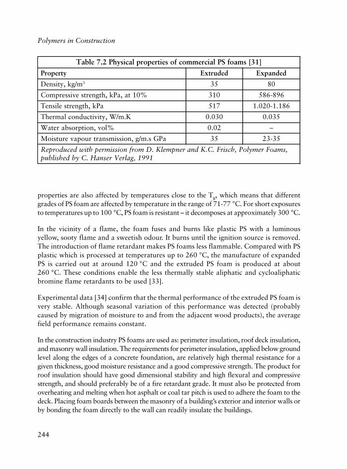
244
Polymers in Construction
properties are also affected by temperatures close to the Tg, which means that differentgrades of PS foam are affected by temperature in the range of 71-77 °C. For short exposuresto temperatures up to 100 °C, PS foam is resistant – it decomposes at approximately 300 °C.
In the vicinity of a flame, the foam fuses and burns like plastic PS with a luminousyellow, sooty flame and a sweetish odour. It burns until the ignition source is removed.The introduction of flame retardant makes PS foams less flammable. Compared with PSplastic which is processed at temperatures up to 260 °C, the manufacture of expandedPS is carried out at around 120 °C and the extruded PS foam is produced at about260 °C. These conditions enable the less thermally stable aliphatic and cycloaliphaticbromine flame retardants to be used [33].
Experimental data [34] confirm that the thermal performance of the extruded PS foam isvery stable. Although seasonal variation of this performance was detected (probablycaused by migration of moisture to and from the adjacent wood products), the averagefield performance remains constant.
In the construction industry PS foams are used as: perimeter insulation, roof deck insulation,and masonry wall insulation. The requirements for perimeter insulation, applied below groundlevel along the edges of a concrete foundation, are relatively high thermal resistance for agiven thickness, good moisture resistance and a good compressive strength. The product forroof insulation should have good dimensional stability and high flexural and compressivestrength, and should preferably be of a fire retardant grade. It must also be protected fromoverheating and melting when hot asphalt or coal tar pitch is used to adhere the foam to thedeck. Placing foam boards between the masonry of a building’s exterior and interior walls orby bonding the foam directly to the wall can readily insulate the buildings.
]13[smaofSPlaicremmocfoseitreporplacisyhP2.7elbaT
ytreporP dedurtxE dednapxE
m/gk,ytisneD 3 53 08
%01ta,aPk,htgnertsevisserpmoC 013 698-685
aPk,htgnertselisneT 715 681.1-020.1
K.m/W,ytivitcudnoclamrehT 030.0 530.0
%lov,noitprosbaretaW 20.0 –
aPGs.m/g,noissimsnartruopaverutsioM 53 53-32
,smaoFremyloP,hcsirF.C.KdnarenpmelK.DmorfnoissimrephtiwdecudorpeR1991,galreVresnaH.Cybdehsilbup
245
Due to its relatively good thermal resistance, stability to water and water vapour, ease offabrication and ease of bonding to other construction materials such as metals, wood,concrete or plaster faces, PS foams are widely used as a core for sandwich panels. Themost important drawback for this application is that it undergoes heat distortion.
7.1.3.2 PVC Foam
PVC foams differ from most other foams in having a broad range of characteristicsbecause they can be formulated in various ways, with different foaming agents, andusing different foaming technologies.
The foam for the construction industry is made mainly without plasticiser. Such an additiveis introduced in the manufacturing of flexible or semi-flexible foams.
The greatest interest in rigid PVC foam is in applications where low flammabilityrequirements prevail. Most PVC foam products are made with chemical foaming agentssuch as azobisformamide in amounts of 1 to 2 wt% [35]. They have an almost completelyclosed cell structure and therefore low water absorption.
A single-screw extruder or a twin-screw extruder is used for the manufacturing of PVCrigid foam. This type of foam is widely used as the core of some sandwich and multilayerpanels. The flexible one is used as the foam layer in coated fabric flooring. Its low vapourtransmission is an advantage when condensation might be a problem.
Due to the fact that foaming characteristics deteriorate with increasing MW, types ofPVC with a MW of fewer than 65,000 are preferred. If high demands are made on thephysical-mechanical properties of the semi-finished foam products, then types of PVCwith high a MW are used despite their inferior foaming characteristics. These can becompensated for by using a larger amount of foaming additive [36].
Some of the best advantages of PVC rigid foam are: low volume cost, good mechanicalcharacteristics (high tensile, compressive and shear strength), good chemical and weatherstability, low thermal conductivity, low water permeability, resistance to termites andbacterial growth, good fire stability and they do not crumble under impact or vibration.
Microcellular PVC foams with a relative density (density divided by the density of unfoamedpolymer) ranging from 0.15 to 0.94 and with a very homogeneous cell distribution andcell densities ranging from 107 to 109 cells/cm3 have been produced [37].
It is possible to produce rigid PVC closed cell foam with exceptional strength, through acrosslinking reaction with maleic anhydride, isocyanate and a catalyst [30].
Plastics and Polymer Composites: A Perspective on Properties Related to their use

246
Polymers in Construction
With regard to the mechanical properties, the rigid PVC foam with a low density of 40kg/m3 has a compressive and shear strength of about 0.34 MN/m2, a tensile strength of0.48 MN/m2 and a flexural strength of 0.38 MN/m2.
In the construction industry, PVC foam is used for wall panelling, as a flooring material,insulation of metallic pipes, shutter boxes, wall partitions, door panels, and windowboxes [36]. It is also used in sandwich panels to increase their stiffness [10].
7.1.4 Thermosetting Foams
In this group of products, foaming takes place at the same time with the chemical reaction(polycondensation) between the initial starting materials in view to produce the polymer.The most common are made of PU, PIR, PF, UF, EP, and silicone polymers. The mostversatile and most used in the construction industry are the foams based on PU and morerecently on PIR.
7.1.4.1 PU and PIR Foams
PU foam is available in flexible or rigid forms, closed and open cell. Its characteristicsdepend on: the nature of the starting components, the type of the foaming agent and thetechnology used. The starting components are polyisocyanates (prepolymers) and polyols(polyesters or more usually polyethers). The polycondensation takes place in the presenceof some additives such as a selected catalyst, a stabiliser, foaming agent and flame retardant.The heat released during the process is used to evaporate the resulting liquid physicalfoaming agent [38]. The use of water generated CO2 as a foaming agent, is well knownand produces a more stable foam, through higher thermal conductivity [39].
Though closed cell rigid PU foams are excellent thermal insulators, they suffer from thedrawback of unsatisfactory fire resistance even in the presence of phosphorus, and halogen-based flame retardants. From the flammability point of view, PIR, which are also basedon isocyanates have greater flame resistance than PU. PIR withstand service temperatureup to 149 °C compared with 93 °C for PU [35].
PIR foams are produced by using standard PU foaming equipment. Unmodified PIRfoams have a highly crosslinked structure, and therefore are extremely brittle. What didprove successful was to lower the crosslinking density of the foams by adding modifiers,which led to, modified polyisocyanurate foams such as [40]: urethane-modified PIR foam,amide-modified PIR foam, imide-modified PIR foam, carbodiimide-modified PIR foamand oxazolidone-modified PIR foam.

247
The most used technologies for producing rigid PU foams include foaming in place,spraying and continuous slabbing. Foaming in place is convenient especially for fillingirregular voids or cavities. It requires relatively portable equipment and, in many cases,is conducted outdoors or under poorly controlled conditions. The use of CFC providesrapid expansion or frothing. The resulting product is less uniform in quality than thoseformed in more controlled, in-plant operations [39]. The spraying technique permitsthin layers of PU foam to be built up on large, uneven surface areas and additional layerscan be applied. It is an effective way of insulating and sealing commercial and residentialbuildings. In all cases, the exposed, usually rough surface of sprayed foam must beprotected by fire resistant materials [10, 39]. The slab (block) or sheet produced byslabbing technology can be cut after curing or formed to a specific shape and size. Coatedsheets are widely used for construction applications such as roofing or facing for frameconstruction [35].
Chemically, rigid PU foam can be considered the most complex of polymer foams becauseof its high number of additives. It is the most widely used and it is the most expensive. Itoffers a series of advantages as a thermal insulator, such as: low thermal conductivity,light weight, high strength, extreme versatility with which it can be formulated to meet awide range of requirements, ability to form a strong adhesive bond with many materials,low water permeability, stability up to 90 °C, ability to be foamed in situ to fill complexshaped cavities. More recently introduced PIR foams, closely related to the PU foams,have higher thermal stability and inherently better flammability characteristics. Both PUand PIR rigid foams are usually anisotropic in their strength characteristics [41].
Rigid PU and PIR foams as normally used for building thermal insulation have a densityof 30-35 kg/m3. Thus the product is about 97% gas, which is contained in non-interconnecting cells with diameters in the range of 0.2-1.0 mm. The physical propertiesdepend on the interaction and separate contributions of the gaseous and solid phases.Strength depends on the polymeric phase, thermal conductivity depends on the gas phaseand dimensional stability depends on both phases. The most important parametersaffecting long-term dimensional stability can be brought together in four categories,which are: matrix strength, cell gas pressure, processing and plasticisation [42].
Dimensional stability in the case of closed cell foams is dependent on the ability of thefoam to resist atmospheric pressure. Changes in the internal cell pressure are due to thefact that the initial gas in the cells does not diffuse out quickly. The foam, to be stable,must resist the differential pressure.
Values of thermal conductivity (K factor) depend on density, closed cell content,composition of the gas. Cell size and orientation also affect the K factor, which decreaseswith the decrease of temperature independent on the nature of foaming agent [39].
Plastics and Polymer Composites: A Perspective on Properties Related to their use

248
Polymers in Construction
The time at which cell gas minimum pressure is obtained is dependent upon foam structure,i.e., number of cells, thickness of the cell membranes, foam size, ageing temperature andfacing material [42].
The two largest markets for PU and PIR rigid foams are in building thermal insulation,where they are supplied as sheets produced on a laminator and applied for roofing, sheathing,and facing panels. The sprayed foam is used for complex or uneven surfaces. The lowthermal conductivity of rigid PU foam allows thin wall design and more efficient use ofspace. PIR rigid foams are superior to PU and PS foams in terms of low rate of heat release(RHR) and low rate of smoke release, probably due to its higher decomposition temperature.
7.1.4.2 Phenolic (PF) Foam
The early technique for PF manufacturing was based on the expansion of novolac-hexamethylenetetramine (HMTA) mixtures. Now, the manufacturing is based on acidcatalysed process of a resole type PF with added foaming agent and surfactant [43].
PF foam has good chemical and thermal stability, high resistance to water transmissionand water uptake, good dimensional stability, high strength to weight ratio, high insulationvalue per cm, and good flammability characteristics. However, due to its high open cellcontent it has relatively low thermal resistance. The cell sizes of closed cell PF foams areabout half the size of typical PU and PIR foams. Thus there are more cell walls per cm3,which results in greater retention of insulation efficiency. Cell sizes vary in the range0.08-0.2 mm [44]. Thermal insulation efficiency can be improved by the application of asuitable skin material.
PF foam technology has progressed in recent years so that slabstock and laminated boardscan now be produced using continuous technologies. PF cannot match the versatility offoam/facing combinations developed by PU and PIR, but it offers to the constructionindustry a useful combination of physical, mechanical and fire properties.
The resole closed cell foam can be classified as: high closed cell content, low thermalconductivity, high fire resistance, and high closed cell content, low thermal conductivity andlow fire resistance. Both these types have a density of 40 kg/cm3, a thermal conductivity of0.02 kcal/m.h.°C, a closed cell content of 90%, a water absorption of 0.5 g/100 cm2, but thelimited oxygen index (LOI) is 50 for the first type and only 33 for the second one. Compressivestrength varies between 1.6 and 2.0 kg/cm2 and the tensile strength is 1.1 kg/cm2 [45].
While the fire characteristics are attractive to users, manufacturers have to overcomesome weak points of this foam such as: low productivity, high friability and low yieldrate in materials [10, 45].

249
7.1.4.2 Urea-Formaldehyde (UF) Foam
This foam is produced by polycondensation of urea with formaldehyde in an alkalinemedium, the reaction proceeding further under weakly acidic conditions. Becausefactory made foam slabs are easily damaged during transportation and occupyexcessive and uneconomical shipping volume, UF foams are produced on site byspraying from portable foaming equipment, containing the resin (prepolymer) stock,water solution and a hardener-surfactant solution. The system also contains a catalystand more often than not a mixture of foaming agents. A good foam sets within thefirst minute when it can be sliced if need be. It hardens fully within one day. Theresidual water vapourises from the cured foam. If the drying is too quick, it tends towarp, shrink or crack.
Home insulating foam in closed spaces, retains moisture on occasion for several years,mainly in cold climates. UF foam, having a density of 10-14 kg/m3, is the lightest ofthe polymeric insulating materials. It is white, has no mechanical strength even incompression, and does not support combustion and it is very friable. Commercialproducts have a closed cell content of about 80%. UF foams have a thermalconductivity of 0.022-0.029 W/m.K. Its maximum service temperature is very low,around 49 °C. If not formulated properly UF foams lose their insulation efficiency.Since they are water-absorbing, they lose this characteristic at high humidity [30].
A drastic decline in the production and use of UF foam undoubtedly resulted fromthe health danger from gaseous formaldehyde released by the foam due to the incorrectratio of components (excess of formaldehyde), high humidity, excess of foaming agent.As a result it was banned in some countries and in the USA, the Consumer ProductsSafety Commission (CPCS), ruled against its use [30, 46-48]. Gaseous formaldehydeis an irritant to the eyes, nose and throat, and is classified as ‘suspected humancarcinogen’ which should be controlled in workplaces to gas concentrations below 1ppm. In Australia this concentration should not exceed 0.1 ppm in dwellings andschools [49-54]. To reduce formaldehyde emission post-manufactured boardtreatments were proposed such as [55]:
• Application of scavengers as solids or aqueous solutions based on ammoniacompounds
• Exposure to scavengers as gases (ammonium, sulfur dioxide)
• Application of coatings
• Lamination with barrier materials, like polymer films, metallic films, impregnated paper.
Plastics and Polymer Composites: A Perspective on Properties Related to their use

250
Polymers in Construction
7.1.4.3 Epoxy (EP) Foam
EP foams are among the hardest and stiffest foams because they are highly crosslinked.The processing and final physical properties depend on their chemical compositionand degree of cure (crosslinking) [55]. Curing is realised using primary amines,anhydrides or polyphenols. The density can be adjusted by the amount of foamingagent. To achieve full strength, the foam should be postcured for several hours. Thedensities of EP foams range from 32 to 600 kg/m3. The low-density foams areserviceable up to 82 °C. At a density of 140 kg/m3 the compressive strength is around1 MPa and tensile strength 0.7 MPa [30].
7.1.4.4 Silicone Foam
Thermosetting silicone foams are available in densities from about 48 to 240 kg/m3.They can be moulded or sprayed in place. Board stocks are also available. Fillers andcrosslinking agents improve their physical strength and toughness. They possess goodlow and high temperature stability.
7.1.5 Special Foams
7.1.5.1 Syntactic Foams
These foams can be defined as composites consisting of hollow microspheres and apolymeric matrix. This one is made of a thermosetting (PU, PIR, PF, EP, silicone orunsaturated polyester) or of a thermoplastic (PE, PP, PVC, PS, polyimide) [56].The microspheres can be made of silica, glass, carbon, ceramics or polymers suchas PS, PE, PP, polyamide (PA), polymethyl methacrylate (PMMA), divinyl benzene(DVB)-maleic anhydride, and so on [56-58]. The diameter of the tiny hollow spheresis 300 mm or less [35]. They contain an inert gas such as nitrogen or a CFC. Theproperties of these syntactic foams depend on: matrix type, microsphere type (andthe contained gas), ratio matrix to microspheres, curing process, productiontechnology. Syntactic foams can be made in combination with the conventionalones. Such a complex composite can be formulated into a mouldable mass thenshaped or pressed into cavities.
Epoxy syntactic foams are the best-known representatives of this type of specialfoam. The main disadvantage of such a matrix is its high viscosity at ambienttemperature, but the adding of diluents can circumvent this [20].

251
7.1.5.2 Structural Foam
The term ‘structural foam’ designates components possessing skins and cellular cores,similar to structural sandwich panels. For structural proposes, they have favourablestrength and stiffness-to-weight ratios, because of their sandwich type configuration.Frequently, they can provide enhanced structural performance at reduced cost ofmaterials and for this reason they are replacing structural parts, mainly those made ofwood, metals or solid plastics. High-impact PS (HIPS) is the most widely used structuralfoam, followed by PP, high-density polyethylene (HDPE), and PVC. The sandwichtype structure of PU with a smooth integral skin produced by RIM provides a highdegree of stiffness and excellent thermal and acoustical properties [31].
7.1.5.3 Microcellular Polymers
Microcellular polymers are closed cell thermoplastics produced by gas nucleation. Theyhave a high number of very small cells with a diameter of 10 μm, and bubble densitiesin excess of 100 million per cm3. First produced in the early 1980s with the objectiveof reducing the amount of polymer used in mass produced items, these novel materialshave the potential to revolutionise the way thermoplastic polymers are used today.PVC, PS, polycarbonate (PC), polyethylene terephthalate (PET) and not only thesepolymers can be applied for such kinds of products. As no harmful chemicals are usedin the microcellular technology, it is likely that these new products will replace manytypes of foam now produced by processes that damage the environment [59].
7.1.5.4 Acoustic Insulation Foams
The acoustic characteristics of polymers are altered in a cellular structure. Soundtransmission changes only slightly, because it depends mainly upon the barrier density,in this case the polymer phase. Therefore polymeric foams are poor materials forreducing the transmission of the sounds. They are however, effective in absorbingsound waves of certain frequencies.
In open cell structures the gas is air and for this reason they have a higher absorptivecapacity of moisture, a higher gas and vapour permeability, less effective insulationcapabilities for either heat or electricity, and a better ability to absorb and dampensound. For any polymer composite, the proportion of open gas structural elementsincreases as the density of the foamed plastic decreases, because an increase in cell sizemeans a decrease in the thickness of cell walls and ribs [60]. The combination of otheradvantageous physical properties with fair acoustic characteristics has led to the use ofplastic foams in sound proofing [31].
Plastics and Polymer Composites: A Perspective on Properties Related to their use

252
Polymers in Construction
Many open cell foams such as PU, PIR, PS and integral foams based on polyphenyleneoxide are used in construction for acoustic insulation [61-63]. UF and PF foam are usedfor interior sound absorbing floors [31].
7.1.5.5 Electrical Insulation Foams
Organic polymers are inherently electrical insulators, as a consequence of theirmicrostructures of covalently bonded discrete molecules, a characteristic which has longbeen exploited for restricting access and affording environmental protection to metallicconductors carrying electrical power. Plastics are used also to restrain high electricalfields. The expansion of plastics industry that occurred in the 1940s led to the replacementof rubber insulation with PVC.
Unlike the common plastics, conductive polymers offer a unique combination of propertiesthat make them attractive alternatives to traditional conducting materials. Polymers,which are conducting rather than insulating, offer properties providing excitingpossibilities for new applications [64].
The substitution of a gas for part of the polymeric matrix usually changes the electricalproperties. The dielectric constant, dissipation factor, and dielectric strength are loweredroughly proportionally to the amount of gas in the foam. The lower the density of thecellular plastic, the lower the dielectric constant and the better the insulation. Becausethe dielectric strength is also reduced, the insulation is susceptible to breakdown fromvoltage surges from lightning and short circuits. Polyolefin foams are preferred for lowfrequency electrical insulation - PVC, PS foams, silicone and fluoropolymer foams arealso used [31, 65, 66].
7.2 Ageing
The rate of deterioration of materials depends on their nature, for the hardest rocks, thetime scale stretches to millions of years, whereas for some organic polymers, majormodifications can be induced by exposure of only a few days. Ageing is often usedsomewhat interchangeably with the term degradation.
The ageing process of polymers occurs in a wide variety of environments and serviceconditions, and very often limits the service lifetime [67]. Ageing is the adverse ordetrimental change in a desired physical or chemical property. This process is primarilycaused by the climatic stresses of sunlight, pollutants, temperature and water (dew,humidity, rain, snow). To serve satisfactorily, polymers, like most materials, must meet

253
the more stringent requirements of general use in terms of sustaining their function witha minimum of change in properties. They have to be maintained in a wide range ofsituations including use under rigorous weather, that is the case for some plastics used inconstruction [68, 69].
Polymer degradation can be caused by chemical factors (oxidation-degradation,hydrolysis), heat (thermal-degradation), light (photo-degradation), ionising radiation(radio-degradation), mechanical action (mechanical-degradation), or by fungi, bacteria,yeast, algae, and their enzymes (biodegradation).
In principle, there are a few ways to control the ageing process, such as through the useof stabilisers, by avoiding unnecessary thermal exposure, and by excluding oxygen andwater as much as possible [70]. Stabilisation is the procedure of slowing down the rateof degradation. Free radical stabilisation techniques commonly used include: UV screeners,UV absorbers, free-radical scavangers, excited-state quenchers and peroxide decomposers[71, 72]. Because of synergistic action of radiation and oxygen, antioxidants as well asUV absorbers are generally added to construction plastics designed for exterior use.
The profound knowledge of polymer ageing is useful to develop stable polymer materials.It is well known that ageing affects not only the microstructure but also the morphologyof polymers [73].
The deleterious effects of weathering on construction polymers used outside buildingshave been ascribed to a complex set of processes in which the combined action of UVlight and oxygen are predominant [72, 74-80]. Biodegradation of polymers is due first tothe attack of its additives (plasticisers, antioxidants, processing aids, stabilisers, dyesand extenders) by microorganisms such as bacteria and fungi via enzymic action. Theseadditives are more susceptible to biological attack than the polymer and only after theirattack degradation does take place [81-84]. In order for biodegradation to occur, someprerequisites must be satisfied [82]:
• The presence of fungi, bacteria, actinomycetes, and so on
• The presence of oxygen, moisture and mineral nutrients
• A temperature in the range of 20-60 °C depending on the type of microorganism
• A pH in the range of 5 to 8.
With today’s accelerated weathering equipment, it is possible to generate reliableweatherability information in a matter of days or weeks [85].
Polymer composites in outdoor applications are susceptible to photoinitiated oxidationleading to surface degradation and are also sensitive to moisture-induced damage, alkaline
Plastics and Polymer Composites: A Perspective on Properties Related to their use

254
Polymers in Construction
solutions or saline solutions [86, 87]. The durability of polymer composites inenvironments such as replacements for steel reinforcing bars in concrete (a highly alkalineenvironment), off-shore and marine structures is one of the primary issues limiting theiracceptance in infrastructure applications [86].
Physical ageing effects are operative for all polymer composites (based on thermoplastics,thermosets) representing semicrystalline, amorphous and highly filled amorphous matrices.Time/ageing-time and time/temperature superposition are found to be valid proceduresfor short-term creep behaviour; they cannot be applied to long-term creep behaviour[88]. The ageing in the form of creep performance has been analysed for a large series ofpolymer composites. Physical ageing causes a significant reduction in the creep of suchsystems and its influence is comparable in magnitude to that of temperature [89].
A study [90] shows that in the case of glass fibre/polymer composites, the environmentalattack by moisture for example, can degrade the strength of the fibre, plasticises thematrix, swells or microcracks the matrix, and degrades the fibre/matrix interface byeither chemical or mechanical attack. The relative rates of these degradation processesare a function of the type of the polymer, temperature, exposure time, degree of stress(cyclic, static), type of the fibre, its coating and the nature of the coupling agent.
The ageing of polymer foams is due to a more complex mechanism because it can beproduced by matrix degradation, by changes in gas composition or because of both.During ageing the foam structure and the main properties such as thermal conductivityin the case of thermal insulation, are modified.
After manufacturing, the composition of cell gas in many cases is based on a CFC (Freon)and CO2. For example the PU cell membranes are permeable to the gases present in thefoam, though to a different extent, as measured by the diffusion coefficients. The CFChaving a higher molecular weight diffuses much more slowly than nitrogen, oxygen wateror carbon dioxide molecules. A minimum of cell gas pressure versus time is obtainedbecause carbon dioxide diffuses out at a much faster rate than other gases. The time atwhich this cell gas minimum pressure is obtained is dependent upon foam structure, i.e.,number of cells, thickness of the cell membranes, foam sample size, ageing temperatureand facing material [42]. The mass transport of each gas species occurs by three modes:permeation through the cell walls, diffusion across the cells interior and infusion andeffusion through breaks and holes of the cell walls [39]. The net effect of the dilution oflow thermal conductivity CFC with gases with higher thermal conductivity (oxygen,nitrogen, water vapour) is a gradual increase in the K value of the foam. The change inthis characteristic is due rather to the influx of air than to the efflux of CFC, since thechange in CFC content is small compared to the increase in the concentration of nitrogenand oxygen in the cells (Figure 7.1).

255
In the ageing process the gas composition in the cells will change gradually towards theequilibrium, i.e., until the composition in the cells is equal to the surrounding air.
Foam ageing depends strongly upon its application and the facer material. If faced withdiffusion-tight barriers, the low initial thermal conductivity remains unchanged [38]. Akey factor tending to diminish the effectiveness of facing on foam slabs is the lack ofgood adhesion of the faces to the rigid foam substrate. This lack of good adhesion occursfrequently with commercial products. Many detailed laboratory studies have been carriedout to determine the effects of long-term ageing on the thermal conductivity of the polymerfoams [42-44, 91-95].
PU foam withstands, without difficulty, both water and a wide range of petroleumproducts, but has poor resistance to mineral acids, and moderate resistance to a widerange of organic solvents. Recently it was pointed out that the changes in physical andmechanical characteristics (thermal conductivity, open pores content, strength) duringlong-term ageing of PU foams are explained by influence of thermal and thermal-oxidativedegradation of the polymeric matrix [96].
7.3 Electrostaticity
The electrical charge capacity of an item depends on the condition of its surface, on thedielectric constant, the surface resistivity, and the relative humidity of the surrounding
Figure 7.1 Diffusion of nitrogen and oxygen
Plastics and Polymer Composites: A Perspective on Properties Related to their use

256
Polymers in Construction
atmosphere. While the charge capacity is inversely proportional to the dielectric constantand relative humidity, it is directly proportional to surface resistivity. The sign of theelectrical charge is invariably from the material with the higher to the one with the lowerdielectric constant. An electrostatic discharge event can produce sufficient energy to ignitesome materials, resulting in fire or explosion.
Due to their composition, most plastics are powerful insulators, a property that makesthem indispensable materials for high frequency equipment (radar). An associateddrawback of the electrical insulation characteristic is the accumulation of static electricity,which is not discharged fast enough due to the low surface conductivity of most plastics,a difference between plastics and metals. The material, which gains electrons, becomesnegatively charged, while the material that loses electrons acquires a positive charge[97]. In an explosive environment, this sudden transfer of charge may be energetic enoughto serve as an ignition source [98-100].
There are three basic routes to modify the static discharge behaviour of plastics used inbuilding or other applications:
• Incorporating electro-conductive fillers into the plastic compound
• Incorporating migrating, internal antistatic agents
• Treating the finished product with a coating (painting) of an external antistatic agent[97, 101, 102].
Internal antistatic agents are of interfacially active character, and via migration accumulateon the surface of the plastic product. Their molecules posses hydrophobic and hydrophilicgroups; the former confer a certain compatibility with the polymer and the hydrophilicgroups take care of the binding and exchange of water on the surface. They are anionic,cationic or nonionic compounds [97]. External agents are applied to the surface of theplastic material in the form of aqueous or alcoholic solutions.
Besides the charge control agents (also called charge additives, charge assistants or chargedirect agents), there is a class of compounds able to stabilise triboelectric charge. Theyare called charge stabilisers. In comparison with charge control agents, they show lowercharging magnitude but higher long-term stability [103].
Many recent studies deal with flooring materials [104-106], elctrostatically actuatedwindow [107], electrostatic testing of materials [108], charge transfer metal/polymer[109], a new unsaturated antistatic polymer able to be used for a storehouse of inflammableand explosive materials [110].

257
7.4 Fire Safety
Most national fire safety strategies are based on prescriptive approaches that have beendeveloped historically to meet fire safety needs, often in the wake of major fire disasters.Building regulations of most countries have codes that can be stated in very generalterms, as seeking to insure that [111]:
• The structure remains stable for the required period (fire resistance),
• The fire is contained within defined compartments by the appropriate fire separatingelements (fire resistance),
• Internal spread of fire (and smoke and toxic gases) is restricted within the building(reaction-to-fire and fire resistance),
• Spread of fire from one building to another is limited (reaction-to-fire andfire resistance),
• Adequate means of escape are provided (reaction-to-fire and fire resistance), and
• Access and provision are maintained for firefighting and rescue.
Fire is a continuous threat to life and property. The human cost is financially incalculable.
The demand of better and safer engineering materials has lead to a rapid proliferation ofhigh performance polymers in the building construction and other industries. Polymersused in building for thermal and acoustic insulation, panels, carpets, frames for door orwindows, floor tiles, cable insulation, paints, wallpaper, etc., are exposed to fire. Mostbeing organic polymers, are combustible, decompose thermally, and decompositionproducts burn. In the case of polymers used in buildings, fire safety combines: thermaldecomposition, ignition, flame spread, heat release, smoke obscuration, ignition, andother characteristics [112].
Our environment is largely one of organic polymers and these materials burn, whethernatural like wool or wood, or synthetic. With improved building design, home fire deathsdecreased in USA about one-third between 1980 and 2000 from 5200 to 3420; civilianfire deaths in 2000 were 38% lower than in 1980. Plenty of factors were involved,including much wider use of smoke detectors and greater public awareness about fireprevention. Even though the rate of home fires has fallen, it remains twice that of mostEuropean countries and the number of deaths by fires is still about the same.
Polymers are degraded by intense heat to yield micromolecules in gas or liquid state,which are often flammable and thus provide fuel in a fire situation. These combustion
Plastics and Polymer Composites: A Perspective on Properties Related to their use

258
Polymers in Construction
products can be determined by gas chromatography, nuclear magnetic resonance (NMR)spectroscopy, infrared (IR) spectroscopy, mass spectroscopy, and others. Additivity ofmolar groups appears to be a viable method for calculating the heat release capacity ofplastics from their chemical composition based on the high correlation between measuredand calculated values [113]. Presence or absence of a flame or spark gives the pilot orauto ignition temperature, which varies from one polymer to another. For example, PUfoam used for thermal insulation has a pilot ignition temperature of 310 °C and an autoignition one of 416 °C, compared with the PS foam where the pilot ignition temperatureis 316 °C and the auto ignition is 491 °C.
The continuous rapid growth of applications of polymers in construction and other areascoupled with the rising proportion of deaths attributed to toxic gases/smoke, have led towidespread concerns over the toxicity of burning polymers and their possible contributionto the trend.
Nonflammable polymers, by definition, possess significant fire-resistant properties becauseof their chemical structure or due to some additives. All thermally stable plastics belongto the broad nonflammable plastic group, but a number of them within this group possessperformance characteristics that are different. Halogenated polymers such as PVC,fluorinated polymers or those, which contain flame retardant, are classed as fire resistant.In fact, every plastic can be improved by the addition of fireproofing agents [114-118].
Combustibles must be produced before the ignition of polymers to flame. By heating aplastic it eventually reaches a temperature at which the weakest bonds start to break, andlittle change occurs such as discoloration. At higher temperature pyrolysis: ‘an irreversiblechemical decomposition due to an increased temperature without oxidation’ plays themain role in the production of combustible gases in the burning of plastics [119].
The process starts at ignition and continues after it to the complete consumption of thematerial if the heat fed back from flames to the plastic is sufficient to keep its rate ofdegradation above the minimum value for feeding the flame itself. Otherwise, the cycliccombustion process stops and the flame extinguishes.
The essential requirements for fire are: heat, oxygen and fuel [120], as illustrated inFigure 7.2. Once combustion has occurred, the course of the fire often accelerates rapidly,passing from ignition initiation through fire propagation to fully developed fire and itsdecay (Figure 7.3) [121].
Plastic characteristics related to their combustion are ignition and flash point, thermalconductivity, specific heat capacity and exothermic heat of combustion. Ignition occurs when asufficient amount of combustibles (gases or liquids) are produced. The combustion mechanismis complex and involves reactions between radicals resulting during plastic degradation [120].
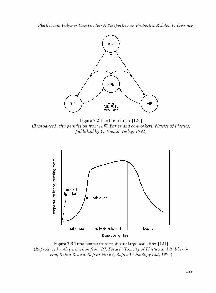
259
Figure 7.2 The fire triangle [120](Reproduced with permission from A.W. Barley and co-workers, Physics of Plastics,
published by C. Hanser Verlag, 1992)
Figure 7.3 Time-temperature profile of large scale fires [121](Reproduced with permission from P.J. Fardell, Toxicity of Plastics and Rubber in
Fire, Rapra Review Report No.69, Rapra Technology Ltd, 1993)
Plastics and Polymer Composites: A Perspective on Properties Related to their use
260
Polymers in Construction
In the early studies of the combustion of organic materials, their reaction to fire wasdefined by the time to ignition and rate of flame propagation. The experience acquiredon causalities, and building damage in fires has led to the consideration of othercharacteristics of building materials such as: rate of heat release (RHR), optical density,toxicity and corrosiveness of smoke produced on burning. About 800 tests have beendeveloped worldwide to characterise the plastic’s reaction to fire. Many such tests havebeen designed to measure the same characteristics, with however, contradictory resultsin some cases [122].
Fire resistance has a very special meaning, relating to the ability of an assembly to remainstructurally stable in the presence of a fire. It does not mean resistance to ignition or toflame spread. An example is ‘self extinguishing’ which implies that a product will be safein the presence of fire. All that is really meant is that if a small flame is applied on to thesurface of a sample, than any burning will cease after its removal. It is also thought thatonce a product has passed a test it is fire safe, and will remain so throughout its workinglife. None of this is true. No test can guarantee fire safety [123].
Fire testing and classification of building and other materials are based on certainflammability characteristics such as: flame spread, ignition temperature, smokedevelopment, non-combustibility, fire resistance, rate of heat release, oxygen index, etc.Some of them are briefly discussed in the following paragraphs [124-126].
Steiner tunnel tests (ASTM E84) [127] measure the surface flame spread of a material.The specimen is exposed to an ignition source, and the rate at which the flames travel tothe end of the specimen is measured. The severity of the exposure and the time a specimenis exposed to the ignition source are the main differences between the tunnel test methods[119]. The data obtained provide a measure of fire hazard, in that flame spread cantransmit fire to more flammable materials in the vicinity and thus enlarge a conflagration,even though the transmitting material itself contributes little fuel to the fire.
Tunnel testing provides data on: burning rate or combustion rate, burning extent ordistance of flame travel, flame spread factor and flame height. It is a mandatory test forflooring materials and many others. Materials are rated on flame spread classificationwith red oak as 100:
• Moulded plastics range between 10 and 100
• Polymer composites between 15 and 160
Flash ignition temperature is defined as the lowest initial temperature of air passingaround the specimen from which a sufficient amount of combustible gas is evolved to beignited by the external pilot flame. Self-ignition temperature is defined as the lowest
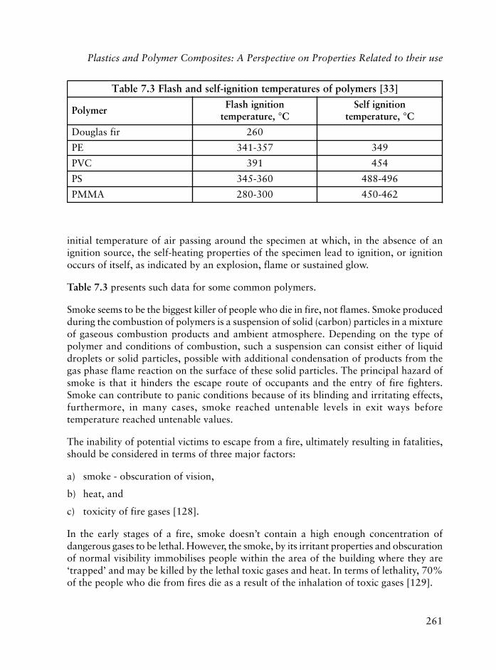
261
initial temperature of air passing around the specimen at which, in the absence of anignition source, the self-heating properties of the specimen lead to ignition, or ignitionoccurs of itself, as indicated by an explosion, flame or sustained glow.
Table 7.3 presents such data for some common polymers.
Smoke seems to be the biggest killer of people who die in fire, not flames. Smoke producedduring the combustion of polymers is a suspension of solid (carbon) particles in a mixtureof gaseous combustion products and ambient atmosphere. Depending on the type ofpolymer and conditions of combustion, such a suspension can consist either of liquiddroplets or solid particles, possible with additional condensation of products from thegas phase flame reaction on the surface of these solid particles. The principal hazard ofsmoke is that it hinders the escape route of occupants and the entry of fire fighters.Smoke can contribute to panic conditions because of its blinding and irritating effects,furthermore, in many cases, smoke reached untenable levels in exit ways beforetemperature reached untenable values.
The inability of potential victims to escape from a fire, ultimately resulting in fatalities,should be considered in terms of three major factors:
a) smoke - obscuration of vision,
b) heat, and
c) toxicity of fire gases [128].
In the early stages of a fire, smoke doesn’t contain a high enough concentration ofdangerous gases to be lethal. However, the smoke, by its irritant properties and obscurationof normal visibility immobilises people within the area of the building where they are‘trapped’ and may be killed by the lethal toxic gases and heat. In terms of lethality, 70%of the people who die from fires die as a result of the inhalation of toxic gases [129].
]33[sremylopfoserutarepmetnoitingi-flesdnahsalF3.7elbaT
remyloPnoitingihsalF
,erutarepmet °CnoitingifleS
,erutarepmet °C
rifsalguoD 062
EP 753-143 943
CVP 193 454
SP 063-543 694-884
AMMP 003-082 264-054
Plastics and Polymer Composites: A Perspective on Properties Related to their use

262
Polymers in Construction
The nature of smoke produced during the burning of polymers depends to a large extenton their chemical composition, pyrolysis conditions and oxidation processes.
For example, during the incomplete combustion of PVC, a thick fog, which containsdroplets of hydrochloric acid, is produced. In general, this acid is formed from thecombustion of chlorine-containing materials, the most notable of which is PVC.Hydrochloric acid is both a potent sensory irritant and a pulmonary irritant, being alsocorrosive to sensitive tissues such as the eyes [130].
Polymers like polyoxymethylene (POM) and polyethylene terephthalate (PTFE, Teflon),do not form hydrocarbon compounds during combustion and do not exhibit an inclinationtowards formation of soot. Polyolefins, which form predominantly aliphatic hydrocarbonsduring pyrolysis, are less inclined to form soot than others like PS, styrene copolymers orABS, which produce aromatic hydrocarbon [131].
Most of the tests done for smoke characterisation are gravimetric or optical, the lattermeasures the density of smoke accumulated in an enclosure or density of smoke pastspecific location [132].
Toxicity of smoke is measured by analytical or biological methods [133], and is definedas the action of some agents upon an unprotected individual, which impairs the vitalfunctions of the human organism.
The nature of smoke particles and its toxic gas emission vary besides the factors alreadymentioned with the fire temperature. The toxic components of smoke can be: asphyxiants(carbon monoxide, carbon dioxide, hydrogen cyanide) or irritants (hydrochloric acid,aldehydes, organic acids, others). Between 200 and 400 °C, low yields of hydrocarbonspecies derived from the partial breakdown of polymer macromolecules are observed.Between 400 and 700 °C an extensive breakdown takes place and oxygen from thesurrounding atmosphere is incorporated in the combustion products. In such circumstancesvery irritant species such as aldehydes and organic acids are produced. Above 700 °Corganic compounds will be decomposed and some rearrangements with the formation ofpolycyclic aromatic hydrocarbons (thought to be precursors of carbonaceous smoke)together with hydrogen cyanide (HCN) from polyacrylonitrile (PAN) or other nitrogen-containing polymers will be produced. The lethal dose of HCN is approximately 20 timeslower than that of carbon monoxide (CO). The toxicity of HCN comes from the inhibitionof cytochrome oxidase (an enzyme) activity and respiratory arrest from disturbed centralnervous system functionality is usually the cause of its induced death [119].
The nature of fire products and yields depends on the amount of oxygen present in thecombustion system. Above 12% oxygen, a significant amount of toxic CO will be released[121]. CO is undoubtedly an important toxic component of smoke and major threat in

263
fires. Although it is less toxic than some other gases, it is always very abundant. It combineswith haemoglobin forming carboxyhaemoglobin. The affinity of CO for haemoglobin isabout 240 times higher than that of oxygen. If even a small part of haemoglobin hasbeen converted to carboxyhaemoglobin, this has a high impact on the oxygen carryingcapacity of blood and the supply of this vital component [119].
Experiments done on polymers for the insulation of cables used in buildings (Hypalon,PVC, PE, PP, Teflon and others) indicate that these materials constitute in general arelatively low flammability risk in terms of flame spread rate or thermal exposure totheir environment. However, most of them release smoke components that are bothcorrosive and toxic [134, 135].
‘Rate of Heat Release’ (RHR) determines the size of a fire and such data are key tocomputer fire models. In principle, a reasonably sized sample is exposed to such radiation(up to 100 kW/m2) with an igniting flame and the heat generated by the burning sampleis measured over time intervals [123, 136-138]. The burning of the materials used inconstruction yields a nearly constant value of 13.1 MJ energy per kg of oxygen consumed.A set of equations was developed for an ‘open system’ which is not dependent oncontrolling the oxygen input to the system, but only for measuring the oxygen ‘deflection’of the output gases [139, 140]. Some RHR data on polymers are presented in Table 7.4.
The limited oxygen index (LOI) is defined as the minimum concentration of oxygen in anoxygen-nitrogen atmosphere, necessary to support a flame [141]. The test is carried out on
]321[sremylopfoatadRHR4.7elbaT
etisopmocroremyloPelpmaS
noitatneiro
taehtseT,xulf
m/Wk 2
m.nim/JM,RHRlatoT 2
nim3 nim5 nim01
enerpoennorevocCVP latnoziroH01 8.1 0.3 8.4
02 4.5 7.7 5.41
etisopmocPRG lacitreV 02 9.1 8.21 4.61
etanimalenimaleM lacitreV02 9.6 7.9 0.01
53 9.51 5.81 2.22
teksaggnizalgenerpoeN lacitreV 53 6.5 5.11 8.52
citsalpdecrofniererbifssalG:PRG
thgirypoC,761-061.pp,3,8,ngiseDdnaslairetaM,rednellA.J.PmorfdetnirpeRreiveslEmorfnoissimrephtiwdecudorper,)7891(
Plastics and Polymer Composites: A Perspective on Properties Related to their use

264
Polymers in Construction
a film specimen in a variable mixture of oxygen and nitrogen. Work was done to determinewhich change in gas composition alters the burning characteristics of the polymeric materialfrom a self-extinguishing to burning classification. LOI relates the relative flammability ofa material to any other one provided that the material was able to burn in pure oxygen[142]. Polymer LOI value (Table 7.5) is not an absolute measure for the flammability andcombustibility, it is affected by the sample thickness, pressure, flame temperature, heatcapacity, thermal conductivity, melting temperature, and the existing additives beside itscomposition. For some polymers like PE, PMMA and PS, LOI values are independent ofthickness in the range of 0.2 to 1 cm and decrease only slightly with smaller thicknesses.For epoxy, polyimide and PF, LOI decreases with the increase of the temperature [143].
Flammability tests for polymers are discussed in detail in other papers [119, 120, 123,138, 143-152].
7.4.1 Flammability of Polymer Foams
The wide acceptance of polymer foams in construction has led to the necessity of developingsuch materials of low combustibility often combined with a low smoke evolution during fire.Their characterisation from the point of view of fire safety is a very complex task because ofthe fact that such materials can potentially be exposed to a large variety of ignition sourcesand circumstances and the environment influences their performance in a fire.
]441-241[sremylopemosrofatadIOL5.7elbaT
remyloP IOL
MOP 61,51
AMMP 71,61
PP 71
SP 81,71
FP 12
AVP,lohoclalynivyloP 22
6edimayloP 62,52
lA%05htiwdellif(PE 2O3) 52
)digir(CVP 74,54
edirolhcenedilynivyloP 06
EFTP 59

265
A relatively large amount of unfavourable publicity has appeared in the media related totheir flammability, smoke and toxicity aspects. Examples are the major fire in 1992 at avegetable processing facility in Yuma (Arizona, USA), in 1996 at the internationalobservatory in Hawaii, in 2002 in nightclubs in Chicago, Rhode Island and Bali. Producersof polymer foams have made determined efforts to demonstrate that these products do notpresent an unacceptable fire hazard when properly installed and maintained [153, 154].
The fire behaviour of polymer foams is largely dependent on their exposure to air and isdominated by the characteristic low thermal inertia which permits the surface to respondvery rapidly to any imposed heat flux and consequently ignition; maximum rates ofburning can be achieved very quickly. Approaches toward reducing the flammability ofpolymer systems, in general, can be grouped in several categories [25, 142, 155-176]:
• Dilution of the polymer with non-flammable additives, such as mineral fillers.
• Incorporation of materials which decompose when heated, to release non-flammablegases such as nitrogen, or carbon dioxide.
• Addition of flame retardants which catalyse char rather than from flammableproducts.
• Tailoring polymer macro structure which favours char formation.
• Incorporation in the foam of additives able to stop the free radical chain reactionswhich occur during combustion.
• Formulation of products, which decompose thermally with a net endothermic reaction.
The most common route to improve the non-flammable behaviour of polymer-basedproducts including foams is the addition of flame retardant. A number of basic types offlame retardant additives are in commercial use such as: phosphorus containing products,halogen containing additives, mixtures of halogen compounds with antimony oxide,nitrogen and boron compounds, alkali metal salts, hydrates of metal oxides. Somesynergistic interactions between flame retardant can be expected to lead to efficient systems[25, 156, 157]. Studies were done also on ternary reactions among polymer, organo-halogens and metal oxides in the condensed phase under pyrolytic conditions [158].
Flame retardant additives operate in several ways. The minerals are resistant to fire andabsorb heat. Due to the fact they are likely to be good heat conductors, they carry heatrapidly away from local hot spots, thus preventing or delaying the possibility of thetemperature rising to the ignition point. For example, hydrated alumina whosedecomposition retards the raising of temperature until the water evapourates. Aromatic
Plastics and Polymer Composites: A Perspective on Properties Related to their use

266
Polymers in Construction
additives are able to sometimes form char in a cellular form that insulates the substrateagainst heat and access by oxygen, thus reducing the chance of fire. Flame retardantadditives interfere with the mechanical integrity of plastic products and often requirereinforcement to salvage strength.
The relatively low temperatures of manufacturing of PS foams (120 °C for expandedand about 200 °C for the extruded one with physical blowing agents) enable the lessthermally stable aliphatic and cycloaliphatic bromine flame retardants such ashexabromocyclohexane or dibromoethyl dibromocyclohexane to be used. Using NH4Bran important increase in LOI of PS was obtained [158]. Brominated flame retardant ishighly effective in improving fire safety cost-effectively [177]. PS foam can produce moltendrips (especially in ceiling applications) and with some formulations these drips burn.However, the presence of bromine containing flame retardant is able to delay the ignitionof molten PS. However, in large fires PS foam burns with the generation of a densesmoke. If the foam is behind plaster or concrete facings, the extent of burning is usuallylimited to a small area near the original site of the fire [148].
Improved technologies of manufacturing PU foams led to the use of reactive flameretardants, which have the advantage over the additive flame retardants of providing apermanent effect. Polyols, isocyanates containing phosphorus, halogens (usually bromine)or both are the most used reactive flame retardant [33]. PU foams containing such flameretardant have to be produced with technologies, which exclude completely the presenceof the water because of their sensitivity to hydrolysis. High levels of brominated aromaticester polyol result in lower flame spread and smoke, but generally, with reduced physicalproperties and poorer dimensional stability (Figure 7.4). With phosphorus flame retardantin the presence of sodium molybdate the toxicity of pyrolysis and combustion productsdecreased [178].
Phosphorus containing flame retardants are used as phosphates, phosphonates, phosphinesand phosphinic oxides. Halogen-containing phosphate esters such as bromine and chlorinein the form of tris (halogen alkyl) phosphates are popular [33]. The effects of phosphorusand brominated additives on flexible PU foam were compared [179]. Melamine hasbroad utility as a flame retardant additive in flexible PU foams [180].
The fineness of the fire retardant particles and the state of development of the polymerproduct surface have a significant influence on their ignition and combustibility. Howeverthese aspects have not yet been investigated to a satisfactory extent [181, 182].
PU foams do not melt in a fire but burn to produce pyrolysis gases, dense smoke andsome char. The rate of their burning depends on the type and amount of fire retardantpresent in the foam.

267
PIR foam behaves similarly to fire retarded PU foam in the early stages of a fire, but the charformation significantly restricts the spread of the fire. Recognition of the efficient fire barriercharacteristics of glass fibre reinforced PIR foam chars has allowed new PIR formulationseven some without flame retardants. Such composites generate less smoke than PIR foam.
The presence of ammonium polyphosphate and melamine cyanurate filler causes a slightworsening of the physical and mechanical properties of PU and PIR foams but the firebehaviour of flame retarded foams is better than that of unfilled foams. In particular theuse of the previously mentioned mixture, which produces a synergistic effect causes asignificant improvement of the fire performance. This is characterised by a remarkabledecrease of RHR and weight loss without worsening smoke opacity and toxicity [183].
PF foams offer to the construction industry a useful combination of physical andflammability characteristics. They generate low levels of smoke in most fire tests. It wasreported that a cupric complex of a macro heterocyclic compound is an effective stabiliserfor thermo-oxidative decomposition of PF foams above 200 °C. An amount of 0.25-5.0pph permits significant decrease of ignitability [178].
Figure 7.4 Effect of fire retardants on flammability of PU foams [153](Reproduced with permission from P.J. Briggs, Cellular Polymers, published by Rapra
Technology Ltd., 1985, 4, 265)
Plastics and Polymer Composites: A Perspective on Properties Related to their use

268
Polymers in Construction
Some flammability data [153] of expanded PS (EPS), PU, PIR and PF foams are presentedin Table 7.6.
Chemical modification of UF foam and the use of inorganic phosphorus and nitrogencontaining flame retardants are a general approach to UF flame retardancy. Hardlycombustible UF foams with closed cells were developed by chemical modification and byadding 1-2 pph of phosphorus compounds. Using a level of 2-2.5 pph, an important increaseof time for the beginning and termination of burning process was observed [178].
The fire performance of plastics as electrical insulating materials was recently studied [184].Short circuits or ground faults were responsible for the largest percentage of thermal andacoustical insulation (normally in a concealed space), fires in buildings. The largest share of thecivilian injuries occurred in fires began by cutting or welding too close to combustibles [185].
Although still a relatively new area of development, the polymer nanocomposites showgreat promise as fire retardant materials. Not only can the combustion properties of thematerials be modified but in many cases the mechanical properties are also improved [186,187]. In such product with about 3% clay, the RHR decreases 20-60%, depending onpolymer matrix without affecting at this loading the mechanical properties [188].
7.4.2 Flammability of Composites
The polymer matrix is by far the most important component of the composite indetermining the combustion characteristics. Under fires, the glass fibre doesn’t burn and
m/gk53htiwsmaofdigirfoatadytilibammalF6.7elbaT 3 ]351[ytisned
tsetytilibammalF SPE UP RIP FP
IOL 82 42 03 64
,erutarepmetnoitingihsalF °C 543 582 514 094
,erutarepmetnoitingifleS °C 094 005 015 054
mm,)gninrublatnoziroh(daerpsemalF 73 521 01 41
%,noitarucsbomumixamekomS 08 58 03 3
edomgnimalf-nonniytisnedekomS 52 021 07 8
edomgnimalfniytisnedekomS 003 033 031 01
ybdehsilbup,sremyloPralulleC,sggirB.J.PmorfnoissimrephtiwdecudorpeR.5891,.dtLygolonhceTarpaR

269
does not, therefore contribute to the combustion of the glass fibre reinforced polymer(GFP). The other common fibre reinforcements, carbon, aramid, ultra high molecularweight PE (UHMWPE) will burn under normal fire conditions, but their contributionsto the fire are generally much smaller than that of the matrix [189].
Fibre reinforced polymers (FRP) were found to generate higher amounts of productsassociated with incomplete combustion such as carbon monoxide and smoke, comparedto ordinary combustibles [190].
The fire characteristics of many FRP with different matrices and various fibres have beenstudied [191-195]. Heat resistant composites with very low smoke density, toxicity andcorrosivity were obtained with a group of flame retardants (based ondihydrobenzoxazines) which don’t contain halogen, sulfur or phosphorus [196]. Also,glass fibre reinforced resole phenolic composites have some outstanding fire properties,e.g., low RHR and low toxic smoke emissions [197].
Intumescent technology emerged in polymer science comparatively recently as a techniqueensuring the fire protection of polymers and composites. Intumescent systems stop thecombustion at an early stage, i.e., at the stage of thermal decomposition which isaccompanied with the release of flammable gaseous products. The intumescent processconsists of combining carbon (coke) formation and swelling of the surface of the burningpolymer [198]. A coating of intumescent resin retards the combustion of the organiccomponents present in GRP composites and also significantly reduces the area affected bythe flame, drastically reducing the volume of smoke and practically eliminating burning.The specially formulated resin gives fire protection by foaming in situations where GRPlaminates are exposed to direct flaming. The resin can be applied by brush as a flowcoating, normally to the reverse side of the building panel where it will provide fire retardantproperties. Mineral fillers impart varying degrees of flame retardancy to GRP [199]. Aninorganic intumescent coating was developed for the protection of FRP. This one releasesonly water vapour when it is exposed to fire, so it is safer than organic coatings [200].
7.5 Environmental Hazards
There is a two-way relationship between plastic materials and the environment. The firstone, which is well studied, is known as weathering: that means the effect of the environmentalfactors on plastics that leads to their ageing during outdoor exposure. The second onedeals with the effects of plastics and their additives on the environment [69, 74, 201, 202].
The effect of plastics on the environment is manifested outdoor and indoor. The mostimportant outdoor effects come from: plastics industry emissions, the ozone depletion
Plastics and Polymer Composites: A Perspective on Properties Related to their use

270
Polymers in Construction
produced by halogenated additives in plastics and other products, potential productionof dioxins and furans on the incineration of PVC in mixed municipal solid waste streams,and from disposed of end-of-life plastic products in sanitary landfills [203].
The indoor environment polluted by emissions from organic polymeric building materialssuch as plastics, paints, adhesives, wall covering, etc., have a strong impact on the indoorair quality (IAQ) and from it on people’s comfort and health. IAQ is an importantdeterminant of population health and well being but in spite of this, its control is ofteninadequate. Presently, few of the hundred known IAQ pollutants have been addresseddirectly by guidelines. From the draft of World Health Organisation (WHO) statementsit follows that national and international organisations have an obligation to establishcriteria for acceptable IAQ [204]. Allergies, other hyperactive reactions, sick buildingsyndrome (SBS), airway infections, lung cancer, etc., are associated with IAQ in buildings[205]. The term SBS has come into vogue during the past several years and refers tocomplaints of illness made by building occupants [206].
More information on this subject is presented in Chapter 10, and additional referencesare also provided on this topic [207-236].
7.6 Recycling
For ecological and economical reasons, materials recycling is of great importance as anintegral component of plastics waste management.
The economic driving forces for recycled plastics have been anything but constant duringthe last 50 years due to large fluctuations in prices of virgin materials and supply. Earlyrecycling efforts were seen only as a means of lowering material’s consumption withinthe industry by mixing clean, uncontaminated processing waste with virgin material.During the 1960s, virgin material prices fell abruptly and recycling activities stagnated.In the 1970s they picked up again as an oil embargo caused material shortages. Duringthe late 1980s material prices decreased again. As legislative pressure on industry andconsumer preferences are evolving, however, recycling is becoming less of an option andmore of a necessity and business opportunity [201].
Plastics became in the 1990s the symbol of a throwaway society and were regarded as amajor culprit of the landfill crisis. The response of the industry is plastics recycling [237-241]. Severe restrictions are being imposed on two of the most popular waste managementtechniques, landfill and incineration [201].
Plastic building products occupy the second place in quantity of residual plastics inmunicipal waste [242]. The important benefits of polymer recycling consist in a reduction

271
of waste generation, less need for landfills and from an economic point of view a reductionof the consumption of resources. However the amount of used plastic waste from theconstruction sector is likely to increase in the future and so issues relating to recyclingneed to be addressed [243].
The life cycle of most plastics starts with the extraction of natural gas or crude oil. Thelatter one is cracked into naphtha which is refined into ethylene, propylene, styrene,benzene, etc., the basic polymer feedstock. The next step is polymer synthesis followedby the third one, polymer processing into different items for application and consumption.Sooner or later, all plastics end up as waste that can be incinerated, dumped (land filling)or recycled and re-used [241, 244]. The recycling of plastics and all polymers in generalis important to both conservation of materials and conservation of energy [245]. InEurope the amount of plastics in the municipal solid waste is about 10% (in weight), PEand PP representing 55% of the total and PVC, 25%. As we can see from the Table 7.7,the building plastic wastes are in second place after the packaging waste [242].
%nietsawlapicinumniscitsalplaudiserfonigirO7.7elbaT]242[
gnigakcaP 52
gnidliuB 12
scinortcele-yticirtcelE 51
gnitniap,hsinrav,muG 01
elibomotuA 7
gnihsinruF 5
erutlucirgA 4
suoenallecsiM 31
srehsilbuPcimedacArewulKfonoissimrepdnikhtiwdetnirpeRdnasoillaG.P.GybtnemnorivnEdnagnissecorPlareniMmorf
.692egap,2elbaT,8991,)srotidE(sitaM.H.K
Recycling of plastics can be done chemically or mechanically [245-248]. Chemicalrecycling is based on techniques which degrade the macromolecules (pyrolysis, oxidation,combustion for energy recovery, etc.), leading to monomers (like styrene, methylmethacrylate) which are able to be reused in polymerisation technologies or to produceoil-like products. In the case of mechanical recycling, products are melted down, whilethe polymer itself doesn’t suffer any change. Only thermoplastics which form the highest
Plastics and Polymer Composites: A Perspective on Properties Related to their use
272
Polymers in Construction
volume of the waste, qualify for this type of recycling. A type of recycling of plastics bysurface refurbishing (coating application, polishing) [249] was also proposed. It isrecognised that a variety of recycling and recovery processes will be required in order tobe able to deal with scrap composite material from a wide range of sources and in varyingquantities [250]. So far processing of mixed plastics wastes, such as ‘tailings’ frommunicipal solid waste (MSW), after minimum refining has seen uses in building as timberreplacement (‘plastic lumber’) [251].
Recently a fluorescent tracer system was proposed for automatic identification and sortingof waste plastics [252]. The system is based on the following three elements: the use ofselected tracers in the polymer, a high speed system for identification of the tracers, aprocess for automatically separating the plastics identified.
The reluctance of most polymers to mix with one another has important ramifications inthe plastics recycling technologies. Sometimes compatibilisers are necessary. While somebelieve it is simply an industrial conspiracy that prevents recycling of plastics, it is actuallyquite difficult to achieve [253].
7.6.1 Recycling of Some Polymers Used in Building
A technology (Encap) has been developed that will remove expanded PS and otherexpanded polymers from the waste products. This process represents a cost-effectivemeans of solving a major environmental problem associated with producing and recyclingfoams and other plastics. It mixes ground, recycled expanded PS and other recycledcellular plastics with a proprietary phenolic resin hybrid, and pours them into a mould,and after remoulding the resulting item can be used [254]. The applications suggestedfor this technology are: roofing, insulation sheathing for wall and low-slope roofassemblies, stress skin panels to wood, or cardboard for structural purposes, soundabsorbing and decorative for furniture wall systems.
Research done by the PU industries has shown that there is a range of technology optionsfor manageing PU wastes in addition to the practice of land filling. Chemical recycling(glycolysis, hydrolysis, etc.), mechanical recycling and energy recovery are the main optionsunder development [255]. Economically and environmentally sustainable closed-loopchemical recycling of PU has been a goal of the PU industry for many years [256].
For low density, flexible high resilient and rigid PU foam post-consumer wastes, a modifiedsolid state shear extrusion (SSSE) technique was applied for their pulverisation. The finepowder obtained can be used as a filler and/or reinforcing material for polymers andmineral products with improved mechanical properties [257].
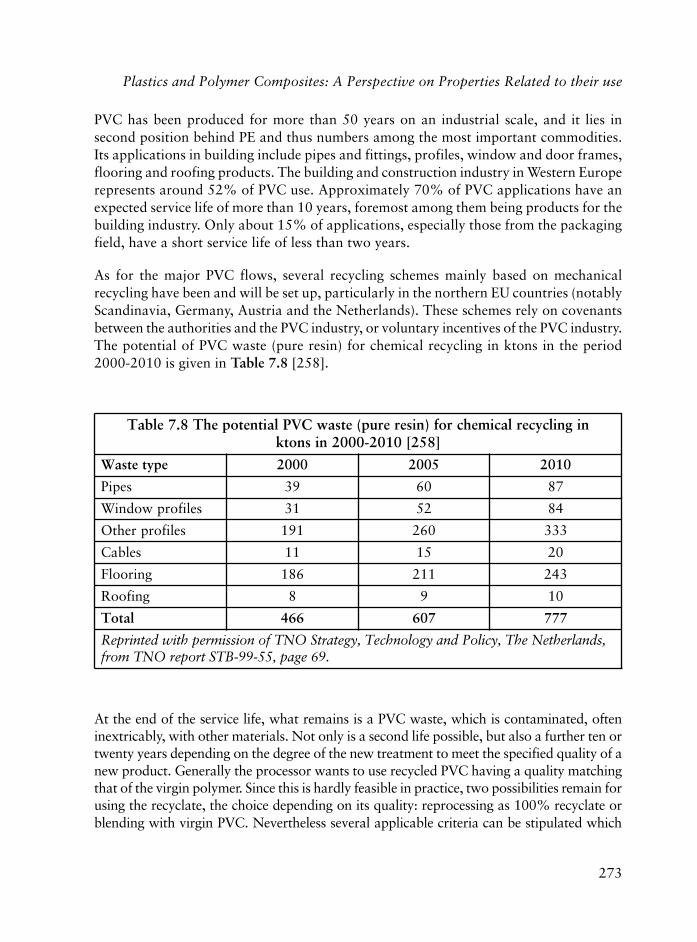
273
PVC has been produced for more than 50 years on an industrial scale, and it lies insecond position behind PE and thus numbers among the most important commodities.Its applications in building include pipes and fittings, profiles, window and door frames,flooring and roofing products. The building and construction industry in Western Europerepresents around 52% of PVC use. Approximately 70% of PVC applications have anexpected service life of more than 10 years, foremost among them being products for thebuilding industry. Only about 15% of applications, especially those from the packagingfield, have a short service life of less than two years.
As for the major PVC flows, several recycling schemes mainly based on mechanicalrecycling have been and will be set up, particularly in the northern EU countries (notablyScandinavia, Germany, Austria and the Netherlands). These schemes rely on covenantsbetween the authorities and the PVC industry, or voluntary incentives of the PVC industry.The potential of PVC waste (pure resin) for chemical recycling in ktons in the period2000-2010 is given in Table 7.8 [258].
nignilcycerlacimehcrof)nisererup(etsawCVPlaitnetopehT8.7elbaT]852[0102-0002nisnotk
epytetsaW 0002 5002 0102
sepiP 93 06 78
seliforpwodniW 13 25 48
seliforprehtO 191 062 333
selbaC 11 51 02
gniroolF 681 112 342
gnifooR 8 9 01
latoT 664 706 777
,sdnalrehteNehT,yciloPdnaygolonhceT,ygetartSONTfonoissimrephtiwdetnirpeR.96egap,55-99-BTStroperONTmorf
At the end of the service life, what remains is a PVC waste, which is contaminated, ofteninextricably, with other materials. Not only is a second life possible, but also a further ten ortwenty years depending on the degree of the new treatment to meet the specified quality of anew product. Generally the processor wants to use recycled PVC having a quality matchingthat of the virgin polymer. Since this is hardly feasible in practice, two possibilities remain forusing the recyclate, the choice depending on its quality: reprocessing as 100% recyclate orblending with virgin PVC. Nevertheless several applicable criteria can be stipulated which
Plastics and Polymer Composites: A Perspective on Properties Related to their use
274
Polymers in Construction
determine both the direction and limits of recycling: sorting by MW or by colour, size reductionand pulverisation, compatibilisation or by contamination with other materials [259].
For collecting purposes with a view to recycling of PVC waste, it is recommended that asingle material is used, for example window profiles [260-263]. Complete PVC windowframes are made of 38% PVC, 34% glass, 24% metal, 4% other materials. Such a framecontains 18 kg PVC [264].
The mechanical properties of recycled PVC are detrimentally affected by the presence ofcontaminants which act as stress concentrators and so cause premature failure uponloading. Pulverisation of the recyclate to reduce the size of such impurities results inimproved properties that compare with those of pure grades. Often contaminants can beother polymers such as PET, PE, paper, and so on [265]. In many countries especiallyEuropean countries, PVC windows are now the first choice, ahead of those made fromconventional materials and recycling is increasing to meet this demand. Thanks to theirlife span of up to 40 years without necessary maintenance, the qualities of these windowframes currently entering the waste stream are modest. This will increase over time asmore are used and as the windows, which were installed in the sixties, enter the wastestream. Germany already has automated plants for recycling PVC window frames.
The recycled polymer can be used in new frames making up the core layer (two-thirds byweight) while virgin PVC forms an external layer in a coextrusion process. These profilesperform just as well as those from the virgin polymer and, after another 10 years ofservice, are ready for another recycling loop [259, 263].
PVC pipe producers have been collecting PVC pipes that have been used for 10, 20 or30 years but far from having reached the expected service life which is 100 years andmore. Large quantities of used PVC pipe are expected at the earliest beyond 2010. Theprocessing of recycled PVC pipes through coextrusion is convenient for layered productswith virgin PVC on the side contacting with other materials, and the recycled one onthe other side [266].
Manually sorted PVC scrap flooring can be coarsely and then finely ground. Sieves andwind sifters are used to remove plaster, glass cloth, adhesive residues and other adheringcontaminants, so that this treatment step yields a PVC flooring recyclate whose purity ishigher than 99% including fillers. The recyclate is reformulated with added plasticisers,fillers and serves as a dry blend for new, calendered PVC flooring. Such multi-layer PVCflooring may contain up to 70% of recyclate material.
Experience gained over the next few years will show how far recycled material fromscrap roofing membrane can be re-used in new roofing membranes, tunnel membranes,protective membrane, civil engineering membrane, and so on [257].

275
Another segment for recyclate is the substitution of conventional construction materialssuch as hardwood, non-structural lumber, or concrete. It is precisely the plastics specificcharacteristics from which technological advantages can be derived, leading to a lowsystem cost as long as a comparable lifetime can be achieved [251, 267, 268].
There have also been attempts to chemically recycling PVC scrap [269].
7.6.2 Reclaim Plastic Scrap
The fear of the waste crisis in the late 1980s helped to create the thermoplastic scrapreclaiming business. Most processing plants have to reclaim reprocessable scrap, flash,rejected parts, etc. The goal is to eliminate scrap, because it has already cost money andtime to go through the process. The reprocessing starts with the transformation of scrapin pellets, by using a granulator. Blending the reclaimed material with the virgin onedefinitely influences and can significantly change the melt processing conditions and theperformance of the end product [270, 271].
7.6.3 Biodegradable Plastics
Environmental awareness has led to the design and development of degradable plastics[271]. Biodegradable polymers are completely degraded via microbial attack. The term‘biodegradable’ has in recent years become part of the ‘green’ vocabulary.
New concepts are now known in material sciences and materials degradation suchas [272]:
• The production of materials which must have strength and functionality while in usebut which become degradable after service.
• Polymers should come from renewable resources instead from petroleum.
• Save materials by improved product design and by recycling.
To achieve degradability, the units (mers) of the macromolecular chains have to be sensitiveto hydrolysis and oxidation at higher temperatures. Some polymers are sensitive tobiodegradation by enzymes and/or microorganisms while others in later stages ofdeterioration can be biodegraded. Addition of biopolymers to synthetic polymers canprovide susceptibility to auto-oxidation due to the porous matrix left after the degradationof the biopolymer. Combining several methods of degradation in a material is a successfulmode of rendering a plastic degradable [273, 274].
Plastics and Polymer Composites: A Perspective on Properties Related to their use

276
Polymers in Construction
A degradable plastic undergoes disassembly that becomes part of the ecosystem carboncycle in appropriate waste management infrastructures. For example, a biodegradableplastic would degrade into carbon dioxide and biomass (compost) in a compostinginfrastructure [275, 276].
Among biopolymers, in many cases polysaccharides are used, increasing attention is beinggiven to more complex carbohydrate polymers produced by bacteria and fungi, especiallyto polysaccharides such as xanthan, curdlan, pullan and hyaluronic acid [277, 278].
7.7 Repair and Maintenance
Building materials, mainly the conventional ones like concrete, timber, or metals need servicerepair and maintenance during their life. Concrete, in spite of being the most extensively usedconstruction material, has not proved to be as durable and maintenance free as one wouldhave liked. An increasing number of buildings develop signs of distress within a few yearsafter their construction, mainly when built in locations subject to an aggressive environment.Factors such as design inadequacies, poor workmanship, use of low quality materials, andpoor maintenance practices, besides corrosion of reinforcement are the major causes for therapid deterioration of many structures [279]. Once cracking or other manifestations ofdeterioration are visible, the concrete is more susceptible to further damage, which mayeventually render it unsuitable for further use. Although it is obvious that economic andpolitical considerations will be important in decisions on maintenance and repair, from atechnical point of view early maintenance is desirable for maintaining its integrity. Preventivemaintenance consisting of regular inspection and restoration of sealed joints, drainage systems,etc., will play an important role in the durability of concrete [280].
The important matter in repair is to establish the nature and severity of the serviceenvironment, to properly assess how much degradation has occurred, and to reasonablyestimate the intended service life. From these and known relationships of environmentalinfluences on building materials, techniques can be developed to give a repair that willhave a reasonable probability of success.
Economic considerations have made it mandatory to look to repair the damaged concreterather than it’s total replacement.
The repair of concrete can be done by:
• Injection grouting of cracks.• Patching up of damaged surfaces.• Coating of concrete surfaces and reinforcing bars.• Replacing of deteriorated concrete and reinforcing bars.• Using new polymer-concrete composites.
277
7.7.1 Injection Grouting
This technique involves the following stages:
• Assessment of the cause of cracking and structural significance of the crack.
• Injection of the resin (EP, PU, etc).
• Assessment of effectiveness of the repair by ultrasound testing and examination ofcores obtained from the repaired structure.
So far EP resin injection has proved to be an effective technique for repairing cracks instructural members such as walls, piers, floors ceilings, and so on [281].
A comparison was recently made between resin injection that is done manually and self-repair in which the adhesive for repair is already present in the matrix at the time thecracking occurs. Self-repair adhesives with higher modulus of elasticity transferred stresseswell across the crack width allowing the crack to sustain as much, if not more, as theoriginal loading (as measured by specimen strength). The adhesives with lower modulusof elasticity (more flexible) also transfer the stresses [282].
7.7.2 Patching
Patching refers to the restoration of relatively small areas of damage to the profile of thesurrounding concrete. Surface preparation of the substrate is critical. Portland cementmortars and grouts, including various preparatory products which contain a variety ofcementing and filler ingredients are the most frequently used materials. Latex modifiedmortar and epoxy mortar is often substituted for cementitious patching materials whena fast cure time, higher bond strengths and some feather edging is required. Some timesacrylic, styrene-butadiene copolymer, polyvinylacetate (PVAc) lattices are preferred [283].It was also reported that repair mortars using redispersible polymer powders for concretestructures show high resistance to the diffusion of chloride ions, oxygen and carbondioxide, and also low shrinkage [284].
7.7.3 Coating
It is now widely accepted that the inherent chemical resistance of concrete is limited andthat the concrete surface needs additional barrier protection when exposed to aggressiveenvironments. Unlike the metallic substrate, the concrete substrate is heterogeneous andporous in nature. Protective barrier systems protect concrete from degradation by
Plastics and Polymer Composites: A Perspective on Properties Related to their use

278
Polymers in Construction
chemicals and subsequent loss of structural integrity, prevent the staining of concrete,and protect liquids from being contaminated by concrete [285]. Painting a concrete surfacecan increase its resistance against pollutants and acid attack.
Many types of coating are available which exhibit varying degrees of chemical resistance,durability and ease of application. Intumescent coatings are also used in the repair of firedamaged structures. Some of the more widely used products are bituminous coatingsand mastics, polyesters and vinyl esters, PU, EP, polychloroprene, coal tar, acrylics, andso on [281].
Reinforcing steel bars need protection against corrosion. Powdered polymers like EP areapplied by fluidised technique. In this process air is used to force powdered polymer intothe heated surface of the object, which is in the upper section of a closed tank. Thecoated object is removed and heated in an oven to assure a continuous coating.
7.7.4 Repair with Polymer Concrete
Due to the possibility of tailoring its properties to suit any particular situation, and alsoowing to its excellent chemical stability and high bond strength, polymer concrete is asuccessful repair material.
It is recommended that all unsound concrete be removed and all surfaces to which polymer-concrete will bond to be cleaned preferably by sand/shot blasting and dried.
The polymer-concrete repair can be carried out in the following ways:
• Dry pack system containing aggregates and a low viscosity monomer or oligomer.
• Premixed polymer concrete in which the aggregate and monomer (or oligomer) aremixed together in a wheelbarrow or a conventional concrete mixer and then directlyapplied to the concrete surface. This system results in a more cohesive and uniformmix and is more popularly used in practice [279].
Latex modified mortar and EP mortar is often substituted for cementitious patchingmaterials when a fast cure time, higher bond strengths, and some feather edging is required.Then properties can be adjusted within fairly wide margins by suitable formulation sothat they can be tailored to fit the job at hand.
A relatively new repair technique for concrete structures, including prestressed structures,consists of externally bonding flexible sheets of FRP composites to the concrete surface.Depending on the type of application, the function of the externally bonded reinforcement

279
can be any combination of strengthening, stiffening, crack arrest, or corrosion protection.This technique originated from the strengthening of steel beams with EP adhered steelplates [286, 287].
7.7.5 Metals Maintenance
Maintenance of metals is done to avoid corrosion which is defined as destructive andunintentional attack. The problem of metallic corrosion is one of significant proportions;in economic terms, it has been estimated that approximately 5% of an industrialisednation’s income is spent on corrosion prevention and the maintenance or replacement ofproducts lost or contaminated as a result of corrosion reactions.
Prevention and maintenance in this case is done by anodic or cathodic protection or bythe application of organic coatings made of polymers. The protective value of a coatingdepends on its chemical inertness to the corrosive environment, good surface adhesion,impermeability to water, salt and gases, and the proper application technique. Providingthe coating is continuous and uniform, its impermeability depends directly on its thickness.At low thickness, it is difficult to avoid the presence of pinholes and discontinuities inthe coating, particularly over the sharp edges, projections, welds, crevices and otherirregularities normally present on surfaces.
7.7.6 Repair of Plastics and Their Composites
It is often necessary to join two or more plastic components or to repair a broken part.For some thermoplastics solvent welding is applicable. The process uses solvents whichdissolve the plastic to provide molecular interlocking and then evaporate. Normally itrequires close-fitting joints [25].
The techniques for repair and joining plastics and composites can be divided intomechanical joining (based on the use of metallic or polymeric screws), adhesive bondingand welding. Various welding processes such as hot plate welding, hot gas welding,extrusion welding, implant induction (electromagnetic) welding, resistive implant welding,ultrasonic welding, linear and orbital vibration welding, spin welding, radio frequencywelding, infrared and laser welding, microwave welding, are available [25, 288].
7.8 Smart Materials and Structures
Due to some properties which are close to those of biological materials, and their responseto the environment, some chemicals, polymers and composites have more recently been
Plastics and Polymer Composites: A Perspective on Properties Related to their use

280
Polymers in Construction
considered as smart materials. The smart materials field is a new area of materials scienceand engineering and hence the number of concepts is not finally established. Itsdevelopment is advancing based on conceptual and fundamental research in materialsand technology of manufacturing [289].
The expression smart materials and structures is widely used to describe the uniquemarriage of materials science and structural engineering by using sensors (mostly basedon optical fibres) and actuation control technology [287].
It is considered that the smart materials will have an important series of functions suchas sensory, processor, executive functions, information transfer, energy transformation,etc. A great deal of smart materials work is still in the research stage. So far conductive(conjugated) polymers appear to be the largest area of growth but their manufacturingcontinues to be expensive [290]. Also the blending of non-covalent interactions withtraditional polymer chemistry can lead to a novel class of smart (responsive) materialsallowing a new access to high technology applications [291].
The field of smart materials and structures is emerging rapidly with technologicalinnovations appearing in engineering materials, like sensors, actuators and imageprocessing. Smart materials can be defined in several ways [292]:
• Materials functioning as both sensing and actuating.
• Materials which have multiple responses to one stimulus in a coordinated fashion.
• Passively smart materials with self-repairing or stand-by characteristics to withstandsudden changes.
• Actively smart materials utilising feedback.
• Smart materials and systems reproducing biological functions in load bearing systems.
It appears that smart structures offer a potential solution for continuous structuralhealth monitoring. A smart structure is defined as a system that is designed for a specificfunctional purpose, and that operates at a higher level of performance than itsconventional counterpart in fulfilling this purpose. The system senses its internal stateand external, and based on information obtained makes decisions and responds tomeet the functional requirements [293].
Until recently, researchers from different disciplines have made intensive efforts to developsmart structures able to measure their own structural condition by using embedded opticalfibre. Such composite systems are able to assess damage and warn of impending weakness inthe structural integrity of the structure. Constructions built with such materials with self-
281
optical nerves can monitor their own mechanical and thermal properties. In civil and buildingengineering the embedded optical fibres can improve concrete evaluation and enable immediatecondition awareness for service assessment of the structural integrity [287].
Recent studies indicated that carbon fibre reinforced concrete-based material couldfunction as a smart material for real time diagnosis of damage. The electrical signal isrelated to an increase in the material’s volume resistivity during crack generation orpropagation and a decrease in the resistivity during crack closure. The change of electricalcharacteristics reflects large numbers of information of inner damage of concrete-basedmaterial, which can be used to detect potential damage and prevent fatal failure [294].
It was established that the performance of smart structures depends on the quality of thebonding along the interface between the main structure and the attached sensing andactuating elements [295].
7.8.1 Examples of Smart Materials
The vibration damping properties of composite beams were investigated using interfacialadhesive showing the optimum bonding condition between the beam and the piezoelectriczirconate titanate (PZT) sensor and actuator having different material properties. Anoptimum bonding condition is one of the most important factors in manufacturing smartstructures. Good adhesives used in structural composites are able to contribute to thetransfer of the structure elastic deformation. Among others, epoxy adhesive showed thefastest response speed and most stable frequency curve, meaning that it can provide theoptimum interfacial bonding [294].
Functionalised conjugated polymers such as polythiophenes were studied from the pointof view of the detection and transduction of chemical and physical information into anoptical or electrical signal. Their ionochromism (reversible change of colour in the presenceof ions), photochromism (reversible change of colour on exposure to light), affinitychromism (tendency to colour change) and electroluminescence of polythiophenecomplexes with crown ethers and other solutions are discussed in detail [295].
The basic polymer principles related to smart polymer flame retardancy and therelationship between flammability and polymer structure are also reviewed [296].
Conductive polymers have been produced to develop smart windows by electrodepositionof various high conductivity polymers on transparent conductive substrate. A suspendedparticle device that enables users to control the passage of light through glass or plasticwindows has been commercialised. The specially treated panes can also be used to shieldinstrumentation. In such systems a polymer film between two panes of glass or plastic is
Plastics and Polymer Composites: A Perspective on Properties Related to their use

282
Polymers in Construction
connected to an electrical current. By turning the voltage up or down, one can increaseor decrease the amount of light being transmitted through the window. When in an onstate, the particles will align and the view through the glass or plastic will change fromopaque to clear. If only a partial voltage is applied, then the viewing area becomes onlypartially clear [290].
An overview on supramolecular polymer chemistry is presented in combination with adiscussion of several potential smart systems based on hydrogen bonding and metal-ligand interactions. For a particular system, terpyridine-metal, the switchable propertiesare discussed in [291].
Acknowledgments
The author is grateful for the copyright permissions received from: C. Hanser Verlag,Rapra Technology Ltd., Elsevier, Kluwer Academic Publisher, TNO Strategy, Technologyand Policy, The Netherlands, and Dr. J. Frebay from Universite de Liege.
References
1. K.C. Khemani in Polymeric Foams: Science and Technology, Ed., K.C. Khemani,ACS Symposium Series No.669, ACS, Washington, DC, USA, 1997, 1.
2. S. Japon, Y. Leterrier and J-A.E. Manson, Polymer Engineering and Science,2000, 40, 8, 1942.
3. M.K. Williams, G.L. Nelson, J.R. Brenner, E.S. Weiser and T.L. St.Clair in Fireand Polymers: Materials and Solutions for Hazard Prevention, Eds., G.L. Nelsonand C.A. Wilkie, ACS Symposium Series No.797, ACS, Washington, DC, USA,2001, 49.
4. N.C. Hilyard and J. Young in Mechanics of Cellular Plastics, Ed., N.C. Hilyard,Macmillan Publishing Co. Inc., New York, NY, USA, 1982, 1.
5. V.K. Gupta and D.V. Khakhar, Polymer Engineering and Science, 1999, 39, 1, 164.
6. V. Kumar and J.E. Weller, International Polymer Processing, 1993, 8, 1, 73.
7. V. Kumar and J.E. Weller, Polymer Engineering and Science, 1994, 34, 3, 169.
8. K.L. Parks and E.J. Beckman, Polymer Engineering and Science, 1996, 36, 19, 2404.
283
9. K.L. Parks and E.J. Beckman, Polymer Engineering and Science, 1996, 36, 19, 2417.
10. D. Feldman, Polymeric Building Materials, Elsevier Applied Science, London,UK, 1989.
11. R. Akkerman and R. Pronk, Polymer Engineering Science, 1999, 39, 10, 2064.
12. G. Heilig and R.E. Wiedermann, Proceedings of Polyurethane World Congress,Vancouver, BC, Canada, 1993, p.241.
13. B.R. Decaire, H.T. Pham, R.G. Richard and I.R. Shankland, Journal of CellularPlastics, 1994, 30, 1, 11.
14. P.L. Bartlett, J.A. Creazzo and H.S. Hammel, Journal of Cellular Plastics, 1994,30, 2, 126.
15. G.F. Baumann in Proceedings of Polyurethane 90, 33rd SPI Annual TechnicalMarketing Conference, Orlando, FL, USA, 1990, p.232.
16. J. Wu, A. Albouy and D. Mouton, Journal of Cellular Plastics, 1999, 35, 5, 421.
17. A.L. Andrady in Plastics and the Environment, Ed., A.L. Andrady, WileyInterscience, Hoboken, NJ, USA, 2003, p.8.
18. M.C. Bogdan, R.C. Parker and D.J. Williams, Journal of Cellular Plastics, 1999,35, 1, 11.
19. L. Zipfel, P. Barthelemy and P. Dournel, Journal of Cellular Plastics, 1999, 35, 4,345.
20. G. Rizvi, L. Matuana and C.B. Park, Polymer Engineering and Science, 2000, 40,10, 2124.
21. D. Niyogi, R. Kumar and K.S. Gandhi, Polymer Engineering Science, 1999, 39,1, 199.
22. F.A. Shutov in Handbook of Polymeric Foams and Foam Technology, Eds., D.Klempner and K.C. Frisch, Hanser Publishers, Munich, Germany, 1991, p.375.
23. R.B. Seymour, Reinforced Plastics: Properties and Applications, ASMInternational, Materials Park, OH, USA, 1991.
24. W. Michaeli, H. Grief, H. Kaufman and F.J. Vossenburger, Training in PlasticsTechnology, Hanser Publishers, Munich, Germany, 1992.
Plastics and Polymer Composites: A Perspective on Properties Related to their use

284
Polymers in Construction
25. M. Chandra and S.K. Roy, Plastics Technology Handbook, Marcel Dekker, NewYork, NY, USA, 1987.
26. H.R. Alcock and F.W. Lampe, Contemporary Polymer Chemistry, Prentice Hall,Inc., Eaglewood Cliffs, NJ, USA, 1981, p.526.
27. K.C. Frish and D. Klempner in Handbook of Polymeric Foams and FoamTechnology, Eds., D. Klempner and K.C. Frisch, Hanser Publishers, Munich,Germany, 1991, p.1.
28. F.A. Shutov, Integral/Structural Polymer Foams: Technology, Properties andApplications, Springer Verlag, Berlin, Germany, 1986.
29. S.J. Velickovic, D. Stojkov, I.G. Popovic, K. Brankov and L. Cvorkov, Journal ofVinyl and Additive Technology, 2002, 8, 2, 159.
30. A.H. Landrock in Handbook of Plastic Foams: Types, Properties, Manufactureand Applications, Ed., A.H. Landrock, Noyes Publications, Park Ridge, NJ, USA,1995, p.253.
31. K.W. Suh in Handbook of Polymeric Foams and Foam Technology, Eds., D.Klempner and K.C. Frisch, Hanser Publishers, Munich, Germany, 1991, p.151.
32. A.L. Andrady and J.E. Pegram in Journal of Applied Polymer Science, 1991, 42,6, 1589.
33. J. Troitzsh, International Plastics Flammability Handbook, 2nd Edition, HanserPublishers, Munich, Germany, 1990.
34. M. Bomberg and M. Kumaran, Procedures to Predict Long-term ThermalPerformance of Boardstock Foam Insulations, International Report, No.694 NRC-CNRC, National Research Council of Canada, Ottawa, Ontario, Canada, 1995.
35. D.V. Rosato, Plastics Processing Data Handbook, 2nd edition, Chapman andHall, London, UK, 1997.
36. R. Brathun and P. Zingsheim in Handbook of Polymeric Foams and FoamTechnology, Eds., D. Klempner and K.C. Frisch, Hanser Publishers, Munich,Germany, 1991, p.243.
37. V. Kumar and J.E. Weller, International Polymer Processing, 1993, 8, 1, 73.
38. J.A. Thoen in Reaction Polymers, Eds., W.F. Gum, W. Rise and H. Ulrich, HanserPublishers, Munich, Germany, 1992, p.288.
285
39. J.K. Backus in Handbook of Polymeric Foams and Foam Technology, Eds., D.Klempner and K.C. Frisch, Hanser Publishers, Munich, Germany, 1991, p.73.
40. K. Ashida in Handbook of Polymeric Foams and Foam Technology, Eds., D.Klempner and K.C. Frisch, Hanser Publishers, Munich, Germany, 1991, p.95.
41. A.B. Boscoletto and B. Cellarosi, Journal of Thermal Insulation, 1992, 15, 4, 294.
42. D. Daems, D. Rosbotham, S.N. Singh and M. V.Franco, Journal of CellularPlastics, 1996, 32, 5, 485.
43. A. Knop and L.A. Pilato, Phenolic Resins - Chemistry, Applications andPerformance: Future Directions, Springer Verlag, Berlin, Germany, 1985.
44. D. Nhattacharjee in Reaction Polymers, Eds., W.F. Gum, W. Riese and H. Ulrich,Hanser Publishers, Munich, Germany, 1992, p.478.
45. K. Iwasaki in Handbook of Plastic Foams: Types, Properties, Manufacture andApplications, Ed., A.H. Landrock, Noyes Publications, Park Ridge, NJ, USA,1995, p.183.
46. H.H. Baumann in Handbook of Polymeric Foams and Foam Technology, Eds., D.Klempner and K.C. Frisch, Hanser Publishers, Munich, Germany, 1991, p.289.
47. G.M. Kim and L.W. Amos, Industrial and Engineering Chemical (I&EC)Research, 1990, 29, 208.
48. R.B. Gammage and A.R. Howthorne in Formaldehyde Analytical Chemistry andToxicology, Ed., V. Turoski, Advances in Chemistry Series 210, AmericanChemical Society, Washington, DC, USA, 1985, p.117.
49. S.K. Brown, Polymer Degradation and Stability, 1990, 27, 2, 121.
50. P.N. Preuss, P.L. Daily and E.S. Lehman in Formaldehyde Analytical Chemistryand Toxicology, Ed., V. Turoski, Advances in Chemistry Series 210, AmericanChemical Society, Washington, DC, USA, 1985, p.247.
51. A. Blair, J. Walrath and H. Malker in Formaldehyde Analytical Chemistry andToxicology, Ed., V. Turoski, Advances in Chemistry Series No.210, AmericanChemical Society, Washington, DC, USA, 1985, p.261.
52. M.T. O’Berg in Formaldehyde Analytical Chemistry and Toxicology, Ed., V.Turoski, Advances in Chemistry Series No. 210, American Chemical Society,Washington, DC, USA, 1985, p.289.
Plastics and Polymer Composites: A Perspective on Properties Related to their use
286
Polymers in Construction
53. J.J. Clary in Formaldehyde Analytical Chemistry and Toxicology, Ed., V. Turoski,Advances in Chemistry Series No.210, American Chemical Society, Washington,DC, USA, 1985, p.341.
54. G.E. Myers, Forest Products Journal, 1986, 36, 6, 41.
55. H.P. Horner in Handbook of Polymeric Foams and Foam Technology, Eds., D.Klempner and K.C. Frisch, Hanser Publishers, Munich, Germany, 1991, Chapter11, p.273.
56. K. Ashida in Handbook of Plastic Foams: Types, Properties, Manufacture andApplications, Ed., A.H. Landrock, Noyes Publications, Park Ridge, NJ, USA,1995, p.47.
57. L.S. Ramanathan, P.G. Shukla, and S. Sivaram, Pure and Applied Chemistry,1998, 70, 6, 1295.
58. R.S. Frank, J.S. Downey and H.D.H. Stover, Journal of Polymer Science: PolymerChemistry, 1998, 36, 13, 2223.
59. V. Kumar, Cellular Polymers, 1993, 12, 3, 207.
60. F.A. Shutov in Handbook of Polymeric Foams and Foam Technology, Eds., D.Klempner and K.C. Frisch, Hanser Publishers, Munich, Germany, 1991, p.23.
61. A. Linzmeier, inventor; Bauelemente GmbH Franz Josef Linzmeier, assignee; DE,1031035A, 2002.
62. J. Thoen, J. Zhao, P. Ansems, K. Hughes, L. Madenjian, R. Sammler and K. Suk,in Proceedings of Foams 2000: SPE 2nd International Conference onThermoplastic Foam, Parsippany, NJ, USA, 2000, p.5.
63. V.L. Kefford, Plastics in Thermal and Acoustic Building Insulation, RapraReview Report No.67, 1993, 6, 7
64. A. Blanco, Plastics Engineering, 2003, 59, 7, 84.
65. J.R. Harper and T.M. Bauman in Handbook of Polymeric Foams and FoamTechnology, Eds., D. Klempner and K.C. Frisch, Hanser Publishers, Munich,Germany, 1991, p.328.
66. C.V. Gupta in Handbook of Polymeric Foams and Foam Technology, Eds., D.Klempner and K.C. Frisch, Hanser Publishers, Munich, Germany, 1991, Chapter15, p.339.

287
67. R.M. Fisher and W.D. Ketola in Accelerated and Outdoor Durability Testing ofOrganic Materials, Eds., W.D. Ketola and D. Grossman, ASTM-STP 1202,ASTM, Philadelphia, PA, USA, 1993, p.9.
68. J.RT. Crowder in Durability of Building Materials and Components, Eds., P.J. Seredaand G.G. Litvan, ASTM - STP 691, ASTM, Philadelphia, PA, USA, 1980, p.811.
69. N.D. Searle in Plastics and the Environment, Ed., A.L. Andrady, J. Wiley & SonsInc., New York, NY, USA, 2003, p.313.
70. K. Kircher, Chemical Reactions in Plastics Processing, Hanser Publishers,Munich, Germany, 1987.
71. G. Mills in Handbook of Polymer Degradation, Eds., S.H. Hamid, M.B. Aminand A.G. Maadhah, Marcel Dekker, New York, NY, USA, 1992, p.515.
72. G. Scott, Chemistry and Industry, 1987, 24, 841.
73. A. Torikai, Die Angewandte Makromolekulare Chemie, 1994, 216, 225.
74. D. Feldman, Journal of Polymers and the Environment, 2002, 10, 4, 163.
75. P. Pagan, Polymers Paint Colour Journal, 1987, 177, 4199, 648.
78. A.L. Andrady, Polymer Analysis, Polymer Physics, Advances in Polymer ScienceNo.125, Springer Verlag, Berlin, Germany, 1997, 47.
79. J.W. Martin, J.A. Lechner and R.N. Varner in Accelerated and OutdoorDurability Testing of Organic Materials, Eds., W.D. Ketola and D. Grossman,American Society for Testing and Materials, Standard Technical PublicationNo.1202, Philadelphia, PA, USA, 1994, p.27.
80. J. Lemaire, R. Arnand and J. Lacoste, Acta Polymerica, 1988, 39, 1/2, 27.
81. D.A. Brandreth and H.G. Ingersoll, Proceedings of the SPI 25th Annual UrethaneDivision Technical Conference, Scottsdale, AZ, USA, 1979, p.54.
82. J-C. Huang, A.S. Shetty and M-S. Wang, Advances in Polymer Technology, 1990,10, 1, 23.
83. E. Ikada, Journal of Environmental Polymer Degradation, 1999, 7, 4, 197.
84. A. Modelli, B. Calcagno and M. Scandola, Journal of Environmental PolymerDegradation, 1999, 7, 2,109.
Plastics and Polymer Composites: A Perspective on Properties Related to their use

288
Polymers in Construction
85. D.M. Grossman, Surface Coating Australia, 1988, 25, 3, 6.
86. J.W. Chin, T. Nguyen and K. Aouadi, Journal of Composites Technology &Research, 1997, 19, 4, 205.
87. A. Coomarasamy and S. Goodman, Journal of Thermoplastic CompositeMaterials, 1999, 12, 3, 214.
88. J.L. Sullivan, E.J. Blais and D. Houston, Composites Science and Technology,1993, 47, 4, 389.
89. J.L. Sullivan, Composites Science and Technology, 1990, 39, 3, 207.
90. C.L. Schutte, Materials Science and Engineering, 1994, R13, 7, 265.
91. J.A. Valenzuela and L.R. Glicksman in Thermal Insulations, Materials, and Systemsfor Energy Conservation in the ‘80s, Eds., F.A. Govan, D.M. Greason and J.D.McAllister, ASTM - STP 789, ASTM, Washington, DC, USA, 1983, p.688.
92. D.A. Brandreth, Journal of Cellular Plastics, 1989, 25, 2, 139.
93. M. Bomberg, Journal of Cellular Plastics, 1988, 24, 4, 327.
94. M. Bomberg and D.A. Brandreth in Insulation Materials Testings, andApplications, ASTM, Philadelphia, PA, USA, 1990, p.156.
95. M. Bomberg, Journal of Thermal Insulation, 1990, 13, 3, 149.
96. A.G. Dementyev in Ageing of Polymers, Polymer Blends and PolymerComposites, Eds., G.E. Zaikov, A.L. Bouchachenko and V.B. Ivanov, Volume 2,Nova Science Publishers Inc., Hauppauge, NY, USA, 2002, p.213.
97. P. Miles, Finishing, 1993, 17, 7, 18.
98. J.L. Davidson, T.J. Williams, A.G. Bailey and G.L. Hearn, Journal ofElectrostatics, 2001, 51-52, 374.
99. J.F. Louvar, B. Maurer and G.W. Boicourt, Chemical Engineering Progress, 1994,90, 11, 75.
100. N. Gibson, Journal of Electrostatics, 1997, 40-41, 21.
101. M. Thatcher and J. Alberts, British Plastics and Rubber, 1998, March, 4.
102. G.S.P. Castle, Journal of Electrostatics, 2001, 51-52, 1.

289
103. E. Michel, R. Baur and H.R. Macholdt, Journal of Electrostatics, 2001, 51-52, 91.
104. H. Ono, A. Ohsawa and Y. Tabata, Journal of Electrostatics, 2003, 57, 3-4, 335.
105. W.K. Fisher, International Physics Conference Series, 1999, 163, 321.
106. A. Ohsawa, Journal of Electrostatics, 2001, 51-52, 625.
107. S.F. Kiefer, L.M. Silverberg and M.L. Gonzalez, Journal of Electrostatics, 2001,50, 4, 229.
108. J. Chubb, Journal of Electrostatics, 2002, 54, 3-4, 233.
109. A.R. Akande and J.A. Adedoyin, Journal of Electrostatics, 2001, 51-52, 105.
110. Z. Jian, Yingyong Huagong, 2002, 31, 6, 45.
111. D. Woolley, Die Makromolekulare Chemie - Macromolecular Symposia, 1993,74, 1.
112. M.H. Hirschler in Fire and Polymers: Materials and Solutions for HazardPrevention, Eds., G.L. Nelson and C.A. Wilkie, ACS Symposium Series No.797,American Chemical Society, Washington, DC, USA, 2001, p.293.
113. R.N. Walters and R.E. Lyon, Polymeric Materials: Science and Engineering,2000, 83, 86.
114. A. Prociak, J. Pielchowski, M. Modesti and F. Simioni, Cellular Polymers, 1997,16, 4, 284.
115. M. Modesti, F. Simioni, G. Navazio and P. Alberton, Materials Engineering,Modena Italy, 1994, 5, 3, 429.
116. K. Pielichowski, K. Kulesza and E.M. Pearce, Journal of Polymer Engineering,2002, 22, 3, 195.
117. A. Petsom, S. Roengsumran, A. Ariyaphattanakul and P. Sangvanich, PolymerDegradation and Stability, 2003, 80, 1, 17.
118. G. Dessiter and R. Cassat in Synthetic Fibre Materials, Ed., H. Brody, LongmanScientific & Technical, New York, NY, USA, 1994, 287.
119. M. Elomaa, L. Savaranta, E. Mikkola, R. Kallonen, A. Zitting, C.A.P.Zevenhoven and M. Hupa, Critical Reviews in Analytical Chemistry, 1997, 27,3, 137.
Plastics and Polymer Composites: A Perspective on Properties Related to their use

290
Polymers in Construction
120. A.W. Birley, B. Haworth and J. Batchelor, Physics of Plastics: Processing, Propertiesand Materials Engineering, Hanser Publishers, Munich, Germany, 1991.
121. P.J. Fardell, Toxicity of Plastics and Rubber in Fire, Rapra Review ReportNo.69, Rapra Technology Ltd., Shrewsbury, UK, 1993, 6, 9, 1.
122. L. Costa, G. Camino, G. Bertelli and G. Borsini, Fire and Materials, 1995, 19,3, 133.
123. P.J. Allender, Materials and Design, 1987, 8, 3, 160.
124. C.I. Beyler in SFPE Handbook of Fire Protection Engineering, Eds., P.J.DiNenno, C.L. Beylei, W.D. Walton, R.L.P. Custer and J.M. Watts Jr., NationalFire Protection Association, Quincy, MA, USA, 1990, 1.
125. S. Ghandi, R.V. Walters, and R.E. Lyon, International SAMPE Symposium andExhibition, 1999, 44, 1142.
126. S. Gandi and R.E. Lyon, Polymeric Materials: Science and Engineering, 2000,83, 83.
127. ASTM E84-04, Standard Test Method for Surface Burning Characteristics ofBuilding Materials, 2004.
128. G.E. Hartzell, Journal of Cellular Plastics, 1992, 28, 4, 330.
129. B. Harwood and J.R. Hall, Jr., Fire Journal, 1989, 83, 29.
130. G.E. Hartzell, A.F. Grand and W.G. Switzer in Fire and Polymers: HazardsIdentification and Prevention, Ed., G.L. Nelson, ACS Symposium SeriesNo.425, ACS, Washington, DC, USA, 1990, 12.
131. R.M. Aseeva and G.E. Zaikov, Combustion of Polymers, Hanser Publishers,Munich, Germany, 1986.
132. B.J. Sutker in Behavior of Polymeric Materials in Fire, Ed., E.I. Shaffer, STP816, ASTM, Washington, DC, USA, 1983, 78.
133. B.C. Levin and R.G. Gann in Fire and Polymers: Hazards Identification andPrevention, Ed., G.L. Nelson, ACS Symposium Series No.425, ACS,Washington, DC, USA, 1990, 3.
134. N.J. Alvares, A.E. Lipska-Quinn and H.K. Hasegawa in Behavior of PolymericMaterials in Fire, Ed., E.I. Shaffer, STP 816, ASTM, Washington, DC, USA,1983, 42.

291
135. F.M. Galloway and M.M. Hirschler in Fire and Polymers: HazardsIdentification and Prevention, Ed., G.L. Nelson, ACS Symposium SeriesNo.425, ACS, Washington, DC, USA, 1990, 592.
136. G.L. Nelson in Fire and Polymers II: Materials and Tests for Hazard Prevention,Ed., G.L. Nelson, ACS Symposium Series No.599, ACS, Washington, DC, USA,1995, 1.
137. A. Tewarson, Journal of Fire Sciences, 1994, 12, 4, 329.
138. R.E. Lyon in Proceedings of SAMPE Symposium, Anaheim, CA, USA, 1996, p.1.
139. R.B. Williamson and N.A. Dembsey, Fire Safety Journal, 1993, 20, 1, 15.
140. B. Karlsson and E.E. Magnuson in Fire and Polymers: Hazards Identificationand Prevention, Ed., G.L. Nelson, ACS Symposium Series No.425, ACS,Washington, DC, USA, 1990, p.566.
141. T.W. Whang and E.M. Pearce in Fire and Polymers: Hazards Identification andPrevention, Ed., G.L. Nelson, ACS Symposium Series No.425, ACS,Washington, DC, USA, 1990, p.266.
142. R.R. Hindersinn in Fire and Polymers: Hazards Identification and Prevention,Ed., G.L. Nelson, ACS Symposium Series No.425, ACS, Washington, DC, USA,1990, p.87.
143. T.M. Aminabhavi and P.E. Cassidy, Polymer, Plastics Technology andEngineering, 1989, 28, 7-8, p.717.
144. N. Grassie and G. Scott, Polymer Degradation and Stabilisation, CambridgeUniversity Press, Cambridge, UK, 1988, p.172.
145. M.M. Hirschler in Fire and Polymers: Hazards Identification and Prevention,Ed., G.L. Nelson, ACS Symposium Series No.425, ACS, Washington, DC, USA,1990, p.462.
146. U. Flisi in Fire and Polymers: Hazards Identification and Prevention, Ed., G.L.Nelson, ACS Symposium Series No.425, ACS, Washington, DC, USA, 1990, 479.
147. E.F. Smith, Fire Technology, 1996, 32, 4, 333.
148. D.J. Irvine, J.A. McCluskey and I.M. Robinson, Polymer Degradation andStability, 2000, 67, 3, 383.
Plastics and Polymer Composites: A Perspective on Properties Related to their use
292
Polymers in Construction
149. A.A. Basfar, Polymer Degradation and Stability, 2002, 77, 2, 221.
150. P. Carty and S. White, Polymer Degradation and Stability, 1999, 63, 3, 455.
151. C. Lukas in Proceedings of the Flame Retardants 2000 Conference, London,UK, 2000, 7.
152. J.S. Stimitz, in Proceedings of Recent Advances in Flame Retardancy ofPolymeric Materials, Stamford, CT, USA, 2000, Session V, Paper No.3.
153. P.J. Briggs, Cellular Polymers, 1985, 4, 4, 261.
154. J. Zicherman, Journal of Architectural Engineering, 2003, 9, 3, 97.
155. D.J. Sparrow and I.G. Walton in Macromolecular Chemistry, Eds., A.D. Jenkinsand J.F. Kennedy, Specialist Periodical Reports No.2, The Royal Society ofChemistry, London, UK, 1982, 73.
156. E.D. Weil, R.H. Hansen and N. Patel in Fire and Polymers: HazardsIdentification and Prevention, Ed., G.L. Nelson, ACS Symposium SeriesNo.425, ACS, Washington, DC, USA, 1990, p.97.
157. M.J. Drews, C.W. Jarvis and G.C. Lockfield in Fire and Polymers: HazardsIdentification and Prevention, Ed., G.L. Nelson, ACS Symposium SeriesNo.425, ACS, Washington, DC, USA, 1990, p.109.
158. M. Lewin, H. Guttman and N. Sarsour in Fire and Polymers: HazardsIdentification and Prevention, Ed., G.L. Nelson, ACS Symposium SeriesNo.425, ACS, Washington, DC, USA, 1990, p.130.
159. M. Lewin in Fire Retardancy in Polymers: the use of Intumescence, Eds., M.LeBras, G. Camino, S. Bourbigot and R. Delobel, Special Publication 224, RoyalSociety of Chemistry, Cambridge, UK, 1998, p.3.
160. M. LeBras and S. Bourbigot in Fire Retardancy in Polymers: the use ofIntumescence, Eds., M. LeBras, G. Camino, S. Bourbigot and R. Delobel, SpecialPublication 224, Royal Society of Chemistry, Cambridge, UK, 1998, p.64.
161. T. Kashiwagi, J.W. Gilman, M.R. Nyden and S.M. Lomekin in Fire Retardancyin Polymers: the use of Intumescence, Eds., M. LeBras, G. Camino, S. Bourbigotand R. Delobel, Special Publication 224, Royal Society of Chemistry,Cambridge, UK, 1998, p.175.
162. T.P. Fidelle in Plastics Additives and Modifiers Handbook, Ed., J. Edenbaum,Van Nostrand Reinhold, New York, NY, USA, 1992, 1019.

293
163. T.P. Fidelle in Plastics Additives and Modifiers Handbook, Ed., J. Edenbaum,Van Nostrand Reinhold, New York, NY, USA, 1992, 1022.
164. W.H. Starnes, Jr., Journal of Vinyl and Additive Technology, 1998, 4, 2, 101.
165. E.W.J. Michell and J.C. Morley in Plastics Additives and Modifiers Handbook,Ed., J. Edenbaum, Van Nostrand Reinhold, New York, NY, USA, 1992, 1034.
166. L.L. Musselman, E.W. Moore and W.J. Kennelly in Plastics Additives andModifiers Handbook, Ed., J. Edenbaum, Van Nostrand Reinhold, New York,NY, USA, 1992, 1050.
167. F. Molesky in Plastics Additives and Modifiers Handbook, Ed., J. Edenbaum,Van Nostrand Reinhold, New York, NY, USA, 1992, 1071.
168. R.J. Robers and J. Edenbaum in Plastics Additives and Modifiers Handbook,Ed., J. Edenbaum, Van Nostrand Reinhold, New York, NY, USA, 1992, 1086.
169. J. Green in Proceedings of the Seventh Annual Business Communications Co.Inc. Conference on Flame Retardancy, Stamford, CT, USA, 1996.
170. J. Troitzsh, Die Macromolekulare Chemie - Macromolecular Symposia, 1993,74, 125.
171. F.P. Shall in Proceedings of the Environmentally Friendly Fire Retardants,Atlanta, GA, USA, 1993
172. E.F. Feske, F.A. Pettigrew and W.K. Hayes in Proceedings of Polyurethanes 90,the 33rd SPI Annual Technical/Marketing Conference, Orlando, FL, USA,1990, p.107.
173. E.D. Weil, W. Zhu, H. Kim, N. Patel and L.R. di Montelera in Fire Retardancyof Polymers, Eds., M. LeBras, G. Camino, S. Bourbigot and R. Delobel, TheRoyal Society of Chemistry, Cambridge, UK, 1998, 35.
174. M. Lewin in Fire Retardancy in Polymers: the use of Intumescence, Eds., M.LeBras, G. Camino, S. Bourbigot and R. Delobel, Special Publication No.224,Royal Society of Chemistry, Cambridge, UK, 1998, p.2.
175. B.K. Kandola and A.R. Horroks in Fire Retardancy in Polymers: the use ofIntumescence, Eds., M. LeBras, G. Camino, S. Bourbigot and R. Delobel,Special Publication No.224, Royal Society of Chemistry, Cambridge, UK,1998, 1998, p.395.
Plastics and Polymer Composites: A Perspective on Properties Related to their use

294
Polymers in Construction
176. T. Kashiwagi, J.W. Gilman, M.R. Nyden, and S.M. Lomakin in Fire Retardancyin Polymers: the use of Intumescence, Eds., M. LeBras, G. Camino, S. Bourbigotand R. Delobel, Special Publication No.224, Royal Society of Chemistry,Cambridge, UK, 1998, p.174.
177. R. Stewart, Plastics Engineering, 2003, 59, 1, 16.
178. R.M. Aseeva and G.E. Zaikov in Flammability of Polymeric Materials, Ed., G.E.Zaikov, Nova Science Publishers, Commark, NY, USA, 1996, 1.
179. C.Y.H. Chao and J.H. Wang, Journal of Fire Sciences, 2001, 19, 2, 137.
180. E.D. Weil, and V. Choudhary, Journal of Fire Sciences, 1995, 13, 2, 104.
181. S. Boriniec and W. Przygocki, International Polymer Science and Technology,2000, 27, 1, T/83.
182. P.R. Hornsby, International Materials Reviews, 2001, 46, 4, 199.
183. M. Modesti, A. Lorenzetti, F. Simioni and M. Checchin, Polymer Degradationand Stability, 2001,74, 3, 475.
184. J. Zicherman, Fire and Materials, 2001, 25, 5, 209.
185. K.D. Rohr, Fire and Materials, 2001, 25, 2, 43.
186. D. Porter, E. Metcalfe and M.J.K. Thomas, Fire and Materials, 2000, 24, 1, 45.
187. M. Lewin, Fire and Materials, 2003, 27, 1, 1.
188. B. Maynard, Chemistry, 2003, Winter, 19.
189. A.B. Strong, Composites Fabrication, 1998, 14, 2, 8.
190. A. Tewarson and D.P. Macaione, Journal of Fire Sciences, 1993, 11, 5, 421.
191. T.J. Ohlemiller, T.G. Cleary, J.E. Brown and J.R. Shields, Journal of FireSciences, 1993, 11, 4, 308.
192. D.A. Kourtides, Polymer Composites, 1984, 5, 2, 143.
193. S-B. Kwak and J-D. Nam, Polymer Engineering and Science, 2002, 42, 8, 1674.
194. M. Helwig and D. Paukszta, Molecular Crystals and Liquid Crystals, 2000,354, 373.

295
195. A.G. Gibson in Proceedings of The 2nd International Conference Composites inFire, Newcastle-upon-Tyne, UK, 2001, p.1.
196. H. Schreiber and W.E. Saur, Die Macromolekulare Chemie - MacromolecularSymposia, 1993, 74, 165.
197. A.P. Mouritz and Z. Mathys, Fire and Materials, 2000, 24, 2, 67.
198. L.V. Ruban and G.E. Zaikov, International Polymer Science and Technology,2000, 27, 9, 73.
199. L. Hollaway, Polymer Composites for Civil and Structural Engineering, BlackieAcademic & Professional, London, UK, 1993.
200. K. Langille, D. Nguyen and D.E. Veinot, Fire Technology, 1999, 35, 2, 99.
201. L. Lundquist, Y. Leterrier, P. Sunderlands and J.A.E. Manson, Life CycleEngineering of Plastics: Technology, Economy and the Environment, ElsevierScience, Oxford, UK, 2000, p.1.
202. J.R. White and A. Turnbull, Journal of Materials Science, 1994, 29, 3, 584.
203. I. Mersiowsky, Progress in Polymer Science, 2002, 27, 10, 2227.
204. L. Molhave in Proceedings of the 6th International Conference on HealthyBuildings 2000, Espoo, Findland, 2000, Volume 1, p.3.
205. J. Sundell in Proceedings of the 6th International Conference on HealthyBuildings 2000, Espoo, Findland, 2000, Volume 1, p.23.
206. I. Senitkova in Proceedings of the 6th International Conference on HealthyBuildings 2000, Espoo, Findland, 2000, Volume 1, p.109.
207. H.J. Bowen, S.R. Palmer, H.M.P. Fielder, G. Coleman, P.H.Routledge and D.L.Fone, Journal of Epidemiology and Community Health, 2000, 54, 870.
208. J.J.K. Jaakkola, P.K. Versakola and N. Jaakkola, American Journal of PublicHealth, 2000, 90, 5, 797.
209. F. Bjork, C-A. Eriksson, S. Karlsson and F. Khabbaz, Construction and BuildingMaterials, 2003, 17, 3, 213.
210. C. Yu and D. Crump, Building Research Establishment Digest, 2002, 464, 1, 1.
Plastics and Polymer Composites: A Perspective on Properties Related to their use

296
Polymers in Construction
211. R.W. Prugh in Polymer Powder Technology, Eds., M. Narkis and N.Rozenzweig, J. Wiley & Sons, New York, NY, USA, 1996, 591.
212. R.D. Edwards, K. Koistinen, K. Saarela and M. Jantunen in Proceedings of the6th International Conference on Healthy Buildings 2000, Espoo, Findland,2000, Volume 1, p.395.
213. L. Bretherick, Health and Safety at Work, 2000, 22, 3, 19.
214. M. McCarthy, J.P. Biddulph, M. Utley, J. Ferguson and S. Gallivan, Journal ofEpidemiology and Community Health, 2002, 56, 8, 611.
215. H. Huang and F. Haghighat, Building and Environment, 2002, 37, 12, 1349.
216. H. Huang and F. Haghighat, Building and Environment, 2003, 38, 8, 995.
217. F. Haghighat and H. Huang, Building and Environment, 2003, 38, 8, 1007.
218. F. Haghighat and L. DeBellis, Building and Environment, 1998, 33, 5, 261.
219. L. Camiluci, A. Campopiano, S. Casciardi, P.De Simone, C. Fanizza, F. Pagliettiand D. Ramires in Proceedings of the 6th International Conference on HealthyBuildings 2000, Espoo, Finland, 2000, Volume 1, p.561.
220. C. Fanizza in Proceedings of the 6th International Conference on HealthyBuildings 2000, Espoo, Finland, 2000, Volume 1, p.563.
221. P.J. Franklin, P.W. Dingle, S.M. Stick in Proceedings of the 6th InternationalConference on Healthy Buildings 2000, Espoo, Finland, 2000, Volume 1, p.65.
222. K. Ikeda and J.S. Park in Proceedings of the 6th International Conference onHealthy Buildings 2000, Espoo, Finland, 2000, Volume 1, p.413.
223. Canadian Environmental Protection Act 1999, Minister of Public Works andGovernment Services Canada, Ottawa, Canada, 2001.
224. Indoor Air Quality Control Techniques: Radon, Formaldehyde, CombustionProducts, Eds., W.J. Fisk, R.K. Spencer, D.T. Grimsrud, F.J. Offerman, B.Pedersen and R. Sextro, Noyes Data Corporation, Park Ridge, NJ, USA, 1987.
225. G.E. Myers and J.A. Koutsky, Forest Products Research Society, 1987, 37, 9, 56.
226. W.J. Rossiter Jr., and R.G. Mathey, Urea-Formaldehyde Foam Insulations,National Bureau of Standards, Gaitherburg, MD, USA, 1985.

297
227. L. Morfini, P. Dessy and L. Nirani, Proceedings of the 2nd InternationalConference on Building and the Environment, Paris, France, 1997, 1, 181.
228. J.P. Kasanen, K. Villberg, K. Saarela, P. Pasanen, P. Kalliokoski and A.L.Pasanen in Proceedings of the 6th International Conference on HealthyBuildings 2000, Espoo, Findland, 2000, Volume 1, p.101.
229. J.J. Jaakkola, P.K. Verkasalo and N. Jaakkola Proceedings of the 6thInternational Conference on Healthy Buildings 2000, Espoo, Findland, 2000,Volume 1, p.139.
230. Additives for Polymers, 2002, 3, 12.
231. Y.R. Shashoua, Polymer Degradation and Stability, 2003, 81, 1, 29.
232. A.L. Andrady in Plastics and the Environment, Ed., A.L. Andrady, Wiley-Interscience, Hoboken, NJ, USA, 2003, 79.
233. J. Popa and F. Haghighat, Building and Environment, 2003, 38, 7, 959.
234. L.W. Hill in Plastics and the Environment, Ed., A.L. Andrady, Wiley-Interscience, Hoboken, NJ, USA, 2003, 232.
235. K.F. Nielsen, P.A. Nielsen and G. Holm Proceedings of the 6th InternationalConference on Healthy Buildings 2000, Espoo, Findland, 2000, Volume 3, p.283.
236. W. Hui, M. Elektorowicz, R. Chifrina, D. Banu and D. Feldman in Proceedingsof the Annual Conference of the Canada Society for Civil Engineering, 8thSpeciality Conference on Environmental and Sustainable Engineering, Moncton,NB, Canada, 2003, Paper No. ENM 548.
237. E.M. Kuschner, Chemical and Engineering News, 1996, 74, 45, 3.
238. M. Heyde, Polymer Degradation and Stability, 1998, 59, 1-3, 3.
239. G. Scott, Polymers and the Environment, Royal Society of Chemistry,Cambridge, UK, 1999, 68.
240. C.P. Rader and R.F. Stocker in Plastics, Rubber, and Paper: Recycling a PragmaticApproach, Eds., C.P. Rader, S.D. Baldwin, D.D. Cornell, G.D. Sadler and R.F.Stockel, ACS Symposium Series No.609, ACS, Washington, DC, USA, 1995, 1.
241. T.R. Curlee and S. Das, Plastics Wastes: Management, Control, Recycling andDisposal, Noyes Data Corporation, Park Ridge, NJ, USA, 1991.
Plastics and Polymer Composites: A Perspective on Properties Related to their use

298
Polymers in Construction
242. J. Frenay, C. Pagnoulle, R. Jerome and P. Ancia in Mineral Processing and theEnvironment, Eds., G.P. Gallios and K.A. Matis, Kluwer Academic Publishers,Dordrecht, The Netherlands, 1998, 295.
243. G. Hobbs and S. Halliwell, Polymer Recycling, 2000, 5, 1, 23.
244. M. Smits in Polymer Products and Waste Management: A MultidisciplinaryApproach, Ed., M. Smits, International Books, Utrecht, Germany, 1996.
245. M.M.K. Khan, E.E. Smith, C.J. Hilado, R.F. Liang and R.K. Gupta inProceedings of the International Conference on Fire Safety, Rockhampton,Australia, 2001, 32, p.86.
246. L.A. Utracki in Commercial Polymer Blends, Ed., L.A. Utracki, Chapman &Hall, London, UK, 1998, 469.
247. M.M. Fisher in Plastics and the Environment, Ed., A.L. Andrady, J. Wiley-Interscience, Hoboken, NJ, USA, 2003, 563.
248. N. Mustafa and J. Hausmann in Plastics Waste Management: Disposal,Recycling and Reuse, Ed., N. Mustafa, Marcel Dekker, New York, NY, USA,1993, 249.
249. M. Gnatowski in Plastics Waste Management: Disposal, Recycling and Reuse,Ed., N. Mustafa, Marcel Dekker, New York, NY, USA, 1993, 273.
250. S.J. Pickering, M.J. Bevis and P.R. Hornsby in Proceedings of Composites ’94:Designed for Life, Birmingham, UK, 1994, p.59.
251. M. Xanthos, S.K. Dey, S. Mitra, U. Yilmazer and C. Feng, Polymer Composites,2002, 23, 2, 153.
252. B. Simmons, R. Ahmad and B. Overton, British Plastics and Rubber, 1998, June, 4.
253. P.C. Painter and M.M. Coleman, Fundamentals of Polymer Science: AnIntroductory Text, 2nd Edition, Technomic Publishers Inc, Lancaster, PA, USA,1997.
254. Plastics Engineering, 1997, 53, 2, 49.
255. D.A. Hicks, M. Krommenhoek, D.J. Soderberg and J.F.G. Hopper inProceedings of UTECH ’94 Conference, The Hague, The Netherlands, 1994,Paper No.51.
299
256. V. Markovi and D.A. Hicks, Philosophical Transactions of the Royal Society,London, UK, 1997, A355, 1728, 1415.
257. H. Arastoopour, G. Ivanov and F. Shutov, Proceedings of the 2nd InternationalCongress for Cellular Polymers, Edinburgh, UK, 1993, Paper No.18.
258. A. Tukker, H. de Groot, L. Simons and S. Wiegersma, Chemical Recycling ofPlastic Waste (PVC and other Resins), TNO Final Report STB-99-55, TNO,Delft, The Netherlands, 1999, 68.
259. R. Buhl in Recycling and Recovery of Plastics, Eds., J. Brandrup, G. Menges, W.Michaeli and M. Bittner, Hanser Publishers, Munich, Germany, 1996, 650.
260. G. Scott in Recycling of PVC and Mixed Plastic Waste, Ed., F.P. La Mantia,ChemTec Publishing, Totonto, Canada, 1996, 1.
261. N.L. Thomas and J.P. Quirk, Cellular Polymers, 1996, 16, 5, 364.
262. K. Richter in Proceedings of the International Congress on Recovery, Recycling,Reintegration (R97), Geneva, Switzerland, 1997, Volume II, p.187.
263. Macplas, 1998, E3, 14, 63.
264. H. Uhlen in Recycling of PVC and Mixed Plastic Waste, Ed., F.P. La Mantia,ChemTec Publishing, Totonto, Canada, 1996, 43.
265. B. Maund, J.C. Arnold and D.H. Isaac, Key Engineering Materials, 1996, A214, 68.
266. S. Ulutan, Journal of Applied Polymer Science, 1998, 69, 5, 865.
267. H. Herbst, K. Hoffmann, R. Pfaendner and F. Sitek, Polymer Recycling, 1995,1, 3, 57.
268. R.H. Burnett in Plastics, Rubber, and Paper: Recycling a Pragmatic Approach,Eds., C.P. Rader, S.D. Baldwin, D.D. Cornell, G.D. Sadler and R.F. Stockel, ACSSymposium Series No.609, ACS, Washington, DC, USA, 1995, 99.
269. T. Yoshioka, K. Furukawa, T. Sato, and A.Okuwaki, Journal of AppliedPolymer Science, 1998, 70, 1, 129.
270. D.V. Rosato in Plastics Processing Handbook, 2nd Edition, Eds., D.V. Rosatoand D.V. Rosato, Chapman & Hall, London, UK, 1997, 588.
271. S. Gobstein, Chemical & Engineering News, 1997, 75, 7, 7
Plastics and Polymer Composites: A Perspective on Properties Related to their use

300
Polymers in Construction
272. S. Karlsson and A.C. Albertsson in Degradable Polymers: Principles and Applications,Eds., G. Scott and D. Gilead, Chapman & Hall, London, UK, 1995, 29.
273. A.C. Albertsson and S. Karlsson, Acta Polymerica, 1995, 46, 2, 114.
274. G. Swift, Journal of Macromolecular Science A, 1995, A32, 4, 641.
275. H. Chua, P.H.F. Yu, S. Xing and L.Y. Ho, Journal of Plastics Technology, 1995,18, 132.
276. M.M. Nir, J. Miltz and A. Ram, Plastics Engineering, 1993, 49, 3, 75.
277. S. Karlsson and C. Albertsson, Polymer Engineering Science, 1998, 38, 8, 1251.
278. R. Chandra, and R. Rustgi, Progress in Polymer Science, 1998, 23, 1273.
279. V.S. Parameswaran, M. Neelamegan and J.K. Dattatreya, Proceedings of theInternational Symposium on Innovative World of Concrete, Bangalore, India,1993, 3, 359.
280. S. Mindess and J.F. Young, Concrete, Prentice Hall Inc., Englewood Cliffs, NJ,USA, 1981.
281. N.P. Mailvaganam and J.J. Deans in Repair and Protection of ConcreteStructures, Ed., N.P. Mailvaganam, CRC Press, Boca Raton, FL, USA, 1992, 305.
282. C. Dry, M. Corsaw and E. Bayer, Journal of Adhesion Science and Technology,2003, 17, 1, 79.
283. N.P. Mailvaganam, J.J. Deans and K. Cleary in Repair and Protection ofConcrete Structures, Ed., N.P. Mailvaganam, CRC Press, Boca Raton, FL, USA,1992, 231.
284. Y. Ohama, Handbook of Polymer-Modified Concrete and Mortars: Propertiesand Process Technology, Noyes Data Publications, Park Ridge, NJ, USA, 1995.
285. N.P. Mailvaganam, J.J. Deans and K. Cleary in Repair and Protection ofConcrete Structures, Ed., N.P. Mailvaganam, CRC Press, Boca Raton, FL, USA,1992, 271.
286. A. Nanni, Concrete International, 1995, 17, 6, 22.
287. K-T. Lau, L-M. Zhou, P-C. Tse and L-B. Yuan, Applied Composite Materials,2002, 9, 4, 221.
301
288. E.F. Vainstein, Polymer Plastics Technology and Engineering, 2001, 40, 5, 703.
289. C.M. Caruana, Chemical Engineering Progress, 1998, 94, 11, 13.
290. U.S. Schubert, G. Hochwimmer, S. Schmatloch and H. Hofmeier, EuropeanCoatings Journal, 2003, 6, 28.
291. M. Kallio, R. Lahtinen and J. Koskinen in VTT Symposium on Processes,Tampere, Finland, 2003, 225, 7.
292. Y.L. Koh, W.K. Chiu, I.H. Marshall, N. Rajic and S.C. Galea, Smart Materialsand Structures, 2001, 10, 5, 946.
293. Y. Wu, C. Bing, W. Keru, Proceedings of International Symposium of ToungScholars on Mechanics and Material Engineering for Science and Experiments,Changsha/Zhangilajie, China, 2001, p.172.
294. J.M. Park, D.S. Kin and S.B. Han, Composites Science and Technology, 2000,60, 10, 1953.
295. M. Leclerc, Canadian Chemical News, 2000, 52, 6, 22.
296. E.M. Pearce, E.D. Weil and V.Y. Barinov in Fire and Polymers: Materials andSolutions for Hazard Prevention, ACS Symposium Series No.797, Eds., G.L.Nelson and C.A. Wilkie, ACS, Washington, DC, USA, 2001, 37.
Plastics and Polymer Composites: A Perspective on Properties Related to their use

302
Polymers in Construction

303
8 Sustainable Construction
Charles J. Kibert
8.1 Introduction
The rapidly growing sustainable construction movement is affecting the design andconstruction of buildings in many countries worldwide. Sustainable construction is simplythe design and operation of a healthy built environment using ecologically based principles.It is alternatively referred to as green building, ecological design, and ecologicallysustainable design. It has two key components: environmental protection and resource-efficiency. Contemporary sustainable construction considers five categories of resources:land, materials, landscape (biota), energy, and water. These are the ‘stuff’ of the builtenvironment and the essential components that are used to create and operate it. Usingthese resources ‘efficiently’ means that the need to extract material resources from thebiosphere is minimised, that energy as much as possible is derived from renewable sources,that land is used to preserve biodiversity, biological function, and natural system services.Resource-efficient design is the process by which planners, architects, engineers, andothers describe the location and content of buildings to use resources efficiently.
8.2 Resource-Efficiency and Sustainable Construction
Sustainable construction is defined as ‘...the creation and operation of a healthy builtenvironment based on resource-efficiency and ecological principles’. In fact resource-efficiency and ecological principles are coupled and must be considered together.Sustainable construction is in effect the efforts by which the construction industrysupports sustainable development. Clearly, and as is spelled out in its definition,sustainable construction is of primary importance for achieving sustainability in thisindustrial sector. In most industrial countries, buildings consume in the order of 40%of the nation’s primary energy for their operation. In the US, buildings consume 30%of primary energy supplies because transportation takes a larger portion of energythan in other nations. In terms of materials, the built environment absorbs about 40%of all extracted materials in industrial countries and probably higher percentages indeveloping countries. It has been estimated that the built environment contains asmuch as 90% of all materials ever extracted in the US. The built environment can be a

304
Polymers in Construction
major source of resources for future generations or a major disposal headache. Inaddition to materials and energy, the built environment is a major consumer of landresources and its creation generally results in the destruction of significant biologicalresources. Consequently buildings have profound impacts on efforts to use resourcesmore wisely.
8.2.1 Brief History of Sustainable Construction
The first description of sustainable construction emerged from the activities Task Group8 (Building Assessment) and Task Group 16 (Sustainable Construction), both activitiesof Conseil International du Batiment (CIB), an international research networkingorganisation. These Task Groups, both organised in 1993, created international forumsto enable collaboration among construction researchers and professionals to sort outthe issues and priorities of an emerging class of high performance buildings that werebeginning to emerge in the late 1980s and 1990s. The American Institute of Architects(AIA) established its Committee on the Environment (COTE) in 1989. In the UK, theBuilding Research Establishment (BRE) developed the first truly successful buildingassessment system in 1992. Known as Building Research Establishment EnvironmentalAssessment Method (BREEAM), this system focused on commercial properties andrepresented the first attempt to differentiate the performance of green buildings fromtheir conventional counterparts. In 1993 the US Green Building Council (USGBC) wasstarted with the first conference on green buildings in the US being organised inMarch 1994. Additionally the USGBC initiated the process of developing a buildingassessment method for the US. Known as Leadership in Energy and EnvironmentalDesign (LEED), the final operational version was made available for use in early2000 and has since been adopted by a wide variety of public and private organisationsfor guiding the design of their facilities. Task Group 8 held the Buildings andEnvironment Conference in May 1994 in the UK and Task Group 16 organised theFirst International Conference on Sustainable Construction in Florida in November1994. These initial meetings were followed by numerous conferences on a wide varietyof green building issues. Task Group 8 became Working Commission 100 (BuildingAssessment) and has since held Green Building Challenge conferences in Vancouver(1998), Maastricht (2000), and Oslo (2002).
8.2.2 Resource-Efficiency as a Key Concept of Sustainable Construction
The efficient and effective use of resources is an essential element of sustainability forthe built environment. Buildings are storehouses of materials and have embedded inthem a potential for consuming energy, water, and materials over their unusually long

305
Sustainable Construction
lifetimes. When considering building products and systems, the entire life-cycle of thematerials utilised in the building, from extraction to disposal, needs to be considered.Buildings differ from other human artifacts because they incorporate a significantnumber of high mass, low performance materials, the latter in the sense thatcomparatively massive materials are used to accomplish the intended function. Forexample, the built environment makes extensive use of fill dirt, aggregates, cement,concrete blocks, clay blocks, bricks and other similar low technology materials. Therecycling potential for these types of materials is relatively low compared to metalsand plastics. Consequently resource-efficiency, in the sense of being able to close materialloops, is difficult to achieve due to the use of significant quantities of these high mass,cheap, and difficult to reuse or recycle materials.
Figure 8.1 illustrates how resource efficiency is the key issue for sustainability in thebuilt environment and how resources can be evaluated using the seven principles shownon the ‘Principles’ axis [3]. The fundamental idea is to ensure the resources ofconstruction are used in a sustainable manner throughout the life-cycle of the constructedartifact, from planning through to ultimate disposal in a sustainable manner. Thephysical resources needed to create constructed artifacts are: land, energy, water,materials, and landscaping or biota.
Figure 8.1 Framework for sustainable construction. Resource efficiency is the key andit is the application of the basic principles during all phases of the life-cycle of the built
environment that provides the potential for sustainability.
306
Polymers in Construction
Over the life-cycle of a building, significant resources will be consumed as it is used, operatedand maintained. For example, in a typical building, the operational energy will amount to 5to 10 times the embodied energy of the building’s components. Virtually all the water consumedby a building will be by its occupants or by its landscaping over its lifetime. Landscaping is agreatly overlooked resource of the built environment and can have both positive and negativeimpacts. At one extreme the misuse of landscaping can result in significant water consumptionand energy use for maintenance as well as biological consequences depending on the speciesselected for incorporation with the building. At the other extreme, landscaping can beintegrated in with the building to provide a wide range of services that would otherwise haveto be provided by human-fabricated systems. Among these services are passive heating andcooling, waste assimilation and processing, food production, and stormwater handling.
For the purposes of sustainability the end-stage of a constructed artifact is referred to as‘deconstruction’. Deconstruction is the disassembly of the building to promote the reuseand recycling of its material content, that is, to enhance the ‘recycling potential’ of itsconstituent materials.
The issue of resource conscious design is central to sustainable construction and thequestion to be resolved when designing under this paradigm is how to minimise virginresource consumption and the resulting impact on ecological systems. The following is abrief summary of how resources can be considered for efficiency in building.
• Materials: In terms of materials selection – closing loops and eliminating emissions(including solid waste) are the key concepts. The types of materials that account forthe bulk of construction do not lend themselves to true recycling but to downcycling,that is lower value reuse. Aggregates, concrete, fill dirt, block, brick, mortar, tiles,terrazzo, and similar low technology materials are fortunately largely inert. Moreeffort needs to be made to keep these low-end materials in productive use. Otherthan these high mass materials, most other building components are manufacturedin factories and it is the design of these products plus their manufacture that must beexamined for their resource impacts. For closed loop behaviour, products should beable to be easily disassembled and the constituent materials should be capable of andworthy of recycling. Because recycling is not thermodynamically 100% efficient, therecycled materials must be inherently safe for biological systems because dissipationinto the biosphere of the residue is inevitable.
• Land: Conversion of natural and agricultural land or ‘greenfields’ to built environmentshould be minimised and land must be ‘recycled’ in the sense that disturbed landsuch as former industrial zones (brownfields) and used or blighted urban areas(greyfields) need to be restored to productive use. Land use is also connected topatterns of development that either create efficient urban forms at one extreme orurban sprawl at the other. Urban sprawl leads to overdependence on the automobile

307
Sustainable Construction
for transportation and significant fossil fuel consumption and emissions. Land alsoprovides environmental amenities, biodiversity, and food. Over production of thebuilt environment, coupled with inefficient layout of the built environment in theform of planning leads to excessive consumption of this very finite, important resource.
• Energy: Energy in most cases remains the paramount issue for building design andhas three general approaches that can be integrated:
(1) Envelope resistance to conductive, convective, and radiative heat transfer.
(2) Employment of renewable energy resources.
(3) Passive Design. Passive design is perhaps the most critical of all of the aspects ofresource conscious design because it uses building geometry, orientation, andmassing (the arrangement of the building’s mass on the site to be able to storesolar energy) to obtain conditioning from natural effects such as solar insolationincoming solar radiation), thermal chimney effects, prevailing winds, localtopography, microclimate and landscaping.
• Water: In many areas of the world, the availability of potable water is the limiting factorfor both development and construction. Only a small portion of the earth’s hydrologicalcycle is comprised of a potable component and protection of existing ground and surfacewater supplies is becoming increasingly critical. Once contaminated, it is extremely difficultif not impossible to reverse the damage. Emphasis must be placed on low flow fixtures,water recycling, rainwater harvesting, and low water use landscaping.
• Landscape: Landscaping can play an important role in resource conscious designbecause it can supplant conventional manufactured systems and complex technologiesin controlling external building loads, processing waste, absorbing stormwater,providing food, and of course, providing environmental amenities.
8.2.3 Resource-Efficiency Economics
One of the key challenges of sustainable construction is demonstrating the economicadvantage of choosing resource-efficient strategies over conventional approaches. It isclear that high performance buildings that are well-designed in an eco-efficiency sensewill most often have lower total lifetime costs than the typical alternatives. Although theinitial costs will sometimes be higher, the operational costs are usually significantly lower.Additionally creating a healthy built environment, a key concept of sustainable building,provides significant additional benefits such as increased productivity and lowerabsenteeism. A typical US office building will lease for $220/m2 annually but the cost of

308
Polymers in Construction
the employees is in the order of $1,500/m2. Consequently a readily achievable increasein productivity of 10% would produce a payback of about $150/m2, a cost benefitapproaching the entire lease cost of the office space. To-date this type of benefit has notbeen included in the economic analysis of high performance green buildings because theresults have not been scientifically verified and also because the impact is so enormous.In general, for the economic advantages of green buildings to be fully evident, the use ofLife-Cycle Costing (LCC) is essential. LCC readily demonstrates that the total cost of abuilding, its construction and operational costs, are lower for high performance buildings.Generally energy consumption is the driving force in LCC because it is most readilyaffected by building design, is readily quantifiable, and there are extensive simulationprograms to help optimise energy measures versus costs. Broadened LCC that includewater consumption, maintenance, and other operational costs should be used wheneveradequate data exists.
8.3 Ecology as the Basis for Resource Efficient Design
To-date the green building concept has been slightly hampered by the lack of aphilosophical and technical foundation that would give it a unifying theme and direction.In effect the definition of sustainable construction mentions what should most clearlyprovide this direction, that is, ecological principles. Unfortunately, it is the rare buildingprofessional, even one dedicated to green building, that has developed more than a verycursory knowledge of the science of ecology. In this section some of the basic ecologicalconcepts that should be understood for resource efficient design are covered.
8.3.1 Ecological Concepts
Ecology is a science which involves the study of systems, specifically the study of theinteractions of organisms, populations, and biological species (including humans) withtheir living and nonliving environment. The green building movement espouses that thebuilt environment should be created using ‘ecological’ principles, yet there is little evidencethat there is any real understanding of ecology or ecological principles on the part of thevarious protagonists in the building process. The reasons for this disconnection are fairlyobvious. Foremost among these reasons is that the protagonists are generally designers,builders, managers, and investors with no environmental or ecological education ortraining. Consequently, although their intuition is that ecological literacy is an importantaspect of creating a high performance built environment, adhering to ecological preceptsis strictly by a ‘seat of the pants’ approach. A deeper understanding of ecology andecological concepts is essential for a truly effective green building movement. Without it,these efforts are not much more than mere decor or window dressing.

309
Some have suggested that human industrial systems can and must use both the metaphorand actual behaviour of ecological systems as guidance for their design. Current industrialsystems are the equivalent of ecosystem r-strategists (pioneer species) that rapidly coloniseareas laid bare by fire or other natural catastrophes. Their strategy of maximum mobilityand reproduction invests all their energy in seeds and rapid growth and minimisesinvestments in structure. r-Strategists are mobile, surviving by being the first at the scene ofa disturbance and securing resources before they are eroded away. However when theresource base has been expended, their populations will diminish to very low levels. Theyare not competitive in the long run and only excel at out competing each other in a loose‘scramble competition,’ eventually losing out to better strategies. In natural succession, K-strategist species supplant r-strategist species because they spend less energy on generatingseeds and more on systems such as roots that will enable their survival during periods oflower available resources. K-strategists live in synergy with surrounding species and are farmore complex than the other r-strategists. K-strategists, unlike r-strategists, are not mobilebut survive longer at higher density by developing highly efficient resource and energyfeedback loops. K-strategists invest more in structure than mobility and this is the templatearound which their complex interrelationships efficiently conserve the flow of energy andresources. Figure 8.2 depicts the r-K strategies and their cyclical nature [4].
Sustainable Construction
Figure 8.2 Ecological systems from the point of view of ‘adaptive management’.Ecosystems have cyclic behaviour starting with a growth r-strategy in which energy is
directed toward growth and reproduction, eventually shifting to a synergisticK-strategy in which species occupy specialised niches. Ecosystems are eventually upsetand crash, (e.g., through disease or fire), moving rapidly through �- and �-stages back
to a point where it can cycle back into its original system or exit into a totally newsystem (Escape in the diagram above). A forest can cycle through multiple iterations as
a pine forest but exit into a state as a cypress swamp.

310
Polymers in Construction
In a similar manner it could be said that industrial systems behave in a similar fashion.s-Strategist industries employ the typical industrial processes of today, linear systemswith little or no recovery of materials from the waste stream. Closed-loop K-strategistindustrial ecosystems with full materials recovery do not exist at present, partiallydue to a lack of technology and partially due to poor product design. It is only veryrecently that industrial products such as automobiles are being ‘designed for theenvironment’, that is designed for reusing or recycling of components and with fullconsideration of how to reduce the impacts on ecological systems. Today’s r-strategistindustrial system is simply a primitive stage in a process of never ending evolution ofhuman designed systems that evolve in a manner similar to nature. The question forhumankind emerging from this observation of nature is how to move as rapidly aspossible from our r-strategy global economy to an advanced, closed materials cycleK-strategy.
The primary lesson the construction industry can learn from nature is to cycle itsmaterials in a closed-loop manner, the goal being a ‘zero waste’ system. This couldbe achieved by designing all components from recyclable materials and for quickdisassembly. For example, when its useful life has ended, an air handler in a largecommercial building would be returned to its producer who would then be able toquickly separate all steel, copper, and aluminium components for recycling, compostthe organic insulation, and essentially throw away nothing. Building structuralelements would be designed to be unpinned or unscrewed rather than demolished inplace. Integrated with a similarly functioning industrial system, builders andmanufacturers of building materials and products would exchange resources withautomobile industry, computer chip manufacturers, and consumer products on anas-needed basis. Today’s building curtain wall system may be comprised largely ofyesterday’s washing machine, Ford transmission, and other artifacts, all designed aspart of a larger human ecosystem.
The outcomes of applying these natural system analogues to construction would be abuilt environment:
(1) that is readily deconstructable at the end of its useful life;
(2) consists of components that are decoupled from the building for easy replacement;
(3) comprised of products that are themselves designed for recycling;
(4) whose bulk structural materials are recyclable;
(5) whose metabolism would be very slow due to its durability and adaptability; and
(6) that promotes health for its human occupants.

311
8.3.2 Industrial Ecology as a Starting Point
Perhaps the most serious and developed effort at applying ecological principles to humansystems is industrial ecology. Industrial ecology can be defined as the application of ecologicaltheory to industrial systems or the ecological restructuring of industry. In its implementationit addresses materials, institutional barriers, and regional strategies and experiments.Industrial metabolism is the flow of materials and energy through the industrial systemand is directed at understanding the flows of materials and energy from human activitiesand the interaction of these flows with global biogeochemical cycles. The rejection of theconcept of ‘waste’ is one of the most important outcomes of industrial ecology. In an idealindustrial system, nonrenewable materials would be utilised in a closed loop to minimisethe input of virgin resources. Products degraded by age or service would be designed to bereverse-distributed back to industry for recycling or remanufacturing. The processes creatingthe loops would be designed for zero solid waste to include zero emissions to water and air.Renewable resources would also be used in a closed loop manner to the maximum extentpossible and follow the same zero waste rules as for nonrenewables. Renewable resources,being biological in origin, could be recycled by natural processes as simple biomass whichcould serve as nourishment for biological growth.
According to Richards and Frosch [5], ‘industrial ecology views environmental qualityin terms of the interactions among and between units of production and consumptionand their economic and natural environments, and it does so with a special focus onmaterials flows and energy use.’ They also go on to note that the integration ofenvironmental factors can occur at three scales:
• Microlevel (the industrial plant).
• Mesolevel (corporation or group operating as a system).
• Macrolevel (nation, region, world).
It is interesting to note that these three levels are identical to the levels at which naturalsystems are studied for their function.
Industrial ecology has evolved in several major directions since it became well-known inthe late 1980s. The first direction is the evolution of the concept of eco-industrial parks(EIP) in which waste and by-products from a group of companies are shared as resources.Sometimes referred to as ‘industrial symbiosis,’ the grouping of industries with compatibleenergy and materials waste and needs helps minimise the emissions of the industrial cluster.Extending the concept of waste energy/materials sharing to regional scale can hypotheticallyresult in ‘islands of sustainability’. The Kalundborg EIP in Denmark is the most frequentlycited success story of industrial symbiosis but detailed knowledge of the materials, energy,economic, environmental, and social effects of this industry cluster are not well-known.
Sustainable Construction

312
Polymers in Construction
The second major direction of industrial ecology is the optimisation of material flow byincreasing resource productivity or dematerialisation. The notion of a service economywhich sells services instead of the actual material products is considered the sine qua nonof this strategy, alternatively referred to as ‘systemic dematerialisation’. One of thequestions facing industrial ecology is whether corporations can profit more from closingmaterial loops and behaving environmentally responsibly or through built-in obsolescenceand open material cycles.
8.3.3 Rules of the Production-Consumption System
For the system that produces the components for construction, the question remains asto how this system and, for that matter, the overall industrial system should behave if itis to follow ecological principles. James Kay, an ecologist and professor at the Universityof Waterloo, Ontario, Canada, suggests a set of rules for use in considering how to makethe transition from today’s industrial system, which would of course include theconstruction industry, to one that operates in concert rather than in conflict withecosystems [2]. These four rules are:
(1) Interfacing: the interface between man-made systems and natural ecosystems shouldreflect the limited ability of natural ecosystems to provide energy and absorb wastebefore their survival potential is significantly altered, and that the survival potentialnatural ecosystems must be maintained.
(2) Bionics: the behaviour and structure of large-scale, man-made systems should be assimilar as possible to those exhibited by natural ecosystems.
(3) Appropriate biotechnology: whenever feasible the function of a component of a man-made system should be carried out by a subsystem of the natural biosphere. This isreferred to as using appropriate biotechnology.
(4) Renewable resources: non-renewable resources should be used only as capitalexpenditure to bring renewable resources on line.
8.3.4 The Golden Rules of Eco-Design
Stefan Bringezu of the Wuppertal Institute in Germany suggests an alternative set ofrules for the industrial systems to follow in shifting course to one that adheres toecological principles. He labels them the Golden Rules of Eco-Design and they are asfollows [1]:
313
(1) Potential impacts to the environment should be considered on a life-cycle basis orfrom cradle-to-grave.
(2) The intensity of use of processes, products and services should be maximised.
(3) The intensity of resource use (materials, energy, and land) should be minimised.
(4) Hazardous substances should be eliminated.
(5) Resource input should be shifted towards renewables.
8.3.5 Construction Ecology
Clearly a new concept for materials and energy use in the construction industry is neededif sustainability is to be achieved. As noted at the start of this chapter, industrial systemsin general are beginning to take the first steps towards examining their resource utilisationor metabolism, and beginning the process of defining and implementing industrial ecology.In this same spirit, a subset of these efforts for the construction industry would helpaccelerate the move toward integrating in with nature and behaving in a ‘natural’ manner.It is proposed that construction ecology be considered as the development and maintenanceof a built environment:
(1) with a materials system that functions in a closed loop that is integrated with eco-industrial and natural systems;
(2) that depends solely on renewable energy sources, and
(3) that fosters preservation of natural system functions. Construction metabolism isresource utilisation in the built environment that mimics natural system’s metabolismby recycling materials resources by using renewable energy systems. It would be aresult of applying the general principles of industrial ecology and the specific dictatesof construction ecology.
The outcomes of applying these natural system analogues to construction would be abuilt environment:
(1) That is readily deconstructable at the end of its useful life.
(2) Whose components are decoupled from the building for easy replacement.
(3) Comprised of products that are themselves designed for recycling.
Sustainable Construction
314
Polymers in Construction
(4) Whose bulk structural materials are recyclable.
(5) Whose metabolism would be very slow due to its durability and adaptability, and
(6) That promotes health for its human occupants.
8.4 Resource Efficiency Strategies for Building Design
Resource efficiency in general is well-recognised as a key issue for resolution in producinga new class of high performance buildings. Several new concepts have emerged in thepast few years which are affecting how we look at resources in the light of sustainabledevelopment, among them Factor 4, Factor 10, and dematerialisation. Factor 4 proposedby the authors of the book of the same title suggests that we already have the technologiesneeded to create a 75% reduction in energy, water, and materials use [6]. Examples arecompact disks for data storage, fibre optic cables for data transmission, and carbon fibrecomposites for automobile bodies. Each of these strategies reduces the need for materialsby at least 75% for the purposes for which they were designed. A Factor 4 reduction inconsumption of these resources would allow humanity to approach a conditionapproaching sustainability today. Over the long-term, however, a Factor 10 reduction inresource consumption will be needed to accommodate both the needs of the developingworld as well as a slowly increasing total world population. Considering the materialsissues, the general strategy is called ‘dematerialisation’. For automobiles, computers,and many other human artifacts, this strategy makes sense, especially when coupledwith increased recycling of materials. For the built environment, the option ofdematerialisation of buildings is not so straightforward as the bulk of the built environmentis comprised of high mass, low value materials such as concrete, aggregates, fill, andstone. The question then becomes one of how best to apply these materials to maximisetheir recycling potential.
8.4.1 Materials Selection and Design for Deconstruction
Selecting ‘environmentally friendly’ materials and products for construction is perhapsthe most difficult challenge faced by design professionals today. It is difficult if notimpossible to define a ‘green’ building material or product as so few exist today. Somequalities of one ‘set’ of ideal materials is that they are derived from renewable resourcesand recyclable in the sense that they can be composted and returned to nature as anutrient. Clearly wood products, cotton, wool, jute, hemp, sisal, kenaf and many othermaterials have these qualities but they are not being recycled or composted in anymeaningful way at present. Another set of ideal materials are derived from non-renewable

315
resources but are highly recyclable. Metals, plastics, glass, aggregates, and dirt allpotentially have this property but it is only metals that actually have high rates of recycling.Assembling materials into more complex products creates another range of problems forrecycling. Clearly products have to be designed for economic disassembly and compriserecyclable organic or inorganic materials to be considered truly green. It must also bekept in mind that thermodynamics limit the maximum rate of recycling, with theimplication that what is not recycled will dissipate into the biosphere and potentiallyhave effects on living systems.
That being said, it must also be acknowledged that we are in the midst of a transitionthat in some circles is being referred to as the post-industrial revolution. The shift topractices where resource efficiency is the norm rather than the exception is just beginningand there are only a small number of cases where appropriate use of materials can bedemonstrated. Innovation coupled with appropriate policy instruments will be neededto complete the shift to practices that for all practical purposes eliminate the idea ofwaste. In this transitional era, materials selection involves various compromises.Environmental Building News (EBN), a US publisher of perhaps the most informativemonthly journal on green building, suggested the order of approaching this problem.First, they suggest that materials selection follow the following priority with respect tolife-cycle considerations:
1. Construction and use
2. Manufacturing
3. Raw materials acquisition and preparation
4. Disposal/reuse
The following are the steps EBN suggests for each of these four life-cycle phases.
Construction and use phase
Step 1: Energy use
Step 2: Occupant health
Step 3: Durability and maintenance
Manufacturing phase
Step 4: Hazardous by-products
Step 5: Energy use (in manufacturing)
Step 6: Manufacturing waste
Sustainable Construction

316
Polymers in Construction
Raw Materials acquisition and preparation phase
Step 7: Resources limitations
Step 8: Impacts of resource extraction
Step 9: Transportation
Disposal or reuse phase
Step 10: Demolition waste
Step 11: Hazardous materials from demolition
Step 12: Review the results
An examination of these phases and steps indicates that the authors propose that theperformance of the materials is the foremost consideration, particularly when they affect thebuilding’s energy consumption. Impacts on ecosystems appear only in the bottom half of thelist (Step 8) and consequently the application of ecology to construction in this approach isvery weak. Nonetheless, we are in a state of change and hopefully impact on ecosystems willsomeday rise to the top of the list as innovation and policy instruments reshape priorities.
8.4.2 Energy Strategies
Buildings consume 30% of primary energy in the US and 40% in other industrialisedcountries. As indicated in the previous section, energy use remains the predominantconcern of most advocates of high performance buildings and compromises in materialsand systems are generally made to reduce energy use to the minimum. For example,insulation that has significant environmental impacts would be favoured if its energyconserving performance was significant. Its ability to be recycled or its impact onecosystems would be minimal concerns compared to the quantity of energy consumed.For minimising energy use in buildings, the following are the priorities for consideration:
(1) Passive design: Ensure the building ‘defaults to nature,’ that is, that it is able tofunction reasonably well and be used for its intended purpose even if it were to be cutoff from the grid. Passive design uses the building’s geometry, materials, mass, compassorientation and the site’s natural resources and microclimate to provide heating,cooling, lighting, and ventilation with minimal reliance on manufactured mechanicalor electrical components.
(2) Envelope design: Ensure the envelope (walls, roof, floor, windows, and doors)provide a tight, highly thermally resistant skin for the building such that ventilationis easily controllable.

317
(3) Active system design: Design the mechanical and electrical components of thebuilding’s services to maximise efficiency and minimise losses. This includesselecting equipment, motors, and lighting to maximise their efficiency anddesigning ductwork and piping to minimise energy for moving air and other fluids.Control systems are an important component of active design. Occupancy sensorscan be used to turn lighting on/off depending on room use. Throttling sensorscan reduce lighting energy use to the exact level needed to supplement naturallighting. Other sensors and their associated computers can control outdoorventilation.
(4) Device selection: Selectors of appliances, computers, and other energy consumingdevices should pay close attention to minimising energy consumption. The USEnvironmental Protection Agency (EPA) Energy Star program provides a labelfor computers, monitors, fax machines, and copy machines that can go into ‘sleep’mode. However it does not address total energy consumption. Consequentlyowners or tenants need to become more sophisticated when selecting equipmentto complete the outfitting of a building.
(5) Energy source selection: In light of sustainability, renewable energy systems havepriority for supplying energy to the built environment. Two basic approaches canbe followed. First, renewable energy systems such as photovoltaics can be part ofthe building design and construction and incorporated into the building project.Second, energy from renewable resources can be procured from so-called ‘green’power companies, that is, electrical utilities that generate electricity from wind,solar energy, or by hydropower.
It should be noted that the design of energy systems in this manner is an iterativeprocess. Passive and envelope design will affect building loads and consequently thesize of mechanical and electrical systems. The passive ventilation strategy may involveoperable windows and therefore affect the building’s envelope. With respect to goalsfor energy use in buildings, a Factor 10 reduction in building energy use in the USwould bring the current annual average consumption of about 290 kwh/m2 down toabout 29 kwh/m2. A current state-of-the-art classroom building at the University ofFlorida in Gainesville, Florida, following the most recent US Green Building CouncilLEED building assessment standard is predicted to consume 179 kwh/m2 annually, asignificant improvement over average consumption but a far cry away from the Factor10 reduction in energy consumption that is proposed as the road to sustainability.Conventional approaches to energy conservation clearly will not work and someradical changes are needed to create a resource efficient building. These includeintensive simulation, rediscovering passive design, a flexible comfort zone, and detailedintegration of landscaping into the building proper.
Sustainable Construction
318
Polymers in Construction
8.4.3 Water, Wastewater and Stormwater
Water is probably the limiting resource for development in most areas of the world.Of the hydrological cycle’s vast quantity of water, only 2% is potable and only asmall percentage of potable water is accessible. The earth’s surface is 70% water butonly 2.5% of this is freshwater and only 0.007% of the earth’s freshwater resourcesare accessible for human use. Consequently water is a very precious resource inrelatively short supply in most locations worldwide. In the US water consumption inhomes is at a rate of about 380 litres per person daily and half of that is attributed tolandscape irrigation. Current technology provides fixtures with relatively low flowcharacteristics:
Toilets: 6 litres/flushUrinals: 3.8 litres/flushShowerheads: 9.5 litres/minuteTaps: 8.3 litres/minute
Water consumption by landscaping can be dramatically reduced through appropriateplant selection and use of low flow or trickle irrigation systems. The use of extravagantareas of turf grass is a serious problem in that it requires not only substantial irrigationbut also high maintenance and the use of pesticides, herbicides, and fertiliser.
Several other techniques are emerging or re-emerging in today’s green buildings.Rainwater harvesting or the use of cisterns provides for the collection and use ofrainwater for non-potable uses such as fixture flushing and landscape irrigation.Greywater systems or the recycling of water uncontaminated by human waste, e.g.,from sinks, lavatories, clothes washing machines, is a practical reality for recoveringwater for reuse.
8.4.4 Land Use
The reuse of land that has seen prior human use as industrial or urban areas is an importantresource conservation strategy that is complex and difficult to include in planning andshaping the future built environment. It is however a matter of the highest importancebecause of the role of land in providing ecological capacity, environmental amenity,biodiversity and food production. Brownfields or grayfields, the former land that hasbeen contaminated by human activities, the latter land that has been built on in the past(for example, a shopping centre), should both have high priority for reuse. Greenfields,that is land that has not previously been built upon, needs to be protected for its ecologicaland biological value to the maximum extent possible.

319
8.4.5 Landscape as a Resource
The final resource considered here is landscape. In the context of this chapter, landscaperefers to the biological species that are deliberately integrated with the built environment,whether they exist on site or are imported to the site. At this point in the evolution ofgreen buildings, landscaping is an highly underrated and under-utilised resource. Treesand other plants can provide shading for buildings, reducing direct solar insolation onthe building as well as reducing the local air temperature. In temperate climates, manyspecies of trees shed their foliage and allow sunlight to pass through their branches,providing solar access for heating.
The role of trees in contending with stormwater is an important and largely overlookedbenefit of landscaping. A study by American Forests (www.americanforests.org), forexample, showed that the loss of trees in the Atlanta metropolitan area from 1986 to1993 had increased stormwater runoff on over 202,350 hectares in that region, and thecost of stormwater structures to handle the excess stormwater was estimated at $2 billion.Trees and other landscaping can provide both significant stormwater and flood controlbenefits. Trees and forests also provide clean water and act as natural reservoirs, providingclean water and protecting watersheds.
Landscaping also provides environmental amenities, improving the area surrounding abuilding, and improving its value. Landscaping and green space is also connected tohuman well-being and to the productivity of a work force. Landscape also provideshabitat for all types of species and planting trees also helps offset the ever increasing‘carbon debt’.
8.5 Case Study
The following case study covers the production of products and an approach to theresource efficiency strategy evolving in a typical construction products supply sector, inthis case, the US carpet tile industry. It discusses both technical and policy approachesthat can be taken to create a resource-efficient product.
Perhaps the industry most approaching the ideals of a true ecology of construction in theUS is the carpet tile industry. Carpet tiles are semi-rigid squares (typically 450 mm perside) of carpet that are used in commercial and industrial applications. The advantage ofthis carpeting system is that areas of carpet that have become worn out due to heavytraffic or damage can be simply removed and replaced with new carpet tiles. For a varietyof reasons several major manufacturers of carpet tiles are competing for market sharebased, at least partially, on the recyclability of their products. Among these manufacturers
Sustainable Construction

320
Polymers in Construction
are Interface, Collins & Aikman, and Milliken. Each of these manufacturers has evolveda different strategy for competing in this age of emerging awareness of greening issues.
Interface recently released information about a new product called Solenium which is ahybrid carpet-resilient flooring material. Although it is a composite of several differentlayers of materials polytrimethylene terephthalate (PTT) face fibre, fibreglass and carbiteadhesive, polyurethane cushion, and polypropylene secondary backing, it is designed fordisassembly. At about 190 °C, the adhesive bonding between the face fibre and urethanecushion dissociates, allowing the materials to be peeled apart for recycling. The secondarybacking can be manually peeled away from the urethane cushion. Although the newproduct does require some virgin materials for its manufacture, the bulk of the materialscan be recycled into new product. Interface also offers materials such as Solenium as‘Products of Service’, meaning that they can be leased from Interface who then take onthe responsibility for maintaining, removing worn sections, and recycling the usedmaterials into new products.
Backing materials are one of the most important components of carpeting becausethey come into contact with the underlying surface and must have adequate toughness,strength, and durability to withstand the wide variety of loads to which they will besubjected. Collins & Aikman created a new backing material which they refer to asPowerbond ER3 and which contains up to 50% post-consumer waste in the form ofold carpet from its competitors. The remainder of the ER3 product is internalproduction waste and post-industrial automotive waste. The manufacturer claimsthat the ER3 backing may in fact be superior to backing it manufactures made of100% virgin materials.
Milliken’s approach to effective materials use is to remanufacture used carpeting by deepcleaning, retexturing the surface and overprinting a new pattern on top of the old colour.As part of their marketing strategy, Milliken is planning on selling a product called‘Precycle’ which indicates the carpet tiles are designed for remanufacture and with aneye to potential colour schemes for future generations of remanufactured product.Remanufactured carpeting also carries a significant financial incentive – the cost of theremanufactured version is half that of the new carpet tiles.
Raw materials manufacturers such as Dupont, AlliedSignal, BASF, and DSM Chemicalsare also participating in related closed loop materials ventures. In a new venture calledEvergreen Nylon Recycling, Allied Signal and DSM are building a facility which recyclesa variety of polyamide called Nylon 6, which is highly recyclable. In effect the recycledpolymer is identical to the virgin polymer and thus 100% recyclable. A process knownas selective pyrolysis uses heat and steam to separate the constituent products of theNylon carpet, and caprolactam, the building block of Nylon 6, rises to the top of the

321
vat during processing. To assist with identifying carpet containing Nylon 6 and toprevent contamination from other types of Nylon carpeting, AlliedSignal developed ahand-held infrared device to assist contractors in the collection of the appropriate usedcarpeting in the field.
These actions and strategic moves by carpet tile manufacturers and raw materialsproducers for the carpet industry are perhaps the most comprehensive example of theevolution of a construction ecology that has similarities to its natural system counterpart.For the first time, manufacturers are actually competing not only on the function andcost of their products, but also on the ability of the materials to be kept in a closed loopsystem of manufacture-use-recovery-manufacture. The question that emerges from thisobservation of this one segment of construction materials is: when can we expect to seesimilar progress in other product segments, for example wall panels or acoustic tiles?The carpet tile industry is providing ample evidence that systems approaching the idealsof construction ecology are both achievable and profitable.
The flooring industry is an anomaly in that the industry has moved towards wasteminimisation of its own volition without regulatory incentive. However, in otherindustries, the voluntary adoption of life-cycle analysis is unlikely to occur withoutsome regulation and incentives. Therefore, in order to use the lessons learned from thecarpet and flooring industry regarding the possible innovation in life-cycle approachesto products that result in waste minimisation, a framework has been designed usingHasegawa’s scheme for classifying policy instruments. In the case of carpet tiles, theconsumer would be the carpet subcontractor who purchases and installs the tiles. Thefollowing paragraphs address the various policy instrument possibilities by phase ofthe built environment.
8.5.1 Design and Construction
Producers could be required by regulation to take life-cycle responsibility for theirproducts, thus designing them for recycling, using Design for the Environment principles,or to use recyclable materials in their products. This could include a scheme similar toExtended Producer Responsibility (EPR) in which the producer is required to takeback both used and waste products they had manufactured. For the consumer or builder,a requirement that buildings must contain a certain minimum percentage of recycledcontent and recyclable materials would be in order. Producers could also be requiredto use specific materials for specific products if technical data indicated that thesematerials were in fact recyclable where the alternatives were not. Economic incentivesfor improved materials use behaviour could include taxes on virgin materials andsubsidies for using recycled materials. It is important to pair incentives and disincentives
Sustainable Construction

322
Polymers in Construction
together across the life-cycle of a specific product to ensure waste minimisation acrossthe board for existing products as well as new products. To assist the impacts ofregulatory and economic instruments, Eco-Labelling and Certification schemes couldassist in providing information about products that meet the highest standards formaterials recycling and recyclability.
8.5.2 Use and Refurbishment
Carpet tiles are one of the shorter lived products of the built environment, requiring replacementin as little as five years in heavily trafficked areas such as corridors. It could well occur thatcarpet tiles are replaced eight to ten times over the life-cycle of a 50 year building. Consequentlycarpet tiles must be designed for easy removal and replacement to minimise their impacts.Keeping carpet tile waste out of landfills has to be a primary objective of policy instrumentsat this stage of the building cycle. The general rules would be for contractors to be requiredto extract used carpet tiles and return them to the manufacturer or in fact any manufacturerfor refurbishment and/or recycling. When replacing materials, the same incentives anddisincentives that exist at the construction stage would occur once again. Closing materialloops must also include incentives to set up the logistics of moving materials from tens ofthousands of building sites back to the manufacturer. In the case of Interface, their strategy isto create products of service, for example through their Evergreen Lease programme in whichthey retain ownership of the carpet tiles while leasing the service of the carpet tiles to the user.A similar strategy could be used for many building components, with the manufacturersretaining both ownership and responsibility for building products. This type of activity couldbe encouraged via economic instruments that would provide tax credits for products ofservice utilised in buildings.
8.5.3 Demolition/End Use
Demolition waste comprises the bulk of the construction and demolition waste streamfrom construction. In the US, of the approximately 145 million metric tonnes constructionand demolition waste, 92% of this waste stream is connected to demolition activities.For products to be returned to their manufacturers for use as raw materials for newproducts, it is necessary to insure that the removed materials are as clean as possible inorder to maximise the ‘recycling potential’ of the waste materials. This generally impliesan orderly process of buildings disassembly, that is a process of ‘deconstruction’ ratherthan demolition in which the materials of the former building are all commingled.Consequently policy instruments that require deliberate disassembly of buildings areneeded to insure materials are removed in as high quality a condition as possible. Withrespect to regulatory instruments, the primary instruments would require two actions:

323
(1) the storage of disassembly information in the building, and
(2) the provision of adequate time in the permitting process to allow building disassembly.
The latter could be implemented by requiring delay times after application for a buildingdemolition permit. Economic instruments for this phase would include increasing thecost of disposal of demolition waste and providing incentives, perhaps in the form ofsubsidies, for entities that set up deconstruction, recycling, and/or materials reusebusinesses. Information instruments could include Eco-Labelling schemes that have asone of their criteria the ability to disassemble products into recyclable materials.
8.6 Conclusions
Resource efficient design of the built environment is a very complex undertaking.Buildings are historical and cultural artifacts as well as in some cases being works ofart. Their evolution in the industrial age has made them fairly difficult to alter in theemerging post-industrial, information and service driven world. Shifts in thinkingand practice need to take place at several levels in order to create a truly resourceefficient, built environment. Industries engaged in manufacturing building productshave to create components that are able to be reused or readily recycled. They haveto utilise technology to create energy systems based on renewable energy and thatconsume minimal energy. Materials of building components need to be of high valuewhich motivates their recycling. It stands to reason that these materials need to beeasily extractable from these components to facilitate their recycling. Water use canbe squeezed even further through rainwater harvesting and water recycling as well ascontinuing to reduce the consumption profile of plumbing profiles and landscaping.Land must be used wisely and preserved for amenity, biological function, and forfood production. We also have much to learn about the use of landscaping integratedwith the built environment. Finally we have to make the transition in building designfrom guessing about how to create a sustainable built environment to truly usingdeep ecological design and the understanding of ecology in the design process. Whenwe are able to achieve this, we will be able to properly claim we are engaged inresource efficient design.
References
1. S. Bringezu in Construction Ecology and Metabolism: Nature as the Basis forGreen Buildings, Eds., C. Kibert, J. Sendzimir and G. Guy, EF Spon, Ltd.,London, UK, 2002.
Sustainable Construction

324
Polymers in Construction
2. J. Kay in Construction Ecology and Metabolism: Nature as the Basis for GreenBuildings, Eds., C. Kibert, J. Sendzimir and G. Guy, EF Spon, Ltd., London, UK,2002.
3. C.J. Kibert in Proceedings of the First International Conference on SustainableConstruction, Tampa, FL, USA, 1994, p.1-9.
4. G. Peterson in Construction Ecology and Metabolism: Nature as the Basis forGreen Buildings. Eds., C. Kibert, J. Sendzimir and G. Guy, EF Spon, Ltd.,London, UK, 2002.
5. D.J. Richards and R.A. Frosch in The Industrial Green Game, Ed., D.J. Richards,National Academy Press, Washington, DC, USA, 1997.
6. E. von Weiszäcker, A. Lovins and L. Hunter Lovins, Factor Four: DoublingWealth, Halving Resource Use, Earthscan Publications Ltd, London, UK, 1997.
325
9 Processing of Individual Plastics Componentsfor House Construction, for Civil and HighwayEngineering Applications
Leyla Aras and Guneri Akovali
9.1 Processing of Plastics
Polymer processing is very much dependent on the rheological properties of the polymerin question. An important consideration should be whether the material is thermoplasticor thermosetting. The other important considerations are the softening temperature,thermal stability and the size and shape of the end product. Methods of processingpolymers have several elementary steps in common, i.e., handling of particulate solids,melting pressurisation and pumping, mixing, and final steps of devolatilisation andstripping off undesired components [1].
Polymer processing operations may be classified as:
1. Extrusion
2. Moulding
3. Spinning
4. Calendering
5. Coating
9.1.1 Extrusion
This is the most widely used processing method for plastics and its applications includethe continuous production of plastic pipe, sheet and rods. As shown in Figure 9.1, in theextrusion process, polymer is propelled continuously along a screw through regions ofhigh temperature and pressure where it is melted and compacted and finally forced througha die shaped to give the final object [2]. The main components of an extruder as shownin the figure are the extruder and the die. The extruder barrel is divided into three sections.The first section is called the feed, picks up the finally divided (in the form of smallpellets or powder) polymer from a hopper and propels it into the extruder cylinder. Thepolymer is heated by the electrical heaters attached and molten polymer is now in thesecond section called the compression zone. By the time the resin reaches the third section,

326
Polymers in Construction
the metering zone, all the resin has melted and the shearing action of the screw rotatingagainst the inner wall of the extruder barrel forces the melt out of the extruder andthrough a die. The die can be of several shapes, i.e., it can be in the form of an annulusfor extruding pipe, it can be a capillary die to extrude rods, or a slit die having a rectangularopening to extrude sheet. A specially designed capillary die is used to coat wire with alayer of plastic insulation, [3].
In commercial polymer production, devolatilisation is also carried out through an openingfor venting volatile products.
Films and sheets consisting of layers of two or more different polymers can be producedby mixing the molten streams from a similar number of extruders in a multi-manifolddie. By this process, it is possible to combine materials to provide combinations ofproperties that cannot be obtained in a single polymer.
The extrusion of film can also be carried out by casting, as in sheet extrusion or by theblown film process.
In the construction industry, extrusion is used to produce:
• Pipes such as polyethylene (PE) and rigid polyvinyl chloride (PVC), pressure pipes inchemical plant.
• Rigid PVC or acrylonitrile-butadiene-styrene (ABS) tubes for plumbing.
Figure 9.1 Illustration of a single-screw plasticating extruder

327
Processing of Individual Plastics Components for House Construction, for Civil andHighway Engineering Applications
• PE, PVC or other polymer films for green houses.
• Profiles, such as gaskets and sealing strips (from plasticised PVC and ethylene-vinylacetate copolymer), hollow section fencing, window frames, architraves, skirtingboards, and curtain rails from rigid PVC.
• Flat sheet such as ABS and toughened polystyrene (PS) sheet for subsequentthermoforming into hulls and dairy product containers, respectively.
• Corrugated sheet in translucent PVC for roof lights.
• Wire cable covering
• Thermoplastic polyester films for decorative, electrical and drawing use in offices.
9.1.2 Moulding
In the moulding process, finely divided plastic is forced by the application of heat andpressure to flow into, fill, and conform to the shape of a cavity (mould). Moulding canbe carried out in several ways.
9.1.2.1 Compression Moulding
In compression moulding, the polymer is put between stationary and movable membersof a mould. Under heat and pressure the material becomes plastic, flows to fill the mouldand becomes homogeneous. Thermal and rheological properties of the polymer determinesthe necessary pressure and temperature, which typically is 150 °C and 6.9-20.7 MPa. Aslight excess of material is placed in the mould to ensure its being completely filled.
9.1.2.2 Injection Moulding
Most thermoplastic materials are moulded by the process of injection moulding. In thisprocess, the polymer is heated in a cylindrical chamber to a temperature at which it willflow and then it is forced in to a relatively cold, closed mould cavity by means ofhydrolytically applied high pressure through a plunger or ram, but recently by means ofa reciprocating screw that serves the dual purpose of providing the molten polymer massand forcing it into the mould. The particulate polymer is picked up by the rotation of thescrew, compressed and melted, the melt is mixed, and delivered to the entrance of themould. The screw then moves forward to force a fixed volume of the molten polymer

328
Polymers in Construction
into the closed mould. Melt temperature and pressure may be higher than those forcompression moulding. The screw rotates and moves backward to ready the charge ofpolymer for the next cycle after the polymer melt has solidified in the cold mould. Thespeed of this type of moulding is very high.
9.1.2.2 Reaction Injection Moulding (RIM)
This is a relatively new process developed in Germany during late 1960s. The polymeris simultaneously synthesised and moulded into the finished product. Stoichiometricquantities of monomers (including catalysts and other additives) are placed into a mixingunit and rapidly forced into the mould where polymerisation occurs. The polymerisationreactions must be rapid enough to let cycle times be short. Temperatures and pressuresin the RIM process are relatively lower than injection moulding. RIM has otheradvantages such as low energy consumption, rapid start up time, and it is suitable forthe manufacture of large articles. RIM is suitable only for condensation typepolymerisation kinetics.
Examples of polymers that can be processed by RIM are:
• Polyamides
• Epoxides
• Polyurethanes (PU) (approximately 95% of PU is produced by RIM)
If short fibres or fillers are introduced into the mould, the process is called reinforcedreaction injection moulding (RRIM).
Both RIM and RRIM are particularly suited for the production of large parts.
Some additional information on this topic is provided in Section 9.2.1.2.
9.1.2.3 Spinning
Spinning is a process by which bulk polymer is converted to fibre form and this processrequires solution and melting of the polymer. There are three spinning processes [4]:
1. Melt spinning
2. Dry spinning
3. Wet spinning

329
The three processes have many features in common. The conversion of the spun polymermelt or solution to a solid fibre involves cooking, solvent evaporation or coagulationdepending on the spinning type used. Cooling of a fine filament is generally very rapid;solvent evaporation involves simultaneous outward mass transfer and inward heat transferwhile coagulation involves both of the two-way mass transfers.
9.1.2.4 Calendering
Calendering, as shown in Figure 9.2, is a process which produces plastic sheets or filmscontinuously. Thick sheet or granular resin is passed between pairs of highly polishedheated rolls under high pressure. Precise control of roll temperature, pressure and speedof rotation are required for proper calendering. A large proportion of the resin used incalendering is PVC.
Figure 9.2. Generalised calendering process
9.1.2.5 Coating
The technology of coating fabrics and paper is a complex process and many differenttypes of processes can be used to coat a thin layer of liquid onto a moving sheet calledthe web. Examples of coatings include the deposition of photographic emulsion on acellular web, production of a magnetic surface on poly(ethyleneterephthalate) for recordingand computer tape, polymer layer on a metal for capacitor applications, and finishes andbackings on textile fibres and fabrics.
Processing of Individual Plastics Components for House Construction, for Civil andHighway Engineering Applications
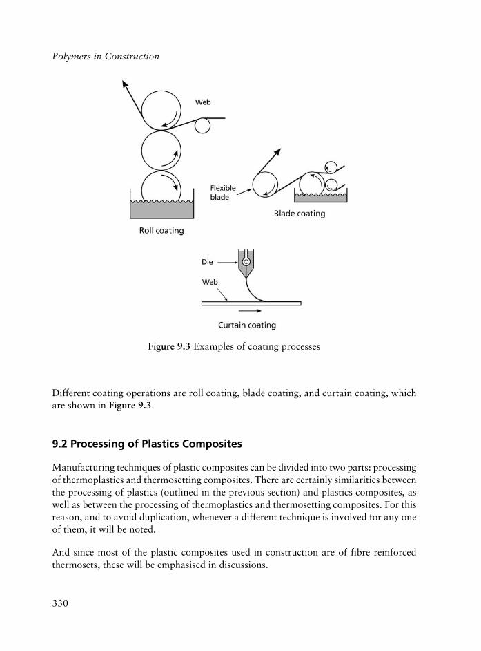
330
Polymers in Construction
Different coating operations are roll coating, blade coating, and curtain coating, whichare shown in Figure 9.3.
9.2 Processing of Plastics Composites
Manufacturing techniques of plastic composites can be divided into two parts: processingof thermoplastics and thermosetting composites. There are certainly similarities betweenthe processing of plastics (outlined in the previous section) and plastics composites, aswell as between the processing of thermoplastics and thermosetting composites. For thisreason, and to avoid duplication, whenever a different technique is involved for any oneof them, it will be noted.
And since most of the plastic composites used in construction are of fibre reinforcedthermosets, these will be emphasised in discussions.
Figure 9.3 Examples of coating processes

331
9.2.1 Processing of (Fibre Reinforced) Thermoset Plastic Composites
In composite processing, the fibres and the resin mixture (with catalyst, etc.), is pressedfirst into the required shape and size (in the mould), then the system is left to cure tobecome permanently hardened.
Fibre reinforced (FR) thermoset plastic composites can be processed in the followingdifferent ways, depending on differences in the processing:
(a) manual processing (hand lay-up, spray-up, pressure bag and autoclave moulding),
(b) semi-automatic processing (cold pressing, compression moulding and resin injection),
(c) automatic processing (pultrusion, filament winding and injection moulding).
On the other hand, their processing can also be classified as follows:
(i) Open mould processing where there is only one mould involved and the material isin contact with the mould on one surface only. This technique is widely used in civilengineering applications
(ii) Closed mould processing, also called matched die processing, where the product isformed within a closed space of two moulds, i.e., with the conventional male-femalemould. This technique is not usually used for the production of materials involved inconstruction industry [5].
Open mould processes are operated manually, with one exception (filament winding);while closed mould processes are either semi-automatic or completely automatic(Figure 9.4).
9.2.1.1 Open Mould Processes
In open mould processes (also called ‘contact lamination’ or ‘contact moulding’, there isa single positive, or a single negative, mould surface (usually with a large surface) onwhich starting materials (resins – commonly unsaturated polyesters and epoxies, fibres –usually either chopped or continuous glass fibres or mats, woven rovings and yarns orprepregs) are applied in layers to the desired thicknesses. This step is then followed bycuring and removal of the part. In this process, there is no pressure application (or relativelylittle pressure in some cases) during the curing cycle.
Depending on the differences used in the application methods of layers and curing details,there are different open mould processes (such as hand lay-up, spray-up, automated laying
Processing of Individual Plastics Components for House Construction, for Civil andHighway Engineering Applications

332
Polymers in Construction
and spraying, bag moulding and autoclave moulding); two or more of which can be combined.Economy and design flexibilities provided by the process are the main advantages, (i.e., largeand complex items can be produced easily), whereas, the process is labour intensive andgives rise to parts with only one finished surface. As mentioned previously, filament windingis an automated open mould process without having the disadvantages noted before.
Hand lay-up is a wet process and it is the simplest yet most labour-intensive and the mostcommonly used technique, since the 1940s. It is most suited for the production of similarcomponents in limited numbers, (i.e., fibre-reinforced plastic (FRP) infill panels). In thismethod, successive layers of resin and reinforcement, (i.e., rovings, fabric, mat or randomlyarranged chopped fibres of glass), are manually applied to an open mould, with thefollowing basic procedure of five steps:
(i) cleaning and treatment of the mould with release agent(s),
(ii) application of a thin gel coat (of approximately 0.35 mm thick resin, possibly coloured;used to protect glass fibres (GF) from external effects including moisture and to providea smooth finish). The gel coat applied face will be the finished surface part. If qualityof surface finish is very important, the gel coat layer is applied with a spray gun.
(iii) application of successive layers of resin and GF, as soon as the gel coat has partiallyset. GF is usually used in the form of mat or cloth, and each layer is rolled carefullyto remove possible air bubbles and to fully impregnate the fibre with the resin.
Figure 9.4 General processing diagram for reinforced thermosettingplastics composites

333
(iv) curing the part, and
(v) removing the fully hardened part from the mould and trimming the outside edgesto size.
This method is preferred for relatively short production runs and large size objects.
‘Hand lay-up with brush’ method is used mostly for very low volume scale manufacturingand in general, the parts processed are considerably larger in size. In addition to productionof huge boat hulls, this technique is also used to produce swimming pools, large containertanks, stage props, radomes and other formed sheets.
Most manufacturers use spray guns and pumping systems to have a more rapid andconsistent mix to wet out the laminate, where highly accurate metering systems can alsobe used; and automated tape-laying machines have been developed recently, as discussedin the part on spray-up techniques.
Hand lay-up technique is also used for construction of highway bridges. For example theglass fibre reinforced plastic (GFRP) bridge in Bulgaria (with a 10 m span constructed in1983), and the Miyun Bridge which is under construction in Beijing, China.
Hand lay-up for retrofitting (rehabilitation) is used in the construction industry tostrengthen and upgrade the structures in flexure and shear (by retrofitting the materialto their tensile and shear faces, where the surface of the structure, such as concrete steel,forms the mould for the composite). A number of different applications can be cited forhand lay-up for retrofitting (rehabilitation), such as: the confinement of concrete columnswith composite sheets or plates bonded to them, the use of polymer composite plates forthe flexural and shear strengthening of beams and slabs, wrapping of reinforced concretestructural elements for corrosion protection and durability of repairs. There are a numberof examples for retrofitting of concrete bridges, (i.e., by using pultruded plates to upgradefor higher load capacities in situ) [5].
The hand lay-up technique is presented schematically in Figure 9.5.
Spray-up is a less labour intensive process than hand lay-up, and it is an another way tomechanise the application of resin-fibre layers and to reduce the time needed for theprocess. In this technique, liquid resin and chopped GF are simultaneously sprayed anddeposited onto the open mould. Continuous rovings are chopped in the spray gun (tofibres of 25-75 mm length) and are added to the resin stream as it exits the nozzle. Sprayguns are either: internal mix with air, airless internal mix, external mix with air, orairless external mix. The technique requires considerable operator skill if operatedmanually (for control of the thickness of the composite and to maintain a consistentpolymer/glass ratio), however, the tooling costs are not too high. Spraying can also be
Processing of Individual Plastics Components for House Construction, for Civil andHighway Engineering Applications

334
Polymers in Construction
done automatically where the path of the spray gun is pre-programmed and computercontrolled and is attached to an operator controlled machine or operated by a robot. Toavoid possible volatile hazardous emissions, it is advantageous to use automated spray-up machines that can operate in sealed-off areas.
The spray-up technique is presented schematically in Figure 9.6.
Bag moulding processes use pressure applied to uncured resins on the mould in order tocompact the laminates and to drive out volatiles. It can be in two different forms: vacuumbag or pressure bag moulding. Either of these can be used to supplement curing in thelay-up or spray-up processes.
Figure 9.5 Hand lay-up moulding method
Figure 9.6 Spray-up moulding method

335
In vacuum bag moulding, a flexible non-adhering plastic [polyvinyl alcohol (PVA) orNylon] sheet is used that covers the part after the lay-up or spray-up steps, and a vacuumis drawn to press the bag against the laminated part during curing, after the edges aresealed (Figure 9.7a). Vacuum bag moulding provides high reinforcement concentrationsand better adhesion between the layers. Heat is often used to accelerate curing.
In pressure bag moulding, a positive air pressure (of several atmospheres) is used toinflate an elastomeric bag against the part while curing proceeds, which is mostly usedfor complex hollow shaped parts. Heat is often used to accelerate curing (Figure 9.7b).
Vacuum bag moulding for retrofitting is a semi-automatic resin infusion under flexibletooling (RIFT) technique, which allows production of quality composites. In the RIFTprocess, dry GF are pre-formed in a mould and are taken to the side and attached to thestructure. A resin supply is then channelled to the prepreg, and both are enveloped in avacuum bag. The flow of resin into dry GF (preform) develops the composite materialand the adhesive bond between composite and structure as well.
Figure 9.7 Moulding techniques: (a) Vacuum bag, (b) Pressure bag
(a)
(b)
Processing of Individual Plastics Components for House Construction, for Civil andHighway Engineering Applications

336
Polymers in Construction
Seismic retrofitting to columns uses filament winding of prepreg (pre impregnated)carbon fibres to produce a jacket which is then upgradable as described previously.
Autoclave moulding is a modification of the pressure bag method. It is used to producehigh quality composites, (i.e., for aerospace applications), where high pressures (upto 0.6 MPa) and high temperatures (up to 700 °C) are used. An autoclave is a pressurevessel inside which the curing reaction occurs. With this process, it is possible toproduce composite structures with up to 70 wt% GF reinforcements [5]. However,the autoclave process is rather costly.
Filament winding is a completely automatic open mould process. The process usescontinuous strands of GF or carbon fibres applied with one of two commontechniques: helical winding or polar winding. Helical winding is mostly used forhigh strength pipe type structures production, including sewage pipes; whereas polarwinding is applied for pressure vessels.
In this technique, continuous reinforcements are fed through a transversing bath ofactivated resin and the polymer produced is then wound onto a rotating mandrel.Products with large structural shapes and with high circumferential and longitudinalmechanical strengths can be successfully produced by this technique. Since thefilaments can be oriented with any desired controlled angle and that continuousreinforcements can be applied to very high levels, highly efficient products withmaximum strength to weight ratios with good uniformities are obtained by filamentwinding [6] (Figure 9.8).
Figure 9.8 Filament winding
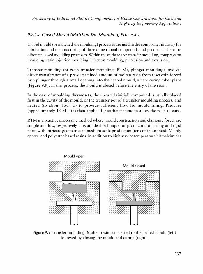
337
9.2.1.2 Closed Mould (Matched-Die Moulding) Processes
Closed mould (or matched-die moulding) processes are used in the composites industry forfabrication and manufacturing of three dimensional compounds and products. There aredifferent closed moulding processes. Within these, there are: transfer moulding, compressionmoulding, resin injection moulding, injection moulding, pultrusion and extrusion.
Transfer moulding (or resin transfer moulding (RTM), plunger moulding) involvesdirect transference of a pre-determined amount of molten resin from reservoir, forcedby a plunger through a small opening into the heated mould, where curing takes place(Figure 9.9). In this process, the mould is closed before the entry of the resin.
In the case of moulding thermosets, the uncured (initial) compound is usually placedfirst in the cavity of the mould, or the transfer pot of a transfer moulding process, andheated (to about 150 °C) to provide sufficient flow for mould filling. Pressure(approximately 13 MPa) is then applied for sufficient time to allow the resin to cure.
RTM is a reactive processing method where mould construction and clamping forces aresimple and low, respectively. It is an ideal technique for production of strong and rigidparts with intricate geometries in medium scale production (tens of thousands). Mainlyepoxy- and polyester-based resins, in addition to high service temperature bismaleimides
Figure 9.9 Transfer moulding. Molten resin transferred to the heated mould (left)followed by closing the mould and curing (right).
Processing of Individual Plastics Components for House Construction, for Civil andHighway Engineering Applications
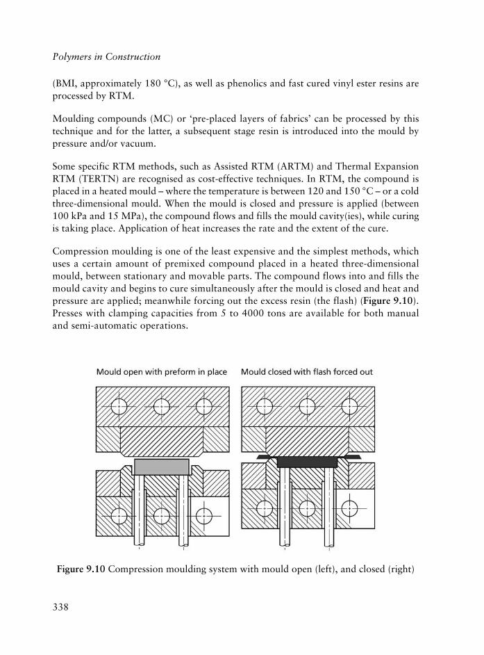
338
Polymers in Construction
(BMI, approximately 180 °C), as well as phenolics and fast cured vinyl ester resins areprocessed by RTM.
Moulding compounds (MC) or ‘pre-placed layers of fabrics’ can be processed by thistechnique and for the latter, a subsequent stage resin is introduced into the mould bypressure and/or vacuum.
Some specific RTM methods, such as Assisted RTM (ARTM) and Thermal ExpansionRTM (TERTN) are recognised as cost-effective techniques. In RTM, the compound isplaced in a heated mould – where the temperature is between 120 and 150 °C – or a coldthree-dimensional mould. When the mould is closed and pressure is applied (between100 kPa and 15 MPa), the compound flows and fills the mould cavity(ies), while curingis taking place. Application of heat increases the rate and the extent of the cure.
Compression moulding is one of the least expensive and the simplest methods, whichuses a certain amount of premixed compound placed in a heated three-dimensionalmould, between stationary and movable parts. The compound flows into and fills themould cavity and begins to cure simultaneously after the mould is closed and heat andpressure are applied; meanwhile forcing out the excess resin (the flash) (Figure 9.10).Presses with clamping capacities from 5 to 4000 tons are available for both manualand semi-automatic operations.
Figure 9.10 Compression moulding system with mould open (left), and closed (right)

339
The compression moulding technique is suitable for many forms of preform and premixmouldings, with a variety of fibre arrangements. Sheet moulding compounds (SMC) orprepregs, bulk moulding compounds (BMC) or dough moulding compounds (DMC)and MC are all processable by this method.
A typical composition for BMC and SMC includes base resins, catalysts, peroxidesaccelerators, fillers/chopped GF, thickeners and other additives. The base resins that areusually used are either polyester-based (orthophthalic or isophthalic), which are usedwith styrene, acrylic, vinyl toluene or di-allyl-phthalate (DAP) monomers, as crosslinkers,or styrene type monomers for general purpose products. Acrylic base resins are used forlow shrinkage, while vinyl type monomers for high hot strengths (heat deflectiontemperatures). Catalysts are used for polyester type resins. Peroxides, such as benzoylperoxide (BPO) and t-butyl perbenzoate are used as high temperature catalysts.
Compression moulded parts usually possess high rigidity and strength (tensile,compression and impact) along with good surface properties (gloss, smoothness,paintability), and in principle, the thickness of compression parts are not limited insize (in contrast to injection moulding).
Resin injection moulding is a cold moulding process applied at medium pressures(approximately 450 kPa), where mould surfaces are enriched with release agents and gelcoat before GF reinforcement is placed on the bottom of the mould, allowing the plasticto extend beyond the sides of the mould. Then the upper mould is placed in its place andit is clamped to stop followed by injection of activated resin under pressure into themould cavity (Figure 9.11). By using this technique, it is possible to obtain a fibre/matrixratio of 65 wt%.
Injection moulding is a non-continuous process where a thermoplastic (or a reactive,thermoset) system is injected under high pressures into a closed three-dimensional mouldthrough a reciprocating-screw, which plasticises the solid polymer forming melt. Afterthat stage, the screw ceases to rotate and acts as a ram injecting the melt into themould. The system can be used to process both thermoplastics and thermosets withcertain variations in design, (i.e., for thermosets: barrels are shorter, heaters are onlyused at start-up followed by water coolers to remove the unnecessary heat), as well asin operation (use of lower compression ratios, higher temperatures in the moulds thanthe barrel, shorter cycle times and opening of the mould when it is still hot; all forthermosets). Heater bands existing on the barrel help to increase the temperature alongthe barrel. The mould is held at ambient temperatures (or at higher temperatures, inthe case of a thermoset), where the product solidifies. Cooling and solidification (ofthe thermoplastic), or curing (of the thermoset) takes place while the material is keptunder high pressure. With injection moulding, it is possible to have high productionrates and high automation, although the cost is rather high due to the special moulds
Processing of Individual Plastics Components for House Construction, for Civil andHighway Engineering Applications

340
Polymers in Construction
involved. Since the quality of moulded articles are strongly dependent on the precisionof repeatable cycle times (much more critical for thermosets), replacement of the humanoperator by robots for parts removal is usually very important. Figure 9.12 presentsthe system schematically.
A few variations of the injection moulding processes are available, such as, injectionmoulding of pre-compounded resin with short GF and/or fillers and injection mouldingunder high pressure into a heated mould where GF fabric reinforcement is placed – alsocalled structural reaction injection moulding, SRIM. The first of these is based on polyester(BMC/SMC) [7], as well as phenolics based on novolacs, while the second is based on PU(mixed polyol and isocyanate) injection which has the potential of low cost, low weightproducts where mineral fillers (RRIM) or glass mat reinforcements (SRIM) can be used.In RIM, two or more reactants are polymerised in the mould (for rapid reactions withshort cycle times). In all RIM, there is substantial savings of energy in addition to thesavings in the time element.
It is possible to perform injection moulding with very high speeds, (i.e., with commoncycle times of 10-30 s). A recent process called foiled FibrePur technology (FFT), whichis a plastic-foil finishing technique in RIM based on long-fibre reinforced PU whichproduces fully finished painted parts in a single-step process [8, 9].
Figure 9.11 The resin injection set-up

341
Anisotropy and fibre distribution in the case of short GF reinforced items cause thebiggest disadvantage in injection moulding, as regards the final mechanical performance,however, the economy of process with short GF is much more promising than use ofcontinuous fibres.
Pultrusion is a continuous, highly automated, closed mould composite manufacturingprocess that is widely used for both semi-structural and structural applications (such aswindow frames, cable coating, rods and bars, grids and meshes, beams and columns, panelsand plates). The pultruded profiles sector is the most rapidly growing sector both in Europeand in US (with 10% and 15% annual growth rates, respectively). The possibility ofpultruding with a wide range of different reinforcements, (i.e., GF, carbon and Kevlarfibres up to 60-80 wt%) and matrices (thermosets like polyester, epoxy, phenolic and anumber of thermoplastics), as well as applicability of the pultrusion process beyond thetraditional constant shape/section profiles, (i.e., pullshaping which offers a method forpultruding elongated non-linear composite elements, pullforming which is a method forproducing products with variable cross sections by using a specially adapted temperaturecontrollable pultrusion die, and pullwinding which produces high performance compositetubes by combining the techniques of conventional pultrusion and continuous filamentwinding) have opened ever increasing markets for this technique [10].
During pultrusion, the pultruder acts as a reactor. In the system fibres (either in theform of continuous tape, woven fabrics or mats) are first passed through a resinimpregnation system (wet bath). This is followed by removal of excess resin. Thepultrudate is then shaped in performing guides and go through the cure process in aheated die. The heated die has different heating zones and different geometrical shapes(like I, L, Tee and circular). Finally, the continuous composite pultrudate is cut offwith a saw. In this process, the cure step is on-line. In pultrusion, continuous strand
Figure 9.12 A typical injection moulding system
Processing of Individual Plastics Components for House Construction, for Civil andHighway Engineering Applications

342
Polymers in Construction
GF rovings are used usually for unidirectional pultrusion and a continuous strand matfabric (typically of glass/polyester) may be used to add off-axis fibres, as a reinforcementsupplier. In the case of some thermoset resins with short pot lives, (i.e., phenolics, BMIand epoxy resins), the wet bath process is modified by directly injecting the resin intoa fibre preform at the pultruder entrance (by using a pressurised pumping system).Figure 9.13 shows a pultrusion process. Thermoset pultrusion is usually done by useof unsaturated polyester resin and GF spun from E-glass (E-GF) with 20% to 80%loadings of the latter, however, thermoset pultrusion has several disadvantages overthermoplastics, such as the limitations imposed on the process by cure rates and thefact that reinforcements are usually in the longitudinal direction with only a smallpercentage of fibres in the transverse direction. To avoid the latter disadvantage, the‘pull-winding’ process was developed where fibres were wound in the transversedirection simultaneously with the pultrusion operation [10].
Pultrusion has been applied for production of a number of materials, including:pultruded FRP composite decks in elevated freeways, in The Netherlands [11], andproduction of pultruded reinforced fibre glass (FGR) windows and doors [12].
Extrusion: A range of different shapes can be processed by extrusion, such as, profilesfor gaskets and sealing strips, window frames, rods, tubing, pipes, corrugated andnormal sheeting, films, etc. The screw in the system works continuously on theArchimedean principle with approximately one revolution per second and there areconsiderably high pressures developed in the barrel (100 MPa). The characteristics ofthe screw can show differences from polymer to polymer: for polymers that melt abruptly(like Nylon 6,6) or slowly (branched PE) or for polymers that pass through a glasstransition and plasticate slowly (PVC type), screws with different geometries are used.The extrusion system manufactures an endless product with a constant cross-sectionat the end, which is then cut, chopped, etc., to reduce it to the desired length. In theextrusion process, compound (solid feedstock) is fed into the feed throat from thehopper and is converted to a high viscosity paste by heat and pressure, and it is propelled
Figure 9.13 Schematic representation of the pultrusion process
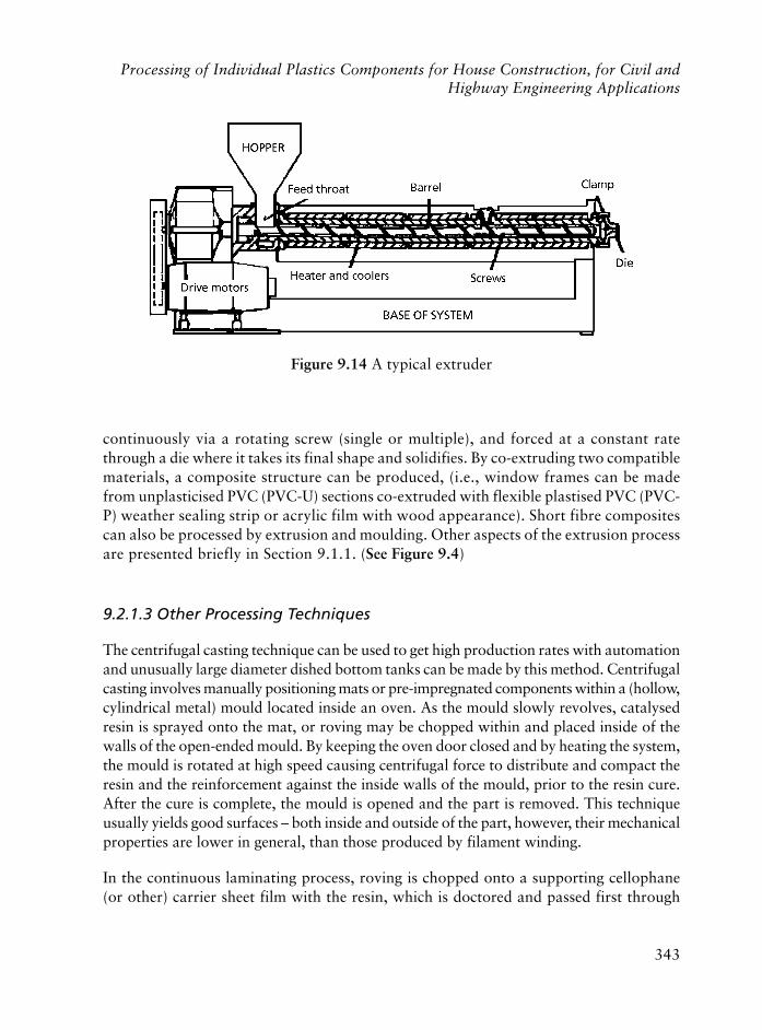
343
continuously via a rotating screw (single or multiple), and forced at a constant ratethrough a die where it takes its final shape and solidifies. By co-extruding two compatiblematerials, a composite structure can be produced, (i.e., window frames can be madefrom unplasticised PVC (PVC-U) sections co-extruded with flexible plastised PVC (PVC-P) weather sealing strip or acrylic film with wood appearance). Short fibre compositescan also be processed by extrusion and moulding. Other aspects of the extrusion processare presented briefly in Section 9.1.1. (See Figure 9.4)
9.2.1.3 Other Processing Techniques
The centrifugal casting technique can be used to get high production rates with automationand unusually large diameter dished bottom tanks can be made by this method. Centrifugalcasting involves manually positioning mats or pre-impregnated components within a (hollow,cylindrical metal) mould located inside an oven. As the mould slowly revolves, catalysedresin is sprayed onto the mat, or roving may be chopped within and placed inside of thewalls of the open-ended mould. By keeping the oven door closed and by heating the system,the mould is rotated at high speed causing centrifugal force to distribute and compact theresin and the reinforcement against the inside walls of the mould, prior to the resin cure.After the cure is complete, the mould is opened and the part is removed. This techniqueusually yields good surfaces – both inside and outside of the part, however, their mechanicalproperties are lower in general, than those produced by filament winding.
In the continuous laminating process, roving is chopped onto a supporting cellophane(or other) carrier sheet film with the resin, which is doctored and passed first through
Figure 9.14 A typical extruder
Processing of Individual Plastics Components for House Construction, for Civil andHighway Engineering Applications
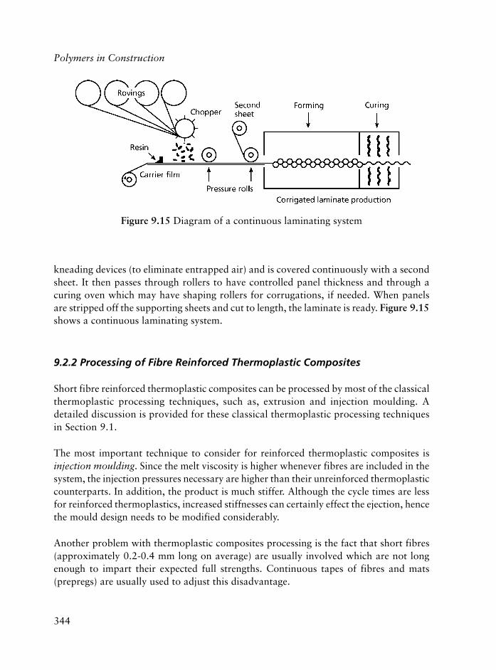
344
Polymers in Construction
kneading devices (to eliminate entrapped air) and is covered continuously with a secondsheet. It then passes through rollers to have controlled panel thickness and through acuring oven which may have shaping rollers for corrugations, if needed. When panelsare stripped off the supporting sheets and cut to length, the laminate is ready. Figure 9.15shows a continuous laminating system.
9.2.2 Processing of Fibre Reinforced Thermoplastic Composites
Short fibre reinforced thermoplastic composites can be processed by most of the classicalthermoplastic processing techniques, such as, extrusion and injection moulding. Adetailed discussion is provided for these classical thermoplastic processing techniquesin Section 9.1.
The most important technique to consider for reinforced thermoplastic composites isinjection moulding. Since the melt viscosity is higher whenever fibres are included in thesystem, the injection pressures necessary are higher than their unreinforced thermoplasticcounterparts. In addition, the product is much stiffer. Although the cycle times are lessfor reinforced thermoplastics, increased stiffnesses can certainly effect the ejection, hencethe mould design needs to be modified considerably.
Another problem with thermoplastic composites processing is the fact that short fibres(approximately 0.2-0.4 mm long on average) are usually involved which are not longenough to impart their expected full strengths. Continuous tapes of fibres and mats(prepregs) are usually used to adjust this disadvantage.
Figure 9.15 Diagram of a continuous laminating system
345
9.3 On-Site Processing
On-site processing is very suitable for plastics materials and, in addition to the existingpractices, there have also been studies to increase the proportion of on-site processing inconstruction, i.e., rolls of crosslinked polyethylene (XLPE) foam with a range of thicknessand densities can simply be cut to the size and applied on-site.
In the earlier ‘Nestehous’, Concept House of Neste, Finland, the development of newon-site processing techniques were aimed at. Concrete casting moulds that stayed onthe construction site were prepared from GFRP composites of polyester and they wereused to prepare concrete rebars (prepared with concrete and PP fibres) used as themain load bearing material in the house.
Plastic composite bridges are very successful examples of on-site production: pultrudedparts can be easily carried to the application site and processed (GFR resin – polyesterthin-walled cellular modules were quickly assembled and bonded by epoxy-basedadhesives on-site in a very short time in the Aberfeldy foot bridge).
Joining of plastic pipes is shown to be done more effectively, economically and in a muchshorter time on-site by ‘linear vibration welding’, rather than the conventional hot platewelding or electrofusion welding techniques.
Sealants are materials used to seal joints in buildings or concrete slabs against thepenetration of water or air; and they are one of the best examples of on-site processing.Seal joints can be expansion joints in concrete or masonry walls, they can be the jointsused between glazing materials and its frames; or joints between precast concrete wallpanels. Polysulfides offer good resistance to chemicals and fuels, silicones provideperformance within a wide range of temperatures, and urethanes provide abrasion andchemical resistant seals; all of these being flexible. Sealants can be of two types, dependingon their application: hot or ambient applied sealants.
Hot applied sealants provide excellent bonding, high resiliency with a positive seal; whileambient applied sealants are usually in the semi-cured state and can be one- or two-part.
One part-ambient sealants, (i.e., premixed sealants with polysulfide, silicone or urethanebase and a catalyst) are applicable with a caulking gun on site, which cure chemically togive rise to sealants on-site with rubberlike properties. Pre-mixed two part sealants (thefirst part being the polymer base and the second is the catalyst) that are prepared andkept at low temperatures (approximately –20 °C) in boxes can also be applied directlyon-site, after its thawing at room temperature. These pre-prepared types have theadvantage of their availability in a range of hardnesses: from the softest types (usedwhere there is maximum movement and minimum of strain) and medium grades (used ifthere is vibration movement) to hard types (for high abrasion resistance).
Processing of Individual Plastics Components for House Construction, for Civil andHighway Engineering Applications

346
Polymers in Construction
Epoxy pre-mixed putty sticks are well-known examples of one part sealants where epoxyin the premix is at a high cure consistency.
Two part ambient sealants (for example, chemically cured two part polysulfide or urethaneresilient sealants) are applied on-site after mixing the two parts (the polymer-based part andthe catalyst) within the pot life of the hardening of the system, which is usually one hour.
There are also preformed sealants to consider within the ambient type of sealants thatcan be applied on-site. They are pre-moulded and are fabricated from a range of materials(synthetic rubber, PVC) with different shapes (ribbons, tapes, beads, or extruded shapes),and are mainly used for glazing applications.
In situ foaming is an another typical on-site application used mainly for insulationpurposes. Since rigid PU and polyisocyanurate foams provide the most energy efficientand versatile thermal insulations, they are preferable for use in roof and wall systemapplications, for both residential and commercial buildings.
In site foaming can either be ‘pour-in place and foam’ or ‘spray on in-site’ type.
Pour-in place and foam is a very attractive on-site method used for thermal insulation.This method, although not commonly used mainly due to its rather unfavourable economy,is very practical. The technique uses relatively simple equipment, and rests on the principleof pouring the specially formulated mixture to be foamed as a low viscosity liquid intothe cavity to be filled (usually between the load bearing inner face of the wall and theweather resistant facade wall of brick-cement or masonry, for cavity wall constructionor between metal boards to produce sandwich panels, etc.), where the mixture is left tofoam and adhere the walls by sealing the cavity effectively.
For the pour-in place and foam technique, there is a group of characteristic rigid PUfoam applications available, however, their largest consumption area is in the insulationof refrigerators and freezers, but not that much in the construction industry. Standardtwo-component formulations with special adaptations, or one-component systems thatcure by reaction with the moisture existing in the atmosphere, are available. The methodproduces highly effective thermal and noise insulation as well as physical reinforcement,although the foams produced are less uniform than those produced in-plant.
Another cavity wall and foam technique is done by use of prefoamed EPS particles. Thecavity between the two faces (walls) can be completely filled with the prefoamed expandedpolystyrene (EPS) particles and then foamed by applying steam.
Spray-on in situ is an another attractive technique used mainly for thermal, (i.e., toproduce spray-on insulating layer in roofing or coating on a wall) as well as for moisture

347
insulation; it also provides air barriers (to prevent condensation in construction systemsat joints) and to produce vapour barriers. Sprayed PU foam provides weatherproofsealants, forms a seamless layer of insulation, and fills gaps, seams and covers irregular,hard-to-insulate shapes to make them more durable and easier to maintain. Spray PUfoam has a closed-cell structure and with its high water and thermal insulationcharacteristics, they are very promising for residential and commercial building envelopeinsulation, as well as for air seal [13].
They are also rigid, and they generally are based on PU or PU-modified isocyanuratesor polyureas.
The spray-on application technique is similar to paint spraying. Mechanical or pneumaticdrive pumping units with mix heads are used, and to facilitate the foaming and curing(quickly, within 10 seconds) directly on the sprayed surface, without much draining,special formulations (containing high proportions of catalysts and foaming agents) areused to yield thicknesses of approximately 5 cm per application (for PU). PU spray-onproducts are structurally self-supporting, and can be attached to a wide range of substrateswhile requiring no additional adhesive.
Two liquid components (resin and catalyst) are combined, either within or immediatelyoutside of a spray gun nozzle and are deposited in place by spraying. The chemicalreaction created by the mixing at the nozzle causes the material to expand while it issprayed ‘onto’ a wall (or ‘into’ a wall cavity). The foam expands up to 140 times itsoriginal liquid volume within seconds. Multiple layers can be applied by using multiplepasses to reach the desired thickness. Spray PU foam (SPF) is most commonly usedwhich typically rises and sets in between 5-15 seconds and it is dry to the touch in lessthan a minute. The scheduled phase-out of and hydrochlorofluorocarbons (HCFC) (inaccordance with the Montreal Protocol, both of which were the blowing agents usedfor PU and they have been shown to deplete stratospheric ozone layer), caused thesharp decline in the strong, industrial position of PU to, although SPF with the highestR values (resistance to heat flow; 6-7 per inch) are still unbeatable in residentialinsulation. There are certain SPF techniques that use non-ozone depleting chemicals,such as water. A more detailed information on the subject is given in Chapter 6 (Sections6.1.1.1, 6.1.1.2 and 6.1.2).
Spray-on in situ technique is a very effective one for insulation and sealing inconstruction applications, which requires rather simple but special equipment to meter,mix and spray [7]. However, mainly due to the wasted overspray, this technique isalso not very economical: in addition to the fact that SPF applied usually needs aprotective elastomeric coating to prevent and protect its surfaces from degradationcaused by UV exposure [14].
Processing of Individual Plastics Components for House Construction, for Civil andHighway Engineering Applications

348
Polymers in Construction
References
1. Z. Tadmor and C.G. Gogos, Principles of Polymer Processing, Wiley Interscience,New York, NY, USA, 1979.
2. L. Mascia, The Role of Additives in Plastics, Edward Arnold, London, UK, 1974.
3. J.R. Fried, Polymer Science and Technology, Prentice Hall, Upper Saddle River,NJ, USA, 2003.
4. F.W. Billmeyer, Textbook of Polymer Science, Wiley Interscience, New York, NY,USA, 1984.
5. J.M. Illston and P.L.J. Domone, Construction Materials: Their Nature andBehaviour, 3rd Edition, Spon Press, London, UK, 2001.
6. Handbook of Composite Materials, Ed., G. Akovali, Rapra Technology Ltd.,Shrewsbury, Shropshire, UK, 2001.
7. R.S. Drake and A.R. Siebert, Proceedings of the 42nd Annual SPI Conference,Cincinnati, OH, USA, 1987, Session 11-D/1.
8. D.E. Shaw-Stewart in Proceedings of the Second International Conference onAutomotive Composites, Noordwijkerhout, The Netherlands, 1988, Paper No.15.
9. G. Furlanetto, Urethanes Technology, 2003, 20, 5, 25.
10. M. Giordano, A. Borzacchiello and L. Nicolais in Handbook of CompositeMaterials, Ed., G. Akovali, Rapra Technology Ltd., Shrewsbury, Shropshire, UK,2001, Chapter 6.
11. Pultruded FRP Composite Decks in Elevated Freeways? Composites NewsSuperSite: http://www.compositesnews.com/articles.asp?ArticleID=4384.
12. Pultruded Fibreglass Windows, NetComposites News, 2002, 8th February,www.netcomposites.com.
13. Spray Polyurethane Foam for Residential Building Envelope Insulation and Air Seal,Spray Polyurethane Foam Alliance, Fairfax, VA, USA, Publication No. AY-112, 2000.
14. A Guide for Selection of Elastomeric Protective Coatings over PolyurethaneSpray Foam, Spray Polyurethane Foam Alliance, Fairfax, VA, USA, PublicationNo.AY-102, 2000.

349
10 Lignocellulosic Fibre – PlasticComposites in Construction
Elsayed M. Abdel-Bary
10.1 Introduction
The application of lignocellulosic fibres in reinforcing plastics has been known for along time. As early as 1908 the first composite materials were applied for the productionof large quantities of sheets, tubes and pipes for electronic purposes (paper or cottonto reinforce sheets, made of phenol or melamine formaldehyde resins). In 1896,aeroplane seats and fuel tanks were made of natural fibres with a small amount ofpolymeric binder [1].
Because of low prices and the steadily rising performance of technical and standardplastics, the application of natural fibres for obtaining lignocellulosic fibre – plasticcomposites is widely used. More recently, the critical discussion about the preservationof natural resources and recycling has led to a renewed interest concerning naturalmaterials with the focus on renewable raw materials [2].
Wood fibre as a lignocellulosic fibre possesses a number of potential advantages as asuitable candidate for fibre reinforced polymer composites. Among these advantages,those of major importance include low price, low density, low abrasiveness, and theabsence of potential health hazards during processing. Besides, natural fibre reinforcedplastics using biodegradable polymers, as matrixes, are the most environmental friendlymaterials, as they can be composted at the end of their life. There is currently a great dealof interest in updating the technology to incorporate cellulosics in plastic composites.
The field of natural fibre reinforced thermoplastic composite materials is now rapidlygrowing both in terms of industrial applications and fundamental research.
The use of lignocellulosics as fillers and reinforcements in thermoplastics has beengaining acceptance in commodity plastics applications in the past few years. It isinteresting to note that the use of the lignocellulosics in commodity thermoplastics toreduce cost and/or to improve mechanical performance is not new, and there are plentyof published papers, including patents dating back to the 1960s and 1970s. Thereappearance of interest in the 1990s is probably due to increasing plastic costs andthe environmental aspects of using renewable materials.

350
Polymers in Construction
Agro-based lignocellulosics suitable for composites come from two main sources. Thefirst is agricultural residues and the second is those lignocellulosics grown specificallyfor their fibre. The first source includes rice husks or cereal straws, which are by-productsof food or feed crops and can be used for everyday purposes such as animal bedding orfuel or alternatively are simply left on the field or burnt to reduce mass. Two examplesof the second source are jute and kenaf. These plants also have residues, which are oftenused for bedding or fuel as well.
Technically speaking, almost any agricultural fibre can be used to manufacture compositepanels. However, it becomes more difficult to use certain kinds of fibres when restrictionsin quality and economy are imposed. The literature shows that several kinds of fibreshave existed in sufficient quantity, in the right place, at the right price and at the righttime to merit at least occasional commercial use.
This chapter briefly addresses the issues of using some of these fibre sources incomposites production. More attention is given to the type of binders, eitherthermoplastics or thermosets used as matrixes for some selected fibres. The problem ofcompatibility of these fibres as polar materials and nonpolar thermoplastics such aspolyolefins is discussed. Grafting of fibres as well as thermoplastics and their chemicalmodifications is discussed without going too deep into the mechanisms or chemicalequations. The applications of corresponding composites are given and the effect ofweathering governing the limitation of the application in one field or another isdiscussed. Evaluation of the performance of composites using standard testing methodsis given briefly as it is given in detail in other chapters.
10.2 Sources of Lignocellulosic Fibres
While others may exist, a choice was made to only discuss bagasse, cereal straw, coconutcoir, corn stalks, cotton stalks, jute, kenaf and rice husks [3, 4].
10.2.1 Bagasse
Bagasse is the fibre residue remaining when sugarcane is pressed to extract the sugar.Some bagasse is burned to supply heat to the sugar refining operation, some is returnedto the fields, and some is used in various board products. Bagasse is composed of fibreand pith. The fibre is thick walled and relatively long (1-4 mm). For use in composites,fibres are obtained mostly from the rind, but there are fibro-vascular bundles dispersedthroughout the interior of the stalk as well [5].

351
Lignocellulosic Fibre – Plastic Composites in Construction
Special care must be taken during bagasse storage to prevent fermentation resulting fromresidual sugar content. To reduce the sugar content and increase storage life, bagasse isusually depithed before storage. The pith is an excellent fuel source for the sugar refiningoperation. Generally, if the bagasse is depithed, dried, and densely baled it can be storedoutside; handled in a careful manner, bagasse can also be stored wet. In the wet methodlarge bales of bagasse are specially fabricated and stacked to insure adequate air flow.Heat from fermenting sugars effectively sterilises the bales. Bagasse can be stored forseveral years using this method [6]. Other storage options are available, including somethat keep the bagasse wet beyond the fibre saturation point.
As previously mentioned, only bagasse fibre is utilised for the production of high-quality composite panels. The fibres after depithing are more accurately described asfibre bundles that can be used for making particleboard, or they can be refined toproduce fibres for fibreboard.
10.2.2 Cereal Straw
After bagasse, cereal straw is probably the second most important agricultural fibre forcomposite panel production. Cereal straw includes straw from wheat, rye, barley, oatsand rice. Straw is also an agricultural residue. Unlike bagasse, large quantities of cerealstraw are generally not available at one location. Storage is usually accomplished bybaling. Their high inherent silica content results in increased tool wear compared toother lignocellulosic composites. Conversely, the high silica content also tends to makethem naturally fire-resistant. Manufacturing plants are found in several countries, whichmake thick (5-15 cm) straw panels faced with kraft paper.
The straw is heated to about 200 °C, at which point the spring back properties arevirtually nil and then the panels are made. The straw is fed through a reciprocating armextruder and made into a continuous low-density panel. Kraft paper is then glued to thefaces and edges of the panels. These panels can then be cut for prefabrication into housingand other structures. The low density of these panels makes them fairly resilient, and testdata show that houses built using these panels are especially earthquake resistant.
For particleboards, straw is reduced by hammer milling or knife milling. For the productionof fibre-based products, straw can be pulped by using alkali treatments and refining.
10.2.3 Coconut Coir
Coconut coir is the long fibre (15-35 cm) from the husk of the mature coconut and theaverage husk weighs 400 grams [7]. Coir is a fibre source for many cottage industries

352
Polymers in Construction
and it is readily woven into mats and made into ropes and other articles for both domesticuse and export. Coir has been used to produce a variety of composite products includingparticleboards and fibreboards. When used as a reinforcing fibre in inorganic-bondedcomposites, coir is very resistant to alkalinity and variations in moisture, when comparedto other lignocellulosics [8].
10.2.4 Corn Stalks
A three-layer board having a corncob core and wood veneer face was produced for ashort time in Czechoslovakia after World War II [9]. Corn stalks, like many agriculturalfibre sources, consist of a pithy core with an outer layer of long fibres. Corn stalksand cobs are either hammer milled into particles or reduced to fibres in apressurised refiner.
10.2.5 Cotton Stalks
Cotton is cultivated primarily for textile fibres, and little use is made of the cotton plantstalk. Stalk harvest yields tend to be low and storage can be a problem. The cotton stalkis plagued with parasites, and stored stalks can serve as a breeding ground for the parasitesto winter over for next year’s crop. Attempted commercialisation of cotton stalkparticleboard was unsuccessful for this reason.
10.2.6 Jute
Jute is an annual plant of the genus Corchorus. Jute has a pithy core, known as jute stickand the bast fibres grow lengthwise around this core. Jute bast fibre is separated fromthe pith in a process known retting. Retting is accomplished by placing cut jute stalks inponds for several weeks. The fibre strands are manually stripped from the jute stick andhung on racks to dry. Very long fibre strands can be obtained this way. If treated withvarious oils or conditioners to increase flexibility, the retted jute fibre strands are suitablefor manufacturing into textiles.
Most composites made using jute exploit the long fibre strand length. Commercially,both woven and non-woven jute textiles are resin- or epoxy-impregnated and mouldedinto fairly complex shapes. In addition, jute textiles are used as overlays over othercomposites. Jute stick is used for fuel, and in poor areas it is stacked on end, tied intobundles, and used as fences and walls.

353
10.2.7 Kenaf
Kenaf is a form of hibiscus, and is similar to jute or hemp in that it has a pithy stemsurrounded by fibres. The fibres make up 20-25% of the dry weight of the plant [10].Kenaf grows well in warm climates and does not have the narcotic effect found in thenon-fibrous parts of the hemp plant. Mature kenaf plants can be 5 m high.
Historically, kenaf fibre was first used as cordage. Industry is now exploring the use ofkenaf in papermaking and non-woven textiles. Like jute, most kenaf composite productsexploit the long aspect ratio of kenaf fibres and fibre bundles. One way to do this is toform the kenaf into a non-woven textile mat that can be used for erosion control, seedlingmulches or oil spill absorbents. After a resin is added to the kenaf mats, they can bepressed into flat panels or moulded into shapes.
Standard screening and air separation techniques can then be used to separate the twodifferent materials. Commercially, kenaf bast fibre separated this way can be purchased98% pith-free.
10.2.8 Rice Husks
Rice husks are an agricultural residue that is available in fairly large quantities in anyone area. Rice husks are quite fibrous by nature and little energy input is required toprepare the husks for the board manufacturer. To make high-quality boards, the innerand outer husks are separated and broken at their ‘spine.’ This can be accomplished byhammer milling or refining. Rice husks have a high silica content, and present the samecutting tool problems.
10.2.9 Other Fibre Sources
Other important fibre sources include flax shaves, bamboo, papyrus, and reed stalks.There are two varieties of flax: one is for fibre and the other is for linseed oil production.Bamboo is an important source of raw material for fibreboards in tropical countries.Most varieties of bamboo are fast-growing and produce strong fibres; particleboardshave also been made from bamboo.
Papyrus is used in making hardboard in East Africa. Insulation boards and plastic-bondedboards have also been prepared from reeds. Other miscellaneous fibres include: bananaleaves, grasses, palm, sorghum while many fibres have been used successfully in thelaboratory to produce boards, most of these materials have not been used commerciallybecause of cost or other factors [4].
Lignocellulosic Fibre – Plastic Composites in Construction

354
Polymers in Construction
10.2.10 Chemical Composition
As mentioned before, agro-based lignocellulosics suitable for composites stem from twomain sources. The first is agricultural residues, which have unknown mechanical propertiesand the second source is those lignocellulosics grown specifically for their fibre. Examplesof the second source are cotton, jute, flax, sisal and many others.
With the exception of cotton, the components of natural fibres are cellulose, hemi-cellulose,lignin, pectin, waxes and water soluble substances, with cellulose, hemi-cellulose and ligninas the basic components with regard to the physical properties of the fibres. Theconcentration of cellulose achieved is 82.7% in cotton and 64.4% in jute. In contrasthemi-cellulose concentration is 5.7% in cotton and 16.7% in flax. Pectin levels are 5.7%in cotton and 0.2% in jute. In contrast lignin levels are 11.8% in jute and 2.0% in flax anddo not exist in cotton. The water content is 10% for cotton, jute, flax and sisal [11].
10.3 Types of Polymers (Binders)
The term ‘binder’ is used to mean the matrix in which the fibres are embedded or treated.The binders, sometimes called adhesives or matrixes, in this chapter refer to polymericmaterials having reasonable mechanical properties. The binder may be thermosetting orthermoplastic polymers.
10.3.1 Thermosets
Thermosets are based on crosslinked polymers. They harden permanently with the aidof catalysts and/or heat, and cannot be remelted without degrading their polymericstructure. The thermosetting family includes phenolics, epoxides, alkyds, polyurethanes,melamine, urea-formaldehyde and unsaturated polyesters.
10.3.1.1 Phenol Formaldehyde
Phenol formaldehyde (PF) is two to three times as expensive as urea-formaldehyde (UF),but the increased durability for exterior applications makes it a popular resin. PF resinsare typically used in the manufacture of products requiring some degree of exteriorexposure durability, for example, oriented strandboard (OSB), softwood and plywood.These resins require longer press times and higher press temperatures than do UF resins,which results in higher energy consumption and lower production line speeds. Productsusing PF resins (often referred to as phenolics) may have lowered dimensional stability

355
because of lower moisture contents in the finished products. The inherently dark colourof PF resins may render them unsuitable for decorative product applications such aspanelling and furniture.
10.3.1.2 Urea-Formaldehyde (UF)
The most common resin for lignocellulosic composites is urea formaldehyde. About 90%of all lignocellulosic composite panel products are bonded with UF [12]. UF is inexpensive,reacts quickly when the composite is hot-pressed, and is easy to use. UF is water-resistant,but not waterproof. As such, its use is limited to interior applications unless special treatmentsor coatings are applied. UF resins are typically used in the manufacture of products wheredimensional uniformity and surface smoothness are of primary concern, for example,particleboard and medium density fibreboard (MDF). Products manufactured with UFresins are designed for interior applications. They can be formulated to cure anywherefrom room temperature to 150 °C; press times and temperatures can be moderatedaccordingly. UF resins (often referred to as urea resins) are more economical than PF resinsand are the most widely used adhesive for composite wood products. The inherently lightcolour of UF resins make them quite suitable for the manufacture of decorative products.
10.3.1.3 Melamine-Formaldehyde (MF)
Melamine-formaldehyde (MF) resins are used primarily for decorative laminates, treatingpaper, and paper coating. They are typically more expensive than PF resins. MF resinsmay be blended with UF resins for certain applications (melamine urea).
10.3.1.4 Isocyanate
Isocyanate as diphenylmethane di-isocyanate (MDI) is commonly used in themanufacture of composite wood products. MDI is used primarily in the manufactureof OSB. Facilities that use MDI are required to take special precautionary protectivemeasures due to its toxicity. These adhesives have been chosen based upon theirsuitability for the particular product under consideration. Factors that must be takeninto account include the materials to be bonded together, moisture content at time ofbonding, mechanical property and durability requirements of the resultant compositeproducts, and of course, resin system costs.
A more durable adhesive is PF. A third common resin, MF, falls roughly midway betweenUF and PF in terms of both cost and performance.
Lignocellulosic Fibre – Plastic Composites in Construction

356
Polymers in Construction
Natural options exist that might someday replace or supplement the synthetic resinslisted previously. Tannins, which are natural phenols, can be modified and reacted withformaldehyde to produce a satisfactory resin. Resins have also been developed byacidifying spent sulfite liquor, generated when wood is pulped for paper. Wet processfibreboards frequently use the lignin inherent in the lignocellulosic as the resin [13].
Except for two major uncertainties, expectations are that UF and PF systems will continueto be the dominant wood adhesives for lignocellulosic composites. The two uncertainties[4] are the possibility of much more stringent regulation of formaldehyde-containingproducts and the possibility of limitations or interruptions in the supply of petrochemicals.One result of these uncertainties is that considerable research has been carried out indeveloping new adhesive systems from renewable resources.
Although research has indicated that a number of new adhesive systems have promise,their commercial use is currently limited. One example is the use of isocyanate adhesives.The slow adoption of this material is due to the relatively high cost and to toxicityconcerns. This material does have some definite advantages from a variety of agriculturalresidues. Low-density insulating or sound absorbing particleboards can be made fromkenaf core or jute stick. Low, medium, high-density panels can be produced with cerealstraw. Rice husks are commercially manufactured into medium and high density productsin the Middle East.
All other things being equal, reducing lignocellulosic materials to particles requires lessenergy than reducing the same material into fibres. Particleboards are used as furniturecores, where they are often overlaid with other materials for decorative purposes. Thickparticleboard can be used in flooring systems and as an underlay. Thin panels can beused as panelling. Most particleboard applications are interior, and so they are usuallybonded with UF.
10.3.2 Thermoplastics
Thermoplastics, based on linear or branched polymers, become rigid when cooled andsoften at varying elevated temperatures (depending on the polymer resin type andadditives). Thermoplastics can repeatedly soften and harden in response to heating andcooling, which makes them especially suitable for recycling.
The term wood-plastic composites (WPC) covers an extremely wide range of compositematerials using plastics ranging from polypropylene (PP) to polyvinyl chloride (PVC)and binders/fillers ranging from wood flour to flax. These new materials extend thecurrent concept of ‘wood composites’ from the traditional compressed materials such as

357
particleboard and MDF into new areas and, more importantly, a new generation of highperformance products.
The first generation of ‘wood composites’ was a combination of recycled woodflour orchips and binders. These were ideal for relatively undemanding applications. The newand rapidly developing generation of WPC ‘wood composites’ have good mechanicalproperties, high dimensional stability and can be used to produce complex shapes. Theyare tough, stable and can be extruded to high dimensional tolerances. The new WPCmaterials are high technology products for the most demanding applications.
The most common types of the new WPC are produced by mixing wood flour and plasticsto produce a material that can be processed just like a plastic but has the best features ofwood and plastics. The wood can be from sawdust and scrap wood products. This meansthat no additional wood resources are depleted in WPC, waste products that currentlycost money for disposal are now a valuable resource – recycling can be both profitableand ethical. The plastic can be from recycled plastic bags and recycled battery casematerials although in demanding applications, new plastics materials are used. Thus it isinteresting to use materials recovered from short life cycle applications in long life cycleapplications. The benefits of WPC combine the best features of wood and plastics.
The final shape of WPC can be produced through extrusion processing. This maximisesresource efficiency and gives design flexibility for improved fastening, stiffening,reinforcement, finishing and joining. WPC need no further processing: they are weather,water and mould resistant for outdoor applications where untreated timber productsare unsuitable.
In recent years, increasing interest has focused on thermoplastic composites reinforcedwith wood fibre or with other lignocellulosic and cellulosic-based materials [14-17].Lignocellulosics are favoured as new generation reinforcing materials in sources. Secondly,the increasing concern about our environment promotes recyclable raw materials andproducts, emphasising the demand for lignocellulosic – thermoplastic composite.
Typical thermoplastics are polyethylene (PE), PP, PVC, polystyrene (PS), acrylics, polyestersand polyamides.
Thermoplastics represent more than 80% of all plastics manufactured. Of these, thefour major commodity plastics: PE, PP, PS and PVC represent nearly 75% of all syntheticpolymers produced annually, or about 75 million tons worldwide. Filled thermoplasticsrepresent a huge and growing market for all types of manufactured products. It is estimatedthat each year 20 million tons of fillers are used in plastic materials. Currently, the mostimportant fillers are calcium carbonate, talc, silica, mica, clay, aluminium trihydrate,glass fibres, starch and cellulosic powders.
Lignocellulosic Fibre – Plastic Composites in Construction

358
Polymers in Construction
The lower thermal stability of natural fibres (up to 230 °C), limits the number ofthermoplastics to be considered as matrix material for natural fibre thermoplasticcomposites. Only thermoplastics whose processing temperature does not exceed 230 °Care useable for natural fibre reinforced composites. These are, most of all, polyolefines,like PE and PP. Technical thermoplastics, like polyamides, polyesters and polycarbonatesrequire processing temperatures >250 °C and are therefore not useable for such compositeprocessing without fibre degradation.
Examples of the use of PE, PP and PVC in fibre-plastic composites are given in thenext section.
10.3.2.1 Polyethylene (PE)
Use of thermoplastics reinforced with special wood fillers is rapidly growing due to theiradvantages. Lightweight, reasonable strength and stiffness are some of these advantages.The processing is flexible, economical and ecological. Since early times, wood has been apreferred, aesthetically pleasing, building and engineering material.
Meanwhile, if the attention is drawn to the replacement of wood products by WPC, theaesthetic features of the products are as important as strength issues for many applications.The addition of large quantities of wood-based fillers can supplement woody texture tothe polymeric composites and this favourable feature can provide ample opportunitiesof applying these composites to much wider areas such as decorative panels. If wood-grain patterns on the surface of the products are needed, a coating or lamination processcan be used. Furthermore, the present limits of the wood-plastic composites in the practicalapplications can greatly be overcome by the successful development of economic processesto generate wood-grain patterns on the surface of the extruded products.
Wood particles, such as chips, flakes, fibres, and wood pulps are used as reinforcementagents. Thus, previously wasted wood materials are converted into useful products, andthis trend will probably accelerate in the future. The main problems of processing woodreinforced compounds are the variations in the quality of raw material, the compatibilitylimitations because of hydrophilic wood fillers and hydrophobic matrices, limited thermalstability during processing, and shape deviation of the component caused by the swellingof wood. The decomposition temperature of cellulose (about 220 °C) places an upperlimit on the processing temperature for wood plastic composites. Fortunately the fourmajor commodity polymers may be processed below this limit. The principal advantageof wood plastic composites is that they can be melt-processed. In this case the meltobtained is an intimate mixture of fibres dispersed into a plastic matrix as a result ofblending at a temperature above the melt temperature of the plastic. The resulting mixture

359
of compounds can subsequently be fabricated into articles by common plastic melt-processing techniques, such as extrusion or injection moulding [18].
Waste Wood – Waste Thermoplastics Composites
The use of waste wood and post-consumer thermoplastics will help to solve the severeenvironmental and recycling problems. The increasing concern about our environmentpromotes recycling of thermoplastics for lignocellulosic-thermoplastic composites
However some problems are experienced if waste wood and waste thermoplastics areused. This is due to the fact that characteristic properties of these raw materials dependon the kind of treatment of the waste, on their origin, and on their age.
Also, high density PE, for example, is limited in use for structural applications by its lowstiffness and high creep properties. By reinforcing the polymer with a stiff and strongfiller this limitation could be overcome for some applications, thus increasing themarketability of the recycled polymer [19, 20].
The properties of polymer-wood materials based on virgin and recycled low densitypolyethylene (LDPE), PS, and their blends (LDPE-PS) were studied [21] and it was foundthat reactive groups in recycled polymers bring about chemical and specific interactionsat the polymer-wood and polymer-polymer interface, thus improving the mechanicalproperties of these materials.
A promising new trend is the development of PWC based on ground wood andthermoplastics [22, 23]. Thus, the effects of woodflour on PE have been studied [24]
These materials differ from mineral-filled composites [23]. PWC based on recycledthermoplastics and their blends are of special interest because the desired compositionswith the required service performance could be developed.
IR spectroscopic studies of virgin and recycled polymers show that virgin thermoplasticsundergo chemical changes under the action of external factors (such as UV radiation,oxygen, or water), so that reactive groups form in them. For example, it is establishedthat recycled PE contain unsaturated bonds of the R-CH=CH2, vinyl type, ketones, ethergroups of the =C-O-C type, and ester groups [23].
At the same time, the IR spectrum of recycled PS almost coincides with that of the virginpolymer because commercial PS is stable, and it is not subject to prolonged exposure tooperating factors involving photochemical and thermo-oxidation processes. Because woodcontains polar –OH, –OOH and –COOH groups, it is natural to assume, that PWCcomponents are capable of specific (for example, hydrogen bonding) chemical interactions
Lignocellulosic Fibre – Plastic Composites in Construction

360
Polymers in Construction
between PWC components. The comparison of IR spectra of PWC based on PE andrecycled PE filled with sawdust indicates that in addition to PE absorption bands, aspectrum characteristic of wood is observed, where the wood spectrum grows with theincreasing filler loading. The bands at 1515 and 1585 cm-1 are due to C=C vibrations inbenzene rings of wood lignin, whereas the band at 1730 cm-1 in the sawdust spectrum isdue to absorption involving aldehyde groups [23].
The addition of wood fibre to high density PE (HDPE) increased the stiffness of the compositeswhile the tensile strength decreased. To improve the adhesion between the filler and thepolymer matrix, wood fibres were pretreated with a silane coupling agent/polyisocyanatebefore compounding with the polymer [25]. Tensile strength increased from 18.5 MPa(untreated fibre) to 35.2 MPa in isocyanate-treated fibre composites. Analysis of the fillercost/performance showed the advantage of wood fibre over glass fibre and mica [25].
Another critical parameter influencing the properties of these composites is the size ofthe fibres. Short and tiny fibres (average particle size 0.24-0.35 mm) are preferred. Theyprovide a higher specific surface area and the fibres are distributed more homogeneouslycompared to composites with long fibres and so the compatibility of fibre and matrix isimproved. In this case, swelling decreases and breaks during processing are reduced.
The application of wood fillers is limited mainly because of the changing in geometrydue to moisture absorption and swelling. The hydroxyl groups (–OH) in the cellulose,the hemicellulose and the lignin build a large amount of hydrogen bonds between themacromolecules of the wood polymers. Submitting the wood to humidity causes thesebonds to be broken. The hydroxyl groups then form new hydrogen bonds with watermolecules, which induce the swelling. The swelling of wood exerts very large forces. Thetheoretical swelling pressure for wood is approximately 165 MPa. Such forces causesevere problems in wood composites, which are the major reason for their restricted use.Moisture absorption is increased with rising filler content in untreated wood –thermoplastic composites. An advantage of the presence of a large amount of –OH groupsin wood fibres is that different chemical groups can be connected to the surface easily.
Blending different recycled polyolefins composed of 95% PE and 5% PP and reinforcedwith chemico-thermomechanicalpulp fibre (CTMP) have been studied [26]. The effectsof fibre concentration, fibre surface treatment with acetic anhydride and PF, and samplestorage time in water on tensile properties have been studied [26]. The authors foundthat strength and toughness of the recycled polyolefins were increased with addition ofnon-treated fibre. Addition of 30% fibre, by weight, in the polymer matrix, increased itsYoung’s modulus up to 150%. Composites with 10% of treated fibre showed generallyhigher tensile properties than those containing 10% of non-treated fibre. For compositesmade with treated fibre, water sorption during storage time was lower and mechanicalproperties remained higher, compared with composites made from non-treated fibre.

361
The acetylation of CTMP fibre, and the treatment with the PF improves the tensileproperties, especially the Young’s modulus, of the composite containing 10% of fibre.Fibre treatment with acetic anhydride reduces the surface polarity of the fibre and improvesthe interfacial adhesion between the fibre and the polymer. The highest improvementswere obtained with about 12% of acetic anhydride on fibre. Fibre could be deterioratedand lose its mechanical property if the acetylation degree is too high. Fibre was reinforcedwith the PF as a high modulus thermoset resin. Such reinforcement leads to thereinforcement of the composite. The highest improvements were obtained with around12% of PF on the fibre. The dispersion of treated fibres becomes more difficult with ahigher percentage of PP. Both treatments were less beneficial in injection moulding wherethe fibres experience higher rates of deformation than in compression moulding.
10.3.2.1 Polypropylene (PP)
Two major problems have been encountered in preparing wood fibre-filled PP composites.First, the affinity and adhesion between PP and wood is poor [27]. Second, the rate ofthermal decomposition of lignocellulosics increases exponentially with increase intemperature and reaches a significant level in the processing range of PP (180-200 °C).This can result in the formation of tar-like products and acid products of pyrolysis,which can have various damaging effects not only on the processing machines but alsoon the ultimate properties of the composites. The properties of the composite of (PP) andCTMP reactively treated with bismaleimide-modified PP or premodified pulp showedthat premodifications of PP, as well as pulp, with m-phenylene bismaleimide provided apositive response on the mechanical properties of the composites. The occurrence ofchemical grafting reactions between PP and bismaleimide as well as between pulp andbismaleimide have been suggested, which can explain the difference in mechanicalproperties among different composites. In situ addition of sodium borate, boric acid, orphenolic resin during processing of the composite improves the flame resistance of PP.
The surface of wood fibres was modified by using silane coupling agents and/or coatingwith PP or maleated polypropylene [28-30]. Evidence shows that 180 °C is the bestmixing temperature, while the use of vinyl-tris (2-methoxy ethoxy) silane with or withoutmaleated polypropylene coating is the best surface treatment.
Cellulosic fibres used for reinforcement in nonpolar thermoplastics, such as PP, have to bemodified because effective wetting of fibres and strong interfacial adhesion are required toobtain composites with optimised mechanical properties [31, 32]. Several methods forimprovement in the adhesion between polymer and cellulosic fibres have been developed.
An attempt was made to chemically coat the wood fibres with PP through in situ PPpolymerisation. In olefin polymerisation, silica is sometimes used as a catalyst support
Lignocellulosic Fibre – Plastic Composites in Construction
362
Polymers in Construction
because of its high surface area and good morphology. Silica reacts with the Ziegler-Natta catalyst through hydroxyl groups forming different active sites for olefinpolymerisation. Wood fibres also present hydroxyl groups, which, similarly to silica,can react with a titanium catalyst, forming active centres so that a thin layer of theforming polymer on the wood fibres surface would be produced, as low activityshould be expected for the system. A thin PP coating on wood fibres can facilitatethe filler dispersion into the PP matrix and also improve adhesion between polymerand cellulosic fibres.
Besides poor dispersion characteristics in the thermoplastic melt and limited compatibilitywith the PP matrix, unsatisfactory final properties of wood fibres/PP composites are dueto limited thermal stability during processing.
The effect of acetic, maleic or succinic anhydride modifications of wood fibre on themechanical properties and dimensional stability of differently bonded fibre boards wasstudied [33]. The binders for the fibreboards used in that work were: powdered PF resinof the novolak type, PP and a combination of the two. Significant improvement in themechanical properties was obtained as a result of the anhydride modifications. Thus,modification of wood fibres with maleic anhydride (MA) resulted in a reduction in themodulus of rupture of the PF and PF/PP-bonded boards, whereas acetylation andmodification with succinic anhydride did not cause any significant changes in the modulusof rupture of the boards. The anhydride modifications improved the internal bond strengthof the binder type used. Dimensional stability of the fibreboards was observed to increasesignificantly as result of the modifications [33].
10.3.2.2 Poly(vinylchloride) (PVC)
The problem of reinforcing PVC with fibres differs from that of polyolefins. This isbecause PVC needs another additive such as plasticiser, which should be added. Theimprovement in dispersion and adhesion between the wood particles and the polymermatrix showed that the mechanical strengths can be greatly enhanced, while the rheologyor processing of thermoplastics/wood flour composites is seldom studied [34, 35]. Recently,the effect of low levels of plasticiser on the rheology and mechanical properties ofPVC/newsprint fibre composites has been reported [36].
The addition of plasticiser would significantly reduce the viscosity of the composites.Thus, the shear viscosity and shear thinning behaviour of the composites can be tailoredby varying the contents of wood flour and plasticiser [37]. The incomplete plasticisationof the high viscosity component might take place due to the premature plasticisation ofthe low viscosity component.
363
The authors found that the depression of glass transition temperature (Tg) due to theaddition of plasticiser is substantially reduced by the loading of wood flour. In addition,various wood-plastic composites were compounded into different colours, and severalpairs of the compounds with different rheological properties were extruded in single andtwin-screw extruders to see whether any wood-patterns are developed. When thedifferences in the shear viscosity and the Tg of the two compounds were too large, theincomplete plasticisation of the higher viscosity component was observed due to thelower viscosity component. It was found also that distinct wood-patterns were onlydeveloped both inside and on the surface of the extruded products for the pairs of thecomposites with optimal differences in both viscosity and plasticiser content.
The effects of wood flour, acrylic impact modifier, and plasticiser on the rheology ofPVC based wood-plastic composites have been presented. The authors tried to determinean optimal pair of wood-plastic composites that would exhibit substantially differentrheological characteristics at high shear so that patterns similar to the grain of wood canbe developed inside and on the surface of the product if two composites with differentcolours are extruded at once.
The shear thinning, and the shear viscosity were increased as the wood flour content wasincreased and they decreased with increasing temperature. Also, plasticiser significantlyreduces the viscosity of PVC, while the addition of impact modifier to PVC yielded littleeffect on the shear viscosity.
It was also found that when the wood flour content was high, the addition of a largeamount of impact modifier increased the viscosity of the composites. The depression ofthe Tg due to the addition of plasticiser can substantially be reduced by the loading ofwood flour.
10.4 Wood-Plastic Composites
The production of WPC typically uses a fine wood waste (sawdust in the 40 to 60 meshrange) mixed with various plastics. The powder is extruded to a dough-like consistencyand the profile is then extruded through a single-step die with no additional calibrationand only a simple water bath for cooling.
Currently, most WPC are made with PE, both recycled and virgin, for use in exteriorbuilding components. However, WPC made with wood-PP are typically used in automotiveapplications and consumer products, and these composites have recently been investigatedfor use in building profiles. Wood-PVC composites typically used in window manufactureare now being used in decking as well. Polystyrene and acrylonitrile-butadiene-styrene(ABS) are also being used.
Lignocellulosic Fibre – Plastic Composites in Construction
364
Polymers in Construction
The plastic is often selected based on its inherent properties, product need, availability,cost, and the manufacturer’s familiarity with the material. Small amounts of thermosetresins such as PF or diphenyl methane diisocyanate, as mentioned before, are alsosometimes used in composites with a high wood content [38].
The wood used in WPC is most often in particulate form, e.g., wood flour, or very shortfibres, rather than longer individual wood fibres. Products typically contain approximately50% wood, although some composites contain very little wood and others as much as70%. The relatively high bulk density and free-flowing nature of wood flour comparedwith wood fibres or other longer natural fibres, as well as its low cost, familiarity, andavailability, is attractive to WPC manufacturers and users. Common species used includepine, maple, and oak. Typical particle sizes are 10 to 80 mesh.
Processing temperatures are less than 150 °C, a temperature that allows high processingrates and low energy consumption. During production, the flow characteristics ofcrosslinked composite, through the extrusion system, permit the use of simple dies foreven the most complex profiles.
10.4.1 Additives
Wood and plastic are not the only components in WPC. These composites also containmaterials that are added in small amounts to the compound prior to extrusion, whichaffect processing and performance. Although formulations are highly proprietary,additives such as coupling agents, light stabilisers, pigments, lubricants, fungicides, andfoaming agents are all used to some extent. Some additive suppliers are specificallytargeting the WPC industry [39].
10.4.2 Properties
With up to 70% of the WPC being cellulose material, the materials behave like wood andcan be turned, drilled, sanded, sawed, mitred, routed, tenoned and planed like wood usingconventional woodworking tools. WPC products can also be used with fasteners such asnails, screws and staples and can hold fasteners up to two to four times better than wood.This permits further design freedom since smaller fasteners may be used to achieve equalhold. Special adhesives can be used to provide excellent adhesion on all types of joints.During installation, silicone or acrylic seals and wood fillers can be used successfully.
WPC products are extremely moisture-resistant (water absorption of 0.7% compared to17.2% for Ponderosa pine) with less thickness swell (0.2% compared to 2.6%). Since

365
there is little or no water present, fungal attack and decay are not issues. The coefficientof thermal expansion of WPC is very similar to that of aluminium and the mechanicalproperties can actually improve over time at higher temperatures. Low temperatureperformance is good and extrusions perform better than wood in temperature extremes.This flame resistance can be improved by the addition of flame and smoke retardants atthe mixing stage to improve performance.
10.4.3 Applications
WPC have a wide range of applications. They can replace, cost-effectively, wood products inapplications such as furniture, door frames, decorative profiles, window frames, cable trunking,roofline products and cladding, in fact anywhere that plastic shapes are used. WPC are truehybrid materials and combine the best properties of both wood and plastics. They use lowcost and plentiful raw materials. Wood waste and recycled plastics become assets instead ofliabilities. They are competitively priced and are competitive with traditional materials suchas timber, MDF and PVC. They are easily produced and easily fabricated using traditionalwood processing techniques. Decking, cladding and window frames are already on the marketand are now being developed to use the improved physical properties of WPC.
10.5 Compatibility
The strength of composite materials formed by incorporating randomly oriented woodfibres into a plastic matrix depends primarily on the strength of wood fibre and on howeffectively the polymer matrix is able to transfer externally applied loads to the fibres.The interfacial zone between the wood fibre and the polymer matrix must satisfy severalmechanical and chemical requirements to obtain a useful composite:
(1) adequate bonding (preferably between fibre and matrix),
(2) maximum surface area of contact between fibre and plastics, and
(3) no chemical attack of the matrix by the fibre that would be detrimental to the strengthof the composite or to the interfacial bonding.
The problem of compatability between the filler and polymer matrix can be overcomeby modifying the filler-matrix interface [40-42].
Wood fibre is a polar substance primarily due to the presence of hydroxyl (OH) group inits constituent polymers. This leads to poor compatibility between the two types ofmaterials and it confers poor mechanical properties and dimensional stability.
Lignocellulosic Fibre – Plastic Composites in Construction
366
Polymers in Construction
The quality of the fibre-matrix interface is significant for the application of natural fibresas reinforcement fibres for plastics. Physical and chemical methods can be used to optimisethis interface. These modification methods have a different efficiency for the adhesionbetween matrix and fibre. Accordingly, one has to modify the surface of the fibres or thechemical structure of the plastic or use coupling agents.
Based on the increase in the mechanical properties of the PP-bonded boards, it seemsevident, however, that the fibres have not been subjected to any significant loss of strengthand if so, compensation for the loss of strength by improved compatibility is taking place.
According to the literature, the use of catalysts is needed in order to modify not onlylignin and hemicellulose but cellulose as well [43].
Some authors used no catalysts or solvents to carry out the succinic anhydride (SA) andmaleic anhydride (MA) modifications, which supports the assumption of the limitedeffect of the modifications on the fibre strength. It is not excluded that the improvedinteraction between the wood fibres and PP is related to more similar surface energiesand even to chemical bond formation between the components.
On the other hand, Boeglin and co-workers [44], have reported that despite the lack ofchemical compatibility between polyolefins and wood (unmodified), adequate mechanicaladhesion between the materials can occur, leading to good mechanical properties of thecomposites. Evidence of the mechanical interlocking of the components in particleboardsbonded with recycled polyethylene has been obtained by means of scanning electronmicroscopy (SEM) micrographs [44]. The authors state that SEM showed wood cellsfilled with the plastic. Furthermore, particleboards bonded with recycled polyolefinshave been proved to have mechanical properties comparable to those of commercialparticleboards [45, 46].
10.5.1 Surface Modification of Natural Fibres
10.5.1.2 Chemical Methods
Strongly polarised cellulose fibres are inherently incompatible with hydrophobic polymers[47]. When two materials are incompatible, it is often possible to bring about compatibilityby introducing a third material that has properties intermediate between those of theother two. There are several mechanisms [48] of coupling in materials where couplingagents are used to eliminate weak boundary layers, produce a tough, flexible layer, developa highly crosslinked interphase, improve the wetting between polymer and substrateand/or forming covalent bonds with both materials.
367
The development of a definitive theory for the mechanism of bonding by coupling agentsin composites is a complex problem. The main chemical bonding theory alone is notsufficient. So the consideration of other concepts appears to be necessary, which includethe morphology of the interphase, the acid-base reactions at the interface, surface energyand the wetting phenomena.
10.5.1.3 Change of Surface Tension
The surface energy of fibres is closely related to the hydrophility of the fibre. Someinvestigations are concerned with methods to decrease hydrophility. The modification ofwood-cellulose fibres with stearic acid [49] causes those fibres to become hydrophobic andimproves their dispersion in PP. As can be observed in jute reinforced unsaturated polyesterresin composites, treatment with polyvinylacetate increases the mechanical properties [50]and moisture repellence. Silane coupling agents may contribute hydrophilic properties tothe interface, especially when amino-functional silanes, such as epoxies and urethane silaneare used as primers for reactive polymers. The primer may supply much more aminefunctionality than can possibly react with the resin at the interphase. Those amines, whichcould not react, are hydrophilic and therefore responsible for the poor water resistance ofthe bonds. An effective way to use hydrophilic silanes is to blend them with hydrophobicsilanes such as phenyltrimethoxysilane. Mixed siloxane primers also have an improvedthermal stability, which is typical for aromatic silicones [48].
10.5.1.4 Impregnation of Fibres
A better combination of fibre and polymer is achieved by impregnation of the reinforcingfabrics with polymer matrixes compatible to the polymer. For this purpose polymersolutions [51] or dispersions of low viscosity are used. For a number of interestingpolymers, the lack of solvents limits the use of the method of impregnation. When cellulosefibres are impregnated with a butyl benzyl phthalate plastified PVC dispersion, excellentpartitions can be achieved in PS. This significantly lowers the viscosity of the compoundand of the plasticator and results in co-solvent action for both PS and PVC.
10.5.1.5 Graft Copolymerisation
An effective method of chemical modification of natural fibres is graft copolymerisation.Graft copolymerisation is generally effected, through an initiation reaction involvingattack by a macroradical on the monomer to be grafted. The generation of themacroradical is accomplished by different means such as:
Lignocellulosic Fibre – Plastic Composites in Construction

368
Polymers in Construction
(1) a decomposition of weak bond or liberation of unstable group present in side groupsin the chemical structure of polymer,
(2) chain transfer reactions,
(3) redox reaction,
(4) photochemical initiation, or,
(5) gamma radiation induced copolymerisation [52].
Thus, grafting is initiated by free radicals generated on the cellulose molecule. Afterwardsthe radical sites of the cellulose are treated with a suitable solution (compatible with thepolymer matrix), for example, vinyl monomer, acrylonitrile methyl methacrylate or styrene[53]. The resulting co-polymer possesses properties characteristic of both, fibrous celluloseand grafted polymer.
After this treatment the surface energy of the fibres is increased to a level much closer tothe surface energy of the matrix. Thus, a better wettability and a higher interfacial adhesionare obtained. The PP chain permits segmental crystallisation and cohesive couplingbetween the modified fibre and the PP matrix. The graft copolymerisation method iseffective, but complex.
The polar nature of wood-based fillers also simplifies the chemical modification of thefiller surface. Grafting is one of the most widely studied methods of improving adhesionat the fibre-matrix interface. By attaching a suitable polymer segment to wood fibreshaving a solubility parameter similar to that of the polymer matrix, the compatabilitybetween the polymer and fibre can be improved. Kokta and co-workers reported animprovement in the mechanical properties of PS filled with styrene-grafted hard woodfibres [54].
10.5.1.6 Chemical Modifications
There was range of new chemical treatments introduced during the period of 1930 to1960. Some of the monomers are of the condensation type and react with the OH groupsin the wood, while other chemicals react with the OH groups to form crosslinks. Anothergroup of compounds simply bulk the wood by replacing the moisture content of the cellwall. A brief summary of the various processes of wood modification are acetylation,reacion with ammonia vapour or liquid at 1.03 MPa, crosslinking: using 2% zinc chlorideas catalyst in wood then exposure to paraformaldehyde and heating to 120 °C for 20minutes, reaction with acrylonitrile (this reaction using NaOH catalyst at 80 °C is knownas cyanoethylation), or with ethylene oxide.
369
Chemical compounds which contain reactive groups such as the methanol group (-CH2OH)as in methanolamine compounds are able to form stable, covalent bonds with cellulosefibres. This treatment decreases the moisture pick-up and increases the wet strength ofreinforced plastics. Isocyanates are also suitable to modify the chemical structure via itsreaction with the OH groups of cellulose. The mechanical properties of composites reinforcedwith wood-fibre and PVC or PS can be improved by an isocyanate treatment of thosecellulose fibres or the polymer matrix. The improvement of the properties of the compositescan be explained by the reduction in the number of OH groups responsible for moistureuptake and consequently the increase in the hydrophobicity of the fibre’s surface
In addition, the esterification of wood with all the anhydrides studied, except acetic anhydride,has been shown to improve mouldability of wood. The effect of the anhydrides on themouldability properties decreases in the order: succinic > maleic > phthalic anhydride [55].
The degree of thermo-plasticity achieved by chemical modification depends on severalfactors including: the type of chemical, the degree of substitution, the method used andchemical composition of the fibre. From the standpoint of reinforcing materials, it is essentialthat modification only takes place on the matrix of the fibre leaving the cellulose backboneunattacked [56].
Polyolefins perform well as binder materials for fibreboards but a slight improvement inthe mechanical properties of the boards as a result of acetylation can be achieved [57].Furthermore, acetylation increases the surface free energy of wood fibres leading to improvedwetting of the fibre surfaces with melting thermoplastics and thereby to improved interfacialshear strength between the materials [58]. The anhydrides studied are known to form esterand hydrogen bonds with –OH groups of wood components and therefore were used toimprove the adhesion between the wood fibres and PE [59].
By reducing free –OH groups in wood, susceptibility of the wood material to water andthereby to swelling is reduced. Acetylation of fibres had been carried out on an industrialscale with controlled reaction times among other parameters, which assures thoroughmodification throughout the whole fibre batch. Contrary to this, it was unclear to whatextent the covalent ester bonding between the fibres and the powdered anhydrides (SA,MA) takes place during the short board pressing and post-treatment at 170 °C. However,the reduction in thickness swelling of the boards due to SA and MA modifications wasconsiderable and did not differ from that of the acetylated boards, which leads to theconclusion that the modification level in the wood fibre was sufficient to result in boardswith good dimensional stability [60].
Thus, the mechanical tests of the fibreboards carried out by the same authors [60] showedthat chemical modification of wood fibre by means of anhydrides was most beneficial forthe fibre boards bonded with PP, i.e., significant improvement in the mechanical properties
Lignocellulosic Fibre – Plastic Composites in Construction

370
Polymers in Construction
and dimensional stability of the PP-bonded boards took place as a result of the modifications.The observations on the positive effects of the modifications on the compatibility betweenPP and wood were supported by increased adhesion values between the PP films and veneersurfaces due to different anhydride modifications. Additional information on the improvedinteraction between PP and wood due to the modifications was gained from SEM studiesof the fibre and veneer composites. In general, the modifications studied had a positiveeffect, although not always statistically significant, on the mechanical properties of fibreboards regardless of the binder used (PF, PP or both). Exceptionally, modification of woodfibres with maleic anhydride caused reduction in the modulus of rupture of PF and PF/PP-bonded boards. Improved dimensional stability of the fibre boards due to the treatmentswas prominent in all the modification and binder types.
10.5.1.7 Coupling Agents
An important chemical modification method is the chemical coupling method, whichimproves the interfacial adhesion. The fibre surface is treated with a compound, thatforms a bridge of chemical bonds between fibre and matrix. The increase in the mechanicalproperties of the fibreboards due to chemical modification is an indication of improvedinteraction and stress transfer between the components. Some authors have reportedthat softening and increased thermo-plasticity of wood fibre surface facilitates contactand dispersion of the fibre with thermoplastics [61, 62].
The use of coupling agents is said to improve the efficiency of cellulose fillers in thethermoplastic matrix [63, 64].
10.5.2 Grafting Modifications of Plastics
Considerable efforts have been made in producing new polymer materials with animproved performance/cost balance. This can be achieved by (co)polymerisation of newmonomers or by modification or blending of existing polymers. From a research anddevelopment point of view, the latter routes are usually more efficient and less expensive[65, 66]. Free radical grafting of monomers is one of the most attractive ways for thechemical modification of polymers. It involves the reaction between a polymer and avinyl-containing monomer, which is able to form grafts onto the polymer backbone inthe presence of free radical generating chemicals, such as peroxides [65, 66]. Such reactionscan be performed in solution, yielding a relatively homogeneous medium because thereactants are easily mixed and the polymer and monomer are usually soluble. However,carrying out these reactions in the melt, i.e., via reactive extrusion, has economicadvantages, as the modification is very fast and the need for solvent recovery is avoided.

371
Free radical grafting of maleic anhydride (MA) onto polyolefins has gained wide industrialuse. MA modified polyolefins are an essential part of many plastics formulations. Theyare used as chemical coupling agents, impact modifiers, and compatibilisers for blendsand filler reinforced systems [65-67].
Despite the large number of studies on MA grafting and the commercial success of MAgrafted polyolefins, the chemical mechanism involved in the functionalisation process isnot fully understood. Several studies have shown that the reaction pathways depend onthe polyolefin molecular structure. When a peroxide is used as initiator, crosslinking orchain scission may occur simultaneously with the grafting reaction. The dominant sidereaction for PE is crosslinking [68-76] and for PP is chain scission [77, 78].
Avella and co-workers [79] and Martinez and co-workers [80] showed that tacticity isalso an important parameter and they found that the grafting level for atatic polypropene(aPP) was significantly higher than that of isotatic polypropene (iPP). Recently,considerable progress has been made in elucidating the structure of MA grafted polyolefins.It was shown unambiguously that the MA graft structure consists of single saturatedMA units [81]. Grafting occurs on secondary and/or tertiary carbons depending on thepolyolefin composition. When long methylene sequences are present, grafting occursmainly on the secondary carbons. Actually, MA units seem to be attached to the polyolefinchain in close proximity to each other [82].
Despite the progress that has been made, the effect of the polyolefin composition on MAgrafting is still not fully understood, due to the lack of true insight into the reactionmechanism. Actually, most grafting studies have been carried out using different graftingrecipes (type and amount of peroxide levels for PP).
10.6 Processing
10.6.1 Thermosets
Detailed scientific information on the composting of composite wood material is limited,as the majority of information is presented as case studies in industry-based journals.The absence of solid information has significant implications, as composite wood productsoften possess a range of physical attributes and chemical ingredients that may affecthandling requirements and end-product application. Consequently, significant cautionand awareness of feedstock variability is required prior to establishing an operation forthe composting of composite wood products.
Composite wood products may be constructed using wood fibres, flakes, chips or shavings,veneers or paper. During the manufacturing process, these materials are often combined
Lignocellulosic Fibre – Plastic Composites in Construction

372
Polymers in Construction
with different glues, resins, water repellents and preservatives to produce sheet boards.Some examples of major composite wood products include [83]:
Fibreboard (constructed from fibres of wood)
Particleboard (constructed from wood flakes, shavings or splinters)
Chipboard (constructed from wood flakes, shavings, splinters or paper)
Plywood (constructed from one or more veneers)
Each of these composite wood product types can be manufactured in a variety ways,comprising different physical or chemical attributes that may affect composting proceduresand end-product applications. Furthermore, the prior use of these wood products willdetermine the presence or absence of such components as fasteners, nails, screws, bolts,plastic coatings and paint. It is therefore critical for the production of quality compost tobe aware of how a wood residual was manufactured, its prior use, and its condition attime of recycling, (e.g., presence of fasteners, paint, etc., and moisture content).
The manufacture of composite wood products requires the use of bonding thermosettingresins mentioned before. In addition, to protect these products from biologicaldegradation, (e.g., fungal induced decay), preservatives (insecticides and/or fungicides)are combined with resins or applied separately to the composite material. Other property-modifying chemicals such as waxes and fire retardants [84] may also be used.
Chemical processes such as acetylation are in some cases used to increase the waterrepellency of fibres in composite wood products [85].
10.6.1.1 Panel-Type Composites
The most common additive to lignocellulosic composite panels other than resin is wax.Even small amounts 0.5-1%, act to retard the rate of liquid water pick up. This isimportant when the composite is exposed to wet environments for short periods of time.However, wax addition has little effect on long-term equilibrium moisture content. Flameretardants, biocides, and dimensional stabilisers are also added to panel products [4].
10.6.1.2 Particleboards
Particleboard is produced by hammer-milling the material into small particles, sprayapplication of adhesive to the particles, and consolidating a loose mat of the particlesinto a panel product with heat and pressure. All particleboards are currently made usinga dry process, where air is used to randomise and distribute the particles prior to pressing.

373
Reducing lignocellulosic materials to particles requires less energy than reducing thesame material into fibres. Particleboards are generally not as strong as fibreboards,however, because the fibrous nature of lignocellulosics is not exploited as well.
Particle Preparation
There are two basic particle types: hammer-mill type particles and flake type particles.Hammer-milled particles are often roughly granular or cubic in shape, and thus have nosignificant length-to-width ratio. For non-woody materials, flake-type particles are themost common. Their sizes are usually in the range of 0.2-0.4 mm in thickness, 3.0-30mm in width, and 10.0-60.0 mm in length. Particle geometry significantly influences theboard properties: the length of flake-type particles is probably most important as itinfluences maximum strength [4].
The most common type of machines used to produce flake-type particles are the ‘cylinder’type and the rotating disc type. The cylinder type has knives mounted either on theexterior of the cylinder similar to a planer or on the interior of a hollow cylinder. For therotating disc type, the knives are mounted on the face of the disc at various angles. Theknife angle and spacing influence the nature of the flake obtained.
Classification and Conveying of Particles
It is desirable to classify the particles before they are used in further operations. Whenthe particles are very small the surface area increases and thus the amount of resin requiredto wet the surface increases. Oversized particles can adversely affect the quality of thefinal product because of internal flaws in the particles. While some classification isaccomplished using air streams, screen classification methods are the most common. Inscreen classification, the particles are fed over a vibrating flat screen, or a series of screens.The screens may be wire cloth, plates with holes or slots, or plates set on edge.
The two basic methods of particle conveying are mechanical and air conveying. The choiceof conveying method depends upon the size of particles. In air conveying, care should betaken that the material does not pass through many fans resulting in particle size reduction.In some types of flakes, damp conditions are maintained to reduce break-up during conveying.
Drying
The moisture content of particles is critical during hot pressing operations. Thus, it isessential to carefully select the proper dryers and control equipment. The moisture contentof the material depends on whether resin is to be added dry or in the form of a solution or
Lignocellulosic Fibre – Plastic Composites in Construction
374
Polymers in Construction
emulsion. The moisture content of materials leaving the dryers is usually in the range of4-8%. The main methods used in drying particles include rotary, disc, and suspension drying.
A rotary dryer consists of a large horizontal rotating drum that is heated either by steamor direct heat from 100-200 °C. The drum is set at a slight angle, and material is fed inon the high end and discharged at the low end. The rotary movement of the drum allowsmovement of the material from the input to the output end.
A disc drier consists of a large vertical drum. It is equipped with a vertical shaft mountedwith several horizontal discs with flaps. The particles move from the upper disc to thelower disc as drying progresses. Air is circulated from the bottom to the top. Drying timeis usually from 15-45 minutes while the temperature is about 100 °C. A suspension drierconsists of a vertical tube where the particles are introduced. The particles are kept insuspension by ascending air, resulting in rapid drying. As drying progresses, the particlesleave the tube and are carried away by the air stream to be deposited as dried material.The drying temperature varies from 90 °C to 180 °C. High flashpoint drying is similarto suspension drying. It consists of a looped length of ducting approximately 40 cm indiameter. The temperature applied is high, approximately 400 °C. It may be necessary topass the dried particles through a cooling drum to reduce the fire hazard and to bring theparticles to the proper temperature for resin addition.
Resins and Wax Addition
Frequently used resins for particleboards include UF, PF, and to a much lesser extent MF,as described before. The type and amount of resin used for particleboards depend on thetype of product desired. Based on the weight of dry resin solids and oven dry weight ofthe particles, resin content is usually in the range of 4-15%, but is most likely 6-9% [4].
Resins are usually introduced in water solutions containing about 50-60% solids. Besidesresin, paraffin wax emulsion is added to improve moisture resistance. The amount ofwax ranges from 0.3-1% based on the oven-dry weight of the particles.
Mat-Forming
After the particles have been prepared, they must be laid into an even and consistent matto be pressed into a panel. This can be accomplished in a batch mode or by continuousformation. The batch system uses a caul or tray on which a cover frame is placed. Matformation is induced either by the backwards and forwards movement of the tray or thebackwards and forwards movement of the hopper feeder. After formation, the mat isusually pre-pressed prior to hot pressing. Producing a panel this way gives better materialutilisation and the smooth face presents a better surface for overlaying or veneering.

375
Conventional composites typically use a heat-curing adhesive to hold the lignocellulosiccomponents together. Conventional composites fall into two main categories based onthe physical configuration of the comminuted lignocellulosic: fibreboards andparticleboards. Within these categories are low, medium, and high-density classifications.Within the fibreboard category, both wet and dry processes exist.
Within limits, the performance of a conventional type composite can be tailored to itsend use by varying the physical configuration of the comminuted lignocellulosic andadjusting the density of the composites. Other ways include varying the resin type andamount, and incorporating additives to increase water resistance or to resist specificenvironmental factors. On an experimental basis, lignocellulosics have also beenchemically modified to change performance.
For three layer boards, the two outer layers consist of particles differing in geometryfrom those of the core. The resin content of the outer layers is usually higher, about 8-15%, with the core having a resin content of about 4-8%.
In continuous mat forming systems, the particles are distributed in one or several layerson travelling cauls or on a moving belt. Mat thickness is controlled volumetrically.Like batch forming, the formed mats are usually pre-pressed, commonly with a single-opening platen press. Pre-pressing reduces the mat height and helps to consolidate themat for pressing.
Hot-Pressing
After pre-pressing, the mats are hot-pressed into panels. The temperatures of the hotpress are usually in the range of 100-140 °C. Urea-based resins are usually cured between100 and 130 °C. Pressure depends on a number of factors, but is usually in the range of14 to 35 kg/cm2 for medium density boards. Upon entering the hot press, the mats usuallyhave a moisture content of 10-15% but are reduced to about 5-12% during pressing.
Comparison between cold and hot pressing of bagasse unsaturated polyester used asbinding matrix [86] showed that better swelling resistant efficiency and higher dimensionalstability of the corresponding composites were obtained with hot pressing than withcold pressing. Also, improved mechanical properties were obtained by the hot pressingtechnique. Besides, hot pressing offers relatively low binding costs since cold pressingneeds a higher amount of resin than that of hot pressing to obtain the same results.
Alternatively, some particleboards are made by the extrusion process. In this system,formation and pressing occur in one operation. The particles are forced into a long,heated die (made of two sets of platens) by means of reciprocating pistons.
Lignocellulosic Fibre – Plastic Composites in Construction

376
Polymers in Construction
The board is extruded between the platens. The particles are oriented in a planeperpendicular to the plane of the board, resulting in properties which differ from thoseobtained with flat-pressing.
Board Finishing
After pressing, the board is trimmed to bring the board to the desired length and widths,and to square the edges. Trim losses usually amount to 0.5-8%, depending on the size ofthe board, the process used and the control exercised. Trimmers usually consist of sawswith tungsten carbide tips. After trimming, the boards are sanded or planed prior topackaging and shipping. The particleboards may also be veneered or overlaid with othermaterials to provide a better surface and improve strength properties. In such products,further finishing with lacquer or paint coatings may be done, or some fire-resistantchemicals may be applied.
10.6.1.3 Fibreboards
Several things differentiate fibreboards from particleboards; the most notable of these isthe physical configuration of the comminuted material. Because lignocellulosics are fibrousby nature, fibreboards exploit their inherent strength to a higher degree thanparticleboards. To make fibres for composite production, bonds between the fibres inthe plant must be broken. In its simplest form, this is accomplished by attrition milling.Attrition milling is an age-old concept whereby material is fed between two discs, onerotating, one stationary. As the material is forced through the pre-set gap between thediscs, it is sheared, cut and abraded into fibres and fibre bundles. Grain has been groundthis way for centuries.
Dry Process Fibreboards
Dry process fibreboards are made in a similar fashion to particleboards. Resin (UF, PF)and other additives may be applied to the fibres by spraying in short retention blenders,or introduced as the wet fibres from the refiner are fed into a blow line dryer. Alternatively,some fibreboard plants add the resin in the refiner. The adhesive coated fibres are thenair-laid into a mat for subsequent pressing much the same as particleboard. Pressingprocedures for dry process fibreboards differ somewhat from particleboards.
After the fibre mat is formed, it is typically prepressed in a band press. The densified matis then trimmed by disc cutters and transferred to caul plates for the pressing operation.Dry-formed boards are pressed in multi-opening presses with temperatures of around

377
190-210 °C. Continuous-pressing, large, high pressure band presses are also gaining inpopularity. Board density is a basic property and is an indicator of board quality. Moisturecontent greatly influences density, thus, the moisture content is constantly monitored bymoisture sensors using infrared light.
10.6.2 Thermoplastics
The manufacture of thermoplastic composites is often a two-step process. The rawmaterials are first mixed together in a process called compounding, and the compoundedmaterial is then formed into a product. Compounding is the feeding and dispersing offillers and additives in the molten polymer. Many options are available for compounding,using either batch or continuous mixers. The compounded material can be immediatelypressed or shaped into an end product or formed into pellets for future processing. Someproduct manufacturing options for WPC force molten material through a die (sheet orprofile extrusion), into a cold mould (injection moulding), between calenders (calendering),or between mould halves (thermoforming and compression moulding) [87]. Combiningthe compounding and product manufacturing steps is called in-line processing.
The majority of WPC are manufactured by profile extrusion, in which molten compositematerial is forced through a die to make a continuous profile of the desired shape.Extrusion lends itself to processing the high viscosity of the molten WPC blends and toshaping the long, continuous profiles common to building materials. These profiles canbe a simple solid shape, or highly engineered and hollow. Outputs up to 3 m/min arecurrently possible [88].
Although extrusion is by far the most common processing method for WPC, the processorsuse a variety of extruder types and processing strategies [89]. Some processors runcompounded pellets through single-screw extruders to form the final shape, otherscompound and extrude final shapes in one step using twin-screw extruders.
Some processors use two extruders in tandem, one for compounding and the other forprofiling [89]. Moisture can be removed from the wood component before processing,during a separate compounding step (or in the first extruder in a tandem process), or byusing the first part of an extruder as a dryer in some in-line processes.
Equipment has been developed for many aspects of WPC processing, including materialshandling, drying and feeding systems, extruder design, die design, and downstreamequipment, i.e., equipment needed after extrusion, such as cooling tanks, pullers, andcut-off saws. Equipment manufacturers have joined together to develop completeprocessing lines specifically for WPC. Some manufacturers are licensing new extrusiontechnologies that are very different from conventional extrusion processing [89, 90].
Lignocellulosic Fibre – Plastic Composites in Construction

378
Polymers in Construction
Compounders specialising in wood and other natural fibres mixed with thermoplasticshave fuelled growth in several markets. These compounders supply preblended, free-flowing pellets that can be reheated and formed into products by a variety of processingmethods. The pellets are a boon to manufacturers who do not typically do their owncompounding or do not wish to compound in-line (for example, most single-screw profilersor injection moulding companies).
Other processing technologies such as injection moulding and compression mouldingare also used to produce WPC, but the total weight is much less than that produced withextrusion [91]. These alternative processing methods have advantages when processingof a continuous piece is not desired or if a more complicated shape is needed. Compositeformulation must be adjusted to meet processing requirements, e.g., the low viscosityneeded for injection moulding can limit wood content.
10.7 Testing Methods
Standards authorities require that wood-based structural members used in housingbe assigned six mechanical properties: bending strength and modulus of elasticity,tension and compression strength parallel to the long axis of the member, compressionstrength perpendicular to the long axis of the member, and shear strength. Theseproperties are established from standardised static test methods. For specificapplications and materials other properties may also be required and may requirethe establishment of new test methods.
The three most influential groups which affect the acceptance or rejection of any newbuilding product, component or system are building standard authorities, buildingcontractors and consumers. While these three groups share many of the same concerns,code authorities typically focus on structural performance, contractors on applicationand cost savings, and consumers on aesthetics and durability. These five traits need tobe considered when determining the acceptability of building products from WPC forbuilding applications.
To assure that new products meet or exceed existing requirements for use as buildingcomponents, and to avoid confusion for the consumer, newly developed WPC productsare likely to be evaluated against performance criteria for existing solid wood products.In some cases it will be necessary to modify existing standards, or develop new standardsto evaluate these newly developed products.
Engineering standards organisations such as the American Society for Testing andMaterials (ASTM), the American National Standards Institute (ANSI), and the

379
International Standards Organisation (ISO) develop test standards and performancecriteria for comparing properties across a range of products intended for a specificapplication. Such standards are essential for the acceptance of product performance criteriaby building code authorities and need development for WPC.
There are two basic categories of acceptance standards: performance standards andproduct specifications. Performance standards focus on the ability of a material,component or assembly to resist the loads or environmental effects of its intendedapplication. Product specifications focus on aspects of material quality, which mayaffect strength, appearance and durability. In some instances it may be possible to useexisting standards directly with newly developed products and materials; in other casesit may be necessary to modify existing standards or develop new standards to assureequitable evaluation. Consensus committees comprising producer, consumer, and usergroups develop performance standards, which are used to evaluate the engineeringperformance of wood-based panels, such as hardboard, MDF and particleboard. Thisstandard was used because no standard exists for the evaluation of woodfibre-plasticpanel materials.
A variety of material property and engineering tests were performed, including bendingmodulus of rupture (MOR), bending modulus of elasticity (MOE), tension strength,shear strength, thermal expansion, moisture absorption, hardness, and fastenerwithdrawal.
Some of the common standards used are ASTM D1037-94 [92], ASTM D2718-90 [93],ASTM D2719-89 [94], ASTM D3043-87 [95], ASTM D3044-76 [96], ASTM D3500-90 [97] and ASTM D3501-76 [98].
10.8 Environmental Effects
When fibre-plastic composites are used outdoors in construction building or as furniture,they are exposed to UV radiation, moisture from rain, snow and humidity, freezing-thawing and fungal attacks. The literature contains little data on the environmentaldegradation of organic composites. Simonsen [99] found that composites of wood orother biofillers in thermoplastics are not impervious to the effects of outdoor exposure.Degradation was noted especially in stiffness. English and Falk [100] found that WPCabsorb very little water and observed that the linear coefficients of thermal expansiondecrease with increasing fibre concentration. Coomarasamy and Boyd [101] examinedthe effect of the freeze-thaw cycle on the mechanical properties of plastic lumber andfound that at the end of the temperature cycling, none of the samples showed any signsof cracking or other forms of deterioration, but several samples showed a reduction in
Lignocellulosic Fibre – Plastic Composites in Construction

380
Polymers in Construction
strength. All the plastic materials showed sign of oxidation with weathering. Unfilled PPshowed detectable crazing and yellowing, while unfilled PE is more resistant than PP.The agro-plastics exhibited noticeable fading.
The durability performance of natural fibre-thermoplastic composites intended for usein roofing applications has been evaluated [102]. An accelerated ageing device was usedto evaluate the effect of UV light exposure on the fading of various composites as well asthe effect of weathering on the degradation of engineering properties. The results indicatelow variability in fading and mechanical properties.
10.9 Conclusions
The huge amount of scientific papers, reviews, books and technical reports dealing withlignocellulosic fibres and their possible use in reinforcing plastics reflects the importance ofthis subject both from the scientific basis, and the technical, economical and environmentalpoints of view. The mechanical and physical properties of natural fibres vary considerablydepending on their chemical and structural composition, which depend on the fibre typeand its growth circumstances. Cellulose, the main component of all natural fibres, variesfrom fibre to fibre. Almost any agricultural fibre can be used to manufacture compositionpanels. However, it becomes more difficult to use certain kinds of fibres when restrictionsin quality and economy are imposed. The literature has shown that several kinds of fibreshave existed in sufficient quantity, in the right place, at the right price and at the right timeto merit at least occasional commercial use. The use of thermoplastics is going to replacethermosetting binders to obtain wood plastic composites. A marked development has beenobserved and expected to go further. Many questions however are still open, especiallywith the problem of using thermoplastic – thermoplastic blends or thermoplastic – thermosetblends as binders for obtaining wood-plastic composites. This topic is growing very rapidlyas thermosetting processing is faced by many environmental precautions.
The moisture sensitivity of natural fibres is remarkable and easily influenced by environmentaleffects. Generally speaking, rising moisture content lowers the mechanical properties. Themechanical properties of composites are influenced mainly by the adhesion between matrixand fibres. Chemical modifications of the fibres or the matrix or using coupling agents canchange the adhesion properties and at least improves the compatibility. So, special processing,such as chemical and physical modification methods were developed and are still in progress.These modifications also improve moisture repellency, resistance to environmental effects,and the mechanical properties are improved accordingly. Various applications of naturalfibres as reinforcement in plastics, have proved encouraging. The development of processingsand modification methods is not finished. Further improvements can be expected, so that itmight become possible to substitute technical fibres in composites quite generally.

381
Acknowledgment
The author would like to thank Professor Dr. N.G. Kandil, Head of Chemistry, Faculty ofGirls, Ain Shams University, Cairo, for the help provided during the writing of this chapter.
References
1. A.K. Bledzki and J. Gassan, Progress in Polymer Science, 1999, 24, 2, 221.
2. W. Wittig, Kunststoffe im Automobilbau, VDI-Verlag, Dusseldorf, Germany, 1994.
3. J.A. Youngquist in Wood Handbook – Wood as an Engineering Material, 1999,US Department of Agriculture, Forest Services, Forest Products Laboratory,Madison, WI, Report No.: FPL-GTR-113, Chapter 10.
4. B. English, P. Chow and D.S. Singh Bajwa in Paper and Composites from Agro-Based Resources, Eds., R.M. Rowell, R.A. Young and J.K. Rowell, CRC Press,Boca Raton, FL, USA, 1996, Chapter 8.
5. S.H. Hamid, A.G. Maadhah and A.M. Usmani, Polymer Plastics Technology andEngineering, 1983, 21, 2, 173.
6. A.W. Chapman in Proceedings of FAO UN Conference on Pulp and PaperProspects in Latin America, New York, NY, USA, 1956, p.335.
7. S.M Sing, Research and Industry, 1979, 24, 1.
8. H. Savastano, Jr., P.G. Warden and R.S.P Coutts, Cement and ConcreteComposites, 2000, 22, 5, 379.
9. UNIDO, Food and Agricultural Organisation of the United Nations, UnitedNations Industrial Development Organisation, FO/WCWBP/75, DocumentNo.127, UNIDO, New York, NY, USA, 1975.
10. P. J. LaMahieu, E.S. Opiinger and D.H. Putman in Alternative Field CropsManual, University of Wisconsin-Madison Extension Publication, Madison, WI,USA, 1991, Chapter on Kenaf.
11. A.K. Bledzki and J. Gassan, Die Angewandte Makromolekulare Chemie, 1996,236, 129.
12. T.M. Maloney, Modern Particleboard and Dry-Process FiberboardManufacturing, Miller Freeman Publications, San Francisco, CA, USA, 1989.
Lignocellulosic Fibre – Plastic Composites in Construction
382
Polymers in Construction
13. O. Suchsland and G.E. Woodson, Fiberboard Manufacturing Practices in theUnited States, USDA, Forest Service, Agricultural Handbook No.640, USDA,Washington, DC, 1986.
14. E.M. Abdel-Bary, Recycling of Plastic Wastes, Final Report, Project No.62,Academy of Scientific Research and Technology, Cairo, Egypt, 2001.
15. A.M. Krzysik and J.A. Youngquist, International Journal of Adhesion andAdhesives, 1991, 11, 4, 235.
16. A.R. Sanadi, D.F. Caulfield and R.M. Rowell, Plastics Engineering, 1994, 50, 4, 27.
17. A.R. Sanadi, D.F. Caulfield, R.E. Jacobson and R.M. Rowell, Industrial andEngineering Chemical Research, 1995, 34, 5, 1889.
18. J.J. Balatinecz and R.T. Woodhams, Journal of Forestry, 1993, 91, 11, 22.
19. K.L. Yam, B.K. Gogol, C.C. Lai and S.E. Selke, Polymer Engineering and Science,1990, 30, 11, 693.
20. S.S. Selke and J. Childress in Wood-Fibre/Polymer Composites: FundamentalConcepts, Processes and Material Options, Ed., M.P. Wolcott, Forest ProductsResearch Society, Madison, WI, USA, Report No.109, 1993.
21. E.P. Mamunya, V.D. Mishak, G.M. Semenovich and E.V. Lebedev, PolymerScience, Series A, 1994, 36, 8, 1125.
22. E.P. Mamunya, V.D. Mishak, E.V. Lebedev and V.F. Amenekov, PlasticheskieMassy, 1989, 8, 39.
23. E.P. Mamunya, V.D. Mishak, V.D. Shumskii and E.V. Lebedev,Vysokomolekulyarnye Soedineniya Seriya B, 1991, 32, 11, 839.
24. P.A. Berenbrok andB.E. Liles, Proceedings of Antec’97 Conference, Toronto,Canada, 1997, Volume III, p.2931.
25. R.G. Raj, B.V. Kokta, G. Grouleau and C. Daneault, Polymer PlasticsTechnology and Engineering, 1990, 29, 4, 339.
26. H. Chtourou, B. Riedl and A. Ait-Kadi, Journal of Reinforced Plastics andComposites, 1992, 11, 4, 372.
27. M.M. Sain and B.V. Kokta, Polymer Science, Series A, 1994, 36, 8, 1125.
383
28. F.M.B. Coutinho, T.H.S. Costa and D.L. Carvalho, Journal of Applied PolymerScience, 1997, 65, 6, 1227.
29. P. Bataille, L. Ricard and S. Sapieha, Polymer Composites, 1989, 10, 2, 103.
30. D.N.S. Hon, Polymer News, 1988, 13, 134.
31. R.G. Raj, B.V. Kokta and C. Daneault, International Journal of PolymericMaterials, 1989, 12, 3, 239.
32. J.M. Felix and P. Gatenholm, Journal of Applied Polymer Science, 1991, 42, 3, 609.
33. R. Mahlberg, L. Paajanen, A. Nurmi, A. Kivisto, K. Koskela and R.M. Rowell,Holz als Roh- und Werkstoff, 2001, 59, 5, 319.
34. M. Xanthos, Plastics and Rubber Processing and Applications, 1983, 3, 3, 223.
35. S.N. Maiti, M.R. Hassan, Journal of Applied Polymer Science, 1989, 37, 7, 2019.
36. L.M. Matuana, C.B. Park and J.J. Balatinecz, Journal of Vinyl and AdditiveTechnology, 1997, 3, 4, 265.
37. T.L. Joo and M.H. Cho, International Polymer Processing, 1999, XIV, 1, 11.
38. M.P. Wolcott and T. Adcock in Proceedings of Wood-Plastic Conference, PlasticsTechnology Magazine and Polymer Process Communications, 2000, pp. 107-114.
39. P. Mapleston, Modern Plastics International, 2001, 31, 8, 52.
40. B.V. Kokta, L. Araneda and C. Daneault, Polymer Engineering and Science,1984, 24, 12, 950.
41. L.A. Goettler, inventor; Monsanto Company, assignee; US 4, 376, 144, 1983.
42. A.K. Rana, A. Mandal, B.C. Mitra, R. Jacobson, R. Rowell and A.N. Banerjee,Journal of Applied Polymer Science, 1998, 69, 2, 329.
43. R.M Rowell, R. Simonson, S. Hess, D.V. Plackett, D. Cronshaw and E.Dunningham, Wood Fibre Science, 1994, 26, 1, 8.
44. N. Boeglin, D. Masson and A. Pizzi, Holz als Roh- und Werkstoff, 1996, 54, 1, 48.
45. N. Boeglin, P. Triboulot and D. Masson, Holz als Roh- und Werkstoff, 1997,55, 1, 13.
Lignocellulosic Fibre – Plastic Composites in Construction

384
Polymers in Construction
46. H. Pecina, G. K¸hne and J-P. Stephan, Holz als Roh- und Werkstoff, 1998, 56,2, 114.
47. M.N. Belgacem, P. Bataille and S. Sapieha, Journal of Applied Polymer Science,1994, 53, 4, 379.
48. Silanes and Other Coupling Agents, Ed., K.L. Mittal, VSP BV, The Netherlands, 1992.
49. R.G. Raj, B.V. Kokta, F. Dembele and B. Sanschagrain, Journal of AppliedPolymer Science, 1989, 38, 11, 1987.
50. M.A. Semsarzadeh, A.R. Lotfalli and H. Mirzadeh, Polymer Composites, 1984,5, 2, 2141.
51. J.M. Felix and P. Gatenholm, Journal of Applied Polymer Science, 1991, 42, 3, 609.
52. E.M. Abdel-Bary and E. El-Nesr in Handbook of Engineering PolymericMaterials, Ed., N.P. Cheremisinoff, Marcel Dekker Inc., New York, NY, USA,1997, Chapter 32, p.501-151.
53. D. Maldas, B.V. Kokta and C. Daneault, Journal of Applied Polymer Science,1989, 37, 3, 751.
54. B.V. Kokta, R. Chen, C. Daneault and J.L. Valade, Polymer Composites, 1983, 4,4, 229.
55. H. Matsuda, Wood Science and Technology, 1987, 21, 75.
56. R.M Rowell, J.L O’Dell and T.G Rials in Second Pacific Rim Bio-BasedComposites Symposium, Vancouver, Canada, 1994, p.144.
57. J. Gomez-Bueso, M. Westin, R. Torgilsson, P.O. Olesen and R. Simonson, Holzals Roh-und Werkstoff, 1999, 57, 3, 178.
58. F.P. Liu, M.P. Wolcott, D. Gardner and T.G. Rials, Composite Interfaces, 1994, 2,6, 419.
59. R.M. Rowell in The Chemistry of Solid Wood, Ed., R.M. Rowell, AmericanChemical Society, Washington, DC, USA, 1984.
60. A.M. Krzysik and J.A. Youngquist, International Journal of Adhesion andAdhesives, 1991, 11, 4, 235.
61. D. Maldas and B.V. Kokta, Journal of Testing and Evaluation, 1993, 21, 1, 68.

385
62. R.M. Rowell and C.M. Demons in Proceedings of 26th InternationalParticleboard/Composite Materials Symposium, Ed., M. Moloney, Pullman, WA,Australia, 1992.
63. S.J. Monte and G. Sugannan, Polymer Plastics Technology and Engineering,1981, 17, 1, 95.
64. S.H. Morrell, Plastics and Rubber Processing and Applications, 1981, 1, 2, 179.
65. Reactive Extrusion: Principles and Practice, Eds., M. Xanthos and J.A.Biesenberger, Hanser, New York, NY, USA, 1992.
66. Reactive Modifiers for Polymers, Ed., S. Al-Malaika, Blackie Academic andProfessional, London, UK, 1997.
67. G. Moad, Progress in Polymer Science, 1999, 24, 1, 81.
68. S. Porejko, W. Gabara and J. Kulesza, Journal of Polymer Science, Part A-1,1967, 5, 1563.
69. S. Porejko, W. Gabara, T. Blazejewicz and M. Lecka, Journal of Polymer Science,Part A-1, 1969, 7, 1617.
70. R. Greco, P. Musto, F. Riva and G. Maglio, Journal of Applied Polymer Science,1989, 37, 3, 789.
71. A.E. Hamielec, P.E. Gloor, S. Zhu and Y. Tang, Proceedings of Compalloy ’90,New Orleans, LA, USA, 1990, p.83.
72. R.M. Ho, A.C. Su, C.H. Wu and S.I. Chen, Polymer, 1993, 34, 15, 3264.
73. Y.H.R. Jois and J.M. Bronk, Polymer, 1996, 37, 19, 4345.
74. D.H. Roberts, R.C. Constable and S. Thiruvengada, Polymer Engineering andScience, 1997, 37, 8, 1421.
75. T. Bray, S. Damiris, A. Grace, G. Moad, M. O’Shea, E. Rizzardo and G.V.Diepen, Macromolecular Symposia, 1998, 129, 109.
76. C. Rosales, R. Perera, M. Ichazo, J. Gonzalez, H. Rojas, A. Sanchez and A.D.Barrios, Journal of Applied Polymer Science, 1998, 70, 1, 161.
77. H-T. Chiu and W-M. Chiu, Journal of Applied Polymer Science, 1998, 68, 6, 977.
Lignocellulosic Fibre – Plastic Composites in Construction
386
Polymers in Construction
78. N.G. Gaylord, M. Mehta and R. Mehta, Journal of Applied Polymer Science,1987, 33, 7, 2549.
79. M. Avella and G. Maglio in Polymer Blends, Volume 2, Eds., M. Kryszewski, A.Galeski and E. Martuscelli, Plenum Press, New York, NY, USA, 1984.
80. J.M. Garcia-Martinez, J. Taranco, O. Laguna and E.P. Collar, InternationalPolymer Processing, 1994, 9, 3, 246.
81. W. Heinen, C.H. Rosenmoller, C.B. Wenzel, H.J.M. de Groot, J. Lugtenburg andM. van Duin, Macromolecules, 1996, 29, 4, 1151.
82. S. Ranganathan, W.E. Baker, K.E. Russell and R.A. Whitney, Journal of PolymerScience, Chemistry Edition, 1999, 37, 20, 3817.
83. F. Valzano, A Literature Review on the Composting of Composite WoodProducts, Recycled Organics Unit, Western Sydney Waste Board, Sydney, NSW,Australia, 2000.
84. M.K. Yalinkilic, Y. Imamura, M. Takahashi and Z. Demirci, Wood and FiberScience, 1998, 30, 3, 348.
85. Wood: Decay, Pests and Protection, Eds., R.A. Eaton and M.D.C. Hale,Chapman and Hall, London, UK, 1993.
86. E.M. Abdel-Bary, A. Elmagraby, R.M. Abdel Aal and A.K. Bakry in Proceeedingsof the 7th Arab International Conference on Polymer Science and Technology,Hurghada, Egypt, 2003, Part 1, p.93.
87. J.A. Youngquist in Wood Handbook - Wood as an Engineering Material, USDAForest Services, Forest Products Laboratory, Forest Products Society, Madison,WI, USA, 1999, Chapter 10, p.27-28.
88. P. Mapleston, Modern Plastics, 2001, 79, 6, 49.
89. P. Mapleston, Modern Plastics, 2001, 79, 6, 56.
90. P. Mapleston, Modern Plastics, 2001, 79,10, 41.
91. B. English, C.M. Demons, N. Stark and J.P. Schnieder, 1996. ‘Waste-WoodDerived Fillers For Plastics’. General Technical Report FPL-GTR-91. USDAForest Services, Forest Products, Laboratory, Madison, WI, USA, pp. 282-291.
92. ASTM D1037-94, Standard Test Method for Evaluating the Properties of Wood-Based Fibre and Particle Panel Materials.

387
93. ASTM D2718-90, Standard Test Method for Structural Panels in Planar Shear(Rolling Shear).
94. ASTM D2719-89, Standard Test Method for Testing Structural Panels in ShearThrough the Thickness.
95. ASTM D 3043-87, Standard Test Method for Testing Structural Panels in Flexure.
96. ASTM D 3044-76, Standard Test Method for Shear Modulus of Plywood.
97. ASTM D 3500-90, Standard Test Method for Structural Panels in Tension.
98. ASTM D 3501-76, Standard Method for Testing Plywood in Compression, 1976.
99. J. Simonsen in Woodfiber Plastic Composites, Forest Products Society, Madison,WI, USA, 1996, p.47.
100. B.W. English and R.H. Falk in Woodfiber Plastic Composites, Forest ProductsSociety, Madison, WI, USA, 1996, p.189.
101. A. Coomarasamy and S.J. Boyd in Woodfiber Plastic Composites, ForestProducts Society, Madison, WI, USA, 1996, p.199.
102. R.H. Falk, T. Lundin and C. Felton in Proceedings of the 2nd Annual Conferenceon Durability and Disaster Mitigation in Wood-Frame Housing, 2000, Madison,WI, USA, p.175.
Lignocellulosic Fibre – Plastic Composites in Construction

388
Polymers in Construction

389
11 Rubber Concrete
Han Zhu
11.1 An Introduction to Rubber Concrete
‘Rubber concrete’ represents a generic name for a mixture of conventional Portlandcement concrete with crumb rubber, which is a granular material produced by shreddingand comminuting used automobile tyres. In the USA, 250 millions of used automobiletyres are generated each year and there are about 2 to 3 billion used tyres already existingin landfills. The question of how to improve the properties of concretes in addition tohow to simultaneously find new ways to reuse those used tyres, has been the main drivingforce for exploring new ideas, and rubber concrete has evolved from one of them.
There are about 40 research papers available in the literature on this subject worldwide,most of which involve mainly analytical and laboratory work.
The early research on rubber concrete begun at late 1980s and early 1990s. One of theearly studies was carried out by Eldin and Senouci [1] to explore the effect of rubber chipsand crumb rubber on the compressive and tensile (flexural) strengths of concrete mixes,and the use of rubber concrete in light-duty concrete pavements was suggested [2, 3]. Inthe same year, Biel and Lee experimented with a special (magnesium oxychloride) cementto enhance the bonding between rubber particles and cement [4]. Later, rubber concretesare shown to achieve higher toughnesses [5, 6], and the models of composite mechanicswere provided [7, 8]. The issue of freeze-thaw durability of rubber concrete was firstinvestigated by Savas and co-workers [9]; and later a compressive strength reductionmodel of concrete mixes versus rubber content was proposed [8], and the mechanics ofcrumb rubber cement mortar were also determined [10].
Xiao [11] characterised the role of crumb rubber as a distribution of mini-control/expansionjoints within concrete. Recently, Zhu [12] did an extensive analysis of the air contentincrease due to the presence of crumb rubber in concrete and developed a method tomitigate such an increase for the purpose of bringing back the loss in compressive strengthfor rubber concrete.
Since 1999, a wave of pioneering effort to build rubber concrete test sites has been madein the state of Arizona by a coalition of Arizona State University (ASU), ArizonaDepartment of Transportation (ADOT), Arizona Department of Environmental Quality

390
Polymers in Construction
(ADEQ), Salt River Project, local concrete and tyre recycling industries. In February1999, the author designed (about 23.6 kg of mesh #14 crumb rubber per cubic meter offresh concrete) and supervised the construction of a section of rubber concrete sidewalkon the campus of ASU (warm climate). This sidewalk has entered its fifth year in serviceand it appears in excellent condition.
In May 2001, under the management of George Way, the chief pavement design engineerwith ADOT, an 11 m by 11 m rubber concrete parking lot in ADOT’s Phoenix Divisionsite (warm climate) was built with a design of 35.4 kg of crumb rubber per cubic metre.In April 2002, three rubber concrete mixes without air entrainment agent were placedon the campus of Northern Arizona University (NAU) in Flagstaff, Arizona (cold climate),the purpose was to determine the possibility of reducing/replacing air entrained concretewith rubber concrete.
In December 2002, Thornton Kelley with Hanson Aggregates Arizona Inc., poured threelarge rubber concrete thin slabs as a truck loading area (5 cm in thickness and 177 kg ofcrumb rubber per cubic metre) without any joints at its plant in Phoenix, Arizona (warmclimate). Two of the three slabs have the surface area that exceeds 46 m2. In May 2003,a rubber concrete tennis court was constructed (two huge jointless slabs of 12 m by11 m with a thickness varying from 3.8 cm to 10 cm) in Phoenix, Arizona (warm climate)with a design of 177 kg per cubic metre! In the same month, with the help from twoengineers with Rinker Materials in Arizona, P. Hursh, E. Dennis, D. Pelley with SaltRiver Project (SRP) in Arizona and the author worked on spraying rubber shot-crete(118 kg per cubic metre) to repair a few sections of waste water cannel in Phoenix,Arizona (warm climate).
In June 2003, a section of rubber concrete (29.5 kg per cubic metre) roadway at a majorintersection in the city of Cottonwood, Arizona (cold climate), was constructed by ADOT.The thickness for controlled concrete design was 23 cm. But for the purpose of testingthe performance of rubber concrete, the thickness was reduced to 13 cm. In December2003, ADOT built a second major road (29.5 kg per cubic metre and a small volume offibres) in Sunland Gin near Tucson, Arizona (warm climate). There are about one dozenrubber concrete structures that have been built here and there in Arizona, and they so farare performing well.
11.2 Experience Related to Rubber Concrete Construction
Building these test sites has provided very useful experience and the means to evaluatefirst-hand, mixing, hauling, handling, pumping, placing, finishing, and curing of crumbrubber concrete.

391
Rubber Concrete
Rubber concrete placed in all the test sites previously mentioned was mixed by the processdescribed next, excluding the rubber concrete tennis court project. Fresh concrete wasfirst mixed without crumb rubber in a batch plant, and then hauled to the job site by aconcrete truck. Crumb rubber was then added to the truck on the job site, and a remixwas performed. To make the crumb rubber disperse uniformly in a concrete truck, a per-metre based empirical formula of the re-mixing time needed for a regular concrete truck(about 7.6 m3 capacity) is proposed here that states:
Remixing time = 180 seconds for the first 5.89 kg per cubic metre+ 60 seconds for every additional 17.7 kg of crumb rubber/37 m3.
The time computed by the above formula may be an overstatement. What has beenobserved is that 5-6 minutes remixing time is adequate for most rubber concrete to havea uniform distribution of rubber particles in concrete. When rubber content reaches177 kg per cubic metre and over, the remixing time may be increased to 8-10 minutes.Also, when adding crumb rubber into a loaded mixing truck, the truck needs to be setspinning at 2 rpm to 4 rpm. When in re-mixing mode, 16 rpm is required.
This on-site remixing method means that crumb rubber was added at least 30 minutesafter water was added and setting was beginning. On the other hand, it is speculated thatmost rubber concrete specimens made in a laboratory environment as reported in variousstudies referred to previously would have rubber and other materials mixed almost atthe same time. Though whether the two ways to make rubber concrete will make adifference remains unanswered, it was noticed in one case from the rubber shot-concreteproject that, the compressive strength for the specimens made in the laboratory wasmuch lower than that measured on samples made from the job site.
It appears that addition of crumb rubber helps prevent the phenomenon of separation. Whenfresh, controlled concrete looks ‘watery’ with coarse aggregates being wrapped by ‘thin andfluid’ cement paste. With the presence of crumb rubber, the fresh mix appears more viscousor ‘sticky’, and less ‘watery’ as compared to controlled concrete. This is particularly truewhen the rubber content is high, say above the level of 58.9 kg per cubic metre.
When pumped and discharged from a hose, a satisfactory workability and little separationwas observed in the project of constructing a tennis court. But the pumping pressure wasset to 0.55 MPa, which was higher than the typical work pressure of 0.35 MPa. Theexplanation given by Thornton Kelly with Hanson Aggregates Inc., in Arizona was thatsince the rubber content was high (221 kg per m3) it was a much more ‘airy’ mix sohigher pressure was needed to push it.
For a rubber content under 59 kg per cubic metre, the slump may be reduced but notnecessarily the flowability (workability). It appears more power or force was needed to

392
Polymers in Construction
shovel rubber concrete or at least psychologically, but all the placing jobs were donewith ease most of the time. When the rubber content is higher than 59 kg per cubicmetre, it does reduce slump and workability in a significant way. Because of this a waterreducer is needed. Tested water reducer brands showed that a mid-range water reducermight not be as effective to rubber concrete as to controlled concrete, but at least onebrand high-range water reducer has worked very well with rubber concrete. This issuewill be discussed further later in this chapter.
Polishing remains a challenge, especially when the rubber content is high. In the tenniscourt project, the rubber content was 177 kg per cubic metre. It appears that the polishingdid not produce the result to the level of what to be considered satisfactory. In a comparisonof current polishing machines, it is suggested that a lighter one with a higher spin speedmay work better for rubber concrete.
Curing remains more or less the same. It appears that there have not been any problemsin curing in all the projects previously mentioned, and most curing compounds used inthose projects appeared to work well. Also, it is speculated that, allowing for the factthat rubber concrete has a water affinity, it may require less watering in a water curingtreatment.
In summary, it appears there is no major hurdle to mixing, hauling, handling, pumping,placing, finishing, and curing of crumb rubber concrete.
11.3 Characterisation of Rubber Concrete
The number one damage mechanism causing concrete to fail is cracking. The reason is thatconcrete is very rigid and full of small air voids or micro-cracks. When absorbing heat,concrete tends to expand and so do those air voids or micro-cracks within. When thetemperature drops, concrete will experience contraction. So will those air voids and micro-cracks inside the concrete. High stress concentration will then be induced around air voidsor micro-cracks under the alternation of hot and cold temperatures. Such thermal basedand repeated expansion-contraction fatigue is the main driving force that causes micro-cracks to grow. Upon the growth of micro-cracks reaching a certain level, they start tointer-connect themselves, giving birth to macro-cracks. This type of failure mechanism formicro-macro crack development and propagation in a brittle material is well observed.
It has been well studied in fracture physics that one way to help resist or slow the crackingprocess as described previously in a brittle material like concrete is to add softreinforcement into the material. The theory is that those soft particles can reduce stressconcentration at the vicinity of air voids or micro-cracks so as to prevent, or more precisely,

393
to delay the formation of macro-cracks from the merging of air voids or micro-cracks. Itis well known that at the tip or frontier of micro-cracks, a high stress concentrationexists under external forces or thermal expansion-contraction fatigue. Cleavage will takeplace along the direction that is normal to the contour of a crack tip/frontier into thematerial matrix that surrounds a micro-crack. But, when the tip of a micro-crackencounters or impinges on a soft inclusion, the stress concentration at the tip will begreatly reduced, so that the cracking process will be delayed or slowed in concrete [13].
In comparison with metals, concrete is an inhomogeneous material with theinhomogenity being very random spatially, so the stress field inside concrete may notbe quite uniform even in a small scale, and is difficult to quantify the unevennessmagnitude of the stress field. Concrete rupture is a dynamic process and depends onstress locality. One way to control crack development in a concrete structure is tointroduce joints in it. Rubber grains in concrete may be considered as a distribution ofcombined control-expansion mini joints within. The theory proposed here is that thoserubber grains provide a cushion space to re-justify or alter both the magnitude andorientation of stress distribution, playing a role like conventional control or expansionjoints, but in a much smaller scale.
On the other hand, crumb rubber may be characterised as a special kind of sand, beingextremely coarse, easily deformable and light in weight. It functions as distributed minicontrol/expansion joints inside concrete to intercept micro-cracks before they merge toform macro-cracks. Also, in the case of thermal fatigue, rubber can be easily ‘yielded’ toprovide extra space for depleting internal stress or pressure build-up. In an analysis byXiao [11] she estimates the role of rubber on thermal stress. In this analysis, a seriesconnected model is used (See Figure 11.1) with both ends being fixed. Two cases ofthermal stress are computed, one is with rubber (L1 is finite), and the other is an extremecase when rubber is zero (L1 is zero). The relative stress ratios from the former to thelatter is tabulated in Table 11.1 with two rubber content levels: 5.9 kg and 23.6 kg percubic metre per metre. It can be seen from Table 11.1 that thermal stress has been greatlyreduced by the presence of rubber.
It should be mentioned that this model may not be universally true for representing thethermal behaviour of rubber concrete. Other models such as parallel connection mayalso be appropriate. It may take a lengthy discussion to quantify the modellingapplicability, but the point to be made here is that for rubber concrete, internalstress/pressure build-up, which could be developed in controlled concrete, may bemitigated because of the presence of rubber particles inside.
Presence of rubber also makes concrete more ductile or ‘giving’. Figure 11.2 shows theforce-time response (displacement control) for two compressive strength tests in which
Rubber Concrete
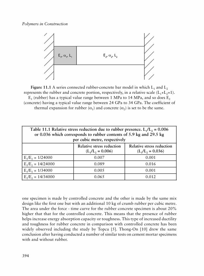
394
Polymers in Construction
Figure 11.1 A series connected rubber-concrete bar model in which L1 and L2
represents the rubber and concrete portion, respectively, in a relative scale (L1+L2=1).E1 (rubber) has a typical value range between 1 MPa to 14 MPa, and so does E2
(concrete) having a typical value range between 24 GPa to 34 GPa. The coefficient ofthermal expansion for rubber (�1) and concrete (�2) is set to be the same.
L.ecneserprebburoteudnoitcuderssertsevitaleR1.11elbaT 1 L/ 2 600.0=gk5.92dnagk9.5fostnetnocrebburotsdnopserrochcihw630.0ro
ylevitcepser,ertemcibucrep
noitcuderssertsevitaleRL( 1 L/ 2 )600.0=
noitcuderssertsevitaleRL( 1 L/ 2 )630.0=
E1 E/ 2 00042/1= 700.0 100.0
E1 E/ 2 00042/41= 980.0 610.0
E1 E/ 2 00043/1= 500.0 100.0
E1 E/ 2 00043/41= 560.0 210.0
one specimen is made by controlled concrete and the other is made by the same mixdesign like the first one but with an additional 10 kg of crumb rubber per cubic metre.The area under the force - time curve for the rubber concrete specimen is about 20%higher that that for the controlled concrete. This means that the presence of rubberhelps increase energy absorption capacity or toughness. This type of increased ductilityand toughness for rubber concrete in comparison with controlled concrete has beenwidely observed including the study by Topcu [5]. Thong-On [10] drew the sameconclusion after having conducted a number of similar tests on cement mortar specimenswith and without rubber.

395
Based on what is discussed in this section, and the physics and engineering properties ofrubber and concrete, the characteristics of rubber concrete may be deduced as:
• Increased ductility and toughness.
• Increased crack and freeze-thaw resistance.
• Increased skid resistance, noise absorption and thermal insulation.
• Reduced Young’s modulus, weight, drying shrinkage and thermal expansion.
So far the observation and laboratory test results generally support the characteristicslisted above. For example, 0.02% dry shrinkage, 0.6% failure strain, 20-50% reductionin the coefficient of thermal expansion [11] have been achieved. The increase of energyabsorption is 20% or higher in comparison with controlled concrete [5].
Rubber is organic and cement/concrete is inorganic. One question frequently asked is howthe two can ‘get along’? Is it true that rubber particles sit loosely inside concrete? Theobservations made so far indicate that rubber particles are embedded well in cement pasteinside concrete, and they are not as easily removed from their bases as it is thought. It
Figure 11.2 Force-time response for the compression of two concrete cylinders. Thecylinder without rubber has a higher compressive strength but lower failure strain and
energy absorption. The cylinder with rubber shows an opposite trend. Such a trendhas been extensively observed in other similar tests [11].
Rubber Concrete

396
Polymers in Construction
should be pointed out that crumb rubber used in current studies is made by the ambientprocess, whether this is also true for crumb rubber made by the cryogenic process remainsto be verified. Because of the work of placing and finishing, there are fewer rubber particleson the surface than in the interior. Rubber particles sitting on the surface of the sidewalkon the campus of ASU remain visible and intact after more than four years of ‘wear andtear’. A more revealing case is when a diamond saw cuts through a rubber concrete cylinder.Most rubber particles on the surface area of cutting trail, though sticking out, still sitfirmly on the surface area. The explanation is that rubber has a ‘jaggy’ surface that is filledwith cement paste to form an interlock layer [11]. Also, concrete will undergo a shrinkageon drying that may make rubber particles as ‘pre-stressed’ reinforcement.
Is there any chemical reaction between rubber and concrete? Or will rubber participate inhydration in any capacity? It appears that it is inadequate to even try to answer this question.Yet, there have been a few cases observed in which the relationship of compressive strengthversus time for rubber concrete does not follow the pattern of controlled concrete.
11.4 Air Content and Compressive Strength
As mentioned in Section 11.2, during the preparation for the tennis court project, a seriesof experimental test slabs (0.6 m x 1.2 m in size), with a thickness of either 5 cm or 7.5 cm)were poured in January 2003 in Phoenix, Arizona (warm climate) with rubber contentvarying between 29.5 kg to 177 kg of crumb rubber per cubic metre. The details of thepouring are as follows. Controlled concrete (Mix-1) of 3.8 m3 arrived at the pour site afterabout 30 minutes of driving from the concrete plant and the first sampling and measurementswere carried out. Afterwards, 114 kg of crumb rubber were added to the concrete truck tomake a rubber concrete (Mix-2) with a rubber content of 29.8 kg per cubic metre and a re-mix for 6 minutes was performed. The second sampling and measurements were taken 20minutes after the truck’s arrival. Then more crumb rubber was added to the concrete truckto reach the level of 59.6 kg per cubic metre with sampling and measurements being donefor the third time. The time gap between the truck’s arrival and the third one was about 50minutes. After that, the truck discharged more than 2.29 m3 rubber concrete (Mix-3) intoa pre-framed sidewalk and placing/finishing (rodding and trowelling) was done manuallywith relative ease. Then more crumb rubber was added to give a level of 89.3 kg per cubicmetre, the rubber concrete (Mix-4) appeared very dry and extra water was added to thetruck with re-mixing, which was 100 minutes after the truck’s arrival. Mix-5 was made byadding more crumb rubber into the truck to give a level of 118 kg per cubic metre whichwas almost two hours after the truck’s arrival. After that, another portion of water withrubber was added to give a level of 179 kg per cubic metre, which was called Mix-6, andmade at about 130 minutes after the truck’s arrival. Rubber concrete pads for Mix-4, Mix-5 and Mix-6 were also poured along with sampling and the measurements.

397
There was some speculation about whether those 179 kg per cubic metre rubber concretepads (Mix-6) might disintegrate in any minute since its compressive strength was verylow (see Table 11.2) as discovered later. But in the end, those pads still did what concretewas supposed to do, and have held up well since, though, with a very different andsomewhat revealing characteristic in comparison with controlled concrete.
The measured data for Mix-1, Mix-2, Mix-3, Mix-4, Mix-5 and Mix-6 are given inTable 11.2, which shows that high air content was measured for rubber mixes. Sinceextra water was added to Mix-4, Mix-5 and Mix-6 and the air content was measuredwhen those mixes were much ‘older’, the values for air content given in Table 11.2 forthose mixes may not have good repeatability. The pressure method, ASTM C231 [14],appears to be giving the low-end value, and the volumetric method, ASTM C173 [15],appears to be giving the high-end value. The air content can also be estimated by usingmeasured unit weight, which yields somewhere in between the pressure and volumetricmethod. More details can be found in Zhu’s recent paper [12].
The SRP project was to repair water cannel by spraying rubber shot-crete. The rubbercontent was 104.7 kg per cubic metre and the relevant information is given in Table 11.3,which again shows a high measured air content.
ehtrofyrotsihhtgnertsdnatnetnocria,pmuls,thgiewtinU2.11elbaTnoitaraperptruocsinnetfoselpmas
epyTtinU
,thgieWm.gk 3-
,pmulSmc
%,riAMTSA371C]51[
%,riAMTSA132C]41[
htgnertS,yaddr3
aPM
htgnertS,yadht7
aPM
htgnertS,yadht82
aPM
1-xiM 73.2 7.21 9.2 7.1 1.02 3.52 0.03
2-xiM)gk8.22(
52.2 9.8 1.9 3.4 5.41 2.81 2.62
3-xiM)gk6.54(
61.2 7.5 0.31 1.6 1.11 1.41 9.61
*4-xiM)gk4.86(
10.2 7.5 4.02 3.01 15.5 15.7 01.9
*5-xiM)gk2.19(
20.2 45.2 8.02 8 71.5 87.5 84.8
**6-xiM)gk8.631(
57.1 3.8 2.33 51 08.1 55.2 30.3
.emitdnocesehtdeddasawretawartxe**;deddasawretawartxe*
Rubber Concrete

398
Polymers in Construction
Besides the two cases given here, it has been consistently observed that rubber crumbs dobring air into concrete, though the quantification can be very difficult. This increase inair content may act as a major contribution to the loss of compressive strength.
Following the logic given previously that the increase in air content is to be blamed for lossof compressive strength, the question is to how to reduce the air content induced by thepresence of crumb rubber. One method has been used to try and answer this question, inwhich ‘additional’ fine particles that were smaller than mesh #200, such as fly ash, dustcollected from the asphalt plant and even gypsum powders were used. Here, ‘additional’means to use more than what is normally specified in controlled concrete design.
In this experiment, three rubber concrete designs were studied with the same crumbrubber level: 148.79 kg per cubic metre. The details including both design specificationand test results are given in Table 11.4a and 11.4b (Design-I), Table 11.5a and 11.5b(Design-II), Table 11.6a and 11.6b (Design-III). All the tests were performed by DaveRuth and his staff at Speedie and Associates in Arizona, a licensed professional test
tcejorpPRSnonoitamrofnitnetnocriA3.11elbaT
thgiewlatoTemuloV
m,riagnidulcxe 3,thgiewtinU
mc/g 3371CMTSA,riA
]51[
gk1831 36.0 18.1 %71
I-ngiseDrofnoitacificepSxiMa4.11elbaT
slairetaM gk,thgieW ytivargcificepS m,emuloV 3 tnuomA
)II/I(tnemeC 05.824 51.3 30.631
hsaylF 01.011 1.2 34.25
retaW 67.671 1 67.671
esraoC 00.758 56.2 04.323
eniF 04.691 56.2 11.47
rebburbmurC 97.841 30.1 54.441
)%(riA 59 5.9
recuderretaW m/gk4.2 3
muspyG
latoT 55.7191 81.2001

399
I-ngiseDrofstlusertseTb4.11elbaT
pmulSriA
tnetnoctinUthgiew
yadts1,htgnerts
aPM
yaddr3,htgnerts
aPM
yadht7,htgnerts
aPM
yadht82,htgnerts
aPM
mc3.02 %51 68.1 84.6 7.01 9.11 4.41
II-ngiseDrofnoitacificepSxiMa5.11elbaT
slairetaM gk,thgieW ytivargcificepS m,emuloV 3 tnuomA
)II/I(tnemeC 05.824 51.3 30.631
hsaylF 01.011 1.2 34.25
retaW 67.671 1 67.671
esraoC 94.797 56.2 49.003
eniF 04.691 56.2 11.47
rebburbmurC 97.841 30.1 54.441
)%(riA 59 5.9
recuderretaW m/gk4.2 3
muspyG 58.24 2 34.12
latoT 98.0091 51.1001
II-ngiseDrofstlusertseTb5.11elbaT
pmulSriA
tnetnoctinUthgiew
yadts1,htgnerts
aPM
yaddr3,htgnerts
aPM
yadht7,htgnerts
aPM
yadht82,htgnerts
aPM
mc3.8 %5.9 89.1 32.7 33.01 2.21 2.71
laboratory located in Phoenix, Arizona. Cement used in the tests is in compliance withASTM C150 [16] type I/II, low alkali; coarse aggregate is in compliance with ASTMC33 [17]; size #7, 2.54 cm fine aggregate is in compliance with ASTM C33 size #1; flyash is in compliance with ASTM C618 [18], type F; water reducer is in compliancewith ASTM C494 [19]. Type A (high range); water is supplied from the city watersource. Crumb rubber is the same grade as used for asphalt–rubber and is made by the
Rubber Concrete
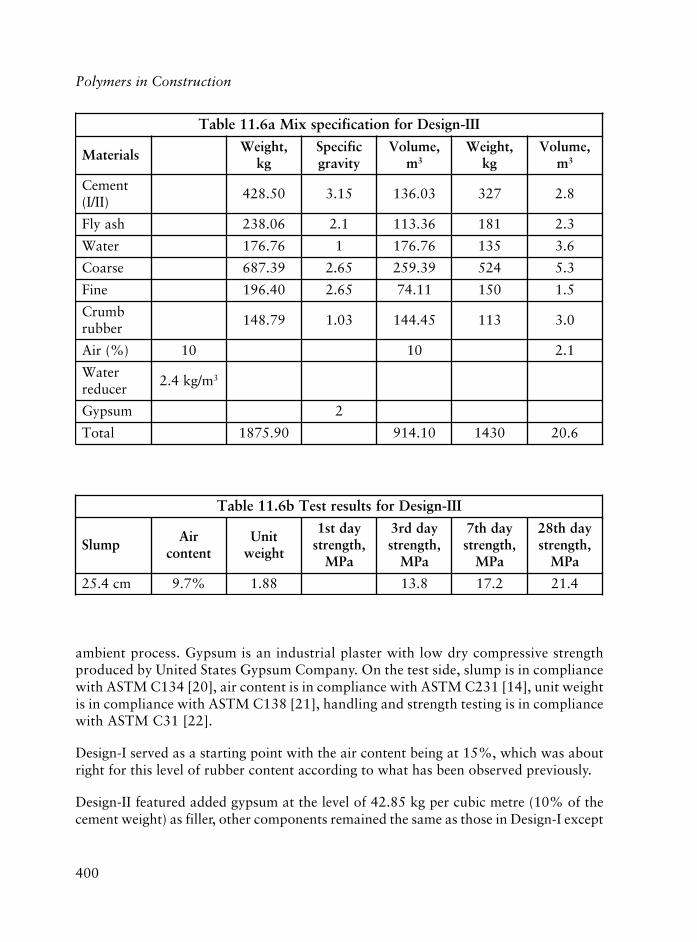
400
Polymers in Construction
III-ngiseDrofnoitacificepsxiMa6.11elbaT
slairetaM,thgieW
gkcificepSytivarg
,emuloVm3
,thgieWgk
,emuloVm3
tnemeC)II/I(
05.824 51.3 30.631 723 8.2
hsaylF 60.832 1.2 63.311 181 3.2
retaW 67.671 1 67.671 531 6.3
esraoC 93.786 56.2 93.952 425 3.5
eniF 04.691 56.2 11.47 051 5.1
bmurCrebbur
97.841 30.1 54.441 311 0.3
)%(riA 01 01 1.2
retaWrecuder
m/gk4.2 3
muspyG 2
latoT 09.5781 01.419 0341 6.02
III-ngiseDrofstlusertseTb6.11elbaT
pmulSriA
tnetnoctinUthgiew
yadts1,htgnerts
aPM
yaddr3,htgnerts
aPM
yadht7,htgnerts
aPM
yadht82,htgnerts
aPM
mc4.52 %7.9 88.1 8.31 2.71 4.12
ambient process. Gypsum is an industrial plaster with low dry compressive strengthproduced by United States Gypsum Company. On the test side, slump is in compliancewith ASTM C134 [20], air content is in compliance with ASTM C231 [14], unit weightis in compliance with ASTM C138 [21], handling and strength testing is in compliancewith ASTM C31 [22].
Design-I served as a starting point with the air content being at 15%, which was aboutright for this level of rubber content according to what has been observed previously.
Design-II featured added gypsum at the level of 42.85 kg per cubic metre (10% of thecement weight) as filler, other components remained the same as those in Design-I except
401
for a small reduction in coarse aggregate. The air content was dropped to about 9.5%and the strength increased.
Design-III was made, after examining the test results from Design-I and Design-II, witha high amount of fly ash and more than 50% of cement weight. In controlled concrete,fly ash usually takes about 15% to 20% of cement weight. The test results show an aircontent of 9.5%, 13.8 MPa for 3-day compressive strength, and 21.4 MPa for 28-daystrength. The slump is 25.4 cm and the unit weight is below 1.9 kg/m3 which qualifies aslightweight concrete. It appears based on the results given in Table 11.6b that this methodcan provide an improvement on strength recovery [12].
The second method is to premix crumb rubber with certain liquid polymers to ‘squeeze out’air bubbles at the rubber/cement-paste interface. Polymer layers in-between rubber and cementpaste may also help increase the bonding strength connecting rubber/cement paste. The issuewith this method is that it may be costly [10]. It can be seen that reduction in air content willremain to be a major research issue in the days to come for rubber concrete.
11.5 Applicability
What is the possible application of rubber concrete? Before replying to this question,let’s categorise three levels of rubber content in concrete:
Low level: 0 kg per cubic metre to 29.5 kg – 35.4 kg per cubic metre
Intermediate level: 29.5 kg – 35.4 kg per cubic metre to 88.3 kg – 147.2 kgper cubic metre
High level: 88.3 kg – 147 kg per cubic metre to 236 kg per cubic metre.
This categorisation is simplistic, yet it may provide a framework to quantify theapplicability for rubber concrete.
At the low level of rubber, rubber concrete essentially functions like controlled concreteand it appears that one possible application is as a replacement for air entrained concrete.The results obtained from the test site in NAU indicate that, while it performs well in acold climate, rubber concrete has the advantage of higher compressive strength than airentrained concrete. Also, while it has good ability to resist cracks, rubber concrete maybe used as controlled concrete but with fewer or no expansion joints.
At a level of rubber between 88.3-147 kg per cubic metre, rubber concrete possesses allthe characteristics given previously. Its Young’s modulus is a fraction of that for controlled
Rubber Concrete

402
Polymers in Construction
concrete. It can achieve 3-day and 28-day compressive strength of 14 and 21 MPa,respectively, or more and a unit density of 1.9. Applications may include roadways,roofing, floors, shear and interior walls, etc.
At the level of 177 kg per cubic metre and more, rubber is in a very high concentration.For example, the level of 236 kg per cubic metre will have a volume of 0.18 cubic metre,and take about 25% of the total volume. Considering the air the rubber will bring in,rubber concrete at this level will be very light. In a few cases, the measured unit-weightvalues of rubber concrete at this level are as low as 1600 kg per cubic metre. Applicationsmay include outdoor sports and recreational facilities like tennis courts, basketball courts,walkways, etc., with a design strength of 14 MPa or less.
Roads made with Portland concrete have been out of favour because of the noisyrideability, because of the high rigidity of concrete and the unevenness of expansionjoints embedded in the roads as they age. Rubber concrete can also have low rigidityas close as that of asphalt concrete. It may also be acceptable to have narrowedexpansion joints. The Arizona Department of Transportation has just built a majorconcrete road in October 2003 with a rubber content of 32.4 kg/m3 and a smallamount of glass fibres and polypropylene fibres. The soft cut method was used tomake expansion joints so that the joint width was much narrowed in comparison tothose ones made by the traditional method of forming. It has been reported in Spainthat a concrete road with shredded rubber fibres (average length is 1.25 cm) wasbuilt three years ago, and it has performed well with heavy traffic flow [23]. It appearsthat there are a variety of ways to use rubber concrete in road applications aimed atvarious tangible benefits.
Dam and canal applications may present another market for rubber concrete for utilisingits ability in resisting cracks. Rubber concrete may be used to provide ‘more shockabsorptive’ joints in connecting rigid columns/beams in a building constructed in anearthquake active zone. The use of rubber concrete with steel reinforcement remainsbasically unexplored. It appears that more plausible applications for rubber concretemay emerge as the progress on rubber concrete is advancing.
11.6 Discussions and Conclusion
One question that has been asked is whether rubber will contribute anything other thanto function likes air bubbles inside concrete? To answer this question, an analysis isgiven here in which the staring point is the mix design given in Table 11.6a andTable 11.6b. Since rubber takes 14.8% volume and the air content is 9.5%, the equivalentair content for combined air and rubber is 24.3%.

403
Taking an assumption that 8% air increase will yield a compressive strength reductionby 50%, and assuming a mix design that has 165 MPa 28-day compressive strength with1% air content, as a deduction, the same mix design now may have 82.2 MPa at the aircontent being somehow raised to 9%, and 41 MPa at the air content being 17% and20.5 MPa at the air content being 25%, respectively. Based on this deduction, this meansthat if all the air bubbles including rubber were to be squeezed out in the mix designgiven in Table 11.6a and Table 11.6b, the level of compressive strength at 165 MPawould be reached. Certainly, removing the rubber component out of the mix recipegiven in Table 11.6a would not make it a 165 MPa concrete. This may suggest thatrubber crumbs may do more than just be air bubbles inside concrete.
On another note, rubber concrete appears in a product called ‘elastic concrete’ withcharacteristics in between asphalt concrete and conventional Portland concrete. So far,the concrete design is governed by the concept of strength, and rubber concrete may bean alternative, or at least a thought of as the alternative, not only because of its strengthbut also because of its toughness.
Rubber concrete is in its infancy and much remains to be explored. Admittedly, the casespresented here are limited in number with many analytical analyses, deductions, andobservations. It is hoped that more progress will be made that will shed more light onrubber concrete.
Acknowledgement
The author would like to acknowledge those individuals in Arizona, USA, who made theeffort in advancing rubber concrete: George B. Way, Thornton Kelly, Bob Fairburn, DougCarlson, Can Xiao, Norasit Thong-On and many others, as well as Dr. K. Kaloush andDr. B. Mobasher in ASU.
References
1. N.N. Eldin and A.B. Senouci, Journal of Materials in Civil Engineering, 1993, 5,4, 478.
2. R.R. Schimizze, J.K. Nelson, S.N. Amirkhanian and J.A. Murden in Proceedingsof the Third Material Engineering Conference, Infrastructure: New Materials andMethods of Repair, San Diego, CA, USA, 1994, p.367.
3. D. Fedroff, S. Ahmad and B.Z. Savas, Transportation Research Record, 1996,1532, 66.
Rubber Concrete
404
Polymers in Construction
4. T.D. Biel and H. Lee in Proceedings of the Third Material EngineeringConference, Infrastructure: New Materials and Methods of Repair, San Diego,CA, USA, 1994, p.351.
5. I.B. Topcu, Cement and Concrete Research, 1995, 25, 2, 304.
6. H.A. Toutanji, Cement and Concrete Composites, 1996, 18, 2, 135.
7. I.B. Topcu and N. Avcular, Cement and Concrete Research, 1999, 27, 8, 1135.
8. Z.K. Khatib and F.M. Bayomy, Journal of Materials in Civil Engineering, 1999,11, 206.
9. B.Z. Savas, S. Ahmad and D. Fedroff, Transportation Research Record, 1997,1574, 80.
10. N. Thong-On, Crumb Rubber in Mortar Cement Application, Arizona StateUniversity, Tempe, AZ, USA, 2001. [MSc Thesis]
11. C. Xiao, Engineering Properties and Performance of Rubber Concrete, ArizonaState University, Tempe, AZ, USA, 2002. [MSc Thesis]
12. H. Zhu, Cement and Concrete Research, 2003, submitted.
13. H. Zhu, Scrap Tire News, 2001, 16, 6, 16.
14. ASTM C231-03, Standard Test Method for Air Content of Freshly MixedConcrete by the Pressure Method, 2003.
15. ASTM C173/C173M-01e1, Standard Test Method for Air Content of FreshlyMixed Concrete by the Volumetric Method, 2001.
16. ASTM C150-04, Standard Specification for Portland Cement, 2004.
17. ASTM C33-03, Standard Specification for Concrete Aggregates, 2003.
18. ASTM C618-03, Standard Specification for Coal Fly Ash and Raw or CalcinedNatural Pozzolan for Use as a Mineral Admixture in Concrete, 2003.
19. ASTM C494/C494M-04, Standard Specification for Chemical Admixtures forConcrete, 2004.
20. ASTM C134-95(1999), Standard Test Methods for Size, Dimensional Measurements,and Bulk Density of Refractory Brick and Insulating Firebrick, 1999.

405
21. ASTM C138/C138M-01a, Standard Test Method for Density (Unit Weight),Yield, and Air Content (Gravimetric) of Concrete, 2001.
22. ASTM C31/C31M-03a, Standard Practice for Making and Curing Concrete TestSpecimens in the Field, 2003.
23. F. Hernandez-Olivares, G. Barluenga, M. Bollati and B. Witoszek, Cement andConcrete Research, 2002, 32, 10, 1587.
Rubber Concrete

406
Polymers in Construction
407
12 Some Possible Health Issues Related toPolymeric Construction Materials andon Indoors Atmosphere
Güneri Akovali
12.1 Introduction
The environment of modern society is full of toxic chemicals. In the case of indoors,where there is a closed environment, the concentration of toxic chemicals can be evenhigher and thus more critical. Some researchers have suggested that even minute amountsof certain chemical compounds can act directly or may adversely change the way humansand wildlife develop and reproduce. These toxic chemicals may already be existingnaturally indoors, such as radon, or they may come from materials of construction(flooring materials, wall-papers, wooden structures, various furniture, paints, etc.), oreven from common household products (such as cleaning agents). This exposure usuallyis done unintentionally and in most cases without knowing it. However, hazards resultingfrom exposure to some of these possibly toxic chemicals that exist indoors and theireffect on health may be a very serious issue. Effects of them on health are usually neglectedand, in fact, they are one of the least known issues in our living sphere. However, asshown in the following examples, they should be considered more seriously becausetheir effects can be important and even vital, and, they may be the reason for a numberof health problems from the long-lasting allergy or asthma or even a lasting headache, tomore serious issues, like cancer.
These possible sources will be discussed briefly next, by considering natural but with theemphasis on plastic construction materials. It should be noted, however, that inclusionof plastics in general should not automatically mean that its use will result in adversehealth effects. Many plastics are being used in many critical areas, including foodpackaging and health sector, even as blood bags and dialysis equipment tubing; thisshows that in most cases it is not the plastic itself but the additives and other foreignchemicals that are added for different purposes that can pose health hazards and shouldbe carefully considered. This being the case, the same plastic material can be very safe orvery hazardous; depending on the ingredients added to it.
To begin with, general aspects of poor indoor air quality (IAQ) and sick building syndrome(SBS) will be discussed, which will be followed by the other possible ‘toxic’ issues indoors.
408
Polymers in Construction
12.1.1 Indoor Air Quality (IAQ) and Sick Building Syndrome (SBS)
IAQ and SBS are also known as Building Related Illnesses (BRI). We usually spend most ofour time indoors where chemical concentrations can be significantly higher than outdoors,and hence air quality in homes and in offices is a matter of ever increasing concern. Inaddition, there are a number of different materials existing indoors, most of which are arisingfrom furniture and construction. New consumer products increased the variety of pollutantsin the indoors air. Volatile organic chemicals (VOC) emitted by building materials, furnishings,cleaning products, carpets and other materials found or used indoors as well as occupantactivities can accumulate to detectable (and sometimes to harmful) concentrations; hencethey should be considered seriously in most cases. In fact, the Environmental ProtectionAgency (EPA) has listed both IAQ and SBS as one of the top five environmental problems.
Adverse health effects that are associated with increased VOC concentrations can beginwith eye and respiratory irritation (including asthma), irritability, inability to concentrateand sleepness, and can end up with various disorders in health and even with cancer. Ina report [1], it is shown that 7-10% of the population suffers ill health, usually as adirect result of poor IAQ.
Indoor environments can also concentrate biological contaminants (such as bacteria, fungi,moulds, pollens, arachnids and insects) which can lead to various allergies and healthproblems. Since biological contamination is beyond the scope of this chapter, it will not bediscussed at all and only chemical contamination indoors will be focused on briefly, althoughin over 40% of SBS cases there is bacterial or fungal contamination involved.
SBS is directly connected to IAQ and it is simply due to the ‘poor indoor air quality’.
12.1.2 What is SBS?
SBS is a serious air quality problem in homes, as well as in work places. An area can bedescribed as ‘sick’ mainly because people develop symptoms of illness such as headache,watery eyes, nausea, throat irritation, skin disorders and fatigue when spendingconsiderable time indoors where there is a build up of air pollutants from householdproducts, building materials, formaldehyde and/or respirable particles, and there is noprecise definition of SBS. There are several important notes to consider:
(a) Signs of a sick house usually include a musty, stuffy smell and other odours,
(b) Moisture build up indoors plays a large part in SBS since high humidity increases theemissions of odours and chemicals such as formaldehyde, and it promotes the spreadof mildew which can aggravate or cause allergies.

409
Possible Health Issues Related to Plastics Construction Materials and Indoor Atmosphere
(c) Since everyone’s tolerance level and metabolism are different, SBS can have an affect ononly one of the occupants while the others in the same environment may not be affected.
(d) In the classic case of SBS, sufferers report relief of their symptoms once they cut offtheir exposure to the building.
An area of concern several years ago was new carpeting which sometimes releasedvapours, however, this is regulated by standards for emissions. There is also interest insome other synthetics, such as vinylics with phthalates, as a source of some SBS problems,which is still under investigation and will be discussed in following sections.
As regards the ‘diagnosis’ of a sick building, the rule of thumb is as follows: when atleast 20% of building occupants ‘complain of the same medical symptoms from anunknown cause for at least two weeks’ the building can be suspected of being ‘sick’.
SBS is rather a misnomer in as much as the syndrome can only be diagnosed by assessingthe health of the building occupants, not by an examination of the building itself.
The oil crises during 1973-1974 and 1980-1981 agitated the development of super-tight, highly insulated houses in an effort to make homes more energy efficient. Asbuilding enclosures become tighter to reduce the exchange of air between the indoorand outdoor environments in building technology, the less effective is the dilution ofpollutants in the indoors space. Although no solid correlation between tight housesand health problems exists, still some tightly built, well-insulated and vapour-sealedhouses are known to develop signs of a sick house especially during winter months, inmoderate and cold climates. The cure for this is proper ventilation, because cool airholds less moisture and replaces air that is moist and contains contaminants. In warm,humid climates SBS can occur during summer months when the outside air is verymoist. Infiltration and ventilation, which bring humid outside air in, may increasemildew and other moisture related problems when air conditioning does not providesufficient dehumidification. In most cases, the ideal relative humidity range should bebetween 37 and 55%.
Concentration and emission rate build up of pollutants indoors depend mainly on [2]:
(i) the characteristics and the nature of the material(s), i.e., volatility,
(ii) parameters such as temperature, relative humidity and surface air velocity, and,
(iii) for solid materials, the age of the material, i.e., formaldehyde, which is used in wallpanelling and kitchen cabinets has a half-life of 3-5 years [5]. Outgassing decreaseswith time.

410
Polymers in Construction
It is thought that some 800,000 to 1,200,000 buildings in the USA have been ‘diagnosed’as sick. In 1987, the Polk County Courthouse, in Barstow, Florida, USA, constructed ata cost of $37 million, had to be demolished and built again with an additional cost of$26 million in order to ‘cure’ the building of its ‘sickness’ which had necessitated therelocation of over 600 occupants of the courthouse due to their claims of sick buildingsymptoms. There are a number of Court Rulings known, mostly in USA, involving SBScases. There are also cases of long-term disability claims and court orders for employersclaiming total disability as a result of sick-building syndrome [3, 4]. Consequently, theSBS issue has become unsettled and scientists still continue their efforts to understandwhat it is about some buildings that makes some of the occupants sick.
According to a study accomplished by US Federal Environmental Protection Agency(EPA), ‘indoor air is often a greater source of exposure to hazardous chemicals than isoutdoor exposure’. The air quality inside most houses can be 5-10 times worse than thatoutdoors [5].
12.1.2.1 Some Solutions to Combat Existing SBS
An IAQ problem can be of natural origin or it can be due to various VOC emissionsfrom different indoors sources, mostly associated with inadequate fresh air. Deteriorationof IAQ eventually leads to SBS. Hence, availability of fresh air is very important incombating this problem. In principle, a house should have complete air change regularly.A typical old house is expected to have more frequent air changes due to possible leaks(natural stack effect). In any case, the need for air-change component can be decreasedif more electric heat and heat pumps are used in place of gas furnaces and water heatersin the house. If heated by gas, an airtight house can have carbon dioxide levels two tosix times higher than outdoors which can make one to feel sluggish and sleepy. Othercommon pollutants are from construction materials, household cleaners, gases fromfurniture and carpet, etc.
Heat recovery ventilator (HRV) is the most efficient method to bring in fresh outdoor airall year-round and which is much more efficient and controllable than just openingwindows. HRV incorporate one of several designs of heat exchanger cores.
Heating and air-conditioning systems keep a building warm in winter and cool in summer,however, they do not help to improve the air quality in the house. A total heating-ventilationand air conditioning system (HVAC), which should include a furnace, an air filter, humidifier,make-up-air unit and air conditioner, is very effective in improving IAQ. If the HVACsystem used is not total, it can cause the circulation of harmful, contaminated air throughoutthe home, and hence can activate SBS. If the HVAC system does not effectively distribute

411
air to people in the building for some reason, there is inadequate ventilation and hencepoor IAQ results [6]. In fact, older office-HVAC systems were designed for ‘one person per1500-2000 cm2, and a PC on every third or fourth desk’ and in a modern office withhigher occupant densities, it is ‘for more people in much less space’. Today’s standardsrequire approximately 10,000 litres per minute of outside air per person.
Plants are found to improve and cleanse the indoors air from a number of harmfulpollutants such as formaldehyde, benzene and trichloroethylene, as shown in a NASAstudy [5]. Golden pothos, philodendron, corn plants and bamboo palms are found to beeffective in cleansing the air from formaldehyde. Spathiphyllum (Peace Lily) and Dracaenaderemensis ‘Janet Craig’ are good for removing quantities of benzene, such as tobaccosmoke. Trichloroethylene is very effectively removed by Dracaena marginata, Dracaenawarneckei and Spathiphyllum. It is recommended by the Plants for Clean Air Council,that one potted plant for each 1,000 cm2 of floor space is needed for better IAQ [5, 7].
12.1.2.2 Four Elements of SBS
In general, there are four elements of SBS, which may act separately or in combination:
(a) Inadequate ventilation which occurs when heating, ventilating, and air conditioning(HVAC) systems do not effectively distribute air to people in the building, asdiscussed previously.
(b) Chemical contaminants from indoor sources: are the predominating direct source ofindoor air pollution. Adhesives, carpeting, upholstery, manufactured wood products,various construction materials, in addition to copy machines, pesticides, and cleaningagents that all emit VOC. If coupled with poor ventilation, they can create poor airquality which is believed by adherents of SBS to either create health problems orincrease existing ones.
(c) Chemical contaminants from outdoor sources: are more indirect than indoorcontaminants. Pollutants such as motor vehicle exhausts can be conveyed indoorsthrough air intake vents, doors, and windows.
(d) Biological contaminants: are bacteria, moulds, pollen, and viruses. These contaminantsmay breed in stagnant water that accumulates in duct work, humidifiers, and thelike, or where water has collected on ceiling tiles, carpeting, or insulation. Insects orbird droppings, too, can be a source of biological contaminants. Physical symptomsrelated to biological contamination include cough, chest tightness, fever, chills, muscleaches, and allergic responses such as mucous membrane irritation and upperrespiratory congestion.
Possible Health Issues Related to Plastics Construction Materials and Indoor Atmosphere

412
Polymers in Construction
Most of the chemical contaminants from indoor sources (the second factor listed) can beavoided by selecting proper safer materials in construction. Commonly, plastics materials(hence all synthetics) are blamed for the source of chemical contamination indoors, and‘natural’ construction materials are presented as safe and ‘green’ [8, 9]. However, a numberof natural materials can also contain VOC and hence pose hazards to health as well. Radonis one such material, it is found naturally and it is radioactive and exists almost everywherein the house, asbestos is another such material. In addition, allergic reactions to the odoursfrom cedar furniture are very common. The reality with plastics is that, it is not the plasticitself that can cause contamination, but the additives used with it, and a careful selection ofthe material will avoid such problems. And the risk is still always low if a certain agentremains in the building product that does not affect occupants through respiration and physicalcontact. Certainly, products that give off gas a little are preferable to those that give off gas alot, and less toxic alternative materials should be used whenever possible.
There are studies to model SBS in residential interiors depicting the relationship betweencommon health problems and factors leading to SBS [10].
12.1.3 Volatile Organic Compounds (VOC)
12.1.3.1 Possible Sources of VOC
A volatile compound is a material that at ambient temperatures or under the influence ofheat is capable of being vapourised or becoming a gas, i.e., solvents involved in paints.Some materials indoors may continue to generate VOC over many years (ageing), theconcentration of which varies with time, variation in temperature, airflow and volumeof the house. Possible sources of VOC indoors are outlined in Section 12.1.2.2.
12.1.3.2 Some Toxic Chemicals that Can be Found Indoors
Table 12.1 presents some toxics that can be found indoors originating from constructionmaterials, and in Table 12.2, their effects on humans are presented, followed by somemore information about radon and endocrine disrupters (ECD).
Table 12.1 is a general list of some toxic compounds that are commonly found indoors, dueto construction materials [19]. One should consider the fact that each indoor space is uniqueand a specific indoor space may have different toxic chemicals compared to another space.
As an exception, ‘radon’ is added to the list because of its importance, however, it is stillnot well known yet. Although radon is not directly related to construction materials, itexists in houses and it can be eliminated by certain construction techniques.

413
sroodnidnuofebnactahtscixotemoS1.21elbaT)a( lwarc,stnemesabmorfgnikael;sagevitcaoidargnirruccoyllarutana(nodaR
)seilppusretawdnasecaps
)b( sedyhedlarehtodna)sgnihsinrufdnadraobelcitrapmorfylniam(edyhedlamroF
)c( :sahcus,).cte,sevisehda,erutinruf,srenaelc,stniap,stepracmorfgnittime(COVrehtO
• enaxehylniam,snobracordyhcitahpilA
• mroforolhcylniam,snobracordyhcitahpiladetanegolaH
• lonatub-1dnalonahte,lonahtem,.e.i,slohoclacitahpilA)sreuqcaldnastniap,snisercitehtnysdnalarutannidnuof(
• srehtelocylgdnaslocylG
• enelyxdnaeneulot,eneznebylniam,snobracordyhcitamorA)sedicitsepdnasevisehda,stniapnidnuof(
• )sresicitsalpdnasevitiddaniatrec(DCEsuoiraV
sroodnidnuofscixotemosfostceffehtlaehehT2.21elbaT)a( enezneB dnassenisword,gnitimov,ehcadaeh,ssenizzidsesuacylniaM:
.sesodwoltassensuoicnocnulausiv,yhporta,sitiruen:seyeehthtiwtcatnocnifi:erusopxecinorhC
worramenob,noisserpedesuacnacti,stcaratacdnaamedeo,tnemriapmi,aimeana,sseniraew,ssensuovren,aixerona,sehcadaehnegomekuel,noisserped
etarebileD.aimekuelyllanifdnaegamadworram,gnittolcdecuder,rollap.yltceridlliknac)gniffinseulg(sruopaveneznebfonoitalahni
)b( mroforolhC sredrosidmetsyssuovren,yendik,revilesuacnac:erusopxecinorhC:lairetamcitenegfonoitaretlaotesirsevigdnanegonicracasiti,egamadtraehdna
gniwollofehtdnayticixototeof,smelborpytilitref,)DCErofwolebeesesaelp(.lanitsetniortsagdnalateleksolucsum,laicafoinarc:smelborplatnempoleved
)c( nodaR otsdnettahtnigirolarutanfosagevitcaidarelbatsnuylhgihasinodaR:gnulgnisuac,htlaehehtotksirsuoiresaesopnacdnasgnidliubnietalumucca
tuobanoitamrofnideliatederomroF.]31-11[hgihsinoitartnecnocstifi,recnac.6.1.21noitceSeesesaelp,sroodninodar
)d( )DCE(sretpursiDenircodnE yllanomroh‘esuacnactahtslacimehceraesehT:ebnactaht’noitcnufsyd‘dna’noitcudorperotdetaleryltsom,sesaesiddetaler
htob,slacimehcfoegnarediwA.slevelnoillirtrepstraptaneveevitceffednasevitiddaniatrecgnidulcni(slacimehccitehtnysdnasdnuopmoclarutan
deliatederoM.stnegaDCEdetcepsusera)scitsalpnidesusresicitsalp.7.1.21noitceSnitcejbussihtnodetneserpsinoitamrofni
Possible Health Issues Related to Plastics Construction Materials and Indoor Atmosphere

414
Polymers in Construction
12.1.3.3 Permissable Limits for VOC Indoors
As far as the permissible limits of VOC concentration indoors are concerned, there ishardly any universal regulation established, i.e., in the USA there is no such federal regulationexisting, however, several regulatory agencies such as the EPA and the Occupational Safetyand Health Administration (OSHA) have worked on developing several standards. However,these are not easy to apply because correlation between methods and indoor VOCconcentrations is not straightforward, in addition to the fact that detection of specific lowconcentrations of VOC may not indicate whether there will be long-term negative healtheffects or not. However, it would still be essential to have VOC emission information forany material that is to be used in construction to make proper decisions on which materialsbest meet the requirements while fulfilling structural and aesthetic needs.
In a comprehensive study for IAQ and SBS qualities of office buildings selected in USA[14], it was reported that total VOC (TVOC) ranged from 73-235 μg/m3 where the mostprevalent compounds were heptane, limonene, 2-propanol, toluene and xylene. Geometricmean formaldehyde concentrations were found to range from 1.7 to 13.3 μg/m3 andmean aldehyde levels from < 3.0 to 7.5 μg/m3. The prevalence of upper respiratorysymptoms (dry eyes, runny nose), symptoms of central nervous system (headache,irritability) as well as musculoskeletal symptoms (pain and stiffness in neck) were foundto be high within the workers. While in another study done in Japan to assess the impactof office equipment on the IAQ, it was found that the emission of ozone and organicvolatiles (mainly formaldehyde followed by lesser amounts of other volatile aldehydes)emitted are in significant quantities [15]. In one application, in the Washington StateEast Campus Plus project, office furniture systems were required to emit no more than0.05 ppm formaldehyde and 0.50 ppm total VOC to be considered for installation. In ananother study in Finland [16], estimation of the impact of office equipment on IAQ wasquestioned and the emission of ozone and various organic volatiles was found fromphotocopiers and laser printers. The laser printers equipped with traditional (coronarod) technology were found to emit significant amounts of ozone and formaldehyde,with lesser amount of other volatile aldehydes and it is suggested that these are not to beplaced beside or immediately at the working site of office personnel.
To give some more depth on this subject, some basic concepts in toxicology and toxiccompounds need to be considered. They are summarised in Section 12.1.4.
12.1.4 Toxic compounds and Toxicology
Toxics are the chemical and physical agents that have adverse effects on living organisms,and toxicology is the science dealing with toxic agents. The word ‘toxic’ may be consideredto be synonymous with ‘harmful’ in regard to the effects of chemicals [17].

415
A poison is any agent capable of producing a deleterious response in a biological system,seriously injuring function or producing death [18]. Hence, a poison is a substance whichby chemical action and at low dosage can kill or injure humans or mammals. The mostimportant factor that influences the toxic effect of a specific chemical is the dose. Almostall chemicals are toxic at sufficient dosage. Paracelsus (1493-1541) phrased this as: ‘allsubstances are poisons; there is none which is not a poison. The right dose differentiatesa poison and a remedy’. The strength or potency of poisons is most frequently measuredby the lethal dose.
Dose is the number one factor in toxic effect determinations. From statistically treateddose-response data, the dose (in mg/kg body weight) killing 50% of the sample populationis designated as the median lethal dose (MLD or LD50). However, one should keep in mindthat, LD50 values may not accurately reflect the full spectrum of toxicity or hazard all thetime, because some chemicals with low acute toxicity may have carcinogenic (or endocrine)effects even at very low doses that produce no evidence of acute toxicity at all.
Another significant factor that influences the toxic effect of a specific chemical is theroute of exposure (inhalation, ingestion or skin contact). In general, substances areabsorbed into the body most efficiently through the lungs, so that inhalation (which isthe case indoors for SBS) is unfortunately often one of the most serious routes of exposureto the poisons, and this route of exposure is our main interest for construction materials.Toxic gases are absorbed by inhalation whenever VOC are released by out-gassing frombuilding materials. The absorption of the toxic chemicals (toxicants, named by Paracelsus)after inhalation occur first in the nose then in the lungs. The nose acts as a ‘chemicalscrubber’ for water soluble and for highly reactive gases, i.e., formaldehyde. Gas moleculesdiffuse quickly (three-quarters of a second) into the capillary network in the lungs anddissolve into the blood and are then carried to the rest of the body.
Some toxic agents can also be absorbed by the skin. Since skin is permeable, toxic gasescan be absorbed and can be distributed by the blood stream quickly through skinpenetration. Cuts and other abrasions can accelerate the absorption process.
There is a third factor: the fate of the chemical after the organism is exposed to it. Thechemical absorbed can be altered or metabolised (by either being broken down intoproducts that can be incorporated or excreted or by producing less toxic chemicals,called detoxification). The chemical and its metabolites can be excreted, stored ortransported in the organism and may, therefore, reach sites where toxic effects are induced,(i.e., by concentrating in a specific tissue, such as liver, kidney or fat). Rapidly excretedsubstances are generally of low toxicity, and those that are excreted more slowly havethe potential to cause long-term effects. Many substances that are stored in the body,mainly in fat or bone, can circulate throughout the organism for a long time.
Possible Health Issues Related to Plastics Construction Materials and Indoor Atmosphere
416
Polymers in Construction
If a chemical is completely excreted, then succeeding doses have no increased effect,but if a residue remains, then it is possible for the second dose to add to the first and,if doses are repeated often enough, to reach a level high enough to be toxic. In thiscontext, it is obvious that, the water solubility – tissue reactivity and blood to gasphase partition coefficient values of the toxicants are all important in cases of exposureto gases indoors.
It is also worth noting the differences between acute toxicity (effects that occur shortlyafter a single exposure) and chronic toxicity (delayed effects that occur after long-term, repeated exposures).
12.1.4.1 Classification of Toxic Effects
As far as classification of toxic effects are concerned, there may be five general groupsto consider:
(a) Independent Effect: Substances exert their own effect being independent of eachother, in the case of existence of a combination of toxins.
(b) Additive Effect: Materials with similar toxicity produce a response equal to the sumof the effects produced by individual material.
(c) Antagonistic Effect: Materials oppose or interfere with each other’s toxicity.
(d) Potentiating Effect: One material enhances the toxicity of the other.
(e) Synergistic Effect: Two materials produce a toxic effect greater than the sum of thetwo individual toxicants.
12.1.5 Carcinogens
Carcinogens are the chemicals capable of inducing malignant neoplasms. They aresubstances that induce unregulated growth processes in cells or tissues leading to thedisease called cancer. They can be a number of organic and inorganic chemicals withvarious biological actions, such as, alteration of endocrine system or immuno-suppression.Although carcinogenic chemicals, at least in principle, act in a similar way to other toxicagents (carcinogens show the similar classical dose-response relationship existing in toxicchemicals), carcinogens also show several distinct differences and hence they are describedas a ‘specialised field of toxicology’.

417
It is known that, cancer is one of the three leading causes of death in most countries. Theassociation between the exposure to soot and coal tars and cancer was identified in thelate eighteenth century after observation of the incidence of cancer patients among chimneysweeps in the UK. Later, the carcinogenic potency of tar was related to its polynucleararomatic hydrocarbon structure.
Carcinogens can be separated into two general classes based on their chemical andbiological properties:
(1) DNA-reactive carcinogens: most of the human carcinogenics are of this type. Theyare active with a single dose, and often such toxic effects are cumulative. They canact synergistically with one another.
(2) Epigenetic carcinogens (EGC): plastics and asbestos are in this group. They are‘genotoxic’ (that is they are not DNA reactive and appear to operate by the productionof other biological effects)
12.1.6 Risk Management
Since any material must be ‘assessed’ in the context of the system, there are no trulybenign materials and nothing is risk free and ‘risk can be managed’, i.e., a toxic materialcan provide significant benefits and may pose little risk ‘when used properly’: Use ofdamp-proofing on the exterior of a preserved wood foundation that has an inherentlytoxic chemical may provide a decreased risk to the occupants [9].
Overall risk assessment rests on three factors:
(a) exposure assessment,
(b) toxicity assessment, and
(c) dose-response assessment.
Exposure assessment is a necessary component in understanding the hazard involved byexposure to naturally, i.e., radon, or non-naturally existing toxicants, chemicals emittingfrom construction materials [19]. However, the other two (toxicity and dose-responseassessments) are the next two important factors to know.
12.1.7 Radon Indoors
Radon is the biggest possible contribution to radiation exposure in houses (50%) thatoccurs naturally [13]; and as a gas, it has no taste, smell or colour. Radon exists
Possible Health Issues Related to Plastics Construction Materials and Indoor Atmosphere

418
Polymers in Construction
everywhere but it is usually in insignificant levels that pose negligible health risks. It isa radioactive decay product of uranium (over radium). Since uranium is found in allsoil and rocks usually in small quantities varying from place to place, radon also existsand in varying quantities.
Due to the effects of wind and temperature, the air pressure inside a house is usuallylower than the air pressure in the soil beneath it and air containing radon from the soilcreeps into the lower pressure area of the house (through cracks and gaps in the floor orwalls). When radon rises from the soil to the air, outdoors, it is diluted enough, however,when it enters enclosed spaces, high concentrations can build up indoors with a seriousrisk to health. Especially in air with already high levels of radon, indoors, concentrationscan rise up to very high dangerous levels easily.
Radioactive decay of radon forms particles called ‘radon daughters’ which, afterinhalation, can damage lung tissues leading to cancer [20].
12.1.7.1 On Indoors Radon and Measurement of its Concentration
Radon gas concentrations are measured in becquerels per cubic metre (Bq/m3), and the levelof 200 Bq/m3 (maximum) is considered as the action level for homes. This value is double foroffices, because usually more time is spent in the home than at work. The level of radonobserved normally is 1/10th of the action level (20 Bq/m3). In a study done in the UK, it isshown that levels of radon varies considerably from location to location on site with thepossibility of reaching values well above the action level suggested (called ‘high radon potentialareas’) [21]. One should realise that radon is not a problem of basements only, but it canexist even on the upper floors of high rise buildings. In an experimental study, indoor radonlevels were monitored continuously with and without air-conditioning in a number of high-rise office buildings in Hong Kong [22], and it was found that the average indoor radon levelduring office hours were not as low as expected from the high rise positions (they werebetween 87-296 Bq/m3 with ventilation, which was some 25% lower than without ventilation).The average radon emanation rates were found to vary between 0.0019-0.0033 Bq/m3 fordifferent high rise buildings and it was estimated that building infiltration rate accounted forabout 10-30% of the total building ventilation rate in the buildings depending on buildingtightness [22, 23]. On the contrary, there are also reports claiming that sealing homes to saveenergy does not concentrate radon indoors [22, 23].
Radon levels indoors can be measured by a safe and a rather simple method by use ofdetectors, one in the living room and another in an occupied bedroom. In one experiment(in UK), the detectors used are just a piece of spectacle lens plastic put in a protective shell,about the size and shape of a small door knob (obtainable through mail order in some

419
countries [24] and which are returned after three months of test in the reply paid envelopeprovided). The plastic in this system records radon which is measured by accredited laboratoriesafter its return. There are also much shorter, (i.e., fortnightly) measurements available, however,they are less accurate, that can be used for screening purposes as well [24].
Indoor radon measurements obtained for homes in North Virginia, USA, revealed thatexisting high or low median indoor radon levels in each house persist through four seasons[25], however, attempts to compare the soil radon and soil permeability was not successful.
12.1.7.2 Some Measures to Prevent Radon Accumulation Indoors
There are several studies showing the main defects in design and implementation toavoid high radon indoors and to give guidance on radon-safe buildings in slab-on-gradehouses [24, 26, 27]. It is certainly best to stop radon entering the house first, and if thisis impractical, then effective removal (or dilution of it) is recommended. It is shown thatthere are several ways to achieve these [24, 26]. The prevention (or decrease) of the flowof radon-bearing air indoors can be done through installation of aluminised bitumen feltas well as by use of elastic sealants – to seal cracks and gaps in solid concrete floors andwalls. As a precaution, it is suggested that perforated piping is installed in the subsoil ofthe floor slab. There are a number of studies such as on sub-slab ventilation matting[28], as well as production of alpha particle radiation barriers of sulfopolyester-acryliccopolymer [29], and polyamide/polyester matting [30] and others [31, 32].
Installation of a radon sump system equipped with a fan is suggested as the most effectiveand best choice for high levels of radon [24]. For this, a sump which is a small emptyspace about the volume of a bucket is dug under the solid floor and a pipe is routed fromit to the outside air. The sump and the fan connected at the exit of the pipe to suck outair, both help to alter the air pressure below the floor and to release it harmlessly into theatmosphere. There are also applications where the fan is replaced by a blowing system tofacilitate removal of the remaining radon in the soil. It is also possible to increase thecirculation of air beneath the floor (improved ventilation under suspended timber floorswith or without a fan via air-brick) or at loft level or even by using positive houseventilation as a whole (‘positive pressurisation’ is most effective if the house is very air-tight). All of these are common methods that have been suggested and applied.
12.1.8 Endocrine Disrupters (ECD)
As outlined previously, ECD are chemicals that can cause ‘hormonally related diseases’and ‘dysfunction’ that can be effective at very low levels (even at parts per trillion levels
Possible Health Issues Related to Plastics Construction Materials and Indoor Atmosphere

420
Polymers in Construction
at which most chemicals have never been tested). ECD has become a significant focus ofenvironmental science and medicine in recent years.
A wide range of chemicals, both natural compounds and synthetic chemicals (includingcertain additives and plasticisers used in plastics, in addition to well known pesticidessuch as dichlorodiphenyltrichloroethane (DDT) and many industrial and consumerproducts, liquid soaps, shampoos, conditioners, and hair colours – that containalkylphenol ethoxylates (APE), polychlorinated biphenyls (PCB), dioxins, certainpreservatives and metal ions, even certain woods, are all now suspected of causingendocrine disruption in humans. In the EU, the products with APE have been replacedby the more expensive, but much safer, alcohol ethoxylates.
Some ‘endocrine disruptors’, phytoestrogens, occur naturally in a variety of plants. Livingthings evolved with them, they are metabolised or degraded so that they do notbioaccumulate. Of current concern are the synthetic estrogens produced either throughindustrial manufacture or as by-products of such processes or burning. Those we knowabout have been identified by laboratory tests such as those that measure a chemical’sability to speed the growth of cultures of breast cancer cells.
The mechanisms of ECD is poorly understood and specific end points or effects of ECDare not clearly defined yet, and there is still much to be understood and to be exploredabout its role.
12.1.8.1 Suspected ECD Agents
There are four groups of chemicals that are labelled as ‘suspected ECD Agents’:
(a) Certain plastics additives,
(b) Certain PCB,
(c) Chlorinated dioxins and dibenzofurans, and
(d) Certain metal and metal compounds.
Plastics Additives (Mainly Plasticisers)
Plastics contain various additives, such as phthalates, bisphenol-A, and nonylphenols,usually present as plasticisers used to make them flexible and durable. They can leachout into liquids as well as evaporate into the gas phase and can be inhaled. Increase intemperature usually speeds all of these (which is why microwaving foods in plastic isdiscouraged). Oestrogenic butyl benzyl phthalate is found in vinyl floor tiles, adhesives,
421
and synthetic leathers. Its relative, dibutyl phthalate is present in some food-contactpapers. Bisphenol-A is a breakdown product and plasticiser of polycarbonate plastics,which is mainly used as a glazing material.
The EU decided that the year 2002 was the key milestone to complete risk assessmentof phthalates [33].
For more detailed information about certain plastics and plasticisers and their effectson health, please see Section 12.2.2.1 [Thermoplastic construction materials (polyvinylchloride (PVC), polymethyl methacrylate (PMMA), polyethylene (PE) and polycarbonate(PC)] and the plasticisers part of Section 12.2.2.1 (Additives).
In addition to plasticisers, there are a number of different additives used for differentpurposes, i.e., stabilisers used in PVC window profiles and pipes are mostly lead-based,or they can be either barium/cadmium/or zinc compounds. All of these can pose ahealth hazard if they migrate out of the system above certain concentrations.
PCB
PCB are a family of toxic, oily, non-flammable industrial chemicals, commercialised in1929 by Monsanto. Although their production in the USA was stopped in 1977, worldproduction still continues. PCB are still present in the USA in certain (old) electricalequipment and frequently found at toxic waste sites and in contaminated sediments.Recently it was confirmed that children exposed to low levels of PCB in the wombbecause of their mother’s fish consumption grow up with low IQ, poor readingcomprehension, difficulty paying attention, and memory problems.
A Swedish study showed that there may be high levels of PCB around some old buildingsin which sealants containing the chemicals were used some 20-40 years ago. Thesesealants based on polysulfide polymers were used from the 1950s for filling externaljoints in buildings and until the late 1970s and they may have contained up to 20%PCB. In the study, a very high PCB level about 100 times the typical ambient levels inStockholm was measured on a balcony on a hot summer day. Although these sealantsare normally not used inside buildings, the study found one exceptional case wherethere were high levels of PCB in the stairway of a building too. The report recommendschecks on PCB levels in all structures built between 1956-1972. PCB sealants have alsoattracted attention in USA, UK and Germany, but no research or monitoring is ineffect in any of them. PCB in many polysulfide sealants have now been replaced bychlorinated paraffins which are also have certain restrictions raised within the Osloand Paris commission [34, 35].
Possible Health Issues Related to Plastics Construction Materials and Indoor Atmosphere

422
Polymers in Construction
Chlorinated Dioxins and Dibenzofurans
The term ‘dioxin’ is commonly used to refer to a family of compounds comprising around75 dioxins and 135 related furans. The number and position of the chlorine atom differsfor each of these compounds and also has a considerable effect on their relative toxicity– 17 of them are recognised as highly toxic. Chlorinated dioxins (PCDD) anddibenzofurans (PCDF) are within this group, and they are by-products of chlorinebleaching of paper, the burning of chlorinated hydrocarbons such as pentachlorophenol,PCB, and PVC, the incineration of municipal and medical wastes, and natural eventssuch as forest fires, traffic exhaust and even volcanic eruptions. They often contaminatetoxic waste sites, especially where there have been fires. They bioaccumulate in fish andother wildlife and the most common human route of exposure is through the food chain.The International Agency for Research on Cancer has classified the dioxin 2,3,7,8-tetrachlorodibenzo-p-dioxin (2,3,7,8-TCDD) as a known human carcinogen.
Metals and Metal Compounds
Although all living organisms require certain metals for physiological processes, whenthey present at concentrations above the level of homeostatic regulation they can betoxic. Metals can exert toxic effects directly on the functional groups in enzymes eitherthrough altering the conformation of biomolecules or through displacement of essentialmetals in metalloenzymes.
The most common metals and metal compounds that can be found in the atmosphere indoorsare antimony, lead, methyl mercury and cadmium. These metals, their organic metalcompounds and metal ions that can exist in plastics as additives used for different purposesare believed to disrupt the endocrine system by causing problems in steroid production. Thefate of these metal and metal ions, mostly found and used as stabilisers, has been moreextensively studied for the lead and lead-based compounds, however, much less for the others.
(a) Lead (Pb): Lead has no biological role and it is a cumulative poison. The most seriousadverse effects, mental retardation and learning problems, occur in young childrensubjected to chronic exposure, most often through ingestion of paints. All forms oflead are extremely toxic to humans. Children with iron and calcium deficienciesabsorb more lead and hence there is greater adverse effect. The main effect on adultsis also neurological. The initial symptoms of mild lead poisoning are headaches,nausea, stomach pains, vomiting, joint pain and constipation. At higher exposurelevels, there is toxic psychosis. It can cause hypertension, anaemia, neurological effects(especially in children), kidney damage, digestive problems, sterility, miscarriages,and possibly cancer. A single dose is unlikely to kill, but its absorption over a periodof time is fatal. It is locked away in the bones as lead phosphate.

423
Soluble lead can leach from old water pipes, badly glazed pottery and even from leadcrystal decanters. In a study, it was shown that the rate of lead extraction from a100 mm diameter PVC wastewater pipe system was 0.7 μg/l/day [36] and that sewersystems can contribute 0.5 μg/l lead to the wastewater [37]. On the other hand, in theCSIRO report it is concluded that, ‘under normal use conditions in the potable waterindustry, the level of lead extracted from properly commissioned PVC pipe has beenfound to be below the levels of detection’ [37]. Some old paint may also contain lead.Lead or lead compounds are absorbable by the body and also by inhalation. If theamount absorbed is small, the body can get rid of some of it through urination, butsome may still stay in the body stored mainly in the bones and can stay there withoutany poisoning effects until a certain dose is reached by accumulation in time [38].
The EU put forward following key milestones as regards to control and diminishingthe use of lead stabilisers in plastics: by the year 2004, completion of initial riskassessment on lead stabilisers will be accomplished; by 2005: 15% (to reach 100 Kt),and by 2010: 50% reduction target of their use (reaching 60 Kt), and by 2015, it willbe 100% off for use of lead stabilisers [33].
(b) Antimony (Sb): although it has no biological role, antimony is toxic. It cannot beexcreted from the body and large doses cause copious vomiting and liver damage.Antimony is used as a flame retardant additive (mainly for PVC). During the 1990s,antimony containing PVC was accused of causing cot deaths in babies (it is claimedthat antimony is converted to the volatile toxic gas, stibine (SbH3) by a fungus existingin the mattress). However, this claim is not proved so far and although the analysisof tissue from cot death victims had antimony levels somewhat higher than allowed,13 ppm, similar results are also observed for healthy babies. Moreover, in the housedust of some old houses the level of antimony can already exceed 1800 ppm, thesource of which is not known exactly [24, 39].
(c) Arsenic (As): Arsenic is a deadly poison with a lethal dose of 100 mg. It is the thirdmetal most often implicated in human toxicity. The valence form of arsenic is criticalto its toxicity, trivalent arsenic (as in arsenic trioxide) is the most toxic. The symptomsof arsenic poisoning are vomiting, colic, diarrhoea and disturbances of thehaematopoietic and central nervous systems, progressing to coma which leads likelyto a heart failure [24]. Chronic exposure is associated with cancers of the skin andlung and may be linked to cancers of internal organs.
In houses, the source of arsenic can be from paintings (the bright yellow pigment, called‘royal yellow’ is in fact ‘orpiment’, or arsenic trisulfide chemically); which was favouredby Dutch painters in the near past. This paint slowly oxidises to arsenic trioxide, whichis very toxic, by fading in colour. Arsenic is also used in treated lumber (wood).
Possible Health Issues Related to Plastics Construction Materials and Indoor Atmosphere
424
Polymers in Construction
The arsenic allowed under the EPA’s proposed drinking water standard is a maximumof 10 parts per billion.
(d) Cadmium (Cd): Cadmium is an accumulative poison. If its level exceeds 200 ppm inthe body, kidney failure and damage develops and its further increase weakens thebones and joints (most probably leading to cancer). Exposure to high levels overshort periods of time leads to nausea, vomiting and cramps.
Cadmium is used as a common bright pigment (cadmium yellow) in the form ofcadmium sulfide in paints, rubber and plastics as additive. Until recently, cadmiumred was widely used for containers, toys and household wares but has now beenphased out completely. The EU put forward March 2001 as the key milestone to endsales of any cadmium containing stabiliser [33].
(e) Phosphorus (P): As a poison, phosphorus attacks the liver quickly. Breathingphosphorus vapour over a long period of time can lead to the disease known as‘phossy jaw’, which slowly ate away the victim’s jaw bone. Phosphorus containingcompounds are used as flame retardants (specifically in the synthetic fibre industries,such as polyester production).
(f) Tin (Sn): Tin compounds can be poisonous by ingestion, especially organotincompounds, [(i.e., trimethyl (TMT) or triethyl-tin (TET)]. They can upset variousmetabolic processes with fatal results in the human body. Organo-tin compounds(with four organic groups attached) are used as catalysts in the production ofpolyolefins such as polyethylene. Tin (with one or two organic groups) are effectiveadditives used to decrease heat sensitivity of plastics (as organotin stabilisers), i.e.,for PVC.
Tin (with three groups attached, such as TBT) are widely used as wood preservativesand anti-fouling paints, as well as to prevent unwanted growth of moulds on stonestructures.
(g) Zinc (Zn): Zinc is generally labelled as non-toxic, however, excess can be stored inthe bones and spleen. The most significant toxic effect of zinc is fume fever, that canresult from acute inhalation of zinc oxide fumes.
Zinc oxide is used largely in the rubber industry (acting as a catalyst duringmanufacture and as a heat dispenser in the final product) as well as in pigments forplastics and wallpaper. It also functions to prevent the UV damage of the plasticsand rubber.
In addition, there may be mercury vapour emitting from biocides used in paints.

425
12.2 Construction Materials and Health Issues Indoors
Some of the ingredients, mainly additives existing in various construction materials canslowly evaporate and/or breakdown, releasing different chemicals. Of all the constructionmaterials, plastics and wood are our main concern in this chapter. It is essential to seetheir possible VOC contributions briefly.
12.2.1 Plastics
In the plastics construction materials list, the biggest share belongs to PVC (55%), asfollowed by polystyrene (PS, 15%), polyolefins (15%), polyurethanes (PU, 8%), andothers, mainly PMMA (7%) [24]. These plastics are used in different applications inconstruction and they are usually blended with certain additives. These additives causethe main toxic effects of construction materials.
12.2.1.1 Additives in Plastics
Additives are materials that are blended with polymers to make them easy to processand to give them certain physical properties for specific applications as well as to protectthem from the effects of time, heat and environmental conditions. Additives play a keyrole in improving and creating the unique performance characteristics of plastics. Usually,additives are stabiliser systems to ensure durability and plasticisers to produce a degreeof flexibility, in addition to other additives, (i.e., pesticides and antimicrobials, lubricants,pigments, flame retarders, impact modifiers, antistatic agents, UV absorbers,compatibilisers). Being smaller in size in general than the parent polymer, and beingorganic molecules, migration and even sweating of the additives can occur which resultstheir vapourisation and hence emission of their toxic effect into the vapour phase whichcan then be inhaled by humans. There are ongoing studies to bond the additive to polymerbackbone to blockade and hence control the migration.
Pesticides and Antimicrobials: Pesticides and antimicrobials (biocides) are used in constructionmaterials to provide resistance to the growth of microorganisms – such as bacteria, fungi andalgae (used mostly for PVC and PU grades, the latter for roofing membranes) [40], becausesome ingredients (several plasticisers, lubricants, thickening agents and fillers) can supporttheir growth. Use of these materials in contact with high humidity can activate microbialattack. Some commonly used plasticisers (dioctyl phthalate, diisooctylphthalate,dibutylphthalate, tricrescyl and triphenyl phosphate are the most resistant to microbial attack.The major antimicrobial agents used in PVC are 10-10�-oxybisphenoxarsine (OBPA),n-(trichloromethylthio) phthalimide and 2-N-octyl-4-isothiazolin-3-one (OITO).
Possible Health Issues Related to Plastics Construction Materials and Indoor Atmosphere

426
Polymers in Construction
Stabilisers: Stabilisers are added to plastics to afford protection against thermal and UVdegradation of the polymer during processing and use, respectively. Some thermalstabilisers also have an activating influence on the blowing agent. The commonly usedstabilisers for PVC are compounds of lead (basic lead sulfate and lead stearate: they arerelatively low cost), tin (mono-and dibutyltin as well as thioglycolate: with excellent thermalstability and very low toxicity), cadmium, and complex salt systems of barium/zinc andcalcium/zinc. Within these, it is known that all forms of lead are extremely toxic tohumans because of their cumulative effects. Metallic tin is harmless but organotincompounds can be toxic to the central nervous system and the liver. Cadmium causeskidney damage and anaemia and phasing out of cadmium containing heat stabilisers isunderway. Calcium and zinc systems are non-toxic to humans, they can offer comparableproperties but at a higher cost. Lead systems, although considerable toxicity may result,are still expected to remain the dominate stabiliser type until legislation dictates otherwise.The fate of heavy metal stabilisers are dependent on a number of complex factors, butnever the less, since the stabiliser is held within the plastic matrix only limited lossesfrom the surface of the bulk is expected.
Recently some organic-based stabilisers with a pyrimidinedione system with no heavymetals were introduced and they found immediate use.
Hindered amine light stabilisers (HALS) are the main stabiliser type (as a scavenger toinhibit free radical chain propagation) in addition to organo-nickel compounds (as aquencher to prevent initiation of polymer degradation) are used for UV stabilisation.
Plasticisers: A plasticiser is an organic compound which when added to a plastic makesit flexible, resilient and easier to handle. They may function either ‘externally’ or ‘internally’in their preparation and action. The most common type, which also fits mostly to thegeneral definition used above, is ‘external’. Internal plasticisation is accomplished bystructural groups incorporated chemically onto the polymer chain through a plasticisingcomonomer. On the other hand, plasticisers can be classified by their function, as ‘primary’,‘secondary’, ‘extender’, ‘general purpose’, ‘high/low temperature’, ‘non-migratory’, ‘fastfusing’, and ‘low viscosity’ [41].
In early applications, oils were used to plasticise pitch for waterproofing ancient boats.However, modern plasticisers are usually man-made organic chemicals and are externallyused. They are mostly esters, such as adipates and phthalates, that have been in use forabout 50 years. There are more than 300 different types of such plasticisers and 100 ofthem are in commercial use. The PVC industry, because of its industrial status makes thelargest usage of plasticisers, and dominates the literature on plasticisers. These PVCplasticisers are mainly phthalate esters of C8, C9 and C10. They are used to make flexiblePVC, mostly used in flooring products to make them easy to roll, store and install.

427
Although these plasticisers have low volatilities, there is still a probability of their emissionoccurring and subsequent accumulation indoors in time, in addition to their inclusion inhousehold dust as vinyl floor surfaces are abraded in use. About one million tons ofplasticisers are used annually in the EU, mainly in the plasticisation of PVC.
The first adverse publicity on plasticisers was in the 1980s for one of the phthalates,dibutyl phthalate (DBP), when it was shown that the vapour emitting from plasticisedPVC (PVC-P) glazing seals could damage certain greenhouse crops. In fact, phthalateswere the first known to cause liver tumours in the 1980s after a three year study done bythe National Toxicology Program in the USA on di-(2-ethyl hexyl) phthalate (DEHP),also known as di-octyl phthalate (DOP). A short term (or subchronic) effect of DEHP isenlargement of the liver. Studies, however, have shown that, DEHP alone does not causethis hazardous effect. In fact, in one study in Japan, it is shown that high densities of anumber of chemicals are created when DEHP reacts with water. In February 2000, theInternational Agency for Research on Cancer (IARC) reclassified DEHP alone as ‘notclassifiable as to its carcinogenicity to humans’ [42]. However, the potential effects ofDEHP are still under investigation. It should be added that, peak levels of DEHP weretraced in sediments of the river Rhine between 1972 and 1978, concentrations in themost recently laid sediments being lower by a factor of six [40].
PVC-P, on average, contains 55 phr (parts per weight per hundred of PVC) plasticiser.PVC has the ability to accept high levels of plasticiser (100 phr and even above). Themost common plasticisers that are used today in PVC are DOP (used in the manufactureof flooring and carpet tiles), DEHP (used mainly for any flexible PVC applications), di-isodecyl phthalate (DIDP), used mainly in wire and cable production, carpet backingand pool liners, di-isononyl phthalate (DINP), and butyl benzyl phthalate (used mainlyin vinyl tile production), and di-n-hexyl phthalate (used in flooring applications). Thereare also several plasticisers that are specific for almost no toxicity, such as tri-(2-ethylhexyl)trimellitate (TEHTM), a polymeric adipate, and acetyl triburyl citrate (ATBC), whichare economically unfeasible for their industrial applications, i.e., TEHTM is some threetimes as expensive as DEHP, and polymeric adipate four times as expensive. Analyticaltechniques are available to detect traces of plasticisers at the parts per billion level [43].
External plasticisers are not bound chemically to the polymer but they are held by ratherweak intermolecular forces in the system, with the capability of migrating to surfacesand hence their evaporation occurs. Since they are organic chemicals with certain levelsof toxicity, their effects on health are being questioned. Five phthalates (DBP, DEHP,DINP, DIDP and benzylbutylphthalate (BBP)) are currently undergoing EU risk assessment,however, under the ‘European Dangerous Substances Legislation (Directive 67/548/EEC)’,no phthalates are classified as carcinogenic. Some plasticisers, mainly certain phthalates,in fact, are found to affect stereoid metabolism by increasing the levels of endogeneous
Possible Health Issues Related to Plastics Construction Materials and Indoor Atmosphere

428
Polymers in Construction
oestrogens by inhibiting their sulfation, these are known as endocrine disruptors (ECD)[44]. The phthalate plasticiser DEHP was used extensively in PVC floor coverings,however, recently another phthalate, DINP, has been used. Although not proved so far, itis claimed that, even during normal wear and tear of the plastised product, i.e., duringwashing vinyl floors, phthalates can get into the environment [45]. Recently, DEHP wascleared from being a carcinogenic substance by ECPI (European Council for Plasticisersand Intermediates). It is relevant to note that the often recommended alternative tophthalate plasticisers, di-2-ethylhexyl adipate (DEHA) migrates from PVC products to asubstantially greater extent and is also an ECD for mammals. Hence, alternatives tophthalate plasticisers need to be studied in far greater detail before their consideration asappropriate replacement [46]. In any case, the use of adipate, mellitate and azoalate typeplasticisers are expected to grow in use at the expense of different phthalate types.
For rubbers, process oils, which are simply hydrocarbons, do plasticise the system.
Polyvinyl acetate (PVAc) (adhesives), as well as cellulose acetate (CA) compounds andsheets, cellulose nitrate pigment binders and polyvinyl butyral (PVB) sheets (used mainlyfor safety glass interlayers) are other main users of plasticisers.
Polybutenes are applied as plasticisers in butyl rubber-based membranes for roofing systems.
Butene-based alcohols have been primarily used in the manufacture of flexible PVC [47],whereas polycaprolactone is applied as permanent plasticiser for PVC [48].
As mentioned previously, the EU put forward the year 2002 as the key milestone tocomplete risk assessment of phthalates [33], unfortunately this was not completed andwork is still ongoing. Currently, it is known that there is high interest in plasticisers andtheir effects on health, worldwide and that in the EU, about one million Euro a year isbeing spent on such research in industry.
Flame Retarders: Flame retarders are used to inhibit or retard the fire. The activeretarders of fire are the halogens (by inhibiting free radical formation in the vapourphase, chlorine and bromine being the most effective) and phosphorus (which functionsby developing a protective char); and there is a synergy between antimony, zinc andother metal salts. The common flame retarders are mainly hydrates, such as antimonytrioxide and aluminium or magnesium hydroxide, alumina trihydrate, zinc borate,phosphate esters and chloro-paraffins. They were mostly developed after the ban onhalogen-containing retardants. The ban was because of the toxic nature of halogensand especially their emission to the gas phase when the system is heated, however, thepressure to ban in Europe has abated nowadays. ‘Zero halogen’ flame retardants aremainly used for cable applications.

429
Chlorinated paraffins: (mainly chlorinated PVC (CPVC)) are widely used in PVC asthey have greater resistance to ignition and combustion than general purpose plasticisers.However, the effects of chloroparaffins on health is still a controversial issue and itsuse as a flame retarder in PVC applications for cables, wall coverings and flooring aredeclining [41].
Impact Modifiers: Impact modifiers are either systems with spherical elastomer particlesin a rigid polymer matrix or they are systems with a honeycomb, network type of dispersedelastomeric phase. For the spherical elastomeric particles, examples are acrylonitrilebutadiene styrene (ABS), methacrylate-butadiene-styrene (MBS) and acrylics. Thesesystems are either graft copolymers of methyl methacrylate-butyl acrylate-styrene ormethyl methacrylate-ethylhexyl acrylate-styrene. For the honeycomb, network type ofdispersed elastomeric phase ethylene vinyl acetate (EVA) and chlorinated polyethylene(CPE) or directly dispersed rubber are examples. Both of these two impact modifiersexist in the polymeric form, hence they can hardly migrate and evaporate because oftheir size. As a result, they pose almost no problems to health. For PVC window frameproduction, usually the first type (and acrylic impact modifiers) are used while MBSmodifiers are found to be very effective in plasticised as well as in rigid PVC. CPE ismainly used in PVC for products like sheet, pipe, gutters and sidings.
Others: Lubricants are processing aids and function to ease the process and are of twotypes: internal (that influence the viscosity, such as calcium stearates) or external (suchas oxidised polyethylene wax). Lead stabilised PVC lubricants are a part of the stabilisersystem. They are important in the PVC foam formulations.
Processing aids are usually based on high molecular weight acrylic copolymers (for PVC).They modify the rheology and processing characteristics of melt to be processed.
12.2.1.1 Some Thermoplastic Construction Materials (PVC, PMMA,Polyolefins and PC)
PVC
PVC is one of the world’s oldest plastics, and it is the most dominant in building andconstruction. PVC is a tough, strong thermoplastic material which has an excellentcombination of physical and electrical properties. PVC is a major plastic material whichis commonly used in building (55% of plastics used in construction are PVC), mainlybecause of its excellent fire performance [49]. PVC is replacing ‘traditional’ buildingmaterials like wood, concrete and even clay. PVC and its copolymers are one of the mostversatile and widely used resins in building product applications. The uses of PVC are
Possible Health Issues Related to Plastics Construction Materials and Indoor Atmosphere

430
Polymers in Construction
many and varied. Its use in the building sector includes piping and pipe fittings (pressurepiping for potable water as well as for gas and normal piping for drains and sewerage),cable and wiring covers, electrical switches and conduits, roofing and building membranes,insulation, flooring, wallcovering, trim, carpet fibre and backing, miniblinds and shades,window frames (all vinyl and composite) and doors, partitions. Its exterior uses aresidings, cladding, profiles and coatings, as geomembranes in outdoor landscaping, (i.e.,in ponds or to waterproof large areas), and as tensile or stressed fabric structures (inplace of conventional roofs and structures of a semi-permanent nature), such as vinylfence and sound barriers, and in many others. More than 60% of all PVC applicationshave a life cycle between 15-100 years.
PVC products are usually characterised as either plasticised elastic materials or as rigidtypes (rigid PVC, or PVC-U). PVC-P are used as shower curtains, floor coverings, inwires and cables, as coatings and as wall covering, etc. Rigid PVC on the other hand, aremainly used in pipe production and in making window and door profiles. Copolymersof PVC are used mainly as filaments for upholstery and window screens, in addition totheir use in pipes. PVC pipes are primarily used for urban and construction water supply,and drainage as well as for wire and cable pipe (coatings). One of the major uses of rigidPVC in Europe and the US is as profiles for windows and doors and some 40% of allwindow profiles in Europe are made from PVC. In addition, the Chinese governmentbanned the use of wooden or iron or aluminium window frames by actively promotingvinyl frames in the country with a target of 20% for the use of vinyl in the constructionof new homes. China has became the country with the largest production for windowsand doors in the world where plastic windows and frames production has advanced tentimes during the last decade [50].
In Europe, plasticised flexible PVC is the key material used in single ply membranes usedto cover large flat roofs. For these applications, plasticiser systems used are mostly linearphthalates (mainly due to their low volatility and high photostability).
Cellular PVC, developed during World War II in Germany, is largely used in a number ofdifferent structural applications, i.e., closed cell rigid PVC foam, as a structural core insandwich panels and plasticised closed/open cell soft PVC foam in cushioned flooring,etc. For these, usually air, or chemical blowing agents (carbon dioxide, nitrogen, etc.) areused. PVC production was about 40 kT in Western Europe in 2001. Additionalinformation on PVC is provided in Chapter 2.
PVC and Health Effects: Virgin PVC is thermally and photochemically unstable and hasa tendency to loose hydrogen chloride easily when heated, hence a stabiliser (a tin or alead compound, usually heavy metal based compounds) is commonly used in the finalcompound to improve the heat stability. Various additives that are used to reduce various

431
limitations in PVC are inert fillers, heat stabilisers, plasticisers, flame retardants, impactmodifiers, smoke retardants, pigments, UV-radiation stabilisers, antistatic agents, bubblingagents and fungicides. Some of these additives can leave the system as a vapour duringthe use of the PVC material, and since most of these chemicals are toxic, their emissionposes several health problems [51, 52].
PVC is produced from its monomer, vinyl chloride monomer (VCM). VCM is highlycarcinogenic and can cause liver cancer (in a recent study it is shown that VCM cancause brain cancer [53]). VCM can stay in the polymer in trace amounts after itsproduction, which can stay in the (solid) system in small proportions even afterprocessing the PVC into final shaped products. Maltoni and co-workers first reportedthat the presence of VCM led to carcinogenicity in animals and linked this to a rarebut lethal form of liver cancer (liver angiosarcoma) that was found in a limited numberof operators exposed to VCM in PVC plants in the early 1970s [54]. In humans, VCMis known to metabolise into chloroethylene oxide which is believed to have a mostpotent effect as a carcinogen. However, since 1974, the PVC industry has taken necessarymeasures worldwide to reduce the VCM intake. The occupational limit for VCM iscurrently 1 ppm averaged over an eight hour period and 5 ppm averaged over anyperiod not exceeding 15 minutes, with an annual maximum exposure limit of 3 ppm.The 1997 European Pharmacopoeia requires a maximum of 1 ppm of VCM residual invirgin PVC.
PVC is regarded as inherently flame retardant (due to its high chlorine content, 57% invirgin PVC is chlorine) and in most cases PVC-U cannot burn without an external heatsource, except the plasticised form of it and for this reason a number of flame retardantsare used in its plasticised formulations. When burned, PVC produces ‘dioxins’, whichare known to be a deadly poison and a strong carcinogen. In addition, its smoke gasdensity is high and releases corrosive and toxic hydrogen chloride gas. A study carriedout to examine the possibility of VCM formation during routine PVC thermal weldingrevealed that atmospheric concentrations of VCM as well as for acetaldehyde, benzeneand formaldehyde are well below accepted occupational exposure limits [55]. On theother hand in the UK, it was reported that overheating PVC in a PVC processing plant(through an overheated extruder) caused acute upper and lower respiratory irritationdue to toxic hydrogen chloride and carbon monoxide emissions [56].
Health effects of PVC itself and its additives (mainly plasticisers) have been the subjectof a very intense debate for many years, beginning from the ‘danger of release or extractionof the heavy metal based stabilisers’ and ‘health implications of phthalate plasticisersand other additives’ to ‘the danger of formation of dioxins and hydrogen chloride gasduring accidental fires’. For many years, there has been a never ending debate betweendifferent parties about PVC and its effect on health and on the environment, some are
Possible Health Issues Related to Plastics Construction Materials and Indoor Atmosphere

432
Polymers in Construction
correct but most of which is speculative and opportunistic. It is interesting to observethat there is no country in the world yet where PVC has been banned as a material,although there exists strong anti-PVC lobbies in certain countries. The details of thisdebate and discussions are beyond the scope of this book. But nevertheless, by consideringthe fact that PVC is being used heavily in the health sector, even as blood bags anddialysis equipment tubing, which appears to be a paradox; and that its production andconsumption rate increases every year, it should not be difficult to predict that PVC willcontinue to be the number one plastic for the construction sector for years to come.
In fact, it is known that if the production and use of PVC applications are made carefully,PVC products will be completely safe without any detrimental effects to health or theenvironment [57].
Greenpeace has launched a site on its web page that even gives suggestions for ‘PVCAlternatives’ as a database for those seeking alternatives for vinyl products in construction[58]. In fact, there are many alternatives to most PVC building and construction products.However, available evidence indicates that PVC in its building and construction applicationshas no more effect on the environment than its alternatives. The possible adverse humanhealth and environmental effects of using PVC in building is not greater than those ofother materials [57]. Additional studies are still required on certain aspects of PVC due tothe either unavailable, inconclusive or even contradictory evidence available, and studiesare underway for the clarification of some of the issues surrounding the use of PVC, especiallythe health effects of the phthalate plasticisers (used to flexibilise) and heavy metals (used asheat stabilisers) as well as the toxicity of the emissions from fires involving PVC.
As a final note, it is worth noting that, there is an EU voluntary commitment study onthe PVC industry initiated in 2001 for the following 10 years (called Vinyl 2010), includingmid-term revisions of targets in 2005 and definition of new objectives in 2010. The planincludes full replacement of lead stabilisers by 2015, in addition to the replacement ofcadmium stabilisers by March 2001 [33, 57]. In addition, in the same EU proposal (Vinyl2010 [33, 34, 35]) the following values are proposed for maximum permissible VCMconcentrations acceptable in the final PVC products:
For suspension type PVC: maximum VCM: 5 g/ton of PVC (for general purpose) or1 g/ton of PVC (for food and medical applications), and for emulsion type (E-PVC),maximum VCM: 1 g/ton of E-PVC.
In the same study, the year 2002 was put forward as the key milestone to completephthalate risk assessment [33] this was partially completed and is still ongoing.
On the other hand, by the use of ‘internal plasticisers’ where the plasticiser isincorporated (usually by grafting) onto the polymer chain of PVC (see Section 12.2.2.1)

433
or by use of special plasticising polymers, problems associated with migration areminimised or even eliminated completely. Different types of plasticising polymers (withless danger of migration) for PVC are suggested, such as, EVA terpolymers, ethylene-acrylate terpolymers and nitrile rubber blends, although economy of their use is nottoo favourable [41].
Polycarbonates
The building block for polycarbonate (PC) is bisphenol-A (BPA). It is a tough, durable,shatter and bulletproof, and heat resistant, perfectly transparent, easily mouldable anddyable engineering plastic and it is ideal for a number of applications for creatingfunctional and aestetically pleasing products. The first audio compact disc (CD)introduced in 1982 was made of PC, followed by compact disc - read only memory(CD-ROM) within 10 years and within 15 years digital video disc (DVD). All of theseoptical data storage systems depend on PC. PC are being extensively used for transparentroofing, impact-resistant glazing and sheet (about 32%) and for structural parts inbuilding and construction. Green houses and the dome of the Sydney Olympic stadiumare all PC sheet glazing. PC sheets are virtually unbreakable (bullet resistant windows,protective PC glazing panels). PC resins and BPA are known to be safe and they poseno health risk to humans.
BPA exhibits toxic effects only at very high exposures and realistically, such high exposuresare not possible under normal conditions indoors. BPA is not a carcinogen or areproductive or developmental toxin.
Polyolefins
Polyolefin is a generic term for polyethylene (PE) and polypropylene (PP). The burningof these plastics can generate several volatiles, including formaldehyde and acetaldehyde,both of which are suspected to be carcinogens.
Polyethylene is the second oldest and the most common commodity plastic. Within thethree different versions of PE, there are:
(a) Low Density Polyethylene (LDPE) covers all types of PE with densities 0.940 or lessexcluding copolymer grades marketed as linear low-density PE (LLDPE),
(b) High Density Polyethylene (HDPE) covers all types of PE with densities in excess of0.940, and,
(c) Linear Low Density Polyethylene (LLDPE) is the third grade of PE.
Possible Health Issues Related to Plastics Construction Materials and Indoor Atmosphere
434
Polymers in Construction
Recent metallocene technology widened the range of properties and applications of polyolefins.
PE have very low compatibility with plasticisers and in fact it does not need plasticisers,however, they may contain other additives, (i.e., UV and heat stabilisers). Chloroparaffinor brominated flame retardant containing polyolefins should be used with caution.
PE (beginning from low-density PE (LDPE), medium-density PE (MDPE) and especiallyhigh-density PE (HDPE)) are mainly used for piping (mainly for pressure pipe production)and floor coverings in the construction industry. Plastic pipes provide a reduced numberof joints, and in addition, PE pipes are preferred because of the inertness and mechanicalproperties of the material. However, HDPE has the greatest coefficient of thermalexpansion (CTE) value of any plastic pipe material, almost three times that of PVC,which is one of its main drawbacks in construction applications. HDPE is commonlyused in perimeter drain pipe around foundations, but rarely inside houses.
Porous PE nonwoven, breathable fabric is used as the strength component and startingmaterial for both a perforated housewrap as well as several non-perforated breathablefilms in many other applications. These products are designed to offer the end user arange of products and performance up to the highest grade of breathable film housewrap.
Corrugated HDPE pipes are recommended for use in mortar, walls and concrete. Becausethe corrugated pipes are produced from pure HDPE they are resistant to stress crackingand therefore exhibit a flexibility that allows them to suffer slight denting without crackingor breaking.
Polyethylene foams (expanded polyethylene; EPS) have been known since 1941, and laterdevelopments in the production of different types of polyethylenes have made it possible tomanufacture cellular products for their use in construction with better and better physicalproperties. HDPE and LDPE are often foamed with chemical crosslinking agents to reinforcethe foam structure, converting thermoplastic material into a thermoset. The blowing agentsusually used are different azobis-compounds which decompose at high temperatures to yieldnitrogen and for crosslinking, different peroxides are used which yield products with a widerange of properties, i.e., LDPE foams can be semi-rigid or tough-rigid closed cell products.EPS foams are used in various applications for seals and insulation (on exterior walls, interioror between the walls, in flooring and hot water pipe insulations) in building and construction.
Polyolefin (PP and PE) floor coverings, power cables with PE coverings and HDPE pipesand wall covering materials, halogen free LLDPE and thermoset crosslinked polyethylene(XLPE) are all suggested as alternatives to PVC by Greenpeace, (PVC Fact Sheet.<www.healthybuilding.net>).
Additional information on polyolefins is provided in Chapter 2.

435
Poly(methylmethacrylate) (PMMA) and Acrylics
PMMA (or Plexiglas as it is commonly called) is a vinyl polymer, made by free radicalvinyl polymerisation from the monomer methyl methacrylate. PMMA is a member ofa family of polymers which are called either acrylates or acrylics. Acrylics are knownfor their excellent optical clarity, colour stability, and good weatherability characteristicsand are used mostly for glazing, lighting, curtain-wall panels as a sealant and fordecorative features.
PMMA is a clear plastic used as a shatterproof replacement for glass being moretransparent and less dense than glass. The largest single window in the world, anobservation window at California’s Monterrey Bay Aquarium, USA, is made of one bigpiece of PMMA which is (16.6 m long, 5.5 m high, and 33 cm thick). PMMA is alsofound in paints: acrylic ‘latex’ paints often contain PMMA suspended in water. PMMAdoesn’t dissolve in water, so dispersing PMMA in water requires the use another polymer,poly(vinyl acetate) (PVAc) or it’s copolymer, poly(vinyl alcohol-co-vinyl acetate) to makewater and PMMA compatible with each other.
PMMA can contain some of its monomer, methyl methacrylate (MMA). MMA canalso be evolved from thermal degradation of PMMA. Potential risks from the MMAmainly arise from repeated exposure to it. The absorption and hydrolysis of MMA tomethacrylic acid and subsequent metabolism via physiological pathways results in alow systemic toxicity by any route of exposure. Health issues include asthma,dermatitis, eye irritation including possible corneal ulceration, headache andneurological signs. Exposures to very high levels of MMA (>1,000 ppm), which isnormally highly improbable indoors under any condition, can result in neurochemicaland behavioural changes, reduced body weight gain, and degenerative and necroticchanges in the liver, kidney, brain, spleen, and bone marrow. Relatively lowconcentrations can cause changes in liver enzyme activities. The data concerning MMA’sability to cause cardiovascular effects are inconsistent.
Additional information on PMMA is provided in Chapter 2.
Polystyrene (PS)
PS is a vinyl polymer and styrene is used as a monomer in the production of polystyreneplastics and resins. PS is mainly used in construction in the form of high performanceexpanded polystyrene foam (EPS), used for insulation for floors, walls and roofs.
Since PS progressively lose their deformation recovery properties with increase of plasticiserlevels and yield to systems of little practical value, usually they are used ‘neat’, without
Possible Health Issues Related to Plastics Construction Materials and Indoor Atmosphere

436
Polymers in Construction
adding plasticisers. Hence, the health hazard concern should be focused on the monomer,styrene, as discussed next.
Acute (short-term) exposure to styrene in humans is known to result in mucousmembrane and eye irritation, upper respiratory tract and gastrointestinal effects. Chronic(long-term) exposure to styrene results in effects on the central nervous system (CNS)such as headache, fatigue, weakness and depression, CSN dysfunction, hearing loss,and can cause minor effects on kidney function and blood as well. Human studies areinconclusive on the reproductive and developmental effects of styrene, hence the ECDeffect of styrene is not established. Several epidemiologic studies suggest that theremay be an association between styrene exposure and an increased risk of leukaemiaand lymphoma. However, the evidence is inconclusive due to several confoundingfactors. The EPA’s Office of Research and Development and the International Agencyfor Research on Cancer (IARC) concluded that styrene is appropriately classified inGroup C, ‘possible human carcinogen.’
Polystyrene foam, developed during 1930s (commonly known as Styropor - invented byBASF) uses either expandable bead moulding hydrocarbons incorporated duringpolymerisation (BASF process) and then the polymer beads are prefoamed by steam, orit involves use of chlorinated hydrocarbons during processing (Dow process) and physicalfoaming is activated by reaction heat. Both methods yield closed cell thermoplasticcomponents that are mainly used for thermal insulation of buildings. For EPS, styrenemonomer is used which is known to be toxic to the reproductive system, and hence theresidual monomer poses a problem for use of EPS.
Without including expandable or modified grades, over 20 kT of PS was produced inWestern Europe during 2003.
12.2.1.2 Some Thermoset Construction Materials (Polyesters, Epoxides,PU and Phenolics)
The industrial composites industry has been in place for over four decades. This largeindustry utilises various resin systems including polyester, epoxy, PU, phenolic and aminoresins, bismaleimides (BMI, polyimides) and other specialty resins. Of these, epoxy resinsare the most commonly used in today’s construction industry. These materials, alongwith a catalyst or curing agent/hardener and some type of fibre reinforcement (typicallyglass fibres) are used in the production of a wide spectrum of industrial and structuralcomponents and consumer goods. When the mixture of resin, catalyst and reinforcementis cured, the finished part is produced. After this stage the part cannot be changed orreformed, except for finishing techniques which are applied afterwards.

437
Epoxy resins are used for durable and inert coatings, in laminates and composites and theyare used as an adhesive. Since epoxies are relatively high molecular weight compounds andhence have low vapour pressures, the potential for respiratory exposure is very low, whichis increased only when the resin mixture is applied by spraying or when curing temperaturesare high enough to volatilise the resin mixture. Hence, epoxies do not pose any healthhazard indoors. The potential for dermal (contact) exposure is, however, much greaterthan respiratory exposure. The basic epoxy molecule is a reaction product ofepichlorohydrin (ECH) and BPA and some epoxies contain trace amounts of residual ECH(typically in the range of <1 to 10 ppm, by weight). However, industrial hygiene airmonitoring has shown no detectable levels of ECH in the air and BPA exhibits toxic effectsonly at very high exposures and realistically, such high exposures are not possible indoors.BPA, as a chemical, is not a carcinogen or a reproductive or developmental toxin.
Curing agents are used with epoxy resins, the most commonly used ones are aromaticamines, and two of the most common are 4,4-methylene-dianiline (MDA) and4,4-sulfonyl-dianiline (DDS). Like the epoxies, these compounds have very low vapourpressures and in principle they should not present any airborne hazard, unless a mixtureis sprayed or cured at high temperatures and certainly potential for dermal exposure ishigh. Several other types of curing agents to consider are aliphatic and cycloaliphaticamines, polyaminoamides, amides, and anhydrides.
PU are compounds formed by reacting a polyol component with an isocyanate compound,typically toluene diisocyanate (TDI), diphenylmethylene diisocyanate (MDI) orhexamethylene diisocyanate (HDI). While the polyols are relatively innocuous, the highlytoxic isocyanates can represent a significant respiratory (as well as a dermal) hazard.Exposure to the vapour may cause irritation of the eyes, respiratory tract and skin.Irritation may be severe enough to produce bronchitis and pulmonary oedema at highconcentrations. PU resins with such impurities left may cause severe irritation to theeyes, and if such PU resin is allowed to remain in contact with the skin, they may produceredness, swelling, and blistering of the skin. Respiratory sensitisation (an allergic,asthmatic-type reaction) may also occur.
Catalysts used for PU foams are tertiary amines and organometallic compounds,particularly organotin compounds like dibutyltin esters. Tertiary amines are stronglybasic and usually have high vapour pressures, causing irritation of skin or eyes as well asthe respiratory system by its vapour. Although organotins are less irritant, contact shouldstill be avoided. PU can be rigid (used mainly for insulation) or flexible (used forupholstery) and the former in the form of laminates are mostly being used in theconstruction industry.
Polyether polyol types used in PU foam production are found to be safe (they are low inoral toxicity with no irritation caused to the eyes and skin).
Possible Health Issues Related to Plastics Construction Materials and Indoor Atmosphere

438
Polymers in Construction
Phenolic and amino resins have well-known hazards due to both phenol and formaldehyde.In addition to traces of free formaldehyde, they may also contain free phenol. Free phenolis known to have a high skin-absorption potential.
The urea- and melamine-formaldehyde (UF and MF) resins present similar hazards.Free formaldehyde, which is present in trace amounts and may be liberated when theirresins are processed or slowly afterwards, can irritate the mucous membranes (and cancause skin sensitisation). Formaldehyde is a metabolite occurring normally in the humanbody and is converted to formic acid by enzymic oxidation. Trace amounts of freeformaldehyde can have an irritating effect on mucous membranes (and can cause skinsensitisation). Formaldehyde in the cured resin is believed to be due to left unreactedfree formaldehyde, in addition, it is thought that it may be also be due to ademethylolation reaction and/or cleavage of methylene-ether bridges. UF resins andfoams are banned in a number of countries.
The bismaleimides and polyamides are relative newcomers to the advanced compositeindustry and have not been studied to the extent of the other resins. However, it isreported that dust or vapour from heated products may cause irritation of the eyes, nose,and throat, which can hardly be the case indoors under normal conditions.
Comprehensive information about thermoset materials and their chemistry is presentedin Section 5.2.
Low Density Plastics (Synthetic Foams, Cellular Plastics)
Low density plastics, with a range of densities between 2 kg/m3 to over 1000 kg/m3, generallyconsist of a minimum of two phases: a solid polymer matrix and a gaseous phase (hencethat can be called solid-gas composites). It is known that physical properties of a foamedresin, change in direct proportion to the density of the material. Chemical properties offoamed and solid moulded parts are identical. Hence, data from the solid form may beextrapolated to provide foamed-part performance. Since densities of structural foams, whichare affected by many factors, can generally vary from 45-100% below the base polymer,polymeric foams provide numerous advantageous properties. Foams can be ‘flexible’ or‘rigid’ as well as ‘semirigid’ or ‘semiflexible’ [60]. The cell geometries may be open (generallyflexible, softer and pliable, used in cushion foams and in acoustic insulation) or closed(generally rigid and hard, mostly suitable for thermal insulation because of its low thermalconductivity). Usually rigid foams with high densities and moduli are used for load-bearingapplications and thermal insulation in construction, while low density flexible foams aremainly used for carpet backing and as cushions. Usually, rigid foams with densities greaterthan 320 kg/m3 are termed ‘structural foams’ [40], which are increasingly used as substitutesfor wood, metal or unfoamed plastics. During recent years, applications of plastic cellular
439
materials have mostly been in structural and in insulation areas (wall, ceiling and pipe). Ininsulation of both new and old buildings (retrofit insulation), fibreboard is the most usedproduct for sheathing insulation, in addition to the use of extruded and moulded PS foamand foil-faced isocyanurate foam. In cavity wall insulation, mineral wool, PU, UF, andfibre glass are widely used. Especially in modular homes, cellular plastics are preferredbecause of their light weight and insulation capacity. PS and PU foams are used widely forpipe insulation. Cellular rubber and cellular PVC are preferred for small pipe insulation.Urethane-modified and glass fibre reinforced polyisocyanurate foam boards are widelyused as insulation materials for buildings. Modified polyisocyanurate foams, with theirlight weights and high thermal insulations and strengths, are used on the outer walls ofhigh rise buildings (curtain walls) and for insulation of metal siding (in Japan for the latter,for fire-proof outdoor walls). Extruded PS foam boardstock is used in residential sheathingand in roofing. Both PS and PU foams are preferred for roof insulations. A typical EPS ismade of 98% air.
Within the problems that the foam industry faces, there are ‘the residual chemicals left inthe system’ and ‘flammability and smoke evolution on combustion’. Any unreactedmonomer(s), blowing agent(s), polyols, catalyst(s) and/or fire retardants left and/or trappedin the system inside of the internal cells can be released slowly with time by themselves oras the cells are broken down by use, with the possibility of causing some health problemsin both cases. The most widely used blowing agents are azodicarbonamide andazobisformamide, which give off the following gases during their reaction: ammonia,carbon monoxide and nitrogen.
Foams can contain residual monomers (styrene, vinyl acetate) and polyols as well asisocyanate (TDI and MDI) and hydrocarbon blowing agents. Organic isocyanates arestrong respiratory irritants and can initiate asthma-like symptoms for overexposed personsand chemical sensitisation. Threshold limit values (TLV) for vapour exposure to cyanatesare given as either 0.005 ppm (parts per million) as an 8 hour (for long-term exposure)ceiling limit or 0.02 ppm as a short-term exposure ceiling limit.
Foams, especially PU foams, present a considerable fire hazard. To supress flammability,certain additives (chemicals with elements such as phosphorus, halogens, antimony,nitrogen (melamine), and their synergistic combinations, called fire retarders orcombustion modifiers), are added to the system. In addition to the foam itself, manyflame retardants, i.e., halogen containing ones, contribute to smoke appreciably, andsmoke evolution is shown to be a far greater danger to people than the fire itself. However,flame retarded rigid PU foams, when ignited at high temperatures, can give off cyanicacid (12 ppm) and a small amount of carbon monoxide [59]. The burning of polystyreneand PU (bulk or foam) releases a number of hazardous chemicals (styrene for the first,and isocyanates, hydrogen cyanide and may be even dioxin for the latter).
Possible Health Issues Related to Plastics Construction Materials and Indoor Atmosphere

440
Polymers in Construction
A model specification to set out the performance criteria and health hazards is presentedfor polymer mortar surfacings of epoxy, polyester and PU thermosets that are intendedfor use as indoor floor tappings [61].
In-depth information on foamed plastics is presented in Chapter 6.
12.2.2 Rubbers
Rubbers (or elastomers) are used mainly as floor coverings and membranes. Rubberflooring containing chlorine-based ingredients are not recommended because of thehazards involved. However, in most cases it is not true for other rubber types: ethylenepropylene diene (EPDM) rubber is recommended by the Danish Environmental ProtectionAgency as an alternative to PVC.
The rubber industry uses hydrocarbon additives, specifically called process oils (whichact more or less as plasticiser, used below 20 phr) or extenders (used to decrease the cost)to function as a plasticisers. There are a wide range of mineral oils used as process oils.They are produced by blending crude oil distillates and there are three main grades toconsider: paraffinic (with branched and linear aliphatic hydrocarbons), naphthenic (withsaturated ring structures) and aromatic. These, with compounds containing sulfur, nitrogenor oxygen are the polar component of the oil. The polycyclic aromatic hydrocarbon(PAH) containing process oils are classified as carcinogens, and their use is decreasing.
Liquid polybutenes are mainly used as process oils in EPDM formulations or where aproduct will have long-term weathering, i.e., for roofing membranes.
Emissions from building gaskets made from EPDM rubber indoors are tested in Swedenin an experimental wooden house at the Swedish National Testing Institute for exposuretesting of rubber materials, at 20 °C [62].
The term plasticiser for rubber, usually refers to the synthetic liquids used with the polarrubbers, i.e., triethylene glycol di-2-ethylhexanote and similar esters are the most favouritelow temperature plasticisers for polar synthetic rubbers.
Most rubbers burn easily. Self-extinguishing properties can be obtained by appropriatecompounding. Burning rubber produces considerably high heat and acrid smoke whichmay contain harmful constituents, including halogens.
12.2.3 Wood and Wood Laminates
Wood by itself as well as its composite products, such as particleboard, plywood, andmedium density fibreboard (MDF) are widely used in indoor products (structural panels,
441
subflooring, ceiling, door cores, as well as in cabinets, panelling and furniture).Particleboard and MDF are generic terms for a panel composed of cellulosic materials,generally in the form of discrete pieces or particles, and for a panel primarily composedof lignocellulosic fibres combined with a synthetic resin or other bonding system andbonded together under heat and pressure.
Most wood products are simple combinations of wood and water-based adhesives, the lattercomposed of mostly UF or PF, plus catalysts, filler and extenders (for plywood products). Insome special applications, products can also be bonded with MDI. These resins mainly usedas adhesives were blamed for causing a problem of emission of various toxic compounds.Interest on VOC emissions from wood products has so far focused mainly on formaldehyde,although formaldehyde is given in List 3 of Environmental Protection Agency (EPA) as ‘achemical of unknown toxicity’ and phenol in the List 1 as ‘chemical of toxicological concern’.The particleboard industry, primarily through new resin technology and better process controltechniques, has reduced formaldehyde emissions to very low levels. Permissible limits offormaldehyde emission show differences from country to country (American NationalStandards Institute, ANSI, restricts this emission from particle board flooring to 0.2 ppmand for others to 0.3 ppm. OSHA has adopted a permissible exposure level of 0.75 ppm andan action level of 0.5 ppm, some states established a standard of 0.4 ppm. In their codes forresidence others, i.e., California, established the lower level as 0.05 ppm; while in Germany,it is 6.5 mg/100 g and 7.0 mg/100 g of dry particle board and dry board for MFD, respectively,which corresponds to 0.1 ppm as also recommended by World Health Organisation (WHO).Melamine laminates that are commonly used for kitchen and bathroom cabinets, door facingsand countertops may have residual formaldehyde volatiles also from either the laminateitself or the substrate material.
Formaldehyde is normally present in air, at low levels (<0.03 ppm). Typical levels of itfound in the smoking section of a restaurant are approximately 0.16 ppm.
Tests with composite wood products have also yielded certain volatiles of differentpreservatives, in addition to formaldehyde. These can be different volatile solvents orfree monomers and plasticisers or from coatings applied to them, as well as from theadhesives. The latter are commonly phenol- or formaldehyde-based and they are used inthe manufacture of compressed fibre, composite board and plywood materials. As far asthe coatings are concerned, some products that are sealed with a polymeric film or coatingthat can trap residual volatiles and allow a slow gradual release of VOC over a period oftime). The binding agents used in particle board and plywood can contain volatile phenolsand traces of residual solvents.
In the laminate application of wood (particularly on cabinets and cupboards that are madefrom porous composite wood materials such as particle board), it is always possible to
Possible Health Issues Related to Plastics Construction Materials and Indoor Atmosphere

442
Polymers in Construction
have trapped solvents (mainly aromatic hydrocarbons like toluene and xylene and ketoneslike acetone and methylethyl ketone) in the adhesives. The adhesive solvents that areabsorbed at the wood surface can diffuse into the air, over longer periods of time, and insmall amounts. Xylene and toluene are given in the List 2 of EPA as ‘potentially toxic’.
Formaldehyde is a strong irritant to mucous membranes. Adverse health effects that areassociated with increased VOC concentrations of formaldehyde can begin with eye andrespiratory irritation (including allergy and asthma), irritability, inability to concentrate andsleeplessness, and can end up with more serious health problems. The EPA tested formaldehydelevels in a newly constructed test home that contained various UF-bonded building materialsand found values below that expected (0.06 ppm), and it is not clear whether adsorption offormaldehyde, most notably by painted gypsum wallboard, contributed to this unexpectedresult or not [63].
In addition to the improvements involved in resin technology and better process controltechniques, there are different methods applicable to produce wood products with lower -even with minute - formaldehyde emissions as well. Within these, there are several approachesto consider:
• resin formulation can be changed
• ageing can be applied to it - emissions decay considerably with time such that within ayear or so, their level can be as low as the background,
• formaldehyde scavengers, such as urea solution can be used – which is mainly appliedin the USA
• by application of proper coating/laminates - formaldehyde emissions can be reduced byas much as 95% with a sealing finish, or
• the process can shift completely to the melamine-urea-formaldehyde (MUF) process –this technique is mainly applied in Europe.
Recently, there has also been a growing interest in the production of wood and wood productswithout any other possible non-formaldehyde VOC emissions. Recent results showed theexistence of other volatiles, mainly terpenes, ketones, acetone and hexanal, in addition toaldehydes in such systems [39, 64, 65].
Wood furniture coatings usually contain urethane/isocyanates in addition to UF, volatileplasticisers, residual solvents and free monomers from incomplete polymerisation of thecoating. Nitrocellulose lacquer, acrylic, cellulose acetate butyrate and polyurethane(with plasticisers like epoxy, di-butyl phthalate, butyl benzyl phthalate and isopropyl myristate)are the coatings commonly used on clear finished wood furniture. In these, the amounts and
443
the types of VOC mainly depend on the type of curing. Heat cured and high solid coatingsusually retain the lowest amounts of organic solvents. In one study, emission characteristicsof the release of VOC, especially detection of photoinitiator fragments, from UV cured furniturecoatings was studied, and it was found that they contribute significantly (20-60%) to thetotal emission [66]. One main compound found in this study was benzaldehyde, generatedby many applied photoinitiators via cleavage. While in another similar study [67],environmental issues indoors related mainly to wood products and furnishings were surveyed.
Since the 1940s, lumber producers and manufacturers have used a chemical compoundmixture that contains inorganic arsenic, copper, and chromium called chromated copperarsenate (CCA) as a wood preservative. CCA is usually injected into wood by a highpressure process to saturate wood products with the chemicals, to produce ‘pressure-treated lumber’, (between 75 and 90% of the arsenic used in the United States is estimatedto be used for wood preservation).For more information on wood and wood-plasticcomposites used in construction, see Chapter 9.
12.2.4 Other Hazardous Construction Materials and Possible Health HazardsFrom Some Construction Applications
12.2.4.1 Asbestos
Before the mid-1980s, one of the main ingredients used in the resilient flooring andacoustic ceiling tiles industry was asbestos. Asbestos is a mineral and is hazardous tohealth when it becomes ‘friable’ or ‘free floating and airborne’, as in dust. Asbestos wasoutlawed a long time ago, it is no longer used in construction. But in an old buildingprior to the mid-1980s, it can still be found as an insulating coating on steelwork orconcrete, as lagging on pipes and boilers, as insulation boards in walls, on doors andceilings or as asbestos cement for roof and wall coverings, pipes and tanks, and in somedecorative plasters. The danger comes from drilling, cutting, sanding or disturbingmaterials made from asbestos and by breathing the dust. The EPA has determined thatencapsulated or nonfriable asbestos containing products are not subject to extensiveregulatory requirements as long as they remain in that state, provided that they are notsanded, sawed or reduced to a powder. There are still a number of people that suffereach year from asbestos-related diseases, mainly cancer [68-70].
12.2.4.2 Sealants
As discussed briefly in Section 12.1.7.1.2, PCB, a family of highly toxic and oily non flammableindustrial chemicals, can exist at high levels in and around some old buildings, due to sealants
Possible Health Issues Related to Plastics Construction Materials and Indoor Atmosphere

444
Polymers in Construction
based on polysulfide polymers containing PCB being used. PCB in many polysulfide sealantshave been replaced now by chlorinated paraffins and smaller volumes of chloroparaffins areused as plasticising agents for various sealants. However, the effects of chloroparaffins onhealth is also a controversial issue and its use in sealants is in decline. In sealants, especially inpolysulfide and PU sealants: butyl benzyl phthalate (BBP) is also used [71].
Polyurea seals are 100% solid, with high elongation and self-levelling elastomers. Theyare VOC free, used in horizontal saw or preformed joints on concrete or asphalt.
12.2.4.3 Paints, Varnishes and Lacquers
Paints, varnishes and lacquers contain various solvents as carriers. When a paint is appliedin liquid form, a volatile component (mineral spirits and white spirits for alkyds, water forlatex emulsions, alcohol for shellac and lacquer thinner for lacquers, in addition to xylene,naphtha, etc., used as thinner) evaporates and the non-volatile portion of the paint (binders:liquid adhesives that form the surface film) is left on the surface. Binders can be natural(shellac, rosin, lindseed oil) or synthetic (alkyd, epoxy, urethane or styrene butadiene inwater-based paints as well as acrylic/vinyl acrylic latexes, latex referring to water-based).To comply with the VOC emission laws, more solids are added which eventually makesthe paint thicker and take longer to dry. Depending on the drying speed, application andthe type of finish that results, variations in the type of solvent is possible. The most commonsolvents encountered in construction are: white spirit, xylene and 1-butanol. Some paints,long after their curing and drying, can still give off some residual odours, which can be dueto a number of factors, (i.e., due to un-reacted monomers used in the manufacture of theresins and plasticisers or trapped solvents in small amounts).
In the case of water-based or latex emulsion type paints, there would be un-reacted (freeto evaporate) monomers, glycols and glycol ethers, alcohols, amines, and possiblyformaldehyde, free monomers and plasticisers, that will continue to be generated for along time after the paint has dried. However, the VOC level in a water-based paint isgenerally much lower than other common solvent-based products due to slowerevaporation of VOC producing constituents.
Glycols, such as ethylene and propylene glycol are commonly used in interior and exteriorlatex/emulsion based coatings with concentrations of 2 to 5% by weight. They evaporatevery slowly. The glycol ethers are needed for proper film formation, they evaporate slowlyand can remain in the applied coating film for a period of about 72 hours or longer.Preservatives used in water-based paints were a mercury compound such as phenylmercuric acetate or formaldehyde, and they are substituted by other organic preservativesnow. Amines can be of different types: from fast evaporating (ammonium hydroxide) to

445
slow evaporating (amino-2-methyl propanol). The types of free monomers in water-based/latex paints depend on the type of polymer or its blend used, and are the basicbuilding blocks of the adhesive film forming polymer.
Petroleum solvent-based paints contain aliphatic and aromatic hydrocarbons, ketoximes,alcohols, free monomers and plasticisers. In a general purpose petroleum solvent-basedpaint the volatile components are aliphatic hydrocarbons and paraffin naphtha. Odourlesssolvents (isoparaffinic naphtha or petroleum distillate) used in some interior oil/alkyd-based coatings can pose a danger for hypersensitive persons.
Fast drying paints generally contain certain aromatic hydrocarbons (toluene and butylacetate) and smaller volumes of chloroparaffins are used as plasticising agents for variouspaints, however, the effects of chloroparaffins on health is still a controversial issue andits use in paint applications are in decline.
Varnish is a transparent (or pigmentless) film applied (to stained or unstained wood) andcontains volatile solvents like white spirits and 1-butanol.
12.2.4.4 Adhesives, Polishes and other Maintenance Materials
Solvent-based adhesives (commonly used on laminates, tiles, parquet and vinyl flooring)can contain alcohols, ketones, hydrocarbons, plasticisers, and some monomers [71].
Water-based adhesives can contain formaldehyde (as preservative), amines, glycol ethers,alcohols, plasticisers (and some free monomer depending on the type of polymer andpolymerisation used). Smaller volumes of chloroparaffins are used as plasticising agentsfor various adhesives.
With both types of adhesives, a long-term, slow release of the VOC are expected due totheir possible absorption into the surface and hence sealing of the adhesive.
Adhesives used in carpet backings can contain residual formaldehyde or isocyanates andvinyl acetate and various hydrocarbon solvents (from treatments and adhesives used tolaminate the backing). From new carpeting, 4-phenylcyclohexane (4-PC, a by-productof styrene-butadiene commonly used to bind the backing) is usually emitted which isclaimed to cause headaches, sore throats, lethargy, skin and eye irritation even at verylow concentrations (1 part per billion). Chlorinated paraffins (mainly CPVC) is widelyused in PVC for adhesive applications, mainly to gain greater resistance to ignition andcombustion than general purpose plasticisers. However, the effects of chloroparaffins onhealth is still a controversial issue and its use is decreasing [41].
Cleaners, waxes and polish can contain a number of chemicals, along with a volatile carrier.
Possible Health Issues Related to Plastics Construction Materials and Indoor Atmosphere
446
Polymers in Construction
12.2.4.5 Wall-Coverings
Although the terms wall coverings and wallpapers are used interchangeably, they may bemade of paper backed by cotton fabric, vinyl face with paper or cotton backing, fabricwith a paper backing or may be all paper. Wall coverings are mainly one of the flexiblePVC applications (in vinyl coated paper, paper backed vinyl/solid sheet vinyl, fabric backedvinyl, etc.), and they may contain some free monomers, (i.e., vinyl acetate, styrene, acrylicand even vinyl chloride), plasticisers (general purpose, mostly phthalates, like DOP, DINPor DIDP are used), adhesives and certain preservatives. Adhesives used for wall-coveringsin general are modified starch products and special adhesives can be either styrene-butadieneor vinylacetate-ethylene copolymers with organic solvents and preservatives.
Chlorinated paraffins (mainly CPVC) are widely used in PVC for wall paper applications,to introduce greater resistance to ignition and combustion than general purposeplasticisers. However, the effects of chloroparaffins on health is still a controversial issueand its use as a flame retardant is decreasing [41].
12.2.4.6 Wires and Cables
Cable application of plastics is mainly done with PVC in the form of PVC-P, because ofthe economy and fire safety provided by the base polymer PVC. Chlorinated paraffins(mainly CPVC) are widely used in PVC to give greater resistance to ignition andcombustion than general purpose plasticisers where CPVC are large sized moleculeswith almost no probability of emission. However, the effects of chloroparaffins on healthis still a controversial issue and its use as a flame retarder in PVC applications for cablesare decreasing [41]. The most common plasticisers used in cables in Europe are DOPand DIDP. In high temperature PVC cable applications, trimellitate plasticisers (preferablyhigh molecular weight versions) are mainly used, without any health hazard expected.
12.2.4.7 Piping and Fittings
Plastic pipe and fittings, particularly PVC-P and to some extent PE, are overwhelminglybeing used in construction as a big competitor of metallics. Rapra’s report [72] demonstratesthat plastics’ use in gas, sewage and water piping has tripled in the EU. Health hazards insuch PVC-P pipes and fittings, are subject to emission of the plasticisers used.
12.2.4.8 Flooring and Floor Tiles
‘Safe kids’, a non-governmental organisation, with headquarters in Washington, DC,USA, selected a playground material made from PVC, because they are found to be ‘safe,

447
non toxic’ and ‘ideal in preventing the accumulation of allergic bodies such as fungi andmildew’. In fact, PVC floors are commonly used in ‘many nursing homes and hospitals,in particular in operating theatres’. Since flexible PVC is needed in such flooring, it isnecessary to use plasticised PVC. Usually general purpose plasticisers (various phthalates,DOP, DINP and DIDP) are used for this purpose. RAPRA’s report [72] demonstratesthat plastics’ use in floor coverings in construction rose from 160 000 tonnes in 1970 to343 000 tonnes during the period of 1970 to 1995.
Chlorinated paraffins (mainly CPVC) are widely used in PVC to have greater resistanceto ignition and combustion than general purpose plasticisers. Hovewer, the effects ofchloroparaffins on health is still a controversial issue and its use as flame retarders inPVC applications for flooring are decreasing [41]. For cushion vinyl flooring applications,several phthalates such as DOP are used due to its cost and the safety provided, BBP ordi-isoheptyl phthalate as well as plastisols of PVC plasticised with 2,2,4-trimethylpentan-1,3-diol di-isobutyrate are also used.
References
1. D.A. Middaugh, S.M. Pinney and D.H. Linz, Journal of Occupational Medicine,1992, 34, 1197.
2. F. Haghighat and L. De Bellis, Building and Environment, 1998, 33, 5, 261.
3. Clausen v Standard Insurance Co. records, 1997 US Dist. Lexis 5873 (District ofColorado, April 29, 1997) (DC Super. Ct. Civil Action No. 90-CA-10594,November 29, 1995).
4. Weekly v The Industrial Commission, 1993, 615 N.E. 2d 59 (App. III, 1993).
5. J. Bower and L.M. Bower, The Healthy House Answer Book, The Healthy HouseInstitute, Unionville, IN, USA, 1997.
6. J. Thornburg, D.S. Ensor, C.E. Rodes, P.A. Lawless, L.E. Sparks and R.B. Mosley.Aerosol Science and Technology, 2001, 34, 3, 284.
7. J.R. Riggs, Materials and Components of Interior Architecture, 6th Edition,Prentice Hall, Upper Saddle River, NJ, USA, 2003.
8. Alternative Construction: Contemporary Natural Building Methods, Eds., L.Elisabeth and C. Adams, J. Wiley & Sons, New York, NY, USA, 2000.
9. M.T. Bomberg and J.W. Lstiburek, Journal of Thermal Insulation, 1998, 21, 385.
Possible Health Issues Related to Plastics Construction Materials and Indoor Atmosphere
448
Polymers in Construction
10. V. Jowaheer and A.H. Subratty, International Journal of Environmental HealthResearch, 2003, 13, 1, 71.
11. M.C. Robe, J. Brenot, J.P. Gambart, G. Ielsch, D. Haristoy, V. Labed, A. Beneitoand A. Thoreux, Indoor Environment, 2001, 10, 5, 325.
12. M. Antonietta and S. Henke, Chemie in Unserer Zeit, 1995, 29, 5, 275.
13. Building Research and Information, 1995, 23, 6, 306.
14. S.J. Reynolds, D.W. Black, S.S. Borin, G. Breuer, L.F. Burmeister, L.J. Fuortes,T.F. Smith, M.A. Stein, P. Subramanian, P.S. Thorne and P. Whitten, AppliedOccupational and Environmental Hygiene, 2001, 16, 11, 1065.
15. Y. Soma, H. Sone, A. Takahagi, K. Onizawa, T. Ueda and S. Kobayashi, Journalof Risk Research, 2002, 5, 2, 105.
16. T. Tapani, B. Engström, R. Niemela, J. Shinhufvud and K. Reijula, AppliedOccupational and Environmental Hygiene, 2000, 15, 8, 629.
17. T.A. Loomis and A.W. Hayes, Loomis’s Essentials of Toxicology, 4th Edition,Academic Press., San Diego, CA, USA, 1996.
18. Casarett and Doull’s Toxicology: The Basic Science of Poisons, 4th Edition,Eds., M.O. Amdur, J. Doull and C.D. Klaassen, Pergamon Press, New York,NY, USA, 1991.
19. D.J. Paustenbach, Journal of Toxicology and Environmental Health, Part B:Critical Reviews, 2000, 3, 3, 179.
20. The Health Effects of Exposure to Indoor Radon, Part VI: Biological Effects ofIonising Radiation (BEIR), Environmental Protection Agency, Washington, DC,USA1998.
21. B.M.R. Green, J.C.H. Miles, E.J. Bradley and D.M. Rees, Radon Atlas ofEngland and Wales, 2002, National Radiological Protection Board, Didcot,Oxford, UK.
22. C.Y.H Chao, Applied Occupational and Environmental Hygiene, 1999, 14, 12, 811.
23. Adhesives and Sealants Newsletter, 1988, 7, 11, 1.
24. Department for Environment, Food and Rural Affairs (DEFRA), UK, Radonwebsite, www.defra.gov.uk/environment/radioactivity/radon/index.htm.
449
25. D.G. Mose and G.W. Mushrush, Energy Sources, 1999, 21, 8, 723.
26. H. Arvela, Science of the Total Environment, 2001, 272, 1-3, 169.
27. V.C. Titov, D.P. Lashkov, I.M. Khaykovich and D.A. Chernik, Applied Radiationand Isotopes, 1997, 48, 7, 997.
28. Plastics in Building Construction, 1988, 13, 1, 4.
29. C.H. Sloan, R.L. Minga and T.H. Williams, inventors; Eastman Chemical Co.,assignee; US Patent 5399603, 1995.
30. K.F. Lindsay, Modern Plastics, 1989, 66, 4, 149.
31. K.R. Kistler and E.L. Cussler, Chemical Engineering Research and Design, 2002,80, A1, 53.
32. European Plastics News, 1999, 26, 5, 49.
33. Vinyl 2010, www.vinyl2010.org.
34. ENDS Report, 1997, 266, 11.
35. ENDS Report, 1997, 246, 35.
36. L.S. Burn and A.P. Sullivan, Aqua (London), 1993, 42, 135.
37. L.S. Burn and B.L. Schafer, The Environmental Impact of Lead Leaching from uPVCSewerage Waste and Vent Pipes, CSIRO Building, Construction and EngineeringTechnical Report, TR97/1, CSIRO, Collingwood, VIC, Australia, 1997.
38. Lead and You, A Guide to Working Safely with Lead, HSE Books, Sudbury,Suffolk, UK, 1998.
39. Toxic Woods, HSE Information Sheet, Woodworking Sheet No.30, HSE,Caerphilly, UK, 2003.
40. M.C. Gabriele, Modern Plastics International, 1998, 28, 9, 88.
41. A.S. Wilson, Plasticisers: Selection, Applications and Implications, RapraReview Reports, 1996, Volume 8, Number 4, Report No.88, Rapra TechnologyLtd., UK, 1996.
42. Some Industrial Chemicals, Volume 77, IARC Monograph, IRAC, Lyon, France,2000, 41.
Possible Health Issues Related to Plastics Construction Materials and Indoor Atmosphere

450
Polymers in Construction
43. E.F. Group, Journal of Vinyl Technology, 1984, 6, 1, 28.
44. R. Waring, University of Birmingham, UK, Private Communication, (Ongoing EUfunded ENDOMET project) several plasticisers (alkylphenols, adipates,phthalates and bisphenol-A) tested are shown to act as environmental oestrogensin mammals, in vivo, 1999.
45. Greenpeace’s letter to Chief Executives, as mentioned on British PolymerFederation website, ‘PVC explained’, www.bpf.co.uk/bpfissures/pvc-pvcexplained.cfm.
46. CSTEE, Opinion on the Toxicological Characteristics and Risks of CertainCitrates and Adipates used as a Substitute for Phthalates as Plasticisers in certainSoft PVC Product,’ Opinion adopted at the 11th CSTEE plenary meeting, 1999.
47. Rubber World, 1984, 189, 5, 60.
48. R.D. Deanin and Z.-B. Zhang, Journal of Vinyl Technology, 1984, 6, 1, 18.
49. H. Fisch, Proceedings of the Eurochem Conference, Toulouse, France, 2002.
50. Asia Market Information and Development Company, Chinese Markets forConstruction Plastics, Marketresearch.com, USA, 2002.
51. C.J. Howick and S.A. McCarty, Journal of Vinyl and Additive Technology, 1996,2, 2, 132.
52. C.J. Howick, Proceedings of PVC ’99, Brighton, UK, 1999, 233.
53. Plastics News (USA), 2000, 12, 8, 19.
54. C. Maltoni, G. Lefemine and A. Ciliberti, Experimental Research on VinylChloride Carcinogenesis, Archives of Research on Industrial Carcinogenesis,Princeton Scientific Publishers, Princetown, USA, Volume II, 1984.
55. J. Williamson and B. Kavanagh, American Industrial Hygiene AssociationJournal, 1987, 48, 5, 432.
56. B. Froneberg, L. Johnson and P.J. Landrigan, British Journal of IndustrialMedicine, 1982, 39, 3, 239.
57. P. Coghlan, A Discussion of Some of the Scientific Issues Concerning the Use ofPVC – An Update of the CSIRO Report: The Environmental Aspects of the Use
451
of PVC in Building Products, 2nd Edition, 1998, CSIRO, Molecular Science,Clayton South, VIC, Australia, 2001.
58. P.A. Toensmeier, Modern Plastics International, 2001, 31, 8, 11.
59. K. Paul, Urethanes Technology, 1987, 4, 2, 38.
60. K.W. Shuh, Handbook of Polymeric Foams, Eds., D. Klempner and K.C. Frisch,Hanser Publishers, New York, NY, USA, 1991.
61. M. Judgeford, Model Specification for Industrial Polymer Mortar Surfacings onConcrete Basis, Technical Paper, Building Research Association of New Zealand,1983, Paper no 39.
62. A. Holmström in Proceedings of Elastocon, 2000, Boras, Sweden, Paper No.2.
63. Formaldehyde Product Standard, Minnesota Statues, Section 325F.181, 2003.
64. A.O. Barry, Measurement of VOCs Emitted from Particleboard and MDF PanelProducts Supplied by CPA Mills, Project Report No.388N871, CanadianParticleboard Association, 1995.
65. M.D. Koontz and M.L. Hoang, Volatile Organic Compound Emissions fromParticleboard and Medium Density Fiberboard, Proceedings of Measuring andControlling VOCs, No.7301, Forest Products Society, WI, USA, 1995, p.76-87.
66. T. Salthammer, Journal of Coatings Technology, 1996, 68, 856, 41.
67. D. Franke, C. Northeim and M. Black, Journal of the Textile Institute, 1994, 85,4, 496.
68. Asbestos Alert, Health and Safety Executive, INDG 188, HSE, Caerphilly,UK, 2004.
69. Asbestos Dust: The Hidden Killer, HSE , Caerphilly, UK, 2003.
70. Managing Asbestos in Work Place Premises, HSE, Caerphilly, UK, 2002.
71. J.S. Amstock, Handbook of Adhesives and Sealants in Construction,McGraw-Hill, New York, NY, USA, 2001.
72. P. Dufton, Polymers in Building and Construction, Rapra Industry AnalysisReport, Rapra Technology, Shrewsbury, UK, 1997.
Possible Health Issues Related to Plastics Construction Materials and Indoor Atmosphere

452
Polymers in Construction
Additional Bibliography
(Please see also references of Chapter 6)
Formaldehyde Product Standard, Department of Health, Minnesota, Minnesota Statues,Section 144.495, 1985.
The Health Effects of Exposure to Indoor Radon, Part VI of ‘the Biological Effects ofIonising Radiation, BEIR, 1998 document released by US Environmental ProtectionAgency.
Specification of Indoor Environmental Performance of Buildings, Building ServicesResearch and Information Association (BSRIA), West Bracknell Berkshire UK.
Towards More Sustainable Construction: Green Guide for Managers on the GovernmentEstate, http://www.sustainable-development.gov.uk/sdig/improving/partg/suscon/fore.htm#fore
D. Anink, C. Boonstra and J. Mak, Handbook of Sustainable Building: An EnvironmentalPreference Method for Selection of Materials for Use in Construction and Refurbishment,2nd Edition, James & James Science Publishers, London, UK, 1998.
N.A. Ashford and C.S. Miller, Chemical Exposures: Low Levels and High Stakes, 2ndEdition, Van Nostrand Reinhold, New York, NY, USA, 1998.
R.M. Bauer, K.W. Greve, E.L. Besch, C.J. Schranke, J. Crouch, A. Hicks, M.R. Ware andW.B. Lyles, J. Consulting and Clinical Psychology, 1992, 60, 2, 213.
M.G.D. Baumann, Volatile Organic Chemical Emissions from Composite Wood Products:A Review, USDA Report, 1997.
J. Bower and L. Bower, The Healthy House Answer Book, The Healthy House Institute,Unionville, IL, USA, 1997.
J. Bower, The Healthy House Building for the New Millennium: A Design and ConstructionGuide, 3rd Edition, The Healthy House Institute, Bloomington, IL, USA, 2000.
J. Emsley, Nature’s Building Blocks: An A-Z Guide to the Elements, Oxford UniversityPress, Oxford, UK, 2001, 33.
Handbook of the Toxicology of Metals, 2nd Edition, Eds., L. Friberg, G.F. Nordbergand V.B. Voux, Elsevier, Amsterdam, The Netherlands, 1986.

453
G. Heady, Texas Tech Law Review, 1995, 26, 1041.
H. Hirsh, Medical Trial Technique Quarterly, 1996, 43, 1.
M.A. Kamrin, Toxicology: A Primer on Toxicology Principles and Applications, Lewis,Chelsea, MI, USA, 1988.
R.W. Katz and J.N. Portner, Trial 29, 1993, 38.
Kustin, New York University Environmental Law Journal, 1999, 7, 1, 19.
R. Menzies, R. Tamblyn, J.P. Farant, J. Hanley, F. Nunes and R. Tamblyn, New EnglandJournal of Medicine, 1993, 328, 12, 821.
L.A. Morrow, Otolaryngology and Head and Neck Surgery, 1992, 106, 649.
M. Nagahama, Japan Solid Wood Products, Sick House Syndrome in Japan: A KeyIssue, 2001, USDA - GAIN Report No. JA1054, 2001, http://ffas.usda.gov/gainfiles/200107/120681333.pdf
S. Pfeiffer, Boston Globe, March 17th 1999, Section B1.
Sick Building Syndrome: Concepts, Issues and Practice, Ed., J. Rostron, E & FN Spon,London, UK, 1997.
Seidner, Hospital Practice, 1999, 34, 4, 127.
G.H. Wan and C.S. Li, Archives of Environmental Health, 1999, 54, 1, 58.
Possible Health Issues Related to Plastics Construction Materials and Indoor Atmosphere

454
Polymers in Construction

455
13 Glossary
Güneri Akovali
A
AblativeMaterial that absorbs heat through pyrolysis at or near the exposed surface.
AcceleratorAn active material that is suspended in a liquid carrier to produce heat to accelerate the cure ofa liquid resin. Accelerators usually work in conjuction with an initiator.
Acetal resinLinear, hard, tough synthetic resins produced by the polymerisation of formaldehyde (for acetalhomopolymers) or of formaldehyde with trioxane (for acetal copolymers). Acetal resins arealso called as polyacetals and are used as substitutes for metals.
Activator (see Accelerator)
Active envelopeConsists of two panes with a cavity in between, through which air flows. They are also knownas double-skin facades, twin facades or second-skin facades. (See also Building envelope)
AdhesiveA liquid, film or paste applied to the mating surfaces to bond them together by surfaceattachment. They are substances capable of holding two or more surfaces together in a strong,often permanent bond, which may provide a specific function in themselves as well.
Addition polymer/(polymerisation)Long chain molecules (polymers) formed (the chemical reaction to form polymers) between oneor more different types of monomer units with unsaturation (double bonds).
AdditivesA large number of different chemicals that are added to polymers to impart specific properties,such as flame retardancy and UV resistance.
Additive toxic effectWhere materials with similar toxicities produce a response equal to the sum of the effectsproduced by an individual material.

456
Polymers in Construction
AerogelOne of the strongest, lightest and yet transparent (although non-polymeric) building productswith 99% empty volume, typically produced from silicone or carbon.
Antagonistic toxic effectWhere materials oppose or interfere with each other’s toxicity.
Antiblock agentAn additive incorporated in polymer film to prevent the sticking of the touching layers duringfabrication, storage or use.
AntioxidantAn additive which inhibits the degradation and oxidation of a polymeric material whenexposed to ambient air during processing and in the end product.
Antistatic agentAn additive which permits the dissipation of static electricity in plastics through imparting aslight degree of electrical conductivity.
Admixtures for concreteMaterials other than cement, water, aggregates and fibres, used as concrete ingredients whichare added to the concrete batch before or during mixing.
Air barrierProducts that keep infiltration of exterior unconditioned air from entering the building.
Alkyd resinA group of synthetic adhesive resins produced from unsaturated acids and glycerol.Unsaturated polyester (uPES) resins based on phthalic anhydride obtained in the early 1930s.They are also called glyptal resins.
Allyl resinThermosetting synthetic resins produced from esters of allyl alcohol or allyl chloride, alsocalled an allyl plastic.
Amino resinSynthetic condensation product of aldehyde and a compound containing an amino group.
AntioxidantsChemicals that help prevent the polymer from reacting with oxygen.
Antistatic agentsChemicals that help to prevent the build up of static electric charge.
Aramid fibre (AF)A high-strength, high-stiffness, aromatic polyamide fibre.

457
Glossary
Aspect ratioLength-to-diameter ratio (L/D) in fibres.
AsbestosA natural inorganic fibrous material, mainly composed of chrysolite, that was used as aneffective reinforcing material in the past. Asbestos is a proven lung cancer producing agent andits use is banned.
ASSET (Applications of Smart Structures in Engineering and Technology)www.mouchel.comEuropean Brite-Euram research project and EU Thematic Network to develop lightweight,durable decking systems and smart structures for buildings using advanced compositematerials.
Atactic (polymer)A type of polymer molecule where substituent groups or atoms are arranged randomly aboveand below the backbone chain of atoms, when the latter are all in the same plane.
B
BallastGranular material supporting railway tracks.
BeamA structural member with a bigger length than its depth or width that resists loadsperpendicular to its longitudinal axis. (See also composite beam)
BinderSolid ingredients in a coating (that hold pigment particles in suspension and attach them to thesubstrate), which consist of resins (oils, alkyd, latex), the nature and amount of whichdetermines the paint’s performance such as its washability, toughness, adhesion, colourretention, etc.
Blister/blisteringRaised undesirable areas in a plastic moulded part (or on the surfaces of walls in houses).Blisters can be produced by trapped air, as well as by volatile by-products or water.
Blowing agentA substance which, alone or with others, has the capacity to produce a cellular structure in aplastic mass.
Branched polymerA polymer in which side chains are attached to the backbone of the molecular chain.
BranchingLateral extension of a main chain in a polymer chain.

458
Polymers in Construction
BuildingAny structure built with walls and a roof, used, or intended to be used, for shelter.
Building envelopeAll building components that separate the indoor from the outdoors which provides athermal shell.
Building related illness (BRI)A variety of illnesses that have been attributed to toxic fumes inside a building.
Bulk moulding compound (BMC)Uncured thermoset resin/glass fibre premix for injection or transfer moulding, also known asdough moulding compound (DMC). (See also DMC: Dough moulding compound)
C
Carbon fibre (CF)Fibre which is produced by high temperature treatment of an organic precursor fibre based onpolyacrylonitrile (PAN), rayon or pitch in an inert atmosphere at temperatures above 1000 °C.It is a reinforcing fibre known for its light weight, high strength and stiffness.
Casa ForteBrand name of Medabil (Brazil) patented all-vinyl houses and the first group of plasticscondomium vinyl houses (Casa Forte meaning strong house).
CatalystA substance (usually a peroxide) which initiates and accelerates the polymerisation reactionswithout being consumed itself. It is also known as a hardener. (See Initiator and Hardener)
CavityIn processing: the space between matched moulds, also the female mould half.In walls: the space between the bricks.
CelluloidThe first plastic material obtained by chemical modification (nitration) of cellulose.Also known as cellulose nitrate.
Cellular polymers (or cellular plastics/polymer foam)Multi-phase material systems (composites) that consist of a polymer matrix and a fluid phase,the latter usually being a gas.
Cellulosic resinAny resin based on cellulose compounds such as esters and ethers.
Chain lengthThe number of monomeric or structural units in a linear polymer.

459
Chain extendersSubstances which lengthen the main chain of a polymer molecule with end-to-end attachments.
Chopped strand/(chopped strand mat)Cut continuous strands into shorter (approximately 50 mm) lengths not held together by anymeans/(chopped randomly oriented strands held together through by size (thin gelatinousmixture amde from glue, wax or clay)).
Chlorinated paraffinsEffective flame retardant additives for polyester resins.
Chlorosulfonated polyethyleneThis material, also called Hypalon, shows its strength when exposed to high temperatures andoxidising chemicals; it has excellent resistance to ozone and weathering. This accounts for itssuccess in roofing, belting, and wire and cable.
ChromogenicProperty that functions as optical switch. (See also electrochromic, photochromic,thermochromic and thermotropic).
CoatingA polymer film used to cover, protect, decorate or finish.
Co-extrusionThe technique of extruding two or more materials through a single die while being fed byseparate extruders.
Co-polymerAn addition polymer of at least two chemically different monomers.
Condensation resinAny resin produced by a polycondensation reaction of at least two monomer units containingfunctional units, during which, a by-product of low molecuular weight is also usuallyproduced.
CompatibilisersChemicals that help to blend different types of waste plastics and ingredients.
Conduction heatHeat energy transferred directly through materials in contact with each other where atemperature difference exists, i.e., conduction of heat along a metal rod.
Convection heatAir movements occurring in spaces between the framing members of ceilings or walls of a building.
CoatingA polymer film used as cover, protection, decoration or finish. It is applied to a substratesurface and which becomes a continuous film after drying.
Glossary

460
Polymers in Construction
Coefficient of thermal expansion (CTE)A material’s fractional change in length for a given unit change of temperature.
Composite (polymer)A material made up of a polymer matrix and reinforcement.
Composite beamA structural member with two or more dissimilar materials all joined together to act as a unit.
Compression strengthThe crushing load at failure divided by the cross-sectional area.
Condensation polymer/(polymerisation)Long chain molecules (polymer) formed /(the chemical reaction to form polymers) betweentwo or more monomer units with functional groups, in most cases, with the production of aby-product.
ConfigurationThe stereochemical arrangement of an atom’s configuration which cannot be altered withoutbreaking the chemical bonds.
ConformationThe geometric arrangement of atoms in the polymer chain which can be altered by rotationof atoms.
ConsolidationCompression of soil due to expulsion of water from the pores.
Contact mouldingMoulding of fibre-reinforced resins without application of external pressure.
CopolymerA polymer produced from at least two different monomers, or a polymer with more than onedifferent type of monomer unit.
CoreThe central foam or honeycomb component in sandwich construction, to which inner andouter skins are attached.
Corrosion resistanceThe ability of a polymeric material to withstand contact with ambient weather or severe specialchemical conditions, without degradation or any appreciable change in properties.Environmental corrosion can usually cause crazing of polymer composites.
Coupling agentA chemical that promotes (or establishes directly) a stronger bond at the polymer matrix andreinforcement interface.

461
CrazingFine cracks on or under the surface.
Critical (fibre) lengthMinimum length of a fibre required for the fibre stress to develop its maximum value when acomposite is under load.
Crosslinks(X-links)/(crosslinking)Chemical links/(the setting up of chemical links) between different molecular chains. A highamount of crosslinking can convert a thermoplastic into a thermoset, and this can beaccomplished by chemical reaction, vulcanisation, degradation and radiation.
CrystallinityThe state of a molecular structure denoting uniformity and compactness of the polymer chain.
CureThe crosslinking/total polymerisation of the molecules via transformation of liquid resin into ahard solid state under the influence of heat. Cure refers to the completeness of the chemicalreaction processes.
Cure timeTime required to cure the system completely after initiators are added.
Curing agents(also known as hardeners)Chemicals used to cure thermosetting polymers (to bring the system chemically from a liquid,paste or mortar consistency to a solid plastic).
D
DegradationA change in the chemical structure, physical properties or appearance of a plastic caused byexposure to heat, light, oxygen, other irradiation or weathering.
Degree of polymerisation (average)Number of repeating units in the chain. It is used as a measure of the length of polymer chains.
DelaminationSplitting, physical separation or loss of bond of ply layers due to adhesive failure in alaminated material.
Dimensional StabilityAbility to retain a given shape and size.
Di-isocyanateA reactive chemical grouping of a nitrogen atom bonded to a carbon atom bonded to anoxygen atom: -N = C = O. A chemical compound, usually organic, containing one or moreisocyanate groups.
Glossary

462
Polymers in Construction
DiscolorationAny change from the initial color of a plastic.
Dose-response assessmentThe determination of the relationship between the magnitude of exposure and the magnitudeand/or frequency of an effect.
Dough moulding compound (DMC)Polyester/resin fibre premix, for injection or transfer moulding. It is also called bulk mouldingcompound (BMC).
DrainageRemoval of excess surface or ground water.
Dry film thickness (DFT)The mil thickness when the coating has dried.
Durability of concreteAbility of concrete to resist external and internal aggressive effects.
E
E-glass (electrical glass)Borosilicate glass fibres (which are most often used in conventional polymer matrixcomposites).
ElastomerA synthetic rubber-like, material capable of rapid, reversible extension.
ElectrochromicA property where a small electrical current is used to alter the transmission properties.(See also photochromic, chromogenic, thermochromic and thermotropic)
Epoxy resinA polyester thermoset material prepared by polymerisation of bisphenol and epichlorohydrin,with high strength and low shrinkage during curing, used as a bonding matrix to hold fibrestogether or used as a coat, adhesive or foam.
Exotherm curveTemperature versus time chart of a resin mix during curing where peak isotherm is themaximum temperature of interest.
Exotherm heatHeat given off during polymerisation reaction/curing of the resin.

463
ExtendersIngredients added to paint (a) to increase coverage, (b) to reduce cost, (c) to achieve durabilityand (d) to alter the appearance. Extenders are less expensive than prime hiding pigments, i.e.,titanium dioxide.
F
FabricWoven material, older term for geotextile.
FibreA material of relatively short length with a high ratio of length to thickness or diameter withthe ratio of minimum length to maximum transverse dimension of 10:1.
Fibre, continuousFibres with aspect ratios much bigger than 5000.
Fibre, discontinuousFibres with aspect ratios between 100-5000 (See also filament, yarn, strand/chopped strand).
Fibre contentThe amount of fibre in a composite expressed as a volumetric ratio.
Fibre reinforced concreteConcrete containing fibres as reinforcement.
Fibre reinforced polymer (FRP)A composite material or part that consists of a resin matrix containing reinforcing fibreshaving higher strength or stiffness than the resin.
Fibrillated yarnYarn split into thin fibres.
FilamentIndividual single strand of natural synthetic fibre of small diameter (up to 0.0025 mm indiameter) with indefinite continuous length.
Filler (inert)An inorganic, low cost, inert material added to polymers to improve properties, and to extendvolume to reduce costs. Fillers are usually solid, particulate materials.
FiltrationUnimpeded flow of water through granular filter or geotextile layer without significantwashout of fines (small particles) from natural soil.
FittingsA word used for the tap assembly, used by the plumbing industry.
Glossary

464
Polymers in Construction
FinishingApplication of coupling agent(s) to textile reinforcements to improve the interfaces and thefibre/resin bond.
Flame retardantChemicals that help to prevent (a) the ignition or (b) reduce the spread of flame in a plasticmaterial when exposed to high temperature, and/or (c) insulate the substrate and delay damageto the substrate.
FlammabilityThe measure of the extent to which a material will support combustion.
FlashA thin, surplus of material that remains attached to the moulded plastic article, which isremoved by deflashing operations.
Flexural strengthThe strength of a material in bending.
FlowThe movement of thermosetting or thermoplastic material under pressure to fill all parts of aclosed mould.
FormicaTrademark for laminated sheets produced from melamine/phenolic plastics. (The term mica-describing the use of hydrous disilicates as insulation for electrical applicances).
Free radicalAn atom (or group of atoms) with at least one unpaired electron.
FunctionalityThe number of reactive groups in a chemical molecule.
G
Galalith(from the Greek: gala = milk, lithos = stone) known as milk stone, is a modified naturalpolymer produced by reacting casein, a milk protein, with formaldehyde.
GabionA box made of wire mesh or geogrid filled with stone.
GateThe opening in the mould through which melted compound is injected into a closed mould, thesize and geometry of which can affect properties of the finished product.

465
GelA partially cured resin with a semi-solid jelly consistency.
Gel coatProtective thin surface coating on the outer surface of a reinforced mould used to hide the fibrepattern of the reinforcement, protect the system and to give smooth external finish.
Gel timeTime required to change a liquid resin to a non flowable gel.
GeocellInterlocking cells of geogrid filled with granular soil, forming a mattress to provide stability. Arow of geogrid cells is typically 1 m high, filled with sand or gravel.
GeocompositeManufactured material using a combination of geosynthetics.
GeofoamPolymeric foam used for insulation, infill and vibration damping.
GeogridA planar, grid-like polymeric material with large apertures used mainly to reinforce soil andasphalt pavements.
GeomembraneA practically impervious polymeric sheet used as a liquid or vapour barrier.
GeonetA planar, polymeric material which resembles a net and is used primarily for liquid and vapourtransmission.
GeopipePlastic pipe placed beneath the ground surface and subsequently backfilled.
Geosynthetic(s)Common name for all kinds of synthetic materials including geotextiles, geomembranes,geonets, geogrids, and so forth, used in geotechnical and civil engineering applications.
Geotechnical engineeringA branch of civil engineering that deals with the analysis of soil behaviour, design offoundations and earth structures.
GeotextileA planar, polymeric, permeable textile (geosynthetic) used for geotechnical engineering purposes.
Glass fibre (GF)Reinforcing fibre made by attenuating molten glass known for its good strength, processabilityand economy, generally spun from the molten standard E-glass to approximately 9 μm in
Glossary
466
Polymers in Construction
thickness. These fibres are bundled together on a drum and can then be used as continuousrovings, and used generally either as chopped strand (20-50 mm) or as woven mat.
Glass transition temperature (Tg)Temperature at which a reversible change in an amorphous polymer between a viscous,rubbery condition and a hard and brittle one takes place.
GlazeA glossy coating, also known as enamel.
Glazing(a) Cutting and fitting of panes of glass into frames, or(b) The application of ground glass or glass-forming materials to a ceramic surface by melting.
Granular filterLayer of granular soil of selected gradation used for filtration.
Glyptal resinUnsaturated polyester resins based on phthalic anhydride obtained in the early 1930s. They arealso called alkyd resins.
H
Halocarbon resinResin produced by the polymerisation of halogenated hydrocarbon monomers, liketetrafluoroethylene (C2F4), and trifluorochloroethylene (C2F3Cl).
Hardener (see Initiator)
Hazardous materialAny material or substance which can be damaging to the health and well-being of man (such aspoisons/toxic agents, corrosive chemicals, flammable materials, explosives, radioactivematerials).
Heat stabilisersChemicals that help to prevent decomposition of the polymer during processing.
Heat transfer coefficient (U, with units of W/m2K)Quantity of heat flowing through a 1 m2 area during one hour when there is a difference in thehot and cold side temperature of 1 K. It is also called the ‘heat loss factor’. (In the French andGerman technical literature, it is known as ‘Coefficient k’ or ‘k-wert’, respectively).
High-range water reducing admixtures (HRWRA)Admixtures that reduce the mixing water requirement of a fresh concrete with a givenconsistency by more than 12%.

467
HomopolymerPolymer produced from a single type of monomer.
HoneycombLight weight, cellular structure formed into hexagonal nested cells, similar in appearance to thecross-section of a beehive.
HybridA resin or reinforcement made from two or more different polymers or reinforcement materials.
HydroxylAn alcoholic group (-OH). (See also the reactive group in polyols).
Hypalon (CSPE)Chlorosulfonated polyethylene.
HydrolysisDecomposition of a substance by reaction with water.
I
ImpregnateTo saturate the voids and interstices of a reinforcement with resin.
Impact modifiersChemicals that enable plastic products to absorb shocks without cracking.
Indoor air quality (IAQ)The result of measuring the air inside a building for toxic emissions.
Infiltration (i)Loss or gain of heat through areas where inside and outside air meets, through leaks.
InhibitorChemical that retards polymerisation and increases gel time.
InitiatorChemical which produces free radicals, also known as a catalyst.
Inorganic polymersA group of polymers that do not contain carbon atoms but all of the elements of group IVwith linear chains analogous to those of polyethylene. Inorganic polymers are also calledmineral polymers.
Insulation strengthThe ability of a particular thickness of a material to resist heat flow (rated in terms of R, thethermal resistance, in m2K/W).
Glossary

468
Polymers in Construction
Intumescence/(intumescent)A property of a material which swells when heated/(a material able to swell during heating,forming an insulating protective layer over the substrate). Intumescent materials are used asfireproofing agents.
Isocyanate resinA linear alkyd resin with excellent abrasion resistance, chains of which are extended byisocyanates and glycol or diamine and then crosslinked.
Isotactic (polymer)A type of polymer structure where groups of atoms that are not a part of the backbonestructure are located either all above or all below the atoms in the backbone chain, when thelatter are in one plane.
L
Laminates (laminar composites)A composite where the reinforcing phases are in the form of sheets bonded together and areoften impregnated with more than one continuous phase in the system.
LandfillA waste disposal site for the deposit of waste onto or into land, i.e., underground.
LatexThe suspension of a water insoluble substance, like polymethylmethacrylate (PMMA), held insuspension by being wrapped in another kind of molecule in paints. (See also latex paints)
Latex paintA paint that is composed of latex(es). (See also latex)
Latex-modified concrete (LMC)Portland cement concrete produced by replacing a specified portion of the mixing water with alatex (polymer emulsion).
Lay-upA resin impregnated reinforcement in the mould, prior to polymerisation.
LeachateContaminated liquid formed by the passage of water through waste.
LinoleumA product (from the Greek: linum = flax, oleum = oil) composed of a coarse fibre backingcoated with a mixture of linseed oil, cork filler, rosin, binders plus the desired colorants.
LubricantsChemicals that help to prevent damage to plastics or the mould during processing.

469
M
MacrocompositeA composite where there is more than one continuous phase present.
MasonryA widely used construction technique and one of the oldest family of building material.Common masonry materials being stone, brick and concrete masonry.
MatSheet type reinforcement made up of filaments, staple fibres or strands that are lightly bondedtogether (in cut or uncut, oriented or random shapes).
Median lethal dose (MLD or ‘LD 50’)The dose (in mg/kg body weight) killing 50% of a sample population from statistically treateddose-response data. It is a measure of the strength or potency of poisons.
MicrocompositeA composite where all the dispersed phases are between 10-1000 nm in size and with only onecontinuous phase.
Micron (μm)A unit of length equal to 0.001 mm.
MigrationThe exudation of an ingredient from one material to an another, i.e., migration of plasticiserfrom one plastic material into an adjacent one with a lower plasticiser content.
MildewDiscoloration caused by fungi.
MilMeasurement of thickness of film, which is equal to 25.4 mm.
Mineral PolymerInorganic polymer.
ModbitA polymer modified bitumen.
MonomerA low molecular weight starting material (either with double bond or functional groups) toproduce polymers.
MouldEnclosure, usually metal, in which a plastic material takes its final shape.
Mould ReleaseChemical or chemicals used to coat the mould to prevent the product sticking to it.
Glossary

470
Polymers in Construction
N
NanotechnologyIs the design, fabrication, and characterisation of functional objects having dimensions at thenanometer (one billionth of a metre) length scale.
NanocompositeA microcomposite where sizes of reinforcing components are in the form of ‘quantum dots’specifically smaller than 25 nm.
NonbridgingA paint that will not cover the small holes in an acoustical tiled ceiling.
Non-Structural ElementsNon-load bearing structures (like sidings, window frames, piping, wall papers, etc.), in housingconstruction.
Nonwoven FabricFabric produced from fibres or yarns without interlacing, e.g., stitched.
Novolac resinAn additive used in varnishes. A thermoplastic phenol-formaldehyde product, produced withexcess of phenol in the mixture.
NylonA member of the family of polyamides.
O
Off-gassing (see also out-gassing)The process by which toxic fumes are emitted from a substance, i.e., carpet when it is newlylaid.
Organic polymerPolymer group that consists of carbon (C), hydrogen (H), oxygen (O), nitrogen (N), sulfur (S),halogen atoms, or O, N, or S in some cases, on the backbone chain.
Orthophthalic resinAn unsaturated polyester resin originated from phthalic anhydride.
Out-gassing (see also off-gassing)The release of volatile organic compounds from building materials, furniture and syntheticcomposites, which usually increases with increase in temperature.
OverlayA layer of asphalt material placed on top of an existing pavement for purposes of repair andstrengthening.

471
P
PaintArchitectural and household coatings.
PavementOne or more layers of artificial construction for a road or runway.
Permeation/(Permeability)The passage (or diffusion) of a gas, liquid or solid through a barrier without physically orchemically affecting it. (A property of a material which shows the degree to which it allowspermeation to occur).
PermittivityA parameter for cross-plane permeability of a geotextile.
PitchResidual petroleum product used in the manufacture of carbon fibres.
PhenoplastPhenol-formaldehyde polymers, made by the reaction of phenol and formaldehyde - alsoknown as Bakelite.
Phenoxy resinA high molecular weight thermoplastic polyether based on bisphenol A and epichlorohydrinwith bisphenol-A terminal groups.
PhotochromicCapability of changing heat transmittance characteristics according to ambient temperatureswings. (See also Chromogenic, Electrochromic, Thermochromic and Thermotropic)
PigmentsInsoluble, finely ground materials (tiny particles) used to create a decorative effect that givepaint the property of colour.
PlasticShaped and ready to use solid polymeric material containing various additives.
PlasticisersChemicals added to polymers to gain flexibility and resiliency.
PoisonA substance which by chemical action and at low dosage can kill or injure humans (and mammals).
Post-CureApplication of (external) heat to bring a resin system to a stable state of cure in the shortestpossible time.
Glossary

472
Polymers in Construction
Potentiating EffectWhere one material enhances the toxicity of the other.
Polyester resinA thermosetting or thermoplastic polymeric material made by esterification of polybasicorganic acids with polyhydric acids, in which ester groups are in the main chains. The aliphaticpolyesters tend to be relatively soft, whereas the aromatic derivatives are usually hard andbrittle or tough.
Polymer/polymerisationHigh molecular weight compounds produced from low molecular weight species/(productionreaction of polymers).
Polymer (see also co-polymer)A substance, natural or synthetic, which can be represented bys at least two repeatedmonomer units.
Polymer foam (cellular polymers or cellular plastics)Multi-phase material systems (composites) that consist of a polymer matrix and a fluid phase,the latter usually being a gas.
PolyolA substance containing several hydroxyl groups. Diol, triols and tetrols contain 2, 3 or 4hydroxyl groups, respectively.
Polyurethane (PU)Polymeric substance containing many urethane linkages.
PolyisocyanateA polyisocyanate contains more than one isocyanate group.
Polymer concreteA composite material formed by polymerising a monomer and aggregate mixture (or ahardened mixture of various dry aggregates and a synthetic resin that is used as thebonding agent).
Polymer impregnated concrete (PIC)Hardened portland cement concrete with impregnated monomer which is polymerised in situ.
Polymer Portland cement concrete (PPCC)Portland cement concrete produced by replacing a specified portion of the mixing water with alatex (polymer emulsion).
Polyurethane resin (PU resin)Resins that can be in different forms, (varying from hard, glossy, solvent-resistant coatings toabrasion and solvent-resistant rubbers, fibres and flexible-to-rigid foams), produced by thereaction of diisocyanates with a phenol, amine, hydroxyl or carboxyl compound.

473
Polyvinyl resin (polyvinylics, vinyl plastics)Any resin derived from vinyl monomers.
PreformThe formation of an intermediate part that will subsequently be processed into the requiredpart. (It is the process where glass mats are formed over a perforated screen like mould).
PrepregIntermediate mixed product of an uncured composite (with continuous unidirectional or wovenfibres) with catalysed resin matrix material, ready for cure, usually in flexible sheet form.
Primary structural materialsMaterials, which if the structure fails, can cause serious damage that cannot be repaired.
ProtectionThe use of a nonwoven geotextile to cushion a geomembrane to prevent it from gettingpunctured.
PultrusionA continuous manufacturing process for composite rods, tubes, and structural shapes having aconstant cross-section.
PyrolysisChemical decomposition.
R
R-valueA measure of resistance to heat flow. The higher the R value, the better the resistance andbetter insulating properties, which change considerably with density.
RadiationHeat energy that is radiated across the air space and absorbed by another body, i.e., radiantenergy of the sun which can be absorbed as heat by the human body.
RebarPolymer fibre reinforced concrete composite.
Residual monomerThe unpolymerised monomer that remains in a polymer after the polymerisation reaction iscompleted.
Resilient (floor)A category of tile and sheet material characterised by its ability to return to its original formafter compaction.
Glossary
474
Polymers in Construction
ResinSolid or semi-solid organic polymeric products of high molecular weight, natural or syntheticorigin with no definite melting points, which as a matrix binds together the reinforcement fibres.
Reinforcing agentsSolid inclusions of various types with different geometries (powders, flakes, fibres, fabric, etc.),used to reinforce the polymers. (See also Reinforcement)
ReinforcementThe use of reinforcing agents to impart tensile resistance to polymers. (See also Reinforcingagents)
ResilientMaterial that characteristically ‘bounces back’ from the weight of objects that compress itssurface. Vinyl flooring is also called ‘resilient’ flooring.
RevetmentStones, rocks, concrete blocks or other materials used for the erosion protection of a soilsurface.
Rigid polymerA polymer with a modulus of 6.895 Pa.s or greater.
RiprapLarge stones used for purposes of revetment.
RovingA collection of bundles of continuous fibre filaments, either as untwisted strands or as twistedyarn.
RuttingSunken track in road created over time by the passage of wheels.
S
Sandwich panels (SWP)Layered structures with two thin, high modulus (metallic, concrete or polymeric) facingsadhered to a lightweight core of foam (or honeycomb).
SealantElastomeric substances used to seal or caulk, an opening, or expansion/contraction joints inbuilding structures against wind and water.
SealingImpeding or obstructing the flow of liquid or gas by using geomembranes or spraying orimpregnating the geotextile with bitumen or other mixes.

475
Secondary structural materialsMaterials, which, if the structure fails, can only cause local damage that can be repaired.
Self-skinningA foam reaction mixture which forms a skinned surface on being moulded at a specifiedtemperature and pressure.
Semi-organic polymerPolymers where chains contain carbon and heteroatoms.
SeparationUsing a geosynthetic material to prevent the intermixing of soils of different sizes.
Sheet moulding compound (SMC)A flat pre-preg material containing resin, glass-fibre and filler, which is covered on both sideswith polyethylene (PE) or Nylon film, and is used for press-moulding.
ShellacIs a natural resin produced by refining an insect (Coccus lacca) secretion.
ShrinkageThe decrease in dimensions of a moulded part through cooling.
Sick building syndrome (SBS)The symptoms of an illness caused by toxic emissions inside a building.
Silicone resinPolymer chains with alternating atoms of silicon and oxygen with organic substituents attachedto silicon atoms.
Slab-on-Grade ConstructionThe usual method of constructing a structural slab-on-grade is to use a thickened slab. At theedges of the slab, where most of the load will be carried, the slab is thickened, the thickenedportion being cast integrally with the rest of the slab. A slab-on-grade can also be constructedwith grade beams supported on piers, piles or pedestal types of footings. However, this type ofconstruction is generally not used for residential construction.
SlabstockRigid or flexible polyurethane foam made in the form of a continuous block, usually ofapproximately rectangular cross-section.
Slip agentAn additive added to the plastic, providing surface lubrication to lower the coefficient offriction by their gradual migration to the surface.
StabiliserChemicals used to inhibit the reactions in plastics which can cause undesirable chemicaldegradation during processing and in use.
Glossary

476
Polymers in Construction
Static loadAny load remaining in a stationary position for long periods of time.
Stereospecific (polymer)Polymer whose molecular structure has a definite spatial arrangement. Also known asstereoregular.
Structural elementsElements that require proper mechanical performance (strength, stiffness, vibration dampingability, to withstand ‘live’ as well as ‘dead’ loads), which may or may not bear the load in thestructure. (See also Primary/Secondary Structural Elements)
Structural foamComponents possessing skins and cellular cores, similar to structural sandwich panels.
StrandA collection or bundle of continuous filaments.
Sub-baseA bed of material under the base of a road, to provide drainage or to strengthen the road.
SubgradeThe natural ground under the pavement or base layer of a road.
SuperplasticiserAdmixture that reduces the mixing water requirement of a concrete with a given consistency bymore than 12%.
SurfactantSurface active materials (used to help in mixing incompatible components of the reactionmixture).
Surface impoundmentA waste disposal site for the deposit or treatment of waste water (liquid or with less than 5%solids by weight) onto or into land.
Syndiotactic (polymer)A type of polymer molecule where groups of atoms that are not a part of the backbonestructure are located in some symmetrical fashion above and below the atoms in the backbonechain, when the latter are in a single plane.
Synergistic effect/synergismA phenomenon where the effect of a combination of two (additives) is greater than the effect ofsum of the two.
Syntactic foamsFoams with hollow microspheres.

477
T
TacticityThe regularity or symmetry in the molecular arrangement or structure of a polymer molecule.
TeflonDupont’s trademark covering all of its fluorocarbon resins, including polytetrafluoroethylene(PTFE) and various copolymers.
TexturingThe artificial roughening of the surface of a geomembrane.
Thermal Conductance (C, with units W/m2K)The amount of heat that will pass through a given amount of material in a given amount oftime, and with a unit temperature difference maintained between the surfaces of the materialunder uniform and steady conditions.
Thermal Resistance (R, with units of m2K/W)The ability of a material of particular thickness to resist heat flow. R is reciprocal of thermalconductance, C. It is also known as insulation strength
Thermal Conductivity (k, with units of W/m K)The rate of heat transfer in any homogeneous material. A material with k = 1 means that a 1 mcube of this material transfers heat at a rate of 1 watt for every degree of temperaturedifference between opposite faces.
Thermal Resistivity (r, with units of mK/W)Reciprocal of thermal conductivity, k.
Thermoplastics (Thermoplastic Polymers)A polymer shaped by heating and cooling, or re-heating.In this group, there are: acrylics, polymethylmethacrylate (PMMA)acrylonitrile butadiene styrene (ABS), aromatic polyamides (PI),cellulosics (CA, CAB, CAP, CN), ethylene vinyl acetate (EVA),fluoroplastics (Teflon, PTFE and FEP), Nylons - polyamides - (PA),polyacetals (POM), polyethylethylketone (PEEK), polybutene-1 (PB-1),polycarbonate (PC), polyesters - thermoplastic - (PETP, PBT, PET),polyethylene - high density (HDPE), - low densty (LDPE) and - linear low density (LLDPE),polymethylpentene (PMP), polyphenylene oxide (PPO),polyphenylene sulfide (PPS), polypropylene (PP), polystyrene - General Purpose (GPPS),- high impact (HIPS), thermoplastic elastomers (TPE, TPR), polyvinyl chloride (PVC),styrene acrylonitrile (SAN).
Thermosets (Thermosetting Polymers)A polymer which is preshaped and that can not soften or melt by re-heating.In this group, there are: alkyds (AMC), allylics (DAP, DAIP, ADC), epoxies (EP), furans,melamines/urea [aminos] (MF, UF) phenolics (PF), polyester, unsaturated (Polyester-U),polyurethane (cast elastomers) (PU) and vinyl esters.
Glossary
478
Polymers in Construction
Thermochromic materialA physical material containing a heat-sensitive ink which changes colour as it changestemperature. (See also Chromogenic, Electrochromic Photochromic, and Thermotropic)
Thermotropic polymerA polymer that is capable of transforming from a glassy melt or crystalline state into a liquidcrystalline state, at a particular temperature, without being diluted by a solvent.(See also Chromogenic, Electrochromic Photochromic, and Thermochromic)
ThinnerAn additive used in paints and varnishes to adjust the consistency for application.
Titanium dioxideA white non-reactive and non-toxic pigment that provides the greatest hiding power of allwhite pigments.
Toxic agentsChemical and physical agents that have adverse effects on living organisms.
Toxic effects (see also independent toxic effect, potentiating effect, and synergistic effect)
(Independent) Toxic EffectWhere one or more substances exert their own effect which is independent of the others, forexample in the case of of a combination of toxins.
ToxicityDeleterious or adverse biological effects elicited by a chemical, physical, or biological agent.
ToxicologyThe science dealing with toxic agents.
TowAn untwisted bundle of continuous filaments (usually carbon), typically designated by anumber followed by K, which stands for a multiplication by 1,000, and indicates the numberof filaments in it, e.g., 12K tow has 12,000 filaments.
TransmissivityA parameter for in-plane permeability of a geotextile or drainage geocomposite.
U
U factorThe heat transfer coefficient or heat loss factor.
Urea-formaldehyde resin (UF resin, urea resin)Condensation products of urea (or melamine) with formaldehyde that yields to a syntheticthermoset resin. It is also known as urea resin.

479
UrethaneAn organic group characteristic for polyurethanes, produced from the reaction ofdiisocyanates, [i.e., toluene diisocyanate, (TDI)], with a phenol, amine or hydroxylic orcarboxylic compound.
Unidirectional (UD) laminateA reinforced polymer laminate in which, most of the fibres are oriented in the same direction.
Ultra violet light (UV)It is the high frequency wavelengths of light beyond violet in the visible spectrum, withwavelengths ranging from approximately 3900 Å to the upper limits of x-rays. The mostcommon UV source is the sun and this can cause the chemical breakdown of many polymericmaterials to produce fumes or dusts in time.
UV AbsorbersChemicals used to protect plastics against the harmful effects of UV light.
W
WarpDimensional distortion in a plastic object after moulding or other fabrication due to the releaseof moulded-in stresses.
Water reducing admixture (WRA)Materials that have the primary function of producing concrete of a specified workability at alower water:cement ratio.
WaterstopA water stop is a metallic or non-metallic material that is embedded in the concrete on eitherside of the joint, for the full extend of the joint, forming a liquid tight diaphragm that does notallow the passage of fluid through the joint.
Water vapour transmissionThe amount of water vapour passing through a given area and thickness of a plastic sheet orfilm in a given time, when the sheet (or film) is maintained at a constant temperature and whenits faces are exposed to certain different relative humidities, the result of which is given asgrams per 24 hours per m2.
Wet wallThe wall in which the water and waste pipes are located.
WhiskersFibres with aspect ratios of 150-2500.
Wicking-inAbsorption of liquids into a material (in the paint, it is the absorption of paint into the
Glossary
480
Polymers in Construction
substrate).
WindowThe word originating from the old Norse word, ‘vindauga’, which is a combination of ‘vinder’(wind) and ‘auga’ (eye), hence meaning ‘eye for the wind’ or ‘wind-eye’, is one of the essentialfeatures of a home providing a bridge between the exteriors (nature) and interiors (man-madeenvironment).
Workability of concreteAbility of concrete to be placed, compacted and finished without harmful segregation.
Woven fabric/woven rovingFabric produced by bidirectional interlacing strands or yarns/collection of uni-orbidirectionally oriented continuous strands.
V
Vapour BarrierA layer through which water vapour cannot pass readily or at all.
VehiclePortion of a coating that includes all liquids and the binder.
VentA small hole (or shallow channel) in a mould which allows air or gas to exit as the mouldingmaterial enters.
Volatile organic compound (VOC)Toxic gaseous emissions from solvents in paints and plasticisers from some plastics.
Y
YarnContinuously twisted fibres or strands suitable for weaving into fabrics.

481
Web Addresses of Interest
Societies/Agencies/Associations/Institutes
American Plastics Council http://www.plastics.orgwww.AmericanPlasticsCouncil.orghttp://www.plasticsresource.com
US Environmental Protection Agency www.epa.gov
National Paint & Coatings Association www.paint.org
European Pultrusion Technology www.pultruders.comAssociation (EPTA)
Alliance for Flexible Polyurethane Foam (AFPF) http://www.AFPF.com
Alliance for the Polyurethanes Industry (API) www.Polyurethane.org
Spray Polyurethane Foam Alliance http://www.sprayfoam.org/
Polyisocyanurate Insulation Manufacturers www.pima.orgAssociation
The European Chemical Industry www.cefic.beCouncil (CEFIC)
The European Diisocyanate and Polyol www.isopa.orgProducers Association (ISOPA)
The Construction Specifications Institute (CSI) www.csinet.org
The American Chemical Society (ACS), www.polyacs.orgDivision of Polymer Chemistry
The Society of Plastics Engineers (SPE) www.4spe.org/
The Society of the Plastics Industry (SPI) www.socplas.org
Sealant, Waterproofing and www.swrionline.orgRestoration Institute (SWRI)
Construction Industry Research and www.ciria.org.ukInformation Association (CIRIA)
Institution of Structural Engineers Study Group www-civ.eng.cam.ac.uk/isegroup/on Advanced Composites study.htm

482
Polymers in Construction
The Construction Specifications Institute (CSI) www.csinet.org
International Council for Research and www.cibworld.nlInnovation in Building and Construction (CIB)
Japanese Technical Evaluation Centre – http://itri.loyola.edu/polymersPanel Report on Advanced ManufacturingTechnology for Polymer CompositeStructures in Japan
The Vinyl Institute www.Vinylinfo.org
Composites Processing Association, UK www.composites-proc-assoc.co.uk
The Composites Institute of Australia www.compinst.asn.au
Safety/Environment
Plastics and the Environment www.Plasticsresource.com(American Plastics Council)
Plastics and Your Health www.Plasticsinfo.org(American Plastics Council)
Material Safety Data Sheets, www.orcbs.msu.edu/pat/Michigan State University msdslinkmain.html
Phthalate Information Centre www.phthalates.org
Dansk Phthalate Information www.phthalater.dk
DEHP Information Centre www.dehp-facts.com
Healthy Building Network www.healthybuilding.net
General
Environmentally Preferable Purchasing Guide - http://www.swmcb.org/eppg/8_1.aspPlastic Lumber (in structural applications)
SealantsandCoatings.com www.sealantsandcoatings.com
Bisphenol-A www.bisphenol-a.org
Vinyl By Design www.vinylbydesign.com
Vinyl Council of Australia www.vinyl.org.au
Alliance for the Polyurethanes Industry www.polyurethane.org

483
Alliance for the Polyurethanes Industry - www.polyurethane.org/standards/Building Codes, Standards, and Test Methods
Hands on Plastics Programme www.HandsOnPlastics.com
Polystyrene Packaging Website www.Polystyrene.org
Composites in Construction
Network Group for Composites in www.ngcc.org.ukConstruction (NGCC)
Advanced Polymeric Composites for Structural www.cosacnet.soton.ac.ukApplications in Construction (CoSACNet)
Intelligent Sensing for Innovative Structures www.isiscanada.com(ISIS)
Worldwide Composites Search Engine www.wwcomposites.com
MatWeb – Materials Property database www.matweb.com
About.com Composite materials http://composite.about.com/mbody.htm
International Research on Advanced www.iper.net/co-force/iracchtmComposites in Construction (IRACC)
ConFibreCrete (TMR.Network) www.shef.ac.uk/~tmrnet
Web Addresses of Interest

484
Polymers in Construction

485
Abbreviations and Acronyms
4-PC 4-Phenylcyclohexane
ABS Acrylonitrile-butadiene-styrene terpolymer
ACCS Advanced Composite Construction System
ACM Advanced composite materials (s)
ADEQ Arizona Department of Environmental Quality
ADOT Arizona Department of Transportation
AF Aramid fibres
AFRP Aramid-fibre-reinforced polymer composites
AIA The American Institute of Architects
ANSI American National Standards Institute
APE Alkylphenol ethoxylate(s)
APME Association of Plastic Manufacturers’s in Europe
aPP Atactic polypropylene
ARTM Assisted RTM
ASA Acrylonitrile-styrene-acrylonitrile copolymer
ASHRAE American Society for Heating Refrigeration and Air ConditioningEngineering
ASSET Applications of Smart Structures in Engineering and Technology
ASTM The American Society for Testing and Materials
ASU Arizona State University
ATBC Acetyl tributyl citrate
BA Butyl acrylate
BBP Benzylbutylphthalate
BBRI Belgian Building Research Institute
BD Bi-directional
BMC Bulk moulding compound(s)
BMI Bismaleimide(s)

Polymers in Construction
486
Commercial rubbers
BPA Bisphenol-A
BPO Benzoyl peroxide
BRE The Building Research Establishment
BREEAM Building Research Establishment Environmental Assessment Method
BRI Building related illness
BuProp n-Butyl propionate
CA Cellulose acetate
CAB Cellulose acetate butyrate
CCA Chromated copper arsenate
CD-ROM Compact disk - read only memory(s)
CF Carbon fibre (s)
CFC Chlorofluorocarbon(s)
CFRP Carbon-fibre-reinforced polymer composites
CIB International Council for Research and Innovation in Building andConstruction, The Netherlands
CMC Carbon matrix composite(s)
CNS Central nervous system
CO Carbon monoxide
COTE Committee on the Environment
CPCS Consumer Products Safety Commission
CPE Chlorinated polyethylene
CPVC Chlorinated PVC(s)
CR Chloroprene rubber
CSIRO Commonwealth Scientific & Industrial Research Organisation, Australia
CSM Chopped strand mat
CSPE Chlorosulfonated polyethylene
CTE Coefficient of thermal expansion
CTMP Chemico-thermomechanical pulp fibre
DAP Di-allyl-phthalate
DBP Dibutylphthalate
DCPD Dicyclopentadiene
DDS 4,4´-Sulfonyl dianiline

487
Abbreviations and Acronyms
DDT Dichlorodiphenyltrichloroethane
DEHA Di(2-ethylhexyl) adipate
DEHP Di(2-ethylhexyl) phthalate
DFT Dry film thickness
DIDP Di-isodecyl phthalate
DIHP Di-isoheptyl phthalate
DINP Di-isononyl phthalate
DIOP Di-isooctyl phthalate
DMC Dough moulding compound(s)
DNA Deoxyribonucleic acid
DOA Dioctyl adipate
DOE Department of the Environment
DOP Dioctyl phthalate
DP Degree of polymerisation
DTPD N¢, N-diaryl-paraphenylene diamine
DVB Divinylbenzene
DVD Digital video disk(s)
EB Electron beam radiation
EBN Environmental Building News
EBR Externally bonded reinforcements
ECD Endocrine disrupter(s)
ECH Epichlorohydrin
ECPI European Council for Plasticisers and Intermediates
EGC Epigenetic carcinogens
E-GF E-glass
EIP Eco-industrial park(s)
EM Electromagnetic
ENB Ethylidene norbornene
EP Epoxy polymer
EPA Environmental Protection Agency
EPDM Ethylene-propylene-diene terpolymer(s)
EPE Expanded polyethylene
EPM Ethylene-propylene monomer

Polymers in Construction
488
EPR Extended Producer Responsibility
EPS Expanded polystyrene
E-PVC Emulsion type PVC
ERA Evaporation rate analysis
EU European Union
EVA Ethylene vinyl acetate
FEF Fast extrusion furnace
FFT Foiled FibrePur Technology
FGR Fibre glass reinforced
FR Fibre-reinforced
FRC Fibre reinforced composite(s)
FRP Fibre-reinforced plastic(s)
GDP Gross domestic product
GF Glass fibre(s)
GFP Glass fibre reinforced polymer
GFRP Glass-fibre reinforced plastic
GIFT Goldsworthy Innovative Fabrication Technology
GRP Glass reinforced plastic(s)
GWP Global warming potential
HALS Hindered amine light stabilisers
HAM Heat, air and moisture
HAP Hazardous air pollutant
HC Hybrid composites (s)
HCFC Hydrochlorofluorocarbon(s)
HCM Hybrid composite materials (s)
HCN Hydrogen cyanide
HDI Hexamethylene diisocyanate
HDPE High-density polyethylene
HFC Hydrofluorocarbon
HI Heterogeneity index
HIPS High-impact polystyrene

489
Abbreviations and Acronyms
HM High modulus
HMTA Hexamethylenetetramine
HRV Heat recovery ventilator(s)
HRWRA High-range water reducing admixture(s)
HT High tensile
HVAC Heating, ventilation and air conditioning system
IAQ Indoor air quality
IARC International Agency for Research on Cancer
IIATP International Institue of Polymer Arts and Techniques
IM Intermediate modulus
IPN Interpenetrating networks
iPP Isotactic polypropylene
IQ Intelligence quotient
IR Infra-red
IRHD International Rubber Hardness Degrees
ISO International Standards Organisation
L/D Length:diameter ratio
LC Liquid crystalline
LCC Life cycle costing(s)
LD50 Median lethal dose
LDPE Low-density polyethylene
LED Light-emitting diode(s)
LEED Leadership in Energy and Environmental Design
LLDPE Linear low-density polyethylene
LMC Latex-modified concrete
LOI Limited oxygen index
LSOH Low-smoke, zero halogen
M Monomer molecule
MA Maleic anhydride
MBS Methacrylate-butadiene-styrene (s)
MBT 2-Mercapto benzothiazole

Polymers in Construction
490
MC Moulding compound(s)
MDA 4,4�-Methylene-dianiline
MDF Medium density fibreboard
MDI Diphenylmethane di-isocyanate
MDPE Medium-density polyethylene
MEKP Methylethylketone peroxide
MF Melamine-formaldehyde
MLD Median lethal dose
MMA Methyl methacrylate
MMC Metal matrix composite(s)
MNAK Methyl n-amyl ketone
MOE Modulus of elasticity
MOPVC Molecularly oriented PVC(s)
MOR Modulus of rupture
MRI Magnetic resonance imaging
MSW Municipal solid waste
MUF Melamine-urea-formaldehyde
MW Molecular weight
NASA National Aeronautics and Space Administration
NAU Northern Arizona University
NBR Acrylonitrile-butadiene rubber
NMR Nuclear magnetic resonance
NR Natural rubber
NSM Near surface mounted bars
OBPA 10-10�-Oxybisphenoxarsine
ODP Ozone depletion potential
OITO 2-N-octyl-4-isothiazolin-3-one
OSB Oriented strandboard
OSHA Occupational Safety and Health Administration
PA Polyamide(s)
PAE Polyacrylic ester
PAH Polycyclic aromatic hydrocarbon

491
PAN Polyacrylonitrile
PATH Partnership for Advancing Technology in Housing
PB Polybutylene
PBO Paraphenylene polybenzobisoxazole
Pbw Parts by weight
PBZ Polybenzazoles
PC Polycarbonate(s)
PC Polymer cement
PCB Polychlorinated biphenyl(s)
PCC Polymer modified cement concrete
PCDD Polychlorinated dibenzo-p-dioxin(s)
PCDF Polychlorinated dibenzofuran(s)
PE Polyethylene(s)
PEEK Poly-ether-ether-ketone
PEI Poly ether imide
PES Saturated polyester
PET Polyethylene terephthalate
PF Phenol formaldehyde
phr Parts per hundred rubber
PIC Polymer impregnated concrete
PIR Polyisocyanurate(s)
PMC Polymer matrix composite(s)
PMMA Poly(methyl methacrylate)
PMR Polymerisation of monomer reactant(s)
POM Polyoxymethylene
PP Polypropylene
PPCC Polymer portland cement concrete
PPD Para-phenyleneterephtalamide
PPO Polyphenylene oxide
PPRC Pollution Prevention Resource Center
PPS Polyphenylene sulfide
PS Polystyrene(s)
PTFE Poly(tetrafluoroethylene)
PTT Polytrimethylene terephthalate

Polymers in Construction
492
PU Polyurethane(s)
PUR Polyurethane rubber
PVA Poly(vinyl alcohol)
PVAc Polyvinyl acetate
PVB Polyvinyl butyral
PVC Polyvinyl chloride(s)
PVC-P Plasticised PVC
PVC-U Unplasticised PVC
PVDC Polyvinylidene chloride
PVDF Polyvinylidene fluoride
PZT Piezoelectric zirconate titanate
RC Reinforced concrete
RH Relative humidity
RHR Rate of heat release
RIFT Resin infusion under flexible tooling
RIM Reaction injection moulding (s)
RP Reinforced plastic(s)
RPL Recycled plastic lumber
RPL-U Unreinforced RPL
rpm Revolutions per minute
RRIM Reinforced reaction injection moulding
RTM Resin transfer moulding
SAE Poly(styrene-acrylic ester)
SAN Styrene-acrylonitrile
SBR Styrene-butadiene rubber
SBS Sick Building Syndrome
S-B-S Styrene-butadiene-styrene
SEM Scanning electron microscope
SIP Structural insulated panel(s)
SIS Styrene-isoprene-styrene
SMC Sheet moulding compound(s)
SPF Spray PU foam
493
SRF Semi-reinforcing furnace (carbon black)
SRIM Structural reaction injection moulding
SSSE Solid state shear extrusion
SSWP Structural sandwich panel
SWP Sandwich panel(s)
TCP Tricresyl phosphate
TDI Toluene diisocyanate
TEC Thermal expansion coefficient(s)
TEHTM Tri-(2-ethylhexyl) trimellitate
TERTN Thermal expansion RTM
TET Triethyl-tin
Tg Glass transition temperature(s)
TGMDA Tetraglycidyl methylene dianiline
TLV Threshold limit value(s)
Tm Crystalline melting temperature
TMA Trimellitic anhydride
TMPTMA Trimethylolpropane trimethacrylate
TMT Trimethyl tin
TMTDS Tetramethyl thiuram disulfide
ToE Tonnes of oil equivalent
TOTM Trioctyl trimellitate
TS Tensile strength
TTT Time-temperature-transformation
TVOC Total VOC
UD Unidirectional
UF Urea-formaldehyde
UHMWPE Ultra high molecular weight PE
UMR University of Missouri - Rolla
UP Unsaturated polymer resin
uPES Unsaturated polyester
USGBC US Green Building Council
UTS University of Technology, Sydney
UV Ultraviolet

Polymers in Construction
494
VAc Vinyl acetate
VC Vinyl chloride
VCM Vinyl chloride monomer
VE Vinyl ester resin
VLDPE Very-low density PE
VOC Volatile organic compound(s)
VR Vapour retarder(s)
W/C Water to cement ratio
WHO World Health Organisation
WPC Wood-plastic composites (s)
WRA WWWater reducing admixture
XLPE Crosslinked polyethylene

495
Index
A
Accelerating WRA 138Acceptance standards 379Acetone process 72-73Acetyl tributyl citrate (ATBC) 427Acoustic insulation foams 251-252Acrylics 55, 206, 429
coatings 69, 71-74health effects 435sheet 19
Acrylonitrile-butadiene-styrene (ABS) 46,206, 429
Acrylonitrile-styrene-acrylonitrile (ASA)46
Addition polyimides 223Addition polymerisation 173-177Additives 135, 190, 198, 206-207
classification 190-199health effects 420-421polymer modification through 190specific groups 191-192toxic effects 425types 190-199in WPC 364
Adhesive bonding 155, 320EPDM roof membranes 86-87
Adhesives 56-57, 356health effects 445preparation for EPDM membrane 83
Advanced Composite Construction System(ACCS) 41
Advanced composite materials (ACM) 212global market 226
Aerated concrete building blocks 49Aerogels 29Ageing process 252-255
chemical factors 253
control 253environmental factors 254foam 255mechanisms 254physical 254PU foam 255
Agricultural fibres 350Agricultural residues 354Agro-based lignocellulosics 354
sources 350Air barrier systems
air permeance of 105and requirements, Canadian example
105-106Air entraining agents 136Air entraining WRA 138Air flow patterns in insulated cavities 103Air leakage, moisture accumulation due to
101-103Air leakage control 101-107
in building practice 106-107roof design for 107
Air movement, thermal effects of 103-105Air permeance of air barrier systems 105Airborne sound insulation 54Airtight construction 106Aliphatic hydrocarbons 240Alkyd-based polyols 68Alkyds 69
coatings 70-74Alkylphenol ethoxylates (APE) 420All-composites housing 41-42All-vinyl housing 42American National Standards Institute
(ANSI) 378American Society for Testing and
Materials (ASTM) 62, 115, 136, 378

496
Polymers in Construction
Aminoplast 14Ammonium polyphosphate 267Animal proteins 67Anionic polymerisation 177-178Anodic protection 279Antimicrobials, toxic effects 425Antimony, health effects 423Antioxidants 195-196Anti-skinning agents 70Antistatic agents 256Aramid fibre (AF) 145, 228
mechanical properties 147Aramid-fibre-reinforced polymer (AFRP)
composites 145Arched truss bridge 63Architectural coatings 65Architecture 19Aromatic acids 69Aromatic azo 202Arsenic, health effects 423-424Asbestos, health effects 443Asphalt
modifiers 207pavement reinforcement 122polymer 21polymer modification 22, 208
Assisted RTM (ARTM) 338Association of Plastic Manufacturers in
Europe (APME) 43Atactic polymers 183-184, 186Atactic polypropene (aPP) 371Autoclave moulding 336Auto-oxidation 67Azobisformamide, health effects 439Azodicarbonamide, health effects 439
B
B-stage resin 215Bagasse 350-351Bakelite 14Ballasting of EPDM roof membranes 86Barrier films 20Beams 37Belgian Building Research Institute (BBRI) 99
Benzene 413Benzoyl peroxide (BPO) 339Benzylbutyl (BBP) 59Benzylbutylphthalate (BBP) 427Bi-dimensional network polymers 183Binders 354, 369Biocomposites 210Biodegradable plastics, recycling 275-276Biodegradation, prerequisites for 253Biological contaminants 411Biphenyl 202Bismaleimides (BMI) 337-338
chemistry of 221-222structure 223
Bisphenol A 220, 433diglycidyl ether of 217-218
Bisphenol A PC 206Bitumen modification 207-208Bituminous mortars, historic applications
16-17Blinds 64Blowing agents 19, 198
health effects 439see also Foaming agents
Bone 209Branched polymers 182Bridge decks 132Bridges 23-24, 38, 62-63, 229, 333, 345Building construction 35-95
materials used 35, 204overview 35plastics applications 35statistics 35structural applications of polymers
36-64Building design, resource efficiency
strategies 314-319Building materials 16-17Building Research Establishment
Environmental Assessment Method(BREEAM) 304
Bulk moulding compounds (BMC) 339Burning characteristics 264Butene-based alcohols 428Butyl acrylate (BA) 71

497
Index
Butyl benzyl phthalate 427t-Butyl perbenzoate 339
C
C-stage resin 215Cables
health effects 446types 45
Cadmium, health effects 424Calandering process 329
EPDM membrane 82Carbon dioxide emissions 8Carbon fibre (CF) 31, 145, 226-228
composite blanket 24mechanical properties 147properties of 227types 227-228
Carbon-fibre reinforced concrete-basedmaterial as smart material for real timediagnosis of damage 281
Carbon-fibre-reinforced polymer (CFRP)classification 145creep strength 149fatigue strength 149
Carbon monoxide 262-263Carboxyhaemoglobin 263Carcinogens 416-417Carpet tiles
industry case study 319-323use and refurbishment 322
Casa Forte 42Castor oil 67Catalysts, health effects 437Cathodic protection 279Cationic polymerisation 178-179Cavity walls 51Cellular plastics, health effects 438Cellular PS 18Cellular PVC 430Celluloid 13-14Cellulose acetate (CA) 428Cellulose esters 67Cellulose nitrate 428Cellulosic fibres 228-229, 361
Central nervous system (CNS) 436Centrifugal casting technique 343Ceramic matrix composites (CMC) 210Cereal straw 351Chain (addition) polymerisation 173-177Chain reaction degradation 195-197Chain structures 183Channel Tunnel 23Chemical admixture-cement interactions
136-137Chemical admixtures 136-143Chemical contaminants 411-412Chemico-thermomechanical pulp fibre
(CTMP) 360acetylation 361
Chemistry of plastics 169-190Chlorinated dioxins, health effects 422Chlorinated paraffins 429, 446-447Chlorinated polyethylene (CPE) 18, 429Chlorine, atmospheric content 241Chlorofluorocarbons (CFC) 19, 240-241, 254Chloroform 413Chloroprene rubber (CR) 132Civil engineering applications 115-168Cladding 45-46Closed mould processes 337-343Coatings 64-78
applications 65concrete protection 277-278durability 77-78environmental factors 78for wood 72formulation 65industrial 65loss of adhesion 78main requirements 66metal maintenance 279miscellaneous types and applications 74natural products and modified natural
polymers 67polymers used 66-67process examples 330processes for fabrics and paper 329-330see also Paints and specific types and
applications

498
Polymers in Construction
Coconut coir 351-352Coefficient of thermal expansion 37, 149-
150, 213-214, 232Collins & Aikman, Powerbond ER3 320Combustion
characteristics of plastics 258organic materials 260
Combustion products 257-258Commonwealth Scientific & Industrial
Research Organisation (CSIRO) 28, 31Composites 21-22, 208-232
bars 232classifications 208-212definitions 208-212dispersed phase related classifications
210-211flammability 268-269interface and interphases 211matrix related classification 210natural origin 209overview 208-212processing 330-334properties of 209rebars 37-38repair techniques 279skeletal systems 37wood material composting 371
Compression moulding 327, 338-339Concept House 25Concrete
air-entrainment 141bleeding 141chemical resistance 277compressive strength 143creep 143durability 143, 276FRP reinforcement 229-230modulus of elasticity 143patching 277permeability 142polymer based admixtures 136-143polymers in 128-144porosity 142protective barrier systems 277-278repair 276-279
shrinkage 143specific gravity 142-143stress-strain behaviour 160water reduction 141workability 140workability loss 141, 144see also Polymer concrete (PC);
Polymer impregnated concrete (PIC);Polymer Portland cement concrete(PPCC)
Concrete coverdelamination 150rip-off failure 150separation 150
Concrete-polymer composites 129Concrete structural members 9Condensation control 97-113
conventional strategies 97evolution of principles 102potential measures 109principles and measures 99-101roofs 100standard assesssment methods 97-99systems approach 107-110
Condensation polymerisation 172-173Conduit systems 45Conseil International du Batiment (CIB)
304Construction products 4Consumer Products Safety Commission
(CPCS) 249Contact lamination 331Contact moulding 331Continuous fibre mats 37Continuous laminating process 343-344Copolymerisation 179Corn stalks 352Corrosion prevention 279Cotton stalks 352Coupling agents 366, 370Crack-induced interfacial debonding 150Crack resistance of EPDM polymer
characteristics 84Crosslinked materials 183, 215, 354Crosslinked polyethylene 44, 345

499
Index
Crosslinking 198Crosslinking agent 75Crumb rubber 389, 391, 393, 396Crystalline melting temperature 185Crystalline polymer morphology, basic
units 184Crystalline state 183-184Curing
techniques 74-76thermosetting PMC 216
Curing agents 198for epoxides 219health effects 437
D
Decks and decking 62, 64, 132Deconstruction 306
materials selection and design for 314Degradation see AgeingDegree of polymerisation (DP) 170Dematerialisation 314Demolition permit 323Demolition waste 322Devolatilisation 326Dewar’s principle 29Di-allyl-phthalate (DAP) 339Dibenzofurans, health effects 422Dibromoethyl dibromocyclohexane 266Dibutylphthalate (DBP) 135, 427Dichlorodiphenyltrichloroethane
(DDT) 420Dicyclopentadiene (DCPD) 79-80Di-(2-ethylhexyl) adipate (DEHA) 428Di-(2-ethylhexyl) phthalate (DEHP) 59,
427-428Digital technology 29Digital video disc (DVD) 433Diglycidyl ether of bisphenol A 217-218Di-n-hexyl phthalate 4272,2´-Dihydroxybenzophenone 196Di-isodecyl phthalate (DIDP) 427Di-isohoptyl phthalate (DIHP) 59Di-isononyl phthalate (DINP) 59, 427-428Di-octyl phthalate (DOP) 427
Dioxin, health effects 420, 422Diphenylmethane di-isocyanate (MDI) 355Disassembly 320, 322-323Dissociation 174DNA-reactive carcinogens 417Dome Home 26Dose-response assessment 417Dough moulding compounds (DMC) 339Drainage systems, geosynthetics in 123-125Drying of particles 373-374Dubai airport 38
E
Earthquake-proof buildings 53Eco-design rules 312Eco-industrial parks (EIP) 311Eco-labelling and certification 322-323Ecology
concepts of 308-310in resource-efficient design 308-314see also Industrial ecology
Ecosystems, cyclic behaviour 309Effluent treatment plant lining, EPDM
sheeting for 87Elastic concrete 403Electrical cables, wiring and conduits 44-45Electrical charge capacity 255-256Electrical insulators 9
foams 252materials 268
Electro-conductive fillers 256Electron beam (EB) radiation 75Electrostaticity 255-256Emulsion polymerisation 179-180Endocrine disrupters (ECD) 412-413,
419-424mechanisms of 420suspected agents 420-424
End-zone debonding 150anchorage schemes to prevent 154
Energy conservation 4, 7, 51Energy consumption 76Energy efficiency 26, 103-104Energy saving 27

500
Polymers in Construction
Energy strategiesactive system design 317device selection 317energy source selection 317envelope design 316-317high performance buildings 316-317passive designs 316-317sustainable construction 307
Energy transfer agent 196Engineering materials 13Engineering thermoplastics 206-207Environmental Building News (EBN) 315Environmental factors 311
fibre-plastic composites 379-380Environmental hazards 269-270Environmental pollution, effect of plastics
269-270Environmental Protection Agency (EPA)
408, 410EPDM 59, 78, 80
chemistry of 79-80sheet extrusion 82-83with ENB 80
EPDM membranes 58, 78-87adhesive bonding 86-87adhesive preparation 83applications 84ballasting 86calendering 82characteristics of crack resistance 84comparative properties versus other
materials 85ecological and decorative gardening
applications 87installation engineering 86manufacture 82-83manufacturing formulations 81mechanical fixing 87preparation of adhesives 83properties after Mooney scorch 81waterproofing properties 84
EPDM sheeting 24, 78, 85for effluent treatment plant lining 87
Epichlorohydrin (ECH) 437Epigenetic carcinogens (EDC) 417
EPM 79structure 79
Epoxide groups 217Epoxides, curing agents 219Epoxidised novolaks 217Epoxy foam 250Epoxy polymer (EP) 17
coatings 69, 73-74Epoxy pre-mixed putty 346Epoxy resins 56-57, 128, 145, 150, 216,
219-220characteristic group 217chemistry of 217-220health effects 437
Epoxy syntactic foams 250Epoxy thermosets 222Erosion control systems, geosynthetics in
123-125Esterification of wood 369Ester-interchange polymerisation 174Ethylene-propylene-diene monomer see
EPDMEthylene propylene 1,4 hexadiene 80Ethylene vinyl acetate (EVA) 429Ethylidene norbornene (ENB) 79-80Eureka scheme 24European Dangerous Substances
Legislation Directive 427Evaporation rate analysis (ERA) 76Evergreen Lease programme 322Evergreen Nylon Recyling 320Expanded polyethylene 19Expanded polystyrene (EPS) 22, 24, 206
cores 37recycling 272
Expansion joints 38, 54Exposure assessment 417Extended producer responsibility (EPR)
321Exterior use of plastics 4Externally bonded reinforced (EBR) FRP
composites 229Extruded polystyrene (EPS) 49-51Extruded PVC 47Extrusion 229, 325-327, 342-343

501
Index
EPDM rubber sheet 82-83uses in construction industry 326-327WPC 377
F
Factor 4 314Factor 10 314Fatty acids 67Fencing 64Fibre-plastic composites, environmental
effects 379-380Fibre-reinforced composites (FRC) 211,
225-226, 231structures 41
Fibre-reinforced concrete, polymeric fibresin 143-144
Fibre-reinforced plastic (FRP) composites22, 144-163deformability 149end-zone anchoring by steel plates and
anchor bolts 157flexural strengthening of RC beam
using 153-155formation 145-147mechanical properties 147-150modulus of elasticity 148prefabrication 146pultruded 146risk of debonding 155shear strength 149stress-strain behaviour 148types 144-145wet lay-up method 146
Fibre-reinforced plastic (FRP)-to-concretebonded jointsbond strength and failure modes
150-151bond strength models 152-153shear-slip models 153
Fibre-reinforced plastics (FRP) 9, 21-23,35, 213anchorage for wall-supported slabs 159applications 229-230bars 229-230
composites 10applications 213
fibres 38flammability 269pipes 44plate bonding 155polyester composite 27rebars 9-10reinforcement in concrete 229-230rods 229sheet U jackets 155shells 160-161wraps 23
Fibre-reinforced thermoplastic composites,processing 344
Fibre-reinforced thermoset plasticcomposites 331
Fibre-reinforcement, flammability 269Fibreboards 376
dry process 376-377mechanical tests 369polyolefins as binder materials for 369
Fibres 350fibre-reinforced plastics (FRP) 38impregnation of 367natural polymeric 228-229organic precursor 227synthetic 228-229use in FRC 226see also specific types
Fibrillated PTFE 208Filament winding 230, 336Fillers 194, 349Film 71, 74
extrusion 326formation stages 67forming temperature 70protein-based 67
Filtration, geotextiles in 123-124Fire, time-temperature profile 259Fire products and yields 262-263Fire protection
building materials 77intumescent technology 269
Fire resistance 257-258, 260

502
Polymers in Construction
Fire retardants 206, 268Fire safety strategies 257-269Fire testing and classification of building
and other materials 260Fire triangle 259Fittings, health effects 446Flake type particles 373Flame retardants 197-198, 258, 265-266,
269, 281, 428, 431phosphorus-containing 266
Flame spread classification 260Flammability
characteristics 260composites 268-269foams 264-268rigid foams 268
Flammability risk 263Flammability tests 264Flash ignition temperature 260-261Flexible sheeting 24Flexural strengthening of RC beams 153-155Floating docks 63Floor tiles, health effects 446-447Floors and flooring 17, 58-59
health effects 446-447industry waste minimisation 321polymer Portland cement concrete
(PPCC) 133Fluoropolymers 15, 74Foamed plastic sheeting 49Foaming
pour-in place and foam 346spray on in-site 346
Foaming agents 240-242chemical 241-242organic 241-242physical 240-241see also Blowing agents
Foams 237-252ageing process 255cellular structure 239classification 238fire behaviour 265fire hazard 439flammability 264-268
manufacturing technologies 242-243materials used 237-238microcellular 245see also specific types
Folding-house 41Formaldehyde 413
emission 249health effects 438, 442
Formaldehyde-melamine sulfonate salts 140Formaldehyde-naphthalene sulfonate
salts 139Fort Leonard Wood, MO, USA 62FRP-ConstruNet initiative 232Furan resins 128Futuro house 25, 27
G
Galalith 13Gaskets 56Geocells 128Geocomposites 115, 118Geofoams 128Geogrids 115-116
reinforcements 120Geomembranes 115-116
in canal, tank and tunnel linings 127Geonets 115-116Geopipes 128Geosynthetics
basic functions 118clay liners 115, 118definition 115drainage and erosion control systems
123-125durability/degradation properties 119examples 117hydraulic properties 119in landfill containment 127in paved roads/pavements 122-123in railways 123in soil reinforcement 125in unpaved roads 120in waste disposal 125-127main types 115

503
Index
mechanical properties 119miscellaneous applications 127-128permeable 116properties and testing 118-119
Geotechnical engineering applications115-128
Geotextiles 115-116, 123filtration function 123-124in silt fences 127
Glass-fibre reinforced plastics (GFRP) 23,46, 333combustion 269composites 145structures 21
Glass-fibre reinforced polypropylene 64Glass-fibre reinforcements 44Glass-fibre-uPES composites 21Glass fibres 145, 226, 232
mechanical properties 147, 226properties of 227
Glass melting temperature 199-200, 242Glass-reinforced plastic (GRP) composites,
flame retardancy 269Glass transition temperature 181, 184-
187, 194, 199-202, 363Glassy state 187Glazing 19, 59-61
advanced systems 59low-e 59-60substitutes for glass 60thermal performance 59see also Window(s)
Global warming potential (GWP) 240Golden Rules of Eco-Design 312-313Goldsworthy Innovative Fabrication
Technology (GIFT) housing project 41Graft copolymerisation 367-368Grafting modifications of plastics 370-371Green building movement 308Greywater systems 318
H
Halogenated aliphatic hydrocarbons 240Halogenated polymers 258
Halpin-Tsai equation 231Hammer-mill type particles 373Hand lay-up process 332-334
for retrofitting 333with brush method 333
Hazardous air pollutant (HAP) products 68HDPE 15, 20, 43, 116, 125-126, 198,
205, 360, 433-434Health issues 407-453
indoors 425-447toxics found indoors 413
Health pad 25Heat, air and moisture (HAM) models
102-103Heat insulation 47-51
application 49attic space 51exterior walls 50floors 51materials 50pitched roofs 52types 48see also Themal insulation
Heat recovery ventilator (HRV) 410Heat stabilisers 197Heating, ventilation and air conditioning
system (HVAC) 410-411Heating-oil costs 8, 28Hemicellulose 360Hexabromocyclohexane 2661,4 Hexadiene 79Hexamethylene diisocyanate (HDI) 437High-density polyethylene see HDPEHigh-impact polystyrene (HIPS) 206High-range water reducing admixtures
(HRWRA) 138History of polymeric materials 13-31Hooke’s law 189Hot-applied polymeric sealants 55, 345Hot-pressing of panels 375-376Hot-water systems 44Housewarming 30Housing construction 10, 15, 20, 24-25,
27-28, 37, 41-64, 345see also Smart materials and structures

504
Polymers in Construction
Hybrid composites (HC) 210-211Hydrochloric acid 262Hydrochlorofluorocarbons (HCFC) 347Hydrogels 25Hydrogen bonding 282Hydrolysis stability 73Hydrophilic thickeners 70Hydrophility 367Hydroxycarboxylic acid 139, 142Hydroxyl groups 203Hydroxylated polymers 139, 142
I
Impact modifiers 429Impregnation of fibres 367In situ foaming 346Indoor air quality (IAQ) 270, 407-412, 414
plants to improve 411Indoor atmosphere 407-453Industrial ecology 311-312
construction industry 313-314evolution 311-312rules of production-consumption
system 312Industrial symbiosis 311Injection grouting 277Injection moulding 327-328, 339-341, 344Inorganic polymers 182Insulation 7-8, 18-19, 24, 47-54
panels 29see also Electrical insulators; Heat
insulation; Thermal insulationIntelligent material applications see Smart
materials and structuresInterface 320, 322Interior use of plastics 4International Agency for Research on
Cancer (IARC) 427International Institute of Polymer Arts and
Techniques (IIATP) 25International Standards Organisation
(ISO) 379Interpenetrating polymer networks
(IPRN) 211
Intumescent coatings 77Intumescent technology in fire
protection 269Ionic copolymerisation 179Ionochromism 281Isocyanate-terminated polyurethane
(PU) 72Isocyanates 355-356, 437Isocyanurates 347Isotactic polymers 15-16, 183-184, 371Isotactic polypropene (iPP) 371
J
Jointing of skeletal composite structures 37Jute 350, 352
K
K-factor 247K-strategists 309-310Kalundborg EIP 311Kenaf 350, 353Kevlar fibres 228
L
Lacquersdrying process 74health effects 444
Lake Placid, NY, USA 63Land use in resource conservation 318Landfill containment, geosynthetics in 127Landscape in resource conservation 319Landscaping in sustainable construction
306-307Laser emission 75LDPE 19-20, 44, 359, 433-434Lead, health effects 422-423Leadership in Energy and Environmental
Design (LEED) 304Life-cycle costing (LCC) 308Life-cycle responsibility 321Light stabilisers 196Lignin 360

505
Index
Lignocellulosic fibre plastic composites349-387
Lignocellulosic fibres, sources 350-354Lignocellulosics as fillers 349Lignosulfonates 138-139Limited oxygen index (LOI) 263-264Linear low density polyethylene (LLDPE)
44, 433Linear polymers 182Linear PU dispersions 72Linear vibration welding 345Linoleum 17Liquid crystal polymers 211Living environments model house 24,
60-61LLDPE 44, 433Load-bearing sandwich panel (SWP) 36Load-bearing structural applications 36Low density plastics, health effects 438Low density polyethylene see LDPELubricants 198, 429
M
Macrocomposites 211Macromolecular skeleton 199-200Macrostructure 188Maintenance materials, health effects 445Maleic anhydride (MA) 366, 371Mark-Houwink equation 171Masonry walls and infills, strengthening
of 161-163Mat-forming of particleboards 374-375Matched-die moulding 337Materials selection, life-cycle
considerations 315-316MDPE 44, 434Mechanical models 189Mechanical properties
measurement of 188of polymers 187see also under specific materials
Median lethal dose (MLD or LD 50) 415Medium-density fibreboard (MDF)
440-441
Medium-density polyethylene (MDPE)44, 434
Melamine cyanurate 267Melamine-formaldehyde (MF) 355
health effects 438Metal-ligand interactions 282Metal-matrix composites (MMC) 210Metals and metal compounds
as soaps 67health effects 422maintenance 279
Methacrylate-butadiene-styrene (MBS)429
Methanolamine compounds 369Methyl n-amyl ketone (MNAK) 68Methyl methacrylate (MMA) 71, 1284,4-Methylene dianiline (MDA) 437Methylene diisocyanate (MDI), health
effects 437, 439Microcellular foams 245Microcellular polymers 239, 251Microcomposites 211Microstructure 188MIT Home of the Future Consortium 25Modbit 18Modifiers 135, 207Modular composite house 41Moisture accumulation due to air
leakage 101-103Moisture control, design guidelines 106Moisture insulation 51-52Moisture load reduction 110Moisture sensitivity of natural fibres 380Molecular weight 169-172Molybdenum disulfide 208Monsanto House 26Montreal Protocol 347Mood paint 30MOPVC (molecularly oriented PVC)
43-44Morphology changes in polymers 184-187Moulding compounds 338-339Moulding process 327-330Multi-cellular reinforced plastic 41

506
Polymers in Construction
N
Nanocomposites 268NanoHouse concept 10, 20Nanotechnology 28National Building Code of Canada 105Natural fibre-thermoplastic composites,
roofing 380Natural fibres
components 354moisture sensitivity 380surface modification 366-370
Natural organic polymers 13Natural polymers 22Natural system analogues in
construction 310Neste model house 25, 37, 345Nipolan 15Nitrocellulose 13Noise absorbing properties 8Nonflammable polymers 258Non-load bearing applications 42Northridge earthquake 9Number average molecular weight 170Nylon 6, recyling 320-321Nylon 15
O
Occupational Safety and HealthAdministration (OSHA) 414
Olefinic polymers 205On-site processing 345One-component sealants 55Open mould processes 331-336Open Source Building Alliance 25Orange at Home House 27Organic polymers 182Organic solvent evaporation 68
P
Pacific Northwest Pollution PreventionResource Center (PPRC) 74
Paints 63, 74
architectural 66degradation 77health effects 444
Panel-type composites 372Panels
hot-pressing 375-376see also Sandwich panels
Papyrus 353Para-aramid fibres, properties of 227Paraphenylene polybenzobisoxazole
(PBO) fibres 229Particle preparation 373Particleboards 356, 372-373
finishing 376mat-forming 374-375resins and wax addition 374
Particlesclassification and conveying 373drying 373-374
Particulate reinforced composite systems225
Patching of concrete 277Paved roads/pavements
geosynthetics in 122-123polymer Portland cement concrete
(PPCC) 133PCDD 422PCDF 422Pellets, processing 378Perfluorinated coatings 74Performance standards 379Permeable geosynthetics 116Pesticides, toxic effects 425Petroleum derived solvents 69Phase change materials 29Phenol, health effects 438Phenol-formaldehyde (PF) foam 248
fire characteristics 248flammability characteristics 267properties 248technology 248
Phenol-formaldehyde (PF) resin 14, 354-356Phenolics 217
chemistry of 223-224types 223-224

507
Index
Phenyl salicylate 196Phosphorus, health effects 424Photochromism 281Photoinitiated oxidation 253Phthalate plasticisers 14, 59, 431Phthalic anhydride 14Physical structure of polymers 183Phytoestrogens 420Piping 42-45, 326, 345
buried 128health effects 446materials available 43-44total usage 20
PIR foam 19, 49, 246-248amide-modified 246burning 267carbodiimide-modified 246flame resistance 246imide-modified 246oxazolidone-modified 246production 246thermal insulation 248urethane-modified 246uses 247
Plants to improve indoor air quality(IAQ) 411
Plastic lumberapplications 62-63properties 61-62
Plasticisation 194Plasticisers 135, 193-194, 362-363, 431
for PVC 195health effects 420-421toxic effects 426-428
Plasticsrepair techniques 279use in construction 3-10
past and future trends 13-34Plumbing 20Plunger moulding 337PMC 210
applications 213composite 214high performance 216matrix materials 214
matrix requirements 212-213mechanical properties 231see also Thermoplastic PMC;
Thermosetting PMCPMR (polymerisation of monomer
reactants) 223Poisson’s ratio 231Polishes, health effects 445Polk County Courthouse 410Pollutants, indoors 409, 411Pollution prevention 74Polyacetals 16Polyacrylic ester (PAE) 132Polyacrylic films 71Polyacrylonitrile (PAN) 227Polyamidation 174Polyamide (PA) 15, 228Polybenzazoles (PBZ) fibres 229Polybutenes 428Polycaprolactone 428Polycarbonate (PC) 16, 19, 58, 433Polychlorinated biphenyls (PCB) 420
health effects 421Polychloroprene based contact adhesive 83Polychloroprene latices 74Polydimethyl siloxane 202Polyester thermosets 222Polyesterification 174Polyesters 15, 145
as matrix materials 221see also Unsaturated polyester
Polyether imide (PEI) fibres 229Polyether-polyol 18Polyethylene (PE) 15, 187-188, 358-361,
433-434and copolymers 205-206crosslinked 44, 345pipes 20see also HDPE; LDPE; LLDPE; MDPE;
VLDPEPolyethylene terephthalate (PET/PTFE)
15, 262Poly(ethylene-vinyl acetate) (EVA) 132Polyimides 238
aromatic heterocyclic 222

508
Polymers in Construction
chemistry of 221-222condensation 222
Polyisobutylene (PIB) 17, 202Polyisocyanurate see PIR foamPolymer asphalt 21Polymer composites see CompositesPolymer concrete (PC) 21, 128-132
fibre-reinforced 21overlays 131precast elements 131-132prepack method 130production 129-130properties 129repair material 130, 278-279uses 130
Polymer fibres 143-144Polymer foams see FoamsPolymer impregnated concrete (PIC) 21,
134-136additives 135formation 134fully impregnated 136initiators 134modifiers 135partially impregnated 135plasticisers 135polymerisation 135selection of monomer 135thermal-catalytic method 134
Polymer matrix, chemical structure 212-224Polymer matrix composites see PMCPolymer modified asphalt 22, 208Polymer modified cement concrete (PCC) 21Polymer mortars 130Polymer Portland cement concrete
(PPCC) 132bonding characteristics 132curing 132floors and pavements 133mix proportions 133mixing and placing 132patching and repair 133precast units 133preparation, mixing, placing and
curing 133-134
uses 132-133Polymeric adipate (PA) 427Polymerisation of monomer reactants
(PMR) 223Polymers
classification 181-183history of 13-31
Poly(methylmethacrylate) (PMMA) 7, 15,63, 184, 188health effects 435sheets 206
Polyolefins 7, 16, 371, 433-434as binder materials for fibreboards 369recycling 360
Polyoxymethylene (POM) 262Polypropene, isotactic polypropene 371Polypropylene (PP) 17, 202, 208, 229,
361-362, 433-434bonded boards 370glass-fibre reinforced 64isotactic 15-16
Polysaccharides 276Polystyrene (PS) 7, 15, 128, 184-185, 188,
206, 436foam 18, 243-245, 266
flame retardants 266properties of 244uses 244
health effects 435-436high-impact (HIPS) 206
Poly(styrene-acrylic ester) (SAE) 132Polysulfides 345Polytetrafluoroethylene (PTFE) 15
fibrillated 208Polythiophenes 281Polytrimethlylene terephthalate (PTT) 320Polyunsaturated fatty acids 67Polyureas 347Polyurethane (PU) 7, 15, 207
coatings 69, 72-73health effects 437isocyanate-terminated 72recycling 272two-part sealants 56weatherability 73

509
Polyurethane (PU) foam 18, 49, 51, 246-248additives 247ageing process 255burning 266flame retardants 266production 247thermal insulation 246, 248uses 247
Poly(vinyl acetate) (PVAc) 57, 74, 428Polyvinyl alcohol (PVA) 64, 184Polyvinyl butyral (PVB) 428Poly(vinyl chloride) (PVC) 7, 9, 14-19, 24,
184, 204-205, 362-363alternatives 432flooring 274foam 245-246
applications 245mechanical properties 246uses 246
health effects 430-433molecularly oriented (MOPVC) 43-44pipes 20, 274plasticised (PVC-P) 14-15, 44, 59, 188,
343, 427, 430, 438plasticisers for 195recycling 273-274rigid 430sealants 55sheeting 58siding 46unplasticised (PVC-U) 44-46, 343, 430use in building sector 429-430waste potential 273
Polyvinylidene chloride 20Potable water 307, 318
pipes 44Pour-in place and foam 346Powder coatings 76-77
advantages and disadvantages 76surface quality 76thermosetting resins for 76
Powerbond ER3 320Precycle carpet tiles 320Prefoamed expanded polystyrene (EPS) 346Preformed sealants 55, 346
Preforms 230Prepregs 215, 230, 339Pressure bag moulding 335Primary structural applications 36-38Privacy Film 30Processing, thermosets 371-377Processing aids 429Processing of plastics 325-330
see also specific processesProduct coatings 65Product specifications 379Profiles 46-47Protein-based films 67PTFE 15
fibrillated 208Pull winding process 342Pultrusion 37, 47, 146, 230, 341-343
applications 342unidirectional 342
Q
Quinone 196
R
R-strategists 309-310Radiance paint 30Radiation-curing polymers 69Radon 412-413, 417-419
measurement of 418-419prevention of accumulation indoors 419
Railing 64Railroad cross-ties 63Railways, geosynthetics in 123Rainwater harvesting 318Rate of heat release (RHR) 263, 267, 269RC beams
flexural strengthening 153-155shear strengthening 155-156
RC columnsfailure modes 159strengthening 159-161
RC slabs, strengthening 157-159

510
Polymers in Construction
Reaction injection moulding (RIM) 328polymer processing by 328
Rebars 37-38Reclaiming of thermoplastic scrap 275Recycled plastic lumber (RPL)
applications 62-63properties 61-62
Recycling 270-276, 310, 315, 320biodegradable plastics 275-276chemical 271compatibilisers 272design and construction for 321-322mechanical 271-272Nylon 6 320-321polymers used in building 272-275polyolefins 360thermoplastics 359water 318
Recycling potential 306Regulatory instruments 322-323Reinforced plastics (RP) 213Reinforced sheets 211Reinforcements 194Reinforcing fibre forms 230Renewable resources 311Repair and maintenance of building
materials 276-279Residual stresses 216Resin infusion under flexible tooling
(RIFT) technique 335Resin injection moulding 339Resin transfer moulding (RTM) 337Resource conservation
land use in 318landscape in 319
Resource efficiencyecology in design 308-314economics 307-308
Resource efficiency strategiesand sustainable construction 303-308building design 314-319case study 319-323
Retarders 136Retarding WRA 138Rice husks 353
Rigid foam 28, 49, 239, 245flammability data 268
Rigid polyvinyl chloride (PVC) 430Risk management 417Roads
rubber concrete 402see also Paved roads/pavements
Roofing 17-18, 57-58, 208condensation control in 100design for air leakage control 107EPDM membranes 78-87natural fibre-thermoplastic composites
380waterproofing systems 57-58
Roofing membranes 52Rubber concrete 389-405
air content 396-401application 390, 401bar model 394characterisation 392-398compressive strength 396-401curing 392dam and canal applications 402definition 389design variations 398-400early research 389experience related to 390-392force-time response for cylinders 395function of rubber 402-403on-site remixing method 391overview 389-390polishing 392roads 402rubber content 391-394, 401tennis court project 396-397test sites 389Young’s modulus 401
Rubber flooring 59Rubber shotcrete 397Rubber vibration isolation bearing
systems 53Rubbers
health effects 440use in construction sector 3-10
Rule of mixture 231

511
S
Sandwich panels (SWP)advantages 40applications in housing construction
38-40with honeycomb core 40
Seal joints 54Sealants 54-56, 345-346
health hazards 443-444hot applied 55, 345one-component 55one part-ambient 345preformed 55, 346premixed 345two-part ambient 346
Secondary structural materials 38Seismic retrofitting 336Self-condensation 174Self-ignition temperature 260-261Sewage transport 28Shear strengthening of RC beams 155-156Shear thinning 363Shear viscosity 363Sheet moulding compounds (SMC) 339Shellac 67Sick building syndrome (SBS) 51, 407-
412, 414elements of 411solutions to combat 410-411
Side groups 201-203Sidings 19-20Signature Place 25Silicone-based thermosetting two-part
sealants 56Silicone foam 250Silicone rubber building sealants 56Silt fences, geotextiles in 127Single-ply membrane 17Single-screw plasticating extruder 326Smart materials and structures 279-282
applications 25brick concept 26concepts 10concrete 30-31
definition 280examples 281-282housing 26, 29-30overview 279-281walls 30-31windows 30, 281
Smoke characterisation tests 262Smoke hazard 261-262Soaps, metals as 67Soil reinforcement, geosynthetics in 125Solar heating 61Solid state shear extrusion (SSSE) 272Solvent-based coatings 68-69Solvent emission 76Solvent release type thermosetting
sealants 56Solvent welding, thermoplastic 279Sound insulation 8, 53-54Spinning processes 328-329Spray polyurethane foam (SPF) 347Spray-on in situ technique 346-347Spray-up process 333-334Sprayed polyurethane foam 347Spunbonded plastic films 105Stabilisers 204
toxic effects 426Stade de France 9Static discharge behaviour 256Steiner tunnel tests 260Step-polymerisation 173Stormwater 318Stress-strain curve 187-188Structural bearings 38Structural foam 251Structural insulated panels (SIP) 41Structural sandwich (SSWP)
construction 41Structure-property relationships 199-208
in building and construction 203-208Styrene, health effects 436Styrene-acrylonitrile (SAN) 16Styrene-butadiene rubber (SBR) 132Styrene-butadiene-styrene (SBS) 18, 208Styrene monomer 15Styrenics 206-207

512
Polymers in Construction
Styropor 436Succinic anhydride (SA) 3664,4-Sulfonyldianiline (DDS) 437Supercritical fluids 66Super-windows 60Supramolecular polymer chemistry 282Surface modification of natural fibres
366-370Surface tension, change of 367Sustainable construction 303-324
and resource-efficiency 303-308brief history 304definition 303design 306energy use in 307framework for 305land use 306-307landscaping in 306-307materials selection 306resource-efficiency as key concept 304-
307resources 303water supplies in 307
Syndiotactic polymers 184Syntactic foams 250Synthesis of polymers 172-180Synthetic fibres 21Synthetic foams 18
health effects 438Systematic dematerialisation 312
T
t-Butyl perbenzoate 339Tacticity 183Tannins 356Task Group 8 304Task Group 16 3042,3,7,8-TCDD 422Tennis court project 396-397Termination
by combination 176by disproportionation 176
Termination mechanisms 176-177Testing methods, WPC 378-379
Tetrafluoroethylene 15Thermal comfort 51Thermal conductivity 48Thermal effects of air movement 103-105Thermal expansion coefficient 37, 149-
150, 213-214, 232Thermal expansion RTM (TERTN) 338Thermal insulation 104, 346
materials 102see also Heat insulation
Thermal properties of polymers 189Thermal resistance 48Thermal stack effect 102Thermoplastic foams 238, 243-246Thermoplastic PMC 213-214
CTE 214matrix materials 214matrix properties 215
Thermoplasticity by chemicalmodification 369
Thermoplastics 181, 356-358construction materials 429-436engineering 206-207manufacture 377-378materials used 357-358recycling 359roofing systems 18scrap reclaiming 275sealants 54-55solvent welding 279
Thermosets 181, 354construction materials 436-440foams 238, 246-250processing 371-377pultrusion 342sealants 55
Thermosetting PMC 215-216curing 216materials used in construction 216matrix properties 217
Three-dimensional networks 69, 183Three-litre house 28Time-temperature-transformation (TTT)
isothermal cure diagrams 216Tin, health effects 424

513
Toluene, health effects 442Toluene diisocyanate (TDI), health effects
437, 439Toughness of plastics 9Toxic chemicals 414-416
indoors 412Toxic effects 425
classification 416Toxicity
assessment 417of burning polymers 258of smoke 262
Toxicology 414-416Transfer moulding 337Transparent plastics 19Transverse modulus 231Tri-(2-ethylhexyl)trimellitate (TEHTM) 427Trifluorochloroethylene 15Triglyceride oils 67Trimethylolpropane trimethacrylate
(TMPTMA) 135Tubes 326Tunnel testing 260Two-part sealants 55
U
U-value 48, 59-60Ultra-high strength polymeric fibres 10Ultraviolet curing 75-76Ultraviolet stabilisers 196Ultraviolet stability 73Unidirectional pultrusion 342University of Technology Sydney (UTS)
28, 31Unpaved roads, geosynthetics in 120Unplasticised PVC (PVC-U) 44-46, 343, 430Unsaturated dibasic acids 68Unsaturated polyester 14, 41, 69
chemistry of 220-221crosslinked matrix 220matrix preparation and properties 221
Unsaturated polymer resin (UP) 128Urea-formaldehyde 14, 354-356
health effects 438
Urea-formaldehyde (UF) foam 249chemical modification 268flame retardancy 268health risks 249production 249
V
Vacuum bag moulding 335for retrofitting 335
Vapour barrier 50, 347Vapour-permeable house wrap 50Vapour retarders (VR) 52
classes 101materials 99
Varnishes, health effects 444Vegetable oils 67Vegetable proteins 67Vernoia oil 67Vibration damping 8, 24, 281Vibration isolation 38, 53Vinyl acetate (VAc) 14, 74Vinyl acetate-methacrylate copolymer 74Vinyl chloride (VC) 14Vinyl chloride monomer (VCM) 431Vinyl ester resin (VE) 128, 145Vinyl flooring 58-59Vinyl fluoride 15Vinyl resins 221Vinyl siding 20Vinylite 15Viscoelasticity 185Viscosity average molecular weight 171VLDPE 116, 125Volatile organic compounds (VOC) 56, 65-
66, 70, 73, 75, 77, 410-415, 442-444permissable limits indoors 414possible sources of 412
W
Wall-coverings 63-64health effects 446
Warm roof designs 107-108Waste disposal, geosynthetics in 125-127

514
Polymers in Construction
Waste generation 270-271Waste minimisation, flooring industry 321Waste plastics, automatic identification
and sorting 272Waste thermoplastic composites 359-361Waste water 318
removal of residual organics 66Waste wood 359-361Water-based coatings 69-74Water consumption 318Water reducing admixtures (WRA) 137-138
categorisation of basic chemicals 139effects on properties of fresh concrete
140-142effects on properties of hardened
concrete 142-143polymerisation 140types 138
Water reducing agents 136Water supplies in sustainable construction
307Waterborne coatings 74Waterborne systems 66Waterproofing
EPDM membranes 78-87essential characteristics 78-79
Weathering 189-190, 253, 269Weight average molecular weight 171Wellington Hospital, London 53Wind barrier performance criteria 104Window frames 19, 46Windows see GlazingWires, health effects 446Wood 209
and wood laminates, health effects440-443
coatings 72Wood fibre
as lignocellulosic fibre 349effect of acetic, maleic or succinic
anhydride modifications 362Wood fibre-filled PP composites 361Wood fillers 360Wood particles 358Wood-plastic composites (WPC) 10, 28-
29, 229, 356-360, 363-365additives in 364applications 365chemical modifications 368-370compatibility 365-371extrusion 377interfacial zone requirements 365-366manufacture 377processing 377-378properties 364-365PVC-based, rheology of 363swelling reduction 369testing methods 378-379
X
Xylene, health effects 442
Z
Z-average molecular weight 171Zero waste system 310Zinc, health effects 424Zirconate titanate (PZT) 281