Polarization-based index of refraction and reflection angle estimation for remote sensing...
10
Polarization-based index of refraction and reflection angle estimation for remote sensing applications Vimal Thilak,* David G. Voelz, and Charles D. Creusere Klipsch School of Electrical and Computer Engineering, New Mexico State University, Las Cruces, New Mexico 88003, USA *Corresponding author: [email protected] Received 8 March 2007; revised 20 August 2007; accepted 21 August 2007; posted 22 August 2007 (Doc. ID 80725); published 18 October 2007 A passive-polarization-based imaging system records the polarization state of light reflected by objects that are illuminated with an unpolarized and generally uncontrolled source. Such systems can be useful in many remote sensing applications including target detection, object segmentation, and material classification. We present a method to jointly estimate the complex index of refraction and the reflection angle (reflected zenith angle) of a target from multiple measurements collected by a passive polarimeter. An expression for the degree of polarization is derived from the microfacet polarimetric bidirectional reflectance model for the case of scattering in the plane of incidence. Using this expression, we develop a nonlinear least-squares estimation algorithm for extracting an apparent index of refraction and the reflection angle from a set of polarization measurements collected from multiple source positions. Com- puter simulation results show that the estimation accuracy generally improves with an increasing number of source position measurements. Laboratory results indicate that the proposed method is effective for recovering the reflection angle and that the estimated index of refraction provides a feature vector that is robust to the reflection angle. © 2007 Optical Society of America OCIS codes: 100.0100, 100.5010, 120.5410. 1. Introduction Polarization is a property of light or electromagnetic radiation that refers to the orientation of the trans- verse electric field. The polarization of reflected light complements other electromagnetic radiation at- tributes such as intensity, frequency, or spectral characteristics. This makes polarization a useful tool in many applications including material classification [1,2], shape extraction [3–5], and target detection recognition [6,7]. Early work on the utility of passive polarimetry for remote sensing applications was published by Wolff [1]. He showed that it was possible to distinguish between metals and dielectrics by recording the polarization state of specularly reflected light using a passive polarimeter. His method involves a threshold-based discrimination procedure that uti- lizes the polarization Fresnel ratio [1], which is the ratio of perpendicular to parallel polarization state components. His method, however, does not directly incorporate the fundamental parameters that de- scribe the material such as the refractive index. Miyazaki et al. developed a method to estimate the surface normal of transparent dielectric objects by recording the polarization state of specularly re- flected light [3]. Their main contribution is to use two views of the object to solve the problem of mapping the degree of polarization to the reflection angle since this correspondence is not one to one. Atkinson and Hancock utilize both specular and diffuse polariza- tion for recovering the surface orientation of dielec- tric objects [8]. Unfortunately, their methods assume the index of refraction of an object is known a priori. Morel et al. have proposed a method to estimate the shape of specular metallic objects from polarization information [4,5]. They use an approximation for the complex index of refraction to simplify the relation- ship between the degree of polarization and the index of refraction. This approximation enables the three- dimensional surface reconstruction of metals from only a single view of the object. Specifically a “pseu- dorefractive index” for the object is estimated, which 0003-6935/07/307527-10$15.00/0 © 2007 Optical Society of America 20 October 2007 Vol. 46, No. 30 APPLIED OPTICS 7527
-
Upload
independent -
Category
Documents
-
view
0 -
download
0
Transcript of Polarization-based index of refraction and reflection angle estimation for remote sensing...
Polarization-based index of refraction and reflection angleestimation for remote sensing applications
Vimal Thilak,* David G. Voelz, and Charles D. CreusereKlipsch School of Electrical and Computer Engineering, New Mexico State University, Las Cruces, New Mexico 88003, USA
*Corresponding author: [email protected]
Received 8 March 2007; revised 20 August 2007; accepted 21 August 2007;posted 22 August 2007 (Doc. ID 80725); published 18 October 2007
A passive-polarization-based imaging system records the polarization state of light reflected by objectsthat are illuminated with an unpolarized and generally uncontrolled source. Such systems can be usefulin many remote sensing applications including target detection, object segmentation, and materialclassification. We present a method to jointly estimate the complex index of refraction and the reflectionangle (reflected zenith angle) of a target from multiple measurements collected by a passive polarimeter.An expression for the degree of polarization is derived from the microfacet polarimetric bidirectionalreflectance model for the case of scattering in the plane of incidence. Using this expression, we developa nonlinear least-squares estimation algorithm for extracting an apparent index of refraction and thereflection angle from a set of polarization measurements collected from multiple source positions. Com-puter simulation results show that the estimation accuracy generally improves with an increasingnumber of source position measurements. Laboratory results indicate that the proposed method iseffective for recovering the reflection angle and that the estimated index of refraction provides a featurevector that is robust to the reflection angle. © 2007 Optical Society of America
OCIS codes: 100.0100, 100.5010, 120.5410.
1. Introduction
Polarization is a property of light or electromagneticradiation that refers to the orientation of the trans-verse electric field. The polarization of reflected lightcomplements other electromagnetic radiation at-tributes such as intensity, frequency, or spectralcharacteristics. This makes polarization a useful toolin many applications including material classification[1,2], shape extraction [3–5], and target detection�recognition [6,7].
Early work on the utility of passive polarimetry forremote sensing applications was published by Wolff[1]. He showed that it was possible to distinguishbetween metals and dielectrics by recording thepolarization state of specularly reflected light usinga passive polarimeter. His method involves athreshold-based discrimination procedure that uti-lizes the polarization Fresnel ratio [1], which is theratio of perpendicular to parallel polarization state
components. His method, however, does not directlyincorporate the fundamental parameters that de-scribe the material such as the refractive index.
Miyazaki et al. developed a method to estimate thesurface normal of transparent dielectric objects byrecording the polarization state of specularly re-flected light [3]. Their main contribution is to use twoviews of the object to solve the problem of mappingthe degree of polarization to the reflection angle sincethis correspondence is not one to one. Atkinson andHancock utilize both specular and diffuse polariza-tion for recovering the surface orientation of dielec-tric objects [8]. Unfortunately, their methods assumethe index of refraction of an object is known a priori.Morel et al. have proposed a method to estimate theshape of specular metallic objects from polarizationinformation [4,5]. They use an approximation for thecomplex index of refraction to simplify the relation-ship between the degree of polarization and the indexof refraction. This approximation enables the three-dimensional surface reconstruction of metals fromonly a single view of the object. Specifically a “pseu-dorefractive index” for the object is estimated, which
0003-6935/07/307527-10$15.00/0© 2007 Optical Society of America
20 October 2007 � Vol. 46, No. 30 � APPLIED OPTICS 7527
is in turn used to estimate the zenith angle needed forsurface reconstruction. Their method, however, is ap-plicable only to shiny or highly specular metallicobjects, which limits its utility for remote sensingapplications.
Fetrow et al. [9] have developed a method to deter-mine the index of refraction of an object from long-wave infrared (LWIR) polarization measurements.They have modified the well-known Torrance–Sparrow [10] scattering model to predict the polar-ization emitted from a roughened surface but theirresults are applicable only to measurements made inthe LWIR, whereas the work presented here is ap-plied to measurements collected in the visible rangeof the spectrum. In addition, our method also recov-ers the reflection angle, a problem not addressed byFetrow et al. [9].
Sadjadi [11] has proposed a method to estimate thesurface normal vector from a single infrared passivepolarization measurement. His method estimatesthe azimuthal angle from the angle of polarizationwhile the reflected zenith or the reflection angle isrecovered by solving an equation derived fromFresnel’s equations. This method, however, requireseither a priori knowledge or a perfect estimate of theindex of refraction in order to accurately recover thereflection angle. In contrast, the method we presenthere accurately recovers the reflection angle withoutmaking any assumptions about the index of refrac-tion. Furthermore, the equations developed by Sad-jadi [11] assume that the objects emitting radiationhave a real index of refraction while our method canalso account for objects that have a complex index ofrefraction.
Photometric stereo [12] refers to the technique thatrecovers the surface orientation and hence the three-dimensional shape of an object from multiple inten-sity [12] or color [13] images wherein the viewpoint isfixed and the direction of the illumination source isvaried between successive measurements. The pro-posed method utilizes a similar setup to accuratelyestimate the reflection angle from a set of passivepolarimetric images. Our method is particularly use-ful in scenarios where polarimetric imagery exhibitshigher contrast compared with intensity and colorimage data [14].
In this paper we present a method to jointly esti-mate the complex index of refraction and the reflec-tion angle of specular targets from a set of passivepolarization measurements made in the visible rangeof the spectrum. The term “reflection angle” refers tothe angle between the observer, or a camera, and theobject surface normal. This work generalizes our pre-vious work [15,16] and is applicable to a wide class ofobjects including dielectrics and metals. The object ismodeled using the polarized microfacet bidirectionalreflectance distribution function (pBRDF) model [17]where it is assumed that polarization is caused byspecular scattering. It is also assumed that the posi-tion of the object is fixed while the position of theillumination source changes between measurementsand that scattering occurs in the plane of incidence.
The parameters of interest are recovered using thewell-known Levenberg–Marquardt method [18], anonlinear least-squares estimation algorithm.
A pattern classification system forms a feature vec-tor that characterizes an object and is used by theclassification algorithm to assign that object to anappropriate category. The classification algorithm re-lies on a priori knowledge of the object categories,often statistical in nature, in order to classify thetarget. Outdoor remote sensing systems that utilizeimaging sensors may record intensity, spectral (mul-tispectral and hyperspectral), and�or polarization in-formation. This information can be used directly toform feature vectors as part of the classifier. How-ever, the intensity, spectral, and polarization infor-mation obtained from target reflections depends on avariety of factors including the position of the illumi-nation source (typically the Sun in passive systems)and the viewing geometry. Consequently, the infor-mation contained in a reflection may change dramat-ically due to varying imaging conditions, which inturn will likely impair the performance of the classi-fication system. Therefore, it is desirable to utilizefeature vectors that describe an object but that areinvariant to the various imaging conditions com-monly encountered in remote sensing. In this work,we demonstrate that the index of refraction as esti-mated using the proposed nonlinear optimization ap-proach is largely invariant to the position of thesource and the reflection angle, thus making it apotentially useful feature vector for designing remotesensing applications that are robust to changing il-lumination conditions.
We note here that accurately estimating the trueindex of refraction, while desirable, is not strictlynecessary for classification since illumination invari-ance and consistency are the keys here. In fact, ourexperimental results with laboratory data indicatethat the estimates for the index of refraction for cer-tain samples considered in this work do not matchwith published values. Consequently, it would be ac-curate to say that we estimate an effective or appar-ent index of refraction, which is then utilized torecover the reflection angle. Experimental resultsclearly indicate, however, that the recovered appar-ent index of refraction is sufficient for accurate re-flection angle estimation.
The paper is organized as follows: Section 2 de-scribes the assumptions used to model the problem.The polarimetric bidirectional reflectance distribu-tion function is outlined in Section 3. An expressionfor the degree of polarization is derived in Section 4and the parameter estimation algorithm is describedin Section 5. We present experimental results in Sec-tion 6 and conclude the paper in Section 7.
2. Problem Description
Figure 1 illustrates the observational geometry forour development. The object is assumed to be planarwith a rough surface modeled as a collection ofmicrofacets—a model referred to as the “microfacetmodel” in the literature [17]. �i1 and �i2 denote the
7528 APPLIED OPTICS � Vol. 46, No. 30 � 20 October 2007
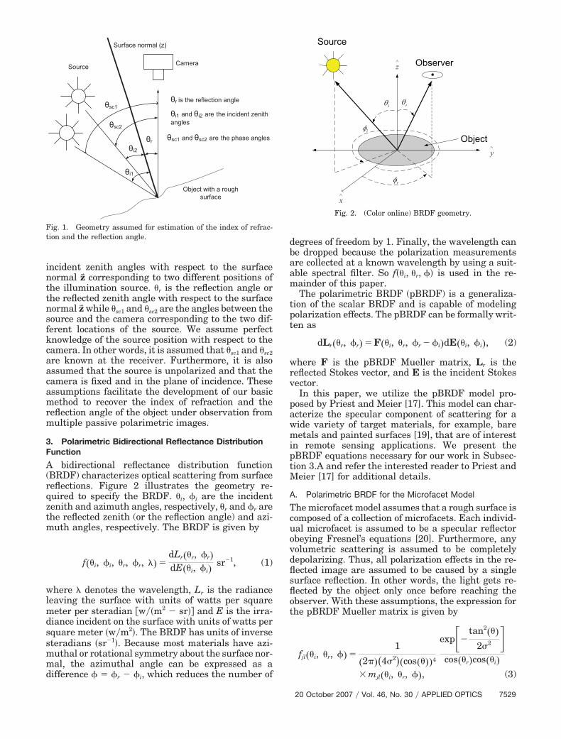
incident zenith angles with respect to the surfacenormal z� corresponding to two different positions ofthe illumination source. �r is the reflection angle orthe reflected zenith angle with respect to the surfacenormal z� while �sc1 and �sc2 are the angles between thesource and the camera corresponding to the two dif-ferent locations of the source. We assume perfectknowledge of the source position with respect to thecamera. In other words, it is assumed that �sc1 and �sc2are known at the receiver. Furthermore, it is alsoassumed that the source is unpolarized and that thecamera is fixed and in the plane of incidence. Theseassumptions facilitate the development of our basicmethod to recover the index of refraction and thereflection angle of the object under observation frommultiple passive polarimetric images.
3. Polarimetric Bidirectional Reflectance DistributionFunction
A bidirectional reflectance distribution function(BRDF) characterizes optical scattering from surfacereflections. Figure 2 illustrates the geometry re-quired to specify the BRDF. �i, �i are the incidentzenith and azimuth angles, respectively, �r and �r arethe reflected zenith (or the reflection angle) and azi-muth angles, respectively. The BRDF is given by
f��i, �i, �r, �r, �� �dLr��r, �r�dE��i, �i�
sr�1, (1)
where � denotes the wavelength, Lr is the radianceleaving the surface with units of watts per squaremeter per steradian �w��m2 � sr�� and E is the irra-diance incident on the surface with units of watts persquare meter �w�m2�. The BRDF has units of inversesteradians �sr�1�. Because most materials have azi-muthal or rotational symmetry about the surface nor-mal, the azimuthal angle can be expressed as adifference � � �r � �i, which reduces the number of
degrees of freedom by 1. Finally, the wavelength canbe dropped because the polarization measurementsare collected at a known wavelength by using a suit-able spectral filter. So f��i, �r, �� is used in the re-mainder of this paper.
The polarimetric BRDF (pBRDF) is a generaliza-tion of the scalar BRDF and is capable of modelingpolarization effects. The pBRDF can be formally writ-ten as
dLr��r, �r� � F��i, �r, �r � �i�dE��i, �i�, (2)
where F is the pBRDF Mueller matrix, Lr is thereflected Stokes vector, and E is the incident Stokesvector.
In this paper, we utilize the pBRDF model pro-posed by Priest and Meier [17]. This model can char-acterize the specular component of scattering for awide variety of target materials, for example, baremetals and painted surfaces [19], that are of interestin remote sensing applications. We present thepBRDF equations necessary for our work in Subsec-tion 3.A and refer the interested reader to Priest andMeier [17] for additional details.
A. Polarimetric BRDF for the Microfacet Model
The microfacet model assumes that a rough surface iscomposed of a collection of microfacets. Each individ-ual microfacet is assumed to be a specular reflectorobeying Fresnel’s equations [20]. Furthermore, anyvolumetric scattering is assumed to be completelydepolarizing. Thus, all polarization effects in the re-flected image are assumed to be caused by a singlesurface reflection. In other words, the light gets re-flected by the object only once before reaching theobserver. With these assumptions, the expression forthe pBRDF Mueller matrix is given by
fjl��i, �r, �� �1
�2���4�2��cos����4
exp��tan2���
2�2 �cos��r�cos��i�
� mjl��i, �r, ��, (3)
Fig. 1. Geometry assumed for estimation of the index of refrac-tion and the reflection angle.
i r
z
y
x
i
r
Fig. 2. (Color online) BRDF geometry.
20 October 2007 � Vol. 46, No. 30 � APPLIED OPTICS 7529
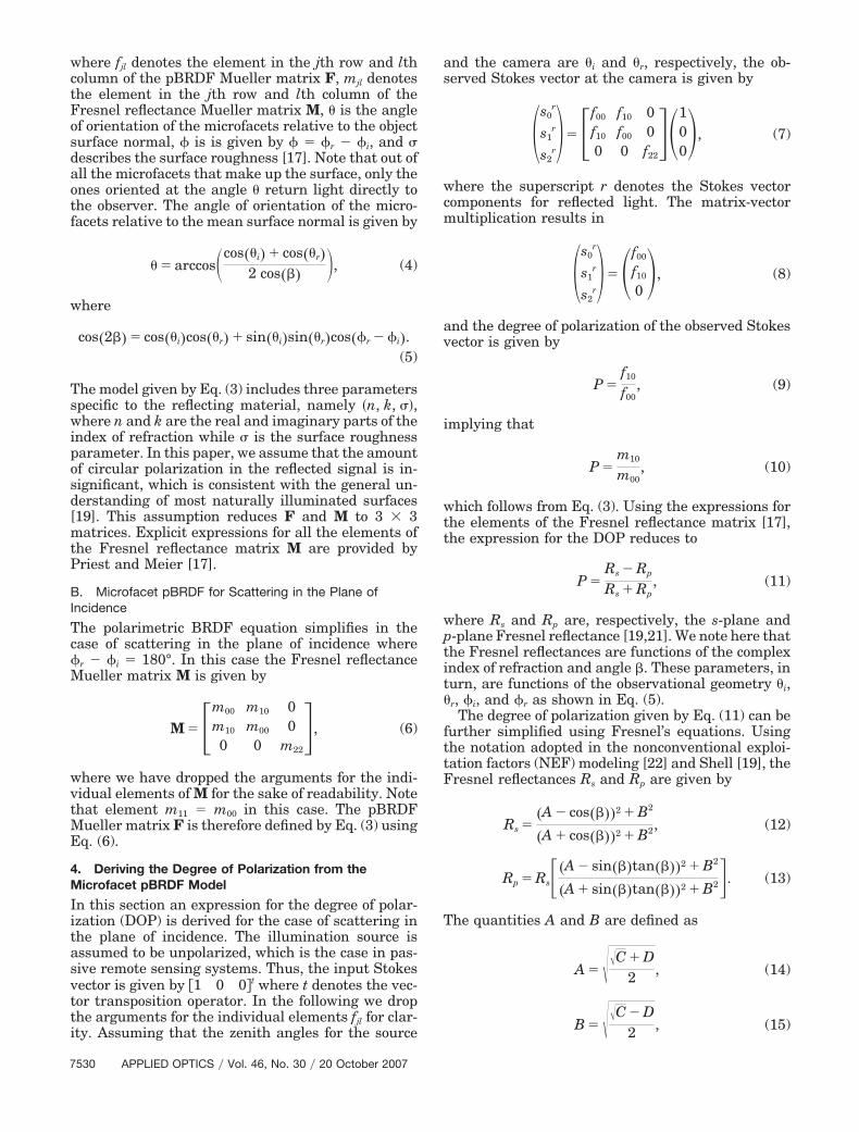
where fjl denotes the element in the jth row and lthcolumn of the pBRDF Mueller matrix F, mjl denotesthe element in the jth row and lth column of theFresnel reflectance Mueller matrix M, � is the angleof orientation of the microfacets relative to the objectsurface normal, � is is given by � � �r � �i, and �describes the surface roughness [17]. Note that out ofall the microfacets that make up the surface, only theones oriented at the angle � return light directly tothe observer. The angle of orientation of the micro-facets relative to the mean surface normal is given by
� � arccos�cos��i� cos��r�2 cos�� , (4)
where
cos�2� � cos��i�cos��r� sin��i�sin��r�cos��r � �i�.(5)
The model given by Eq. (3) includes three parametersspecific to the reflecting material, namely �n, k, ��,where n and k are the real and imaginary parts of theindex of refraction while � is the surface roughnessparameter. In this paper, we assume that the amountof circular polarization in the reflected signal is in-significant, which is consistent with the general un-derstanding of most naturally illuminated surfaces[19]. This assumption reduces F and M to 3 � 3matrices. Explicit expressions for all the elements ofthe Fresnel reflectance matrix M are provided byPriest and Meier [17].
B. Microfacet pBRDF for Scattering in the Plane ofIncidence
The polarimetric BRDF equation simplifies in thecase of scattering in the plane of incidence where�r � �i � 180°. In this case the Fresnel reflectanceMueller matrix M is given by
M ��m00 m10 0m10 m00 00 0 m22
�, (6)
where we have dropped the arguments for the indi-vidual elements of M for the sake of readability. Notethat element m11 � m00 in this case. The pBRDFMueller matrix F is therefore defined by Eq. (3) usingEq. (6).
4. Deriving the Degree of Polarization from theMicrofacet pBRDF Model
In this section an expression for the degree of polar-ization (DOP) is derived for the case of scattering inthe plane of incidence. The illumination source isassumed to be unpolarized, which is the case in pas-sive remote sensing systems. Thus, the input Stokesvector is given by �1 0 0�t where t denotes the vec-tor transposition operator. In the following we dropthe arguments for the individual elements fjl for clar-ity. Assuming that the zenith angles for the source
and the camera are �i and �r, respectively, the ob-served Stokes vector at the camera is given by
s0
r
s1r
s2r���f00 f10 0
f10 f00 00 0 f22
��100, (7)
where the superscript r denotes the Stokes vectorcomponents for reflected light. The matrix-vectormultiplication results in
s0
r
s1r
s2r���f00
f10
0, (8)
and the degree of polarization of the observed Stokesvector is given by
P �f10
f00, (9)
implying that
P �m10
m00, (10)
which follows from Eq. (3). Using the expressions forthe elements of the Fresnel reflectance matrix [17],the expression for the DOP reduces to
P �Rs � Rp
Rs Rp, (11)
where Rs and Rp are, respectively, the s-plane andp-plane Fresnel reflectance [19,21]. We note here thatthe Fresnel reflectances are functions of the complexindex of refraction and angle �. These parameters, inturn, are functions of the observational geometry �i,�r, �i, and �r as shown in Eq. (5).
The degree of polarization given by Eq. (11) can befurther simplified using Fresnel’s equations. Usingthe notation adopted in the nonconventional exploi-tation factors (NEF) modeling [22] and Shell [19], theFresnel reflectances Rs and Rp are given by
Rs ��A � cos���2 B2
�A cos���2 B2, (12)
Rp � Rs��A � sin��tan���2 B2
�A sin��tan���2 B2�. (13)
The quantities A and B are defined as
A � ��C D2 , (14)
B � ��C � D2 , (15)
7530 APPLIED OPTICS � Vol. 46, No. 30 � 20 October 2007
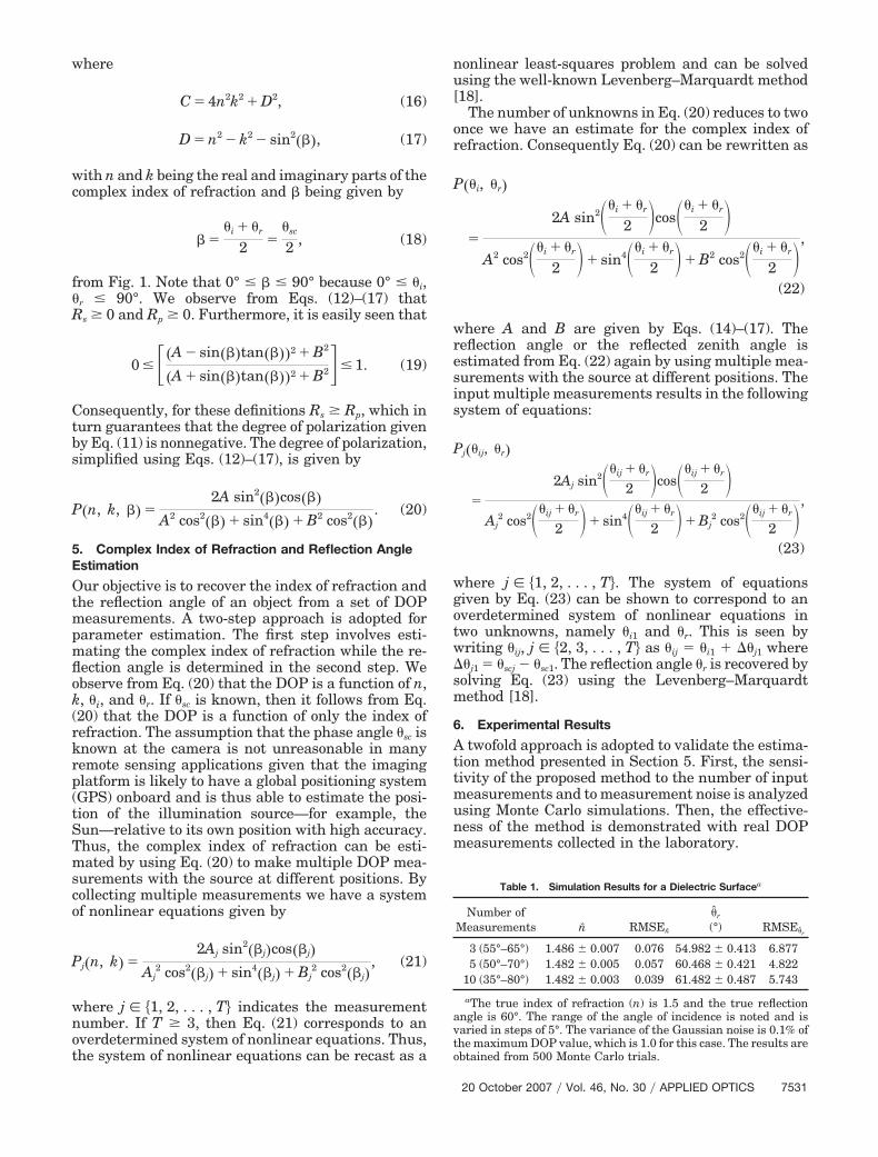
where
C � 4n2k2 D2, (16)
D � n2 � k2 � sin2��, (17)
with n and k being the real and imaginary parts of thecomplex index of refraction and � being given by
��i �r
2 ��sc
2 , (18)
from Fig. 1. Note that 0° � � 90° because 0° � �i,�r � 90°. We observe from Eqs. (12)–(17) thatRs � 0 and Rp � 0. Furthermore, it is easily seen that
0 � ��A � sin��tan���2 B2
�A sin��tan���2 B2�� 1. (19)
Consequently, for these definitions Rs � Rp, which inturn guarantees that the degree of polarization givenby Eq. (11) is nonnegative. The degree of polarization,simplified using Eqs. (12)–(17), is given by
P�n, k, � �2A sin2��cos��
A2 cos2�� sin4�� B2 cos2��. (20)
5. Complex Index of Refraction and Reflection AngleEstimation
Our objective is to recover the index of refraction andthe reflection angle of an object from a set of DOPmeasurements. A two-step approach is adopted forparameter estimation. The first step involves esti-mating the complex index of refraction while the re-flection angle is determined in the second step. Weobserve from Eq. (20) that the DOP is a function of n,k, �i, and �r. If �sc is known, then it follows from Eq.(20) that the DOP is a function of only the index ofrefraction. The assumption that the phase angle �sc isknown at the camera is not unreasonable in manyremote sensing applications given that the imagingplatform is likely to have a global positioning system(GPS) onboard and is thus able to estimate the posi-tion of the illumination source—for example, theSun—relative to its own position with high accuracy.Thus, the complex index of refraction can be esti-mated by using Eq. (20) to make multiple DOP mea-surements with the source at different positions. Bycollecting multiple measurements we have a systemof nonlinear equations given by
Pj�n, k� �2Aj sin2�j�cos�j�
Aj2 cos2�j� sin4�j� Bj
2 cos2�j�, (21)
where j � 1, 2, . . . , T� indicates the measurementnumber. If T � 3, then Eq. (21) corresponds to anoverdetermined system of nonlinear equations. Thus,the system of nonlinear equations can be recast as a
nonlinear least-squares problem and can be solvedusing the well-known Levenberg–Marquardt method[18].
The number of unknowns in Eq. (20) reduces to twoonce we have an estimate for the complex index ofrefraction. Consequently Eq. (20) can be rewritten as
P��i, �r�
�
2A sin2��i �r
2 cos��i �r
2 A2 cos2��i �r
2 sin4��i �r
2 B2 cos2��i �r
2 ,
(22)
where A and B are given by Eqs. (14)–(17). Thereflection angle or the reflected zenith angle isestimated from Eq. (22) again by using multiple mea-surements with the source at different positions. Theinput multiple measurements results in the followingsystem of equations:
Pj��ij, �r�
�
2Aj sin2��ij �r
2 cos��ij �r
2 Aj
2 cos2��ij �r
2 sin4��ij �r
2 Bj2 cos2��ij �r
2 ,
(23)
where j � 1, 2, . . . , T�. The system of equationsgiven by Eq. (23) can be shown to correspond to anoverdetermined system of nonlinear equations intwo unknowns, namely �i1 and �r. This is seen bywriting �ij, j � 2, 3, . . . , T� as �ij � �i1 �j1 where �j1 � �scj � �sc1. The reflection angle �r is recovered bysolving Eq. (23) using the Levenberg–Marquardtmethod [18].
6. Experimental Results
A twofold approach is adopted to validate the estima-tion method presented in Section 5. First, the sensi-tivity of the proposed method to the number of inputmeasurements and to measurement noise is analyzedusing Monte Carlo simulations. Then, the effective-ness of the method is demonstrated with real DOPmeasurements collected in the laboratory.
Table 1. Simulation Results for a Dielectric Surfacea
Number ofMeasurements n̂ RMSEn̂
�̂r
(°) RMSE�̂r
3 (55°–65°) 1.486 � 0.007 0.076 54.982 � 0.413 6.8775 (50°–70°) 1.482 � 0.005 0.057 60.468 � 0.421 4.822
10 (35°–80°) 1.482 � 0.003 0.039 61.482 � 0.487 5.743
aThe true index of refraction (n) is 1.5 and the true reflectionangle is 60°. The range of the angle of incidence is noted and isvaried in steps of 5°. The variance of the Gaussian noise is 0.1% ofthe maximum DOP value, which is 1.0 for this case. The results areobtained from 500 Monte Carlo trials.
20 October 2007 � Vol. 46, No. 30 � APPLIED OPTICS 7531
A. Sensitivity Analysis
Synthetic data sets for the simulation study are gen-erated using Eq. (20) with specific input values for nand k and a fixed value of �r but a sequence of valuesfor �i as described in Section 5. The sequence for �i isgenerated in fixed steps of 5°. We chose this step sizevalue to be consistent with our choice of step size forthe laboratory experiments. We use three, five, andten measurements for the analysis, which impliesthat the maximum range for the angles of incidence is45° corresponding to the case of ten measurements.We chose this range because our experimental resultsas presented in Subsection 6.B indicate that therange of the specular lobe is approximately 40° for thematerials used here. Our experiments with ideal syn-thetic data (no noise) indicate that the proposedestimation approach can accurately recover the pa-rameters of interest for all the cases considered in ourexperiments. Thus, the algorithm is not affected bythe number of measurements for the noiseless case.
The synthetic data sets are then perturbed withadditive white Gaussian noise in order to analyze therobustness of the proposed algorithm to nonideal ornoisy inputs. Specifically, the noise is added to theDOP values in Eq. (20), which are then input to theLevenberg–Marquardt solver. The analysis is per-formed for both a dielectric surface and a metallicsurface. We consider two levels of measurement noisein our analysis: (i) a “low-noise” scenario where theDOP values are perturbed with Gaussian noise ofvariance equal to 0.1% of the maximum DOP valueand (ii) “high-noise” scenario in which the DOP val-ues are perturbed with Gaussian noise of varianceequal to 1% of the maximum DOP value. The maxi-mum DOP values for the dielectric and metallic sur-faces are 1 and 0.082, respectively. We note here thatfor these noisy cases, the Levenberg–Marquardt al-
gorithm occasionally converged to physically unreal-izable estimates due to its unconstrained nature.Consequently, we discard such estimates and restartthe optimization algorithm for the cases when eithern or k is negative or the reflection angle is less than0° or greater than 90°.
Tables 1 and 2 show the average index of refractionn and reflection angle ��r� estimates for the case of asimple dielectric surface. Table 1 lists the samplemean and its 95% confidence interval for the low-noise scenario. We observe that the index of refrac-tion is estimated to a high degree of accuracy for thethree cases considered. In addition, we observe thatthe root-mean-square error (RMSE) value for theestimates of the index of refraction improves with anincreasing number of measurements. We also notethat there is a dramatic improvement in the reflec-tion angle estimate when the number of measure-ments is increased from 3 to 5. However, it is alsoclear from Table 1 that no further improvement isachieved beyond five measurements for the reflectionangle because of a noise floor introduced by the ad-ditive Gaussian noise. This trend is also observed inthe RMSE values for the reflection angle. Thus, wesee that the accuracy of the proposed estimationmethod improves as we collect more measurementsup to some saturation point. Table 2 shows the re-sults for the high-noise scenario. The sample meanestimates as well as the RMSE values indicate thatthe estimation performance for the index of refractionimproves with an increasing number of measure-ments. The reflection angle estimation performancealso consistently improves with increasing measure-ments, unlike the results presented in Table 1 for thelow-noise scenario. However, as might be expected,the estimates for the higher-noise scenario are lessaccurate compared to the low-noise case.
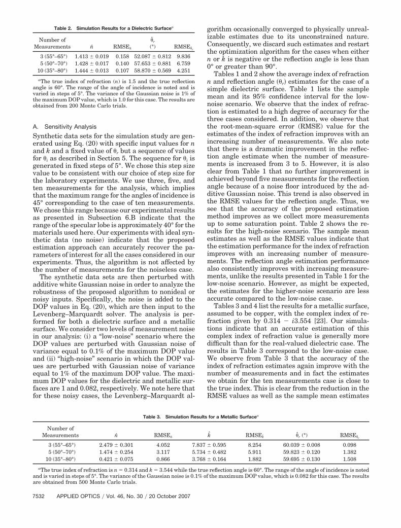
Tables 3 and 4 list the results for a metallic surface,assumed to be copper, with the complex index of re-fraction given by 0.314 � i3.554 [23]. Our simula-tions indicate that an accurate estimation of thiscomplex index of refraction value is generally moredifficult than for the real-valued dielectric case. Theresults in Table 3 correspond to the low-noise case.We observe from Table 3 that the accuracy of theindex of refraction estimates again improve with thenumber of measurements and in fact the estimateswe obtain for the ten measurements case is close tothe true index. This is clear from the reduction in theRMSE values as well as the sample mean estimates
Table 2. Simulation Results for a Dielectric Surfacea
Number ofMeasurements n̂ RMSEn̂
�̂r
(°) RMSE�̂r
3 (55°–65°) 1.413 � 0.019 0.158 52.087 � 0.812 9.8365 (50°–70°) 1.428 � 0.017 0.140 57.653 � 0.881 6.759
10 (35°–80°) 1.444 � 0.013 0.107 58.870 � 0.569 4.251
aThe true index of refraction (n) is 1.5 and the true reflectionangle is 60°. The range of the angle of incidence is noted and isvaried in steps of 5°. The variance of the Gaussian noise is 1% ofthe maximum DOP value, which is 1.0 for this case. The results areobtained from 200 Monte Carlo trials.
Table 3. Simulation Results for a Metallic Surfacea
Number ofMeasurements n̂ RMSEn̂ k̂ RMSEk̂ �̂r (°) RMSE�̂r
3 (55°–65°) 2.479 � 0.301 4.052 7.837 � 0.595 8.254 60.039 � 0.008 0.0985 (50°–70°) 1.474 � 0.254 3.117 5.734 � 0.482 5.911 59.823 � 0.120 1.382
10 (35°–80°) 0.421 � 0.075 0.866 3.768 � 0.164 1.882 59.695 � 0.130 1.508
aThe true index of refraction is n � 0.314 and k � 3.544 while the true reflection angle is 60°. The range of the angle of incidence is notedand is varied in steps of 5°. The variance of the Gaussian noise is 0.1% of the maximum DOP value, which is 0.082 for this case. The resultsare obtained from 500 Monte Carlo trials.
7532 APPLIED OPTICS � Vol. 46, No. 30 � 20 October 2007
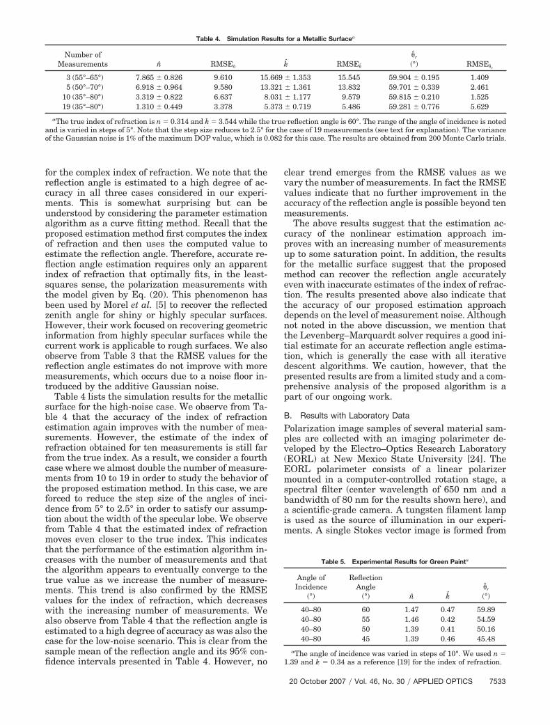
for the complex index of refraction. We note that thereflection angle is estimated to a high degree of ac-curacy in all three cases considered in our experi-ments. This is somewhat surprising but can beunderstood by considering the parameter estimationalgorithm as a curve fitting method. Recall that theproposed estimation method first computes the indexof refraction and then uses the computed value toestimate the reflection angle. Therefore, accurate re-flection angle estimation requires only an apparentindex of refraction that optimally fits, in the least-squares sense, the polarization measurements withthe model given by Eq. (20). This phenomenon hasbeen used by Morel et al. [5] to recover the reflectedzenith angle for shiny or highly specular surfaces.However, their work focused on recovering geometricinformation from highly specular surfaces while thecurrent work is applicable to rough surfaces. We alsoobserve from Table 3 that the RMSE values for thereflection angle estimates do not improve with moremeasurements, which occurs due to a noise floor in-troduced by the additive Gaussian noise.
Table 4 lists the simulation results for the metallicsurface for the high-noise case. We observe from Ta-ble 4 that the accuracy of the index of refractionestimation again improves with the number of mea-surements. However, the estimate of the index ofrefraction obtained for ten measurements is still farfrom the true index. As a result, we consider a fourthcase where we almost double the number of measure-ments from 10 to 19 in order to study the behavior ofthe proposed estimation method. In this case, we areforced to reduce the step size of the angles of inci-dence from 5° to 2.5° in order to satisfy our assump-tion about the width of the specular lobe. We observefrom Table 4 that the estimated index of refractionmoves even closer to the true index. This indicatesthat the performance of the estimation algorithm in-creases with the number of measurements and thatthe algorithm appears to eventually converge to thetrue value as we increase the number of measure-ments. This trend is also confirmed by the RMSEvalues for the index of refraction, which decreaseswith the increasing number of measurements. Wealso observe from Table 4 that the reflection angle isestimated to a high degree of accuracy as was also thecase for the low-noise scenario. This is clear from thesample mean of the reflection angle and its 95% con-fidence intervals presented in Table 4. However, no
clear trend emerges from the RMSE values as wevary the number of measurements. In fact the RMSEvalues indicate that no further improvement in theaccuracy of the reflection angle is possible beyond tenmeasurements.
The above results suggest that the estimation ac-curacy of the nonlinear estimation approach im-proves with an increasing number of measurementsup to some saturation point. In addition, the resultsfor the metallic surface suggest that the proposedmethod can recover the reflection angle accuratelyeven with inaccurate estimates of the index of refrac-tion. The results presented above also indicate thatthe accuracy of our proposed estimation approachdepends on the level of measurement noise. Althoughnot noted in the above discussion, we mention thatthe Levenberg–Marquardt solver requires a good ini-tial estimate for an accurate reflection angle estima-tion, which is generally the case with all iterativedescent algorithms. We caution, however, that thepresented results are from a limited study and a com-prehensive analysis of the proposed algorithm is apart of our ongoing work.
B. Results with Laboratory Data
Polarization image samples of several material sam-ples are collected with an imaging polarimeter de-veloped by the Electro–Optics Research Laboratory(EORL) at New Mexico State University [24]. TheEORL polarimeter consists of a linear polarizermounted in a computer-controlled rotation stage, aspectral filter (center wavelength of 650 nm and abandwidth of 80 nm for the results shown here), anda scientific-grade camera. A tungsten filament lampis used as the source of illumination in our experi-ments. A single Stokes vector image is formed from
Table 4. Simulation Results for a Metallic Surfacea
Number ofMeasurements n̂ RMSEn̂ k̂ RMSEk̂
�̂r
(°) RMSE�̂r
3 (55°–65°) 7.865 � 0.826 9.610 15.669 � 1.353 15.545 59.904 � 0.195 1.4095 (50°–70°) 6.918 � 0.964 9.580 13.321 � 1.361 13.832 59.701 � 0.339 2.461
10 (35°–80°) 3.319 � 0.822 6.637 8.031 � 1.177 9.579 59.815 � 0.210 1.52519 (35°–80°) 1.310 � 0.449 3.378 5.373 � 0.719 5.486 59.281 � 0.776 5.629
aThe true index of refraction is n � 0.314 and k � 3.544 while the true reflection angle is 60°. The range of the angle of incidence is notedand is varied in steps of 5°. Note that the step size reduces to 2.5° for the case of 19 measurements (see text for explanation). The varianceof the Gaussian noise is 1% of the maximum DOP value, which is 0.082 for this case. The results are obtained from 200 Monte Carlo trials.
Table 5. Experimental Results for Green Painta
Angle ofIncidence
(°)
ReflectionAngle
(°) n̂ k̂�̂r
(°)
40–80 60 1.47 0.47 59.8940–80 55 1.46 0.42 54.5940–80 50 1.39 0.41 50.1640–80 45 1.39 0.46 45.48
aThe angle of incidence was varied in steps of 10°. We used n �1.39 and k � 0.34 as a reference [19] for the index of refraction.
20 October 2007 � Vol. 46, No. 30 � APPLIED OPTICS 7533

ten images of a scene collected with the polarizerrotated in steps of 15° for each measurement. Theinterested reader is referred to Damarla [24] for ad-ditional details regarding the EORL polarimeter.
The target sample is mounted on a micrometer-driven rotation stage and the positioning of thesource and the camera mounts is done with the aid ofa large protractor device. The incidence and reflectionangles can be set to a precision of approximately 1° orslightly better in the laboratory testbed. The targetsamples in our experiments include Styrofoam piecescoated with flat green paint and flat black paint aswell as pieces of sandblasted copper and aluminum.The root-mean-square (rms) surface roughness of thesamples was measured using a Surfcom 120A stylusprofilometer to be 2.58 �m for flat green paint,4.92 �m for copper, 2.99 �m for flat black paint, and3.3 �m for aluminum. Thus, the rms surface rough-ness in all cases is greater than the wavelength of
interest �650 nm�, which satisfies the assumptionmade by the Torrance–Sparrow model [10], whichunderlies the pBRDF model employed in our work.The DOP values needed for parameter estimationwere computed by averaging at least 100 � 100 pixelsin the Stokes vector images.
The range of the angles of incidence and the anglestep sizes are not the same for all the cases consid-ered in our experiments. One of the reasons for this isthe specular assumption inherent in our modelingprocedure. The camera needs to be in a region wherethe specular component clearly dominates the diffusereflection for the incident angles of interest. We couldroughly identify this region as a relatively bright areaof reflection centered about the mirror reflection an-gle. However, we were forced in some cases to adjustthe incident angle range when the measured degreeof polarization became relatively small, suggestingwe were out of the specular reflection lobe. In addi-tion, the sensitivity analysis suggests that we needfive to ten measurements in order to obtain a reason-able estimate for the parameters of interest. Thus,the example results presented in this section involveseveral ranges of angles of incidence and step sizes.In general, we have used either 5° or 10° incidentangle steps and have found that our sample materialsproduce usable specular patterns that extend over atleast a 40° range.
Table 5 shows the results for the green paint tar-get. For clarity, we mention again that the angle ofincidence refers to the angle between the source andthe object surface normal while the reflection anglerefers to the angle between the camera and the objectsurface normal. We observe that the estimates for theindex of refraction values agree reasonably well withvalues published in literature [19]. More importantly,however, the extracted index of refraction values are
Fig. 3. (Color online) DOP plots derived from the pBRDF modeland experimental data for green paint.
Fig. 4. (Color online) DOP plots derived from the pBRDF modeland experimental data for copper.
Table 6. Experimental Results for Roughened Coppera
Angle ofIncidence
(°)
ReflectionAngle
(°) n̂ k̂�̂r
(°)
35–70 60 0.54 3.19 59.5135–70 55 0.53 3.26 54.6335–70 50 0.53 3.32 49.6235–70 45 0.51 3.37 44.85
aThe angle of incidence was varied in steps of 5°. We used n � 0.4and k � 2.95 as a reference [19] for the index of refraction.
Table 7. Experimental Results for Black Painta
Angle ofIncidence
(°)
ReflectionAngle
(°) n̂ k̂�̂r
(°)
10–80 60 1.46 1.32 60.0510–80 50 1.46 1.28 49.9110–80 40 1.31 1.21 39.78
aThe angle of incidence was varied in steps of 10°. We used n �1.405 and k � 0.2289 as a reference [19] for the index of refraction.
7534 APPLIED OPTICS � Vol. 46, No. 30 � 20 October 2007
also largely invariant to the reflection angle over ourmeasurement range. This is critical if the index is tobe used for identifying and classifying materialsbased on their polarimetric signatures. In addition,we see that the reflection angle is recovered accu-rately for the various cases considered in our exper-iments. Figure 3 shows the DOP as a function of theangle of incidence for a reflection angle of 60° andillustrates the effectiveness of the Levenberg–Maruquardt method for estimating the index of re-fraction for the green paint target. We observe thatthe DOP curve corresponding to the experimentaldata (labeled “Experiment”) matches well with theDOP curve (labeled “Estimate”) that was generatedfrom the pBRDF model using the estimated index ofrefraction as the input parameter. We also includethe DOP plot (labeled “Reference”) generated fromthe pBRDF model using the published index of re-fraction value [19] for comparison. A similar trend isnoted for experiments with the roughened copperpiece as shown in Fig. 4. Table 6 summarizes theresult for the roughened copper piece.
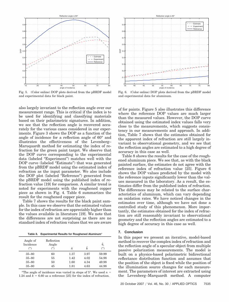
Table 7 shows the results for the black paint sam-ple. In this case we observe that the estimated valuesfor the index of refraction are appreciably higher thanthe values available in literature [19]. We note thatthe differences are not surprising as there are nostandard index of refraction values that we are aware
of for paints. Figure 5 also illustrates this differencewhere the reference DOP values are much largerthan the measured values. However, the DOP curveobtained using the estimated index values falls veryclose to the measurements, which suggests consis-tency in our measurements and approach. In addi-tion, Table 7 shows that the estimates obtained forthe apparent index of refraction are still largely in-variant to observational geometry, and we see thatthe reflection angles are estimated to a high degree ofaccuracy in this case as well.
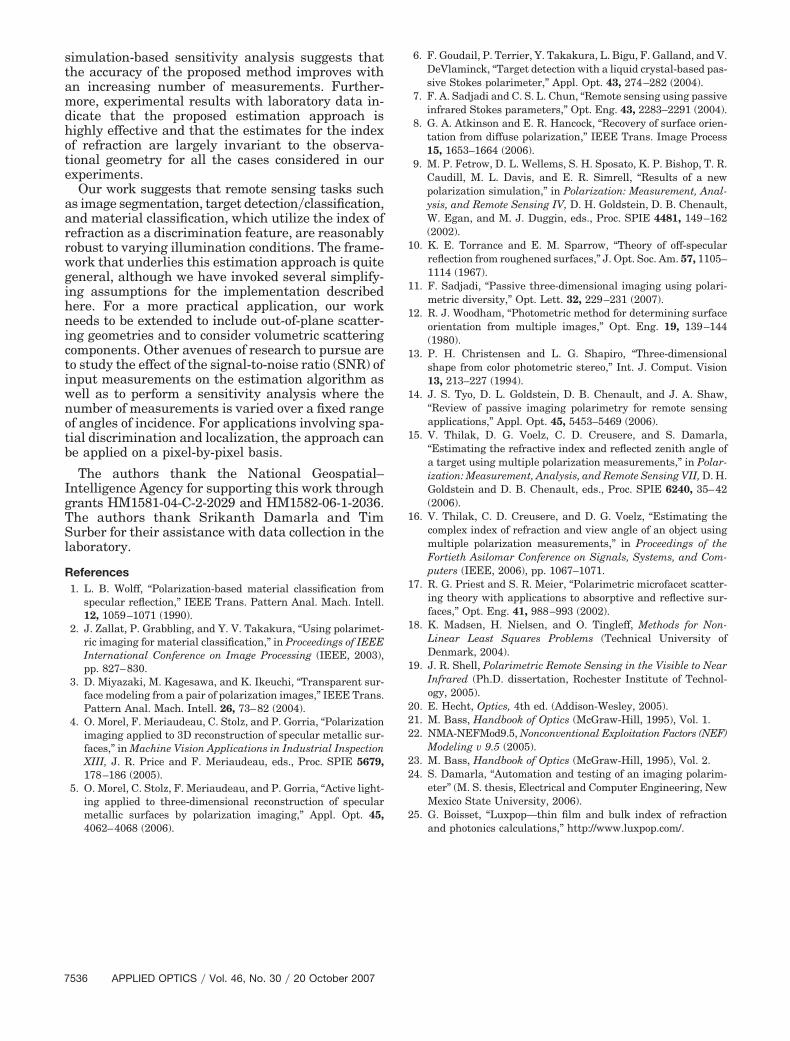
Table 8 shows the results for the case of the rough-ened aluminum piece. We see that, as with the blackpainted surface, the estimates do not agree with thereference index of refraction value [25]. Figure 6shows the DOP values predicted by the model withthe reference inputs significantly lower than the val-ues measured in the laboratory. As a result, the es-timates differ from the published index of refraction.The differences may be related to the surface char-acteristics of aluminum, which can vary dependingon oxidation rates. We have noticed changes in theestimates over time, although we have not done acontrolled study of this phenomenon. More impor-tantly, the estimates obtained for the index of refrac-tion are still reasonably invariant to observationalgeometry and the reflection angles are estimated to ahigh degree of accuracy in this case as well.
7. Conclusion
In this paper we present an iterative, model-basedmethod to recover the complex index of refraction andthe reflection angle of a specular object from multiplepassive polarization measurements. The model isbuilt on a physics-based polarimetric bidirectionalreflectance distribution function and assumes thatthe position of the object is fixed while the position ofthe illumination source changes for each measure-ment. The parameters of interest are extracted usingthe Levenberg–Marquardt method. A computer
Fig. 5. (Color online) DOP plots derived from the pBRDF modeland experimental data for black paint.
Fig. 6. (Color online) DOP plots derived from the pBRDF modeland experimental data for aluminum.
Table 8. Experimental Results for Roughened Aluminuma
Angle ofIncidence
(°)
ReflectionAngle
(°) n̂ k̂�̂r
(°)
35–80 60 1.37 3.97 59.9935–80 55 1.42 4.02 54.9835–80 50 1.60 4.34 49.9835–80 45 1.81 4.63 44.98
aThe angle of incidence was varied in steps of 5°. We used n �1.24 and k � 6.60 as a reference [25] for the index of refraction.
20 October 2007 � Vol. 46, No. 30 � APPLIED OPTICS 7535
simulation-based sensitivity analysis suggests thatthe accuracy of the proposed method improves withan increasing number of measurements. Further-more, experimental results with laboratory data in-dicate that the proposed estimation approach ishighly effective and that the estimates for the indexof refraction are largely invariant to the observa-tional geometry for all the cases considered in ourexperiments.
Our work suggests that remote sensing tasks suchas image segmentation, target detection�classification,and material classification, which utilize the index ofrefraction as a discrimination feature, are reasonablyrobust to varying illumination conditions. The frame-work that underlies this estimation approach is quitegeneral, although we have invoked several simplify-ing assumptions for the implementation describedhere. For a more practical application, our workneeds to be extended to include out-of-plane scatter-ing geometries and to consider volumetric scatteringcomponents. Other avenues of research to pursue areto study the effect of the signal-to-noise ratio (SNR) ofinput measurements on the estimation algorithm aswell as to perform a sensitivity analysis where thenumber of measurements is varied over a fixed rangeof angles of incidence. For applications involving spa-tial discrimination and localization, the approach canbe applied on a pixel-by-pixel basis.
The authors thank the National Geospatial–Intelligence Agency for supporting this work throughgrants HM1581-04-C-2-2029 and HM1582-06-1-2036.The authors thank Srikanth Damarla and TimSurber for their assistance with data collection in thelaboratory.
References1. L. B. Wolff, “Polarization-based material classification from
specular reflection,” IEEE Trans. Pattern Anal. Mach. Intell.12, 1059–1071 (1990).
2. J. Zallat, P. Grabbling, and Y. V. Takakura, “Using polarimet-ric imaging for material classification,” in Proceedings of IEEEInternational Conference on Image Processing (IEEE, 2003),pp. 827–830.
3. D. Miyazaki, M. Kagesawa, and K. Ikeuchi, “Transparent sur-face modeling from a pair of polarization images,” IEEE Trans.Pattern Anal. Mach. Intell. 26, 73–82 (2004).
4. O. Morel, F. Meriaudeau, C. Stolz, and P. Gorria, “Polarizationimaging applied to 3D reconstruction of specular metallic sur-faces,” in Machine Vision Applications in Industrial InspectionXIII, J. R. Price and F. Meriaudeau, eds., Proc. SPIE 5679,178–186 (2005).
5. O. Morel, C. Stolz, F. Meriaudeau, and P. Gorria, “Active light-ing applied to three-dimensional reconstruction of specularmetallic surfaces by polarization imaging,” Appl. Opt. 45,4062–4068 (2006).
6. F. Goudail, P. Terrier, Y. Takakura, L. Bigu, F. Galland, and V.DeVlaminck, “Target detection with a liquid crystal-based pas-sive Stokes polarimeter,” Appl. Opt. 43, 274–282 (2004).
7. F. A. Sadjadi and C. S. L. Chun, “Remote sensing using passiveinfrared Stokes parameters,” Opt. Eng. 43, 2283–2291 (2004).
8. G. A. Atkinson and E. R. Hancock, “Recovery of surface orien-tation from diffuse polarization,” IEEE Trans. Image Process15, 1653–1664 (2006).
9. M. P. Fetrow, D. L. Wellems, S. H. Sposato, K. P. Bishop, T. R.Caudill, M. L. Davis, and E. R. Simrell, “Results of a newpolarization simulation,” in Polarization: Measurement, Anal-ysis, and Remote Sensing IV, D. H. Goldstein, D. B. Chenault,W. Egan, and M. J. Duggin, eds., Proc. SPIE 4481, 149–162(2002).
10. K. E. Torrance and E. M. Sparrow, “Theory of off-specularreflection from roughened surfaces,” J. Opt. Soc. Am. 57, 1105–1114 (1967).
11. F. Sadjadi, “Passive three-dimensional imaging using polari-metric diversity,” Opt. Lett. 32, 229–231 (2007).
12. R. J. Woodham, “Photometric method for determining surfaceorientation from multiple images,” Opt. Eng. 19, 139–144(1980).
13. P. H. Christensen and L. G. Shapiro, “Three-dimensionalshape from color photometric stereo,” Int. J. Comput. Vision13, 213–227 (1994).
14. J. S. Tyo, D. L. Goldstein, D. B. Chenault, and J. A. Shaw,“Review of passive imaging polarimetry for remote sensingapplications,” Appl. Opt. 45, 5453–5469 (2006).
15. V. Thilak, D. G. Voelz, C. D. Creusere, and S. Damarla,“Estimating the refractive index and reflected zenith angle ofa target using multiple polarization measurements,” in Polar-ization: Measurement, Analysis, and Remote Sensing VII, D. H.Goldstein and D. B. Chenault, eds., Proc. SPIE 6240, 35–42(2006).
16. V. Thilak, C. D. Creusere, and D. G. Voelz, “Estimating thecomplex index of refraction and view angle of an object usingmultiple polarization measurements,” in Proceedings of theFortieth Asilomar Conference on Signals, Systems, and Com-puters (IEEE, 2006), pp. 1067–1071.
17. R. G. Priest and S. R. Meier, “Polarimetric microfacet scatter-ing theory with applications to absorptive and reflective sur-faces,” Opt. Eng. 41, 988–993 (2002).
18. K. Madsen, H. Nielsen, and O. Tingleff, Methods for Non-Linear Least Squares Problems (Technical University ofDenmark, 2004).
19. J. R. Shell, Polarimetric Remote Sensing in the Visible to NearInfrared (Ph.D. dissertation, Rochester Institute of Technol-ogy, 2005).
20. E. Hecht, Optics, 4th ed. (Addison-Wesley, 2005).21. M. Bass, Handbook of Optics (McGraw-Hill, 1995), Vol. 1.22. NMA-NEFMod9.5, Nonconventional Exploitation Factors (NEF)
Modeling v 9.5 (2005).23. M. Bass, Handbook of Optics (McGraw-Hill, 1995), Vol. 2.24. S. Damarla, “Automation and testing of an imaging polarim-
eter” (M. S. thesis, Electrical and Computer Engineering, NewMexico State University, 2006).
25. G. Boisset, “Luxpop—thin film and bulk index of refractionand photonics calculations,” http://www.luxpop.com/.
7536 APPLIED OPTICS � Vol. 46, No. 30 � 20 October 2007