The Conclusion of Searching Bukit Bunuh Crater Using Seismic Refraction Method
11
The Conclusion of Searching Bukit Bunuh Crater Using Seismic Refraction Method I. N. Azwin Postgraduate Student, Geophysics Section, School of Physics, 11800 Universiti Sains Malaysia, Penang, Malaysia e-mail: [email protected] Dr. Rosli Saad Senior Lecturer, Geophysics Section, School of Physics, 11800 Universiti Sains Malaysia, Penang, Malaysia e-mail: [email protected] Dr. M. M. Nordiana Lecturer, Geophysics Section, School of Physics, 11800 Universiti Sains Malaysia, Penang, Malaysia e-mail: [email protected] Dr. Mokhtar Saidin Professor, Centre for Archaeological Research Malaysia, Universiti Sains Malaysia, Penang, Malaysia e-mail: [email protected] ABSTRACT Seismic refraction is one of the geophysical methods that are effective in searching impact crater on earth. A study was conducted within the area of Bukit Bunuh, Lenggong, Perak (Malayisa) using ABEM MK8 with 24 channel seismograph, sledgehammer, weight drop and 14 Hz geophones with 5 m geophones spacing. The study was divided into two stages; (i) regional stage, which covered large area of 12x11 km 2 to study the general trend of the area, (ii) interest stage, which covered the suspected impact area of 7x7 km 2 . All the seismic section correlated with onsite boreholes. The study is to map bedrock, structure and fracture of ground subsurface for possible meteorite impact. Seismic sections generally show a two layer case. The first layer with velocity 328- 1100m/s predominantly consists of alluvium mix with gravel to forms an overburden. The second layer with velocity >1850m/s is represents by granitic bedrock with various depths and undulating. There is lots of unusual fractured bedrock identified which represent features associated with impact. Generally the study indicated that the area was a meteorite impacted area with depth of the crater is <50 m with diameter of 4.9 km. The study also identify the boundry of the crater rim, rebounds and concluded that the crater is complex crater. KEYWORDS: Seismic refraction, Crater, Bukit Bunuh, Bedrock, Borehole, Crater rim INTRODUCTION After a process of erosion, infilling and burial, a meteorite impact event which produced an impact crater could become one of the potential hydrocarbon reservoirs. The impact features on Earth’s surface are identified by their topographic characters such as circular hills, similar to a large bowl with an upturned rim and sometimes uplifted centre. Geophysical studies such as seismic, resistivity, gravity and magnetic may reveal the existence of - 2265 -
Transcript of The Conclusion of Searching Bukit Bunuh Crater Using Seismic Refraction Method

The Conclusion of Searching Bukit Bunuh Crater Using Seismic Refraction
Method
I. N. Azwin Postgraduate Student, Geophysics Section, School of Physics, 11800
Universiti Sains Malaysia, Penang, Malaysia e-mail: [email protected]
Dr. Rosli Saad Senior Lecturer, Geophysics Section, School of Physics, 11800 Universiti
Sains Malaysia, Penang, Malaysia e-mail: [email protected]
Dr. M. M. Nordiana Lecturer, Geophysics Section, School of Physics, 11800 Universiti Sains
Malaysia, Penang, Malaysia e-mail: [email protected]
Dr. Mokhtar Saidin Professor, Centre for Archaeological Research Malaysia, Universiti Sains
Malaysia, Penang, Malaysia e-mail: [email protected]
ABSTRACT Seismic refraction is one of the geophysical methods that are effective in searching impact crater on earth. A study was conducted within the area of Bukit Bunuh, Lenggong, Perak (Malayisa) using ABEM MK8 with 24 channel seismograph, sledgehammer, weight drop and 14 Hz geophones with 5 m geophones spacing. The study was divided into two stages; (i) regional stage, which covered large area of 12x11 km2 to study the general trend of the area, (ii) interest stage, which covered the suspected impact area of 7x7 km2. All the seismic section correlated with onsite boreholes. The study is to map bedrock, structure and fracture of ground subsurface for possible meteorite impact. Seismic sections generally show a two layer case. The first layer with velocity 328-1100m/s predominantly consists of alluvium mix with gravel to forms an overburden. The second layer with velocity >1850m/s is represents by granitic bedrock with various depths and undulating. There is lots of unusual fractured bedrock identified which represent features associated with impact. Generally the study indicated that the area was a meteorite impacted area with depth of the crater is <50 m with diameter of 4.9 km. The study also identify the boundry of the crater rim, rebounds and concluded that the crater is complex crater. KEYWORDS: Seismic refraction, Crater, Bukit Bunuh, Bedrock, Borehole, Crater rim
INTRODUCTION After a process of erosion, infilling and burial, a meteorite impact event which produced
an impact crater could become one of the potential hydrocarbon reservoirs. The impact features on Earth’s surface are identified by their topographic characters such as circular hills, similar to a large bowl with an upturned rim and sometimes uplifted centre. Geophysical studies such as seismic, resistivity, gravity and magnetic may reveal the existence of
- 2265 -

Vol. 19 [2014], Bund. J 2266 hydrocarbon accumulation and buried structures includes raised rims, annular synforms, terraced regions, inferred breccia infills, and meso-scale faults. Base on the size and morphology, the impact craters classified as simple or complex. The bowl-shaped cavity partially filled with breccia lens, well-defined rims and regular shapes is name as simple crater (Figure 1). The rim-to-floor depth is ~ one-fifth of the rim-to-rim diameter, and the rim height is ~ 4 % of the total diameter (Melosh, 1989). The maximum diameter of such a crater is strongly influenced by the surface gravity of the impacted body with additional influence of the strength of the impacted surface. In igneous rock, the limit is ~ 4 km, whereas in sedimentary rock, it is ~ 2 km. Beyond this limit, the morphology of an impact crater would change dramatically because of the gravity which flattens the crater.
Figure 1: A schematic cross-section of simple crater (Grieve and Pilkington, 1987).
The character of a complex crater is recognized by the formation of a central uplift and slump blocks that arranged within an annular synform, which appear like collapsed simple craters and have much smaller diameter (Figure 2). The central peak is originated from central uplift of a rock from below the crater floor and could change into a concentric ring of peaks as crater size increases. The total amount of stratigraphic uplift is approximately 8 percent of the crater’s final diameter (Melosh, 1989). Ejecta are common and present in both types of craters. Usually overturned stratigraphic features can be observed around the rim of simple craters or on top of the slumped blocks in a complex crater. The peak ring does not surpass half the rim-to-rim diameter. The peak to peak ring transition diameter scales the same way as the simple to complex transition diameter, that is, inversely with the gravitational acceleration.
Figure 2: A schematic cross-section of complex crater (Grieve and Pilkington, 1987).

Vol. 19 [2014], Bund. J 2267
Both simple and complex craters demonstrate a raised rim structure that is caused by both ejected deposits and structural uplift of the underlying pre-impact surface. The uplift is upmost at the rim crest and vanishes at ~ 1.3 to 1.7 centre radii from the centre (Melosh, 1989). As the crater grows, an enormous radial force tends to push the rock units upwards (Sawatzky, 1972; Isaac and Stewart, 1993).
GENERAL GEOLOGY
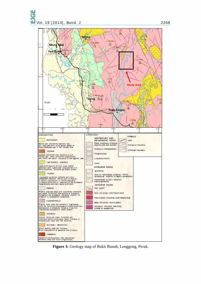
Lenggong district was situated between two mountain ranges; Titiwangsa and Bintang Range. The geology of the area was dominated by granitic rock from Jurassic end to Carbonaceous low era (Figure 3). It is originated from Bintang Range at west of Lenggong (Mokhtar, 1993). The district consists of few lithologies which are alluvium, tefra dust and granitic rock. Most of alluvium units are situated along the river area where the quaternary sediment consist of alluvium and tefra dust. Bukit Bunuh is located in Lenggong district and about 1 km from Kota Tampan town, Lenggong. Meteorite impact evidences are found in Bukit Bunuh based on the surrounding geological characteristics. The surrounding topography of Bukit Bunuh was said to be formed due to meteorite impact about 1.83 million years ago (Nawawi et al., 2009).
STUDY AREA The study was carried out in district of Lenggong, Perak (Malaysia). It was divided into
two (2) study stages, regional and interest stage. The regional stage covers and area of about 12 km x 11 km, which is approximately 132.00 km2 from Lenggong Town on the north region until Kampung Raban on the south region (Figure 4). The surveys conducted according to the accessibility of survey area. Generally the survey area is undulating with some part is very rough with, primary and secondary jungle, palm oil/rubber estate, villages, few small towns and Perak river. Bukit Bunuh is situated in Lenggong valley area which is at the north part of Kota Tampan with few unit of lithology, such as alluvium, tefra dust and granitic rock. Site observation indicates the presence of suevite rock with various size and shape (Nawawi et al., 2009). At the center of the survey area, a lot of cobbles and pebbles found which suspected as impacted rocks. Shattering and brecciation of the rocks is one of the evidence of meteorite impact (Photo 1).
Vol. 19 [2014], Bund. J 2268
Figure 3: Geology map of Bukit Bunuh, Lenggong, Perak.
Study area
100° 25′ 101°15′
4° 45′
5° 10′
100° 45′ 100° 55′ 101° 05′ 100° 35′
5° 00′
Scale
0 5 10 15 km

Vol. 19 [2014], Bund. J 2269
Figure 4: Study area (Google earth, 2013).
(a) (b)
Photo 1: Site observation, (a) cobbles and pebbles (b) shatter cones in suevite rock.
SEISMIC REFRACTION METHOD Seismic refraction method is based on measuring an elastic wave travelling through the
subsurface. The instrument used include a seismograph, geophones and seismic source such as sledgehammer, weight drop or dynamite. Wave generated from seismic source, propagate downward through the subsurface and critically refracted when it encounter different density medium (Dobrin, 1976). Seismic refraction is based on first arrival of a signal that travels through a layer with a higher velocity. The direct wave travels within short geophone-source distance through topsoil layer while the refracted wave travels through boundary of different medium (Figure 5). Table 1 shows the value of seismic refraction for common rocks (Telford and Sheriff , 1984).

Vol. 19 [2014], Bund. J 2270
Figure 5: Ray paths in a material with two horizontal interfaces. Time-distance graph for the direct and two critically refracted rays are shown in the travel-time curve
(Burger, 1992)
Table 1: Velocity of some common rocks and minerals (Telford and Sheriff, 1984)
Material Seismic (m/s) Igneous / Metamorphic
Granite 4580 - 5800 Weathered granite 305 - 610 Basalt 5400 - 6400 Sediments Sandstone 1830 - 3970 Shale 2750 - 4270 Limestone 2140 - 6100 Unconsolidated sediment Clay 915 - 2750 Alluvium 500 - 2000 Groundwater Fresh water 1430 - 1680 Salt water 1460 - 1530
METHODOLOGY The study used seismic refraction method and consist of two stages; regional and interest
stage (Figure 6). The regional area covers large area, approximately 132.00 km2. Four (4)
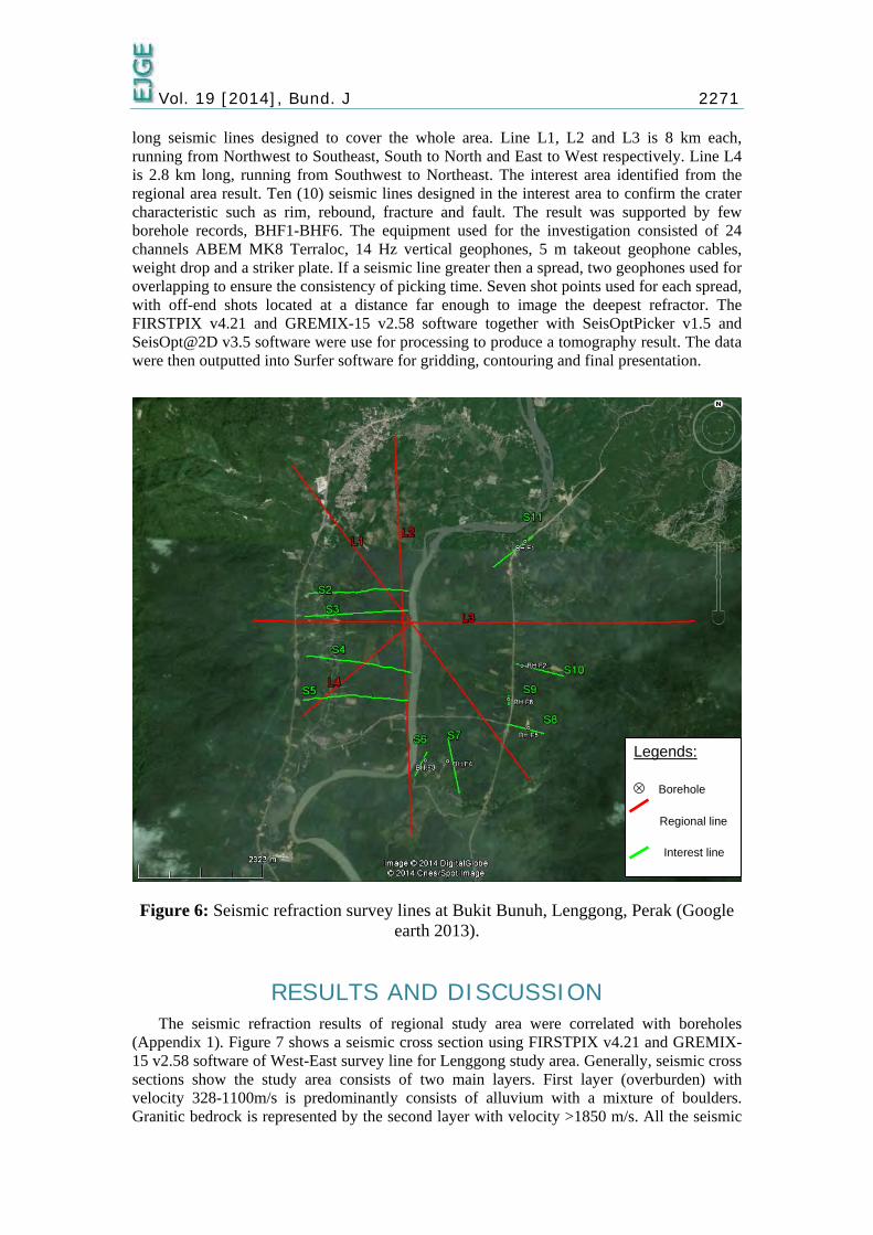
Vol. 19 [2014], Bund. J 2271 long seismic lines designed to cover the whole area. Line L1, L2 and L3 is 8 km each, running from Northwest to Southeast, South to North and East to West respectively. Line L4 is 2.8 km long, running from Southwest to Northeast. The interest area identified from the regional area result. Ten (10) seismic lines designed in the interest area to confirm the crater characteristic such as rim, rebound, fracture and fault. The result was supported by few borehole records, BHF1-BHF6. The equipment used for the investigation consisted of 24 channels ABEM MK8 Terraloc, 14 Hz vertical geophones, 5 m takeout geophone cables, weight drop and a striker plate. If a seismic line greater then a spread, two geophones used for overlapping to ensure the consistency of picking time. Seven shot points used for each spread, with off-end shots located at a distance far enough to image the deepest refractor. The FIRSTPIX v4.21 and GREMIX-15 v2.58 software together with SeisOptPicker v1.5 and SeisOpt@2D v3.5 software were use for processing to produce a tomography result. The data were then outputted into Surfer software for gridding, contouring and final presentation.
Figure 6: Seismic refraction survey lines at Bukit Bunuh, Lenggong, Perak (Google
earth 2013).
RESULTS AND DISCUSSION The seismic refraction results of regional study area were correlated with boreholes
(Appendix 1). Figure 7 shows a seismic cross section using FIRSTPIX v4.21 and GREMIX-15 v2.58 software of West-East survey line for Lenggong study area. Generally, seismic cross sections show the study area consists of two main layers. First layer (overburden) with velocity 328-1100m/s is predominantly consists of alluvium with a mixture of boulders. Granitic bedrock is represented by the second layer with velocity >1850 m/s. All the seismic
Legends: ⊗ Borehole Regional line Interest line

Vol. 19 [2014], Bund. J 2272 cross sections are combined using surfer 8 to produce a topography contour map of ground surface and bedrock for regional study area (Figure 8). The interest area identified by regional study shows few features which related to crater.
Figure 7: Seismic cross section of West-East survey line (0-8000 m).
Figure 8: Seismic topography contour map; (a) ground surface, (b) bedrock.
All seismic data of interest area was processed using SeisOptPicker v1.5 and SeisOpt@2D v3.5 software to produce tomography section and correlated with boreholes (Appendix 1). Figure 9 shows a topography map of ground surface and bedrock of the study area after combining regional and interest study of the whole area.
Interest area

Vol. 19 [2014], Bund. J 2273
Figure 9: Seismic refraction topography map of bedrock with crater rim and rebound
effect, R; (a) 2-D view of bedrock depth, (b) 3-D view of bedrock depth.
CONCLUSION The seismic refraction method is capable to identify the subsurface of the study area. The
regional study identify the interest area of the study objective. Generally the study indicated that the area was a meteorite impacted area with depth of the crater is <50 m with diameter of 4.9 km. The study also identify the boundry of the crater rim, rebounds and concluded that the crater is complex crater.
ACKNOWLEDGEMENTS The authors would like to thank to all who involved in this project directly or indirectly.
In addition, thanks to Centre for Global Archaeological Research Malaysia (CGAR), Universiti Sains Malaysia for sponsoring the project.

Vol. 19 [2014], Bund. J 2274
REFERENCES 1. Burger, H. R. (1992) “Exploration geophysics of the shallow subsurface,” Prentice Hall P
T R. 2. Dobrin, M. B. (1976) “Introduction to geophysical prospecting,” New York, McGraw-
Hill, pp 619.
3. Google earth (2013). 4. Grieve, R. A. F. and Pilkington M. (1987) “The signature of terrestrial impacts,” AGSO J.
Austral. Geol. Geophys., 16, pp 399–420 5. Isaac, J.H and R.R. Stewart (1993) “3-D seismic expression of a cryptoexplosion
structure,” J. Can. Expl. Geophys., Vol.29, No.2, pp 429-439. 6. Melosh, H.J. (1989) “Impact Cratering: A Geologic Process,” Research supported by
NASA. New York, Oxford University Press (Oxford Monographs on Geology and Geophysics, No.11), Vol.1, pp 253.
7. Mokhtar Saidin. (1993) “Paleolithic site comparison study of Kota Tampan with
Temelong village and its contribution to the cultural end of Pleistosein age in Southeast Asia.” Malaysia Museum Journal, 32.
8. Nawawi, M. N. M, Rosli, S., Khairul Arifin, M. N., Mokhtar, S., Abdullah, K. M. And
Shyeh, S. K. (2009) “Integration of Geophysical and Remote Sensing Techniques for Geophysical Prospection in Lenggong, Perak.” Proceeding paper on International Symposium and Exhibition on Geoinformation 2009. August 10-11, 2009.
9. Sawatzky, H.B. (1972) “Viewfield – a producing fossil crate,” J. Can. Soc. Expl. Geophys., Vol. 8, pp 22-40.
10. Telford, W. M. and R. F. Sheriff (1984) “Applied Geophysics,” Cambridge University
Press.
Appendix 1 follows…

Vol. 19 [2014], Bund. J 2275
APPENDIX 1
© 2014 ejge
BH1 BH2
-1.5 sandy silt-3 sandy silt with gravel-4.5 sandy silt with gravel-6 sandy silt with gravel-7.5 silty gravel with sand-9 sandy silt with gravel-10.5 sandy silt-12 silty sand with gravel-13.5 sandy silt with gravel-15 sandy silt with gravel-16.5 silty sand with gravel-18 no recovery-19.5 highly weathered granite-21 highly weathered granite-22.5 no recovery
Depth Legend Lithology (m)
1.5 sandy silt with gravel3 sandy silt with gravel4.5 sandy silt with gravel6 silty sand7.5 gravel with sand and fine soil9 silty sand with gravel10.5 sand and gravel with fine soil12 sand and gravel with fine soil13.5 slightly weathered granite15 slightly weathered granite16.5 slightly weathered granite18 slightly weathered granite
Depth Legend Lithology (m)
-1.5 silt with sand-3 silt with sand-4.5 silt with sand-6 silt with sand-7.5 silt with sand-9 silty sand with gravel-10.5 slightly weathered granite-12 slightly weathered granite-13.5 slightly weathered granite-15 moderately weathered granite
Depth Legend Lithology (m)
BH3
-1.5 sandy silt with gravel-3 sandy silt-4.5 silty sand-6 silty sand with gravel-7.5 silty sand with gravel-9 silty sand with gravel-10.5 no recovery-12 no recovery-13.5 no recovery-13.6 moderately weathered granite-14.1 moderately weathered granite-15.6 moderately weathered granite-17.1 moderately weathered granite
Depth Legend Lithology (m)
BH4
-1.5 silty sand with gravel-3 silty sand with gravel-4.5 silty sand with gravel-6 sand with gravel-7.5 sand with gravel and fine soil-9 sand with gravel and fine soil-10.5 sand with gravel and fine soil-12 sand with gravel and fine soil-13.5 no recovery-15 moderately weathered granite-16.5 moderately weathered granite-18 highly weathered granite-19.5 slightly weathered granite
Depth Legend Lithology (m)
BH5
-1.5 sand with gravel and fine soil-3 sandy silt with gravel-4.5 sandy silt with gravel-6 silt with sand-7.5 silt with gravel-9 sand-10.5 sand with fine soil-12 no recovery-13 highly weathered granite-14.5 moderately weathered granite-16 slightly weathered granite-17.5 slightly weathered granite
Depth Legend Lithology (m)
BH6