PMC-670 - cet-global.com
146
PMC-670 Advanced C&I Power Quality Analyzer User Manual Version: V1.0 October 18, 2018
-
Upload
khangminh22 -
Category
Documents
-
view
0 -
download
0
Transcript of PMC-670 - cet-global.com

PMC-670
Advanced C&I Power Quality Analyzer
User Manual
Version: V1.0
October 18, 2018

2
CET Electric Technology
This manual may not be reproduced in whole or in part by any means without the express written
permission from CET Electric Technology (CET).
The information contained in this Manual is believed to be accurate at the time of publication;
however, CET assumes no responsibility for any errors which may appear here and reserves the
right to make changes without notice. Please consult CET or your local representative for latest
product specifications.
Standards Compliance
DANGER
This symbol indicates the presence of danger that may result in severe injury or death and
permanent equipment damage if proper precautions are not taken during the installation,
operation or maintenance of the device.
CAUTION
This symbol indicates the potential of personal injury or equipment damage if proper precautions
are not taken during the installation, operation or maintenance of the device.

3
CET Electric Technology
DANGER Failure to observe the following instructions may result in severe injury or death
and/or equipment damage.
Installation, operation and maintenance of the device should only be performed
by qualified, competent personnel that have the appropriate training and
experience with high voltage and current devices. The device must be installed
in accordance with all local and national electrical codes.
Ensure that all incoming AC power and other power sources are turned OFF before
performing any work on the device.
Before connecting the device to the power source, check the label on top of the
device to ensure that it is equipped with the appropriate power supply, and the
correct voltage and current input specifications for your application.
During normal operation of the device, hazardous voltages are present on its
terminal strips and throughout the connected potential transformers (PT) and
current transformers (CT). PT and CT secondary circuits are capable of generating
lethal voltages and currents with their primary circuits energized. Follow
standard safety precautions while performing any installation or service work (i.e.
removing PT fuses, shorting CT secondaries, …etc).
Do not use the device for primary protection functions where failure of the device
can cause fire, injury or death. The device should only be used for shadow
protection if needed.
Under no circumstances should the device be connected to a power source if it is
damaged.
To prevent potential fire or shock hazard, do not expose the device to rain or
moisture.
Setup procedures must be performed only by qualified personnel familiar with the
instrument and its associated electrical equipment.
DO NOT open the instrument under any circumstances.

4
CET Electric Technology
Limited warranty
CET Electric Technology (CET) offers the customer a minimum of 12-month functional
warranty on the meter for faulty parts or workmanship from the date of dispatch from
the distributor. This warranty is on a return to factory for repair basis.
CET does not accept liability for any damage caused by meter malfunctions. CET
accepts no responsibility for the suitability of the meter to the application for which it
was purchased.
Failure to install, set up or operate the meter according to the instructions herein will
void the warranty.
Only CET’s duly authorized representative may open your meter. The unit should
only be opened in a fully anti-static environment. Failure to do so may damage the
electronic components and will void the warranty.

5
CET Electric Technology
Table of Contents
Table of Contents .................................................................................... 5 Glossary ................................................................................................... 9 Chapter 1 Introduction .......................................................................... 11
1.1 Overview ......................................................................................................... 11 1.2 Features .......................................................................................................... 11 1.3 PMC-670’ application in Power and Energy Management and Analyzer Systems 16 1.4 Getting more information .............................................................................. 17
Chapter 2 Installation ............................................................................ 18 2.1 Appearance ..................................................................................................... 18 2.2 Unit Dimensions ............................................................................................. 19 2.3 Mounting ........................................................................................................ 19 2.4 Wiring Connections ........................................................................................ 20
2.4.1 3-phase 4-wire Wye Direct Connection ................................................................ 20
2.4.2 3-phase 4-wire Wye with 3PTs and 4CTs............................................................... 21
2.4.3 3-phase 3-wire Grounded Wye Direct Connection ............................................... 21
2.4.4 3-phase 3-wire Grounded Wye with 3PTs and 4CTs ............................................. 22
2.4.5 3-phase 3-wire Open Delta Direct Connection ..................................................... 22
2.4.6 3-phase 3-wire Open Delta with 2PTs and 4CTs ................................................... 23
2.4.7 3-phase 3-wire Open Delta with 2PTs and 3CTs ................................................... 23
2.5 Communications Wiring ................................................................................. 24
2.5.1 Ethernet Port (10/100BaseT) ................................................................................ 24
2.5.2 RS485 Port ............................................................................................................. 24
2.6 Digital Input Wiring ........................................................................................ 24 2.7 GPS 1PPS Input wiring .................................................................................... 25 2.8 Digital Output Wiring ..................................................................................... 25 2.9 RO Wiring ........................................................................................................ 25 2.10 Pulse Output Wiring ..................................................................................... 26 2.11 Power Supply Wiring .................................................................................... 26 2.12 Chassis Ground Wiring ................................................................................. 26
Chapter 3 User Interface ....................................................................... 27 3.1 Front Panel Interface ...................................................................................... 27
3.1.1 Menu Tree and Display Hierarchy ......................................................................... 28
3.1.2 Navigating the Front Panel User Interface ............................................................ 29
3.2 Web Interface ................................................................................................. 34
3.2.1 Setting PC's IP Address .......................................................................................... 34
3.2.2 Configure PMC-670's IP Addresses ....................................................................... 35
3.2.3 Enabling Java Scripting in Google Chrome ............................................................ 35
3.2.4 Web Interface ........................................................................................................ 37
Chapter 4 Applications .......................................................................... 52 4.1 Inputs and Outputs ........................................................................................ 52
4.1.1 Digital Inputs ......................................................................................................... 52
4.1.2 Relay Outputs and Digital Outputs ....................................................................... 53
4.1.3 Energy Pulse Outputs ............................................................................................ 54
4.2 Power, Energy and Demand ........................................................................... 55
4.2.1 Basic Measurements ............................................................................................. 55
4.2.2 Energy Measurements........................................................................................... 56
4.2.3 Demands ................................................................................................................ 56

6
CET Electric Technology
4.2.4 Time of Use (TOU) ................................................................................................. 58
4.3 Setpoints ......................................................................................................... 60 4.4 Logical Module ............................................................................................... 62 4.5 Power Quality Parameters ............................................................................. 63
4.5.1 Power Frequency ................................................................................................... 63
4.5.2 Magnitude of the Supply Voltage ......................................................................... 64
4.5.3 Flicker ..................................................................................................................... 64
4.5.4 Supply Voltage Dips and Swells............................................................................. 64
4.5.5 Voltage Interruptions ............................................................................................ 66
4.5.6 Voltage Transients ................................................................................................. 67
4.5.7 Supply Voltage Unbalance .................................................................................... 67
4.5.8 Harmonics and Interharmonics ............................................................................. 68
4.5.9 Mains Signaling Voltage (MSV) ............................................................................. 69
4.5.10 Voltage Deviation ................................................................................................ 70
4.5.11 Rapid Voltage Changes (RVC) .............................................................................. 70
4.5.12 Flagging Concept ................................................................................................. 72
4.5.13 EN50160 Compliance Report .............................................................................. 73
4.6 Data Logging ................................................................................................... 73
4.6.1 SOE Log and PQ Log ............................................................................................... 74
4.6.2 Data Recorder (DR) ................................................................................................ 75
4.6.3 Max/Min Log ......................................................................................................... 76
4.6.4 Interval Energy Recorder (IER) .............................................................................. 77
4.6.5 WFR (Waveform Recorder) ................................................................................... 77
4.6.6 Disturbance Waveform Recorder (DWR) .............................................................. 77
4.6.7 PQ Counters ........................................................................................................... 78
4.6.8 Data Backup ........................................................................................................... 79
4.7 Time Synchronization ..................................................................................... 79
4.7.1 PMC Setup ............................................................................................................. 79
4.7.2 PecStar iEMS .......................................................................................................... 80
4.7.3 SNTP ....................................................................................................................... 80
4.7.4 GPS with Time Sync Pulse ..................................................................................... 80
4.7.5 IRIG-B ..................................................................................................................... 81
4.7.6 DI with PPS............................................................................................................. 81
4.8 On-board Web Server..................................................................................... 81 4.9 Meter Email .................................................................................................... 81 4.10 Ethernet Gateway ......................................................................................... 82
Chapter 5 Modbus Register Map .......................................................... 83 5.1 Basic Measurements ...................................................................................... 83 5.2 PQ Measurements .......................................................................................... 85 5.3 Energy Measurements ................................................................................... 86
5.3.1 RMS Energy ............................................................................................................ 86
5.3.2 Fundamental Energy.............................................................................................. 87
5.3.3 Harmonic Energy ................................................................................................... 87
5.4 Pulse Counter ................................................................................................. 87 5.5 Harmonic Measurements .............................................................................. 88
5.5.1 Fundamental .......................................................................................................... 88
5.5.2 K Factor, THD, TOHD and TEHD ............................................................................. 88
5.5.3 Individual Harmonic .............................................................................................. 89

7
CET Electric Technology
5.5.4 Interharmonics ...................................................................................................... 89
5.5.5 Harmonic Power .................................................................................................... 90
5.6 Demand .......................................................................................................... 91
5.6.1 Present Demand .................................................................................................... 91
5.6.2 Predicted Demand ................................................................................................. 93
5.6.3 Max Value per Demand Period ............................................................................. 94
5.6.4 Min Value per Demand Period .............................................................................. 96
5.6.5 Max. Demand Log .................................................................................................. 98
5.7 Log Register .................................................................................................... 99
5.7.1 SOE Log .................................................................................................................. 99
5.7.2 PQ Log .................................................................................................................... 99
5.7.3 MM Log (Max/Min Log) ...................................................................................... 101
5.7.4 EN50160 Log (Simon) .......................................................................................... 104
5.7.5 TOU Log ................................................................................................................ 110
5.8 File Transfer Register .................................................................................... 111
5.8.1 File Path ............................................................................................................... 111
5.8.2 File Name ............................................................................................................. 112
5.8.3 Reading File ......................................................................................................... 112
5.8.4 Register Address .................................................................................................. 112
5.9 Setup Parameters ......................................................................................... 113
5.9.1 System Parameters .............................................................................................. 113
5.9.2 Clock and Language Setup ................................................................................... 115
5.9.3 Communications Setup ....................................................................................... 115
5.9.4 Demand Setup ..................................................................................................... 116
5.9.5 I/O Setup .............................................................................................................. 116
5.9.6 Energy Pulsing Setup ........................................................................................... 117
5.9.7 Setpoints Setup.................................................................................................... 118
5.9.8 DR Setup .............................................................................................................. 119
5.9.9 WFR Setup ........................................................................................................... 120
5.9.10 Interval Energy Recorder (IER) Setup ................................................................ 121
5.9.11 PQ Log Setup ...................................................................................................... 122
5.9.12 EN50160 Setup (Simon) ..................................................................................... 123
5.9.13 TOU Setup .......................................................................................................... 124
5.9.14 TOU Status Setup ............................................................................................... 127
5.9.15 Control Setup ..................................................................................................... 128
5.10 Time Registers ............................................................................................ 129 5.11 Information ................................................................................................. 130
5.11.1 Meter Information ............................................................................................. 130
5.11.2 Tag Information ................................................................................................. 130
Appendix A - Data Recorder Parameter .............................................. 132 Appendix B - SOE Event Classification ................................................. 135 Appendix C - Technical Specifications ................................................. 141 Appendix D - Accuracy Specifications ................................................. 142 Appendix E - IEC61000-4-30 Class A Certificate ................................... 143 Appendix G - Ordering Guide .............................................................. 145 Contact us............................................................................................ 146

8
CET Electric Technology
9
CET Electric Technology
Glossary
1PPS = 1 Pulse Per Second
CET = CET Electric Technology
Comm. = Communication
CP95 = Cumulative Percent 95%
DI = Digital Input
DMD = Present Demand
DO = Digital Output
DR = Data Recorder
DWR = Disturbance Waveform Recorder
FIFO = First In First Out
Fund. = Fundamental
GB = Giga Byte
GPS = Global Positioning System
HS = High-Speed
Hn = nth order Harmonic, integer multiple (n) of the Fundamental Frequency (50Hz or 60Hz)
IHn = nth order Interharmonic represents all components between the (n-1)th and nth harmonic orders in RMS
HDn = nth order Harmonic Distortion
IHDn = nth order Interharmonic Distortion
IER = Interval Energy Recorder
LCD = Liquid Crystal Display
MB = Mega Byte
MSV = Mains Signalling Voltage
MSVR = Mains Signalling Voltage Recorder
Pred. DMD = Predicted Demand
P = Active Power (kW)
Q = Reactive Power (kvar)
S = Apparent Power (kVA)
Plt = Long-term Flicker
Pst = Short-term Flicker
PQ = Power Quality
RO = Relay Output
RTC = Real Time Clock
RVC = Rapid Voltage Changes
SOE = Sequence Of Events
SYNC DI = Demand Sync Input
TH = Total Harmonic in RMS, excluding Fundamental
THD = Total Harmonic Distortion
TOHD = Total Odd Harmonic Distortion
TEHD = Total Even Harmonic Distortion
U0 / I0 = Zero Sequence Voltage / Current
U1 / I1 = Positive Sequence Voltage / Current
U2 / I2 = Negative Sequence Voltage / Current
U0 / I0 Unb = Zero Sequence Voltage / Current Unbalance
U2 / I2 Unb = Negative Sequence Voltage / Current Unbalance
WF = Waveform
WFR = Waveform Recorder
Swell = Temporary increases in RMS value of AC voltage
Transient = Unidirectional impulse of either polarity or a damped oscillatory wave with the first peak occurring in
either polarity
Urms(1/2) = Half-Cycle RMS Voltage
Udin = Declared input voltage - Value obtained from the declared supply voltage by a transducer ratio
Usr = Sliding Reference Voltage
Ihalf cycle rms = Value of the RMS Current measured over each half period
Dip Threshold = Voltage magnitude specified for the purpose of detecting the start and end of a voltage dip
Flagged data = For any measurement time interval in which interruptions, dips or swells occur, the measurement results

10
CET Electric Technology
of all other parameters made during this time interval are flagged

11
CET Electric Technology
Chapter 1 Introduction
This manual explains how to use the PMC-670 Advanced C&I Power Quality Analyzer.
This chapter provides an overview of the PMC-670 Analyzer and summarizes many of its key features.
1.1 Overview
The PMC-670 represents the latest offer from CET for the Advanced C&I PQ monitoring market as it
offers un-surpassed functionality by combining Class 0.2S accuracy and advanced PQ features in a
standard DIN 144 form factor with a stunning, high resolution, color TFT LCD display. The PMC-670
satisfies such standards as IEC 62053-22 Class 0.2S, IEC 61000-4-7, IEC-61000-4-15 and IEC 61000-4-30
Class A. Further, the PMC-670 offers 2GB on-board memory, extensive I/O with 8xDIs, 4xROs and
2xDOs, hardware GPS Time Sync., one Ethernet and two RS-485 ports. These features likely make the
PMC-670 the world's most advanced PQ monitor for the C&I market today.
Typical Applications
HV, MV and LV Distribution Substations at critical customers
Data Centers, Semiconductor Fabs, Heavy Industries
7x24 Automated Manufacturing Facilities
Dip/Swell, Transient, Harmonics and Flicker monitoring
Mains and critical feeder monitoring
Substation automation with IEC61850 protocol support
The above are just a few of the many applications. Contact CET Technical Support should you require
further assistance with your application.
1.2 Features
Basic Features
IEC 62053-22 Class 0.2S metering
Standard 512 samples/cycle sampling
2GB of on-board memory
Industrial-grade, high-resolution Color TFT LCD @ 640x480
TOU Measurement
Time Sync. Via SNTP, GPS 1PPS or IRIG-B inputs
32 setpoints with programmable logic
Standard Ethernet and two RS485 ports
Power Quality Features
IEC 61000-4-30 Class A Certified
EN50160 Reporting, IEC 61000-4-7, IEC 61000-4-15
Transient, Dip/Swell, Interruption, Rapid Voltage Changes, HS Frequency, Disturbance Location
Disturbance Recording with variable waveform sampling rate
Harmonic Analysis up to 63rd on-board and 256th via software
WFR Log in COMTRADE file format
Front Panel Display

12
CET Electric Technology
Real-time and Energy measurements
Real-time waveforms for 4-phase Voltages and Currents for 4 cycles/second @ 128 samples/cycle
Harmonic & Interharmonic histogram and Vector displays
EN50160 Report
PQ Analysis with ITIC/SEMI F47 and Waveform displays
SOE Log
I/O status
Device configuration
Diagnostics
Power Quality Metering
PQ Parameters as per IEC 61000-4-30
Power Frequency
Magnitude of the Supply Voltage
Flicker
Supply Voltage Dips and Swells
Voltage Interruptions
Transient Voltages
Supply Voltage Unbalance
Voltage Harmonics and Interharmonics
Mains Signalling Voltage on the Supply Voltage
Rapid Voltage Changes
Measurement of Underdeviation and Overdeviation parameters
Harmonic and Interharmonic measurements
K-Factor for Current
V and I THD, TOHD, TEHD
Individual Harmonics from 2nd to 63rd in % or RMS
Individual Interharmonics from DC 2nd to 63rd in % or RMS
Harmonic kW, kvar and kVA from in 2nd to 63rd RMS
Fundamental V, I, kW, kvar, kVA and PF in RMS
Fundamental kWh, kvarh Import/Export
Total Harmonic kWh, Harmonic kWh Import/Export from 2nd to 31st
Symmetrical Components and Unbalances
Zero, Positive and Negative Sequence Components
V and I Unbalance based on Zero and Negative Sequence Components
Transient and Dip/Swell Recording
Transient Recording as short as 40us at 512 samples @ 50Hz for sub-cycle disturbances such as
capacitor switching and resonance phenomena
Dip/Swell Recording @ 10ms (½ cycle at 50Hz)
Trigger for DO, Data Recording, High-Speed Data Recording, Waveform Recording, Disturbance
Waveform Recording and Alarm Email
On-board Event Analysis via ITIC/SEMI F47 plot as well as Waveform display on the Front Panel and

13
CET Electric Technology
Web Interface
Rapid Voltage Changes
Detection of transitions in RMS voltage between two steady state conditions created by Tap
Changer or a sudden change of load conditions
PQ Event Counters
Transient, Dip, Swell, Interruption, Rapid Voltage Changes, Mains Signaling Voltages and Total PQ
Event Counters
Metering
Basic Measurements (1-second update)
3-phase Voltage, Current, Power, PF and Phase Angles
kWh, kvarh Import/Export/Net/Total and kVAh Total
U4, I4, Frequency
Configurable timestamped measurements for 10/12-cycle, 1-second, 3-second, 10-minute and 2-
hour
High-speed Measurements
4-phase Voltage and Current, Power, PF @ ½ cycle
Frequency @ 5 cycles
Sliding Window and Predicted Demands
3-phase Voltage, Current, Power, PF, U4, I4, Frequency,
Present Demand of 4-phase Voltage and Current THD/TOHD/TEHD/HD 2nd to HD 63rd
Max/Min values per Demand Interval
Demand synchronization with DI
Max. Demands and Predicted Demands
Multi-Tariff TOU capability
Two independent TOUs
Up to 12 Seasons
90 Holidays or Alternate Days
20 Daily Profiles, each with 12 Periods with minimum 15mins interval
8 Tariffs, each with the following information:
o kWh/kvarh Import/Export and kVAh
o kW/kvar Import/Export Max. Demands
o Register Rollover value at 1,000,000,000 kXh
Automatic switching between two TOUs according to scheduled time
Data, Waveform and Event Recording
Log Memory
2GB on-board log memory
Interval Energy Recorder (IER) Log

14
CET Electric Technology
kWh, kvarh Import/Export and kVAh Total
Support FIFO and Stop-When-Full mode
Data Recording (DR) Log
16 Standard DRs and 4 HS DRs
Recording Interval from 1s to 40 days for Standard DR and 0.5 to 60 cycles HS DR
Each DR supports 16 parameters
Programmable sources
Configurable Depths and Recording Offsets
Support FIFO or Stop-When-Full modes for standard DR and Stop-When-Full mode for HS DR
Max/Min Recorder (MMR) Log
Logging of Max/Min values for real-time measurements such as V, I, kW, kvar, kVA, PF, Freq.,
Unbalance, K-factor, THD
Two log transfer modes:
Manual: Max/Min Since Last Reset/Before Last Reset
Automatic: Max/Min of This Month/Last Month
SOE Log
1024 FIFO events time-stamped to ±1ms resolution
Setup changes, System events, Setpoint events and I/O operations
PQ Log
1024 FIFO entries time-stamped to ±1ms resolution
Transient, Dip/Swell, Rapid Voltage Change, and Mains Signaling Voltages
Waveform Capture (WFC) and Waveform Recording (WFR)
Real-time WFC for 4 cycles/second @ 128 samples/cycle
2 WFR with a combined total of 128 entries
Simultaneous recording of 4-phase Voltage and Current inputs
# of Cycles x Samples/Cycles (# of pre-fault cycles)
20x512 (6), 40x256 (12), 80x128 (24)
160x64 (48), 320x32 (96), 640x16 (192)
COMTRADE file format, downloadable from the on-board FTP Server
Disturbance Waveform Recording (DWR)
Complete recording of all Voltage (U1-U4), Current (I1-I4) Inputs and I/O where the disturbance
consists of 6 stages with variable WF sampling rates.
Triggered by Transient, Dip/Swell, Rapid Voltage Change, Setpoints, DI status changes and
Communication.
COMTRADE file format, downloadable from the on-board FTP Server
Setpoints
Control Setpoints
24 Control Setpoints with programmable Combinational Logic
8 HS Setpoints
15
CET Electric Technology
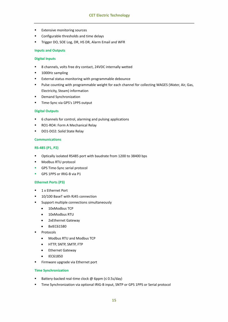
Extensive monitoring sources
Configurable thresholds and time delays
Trigger DO, SOE Log, DR, HS DR, Alarm Email and WFR
Inputs and Outputs
Digital Inputs
8 channels, volts free dry contact, 24VDC internally wetted
1000Hz sampling
External status monitoring with programmable debounce
Pulse counting with programmable weight for each channel for collecting WAGES (Water, Air, Gas,
Electricity, Steam) information
Demand Synchronization
Time-Sync via GPS's 1PPS output
Digital Outputs
6 channels for control, alarming and pulsing applications
RO1-RO4: Form A Mechanical Relay
DO1-DO2: Solid State Relay
Communications
RS-485 (P1, P2)
Optically isolated RS485 port with baudrate from 1200 to 38400 bps
Modbus RTU protocol
GPS Time-Sync serial protocol
GPS 1PPS or IRIG-B via P1
Ethernet Ports (P3)
1 x Ethernet Port
10/100 BaseT with RJ45 connection
Support multiple connections simultaneously
10xModbus TCP
10xModbus RTU
2xEthernet Gateway
8xIEC61580
Protocols
Modbus RTU and Modbus TCP
HTTP, SNTP, SMTP, FTP
Ethernet Gateway
IEC61850
Firmware upgrade via Ethernet port
Time Synchronization
Battery-backed real-time clock @ 6ppm (≤ 0.5s/day)
Time Synchronization via optional IRIG-B input, SNTP or GPS 1PPS or Serial protocol
16
CET Electric Technology
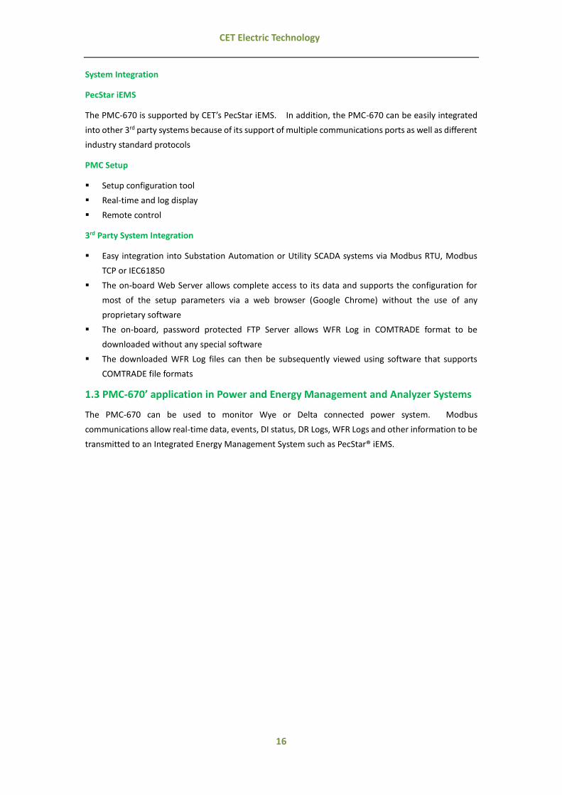
System Integration
PecStar iEMS
The PMC-670 is supported by CET’s PecStar iEMS. In addition, the PMC-670 can be easily integrated
into other 3rd party systems because of its support of multiple communications ports as well as different
industry standard protocols
PMC Setup
Setup configuration tool
Real-time and log display
Remote control
3rd Party System Integration
Easy integration into Substation Automation or Utility SCADA systems via Modbus RTU, Modbus
TCP or IEC61850
The on-board Web Server allows complete access to its data and supports the configuration for
most of the setup parameters via a web browser (Google Chrome) without the use of any
proprietary software
The on-board, password protected FTP Server allows WFR Log in COMTRADE format to be
downloaded without any special software
The downloaded WFR Log files can then be subsequently viewed using software that supports
COMTRADE file formats
1.3 PMC-670’ application in Power and Energy Management and Analyzer Systems
The PMC-670 can be used to monitor Wye or Delta connected power system. Modbus
communications allow real-time data, events, DI status, DR Logs, WFR Logs and other information to be
transmitted to an Integrated Energy Management System such as PecStar® iEMS.

17
CET Electric Technology
Figure 1-1 Typical Application
1.4 Getting more information
Additional information is available from CET via the following sources:
Visit www.cet-global.com
Contact your local representative
Contact CET directly via email or telephone

18
CET Electric Technology
Chapter 2 Installation
2.1 Appearance
1
2
4
5
3
6
1
2
3
4
5
6
Enclosure
Front Panel
Mounting Brackets
LED Pulse Output
TFT Display
Buttons
Figure 2-1 Appearance
Caution
Installation of the PMC-670 should only be performed by qualified, competent personnel that have
the appropriate training and experience with high voltage and current devices. The meter must be
installed in accordance with all local and national electrical codes.
During the operation of the meter, hazardous voltages are present at the input terminals. Failure to
observe precautions can result in serious or even fatal injury and equipment damage.

19
CET Electric Technology
Figure 2-2 Rear Panel
2.2 Unit Dimensions
Front View Side View
Figure 2-3 Dimensions
2.3 Mounting
The PMC-670 should be installed in a dry environment with no dust and kept away from heat, radiation
and electrical noise sources.
Installation steps:
Remove the mounting brackets from the device
Fit the device through a 138mmx138mm cutout as shown in Figure 2-4
Re-install and tighten the mounting brackets against the panel to secure the device

20
CET Electric Technology
Figure 2-4 Panel Cutout
2.4 Wiring Connections
PMC-670 can satisfy almost any three or four phase power systems. Please read this section carefully
before installation and choose the correct wiring method for your power system. The following wiring
modes are supported:
3-phase 4-wire Wye Direct Connection
3-phase 4-wire Wye with 3PTs and 3CTs
3-phase 3-wire Grounded Wye Direct Connection
3-phase 3-wire Grounded Wye with 3PTs and 3CTs
3-phase 3-wire Open Delta Direct Connection
3-phase 3-wire Open Delta with 2PTs and 3CTs
3-phase 3-wire Open Delta with 2PTs and 2CTs
2.4.1 3-phase 4-wire Wye Direct Connection
Please consult the serial number label to ensure that the system phase voltage is less than or equal to
the device’s voltage input specification. Set the Wiring Mode to Wye.
Caution
Under no circumstances should the PT secondary be shorted.
Under no circumstances should the CT secondary be open when the CT primary is energized.
CT shorting blocks should be installed to allow for easy maintenance.

21
CET Electric Technology
Figure 2-5 4-Wire Wye, Direct Connection
2.4.2 3-phase 4-wire Wye with 3PTs and 4CTs
Please consult the serial number label to ensure that the rated PT secondary voltage is less than or
equal to the device’s voltage input specification. Set the Wiring Mode to Wye.
Figure 2-6 4-Wire Wye, 3PTs, 4CTs
2.4.3 3-phase 3-wire Grounded Wye Direct Connection
Please consult the serial number label to ensure that the system phase voltage is less than or equal to
the device’s voltage input specification. Set the Wiring Mode to Wye.
22
CET Electric Technology
Figure 2-7 3-Wire Grounded Wye, Direct Connection
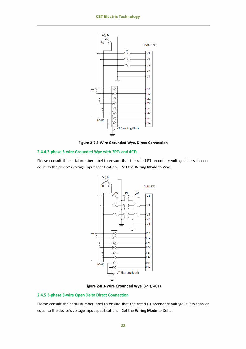
2.4.4 3-phase 3-wire Grounded Wye with 3PTs and 4CTs
Please consult the serial number label to ensure that the rated PT secondary voltage is less than or
equal to the device’s voltage input specification. Set the Wiring Mode to Wye.
Figure 2-8 3-Wire Grounded Wye, 3PTs, 4CTs
2.4.5 3-phase 3-wire Open Delta Direct Connection
Please consult the serial number label to ensure that the rated PT secondary voltage is less than or
equal to the device’s voltage input specification. Set the Wiring Mode to Delta.

23
CET Electric Technology
Figure 2-9 3-Wire Delta, no PTs, 4CTs
2.4.6 3-phase 3-wire Open Delta with 2PTs and 4CTs
Please consult the serial number label to ensure that the rated PT secondary voltage is less than or
equal to the device’s voltage input specification. Set the Wiring Mode to Delta.
Figure 2-10 3-Wire Delta, 2PTs, 4CTs
2.4.7 3-phase 3-wire Open Delta with 2PTs and 3CTs
Please consult the serial number label to ensure that the rated PT secondary voltage is less than or
equal to the device’s voltage input specification. Set the Wiring Mode to Delta.

24
CET Electric Technology
Figure 2-11 3-Wire Delta, 2PTs, 3CTs
2.5 Communications Wiring
2.5.1 Ethernet Port (10/100BaseT)
RJ45 Connector Pin Meaning
1 Transmit Data+ 2 Transmit Data- 3 Receive Data+
4,5,7,8, NC 6 Receive Data-
Table 2-1 RJ45 Connector Pin Description for 10/100BaseT Applications
2.5.2 RS485 Port
The PMC-670 provides up to two RS485 ports and supports the Modbus RTU protocol. Up to 32
devices can be connected on an RS485 bus. The overall length of the RS485 cable connecting all
devices should not exceed 1200m.
If the master station does not have an RS485 communications port, an RS232/RS485 or USB/RS485
converter with optically isolated outputs and surge protection should be used.
The following figure illustrates the RS485 communication connections on the PMC-670:
Figure 2-12 RS485 Communication Connections
2.6 Digital Input Wiring
The following figure illustrates the Digital Input connections on the PMC-670:

25
CET Electric Technology
Figure 2-13 DI Connections
2.7 GPS 1PPS Input wiring
The Digital Input on the PMC-670 can be used for time synchronization with a GPS 1PPS output. The
following figure illustrates the wiring connections:
Figure 2-14 Time Sync. Connections
2.8 Digital Output Wiring
The following figure illustrates the Digital Output connections on the PMC-670:
Figure 2-15 DO Connections
2.9 RO Wiring
The following figure illustrates the RO connections on the PMC-670:

26
CET Electric Technology
Figure 2-16 RO Connections
2.10 Pulse Output Wiring
The following figure illustrates the Pulse Output connections on the PMC-670:
Figure 2-17 Pulse Output Connections
2.11 Power Supply Wiring
For AC supply, connect the live wire to the L/+ terminal and the neutral wire to the N/- terminal. For
DC supply, connect the positive wire to the L/+ terminal and the negative wire to the N/- terminal.
Figure 2-18 Power Supply Connections
2.12 Chassis Ground Wiring
Connect the G terminal to earth ground.
Figure 2-19 Chassis Ground Connection

27
CET Electric Technology
Chapter 3 User Interface
3.1 Front Panel Interface
The PMC-670 is equipped with a stunning, 640x480, TFT Color, LCD Display. The following figure
illustrates PMC-670's Main Display, which is the first screen shown upon device power up.
Figure 3-1 Main Display

28
CET Electric Technology
3.1.1 Menu Tree and Display Hierarchy
Power On
Metering
Real Time
Fundamental
Power Quality
EN50160
Phases
Harmonics
Energy
I/O
Events
Setup
Diagnostics
SOE
PQ Log
This Max
Clear
Demand & Energy
Basic Setup
COMM Setup
PQ Setup
RVC Setup
Clock & Language
Password Setup
Device Information
Site Information
This Min
PQ Log Counter
Waveform Total Energy
Harmonics Energy
Demand
Max Demand
TOU
TOU Record
Statistics
Last Max
Last Min
Mains Signaling
WFR Setup
I/O Setup
Figure 3-2 Menu Tree
Figure 3-3 Hierarchy of Menu
For the PMC-670, the display of the measurements is organized in a hierarchy that consists of Categories,
Category
Page
Topic
Status

29
CET Electric Technology
Topics and Pages. There are 8 icons in the Main Display, and each icon represents a Category. Each
Category displays a specific type of information and may have one or more Topics. Each Topic may
provide one or more Pages of measurement information. The Status area indicates if there are
additional Pages of measurements under a particular Topic and how to get there.
3.1.2 Navigating the Front Panel User Interface
Figure 3-4 Front Panel User Interface
The PMC-670 features a stunning, high resolution, color LCD display with an intuitive graphical user
interface that makes it extremely simple to operate. There are six buttons located beneath the LCD
display on the Front Panel: , , , , < > and < >.
Buttons Description
In the Main Display, the four arrow buttons are used to move the cursor between Categories, which are represented by the different icons. The current cursor position is indicated by the highlighted Category's description. While inside a Category and under a particular Topic, the arrow buttons are
used to navigate between Pages.
< > Enter a Category.
< > Return to the Main Menu display.
Table 3-1 Description of Buttons in Front Panel

30
CET Electric Technology
The following table gives a general description of this information hierarchy.
Categories Topics Pages
Metering
Real Time

31
CET Electric Technology
Fundamental
Power Quality
Phases -
Harmonics
UA
UB
UC
U4
IA
IB
IC
I4
Harmonic
Inter-Harmonic
Waveform Real Time
Waveform
Energy Total Energy

32
CET Electric Technology
Harmonics Energy
Demand
Max. Demand
TOU
TOU Record
I/O -
Events
SOE
PQ Log
PQ Counter

33
CET Electric Technology
Statistics
EN50160
This Max.
This Min.
Last Max.
Last Min.
Setup
Basic Setup
COMM Setup
PQ Setup
RVC Setup
Mains Signaling
WFR Setup

34
CET Electric Technology
I/O Setup
Clock & Language
Demand & Energy
Password Setup
Clear
Diagnostics Device Information
Site Information
Table 3-2 Captures of each Hierarchy
3.2 Web Interface
The PMC-670's web interface has been designed specifically to work with Google Chrome. Please use
this link (https://www.google.com/intl/en/chrome/browser/) to download and install Google Chrome
if it's not already installed on the PC.
The default IP Address of the PMC-670’s one Ethernet Port is 192.168.0.100 for P3. Please make sure
to configure the IP Addresses and Subnet Masks for the PMC-670 and the PC so that they are in the
same subnet.
3.2.1 Setting PC's IP Address
To determine the PC's IP Address, go to Control Panel, and double-click on Network and Sharing Center
and the Network Connections folder appears.

35
CET Electric Technology
Figure 3-5 Control Panel and Network Connections Pages
Double-click on the Ethernet adapter to open its dialog box. Then double-click on Internet Protocol
Version 4 (TCP/IPv4) to show the PC's IP configuration.
Figure 3-6 Setting PC’s IP Address
3.2.2 Configure PMC-670's IP Addresses
To configure the PMC-670's IP Address, move the cursor to the Setup category, hit <Enter> and then the
Basic Setup topic appears. Use the arrow buttons to move from Basic Setup to COMM Setup. The
IP Address can be modified by hitting <Enter> and going inside the page.
Figure 3-7 Configure PMC-670’s IP Address
3.2.3 Enabling Java Scripting in Google Chrome
1) Open Google Chrome with Java scripting enabled. To enable Java Scripting, move the mouse
pointer to the upper right-hand corner of the Google Chrome interface and then click on this icon

36
CET Electric Technology
to open the Settings page.
Figure 3-8 Open Setting page of Google Chrome
2) Double-click on the link Show Advanced Settings located at the bottom of the page to show the
advanced settings.
Figure 3-9 Advanced Setting page of Google Chrome
3) Double-click on the Content Settings and the following screen appears. Select the option Allow
all sites to run JavaScript (recommended).

37
CET Electric Technology
Figure 3-10 Set Content Setting for Google Chrome
3.2.4 Web Interface
1) Enter the IP Address of the PMC-670 in the Address area of Google Chrome and then press <Enter>.
2) The PMC-670’s Web Interface appears. There are four main menu items on the left-hand pane -
Metering, Statistics, Setup and Diagnostics.
Figure 3-11 Web Interface
3.2.4.1 Metering
Click on the down arrow icon on the left of Metering to expand its sub-menu, which consists of Phase,
Real Time, Power Quality, Harmonics, Inter-Harmonics, Demand, Energy, Waveform and I/O. The
following sections provide a quick overview of the web pages available under Metering.
3.2.4.1.1 Phase
Click Phase on the left-hand pane and the page displays following information:
Phasor diagram
Phase and Magnitude information of Ua, Ub, Uc, U4, Ia, Ib, Ic and I4
U1, U2 and U0
I1, I2 and I0

38
CET Electric Technology
Figure 3-12 Phase Interface
3.2.4.1.2 Real Time
Click Real Time on the left-hand pane and the page displays the available measurements for Voltage,
Current, U/I Phase Angle, Power and Frequency.
Figure 3-13 Real Time Interface
3.2.4.1.3 Power Quality
Click Power Quality on the left-hand pane and the page displays the available measurements for Voltage
Deviation, Flicker, Symmetrical Components, Unbalance, PQ Log Counter and Frequency Deviation.

39
CET Electric Technology
Figure 3-14 Power Quality Interface
3.2.4.1.4 Harmonics
Click on the drop-down box underneath Harmonics on the right-hand pane to select which input to
display. The available inputs are Ua, Ub, Uc, U4, Ia, Ib, Ic and I4. Click Harmonic Distortion (%),
Harmonic P (W) and Harmonic Q (var) to view the corresponding information.
Figure 3-15 Harmonics Interface
3.2.4.1.5 Inter-Harmonics
Click on the drop-down box underneath Inter-Harmonics on the right-hand pane to select which input
to display. The available inputs are Ua, Ub, Uc, U4, Ia, Ib, Ic and I4.

40
CET Electric Technology
Figure 3-16 Inter-Harmonics Interface
3.2.4.1.6 Demand
Depending on the setting of the Self-Read Time setup register, the page may display the Max. Demand
of This/Last Month or Max. Demand Since/Before Last Reset.
Figure 3-17 Demand Interface
3.2.4.1.7 Energy
Click Energy on the left-hand pane and the page displays kWh Import/Export and kvarh Import/Export
for total RMS, TH, and H1 to H31.

41
CET Electric Technology
Figure 3-18 Energy Interface
3.2.4.1.8 TOU
Click TOU on the left-hand pane and the page displays the real time TOU data and detailed
measurements which include Energy and Max. Demand. Click the History Record tab to display the
Average PF, Energy TOU and Demand for the last 3 months (periods).
Figure 3-19 TOU Interface
3.2.4.1.9 Waveform
Click Waveform on the left-hand pane to display the real-time waveform captured by the PMC-670. A
small fly-out comment showing the channel name and the measurement value is displayed when the
mouse pointer is positioned at a particular point in the waveform.

42
CET Electric Technology
Figure 3-20 Waveform Interface
3.2.4.1.10 I/O
Click I/O on the left-hand pane to display status of Digital Inputs, Relay Outputs and Digital Outputs.
Figure 3-21 I/O Interface
3.2.4.2 Statistics
Click on the down arrow icon beside Statistics on the left-hand pane to expand its sub-menu, which
includes Counter, SOE, PQ Log, Max/Min, COMTRADE and EN50160. The following sections provide
a quick overview of the web pages available under Statistics.
3.2.4.2.1 Counter
Click Counter on the left-hand pane to display the counters for HS DR, Standard DR, SOE, PQ log, TOU
Recorder, Disturbance Recorder (DWR), WFR, Mains signalling Recorder, Interval Energy (IER) and
EN50160.

43
CET Electric Technology
Figure 3-22 Counter Interface
3.2.4.2.2 SOE
Click SOE on the left-hand pane to display the SOE Log starting with the most recent event (with a Start
Index of 1). There is a control dialog near the lower right-hand corner of the page. The user can
scroll backward and forward through the pages using the left and right arrow icons, jump to a particular
page by entering a specific value in the text box, or jump to the First or Last page by clicking on the First
or Last icons.
Figure 3-23 SOE Interface
3.2.4.2.3 PQ Log
Click PQ Log on the left-hand pane to display the PQ Log starting with the most recent event (with a
Start Index of 1). Select the event type from the Type drop-down box to filter the displaed events or
select the Start Date and End Date to limit the query for a specifc date range. Click on the ITIC or
Waveform icons, if available, to display the ITIC Plot or the WFR Log for the associated PQ event.

44
CET Electric Technology
Figure 3-24 PQ Log Interface
3.2.4.2.4 Max./Min. Log
Click Max./Min. on the left-hand pane to display the Max./Min. Log information of This Month (since
Last Reset) and Last Month (before Last Reset).
Figure 3-25 Max/Min Interface
3.2.4.2.5 COMTRADE
Click COMTRADE on the left-hand pane and the following screen appears on the right-hand pane. This
page displays the available COMTRADE files in a table format. Choose Waveform Record (WFR),
Signalling Volt. Rec (MSVR), or Disturbance Recorder (DWR) from the drop-down box and then click
the hyperlink for CFG or DAT to download the COMTRADE files and store them locally on a PC where
they can be viewed using a COMTRADE viewer.

45
CET Electric Technology
Figure 3-26 COMTRADE Interface
3.2.4.2.6 EN50160
Click EN50160 on the left-hand pane and the following screen appears. This page displays the
EN50160 Compliance summary for a specific period in a Table format. The user can click on the
hyperlinks for PASS, Fail or Detail to view the compliance details.
Figure 3-27 EN50160 Interface
3.2.4.3 Setup Menu
Click Setup on the left-hand pane to expand its sub-menu, which includes Basic Setup, PQ Setup,
Demand Setup, Comm Setup, Energy Setup, Record Setup, I/O Setup, Clock Setup, Password Setup
and Clear.
In order to make changes, the user needs to first login to the web interface by clicking on the Login icon
at the upper right-hand corner. The user must enter the password (default password = 000000) at the
Login dialog box before any changes can be made.
46
CET Electric Technology
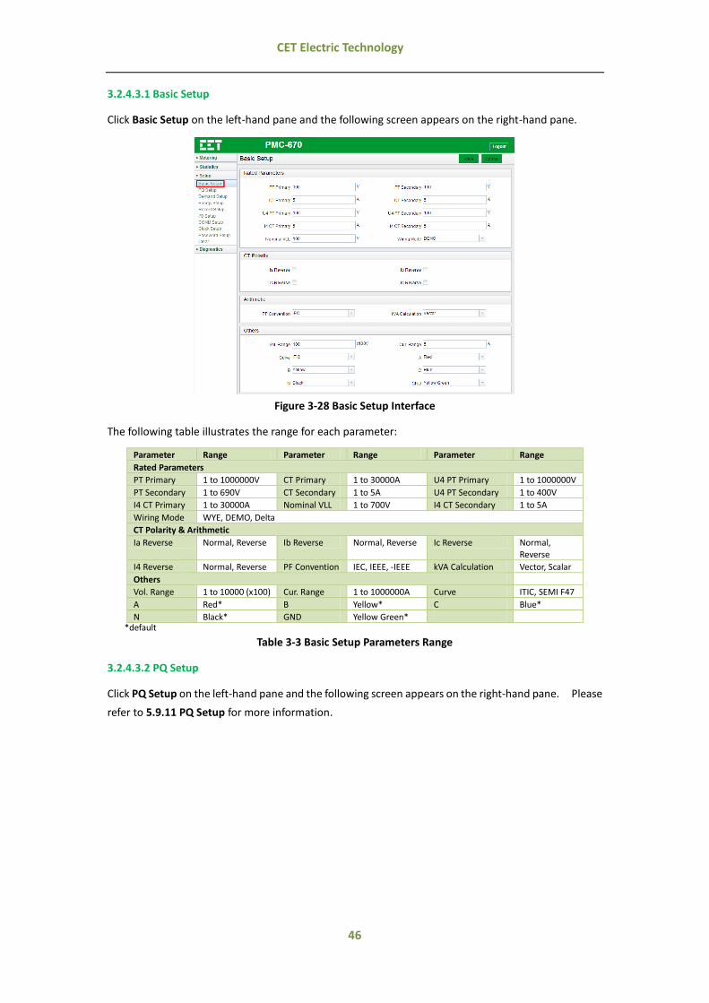
3.2.4.3.1 Basic Setup
Click Basic Setup on the left-hand pane and the following screen appears on the right-hand pane.
Figure 3-28 Basic Setup Interface
The following table illustrates the range for each parameter:
Parameter Range Parameter Range Parameter Range
Rated Parameters
PT Primary 1 to 1000000V CT Primary 1 to 30000A U4 PT Primary 1 to 1000000V
PT Secondary 1 to 690V CT Secondary 1 to 5A U4 PT Secondary 1 to 400V
I4 CT Primary 1 to 30000A Nominal VLL 1 to 700V I4 CT Secondary 1 to 5A
Wiring Mode WYE, DEMO, Delta
CT Polarity & Arithmetic
Ia Reverse Normal, Reverse Ib Reverse Normal, Reverse Ic Reverse Normal, Reverse
I4 Reverse Normal, Reverse PF Convention IEC, IEEE, -IEEE kVA Calculation Vector, Scalar
Others
Vol. Range 1 to 10000 (x100) Cur. Range 1 to 1000000A Curve ITIC, SEMI F47
A Red* B Yellow* C Blue*
N Black* GND Yellow Green* *default
Table 3-3 Basic Setup Parameters Range
3.2.4.3.2 PQ Setup
Click PQ Setup on the left-hand pane and the following screen appears on the right-hand pane. Please
refer to 5.9.11 PQ Setup for more information.

47
CET Electric Technology
Figure 3-29 PQ Setup Interface
3.2.4.3.3 Demand Setup
Click Demand Setup on the left-hand pane and the following screen appears. Please refer to 5.9.4
Demand Setup for more information.
Figure 3-30 Demand Setup Interface
3.2.4.3.4 Energy Setup
Click Energy Setup on the left-hand pane and the following screen appears. Please refer to 5.9.10

48
CET Electric Technology
Energy Recorder Setup for more information.
Figure 3-31 Energy Setup Interface
3.2.4.3.5 Record Setup
Click Record Setup on the left-hand pane and the following screen appears. Please refer to 5.9.9 WFR
Log Setup for more information.
Figure 3-32 Record Setup Interface
3.2.4.3.6 I/O Setup
Click I/O Setup on the left-hand pane and the following screen appears. Please refer to 5.9.5 I/O Setup
for more information.

49
CET Electric Technology
Figure 3-33 I/O Setup Interface
3.2.4.3.7 COMM Setup
Click COMM Setup on the left-hand pane and the following screen appears. Please refer to 5.9.3
Communications Setup for more information.
Figure 3-34 COMM Setup Interface
3.2.4.3.8 Clock Setup
Click Clock Setup on the left-hand pane and the following screen appears. This page shows three
sections:
Section Function
PC Clock & Device Clock Synchronize the device time with the PC clock by clicking .
Clock Setup Please refer to Section 4.7 Time Synchronization for details.
SNTP Please refer to Section 4.7 Time Synchronization for details.
Table 3-4 Function Description of Clock Setup Interface

50
CET Electric Technology
Figure 3-35 Clock Setup Interface
3.2.4.3.9 Password Setup
Click Password Setup on the left-hand pane and the following screen appears. This web page allows
the user to change the Login password for the PMC-670. It's highly recommended for the user to
change the default Login password to something unique and keep the new password at a safe place for
future reference.
Figure 3-36 Password Setup Interface
3.2.4.3.10 Clear
Click Clear on the left-hand pane and the following screen appears. This web page allows the user to
clear Demands, Recorder Logs, Counters, TOU and Energy manually.
Figure 3-37 Clear Setup Interface

51
CET Electric Technology
3.2.4.4 Diagnostics
Click Diagnostics on the left-hand pane to expand its sub-menu, which includes Diagnostics and
Maintenance
3.2.4.4.1 Diagnostics
Click Diagnostics on the left-hand pane, the web pages display detailed device information and site
information.
Figure 3-38 Diagnostics Interface
3.2.4.4.2 Maintenance
Click Maintenance on the left-hand pane and the following screens appear. The web pages display
the PMC-670’s maintenance information and allows the user to backup configuration settings, restore
device’s factory configuration, and test alarm e-mail settings (Misc tab).
Figure 3-39 Maintenance Interface

52
CET Electric Technology
Chapter 4 Applications
4.1 Inputs and Outputs
4.1.1 Digital Inputs
The PMC-670 is equipped with 8 self-excited Digital Inputs (DIs) that are internally wetted at 24 VDC.
Each DI has the following setup parameters:
Setup Parameters Definition Options
DIx Mode
Each DI can be configured as a Status Input, Pulse Counter Input, Dmd Sync and PPS.
Only one DI can be programmed as PPS, and then Clock Source (7086) need to set as DI PPS.
0=Status Input* 1=Pulse Counter
2=Dmd Sync
3=PPS
DIx Debounce Specify the minimum duration the DI must remain in the Active or Inactive state before a DI state change is considered to be valid.
1 to 1000 (ms) (Default=20ms)
DIx Pulse Weight Specify the incremental value for each received pulse. This is only used when a DI is configured as a Pulse Counter Input.
1 to 1000000 (Default=10)
Table 4-1 Definition for DI Parameters
The PMC-670's DIs can be used in the following applications:
1) DIs are typically used for monitoring external status which can help prevent equipment damage,
improve maintenance, and track security breaches. The real-time statuses of the DIs are available
on the Front Panel as well as through communications. Changes in DI status are stored as events
in the SOE Log in 1 ms resolution. The following table illustrates how to program a particular DI
for Status monitoring.
Setup Parameters Value Description
DIx Mode 0 Status Input
DIx Debounce 20 (ms) Default
DIx Pulse Weight N/A N/A
Table 4-2 DI Setup Parameters for Status Input
Front Panel Web Interface
Figure 4-1 Program DI for Status Monitoring
2) A DI can be used for pulse counting to collect WAGES (Water, Air, Gas, Electricity and Steam)
information. The DI Pulse Counter information is available through the Front Panel Interface or
via communications. The DI Pulse Counters can be reset from the Front Panel or via
communications. The following table illustrates how to program a DI for pulse counting.
Setup Parameters Value Description
DIx Mode 1 Pulse Counter

53
CET Electric Technology
DIx Debounce 20 (ms) Default
DIx Pulse Weight 10 Default
Table 4-3 DI Setup Parameters for Pulse Counting
3) One of the Dls can be programmed to receive the Demand Sync Pulse by setting DI Mode to Dmd
Sync. The following table illustrates how to program a DI as a Demand Sync Input. Please refer
to Section 4.2.3 for a detailed description.
Setup Parameters Value Description
DIx Mode 2 Dmd Sync
DIx Debounce 20 (ms) Default
DIx Pulse Weight N/A N/A
Table 4-4 DI Setup Parameters for Demand Sync Pulse
4) When the Clock Source parameter is set to DI, DI8 is used by default to receive the 1PPS GPS Time
Sync. Signal for synchronizing its internal RTC. All DI8 setup parameters are disregarded except
for the DI8 Debounce. Please refer to Section 4.7.7 for a detailed description.
Figure 4-2 Program DI for Clock Source Setup
4.1.2 Relay Outputs and Digital Outputs
The PMC-670 comes standard with 4 Form A Mechanical Relay Outputs (RO) as well as 2 Solid State
Relay Outputs (DO). RO and DO are normally used for setpoint alarming, load control, or remote
control applications.
RO and DO on the PMC-670 can be used in the following applications:
Application Description
Front Panel Control Manual operation from the Front Panel, mainly used for relay testing.
Remote Control Remotely operated over communications via our free PMC Setup software or PecStar® iEMS.
Remote Control of RO and DO is not supported by the Web Interface.
Control Setpoint Control Setpoints can be programmed to trigger RO/DO, WFR, DR, Alarm Email, etc, upon becoming active. Please refer to Section 4.3 for a detailed description.
Dip/Swell Setpoint Dip/Swell Setpoint can be programmed to trigger RO/DO, WFR, DR, Alarm Email, etc, upon becoming active. Please refer to Section 4.5.4 for detailed description.
Transient Setpoint Transient setpoint can be programmed to trigger RO/DO, WFR, DR, Alarm Email, etc, upon becoming active. Please refer to Section 4.5.6 for detailed description.
RVC Setpoint RVC (Rapid Voltage Changes) setpoint can be programmed to trigger RO/DO, WFR, DR, Alarm Email, etc, upon becoming active. Please refer to Section 4.5.11 for detailed description.
Table 4-5 RO and DO Application

54
CET Electric Technology
Figure 4-3 Manual Operation of RO/DO via the Front Panel
Since there are so many ways to utilize the relay output on the PMC-670, a prioritized scheme has been
developed to avoid conflicts between different applications. In general, Front Panel Control has the
highest priority and can override other applications. Remote Control, Control, Dip/Swell, Transient
and RVC Setpoint share the same priority, meaning that they can all be programmed to control the same
relay output. This scheme is equivalent to having an implicit Logical OR operation for the control of a
Relay Output and may be useful in providing a generic alarm output signal. However, the sharing of a
Relay Output is not recommended if the user intends to generate a control signal in response to a
specific setpoint condition.
4.1.3 Energy Pulse Outputs
There are two common applications for Energy Pulsing:
Accuracy Testing
Providing energy consumption information to an external device such as a PLC or a Pulse Counter
The PMC-670 can be configured to generate kWh and/or kvarh energy pulsing via either the 2 Front
Panel LED Pulse Outputs (kWh and kvarh) or two Digital Outputs in the back. Energy pulsing can be
enabled from the Front Panel through the Energy Pulse screen.
There are two setup parameters that need to be configured:
Setup Parameters Definition Options
Energy Pulse Source Specify the source to which the energy pulse output is
proportional.
Fundamental kWh Fundamental kvarh
Total kWh Total kvarh
Harmonic kWh Harmonic kvarh
Energy Pulse Constant
Specify the rate of the energy pulse output. For example, 1000 means 1000 Impulses per kWh or 1
Impulse per 1Wh.
1000, 3200, 5000, 6400 or 12800 Impulses per kXh (imp/kXh)
Table 4-6 Setup Parameters for Energy Pulse Output

55
CET Electric Technology
Figure 4-4 Energy Pulse Setup via the Front Panel
The pulse width (On Time) of the energy pulse is fixed at 80ms so the period of each pulse is fixed at
160ms.
It's important to understand that energy pulsing is always based on the secondary ratings (e.g. 230V
and 5A) as it would be impossible to generate the required number or pulses based on the primary
ratings. The following table illustrates the recommended settings for the Energy Pulse Constant based
on Z = Vnominal x Inominal, where Vnominal and Inominal are the secondary voltage and current nominal ratings,
respectively. In general, one would use a higher Pulse Constant for a smaller Z value (i.e. a smaller
Vnominal and Inominal) in an accuracy testing situation to reduce the test time.
Z Energy Pulse Constant Default
≤500 1000/3200/5000/6400/12800 1000
≤690 1000/3200/5000 1000
≤1900 1000/3200 1000
>1900 1000 1000
Table 4-7 Settings for Energy Pulse Constant
4.2 Power, Energy and Demand
4.2.1 Basic Measurements
The PMC-670 provides the following basic measurements with 1 second update rate:
3-phase Voltages and Currents
3-phase Powers and PFs
U4, I4 and Frequency
Bi-directional Energy measurements
Voltage and Current phase angles
Real-time status for DIs, ROs and DOs

56
CET Electric Technology
Figure 4-5 Displaying for Basic Measurements
4.2.2 Energy Measurements
The PMC-670's Energy measurements include fundamental energy as well as harmonic energy. The
energy has a maximum value of 1,000,000,000 kxh and will roll over to zero when it is reached.
Basic energy parameters include active energy (kWh), reactive energy (kvarh) and apparent energy
(kVAh). The energy can be reset manually or preset to user-defined values through the Front Panel or
via communications. The PMC-670 provides the following energy measurements:
kWh kvarh kVAh
Import (Total RMS) Import (Total RMS)
kVAh Total Export (Total RMS) Export (Total RMS)
Net (Total RMS) Net (Total RMS)
Total (Total RMS) Total (Total RMS)
Import Fundamental Import Fundamental -
Export Fundamental Export Fundamental -
Import/Export H02 to H31 Import/Export H02 to H31 -
Table 4-8 Energy Measurements
4.2.3 Demands
Demand is defined as the average power consumption over a fixed interval (usually 15 minutes).
Figure 4-6 Displaying for Demand

57
CET Electric Technology
The PMC-670 supports the sliding window demand calculation and has the following setup parameters:
Setup Parameters Definition Options
Demand Sync. Mode SLD - Internally synchronized to the device clock. Dmd Sync - Externally synchronized to a DI that has been programmed as a
Demand Sync Input by setting the DI Mode setup parameter as Dmd Sync.
0=SLD (Default) 1=Dmd Sync
# of Sliding Windows The number of Sliding Windows. 1 to 15
Default=1
Demand Period 1 to 60 minutes. For example, if the # of Sliding Windows is set as 1 and
the Demand Period is 15, the demand cycle will be 1×15=15min.
1 to 60 minutes
Default=15
Predicted Response Predicated Response is used to adjust the speed of the predicted demand output. A value between 70 and 99 is recommended for a reasonably fast
response. Specify a higher value for higher sensitivity.
70 to 99 Default=70
Table 4-9 Setup Parameters for Demand
The PMC-670 provides the following Present Demand and Predicted Demand parameters:
Present
Demand
Ua/Ub/Uc ULN avg Uab/Ubc/Uca ULL avg U4
Ia/Ib/Ic I avg I4 ∑kVA Import
kWa/kWb/kWc
Import/Export
∑kW
Import/Export
kvara/kvarb/kvarc
Import/Export
∑kvar
Import/Export
kVAa/kVAb/kVAc
Import
P.F.a/P.F.b/P.F.c ∑P.F. Ua/Ub/Uc Deviation Freq Deviation Frequency
U2/U0 Unbalance I2/I0 Unbalance Ia/Ib/Ic K Factor I4 K Factor
Ua/Uab THD Ub/Ubc THD Uc/Uca THD U4 THD Ia/Ib/Ic THD
I4 THD Ua/Uab TOHD Ub/Ubc TOHD Uc/Uca TOHD U4 TOHD
Ia/Ib/Ic TOHD I4 TOHD Ua/Uab TEHD Ub/Ubc TEHD Uc/Uca TEHD
U4 TEHD Ia/Ib/Ic TEHD I4 TEHD
Predicted Demand
Ua/Ub/Uc ULN avg Uab/Ubc/Uca ULL avg ∑kVA Import
Ia/Ib/Ic I avg I4 U4
kWa/kWb/kWc Import ∑kW Import kvara/kvarb/kvarc
Import ∑kvar Import
kVAa/kVAb/kVAc Import ∑kVA Import P.F.a/P.F.b/P.F.c ∑P.F. Frequency
Table 4-10 Demand Parameters
The Self-Read allows the user to specify the time and day of the month for the Max. Demand Self-Read
operation. The Self-Read supports three options:
A zero value means that the Self-Read will take place at 00:00 of the last day of each month.
A non-zero value means that the Self-Read will take place at a specific time and day based on the
formula: Self-Read Time = Day * 100 + Hour where 0 ≤ Hour ≤ 23 and 1 ≤ Day ≤ 28. For example,
the value 1512 means that the Self-Read will take place at 12:00pm on the 15th day of each month.
A 0xFFFF value will disable the Self-Read operation and replace it with manual reset operation. A
manual reset will cause the Peak Demands (and Max/Min Log) of This Month to be transferred to
the Peak Deamnds (and Max/Min Log) of Last Month and then reset. The terms This Month and
Last Month will become Since Last Reset and Before Last Reset.
The Max. Demand can be reset manually through the Front Panel or via communications.

58
CET Electric Technology
Figure 4-7 Clear the Max Demand through the Front Panel and Web Interface
The PMC-670 calculates the Max./Min. value per demand period for the following measurements and
all the Max./Min. data can be accessed through communications:
4-phase voltage and current, and Frequency
3-phase power and power factor
Voltage, Current and Frequency Deviation
I0 / V0 Unbalance
4-phase Current K Factor demand
2-phase Voltage and Current THD/TOHD/TEHD/02 to 63 Harmonics demand
4.2.4 Time of Use (TOU)
TOU is used for electricity pricing that varies depending on the time of day, day of week, and the season.
For power provider, TOU is typically used for billing application, as it consists of daily profiles for seasons,
holidays, weekdays and weekends. For power consumers, understanding TOU may provide you with
an opportunity to save money by using less electricity at peak times.
The PMC-670 supports two TOU schedules, which can be switched at a pre-defined time. The
switching between the two schedules is stored in the SOE log as an event. Each TOU schedule supports
up to 12 Seasons, 20 Daily Profiles, Day Types for Weekday1, Weekday2 and Weekday3 and 90 Alternate
Days.

59
CET Electric Technology
Alternate Days?
Get the current time
Start
Choose Alternate Day rate schedule
Choose current daily profile
Choose current rates
Statistic Energy & Demand
End
Choose season
Choose corresponding weekday rate schedule
Identify Weekday Type
Yes
No
Figure 4-8 TOU Logic
Each TOU schedule has the following setup parameters and can only be programmed via
communications:
Setup Parameters Definition Options
Daily Profile #
Specify a daily rate schedule which can be divided into a maximum
of 12 periods in 15-min intervals. Up to 20 Daily Profiles can be programmed for each TOU schedule.
1 to 20. For each Daily Profile, the first period starts at 00:00 and the last period ends
at 24:00.
Season # A year can be divided into a maximum of 12 Seasons. Each Season is specified with a Start Date and ends with the next season’s Start
Date.
1 to 12. Season 1 starts on January 1st
Alternate Days # Up to 90 days can be defined as an Alternate Day, such as May 1st.
Each Alternate Day is assigned with a specific Daily Profile. 1 to 90.
Day Types Specify the Day Types for each day of the week, which can be categorized as Weekday1, Weekday2, Weekday3 or Alternate Day.
The Alternate Day has the highest priority.
Weekday1, Weekday2, Weekday3 and Alternate Day
Switch Time
Specify when to switch from one TOU schedule to another.
Write 0xFFFFFFFF to this parameter (register 48613) if there is no need to switch or if there is only one TOU schedule.
Format: YYYYMMDDHH
TOU Self-Read time
Specify the day and time of each month to save the TOU
measurements in the TOU Recorder Log and reset. A zero value means that the Self-Read will take place at 00:00 of the last day of each month. A non-zero value means that the TOU Self-Read will
take place at a specific time and day based on the formula: Self-Read Time = Day * 100 + Hour where 0 ≤ Hour ≤ 23 and 1 ≤ Day ≤ 28. For example, the value 1512 means that the Self-Read will
take place at 12:00pm on the 15th day of each month.
Format: DDHH
Table 4-11 TOU Setup Parameters
The TOU status and readings can be displayed through the Front Panel or via communications, see the
below captures.

60
CET Electric Technology
Figure 4-9 TOU Status
For each Tariff, the PMC-670 provides the following TOU Energy and Demand information: kWh/kvarh
Import/Export, kVAh and kW/kvar Import/Export Max. Demands. The energy registers will roll over to
zero automatically when it reaches 1,000,000,000.00 kWh.
The PMC-670 provides the real-time TOU measurements and TOU Recorder Log for up to 3 previous
preiods, organized in a FIFO basis with the newest entry replacing the oldest. Each TOU Recorder Log
contains energy and demand information for all the tariffs and is triggered by the TOU Self-Read Time
on a monthly basis. Each TOU Recorder Log also comes with a Monthly Average Power Factor, which
is calculated as the cos(arctan(total kWh Import of all the tariffs / total kvarh Import of all the tariffs))
during the period.
All TOU Recorder Logs can be retrieved or reset via the Front Panel or communications.
4.3 Setpoints
The PMC-670 comes standard with 32 user programmable setpoints which provide extensive control by
allowing a user to initiate an action in response to a specific condition. There are 24 Standard
Setpoints and 8 HS Setpoints. Typical setpoint applications include alarming, recording and power
quality monitoring.

61
CET Electric Technology
Figure 4-10 Over Setpoints
Figure 4-11 Under Setpoints
The Setpoints can be programmed over communications and have the following setup parameters:
Setup Parameters Definition Options
Setpoint Type Specify the monitoring condition. Please refer to Figures 4-10 and 4-11 for more details.
0*=Disabled 1=Over Setpoint

62
CET Electric Technology
2=Under Setpoint
Setpoint Parameter Specify the parameter to be monitored. See Table 4-13
Setpoint Active Limit
Specify the value that the setpoint parameter must exceed for Over
Setpoint or go below for Under Setpoint for the setpoint to become active.
0*
Setpoint Inactive Limit
Specify the value that the setpoint parameter must go below for Over
Setpoint or exceed for Under Setpoint for the setpoint to becomes inactive.
0*
Setpoint Active Delay
Specify the minimum duration that the setpoint condition must be met before the setpoint becomes active. An event will be generated and stored in the SOE Log. The range of the Setpoint Active Delay is
between 0 and 9,999 seconds for Standard Setpoints and between 0 and 9,999 cycles for HS Setpoints.
0* to 9999
Setpoint Inactive Delay
Specify the minimum duration that the setpoint return condition must
be met before the setpoint becomes inactive. An event will be generated and stored in the SOE Log. The range of the Setpoint Inactive Delay is between 0 and 9,999 seconds for Standard Setpoints
and between 0 and 9,999 cycles for HS Setpoints.
0* to 9999
Setpoint Trigger Specify what action a setpoint can take when it becomes active.
Please refer to Table 4-14 below for a list of Setpoint Triggers. 0*
*indicates the default value
Table 4-12 Description for Setpoint Parameters
Setpoint Parameters
Real-time* Demand PQ Harmonics & Interharmonics
ULN kW Total DMD U0 Unb V_THD
ULL kvar Total DMD U2 Unb V_TOHD
U0 kVA Total I0 Unb V_TEHD
Ia / Ib /Ic P.F. Total DMD I2 Unb I_THD
I0 kW Total Pred. DMD Volt. Fluctuation I_TOHD
DI1~DI8 kvar Total Pred. DMD -- I_TEHD
Freq Deviation kVA Total Pred. DMD -- V HD02 to V HD63
kW Total P.F. Total Pred. DMD -- I HD02 to I HD63
kvar Total -- -- --
kVA Total -- -- --
P.F. -- -- -- * HS Setpoint Parameters
Table 4-13 Setpoint Parameters
Key Action Key Action Key Action
0 None 5 DO1 31 WFR #1
1 RO1 6 DO2 32 WFR #2
2 RO2 7~10 HS DR #1 to HS DR #4 33 Reserved
3 RO3 11~14 Reserved 34 DWR
4 RO4 15~30 DR#1 to DR #16 35 Alarm Email
Table 4-14 Setpoint Triggers
4.4 Logical Module
The PMC-670 comes standard with 8 user programmable Logical Modules which perform an AND, NAND,
OR or NOR logical operation. The Logical Module provides extensive control by allowing a user to
initiate an action based on the combinational logic of four different Setpoint conditions. The Logical
Modules can be programmed over communications and have the following setup parameters:
Setup Parameters Definition
Enable Logical Module Enable the Logical Module - Enable or Disable.
Mode 1 / 2 / 3 / 4 Specify the type of logical evaluation to be performed – AND, OR, NAND or NOR
Source 1 / 2 / 3 / 4 Specify the source input. Table 4-16 below provides a list of source inputs.
Trigger 1 and Trigger 2
Specify what action the Logical Module will take when it becomes active. Table 4-17 below
provides a list of Logical Module Triggers. Logical Equation = ((Source 1 [Mode 1] Source 2) [Mode 2] Source 3) [Mode 3] Source 4
Table 4-15 Setpoint Parameters
The PMC-670 provides the following Logical Module Sources (Setpoint No.).
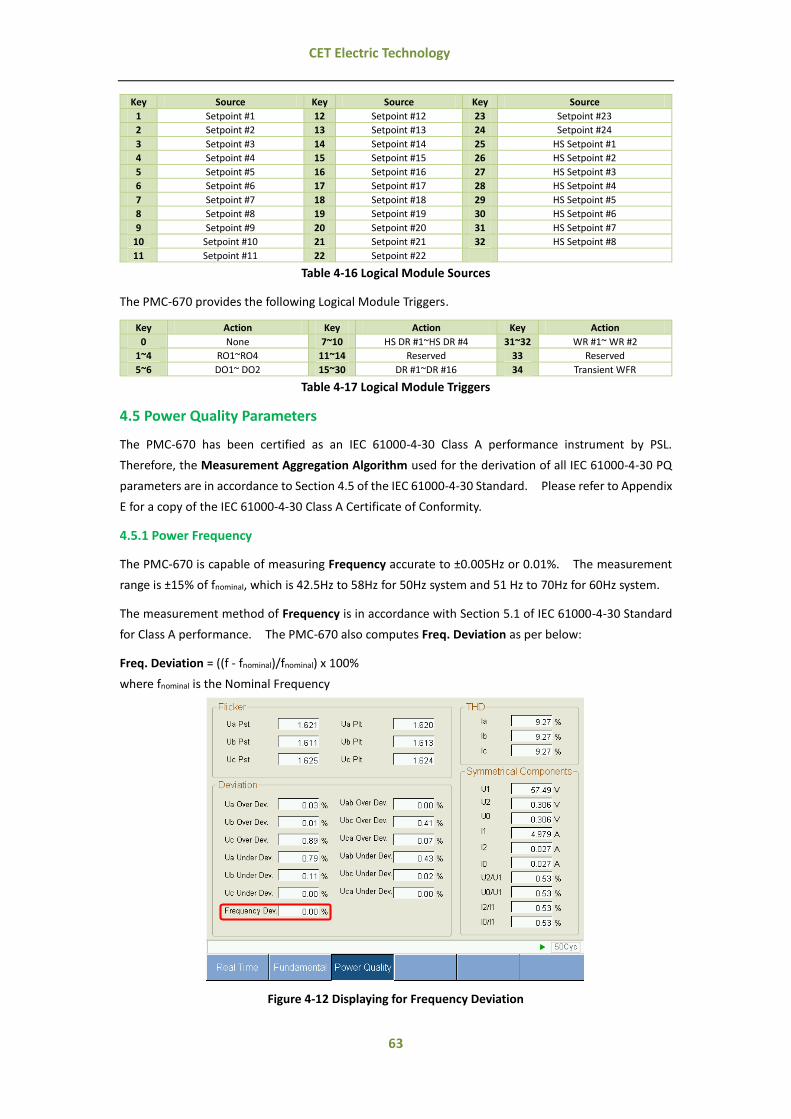
63
CET Electric Technology
Key Source Key Source Key Source
1 Setpoint #1 12 Setpoint #12 23 Setpoint #23
2 Setpoint #2 13 Setpoint #13 24 Setpoint #24
3 Setpoint #3 14 Setpoint #14 25 HS Setpoint #1
4 Setpoint #4 15 Setpoint #15 26 HS Setpoint #2
5 Setpoint #5 16 Setpoint #16 27 HS Setpoint #3
6 Setpoint #6 17 Setpoint #17 28 HS Setpoint #4
7 Setpoint #7 18 Setpoint #18 29 HS Setpoint #5
8 Setpoint #8 19 Setpoint #19 30 HS Setpoint #6
9 Setpoint #9 20 Setpoint #20 31 HS Setpoint #7
10 Setpoint #10 21 Setpoint #21 32 HS Setpoint #8
11 Setpoint #11 22 Setpoint #22
Table 4-16 Logical Module Sources
The PMC-670 provides the following Logical Module Triggers.
Key Action Key Action Key Action
0 None 7~10 HS DR #1~HS DR #4 31~32 WR #1~ WR #2
1~4 RO1~RO4 11~14 Reserved 33 Reserved
5~6 DO1~ DO2 15~30 DR #1~DR #16 34 Transient WFR
Table 4-17 Logical Module Triggers
4.5 Power Quality Parameters
The PMC-670 has been certified as an IEC 61000-4-30 Class A performance instrument by PSL.
Therefore, the Measurement Aggregation Algorithm used for the derivation of all IEC 61000-4-30 PQ
parameters are in accordance to Section 4.5 of the IEC 61000-4-30 Standard. Please refer to Appendix
E for a copy of the IEC 61000-4-30 Class A Certificate of Conformity.
4.5.1 Power Frequency
The PMC-670 is capable of measuring Frequency accurate to ±0.005Hz or 0.01%. The measurement
range is ±15% of fnominal, which is 42.5Hz to 58Hz for 50Hz system and 51 Hz to 70Hz for 60Hz system.
The measurement method of Frequency is in accordance with Section 5.1 of IEC 61000-4-30 Standard
for Class A performance. The PMC-670 also computes Freq. Deviation as per below:
Freq. Deviation = ((f - fnominal)/fnominal) x 100%
where fnominal is the Nominal Frequency
Figure 4-12 Displaying for Frequency Deviation

64
CET Electric Technology
4.5.2 Magnitude of the Supply Voltage
The measurement method of the Magnitude of the Supply Voltage parameters is in accordance with
Section 5.2 of IEC 61000-4-30 Standard for Class A performance. The measurement method is not
intended for the detection and measurement of disturbances such as Dips, Swells, Voltage
Interruptions and Transients. The RMS value includes voltage related measurements such as
Harmonics, Interharmonics, Mains Signaling, etc.
4.5.3 Flicker
The PMC-670 provides the Flicker measurements in accordance with the IEC 61000-4-15 (2010)
Standard for Class A performance using the recommended model for 120V and 230V, supporting both
50Hz and 60Hz for each model. Voltage Dips, Swells and Interruptions shall cause Pst and Plt output
values as well as "output 4 and 5 values" (see IEC 61000-4-15) to be flagged. Please refer to Section
4.5.12 Flagging Concept for detailed description.
Figure 4-13 Displaying for Flicker
4.5.4 Supply Voltage Dips and Swells
The PMC-670 supports the detection of the Supply Voltage Dips and Swells using a method that is in
accordance with Section 5.4 of IEC 61000-4-30 Standard for Class A performance.
The PMC-670 provides Dip/Swell detection for voltage quality monitoring on a per phase basis can
trigger two of the following parameters at the same time: RO/DO, PQ Log, WFR Log, DR, DWR or SMTP.
The timestamp, duration and Maximum and Minimum of per phase voltage of each Dip/Swell would be
recorded by the PMC-670.
4.5.4.1 Voltage Dip Evaluation
A Voltage Dip is characterized by a pair of data, the Residual Voltage (Ures) or Depth and Duration:
Parameter Definition
Residual Voltage The lowest Urms (1/2) value measured on any channel during the Dip
Depth The difference between the Reference Voltage (either Udin or Usr) and the Residual Voltage. It's generally expressed in percentage of the Reference Voltage.
Duration The time difference between the beginning and the end of the Voltage Dip.
Table 4-18 Dip Evaluation Parameter

65
CET Electric Technology
4.4.5.2 Voltage Swell Evaluation
A Voltage Swell is characterized by a pair of data, the Maximum Swell Voltage Magnitude and Duration:
Parameter Definition
Max. Voltage Swell Magnitude The largest Urms (1/2) value measured on any channel during the Swell.
Duration The time difference between the beginning and the end of the Voltage Swell.
Table 4-19 Swell Evaluation Parameter
4.5.4.3 Sliding Reference Voltage (Usr)
If a sliding reference is chosen for the detection of Voltage Dip or Swell, this shall be calculated using a
first order filter with a 1-min time constant. This filter is given by
Usr(n) = 0.9967 x Usr(n-1) + 0.0033 x U(10/12)rms
where
Usr(n) is the present value of the Sliding Reference Voltage
Usr(n-1) is the previous value of the Sliding Reference Voltage
U(10/12)rms is the most recent 10/12-cycle r.m.s. value
4.5.4.4 Dip/Swell Setpoint
As per IEC 41000-4-30:
Voltage Swell Detection
On polyphase systems a Swell begins when the Urms(1/2) voltage of one or more channels rises above the Swell Threshold and ends
when the Urms(1/2) voltage on all measured channels is equal to or below the Swell Threshold minus the Hysteresis voltage.
Voltage Dip Detection
On polyphase systems a Dip begins when the Urms(1/2) voltage of one or more channels is below the Dip Threshold and ends when
the Urms(1/2) voltage on all measured channels is equal to or above the Dip Threshold plus the Hysteresis voltage.
The Dip/Swell Setpoint provides the following setup parameters which can be programmed over
communications:
Setup Parameters Definition Options/Range
Dip/Swell
Reference Voltage Udin / Usr
0=Udin, 1=Usr
(Default=0)
Dip/Swell Enable Dip/Swell Enable. 0*=Disabled, 1=Enabled
Swell Limit Specify the limit of Swell. 101 to 200, Default=150
Dip Limit Specify the limit of Dip. 1 to 99, Default=50
Dip/Swell Return Specify the return value of Dip/Swell. x0.1%, Default=5
Dip/Swell Trigger Specify what action a setpoint can take when Dip / Swell becomes active
DO1 to DO2 RO1 to RO4
HS-DR#1 to HS-DR#4 WFR1 to WFR2 DR#1 to DR#16
DWR
Table 4-20 Description for Dip/Swell Parameter
The Dip Limit, Swell Limit, Voltage Interruption Threshold (See Section 4.5.5.2) and Dip/Swell Return
values should be configured to meet the following criteria:
a) The Voltage Interruption Threshold (please see Section 4.5.5.2) shall not be set below Dip Limit.
b) The Swell Limit and Dip Limit should associate with Rapid Voltage Changes in the minimum
difference between the two steady-states. The absolute value of the difference between the Dip
/Swell Limits and 100% must always be greater than the Voltage Rapid Changes in the minimum
pressure difference between the two steady-states (actual percentage).

66
CET Electric Technology
c) The Dip/Swell Return value should associate with Swell limit and Dip Limit, Dip/Swell return value
(actual value) must be less than the Dip/Swell limit (Dip, Swell of the absolute difference of the
minimum value and 100%).
d) Regardless of whether Dip/Swell is enabled, the conditions for a), b) and c) must always be met.
4.5.4.5 WFR of Dips/Swells Events
Figure 4-14 WFR of a Dip Event
Figure 4-15 RMS Plot of the same Dip Event
4.5.5 Voltage Interruptions
The PMC-670 supports the detection of Voltage Interruptions using a method that is in accordance with
Section 5.5 of IEC 61000-4-30 Standard for Class A performance.
4.5.5.1 Voltage Interruption Evaluation
On polyphase systems, a Voltage Interruption begins when the Urms (1/2) voltages of all channels fall below
the Interruption Threshold and ends when the Urms (1/2) voltage on any one channel is equal to, or
greater than, the Interruption Threshold plus the Hysteresis.
The Interruption Threshold shall not be set below the uncertainty of Residual Voltage measurement

67
CET Electric Technology
plus the value of Hysteresis. Typically, Hysteresis is equal to 2% of Udin. The Interruption Threshold
can, for example, be set to 5% of Udin.
The Duration of a voltage interruption is the time difference between the beginning and the end of the
Voltage Interruption.
4.5.5.2 Voltage Interruption Setpoint
The Voltage Interruption Setpoint provides the following setup parameters which can be programmed
over communications:
Parameter Definition
Interruption Threshold 0% to 50% ULL nominal and must be less than the Dip Limit (Default=??)
Hysteresis 0% to 100% ULL nominal and the default value is 0.5% ULL nominal
Interruption Trigger DO1 to DO2/RO1 to RO4/HS-DR#1 to HS-DR#4/WFR1 to WFR2/DR#1 to DR#16/DWR
Table 4-21 Voltage Interruption Setpoint Parameter
4.5.6 Voltage Transients
The PMC-670 provides the capability for detecting voltage transients using the sliding-window method
according to IEC 61000-4-30 with a maximum resolution of 40µs (@50Hz).
4.5.6.1 Transient Setpoint
The Transient Setpoint provides the following setup parameters which can be programmed over
communications:
Setup Parameters Definition Options
Transient Enable Transient Setpoint Enable. Disabled / Enabled
Transient Limit Specify the limit of Transient 5% to 500% V nominal (Default =??)
Transient Trigger Specify what action the Transeitn Setpoint would take when it becomes active
DO1 to DO2/RO1 to RO4/WFR/Alarm Email/DWR
Table 4-22 Setup parameters for Transient Setpoint
4.5.6.2 WFR of Transient Events
Figure 4-16 WFR of a Transient Event at 512 samples/cycle
4.5.7 Supply Voltage Unbalance
The PMC-670 provides both the Zero Sequence and Negative Sequence Voltage and Current Unbalance
measurements using Symmetrical Components and in accordance with Section 5.7 of IEC 61000-4-30
Standard for Class A performance.

68
CET Electric Technology
2V2 Unbalance x100%
V
V1,
2I2 Unbalance x100%
I
I1 (Negative Sequence Unbalance)
0V0 Unbalance x100%
V
V1,
I0I0 Unbalance x100%
I1 (Zero Sequence Unbalance)
where
U0, U1, U2 are the Zero, Positive and Negative Sequence Components for Voltage, respectively.
and
I0, I1, I2 are the Zero, Positive and Negative Sequence Components for Current, respectively.
4.5.8 Harmonics and Interharmonics
The PMC-670 provides the Harmonics and Interharmonics measurements in accordance with Sections
5.8 and 5.9 of IEC 61000-4-30 Standard for Class A performance using a 10/12 cycle gapless centered
harmonic sub-group measurement, denoted Cng for Harmonics and Cn-200-ms for Interhamonics, as per
IEC 61000-4-7:2002.
There are two methods to calculate the Harmonic Distortion (HD):
a) Fundamental Method:
Voltage Kth Harmonic/Interharmonic Distortion = X100%U
U
1
k where U1 is the Fundamental Voltage
Current Kth Harmonic/Interharmonic Distortion = %100I
I
1
k X where I1 is the Fundamental Current
b) RMS Method:
Voltage Kth Harmonic /Interharmonic Distortion = X100%
U
U
2K
1K
k
where the denominator is the RMS
Current Kth Harmonic/Interharmonic Distortion = X100%
I
I
2K
1K
k
where the denominator is the RMS
The PMC-670 also provides, in addition to Voltage Harmonics, measurements for Current Harmonics, K-
Factor, Power Harmonics and Energy Harmonics.
K-Factor
K-factor is defined as the weighted sum of the harmonic load currents according to their effects on
transformer heating, as derived from ANSI/IEEE C57.110. A K-Factor of 1.0 indicates a linear load (no
harmonics). The higher the K-Factor, the greater the harmonic heating effects.
)(
)(
K2
hh
1h
2hh
1h
max
max
h
h
I
hI
Factor
Ih = hth Harmonic Current in RMS
hmax = Highest harmonic order
4.5.8.1 Voltage and Current Harmonics and Interharmonics

69
CET Electric Technology
The following table illustrates the Voltage, Current and Power Harmonics and Interharmonics
measurements available on the PMC-670:
Ua Ub Uc U4 Ia Ib Ic I4
THD, TOHD, TEHD (%)
HD02 to HD63 (%)
TH, H01 to H63 (RMS)
Current K-Factor -- -- -- --
IHD01 to IHD63 (%)
IH01 to IH63 (RMS)
TIHD, TOIHD, TEIHD (%)
kW TH -- --
kvar TH -- --
kW H02 to H63 -- --
kvar H02 to H63 -- --
kVA H02 to H63 -- --
Table 4-23 Voltage and Current Harmonics and Interharmonics Measurements
4.5.8.2 Energy Harmonics
Please refer to Section 4.2.2 Energy Measurements for a complete description.
4.5.8.3 Screen Captures of Harmonics Measurements
Please refer to Chapter 3 User Interface for the display examples of Harmonics measurements for the
Front Panel and Web Interface, respectively.
4.5.9 Mains Signaling Voltage (MSV)
The PMC-670 provides the Mains Signaling Voltage measurements in accordance with Section 5.10 of
IEC 61000-4-30 Standard for Class A performance.
As per 5.10 of IEC 61000-4-30:
Mains Signaling Voltage is RMS voltage of mains signal.
Mains signaling voltage measurement shall be based on
Either the corresponding 10/12-cycle r.m.s. value interharmonic bin
Or the r.m.s. of the four nearest 10/12-cycle r.m.s. value interharmonic bins
The beginning of a signaling emission shall be detected when the measured value of the concerned interharmonic exceeds a
threshold. The measured values are recorded during a period of time specified by the user, in order to give the level and the
sequence of the signal voltage.
The user must select a detection threshold above 0.1% Udin as well as the length of the recording period up to 120s.
The PMC-670 can simultaneously detect three different frequencies for Mains Signaling Voltage. The
emission signaling will trigger PQ event recording with detail data such as start time, end time,
monitoring frequency, trigger phase and max value of three-phase voltage of each emission. The
waveform record log will be stored in file system in COMTRADE format and up to 8 entries can be stored
into PMC-670 memory.
The PMC-670 provides the following setup parameters which can be programmed over communications:
Setup Parameters Definition Options
MSV Enable MSV Setpoint Enable. Disabled / Enabled
MSV Frequency
This parameter specifies the frequency settings of the Mains Signaling Voltage. The device can measure
three groups of signalling voltage, each with a different frequency.
60~3000@50Hz / 70~3000@60Hz
Default: MSV #1=1000 Hz MSV #2=2000 Hz
MSV #3=3000 Hz
MSV Threshold When the measured value exceeds the threshold, a signal emission is detected.
3~1000 (Unit: 0.001Ue) Default=50

70
CET Electric Technology
Signal Emission Time The duration of signal emission. 1~120s Default=60
Table 4-24 Mains Signaling Voltage Setup Parameters
4.5.10 Voltage Deviation
As per Section 5.12 of IEC 61000-4-30:
The 10/12-cycle r.m.s value Urms can be used to assess the underdeviation and overdeviation parameters in per cent of Udin.
The underdeviation Uunder and overdeviation Uover parameters are determined by the following equations:
Voltage Overdeviation (%)
Uover = 0 if Urms < Udin
Uover = ((Urms - Udin) / Udin) x 100% if Urms ≥ Udin
Voltage Underdeviation (%)
Uunder = 0 if Urms > Udin
Uunder = ((Udin - Urms) / Udin) x 100% if Urms ≤ Udin
The PMC-670 is capable of measuring Voltage with an accuracy of 0.1% and monitoring Voltage
Deviation on line. In addition, the Voltage Deviation can be set as setpoint. The following screen
captures illustrate the display of the Deviation parameters on the Front Panel and Web Interface.
Figure 4-17 Voltage Deviation measurements via Front Panel and Web Interface
4.5.11 Rapid Voltage Changes (RVC)
4.5.11.1 About RVC
As per IEC 61000-4-30:
A rapid voltage change is a quick transition in RMS voltage between two steady-state conditions.
To measure rapid voltage change, threshold must be defined for each of the following: the minimum rate of change, the minimum
duration of the steady-state conditions, the minimum difference in voltage between the two steady-state conditions, and the
steadiness of the steady-state conditions.
The voltage during a rapid voltage change must not exceed the voltage dip and/or the voltage swell threshold, as it would
otherwise be considered as a voltage dip or swell.
The characteristic parameter of the rapid voltage change is the difference between the steady-state value reached after the
change and the initial steady-state value.
The PMC-670 provides the ability to capture RVC in accordance with the IEC 61000-4-30 Standard.
4.5.11.2 RVC Setpoint

71
CET Electric Technology
Figure 4-18 Rapid Voltage Changes
The RVC Setpoint provides the following setup parameters which can be programmed over
communications:
Setup Parameters Definition Options
RVC Enable RVC Setpoint Enable 0=Disabled (Default), 1=Enabled
Detection Mode RVC detection mode. 0=Ustep (Default), 1=Umax
Voltage Tolerance Maximum allowable fluctuation between the maximum and
minimum voltage values during the steady state condition.
0 to 100% ULL nominal
Default=1%
SS Duration Min. Minimum duration to reach the steady-state condition. 0.1 to 5 seconds Default= 10
VStep Min. Minimum voltage step change between two steady-state conditions
0.1% to 100% ULL nominal Default=1%
Rate of Min. Minimum rate of change between two steady-state conditions 0.1%/second to 100%/second Default=5%
RVC Trigger RVC Setpoint Trigger Output DO1-DO2/RO1-RO4/WFR1-
WFR2/Alarm Email/ DWR
Table 4-25 Setup Parameters for RVC Setpoint
To reach the steady-state condition, the voltage fluctuation (voltage difference in RMS between Max.
and Min.) must be less than Voltage Tolerance for a period longer than SS Duration
For the RVC Setpoint to trigger, the following conditions must be met:
a) The voltage step change between two steady-state conditions is greater than Minimum Voltage
Change Step.
b) The rate of change between two steady-state conditions is greater than Minimum of V Change
Rate.
c) The voltage during a Rapid Voltage Change must not exceed the voltage dip and/or the voltage
swell threshold, as it would otherwise be considered as a voltage dip or swell.
4.5.11.3 Rapid Voltage Changes Recorder (RVCR)

72
CET Electric Technology
Figure 4-19 WFR of a RVC Event
Figure 4-20 RMS Plot of the same RVC Event
4.5.12 Flagging Concept
As per Section 4.7 of IEC 61000-4-30:
During a dip, swell, or interruption, the measurement algorithm for other parameters (for example, frequency measurement)
might produce an unreliable value. The flagging concept therefore avoids counting single event more than once in different
parameters (for example, counting a single dip as both a dip and a frequency variation) and indicates that an aggregated value
might be unreliable.
Flagging is only triggered by dips, swells and interruptions. The detection of dips and swells is dependent on the threshold
selected by the user, and this selection will influence which data are "flagged".
The flagging concept is applicable for Class A measurement performance during measurement of power frequency, voltage
magnitude, flicker, supply voltage unbalance, voltage harmonics, voltage interharmonics, mains signalling and measurement of
underdeviation and overdeviation parameters.
If during a given time interval any value is flagged, the aggregate value indicating that value shall also be flagged. The flagged
value shall be stored and also included in the aggregation process, for example, if during a given time interval any value is flagged
the aggregated value that includes this value shall also be flagged and stored.
The PMC-670 is a certified IEC 61000-4-30 Class A device so it supports the Flagging Concept.
The Flagging Setup register (7032) defines if Flagging is enabled for a particular type of data. The

73
CET Electric Technology
Voltage Flagged (0172) and Current Flagged (0173) registers indicate if voltage and current has been
flagged with value of 1 meaning Dip/Swell events are flagged and value of 2 meaning interruption event
is flagged. The Frequency Flagged (0174) register indicates if frequency has been flagged, the flagged
data would not be involved in the Statistic Recorder.
4.5.13 EN50160 Compliance Report
Simon
The EN50160 Standard defines the Voltage Characteristics of Electricity Supplied by Public Distribution
Systems. It provides the limits within which any customer can expect voltage characteristics to remain.
For a complete definition of the non-conformity level for each of the following EN50160 parameters,
please consult the EN50160 Standard document.
The PMC-670 can measure, summarize data and statistics relevant data in accordance with the EN50160
standard. Further, the device will create a report per week for the following PQ parameters and the
report can be stored for one year.
Power Frequency, including Maximum and Minimum
Supply Voltage Variations, including Maximum and Minimum
Flicker, including Max./Min. and Cp95
Voltage Unbalance, including Max./Min. and Cp95
Harmonic Voltage, including Max./Min., average and Cp95
Mains Signal Voltage, including Max./Min. and Cp95
Rapid Voltage Changes
Swell and Dips, statistic parameters classified according to characteristic voltage and duration
Interruption, statistics parameters classified according to duration
Transient
The programming of EN50160 Log only supports communications, please refer to section 5.9.12 to set
parameters for each item. EN50160 Report can be accessed through the Front Panel or via
communications. The PMC-670 can store up to 52 logs, if there are more than 52 logs, the newest log
will replace the oldest on a FIFO basis.
The following screen captures illustrate the PMC-670's EN50160 Compliance Report available on its
Front Panel and Web Interface.
Figure 4-21 EN50160 Report Display via Front Panel and Web
4.6 Data Logging
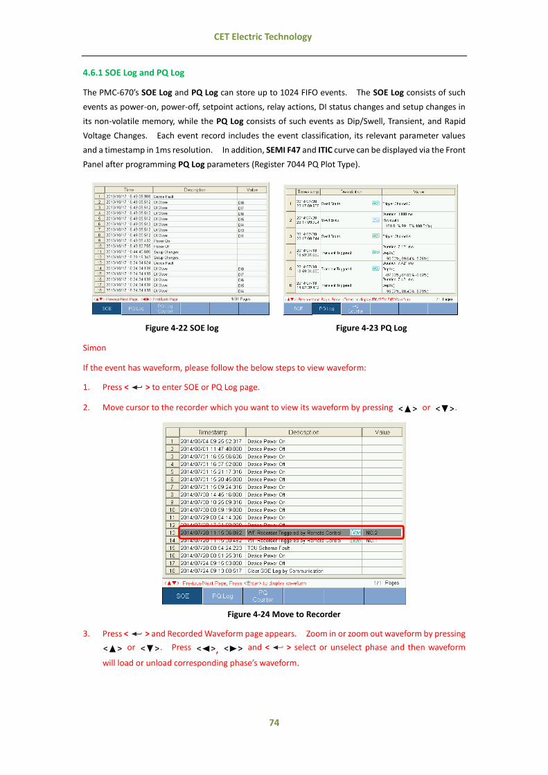
74
CET Electric Technology
4.6.1 SOE Log and PQ Log
The PMC-670’s SOE Log and PQ Log can store up to 1024 FIFO events. The SOE Log consists of such
events as power-on, power-off, setpoint actions, relay actions, DI status changes and setup changes in
its non-volatile memory, while the PQ Log consists of such events as Dip/Swell, Transient, and Rapid
Voltage Changes. Each event record includes the event classification, its relevant parameter values
and a timestamp in 1ms resolution. In addition, SEMI F47 and ITIC curve can be displayed via the Front
Panel after programming PQ Log parameters (Register 7044 PQ Plot Type).
Figure 4-22 SOE log Figure 4-23 PQ Log
Simon
If the event has waveform, please follow the below steps to view waveform:
1. Press < > to enter SOE or PQ Log page.
2. Move cursor to the recorder which you want to view its waveform by pressing or .
Figure 4-24 Move to Recorder
3. Press < > and Recorded Waveform page appears. Zoom in or zoom out waveform by pressing
or . Press , and < > select or unselect phase and then waveform
will load or unload corresponding phase’s waveform.

75
CET Electric Technology
Figure 4-25 Zoom in/out waveform and select/unselect phase
4. Press < > to return to SOE or PQ Log page.
All events can be displayed on the Front Panel interface or retrieved via communications. If there are
more than 1024 events, the newest event will replace the oldest on a FIFO basis. The SOE Log and PQ
Log can be reset from the Front Panel or via communications.
Figure 4-26 Clear PQ Log and SOE Log via Front Panel
4.6.2 Data Recorder (DR)
The PMC-670 provides 16 standard data recorders with recording interval from 1s to 40 days and 4 HS
data recorders with recording interval from 0.5 to 60 cycles, each recorder supports 16 parameters.
The recorded log is stored in non-volatile memory and will not suffer any loss in the event of a power
failure.
The programming of the DR is only supported over communications. Each DR provides the following
setup parameters:
Setup Parameters Value
Triggered Mode 0=Disabled / 1=Triggered by Timer / 2=Triggered by Setpoint Default=0
Recording Mode 0=Stop-When-Full / 1=First-In-First-Out
HS DR only be 0=Stop-when-Full.
Recording Depth 0 to 65535 (entry), default=0
Number of Parameters 1 to 16

76
CET Electric Technology
Recording Interval Standard DR: 1 second to 40 days
HS DR: 0.5 cycle to 60 cycles
Offset Time 0 to 43200 seconds, 0 indicates no offset. For standard data recorder, the offset time should be less than recording interval.
For HS data recorder, the offset time indicates recording begins after specified time.
Parameter 1 to 16 All real-time data can be configured to parameters, please see Appendix A.
Table 4-26 Setup Parameters for DR
The DR is only operational when the values of Triggered Mode, Recording Mode, Recording Depth,
Recording Interval, and Number of Parameters are all non-zero.
4.6.3 Max/Min Log
The PMC-670 provides Max Logs and Min Logs capable of recording for This Month (Since Last Reset)
and Last Month (Before Last Reset). Each record includes relevant parameter values and timestamp.
The recorded data is stored in non-volatile memory and will not suffer any loss in the event of a power
failure.
The PMC-670 Max/Min Log can record the following parameters:
Max./Min. Value of This Month (Since Last Reset) Max./Min. Value of Last Month (Before Last Reset)
Ua/Ub/Uc Max. Ua/Ub/Uc Min. Ua/Ub/Uc Max. Ua/Ub/Uc Min.
ULN avg. Max. ULN avg. Min. ULN avg. Max. ULN avg. Min.
Uab/Ubc/Uca Max. Uab/Ubc/Uca Min. Uab/Ubc/Uca Max. Uab/Ubc/Uca Min.
ULL avg. Max. ULL avg. Min. ULL avg. Max. ULL avg. Min.
Ia/Ib/Ic Max. Ia/Ib/Ic Min. Ia/Ib/Ic Max. Ia/Ib/Ic Min.
I avg. Max. I avg. Min. I avg. Max. I avg. Min.
U4 Max. U4 Min. U4 Max. U4 Min.
I4 Max. I4 Min. I4 Max. I4 Min.
∑kW Max. ∑kW Min. ∑kW Max. ∑kW Min.
∑kvar Max. ∑kvar Min. ∑kvar Max. ∑kvar Min.
∑kVA Max. ∑kVA Min. ∑kVA Max. ∑kVA Min.
∑P.F. Max. ∑P.F. Min. ∑P.F. Max. ∑P.F. Min.
FREQ Max. FREQ Min. FREQ Max. FREQ Min.
Ua/Ub/Uc THD Max. Ua/Ub/Uc THD Min. Ua/Ub/Uc THD Max. Ua/Ub/Uc THD Min.
Ia/Ib/Ic THD Max. Ia/Ib/Ic THD Min. Ia/Ib/Ic THD Max. Ia/Ib/Ic THD Min.
Ia/Ib/Ic K-Factor Max Ia/Ib/Ic K-Factor Min. Ia/Ib/Ic K-Factor Max. Ia/Ib/Ic K-Factor Min.
I4 K-Factor Max. I4 K-Factor Min. I4 K-Factor Max. I4 K-Factor Min.
U2 Unbalance Max. U2 Unbalance Min. U2 Unbalance Max. U2 Unbalance Min.
U0 Unbalance Max. U0 Unbalance Min. U0 Unbalance Max. U0 Unbalance Min.
I2 Unbalance Max. I2 Unbalance Min. I2 Unbalance Max. I2 Unbalance Min.
I0 Unbalance Max. I0 Unbalance Min. I0 Unbalance Max. I0 Unbalance Min.
Table 4-27 Max/Min Measurements
All the Max/Min Log can be accessed over communications and the Max/Min Log can be reset over
Front Panel or via communications.
Figure 4-27 Clear Max./Min. Log

77
CET Electric Technology
4.6.4 Interval Energy Recorder (IER)
The PMC-670’s IER can store up events per five minutes for kWh/kvarh Import/Export and kVAh in its
non-volatile memory. Each event record includes the event classification, its relevant parameter
values and a timestamp.
All events can be retrieved via communications for display. If there are more than 65535 events, the
newest event will replace the oldest event on a FIFO basis. The IER can be reset from the Front Panel
or via communications.
The programming of the IER is only supported over communications. IER provides the following setup
parameters:
Setup Parameters Value
Recording Mode 0=Disabled / 1=Stop-When-Full / 2=First-In-First-Out
Recording Depth 0 to 65535 (entry)
Recording Interval 0=5mins / 1=10mins / 2=15mins / 3=30mins / 4=60mins
Start Time 20YY/MM/DD, HH:MM:SS
Number of Parameters 1 to 5
Parameter 1 to 5 kWh, kvarh Import/Export and kVAh Total
Table 4-28 Setup Parameters for IER
The IER is only operational when the values of Recording Mode, Recording Depth, Recording Interval,
Start Time and Number of Parameters are all non-zero. When the current time meets the Start Time,
the Interval Energy Log will start to record.
4.6.5 WFR (Waveform Recorder)
The PMC-670 provides 2 independent WFRs with a combined total of 128 entries. Each WFR can
simultaneously capture 4-phase voltage and current at a maximum resolution of 512 samples per cycles.
WFR on the PMC-670 can be triggered by Setpoints, Dip/Swell, Transient, and Rapid Voltage Change
through communications manually. The manual trigger command has a higher priority. When WFR
is already in progress, other WFR commands will be ignored until the present recording has completed.
The WFR has a capacity of 128 entries organized in a FIFO basis, with the newest waveform log replacing
the oldest one. The WFR log is stored in the device’s non-volatile memory with COMTRADE file format
and will not suffer any loss in the event of power failure. The log can be downloaded from the on-
board FTP server.
The programming of the WFR is only supported over communications. The WFR provides the
following setup parameters:
Setup Parameters Value/Option
Recording Depth 0 to 128 (entry)
# of Samples 0*=16 Samples/640 Cycles 1=32 Samples/320 Cycles
2=64 Samples/160 Cycles 3=128 Samples/80 Cycle
4=256 Samples/40 Cycles 5=512 Samples /20 Cycles
Pre-fault Cycle 2 to 192 (16 Samples 640 Cycles) 2 to 96 (32 Samples/320 Cycles)
2 to 48 (64 Samples/160 Cycles) 2 to 24 (128 Samples/80 Cycles)
2 to 12 (256 Samples/40 Cycles) 2 to 6 (512 Samples/20 Cycles)
Table 4-29 Setup Parameters for WFR
All WFR logs can be retrieved via communications by our PecStar® iEMS or our free PMC Setup Software
for display.
4.6.6 Disturbance Waveform Recorder (DWR)
The PMC-670 provides disturbance waveform recording including U1 to U4, I1 to I4, 8 DIs, 4 ROs and 2
DOs. The disturbance waveform recording can be triggered by dip, swell, transient, rapid voltage
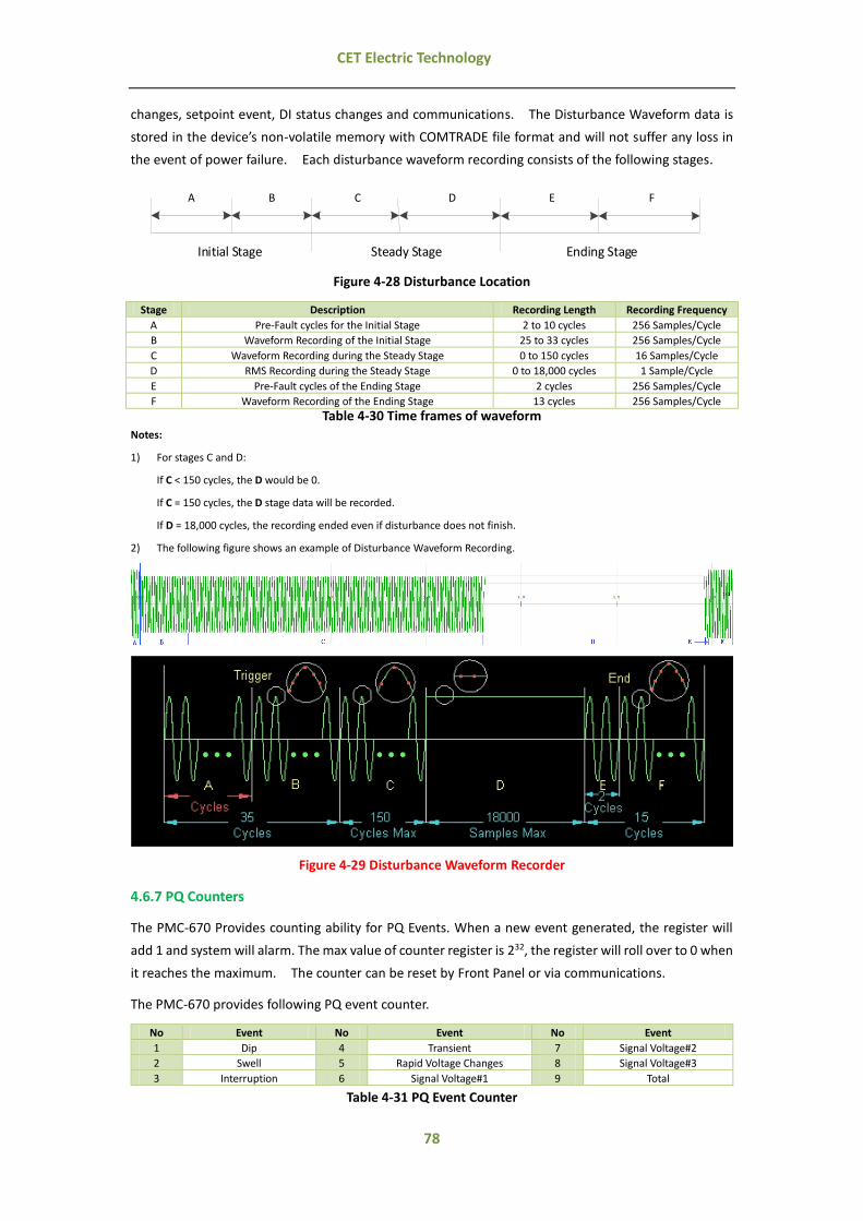
78
CET Electric Technology
changes, setpoint event, DI status changes and communications. The Disturbance Waveform data is
stored in the device’s non-volatile memory with COMTRADE file format and will not suffer any loss in
the event of power failure. Each disturbance waveform recording consists of the following stages.
A B C D E F
Initial Stage Ending StageSteady Stage
Figure 4-28 Disturbance Location
Stage Description Recording Length Recording Frequency
A Pre-Fault cycles for the Initial Stage 2 to 10 cycles 256 Samples/Cycle
B Waveform Recording of the Initial Stage 25 to 33 cycles 256 Samples/Cycle
C Waveform Recording during the Steady Stage 0 to 150 cycles 16 Samples/Cycle
D RMS Recording during the Steady Stage 0 to 18,000 cycles 1 Sample/Cycle
E Pre-Fault cycles of the Ending Stage 2 cycles 256 Samples/Cycle
F Waveform Recording of the Ending Stage 13 cycles 256 Samples/Cycle
Table 4-30 Time frames of waveform
Notes:
1) For stages C and D:
If C < 150 cycles, the D would be 0.
If C = 150 cycles, the D stage data will be recorded.
If D = 18,000 cycles, the recording ended even if disturbance does not finish.
2) The following figure shows an example of Disturbance Waveform Recording.
Figure 4-29 Disturbance Waveform Recorder
4.6.7 PQ Counters
The PMC-670 Provides counting ability for PQ Events. When a new event generated, the register will
add 1 and system will alarm. The max value of counter register is 232, the register will roll over to 0 when
it reaches the maximum. The counter can be reset by Front Panel or via communications.
The PMC-670 provides following PQ event counter.
No Event No Event No Event
1 Dip 4 Transient 7 Signal Voltage#2
2 Swell 5 Rapid Voltage Changes 8 Signal Voltage#3
3 Interruption 6 Signal Voltage#1 9 Total
Table 4-31 PQ Event Counter

79
CET Electric Technology
All PQ counters can be reset over the Front Panel or via communications:
Table 4-30 Clear PQ Counters
4.6.8 Data Backup
The PMC-670 comes standard with a maximum of 250MB storage capacity for backing up logs such as
WFR, DR, IER, EN50160 Report, SOE, PQ and TOU DR (…). WFR, MSVR and DWR are stored in
COMTRADE format.
4.7 Time Synchronization
The PMC-670 is equipped with a 6ppm, battery-backed real-time clock that has a maximum error of
0.5s per day. If the supply power is lost or removed, the internal back-up battery keeps the real-time
clock running until power is restored.
The PMC-670 provides timestamps for all recorded data so it's extremely important for the clock to be
properly configured to achieve precise events time stamping for energy and power quality analysis.
There are several methods to set and synchronize the PMC-670’s clock, please refer to following
description.
Simon
Modbus can be used to synchronize the PMC-670’s clock through communications. Set the Clock
Source (7086) as RTC via the Front Panel or communications, then set the register values of 60000 to
60005 or 9000 to 9005, please refer to Table5-71 Time Registers for detailed description.
4.7.1 PMC Setup
PMC Setup can be used to manually set the time of an individual device through the “Set Time” function
under the Manual Operate menu using the computer’s clock as the clock source. Please refer to the
PMC Setup's User Manual for a complete description.
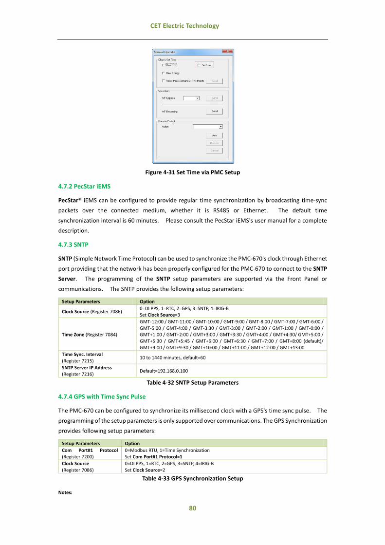
80
CET Electric Technology
Figure 4-31 Set Time via PMC Setup
4.7.2 PecStar iEMS
PecStar® iEMS can be configured to provide regular time synchronization by broadcasting time-sync
packets over the connected medium, whether it is RS485 or Ethernet. The default time
synchronization interval is 60 minutes. Please consult the PecStar iEMS's user manual for a complete
description.
4.7.3 SNTP
SNTP (Simple Network Time Protocol) can be used to synchronize the PMC-670's clock through Ethernet
port providing that the network has been properly configured for the PMC-670 to connect to the SNTP
Server. The programming of the SNTP setup parameters are supported via the Front Panel or
communications. The SNTP provides the following setup parameters:
Setup Parameters Option
Clock Source (Register 7086) 0=DI PPS, 1=RTC, 2=GPS, 3=SNTP, 4=IRIG-B Set Clock Source=3
Time Zone (Register 7084)
GMT-12:00 / GMT-11:00 / GMT-10:00 / GMT-9:00 / GMT-8:00 / GMT-7:00 / GMT-6:00 /
GMT-5:00 / GMT-4:00 / GMT-3:30 / GMT-3:00 / GMT-2:00 / GMT-1:00 / GMT-0:00 / GMT+1:00 / GMT+2:00 / GMT+3:00 / GMT+3:30 / GMT+4:00 / GMT+4:30/ GMT+5:00 / GMT+5:30 / GMT+5:45 / GMT+6:00 / GMT+6:30 / GMT+7:00 / GMT+8:00 (default)/
GMT+9:00 / GMT+9:30 / GMT+10:00 / GMT+11:00 / GMT+12:00 / GMT+13:00
Time Sync. Interval
(Register 7215) 10 to 1440 minutes, default=60
SNTP Server IP Address (Register 7216)
Default=192.168.0.100
Table 4-32 SNTP Setup Parameters
4.7.4 GPS with Time Sync Pulse
The PMC-670 can be configured to synchronize its millisecond clock with a GPS's time sync pulse. The
programming of the setup parameters is only supported over communications. The GPS Synchronization
provides following setup parameters:
Setup Parameters Option
Com Port#1 Protocol (Register 7200)
0=Modbus RTU, 1=Time Synchronization Set Com Port#1 Protocol=1
Clock Source
(Register 7086)
0=DI PPS, 1=RTC, 2=GPS, 3=SNTP, 4=IRIG-B
Set Clock Source=2
Table 4-33 GPS Synchronization Setup
Notes:
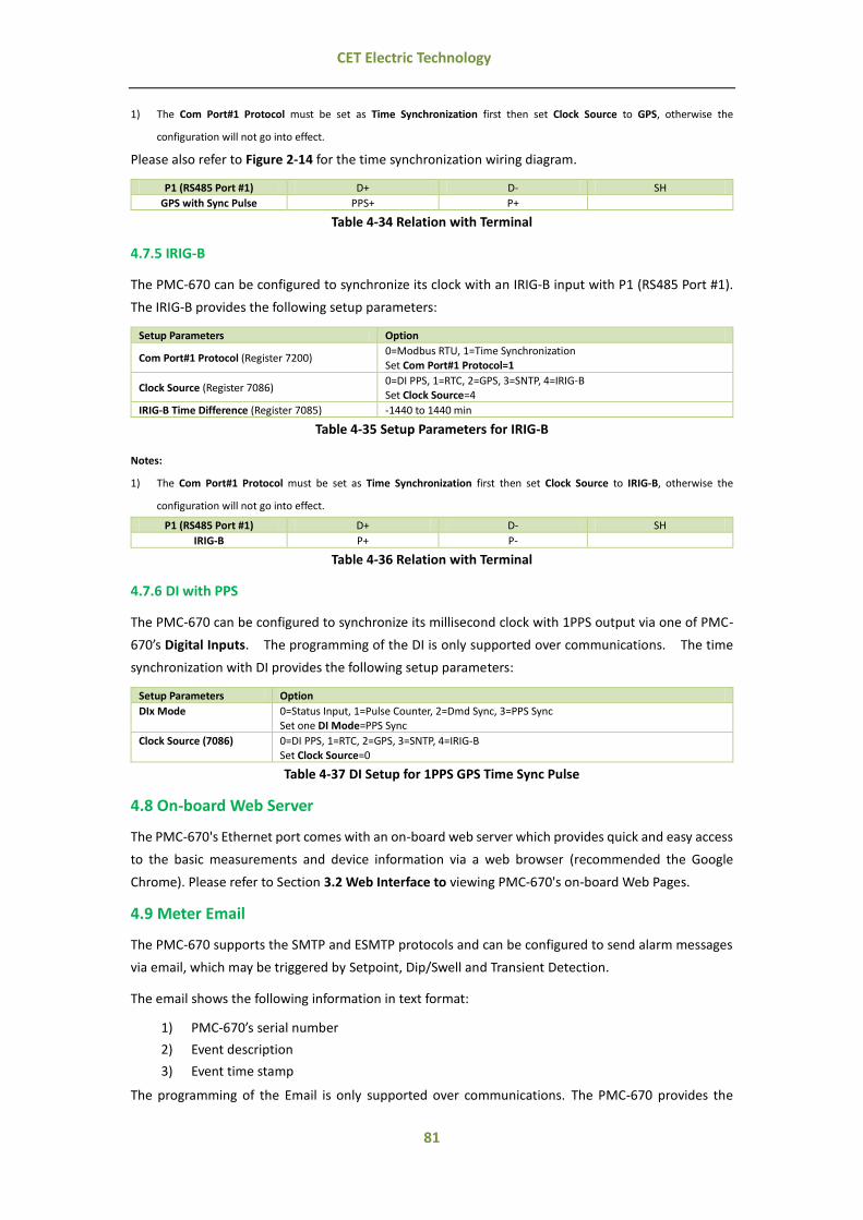
81
CET Electric Technology
1) The Com Port#1 Protocol must be set as Time Synchronization first then set Clock Source to GPS, otherwise the
configuration will not go into effect.
Please also refer to Figure 2-14 for the time synchronization wiring diagram.
P1 (RS485 Port #1) D+ D- SH
GPS with Sync Pulse PPS+ P+
Table 4-34 Relation with Terminal
4.7.5 IRIG-B
The PMC-670 can be configured to synchronize its clock with an IRIG-B input with P1 (RS485 Port #1).
The IRIG-B provides the following setup parameters:
Setup Parameters Option
Com Port#1 Protocol (Register 7200) 0=Modbus RTU, 1=Time Synchronization Set Com Port#1 Protocol=1
Clock Source (Register 7086) 0=DI PPS, 1=RTC, 2=GPS, 3=SNTP, 4=IRIG-B Set Clock Source=4
IRIG-B Time Difference (Register 7085) -1440 to 1440 min
Table 4-35 Setup Parameters for IRIG-B
Notes:
1) The Com Port#1 Protocol must be set as Time Synchronization first then set Clock Source to IRIG-B, otherwise the
configuration will not go into effect.
P1 (RS485 Port #1) D+ D- SH
IRIG-B P+ P-
Table 4-36 Relation with Terminal
4.7.6 DI with PPS
The PMC-670 can be configured to synchronize its millisecond clock with 1PPS output via one of PMC-
670’s Digital Inputs. The programming of the DI is only supported over communications. The time
synchronization with DI provides the following setup parameters:
Setup Parameters Option
DIx Mode 0=Status Input, 1=Pulse Counter, 2=Dmd Sync, 3=PPS Sync Set one DI Mode=PPS Sync
Clock Source (7086) 0=DI PPS, 1=RTC, 2=GPS, 3=SNTP, 4=IRIG-B Set Clock Source=0
Table 4-37 DI Setup for 1PPS GPS Time Sync Pulse
4.8 On-board Web Server
The PMC-670's Ethernet port comes with an on-board web server which provides quick and easy access
to the basic measurements and device information via a web browser (recommended the Google
Chrome). Please refer to Section 3.2 Web Interface to viewing PMC-670's on-board Web Pages.
4.9 Meter Email
The PMC-670 supports the SMTP and ESMTP protocols and can be configured to send alarm messages
via email, which may be triggered by Setpoint, Dip/Swell and Transient Detection.
The email shows the following information in text format:
1) PMC-670’s serial number
2) Event description
3) Event time stamp
The programming of the Email is only supported over communications. The PMC-670 provides the

82
CET Electric Technology
following setup parameters:
Setup Parameters Option
SMTP TCP Port 0 to 65535 (Default=25)
SMTP Server IP Address IP Address of the SMTP Server
Source Email Address Source email address that appears in the “From” field of the email. This string is up to 35 characters long.
Logon Password Set the logon password to send an email using the Source Email account. This string is up to 19
characters long.
Destination Email Address Destination email address that appears in the “To” field of the email. This string is up to 35
characters long.
Table 4-38 Email Setup Parameters
4.10 Ethernet Gateway
The PMC-670's Ethernet port together with its RS485 port can be used as an Ethernet Gateway (EGATE)
to allow communications between a Modbus Master on the Ethernet network and a network of serial
devices connected to the PMC-670's RS485 port.
To use the PMC-670 as an Ethernet Gateway, the following parameters should be configured via the
Front Panel:
1) Set the IP address, Subnet Mask and Gateway Address
2) Set the Protocol of the RS485 Port as EGATE
3) Use 6000 (cannot be configured) as the IP Port No. to connect to PMC-670's Ethernet Gateway with your software
4) Please refer to Section 3.1.2 or Section 3.2.4.3.7 for more information
For detailed information on how to use the Ethernet Gateway feature, please refer to PMC Setup's User
Manual.

83
CET Electric Technology
Chapter 5 Modbus Register Map
This chapter provides a complete description of the Modbus register map (Protocol Version 2.1) for the
PMC-670 Advanced Utility Power Quality Analyzer to facilitate the development of 3rd party Modbus
RTU communications driver for accessing information on the PMC-670.
The PMC-670 supports the following Modbus functions:
1) Read Holding Registers (Function Code 0x03)
2) Force Single Coil (Function Code 0x05)
3) Preset Multiple Registers (Function Code 0x10)
4) Read Recording Files (Function Code 0x14)
For a complete Modbus Protocol Specification, please visit http://www.modbus.org.
5.1 Basic Measurements
Register Property Description Format Scale/Unit
0000 RO Ua1,4 Float V
0002 RO Ub1 Float V
0004 RO Uc1 Float V
0006 RO ULN average1 Float V
0008 RO Uab Float V
0010 RO Ubc Float V
0012 RO Uca Float V
0014 RO ULL average Float V
0016 RO Ia Float A
0018 RO Ib Float A
0020 RO Ic Float A
0022 RO I average Float A
0024 RO kWa1 Float W
0026 RO kWb1 Float W
0028 RO kWc1 Float W
0030 RO ∑kW Float W
0032 RO kvara1 Float var
0034 RO kvarb1 Float var
0036 RO kvarc1 Float var
0038 RO ∑kvar Float var
0040 RO kVAa1 Float VA
0042 RO kVAb1 Float VA
0044 RO kVAc1 Float VA
0046 RO ∑kVA Float VA
0048 RO P.F.a1 Float --
0050 RO P.F.b1 Float --
0052 RO P.F.c1 Float --
0054 RO ∑P.F. Float --
0056 RO Freq5 Float Hz
0058 RO U4 Float V
0060 RO I4 Float A
0062~0069 RO Reserved UINT16
0070 RO Ua(WYE) / Uab(Delta) Angle UINT16 x100, °
0071 RO Ub(WYE) /Ubc(Delta) Angle UINT16 x100, °
0072 RO Uc(WYE) / Uca(Delta) Angle UINT16 x100, °
0073 RO Ia Angle UINT16 x100, °
0074 RO Ib Angle UINT16 x100, °
0075 RO Ic Angle UINT16 x100, °
0076 RO DI Status2 UINT16 --
0077 RO DO/RO Status3 UINT16 --
0078 RO Alarm Status #16 UINT32 --
0080 RO Alarm Status #26 UINT32 --
0082 RO SOE Log Pointer7 UINT32 --
0084 RO PQ Log Pointer7 UINT32 --
0086 RO WFR Log#1 Pointer8 Bitmap --

84
CET Electric Technology
0088 RO WFR Log#2 Pointer8 Bitmap --
0090 RO IER Pointer9 Bitmap --
0092 RO HS DR Log #1 Pointer9 UINT32 --
0094 RO HS DR Log #2 Pointer9 UINT32 --
0096 RO HS DR Log #3 Pointer9 UINT32 --
0098 RO HS DR Log #4 Pointer9 UINT32 --
0100 RO Reserved UINT32
0102 RO Reserved UINT32
0104 RO Reserved UINT32
0106 RO Reserved UINT32
0108 RO DR Log #1 Pointer9 UINT32 --
0110 RO DR Log #2 Pointer9 UINT32 --
0112 RO DR Log #3 Pointer9 UINT32 --
0114 RO DR Log #4 Pointer9 UINT32 --
0116 RO DR Log #5 Pointer9 UINT32 --
0118 RO DR Log #6 Pointer9 UINT32 --
0120 RO DR Log #7 Pointer9 UINT32 --
0122 RO DR Log #8 Pointer9 UINT32 --
0124 RO DR Log #9 Pointer9 UINT32 --
0126 RO DR Log #10 Pointer9 UINT32 --
0128 RO DR Log #11 Pointer9 UINT32 --
0130 RO DR Log #12 Pointer9 UINT32 --
0132 RO DR Log #13Pointer9 UINT32 --
0134 RO DR Log #14 Pointer9 UINT32 --
0136 RO DR Log #15 Pointer9 UINT32 --
0138 RO DR Log #16 Pointer9 UINT32 --
0140 RO EN50160 Pointer UINT32 --
0142 RO Mains Signalling Voltage #1 Triggered WFR Pointer UINT32 --
0144 RO Mains Signalling Voltage #2 Triggered WFR Pointer UINT32 --
0146 RO Mains Signalling Voltage #3 Triggered WFR Pointer UINT32 --
0148 RO Reserved UINT32
0150 RO DWR Pointer UINT32 --
0152 RO Historical TOU Data Record Pointer UINT32 --
0154~0159 RO Reserved --
0160 RO Real-time data timestamp-second UINT32 s
0162 RO Real-time data timestamp-millisecond UINT16 ms
0163 RO Frequency timestamp-second5 UINT32 s
0165 RO Frequency timestamp-millisecond5 UINT16 ms
0166 RO Pst timestamp-second UINT32 s
0168 RO Pst timestamp- millisecond UINT16 ms
0169 RO Plt timestamp-second UINT32 s
0171 RO Plt timestamp- millisecond UINT16 ms
0172 RO Voltage Flagged10 UINT16 --
0173 RO Current Flagged UINT16 --
0174 RO Freq Flagged UINT16 --
0175 RO Plt Flagged 11 UINT16 --
0176 RO Pst Flagged 11 UINT16 --
0177 RO Reserved UINT16
0178 RO Dip Event Counter UINT32 --
0180 RO Swell Event Counter UINT32 --
0182 RO Interruption Event Counter UINT32 --
0184 RO Transient Event Counter UINT32 --
0186 RO RVS Event Counter UINT32 --
0188 RO Mains Signalling Voltage #1 Event Counter UINT32 --
0190 RO Mains Signalling Voltage #2 Event Counter UINT32 --
0192 RO Mains Signalling Voltage #3 Event Counter UINT32 --
0194 RO Total PQ Event UINT32 --
Table 5-1 Basic Measurements
Notes:
1) When the Wiring Mode is Delta, the per phase line-to-neutral voltages, kWs, kvars, kVAs and PFs have no meaning, and
their registers are reserved.
2) For the DI Status register, the bit values of B0 to B7 represent states of DI1 to DI8, respectively, with “1” meaning active
(closed) and “0” meaning inactive (open).
3) For the RO/DO Status register, the bit values of B0 to B3 represent the states of RO1 to RO4 while the bit values of B4 to B5
represent the states of DO1 to DO2, respectively, with “1” meaning active (closed) and “0” meaning inactive (open).

85
CET Electric Technology
4) The following registers can be refreshed at the speed of 10 cycle (50Hz)/12cycle (60Hz), 50 cycle (50Hz) / 60 cycle (60Hz),
150 cycle (50Hz) / 180 cycle (60Hz), 10mins, or 2hours by setting Data Refreshing Speed (7030).
0000~0060
0070~0075
0160~0162 (Real-time data timestamp-second, Real-time data timestamp-millisecond)
0166~0167 (Pst timestamp-second)
5) The following registers can be refreshed every 1s or 10s by setting Frequency Refreshing Cycle (7031).
0056~0057 (Freq)
0163~0165 (Frequency timestamp-second, Frequency timestamp-millisecond)
6) The Alarm Status registers indicate the various alarm states with a bit value of 1 meaning active and 0 meaning inactive.
The following tables illustrate the details of the Alarm Status #1 and Alarm Status #2.
Alarm Status #1
Bit Alarm Event Bit Alarm Event Bit Alarm Event Bit Alarm Event
B0 Setpoint #1 B8 Setpoint #9 B16 Setpoint #17 B24 Setpoint #25
B1 Setpoint #2 B9 Setpoint #10 B17 Setpoint #18 B25 Setpoint #26
B2 Setpoint #3 B10 Setpoint #11 B18 Setpoint #19 B26 Setpoint #27
B3 Setpoint #4 B11 Setpoint #12 B19 Setpoint #20 B27 Setpoint #28
B4 Setpoint #5 B12 Setpoint #13 B20 Setpoint #21 B28 Setpoint #29
B5 Setpoint #6 B13 Setpoint #14 B21 Setpoint #22 B29 Setpoint #30
B6 Setpoint #7 B14 Setpoint #15 B22 Setpoint #23 B30 Setpoint #31
B7 Setpoint #8 B15 Setpoint #16 B23 Setpoint #24 B31 Setpoint #32
Table 5-2 Alarm Status#1 Register (Register 0078)
Alarm Status #2
Bit Alarm Event Bit Alarm Event Bit Alarm Event
B0 Logical Module #1 B3 Logical Module #4 B6 Logical Module #7
B1 Logical Module #2 B4 Logical Module #5 B7 Logical Module #8
B2 Logical Module #3 B5 Logical Module #6 B8~B31 Reserved
Table 5-3 Alarm Status#2 Register (Register 0080)
7) The range of the SOE / PQ Log Pointer is between 0 and FFFFFFFFH. The SOE / PQ Log Pointer is incremented by one for
every SOE / PQ Log generated and will roll over to 0 if its current value is FFFFFFFFH. Since the SOE / PQ Log Pointer is a
32-bit value and the SOE / PQ Log capacity is relatively small with only 1024 entries in the PMC-670. If a Clear SOE / PQ
Log is performed from the Front Panel or via communications, the SOE / PQ Log Pointer will be reset to zero. Therefore,
any 3rd party software should assume that a Clear SOE / PQ Log action has been performed if it sees the SOE / PQ Log
Pointer rolling over to zero or to a value that is smaller than its own pointer. In this case, the new SOE / PQ Log Pointer
also indicates the number of logs in the SOE / PQ Log if it is less than 1024, otherwise, there will always be 1024 entries.
8) The PMC-670 has two waveform Recorder Logs (WFR Log #1 and WFR #2). Each WFR Log has a pointer that indicates its
current logging position. The range of the WFR Log Pointer is between 0 and 0xFFFFFFFFH. The WFR Log Pointer is
incremented by one for every WFR Log generated and will roll over to 0 if its current value is 0xFFFFFFFFH. A value of zero
indicates that the device does not contain any WFR Log. Since the WFR Log Pointers are 32-bit values, an assumption has
been made that these pointers will never roll over. If a Clear WFR log is performed via communications, the WFR Log
Pointers will be reset to zero.
9) The PMC-670 has one Interval Energy Pointer, 4 HS Data Record logs and 16 DR Logs (DR Log #1 to 16). Each DR Log has a
pointer that indicates its current logging position. The range of the Interval Energy Pointer and DR Log Pointer is between
0 and 0XFFFFFFFFH. The DR Log Pointer is incremented by one for every real-time DR Log generated and will roll over to 0
if its current value is 0xFFFFFFFFH. A value of zero indicates that the device does not contain any DR Log. If a Clear All
DR Log is performed via the Front Panel or communications, all DR Log Pointers will be reset to zero.
10) For Voltage Flagged register, there are three values 0, 1 and 2 which indicate voltage is not flagged, voltage is flagged as
Dips, swells and other non-interruptible event, and voltage is flagged as interruption event, respectively.
11) The Plt Stamp and Pst Flagged only be active when 7032=1.
5.2 PQ Measurements
Register Property Description Format Unit
0200 RO Ua (WYE) / Uab (Delta) Deviation1 Float %
0202 RO Ub (WYE) / Ubc (Delta) Deviation1 Float %
0204 RO Uc (WYE) / Uca (Delta) Deviation1 Float %
0206 RO Freq Deviation2 Float Hz
0208 RO U2 Unbalance3 Float %

86
CET Electric Technology
0210 RO U0 Unbalance3 Float %
0212 RO I2 Unbalance3 Float %
0214 RO I0 Unbalance3 Float %
0216 RO U1 Float V
0218 RO U2 Float V
0220 RO U0 Float V
0222 RO I1 Float A
0224 RO I2 Float A
0226 RO I0 Float A
0228 RO Ua (WYE) / Uab (Delta) Pst Float --
0230 RO Ub (WYE) / Ubc (Delta) Pst Float --
0232 RO Uc (WYE) / Uca (Delta) Pst Float --
0234 RO Ua (WYE) / Uab (Delta) Plt Float --
0236 RO Ub( WYE) / Ubc (Delta) Plt Float --
0238 RO Uc (WYE) / Uca (Delta) Plt Float --
0240 RO Over Ua (WYE) Deviation Float %
0242 RO Over Ub (WYE) Deviation Float %
0244 RO Over Uc (WYE) Deviation Float %
0246 RO Under Uab (WYE) Deviation Float %
0248 RO Under Ubc (WYE) Deviation Float %
0250 RO Under Uca (WYE) Deviation Float %
0252 RO Over Uab Deviation Float %
0254 RO Over Ubc Deviation Float %
0256 RO Over Uca Deviation Float %
0258 RO Under Uab Deviation Float %
0260 RO Under Ubc Deviation Float %
0262 RO Under Uca Deviation Float %
0264 RO Mains Signalling Voltage #1 Phase A Voltage Float V
0266 RO Mains Signalling Voltage #1 Phase B Voltage Float V
0268 RO Mains Signalling Voltage #1 Phase C Voltage Float V
0270 RO Mains Signalling Voltage #2 Phase A Voltage Float V
0272 RO Mains Signalling Voltage #2 Phase B Voltage Float V
0274 RO Mains Signalling Voltage #2 Phase C Voltage Float V
0276 RO Mains Signalling Voltage #3 Phase A Voltage Float V
0278 RO Mains Signalling Voltage #3 Phase B Voltage Float V
0280 RO Mains Signalling Voltage #3 Phase C Voltage Float V
Table 5-4 PQ Measurements
Notes:
1) Please refer to Section 4.5.10 Voltage Deviation for a detailed description.
2) Please refer to Section 4.5.1 Power Frequency for a detailed description.
3) Please refer to Section 4.5.7 Supply Voltage Unbalance for a detailed description.
5.3 Energy Measurements
5.3.1 RMS Energy
Register Property Description Format Unit
0300 RW kWh Import UINT32 kWh
0302 RW kWh Export UINT32 kWh
0304 RO kWh Net INT32 kWh
0306 RO kWh Total UINT32 kWh
0308 RW kvarh Import INT32 kvarh
0310 RW kvarh Export UINT32 kvarh
0312 RO kvarh Net INT32 kvarh
0314 RO kvarh Total UINT32 kvarh
0316 RW kVAh UINT32 kVAh
0318~0324 RO Reserved
0326 RO kWh Import Float W.s
0328 RO kWh Export Float W.s
0330 RO kWh Net Float W.s
0332 RO kWh Total Float W.s
0334 RO kvarh Import Float var.s
0336 RO kvarh Export Float var.s
0338 RO karh Net Float var.s
0340 RO kvarh Total Float var.s

87
CET Electric Technology
0342 RO kVAh Float VA.s
0344~0350 RO Reserved
Table 5-5 RMS Energy
5.3.2 Fundamental Energy
Register Property Description Format Unit
0352 RW kWh Import UINT32 kWh
0354 RW kWh Export UINT32 kWh
0356 RW kvarh Import UINT32 kvarh
0358 RW kvarh Export UINT32 kvarh
0360~0366 RO Reserved
0368 RO kW.s Import Float W.s
0370 RO kW.s Export Float W.s
0372 RO kvar.s Import Float var.s
0374 RO kvar.s Export Float var.s
0376~0382 RO Reserved
Table 5-6 Fundamental Energy
5.3.3 Harmonic Energy
Register Property Description Format Unit
60400 RW kWh Import TH UINT32 kWh
60402 RW kvarh Import TH UINT32 kvarh
60404 RW kWh Export TH UINT32 kWh
60406 RW kvarh Export TH UINT32 kvarh
60408~60411 RW Reserved
60412 RW kWh Import H02 UINT32 kWh
60414 RW kvarh Import H02 UINT32 kvarh
60416 RW kWh Export H02 UINT32 kWh
60418 RW kvarh Export H02 UINT32 kvarh
…….
60644 RW kWh Import H31 UINT32 kWh
60646 RW kvarh Import H31 UINT32 kvarh
60648 RW kWh Export H31 UINT32 kWh
60650 RW kvarh Export H31 UINT32 kvarh
60652~60659 RO Reserved
60660 RO kWs Import Harmonic Float W.s
60662 RO kvars Import Harmonic Float var.s
60664 RO kWs Export Harmonic Float W.s
60666 RO kvars Export Harmonic Float var.s
60668~60671 RO Reserved
60672 RO kWs Import H02 Float W.s
60674 RO kvars Import H02 Float var.s
60676 RO kWs Export H02 Float W.s
60678 RO kvars Export H02 Float var.s
… … … … …
60904 RO kWs Import H31 Float W.s
60906 RO kvars Import H31 Float var.s
60908 RO kWs Export H31 Float W.s
60910 RO kvars Export H31 Float var.s
Table 5-7 Harmonics Energy
5.4 Pulse Counter
Register Property Description Format Scale
0680 RW DI1 Counter UINT32
0 to 999,999,999
0682 RW DI2 Counter UINT32
0684 RW DI3 Counter UINT32
0686 RW DI4 Counter UINT32
0688 RW DI5 Counter UINT32
0690 RW DI6 Counter UINT32
0692 RW DI7 Counter UINT32
0694 RW DI8 Counter UINT32
Table 5-8 Pulse Counter
Notes:

88
CET Electric Technology
1) DI Counter Register Value = DI Counter *DI Pulse Weight, for example, DI Pulse Weight is 5 and DI Counter is 400, then DI
Counter Register Value = 5*400 =2000 .
2) The Counter registers have a maximum value of 999,999,999 and will roll over to zero automatically when it is reached.
5.5 Harmonic Measurements
5.5.1 Fundamental
Register Property Description Format Unit
0700 RO Ua (WYE) / Uab (Delta)² Float V
0702 RO Ub (WYE) / Ubc (Delta)² Float V
0704 RO Uc (WYE) / Uca (Delta)² Float V
0706 RO ULN (WYE) / ULL (Delta) Average Float V
0708 RO Ia Float A
0710 RO Ib Float A
0712 RO Ic Float A
0714 RO I Average Float A
0716 RO U4 Float V
0718 RO I4 Float A
0720 RO kWa1 Float W
0722 RO kWb1 Float W
0724 RO kWc1 Float W
0726 RO Total kW Float W
0728 RO kvar a1 Float var
0730 RO kvar b1 Float var
0732 RO kvar c1 Float var
0734 RO Total kvar Float var
0736 RO kVA a1 Float VA
0738 RO kVA b1 Float VA
0740 RO kVA c1 Float VA
0742 RO Total kVA Float VA
0744 RO dPF a1 Float --
0746 RO dPF b1 Float --
0748 RO dPF c1 Float --
0750 RO Total dPF Float --
Table 5-9 Fundamental Component Measurements
Notes:
1) When the Wiring Mode is Delta, the per phase kWs, kvars, kVAs and dPF have no meaning, and their registers are reserved.
2) The 0700 to 0706 registers can be refreshed at the speed of 10 cycle (50Hz) / 12cycle (60Hz), 50 cycle (50Hz) / 60 cycle
(60Hz), 150 cycle (50Hz) / 180 cycle (60Hz), 10min, 2hour by setting Data Refreshing Speed (7030).
5.5.2 K Factor, THD, TOHD and TEHD
Register Property Description Format Unit
0752 RO Ia K Factor Float --
0754 RO Ib K Factor Float --
0756 RO Ic K Factor Float --
0758 RO I4 K Factor Float --
0760 RO Ua (WYE) / Uab (Delta) THD Float 100%/V
0762 RO Ub (WYE) / Ubc (Delta) THD Float 100%/V
0764 RO Uc (WYE) / Uca (Delta) THD Float 100%/V
0766 RO U4 THD Float 100%/V
0768 RO Ia THD Float 100%/A
0770 RO Ib THD Float 100%/A
0772 RO Ic THD Float 100%/A
0774 RO I4 THD Float 100%/A
0776 RO Ua (WYE) / Uab (Delta) TOHD Float 100%/V
0778 RO Ub (WYE) / Ubc (Delta) TOHD Float 100%/V
0780 RO Uc (WYE) / Uca (Delta) TOHD Float 100%/V
0782 RO U4 TOHD Float 100%/V
0784 RO Ia TOHD Float 100%/A
0786 RO Ib TOHD Float 100%/A
0788 RO Ic TOHD Float 100%/A
0790 RO I4 TEHD Float 100%/A
0792 RO Ua (WYE) / Uab (Delta) TEHD Float 100%/V

89
CET Electric Technology
0794 RO Ub (WYE) / Ubc (Delta) TEHD Float 100%/V
0796 RO Uc (WYE) / Uca (Delta) TEHD Float 100%/V
0798 RO U4 TEHD Float 100%/V
0800 RO Ia TEHD Float 100%/A
0802 RO Ib TEHD Float 100%/A
0804 RO Ic TEHD Float 100%/A
0806 RO I4 TEHD Float 100%/A
Table 5-10 K Factor, THD, TOHD and TEHD Measurements
Notes:
1) All harmonics measurements registers can be refreshed at the speed of 10 cycle (50Hz)/12cycle (60Hz), 50 cycle (50Hz)/60
cycle (60Hz), 150 cycle (50Hz)/180 cycle (60Hz), 10min, 2hour by setting Data Refreshing Speed (7030.
2) There are two methods to calculate the Harmonic Distortion, for details please refer to section 4.5.8. For fundamental
method, the unit is 100%. For RMS method, the units of voltage and current are V and A respectively.
5.5.3 Individual Harmonic
Register Property Description Format Scale/Unit
0808 RO Ua (WYE) / Uab (Delta) HD02 Float 100%, V
0810 RO Ub (WYE) / Ubc (Delta) HD02 Float 100%, V
0812 RO Uc (WYE) / Uca (Delta) HD02 Float 100%, V
0814 RO U4 HD02 Float 100%, V
0816 RO Ia HD02 Float 100%, A
0818 RO Ib HD02 Float 100%, A
0820 RO Ic HD02 Float 100%, A
0822 RO I4 HD03 Float 100%, A
0824 RO Ua (WYE) / Uab (Delta) HD03 Float 100%, V
0826 RO Ub (WYE) / Ubc (Delta) HD03 … 100%, V
0828 RO Uc (WYE) / Uca (Delta) HD03 Float 100%, V
0830 RO U4 HD03 Float 100%, V
0832 RO Ia HD03 Float 100%, A
0834 RO Ib HD03 Float 100%, A
0836 RO Ic HD03 Float 100%, A
0838 RO I4 HD03 Float 100%, A
… … Float --
1784 RO Ua (WYE) / Uab (Delta) HD63 Float 100%, V
1786 RO Ub (WYE) / Ubc (Delta) HD63 Float 100%, V
1788 RO Uc (WYE) / Uca (Delta) HD63 Float 100%, V
1790 RO U4 HD63 Float 100%, V
1792 RO Ia HD63 Float 100%, A
1794 RO Ib HD63 Float 100%, A
1796 RO Ic HD63 Float 100%, A
1798 RO I4 HD63 Float 100%, A
Table 5-11 Individual Harmonic
5.5.4 Interharmonics
Register Property Description Format Unit
1800 RO Ua (WYE) / Uab (Delta) TIHD1 Float 100%
1802 RO Ub (WYE) / Ubc (Delta) TIHD1 Float 100%
1804 RO Uc (WYE) / Uca (Delta) TIHD1 Float 100%
1806 RO U4 TIHD Float 100%
1808 RO Ia TIHD Float 100%
1810 RO Ib TIHD Float 100%
1812 RO Ic TIHD Float 100%
1814 RO I4 TIHD Float 100%
1816 RO Ua (WYE) / Uab (Delta) TOIHD1 Float 100%
1818 RO Ub (WYE) / Ubc (Delta) TOIHD1 Float 100%
1820 RO Uc (WYE) / Uca (Delta) TOIHD1 Float 100%
1822 RO U4 TOIHD Float 100%
1824 RO Ia TOIHD Float 100%
1826 RO Ib TOIHD Float 100%
1828 RO Ic TOIHD Float 100%
1830 RO I4 TOIHD Float 100%
1832 RO Ua (WYE) / Uab (Delta) TEIHD1 Float 100%
1834 RO Ub (WYE) / Ubc (Delta) TEIHD1 Float 100%

90
CET Electric Technology
1836 RO Uc (WYE) / Uca (Delta) TEIHD1 Float 100%
1838 RO U4 TEIHD Float 100%
1840 RO Ia TEIHD Float 100%
1842 RO Ib TEIHD Float 100%
1844 RO Ic TEIHD Float 100%
1846 RO I4 TEIHD Float 100%
1848 RO U a(WYE) / Uab (Delta) IHD01 Float 100%, V
1850 RO Ub (WYE) / Ubc (Delta) IHD01 Float 100%, V
1852 RO Uc (WYE) / Uca (Delta) IHD01 Float 100%, V
1854 RO U4 IHD0 Float 100%, V
1856 RO Ia IHD0 Float 100%, A
1858 RO Ib IHD0 Float 100%, A
1860 RO Ic IHD0 Float 100%, A
1862 RO I4 IHD0 Float 100%, A
1864 RO Ua (WYE) / Uab (Delta) IHD011 Float 100%, V
1866 RO Ub (WYE) / Ubc (Delta) IHD011 Float 100%, V
1868 RO Uc (WYE) / Uca (Delta) IHD011 Float 100%, V
1870 RO U4 IHD01 Float 100%, V
1872 RO Ia IHD01 Float 100%, A
1874 RO Ib IHD01 Float 100%, A
1876 RO Ic IHD01 Float 100%, A
1878 RO I4 IHD01 Float 100%, A
1880 RO Ua (WYE) / Uab (Delta) IHD021 Float 100%, V
1882 RO Ub (WYE) / Ubc (Delta) IHD021 Float 100%, V
1884 RO Uc (WYE) / Uca (Delta) IHD021 Float 100%, V
1886 RO U4 IHD02 Float 100%, V
1888 RO Ia IHD02 Float 100%, A
1890 RO Ib IHD02 Float 100%, A
1892 RO Ic IHD02 Float 100%, A
1894 RO I4 IHD02 Float 100%, A
1896 RO Ua (WYE) / Uab (Delta) IHD031 Float 100%, V
1898 RO Ub (WYE) / Ubc (Delta) IHD031 Float 100%, V
1900 RO Uc (WYE) / Uca (Delta) IHD031 Float 100%, V
1902 RO U4 IHD03 Float 100%, V
1904 RO Ia IHD03 Float 100%, A
1906 RO Ib IHD03 Float 100%, A
1908 RO Ic IHD03 Float 100%, A
1910 RO I4 IHD03 Float 100%, A
… … … … …
2856 RO Ua (WYE) / Uab (Delta) IHD631 Float 100%, V
2858 RO Ub (WYE) / Ubc (Delta) IHD631 Float 100%, V
2860 RO Uc (WYE) / Uca (Delta) IHD631 Float 100%, V
2862 RO U4 IHD63 Float 100%, V
2864 RO Ia IHD63 Float 100%, A
2866 RO Ib IHD63 Float 100%, A
2868 RO Ic IHD63 Float 100%, A
2870 RO I4 IHD63 Float 100%, A
Table 5-12 Interharmonics
Notes:
1) The voltage TIHD/ TOIHD/TEIHD/02 to 63 Interharmonic are phase voltage measurements and they will be automatically
changed to line voltage measurements when wiring mode is Delta.
2) All harmonics measurements registers can be refreshed at the speed of 10 cycle (50Hz)/12cycle (60Hz), 50 cycle (50Hz)/60
cycle (60Hz), 150 cycle (50Hz)/180 cycle (60Hz), 10min, 2hour by setting Data Refreshing Speed (Register 7030).
3) There are two methods to calculate the Harmonic Distortion, for details please refer to section 4.5.8. For fundamental
method, the unit is 100%. For RMS method, the units of voltage and current are V and A respectively.
5.5.5 Harmonic Power
Register Property Description Format Unit
61000 RO kW TH Float W
61002 RO kvar TH Float var
61004 RO kWa H02¹ Float W
61006 RO kWb H02¹ Float W
61008 RO kWc H02¹ Float W
61010 RO kW TH02 Float W

91
CET Electric Technology
61012 RO kvara H02¹ Float var
61014 RO kvarb H02¹ Float var
61016 RO kvarc H02¹ Float var
61018 RO kvar TH02 Float var
61020 RO kVAa H02¹ Float VA
61022 RO kVAb H02¹ Float VA
61024 RO kVAc H02¹ Float VA
61026 RO kVA TH02 Float VA
……
62468 RO kWa H63¹ Float W
62470 RO kWb H63¹ Float W
62472 RO kWc H63¹ Float W
62474 RO kW TH63 Float W
62476 RO kvara H63¹ Float var
62478 RO kvarb H63¹ Float var
62480 RO kvarc H63¹ Float var
62482 RO kvar TH63 Float var
62484 RO kVAa H63¹ Float VA
62486 RO kVAb H63¹ Float VA
62488 RO kVAc H63¹ Float VA
62490 RO kVA TH63 Float VA
Table 5-13 Harmonic Power
Notes:
1) When the Wiring Mode is Delta, per phase kW, kvar, kVA have no meaning, and their registers are reserved.
5.6 Demand
5.6.1 Present Demand
5.6.1.1 Real-time Demand
Register Property Description Format Unit
3000 RO Ua1 Float V
3002 RO Ub1 Float V
3004 RO Uc1 Float V
3006 RO ULN average Float V
3008 RO Uab Float V
3010 RO Ubc Float V
3012 RO Uca Float V
3014 RO ULL average Float V
3016 RO Ia Float A
3018 RO Ib Float A
3020 RO Ic Float A
3022 RO I average Float A
3024 RO U4 Float A
3026 RO I4 Float A
3028 RO kWa Import1 Float W
3030 RO kWb Import1 Float W
3032 RO kWc Import1 Float W
3034 RO ∑kW Float W
3036 RO kvara Import1 Float var
3038 RO kvarb Import1 Float var
3040 RO kvarc Import1 Float var
3042 RO ∑kvar Float var
3044 RO kVAa Import1 Float VA
3046 RO kVAb Import1 Float VA
3048 RO kVAc Import1 Float VA
3050 RO ∑kVA Float VA
3052 RO P.F.a1 Float --
3054 RO P.F.b1 Float --
3056 RO P.F.c1 Float --
3058 RO ∑P.F. Float Hz
3060 RO Frequency Float HZ
Table 5-14 Real-time Demand Measurement

92
CET Electric Technology
Notes:
1) When the Wiring Mode is Delta, the phase voltage demand, kWs demand, kvars demand, kVAs demand and PFs demand
have no meaning, and their registers are reserved.
5.6.1.2 Power Quality Demand
Register Property Description Format Unit
3062 RO Ua Deviation1 Float 100%
3064 RO Ub Deviation1 Float 100%
3066 RO Uc Deviation1 Float 100%
3068 RO Freq Deviation Float Hz
3070 RO U2 Unbalance Float --
3072 RO U0 Unbalance Float --
3074 RO I2 Unbalance Float --
3076 RO I0 Unbalance Float --
Table 5-15 Power Quality Demand
Notes:
1) The voltage demands are phase measurements and they will be automatically changed to line voltage demand
measurements when the wring mode is delta.
5.6.1.3 Harmonic Demand
Register Property Description Format Scale/Unit
3078 RO Ia K Factor Float --
3080 RO Ib K Factor Float --
3082 RO Ic K Factor Float --
3084 RO I4 K Factor Float --
3086 RO Ua (WYE) / Uab (Delta) THD Float 100%
3088 RO Ub (WYE) / Ubc (Delta) THD Float 100%
3090 RO Uc (WYE) / Uca (Delta) THD Float 100%
3092 RO U4 THD Float 100%
3094 RO Ia THD Float 100%
3096 RO Ib THD Float 100%
3098 RO Ic THD Float 100%
3100 RO I4 THD Float 100%
3102 RO Ua/Uab TOHD Float 100%
3104 RO Ub (WYE) / Ubc (Delta) TOHD Float 100%
3106 RO Uc (WYE) / Uca (Delta) TOHD Float 100%
3108 RO U4 TOHD Float 100%
3110 RO Ia TOHD Float 100%
3112 RO Ib TOHD Float 100%
3114 RO Ic TOHD Float 100%
3116 RO I4 TOHD Float 100%
3118 RO Ua/Uab TEHD Float 100%
3120 RO Ub (WYE) / Ubc (Delta) TEHD Float 100%
3122 RO Uc (WYE) / Uca (Delta) TEHD Float 100%
3124 RO U4 TEHD Float 100%
3126 RO Ia TEHD Float 100%
3128 RO Ib TEHD Float 100%
3130 RO Ic TEHD Float 100%
3132 RO I4 TEHD Float 100%
3134 RO Ua/Uab HD02 Float 100%, V
3136 RO Ub (WYE) / Ubc (Delta) HD02 Float 100%, V
3138 RO Uc (WYE) / Uca (Delta) HD02 Float 100%, V
3140 RO U4 HD02 Float 100%, V
3142 RO Ia HD02 Float 100%, A
3144 RO Ib HD02 Float 100%, A
3146 RO Ic HD02 Float 100%, A
3148 RO I4 HD02 Float 100%, A
3150 RO Ua/Uab HD03 Float 100%, V
3152 RO Ub (WYE) / Ubc (Delta) HD03 Float 100%, V
3154 RO Uc(WYE)/Uca(Delta) HD03 Float 100%, V
3156 RO U4 HD03 Float 100%, V
3158 RO Ia HD03 Float 100%, A

93
CET Electric Technology
3160 RO Ib HD03 Float 100%, A
3162 RO Ic HD03 Float 100%, A
3164 RO I4 HD03 Float 100%, A
… … … … …
4110 RO Ua/Uab HD63 Float 100%, V
4112 RO Ub (WYE) / Ubc (Delta) HD63 Float 100%, V
4114 RO Uc (WYE) / Uca (Delta) HD63 Float 100%, V
4116 RO U4 HD63 Float 100%, V
4118 RO Ia HD63 Float 100%, A
4120 RO Ib HD63 Float 100%, A
4122 RO Ic HD63 Float 100%, A
4124 RO I4 HD63 Float 100%, A
Table 5-16 Harmonic Measurement Demand
Notes:
1) The voltage harmonic demands are phase measurements and they will be automatically changed to line voltage harmonic
demand measurements when the wring mode is delta.
2) There are two methods to calculate the Harmonic Distortion, for details please refer to section 4.5.8. For fundamental
method, the unit is 100%. For RMS method, the units of voltage and current are V and A respectively.
5.6.1.4 Export Power Real-Time Demand
Register Property Description Format Unit
4126 RO kWa Export Float W
4128 RO kWb Export Float W
4130 RO kWc Export Float W
4132 RO kW Total Export Float W
4134 RO kvara Export Float var
4136 RO kvarb Export Float var
4138 RO kvarc Export Float var
4140 RO kvar Total Export Float var
Table 5-17 Export Power Real-Time Demand
Notes:
1) When the wring mode is delta, the kWa, kWb, kWc, kvara, kvarb and kvarc have no meaning, and their register will be
reserved.
5.6.2 Predicted Demand
Register Property Description Format Unit
4200 RO Ua1 Float V
4202 RO Ub1 Float V
4204 RO Uc1 Float V
4206 RO ULN Average Float V
4208 RO Uab Float V
4210 RO Ubc Float V
4212 RO Uca Float V
4214 RO ULL Average Float V
4216 RO Ia Float A
4218 RO Ib Float A
4220 RO Ic Float A
4222 RO I Average Float A
4224 RO U4 Float V
4226 RO I4 Float A
4228 RO kWa Import1 Float A
4230 RO kWb Import1 Float W
4232 RO kWc Import1 Float W
4234 RO ∑Kw Float W
4236 RO kvara Import1 Float W
4238 RO kvarb Import1 Float var
4240 RO kvarc Import1 Float var
4242 RO ∑kvar Import Float var
4244 RO kVAa Import1 Float var
4246 RO kVAb Import1 Float VA

94
CET Electric Technology
4248 RO kVAc Import1 Float VA
4250 RO ∑kVA Float VA
4252 RO P.F.a Float VA
4254 RO P.F.b Float --
4256 RO P.F.c Float --
4258 RO ∑P.F. Float --
4260 RO Freq Float Hz
Table 5-18 Predicted Demand
Notes:
1) When the Wiring Mode is Delta, per phase V/kW/kvar/kVA/PF Predicted demand have no meaning, and their registers are
reserved.
5.6.3 Max Value per Demand Period
5.6.3.1 Real-Time Max
Register Property Description Format Unit
4300 RO Ua1 Float V
4302 RO Ub1 Float V
4304 RO Uc1 Float V
4306 RO ULN Average Float V
4308 RO Uab Float V
4310 RO Ubc Float V
4312 RO Uca Float V
4314 RO ULL Average Float V
4316 RO Ia Float A
4318 RO Ib Float A
4320 RO Ic Float A
4322 RO I Average Float A
4324 RO U4 Float V
4326 RO I4 Float A
4328 RO kWa1 Float W
4330 RO kWb1 Float W
4332 RO kWc1 Float W
4334 RO ∑kW Float W
4336 RO kvara1 Float var
4338 RO kvarb1 Float var
4340 RO kvarc1 Float var
4342 RO ∑kvar Float var
4344 RO kVAa1 Float VA
4346 RO kVAb1 Float VA
4348 RO kVAc1 Float VA
4350 RO ∑kVA Float VA
4352 RO P.F.a1 Float --
4354 RO P.F.b1 Float --
4356 RO P.F.c1 Float --
4358 RO ∑P.F. Float --
4360 RO Freq Float Hz
Table 5-19 Max Value per Demand Period- Real-Time
Notes:
1) When the Wiring Mode is Delta, per phase U/kW/kvar/kVA/PF Max demands have no meaning, and their registers are
reserved.
5.6.3.2 Power Quality
Register Property Description Format Unit
4362 RO Ua (WYE) / Uab (Delta) Deviation1 Float 100%
4364 RO Ub (WYE) / Ubc (Delta) Deviation1 Float 100%
4366 RO Uc (WYE) / Uca (Delta) Deviation1 Float 100%
4368 RO Freq Deviation Float Hz
4370 RO U2 Unbalance Float --
4372 RO U0 Unbalance Float --
4374 RO I2 Unbalance Float --

95
CET Electric Technology
4376 RO I0 Unbalance Float --
Table 5-20 Max Value per Demand Period-Power Quality
Notes:
1) When the Wiring Mode is Delta, per phase Voltage Deviation demand will be changed to line Voltage Deviation demand
automatically.
5.6.3.3 Harmonic
Register Property Description Format Unit
4378 RO Ia K Factor Float --
4380 RO Ib K Factor Float --
4382 RO Ic K Factor Float --
4384 RO I4 K Factor Float --
4386 RO Ua (WYE) / Uab (Delta) THD1 Float %
4388 RO Ub (WYE) / Ubc (Delta) THD1 Float %
4390 RO Uc (WYE) / Uca (Delta) THD1 Float %
4392 RO U4 THD Float %
4394 RO Ia THD Float %
4396 RO Ib THD Float %
4398 RO Ic THD Float %
4400 RO I4 THD Float %
4402 RO Ua (WYE) / Uab (Delta) TOHD1 Float %
4404 RO Ub (WYE) / Ubc (Delta) TOHD1 Float %
4406 RO Uc (WYE) / Uca (Delta) TOHD1 Float %
4408 RO U4 TOHD Float %
4410 RO Ia TOHD Float %
4412 RO Ib TOHD Float %
4414 RO Ic TOHD Float %
4416 RO I4 TOHD Float %
4418 RO Ua (WYE) / Uab (Delta) TEHD1 Float %
4420 RO Ub (WYE) / Ubc (Delta) TEHD1 Float %
4422 RO Uc (WYE) / Uca (Delta) TEHD1 Float %
4424 RO U4 TEHD Float %
4426 RO Ia TEHD Float %
4428 RO Ib TEHD Float %
4430 RO Ic TEHD Float %
4432 RO I4 TEHD Float %
4434 RO Ua (WYE) / Uab (Delta) HD021 Float 100%, V
4436 RO Ub (WYE) / Ubc (Delta) HD021 Float 100%, V
4438 RO Uc (WYE) / Uca (Delta) HD021 Float 100%, V
4440 RO U4 HD02 Float 100%, V
4442 RO Ia HD02 Float 100%, A
4444 RO Ib HD02 Float 100%, A
4446 RO Ic HD02 Float 100%, A
4448 RO I4 HD02 Float 100%, A
4450 RO Ua (WYE) / Uab (Delta) HD031 Float 100%, V
4452 RO Ub (WYE) / Ubc (Delta) HD031 Float 100%, V
4454 RO Uc (WYE) / Uca (Delta) HD031 Float 100%, V
4456 RO U4 HD03 Float 100%, V
4458 RO Ia HD03 Float 100%, A
4460 RO Ib HD03 Float 100%, A
4462 RO Ic HD03 Float 100%, A
4464 RO I4 HD03 Float 100%, A
… … … ... ...
5410 RO Ua (WYE) / Uab (Delta) HD631 Float 100%, V
5412 RO Ub (WYE) / Ubc (Delta) HD631 Float 100%, V
5414 RO Uc (WYE) / Uca (Delta) HD631 Float 100%, V
5416 RO U4 HD63 Float 100%, V
5418 RO Ia HD63 Float 100%, A
5420 RO Ib HD63 Float 100%, A
5422 RO Ic HD63 Float 100%, A
5424 RO I4 HD63 Float 100%, A
Table 5-21 Max Value per Demand Period-Harmonic

96
CET Electric Technology
Notes:
1) The voltage harmonic demands are phase measurements and they will be automatically changed to line voltage harmonic
demand measurements when the wring mode is delta.
2) There are two methods to calculate the Harmonic Distortion, for details please refer to section 4.5.8. For fundamental
method, the unit is 100%. For RMS method, the units of voltage and current are V and A respectively.
5.6.3.4 Export Power Max.
Register Property Description Format Unit
5426 RO kWa Export Float W
5428 RO kWb Export Float W
5430 RO kWc Export Float W
5432 RO kW Total Export Float W
5434 RO kvara Export Float var
5436 RO kvarb Export Float var
5438 RO kvarc Export Float var
5440 RO Total kvar Export Float var
Table 5-22 Max Value per Demand Period-Export Power
Notes:
1) When the wring mode is delta, the kWa, kWb, kWc, kvara, kvarb and kvarc have no meaning, and their register will be
reserved.
5.6.4 Min Value per Demand Period
5.6.4.1 Real-time Min.
Register Property Description Format Unit
5500 RO Ua1 Float V
5502 RO Ub1 Float V
5504 RO Uc1 Float V
5506 RO ULN Average Float V
5508 RO Uab Float V
5510 RO Ubc Float V
5512 RO Uca Float V
5514 RO ULL Average Float V
5516 RO Ia Float A
5518 RO Ib Float A
5520 RO Ic Float A
5522 RO I Average Float A
5524 RO U4 Float V
5526 RO I4 Float A
5528 RO kWa1 Float W
5530 RO kWb1 Float W
5532 RO kWc1 Float W
5534 RO ∑kW Float W
5536 RO kvara1 Float W
5538 RO kvarb1 Float var
5540 RO kvarc1 Float var
5542 RO ∑kvar Float var
5544 RO kVAa1 Float VA
5546 RO kVAb1 Float VA
5548 RO kVAc1 Float VA
5550 RO ∑kVA Float VA
5552 RO P.F.a Float --
5554 RO P.F.b Float --
5556 RO P.F.c Float --
5558 RO ∑P.F. Float --
5560 RO Freq Float Hz
Table 5-23 Min Value per Demand Period-Real-Time
Notes:
1) When the Wiring Mode is Delta, per phase V/kW/kvar/kVA/PF Min. demands have no meaning, and their registers are
reserved.

97
CET Electric Technology
5.6.4.2 Power Quality Min.
Register Property Description Format Unit
5562 RO Ua (WYE) / Uab (Delta) Deviation1 Float %
5564 RO Ub (WYE) / Ubc (Delta) Deviation1 Float %
5566 RO Uc (WYE) / Uca (Delta) Deviation1 Float %
5568 RO Freq Deviation Float Hz
5570 RO U2 Unbalance Float --
5572 RO U0 Unbalance Float --
5574 RO I2 Unbalance Float --
5576 RO I0 Unbalance Float --
Table 5-24 Min Value per Demand Period-Power Quality
Notes:
1) When the Wiring Mode is Delta, per phase Voltage Deviation demand will be changed to line Voltage Deviation demand
automatically.
5.6.4.3 Harmonic Min.
Register Property Description Format Unit
5578 RO Ia K Factor Float --
5580 RO Ib K Factor Float --
5582 RO Ic K Factor Float --
5584 RO I4 K Factor Float --
5586 RO Ua (WYE) / Uab (Delta) THD1 Float %
5588 RO Ub (WYE) / Ubc (Delta) THD1 Float %
5590 RO Uc (WYE) / Uca (Delta) THD1 Float %
5592 RO U4 THD Float %
5594 RO Ia THD Float %
5596 RO Ib THD Float %
5598 RO Ic THD Float %
5600 RO I4 THD Float %
5602 RO Ua (WYE) / Uab (Delta) TOHD1 Float %
5604 RO Ub (WYE) / Ubc (Delta) TOHD1 Float %
5606 RO Uc (WYE) / Uca (Delta) TOHD1 Float %
5608 RO U4 TOHD Float %
5610 RO Ia TOHD Float %
5612 RO Ib TOHD Float %
5614 RO Ic TOHD Float %
5616 RO I4 TOHD Float %
5618 RO Ua (WYE) / Uab (Delta) TEHD1 Float %
5620 RO Ub (WYE) / Ubc (Delta) TEHD1 Float %
5622 RO Uc (WYE) / Uca (Delta) TEHD1 Float %
5624 RO U4 TEHD Float %
5626 RO Ia TEHD Float %
5628 RO Ib TEHD Float %
5630 RO Ic TEHD Float %
5632 RO I4 TEHD Float %
5634 RO Ua (WYE) / Uab (Delta) HD021 Float 100%, V
5636 RO Ub (WYE) / Ubc (Delta) HD021 Float 100%, V
5638 RO Uc (WYE) / Uca (Delta) HD021 Float 100%, V
5640 RO U4 HD02 Float 100%, V
5642 RO Ia HD02 Float 100%, A
5644 RO Ib HD02 Float 100%, A
5646 RO Ic HD02 Float 100%, A
5648 RO I4 HD02 Float 100%, A
5650 RO Ua (WYE) / Uab (Delta) HD031 Float 100%, V
5652 RO Ub (WYE) / Ubc (Delta) HD031 Float 100%, V
5654 RO Uc (WYE) / Uca (Delta) HD031 Float 100%, V
5656 RO U4 HD03 Float 100%, V
5658 RO Ia HD03 Float 100%, A
5660 RO Ib HD03 Float 100%, A
5662 RO Ic HD03 Float 100%, A
5664 RO I4 HD03 Float 100%, A
… … … ... ...

98
CET Electric Technology
6610 RO Ua (WYE) / Uab (Delta) HD631 Float 100%, V
6612 RO Ub (WYE) / Ubc (Delta) HD631 Float 100%, V
6614 RO Uc (WYE) / Uca (Delta) HD631 Float 100%, V
6616 RO U4 HD63 Float 100%, V
6618 RO Ia HD63 Float 100%, A
6620 RO Ib HD63 Float 100%, A
6622 RO Ic HD63 Float 100%, A
6624 RO I4 HD63 Float 100%, A
Table 5-25 Min Value per Demand Period-Harmonic
Notes:
1) The voltage harmonic demands are phase measurements and they will be automatically changed to line voltage harmonic
demand measurements when the wring mode is delta.
2) There are two methods to calculate the Harmonic Distortion, for details please refer to section 4.5.8. For fundamental
method, the unit is 100%. For RMS method, the units of voltage and current are V and A, respectively.
5.6.4.4 Export Power Min.
Register Property Description Format Unit
6626 RO kWa Export1 Float W
6628 RO kWb Export1 Float W
6630 RO kWc Export1 Float W
6632 RO Total kW Export Float W
6634 RO kvara Export1 Float var
6636 RO kvarb Export1 Float var
6638 RO kvarc Export1 Float var
6640 RO Total kvar Export Float var
Table 5-26 Min Value per Demand Period- Export Power
Notes:
1) When the wring mode is delta, the kWa, kWb, kWc, kvara, kvarb and kvarc have no meaning, and their register will be
reserved.
5.6.5 Max. Demand Log
Register Property Description Format Unit
6700~6705 RO ∑kW Max. Demand of This Month (since Last Reset)
See Table 5-28
Max. Demand
Data Structure
W
6706~6711 RO ∑kvar Max. Demand of This Month (since Last Reset) var
6712~6717 RO ∑kVA Max. Demand of This Month (since Last Reset) VA
6718~6723 RO Ia Max. Demand of This Month (since Last Reset) A
6724~6729 RO Ib Max. Demand of This Month (since Last Reset) A
6730~6735 RO Ic Max. Demand of This Month (since Last Reset) A
6736~6741 RO ∑kW Max. Demand of Last Month (before Last Reset) W
6742~6747 RO ∑kvar Max. Demand of Last Month (before Last Reset) var
6748~6753 RO ∑kVA Max. Demand of Last Month (before Last Reset) VA
6754~6759 RO Ia Max. Demand of Last Month (before Last Reset) A
6760~6765 RO Ib Max. Demand of Last Month (before Last Reset) A
6766~6771 RO Ic Max. Demand of Last Month (before Last Reset) A
Table 5-27 Max. Demand Log
Notes:
1) Max. Demand Data Structure:
Offset Property Description Format Range/Note
+0 RO Max. Demand INT32 /
+2 RO High-order Byte: Year
UINT16 0-99 (Year-2000)
Low-order Byte: Month 1 to 12
+3 RO High-order Byte: Day
UINT16 1 to 31
Low-order Byte: Hour 0 to 23
+4 RO High-order Byte: Minute
UINT16 0 to 59
Low-order Byte: Second 0 to 59
+5 RO Millisecond UINT16 0 to 999
Table 5-28 Max. Demand Data Structure
2) There are two self-read methods:

99
CET Electric Technology
0: indicates that the transfer will happen at 0:00 of the last day of every month.
A non-zero value indicates the transfer will happen at a specific time based on the formula [Day*100+Hour] where
1≤Day≤28 and 0≤Hour≤23. For example, the value 1512 means the Max. Demand of Current Month will be
transferred to the Max. Demand of Last Month at 12:00am on the 15th day of each month.
5.7 Log Register
5.7.1 SOE Log
Register Property Description Format Unit
10000~10007 RO SOE Log Event#1
See Table 5-30
SOE Log Data Structure
--
10008~10015 RO SOE Log Event#2 --
10016~10023 RO SOE Log Event#3 --
10024~10031 RO SOE Log Event#4 --
10032~10039 RO SOE Log Event#5 --
10040~10047 RO SOE Log Event#6 --
10048~10055 RO SOE Log Event#7 --
10056~10063 RO SOE Log Event#8 --
10064~10071 RO SOE Log Event#9 --
10072~10079 RO SOE Log Event#10 --
10080~10087 RO SOE Log Event#11 --
10088~10095 RO SOE Log Event#12 --
… … … --
18176~18183 RO SOE Log Event#1023 --
18184~18191 RO SOE Log Event#1024 --
Table 5-29 SOE Log
Offset Property Description Format Range/Note
+0 RO Reserved UINT16 -
+1 RO High-order Byte: Event Classification
UINT16 See Appendix B
Low-order Byte: Sub-Classification See Appendix B
+2 RO High-order Byte: Year
UINT16 0-99 (Year-2000)
Low-order Byte: Month 1 to 12
+3 RO High-order Byte: Day
UINT16 1 to 31
Low-order Byte: Hour 0 to 23
+4 RO High-order Byte: Minute
UINT16 0 to 59
Low-order Byte: Second 0 to 59
+5 RO Millisecond UINT16 0 to 999
+6,+7 RO Event Value INT32 -
Table 5-30 SOE Log Data Structure
Notes:
1) The PMC-670 can store up to 1024 SOE events, if there are more than 1024 events, the newest event will replace the oldest
on a FIFO basis.
2) Use the blow calculation to get the location of newest SOE event.
regNum = 10000 + 8*[Modulo ((N-1)/1024)]
where N is event index
For example, the current event index is 1050, the newest event’s register is: regnum = 10000 + 8*[Modulo ((1050-
1024)/1024)] = 10200.
3) If there are more than 1024 events, only the latest 1024 events can be read.
5.7.2 PQ Log
Register Property Description Format Unit
21000~21015 RO PQ Log Event#1
See Table 5-32
PQ Log Data Structure
--
21016~21031 RO PQ Log Event#2 --
21032~21047 RO PQ Log Event#3 --
21048~21063 RO PQ Log Event#4 --
21064~21079 RO PQ Log Event#5 --
21080~21095 RO PQ Log Event#6 --
21096~21111 RO PQ Log Event#7 --
21112~21127 RO PQ Log Event#8 --
21128~21143 RO PQ Log Event#9 --

100
CET Electric Technology
21144~21159 RO PQ Log Event#10 --
21160~21175 RO PQ Log Event#11 --
21176~21191 RO PQ Log Event#12 --
… … … --
37368~37383 RO PQ Log Event#1024 --
Table 5-31 PQ Log
Offset Property Description Format Range/Note
+0 RO Reserved UINT16 /
+1 RO High-order Byte: Event Classification
UINT16 4
Low-order Byte: Sub-Classification 1 to 4
+2 RO High-order Byte: Year
UINT16 0-99 (Year-2000)
Low-order Byte: Month 1 to 12
+3 RO High-order Byte: Day
UINT16 1 to 31
Low-order Byte: Hour 0 to 23
+4 RO High-order Byte: Minute
UINT16 0 to 59
Low-order Byte: Second 0 to 59
+5 RO Millisecond UINT16 0 to 999
+6,+7 RO Event Value 1 Float
See Note 1)
+8,+9 RO Event Value 2 UINT32
+10,+11 RO Event Value 3 Float
+12,+13 RO Event Value 4 Float
+14,+15 RO Event Value 5 Float
Table 5-32 PQ Log Data Structure
Notes:
1) The PMC-670 can store up to 1024 PQ events, if there are more than 1024 events, the newest event will replace the oldest
on a FIFO basis.
2) Use the blow calculation to get the location of newest PQ event.
regNum = 21000 + 16*[Modulo ((N-1)/1024)]
where N is event index
For example, the current event index is 1050, the newest event’s register is: regnum = 21000 + 16*[Modulo ((1050-
1024)/1024)] = 21400.
3) If there are more than 1024 events, only the latest 1024 events can be read.
4) The following table shows PQ Log’s Classification and Sub-Classifications:
PQ Log Classification
Sub- Classification
PQ Value Scale/Option Description
1.Dip/Swell
1
Record Value 1 (UINT32): Trigger Phase BIT0=Ua BIT1=Ub
BIT2=Uc
Swell Starts
2
Record Value 1 (Float): Maximum Residual ULN %
Record Value 2 (UINT32): Duration (ms) Record Value 3 (Float): Residual Ua (Max/Benchmark Value), %
Record Value 4 (Float): Residual Ub (Max/Benchmark Value), % Record Value 5 (Float): Residual Uc (Max/Benchmark
Value), % Benchmark Value: refer to Register 8751
Swell Ends
3 See Sub-Classification 1 Dip Starts
4 See Sub-Classification 2 Dip Ends
5 See Sub-Classification 1 Interrupt Starts
6 See Sub-Classification 2 Interrupt Ends
7
Record Value1 (UINT32): Direction
0: Upstream 1: Downstream Record Value2 (UINT32): Confidence
0: Low 1: Medium 2: High
Record Value3: Reserved Record Value4: Reserved Record Value5: Reserved
Disturbance Direct Indicator
2.Transient 1 Record Value 1 (Float): Maximum of Transient (%) Transient Triggered

101
CET Electric Technology
Record Value 2 (UINT32): Duration (us)
Record Value 3 (Float): Maximum Ua Transient % Record Value 4 (Float): Maximum Ub Transient % Record Value 5 (Float): Maximum Uc Transient %
3.Rapid Voltage Change
1 Record Value 1 (Float): Steady-state Voltage Change Rate (%) Record Value 2 (UINT32): Duration (ms)
Record Value 3 (Float): Max. Voltage Change Rate (%) Record Value 4 (UINT32): Voltage Direction Change (0=down, 1=up)
Record Value 5 (UINT32): 0
Ua Rapid Voltage Change
2 Ub Rapid Voltage Change
3 Uc Rapid Voltage Change
4. Mains
Signaling Voltage
1
Record Value 1 (UINT32): Freq (x0.1Hz)
Record Value 2 (UINT32): Trigger Phase BIT0=Phase A BIT1=Phase B
BIT2=Phase C
Mains Signaling#1 Detected
2
Record Value 1 (UINT32): Freq (x0.1Hz) Record Value 2 (Float): Max Signal Ua
Record Value 3 (Float): Max Signal Ub Record Value 4 (Float): Max Signal Uc Record Value 5: Reserved
Mains Signaling #1 End
3
Record Value 1 (UINT32): Freq (x0.1Hz) Record Value 2 (UINT32): Trigger Phase
BIT0=Phase A BIT1=Phase B BIT2=Phase C
Mains Signaling#2 Detected
4
Record Value 1 (UINT32): Freq (x0.1Hz) Record Value 2 (Float): Max Signal Ua Record Value 3 (Float): Max Signal Ub
Record Value 4 (Float): Max Signal Uc Record Value 5: Reserved
Mains Signaling #2 Ends
5
Record Value 1 (UINT32): Freq (x0.1Hz) Record Value 2 (UINT32): Trigger Phase BIT0=Phase A
BIT1=Phase B BIT2=Phase C
Mains Signaling#3 Detected
6
Record Value 1 (UINT32): Freq (x0.1Hz)
Record Value 2 (Float): Max Signal Ua Record Value 3 (Float): Max Signal Ub Record Value 4 (Float): Max of Signal Uc
Record Value 5: Reserved
Mains Signaling#3 Ends
Table 5-33 PQ Log Classification
5.7.3 MM Log (Max/Min Log)
5.7.3.1 Max Log of This Month (since Last Reset)
Register Property Description Format Unit
20000~20005 RO Ua1
See
5.7.3.5 MM Log Data
Structure
V
20006~20011 RO Ub1 V
20012~20017 RO Uc1 V
20018~20023 RO ULN Average1 V
20024~20029 RO Uab V
20030~20035 RO Ubc V
20036~20041 RO Uca V
20042~20047 RO ULL Average V
20048~20053 RO Ia A
20054~20059 RO Ib A
20060~20065 RO Ic A
20066~20071 RO I Average A
20072~20077 RO U4 V
20078~20083 RO I42 A
20084~20089 RO ∑kW W
20090~20095 RO ∑kvar var
20096~20101 RO ∑kVA VA
20102~20107 RO ∑P.F.
20108~20113 RO Freq Hz

102
CET Electric Technology
20114~20119 RO Ua (WYE) / Uab (Delta) THD %
20120~20125 RO Ub (WYE) / Ubc (Delta) THD %
20126~20131 RO Uc (WYE) / Uca (Delta) THD %
20132~20137 RO Ia THD %
20138~20143 RO Ib THD %
20144~20149 RO Ic THD %
20150~20155 RO Ia K-Factor
20156~20161 RO Ib K-Factor
20162~20167 RO Ic K-Factor
20168~20173 RO I4 K-Factor
20174~20179 RO U2 Unbalance %
20180~20185 RO U0 Unbalance %
20186~20191 RO I2 Unbalance %
20192~20197 RO I0 Unbalance %
Table 5-34 Max Log of This Month (since Last Reset)
Notes: 1) When the Wiring Mode is Delta, the per phase line-to-neutral voltages max have no meaning, and their registers are
reserved. 2) Registers 20078 to 20083 are valid only if the device is equipped with the Zero-sequence Current Input. Otherwise, they
are reserved.
5.7.3.2 Min Log of This Month (since Last Reset)
Register Property Description Format Unit
20200~20205 RO Ua1
See
5.7.3.5 MM Log Data
Structure
V
20206~20211 RO Ub1 V
20212~20217 RO Uc1 V
20218~20223 RO ULN Average1 V
20224~20229 RO Uab V
20230~20235 RO Ubc V
20236~20241 RO Uca V
20242~20247 RO ULL Average V
20248~20253 RO Ia A
20254~20259 RO Ib A
20260~20265 RO Ic A
20266~20271 RO I Average A
20272~20277 RO U4 V
20278~20283 RO I42 A
20284~20289 RO ∑kW W
20290~20295 RO ∑kvar var
20296~20301 RO ∑kVA VA
20302~20307 RO ∑P.F.
20308~20313 RO Freq Hz
20314~20319 RO Ua (WYE) / Uab (Delta) THD %
20320~20325 RO Ub (WYE) / Ubc (Delta) THD %
20326~20331 RO Uc (WYE) / Uca (Delta) THD %
20332~20337 RO Ia THD %
20338~20343 RO Ib THD %
20344~20349 RO Ic THD %
20350~20355 RO Ia K-Factor
20356~20361 RO Ib K-Factor
20362~20367 RO Ic K-Factor
20368~20373 RO I4 K-Factor
20374~20379 RO U2 Unbalance %
20380~20385 RO U0 Unbalance %
20386~20391 RO I2 Unbalance %
20392~20397 RO I0 Unbalance %
Table 5-35 Min Log of This Month (since Last Reset)
Notes:
1) When the Wiring Mode is Delta, the per phase line-to-neutral voltages min have no meaning, and their registers are reserved.
2) Registers 20278 to 20283 are valid only if the device is equipped with the Zero-sequence Current Input. Otherwise, they
are reserved.

103
CET Electric Technology
5.7.3.3 Max. Log of Last Month (before Last Reset)
Register Property Description Format Unit
20400~20405 RO Ua1
See 5.7.3.5
MM Log Data
Structure
V
20406~20411 RO Ub1 V
20412~20417 RO Uc1 V
20418~20423 RO ULN Average1 V
20424~20429 RO Uab V
20430~20435 RO Ubc V
20436~20441 RO Uca V
20442~20447 RO ULL Average V
20448~20453 RO Ia A
20454~20459 RO Ib A
20460~20465 RO Ic A
20466~20471 RO I Average A
20472~20477 RO U4 V
20478~20483 RO I42 A
20484~20489 RO ∑kW W
20490~20495 RO ∑kvar var
20496~20501 RO ∑kVA VA
20502~20507 RO ∑P.F.
20508~20513 RO Freq Hz
20514~20519 RO Ua (WYE) / Uab (Delta) THD %
20520~20525 RO Ub (WYE) / Ubc (Delta) THD %
20526~20531 RO Uc (WYE) / Uca (Delta) THD %
20532~20537 RO Ia THD %
20538~20543 RO Ib THD %
20544~20549 RO Ic THD %
20550~20555 RO Ia K-Factor
20556~20561 RO Ib K-Factor
20562~20567 RO Ic K-Factor
20568~20573 RO I4 K-Factor
20574~20579 RO U2 Unbalance %
20580~20585 RO U0 Unbalance %
20586~20591 RO I2 Unbalance %
20592~20597 RO I0 Unbalance %
Table 5-36 Max Log of Last Month (before Last Reset)
Notes:
1) When the Wiring Mode is Delta, the per phase line-to-neutral voltages max have no meaning, and their registers are
reserved.
2) Registers 20478 to 20483 are valid only if the device is equipped with the Zero-sequence Current Input. Otherwise, they
are reserved.
5.7.3.4 Min. Log of Last Month (before Last Reset)
Register Property Description Format Unit
20600~20605 RO Ua1
See 5.7.3.5
MM Log Data
Structure
V
20606~20611 RO Ub1 V
20612~20617 RO Uc1 V
20618~20623 RO ULN Average1 V
20624~20629 RO Uab V
20630~20635 RO Ubc V
20636~20641 RO Uca V
20642~20647 RO ULL Average V
20648~20653 RO Ia A
20654~20659 RO Ib A
20660~20665 RO Ic A
20666~20671 RO I Average A
20672~20677 RO U4 V
20678~20683 RO I42 A
20684~20689 RO ∑kW W
20690~20695 RO ∑kvar var
20696~20701 RO ∑kVA VA
20702~20707 RO ∑P.F.

104
CET Electric Technology
20708~20713 RO Freq Hz
20714~20719 RO Ua (WYE) / Uab (Delta) THD %
20720~20725 RO Ub (WYE) / Ubc (Delta) THD %
20726~20731 RO Uc (WYE) / Uca (Delta) THD %
20732~20737 RO Ia THD %
20738~20743 RO Ib THD %
20744~20749 RO Ic THD %
20750~20755 RO Ia K-Factor
20756~20761 RO Ib K-Factor
20762~20767 RO Ic K-Factor
20768~20773 RO I4 K-Factor
20774~20779 RO U2 Unbalance %
20780~20785 RO U0 Unbalance %
20786~20791 RO I2 Unbalance %
20792~20797 RO I0 Unbalance %
Table 5-37 Min Log of Last Month (before Last Reset)
5.7.5.5 MM Log Data Structure
Offset Property Description Format Range/Note
+0 RO Max/Min Value Float -
+2 RO High-order Byte: Year
UINT16 0-99 (Year-2000)
Low-order Byte: Month 1 to 12
+3 RO High-order Byte: Day
UINT16 1 to 31
Low-order Byte: Hour 0 to 23
+4 RO High-order Byte: Minute
UINT16 0 to 59
Low-order Byte: Second 0 to 59
+5 RO Millisecond UINT16 0 to 999
Table 5-38 Max/Min Log Data Structure
5.7.4 EN50160 Log (Simon)
The PMC-670 can store up to 52 entries EN50160 Log for a year. Retrieve the newest 52 entries
EN50160 logs through writing entry number which you can get form EN50160 Pointer (Register 0140)
into EN50160 Report Log Number (Register 42000). For example, if the value EN50160 Pointer is 100,
then you can write 100 to 49 into Recorder No. register where 100 means the newest logs, and 49
means the oldest logs.
Register Property Description Format Note
42000 RW EN50160 Report Log Number UINT32
42002 RO Start Time UINT32 Second (UINX)
42004 RO End Time UINT32 Second (UINX)
local time
42006 RO Frequency Assessment Conclusion¹ UINT32
42008 RO Frequency Valid Counter N UINT32 Flagged Data are excluded.
42010 RO Frequency Invalid Counter UINT32 Flagged Data
42012 RO Frequency wide limit Assessment Conclusion¹ UINT32
42014 RO Setpoint Counter of Frequency wide limit UINT32 Time counter of frequency out
of wide limit
42016 RO Frequency wide qualified rate² Float
42018 RO Frequency narrow limit Assessment Conclusion¹ UINT32
42020 RO Setpoint Counter of Frequency narrow limit UINT32 Time counter of frequency out
of narrow limit
42022 RO Frequency narrow qualified rate² Float
42024 RO Frequency Max. Float Statistic Valid Counter within this week 42026 RO Frequency Min. Float
42028 RO Voltage Assessment conclusion1 UINT32
42030 RO Voltage Valid Counter N UINT32 Flagged Data are excluded
42032 RO Voltage Invalid Number UINT32 Flagged Interruption Data
42034 RO Voltage wide limits Assessment Conclusion¹ UINT32
42036 RO Setpoint Counter of Ua wide limits UINT32 Time Counter of Ua out of
wide limit
42038 RO Setpoint Counter of Ub wide limits UINT32 Time Counter of Ub out of
wide limit

105
CET Electric Technology
42040 RO Setpoint Counter of Uc wide limits UINT32 Time Counter of Uc out of
wide limit
42042 RO Ua wide limits qualified rate² Float x100%
42044 RO Ub wide limits qualified rate² Float x100%
42046 RO Uc wide limits qualified rate² Float x100%
42048 RO Voltage narrow limits Assessment Conclusion¹ UINT32
42050 RO Setpoint Counter of Ua narrow limits UINT32 Time Counter of Ua out of
narrow limit
42052 RO Setpoint Counter of Ub narrow limits UINT32 Time Counter of Ub out of
narrow limit
42054 RO Setpoint Counter of Uc narrow limits UINT32 Time Counter of Uc out of
narrow limit
42056 RO Ua narrow limits qualified rate² Float x100%
42058 RO Ub narrow limits qualified rate² Float x100%
42060 RO Uc narrow limits qualified rate² Float x100%
42062 RO Ua Max. Float
Statistic Valid Value within this week
42064 RO Ub Max. Float
42066 RO Uc Max. Float
42068 RO Ua Min. Float
42070 RO Ub Min. Float
42072 RO Uc Min. Float
42074 RO Flicker Assessment Conclusion1 UINT32
42076 RO Flicker Valid Counter UINT32 Flagged Data are excluded
42078 RO Flicker Invalid Counter UINT32 Flagged Data
42080 RO Ua Plt Setpoint Counter UINT32
42082 RO Ub Plt Setpoint Counter UINT32
42084 RO Uc Plt Setpoint Counter UINT32
42086 RO Ua Plt qualified rate² Float
42088 RO Ub Plt qualified rate² Float
42090 RO Uc Plt qualified rate² Float
42092 RO Max. of Ua Plt Float
Statistic Valid Value within this week
42094 RO Max. of Ub Plt Float
42096 RO Max. of Uc Plt Float
42098 RO Min. of Ua Plt Float
42100 RO Min. of Ub Plt Float
42102 RO Min. of Uc Plt Float
42104 RO Cp95 (Cumulative Percent 95%) of Ua Plt Float
42016 RO Cp95 of Ub Plt Float
42108 RO Cp95 of Uc Plt Float
42110 RO Voltage Unbalance Assessment Conclusion UINT32
42112 RO Voltage Unbalance Valid Counter UINT32 Flagged Data are excluded
42114 RO Voltage Unbalance Invalid Counter UINT32 Flagged Data
42116 RO Setpoint Counter of Voltage Unbalance UINT32
42118 RO Voltage Unbalance qualified rate² Float
42120 RO Max. of Voltage Unbalance Float Statistic Valid Value within this
week 42122 RO Min. of Voltage Unbalance Float
42124 RO Cp95 of Voltage Unbalance Float
42126 RO Harmonic Assessment Conclusion UINT32
42128 RO Harmonic Valid Counter UINT32 Flagged Data are excluded
42130 RO Harmonic Invalid Counter UINT32 Flagged Data
42132 RO THD Assessment Conclusion UINT32
42134 RO Setpoint Counter of Ua Distortion UINT32
42136 RO Setpoint Counter of Ub Distortion UINT32
42138 RO Setpoint Counter of Uc Distortion UINT32
42140 RO Phase A Harmonic qualified rate² Float
42142 RO Phase B Harmonic qualified rate² Float
42144 RO Phase C Harmonic qualified rate² Float
42146 RO HD2 Assessment Conclusion UINT32
42148 RO Setpoint Counter of Phase A HD2 UINT32
42150 RO Setpoint Counter of Phase C HD2 UINT32
42152 RO Setpoint Counter of Phase C HD2 UINT32
42154 RO Phase A HD2 qualified rate² Float x100%
42156 RO Phase B HD2 qualified rate² Float x100%
42158 RO Phase C HD2 qualified rate² Float x100%
… …
42468 RO HD25 Assessment Conclusion UINT32
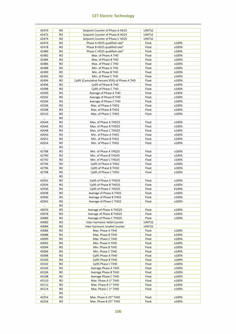
106
CET Electric Technology
42470 RO Setpoint Counter of Phase A HD25 UINT32
42472 RO Setpoint Counter of Phase B HD25 UINT32
42474 RO Setpoint Counter of Phase C HD25 UINT32
42476 RO Phase A HD25 qualified rate² Float x100%
42478 RO Phase B HD25 qualified rate² Float x100%
42480 RO Phase C HD25 qualified rate² Float x100%
42482 RO Max. of Phase A THD Float x100%
42484 RO Max. of Phase B THD Float x100%
42486 RO Max. of Phase C THD Float x100%
42488 RO Min. of Phase A THD Float x100%
42490 RO Min. of Phase B THD Float x100%
42492 RO Min. of Phase C THD Float x100%
42494 RO Cp95 (Cumulative Percent 95%) of Phase A THD Float x100%
42496 RO Cp95 of Phase B THD Float x100%
42498 RO Cp95 of Phase C THD Float x100%
42500 RO Average of Phase A THD Float x100%
42502 RO Average of Phase B THD Float x100%
42504 RO Average of Phase C THD Float x100%
42506 RO Max. of Phase A THD2 Float x100%
42508 RO Max. of Phase B THD2 Float x100%
42510 RO Max. of Phase C THD2 Float x100%
… RO …
42644 RO Max. of Phase A THD25 Float x100%
42646 RO Max. of Phase B THD25 Float x100%
42648 RO Max. of Phase C THD25 Float x100%
42650 RO Min. of Phase A THD2 Float x100%
42652 RO Min. of Phase B THD2 Float x100%
42654 RO Min. of Phase C THD2 Float x100%
… RO …
42788 RO Min. of Phase A THD25 Float x100%
42790 RO Min. of Phase B THD25 Float x100%
42792 RO Min. of Phase C THD25 Float x100%
42794 RO Cp95 of Phase A THD2 Float x100%
42796 RO Cp95 of Phase B THD2 Float x100%
42798 RO Cp95 of Phase C THD2 Float x100%
… RO …
42932 RO Cp95 of Phase A THD25 Float x100%
42934 RO Cp95 of Phase B THD25 Float x100%
42936 RO Cp95 of Phase C THD25 Float X100%
42938 RO Average of Phase A THD2 Float x100%
42940 RO Average of Phase B THD2 Float x100%
42942 RO Average of Phase C THD2 Float x100%
… RO …
43076 RO Average of Phase A THD25 Float x100%
43078 RO Average of Phase B THD25 Float x100%
43080 RO Average of Phase C THD25 Float x100%
43082 RO Inter-harmonic Valid Counter UINT32
43084 RO Inter-harmonic Invalid Counter UINT32
43086 RO Max. Phase A TIHD Float x100%
43088 RO Max. Phase B TIHD Float x100%
43090 RO Max. Phase C TIHD Float x100%
43092 RO Min. Phase A TIHD Float x100%
43094 RO Min. Phase B TIHD Float x100%
43096 RO Min. Phase C TIHD Float x100%
43098 RO Cp95 Phase A TIHD Float x100%
43100 RO Cp95 Phase B TIHD Float x100%
43102 RO Cp95 Phase C TIHD Float x100%
43104 RO Average Phase A TIHD Float x100%
43106 RO Average Phase B TIHD Float x100%
43108 RO Average Phase C TIHD Float x100%
43110 RO Max. Phase A 1st TIHD Float x100%
43112 RO Max. Phase B 1st TIHD Float x100%
43114 RO Max. Phase C 1st TIHD Float x100%
... RO …
43254 RO Max. Phase A 25th TIHD Float x100%
43256 RO Max. Phase B 25th TIHD Float x100%

107
CET Electric Technology
43258 RO Max. Phase C 25th TIHD Float x100%
43260 RO Min. Phase A TIHD1 Float x100%
43262 RO Min. Phase B TIHD1 Float x100%
43264 RO Min. Phase C TIHD1 Float x100%
... RO …
43404 RO Min. Phase A TIHD25 Float x100%
43406 RO Min. Phase B TIHD25 Float x100%
43408 RO Min. Phase C TIHD25 Float x100%
43410 RO Cp95 Phase A TIHD1 Float x100%
43412 RO Cp95 Phase B TIHD1 Float x100%
43414 RO Cp95 Phase C TIHD1 Float x100%
... RO …
43554 RO Cp95 Phase A TIHD25 Float x100%
43556 RO Cp95 Phase B TIHD25 Float x100%
43558 RO Cp95 Phase C TIHD25 Float x100%
43560 RO Average Phase A TIHD1 Float x100%
43562 RO Average Phase B TIHD1 Float x100%
43564 RO Average Phase C TIHD1 Float x100%
... RO …
43704 RO Average Phase A TIHD25 Float x100%
43706 RO Average Phase B TIHD25 Float x100%
43708 RO Average Phase C TIHD25 Float x100%
43710 RO Signal Voltage Assessment Conclusion¹ UINT32
43712 RO Signal Voltage Valid Counter UINT32
43714 RO Signal Voltage Invalid Counter UINT32
43716 RO Signal Voltage #1 Assessment Conclusion¹ UINT32
43718 RO Setpoint Counter of Signal Ua#1 Limit UINT32
43720 RO Setpoint Counter of Signal Ub#1 Limit UINT32
43722 RO Setpoint Counter of Signal Uc#1 Limit UINT32
43724 RO Signal Ua#1 qualified rate² Float
43726 RO Signal Ub#1 qualified rate² Float
43728 RO Signal Uc#1 qualified rate² Float
... RO …
43744 RO Signal Voltage #3 Assessment Conclusion¹ UINT32
43746 RO Setpoint Counter of Signal Ua#3 Limit UINT32
43748 RO Setpoint Counter of Signal Ub#3 Limit UINT32
43750 RO Setpoint Counter of Signal Uc#3 Limit UINT32
43752 RO Signal Ua#3 qualified rate² Float
43754 RO Signal Ub#3 qualified rate² Float
43756 RO Signal Uc#3 qualified rate² Float
43758 RO Maximum of Signal Ua#1 Float
43760 RO Max. of Signal Ub#1 Float
43762 RO Max. of Signal Uc#1 Float
43764 RO Max. of Signal Ua#2 Float
43766 RO Max. of Signal Ub#2 Float
43768 RO Max. of Signal Uc#2 Float
43770 RO Max. of Signal Ua#3 Float
43772 RO Max. of Signal Ub#3 Float
43774 RO Max. of Signal Uc#3 Float
43776 RO Min. of Signal Ua#1 Float
43778 RO Min. of Signal Ub#1 Float
43780 RO Min. of Signal Uc#1 Float
43782 RO Min. of Signal Ua#2 Float
43784 RO Min. of Signal Ub#2 Float
43786 RO Min. of Signal Uc#2 Float
43788 RO Min. of Signal Ua#3 Float
43790 RO Min. of Signal Ub#3 Float
43792 RO Min. of Signal Uc#3 Float
43794 RO Cp95 of Signal Ua#1 Float
43796 RO Cp95 of Signal Ub#1 Float
43798 RO Cp95 of Signal Uc#1 Float
43800 RO Cp95 of Signal Ua#2 Float
43802 RO Cp95 of Signal Ub#2 Float
43804 RO Cp95 of Signal Uc#2 Float
43806 RO Cp95 of Signal Ua#3 Float
43808 RO Cp95 of Signal Ub#3 Float

108
CET Electric Technology
43810 RO Cp95 of Signal Uc#3 Float
43812 RO Rapid Ua Change Counter UINT32
43814 RO Rapid Ub Change Counter UINT32
43816 RO Rapid Uc Change Counter UINT32
43818 RO Swell Counter #1 UINT32
10ms ≤ Duration Time ≤
500ms 110% < Voltage% < 120%
43820 RO Swell Counter #2 UINT32
500ms < Duration Time ≤
5000ms 110% < Voltage% < 120%
43822 RO Swell Counter #3 UINT32 5000ms < Duration Time ≤
60000ms 110% < Voltage% < 120%
43824 RO Swell Counter #4 UINT32 60000ms < Duration Time 110% < Voltage% < 120%
43826 RO Swell Counter #5 UINT32 10ms ≤ Duration Time ≤
500ms 120% ≤ Voltage% < 140%
43828 RO Swell Counter #6 UINT32 500ms < Duration Time ≤
5000ms 120% ≤ Voltage% < 140%
43830 RO Swell Counter #7 UINT32 5000ms < Duration Time ≤
60000ms
120% ≤ Voltage% < 140%
43832 RO Swell Counter #8 UINT32 60000ms < Duration Time 120% ≤ Voltage% < 140%
43834 RO Swell Counter #9 UINT32 10ms ≤ Duration Time ≤
500ms
140% ≤ Voltage% < 160%
43836 RO Swell Counter #10 UINT32 500ms < Duration Time ≤
5000ms
140% ≤ Voltage% <160%
43838 RO Swell Counter #11 UINT32
5000ms < Duration Time ≤
60000ms 140% ≤ Voltage% < 160%
43840 RO Swell Counter #12 UINT32 60000ms < Duration Time
140% ≤ Voltage% <160%
43842 RO Swell Counter #13 UINT32
10ms ≤ Duration Time ≤
500ms 160% ≤ Voltage% < 200%
43844 RO Swell Counter #14 UINT32
500ms < Duration Time ≤
5000ms 160% ≤ Voltage% < 200%
43846 RO Swell Counter #15 UINT32 5000ms < Duration Time ≤
60000ms 160% ≤ Voltage% < 200%
43848 RO Swell Counter #16 UINT32 60000ms < Duration Time 160% ≤ Voltage% < 200%
43850 RO Swell Counter #17 UINT32 10ms ≤ Duration Time ≤
500ms 200% ≤ Voltage%
43852 RO Swell Counter #18 UINT32 500ms < Duration Time ≤
5000ms 200% ≤ Voltage%
43854 RO Swell Counter #19 UINT32 5000ms < Duration Time ≤
60000ms
200% ≤ Voltage%
43856 RO Swell Counter #20 UINT32 60000ms < Duration Time
200% ≤ Voltage%
43858 RO Dip Counter #1 UINT32 10ms < Duration Time ≤
200ms
Residual Voltage% < 5
43860 RO Dip Counter #2 UINT32 200ms < Duration Time ≤
500ms
Residual Voltage% < 5
43862 RO Dip Counter #3 UINT32
500ms < Duration Time ≤
1000ms Residual Voltage% < 5

109
CET Electric Technology
43864 RO Dip Counter #4 UINT32
1000ms < Duration Time ≤
5000ms Residual Voltage% < 5
43866 RO Dip Counter #5 UINT32
5000ms < Duration Time ≤
60000ms Residual Voltage% < 5
43868 RO Dip Counter #6 UINT32 60000ms < Duration Time
Residual Voltage% < 5
43870 RO Dip Counter #7 UINT32
10ms < Duration Time ≤
200ms 5 ≤ Residual Voltage% < 40
43872 RO Dip Counter #8 UINT32 200ms < Duration Time ≤
500ms 5 ≤ Residual Voltage% < 40
43874 RO Dip Counter #9 UINT32 500ms < Duration Time ≤
1000ms 5 ≤ Residual Voltage% < 40
43876 RO Dip Counter #10 UINT32 1000ms < Duration Time ≤
5000ms
5 ≤ Residual Voltage% < 40
43878 RO Dip Counter #11 UINT32 5000ms < Duration Time ≤
60000ms
5 ≤ Residual Voltage% < 40
43880 RO Dip Counter #12 UINT32 60000ms < Duration Time
5 ≤ Residual Voltage% < 40
43882 RO Dip Counter #13 UINT32 10ms < Duration Time ≤
200ms
40 ≤ Residual Voltage% < 70
43884 RO Dip Counter #14 UINT32
200ms < Duration Time ≤
500ms 40 ≤ Residual Voltage% < 70
43886 RO Dip Counter #15 UINT32
500ms < Duration Time ≤
1000ms 40 ≤ Residual Voltage% < 70
43888 RO Dip Counter #16 UINT32 1000ms < Duration Time ≤
5000ms 40 ≤ Residual Voltage% < 70
43890 RO Dip Counter #17 UINT32 5000ms < Duration Time ≤
60000ms 40 ≤ Residual Voltage% < 70
43892 RO Dip Counter #18 UINT32 60000ms < Duration Time
40 ≤ Residual Voltage% < 70
43894 RO Dip Counter #19 UINT32 10ms < Duration Time ≤
200ms 70 ≤ Residual Voltage% < 80
43896 RO Dip Counter #20 UINT32 200ms < Duration Time ≤
500ms
70 ≤ Residual Voltage% < 80
43898 RO Dip Counter #21 UINT32 500ms < Duration Time ≤
1000ms
70 ≤ Residual Voltage% < 80
43900 RO Dip Counter #22 UINT32
1000ms < Duration Time ≤
5000ms 70 ≤ Residual Voltage% < 80
43902 RO Dip Counter #23 UINT32
5000ms < Duration Time ≤
60000ms 70 ≤ Residual Voltage% < 80
43904 RO Dip Counter #24 UINT32 60000ms < Duration Time
70 ≤ Residual Voltage% < 80
43906 RO Dip Counter #25 UINT32
10ms < Duration Time ≤
200ms 80 ≤ Residual Voltage% < 90
43908 RO Dip Counter #26 UINT32 200ms < Duration Time ≤
500ms 80 ≤ Residual Voltage% < 90
43910 RO Dip Counter #27 UINT32 500ms < Duration Time ≤
1000ms 80 ≤ Residual Voltage% < 90

110
CET Electric Technology
43912 RO Dip Counter #28 UINT32
1000ms < Duration Time ≤
5000ms 80 ≤ Residual Voltage% < 90
43914 RO Dip Counter #29 UINT32
5000ms < Duration Time ≤
60000ms 80 ≤ Residual Voltage% < 90
43916 RO Dip Counter #30 UINT32 60000ms < Duration Time
80 ≤ Residual Voltage% < 90
43918 RO Interruption Counter #1 UINT32 Duration Time ≤ 1000ms
43920 RO Interruption Counter #2 UINT32 Duration Time ≤ 180000ms
43922 RO Interruption Counter #3 UINT32 Duration Time > 180000ms
43924 RO Ua Transient Counter UINT32 Statistic valid counter within
this week 43926 RO Ub Transient Counter UINT32
43928 RO Uc Transient Counter UINT32
Table 5-39 EN50160 Log Buffer
Notes:
1) The meaning of conclusion is described in below table:
Bit Conclusion
BIT0 0: Qualified, 1: Unqualified
2) Equation for qualified is 𝑄𝑢𝑎𝑙𝑖𝑓𝑖𝑒𝑑 𝑇𝑖𝑚𝑒𝑠
𝑇𝑜𝑡𝑎𝑙 𝑇𝑖𝑚𝑒𝑠
The qualified rate is a fractional value. For example, if qualified rate is 10%, then the value 0.10 will be uploaded.
3) When the Wiring Mode is Delta, the statistic Voltage will be changed to line voltage automatically.
4) Besides X Invalid Counter such as Frequency Invalid Counter, other registers’ values are statistic and calculated within valid
scope.
5) The equation for Voltage Rating is
𝐷𝑒𝑣𝑖𝑐𝑒 𝑉𝑜𝑙𝑡𝑎𝑔𝑒 𝑅𝑎𝑡𝑖𝑛𝑔 × 𝑃𝑇 𝑃𝑟𝑖𝑚𝑎𝑟𝑦 ÷ 𝑃𝑇 𝑆𝑒𝑐𝑜𝑛𝑑𝑎𝑟𝑦 ÷ √3
When the Wiring Mode is Delta, the equation for Voltage Rating is
𝐷𝑒𝑣𝑖𝑐𝑒 𝑉𝑜𝑙𝑡𝑎𝑔𝑒 𝑅𝑎𝑡𝑖𝑛𝑔 × 𝑃𝑇 𝑃𝑟𝑖𝑚𝑎𝑟𝑦 ÷ 𝑃𝑇 𝑆𝑒𝑐𝑜𝑛𝑑𝑎𝑟𝑦
5.7.5 TOU Log
All TOU Logs’ timestamps are recorded according to local time.
5.7.5.1 TOU Real-time Log
Register Description Format
47700~47734 Tariff #1 Data
See 5.7.5.4 TOU Log Data
Structure
47736~47771 Tariff #2 Data 47772~47817 Tariff #3 Data 47818~47843 Tariff #4 Data 47844~47879 Tariff #5 Data 47880~47915 Tariff #6 Data 47916~47951 Tariff #7 Data 47952~47987 Tariff #8 Data
Table 5-40 TOU Real-time Log
5.7.5.2 TOU Historical Log
The PMC-670 can store up to 3 entries historical data and register start from 48000. To retrieved
historical TOU log, write entry number which you can get from History TOU Data Record Pointer
(Register 0152) into Recorder No. (Register 48000), and then read registers data from 48002 to 48292.
For example, if the value of History TOU Data Record Pointer is 9, then 7, 8 or 9 can be wrote into
Recorder No. register where 9 means last month, 8 means the month before last month, and so on.
Register Property Description Format
48000 RW Recorder No. UINT32
48002 RO Record Time (s) UINT32
48004 RO Monthly Average PF (1) Float
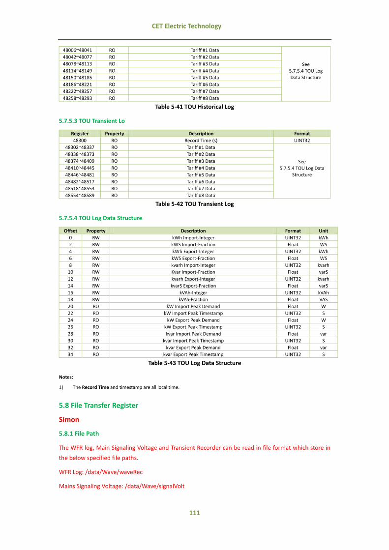
111
CET Electric Technology
48006~48041 RO Tariff #1 Data
See
5.7.5.4 TOU Log Data Structure
48042~48077 RO Tariff #2 Data 48078~48113 RO Tariff #3 Data 48114~48149 RO Tariff #4 Data 48150~48185 RO Tariff #5 Data 48186~48221 RO Tariff #6 Data 48222~48257 RO Tariff #7 Data 48258~48293 RO Tariff #8 Data
Table 5-41 TOU Historical Log
5.7.5.3 TOU Transient Lo
Register Property Description Format
48300 RO Record Time (s) UINT32
48302~48337 RO Tariff #1 Data
See 5.7.5.4 TOU Log Data
Structure
48338~48373 RO Tariff #2 Data 48374~48409 RO Tariff #3 Data 48410~48445 RO Tariff #4 Data 48446~48481 RO Tariff #5 Data 48482~48517 RO Tariff #6 Data 48518~48553 RO Tariff #7 Data 48554~48589 RO Tariff #8 Data
Table 5-42 TOU Transient Log
5.7.5.4 TOU Log Data Structure
Offset Property Description Format Unit
0 RW kWh Import-Integer UINT32 kWh
2 RW kWS Import-Fraction Float WS
4 RW kWh Export-Integer UINT32 kWh
6 RW kWS Export-Fraction Float WS
8 RW kvarh Import-Integer UINT32 kvarh
10 RW Kvar Import-Fraction Float varS
12 RW kvarh Export-Integer UINT32 kvarh
14 RW kvarS Export-Fraction Float varS
16 RW kVAh-Integer UINT32 kVAh
18 RW kVAS-Fraction Float VAS
20 RO kW Import Peak Demand Float W
22 RO kW Import Peak Timestamp UINT32 S
24 RO kW Export Peak Demand Float W
26 RO kW Export Peak Timestamp UINT32 S
28 RO kvar Import Peak Demand Float var
30 RO kvar Import Peak Timestamp UINT32 S
32 RO kvar Export Peak Demand Float var
34 RO kvar Export Peak Timestamp UINT32 S
Table 5-43 TOU Log Data Structure
Notes:
1) The Record Time and timestamp are all local time.
5.8 File Transfer Register
Simon
5.8.1 File Path
The WFR log, Main Signaling Voltage and Transient Recorder can be read in file format which store in
the below specified file paths.
WFR Log: /data/Wave/waveRec
Mains Signaling Voltage: /data/Wave/signalVolt

112
CET Electric Technology
Transient Recorder: /data/Wave/transWave
5.8.2 File Name
The storage for main signaling voltage and transient Recorder are 8 entries, 128 entries and 128 entries,
respectively. The storage for WFR log can be configured by setting Recording Depth (8603).
The following are naming rules for files:
WFR Log1: if the record depth is 64, the file names are W1000001.cfg, W1000002.cfg,
W1000003.cfg, …, W10000064.cfg
WFR Log2: if the record depth is 64, the file names are W2000001.cfg, W2000002.cfg,
W2000003.cfg, …, W20000064.cfg
Main Signaling Voltage: W1000001.cfg to W1000008.cfg, W2000001.cfg to W2000008.cfg,
W3000001.cfg to W3000008.cfg
Transient Recorder Log: W0000001.cfg, W0000002.cfg, W0000003.cfg, …, W0000128.cfg
Since the recorders are stored in FIFO basis, the file index meets the below calculation:
Seq = Modulo [(N-1)/Max] + 1
Where
Seq is file mantissa
N is recorder index
Max is max storage of WFR
For example, the current recorder index is 100, the max storage is 64, then the seq for newest recorder
file is: Modulo [(100-1)/64] +1=36. And the file name is W1000036.dat.
5.8.3 Reading File
The file can be read via file transfer register, the following shows how to read file.
1. Write relative path of file in file name register, for example: waveRec/W1000001.cfg.
2. Write specified offset address in file offset register if specified file want to be read, otherwise no
need to write or read the register.
After writing relative path of file, the file offset register would be set as 0 automatically.
3. Read register 40020 and achieve file size. After writing relative path of file, the file size will be
updated automatically.
4. Read File Data Buffer registers and achieve file data of the frame. After finished reading data,
file offset will be added automatically, and data of file buffer will be updated automatically.
5. Repeat step 4 until the valid data being read equals to file size, and finished reading the file.
5.8.4 Register Address
Register Property Description Format Range/Note
40000~40019 RW File Name¹ UINT16 Writing relative path of file
in a frame, make up the end with \0.
40020 RO File Size² UINT32 File size of currently being

113
CET Electric Technology
transferred
40022 RW File Offset UINT32 Writing indicates should
adjust offset 40024 RO Valid Number of Data Bytes in the Frame UINT16 40025 RO File Data Buffer #1 Char 0~244
… … … Char … 40146 RO File Data Buffer #244 Char 0~244
Table 5-44 File Transfer Register
Notes:
1) When writing file name, the device will do some operations and it will cost several seconds. Please also note that the
PMC-670 only supports two Modbus clients that do operation of transferring file transfer at the same moment. If the file
registers do not do correct operation in 1 minute after writing file name, please rewrite the file name and start next reading
file task.
2) Reading file size will cost number of seconds and please wait patiently.
5.9 Setup Parameters
5.9.1 System Parameters
Register Property Description Format Range/Options
7000 RW PT Primary (V) UINT32 1 to 1000000 Default=100
7002 RW PT Secondary (V) UINT32 1 to 690
Default=100
7004 RW CT Primary (A) UINT32 1 to 30000
Default=5
7006 RW CT Secondary (A) UINT32 1 to 5*
7008 RW U4 Primary (V) UINT32 1 to 1000000 Default=100
7010 RW U4 Secondary (V) UINT32 1 to 400
Default=100
7012 RW I4 Primary (A) UINT32 1 to 30000 Default=5
7014 RW I4 Secondary (A) UINT32 1 to 5*
7016 RW Wiring Mode UINT32 0*=WYE, 1=Delta, 2=Demo
7017 RW Vnominal Secondary UINT32 1 to 700V
Default=100
7018 RW Freq UINT32 0*=50, 1=60
7019 RW P.F. Convention2 UINT32 0*=IEC, 1=IEEE, 2=-IEEE
7020 RW kVA Calculation3 UINT32 0*=Vector, 1=Scalar
7021 RW Ia Polarity UINT16 0*=Normal, 1=Reverse
7022 RW Ib Polarity UINT16 0*=Normal, 1=Reverse
7023 RW Ic Polarity UINT16 0*=Normal, 1=Reverse
7024 RW Voltage Kth Harmonic Calculation4 UINT16 0*=Distortion
1=RMS
7025 RW Current Kth Harmonic Calculation4 UINT16 0*=Distortion
1=RMS
7026 RW HD Calculation UINT16 0*=% of Fundamental
1=% of RMS
7027 RW Harmonic Calculation4 UINT16 0*=Subgroup, 1=Group
7028 RW Orders of Total Harmonic UINT16 2 to 63*
7029 RW DO/RO Arm Before Execute Enable UINT16 0=Disabled, 1*=Enabled
7030 RW Data Refreshing Speed UINT16
0=10/12 cycles
1*=50/60 cycles 2=150/180 cycles
3=10 minutes
4=2 hours
7031 RW Frequency Refreshing Cycle UINT16 0*=1s, 1=10s
7032 RW Enable Flagging 1 UINT16 0*=Disabled, 1=Enabled
7033 RW Reserved UINT16
7034 RW Reserved UINT16
7035 RW Reserved UINT32
7037 RW I4 Polarity UINT16 0*=Normal, 1=Reverse
7038 RW EN50160 Voltage Level⁵ UINT16 0*=Low Voltage
1=Medium Voltage 2=High Voltage
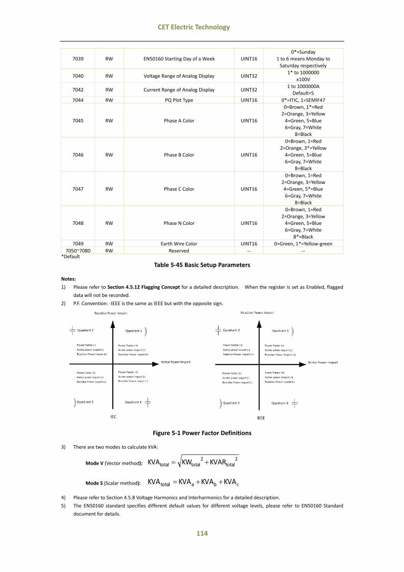
114
CET Electric Technology
7039 RW EN50160 Starting Day of a Week UINT16 0*=Sunday
1 to 6 means Monday to
Saturday respectively
7040 RW Voltage Range of Analog Display UINT32 1* to 1000000
x100V
7042 RW Current Range of Analog Display UINT32 1 to 1000000A
Default=5
7044 RW PQ Plot Type UINT16 0*=ITIC, 1=SEMIF47
7045 RW Phase A Color UINT16
0=Brown, 1*=Red 2=Orange, 3=Yellow
4=Green, 5=Blue 6=Gray, 7=White
8=Black
7046 RW Phase B Color UINT16
0=Brown, 1=Red 2=Orange, 3*=Yellow
4=Green, 5=Blue 6=Gray, 7=White
8=Black
7047 RW Phase C Color UINT16
0=Brown, 1=Red 2=Orange, 3=Yellow 4=Green, 5*=Blue
6=Gray, 7=White 8=Black
7048 RW Phase N Color UINT16
0=Brown, 1=Red
2=Orange, 3=Yellow 4=Green, 5=Blue 6=Gray, 7=White
8*=Black
7049 RW Earth Wire Color UINT16 0=Green, 1*=Yellow-green
7050~7080 RW Reserved -- -- *Default
Table 5-45 Basic Setup Parameters
Notes:
1) Please refer to Section 4.5.12 Flagging Concept for a detailed description. When the register is set as Enabled, flagged
data will not be recorded.
2) P.F. Convention: -IEEE is the same as IEEE but with the opposite sign.
Figure 5-1 Power Factor Definitions
3) There are two modes to calculate kVA:
Mode V (Vector method): 2
total2
totaltotal KVARKWKVA
Mode S (Scalar method): cKVAKVAKVAKVA batotal
4) Please refer to Section 4.5.8 Voltage Harmonics and Interharmonics for a detailed description.
5) The EN50160 standard specifies different default values for different voltage levels, please refer to EN50160 Standard
document for details.

115
CET Electric Technology
5.9.2 Clock and Language Setup
Register Property Description Format Range/Options
7081 RW Self-Read Time for Recording1 UINT16 0XFFFF*
7082 RW Backlight Timeout (min) UINT16 0 to 60minutes
Default=3
7083 RW Language UINT16 0*=English
Others=Reserved
7084 RW Time Zone2 UINT16 0 to 32
Default=26
7085 RW IRIG-B Time Difference INT16 -1440 to 1440minutes
Default: 0
7086 RW Clock Source1 UINT16
0=DI PPS
1*=RTC 2=GPS
3=SNTP
4=IRIG-B
7087 RW Front Panel Date Format UINT16
0*=YYMMDD
1=MMDDYY 2=DDMMYY
7088~7100 RW Reserved UINT16 *Default
Table 5-46 System Setup Parameters
Notes:
1) Self-Read Time is applied to Max. Demand Log and Max./Min. Log, there are two types of Self-Read Time as following:
A zero value means that the Self-Read will take place at 00:00 of the end of the month.
A non-zero value means that the Self-Read will take place at a specific time and day based on the formula: Self-Read
Time = Day * 100 + Hour where 0 ≤ Hour ≤ 23 and 1 ≤ Day ≤ 28. For example, the value 1512 means that the Self-Read
will take place at 12:00pm on the 15th day of each month.
2) When Clock Source is set to GPS or IRIG-B, P1 (RS485 Port 1) will be automatically used for the respective Time Sync signal.
Please refer to Section 4.7 Time Synchronization for a detailed description.
When Clock Source is set to DI, DI8 will be used by default for the 1PPS GPS Time Sync input.
3) The following table lists the Codes for different Time Zones. The IRIG-B Time Zone parameter should be configured when
Clock Source is set to IRIG-B.
Code Time Zone Code Time Zone Code Time Zone
0 GMT-12:00 11 GMT-2:00 22 GMT+5:45
1 GMT-11:00 12 GMT-1:00 23 GMT+6:00
2 GMT-10:00 13 GMT-0:00 24 GMT+6:30
3 GMT-9:00 14 GMT+1:00 25 GMT+7:00
4 GMT-8:00 15 GMT+2:00 26 GMT+8:00
5 GMT-7:00 16 GMT+3:00 27 GMT+9:00
6 GMT-6:00 17 GMT+3:30 28 GMT+9:30
7 GMT-5:00 18 GMT+4:00 29 GMT+10:00
8 GMT-4:00 19 GMT+4:30 30 GMT+11:00
9 GMT-3:30 20 GMT+5:00 31 GMT+12:00
10 GMT-3:00 21 GMT+5:30 32 GMT+13:00
Table 5-47 Time Zones
5.9.3 Communications Setup
Register Property Description Format Note
7200 RW
RS485 Port 1 (P1)
Protocol1 UINT16 0*=Modbus RTU
1=Time Synchronization
7201 RW Unit ID UINT16 1 to 247
Default: 100
7202 RW Baud rate UINT16 0=1200 1=2400
2=4800 3*=9600
4=19200 5=38400
7203 RW Configuration UINT16 0=8N2 1=8O1
2*=8E1 3=8N1
4=8O2 5=8E2
7204 RW RS485 Port 2
(P2)3
Protocol UINT16 0*=Modbus RTU
1=Gateway
7205 RW Unit ID UINT16 1 to 247

116
CET Electric Technology
Default: 101
7206 RW Baud rate UINT16 0=1200 1=2400
2=4800 3*=9600
4=19200 5=38400
7207 RW Configuration UINT16 0=8N2
1=8O1
2*=8E1
3=8N1
4=8O2
5=8E2
7208 RW Ethernet 1
(P3)
IP Address UINT32 Default=192.168.0.100
If the IP Address is 192.168.0.100,
write “0xC0A00064” to the register.
7210 RW Subnet Mask UINT32 Default=255.255.255.0
7212 RW Default Gateway UINT32 Default=192.168.0.1
7214 RW Reserved -- --
7215 RW SNTP Sync. Interval UINT16 10 to 1440mins
Default=60
7216 RW SNTP Server IP Address UINT32 Default=191.0.0.6
If the IP Address is 191.0.0.6, write
“0XBF000006” to the register
7218 RW Reserved -- --
7219 RW SMTP Server Port UINT32 0 to 65535 Default=25
7220 RW SMTP Server IP Address UINT32
7222~7257 RW Sender Email UINT32 See note 1)
7258~7277 RW Login Email Password UINT16 See note 2)
7278~7313 RW Receiver Email UINT16 See note 3)
7314~7315 RW Reserved UINT16 -- *Default
Table 5-48 Communication Setup
Notes:
1) This string register specifies the source email address that appears in the “From” field of the email. This string may be up
to 36 characters long. Please add the value zero “0000” at the end of the string as the string terminator. For example, if
the email address is [email protected], set the registers as”00 50 00 4D 00 43 00 2D 00 40 00 63 00 65 00 69 00
65 00 63 00 2D 00 65 00 6C 00 65 00 63 00 74 00 72 00 69 00 63 00 2E 00 63 00 6F 00 6D 00 00”.
2) This string register specifies the Logon Password to login the “Sender Email” account. This string may be up to 20
characters long. Please add the value zero “0000” at the end of the string as the string terminator. For example, if the
password is “PMC-670”, set the registers as “00 50 00 4D 00 43 00 2D 00 36 00 37 00 30 00 00”.
3) This string register specifies the destination email address that appears in the “To” field of the email. This string may be
up to 36 characters long. Please add the value zero “0000” at the end of the string as the string terminator. For example,
if the email address is [email protected], so set the registers as”00 50 00 4D 00 43 00 2D 00 36 00 37 00 30 2D
00 61 00 40 00 63 00 65 00 69 00 65 00 63 00 2D 00 65 00 6C 00 65 00 63 00 74 00 72 00 69 00 63 00 2E 00 63 00 6F 00 6D
00 00”.
5.9.4 Demand Setup
Register Property Description Format Range/Options
7101 RW Demand Calculation Mode UINT16 0*=SLD
1=SYNC DI
7102 RW Demand Sub-Interval Cycle UINT16 1 to 60 (minutes)
Default=15
7103 RW Number of Sliding Windows UINT16 1* to 15
7104 RW Prediction Sensitivity UINT16 70* to 99
7105~7109 RW Reserved -- -- *Default
Table 5-49 Demand Setup
5.9.5 I/O Setup
Register Property Description Format Range/Options
7110 RW DI1 Mode UINT16
0*=Normal
1=Pulse Counter 2=Demand Sync
3=PPS Sync
7111 RW DI2 Mode UINT16
7112 RW DI3 Mode UINT16
7113 RW DI4 Mode UINT16
7114 RW DI5 Mode UINT16
7115 RW DI6 Mode UINT16
7116 RW DI7 Mode UINT16

117
CET Electric Technology
7117 RW DI8 Mode UINT16
7118 RW DI1 Debounce UINT16
1 to 1000ms
Default=20
7119 RW DI2 Debounce UINT16
7120 RW DI3 Debounce UINT16
7121 RW DI4 Debounce UINT16
7122 RW DI5 Debounce UINT16
7123 RW DI6 Debounce UINT16
7124 RW DI7 Debounce UINT16
7125 RW DI8 Debounce UINT16
7126 RW DI1 Pulse Weight UINT32
1 to 1000000
Default=10
7128 RW DI2 Pulse Weight UINT32
7130 RW DI3 Pulse Weight UINT32
7132 RW DI4 Pulse Weight UINT32
7134 RW DI5 Pulse Weight UINT32
7136 RW DI6 Pulse Weight UINT32
7138 RW DI7 Pulse Weight UINT32
7140 RW DI8 Pulse Weight UINT32
7142 RW DO1 Mode
(kWh SS Pulse) UINT16
0*=Remote Control/Alarm 1=RMS kWh Import
2=Fundamental kWh Import
3=Harmonic kWh Import 4=RMS kWh Export
5=Fundamental kWh Export
6=Harmonic kWh Export
7143 RW DO2 Mode
(kvarh SS Pulse) UINT16
0*=Remote Control/Alarm
1=RMS kvarh Import 2=Fundamental kvarh Import
3=Harmonic kvarh Import
4=RMS kvarh Export 5=Fundamental kvarh Export
6=Harmonic kvarh Export
7144 RW DO1 Pulse Width UINT16
0 to 6000 (x0.1s) 0=Latch Mode
Default=10
7145 RW DO2 Pulse Width UINT16
7146 RW RO1 Pulse Width UINT16
7147 RW RO2 Pulse Width UINT16
7148 RW RO3 Pulse Width UINT16
7149 RW RO4 Pulse Width UINT16
7150~7159 RW Reserved -- -- *Default
Table 5-50 I/O Setup
Notes:
1) Only one DI can be set for PPS, at the same time Clock Source 7086 need to set for DI PPS.
5.9.6 Energy Pulsing Setup
Register Property Description Format Range/Options
7160 RW Energy Pulse Constant UINT16
0=1000 Pulse/kWh 1=3200 Pulse/kWh
2*=5000 Pulse/kWh 3=6400 Pulse/kWh
4=12800 Pulse/kWh
7161 RW kWh LED Pulse Output UINT16
0=Disabled 1*=RMS kWh
2=Fundamental kWh 3=Harmonic kWh
1 to 3 are LED Pulse
7162 RW kvarh LED Pulse Output UINT16
0= Disabled 1*=RMS kvarh
2=Fundamental kvarh
3=Harmonic kvarh 1 to 3 are LED Pulse
*Default
Table 5-51 Energy Pulsing Setup
Notes:

118
CET Electric Technology
1) The PMC-670 provides the following pulse constants for different input ratings:
kVA (Secondary) Pulse Constant Options (imp/kWh) Default
≤500 1000/3200/5000/6400/12800 1000
≤690 1000/3200/5000 1000
≤1900 1000/3200 1000
>1900 1000 1000
Table 5-52 Pulse Constant
5.9.7 Setpoints Setup
Register Property Description Format Range/Options
7600 RW
Setpoint #1
Type UINT16 0*=Disabled
1=Over Setpoint 2=Under Setpoint
7601 RW Paramenter1 UINT16 0* to 159
7602 RW Active Limit Float Default=0
7604 RW Inactive Limit Float Default=0
7606 RW Active Delay UINT16 0* to 9999
7607 RW Inactive Delay UINT16 0* to 9999
7608 RW Trigger12 UINT16 0* to 35
7609 RW Trigger22 UINT16 0* to 35
… … … …
7910 RW
Setpoint #32
Type UINT16 0*=Disabled
1=Over Setpoint
2=Under Setpoint
7911 RW Paramenter1 UINT16 0* to 159
7912 RW Active Limit Float Default=0
7914 RW Inactive Limit Float Default=0
7916 RW Active Delay UINT16 0* to 9999
7917 RW Inactive Delay UINT16 0* to 9999
7918 RW Trigger12 UINT16 0* to 35
7919 RW Trigger22 UINT16 0* to 35
7920 RW
Logical Module #1
Enable Logical Module UINT16 0*=Disabled 1=Enabled
7921 RW Mode 1 UINT16 0*=AND
1=OR 2=NAND 3=NOR
7922 RW Mode 2 UINT16
7923 RW Mode 3 UINT16
7924 RW Source 11 UINT16
0* to 32 7925 RW Source 21 UINT16
7926 RW Source 31 UINT16
7927 RW Source 41 UINT16
7928 RW Trigger 12 UINT16 0* to 34
7929 RW Trigger 22 UINT16
… … … …
7990 RW
Logical Module #8
Enable Logical Module UINT16 0*=Disabled
1=Enabled
7991 RW Mode 1 UINT16 0*=AND
1=OR 2=NAND 3=NOR
7992 RW Mode 2 UINT16
7993 RW Mode 3 UINT16
7994 RW Source 11 UINT16
0* to 32 7995 RW Source 21 UINT16 7996 RW Source 31 UINT16 7997 RW Source 41 UINT16 7998 RW Trigger 12 UINT16
0* to 34 7999 RW Trigger 22 UINT16
*Default
Table 5-53 Setpoint Setup Parameters
Notes:
1) The setpoint#1 to setpoint#24 are standard setpoints and the setpoint#25 to setpoint#32 are HS setpoints. The PMC-670
provides the following setpoint parameters, standard Setpoint can monitor all parameters and HS Setpoint only can monitor
0 to 18:
Key Parameter Scale/Unit Key Parameter Scale/Unit

119
CET Electric Technology
0 None -- 22 ∑P.F. Demand --
1 ULN V 23 ∑kW Predicted Demand W
2 ULL V 24 ∑kvar Predicted Demand var
3 I A 25 ∑kVA Predicted Demand VA
4 U4 V 26 ∑P.F. Predicted Demand --
5 I4 A 27 V THD 100%
6 Freq Deviation Hz 28 V TOHD 100%
7 ∑kW W 29 V TEHD 100%
8 ∑kvar var 30 I THD 100%
9 ∑kVA VA 31 I TOHD 100%
10 ∑P.F. -- 32 I TEHD 100%
11 DI1* -- 33 U2 Unbalance 100%
12 DI2* -- 34 U0 Unbalance 100%
13 DI3* -- 35 I2 Unbalance 100%
14 DI4* -- 36 I0 Unbalance 100%
15 DI5* -- 37 V Deviation 100%
16 DI6** -- 38 Phase Reversal
17 DI7 -- 39 Voltage H02 V, 100%
18 DI8* -- 40 Current H02 A, 100%
19 ∑kW Demand W … … …
20 ∑kvar Demand var 161 Voltage H63 V, 100%
21 ∑kVA Demand VA 162 Current H63 A, 100%
Table 5-54 Setpoint Parameters
* For Over Setpoint, the Active Limit is DI Close (DI=1), and Inactive Limit is DI Open (DI=0). For Under Setpoint, the Active
Limit is DI Open (DI=0), and Inactive Limit is DI Close (DI=1); 2) The PMC-670 provides the following Setpoint Triggers:
Key Action Key Action Key Action Key Action
0 None 9 HS DR #3 18 DR #4 27 DR #13
1 RO1 10 HS DR #4 19 DR #5 28 DR #14
2 RO2 11 Reserved 20 DR #6 29 DR #15
3 RO3 12 Reserved 21 DR #7 30 DR #16
4 RO4 13 Reserved 22 DR #8 31 WR #1
5 DO1 14 Reserved 23 DR #9 32 WR #2
6 DO2 15 DR #1 24 DR #10 33 Reserved
7 HS DR #1 16 DR #2 25 DR #11 34 DWR
8 HS DR #2 17 DR #3 26 DR #12 35 Alarm Email
Table 5-55 Setpoint Triggers
5.9.8 DR Setup
Register Property Description Format Range/Options/Note
8000 RW
HS DR Log #1
Trigged Mode1 UINT16 0*=Disabled
1=Triggered by Timer
2=Triggered by Setpoint
8001 RW Recording Mode2 UINT16 0*=Stop-When-Full 1=First In First Out
8002 RW Recording Depth3 UINT16 0* to 65535
8003 RW Recording Interval UINT32
1* to 120 (x0.5 cycle) for HS DR
Log 1 to 3456000s for Standard DR Log
8005 RW Recording Offset4 UINT16 0* to 43200s
8006 RW Parameters Number5 UINT16 0 to 16*
8007 RW Parameter1 UINT16
0* to 31 0 to 1743
8008 RW Parameter2 UINT16
8009 RW Parameter3 UINT16
… … UINT16
8022 RW Parameter16 UINT16
8023~8045 RW HS DR Log #2 Please refer to HS DR Log #1
8046~8068 … HS DR Log #3
8069~8091 RW HS DR Log #4
8092~8114 RW Reserved
8115~8137 RW Reserved
8138~8160 RW Reserved
8161~8183 RW Reserved
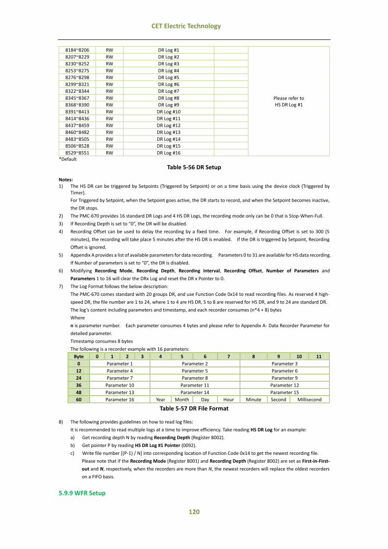
120
CET Electric Technology
8184~8206 RW DR Log #1
Please refer to HS DR Log #1
8207~8229 RW DR Log #2
8230~8252 RW DR Log #3
8253~8275 RW DR Log #4
8276~8298 RW DR Log #5
8299~8321 RW DR Log #6
8322~8344 RW DR Log #7
8345~8367 RW DR Log #8
8368~8390 RW DR Log #9
8391~8413 RW DR Log #10
8414~8436 RW DR Log #11
8437~8459 RW DR Log #12
8460~8482 RW DR Log #13
8483~8505 RW DR Log #14
8506~8528 RW DR Log #15
8529~8551 RW DR Log #16 *Default
Table 5-56 DR Setup
Notes: 1) The HS DR can be triggered by Setpoints (Triggered by Setpoint) or on a time basis using the device clock (Triggered by
Timer).
For Triggered by Setpoint, when the Setpoint goes active, the DR starts to record, and when the Setpoint becomes inactive,
the DR stops.
2) The PMC-670 provides 16 standard DR Logs and 4 HS DR Logs, the recording mode only can be 0 that is Stop-When-Full.
3) If Recording Depth is set to “0”, the DR will be disabled.
4) Recording Offset can be used to delay the recording by a fixed time. For example, if Recording Offset is set to 300 (5
minutes), the recording will take place 5 minutes after the HS DR is enabled. If the DR is triggered by Setpoint, Recording
Offset is ignored.
5) Appendix A provides a list of available parameters for data recording. Parameters 0 to 31 are available for HS data recording.
If Number of parameters is set to “0”, the DR is disabled.
6) Modifying Recording Mode, Recording Depth, Recording Interval, Recording Offset, Number of Parameters and
Parameters 1 to 16 will clear the DRx Log and reset the DR x Pointer to 0.
7) The Log Format follows the below description:
The PMC-670 comes standard with 20 groups DR, and use Function Code 0x14 to read recording files. As reserved 4 high-
speed DR, the file number are 1 to 24, where 1 to 4 are HS DR, 5 to 8 are reserved for HS DR, and 9 to 24 are standard DR.
The log’s content including parameters and timestamp, and each recorder consumes (n*4 + 8) bytes
Where
n is parameter number. Each parameter consumes 4 bytes and please refer to Appendix A- Data Recorder Parameter for
detailed parameter.
Timestamp consumes 8 bytes
The following is a recorder example with 16 parameters:
Byte 0 1 2 3 4 5 6 7 8 9 10 11
0 Parameter 1 Parameter 2 Parameter 3
12 Parameter 4 Parameter 5 Parameter 6
24 Parameter 7 Parameter 8 Parameter 9
36 Parameter 10 Parameter 11 Parameter 12
48 Parameter 13 Parameter 14 Parameter 15
60 Parameter 16 Year Month Day Hour Minute Second Millisecond
Table 5-57 DR File Format
8) The following provides guidelines on how to read log files:
It is recommended to read multiple logs at a time to improve efficiency. Take reading HS DR Log for an example:
a) Get recording depth N by reading Recording Depth (Register 8002).
b) Get pointer P by reading HS DR Log #1 Pointer (0092).
c) Write file number [(P-1) / N] into corresponding location of Function Code 0x14 to get the newest recording file.
Please note that if the Recording Mode (Register 8001) and Recording Depth (Register 8002) are set as First-in-First-
out and N, respectively, when the recorders are more than N, the newest recorders will replace the oldest recorders
on a FIFO basis.
5.9.9 WFR Setup

121
CET Electric Technology
Register Property Description Range/Option
8600 RW
WFR #1
Recording Depth1 0 to 128
Default=64
8601 RW # of Samples2 0*=16 Samples/640 Cycles 1=32 Samples/320 Cycles 2=64 Samples/160 Cycles
3=128 Samples/80 Cycles 4=256 Samples/40 Cycles 5=512 Samples/20 Cycles
8602 RW Pre-fault Cycles
2* to 192 (16 Samples/640 Cycles) 2* to 96 (32 Samples/320 Cycles) 2* to 48 (64 Samples/160 Cycles)
2* to 24 (128 Samples/80 Cycles) 2* to 12 (256 Samples/40 Cycles) 2* to 6 (512 Samples/20 Cycles)
8603 RW
WFR #2
Recording Depth1 0* to 128
8604 RW # of Samples2
0*=16 Samples/640 Cycles
1=32 Samples/320 Cycles 2=64 Samples/160 Cycles
3=128 Samples/80 Cycles
4=256 Samples/40 Cycles 5=512 Samples/20 Cycles
8605 RW Pre-fault Cycles
2* to 192 (16 Samples/640 Cycles) 2* to 96 (32 Samples/320 Cycles) 2* to 48 (64 Samples/160 Cycles)
2* to 24 (128 Samples/80 Cycles) 2* to 12 (256 Samples/40 Cycles) 2* to 6 (512 Samples/20 Cycles)
8606 RW Reserved -- --
8607 RW DWR Pre-fault Cycles 2 to 10
Default=5 *Default
Table 5-58 WFR Log Setup
Notes:
1) The total capacity of WFR #1 and WFR #2 is 128, i.e. WFR Log 1 Recording Depth + WFR Log 2 Recording Depth <= 128
2) The valid WFR formats (# of samples/cycle x # of cycles) include 16x640, 32x320, 64x160, 128x80, 256x40 and 512x20.
3) WFR Log Size = (Number of Samples*Number of Cycle*2+10)*Recording Depth; The Log Size is rounded up to the nearest
KB.
4) Modifying the Setup Parameters of WFRx will clear the WFRx Log and reset WFRx Pointer will be reset to “0”.
5.9.10 Interval Energy Recorder (IER) Setup
Register Property Description Format Range/Option
8700 RW Recording Mode UINT16
0*=Disabled
1=Stop-When-Full 2=First-In-First-Out
8701 RW Recording Depth1 UINT16 0* to 65535
8702 RW Recording Interval UINT16
0*=5min 1=10min
2=15min 3=30min 4=60min
8703 RW
Start Time2
High-order Byte: Year UINT16
0-99 (Year-2000)
Low-order Byte: Month 1 to 12
8704 RW High-order Byte: Day
UINT16 1 to 31
Low-order Byte: Hour 0 to 23
8705 RW High-order Byte: Minute
UINT16 0 to 59
Low-order Byte: Second 0 to 59
8706 RW Number of Parameters UINT16 0* to 5
8707 RW Parameter 1 UINT16 0*=kWh Import (0.01kWh) 1=kWh Export (0.01kWh)
2=kvarh Import (0.01kvarh)
3=kvarh Export (0.01kvarh) 4=kVAh (0.01kVAh)
8708 RW Parameter 2 UINT16
8709 RW Parameter 3 UINT16
8710 RW Parameter 4 UINT16
8711 RW Parameter 5 UINT16 * Default
Table 5-59 IER Setup
Notes:
1) If Recording Depth is set to 0, the Energy Log is disabled.
2) When the current time meets or exceeds the Start Time, the Interval Energy Log starts to record.
3) Record Size (Bytes) = Number of Parameters*4+8.

122
CET Electric Technology
Energy Log Size = Recording Depth * Record Size. The Log Size is rounded up to the nearest 1.79M.
4) Modifying Recording Depth, Recording Interval, Start Time, Number of Parameters and Parameter 1 to 5 will clear the
Energy Log and reset the Energy Log Pointer to 0.
5) The PMC-670 has only one energy log and the format of log file is similar to DR Log, please refer to 5.9.8 DR Setup note 7).
6) The guideline on how to read Energy Log is similar to DR Log too, please refer to 5.9.8 DR Setup note 8). The differences
between them are: the energy recorder file number is 25 and the each entry consumes 28 bytes and does not change with
parameters configuration.
5.9.11 PQ Log Setup
Register Property Description Format Note
8750 RW Dip/Swell Enable1 UINT16 0*=Disabled 1=Enabled
8751 RW Dip/Swell Voltage Reference UINT16 0*=Udin (Nominal)
1=Usr (Slide Reference Voltage)
8752 RW Swell Limit UINT16 101 to 200 (x0.01Ue)
Default=110
8753 RW Dip Limit2 UINT16 1 to 99 (x0.01Ue)
Default=90
8754 RW Interruption Voltage Limit2 UINT16 0to 50 (x0.01Ue)
Default=10
8755 RW Swell Hysteresis UINT16 1 to 1000 (x0.001Ue)
Default=5 8756 RW Dip Hysteresis UINT16
8757 RW Interruption Voltage Hysteresis UINT16
8758 RW Dip/Swell Trigger 13 UINT16 0 to 35
Default=31
8759 RW Dip/Swell Trigger 23 UINT16 0* to 325
8760 RW Transient Active UINT16 0*=Disabled 1=Enabled
8761 RW Transient Limit UINT16 5 to 500 (x0.01Ue)
Default=50
8762 RW Transient Trigger 13 UINT16 0 to 6 and 31 to 35
Default=32
8763 RW Transient Trigger 23 UINT16 0* to 6 and 31 to 35
8764 RW Rapid Voltage Changes Enable UINT16 0*=Disabled 1=Enabled
8765 RW Minimum Rate of Change UINT16 0 to 100 (x0.01Ue/s)
Default=5
8766 RW Steady-State Duration UINT16 1 to 50 (x0.1s)
Default=10
8767 RW Minimum Step Change UINT16 0 to 1000 (x0.001Ue)
Default=10
8768 RW Voltage Tolerance UINT16 0 to 1000 (x0.001Ue)
Default=1
8769 RW Detection mode (Set Voltage Reference) UINT16 0*=Steady-state
1=Maximum V change
8770 RW RVC Trigger 13 UINT16 0 to 6 and 31* to 35
8771 RW RVC Trigger 23 UINT16 0* to 6 and 31 to 35
8772 RW MSV #1 Enable UINT16 0*=Disabled 1=Enabled
8773 RW RVC #1 Frequency UINT16
50 Hz:
600 to 30000 (x0.1Hz) 60 Hz:
700 to 30000 (x0.1Hz)
Default=10000
8774 RW RVC #1 Limit UINT16 3 to 1000 (x0.001Ue)
Default=50 (x0.001Ue)
8775 RW RVC #1 Emission Time UINT16 1 to 120s,
Default=60s
8776 RW RVC #2 Enable UINT16 0*=Disabled
1=Enable
8777 RW RVC #2 Frequency UINT16
50 Hz: 600 to 30000 (x0.1Hz)
Default=20000
60 Hz: 700 to 30000 (x0.1Hz)
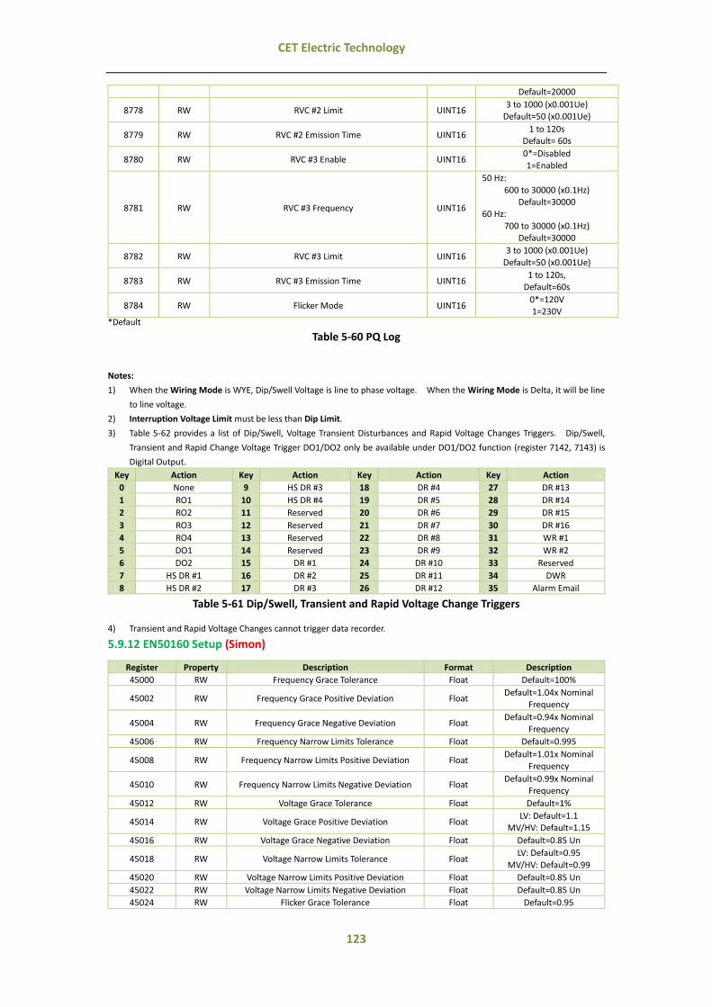
123
CET Electric Technology
Default=20000
8778 RW RVC #2 Limit UINT16 3 to 1000 (x0.001Ue)
Default=50 (x0.001Ue)
8779 RW RVC #2 Emission Time UINT16 1 to 120s
Default= 60s
8780 RW RVC #3 Enable UINT16 0*=Disabled
1=Enabled
8781 RW RVC #3 Frequency UINT16
50 Hz:
600 to 30000 (x0.1Hz) Default=30000
60 Hz:
700 to 30000 (x0.1Hz) Default=30000
8782 RW RVC #3 Limit UINT16 3 to 1000 (x0.001Ue)
Default=50 (x0.001Ue)
8783 RW RVC #3 Emission Time UINT16 1 to 120s,
Default=60s
8784 RW Flicker Mode UINT16 0*=120V 1=230V
*Default
Table 5-60 PQ Log
Notes:
1) When the Wiring Mode is WYE, Dip/Swell Voltage is line to phase voltage. When the Wiring Mode is Delta, it will be line
to line voltage.
2) Interruption Voltage Limit must be less than Dip Limit.
3) Table 5-62 provides a list of Dip/Swell, Voltage Transient Disturbances and Rapid Voltage Changes Triggers. Dip/Swell,
Transient and Rapid Change Voltage Trigger DO1/DO2 only be available under DO1/DO2 function (register 7142, 7143) is
Digital Output.
Key Action Key Action Key Action Key Action
0 None 9 HS DR #3 18 DR #4 27 DR #13
1 RO1 10 HS DR #4 19 DR #5 28 DR #14
2 RO2 11 Reserved 20 DR #6 29 DR #15
3 RO3 12 Reserved 21 DR #7 30 DR #16
4 RO4 13 Reserved 22 DR #8 31 WR #1
5 DO1 14 Reserved 23 DR #9 32 WR #2
6 DO2 15 DR #1 24 DR #10 33 Reserved
7 HS DR #1 16 DR #2 25 DR #11 34 DWR
8 HS DR #2 17 DR #3 26 DR #12 35 Alarm Email
Table 5-61 Dip/Swell, Transient and Rapid Voltage Change Triggers
4) Transient and Rapid Voltage Changes cannot trigger data recorder.
5.9.12 EN50160 Setup (Simon)
Register Property Description Format Description
45000 RW Frequency Grace Tolerance Float Default=100%
45002 RW Frequency Grace Positive Deviation Float Default=1.04x Nominal
Frequency
45004 RW Frequency Grace Negative Deviation Float Default=0.94x Nominal
Frequency
45006 RW Frequency Narrow Limits Tolerance Float Default=0.995
45008 RW Frequency Narrow Limits Positive Deviation Float Default=1.01x Nominal
Frequency
45010 RW Frequency Narrow Limits Negative Deviation Float Default=0.99x Nominal
Frequency
45012 RW Voltage Grace Tolerance Float Default=1%
45014 RW Voltage Grace Positive Deviation Float LV: Default=1.1
MV/HV: Default=1.15
45016 RW Voltage Grace Negative Deviation Float Default=0.85 Un
45018 RW Voltage Narrow Limits Tolerance Float LV: Default=0.95
MV/HV: Default=0.99
45020 RW Voltage Narrow Limits Positive Deviation Float Default=0.85 Un
45022 RW Voltage Narrow Limits Negative Deviation Float Default=0.85 Un
45024 RW Flicker Grace Tolerance Float Default=0.95

124
CET Electric Technology
45026 RW Flicker Grace Limits Float Default=1
45028 RW Unbalance Tolerance Float Default=0.95%
45030 RW Unbalance Limits Float Default=0.02
45032 RW Harmonic Grace Tolerance Float Default=0.95
45034 RW Harmonic Limits Float Default=0.08
45036~45038 RW Reserved
45040 RW H02 Limit Float LV/MV: Default=0.02
HV: Default=0.019
45042 RW H03 Limit Float LV/MV: Default=0.05
HV: Default=0.03
45044 RW H04 Limit Float Default=0.01
45046 RW H05 Limit Float LV/MV: Default=0.06
HV: Default=0.05
45048 RW H06 Limit Float Default=0.005
45050 RW H07 Limit Float LV/MV: Default=0.05
HV: Default=0.04
45052 RW H08 Limit Float Default=0.005
45054 RW H09 Limit Float LV/MV: Default=0.015
HV: Default=0.013
45056 RW H10 Limit Float Default=0.005
45058 RW H11 Limit Float LV/MV: Default=0.035
HV: Default=0.03
45060 RW H12 Limit Float Default=0.005
45062 RW H13 Limit Float LV/MV: Default=0.03
HV: Default=0.25
45064 RW H14 Limit Float Default=0.005
45066 RW H15 Limit Float Default=0.005
45068 RW H16 Limit Float Default=0.005
45070 RW H17 Limit Float Default=0.02
45072 RW H18 Limit Float Default=0.005
45074 RW H19 Limit Float Default=0.015
45076 RW H20 Limit Float Default=0.005
45078 RW H21 Limit Float Default=0.005
45080 RW H22 Limit Float Default=0.005
45082 RW H23 Limit Float Default=0.015
45084 RW H24 Limit Float Default=0.005
45086 RW H25 Limit Float Default=0.015
45088~15098 RW Reserved
Table 5-62 EN50160 Setup (Check)
5.9.13 TOU Setup
5.9.13.1 Daily Profile Setup
Register Address Property Description Format
46000~46023 RW Daily Profile #1
See Table 5-64 Daily Profile
Data Structure Setup
46024~46047 RW Daily Profile #2
46048~46071 RW Daily Profile #3
46072~46095 RW Daily Profile #4
46096~46119 RW Daily Profile #5
46120~46143 RW Daily Profile #6
46144~46167 RW Daily Profile #7
46168~46191 RW Daily Profile #8
46192~46215 RW Daily Profile #9
46216~46239 RW Daily Profile #10
46240~46263 RW Daily Profile #11
46264~46287 RW Daily Profile #12
46288~46311 RW Daily Profile #13
46312~46335 RW Daily Profile #14
46336~46359 RW Daily Profile #15
46360~46383 RW Daily Profile #16
46384~46407 RW Daily Profile #17
46408~46431 RW Daily Profile #18
46432~46455 RW Daily Profile #19
46456~46479 RW Daily Profile #20
Table 5-63 Daily Profile Setup

125
CET Electric Technology
Offset Property Description Format Note
+0 RW Daily Profile #x Period #1 Start Time UINT16 0x0000
+1 RW
Daily Profile #x Period #1 Tariff UINT16 0 to 7
0=T1, 7=T8
+2 RW Daily Profile #x Period #2 Start Time UINT16
+3 RW
Daily Profile #x Period #2 Tariff UINT16 0 to 7
0=T1, 7=T8
+4 RW Daily Profile #x Period #3 Start Time UINT16
+5 RW
Daily Profile #x Period #3 Tariff UINT16 0 to 7
0=T1, 7=T8
+6 RW Daily Profile #x Period #4 Start Time UINT16
+7 RW
Daily Profile #x Period #4 Tariff UINT16 0 to 7
0=T1, 7=T8
+8 RW Daily Profile #x Period #5 Start Time UINT16
+9 RW
Daily Profile #x Period #5 Tariff UINT16 0 to 7
0=T1, 7=T8
+10 RW Daily Profile #x Period #6 Start Time UINT16
+11 RW
Daily Profile #x Period #6 Tariff UINT16 0 to 7
0=T1, 7=T8
+12 RW Daily Profile #x Period #7 Start Time UINT16
+13 RW
Daily Profile #x Period #7 Tariff UINT16 0 to 7
0=T1, 7=T8
+14 RW Daily Profile #x Period #8 Start Time UINT16
+15 RW
Daily Profile #x Period #8 Tariff UINT16 0 to 7
0=T1, 7=T8
+16 RW Daily Profile #x Period #9 Start Time UINT16
+17 RW
Daily Profile #x Period #9 Tariff UINT16 0 to 7
0=T1, 7=T8
+18 RW Daily Profile #x Period #10 Start Time UINT16
+19 RW
Daily Profile #x Period #10 Tariff UINT16 0 to 7
0=T1, 7=T8
+20 RW Daily Profile #x Period #11 Start Time UINT16
+21 RW
Daily Profile #x Period #11 Tariff UINT16 0 to 7
0=T1, 7=T8
+22 RW Daily Profile #x Period #12 Start Time UINT16
+23 RW
Daily Profile #x Period #12 Tariff UINT16 0 to 7
0=T1, 7=T8 x indicates Daily Profile number.
Table 5-64 Daily Profile Data Structure Setup
Notes:
1) Daily Profile#1 Period #1 Start Time should be 00:00 and cannot be modified.
2) It is invalid when set Start Time as 0xFFFF. If one of daily profile’s Start Time is set as 0xFFFF, then all the later daily profiles’
Start Time must be 0xFFFF which means the valid period of last daily profile is from Start Time to the end of the year.
3) The minimum interval of period is 15mins.
4) The previous period must be earlier than the later period.
5.9.13.2 Season Setup
The PMC-670 has two sets of Season setup parameters. The base addresses for two sets are 47000
and 47050 respectively. Register Address = Base Address + Register Offset, for example, the season
#2’s start date of second schedule is 47050+4 = 47054.
Offset Property Description Format Range/Note
0 RW Season #1: Start Date¹ UINT16 0x0101
1 RW Season #1: Weekday#1 Daily Profile UINT16
0 to 19 2 RW Season #1: Weekday#2 Daily Profile UINT16
3 RW Season #1: Weekday#3 Daily Profile UINT16
4 RW Season #2: Start Date High-order Byte: Month
UINT16 Low-order Byte: Day
5 RW Season #2: Weekday#1 Daily Profile UINT16
0 to 19 6 RW Season #2: Weekday#2 Daily Profile UINT16
7 RW Season #2: Weekday#3 Daily Profile UINT16
8 RW Season #3: Start Date UINT16 See Season #2: Start Date

126
CET Electric Technology
9 RW Season #3: Weekday#1 Daily Profile UINT16
0 to 19 10 RW Season #3: Weekday#2 Daily Profile UINT16
11 RW Season #3: Weekday#3 Daily Profile UINT16
12 RW Season #4: Start Date UINT16 See Season #2: Start Date
13 RW Season #4: Weekday#1 Daily Profile UINT16
0 to 19 14 RW Season #4: Weekday#2 Daily Profile UINT16
15 RW Season #4: Weekday#3 Daily Profile UINT16
16 RW Season #5: Start Date UINT16 See Season #2: Start Date
17 RW Season #5: Weekday#1 Daily Profile UINT16
0 to 19 18 RW Season #5: Weekday#2 Daily Profile UINT16
19 RW Season #5: Weekday#3 Daily Profile UINT16
20 RW Season #6: Start Date UINT16 See Season #2: Start Date
21 RW Season #6: Weekday#1 Daily Profile UINT16
0 to 19 22 RW Season #6: Weekday#2 Daily Profile UINT16
23 RW Season #6: Weekday#3 Daily Profile UINT16
24 RW Season #7: Start Date UINT16 See Season #2: Start Date
25 RW Season #7: Weekday#1 Daily Profile UINT16
0 to 19 26 RW Season #7: Weekday#2 Daily Profile UINT16
27 RW Season #7: Weekday#3 Daily Profile UINT16
28 RW Season #8: Start Date UINT16 See Season #2: Start Date
29 RW Season #8: Weekday#1 Daily Profile UINT16
0 to 19 30 RW Season #8: Weekday#2 Daily Profile UINT16
31 RW Season #8: Weekday#3 Daily Profile UINT16
32 RW Season #9: Start Date UINT16 See Season #2: Start Date
33 RW Season #9: Weekday#1 Daily Profile UINT16
0 to 19 34 RW Season #9: Weekday#2 Daily Profile UINT16
35 RW Season #9: Weekday#3 Daily Profile UINT16
36 RW Season #10: Start Date UINT16 See Season #2: Start Date
37 RW Season #10: Weekday#1 Daily Profile UINT16
0 to 19 38 RW Season #10: Weekday#2 Daily Profile UINT16
39 RW Season #10: Weekday#3 Daily Profile UINT16
40 RW Season #11: Start Date UINT16 See Season #2: Start Date
41 RW Season #11: Weekday#1 Daily Profile UINT16
0 to 19 42 RW Season #11: Weekday#2 Daily Profile UINT16
43 RW Season #11: Weekday#3 Daily Profile UINT16
44 RW Season #12: Start Date UINT16 See Season #2: Start Date
45 RW Season #12: Weekday#1 Daily Profile UINT16
0 to 19 46 RW Season #12: Weekday#2 Daily Profile UINT16
47 RW Season #12: Weekday#3 Daily Profile UINT16
Table 5-65 Season Setup
Notes:
1) Start Date for Season#1 is Jan. 1st and cannot be modified.
2) It is invalid when set Start Date as 0xFFFF. If one of season’s start time is set as 0xFFFF, then all the later seasons’ Start
Date must be 0xFFFF which means the valid period of last season is from Start Date to the end of this year.
3) The previous season must be earlier than the later season.
5.9.13.3 Alternate Days Setup
The Alternate Days has higher priority than season, that means if one day is set as alternate day, then
this day’s rate distribution will according to Alternate Days schedule.
The PMC-670 has two sets of Alternate Days setup parameter. The base addresses for two sets are
47100 and 47400 respectively. Register Address = Base Address + Register Offset.
Offset Property Description Format Note
0 RW Alternate Day #1 Date¹ UINT32
2 RW Alternate Day #1 Daily Profile UINT16 0 to 19
3 RW Alternate Day #2 Date¹ UINT32
5 RW Alternate Day #2 Daily Profile UINT16 0 to 19
6 RW Alternate Day #3 Date¹ UINT32
8 RW Alternate Day #3 Daily Profile UINT16 0 to 19
9 RW Alternate Day #4 Date¹ UINT32
11 RW Alternate Day #4 Daily Profile UINT16 0 to 19

127
CET Electric Technology
12 RW Alternate Day #5 Date¹ UINT32
14 RW Alternate Day #5 Daily Profile UINT16 0 to 19
15 RW Alternate Day #6 Date¹ UINT32
17 RW Alternate Day #6 Daily Profile UINT16 0 to 19
18 RW Alternate Day #7 Date¹ UINT32
19 RW Alternate Day #7 Daily Profile UINT16 0 to 19
21 RW Alternate Day #8 Date¹ UINT32
22 RW Alternate Day #8 Daily Profile UINT16 0 to 19
24 RW Alternate Day #9 Date¹ UINT32
25 RW Alternate Day #9 Daily Profile UINT16 0 to 19
27 RW Alternate Day #10 Date¹ UINT32
29 RW Alternate Day #10 Daily Profile UINT16 0 to 19
… …
… …
240 RW Alternate Day #81 Date¹ UINT32
242 RW Alternate Day #81 Daily Profile UINT16 0 to 19
243 RW Alternate Day #82 Date¹ UINT32
245 RW Alternate Day #82 Daily Profile UINT16 0 to 19
246 RW Alternate Day #83 Date¹ UINT32
248 RW Alternate Day #83 Daily Profile UINT16 0 to 19
249 RW Alternate Day #84 Date¹ UINT32
251 RW Alternate Day #84 Daily Profile UINT16 0 to 19
252 RW Alternate Day #85 Date¹ UINT32
254 RW Alternate Day #85 Daily Profile UINT16 0 to 19
255 RW Alternate Day #86 Date¹ UINT32
256 RW Alternate Day #86 Daily Profile UINT16 0 to 19
258 RW Alternate Day #87 Date¹ UINT32
260 RW Alternate Day #87 Daily Profile UINT16 0 to 19
261 RW Alternate Day #88 Date¹ UINT32
263 RW Alternate Day #88 Daily Profile UINT16 0 to 19
264 RW Alternate Day #89 Date¹ UINT32
266 RW Alternate Day #89 Daily Profile UINT16 0 to 19
267 RW Alternate Day #90 Date¹ UINT32
269 RW Alternate Day #90 Daily Profile UINT16 0 to 19
Table 5-66 Alternate Days Setup
Notes:
1) The following table illustrate the register of date:
Byte3 Byte2 Byte1 Byte0
Reserved Year Month Day
Table 5-67 Date Format
The Year and Month can be set as 0xFF which indicates the alternate day is repeated by year or month, that is the day of
every year or every month is alternate day. Simon
5.9.14 TOU Status Setup
Register Property Description Format Range/Option
48600 RO Present Tariff Schedule UINT16 0 to 7
48601 RO Present TOU Schedule UINT16 0 to 1
48602 RO Present Daily Profile Index UINT16 0 to 19
48603 RO Present Daily Profile UINT16 0 to 11
48604 RO Present Daily Season UINT16 0 to 11
48605 RO Present Weekday Type UINT16
0=Weekday1
1=Weekday2 2=Weekday3
3=Alternate Day
48606 RW Sunday Setup UINT16
0=Weekday1 1=Weekday2
2=Weekday3
48607 RW Monday Setup UINT16
48608 RW Tuesday Setup UINT16
48609 RW Wednesday Setup UINT16
48610 RW Thursday Setup UINT16
48611 RW Friday Setup UINT16
48612 RW Saturday Setup UINT16
48613 RW Switch Time Between Two TOU Schedules UINT32 YYYYMMDDHH

128
CET Electric Technology
48615 RW TOU Self-read Time UINT32 DDHH
Table 5-68 TOU Schedule Status and Configuration Setup
5.9.15 Control Setup
5.9.15.1 RO/DO Control
Register Property Description Format Note
9100 WO Arm RO1 Close UINT16 Writing “0xFF00”
9101 WO Execute RO1 Close UINT16 Writing “0xFF00”
9102 WO Arm RO1 Open UINT16 Writing “0xFF00”
9103 WO Execute RO1 Open UINT16 Writing “0xFF00”
9104 WO Arm RO2 Close UINT16 Writing “0xFF00”
9105 WO Execute RO2 Close UINT16 Writing “0xFF00”
9106 WO Arm RO2 Open UINT16 Writing “0xFF00”
9107 WO Execute RO2 Open UINT16 Writing “0xFF00”
9108 WO Arm RO3 Close UINT16 Writing “0xFF00”
9109 WO Execute RO3 Close UINT16 Writing “0xFF00”
9110 WO Arm RO3 Open UINT16 Writing “0xFF00”
9111 WO Execute RO3 Open UINT16 Writing “0xFF00”
9112 WO Arm RO4 Close UINT16 Writing “0xFF00”
9113 WO Execute RO4 Close UINT16 Writing “0xFF00”
9114 WO Arm RO4 Open UINT16 Writing “0xFF00”
9115 WO Execute RO4 Open UINT16 Writing “0xFF00”
9116 WO Arm DO1 Close UINT16 Writing “0xFF00”
9117 WO Execute DO1 Close UINT16 Writing “0xFF00”
9118 WO Arm DO1 Open UINT16 Writing “0xFF00”
9119 WO Execute DO1 Open UINT16 Writing “0xFF00”
9120 WO Arm DO2 Close UINT16 Writing “0xFF00”
9121 WO Execute DO2 Close UINT16 Writing “0xFF00”
9122 WO Arm DO2 Open UINT16 Writing “0xFF00”
9123 WO Execute DO2 Open UINT16 Writing “0xFF00”
Table 5-69 DO Control
Notes:
1) The RO/DO has two modes which can be set via 7029: Remote Control Preset Enabled and Remote Control Preset Disabled.
When under preset disabled mode, execute register comes into effect directly. As for preset mode, there are two steps:
remote control arm register first and then remote control execute register. If there is no operation in 15s after presetting
register, the command is invalid. (Simon)
5.9.15.2 Clear/Reset Control
Register Property Description Format Note
7400 WO WFR #1 Trigger Manually UINT16 Writing ”0xFF00” triggers the respective Waveform
Recorder 7401 WO WFR #2 Trigger Manually UINT16
7402 WO Reserved UINT16
7403 WO DWR Trigger Manually UINT16 Writing ”0xFF00” triggers the respective Transient
Recorder
7404 WO Clear HS DR #1 Log UINT16 Writing “0xFF00” to the
register clears the respective Daily Recorder
7405 WO Clear HS DR #2 Log UINT16
7406 WO Clear HS DR #3 Log UINT16
7407 WO Clear HS DR #4 Log UINT16
7408~7411 WO Reserved UINT16
7412 WO Clear DR #1 Log UINT16 Writing “0xFF00” to the
register clears the respective Daily Recorder
… …
7427 WO Clear DR #16 Log UINT16
7428 WO Clear WFR #1 Log UINT16 Writing “0xFF00” to the register clears the
respective Waveform
Recorder 7429 WO Clear WFR #2 Log UINT16
7430 WO Reserved UINT16
7431 WO Clear DWR Log UINT16 Writing “0xFF00” to the
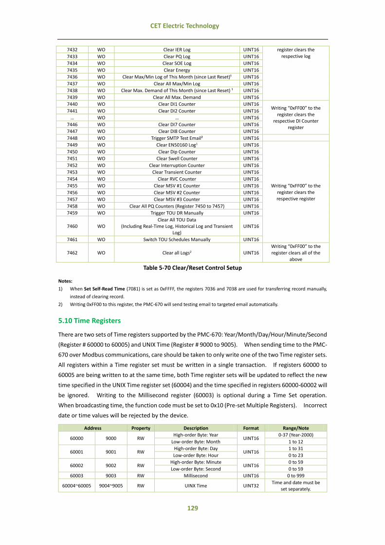
129
CET Electric Technology
7432 WO Clear IER Log UINT16 register clears the
respective log 7433 WO Clear PQ Log UINT16
7434 WO Clear SOE Log UINT16
7435 WO Clear Energy UINT16
7436 WO Clear Max/Min Log of This Month (since Last Reset)¹ UINT16
7437 WO Clear All Max/Min Log UINT16
7438 WO Clear Max. Demand of This Month (since Last Reset) ¹ UINT16
7439 WO Clear All Max. Demand UINT16
7440 WO Clear DI1 Counter UINT16 Writing “0xFF00” to the
register clears the respective DI Counter
register
7441 WO Clear DI2 Counter UINT16
… WO … UINT16
7446 WO Clear DI7 Counter UINT16
7447 WO Clear DI8 Counter UINT16
7448 WO Trigger SMTP Test Email² UINT16
7449 WO Clear EN50160 Log1 UINT16
Writing “0xFF00” to the
register clears the respective register
7450 WO Clear Dip Counter UINT16
7451 WO Clear Swell Counter UINT16
7452 WO Clear Interruption Counter UINT16
7453 WO Clear Transient Counter UINT16
7454 WO Clear RVC Counter UINT16
7455 WO Clear MSV #1 Counter UINT16
7456 WO Clear MSV #2 Counter UINT16
7457 WO Clear MSV #3 Counter UINT16
7458 WO Clear All PQ Counters (Register 7450 to 7457) UINT16
7459 WO Trigger TOU DR Manually UINT16
7460 WO Clear All TOU Data
(Including Real-Time Log, Historical Log and Transient Log)
UINT16
7461 WO Switch TOU Schedules Manually UINT16
7462 WO Clear all Logs2 UINT16
Writing “0xFF00” to the
register clears all of the above
Table 5-70 Clear/Reset Control Setup
Notes:
1) When Set Self-Read Time (7081) is set as 0xFFFF, the registers 7036 and 7038 are used for transferring record manually,
instead of clearing record.
2) Writing 0xFF00 to this register, the PMC-670 will send testing email to targeted email automatically.
5.10 Time Registers
There are two sets of Time registers supported by the PMC-670: Year/Month/Day/Hour/Minute/Second
(Register # 60000 to 60005) and UNIX Time (Register # 9000 to 9005). When sending time to the PMC-
670 over Modbus communications, care should be taken to only write one of the two Time register sets.
All registers within a Time register set must be written in a single transaction. If registers 60000 to
60005 are being written to at the same time, both Time register sets will be updated to reflect the new
time specified in the UNIX Time register set (60004) and the time specified in registers 60000-60002 will
be ignored. Writing to the Millisecond register (60003) is optional during a Time Set operation.
When broadcasting time, the function code must be set to 0x10 (Pre-set Multiple Registers). Incorrect
date or time values will be rejected by the device.
Address Property Description Format Range/Note
60000 9000 RW High-order Byte: Year
UINT16 0-37 (Year-2000)
Low-order Byte: Month 1 to 12
60001 9001 RW High-order Byte: Day
UINT16 1 to 31
Low-order Byte: Hour 0 to 23
60002 9002 RW High-order Byte: Minute
UINT16 0 to 59
Low-order Byte: Second 0 to 59
60003 9003 RW Millisecond UINT16 0 to 999
60004~60005 9004~9005 RW UINX Time UINT32 Time and date must be
set separately.
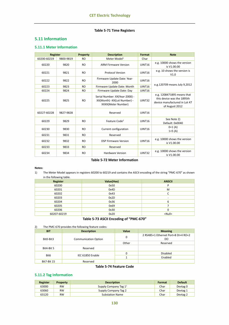
130
CET Electric Technology
Table 5-71 Time Registers
5.11 Information
5.11.1 Meter Information
Register Property Description Format Note
60200-60219 9800-9819 RO Meter Model1 Char
60220 9820 RO ARM Firmware Version UINT16 e.g. 10000 shows the version
is V1.00.00
60221 9821 RO Protocol Version UINT16 e.g. 10 shows the version is
V1.0
60222 9822 RO Firmware Update Date: Year-
2000 UINT16
e.g.120709 means July 9,2012 60223 9823 RO Firmware Update Date: Month UINT16
60224 9824 RO Firmware Update Date: Day UINT16
60225 9825 RO
Serial Number: XX(Year-2000) -
XX(Month) -XX(Lot Number) - XXXX(Meter Number)
UINT32
e.g. 1208471895 means that this device was the 1895th
device manufactured in Lot 47
of August 2012
60227-60228 9827-9828 Reserved UINT16
60229 9829 RO Feature Code2 UINT16 See Note 2)
Default: 0x0040
60230 9830 RO Current configuration UINT16 0=1 (A)
1=5 (A)
60231 9831 RO Reserved
60232 9832 RO DSP Firmware Version UINT16 e.g. 10000 shows the version
is V1.00.00
60233 9833 RO Reserved
60234 9834 RO Hardware Version UINT32 e.g. 10000 shows the version
is V1.00.00
Table 5-72 Meter Information
Notes:
1) The Meter Model appears in registers 60200 to 60219 and contains the ASCII encoding of the string “PMC-670” as shown
in the following table.
Register Value(Hex) ANSCII
60200 0x50 P
60201 0x4D M
60202 0x43 C
60203 0x2D -
60204 0x36 6
60205 0x69 7
60206 0x30 0
60207-60219 0x20 <Null>
Table 5-73 ASCII Encoding of “PMC-670”
2) The PMC-670 provides the following feature codes:
BIT Description Value Meaning
Bit0-Bit3 Communication Option 0
2 RS485+1 Ethernet Port+8 DI+4 RO+2 DO
Other Reserved
Bit4-Bit 5 Reserved
Bit6 IEC 61850 Enable 0 Disabled
1 Enabled
Bit7-Bit 15 Reserved
Table 5-74 Feature Code
5.11.2 Tag Information
Register Property Description Format Default
63000 RW Supply Company Tag 11 Char Devtag 0
63060 RW Supply Company Tag 2 Char Devtag 1
63120 RW Substation Name Char Devtag 2
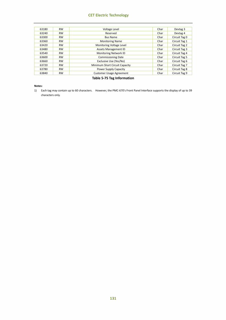
131
CET Electric Technology
63180 RW Voltage Level Char Devtag 3
63240 RW Reserved Char Devtag 4
63300 RW Bus Name Char Circuit Tag 0
63360 RW Monitoring Name Char Circuit Tag 1
63420 RW Monitoring Voltage Level Char Circuit Tag 2
63480 RW Assets Management ID Char Circuit Tag 3
63540 RW Monitoring Network ID Char Circuit Tag 4
63600 RW Commissioning Date Char Circuit Tag 5
63660 RW Exclusive Use (Yes/No) Char Circuit Tag 6
63720 RW Minimum Short Circuit Capacity Char Circuit Tag 7
63780 RW Power Supply Capacity Char Circuit Tag 8
63840 RW Customer Usage Agreement Char Circuit Tag 9
Table 5-75 Tag Information
Notes:
1) Each tag may contain up to 60 characters. However, the PMC-670's Front Panel Interface supports the display of up to 39
characters only.

132
CET Electric Technology
Appendix A - Data Recorder Parameter
Key Parameters Scale/Unit Key Parameters Scale/Unit
1 Ua V 2 Ub V
3 Uc V 4 ULN average V
5 Uab V 6 Ubc V
7 Uca V 8 ULL average V
9 Ia A 10 Ib A
11 Ic A 12 I average A
13 U4 V 14 I4 A
15 kWa W 16 kWb W
17 kWc W 18 ∑kW W
19 kvara var 20 kvarb var
21 kvarc var 22 ∑kvar var
23 kVAa VA 24 kVAb VA
25 kVAc VA 26 ∑kVA VA
27 P.F.a 28 P.F.b
29 P.F.c 30 ∑P.F.
31 Frequency Hz 32 Ua Demand V
33 Ub Demand V 34 Uc Demand V
35 ULN average Demand V 36 Uab Demand V
37 Ubc Demand V 38 Uca Demand V
39 ULL average V 40 Ia Demand A
41 Ib Demand A 42 Ic Demand A
43 I average Demand A 44 U4 Demand V
45 I4 Demand A 46 kWa Demand W
47 kWb Demand W 48 kWc Demand W
49 ∑kW Demand W 50 kvara Demand var
51 kvarb Demand var 52 kvarc Demand var
53 ∑kvar Demand var 54 kVAa Demand VA
55 kVAb Demand VA 56 kVAc Demand VA
57 ∑kVA Demand VA 58 P.F.a Demand
59 P.F.b Demand VA 60 P.F.c Demand
61 ∑P.F. Demand 62 FREQ Demand Hz
63 Ua Deviation Demand 100% 64 Ub Deviation Demand 100%
65 Uc Deviation Demand 100% 66 FREQ Deviation Demand Hz
67 U2 (Negative Sequence)
Unbalance Demand 68
U0 (Zero Sequence) Unbalance Demand
69 I2 (Negative Sequence)
Unbalance Demand 70
I0 (Zero Sequence) Unbalance
Demand
71 Ia K Factor Demand 72 Ib K Factor Demand
73 Ic K Factor Demand 74 I4 K Factor Demand
75 Ua THD Demand 100% 76 Ub THD Demand 100%
77 Uc THD Demand 100% 78 U4 THD Demand 100%
79 Ia THD Demand 100% 80 Ib THD Demand 100%
81 Ic THD Demand 100% 82 I4 THD Demand 100%
83 Ua TOHD Demand 100% 84 Ub TOHD Demand 100%
85 Uc TOHD Demand 100% 86 U4 TOHD Demand 100%
87 Ia TOHD Demand 100% 88 Ib TOHD Demand 100%
89 Ic TOHD Demand 100% 90 I4 TOHD Demand 100%
91 Ua TEHD Demand 100% 92 Ub TEHD Demand 100%
93 Uc TEHD Demand 100% 94 U4 TEHD Demand 100%
95 Ia TEHD Demand 100% 96 Ib TEHD Demand 100%
97 Ic TEHD Demand 100% 98 I4 TOHD Demand 100%
99 Ua 2nd Harmonic Demand V/100% 100 Ub 2nd Harmonic Demand V/100%
101 Uc 2nd Harmonic Demand V/100% 102 U4 2nd Harmonic Demand V/100%
103 Ia 2nd Harmonic Demand A/100% 104 Ib 2nd Harmonic Demand A/100%
105 Ic 2nd Harmonic Demand A/100% 106 I4 2nd Harmonic Demand A/100%
107 Ua 3rd Harmonic Demand V/100% 108 Ub 3rd Harmonic Demand V/100%
109 Uc 3rd Harmonic Demand V/100% 110 U4 3rd Harmonic Demand V/100%
111 Ia 3rd Harmonic Demand A/100% 112 Ib 3rd Harmonic Demand A/100%
113 Ic 3rd Harmonic Demand A/100% 114 I4 3rd Harmonic Demand A/100%
… …

133
CET Electric Technology
587 Ua 63rd Harmonic Demand V/100% 588 Ub 63rd Harmonic Demand V/100%
589 Uc 63rd Harmonic Demand V/100% 590 U4 63rd Harmonic Demand V/100%
591 Ia 63rd Harmonic Demand A/100% 592 Ib 63rd Harmonic Demand A/100%
593 Ic 63rd Harmonic Demand A/100% 594 I4 63rd Harmonic Demand A/100%
595 Ua Demand max V 596 Ub Demand max V
597 Uc Demand max V 598 ULN average Demand max V
599 Uab Demand max V 600 Ubc Demand max V
601 Uca Demand max V 602 ULL average Demand max V
603 Ia Demand max A 604 Ib Demand max A
605 Ic Demand max A 606 I average Demand max A
607 U4 Demand max A 608 I4 Demand max A
609 kWa Demand max W 610 kWb Demand max W
611 kWc Demand max W 612 ∑kW Demand max W
613 kvara Demand max var 614 kvarb Demand max var
615 kvarc Demand max var 616 ∑kvar Demand max var
617 kVAa Demand max VA 618 kVAb Demand max VA
619 kVAc Demand max VA 620 ∑kVA Demand max VA
621 P.F.a Demand max 622 P.F.b Demand max
623 P.F.c Demand max 624 ∑P.F. Demand max
625 FREQ Demand max Hz 626 Ua Deviation Demand max 100%
627 Ub Deviation Demand max 100% 628 Uc Deviation Demand max 100%
629 FREQ Deviation Demand max Hz 630 U2 (Negative Sequence) Unbalance Demand max
631 U0 (Zero Sequence) Unbalance
Demand max 632
I2 (Negative Sequence) Unbalance Demand max
633 I0 (Negative Sequence)
Unbalance Demand max 634 Ia K Factor Demand max
635 Ib K Factor Demand max 636 Ic K Factor Demand max
637 I4 K Factor Demand max 638 Ua THD Demand max 100%
639 Ub THD Demand max 100% 640 Uc THD Demand max 100%
641 U4 THD Demand max 100% 642 Ia THD Demand max 100%
643 Ib THD Demand max 100% 644 Ic THD Demand max 100%
645 I4 THD Demand max 100% 646 Ua TOHD Demand max 100%
647 Ub TOHD Demand max 100% 648 Uc TOHD Demand max 100%
649 U4 TOHD Demand max 100% 650 Ia TOHD Demand max 100%
651 Ib TOHD Demand max 100% 652 Ic TOHD Demand max 100%
653 I4 TOHD Demand max 100% 654 Ua TEHD Demand max 100%
655 Ub TEHD Demand max 100% 656 Uc TEHD Demand max 100%
657 U4 TEHD Demand max 100% 658 Ia TEHD Demand max 100%
659 Ib TEHD Demand max 100% 660 Ic TEHD Demand max 100%
661 I4 TEHD Demand max 100% 662 Ua H02 Demand max V/100%
663 Ub H02 Demand max V/100% 664 Uc H02 Demand max V/100%
665 U4 H02 Demand max V/100% 666 Ia H02 Demand max A/100%
667 Ib H02 Demand max A/100% 668 Ic H02 Demand max A/100%
669 I4 H02 Demand max A/100% 670 Ua H03 Demand max V/100%
671 Ub H03 Demand max V/100% 672 Uc H03 Demand max V/100%
673 U4 H03 Demand max V/100% 674 Ia H03 Demand max A/100%
675 Ib H03 Demand max A/100% 676 Ic H03 Demand max A/100%
677 I4 H03 Demand max A/100% ……
…… ……
1150 Ua H63 Demand max V/100% 1151 Ub H63 Demand max V/100%
1152 Uc H63 Demand max V/100% 1153 U4 H63 Demand max V/100%
1154 Ia H63 Demand max A/100% 1155 Ib H63 Demand max A/100%
1156 Ic H63 Demand max A/100% 1157 I4 H63 Demand max A/100%
1158 Ua Demand min V 1159 Ub Demand min V
1160 Uc Demand min V 1161 ULN average Demand min V
1162 Uab Demand min V 1163 Ubc Demand min V
1164 Uca Demand min V 1165 ULL average Demand min V
1166 Ia Demand min A 1167 Ib Demand min A
1168 Ic Demand min A 1169 I average Demand min A
1170 U4 Demand min V 1171 I4 Demand min A
1172 kWa Demand min W 1173 kWb Demand min W

134
CET Electric Technology
1174 kWc Demand min W 1175 ∑kW Demand min W
1176 kvara Demand min var 1177 kvarb Demand min var
1178 kvarc Demand min var 1179 ∑kvar Demand min var
1180 kVAa Demand min VA 1181 kVAb Demand min VA
1182 kVAc Demand min VA 1183 ∑kVA Demand min VA
1184 P.F.a Demand min 1185 P.F.b Demand min
1186 P.F.c Demand min 1187 ∑P.F. Demand min
1188 FREQ Demand min Hz 1189 Ua Deviation Demand min 100%
1190 Ub Deviation Demand min 100% 1191 Uc Deviation Demand min 100%
1192 FREQ Deviation Demand min Hz 1193 U Unbalance Demand min
1194 U0 Unbalance Demand min 1195 I2 Unbalance Demand min
1196 I0 Unbalance Demand min 1197 Ia K Factor Demand min
1198 Ib K Factor Demand min 1199 Ic K Factor Demand min
1200 I4 K Factor Demand min 1201 Ua THD Demand min 100%
1202 Ub THD Demand min 100% 1203 Uc THD Demand min 100%
1204 U4 THD Demand min 100% 1205 Ia THD Demand min 100%
1206 Ib THD Demand min 100% 1207 Ic THD Demand min 100%
1208 I4 THD Demand min 100% 1209 Ua TOHD Demand min 100%
1210 Ub TOHD Demand min 100% 1211 Uc TOHD Demand min 100%
1212 U4 TOHD Demand min 100% 1213 Ia TOHD Demand min 100%
1214 Ib TOHD Demand min 100% 1215 Ic TOHD Demand min 100%
1216 I4 TOHD Demand min 100% 1217 Ua TEHD Demand min 100%
1218 Ub TEHD Demand min 100% 1219 Uc TEHD Demand min 100%
1220 U4 TEHD Demand min 100% 1221 Ia TEHD Demand min 100%
1222 Ib TEHD Demand min 100% 1223 Ic TEHD Demand min 100%
1224 I4 TEHD Demand min 100% 1225 Ua H02 Demand min V/100%
1226 Ub H02 Demand min V/100% 1227 Uc H02 Demand min V/100%
1228 U4 H02 Demand min V/100% 1229 Ia H02 Demand min A/100%
1230 Ib H02 Demand min A/100% 1231 Ic H02 Demand min A/100%
1232 I4 H02 Demand min A/100% 1233 Ua H03 Demand min V/100%
1234 Ub H03 Demand min V/100% 1235 Uc H03 Demand min V/100%
1236 U4 H03 Demand min V/100% 1237 Ia H03 Demand min A/100%
1238 Ib H03 Demand min A/100% 1239 Ic H03 Demand min A/100%
1240 I4 H03 Demand min A/100% ……
…… ……
1713 Ua H63 Demand min V/100% 1714 Ub H63 Demand min V/100%
1715 Uc H63 Demand min V/100% 1716 U4 H63 Demand min V/100%
1717 Ia H63 Demand min A/100% 1718 Ib H63 Demand min A/100%
1719 Ic H63 Demand min A/100% 1720 I4 H63 Demand min A/100%
1721 kWh Import* kWh 1722 kWh Export* kWh
1723 kWh Total* kWh 1724 kWh Net* kWh
1725 kvarh Import* kvarh 1726 kvarh Export* kvarh
1727 kvarh Total* kvarh 1728 kvarh Net* kvarh
1729 kVAh* kVAh 1730 Fundamental kWh Import* kWh
1731 Fundamental kWh Export* kWh 1732 Fundamental kvarh Import* kvarh
1733 Fundamental kvarh Export* kvarh 1734 Total Harmonic kWh Import* kWh
1735 Total Harmonic kWh Export* kWh 1736 Ua/Uab Pst
1737 Ub/Ubc Pst 1738 Uc/Uca Pst
1739 Ua/Uab Plt 1740 Ub/Ubc Plt
1741 Uc/Uca Plt
* Parameters # 1721 to 1735 are accumulative energy values.
Notes:
All the parameters’ values are single precision float type except energy parameters which are 32-bit signed integer type.

135
CET Electric Technology
Appendix B - SOE Event Classification
Classification Format Description
1 INT 32 DI Status Change
2 INT 32 DO/RO Operation
3 Float Alarm
4 INT 32 Self-test
5 INT 32 Parameters Configuration via Comm. or Front Panel
6 INT 32 Trigger Events
7 Float Over/Under U H02 to H63 Active/Return
8 Float Over/Under I H02 to H63 Active/Return
Event Classification
Sub-Classification
Description SOE
1
1 DI1 Close/DI1 Open 1/0
2 DI2 Close/DI2 Open 1/0
3 DI3 Close/DI3 Open 1/0
4 DI4 Close/DI4 Open 1/0
5 DI5 Close/DI5 Open 1/0
6 DI6 Close/DI6 Open 1/0
7 DI7 Close/DI5 Open 1/0
8 DI8 Close/DI6 Open 1/0
2
1 RO1 Operated/Released by Remote Control 1/0
2 RO2 Operated/Released by Remote Control 1/0
3 RO3 Operated/Released by Remote Control 1/0
4 RO4 Operated/Released by Remote Control 1/0
5 DO1 Operated/Released by Remote Control 1/0
6 DO2 Operated/Released by Remote Control 1/0
7 RO1 Operated/Released by Setpoint 1/0
8 RO2 Operated/Released by Setpoint 1/0
9 RO3 Operated/Released by Setpoint 1/0
10 RO4 Operated/Released by Setpoint 1/0
11 DO1 Operated/Released by Setpoint 1/0
12 DO2 Operated/Released by Setpoint 1/0
13 RO1 Operated/Released by Dip/Swell 1/0
14 RO2 Operated/Released by Dip/Swell 1/0
15 RO3 Operated/Released by Dip/Swell 1/0
16 RO4 Operated/Released by Dip/Swell 1/0
17 DO1 Operated/Released by Dip/Swell 1/0
18 DO2 Operated/Released by Dip/Swell 1/0
19 RO1 Operated/Released by Transient 1/0
20 RO2 Operated/Released by Transient 1/0
21 RO3 Operated/Released by Transient 1/0
22 RO4 Operated/Released by Transient 1/0
23 DO1 Operated/Released by Transient 1/0
24 DO2 Operated/Released by Transient 1/0
25 RO1 Operated/Released by RVC 1/0
26 RO2 Operated/Released by RVC 1/0
27 RO3 Operated/Released by RVC 1/0
28 RO4 Operated/Released by RVC 1/0
29 DO1 Operated/Released by RVC 1/0
30 DO2 Operated/Released by RVC 1/0
31 RO1 Closed/Open via Front Panel 1/0
32 RO2 Closed/Open via Front Panel 1/0
33 RO3 Closed/Open via Front Panel 1/0
34 RO4 Closed/Open via Front Panel 1/0
35 DO1 Closed/Open via Front Panel 1/0
36 DO2 Closed/Open via Front Panel 1/0
3
1 Over ULN Setpoint Active Trigger Value
2 Over ULL Setpoint Active Trigger Value
3 Over I Setpoint Active Trigger Value
4 Over U4 Setpoint Active Trigger Value
5 Over I4 Setpoint Active Trigger Value

136
CET Electric Technology
6 Over Freq. Deviation Setpoint Active (Definition??) Trigger Value
7 Over ∑P Setpoint Active Trigger Value
8 Over ∑Q Setpoint Active Trigger Value
9 Over ∑S Setpoint Active Trigger Value
10 Over ∑P.F. Setpoint Active Trigger Value
11 DI1 Closed Setpoint Active 1
12 DI2 Closed Setpoint Active 1
13 DI3 Closed Setpoint Active 1
14 DI4 Closed Setpoint Active 1
15 DI5 Closed Setpoint Active 1
16 DI6 Closed Setpoint Active 1
17 DI7 Closed Setpoint Active 1
18 DI8 Closed Setpoint Active 1
19 Over ∑P Demand Setpoint Active Trigger Value
20 Over ∑Q Demand Setpoint Active Trigger Value
21 Over ∑S Demand Setpoint Active Trigger Value
22 Over ∑P.F. Demand Setpoint Active Trigger Value
23 Over ∑P Predicted Setpoint Active Trigger Value
24 Over ∑Q Pred. DMD Active Trigger Value
25 Over ∑S Pred. DMD Active Trigger Value
26 Over ∑P.F. Pred. DMD Active Trigger Value
27 Over U THD Setpoint Active Trigger Value
28 Over U TOHD Setpoint Active Trigger Value
29 Over U TEHD Setpoint Active Trigger Value
30 Over I THD Setpoint Active Trigger Value
31 Over I TOHD Setpoint Active Trigger Value
32 Over I TEHD Setpoint Active Trigger Value
33 Over U2 Unbalance Setpoint Active Trigger Value
34 Over U0 Unbalance Setpoint Active Trigger Value
35 Over I2 Unbalance Setpoint Active Trigger Value
36 Over I0 Unbalance Setpoint Active Trigger Value
37 Over U Deviation Setpoint Active Trigger Value
38 Over Phase Reversal Setpoint Active (Definition??) 1
39~45 Reserved
46 Over ULN Setpoint Return Return Value
47 Over ULL Setpoint Return Return Value
48 Over I Setpoint Return Return Value
49 Over U4 Setpoint Return Return Value
50 Over I4 Setpoint Return Return Value
51 Over Freq. Deviation Setpoint Return (Definition??) Return Value
52 Over ∑P Setpoint Return Return Value
53 Over ∑Q Setpoint Return Return Value
54 Over ∑S Setpoint Return Return Value
55 Over ∑P.F. Setpoint Return Return Value
56 DI1 Closed Setpoint Return 0
57 DI2 Closed Setpoint Return 0
58 DI3 Closed Setpoint Return 0
59 DI4 Closed Setpoint Return 0
60 DI5 Closed Setpoint Return 0
61 DI6 Closed Setpoint Return 0
62 DI7 Closed Setpoint Return 0
63 DI8 Closed Setpoint Return 0
64 Over ∑P Demand Setpoint Return Return Value
65 Over ∑Q Demand Setpoint Return Return Value
66 Over ∑S Demand Setpoint Return Return Value
67 Over ∑P.F. Demand Setpoint Return Return Value
68 Over ∑P Pred. DMD Return Return Value
69 Over ∑Q Pred. DMD Return Return Value
70 Over ∑S Pred. DMD Return Return Value
71 Over ∑P.F. Pred. DMD Return Return Value
72 Over U THD Setpoint Return Return Value
73 Over U TOHD Setpoint Return Return Value
74 Over U TEHD Setpoint Return Return Value
75 Over I THD Setpoint Return Return Value
76 Over I TOHD Setpoint Return Return Value
77 Over I TEHD Setpoint Return Return Value

137
CET Electric Technology
78 Over U2 Unbalance Setpoint Return Return Value
79 Over U0 Unbalance Setpoint Return Return Value
80 Over I2 Unbalance Setpoint Return Return Value
81 Over I0 Unbalance Setpoint Return Return Value
82 Over U Deviation Setpoint Return Return Value
83 Over Phase Reversal Setpoint Return (Definition??) 0
84~90 Reserved
91 Under ULN Setpoint Active Trigger Value
92 Under ULL Setpoint Active Trigger Value
93 Under I Setpoint Active Trigger Value
94 Under U4 Setpoint Active Trigger Value
95 Under I4 Setpoint Active Trigger Value
96 Under Freq. Deviation Setpoint Active Trigger Value
97 Under ∑P Setpoint Active Trigger Value
98 Under ∑Q Setpoint Active Trigger Value
99 Under ∑S Setpoint Active Trigger Value
100 Under ∑P.F. Setpoint Active Trigger Value
101 DI1 Open Setpoint Active 0
102 DI2 Open Setpoint Active 0
103 DI3 Open Setpoint Active 0
104 DI4 Open Setpoint Active 0
105 DI5 Open Setpoint Active 0
106 DI6 Open Setpoint Active 0
107 DI7 Open Setpoint Active 0
108 DI8 Open Setpoint Active 0
109 Under ∑P Demand Setpoint Active Trigger Value
110 Under ∑Q Demand Setpoint Active Trigger Value
111 Under ∑S Demand Setpoint Active Trigger Value
112 Under ∑P.F. Demand Setpoint Active Trigger Value
113 Under ∑P Pred. DMD Active Trigger Value
114 Under ∑Q Pred. DMD Active Trigger Value
115 Under ∑S Pred. DMD Active Trigger Value
116 Under ∑P.F. Pred. DMD Active Trigger Value
117 Under U THD Setpoint Active Trigger Value
118 Under U TOHD Setpoint Active Trigger Value
119 Under U TEHD Setpoint Active Trigger Value
120 Under I THD Setpoint Active Trigger Value
121 Under I TOHD Setpoint Active Trigger Value
122 Under I TEHD Setpoint Active Trigger Value
123 Under U2 Unbalance Setpoint Active Trigger Value
124 Under U0 Unbalance Setpoint Active Trigger Value
125 Under I2 Unbalance Setpoint Active Trigger Value
126 Under I0 Unbalance Setpoint Active Trigger Value
127 Under U Deviation Setpoint Active Trigger Value
128~135 Reserved
136 Under ULN Setpoint Return Return Value
137 Under ULL Setpoint Return Return Value
138 Under I Setpoint Return Return Value
139 Under U4 Setpoint Return Return Value
140 Under I4 Setpoint Return Return Value
141 Under Freq. Deviation Setpoint Return Return Value
142 Under ∑P Setpoint Return Return Value
143 Under ∑Q Setpoint Return Return Value
144 Under ∑S Setpoint Return Return Value
145 Under ∑P.F. Setpoint Return Return Value
146 DI1 Open Setpoint Return 1
147 DI2 Open Setpoint Return 1
148 DI3 Open Setpoint Return 1
149 DI4 Open Setpoint Return 1
150 DI5 Open Setpoint Return 1
151 DI6 Open Setpoint Return 1
152 DI7 Open Setpoint Return 1
153 DI8 Open Setpoint Return 1
154 Under ∑P Demand Setpoint Return Return Value
155 Under ∑Q Demand Setpoint Return Return Value
156 Under ∑S Demand Setpoint Return Return Value
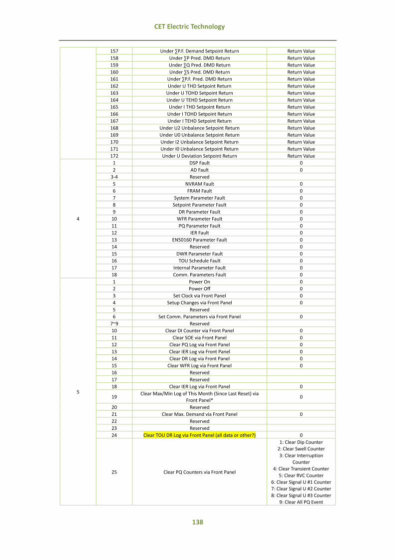
138
CET Electric Technology
157 Under ∑P.F. Demand Setpoint Return Return Value
158 Under ∑P Pred. DMD Return Return Value
159 Under ∑Q Pred. DMD Return Return Value
160 Under ∑S Pred. DMD Return Return Value
161 Under ∑P.F. Pred. DMD Return Return Value
162 Under U THD Setpoint Return Return Value
163 Under U TOHD Setpoint Return Return Value
164 Under U TEHD Setpoint Return Return Value
165 Under I THD Setpoint Return Return Value
166 Under I TOHD Setpoint Return Return Value
167 Under I TEHD Setpoint Return Return Value
168 Under U2 Unbalance Setpoint Return Return Value
169 Under U0 Unbalance Setpoint Return Return Value
170 Under I2 Unbalance Setpoint Return Return Value
171 Under I0 Unbalance Setpoint Return Return Value
172 Under U Deviation Setpoint Return Return Value
4
1 DSP Fault 0
2 AD Fault 0
3-4 Reserved
5 NVRAM Fault 0
6 FRAM Fault 0
7 System Parameter Fault 0
8 Setpoint Parameter Fault 0
9 DR Parameter Fault 0
10 WFR Parameter Fault 0
11 PQ Parameter Fault 0
12 IER Fault 0
13 EN50160 Parameter Fault 0
14 Reserved 0
15 DWR Parameter Fault 0
16 TOU Schedule Fault 0
17 Internal Parameter Fault 0
18 Comm. Parameters Fault 0
5
1 Power On 0
2 Power Off 0
3 Set Clock via Front Panel 0
4 Setup Changes via Front Panel 0
5 Reserved
6 Set Comm. Parameters via Front Panel 0
7~9 Reserved
10 Clear DI Counter via Front Panel 0
11 Clear SOE via Front Panel 0
12 Clear PQ Log via Front Panel 0
13 Clear IER Log via Front Panel 0
14 Clear DR Log via Front Panel 0
15 Clear WFR Log via Front Panel 0
16 Reserved
17 Reserved
18 Clear IER Log via Front Panel 0
19 Clear Max/Min Log of This Month (Since Last Reset) via
Front Panel* 0
20 Reserved
21 Clear Max. Demand via Front Panel 0
22 Reserved
23 Reserved
24 Clear TOU DR Log via Front Panel (all data or other?) 0
25 Clear PQ Counters via Front Panel
1: Clear Dip Counter 2: Clear Swell Counter
3: Clear Interruption Counter
4: Clear Transient Counter
5: Clear RVC Counter 6: Clear Signal U #1 Counter 7: Clear Signal U #2 Counter
8: Clear Signal U #3 Counter 9: Clear All PQ Event

139
CET Electric Technology
26 Clear All Record 0
27 Setup Changes via Comm. 0
28 Set Internal Parameter via Comm. 0
29 Set Comm. Parameter via Comm. 0
30 Set DI Counter via Comm. 0
31 Set Energy Value via Comm. 0
32 Set TOU Energy Value via Comm. 0
33 Clear DI Counter via Comm. 1~8
34 Clear SOE via Comm. 0
35 Clear PQ Log via Comm. 0
36 Clear IER Log via Comm. 0
37 Clear DR Log via Comm. 1~24
38 Clear WFR Log via Comm. 1~2
39 Reserved
40 Clear Transient Log via Comm. 0
41 Clear IRE Log via Comm. 0
42 Clear Max/Min Log of This Month (since Last Reset) via
Comm.* 0
43 Clear All the Max/Min Log via Comm. 0
44 Clear Max. Demand via Comm. 0
45 Clear All the Max. Demand via Comm. 0
46 Clear EN50160 Log via Comm. 0
47 Clear TOU DR via Comm. 0
48 Clear PQ Counters via Comm.
1: Clear Dip Counter 2: Clear Swell Counter 3: Clear Interruption
Counter 4: Clear Transient Counter
5: Clear RVC Counter
6: Clear Signal U#1 Counter 7: Clear Signal U#2 Counter 8: Clear Signal U#3 Counter
9: Clear All PQ Event
49 Clear All Record and Statistics 0
50 Transfer TOU DR manually 0
51 Switch TOU Schedule
1: Switch Schedule #1 to Schedule #2 Manually
2: Switch Schedule #2 to Schedule #1 Manually
3: Switch Schedule #1 to
Schedule #2 Automatically 4: Switch Schedule #2 to
Schedule #1 Automatically
6
1 WFR Triggered by Remote Control 0
2 WFR Triggered by Setpoint #X Setpoint # X
(X = 1 to 40)
3 WFR Triggered by Dip/Swell 0
4 WFR Triggered by Transient 0
5 WFR Triggered by RVC 0
6 DR Triggered by Setpoint #X Setpoint # X (X = 1 to 40)
7 DR Triggered by Dip/Swell 0
8-9 Reserved
10 HS DR Triggered by Setpoint # X Setpoint # X (X = 1 to 40)
11 HS DR Triggered by Dip/Swell 0
12-13 Reserved
14 Alarm Email Triggered by Setpoint #X Setpoint # X
(X = 1 to 40)
15 Alarm Email Triggered by Dip/Swell 0
16 Alarm Email Triggered by Transient 0
17 Alarm Email Triggered by RVC 0
18~22 Reserved
23 DWR Triggered by Comm. 0
24 DWR Triggered by Setpoint #X Setpoint # X (X = 1 to 40)
25 DWR Triggered by Dip/Swell 0

140
CET Electric Technology
26 DWR Triggered by Transient 0
27 DWR Rec Triggered by RVC 0
28 DWR Complete 0
7
1 Over H02 U Active Trigger Value
… … …
62 Over H63 U Active Trigger Value
63 Over H02 U Return Return Value
… … …
124 Over H63 U Return Return Value
125 Under H02 U Active Trigger Value
… … …
186 Under H63 U Active Trigger Value
187 Under H02 U Return Return Value
… … …
248 Under H63 U Return Return Value
8
1 Over H02 I Active Trigger Value
… … …
62 Over H63 I Active Trigger Value
63 Over H02 I Return Return Value
… … …
124 Over H63 I Return Return Value
125 Under H02 I Active Trigger Value
… … …
186 Under H63 I Active Trigger Value
187 Under H02 I Return Return Value
… … …
248 Under H63 I Return Return Value
*There are two modes to transfer Max/Min Log by setting Set Self-Read Time (7081): auto transfer monthly (Clear Max/Min Log
of This Month via Front Panel) and transfer manually (Clear Max/Min Log since Last Reset via Front Panel).

141
CET Electric Technology
Appendix C - Technical Specifications
Voltage Inputs (V1, V2, V3, V4, VN)
Standard (Un) Range PT Ratio
Primary Secondary V4 Primary
V4 Secondary Overload Burden
400VLN/690VLL 10% to 120% Un
1-1000000V 100-690V 1-1000000V
1-400V 1.2xUn continuous, 4xUn for 1s <0.1VA per phase
Frequency 42Hz-58Hz @ 50Hz 50Hz-70Hz @ 60Hz
Current Inputs (I11, I12, I21, I22, I31, I32, I41, I42, I51, I52)
Standard (In) Optional (In)
Range Starting Current CT Ratio
Primary Secondary I4 Primary
I4 Secondary Overload Burden
5A 1A
0.1% to 400% In 0.1% In
1-30000A 1-5A 1-30000A
1-5A 4xIn continuous, 10xIn for 1s <0.5VA per phase
Power Supply (L+, N-, G)
Standard
Optional Burden
95-250VAC/VDC ± 10%, 47-440 Hz
20-60VDC <8W
Digital Inputs (COM, DI1, DI2, …DI7, DI8)
Standard Sampling
Hysteresis
Dry contact, 24VDC internally wetted 1000Hz
1ms minimum
Relay Outputs (RO1, RO2, RO3, RO4)
Type Loading
Form A Mechanical Relay 5A @ 250VAC / DC
Digital Outputs (COM, DO1, DO2)
Type Isolation
Max. Load Voltage Max. Forward Current
Form A Solid State Relay Optical
80V 50mA
GPS (I+, I-, SH)
Hardware Interface D+, D-, SH
LCD Display
Type Resolution
View Area
Color TFT LCD, Industrial Grade 640x480
115x86 mm
Environmental Conditions
Operating Temp. Storage Temp. Humidity
Atmospheric Pressure Pollution Degree Measurement Category
-25°C to 70°C -40°C to 85°C 5% to 95% non-condensing
70 kPa to 106 kPa 2 CAT III
Mechanical Characteristics
Panel Cutout
Unit Dimensions IP Rating
138x138mm
144x144x129 mm 52

142
CET Electric Technology
Appendix D - Accuracy Specifications
Parameters Accuracy Resolution
Voltage ±0.1% 0.01V
Current ±0.1% 0.001A
kW, kVA ±0.2% 0.001k
kvar ±0.2% 0.001k
kWh, kVAh IEC 62053-22 Class 0.2S 0.1kXh
kvarh IEC 62053-23 Class 2 0.1kvarh
P.F. ±0.5% 0.0001
Frequency ±0.005 Hz 0.001Hz
Harmonics IEC 61000-4-7 Class A 0.01%
Phase angles ±1° 0.1°
Voltage Deviation ±0.1% 0.01%
Voltage Unbalance ±0.1% 0.01%
Current Unbalance ±0.5% 0.01%

143
CET Electric Technology
Appendix E - IEC61000-4-30 Class A Certificate

144
CET Electric Technology
Appendix F - Standards Compliance
Safety Requirements
LVD Directive 2006/95/EC Insulation
Dielectric test
Between Power, AC circuits, and GND Between I/O, GPS and GND
Insulation resistance
Between Power, AC Circuits, and GND Between GPS and GND
Impulse voltage
Rated input voltage > 60V Rated input voltage ≤ 60V
EN61010-1-1-2001 IEC 60255-5-2000
2kV @ 1 minute 500V @ 1 minute
>100MΩ >10MΩ
6kV, 1.2/50µs 1kV, 1.2/50µs
EMC Compatibility
EMC Directive 2004/108/EC (EN 61326: 2006)
Immunity Tests
Electrostatic discharge IEC 61000-4-2: 2009
Radiated fields EN 61000-4-3: 2006+A1: 2008+A2:
2010
Fast transients EN 61000-4-4: 2004+A1: 2010
Surges EN 61000-4-5: 2006
Conducted disturbances EN 61000-4-6: 2009
Magnetic Fields EN 61000-4-8: 2010
Oscillatory waves EN 61000-4-12: 2006
Electromagnetic Emission IEC 60255-25: 2000
Emission Tests
Limits and methods of measurement of electromagnetic disturbance characteristics of industrial, scientific and medical (ISM) radio-frequency equipment
EN 55011: 2009+A1: 2010
(CISPR 11)
Limits and methods of measurement of radio disturbance characteristics of information technology equipment
EN 55022: 2010/AC: 2011 (CISPR 22)
Limits for harmonic current emissions for equipment with rated current ≤16 A EN 61000-3-2: 2006+ A1: 2009+A2: 2009
Limitation of voltage fluctuations and flicker in low-voltage supply systems for
equipment with rated current ≤16 A EN 61000-3-3: 2008
Emission standard for residential, commercial and light-industrial environments EN 61000-6-4: 2007+A1: 2011
Electromagnetic Emission Tests for Measuring Relays and Protection Equipment EN 61000-4-12: 2006
Mechanical Tests
Vibration Test Response IEC 60255-21-1:1988 Level II
Endurance IEC 60255-21-1:1988 Level I
Shock Test Response IEC 60255-21-2:1988 Level I
Endurance IEC 60255-21-2:1988 Level I
Bump Test IEC 60255-21-2:1988 Level I

145
CET Electric Technology
Appendix G - Ordering Guide

Contact us
CET Electric Technology Headquarters
8/F, Westside, Building 201, Terra Industrial & Tradepark, Che Gong Miao, Shenzhen, Guangdong,
P.R.China 518040
Tel: +86.755.8341.5187
Fax: +86.755.8341.0291
Email: [email protected]
Web: www.cet-global.com