PMC-660 User Manual V1.1A (20180814) - CET Global
95
PMC-660 Series Advanced Power Quality Meter User Manual Version: V1.1A August 14, 2018
-
Upload
khangminh22 -
Category
Documents
-
view
0 -
download
0
Transcript of PMC-660 User Manual V1.1A (20180814) - CET Global

PMC-660 Series Advanced Power Quality Meter
User Manual
Version: V1.1A
August 14, 2018

2
CET Electric Technology
This manual may not be reproduced in whole or in part by any means without the express
written permission from CET Electric Technology (CET).
The information contained in this Manual is believed to be accurate at the time of publication;
however, CET assumes no responsibility for any errors which may appear here and reserves
the right to make changes without notice. Please consult CET or your local representative for
latest product specifications.
Standards Compliance
DANGER
This symbol indicates the presence of danger that may result in severe injury or death and
permanent equipment damage if proper precautions are not taken during the installation,
operation or maintenance of the device.
CAUTION
This symbol indicates the potential of personal injury or equipment damage if proper
precautions are not taken during the installation, operation or maintenance of the device.

3
CET Electric Technology
DANGER Failure to observe the following instructions may result in severe injury or
death and/or equipment damage.
Installation, operation and maintenance of the meter should only be
performed by qualified, competent personnel that have the appropriate
training and experience with high voltage and current devices. The meter must
be installed in accordance with all local and national electrical codes.
Ensure that all incoming AC power and other power sources are turned OFF
before performing any work on the meter.
Before connecting the meter to the power source, check the label on top of
the meter to ensure that it is equipped with the appropriate power supply, and
the correct voltage and current input specifications for your application.
During normal operation of the meter, hazardous voltages are present on its
terminal strips and throughout the connected potential transformers (PT) and
current transformers (CT). PT and CT secondary circuits are capable of
generating lethal voltages and currents with their primary circuits energized.
Follow standard safety precautions while performing any installation or service
work (i.e. removing PT fuses, shorting CT secondaries, …etc).
Do not use the meter for primary protection functions where failure of the
device can cause fire, injury or death. The meter should only be used for
shadow protection if needed.
Under no circumstances should the meter be connected to a power source if it
is damaged.
To prevent potential fire or shock hazard, do not expose the meter to rain or
moisture.
Setup procedures must be performed only by qualified personnel familiar with
the instrument and its associated electrical equipment.
DO NOT open the instrument under any circumstances.

4
CET Electric Technology
Limited warranty
CET Electric Technology (CET) offers the customer a minimum of 12-month
functional warranty on the meter for faulty parts or workmanship from the date
of dispatch from the distributor. This warranty is on a return to factory for repair
basis.
CET does not accept liability for any damage caused by meter malfunctions. CET
accepts no responsibility for the suitability of the meter to the application for
which it was purchased.
Failure to install, set up or operate the meter according to the instructions herein
will void the warranty.
Only CET’s duly authorized representative may open your meter. The unit should
only be opened in a fully anti-static environment. Failure to do so may damage the
electronic components and will void the warranty.
5
CET Electric Technology
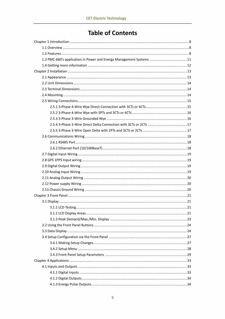
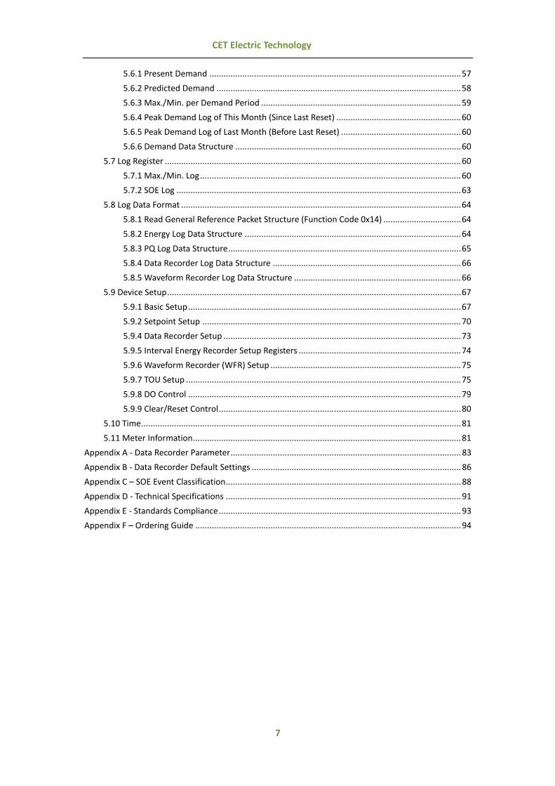
Table of Contents
Chapter 1 Introduction ............................................................................................................................. 8
1.1 Overview .................................................................................................................................... 8
1.2 Features ...................................................................................................................................... 8
1.3 PMC-660’s application in Power and Energy Management Systems ....................................... 11
1.4 Getting more information ........................................................................................................ 12
Chapter 2 Installation ............................................................................................................................. 13
2.1 Appearance .............................................................................................................................. 13
2.2 Unit Dimensions ....................................................................................................................... 14
2.3 Terminal Dimensions ................................................................................................................ 14
2.4 Mounting .................................................................................................................................. 14
2.5 Wiring Connections .................................................................................................................. 15
2.5.1 3-Phase 4-Wire Wye Direct Connection with 3CTs or 4CTs ........................................... 15
2.5.2 3-Phase 4-Wire Wye with 3PTs and 3CTs or 4CTs ......................................................... 16
2.5.3 3-Phase 3-Wire Grounded Wye .................................................................................... 16
2.5.4 3-Phase 3-Wire Direct Delta Connection with 3CTs or 2CTs ......................................... 17
2.5.5 3-Phase 3-Wire Open Delta with 2PTs and 3CTs or 2CTs .............................................. 17
2.6 Communications Wiring ........................................................................................................... 18
2.6.1 RS485 Port ..................................................................................................................... 18
2.6.2 Ethernet Port (10/100BaseT) ........................................................................................ 18
2.7 Digital Input Wiring .................................................................................................................. 19
2.8 GPS 1PPS Input wiring .............................................................................................................. 19
2.9 Digital Output Wiring ............................................................................................................... 19
2.10 Analog Input Wiring ............................................................................................................... 19
2.11 Analog Output Wiring ............................................................................................................ 20
2.12 Power supply Wiring .............................................................................................................. 20
2.13 Chassis Ground Wiring ........................................................................................................... 20
Chapter 3 Front Panel ............................................................................................................................. 21
3.1 Display ...................................................................................................................................... 21
3.1.1 LCD Testing .................................................................................................................... 21
3.1.2 LCD Display Areas .......................................................................................................... 21
3.1.3 Peak Demand/Max./Min. Display ................................................................................. 23
3.2 Using the Front Panel Buttons .................................................................................................. 24
3.3 Data Display .............................................................................................................................. 24
3.4 Setup Configuration via the Front Panel .................................................................................. 27
3.4.1 Making Setup Changes .................................................................................................. 27
3.4.2 Setup Menu .................................................................................................................. 28
3.4.3 Front Panel Setup Parameters ...................................................................................... 29
Chapter 4 Applications ........................................................................................................................... 33
4.1 Inputs and Outputs .................................................................................................................. 33
4.1.1 Digital Inputs ................................................................................................................. 33
4.1.2 Digital Outputs .............................................................................................................. 34
4.1.3 Energy Pulse Outputs .................................................................................................... 34

6
CET Electric Technology
4.1.4 Analog Input .................................................................................................................. 34
4.1.5 Analog Output ............................................................................................................... 35
4.2 Power and Energy .................................................................................................................... 35
4.2.1 Basic Measurements ..................................................................................................... 35
4.2.2 Energy Measurements .................................................................................................. 36
4.2.3 Interval Energy Measurements (Firmware V2.00.00 or later) ...................................... 36
4.2.4 High-speed Measurements ........................................................................................... 36
4.2.5 Demand Measurements ............................................................................................... 36
4.2.6 Max./Min. per Demand Period ..................................................................................... 37
4.3 Power Quality ........................................................................................................................... 37
4.3.1 Phase Angles ................................................................................................................. 37
4.3.2 Power Quality Parameters ............................................................................................ 38
4.3.3 Unbalance ..................................................................................................................... 39
4.3.4 Symmetrical Components ............................................................................................. 39
4.3.5 Deviation ....................................................................................................................... 39
4.3.6 Supply Voltage Dips/Swells and Interruptions .............................................................. 39
4.3.7 Transients ...................................................................................................................... 40
4.4 Setpoints .................................................................................................................................. 40
4.5 Logical Module ......................................................................................................................... 42
4.6 Logging ..................................................................................................................................... 43
4.6.1 Max./Min. Log ............................................................................................................... 43
4.6.2 Peak Demand Log ......................................................................................................... 43
4.6.3 Interval Energy Recorder (IER) Log ................................................................................ 44
4.6.4 Waveform Recorder (WFR) Log ..................................................................................... 44
4.6.5 PQ Log ........................................................................................................................... 45
4.6.6 SOE Log ......................................................................................................................... 45
4.6.7 Data Recorder (DR) Log ................................................................................................. 45
4.7 Time of Use (TOU) .................................................................................................................... 46
4.8 Time Synchronization ............................................................................................................... 47
4.9 On-board Web Server ............................................................................................................... 48
4.10 Meter Email ............................................................................................................................ 49
4.11 Ethernet Gateway ................................................................................................................... 49
Chapter 5 Modbus Register Map ............................................................................................................ 51
5.1 Basic Measurements ................................................................................................................ 51
5.2 Energy Measurements ............................................................................................................. 53
5.2.1 Total Energy Measurements ......................................................................................... 53
5.2.2 TOU Energy Measurements .......................................................................................... 53
5.2.3 Interval Energy Measurements ..................................................................................... 55
5.3 Pulse Counter ........................................................................................................................... 55
5.4 Harmonic Measurements ......................................................................................................... 55
5.4.1 Fundamental (Displacement) Measurements .............................................................. 55
5.4.2 Harmonic Measurements ............................................................................................. 56
5.5 High-speed Measurements ...................................................................................................... 57
5.6 Demand Measurements ........................................................................................................... 57
7
CET Electric Technology
5.6.1 Present Demand ........................................................................................................... 57
5.6.2 Predicted Demand ........................................................................................................ 58
5.6.3 Max./Min. per Demand Period ..................................................................................... 59
5.6.4 Peak Demand Log of This Month (Since Last Reset) ..................................................... 60
5.6.5 Peak Demand Log of Last Month (Before Last Reset) ................................................... 60
5.6.6 Demand Data Structure ................................................................................................ 60
5.7 Log Register .............................................................................................................................. 60
5.7.1 Max./Min. Log ............................................................................................................... 60
5.7.2 SOE Log ......................................................................................................................... 63
5.8 Log Data Format ....................................................................................................................... 64
5.8.1 Read General Reference Packet Structure (Function Code 0x14) ................................. 64
5.8.2 Energy Log Data Structure ............................................................................................ 64
5.8.3 PQ Log Data Structure ................................................................................................... 65
5.8.4 Data Recorder Log Data Structure ................................................................................ 66
5.8.5 Waveform Recorder Log Data Structure ....................................................................... 66
5.9 Device Setup ............................................................................................................................. 67
5.9.1 Basic Setup .................................................................................................................... 67
5.9.2 Setpoint Setup .............................................................................................................. 70
5.9.4 Data Recorder Setup ..................................................................................................... 73
5.9.5 Interval Energy Recorder Setup Registers ..................................................................... 74
5.9.6 Waveform Recorder (WFR) Setup ................................................................................. 75
5.9.7 TOU Setup ..................................................................................................................... 75
5.9.8 DO Control .................................................................................................................... 79
5.9.9 Clear/Reset Control ....................................................................................................... 80
5.10 Time ........................................................................................................................................ 81
5.11 Meter Information.................................................................................................................. 81
Appendix A - Data Recorder Parameter .................................................................................................. 83
Appendix B - Data Recorder Default Settings ......................................................................................... 86
Appendix C – SOE Event Classification .................................................................................................... 88
Appendix D - Technical Specifications .................................................................................................... 91
Appendix E - Standards Compliance ....................................................................................................... 93
Appendix F – Ordering Guide ................................................................................................................. 94

8
CET Electric Technology
Chapter 1 Introduction
This manual explains how to use the PMC-660 Advanced Power Quality Meter. Throughout the manual
the term “meter” generally refers to all models.
This chapter provides an overview of the PMC-660 meter and summarizes many of its key features.
1.1 Overview
The PMC-660 is CET’s latest offer for the advanced Power Quality Monitoring of Incomers and Critical
Feeders for Utilities, Data Centers, High-Tech manufacturing facilities and Heavy Industries. Housed in
an industry-standard DIN form factor measuring 96mmx96mmx125mm, the PMC-660’s compact size is
perfectly suited for today’s space restricting installations. The PMC-660 features quality construction
with metal enclosure, advanced Power Quality and Revenue-Accurate measurements, high-resolution
Waveform Recording capabilities, comprehensive Data Logging with 4MB memory, extensive I/O and
an easy-to-read LCD display, capable of displaying 5 measurements at once. With standard dual RS-485
ports and optional 100BaseT Ethernet port as well as Modbus RTU and TCP protocols support, the PMC-
660 becomes a vital component of an intelligent Power Quality Monitoring System.
You can setup the meter through its Front Panel or via our free PMC Setup software. The meter is also
supported by our PecStar® iEMS Integrated Energy Management System. Following is a list of typical
applications for the PMC-660:
Class 0.2S Revenue Metering
Power Quality Monitoring of Main Incomer or Critical Feeder
Utility, Industrial and Commercial Metering
Substation, Building and Factory Automation
Low, Medium and High Voltage applications
Neutral (I4) or Residual/Leakage Current (via optional AI) Monitoring
Contact CET Technical Support should you require further assistance with your application.
1.2 Features
Ease of use
Large, backlit, easy to read LCD display with wide viewing angle
Password protected setup via Front Panel or free PMC Setup software
Easy installation with mounting slide bar, no tools required
Basic True RMS Measurements (1 second update)
3-Phase Voltage, Current and Power measurements
Neutral Current (I4) and Frequency
kWh/kvarh Import/Export/Net/Total, kVAh Total
kvarh Q1 - Q4
Voltage and Current Phase Angles (equivalent to Vector Diagram)
Interval Energy measurements for kWh Import/Export, kvarh Import/Export and kVAh with
programmable EN Period*
Device Operating Time (Running Hours)*
Calculated Residual Current (Ir)* with the I4 measurement option
*Available in Firmware V2.00.00 or later

9
CET Electric Technology
High-speed RMS Measurements
3-phase Voltage @ ½ cycle
3-phase Current and Neutral Current (I4) and I0 @ 1 cycle
3-phase Power and Power Factor @ 1 cycle
Power Quality
Waveform Recording at 256 samples per cycle
Fundamental measurements for 3-Phase Voltage, Current, Power, PF
Voltage and Current Unbalance
Voltage and Frequency Deviation
U and I Symmetrical Components*
THD, TOHD, TEHD, K-Factor and Displacement PF
Individual Harmonics up to 31st via Front Panel and 63rd via communications
Dip/Swell Detection and Transient Capture
PQ Log with 1000 entries
*Available in Firmware V2.00.00 or later
Sliding Window and Predicted Demands
Demands and Predicted Demands for 3-Phase Voltage, Current, Power and PF as well as I4,
Frequency, U and I Unbalance and THD
Peak Demands with Timestamp for This Month and Last Month (or Since and Before Last Reset)
Max./Min. values per demand interval
Demand synchronization with DI
Setpoints
16 Standard Setpoints with extensive list of monitoring parameters including Voltage, Current,
Power, Demands and THD, … etc.
8 High-Speed Setpoints for High-Speed measurements and DI
Configurable thresholds and time delays
6 Logical Modules supporting AND/OR/NAND/NOR operations
WF Recording, Data Recorder, DO, and Email Alarm trigger
Log memory
4MB on-board memory
Dynamic allocation for Data Recorder Logs, Waveform Recorder Logs and Interval Energy
Recorder Log
Multi-Tariff TOU Capability*
Two independent sets of TOU Schedules
o Up to 12 Seasons
o 90 Holidays or Alternate Days
o 20 Daily Profiles, each with 12 Periods with minimum 15-minute interval
o 8 Tariffs, each providing kWh/kvarh Import/Export and kVAh
Switch between two TOU schedules according to programmable time with the switching event
stored in the SOE Log
Tariff switching based on DI status*
*Available in Firmware V2.00.00 or later

10
CET Electric Technology
Waveform Recorder Log
2 independent groups of Waveform Recorders with a combined total of 32 entries
Simultaneous capture of 3-Phase Voltage and Current signals
Programmable formats and pre-fault cycles from 256x20 to 16x320
Support FIFO Recording Mode
Interval Energy Recorder Log
Interval recording of kWh/kvarh Import/Export and kVAh Total
Support FIFO or Stop-When-Full Recording Mode
Data Recorder Log
12 Standard Data Recorder Logs and 4 High-Speed Data Recorder Logs
Recording interval from 1s to 40 days for standard and 1 to 60 cycles for High-Speed DR
Programmable sources include almost all real-time measurements, Harmonics, Unbalance and
Demand values
Configurable Depth and Recording Offset
Support FIFO or Stop-When-Full Recording Mode
SOE Log
512 events time-stamped to ±1ms resolution
Setup changes, Setpoint events and I/O operations
PQ Log
1000 entries time-stamped to ±1ms resolution
Dip/Swell and Transient detection or other PQ events
Max./Min. Log
Logging of Max./Min. values for measurements such as Voltage, Current, Frequency, kW, kvar,
kVA, PF, Unbalance, K-factor, THD and Ir with Timestamp for This Month and Last Month (or Since
and Before Last Reset)
Digital Inputs
6 channels, volts free dry contact, 24VDC internally wetted
1000Hz sampling for status monitoring with programmable debounce
Pulse counting with programmable weight for each channel for collecting WAGES (Water, Air, Gas,
Electricity, Steam) information
Demand Synchronization
Tariff switching based on DI status*
*Available in Firmware V2.00.00 or later
Digital Outputs
Up to 3 channels Form A Mechanical Relays for alarming and control
Analog Input (Optional)
0/4-20mA DC input with programmable zero and full scales
Can be used to measure external transducer signal such as Residual or Leakage Current

11
CET Electric Technology
Analog Output (Optional)
0/4-20mA DC output with programmable zero and full scales
Can be “keyed” to any measured quantity
Communications
RS-485 (Port 1 and Port 2)
o Optically isolated RS485 port
o Baud rate from 1200 to 38,400bps
o Modbus RTU protocol
Ethernet (optional and replaces RS-485 P2)
o 10/100BaseT Ethernet with RJ45 connection
o Modbus RTU over TCP/IP, Modbus TCP, Ethernet Gateway, HTTP, SMTP, SNTP
Real-time clock
Equipped with a battery-backed Real-time Clock with 6ppm accuracy (<0.5s per day)
System Integration
Supported by CET’s PecStar® iEMS and iEEM
Easy integration into other Automation, SCADA or BMS systems via Modbus RTU and Modbus TCP
protocols
1.3 PMC-660’s Application in Power and Energy Management Systems
The PMC-660 can be used to monitor Wye or Delta connected power system. Modbus communications
allow real-time data, events, DI status, Data Logs, Waveform and other information to be transmitted
to an Integrated Energy Management System such as PecStar® iEMS.

12
CET Electric Technology
1.4 Getting more information
Additional information is available from CET via the following sources:
Visit www.cet-global.com
Contact your local representative
Contact CET directly via email at [email protected]

13
CET Electric Technology
Chapter 2 Installation
2.1 Appearance
Figure 2-1 Appearance (RS485+6DIs+2DOs+AO)
Caution
Installation of the PMC-660 should only be performed by qualified, competent personnel that have
the appropriate training and experience with high voltage and current devices. The meter must be
installed in accordance with all local and national electrical codes.
During the operation of the meter, hazardous voltages are present at the input terminals. Failure to
observe precautions can result in serious or even fatal injury and equipment damage.

14
CET Electric Technology
2.2 Unit Dimensions
Front View Side View
Figure 2-2 Dimensions
2.3 Terminal Dimensions
Figure 2-3 Terminal Dimensions
No. Terminal Terminal Dimensions Wire Size Max. Torque
1 DI
2.6mm x 3.3mm
1.5mm2 5 kgf.cm/M3
(4.3 lb-in)
Power Supply
2 RS485
2.6mm x 3.2mm AO DO
3 I4 Input
Voltage Input
4 Current Input 8.1mm x 8.1mm 1.0mm2 - 2.5mm2 (14AWG - 22AWG)
18.0 kgf.cm/M4 (15.6 lb-in)
Table 2-1 Terminal Dimensions
2.4 Mounting
The PMC-660 should be installed in a dry environment with no dust and kept away from heat, radiation
and electrical noise sources.

15
CET Electric Technology
Installation steps:
Remove the mounting slide bars from the meter
Fit the meter through a 92mmx92mm cutout as shown in Figure 2-4
Re-install the mounting slide bars and tighten the screws against the panel to secure the meter
Figure 2-4 Panel Cutout
2.5 Wiring Connections
PMC-660 can satisfy almost any three phase power systems. Please read this section carefully before
installation and choose the correct wiring method for your power system. The following Wiring Modes
are supported:
3-Phase 4-Wire Wye Direct Connection with 3CTs or 4CTs
3-Phase 4-Wire Wye with 3PTs and 3CTs or 4CTs
3-Phase 3-Wire Grounded Wye Direct Connection
3-Phase 3-Wire Grounded Wye with 3PTs and 3CTs
3-Phase 3-Wire Direct Connection with 3CTs or 2CTs
3-Phase 3-Wire Open Delta with 2PTs and 3CTs or 2CTs
2.5.1 3-Phase 4-Wire Wye Direct Connection with 3CTs or 4CTs
Please consult the serial number label to ensure that the rated system phase voltage is less than or
equal to the meter’s rated Phase voltage input specification. Set the Wiring Mode to Wye.
Caution
Under no circumstances should the PT secondary be shorted.
Under no circumstances should the CT secondary be open when the CT primary is energized. CT
shorting blocks should be installed to allow for easy maintenance.

16
CET Electric Technology
Figure 2-5 3P4W Wye Direct Connection with 3CTs or 4CTs (Optional I41 & I42)
2.5.2 3-Phase 4-Wire Wye with 3PTs and 3CTs or 4CTs
Please consult the serial number label to ensure that the rated PT secondary voltage is less than or
equal to the meter’s rated Phase voltage input specification. Set the Wiring Mode to Wye.
Figure 2-6 3P4W Wye with 3PTs and 3CTs or 4CTs (Optional I41 & I42)
2.5.3 3-Phase 3-Wire Grounded Wye
Please consult the serial number label to ensure that the system phase voltage is less than or equal to
the meter’s rated Phase voltage input specification. Set the Wiring Mode to Wye.
17
CET Electric Technology
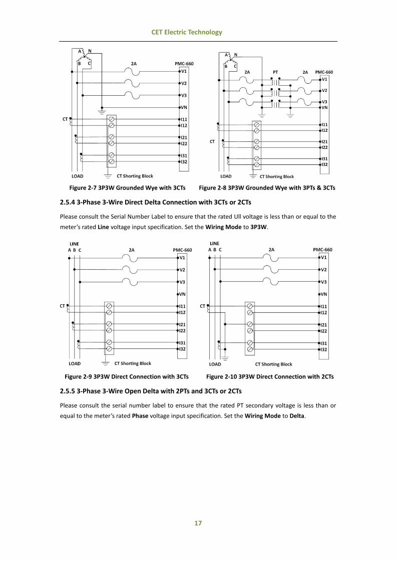
Figure 2-7 3P3W Grounded Wye with 3CTs Figure 2-8 3P3W Grounded Wye with 3PTs & 3CTs
2.5.4 3-Phase 3-Wire Direct Delta Connection with 3CTs or 2CTs
Please consult the Serial Number Label to ensure that the rated Ull voltage is less than or equal to the
meter’s rated Line voltage input specification. Set the Wiring Mode to 3P3W.
Figure 2-9 3P3W Direct Connection with 3CTs Figure 2-10 3P3W Direct Connection with 2CTs
2.5.5 3-Phase 3-Wire Open Delta with 2PTs and 3CTs or 2CTs
Please consult the serial number label to ensure that the rated PT secondary voltage is less than or
equal to the meter’s rated Phase voltage input specification. Set the Wiring Mode to Delta.

18
CET Electric Technology
Figure 2-11 3P3W Open Delta with 2PTs & 3CTs Figure 2-12 3P3W Open Delta with 2PTs & 2CTs
2.6 Communications Wiring
2.6.1 RS485 Port
The PMC-660 provides up to two RS485 ports and supports the Modbus RTU protocol. Up to 32 devices
can be connected on a RS485 bus. The overall length of the RS485 cable connecting all devices should
not exceed 1200m.
If the master station does not have a RS485 communications port, a RS232/RS485, USB/RS485 or
Ethernet/RS485 converter with optically isolated outputs and surge protection should be used.
The following figure illustrates the RS485 communications connections on the PMC-660:
Figure 2-13 RS485 Communications Connections
2.6.2 Ethernet Port (10/100BaseT)
RJ45 Connector Pin Meaning
1 Transmit Data+ 2 Transmit Data- 3 Receive Data+
4,5,7,8, NC 6 Receive Data-
Table 2-2 RJ45 Connector Pin Description for 10/100BaseT Applications
19
CET Electric Technology
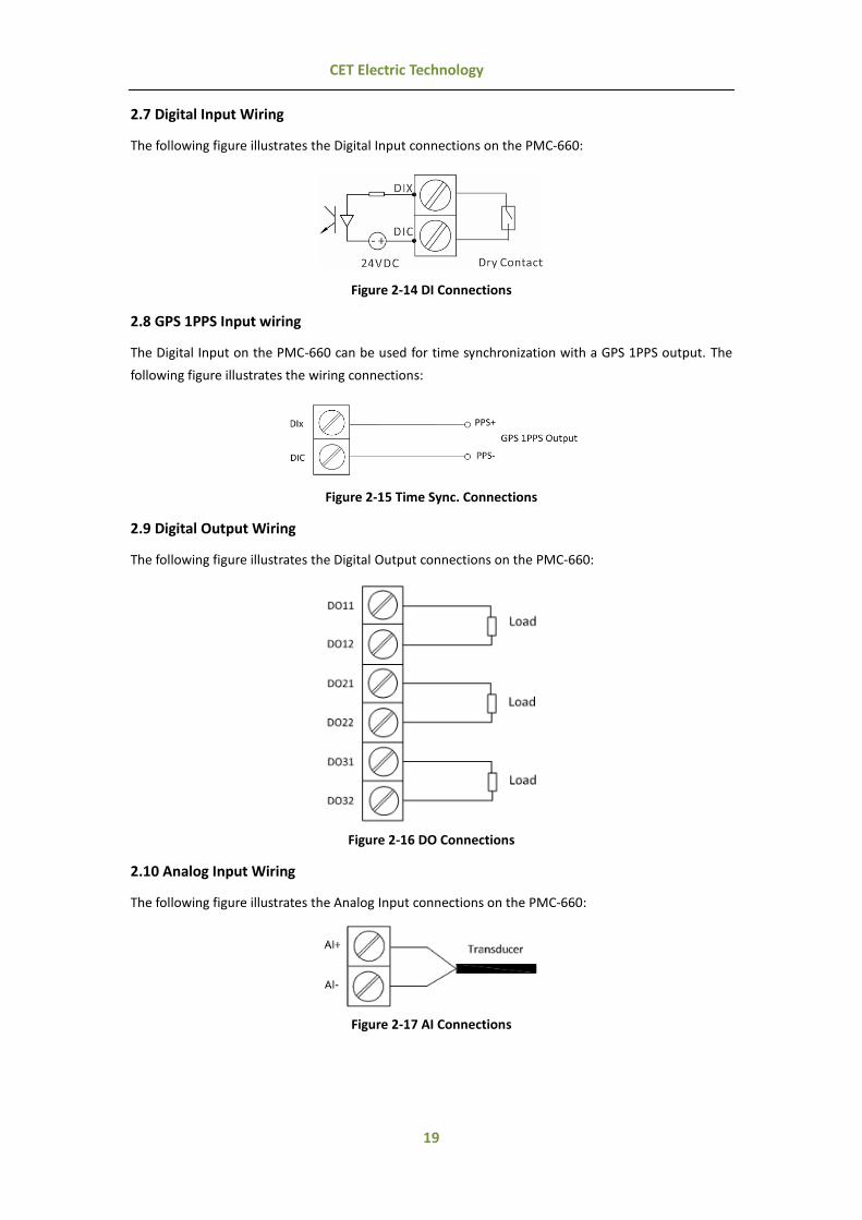
2.7 Digital Input Wiring
The following figure illustrates the Digital Input connections on the PMC-660:
Figure 2-14 DI Connections
2.8 GPS 1PPS Input wiring
The Digital Input on the PMC-660 can be used for time synchronization with a GPS 1PPS output. The
following figure illustrates the wiring connections:
Figure 2-15 Time Sync. Connections
2.9 Digital Output Wiring
The following figure illustrates the Digital Output connections on the PMC-660:
Figure 2-16 DO Connections
2.10 Analog Input Wiring
The following figure illustrates the Analog Input connections on the PMC-660:
Figure 2-17 AI Connections
20
CET Electric Technology
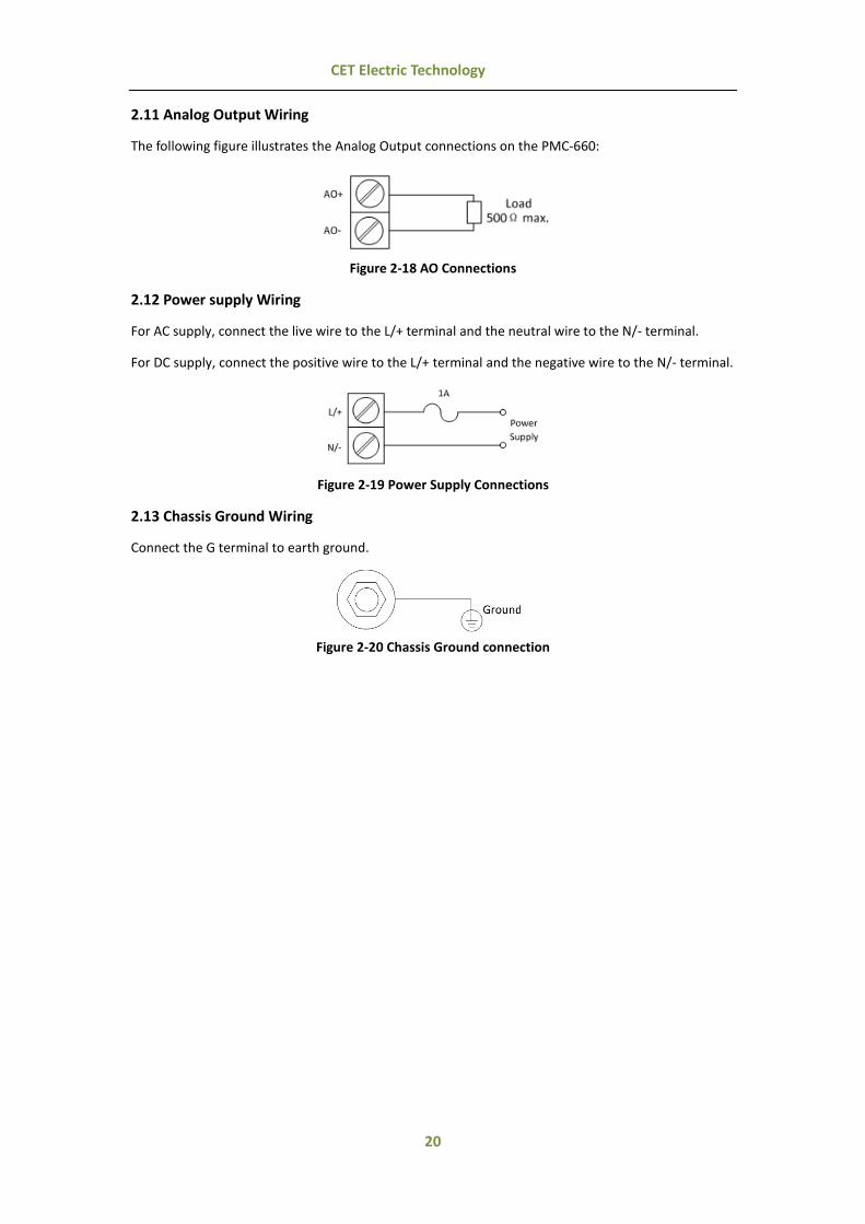
2.11 Analog Output Wiring
The following figure illustrates the Analog Output connections on the PMC-660:
Figure 2-18 AO Connections
2.12 Power supply Wiring
For AC supply, connect the live wire to the L/+ terminal and the neutral wire to the N/- terminal.
For DC supply, connect the positive wire to the L/+ terminal and the negative wire to the N/- terminal.
Figure 2-19 Power Supply Connections
2.13 Chassis Ground Wiring
Connect the G terminal to earth ground.
Figure 2-20 Chassis Ground connection

21
CET Electric Technology
Chapter 3 Front Panel
The PMC-660 has a large, easy to read LCD display with backlight and four buttons for data display and
meter configuration. This chapter introduces the Front Panel operations.
Figure 3-1 Front Panel
3.1 Display
The Front Panel provides two display modes: Data Display and Setup Configuration. There are four
buttons on the Front Panel: <V/I>/ , <Power>/ , <Harmonics>/ and <Energy>/ . Use these
buttons to view metering data and configure setup parameters.
3.1.1 LCD Testing
Pressing both the <Power> and the <Harmonics> buttons simultaneously for 2 seconds enters the LCD
Testing mode. All LCD segments are illuminated for 5 seconds and then turned off for 1 second during
testing. This cycle will repeat 3 times to allow for the detection of faulty segments. The LCD will return
to normal data display afterwards.
Figure 3-2 PMC-660 Full Display
3.1.2 LCD Display Areas
This section provides a description of the LCD display areas. The PMC-660 LCD display can generally be
divided into 5 areas:

22
CET Electric Technology
A: Measurement symbols for parameters such as Voltage, Current, Fundamental, Power, THD,
TOHD, TEHD, 2nd to 31st Individual Harmonics, K-Factor, Unbalance, PF, Voltage/Current Phase
Angles and Demand, ...etc.
B: DI and DO Status Indicators
C: Measurement Units, Loading Factor and PF Quadrant status
D: Measurement values
E: Energy information such as kWh/kvarh Imp/Exp/Net/Total and kVAh Total
Figure 3-3 LCD Display
The following table shows the special LCD display symbols:
NO. Label Description
A
Voltage
Current
kW
kvar
kVA
Fundamental
K-Factor
Frequency
Phase A
Phase B
Phase C
Predicted Demand
Line to Neutral
Line to Line
Power Factor
Average
Total
Negative Symbol
Phase Angle
THD
TEHD
TOHD
to
2nd to 31st Harmonics
Unbalance
Demand
Maximum
Minimum
This Month
Last Month
DeviceOperating Time
Reserved

23
CET Electric Technology
B
DI Open
DI Close
DO Open
DO Close
C&D
Units for Voltage, Current, %Harmonic Distortion and Frequency
Units for Real, Reactive and Apparent Power
%Loading
Inductive Load Capacitive Load
COM 1 Port Status COM 2 Port Status
Alarm Symbol
PF Quadrant – Q1/Q2/Q3/Q4
Reserved
E
kWh Import
kWh Export
kWh Net
kWh Total
kvarh Import
kvarh Export
kvarh Net
kvarh Total
Reserved
Reserved
Table 3-1 LCD Display Symbols
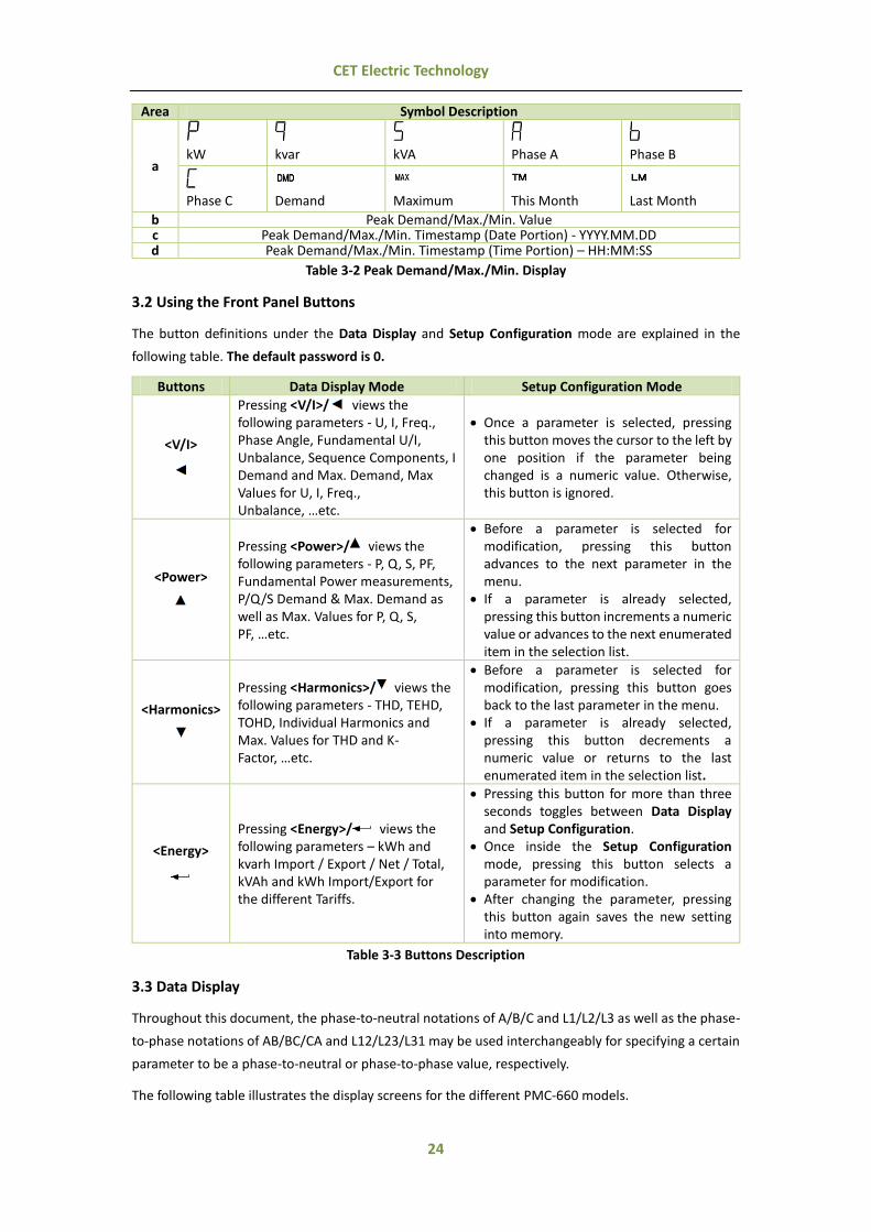
3.1.3 Peak Demand/Max./Min. Display
The following special arrangements have been made for the display of the Peak Demand and its
timestamp with the appropriate unit displayed in the Measurement Unit area.
a: Peak Demand/Max./Min. Indicator – Peak Demand/Max./Min. of This/Last Month:
b: Peak Demand/Max./Min. value
c: Date portion of the Peak Demand timestamp
d: Time portion of the Peak Demand timestamp
Figure 3-4 Peak Demand Display
24
CET Electric Technology
Area Symbol Description
a
kW
kvar
kVA
Phase A
Phase B
Phase C
Demand
Maximum
This Month
Last Month
b Peak Demand/Max./Min. Value c Peak Demand/Max./Min. Timestamp (Date Portion) - YYYY.MM.DD d Peak Demand/Max./Min. Timestamp (Time Portion) – HH:MM:SS
Table 3-2 Peak Demand/Max./Min. Display
3.2 Using the Front Panel Buttons
The button definitions under the Data Display and Setup Configuration mode are explained in the
following table. The default password is 0.
Buttons Data Display Mode Setup Configuration Mode
<V/I>
Pressing <V/I>/ views the following parameters - U, I, Freq., Phase Angle, Fundamental U/I, Unbalance, Sequence Components, I Demand and Max. Demand, Max Values for U, I, Freq., Unbalance, …etc.
Once a parameter is selected, pressing this button moves the cursor to the left by one position if the parameter being changed is a numeric value. Otherwise, this button is ignored.
<Power>
Pressing <Power>/ views the following parameters - P, Q, S, PF, Fundamental Power measurements, P/Q/S Demand & Max. Demand as well as Max. Values for P, Q, S, PF, …etc.
Before a parameter is selected for modification, pressing this button advances to the next parameter in the menu.
If a parameter is already selected, pressing this button increments a numeric value or advances to the next enumerated item in the selection list.
<Harmonics>
Pressing <Harmonics>/ views the following parameters - THD, TEHD, TOHD, Individual Harmonics and Max. Values for THD and K-Factor, …etc.
Before a parameter is selected for modification, pressing this button goes back to the last parameter in the menu.
If a parameter is already selected, pressing this button decrements a numeric value or returns to the last enumerated item in the selection list.
<Energy>
Pressing <Energy>/ views the following parameters – kWh and kvarh Import / Export / Net / Total, kVAh and kWh Import/Export for the different Tariffs.
Pressing this button for more than three seconds toggles between Data Display and Setup Configuration.
Once inside the Setup Configuration mode, pressing this button selects a parameter for modification.
After changing the parameter, pressing this button again saves the new setting into memory.
Table 3-3 Buttons Description
3.3 Data Display
Throughout this document, the phase-to-neutral notations of A/B/C and L1/L2/L3 as well as the phase-
to-phase notations of AB/BC/CA and L12/L23/L31 may be used interchangeably for specifying a certain
parameter to be a phase-to-neutral or phase-to-phase value, respectively.
The following table illustrates the display screens for the different PMC-660 models.

25
CET Electric Technology
Press Button Display Screens
1st Row 2nd Row 3rd Row 4th Row
<V,I>
Display 1 Ull average I average kW Total P.F. Total Display 21 U1 U2 U3 Uln average Display 3 U12 U23 U31 Ull average Display 4 I1 I2 I3 I average Display 52 I4 (Measured)
Display 6,# I0 (Calculated Neutral Current)
Display 7~ Ir (Calculated) Display 81 dU1 dU2 dU3 dUln average Display9 dI1 dI2 dI3 dI average
Display 10 Frequency Display 11 U Unbalance Display 12 I Unbalance
Display 13~ U1 SEQ U2 SEQ U0 SEQ Display 14~ I1 SEQ I2 SEQ I0 SEQ Display 153 AI Display 16 U1 Angle U2 Angle U3 Angle Display 17 I1 Angle I2 Angle I3 Angle
Display 18~ Operating Time Display 19 I1 Demand I2 Demand I3 Demand Display 20 I4 Demand Display 21 I1 Peak Demand of This Month (Since Last Reset) with Timestamp Display 22 I2 Peak Demand of This Month (Since Last Reset) with Timestamp Display 23 I3 Peak Demand of This Month (Since Last Reset) with Timestamp Display 24 I1 Peak Demand of Last Month (Before Last Reset) with Timestamp Display 25 I2 Peak Demand of Last Month (Before Last Reset) with Timestamp Display 26 I3 Peak Demand of Last Month (Before Last Reset) with Timestamp
Display 27~ U1 Max. of This Month (Since Last Reset) with Timestamp Display 28~ U2 Max. of This Month (Since Last Reset) with Timestamp Display 29~ U3 Max. of This Month (Since Last Reset) with Timestamp Display 30~ Uln Avg. Max. of This Month (Since Last Reset) with Timestamp Display 31~ I1 Max. of This Month (Since Last Reset) with Timestamp Display 32~ I2 Max. of This Month (Since Last Reset) with Timestamp Display 33~ I3 Max. of This Month (Since Last Reset) with Timestamp Display 34~ I Avg. Max. of This Month (Since Last Reset) with Timestamp Display 35~ I4 Max. of This Month (Since Last Reset) with Timestamp Display 36~ Ir Max. of This Month (Since Last Reset) with Timestamp Display 37~ U12 Max. of This Month (Since Last Reset) with Timestamp Display 38~ U23 Max. of This Month (Since Last Reset) with Timestamp Display 39~ U31 Max. of This Month (Since Last Reset) with Timestamp Display 40~ Ull Avg. Max. of This Month (Since Last Reset) with Timestamp Display 41~ Frequency Max. of This Month (Since Last Reset) with Timestamp Display 42~ U Unbalance Max. of This Month (Since Last Reset) with Timestamp Display 43~ I Unbalance Max. of This Month (Since Last Reset) with Timestamp Display 44~ U1 Max. of Last Month (Before Last Reset) with Timestamp Display 45~ U2 Max. of Last Month (Before Last Reset) with Timestamp Display 46~ U3 Max. of Last Month (Before Last Reset)with Timestamp Display 47~ Uln Avg. Max. of Last Month (Before Last Reset) with Timestamp Display 48~ I1 Max. of Last Month (Before Last Reset) with Timestamp Display 49~ I2 Max. of Last Month (Before Last Reset) with Timestamp Display 50~ I3 Max. of Last Month (Before Last Reset) with Timestamp Display 51~ I Avg. Max. of Last Month (Before Last Reset) with Timestamp Display 52~ I4 Max. of Last Month (Before Last Reset) with Timestamp Display 53~ Ir Max. of Last Month (Before Last Reset) with Timestamp Display 54~ U12 Max. of Last Month (Before Last Reset) with Timestamp Display 55~ U23 Max. of Last Month (Before Last Reset) with Timestamp Display 56~ U31 Max. of Last Month (Before Last Reset) with Timestamp Display 57~ Ull Avg. Max. of Last Month (Before Last Reset) with Timestamp Display 58~ Frequency Max. of Last Month (Before Last Reset) with Timestamp Display 59~ U Unbalance Max. of Last Month (Before Last Reset) with Timestamp Display 60~ I Unbalance Max. of Last Month (Before Last Reset) with Timestamp
<Power> Display 11 kWa kWb kWc kW Total Display 21 kvara kvarb kvarc kvar Total Display 31 kVAa kVAb kVAc kVA Total

26
CET Electric Technology
Display 41 P.F.a P.F.b P.F.c P.F. Total Display 51 dkWa dkWb dkWc dkW Total Display 61 dkvara dkvarb dkvarc dkvar Total Display 71 dkVAa dkVAb dkVAc dkVA Total Display 81 dP.F.a dP.F.b dP.F.c dP.F. Total Display 9 kW Total kvar Total kVA Total P.F. Total
Display 10 dkW Total dkvar Total dkVA Total dP.F. Total Display 11 kW Total Dmd kvar Total Dmd kVA Total Dmd P.F. Total Dmd
Display 12 kW Total
Predicted Dmd kvar Total
Predicted Dmd kVA Total
Predicted Dmd P.F. Total
Predicted Dmd Display 13 kW Peak Dmd of This Month (Since Last Reset) with Timestamp Display 14 kvar Peak Dmd of This Month (Since Last Reset) with Timestamp Display 15 kVA Peak Dmd of This Month (Since Last Reset) with Timestamp Display 16 kW Peak Dmd of Last Month (Before Last Reset) with Timestamp Display 17 kvar Peak Dmd of Last Month (Before Last Reset) with Timestamp Display 18 kVA Peak Dmd of Last Month (Before Last Reset) with Timestamp
Display 19~ kW Total Max. of This Month (Since Last Reset) with Timestamp Display 20~ kvar Total Max. of This Month (Since Last Reset) with Timestamp Display 21~ kVA Total Max. of This Month (Since Last Reset) with Timestamp Display 22~ P.F. Total Max. of This Month (Since Last Reset) with Timestamp Display 23~ kW Total Max. of Last Month (Before Last Reset) with Timestamp Display 24~ kvar Total Max. of Last Month (Before Last Reset) with Timestamp Display 25~ kVA Total Max. of Last Month (Before Last Reset) with Timestamp Display 26~ P.F. Total Max. of Last Month (Before Last Reset) with Timestamp
<Harmonics>
Display 1 U1 THD U2 THD U3 THD Uln avg. THD Display 2 I1 THD I2 THD I3 THD I avg. THD Display 3 I1 K-Factor I2 K-Factor I3 K-Factor Display 4 U1 TEHD U2 TEHD U3 TEHD Uln avg. TEHD Display 5 I1 TEHD I2 TEHD I3 TEHD I avg. TEHD Display 6 U1 TOHD U2 TOHD U3 TOHD Uln avg. TOHD Display 7 I1 TOHD I2 TOHD I3 TOHD I avg. TOHD Display 8 U1 HD02 U2 HD02 U3 HD02 Uln avg. HD02 Display 9 I1 HD02 I2 HD02 I3 HD02 I avg. HD02
… … Display 66 U1 HD31 U2 HD31 U3 HD31 Uln avg. HD31 Display 67 I1 HD31 I2 HD31 I3 HD31 I avg. HD31
Display 68~ U1/U12 THD Max. of This Month (Since Last Reset) with Timestamp Display 69~ U2/U23 THD Max. of This Month (Since Last Reset) with Timestamp Display 70~ U3/U31 THD Max. of This Month (Since Last Reset) with Timestamp Display 71~ I1 THD Max. of This Month (Since Last Reset) with Timestamp Display 72~ I2 THD Max. of This Month (Since Last Reset) with Timestamp Display 73~ I3 THD Max. of This Month (Since Last Reset) with Timestamp Display 74~ I1 K-Factor Max. of This Month (Since Last Reset) with Timestamp Display 75~ I2 K-Factor Max. of This Month (Since Last Reset) with Timestamp Display 76~ I3 K-Factor Max. of This Month (Since Last Reset) with Timestamp Display 77~ U1/U12 THD Max. of Last Month (Before Last Reset) with Timestamp Display 78~ U2/U23 THD Max. of Last Month (Before Last Reset) with Timestamp Display 79~ U3/U31 THD Max. of Last Month (Before Last Reset) with Timestamp Display 80~ I1 THD Max. of Last Month (Before Last Reset) with Timestamp Display 81~ I2 THD Max. of Last Month (Before Last Reset) with Timestamp Display 82~ I3 THD Max. of Last Month (Before Last Reset) with Timestamp Display 83~ I1 K-Factor Max. of Last Month (Before Last Reset) with Timestamp Display 84~ I2 K-Factor Max. of Last Month (Before Last Reset) with Timestamp Display 85~ I3 K-Factor Max. of Last Month (Before Last Reset) with Timestamp
<Energy>
Display 1 kWh Import Display 2 kWh Export
Display 34~ A (T1) kWh Import Display 44~ B (T2) kWh Import Display 54~ C (T3) kWh Import Display 64~ D (T4) kWh Import Display 74~ E (T5) kWh Import Display 84~ F (T6) kWh Import Display 94~ G (T7) kWh Import
Display 104~ H (T8) kWh Import Display 114~ A (T1) kWh Export Display 124~ B (T2) kWh Export

27
CET Electric Technology
Display 134~ C (T3) kWh Export Display 144~ D (T4) kWh Export Display 154~ E (T5) kWh Export Display 164~ F (T6) kWh Export Display 174~ G (T7) kWh Export Display 184~ H (T8) kWh Export Display 19 kWh Net Display 20 kWh Total Display 21 kvarh Import Display 22 kvarh Export Display 23 kvarh Net Display 24 kvarh Total Display 25 kVAh
# Available in Firmware V1.00.05 or later ~Available in Firmware V2.00.00 or later
Table 3-4 PMC-660 Data Display Screens
Notes:
1) When the Wiring Mode is Delta or 3P3W, the screens that display per phase Line-to-Neutral Voltages, kWs, kvars, kVAs and
PFs are not shown. 2) This display only appears if the meter is equipped with the I4 Current Input. 3) This display only appears if the meter is equipped with the Analog Input.
4) This display only appears if the corresponding Tariff is Enabled.
3.4 Setup Configuration via the Front Panel
3.4.1 Making Setup Changes
1) Entering the Passwords:
Press the <Energy>/ button for more than 3 seconds to access Setup Configuration mode.
Press the <Power>/ button to advance to the Password page.
A correct password must be entered before changes are allowed. Press the <Energy>/ button
to enter the password. The factory default password is zero.
Press <V/I>/ to shift the cursor to the left by one position and press <Power>/ or
<Harmonics>/ to increment or decrement the numeric value for the password.
2) Selecting a parameter to change:
Use the <Power>/ and <Harmonics>/ buttons to scroll to the desired parameter.
Press the <Energy>/ button to select the parameter. Once selected, the parameter value will
blink.
3) Changing and saving a parameter:
Use the <Power>/ , <Harmonics>/ and <V/I>/ buttons to make modification to the selected
parameter.
For a Numeric parameter, press <V/I>/ , <Power>/ or <Harmonics>/ to shift the cursor and
increment or decrement the numeric value
For an Enumerated parameter, press <Power>/ or <Harmonics>/ to scroll forward or
backward in the selection list.
After modification, press the <Energy>/ button to save the new value into memory.
4) Exiting to the Setup Mode:
Pressing the <Energy>/ button for more than three seconds to return to the default display
screen.

28
CET Electric Technology
3.4.2 Setup Menu
Figure 3-5 Setup Menu
29
CET Electric Technology
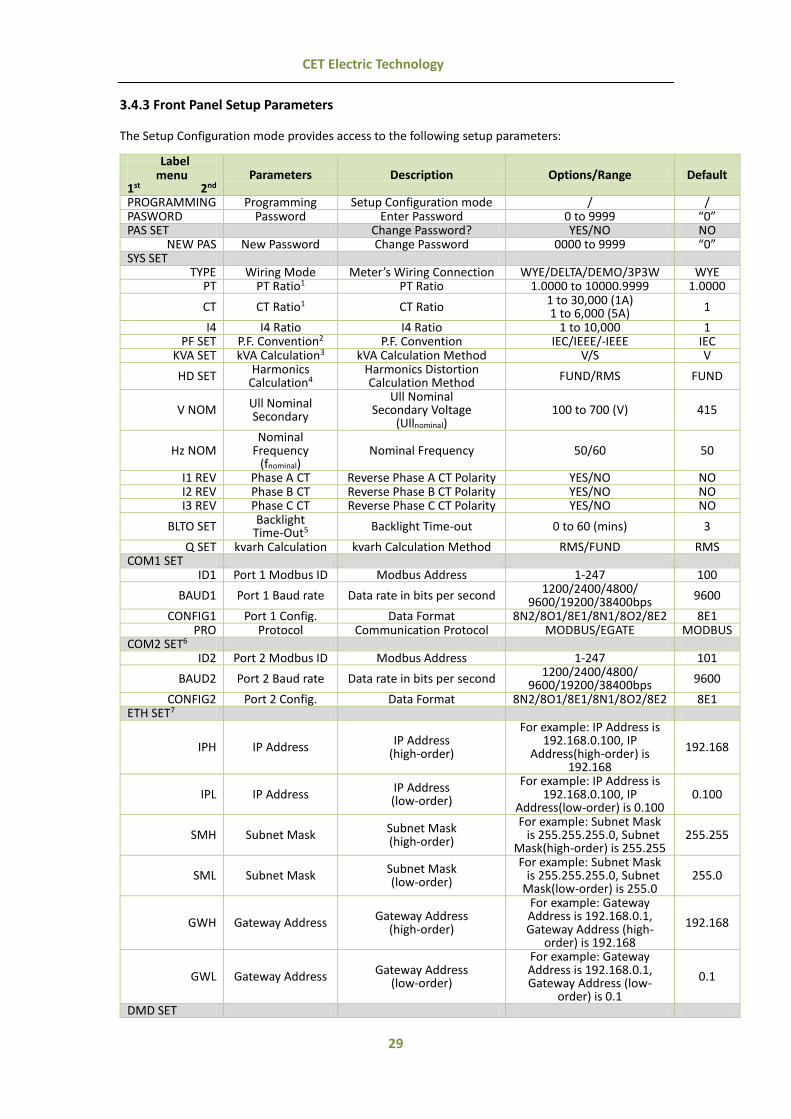
3.4.3 Front Panel Setup Parameters
The Setup Configuration mode provides access to the following setup parameters:
Label Parameters Description Options/Range Default menu
1st 2nd PROGRAMMING Programming Setup Configuration mode / / PASWORD Password Enter Password 0 to 9999 “0” PAS SET Change Password? YES/NO NO
NEW PAS New Password Change Password 0000 to 9999 “0” SYS SET
TYPE Wiring Mode Meter’s Wiring Connection WYE/DELTA/DEMO/3P3W WYE PT PT Ratio1 PT Ratio 1.0000 to 10000.9999 1.0000
CT CT Ratio1 CT Ratio 1 to 30,000 (1A) 1 to 6,000 (5A) 1
I4 I4 Ratio I4 Ratio 1 to 10,000 1 PF SET P.F. Convention2 P.F. Convention IEC/IEEE/-IEEE IEC
KVA SET kVA Calculation3 kVA Calculation Method V/S V
HD SET Harmonics
Calculation4 Harmonics Distortion Calculation Method
FUND/RMS FUND
V NOM Ull Nominal Secondary
Ull Nominal Secondary Voltage
(Ullnominal) 100 to 700 (V) 415
Hz NOM Nominal
Frequency (fnominal)
Nominal Frequency 50/60 50
I1 REV Phase A CT Reverse Phase A CT Polarity YES/NO NO I2 REV Phase B CT Reverse Phase B CT Polarity YES/NO NO I3 REV Phase C CT Reverse Phase C CT Polarity YES/NO NO
BLTO SET Backlight
Time-Out5 Backlight Time-out 0 to 60 (mins) 3
Q SET kvarh Calculation kvarh Calculation Method RMS/FUND RMS COM1 SET
ID1 Port 1 Modbus ID Modbus Address 1-247 100
BAUD1 Port 1 Baud rate Data rate in bits per second 1200/2400/4800/
9600/19200/38400bps 9600
CONFIG1 Port 1 Config. Data Format 8N2/8O1/8E1/8N1/8O2/8E2 8E1 PRO Protocol Communication Protocol MODBUS/EGATE MODBUS
COM2 SET6 ID2 Port 2 Modbus ID Modbus Address 1-247 101
BAUD2 Port 2 Baud rate Data rate in bits per second 1200/2400/4800/
9600/19200/38400bps 9600
CONFIG2 Port 2 Config. Data Format 8N2/8O1/8E1/8N1/8O2/8E2 8E1 ETH SET7
IPH IP Address IP Address
(high-order)
For example: IP Address is 192.168.0.100, IP
Address(high-order) is 192.168
192.168
IPL IP Address IP Address (low-order)
For example: IP Address is 192.168.0.100, IP
Address(low-order) is 0.100 0.100
SMH Subnet Mask Subnet Mask (high-order)
For example: Subnet Mask is 255.255.255.0, Subnet
Mask(high-order) is 255.255 255.255
SML Subnet Mask Subnet Mask (low-order)
For example: Subnet Mask is 255.255.255.0, Subnet Mask(low-order) is 255.0
255.0
GWH Gateway Address Gateway Address
(high-order)
For example: Gateway Address is 192.168.0.1, Gateway Address (high-
order) is 192.168
192.168
GWL Gateway Address Gateway Address (low-order)
For example: Gateway Address is 192.168.0.1, Gateway Address (low-
order) is 0.1
0.1
DMD SET

30
CET Electric Technology
MODE Demand Sync.
Mode Demand Sync. Mode SLD/SYNC SLD
PERIOD Sliding Window
Interval Sliding Window Interval 1 to 60 (minutes) 15
NUM Number of Sliding
Windows Number of Sliding Windows 1 to 15 1
SENS Predicted Response
Predicted Demand Sensitivity
70 to 99 70
PULS SET EN PULSE Energy Pulse Enable Energy Pulsing YES/NO NO
EN CONST Pulse Constant Pulse Constant8 1k/3.2k/5k/6.4k/12.8k 1k ENGY SET
IMP kWh kWh Import Preset kWh Import Value 0 to 999,999,999 0 EXP kWh kWh Export Preset kWh Export value 0 to 999,999,999 0
IMP kvarh kvarh Import Preset kvarh Import Value 0 to 999,999,999 0 EXP kvarh kvarh Export Preset kvarh Export value 0 to 999,999,999 0
kVAh kVAh Preset kVAh Value 0 to 999,999,999 0 DO SET
DO1 DO1 Control DO1 Control NORMAL/ON/OFF NORMAL DO2 DO2 Control DO2 Control NORMAL/ON/OFF NORMAL DO3 DO3 Control DO3 Control NORMAL/ON/OFF NORMAL
AI SET
TYPE Analog Input Type Select between 0-20mA or 4-20mA input
4-20 / 0-20 4-20
ZERO Zero Scale The value that corresponds
to the minimum Analog Input of 0 mA or 4 mA
-999,999 to 999,999 400
FULL Full Scale The value that corresponds
to the maximum Analog Input of 20 mA
-999,999 to 999,999 2000
AO SET
TYPE Analog Output
Type Select between 0-20mA or
4-20mA output 4-20 / 0-20 4-20
ZERO Zero Scale
The parameter value that corresponds to the
minimum Analog Output of 0 mA or 4 mA
-999,999 to 999,999 0
FULL Full scale
The parameter value that corresponds to the
maximum Analog Output of 20 mA
-999,999 to 999,999 999999
KEY9 Analog Output Parameter
The parameter to which the Analog Output is
proportional See Note 9) Uab
CLR SET
CLR ENGY Clear Energy Clear Total Energy and TOU Energy measurements
YES/NO NO
CLR MXMN Clear Max./Min. Clear Max./Min. Logs of This Month (Since Last
Reset) YES/NO NO
CLR PDMD Clear Demand Clear Peak Demands of This Month
YES/NO NO
CLR DIC Clear Pulse Counter
Clear Pulse Counter YES/NO NO
CLR SOE Clear SOE Clear SOE Log YES/NO NO CLR PQ Clear PQ Log Clear PQ Log YES/NO NO
CLR RT Clear operating
time Clear device operating time YES/NO NO
DAT Date Enter the Current Date (20)YY-MM-DD / CLK Time Enter the Current Time HH:MM:SS /
INFO Information (Read Only)
Check meter information YES/NO NO
660 Version Firmware Version
For example, 660 10000 means the meter is PMC-
660 and the firmware version is V1.00.00.
/
PRO VER Protocol Version Protocol Version e.g. 10 means V1.0 /

31
CET Electric Technology
UPDAT Update Date Date of the latest firmware
update e.g. 090821 /
Serial Number Meter Serial Number e.g. 0908471895 /
Table 3-5 Setup Parameters
Notes:
1) For 5A configuration, PT Ratio × CT Ratio must be less than 1,000,000.
For 1A configuration, PT Ratio x CT Ratio must be less than 5,000,000. 2) P.F. Convention: -IEEE is the same as IEEE but with the opposite sign.
Figure 3-6 Power Factor Definitions
3) There are two ways to calculate kVA:
Mode V (Vector method): 22
totaltotal kvarkWkVAtotal

32
CET Electric Technology
Mode S (Scalar method): ckVAkVAkVAkVA batotal
4) There are two ways to calculate the individual harmonic distortion:
% of Fundamental Method:
Voltage Kth Harmonic Distortion= X100%U
U
1
k
, U1 is Fundamental Voltage
Current Kth Harmonic Distortion=
1
k
I
IX100%
, I1 is Fundamental Current
% of RMS Method:
Voltage Kth Harmonic Distortion= X100%
U
U
2K
1K
k
Current Kth Harmonic Distortion= X100%
I
I
2K
1K
k
5) The Backlight Time-out can be set from 0 to 60 minutes. If the value is 0, the backlight is always on. This setup parameter is
available in Firmware V1.00.04 or later. 6) This menu only appears if the meter is equipped with the 2nd RS-485 port option. 7) This menu only appears if the meter is equipped with the Ethernet port option. The PMC-660 supports two types of Modbus
protocols for its Ethernet port:
a. RTU: Modbus RTU over TCP/IP (IP Port No. = 27011)
b. TCP: Modbus TCP (IP Port No. = 502)
8) Recommended Pulse Constant settings for the different Line Voltage & Current Inputs
Line Voltage Input Current Input X Value Energy Pulse Constant (X Value)
100V 1A 4
0=1000 imp/kWh 1=3200 imp/kWh
2=5000 imp/kWh 3=6400 imp/kWh
4=12800 imp/kWh
5A 4
380V 1A 4
5A 1
690V 1A 2
5A 0
Table 3-6 Pulse Constant
9) Analog Output Parameters
If PF Total is chosen as the AO parameter, the values for ZERO (zero scale) and FULL (full scale) should be set as 1000 times
the actual value. The Units for Voltage, Current, kW, kvar, kVA and FREQ are V, A, kW, kvar, kVA and Hz, respectively.
Key Parameter Scale Unit Key Parameter Scale Unit
0 Uab
x1
V 8 kW Total
x1
kW
1 Ubc V 9 kvar Total kvar
2 Uca V 10 kVA Total kVA
3 Ull Average V 11 PF Total x1000 -
4 Ia A 12 Frequency x1 Hz
5 Ib A 13 kW Total Present Demand
x1
kW
6 Ic A 14 kvar Total Present Demand kvar
7 I Average A 15 kVA Total Present Demand kVA
16 PF Total Present Demand -
Table 3-7 Analog Output Parameters

33
CET Electric Technology
Chapter 4 Applications
4.1 Inputs and Outputs
4.1.1 Digital Inputs
The PMC-660 comes standard with six self-excited Digital Inputs that are internally wetted at 24 VDC
with a sampling frequency of 1000Hz and programmable debounce. The PMC-660 provides the
following programmable functions for its Digital Inputs:
1) Digital Input The Digital Inputs are typically used for status monitoring which
can help prevent equipment damage, improve maintenance, and
track security breaches. The real-time statuses of the Digital Inputs
are available on the Front Panel LCD Display as well as through
communications. Changes in Digital Input status are stored as
events in the SOE Log in 1 ms resolution.
2) Pulse Counting Pulse counting is supported with programmable pulse weight and
facilitates WAGES (Water, Air, Gas, Electricity and Steam)
information collection.
3) Demand Sync Pulse One of the Digital Inputs can be programmed to receive Demand
Sync Pulse. Please refer to Section 4.2.5 for a detailed description.
4) Time Synchronization The Digital Inputs can be used as external time synchronization
pulse. Please refer to Section 4.8 for a detailed description.
5) Tariff Switching Up to 3 Digital Inputs may be used to select to which of the 8 Tariffs
the energy consumption should be accumulated. The 3 Digital
Inputs (DI1 to DI3) represent 3 binary digits where Tariff 1=000,
Tariff 2=001, …, Tariff 8=111 where DI1 represents the least
significant digit and DI3 represents the most significant digit. The
DI1 Function setup register must first be programmed as a Tariff
Switch before configuring DI2 with the same function. In other
words, if DI1 is configured as a Digital Input or Energy Pulse
Counter and DI2 is configured as a Tariff Switch, the TOU will
continue to function based on the TOU Schedule. This feature is
available in Firmware V2.00.00 or later.
The following table describes the DI’s setup parameters:
Setup Parameter Definition Options/*Default
DIx Function Each DI can be configured as a Status Input, Pulse Counter or SYNC DI. Only DI1 to DI3 can be set as Tariff Switch.
0=Status Input* 1=Pulse Counter
2=SYNC DI, 3=1 PPS 4=Tariff Switch
DIx Debounce Specifies the minimum duration the DI must remain in the Active or Inactive state before a state change is considered to be valid.
1 to 1000 (ms) (Default=20ms)
DIx Pulse Weight Specifies the incremental value for each received pulse. This is only used when a DI is configured as a Pulse Counter.
1* to 1,000,000
Table 4-1 DI Setup Parameters

34
CET Electric Technology
4.1.2 Digital Outputs
The PMC-660 comes standard with three Form A Electromechanical Digital Outputs. Digital Outputs are
normally used for setpoint alarming, load control, or remote control applications.
Digital Outputs on the PMC-660 can be used in the following applications:
1) Front Panel Control Manually operated from the Front Panel. Please refer to the DO SET
setup parameter in Section 3.4.3 for a detailed description.
2) Remote Control Remotely operated over communications via our free PMC Setup
software or the PecStar® iEMS Integrated Energy Management
System.
3) Control Setpoint Control setpoints can be programmed to trigger DO, Data Recorder,
Waveform Recorder or Alarm Email upon becoming active. Please
refer to Section 4.4 for a detailed description.
4) Logical Module Logical Module can be programmed to trigger DO, Data Recorder or
Waveform Recorder upon becoming active. Please refer to Section
4.5 for a detailed description.
5) Dip/Swell Setpoint Dip/Swell setpoint can be programmed to trigger DO, Data Recorder,
Waveform Recorder or Alarm Email upon becoming active. Please
refer to Section 4.3.5 for a detailed description.
6) Transient Setpoint: Transient setpoint can be programmed to trigger DO, Data Recorder,
Waveform Recorder or Alarm Email upon becoming active. Please
refer to Section 4.3.6 for a detailed description.
Since there are multiple ways to trigger the Digital Outputs on the PMC-660, a prioritized scheme has
been developed to avoid conflicts between different applications. In general, Front Panel Control has
the highest priority and can override other applications. Remote Control, Control Setpoint, Logical
Module, Dip/Swell Setpoint and Transient Setpoint share the same priority, meaning that they can all
be programmed to control the same Digital Output. This scheme is equivalent to having an implicit
Logical OR operation for the control of a Digital Output and may be useful in providing a generic alarm
output signal. However, the sharing of a Digital Output is not recommended if the user intends to
generate a control signal in response to a specific setpoint condition.
4.1.3 Energy Pulse Outputs
The PMC-660 comes standard with two Front Panel LED Pulse Outputs for kWh and kvarh pulsing.
Energy Pulse Outputs are typically used for accuracy testing. Energy pulsing can be enabled from the
Front Panel through the EN PULSE setup parameter. The pulse constant can be configured as
1000/3200/5000/6400/12800 pulses per kWh or kvarh through the EN CONST setup parameters. The
pulse width is fixed at 80ms.
4.1.4 Analog Input
The PMC-660 comes optionally with an Analog Input which can be programmed as 0mA to 20mA or
4mA to 20mA input. There are 3 setup parameters:
Type: Select between 0-20mA or 4-20mA input.
AI Zero: This value corresponds to the minimum Analog Input of 0 mA (for 0-20mA input) or 4

35
CET Electric Technology
mA (for 4-20mA input) and has a range of -999,999 to +999,999.
AI Full: This value corresponds to the maximum Analog Input of 20 mA and has a range of -
999,999 to +999,999.
For example, to measure the oil temperature of a transformer, connect the outputs of the temperature
sensor to the AI terminals of the PMC-660. The temperature sensor outputs 4mA when the temperature
is -25°C and 20mA when the temperature is 100°C. As such, the Type parameter should be programmed
as 4-20mA. The AI FULL parameter should be programmed with the value 100, and the AI ZERO
parameter should be programmed with the value -25. Therefore, when the output of the sensor is 20mA,
the reading will be 100.00°C. When the output is 4mA, the reading will be -25.00°C. When the output
is 12mA, the reading will be (100°C - (-25°C)) x (12mA-4mA) / (20mA-4mA) + (-25°C) = 37.50°C.
4.1.5 Analog Output
The PMC-660 comes optionally with one Analog Output which can be programmed as 0mA to 20mA or
4mA to 20mA output. There are 4 setup parameters:
Type: Select between 0-20mA or 4-20mA output.
AO Zero: Defines the zero scale value of the parameter when the Analog Output is 0 mA (for 0-
20mA output) or 4 mA (for 4-20mA output). The value ranges between -999,999 to
+999,999.
AO Full: Defines the full scale value of the parameter when the Analog Output is 20 mA. The
value ranges between -999,999 and +999,999.
Key: Defines the parameter to which the Analog Output is proportional. The Analog Output
Parameters are listed in Table 3-7.
For example, an AO of 4-20mA is required to be proportional to Phase A current. The maximum value
of phase A current is 2000A, and the minimum value is 500A. As such, the Type parameter should be
programmed as 4-20mA. The Key parameter should be programmed with Ia (Phase A Current). The AO
FULL parameter should be programmed with the value 2000. The AO ZERO parameter should be
programmed with the value 500. Therefore, when Phase A Current is 500A or below, the AO output is
4mA. When Phase A Current is 2000A, the AO output is 20mA. When Phase A Current is 1250A, the AO
is (1250A-500A) x (20mA-4mA) / (2000A-500A) + 4mA = 12.00(mA).
4.2 Power and Energy
4.2.1 Basic Measurements
The PMC-660 provides the following basic measurements with 1 second update rate which are available
through the Front Panel or communications
Parameter Phase A Phase B Phase C Total Average Uln - Ull -
Current - Neutral Current - - - I0 (Calculated) I4 (Measured)
Residual Current* - - - Ir (Calculated) - kW - kvar - kVA -
Power Factor - Frequency - - - -
U Fundamental
U Sequence* U1 (Positive Sequence) U2 (Negative Sequence) U0 (Zero Sequence)

36
CET Electric Technology
I Sequence* I1 (Positive Sequence) I2 (Negative Sequence) I0 (Zero Sequence) *Available in Firmware V2.00.00 or later
Table 4-2 Basic Measurements
4.2.2 Energy Measurements
The PMC-660 provides Energy parameters for active energy (kWh), reactive energy (kvarh) and
apparent energy (kVAh) with a resolution of 0.01 and a maximum value of ±1,000,000,000.00. When
the maximum value is reached, the energy registers will automatically roll over to zero. The energy can
be reset manually or preset to user-defined values through the Front Panel or via communications.
The PMC-660 provides the following energy measurements:
Active Energy kWh Import/Export/Net/Total kWh Import/Export of TOU T1-8*
Reactive Energy kvarh Import/Export/Net/Total kvarh Import/Export of TOU T1-8* kvarh of Q1/Q2/Q3/Q4
Apparent Energy kVAh Total kVAh of TOU T1-8*
*Available in Firmware V2.00.00 or later
Table 4-3 Energy Measurement
4.2.3 Interval Energy Measurements (Firmware V2.00.00 or later)
The PMC-660 provides Interval Energy measurements of kWh Import/Export, kvar Import/Export and
kVAh since Firmware V2.00.00. The Interval Energy measurements represent the amount of energy
consumed during the last completed interval as defined by EN Period. The Interval Energy
Measurements can only be retrieved through communications and are not available on the Front Panel.
The Interval Energy Period (EN Period) setup parameter can be programmed through communications
and allows the user to specify the interval for which the real-time energy consumption should be
accumulated. Please note that changing the Interval Energy Period would clear the present Interval
Energy measurements.
4.2.4 High-speed Measurements
The PMC-660 provides the following high-speed measurements which are available through the Front
Panel or communications.
3-Phase Voltage with ½ cycle update rate
3-Phase Current, Neutral Current (I4) and I0 with 1 cycle update rate
3-Phase Power and Power Factor with 1 cycle update rate
4.2.5 Demand Measurements
Demand is defined as the average power consumption over a fixed interval (usually 15 minutes) based
on the sliding window method. Predicted Demand is typically used for pre-alarming and to help users
reduce power consumption using a Setpoint to warn that the Demand limit may be exceeded. The PMC-
660 provides the following setup parameters:
Setup Parameter Definition Options/*Default
Demand Sync. Mode
SLD - Internally synchronized to the meter clock SYNC DI - Externally synchronized to a DI that has been programmed as a Demand Sync Input by setting the DI Function setup parameter as “SYNC DI”.
0= SLD* 1=SYNC DI
Demand Period 1 to 60 minutes. For example, if the # of Sliding Windows is set as 1 and the Demand Period is 15, the demand cycle will be 1×15=15min.
1 to 60 min Default=15

37
CET Electric Technology
# of Sliding Windows
Number of Sliding Windows. 1* to 15
Self-Read Time
The Self-Read Time allows the user to specify the time and day of the month for the Peak Demand Self-Read operation. The Self-Read Time supports three options: A zero value means that the Self-Read will take place at
00:00 of the first day of each month. A non-zero value means that the Self-Read will take place
at a specific time and day based on the formula: Self-Read Time = Day * 100 + Hour where 0 ≤ Hour ≤ 23 and 1 ≤ Day ≤ 28. For example, the value 1512 means that the Self-Read will take place at 12:00pm on the 15th day of each month.
A 0xFFFF value will disable the Self-Read operation and replace it with manual operation. A manual reset will cause the Peak Demand of This Month to be transferred to the Peak Demand of Last Month and then reset. The terms This Month and Last Month will become Since Last Reset and Before Last Reset.
Default=0xFFFF
Predicted Response
The Predicated Response shows the speed of the predicted demand output. A value between 70 and 99 is recommended for a reasonably fast response. Specify a higher value for higher sensitivity.
70* to 99
Table 4-4 Demand Setup
The PMC-660 provides the following Demand parameters:
Present and Predicted Demand Parameters
Voltage Uan / Ubn / Ucn / Uln average Uab / Ubc / Uca / Ull average
Current Ia / Ib / Ic / I average/I41
Energy kWa / kWb / kWc /kW Total kvara / kvarb / kvarc / kvar Total kVAa / kVAb / kVAc / kVA Total
Power Factor P.F.a / P.F.b / P.F.c /P.F. Total Frequency FREQ Unbalance U / I Unbalance
THD Uan / Ubn / Ucn THD Uab / Ubc / Uca THD Ia / Ib / Ic THD
Table 4-5 Demand Parameters Notes: 1) I4 is valid if the meter is equipped with the I4 option, and it will be automatically changed to I0 (Zero Sequence
Current) if the meter is equipped with the AI option.
4.2.6 Max./Min. per Demand Period
The PMC-660 provides the Max./Min. value per demand period of the following measurements:
3-Phase Voltage and Frequency
3-Phase Current and Neutral Current (I4)
3-Phase Power and Power Factor
Voltage and Current Unbalance
Voltage and Current THD
All Max./Min. data can be accessed through communication.
4.3 Power Quality
4.3.1 Phase Angles
Phase analysis is used to identify the angle relationship between 3-phase Voltages and Currents.
For WYE connected systems, the per phase difference of the Current and Voltage angles should
correspond to the per phase PF. For example, if the PF is 0.5 Lag and the Voltage phase angles are 0.0°,

38
CET Electric Technology
240.0° and 120.0°, the Current phase angles should have the values of -60.0°, 180.0° and 60.0°.
4.3.2 Power Quality Parameters
The PMC-660 provides the following PQ parameters:
4.3.2.1 Fundamental
The PMC-660 provides the following Fundamental Components (Displacement RMS values):
Fundamental Components dUan dUbn dUcn dUln average dUab dUbc dUca dUll average
dIa dIb dIc dI average dkWa dkWb dkWc dkW Total dkvara dkvarb dkvarc dkvar Total dkVAa dkVAb dkVAc dkVA Total dP.F.a dP.F.b dP.F.c dP.F. Total
dI4
Table 4-6 Fundamental Components
4.3.2.2 Harmonics
The PMC-660 provides harmonic analysis for THD, TOHD, TEHD and individual harmonics up to the 63rd
order. Only 31 individual harmonics are available through the Front Panel, and all 63 individual
parameters are available via communications. The PMC-660 also provides Current K-Factor
measurements.
4.3.2.3 K-Factor
K-Factor is defined as the weighted sum of the Harmonic Load Current according to their effects on
transformer heating, as derived from ANSI/IEEE C57.110. A K-Factor of 1.0 indicates a linear load (no
harmonics). The higher the K-Factor, the greater the harmonic heating effect.
Kmax
max
hh
h
hh
h
2
1
2
1
)(
)(
h
h
I
hI
Factor
where
Ih = hth Harmonic Current in RMS
hmax = Highest harmonic order
The following table illustrates the Voltage and Current Harmonics measurements on the PMC-660.
Phase A/AB Phase B/BC Phase C/CA
Harmonics-Voltage
THD THD THD TEHD TEHD TEHD TOHD TOHD TOHD
2nd Harmonics 2nd Harmonics 2nd Harmonics …
63rd Harmonics 63rd Harmonics 63rd Harmonics
Harmonics-Current
THD THD THD TEHD TEHD TEHD TOHD TOHD TOHD
K-Factor K-Factor K-Factor 2nd Harmonics 2nd Harmonics 2nd Harmonics
… 63rd Harmonics 63rd Harmonics 63rd Harmonics
I4 THD/TEHD/TOHD and 2nd to 63rd Harmonics
Table 4-7 Harmonics Measurements

39
CET Electric Technology
4.3.3 Unbalance
The PMC-660 provides Voltage and Current Unbalance measurements. The calculation method of
Voltage and Current Unbalances are listed below:
Voltage Unbalance = 100%V1
V2 Current Unbalance = 100%
I1
I2
where
V1, V2 are the Positive and Negative Sequence Components for Voltage, respectively, and I1, I2 are the Positive and Negative Sequence Components for Current, respectively.
4.3.4 Symmetrical Components
The PMC-660 provides the Voltage and Current Symmetrical Components measurements, which can be
accessed via the Front Panel or through communications.
Symmetrical Components Positive Sequence Negative Sequence Zero Sequence U U1 U2 U0 I I1 I2 I0
Table 4-8 Symmetrical Parameters
4.3.5 Deviation
The PMC-660 can measure deviation for Uan/Uab, Ubn/Ubc, Ucn/Uca and Frequency.
For Voltage Deviation, the calculation methods are listed below:
When the Wring Mode is 3P3W or Delta:
Voltage Deviation = ((Ull – Ullnominal) / Ullnominal) x 100%
When the Wring Mode is WYE:
Voltage Deviation = ((Uln – (Ullnominal÷√3)) / (Ullnominal÷√3)) x 100%
where Ullnominal
is the Secondary Nominal Voltage
For Freq. Deviation, the calculation method is listed below:
Freq. Deviation = ((f - fnominal)/fnominal) x 100%
where fnominal is the Nominal Frequency
4.3.6 Supply Voltage Dips/Swells and Interruptions
The PMC-660 supports the detection of Supply Voltage Dips/Swells and Interruptions based on 1-cycle
high-speed RMS Voltage values that are updated every ½ cycle and records any detected event in the
PQ Log with timestamp and event type. Further, the Dip/Swell and Interruption Detection can be
programmed to trigger WFR, DR, DO and Alarm Email. The programming of the Dip/Swell and
Interruption setpoint parameters is only supported over communications.
Parameter Definition Options/*Default Dip/Swell Enable Dip/Swell Detection Enable 0=Disabled, 1=Enabled* Swell Limit Specify the Swell limit 105 to 200 (x0.01Ullnominal), 110* Dip Limit Specify the Dip limit 10 to 95 (x0.01Ullnominal), 90* Interruption Limit Specify the Interruption limit 0 to 50 (x0.01Ullnominal), 10*
Dip/Swell/Interruption Trigger
Specify what action the setpoint will take when the Dip/Swell/Interruption detection becomes active
None / DO1 to DO3 / DR1 to DR16 / WR1* to WR2 / Alarm Email
Table 4-9 Dip/Swell/Interruption Setup Parameters
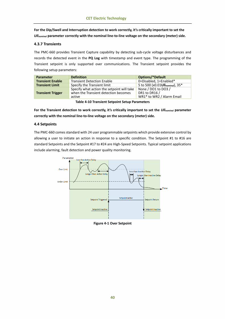
40
CET Electric Technology
For the Dip/Swell and Interruption detection to work correctly, it’s critically important to set the
Ullnominal parameter correctly with the nominal line-to-line voltage on the secondary (meter) side.
4.3.7 Transients
The PMC-660 provides Transient Capture capability by detecting sub-cycle voltage disturbances and
records the detected event in the PQ Log with timestamp and event type. The programming of the
Transient setpoint is only supported over communications. The Transient setpoint provides the
following setup parameters:
Parameter Definition Options/*Default Transient Enable Transient Detection Enable 0=Disabled, 1=Enabled* Transient Limit Specify the Transient limit 5 to 500 (x0.01Ullnominal), 35*
Transient Trigger Specify what action the setpoint will take when the Transient detection becomes active
None / DO1 to DO3 / DR1 to DR16 / WR1* to WR2 / Alarm Email
Table 4-10 Transient Setpoint Setup Parameters
For the Transient detection to work correctly, it’s critically important to set the Ullnominal parameter
correctly with the nominal line-to-line voltage on the secondary (meter) side.
4.4 Setpoints
The PMC-660 comes standard with 24 user programmable setpoints which provide extensive control by
allowing a user to initiate an action in response to a specific condition. The Setpoint #1 to #16 are
standard Setpoints and the Setpoint #17 to #24 are High-Speed Setpoints. Typical setpoint applications
include alarming, fault detection and power quality monitoring.
Figure 4-1 Over Setpoint
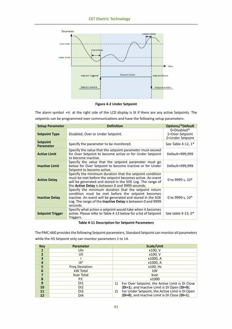
41
CET Electric Technology
Figure 4-2 Under Setpoint
The alarm symbol at the right side of the LCD display is lit if there are any active Setpoints. The
setpoints can be programmed over communications and have the following setup parameters:
Setup Parameter Definition Options/*Default
Setpoint Type Disabled, Over or Under Setpoint. 0=Disabled*
1=Over Setpoint 2=Under Setpoint
Setpoint Parameter
Specify the parameter to be monitored. See Table 4-12, 1*
Active Limit Specify the value that the setpoint parameter must exceed for Over Setpoint to become active or for Under Setpoint to become inactive.
Default=999,999
Inactive Limit Specify the value that the setpoint parameter must go below for Over Setpoint to become inactive or for Under Setpoint to become active.
Default=999,999
Active Delay
Specify the minimum duration that the setpoint condition must be met before the setpoint becomes active. An event will be generated and stored in the SOE Log. The range of the Active Delay is between 0 and 9999 seconds.
0 to 9999 s, 10*
Inactive Delay
Specify the minimum duration that the setpoint return condition must be met before the setpoint becomes inactive. An event will be generated and stored in the SOE Log. The range of the Inactive Delay is between 0 and 9999 seconds.
0 to 9999 s, 10*
Setpoint Trigger Specify what action a setpoint would take when it becomes active. Please refer to Table 4-13 below for a list of Setpoint Triggers.
See table 4-13, 0*
Table 4-11 Description for Setpoint Parameters
The PMC-660 provides the following Setpoint parameters, Standard Setpoint can monitor all parameters
while the HS Setpoint only can monitor parameters 1 to 14.
Key Parameter Scale/Unit 1 Uln x100, V 2 Ull x100, V 3 I x1000, A 4 I41 x1000, A 5 Freq Deviation x100, Hz 6 kW Total kW 7 kvar Total kvar 8 P.F. x1000 9 DI1 1) For Over Setpoint, the Active Limit is DI Close
(DI=1), and Inactive Limit is DI Open (DI=0); 2) For Under Setpoint, the Active Limit is DI Open
(DI=0), and Inactive Limit is DI Close (DI=1).
10 DI2 11 DI3 12 DI4

42
CET Electric Technology
13 DI5 14 DI6 15 AI / 16 kW Total Present Demand kW 17 kvar Total Present Demand kvar 18 P.F. Present Demand x1000 19 Total kW Predicted Demand kW 20 Total kvar Predicted Demand kvar 21 P.F. Predicted Demand x1000 22 U THD x100, % 23 U TOHD x100, % 24 U TEHD x100, % 25 I THD x100, % 26 I TOHD x100, % 27 I TEHD x100, % 28 U Unbalance x10, % 29 I Unbalance x10, % 30 U Deviation x100, %
31 Phase Reversal
1) For Over Setpoint, the Active Limit is Negative Phase Sequence, and Inactive Limit is Positive Phase Sequence.
2) For Under Setpoint, the Active Limit is Positive Phase Sequence, and Inactive Limit is Negative Phase Sequence.
32 I Residual x1000, A 33 U2 (Negative Sequence Voltage) x100, V 34 U0 (Zero Sequence Voltage) x100, V
Table 4-12 Setpoint Parameters
Notes 1) I4 is valid only if the device is equipped with the I4 Input option, and I0 (Zero Sequence Current) will automatically be used
to if the meter is equipped with the AI option (instead of I4).
Key Action Key Action 0 None 12 DR #9 1 DO1 13 DR #10 2 DO2 14 DR #11 3 DO3 15 DR #12 4 DR #1 16 DR #13 5 DR #2 17 DR #14 6 DR #3 18 DR #15 7 DR #4 19 DR #16 8 DR #5 20 WFR #1 8 DR #6 21 WFR #2
10 DR #7 22 Alarm Email 11 DR #8
Note: Only when DOx Mode is set to Remote Control/Setpoint would setting Setpoint Trigger to DOx be valid.
Table 4-13 Setpoint Triggers
4.5 Logical Module
The PMC-660 comes standard with 6 user programmable Logical Modules which perform an AND, NAND,
OR and NOR logical operation. The Logical Module provides extensive control by allowing a user to
initiate an action based on the combinational logic of up to four different Setpoint conditions.
The alarm symbol at the right side of the LCD display is lit if there are any active Logical Modules.
The Logical Modules can be programmed over communications and have the following setup
parameters:
Setup Parameters Definition Options/*Default Enable Logical Module
Logical Module Enable 0=Disabled*,
1=Enabled
Mode 1 to 3 Specify the type of logical evaluation to be performed 0=AND*, 1=OR,
2=NAND, 3=NOR Source 1 to 4 Specify the source input. See Table 4-15

43
CET Electric Technology
Trigger 1 Trigger 2
Specify what action the Logical Module will take when it becomes active. Logical Equation = ((Source 1 [Mode 1] Source 2) [Mode 2] Source 3) [Mode 3] Source 4
See Table 4-16
Table 4-14 Setpoint Parameters
Key Source Key Source 0 None 13 Setpoint #13 (Standard) 1 Setpoint #1 (Standard) 14 Setpoint #14 (Standard) 2 Setpoint #2 (Standard) 15 Setpoint #15 (Standard) 3 Setpoint #3 (Standard) 16 Setpoint #16 (Standard) 4 Setpoint #4 (Standard) 17 Setpoint #17 (High Speed) 5 Setpoint #5 (Standard) 18 Setpoint #18 (High Speed) 6 Setpoint #6 (Standard) 19 Setpoint #19 (High Speed) 7 Setpoint #7 (Standard) 20 Setpoint #20 (High Speed) 8 Setpoint #8 (Standard) 21 Setpoint #21 (High Speed) 9 Setpoint #9 (Standard) 22 Setpoint #22 (High Speed)
10 Setpoint #10 (Standard) 23 Setpoint #23 (High Speed) 11 Setpoint #11 (Standard) 24 Setpoint #24 (High Speed) 12 Setpoint #12 (Standard)
Table 4-15 Logical Module Sources
The PMC-660 provides the following Logical Module Triggers:
Key Action Key Action 0 None 4-19 DR1 to DR16
1-3 DO1 to DO3 20, 21 WR1, WR2
Table 4-16 Logical Module Triggers
4.6 Logging
4.6.1 Max./Min. Log
The PMC-660 records the Max. Log and Min. Log of This Month (Since Last Reset) and Last Month
(Before Last Reset) with timestamp for Uln, Ull, I, kW/kvar/kVA/PF Total, Frequency, Voltage and
Current THD, K-Factor and Voltage and Current Unbalance. Each log includes the relevant parameter
value and its timestamp. The recorded data is stored in the device’s non-volatile memory and will not
suffer any loss in the event of power failure. All of the maximum and minimum data can be accessed
through communications.
Max./Min. Parameters Uan Ubn Ucn Uln avg Uab Ubc Uca Ull avg
Ia Ib Ic I avg. kW Total kvar Total kVA Total P.F. Total
Uan/Uab THD Ubn/Ubc THD Ucn/Uca THD I4 Ia THD Ib THD Ic THD FREQ
Ia K-Factor Ib K-Factor Ic K-Factor Voltage Unbalance Current Unbalance I Residual
Table 4-17 Max./Min. Log
The same Self-Read Time for the Peak Demand Log is used to specify the time and day of the month
for the Max./Min. Self-Read operation. Please refer to Section 4.2.5 for a complete description of the
Self-Read Time and its operation. The Max./Min. Log of This Month (Since Last Reset) can be reset
manually from the Front Panel or via communications.
4.6.2 Peak Demand Log
The PMC-660 stores the Peak Demand of This Month (Since Last Reset) and Last Month (Before Last
Reset) with timestamp for Ia, Ib, Ic, kW Total, kvar Total and kVA Total. All Peak Demand data can be
accessed through the Front Panel as well as communications. Please refer to Section 4.2.5 for a
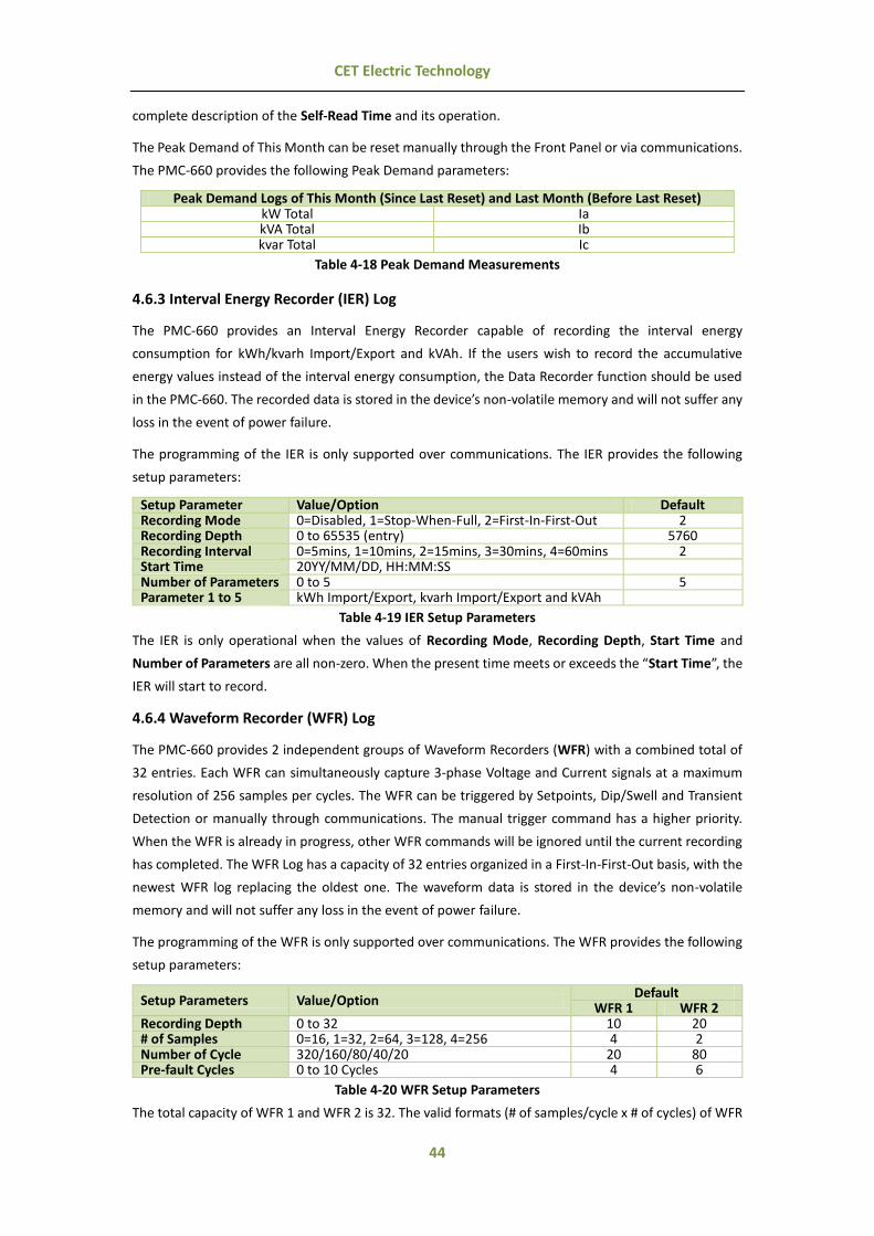
44
CET Electric Technology
complete description of the Self-Read Time and its operation.
The Peak Demand of This Month can be reset manually through the Front Panel or via communications.
The PMC-660 provides the following Peak Demand parameters:
Peak Demand Logs of This Month (Since Last Reset) and Last Month (Before Last Reset) kW Total Ia kVA Total Ib kvar Total Ic
Table 4-18 Peak Demand Measurements
4.6.3 Interval Energy Recorder (IER) Log
The PMC-660 provides an Interval Energy Recorder capable of recording the interval energy
consumption for kWh/kvarh Import/Export and kVAh. If the users wish to record the accumulative
energy values instead of the interval energy consumption, the Data Recorder function should be used
in the PMC-660. The recorded data is stored in the device’s non-volatile memory and will not suffer any
loss in the event of power failure.
The programming of the IER is only supported over communications. The IER provides the following
setup parameters:
Setup Parameter Value/Option Default Recording Mode 0=Disabled, 1=Stop-When-Full, 2=First-In-First-Out 2 Recording Depth 0 to 65535 (entry) 5760 Recording Interval 0=5mins, 1=10mins, 2=15mins, 3=30mins, 4=60mins 2 Start Time 20YY/MM/DD, HH:MM:SS Number of Parameters 0 to 5 5
Parameter 1 to 5 kWh Import/Export, kvarh Import/Export and kVAh
Table 4-19 IER Setup Parameters
The IER is only operational when the values of Recording Mode, Recording Depth, Start Time and
Number of Parameters are all non-zero. When the present time meets or exceeds the “Start Time”, the
IER will start to record.
4.6.4 Waveform Recorder (WFR) Log
The PMC-660 provides 2 independent groups of Waveform Recorders (WFR) with a combined total of
32 entries. Each WFR can simultaneously capture 3-phase Voltage and Current signals at a maximum
resolution of 256 samples per cycles. The WFR can be triggered by Setpoints, Dip/Swell and Transient
Detection or manually through communications. The manual trigger command has a higher priority.
When the WFR is already in progress, other WFR commands will be ignored until the current recording
has completed. The WFR Log has a capacity of 32 entries organized in a First-In-First-Out basis, with the
newest WFR log replacing the oldest one. The waveform data is stored in the device’s non-volatile
memory and will not suffer any loss in the event of power failure.
The programming of the WFR is only supported over communications. The WFR provides the following
setup parameters:
Setup Parameters Value/Option Default
WFR 1 WFR 2 Recording Depth 0 to 32 10 20 # of Samples 0=16, 1=32, 2=64, 3=128, 4=256 4 2 Number of Cycle 320/160/80/40/20 20 80 Pre-fault Cycles 0 to 10 Cycles 4 6
Table 4-20 WFR Setup Parameters
The total capacity of WFR 1 and WFR 2 is 32. The valid formats (# of samples/cycle x # of cycles) of WFR

45
CET Electric Technology
include 16x320, 32x160, 64x80, 128x40 and 256x20. When the WFR format is 256 samples/cycles, the
“Pre-fault Cycle” can only be set between 0 and 5.
The WFR logs can be retrieved via communications by our PecStar® iEMS or our free PMC Setup
Software for display.
Figure 4-3 WFR Log displayed in PecStar®
4.6.5 PQ Log
The PMC-660’s PQ Log can store up to 1000 PQ events such as Dips/Swells and Transients. Each event
record includes the event classification, its relevant voltage values and a timestamp in 1ms resolution.
All events can be retrieved via communications for display. If there are more than 1000 events, the
newest event will replace the oldest event on a First-In-First-Out basis. The PQ Log can be reset from
the Front Panel or via communications.
4.6.6 SOE Log
The PMC-660’s SOE Log can store up to 512 events such as Power-on, Power-off, Setpoint actions, Relay
actions, Digital Input status changes and setup changes in its non-volatile memory. Each event record
includes the event classification, its relevant parameter values and a timestamp in 1ms resolution. All
events can be retrieved via communications for display. If there are more than 512 events, the newest
event will replace the oldest event on a First-In-First-Out basis. The SOE Log can be reset from the Front
Panel or via communications.
4.6.7 Data Recorder (DR) Log
The PMC-660 comes equipped with 4MB of memory and provides 4 High-Speed Data Recorders (HS DR)
as well as 12 Standard Data Recorders (DR) capable of recording 16 parameters each. The recorded data
is stored in the device’s non-volatile memory and will not suffer any loss in the event of power failure.
The programming of the Data Recorder is only supported over communications. Each Data Recorder
provides the following setup parameters:
Setup Parameters Value/Option Default
Trigger Mode 0=Disabled / 1=Triggered by Timer / 2=Triggered by Setpoint
See Appendix B
Recording Mode 0=Stop-When-Full / 1=First-In-First-Out Recording Depth 1 to 65535 (entry)
Recording Interval 0 to 3456000 seconds for Standard Data Recorder 0 to 60 cycles for High-Speed Data Recorder
Offset Time 0 to 43,200 seconds, 0 indicates no offset If the Trigger Mode is set to Triggered by Setpoint, the Offset Time will be disregarded.
Number of Parameters 0 to 16
Parameter 1 to 16 0 to 329 for Standard Data Recorder 0 to 28 for High-Speed Data Recorder Please see refer to Appendix A for more information.
Table 4-21 DR Setup Parameters

46
CET Electric Technology
The DR Log is only operational when the values of Triggered Mode, Recording Mode, Recording Depth,
Recording Interval, and Number of Parameters are all non-zero.
Data Recorder #X can be triggered by clearing the Data Recorder #X when it is full in Stop-When-Full
mode (See Section 5.8.9).
For Standard Data Recorder, the Recording Offset parameter can be used to delay the recording by a
fixed time from the Recording Interval. For example, if the Recording Interval parameter is set to 3600
(hourly) and the Recording Offset parameter is set to 300 (5 minutes), the recording will take place at
5 minutes after the hour every hour, i.e. 00:05, 01:05, 02:05…etc. The programmed value of the
Recording Offset parameter should be less than that of the Recording Interval parameter.
For High-speed Data Recorder, the Recording Offset should be set to zero.
4.7 Time of Use (TOU)
TOU is used for electricity pricing that varies depending on the time of day, day of week, and season.
The TOU system allows the user to configure an electricity price schedule inside the PMC-660 and
accumulate energy consumption into different TOU tariffs based on the time of consumption. TOU
programming is only supported through communications. This feature is available in Firmware V2.00.00
or later.
The TOU feature on PMC-660 supports two TOU schedules, which can be switched at a pre-defined time.
Each TOU schedule supports:
Up to 12 seasons
90 Holidays or Alternate Days
20 Daily Profiles, each with 12 Periods in 15-minute interval
8 Tariffs
Instead of using the TOU schedule to switch between Tariffs, the PMC-660 supports Tariff switching
based on the status of DI1 to DI3.
The 3 Digital Inputs (DI1, DI2 and DI3) represent 3 binary digits where Tariff 1=000, Tariff 2=001, Tariff
3=010, …Tariff 7=110 and Tariff 8=111 where DI1 represents the least significant digit and DI3 represents
the most significant digit. As soon as DI1, DI2 and/or DI3 are configured as Tariff Switches, the current
TOU Tariff will be determined by the status of the DIs, and the TOU Schedule will be ignored. The DI1
Function setup register must first be programmed as a Tariff Switch before configuring DI2 and DI3 with
the same function. In other words, if DI1 is configured as a Digital Input or Energy Pulse Counter, and
DI2 is configured as a Tariff Switch, the TOU will continue to function based on the TOU Schedule. The
number of Tariffs supported depends on how many DIs are programmed as a Tariff Switch as indicated
in the following table.
Tariff DI Function
DI1 = Tariff Switch DI2 & DI1 = Tariff Switch DI3, DI2 & DI1 = Tariff Switch T1 DI1 (0=T1) DI2 + DI1 (00=T1) DI3 + DI2 + DI1 (000=T1) T2 DI1 (1=T2) DI2 + DI1 (01=T2) DI3 + DI2 + DI1 (001=T2) T3 Not Available DI2 + DI1 (10=T3) DI3 + DI2 + DI1 (010=T3) T4 Not Available DI2 + DI1 (11=T4) DI3 + DI2 + DI1 (011=T4) T5 Not Available Not Available DI3 + DI2 + DI1 (100=T5) T6 Not Available Not Available DI3 + DI2 + DI1 (101=T6) T7 Not Available Not Available DI3 + DI2 + DI1 (110=T7) T8 Not Available Not Available DI3 + DI2 + DI1 (111=T8)
Table 4-22 DIs and the Number of Tariffs Setup
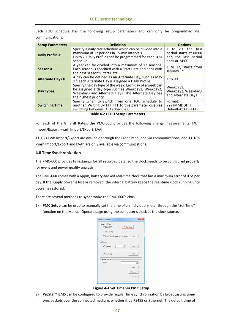
47
CET Electric Technology
Each TOU schedule has the following setup parameters and can only be programmed via
communications:
Setup Parameters Definition Options
Daily Profile #
Specify a daily rate schedule which can be divided into a maximum of 12 periods in 15-min intervals. Up to 20 Daily Profiles can be programmed for each TOU schedule.
1 to 20, the first period starts at 00:00 and the last period ends at 24:00.
Season # A year can be divided into a maximum of 12 seasons. Each season is specified with a Start Date and ends with the next season’s Start Date.
1 to 12, starts from January 1st
Alternate Days # A day can be defined as an Alternate Day, such as May 1st. Each Alternate Day is assigned a Daily Profile.
1 to 90.
Day Types
Specify the day type of the week. Each day of a week can be assigned a day type such as Weekday1, Weekday2, Weekday3 and Alternate Days. The Alternate Day has the highest priority.
Weekday1, Weekday2, Weekday3 and Alternate Days
Switching Time Specify when to switch from one TOU schedule to another. Writing 0xFFFFFFFF to this parameter disables switching between TOU schedules.
Format: YYYYMMDDHH Default=0xFFFFFFFF
Table 4-23 TOU Setup Parameters
For each of the 8 Tariff Rates, the PMC-660 provides the following Energy measurements: kWh
Import/Export, kvarh Import/Export, kVAh.
T1-T8’s kWh Import/Export are available through the Front Panel and via communications, and T1-T8’s
kvarh Import/Export and kVAh are only available via communications.
4.8 Time Synchronization
The PMC-660 provides timestamps for all recorded data, so the clock needs to be configured properly
for event and power quality analysis.
The PMC-660 comes with a 6ppm, battery-backed real-time clock that has a maximum error of 0.5s per
day. If the supply power is lost or removed, the internal battery keeps the real-time clock running until
power is restored.
There are several methods to synchronize the PMC-660’s clock:
1) PMC Setup can be used to manually set the time of an individual meter through the “Set Time”
function on the Manual Operate page using the computer’s clock as the clock source.
Figure 4-4 Set Time via PMC Setup
2) PecStar® iEMS can be configured to provide regular time synchronization by broadcasting time-
sync packets over the connected medium, whether it be RS485 or Ethernet. The default time of

48
CET Electric Technology
synchronization interval is 60 minutes.
3) SNTP server can be used to synchronize the PMC-660's clock through its Ethernet port providing
that the network where the PMC-660 resides has access to the Internet. The programming of the
SNTP server is only supported over communications. The SNTP server provides the following
setup parameters:
Setup Parameters Option/*Default SNTP Enable Disabled*/Enabled Time Zone GMT-12:00 / GMT-11:00 / GMT-10:00 / GMT-9:00 / GMT-8:00 /
GMT-7:00 / GMT-6:00 / GMT-5:00 / GMT-4:00 / GMT-3:30 / GMT-3:00 / GMT-2:00 / GMT-1:00 / GMT-0:00 / GMT+1:00 / GMT+2:00 / GMT+3:00 / GMT+3:30 / GMT+4:00 / GMT+4:30/ GMT+5:00 / GMT+5:30 / GMT+5:45 / GMT+6:00 / GMT+6:30 / GMT+7:00 / GMT+8:00*/ GMT+9:00 / GMT+9:30 / GMT+10:00 / GMT+11:00 / GMT+12:00 / GMT+13:00
Sync. Interval 10 to 1440 minutes, 60* IP Address of Time Server Set the IP address of your Time Server
Table 4-24 SNTP Setup Parameters
4) Further, a GPS that has a 1 PPS output can be used to synchronize the millisecond clock through
one of PMC-660's Digital Inputs. The programming of the DI is only supported over communications.
The PMC-660 provides the following setup parameters (please refer to Modbus registers 6025 to
6047 in Section 5.8.1 for a complete description of these DI Setup registers):
Setup Parameters Recommended Settings DI Function 0=Digital Input, 1=Pulse Counter, 2=SYNC DI, 3=PPS, 4=Tariff Switch* DI Debounce 0 and 1000 (ms), Default = 20 (ms) DI Pulse Weight 1 and 1,000,000 (x0.001), Default = 1 (0.001)
*Available in Firmware V2.00.00 or later, and only DI1 to DI3 can be set as Tariff Switch.
Table 4-25 DI Setup Parameters
Please also refer to Figure 2-15 for the time synchronization wiring diagram.
4.9 On-board Web Server
The PMC-660's Ethernet port comes with an on-board web server which provides quick and easy access
to the basic measurements and device information via a web browser like Microsoft's Internet Explorer.
The PMC-660 currently comes with only one web page as displayed in Figure 4-5. The PMC-660’s web
server supports simultaneous access from two different computers.
Viewing PMC-660's on-board Web Page:
1) Make sure the Ethernet settings of your computer and the PMC-660 are in the same subnet.
2) Enter the IP Address of the PMC-660 in the Address input box of the Internet Explorer and then press <Enter>.
3) The PMC-660’s web page appears as follows.
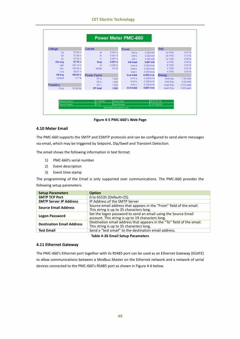
49
CET Electric Technology
Figure 4-5 PMC-660's Web Page
4.10 Meter Email
The PMC-660 supports the SMTP and ESMTP protocols and can be configured to send alarm messages
via email, which may be triggered by Setpoint, Dip/Swell and Transient Detection.
The email shows the following information in text format:
1) PMC-660’s serial number
2) Event description
3) Event time stamp
The programming of the Email is only supported over communications. The PMC-660 provides the
following setup parameters:
Setup Parameters Option SMTP TCP Port 0 to 65535 (Default=25) SMTP Server IP Address IP Address of the SMTP Server
Source Email Address Source email address that appears in the “From” field of the email. This string is up to 35 characters long.
Logon Password Set the logon password to send an email using the Source Email account. This string is up to 19 characters long.
Destination Email Address Destination email address that appears in the “To” field of the email. This string is up to 35 characters long.
Test Email Send a “test email” to the destination email address.
Table 4-26 Email Setup Parameters
4.11 Ethernet Gateway
The PMC-660's Ethernet port together with its RS485 port can be used as an Ethernet Gateway (EGATE)
to allow communications between a Modbus Master on the Ethernet network and a network of serial
devices connected to the PMC-660's RS485 port as shown in Figure 4-6 below.
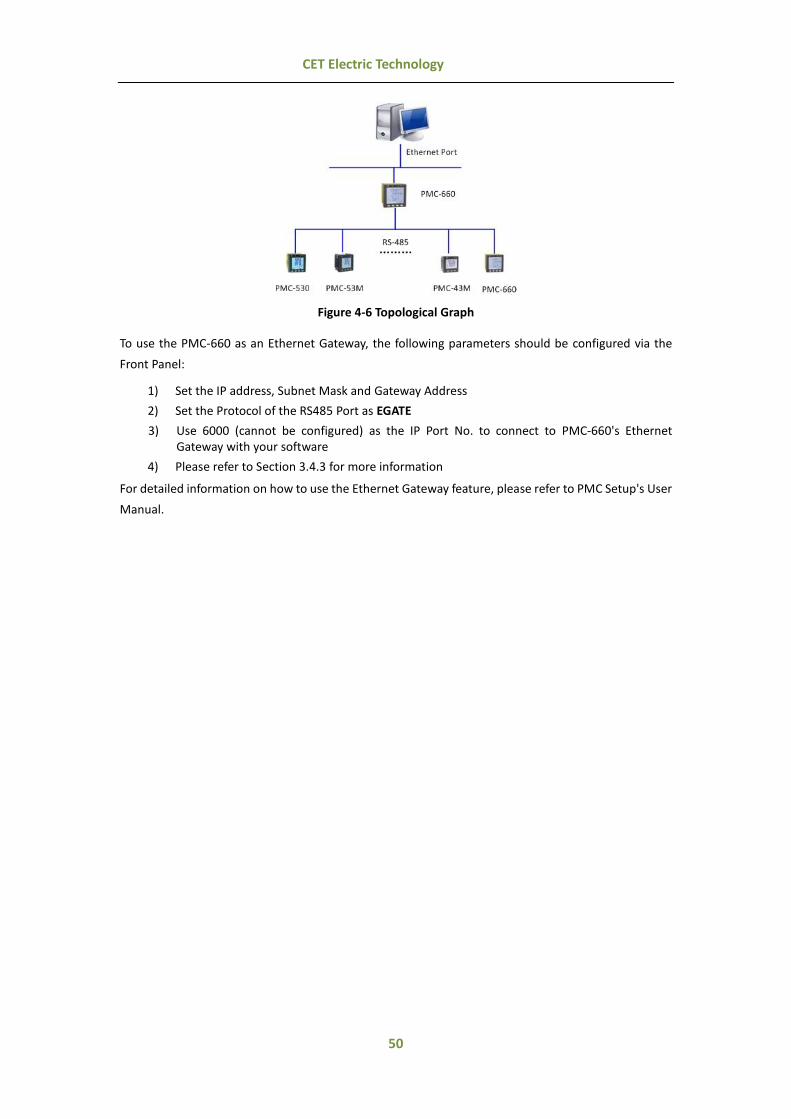
50
CET Electric Technology
Figure 4-6 Topological Graph
To use the PMC-660 as an Ethernet Gateway, the following parameters should be configured via the
Front Panel:
1) Set the IP address, Subnet Mask and Gateway Address
2) Set the Protocol of the RS485 Port as EGATE
3) Use 6000 (cannot be configured) as the IP Port No. to connect to PMC-660's Ethernet Gateway with your software
4) Please refer to Section 3.4.3 for more information
For detailed information on how to use the Ethernet Gateway feature, please refer to PMC Setup's User
Manual.

51
CET Electric Technology
Chapter 5 Modbus Register Map
This chapter provides a complete description of the Modbus register map (Protocol Version 1.6) for the
PMC-660 to facilitate the development of 3rd party communications driver for accessing information on
the PMC-660. For a complete Modbus Protocol Specification, please visit http://www.modbus.org. The
PMC-660 supports the following Modbus functions:
1) Read Holding Registers (Function Code 0x03)
2) Force Single Coil (Function Code 0x05)
3) Preset Multiple Registers (Function Code 0x10)
4) Read General Reference (Function Code 0x14)
The following table provides a description of the different data formats used for the Modbus registers.
The PMC-660 uses the Big Endian byte ordering system.
Format Description UINT16/INT16 Unsigned/Signed 16-bit Integer UINT32/INT32 Unsigned/Signed 32-bit Integer
Float IEEE 754 32-bit Single Precision Floating Point Number
5.1 Basic Measurements
Register Property Description Format Scale Unit 0000 RO Uan1 Float
x1 V
0002 RO Ubn1 Float 0004 RO Ucn1 Float 0006 RO Uln average1 Float 0008 RO Uab Float 0010 RO Ubc Float 0012 RO Uca Float 0014 RO Ull average Float 0016 RO Ia Float
x1 A 0018 RO Ib Float 0020 RO Ic Float 0022 RO I average Float 0024 RO kWa1 Float
x1 W 0026 RO kWb1 Float 0028 RO kWc1 Float 0030 RO kW Total Float 0032 RO kvara1 Float
x1 var 0034 RO kvarb1 Float 0036 RO kvarc1 Float 0038 RO kvar Total Float 0040 RO kVAa1 Float
x1 VA 0042 RO kVAb1 Float 0044 RO kVAc1 Float 0046 RO kVA Total Float 0048 RO P.F.a1 Float
x1 - 0050 RO P.F.b1 Float 0052 RO P.F.c1 Float 0054 RO P.F. Total Float 0056 RO FREQ Float x1 Hz 0058 RO I4 Measured Float x1 A 0060 RO I0 (Calculated Neutral Current)# Float x1 A
0062~0069 Reserved 0070 RO U Unbalance UINT16
×10 % 0071 RO I Unbalance UINT16 0072 RO Uan (Wye)/Uab (Delta/3P3W) Deviation INT16
x100 % 0073 RO Ubn (Wye)/Ubc (Delta/3P3W) Deviation INT16 0074 RO Ucn (Wye)/Uca (Delta/3P3W) Deviation INT16 0075 RO FREQ Deviation INT16 x100 Hz
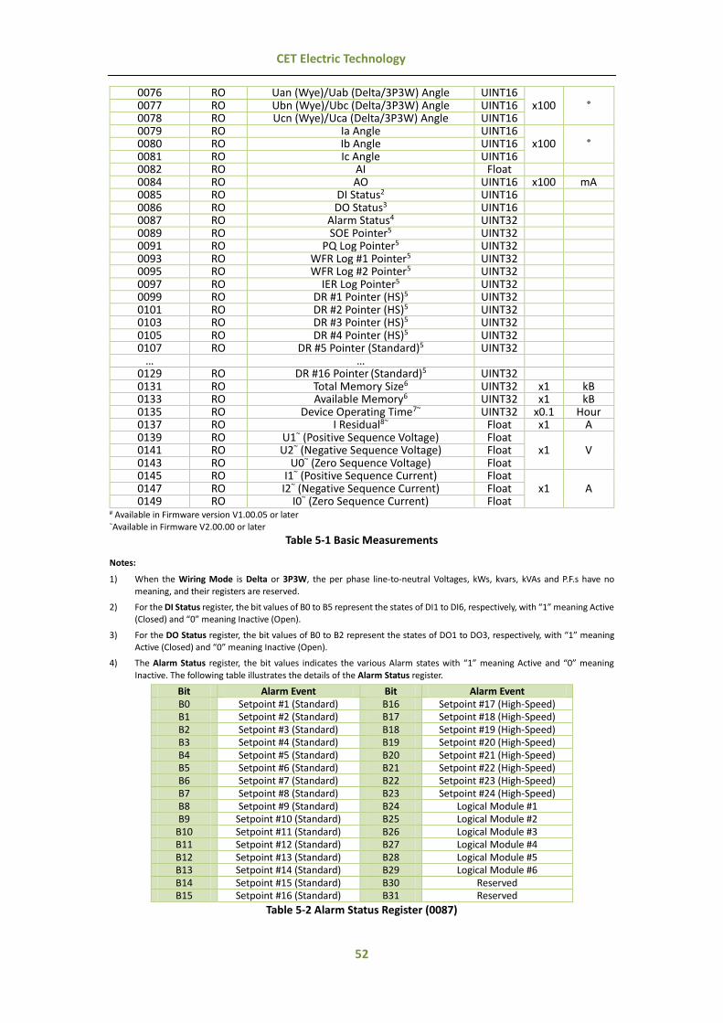
52
CET Electric Technology
0076 RO Uan (Wye)/Uab (Delta/3P3W) Angle UINT16 x100 ° 0077 RO Ubn (Wye)/Ubc (Delta/3P3W) Angle UINT16
0078 RO Ucn (Wye)/Uca (Delta/3P3W) Angle UINT16 0079 RO Ia Angle UINT16
x100 ° 0080 RO Ib Angle UINT16 0081 RO Ic Angle UINT16 0082 RO AI Float 0084 RO AO UINT16 x100 mA 0085 RO DI Status2 UINT16 0086 RO DO Status3 UINT16 0087 RO Alarm Status4 UINT32 0089 RO SOE Pointer5 UINT32 0091 RO PQ Log Pointer5 UINT32 0093 RO WFR Log #1 Pointer5 UINT32 0095 RO WFR Log #2 Pointer5 UINT32 0097 RO IER Log Pointer5 UINT32 0099 RO DR #1 Pointer (HS)5 UINT32 0101 RO DR #2 Pointer (HS)5 UINT32 0103 RO DR #3 Pointer (HS)5 UINT32 0105 RO DR #4 Pointer (HS)5 UINT32 0107 RO DR #5 Pointer (Standard)5 UINT32
… … 0129 RO DR #16 Pointer (Standard)5 UINT32 0131 RO Total Memory Size6 UINT32 x1 kB 0133 RO Available Memory6 UINT32 x1 kB 0135 RO Device Operating Time7~ UINT32 x0.1 Hour 0137 RO I Residual8~ Float x1 A 0139 RO U1~ (Positive Sequence Voltage) Float
x1 V 0141 RO U2~ (Negative Sequence Voltage) Float 0143 RO U0~ (Zero Sequence Voltage) Float 0145 RO I1~ (Positive Sequence Current) Float
x1 A 0147 RO I2~ (Negative Sequence Current) Float 0149 RO I0~ (Zero Sequence Current) Float
# Available in Firmware version V1.00.05 or later ~Available in Firmware V2.00.00 or later
Table 5-1 Basic Measurements
Notes:
1) When the Wiring Mode is Delta or 3P3W, the per phase line-to-neutral Voltages, kWs, kvars, kVAs and P.F.s have no
meaning, and their registers are reserved.
2) For the DI Status register, the bit values of B0 to B5 represent the states of DI1 to DI6, respectively, with “1” meaning Active (Closed) and “0” meaning Inactive (Open).
3) For the DO Status register, the bit values of B0 to B2 represent the states of DO1 to DO3, respectively, with “1” meaning Active (Closed) and “0” meaning Inactive (Open).
4) The Alarm Status register, the bit values indicates the various Alarm states with “1” meaning Active and “0” meaning
Inactive. The following table illustrates the details of the Alarm Status register.
Bit Alarm Event Bit Alarm Event B0 Setpoint #1 (Standard) B16 Setpoint #17 (High-Speed) B1 Setpoint #2 (Standard) B17 Setpoint #18 (High-Speed) B2 Setpoint #3 (Standard) B18 Setpoint #19 (High-Speed) B3 Setpoint #4 (Standard) B19 Setpoint #20 (High-Speed) B4 Setpoint #5 (Standard) B20 Setpoint #21 (High-Speed) B5 Setpoint #6 (Standard) B21 Setpoint #22 (High-Speed) B6 Setpoint #7 (Standard) B22 Setpoint #23 (High-Speed) B7 Setpoint #8 (Standard) B23 Setpoint #24 (High-Speed) B8 Setpoint #9 (Standard) B24 Logical Module #1 B9 Setpoint #10 (Standard) B25 Logical Module #2
B10 Setpoint #11 (Standard) B26 Logical Module #3 B11 Setpoint #12 (Standard) B27 Logical Module #4 B12 Setpoint #13 (Standard) B28 Logical Module #5 B13 Setpoint #14 (Standard) B29 Logical Module #6 B14 Setpoint #15 (Standard) B30 Reserved B15 Setpoint #16 (Standard) B31 Reserved
Table 5-2 Alarm Status Register (0087)
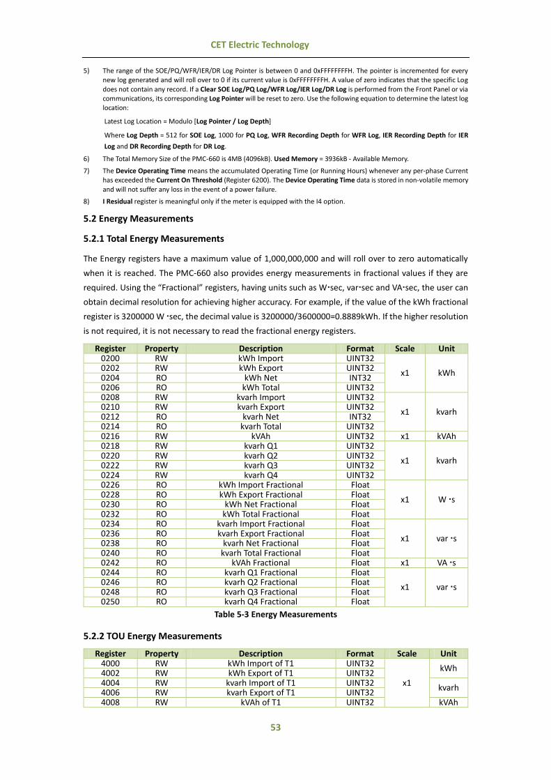
53
CET Electric Technology
5) The range of the SOE/PQ/WFR/IER/DR Log Pointer is between 0 and 0xFFFFFFFFH. The pointer is incremented for every new log generated and will roll over to 0 if its current value is 0xFFFFFFFFH. A value of zero indicates that the specific Log
does not contain any record. If a Clear SOE Log/PQ Log/WFR Log/IER Log/DR Log is performed from the Front Panel or via communications, its corresponding Log Pointer will be reset to zero. Use the following equation to determine the latest log location:
Latest Log Location = Modulo [Log Pointer / Log Depth]
Where Log Depth = 512 for SOE Log, 1000 for PQ Log, WFR Recording Depth for WFR Log, IER Recording Depth for IER
Log and DR Recording Depth for DR Log.
6) The Total Memory Size of the PMC-660 is 4MB (4096kB). Used Memory = 3936kB - Available Memory.
7) The Device Operating Time means the accumulated Operating Time (or Running Hours) whenever any per-phase Current has exceeded the Current On Threshold (Register 6200). The Device Operating Time data is stored in non-volatile memory
and will not suffer any loss in the event of a power failure.
8) I Residual register is meaningful only if the meter is equipped with the I4 option.
5.2 Energy Measurements
5.2.1 Total Energy Measurements
The Energy registers have a maximum value of 1,000,000,000 and will roll over to zero automatically
when it is reached. The PMC-660 also provides energy measurements in fractional values if they are
required. Using the “Fractional” registers, having units such as Wsec, varsec and VAsec, the user can
obtain decimal resolution for achieving higher accuracy. For example, if the value of the kWh fractional
register is 3200000 W sec, the decimal value is 3200000/3600000=0.8889kWh. If the higher resolution
is not required, it is not necessary to read the fractional energy registers.
Register Property Description Format Scale Unit 0200 RW kWh Import UINT32
x1 kWh 0202 RW kWh Export UINT32 0204 RO kWh Net INT32 0206 RO kWh Total UINT32 0208 RW kvarh Import UINT32
x1 kvarh 0210 RW kvarh Export UINT32 0212 RO kvarh Net INT32 0214 RO kvarh Total UINT32 0216 RW kVAh UINT32 x1 kVAh 0218 RW kvarh Q1 UINT32
x1 kvarh 0220 RW kvarh Q2 UINT32 0222 RW kvarh Q3 UINT32 0224 RW kvarh Q4 UINT32 0226 RO kWh Import Fractional Float
x1 W s 0228 RO kWh Export Fractional Float 0230 RO kWh Net Fractional Float 0232 RO kWh Total Fractional Float 0234 RO kvarh Import Fractional Float
x1 var s 0236 RO kvarh Export Fractional Float 0238 RO kvarh Net Fractional Float 0240 RO kvarh Total Fractional Float 0242 RO kVAh Fractional Float x1 VA s 0244 RO kvarh Q1 Fractional Float
x1 var s 0246 RO kvarh Q2 Fractional Float 0248 RO kvarh Q3 Fractional Float 0250 RO kvarh Q4 Fractional Float
Table 5-3 Energy Measurements
5.2.2 TOU Energy Measurements
Register Property Description Format Scale Unit 4000 RW kWh Import of T1 UINT32
x1
kWh 4002 RW kWh Export of T1 UINT32 4004 RW kvarh Import of T1 UINT32
kvarh 4006 RW kvarh Export of T1 UINT32 4008 RW kVAh of T1 UINT32 kVAh
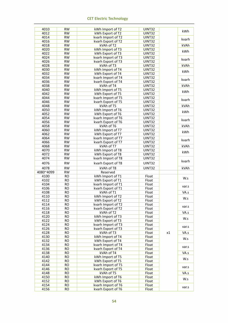
54
CET Electric Technology
4010 RW kWh Import of T2 UINT32 kWh
4012 RW kWh Export of T2 UINT32 4014 RW kvarh Import of T2 UINT32
kvarh 4016 RW kvarh Export of T2 UINT32 4018 RW kVAh of T2 UINT32 kVAh 4020 RW kWh Import of T3 UINT32
kWh 4022 RW kWh Export of T3 UINT32 4024 RW kvarh Import of T3 UINT32
kvarh 4026 RW kvarh Export of T3 UINT32 4028 RW kVAh of T3 UINT32 kVAh 4030 RW kWh Import of T4 UINT32
kWh 4032 RW kWh Export of T4 UINT32 4034 RW kvarh Import of T4 UINT32
kvarh 4036 RW kvarh Export of T4 UINT32 4038 RW kVAh of T4 UINT32 kVAh 4040 RW kWh Import of T5 UINT32
kWh 4042 RW kWh Export of T5 UINT32 4044 RW kvarh Import of T5 UINT32
kvarh 4046 RW kvarh Export of T5 UINT32 4048 RW kVAh of T5 UINT32 kVAh 4050 RW kWh Import of T6 UINT32
kWh 4052 RW kWh Export of T6 UINT32 4054 RW kvarh Import of T6 UINT32
kvarh 4056 RW kvarh Export of T6 UINT32 4058 RW kVAh of T6 UINT32 kVAh 4060 RW kWh Import of T7 UINT32
kWh 4062 RW kWh Export of T7 UINT32 4064 RW kvarh Import of T7 UINT32
kvarh 4066 RW kvarh Export of T7 UINT32 4068 RW kVAh of T7 UINT32 kVAh 4070 RW kWh Import of T8 UINT32
kWh 4072 RW kWh Export of T8 UINT32 4074 RW kvarh Import of T8 UINT32
kvarh 4076 RW kvarh Export of T8 UINT32
4078 RW kVAh of T8 UINT32 kVAh 4080~4099 RW Reserved
4100 RO kWh Import of T1 Float
x1
W.s 4102 RO kWh Export of T1 Float 4104 RO kvarh Import of T1 Float
var.s 4106 RO kvarh Export of T1 Float 4108 RO kVAh of T1 Float VA.s 4110 RO kWh Import of T2 Float
W.s 4112 RO kWh Export of T2 Float 4114 RO kvarh Import of T2 Float
var.s 4116 RO kvarh Export of T2 Float 4118 RO kVAh of T2 Float VA.s 4120 RO kWh Import of T3 Float
W.s 4122 RO kWh Export of T3 Float 4124 RO kvarh Import of T3 Float
var.s 4126 RO kvarh Export of T3 Float 4128 RO kVAh of T3 Float VA.s 4130 RO kWh Import of T4 Float
W.s 4132 RO kWh Export of T4 Float 4134 RO kvarh Import of T4 Float
var.s 4136 RO kvarh Export of T4 Float 4138 RO kVAh of T4 Float VA.s 4140 RO kWh Import of T5 Float
W.s 4142 RO kWh Export of T5 Float 4144 RO kvarh Import of T5 Float
var.s 4146 RO kvarh Export of T5 Float 4148 RO kVAh of T5 Float VA.s 4150 RO kWh Import of T6 Float
W.s 4152 RO kWh Export of T6 Float 4154 RO kvarh Import of T6 Float
var.s 4156 RO kvarh Export of T6 Float

55
CET Electric Technology
4158 RO kVAh of T6 Float VA.s 4160 RO kWh Import of T7 Float
W.s 4162 RO kWh Export of T7 Float 4164 RO kvarh Import of T7 Float
var.s 4166 RO kvarh Export of T7 Float 4168 RO kVAh of T7 Float VA.s 4170 RO kWh Import of T8 Float
W.s 4172 RO kWh Export of T8 Float 4174 RO kvarh Import of T8 Float
var.s 4176 RO kvarh Export of T8 Float 4178 RO kVAh of T8 Float VA.s
Table 5-4 TOU Energy Measurements
5.2.3 Interval Energy Measurements
Register Property Description Format Scale Unit 4500 RO kWh Import INT32
x0.01
kWh 4502 RO kWh Export INT32 4504 RO kvarh Import INT32
kvarh 4506 RO kvarh Export INT32 4508 RO kVAh INT32 kVAh
Table 5-5 Interval Energy Measurements
5.3 Pulse Counter
The Pulse Counter data returned is 1000 times the actual value. For example, if the register contains a
value of 1234567, the actual counter value is 1234.567.
Register Property Description Format Scale Unit 0350 RW DI1 Pulse Counter UINT32
x1000 -
0352 RW DI2 Pulse Counter UINT32 0354 RW DI3 Pulse Counter UINT32 0356 RW DI4 Pulse Counter UINT32 0358 RW DI5 Pulse Counter UINT32 0360 RW DI6 Pulse Counter UINT32
Table 5-6 Pulse Counter
5.4 Harmonic Measurements
5.4.1 Fundamental (Displacement) Measurements
Register Property Description Format Scale Unit 0400 RO dUan1 Float
x1
V
0402 RO dUbn1 Float 0404 RO dUcn1 Float 0406 RO dUln average1 Float 0408 RO dUab2 Float 0410 RO dUbc2 Float 0412 RO dUca2 Float 0414 RO dUll average2 Float 0416 RO dIa Float
A 0418 RO dIb Float 0420 RO dIc Float 0422 RO dI average Float 0424 RO dI43 Float 0426 RO dkWa1 Float
W 0428 RO dkWb1 Float 0430 RO dkWc1 Float 0432 RO dkW Total Float 0434 RO dkvara1 Float
var 0436 RO dkvarb1 Float 0438 RO dkvarc1 Float 0440 RO dkvar Total Float 0442 RO dkVAa1 Float
VA 0444 RO dkVAb1 Float

56
CET Electric Technology
0446 RO dkVAc1 Float 0448 RO dkVA Total Float 0450 RO dP.F.a1 Float
- 0452 RO dP.F.b1 Float 0454 RO dP.F.c1 Float 0456 RO dP.F. Total Float
Table 5-7 Fundamental Measurements
Notes:
1) When the Wiring Mode is Delta or 3P3W, the fundamental components of per phase line-to-neutral Voltages, kWs, kvars, kVAs and P.F.s have no meaning, and their registers are reserved.
2) When the Wiring Mode is Wye, the fundamental components of line-to-line voltages have no meaning, and their registers
are reserved.
3) I4 is valid only if the device is equipped with I4 option. Otherwise, it is reserved.
5.4.2 Harmonic Measurements
The Harmonics data (Individual Harmonics, THD, TOHD and TEHD) returned is 100 times the actual value.
For example, if the register contains a value of 1031, the actual harmonic value is 10.31. The K Factor
data returned is 10 times the actual value.
Register Property Description Format Scale Unit 0458 RO Ia K-Factor UINT16
×10 - 0459 RO Ib K-Factor UINT16 0460 RO Ic K-Factor UINT16 0461 RO Uan (WYE)/Uab (Delta/3P3W) THD UINT16
x100 %
0462 RO Ubn (WYE)/Ubc (Delta/3P3W) THD UINT16 0463 RO Ucn (WYE)/Uca (Delta/3P3W) THD UINT16 0464 RO Ia THD UINT16 0465 RO Ib THD UINT16 0466 RO Ic THD UINT16 0467 RO I4 THD1 UINT16 0468 RO Uan (WYE)/Uab (Delta/3P3W) TOHD UINT16 0469 RO Ubn (WYE)/Ubc (Delta/3P3W) TOHD UINT16 0470 RO Ucn (WYE)/Uca (Delta/3P3W) TOHD UINT16 0471 RO Ia TOHD UINT16 0472 RO Ib TOHD UINT16 0473 RO Ic TOHD UINT16 0474 RO I4 TOHD1 UINT16 0475 RO Uan (WYE)/Uab (Delta/3P3W) TEHD UINT16 0476 RO Ubn (WYE)/Ubc (Delta/3P3W) TEHD UINT16 0477 RO Ucn (WYE)/Uca (Delta/3P3W) TEHD UINT16 0478 RO Ia TEHD UINT16 0479 RO Ib TEHD UINT16 0480 RO Ic TEHD UINT16 0481 RO I4 TEHD1 UINT16 0482 RO Uan (WYE)/Uab (Delta/3P3W) 2nd Harmonic UINT16 0483 RO Ubn (WYE)/Ubc (Delta/3P3W) 2nd Harmonic UINT16 0484 RO Ucn (WYE)/Uca (Delta/3P3W) 2nd Harmonic UINT16 0485 RO Ia 2nd Harmonic UINT16 0486 RO Ib 2nd Harmonic UINT16 0487 RO Ic 2nd Harmonic UINT16 0488 RO I4 2nd Harmonic1 UINT16
… … 0909 RO Uan (WYE)/Uab (Delta/3P3W) 63rd Harmonic UINT16 0910 RO Ubn (WYE)/Ubc (Delta/3P3W) 63rd Harmonic UINT16 0911 RO Ucn (WYE)/Uca (Delta/3P3W) 63rd Harmonic UINT16 0912 RO Ia 63rd Harmonic UINT16 0913 RO Ib 63rd Harmonic UINT16 0914 RO Ic 63rd Harmonic UINT16 0915 RO I4 63rd Harmonic1 UINT16
Table 5-8 Harmonics Measurements
Notes:
1) I4 THD/TOHD/TEHD and Individual Harmonic Registers are valid only if the device is equipped with the I4 option.
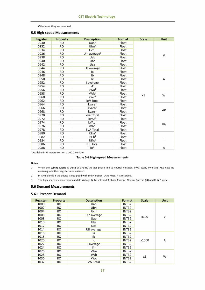
57
CET Electric Technology
Otherwise, they are reserved.
5.5 High-speed Measurements
Register Property Description Format Scale Unit 0930 RO Uan1 Float
x1
V
0932 RO Ubn1 Float 0934 RO Ucn1 Float 0936 RO Uln average1 Float 0938 RO Uab Float 0940 RO Ubc Float 0942 RO Uca Float 0944 RO Ull average Float 0946 RO Ia Float
A 0948 RO Ib Float 0950 RO Ic Float 0952 RO I average Float 0954 RO I42 Float 0956 RO kWa1 Float
W 0958 RO kWb1 Float 0960 RO kWc1 Float 0962 RO kW Total Float 0964 RO kvara1 Float
var 0966 RO kvarb1 Float 0968 RO kvarc1 Float 0970 RO kvar Total Float 0972 RO kVAa1 Float
VA 0974 RO kVAb1 Float 0976 RO kVAc1 Float 0978 RO kVA Total Float 0980 RO P.F.a1 Float
- 0982 RO P.F.b1 Float 0984 RO P.F.c1 Float 0986 RO P.F. Total Float 0988 RO I0* Float A
*Available in Firmware version V1.00.05 or later
Table 5-9 High-speed Measurements
Notes:
1) When the Wiring Mode is Delta or 3P3W, the per phase line-to-neutral Voltages, kWs, kvars, kVAs and P.F.s have no
meaning, and their registers are reserved.
2) I4 is valid only if the device is equipped with the I4 option. Otherwise, it is reserved.
3) The high-speed measurements update Voltage @ ½ cycle and 3-phase Current, Neutral Current (I4) and I0 @ 1 cycle.
5.6 Demand Measurements
5.6.1 Present Demand
Register Property Description Format Scale Unit 1000 RO Uan INT32
x100 V
1002 RO Ubn INT32 1004 RO Ucn INT32 1006 RO Uln average INT32 1008 RO Uab INT32 1010 RO Ubc INT32 1012 RO Uca INT32 1014 RO Ull average INT32 1016 RO Ia INT32
x1000 A 1018 RO Ib INT32 1020 RO Ic INT32 1022 RO I average INT32 1024 RO I41 INT32 1026 RO kWa INT32
x1 W 1028 RO kWb INT32 1030 RO kWc INT32 1032 RO kW Total INT32

58
CET Electric Technology
1034 RO kvara INT32
x1 var 1036 RO kvarb INT32 1038 RO kvarc INT32 1040 RO kvar Total INT32 1042 RO kVAa INT32
x1 VA 1044 RO kVAb INT32 1046 RO kVAc INT32 1048 RO kVA Total INT32 1050 RO P.F.a INT32
x1000 - 1052 RO P.F.b INT32 1054 RO P.F.c INT32 1056 RO P.F. Total INT32 1058 RO FREQ INT32 x100 Hz 1060 RO U Unbalance INT32
x10 % 1062 RO I Unbalance INT32 1064 RO Uan (WYE)/Uab (Delta/3P3W) THD INT32
x100 %
1066 RO Ubn (WYE)/Ubc (Delta/3P3W) THD INT32 1068 RO Ucn (WYE)/Uca (Delta/3P3W) THD INT32 1070 RO Ia THD INT32 1072 RO Ib THD INT32 1074 RO Ic THD INT32
Table 5-10 Present Demand
Notes:
1) I4 Present Demand is valid only if the device is equipped with the I4 option, and it will be automatically changed to I0 (Zero Sequence Current) Present Demand if the meter is equipped with the AI option.
5.6.2 Predicted Demand
Register Property Description Format Scale Unit 1200 RO Uan INT32
x100 V
1202 RO Ubn INT32 1204 RO Ucn INT32 1206 RO Uln average INT32 1208 RO Uab INT32 1210 RO Ubc INT32 1212 RO Uca INT32 1214 RO Ull average INT32 1216 RO Ia INT32
x1000 A 1218 RO Ib INT32 1220 RO Ic INT32 1222 RO I average INT32 1224 RO I41 INT32 1226 RO kWa INT32
x1 W 1228 RO kWb INT32 1230 RO kWc INT32 1232 RO kW Total INT32 1234 RO kvara INT32
x1 var 1236 RO kvarb INT32 1238 RO kvarc INT32 1240 RO kvar Total INT32 1242 RO kVAa INT32
x1 VA 1244 RO kVAb INT32 1246 RO kVAc INT32 1248 RO kVA Total INT32 1250 RO P.F.a INT32
x1000 - 1252 RO P.F.b INT32 1254 RO P.F.c INT32 1256 RO P.F. Total INT32 1258 RO FREQ INT32 x100 Hz 1260 RO U Unbalance INT32
x10 % 1262 RO I Unbalance INT32 1264 RO Uan (WYE)/Uab (Delta/3P3W) THD INT32
x100 % 1266 RO Ubn (WYE)/Ubc (Delta/3P3W) THD INT32 1268 RO Ucn (WYE)/Uca (Delta/3P3W) THD INT32 1270 RO Ia THD INT32

59
CET Electric Technology
1272 RO Ib THD INT32 1274 RO Ic THD INT32
Table 5-11 Predicted Demand Notes:
1) I4 Predicted Demand is valid only if the device is equipped with the I4 option, and it will be automatically changed to I0 (Zero Sequence Current) Predicted Demand if the meter is equipped with the AI option.
5.6.3 Max./Min. per Demand Period
Register Property Description Format Scale Unit 1400 RO Uan Max. INT32
x100 V
1402 RO Ubn Max. INT32 1404 RO Ucn Max. INT32 1406 RO Uln average Max. INT32 1408 RO Uab Max. INT32 1410 RO Ubc Max. INT32 1412 RO Uca Max. INT32 1414 RO Ull average Max. INT32 1416 RO Ia Max. INT32
x1000 A 1418 RO Ib Max. INT32 1420 RO Ic Max. INT32 1422 RO I average Max. INT32 1424 RO I4 Max.1 INT32 1426 RO kWa Max. INT32
x1 W 1428 RO kWb Max. INT32 1430 RO kWc Max. INT32 1432 RO kW Total Max. INT32 1434 RO kvara Max. INT32
x1 var 1436 RO kvarb Max. INT32 1438 RO kvarc Max. INT32 1440 RO kvar Total Max. INT32 1442 RO kVAa Max. INT32
x1 VA 1444 RO kVAb Max. INT32 1446 RO kVAc Max. INT32 1448 RO kVA Total Max. INT32 1450 RO P.F.a Max. INT32
x1000 - 1452 RO P.F.b Max. INT32 1454 RO P.F.c Max. INT32 1456 RO P.F. Total Max. INT32 1458 RO FREQ Max. INT32 x100 Hz 1460 RO U Unbalance Max. INT32
x10 % 1462 RO I Unbalance Max. INT32 1464 RO Uan (WYE)/Uab (Delta/3P3W) THD Max. INT32
x100 %
1466 RO Ubn (WYE)/Ubc (Delta/3P3W) THD Max. INT32 1468 RO Ucn (WYE)/Uca (Delta/3P3W) THD Max. INT32 1470 RO Ia THD Max. INT32 1472 RO Ib THD Max. INT32 1474 RO Ic THD Max. INT32
1476~1598 Reserved 1600 RO Uan Min. INT32
x100 V
1602 RO Ubn Min. INT32 1604 RO Ucn Min. INT32 1606 RO Uln average Min. INT32 1608 RO Uab Min. INT32 1610 RO Ubc Min. INT32 1612 RO Uca Min. INT32 1614 RO Ull average Min. INT32 1616 RO Ia Min. INT32
x1000 A 1618 RO Ib Min. INT32 1620 RO Ic Min. INT32 1622 RO I average Min. INT32 1624 RO I4 Min.1 INT32 1626 RO kWa Min. INT32
x1 W 1628 RO kWb Min. INT32 1630 RO kWc Min. INT32 1632 RO kW Total Min. INT32
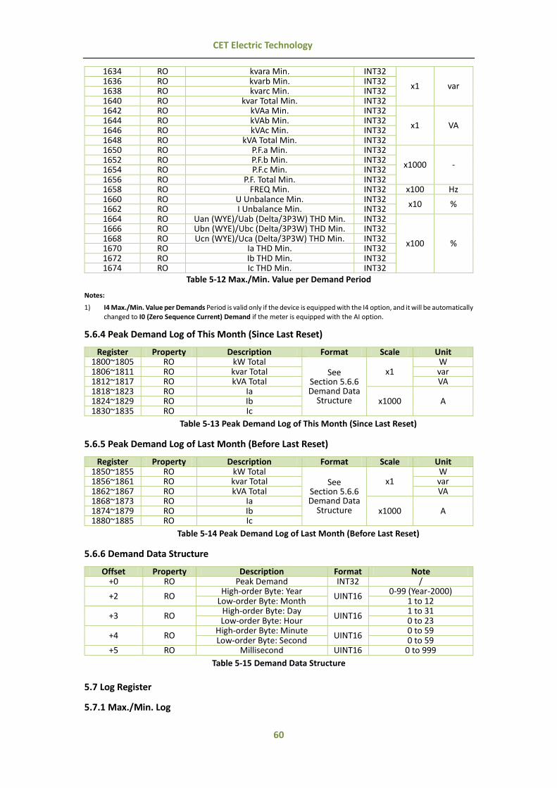
60
CET Electric Technology
1634 RO kvara Min. INT32
x1 var 1636 RO kvarb Min. INT32 1638 RO kvarc Min. INT32 1640 RO kvar Total Min. INT32 1642 RO kVAa Min. INT32
x1 VA 1644 RO kVAb Min. INT32 1646 RO kVAc Min. INT32 1648 RO kVA Total Min. INT32 1650 RO P.F.a Min. INT32
x1000 - 1652 RO P.F.b Min. INT32 1654 RO P.F.c Min. INT32 1656 RO P.F. Total Min. INT32 1658 RO FREQ Min. INT32 x100 Hz 1660 RO U Unbalance Min. INT32
x10 % 1662 RO I Unbalance Min. INT32 1664 RO Uan (WYE)/Uab (Delta/3P3W) THD Min. INT32
x100 %
1666 RO Ubn (WYE)/Ubc (Delta/3P3W) THD Min. INT32 1668 RO Ucn (WYE)/Uca (Delta/3P3W) THD Min. INT32 1670 RO Ia THD Min. INT32 1672 RO Ib THD Min. INT32 1674 RO Ic THD Min. INT32
Table 5-12 Max./Min. Value per Demand Period
Notes:
1) I4 Max./Min. Value per Demands Period is valid only if the device is equipped with the I4 option, and it will be automatically changed to I0 (Zero Sequence Current) Demand if the meter is equipped with the AI option.
5.6.4 Peak Demand Log of This Month (Since Last Reset)
Register Property Description Format Scale Unit 1800~1805 RO kW Total
See Section 5.6.6 Demand Data
Structure
x1 W
1806~1811 RO kvar Total var 1812~1817 RO kVA Total VA 1818~1823 RO Ia
x1000 A 1824~1829 RO Ib 1830~1835 RO Ic
Table 5-13 Peak Demand Log of This Month (Since Last Reset)
5.6.5 Peak Demand Log of Last Month (Before Last Reset)
Register Property Description Format Scale Unit 1850~1855 RO kW Total
See Section 5.6.6 Demand Data
Structure
x1 W
1856~1861 RO kvar Total var 1862~1867 RO kVA Total VA 1868~1873 RO Ia
x1000 A 1874~1879 RO Ib 1880~1885 RO Ic
Table 5-14 Peak Demand Log of Last Month (Before Last Reset)
5.6.6 Demand Data Structure
Offset Property Description Format Note +0 RO Peak Demand INT32 /
+2 RO High-order Byte: Year
UINT16 0-99 (Year-2000)
Low-order Byte: Month 1 to 12
+3 RO High-order Byte: Day
UINT16 1 to 31
Low-order Byte: Hour 0 to 23
+4 RO High-order Byte: Minute
UINT16 0 to 59
Low-order Byte: Second 0 to 59 +5 RO Millisecond UINT16 0 to 999
Table 5-15 Demand Data Structure
5.7 Log Register
5.7.1 Max./Min. Log

61
CET Electric Technology
5.7.1.1 Max. Log of This Month (Since Last Reset)
Register Property Description Format Scale Unit 2000~2005 RO Uan
See Section 5.7.1.5 Max./Min. Log Data Structure
x100 V
2006~2011 RO Ubn 2012~2017 RO Ucn 2018~2023 RO Uln average 2024~2029 RO Uab 2030~2035 RO Ubc 2036~2041 RO Uca 2042~2047 RO Ull average 2048~2053 RO Ia
x1000 A
2054~2059 RO Ib 2060~2065 RO Ic 2066~2071 RO I average 2072~2077 RO I41 2078~2083 RO kW Total
x1 W
2084~2089 RO kvar Total var 2090~2095 RO kVA Total VA 2096~2101 RO P.F. Total x1000 - 2102~2107 RO FREQ x100 Hz 2108~2113 RO Uan (WYE)/Uab (Delta/3P3W) THD
x100 %
2114~2119 RO Ubn (WYE)/Ubc (Delta/3P3W) THD 2120~2125 RO Ucn (WYE)/Uca (Delta/3P3W) THD 2126~2131 RO Ia THD 2132~2137 RO Ib THD 2138~2143 RO Ic THD 2144~2149 RO Ia K-Factor
x10 - 2150~2155 RO Ib K-Factor 2156~2161 RO Ic K-Factor 2162~2167 RO U Unbalance
x10 % 2168~2173 RO I Unbalance 2174~2179 RO I Residual x1000 A
Table 5-16 Max. Log of This Month (Since Last Reset)
Notes:
1) I4 is valid only if the device is equipped with the I4 option, and it will be automatically changed to I0 (Zero Sequence Current) if the meter is equipped with the AI option.
5.7.1.2 Min. Log of This Month (Since Last Reset)
Register Property Description Format Scale Unit 2300~2305 RO Uan
See Section 5.7.1.5 Max./Min. Log Data Structure
x100 V
2306~2311 RO Ubn 2312~2317 RO Ucn 2318~2323 RO Uln average 2324~2329 RO Uab 2330~2335 RO Ubc 2336~2341 RO Uca 2342~2347 RO Ull average 2348~2353 RO Ia
x1000 A 2354~2359 RO Ib 2360~2365 RO Ic 2366~2371 RO I average 2372~2377 RO I41 2378~2383 RO kW Total
x1 W
2384~2389 RO kvar Total var 2390~2395 RO kVA Total VA 2396~2401 RO P.F. Total x1000 - 2402~2407 RO FREQ x100 Hz 2408~2413 RO Uan (WYE)/Uab (Delta/3P3W) THD
x100 %
2414~2419 RO Ubn (WYE)/Ubc (Delta/3P3W) THD 2420~2425 RO Ucn (WYE)/Uca (Delta/3P3W) THD 2426~2431 RO Ia THD 2432~2437 RO Ib THD 2438~2443 RO Ic THD

62
CET Electric Technology
2444~2449 RO Ia K-Factor x10 - 2450~2455 RO Ib K-Factor
2456~2461 RO Ic K-Factor 2462~2467 RO U Unbalance
x10 % 2468~2473 RO I Unbalance 2474~2479 RO I Residual x1000 A
Table 5-17 Min. Log of This Month (Since Last Reset)
Notes:
1) I4 is valid only if the device is equipped with the I4 option, and it will be automatically changed to I0 (Zero Sequence Current) if the meter is equipped with the AI option.
5.7.1.3 Max. Log of Last Month (Before Last Reset)
Register Property Description Format Scale Unit 2600~2605 RO Uan
See Section 5.7.1.5 Max./Min. Log Data Structure
x100 V
2606~2611 RO Ubn 2612~2617 RO Ucn 2618~2623 RO Uln average 2624~2629 RO Uab 2630~2635 RO Ubc 2636~2641 RO Uca 2642~2647 RO Ull average 2648~2653 RO Ia
x1000 A
2654~2659 RO Ib 2660~2665 RO Ic 2666~2671 RO I average 2672~2677 RO I41 2678~2683 RO kW Total
x1 W
2684~2689 RO kvar Total var 2690~2695 RO kVA Total VA 2696~2701 RO P.F. Total x1000 - 2702~2707 RO FREQ x100 Hz 2708~2713 RO Uan (WYE)/Uab (Delta/3P3W) THD
x100 %
2714~2719 RO Ubn (WYE)/Ubc (Delta/3P3W) THD 2720~2725 RO Ucn (WYE)/Uca (Delta/3P3W) THD 2726~2731 RO Ia THD 2732~2737 RO Ib THD 2738~2743 RO Ic THD 2744~2749 RO Ia K-Factor
x10 - 2750~2755 RO Ib K-Factor 2756~2761 RO Ic K-Factor 2762~2767 RO U Unbalance
x10 % 2768~2773 RO I Unbalance 2774~2779 RO I Residual x1000 A
Table 5-18 Max. Log of Last Month (Before Last Reset)
Notes:
1) I4 is valid only if the device is equipped with the I4 option, and it will be automatically changed to I0 (Zero Sequence Current) if the meter is equipped with the AI option.
5.7.1.4 Min Log of Last Month (Before Last Reset)
Register Property Description Format Scale Unit 2900~2905 RO Uan
See Section 5.7.1.5 Max./Min. Log Data Structure
x100 V
2906~2911 RO Ubn 2912~2917 RO Ucn 2918~2923 RO Uln average 2924~2929 RO Uab 2930~2935 RO Ubc 2936~2941 RO Uca 2942~2947 RO Ull average 2948~2953 RO Ia
x1000
A 2954~2959 RO Ib 2960~2965 RO Ic 2966~2971 RO I average 2972~2977 RO I41

63
CET Electric Technology
2978~2983 RO kW Total x1
W 2984~2989 RO kvar Total var 2990~2995 RO kVA Total VA 2996~3001 RO P.F. Total x1000 - 3002~3007 RO FREQ x100 Hz 3008~3013 RO Uan (WYE)/Uab (Delta/3P3W) THD
x100 %
3014~3019 RO Ubn (WYE)/Ubc (Delta/3P3W) THD 3020~3025 RO Ucn (WYE)/Uca (Delta/3P3W) THD 3026~3031 RO Ia THD 3032~3037 RO Ib THD 3038~3043 RO Ic THD 3044~3049 RO Ia K-Factor
x10 - 3050~3055 RO Ib K-Factor 3056~3061 RO Ic K-Factor 3062~3067 RO U Unbalance
x10 % 3068~3073 RO I Unbalance 3074~3079 RO I Residual x1000 A
Table 5-19 Min. Log of Last Month (Before Last Reset)
Notes:
1) I4 is valid only if the device is equipped with the I4 option, and it will be automatically changed to I0 (Zero Sequence Current) if the meter is equipped with the AI option.
5.7.1.5 Max./Min. Log Data Structure
Offset Property Description Format Note +0 RO Max./Min. Value INT32 -
+2 RO High-order Byte: Year
UINT16 0-99 (Year-2000)
Low-order Byte: Month 1 to 12
+3 RO High-order Byte: Day
UINT16 1 to 31
Low-order Byte: Hour 0 to 23
+4 RO High-order Byte: Minute
UINT16 0 to 59
Low-order Byte: Second 0 to 59 +5 RO Millisecond UINT16 0 to 999
Table 5-20 Max./Min. Log Data Structure
5.7.2 SOE Log
The SOE Pointer points to the location within the SOE Log where the next event will be stored. The
following formula is used to determine the register address of the most recent SOE event referenced by
the SOE Pointer value: Register Address = 10000 + Modulo((SOE Pointer-1) / 512)*8
Register Property Description Format 10000~10007 RO Event 1
See Section Note 1) SOE Log Data
Structure
10008~10015 RO Event 2 10016~10023 RO Event 3 10024~10031 RO Event 4 10032~10039 RO Event 5 10040~10047 RO Event 6 10048~10055 RO Event 7 10056~10063 RO Event 8 10064~10071 RO Event 9 10072~10079 RO Event 10 10080~10087 RO Event 11 10088~10195 RO Event 12
… … 14088~14095 RO Event 512
Table 5-21 SOE Log
Notes:
1) SOE Log Data Structure
Offset Properties Description Format Note +0 RO Reserved UINT16 -
+1 RO High-order Byte: Event Classification
UINT16 See Appendix C
Low-order Byte: Sub-Classification See Appendix C

64
CET Electric Technology
+2 RO High-order Byte: Year
UINT16 0-99 (Year-2000)
Low-order Byte: Month 1 to 12
+3 RO High-order Byte: Day
UINT16 1 to 31
Low-order Byte: Hour 0 to 23
+4 RO High-order Byte: Minute
UINT16 0 to 59
Low-order Byte: Second 0 to 59 +5 RO Millisecond UNIT16 0 to 999 +6 RO Event Value INT32 -
Table 5-22 SOE Log Data Structure
5.8 Log Data Format
5.8.1 Read General Reference Packet Structure (Function Code 0x14)
Modbus function code 0x14 is used to access to the Energy Log, PQ Log, Data Recorder Log and
Waveform Recorder Log. The table below list the file format.
Read Reference Request Packet (Master Station to PMC-660)
Read Reference Response Packet (PMC-660 to Master Station)
Slave Address 1 Byte Salve Address 1 Byte Function Code (0x14) 1 Byte Function Code (0x14) 1 Byte Byte Count 1 Byte Byte Count 1 Byte (NxN0+2) Sub-Req X, Reference Type (0x06) 1 Byte Sub-Res X, Byte Count 1 Byte (NxN0+1) Sub-Req X, File Number 2 Bytes Sub-Res X, Reference Type (0x06) 1 Byte Sub-Req X, Start Address 2 Bytes Sub-Res X, Register Data NxN0 Bytes Sub-Req X, Register Count 2 Bytes Sub-Res X+1… Sub-Req X+1… Error Check (CRC) 2 Bytes Error Check (CRC) 2 Bytes
Table 5-23 Read Reference/ Response Request Packet
1) Start Address = [Log #X Pointer / Log #X Depth].
2) In the Request Packet, the File Number parameter is used to reference which log to read:
a) For Energy Log, File Number = 17
b) For PQ Log, File Number = 18
c) For Data Recorder Logs 1 to 16, File Number = 1 to 16
d) For Waveform Recorder Log, File Number = 19 to 50
3) In the Response Packet, N represents the number of logs returned, and N0 is the length of a single
log:
e) For Energy Log, N0 = n*4+8 where n is the number of parameters for the Energy Log
f) For Data Recorder, N0 = n*4+8 where n is the number of parameters for a particular Data
Recorder
g) For PQ Log, N0 = 16
h) For Waveform Recorder Log, N0 = 2
5.8.2 Energy Log Data Structure
Offset Property Description Format Note +0 RO Parameter 1 INT32 - +2 RO Parameter 2 INT32 - … RO … INT32 -
+2N RO Parameter N (N=0 to 5) INT32 -
+2N+1 RO High-order Byte: Year
UINT16 0-99 (Year-2000)
Low-order Byte: Month 1 to 12
+2N+2 RO High-order Byte: Day
UINT16 1 to 31
Low-order Byte: Hour 0 to 23
+2N+3 RO High-order Byte: Minute
UINT16 0 to 59
Low-order Byte: Second 0 to 59 +2N+4 RO Millisecond UINT16 0 to 999
Table 5-24 Energy Log Data Structure
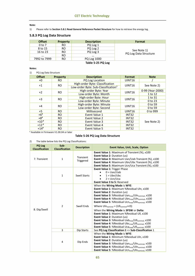
65
CET Electric Technology
Note:
1) Please refer to Section 5.8.1 Read General Reference Packet Structure for how to retrieve the energy log.
5.8.3 PQ Log Data Structure
Offset Property Description Format 0 to 7 RO PQ Log 1
See Note 1) PQ Log Data Structure
8 to 15 RO PQ Log 2 16 to 23 RO PQ Log 3
… RO … 7992 to 7999 RO PQ Log 1000
Table 5-25 PQ Log
Notes:
1) PQ Log Data Structure
Offset Property Description Format Note +0 RO PQ Log Location UINT16 /
+1 RO High-order Byte: Classification
UINT16 See Note 2) Low-order Byte: Sub-Classification2
+2 RO High-order Byte: Year
UINT16 0-99 (Year-2000)
Low-order Byte: Month 1 to 12
+3 RO High-order Byte: Hour
UINT16 1 to 31
Low-order Byte: Minute 0 to 23
+4 RO High-order Byte: Minute
UINT16 0 to 59
Low-order Byte: Second 0 to 59 +5 RO Millisecond UINT16 0 to 999 +6# RO Event Value 1 INT32
See Note 2) +8# RO Event Value 2 INT32
+10 # RO Event Value 3 INT32 +12 # RO Event Value 4 INT32 +14# RO Event Value 5 INT32
# Available in Firmware V1.00.04 or later
Table 5-26 PQ Log Data Structure
2) The table below lists the PQ Log Classifications:
PQ Log Classification
Sub- Classification
Description Event Value, Unit, Scale, Option
7. Transient 1 Transient Triggered
Event Value 1: Maximum of Transient (%), x100 Event Value 2: Duration (us) Event Value 3: Maximum Uan/Uab Transient (%), x100 Event Value 4: Maximum Ubn/Ubc Transient (%), x100 Event Value 5: Maximum Ucn/Uca Transient (%), x100
8. Dip/Swell
1 Swell Starts
Event Value 1: Trigger Phase 0 = Uan/Uab 1 = Ubn/Ubc 2 = Ucn/Uca
Event Value 3 to 5: Reserved
2 Swell Ends
When the Wiring Mode is WYE: Event Value 1: Maximum %Residual Uln, x100 Event Value 2: Duration (us) Event Value 3: %Residual Uanmax/Ulnnominal, x100 Event Value 4: %Residual Ubnmax/Ulnnominal, x100 Event Value 5: %Residual Ucnmax/Ulnnominal, x100
Where Ulnnominal = (Ullnominal÷√3) When the Wiring Mode is 3P3W or Delta: Event Value 1: Maximum %Residual Ull, x100 Event Value 2: Duration (us) Event Value 3: %Residual Uabmax/Ullnominal, x100 Event Value 4: %Residual Ubcmax/Ullnominal, x100 Event Value 5: %Residual Ucamax/Ullnominal, x100
3 Dip Starts See PQ Log Classification 8 => Sub-Classification 1
4 Dip Ends
When the Wiring Mode is WYE: Event Value 1: Minimum %Residual Uln, x100 Event Value 2: Duration (us) Event Value 3: %Residual Uanmin/Ulnnominal, x100 Event Value 4: %Residual Ubnmin/Ulnnominal, x100 Event Value 5: %Residual Ucnmin/Ulnnominal, x100

66
CET Electric Technology
Where Ulnnominal = (Ullnominal÷√3) When the Wiring Mode is 3P3W or Delta: Event Value 1: Maximum %Residual Ull, x100 Event Value 2: Duration (us) Event Value 3: %Residual Uabmin/Ullnominal, x100 Event Value 4: %Residual Ubcmin/Ullnominal, x100 Event Value 5: %Residual Ucamin/Ullnominal, x100
5 Interruption
Starts See PQ Log Classification 8 => Sub-Classification 1
6 Interruption
Ends See PQ Log Classification 8 => Sub-Classification 4
Table 5-27 PQ Classifications
5.8.4 Data Recorder Log Data Structure
Offset Property Description Format Note +0 RO Parameter 1 INT32 / +2 RO Parameter 2 INT32 / … RO … INT32
+2N RO Parameter N (N=1 to 16) INT32 /
+2N+1 RO High-order Byte: Year
UINT16 0-99 (Year-2000)
Low-order Byte: Month 1 to 12
+2N+2 RO High-order Byte: Day
UINT16 1 to 31
Low-order Byte: Hour 0 to 23
+2N+3 RO High-order Byte: Minute
UINT16 0 to 59
Low-order Byte: Second 0 to 59 +2N+4 RO Millisecond UINT16 0 to 999
Table 5-28 DR-LOG Data Structure
Notes:
1) Please refer to Section 5.8.1 Read General Reference Packet Structure for how to retrieve the DR log.
5.8.5 Waveform Recorder Log Data Structure
The WF data contains the secondary side value. The Voltage data returned is 10 times of the actual
secondary Voltage and the Current data is 1000 times of the actual secondary Current. Therefore, the
primary side Voltage and Current values are calculated using the following formulas:
Primary Voltage Value = Voltage Data × PT Ratio ÷ 10
Primary Current Value = Current Data × CT Ratio ÷ 1000
Offset Property Description Format Note
+0 RO Trigger Mode UINT16
0=Disabled* 1=Manual 2=Setpoint
3=Dip/Swell 4=Transient
+1 RO High-order Byte: Year
UINT16 0-99 (Year-2000)
Low-order Byte: Month 1 to 12
+2 RO High-order Byte: Day
UINT16 1 to 31
Low-order Byte: Hour 0 to 23
+3 RO High-order Byte: Minute
UINT16 0 to 59
Low-order Byte: Second 0 to 59 +4 RO Millisecond UINT16 0 to 999
+5 to N+4 RO Uan/Uab sample value (1 to N#) UINT16 x10, V +N+5 to 2N+4 RO Ubn/Ubc sample value (1 to N#) UINT16 x10, V
+2N+5 to 3N+4 RO Ucn/Uca sample value (1 to N#) UINT16 x10, V +3N+5 to 4N+4 RO Ia sample value (1 to N#) UINT16 x1000, A +4N+5 to 5N+4 RO Ib sample value (1 to N#) UINT16 x1000, A +5N+5 to 6N+4 RO Ic sample value (1 to N#) UINT16 x1000, A
#N=# of Samples Table 5-29 WFR Data Structure
Notes:
1) Please refer to Section 5.8.1 Read General Reference Packet Structure for how to retrieve the WFR log.
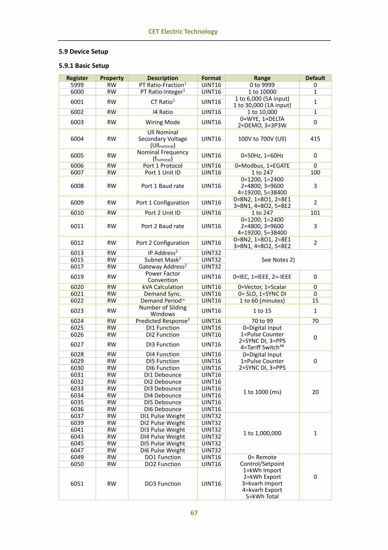
67
CET Electric Technology
5.9 Device Setup
5.9.1 Basic Setup
Register Property Description Format Range Default 5999 RW PT Ratio-Fraction1 UINT16 0 to 9999 0 6000 RW PT Ratio-Integer1 UINT16 1 to 10000 1
6001 RW CT Ratio1 UINT16 1 to 6,000 (5A input) 1 to 30,000 (1A input)
1
6002 RW I4 Ratio UINT16 1 to 10,000 1
6003 RW Wiring Mode UINT16 0=WYE, 1=DELTA
2=DEMO, 3=3P3W 0
6004 RW Ull Nominal
Secondary Voltage (Ullnominal)
UINT16 100V to 700V (Ull) 415
6005 RW Nominal Frequency
(fnominal) UINT16 0=50Hz, 1=60Hz 0
6006 RW Port 1 Protocol UINT16 0=Modbus, 1=EGATE 0 6007 RW Port 1 Unit ID UINT16 1 to 247 100
6008 RW Port 1 Baud rate UINT16 0=1200, 1=2400 2=4800, 3=9600
4=19200, 5=38400 3
6009 RW Port 1 Configuration UINT16 0=8N2, 1=8O1, 2=8E1 3=8N1, 4=8O2, 5=8E2 2
6010 RW Port 2 Unit ID UINT16 1 to 247 101
6011 RW Port 2 Baud rate UINT16 0=1200, 1=2400 2=4800, 3=9600
4=19200, 5=38400 3
6012 RW Port 2 Configuration UINT16 0=8N2, 1=8O1, 2=8E1 3=8N1, 4=8O2, 5=8E2
2
6013 RW IP Address2 UINT32 See Notes 2) 6015 RW Subnet Mask2 UINT32
6017 RW Gateway Address2 UINT32
6019 RW Power Factor Convention
UINT16 0=IEC, 1=IEEE, 2=-IEEE 0
6020 RW kVA Calculation UINT16 0=Vector, 1=Scalar 0 6021 RW Demand Sync. UINT16 0= SLD, 1=SYNC DI 0 6022 RW Demand Period~ UINT16 1 to 60 (minutes) 15
6023 RW Number of Sliding
Windows UINT16 1 to 15 1
6024 RW Predicted Response3 UINT16 70 to 99 70 6025 RW DI1 Function UINT16 0=Digital Input
1=Pulse Counter 2=SYNC DI, 3=PPS 4=Tariff Switch4#
0 6026 RW DI2 Function UINT16
6027 RW DI3 Function UINT16
6028 RW DI4 Function UINT16 0=Digital Input 1=Pulse Counter
2=SYNC DI, 3=PPS 0 6029 RW DI5 Function UINT16
6030 RW DI6 Function UINT16 6031 RW DI1 Debounce UINT16
1 to 1000 (ms) 20
6032 RW DI2 Debounce UINT16 6033 RW DI3 Debounce UINT16 6034 RW DI4 Debounce UINT16 6035 RW DI5 Debounce UINT16 6036 RW DI6 Debounce UINT16 6037 RW DI1 Pulse Weight UINT32
1 to 1,000,000 1
6039 RW DI2 Pulse Weight UINT32 6041 RW DI3 Pulse Weight UINT32 6043 RW DI4 Pulse Weight UINT32 6045 RW DI5 Pulse Weight UINT32 6047 RW DI6 Pulse Weight UINT32 6049 RW DO1 Function UINT16 0= Remote
Control/Setpoint 1=kWh Import 2=kWh Export
3=kvarh Import 4=kvarh Export
5=kWh Total
0
6050 RW DO2 Function UINT16
6051 RW DO3 Function UINT16
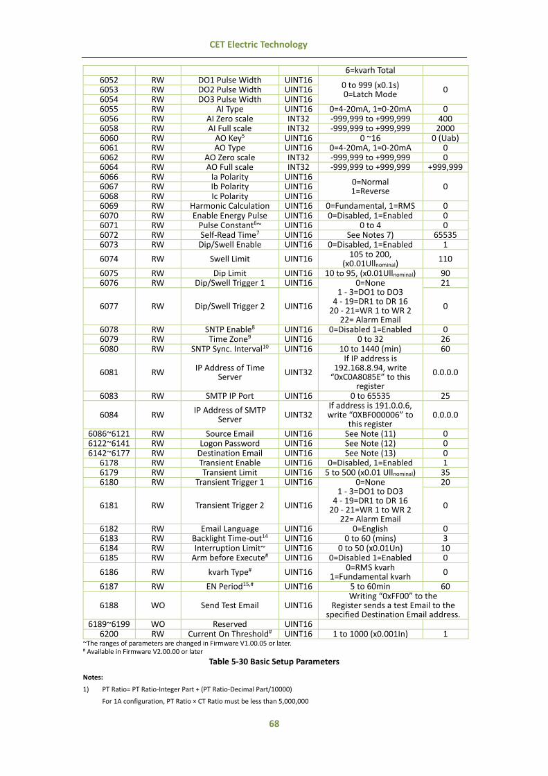
68
CET Electric Technology
6=kvarh Total 6052 RW DO1 Pulse Width UINT16
0 to 999 (x0.1s) 0=Latch Mode
0 6053 RW DO2 Pulse Width UINT16 6054 RW DO3 Pulse Width UINT16 6055 RW AI Type UINT16 0=4-20mA, 1=0-20mA 0 6056 RW AI Zero scale INT32 -999,999 to +999,999 400 6058 RW AI Full scale INT32 -999,999 to +999,999 2000 6060 RW AO Key5 UINT16 0 ~16 0 (Uab) 6061 RW AO Type UINT16 0=4-20mA, 1=0-20mA 0 6062 RW AO Zero scale INT32 -999,999 to +999,999 0 6064 RW AO Full scale INT32 -999,999 to +999,999 +999,999 6066 RW Ia Polarity UINT16
0=Normal 1=Reverse
0 6067 RW Ib Polarity UINT16 6068 RW Ic Polarity UINT16 6069 RW Harmonic Calculation UINT16 0=Fundamental, 1=RMS 0 6070 RW Enable Energy Pulse UINT16 0=Disabled, 1=Enabled 0 6071 RW Pulse Constant6~ UINT16 0 to 4 0 6072 RW Self-Read Time7 UINT16 See Notes 7) 65535 6073 RW Dip/Swell Enable UINT16 0=Disabled, 1=Enabled 1
6074 RW Swell Limit UINT16 105 to 200, (x0.01Ullnominal)
110
6075 RW Dip Limit UINT16 10 to 95, (x0.01Ullnominal) 90 6076 RW Dip/Swell Trigger 1 UINT16 0=None
1 - 3=DO1 to DO3 4 - 19=DR1 to DR 16
20 - 21=WR 1 to WR 2 22= Alarm Email
21
6077 RW Dip/Swell Trigger 2 UINT16 0
6078 RW SNTP Enable8 UINT16 0=Disabled 1=Enabled 0 6079 RW Time Zone9 UINT16 0 to 32 26 6080 RW SNTP Sync. Interval10 UINT16 10 to 1440 (min) 60
6081 RW IP Address of Time Server
UINT32
If IP address is 192.168.8.94, write
“0xC0A8085E” to this register
0.0.0.0
6083 RW SMTP IP Port UINT16 0 to 65535 25
6084 RW IP Address of SMTP
Server UINT32 If address is 191.0.0.6, write “0XBF000006” to
this register 0.0.0.0
6086~6121 RW Source Email UINT16 See Note (11) 0 6122~6141 RW Logon Password UINT16 See Note (12) 0 6142~6177 RW Destination Email UINT16 See Note (13) 0
6178 RW Transient Enable UINT16 0=Disabled, 1=Enabled 1 6179 RW Transient Limit UINT16 5 to 500 (x0.01 Ullnominal) 35 6180 RW Transient Trigger 1 UINT16 0=None
1 - 3=DO1 to DO3 4 - 19=DR1 to DR 16
20 - 21=WR 1 to WR 2 22= Alarm Email
20
6181 RW Transient Trigger 2 UINT16 0
6182 RW Email Language UINT16 0=English 0 6183 RW Backlight Time-out14 UINT16 0 to 60 (mins) 3 6184 RW Interruption Limit~ UINT16 0 to 50 (x0.01Un) 10 6185 RW Arm before Execute# UINT16 0=Disabled 1=Enabled 0
6186 RW kvarh Type# UINT16 0=RMS kvarh
1=Fundamental kvarh 0
6187 RW EN Period15,# UINT16 5 to 60min 60
6188 WO Send Test Email UINT16 Writing “0xFF00” to the
Register sends a test Email to the specified Destination Email address.
6189~6199 WO Reserved UINT16 6200 RW Current On Threshold# UINT16 1 to 1000 (x0.001In) 1
~The ranges of parameters are changed in Firmware V1.00.05 or later. # Available in Firmware V2.00.00 or later
Table 5-30 Basic Setup Parameters
Notes:
1) PT Ratio= PT Ratio-Integer Part + (PT Ratio-Decimal Part/10000)
For 1A configuration, PT Ratio × CT Ratio must be less than 5,000,000

69
CET Electric Technology
For 5A configuration, PT Ratio × CT Ratio must be less than 1,000,000
2) The last Octet of the IP Address, Subnet Mask and Gateway can neither be “0000 0000” nor “1111 1111”.
If the IP Address is “192.168.8.97”, write “0xC0A80861” to this register. The default values for the IP Address, Subnet Mask and Gateway Address are 192.168.0.100, 255.255.255.0 and 192.168.0.1, respectively.
3) The Predicated Response setup parameter allows the user to adjust the sensitivity of the predicted demand output. A
value between 70 and 99 is recommended for a reasonably fast response. Specify a higher value for higher sensitivity.
4) The 3 Digital Inputs (DI1, DI2 and DI3) represent 3 binary digits where Tariff 1=000, Tariff 2=001, Tariff 3= 010, …Tariff 7=110 and Tariff 8=111 where DI1 represents the least significant digit and DI3 represents the most significant digit. As soon as
DI1, DI2 and/or DI3 are configured as Tariff Switches, the current TOU Tariff will be determined by the status of the DIs, and the TOU Schedule will be ignored. The DI1 Function setup register must first be programmed as a Tariff Switch before configuring DI2 and DI3 with the same function. In other words, if DI1 is configured as a Digital Input or Energy Pulse
Counter, and DI2 is configured as a Tariff Switch, the TOU will continue to function based on the TOU Schedule. The number of Tariffs supported depends on how many DIs are programmed as a Tariff Switch as indicated in the following table.
Tariff DI Function
DI1 = Tariff Switch DI2 & DI1 = Tariff Switch DI3, DI2 & DI1 = Tariff Switch T1 DI1 (0=T1) DI2 + DI1 (00=T1) DI3 + DI2 + DI1 (000=T1) T2 DI1 (1=T2) DI2 + DI1 (01=T2) DI3 + DI2 + DI1 (001=T2) T3 Not Available DI2 + DI1 (10=T3) DI3 + DI2 + DI1 (010=T3) T4 Not Available DI2 + DI1 (11=T4) DI3 + DI2 + DI1 (011=T4) T5 Not Available Not Available DI3 + DI2 + DI1 (100=T5) T6 Not Available Not Available DI3 + DI2 + DI1 (101=T6) T7 Not Available Not Available DI3 + DI2 + DI1 (110=T7) T8 Not Available Not Available DI3 + DI2 + DI1 (111=T8)
Table 5-31 DIs and the Number of Tariffs Setup
5) Analog Output Parameters
If PF Total is chosen as the AO parameter, the values for ZERO (zero scale) and FULL (full scale) should be set as 1000 times the actual value. The Units for voltage, current, kW, kvar, kVA and FREQ are V, A, kW, kvar, kVA and Hz, respectively.
Key Parameter Scale Unit Key Parameter Scale Unit 0 Uab
x1
V 8 kW Total x1
kW 1 Ubc V 9 kvar Total kvar 2 Uca V 10 kVA Total kVA 3 Ull Average V 11 PF Total x1000 - 4 Ia A 12 Frequency x1 Hz 5 Ib A 13 kW Total Present Demand
x1
kW 6 Ic A 14 kvar Total Present Demand kvar 7 I Average A 15 kVA Total Present Demand kVA 16 PF Total Present Demand -
Table 5-32 Analog Output Parameters
6) Recommended Pulse Constant settings for the different Line Voltage & Current Inputs
Voltage Input Current Input X Value Energy Pulse Constant (X Value)
100V 1A 4
0=1000 imp/kWh 1=3200 imp/kWh 2=5000 imp/kWh 3=6400 imp/kWh
4=12800 imp/kWh
5A 4
380V 1A 4 5A 1
690V 1A 2 5A 0
Table 5-33 Pulse Constant
7) The Self-Read Time applies to both the Peak Demand Log as well as the Max./Min. Log and supports the following three options:
A zero value means that the Self-Read will take place at 00:00 of the first day of each month.
A non-zero value means that the Self-Read will take place at a specific time and day based on the formula: Self-Read Time = (Day x 100 + Hour) where 0 ≤ Hour ≤ 23 and 1 ≤ Day ≤ 28. For example, the value 1512 means that the Self-
Read will take place at 12:00pm on the 15th day of each month.
A 0xFFFF value means the automatic self-read operation is disabled and the log will be transferred manually.
8) If the PMC-660 is not equipped with the Ethernet Port, SNTP is disabled.
9) SNTP doesn’t support Daylight Time Saving (DTS). The following table lists the supported Time Zones:
Code Time Zone Code Time Zone 0 GMT-12:00 17 GMT+3:30 1 GMT-11:00 18 GMT+4:00 2 GMT-10:00 19 GMT+4:30 3 GMT-9:00 20 GMT+5:00

70
CET Electric Technology
4 GMT-8:00 21 GMT+5:30 5 GMT-7:00 22 GMT+5:45 6 GMT-6:00 23 GMT+6:00 7 GMT-5:00 24 GMT+6:30 8 GMT-4:00 25 GMT+7:00 9 GMT-3:30 26 GMT+8:00
10 GMT-3:00 27 GMT+9:00 11 GMT-2:00 28 GMT+9:30 12 GMT-1:00 29 GMT+10:00 13 GMT-0:00 30 GMT+11:00 14 GMT+1:00 31 GMT+12:00 15 GMT+2:00 32 GMT+13:00 16 GMT+3:00
Table 5-34 Time Zones
10) The SNTP Sync. Interval should be set between 10 and 1440 minutes.
11) This string register specifies the source email address that appears in the “From” field of the email. This string may be up to 35 characters long. Please add the value zero “0000” at the end of the string as the string terminator. For example, if the
email address is [email protected], set the registers as” 0073 0065 006E 0064 0065 0072 0040 0064 006F 006D 0061 0069 006E 002E 0063 006F 006D 0000”.
12) This string register specifies the Logon Password to login the “Source Email” account. This string may be up to 19 characters
long. Please add the value zero “0000” at the end of the string as the string terminator. For example, if the password is “PMC-660”, set the registers as “0050 004D 0043 002D 0036 0036 0030 0000”
13) This string register specifies the destination email address that appears in the “To” field of the email. This string may be up
to 35 characters long. Please add the value zero “0000” at the end of the string as the string terminator. For example, if the email address is [email protected], so set the registers as” 0072 0065 0063 0065 0069 0076 0065 0072 0040 0064 006F 006D 0061 0069 006E 002E 0063 006F 006D 0000”.
14) The Backlight Time-out can be set from 0 to 60 minutes. A zero (0) value indicates that the backlight time-out is disabled. This setup parameter is available in Firmware Version V1.00.04 or later.
15) The Interval Energy will be reset once the EN Period is changed.
5.9.2 Setpoint Setup
5.9.2.1 Setpoint Setup Registers
Register Property Description Format 6600~6609 RW Setpoint #1 (Standard)
See Section 5.9.2.2 Setpoint Setup Data
Structure
6610~6619 RW Setpoint #2 (Standard) 6620~6629 RW Setpoint #3 (Standard) 6630~6639 RW Setpoint #4 (Standard) 6640~6649 RW Setpoint #5 (Standard) 6650~6659 RW Setpoint #6 (Standard) 6660~6669 RW Setpoint #7 (Standard) 6670~6679 RW Setpoint #8 (Standard) 6680~6689 RW Setpoint #9 (Standard) 6690~6699 RW Setpoint #10 (Standard) 6700~6709 RW Setpoint #11 (Standard) 6710~6719 RW Setpoint #12 (Standard) 6720~6729 RW Setpoint #13 (Standard) 6730~6739 RW Setpoint #14 (Standard) 6740~6749 RW Setpoint #15 (Standard) 6750~6759 RW Setpoint #16 (Standard) 6760~6769 RW Setpoint #17 (High-Speed) 6770~6779 RW Setpoint #18 (High-Speed) 6780~6789 RW Setpoint #19 (High-Speed) 6790~6799 RW Setpoint #20 (High-Speed) 6800~6809 RW Setpoint #21 (High-Speed) 6810~6819 RW Setpoint #22 (High-Speed) 6820~6829 RW Setpoint #23 (High-Speed) 6830~6839 RW Setpoint #24 (High-Speed)
Table 5-35 Setpoints Setup
5.9.2.2 Setpoint Setup Data Structure
Offset Property Description Format Range Default +0 RW Standard Type UINT16 0=Disabled 0

71
CET Electric Technology
Setpoint 1=Over Setpoint 2=Under Setpoint
+1 RW Paramenter1 UINT16 1 to 34 1 +2 RW Active Limit INT32 - 999,999 +4 RW Inactive Limit INT32 - 999,999 +6 RW Active Delay UINT16 0 to 9999 s 10 +7 RW Inactive Delay UINT16 0 to 9999 s 10 +8 RW Trigger 12 UINT16 0 to 22 0 +9 RW Trigger 22 UINT16 0 to 22 0
+0 RW
High-speed
Setpoint
Type UINT16 0=Disabled
1=Over Setpoint 2=Under Setpoint
0
+1 RW Paramenter1 UINT16 1 to 14 1 +2 RW Active Limit INT32 - 999,999 +4 RW Inactive Limit INT32 - 999,999 +6 RW Active Delay UINT16 0 to 9999 s 10 +7 RW Inactive Delay UINT16 0 to 9999 s 10 +8 RW Trigger 12 UINT16 0 to 22 0 +9 RW Trigger 22 UINT16 0 to 22 0
Table 5-36 Setpoint Setup Register Structure
Notes:
1) “Parameter” specifies the parameter to be monitored. The Table 5-37 below provides a list of Setpoint Parameters, Standard Setpoint can monitor all parameters while the HS Setpoint only can monitor 1 to 14. Key Parameter Scale/Unit
1 Uln x100, V
2 Ull 3 I
x1000, A 4 I42
5 Frequency Deviation x100, Hz 6 kW Total x1, kW 7 kvar Total x1, kvar 8 P.F. x1000 9 DI1
1) For Over Setpoint, the Active Limit is DI Close (DI=1), and Inactive Limit is DI Open (DI=0);
2) For Under Setpoint, the Active Limit is DI Open (DI=0), and Inactive Limit is DI Close (DI=1).
10 DI2 11 DI3 12 DI4 13 DI5 14 DI6 15 AI x1, / 16 kW Total Present Demand x1, kW 17 kvar Total Present Demand x1, kvar 18 P.F. Present Demand x1000 19 kW Total Predicted Demand x1, kW 20 kvar Total Predicted Demand x1, kvar 21 P.F. Predicted Demand x1000 22 U THD
x100, %
23 U TOHD 24 U TEHD 25 I THD 26 I TOHD 27 I TEHD 28 U Unbalance
x10, % 29 I Unbalance 30 U Deviation x100, %
31 Phase Reversal
1) For Over Setpoint, the Active Limit is Negative Phase Sequence, and Inactive Limit is Positive Phase Sequence.
2) For Under Setpoint, the Active Limit is Positive Phase Sequence, and Inactive Limit is Negative Phase Sequence.
32 I Residual x1000, A 33 U2 (Negative Sequence Voltage)
x100, V 34 U0 (Zero Sequence Voltage)
Table 5-37 Setpoint Parameters
2) The I4 is valid only if the device is equipped with the I4 option, and it will be automatically changed to I0 (Zero Sequence Current) if the meter is equipped with the AI option.
3) Trigger 1/2 specifies what action the Setpoint will take when it becomes active. Table 5-38 below provides a list of Setpoint Triggers.
Key Action Key Action 0 None 12 DR #9 1 DO1 13 DR #10 2 DO2 14 DR #11 3 DO3 15 DR #12

72
CET Electric Technology
4 DR #1 16 DR #13 5 DR #2 17 DR #14 6 DR #3 18 DR #15 7 DR #4 19 DR #16 8 DR #5 20 WFR #1 8 DR #6 21 WFR #2
10 DR #7 22 Alarm Email 11 DR #8
Table 5-38 Setpoint Triggers
5.9.3 Logical Module Setup
5.9.3.1 Logical Module Setup Registers
Register Property Description Format 6840~6849 RW Logical Module #1
See Section 5.9.3.2 Logical Module
Setup Data Structure
6850~6859 RW Logical Module #2 6860~6869 RW Logical Module #3 6870~6879 RW Logical Module #4 6880~6889 RW Logical Module #5 6890~6899 RW Logical Module #6
Table 5-39 Logical Modules
5.9.3.2 Logical Module Setup Data Structure
Register Property Description Format Range Default +0 RW Enable Logical Module UINT16 0=Disabled, 1=Enabled 0 +1 RW Mode 1 UINT16
0=AND, 1=OR 2=NAND, 3=NOR
0 +2 RW Mode 2 UINT16 0 +3 RW Mode 3 UINT16 0 +4 RW Source 11 UINT16 0 to 24 1 +5 RW Source 21 UINT16 0 to 24 2 +6 RW Source 31 UINT16 0 to 24 3 +7 RW Source 41 UINT16 0 to 24 4 +8 RW Trigger 12 UINT16 0 to 21 0 +9 RW Trigger 22 UINT16 0 to 21 0
Table 5-40 Logical Module Data Structure
Notes:
1) The Logical Modules can have up to 4 Source inputs. Table 5-41 below provides a list of Logical Module Sources.
Key Source Key Source 0 None 13 Setpoint #13 (Standard) 1 Setpoint #1 (Standard) 14 Setpoint #14 (Standard) 2 Setpoint #2 (Standard) 15 Setpoint #15 (Standard) 3 Setpoint #3 (Standard) 16 Setpoint #16 (Standard) 4 Setpoint #4 (Standard) 17 Setpoint #17 (High-Speed) 5 Setpoint #5 (Standard) 18 Setpoint #18 (High-Speed) 6 Setpoint #6 (Standard) 19 Setpoint #19 (High-Speed) 7 Setpoint #7 (Standard) 20 Setpoint #20 (High-Speed) 8 Setpoint #8 (Standard) 21 Setpoint #21 (High-Speed) 9 Setpoint #9 (Standard) 22 Setpoint #22 (High-Speed)
10 Setpoint #10 (Standard) 23 Setpoint #23 (High-Speed) 11 Setpoint #11 (Standard) 24 Setpoint #24 (High-Speed) 12 Setpoint #12 (Standard)
Table 5-41 Logical Module Sources
2) Trigger 1/2 specifies what action the Logical Module will take when it becomes active. Table 5-42 below provides a list of Logical Module Triggers.
Key Action Key Action 0 None 11 DR #8 1 DO1 12 DR #9 2 DO2 13 DR #10 3 DO3 14 DR #11 4 DR #1 15 DR #12 5 DR #2 16 DR #13 6 DR #3 17 DR #14 7 DR #4 18 DR #15 8 DR #5 19 DR #16 8 DR #6 20 WFR #1
10 DR #7 21 WFR #2
Table 5-42 Logical Module Triggers

73
CET Electric Technology
5.9.4 Data Recorder Setup
5.9.4.1 Data Recorder Setup Registers
Register Property Description Format 7000~7022 RW Data Recorder #1 (High-Speed) See Section 5.9.4.2
High-speed Data Recorder
Setup Data Structure
7023~7045 RW Data Recorder #2 (High-Speed) 7046~7068 RW Data Recorder #3 (High-Speed) 7069~7091 RW Data Recorder #4 (High-Speed) 7092~7114 RW Data Recorder #5 (Standard)
See Section 5.9.4.3 Standard Data
Recorder Setup Data Structure
7115~7137 RW Data Recorder #6 (Standard) 7138~7160 RW Data Recorder #7 (Standard) 7161~7183 RW Data Recorder #8 (Standard) 7184~7206 RW Data Recorder #9 (Standard) 7207~7229 RW Data Recorder #10 (Standard) 7230~7252 RW Data Recorder #11 (Standard) 7253~7275 RW Data Recorder #12 (Standard) 7276~7298 RW Data Recorder #13 (Standard) 7299~7321 RW Data Recorder #14 (Standard) 7322~7344 RW Data Recorder #15 (Standard) 7345~7367 RW Data Recorder #16 (Standard)
7368 RO Data Recorder #1 Record Size (Bytes) UINT16 7369 RO Data Recorder #2 Record Size (Bytes) UINT16
7370~7381 RO … 7382 RO Data Recorder #15 Record Size (Bytes) UINT16 7383 RO Data Recorder #16 Record Size (Bytes) UINT16
Table 5-43 Data Recorder Setup Registers
Notes: 1) DRx Record Size (Bytes) = Number of Parameters*4+8.
DRx Log Size=DRx Recording Depth * DRx Record Size. The Log Size is rounded up to the nearest kB.
5.9.4.2 High-speed Data Recorder Setup Data Structure
Offset Property Description Format Range
+0 RW Trigged Mode 1 UINT16 0=Disabled
1=Triggered by Timer 2=Triggered by Setpoint
+1 RW Recording Mode2 UINT16 0=Stop-When-Full +2 RW Recording Depth3 UINT16 0 to 65535 +3 RW Recording Interval UINT32 1 to 60 (cycles) +5 RW Recording Offset4 UINT16 0 +6 RW Number of Parameters5 UINT16 0 to 16 +7 RW Parameter 1 UINT16
Please refer to Appendices A and B for a complete list of the Data Recorder Parameters and the
default configuration for each DR, respectively.
+8 RW Parameter 2 UINT16 +9 RW Parameter 3 UINT16
+10 RW Parameter 4 UINT16 +11 RW Parameter 5 UINT16 +12 RW Parameter 6 UINT16 +13 RW Parameter 7 UINT16 +14 RW Parameter 8 UINT16 +15 RW Parameter 9 UINT16 +16 RW Parameter 10 UINT16 +17 RW Parameter 11 UINT16 +18 RW Parameter 12 UINT16 +19 RW Parameter 13 UINT16 +20 RW Parameter 14 UINT16 +21 RW Parameter 15 UINT16 +22 RW Parameter 16 UINT16
Table 5-44 HS DR Setup Data Structure
Notes:
1) The High-speed Data Recorder can be triggered by Setpoints (Triggered by Setpoint) or on a time basis using the meter clock (Triggered by Timer).
For Triggered by Setpoint, when the Setpoint goes active, the Data Recorder starts to record, and when the Setpoint
becomes inactive, the Data Recorder stops.

74
CET Electric Technology
2) For High Speed Data Recorder, the Recording Mode only supports Stop-When-Full.
3) If Recording Depth is set to “0”, the Data Recorder will be disabled.
4) Recording Offset should be set to zero for High-Speed Data Recorder.
5) Appendix A provides a list of available parameters for data recording. Parameters 0 to 28 are available for high-speed data recording. If Number of parameters is set to 0, the Data Recorder is disabled.
6) Modifying Recording Mode, Recording Depth, Recording Interval, Recording Offset, Number of Parameters and Parameters 1 to 16 will clear the DRx Log and reset the DRx Pointer to “0”.
5.9.4.3 Standard Data Recorder Setup Data Structure
Offset Property Description Format Range
+0 RW Trigged Mode1 UINT16 0=Disabled
1=Triggered by Timer 2=Triggered by Setpoint
+1 RW Recording Mode UINT16 0=Stop-When-Full 1=First-In-First-Out
+2 RW Recording Depth2 UINT16 0 to 65535 +3 RW Recording Interval UINT32 1 to 3456000 (seconds) +5 RW Recording Offset3 UINT16 0 to 43200 (seconds) +6 RW Number of Parameters4 UINT16 0 to 16 +7 RW Parameter 1 UINT16
Please refer to Appendices A and B for a complete list of the Data Recorder Parameters and the default configuration for each DR, respectively.
+8 RW Parameter 2 UINT16 +9 RW Parameter 3 UINT16
+10 RW Parameter 4 UINT16 +11 RW Parameter 5 UINT16 +12 RW Parameter 6 UINT16 +13 RW Parameter 7 UINT16 +14 RW Parameter 8 UINT16 +15 RW Parameter 9 UINT16 +16 RW Parameter 10 UINT16 +17 RW Parameter 11 UINT16 +18 RW Parameter 12 UINT16 +19 RW Parameter 13 UINT16 +20 RW Parameter 14 UINT16 +21 RW Parameter 15 UINT16 +22 RW Parameter 16 UINT16
Table 5-45 Standard DR Setup Data Structure
Notes:
1) The Standard Data Recorder can be triggered by Setpoint (Triggered by Setpoint) or on a time basis using the meter clock
(Triggered by Timer).
For Triggered by Setpoint, when the Setpoint goes active, the Data Recorder starts to record, and when the Setpoint becomes inactive, the Data Recorder stops.
2) If the Recording Depth is set to 0, the Data Recorder will be disabled.
3) Recording Offset can be used to delay the recording by a fixed time from the Recording Interval. For example, if Recording Interval is set to 3600 (hourly) and Recording Offset is set to 300 (5 minutes), the recording will take place at 5 minutes
after the hour every hour, i.e. 00:05, 01:05, 02:05…etc. The programmed value of Recording Offset should be less than that of Recording Interval.
4) Appendix A provides a list of available parameters for data recording. All parameters are available for standard data
recording. If Number of parameters is set to 0, the Data Recorder is disabled.
5) Modifying Recording Mode, Recording Depth, Recording Interval, Recording Offset, Number of Parameters and Parameters 1 to 16 will clear the DRx Log and reset the DRx Pointer to “0”.
5.9.5 Interval Energy Recorder Setup Registers
Register Property Description Format Range Default
7700 RW Recording Mode UINT16 0=Disabled
1=Stop-When-Full 2= First-In-First-Out
2
7701 RW Recording Depth1 UINT16 0 to 65535 5760
7702 RW Recording Interval UINT16 0=5mins, 1=10mins
2=15mins, 3=30mins 4=60mins
2
7703 RW Start Time2
High-order Byte: Year UINT16 0-99 (Year-2000) 10
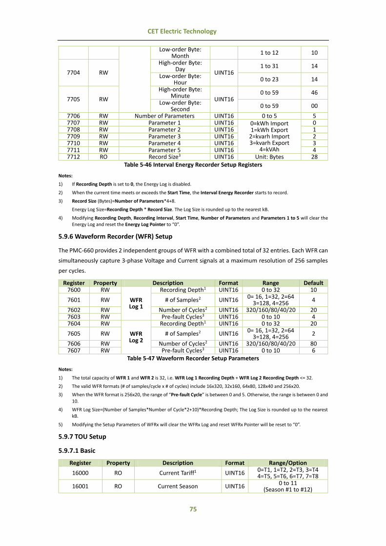
75
CET Electric Technology
Low-order Byte: Month
1 to 12 10
7704 RW
High-order Byte: Day
UINT16 1 to 31 14
Low-order Byte: Hour 0 to 23 14
7705 RW
High-order Byte: Minute
UINT16 0 to 59 46
Low-order Byte: Second
0 to 59 00
7706 RW Number of Parameters UINT16 0 to 5 5 7707 RW Parameter 1 UINT16 0=kWh Import
1=kWh Export 2=kvarh Import 3=kvarh Export
4=kVAh
0 7708 RW Parameter 2 UINT16 1 7709 RW Parameter 3 UINT16 2 7710 RW Parameter 4 UINT16 3 7711 RW Parameter 5 UINT16 4 7712 RO Record Size3 UINT16 Unit: Bytes 28
Table 5-46 Interval Energy Recorder Setup Registers
Notes:
1) If Recording Depth is set to 0, the Energy Log is disabled.
2) When the current time meets or exceeds the Start Time, the Interval Energy Recorder starts to record.
3) Record Size (Bytes)=Number of Parameters*4+8.
Energy Log Size=Recording Depth * Record Size. The Log Size is rounded up to the nearest kB.
4) Modifying Recording Depth, Recording Interval, Start Time, Number of Parameters and Parameters 1 to 5 will clear the Energy Log and reset the Energy Log Pointer to “0”.
5.9.6 Waveform Recorder (WFR) Setup
The PMC-660 provides 2 independent groups of WFR with a combined total of 32 entries. Each WFR can
simultaneously capture 3-phase Voltage and Current signals at a maximum resolution of 256 samples
per cycles.
Register Property Description Format Range Default 7600 RW
WFR Log 1
Recording Depth1 UINT16 0 to 32 10
7601 RW # of Samples2 UINT16 0= 16, 1=32, 2=64
3=128, 4=256 4
7602 RW Number of Cycles2 UINT16 320/160/80/40/20 20 7603 RW Pre-fault Cycles3 UINT16 0 to 10 4 7604 RW
WFR Log 2
Recording Depth1 UINT16 0 to 32 20
7605 RW # of Samples2 UINT16 0= 16, 1=32, 2=64 3=128, 4=256
2
7606 RW Number of Cycles2 UINT16 320/160/80/40/20 80 7607 RW Pre-fault Cycles3 UINT16 0 to 10 6
Table 5-47 Waveform Recorder Setup Parameters
Notes:
1) The total capacity of WFR 1 and WFR 2 is 32, i.e. WFR Log 1 Recording Depth + WFR Log 2 Recording Depth <= 32.
2) The valid WFR formats (# of samples/cycle x # of cycles) include 16x320, 32x160, 64x80, 128x40 and 256x20.
3) When the WFR format is 256x20, the range of “Pre-fault Cycle” is between 0 and 5. Otherwise, the range is between 0 and
10.
4) WFR Log Size=(Number of Samples*Number of Cycle*2+10)*Recording Depth; The Log Size is rounded up to the nearest kB.
5) Modifying the Setup Parameters of WFRx will clear the WFRx Log and reset WFRx Pointer will be reset to “0”.
5.9.7 TOU Setup
5.9.7.1 Basic
Register Property Description Format Range/Option
16000 RO Current Tariff1 UINT16 0=T1, 1=T2, 2=T3, 3=T4 4=T5, 5=T6, 6=T7, 7=T8
16001 RO Current Season UINT16 0 to 11 (Season #1 to #12)

76
CET Electric Technology
16002 RO Current Period UINT16 0 to 11
(Period #1 to #12)
16003 RO Current Daily Profile No. UINT16 0 to 19
(Daily Profile #1 to #20)
16004 RO Current Day Type UINT16
0=Weekday1 1=Weekday2 2=Weekday3
3= Alternate Day 16005 RO Current TOU No. UINT16 0=TOU #1, 1=TOU #2 16006 RW TOU Switch Time UINT32 See Note (1)
16008 WO Switch TOU Manually UINT16 Write 0xFF00 to manually switch the TOU schedules
16009 RW Sunday Setup UINT16
0=Weekday1* 1=Weekday2 2=Weekday3
16010 RW Monday Setup UINT16 16011 RW Tuesday Setup UINT16 16012 RW Wednesday Setup UINT16 16013 RW Thursday Setup UINT16 16014 RW Friday Setup UINT16 16015 RW Saturday Setup UINT16
Table 5-48 TOU Basic Setup
Notes:
1) If DI1 is not programmed as a Tariff Switch, the TOU will function based on the TOU Schedule. If at least one DI (DI1) is programmed as a Tariff Switch, the TOU Schedule will no longer be used and the Tariff switching will be based on the status
of the DIs.
2) The following table illustrates the data structure for the TOU Switch Time. For example, 0x1003140C indicates a switch time of 12:00pm on March 20th, 2016. Writing 0xFFFFFFFF to this register disables the switching between TOU Schedule.
Byte 3 Byte 2 Byte 1 Byte 0 Year-2000 (0-37) Month (1-12) Day (1-31) Hour (00-23)
Table 5-49 TOU Switch Time Format
5.9.7.2 Season
The PMC-660 has two sets of Season setup parameters, one for each TOU. The Base Addresses for the
two sets are 16100 and 17100, respectively, where the Register Address = Base Address + Offset. For
example, the register address for TOU #1’s Season #2’s Start Date is 17100+4 = 17104.
Offset Property Description Format Range/Note
0 RW Season #1: Start Date UINT16 0x0101
1 RW Season #1: Weekday#1 Daily Profile UINT16 0 to 19 2 RW Season #1: Weekday#2 Daily Profile UINT16
3 RW Season #1: Weekday#3 Daily Profile UINT16
4 RW Season #2: Start Date UINT16 High-order Byte: Month
Low-order Byte: Day 5 RW Season #2: Weekday#1 Daily Profile UINT16
0 to 19 6 RW Season #2: Weekday#2 Daily Profile UINT16 7 RW Season #2: Weekday#3 Daily Profile UINT16 8 RW Season #3: Start Date UINT16 See Season #2: Start Date 9 RW Season #3: Weekday#1 Daily Profile UINT16
0 to 19 10 RW Season #3: Weekday#2 Daily Profile UINT16 11 RW Season #3: Weekday#3 Daily Profile UINT16 12 RW Season #4: Start Date UINT16 See Season #2: Start Date 13 RW Season #4: Weekday#1 Daily Profile UINT16
0 to 19 14 RW Season #4: Weekday#2 Daily Profile UINT16 15 RW Season #4: Weekday#3 Daily Profile UINT16 16 RW Season #5: Start Date UINT16 See Season #2: Start Date 17 RW Season #5: Weekday#1 Daily Profile UINT16
0 to 19 18 RW Season #5: Weekday#2 Daily Profile UINT16 19 RW Season #5: Weekday#3 Daily Profile UINT16 20 RW Season #6: Start Date UINT16 See Season #2: Start Date 21 RW Season #6: Weekday#1 Daily Profile UINT16
0 to 19 22 RW Season #6: Weekday#2 Daily Profile UINT16 23 RW Season #6: Weekday#3 Daily Profile UINT16 24 RW Season #7: Start Date UINT16 See Season #2: Start Date

77
CET Electric Technology
25 RW Season #7: Weekday#1 Daily Profile UINT16 0 to 19 26 RW Season #7: Weekday#2 Daily Profile UINT16
27 RW Season #7: Weekday#3 Daily Profile UINT16 28 RW Season #8: Start Date UINT16 See Season #2: Start Date 29 RW Season #8: Weekday#1 Daily Profile UINT16
0 to 19 30 RW Season #8: Weekday#2 Daily Profile UINT16 31 RW Season #8: Weekday#3 Daily Profile UINT16 32 RW Season #9: Start Date UINT16 See Season #2: Start Date 33 RW Season #9: Weekday#1 Daily Profile UINT16
0 to 19 34 RW Season #9: Weekday#2 Daily Profile UINT16 35 RW Season #9: Weekday#3 Daily Profile UINT16 36 RW Season #10: Start Date UINT16 See Season #2: Start Date 37 RW Season #10: Weekday#1 Daily Profile UINT16
0 to 19 38 RW Season #10: Weekday#2 Daily Profile UINT16 39 RW Season #10: Weekday#3 Daily Profile UINT16 40 RW Season #11: Start Date UINT16 See Season #2: Start Date 41 RW Season #11: Weekday#1 Daily Profile UINT16
0 to 19 42 RW Season #11: Weekday#2 Daily Profile UINT16 43 RW Season #11: Weekday#3 Daily Profile UINT16 44 RW Season #12: Start Date UINT16 See Season #2: Start Date 45 RW Season #12: Weekday#1 Daily Profile UINT16
0 to 19 46 RW Season #12: Weekday#2 Daily Profile UINT16 47 RW Season #12: Weekday#3 Daily Profile UINT16
Table 5-50 Season Setup
Notes:
1) Start Date for Season #1 is Jan. 1st and cannot be modified.
2) Setting a Season’s Start Date as 0xFFFF terminates the TOU’s Season settings. All subsequent Seasons’ setup parameters
will be ignored since the previous Season’s duration is from its Start Date to the end of the year.
3) The Start Date of a particular Season must be later than the previous Season’s.
5.9.7.3 Daily Profile
The PMC-660 has two sets of Daily Profile setup parameters, one for each TOU.
Register Property Description Format 16200~16223 RW Daily Profile #1
See Table 5-53 Daily Profile Data
Structure
16224~16247 RW Daily Profile #2 16248~16271 RW Daily Profile #3 16272~16295 RW Daily Profile #4 16296~16319 RW Daily Profile #5 16320~16343 RW Daily Profile #6 16344~16367 RW Daily Profile #7 16368~16391 RW Daily Profile #8 16392~16415 RW Daily Profile #9 16416~16439 RW Daily Profile #10 16440~16463 RW Daily Profile #11 16464~16487 RW Daily Profile #12 16488~16511 RW Daily Profile #13 16512~16535 RW Daily Profile #14 16536~16559 RW Daily Profile #15 16560~16583 RW Daily Profile #16 16584~16607 RW Daily Profile #17 16608~16631 RW Daily Profile #18 16632~16655 RW Daily Profile #19 16656~16679 RW Daily Profile #20
Table 5-51 TOU #1’s Daily Profile Setup
Register Property Description Format 17200~17223 RW Daily Profile #1
See Table 5-53 Daily Profile Data
Structure
17224~17247 RW Daily Profile #2 17248~17271 RW Daily Profile #3 17272~17295 RW Daily Profile #4 17296~17319 RW Daily Profile #5 17320~17343 RW Daily Profile #6 17344~17367 RW Daily Profile #7

78
CET Electric Technology
17368~17391 RW Daily Profile #8 17392~17415 RW Daily Profile #9 17416~17439 RW Daily Profile #10 17440~17463 RW Daily Profile #11 17464~17487 RW Daily Profile #12 17488~17511 RW Daily Profile #13 17512~17535 RW Daily Profile #14 17536~17559 RW Daily Profile #15 17560~17583 RW Daily Profile #16 17584~17607 RW Daily Profile #17 17608~17631 RW Daily Profile #18 17632~17655 RW Daily Profile #19 17656~17679 RW Daily Profile #20
Table 5-52 TOU #2’s Daily Profile Setup
Offset Property Description Format Note +0 RW Period #1 Start Time UINT16 0x0000 +1 RW Period #1 Tariff UINT16 0=T1, …, 7=T8
+2 RW Period #2 Start Time
High-order Byte: Hour UINT16
0 ≤ Hour < 24 Low-order Byte: Min Min = 0, 15, 30, 45
+3 RW Period #2 Tariff UINT16 0=T1, …, 7=T8 +4 RW Period #3 Start Time UINT16 See Period #2 Start Time +5 RW Period #3 Tariff UINT16 0=T1, …, 7=T8 +6 RW Period #4 Start Time UINT16 See Period #2 Start Time +7 RW Period #4 Tariff UINT16 0=T1, …, 7=T8 +8 RW Period #5 Start Time UINT16 See Period #2 Start Time +9 RW Period #5 Tariff UINT16 0=T1, …, 7=T8
+10 RW Period #6 Start Time UINT16 See Period #2 Start Time +11 RW Period #6 Tariff UINT16 0=T1, …, 7=T8 +12 RW Period #7 Start Time UINT16 See Period #2 Start Time +13 RW Period #7 Tariff UINT16 0=T1, …, 7=T8 +14 RW Period #8 Start Time UINT16 See Period #2 Start Time +15 RW Period #8 Tariff UINT16 0=T1, …, 7=T8 +16 RW Period #9 Start Time UINT16 See Period #2 Start Time +17 RW Period #9 Tariff UINT16 0=T1, …, 7=T8 +18 RW Period #10 Start Time UINT16 See Period #2 Start Time +19 RW Period #10 Tariff UINT16 0=T1, …, 7=T8 +20 RW Period #11 Start Time UINT16 See Period #2 Start Time +21 RW Period #11 Tariff UINT16 0=T1, …, 7=T8 +22 RW Period #12 Start Time UINT16 See Period #2 Start Time +23 RW Period #12 Tariff UINT16 0=T1, …, 7=T8
Table 5-53 Daily Profile Data Structure
Notes:
1) Daily Profile #1’s Period #1 Start Time is always 00:00 and cannot be modified.
2) Setting a Period’s Start Time as 0xFFFF terminates the Daily Profile’s settings. All later Daily Profile’ setup parameters will be ignored, and the previous Period’s duration is from its Start Time to the end of the day.
3) The minimum interval of a period is 15 minutes.
4) The Start Time of a particular Period must be later than the previous Period’s.
5.9.7.4 Alternate Days
Each Alternate Day is assigned a Daily Profile and has a higher priority than Season. If a particular date
is set as an Alternate Day, its assigned Daily Profile will override the “normal” Daily Profile for this day
according the TOU settings.
The PMC-660 has two sets of Alternate Days setup parameters, one for each TOU. The Base Addresses
for the two sets are 16700 and 17700, respectively, where the Register Address = Base Address + Offset.
For example, the register address for TOU #2’s Alternative Day #2’s Date is 17700+3 = 17703.
Offset Property Description Format Note 0 RW Alternate Day #1 Date¹ UINT32 Table 5-55 2 RW Alternate Day #1 Daily Profile UINT16 0 to 19
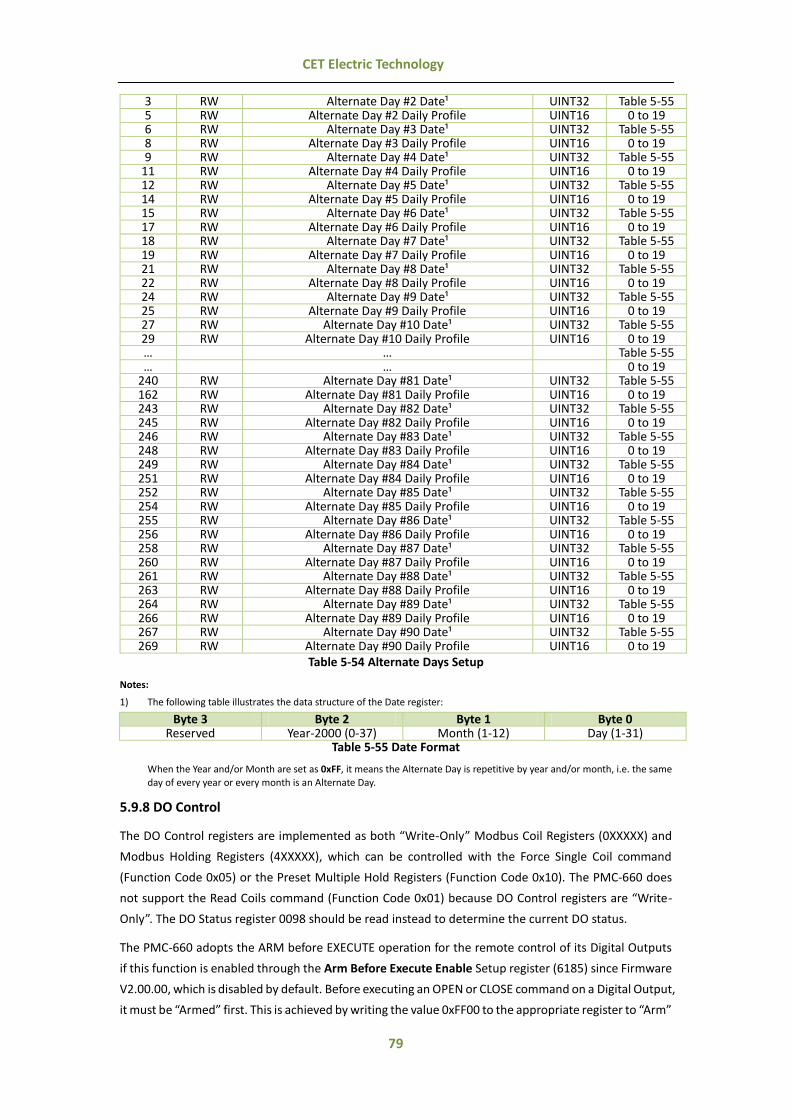
79
CET Electric Technology
3 RW Alternate Day #2 Date¹ UINT32 Table 5-55 5 RW Alternate Day #2 Daily Profile UINT16 0 to 19 6 RW Alternate Day #3 Date¹ UINT32 Table 5-55 8 RW Alternate Day #3 Daily Profile UINT16 0 to 19 9 RW Alternate Day #4 Date¹ UINT32 Table 5-55
11 RW Alternate Day #4 Daily Profile UINT16 0 to 19 12 RW Alternate Day #5 Date¹ UINT32 Table 5-55 14 RW Alternate Day #5 Daily Profile UINT16 0 to 19 15 RW Alternate Day #6 Date¹ UINT32 Table 5-55 17 RW Alternate Day #6 Daily Profile UINT16 0 to 19 18 RW Alternate Day #7 Date¹ UINT32 Table 5-55 19 RW Alternate Day #7 Daily Profile UINT16 0 to 19 21 RW Alternate Day #8 Date¹ UINT32 Table 5-55 22 RW Alternate Day #8 Daily Profile UINT16 0 to 19 24 RW Alternate Day #9 Date¹ UINT32 Table 5-55 25 RW Alternate Day #9 Daily Profile UINT16 0 to 19 27 RW Alternate Day #10 Date¹ UINT32 Table 5-55 29 RW Alternate Day #10 Daily Profile UINT16 0 to 19 … … Table 5-55 … … 0 to 19
240 RW Alternate Day #81 Date¹ UINT32 Table 5-55 162 RW Alternate Day #81 Daily Profile UINT16 0 to 19 243 RW Alternate Day #82 Date¹ UINT32 Table 5-55 245 RW Alternate Day #82 Daily Profile UINT16 0 to 19 246 RW Alternate Day #83 Date¹ UINT32 Table 5-55 248 RW Alternate Day #83 Daily Profile UINT16 0 to 19 249 RW Alternate Day #84 Date¹ UINT32 Table 5-55 251 RW Alternate Day #84 Daily Profile UINT16 0 to 19 252 RW Alternate Day #85 Date¹ UINT32 Table 5-55 254 RW Alternate Day #85 Daily Profile UINT16 0 to 19 255 RW Alternate Day #86 Date¹ UINT32 Table 5-55 256 RW Alternate Day #86 Daily Profile UINT16 0 to 19 258 RW Alternate Day #87 Date¹ UINT32 Table 5-55 260 RW Alternate Day #87 Daily Profile UINT16 0 to 19 261 RW Alternate Day #88 Date¹ UINT32 Table 5-55 263 RW Alternate Day #88 Daily Profile UINT16 0 to 19 264 RW Alternate Day #89 Date¹ UINT32 Table 5-55 266 RW Alternate Day #89 Daily Profile UINT16 0 to 19 267 RW Alternate Day #90 Date¹ UINT32 Table 5-55 269 RW Alternate Day #90 Daily Profile UINT16 0 to 19
Table 5-54 Alternate Days Setup
Notes:
1) The following table illustrates the data structure of the Date register:
Byte 3 Byte 2 Byte 1 Byte 0 Reserved Year-2000 (0-37) Month (1-12) Day (1-31)
Table 5-55 Date Format
When the Year and/or Month are set as 0xFF, it means the Alternate Day is repetitive by year and/or month, i.e. the same
day of every year or every month is an Alternate Day.
5.9.8 DO Control
The DO Control registers are implemented as both “Write-Only” Modbus Coil Registers (0XXXXX) and
Modbus Holding Registers (4XXXXX), which can be controlled with the Force Single Coil command
(Function Code 0x05) or the Preset Multiple Hold Registers (Function Code 0x10). The PMC-660 does
not support the Read Coils command (Function Code 0x01) because DO Control registers are “Write-
Only”. The DO Status register 0098 should be read instead to determine the current DO status.
The PMC-660 adopts the ARM before EXECUTE operation for the remote control of its Digital Outputs
if this function is enabled through the Arm Before Execute Enable Setup register (6185) since Firmware
V2.00.00, which is disabled by default. Before executing an OPEN or CLOSE command on a Digital Output,
it must be “Armed” first. This is achieved by writing the value 0xFF00 to the appropriate register to “Arm”

80
CET Electric Technology
a particular DO operation. The DO will be “Disarmed” automatically if an “Execute” command is not
received within 15 seconds after it has been “Armed”. If an “Execute” command is received without first
having received an “Arm” command, the meter ignores the “Execute” command and returns the 0x04
exception code.
Register Property Description Format Note 9100 WO Arm DO1 Close UINT16
Writing “0xFF00” to the register to perform the
described action.
9101 WO Execute DO1 Close UINT16 9102 WO Arm DO1 Open UINT16 9103 WO Execute DO1 Open UINT16 9104 WO Arm DO2 Close UINT16 9105 WO Execute DO2 Close UINT16 9106 WO Arm DO2 Open UINT16 9107 WO Execute DO2 Open UINT16 9108 WO Arm DO3 Close UINT16 9109 WO Execute DO3 Close UINT16 9110 WO Arm DO3 Open UINT16 9111 WO Execute DO3 Open UINT16
Table 5-56 DO Control
5.9.9 Clear/Reset Control
Register Property Description Format Note 6400 WO Manual WFR Log #1 Trigger UINT16
Writing “0xFF00” to the register to
execute the described action.
6401 WO Manual WFR Log #2 Trigger UINT16 6402 WO Clear DR #1 (High-Speed) UINT16 6403 WO Clear DR #2 (High-Speed) UINT16 6404 WO Clear DR #3 (High-Speed) UINT16 6405 WO Clear DR #4 (High-Speed) UINT16 6406 WO Clear DR #5 (Standard) UINT16
… WO … UINT16 6416 WO Clear DR #15 (Standard) UINT16 6417 WO Clear DR #16 (Standard) UINT16 6418 WO Clear WFR Log #1 UINT16 6419 WO Clear WFR Log #2 UINT16 6420 WO Clear Energy Log UINT16 6421 WO Clear PQ Log UINT16 6422 WO Clear SOE Log UINT16 6423 WO Clear Total Energy and TOU Energy UINT16
6424 WO Clear Max./Min. Log of This Month
(Since Last Reset) UINT16
6425 WO Clear Peak Demand Log of This Month
(Since Last Reset) UINT16
6426 WO Clear Counter #1 (DI1) UINT16 6427 WO Clear Counter #2 (DI2) UINT16
… WO … UINT16 6430 WO Clear Counter #5 (DI5) UINT16 6431 WO Clear Counter #6 (DI6) UINT16 6432 WO Clear Device Operating Time# UINT16
6433~6436 WO Reserved UINT16
6437 WO Clear all Logs1 UINT16 Writing “0xFF00” to the register clears all
of the above #Available in Firmware V2.00.00 or later
Table 5-57 Clear/Reset Registers
Notes:
1) Writing “0XFF00” to the register clears all logs, including Data Recorder, Waveform Recorder, Energy Log, PQ Log, SOE Log,
Max./Min. Log of This Month (Since Last Reset), Peak Demand of This Month (Since Last Reset), DI Counters, Energy Registers and Device Operating Time.
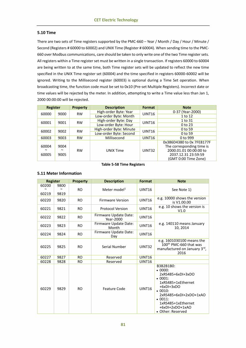
81
CET Electric Technology
5.10 Time
There are two sets of Time registers supported by the PMC-660 – Year / Month / Day / Hour / Minute /
Second (Registers # 60000 to 60002) and UNIX Time (Register # 60004). When sending time to the PMC-
660 over Modbus communications, care should be taken to only write one of the two Time register sets.
All registers within a Time register set must be written in a single transaction. If registers 60000 to 60004
are being written to at the same time, both Time register sets will be updated to reflect the new time
specified in the UNIX Time register set (60004) and the time specified in registers 60000-60002 will be
ignored. Writing to the Millisecond register (60003) is optional during a Time Set operation. When
broadcasting time, the function code must be set to 0x10 (Pre-set Multiple Registers). Incorrect date or
time values will be rejected by the meter. In addition, attempting to write a Time value less than Jan 1,
2000 00:00:00 will be rejected.
Register Property Description Format Note
60000 9000 RW High-order Byte: Year
UINT16 0-37 (Year-2000)
Low-order Byte: Month 1 to 12
60001 9001 RW High-order Byte: Day
UINT16 1 to 31
Low-order Byte: Hour 0 to 23
60002 9002 RW High-order Byte: Minute
UINT16 0 to 59
Low-order Byte: Second 0 to 59 60003 9003 RW Millisecond UINT16 0 to 999
60004 ~
60005
9004 ~
9005 RW UNIX Time UINT32
0x386D4380 to 0x 7FE8177F The corresponding time is
2000.01.01 00:00:00 to 2037.12.31 23:59:59
(GMT 0:00 Time Zone)
Table 5-58 Time Registers
5.11 Meter Information
Register Property Description Format Note 60200
~ 60219
9800 ~
9819 RO Meter model1 UINT16 See Note 1)
60220 9820 RO Firmware Version UINT16 e.g. 10000 shows the version is V1.00.00
60221 9821 RO Protocol Version UINT16 e.g. 10 shows the version is V1.0
60222 9822 RO Firmware Update Date:
Year-2000 UINT16
e.g. 140110 means January 10, 2014
60223 9823 RO Firmware Update Date:
Month UINT16
60224 9824 RO Firmware Update Date:
Day UINT16
60225 9825 RO Serial Number UINT32
e.g. 1601030100 means the 100th PMC-660 that was
manufactured on January 3rd, 2016
60227 9827 RO Reserved UINT16 60228 9828 RO Reserved UINT16
60229 9829 RO Feature Code UINT16
B3B2B1B0: 0000:
2xRS485+6xDI+3xDO 0001:
1xRS485+1xEthernet +6xDI+3xDO
0010: 2xRS485+6xDI+2xDO+1xAO
0011: 1xRS485+1xEthernet +6xDI+2xDO+1xAO
Other: Reserved

82
CET Electric Technology
B5B4: 00: 5A I4 CT 01: 1A I4 CT 10: Analog Input 11: Reserved Other bits are reserved.
60230 9830 RO Current configuration UINT16 0=5 (A) 3-Phase CT 1=1 (A) 3-Phase CT
60231 9831 RO Voltage configuration UINT16 0=120 (V) , 1=415 (V)
2=690 (V) 3=690 (V) 3P3W Open Delta
Table 5-59 Meter Information
Notes:
1) The Meter Model appears in registers 9800 to 9819 and contains the ASCII encoding of the string “PMC-660” as shown in the following table.
Register Value(Hex) ANSCII 9800 0x50 P 9801 0x4D M 9802 0x43 C 9803 0x2D - 9804 0x36 6 9805 0x36 6 9806 0x30 0
9807-9819 0x20 <Null>
Table 5-60 ASCII Encoding of “PMC-660”

83
CET Electric Technology
Appendix A - Data Recorder Parameter Key Parameters Scale/Unit Key Parameters Scale/Unit
0 Uan x100, V 1 Ubn x100, V 2 Ucn x100, V 3 Uln average x100, V 4 Uab x100, V 5 Ubc x100, V 6 Uca x100, V 7 Ull average x100, V 8 Ia x1000, A 9 Ib x1000, A
10 Ic x1000, A 11 I average x1000, A 12 I4^ x1000, A 13 kWa W 14 kWb W 15 kWc W 16 kW Total W 17 kvara var 18 kvarb var 19 kvarc var 20 kvar Total var 21 kVAa VA 22 kVAb VA 23 kVAc VA 24 kVA Total VA 25 P.F.a x1000 26 P.F.b x1000 27 P.F.c x1000 28 P.F. Total x1000 29 Frequency x100, Hz 30 Counter #1 (DI1) - 31 Counter #2 (DI2) - 32 Counter #3 (DI3) - 33 Counter #4 (DI4) - 34 Counter #5 (DI5) - 35 Counter #6 (DI6) - 36 U Unbalance x10, % 37 I Unbalance x10, % 38 Ia K-factor x10 39 Ib K-factor x10 40 Ic K-factor x10 41 Uan THD x100, % 42 Ubn THD x100, % 43 Ucn THD x100, % 44 Uan TOHD x100, % 45 Ubn TOHD x100, % 46 Ucn TOHD x100, % 47 Uan TEHD x100, % 48 Ubn TEHD x100, % 49 Ucn TEHD x100, % 50 Ia THD x100, % 51 Ib THD x100, % 52 Ic THD x100, % 53 Ia TOHD x100, % 54 Ib TOHD x100, % 55 Ic TOHD x100, % 56 Ia TEHD x100, % 57 Ib TEHD x100, % 58 Ic TEHD x100, % 59 Uan 2nd Harmonic x100, % 60 Ubn 2nd Harmonic x100, % 61 Ucn 2nd Harmonic x100, % 62 Uan 3rd Harmonic x100, % 63 Ubn 3rd Harmonic x100, % 64 Ucn 3rd Harmonic x100, % 65 Uan 4th Harmonic x100, % 66 Ubn 4th Harmonic x100, % 67 Ucn 4th Harmonic x100, % 68 Uan 5th Harmonic x100, % 69 Ubn 5th Harmonic x100, % 70 Ucn 5th Harmonic x100, % 71 Uan 6th Harmonic x100, % 72 Ubn 6th Harmonic x100, % 73 Ucn 6th Harmonic x100, % 74 Uan 7th Harmonic x100, % 75 Ubn 7th Harmonic x100, % 76 Ucn 7th Harmonic x100, % 77 Uan 8th Harmonic x100, % 78 Ubn 8th Harmonic x100, % 79 Ucn 8th Harmonic x100, % 80 Uan 9th Harmonic x100, % 81 Ubn 9th Harmonic x100, % 81 Ucn 9th Harmonic x100, % 83 Uan 10th Harmonic x100, % 84 Ubn 10th Harmonic x100, % 85 Ucn 10th Harmonic x100, % 86 Uan 11th Harmonic x100, % 87 Ubn 11th Harmonic x100, % 88 Ucn 11th Harmonic x100, % 89 Uan 12th Harmonic x100, % 90 Ubn 12th Harmonic x100, % 91 Ucn 12th Harmonic x100, % 92 Uan 13th Harmonic x100, % 93 Ubn 13th Harmonic x100, % 94 Ucn 13th Harmonic x100, % 95 Uan 14th Harmonic x100, % 96 Ubn 14th Harmonic x100, % 97 Ucn 14th Harmonic x100, % 98 Uan 15th Harmonic x100, % 99 Ubn 15th Harmonic x100, %
100 Ucn 15th Harmonic x100, % 101 Uan 16th Harmonic x100, % 102 Ubn 16th Harmonic x100, % 103 Ucn 16th Harmonic x100, % 104 Uan 17th Harmonic x100, % 105 Ubn 17th Harmonic x100, % 106 Ucn 17th Harmonic x100, % 107 Uan 18th Harmonic x100, % 108 Ubn 18th Harmonic x100, % 109 Ucn 18th Harmonic x100, % 110 Uan 19th Harmonic x100, % 111 Ubn 19th Harmonic x100, % 112 Ucn 19th Harmonic x100, % 113 Uan 20th Harmonic x100, % 114 Ubn 20th Harmonic x100, % 115 Ucn 20th Harmonic x100, % 116 Uan 21st Harmonic x100, % 117 Ubn 21st Harmonic x100, % 118 Ucn 21st Harmonic x100, % 119 Uan 22nd Harmonic x100, % 120 Ubn 22nd Harmonic x100, % 121 Ucn 22nd Harmonic x100, % 122 Uan 23rd Harmonic x100, % 123 Ubn 23rd Harmonic x100, % 124 Ucn 23rd Harmonic x100, % 125 Uan 24th Harmonic x100, % 126 Ubn 24th Harmonic x100, % 127 Ucn 24th Harmonic x100, % 128 Uan 25th Harmonic x100, % 129 Ubn 25th Harmonic x100, % 130 Ucn 25th Harmonic x100, % 131 Ia 2nd Harmonic x100, % 132 Ib 2nd Harmonic x100, % 133 Ic 2nd Harmonic x100, % 134 Ia 3rd Harmonic x100, % 135 Ib 3rd Harmonic x100, % 136 Ic 3rd Harmonic x100, % 137 Ia 4th Harmonic x100, % 138 Ib 4th Harmonic x100, % 139 Ic 4th Harmonic x100, % 140 Ia 5th Harmonic x100, % 141 Ib 5th Harmonic x100, % 142 Ic 5th Harmonic x100, % 143 Ia 6th Harmonic x100, % 144 Ib 6th Harmonic x100, % 145 Ic 6th Harmonic x100, % 146 Ia 7th Harmonic x100, % 147 Ib 7th Harmonic x100, % 148 Ic 7th Harmonic x100, % 149 Ia 8th Harmonic x100, % 150 Ib 8th Harmonic x100, % 151 Ic 8th Harmonic x100, % 152 Ia 9th Harmonic x100, % 153 Ib 9th Harmonic x100, % 154 Ic 9th Harmonic x100, % 155 Ia 10th Harmonic x100, % 156 Ib 10th Harmonic x100, % 157 Ic 10th Harmonic x100, %
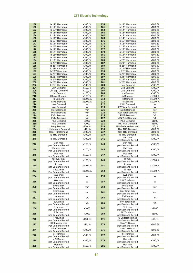
84
CET Electric Technology
158 Ia 11th Harmonic x100, % 159 Ib 11th Harmonic x100, % 160 Ic 11th Harmonic x100, % 161 Ia 12th Harmonic x100, % 162 Ib 12th Harmonic x100, % 163 Ic 12th Harmonic x100, % 164 Ia 13th Harmonic x100, % 165 Ib 13th Harmonic x100, % 166 Ic 13th Harmonic x100, % 167 Ia 14th Harmonic x100, % 168 Ib 14th Harmonic x100, % 169 Ic 14th Harmonic x100, % 170 Ia 15th Harmonic x100, % 171 Ib 15th Harmonic x100, % 172 Ic 15th Harmonic x100, % 173 Ia 16th Harmonic x100, % 174 Ib 16th Harmonic x100, % 175 Ic 16th Harmonic x100, % 176 Ia 17th Harmonic x100, % 177 Ib 17th Harmonic x100, % 178 Ic 17th Harmonic x100, % 179 Ia 18th Harmonic x100, % 180 Ib 18th Harmonic x100, % 181 Ic 18th Harmonic x100, % 182 Ia 19th Harmonic x100, % 183 Ib 19th Harmonic x100, % 184 Ic 19th Harmonic x100, % 185 Ia 20th Harmonic x100, % 186 Ib 20th Harmonic x100, % 187 Ic 20th Harmonic x100, % 188 Ia 21st Harmonic x100, % 189 Ib 21st Harmonic x100, % 190 Ic 21st Harmonic x100, % 191 Ia 22nd Harmonic x100, % 192 Ib 22nd Harmonic x100, % 193 Ic 22nd Harmonic x100, % 194 Ia 23rd Harmonic x100, % 195 Ib 23rd Harmonic x100, % 196 Ic 23rd Harmonic x100, % 197 Ia 24th Harmonic x100, % 198 Ib 24th Harmonic x100, % 199 Ic 24th Harmonic x100, % 200 Ia 25th Harmonic x100, % 201 Ib 25th Harmonic x100, % 202 Ic 25th Harmonic x100, % 203 Uan Demand x100, V 204 Ubn Demand x100, V 205 Ucn Demand x100, V 206 Uln avg. Demand x100, V 207 Uab Demand x100, V 208 Ubc Demand x100, V 209 Uca Demand x100, V 210 Ull avg. Demand x100, V 211 Ia Demand x1000, A 212 Ib Demand x1000, A 213 Ic Demand x1000, A 214 I avg. Demand x1000, A 215 I4 Demand x1000, A 216 kWa Demand W 217 kWb Demand W 218 kWc Demand W 219 kW Total Demand W 220 kvara Demand var 221 kvarb Demand var 222 kvarc Demand var 223 kvar Total Demand var 224 kVAa Demand VA 225 kVAb Demand VA 226 kVAc Demand VA 227 kVA Total Demand VA 228 P.F.a Demand x1000 229 P.F.b Demand x1000 230 P.F.c Demand x1000 231 P.F. Total Demand x1000 232 Freq. Demand x100, Hz 233 U Unbalance Demand x10, % 234 I Unbalance Demand x10, % 235 Uan THD Demand x100, % 236 Ubn THD Demand x100, % 237 Ucn THD Demand x100, % 238 Ia THD Demand x100, % 239 Ib THD Demand x100, %
240 Ic THD Demand x100, % 241 Uan max
per Demand Period x100, V
242 Ubn max per Demand Period
x100, V 243 Ucn max per Demand Period
x100, V
244 Uln avg. max
Per Demand Period x100, V 245 Uab max
per Demand Period x100, V
246 Ubc max per Demand Period
x100, V 247 Uca max per Demand Period
x100, V
248 Ull avg. max
per Demand Period x100, V 249 Ia max
per Demand Period x1000, A
250 Ib max per Demand Period
x1000, A 251 Ic max per Demand Period
x1000, A
252 I avg. max
Per Demand Period x1000, A 253 I4 max
per Demand Period x1000, A
254 kWa max per Demand Period
W 255 kWb max per Demand Period
W
256 kWc max
per Demand Period W 257 kW Total max
per Demand Period W
258 kvara max per Demand Period
var 259 kvarb max per Demand Period
var
260 kvarc max
per Demand Period var 261 kvar Total max
per Demand Period var
262 kVAa max per Demand Period
VA 263 kVAb max per Demand Period
VA
264 kVAc max
per Demand Period VA 265 kVA Total max
per Demand Period VA
266 P.F.a max per Demand Period
x1000 267 P.F.b max per Demand Period
x1000
268 P.F.c max
per Demand Period x1000 269 P.F. Total max
per Demand Period x1000
270 Freq. max per Demand Period
x100, Hz 271 U Unbalance max Per Demand Period
x10, %
272 I Unbalance max
Per Demand Period x10, % 273 Uan THD max
per Demand Period x100, %
274 Ubn THD max per Demand Period
x100, % 275 Ucn THD max per Demand Period
x100, %
276 Ia THD max
per Demand Period x100, % 277 Ib THD max
per Demand Period x100, %
278 Ic THD max per Demand Period
x100, % 279 Uan min per Demand Period
x100, V
280 Ubn min
per Demand Period x100, V 281 Ucn min
per Demand Period x100, V

85
CET Electric Technology
282 Uln avg. min
Per Demand Period x100, V 283 Uab min
per Demand Period x100, V
284 Ubc min per Demand Period x100, V 285 Uca min
per Demand Period x100, V
286 Ull avg. min
Per Demand Period x100, V 287 Ia min
per Demand Period x1000, A
288 Ib min per Demand Period x1000, A 289 Ic min
per Demand Period x1000, A
290 I avg. min
per Demand Period x1000, A 291 I4 min
per Demand Period x1000, A
292 kWa min per Demand Period W 293 kWb min
per Demand Period W
294 kWc min
per Demand Period W 295 kW Total min
per Demand Period W
296 kvara min per Demand Period var 297 kvarb min
per Demand Period var
298 kvarc min
per Demand Period var 299 kvar Total min
per Demand Period var
300 kVAa min per Demand Period VA 301 kVAb min
per Demand Period VA
302 kVAc min
per Demand Period VA 303 kVA Total min
per Demand Period VA
304 P.F.a min per Demand Period x1000 305 P.F.b min
per Demand Period x1000
306 P.F.c min
per Demand Period x1000 307 P.F. Total min
per Demand Period x1000
308 Freq. min Per Demand Period x100, Hz 309 U Unbalance min
per Demand Period x10, %
310 I Unbalance
per Demand Period x10, % 311 Uan THD min
per Demand Period x100, %
312 Ubn THD min per Demand Period x100, % 313 Ucn THD min
per Demand Period x100, %
314 Ia THD min
per Demand Period x100, % 315 Ib THD min
per Demand Period x100, %
316 Ic THD min per Demand Period x100, % 317 dUan/dUab x100, V
318 dUbn/dUbc x100, V 319 dUcn/dUca x100, V 320 dIa x1000, A 321 dIb x1000, A 322 dIc x1000, A 323 kWh Import*,# kWh 324 kWh Export*,# kWh 325 kWh Total *,# kWh 326 kvarh Import*,# kvarh 327 kvarh Export*,# kvarh 328 kvarh Total*,# kvarh 329~ I Residual x1000, A
^ I4 is valid only if the device is equipped with the I4 option, and it will be automatically changed to I0 (Zero Sequence Current)
if the meter is equipped with the AI option. * Parameters # 323 to 328 are accumulative energy values. # Available in Firmware V1.00.04 or later
~ Available in Firmware V2.00.00 or later

86
CET Electric Technology
Appendix B - Data Recorder Default Settings
Parameter DR 1 (HS) DR 2 (HS) DR 3 (HS) DR 4 (HS) Trigger Mode Disabled Disabled Disabled Disabled Recording Mode Stop-When-Full Stop-When-Full Stop-When-Full Stop-When-Full Recording Depth 0 0 0 0 Recording Interval 2 2 2 2 Recording Offset 0 0 0 0 Number of Parameters 0 0 0 0
Parameter 1~16 Null Null Null Null
Parameter DR 5 DR 6 DR 7 DR 8 Trigger Mode Triggered by Timer Triggered by Timer Triggered by Timer Triggered by Timer Recording Mode First-In-First-Out First-In-First-Out First-In-First-Out First-In-First-Out Recording Depth 3360 1440 1440 1440 Recording Interval 900 900 900 900 Recording Offset 0 0 0 0 No. of Parameters 6 15 16 6 Parameter 1 kWh Import Uab Uan Uan THD Parameter 2 kWh Export Ubc Ubn Ubn THD Parameter 3 kWh Total Uca Ucn Ucn THD Parameter 4 kvarh Import Ull avg Uln avg Ia THD Parameter 5 kvarh Export Ia kWa Ib THD Parameter 6 kvarh Total Ib kWb Ic THD Parameter 7 Null Ic kWc Null Parameter 8 Null I avg kvara Null Parameter 9 Null kW Total kvarb Null Parameter 10 Null kvar Total kvarc Null Parameter 11 Null kVA Total kVAa Null Parameter 12 Null P.F. Total kVAb Null Parameter 13 Null Freq kVAc Null Parameter 14 Null U Unbalance P.F.a Null Parameter 15 Null I Unbalance P.F.b Null Parameter 16 Null Null P.F.c Null
Parameter DR 9 DR 10 DR 11 DR 12 Trigger Mode Triggered by Timer Triggered by Timer Triggered by Timer Triggered by Timer Recording Mode First-In-First-Out First-In-First-Out First-In-First-Out First-In-First-Out Recording Depth 1440 1440 1440 1440 Recording Interval 900 900 900 900 Recording Offset 0 0 0 0 No. of Parameters 15 16 6 15
Parameter 1 Uab Demand Uan Demand Uan THD Demand Uab max per Demand
Period
Parameter 2 Ubc Demand Ubn Demand Ubn THD Demand Ubc max per Demand Period
Parameter 3 Uca Demand Ucn Demand Ucn THD Demand Uca max per Demand
Period
Parameter 4 Ull avg Demand Uln avg Demand Ia THD Demand Ull avg max per Demand Period
Parameter 5 Ia Demand kWa Demand Ib THD Demand Ia max per Demand
Period
Parameter 6 Ib Demand kWb Demand Ic THD Demand Ib max per Demand Period
Parameter 7 Ic Demand kWc Demand Null Ic max per Demand
Period
Parameter 8 I avg Demand kvara Demand Null I avg max per Demand Period
Parameter 9 kW Total Demand kvarb Demand Null kW Total max per
Demand Period
Parameter 10 kvar Total Demand kvarc Demand Null kvar Total max per Demand Period
Parameter 11 kVA Total Demand kVAa Demand Null kVA Total max per
Demand Period
Parameter 12 P.F. Total Demand kVAb Demand Null P.F. Total max per Demand Period
Parameter 13 Freq Demand kVAc Demand Null Freq max per Demand
Period
Parameter 14 U Unbalance Demand P.F.a Demand Null U Unbalance max per Demand Period
Parameter 15 I Unbalance Demand P.F.b Demand Null I Unbalance max per
Demand Period Parameter 16 Null P.F.c Demand Null Null
Parameter DR 13 DR 14 DR 15 DR 16 Trigger Mode Triggered by Timer Triggered by Timer Triggered by Timer Triggered by Timer Recording Mode First-In-First-Out First-In-First-Out First-In-First-Out First-In-First-Out Recording Depth 1440 1440 1440 1440 Recording Interval 900 900 900 900 Recording Offset 0 0 0 0 No. of Parameters 16 12 15 16
Parameter 1 Uan max per Demand
Period Uan THD max per Demand Period
Uab min per Demand Period
Uan min per Demand Period
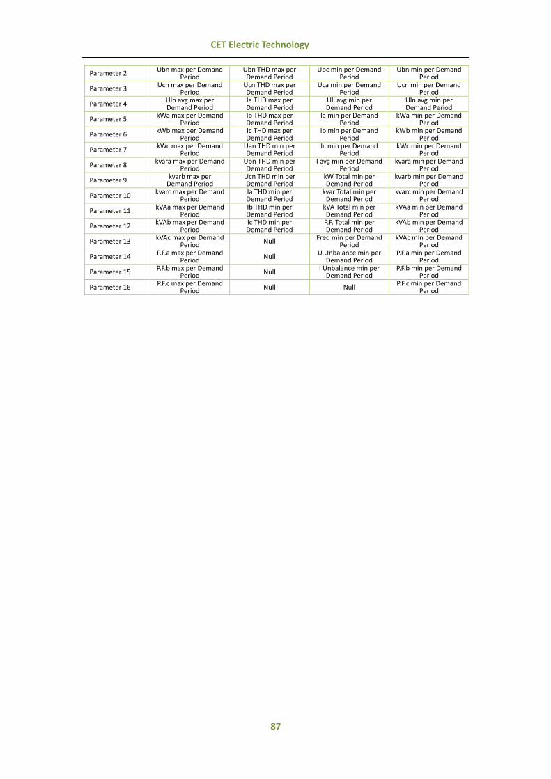
87
CET Electric Technology
Parameter 2 Ubn max per Demand
Period Ubn THD max per Demand Period
Ubc min per Demand Period
Ubn min per Demand Period
Parameter 3 Ucn max per Demand Period
Ucn THD max per Demand Period
Uca min per Demand Period
Ucn min per Demand Period
Parameter 4 Uln avg max per Demand Period
Ia THD max per Demand Period
Ull avg min per Demand Period
Uln avg min per Demand Period
Parameter 5 kWa max per Demand Period
Ib THD max per Demand Period
Ia min per Demand Period
kWa min per Demand Period
Parameter 6 kWb max per Demand
Period Ic THD max per Demand Period
Ib min per Demand Period
kWb min per Demand Period
Parameter 7 kWc max per Demand Period
Uan THD min per Demand Period
Ic min per Demand Period
kWc min per Demand Period
Parameter 8 kvara max per Demand
Period Ubn THD min per Demand Period
I avg min per Demand Period
kvara min per Demand Period
Parameter 9 kvarb max per Demand Period
Ucn THD min per Demand Period
kW Total min per Demand Period
kvarb min per Demand Period
Parameter 10 kvarc max per Demand
Period Ia THD min per Demand Period
kvar Total min per Demand Period
kvarc min per Demand Period
Parameter 11 kVAa max per Demand Period
Ib THD min per Demand Period
kVA Total min per Demand Period
kVAa min per Demand Period
Parameter 12 kVAb max per Demand
Period Ic THD min per Demand Period
P.F. Total min per Demand Period
kVAb min per Demand Period
Parameter 13 kVAc max per Demand Period Null Freq min per Demand
Period kVAc min per Demand
Period
Parameter 14 P.F.a max per Demand
Period Null U Unbalance min per
Demand Period P.F.a min per Demand
Period
Parameter 15 P.F.b max per Demand Period Null I Unbalance min per
Demand Period P.F.b min per Demand
Period
Parameter 16 P.F.c max per Demand
Period Null Null P.F.c min per Demand
Period

88
CET Electric Technology
Appendix C – SOE Event Classification Event
Classification Sub-
Classification Event Value
Scale/Option Description
1
1 1 / 0 DI1 Close/DI1 Open 2 1 / 0 DI2 Close/DI2 Open 3 1 / 0 DI3 Close/DI3 Open 4 1 / 0 DI4 Close/DI4 Open 5 1 / 0 DI5 Close/DI5 Open 6 1 / 0 DI6 Close/DI6 Open
2
1 1 / 0 DO1 Operated/Released by Remote Control 2 1 / 0 DO2 Operated/Released by Remote Control 3 1 / 0 DO3 Operated/Released by Remote Control 4 1 / 0 DO1 Operated/Released by Setpoint 5 1 / 0 DO2 Operated/Released by Setpoint 6 1 / 0 DO3 Operated/Released by Setpoint 7 1 / 0 DO1 Operated/Released by Dip/swell 8 1 / 0 DO2 Operated/Released by Dip/swell 9 1 / 0 DO3 Operated/Released by Dip/swell
10 1 / 0 DO1 Operated/Released by Transient 11 1 / 0 DO2 Operated/Released by Transient 12 1 / 0 DO3 Operated/Released by Transient
3
1 Trigger Value (x100) Over Uln Setpoint Active 2 Trigger Value (x100) Over Ull Setpoint Active 3 Trigger Value (x1000) Over Current Setpoint Active 4 Trigger Value (x1000) Over I4 Setpoint Active 5 Trigger Value (x100) Over Freq. Deviation Setpoint Active 6 Trigger Value Over kW Total Setpoint Active 7 Trigger Value Over kvar Total Setpoint Active 8 Trigger Value (x1000) Over P.F. Total Setpoint Active 9 1 DI1 Close Setpoint Active
10 1 DI2 Close Setpoint Active 11 1 DI3 Close Setpoint Active 12 1 DI4 Close Setpoint Active 13 1 DI5 Close Setpoint Active 14 1 DI6 Close Setpoint Active 15 Trigger Value Over AI Setpoint Active 16 Trigger Value Over kW Total Demand Setpoint Active 17 Trigger Value Over kvar Total Demand Setpoint Active 18 Trigger Value (x1000) Over P.F. Total Demand Setpoint Active 19 Trigger Value Over kW Total Predicted Setpoint Active 20 Trigger Value Over kvar Total Predicted Setpoint Active 21 Trigger Value (x1000) Over P.F. Total Predicted Setpoint Active 22 Trigger Value (x100) Over Voltage THD Setpoint Active 23 Trigger Value (x100) Over Voltage TOHD Setpoint Active 24 Trigger Value (x100) Over Voltage TEHD Setpoint Active 25 Trigger Value (x100) Over Current THD Setpoint Active 26 Trigger Value (x100) Over Current TOHD Setpoint Active 27 Trigger Value (x100) Over Current TEHD Setpoint Active 28 Trigger Value (x10) Over Voltage Unbalance Setpoint Active 29 Trigger Value (x10) Over Current Unbalance Setpoint Active 30 Trigger Value (x100) Over Voltage Deviation Setpoint Active 31 1 Over Phase Reversal Setpoint Active 32 Trigger Value (x1000) Over I Residual Setpoint Active 33 Trigger Value (x100) Over U2 (Negative Sequence Voltage) Setpoint Active 34 Trigger Value (x100) Over U0 (Zero Sequence Voltage) Setpoint Active 46 Return Value (x100) Over Uln Setpoint Return 47 Return Value (x100) Over Ull Setpoint Return 48 Return Value (x1000) Over Current Setpoint Return 49 Return Value (x1000) Over I4 Setpoint Return 50 Return Value (x100) Over Freq. Deviation Setpoint Return 51 Return Value Over kW Total Setpoint Return 52 Return Value Over kvar Total Setpoint Return 53 Return Value (x1000) Over P.F. Total Setpoint Return 54 0 DI1 Close Setpoint Return 55 0 DI2 Close Setpoint Return 56 0 DI3 Close Setpoint Return 57 0 DI4 Close Setpoint Return 58 0 DI5 Close Setpoint Return 59 0 DI6 Close Setpoint Return 60 Return Value Over AI Setpoint Return 61 Return Value Over kW Total Demand Setpoint Return 62 Return Value Over kvar Total Demand Setpoint Return 63 Return Value (x1000) Over P.F. Total Demand Setpoint Return 64 Return Value Over kW Total Predicted Setpoint Return 65 Return Value Over kvar Total Predicted Setpoint Return 66 Return Value (x1000) Over P.F. Total Predicted Setpoint Return 67 Return Value (x100) Over Voltage THD Setpoint Return 68 Return Value (x100) Over Voltage TOHD Setpoint Return 69 Return Value (x100) Over Voltage TEHD Setpoint Return 70 Return Value (x100) Over Current THD Setpoint Return 71 Return Value (x100) Over Current TOHD Setpoint Return
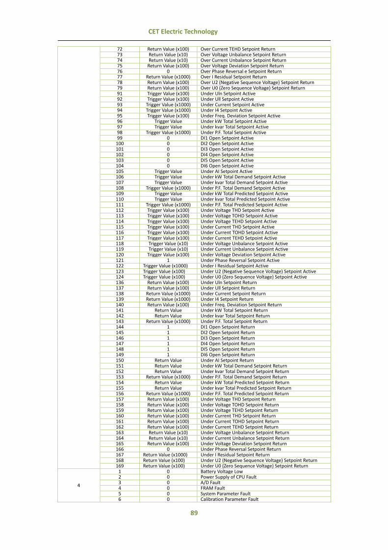
89
CET Electric Technology
72 Return Value (x100) Over Current TEHD Setpoint Return 73 Return Value (x10) Over Voltage Unbalance Setpoint Return 74 Return Value (x10) Over Current Unbalance Setpoint Return 75 Return Value (x100) Over Voltage Deviation Setpoint Return 76 0 Over Phase Reversal e Setpoint Return 77 Return Value (x1000) Over I Residual Setpoint Return 78 Return Value (x100) Over U2 (Negative Sequence Voltage) Setpoint Return 79 Return Value (x100) Over U0 (Zero Sequence Voltage) Setpoint Return 91 Trigger Value (x100) Under Uln Setpoint Active 92 Trigger Value (x100) Under Ull Setpoint Active 93 Trigger Value (x1000) Under Current Setpoint Active 94 Trigger Value (x1000) Under I4 Setpoint Active 95 Trigger Value (x100) Under Freq. Deviation Setpoint Active 96 Trigger Value Under kW Total Setpoint Active 97 Trigger Value Under kvar Total Setpoint Active 98 Trigger Value (x1000) Under P.F. Total Setpoint Active 99 0 DI1 Open Setpoint Active
100 0 DI2 Open Setpoint Active 101 0 DI3 Open Setpoint Active 102 0 DI4 Open Setpoint Active 103 0 DI5 Open Setpoint Active 104 0 DI6 Open Setpoint Active 105 Trigger Value Under AI Setpoint Active 106 Trigger Value Under kW Total Demand Setpoint Active 107 Trigger Value Under kvar Total Demand Setpoint Active 108 Trigger Value (x1000) Under P.F. Total Demand Setpoint Active 109 Trigger Value Under kW Total Predicted Setpoint Active 110 Trigger Value Under kvar Total Predicted Setpoint Active 111 Trigger Value (x1000) Under P.F. Total Predicted Setpoint Active 112 Trigger Value (x100) Under Voltage THD Setpoint Active 113 Trigger Value (x100) Under Voltage TOHD Setpoint Active 114 Trigger Value (x100) Under Voltage TEHD Setpoint Active 115 Trigger Value (x100) Under Current THD Setpoint Active 116 Trigger Value (x100) Under Current TOHD Setpoint Active 117 Trigger Value (x100) Under Current TEHD Setpoint Active 118 Trigger Value (x10) Under Voltage Unbalance Setpoint Active 119 Trigger Value (x10) Under Current Unbalance Setpoint Active 120 Trigger Value (x100) Under Voltage Deviation Setpoint Active 121 1 Under Phase Reversal Setpoint Active 122 Trigger Value (x1000) Under I Residual Setpoint Active 123 Trigger Value (x100) Under U2 (Negative Sequence Voltage) Setpoint Active 124 Trigger Value (x100) Under U0 (Zero Sequence Voltage) Setpoint Active 136 Return Value (x100) Under Uln Setpoint Return 137 Return Value (x100) Under Ull Setpoint Return 138 Return Value (x1000) Under Current Setpoint Return 139 Return Value (x1000) Under I4 Setpoint Return 140 Return Value (x100) Under Freq. Deviation Setpoint Return 141 Return Value Under kW Total Setpoint Return 142 Return Value Under kvar Total Setpoint Return 143 Return Value (x1000) Under P.F. Total Setpoint Return 144 1 DI1 Open Setpoint Return 145 1 DI2 Open Setpoint Return 146 1 DI3 Open Setpoint Return 147 1 DI4 Open Setpoint Return 148 1 DI5 Open Setpoint Return 149 1 DI6 Open Setpoint Return 150 Return Value Under AI Setpoint Return 151 Return Value Under kW Total Demand Setpoint Return 152 Return Value Under kvar Total Demand Setpoint Return 153 Return Value (x1000) Under P.F. Total Demand Setpoint Return 154 Return Value Under kW Total Predicted Setpoint Return 155 Return Value Under kvar Total Predicted Setpoint Return 156 Return Value (x1000) Under P.F. Total Predicted Setpoint Return 157 Return Value (x100) Under Voltage THD Setpoint Return 158 Return Value (x100) Under Voltage TOHD Setpoint Return 159 Return Value (x100) Under Voltage TEHD Setpoint Return 160 Return Value (x100) Under Current THD Setpoint Return 161 Return Value (x100) Under Current TOHD Setpoint Return 162 Return Value (x100) Under Current TEHD Setpoint Return 163 Return Value (x10) Under Voltage Unbalance Setpoint Return 164 Return Value (x10) Under Current Unbalance Setpoint Return 165 Return Value (x100) Under Voltage Deviation Setpoint Return 166 0 Under Phase Reversal Setpoint Return 167 Return Value (x1000) Under I Residual Setpoint Return 168 Return Value (x100) Under U2 (Negative Sequence Voltage) Setpoint Return 169 Return Value (x100) Under U0 (Zero Sequence Voltage) Setpoint Return
4
1 0 Battery Voltage Low 2 0 Power Supply of CPU Fault 3 0 A/D Fault 4 0 FRAM Fault 5 0 System Parameter Fault 6 0 Calibration Parameter Fault

90
CET Electric Technology
7 0 Setpoint Parameter Fault 8 0 Data Recorder Parameter Fault 9 0 Waveform Recorder Parameter Fault
10 0 Energy Log Parameter Fault 11 0 TOU Parameter Fault
5
1 0 Power On 2 0 Power Off 3 0 Set Clock via Front Panel 4 0 Setup Changes via Front Panel 5 0 Clear DI Counter via Front Panel 6 0 Clear SOE via Front Panel 7 0 Clear PQ Log via Front Panel 8 0 Clear Energy via Front Panel 9 0 Clear Data Recorder Log via Front Panel
10 0 Clear Waveform Recorder Log via Front Panel 11 0 Clear Energy Log via Front Panel
12 0 Clear Max./Min. Log of This Month (Since Last Reset) via Front Panel
13 0 Clear Peak Demand of This Month (Since Last Reset) via Front Panel
14 0 Setup Changes via Communications 15 0 Clear DI Counter via Communications 16 0 Clear SOE via Communications 17 0 Clear PQ Log via Communications 18 0 Clear Energy via Communications 19 0 Clear Data Recorder Log via Communications 20 0 Clear Waveform Recorder Log via Communications 21 0 Clear Energy Log via Communications
22 0 Clear Max/Min Log of This Month (Since Last Reset) via Communications
23 0 Clear Peak Demand of This Month (Since Last Reset) via Communications
24 0 Clear Device Operating Time via Front Panel 25 0 Clear Device Operating Time via Communications 26 0 Preset Energy Values via Front Panel 27 0 Preset Energy Values via Communications
6
1 0 WF Recorder Triggered by Remote Control
2 Setpoint # X (X = 1 to 24) WF Recorder Triggered by Setpoint # X
3 0 WF Recorder Triggered by Dip/Swell
4 Setpoint # X (X = 1 to 24) Data Recorder Triggered by Setpoint # X
5 Setpoint # X (X = 1 to 24) High Speed Data Recorder Triggered by Setpoint # X
6 0 Data Recorder Triggered by Dip/Swell 7 0 High Speed Data Recorder Triggered by Dip/Swell
8 Setpoint # X (X = 1 to 24) Alarm Email Triggered by Setpoint # X
9 0 Alarm Email Triggered by Dip/Swell 10 0 WF Recorder Triggered by Transient 11 0 Standard Data Recorder Triggered by Transient 12 0 High Speed Data Recorder Triggered by Transient 13 0 Alarm Email Triggered by Transient 14 1~4 TOU Schedule Switch 7
The event values of Switch TOU Schedule are illustrated in the table below: Record Value Description
1 Schedule Switch from TOU 1 to TOU 2 manually 2 Schedule Switch from TOU 2 to TOU 1 manually 3 Schedule Switch from TOU 1 to TOU 2 based on the pre-defined Switching Time 4 Schedule Switch from TOU 2 to TOU 1 based on the pre-defined Switching Time
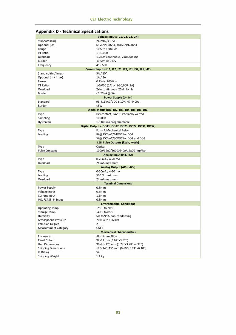
91
CET Electric Technology
Appendix D - Technical Specifications Voltage Inputs (V1, V2, V3, VN)
Standard (Un) Optional (Un) Range
PT Ratio Overload Burden
240VLN/415VLL 69VLN/120VLL, 400VLN/690VLL 10% to 120% Un
1-10,000 1.2xUn continuous, 2xUn for 10s <0.5VA @ 240V
Frequency 45-65Hz
Current Inputs (I11, I12, I21, I22, I31, I32, I41, I42)
Standard (In / Imax) Optional (In / Imax) Range
CT Ratio Overload Burden
5A / 10A 1A / 2A 0.1% to 200% In
1-6,000 (5A) or 1-30,000 (1A) 2xIn continuous, 20xIn for 1s <0.25VA @ 5A
Power Supply (L+, N-)
Standard
Burden
95-415VAC/VDC ± 10%, 47-440Hz
<6W
Digital Inputs (DI1, DI2, DI3, DI4, DI5, DI6, DIC)
Type Sampling Hysteresis
Dry contact, 24VDC internally wetted 1000Hz 1-1,000ms programmable
Digital Outputs (DO11, DO12, DO21, DO22, DO31, DO32)
Type
Loading
Form A Mechanical Relay
8A@250VAC/24VDC for DO1 5A@250VAC/30VDC for DO2 and DO3
LED Pulse Outputs (kWh, kvarh)
Type Pulse Constant
Optical 1000/3200/5000/6400/12800 imp/kxh
Analog Input (I41, I42)
Type
Overload
0-20mA / 4-20 mA
24 mA maximum
Analog Output (AO+, AO-)
Type Loading Overload
0-20mA / 4-20 mA 500 Ω maximum 24 mA maximum
Terminal Dimensions
Power Supply
Voltage Input Current Input I/O, RS485, I4 Input
0.5N·m
0.5N·m 1.8N·m 0.5N·m
Environmental Conditions
Operating Temp.
Storage Temp. Humidity Atmospheric Pressure
Pollution Degree Measurement Category
-25°C to 70°C
-40°C to 85°C 5% to 95% non-condensing 70 kPa to 106 kPa
2 CAT III
Mechanical Characteristics
Enclosure Panel Cutout
Unit Dimensions Shipping Dimensions IP Rating
Shipping Weight
Aluminum Alloy 92x92 mm (3.62˝x3.62˝)
96x96x125 mm (3.78˝x3.78˝×4.92˝) 170x145x155 mm (6.69˝x5.71˝×6.10˝) 52
1.1 kg

92
CET Electric Technology
Accuracy
Parameters Accuracy Resolution
Voltage ±0.1% 0.001V
Current ±0.1% 0.001A
I4 Measured ±0.1% 0.001A
Ir Calculated ±0.1% F.S. 0.001A
kW, kvar, kVA ±0.2% 0.001k
kWh, kVAh IEC 62053-22 Class 0.2S 0.01kXh
kvarh IEC 62053-24 Class 0.5S 0.01kvarh
P.F. ±0.2% 0.001
Frequency ±0.01 Hz 0.01Hz
Harmonics IEC 61000-4-7 Class A 0.01%
K-Factor IEC 61000-4-7 Class A 0.1
Phase Angles ±1° 0.1°
AI ±0.5% F.S. -
AO ±0.5% F.S. -

93
CET Electric Technology
Appendix E - Standards Compliance Safety Requirements
LVD Directive 2014 / 35 / EU
EN61010-1: 2010
EN61010-2-030: 2010
Electrical safety in low voltage distribution systems up to 1000Vac and 1500 Vdc
IEC 61557-12: 2008 (PMD)
Insulation AC Voltage: 4kV @ 1 minute
Insulation resistance: >100MΩ Impulse Voltage: 6kV, 1.2/50µs
IEC 62052-11: 2003
Electromagnetic Compatibility
EMC Directive 2004/108/EC (EN 61326: 2006)
Immunity Tests
Electrostatic Discharge IEC 61000-4-2: 2008 Level III
Radiated Fields IEC 61000-4-3: 2010 Level III
Fast Transients IEC 61000-4-4: 2012 Level IV
Surges IEC 61000-4-5: 2005 Level IV
Conducted Disturbances IEC 61000-4-6: 2008 Level III
Magnetic Fields IEC 61000-4-8: 2009 Level IV
Voltage Dips and Interruptions IEC 61000-4-11: 2004 Level III
Oscillatory waves IEC 61000-4-12: 2006 Level III
Radio Disturbances CISPR 22:2006, Level B
Emission Tests
Limits and methods of measurement of electromagnetic disturbance characteristics of industrial, scientific and medical (ISM) radio-frequency equipment
EN 55011: 2009 + A1: 2010
(CISPR 11)
Limits and methods of measurement of radio disturbance characteristics of information technology equipment
EN 55022: 2010+AC: 2011
(CISPR 22)
Limits for harmonic current emissions for equipment with rated current ≤16 A
EN 61000-3-2: 2006+A1: 2009+A2:2009
Limitation of voltage fluctuations and flicker in low-voltage supply systems for equipment with rated current ≤16 A
EN 61000-3-3: 2008
Emission standard for residential, commercial and light-industrial environments
EN 61000-6-4: 2007+A1: 2011
Testing and measurement techniques - Ring wave immunity test. EN 61000-4-12: 2006
Mechanical Tests
Spring Hammer Test IEC 62052-11: 2003
Vibration Test IEC 62052-11: 2003
Shock Test IEC 62052-11: 2003
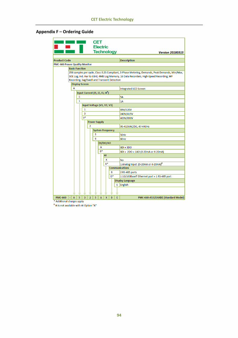
94
CET Electric Technology
Appendix F – Ordering Guide

95
CET Electric Technology
CET Inc.
8/F, Westside, Building 201, Terra Industrial & Tradepark,
Che Gong Miao, Shenzhen, Guangdong, P.R.China 518040
Tel: +86.755.8341.5187
Fax: +86.755.8341.0291
W: www.cet-global.com